NEW Crane Checklist 12 1 13
User Manual: NEW-Crane-Checklist Grove Rough Terrain Crane
Open the PDF directly: View PDF ![]() .
.
Page Count: 2
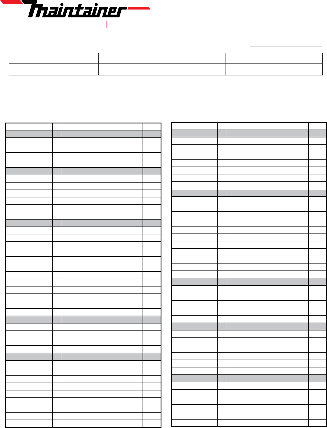
OSHA / ANSI Initial Inspection Checklist
Unit # Unit Serial # Inspector:
Crane Model: Crane Serial # Max. Crane Capacity:
Date:
1701 2ND AVE SHELDON, IA 51201 712-324-5001
1. Crane must be away from power lines and leveled with outriggers fully
extended before inspecting and operating.
2. OSHA and ANSI require qualified and competent individuals to inspect/operate
cranes.
3. Inspectors must have been through training, have extensive knowledge and
demonstrate ability in the subject matter.
Status:
References: O = OSHA Subpart CC, 1910.180, PCSA#2.
A = ANSI/ASME B30.5 (Latest), ASME B30.10 (Latest)
P = Satisfactory X = Deficiency
R = Recommendation N/A = Not Applicable
Mobile Crane Inspection - Revision 12-1-13
MOBILE CRANE
INSPECTION CHECKLIST
#
REFERENCE
ITEM
STATUS
HISTORICAL DATA
O - 1926.1412(e)(3) 1
Monthly Inspection Records
A - B30.5-2.3.1(a) 2
Maintenance Records
O - 1926.1434(a) 3
Modification Records
A - B30.5-2.2.2(a)(2) 4
Initial & post-repair Load Test Records
GENERAL
O - 1926.1433(d)(8) 5
Guards / Covers
O - 1926.601(b)(i)&(ii) 6
External Lights
O - 1926.1433(d)(5) 7
Warning Decals
A - B30.5-3.4.7 8
Housekeeping
O - 1926.1422 9
Hand Signal Chart
A - B30.5.2.2.1(a) 10
No-Load Operational Test
DRIVER’S CAB
A- B30.5-1.8.3(b) 11
Access - Grab Rails / Steps
A - B30.5-3.4.9(a) 12
Fire Extinguisher
A - B30.5-2.1.3(m) 13
PTO (Power Take Off)
O - 1926.601(b)(1) 14
Parking Brake
A - B30.5-2-1.2(a)(4) 15
Air / Hydraulic Lines
A - B30.5-2.1.3(a)(6) 16
Instruments / Gauges
A - B30.5-2.1.2(3) & (7) 17
Electrical Switches / Functions
O - 1926.601(b)(3) 18
Horn
A - B30.5-2.1.3(a)(10) 19
Steering
A - B30.5-1.6.4 20
Clutch
O - 1926.601(b)(1) 21
Brake
O - PCSA#2 8.01 22
Operator's manual
POWER GENERATOR (TRUCK OR AUX ENG)
O - 1926.1412(f)(2)(vi) 23
Performance
O - 1926.1433(d)(9) 24
Exhaust System / Guards & Insulators
O - 1926.1433(d)(8) 25
Belts / Hoses
O - 1926.1433(d)(8) 26
Guards/Covers - Rot & Recip. Parts
CHASSIS/CARRIER
O - 1926.601 (b)(14) 27
Transmission
O - 1926.601 (b)(14) 28
Driveline
O - 1926.1412(f)(2)(ix) 29
Tires/Wheels
O - PCSA #2 8.3.3.5(3) 30
Tire Air pressure
O - 1926.1412(f)(2)(i)(A) 31
Main Frame Members
O - 1926.1412(f)(2)(x) 32
Hydraulic hoses / Tubes / Fittings
O - 1926.1412(d)(1)(iv) 33
Hydraulic Fluid Level
O - 1926.1423(c)(3)(ii) 34
Anti-Skid Surface
O - 1926.601(b)(4)(I) 35
Backup Alarm
REFERENCE
ITEM
STATUS
OUTRIGGERS
O - 1926.1412(f)(2)(i)(A) 36
Beams
A - B30.5-1.9.3(a) 37
Outrigger Lock (if manual extend)
O - 1926.1412(f)(2)(xiii) 38
Cylinders
O - 1926.1412(f)(2)(xiv) 39
Outrigger Sandpads
O - 1926.1412(f)(2)(x) 40
Hydraulic Hoses / Tubes / Fittings
O - 1926.1412(f)(2)(xii) 41
Holding Valves (Vertical O.R. cylinders)
O - 1926.1433(d)(5) 42
Caution / Warning Decals
OPERATOR CONTROLS
O - 1926.1412(f)(2)(xxi) 43
Grab Rails / Steps / Platforms
O - 1926.1423(c)(3)(ii) 44
Anti-Skid Surface
O - 1926.1407(g) 45
Electrocution Warning Decal on Remote
A - B30.5-1.6.1(b) 46
Fully Operating Remote
A - B30.5-1.6.1(a) 47
Controls Identified
O - 1926.1412(d)(1)(I) 48
Controls - Forces / Movements / Proportional
O - PCSA#2 8.2.1.3 49
Hydraulic Leaks
O - 1926.1415(a)(7) 50
Horn - Warning Device
A - B30.5-1.6.3(a) 51
Remote Start/Stop
A - B30.5-1.6.3(b) 52
Speed Control on Remote
O - PCSA#2 8.1.4 53
Hydraulic Pressure
LOAD CHART
O - 1926.1433(d)(1) 54
Per Configuration (correct per crane model)
O - 1910.180(c)(2) 55
Durable
O - 1910.180(c)(2) 56
Legible
O - 1926.1417(c)(1) 57
Both Sides of Tower (Visible from Operator's Station)
O - 1910.180(c)(2) 58
Securely Attached
SAFETY DEVICES/OPERATIONAL AIDE
O - 1926.1416(e)(1) 59
Boom Angle indicator (both sides)
O - 1926.1416(e)(3) 60
Boom length Indicator
O - 1926.1416(e)(4) 61
Overload Protection System
O - 1926.1426(b)(4) 62
Counterbalance Valve
O - 1926.1415(a)(1) 63
Crane level Indicator
O - 1926.1416(d)(3)(I) 64
Anti-2-Block Device
TOWER/WINCH
O - 1926.1412(f)(2)(iii) 65
Rotate & Bearing
O - 1926.1412(f)(2)(i)(B) 66
Bolts installed & Torqued (top and bottom)
O - 1926.1412(f)(2)(x) 67
Hydraulic Hoses / Tubes / Fittings
O - 1926.1412(f)(2)(xvi) 68
Electric Wiring
A - B30.5-1.9.11(g) 69
Electrocution Warning Decal
#
DEFICIENCY / RECOMMENDATION REPORT
X = Deficiency R = Recomme ndat i o n
X / R ITEM # EXPLANATION DATE CORRECTED
REFERENCE
ITEM
STATUS
WINCH
A - B30.5-2.1.3(m) 70
Hydraulic Motors
A - B30.5-1.3.2(2)© 71
Winch - Wrapping on Drum (1/2" Freeboard)
O - 1926.1413(a)(4)(i)(B) 72
Winch - Minimum (2) Rope Wraps - max ext
O - 1926.1433(d)(13) 73
Winch Brake
MAIN BOOM
O - 1926.1412(f)(2)(xiii) 74
Lift cylinder
O - 1926.1412(f)(2)(xiii) 75
Extend Cylinder
O - 1926.1412(f)(2)(x) 76
Hydraulic Hoses / Tubes / Fittings
O - PCSA #2 4.07.1 77
Boom Section Alignment
O - 1926.1412(f)(2)(xv) 78
Wear pads
O - 1926.1412(f)(2)(ii) 79
Sheave(s)
O - 1926.1413(a)(2)(i)(D) 80
Wire Rope End
A - B30.5-1.7.4(b) 81
Wire Rope Retainer (Close Fitting Guards)
O - 1926.1412(f)(2)(iii) 82
Tower & Lift Cylinder Pins
O - 1926.1412(f)(2)(I) 83
Sheave plate head section
O - 1926.1412(f)(2)(i)(A) 84
Structure
LOAD BLOCK & HOOK
O - 1926.1433(d)(3) 85
Capacity marking
O - 1926.1433(d)(3) 86
Weight marking
O - 1926.1412(f)(2)(ii) 87
Sheave
A - B30.5-1.7.4(b) 88
Wire Rope Retainer (Close Fitting Guard)
O - 1926.1433(d)(4) 89
Safety Latching Mechanism
A - B30.10-1.10.5(f) 90
0° Hook Bend or Twist
A - B30.10-1.10.5(g) 91
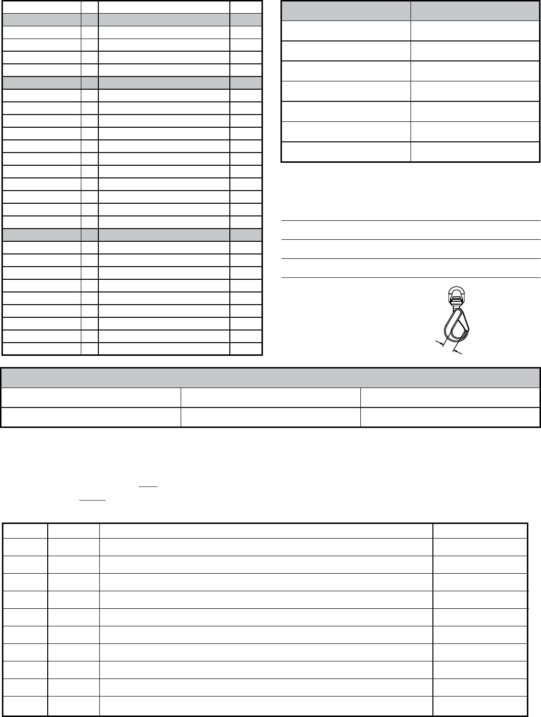
5% Hook Opening or 1/4" Max
A - B30.10-1.10.5(e) 92
10% Hook Wear Max
O - 1926.1412(f)(2)(iii) 93
Hook Swivel/Bearing
The following corrective actions are to be performed by a qualified person in accordance with the manufacturer’s specifications and requirements.
OSHA requires that, “any deficiency X shall be repaired or defective parts replaced before continued use.”
Recommendations R should be considered for corrective action. The advisability of a particular recommendation depends on each situation. Any
corrective action must be performed by a qualified person in accordance with manufacturer’s specifications and requirements.
O-B30.5-2.2.2
LOAD TEST - MAIN BOOM:
Extended Length
Load Radius
Boom Angle
Parts of Line
Rated Capacity
Test Weight
%of Rated Capacity
Results of Load Test: ___Passed ___Failed ___Not Applicable
Explanation:
X
HOOK THROAT OPENING
X = _____________
WIRE ROPE - O-1926.1413
DIAMETER
CLASSIFICATION
GRADE
#
Mobile Crane Inspection - Revision 12-1-13
