NTC1401129S Report OFFICIAL
User Manual: NTC1401129S report - OFFICIAL
Open the PDF directly: View PDF ![]() .
.
Page Count: 37
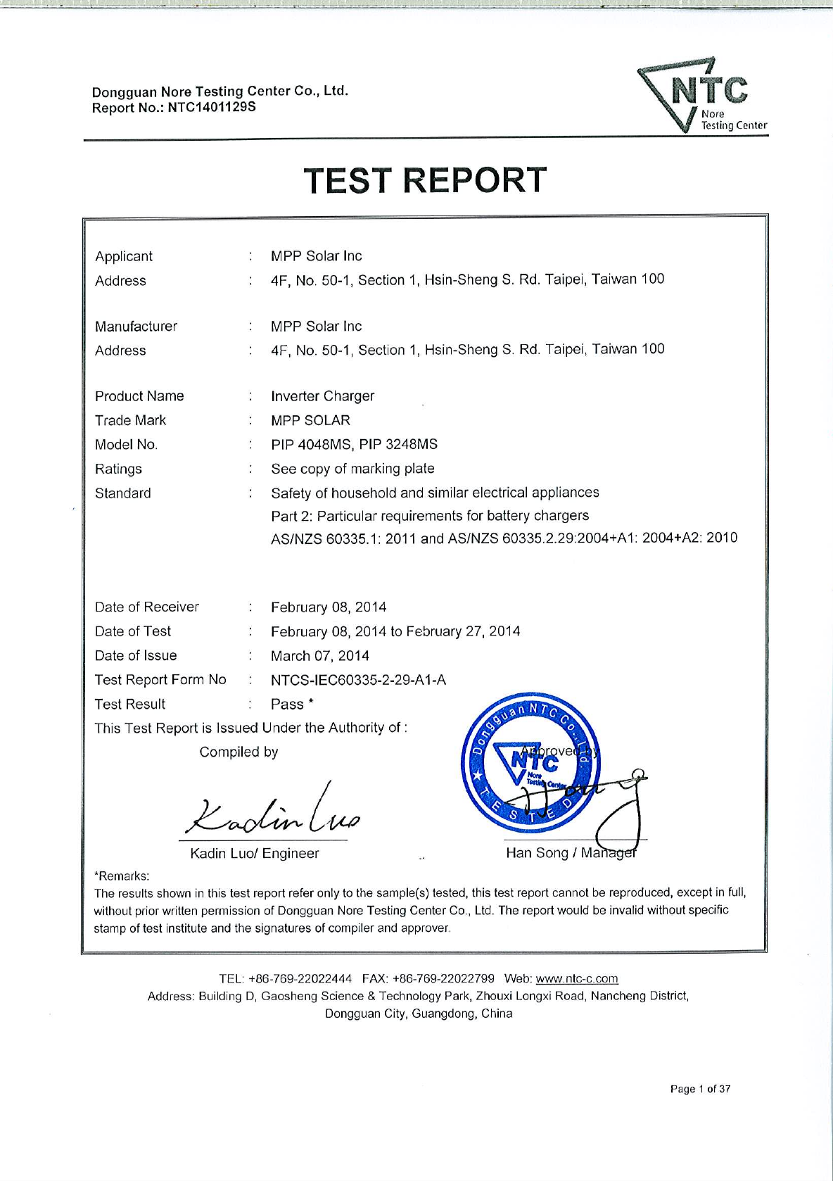
Dongguan Nore Testing Center Co., Ltd.
Report No.: NTC1401129S
Page 2 of 37
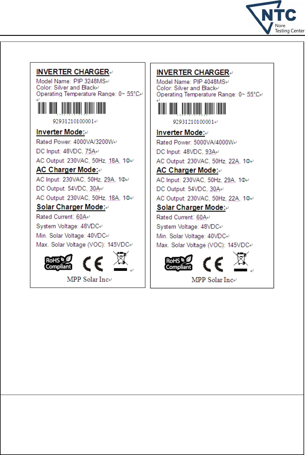
Copy of marking plate:
Summary of testing:
Only clause 11, clause 17, clause 19 and clause 22.101 wich requested by the applicant were considered in this
test report. From the result of our inspection and tests on the submitted samples, we concluded they comply
with requirements of the clause 11, clause 17, clause 19 and clause 22.101.
• Tested for moderate conditions
• EUT is designed for altitudes not exceeding 2000 m.
Dongguan Nore Testing Center Co., Ltd.
Report No.: NTC1401129S
Page 3 of 37
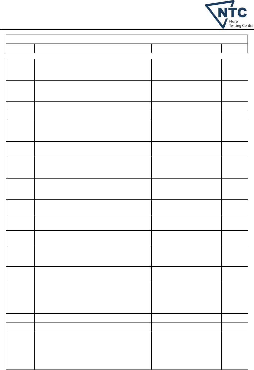
Test item particulars .................................................. :
Classification of installation and use ............................ : Fixed appliance and household indoor use
Supply Connection ....................................................... : Permanent connection equipment
Possible test case verdicts:
- test case does not apply to the test object ................ : N
- test object does meet the requirement ...................... : P (Pass)
- test object does not meet the requirement ................ : F (Fail)
General remarks:
"(see Enclosure #)" refers to additional information appended to the report.
"(see appended table)" refers to a table appended to the report.
Throughout this report a comma is used as the decimal separator.
General product information:
1) The battery charger for household indoor use only.
1) The maximum ambient temperature is +55 ℃
2) Models differences:
Models PIP 3248MS and PIP 4048MS are identical, except model name, appearance of enclosure (for color
and silk-scree only), some components (e.g. PIP 4048MS with Q31, Q19, Q24, Q38 and Q40 but PIP 3248MS
without them) and so on (for detail see appended table 24.1 and photos).
Unless otherwise specified, all tests performed on model PIP 4048MS.
3) The “Inverter Mode” and “Solar charger mode” requirement of the equipment are not covered by the scope of
this standard, so they are not considered in this test report.
4) CAUTION:
Both of the 54Vdc DC output voltage in AC charger mode and the 48Vdc system voltage in solar
charger mode exceeding 42 V between conductors, the no-load voltage exceeding 50 V that does not
meet the requirements for safety extra-low voltage in this standard.
The end users, operators and service personany persons neet to take steps to avoid this hazard.
Name and address of factory (ies):
Same as manufacturer
Dongguan Nore Testing Center Co., Ltd.
Report No.: NTC1401129S
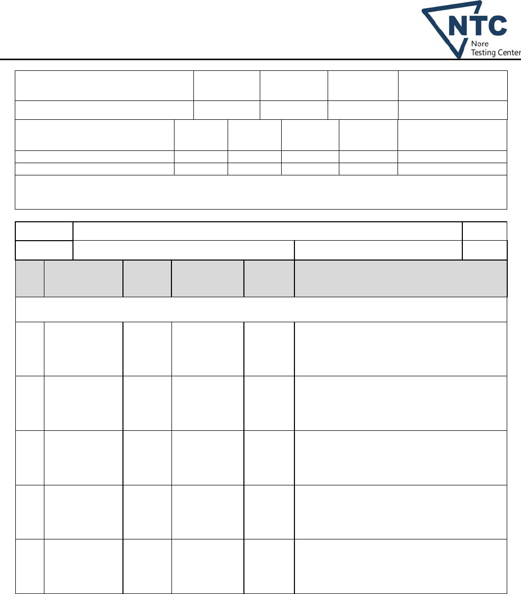
AS/NZS 60335.2.29
Clause Requirement + Test Result - Remark Verdict
Page 4 of 37
11 HEATING P
11.1 No excessive temperatures in normal use P
11.2 Battery chargers are placed in the test corner as
specified for heating appliances (AS/NZS
60335.2.29)
P
11.3 Temperature rises, other than of windings,
determined by thermocouples By thermocouples method P
Temperature rises of windings determined by
resistance method, unless N
the windings are non-uniform or it is difficult to
make the necessary connections Winding for transformer and
inductors
P
11.4 Heating appliances operated under normal
operation at 1,15 times rated power input Not a heating appliances N
11.5 Battery chargers only supplied at 1,06 times rated
voltage (AS/NZS 60335.2.29)
230Vac x 1.06 =243.8 Vac (for
AC charger mode)
P
11.6 Combined appliances operated under normal
operation, supply voltage at most unfavourable
voltage between 0,94 and 1,06 times rated voltage
Not an combined appliances N
11.7 Battery chargers are operated until steady conditions
are established (AS/NZS 60335.2.29)
P
11.8 Temperature rises monitored continuously and not
exceeding the values in table 3
P
If the temperature rise of a motor winding exceeds
the value of table 3, or
No such sealing compound N
if there is doubt with regard to classification of
insulation,
(see appended table 11.8) P
tests of Annex C are carried out N
Sealing compound does not flow out P
Protective devices do not operate, except Protective devices do not
operate.
P
components in protective electronic circuits tested
for the number of cycles specified in 24.1.4
N
17 OVERLOAD PROTECTION OF TRANSFORMERS AND ASSOCIATED CIRCUITS P
No excessive temperatures in transformer or
associated circuits in event of short-circuits likely to
occur in normal use
P
Appliance supplied with 1,06 or 0,94 times rated
voltage and the most unfavourable short-circuit or
overload likely to occur in normal use applied
230Vac x 1.06 =243.8 Vac (for
AC charger mode)
Overload and short-circuit
P
Basic insulation is not short-circuited P
Temperature rise of insulation of the conductors of
safety extra-low voltage circuits not exceeding the
relevant value specified in table 3 by more than 15 K
P
Dongguan Nore Testing Center Co., Ltd.
Report No.: NTC1401129S
AS/NZS 60335.2.29
Clause Requirement + Test Result - Remark Verdict
Page 5 of 37
Temperature of the winding not exceeding the value
specified in table 8
P
however limits do not apply to fail-safe transformers
complying with sub-clause 15.5 of IEC 61558-1 N
Output terminals of battery charger are short-
circuited (AS/NZS 60335.2.29)
P
19 ABNORMAL OPERATION P
19.1 The risk of fire, mechanical damage or electric
shock under abnormal or careless operation
obviated
P
Electronic circuits so designed and applied that a
fault will not render the appliance unsafe
P
Appliances incorporating heating elements
subjected to the tests of 19.2 and 19.3, and
N
if the appliance also has a control that limit the
temperature during clause 11 it is subjected to the
test of 19.4, and
N
if applicable, to the test of 19.5 N
Appliances incorporating PTC heating elements are
also subjected to the test of 19.6
N
Appliances incorporating motors subjected to the
tests of 19.7 to 19.10, as applicable
N
Appliances incorporating electronic circuits
subjected to the tests of 19.11 and 19.12, as
applicable
P
Appliances incorporating contactors or relays
subjected to the test of 19.14, being carried out
before the tests of 19.11
No relay used. N
Appliances incorporating voltage selector switches
subjected to the test of 19.15
N
Unless otherwise specified, the tests are continued
until a non-self-resetting thermal cut-out operates,
or
N
until steady conditions are established P
If a heating element or intentionally weak part
becomes open-circuited, the relevant test is
repeated on a second sample
N
Modification: Instead
of the lists specified, battery chargers are subjected
to the tests of 19.11, 19.12 and 19.101 to 19.103, as
applicable. (AS/NZS 60335.2.29)
P
19.2 Test of appliance with heating elements with
restricted heat dissipation; test voltage (V): power
input of 0,85 times rated power input(W) ............ :
No such heating elements N
Dongguan Nore Testing Center Co., Ltd.
Report No.: NTC1401129S
AS/NZS 60335.2.29
Clause Requirement + Test Result - Remark Verdict
Page 6 of 37
19.3 Test of 19.2 repeated; test voltage (V): power input
of 1,24 times rated power input(W) ..................... :
No such heating elements N
19.4 Test conditions as in cl. 11, any control limiting the
temperature during tests of cl. 11 short-circuited
No controls N
19.5 Test of 19.4 repeated on Class 0I and I appliances
with tubular sheathed or embedded heating
elements. No short-circuiting, but one end of the
element connected to the elements sheath
No such heating elements N
The test repeated with reversed polarity and the
other end of the heating element connected to the
sheath
N
The test is not carried out on appliances intended
to be permanently connected to fixed wiring and on
appliances where an all-pole disconnection occurs
during the test of 19.4
No such heating elements N
19.6 Appliances with PTC heating elements tested at
rated voltage, establishing steady conditions No PTC heating elements. N
The working voltage of the PTC heating element is
increased by 5% and the appliance is operated until
steady conditions are re-established. The voltage is
then increased in similar steps until 1,5 times
working voltage is reached or until the PTC heating
element ruptures
N
19.7 Stalling test by locking the rotor if the locked rotor
torque is smaller than the full load torque or Motors used for approval DC
fans only.
N
locking moving parts of other appliances N
Locked rotor, motor capacitors open circuited or
short-circuited, if required
N
Locked rotor, capacitors open-circuited one at a
time, unless N
capacitor is of class P2 of IEC 60252-1 N
The test is repeated with the capacitors short-
circuited one at a time if required
N
Appliances with timer or controller supplied with
rated voltage for each of the tests, for a period equal
to the maximum period allowed
N
Other appliances supplied with rated voltage for a
period as specified:
N
Winding temperatures not exceeding values
specified in table 8 N
19.8 Three-phase motors operated at rated voltage with
one phase disconnected
No such three-phase motors N
Dongguan Nore Testing Center Co., Ltd.
Report No.: NTC1401129S
AS/NZS 60335.2.29
Clause Requirement + Test Result - Remark Verdict
Page 7 of 37
19.9 Running overload test on appliances incorporating
motors intended to be remotely or automatically
controlled or liable to be operated continuously
N
Motor-operated and combined appliances for which
30.2.3 is applicable and that use overload
protective devices relying on electronic circuits to
protect the motor windings, are also subjected to
the test
N
Winding temperatures not exceeding values as
specified
N
19.10 Series motor operated at 1,3 times rated voltage for
1 min
No such series motor N
During the test, parts not being ejected from the
appliance N
19.11 Electronic circuits, compliance checked by
evaluation of the fault conditions specified in
19.11.2 for all circuits or parts of circuits, unless
P
they comply with the conditions specified in 19.11.1 N
Appliances incorporating an electronic circuit that
relies upon a programmable component to function
correctly, subjected to the test of 19.11.4.8, unless
P
restarting does not result in a hazard N
Appliances having a device with an off position
obtained by electronic disconnection, or a device
placing the appliance in a stand-by mode,
subjected to the tests of 19.11.4
P
If the safety of the appliance under any of the fault
conditions depends on the operation of a miniature
fuse-link complying with IEC 60127, the test of
19.12 is carried out
P
During and after each test the following is checked: P
- the temperature of the windings do not exceed the
values specified in table 8
P
- the appliance complies with the conditions
specified in 19.13
P
- any current flowing through protective impedance
not exceeding the limits specified in 8.1.4
N
If a conductor of a printed board becomes open-
circuited, the appliance is considered to have
withstood the particular test, provided both of the
following conditions are met:
N
- the base material of the printed circuit board
withstands the test of Annex E
N
Dongguan Nore Testing Center Co., Ltd.
Report No.: NTC1401129S
AS/NZS 60335.2.29
Clause Requirement + Test Result - Remark Verdict
Page 8 of 37
- any loosened conductor does not reduce
clearance or creepage distances between live parts
and accessible metal parts below the values
specified in clause 29
N
19.11.1 Before applying the fault conditions a) to f) in 19.11.2, it is checked if circuits or parts
of circuit meet both of the following conditions:
N
- the electronic circuit is a low-power circuit, that is,
the maximum power at low-power points does not
exceed 15 W according to the tests specified
N
- the protection against electric shock, fire hazard,
mechanical hazard or dangerous malfunction in
other parts of the appliance does not rely on the
correct functioning of the electronic circuit
N
19.11.2 Fault conditions applied one at a time, the appliance operated under conditions
specified in Cl. 11, but supplied at rated voltage, the duration of the tests as specified:
P
a) short-circuit of creepage distances and
clearances between live parts of different potential, if
these distances are less than the values specified in
29
P
b) open circuit at the terminals of any component P
c) short-circuit of capacitors, unless they comply with
IEC 60384-14
P
d) short-circuit of any two terminals of an electronic
component, other than integrated circuits. This fault
condition is not applied between the circuits of an
optocoupler
P
e) failure of triacs in the diode mode P
f) failure of an integrated circuit. In this case the
possible hazardous situations of the appliance are
assessed to ensure that safety does not rely on the
correct functioning of such a component
P
g) failure of an electronic power switching device N
Each low power circuit is short-circuited by
connecting the low-power point to the pole of the
supply source from which the measurements were
made
N
19.11.3 If the appliance incorporates a protective electronic
circuit which operates to ensure compliance with
clause 19, the relevant test is repeated with a
single fault simulated, as indicated in a) to f) of
19.11.2
P
19.11.4 Appliances having a switch with an off position
obtained by electronic disconnection, or
P
a switch that can be placed in the stand-by mode, P
subjected to the tests of 19.11.4.1 to 19.11.4.7 P
Dongguan Nore Testing Center Co., Ltd.
Report No.: NTC1401129S
AS/NZS 60335.2.29
Clause Requirement + Test Result - Remark Verdict
Page 9 of 37
Appliances incorporating a protective electronic
circuit subjected to the tests of 19.11.4.1 to
19.11.4.7, except that
P
Appliances operated for 30 s or 5 min during the test
of 19.7 are not subjected to the tests for
electromagnetic phenomena.
P
Surge protective devices disconnected, unless P
They incorporate spark gaps P
19.11.4.1 The appliance is subjected to electrostatic
discharges in accordance with IEC 61000-4-2, test
level 4
P
19.11.4.2 The appliance is subjected to radiated fields in
accordance with IEC 61000-4-3, test level 3
P
19.11.4.3 The appliance is subjected to fast transient bursts in
accordance with IEC 61000-4-4, test level 3 or 4 as
specified
P
19.11.4.4 The power supply terminals of the appliance
subjected to voltage surges in accordance with IEC
61000-4-5, test level 3 or 4 as specified
P
Earthed heating elements in class I appliances
disconnected
No heating elements N
19.11.4.5 The appliance is subjected to injected currents in
accordance with IEC 61000-4-6, test level 3
P
19.11.4.6 The appliance is subjected to voltage dips and
interruptions in accordance with IEC 61000-4-11
N
Appliances having a rated current exceeding 16 A
are subjected to the Class 3 voltage dips and
interruptions in accordance with IEC 61000-4-34
P
19.11.4.7 The appliance is subjected to mains signals in
accordance with IEC 61000-4-13, test level class 2
P
19.11.4.8 The appliance is supplied at rated voltage and
operated under normal operation. After 60s the
power supply is reduces to a level such that the
appliance ceases to respond or a programmable
component cease to operate.
P
The appliance continues to operate normally, or P
requires a manual operation to restart P
19.12 If the safety of the appliance for any of the fault
conditions specified in 19.11.2 depends on the
operation of a miniature fuse-link complying with
IEC 127, the test is repeated, measuring the current
flowing through the fuse-link; measured current (A);
rated current of the fuse-link (A) ............................. :
No such fuse provided in AC
charger mode. N

Dongguan Nore Testing Center Co., Ltd.
Report No.: NTC1401129S
AS/NZS 60335.2.29
Clause Requirement + Test Result - Remark Verdict
Page 10 of 37
19.13 During the tests the appliance does not emit
flames, molten metal, poisonous or ignitable gas in
hazardous amounts
Comply with requirements P
Temperature rises not exceeding the values shown
in table 9 (see appended table 19 ) P
Enclosures not deformed to such an extent that
compliance with Cl. 8 is impaired
P
Appliance still operable and complying with 20.2 P
Addition:
During the tests, the values of Table 8 apply.
There shall be no rupture of the battery.
(AS/NZS 60335.2.29)
P
If the appliance can still be operated it complies
with 20.2
P
Appliance, other than Class III, withstands the electric strength test of 16.3, however,
the test voltage being:
P
- basic insulation: 1250 V L to N P
- supplementary insulation: 1750 V P
- reinforced insulation: 3000 V L/N to output terminal,
L/N to enclosure
P
After operation or interruption of a control,
clearances and creepage distances across the
functional insulation withstand the electric strength
test of 16.3, the test voltage being twice the
working voltage
P
The appliance does not undergo a dangerous
malfunction, and
P
no failure of protective electronic circuits, if the
appliance is still operable
P
Appliances tested with an electronic switch in the off position, or in the stand-by
mode:
P
- do not become operational, or P
- if they become operational, do not result in a
dangerous malfunction during or after the tests of
19.11.4
P
If the appliance contains lids or doors that are controlled by one or more interlocks,
one of the interlocks may be released provided that:
N
- the lid or door does not move automatically to an
open position when the interlock is released, and
N
- the appliance does not start after the cycle in
which the interlock was released
N
19.14 Appliances operated under the conditions of clause
11, any contactor or relay contact operating under
the conditions of clause 11 being short-circuited
N
Dongguan Nore Testing Center Co., Ltd.
Report No.: NTC1401129S
AS/NZS 60335.2.29
Clause Requirement + Test Result - Remark Verdict
Page 11 of 37
For a relay or contactor with more than one contact,
all contacts are short-circuited at the same time
N
A relay or contactor operating only to ensure the
appliance is energized for normal use is not short-
circuited
N
If more than one relay or contactor operates in
clause 11, they are short-circuited in turn
N
19.15 For appliances with a mains voltage selector switch,
the switch is set to the lowest rated voltage position
and the highest value of rated voltage is applied
No such switch N
19.101 Battery chargers supplied at rated voltage and
operated under normal operation (controls operating
during tests of Cl. 11 being short-circuited) (AS/NZS
60335.2.29)
P
19.102 Reverse connection of the battery charger to a fully
charged battery as specified (AS/NZS 60335.2.29)
The appliance did not work
when reverse
P
Battery charger operated while supplied at rated
voltage (AS/NZS 60335.2.29)`
P
19.103 Battery chargers in combination with a d.c.
distribution board supplied at rated voltage and
operated under normal operation until steady
conditions are established (AS/NZS 60335.2.29)
No combination with a d.c.
distribution board
N
Load increased as specified until protective device
operates (AS/NZS 60335.2.29)
N
22 CONSTRUCTION P
22.101 Void --
24 COMPONENTS P
24.1 Components comply with safety requirements in
relevant IEC standards
P
List of components (see appended table 24.1) P
Dongguan Nore Testing Center Co., Ltd.
Report No.: NTC1401129S
Page 12 of 37
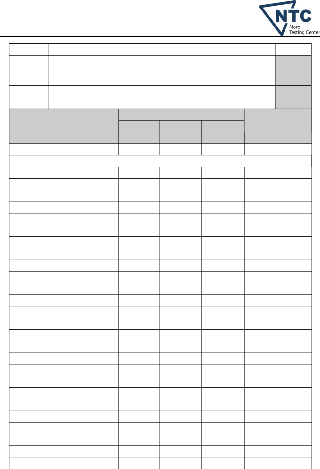
11.8 TABLE: Heating test, thermocouple measurements P
Test voltage (V)………………. Condition A: 230x1.06=243.8Vac, 50Hz (AC
charger mode) --
T1 (°C) Condition A : 24.3 --
T2 (°C) Condition A : 24.6 --
Duration Operated until steady conditions. --
temperature rise dT of part/at: dT (K) Required dT (K)
Condition A Condition B Condition C
Input connector near “L” 5.9 -- -- Ref.
For main board
Varistor MOV1 body 8.1 -- -- 30 (T85-55)
C87 body 2.7 -- -- 70 (T125-55)
L4 coil 39.6 -- -- REF.
C46 body 8.1 -- -- 45 (T100-55)
Relay RY1 coil 22.8 -- -- 30 (65-30)
Relay RY2 coil 21.5 -- -- 30 (65-30)
C90 body 7.1 -- -- 70 (T125-55)
CT1 coil 20.6 -- -- 55 (85-30)
L1 coil 3.4 -- -- Ref.
L2 coil 9.7 -- -- Ref.
C70 body 5.4 -- -- 30 (T85-55)
PCB under Q16 10.2 -- -- For Cl.30
PCB under Q18 11.4 -- -- For Cl.30
PCB under Q20 9.31 -- -- For Cl.30
HCT 6.8 -- -- Ref.
C84 body 17.7 -- -- 70 (T125-55)
TX5 coil 5.7 -- -- 55 (85-30)
TX5 bobbin 3.8 -- -- For Cl.30
TX2 coil 0.4 -- -- 55 (85-30)
TX2 bobbin 0.7 -- -- For Cl.30
TX1 coil 21.8 -- -- 55 (85-30)
TX1 bobbin 31.1 -- -- For Cl.30
C9 body 6.6 -- -- 70 (T125-55)
Optocoupler U8 body 8.1 -- -- Ref.
PCB under Q3 12.5 -- -- For Cl.30
PCB under Q9 4.2 -- -- For Cl.30
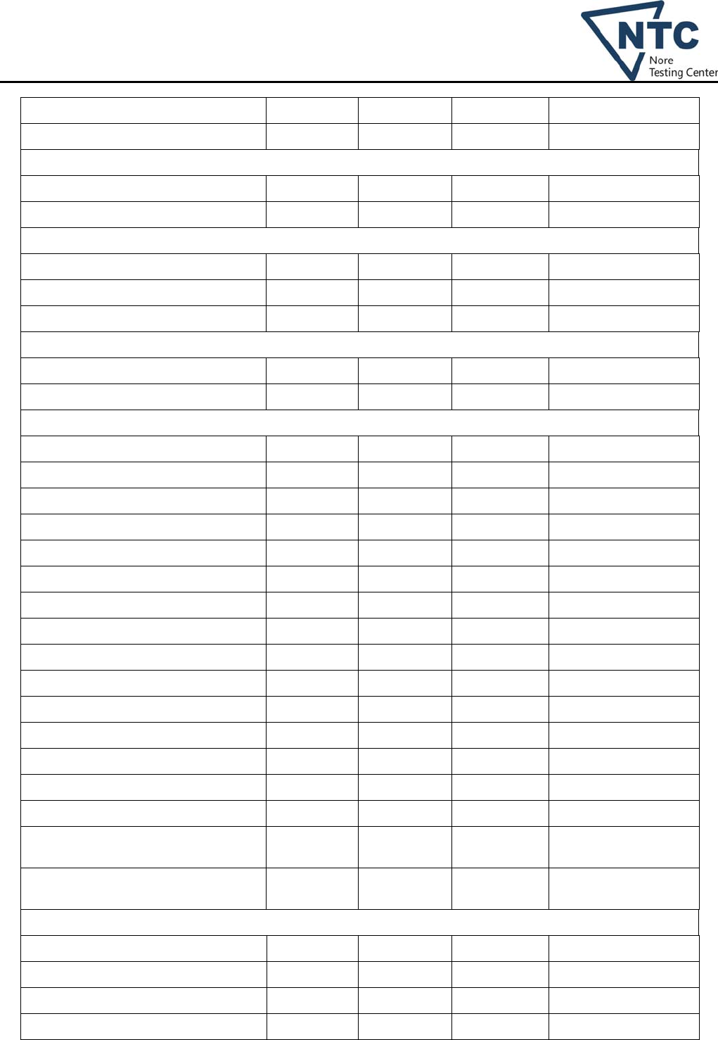
Dongguan Nore Testing Center Co., Ltd.
Report No.: NTC1401129S
Page 13 of 37
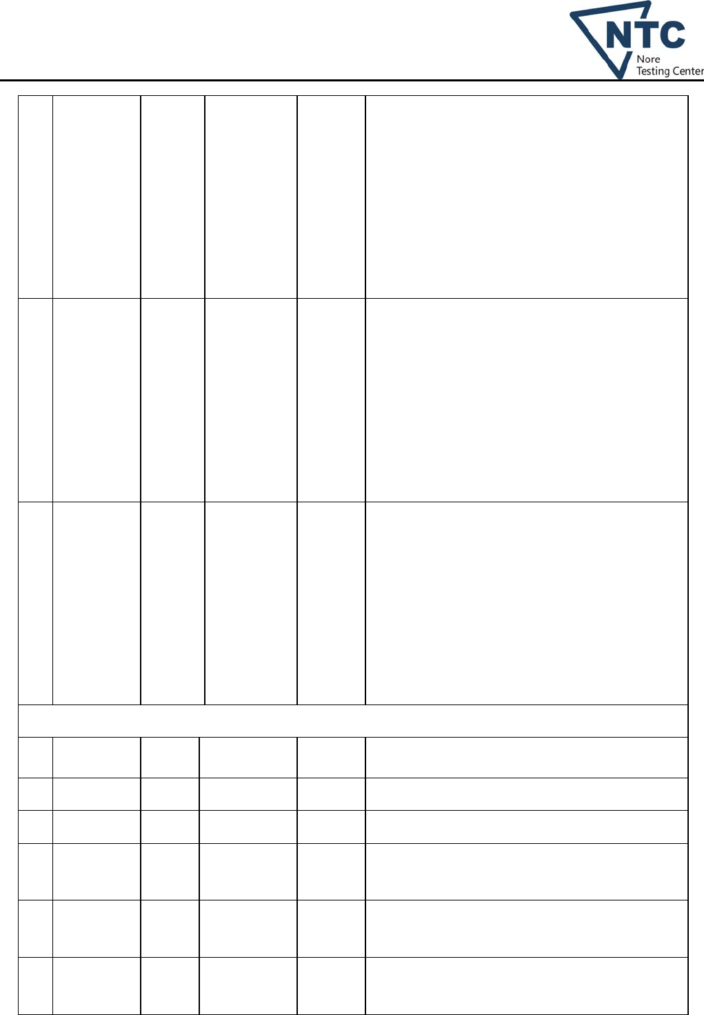
PCB under Q12 8.5 -- -- For Cl.30
PCB under F3 8.5 -- -- For Cl.30
For charge board
RY1 coil 4.6 -- -- 30 (65-30)
Optocoupler U6 body 3.9 -- -- Ref.
16-500243-00G board
TX1 coil 5.3 -- -- 55 (85-30)
TX1 bobbin 5.3 -- -- For Cl.30
RY2 coil 5.2 -- -- 30 (65-30)
Board 16-500271-00G-E
TX1 coil 6.3 -- -- 55 (85-30)
TX1 bobbin 6.9 -- -- For Cl.30
16-600056-00G-F board
RY1 coil 0.5 -- -- 30 (65-30)
RY2 coil 0.4 -- -- 30 (65-30)
Varistor MOV2 0.14 -- -- 30 (T85-55)
Optocoupler U3 1.1 -- -- Ref.
Y-capacitor C10 0.29 -- -- 70 (T125-55)
Y-capacitor C38 0.2 -- -- 70 (T125-55)
TX1 coil 0.9 -- -- 55 (85-30)
TX1 bobbin 0.9 -- -- For Cl.30
PCB under TX1 0.9 -- -- For Cl.30
PCB under Q8 1.1 -- -- For Cl.30
PCB under Q14 0.9 -- -- For Cl.30
PCB near BAT+ 0.56 -- -- For Cl.30
E-capacitor C8 0.9 -- -- Ref.
Battery wire (connected to BAT+) 0.45 -- -- 50 (T105-55)
Internal wire bigger inductor 1 1.1 -- -- 50 (T105-55)
Bigger inductor 1 coil (fixed to
enclosure) 0.6 -- -- Ref.
Bigger inductor 2 coil (fixed to
enclosure) 0.74 -- -- Ref.
R232 board(16-500245-00G)
TX1 coil 4.8 -- -- 55 (85-30)
TX1 bobbin 4.9 -- -- For Cl.30
AC output wire inside 7.3 -- -- 50 (T105-55)
Enclosure top outside near Main board 1.1 -- -- 30 (60-30)
Dongguan Nore Testing Center Co., Ltd.
Report No.: NTC1401129S
Page 14 of 37
Enclosure bottom outside near Main
board 4.6 -- --
30 (60-30)
Floor of test corner 3 -- -- 35 (65-30)
temperature rise dT of part/at: R1 (Ω) R2 (Ω) dT (K) Limit dT
(K)
Insulation class
-- -- -- -- -- --
-- -- -- -- -- --
Supplementary information:
1) appliance is test on horizontal position due to its normal working position.
17 TABLE: overload of transfomer and associated circuit P
ambient temperature (°C) .....................................
.
25°C or see below —
No. location fault test voltage
(V)
test time result
Test on model PIP 4048MS (under AC charger mode condition)
1 Transformer
TX2 (on main
board) output
pin
o-l 243.8Vac 30min Due to the design of equipment, it was
difficult to make overload for secondary of
transformer. the unit was abnormal when
overload, no hazard.
2 Transformer
TX5 (on main
board) output
pin
o-l 243.8Vac 30min Due to the design of equipment, it was
difficult to make overload for secondary of
transformer. the unit was abnormal when
overload, no hazard.
3 Transformer
TX6 (on main
board) output
pin
o-l 243.8Vac 30min Due to the design of equipment, it was
difficult to make overload for secondary of
transformer. the unit was abnormal when
overload, no hazard.
4 Transformer
TX8 (on main
board) output
pin
o-l 243.8Vac 30min Due to the design of equipment, it was
difficult to make overload for secondary of
transformer. the unit was abnormal when
overload, no hazard.
5 Transformer
TX9 (on main
board) output
pin
o-l 243.8Vac 30min Due to the design of equipment, it was
difficult to make overload for secondary of
transformer. the unit was abnormal when
overload, no hazard.
Dongguan Nore Testing Center Co., Ltd.
Report No.: NTC1401129S
Page 15 of 37
6 Transformer
TX1 (on main
board) output
pin
o-l 243.8Vac 3hours
50min
Unit temperature sable load to 30A Max, no
damaged, no hazards.
The Max. Temperature rise were:
For main board:
PCB under Q18: 15.3K;
PCB under Q20: 12.4K;
PCB under Q12: 10.5K;
PCB under F3: 9.7K;
TX1 coil: 28.9K, TX2 coil: 4.5K, TX5 coil:
7.1K;
For board 16-500243-00G:
TX1 coil: 4.3K;
For board 16-500271-00G-E:
TX1 coil: 4.7K;
For board 16-600056-00G-F:
TX1 coil: 4.8K;
For board16-500245-00G:
TX1 coil: 8.4K, Ambient: 24.7°C.
7 DC output o-l 243.8Vac 5hours Unit temperature sable load to 30A Max, no
damaged, no hazards.
The Max. Temperature rise were:
For main board:
TX1 coil: 74.7K, TX2 coil: 21.4K, TX5 coil:
21.3K;
For board 16-500243-00G:
TX1 coil: 18.8K;
For board 16-500271-00G-E:
TX1 coil: 22.0K;
For board 16-600056-00G-F:
TX1 coil: 15.0K;
For board16-500245-00G:
TX1 coil: 18.3K, Ambient: 24.8°C.
8 DC output S-C 243.8Vac 10min The DC fuse opened, the unit is working in
fault mode, no any output, no hazards.
Test on model PIP 4048MS (under solar charger mode condition)
Remark:
“s-c”= short circuit, “o-l”=overload
19 TABLE: abnormal operation tests P
ambient temperature (°C) ..............................
.
25°C —
No. component
No.
fault test voltage
(V)
test time result
Test on model PIP 4048MS (under AC charger mode condition)
1 Battery Reverse
d
230Vac 10min Unit is working in fault mode immediately, no any
output, no damaged, no hazards.
Dongguan Nore Testing Center Co., Ltd.
Report No.: NTC1401129S
Page 16 of 37
2 Ventilation Block 230Vac 1h36 min Unit temperature sable, no hazards, no damaged.
The Max. Temperature rise were:
For main board:
TX1 coil: 59.0K, TX2 coil: 21.0K, TX5 coil: 23.0K;
For board 16-500243-00G:
TX1 coil: 13.3K;
For board 16-500271-00G-E:
TX1 coil: 24.6K;
For board 16-600056-00G-F:
TX1 coil: 19.3K;
For board16-500245-00G:
TX1 coil: 8.8K, Ambient: 24.8°C.
3 Fan 1 Lock 230Vac 30min
Unit temperature sable, no hazards, no damaged.
The Max. Temperature rise were:
For main board:
TX1 coil: 74.4K, TX2 coil: 16.5K, TX5 coil: 24.2K;
For board 16-500243-00G:
TX1 coil: 21.2K;
For board 16-500271-00G-E:
TX1 coil: 23.7K;
For board 16-600056-00G-F:
TX1 coil: 14.0K;
For board16-500245-00G:
TX1 coil: 20.1K, Ambient: 24.6°C.
4 Fan 2 Lock 230Vac 30min
Unit temperature sable, no hazards, no damaged.
The Max. Temperature rise were:
For main board:
TX1 coil: 74.7K, TX2 coil: 21.4K, TX5 coil: 21.3K;
For board 16-500243-00G:
TX1 coil: 18.8K;
For board 16-500271-00G-E:
TX1 coil: 22.0K;
For board 16-600056-00G-F:
TX1 coil: 15.0K;
For board16-500245-00G:
TX1 coil: 18.3K, Ambient: 24.8°C.
Test on model PIP 4048MS for main board (under AC charger mode condition)
5 Q36 Pin 2-3 S-C 230Vac 10min
Unit shutdown immediately, no damaged, no
hazards
6 Q37 Pin 2-3 S-C 230Vac 10min
R242 damaged, no hazards.
7 C37 S-C 230Vac 10min
Normal operation, no damaged, no hazards.
8 Transformer
TX1 output
pin
S-C 230Vac
10min Unit shutdown immediately, unrecoverable, no
hazards
9 Transformer
TX2 output
pin
S-C 230Vac
10min Unit shutdown immediately, unrecoverable, no
hazards
10 Transformer
TX5 output
pin
S-C 230Vac
10min Unit shutdown immediately, unrecoverable, no
hazards
Dongguan Nore Testing Center Co., Ltd.
Report No.: NTC1401129S
Page 17 of 37
11 Transformer
TX6 output
pin
S-C 230Vac
10min Q37 damaged, no hazards.
12 Transformer
TX8 output
pin
S-C 230Vac
10min Unit shutdown immediately, unrecoverable, no
hazards
13 Transformer
TX9 output
pin
S-C 230Vac
10min Unit shutdown immediately, no damaged, no
hazards
14 U8 Pin 1-2 S-C 230Vac
10min Unit normal operation, no damaged, no hazards
15 U8 Pin 3-4 S-C 230Vac
10min Unit shutdown immediately, no damaged, no
hazards
16 U8 Pin 1 O-C 230Vac 10min Unit normal operation, no damaged, no hazards
17 U18 Pin 1-2 S-C 230Vac
10min Unit normal operation, no damaged, no hazards
18 U18 Pin 3-4 S-C 230Vac
10min Unit normal operation, no damaged, no hazards
19 U18 Pin 1 O-C 230Vac 10min Unit normal operation, no damaged, no hazards
Test on model PIP 4048MS for board 16-600056-00G-F (under AC charger mode condition)
20 C8 S-C 230Vac 10min
Normal operation, no damaged, no hazards.
21 Q8 Pin 2-3 S-C 230Vac 10min
Unit will word in fault mode, no damaged, no
hazards
22 Q14 Pin 2-3 S-C 230Vac 10min
Unit will word in fault mode, no damaged, no
hazards
Remark:
“S-C”= short circui, “O-C”= open circui
24.1 TABLE: Components P
object/part No. manufacturer/
trademark
type/model technical data standard mark(s) of
conformity1)
Metal enclsure -- -- Min.
thickness: 1.5m
m
AS/NZS
60335.1,
AS/NZS
60335.2.29
Test with
appliance
AC terminal
blocks
SHENZHEN
SUCCEED
ELECTRONICS
TECHNOLOGY
CO., LTD.
TR-6N-01-3P-
BK
600V, 50A UL 1059 UL E332956
DC terminal
blocks
SHENZHEN
SUCCEED
ELECTRONICS
TECHNOLOGY
CO., LTD.
TR-6N-01-2P-
BK
600V, 50A UL 1059 UL E332956
Switch Rong Feng
Industrial Co.,
Ltd
RF-1033 250Vac, 6A EN 61058-1 VDE 40021707,
UL E94138
Circuit breaker TOPSTONE L1 125/250Vac, EN 60934:2001 TUV RH(R
Dongguan Nore Testing Center Co., Ltd.
Report No.: NTC1401129S
Page 18 of 37
CORP
(E244552)
40A 50046704)
DC Fans ADDA
CORPORATION
AD0812XB-
A7BGP
DC12V, 0.55A UL 507 UL E132139
Bigger choke 1
and 2 (fixed to
enclosure)
DINGMEI
41-110135-00G
130°C AS/NZS
60335.1,
AS/NZS
60335.2.29
Test with
appliance
Mylar sheet
(above main
board)
SHIN-ETSU
CHEMICAL CO
LTD
TC-(xxxx)TCI V-0, 0.2mm,
150°C
UL 94 UL E48923
Insulation sheet
(under display
board)
TEIJIN LIMITED
RESIN AND
PLASTIC
PC-
(c1)(b2)(c2)(#)
115 , Min. ℃
1.5mm
thickness
UL 94 UL E50075
Internal wiring VEGA
TECHNOLOGIE
S INDUSTRIAL
(AUSTRIA) CO
1015 10AWG, 105°C UL758 UL E189529
Alternate YONG HAO
ELECTRICAL
INDUSTRY CO
LTD
1015 10AWG, 105°C UL758 UL E240426
Alternate Various Various Min. 10AWG,
105°C
UL758 UL
Heat shrink
tube
CHANGYUAN
ELECTRONICS
(SHENZHEN)
CO LTD
CB-HFT 600V, 125°C UL224 UL E180908
For Main board(16-500242-00G)
Varistor
(MOV1)
(for model PIP
4048MS),
BRIGHTKING
(SHENZHEN)
CO., LTD
561KN20 300Vac,
385Vdc
EN 61051-1,
IEC61051-
2/A1, UL 1449
VDE
UL E327997
Varistor
(MOV1)
(for model PIP
3248MS)
BRIGHTKING
(SHENZHEN)
CO., LTD
471KN20 300Vac,
385Vdc
EN 61051-1,
IEC61051-
2/A1, UL 1449
VDE
UL E327997
Y-Cap (C59,
C60)
JUHONG ELE
CO
JA 1000pF, min.
250Vac, min.
85°C
IEC 60384-
14
VDE
UL E253194
Alternate Various Various 1000pF, min.
250Vac, min.
85°C
IEC 60384-
14
VDE
UL
Y-Cap (C119,
C120, C121,
C122, C52,
C53, C70, C71)
JUHONG ELE
CO
JA Max. 10000pF,
min. 250Vac,
min. 85°C
IEC 60384-
14
VDE
UL E253194
Alternate Various Various Max. 10000pF,
min. 250Vac,
min. 85°C
IEC 60384-
14
VDE
UL
X-Cap(C72) FARAD
ELECTRONICS
CO., LTD
PXK Max. 0.22uF,
Rated: 275Vac,
min. 100°C
IEC 60384-
14
VDE
UL E247953
X2-Cap (C33) FARAD
ELECTRONICS
CO LTD
PXK Max. 20uF,
Rated: 275Vac,
min. 100°C
IEC 60384-
14
VDE, UL
E247953
X2-Cap (C17) FARAD
ELECTRONICS
PXK Max. 0.47uF,
Rated: 275Vac,
IEC 60384-
14
VDE, UL
E247953
Dongguan Nore Testing Center Co., Ltd.
Report No.: NTC1401129S
Page 19 of 37
CO LTD min. 100°C
Relay ( RY1,
RY2, RY3,
RY4)
SONG CHUAN
PRECISION
CO., LTD
832HA-1A-F-C 277Vac, 40A EN 60255-23,
EN 61810-1,
EN 61810-5,
UL508.
UL E88991
E-Cap (C40,
C41)
-- -- 470uF, 500Vac,
105°C
-- --
IGBT(QB2,
QD2, QA1,
QC1, Q28,
Q27, Q29, Q30,
Q31, Q32, )
-- -- 45A, 600V -- --
Mosfet (Q19,
Q13, Q18, Q23,
Q24, Q11, Q17,
Q20, Q38, Q21,
Q22, Q12, Q40,
Q26, Q25, Q14)
(for model PIP
4048MS)
-- -- 120A, 75V -- --
Mosfet (Q13,
Q18, Q23, Q11,
Q17, Q20, Q21,
Q22, Q12, Q26,
Q25, Q14)
(for model PIP
3248MS)
-- -- 120A, 75V -- --
Thermistor
(NTCCN4-HS3,
NTCCN8-HS1)
Lattron Co., Ltd LNTA153@W* 15Kohm at
25°C
UL 1434 UL E306546
Chock(L2) CLICK 41-110111-00G 1mH, 130°C AS/NZS
60335.1,
AS/NZS
60335.2.29
Test with
appliance
Chock(L4) DINGMEI SP36123B-
00SS
400uH, 130°C AS/NZS
60335.1,
AS/NZS
60335.2.29
Test with
appliance
Chock (L1) DINGMEI 41-110103-00G 120uH, 130°C AS/NZS
60335.1,
AS/NZS
60335.2.29
Test with
appliance
Current
transformer
(CT1)
DINGMEI 41-020027-00G Class B
(130°C)
AS/NZS
60335.1,
AS/NZS
60335.2.29
Test with
appliance
--Bobbin of CT1 SUMITOMO
BAKELITE CO
LTD
PM-9820 V-0, 150°C,
Min. 0.51mm
thickness
UL 94 UL E41429
Current
transformer
(HCT1)
DINGMEI 41-025003-00G Class B
(130°C)
AS/NZS
60335.1,
AS/NZS
60335.2.29
Test with
appliance
--Bobbin of
HCT1
SUMITOMO
BAKELITE CO
LTD
PM-9820 V-0, 150°C,
Min. 0.51mm
thickness
UL 94 UL E41429
Opto
coupler (U8,
U13, U11, U17,
COSMO
ELECTRONICS
CORP
K1010 Int. CR / Ext.
CR / Dti.
≥6,5 mm / ≥6,5
IEC 60747-5-2:
1997 + A1:
2002
VDE 101347
UL E169586
Dongguan Nore Testing Center Co., Ltd.
Report No.: NTC1401129S
Page 20 of 37
U18) mm / >0,4 mm,
55/115/21
Transformer
(TX1)
CLICK 41-070237-00G Class F(155°C) AS/NZS
60335.1,
AS/NZS
60335.2.29
Test with
appliance
--Bobbin E I DUPONT DE
NEMOURS &
CO INC
410 V-0, 200°C,
Min. 0.51mm
thickness
UL 94 UL E34739
--Insulation tape JINGJIANG
YAHUA
PRESSURE
SENSITIVE
GLUE CO LTD
PF 180°C UL 510 UL E165111
--Margin tape JINGJIANG
YAHUA
PRESSURE
SENSITIVE
GLUE CO LTD
PF 180°C UL 510 UL E165111
--Magnet wire PACIFIC
ELECTRIC
WIRE & CABLE
(SHENZHEN)
CO LTD
PEWF/U,
UEWN/U
155°C UL 1446 UL E201757
Alternate TAI-I ELECTRIC
WIRE & CABLE
CO LTD
UEWF 155°C UL 1446 UL E85640
--Tubing GREAT
HOLDING
INDUSTRIAL CO
LTD
TFL 200°C UL 224 UL E156256
--Varnish JOHN C DOLPH
CO
BC-346A Min. 200°C UL 1446 UL E317427
Alternate ELANTAS
ELECTRICAL
INSULATION
ELANTAS
PDG INC
V1630FS Min. 155°C UL 1446 UL E75225
Transformer
(TX10, TX11)
CLICK 41-070183-00G Class B AS/NZS
60335.1,
AS/NZS
60335.2.29
Test with
appliance
--Bobbin of
TX10, TX11
SUMITOMO
BAKELITE CO
LTD
PM-9820 V-0, 150°C,
Min. 0.51mm
thickness
UL 94 UL E41429
Transformer
(TX5, TX8)
Rong Chyuan
Technology
Corporation
EE16 Class B AS/NZS
60335.1,
AS/NZS
60335.2.29
Test with
appliance
--
Triple insulated
wire of TX5,
TX8
FURUKAWA
ELECTRIC CO.,
LTD
TEX-E 130°C UL 2353 UL E206440
--Bobbin of
TX5, TX8
SUMITOMO
BAKELITE CO
LTD
PM-9820 V-0, 150°C,
Min. 0.51mm
thickness
UL 94 UL E41429
Transformer
(TX7)
CLICK 41-070184-00G Class B AS/NZS
60335.1,
AS/NZS
Test with
appliance
Dongguan Nore Testing Center Co., Ltd.
Report No.: NTC1401129S
Page 21 of 37
60335.2.29
--Bobbin of TX7 SUMITOMO
BAKELITE CO
LTD
PM-9820 V-0, 150°C,
Min. 0.51mm
thickness
UL 94 UL E41429
Transformer
(TX6)
CLICK 41-070185-00G Class B AS/NZS
60335.1,
AS/NZS
60335.2.29
Test with
appliance
--Bobbin of TX6 CHANG CHUN
PLASTICS CO
LTD
T375J Phenolic, V-0,
150°C, Min.
0.75mm
thickness
UL 94 UL E59481
Transformer
(TX2)
CLICK 41-070186-00G Class B AS/NZS
60335.1,
AS/NZS
60335.2.29
Test with
appliance
--Bobbin of TX2 CHANG CHUN
PLASTICS CO
LTD
T375J Phenolic, V-0,
150°C, Min.
0.75mm
thickness
UL 94 UL E59481
Transformer
(TX9)
CLICK 41-070194-00G Class B AS/NZS
60335.1,
AS/NZS
60335.2.29
Test with
appliance
--Bobbin of TX9 CHANG CHUN
PLASTICS CO
LTD
T375J Phenolic, V-0,
150°C, Min.
0.75mm
thickness
UL 94 UL E59481
DC fuse (F3) LITTELFUSE
AUTOMOTIVE
GMBH
BTF1 200A, 58Vdc UL 248-1
UL 248-14
UL E211637
PCB KINGBOARD
LAMINATES
HOLDINGS LTD
KB6160 V-0, 130°C UL94 UL E123995
Charge board(16-500244-00C)
Opto
coupler (U6,
U8)
COSMO
ELECTRONICS
CORP
K1010 Int. CR / Ext.
CR / Dti.
≥6,5 mm / ≥6,5
mm / >0,4 mm,
55/115/21
IEC 60747-5-2:
1997 +
A1: 2002
VDE 101347
UL E169586
Relay (RY1) SONG CHUAN
PRECISION
CO., LTD
897P1-1AH-C 14Vac,70A IEC/EN 60950-
1
Test in appliance
X-Cap(C5) FARAD
ELECTRONICS
CO., LTD
PXK Max. 0.1uF,
min. 250Vac,
min. 100°C
IEC 60384-
14
VDE
UL E247953
PCB KINGBOARD
LAMINATES
HOLDINGS LTD
KB6160 V-0, 130°C UL94 UL E123995
Mini board(16-500237-00G)
Transformer
(TX1)
Rong Chyuan
Technology
Corporation
41-070193-00G Class B AS/NZS
60335.1,
AS/NZS
60335.2.29
Test with
appliance
--Bobbin of TX1 SUMITOMO
BAKELITE CO
LTD
PM-9820 V-0, 150°C,
Min. 0.51mm
thickness
UL 94 UL E41429
-Triple insulated
wire
FURUKAWA
ELECTRIC CO.,
TEX-E 130°C UL 2353 UL E206440
Dongguan Nore Testing Center Co., Ltd.
Report No.: NTC1401129S
Page 22 of 37
LTD
Opto coupler
(U1, U2)
COSMO
ELECTRONICS
CORP
K1010 Int. CR / Ext.
CR / Dti.
≥6,5 mm / ≥6,5
mm / >0,4 mm,
55/115/21
IEC 60747-5-2:
1997 + A1:
2002
VDE(101347)
UL(E169586)
PCB KINGBOARD
LAMINATES
HOLDINGS LTD
KB5150 V-0, 130°C,
Min. thickness
1.6mm
UL94 UL E123995
Board 16-600056-00G
Transformer
(TX1)
Rong Chyuan
Technology
Corporation
41-070209-00G
Class B AS/NZS
60335.1,
AS/NZS
60335.2.29
Test with
appliance
--Bobbin SUMITOMO
BAKELITE CO
LTD
PM-9820 V-0, 150°C,
Min. 0.51mm
thickness
UL 94 UL E41429
--Insulation tape JINGJIANG
YAHUA
PRESSURE
SENSITIVE
GLUE CO LTD
PZ 130°C UL 510 UL E165111
--Margin tape JINGJIANG
YAHUA
PRESSURE
SENSITIVE
GLUE CO LTD
WF 130°C UL 510 UL E165111
--Magnet wire SHENZHEN
DAYANG
INDUSTRY CO
LTD
xUEW-NY 130°C UL 1446 UL E176101
--Tubing ZEUS
INDUSTRIAL
PRODUCTS INC
TFE-TW-300 300V, 200°C UL 224 UL E64007
Opto
coupler (U3,
U5, U6)
COSMO
ELECTRONICS
CORP
K1010 Int. CR / Ext.
CR / Dti.
≥6,5 mm / ≥6,5
mm / >0,4 mm,
55/115/21
IEC 60747-5-2:
1997 + A1:
2002
VDE(101347)
UL(E169586)
Alternate COSMO
Electronics
Corporation
KPC 357 NT Int. CR / Ext.
CR / Dti.
≥6,5 mm / ≥6,5
mm / >0,4 mm,
Min. 100°C
DIN EN 60747-
5-2:
2001-01
VDE 40014684
Y-Cap (C37,
C10, C11, C38)
JUHONG ELE
CO
JA Max. 10000pF,
min. 250Vac,
min. 85°C
IEC 60384-
14
VDE
UL E253194
Alternate Various Various Max. 10000pF,
min. 250Vac,
min. 85°C
IEC 60384-
14
VDE
UL
Varistor (MOV1,
MOV2)
JOYIN CO LTD
14N471K 300Vac,
385Vdc
EN 61051-1,
IEC61051-
2/A1, UL 1449
VDE
UL E325508
Relay (RY1,
RY2)
NEC TOKIN
CORP
897P1-1AH-C 12Vdc, 133mA EN 60255-23,
EN 61810-1,
EN 61810-5,
UL508.
UL E73266
TUV
PCB KINGBOARD
LAMINATES
KB5150 V-0, 130°C,
Min. thickness
UL94 UL E123995
Dongguan Nore Testing Center Co., Ltd.
Report No.: NTC1401129S
Page 23 of 37
HOLDINGS LTD 1.6mm
Board 16-500243-00G
Opto
coupler (U1,U3,
U7,U8,U9,U10)
COSMO
ELECTRONICS
CORP
K1010 Int. CR / Ext.
CR / Dti.
≥6,5 mm / ≥6,5
mm / >0,4 mm,
55/115/21
IEC 60747-5-2:
1997 + A1:
2002
VDE(101347)
UL(E169586)
Alternate COSMO
Electronics
Corporation
KPC 357 NT Int. CR / Ext.
CR / Dti.
≥6,5 mm / ≥6,5
mm / >0,4 mm,
Min. 100°C
DIN EN 60747-
5-2:
2001-01
VDE 40014684
PCB KINGBOARD
LAMINATES
HOLDINGS LTD
KB5150 V-0, 130°C UL94 UL E123995
Board 16-500271-00G
Transformer
(TX1, TX2)
Rong Chyuan
Technology
Corporation
41-070209-00G
Class B AS/NZS
60335.1,
AS/NZS
60335.2.29
Test with
appliance
--Bobbin SUMITOMO
BAKELITE CO
LTD
PM-9820 V-0, 150°C,
Min. 0.51mm
thickness
UL 94 UL E41429
--Insulation tape JINGJIANG
YAHUA
PRESSURE
SENSITIVE
GLUE CO LTD
PZ 130°C UL 510 UL E165111
--Margin tape JINGJIANG
YAHUA
PRESSURE
SENSITIVE
GLUE CO LTD
WF 130°C UL 510 UL E165111
--Magnet wire SHENZHEN
DAYANG
INDUSTRY CO
LTD
xUEW-NY 130°C UL 1446 UL E176101
--Tubing ZEUS
INDUSTRIAL
PRODUCTS INC
TFE-TW-300 300V, 200°C UL 224 UL E64007
PCB KINGBOARD
LAMINATES
HOLDINGS LTD
KB5150 V-0, 130°C,
Min. thickness
1.6mm
UL94 UL E123995
Board 16-000285-00G
Opto
coupler (U2)
COSMO
ELECTRONICS
CORP
K1010 Int. CR / Ext.
CR / Dti.
≥6,5 mm / ≥6,5
mm / >0,4 mm,
55/115/21
IEC 60747-5-2:
1997 + A1:
2002
VDE(101347)
UL(E169586)
Alternate COSMO
Electronics
Corporation
KPC 357 NT Int. CR / Ext.
CR / Dti.
≥6,5 mm / ≥6,5
mm / >0,4 mm,
Min. 100°C
DIN EN 60747-
5-2:
2001-01
VDE 40014684
PCB KINGBOARD
LAMINATES
HOLDINGS LTD
KB5150 V-0, 130°C,
Min. thickness
1.6mm
UL94 UL E123995
PCB (for KINGBOARD KB5150 V-0, 130°C, UL94 UL E123995
Dongguan Nore Testing Center Co., Ltd.
Report No.: NTC1401129S
Page 24 of 37
board16-
000225-00G-A,
16-000290-
00G-A)
LAMINATES
HOLDINGS LTD
Min. thickness
1.6mm
Supplementary information: 1) An asterisk indicates a mark which assures the agreed level of surveillance
Dongguan Nore Testing Center Co., Ltd.
Report No.: NTC1401129S
Page 25 of 37
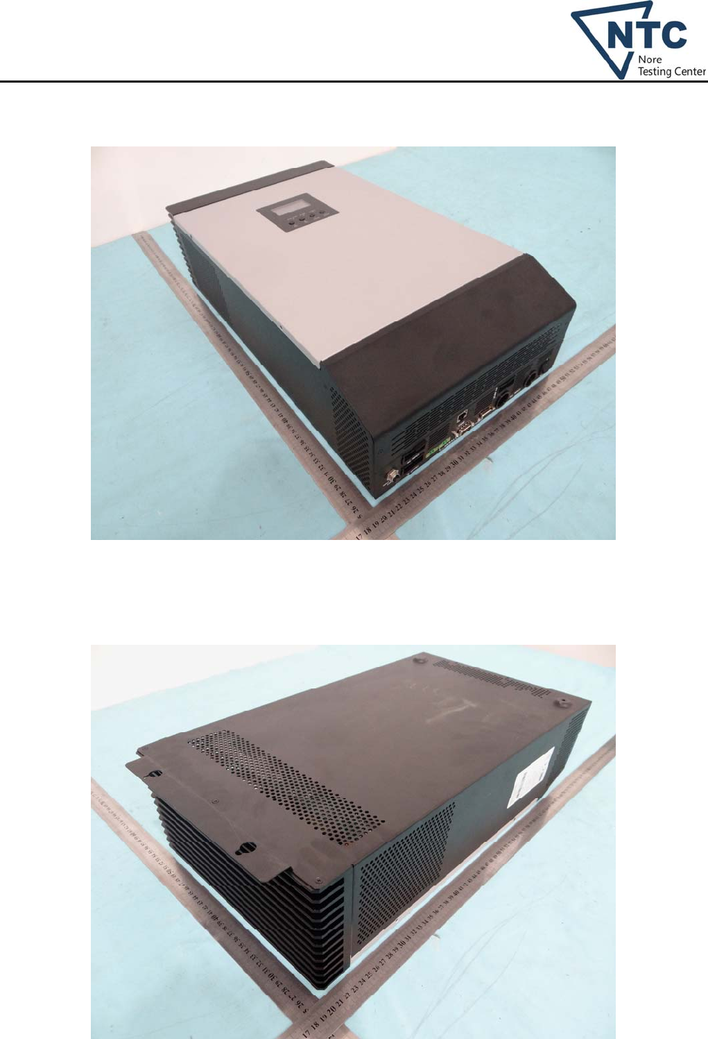
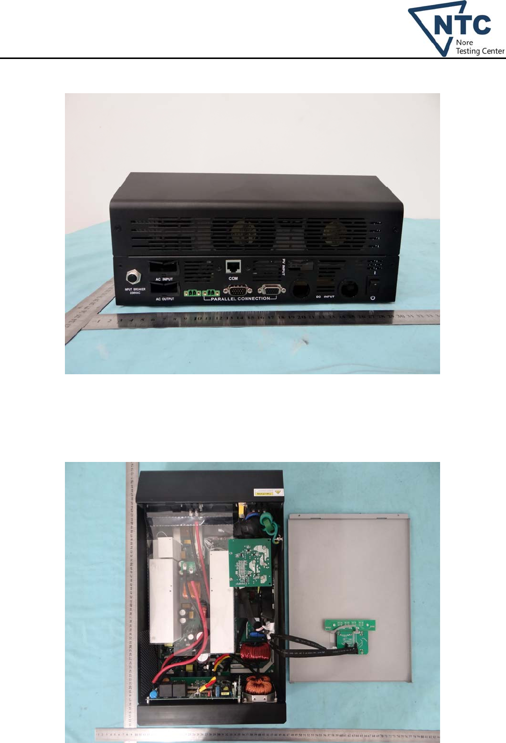
Photo documentation
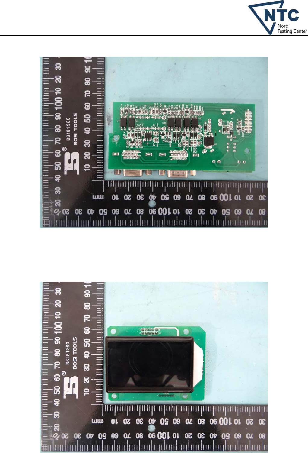
Photo 1 (for all models)
Photo 2 (for all models)
Dongguan Nore Testing Center Co., Ltd.
Report No.: NTC1401129S
Page 26 of 37
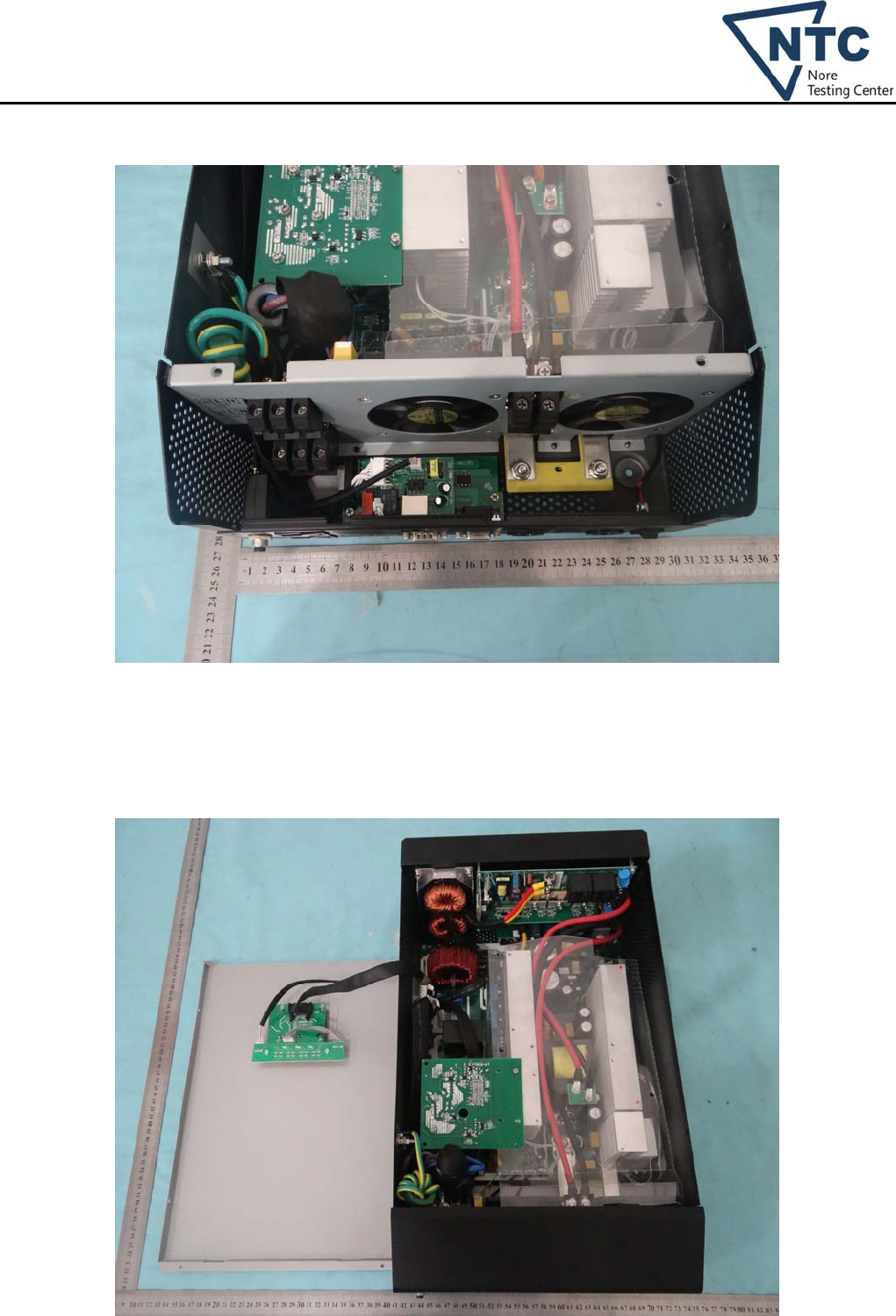
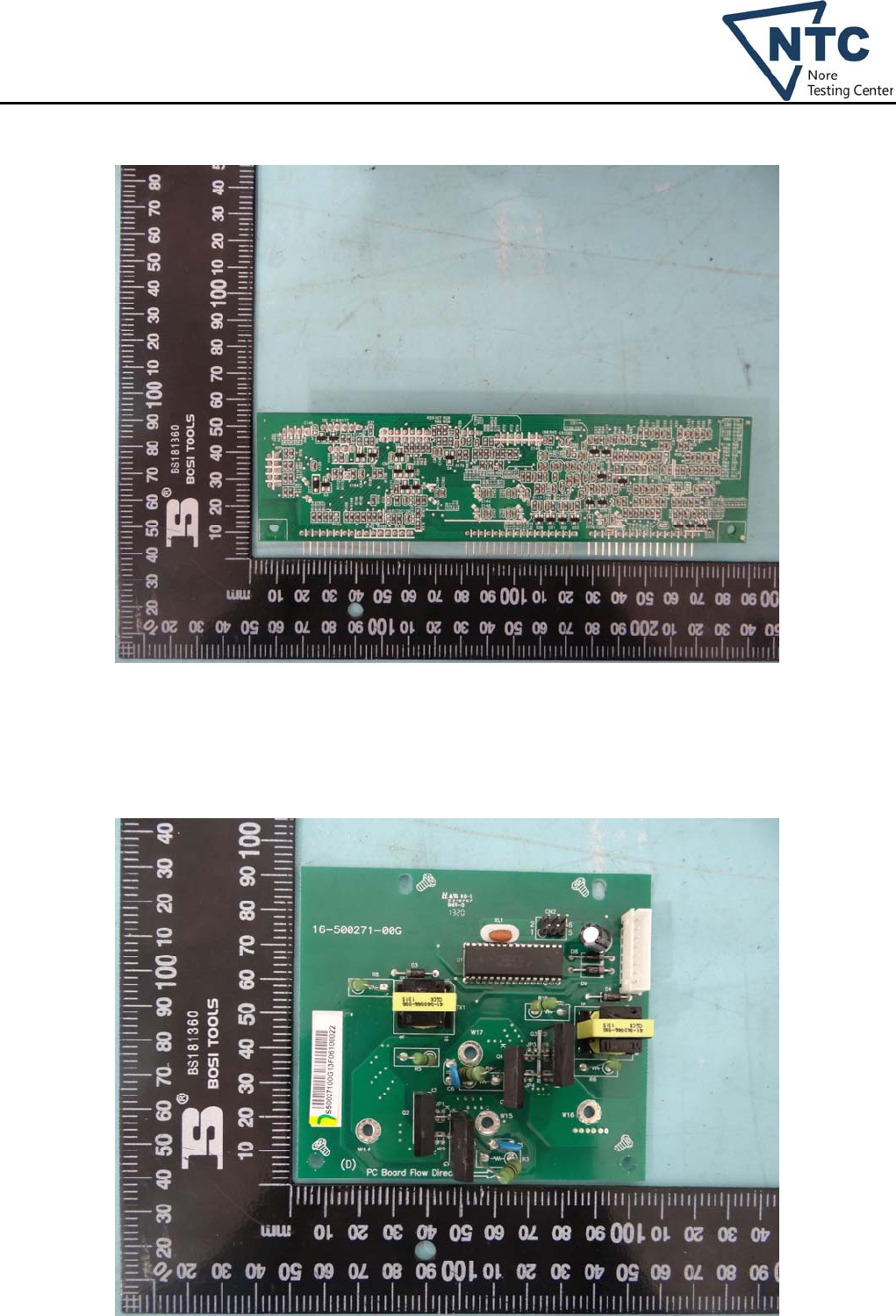
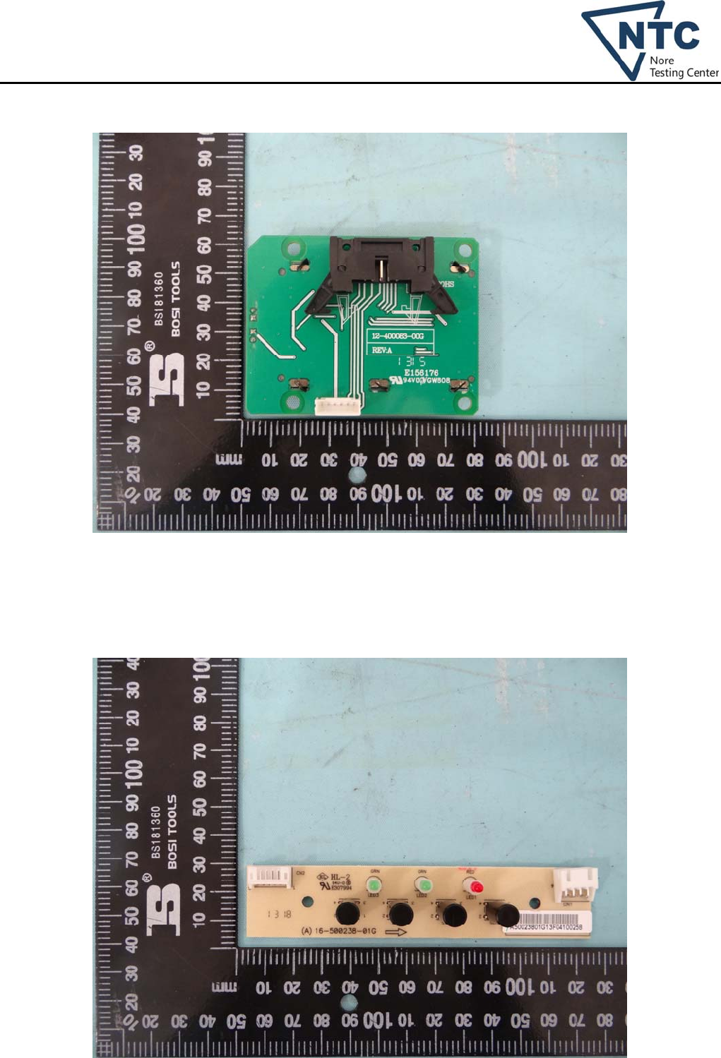
Photo 3 (for all models)
Photo 4 (for model PIP 4048MS)
Dongguan Nore Testing Center Co., Ltd.
Report No.: NTC1401129S
Page 27 of 37
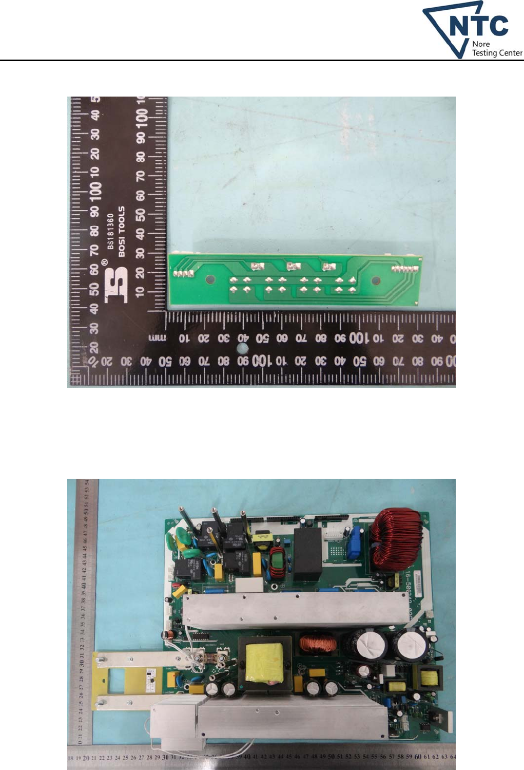
Photo 5 (for model PIP 4048MS)
Photo 6 (for model PIP 3248MS)
Dongguan Nore Testing Center Co., Ltd.
Report No.: NTC1401129S
Page 28 of 37
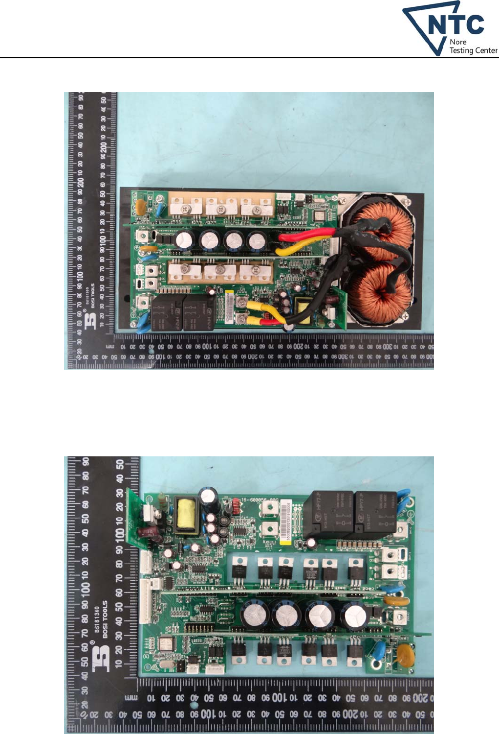
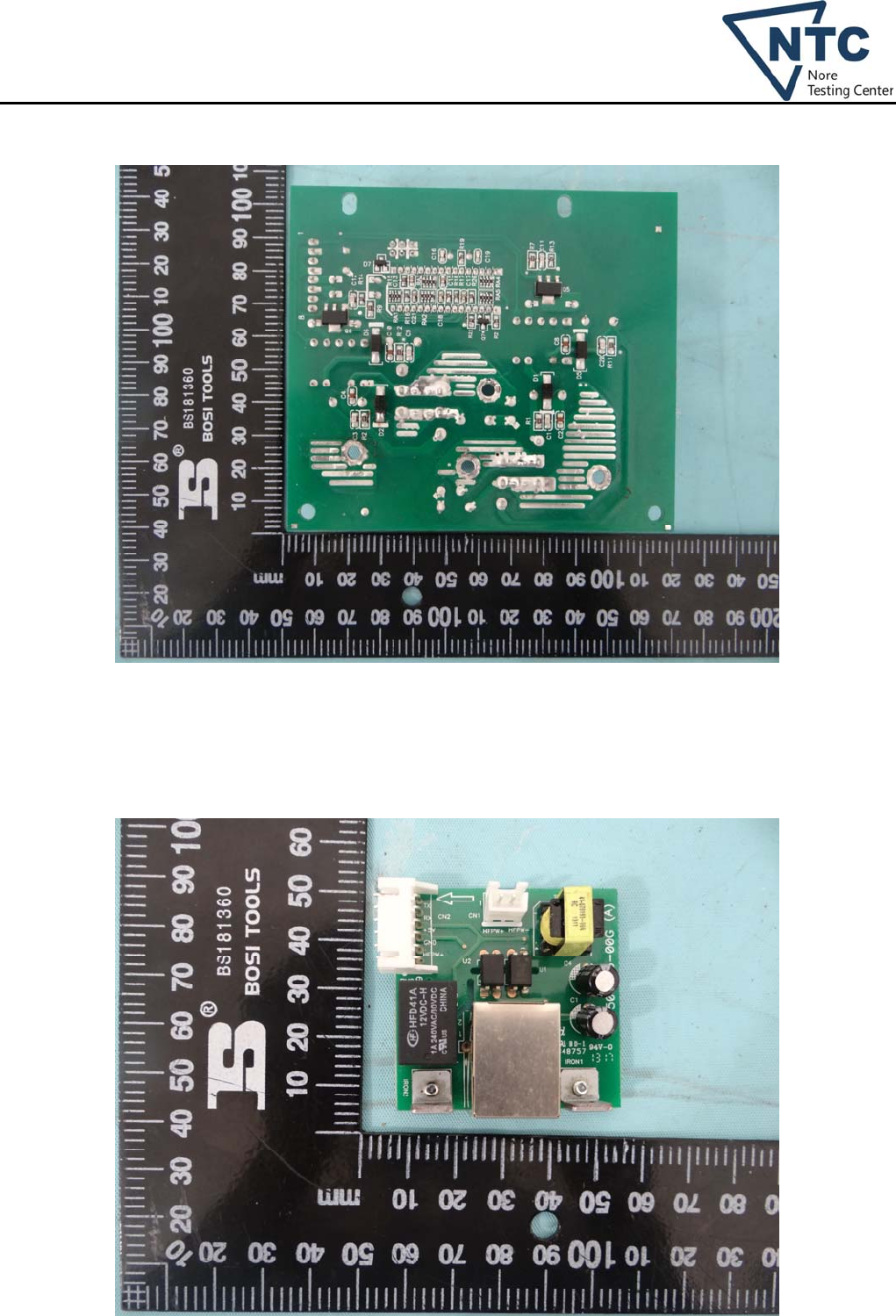
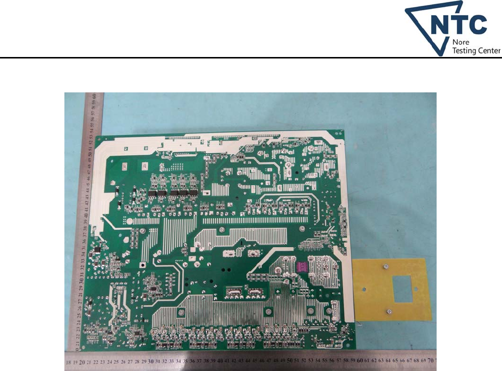
Photo 7 (for all models)
Photo 8 (for all models)
Dongguan Nore Testing Center Co., Ltd.
Report No.: NTC1401129S
Page 29 of 37
Photo 9 (for all models)
Photo 10 (for model PIP 4048MS)
Dongguan Nore Testing Center Co., Ltd.
Report No.: NTC1401129S
Page 30 of 37
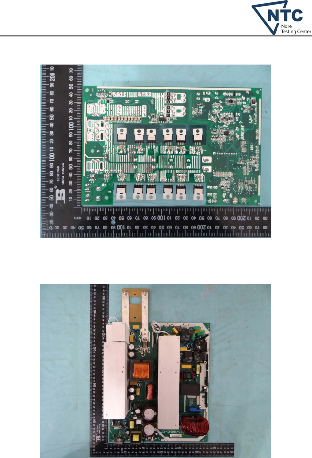
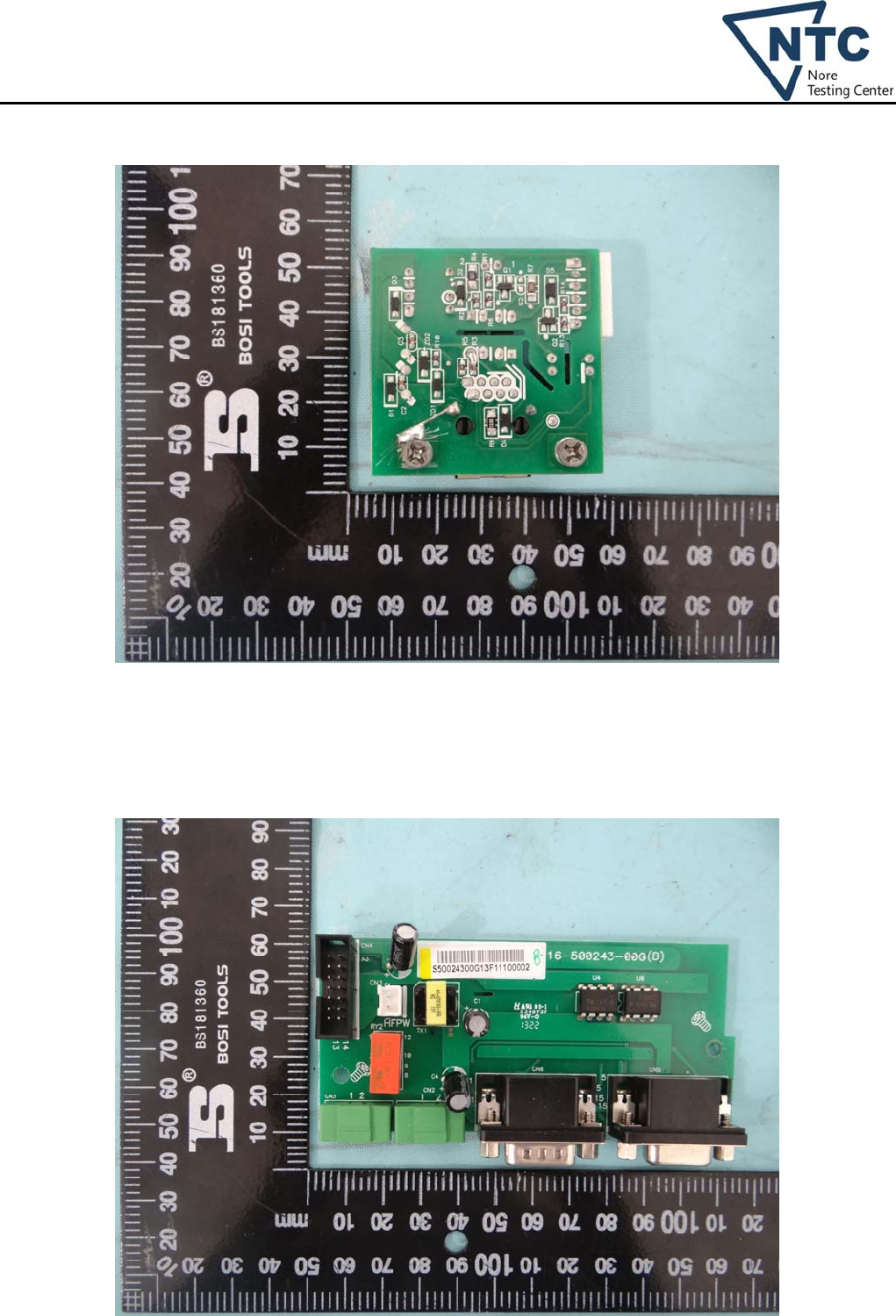
Photo 11 (for model PIP 4048MS)
Photo 12 (for all models)
Dongguan Nore Testing Center Co., Ltd.
Report No.: NTC1401129S
Page 31 of 37
Photo 13 (for all models)
Photo 14 (for all models)
Dongguan Nore Testing Center Co., Ltd.
Report No.: NTC1401129S
Page 32 of 37
Photo 15 (for all models)
Photo 16 (for all models)
Dongguan Nore Testing Center Co., Ltd.
Report No.: NTC1401129S
Page 33 of 37
Photo 17 (for all models)
Photo 18 (for all models)
Dongguan Nore Testing Center Co., Ltd.
Report No.: NTC1401129S
Page 34 of 37
Photo 19 (for all models)
Photo 20 (for all models)
Dongguan Nore Testing Center Co., Ltd.
Report No.: NTC1401129S
Page 35 of 37
Photo 21 (for all models)
Photo 22 (for all models)
Dongguan Nore Testing Center Co., Ltd.
Report No.: NTC1401129S
Page 36 of 37
Photo 23 (for all models)
Photo 24 (for model PIP 3248MS)
Dongguan Nore Testing Center Co., Ltd.
Report No.: NTC1401129S
Page 37 of 37
Photo 25 (for model PIP 3248MS)
--- END OF THIS REPORT---
