Modular ICS 6.0 Installer Guide PDF Nortel Mics
Mics 6-0 Installer Guide Mics 6-0 Installer Guide
User Manual: PDF T E X T F I L E S
Open the PDF directly: View PDF ![]() .
.
Page Count: 656 [warning: Documents this large are best viewed by clicking the View PDF Link!]
- Table of Contents
- Regulations
- How to use this document
- What’s new with Norstar
- Welcome to ISDN
- Working with ISDN
- Trunks and target lines
- Remote system access
- Controlling system access
- Networking with Norstar
- Tie-line networking
- Dialing plans
- Private networking using PRI SL-1
- SL-1 networking features
- Private Network Tandem calling
- Advanced Private Networking
- MCDN Private Networking
- MCDN trunk call features
- MCDN voice mail/auto attendant call features
- Central voice mail and Auto Attendant with Norstar
- Configuring centralized voice mail
- Using centralized voice mail
- Configuring Centralized Auto Attendant (CAA)
- Voice mail configuration
- Customer Use
- ETSI MCDN and network features
- Data Solutions
- Planning the installation
- Planning checklist
- Required equipment
- Expansion equipment
- Optional equipment
- Equipment for installing the ICS and modules
- Location requirements
- Electrical requirements
- Configuring Trunk Cartridges
- Configuring Station Modules
- Internal wiring requirements
- System overview
- Upgrading your Norstar system
- Supported upgrades in MICS 6.0
- Upgrading from MICS 6.0 to MICS-XC 6.0
- Trunk and Station Modules
- Replacing a Modular 8x24 KSU
- Trunk module line numbering
- Installation
- Installation checklist
- Testing the ISDN BRI network connection
- Installing the cartridges
- Mounting the modules
- Installing the ROM Software Cartridge
- Inserting a cartridge
- Installing fiber cables
- Fiber cable management system
- Connecting the wiring
- Emergency telephone
- Moving telephones
- Installing ISDN BRI terminal equipment
- Installing optional equipment
- Powering up the system
- Programming
- Programming overview
- Programming tools
- Copying telephone programming
- Programming sequence
- Profiles and Dialpads
- Startup programming
- Programming
- Terminals&Sets
- Lines
- Trunk/Line data
- Copying Trunk and Line data
- Trunk type Installer password required
- Line type Installer password required
- Line connected to a DTI Installer password required
- Dial mode Installer password required
- Rec’d # Installer password required
- Prime set Installer password required
- Auto privacy Installer password required
- Trunk mode Installer password required
- Ans mode Installer password required
- Ans with DISA Installer password required
- Link at CO (loop trunks only) Installer password required
- Aux. ringer Installer password required
- Full AutoHold Installer password required
- LossPkg Installer password required
- Signal Installer password required
- ANI Number Installer password required
- DNIS Number Installer password required
- Gain Installer password required
- Programming distinctive ring patterns Installer password required
- Name
- Restrictions
- Telco features
- Services
- Routes and destination codes Installer password required
- Sys speed dial
- Passwords
- Time&Date
- System prgrming
- CAP assignment Installer password required
- Dialing Plan Installer password required
- Access codes Installer password required
- Line pool codes Installer password required
- Park prefix Installer password required
- External code Installer password required
- Direct-dial # Installer password required
- Auto DN Installer password required
- DISA DN Installer password required
- PrivAccCode Installer password required
- Carrier Codes Installer password required
- Remote access
- Changing Companion DN type Installer password required
- Rec’d # length Installer password required
- DN length Installer password required
- Nat’nl length (profile 2, only) Installer password required
- Make/Break (profile 2, only) Installer password required
- Call by Call service selection for PRI Installer password required
- Network Services
- Telco features
- Software keys
- Hardware
- Show module Installer password required
- Cards on KSU Installer password required
- Answer timer Installer password required
- CO fail Installer password required
- I/F levels Installer password required
- Framing Installer password required
- Internal CSU Installer password required
- CSU line bld Installer password required
- Line coding Installer password required
- ClockSrc Installer password required
- Max transits Installer password required
- Modules
- StnMod
- ASM
- TrunkMod
- BRI card
- Loop Installer password required
- No SPIDs assignd Installer password required
- # of B-channels Installer password required
- Network DNs Installer password required
- Call type Installer password required
- D-packet servce Installer password required
- Lp Installer password required
- TEIs Installer password required
- No TEIs on loop Installer password required
- Sampling Installer password required
- DNs on Loop Installer password required
- Assign DNs Installer password required
- Clock Src Installer password required
- Setting the clock source for DTIs and PRI Installer password required
- DataMod
- Maintenance
- Beginning a Maintenance session
- System version
- Port/DN status
- Identifying a connected device Installer password required
- Checking the device version number Installer password required
- Checking the state of the device Installer password required
- Disabling a device Installer password required
- Enabling the device Installer password required
- Returning to the beginning Installer password required
- Module status
- Looking at the module inventory Installer password required
- Checking the number of Cartridges Installer password required
- Checking the state of a module Installer password required
- Checking the state of a cartridge Installer password required
- Disabling a module or its cartridges Installer password required
- Enabling a module or its cartridge Installer password required
- Returning to the beginning Installer password required
- System test log
- System administration log
- Network evt log
- Alarm codes
- Event messages
- Provisioning BRI and PRI lines
- Tests
- CSU stats
- Statistics Installer password required
- Checking the performance statistics Installer password required
- Checking the CSU alarms Installer password required
- Checking active alarms Installer password required
- Checking carrier failure alarms Installer password required
- Checking bipolar violations Installer password required
- Checking short term alarms Installer password required
- Checking defects Installer password required
- Resetting all statistics Installer password required
- Diagnostic tools
- Link Status
- Usage Metrics
- Troubleshooting
- Getting ready
- Types of problems
- General troubleshooting procedure
- Problems with telephones
- Problems with lines
- Problems with optional equipment
- Problems with trunk cartridges service
- Problems with BRI service
- ICS down
- Trunk or Station Module down
- Data Module down
- Problems for network or remote users
- Remote feature code gets no response
- Dialed number gets ringback and the wrong person
- Dialed number gets stuttered dial tone instead of ringback
- Dialed number gets dial tone instead of ringback
- Dialed number gets busy tone
- Dialed number does not get through
- Dialed DISA number gets ringback instead of stuttered dial tone
- Dialed DISA number gets dial tone instead of stuttered dial tone
- DISA user gets overflow tone when entering COS password
- Dialed feature code gets overflow tone
- Dialed feature code gets busy tone
- Line pool access code gets overflow tone
- Line pool access code gets ringback
- Line pool access code gets busy tone
- Dialed number gets no response
- Specifications
- Glossary
- Index

Norstar and Meridian are trademarks of Nortel Networks
© Copyright Nortel Networks 2002
Modular ICS 6.0
Installer Guide
1-800-4 NORTEL
www.nortel.com/norstar
P0992638 03
Printed in Canada
Return
to Menu

P0992638 03 Modular ICS 6.0 Installer Guide
Table of Contents
Regulations 21
Safety and installation 21
For equipment with internal power supplies 21
For equipment with external power supplies 22
Important safety instructions 22
North American regulations 23
Federal Communication Commission (FCC) Notice Radio/
TV interference 23
Devices intended to be connected to the Public Switched
Telephone Network 24
Signaling method 27
Ringer Equivalence Number 27
Hearing aid compatibility 28
Use of a music source 28
Programming emergency numbers 28
CE marking 29
How to use this document 31
What’s new with Norstar 33
New features for version 6.0 33
Functionality changes for version 6.0 35
Welcome to ISDN 37
Comparing ISDN to Analog 38
Type of ISDN service 38
B channels 39
D channels 39
ISDN layers 39
ISDN bearer capability 40
Services and features for ISDN PRI and BRI 41
PRI services and features 41
BRI services and features 42
Feature descriptions 43
Network name display 43
Message Waiting Indicator (MWI) 44
Name and number blocking 44

iv / Table of Contents
Modular ICS 6.0 Installer Guide P0992638 03
External call forwarding 44
MCDN trunk features 45
Call by Call service selection for PRI 45
Emergency 911 dialing 46
MCID (Profile 2) 47
Network Call Diversion (Profile 2) 47
DTI card configured as a PRI card 47
ISDN hardware 48
DTI Card configured as PRI 48
BRI Card 48
BRI-U2 and BRI-U4 card 49
BRI-ST card 49
U-LT reference point 49
U-NT reference points 50
S reference point 51
T reference points 51
Clock source for ISDN cards 52
Other ISDN BRI equipment: NT1 54
ISDN standards compatibility 54
Working with ISDN 55
Planning your ISDN network 55
Ordering ISDN PRI 55
Ordering ISDN PRI service in Canada 55
Ordering ISDN PRI service in United States 56
Ordering ISDN BRI 56
Ordering service in Canada 56
Ordering ISDN service in the U.S. 56
Supported ISDN protocols 58
ISDN programming 58
Programming ISDN PRI resources 58
Programming ISDN BRI resources 60
Programming ISDN PRI lines 62
Programming ISDN BRI lines 63
Programming Direct Inward System Access (DISA) on PRI
trunks 64
Programming ISDN equipment 65
Terminal equipment for BRI cards 65
Devices on an S or LT loop (BRI cards only) 65
ISDN router 67
D-packet service (BRI cards only) 68
POSTA for ISDN BRI 69

Table of Contents / v
P0992638 03 Modular ICS 6.0 Installer Guide
Point-of-sale terminal adapter 69
Trunks and target lines 71
Trunk operating modes (T1) 72
Ground start trunks (T1 only) 72
DID trunks 73
Analog loop start trunks 75
Analog E&M trunks 77
BRI trunks 79
PRI trunks 79
Target lines 80
Remote system access 81
Use system features during a remote call 81
Remote access on loop start and E&M trunks 82
Remote access on a private network 82
Remote access on Direct Inward Dial (DID) trunks 83
Remote access on PRI trunks 83
Controlling system access 85
Class of Service 85
Restriction filters 86
Direct inward system access (DISA) 89
Networking with Norstar 91
Tie-line networking 92
Norstar behind a PBX 93
Dialing plans 94
Dialing plan using public lines 96
Destination code numbering in a network 96
Dialing plan using E&M lines 97
Dialing plans with shared line pools 102
Call-by-Call Services Example 104
Norstar Configuration 106
PRI dialing plan example for two-way DID 108
Static DID and two-way DID 109
Private networking using PRI SL-1 110
SL-1 networking features 110
Features specific to Advanced Private Network 111
Private Network Tandem calling 112

vi / Table of Contents
Modular ICS 6.0 Installer Guide P0992638 03
Calls originating from the public network 113
Calls originating in the private network 116
Routing for tandem networks 119
Advanced Private Networking 121
Networking using routing codes 121
MCDN Private Networking 126
Using a UDP dialing plan 127
Using a CDP dialing plan 130
MCDN trunk call features 133
Network Call Redirection Information 134
ISDN Call Connection Limitation 136
Trunk Route Optimization 138
Trunk Anti-tromboning 140
MCDN voice mail/auto attendant call features 141
Camp-on 142
Break-in 143
Central voice mail and Auto Attendant with Norstar 146
Configuring centralized voice mail 146
Local system 147
Remote system 148
Using centralized voice mail 149
Configuring Centralized Auto Attendant (CAA) 150
Assigning PNIs 150
Assigning PNIs for adjacent nodes 151
Local system 151
Remote system 152
Voice mail configuration 154
Customer Use 155
Public network 155
Private network 159
Call one or more Norstar telephones 159
Use tie lines to other nodes in the private network 160
Select lines to the public network 161
Select E&M trunks to the private network 162
Norstar Line Redirection feature 163
ETSI MCDN and network features 165
Network Call Diversion 165
Allowing NCD 166
Feature description 166
Programming and restrictions 167
Selective Line Redirection 168
Programming Extensions 169

Table of Contents / vii
P0992638 03 Modular ICS 6.0 Installer Guide
Enhanced Caller ID 169
Malicious caller identification (MCID) 170
Programming MCID capability 170
Data Solutions 173
Examples of ISDN Scenarios 173
ISDN applications 173
Video conferencing and video telephony 173
Desktop conferencing 173
File transfer 174
Telecommuting 174
Group 4 fax 174
Remote LAN access 174
Leased line backup 174
LAN to LAN bridging 175
Internet and database access 175
Planning the installation 177
Planning checklist 178
Hardware 178
Initial configuration 178
System configuration 179
Required equipment 179
Expansion equipment 180
Optional equipment 181
Equipment for installing the ICS and modules 182
Location requirements 182
Electrical requirements 184
Configuring Trunk Cartridges 185
Configuring Station Modules 186
Internal wiring requirements 186
Norstar loop 186
ISDN S reference point (S Loop) 187
System overview 188
Upgrading your Norstar system 189
Supported upgrades in MICS 6.0 192
Upgrading from MICS 6.0 to MICS-XC 6.0 196
Trunk and Station Modules 199
Global Analog Trunk Cartridge/CLI Cartridge 200
Off-core DTI card 201
Replacing a Modular 8x24 KSU 201
Trunk module line numbering 205

viii / Table of Contents
Modular ICS 6.0 Installer Guide P0992638 03
Upgrading ILG functionality with hunt groups 206
Planning Hospitality functions 207
Installation 209
Installation checklist 210
Testing the ISDN BRI network connection 211
Installing the cartridges 213
Mounting the modules 215
Installation tips 217
Installing the ROM Software Cartridge 219
Inserting a cartridge 221
Terminating resistors on BRI-ST Cards 222
Shorting straps on a BRI-ST card 223
Connecting expansion modules 224
Order of connection 224
Analog Station Module 224
Installing fiber cables 230
Fiber cable management system 231
Using the fiber cable management system 232
Using the fiber spool 234
Making fiber connections 235
Routing fiber cables 236
Connecting the wiring 237
Connecting the wiring to the distribution panel 237
Wiring charts 241
Port numbering on the wiring charts 241
Integrated Communications System (ICS) 241
BRI Wiring charts 248
Wiring the BRI network interface 252
DTI wiring 254
E&M/DISA Trunk Cartridge wiring chart 257
DID supervisory signaling 261
Emergency transfer conditions 261
Emergency telephone 265
Moving telephones 267
Installing ISDN BRI terminal equipment 268
S or T wiring for terminal equipment 268
S or T extension wiring configurations 268
Additional power 269
U-LT wiring for terminal equipment 270

Table of Contents / ix
P0992638 03 Modular ICS 6.0 Installer Guide
Installing optional equipment 271
Auxiliary ringer (customer supplied) 271
Auxiliary ringer programming 271
External music source (customer supplied) 272
External music source programming 272
External paging system (customer supplied) 273
Powering up the system 274
Check the power 275
Programming 277
Programming overview 278
Profile, Dialpad and Startup programmin g279
Installer or System Coordinator Plus programming 280
System Coordinator programming 281
Admin/Basic programming 281
Programming tools 282
The programming overlay 283
Using the telephone buttons for programming 284
Special characters on the display 285
The display buttons 285
The Norstar Programming Record 287
Exiting 287
Viewing your programming updates 287
Entering numbers 288
Viewing long telephone numbers 288
Setting up User Preferences 289
Copying telephone programming 290
System ID 293
Reviewing programmed settings 293
Viewing the programming for a telephone 294
Viewing the programming for a line 294
Programming sequence 295
Profiles and Dialpads 296
Profile programming 296
Profile parameters 296
Changing the profile 299
Dialpad programmin g300
Startup programmin g301
Performing Startup 301
Changing the default template 302

x / Table of Contents
Modular ICS 6.0 Installer Guide P0992638 03
Changing the starting DN 302
Programming 304
Entering programming for installers 305
Entering programming for system coordinators 306
Entering programming using other passwords 307
Terminals&Sets 308
Line access 308
Line assignment 309
Appearances 310
Line pool access 312
Prime line 313
Intercom keys 314
Answer DNs 314
OLI # 315
Capabilities 317
ATA settings 319
ATA ans timer 319
ATA use 320
ATA dvc 320
MsgIndicate 320
Name 320
User prefernces 321
Restrictions 322
Filters 322
Default filters 324
Set restrns 327
Filters 327
Set lock 328
Allow last no 328
Allow saved no 328
Allow link 328
Line/set restrns 329
Telco features 330
Feature assignment (CLID alignment) 330
Caller ID set 330
Extl VMsg set 331
1stDisplay 331
Called ID 332
Log space 332
Lines 333
Trunk/Line data 333

Table of Contents / xi
P0992638 03 Modular ICS 6.0 Installer Guide
Copying Trunk and Line data 335
Trunk type 335
Line type 336
Line connected to a DTI 337
Dial mode 338
Rec’d # 339
Prime set 340
Auto privacy 340
Trunk mode 341
Ans mode 341
Ans with DISA 342
Link at CO (loop trunks only) 343
Aux. ringer 343
Full AutoHold 344
LossPkg 344
Signal 345
ANI Number 346
DNIS Number 346
Gain 347
Programming distinctive ring patterns 348
Name 349
Restrictions 349
Restrn filters 350
Line restrns 350
Remote restrns 351
Telco features 352
VMsg center 1 352
Services 353
Common settings 354
Control sets 354
Schedule names 355
Schedule times 355
Ringing service 357
Ringing groups 357
Sched:Night 358
Service 358
Trunk answer 358
ExtraDial telephone 359
Line settings 359
Restrn service 360
Routing service 361
Routes and destination codes 363

xii / Table of Contents
Modular ICS 6.0 Installer Guide P0992638 03
Routes 363
DialOut 364
Use Pool 364
Routing table 365
Programming the PRI routing table 366
Dest codes 367
Wild card character 368
Normal rte 370
Digit Absorption 370
Setting up a route for local calling 371
Setting up a route for long distance calling 373
Adding a long distance carrier access code 375
Programming for least cost routing 377
Sched:Night 378
Using dialing restrictions with routing 380
Sys speed dial 381
Passwords 382
COS pswds 382
Pswd 383
User flt 383
Line flt 383
Remote pkg 384
Call log pswd s384
Progrming pswds 385
Installer 385
SysCoord+ 386
SysCoord 386
Basic 386
Registration password (MICS-XC only) 386
Hospitality password 387
Desk pswd 387
Cond pswd 387
Time&Date 388
System prgrming 389
Hunt groups 389
Adding or removing members from a group 390
Moving members of a group 391
Assigning or unassigning lines to a group 392
Assigning a distinctive ring pattern to a Hunt Group 392
Setting the distribution mode 393
Setting the hunt delay 394

Table of Contents / xiii
P0992638 03 Modular ICS 6.0 Installer Guide
Programming busy line setting 395
Programming the queue timeout 395
Programming the overflow set 396
Setting the function name 396
Change DNs 397
Featr settings 397
Backgrnd music 397
On hold 398
Receiver volume 398
Camp timeout 398
Park timeout 399
Park mode 399
Trnsfr callbk 399
DRT to prime 400
DRT delay 400
Held reminder 400
Remind delay 401
Directd pickup 401
Page tone 401
Page Timeout 402
Daylight time 402
AutoTime&Date 402
Setting SWCA controls 403
Call log space 405
Host delay 406
Link time 406
AlarmSet 406
Set relocation 407
Msg reply enh 407
Answer key 408
Clid match 409
Direct-dial 410
D-Dial1 410
Intrnl/Extrnl# 410
Line selection 410
CAP assignment 411
Dialing Plan 412
DN lengths (enbloc dialing) 412
Private networks 413
Public networks 415
Dial Timeout 416
Access codes 416

xiv / Table of Contents
Modular ICS 6.0 Installer Guide P0992638 03
Line pool codes 417
Park prefix 418
External code 419
Direct-dial # 419
Auto DN 420
DISA DN 421
PrivAccCode 421
Carrier Codes 422
Remote access 423
Rem access pkgs 423
Rem line access 423
Changing Companion DN type 425
Rec’d # length 426
DN length 427
Nat’nl length (profile 2, only) 428
Make/Break (profile 2, only) 428
BusName 429
Receiving and Sending Calling Party Name 429
Receiving and Sending Connected Name 430
Network Name Display interactions 430
Programming Network Name Display 431
Outgoing Name and Number Blocking 432
Call by Call service selection for PRI 433
Line Pools 436
Programming Call by Call service selection 436
PRI Call by Call Limits 437
Programming Call by Call Limits 437
Release Reasons 438
Mk/BR: 40/60 (profile 2 only) 438
Programming Hospitality Services 439
Room/desk information 439
Call restrns 440
Setting Service times 440
Configuring alarms and expired alarms settings 441
Network Services 442
ETSI: Network diversion and MCID (profile 2 only) 442
Network Call Diversion 443
Malicious call identification (MCID) 445
MCDN services (profiles 1, 2, 4) 445
Telco features 447
VMsg ctr tel#s 447
Outgoing Name and Number Blocking 448

Table of Contents / xv
P0992638 03 Modular ICS 6.0 Installer Guide
Programming the analog vertical service code (VSC) 449
Programming the BRI VSC 449
Setting up the modules for ONN blocking 450
Software keys 452
ISDN-PRI 452
MCDN 452
Companion (MICS-XC only) 452
System Identification Number 453
Call the Nortel Customer Response Center 453
Entering the software keys 454
Hardware 455
Show module 455
Cards on KSU 455
Provisioning the DTI card for PRI 456
Selecting a protocol 456
BchanSeq 458
Call-by-call routing 458
Discon timer 460
Answer timer 460
CO fail 460
I/F levels 461
Framing 462
Internal CSU 462
CSU line bld 463
Line coding 464
ClockSrc 464
Max transits 465
Modules 465
StnMod 466
ASM 466
TrunkMod 467
BRI card 471
Loop 471
Type 471
Lines 471
No SPIDs assignd 472
# of B-channels 472
Network DNs 473
Call type 473
D-packet servce 474
Lp 474
TEIs 474

xvi / Table of Contents
Modular ICS 6.0 Installer Guide P0992638 03
No TEIs on loop 475
Sampling 475
DNs on Loop 475
Assign DNs 476
Loop DN 476
Clock Src 476
Primary reference 477
Secondary reference (Secndry) 477
Timing master (TimeMst) 477
Setting the clock source for DTIs and PRI 481
T1 or ISDN-PRI configurations 482
DataMod 483
Type 483
Maintenance 485
Beginning a Maintenance session 486
System version 487
Checking the version of the system 487
Port/DN status 488
Identifying a connected device 489
Displays 490
Checking the device version number 491
Checking the state of the device 491
Disabling a device 492
Displays 493
Enabling the device 493
Returning to the beginning 494
Module status 495
Looking at the module inventory 495
Checking the number of Cartridges 496
Checking the state of a module 496
Checking the state of a cartridge 497
Disabling a module or its cartridges 498
Enabling a module or its cartridge 498
Returning to the beginning 498
System test log 499
Checking the items in the log 499
Checking the current alarm 500
Checking when each item occurred 500
Checking consecutive repetitions of an event or alarm 500
Erasing the log 501

Table of Contents / xvii
P0992638 03 Modular ICS 6.0 Installer Guide
System administration log 502
Checking the items in the log 502
Checking the current alarm 503
Checking when each item in the log occurred 503
Erasing the log 503
Network evt log 504
Checking the items in the log 504
Checking the current alarm 504
Erasing the log 505
Checking when each item in the log occurred 505
Alarm codes 506
If you see an alarm code 507
Alarm troubleshooting 510
Event messages 514
Dealing with event messages 514
Significant event messages 515
Event message 799 518
Displays 519
Provisioning BRI and PRI lines 522
BRI and T1 lines 522
Cd1-ICS 522
L001 523
Provisioning a T1 line 523
Provisioning a PRI line 523
Deprovisioning a line 524
Disabling a PRI Channel 524
Tests 525
Loopback tests for T1 or ISDN-PRI lines 525
Tests initiated from Norstar 529
Tests initiated by the central office 529
Starting a loopback tests 530
Operating a Continuity loopback test 531
Loopback test for BRI lines 531
Operating a payload loopback test 532
CSU stats 533
Statistics 533
Checking the performance statistics 534
Checking the CSU alarms 536
Checking active alarms 536
Checking carrier failure alarms 536
Checking bipolar violations 537

xviii / Table of Contents
Modular ICS 6.0 Installer Guide P0992638 03
Checking short term alarms 537
Checking defects 537
Resetting all statistics 538
Diagnostic tools 539
Link Status 540
Fractional PRI 540
Usage Metrics 541
Hunt groups 541
Call-by-Call 542
Clearing the metrics 543
Troubleshooting 545
Getting ready 546
Types of problems 547
Misunderstanding a feature 547
Programming errors 547
Wiring connections 547
Equipment defects 547
General troubleshooting procedure 548
Problems with telephones 549
Set has faulty buttons, display, handset or other hardware
problems 549
Unreadable set display 549
Telephone dead 550
Running a Maintenance session to test a dead telephone
551
Replacing a telephone 551
Emergency telephone dead 552
Problems with lines 553
Calls cannot be made (but can be received) 553
Dial tone absent on external line s554
Hung lines at a telephone 555
Auto-answer line rings at a telephone 556
Prime telephone gets misdialed calls 558
Selected lines reads Not in service or Not available 559
Selected line pool displays: No free lines 561
Problems with optional equipment 562
Analog Terminal Adapter 562
Running a Maintenance session to test an ATA 562

Table of Contents / xix
P0992638 03 Modular ICS 6.0 Installer Guide
Auxiliary ringer 563
External paging 564
Music on Hold/Background Music trouble 564
Problems with trunk cartridges service 566
Digital Trunk Interface trouble 567
Monitoring the T1 or PRI signal 569
Problems with BRI service 570
The BRI card is connected to the ISDN network (U loop) but the
LED for one of more loops is not lit 570
Solution 570
Out of service displays when a BRI is selected
(LED for loop is lit) 571
All the LEDs on a BRI Card are flashin g571
Caller hears one ring and then a fast busy signal when placing
a call on a BRI line 572
ICS down 573
Trunk or Station Module down 574
Data Module down 575
Problems for network or remote users 576
Remote feature code gets no response 576
Dialed number gets ringback and the wrong person 576
Dialed number gets stuttered dial tone instead of ringbac k577
Dialed number gets dial tone instead of ringback 578
Dialed number gets busy tone 578
Dialed number does not get throug h579
Dialed DISA number gets ringback instead of stuttered dial
tone 581
Dialed DISA number gets dial tone instead of stuttered dial
tone 582
DISA user gets overflow tone when entering COS
password 582
Dialed feature code gets overflow tone 584
Dialed feature code gets busy tone 585
Line pool access code gets overflow tone 585
Line pool access code gets ringback 586
Line pool access code gets busy tone 587
Dialed number gets no response 587
Specifications 589
Norstar system 589
Digital Trunk Interface 591

P0992638 03 Modular ICS 6.0 Installer Guide
Regulations
This equipment meets all applicable requirements of CSA and UL safety
standards for North America and relevant EN60950 specifications for
European markets.
Safety and installation
This symbol (if applicable) on the product is used to identify the following
important information:
For equipment with internal power supplies
• Mains nominal AC voltage 110-120 V~; 60Hz
• Mains nominal AC voltage 220-240 V~; 50Hz
The shock hazard symbol within an equilateral
triangle is intended to alert personnel to electrical
shock hazard or equipment damage.
The following precautions should also be
observed when installing telephone equipment.
• Never install telephone wiring during a lightning
storm.
• Never install telephone jacks in wet locations unless
the jack is specifically designed for wet locations.
• Never touch uninsulated telephone wires or terminals
unless the telephone line has been disconnected at
the network interface.
• Use caution when working with telephone lines.
The exclamation point within an equilateral
triangle is intended to alert the user to the
presence of important operating and maintenance
(servicing) instructions in the literature
accompanying the product.

22 / Regulations
Modular ICS 6.0 Installer Guide P0992638 03
For equipment with external power supplies
•Must be powered from an approved Class 2 power source.
For current ratings, refer to product specific documentation and product
labels.
Important safety instructions
When using your telephone equipment, basic safety precautions should
always be followed to reduce the risk of fire, electric shock and injury of
persons, including the following:
•Follow the warnings and instructions marked on the product.
•Unplug this product from the wall outlet before cleaning. Do not use
liquid cleaners or aerosol cleaners. Use a damp cloth for cleaning.
•Do not use this product near water, for example, near a bathtub, wash
bowl, kitchen sink, or laundry tub, in a wet basement or near a
swimming pool.
•Do not place this product on an unstable cart, stand or table. The
product may fall, causing serious damage to the product.
•This product should never be placed near or over a radiator or heat
register. This product should not be placed in a built-in installation
unless proper ventilation is provided.
•Do not allow anything to rest on the power cord. Do not locate this
product where the cord will be abused by persons walking on it.
•Do not overload wall outlets and extension cords as this can result in
the risk of fire or electric shock.
•Never spill liquid of any kind on the product.
•To reduce the risk of electric shock, do not disassemble this product,
but have it sent to a qualified service person when service or repair
work is required.
•Unplug this product from the wall outlet and refer servicing to
qualified service personnel under the following conditions:
a. When the power supply cord or plug is damaged or frayed.
b. If the product has been exposed to rain, water or liquid has been
spilled on the product, disconnect and allow the product to dry out
to see if still operates; but do not open up the product.

Regulations / 23
P0992638 03 Modular ICS 6.0 Installer Guide
c. If the product housing has been damaged.
d. If the product exhibits a distinct change in performance.
•Avoid using telephone equipment during an electrical storm. There
may be a remote risk of electric shock from lightning.
•Do not use the telephone equipment to report a gas leak in the vicinity
of the leak.
•To eliminate the possibility of accidental damage to cords, plugs,
jacks, and the telephone equipment, do not use sharp instruments
during the assembly procedures.
•Do not insert the plug at the free end of the handset cord directly into
a wall or baseboard jack. Such misuse can result in unsafe sound levels
or possible damage to the handset.
•Disconnect telecommunications lines before unplugging main power
cord.
•Save these instructions
North American regulations
MICS 6.0 and MICS-XC 6.0 meet all applicable requirements of both
Industry Canada CS-03 and US Federal Communication Commission
(FCC) part 68, and has been registered under files Industry Canada 332-
5980-A and FCC-AB6CAN-20705-KFE (key system), AB6CAN-20706
MF-F/Hybrid, and AB6CAN-23740 PF-E (PBX System).
The CE marking on this equipment indicates compliance with the
following EU directive: Directive 1999/5/EC - R&TTE
Federal Communication Commission (FCC) Notice Radio/TV interference
This equipment, has been tested and found to comply with the limits for a
Class A digital device, pursuant to Part 15 of the FCC Rules. These limits
are designed to provide reasonable protection against harmful interference
when the equipment is operated in a commercial environment. This
equipment generates, uses, and can radiate radio frequency energy and, if
not installed and used in accordance with the instruction manual, may
cause harmful interference to radio communications. Operation of this
equipment in a residential area is likely to cause harmful interference in
which case the user will be required to correct the interference at his own
expense.

24 / Regulations
Modular ICS 6.0 Installer Guide P0992638 03
Changes or modifications not expressly approved by the party responsible
for compliance could void the user’s authority to operate the equipment.
Devices intended to be connected to the Public Switched Telephone
Network
US
This telephone equipment complies with Part 68, FCC Rules for direct
connection to the Public Switched Telephone Network (The FCC
registration number appears on a label affixed to the ICS).
Your connection to the telephone line must comply with these FCC Rules:
•Use only an FCC Standard network interface jacks and FCC compliant
line cord and plug to connect this equipment to the telephone line.
•If a network interface jack is not already installed in your location, you
can order one from your telephone company. Order the following
network jacks along with the corresponding Facility Interface Code
(FIC):
State and local requirements for support of
Emergency 911 Dialing service by Customer
Premises Equipment vary. Consult your local
telecommunications service provider
regarding compliance with applicable laws
and regulations.
Trunk Cartridge REN USOC SOC FIC
GATC LSDS (NT7B69AAAA)
replacing
Loop Start/Disconnect
Supervision (LS/DS)- NT7B75GA-
93
AC
1.5B
DC 0.3
RJ21X 9.0F 02LS2
GATC CI (NT7B75AAC)
replacing
Call Information (CI)-
NT5B41GA-93
AC
1.5B
DC 0.3
RJ21X 9.0F 02LS2
Regulations / 25
P0992638 03 Modular ICS 6.0 Installer Guide
In some states, customers are permitted to install their own jacks.
•The equipment cannot be used with or connected to a party line or a
public coin phone service provided by the telephone company.
Connection to Party Line Service is subject to state tariffs. Contact the
Public State Utility Commission, Public Service Commission or
Corporation Commission for information.
•It is no longer necessary to notify the Telephone Company of your
system’s Registration and REN numbers. However, you must provide
this information to the telephone company if they request it.
•If this equipment causes harm to the telephone network, the telephone
company will notify you in advance that temporary discontinuance of
service may be required. If advance notice is not practical, the
telephone company will notify the customer as soon as possible. Also,
you will be advised of your right to file a complaint with the FCC if
you believe it necessary.
DTI (T1 or PRI) - NT7B74AAAA/
A0897902
—RJ48C 6.0Y 04DU9-
1SN
E&M - NT5B38GA-93 —RJ2HX 9.0F TL32M
BRI-U2 and BRI-U4 Cards
NT7B86GB-93 and
NT7B87GB-93
—RJ49C 6.0Y 02IS5
BRI-ST - NT7B76GY-93
(when connected to an NT1 which
has a U interface to the telephone
network)
—RJ49C 6.0Y 021S5
DID - NT5B37GA-93 0.0B RJ21X AS.2 02RV2-T
Off-premise sets (OPX) -
Analog Terminal Adapter
—RJ11C 9.0F 0L13B
Notify service provider if DTI is disconnected.
You must notify your T1 service provider any time the
1.544 Mbps DTI interface is disconnected from the
network.
Trunk Cartridge REN USOC SOC FIC

26 / Regulations
Modular ICS 6.0 Installer Guide P0992638 03
•The telephone company may make changes in its facilities, equipment,
operations or procedures that could affect the operation of the
equipment. If this happens the telephone company will provide
advance notice in order for you to make necessary modifications to
maintain uninterrupted service.
•Do not attempt to repair this equipment yourself. If trouble is
experienced with this equipment, please refer to the repair and
warranty information, noted below. If the equipment is causing harm
to the telephone network, the telephone company may request that you
disconnect the equipment until the problem is resolved.
•Allowing Direct Inward Dial (DID) Equipment to be operated in such
a manner as to not provide for proper answer supervision is a violation
of Part 68 of the FCC Rules. Proper answer supervision is when:
a. This equipment returns answer supervision to the PSTN when DID
calls are:
— Answered by the called station
— Answered by the attendant
— Routed to a recorded announcement that can be
administered by the CPE user.
— Routed to a dial prompt
b. This equipment returns answer supervision on all DID calls
forwarded to the PSTN. Permissible exceptions are:
— A call is unanswered.
— A busy tone is received.
— A reorder tone is received.
Canada
Before installing this equipment, users should ensure that it is permissible
to be connected to the facilities of the local telecommunications company.
The equipment must also be installed using an acceptable method of
connection. The customer should be aware that compliance with the above
conditions may not prevent degradation of service in some situations.
Repairs to certified equipment should be made by an authorized Canadian
maintenance facility designated by the supplier. Any repairs or alterations
made by the user to this equipment, or equipment malfunctions, may give

Regulations / 27
P0992638 03 Modular ICS 6.0 Installer Guide
the telecommunications company cause to request the user to disconnect
the equipment.
Users should ensure for their own protection that the electrical ground
connections of the power utility, telephone lines and internal metallic water
pipe system, if present, are connected together. This precaution may be
particularly important in rural areas.
This Class A digital apparatus meets all requirements of the Canadian
Interference-Causing Equipment Regulations as specified in the Industry
Canada Standard ICES-003.
Signaling method
The equipment allows signaling in DTMF tones. It can complete calls to
local and long distance lines and can also complete long distance calls via
computer phone systems such as MCI or SPRINT. This equipment is
capable of providing access to interstate providers of operator services
through the use of access codes. Modification of this equipment by call
aggregators to block access dialing codes is a violation of the Telephone
Operator Consumers Act of 1990.
Ringer Equivalence Number
US
The FCC Registration information on the product label, includes a Ringer
Equivalence Number (REN) which is used to determine the number of
devices you may connect to your phone line. A high total REN may prevent
ICSs from detecting ringing in response to an incoming call and may make
placing calls difficult. In most, but not all areas, the sum of the RENs
should not exceed five (5.0). To be certain of the number of devices that
may be connected to a line, as determined by the total RENs, contact the
local telephone company.
Note: RENs are associated with loop start and ground start ports. Do not
use for E&M or digital ports.
Caution
Users should not attempt to make such connections
themselves, but should contact the appropriate electric
inspection authority, or electrician, as appropriate

28 / Regulations
Modular ICS 6.0 Installer Guide P0992638 03
Canada
The Ringer Equivalence Number (REN) assigned to each terminal device
provides an indication of the maximum number of terminals allowed to be
connected to a telephone interface. The termination on an interface may
consist of any combination of devices subject only to the requirement that
sum of the ringer equivalence numbers of all the devices does not exceed 5.
Hearing aid compatibility
The telephone station sets are compatible with hearing aids equipped with
an appropriate telecoil and is compliant with the requirements of the
Americans with Disabilities Act (ADA).
Use of a music source
In accordance with US, Canadian and international copyright laws, a
license may be required from the American Society of Composers, Authors
and Publishers, or other composers’ or performing rights organization if
Radio, TV or other broadcasts to the public are transmitted through the
Music On Hold or Background Music features of this telecommunication
system.
Programming emergency numbers
When programming emergency numbers and/or making test calls to
emergency numbers:
1. Remain on the line and briefly explain to the dispatcher the reason for
calling before hanging up.
2. Perform such activities in the off-peak hours, such as early mornings
or late evenings.
Substitution of non-approved equipment will void the NORTEL warranty.
Address for warranty and repairs in the US:
Nortel
640 Massman Drive
Nashville TN 37210
Address for warranty and repairs in Canada:
Nortel
30 Norelco Drive
Weston, Ontario M9L 2X6
For more information call 1-800-4NORTEL.

Regulations / 29
P0992638 03 Modular ICS 6.0 Installer Guide
CE marking
The Industry Canada label identifies certified equipment. This certification
means that the equipment meets certain telecommunications network
protective, operational and safety requirements. The Department does not
guarantee the equipment will operate to the user’s satisfaction.

30 / Regulations
Modular ICS 6.0 Installer Guide P0992638 03

P0992638 03 Modular ICS 6.0 Installer Guide
How to use this document
This guide provides core installation and programming
information for MICS 6.0 and MICS-XC 6.0 systems. If you
are installing a MICS-XC system, also refer to the Modular
ICS Companion Installer Guide for Companion installation
and programming.
•The MICS system can be a mini (no expansion cartridge
installed), a midi (installed with a two-port expansion
cartridge), a maxi (installed with a six-port expansion
cartridge), or a mega (Combination Fiber six-port Services
Cartridges and Services cartridges) system. For more on
the configurations, see Connecting expansion modules on
page 224.
This version of the software does not support Companion.
•The MICS-XC system has all the functionality of MICS,
plus it supports the Companion wireless functionality.
Both systems support ISDN PRI and BRI, and T1
functionality. All MICS 6.0 functionality is described in this
book. For system coordinators, the MICS 6.0 System
Coordinator Guide explains how to perform common
telephone programming.
Companion wireless programming and installation
instructions are documented in the Modular ICS Companion
Installer Guide and the Modular ICS Companion System
Coordinator Guide.
Information that is specific to MICS-XC systems or MICS
systems is clearly marked within this guide.
Note: Throughout this guide, reference to KSU refers to
the Integrated Communication System (ICS).

32 / How to use this document
Modular ICS 6.0 Installer Guide P0992638 03

P0992638 03 Modular ICS 6.0 Installer Guide
What’s new with Norstar
The Norstar 0X32 MICS 6.0 includes several new features and
a few functionality changes.
New features for version 6.0
•Distinctive ring for lines and hunt groups
You can now assign distinctive ring patterns (DRP) to both
lines and hunt groups. This is similar to the feature that
allows you to assign different rings to your telephone so
you can distinguish which phone is ringing. All three of
these features work in concert with each other. Which ring
will be used depends on the priority that is assigned to
each, and the order in which the assignment occurred.
Refer to Programming distinctive ring patterns on page
348 and Assigning a distinctive ring pattern to a Hunt
Group on page 392.
•System wide call appearance feature codes (SWCA)
Sixteen new feature codes allow you to assign indicator
memory buttons with SWCA codes. These buttons provide
call appearance for both incoming and outgoing calls to
any group of telephones with the same assigned buttons.
This allows a call to be parked on a SWCA button, and
then the call can be retrieved by any other member of the
group.
To upgrade from any previous version of
MICS software to MICS 6.0, refer to
Upgrading your Norstar system on page 189
for detailed instructions.

34 / What’s new with Norstar
Modular ICS 6.0 Installer Guide P0992638 03
Calls are assigned to the SWCA buttons, either
automatically or manually, at the telephone that receives or
makes the call. This frees up the line for other calls while
maintaining an appearance of the call in the group. Refer
to Setting SWCA controls on page 403.
•CLID display enhancements:
—alpha tagging using system speed dial name and CLID
match
—system speed dial codes increased to 255
—Caller ID indicated for telephone rather than for
individual lines
Alpha tagging is an enhancement to the CLID
functionality of the system. This feature matches incoming
call numbers with system speed dial entries. If enough
digits match (CLID match), and the telephone is set to
receive caller names (Caller ID set), then whatever name is
entered into the system speed dial for that number will
display when the call comes in. Refer to Sys speed dial on
page 381.
Note: Alpha tagging activates when the CO line service
supplies only a number for the incoming call.
Otherwise, the system uses the name supplied by the
CO line service.
To support this feature, the system speed dial codes have
been increased to 200 entries, with three-digit codes from
001 to 255. Refer to the MIC ICS 6.0 System Coordinator
Guide for a detailed description of System Speed dial
programming.

What’s new with Norstar / 35
P0992638 03 Modular ICS 6.0 Installer Guide
•off-core DTI for profiles 1 and 4, allowing additional PRI
lines (new line pool)
Profile 1 and 4 customers can now add an additional DTI
card to their midi (module 3 or 4) and maxi systems
(module 7 or 8) to provide extra T1 or PRI lines to their
system. Since the card uses all available lines on the
module, no other cards can be installed into the module
with this card.
•Further enhancements have been made to MCDN
functionality, which is supported in profiles 1, 2, and 3.
—TAT Refer to Trunk Anti-tromboning on page 140.
—ICCL Refer to ISDN Call Connection Limitation on
page 136.
—Centralized voice mail and auto attendant on Norstar
Voice Mail platform
—Centralized voice mail provided by Meridian Mail
provides attendant features: camp-on (Camp-on on
page 142) and break-in (Break-in on page 143)).
Functionality changes for version 6.0
•Profile 2: This profile has been adjusted to accommodate
systems which use ETSI PRI lines with an a-law
companding protocol.
—The off-core DTI module is not supported on this
profile.
—T1 functionality has been removed from this profile.
—The PRI SL-1 MCDN protocol, and all the networking
features this protocol supports, is supported on this
system. Refer to MCDN services (profiles 1, 2, 4) on
page 445.

36 / What’s new with Norstar
Modular ICS 6.0 Installer Guide P0992638 03
—As well, the EURO PRI protocol is supported for this
profile.
—In addition, the central office ETSI PRI features:
Network Call Redirection and Malicious Caller ID
(MCID) can be used if they are allowed by your service
provider. Refer to ETSI: Network diversion and MCID
(profile 2 only) on page 442.
•Line renumbering: Due to the addition of ETSI to Profile
2, the line numbering for the entire system has been
realigned to accommodate the extra lines provided by
ETSI lines. When you perform an upgrade, existing line
assignments will be automatically updated. Refer to Trunk
module line numbering on page 205 for a comparison table
of line numbering based on software versions. Refer to
TrunkMod on page 467 for detailed line numbering based
on the type of trunk module that is installed. This change
includes the target line numbers.
•Due to the expansion of the system speed dial feature
codes up to 255, the user speed dial list has been changed
to codes 256 to 279 (24 codes, no change from existing
systems). Refer to User prefernces on page 321.

P0992638 03 Modular ICS 6.0 Installer Guide
Welcome to ISDN
This chapter provides you with some background information
about ISDN, including information about:
•analog vs. ISDN
•type of ISDN service
•ISDN layers
•ISDN bearer capability
•services and features for ISDN PRI and BRI
•ISDN hardware
•ISDN standards compatibility
Integrated Services Digital Network (ISDN) technology
provides a fast, accurate, and reliable means of sending and
receiving voice, data, images, text, and other information
through the telecom network.
ISDN uses existing analog telephone wires. The signal on the
wire gets divided into separate digital channels, which
dramatically increases the bandwidth.
ISDN uses a single transport to carry multiple information
types. What once required separate networks for voice, data,
images, or video conferencing is now combined on to one
common high-speed transport.
Note: Nortel endeavors to test all variations of ISDN BRI and
PRI on Norstar. However, due to the number of
variations, this is not always possible. Check with your
service provider about compatibility.

38 / Welcome to ISDN
Modular ICS 6.0 Installer Guide P0992638 03
Comparing ISDN to Analog
ISDN offers significantly higher bandwidth and speed than
analog transmission because of its end-to-end digital
connectivity on all transmission circuits. Being digital allows
ISDN lines to provide better quality signaling than analog
POTS (plain ordinary telephone) lines. Also ISDN out-of-
band data channel signaling offers faster call setup and tear
down.
While an analog line carries only a single transmission at a
time, an ISDN line can carry one or more voice, data, fax and
video transmissions simultaneously.
An analog modem operating at 14.4 K takes about 4.5 minutes
to transfer a 1MB data file and a 28.8K modem takes about
half that time. Using one channel of an ISDN line, the transfer
time is reduced to only one minute. If two ISDN channels are
used, transfer time is just 30 seconds.
When transmitting data, the connect time for an average ISDN
call is about three seconds per call, compared to about 21
seconds for the average analog modem call.
Type of ISDN service
Two types of ISDN services (lines) are available: Basic Rate
Interface (BRI) and Primary Rate Interface (PRI). Each line is
made up of separate channels known as B and D channels
which transmit information simultaneously.
•BRI is known as 2B+D because it consists of
2 B-channels and one D-channel.
•PRI is known as 23B+D because it consists of
23 B-channels and one D-channel.

Welcome to ISDN / 39
P0992638 03 Modular ICS 6.0 Installer Guide
B channels
B channels are the bearer channel. They are used to carry voice
or data information and have speeds of 64 kbps. Since each
ISDN line (BRI or PRI) has more than one B-channel, more
than one transmission can occur at the same time, using a
single ISDN line.
D channels
The standard signaling protocol is transmitted over a dedicated
data channel called the D-channel. The D-channel carries call
setup and feature activation information to the destination.
This channel has speeds of 16 kbps (BRI) and 64 kbps (PRI).
Data information consists of control and signal information
and packet-switched data such as credit card verification.
ISDN layers
ISDN layers refer to the standards established to guide the
manufacturers of ISDN equipment. The layers include both
physical connections, such as wiring, and logical connections,
which are programmed in computer software.
When equipment is designed to the ISDN standard for one of
the layers, it works with equipment for the layers above and
below it.
There are three layers at work in ISDN for Norstar. To support
ISDN service, all three layers must be working properly.
Tip - Norstar PRI supports the D-channel on the 24th
channel only. Norstar does not include support for a
backup D-channel on the span.

40 / Welcome to ISDN
Modular ICS 6.0 Installer Guide P0992638 03
Layer 1: A physical connection that supports fundamental
signaling passed between the ISDN network (your service
provider) and the Norstar ICS. When a DTI card configured as
BRI or PRI is used for a network connection, the LED for the
loop on the card is lit when the layer 1 is functioning.
Layer 2: A logical connection between the ISDN network
(your service provider) and the Norstar ICS. Norstar has two
of these connections for each BRI line, one for each of the
logical lines. Without Layer 2, call processing is not possible,
and there is no dial tone.
Layer 3: Also a logical connection between the ISDN network
(your service provider) and the Norstar ICS. For BRI lines,
layer 3 is where call processing and service profile identifier
(SPID) information is exchanged. This controls which central
office services are available to the connection. For example, a
network connection can be programmed to carry data calls.
The system of layers is important when you are installing,
maintaining, and troubleshooting an ISDN system. See
Problems with BRI service on page 570 for more information
about working with the layers.
ISDN bearer capability
Bearer capability describes the transmission standard used by
the BRI or PRI line that allows it to work within a larger ISDN
hardware and software network.
The bearer capability for BRI and PRI is voice/speech at
3.1 kHz audio, and data at unrestricted 64 kbps, restricted
64 kbps, 56 kbps.

Welcome to ISDN / 41
P0992638 03 Modular ICS 6.0 Installer Guide
Services and features for ISDN PRI and BRI
As part of an ISDN digital network, your Modular ICS
supports enhanced capabilities and features, including:
•faster call setup and tear down
•high quality voice transmission
•dial-up Internet and local area network (LAN) access
•video transmission
•network name display
•name and number blocking (PRI, BRI and analog)
•access to public protocols (only NI-1 for BRI)
PRI services and features
•call by call service selection
•dialing plan
•Emergency 911 dialing, internal extension number
transmission
•Advanced Private Networking to Meridian 1 using SL-1
protocol, providing
–access to central Voice Mail and Automated Attendant
equipment connected to the Meridian system
–trunk route optimization (TRO)
–Message Waiting Indication (MWI) from the Voice
Mail application
–Network Call Redirection Information (NCRI), which
is built on the existing Call Forward and Call Transfer
features
•tandem networking between Norstar systems

42 / Welcome to ISDN
Modular ICS 6.0 Installer Guide P0992638 03
BRI services and features
•data transmission at speeds up to 128 kbps per loop,
depending on the bandwidth supported by your service
provider
•shared digital lines for voice and data ISDN terminal
equipment
Norstar Basic Rate Interface (BRI) cards also support
D-channel packet service between a network and terminal
connection. This allows you to add applications such as point-
of-sale terminals without additional network connections.
Any analog or digital network connections can be shared by all
Norstar telephones, peripherals and applications, and ISDN
terminal equipment (TE).
Modular ICS supports the following ISDN services and
features offered by ISDN service providers:
•D-channel packet service (BRI only) to support devices
such as transaction terminals. Transaction terminals are
used to swipe credit or debit cards and transmit the
information to a financial institution in data packets.
•calling number identification, which appears on both
Norstar sets and ISDN terminal equipment with the
capability to show the information
•Multi-Line Hunt or DN Hunting which switches a call to
another ISDN line if the line usually used by the Network
DN is busy. (BRI only)
•subaddressing of terminal equipment (TE) on the same
BRI loop. However, terminal equipment which supports
sub-addressing is not commonly available in North
America.(BRI only)

Welcome to ISDN / 43
P0992638 03 Modular ICS 6.0 Installer Guide
Transmission of B-channel packet data is not supported by
Modular ICS.
Contact your ISDN service provider for more information
about these services and features. Packages for ISDN service
in North America are described on page 56.
The terminal equipment (TE) connected to the Norstar system
can use some feature codes supported by the ISDN service
provider. Refer to ISDN services and features in the Modular
ICS 6.0 System Coordinator Guide for more information.
Feature descriptions
The following section provides brief descriptions about the
ISDN features, and links for more programming information.
Network name display
This feature allows ISDN to deliver the Name information of
the users to those who are involved in a call that is on a public
or private network. For information on system programming
of this feature see, BusName on page 429.
Systems with Advanced Private Networking connections
(MCDN SL-1) to a Meridian system also retain information
about sets that have forwarded or transferred a call, as well as
the originating caller information.This feature is called
Network Call Redirection Information (NCRI). This
information is available to all parties involved in the call.
Calls can only be redirected a defined number of times within
the network. This is currently hardcoded to five times. Once
this limit is reached, call redirection will be disallowed
regardless of the type of outgoing line being presented for
redirection.

44 / Welcome to ISDN
Modular ICS 6.0 Installer Guide P0992638 03
Instead, the call will be handled in one of these ways:
•If Call Forward on Busy is programmed, the call will ring
if a free key is available. Otherwise, it goes to the Prime
set. DND Busy programming is ignored.
•If Call Forward All Calls is programmed, the call will go
to the Prime set.
•If Call Forward No Answer is programmed, the call will
continue to ring at the destination.
Note: If a terminal rejects a call, the call goes to the Prime set,
if a Prime set is configured for the target line. If the
target line is configured to send a busy tone, the call
gets released with the reason as User Busy.
Message Waiting Indicator (MWI)
Systems with Advanced Private Networking connections to a
Meridian system Voice Mail system provide message-waiting
indicators at telephones connected to those lines. Telephones
with displays display a message. Non-display terminals may
have a lamp that lights when a message is waiting. The setting
for this feature is defined from the Meridian system.
Name and number blocking
This feature suppresses the outgoing name and/or number on
a call by call basis. For information on system programming of
this feature see, Outgoing Name and Number Blocking on
page 432.
External call forwarding
The system now allows you to forward calls to an external
number. This feature is activated using from the
telephone.

Welcome to ISDN / 45
P0992638 03 Modular ICS 6.0 Installer Guide
MCDN trunk features
Systems with MCDN Private Networking connections can
provide these trunk routing features:
•Trunk Route Optimization (TRO) finds the most direct
route through the network to send a call between nodes.
This function occurs during the initial alerting phase of a
call.
•ISDN Call Connection Limitation: The ICCL feature
piggybacks on the call initiation request and acts as a check
at transit PBX points to prevent misconfigured routes or
calls with errors from blocking channels.
•Trunk Anti-tromboning (TAT) is a call-reroute feature that
works to find better routes during a transfer of an active
call. This feature acts to prevent unnecessary tandeming
and tromboning of trunks. This action occurs after the
speech path has been established.
Call by Call service selection for PRI
Call by Call service selection allows a user to access services
or private facilities over a PRI line without the use of dedicated
facilities. Various types of services such as FX, Tie, and
OUTWATS are available, depending on the Protocol that is
selected. Private network settings are used for tandem
networking and Advanced Private Networking.
Outgoing calls are routed through a dedicated PRI Pool and the
calls can be routed based on various schedules.
For information about system programming of this feature, see
Programming Call by Call service selection on page 436.

46 / Welcome to ISDN
Modular ICS 6.0 Installer Guide P0992638 03
For services information about dialing plans and PRI, see
Networking with Norstar on page 91 and Dialing Plan on page
412.
Refer to the hardware section for Call-by-call routing on page
458.
Emergency 911 dialing
Modular ICS 6.0 with the ISDN PRI feature is capable of
transmitting the telephone number and internal extension
number of a calling station dialing 911 to the Public Switched
Telephone Network.
State and local requirements for support of Emergency 911
dialing service by Customer Premises Equipment vary.
Consult your local telecommunications service provider
regarding compliance with applicable laws and regulations.
For most installations, the following configuration rules
should be followed, unless local regulations require other
settings.
•All PSTN connections must be over PRI.
•In order for all sets to be reachable from the Public Safety
Answering Point (PSAP), the system must be configured
for DID access to all sets. In order to reduce confusion, the
dial digits for each telephone should be configured to
correspond to the extension number (DN).
•The OLI digits for each telephone should be identical to
the DID dialed digits for the telephone.
•The System Coordinator is responsible for maintaining a
site map or location directory that allows emergency
personnel to rapidly locate a telephone given its DID
number. This list should be kept up to date and readily
available, and can be included in the Programming Record

Welcome to ISDN / 47
P0992638 03 Modular ICS 6.0 Installer Guide
•The routing table should route 911 to a public line or line
pool.
•If attendant notification is required, the routing table must
be set up for all 911 calls to use a dedicated line which has
an appearance on the attendant console.
Note: The actual digit string 911 is not hard-coded into the
system. More than one emergency number can be
supported
MCID (Profile 2)
The MCID feature allows you to use to have
call information recorded on the central office database for an
incoming call on a specific line (EUROISDN lines, only).
The user must invoke the feature code during the active call or
within 30 seconds (time varies on different networks) after the
caller hangs up. The user must remain on the line to enter the
code.
Network Call Diversion (Profile 2)
This feature is a network function of ETSI E1 lines that allows
forwarding and redirection of calls outside the Norstar
network when using an ETSI ISDN line. Functionality is
similar to that of External Call Forward (ECF). NCD redirects
calls using the same line on which they arrive. Call forward is
efficient since there is no need for additional outside lines.
DTI card configured as a PRI card
The DTI card on your Norstar system can be configured to
support PRI. For information on configuring a DTI card as a
PRI type card, see Provisioning the DTI card for PRI on page
456.

48 / Welcome to ISDN
Modular ICS 6.0 Installer Guide P0992638 03
ISDN hardware
To support connections to an ISDN network and ISDN
terminal equipment, your Modular ICS must be equipped with
one or more BRI Cards (BRI-U or BRI-ST), a DTI card
configured for PRI, and a Combination Fiber 6-port Services
Cartridge or a Services Cartridge.
DTI Card configured as PRI
A DTI card configured as PRI provides one T loop. Refer to
T reference points on page 51 for more information.
In most PRI network configurations, you need one DTI card
configured as PRI in your ICS to act as the primary clock
reference. The only time when you may not have PRI
designated as the primary clock reference is in a network
where your Norstar system is connected back-to-back with
another switch using a PRI link, such as is the case with the
Advanced Private Networking configuration.
However, if the other switch is loop-timed to your Norstar
system, your DTI card, configured as PRI, can be designated
as a timing master.
If your Norstar has two DTI cards configured as PRI, you
cannot assign both cards as the primary reference or both cards
as the secondary reference. You can only have one primary
reference and one secondary reference per system. Refer to
ClockSrc on page 464 for more information.
BRI Card
The loops on BRI-U and BRI-ST cards can be programmed to
support either network or terminal connections. This allows
you to customize your arrangement of lines, voice terminals,
data terminals and other ISDN equipment.

Welcome to ISDN / 49
P0992638 03 Modular ICS 6.0 Installer Guide
Detailed wiring information for BRI and PRI network and
terminal connections is included in the Installation on page
209.
BRI-U2 and BRI-U4 card
A BRI-U2 card supports two loops and the BRI-U4 supports
four loops. Each loop can be individually programmed to
provide one of the following:
•a U-LT reference point connection for terminal equipment
(TE) with built-in NT1 functionality (U interface)
•a U-NT reference point connection for direct connection to
an ISDN network
BRI-ST card
A BRI-ST card provides four loops. Each loop can be
individually programmed to one of the following:
•an S reference point connection (S loop) to ISDN terminal
equipment (TE)
•a T or S reference point connection (T loop or S loop) to an
ISDN network using an external NT1
U-LT reference point
The U-LT reference point connection provides a point-to-
point digital connection between Norstar and TE equipped
with a U interface.
50 / Welcome to ISDN
Modular ICS 6.0 Installer Guide P0992638 03
A U-LT loop supports up to eight ISDN DNs, which identify
TE to the ICS.
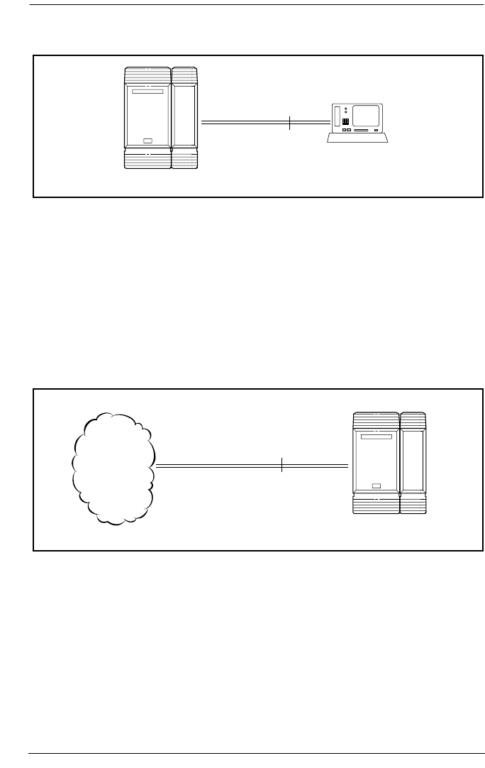
U-NT reference points
The U-NT reference point connection provides a point-to-
point digital connection between the ISDN network and the
ICS.
A U-NT loop provides lines that can be used by all Norstar
telephones, peripherals and applications, and ISDN TE.
U-NT and U-LT loops can be used in combination to provide
D-packet service for a point-of-sale terminal adapter (POSTA)
or other D-packet device. D-packet service is a 16 kbps data
transmission service that uses the D-channel of an ISDN line.
To deliver D-packet service, a network connection (U-NT) is
programmed to work with a terminal connection (U-LT). The
loops must be on the same physical card. For example, if the
point-to-point
U-LT
ICS
U interface TE
network
connection
U-NT
ICS
ISDN
Welcome to ISDN / 51
P0992638 03 Modular ICS 6.0 Installer Guide
network connection is a loop found on the BRI Card in Slot 1,
the terminal connection must be a loop found on the same card.
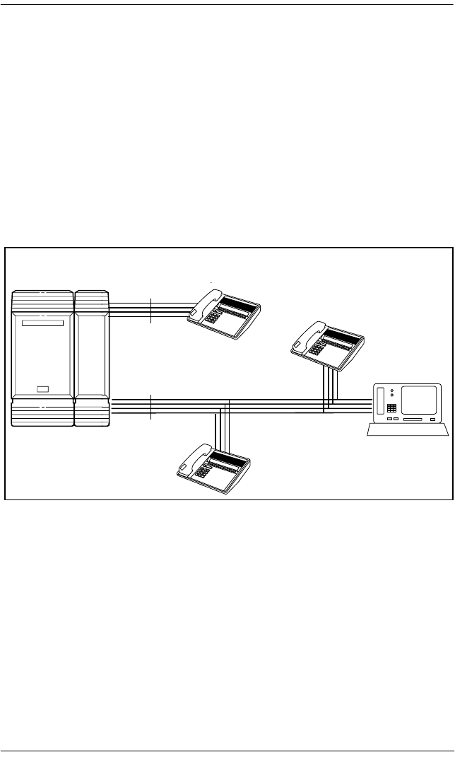
S reference point
The S reference point connection provides either a point-to-
point or point-to-multipoint digital connection between
Norstar and ISDN terminal equipment (TE) that uses an
S interface.
S loops support up to seven ISDN DNs, which identify TE to
the ICS.
T reference points
The T reference point connections provide a point-to-point
digital connection between the ISDN network and Norstar.
A T loop provides lines that can be shared by all Norstar
telephones, peripherals and applications, and ISDN TE.
Inspect FORWARD Callers
Inspect FORWARD Callers
MXP
MXP
S
S
Inspect FORWARD Callers
Inspect FORWARD Callers
MXP
MXP
Inspect FORWARD Callers
Inspect FORWARD Callers
MXP
MXP
point-to-point
ISDN TE
ISDN TE
ISDN TE
(with terminating
resistors)
ICS
ISDN TE
(with terminating resistors)

52 / Welcome to ISDN
Modular ICS 6.0 Installer Guide P0992638 03
A T loop can be used in combination with an S loop to provide
D-packet service for a point-of-sale terminal adapter (POSTA)
or other D-packet device. D-packet service is a 16 kbps data
transmission service that uses the D-channel of an ISDN line.
To deliver D-packet service, a network connection (T loop) is
programmed to work with a terminal connection (S loop). The
loops must be on the same physical card. For example, if the
network connection is a loop found on the BRI Card in Slot 1,
the terminal connection must be a loop found on the same card
Clock source for ISDN cards
Systems with ISDN interfaces need to synchronize clocking
with the ISDN network and any connected ISDN terminal
equipment. Clocking synchronization is supported by either a
Combination Fiber 6-port Services Cartridge or a Services
Cartridge.
The Modular ICS derives timing from the network using
U-NT and T reference points (loops). Terminal equipment on
U-LT and S reference points (loops) derive timing from the
ICS.
Systems synchronize clocking to the first available, functional,
network connection. If there are excessive errors on the
network
connection
T
ICS
ISDN

Welcome to ISDN / 53
P0992638 03 Modular ICS 6.0 Installer Guide
reference network connection, or the loop fails, the next
available, functional, network connection is used for clock
synchronization.
The clock synchronization process generates alarm codes and
event messages. See the Alarm codes on page 506 and Event
messages on page 514 for more information.
When you configure the network connections to the Modular
ICS, you should take into account the system preferences for
selecting loops for synchronization:
•lower numbered loops have preference over higher
numbered loops
•the loop preference order is: 201, 202, 203, 204, 225, 226,
227, 228
•the system skips U-LT, S, and analog loops when selecting
a network connection for synchronization
Systems with only U-LT and S loops act as timing masters for
the attached terminal equipment (TE), and are not
synchronized to the network. ISDN TE without access to a
network connection (BRI lines) has limited or no
functionality.
If your system has both a BRI and a DTI card configured as
PRI installed, it is recommended that you use PRI as the
primary clock source, see DTI card configured as a PRI card
on page 47.

54 / Welcome to ISDN
Modular ICS 6.0 Installer Guide P0992638 03
Other ISDN BRI equipment: NT1
The NT1 (network termination type 1) connects an S interface
(four-wire) to a U interface (two-wire). In most cases, it
connects loops from a BRI-ST card to the network connection,
which uses the U interface. It can also connect S interface
terminal equipment (TE) to the U loop from a BRI-U2 or
BRI-U4 Card.
An NT1 is not required to connect from the network to BRI-U
Cards or to connect U interface TE to an ICS equipped with
BRI-U Cards.
The NT1 converts and reformats data so it can be transmitted
to and from the S or T connection. In addition, it manages the
maintenance messages travelling between the network and the
NT1, and between the NT1 and the ICS.
The NT1 from Nortel Networks is packaged two ways:
•a stand alone package which contains one NT1 card
(NTBX80XX) and a power supply (NTBX81XX)
•a modular package which contains up to 12 NT1 cards
(NTBX83XX) and a power supply (NTBX86AA)
ISDN standards compatibility
Norstar ISDN equipment supports National ISDN standards
for basic call and calling line identification services.
Norstar BRI is compliant with National-1 and PRI is
compliant with National-2.
Modular ICS does not support EKTS (Electronic Key
Telephone System) or CACH (Call Appearance Call
Handling).

P0992638 03 Modular ICS 6.0 Installer Guide
Working with ISDN
Planning your ISDN network
Consult ISDN hardware on page 48 and ISDN programming
on page 58 to determine a configuration of ISDN trunks and
terminal equipment (TE) for the Modular ICS, then order the
appropriate ISDN capability package from your ISDN service
provider.
For ISDN BRI service your service provider supplies service
profile identifiers (SPIDs), network directory numbers
(Network DNs), terminal endpoint identifiers (TEIs), and
other information, as required, to program your Modular ICS,
TE and other ISDN equipment.
Modular ICS does not support any package with EKTS
(Electronic Key Telephone System) or CACH (Call
Appearance Call Handling). EKTS is a package of features
provided by the service provider and may include features
such as Call Forwarding, Link, Three-Way Calling, and
Calling Party Identification.
Ordering ISDN PRI
When you order ISDN PRI, order two-way DID because it
simplifies provisioning and provides efficient use of the PRI
bandwidth.
Ordering ISDN PRI service in Canada
In Canada, order Megalink™ service, the trade name for
standard PRI service and set the Norstar equipment to the
supported protocol that is identified by your service provider,
either DMS-100 or NI-2.

56 / Working with ISDN
Modular ICS 6.0 Installer Guide P0992638 03
Ordering ISDN PRI service in United States
In the United States order PRI service from your service
provider. Set the Norstar equipment to the PRI protocol
provided by your service provider.
Ordering ISDN BRI
Ordering service in Canada
In Canada, order Microlink™ service, the trade name for
standard BRI service. You can order either regular
Microlink™ service, which includes the CLID (Calling Line
Identification) feature, or Centrex Microlink™, which
includes access to additional ISDN network features
(including Call Forwarding).
When ordering Microlink™ service, it must be ordered with
EKTS (Electronic Key Telephone System) turned off. If you
will be using a point-of-sale terminal adapter (POSTA), ask
for D-packet service to be enabled.
Ordering ISDN service in the U.S.
In the U.S., regardless of the CO (Central Office) type, order
National ISDN BRI-NI-1 with EKTS (Electronic Key
Telephone System) turned off. Use the following packages as
a guideline for ordering your National ISDN BRI-NI-1.
However we recommend using packages M or P with the
Modular ICS. Contact your service provider for more
information about the capability packages it offers.

Working with ISDN / 57
P0992638 03 Modular ICS 6.0 Installer Guide
Bellcore/National ISDN Users Forum (NIUF) ISDN packages
supported by Modular ICS (for ordering in U.S.)
If you want to transmit both voice and data, and support
D-channel packet service, order package P. However,
Modular ICS does not support the flexible calling for voice
and additional call offering features that are included in
package P.
Multi-Line Hunt may be ordered with your package. When a
telephone number (the Network DN) in the group of numbers
assigned by your service providers is busy, the Multi-Line
Hunt feature connects the call to another telephone number in
the group. Norstar supports the feature only on point-to-point,
network connections (T loop or U-NT loop). Check with your
service provider for more information about Multi-Line Hunt.
Any of the ISDN packages will allow you to use sub-
addressing, but your ISDN TE must be equipped to use sub-
addressing for the feature to work.
Capability Feature set Optional
features
Point
-of-
sale
Voice Data
MAlternate
voice/circuit-
switched data
on both
B-channels
-- calling line
identification
--
√ √
PAlternate
voice/circuit-
switched data
on both
B-channels
D-channel
packet
flexible
calling for
voice (not
supported by
Modular
ICS)
Basic
D-Channel
Packet
additional
call offering
(not
supported by
Modular ICS)
calling line
identification
√ √ √

58 / Working with ISDN
Modular ICS 6.0 Installer Guide P0992638 03
Supported ISDN protocols
The switch used by your service provider must be running the
appropriate protocol software and the correct version of that
software to support ISDN PRI and ISDN BRI. Each protocol
is different and supports different services. Contact your
service provider to ensure that your ISDN connection has the
protocol you require.
For more information on the supported protocols and services,
refer to Call by Call service selection for PRI on page 433.
ISDN programming
Most of the configuration programming for PRI and BRI lines
and ISDN terminals and devices is done under Hardware. This
section gives you an overview of programming for PRI and
BRI lines, ISDN terminals and devices, and D-packet service.
Programming ISDN PRI resources
Some steps will not be necessary, depending on the service
you are providing.
More detailed information is included under the individual
headings and settings in the Programming and Maintenance
sections.
PRI or BRI programming activity Programming
heading
View or change the card configuration for each slot
in the ICS
Hardware
Provision or deprovision loops and lines Provisioning
Enable or disable BRI or DTI card (PRI) Module status
View status of line, loop or port Port/DN status
Enable/disable individual PRI channels Link Status
Working with ISDN / 59
P0992638 03 Modular ICS 6.0 Installer Guide
For complete card and cartridge installation instructions and
safety precautions, see Installation on page 209.
1. Collect the information supplied by your service provider
to support your ISDN package.
2. Ensure that a Combination Fiber 6-port Services
Cartridge, or a Services Cartridge has been installed in the
ICS.
3. Install the DTI cards in the ICS. Refer to Installing the
cartridges on page 213 for information about card
placement. If you are not using DTI cards, determine
which type of card you will preprogram the ICS to use in
each slot.
4. Disable each card under Maintenance.
5. Select a card type (PRI) in Hardware. See Provisioning the
DTI card for PRI on page 456, for information on protocol
and other settings you must configure.
6. Re-enable the card in Maintenance.
If required, the card goes through a firmware download
process, which takes five to six minutes. During a
firmware download, the bottom LED on the DTI card
flashes.
Tips - A new DTI card being released with MICS 6.0 can
be installed off-core on Module 3 or 4 on the Midi system, or
module 7 or 8 on the Maxi system to expand the PRI capability
of your system. This card is only support on Profile 1 and 4.
Tips - If you are using one or more of the lines on this card
for MCDN private networking, this is where you specify that
protocol (SL-1).

60 / Working with ISDN
Modular ICS 6.0 Installer Guide P0992638 03
Programming ISDN BRI resources
Some steps will not be necessary depending on the service you
are providing.
More detailed information is included under the individual
headings and settings in the Programming and Maintenance
sections.
For complete card and cartridge installation instructions and
safety precautions, see Installation on page 209.
1. Collect the information supplied by your service provider
to support your ISDN package. This includes network
service profile identifiers (SPIDs) and Network DNs. If
you are supporting a point-of-sale terminal adapter, you
also need one or more terminal endpoint identifiers (TEIs).
2. Make sure a Combination Fiber 6-port Services Cartridge,
or a Services Cartridge has been installed in the ICS.
3. Install the BRI card in the ICS, Trunk Module. Refer to
Installing the cartridges on page 213 for information about
BRI card placement. If you are not using a BRI card,
determine which type of card you will preprogram the ICS
to use in each slot.
4. Disable each card in Maintenance under Module
Status.
5. Under Hardware, select a card type: BRI-ST, BRI-U2,
BRI-U4.
6. Under Hardware, select the type for each loop:
•for a BRI card, select T or S if the card type is BRI-ST
•for a BRI-U2 or BRI-U4 card, select LT or NT

Working with ISDN / 61
P0992638 03 Modular ICS 6.0 Installer Guide
7. If the card uses a T or NT loop, enter the following
information, as supplied by your service provider:
•the SPID assigned to the loop
•the number of B-channels associated with each SPID
•the Network DNs used with the network SPID
•the call type of the Network DN
Repeat the programming for the second network SPID, if
any.
If the T or NT loop is used for D-packet service:
•turn on the service
•assign the appropriate S-loop mapping for BRI-ST
cards or LT-loop mapping for BRI-U2 or U4 cards
•assign the TEIs to the loop. These are provided by the
telco to support a point-of-sale terminal adapter or
other D-packet service device.
If the loop type is S, select the sampling used on the loop.
If the loop type is S or LT:
•assign ISDN DNs to the loop
•designate one of the assigned ISDN DNs to be the DN
for the loop (Loop DN).
Note: You can have a maximum of 30 ISDN DNs on your
system. The default ISDN DN range is 667–696 for a
system with three-digit DNs. To change ISDN DN
type, see Change DNs on page 397.
8. Re-enable the card in Maintenance. Refer to Disabling a
PRI Channel on page 524.
If required, the card goes through a firmware download
process, which takes five to six minutes. During a
firmware download, the bottom LED on the BRI card
flashes.

62 / Working with ISDN
Modular ICS 6.0 Installer Guide P0992638 03
9. Provision the loops and lines , as appropriate, in
Maintenance. Refer to Provisioning BRI and PRI lines on
page 522.
10. If you are configuring auto-answer BRI trunks to map to
target lines, program the received number for the target
line to be the same as the Network DN supplied by your
service provider. This setting is found under Lines.
Assign the ISDN lines and target lines to the appropriate
ISDN DNs, which are the set of DNs reserved for use by
ISDN devices. This setting is found under
Terminals&Sets/Line access. ISDN lines can also be
assigned to the DNs used by the telephones or any other
devices connected to the Modular ICS.
Program the ISDN terminals and devices with the
appropriate ISDN DNs and terminal SPIDs by following
the instructions that come with the devices. For more
information, see Programming ISDN equipment on page
65.
If you are setting up a D-packet service, program the point-
of-sale terminal adapter or other D-packet service device
with the appropriate TEI (provided by your service
provider), terminal SPID, and DN by following the
instructions that come with the device.
Programming ISDN PRI lines
When the configuration programming under Hardware is
complete, your PRI lines are ready to be programmed. For
information on programming your PRI lines, see Call by Call
service selection for PRI on page 433.

Working with ISDN / 63
P0992638 03 Modular ICS 6.0 Installer Guide
Programming ISDN BRI lines
When the configuration programming under Hardware is
complete, your BRI lines are ready to be programmed in the
same way as analog lines. You can, for example, place them in
pools and assign them to Norstar telephones, Business Series
Terminals, or ISDN terminal equipment.
However, there are some differences in the way BRI lines
work that will influence how you configure them to handle
incoming and outgoing calls.
•For BRI lines, in most cases, your service provider
supplies two SPIDs – one for each B channel. Each SPID
and one or more Network DNs are associated with a single
line. Calls to a Network DN come in on a specific line.
Pressing a line button selects the same line every time.
•If your service provider supplies you with a single SPID
for both B channels, incoming and outgoing calls are
handled according to the loop. The two lines provided by
the BRI loop are pooled for both incoming and outgoing
calls.
For example, if Loop 201 is programmed with a single
SPID, which supports lines 001 and 002, incoming calls
made to a Network DN associated with the SPID appear on
either line 001 or line 002. If you press the line button for
line 001, either line 001 or line 002 is selected. For loops
which use a single SPID, assign both lines on a loop to a
telephone to guarantee that all calls appear at the
telephone.

64 / Working with ISDN
Modular ICS 6.0 Installer Guide P0992638 03
Programming Direct Inward System Access (DISA) on PRI
trunks
When a trunk cartridge is set to PRI, all lines on that trunk are
set to Auto Answer without Direct Inward System Access
(DISA).
DISA can be accessed by one of two methods.
1) Define the DISA DN to match the trailing digits of the
Called Party Number (CDN).
With Public, Private, and Tie service types, the CDN is
simply truncated to the Target Line Receive Digit Length
and is parsed to match the Target Line Receive Digits.
DISA can be accessed by having the DISA DN match the
trailing digits of the CDN. For example, with a Receive
Digit Length = 4, and DISA DN = 1234, a call made to
Public DN 763-1234 will be handled as follows:
•the ISDN setup message will contain a CDN of 763-1234
•the CDN will be truncated to the four digits, 1234
•1234 matches the DISA DN
•the call will be answered with DISA
2) Use incoming Call by Call (CbC) Service routing to map the
call type to the DISA DN. Refer to Programming Call by
Call service selection on page 436 for more information.
With FX, INWATS, 900, and SDS service types, either a
Service Id (SID) or a CDN is mapped to Target Line
Receive Digits.
This is programmed under Call-by-Call Routing. DISA
may be accessed by having the SID or CDN map to the
DISA DN. This example has a Receive Digit Length = 4,
DISA DN = 1234, and CbC Routing with (Service Type =
FX, Map from SID = 2, Map to digits = 1234).

Working with ISDN / 65
P0992638 03 Modular ICS 6.0 Installer Guide
A call presented to the Norstar system with service type
FX and SID 2 will be handled as follows:
•The ISDN setup message will specify FX with SID = 2
•The FX SID = 2 will be mapped to DISA DN digits 1234
The call will be answered with DISA
Programming ISDN equipment
DTI cards configured as PRI support various applications that
are enabled by PRI. For a list of the type of applications that
are support, see ISDN applications on page 173.
Terminal equipment for BRI cards
ISDN devices and terminals connected to the ICS must be
configured under the Hardware heading in system
programming. You choose directory numbers for ISDN
equipment from a pre-determined range of DNs (667-696).
Any of the ISDN DNs can be assigned to any U-LT or S loop,
but each can only be assigned to one loop and one device.
Devices on an S or LT loop (BRI cards only)
Terminal equipment using a U-LT loop or S loop must be
assigned an ISDN directory number (ISDN DN). This allows
the TE to be assigned lines and to communicate with other
devices connected to the ICS. Each DN can be assigned to only
one TE and one loop.
You assign ISDN DNs to S loops and LT loops under Assign
DNs under Hardware. Each S or LT loop can be programmed
with eight ISDN DNs, but you cannot exceed a total of 30
ISDN DNs for the Modular ICS.
Once you have assigned ISDN DNs to a loop, designate one of
the DNs as a Loop DN. The Loop DN acts as a main ISDN DN
and completes the configuration of the loop.
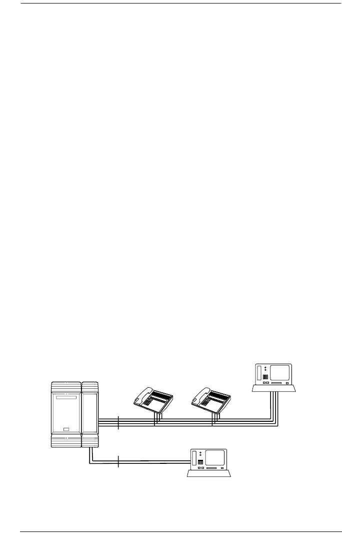
66 / Working with ISDN
Modular ICS 6.0 Installer Guide P0992638 03
The ISDN terminal equipment (TE) on the loop is also
programmed with its ISDN DN. See the instructions that come
with the ISDN device for information on how to program it to
recognize the assigned DN. Most devices will require both a
terminal service profile identifier (terminal SPID) and a DN,
and some will require two terminal SPIDs and two ISDN DNs.
The SPID used with the device should not be confused with a
SPID used for network connections using an T or NT loop.
To create a terminal SPID for a device, add at least two zeros
to the end of the of the ISDN DN. Add more zeros to the
beginning or end of the ISDN DN until you have the length of
SPID required by the TE. For example, if an ISDN telephone
requires a six-digit SPID and has a DN of 667, its SPID is
066700. If the same TE requires a minimum of ten digits, the
SPID is 0000066700.
Most ISDN terminals require a five-digit SPID. An ISDN PC
card usually requires a 10-digit SPID. Follow the directions
that come with the ISDN device to program it with a SPID and
ISDN DN.
Inspect FORWARD Callers
Inspect FORWARD Callers
MXP
MXP
Inspect FORWARD Callers
Inspect FORWARD Callers
MXP
MXP
U-LT
S
DN 275
SPID 0000027500
Loop DN 667
DN 669 (incoming)
SPID 0000066900
DN 670 (outgoing)
SPID 0000067000
DN 667
SPID 066700
Loop DN 669
DN 668
SPID 066800
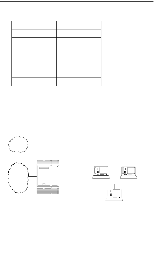
Working with ISDN / 67
P0992638 03 Modular ICS 6.0 Installer Guide
The following table uses the example in the illustration to
show the programming for the S loop.
ISDN router
By connecting an ISDN router to your Modular ICS, a group
of PCs can share Internet access. This arrangement is best for
a workplace where each personal computer occasionally uses
an Internet connection.
To support Internet access, you must order BRI lines from
your service provider, and subscribe to an Internet service
from an Internet service provider (ISP). Your personal
computer must have an Internet browser and any applications
supplied by your ISP.
Setting Option
Loop 201
Type S
Sampling Fixed
DNs on Loop 201:
Assign DNs
667: Assigned
668: Assigned
669: Assigned
670: Assigned
Loop DN 667
Internet
service
provider
ISDN
ICS
U-LT loop PCs with
applications
ISDN router
LAN

68 / Working with ISDN
Modular ICS 6.0 Installer Guide P0992638 03
D-packet service (BRI cards only)
The D-packet service supplied by the Modular ICS supports a
point-of-sale terminal adapter (POSTA). Connecting a
POSTA allows transaction terminals, such as devices where
you swipe credit or debit cards, to transmit information using
the D channel of the BRI line. At the same time, the B channels
of the BRI line remain available for voice and data calls. A
special adapter links transaction equipment, such as cash
registers, credit card verification rigs, and point-of-sale
terminals, to the X.25 network. This is a data communications
network designed to transmit information in the form of small
data packets.
To support the D-packet service, your ISDN network and
financial institution must be equipped with a D-packet
handler. To convert the protocol used by the transaction
equipment to the X.25 protocol, your ISDN network must also
be equipped with an integrated X.25 PAD.
X.25 PAD works with the following versions of X.25: Datapac
32011, CCITT, T3POS, ITT and API. The ISDN service
package you order must include D-packet service, for
example, Package P in the U.S. or Microlink™ with D-
channel in Canada.
Your service provider supplies a Terminal Endpoint Identifier
(TEI) and a DN to support D-packet service. The TEI is a
number between 00 and 63 in the U.S. In Canada, the default
range is 21-63. Your service provider may also supply you
with a DN to program your D-packet device. The DN for
D-packet service becomes part of the dialing string used by the
D-packet to call the packet handler.

Working with ISDN / 69
P0992638 03 Modular ICS 6.0 Installer Guide
POSTA for ISDN BRI
When you configure D-channel packet service, you are
specifying the transmission path between an ISDN loop on the
network side of the ICS and the ISDN loop on the telephone
side. The telephone side loop is the loop used by the point-of-
sale terminal adapter. The service is turned on and configured
using the network loop programming found under Hardware.
Use NT loop for BRI-U2 and BRI-U4 cards and S or T loop
for BRI-ST cards.
To set up D-packet service:
•go to the programming settings for the network loop under
Hardware. (S, T, or NT loop)
•select the S loop or LT loop used by the POSTA
•enter the terminal endpoint identifiers (TEIs) supplied by
your service provider
Point-of-sale terminal adapter
The point-of-sale terminal adapter is an analog device that
connects to point-of-sale devices using an RS-232 interface
and a U-LT loop. It handles the routing of packet information
from the devices to the ICS and into the ISDN network.
Your service provider, usually a financial institution, supplies
you with information about the compatible controller, which
handles the routing of packet information from the devices to
the ICS and into the ISDN network.

70 / Working with ISDN
Modular ICS 6.0 Installer Guide P0992638 03

P0992638 03 Modular ICS 6.0 Installer Guide
Trunks and target lines
Trunks are external lines that provide the physical connection
between a Norstar system and other systems in a private or
public network. Trunks are numbered 001 to 156 in a fully
expanded system. Norstar Modular ICS supports six different
types of trunks:
•PRI trunks are used for incoming and outgoing calls over
an ISDN network. PRI SL-1 lines can provide MCDN
network functionality in a private network between other
Norstar systems, Meridian 1 systems, or Business
Communications Systems, if the appropriate software
code has been installed.
•T1 trunks are digital trunks that can be configured to act as
loop start, ground start, E&M, DID, or leased lines,
depending on your requirements.
—DID trunks route incoming calls from the public
network directly to telephones within Norstar, without
an attendant.
—Loop start trunks handle incoming and outgoing calls
between Norstar and the public network.
—E&M trunks handle incoming and outgoing traffic
between the Norstar system and the private network.
•BRI trunks handle incoming and outgoing calls between
Norstar and an ISDN network.
•Target lines are virtual communication paths between
trunks and telephones on the Norstar system. They are
incoming lines only, and cannot be selected for outgoing
calls. With 192 target lines in a fully expanded system, you
can concentrate auto answer calls on fewer trunks. This
type of concentration is an advantage of target lines.
Norstar mapping allows you to direct each target line to

72 / Trunks and target lines
Modular ICS 6.0 Installer Guide P0992638 03
one or more telephones. Target lines are numbered 157 to
348 in a fully expanded system, and 157 to 284 in all
others.
Telephones can be configured to have an appearance of any
type of trunk and line, including target lines, but excluding PRI
trunks. If assigned, they are used for monitoring call usage.
Trunk operating modes (T1)
T1 trunks have four operating modes:
•ground start (T1 only)
•loopstart (analog and T1)
•E&M (analog and T1)
•DID (analog and T1)
Ground start trunks (T1 only)
Ground start trunks offer the same features as loop start trunks,
but are used when the local service provider does not support
disconnect supervision for the digital loop start trunks. Ground
start trunks work with T1 only.
By configuring lines as ground start, the system will be able to
recognize when a call is released at the far end.
Tips - You cannot change the trunk mode for a ground
start trunk on a DTI. It always has disconnect supervision.
A DTI can provide a maximum of 24 ground start trunks.
Analog ground start trunks are not supported.
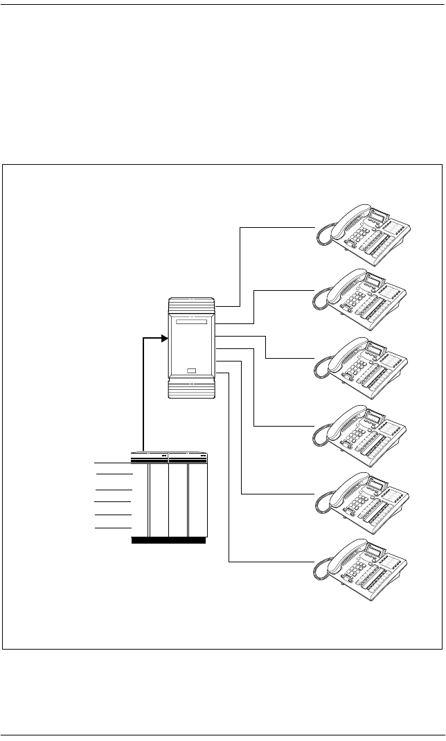
Trunks and target lines / 73
P0992638 03 Modular ICS 6.0 Installer Guide
DID trunks
DID trunks give you direct inward dialing (DID) from the
public network. A typical application of these trunks is to map
incoming digits onto target line appearances within the
Norstar system. DID trunks can operate only as auto-answer
trunks.
Target lines
204
205
206
207
208
209
Central office (CO)
Norstar
DID trunk
593-1234
593-1235
593-1236
593-1237
593-1238
593-1239

74 / Trunks and target lines
Modular ICS 6.0 Installer Guide P0992638 03
When a call comes in on a DID trunk, the Norstar system
interprets the incoming digits in one of the following ways.
•If the digits map onto a target line, the call is routed to all
telephones with an appearance of that target line.
•If the digits map onto the DISA DN, the caller hears
stuttered dial tone. They must enter a six-digit Class of
Service (COS) password from a DTMF telephone to hear
system dial tone.
They can then enter a:
—target line number
—line pool access code
—remote feature code
•If the digits map onto the Auto DN, the caller hears system
dial tone. They can then enter:
—a target line number
—the DISA DN, which will prompt for a Class of Service
password
—a line pool access code
—a destination code
—a remote feature code from a DTMF telephone
Tips - Each DID Trunk Cartridge can provide four DID
trunks. Each DID Trunk Cartridge also has four DTMF
receivers dedicated to those trunks. A DTI can provide up to 24
DID trunks.
You cannot configure a DID trunk as the prime line for a
Norstar telephone or a Business Series Terminal.
The capabilities available to a remote caller are determined by
the remote filters and remote package assigned to a line, or by
the set restrictions, line restrictions and remote package
assigned to the Class of Service password.

Trunks and target lines / 75
P0992638 03 Modular ICS 6.0 Installer Guide
Analog loop start trunks
Loop start trunks give you incoming and outgoing access to
the public network. Loop start trunks can be configured as
manual-answer or auto-answer. The answer mode determines
how the system handles incoming calls.
When a call comes in on a manual-answer loop start trunk, it
alerts at all telephones with that line appearance.
When a call comes in on an auto-answer loop start trunk that
is configured to answer with direct inward system access
(DISA), the caller hears a stuttered dial tone. They must enter
a six-digit Class of Service (COS) password from a DTMF
telephone to access system dial tone.
Once the caller has system dial tone, they can then enter:
•a target line number
•a line pool access code
•a remote feature code.
By default, auto answer loop start trunks are configured to
answer with DISA, and are used to provide controlled access
to Norstar system resources.
When a call comes in on an auto-answer loop start trunk that
is not configured to answer with DISA, the caller hears system
dial tone.
They can then enter:
•a target line number
•the DISA DN, which will prompt for a Class of Service
password
•a line pool access code
•a remote feature code from a DTMF telephone

76 / Trunks and target lines
Modular ICS 6.0 Installer Guide P0992638 03
To place an outgoing call, a loop start line can be selected by:
•pressing a line button on the telephone
•dialing a line pool access code
•pressing a memory button that has been programmed with
a line pool access code
Configuration tips
•Loop start signaling is supported by Loop Start Trunk
Cartridges, Call Information (CI) Trunk Cartridges and
Digital Trunk Interfaces (DTI). Each Loop Start Trunk
Cartridge or CI Trunk Cartridge can provide four loop start
trunks. A DTI can provide up to 24 loop start trunks. If you
wish to configure your loop start trunks as auto-answer,
the trunks must have disconnect supervision.
•For Loop Start or CI Trunk Cartridges installed in a Trunk
Module, you will also need one E&M/DISA Trunk
Cartridge for every two loop start trunks that you configure
as auto-answer. The E&M/DISA Trunk Cartridge provides
two DTMF receivers to receive the incoming digits from
the central office. An auto-answer loop start trunk can give
you the same kind of direct inward dialing function as a
DID trunk.
•If your system includes both loop start trunks and DID
trunks, you would typically use loop start trunks for
outgoing calls and DID trunks for incoming calls.
•You may configure a loop start trunk as the prime line for
a Norstar telephone or a Business Series Terminal.
•The capabilities available to a remote caller are determined
by the remote filters and remote package assigned to a line,
or by the set restrictions, line restrictions, and remote
package assigned to the Class of Service password.
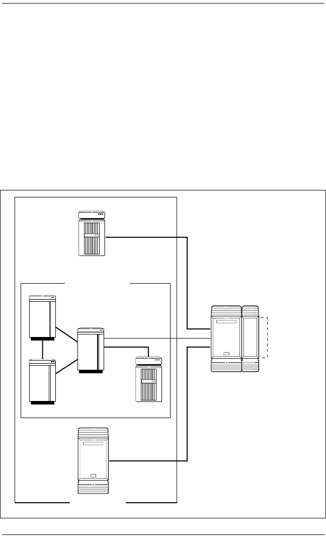
Trunks and target lines / 77
P0992638 03 Modular ICS 6.0 Installer Guide
•Two loopstart trunk cartridges are compatible with
Modular ICS 6.0. The NT5B40GA-93 can be installed in
trunk module (TM) slots only. The NT7B75GA-93 can be
installed in either core slots three or four, or TM slots one,
two or three.
Analog E&M trunks
An Analog E&M trunk gives you incoming and outgoing
access to other systems in a private network. E&M trunks can
be configured as manual-answer or auto-answer. The answer
mode determines how the system handles incoming calls.
Key system
E&M
intelligent network
PABX
PBX
PBX
E&M
Key system
Norstar
Norstar
E&M
Private network
E&M/DISA
Trunk
Cartridges

78 / Trunks and target lines
Modular ICS 6.0 Installer Guide P0992638 03
By default, auto-answer E&M trunks are answered by the
system with direct inward system access (DISA), and are used
to provide controlled access to Norstar system resources.
When a call comes in on a manual-answer E&M trunk, it alerts
at all telephones with that line appearance.
When a call comes in on an auto-answer E&M trunk that is
configured to answer with DISA, the caller hears stuttered dial
tone. They must enter a six-digit COS password from a DTMF
telephone to hear system dial tone.
They can then enter a:
•target line number
•line pool access code
•remote feature code
When a call comes in on an auto-answer E&M trunk that is not
configured to answer with DISA, the caller hears system dial
tone. At that point they can then enter one of the following:
•a target line number
•the DISA DN, which will prompt for a COS password
•a line pool access code
•a remote feature code from a DTMF telephone
To place an outgoing call, an E&M trunk can be selected by
one of the following:
•pressing a line button on the telephone
•dialing a line pool access code
•pressing a memory button that has been programmed with
a line pool access code.

Trunks and target lines / 79
P0992638 03 Modular ICS 6.0 Installer Guide
BRI trunks
BRI trunks give you incoming and outgoing access to an ISDN
network. Like loop start trunks, they can be configured as
manual-answer or auto-answer. See Ans mode on page 341.
BRI trunks provide a fast, accurate, and reliable means of
sending and receiving data, images, text, and voice
information. Using BRI lines allows for faster transmission
speeds and the addition of a variety of powerful business
applications, including remote LAN access, video
conferencing, file transfer and Internet access.
For more information see Welcome to ISDN on page 37.
Note Profile 2: European BRI trunks can be either EURO or
SL-1.
PRI trunks
PRI trunks are used for incoming and outgoing calls over an
ISDN network. PRI trunks are automatically set to auto-
answer.
Incoming calls are routed to system telephones through
assigned target lines. Outgoing calls are made using the
intercom key, which connects to a line pool, or by entering a
destination code, which defines a route for the call.
PRI Sl-1 lines also can provide MCDN network functionality
over a private network between other Norstar systems,
Meridian 1 systems, or Business Communications Systems, if
the appropriate keycode has been installed. Private networking
is described in Networking with Norstar on page 91.
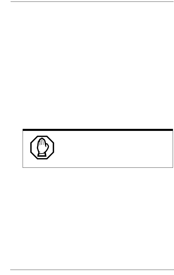
80 / Trunks and target lines
Modular ICS 6.0 Installer Guide P0992638 03
Target lines
A target line is a specific communication path that is reached
by means of digits received from an incoming trunk. Target
lines are used to answer incoming calls but cannot be used to
make outgoing calls.
You can program auto-answer trunks to map to target lines to
provide for attendant bypass, which allows the call to go
directly to a department or individual, and line concentration,
where one trunk can map onto several target lines.
No target lines are assigned to sets, except if the DID template
has been applied to the system.
Target lines are referred to by line numbers 157-348 or
157-284, in the same way as physical lines.
Privacy issue
You can set a target line to Private (default is
Public), however, such features as Call Pickup
can still answer these lines at remote telephones.

P0992638 03 Modular ICS 6.0 Installer Guide
Remote system access
The remote access feature allows callers elsewhere on the
private or the public network to access a Norstar system by
dialing directly without going through an attendant. Once in
the system, the remote user can use some of the system
resources. The remote access must be enabled in programming
before callers can use it.
Norstar systems support remote system access on the
following trunk types which may require the remote caller to
enter a COS password for direct inward system access (DISA):
•auto-answer loop start trunks
•auto-answer E&M trunks
•DID trunks, by means of the DISA DN
•PRI trunks, by means of the DISA DN
The system resources, such as dialing capabilities, line pool
access and feature access, that a remote user may access
depends on the Class of Service (COS) assigned to the user.
See Class of Service on page 85, COS pswds on page 382 and
the Modular ICS 6.0 System Coordinator Guide for more
details.
Use system features during a remote call
To use features on a Norstar system during a remote call-in,
press , followed by the feature code. Even if you are calling
from another Norstar system, press instead of .

82 / Remote system access
Modular ICS 6.0 Installer Guide P0992638 03
Remote access on loop start and E&M trunks
Loop start trunks provide remote access to Norstar from the
public network. E&M trunks provide remote access from a
private network. Each must be configured to be auto-answer to
provide remote system access.
A loop start trunk must have disconnect supervision if it is to
operate in auto-answer mode. E&M trunks always operate in
disconnect supervised mode.
When a caller dials into the system on a line that has auto-
answer, the system answers with system dial tone and no COS
password is required. In this case, control over the system
capabilities available to the caller is provided only by the
restriction filters assigned to the line.
When a caller dials in on a line that has auto-answer with
DISA, the system answers with stuttered dial tone. This is the
prompt to enter a COS password. The password used by the
caller determines which system capabilities are available to
the caller.
Remote access on a private network
Nodes on the private network deliver the last dialed digits to
the destination Norstar node, for interpretation by the
destination Norstar node. The destination Norstar node either
matches the digits to a target line or interprets the digits as a
remote feature request. The call is either routed to the specified
target line, or the remote feature is activated.
By default, E&M trunks are set to answer with DISA. For
auto-answer E&M trunks connected to a private network,
change the default so that the trunks are not answered with
DISA. If an auto-answer E&M trunk is configured to answer
with DISA, the system tries to interpret any received digits as
a COS password.

Remote system access / 83
P0992638 03 Modular ICS 6.0 Installer Guide
The DISA DN and the Auto DN allow auto-answer private
network and DID calls, in the same way that calls on
auto-answer loop start and auto-answer E&M trunks can be
answered, with or without DISA. These DNs are described in
System prgming under Access codes.
Remote access on Direct Inward Dial (DID) trunks
Remote system access on DID trunks is similar to that of E&M
trunks connected to a private network.
The main differences are:
•a remote caller is on the public network dialing standard
local or long-distance telephone numbers
•the digits received are delivered by the central office
•DISA cannot be administered to a DID trunk
As with a private network, the dialed digits may be
programmed to match those of a specific target line DN, the
DISA DN or the Auto DN.
Remote access on PRI trunks
Remote system access on PRI trunks is similar to that of E&M
trunks connected to a private network.
The main differences are:
•a remote caller is on the public network dialing standard
local or long-distance telephone numbers
•the digits received are delivered by the central office
•answer with DISA cannot be administered to a PRI trunk
since PRI trunks are set to autoanswer.
As with a private network, the dialed digits may be
programmed to match those of a specific target line DN, the
DISA DN, or the Auto DN.

84 / Remote system access
Modular ICS 6.0 Installer Guide P0992638 03

P0992638 03 Modular ICS 6.0 Installer Guide
Controlling system access
Modular ICS programming provides several ways of
protecting your Norstar system from unauthorized access or
use. These features are used in combination to provide control
both to users and to lines.
Class of Service
Class of Service (COS) refers to the capabilities that Norstar
provides to users who access the system from the public or
private network. A password defines which set of capabilities
the user is to have access to.
The COS includes:
•filters that restrict dialing on the line
•an access package defines the set of line pools that may be
accessed and whether or not the user has access to the
paging feature
The COS that is applied to an incoming remote access call is
determined by:
•the filters that you apply to the incoming trunk
•the Class of Service password that the caller used to gain
access to the Norstar system
In cases where DISA is not automatically applied to incoming
calls, the remote caller can change the COS by dialing the
DISA DN and entering a COS password.
To program COS passwords, see Passwords on page 382 and
the Modular ICS 6.0 System Coordinator Guide.

86 / Controlling system access
Modular ICS 6.0 Installer Guide P0992638 03
Restriction filters
Restriction filters can be used to restrict the numbers that may
be dialed on any external line within your Norstar system. Up
to 100 restriction filters can be created for the system.
A restriction filter consists of up to 48 restrictions with
associated overrides.
To restrict dialing within the system, you can apply filters to:
•outgoing external lines (as line restrictions)
•telephones (as set restrictions)
•external lines on specific telephones (as line/set
restrictions)
Restriction filters can also be specified in Restriction
Service, for times when the system is operating according to
a Schedule. See Services on page 353 for more details.
Dialed digits must pass both the line restrictions and the set
restrictions. The line/set restriction overrides the line
restriction and set restriction. Refer to the following diagrams.
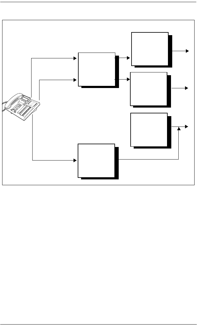
Controlling system access / 87
P0992638 03 Modular ICS 6.0 Installer Guide
Line restrictions
In the previous diagram, a caller using line 1 could only dial
long-distance numbers to area codes 212 and 718. A caller
using line 3 could not dial any long-distance numbers. A caller
using line 5 could dial long-distance numbers to area codes
212, 718, and 415.
Line/Set
restriction
Set restriction
line 1
line 3
line 5
Line restriction
line 1
line 3
line 5
no long
distance
except
area codes
212, 718, 415
no long
distance
except
area codes
212, 718
no long
distance
except area
codes 212
718, 214, 713
no long
distance
no long
distance
Line restriction
Line/set restriction
line 1
line 1
line 3
line 3
line 5
line 5
no long
distance
no long
distance
no long
distance except
area codes
212, 718, 415
no long
distance
except area
codes 212,
718
no long
distance except
area codes
212, 718, 214,
713
Set restriction
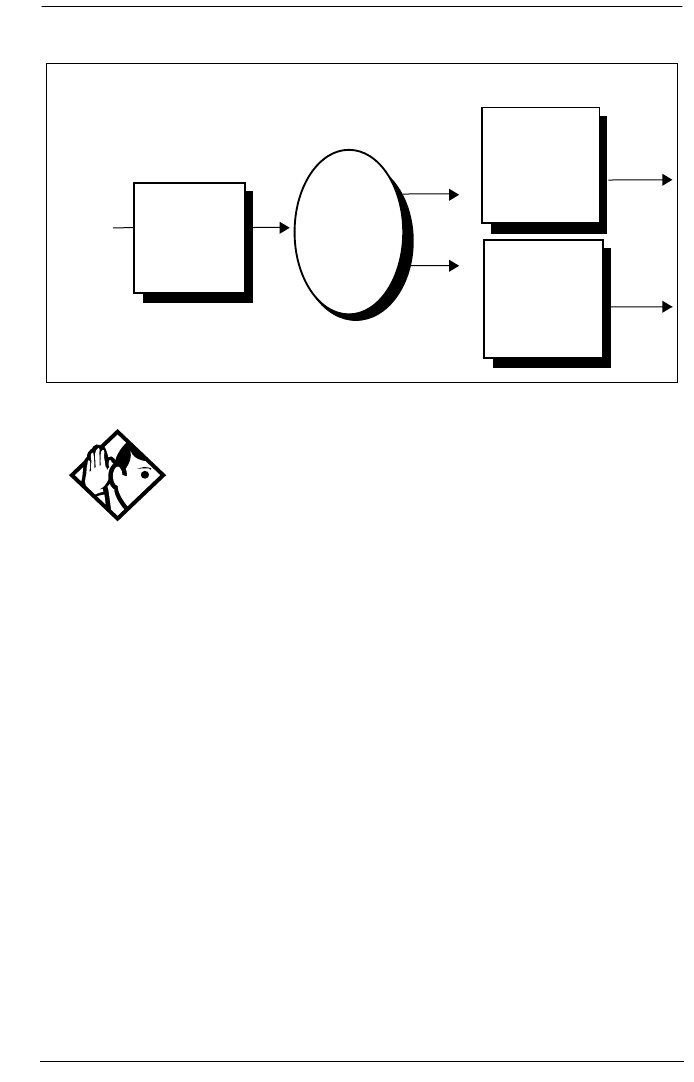
88 / Controlling system access
Modular ICS 6.0 Installer Guide P0992638 03
Remote caller restrictions
In this case, dialed digits must pass both the remote restriction
and the line restriction. A remote caller can override these
filters by dialing the DISA DN and entering a COS password.
For restriction filter programming instructions, see
Restrictions on page 322 and the Modular ICS 6.0 System
Coordinator Guide.
Tips - Set restrictions have no effect on numbers dialed on
an E&M trunk.
To restrict dialing outside the system, once a caller gains
remote access, you can apply restriction filters to incoming
external lines, as remote restrictions.
Remote
caller
Remote restriction
no long
distance
except area
code 212,
718
no long
distance
except area
code 212,
718, 416
no long
distance
except area
code 212,
718, 416
Line pool
access
code 81
Line 1
Line 3
Line filter

Controlling system access / 89
P0992638 03 Modular ICS 6.0 Installer Guide
Direct inward system access (DISA)
To control access from the public or private network, you can
configure auto-answer trunks to answer with DISA. Remote
callers hear a stuttered dial tone and must then enter a COS
password. The password they enter determines what access
they are allowed in the system.
Auto-answer loop start and E&M trunks are configured to
answer with DISA by default. For DISA programming
instructions, see Ans with DISA on page 342.
In addition to public network connections, Norstar Modular
ICS can be integrated into an existing private network, or to
other Norstar or Meridian 1 systems to form a corporate
telecommunications network.
Tips - You must have one E&M/DISA Trunk Cartridge to
provide DTMF receivers for every two auto-answer loop start
trunks on Loop Start or CI Trunk Cartridges.
DID trunks cannot be configured to answer with DISA. If you
want incoming DID calls to be answered with DISA, configure
the system with a DISA DN. Incoming DID calls that map onto
the DISA DN are then routed to a line that has DISA.

90 / Controlling system access
Modular ICS 6.0 Installer Guide P0992638 03

P0992638 03 Modular ICS 6.0 Installer Guide
Networking with Norstar
There are a number of ways you can network Norstar systems
together, or network Norstar systems with other Nortel
systems into private networks. What types of lines you use to
perform the networking will determine the type of services
that can be shared between systems.
Keep in mind, that each node (Norstar system) is considered
an external system by every other node within the network,
even though, to the users, it appears to be all one system. This
affects how you configure call transfer and call out features on
each system. On the home node, all features are configured as
local numbers. On all other nodes, all features are configured
with external numbers.
As well, each node must have a unique identifying code. What
this code will be, and how it is configured for the user, depends
on what type of trunks and dialing rules you choose to use.
This section describes various configurations of private
networks. The general settings that are required to set up the
home node for each system is provided to give you a sense of
what is required for each type of network.
The common goal is to provide the user with the sense that the
network is one large system that provides common access to
colleagues in other buildings, cities, or countries. In some
systems they may need to enter a destination code before the
local number to routes the call to the correct system. In other
systems, using a common dialing plan allows users to dial
colleagues at any location simply by entering the same number
of digits they would use to dial a colleague at the next desk.
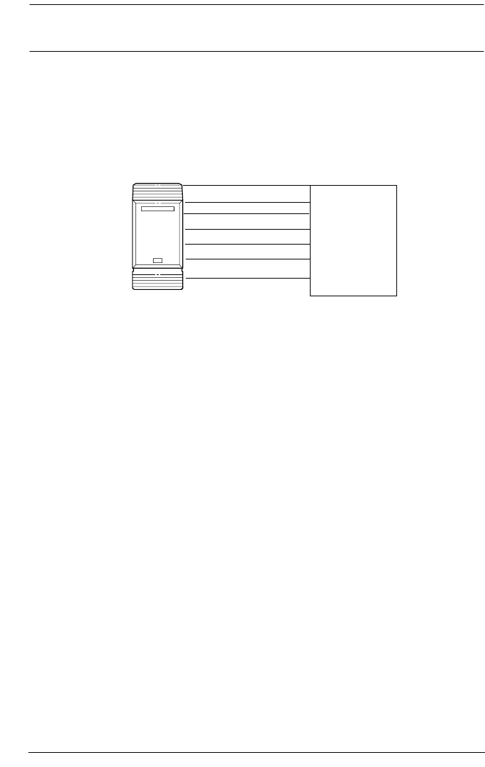
92 / Tie-line networking
Modular ICS 6.0 Installer Guide P0992638 03
Tie-line networking
Norstar uses enhanced trunking to join other Norstar or
customer equipment in a private network. This allows
authorized users access to tie lines, central office lines, and
Norstar features from outside the Norstar system.
Callers using the Norstar Modular ICS system can:
•call directly to a specific Norstar telephone
•select an outgoing tie line to access a private network
•select an outgoing tie line to access features that are
available on the private network
•select an outgoing central office line to access the public
network
•use all of the Norstar features
Callers in the public network can:
•call directly to one or more Norstar telephones
•call into the Norstar system and select an outgoing tie line
to access a private network
•call into the Norstar system and select an outgoing central
office line to access the public network
DID trunks
Loop start trunks
PRI trunks
BRI trunks Public/Private
Networks
T1 trunks
E&M trunks
Norstar
PRI SL-1 trunks

Tie-line networking / 93
P0992638 03 Modular ICS 6.0 Installer Guide
•call into the Norstar system and use remote features
Callers in the private network can:
•call directly to one or more Norstar telephones
•call into the Norstar system and select an outgoing tie line
to access other nodes in a private network
•call into the Norstar system and select an outgoing central
office line to access the public network
•call into the Norstar system and use remote features
Norstar behind a PBX
Norstar Modular ICS can be used behind a PBX. In order to
support this application, the trunk lines must be set up not to
exceed 8 dB total loop loss from the serving central office to
the connection point at the Norstar ICS.

94 / Dialing plans
Modular ICS 6.0 Installer Guide P0992638 03
Dialing plans
Dialing plans allow users to enter consistent dialing
information to call other systems, or out to a public network
through another system. The type of network determines what
kind of dialing scheme is required.
The Norstar system has routing features that allow you to set
up a transparent dialing plan with other systems in a public or
private network. In a private network, you can choose to use
either a uniform dialing plan (UDP) or a coordinated dialing
plan (CDP) to determine how the system recognizes private
network dialing strings.
A networked system uses the Public DN length to determine
the number of digits that must be collected before the call is
dialed outside each node on the system. Calls routed over
private networks using CDP also use the public DNs in concert
with a destination code that determines the routing of dialed
DN. With CDP, the node identifier is included in the dialed
DN string and is unique to each node.
Calls routed over private networks using UDP require a
private DN length, since each node requires an identification
code in the dialing string, which makes the DN length different
than for a public-routed call.
If you create a network-wide dialing plan using CDP:
•all telephone DNs across the network need to be the same
length (Public DN length)
•the first digit of the DN must be unique to each system, i.e.
node A has DNs 2222 to 2999, node B has DNS 3222 to
3999, and so on.

Dialing plans / 95
P0992638 03 Modular ICS 6.0 Installer Guide
•you indicate that you are using a coordinated dialing plan
(System Programming/Dialing Plan/Private
network)
•you create access codes that are routed out on auto-answer
lines connected to the other sites (Access Codes and Call
Routing)
•a telephone can be reached using the access code and the
telephone number, regardless of where the call originates
in the network
If you are networked using UDP:
•you indicate a private DN length, which is the number of
digits required to access sets in the system (System
Programming/Dialing Plan/Private network)
•each system has a unique location code (System
Programming/Dialing Plan/Private network)
•you indicate that you are using a UDP dialing plan
(System Programming/Dialing Plan/Private
network)
•you set up private access codes (Access codes/Private
access codes)
•a telephone in another node is accessed using the access
codes, the location code, and the telephone DN.
Any programming for routing and access codes should be
carefully planned using the tables supplied with the
Programming Record. The settings for routing and destination
codes are fully explained in Services on page 353.
Note: Network access codes must not conflict with access
codes used for other purposes.

96 / Dialing plans
Modular ICS 6.0 Installer Guide P0992638 03
Dialing plan using public lines
For example imagine that you have a system in a network of
three offices such as New York, Toronto, and Santa Clara.
If there is no routing, callers would have to dial this way:
•A Norstar user in New York would have to select a line
pool and dial a number such as 1-416-555-3227 to reach
telephone 3227 in Toronto (416).
If there is routing:
•you could create a destination code of 3, and create a route
that uses the proper line pool and DialOut. In this case, the
user simply dials 3227, the receiving telephone DN being
227.
In the DialOut, P stands for pause, a host system signalling
option. Press to insert a 1.5-second pause in the
dialing string. See the Modular ICS 6.0 System Coordinator
Guide for information about other signals.
Destination code numbering in a network
Because the system checks the initial digits of a call against the
routing tables, each type of internal or external call must begin
with a unique pattern of digits. The following table gives a
sample plan for how initial digits are assigned in a network of
systems with three-digit DNs.
Leading Digits Use
0Network Direct Dial
221-253 (default) Intercom calls (DNs)
4Coordinated Dialing Plan
5Unused
6Unused
8Call Park Prefix
9All PSTN Calls

Dialing plans / 97
P0992638 03 Modular ICS 6.0 Installer Guide
In the table, 4 is used as the initial digit for the Coordinated
Dialing Plan (CDP), but 5 or 6 could also be used for this
purpose.
For PRI you need to define a route with a routing code, then
assign that code to the telephone.
Dialing plan using E&M lines
By properly planning and programming routing tables and
destination codes, an installer can create a dialing plan where:
•E&M lines between Norstar systems are available to other
systems in the network
The following figure and programming chart shows how to
configure a transparent dialing plan for a network of three
Norstars over E&M lines.
•Each system must be running the same version of
MICS 6.0 or MICS-XC 6.0 software.
•Each system must be equipped with target lines and a
Trunk Module with an E&M/DISA Trunk cartridge or an
ICS with a DTI with at least one E&M line.
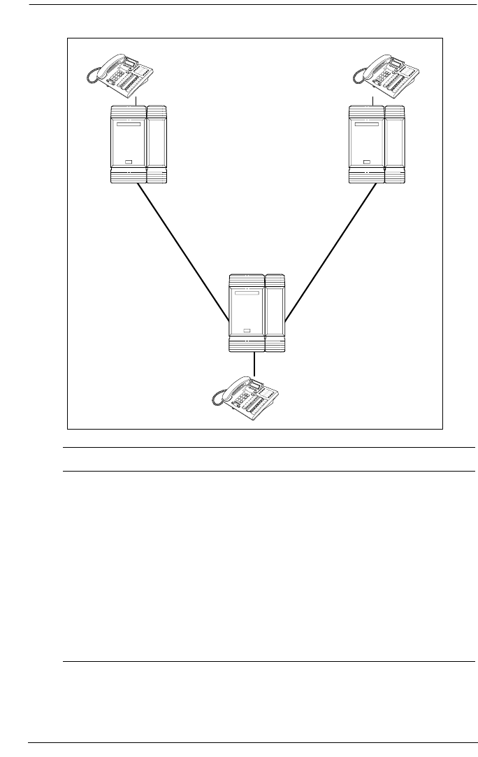
98 / Dialing plans
Modular ICS 6.0 Installer Guide P0992638 03
Routing by destination codes over E&M lines
Heading Parameter Setting
New York:
Trk/Line Data Line 049 E&M
Ans Mode Auto
Line type Pool H
Line 245 Target line
Rec’d # 2221
Line Access DN 2221 L245: Ring only
Line pool access Line pool H
New York
Network #: 2221
Red’d #: 2221
Internal #: 2221
Toronto
Network #: 6221
Red’d #: 6221
Internal #: 6221
Santa Clara
Network #: 4221
Red’d #: 4221
Internal #: 4221
Pool H
Pool B
Pool N
E&M trunk
E&M trunk
Pool M

Dialing plans / 99
P0992638 03 Modular ICS 6.0 Installer Guide
To Santa Clara:
Routing service Route 001
Use Pool H
DialOut None
DestCode 4
Normal rte 001
Absorb 0
To Toronto:
Routing service DestCode 6
Absorb 0
Normal rte 001
Santa Clara:
Trk/Line Data Line 050 E&M
Ans Mode Auto
Line type Pool M
Trk/Line Data Line 049 E&M
Ans Mode Auto
Line type Pool B
Line 250 Target line
Rec’d # 4221
Line Access DN 4221 L250: Ring only
Line pool access Line pool B
Line pool M
To New York:
Routing service Route 001
Use Pool M
DialOut None
DestCode 2
Absorb 0
Heading Parameter Setting

100 / Dialing plans
Modular ICS 6.0 Installer Guide P0992638 03
Normal rte 001
To Toronto:
Routing service Route 002
Use Pool B
DialOut None
DestCode 6
Absorb 0
Normal rte 002
Remote access Rem access pkgs 01
Line pool access Pool M: ON
Rem access pkgs 02
Line pool access Pool B: ON
Line abilities 049
Remote pkg 01
Line abilities 050
Remote pkg 02
Toronto:
Trk/Line Data Line 053 E&M
Ans Mode Auto
Line type Pool N
Line 260 Target line
Rec’d # 6221
Line Access DN 6221 L260: Ring only
Line pool access Line pool N
To New York:
Routing service Route 001
Use Pool N
DialOut None
DestCode 4
Heading Parameter Setting

Dialing plans / 101
P0992638 03 Modular ICS 6.0 Installer Guide
In the above example:
If a user in New York calls Toronto within the network, they
dial 6221. The local Norstar checks the number against the
routing tables and routes the call according to the destination
code 6, which places the call using Route 001.
There is no DialOut change to the number from New York, so
the call appears on the auto answer line on the Norstar in Santa
Clara as 6-221.
Because 6 is also a destination code on the Santa Clara system,
another call is placed using route 002 from Santa Clara. This
call arrives at the Toronto system, where the digits 6-221 are
interpreted as a target line received number. The call will now
alert at telephone 6221 in Toronto.
Absorb 0
Normal rte 001
To Santa Clara:
Routing service DestCode 2
Absorb 0
Normal rte 001
Heading Parameter Setting

102 / Dialing plans
Modular ICS 6.0 Installer Guide P0992638 03
Dialing plans with shared line pools
Using routes and destination codes is a powerful and efficient
way to create a transparent dialing plan. Line pools offer an
alternate method of creating a dialing plan or supplementing
the routing and destination codes. This is the type of dialing
plan you would create for tandem networking between two or
more Norstar systems.
If the Norstar systems are close to each other geographically,
you can conserve resources by not duplicating access. For
example, system A, B, and C are all within the same area code.
System A has a line pool to Santa Clara, System B has a line
pool to Montreal, and system C has a line pool to Miami.
A Norstar user in system A can reach Miami by calling system
C and using that line pool to Miami.
To simplify access between Norstar systems, all line pools that
go to the same destination should have the same line pool
access code. For example, system A and system B both have a
line pool to Ottawa. You can configure both systems with the
same line pool access code for the Ottawa line pool.
A dialing plan similar to the one in the following figure allows
you to create a company directory that uses line pool access
codes and unique DNs of a uniform length.
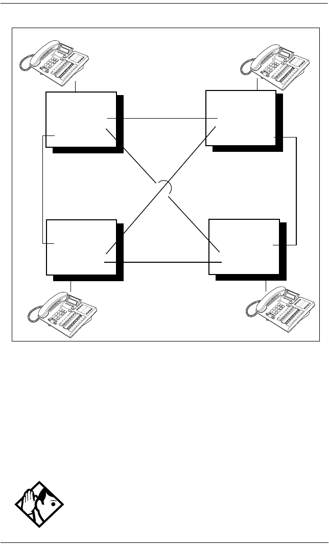
Dialing plans / 103
P0992638 03 Modular ICS 6.0 Installer Guide
Networking with shared line pools
For instance, the person on system A at telephone 234 can
press an Intercom button and dial 7434.
This means that telephone 234 has dialed the line pool access
code of the trunk to system C, and will receive the dial tone of
system C. The digits 434 then map to the Received number
434, and ring telephone 434 with an appearance of the
associated target line.
Tips - Network calls that use routes are subject to any
restriction filters that are in effect.
Network #: 5234
Rec’d #: 234
Internal #: 234
Network #: 6334
Rec’d #: 334
Internal #: 334
Network #: 8534
Rec’d #: 534
Internal #: 534
Network #: 7434
Rec’d #: 434
Internal #: 434
E&M trunk
E&M trunk
E&M trunk
E&M trunk
E&M trunk
E&M trunk
Norstar A Norstar B
Norstar D Norstar C
Pool A(6)
Pool B (7)
Pool C (8)
Pool A(5)
Pool B (8)
Pool C (7)
Pool A(5)
Pool B (6)
Pool C (7)
Pool A(6)
Pool B (5)
Pool C (8)

104 / Dialing plans
Modular ICS 6.0 Installer Guide P0992638 03
Call-by-Call Services Example
This example highlights the use of PRI Call-by-Call Services.
It shows two offices of a company. One office is in New York,
the other is in Toronto. Each office is equipped with a Norstar
system and a PRI line. Each office has to handle incoming and
outgoing calls to the public network. In addition, employees at
each office often have to call colleagues in the other office. To
reduce long-distance costs, and to allow for a coordinated
dialing plan between the offices, private (tie) lines are used to
handle inter-office traffic.
If the telephone used to make a network call has an
appearance of a line used by the route, the call will move from
the intercom button to the line button.
The telephone used to make a network call must have access
to the line pool used by the route.
Network calls are external calls, even though they are dialed
as if they were internal calls. Only the features and
capabilities available to external calls can be used.
When programming a button to dial a Network number
automatically (autodial), network calls must be treated as
external numbers, even though they resemble internal
telephone numbers (DNs).
Routes generally define the path between your Norstar switch
and another switch in your network, not other individual
telephones on that switch.
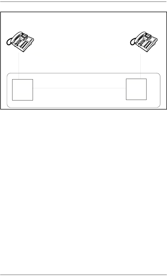
Dialing plans / 105
P0992638 03 Modular ICS 6.0 Installer Guide
Call-by-Call routing
If call-by-call services were not used, each Norstar system
might have to be equipped with the following trunks:
•12 DID lines needed to handle peak incoming call traffic.
•eight Tie (E&M) lines needed to handle inter-office calls.
•eight lines needed to handle outgoing public calls
The total required is 28 lines. If the Norstar systems were using
T1 trunks, then two T1 spans would be required at each office.
Note that the total of 28 lines represents the worst case value
for line usage. In reality, the total number of lines in use at any
one time will generally be less than 28. For example, during
periods of peak incoming call traffic, the demand for outgoing
lines will be low.
With PRI call-by-call services, it is not necessary to configure
a fixed allocation of trunks. Each of the 23 lines on the PRI can
be used for DID, Tie, or outgoing public calls. This
consolidation means that it may be possible for each office to
use a single PRI span, rather than two T1 spans.
Toronto Office New York Office
Network #: 2221
Rec'd #: 2221
Internal #: 2221
DID #: 763-2221
Network #: 6221
Rec'd #: 6221
Internal #: 6221
DID #:562-6221
Central
Office
Central
Office
PRI PRI
Public Network
Tie Connection
Toronto office New York office
Network #: 2221
Rec’d #: 2221
Internal #: 2221
DID #: 763-2221
Network #: 6221
Rec’d #: 6221
Internal #: 6221
DID #: 763-6221
PRI Tie connection PRI
Central
Office
Central
Office
Public network

106 / Dialing plans
Modular ICS 6.0 Installer Guide P0992638 03
With PRI call-by-call services, the only limitation is that there
are no more than 23 calls in progress at any one time.
The dialing plan at each Norstar site is configured to determine
the call type based on the digits dialed by the user. If a user in
Toronto wishes to dial a colleague in New York, they dial the
four-digit private DN (such as 6221). The dialing plan
recognizes this as a private network DN, and routes the call
using Tie service with a private numbering plan.
Incoming Tie calls are routed to sets based on the digits
received by the network, which in this case will be the four-
digit private DN.
If a user in either location wishes to dial an external number,
they dial 9, followed by the number (such as 9-555-1212). The
dialing plan recognizes this as a public DN, and routes the call
using Public service.
Incoming DID calls will be routed to sets based on the trailing
portion of the digits received by the network. For example, if
a public network user dials an employee in the Toronto office,
the network will deliver digits 4167632221. Norstar will route
the call using the last four digits, 2221.
Norstar Configuration
Heading Parameter Setting
Toronto:
Hardware Card 1 PRI
Protocol NI-2
Trk/Line Data Line 245 Target line
Rec’d # 2221
Line Access DN 2221 L245:Ring only
Line pool access Line pool PRI-A

Dialing plans / 107
P0992638 03 Modular ICS 6.0 Installer Guide
To New York:
Routing Service Route 001
DIalOut No numbr
Use Pool PRI-A
SrvcType Tie
ServiceID 1
DN type Private
DestCode 6
Normal rte 001
Absorb 0
To Public Network:
Routing Service Route 002
DialOut No numbr
Use Pool PRI-A
DN type Public
DestCode 9
Normal rte 002
Absorb ALL
New York:
Hardware Card 1 PRI
Protocol NI-2
Trk/Line Data Line 245 Target line
Rec’d # 6221
Line Access DN 6221 L245:Ring only
Line pool access Line pool PRI-A
To Toronto:
Routing Service Route 001
DialOut No numbr
Use Pool PRI-A
Heading Parameter Setting

108 / Dialing plans
Modular ICS 6.0 Installer Guide P0992638 03
PRI dialing plan example for two-way DID
The following list shows the steps involved in configuring a
dialing plan for two-way DID which uses a Public service. In
this example the user dials the prefix 8 to place a call over a
PRI line.
Note: Call-by-call is not needed to have two-way DID.
•in Hardware programming, configure the DTI card (PRI)
to use a Public protocol
•for incoming calls you need to program target lines to
match the DID digit that is being received on the PRI
interface
•set Dial Out to None
•select PRI-A as the line pool
SrvcType Tie
ServiceID 1
DN type Private
DestCode 2
Normal rte 001
Absorb 0
To Public Network:
Routing Service Route 002
DialOut No numbr
Use Pool PRI-A
DN type Public
DestCode 9
Normal rte 002
Absorb ALL
Heading Parameter Setting

Dialing plans / 109
P0992638 03 Modular ICS 6.0 Installer Guide
•set SrvcType to Public
•in Services programming access Routing Service to
enter a Destination Code (8 in this example)
•set the Absorb Length to All
•the telephone that you are dialing out from must have
access to the PRI Pool (programmed in Terminals/Sets)
•define rec’d digits for target lines
•define limits for incoming and outgoing public calls. Refer
to Programming Call by Call Limits on page 437
Static DID and two-way DID
When configuring static DID with two-way service, the
channels programmed as DID at the CO must be the lowest
B-channels on the PRI. On your Norstar system, the BchanSeq
mode must be set to descending. In this configuration, all
calls on the PRI must be Public service.
For example, channels 1 to 4 are configured as DID at the CO.
The CO uses ascending mode for B-channel selection, and the
ICS uses descending mode.

110 / Private networking using PRI SL-1
Modular ICS 6.0 Installer Guide P0992638 03
Private networking using PRI SL-1
You can use PRI SL-1 lines to tandem a number of Norstar
units into a private network. This creates a Private Network
Tandem Calling (PNTC) configuration. Refer to Private
Network Tandem calling on page 112.
You can also use PRI SL-1 lines to link one or more Norstar
systems to a Meridian 1 system, or to create a network that
includes one or more Business Communications Manager
systems. This creates an Advanced Private Network (APN)
where the MCDN protocol can be used to provide network
control features that allow network calls to be delivered and
transferred with optimum efficiency. If you also use a central
voice mail system or central Auto Attendant system, MCDN
provides system-wide Auto Attendant features and line
redirection. Refer to Advanced Private Networking on page
121.
SL-1 networking features
•common dialing plan using a Uniform Dialing Plan
(UDP), or a Coordinated Dialing Plan (CDP)
Note: If Norstar voice mail or Auto Attendant is used as
the centralized voice mail system, CDP must be used for
the network.
•PRI networks can be used for voice, data, and video calls
•no usage costs when placing remote calls over private
networks
Tip - For Modular ICS 6.0 you require both a PRI software
key and an MCDN software key to perform SL-1 networking.
All Norstar systems in the network also must be running
MICS 6.0 or MICS-XC 6.0 or greater software.

Private networking using PRI SL-1 / 111
P0992638 03 Modular ICS 6.0 Installer Guide
•caller information appears on both the caller telephone and
the called telephone, regardless of the number of
redirections
•PSTN lines connected to one of the nodes in a network can
provide local public service, at local rates, to all nodes in
the network, regardless of location
Features specific to Advanced Private Network
•centralized voice mail provides call waiting indications on
the receiving telephone
•centralized voice mail provides common messages, call-
forwarding and transfer options to all networks. If the you
are using the Meridian attendant system, the attendant
console on the Meridian system can use system-wide
parking (camp-on) and break-in features.
•if you have trunk route optimization (TRO) on, the system
optimizes call routing of redirected calls over the private
network
•the Meridian PBX can handle both UDP and CDP, thus
providing more flexibility and less reprogramming when
networking existing systems. The Norstar Voice mail
system requires a CDP dialing plan when it is being used
for central call handling.
•Trunk Anti-tromboning (TAT) provides network rerouting
that provides more efficient routing of calls to prevent
unnecessary tandeming and tromboning of trunks.
•ISDN Call Connection Limitation (ICCL) piggybacks on
the call initiation request and acts as a check at transit PBX
points to prevent misconfigured routes or calls with errors
from blocking channels.

112 / Private networking using PRI SL-1
Modular ICS 6.0 Installer Guide P0992638 03
•NCRI count allows a call to be forwarded in the network
up to five times before the system releases the call as
undelivered. However if TAT or TRO occur, the counter
gets reset, as well. This counter is hard-coded.
•Profile 2: ETSI private networks provide line redirection.
Private Network Tandem calling
Tandem networking is a chained network established between
two or more MICS systems. All the systems are connected via
PRI SL-1 lines.
In the network example shown below, nodes A, B, and E are
in one location, Nodes C, D, and F are in a second location.
The two systems are tied together between nodes A and C.
Nodes A and C are also connected to the local public network.
This configuration allows both local network users and remote
users on the public network to access the remote PSTNs
through the private lines, thus avoiding public call charges.
All nodes have unique three-digit private identification codes
as well as public network codes. Routes and destination tables
are configured on all systems to correctly route dialed numbers
to other nodes. DNs do not necessarily have to be unique, but
they must be the same length on all systems.
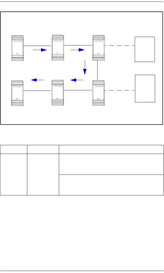
Private networking using PRI SL-1 / 113
P0992638 03 Modular ICS 6.0 Installer Guide
Tandem network
Calls originating from the public network
Received Destination Description
Node A Node A User in Calgary dials 761-xxxx number
Incoming interface: Public
DN type: Public
Node A receives the call and identifies it as
terminating locally. Uses target line to route call.
Destination: Local (target line)
Lines to public
network Public
Network
private trunk private trunk
Norstar Norstar
Public
Network
private trunk
Norstar
private trunk
Norstar
Lines to public
network
Norstar
private trunk
Calgary
Norstar
Ottawa
A
B
E
C
D
F
Calgary network
routes only area
codes 403 and
604
Public: 403-765-XXXX
Private ID: 395
Ottawa network
routes all area
codes except
403 and 604
Public: 403-762-XXXX
Private ID: 392
Public: 403-761-XXXX
Private ID: 391
Public: 613-766-XXXX
Private ID: 396
Public: 613-764-XXXX
Private ID: 394
Public: 613-763-XXXX
Private ID: 393

114 / Private networking using PRI SL-1
Modular ICS 6.0 Installer Guide P0992638 03
Node A Node B User in Calgary dials a 762-xxxx number
DN type: Public
Node A receives it and identifies it as being for
node B. Uses private trunk to route it to B.
Incoming interface: Public
Destination: Remote Node
Outgoing interface: Private
Node B receives the call and identifies it as
terminating locally. Uses target line to route call.
Incoming interface: Private
Destination: Local (target line)
Node A Node E User in Calgary dials a 765-xxxx number.
DN type: Public
Node A receives it and identifies it as being for B.
Uses private trunk to route call to B.
Incoming interface: Public
Destination: Remote node
Outgoing interface: Private
Node B receives it and identifies it as being for E.
Uses private trunk to route call to E.
Incoming interface: Private
Destination: Remote node
Outgoing interface: Private
Node E receives the call and identifies it as
terminating locally. Uses target line to route call.
Incoming interface: Private
Destination: Local (target line)
Received Destination Description

Private networking using PRI SL-1 / 115
P0992638 03 Modular ICS 6.0 Installer Guide
Node A Node C User in Calgary dials a 761-xxxx number which is
answered with DISA.
Incoming interface: Public
DN type: Public
Destination: Local (DISA DN)
User enters a COS password and a private DN
for Node C
i.e. 6 + 393-xxxx
DN type: Private
Node A receives it and identifies it as being for C.
Uses the private trunk to route the call to C.
Incoming interface: (DISA user)
Destination: Remote node
Node C receives the call and identifies it as
terminating locally. Uses target line to route call.
Incoming interface: Private
Destination: Local (target line)
Node A Node D User in Calgary dials a 761-xxxx number which is
answered with DISA.
Incoming interface: Public
DN type: Public
Destination: Local (DISA DN)
User enters a COS password and a private DN
for Node D, i.e. 6 + 394-xxxx
DN type: Private
Node A receives it and identifies it as being for C.
Uses the private trunk to route the call to C.
Incoming interface: (DISA user)
Destination: Remote node
Node C receives it and identifies it as being the
responsibility of D. Uses private trunk to route call
to D.
Incoming interface: Private
Destination: Remote node
Node D receives the call and identifies it as
terminating locally. Uses target line to route call.
Incoming interface: Private
Destination: Local (target line)
Received Destination Description

116 / Private networking using PRI SL-1
Modular ICS 6.0 Installer Guide P0992638 03
Calls originating in the private network
Node A Ottawa
PSTN
User in Calgary dials a 761-xxxx number which is
answered with DISA. User enters a COS
password and an Ottawa public network number.
Incoming interface: Public
DN type: Public
Destination: Local (DISA DN)
Node A receives it and identifies it as being for C.
Uses the private trunk to route the call to C.
Incoming interface: Local (DISA user)
Destination: Remote PSTN
Node C receives the call and identifies it as a
public number and routes it out over the local
PSTN.
Incoming interface: Private
Destination: Local PSTN
Received Destination Description
Node B Node B DN is internal, therefore no trunk routing is
required.
Incoming interface: Intercom
DN type: Local
Destination: Local
Node A Ottawa
PSTN
User in Node A dials the private network access
code for Node C, followed by an Ottawa public
number.
Incoming interface: Intercom
DN type: public
Destination: Remote PSTN
Node C receives the call and identifies it as being
for the public network. Node C routes the call over
the local public network.
Incoming interface: Private
DN type: Public
Destination: Local PSTN
Received Destination Description

Private networking using PRI SL-1 / 117
P0992638 03 Modular ICS 6.0 Installer Guide
Node B Calgary
PSTN
User on Node B dials a public DN.
Node B recognizes it as being the responsibility
of Node A and uses private trunk to route the call
to A.
Incoming interface: Intercom
Destination: Remote node
Node A receives the call and identifies it as being
for the public network. Node A routes the call over
the local public network.
Incoming interface: Private
Destination: Remote PSTN
Node B Node A User in Node B dials a private DN for a user on A.
DN type: Private
Node B recognizes it as being for Node A. Uses
the private trunk to route the call the call to A.
Incoming interface: Intercom
Destination: Remote node
Node B receives the call and identifies it as
terminating locally. Uses target line to route call.
Incoming interface: Private
Destination: Local (target line)
Node B Node C User on Node B dials a private DN for a user on
C.
DN type: Private
Node B recognizes it as being the responsibility
of Node A and routes the call over the private
trunk to A.
Incoming interface: Intercom
Destination: Remote node
Node A receives it and identifies it as being for C.
Uses IP trunk to route call to C.
Incoming interface: Private
Destination: Remote node
Node C receives the call and identifies it as
terminating locally. Uses target line to route call.
Incoming interface: Private
Destination: Local (target line)
Received Destination Description

118 / Private networking using PRI SL-1
Modular ICS 6.0 Installer Guide P0992638 03
Node B Node D User on B dials a private DN for node D.
DN type: Private
Node B identifies it as being for node A and uses
private trunk to route the call to A.
Incoming interface: Intercom
Destination: Remote node
Node A receives it and identifies it as being for C.
Uses IP trunk to route call to C.
Incoming interface: Private
Destination: Remote node
Node C receives it and identifies it as being for D.
Uses the private trunk to route call to D.
Incoming interface: Private
Destination: Remote node
Node D receives the call and identifies it as
terminating locally. Uses target line to route call.
Incoming interface: Private
Destination: Local (target line)
Node B Node F User on B dials a private DN for node F.
DN type: Private
Node B identifies it as being for node A and uses
private trunk to route the call to A.
Incoming interface: Intercom
Destination: Remote node
Node A receives it and identifies it as being for C.
Uses IP trunk to route call to C.
Incoming interface: Intercom
Destination: Remote node
Node C receives it and identifies it as being for D.
Uses the private trunk to route call to D.
Incoming interface: Intercom
Destination: Remote node
continued on next page
Received Destination Description

Private networking using PRI SL-1 / 119
P0992638 03 Modular ICS 6.0 Installer Guide
Routing for tandem networks
In tandem networks each node needs to know how to route
calls that do not terminate locally. To do this, you set up routes
for each connecting node by defining destination codes for
each route.
If the node is also connected to the public network, the usual
routing is required for that connection.
The following examples, show the routing tables for Node A
and Node C for externally-terminating calls.
Note: The PRI lines are enbloc lines, so all dialed digits are
collected before being dialed out.
Node A Destination Code Table, external termination
Node B to Node F
(continued)
Node D receives it and identifies it as being for F.
Uses the private trunk to route call to F.
Incoming interface: Intercom
Destination: Remote node
Node F receives the call and identifies it as
terminating locally. Uses target line to route call.
Incoming interface: Private
Destination: Local (target line)
Route Absorb length Destination code (public DNs)
4 (PSTN) 1 91604
3 (Node B) 091403762 (Node B)
3 (Node B) 091403765 (Node E)
4 (PSTN) 1 9140376* (not internal network)
4 (PSTN) 1 914037* (not internal network)
4 (PSTN) 1 91403* (not internal network)
4 (PSTN) 1 9* (not internal network)
* This wild card represents a digit between 1 and 9.
Received Destination Description
120 / Private networking using PRI SL-1
Modular ICS 6.0 Installer Guide P0992638 03
Node A Destination Code Table, internal termination
Node C Destination Code Table, external termination
Node C Destination Code Table, internal termination
Route Absorb length Destination code (private DNs)
3 (Node B) 0392 (Node B)
3 (Node B) 0395 (Node E)
5 (Node C) 0393 (Node C)
5 (Node C) 0394 (Node D)
5 (Node C) 0396 (Node F)
Route Absorb length Destination code (Public DNs)
3 (Node B) 0 91613764 (Node D)
3 (Node B) 0 91613766 (Node F)
4 (PSTN) 1 9161376* (not internal network)
4 (PSTN) 1 916137* (not internal network)
4 (PSTN) 1 91613* (not internal network)
4 (PSTN) 1 9161* (not internal network)
4 (PSTN) 1 916* (not internal network)
4 (PSTN) 1 91* (not internal network)
4 (PSTN) 1 9 (not internal network)
* This wild card represents a digit between 1 and 9.
Route Absorb length Destination code (Private DNs)
3 (Node D) 0394 (Node D)
3 (Node D) 0396 (Node F)
5 (Node A) 0391 (Node A)
5 (Node A) 0392 (Node B)
5 (Node A) 0395 (Node E)

Private networking using PRI SL-1 / 121
P0992638 03 Modular ICS 6.0 Installer Guide
Advanced Private Networking
There are two ways of setting up dialing plans for an
Advanced Private Network (APN).
•The first method uses routing tables to interconnected
systems. This type of network may use SL-1 lines, but it
does not use the MCDN protocol, even though the MCDN
keycode is require to allow the use of PRI SL-1 lines.
•The second method allows you to network among other
Norstar systems, Meridian systems, and Business
Communications Manager systems using SL-1 lines and
the MCDN protocol. This system uses the private dialing
plans in the same way as the Private Network Tandem
Calling network does. However, if you are using a Norstar
to support your central voice mail or call attendent, you
must use a CDP dialing plan. The MCDN protocol
provides additional features that support the central voice
mail/Auto Attendant as well as system call routing.
Networking using routing codes
If you have a simple private network, composed of one central
Meridian 1 and two smaller sites with Norstar systems, you
can use routing codes to direct calls. The following example
shows a Meridian 1, representing the head office, connected to
several smaller branch offices.
In this network, only the head office has trunks connected to
the public network. The branch offices access the public
network via the private connection to the head office. This
configuration allows for cost savings by consolidating the
public access trunks. Users at all three locations access the
public network by dialing 9, followed by the public number.
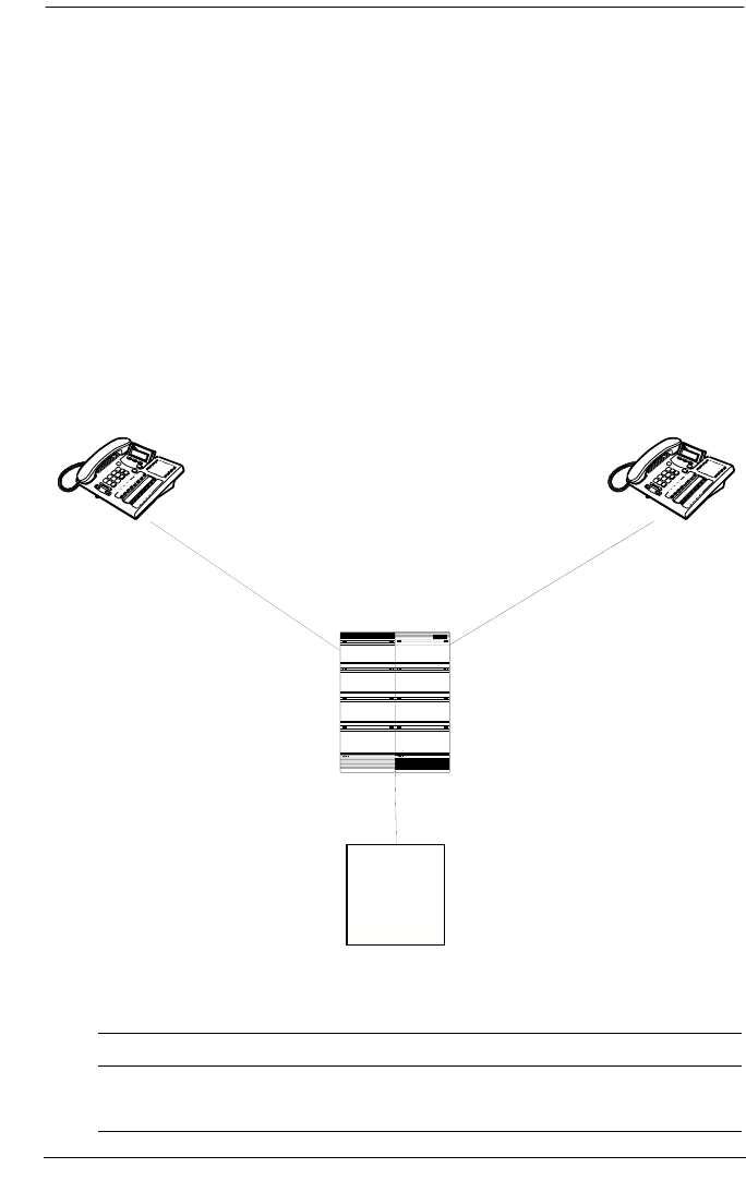
122 / Private networking using PRI SL-1
Modular ICS 6.0 Installer Guide P0992638 03
For example, a user in the west end branch might dial 9-555-
1212 (for a local call) or 9-1-613-555-1212 (for a long distance
call). These public calls are routed to the Meridian 1 by the
Norstar routing table. Routing tables at the Meridian 1 will
then select an appropriate public facility for the call.
Private network calls are made by dialing a four-digit private
network DN. For example, if a user in the west end branch
wishes to call a user in the east end branch within the private
network, they dial 6221.
Private networking using routing tables
Routing network settings
Heading Parameter Setting
West End:
Hardware Card 1 PRI
Meridian 1Meridian 1
West end
Branch East
-
end
Branch
Network #: 2221
Rec'd #: 2221
Internal #: 2221
Network #: 6221
Rec'd #: 6221
Internal #: 6221
Meridian M1
PRI (SL-1) PRI (SL-1)
DN: 4221
Central
Office
PRI (public protocol)
West-end branch East-end branch
Network #: 2221
Rec’d #: 2221
Internal #: 2221
Network #: 6221
Rec’d #: 6221
Internal #: 6221
PRI SL-1 PRI SL-1
Meridian M1
DN: 4221
PRI (public protocol)
Central
Office

Private networking using PRI SL-1 / 123
P0992638 03 Modular ICS 6.0 Installer Guide
Protocol SL-1
BchanSeq Ascend
ClockSrc Primary
Trk/Line Data Line 245 Target line
Rec’d # 2221
Line Access DN 2221 L245:Ring only
Line pool access Line pool PRI-A
To Head Office:
Routing Service Route 001
DialOut No numbr
Use Pool PRI-A
DN type Private
DestCode 4
Normal rte 001
Absorb 0
To East End:
Routing Service DestCode 6
Normal rte 001
Absorb 0
To Public Network:
Routing Service Route 002
DialOut No numbr
Use Pool PRI-A
DN type Public
DestCode 9
Normal rte 002
Absorb 0
East End:
Hardware Card 1 PRI
Protocol SL-1
BchanSeq Ascend
ClockSrc Primary
Trk/Line Data Line 245 Target line
Heading Parameter Setting

124 / Private networking using PRI SL-1
Modular ICS 6.0 Installer Guide P0992638 03
Additional Configuration
In this example, outgoing public network calls dialed from a
Norstar telephone are passed to the Meridian 1, and the
Meridian 1 is responsible for seizing a public trunk. For this
reason, the
9 prefix is left in the number passed to the Meridian 1.
This necessitates that the Public DN lengths table on each
Norstar be modified to account for the extra leading digit.
Rec’d # 6221
Line Access DN 6221 L245:Ring only
Line pool access Line pool PRI-A
To Head Office:
Routing Service Route 001
DialOut No numbr
Use Pool PRI-A
DN type Private
DestCode 4
Normal rte 001
Absorb 0
To West End:
Routing Service DestCode 2
Normal rte 001
Absorb 0
To Public Network:
Routing Service Route 002
DialOut No numbr
Use Pool PRI-A
DN type Public
DestCode 9
Normal rte 002
Absorb 0
Heading Parameter Setting

Private networking using PRI SL-1 / 125
P0992638 03 Modular ICS 6.0 Installer Guide
Essentially, the eight pre-configured entries are modified to
include a leading 9 in the prefix digits, and the length value for
each entry is increased by one.
The new entries are listed below.
Carrier codes:
If a system has a different long-distance service from the local
service, or if the long-distance service changes within the
schedules, the routing tables can be set up to include a carrier
code. You define the code under System Programming/
Access codes/Carrier codes. You then refer this to the
routing tables in Services/Routing Service/route/
Carrier codes where you define it as part of the destination
code, or part or all of the DialOut string when you set up a
routing service schedule.
Meridian M1 Configuration:
•Meridian M1 is the timing master for the private network
PRI connections.
•Meridian M1 uses descending mode for PRI B-channel
selection.
Prefix Length
Default 8
90 12
900 13
901 18
9011 19
91 12
9411 4
9911 4

126 / Private networking using PRI SL-1
Modular ICS 6.0 Installer Guide P0992638 03
•The Meridian M1 must recognize calls dialed to 2xxx and
6xxx numbers, and route the call over PRI to either the
East or West end offices. The same applies to incoming
DID calls from the public network.
•The Meridian M1 must recognize numbers starting with 9
as public numbers, whether the numbers are dialed by
Meridian M1 users or by Norstar users.
MCDN Private Networking
When you use MCDN on your private network, you gain the
advantages of being able to use a central voice mail/Auto
Attendant system to service the entire network, as well as
gaining advanced system network features, which keep
network traffic flowing along the most efficient paths.
MCDN networking uses PRI SL-1 lines and the MCDN
protocol firmware. You need keycodes for each of these
features.
To set up calling over an MCDN network, you define a dialing
plan that allows the user on any system to experience
consistent dialing strings for internal and external calls. For
this type of network, the DNs need to be the same length, but
they do not have to be unique to the entire network.
If your network is connected to a Meridian 1, and it is the
Meridian that you are using for centralized voice mail and
Auto Attendant, you can use either a UDP or CDP dialing
plan.
•If you use UDP, you dial a unique location code with the
local telephone DN range.
•In the case of CDP, the first digit of the DN range denotes
the node and is unique to each system.
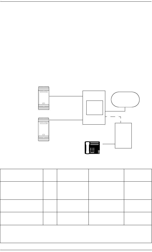
Private networking using PRI SL-1 / 127
P0992638 03 Modular ICS 6.0 Installer Guide
However, if you are using a Norstar voice mail/Auto
Attendant for your centralized voice mail, you must create the
calling protocols on the network using CDP. This is a private
dialing plan where the first digit of the extensions for each
system is unique to that system, and all DNs on all systems are
the same length.
Using a UDP dialing plan
To use UDP, the user dials this combination: ACn+LOC+DN
(private or public ACcess code, LOCation code, Directory
Number)
UDP call scenarios
Call scenario LOC Dialing String
Calling Party
Number
Called Party
Number
Calling to another
site within the
network
244 *6-668-2222 244-1111 668-2222
Calling within the
node
496 2229 1111 2229
Calling the public
network
244 **9-599-9999 613-763-1111
(OLI Public DN)
599-9999
LOC: This code defines the particular Norstar system.
* Private Access Code (within network)
**Public Access Code (out to PSTN)
PRI trunks set
to SL-1
Norstar
LOC 244
telephone DN: 1111
Public
Network
Meridian 1
Voice Mail/
Auto Attendant
Norstar
LOC 496
set DN: 2229
set DN: 2111
External set
set DN: 613-599-9999
A
B
C
PRI trunks set
to SL-1

128 / Private networking using PRI SL-1
Modular ICS 6.0 Installer Guide P0992638 03
UDP call routing
Heading Parameter Setting
A:
Hardware Card 1 PRI
Protocol SL-1
BchanSeq Ascend
ClockSrc Primary
Trk/Line Data Line 245 Target line
Rec’d # 1111
Line Access DN 1111 L245:Ring only
Line pool access Line pool PRI-A
Dialing Plan Private UDP
PrivNetID 1
Loc Code 244
Priv DN len 7
To C:
Routing Service Route 001
DialOut No numbr
Use Pool PRI-A
DN type Private
DestCode 4
Normal rte 001
Absorb 0
Access Codes PrivAccCode 4
To B:
Routing Service DestCode 6
Normal rte 001
Absorb 0
Access Codes PrivAccCode 6
To Public Network:
Routing Service Route 002
DialOut No numbr
Use Pool PRI-A

Private networking using PRI SL-1 / 129
P0992638 03 Modular ICS 6.0 Installer Guide
DN type Public
DestCode 9
Normal rte 002
Absorb 0
Access Codes PrivAccCode 9
B:
Hardware Card 1 PRI
Protocol SL-1
BchanSeq Ascend
ClockSrc Primary
Trk/Line Data Line 245 Target line
Rec’d # 2229
Line Access DN 2229 L245:Ring only
Line pool access Line pool PRI-A
Dialing Plan Private UDP
PrivNetID 2
Loc Code 496
Priv DN len 7
To C:
Routing Service Route 001
DialOut No numbr
Use Pool PRI-A
DN type Private
DestCode 4
Normal rte 001
Absorb 0
Access Codes PrivAccCode 4
To A:
Routing Service DestCode 2
Normal rte 001
Absorb 0
Access Codes PrivAccCode 2
Heading Parameter Setting
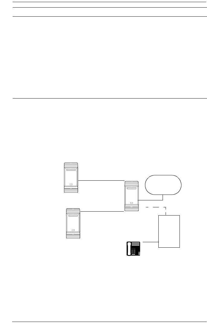
130 / Private networking using PRI SL-1
Modular ICS 6.0 Installer Guide P0992638 03
Using a CDP dialing plan
To use CDP, the user dials the internal DN for the target
telephone. Each node DN range starts with a unique digit.
To Public Network:
Routing Service Route 002
DialOut No numbr
Use Pool PRI-A
DN type Public
DestCode 9
Normal rte 002
Absorb 0
Access Codes PrivAccCode 9
Heading Parameter Setting
SL-1 trunk
Norstar
Steering code: 1
set DN: 1111
Public
Network
SL-1 trunks
Norstar
Voice Mail/
Auto Attendant
Norstar
Steering code: 2
set DN: 2229
set DN: 2111
External set
set DN: 613-599-9999
A
B
C

Private networking using PRI SL-1 / 131
P0992638 03 Modular ICS 6.0 Installer Guide
CDP call scenarios
CDP call routing
Call scenario Dialing String
Calling Party
Number
Called Party
Number
Calling to another site
within the network
2229 1111 2229
Calling within the node 2229 2111 2229
Calling the public network *9-599-9999 613-763-1111
(OLI Public DN)
599-9999
*Public Access Code (out to PSTN)
Heading Parameter Setting
A
Hardware Card 1 PRI
Protocol SL-1
BchanSeq Ascend
ClockSrc Primary
Trk/Line Data Line 245 Target line
Rec’d # 1111
Line Access DN 1111 L245:Ring only
Line pool access Line pool PRI-A
Dialing Plan Private CDP
PrivNetID 1
To C:
Routing Service Route 001
DialOut No numbr
Use Pool PRI-A
DN type Private
DestCode 4
Normal rte 001
Absorb 0

132 / Private networking using PRI SL-1
Modular ICS 6.0 Installer Guide P0992638 03
To B:
Routing Service DestCode 6
Normal rte 001
Absorb 0
To Public Network:
Routing Service Route 002
DialOut No numbr
Use Pool PRI-A
DN type Public
DestCode 9
Normal rte 002
Absorb 0
B:
Hardware Card 1 PRI
Protocol SL-1
BchanSeq Ascend
ClockSrc Primary
Trk/Line Data Line 245 Target line
Rec’d # 2229
Line Access DN 2229 L245:Ring only
Line pool access Line pool PRI-A
Dialing Plan Private CDP
PrivNetID 2
To C:
Routing Service Route 001
DialOut No numbr
Use Pool PRI-A
DN type Private
DestCode 4
Normal rte 001
Absorb 0
Heading Parameter Setting

Private networking using PRI SL-1 / 133
P0992638 03 Modular ICS 6.0 Installer Guide
MCDN trunk call features
The table below lists the MCDN features that are provided by
an SL-1 link with MCDN active (the keycode is installed). The
features affect call redirection and trunking functions, as
shown in the table below.
To A:
Routing Service DestCode 2
Normal rte 001
Absorb 0
To Public Network:
Routing Service Route 002
DialOut No numbr
Use Pool PRI-A
DN type Public
DestCode 9
Normal rte 002
Absorb 0
MCDN network features
Centralized
messaging
•network call redirection information
(NCRI)
Centralize
trunking
•ISDN call connection limitation (ICCL)
•trunk route optimization (TRO)
•trunk anti-tromboning (TAT)
Heading Parameter Setting
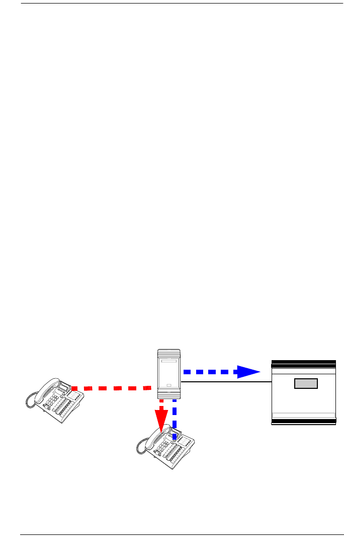
134 / Private networking using PRI SL-1
Modular ICS 6.0 Installer Guide P0992638 03
Network Call Redirection Information
NCRI builds on the following call features:
•External Call Forward
•Call Transfer
•Call Forward
NCRI adds the ability to redirect a call across an MCDN
network using Call Forward (all calls, no answer, busy) and
Call Transfer features. The call destination also receives the
necessary redirection information. This feature allows the
system to automatically redirect calls from within a Norstar
system to the Meridian Mail system, which resides outside the
Norstar system on a Meridian 1 or another Norstar.
The figure below shows an example of this situation, where
user A calls user B on the same Norstar system. If user B is
busy or not answering, the call automatically gets transferred
to a Meridian Mail number (user C) across an MCDN link
between the Norstar system and the Meridian 1 system (or
another Norstar system) where the mailboxes are set up.
Network call redirection path
Norstar
Meridian 1 with
Meridian Mail
SL-1 MCDN
Telephone A
Telephone B
Call forwarded to Meridian Mail
Original call

Private networking using PRI SL-1 / 135
P0992638 03 Modular ICS 6.0 Installer Guide
If you are using the centralized voice message system from a
Meridian 1 system, you require the following programming on
the M1:
M1 programming in LD 17
•NASA set to Yes
•NCRD set to Yes
Verifying NASA is Active
•Overlay 22, LD 22
•REQ: PRT
•TYPE: ADAN DCH (slot number)
•NASA should be set to yes
If NASA is
not on:
Disable the
D channel
•Overlay
96, LD
96
•REQ:
CHG
•TYPE:DIS
DCH
Disable the loop
•Overlay 60, LD 60
•REQ: CHG
•TYPE: DISL (slot
number)
Program the D channel
•Overlay 17, LD 17
•REQ: CHG
•TYPE: ADAN
•ADAN: CHG DCH (slot
number)
•Keep pressing enter
until you get to NASA
•TYPE: yes
•TYPE: end
Verifying NCRD
•Overlay 20, LD 20
•REQ: PRT
•TYPE: TIE
•CUST: 0
•Route: Enter the route
defined in LD 20
•Keep pressing enter
until all values are
displayed. Check if
NCRD is yes.
If NCRD is set to no
•Overlay 16, LD 16
•REQ: CHG
•TYPE: RDB
•CUST: 0
•ROUT: (route number) from LD 20
•Keep pressing enter until you get NCRD and
type Yes
•Keep pressing enter until you get the REQ
prompt again
•TYPE: end

136 / Private networking using PRI SL-1
Modular ICS 6.0 Installer Guide P0992638 03
ISDN Call Connection Limitation
The ICCL feature piggybacks on the call initiation request and
acts as a check at transit PBX points to prevent misconfigured
routes or calls with errors from blocking channels.
This feature adds a transit/tandem counter to a call setup
message. This counter is compared at each transit PBX with a
value programmed into the transit PBX, in a range from 0 to
31. If the call setup counter is higher than the PBX value, the
call will be blocked at the PBX and cleared back to the
network. This prevents calls from creating loops that tie up
lines.
Norstar configurations:
•Setting ICCL
1. With the display showing System prgming press
‘ until the display shows NetworkServices.
2. Press ≠ until MCDN displays.
3. Press ≠. NetwkICCL: displays.
4. Press CHANGE to choose either Y (yes) or N (no)
•Under Hardware, define Maximum transits for the card.
The diagram below demonstrates how a call might loop
through a network if the system is not set up with the ICCL
feature.

Private networking using PRI SL-1 / 137
P0992638 03 Modular ICS 6.0 Installer Guide
Call loop on system without ICCL
Meridian configurations:
The following settings are required on the Meridian system,
using LD15:
•REQ = CHG
•TYPE = CDB
•Net_DATA=Yes
•CUST=0
•ISDN=Yes
•RCNT(5)
•PSTN=No
•TNDM=0-31(15)
•PCMC=0-31(15)
•SATD=0-5(1)
•Number plan CDP, UDP, and access code configured
using LD 86, 87 and LD90
Norstar
Meridian 1
Telephone A
Norstar Meridian 1
Norstar

138 / Private networking using PRI SL-1
Modular ICS 6.0 Installer Guide P0992638 03
Trunk Route Optimization
TRO finds the most direct route through the network to send a
call between nodes. This function occurs during the initial
alerting phase of a call.
Business Communications Manager configurations:
•Under Network Settings, MCDN, set TRO to Y(yes).
•Configure call routing for all optimal routes.
•Configure Call Forward (All Calls, No Answer, Busy) or
Selective Line Redirection to use the optimal routes.
This feature avoids the following situation: A call originating
from a Norstar system may be networked to a Meridian
system, which, in turn, is networked to another Meridian
system, which is the destination for the call. If the call routes
through the first Meridian (M1) to reach the second Meridian
(M2), two trunks are required for the call. An optimal choice
is a straight connection to M2. TRO finds these connections
and overrides the less-efficient setup.
The following figure shows two call paths. The first route,
through the Meridian, demonstrates how a call might route if
TRO is not active. The second route, that bypasses the
Meridian, demonstrates how TRO selects the optimum routing
for a call.
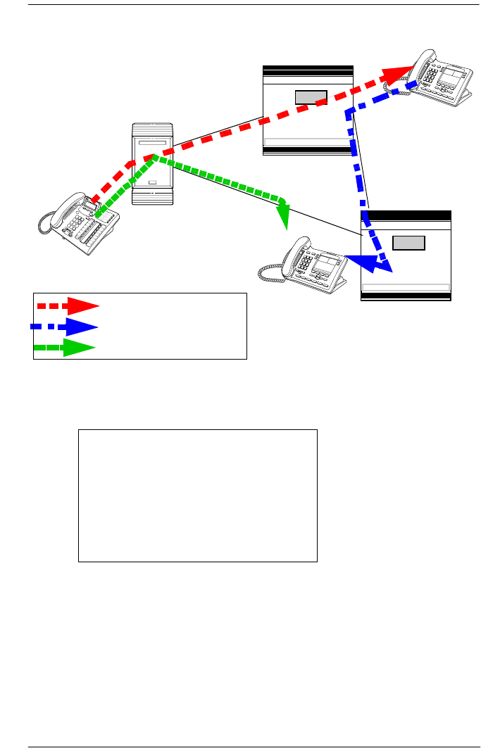
Private networking using PRI SL-1 / 139
P0992638 03 Modular ICS 6.0 Installer Guide
Call paths with and without TRO
If you are using a Meridian 1 system as part of the network,
you need the following programming for each system:
Norstar configuration:
1. With the display showing System prgming press
‘ until the display shows NetworkServices.
2. Press ≠ until MCDN displays.
3. Press ≠. NetwkICCL: displays.
4. Press ‘ until TRO:Y displays.
M1 TRO set to yes for Card1/Mod 1
Norstar route:
LD 16
TYPE: RDB
Cust: xx
Rout: 0-511
TRO: Yes
Norstar
Meridian 1
Telephone A
Telephone B
Telephone C
Forwarded call (no TRO)
Original call (no TRO)
Meridian 1
PRI SL-1
PRI SL-1
PRI SL-1
Call path with TRO

140 / Private networking using PRI SL-1
Modular ICS 6.0 Installer Guide P0992638 03
5. Press CHANGE to choose either Y (yes) or N (no).
Trunk Anti-tromboning
TAT is a call-reroute feature that works to find better routes
during a transfer of an active call. This feature acts to prevent
unnecessary tandeming and tromboning of trunks. This action
occurs after the speech path has been established.
Note: This feature is not applicable for alerting calls.
This feature does not activate if TRO is set to yes.
Norstar configuration:
1. With the display showing System prgming press
‘ until the display shows NetworkServices.
2. Press ≠ until MCDN displays.
3. Press ≠. NetwkICCL: displays.
4. Press ‘ until TAT displays.
5. Press CHANGE to choose either Y (yes) or N (no).
Meridian configuration
The following must be set on the Meridian 1 before this feature
can activate:
•MCDN PRI D-channel must have TAT set to yes (using
LD17 and TRMB in LD17)
•1.5 MB/2MB DTI/PRI card configured as PRI with
interface type of SL1
•NCRD parameter set to yes for the MCDN PRI routes
•Remote capabilities configured for the D-channel (using
LD 17) to include ND2
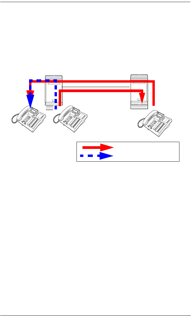
Private networking using PRI SL-1 / 141
P0992638 03 Modular ICS 6.0 Installer Guide
The diagram below shows how TAT reduces the line
requirements. The solid line shows Telephone A calling
Telephone B and being transferred over an additional PRI line
to Telephone C. With TAT active, the same call is transferred
to Telephone C over the same PRI line.
Call paths with and without TAT
MCDN voice mail/auto attendant call features
Besides the general MCDN features described in MCDN trunk
call features on page 133, an MCDN connection with a
Meridian 1 with attached voice mail system, also provides
some special call features, as described below.
Note: Although these features have the same functions as
Camp-on and Priority calls within each Norstar
system, MCDN camp-on and break-in from M1 can
access all network telephones connected to the
centralized voice mail system.
MCDN Meridian 1 attendant MCDN features
Meridian attendant features •camp-on
•break-in
Norstar
Telephone A
Telephone B
Telephone C
Forwarded call (using TAT)
Forwarded call (no TAT)
Norstar

142 / Private networking using PRI SL-1
Modular ICS 6.0 Installer Guide P0992638 03
To all Norstar systems on the private network, the
centralized voice mail system is viewed as an external
call by each system, even though the dialing plan
configurations makes it seem like callers are making
local calls.
Camp-on
A call received by the Meridian attendant can be assigned to a
telephone anywhere in the MCDN network, when the
following situations are valid:
•the target telephone rings busy when the attendant calls
•no free keys on target telephone
•DND regular feature is inactive
•DND on busy feature is inactive
The target user sees that there is a call camped on the
telephone. The called user can then clear a busy lines and take
the call, or the user can choose to reject the call, using F814,
or the user can indicate Do Not Disturb, using F85.
The diagram below demonstrates the call path for a Meridian
attendant to camp a call on a telephone in the Norstar system.
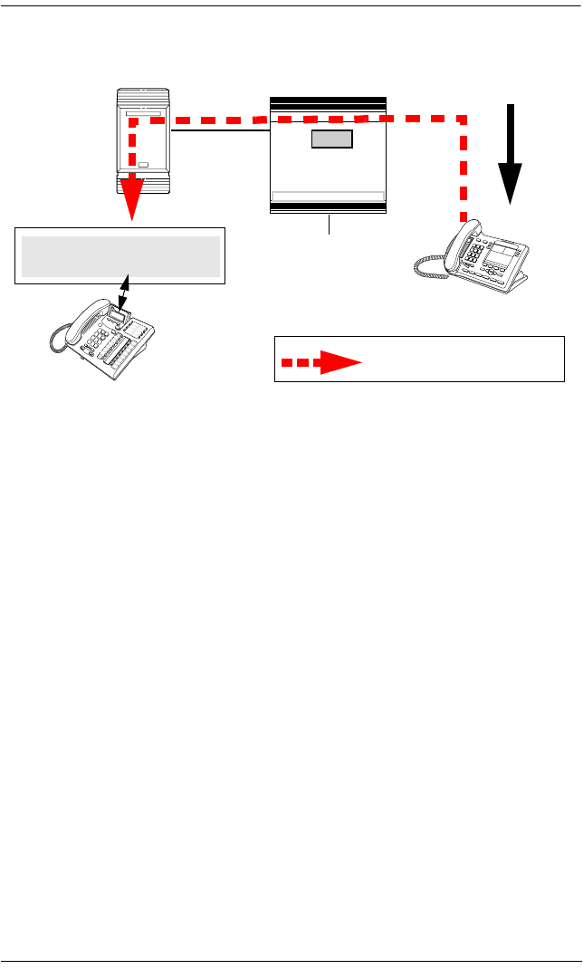
Private networking using PRI SL-1 / 143
P0992638 03 Modular ICS 6.0 Installer Guide
Camping a call on a network telephone
Break-in
The Meridian attendant can break into an on-going call from a
telephone in the Norstar system, if these situations are valid:
•Target Norstar telephone is busy but still has a free
intercom or line key.
•DND busy is turned on, although the attendant can
override a busy signal, if it is turned off, by pressing the
BKI key.
•Prime set also should be busy, with no free key, and with
DND turned on.
•Attendant capability is high (2), and higher than either the
target telephone or the caller the target telephone owner is
busy with.
A warning tone occurs for both parties on the call before the
actual break-in occurs.
Norstar
Meridian-based
central attendant
Telephone A
(rings busy)
Attendant
Call forwarded and camped on
Tel epho ne A
Line XXX Waiting
Incoming call
for Telephone A
Meridian 1
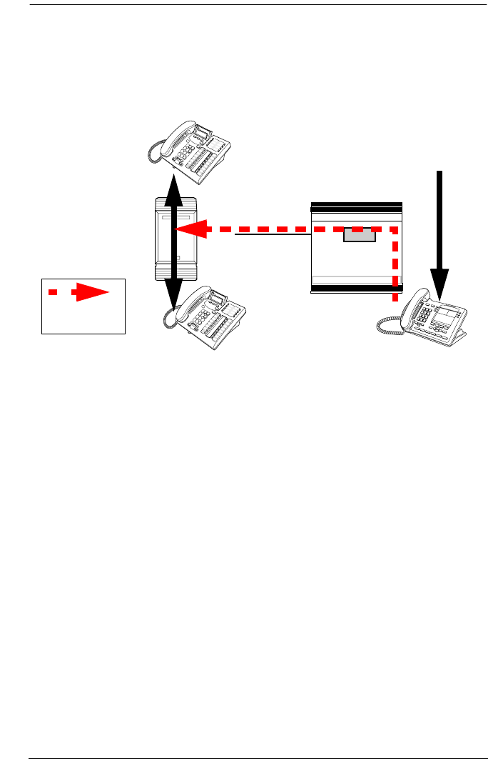
144 / Private networking using PRI SL-1
Modular ICS 6.0 Installer Guide P0992638 03
The diagram below demonstrates the call path for a Meridian
attendant to break into a call between telephones in the Norstar
system.
Breaking into a Norstar call path
Break-in can be accomplished using two methods:
•Pre-dial BKI:
1. Attendant presses BKI button on telephone.
2. Attendant dials the destination number.
3. On receiving a busy signal, the Attendant presses BKI
again.
The attendant is given access to the conversation.
•Post-dial BKI: Attendant:
1. Attendant dials destination number.
2. If a camp-on or busy tone is heard, the attendant presses
the BKI button on the telephone.
The attendant is given access to the conversation.
Norstar
Meridian 1
Telephone A
(rings busy)
Attendant
Incoming call
for Telephone A
Telephone B
Break-in path

Private networking using PRI SL-1 / 145
P0992638 03 Modular ICS 6.0 Installer Guide
You can set a level of priority that will determine if a telephone
will allow an attendant to break in. This is referred to as setting
the Intrusion level.
How the intrusion hierarchy works:
•Break-in allowed if Attendant telephone is High and caller
telephone is Medium.
•Break-in is not allowed if Attendant telephone is Medium
and caller telephone is high.
Set the Intrusion level for each telephone under Capabilities.
1. At Terminals&Sets, press ≠ and enter the DN
number for the telephone to which you want to add
intrusion levels.
The telephone displays <set number>:<set number> or
<name>.
2. Press ≠. The display shows Line Access.
3. Press ‘ until you reach Capabilities.
4. Press ≠. The display shows Fwd no answer.
5. Press ‘ until you reach Intrusion.
6. Press ≠. The display shows Protect lvl.
7. Press CHANGE to select None, Low, Med, or High.

146 / Private networking using PRI SL-1
Modular ICS 6.0 Installer Guide P0992638 03
Central voice mail and Auto Attendant with Norstar
You can use Norstar voice mail (NVM) and Auto Attendant
running on a Norstar Application module (NAM) platform as
the central voice mail/auto attendant node for your MCDN
network. However, this configuration does not allow
centralized camp-on or break-in, since these are Meridian-
voice-mail-based features.
Using NVM requires that all nodes on the network are set up
with the CDP dialing rules. You can have a maximum of 10
nodes on a Norstar-based network if you use all three DTI
cartridges.
Note: Ensure you have the latest version of NVM if you want
to set up this type of centralized system.
Configuring centralized voice mail
System configuration for centralized voice mail depends on
where the NAM is connected. The system with the NAM is
configured using the voicemail DN and a target line. The
systems that are remote to the NAM are configured through
the Telco features sections.
Installation instructions about installing Norstar voice mail as
a centralized voice mail system, are explained in the
addendum titled: Installing Norstar Voice Mail as a
Centralized Voice Mail System. This addendum includes
details about voice mail configuration as well as the Norstar
Modular ICS configuration that is included in the following
sections.

Private networking using PRI SL-1 / 147
P0992638 03 Modular ICS 6.0 Installer Guide
Local system
To set up the local system, you need to assign a target line to
the DN for the voice mail system, then enter that DN into the
target line record.
1. After you enter your password, at the Terminals&Sets
prompt, press ≠.
The prompt displays: Show set:
2. Enter the DN number for the voice mail system.
3. Press ≠. The prompt displays Line access.
4. Press ≠. The prompt displays Line assignment.
5. Enter the target line number for your voice mail system.
6. Press CHANGE to change the setting for each line to one of
the following: Unassigned, Ring only, Appr&Ring, and
Appr only.
7. Press – until you reach the top level, then press
‘. The prompt displays Lines.
8. Press ≠. The prompt displays Show line.
9. Enter the target line number you entered in step 5.
10. Press ≠. The prompt displays Trunk/line data.
11. Press ≠. The prompt displays Line Type.
12. Press ‘. The prompt displays Rec'd #.
13. Enter the DN for the voice mail system.
14. Exit programming.

148 / Private networking using PRI SL-1
Modular ICS 6.0 Installer Guide P0992638 03
Remote system
On the nodes that are not directly connected to the central
voice mail system, you need to use the Telco Features
headings to identify the route to the voice mail system.
1. After you enter your password, press ‘ until the
prompt displays Telco Features:
2. Press ≠. The prompt displays VMsg Center
tel#s.
3. Press ≠. The prompt displays VMsg Center 1.
4. Press ≠. The prompt displays Use:.
5. Press CHANGE to until you reach Routing tbl.
6. Press ‘. The prompt displays Tel #:.
7. Enter the number to access the external voice mail system.
Set Telco features for the VM DN
1. Press – until you reach the top level, then press
‘ until the prompt displays Terminals&Sets.
2. Press ≠. The prompt displays: Show set:
3. Enter the DN for the voice mail system.
4. Press ≠. The prompt displays Line access.
5. Press ‘ until the prompt displays Telco
features.
6. Press ≠. The prompt displays Feature Assign.
7. Press ≠. The prompt displays Show line.
8. Enter the line number that connects to the system for the
central voice mail system.
9. Press ≠. The prompt displays Caller ID Set.

Private networking using PRI SL-1 / 149
P0992638 03 Modular ICS 6.0 Installer Guide
10. Press ‘ until the prompt displays Extl VMsg
set.
11. Press CHANGE to select Y (yes).
Set Telco features for the target line
1. Press “ until you reach the top level, then press
‘ until the prompt displays Lines.
2. Press ≠. The prompt displays: Show line:
3. Enter the target line number for the voice mail system.
4. Press ≠. The prompt displays: Trunk/line
data:
5. Press ‘ until the prompt displays Telco
features.
6. Press ≠. The prompt displays VMsg Center 1.
7. Press ≠. The prompt displays Use:.
8. Press CHANGE to until you reach Routing tbl.
9. Press ‘. The prompt displays Tel #:.
10. Enter the number to access the external voice mail system.
11. Exit programming.
Using centralized voice mail
If you use NVM, ensure that you provide the correct user cards
for system access. Users with telephones connected to the
Meridian or Norstar unit on which NVM is installed, use
internal voice mail feature codes to use the system (F981, and
so on). Users on other nodes of the system, use the remote
access codes, which are similar to the codes they would use if
the central voice mail system was the Meridian-based system.

150 / Private networking using PRI SL-1
Modular ICS 6.0 Installer Guide P0992638 03
Note: Meridian mail and Norstar voice mail can co-exist on
the same Meridian, however, users can only be
configured for one of the systems.
Configuring Centralized Auto Attendant (CAA)
System configuration for centralized Auto Attendant depends
on where the NAM is connected. The system with the NAM is
configured using the CAA DN and a target line. The systems
that are remote to the NAM are configured through the Telco
features sections.
All nodes must have a unique Private Network Identifier
(PNI), which is defined under Dialing Plan. On each node, as
well, the PNIs of adjacent nodes are programmed under
Hardware.
Assigning PNIs
1. After you enter your password, press ‘ until the
prompt displays System Prgrming:
2. Press ≠. The prompt displays Hunt groups.
3. Press ‘ until the prompt displays Dialing Plan.
4. Press ≠. The prompt displays Private Network.
5. Press ≠. The prompt displays Type.
6. Press CHANGE to until you reach CDP.
7. Press ‘. The prompt displays PrivNetID.
8. Enter the private network ID for your system.

Private networking using PRI SL-1 / 151
P0992638 03 Modular ICS 6.0 Installer Guide
Assigning PNIs for adjacent nodes
1. After you enter your password, press ‘ until the
prompt displays Hardware:
2. Press ≠. The prompt displays Show module.
3. Enter the module where the PRI card you have configured
for SL-1 resides.
4. Press ≠. The prompt displays CdX-KSU.
5. Press ≠. The prompt displays Card type.
6. Press ‘. The prompt displays Lines.
7. Enter the line number you want to configure.
8. Press ≠. The prompt displays Protocol.
9. Ensure that this displays SL-1.
10. Press ‘. The prompt displays PrivNetID:.
11. Enter the PNI of the adjacent node.
12. Repeat these steps for all the modes that are directly
adjacent to your system.
Local system
To set up the local system, you need to assign a target line to
the DN for the voice mail system, then enter that DN into the
target line record.
1. After you enter your password, at the Terminals&Sets
prompt, press ≠.
The prompt displays: Show set:
2. Enter the DN number for the Auto Attendant.
3. Press ≠. The prompt displays Line access.

152 / Private networking using PRI SL-1
Modular ICS 6.0 Installer Guide P0992638 03
4. Press ≠. The prompt displays Line assignment.
5. Enter the target line number for the Auto Attendant
system.
6. Press CHANGE to change the setting for each line to one of
the following: Unassigned, Ring only, Appr&Ring, and
Appr only.
7. Press – until you reach the top level, then press
‘. The prompt displays Lines.
8. Press ≠. The prompt displays Show line.
9. Enter the target line number you entered in step 5.
10. Press ≠. The prompt displays. The prompt displays
Line Type.
11. Press ‘. The prompt displays Rec'd #.
12. Enter the DN for the Auto Attendant system.
13. Exit programming.
Remote system
On the nodes that are not directly connected to the central Auto
Attendant system, you need to use the Telco Features headings
to identify the route to the system.
1. After you enter your password, press ‘ until the
prompt displays Telco Features:
2. Press ≠. The prompt displays VMsg Center
tel#s.
3. Press ≠. The prompt displays VMsg Center 1.
4. Press ≠. The prompt displays Use:.
5. Press CHANGE to until you reach Routing tbl.

Private networking using PRI SL-1 / 153
P0992638 03 Modular ICS 6.0 Installer Guide
6. Press ‘. The prompt displays Tel #:.
7. Enter the number to access the external Auto Attendant
system.
Set Telco features for the CAA DN
1. Press – until you reach the top level, then press
‘ until the prompt displays Terminals&Sets.
2. Press ≠. The prompt displays: Show set:
3. Enter the DN for the Auto Attendant system.
4. Press ≠. The prompt displays Line access.
5. Press ‘ until the prompt displays Telco
features.
6. Press ≠. The prompt displays Feature Assign.
7. Press ≠. The prompt displays Show line.
8. Enter the line number that connects to the system for the
central voice mail system.
9. Press ≠. The prompt displays Caller ID Set.
10. Press ‘ until the prompt displays Extl VMsg
set.
11. Press CHANGE to select Y (yes).
Set Telco features for the target line
1. Press – until you reach the top level, then press
‘ until the prompt displays Lines.
2. Press ≠. The prompt displays: Show line:
3. Enter the target line number for the voice mail system.
4. Press ≠. The prompt displays: Trunk/line
data:

154 / Private networking using PRI SL-1
Modular ICS 6.0 Installer Guide P0992638 03
5. Press ‘ until the prompt displays Telco
features.
6. Press ≠. The prompt displays VMsg Center 1.
7. Press ≠. The prompt displays Use:.
8. Press CHANGE to until you reach Routing tbl.
9. Press ‘. The prompt displays Tel #:.
10. Enter the number to access the external Auto Attendant
system.
11. Exit programming.
Voice mail configuration
On the voice mail system, set the following parameters:
•Set Redirected DN to Yes.
•Under the F983 AA promopt, set ANS: Y for the voice
main DN assigned target line.
•Under F983 dial 77 and set External init as Y.
•From the CVM/CAA lines, use the default greeting table 1.
For detailed directions, refer to the addendum titled: Installing
Norstar Voice Mail as a Centralized Voice Mail System.

Customer Use / 155
P0992638 03 Modular ICS 6.0 Installer Guide
Customer Use
This section shows sample configurations for different types
of network access. Each example has four parts:
•A scenario explains the goal of the call and what is
required to achieve it.
•A diagram shows the network configuration that supports
the application.
•A list shows the Norstar hardware required to support the
configuration.
•Tables show the programming. Only those settings that are
important to network access are described.
Public network
The calls described in this section all originate from the public
network. Callers dial in using a public DN into the system.
Call one or more Norstar telephones
Ms. Nelson is a bank customer with a question for an
accountant. She dials the number that maps onto target line
203. All of the telephones ring in the accounting department.
Target line
203
Ms. Nelson
DID
Accountant
(225)
Accountant
(226)
Central Office
DID trunk
cartridges
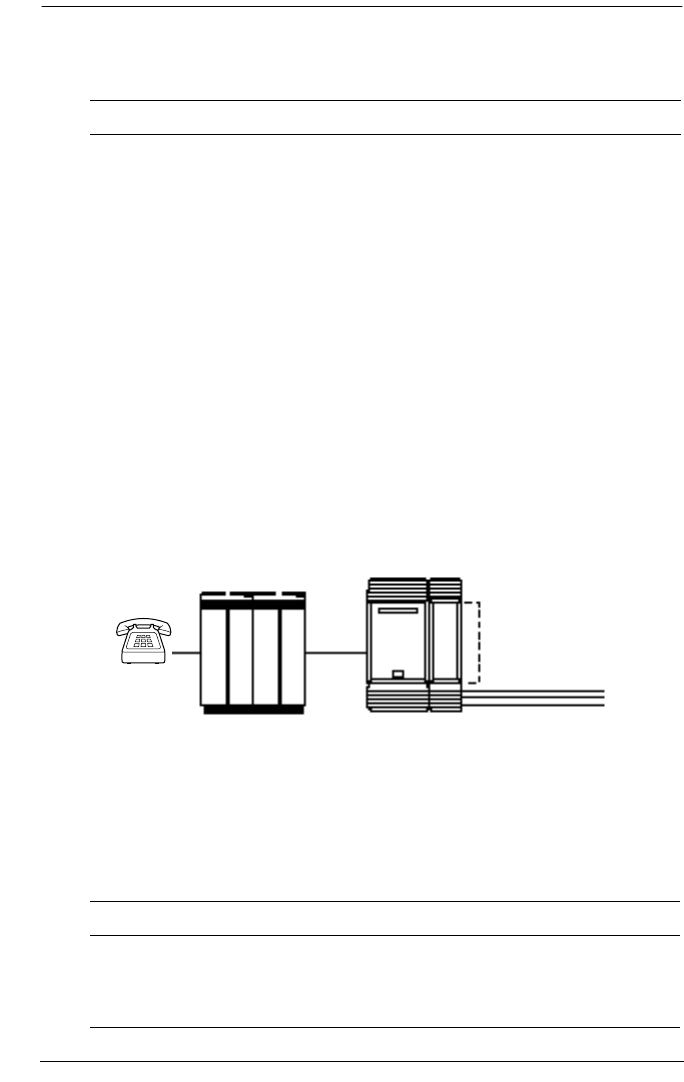
156 / Customer Use
Modular ICS 6.0 Installer Guide P0992638 03
Hardware: ICS, a Trunk Module with a DID Trunk Cartridge,
or a DTI with lines programmed as DID.
Call Norstar and select tie lines to a private network
A manager in Georgia wants to use the tie lines at headquarters
to call Washington. He dials a telephone number that maps
onto the DISA DN, enters a Class of Service (COS) password,
then dials a line pool access code to select a tie line to
Washington.
Using tie lines
Hardware: ICS, a Trunk Module with a DID Trunk Cartridge,
two E&M/DISA Trunk Cartridges for the three trunks in the
line pool to Washington, or a DTI with one DID line and three
E&M lines.
Heading Parameter Setting
Trk/Line Data Rec'd #
Line 051
4321 (for Line 203)
DID
Rec'd # length Rec'd # length four digits (can be from three to
seven digits, but must match
number of digits sent by central
office)
Heading Parameter Setting
Incoming trunk:
Trk/Line Data Line 049 DID
Access codes DISA DN 5321
Manager
(in Georgia)
Central Office Norstar
DID DID and E&M/DISA
trunk cartridges
E&M line pool
to Washington
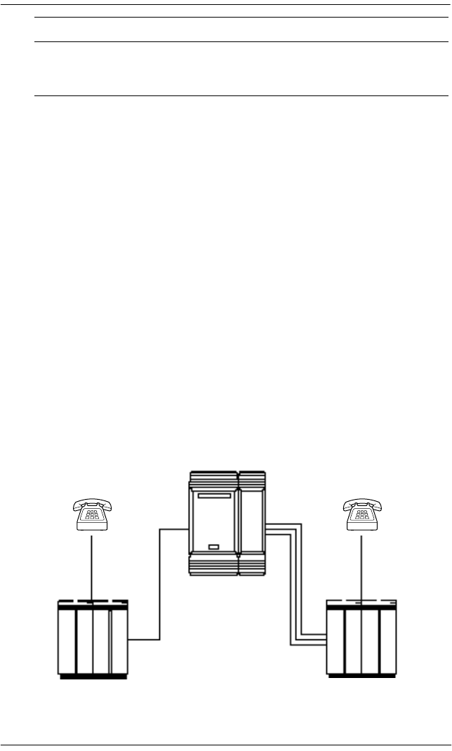
Customer Use / 157
P0992638 03 Modular ICS 6.0 Installer Guide
Call Norstar and select lines to the public network
Gord wants to make a long-distance business call from home.
To avoid being charged, he dials the telephone number that
maps onto the Auto DN at work. After hearing the dial tone,
Gord dials a line pool access code to select a line to the public
network. He then dials the long-distance number.
Using DID to dial long-distance
Rec'd # length Rec'd # length four digits (three to seven digits,
but must match number of digits
sent by central office)
Outgoing trunk:
Trk/Line Data Line 053
Line type
E&M
Pool F
Access codes Line pool F 6 (up to four digits)
COS pswds Define restrictions. Define remote
access pkgs. Assign a restriction
filter to the line. Assign COS
passwords and filters for each
Class of Service.
Heading Parameter Setting
Gord at home Business client
Central Office Central Office
Norstar
DID
line pool

158 / Customer Use
Modular ICS 6.0 Installer Guide P0992638 03
Hardware: ICS, a Trunk Module with a DID Trunk Cartridge
or DTI with several DID lines.
Heading Parameter Setting
Incoming trunk:
Trk/Line Data Line 049 DID
Access codes Auto DN 4321
Rec'd # length Rec'd # length four digits
(can be from three to seven
digits, but must match number of
digits sent by central office)
Lines /Restrictions
and Remote
access
Define restriction filters. Define
remote access packages. Assign
a remote restriction and remote
package to the line.
Outgoing trunk:
Trk/Line Data Line 001
Line type
Loop
Pool A
Access codes Line pool A 1234
Lines /Restrictions Assign a restriction filter to the
line.
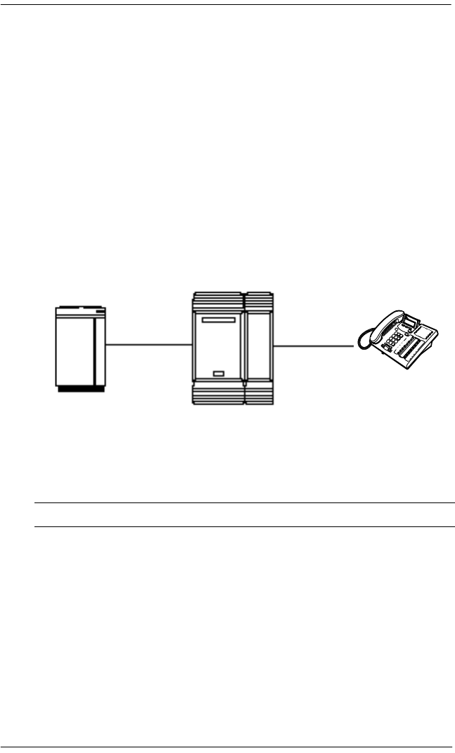
Customer Use / 159
P0992638 03 Modular ICS 6.0 Installer Guide
Private network
All the calls described in this section originate from within the
networked system.
Call one or more Norstar telephones
The production supervisor in Houston selects the less-
expensive company Tie line to call the manager at the
Administration office in Dallas. Once the line is selected, the
production supervisor dials the digits that will map onto the
target line of the manager in Dallas.
Calling from a Norstar to a remote PBX
Hardware: ICS, a Trunk Module with an E&M/DISA Trunk
Cartridge or a DTI with an E&M line.
Heading Parameter Setting
Incoming trunk:
Trk/Line Data Rec'd #
Line 049
Ans Mode
4321(for target line 243)
E&M
Auto
Rec'd # length Rec'd # length four digits (can be from three to
seven digits, but must match number
sent by central office)
PBX in
Houston
Manager
in Dallas
Norstar
E&M target line
243
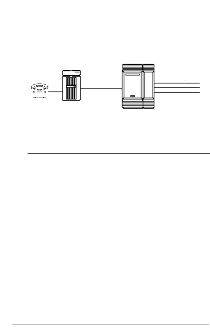
160 / Customer Use
Modular ICS 6.0 Installer Guide P0992638 03
Use tie lines to other nodes in the private network
At a branch office, Joan selects a tie line to the main office.
After hearing the dial tone, she dials a line pool access code to
select another tie line to a branch office in the next state.
Calling within the network through Tie lines
Hardware: ICS, a Trunk Module with two E&M/DISA Trunk
Cartridges, for the three lines in the line pool and the one
incoming line, or a DTI with four E&M lines.
Heading Parameter Setting
Incoming trunk:
Trk/Line Data Line 049
Ans mode
E&M
Auto
Under Lines /
Restrictions /
Remote access
Define restriction filters. Define remote
access packages. Assign a remote
restriction and remote package to the
trunk.
Outgoing trunk:
Trk/Line Data Line 050
Line type
E&M
Pool D
Access codes Line pool D 71 (can be from one to four digits)
Lines /
Restrictions
Assign a restriction filter to the trunk.
Joan at
branch office
key system
Norstar
E&M E&M line pool
to next state
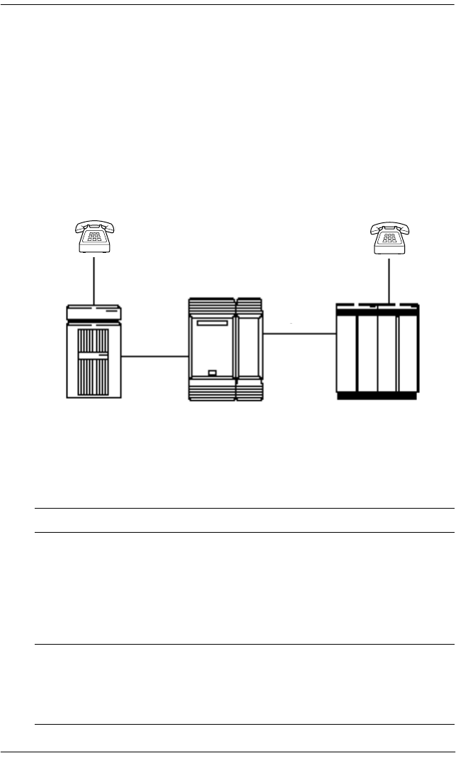
Customer Use / 161
P0992638 03 Modular ICS 6.0 Installer Guide
Select lines to the public network
Liz in Memphis, needs to call long-distance to a client in New
York. She selects a tie-line to the branch office in New York.
After hearing the dial tone, she dials a line pool access code to
select a line to the public network. Then, she dials the external
number as a local call.
Using a Tie line and line pool to call remote PSTN
Hardware: ICS, a Trunk Module with an E&M/DISA Trunk
Cartridge or DTI with an E&M line.
Heading Parameter Setting
Incoming trunk:
Trk/Line Data
Line 049
Ans mode
E&M
Auto
Under Lines /
Restrictions and
Remote access
Define restriction filters and remote
access packages. Assign a remote
restriction and remote package to the
trunk.
Outgoing trunk:
Trk/Line Data Line 001
Line type
Loop
Pool B
Access codes Line pool B 73 (can be one to four digits)
client in New YorkLiz in Memphis
New York
Liz in Memphis
key system Norstar Central Office
New York
E&M
Loop start
client in New York

162 / Customer Use
Modular ICS 6.0 Installer Guide P0992638 03
Select E&M trunks to the private network
For a confidential call, the Montana sales manager presses the
line button for a private E&M trunk to the Oregon office. This
automatically alerts at the line appearance on the telephone of
the Oregon sales manager.
Using private E&M trunks for remote calls
Hardware: (for both systems) ICS, a Trunk Module with an
E&M/DISA Trunk Cartridge or a DTI with an E&M line.
Lines /
Restrictions
Assign a restriction filter to the line.
Heading Parameter Setting
Montana:
Outgoing trunk:
Trunk Data
(Line 049)
Line Data
(Line 049)
Line
Line type
E&M
Private to 372
Heading Parameter Setting
Montana
sales manager
(372)
Oregon
sales manager
(641)
Norstar Norstar
E&M
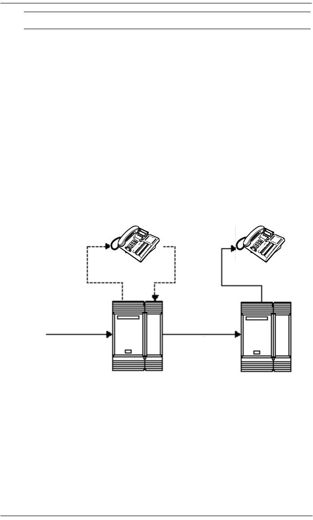
Customer Use / 163
P0992638 03 Modular ICS 6.0 Installer Guide
Norstar Line Redirection feature
The branch office is receiving more calls than it can handle, so
it redirects one of its lines to the main office. All calls that
come in on target line 232 will be routed out on line 003 to the
main office. Whenever a call is redirected, the target line and
outgoing line will be busy for the duration of the call.
Line redirection routes
Hardware: ICS, an E&M/DISA Trunk Cartridge if the
incoming trunk is E&M or a DID Trunk Cartridge if the
incoming trunk is DID, or a DTI with one E&M line or one
DID line.
Oregon:
Incoming trunk:
Trunk Data
(Line 057)
Line
Ans mode
Line type
E&M
Manual
Private to 641
Heading Parameter Setting
target line
232 Branch office Main office
Norstar Norstar
line 3
incoming call redirected
call

164 / Customer Use
Modular ICS 6.0 Installer Guide P0992638 03
Tips - Any line appearance on a telephone can be selected
as the incoming line to be redirected. Restriction filter
restrictions on the line are checked against the filter in effect
at the time a call is redirected not when redirection is
programmed.
A target line cannot be selected as the outgoing line for
redirection.
The incoming trunk must have disconnect supervision.
Heading Parameter Setting
Incoming trunk:
Trk/Line Data
Line 001:
Trunk mode:
Ans mode:
OR
Line 049:
OR
Line 053:
Ans mode:
Rec'd #:
(for target line 232)
Loop
Super
Auto
DID
E&M
Auto
4321
Rec'd # length Rec'd # length: four digits (can be from
three to seven digits, but
must match number of
digits sent by central
office)
Outgoing trunk:
Trk/Line Data
Line 003:
OR
Line 054:
Loop
E&M
Capabilities Allow redirect: Y

ETSI MCDN and network features / 165
P0992638 03 Modular ICS 6.0 Installer Guide
ETSI MCDN and network features
If your system is running Profile 2, and you are using ETSI
PRI lines with SL-1 MCDN protocol to network your systems,
your network has access to all the MCDN features described
in the preceding sections. MCDN features are set up under
Network Features, MCDN.
In addition, ETSI lines can provide the following CO network
features. Availability of these features is first determined by
your service provider, and secondly by turning on the features
under Network Features, ETSI.
Network Call Diversion
Norstar Network Call Diversion (NCD) is a network function
that allows forwarding and redirection of calls outside the
Norstar network when using an ETSI ISDN line. Functionality
is similar to that of External Call Forward (ECF).
NCD redirects calls using the same line on which they arrive.
Call forward is efficient since there is no need for additional
outside lines.
Forwarding calls externally from an extension requires the
user to enter either a Destination Code or Line Pool Access
Code, and the number to which calls will be forwarded.
Examples of NCD include:
•redirecting all calls from an extension to a mobile phone
•forwarding calls to an external destination (rather than to
voicemail), when an extension is busy or the user is
unavailable.

166 / ETSI MCDN and network features
Modular ICS 6.0 Installer Guide P0992638 03
Allowing NCD
To use NCD, you must turn the feature on in Network
Services.
1. Press ‘ until the display reads System
prgrming.
2. Press ≠. The display shows Hunt groups.
3. Press ‘ until the display shows Network
Services.
4. Press ≠. The display shows Netwrk
Redirection: N.
5. Press CHANGE and set to yes.
Feature description
NCD is available only over ETSI ISDN lines. It can be
invoked when calls are presented to Norstar/BST extensions
over ISDN lines. The user must program the selected
extension. Refer to External call forwarding on page 44
NCD is integrated with the following existing Norstar Call
Forward features:
•Call Forward Unconditional (CFU)—implemented on
Norstar Call Forward All Calls (CFAC) , and
Selective Line Redirection (SLR) , also
referred to as Line Redirection. This is programmable by
the user.
•Call Forward on Busy (CFB)—implemented on Norstar
Call Forward Busy.
•Call Forward on No Response (CFNR)—implemented on
Norstar Call Forward No Answer.

ETSI MCDN and network features / 167
P0992638 03 Modular ICS 6.0 Installer Guide
For example:
•When a call comes in on ETSI ISDN and is returned to a
destination being serviced by ETSI ISDN, BTNR 191,
Analogue or DASS2 lines, then ETSI Call Forward (CFU,
CFB or CFNR) is used.
•When a call comes in on ETSI ISDN and is returned to a
private network destination over DPNSS, then External
Call Forward (ECF) is used.
•When a call comes in on DPNSS 1 and is returned on any
line type except DPNSS 1, ECF is used. If that call is
returned over DPNSS, however, then DPNSS 1 Diversion
(DIV) is used. Refer to Network Call Diversion on page
165
•When a call comes in on any other line type, such as
AC15A, then again ECF is used. Note that under certain
line conditions, ECF will not work; refer to Line
Redirection restrictions.
Note: In all cases, if NCD fails due to network errors or
rejections, Norstar invokes ECF. If an outgoing line is
unavailable, Norstar routes the call to the line’s prime
extension.
Programming and restrictions
NCD features are accessed through existing Norstar features.
Extensions requiring redirection must be programmed
individually to either CFAC or SLR. CFB or CFNA must be
set during programming. Allow redirect must be set to Yes
for each extension, in Terminals&Extns/Capabilities.
Note: Any other programming applied to specific lines and
extensions take precedence, for example
Restrictions(extns) under Terminals&Extns.

168 / ETSI MCDN and network features
Modular ICS 6.0 Installer Guide P0992638 03
NCD is used as long as the affected lines are ETSI ISDN, and
the affected DIA lines are accessible via ISDN lines. Incoming
calls are diverted back to the ISDN. If NCD fails due to
network errors, ECF is invoked. If ECF cannot be executed,
the incoming call is routed to the line’s prime extension.
An extension with CFB, CFNA and CFAC programmed will
give priority to CFAC for diversion.
Selective Line Redirection
Selective Line Redirection (SLR), also referred to as Line
Redirection, is enhanced for use with digital lines and operates
in conjunction with NCD.
Diversion by SLR takes precedence over diversion by CFAC.
An SLR line cannot be diverted by CFAC. If the call arrives
on an extension with SLR programmed, a ring splash will
sound (if programmed).
For information on SLR restrictions refer to Selective Line
Redirection on page 168. For information on redirecting lines
see Line Redirection in the Modular Plus System
Administration Guide.
ATTENTION!
If a line is configured to appear on several
extensions with redirection programmed,
predicting which extension will divert the call is not
possible. This should be considered during system
configuration.

ETSI MCDN and network features / 169
P0992638 03 Modular ICS 6.0 Installer Guide
Programming Extensions
The User Interface for programming NCD is the same as for
ECF.
Different types of Call Forward are available depending on the
extension being programmed. Programming an extension to
forward calls externally requires the user to enter a destination
code or line pool number, in addition to the external phone
number. Therefore, care should be taken to identify your
network line types and record the available codes and line
pools.
Enhanced Caller ID
When a Norstar/BST extension which has Call Line Identifier
(CLID) active receives a redirected call due to NCD, the user
will see the DN for the Calling Number. This is followed by a
“>” and the redirecting number. This is displayed for as long
as the call is active (alerting or answered) at that telephone.
If the alerting extension is not the CLID extension for that line,
the line appearance can be pressed to briefly display the
information. Pressing or INFO while the call is
active invokes Call Info. Call Info on DPNSS displays the
redirecting number and the reason for the redirection.
Note: When Norstar requests that an incoming call be
redirected by the distance network, Norstar does not
inform the network of the redirecting DN. In this case,
the diverted-to party will not see the diverting party
DN.

170 / ETSI MCDN and network features
Modular ICS 6.0 Installer Guide P0992638 03
Malicious caller identification (MCID)
The MCID feature allows you to use to have
call information recorded on the central office system for an
incoming call on a specific line (EUROISDN lines, only).
The user must invoke the feature code without hanging up, and
within 30 seconds (time varies on different networks) after the
caller hangs up.
Note: This feature must be allowed in network programming
to work. Check with your system administrator.
The following information registers on the network:
•called party number
•calling party number
•local time and date of the invocation in the network serving
the called user
•service provider option: calling party subaddress, if
provided by calling user)
Programming MCID capability
To allow MCID functionality on your system, you must turn
the feature on in Network Services.
1. Press ‘ until the display reads System
prgrming.
2. Press ≠. The display shows Hunt groups.
3. Press ‘ until the display shows Network
Services.
4. Press ≠. The display shows ETSI.

ETSI MCDN and network features / 171
P0992638 03 Modular ICS 6.0 Installer Guide
5. Press ≠. The display shows Netwrk
Redirection: N.
6. Press ‘. The display shows MCID: N.
7. Press CHANGE and set MCID to yes.

172 / ETSI MCDN and network features
Modular ICS 6.0 Installer Guide P0992638 03

P0992638 03 Modular ICS 6.0 Installer Guide
Data Solutions
Examples of ISDN Scenarios
For information on various ISDN scenarios that may help you
to decide on the data solution that is best for you, refer to the
following web site: http://www.nortelnetworks.com/
support and perform a Search for TIPS. You will need your
user name and access code.
If you do not have a user name and access code, the site
provides information about how to get access to this site.
ISDN applications
ISDN terminal equipment delivers a wide range of powerful
business applications:
Video conferencing and video telephony
Video conferencing offers instant visual and audio contact
between distant parties using either studio-based or desktop
ISDN terminals.
Desktop conferencing
ISDN allows computer users in distant locations to share and
edit any image, data or text file on their own computer screens
while they discuss the information.

174 / Data Solutions
Modular ICS 6.0 Installer Guide P0992638 03
File transfer
The ISDN network allows you to transfer files containing data,
text, images, data, or audio clips, faster and cheaper than with
a conventional modem.
Telecommuting
Convenient retrieval, processing and storage of files is
possible for the employee working at home by using ISDN
lines to give high-speed access to information resources at the
office.
Group 4 fax
ISDN fax applications save money by increasing both
transmission speed and the quality of resolution.
Remote LAN access
ISDN provides an affordable and fast means for employees at
remote sites, such as at home or in branch offices, to access
local area networks (LANs).
Leased line backup
Essential backup for leased lines can be provided using ISDN,
as required, rather than duplicating costly permanent leased
lines.

Data Solutions / 175
P0992638 03 Modular ICS 6.0 Installer Guide
LAN to LAN bridging
Local area network (LAN) bridge/routers allow flexible
interconnection between LANs using ISDN, with charges only
incurred when information is actually transmitted.
Internet and database access
The fast call set up and high bandwidth of ISDN are ideal for
accessing information services such as the Internet and
databases.

176 / Data Solutions
Modular ICS 6.0 Installer Guide P0992638 03

P0992638 03 Modular ICS 6.0 Installer Guide
Planning the installation
Only qualified persons should service the system.
The installation and service of this unit is to be
performed only by service personnel having
appropriate training and experience. It is critical that
installers have the necessary awareness about
hazards to which they are exposed in performing a
task, and of the measures required to minimize the
danger to themselves or other persons.
Electrical shock hazards from the telecommunication
network and AC mains are possible with this
equipment. To minimize risk to service personnel and
users, the ICS must be connected to an outlet with a
third-wire ground. In addition, all unused slots should
have filler faceplates installed and the doors should be
in place at the completion of any servicing.
Service personnel must be alert to the possibility of high
leakage currents becoming available on metal system
surfaces during power line fault events near network
lines. A risk point on the ICS is the power cord earth
ground pin. These leakage currents normally safely
flow to Protective Earth ground via the power cord.
Therefore, it is mandatory that connection to a
grounded outlet is performed first and removed last
when cabling the unit. Specifically, operations requiring
the unit to be powered down must have the network
connections (central office lines) removed first.

178 / Planning the installation
Modular ICS 6.0 Installer Guide P0992638 03
Planning checklist
The following section provides a check list for the set up
processes for the MICS system.
Hardware
åVerify that you have all the equipment and supplies you
need to install the system. See Required equipment on
page 179.
åDetermine the location for the Integrated Communication
System (ICS) and any expansion modules, telephones and
other equipment.
åInstall the ICS equipment. Refer to Installation on page
209.
Initial configuration
Turn on the equipment, and do the following procedures
within 10 minutes. If you change the defaults, note the changes
in the Programming record.
åUse the Profile code to access the profile interface if you
require a profile that is different from the one used for
North American systems. Refer to Profile programming
on page 296.
åUse the Dialpad code to access the dialpad interface if your
system uses the CCITT dialpad. Refer to Dialpad
programming on page 300.
åUse the Startup code to access the template settings. If
your system requires non-default template. Refer to
Performing Startup on page 301.

Planning the installation / 179
P0992638 03 Modular ICS 6.0 Installer Guide
System configuration
åPlan and record system programming details in the
Programming Record.
åUse the System Administrator password to make any
changes to the system defaults. Enter any information
required for your system lines and telephones.
Required equipment
åIntegrated Communication System (ICS)
åModular ICS ROM software cartridge
åModular ICS NVRAM cartridge
åTrunk Cartridge(s) for the ICS
åServices Cartridge — one required for T1, PRI or BRI, two
required for busy sites
or a Combination Fiber 6-port Services Cartridge, which
provides the same Services Cartridge functionality
åDigital Trunk Interface (DTI) configured for PRI
åBRI card(s) for the ICS, as required
åemergency telephones — two for ICS, one for each trunk
module, as required
åBusiness Series Terminals or Norstar telephones
åISDN devices, for example, ISDN equipment or data
devices, as required
ådistribution panel(s)

180 / Planning the installation
Modular ICS 6.0 Installer Guide P0992638 03
Expansion equipment
åExpansion Cartridge — two-port or six-port
åCombination Fiber 6-port Services Cartridge
åTrunk Module(s) (TM)
åStation Module(s) (SM)
åTrunk Cartridge(s) for the TM
åpower bar
The basic Integrated Communication System (ICS) supports
up to 32 telephones. With the addition of Trunk Cartridges,
you can connect up to 48 digital lines to the ICS.
With the addition of an Expansion Cartridge or a Combination
Fiber 6-port Services Cartridge in the ICS, you can add Trunk
Modules, Station Modules, Integrated Data Modules, or a
combination of modules to increase your system capacity.
Your Norstar system requires connection to a
grounded outlet.
To prevent possible injury from voltage on the telephone
network, disconnect all central office and station lines
before removing the plug from the electrical outlet.
Installed in ICS Additional modules allowed
Trunk Station Maximum
MICS 6.0 system
No Expansion cartridge (mini)
0 0 0
2-port Expansion cartridge (midi) 2 2 2
6-port Expansion cartridge (maxi) 6 6 6
XC system
Combination Fiber 6-port Services
Cartridge (maxi)
6 6 6

Planning the installation / 181
P0992638 03 Modular ICS 6.0 Installer Guide
*The last two ports are reserved for Companion use and for data
modules. See the
Modular ICS Companion Installer Guide
for more
information about Companion programming.
Optional equipment
åstation auxiliary power supply (SAPS)
åBusy Lamp Field (BLF) (for the M7310/T7316 telephone
only)
åcentral answering position (CAP) module (for the M7324
telephone only)
åAnalog Terminal Adapter (ATA or ATA2)
åexternal music source
åauxiliary ringer
åheadset
åtelephone loud ring amplifier
åbase stations, handsets, antennas and remote power
interconnect units
åuninterruptible power supply
If the system is equipped with digital lines, use an
uninterruptible power supply so that the DTI keep-alive signal
will continue to be sent to the network in the event of a power
failure.
Combination Fiber 6-port Services
Cartridge and 6-port cartridges
(mega)
612* 12
Two Combination Fiber 6-port
Services Cartridge (mega)
612* 12
Installed in ICS Additional modules allowed
Trunk Station Maximum

182 / Planning the installation
Modular ICS 6.0 Installer Guide P0992638 03
Equipment for installing the ICS and modules
åscrewdriver
åpliers
åconnecting tool (punch-down tool)
åfour 19 mm (3/4 in.) wood screws for each of the mounting
brackets
å38 mm (1 1/2 in.) screws for the cable troughs (two screws
for the ICS and SM, four screws for the TM)
å19 mm (3/4 in.) thick wooden backboard
Location requirements
åminimum distance of 4 m (13 ft.) from equipment such as
photocopiers, electrical motors, and other equipment that
can produce electromagnetic, radio-frequency, or
electrostatic interference
åclean, dry, and well-ventilated
åminimum clearance of 150 mm (5 in.) above and 100 mm
(4 in.) below the ICS
åthe gap between the ICS and the wall should be left
completely clear to allow proper heat dissipation
åtemperature between 0°C and 50°C (32°F and 122°F)
åhumidity between 5% and 95%, non-condensing
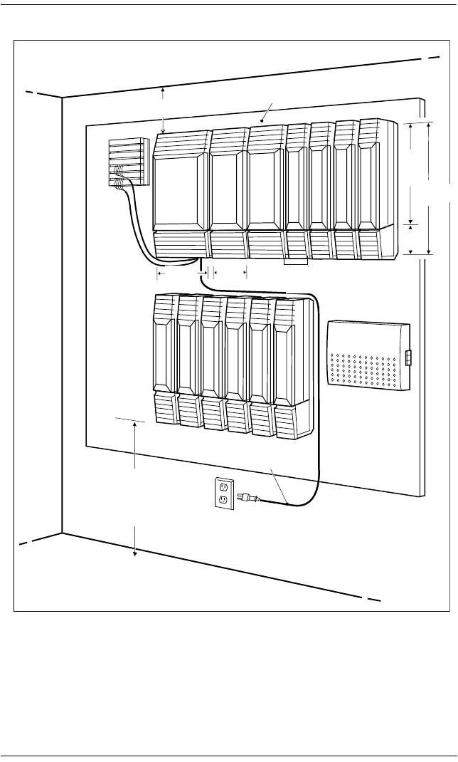
Planning the installation / 183
P0992638 03 Modular ICS 6.0 Installer Guide
Spacing requirements for a typical MICS-XC 6.0 system
300 mm
(12 in)
100
mm
(4 in)
200 mm
(8 in)
500
mm
(20 in)
130
mm
(5 in)
630
mm
(25 in)
19 mm thick (3/4 in) wallboard
if smooth mounting surface
not available
Power cord length 1.5 m (5 ft)
min. 100 mm (4 in)
between bottom of trough
and floor or other object that
might block air flow
Mount well above the floor
to prevent water damage
min.
150 mm (5 in)
min. 100 mm (4 in.) between
bottom of trough and floor or
other object that might block
air flow. Mount well above the
floor to prevent water damage
Power cord length
1.5 m (5 ft.)
300 mm
(12 in)
200
mm
(8 in)
100
mm
(4 in)
100
mm
(4 in)
500
mm
(20
in) 630 mm
(25 in)
19 mm thick (3/4 in) wallboard if
smooth mounting surface not available
min 150 mm
(5 in)
184 / Planning the installation
Modular ICS 6.0 Installer Guide P0992638 03
Electrical requirements
ånon-switched outlet within 1.5 m (5 ft.) of the ICS
åThe ICS and module power cords are 1.5 m (5 ft.) long.
You may connect the ICS and modules to a power bar. The
power bar must be CSA certified and UL listed with a
third-wire ground.
Do not use an extension cord between the ICS and the
power bar, or between the power bar and the electrical
outlet.
åAC outlet equipped with a third wire safety ground to
provide shock protection and avoid electromagnetic
interference
ådedicated 110 V AC nominal, 50/60 Hz, 15 A minimum
service with a third-wire safety ground
Risk of electric shock.
The safety of this product requires connection to an
outlet with a third-wire ground. Use only with
three-prong power cord and outlet.
Check ground connections.
Ensure that the electrical ground connections of the
power utility, telephone lines and internal metallic water
pipe system, if present, are connected together. If they
are not connected together, contact the appropriate
electrical inspection authority. Do not attempt to make
the connections yourself.

Planning the installation / 185
P0992638 03 Modular ICS 6.0 Installer Guide
Configuring Trunk Cartridges
If you plan to configure lines on a Loop Start Trunk Cartridge
as auto-answer, you will need an E&M Trunk Cartridge for
every two auto-answer loop start lines. The E&M Trunk
Cartridge provides DTMF receivers for auto-answer loop start
lines. You can install three additional Trunk Cartridges in each
Trunk Module. The following table shows you the line
capacity of each Trunk Cartridge.
You can install different types of Trunk Cartridges together in
the same Trunk Module. When mixing Trunk Cartridges, use
a separate block on the distribution panel for each type of
Trunk Cartridge.
Trunk Cartridge Line capacity
DTI configured for T1 (ICS only) 24
DTI configured for PRI T1(ICS only) 23
DTI configured for ETSI PRI 30 (Profile 2)
BRI-ST & BRI-U4 8
BRI-U2 4
Loop Start with disconnect supervision 4
GATC/CI 4
DID (TM only) 4
E&M (TM only) 2

186 / Planning the installation
Modular ICS 6.0 Installer Guide P0992638 03
Configuring Station Modules
Each Station Module allows you to connect up to 16 additional
Norstar telephones to the system.
Internal wiring requirements
The following section describes the cable required for the
Norstar loop and an ISDN S reference point S loop.
Norstar loop
åone, two or three twisted pair cables per telephone
ådc loop resistance of less than 64 Ω
åcable length (0.5 mm or 24 AWG) less than
300 m (1000 ft.)
Mini
Midi
Maxi
Mega
Mega /
Companion
ICS
SM3
SM4
SM5
SM6
SM7
SM8
SM9
SM10
SM11
SM12
SM13
SM14
32 48 64 80 96 112 128 144 160 176 192 208 224
Tips - The following combinations are not supported with
the MICS 6.0 and MICS-XC 6.0 systems:
• two 2-port expansion cartridge system (four fiber ports
total)
• a six-port and a two-port expansion combination
(eight fiber ports total)
In a fully expanded system using 48 digital channels, consider
installing two service cartridge functionality to prevent
blocking of incoming calls due to lack of DTMF resources.
Planning the installation / 187
P0992638 03 Modular ICS 6.0 Installer Guide
åuse of a station auxiliary power supply (SAPS) for loops
300 m (1000 ft.) to 790 m (2600 ft.). The SAPS must be a
Class 2 power source that is UL listed and CSA certified.
åno bridge taps
ISDN S reference point (S Loop)
åno longer than 1000 m (3,200 ft.) for point to point
åno longer than 450 m (1,475 ft.) on a point-to-multipoint
extended passive bus
åno longer than 100 m (300 ft.) for 75 ohm cable or
200 m (600 ft.) for 150 ohm cable on a point-to-multipoint
short passive bus
Wiring for the S reference point (S loop) should conform to
ANSI T1.605. Wiring for the ISDN U reference point (U loop)
should conform to ANSI T1.601.
Verify lightning protectors.
Check the lightning protectors at the cable entry point to
the building with special attention to the grounding.
Report any problems to the telephone company in
writing.
Equipment that is designed to be connected using
internal wiring is typically not lightning protected.
Norstar telephone equipment and ISD N Sloops and
T loops should not leave the building where the ICS is
installed.
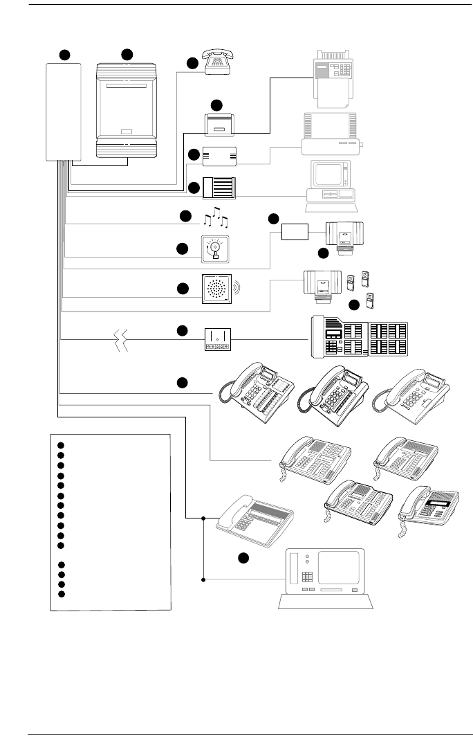
188 / Planning the installation
Modular ICS 6.0 Installer Guide P0992638 03
System overview
6
5
4
10
1
2 3
7
8
9
11
Integrated Communication System
Distribution panel
Emergency telephone
Analogue Terminal Adaptor
Call Logging Interface
Remote Set Device
External music source
Auxiliary ringer
External paging equipment
Station Auxiliary Power Supply
Digital telephones
(not shown: T/M7000 and T7406)
Remote Power Interconnect
Base station
Portable telephones
ISDN devices
2
3
4
5
6
7
8
9
1
10
12
13
14
15
11
12
13
14
15
Inspect FORWARD Callers
Inspect FORWARD Callers
MXP
MXP
Business Series
Terminals
(TXXX)
Norstar M7XXX series

Planning the installation / 189
P0992638 03 Modular ICS 6.0 Installer Guide
Upgrading your Norstar system
What procedure you use to upgrade your Norstar system will
depend on what version of MICS software you are upgrading
to.
Upgrade notes:
•When making simultaneous hardware and software
upgrades (e.g. 12-port expansion plus a MICS 6.0 software
upgrade), upgrade your software release before making
your hardware upgrades.
•Ensure you power up the system after the new software has
been installed, but before any new hardware is added.
Upgrading in this order maintains your 0X32 ICS
programming data for use with MICS 6.0 and
MICS-XC 6.0.
Upgrade from 4.0, 4.1 or 5.0 to 6.0
Your MICS 6.0 upgrade includes a modular CS ROM
cartridge that contains the new software.
To upgrade from a MICS 5.0 system:
1. Power down.
2. Disconnect all amphenol cables.
3. Remove the power to the ICS and all associated modules.
Disconnecting the power ensures protection for electronic
components and that the data stored in the feature cartridge
will not be corrupted.
4. Remove the MICS (4.0, 4.1 or 5.0) CS ROM cartridge.
Note: Your system information remains on the NVRAM unit
that the CS ROM cartridge fits into.

190 / Planning the installation
Modular ICS 6.0 Installer Guide P0992638 03
5. Insert the new MICS 6.0 CS ROM cartridge.
6. Plug the ICS back into the power source.
7. Reconnect all amphenol cables.
8. Wait for the system to reboot.
Upgrade from 4.0/4.1 to 5.0
Your MICS 5.0 upgrade includes a modular CS ROM
cartridge that contains the new software.
To upgrade from a MICS 4.0 or MICS 4.1 system:
1. Power down.
2. Disconnect all amphenol cables.
3. Remove the power to the ICS and all associated modules.
Disconnecting the power ensures protection for electronic
components and that the data stored in the feature cartridge
will not be corrupted.
4. Remove the MICS 4.0 or MICS 4.1 CS ROM cartridge.
Note: Your system information remains on the NVRAM unit
that the CS ROM cartridge fits into.
5. Insert the new MICS 5.0 CS ROM cartridge.
6. Plug the ICS back into the power source.
7. Reconnect all amphenol cables.
8. Wait for the system to reboot.

Planning the installation / 191
P0992638 03 Modular ICS 6.0 Installer Guide
Upgrade from pre-4.0 system to 6.0, (reprogramming may
be required)
If you want to upgrade from a pre-4.0 system, you need both a
MICS Non Volatile Read-only Memory (NVRAM) cartridge
with a MICS 6.0 CS ROM cartridge installed.
Note: This upgrade may require some partial reprogramming.
To upgrade the software, follow these steps:
1. Power down.
2. Disconnect all amphenol cables.
3. Remove the power to the ICS and all associated modules.
Disconnecting the power ensures protection for electronic
components and that the data stored in the feature cartridge
will not be corrupted.
4. Remove the entire cartridge.
5. Insert the new NVRAM cartridge with the Upgrade CS
ROM software.
6. Plug the ICS back into the power source.
7. Reconnect all amphenol cables.
8. Wait for the system to reboot.
9. Repeat steps 1 to 3.
10. Remove the upgrade cartridge and insert the MICS 6.0 CS
ROM cartridge.
11. Repeat steps 6 to 8.
12. Run the profile, dialpad, and startup programming within
15 minutes after reboot.
13. Program the system to your requirements.

192 / Planning the installation
Modular ICS 6.0 Installer Guide P0992638 03
About the MICS NVRAM cartridge
The NVRAM assembly cartridge has a slot for a credit-card
size PC-card, which are also referred to as Flash cards. These
cards contain the system software and accommodate future
system memory requirements and software downloading.
Supported upgrades in MICS 6.0
Do not install a MICS NVRAM cartridge from
other MICS 6.0 systems. This will cause all the
programming to be lost.
Do not attempt to use the MICS NVRAM
cartridge as stored data transfer. This will cause
the system to cold start.
Target Upgrade
MICS
6.0
USA-MICS-XC
6.0
CDA-MICS-XC
6.0
Upgrading from...
MICS (all versions)
1.0-3.0
If you upgrade from software versions prior to MICS
4.0, some partial reprogramming may be required.
An alternative upgrade, to retain programming
integrity, is to upgrade to version 4.0, 4.1, or 5.0 and
then upgrade to 6.0. Refer to
Upgrade from pre-4.0
system to 4.0, 4.1 or 5.0 (retain programming)
on
page 193.
MICS 4.0 Insert MICS CS ROM cartridge with appropriate
software load.
USA-MICS-XC 4.0 Insert MICS CS ROM cartridge with appropriate
software load.
CDA-MICS-XC 4.0 Insert MICS CS ROM cartridge with appropriate
software load.

Planning the installation / 193
P0992638 03 Modular ICS 6.0 Installer Guide
Upgrade from pre-4.0 system to 4.0, 4.1 or 5.0 (retain
programming)
If you want to perform a two-step upgrade from a pre-4.0
system, so you can retain your system information, you need
to use the upgrade tool that was introduced with MICS 4.0 and
either the 4.0, 4.1 or 5.0 software upgrade. The upgrade tool
allows you to transfer your NVRAM information to the new
style NVRAM cartridge that contains a MICS CS ROM
cartridge.
If you do not use the upgrade tool, all or part of your
programming will be lost.
MICS 4.1 Insert MICS CS ROM cartridge with appropriate
software load.
USA-MICS-XC 4.1 Insert MICS CS ROM cartridge with appropriate
software load.
CDA-MICS-XC 4.1 Insert MICS CS ROM cartridge with appropriate
software load.
MICS 5.0 Insert MICS CS ROM cartridge with appropriate
software load.
USA-MICS-XC 5.0 Insert MICS CS ROM cartridge with appropriate
software load.
CDA-MICS-XC 5.0 Insert MICS CS ROM cartridge with appropriate
software load.
Target Upgrade
MICS
6.0
USA-MICS-XC
6.0
CDA-MICS-XC
6.0
Upgrading from...

194 / Planning the installation
Modular ICS 6.0 Installer Guide P0992638 03
To use the Upgrade Tool to upgrade from previous versions of
MICS (all versions prior to MICS 4.0), follow these steps:
1. Power down.
2. Disconnect all amphenol cables.
3. Remove the power to the ICS and all associated modules.
Disconnecting the power ensures protection for electronic
components and that the data stored in the feature cartridge
will not be corrupted.
4. Remove your old Norstar MICS software cartridge.
5. This step determines the type of MICS system you will
ultimately upgrade to.
Insert the MICS NVRAM cartridge. See illustration on
page 219.
Insert the PC-card (or Flash card) that came with your
upgrade tool package.
6. Reconnect all amphenol cables.
7. Power up. Wait until display flashing stops. Insert MICS
Card is displayed.
8. Power down.
9. Insert the Modular ICS ROM software cartridge to
perform the final stage of the upgrade to MICS 4.0, 4.1, or
5.0. See Installing the ROM Software Cartridge on page
219 to verify that you are using the proper software
cartridge.
10. Power up.
Ensure that you use the appropriate MICS
upgrade tool when upgrading.
Your Norstar system will cold start and your data
will be lost if the MICS ROM software cartridge
that came in your upgrade tool does not match
your MICS system software.

Planning the installation / 195
P0992638 03 Modular ICS 6.0 Installer Guide
If no alarm-event messages are observed, the upgrade to
the new MICS software has been performed.
If alarm codes are displayed, refer to Alarm codes on page
506 for definitions.
If event messages are displayed refer to Event messages on
page 514 for definitions.
11. Once you confirm your system information, you can
choose to upgrade to the MICs 6.0 software. Refer to
Upgrade from 4.0, 4.1 or 5.0 to 6.0 on page 189.
Notes
Ensure that you maintain an accurate record of your existing
system programming so that you can plan your new system
programming appropriately.
If you have a Norstar system with a Modular 8X24 Key
Service Unit (KSU), you cannot upgrade your software with
the Upgrade Tool. If you want to upgrade to MICS 6.0, you
All old programming is maintained when
upgrading from the 0X32 Release 1 - T1
software, with the following exceptions:
• all system passwords are returned to the
system defaults
• ATA ans timer setting is returned to the system
default setting
When upgrading from MICS 1.1, note that the
Call log space has increased in newer
versions.
Reallocate log space after upgrading.
196 / Planning the installation
Modular ICS 6.0 Installer Guide P0992638 03
must replace your older Modular 8X24 KSU with the current
0X32 ICS, and then program the system.
Note: The Key Service Unit (KSU) has been renamed the
Integrated Communication System (ICS).
If you have a Norstar system with a Modular 0X32 ICS, you
can use your ICS with the new MICS 6.0 and MICS-XC 6.0
software.
Upgrading from MICS 6.0 to MICS-XC 6.0
MICS 6.0 mini to XC 6.0 mini
1. Install XC 6.0 ROM software cartridge.
2. Use module 1 (ports 101 to 132) for telephones only and
module 2 for Trunk Cartridges only.
When upgrading, Call Log information may be
lost.
During a system restart, Call Log information is
not saved. Make sure to notify users if a system
restart is planned so any log information can be
recorded first.
A loss of UTAM information occurs when
upgrading US MICS-XC systems.
UTAM Recovery Codes are required. If you are
upgrading the system to include Companion
components, see the upgrade instructions
included in the
Modular ICS Companion Installer
Guide
.

Planning the installation / 197
P0992638 03 Modular ICS 6.0 Installer Guide
MICS 6.0 mini to XC 6.0 midi
1. Install XC 6.0 ROM software cartridge.
2. Install two-port Expansion Cartridge in slot 2.
3. Connect trunk modules beginning at port 4 and station
modules beginning at port 3.
MICS 6.0 mini to XC 6.0 maxi
1. Install XC 6.0 ROM software cartridge.
2. Install a Combination Fiber 6-port Services Cartridge in
slot 2.
3. Connect trunk modules beginning at port 8 and work down
and station modules beginning at port 3 and work up.
MICS 6.0 midi to XC 6.0 midi
1. Install XC 6.0 ROM software cartridge.
MICS 6.0 midi to XC 6.0 maxi
1. Install XC 6.0 ROM software cartridge.
2. Replace two-port Expansion Cartridge with either a
Combination Fiber 6-port Services Cartridge or a 6-port
Fiber Expansion Cartridge in ICS slot 2.
3. Connect trunk modules beginning at port 8 and work down
and station modules beginning at port 3 and work up. Refer
to page 216.
MICS 6.0 maxi to XC 6.0 maxi
Install XC 6.0 ROM software cartridge.

198 / Planning the installation
Modular ICS 6.0 Installer Guide P0992638 03
MICS 6.0 maxi to XC 6.0 mega
1. Install XC 6.0 ROM software cartridge.
2. Replace two-port Expansion Cartridge with two
Combination 6-port fiber Expansion Cartridges or one 6-
port Fiber Expansion Cartridge and one Combination
Fiber 6-port Services Cartridge in ICS slots 1 and 2.
3. Connect trunk modules beginning at port 8 and work
down.
4. Connect station modules beginning at port 3 and work up.
Tips - Trunk modules cannot be connected to the
Combination Fiber 6-port Services Cartridge in slot 1. (fiber
interface ports 9 through 14.
To add Station Modules to ports 13 and 14 in a mega system
refer to Modular ICS Companion Installer Guide.
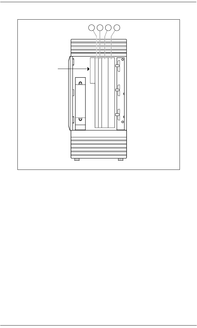
Planning the installation / 199
P0992638 03 Modular ICS 6.0 Installer Guide
Slots on ICS
Trunk and Station Modules
If you are not adding digital T1 trunks to your system, or
expanding to a mega configuration, you may reuse your
existing copper Trunk and/or Station Modules with the
Modular 0X32 ICS in MICS 6.0/XC 6.0. One 6-port copper
expansion cartridge can be supported on the maxi
configuration.
If you are adding digital T1 trunks to your system or
expanding to a mega configuration, you must replace any
copper Trunk and/or Station Modules with the new modules
that have fiber connectors, and use a new fiber Expansion
Cartridge in the ICS. You can reuse your old Trunk Cartridges
in the new Trunk Module with fiber connectors.
1234
ICS
Feature
Cartridge
Slot
Feature
cartridge
slot
ICS

200 / Planning the installation
Modular ICS 6.0 Installer Guide P0992638 03
Trunk modules cannot be installed on the second expansion
(6-port) cartridge. You must relocate station modules to the
second expansion cartridge to free up ports on the first 6-port
expansion cartridge.
Global Analog Trunk Cartridge/CLI Cartridge
These cartridges have dip switches that may need to be set if
your system is not running with the North American profile
(Profile 1). Set the dip switches before you install the
cartridge.
GATC dip switch settings (default is North America)(
The following table lists the various dip switch settings.
However, for this release, only the North America, Taiwan,
and Australia settings are active.
DIP switch setting Country profile
00000000 North America
10000000 Taiwan
01000000 Australia
11000000 *Chili
00100000 *Peru
10100000 *Argentina
01100000 *Mexico
11100000 *Sweden
00010000 *South America
10010000 *Brazil
01010000 *Norway
11010000 *France
00110000 *Germany

Planning the installation / 201
P0992638 03 Modular ICS 6.0 Installer Guide
Off-core DTI card
MICS 6.0 provides the opportunity to expand the number of
DTI cards in your system by adding a DTI card to the
expansion modules in a midi or maxi system. The card must be
installed in either module 3 or 4 on a midi system. On the maxi
system, the card can only be installed in module 7 or 8. One
DTI card requires the entire module resources, so it is installed
in the first slot of the module, and the other two slots must be
left empty. The off-core DTI is configured in the same way as
the other DTIs on your system.
This card is supported for profiles 1 and 4.
Equipment note: The DTI card released in conjunction with
MICs 6.0 can be used either on or off-core. However, any
previous versions of the DTI card can only be used on the core
KSU hardware.
Replacing a Modular 8x24 KSU
If you are upgrading your old KSU (8X24) and adding digital
T1 trunks to your new system (0X32 ICS):
1. Verify your system programming, and update your
Programming Record.
2. Follow the procedures outlined in Installation on page 209
for installing a new system.
10110000 *Korea
XXXXXXX1 *Reserved
XXXXXX1X *Reserved
XXXXX1XX *Reserved
* Reserved for future development
DIP switch setting Country profile

202 / Planning the installation
Modular ICS 6.0 Installer Guide P0992638 03
If you are upgrading your 8X24 KSU, but not adding digital
T1 trunks to a 0X32 system:
1. Verify your system programming, and update your
Programming Record.
2. Disconnect the 50-pin connector for telephones from the
KSU.
3. Disconnect the 50-pin connector for external lines and
auxiliary equipment from the KSU.
4. Remove power from your system.
5. If your system includes Trunk Modules and Station
Modules with DS-30 copper connectors, disconnect the
DS-30 copper connectors from the Expansion Cartridge.
6. Remove any cables from the KSU cable trough.
7. Remove the KSU and wall-mount bracket from the wall.
8. Install the new 0X32 ICS following the procedures in the
Installation on page 209.
9. If your system includes Trunk Modules and or Station
Modules with DS-30 copper connectors, install a
compatible Expansion Cartridge with copper connectors in
slot 1 of the ICS. The faceplate will cover slots 1 and 2.
10. If you have installed a copper Expansion Cartridge in the
0X32 ICS, clip the ferrite bead that was shipped with the
Expansion Cartridge onto the ICS power supply power
cord.
Do not reuse 8X24 Expansion Cartridge
You cannot reuse an 8X24 Expansion Cartridge in the
0X32 ICS. You must install a supported Expansion
Cartridge.
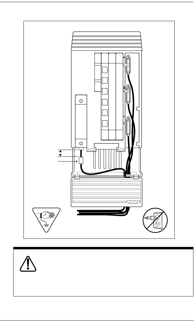
Planning the installation / 203
P0992638 03 Modular ICS 6.0 Installer Guide
Locating the ferrite bead
Ferrite bead required to meet EMI requirements
When using a copper Expansion Cartridge, you must
install the ferrite bead on the ICS power cord to ensure
that the product continues to meet FCC Part 15 Class A
EMI requirements.
max 5 cm (2 in)
ferrite bead
204 / Planning the installation
Modular ICS 6.0 Installer Guide P0992638 03
11. If your system includes Trunk Modules and or Station
Modules with DS-30 copper connectors, reconnect the
fiber interface cables to the Expansion Cartridge.
12. Power up the system.
13. Reconnect your 50-pin connector for internal telephones to
the internal telephone connector on the ICS.
14. Reconnect your external line and auxiliary equipment
wiring according to the procedures and wiring charts in the
Installation on page 209. You cannot reuse your original
50-pin connector for external lines and auxiliary
equipment, because the pin-outs have changed (unless
connections are rewired).
DNs on Station Modules will change
If you simply reconnect the 50-pin connector for
telephones on the ICS, and leave your Station
Modules telephone connectors alone, your
directory numbers will change.
The new 0X32 ICS can accommodate 32
telephones. The old 8X24 KSU connected only
24 telephones. Port numbering has been
changed accordingly.
To preserve existing directory numbers consult
the wiring charts in
Connecting the wiring
on
page 237 and change the DNs using Change DNs
in System prgrming.

Planning the installation / 205
P0992638 03 Modular ICS 6.0 Installer Guide
Trunk module line numbering
In MICS 6.0/MICS-XC 6.0 software, the line numbering for
all profiles has been adjusted to accommodate the Profile 2
ETSI requirement of 30 lines. This could affect applications
such as Norstar Voice Mail or CallPilot 150. The chart below
shows the line numbering transitions between the various
versions of software. Note also that target lines have been
renumbered.
Note: MICS 6.0 line numbering varies, depending on the
profile you choose for your system, and which type of
trunk module you are using, or what protocol you
choose for the module (DTI). Refer to TrunkMod on
page 467.
Line numbering for upgrades
Module Cartridge MICS 1.0
and
1.1 lines
MICS 2.0,
3.0, 4.0, and
5.0 lines
MICS 6.0
lines
Mod 08
Cd1-Mod8 49-52 49-56 61-68
Cd2-Mod8 53-56 57-64 69-76
Cd3-Mod8 57-60 65-72 77-84
Mod 07
Cd1-Mod7 61-64 73-80 85-92
Cd2-Mod7 65-68 81-88 93-100
Cd3-Mod7 69-72 89-96 101-108
Mod 06
Cd1-Mod6 73-76 97-100 109-112
Cd2-Mod6 77-80 101-104 113-116
Cd3-Mod6 81-84 105-108 117-120
Mod 05
Cd1-Mod5 85-88 109-112 121-124
Cd2-Mod5 89-92 113-116 125-128
Cd3-Mod5 93-96 117-120 129-132

206 / Planning the installation
Modular ICS 6.0 Installer Guide P0992638 03
Upgrading ILG functionality with hunt groups
In MICS 4.0, Hunt groups replaced ILG functions from
previous versions of MICS. The hunt group broadcast mode
contains the equivalent of ILG functionality.
Hunt groups allow the following call programming:
•calls can be queued when all the members in a hunt group
are busy
•call forwards are overridden by the hunt group routing,
allowing calls to be distributed to other members in the
hunt group in a way that does not depend on the busy
situation of its members
•the ring / call distribution pattern can be programmed to
determine who receives what call and in what order
•an overflow position can be programmed to another hunt
group
•sequential and rotary modes are also available to provide
versatility to hunt group configurations
Mod 04
Cd1-Mod4 97-100 121-124 133-136
Cd2-Mod4 101-104 125-128 137-140
Cd3-Mod4 105-108 129-132 141-144
Mod 03
Cd1-Mod3 109-112 133-136 145-148
Cd2-Mod3 113-116 137-140 149-152
Cd3-Mod3 117-120 141-144 153-156
Target lines 145-272
145-336
(expanded)
157-284
157-348
(expanded)
Module Cartridge MICS 1.0
and
1.1 lines
MICS 2.0,
3.0, 4.0, and
5.0 lines
MICS 6.0
lines

Planning the installation / 207
P0992638 03 Modular ICS 6.0 Installer Guide
For more information on hunt groups, see System prgrming on
page 389.
Planning Hospitality functions
MICS 4.1 introduced the Hospitality feature, which allows
businesses such as hotels to monitor and set room conditions
and status, and to program alarms from both an administrative
telephone and individual room telephones.
Hospitality features allow the following programming:
• Administrative telephone (password access)
– monitor and set room condition
– monitor and set room occupancy
– monitor and set or cancel alarms
• Room telephone
– Allow staff to set room condition (password access)
– Allow guests to set or cancel wakeup alarms

208 / Planning the installation
Modular ICS 6.0 Installer Guide P0992638 03

P0992638 03 Modular ICS 6.0 Installer Guide
Installation
Only qualified persons should service the system.
The installation and service of this unit is to be
performed only by service personnel having appropriate
training and experience. It is critical that installers have
the necessary awareness about hazards to which they
are exposed in performing a task, and of the measures
required to minimize the danger to themselves or other
persons.
Electrical shock hazards from the telecommunication
network and AC mains are possible with this equipment.
To minimize risk to service personnel and users, the
ICS must be connected to an outlet with a third-wire
ground. In addition, all unused slots should have filler
faceplates installed and the doors should be in place at
the completion of any servicing.
Service personnel must be alert to the possibility of high
leakage currents becoming available on metal system
surfaces during power line fault events near network
lines. A risk point on the ICS is the power cord earth
ground pin. These leakage currents normally safely flow
to Protective Earth ground via the power cord.
Therefore, it is mandatory that connection to a grounded
outlet is performed first and removed last when cabling
to the unit. Specifically, operations requiring the unit to
be powered down must have the network connections
(central office lines) removed first.

210 / Installation
Modular ICS 6.0 Installer Guide P0992638 03
Installation checklist
åtest all ISDN network connections, if any
åmount the Integrated Communications System (ICS)
åmount the expansion modules (as required)
åinstall the Modular ICS NVRAM cartridge
åinstall the Expansion Cartridge, Trunk Cartridges
(DTI, PRI, or BRI cards, as required)
åinstall the optional equipment
åinstall power bars, as required
åmount the distribution panel
åcomplete the wiring
åinstall the fiber cables
åinstall the emergency telephone(s)
åinstall the Norstar telephones
åpower up the system
åconnect the cables between the distribution block and the
expansion modules
åinstall the door
åselect the default template using System Startup
programming
åprogram to customer requirements
årecord programming details in the Programming Record
åensure that all telephone keys are properly labelled
åensure that all telephones are working
åcheck that the system is working properly

Installation / 211
P0992638 03 Modular ICS 6.0 Installer Guide
åensure that all relevant documentation is left with the
person in charge of the system
åtrain the Administrator using the Getting Started section in
the Modular ICS 6.0 System Coordinator Guide
åfor information on upgrading your ICS without adding
digital T1, see Trunk and Station Modules on page 199.
Testing the ISDN BRI network connection
Before you install a Norstar system which uses BRI cards you
should test your connection to the ISDN network.
If you are installing a system which connects to the network
using BRI-ST cards, the network connection must be equipped
with an NT1. See the ISDN chapter and the wiring information
in this chapter for more information about installing an NT1.
To avoid electrical shock hazard to personnel or
equipment damage, observe the following
precautions when installing telephone equipment.
•Always disconnect telecommunication network
connectors before disconnecting the AC power plug.
•Never connect the central office connectors until you
have connected the power plug.
•Never install telephone wiring during a lightning
storm.
•Never install telephone jacks in wet locations unless
the jack is specifically designed for wet locations.
•Never touch non-insulated telephone wires or
terminals unless the telephone line has been
disconnected at the network interface.
•Use caution when modifying or installing telephone
lines.

212 / Installation
Modular ICS 6.0 Installer Guide P0992638 03
To test the ISDN BRI connection:
1. Connect ISDN terminal equipment (TE) that conforms to
Bellcore standard to your central office ISDN jack or NT1.
U interface TE can connect directly to the central office
jack. S interface TE connect to the central office through
an NT1.
2. Program the TE with the appropriate switch type, service
profile identifier (SPID), and Network directory number
(DN) using the instructions that come with the TE.
3. Check for dial tone, then place a call and verify the quality
and clarity of the connection. If there is a problem, contact
your service provider.
4. Repeat steps one through three for each network
connection.

Installing the cartridges / 213
P0992638 03 Modular ICS 6.0 Installer Guide
Installing the cartridges
The following table shows you which cartridges can be
installed in which ICS and TM slots.
Note: Use Slot 1 only when installing cartridges for 12-port, fully
expanded systems. In this case, both slots 1 and 2 are installed with
6-port Expansion or a Combination Fiber 6-port Services Cartridge.
If you use both slot 1 and 2, the software must be MICS-XC.
Cartridge type ICS Slot TM Slot
Modular ICS NVRAM cartridge Feature Cartridge
Slot
Modular ICS ROM software cartridges:
USA-MICS-XC 6.0
CDA-MICS-XC 6.0
NA-MICS 6.0
NVRAM Cartridge
Slot
Services Cartridge 1
Fiber Expansion Cartridge (2-port) 2
Fiber Expansion Cartridge (6-port) 1 or 2
(see note below)
Combination Fiber 6-port Services Cartridge 1 or 2
(see note below)
Digital Trunk Interface (DTI) card configured for TI card or PRI 3 or 4
MICS 6.0: Global Analog LS/DS trunk cartridge replaces:
Loop Start Disconnect Supervision (LS/DS) Trunk Cartridge
3 or 4 1, 2 or 3
MICS 6.0: Global Analog CLI trunk cartridge replaces:
Caller Identification (CI) Trunk Cartridge
3 or 4 1, 2 or 3
E&M Trunk Cartridge 1, 2 or 3
DID Trunk Cartridge 1, 2 or 3
Copper Expansion (2-port) 1
Copper Expansion (6-port) 1
BRI-ST card 3 or 4 1, 2 or 3
BRI-U2 card 3 or 4 1, 2 or 3
BRI-U4 card 3 or 4 1, 2 or 3

214 / Installing the cartridges
Modular ICS 6.0 Installer Guide P0992638 03
•LS/DS Global Analog Trunk Cartridges and CI Global
Analog Trunk Cartridges both support loop start external
lines.
•The Digital trunk Interface (DTI) supports both digital T1
and PRI lines. The DTI card can be configured to support
ISDN PRI
•The Loop Start Trunk Cartridge supports loop start
external lines.
•The E&M Trunk Cartridge supports E&M lines and
provides direct inward system access (DISA).
•The DID Trunk Cartridge supports direct inward dialing
lines.
•The BRI-ST card supports ISDN BRI S or T reference
point loops.
•The BRI-U2 and BRI-U4 cards support two or four ISDN
BRI U reference point loops, respectively.
•The (AEM), also known as an Analog Station Module
(ASM), connects up to eight standard through a fibre cable
link.
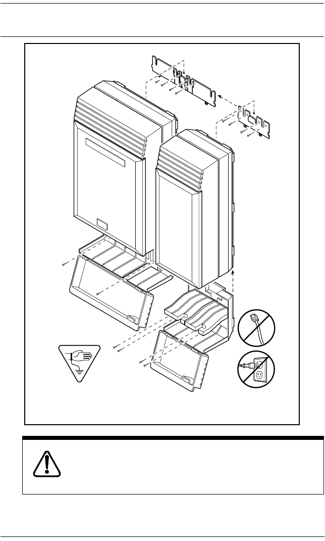
Mounting the modules / 215
P0992638 03 Modular ICS 6.0 Installer Guide
Mounting the modules
Attach bracket to secure surface.
Do not screw bracket directly to drywall. Use the two
inner screw holes on the bracket.
faa
C100 Controller
Trunk Module
19mm (3/4) in
wood screws
38mm
(1-1/2 in)
wood screws
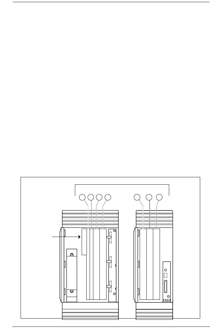
216 / Mounting the modules
Modular ICS 6.0 Installer Guide P0992638 03
1. Secure a 19 mm wood backboard to a wall. It must be
capable of supporting a 20 kg mass.
2. Position the module mounting bracket on the backboard,
smooth side against the backboard, with the screw holes at
the top. Ensure that the bracket is level.
3. Fasten the bracket to the backboard with two 3/4-inch
No. 10 round head wood screws through the inner pair of
holes. The other two holes are optional.
4. Slide the module down onto the center bracket flange. Line
up the notches on the far side of the bracket to the flanges
on the module.
5. Open the front cable trough door. Fasten the bottom of the
module to the backboard.
Use two 3/4-inch No. 10 round head wood screws through
the screw holes on each side of the cable trough.
See T1 or ISDN-PRI configurations on page 482 for
configurations of Trunk Cartridges on the ICS slots.
1234 213
Feature
cartridge
slot
ICS TM
ICS slots

Mounting the modules / 217
P0992638 03 Modular ICS 6.0 Installer Guide
Installation tips
•For a two-port (midi) system, a two-port fiber Expansion
Cartridge is installed only in ICS slot 2.
•For a six-port (maxi) system, a six-port fiber Expansion
Cartridge or a Combination Fiber six-port Services
Cartridge is installed only in ICS slot 2.
•When a six-port fiber Expansion Cartridge is installed in
ICS slot 2, either an additional six-port fiber Expansion
Cartridge, for a fully analog trunk system, or a
Combination Fiber 6-port Services Cartridge, can be
installed in ICS slot 1 for a 12-port (mega) system with
digital or BRI lines.
•Two Combination Fiber 6-port Services Cartridge are
supported on a mega configuration using both ICS slots 1
and 2. When expanding beyond 6 ports, it is recommended
two Combination Fiber 6-port Services Cartridge be used
if two DTI cards are installed.
•For a 12-port (mega) system, any combination of the 6-
port fiber Expansion and the Combination Fiber 6-port
Services Cartridge is supported using both ICS slots 1 and
2.
•A copper Expansion Cartridge is a full-width cartridge and
covers both ICS slots 1 and 2.
•One 6-port copper Expansion Cartridge is supported for a
maxi configuration and can only be installed in slot 1.
Avoid risk of electrical shock.
Voltages of up to 130 V may be present on the 1.544
Mbps circuit and on portions of the DTI circuitry.
218 / Mounting the modules
Modular ICS 6.0 Installer Guide P0992638 03
•One two-port copper Expansion Cartridge is supported for
a midi configuration and can only be installed in slot 1.
•Depending on your system configuration, BRI-ST,
BRI-U2, BRI-U4, the off-core DTI cards can only reside
in certain trunk modules. In a midi system, the cards must
be in trunk modules 3 or 4, for a maxi or mega system, the
cards must be in trunk modules 7 or 8. The cards can reside
in the ICS regardless of system size.
Alarm Telephone will indicate a warm or cold reset.
An alarm and a prompt indicating warm or cold reset will
occur on the alarm telephone if an expansion cartridge
is installed in the wrong ICS slot or when the system
size has been decreased.
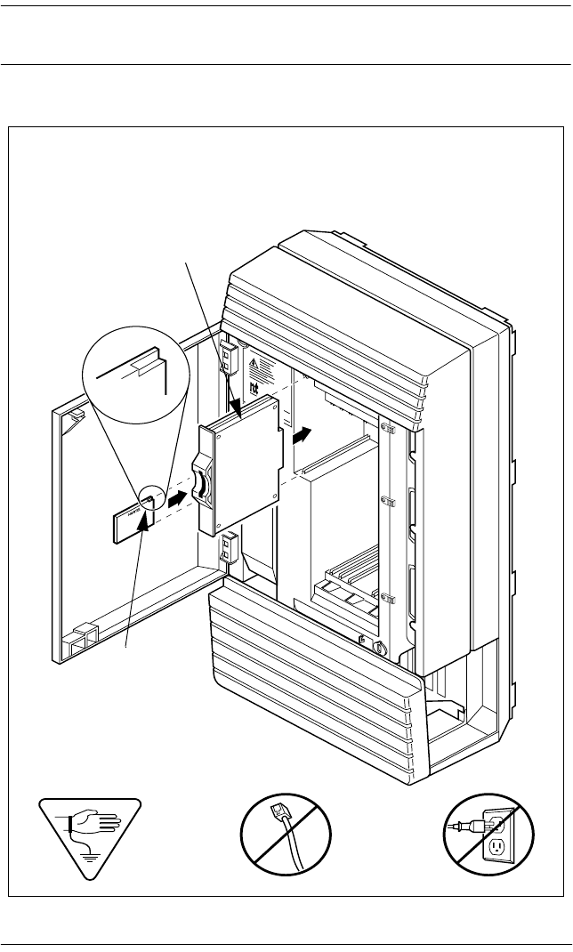
Installing the ROM Software Cartridge / 219
P0992638 03 Modular ICS 6.0 Installer Guide
Installing the ROM Software Cartridge
NVRAM cartridge
MICS NVRAM cartridge
MICS ROM
software cartridge
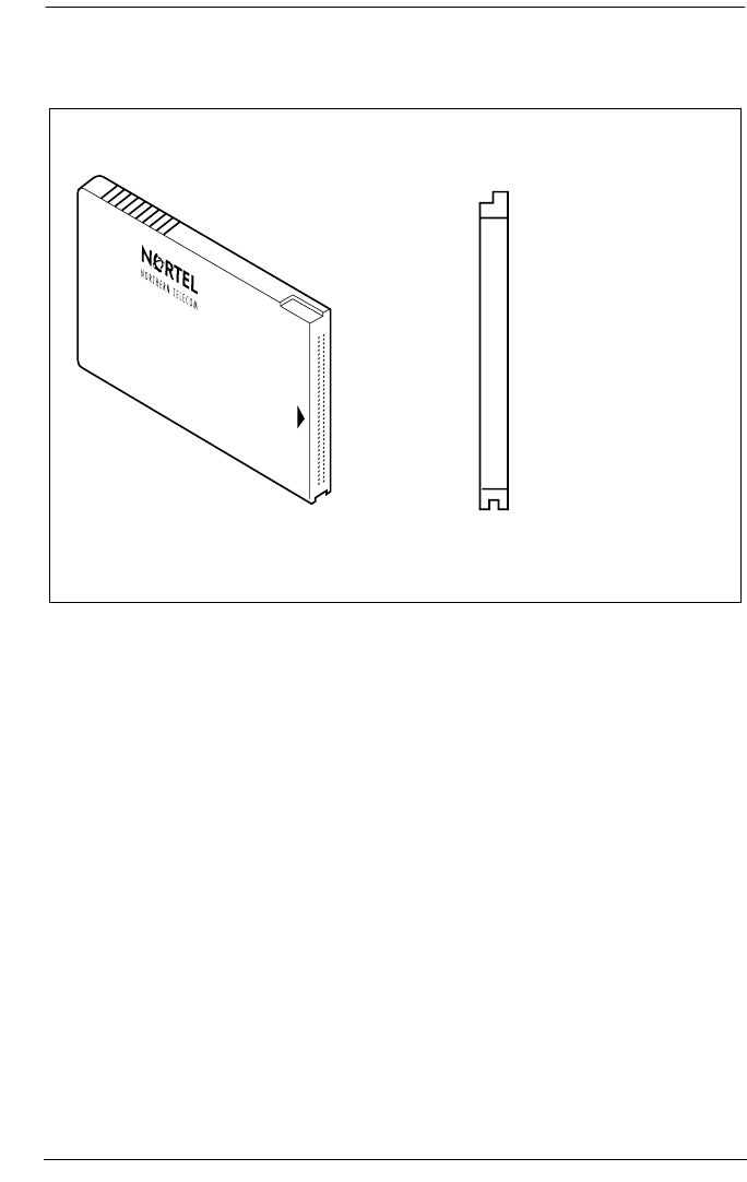
220 / Installing the ROM Software Cartridge
Modular ICS 6.0 Installer Guide P0992638 03
MICS ROM software cartridge
Side view End view
Insert this end into the ICS
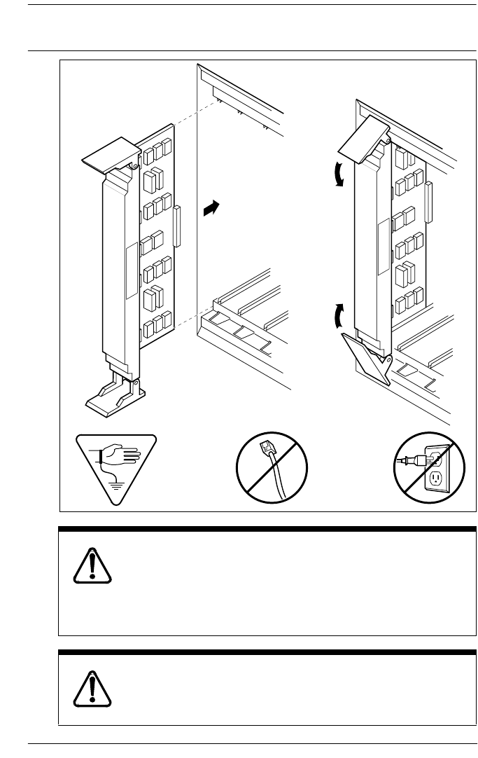
Inserting a cartridge / 221
P0992638 03 Modular ICS 6.0 Installer Guide
Inserting a cartridge
Close clips simultaneously.
It is important to center and close the two clips on the
cartridge simultaneously. The cartridge may become
misaligned in its slot or with its connector. If improperly
inserted, the connector will be damaged.
PCB is electrostatic-sensitive.
Do not touch the printed circuit board on a cartridge.
This is an electrostatic-sensitive device.

222 / Inserting a cartridge
Modular ICS 6.0 Installer Guide P0992638 03
1. Install trunk cartridges in the ICS beginning with Slot 4
then Slot 3.
2. Install trunk cartridges in the trunk modules beginning
with Slot 1 then Slot 2 and then Slot 3.
For easier wiring, install similar type Trunk Cartridges
together in the same Trunk Module.
If you install an E&M or a DID or BRI Trunk Cartridge in the
left-most slot (slot 1) of a TM, emergency telephones cannot
be supported for that Trunk Module.
Terminating resistors on BRI-ST Cards
The standard ISDN user-network interface wiring requires
terminating resistors at each end of the loop for point-to-point
operation. This ensures correct timing of the signaling circuits.
Loop termination can be provided at either the point where the
ISDN terminal is attached, or by the device attached to the
loop which has built-in termination. Because the Modular ICS
is usually at one end of the loop, the BRI-ST card is shipped
with termination built-in for each ISDN loop. It is ready to be
used where the ICS is located at one end of the loop, as in the
following illustration:
ICS
Built-in termination installed
TE connections without termination
TE with
termination
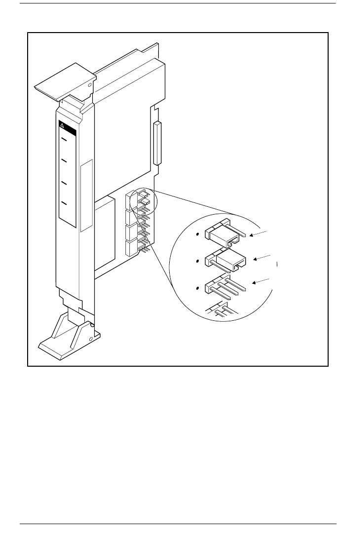
Inserting a cartridge / 223
P0992638 03 Modular ICS 6.0 Installer Guide
Shorting straps on a BRI-ST card
Ensure that the shorting straps are installed on both the receive
and transmit jumpers for the loop. Refer to the illustration
above.
The jumpers are numbered top to bottom, but the loops
associated with each pair of jumpers does not follow the same
top-to-bottom sequence. Refer to the table on the next page.
J8
J7
J6
no shorting
strap
termination
removed
termination
installed

224 / Inserting a cartridge
Modular ICS 6.0 Installer Guide P0992638 03
Receive and transmit jumper loop connections
Connecting expansion modules
If your system includes fiber Trunk Modules, fiber Station
Modules, Data Modules or Analog Station Modules, you need
to connect the modules to the Expansion Cartridge by means
of fiber cables.
Order of connection
In order to keep the default port and telephone numbering:
•Connect Trunk Modules to the Expansion Cartridge
beginning at the top and working down.
•Connect Station Modules to the Expansion Cartridge
beginning at the bottom and working up.
Analog Station Module
If you are installing the ICS system with an ASM, refer to the
diagram below.
Connect jack 1 on the ASM to the first available fibre cable
link on the CCU.
Loop RX and TX shorting straps
1 J3 and J4
2 J7 and J8
3 J1 and J2
4 J5 and J6
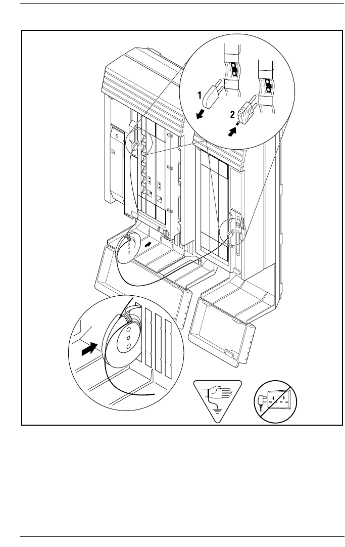
Inserting a cartridge / 225
P0992638 03 Modular ICS 6.0 Installer Guide
ASM cable connections
The cable trough can accommodate two fibre cable spools.
Either slot may be used.
The ASM has three connectors, two fibre cable links and a
25-pair pin connector. Refer to the wiring section for the
pinout for the 25-pair pin connector.
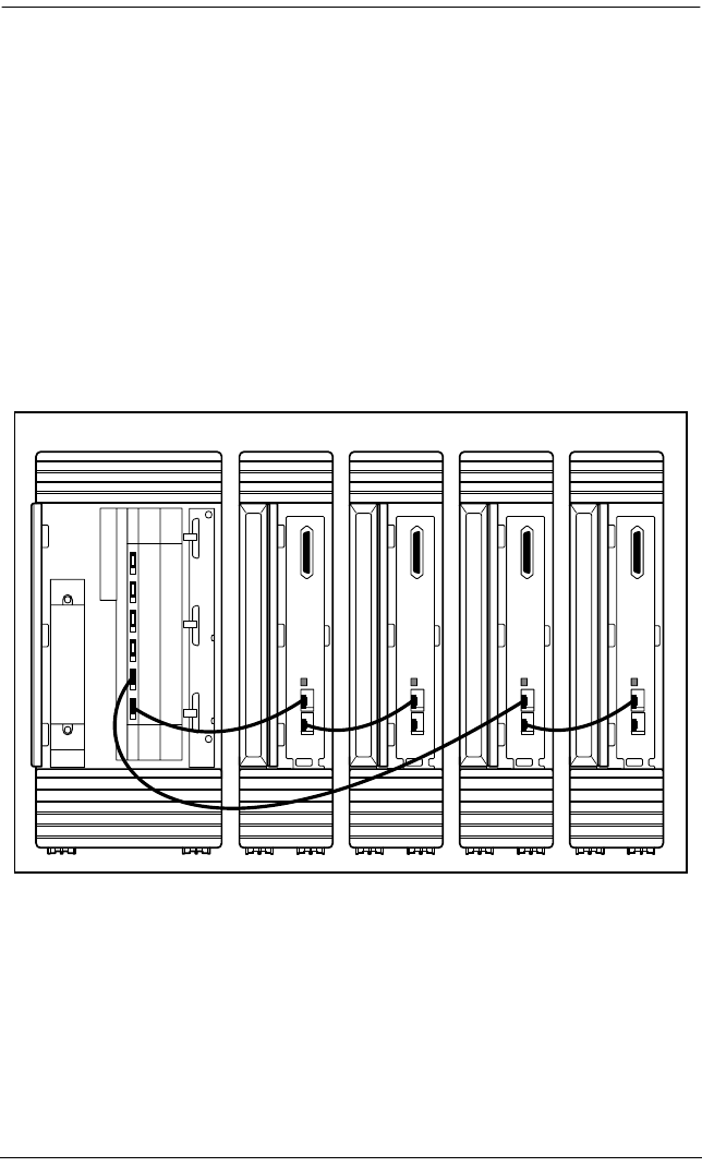
226 / Inserting a cartridge
Modular ICS 6.0 Installer Guide P0992638 03
Connecting more than one ASM
You can connect additional ASMs.
1. Connect jack 1 on the second ASM to jack 2 on the first
ASM.
2. Connect jack 1 on the third ASM to the next available fibre
cable link on the on the ICS.
3. The fourth module is connected to the third and so on.
4. Each fibre cable link can support two ASMs.
Connecting multiple modules
After the modules are mounted and connected, feed the
cables through the cable trough.
M0X8AM
M0X8AMM0X8AMM0X8AM
1
2
1
2
1
2
1
2
ICS ASM ASM ASM ASM
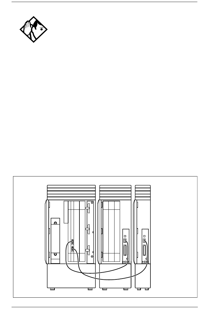
Inserting a cartridge / 227
P0992638 03 Modular ICS 6.0 Installer Guide
Two-port Expansion Cartridge
Tips - On a midi system, ports 3 and 4 can be used for
Trunk Modules or Station Modules. In this case, connect Trunk
Modules beginning at the top (port 4). Connect Station
Modules beginning at the bottom (port 3).
On a maxi system, ports 3 through 8 can be used for Trunk
Modules or Station Modules. In this case, Trunk Modules
should be connected beginning at the top (port 8) and working
down. Station Modules should be connected beginning at the
bottom (port 3) and working up.
On a fully expanded 12-port (mega) system, connect Trunk
Modules beginning at the top (port 8) and working down.
Station Modules would be connected beginning at the bottom
(port 3) and working up. Trunk Modules cannot be connected
to the Expansion Cartridge in slot 1.
When no more Station Modules can be added to the Expansion
Cartridge in slot 2, connect additional Station Modules to the
Expansion Cartridge in slot 1, beginning at the bottom (port 9)
and working up.
ICS (modules 1 and 2) TM4 SM3
ICS (modules 1 and 2) TM4 SM3
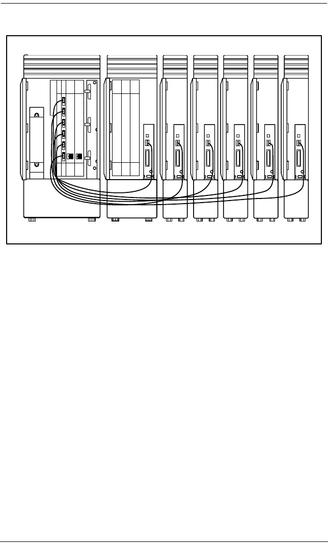
228 / Inserting a cartridge
Modular ICS 6.0 Installer Guide P0992638 03
Six-port Expansion Cartridge
SM3 SM4 SM5 SM6ICS (modules 1 and 2) TM8 SM7
ICS (modules 1 and 2) TM8 SM3 SM4 SM5 SM6 SM7
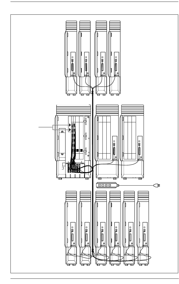
Inserting a cartridge / 229
P0992638 03 Modular ICS 6.0 Installer Guide
Twelve-port Expansion Cartridge
TM8 TM7
SM6 SM5
ICS (modules 1 and 2)
Base Stations
SM4 SM3
SM14 SM13 SM12 SM11 SM10 SM9
To Ac
outlet
SM3SM4SM5SM6
ICS (modules 1 and 2 TM8 TM7
Base stations
To A C
outlet
SM14 SM13 SM12 SM11 SM10 SM9

230 / Installing fiber cables
Modular ICS 6.0 Installer Guide P0992638 03
Installing fiber cables
Installing fiber cables.
Fiber cables are durable, but can be damaged.
Damaged cables can affect the transmitted signals.
To avoid damaging the cables, observe the following:
•Coil excess fiber cable on the spool provided for the
installation.
•Secure the fiber cable spool in the ICS cable trough.
•Ensure that bends in the cable are no tighter than
100 mm. (4 in.) in diameter.
•When using cable ties, bundle fiber cables loosely.
•Avoid excessive pulling, compression or impact.
•Do not grasp the fiber cable, or the clasp where the
cable joins the plug, when connecting or
disconnecting a fiber cable plug into a port.
•Do not leave fiber cables in an environment with
excessively high temperatures (for example, on top of
radiators).
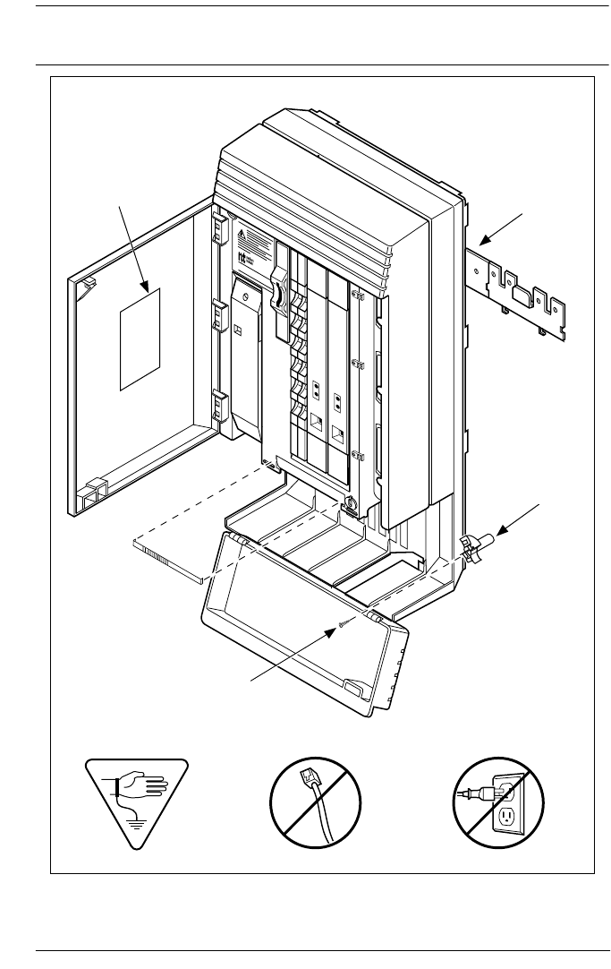
Fiber cable management system / 231
P0992638 03 Modular ICS 6.0 Installer Guide
Fiber cable management system
C100 Controller
38 mm (1 1/2 in)
wood screws
Spacer
90 Fiber
cable guide
Label
Fiber Cable
Guide
Label Spacer
Fiber Cable
Guide
38mm (1-1/2
in) wood screws
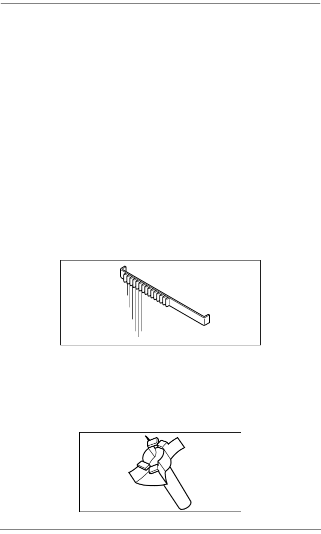
232 / Fiber cable management system
Modular ICS 6.0 Installer Guide P0992638 03
Using the fiber cable management system
To facilitate the installation of an MICS 6.0 or MICS-XC 6.0
configuration, the Fiber Cable Management System ensures
that power cords are located outside of the cable tray. It also
ensures that a 2.6 cm (1 in.) space exists between the ICS
module and other modules.
The following hardware components are used in the Fiber
Cable Management System:
•Fiber Comb (one per system): The Fiber Comb, is
installed, using an adhesive back, on the ICS, below the
fiber expansion cartridges. The Fiber Comb keeps the fiber
cable in place and prevents the cables from being pinched
between doors. Use the comb to keep fiber cables
organized as they are routed to each Station Module, as
shown in the 12-port example below.
•Fiber Cable Guide (three per system): install in the
entrance and exit of the cable trough. The Fiber Cable
Guide allows fibers to be correctly routed to maintain a
minimum bend radius when going through the cable
trough.
SM14
SM13
SM12
SM11
SM10
SM09

Fiber cable management system / 233
P0992638 03 Modular ICS 6.0 Installer Guide
•Spacer (three per system): install between the mounting
brackets of the ICS and an adjacent module. The Spacer
provides a 2.6 cm (1 in.) space between modules and the
ICS.
•Fiber Spool Holder (six per system): Replaces the trough
shelf in modules requiring additional fiber spools. Install
the spool holder in the right side of a Trunk Module.
•ICS Door Label: Located on the inside of the ICS door, it
provides space to identify fiber port allocation on the ICS.
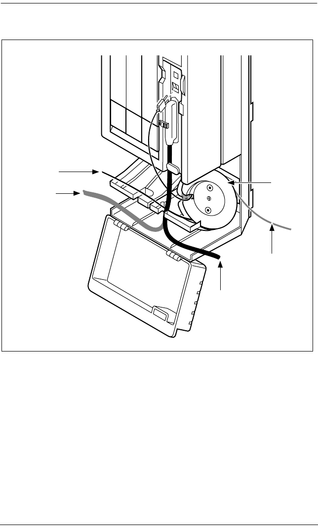
234 / Fiber cable management system
Modular ICS 6.0 Installer Guide P0992638 03
Using the fiber spool
Fiber
Cable –
alternate
routing
Amphenol
Cable
Fiber Cable
Fiber
Spool
Amphenol
Cable –
alternate
routing
Fiber cable
Amphenol
cable -
alternate
routing
Amphenol cable
Fiber cable -
alternate routing
Fiber
spool

Fiber cable management system / 235
P0992638 03 Modular ICS 6.0 Installer Guide
Making fiber connections
MICS-XC 6.0 system
Fiber Cable Fiber
Spool
Fiber
Cable –
alternate
routing
Fiber Comb
6-port
Expansion
Cartridge
6-port
Expansion
cabinet
Fiber cable
Fiber comb
Fiber
spool
Fiber cable -
alternate routing
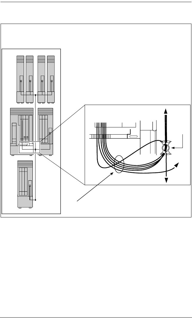
236 / Fiber cable management system
Modular ICS 6.0 Installer Guide P0992638 03
Routing fiber cables
6 port Expansion Cartridge
Fiber
cable
guide
Upward routed fiber cable
Downward routed fiber cable
loose cables

Connecting the wiring / 237
P0992638 03 Modular ICS 6.0 Installer Guide
Connecting the wiring
This section describes the wire connections for your MICS
system.
Connecting the wiring to the distribution panel
1. Route the cables through the hole in the ICS cable through
to the distribution panel.
2. Bundle the cables with cable ties and secure them to the
wall to support their weight.
3. Connect the telephone and auxiliary equipment wires to
the appropriate pins on the distribution block (refer to the
wiring charts).
4. Cross-connect the ICS telephone and auxiliary equipment
wiring.
5. Connect the Station Module telephone wiring to the
corresponding station pins.
6. Using a single pair of wires for each telephone, connect
each of the telephones according to the wiring charts.
7. Cross-connect the external lines to the distribution block
— loop start, E&M, DID, BRI. Refer to the wiring charts.
8. The DTI is equipped with an internal channel service unit
(CSU). You can connect the DTI directly to the
termination point provided by your T1 or PRI service
provider. If you disable the internal CSU, you can connect
the DTI to an external CSU or multiplexer.
The DTI does not provide the DC connection required for
through-fed repeaters. If through-fed repeaters are used on
the T1 or PRI span, disable the internal CSU and connect
the DTI to an external CSU.
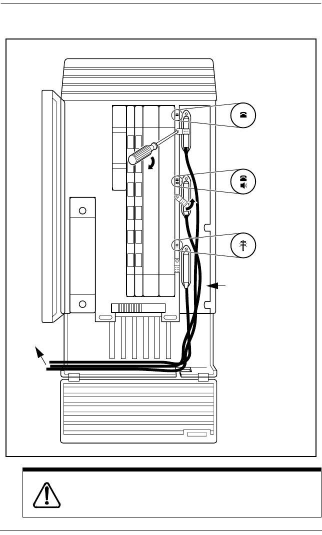
238 / Connecting the wiring
Modular ICS 6.0 Installer Guide P0992638 03
Connecting an ICS with loop start lines
Do not attach central office connections to the ICS
or Modules until power is connected to the units.
2 ICS extensions
and auxiliary
3 ICS lines
25-pair
0.5 mm (24 AWG)
cables with female
50-pin connector
to distribution
panel
1 ICS extensions
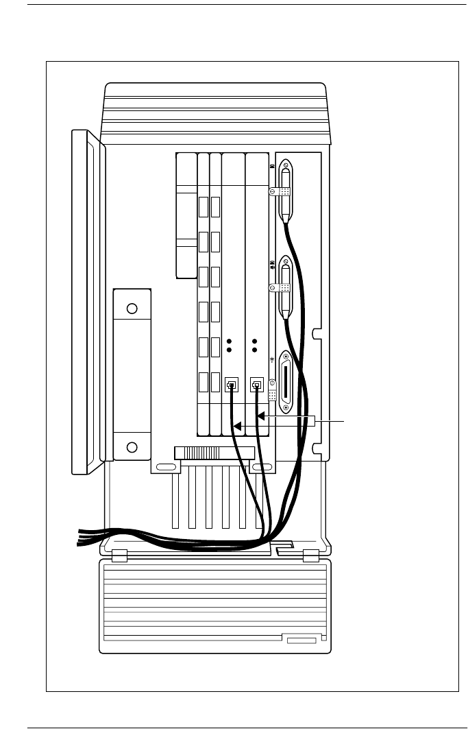
Connecting the wiring / 239
P0992638 03 Modular ICS 6.0 Installer Guide
Connecting the wiring for an ICS with T1 or PRI lines
MICS-XC 6.0 system
T1 lines from
Central Office
T1 or PRI lines from
Central Office
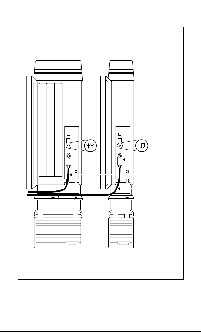
240 / Connecting the wiring
Modular ICS 6.0 Installer Guide P0992638 03
Connecting a module
25-pair
0.5 mm (24 AWG)
cables with female
50-pin connector
Close velcro
cable retainer
Cl
ose ve
l
cro ca
bl
e
retainer
25
-pa
i
r
0.5mm (24 AWG)
cables with female
50-pin connector

Connecting the wiring / 241
P0992638 03 Modular ICS 6.0 Installer Guide
Wiring charts
Port numbering on the wiring charts
The port number listed on the wiring charts is useful in
tracking down faults during a maintenance session where error
codes appear on the alarm telephone display. Refer to Alarm
codes on page 506.
The port numbers (for example: XX12) on the Trunk Cartridge
and Station Module wiring charts have two components:
•XX corresponds to the number that appears on the face of
the Expansion Cartridge port that the Trunk Module or
Station Module is connected to.
•digits (for example, 01 or 12) identify an individual port
number associated with that module.
For example:
The code 812 appearing as part of an error message for a Trunk
Module indicates that the problem is with Expansion Cartridge
port #8 and internal port 12. The corresponding Trunk Module
pins on the distribution block are pin 47 (violet-orange) and
pin 22 (orange-violet).
Integrated Communications System (ICS)
In the charts on the following pages, notice that the ICS has
two internal modules, ICS #1 and ICS #2. ICS #1 handles
telephones and auxiliary equipment. ICS #2 handles lines.
B1 and B2 directory numbers
The terms B1 and B2 correspond to channels on Norstar for
transmitting voice and data. Each DN port number has a B1
DN and a B2 DN. Devices such as the Norstar and Business

242 / Connecting the wiring
Modular ICS 6.0 Installer Guide P0992638 03
Series telephones use only the B1 DN. Other devices may need
both B1 and B2 channels, therefore requiring B1 and B2 DNs.
Non-expanded system (ICS alone) numbering
Two-port Expansion Cartridge and ICS numbering
Six-port Expansion Cartridge and ICS numbering
Module Lines Line ports B1 DN B2 DN DN ports
ICS (#2) 001-060 201-260 — — — — — —
ICS (#1) — — — —21-52 53-84 101-132
Module Lines Line ports B1 DN B2 DN DN ports
Mod 04 133-144 401-412 269-284 333-348 401-416
Mod 03 145-156 301-312 253-268 317-332 301-316
ICS (#2) 001-060 201-260 — — — — — —
ICS (#1) — — — —221-252 285-316 101-132
Module Lines Line
ports
B1 DN B2 DN DN
ports
Mod 08 061-084 801-812 333-348 461-476 801-816
Mod 07 085-108 701-712 317-332 445-460 701-716
Mod 06 109-120 601-612 301-316 429-444 601-616
Mod 05 121-132 501-512 285-300 413-428 501-516
Mod 04 133-144 401-412 269-284 397-412 401-416
Mod 03 145-156 301-312 253-268 381-396 301-316
ICS (#2) 001-060 201-260 — —— —— —
ICS (#1) — —— —221-252 349-380 101-132

Connecting the wiring / 243
P0992638 03 Modular ICS 6.0 Installer Guide
Twelve-port expanded system and ICS numbering
Module Lines Line ports B1 DN B2 DN DN ports
Mod 14 — — — — — — — — — —
Mod 13 — — — — — — — — — —
Mod 12 — — — —397-412 589-604 1201-1216
Mod 11 — — — —381-396 573-588 1101-1116
Mod 10 — — — —365-380 557-572 1001-1016
Mod 09 — — — —349-364 541-556 901-916
Mod 08 061-084 801-812 333-348 525-540 801-816
Mod 07 085-108 701-712 317-332 509-524 701-716
Mod 06 109-120 601-612 301-316 493-508 601-616
Mod 05 121-132 501-512 285-300 477-492 501-516
Mod 04 133-144 401-412 269-284 461-476 401-416
Mod 03 145-156 301-312 253-268 445-460 301-316
ICS (#2) 001-060 201-260 — — — — — —
ICS (#1) — — — —221-252 413-444 101-132
Tips - A 12-port expanded system is available on a
MICS-XC 6.0 system.
Depending on your system configuration, BRI-ST, BRI-U2,
and BRI-U4 cards can only reside in certain trunk modules.
On a Midi system, the cards must be in trunk modules 03 or 04.
On a Maxi or Mega system, the cards must be in trunk modules
07 or 08. The cards can reside in the ICS regardless of system
size.
Expansion module #13 and #14 are reserved for Companion
Wireless capability. Refer to your Modular ICS Companion
Installer Guide for information about using expansion module
#13 and #14.
244 / Connecting the wiring
Modular ICS 6.0 Installer Guide P0992638 03
ICS telephone wiring chart
Port 3 is the bottom fiber cable port on both the two-port and
the six-port Expansion Cartridge in slot 2. Port 9 is the bottom
fiber cable port located on the left most expansion card in slot 1.
B1 and B2 directory numbers reflect the default numbering
scheme.
If you expand your system after initial installation and
programming, there may appear to be gaps in your B1 DN
numbering. This is because the system has already assigned DN
numbers to B2 channels. You can correct these gaps by
performing Startup programming and resetting the system
memory, or by changing the individual DNs. See Change DNs
under System prgrming.
Startup programming erases the system
memory.
Pin Wire color Port Service Devices (ICS) Default DN
26 White-Blue 101 T 1
1 Blue-White 101 R 1 21/221/2221
27 White-Orange 102 T 2
2 Orange-White 102 R 2 22/222/2222
28 White-Green 103 T 3
3 Green-White 103 R 3 23/223/2223
29 White-Brown 104 T 4
4 Brown-White 104 R 4 24/224/2224
30 White-Slate 105 T 5
5 Slate-White 105 R 5 25/225/2225
31 Red-Blue 106 T 6
6 Blue-Red 106 R 6 26/226/2226
32 Red-Orange 107 T 7
7 Orange-Red 107 R 7 27/227/2227
33 Red-Green 108 T 8
8 Green-Red 108 R 8 28/228/2228
34 Red-Brown 109 T 9
9 Brown-Red 109 R 9 29/229/2229

Connecting the wiring / 245
P0992638 03 Modular ICS 6.0 Installer Guide
T and R represent station connections and should not be confused with Tip and Ring on external lines. Station connec-
tions are non-polarized.
ICS telephone and auxiliary equipment wiring chart
35 Red-Slate 110 T 10
10 Slate-Red 110 R 10 30/230/2230
36 Black-Blue 111 T 11
11 Blue-Black 111 R 11 31/231/2231
37 Black-Orange 112 T 12
12 Orange-Black 112 R 12 32/232/2232
38 Black-Green 113 T 13
13 Green-Black 113 R 13 33/233/2233
39 Black-Brown 114 T 14
14 Brown-Black 114 R 14 34/234/2234
40 Black-Slate 115 T 15
15 Slate-Black 115 R 15 35/235/2235
41 Yellow-Blue 116 T 16
16 Blue-Yellow 116 R 16 36/236/2236
42 Yellow-Orange 117 T 17
17 Orange-Yellow 117 R 17 37/237/2237
43 Yellow-Green 118 T 18
18 Green-Yellow 118 R 18 38/238/2238
44 Yellow-Brown 119 T 19
19 Brown-Yellow 119 R 19 39/239/2239
45 Yellow-Slate 120 T 20
20 Slate-Yellow 120 R 20 40/240/2240
46 Violet-Blue 121 T 21
21 Blue-Violet 121 R 21 41/241/2241
47 Violet-Orange 122 T 22
22 Orange-Violet 122 R 22 42/242/2242
48 Violet-Green 123 T 23
23 Green-Violet 123 R 23 43/243/2243
49 Violet-Brown 124 T 24
24 Brown-Violet 124 R 24 44/244/2244
50 Violet-Slate ---- ---- no connection ----
25 Slate-Violet ---- ---- no connection ----
Pin Wire color Port Service Telephones
(ICS)
Default DN
26 White-Blue 125 T 25
1 Blue-White 125 R 25 45/245/2245
27 White-Orange 126 T 26
2 Orange-White 126 R 26 46/246/2246
28 White-Green 127 T 27
Pin Wire color Port Service Devices (ICS) Default DN

246 / Connecting the wiring
Modular ICS 6.0 Installer Guide P0992638 03
3 Green-White 127 R 27 47/247/2247
29 White-Brown 128 T 28
4 Brown-White 128 R 28 48/248/2248
30 White-Slate 129 T 29
5 Slate-White 129 R 29 49/249/2249
31 Red-Blue 130 T 30
6 Blue-Red 130 R 30 50/250/2250
32 Red-Orange 131 T 31
7 Orange-Red 131 R 31 51/251/2251
33 Red-Green 132 T 32
8 Green-Red 132 R 32 52/252/2252
34 Red-Brown ---- ---- no connection
9 Brown-Red ---- ---- no connection
35 Red-Slate ---- ---- no connection
10 Slate-Red ---- ---- no connection
36 Black-Blue ---- ---- no connection
11 Blue-Black ---- ---- no connection
37 Black-Orange ---- ---- no connection
12 Orange-Black ---- ---- no connection
38 Black-Green ---- ---- no connection
13 Green-Black ---- ---- no connection
39 Black-Brown ---- ---- no connection
14 Brown-Black ---- ---- no connection
40 Black-Slate ---- T Page
15 Slate-Black ---- R Page
41 Yellow-Blue ---- Make External page
16 Blue-Yellow ---- Common External page
42 Yellow-Orange ---- T Music
17 Orange-Yellow ---- R Music
43 Yellow-Green ---- ---- reserved
18 Green-Yellow ---- ---- reserved
44 Yellow-Brown ---- Make Auxiliary ringer - 1
19 Brown-Yellow ---- Common Auxiliary ringer - 1
45 Yellow-Slate ---- ---- reserved
20 Slate-Yellow ---- ---- reserved
46 Violet-Blue ---- ---- no connection
21 Blue-Violet ---- ---- no connection
47 Violet-Orange ---- ---- reserved
22 Orange-Violet ---- ---- reserved
48 Violet-Green ---- ---- reserved
23 Green-Violet ---- ---- reserved
49 Violet-Brown ---- ---- reserved
Pin Wire color Port Service Telephones
(ICS)
Default DN

Connecting the wiring / 247
P0992638 03 Modular ICS 6.0 Installer Guide
T and R represent station connections and should not be confused with Tip and Ring on external lines. Station connec-
tions are non-polarized.
ICS external loop start lines wiring
24 Brown-Violet ---- ---- reserved
50 Violet-Slate ---- ---- reserved
25 Slate-Violet ---- ---- reserved
Pin Wire color Port Service Line
26 White-Blue 201 T 1
1 Blue-White 201 R 1
27 White-Orange 202 T 2
2 Orange-White 202 R 2
28 White-Green ---- ---- ----
3 Green-White ---- ---- ----
29 White-Brown ---- ---- ----
4 Brown-White ---- ---- ----
30 White-Slate 203 T 3
5 Slate-White 203 R 3
31 Red-Blue 204 T 4
6 Blue-Red 204 R 4
32 Red-Orange ---- ---- ----
7 Orange-Red ---- ---- ----
33 Red-Green ---- ---- ----
8 Green-Red ---- ---- ----
34 Red-Brown 225 T 25
9 Brown-Red 225 R 25
35 Red-Slate 226 T 26
10 Slate-Red 226 R 26
36 Black-Blue ---- ---- ----
11 Blue-Black ---- ---- ----
37 Black-Orange ---- ---- ----
12 Orange-Black ---- ---- ----
38 Black-Green 227 T 27
13 Green-Black 227 R 27
39 Black-Brown 228 T 28
14 Brown-Black 228 R 28
40 Black-Slate ---- ---- ----
15 Slate-Black ---- ---- ----
41 Yellow-Blue ---- ---- ----
16 Blue-Yellow ---- ---- ----
42 Yellow-Orange ---- ---- ----
17 Orange-Yellow ---- ---- ----
Pin Wire color Port Service Telephones
(ICS)
Default DN

248 / Connecting the wiring
Modular ICS 6.0 Installer Guide P0992638 03
For an explanation of port numbering, see
Port numbering on the wiring charts
on page 241.
BRI Wiring charts
A BRI Card in Slot 4 uses loops 201 through 204. A BRI card
in Slot 3 uses loops 225 through 228. Because a BRI-U2 Card
has only two loops, it only uses the first two loop numbers
(201-202 and 225-226) when it occupies an ICS slot.
The loops appearing on a BRI card may be automatically
assigned lines, or assigned one or more ISDN DNs in
Hardware. If the loop is configured as T or NT, lines are
automatically assigned. If the loop is configured as S or LT,
you can assign one or more ISDN DNs to the loop.
The emergency telephone connections (ET2 and ET1) cannot
be used if a BRI card is installed in Slot 3 or Slot 4,
respectively.
43 Yellow-Green ---- TET1
18 Green-Yellow ---- RET1
44 Yellow-Brown ---- TET2
19 Brown-Yellow ---- RET2
45 Yellow-Slate ---- ---- ----
20 Slate-Yellow ---- ---- ----
46 Violet-Blue ---- ---- ----
21 Blue-Violet ---- ---- ----
47 Violet-Orange ---- ---- ----
22 Orange-Violet ---- ---- ----
48 Violet-Green ---- ---- ----
23 Green-Violet ---- ---- ----
49 Violet-Brown ---- ---- ----
24 Brown-Violet ---- ---- ----
50 Violet-Slate ---- ---- ----
25 Slate-Violet ---- ---- ----
Pin Wire color Port Service Line

Connecting the wiring / 249
P0992638 03 Modular ICS 6.0 Installer Guide
For more information about configuring BRI cards refer to
BRI Card on page 48 in Welcome to ISDN and BRI card on
page 471 in Hardware.
ICS ST Interface Cards wiring
Pin Wire color Port (loop) Service Lines (T-loop)
Terminal
equipment
(S loop)
26 White-Blue 201 +Tx 001-002 Assigned DN
1 Blue-White 201 -Tx 001-002 Assigned DN
27 White-Orange 201 +Rx 001-002 Assigned DN
2 Orange-White 201 -Rx 001-002 Assigned DN
28 White-Green 202 +Tx 003-004 Assigned DN
3 Green-White 202 -Tx 003-004 Assigned DN
29 White-Brown 202 +Rx 003-004 Assigned DN
4 Brown-White 202 -Rx 003-004 Assigned DN
30 White-Slate 203 +Tx 005-006 Assigned DN
5 Slate-White 203 -Tx 005-006 Assigned DN
31 Red-Blue 203 +Rx 005-006 Assigned DN
6 Blue-Red 203 -Rx 005-006 Assigned DN
32 Red-Orange 204 +Tx 007-008 Assigned DN
7 Orange-Red 204 -Tx 007-008 Assigned DN
33 Red-Green 204 +Rx 007-008 Assigned DN
8 Green-Red 204 -Rx 007-008 Assigned DN
34 Red-Brown 225 +Tx 025-026 Assigned DN
9 Brown-Red 225 -Tx 025-026 Assigned DN
35 Red-Slate 225 +Rx 025-026 Assigned DN
10 Slate-Red 225 -Rx 025-026 Assigned DN
36 Black-Blue 226 +Tx 027-028 Assigned DN
11 Blue-Black 226 -Tx 027-028 Assigned DN
37 Black-Orange 226 +Rx 027-028 Assigned DN
12 Orange-Black 226 -Rx 027-028 Assigned DN
38 Black-Green 227 +Tx 029-030 Assigned DN
13 Green-Black 227 -Tx 029-030 Assigned DN
39 Black-Brown 227 +Rx 029-030 Assigned DN
14 Brown-Black 227 -Rx 029-030 Assigned DN
40 Black-Slate 228 +Tx 031-032 Assigned DN
15 Slate-Black 228 -Tx 031-032 Assigned DN
41 Yellow-Blue 228 +Rx 031-032 Assigned DN
16 Blue-Yellow 228 -Rx 031-032 Assigned DN
42 Yellow-Orange ---- ---- ---- ---

250 / Connecting the wiring
Modular ICS 6.0 Installer Guide P0992638 03
BRI S or T wiring is polarity sensitive.
Tx and Rx are Transmit and Receive for Norstar.
17 Orange-Yellow ---- ---- ---- ---
43 Yellow-Green ---- TET1 ---
18 Green-Yellow ---- RET1 ---
44 Yellow-Brown ---- TET2 ---
19 Brown-Yellow ---- RET2 ---
45 Yellow-Slate ---- ---- ---- ---
20 Slate-Yellow ---- ---- ---- ---
46 Violet-Blue ---- ---- ---- ---
21 Blue-Violet ---- ---- ---- ---
47 Violet-Orange ---- ---- ---- ---
22 Orange-Violet ---- ---- ---- ---
48 Violet-Green ---- ---- ---- ---
23 Green-Violet ---- ---- ---- ---
49 Violet-Brown ---- ---- ---- ---
24 Brown-Violet ---- ---- ---- ---
50 Violet-Slate ---- ---- ---- ---
25 Slate-Violet ---- ---- ---- ---
ICS U Interface Cards wiring
Pin Wire color Port
(loop)
Service Lines
(U-NT)
Terminal equipment
(U-LT)
26 White-Blue 201 T 001-002 Assigned DN
1 Blue-White 201 R 001-002 Assigned DN
27 White-Orange 202 T 003-004 Assigned DN
2 Orange-White 202 R 003-004 Assigned DN
28 White-Green ---- ---- ---- ----
3 Green-White ---- ---- ---- ----
29 White-Brown ---- ---- ---- ----
4 Brown-White ---- ---- ---- ----
30 White-Slate 203 T 005-006 Assigned DN
5 Slate-White 203 R 005-006 Assigned DN
31 Red-Blue 204 T 007-008 Assigned DN
6 Blue-Red 204 R 007-008 Assigned DN
32 Red-Orange ---- ---- ---- ----
7 Orange-Red ---- ---- ---- ----
ICS ST Interface Cards wiring (Continued)
Pin Wire color Port (loop) Service Lines (T-loop)
Terminal
equipment
(S loop)

Connecting the wiring / 251
P0992638 03 Modular ICS 6.0 Installer Guide
BRI U wiring is not polarity sensitive.
33 Red-Green ---- ---- ---- ----
8 Green-Red ---- ---- ---- ----
34 Red-Brown 225 T 025-026 Assigned DN
9 Brown-Red 225 R 025-026 Assigned DN
35 Red-Slate 226 T 027-028 Assigned DN
10 Slate-Red 226 R 027-028 Assigned DN
36 Black-Blue ---- ---- ---- ----
11 Blue-Black ---- ---- ---- ----
37 Black-Orange ---- ---- ---- ----
12 Orange-Black ---- ---- ---- ----
38 Black-Green 227 T 029-030 Assigned DN
13 Green-Black 227 R 029-030 Assigned DN
39 Black-Brown 228 T 031-032 Assigned DN
14 Brown-Black 228 R 031-032 Assigned DN
40 Black-Slate ---- ---- ---- ----
15 Slate-Black ---- ---- ---- ----
41 Yellow-Blue ---- ---- ---- ----
16 Blue-Yellow ---- ---- ---- ----
42 Yellow-Orange ---- ---- ---- ---
17 Orange-Yellow ---- ---- ---- ---
43 Yellow-Green ---- ---
18 Green-Yellow ---- ---
44 Yellow-Brown ---- ---
19 Brown-Yellow ---- ---
45 Yellow-Slate ---- ---- ---- ---
20 Slate-Yellow ---- ---- ---- ---
46 Violet-Blue ---- ---- ---- ---
21 Blue-Violet ---- ---- ---- ---
47 Violet-Orange ---- ---- ---- ---
22 Orange-Violet ---- ---- ---- ---
48 Violet-Green ---- ---- ---- ---
23 Green-Violet ---- ---- ---- ---
49 Violet-Brown ---- ---- ---- ---
24 Brown-Violet ---- ---- ---- ---
50 Violet-Slate ---- ---- ---- ---
25 Slate-Violet ---- ---- ---- ---
ICS U Interface Cards wiring (Continued)
Pin Wire color Port
(loop)
Service Lines
(U-NT)
Terminal equipment
(U-LT)

252 / Connecting the wiring
Modular ICS 6.0 Installer Guide P0992638 03
Wiring the BRI network interface
A network interface provides the connection between the
ISDN network and the Modular ICS.
If the card in the ICS is configured as a T-loop, the ICS is
wired to the network connection using an NT1.
See T reference points on page 51 for more information about
the NT1.
Wiring for T network connection
The Modular ICS supplies the NT1 functionality to a U-NT
loop, allowing a direct connection to the network. The
connection may use a plug and jack, or may be directly wired.
Wiring for U-NT network interface
Pin (jack or
plug)
NT1 connection
(for jack)
ICS and optional TE
connection (plug)
1not used optional power source 3 (+)
2not used optional power source 3 (-)
3+Rx +Tx
4+Tx +Rx
5-Tx -Rx
6-Rx -Tx
7not used optional power sink 2 (-)
8not used optional power sink 2 (+)
Pin (jack
or plug)
Norstar connection (for
plug to network interface
jack)
Network interface connection
(jack)
1not used optional battery status indicator (+)
2not used optional battery status indicator (-)
3not used no connection
4 R R
5 T T
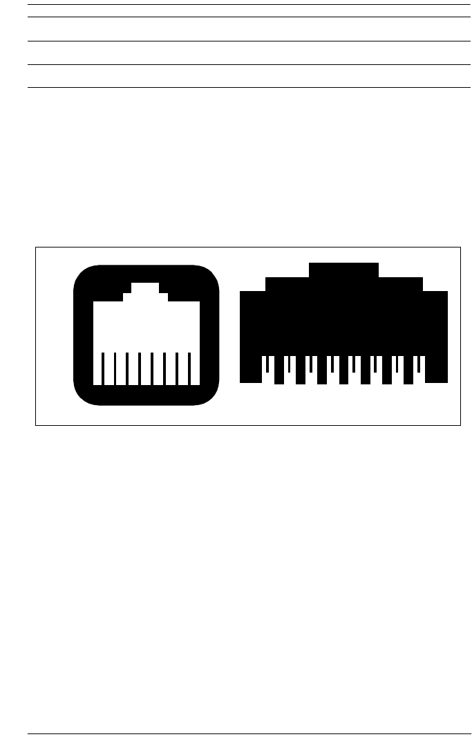
Connecting the wiring / 253
P0992638 03 Modular ICS 6.0 Installer Guide
The BRI-U Card does not use or provide optional power.
Some installations may not use a plug and jack for connections between the ICS (NT) and the network.
The following illustration shows the pin arrangement for a
Bellcore standard ISDN plug and jack. Other pin arrangements
are possible.
Jack and plug pin numbering
6not used no connection
7not used optional power supply (-)
8not used optional power supply (+)
8 7 6 5 4 3 2 1
1 2 3 4 5 6 7 8
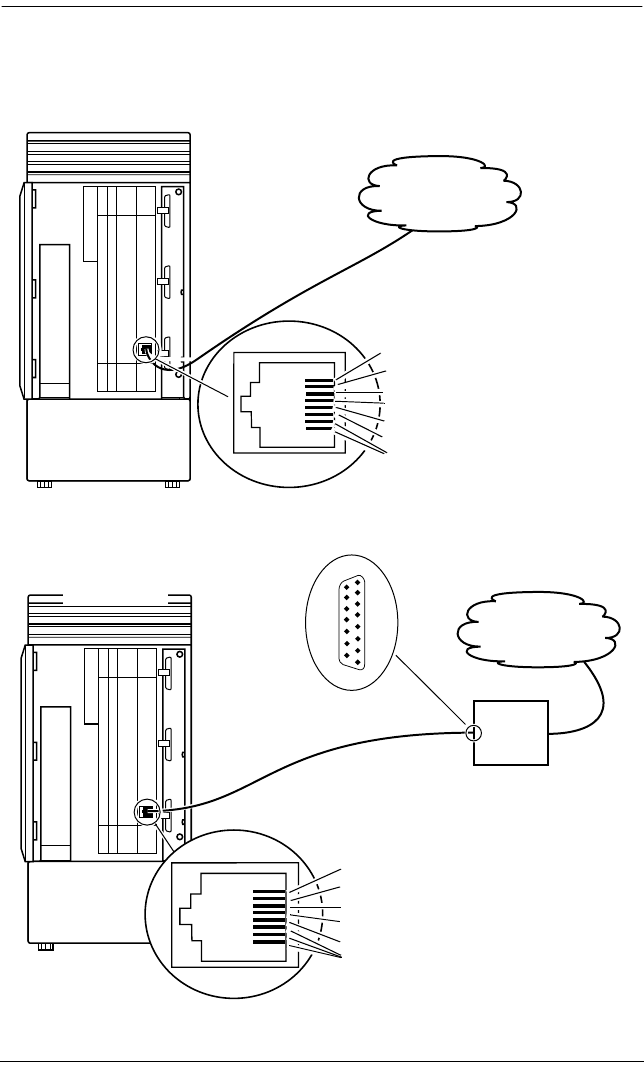
254 / Connecting the wiring
Modular ICS 6.0 Installer Guide P0992638 03
DTI wiring
Connecting the DTI to the T1 or PRI service provider
Connecting the DTI to an external CSU
Pin DirectionSignal
1Rx Ring (Rx from PSTN)
2Rx Tip (Rx from PSTN)
3 Rx cable shield (optional)
4Tx Ring (Tx to PSTN)
5Tx Tip (Tx to PSTN
6 Tx cable shield (optional)
7, 8 no connection
Norstar ICS
T1 or PRI
service provider
Norstar ICS
CSU
to DTE
DA15 connector
Norstar CSU
DT1 Pin Signal Pin
1 Rx Ring (Rx from CSU) 11
2 Rx Tip (Rx from CSU) 3
3 no connection
4 Tx Ring (Tx from CSU) 9
5 Tx Tip (Tx to CSU) 1
6-8 no connection
T1 or PRI
service provider
1
15

Connecting the wiring / 255
P0992638 03 Modular ICS 6.0 Installer Guide
Station Module wiring chart
Pin Wire color Port Service Telephones SM
26 White-Blue X01 T 1
1 Blue-White X01 R 1
27 White-Orange X02 T 2
2 Orange-White X02 R 2
28 White-Green X03 T 3
3 Green-White X03 R 3
29 White-Brown X04 T 4
4 Brown-White X04 R 4
30 White-Slate X05 T 5
5Slate-White X05 R 5
31 Red-Blue X06 T 6
6 Blue-Red X06 R 6
32 Red-Orange X07 T 7
7 Orange-Red X07 R 7
33 Red-Green X08 T 8
8 Green-Red X08 R 8
34 Red-Brown X09 T 9
9 Brown-Red X09 R 9
35 Red-Slate X10 T 10
10 Slate-Red X10 R 10
36 Black-Blue X11 T 11
11 Blue-Black X11 R 11
37 Black-Orange X12 T 12
12 Orange-Black X12 R 12
38 Black-Green X13 T 13
13 Green-Black X13 R 13
39 Black-Brown X14 T 14
14 Brown-Black X14 R 14
40 Black-Slate X15 T 15
15 Slate-Black X15 R 15
41 Yellow-Blue X16 T 16
16 Blue-Yellow X16 R 16
42 Yellow-Orange ---- ---- no connection
17 Orange-Yellow ---- ---- no connection
43 Yellow-Green ---- ---- no connection
18 Green-Yellow ---- ---- no connection
44 Yellow-Brown ---- ---- no connection
19 Brown-Yellow ---- ---- no connection
45 Yellow-Slate ---- ---- no connection
20 Slate-Yellow ---- ---- no connection
46 Violet-Blue ---- ---- no connection

256 / Connecting the wiring
Modular ICS 6.0 Installer Guide P0992638 03
T and R represent station connections and should not be confused with Tip and Ring on external lines. Station connec-
tions are non-polarized.
For an explanation of port numbering, see
Port numbering on the wiring charts
on page 241.
21 Blue-Violet ---- ---- no connection
47 Violet-Orange ---- ---- no connection
22 Orange-Violet ---- ---- no connection
48 Violet-Green ---- ---- no connection
23 Green-Violet ---- ---- no connection
49 Violet-Brown ---- ---- no connection
24 Brown-Violet ---- ---- no connection
50 Violet-Slate ---- ---- no connection
25 Slate-Violet ---- ---- no connection
Loop Start or CI Trunk Cartridge wiring chart
TC Slot Pin Wire color Port Service Line
Slot 1 26 White-Blue X01 T 1
1 Blue-White X01 R 1
27 White-Orange X02 T 2
2 Orange-White X02 R 2
28 White-Green ---- No connection ----
3 Green-White ---- No connection ----
29 White-Brown ---- No connection ----
4 Brown-White ---- No connection ----
30 White-Slate X03 T 3
5Slate-White X03 R 3
31 Red-Blue X04 T 4
6 Blue-Red X04 R 4
32 Red-Orange ---- No connection ----
7 Orange-Red ---- No connection ----
33 Red-Green ---- No connection ----
8 Green-Red ---- No connection ----
Slot 2 34 Red-Brown X05 T 5
9 Brown-Red X05 R 5
35 Red-Slate X06 T 6
10 Slate-Red X06 R 6
36 Black-Blue ---- No connection ----
11 Blue-Black ---- No connection ----
37 Black-Orange ---- No connection ----
12 Orange-Black ---- No connection ----
38 Black-Green X07 T 7
13 Green-Black X07 R 7
Station Module wiring chart (Continued)
Pin Wire color Port Service Telephones SM

Connecting the wiring / 257
P0992638 03 Modular ICS 6.0 Installer Guide
For an explanation of port numbering, see
Port numbering on the wiring charts
on page 241.
E&M/DISA Trunk Cartridge wiring chart
Use the table, Trunk Module with E&M/DISA Trunk
Cartridges, on page258 when a Trunk Module has only
E&M/DISA Trunk Cartridges.
If the Norstar system is being connected to another Norstar
system or private branch exchange by connecting two RJ2HX/
CA2HA distribution blocks together, use the following table
to determine the required cross-connections.
Back-to-back cross-connections
39 Black-Brown X08 T 8
14 Brown-Black X08 R 8
40 Black-Slate ---- No connection ----
15 Slate-Black ---- No connection ----
41 Yellow-Blue ---- No connection ----
Slot 3 42 Yellow-Orange X09 T 9
17 Orange-Yellow X09 R 9
43 Yellow-Green X10 T 10
18 Green-Yellow X10 R 10
44 Yellow-Brown ---- No connection ----
19 Brown-Yellow ---- No connection ----
45 Yellow-Slate ---- No connection ----
20 Slate-Yellow ---- No connection ----
46 Violet-Blue X11 T 11
21 Blue-Violet X11 R 11
47 Violet-Orange X12 T 12
22 Orange-Violet X12 R 12
48 Violet-Green ---- No connection ----
23 Green-Violet ---- No connection ----
49 Violet-Brown ---- No connection ----
24 Brown-Violet ---- No connection ----
50 Violet-Slate ---- ET ----
25 Slate-Violet ---- ET ----
1st distribution block T R T1 R1 ESG MSB
Next distribution block T1 R1 T R SB MSG E
Loop Start or CI Trunk Cartridge wiring chart (Continued)
TC Slot Pin Wire color Port Service Line

258 / Connecting the wiring
Modular ICS 6.0 Installer Guide P0992638 03
Tips - When installing a mixture of E&M/DISA, DID, BRI,
or Loop Start Trunk Cartridges, it is important to cross-
connect the wiring for each type of TC to a separate
distribution block.
To verify the operation of the Norstar E&M cards and the
target lines, wire the two E&M lines on the Norstar E&M back
to back.
The cross-connections to each distribution block must always
begin at pins 26 and 1. To retain emergency telephone function,
install a Loop Start Trunk Cartridge in the left-most slot
(slot 1) of the TM.
Trunk Module with E&M/DISA Trunk Cartridges
TC Slot Pin Wire color Port Service Line
Slot 1 26 White-Blue X01 T 1
1 Blue-White X01 R 1
27 White-Orange X01 T1 1
2 Orange-White X01 R1 1
28 White-Green X01 E 1
3 Green-White X01 SG 1
29 White-Brown X01 M 1
4 Brown-White X01 SB 1
30 White-Slate X02 T 2
5Slate-White X02 R 2
31 Red-Blue X02 T1 2
6 Blue-Red X02 R1 2
32 Red-Orange X02 E 2
7 Orange-Red X02 SG 2
33 Red-Green X02 M 2
8 Green-Red X02 SB 2
Slot 2 34 Red-Brown X05 T 5
9 Brown-Red X05 R 5
35 Red-Slate X05 T1 5
10 Slate-Red X05 R1 5
36 Black-Blue X05 E 5
11 Blue-Black X05 SG 5
37 Black-Orange X05 M 5
12 Orange-Black X05 SB 5
38 Black-Green X06 T 6

Connecting the wiring / 259
P0992638 03 Modular ICS 6.0 Installer Guide
For an explanation of port numbering, see
Port numbering on the wiring charts
on page 241.
13 Green-Black X06 R 6
39 Black-Brown X06 T1 6
14 Brown-Black X06 R1 6
40 Black-Slate X06 E 6
15 Slate-Black X06 SG 6
41 Yellow-Blue X06 M 6
16 Blue-Yellow X06 SB 6
Slot 3 42 Yellow-Orange X09 T 9
17 Orange-Yellow X09 R 9
43 Yellow-Green X09 T1 9
18 Green-Yellow X09 R1 9
44 Yellow-Brown X09 E 9
19 Brown-Yellow X09 SG 9
45 Yellow-Slate X09 M 9
20 Slate-Yellow X09 SB 9
46 Violet-Blue X10 T 10
21 Blue-Violet X10 R 10
47 Violet-Orange X10 T1 10
22 Orange-Violet X10 R1 10
48 Violet-Green X10 E 10
23 Green-Violet X10 SG 10
49 Violet-Brown X10 M 10
24 Brown-Violet X10 SB 10
50 Violet-Slate ---- reserved ----
25 Slate-Violet ---- reserved ----
Trunk Module with DID Trunk Cartridges
TC Slot Pin Wire color Port Service Line
Slot 1 26 White-Blue X01 T 1
1 Blue-White X01 R 1
27 White-Orange X02 T 2
2 Orange-White X02 R 2
28 White-Green ---- No connection ----
3 Green-White ---- No connection ----
29 White-Brown ---- CCI NC1 ----
4 Brown-White ---- CCI Com1 ----
30 White-Slate X03 T 3
5 Slate-White X03 R 3
31 Red-Blue X04 T 4
Trunk Module with E&M/DISA Trunk Cartridges (Continued)
TC Slot Pin Wire color Port Service Line

260 / Connecting the wiring
Modular ICS 6.0 Installer Guide P0992638 03
For an explanation of port numbering, see
Port numbering on the wiring charts
on page 241.
For CCI connections in Service column: NC1 stands for the normally closed relay and Com1 the common relay.
CCI signaling is not supported by all carriers. For carriers or installations that do not use CCI signaling, the CCI and ET
connections should be treated as “no connection”. CCI wiring is a non-standard wiring arrangement which has been
submitted to the DOC.
6 Blue-Red X04 R 4
32 Red-Orange ---- No connection ----
7 Orange-Red ---- No connection ----
33 Red-Green ---- No connection ----
8 Green-Red ---- No connection ----
Slot 2 34 Red-Brown X05 T 5
9 Brown-Red X05 R 5
35 Red-Slate X06 T 6
10 Slate-Red X06 R 6
36 Black-Blue ---- No connection ----
11 Blue-Black ---- No connection ----
37 Black-Orange ---- CCI NC1 ----
12 Orange-Black ---- CCI Com1 ----
38 Black-Green X07 T 7
13 Green-Black X07 R 7
39 Black-Brown X08 T 8
14 Brown-Black X08 R 8
40 Black-Slate ---- No connection ----
15 Slate-Black ---- No connection ----
41 Yellow-Blue ---- No connection ----
16 Blue-Yellow ---- No connection ----
Slot 3 42 Yellow-Orange X09 T 9
17 Orange-Yellow X09 R 9
43 Yellow-Green X10 T 10
18 Green-Yellow X10 R 10
44 Yellow-Brown ---- No connection ----
19 Brown-Yellow ---- No connection ----
45 Yellow-Slate ---- CCI NC1 ----
20 Slate-Yellow ---- CCI Com1 ----
46 Violet-Blue X11 T 11
21 Blue-Violet X11 R 11
47 Violet-Orange X12 T 12
22 Orange-Violet X12 R 12
48 Violet-Green ---- No connection ----
23 Green-Violet ---- No connection ----
49 Violet-Brown ---- No connection ----
24 Brown-Violet ---- No connection ----
50 Violet-Slate ---- ET ----
25 Slate-Violet ---- ET ----
Trunk Module with DID Trunk Cartridges (Continued)
TC Slot Pin Wire color Port Service Line

Connecting the wiring / 261
P0992638 03 Modular ICS 6.0 Installer Guide
DID supervisory signaling
This equipment returns supervisory signals to the public
switched telephone network (PSTN) when the DID calls are:
•answered by the called telephone
•answered by the attendant
•routed to a customer controlled recorded announcement
•routed to a dial prompt
This equipment is designed to return supervisory signals on all
DID calls forwarded through the system back to the PSTN
within 20 seconds of call forwarding being initiated.
Emergency transfer conditions
Every DID Trunk Cartridge has a Control Circuit Interface
(CCI) which should be connected directly to the central office
for monitoring purposes.
If the Norstar system loses power or the microcontroller on the
DID Trunk Cartridge malfunctions, the CCI signals the central
office that it can no longer handle DID calls. The central
office, by prearrangement, then forwards the DID lines to
other numbers.
Connect the CCI com1 connection to a ground connection.
Connect the CCI NC1 connection to the central office
demarcation.
Tips - CCI signaling to report power loss or malfunction
of the DID Trunk Cartridge is not supported by all carriers.
For carriers or installations which do not use CCI signaling,
the CCI and ET connections are treated as not connected.
Wire each CCI independently to the central office. If the
connections are wired in parallel, any CCI trouble disables all
DID Trunk Cartridges. If the connections are wired in series,
all DID Trunk Cartridges must fail before the central office
recognizes the trouble condition.

262 / Connecting the wiring
Modular ICS 6.0 Installer Guide P0992638 03
Trunk Module with BRI-ST cartridge
TC
slot
Pin Wire color Port
(loop)
Service Lines
(T or
S loop)
Terminal
equipment
S loop)
Slot 1 26 White-Blue X01 +Tx 001-002 Assigned DN
1 Blue-White X01 -Tx 001-002 Assigned DN
27 White-Orange X01 +Rx 001-002 Assigned DN
2 Orange-White X01 -Rx 001-002 Assigned DN
28 White-Green X02 +Tx 003-004 Assigned DN
3 Green-White X02 -Tx 003-004 Assigned DN
29 White-Brown X02 +Rx 003-004 Assigned DN
4 Brown-White X02 -Rx 003-004 Assigned DN
30 White-Slate X03 +Tx 005-006 Assigned DN
5 Slate-White X03 -Tx 005-006 Assigned DN
31 Red-Blue X03 +Rx 005-006 Assigned DN
6 Blue-Red X03 -Rx 005-006 Assigned DN
32 Red-Orange X04 +Tx 007-008 Assigned DN
7 Orange-Red X04 -Tx 007-008 Assigned DN
33 Red-Green X04 +Rx 007-008 Assigned DN
8 Green-Red X04 -Rx 007-008 Assigned DN
Slot 2 34 Red-Brown X05 +Tx 009-010 Assigned DN
9 Brown-Red X05 -Tx 009-010 Assigned DN
35 Red-Slate X05 +Rx 009-010 Assigned DN
10 Slate-Red X05 -Rx 009-010 Assigned DN
36 Black-Blue X06 +Tx 011-012 Assigned DN
11 Blue-Black X06 -Tx 011-012 Assigned DN
37 Black-Orange X06 +Rx 011-012 Assigned DN
12 Orange-Black X06 -Rx 011-012 Assigned DN
38 Black-Green X07 +Tx 013-014 Assigned DN
13 Green-Black X07 -Tx 013-014 Assigned DN
39 Black-Brown X07 +Rx 013-014 Assigned DN
14 Brown-Black X07 -Rx 013-014 Assigned DN
40 Black-Slate X08 +Tx 015-016 Assigned DN
15 Slate-Black X08 -Tx 015-016 Assigned DN
41 Yellow-Blue X08 +Rx 015-016 Assigned DN
16 Blue-Yellow X08 -Rx 015-016 Assigned DN

Connecting the wiring / 263
P0992638 03 Modular ICS 6.0 Installer Guide
To determine the assigned lines for a BRI card, refer to BRI and T1 lines on page 522.
For an explanation of port numbering, see Port numbering on the wiring charts on page 241.
Trunk Module with BRI-U cartridge
Slot 3 42 Yellow-Orange X09 +Tx 017-018 Assigned DN
17 Orange-Yellow X09 -Tx 017-018 Assigned DN
43 Yellow-Green X09 +Rx 017-018 Assigned DN
18 Green-Yellow X09 -Rx 017-018 Assigned DN
44 Yellow-Brown X10 +Tx 019-020 Assigned DN
19 Brown-Yellow X10 -Tx 019-020 Assigned DN
45 Yellow-Slate X10 +Rx 019-020 Assigned DN
20 Slate-Yellow X10 -Rx 019-020 Assigned DN
46 Violet-Blue X11 +Tx 021-022 Assigned DN
21 Blue-Violet X11 -Tx 021-022 Assigned DN
47 Violet-Orange X11 +Rx 021-022 Assigned DN
22 Orange-Violet X11 -Rx 021-022 Assigned DN
48 Violet-Green X12 +Tx 023-024 Assigned DN
23 Green-Violet X12 -Tx 023-024 Assigned DN
49 Violet-Brown X12 +Rx 023-024 Assigned DN
24 Brown-Violet X12 -Rx 023-024 Assigned DN
50 Violet-Slate ---- reserved ---- ----
25 Slate-Violet ---- reserved ---- ----
TC
slot
Pin Wire color Port
(loop)
Service Lines
(U-NT)
Terminal
equipment
(U-LT)
Slot 1 26 White-Blue X01 T 001-002 Assigned DN
1 Blue-White X01 R 001-002 Assigned DN
27 White-Orange X02 T 003-004 Assigned DN
2 Orange-White X02 R 003-004 Assigned DN
28 White-Green ---- ---- ---- ----
3 Green-White ---- ---- ---- ----
29 White-Brown ---- ---- ---- ----
4 Brown-White ---- ---- ---- ----
30 White-Slate X03 T 005-006 Assigned DN
5 Slate-White X03 R 005-006 Assigned DN
31 Red-Blue X04 T 007-008 Assigned DN
6 Blue-Red X04 R 007-008 Assigned DN
32 Red-Orange ---- ---- ---- ----
Trunk Module with BRI-ST cartridge (Continued)
TC
slot
Pin Wire color Port
(loop)
Service Lines
(T or
S loop)
Terminal
equipment
S loop)

264 / Connecting the wiring
Modular ICS 6.0 Installer Guide P0992638 03
BRI U wiring is not polarity sensitive.
A BRI-U2 Card only uses the first two loop numbers (X01-X02, X05-X06, or X09-X10) when it occupies a trunk module
slot.
7 Orange-Red ---- ---- ---- ----
33 Red-Green ---- ---- ---- ----
8 Green-Red ---- ---- ---- ----
Slot 2 34 Red-Brown X05 T 009-010 Assigned DN
9 Brown-Red X05 R 009-010 Assigned DN
35 Red-Slate X06 T 011-012 Assigned DN
10 Slate-Red X06 R 011-012 Assigned DN
36 Black-Blue ---- ---- ---- ----
11 Blue-Black ---- ---- ---- ----
37 Black-Orange ---- ---- ---- ----
12 Orange-Black ---- ---- ---- ----
38 Black-Green X07 T 013-014 Assigned DN
13 Green-Black X07 R 013-014 Assigned DN
39 Black-Brown X08 T 015-016 Assigned DN
14 Brown-Black X08 R 015-016 Assigned DN
40 Black-Slate ---- ---- ---- ----
15 Slate-Black ---- ---- ---- ----
41 Yellow-Blue ---- ---- ---- ----
16 Blue-Yellow ---- ---- ---- ----
Slot 3 42 Yellow-Orange X09 T 017-018 Assigned DN
17 Orange-Yellow X09 R 017-018 Assigned DN
43 Yellow-Green X10 T 019-020 Assigned DN
18 Green-Yellow X10 R 019-020 Assigned DN
44 Yellow-Brown ---- ---- ---- ----
19 Brown-Yellow ---- ---- ---- ----
Slot 3 45 Yellow-Slate ---- ---- ---- ----
20 Slate-Yellow ---- ---- ---- ----
46 Violet-Blue X11 T 021-022 Assigned DN
21 Blue-Violet X11 R 021-022 Assigned DN
47 Violet-Orange X12 T 023-024 Assigned DN
22 Orange-Violet X12 R 023-024 Assigned DN
48 Violet-Green ---- ---- ---- ---
23 Green-Violet ---- ---- ---- ---
49 Violet-Brown ---- ---- ---- ---
24 Brown-Violet ---- ---- ---- ---
50 Violet-Slate ---- reserved ---- ---
25 Slate-Violet ---- reserved ---- ---
TC
slot
Pin Wire color Port
(loop)
Service Lines
(U-NT)
Terminal
equipment
(U-LT)

Emergency telephone / 265
P0992638 03 Modular ICS 6.0 Installer Guide
Emergency telephone
You can connect an emergency telephone to an ICS or Trunk
Module (TM) with a Loop Start Trunk Cartridge to provide
emergency service when there is no power to the ICS. The ICS
has emergency telephone connections for lines 002 and 026.
Each Trunk Module has one emergency telephone connection.
1. Wire a modular jack or equivalent to each set of
emergency telephone pins on the 50-pin distribution block
for the ICS or Trunk Module external lines.
Refer to Wiring charts on page 241 for the pin numbers.
2. Connect a single-line telephone (500/2500) to the modular
jack.
3. Prepare to test the emergency telephone by removing the
Trunk Cartridge from the slot (slot 3 or 4 on the ICS, and
slot 1 on the TM).
4. Connect the power, then connect the central office lines to
the ICS.
5. Pick up the emergency telephone receiver and listen for
dial tone.
6. Disconnect the central office lines, then remove power
from the system.
7. Replace the Trunk Cartridge in the left slot.
8. Continue with procedures for powering up the system.
Tips - The emergency telephone connections on the Trunk
Module will not work if there is an E&M/DISA, a BRI-ST or
BRI-U card or a DID Trunk Cartridge in the first slot of the
Trunk Module. The emergency telephone connections on the
ICS will not work if DTIs or PRIs are used.

266 / Emergency telephone
Modular ICS 6.0 Installer Guide P0992638 03
Tips - Norstar telephones and Business Series Terminals
cannot be used as off-premise telephones (OPX). For OPX
applications, use the Norstar Analog Terminal Adapter
(ATA2) and a single-line telephone. Refer to the
ATA
Installation Card
for details.

Moving telephones / 267
P0992638 03 Modular ICS 6.0 Installer Guide
Moving telephones
You can move a system telephone to a new location within the
Norstar system without losing the programmed settings.
When Set relocation is enabled in system programming, the
internal numbers, autodial settings, and personal speed dial
codes remain with the telephone when it is unplugged.
To move a telephone, simply unplug it and plug it in again at
another location. It may take up to 45 seconds for the ICS to
recognize the telephone. Automatic telephone relocation is
disabled by default.
Tips - Relocate the disconnected system telephone before
connecting a new telephone into the jack. This allows the
moved telephone to retain the programmed settings.
If a new telephone is plugged into the jack before the old
telephone is reconnected at a new location, Norstar will give
the current telephone information to the new telephone. The
old telephone will no longer be recognized by the system.
When reprogramming the internal number of a telephone, wait
one minute after Automatic Telephone Relocation.
When you relocate a telephone, the telephone must remain
installed and connected in the new location for at least three
minutes for the programming relocation to be complete.
Moving the telephone again before the three-minute period
may result in losing the programming on the telephone.

268 / Installing ISDN BRI terminal equipment
Modular ICS 6.0 Installer Guide P0992638 03
Installing ISDN BRI terminal
equipment
For each S or T or U-LT reference point, an eight-position
miniature unkeyed plug from the terminal equipment (TE) is
plugged into a jack connected to Norstar wiring. The pin
connections for the jack and plug are shown in the following
charts.
S or T wiring for terminal equipment
S or T extension wiring configurations
The last connection on any ISDN S or T extension wiring must
have terminating resistors to ensure correct timing of the
signaling circuits. Failure to install terminating resistors will
degrade performance. Terminating resistors should not be
connected on a TE which is not the last connection on the loop.
Terminating resistors are provided on terminal equipment. See
the instructions that come with your TE for information on
how to enable or disable the termination, as required.
Pin
(jack or plug)
Norstar connection
(for jack)
Equipment connection (plug)
1not used optional power source 3 (+)
2not used optional power source 3 (-)
3+Rx +Rx
4+Tx +Tx
5-Tx -Tx
6-Rx -Rx
7not used optional power sink 2 (-)
8not used optional power sink 2 (+)

Installing ISDN BRI terminal equipment / 269
P0992638 03 Modular ICS 6.0 Installer Guide
The maximum length of spur and ISDN connection cord
(the extension from the main line or bus) is 10 m (30 ft).
Refer to S reference point on page 51 and T reference points
on page 51 in the Welcome to ISDN chapter for information
about wiring arrangements for ISDN terminal equipment (TE)
on an S or T loop.
Additional power
A Norstar S or T-loop does not provide power on Power
Source 1 (PS1), Power Source (PS2), or Power Source or
Sink 3 (PS3). If you are installing ISDN terminal equipment at
the S-reference point, and the equipment requires additional
power on PS1, PS2, or PS3, then you can install a suitably
approved power supply unit. See ANSI T1.605 or the
documentation that comes with your TE for details.
The Modular ICS does not require power on PS3.
Wiring arrangements using side circuits, also called phantom
circuits, may affect loop performance when they are used to
provide power to the TE (PS1). You must account for any
effects. For example, you may need to reduce the number of
TEs on a passive bus.

270 / Installing ISDN BRI terminal equipment
Modular ICS 6.0 Installer Guide P0992638 03
U-LT wiring for terminal equipment
No power supply is provided for the U-LT wiring. If
equipment attached to the U-LT loop requires optional power,
install an approved power supply unit. See ANSI T1.601-1992
Annex H or the documentation that comes with your TE for
more information.
Jack and plug pin numbering
Pin (jack or plug) Norstar connection
(for jack)
Equipment connection (plug)
1not used optional battery status
indication (+)
2not used optional battery status
indication (-)
3not used no connection
4 R R
5 T T
6not used no connection
7not used optional power (-)
8not used optional power (+)
8 7 6 5 4 3 2 1
1 2 3 4 5 6 7 8

Installing optional equipment / 271
P0992638 03 Modular ICS 6.0 Installer Guide
Installing optional equipment
This section describes the installation procedures for optional,
customer-suppled equipment.
Auxiliary ringer (customer supplied)
The Norstar ICS provides a control contact to operate an
auxiliary ringer.
1. Follow the installation instructions provided by the
manufacturer.
2. Connect the auxiliary ring generator to the 50-pin
distribution block as shown in the wiring charts.
The pins in this chart provide a control contact. They do
not provide ring current or DC voltage. The ringer must
not draw more than 50 mA from a 40 V DC source.
Auxiliary ringer programming
The auxiliary ringer can be activated by setting auxiliary ring
for specific external lines, and auxiliary ring for specific
telephones. Refer to the
Modular ICS 6.0 System Coordinator
Guide
for programming details.
Heading
Trk/Line Data
Capabilities
Services

272 / Installing optional equipment
Modular ICS 6.0 Installer Guide P0992638 03
External music source (customer supplied)
The music source can be any approved low-power device such
as a radio with a high-impedance earphone jack. The
recommended ICS input level is 0.25 V rms across an input
impedance of 3300 Ω.
1. Connect the music source output to the 50-pin distribution
block, as shown in the wiring charts.
2. Adjust the volume of the music source to a comfortable
level by activating Background Music ( ) and
adjusting the volume at the music source.
External music source programming
Music for callers on Hold and for Background Music must be
enabled through programming. Refer to Backgrnd music on
page 397 for more details.
Confirm that the following settings are implemented:
Tips - Background Music volume can also be adjusted at
each telephone.
Heading Setting
Featr settings On hold: Music
Featr settings Backgrnd music: Y

Installing optional equipment / 273
P0992638 03 Modular ICS 6.0 Installer Guide
External paging system (customer supplied)
You can connect an external paging system to provide paging
over external loudspeakers. The paging output from the
Norstar ICS is 100 mV rms across an input impedance of
600 Ω.
1. Follow the installation instructions provided by the
manufacturer.
2. Connect the paging system audio input to the 50-pin
distribution block as shown in the wiring charts.
3. Connect the paging system relay to the 50-pin distribution
block as shown in the wiring charts.
External paging contacts
Tips - Norstar external paging does not support talk-back
paging equipment unless an external line port is used.
The Norstar system provides paging over the Norstar
telephone speakers, even when no external paging equipment
is connected.
idle active
Yellow-Blue
(make)
Blue-Yellow
(common)
Yellow-Blue
(make)
Blue-Yellow
(common)
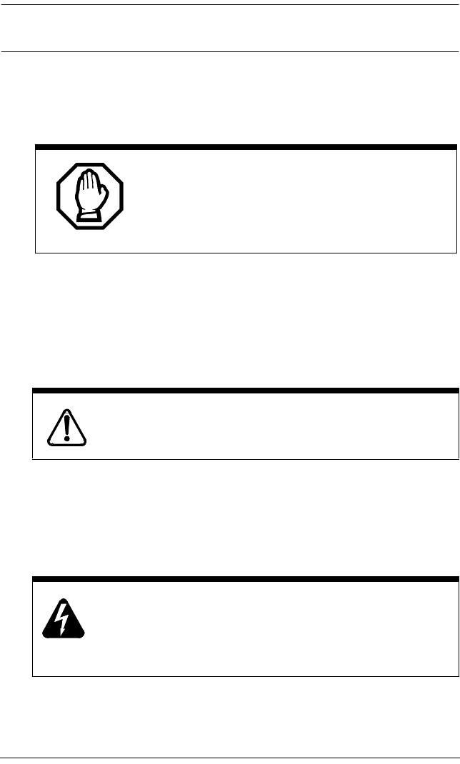
274 / Powering up the system
Modular ICS 6.0 Installer Guide P0992638 03
Powering up the system
1. Double-check all wiring before turning the system power
on. Ensure all outlets where you will plug in the modules
are non-switchable, third-wire ground AC outlets.
2. Route the module power cords through the lower shelf of
the cable trough and out through the bottom of the ICS
cable trough.
3. Route the ICS power cord through the bottom of the ICS
cable trough.
4. Connect each power cord to an electrical outlet.
If you are using a power bar, plug the power cords into the
power bar, and then connect the power bar to the
AC outlet.
Do not connect central office line cables to the
modules until after the system power is on.
Companion: Install Base Stations before powering
up the MICS-XC 6.0 system.
Do not fasten power supply cords.
Do not fasten the ICS power supply cord or module
power supply cords to any building surface, including
the backboard.
Powering up the system / 275
P0992638 03 Modular ICS 6.0 Installer Guide
Check the power
After the power is supplied, the ICS power supply LEDs will
light up green. If a BRI cartridge is installed, the LEDs on the
faceplate of the cartridge will flash for up to five minutes.
Telephones and lines also may take up to five minutes to
initialize.
1. Check that the power LEDs of the power supply, the TMs,
and the SMs are on.
2. If none of the LEDs are on, verify that power is present at
the outlet. If there is power at the outlet, see Problems for
network or remote users on page 576.
Once the system is initialized and the telephone displays read
Jan 1 1:00 am, you have 15 minutes in which to perform Profile,
Dialpad, and Startup programming. After 15 minutes, access
to Startup programming is denied.
Close and lock the ICS door.
Close and lock the ICS door after installation is
complete to avoid accidental shock and to provide
containment in the event of fire.
Tips - During system initialization, the system performs a
self-diagnostic test on the hardware configuration size and
expansion cartridge installation.
Tips - After system startup, you can turn the power off and
on and retain any system data that has been entered. This is
considered a warm start. A warm start takes approximately
5-10 minutes. However, if you run Startup again, the default
programming will be reestablished.
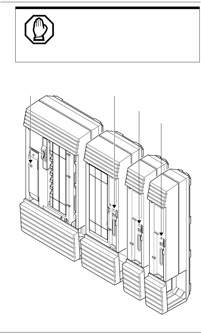
276 / Powering up the system
Modular ICS 6.0 Installer Guide P0992638 03
System power indicators
Call Log information may be lost.
If the Norstar system suffers a power failure or
the system is manually restarted, Call Log
information is not saved. Notify users if a system
restart is planned so any log information can be
written down first.
ICS LED (green) TM LED (red)
SM LED (red)
IDM LED (green)
ICS LED (green) TM LED (red)
SM LED (red)
IDM LED (green)
P0992638 03 Modular ICS 6.0 Installer Guide
Programming
The installer or the customer service representative programs
settings for the entire Norstar system, plus settings for
individual telephones and external lines.
Most of the settings can also be programmed by a system
coordinator who has a SysCoord+ password. The SysCoord+
password should only be used by individuals who are capable
of programming the Norstar ICS. Further, this level of access
should only be distributed to System Coordinators who are
more experienced in programming the Norstar ICS.
Programming affects system operation.
Only a qualified installer or customer service
representative should perform startup, installation and
maintenance programming. Some of the settings affect
the correct operation of the system.

278 / Programming overview
Modular ICS 6.0 Installer Guide P0992638 03
Programming overview
Programming access is controlled by these passwords.
•Profile password — allows you to determine the system
profile. The default profile is the profile used for North
American applications.
•Dialpad password — allows you to determine the style
of dialpad programming for your system. This setting
determines which key you press to obtain the letters Q
and Z. The default is non_CCITT (press 0 for both
letters).
•Installer password — allows you to determine the
defaults you will use as the basis for your system
programming. It also allows you to view these settings
and change them, as required for your system
requirements.
•System Coordinator Plus password — provides
knowledgeable users with access to all but a few
sensitive areas of programming. You should only
distribute this password to experienced System
Coordinators.
•System Coordinator password — allows an
administrator responsible for the day-to-day operation
privileges to view and change the settings that affect
on-going operations. This level of access is documented
in the Modular ICS 6.0 System Coordinator Guide.
•Basic password – provides a limited number of feature
codes to change programming and control system
services.
For information about programming using the System
Coordinator and Basic passwords, see the Modular ICS 6.0
System Coordinator Guide.
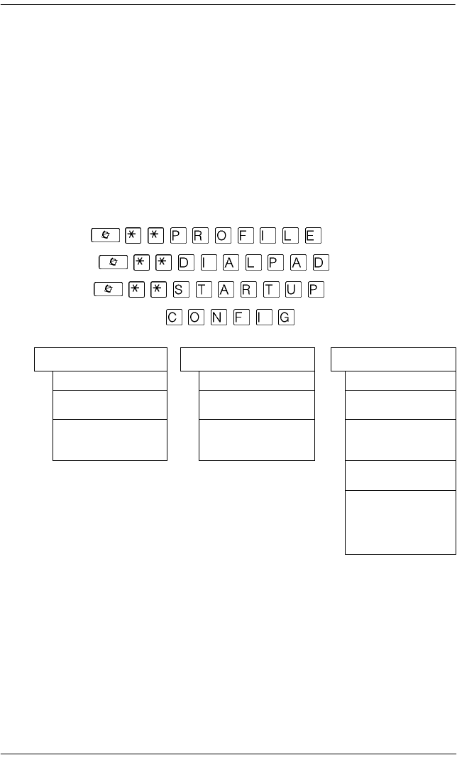
Programming overview / 279
P0992638 03 Modular ICS 6.0 Installer Guide
The tables in this section provide an overview of what
programming is seen by each type of user. For information
about changing the passwords, see Passwords on page 382.
If you are new to programming, you may want to practice
using the step-by-step programming instructions in the Getting
Started section of the Modular ICS 6.0
System Coordinator
Guide
before attempting other programming.
Profile, Dialpad and Startup programming
Profile: (**7763453)
Dialpad: (**3425723)
Startup: (**7827887)
Default password: (266344)
Profile Dialpad Startup
Password: (CONFIG) Password: (CONFIG) Password: (CONFIG)
Region: PROF1
OK CHANGE
QZ:0
CHANGE
Reset Memory?
YES
Template:
CHANGE
Start DN: 2221
CHANGE
Applying Template
(Install is complete
when Date and Time
appears on the dis-
play)

280 / Programming overview
Modular ICS 6.0 Installer Guide P0992638 03
Installer or System Coordinator Plus programming
Entry code: (**266344)
Installer password: (266344)
System Coordinator Plus password:
(727587)
Shaded items are seen only if you are using the Installer
password. Note: As well, some headings will not appear unless
the appropriate software code has been entered, for instance
Network Services requires the PRI and MCDN software
codes. Other settings will not appear unless the appropriate
cards or trunks are assigned. CbC headings, for instance, do
Startup Passwords Telco features
Template COS pswds VMsg ctr tel#s
Start DN Call log pswds ONN blocking
Terminals&Sets Progrming pswds Software keys
Line access Reg. pswd SysID
Capabilities Hospitality Password keys
Name Hardware
User prefernces Time&Date Cards on KSU
Restrictions System prgrming Mod 03 - Mod 14
(depending on
type of system)
Telco features Hunt groups
Lines Change DNs Maintenance
Trunk/Line data Featr settings System version
Name Direct-dial Port/DN status
Restrictions CAP assignment Module status
Telco features Dialing Plan Sys test log
Services Access codes
Ringing service Remote access Sys admin log
Restrn service Change DN type Network evt log
Routing service Companion Provisioning
Rec’d # length Tests
Common settings DN length CSU stats
Sys speed dial BusName Diagnostic tools
CbC limits Link status
Release reasons Usage metrics
Hospitality Hunt groups
Network Services Call-by-Call
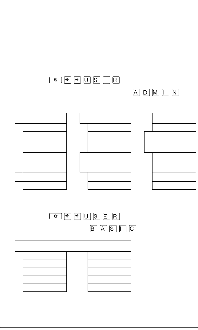
Programming overview / 281
P0992638 03 Modular ICS 6.0 Installer Guide
not appear unless the NI-2 protocol is used on the DTI trunk
card.
Yellow areas are only available with MICS-XC software.
These headings provide programming access for the
Companion wireless setup.
System Coordinator programming
User code: (**8737)
Default System Coordinator password:
(23646)
Admin/Basic programming
User code: (**8737)
Default Basic password: (22742)
Terminals&Sets Services Reg. pswd
Capabilities Ringing service Hospitality
Name Restrn service Time&Date
User prefernces Routing service System prgrming
Restrictions Sys speed dial Hunt Groups
Telco features Passwords Companion
Lines Call log pswds BusName
Name Progrming pswds Hospitality
Set ####
Model Language
Button prgrming Display cntrst
User speed dial Ring Type
Call log opt’ns Voice path
Dialing opt’ns
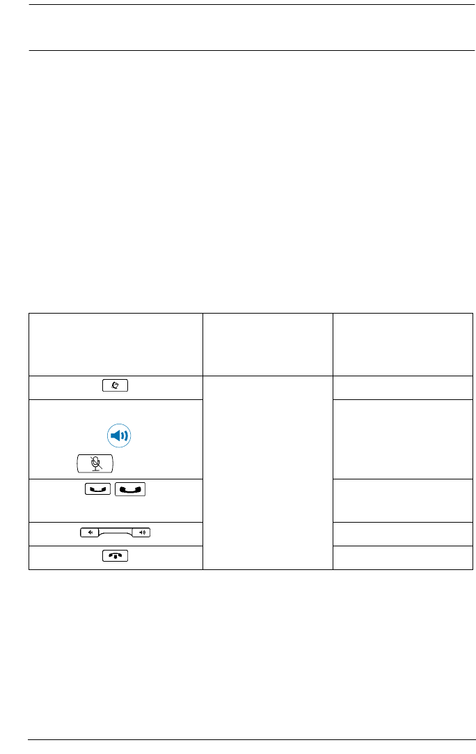
282 / Programming tools
Modular ICS 6.0 Installer Guide P0992638 03
Programming tools
This section describes how to set up a telephone for system
programming.
You will note that two different sheets of programming
overlays came with your Programming Record. Use the one
that was created for the telephone you plan to use to program
your system.
You can use a T7316 Business Series Terminal or an M7310
or M7324 telephone for programming. These telephones have
two-line displays. Use the appropriate template and refer to the
table below for corresponding button faces:
Business Series Terminals
T7100, T7208, T7316, T7406
Button description
Norstar sets
M7100, M7208,
M7310, M7324
Feature ƒ
T7208 and T7316:
Handsfree:
Mute:
Handsfree/Mute ©
≥
Hold ˙
≥
Volume Control √
Release ®
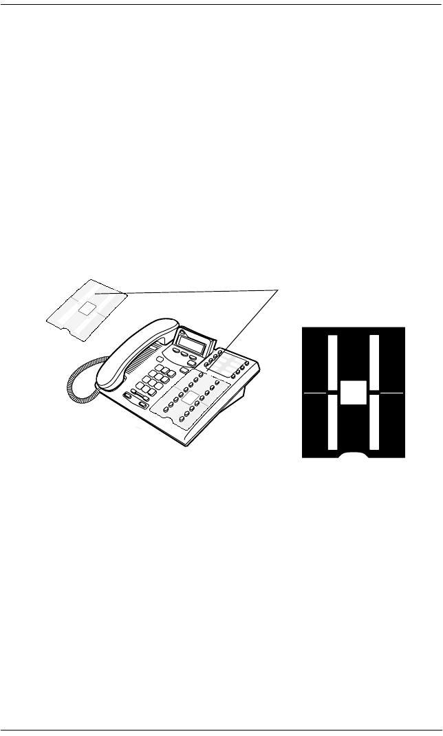
Programming tools / 283
P0992638 03 Modular ICS 6.0 Installer Guide
The programming overlay
The
programming overlay is a paper cutout that labels the four
telephone buttons used during programming. You received
two pages of overlays with your Programming Record. One
page corresponds to the Business Series Terminals T7316
telephone. The second sheet corresponds to the Norstar
M7310 and M7324 telephones.
Remove the appropriate overlay from the page and put it over
the buttons indicated in the following diagrams.
Business Series Terminal T7316 with overlay
Business
Series
Terminals
Programming
Overlay
Heading
Back
Show
Next
Business
Series
Terminals
Programming
Overlay
Heading
Back
Show
Next
Business
Series
Terminals
Programming
Overlay
Heading
Back
Show
Next
Place overlay
over bottom set of
memory buttons
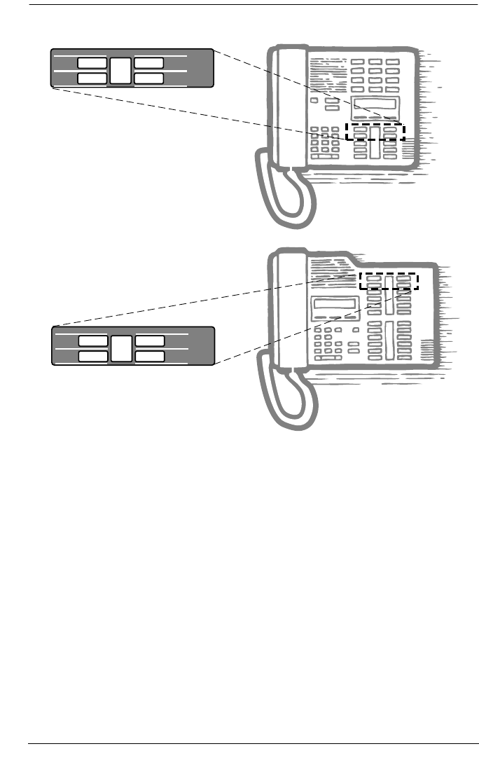
284 / Programming tools
Modular ICS 6.0 Installer Guide P0992638 03
Norstar terminals M7310 and 7324 with overlays
Using the telephone buttons for programming
On the overlay, each of the four programming buttons is
assigned a action feature.
The indicators (º) on the display beside the buttons show
which buttons are active at each programming step. Press the
appropriate button to move up or down through the Norstar
programming menu.
The table below describes the action of each button.
Heading
Back Next
Show
Norstar Programming Overlay
Heading
Back Next
Show
Norstar Programming Overlay

Programming tools / 285
P0992638 03 Modular ICS 6.0 Installer Guide
Telephone overlay button definitions
Special characters on the display
When a heading ends with a triangle (ˆ), you can press
≠ to view the subheadings for that item.
When a heading ends with an ellipsis (…), you can press
≠ to see further information about that heading.
The display buttons
Display buttons on the telephones perform a number of
functions, depending on where you are in programming. Up to
three display button messages may be available at any time.
–moves to a higher level in the hierarchy of headings
and subheadings.
≠moves to a lower level in the hierarchy of headings and
subheadings, or begins programming for a heading or
subheading.
“moves backward at the same level in the hierarchy of
headings and subheadings.
‘moves forward at the same level in the hierarchy of
headings and subheadings.
Heading
Back Next
Show
Norstar Programming Overlay
PO698666 Issue 02
Printed in Canada

286 / Programming tools
Modular ICS 6.0 Installer Guide P0992638 03
Press the display button underneath the message for the
function you want the system to perform.
The most common display button labels are described in the
following table:
Display button definitions
CHANGE changes a programmable setting
BKSP moves the cursor one space to the left (backspace) and
deletes a character, allowing you to re-enter a number or
letter
COPY copies the settings of items like lines, telephones and filters
to an item of the same type
LIST displays the lowest value in a list of DNs, lines or other items
FIND allows you to enter specific code to go directly to a record
VIEW‚ views the last part of a displayed message longer than 16
characters
·VIEW views the first part of a displayed message longer than 16
characters
>moves the cursor one position to the right when
programming a name
<moves the cursor one position to the left when programming
a name
OK confirms the change you made, or accepts the default, if you
made no changes
ANY Enters a wild card character that represents any digit
between 1 and 9.
Show line:
COPY
Display message
Display button message
Display button

Programming tools / 287
P0992638 03 Modular ICS 6.0 Installer Guide
The Norstar Programming Record
The
Programming Record
can be used to help you plan your
programming strategy. If you enter all your settings on the
tables provided, you create a quick reference guide to your
system.
Pages from the record may be photocopied, as necessary, for
programming many telephones or lines. Additional
Programming Records can also be ordered from your vendor.
Exiting
Norstar stores your changes automatically as soon as you alter
any settings. If you changed something in error, you must
re-enter the correct data.
In extreme situations, you may have to restart the system and
reload with your backup material.
To exit the configuration interface, press . The display
briefly reads End of session, then returns to the Date and
Time display.
Viewing your programming updates
If any changes you made to programming have not taken effect
yet, you will see an UPDATE display button when you leave
programming. The display will show you how many
telephones have not been updated yet because the system is
busy with other programming or the telephone is in use.
Press DNs to see the specific telephones where programming
changes have not been updated. Items will disappear from the
list as they are updated, and UPDATE will disappear once all
changes are complete.

288 / Programming tools
Modular ICS 6.0 Installer Guide P0992638 03
Entering numbers
Numbers are entered from the Norstar telephone dialpad. The
backspace display button may be used to edit the number.
A line number must always be entered as a three-digit number.
Line numbers from 10 to 99 must be entered with a leading
zero (line 020, for example). Similarly, line numbers less than
10 must be entered with two leading zeros (line 002, for
example).
Internal telephone numbers, also referred to as directory
numbers (DNs), can be from three to seven digits long. The
default DN length is three. The DN length can be changed in
programming.
Viewing long telephone numbers
External telephone numbers can be up to 24 digits, but the
telephone display is only 16 character spaces long. To see a
previously-programmed number that is longer than 16 digits,
do the following:
Begin, for example, with 123456789012345…. The display
shows only the first 15 digits. The three dots (…) at the end of
the display indicate that more digits remain to the external
number.
1. To see the remaining digits, press VIEW‚.
2. To see the first 15 digits again, press ·VIEW.

Programming tools / 289
P0992638 03 Modular ICS 6.0 Installer Guide
Setting up User Preferences
The User Preferences feature allows you to program memory
buttons, speed dial codes, and other settings for any telephone
on the system.
For example, an employee may want to have the Do Not
Disturb feature programmed onto a memory button or create a
speed dial code. Instead of programming from the target
telephone, you can program these features from another
telephone.
To access User Preferences programming, see instructions in
the Modular ICS 6.0 System Coordinator Guide.
The following table lists the settings you can adjust.
Subheadings under User Preferences
User prefernces
Model
Button prgrming
User speed dial
Call log opt’ns
Dialing opt’ns
Language
Display cntrst
Ring type
Voice path

290 / Copying telephone programming
Modular ICS 6.0 Installer Guide P0992638 03
Copying telephone programming
Copying is done by using COPY under Terminals&Sets. You
can copy programming from one telephone to another
telephone, to a range of telephones, or to all telephones.
1. At Terminals&Sets ˆ, press ≠ and enter the
internal number (DN) of the telephone from which you
wish to copy programming.
2. Press COPY.
3. Select what programming will be copied:
•SYSTEM – the system administration programming
(system data) of a telephone
OR
•SYSTEM+USER – the system administration
programming PLUS the programming for a particular
telephone (user data)
See the tables starting on page 292 to see which settings
will and will not be copied with system and user data.
4. Press ‘, then CHANGE to select the telephone or
telephones which will be programmed with the copied
data: SINGLE, RANGE, ALL.
You can copy programming to telephones which are not
yet hooked up to the system (unequipped).
5. Press ‘, then CHANGE to select which telephones
will be programmed: Only equipped DNs, All set DNs.
This is not necessary when copying to a single telephone.
6. Press ‘ and enter the internal number of the
telephone that will be programmed or the internal numbers
of the first and last telephone in a range.
Copying telephone programming / 291
P0992638 03 Modular ICS 6.0 Installer Guide
7. Press OK to proceed with the copy. This step is not
necessary when you are copying to a single telephone.
You can also use COPY to duplicate the settings found in the
individual subheadings. The button is available in Line access,
Capabilities, User prefernces, Restrictions and Telco
features and will copy only the settings included in the
subheading.
If you press COPY in one of these subheadings, you will not be
asked to decide if user data will be copied. Otherwise, the
procedure is the same.
Tips - To copy to a group of telephones which are not part
of a range, follow the steps for making a single copy and keep
entering new numbers at the
Copy to: display.
Depending on the activities going on in the system, a copy may
not take effect for a while. The brief display you see once you
have finished a copying session does not indicate the process
is complete.
You can leave the programming session even if the copy has
not been completed. If you exit programming, copying will
continue uninterrupted until it is complete.
Tips - Event messages capture both the start and
completion of the copying process. For more information, see
Event messages on page 514.
Some programming settings allow you to choose a delay
according to the number of rings. The ring counts used are
based on a North American standard of six seconds per ring
cycle. The actual delay time may be different for a device other
than a Norstar telephone.

292 / Copying telephone programming
Modular ICS 6.0 Installer Guide P0992638 03
System Data that gets copied System data that is NOT copied
Line access
•Line assignment
•Line pool access
•Prime line designation
•Number of intercom keys
•Answer DNs (unless Answer
button DN is same as
telephone being copied to)
Line access
•Private line appearances
Capabilities
•Call Forward No Answer (DN +
delay + setting)
•Call Forward Busy (DN +
setting)
•DND on busy
•Handsfree setting
•Handsfree answerback
•Pickup group
•Paging zone
•Paging
•Direct-dial (which set is
reached by the D-Dial digit)
•Priority calling
•Hotline
•Auxiliary ringer
•Allow redirect
•Redirect ring
•ATA settings (except Use
ringback setting)
Capabilities
•Set name
•Use ringback setting under ATA
settings
Telco Features
•Call Log set
(Logging set)
•1stDisplay
Telco features
•Log password
•Log space
Restrictions
•Set restrictions
•Set lock
•Allow Last Number Redial
•Allow Saved Number Redial
•Allow Link
•Line/set restrictions
Direct-dial set designation (which set
is the D-Dial set)
CAP assignment
ExtraDial set designation
Service mode ringing set
designation
Prime set designation for a line
Hunt group appearance
Copying telephone programming / 293
P0992638 03 Modular ICS 6.0 Installer Guide
Ring volume, User speed dial and CAP module memory
button programming are not copied with user data.
System ID
The System ID (or System Security number) can be accessed
on a programming terminal display by pressing
or .
Reviewing programmed settings
The Set Profile and Line Profile features help you to check
your programming by allowing you to review the settings.
Programming that can be reviewed
User data that gets copied User data that is not copied
if destination set type is
the same as the source set type
Language choice
Ring type
Calls log options
(Auto logging)
Display contrast
Dialing options (automatic, pre-dial,
standard)
External autodial button assignments
Internal autodial button assignments
Programmable button assignments
Set Profile Line Profile
Terminals&Sets settings Lines settings
Set name Line name
Line Access Trunk data
Capabilities Line data
Restrictions Restrictions
Telco features Telco features
294 / Copying telephone programming
Modular ICS 6.0 Installer Guide P0992638 03
Viewing the programming for a telephone
To display the programming for a set, follow these steps:
1. Press .
The display reads Show set:.
2. Enter the internal number of the telephone you wish to
review.
3. Use BACK, NEXT, and SHOW to navigate through the
settings.
4. Press to exit.
Viewing the programming for a line
To view line programming for a telephone, follow these steps:
1. Press .
The display reads Show line:.
2. Enter the number of the line you wish to review.
3. Use BACK, NEXT, and SHOW to navigate through the
settings.
4. Press to exit.

Programming sequence / 295
P0992638 03 Modular ICS 6.0 Installer Guide
Programming sequence
The programming information in this guide is presented in the
order that is useful for everyday changes and upkeep of the
system.
The following order of process is recommended as more
suitable for an installation. However, the order in which you
program your system will depend on a variety of variables and
may differ from this list.
•Profile and Dialpad, if required (page 296 and page 300)
•Startup (initializes system) (page 301)
•Software keys for PRI and MCDN, if required. (page 452)
•Hardware (starting on page 455)
•Lines (including any networks) (starting on page 333)
•Terminals&Sets (starting on page 308)
•System prgrming (starting on page 389(
•Services (starting on page 353)
•Telco features (starting on page 447)
•Other software keys (Companion) (Companion Installer
and Coordinator Guides)
•Sys speed dial (starting on page 381)
•Passwords (starting on page 382)
•Time&Date (starting on page page 388)
•customized programming, such as Voice Mail (refer to the
documents for the specific application)

296 / Profiles and Dialpads
Modular ICS 6.0 Installer Guide P0992638 03
Profiles and Dialpads
Use Profile programming to determine which types of trunks
are supported, and which are supported on and off core.
Use Dialpad programming to define how your system will
handle the letters Q and Z from the dialpad.
Profile programming
If your system is outside of North America, you may require a
slightly different operating profile for your system. You must
choose these parameters before you perform your system
startup programming.
If your system is in North America or you know that you want
to run that profile, you do not need to run this program.
Profile parameters
Each market profile setting supports a different selection of
trunk cards. In your situation you may require NI (primarily
North America and some parts of South America) or ETSI
(Europe, Asia, and some parts of South America) ISDN.
Analog to digital expansion and compression rates can be
either a-law or mu-law, as well. The tables in the following
sections show which trunks are supported, and where.
You must do this procedure BEFORE you run
Startup, within the first 15 minutes after you plug
in your KSU.
If you run this program after Startup, you will lose
your settings.

Profiles and Dialpads / 297
P0992638 03 Modular ICS 6.0 Installer Guide
Note: If you are unsure of the ISDN protocol or companding
law active in your area, consult with your ISDN service
provider for details.
Profile 1
This profile is the default profile. It supports cards and
protocols for Canada and the United States. This profile has
language support for English, Canadian French, and Spanish.
The mu-law companding law is used in this profile. The off-
core DTI module is supported on this profile.
Profile 2
This profile is for international systems that use ETSI ISDN
lines with aLaw. The languages supported include: English,
French, Spanish, and Turkish.
Cards supported on-core Cards supported off-core
•Analog •Analog
•DTI •E&M
•4-port BRI-ST •4-port BRI-ST
•2-port BRI-ST •2-port BRI-ST
•PRI (E1)
Supported Not supported
•ETSI MCDN (SL-1) and
EURO protocols
•DID
•aLaw companding law •UTAM
•Loops are provisioned
•T7000 telephone

298 / Profiles and Dialpads
Modular ICS 6.0 Installer Guide P0992638 03
Profile 3
This profile provides language support in NA English, CDN
French, US Spanish, and Turkey. This profile is for countries
who use ETSI ISDN with mu-law (i.e. some Asian locations)
Profile 4
This profile provides language support in English, French, and
Spanish. This profile is for countries who use NI ISDN
protocol with mu-law (i.e. some areas in the Caribbean).
Cards supported on-core Cards supported off-core
•Analog •Analog
•T1 •E&M
•4-port BRI-ST •DID
•2-port BRI-ST •4-port BRI-ST
•2-port BRI-ST
Supported Not supported
•ETSI ISDN protocol •PRI
•muLaw companding law •UTAM
•Loops are provisioned
•T7000 telephone
Cards supported on-core Cards supported off-core
•Analog •Analog
•T1 •E&M
•PRI •DID
•4-port BRI-ST •4-port BRI-ST
•2-port U •2-port U
•4-port U •4-port U

Profiles and Dialpads / 299
P0992638 03 Modular ICS 6.0 Installer Guide
Changing the profile
If your system is in North America or you know that you want
to run the North American profile, you do not need to run this
program.
If you need to change the profile, follow these steps:
1. Enter the Profile access code from a programming set by
pressing (**7763453).
2. Enter the password, when prompted.
(266344)
3. Region:PROF1 displays. Press the key below Change to
scroll to another profile number.
4. Click the display key for OK when you reach the profile
you want to choose.
5. Press to exit.
Supported Not supported
•NI ISD protocol •UTAM
•muLaw companding law •Loops are not provisioned
•PRI, including MCDN
•T7000 telephone
300 / Profiles and Dialpads
Modular ICS 6.0 Installer Guide P0992638 03
Dialpad programming
Use this program to determine how the system will recognize
the characters Q and Z from a set dialpad. The two types of
configurations are called CCITT and non-CCITT.
The default is non-CCITT, where Q and Z are accessed
through the dialpad button.
CCITT systems access these characters through the (Q)
and (Z) dialpad keys.
To change the setting, follow these steps:
1. Enter the Dialpad access code from a programming set by
pressing (**3425723).
2. Q,Z:0 displays. To change it, press the key below Change.
3. Press to exit.
Startup programming / 301
P0992638 03 Modular ICS 6.0 Installer Guide
Startup programming
After the hardware has been installed and powered up, use
Startup to initialize the system, and select the system template
that best suits your system.
Performing Startup
1. Enter the Startup access code from a programming set, by
pressing which is the
same as .
To be accepted, the Startup code must be entered no later
than 15 minutes after the Norstar system has been powered
up.
If 15 minutes have elapsed since you powered up the
system, turn system power off and on and wait for the
system to power up again.
2. Enter the Installer password.
The default is which is the same as
.
Startup erases programming.
Startup erases any existing programmed data,
and resets the system to factory defaults.
Tip - Ensure that you have current backups of your
system programming and logs.
All programming is retained for three days if the power
fails or if the Norstar system is powered off. After three
days, it may be necessary to perform Startup.
302 / Startup programming
Modular ICS 6.0 Installer Guide P0992638 03
Changing the default template
After entering the Startup access code and Installer password
the set displays Reset memory?.
1. Press YES to select a default template.
The display shows the current template.
2. Press CHANGE to choose the appropriate template.
Changing the starting DN
You can change the starting number for your telephone
directory numbers (DNs). This is helpful when your system is
part of a network and you want to use a uniform series of
directory numbers for all telephones in your network.
With the display showing the current template.
1. Press ‘.
The display shows the current start DN.
2. Press CHANGE.
Tips - The Installer password shown is the default
normally used for Startup. For a system which has already
been programmed, the Installer password might have been
changed in programming and recorded in the
Programming
Record
.
Changing the template resets programming!
If you change your system template on an
existing system, your programming will be reset
to the defaults.
If this happens, perform an immediate restore
from your backups.
Startup programming / 303
P0992638 03 Modular ICS 6.0 Installer Guide
3. Enter the new directory number you want as the starting
DN, and press OK.
The display shows the new range of DN numbers.
4. Press ‘ to store the programming.
The display shows Applyng template.
This process takes a few minutes. When it is complete, the
indicators begin to flash. When the set displays Jan 1 1:00 am.
the initialization is complete.
The length of the directory number that you enter sets the
length for all directory numbers. Target line received numbers
are set to the same length when using the DID template. DNs
can be from three to seven digits. If your system is part of a
network, the DN length must be the same as all other systems.
A DN length change, if required, should be the first
programming change on a newly-installed Norstar system.
Changing the DN length
If you reduce the length of the directory numbers in DN
length in System prgrming, the starting DN number is
reset to the default value (221).
If you increase the length of directory numbers in DN
length in System prgrming, each increase in length places
the digit 2 in front of any existing DN. For example, if DN 3444
was increased to a length of 6, the new DN would be 223444.
If the new DNs clash with the direct-dial digit, park prefix, or
line pool codes or destination codes, those numbers are
overridden and set to None.
Do not disable or enable ports in Maintenance
programming during the first two minutes after Startup
programming.

304 / Programming
Modular ICS 6.0 Installer Guide P0992638 03
Programming
When Startup is complete, use programming to change default
settings, as required. Use the programming record to orient
yourself within the programming menus.
Programming for both MICS 6.0 and MICS-XC 6.0 has the
following main headings:
Terminals&Sets Allows you to assign settings to each
telephone.
Lines Allows you to assign settings to each
trunk, external and target line.
Services Allows you to create services such as
night ringing, routing and restrictions for
making external calls.
Sys speed dial Allows you to create speed dial codes
that can be used by any telephone in the
system.
Passwords Allows you to view and change
passwords for programming and
features.
Time&Date Allows you to set the time and date on
the system clock.
System prgrming Allows you to change system-wide
settings.
Telco features Allows you to assign settings for
external voice message services.
Software keys* Allows you to access system
identification and password keys.
Allows you to enter the software keys to
activate PRI, Companion (MICS-XC,
only), or the Private Networking (MCDN)
Programming / 305
P0992638 03 Modular ICS 6.0 Installer Guide
*For information about programming for Companion, see the
Modular ICS Companion Installer Guide.
Entering programming for installers
1. Enter the installer codes on a programming set by pressing
,
which is the same as .
The display shows Password:.
2. Enter the Installer password.
The default password is CONFIG (266344).
The display shows Terminals&Sets. Three triangular
indicators º appear on the vertical display between the
rows of buttons.
3. Place the
programming overlay over the buttons pointed to
by the indicators º.
Hardware Allows you to configure the Trunk
Cartridges and BRI cards used by the
system.
Maintenance Allows you to view diagnostic
information about the system and
provision BRI cartridges.
Usage metrics Provides statistical information on Hunt
groups.

306 / Programming
Modular ICS 6.0 Installer Guide P0992638 03
Entering programming for system coordinators
The person on staff who is in charge of making changes on the
Norstar system is called the system coordinator. The everyday
programming done by system coordinators is described in the
Modular ICS 6.0 System Coordinator Guide.
Some system coordinators need to be able to program more
advanced settings and functions in order to carry out the day-
to-day requests and upkeep of the Norstar. These coordinators
are usually dedicated communications specialists who work
with large Norstar systems or other telephone systems like
PBX or Centrex.
By using a special password, a system coordinator can see and
change many, but not all, of the programming settings used by
an installer. In this guide, programming that can only be
changed by an installer is marked in the heading. If you are
programming using the System Coordinator + password, you
will not see these items when you move through the menus.
This level of access is documented in the Modular ICS 6.0
System Coordinator Guide.
1. Enter the System Coordinator plus codes on a
programming set by pressing
, which is the same as
.
The display shows Password:.
2. Enter the System Coordinator + password.
The default password is SCPLUS (727587).
The display shows Terminals&Sets ˆ. Three triangular
indicators º appear on the vertical display between the
rows of buttons.
3. Place the
programming overlay over the buttons pointed to
by the indicators º.

Programming / 307
P0992638 03 Modular ICS 6.0 Installer Guide
Entering programming using other passwords
A set of the most often-used headings and subheadings is
available by using a System Coordinator password. Refer to
page 281. This level of access is designed for the average user
who takes care of the day-to-day changes to the Norstar
system, but who is not interested in more advanced
programming. The default password is ADMIN (23646).
There is also a Basic password that can be used to perform a
few programming tasks. The default password is BASIC
(22742). By using this password, a system coordinator can
delegate some responsibilities while keeping secure more
sensitive programming features. For more information, refer
to Modular ICS 6.0 System Coordinator Guide.

308 / Terminals&Sets
Modular ICS 6.0 Installer Guide P0992638 03
Terminals&Sets
Terminals&Sets allows you to assign settings to each
telephone.
This is the first heading that appears after you enter your
password.
1. Press ≠.
The prompt displays: Show set:
2. Enter the set number of the telephone you would like to
program.
3. Press COPY to duplicate the programming for the telephone
and apply it to another telephone, a range of telephones or
all the telephones on the system.
For more information about copying set programming,
refer to Copying telephone programming on page 290.
Line access
Line access allows you to assign lines to individual
telephones. When you are finished programming Line access
settings for one telephone, you can copy those settings to other
telephones.
In some cases, Line access programming for Norstar
Companion portables works differently than it does for desk
sets. See the Modular ICS Companion Installer Guide for
information.
PRI lines can only be configured as direct inward dialing
(DID) lines. Therefore, PRI lines are always Auto Answer and
cannot be Manual Answer.

Terminals&Sets / 309
P0992638 03 Modular ICS 6.0 Installer Guide
Line assignment
This setting allows you to assign physical trunks and target
lines to each telephone. Target lines are assigned and removed
in the same manner as other lines.
1. After you have chosen a set number, press ≠ and
enter the line number.
2. Press CHANGE to change the setting for each line to one of
the following: Unassigned, Ring only, Appr&Ring, and
Appr only.
Sets that are grouped together, and that are assigned multiple
target lines, can be set to allow ringing at all sets
simultaneously (Broadcast ring).
Tip - When you assign line access for B RI loops which
have only one SPID, make sure that the programming for the
two lines on a BRI loop is identical. For example, if line 001
on BRI loop 201 appears at a DN, line 002 on the same loop
should appear at the DN as well. See the ISDN chapter for
more information about programming BRI lines.
In general, auto-answer loop start trunks and auto-answer
BRI trunks are not assigned to telephones. If assigned, they
are used for monitoring incoming call usage, or for making
outgoing calls.
310 / Terminals&Sets
Modular ICS 6.0 Installer Guide P0992638 03
Appearances
This setting only applies for direct inward dial (DID) digits
mapped onto target lines.”
The Norstar system can handle simultaneous calls to a set with
multiple target line appearances (157 to 284 for MICS, 157 to
348 for XC). The number of target line appearances depends
on the line assignment setting, which include: Appr&Ring,
Ring only, and Appr only.
If Appr&Ring or Appr only is chosen, you can have as many
simultaneous DID calls as there are target line key
appearances. If Ring only is chosen, you can have as many
simultaneous DID calls as you have intercom keys.
When a trunk card is changed to PRI, all existing line
appearances for that card are automatically removed.
The Basic Set, ATA2, portable and BRI ISDN S-terminals
cannot process more than two simultaneous calls.
There is a suggested limit of four keys per set. You can
program more than four keys on an set by programming less
than four on other sets. For instance, you might program 20
keys on a receptionist set equipped with a CAP and only three
keys on the 20 sets connected to the CAP.
1. Enter the line number. The display shows the line number
and its assignment.
2. Press ≠ until the display shows Appearances:1.
Users cannot access PRI lines directly
through line appearances or line pools. All
outgoing PRI calls are dialed via intercom
using routing codes.

Terminals&Sets / 311
P0992638 03 Modular ICS 6.0 Installer Guide
3. Press CHANGE and enter the number of target line
appearances.
4. Press to exit or ‘ to continue programming.
Tips - Press SCAN to view the lines assigned to this
telephone.
In general, auto-answer loop start trunks, auto-answer E&M
trunks and DID trunks are not assigned to telephones. If
assigned, they are used for monitoring incoming call usage, or
for making outgoing calls (auto-answer loop start and E&M
trunks).
In general, fixed data channel trunks are not assigned to
telephones. If assigned, they are used for monitoring call
usage.
You cannot assign a line that is private to another telephone.
Each line assigned to appear at a telephone must appear at a
button with an indicator on that telephone. The maximum
number of line buttons are eight for the M7208 telephone and
T7208 Business Series Terminal, 10 for the M7310 telephone
and T7316 Business Series Terminal, and 24 for the M7324
telephone.
If you set a line to Ring only, incoming calls appear on an
intercom button.
A central answering position (CAP), with one or two CAP
modules, can provide extra line buttons if more than 24 lines
are assigned to the CAP. The remaining lines appear at
buttons on the CAP module. This option is only available on
the M7324 telephone
Tips - The M7100 and T700 sets have no line buttons and
can be assigned any number of lines. Ensure that the lines
assigned to these sets are assigned to ring; otherwise, you
cannot detect incoming calls on the lines.

312 / Terminals&Sets
Modular ICS 6.0 Installer Guide P0992638 03
Line pool access
This setting allows a telephone to access one or more of the 15
line pools available (A to O). When you assign a given line
pool, the telephone being programmed can access any lines in
that line pool.
Press ≠, then press ‘ to scroll through the
settings and display the line pool you want to program access
to. Press CHANGE to select the setting: N (No) and Y (Yes).
Four exclusive line pools are available for PRI lines for
profiles 1 and 4, which support two on-core DTI cards and one
off-core DTI card (Off-core DTI card on page 201). There can
be a maximum of two on-core DTI cards (PRI) on a Norstar
system, regardless of profile. The four possible line pools are
PRI-A, PRI-B, PRI-C, or PRI-D.
Profiles 2 and 3 only support PRI line pool A and B.
•Only PRI lines can belong to a PRI pool. PRI lines cannot
belong to Line Pools A through O.
•All lines on a single DTI card (PRI) belong to the same
pool.
•Lines from multiple DTI cards (PRI) can belong to the
same pool if they are configured with the same protocol.
•PRI lines are assigned to pools with the Line type setting.

Terminals&Sets / 313
P0992638 03 Modular ICS 6.0 Installer Guide
Prime line
This setting assigns a prime line to the telephone. A prime line
is the first line that is automatically selected when the handset
is lifted.
Press CHANGE to select one of these settings: None, Pool (A to
O), or I/C (intercom). Only assigned lines and line pools
appear.
PRI pools are not valid selections for a Prime line.
Tips - An assigned prime line is not associated with the
assignment of a prime telephone.
•An external line must be assigned to the telephone in
Line assignment before it can be assigned as the prime
line to the telephone.
•A line pool must be assigned to the telephone in line pool
access before a line pool can be assigned as the prime
line to the telephone.
•A target line cannot be a prime line for a telephone
because it is incoming-only.
•A DID line should not be assigned as the prime line for
a telephone. If assigned, it is treated as if no prime line
has been assigned. The message Select a line
appears when the receiver is lifted.
Remember that if you set prime line to I/C (intercom), you may
wish to assign loop start lines to the first line pools. When the
system searches for an outgoing line, it begins at line pool A
and chooses the first available line.
By assigning a line pool as a prime line, a telephone can be
made to search automatically for an idle line in a pool. This is
described in the section on programming Line type (Trk/
Line Data).

314 / Terminals&Sets
Modular ICS 6.0 Installer Guide P0992638 03
Intercom keys
This setting assigns the number of intercom buttons to a
telephone. Intercom buttons provide a telephone with access to
internal lines and line pools.
Press CHANGE to select the setting: 0, 1, 2, 3, 4, 5, 6, 7, or 8.
Answer DNs
Calls for other Norstar telephones or Business Series
Terminals can appear and be answered at the telephone being
programmed. The DNs of the other telephones are referred to
as Answer DNs.
This is commonly used when twinning Companion cordless
handsets to allow mobile users to have one phone number that
reaches them either at their desk or elsewhere within radio
range.
Tips - Each intercom button assigned during
programming automatically appears on the telephone. The
buttons start with the lower right-hand button, or one button
above if the Handsfree/Mute feature is assigned to the
telephone.
A telephone needs two intercom buttons to be able to establish
a conference call with two other Norstar telephones.
Only one intercom button may be required if the button will
only be used to make and receive internal calls, and to access
line pools.
Two intercom buttons are required if a telephone has several
lines assigned to ring only.
The M7100 and T7100 sets default assignment of two
Intercom buttons be changed to up to eight buttons. These
buttons do not appear on the telephone.

Terminals&Sets / 315
P0992638 03 Modular ICS 6.0 Installer Guide
1. Press ≠ and enter the Answer DN.
2. Press CHANGE to change the setting for the Answer DN:
Unassigned, Appr&Ring or Appr only.
3. To assign additional Answer DNs, press ‘, then
enter the next Answer DN.
OLI #
Some ISDN devices may require the network Called Number
digits, called the outgoing line identification (OLI), to be able
to accept a call. The OLI as called # parameter permits the
OLI digits to replace the internal DN digits of the ISDN device
during call setup. To enable this capability, set the OLI as
called # parameter to Y for all DNs used by the device.
1. At Terminals&Sets, press ≠ and enter the
ISDN set number.
The set displays 221:221.
2. Press ≠ twice to reach Line Assignment.
Tips - Press SCAN to view the Answer DNs assigned to
this telephone.
Every Answer DN assigned to the telephone automatically
assigns an Answer button with an indicator to the telephone.
These buttons should be labeled accordingly, identifying the
telephone with its name or DN.
The maximum number of Answer DNs that can be assigned to
a particular set is eight.
More than one telephone can have an Answer button for the
same DN. In this way, more than one telephone can provide
call alerting and call answering for any calls directed to that
DN.
When a call to a Norstar set is received via Call Forwarding,
the Answer DN for that set will not alert.

316 / Terminals&Sets
Modular ICS 6.0 Installer Guide P0992638 03
3. Press ‘ until the display shows OLI as called
#:N.
4. Pres CHANGE to select Y to allow for OLI substitution.
5. Press the button to exit programming.
For PRI, the OLI# is based on the set number. However, when
you make an outgoing call on a BRI line, the Call Display
information which appears on the telephone you are calling is
usually based on the first Network DN associated with the
service profile identifier (SPID) and line.
If the SPID and line have more than one Network DN, you can
program a DN to use a Network DN other than the first one for
the outgoing Call Display information. When you program the
alternate Network DN as the 10-digit OLI number, and you
make a call using the line associated with the Network DN, the
OLI number appears on the telephone you are calling.
If an outgoing call is made using a SPID and line that are not
associated with the Network DN number used as the OLI
number, the network ignores the number and the default
Call Display information is displayed. This is the first or only
Network DN associated with the SPID and line.
1. Press CHANGE and enter the 10 digits used for the OLI.
2. Press CLR to choose None.
Note: If your system is equipped with a mixture of digital line
cards, program the sets to use line pools when making
calls. If line pools are not properly configured, a set
may use a line with a network range that does not
include the set CLI, causing the network to present an
incorrect CLID to the called party.

Terminals&Sets / 317
P0992638 03 Modular ICS 6.0 Installer Guide
Capabilities
Settings that control how the system interacts with individual
telephones and the calls they receive are found under
Capabilities. The following table lists these headings. The
default settings are shown in bold.
Setting Description Options
Fwd no answer
Fwd to Redirect all incoming calls when this
telephone does not answer.
Enter DN
None
Forward
delay
Select the number of rings before an
unanswered call is forwarded.
2, 3, 4, 6, 10
Fwd on busy Redirect all incoming calls when this
telephone is busy with another call.
Enter DN
None
DND on Busy Select whether an incoming call rings if the
user is already on another call.
Y, N
Handsfree Select whether Handsfree will be available
to a telephone.
Auto, Std
(Standard),
None
HF answerback Select whether a user can automatically
answer a voice call without lifting the
receiver or pressing the Handsfree/Mute
button.
Y, N
Pickup grp Assign this telephone to a pickup group. None, 1 to 9
Page zone Assign this telephone to page zone. None, 1to 6
Paging Select whether paging announcements
can be made from this telephone.
Y, N
D-Dial Select whether you can call the Direct-dial
telephone from this telephone using the
Direct-dial digit.
Set1 to Set5,
None
Priority call Select whether to allow this telephone to
interrupt calls or to override Do Not Disturb
at another telephone.
Y, N

318 / Terminals&Sets
Modular ICS 6.0 Installer Guide P0992638 03
Hotline Select whether a telephone number will be
dialed automatically when a user lifts the
receiver or presses the button labeled
Handsfree/Mute.
Intrnl, Extrnl,
None
Intrnl # Appears if Hotline is Intrnl Enter DN,
None
Extrnl # Appears if Extrnl None,
<up to 24
digits>
<Extrnl>
facility
choice
Appears if Hotline is Extrnl and number is
specified.
Use routing tabl option routes numbers
through the Routing Table.
Target lines cannot be used as the facility.
Use Prime
line
Use line:
Pool code:
Use Routing
tabl
Aux. ringer Select whether an auxiliary ringer (if
installed) will ring for incoming calls at this
telephone.
Y, N
Allow redirect Select whether to allow this telephone to
redirect its lines.
Y, N
Redirect ring Select whether a telephone rings briefly
when a call on one of its lines is redirected
by the Line Redirection feature
().
Y, N
ATA settings
ATA ans
timer
Select the length of delay between the last
digit you dial and when the ATA device is
ready to receive DTMF tone.
3, 5, 7, 10
ATA use Select where the ATA can be used. On site,
Off site
ATA dvc Select the a device code for the telephone
or terminal attached to your ATA. This
feature enhances ATA telephone connects
from an ATA over PRI/BRI lines.
Telephon
Modem
MsgIndicate Select the type of message indicator.
When a message is received, Tone sends
a Message Tone through the handset and
Lamp turns on the Message Lamp.
None, Tone,
Lamp
Setting Description Options

Terminals&Sets / 319
P0992638 03 Modular ICS 6.0 Installer Guide
For more information, refer to the Modular ICS 6.0 System
Coordinator Guide.
ATA settings
Analog terminal adapters (ATA or ATA2) are used to connect
analog equipment to a digital trunk line. This section describes
the settings that are required for setting up the connection.
ATA ans timer
A timer can be used to administer a delay between the last digit
you dial on a device connected to an ATA and when the
system begins to send out DTMF or modem tones on the
outgoing line without capturing and interpreting them.
To change the delay time, press CHANGE to select the setting (in
seconds): ATA ans timer: 3, 5, 7, or 10.
Intrusion
Protect lvl
Determine the level of access this
telephone will have to allow the user to
break into calls on other telephones in the
system (MCDN Break-in feature).
To be able to use Break-in, the Protect lvl
must be the same or higher than that of the
target telephone.
None, Low,
Medium,
High
Tip - To accommodate the device attached to the ATA, you
may need to change the delay. If a modem or fax machine is
attached to the ATA, you will want to keep the delay short. If a
call to a fax machine or modem cannot be connected, try
shortening the delay. If an individual is dialing the number for
a fax machine or modem, you may want to make the delay a
little longer.
Setting Description Options

320 / Terminals&Sets
Modular ICS 6.0 Installer Guide P0992638 03
ATA use
An ATA can connect to devices that are on your premises or
at some other location.
Press CHANGE to select On site or Off site.
Note: This setting is only programmable for ATA2. You can
change this setting for others, but it has no effect on the
programming. Global ATAs are off site and Analog
Station Modules are on site.
ATA dvc
Devices connected to the system through an ATA can have
connectivity issues over BRI/PRI lines. To alleviate this, you
can specify the type of device.
Press CHANGE to select On telephon or modem.
MsgIndicate
Select the type of message indicator to be activated when a set
on an ASM has a message.
Press CHANGE to select None, Tone, or Lamp.
Name
The default name for a telephone is its DN, but it can be
changed to any combination of letters and numbers to a
maximum length of seven characters.
For more information, refer to the Modular ICS 6.0 System
Coordinator Guide.

Terminals&Sets / 321
P0992638 03 Modular ICS 6.0 Installer Guide
User prefernces
Any programming a user can do at a set can also be done
through User prefernces. In the following table, the default
settings are given in bold.
For more information, refer to the Modular ICS 6.0 System
Coordinator Guide.
Setting Description
Model Allows you to pre-program the model of Norstar set
which will use this DN (M7208).
Note: M7100 is used for T7100; M7208 is used for
T7208, M7310 is used for T7316.
Button prgrming Allows you to program the buttons with internal and
external autodialers and/or programmed feature keys.
User speed dial Allows you to program user speed dialers
(No defaults). (speed dial codes 256 to 279)
Call log opt’ns Allows you to select how the set will log calls:
Log all calls, No autologging, No one answered, or
Unanswered by me.
Dialing opt’ns Allows you to select how the system will dial for this
set: Standard dial, Pre-dial or Automatic dial.
Language Allows you to choose the language that will display on
the set. The choices are based on the Profile chosen
when the system was set up.
Profile 1, 3 and 4: English, French or Spanish.
Profile 2: English, French, Spanish and Turkish
Display cntrst Allows you to adjust the contrast of the display
1, 2, 3, 4, 5.....9
Ring type Allows you to select a ring type 1, 2, 3, 4
Voice path Allows you to select Handsfree or Headset.

322 / Terminals&Sets
Modular ICS 6.0 Installer Guide P0992638 03
Restrictions
Restrictions prevent a user from making certain kinds of calls
from a telephone or from lines that are available at the
telephone. It also restricts some features.
When you are finished programming restriction settings for
one telephone, you can copy those settings to other telephones
by using COPY at the Restrictions ˆ display.
For ISDN PRI, all line restriction changes are applicable to all
lines.
For more information about copying set programming, see
Copying telephone programming on page 290.
Filters
Restriction filters group call restrictions and overrides in
packages that allow you to make restriction assignments to
lines and sets with just one package indicator.
In addition to restricting telephone numbers, you can prevent
people from entering dialing sequences used by the public
network to deliver special services and features. Some public
network features provide the caller with dial tone after they
have entered the special code, usually £ or •, so users may
have an opportunity to bypass restrictions. To prevent this
from happening, you should create filters that block these
special codes.
You create a filter by defining the dialing sequences that are
denied.
There will also be variations of each sequence that you will
want users to be able to dial. Sequences that can be dialed are
called overrides.

Terminals&Sets / 323
P0992638 03 Modular ICS 6.0 Installer Guide
Once you create the filters, you can assign the restrictions to a
telephone (Terminals&Sets), to a line (Lines), to a
particular line on a telephone (Terminals&Sets), and to
remote callers (Remote access).
1. Press ≠ and enter the number of the restriction
filter you want to program, or press ‘ to move
through all the available filters.
2. Press ≠ to see the first restriction in the filter.
The first four digits of the number that will be denied are
included in the display. The full number can be seen by
pressing ≠ again.
3. Use ADD, the dialpad, and OK to program a restriction for
each filter.
4. Press ‘ when the full restricted number is on the
display (it shows Deny: and the number) to see any
overrides to the restriction.
5. Use ADD, the dialpad, and OK to program overrides for each
restriction filter.
6. Press ANY to enter a wild card character that represents any
digit in a sequence of numbers when denying numbers or
creating overrides.
7. You can press REMOVE to delete a restriction.
The overrides will be deleted as well and the restrictions
will renumber to fill the gap.

324 / Terminals&Sets
Modular ICS 6.0 Installer Guide P0992638 03
Default filters
Filter 00 permits unrestricted dialing and cannot be changed.
Filter 01 is pre-programmed with five restrictions and some
associated overrides.
In Filter 01, restriction 02 and override 005 allow long
distance directory assistance calls. Filter 01 reflects the fact
that area codes can now have any digit as a second digit. This
is designed to be used with the North American dialing plan.
The dialing string 911, the number for emergency assistance in
North America, is included as both a restriction and an
override in filter 01. This arrangement prevents anyone from
blocking calls for emergency assistance on lines or sets using
the default filter.
The following table lists the initial defaults for restriction
filters.
Restriction filter defaults
Filter Restrictions (denied) Overrides
00 Unrestricted dialing
01 01: 0
02: 1 001: 1800
002: 1877
003: 1888
03: 911 001: 911
04: 411
05: 976
06: 1976
07: 1•••976

Terminals&Sets / 325
P0992638 03 Modular ICS 6.0 Installer Guide
Note: Default filters are only loaded at a cold start.
Filters 02, 03, and 04, although not preset with restrictions and
overrides, are used as default filters in these programming
headings:
08: 1900
09: 1•••900
10: 5551212
02 - 99 No restrictions or exceptions programmed
Filter Heading Sub-heading
02 Terminals&Sets Set restrns:
03 Lines Line restrn:
04 Lines Remote restrn:
Tips - Filter 00 cannot be changed.
Norstar can have up to 100 restriction filters (00 to 99).
Each programmable filter can have up to 48 restrictions. There
is no limit on the number of overrides that can be allocated to
a restriction.
There is a maximum of 400 restrictions and overrides
allocated to the 100 programmable filters.
The maximum length of a restriction is 15 digits. The maximum
length of an override is 16 digits.
A single dot (•) in a dialing sequence is a wild card (stands for
any digit). It is inserted by pressing
ANY.
Filter Restrictions (denied) Overrides
326 / Terminals&Sets
Modular ICS 6.0 Installer Guide P0992638 03
You can use and in a sequence of numbers in either a
restriction or an override. These characters are often used as
part of feature codes for other systems or for features provided
by the central office (the public network).
When restricting the dialing of a central office feature code,
remember to create separate restrictions for the codes used for
DTMF and pulse lines. Examples of dialing strings that may be
restricted for this reason are *67 and 1167. Do not string
together a central office feature code and a dialing sequence
that you want to restrict. Create a separate restriction for each.
You can use COPY and the dialpad to copy restrictions and
overrides from one filter to another.
Any restriction or override can be used in any number of
filters. Each time it is used, it counts as one entry. For example,
if restriction 411 exists in filters 01, 02 and 03, it uses up three
entries of the 400 entries available.
Removing a restriction from a filter has no effect on the
contents of other filters even if the restriction was copied to
them.
You cannot delete a filter. Removing the restrictions
programmed on a filter makes it an unrestricted filter but the
filter itself is not removed.
Removing a restriction changes the
identifying number of the restriction.
Removing a restriction also removes the
overrides associated with it, and changes the
identifying number of the restriction. For
example, if you remove restriction 01, restrictions
01 to 08 are renumbered as 01 to 07.

Terminals&Sets / 327
P0992638 03 Modular ICS 6.0 Installer Guide
Set restrns
Set restrictions allows you to assign a restriction filter to a
telephone to prevent certain numbers from being dialed from
that telephone. You can also use set restrictions to prevent
certain features from being used by a telephone.
Filters
You can assign a different restriction filter for normal service
and for each of the six schedules. Refer to Services on page
353 for more information about the schedules.
Use ≠, CHANGE and the dialpad to enter the number
of the restriction filter to be assigned to the set for each
schedule.
The following table displays the default set filters.
Default filters for sets
Based on the defaults, if you enter a set of restrictions for filter
11, they will be automatically applied when the Night
schedule is in use.
Schedule Restriction filter
Normal 02
Sched 1 (Night) 11
Sched 2 (Evening) 12
Sched 3 (Lunch) 13
Sched 4 00
Sched 5 00
Sched 6 00

328 / Terminals&Sets
Modular ICS 6.0 Installer Guide P0992638 03
Set lock
You can adjust the amount of personal programming and
customizing that can be performed at a telephone.
Press CHANGE to select a set lock level: None, Partial, or Full.
Allow last no
A telephone can be prevented from using Last Number Redial
().
Press CHANGE to select the setting: Y (Yes) or N (No).
Allow saved no
A telephone can be prevented from using Saved Number
Redial ( ).
Press CHANGE to select the setting: Y (Yes) or N (No).
Allow link
A telephone can be prevented from using Link ( ),
an option that allows a caller to connect to an outside PBX.
Press CHANGE to select the setting: Y (Yes) or N (No).
For more information about host system signaling, refer to the
Modular ICS 6.0 System Coordinator Guide.

Terminals&Sets / 329
P0992638 03 Modular ICS 6.0 Installer Guide
Line/set restrns
Line/set restrns allows you to assign a restriction filter to a
specific line that can be used for outgoing calls at a specific
telephone. This type of filter replaces any line or set restriction
filters which might otherwise apply. It restricts the numbers
you can dial on a line, but only from that telephone. The same
line on another telephone can have different restrictions.
As with set restrictions, you can apply a different line/set
restriction for normal service and for each of six schedules.
Use ≠, CHANGE and the dialpad to enter the number
of the filter to be assigned as the line/set restriction for each
schedule. There are no default line/set restrictions.
Tips - A maximum of 255 line/set restrictions may be
applied to lines at telephones.
If a line/set restriction is assigned to a line at a particular
telephone, it overrides any line restrictions or set restrictions
which might otherwise apply.
If no line/set restrictions have been defined, the numbers are
checked against the set restrictions and the line restrictions, if
either of these have been defined. The numbers may be
rejected by either restriction.

330 / Terminals&Sets
Modular ICS 6.0 Installer Guide P0992638 03
Telco features
Telco features can program the way the Norstar works with
features and services that are based in the public network or
other outside source. Norstar is designed to work with two of
these kinds of services: Call Display and an external voice
message service.
When you are finished programming Telco features settings
for one telephone, you can copy those settings to other
telephones by using COPY at the Telco features... display.
For more information about copying set programming, see
Copying telephone programming on page 290.
Feature assignment (CLID alignment)
If you subscribe to Call Display (Caller ID) services, external
calls are identified on the display of telephones which have
been programmed to display CLID. You may also have a
message indicator from an external voice mail service show on
the display. CLASS assignment programming allows you to
customize how this information is used.
Press ≠ and enter the number of the line you want to
program with CLASS settings for the telephone.
Caller ID set
Caller ID set allows you to specify if a telephone displays the
Call Display information when a call is ringing on an external
line. After the call is answered, Call Display information is
always shown at the telephone that answered the call.
The Caller ID set for target lines is the same set that has
appearance on that target line. Press CHANGE to select the
setting: N(No) or Y (Yes).

Terminals&Sets / 331
P0992638 03 Modular ICS 6.0 Installer Guide
Extl VMsg set
If you subscribe to a voice message service, you can access
that service through your Norstar system. The external voice
message setting controls where the indicator shows up when
there is a voice message waiting on a particular line. The line
must be assigned to appear on that telephone.
Press CHANGE to select the setting: N (No) or Y (Yes).
To find out if your voice message service will work with
Norstar, or if you have any problems with your service, contact
your voice message service provider.
1stDisplay
Depending on the services you subscribe to, Call Display
information may contain the number of the caller, the name of
the line in your Norstar system that the call is on, or both. For
each telephone, you can determine which information is
displayed first.
Tip - In order for a telephone to display the Call Display
information for calls on an external line, it must also be
programmed to appear and ring or ring for that line.
For systems that subscribe to Call Display services, Caller ID
can be viewed on any telephone by entering the Call
Information feature code . See the Telephone
Feature Card or Modular ICS 6.0 System Coordinator Guide
for more information.
Call information does not automatically appear when the
telephone has an Answer DN, or belongs to a Ring group
activated by Ringing Service. Call information is still available
for these calls by pressing .

332 / Terminals&Sets
Modular ICS 6.0 Installer Guide P0992638 03
Press CHANGE to select the setting: Name, Numbr or Line.
Called ID
Called ID allows you to see the extension number and name of
the set being called on the display. The Called ID set for target
lines is the same set that has appearance on that target line.
Press CHANGE to select the setting: N (No) or Y (Yes).
Log space
Log space determines the number of items that can be stored
in the Call log for each telephone.
Use ≠, ADD and REMOVE to redistribute the log space.
There is no log space assigned by default.
Tips - The Call Information feature is used to display and
toggle between the name and line number used for Call
Display information. Refer to Modular ICS 6.0 System
Coordinator Guide for more information.
You may see Unknown number on the display if the
information is not available from your telephone company.
You may see Private number on the display if the caller
blocks that information.
Tips - There must be space available in the log pool in
order for you to add space to a Call log. The maximum number
of spaces available is 600.
System-wide log space allocation is performed in Call log
space under System prgrming. If you want to allocate the
same log space to all telephones, use the Call log space setting
instead.

Lines / 333
P0992638 03 Modular ICS 6.0 Installer Guide
Lines
This chapter describes the settings that allow you to determine
how the lines coming in and going out of the system will be
assigned.
Lines, whether physical or virtual, are the connecting threads
that allow users access into and out of the Norstar system to the
public network or to other private networks.
Lines can be pooled so a number of sets of have access to more
available lines, or they can be assigned specifically to one set.
There are also a number of ways that a set can be configured
to access line pools and special lines like tie lines and private
network lines.
Trunk/Line data
Trunk data allows you to program settings for lines that affect
how Norstar communicates with other switches. These
settings also allow you to determine how lines, including
target lines, will be used in the Norstar system.
Some Trunk data settings may not appear on the display during
programming, depending on the type of trunk. Those that
appear for a given Trunk type are indicated in the following
table.

334 / Lines
Modular ICS 6.0 Installer Guide P0992638 03
Trunk/Line data settings that appear for a given trunk type
Setting
Loop start
Analog
Loop start
Digital
E&M Analog
DID Analog
DID Digital
Target lines
PRI lines
BRI -ST
BRI-U2
BRI-U4
Groundstart
(T1)
E&M Digital
Fixed
Trunk type √√√√√√√ √ √√√
Line type √ √ √√√√√ √ √√—
Dial mode √ √ √√√—— — √√—
Rec’d # — — ———√— — ———
If busy — — ———√— — ———
PrimeSet √ √ √√√√√ √ √√—
Auto
privacy
√ √ √√√—— √ √√—
Trunk
mode
√ √ ————— — ———
Ans mode √√√√——— √ √√—
Ans with
DISA
√ √ √———— √ √√—
Link at CO √——√——— — ———
Aux. ringer √ √ √√√√— √ √√—
Full
AutoHold
√ √ ————— √ ———
LossPkg √ — ————— — ———
Signal ——√√√—— — —√—
ANI
Number
— — √√√—— — —√—
DNIS
Number
——√√√—— — —√—
Gain ——√√——— — ———

Lines / 335
P0992638 03 Modular ICS 6.0 Installer Guide
Copying Trunk and Line data
At the Trk/Line data display COPY appears. This allows you
to copy programming from one line to other lines.
Trunk type Installer password required
The Line setting shows Loop, DID, PRI, BRI-ST, BRI-U4,
BRI-U2, E&M, Ground or Fixed.
Tips - In copying data from a physical trunk to a target
line, or the other way around, only the data in common is
copied. For example, copying a target line to an E&M trunk
copies only the Line data settings because there are no Trunk
data settings for a target line.
If you try to copy line programming between lines on different
types of Trunk Cartridges, the display shows
Incompatible Cd, then returns to Show line: _. You
cannot copy programming between lines on different types of
Trunk Cartridges.
The Received number of a target line is a unique number and
cannot be copied.
Tips - Changing the settings for a trunk type on a system
that is in use, may cause calls to be dropped.
Tips - You can only change this setting for lines connected
to a DTI. For all other lines, such as analog lines and BRI
lines, the trunk type is determined by the Trunk Cartridge type.
The system simply displays the trunk type; you cannot change
it. To change the Trunk Cartridge or BRI Card, see Hardware
on page 455.

336 / Lines
Modular ICS 6.0 Installer Guide P0992638 03
Line type Installer password required
This setting specifies how the line is to be used in relation to
other lines in the system.
Press CHANGE to select the setting: Public, Private to:, or
Pool (A to O, representing 15 line pools) or PRI-A or PRI-B.
•A Public line can be accessed by more than one telephone.
•A Private line can be assigned only to one telephone and
the prime telephone for that line. Use CHANGE and the
dialpad to enter the internal number of the telephone.
•Pool assigns the line to one of the 15 line pools. If a line is
assigned to a line pool, but is not assigned to any
telephone, that line is available only for outgoing calls.
Enable Trunk Cartridges
If you disable any Trunk Cartridges to perform
programming, enable them now using
Module status in Maintenance or your system
will not function properly. See
Module status on
page 495
for information on enabling Trunk
Cartridges in Module status.
Tips - Line pools must never contain a mixture of loop start
lines and E&M lines. All E&M lines in a given line pool should
go to the same location.
Try to avoid putting unsupervised loopstart lines in a line pool.
These lines can become hung, especially when a remote user
uses the line pool to make an external call.

Lines / 337
P0992638 03 Modular ICS 6.0 Installer Guide
There are two more programming settings that must be
assigned before a line pool can be used:
•You must assign line pool access to telephones in
Line access programming.
•You must assign system-wide line pool access codes in
System prgrming.
Line connected to a DTI Installer password required
The Line setting shows the trunk type for a line.
For lines connected to a DTI, press CHANGE to select one of
these settings: Loop, E&M, DID, Ground, Fixed, PRI.
•Loop is used for loop start trunks
•E&M is used for the first two line numbers on E&M trunks
•DID is used for direct inward dialing trunks
•ground is used for groundstart (T1) trunks
Tips - A telephone can be administered to search
automatically for an idle line from several lines appearing on
the telephone. Assign a line pool as the prime line
(in Lin eaccess) and all the lines in the line pool must
appear on that telephone. When the user lifts the receiver or
presses the button marked Handsfree/Mute, any one of the
lines, if idle, can be selected by Automatic Outgoing Line
selection.
Tips - E&M Trunk Cartridges have two E&M lines and
two DTMF receivers (instead of four lines as in a Loop Start
Trunk Cartridge). For example, if an E&M Trunk Cartridge
has the range of line numbers 049 to 052, numbers 049 and
050 are E&M lines, and numbers 051 and 052 are the DTMF
receivers. The display for line 050 appears as
Line050:E&M and for line 051 appears as
Line051:DTMF.

338 / Lines
Modular ICS 6.0 Installer Guide P0992638 03
•PRI is used for ISDN-PRI, which includes the SL-1
MCDN protocol for networking.
Dial mode Installer password required
Dial mode allows you to specify whether dual tone
multifrequency (DTMF) or pulse signalling is used on the
trunk.
Press CHANGE to select the setting: Pulse or Tone.
Tips - Changing the settings for a trunk type on a system
that is in use, may cause calls to be dropped.
When assigning lines to line pools, consider your network
configuration. You may be able to create a unified dialing
plan by assigning lines to the same location to the same line
pool on each of your systems. For example, if system A and
system B each have tie lines to system C, assign the tie lines to
pool D on each of the systems.
If you plan to program the prime line as I/C (intercom) for
some telephones, you may wish to assign loop start lines to the
first line pool. Remember that when the system searches for an
outgoing line, it begins at line pool A and chooses the first
available line.
Assigning a single E&M trunk to a line pool allows features
like Ring Again to help manage access to a shared resource.
You cannot assign target lines (157-284/348) to a line pool.
Tips - For DID and E&M lines connected to a DTI, the
Tone setting does not appear if Signal is Immediate.

Lines / 339
P0992638 03 Modular ICS 6.0 Installer Guide
Rec’d # Installer password required
The Received number setting applies only to target lines.
Target lines are: 157 to 284 for MICS 6.0, and 157 to 348 for
MICS-XC 6.0. It allows you to specify the digits which make
a specific target line ring. The default value is None.
Use CHANGE, and the dialpad to program the digit string for
each target line.
If busy
When a call is received on a target line that is already busy,
you can choose if the caller gets a busy tone or if the call is
forwarded to the prime set.
Busy tone only works for PRI and BRI trunks on target lines.
Programming is done in Line Data under Lines. Press CHANGE
to select one of these settings: To prime or BusyTone.
Tips - A Received number can be three to seven digits
long. It is programmed in System prgming. The default
length is three for all systems.
A received number cannot be the same as, or be the start digits
of a line pool access code, a destination code, the DISA DN or
the Auto DN.
If you are configuring auto-answer BRI trunks to map to target
lines, the received number should be the same as the Network
DN supplied by your service provider. The call will be directed
to the prime telephone for the incoming line if the Network DN
is not used.

340 / Lines
Modular ICS 6.0 Installer Guide P0992638 03
Prime set Installer password required
This feature allows you to assign a telephone to provide
backup answering for calls on the line. Unanswered calls are
redirected to the prime telephone.
Use CHANGE and the dialpad to enter the internal number of the
prime telephone.
The default prime set for each line on a system with three-digit
DNs is 221.
Auto privacy Installer password required
This feature controls whether one Norstar user can select a line
in use at another telephone to join an existing call. The default
setting is Privacy on, so that nobody with a Norstar telephone
can press a line appearance on their telephone to join a call in
progress at another telephone.
Press CHANGE to select either: Y (on) or N (off).
Note: This feature does not work on target lines or PRI lines.
Tips - For auto-answer trunks, calls ring only at the prime
telephone for a trunk, and only when overflow call routing is
active.
Each line can be assigned only one prime telephone.
Tips - Users can change a line privacy setting for an
individual call using the Privacy feature ( ).

Lines / 341
P0992638 03 Modular ICS 6.0 Installer Guide
Trunk mode Installer password required
Trunk mode allows you to specify either disconnect
supervision or unsupervised. Disconnect supervision, also
referred to as loop supervision, releases an external line when
an open switch interval (OSI) is detected during a call on that
line. This prevents the line from remaining unavailable for
other Norstar users.
Press CHANGE to select the setting: Unspr or Super.
•Unspr (the default) turns disconnect supervision off for the
line.
•Super assigns supervised mode, if supported by the line.
otherwise, the line functions as unsupervised.
Ans mode Installer password required
The Answer mode setting appears on the display during
programming for loop start and BRI lines with a Trunk mode
setting of Super, for groundstart (T1) lines, and for E&M lines.
Press CHANGE to select the setting: Manual or Auto.
Tips - The duration of an open switch interval (OSI) before
Norstar disconnects a call is programmed by the Discon timer
setting under Hardware.
Tips - Disconnect supervision is required for loop start
trunks to operate in auto-answer mode or with DISA. It is also
required to conference with two external callers. The line must
be equipped with disconnect supervision from the central
office for the Super option to work.
342 / Lines
Modular ICS 6.0 Installer Guide P0992638 03
Ans with DISA Installer password required
When activated, the Answer with DISA setting specifies that a
trunk is answered with stutter dial tone. This feature is only
active if Ans Mode is set to Auto.
Press CHANGE to select the setting: Y (Yes) or N (No).
To program DISA on PRI trunk, see Programming Direct
Inward System Access (DISA) on PRI trunks on page 64.
Tips - If loop start lines are set to Auto, you will require an
E&M card for the DTMF receivers to function properly.
Remember that disconnect supervision is required if loop start
trunks need to operate in auto-answer mode.
You should change the Answer with DISA setting to N for
E&M trunks in a private network operating in auto-answer
mode. The default, Y (Yes), causes the system to expect a Class
of Service password after it automatically answers a trunk.
Tips - For loop start and E&M lines this setting only
appears if Answer mode is Auto.
Set Ans with DISA to No for E&M lines on an enhanced
switched network (ESN) to operate properly in auto-answer
mode.
Tips - When an incoming call comes in on an auto-answer
loop guarded or Earth calling line that is not configured to
answer with DISA, the caller hears system dial tone. They can
then enter a DIA line public received number to dial direct to
an extension, a line pool access code to break out, or a remote
feature code from a DTMF telephone if a suitable remote
access package has been assigned.

Lines / 343
P0992638 03 Modular ICS 6.0 Installer Guide
Link at CO (loop trunks only) Installer password required
Some exchanges respond to a Link signal ( ) by
providing an alternative line for making outgoing calls.
•When Link at CO is set to Y (Yes), the system applies the
restrictions on outgoing calls to the digits dialed after the
Link signal, and the call on the alternative line will be
subject to all restrictions.
•Setting Link at CO to N (No) prevents a Link signal from
resetting the Norstar restrictions in cases where the host
exchange does not provide an alternative line.
Press CHANGE to select the setting: Y (Yes) or N (No).
For more information about host signalling options, refer to
Modular ICS 6.0 System Coordinator Guide.
Aux. ringer Installer password required
This setting allows you to turn the auxiliary ringer on or off.
An auxiliary ringer can be programmed on a line or a set.
When programmed on a set, the auxiliary ringer will ring
every time a call is received. When programmed on a line, the
auxiliary ringer will not ring when a transferred call is
received.
Press CHANGE to select the setting: Y (Yes) or N (No).
Tips - The auxiliary ringer is an optional device that
should be connected by the installer.
If you have an auxiliary ringer programmed to ring for calls
on an external line, and you transfer a call on that line without
announcing the transfer, the auxiliary ringer will ring for the
call transfer.

344 / Lines
Modular ICS 6.0 Installer Guide P0992638 03
Full AutoHold Installer password required
Full AutoHold on idle line is a variation of the Automatic Hold
feature. If you select an idle line, but do not dial any digits, that
line is automatically placed on hold if you select another line.
Press CHANGE to select the setting: N (No) or Y (Yes).
The line you first selected is held until you press the line
button. The line is not available for use by anyone else .
LossPkg Installer password required
Loss Package allows you to select the appropriate loss/gain
and impedance settings for each line. The setting is based on
the distance between the ICS and the terminating switch, and
the terminating switch type. When measuring the distance
from ICS to CO and from ICS to PBX, use 600 ohms as the
termination resistance setting.
A loss of 4 dB corresponds to a cable length of approximately
2700 m (9000 ft.).
Press CHANGE to select one of the following settings.
Tips - An auxiliary ringer can also be programmed in
Services to ring for a line placed into a scheduled Ringing
service. See the Modular ICS 6.0 System Coordinator Guide
for more information.
Tips - The Full AutoHold setting appears only during loop
start trunk programming. Full AutoHold is always in place for
E&M trunks; it has no meaning for incoming-only DID trunks.
Only change the default setting if Full AutoHold is required
for a specific application.

Lines / 345
P0992638 03 Modular ICS 6.0 Installer Guide
The following table describes the five types of loss packages.
Signal Installer password required
Select the signal type for the line.
Press CHANGE to select one of these settings: WinkStart,
Immediate, DelayDial.
Loss
Pkg
Receive
Loss
Transmit
Loss
Impedance Distance to switch/
cable loss/terminating
switch
ShortCO 0 dB 3 dB Short Short/<2 dB/ICS to CO
MediumCO 0 dB 0 dB TIA/EIA 464 Medium/>2 dB and <6 dB/
ICS to CO
LongCO -3 dB 0 dB TIA/EIA 464 Long/>6 dB/ICS to CO
ShortPBX 0 dB 0 dB Short Short/<2 dB/ICS to PBX
LongPBX -3 dB 0 dB TIA/EIA 464 Long/>2 dB/ICS to PBX
Tips - This setting applies only to lines connected to an
NT7B75GA-93 Loop Start Trunk Cartridge.
When measuring the distance from ICS to CO and ICS to
PBX, use 600 ohms as the termination resistance setting.
Tips - The Signal setting appears on the display only for
E&M or DID lines.
Make sure that this matches the signal type programmed for
the trunk at the other switch.
For E&M and DID lines connected to a DTI, the Immediate
setting does not appear if dial mode for the line is tone.
346 / Lines
Modular ICS 6.0 Installer Guide P0992638 03
ANI Number Installer password required
Select whether the telephone number of the caller will be
collected for this line. The digits can then be displayed on
Norstar telephones as part of Call Display services.
Press CHANGE to select either: N (No) or Y (Yes).
DNIS Number Installer password required
Select whether the digits dialed by an external caller on this
line will be collected.
Press CHANGE to select either: N (No) or Y (Yes).
Tips - The central office must deliver ANI/DNIS in DTMF
mode.The delivery of ANI/DNIS depends on the network
provider and the services they offer. This setting applies only
to E&M and DID lines.
For E&M or DID lines connected to a DTI, the setting only
appears if Signal is WinkStart. For lines connected to an E&M
or DID Trunk Cartridge, the setting only appears if Signal is
WinkStart or Immediate.
If the conditions for signalling mode and start arrangement
are not met, prompts are not presented to the user. No
additional equipment is required.
Tips - This setting applies to E&M lines only.
For E&M lines connected to a DTI, this setting only appears
if Signal is WinkStart and Ans mode is Manual. For E&M lines
connected to an E&M Trunk Cartridge, this setting only
appears if Signal is WinkStart or Immediate and Ans mode is
Manual.
These digits are required for some third-party software
applications.
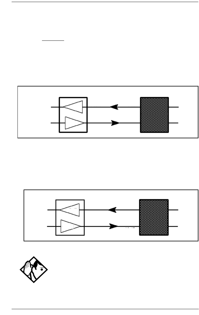
Lines / 347
P0992638 03 Modular ICS 6.0 Installer Guide
Gain Installer password required
Select the appropriate gain level for the line.
Press CHANGE to select either: Normal or High.
The default value Normal induces zero loss. Use it when the
E&M trunks are connected to facilities that present 0 dBm at
the interface, for both the transmit and receive paths.
Normal gain level (0dBm)
The value High induces 7 dB of loss in the receive path and
16 dB of loss in the transmit path. Use it when the E&M trunks
are connected to facilities that present +7 dBm in the receive
path, and -16 dBm in the transmit path, at the interface.
High gain levels
Tip - Control over the gain on transmission levels can only
be set for lines on E&M Trunk Cartridges.
Receive
Transmit
0 dB
0 dB
0 dBrn
0 dBrn
0 dBrn
0 dBrn
Norstar Facility or Norstar
Receive
Transmit
Norstar Facility or Norstar
-7 dB
-16 dB
+7 dBrn
-16 dBrn -16 dBrn
+7 dBrn

348 / Lines
Modular ICS 6.0 Installer Guide P0992638 03
Programming distinctive ring patternsInstaller password required
When lines are configured on your system, they can be
assigned one of four distinctive ring patterns (DRP). The
default for all telephones is 1; the default for lines is None,
which is the lowest priority.
Call ringing: When multiple calls are presented to the
telephone, the call with the highest priority DRP setting will be
the call that rings at the telephone.
Call answering: When multiple calls are presented to a
telephone, and the user picks up the handset, the call with the
highest priority DRP setting is the call that is presented.
Note: External calls always have a higher priority than
internal calls.
Note: If the ring type is changed on a telephone after the DRPs
are set on the line, the line DRPs are overwritten by the
telephone settings. If the line DRPs are set after
telephone programming, then the telephone ring
programming is overridden by the DRP. Refer to the
Modular ICS System Administrator Guide for details
about setting ring types on a telephone.
If Hunt group DRP has a higher priority than the line
DRP, the system will use the Hunt Group DRP within
the Hunt Group. (Refer to Assigning a distinctive ring
pattern to a Hunt Group on page 392.)
1. Place the programming overlay over the appropriate keys
on your programming telephone.
2. Press (CONFIG). The
display shows Password:.
3. Press (CONFIG). The display shows
Terminals&Extns.

Lines / 349
P0992638 03 Modular ICS 6.0 Installer Guide
4. Press ‘ until the display shows Lines.
5. Press ‘. The display shows Linexxx:Line XXX.
6. Press FIND and enter the line to which you want to define
a ring pattern.
7. Press ≠ until the display shows TrunkType:PRI.
8. Press ‘ until the display shows Dstnct ring:
NONE.
9. Press CHANGE to toggle to the ring pattern number you
want to assign to the line (None, 2, 3, 4).
10. Press to exit or ‘ to continue programming.
Name
The default name for a line is Line XXX, XXX being the
three-digit line identifier. For example, Line 001.
This can be changed to any combination of letters and numbers
to a maximum length of seven characters.
For more information, refer to Modular ICS 6.0 System
Coordinator Guide.
Restrictions
Use Restrictions to prevent a user from using a line for making
certain kinds of calls. For example, users should not be able to
make long-distance calls on lines used exclusively for local
calling.

350 / Lines
Modular ICS 6.0 Installer Guide P0992638 03
Restrn filters
Restriction filters are groups of dialing restrictions and dialing
overrides for external numbers or feature codes. By packing a
set of restrictions and overrides in one group, you can assign
them to a line in one step, as a single package.
You can make changes to restriction filters under both
Terminals&Sets, and Lines. Any changes will take affect
for any telephone, line, or line on a telephone, regardless of
where the programming was changed.
See the description and procedures in Restrictions on page
349.
Line restrns
Specify the filter to be applied to this line to restrict the
numbers that can be dialed on it. You can assign a different
restriction filter for normal service and for each of the six
schedules. See the section on Services for more information
about the schedules.
Use ≠, CHANGE and the dialpad to enter the number
of the restriction filter to be assigned as the line restriction for
each schedule.
The default restrictions are shown in the table below:
Default filters for lines
Schedule Restriction filter
Normal 03
Sched 1 (Night) 21
Sched 2 (Evening) 22
Sched 3 (Lunch) 23

Lines / 351
P0992638 03 Modular ICS 6.0 Installer Guide
Remote restrns
Specify the restriction filter to be applied to remote callers
calling in to the Norstar system on this line. A restriction filter
is a set or group of restrictions and overrides.
As with line restrictions, you can apply a different remote
restriction for normal service and for each of six schedules.
Use CHANGE and the dialpad to program the remote restrictions
for each schedule.
The default restrictions are shown in the following table.
Default filters for remote access
Sched 4 00
Sched 5 00
Sched 6 00
Tips - When a remote user places an external call on a
line, any filters used with the line still apply.
Schedule Restriction filter
Normal 04
Sched 1 (Night) 31
Sched 2 (Evening) 32
Sched 3 (Lunch) 33
Sched 4 00
Sched 5 00
Sched 6 00
Schedule Restriction filter

352 / Lines
Modular ICS 6.0 Installer Guide P0992638 03
Telco features
This item allows you to assign features that occur from a telco
level.
VMsg center 1
If you subscribe to a voice message service, you can specify
which voice message center is used for each external line that
can receive message waiting indication.
1. For each line, press CHANGE to select a message center:
1, 2, 3, 4, 5, or N.
Note: If your system is part of a network that provides a
central voice mail system on another site, you must use
this field to specify that service.
Tip - The remote restriction restricts the numbers that can
be dialed on an incoming auto-answer line. If a remote user
then selects a line to place an external call, any filter used with
the line still applies.

Services / 353
P0992638 03 Modular ICS 6.0 Installer Guide
Services
Using Services, you can control three types of service using
the time of day and the day of week:
•alternate call ringing, see page 357
•alternate dialing restrictions, see page 360
•alternate call routing, see page 361
You can customize services in general under Common
Settings. Refer to Common settings on page 354.
Within each type of service, you can customize six schedules.
For example, you may want to combine alternate call ringing
with alternate dialing restrictions for lunchtime, evenings, and
weekends (Schedules 1, 2, and 3). Then you may want to run
alternate call routing using three separate schedules.
Tips - Once you have programmed the different services
and schedules, you can turn each of the services on separately.
For example, the Night schedule might control both Ringing
service and Restriction service. But you can turn on just the
Ringing service part of the Night schedule if you wish.
You can activate the services from the designated control
telephone for each Norstar telephone and line in your system.
You can have one control telephone for the whole system, or
different control telephones for different Norstar telephones
and lines.
If you want to have several services active at the same time,
simply program them on for the same schedule.

354 / Services
Modular ICS 6.0 Installer Guide P0992638 03
Common settings
Services share the settings for control telephones, schedule
names, and schedule times.
Control sets
A control telephone turns Services on and off for the lines and/
or telephones assigned to it. You can assign several control
telephones for your system.
A control telephone for lines controls Ringing service,
Restriction service and Routing service for its assigned lines.
A control telephone for telephones controls Restriction service
and Routing service for its assigned telephones. Assign a
control telephone for each external line and telephone.
Use ≠, ‘, CHANGE and the dialpad to
program the internal number of the control telephone for each
line and each telephone.
Control set configurations for both lines and telephones can be
copied from one set/line to another set/line or to a range of
sets/lines, or to all sets/lines, using the COPY softkey.
Tips - External lines and telephones must be programmed
with a control telephone to use the three kinds of Services. You
can assign a control telephone to more than one external line
or telephone, but a line or telephone cannot be assigned to
more than one control telephone.
One recommendation is to have one control telephone for all
lines and a different control telephone for all telephones.

Services / 355
P0992638 03 Modular ICS 6.0 Installer Guide
Schedule names
The schedule name is shown on the display of the control
telephone when the schedule is turned on. It identifies the
active schedule.
Use ≠, ‘, and CHANGE and the dialpad to
program the name.
Schedule times
Schedule start and stop times are set at times you are most
likely to want each service to be active.
Use ≠, ‘, and CHANGE and the dialpad to
program the start and stop times for each schedule, on each
day.
Tips - A service can be turned on manually or
automatically for all external lines and telephones controlled
by a given control telephone, but you cannot combine
schedules. In other words, a service can only be active as
normal service or one of the six schedules at any one time. You
can have several schedules active, as long as they are using
different services.
The default control telephone for all lines and telephones is
221 (for systems with three-digit DNs).
Tips - The default names of the six possible schedules are
only suggestions and may be changed to any other name.
A schedule name can be one to seven characters long. It is
recommended that you reserve certain schedules (4, 5, and 6)
exclusively for alternate call routing (Routing service).

356 / Services
Modular ICS 6.0 Installer Guide P0992638 03
Default schedule times
Schedule Start time Stop time
Schedule 1: Night 23:00 07:00
Schedule 2: Evening 17:00 23:00
Schedule 3: Lunch 12:00 13:00
Schedule 4: Sched 4 00:00 00:00
Schedule 5: Sched 5 00:00 00:00
Schedule 6: Sched 6 00:00 00:00
Tips - It is only necessary to program start and stop times
for schedules that are activated automatically. See the
instructions with Ringing service for information on
activating schedules.
The time may be entered in either 12 or 24-hour format. If the
display is in English, and the hour entered is less than 13, the
display prompts you to specify AM or PM.
If you assign identical start and stop times for a schedule, for
example, 04:00 start and 04:00 stop, the schedule is in effect
all day. The only exception to this is a start and stop time of
00:00. In that case the schedule is off for the day.
You may assign overlapping times. For example, if schedule 1
is assigned from 9:00 am to 4:00 pm, and schedule 2 is
assigned from 1:00 pm to 5:00 pm, then the start time of the
second schedule is treated as a stop time for the first schedule.
Tips - This is also true if two schedules have the same
start time but different stop times. In that case, the stop time
of the shorter schedule is treated as the start time of the longer
schedule.
If one schedule starts and stops within the times of another
schedule, the first service temporarily ends when the second
service starts. The first service then resumes when the second
service has ended.
Some schedules start and stop at the same times each day. Use
COPY to copy the start and stop times from one day to the next.

Services / 357
P0992638 03 Modular ICS 6.0 Installer Guide
Ringing service
At certain times or in certain situations, you may want
additional telephones to begin ringing for incoming lines. The
most common use of this feature is when a security desk
telephone begins to ring for incoming lines after 5:00 p.m., a
practice often called night service.
These features are programmed under Ringing service.
Ringing groups
Ringing groups allows you to define groups of extended
ringing sets. A group can be assigned to any line for any of the
schedules. You can create up to 100 ringing groups composed
of up to 30 sets for each ringing group.
To define a ringing group use ≠ and enter the number
of the group you want to program (01-100).
Once you define a ringing group, the display will prompt you
to enter the number of the set you want to assign to this ringing
group. You can use SCAN to display the sets that are assigned
to the ringing group.
Start and stop times cannot span days.
When you program a schedule to start in the
evening and stop in the morning, it does not carry
over into the next day. For example, if you
program Night service for Friday (22:00 to 06:00),
the system turns on Night service from midnight
to 6 am on Friday, and then again from 10 pm to
midnight on Friday.

358 / Services
Modular ICS 6.0 Installer Guide P0992638 03
Sched:Night
Indicate how Ringing service should be activated for each of
the schedules.
Service
Use ≠ and CHANGE to change the setting for each
schedule to : Off, Auto, or Manual.
Off — prevents the service from being activated.
Auto — allows you to program a stop and start time for a
service. You will be prompted to enter start and stop times.
You can still start and stop the service by entering the
appropriate Services feature code at a control telephone.
Manual — allows you to turn the service on and off at any
time from a control telephone using the Ringing service
feature code.
Trunk answer
Trunk answer allows you to answer, from any telephone, an
external call that is ringing at another telephone in your office.
This is useful if the other telephones have not been assigned
the same lines as the telephone you are using to answer the
call.
Press CHANGE to select the setting: Y (Yes) or N (No).
Tips - You can assign any set on the Norstar system to a
ringing group. The assigned control set for each schedule is
added to each ringing group.
A set can belong to more than one ringing group.

Services / 359
P0992638 03 Modular ICS 6.0 Installer Guide
ExtraDial telephone
ExtraDial telephone allows you to assign an additional
direct-dial telephone in the Norstar system for each schedule
you use.
Use CHANGE and the dialpad to enter the internal number of the
extra-dial telephone.
Line settings
The ring groups and auxiliary ringer use for Ringing service is
programmed for each line individually.
Ringing group
You can assign a predefined ringing group to a line for each
schedule. See Ringing groups on page 357 to create groups of
extra ringing telephones.
Use the dialpad to enter the line number to see which ringing
group is assigned to the line.
Tip - You can change the Trunk Answer setting only if
Ringing service is set to Manual or Automatic.
Tip - The extra-dial telephone is activated during a
schedule by entering the Ringing service feature code from a
direct-dial telephone. This does not activate the Ringing
service unless the direct-dial telephone is also a control
telephone.

360 / Services
Modular ICS 6.0 Installer Guide P0992638 03
To choose a different ringing group assignment, press CHANGE
and enter the new ringing group number (01-100)
Aux. ringer
Indicate whether the auxiliary ringer, if installed, also rings
when Ringing service is on.
Press CHANGE to select either: Y (Yes) or N (No).
Restrn service
Indicate how the alternate dialing restrictions should be
activated for each of the schedules.
Use ≠ and CHANGE to change the setting for each
schedule: Off, Automatic, or Manual.
For information on using schedules, refer to the Modular ICS
6.0 System Coordinator Guide.
Tip - Only one ringing group can be assigned to a line for
each schedule. To combine groups of ringing sets, you must
create a new ringing group which contains all the sets you
want to ring and assign it to the line.
Tips - The default ringing telephone is 221 (for systems
with a DN length of 3). This means that all lines ring at
telephone 221 when Ringing service is on.
You can use COPY and the dialpad to copy Ringing set and
Auxiliary ringer programming from one line to another.
If you have an auxiliary ringer programmed to ring for calls
on an external line, and you transfer a call on that line without
announcing the transfer, the auxiliary ringer will ring for the
call transfer.

Services / 361
P0992638 03 Modular ICS 6.0 Installer Guide
See Ringing service on page 357 for descriptions of the three
activation settings.
See Restrictions under both Terminals&Sets and Lines
to assign dialing restrictions for telephones, lines and remote
users to the schedules.
Routing service
The programming for routing decides what path an outgoing
call takes using the digits that are dialed. It is sometimes called
Automatic Route Selection (ARS).
When you select an internal line and dial, the numbers you
enter are checked against the routing tables. If the number you
dialed starts with a destination code, the system uses the line
pool and dials out digits specified by the route assigned to that
destination code, and then dials the rest of the number that you
dialed.
Tips - A schedule must be active for overflow routing to be
in effect. Overflow routing is not available in normal mode.
You must create an overflow route to be used with each
destination code. In this way, every route used with a
scheduled mode that has overflow service must have an
alternate route in normal service.
Plan your routing service before doing any
programming.
Routing affects every call placed in the system
and must be carefully planned to avoid conflicts
and gaps in the programming. Use the tables in
the
Programming Record
to design routes and
destination codes, then check for potential
problems before you start programming.

362 / Services
Modular ICS 6.0 Installer Guide P0992638 03
Routing service replaces a number of tasks that otherwise have
to be done manually, including:
•entering a line pool code
•dialing an access code for a long distance carrier
•deciding which line pool to use according to the time and
day
The installer can set up routing to take advantage of any leased
or discounted routes using information supplied by the
customer. The system itself cannot tell which lines are cheaper
to use.
For Call by Call service selection (PRI only), the installer
defines destination codes for various call types over PRI lines
(e.g. Foreign Exchange, Tie Trunk, and OUTWATS). This
information is then recorded in the routing and dialing plan
section of the Programming Record for the PRI Pool-A (and
PRI Pool-B if there are two PRI cards).
The user simply dials a number via the intercom button
without having to enter any special information. For more
information see, Programming Call by Call service selection
on page 436.
How to use routing to create a uniform dialing plan (UDP) or
coordinated dialing plan (CDP) is explained in Dialing plans
on page 94.
Services / 363
P0992638 03 Modular ICS 6.0 Installer Guide
Routes and destination codes Installer password required
Programming for a route makes use of:
•destination codes (maximum of 500 available with a
maximum of seven digits per code)
•a three-digit route number (000-999)
•a line pool
•DialOut digits (up to 24 digits)
•a schedule (programmed in Services)
Routes Installer password required
Press ≠ and enter a three-digit route number
(000-999).
Routing table modifications
Changes to the routing tables can only be made
during low-activity periods or on an idle system.
Plan to program the routing tables when user
activity is at a minimum.
Alternatively, Norstar Remote Utilities (NRU) can
be used to back up, modify and restore these
tables.
Tips - To dial a telephone number which does not match
any of the programmed destination codes, the user chooses a
line and dials the number. For long distance dialing, area
codes in the North American numbering plan can be
programmed as destination codes.
364 / Services
Modular ICS 6.0 Installer Guide P0992638 03
DialOut
DialOut is the number you want the route to use.
Press ≠ and enter the DialOut digits (up to 24), or
press CLR to choose No numbr.
You can press to insert a 1.5-second pause in the
dialing string, if necessary.
Route 000 has no DialOut by default and cannot be changed.
Use Pool
Press ‘ and CHANGE to select a line pool to be used
with the route: Pool A, Pool B...Pool O or PRI-A, PRI-B,
PRI-C, or PRI-D.
Route 000 uses Pool A by default and cannot be changed.
Link – if your Norstar system is connected to a private
branch exchange (PBX), you can use a Link signal to
access special features.
Pause – Enters a 1.5 second delay in a dialing
sequence on an external line.
Programmed Release – performs same function as
in a programmed dialing sequence. When the
system encounters Programmed Release in a dialing
sequence, it stops dialing and hangs up the call.
Run/Stop – inserts a break point into a sequence of
dialed numbers or characters used for automatic
dialing.
Wait for Dial Tone – causes a sequence of numbers
to pause until dial tone is present on the line before
continuing to dial.
See the
Modular ICS 6.0 System Coordinator Guide
for more information.

Services / 365
P0992638 03 Modular ICS 6.0 Installer Guide
Routing table
Call by Call Service information for outgoing calls is recorded
in the Routing Service section of the Programing Record.
The following is an example of a Routing Table containing
CbC programming.
The service identifier (SID) depends on the selected service
type. For example, with NI-2 protocol.
Route #
(000-999)
Dial Out
(24 digits)
Use Pool Service Type Service
Identifier
003 PRI-A Public
004 PRI-A FX xxxxx
005 PRI-A Tie xxxxx
006 PRI-B OUTWATS xxx
007 PRI-B Private
008 PRI-B Switched Digital
Note: The public DN lengths are used for all PRI calls except those whose
routes use service type Private or service type Tie with DN Type specified as
Private.
Service Type Service Identifier description
Public None
FX Facility Number 1-5 digits
Tie Facility Number 1-5 digits
OUTWATS *Optional Band Number 1-3 digits
Private None
Switched Digital None
* For NI-2, do not program the Carrier Access Code for banded OUTWAT calls.
This call may be rejected.

366 / Services
Modular ICS 6.0 Installer Guide P0992638 03
When a PRI protocol is selected or changed, the Service Type
and Service ID fields are automatically cleared for each entry
in the routing table for that PRI.
Programming the PRI routing table
The dialing plan must be thoroughly planned out in advance
before programming the information into the Norstar system.
Programming the routing table takes place in Services under
Routing Service/Routes
1. Press ≠. The display shows Rte000.
2. Press ‘. The display shows Rte001.
3. Press ≠. The display shows Dial-Out:No
numbr. Press CHANGE to enter a number (up to 24 digits).
4. Press ‘. The display shows Use: Pool A.
The PRI pool(s) displayed depend on how the PRI lines are
put into pools in the Trunk/Line data section of
programming. It is possible to have only one PRI pool
even if there are two or three PRI cards in the system.
5. Press ‘. The display shows SrvcType:Public.
Press CHANGE if you want to select a different Service
Type.
Note: This parameter displays for specific protocols,
such as N12, DMS100, DMS250.
6. Press ‘. The display shows Service ID:None.
Press CHANGE to enter the Service ID number. This is
shown only if the service requires an ID.
Note: This parameter displays for specific protocols,
such as N12, DMS100, DMS250.

Services / 367
P0992638 03 Modular ICS 6.0 Installer Guide
7. Press ‘. The display shows DN type:Public.
Press CHANGE to enter Public or Private.
Note: This variable displays only for service type Tie.
Dest codes Installer password required
The first digit of the destination code cannot be the same as:
•Call Park Prefix (Park prefix on page 418)
•External Access code (External code on page 419)
•Direct Dial numbers (Direct-dial # on page 419)
•Line Pool code (Line pool codes on page 417)
The entire destination code cannot conflict with:
•internal set numbers (Terminals&Sets on page 308)
•DISA DNs (DISA DN on page 421)
•Auto DNs (Auto DN on page 420)
For instance, if your park prefix is 1, and you want to start your
destination codes with 1, you must change the park prefix.
If your line pool code for the local PBX is 9, and you want to
start your destination codes with 9 to allow routing to the local
PBX, you must create a destination code that includes the line
pool for the PBX and delete the line pool code for 9.
The following are the default numbers automatically assigned
in MICS-XC 6.0:
System type Expansion used Initial digits pre-assigned
mini no expansion 0, 1, 2, 6 & 9
midi one 2-port cartridge 0, 1, 2, 3, 6 & 9
maxi one 6-port cartridge 0, 1, 2, 3, 4, 6 & 9

368 / Services
Modular ICS 6.0 Installer Guide P0992638 03
The following are the default numbers automatically assigned
in a MICS 6.0 system:
To make the digits available for use with destination codes,
you must change the DN length of B1 and B2 DNs, depending
on your system size. This can be done either at system startup
or in System prgrming. The examples shown above use a
three-digit DN length, unless stated otherwise.
Wild card character
When programming destination codes, you can use wild cards
as the last number in a destination code string. By using wild
cards, you can reduce the number of destination codes
programmed in the system, maximizing the distribution of
destination codes in the system.
The wild card character is added to the destination code by
pressing the ANY key as the last digit of the code. This
character represents any digit from 0 to 9, except for digits
already programmed or used by other numbering plans.
Should there be a conflict with other digits already
programmed or used with by numbering plans, the digit will
not be displayed.
mega two 6-port cartridges
or two combo
cartridges
0, 1, 2, 3, 4, 5, 6 & 9
System type Expansion used Initial digits pre-assigned
mini no expansion 0, 1, 2, 3, 4, 5, 6, 7, 8 & 9
midi one 2-port cartridge 0, 1, 2, 3 & 9
maxi one 6-port cartridge 0, 1, 2, 3, 4 & 9
System type Expansion used Initial digits pre-assigned

Services / 369
P0992638 03 Modular ICS 6.0 Installer Guide
The wild card character can only be used to group destination
codes that use the same Route and Absorb Length.
Given the routes shown in the table below, the next two tables
show you how to set up destination codes with or without wild
card characters.
Destination codes without using a wild card character
Destination codes using a wild card character
Route DialOut Line Pool
555 0162 237 625 Line Pool C
565 0173 133 2211 Line Pool A
Destination codes Route Absorb
Length
DialOut
0621 555 3 0162 237 6251
0622 555 3 0162 237 6252
0623 555 3 0162 237 6253
0624 555 3 0162 237 6254
0625 555 3 0162 237 6255
0626 555 3 0162 237 6256
0627 565 All 0173 133 2211
0628 555 3 0162 237 6258
0629 555 3 0162 237 6259
Destination
codes
Route Absorb
Length
DialOut
062 •555 3 0162 237 625X
where X is the final dialout
digit, from 1 to 9, but not 7
0627 565 All 0173 133 2211

370 / Services
Modular ICS 6.0 Installer Guide P0992638 03
Normal rte
Select which route a call using the destination code takes
during normal service and for each of the schedules. The
automatic schedule times are programmed under Services.
The default Normal route is 000, which has no DialOut digits
and uses Pool A.
Digit Absorption
Select the portion of the destination code that is always
absorbed by the system and not used in the dialing sequence.
Press CHANGE to select the number of digits to be deleted: 0, 1,
2, 3, 4, 5, 6, or All.
Tips - The digit absorption setting (Digit absorb)
only applies to a maximum of two schedules.
Setting digit absorption to 0 (zero) minimizes the effort
involved in preparing destination codes. With a 0 setting, the
actual digits dialed by a caller are preserved in the dialout
sequence. Programming a DialOut sequence as part of the
route may or may not be necessary depending on the required
dialout.

Services / 371
P0992638 03 Modular ICS 6.0 Installer Guide
Setting up a route for local calling
An office may have different suppliers for local and long
distance telephone service. By programming a destination
code, any call that begins with 9, the most common dialout
digit, will automatically use lines dedicated to local service.
The first step is to build a route (under Services/Routing
Service/Routing).
1. At Show route: enter 001 (or any other available route
number)
2. Press SCAN to view defined routes and CLEAR to erase a
defined route.
3. Choose the line pool that contains the lines for local
calling.
4. Enter the DialOut digits (if any) which are needed to direct
the call once it is connected to an external line.
Note: For local calls only, there are no DialOut numbers.
Compare this with Setting up a route for long distance
calling on page 373.
5. Now you need to set up a destination code that will use this
route during the various schedules. Since users will dial 9
to make an external call, 9 should be the destination code.
(Services/Routing Service/Dest Codes)
6. At Show DstCode: press ADD and enter 9.
Tips - If entering a code other than 9, a valid destination
code must be used. See Dest codes on page 367.
To view existing destination codes press ‘ before
entering a new code.

372 / Services
Modular ICS 6.0 Installer Guide P0992638 03
7. Press ≠.
The route for the first schedule appears after Normal:.
8. Press CHANGE and enter the defined route number 001.
The following illustrations show the tables used for planning
and recording routing service found in the Programming
Record. They are filled out to match the examples of routes for
local and long distance calling.
Recording the routes
Tip - The destination code can use a different route
depending on which schedule is being used. Refer to Services
in the Modular ICS 6.0 System Coordinator Guide for
information about using schedules.
In the current example, Route 001 is used when someone dials
9 during normal mode. This is the mode used when the other
Schedules are turned off.
Page 24
Routing Service (Services: Routing Service)
Route #
(000-999)
DialOut (if required)
(max. 24 digits or characters)
001
none
Use Pool
002
none A B C D E F G H I J K L M N O
A B C D E F G H I J K L M N O
A B C D E F G H I J K L M N O
A B C D E F G H I J K L M N O
A B C D E F G H I J K L M N O

Services / 373
P0992638 03 Modular ICS 6.0 Installer Guide
Recording how the routes will be used
Setting up a route for long distance calling
An office may have leased lines or E&M trunks which make it
cheaper to call long distance.
The routing should take place automatically when the number
of the outgoing call begins with 1.
The first step is to build a route (under Services/Routing
Service/Routing).
1. At Route:, enter 002 (or any other available route number)
2. Choose the line pool where the discounted lines for calling
long distance have been placed. Example: Line pool B.
3. Then you need to assign the route to the destination code
and to the destination code schedules. (under Services/
Routing Service/Dest Codes)
4. At DstCode: enter a valid destination code. Example: 1
Refer to Dest codes on page 367.
Destination codes (Services; Routing service; Destination codes)
Normal Rte
Service Schedule
name
(max. 7 char)
Night Rte
Absorb
Length
Evening Rte Lunch Rte
DestCode
(max. 7 digits)
Use route
(000-999)
Use route
(000-999)
Use route
(000-999)
Use route
(000-999)
Absorb
Length
Absorb
Length
Absorb
Length
9
1
000 001 All All All
000
All 0 All All All
000002
All All All All
000 All All All All
All

374 / Services
Modular ICS 6.0 Installer Guide P0992638 03
5. Press ≠.
The route for the first schedule appears: Normal:
6. Press CHANGE and enter the defined route number 002.
7. Press ≠.
The AbsorbLength prompt appears. The default is All.
8. Press CHANGE to choose the number of digits that need to
be absorbed before dialout. In this case, it would be 0, as 1
needs to be dialed out before the rest of the digits.
Tip - To view existing destination codes press ‘
before entering a new code.
Tip - The destination code can use a different route
depending on which schedule is being used. Refer to Services
in the Modular ICS 6.0 System Coordinator Guide for
information about using schedules. In the above example, the
system uses Route 002, which uses Line pool B, to take
advantage of the lower cost when the system is in normal
mode.
Tips - The digit absorption setting (AbsorbLength) only
applies to a maximum of two schedules.
Setting AbsorbLength to 0 (zero) minimizes the effort
involved in preparing destination codes.With a 0 setting, the
actual digits dialed by a caller are preserved in the dialout
sequence. Programming a DialOut sequence as part of the
route is not necessary.

Services / 375
P0992638 03 Modular ICS 6.0 Installer Guide
Adding a long distance carrier access code
In many cases, long distance service uses the same lines as
local service but the call is switched to a specific carrier using
an access number. This number is sometimes called an equal
access code. Programming for routing can include this access
number so users only need to dial the set number, as described
below:
1. Create a route that uses a line pool containing local lines
only.
2. Program the route to use a line pool containing the lines
used to access the long distance carriers.
a. Enter the DialOut digits, which are the same as the
carrier code digits. For example, if the access code was
10222, the DialOut digits would be 10222.
Carrier codes are defined in Carrier Codes on page 422.
b. Create a destination code 91.
9 (for outside access) and 1 (for long distance). Refer to
Dest codes on page 367 to determine a valid code.
c. Set AbsorbLength to 1.
The 9 is only used internally and should be dropped.
The 1 is needed to direct the call to the public carrier
network.
Tips - If rates change depending on the time of the day or
week, a different route can be used for the same destination
code 1 when a particular schedule is in use. See Programming
for least cost routing on page 377.
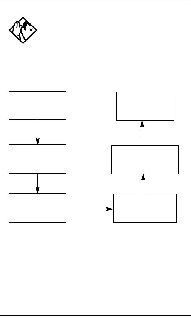
376 / Services
Modular ICS 6.0 Installer Guide P0992638 03
Using destination codes to make a call
Tips - The destination codes 9 and 91 used in the examples
cannot be used together. If the destination code 91 is needed to
direct long distance calls, you must create a separate set of
codes that use local calling routes. These codes would be, for
example, 90, 92, 93, 94, 95, 96, 97, 98 and 99. See Wild card
character on page 368 for information on programming
destination codes.
User dials
9-1-601-555-2222
9-1-601-555-2222
91 is a destination
code – system uses
Route 001 and Line
Pool A
Routing tables
absorb the 9
1-601-555-2222 Dialout programming
tells the system to add
the access code for long
distance (e.g. 10222)
10222-1-601-555-2222
External lines recognize
the long distance access
code and switch to the
appropriate carrier
1-601-555-2222
Call is directed in the
public system

Services / 377
P0992638 03 Modular ICS 6.0 Installer Guide
Programming for least cost routing
It may be cheaper to use another long distance carrier at
another time of day.
Continuing with the example used in the previous flowchart,
the lines that supply local service in normal mode will also be
used for long distance service after 6 p.m. because that is when
rates become competitive. For the system to do this
automatically, another route has to be built.
1. At Route: choose Route 007 (or any available route).
2. Press ≠.
3. At DialOut, press CLR to choose No numbr.
4. Press ≠.
5. Choose Line pool A, or the pool with the local service
carrier lines.
In this case, the change in route uses the start and stop
times for Night Sched.
6. Return to the Routes heading and press ‘ to find
the Dest Code heading.
7. Press ≠ and then ‘.
8. At DstCode:, press ADD, then enter 91.
9. Press ≠ and then ‘.
10. Under Night rte: enter Route 007.
11. Press ≠.
12. Set AbsorbLength to 1.
The 9 will be absorbed before the number is dialed out to
the network. This means, that when the Night schedule is

378 / Services
Modular ICS 6.0 Installer Guide P0992638 03
chosen, either automatically, by time, or manually from a
control telephone, the calls dialed with 91 will dial out to
the long distance network without requiring a special
access code.
Sched:Night
Indicate how the alternate routing should be activated for each
of the schedules.
Service
Use ≠, CHANGE, and ‘ to change the setting
for each schedule to one of these settings: Off, Automatic, or
Manual.
Off — prevents the routing service from being activated. In
this case, the Normal schedule is used.
Auto — allows you to program a stop and start time for a
service. You will be prompted to enter start and stop times.
You can still start and stop the service by entering the
appropriate Services feature code at a control telephone.
Manual — allows you to turn the service on and off at any
time from a control telephone using the Ringing service
feature code.
Refer to the Modular ICS 6.0 Coordinator Guide for a
description of the feature codes used to work with Services.

Services / 379
P0992638 03 Modular ICS 6.0 Installer Guide
Overflow routing
If all the lines used by a route are busy when a call is made, the
mode may be programmed to overflow to the route used for
normal mode. If this happens, the set will sound a warning
tone and display the message Expensive route. The caller
can then release the call to avoid using the normal route, or
continue with the call.
Overflow routing is turned on or off for each schedule when
you program the destination codes schedule.
Press CHANGE to select the setting: Y (Yes) or N (No).
Refer to the Overflow call routing section of the Modular ICS
6.0 Coordinator Guide for details about how to set up
overflow routing.
Tips - A schedule must be active for overflow routing to
be in effect. Overflow routing is not available in normal mode.
You must create an overflow route to be used with each
destination code. In this way, every route used with a
scheduled mode that has overflow service must have an
alternate route in normal service.

380 / Services
Modular ICS 6.0 Installer Guide P0992638 03
Using dialing restrictions with routing
Routing service can be further customized by adding dialing
filters to lines in line pools. Filters restrict the use of the line to
specific area codes. See Restriction filters on page 86 and the
Programming chapter of the Modular ICS 6.0 System
Coordinator Guide for more information.
Tips - Host system signaling codes can be part of the
DialOut. See the Modular ICS 6.0 System Coordinator Guide
for details on host system signaling codes.
Tips - You can also use routing as an alternate method for
a direct-dial number. For example, create a destination code
0 and program the number of the internal or external
destination as the DialOut. Digit absorption should be set to 1.
Because overflow routing directs calls using alternate line
pools, a call may be affected by different line filters when it is
handled by overflow routing.

Sys speed dial / 381
P0992638 03 Modular ICS 6.0 Installer Guide
Sys speed dial
System speed dial allows you to configure speed dial codes
(001 - 255) that can be used by any telephone on the system to
dial pre-programmed numbers.
If you specify a name with the speed dial entry, an incoming
call on a CLID line with a dialed number that matches the
speed dial entry will display the name as part of the CLID
display on the receiving telephone or when is
envoked to display call information. This method of using the
system speed dial entries for CLID display is called
Alpha tagging.
Note: Alpha tagging is only involked when the CO line
service does not supply a name for the incoming call.
It will only occur on telephones that have Caller ID set
turned on (Telco features on page 330).
The CLID Match setting (Clid match on page 409) determines
how many digits of the received number need to match the
system speed dial number to be accepted as a CLID match to
allow the name display to occur.
For more information about using and programming System
speed dial, refer to the Modular ICS 6.0 System Coordinator
Guide.
For information about configuring the system so that the name
displays first, refer to 1stDisplay on page 331.

382 / Passwords
Modular ICS 6.0 Installer Guide P0992638 03
Passwords
COS pswds
Class of Service (COS) passwords permit controlled access to
system resources by both internal and remote users.
When you enter a COS password at a telephone, the restriction
filters associated with your password apply instead of the
normal restriction filters. Similarly, when a remote user enters
a COS password on an incoming auto-answer line, the
restriction filters and remote package associated with their
COS password apply instead of the normal restriction filters
and remote package.
COS passwords allows you to define individual passwords and
determine the restriction filters and remote package associated
with each.
Tips - The Class of Service passwords for a system should
be determined randomly and should be changed on a regular
basis.
Users should memorize their COS passwords. COS passwords
should be deleted when an employee leaves the company.
Tips - Typically, each user has a separate password.
Alternately, several users can share a password or one user
can have several passwords.
A system can have a maximum of 100 six-digit COS passwords
(00 to 99).
You can use COPY and the dialpad to copy the restriction
filters and remote package from one COS password to
another. COS passwords must be unique.

Passwords / 383
P0992638 03 Modular ICS 6.0 Installer Guide
Pswd
Pswd defines the six-digit Class of Service password.
There is no default password.
Use ≠, CHANGE and the dialpad to program the
six-digit password.
Use BKSP to edit numbers you have entered.
User flt
User filter allows you to assign a restriction filter to a COS
password. The user filter associated with the COS password
replaces any normally applicable set restriction, line/set
restriction, or remote restriction.
Use CHANGE and the dialpad to program the two-digit user
filter.
The default setting (None), means that any normally-
applicable filters still apply (set restriction, line/set restriction,
or remote restriction).
Line flt
Line filter allows you to assign a specific line restriction to a
COS password. The line filter associated with the COS
password replaces any normally-applicable line restriction.
Use CHANGE and the dialpad to program the two-digit line
filter.
The default setting (None), means that any normally-
applicable line filter still applies.

384 / Passwords
Modular ICS 6.0 Installer Guide P0992638 03
Remote pkg
Remote pkg allows you to assign a specific remote access
package to a COS password.
The remote access package associated with the COS password
replaces any normally applicable remote access package.
Use CHANGE and the dialpad to program the two-digit remote
package.
The default setting (None), means that any
normally_applicable remote access package still applies.
Call log pswds
This setting allows you to override any Call log password
programmed with the Call log feature, and resets it to None.
This feature is used when someone forgets a password.
1. Press ≠ and enter the DN of the telephone.
2. Press ≠ and then CLR to clear the programmed
password.
Tips - You program a Call log password using the Call
log Password feature. Refer to the Telephone Feature Card or
the Modular ICS 6.0 System Coordinator Guide for more
information.

Passwords / 385
P0992638 03 Modular ICS 6.0 Installer Guide
Progrming pswds
You can choose any combination of six digits for Passwords.
Some passwords allow line assignments to be rearranged,
which could disrupt your telephone service. Provide
passwords only to selected personnel to prevent unauthorized
access to programming.
Installer
The default Installer password is 266344 (CONFIG).
1. Use CHANGE, the dialpad, and OK to program the Installer
password.
2. Record the password in the
Programming Record
.
Tip - It is easier to remember the password if the digits spell
a word.
Tips - You can choose any combination of one to six digits.
It is easier to remember the password if the digits spell a word.
Provide this password only to selected personnel to prevent
unauthorized access to programming. The implications of
such access may include the rearrangement of line
assignments, which could affect the operation of the Norstar
system.

386 / Passwords
Modular ICS 6.0 Installer Guide P0992638 03
SysCoord+
The default System Coordinator Plus password is 727587
(SCPLUS).
Use CHANGE, the dialpad, and OK to program the System
Coordinator Plus password.
SysCoord
The default System Coordinator password is 23646 (ADMIN).
Basic
The default Basic password is 22742 (BASIC).
Registration password (MICS-XC only)
For more information about the Registration password, refer to
the Modular ICS Companion Installer Guide.
Tips - You should only distribute this password to
experienced System Coordinators. This level of access is
documented in the Modular ICS 6.0 System Coordinator
Guide.
An overview of what programming is available by using the
System Coordinator Plus password is on page 280
Tips - For more information about the System Coordinator
and Basic passwords, see the Modular ICS 6.0 System
Coordinator Guide.

Passwords / 387
P0992638 03 Modular ICS 6.0 Installer Guide
Hospitality password
There are two passwords within the Hospitality feature. One
provides secure access to the administration set for
programming the service, and one provides secure access to a
room condition setting from each room set for housekeeping
staff.
Desk pswd
Change this password frequently, to maintain security.
At Hospitality:
1. Press ≠.
2. Desk pswd:4677 displays.
3. Press CHANGE.
4. New pswd: displays
5. Enter a new password, then press OK.
Cond pswd
Change this password frequently, to maintain security.
At Hospitality:
1. Press ≠.
2. Press ‘
3. Cond pswd:None displays.
4. Press CHANGE.
5. New pswd: displays
6. Enter a new password, then press OK.

388 / Time&Date
Modular ICS 6.0 Installer Guide P0992638 03
Time&Date
The time and date shown on the telephone display is used by
the system for scheduled features. It can be changed in
programming or by using a feature code
( or ).
For more information refer to the Modular ICS 6.0 System
Coordinator Guide.

System prgrming / 389
P0992638 03 Modular ICS 6.0 Installer Guide
System prgrming
System prgming allows you to set up features and settings
which are not associated with any specific line or telephone.
Hunt groups
The Hunt groups feature allows a group of sets to be called by
a single directory number, ensuring that calls are easily routed
to the appropriate group.
The default setting for Hunt groups is Broadcast. Hunt group
statistics are available with Usage Metrics on page 541.
Hunt groups can be used to route calls to a support service such
as a Help Line for a software company. Specialists dealing
with Product A can be in one group. Specialists dealing with
Product B can be in another group. Incoming calls will hunt for
the next available set in the group. If no set is available, the call
can be placed in a queue or can be routed to an overflow set.
The Hunt groups subheading in system programming is the
area that programming changes are made to the following:
•members of a group
•member position in a group
•what lines are assigned to a group
•how incoming calls are distributed
•how long the system looks for available agents
•where a call goes if all agents are busy

390 / System prgrming
Modular ICS 6.0 Installer Guide P0992638 03
The hunt group setting impacts other features:
•Call forwards set on telephones that are members of a hunt
group are overridden by the hunt group routing.
•Sets that are members of a hunt group can temporarily
leave a group by activating the DND feature.
•Wireless twinning can be enabled if a hunt group appears
on the portable as well as the set.
•Priority calls to a hunt group will be rejected
•Hunt group set numbers cannot be in a ringing group.
•Hunt group set numbers cannot be in a page zone.
•Hunt group member line keys take precedence over Hunt
group key, therefore, it is recommended that you do not
assign any lines to telephones which are part of the hunt
group. If you do assign lines to a hunt group telephone,
ensure they do not duplicate any of the lines assigned to the
Hunt Group DN.
Note: Videophones should not be programmed as members of
a hunt group. Hunt groups allow one B channel
connection at a time and videophones use two B
channels.
Adding or removing members from a group
Members of the group can be any Norstar telephone or
Business Series Terminal, CTA 500dm, ISDN set, or
portables. A set can be in more than one hunt group but is
considered a member in each hunt group, increasing the total
number of members in the system.
There can be only one appearance of the same hunt group on a
set. The appearance can be: Appr&Ring, Appr only, or Ring
only.

System prgrming / 391
P0992638 03 Modular ICS 6.0 Installer Guide
The set number range for hunt groups is 707 to 736.
Hunt groups can be programmed under System prgrming.
1. Press ≠. The display shows Hunt groups.
2. Press ≠. The display shows Show group:.
3. Enter the hunt group number you want to program (1-30).
4. Press ≠. The display shows Member DNs:.
5. Press ≠. The display shows the members for that
group.
6. Press ADD to add a member or press REMOVE to remove a
member from the group.
7. Select Appr&Ring, Appr only, or Ring only for the hunt
group member. See Appearances on page 310.
Note: Fixed external cadencing is provided for all external
hunt group calls regardless of whether or not they have
been answered and transferred.
Moving members of a group
Member order within a hunt group is important. The member
order determines how a call is routed through a hunt group.
1. Press MOVE to move an existing member to another place
within the hunt group.The display shows the member
number followed by an arrow.
2. Enter the new position number for the set.
Tip - You must program the DNs for telephones you want to
use for hunt group members outside the hunt group DN range.

392 / System prgrming
Modular ICS 6.0 Installer Guide P0992638 03
Assigning or unassigning lines to a group
To avoid delayed ring transfer of external hunt group calls to
a prime set, ensure that the hunt group line prime is set to
None.
A line can only be assigned to one hunt group.
1. When the display shows Member DNs:.
2. Press ‘. The display shows Line assignment.
3. Press ≠. The display shows Show line:.
4. Enter the line number you want to program, press SCAN to
go the first line assigned to this group, or press LIST to go
to the first line in the system.
5. Press CHANGE to program the line as Unassigned or
Assigned.
*HGnn* means the line is assigned to another hunt group.
Assigning a distinctive ring pattern to a Hunt Group
You can assign distinctive ring patterns to your Hunt Group so
that calls can be rated in priority for the group.
These distinctive ring patterns, have the same characteristics
as for line and extension distinctive ring patterns. Refer to
Programming distinctive ring patterns on page 348.
The Hunt Group distinctive ring pattern determines how a call
will ring within the Hunt Group. If members of the group have
ring patterns assigned to their telephones that are higher than
the ring patterns of the incoming line or the Hunt Group, then
the Hunt Group will use the ring of the corresponding member
telephones.

System prgrming / 393
P0992638 03 Modular ICS 6.0 Installer Guide
If the incoming call (line) has a higher ring pattern assigned,
than the Hunt Group, the Hunt Group will ring with the line
ring pattern.
1. Find the heading Hunt groups.
2. Press ≠ until the display shows Member extns:.
3. Press ‘ until the display shows Dstnct
Ring:NONE.
4. Press CHANGE to toggle to the ring pattern number you
want to assign to the Hunt group line. (None, 2, 3, 4)
5. Press to exit or ‘ to continue programming.
Setting the distribution mode
There are three modes of call distribution:
•Broadcast — rings each set in the group simultaneously.
Calls are handled one at a time, other calls are queued. As
soon as a call is picked up, the call next in the queue is
presented to the hunt group without waiting for queue
timeout.
In Broadcast mode, a single incoming call will ring
simultaneously at all the sets in a group. This way, all
receptionists in the group can share the load of answering
large volumes of calls. A familiar example is a fund-
raising campaign where a group of operators would be
waiting to take each call as it comes in.
•Sequential — starts the call at the first set in the hunt
group. Distribution is complete when the first free set has
been found. Simultaneous calls can be presented.
Distribution is order based.
In Sequential mode, you can program your top salesperson
to be the first member of the group to receive calls.

394 / System prgrming
Modular ICS 6.0 Installer Guide P0992638 03
•Rotary — the call starts at the set after the one which was
last presented. Distribution is complete when the next free
set has been found. Simultaneous calls can be presented.
Distribution is order based.
In Rotary mode, you can ensure that all your help-line
people are receiving calls, rather than one person receiving
the majority of calls.
If a hunt group has available agents but nobody answers the
call, the call is routed through the hunt group list until either
someone answers the call or the queue timeout occurs. In the
latter case, the call is diverted to the overflow position.
When the display shows Member DNs:.
1. Press ‘ until the display shows Mode:.
2. Press CHANGE to set the mode: Broadcast, Sequential,
Rotary.
Setting the hunt delay
This setting allows you to program the number of rings the
system permits at a hunt group set before moving on to the
next set in the hunt group. This display only shows if the
distribution mode is sequential or rotary.
1. When the display shows Member DNs:.
2. Press ‘ until the display shows Hunt delay:.
3. Press CHANGE to select the setting: 1, 2, 3, 4, 5, 6, 7, 8, 9,10.

System prgrming / 395
P0992638 03 Modular ICS 6.0 Installer Guide
Programming busy line setting
There are three routing options if all agents are busy:
•BusyTone—the caller gets a busy tone for PRI or BRI,
otherwise the telephone rings back.
•Overflow—the call is routed to an overflow position. You
can not use overflow if the overflow DN is a hunt group
DN.
•Queue—the call stays in the system for a period of time.
Within this period of time, the call will be presented to an
agent if one becomes available. When the time-out occurs,
the call will be presented to an overflow position.
1. When the display shows Member DNs:.
2. Press ‘ until the display shows If busy:.
3. Press CHANGE to set the mode: BusyTone, Overflow,
Queue.
Programming the queue timeout
This setting allows you to program the number of seconds a
call will remain in the hunt group queue before it is also routed
to the overflow position.
1. When the display shows Member DNs:.
2. Press ‘ until the display shows Q Timeout:.
3. Press CHANGE to set the queue timeout: 15, 30, 45, 60, 120
or 180.

396 / System prgrming
Modular ICS 6.0 Installer Guide P0992638 03
Programming the overflow set
This setting allows you to program the overflow set the hunt
group calls will be routed to when the queue is full.
•If the overflow set is not a hunt group set, the call ceases to
be a hunt group call.
•If the overflow set is a hunt group set, the call is treated as
a new call and goes to the bottom of the queue.
The overflow set also can be a set number associated with a
voice mailbox.
1. When the display shows Member DNs:.
2. Press ‘ until the display shows Overflow:.
3. Press CHANGE to change the overflow position.
4. Enter the new overflow position.
Setting the function name
This setting allows you to program the hunt group function
name, such as Service or Sales. The name can be up to seven
characters in length.
1. When the display shows Member DNs:.
2. Press ‘ until the display shows Name:.
3. Press CHANGE.
4. Use the dialpad to enter the name of the hunt group.
5. Press ‘ to store the name.
System prgrming / 397
P0992638 03 Modular ICS 6.0 Installer Guide
Change DNs Installer password required
Change DNs allows you to change the directory number (DN)
or internal number of a telephone.
1. Use ≠ and the dialpad to identify the DN you
want to change.
2. Use the dialpad to enter the new DN.
Featr settings
The following section describes how to configure set features.
Backgrnd music
Background Music allows you to listen to music through your
telephone speaker. A customer-supplied music source must be
connected to the Integrated Communication System.
Press CHANGE to select the setting: N (No) or Y (Yes).
Changing DN locks programming session.
Changing an individual DN locks the
programming session into the Change DNs
programming mode. After you finish and press
, re-enter the programming access code and
the Installer password to continue with other
programming.
Do not perform Startup again or all previous
programming will be erased.

398 / System prgrming
Modular ICS 6.0 Installer Guide P0992638 03
On hold
On hold allows you to choose what a caller hears on an
external line when the line has been put on hold.
Press CHANGE to select the setting: Tones, Music, or Silence.
•Tones provides a periodic tone.
•Music provides any signal from a source such as a radio
connected to the ICS.
•Silence provides no audio feedback.
Receiver volume
Receiver volume allows you to specify whether the volume
level of a handset receiver or headset will return to the system
default level when a call is ended or put on hold, or whether
the volume will remain at the level set at the individual
telephone.
Use ≠ and CHANGE to select either: Use sys volume
or Use set volume.
This feature is not available on some older telephones.
Camp timeout
Camp timeout delay allows you to assign the number of
seconds before an unanswered camped call is returned to the
telephone which camped the call.
Press CHANGE to select the setting: 30, 45, 60, 90, 120, 150, or
180 seconds.

System prgrming / 399
P0992638 03 Modular ICS 6.0 Installer Guide
Park timeout
Park timeout allows you to assign the number of seconds
before a parked call on an external line returns to the
originating telephone.
Press CHANGE to select the setting: 30, 45, 60, 90, 120, 150,
180, 300, or 600 seconds.
Park mode
The Call Park feature allows you to suspend a call. The call
can then be retrieved at any system set by entering the unique
retrieval code. Park Mode is the setting which determines how
a retrieval code is assigned to parked calls.
Press CHANGE to select the way that the system will choose a
Call Park code: Lowest or Cycle.
•When set to Lowest, the system will choose the lowest
code that is available when the call is parked.
•When set to Cycle, the system will choose the codes in
sequence, from lowest to highest, until all the codes have
been used.
Trnsfr callbk
Transfer callback delay allows you to specify the number of
rings before a callback occurs on a transferred call.
Press CHANGE to select the setting: 3, 4, 5, 6, or 12 rings.
Tips - You can estimate the delay in seconds if you multiply
the number of rings by six.

400 / System prgrming
Modular ICS 6.0 Installer Guide P0992638 03
DRT to prime
Delayed Ring Transfer automatically forwards unanswered
external calls to a prime telephone, after a certain period of
time. This helps ensure that no external call goes unanswered.
Press CHANGE to select the setting: Y (Yes) or N (No).
DRT delay
Delayed Ring Transfer delay allows you to specify the number
of rings before a call is transferred to a prime telephone. For
this feature to work, DRT to prime must be set to yes.
Press CHANGE to select the setting: 1, 2, 3, 4, 6, or 10 rings.
Held reminder
When active, Held Line Reminder reminds you that a call at
your telephone is still on hold. You periodically hear two tones
from your telephone until you return to the call on hold.
Press CHANGE to select the setting: N (No) or Y (Yes).
Tips - An operational prime telephone must be assigned
before this feature can operate. A prime telephone is assigned
to one or more external lines in the Line Data of
programming.
Tips - The DRT delay can be programmed only if DRT is
activated.
You can estimate the delay in seconds if you multiply the
number of rings by six.

System prgrming / 401
P0992638 03 Modular ICS 6.0 Installer Guide
Remind delay
Held Line Reminder delay allows you to choose the number of
seconds before the Held Line Reminder feature begins at a
telephone that has an external call on hold.
Press CHANGE to select the setting: 30, 60, 90, 120, 150, or
180 seconds.
Directd pickup
Directd pickup allows you to answer any calls by specifying
the internal number of the ringing telephone.
Press CHANGE to select the setting: Y (Yes) or N (No).
Page tone
You can choose whether a tone sounds before a page begins.
Press CHANGE to select the setting: Y (Yes) or N (No).
Tips - The Held Line Reminder delay can be programmed
only if Held Line Reminder is activated.
Tips - Directed pickup is not to be confused with the Call
Pickup Group feature in programming, which allows you to
answer a call at any telephone within a specific group without
specifying the internal number of the ringing telephone.
Like Call Pickup Group, Directed pickup is useful when not
all the telephones have been assigned the same lines, but you
still want to allow your co-workers to answer a call on any
external line from their telephones.

402 / System prgrming
Modular ICS 6.0 Installer Guide P0992638 03
Page Timeout
The paging feature is automatically disconnected after a set
length of time.
Press CHANGE to select the maximum number of seconds
needed for a page: 15, 30, 60, 120, 180, 300, 600, 2700.
Daylight time
When this feature is turned on, your system will automatically
switch between standard time and daylight savings time.
Press CHANGE, to select the setting: Y (Yes) or N (No).
AutoTime&Date
You can program the Automatic Time&Date feature to enable
the Norstar system to automatically update the time and date
after a power failure.
Whenever the clock is out of sync by more than two minutes
as a result of a power failure or a loss of power, the first
incoming call updates the clock automatically after two rings.
Note: CLASS trunks are required for this feature to work.
Consult your customer service representative to
determine if you have CLASS trunks.
Tips - The hour falls back one hour on the last Sunday of
October at 2:00 am. It advances one hour on the first Sunday
of April at 2:00 am. This function should only be programmed
by your installer.
In regions where daylight savings time does not apply, make
sure this setting is changed to N (No).

System prgrming / 403
P0992638 03 Modular ICS 6.0 Installer Guide
This feature also allows the automatic changing between
North American daylight savings and standard time.
The Automatic Time and Date feature automatically overrides
any manually-programmed changes to the time and date.
Note: The year is not included with the time and date
information and must be programmed manually if the
current year differs from the network time.
Press CHANGE to choose Y or N.
Setting SWCA controls
You can assign up to 16 System Wide Call Appearance
(SWCA) keys to each telephone in a group. This is performed
using the Key progrming heading under Terminals&Sets/User
Preferences headings. SWCA controls are controlled by
feature codes to . The
user can also program this feature using these feature codes.
Refer to the Modular Plus System Administration Guide for a
instructions about programming features onto memory keys.
On the system, under Feature Settings, SWCA Cntl you
define how incoming calls get associated to SWCA keys and
how Hold will handle the calls.
The Auto Associate setting determines if answered calls will
automatically be assigned to SWCA keys (Auto Associate =
Y).
If you want the user to press the Hold button or a free SWCA
key before the call transfers to a SWCA key, set Auto
Associate to N. Calls remain assigned to SWCA keys for the
duration of the call.

404 / System prgrming
Modular ICS 6.0 Installer Guide P0992638 03
The Invoke by Hold setting determines if a SWCA call put on
Hold can be picked up from other extensions in the group.
•If you want the call to be available to be picked up by other
members of the groups when you put a call on Hold, set
Invoke by Hold: to Y. A flashing indicator appears beside
the SWCA key when the call assigned to that key is put on
Hold.
•If you want calls to remain on Hold only at the telephone
where the call is received, set Invoke by Hold: to N. Even
if you set this field to N, users can still put selected calls on
SWCA hold, by pressing a free SWCA key to put the call
on Hold.
Refer to the System Coordinator Guide sections for
information about assigning key programming and for
instructions about using the keys.
1. Under Featr settings, press ≠. The display
shows Backgrnd music:.
2. Press ‘ until the display shows SWCA Cntrl:.
3. Press ≠. The display shows Auto Associate: N.
4. Press CHANGE to choose the Y or N option.
5. Press ‘. The display shows Invoke by Hold: N.
6. Press CHANGE to choose the Y or N option.
7. Press to exit or ‘ to continue programming.
Tips - Since SWCA keys use the park feature, ensure that
you have park turned on for your system by specifying a Park
prefix (Access codes), and a park timeout setting (System
programming, Featr settings).
System prgrming / 405
P0992638 03 Modular ICS 6.0 Installer Guide
Call log space
Call log space programming customizes how log space is
allocated to telephones in the system.
Reset all logs allows you to reallocate the Call log space
equally to all telephones in your system.
1. Press YES and use the dialpad to enter the space allocation
for the Call log at each telephone.
You must use a three-digit number (for example, 020 to
give each set 20 spaces).
2. Press YES to accept the settings and end programming. The
system automatically reallocates Log space.
Press NO to keep existing settings.
Tips - Use this heading only if you want to allocate an
equal amount of log space to all the telephones in your system.
If you want to assign specific amounts of log space to
individual telephones, see the information under
Terminals&Sets in the Modular ICS 6.0 System Coordinator
Guide.
Reallocating Call log space may destroy Call log data at
telephones that lose space.
There are 600 Call log spaces available in the system. There
are no spaces allocated by default.
Changing the space allocation using Log Defaults defines the
log space available to all telephones in the system. Any
remaining unassigned log space is available in a log pool, and
can be reallocated under Terminals&Sets in Telco
features.

406 / System prgrming
Modular ICS 6.0 Installer Guide P0992638 03
Host delay Installer password required
Host delay allows you to assign the delay between the moment
an outgoing line is selected to make an external call, for
example, by lifting the receiver off the telephone, and the
moment that Norstar sends dialed digits or codes on the line.
Press CHANGE to select the setting: 200, 400, 600, 800, 1000,
1200, 1400, 1600, 1800, or 2000 milliseconds.
Link time Installer password required
Link time allows you to specify the duration of a signal
required to access a feature through a remote system.
Press CHANGE to select the setting: 100, 200, 300, 400, 500,
600, 700, 800, 900, or 1000 milliseconds.
For example, to program external dialing through a Centrex
system, which requires a Link time of 400 ms, specify a Link
time of 400.
AlarmSet
Alarm set allows you to assign a telephone on which alarm
messages appear when a problem has been detected in the
system.
Tips - Host delay is provided to ensure that a dial tone is
present before the dialing sequence is sent. Minimizing this
delay provides faster access to the requested features.
Tips - The Link time required depends on the
requirements of the host switching system that must be
accessed.
Link is another name for Recall or Flash.

System prgrming / 407
P0992638 03 Modular ICS 6.0 Installer Guide
1. Use CHANGE and the dialpad to enter the internal number of
the Alarm telephone.
2. Press ‘ to set the Alarm telephone to None.
The default setting is 221.
Set relocation
Set relocation allows you to move any telephone to a new
location within the Norstar system without losing the directory
number, autodial settings, personal speed dial codes, and any
programming for that telephone.
Press CHANGE to select the setting: N (No) and Y (Yes).
Msg reply enh
The Message reply enhancement feature allows for the
message waiting indicator on analog telephones connected to
an Analog Station Module (ASM) to be deactivated
automatically if the reply call from the analog telephone to the
designated direct-dial telephone is answered, no matter where
the call is answered from by the user.
This feature also functions if the user invokes the Call Pickup
feature to answer the reply call from the analog set. It does not
however, work with the Retrieve Parked Call feature.
Tips - It is advisable to activate Set relocation after the
telephone installation and programming is complete. This
provides you with more flexibility in testing equipment.
If this feature is deactivated while a telephone is moved, the
internal number and programming data for that telephone
remain with the physical port on the ICS, and the telephone
does not receive the original programming when it is
reconnected elsewhere.

408 / System prgrming
Modular ICS 6.0 Installer Guide P0992638 03
Press CHANGE to select the setting: Y (Yes) and N (No).
Answer key
Up to eight answer keys can be assigned per set. The Answer
key setting in Feature settings allows you to determine what
types of calls will alert at the telephone.
Answer key changes do not apply to portables.
Press CHANGE to select the settings: Basic, Enhanced, and
Extended.
On the Basic setting answer keys do not ring for:
•Prime set call capture
•call forwarded calls
•other answer key calls
•priority calls
•voice calls
•ringing service
•callbacks
On the Enhanced setting is the same as the Basic setting
except:
•answer keys will ring for overflow call routed calls
(special case of Prime set call capture)
•answer keys will not ring for line transferred calls
Tips - Direct-dial telephones are the only telephones that
can send messages (using ) to analog telephones
connected to an Analog Station Module (ASM). The direct-
dial telephone must be the designated direct-dial set for the
analog telephone receiving a message.

System prgrming / 409
P0992638 03 Modular ICS 6.0 Installer Guide
On Extended all call types will ring except priority calls and
voice calls.
Phantom DNs
A Phantom DN is the term used to describe a situation where
a line is programmed to appear and ring on a set that does not
physically exist. It allows you to create an Answer Key for the
set that does not exist on an existing set. You would use a
phantom DN in the case where you have taken a line out of
service, such as a customer-response line, but you still get calls
to that number. To handle the calls, create an answer key using
the phantom DN on the set where you want these calls to be
taken.
Clid match
This setting determines the minimum number of digits that an
external call must match to an existing system speed dial
number in order for the system to offer a name display for the
CLID prompt if the system speed dial number is set up to
display the caller name. Refer to the Module Plus System
Administrator Guide for information about setting up System
Speed Dials.
1. Under Featr settings, press ≠. The display
shows Backgrnd music:.
2. Press ≠. The display shows Backgrnd music: N.
3. Press ‘ until the display shows CLID match: 8.
4. Press CHANGE to select the a number from 3 to 8, or select
None, if you do not require any number matching.
5. Press to exit or ‘ to continue programming.

410 / System prgrming
Modular ICS 6.0 Installer Guide P0992638 03
Direct-dial
Direct-dial allows you to dial a single system-wide digit that
can be used to call a specific telephone, called a Direct-dial
telephone. The most common example of a Direct-dial
telephone would be telephone for an operator, a receptionist,
or an attendant.
D-Dial1
For the direct-dial telephone, indicate whether it is an internal
or external number. A total of five Direct-dial telephones can
be programmed on the system.
Use ≠ and CHANGE to select the setting: Intrnl,
Extrnl, or None.
Intrnl/Extrnl#
Enter the internal or external number that the system will
automatically dial when someone enters the direct-dial digit.
Use ≠, CHANGE, and the dialpad to enter the
telephone number.
The default number for the direct-dial telephone is 221, on the
default three-digit DN system.
Line selection
If you assign an external number as a direct-dial telephone,
you must indicate which line to use for the call.
Use ‘, CHANGE, and the dialpad to select the line for
the external number.

System prgrming / 411
P0992638 03 Modular ICS 6.0 Installer Guide
CAP assignment Installer password required
This setting designates a telephone as a central answering
position (CAP). The CAP must be an M7324 telephone, and
may have one or two CAP modules attached. A maximum of
five CAPs can be installed in a Norstar system.
The CAP may be used to:
•monitor the busy/not busy and Do Not Disturb status of
Norstar telephones
•answer external calls on up to 120 lines, and extend calls
to other Norstar telephones
•send up to 30 messages to other Norstar telephones
•provide up to 96 extra memory buttons for the M7324
telephone
Tips - There is just one direct-dial digit for the entire
system.
The Norstar system cannot verify that the number you assign
as an external direct-dial telephone is valid. Check the
number before assigning it, then call the direct-dial telephone
after you’ve assigned it to test it.
You cannot forward calls to any direct-dial telephone that is
outside your Norstar system. For more information, refer to
the Modular ICS 6.0 System Coordinator Guide.

412 / System prgrming
Modular ICS 6.0 Installer Guide P0992638 03
Use ≠, CHANGE and the dialpad to enter the internal
number of the M7324 telephone to be designated a CAP.
Dialing Plan Installer password required
The dialing plan acts as a system directive that determines how
a number will be dialed out by the system. This feature works
with enbloc dialing, and, therefore, is only used for PRI lines.
The Dialing Plan has these features:
•allows public or private routing for network calls
•private routing allows the choice of either the uniform
dialing plan (UDP) or a coordinated dialing plan (CDP)
•allows enbloc dialing by buffering user-dialed digits until
a complete DN has been dialed. Enbloc dialing is a
requirement for PRI.
•provides the ability to map user-dialed digits to a service
type on a Call by Call basis
•allows incoming calls to be routed according to the service
type and the digits received
DN lengths (enbloc dialing)
The Private DN Length must be set to the number of digits
users dial to reach other nodes in a private network. The
Private DN Length parameter is used by the PRI trunk to
Tips - If CAP modules are attached to an M7324
telephone that has not been programmed as a CAP, then no
CAP settings are assigned. If a CAP module is relocated with
the M7324 telephone, the settings are retained.
A station auxiliary power supply (SAPS) is required for
M7324 telephones that have one or more CAP modules
attached.

System prgrming / 413
P0992638 03 Modular ICS 6.0 Installer Guide
determine when a complete number has been dialed. The
PSTN DN Length Table is used by the PRI trunk to determine
when a complete PSTN DN has been dialed. Entries in the DN
Length table consist of two fields: Prefix and DN Length.
Defining dialing plans:
At System prgrming/Dialing plan:
1. Press ≠. Private Network:None displays.
2. If you are defining a dialing table for a private network,
press ≠. Refer to Private networks on page 413.
If you are defining a dialing table for external (public) DNs
for a network, press ‘. Refer to “Public
networks” on page 415.
Private networks
Private network: None
Choosing this setting turns off MICS functionality.
1. At Type:None, press ‘.
Priv DN len:4 displays.
2. Press CHANGE to choose a new private DN length. (3-14)
TIP - You do not need to use a Private DN Length if you are
using the coordinated dialing plan, as the system identifier is
part of the set DN.

414 / System prgrming
Modular ICS 6.0 Installer Guide P0992638 03
Private network: CDP
If your dialing plan needs to use steering codes to navigate to
other networks, specify a coordinated dialing plan (CDP).
1. At Type:None, press CHANGE until CDP displays.
2. Press ‘. PrivNetID:1 displays.
3. Press CHANGE, and enter a new private network id.
Note: If you are specifying a private network that has been
created using SL-1 (MCDN) lines, the private network
id is part of the set DN (for instance, system A might
have DNs from 3201 to 3299, whereas system B might
have a DN range starting with 2, such as 2201 to 2299).
However, you must enter a number, so enter the number
that appears first on the set DNs.
This code is defined by the network coordinator and
must be unique to each system.
4. Press ‘. Priv DN len:3 displays.
5. Press CHANGE to choose a new private DN length. (3-14).
Note: The Private DN length must match the DN lengths
being used by the other systems in the network. This is
what enbloc dialing uses to determine when the
complete number has been dialed.
Private network: UDP
If your dialing plan will be using Location codes to navigate to
other systems, specify a uniform dialing plan (UDP).
1. At Type:None, press CHANGE until UDP displays.
2. Press ‘. PrivNetID:1 displays.
3. Press CHANGE, and enter a new private network id.
4. Press ‘. Loc code:None displays.

System prgrming / 415
P0992638 03 Modular ICS 6.0 Installer Guide
5. Press CHANGE and use the dialpad to enter a location code.
Note: This code must be unique to your system.
6. Press ‘. Priv DN len:3 displays.
7. Press CHANGE to choose a new private DN length. (3-14)
Note: The Private DN length must match the DN lengths
being used by the other systems in the network. This is
what enbloc dialing uses to determine when the
complete number has been dialed.
Public networks
When you identify public DNs on a network, use the Dialing
Rules to define any prefixes that need to be dialed out. The
public network refers to connections to the public switching
network (PSTN).
1. At Public Network, press ≠.
Pub DN lengths displays.
2. Press ‘. PrivNetID:1 displays.
3. Press ≠. Show prfix: displays.
4. Press ADD and enter a prefix.
5. Press OK to accept the prefix.
6. Repeat steps 4 and 5 until all the prefixes have been added.
Tip - If you want to view the prefix list, at the Show Prfix:
display, press ‘.
To remove a prefix, find the prefix, then press REMOVE.

416 / System prgrming
Modular ICS 6.0 Installer Guide P0992638 03
Dial Timeout
Dial Timeout (interdigit timeout) specifies how long the ICS
will wait between user-dialed digits. This value allows the ICS
to determine when the user has stopped dialing. The value is
programmed under System progrming, Dialing Plan.
The user can also use the # key to tell the ICS that they are
finished dialing. However, this is not usually required except
for international calls where the number of digits dialed for
country codes varies.
With the display showing System Prgrming
1. Press ≠ then press ‘ until Dialing
Plan displays.
2. Press ≠ then press ‘ until Dial
timeout displays.
3. Press CHANGE to select a the timeout value (3, 4, 5, 6, 8, 10,
15) in seconds.
Too small a timeout value forces the user to enter the digits
very quickly one after the other.
Too large a value causes the system to wait for a long time
after the last digit is entered before the call is dialed out.
For more information on non-PRI routing tables and
destination codes, refer to Routing service on page 361.
Access codes Installer password required
Access codes are used by the system to direct calls to the
correct lines and destinations. If the codes conflict, some of the
features on the system will not work.
The table of default settings can help you plan your access
codes so there are no conflicts.

System prgrming / 417
P0992638 03 Modular ICS 6.0 Installer Guide
Digits assigned by default to settings
Line pool codes Installer password required
This setting allows you to assign a line pool access code for
each of the 15 line pools (A to O). These codes are used to
specify the line pool you want to use for making an outgoing
external call.
If your system is installed without expansion cards, the DN
default is two digits. Therefore, B1 DNs will be from 21 to 52
and the B2 DNs are assigned from 53 to 84. The B2 DN range
is 80 to 84. Therefore, the single digit 8 is not available for a
line pool access code.
Use ≠, CHANGE, the dialpad, and OK to program the
access code.
The default access code is 9 for Line Pool A, and None for
Line Pool B-O.
For ISDN-PRI, see Line Pools on page 436.
Digit Use Heading
0direct-dial digit Access Codes
1Park prefix Access Codes
2the first digit of B1 DNs Startup
9line pool A access code
Takes precedence over the External Line
access code if there is a conflict.
Access Codes
— —external line access code Access Codes
— —destination code Routing Services

418 / System prgrming
Modular ICS 6.0 Installer Guide P0992638 03
Park prefix Installer password required
The Park prefix is the first digit of the call park retrieval code
that must be entered to retrieve a parked call. If the Park prefix
is set to None, calls cannot be parked.
Press CHANGE to select the setting: 1 to 9, None, or 0.
Tips - The code can be one to four digits in length.
A line pool access code can be the same as an external line
access code. In this case, the line pool access code takes
priority over the external line access code, and a line from the
line pool is selected.
A line pool access code cannot conflict with: the Park prefix,
the Direct-dial digit; the first digit of any Received number;
the first digit of any DN (including the Auto DN or the DISA
DN).
To avoid a conflict, refer to the table of default settings in the
description of External code.
Tips - The Park prefix cannot be the same as:
•the Direct-dial digit
•the External Line access code
•the first digit of a DN
•the first digit of a line pool access code
•the first digit of a destination code
Other programmable settings may affect which numbers
appear on the display during programming. Although the
numbers 0 to 9 are valid Park prefix settings, some may have
been already assigned elsewhere by default or by
programming changes. To avoid a conflict, refer to the table
of default settings in the description of External code.

System prgrming / 419
P0992638 03 Modular ICS 6.0 Installer Guide
External code Installer password required
External code allows you to assign the external line access
code. This code is used to allow M7100, T7100 sets, and
Analog Terminal Adapters (ATA2) to access external lines.
Press CHANGE to select the setting: 0 to 9, or None.
Direct-dial # Installer password required
Direct-dial digit allows you to dial a single system-wide digit
to call a specific telephone, called a direct-dial telephone.
If DN length is changed, and the changed DNs conflict with
the Park prefix, the setting changes to None.
SWCA note: If you want to use system wide access (SWCA)
keys on your system, you must specify a Park Prefix to turn on
the feature.
Tips - The external line access code cannot conflict with:
•the Park prefix
•the direct-dial digit
•the first digit of a line pool access code
•the first digit of a DN
•the first digit of a destination code.
If DN length is changed, and the changed DNs conflict with the
Park prefix, the setting changes to None.

420 / System prgrming
Modular ICS 6.0 Installer Guide P0992638 03
Press CHANGE to select the setting: 1 to 9, None, or 0.
Auto DN Installer password required
For calls answered without DISA, no password is required to
access the Norstar system. The Class of Service (COS) that
applies to the call is determined by the COS for the trunk on
which the user is calling.
1. Use CHANGE and the dialpad to enter the digits to be
received from the auto-answer trunk.
2. Press CLR to set the Auto DN back to None.
Tips - Another direct-dial telephone, an extra-dial
telephone, can be assigned for each schedule in Services
programming. The direct-dial digit cannot be the same as the
first digit of:
•a DN
•a line pool access code
•the external line access code
•the Call Park prefix
•the first digit of a destination code
If DN length is changed, and the changed DNs conflict with the
Park prefix, the setting changes to None.
Tips - The length of the Auto DN is the same as the
Rec'd # length specified in System prgming.The Auto DN
is cleared if the Received number length is changed.
The Auto DN cannot be the same as a line pool access code or
a destination code.

System prgrming / 421
P0992638 03 Modular ICS 6.0 Installer Guide
DISA DN Installer password required
For calls answered with DISA, the system presents a stuttered
dial tone to prompt a caller to enter a valid password. The
Class of Service (COS) that applies to the call is determined by
this COS password.
Once a remote user is on the Norstar system, the DISA DN can
be used to change the existing Class of Service. This gives you
greater flexibility when you create access privileges. For
example, you may want to have a shared DN for remote access
and separate COS passwords with different dialing out
privileges for individuals.
Use CHANGE and the dialpad to enter the digits to be received
from the auto-answer trunk.
Press CLR to set the DISA DN to None.
PrivAccCode Installer password required
If you have created a Private or Tandem network, you need to
provide a specific code to access the network links.
1. Press Change and use the keypad to enter a code.
2. Press OK to save the code.
This code must not conflict with any other access code or call
code within the system.
Assign this code as the destination code for the private line or
line pool that connects to the next node in the network.
Tips - The length of the DISA DN is the same as the
Rec'd # length specified in System prgming. The DISA
DN is cleared if the Received number length is changed.
The DISA DN cannot be the same as a line pool access code
or a destination code.

422 / System prgrming
Modular ICS 6.0 Installer Guide P0992638 03
Carrier Codes Installer password required
If you are routing calls with different carriers as you change
schedules, you need to be able to define the access codes for
each carrier you use.
A multi-digit Carrier Access Code (CAC) contains an Equal
Access Identifier Code (EAIC) followed by a
Carrier Identification Code (CIC). The CIC identifies the
carrier to be used to handle the call. The Carrier Access Code
table stores the CAC digit pattern that you define for your
region.
In most cases it is not necessary to change the default values.
The capability is there to modify overall patterns, if required.
•you can define up to five entries
•two entries will be pre-defined in North America, but you
can remove these defaults
•each entry consists of an EAIC prefix (one to six digits)
and a CIC length (one digit, 1 - 9)
•each entry is identified by the prefix digits themselves
This code becomes part of the External Number field in Route
programming that will be used to access the carrier. Refer to
Adding a long distance carrier access code on page 375.
1. From the Access code menu, press ‘ until you
reach Carrier Codes.
2. Press ≠. Prfx:10 appears.
3. Add or Remove prefixes, as you require.
4. Press ≠. ID length:3 appears.
5. Change the length of the prefix, as you require.
This code must not conflict with any other access code or call
code within the system.

System prgrming / 423
P0992638 03 Modular ICS 6.0 Installer Guide
Remote access
Remote access packages allow you to control the remote use
of Norstar line pools. Create a remote access package by
defining which of your system line pools will be able
accessible. You then assign the package to individual lines
(using Rem line access), and to a particular Class of Service
password (Remote pkg in COS passwords).
Rem access pkgs
Use ≠ and the dialpad to select the remote access
package you want to program.
LinePool access
Press CHANGE to select the line pool access setting for each
pool: N (No) or Y (Yes).
Remote page
Press CHANGE to select the remote paging setting for each pool:
N (No) or Y (Yes).
Rem line access
Enter the number of the line which will be accessible by
remote users.
L001 Rem pkg
Press CHANGE and enter the number of the remote access
package remote users accessing the line will be able to use.

424 / System prgrming
Modular ICS 6.0 Installer Guide P0992638 03
Remote access packages defaults
Parameter Square PBX Hybrid Centrex DID
Package 00 Prohibits remote access to line pools, Page, remote
monitoring and administration. Cannot be changed.
Package 01
Line pool access Y for Pool A
N for Pools B to O and PRI-A and PRI-B
Packages 02 - 15
Line pool access N for Pools A to O and PRI-A and PRI-B
Tips - You can use COPY and the dialpad to copy settings
from one remote package to another.
The line pool access display shows an alphabetic line pool
identifier, followed by a numeric line pool access code in
brackets, for example, PoolA (9):N. If no access code has
been identified, there is nothing between the brackets.
For example PoolA ( ):N.
The line pool access code can be programmed under
Terminals&Sets.
Remote package 00 is the default setting and cannot be
changed.
You can define up to 15 remote access packages (01 to 15).

System prgrming / 425
P0992638 03 Modular ICS 6.0 Installer Guide
Changing Companion DN type Installer password required
This Companion setting is applicable for MICS-XC 6.0
systems.
On startup, the DN default ranges are:
•desk sets: 221-605
•portable sets (Companion): 637-666
•ISDN devices: 667-696
BRI S-loops may have more than one DN associated to
each loop.
Note that the DN range 637 to 696 can be used by either
portable telephones or ISDN S-loops.
•You can assign all 60 of the DNs to portable telephones
and none to S-loops.
•You can assign up to 30 DNs to S-loops, leaving 30 for
portable telephones.
Within these two limits you can choose a combination of
ISDN and portable telephone DNs.
If you try to assign more than 30 ISDN DNs, Max 30 ISDN DNs
will appear.
Before you change a registered portable telephone DN to an
ISDN DN, you must first deregister the number. Refer to
Modular ICS Companion Installer Guide.
Tips - When you change an S-loop DN to a portable
telephone DN, service could be disrupted on one of the S-
loops. If you want to change the DN type while people are
using the Norstar system, use the Page feature ( ),
to announce that calls may be disconnected.

426 / System prgrming
Modular ICS 6.0 Installer Guide P0992638 03
1. Press CHANGE to select the DN type setting: ISDN or
Portable.
2. Press STATE to show whether the number is: Assigned,
Registered, Available, Pending, or In use by system
(currently being used by an ISDN device).
If an ISDN DN is being changed, the display may show
Disrupt service? Press No to leave the value as ISDN, or
Yes to remove the ISDN DN from use by the system.
Note: If you change an ISDN DN that has a device already
assigned, the device will fail. To fix this issue: return
the DN to ISDN and unplug and replug the device.
For this reason, changing DNs should only be done
when the system is not busy.
Rec’d # length Installer password required
The Received number length setting allows you to change the
number of digits received on auto-answer trunks. These digits
are used to identify target lines, Auto DNs, and DISA DNs.
Press CHANGE to select the setting: 1, 2, 3, 4, 5, 6, or 7. Then,
press ‘ to make the change.
Tips - The target line number (for example, line 052) and
the Received number for the target line (for example,
Rec'd #: 123 for line 052) are two different numbers.
Tips - The Received number length may be the same as the
system DN length. However, network or central office
constraints may require you to set it to some other value.
Changing the Received number length causes all programmed
received digits to be cleared.

System prgrming / 427
P0992638 03 Modular ICS 6.0 Installer Guide
DN length Installer password required
This feature allows you to change the number of digits for all
DNs. The maximum length is seven. The default, and
minimum length, is 3.
1. Press CHANGE to select the setting: 3, 4, 5, 6, or 7.
2. Press ‘ to save the new DN length.
The display shows Drop data calls?.
3. Press YES to save the new DN length.
NO restores the original value.
Tips - A DN length change, if required, should be the first
programming change on a newly-installed Norstar system.
Each increase in length places the digit 2 in front of any
existing DN. For example, if DN 234 was increased to a
length of 4, the new DN would be 2234.
If the DN length is changed so that a conflict is created with
the Park prefix, external line access code, direct-dial digit, or
any line pool access code, the setting for the prefix or code is
changed to None, and the corresponding feature is disabled.

428 / System prgrming
Modular ICS 6.0 Installer Guide P0992638 03
Nat’nl length (profile 2, only) Installer password required
This feature allows you to change the number of digits that the
system will expect to see for a national telephone number.
1. Press CHANGE to select the setting: (default is 10).
2. Press YES to save the new DN length.
Make/Break (profile 2, only) Installer password required
This feature allows you to change the ratio of your system.
1. Press CHANGE to select the setting to either 40/60 or 30/70.
Do not change DN length immediately after a
system startup.
You must wait for at least two minutes after a
system startup before you change the DN length.
Data devices which use the B2 channel drop calls
when the DN length is changed. Norstar
telephones and Business Series Terminals
T7100, T7208, and T7316 retain their calls
because they only use the B1 channel.
The DN length change is completed within two
minutes, depending on the size of the installed
Norstar system. System response may briefly
slow down during this time. You cannot re-enter
programming during this time. If you enter the
programming access code, the message
In use: SYSTEM appears on the display.
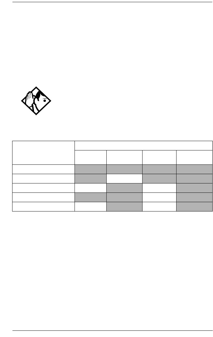
System prgrming / 429
P0992638 03 Modular ICS 6.0 Installer Guide
BusName
Norstar will display the name of the calling party when it is
provided both Private or Public ISDN PRI and BRI interfaces.
The displayed name may include information such as the
Receiving Calling Name, Receiving Redirected Name, and/or
Receiving Connected Name. The outgoing name is the
business name concatenated with the set name.
Network name display supported by protocol
Receiving and Sending Calling Party Name
Network name display allows the name of an incoming PRI/
BRI call to be displayed on the Norstar set receiving the call.
•Calling Party Name with status of PRIVATE may be
displayed on the Called Party set as Private name.
•If the incoming Calling Name is defined by the CO as a
private name, then Private name appears on the
answering set.
Tip - The outgoing name is not supported on BRI.
Refer to Feature assignment (CLID alignment) on page 330.
Network Name Display is an optional feature that is available
based on the interface to which you are subscribed.
Interface
Feature NI PRI DMS
Custom PRI
NI BRI SL-1
Receiving Calling Name Supported Supported Supported Supported
Receiving Redirected Name Supported Supported Supported
Receiving Connected Name Supported Supported
Sending Calling Party Name Supported Supported Supported
Sending Connected Name Supported Supported

430 / System prgrming
Modular ICS 6.0 Installer Guide P0992638 03
•If the Calling Party Name is unavailable it may be
displayed on the Called Party set as Unknown name.
•The system supports sending the calling party name, which
is the Business Name and Set Name concatenated together,
on calls originated by the Norstar system.
For information on programming your Feature assignment,
see Feature assignment (CLID alignment) on page 330.
The Set Name will only be sent if the OLI for the Set is
configured. See OLI # on page 315.
Receiving and Sending Connected Name
Outgoing calls record the Connected Name on outgoing calls.
The Connected Name is stored and displayed on the Norstar
set. In order for this to work you need to set the Called ID to
Yes. See Called ID on page 332.
The system also supports sending the Connected Name, which
is the Business and Set Name concatenated together, with
incoming calls.
If the call is answered by a hunt group, the hunt group name is
used instead of the set name.
The Connected Name is a transient display that appears for
about three seconds.
Network Name Display interactions
Calling and Connected Name information (if available) is
passed between trunks with Selective Line Redirection (SLR).
Only Calling Name information is passed between trunks in
cases where Direct System Inward Access (DISA) has resulted
in tandeming of trunks.

System prgrming / 431
P0992638 03 Modular ICS 6.0 Installer Guide
Programming Network Name Display
The Business Name and the Set Name make up the
information that is used for the outgoing Calling name or
connected name.
Calling/connected name is only sent once the Business Name
is programmed.
To program the Business Name start with the display showing
System prgming.
1. Press ≠.The display shows Hunt groups.
2. Press ‘ until the display shows BusName:.
3. Press CHANGE and use the keypad to enter a Business
Name. You can enter a maximum of eight letters. It is
recommended that you use a blank space for the last
character to act as a separator between the Business name
and Set name.
To program the Set Name start with the display showing
Terminals & Sets.
1. Press ≠ and enter the set number of the telephone
you would like to program.
2. Press ≠. The display shows Line access.
3. Press ‘ until the display shows Name:.
4. Press CHANGE and use the keypad to enter a Set Name. You
can enter a maximum of seven letters.
5. Other areas that must also be programmed include:
•the OLI number, see OLI # on page 315
•under Telco features the Call ID must be set to yes, see
Called ID on page 332

432 / System prgrming
Modular ICS 6.0 Installer Guide P0992638 03
Outgoing Name and Number Blocking
When activated, blocks the outgoing name and
number on a per call basis. When this feature is used, the call
is flagged to the CO so that the name and number will not be
presented to the person being called.
On analog and BRI trunks, a call blocking digit sequence is
sent to the CO before sending the dialout digits. You can
change this digit in a Norstar programming session and set it
to the digit sequence recognized by the local CO for name and
number blocking.
This programming is done in the main program heading Telco
Features. To program the Name and Number blocking digit,
start with the display showing Telco features.
Note: Step 1 through 3 are only for analog and BRI trunks.
1. Press ≠. The display shows VMsg ctr tel#s.
2. Press ‘ until the display shows ONN Blocking:.
3. Press ≠. The display shows Tone:None. You can
choose F78, (0-9), *, #.
4. Press CHANGE to enter a new tone dialing Name and
Number blocking digit sequence.
5. Press ‘. The display shows Pulse:None. You
can choose F78, (0-9), *, #.
6. Press CHANGE to enter a new pulse dialing Name and
Number blocking digit sequence.

System prgrming / 433
P0992638 03 Modular ICS 6.0 Installer Guide
Call by Call service selection for PRI Installer password required
Call by Call service selection allows a user to access services
or private facilities over a PRI line without the need for
dedicated facilities. The different services represent different
types of access to the network. Various services are available
depending on the chosen protocol. The list below identifies the
supported services
Call by Call service selection is supported for the following
protocols:
•National ISDN 2 (NI-2)
•DMS-100 custom
•DMS-250 (MCI, Sprint, Generic)
•AT&T 4ESS custom
The following Call by Call Services are supported:
Public Public calls connect Norstar and a Central Office
(CO). Both incoming (DID) and outgoing
(DOD) calls are supported. Dialed digits
conform to the standard North American dialing
plan (E.164 standard).
Foreign
Exchange
(FX)
Foreign exchange service connects a Norstar site
to a remote central office (CO). This provides
the equivalent of local service at the remote
location.
Tie Tie lines are private incoming and outgoing lines
that connect Private Branch Exchanges (PBXs)
such as Norstar.

434 / System prgrming
Modular ICS 6.0 Installer Guide P0992638 03
OUTWATS
(Outward
Wide Area
Telecommu-
nications)
This outgoing call service allows a Norstar user
to call telephones in a specific geographical area
referred to as a zone or band. Typically a flat
monthly fee is charged for this service.
INWATS
(Inward Wide
Area Tele-
communica-
tions)
This long distance service allows a Norstar user
to receive calls originating from specified areas
without charge to the caller. A toll-free number
is assigned to permit reverse billing.
International
INWATS
An international long distance service that
allows a Norstar user to receive international
calls originating from specified areas without
charge to the caller. A toll-free number is
assigned to permit reverse billing.
Switched
Digital
This service provides premises-to-premises
voice and data transport with call management
and monitoring features.
Nine Hundred This service is commonly referred to as fixed
charge dialing.
Private Private incoming and outgoing calls connect
Norstar to a virtual private network. Dialed
digits may conform to the standard North
American dialing plan (E.164 standard) or the
dialed digits may use a private dialing plan.

System prgrming / 435
P0992638 03 Modular ICS 6.0 Installer Guide
Norstar supported Call by Call Services by protocol
a. A shaded box indicates that the protocol does not support the service.
b. DMS-250 Sprint and UCS support incoming FX only (i.e. Network-to-
Norstar). DMS-250 MCI does not support FX.
c. NI-2 allows two Tie operating modes: senderized and cut-through. Norstar
will only support senderized mode.
d. Rates greater than 64 kbps will not be supported.
e. Bell Canada VNET.
f. Not all service types may be supported by a switch type. For information,
contact your service provider.
Programming Call by Call on PRI requires you to program
various areas of the Norstar system:
åunder Line access, assign the line pool
åunder Services, in routing services section, assign which
pool to use for routing and which service type service id, if
required
Norstar
ServiceaNI-2fDMS-100
(custom)
DMS-250
(MCI, Sprint,
Generic)
AT&T 4ESS
FX FX FXb
TiecTie Tie Tie SDN
(software defined
network)
INWATS INWATS INWATS Eight Hundred Toll Free
MEGACOM
International
INWATS
Same as
INWATS
Same as
INWATS
Same as
INWATS
International
Toll Free
Service
OUTWATS IntraLATA OUTWATS
OUTWATS with bands
InterLATA OUTWATS
OUTWATS PRISM MEGACOM
Private DMS
Privatee
VNET
(virtual
network)
Switched
Digital ACCUNETd
Nine Hundred Nine Hundred MultiQuest
Public Public Public Public

436 / System prgrming
Modular ICS 6.0 Installer Guide P0992638 03
åunder System programming, specify the minimum and
maximum values for the pools
åunder Hardware choose PRI card and select the protocol
Line Pools
All lines in a PRI interface are in the same PRI line pool. This
pool cannot contain any non-PRI lines. There is one PRI pool
available for each PRI interface on the CSU.
Depending on the order that the cards are configured as PRI,
Pool PRI-A represents lines 1 to 30, and Pool PRI-B represents
lines 31 to 60. If both PRIs are connected to the same service
provider and use the same protocol, lines 1 to 30 and 31 to 60
can be put in the same pool. There are four PRI pools available
for profile 1 and 4 systems, PRI-A, PRI-B, PRI-C, PRI-D
because these profiles support the off-core DTI module.
Programming Call by Call service selection
Programming the Norstar system for Call by Call Service
Selection with a PRI interface requires
•provisioning a PRI card if a PRI card is not already a part
of the system, on page 456
•selecting a protocol, on page 456
•programming incoming call routing, on page 458
•programming routes that use the PRI pools (under
Services), see Routing service on page 361

System prgrming / 437
P0992638 03 Modular ICS 6.0 Installer Guide
PRI Call by Call Limits
PRI pool limits for Call by Call services allows you to
configure limits for service types without interacting with the
CO. This feature sets the minimum and maximum number of
incoming and outgoing calls per service type for the PRI pool.
The number of active calls will be tracked so that whenever a
call is being set up, a check will be made to determine if it will
be allowed. Calls will not be allowed if they exceed the
maximum value for that service type or if they will use lines
needed to maintain the minimum value of other service types.
The summation of the minimum values for incoming or
outgoing PRI services cannot exceed the total number of lines
in the PRI pool.
The maximum value for an incoming or outgoing PRI service
cannot exceed the total number of lines in the PRI pool.
Programming Call by Call Limits
With the card set to PRI and the display showing System
prgming.
1. Press ≠.The display shows Hunt groups.
2. Press ‘ until the display shows CbC limits.
3. Press ≠.The display shows the first pool (PRI-A
or PRI-B) that supports CbC routing. Press NEXT to show
the other pool, if it is available.
4. Press ≠.The display shows Service:.
The service that is displayed depends upon the protocol.
Press NEXT to select a different service.
5. Press ≠. If it applies, the display shows Min
incoming:2. Press CHANGE to enter a different number.

438 / System prgrming
Modular ICS 6.0 Installer Guide P0992638 03
6. Press ‘. If it applies, the display shows Max
incoming:23. Press CHANGE to enter a different number.
7. Press ‘. The display shows Min outgoing:4.
Press CHANGE to enter a different number.
8. Press ‘. The display shows Max outgoing:23.
Press CHANGE to enter a different number.
Release Reasons
This feature is useful for diagnostic purposes. It shows the
reason why an ISDN call has been released. The Release
Reason can be displayed as Simple or Detailed text. When the
default None is selected, no release reasons appears on the set.
Release Reasons can be programmed under System prgrming.
With the display showing System prgming.
1. Press ‘ until the display shows Release
reasons.
2. Press ≠. The display shows Text: None.
3. Select the text to be displayed as Simple or Detailed.
Note: If you selected Simple text, press ‘ for Cause
code. The Cause code is for diagnostics. Make sure it
is set to N.
Mk/BR: 40/60 (profile 2 only)
This heading sets the make-break ratio for the system.
1. Press ‘ until the display shows Mk/BR.
2. Press CHANGE and select either 40/60 or 30/70.

System prgrming / 439
P0992638 03 Modular ICS 6.0 Installer Guide
Programming Hospitality Services
The Hospitality heading accesses the settings for the room and
alarm information.
With the display showing System prgming press ‘
until the display shows Hospitality.
Room/desk information
Use this setting to assign set DNs to a specific room.
1. At the Hospitality heading, press ≠.
Room/desk info displays.
2. Press ≠. Show set: displays.
3. Enter a room set number or press LIST and press
‘ until you find the DN of the set you want to
assign to a room.
4. Press ≠. Room #:None displays.
5. Press CHANGE and enter the room number, then press OK to
accept the change.
6. Repeat step 6 for all the sets you want to assign.
7. Press ‘. Adm pwd req’d:Y displays
8. Press CHANGE and choose Y or N, depending on your
security requirements.

440 / System prgrming
Modular ICS 6.0 Installer Guide P0992638 03
Call restrns
You can set up call restrictions based on room occupancy
states. This setting affects the Room occupancy feature.
1. At the Hospitality heading, press ≠ twice.
Call restrns displays.
2. Press ≠. Vacant:00 displays.
3. Press CHANGE and enter the filter that defines the
restrictions for your hospitality system. Refer to Filters on
page 322
4. Repeat steps 2 and 3 for the other room occupancy states.
The table below shows an example of a call restrictions
setup.
Setting Service times
You can set the time when occupied rooms change from
Service done to Service required. This setting affects the
Room condition feature.
1. At the Hospitality heading, press ≠ until
Service time displays.
2. Press ≠. Hour: 00 displays.
3. Press CHANGE and enter the hour (00 to 23).
Room
Occupancy Filter Description
Vacant 11 no calls allowed except 911
Basic 11 no calls allowed except 911 and internal
extensions
Mid 12 no calls allowed except 911, 1800, 188
and internal extensions
Full 13 no call restrictions

System prgrming / 441
P0992638 03 Modular ICS 6.0 Installer Guide
If the number is less than 13, the display shows AM. Press
CHANGE to select PM, if required. Press OK to accept.
4. Press ≠. Minutes: 00 displays.
5. Press CHANGE and enter the minutes (00 to 59).
Configuring alarms and expired alarms settings
Use this feature to create the alarm settings that will govern the
alarm features for both the administrative and room sets.
1. At the Hospitality heading, press ≠ until Alarm
displays.
2. Press ≠. Attn attempts:3 displays.
3. Press CHANGE until you find the number you want (1-5).
4. Press ‘. Retry intrvl:4 displays.
5. Press CHANGE until you find the number you want
(2, 4, 6, or 8).
6. Press ‘. Attn duration: 15 displays.
7. Press CHANGE until you find the number of seconds you
want (10, 15, 20, 30, 40, 50).
8. Press ‘. Time format:12 hr displays.
9. Press CHANGE to choose either 12hr or 24hr.
10. Press ‘. Expired alarms displays.
11. Press ≠. Notify set:None displays.
12. Press CHANGE to enter a set DN to be notified.
13. Press ‘. Use tone: N displays.
14. Press CHANGE to choose either Y (yes) or N (no).

442 / Network Services
Modular ICS 6.0 Installer Guide P0992638 03
Network Services
The headings that appear under Network Services, depends on
which profile the system is running.
Profiles 2 allows ETSI line connections, therefore, systems
running this profile may have access to the two ETSI features.
The service provided on the line by your service provider
determines if these features are available.
Profiles 1, 2, and 4 support MCDN over PRI SL-1 lines.
ETSI: Network diversion and MCID (profile 2 only)
If you are using Profile 2 for your system, and your service
provider supports the features, you can configure your ETSI
PRI lines to allow network diversion and/or MCID recording.
To program these features:
1. With the display showing System prgming press
‘ until the display shows Network Services.
2. Press ≠. ETSI displays.
3. Press ≠. Netwrk Redirection displays.
4. Press CHANGE to choose either Y (yes) or N (no).
5. Press ‘. The display shows MCID.
6. Press CHANGE to choose either Y (yes) or N (no).

Network Services / 443
P0992638 03 Modular ICS 6.0 Installer Guide
Network Call Diversion
Norstar Network Call Diversion (NCD) is a network function
that allows forwarding and redirection of calls outside the
Norstar network when using an ETSI ISDN line. Functionality
is similar to that of External Call Forward (ECF).
NCD redirects calls using the same line on which they arrive.
Call forward is efficient since there is no need for additional
outside lines.
Forwarding calls externally from an extension requires the
user to enter either a Destination Code or Line Pool Access
Code, and the number to which calls will be forwarded.
Examples of NCD include:
•redirecting all calls from an extension to a mobile phone
•forwarding calls to an external destination (rather than to
voicemail), when an extension is busy or the user is
unavailable.
Feature description
NCD is available only over ETSI ISDN lines. It can be
invoked when calls are presented to Norstar/BST extensions
over ISDN lines. The user must program the selected
extension.
NCD is integrated with the following existing Norstar Call
Forward features:
•Call Forward Unconditional (CFU)—implemented on
Norstar Call Forward All Calls (CFAC) , and
Selective Line Redirection (SLR) , also
referred to as Line Redirection. This is programmable by
the user.

444 / Network Services
Modular ICS 6.0 Installer Guide P0992638 03
•Call Forward on Busy (CFB)—implemented on Norstar
Call Forward Busy.
•Call Forward on No Response (CFNR)—implemented on
Norstar Call Forward No Answer.
Programming and restrictions
NCD features are accessed through existing Norstar features.
Extensions requiring redirection must be programmed
individually to either CFAC or SLR. CFB or CFNA must be
set during programming. Allow redirect must be set to Yes
for each extension, in Terminals&Extns/Capabilities.
Note: Any other programming applied to specific lines and
extensions take precedence, for example
Restrictions(extns) under Terminals&Extns.
NCD is used as long as the affected lines are ETSI ISDN, and
the affected DID lines are accessible via ISDN lines. Incoming
calls are diverted back to the ISDN. If NCD fails due to
network errors, ECF is invoked. If ECF cannot be executed,
the incoming call is routed to the prime extension for the line.
An extension with CFB, CFNA and CFAC programmed will
give priority to CFAC for diversion.
ATTENTION!
If a line is configured to appear on several extensions with
redirection programmed, predicting which extension will divert
the call is not possible. This should be considered during system
configuration.

Network Services / 445
P0992638 03 Modular ICS 6.0 Installer Guide
Malicious call identification (MCID)
The MCID feature allows the user to press to
have call information recorded on the central office system for
an incoming call on a specific line (ETSI PRI lines, only).
The user must invoke the feature code either during the active
call or within 30 seconds (time varies on different networks)
after the caller hangs up. The feature will not work once the
called party hangs up.
Note: This feature must be allowed in network programming
for your PRI lines from your service provider.
The following information registers on the network:
•called party number
•calling party number
•local time and date of the invocation in the network serving
the called user
•service provider option: calling party subaddress, if
provided by calling user)
MCDN services (profiles 1, 2, 4)
If your system is part of a private network using PRI SL-1
lines, you can determine the MCDN features that will be
allowed by your system. These settings are described in detail
in the networking section of this book. Refer to MCDN trunk
call features on page 133.
•TRO: Trunk Route Optimization
•ICCL: ISDN Call Connection Limitation
•TAT: Trunk Anti-Tromboning

446 / Network Services
Modular ICS 6.0 Installer Guide P0992638 03
To program these features:
1. With the display showing System prgming press
‘ until the display shows NetworkServices.
2. Press ≠. ETSI displays.
3. Press ‘. MCDN displays.
4. Press ≠. NetwkICCL displays.
5. Press CHANGE to choose either Y (yes) or N (no). Default is
No.
6. Press ‘. TRO displays.
7. Press CHANGE to choose either Y (yes) or N (no). Default is
No.
8. Press ‘. TAT displays.
9. Press CHANGE to choose either Y (yes) or N (no). Default is
No.
Note: TRO and TAT cannot both be set to Y, as TAT will not
work if TRO is active.
Note: If you set NetwkICCL to yes, check the Max transits
settings under hardware to confirm the threshold at
which you want the system to release the call rather
than to continue cycling. Refer to “Max transits” on
page 465.

Telco features / 447
P0992638 03 Modular ICS 6.0 Installer Guide
Telco features
Currently the two features accessed under this heading are the
settings for the voice mail connections for your system, and
how to set up outgoing name and number blocking (ONN).
With the display showing System prgming press ‘
until the display shows Telco features.
VMsg ctr tel#s
If you subscribe to a voice message service outside of your
local system, you can access it through your Norstar system.
This includes centralized voice mail that is installed on another
system within the private network that your system is
connected to. Refer to Central voice mail and Auto Attendant
with Norstar on page 146.
This setting specifies the external telephone numbers that are
dialed by the Message feature to retrieve voice messages.
1. At the Telco Features prompt, press ≠.
Vmsg ctr tel# displays.
2. Press ≠. VMsg center 1 displays.
3. Press ≠. Use: Line displays.
4. Press CHANGE to select either Line or Routing tbl.
5. Press ‘. Tel#: No number displays.
Tip - If you choose Routing tbl, you must ensure that this
number contains the routing code, and that the number is
entered in the routing table and routed to the correct line pool.
448 / Telco features
Modular ICS 6.0 Installer Guide P0992638 03
6. Press CHANGE and enter the telephone number for the voice
message system.
7. Press – to move up a level.
8. Press ‘ to move to the next Voice message
center.
9. Repeat steps 2 to 6 for however many voice message
centers you want to enter.
Outgoing Name and Number Blocking
Outgoing Name and Number blocking blocks the outgoing
name and number on a per call basis when the user presses
ONN blocking is cancelled with
When this feature is used, the call is flagged to the CO so that
the name and number will not be presented to the person being
called. Refer to Outgoing Name and Number Blocking on page
432 for more information.
1. At the Telco Features prompt, press ≠. ONN
blocking displays.
Tips - A telephone does not show that external voice
messages are waiting unless Extl VMsg set is set to Y (Yes).
The setting is in CLASS assignment under Terminals&Sets.
You can program up to five voice message center numbers, but
most systems require only one.

Telco features / 449
P0992638 03 Modular ICS 6.0 Installer Guide
Programming the analog vertical service code (VSC)
1. Press ≠. Analog VSC displays.
2. Press ≠. Tone:None displays.
3. Press CHANGE to enter a new tone dialing Name and
Number blocking VSC.
The VSC for tone trunks can include a maximum of
10 digits consisting of the CO Pause ( ), and
digits 0-9, *, and #.
4. Press ‘. Pulse:None displays.
5. Press CHANGE to enter a new pulse dialing Name and
Number blocking VSC.
The VSC for pulse trunks can include a maximum of
10 digits consisting of the digits 0-9. Pulse trunks do not
support , * or #. The * is represented by 11
(two consecutive ones).
Programming the BRI VSC
1. Press ≠ until BRI USC displays.
2. Press ≠. Code:None displays.
3. Press CHANGE and enter a new BRI name and number
blocking VSC. This entry can be up to 10 digits, consisting
of CO Pause ( ), digits 0-9, *, or #.

450 / Telco features
Modular ICS 6.0 Installer Guide P0992638 03
Setting up the modules for ONN blocking
To utilize ONN blocking, the CO is alerted by two methods,
the Vertical Service Code (VSC) or suppression bit method.
Each method depends on the type of trunk involved in placing
the outgoing call.
Analog trunks use a dialing digit sequence called VSC. Most
COs use the suppression bit method for ONN. You will need
to use the VSC ONN if your CO does not support the
suppression bit method. The VSC differs from region to region
and must be programmed.
•Analog trunks with both tone and pulse dialing trunks can
have separate VSCs.
•BRI trunks support one VSC.
•PRI trunks do not utilize the VSC.
The second method used to alert the CO is by a suppression bit
packaged within the call setup message. BRI trunks can use
either method.
Note: PRI trunks only support the suppression bit method
of signalling the CO to block the outgoing Name
and Number to the calling party, therefore, no
additional programming is required.
When you program ONN blocking on a BRI module, you must
indicate which method the BRI trunk will use. The module
loop setting supports two ONN states. You must program the
BRI loop to match the method supported by your service
provider.
•If SrvcCode is programmed, then the VSC programmed
under Telco Features is used.
•If SuprsBit is programmed, then the suppression bit will
be packaged in the call setup message.

Telco features / 451
P0992638 03 Modular ICS 6.0 Installer Guide
Program ONN blocking BRI loop state
The display shows the loops found on the BRI card.
1. Press ‘ to display the settings for individual
loops on a BRI card.
2. At the Loops display, press next to display the first loop
number.
3. Press ≠. Type:T displays.
4. Press ‘ until ONNblk:SuprsBit displays.
5. Press CHANGE to toggle the BRI loop state setting from
SuperBit to SrvcCode.
6. Repeat steps 1 to 4 to program ONN blocking BRI loop
state for other loops, as required.
ONN call blocking notes:
•Set, line and set/line restrictions have no effect on digits
programmed within the ONN feature code.
•Call back from the CO is disallowed with this feature.

452 / Software keys
Modular ICS 6.0 Installer Guide P0992638 03
Software keys
Some of the MICS system features require special pass codes,
called software keys, to make the feature work. This section
describes each of these options. To obtain the required
Software key, call the Integrated Voice Response (IVR)
Center at: 1-800-4NORTEL (667835), then use Express
Routing Code 1599.
ISDN-PRI
A software key is required so that you can configure a DTI
card as a PRI card.
MCDN
To create a private network using MCDN or tandem linking,
you need a PRI key and a key specific to MCDN.
Companion (MICS-XC only)
Software keys are used to activate Companion components on
systems running the MICS-XC 6.0 software. See the Modular
ICS Companion Installer Guide for more information.
You will need to provide the following information:
•the System ID of the Norstar ICS
•the authorization number printed on the Bandwidth
Allocation License Instruction Sheet
•the number of Directory numbers (DNs) configured in the
system
•the number of lines configured in the system

Software keys / 453
P0992638 03 Modular ICS 6.0 Installer Guide
System Identification Number
Obtain the System ID (SysID) by pressing
, or
on any system set.
This information is also available by accessing
Software keys in an Installer programming session:
1. Press ≠ The display reads SysID: followed by
the unique System Identification Number.
2. Press ‘ to continue in Software keys or
to exit.
3. Record the SysID in the Modular ICS Programming
Record.
Call the Nortel Customer Response Center
1. Call the number given in the description of the software
key you need.
2. Follow the voice prompts.
3. You will be given three separate numeric strings that
contain eight digits each.
4. Record the Password keys in the Modular ICS
Programming Record.
Re-entering software keys.
Should the system be powered down for 72 hours
or more, you will need to obtain and enter new
software keys.

454 / Software keys
Modular ICS 6.0 Installer Guide P0992638 03
Entering the software keys
Keys are entered by accessing Software keys in a
programming session.
1. Press ≠. The display reads SysID:.
2. Press ‘. The display reads Password keys.
3. Press ≠. The display reads Key 1:_.
4. Enter the eight-digit password number for Key 1.
Use BKSP to make corrections. The display reads Key 2:_.
5. Enter the eight-digit password number for Key 2.
6. Proceed as above until you have finished entering Key 3.
The display reads Entry successful.
7. Press – until the display reads Software keys
or press to exit.
Note: If the entry is unsuccessful, the display shows Invalid
password. If this happens, re-enter the code or call
Nortel Customer Response Center at
1-800-4-NORTEL (667835) for assistance.

Hardware / 455
P0992638 03 Modular ICS 6.0 Installer Guide
Hardware
Hardware is where you view and change settings for cartridges
installed in the ICS, Trunk Modules, Station Modules, and
Data Modules.
Show module Installer password required
The Show module setting automatically displays the modules
connected to the system. Press ‘ to select the setting:
KSU, Mod 03, Mod 04, Mod 05, Mod 06, Mod 07, Mod 08.
Note: MICS-XC has 14 modules.
Cards on KSU Installer password required
The Cards on KSU setting allows you to specify the type of
Trunk Cartridges in the ICS.
Press ‘ to select the setting: T1, PRI, BRI-U4, BRI-
U2, BRI-ST, E&M, DID, or Loop.
Note: KSU is also known as the Integrated Communication
System (ICS).
•Loop is the default setting used for Loop Start and Call
Information (CI) Trunk Cartridges.
•Select the T1 or PRI setting for DTIs cards.
Tips - You cannot change this setting unless you first
disable the Trunk Cartridge using Module status in
Maintenance. Remember to enable the Trunk Cartridge
once you have completed programming. See Module status on
page 495 for details. The Trunk Cartridge slots in the ICS are
numbered from right to left.

456 / Hardware
Modular ICS 6.0 Installer Guide P0992638 03
Once you specify the type of Trunk Cartridge in the ICS slot,
press ≠ to display the range of line numbers for the
lines on the Trunk Cartridge.
Provisioning the DTI card for PRI
The Cards on KSU setting allows you to specify the type of
Trunk Cards in the ICS.
Note: Remember, you require a software password to activate
PRI on your system.
Start with the display showing Hardware.
1. Press ≠. The display shows Show module.
2. Press ‘. The display shows Cards on KSU.
3. Press ≠. The display shows Cd1-KSU:
4. Press CHANGE to view the different cards: T1, PRI,
BRI-U4, BRI-U2, BRI-ST or Loop.
5. Select PRI. The display shows Clear line data.
6. Select Y (Yes) to confirm your selection.
For more information on provisioning cards see Hardware
on page 455.
Selecting a protocol
Now that the DTI card has been provisioned as PRI (or is
already part of the system) you can select a protocol.
With the display showing PRI
1. Press ≠.
2. Press ‘ until the display shows Protocol:.

Hardware / 457
P0992638 03 Modular ICS 6.0 Installer Guide
3. Press CHANGE to select a different protocol from the table
that follows:
If you selected the NI-2 protocol, and you are using call-
by-call services, you must specify how Norstar should
handle the NSF (Network Specific Facilities) information
element as follows:
•Press ≠.
•Press ‘ until the display shows the default
protocol NSF EXT: None.
•Press CHANGE to select another setting based on your
switch type, as shown in the following table:
4. Press ‘. If the display shows Clear Routes,
press Y (yes) to confirm your selection.
Protocol Type
NI-2, DMS100, DMS250,
AT&T4ESS
Public
SL-1 Private
Note: This will not display unless
you have entered the MCDN
software code.
Central Office NSF Extension Setting
DMS100 None
Siemens ESWD, Lucent 5ESS WATS
GTD5, DMS10 ALL
The Network Specific Facilities (NSF) information element is used to
request a particular service from the network.
•When you select NONE, the NSF extension bit is not set for any
service.
•When you select WATS, the NSF extension bit is set for
unbanded OUTWATS calls.
•When you select ALL, the NSF extension is always set for all
CbC services.

458 / Hardware
Modular ICS 6.0 Installer Guide P0992638 03
BchanSeq
B-channel sequence allows you to select either ascending or
descending. You need to choose the opposite setting of your
service provider.
However, if all lines for two DTI cards (configured as PRI) are
in the same PRI pool, then both cards must be set to use the
descending B-channel sequence mode. As a result, the service
provider must use ascending mode
Press CHANGE to select either ascending or descending.
Call-by-call routing
By default, incoming calls are routed based on the Called Party
Number. You program the received number length to include
however many digits your system requires. This many digits
from the end of the called party number are then used as
Received Digits to find a target line.
For example, the incoming calling party number is
800-555-1234. The received digit number length is 4.
Therefore, 1234 is used to route the call.
Depending on the protocol and the service, alternate routing
maps may be defined.
To change the incoming call routing for a service, with the
display showing Protocol:, do the following:
1. Press ‘ until the display shows CbC Routing.
2. Press ≠. The display shows FX:.
Press NEXT to display a different service.
Note: The display shows the first applicable service for the
given protocol, in this example the service is FX.

Hardware / 459
P0992638 03 Modular ICS 6.0 Installer Guide
3. Press CHANGE to change the mapping that is applied to
incoming calls of this service type to obtain the received
digits. In all cases, the received digits are used to find a
target line or to activate Remote Access.
None — No mapping is applied. The received number
length determines the number of digits of the Called Party
Number which will be used as received digits.
Note: If there is no called party number, which may occur
with some FX calls, the call will ring at the incoming
trunk Prime set.
All — Allows you to define the received digits used for all
calls with this service type, regardless of the called party
number or service identifier (SID). For this option, all calls
with this service type on this PRI will ring the same target
line.
Map table — Allows you to associate different received
digits with different calls of this service type, depending
on the call party number and/or the service identifier.
Incoming calls that do not match any entry defined in the
map table will ring at the prime set. Depending on the
service type and the protocol, you may be able to map the
called party number and the service identifier.
The following table shows the different options.
Service
Protocol FX 800 I-800 SDS 900
NI-2 SID CDN n/a n/a n/a
DMS-100 SID SID or CDN n/a n/a n/a
DMS-250 SID SID or CDN n/a n/a SID or CDN
4ESS n/a CDN CDN CDN CDN

460 / Hardware
Modular ICS 6.0 Installer Guide P0992638 03
Discon timer
Disconnect timer allows you to specify the duration of an
Open Switch Interval (OSI) before a call on a supervised
external line is considered disconnected.
Press CHANGE to select the setting: 60, 100, 260, 460, or 600
milliseconds.
Answer timer Installer password required
Answer timer allows you to set the minimum duration of an
answer signal before a call is considered to be answered.
Press CHANGE to select the setting: 1, 2, 3, 4 or 5 seconds.
Note: This setting only appears for DTI (T1) and E&M Trunk
Cartridges.
CO fail Installer password required
Select the carrier failure standard used by your T1 or PRI
service provider.
Press CHANGE to select the setting: TIA-547A or TR62411.
Tips - Disconnect Supervision is assigned to each line
with the Trunk mode setting. See Trunk/Line data on page 333.
This setting must match the setting for the line at the central
office (CO).
This setting only appears for DTI (T1) and Loop Trunk
Cartridges.
Tips - This setting only appears for DTIs.
Consult your T1 or PRI service provider for the proper
setting.

Hardware / 461
P0992638 03 Modular ICS 6.0 Installer Guide
I/F levels Installer password required
Interface levels defaults to the ISDN loss plan setting.
Press CHANGE to select setting: ISDN, PSTN or ISD/TT interface
levels.
Tips - Find out if your Norstar system is connected to a
central office (CO) with digital network loss treatment
(ISDN I/F levels) or analog network loss treatment
(PSTN I/F levels) by checking with your telecommunications
service provider.
The ISDN setting requires digital access lines (DAL) that have
digital network loss treatment. On a DAL network, it is the
PBX that administers the dB loss. DALs may have ISDN
signaling or digital (such as T1 and so on) signaling. To have
DAL network loss treatment on a line with digital signaling,
you must contact your service provider.
The PSTN setting requires analog access lines (AAL) that
have analog network loss treatment and digital signaling. On
an AAL network, the CO administers the dB loss.
Tips - The ISD/TT setting is only for T1 and PRI
interfaces (MCI services only). ISD/TT provides a loss level
that is similar to DAL except for certain analog connections
where the DB level increases by three.
Each loss plan uses a transmit objective loudness rating of -
46 dB. The ISDN and ISD/TT loss plan uses a receive
objective loudness rating (ROLR) of 51dB and the PSTN loss
plan uses a ROLR of 48 dB.
Choosing the wrong setting may affect voice quality.
462 / Hardware
Modular ICS 6.0 Installer Guide P0992638 03
Framing Installer password required
Framing allows you to select the framing format used by your
T1 or PRI service provider.
Press CHANGE to select the setting: ESF (Extended Superframe)
or SF (Superframe).
Internal CSU Installer password required
Internal CSU allows you to turn the internal T1 channel
service unit on or off. The channel service unit gathers
performance statistics for your T1 lines or PRI with public
interface.
Press CHANGE to select the setting: On or Off.
You must disable the Trunk Cartridge using
Module status
in Maintenance before you
can change this setting. See Module status on
page 495 for details.
Tips - This setting only appears for DTIs. Consult your T1
or PRI service provider for the proper setting.
SF or Superframe is sometimes known as D4.
You must disable the Trunk Cartridge using
Module status
in Maintenance before you
can change this setting. See Module status on
page 495 for details.

Hardware / 463
P0992638 03 Modular ICS 6.0 Installer Guide
CSU line bld Installer password required
CSU line build allows you to set the gain level of the
transmitted signal.
Press CHANGE to select the setting: 0, 7.5 or 15 dB.
Tips - This setting only appears for DTIs. Consult your
service provider for the proper settings.
You can view the performance statistics for your T1 lines in
Maintenance under the CSU stats heading.
If you use an external CSU with your T1 lines, then set the
internal CSU to off.
You must disable the Trunk Cartridge using
Module status
in Maintenance before you
can change this setting. See Module status on
page 495 for details.
Tips - This setting only appears for DTIs that have the
internal CSU turned on.
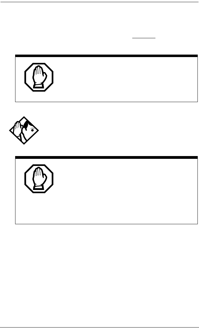
464 / Hardware
Modular ICS 6.0 Installer Guide P0992638 03
Line coding Installer password required
Select the standard used by your T1 service provider for
encoding signals on the T1 lines. Press CHANGE to select the
setting: B8ZS or AMI.
ClockSrc Installer password required
Clock Source allows you to designate which of the system
Digital Trunk Interfaces (DTIs) obtains the timing reference
from the network, which the system synchronizes to. For more
on Clock Source settings, see page 476.
You must disable the Trunk Cartridge using
Module status in Maintenance before you can
change this setting. See
Module status
on page
495 for details.
Tips - This setting only appears for DTIs.
Consult your T1 service provider for the proper setting.
Enable Trunk Cartridges
If you disable any Trunk Cartridges to perform
programming, enable them now using Module
status in Maintenance or your system will
not function properly. See
Module status on page
495
for information on enabling Trunk Cartridges
in Module status.

Hardware / 465
P0992638 03 Modular ICS 6.0 Installer Guide
Max transits Installer password required
If you allow ISDN Call Connection Limitation (ICCL) on your
MCDN PRI system, you need to determine a threshold at
which the system will release the call, rather than allow
continued line tie ups. This threshold is called Max(imum)
transits. The default value for this feature is 31.
Modules
The Mod setting allows you to specify the type of module you
wish to configure.
Press CHANGE to select the setting: StnMod, ASM, TrunkMod or
DataMod.
Note: ASM is the same as AEM, which is the analog station
module.
Tip - MICS-XC can have up to 14 modules.
Other MICS configurations have up to 8.

466 / Hardware
Modular ICS 6.0 Installer Guide P0992638 03
StnMod
If a Station Module is selected and connected to the Modular
ICS, no extra programming is required. Each Station Module
represents 16 new DNs. For more information on lines and
DNs used by the Station Module, see Wiring charts on page
241.
ASM
If an Analog Station Module is selected and connected to the
Modular ICS, no extra programming is required.
The module defaults to:
•two extension lines are assigned
•Full Handsfree is disabled
•Handsfree is enabled
•all exchange lines are assigned to Ring
•Answer Keys cannot be assigned to the AEM
•allow Redirect
To verify the status of the module:
1. Navigate to Maintenance and Module Status.
Show module: displays.
2. Enter the module number you want to verify.
8 extns on EM displays.
3. Press STATE.
“x” sets busy displays

Hardware / 467
P0992638 03 Modular ICS 6.0 Installer Guide
To verify the status of each port:
1. Navigate to Maintenance and Port/Extn stat.
Show port: displays.
2. Enter the port number you want to verify.
The display shows the port number.
TrunkMod
TrunkMod setting allows you to configure the Trunk
Cartridges in the Trunk Module.
Press CHANGE to select the setting: Loop, E&M, DID, BRI-ST,
BRI-U2, BRI-U4 or PRI.
Loop is the default setting used for Loop start and Call
Information (CI) Trunk Cartridges.
Tips - You cannot change this setting unless you first
disable the Trunk Cartridge using Module status in
Maintenance. Remember to enable the Trunk Cartridge once
you have completed programming. See Module status on page
495 for details.
The Trunk Cartridge slots in the Module are numbered from
left to right. Trunk Modules are numbered 3 to 4 for a midi,
3 to 8 for a maxi and a mega system.
Depending on your system configuration, off-core DTI, PRI,
BRI-ST, BRI-U2, and BRI-U4 cards can only reside in certain
trunk modules. In a midi system, the cards must be in trunk
modules 3 or 4. In a maxi or mega system, the cards must be
in trunk modules 7 or 8. The cards can reside in the ICS
regardless of system size.

468 / Hardware
Modular ICS 6.0 Installer Guide P0992638 03
Once you specify the type of Trunk Cartridge in the ICS slot,
press SHOW to display the line number range for the lines on the
Trunk Cartridge.
Midi line number chart
Line numbers
Midi Loop ST U-2 U-4
(prfl 1)
DTI
(PRI SL1-
N12)
DTI (T1)
(prfl 1)
E&M DID
(prfl1)
Cd1 ICS
Mod 2
1-4 1-8 1-4 1-8 1-23
(prfl 1)
1-30
(prfl 2)
1-24 NA NA
Cd2 ICS
Mod 2
31-34 31-38 31-34 31-38 31-53
(prfl 1)
31-60
(prfl 2)
31-54 NA NA
Cd1
Mod 04
61-64 61-68 61-64 61-68 61-83
(prfl 1)
61-84 61-64 61-64
Cd2
Mod 04
69-72 69-76 69-72 69-76 NA NA 69-72 69-72
Cd3
Mod 04
77-80 77-84 77-80 77-84 NA NA 77-80 77-80
Cd1
Mod 03
85-88 85-92 85-88 85-92 85-107
(prfl 1)
85-108
(prfl 1)
85-88 85-88
Cd2
Mod 03
93-96 93-
100
93-96 93-100 NA NA 93-96 93-96
Cd3
Mod 03
101-
104
101-
108
101-
104
101-
108
NA NA 101-
104
101-
104
Target lines: 157-284
Note: Off-core DTI uses line numbers for all three card positions in whichever
module (3 or 4) it is installed in.

Hardware / 469
P0992638 03 Modular ICS 6.0 Installer Guide
Maxi/Mega line number chart
Line numbers
Maxi/
Mega
Loop ST U-2 U-4
(prfl 1)
DTI (PRI
SL1-N12)
DTI (T1)
(prfl 1)
E&M DID
Cd1 ICS
Mod 2
1-4 1-8 1-4 1-8 1-23
(prfl 1)
1-30
(prfl 2)
1-24 NA NA
Cd2 ICS
Mod 2
31-34 31-38 31-34 31-38 31-53
(prfl 1)
31-60
(prfl 2)
31-54 NA NA
Cd1
Mod 08
61-64 61-68 61-64 61-68 61-83
(prfl 1)
61-84 61-64 61-64
(prfl 1)
Cd2
Mod 08
69-72 69-76 69-72 69-76 NA NA 69-72 69-72
(prfl 1)
Cd3
Mod 08
77-80 77-84 77-80 77-84 NA NA 77-80 77-80
(prfl 1)
Cd1
Mod 07
85-88 85-92 85-88 85-92 85-107
(prfl 1)
85-108
(prfl 1)
85-88 85-88
(prfl 1)
Cd2
Mod 07
93-96 93-
100
93-96 93-100 NA NA 93-96 93-96
(prfl 1)
Cd3
Mod 07
101-
104
101-
108
101-
104
101-
108
NA NA 101-
104
101-
104
(prfl 1)
Cd1
Mod 06
109-
112
NA NA NA NA NA 109-
112
109-
112
Cd2
Mod 06
113-
116
NA NA NA NA NA 113-
116
113-
116
Cd3
Mod 06
117-
120
NA NA NA NA NA 117-
120
117-
120
Cd1
Mod 05
121-
124
NA NA NA NA NA 121-
124
121-
124
Cd2
Mod 05
125-
128
NA NA NA NA NA 125-
128
125-
128

470 / Hardware
Modular ICS 6.0 Installer Guide P0992638 03
Cd3
Mod 05
129-
132
NA NA NA NA NA 129-
132
129-
132
Cd1
Mod 04
133-
136
NA NA NA NA NA 133-
136
133-
136
Cd2
Mod 04
137-
140
NA NA NA NA NA 137-
140
137-
140
Cd3
Mod 04
141-
144
NA NA NA NA NA 141-
144
141-
144
Cd1
Mod 03
145-
148
NA NA NA NA NA 145-
148
145-
148
Cd2
Mod 03
149-
152
NA NA NA NA NA 149-
152
149-
152
Cd3
Mod 03
153-
156
NA NA NA NA NA 153-
156
153-
156
Target lines: 157-284 (expanded: 157-348)
Note: Off-core DTI uses line numbers for all three card positions in whichever
module (7 or 8) it is installed in.
Maxi/Mega line number chart (Continued)
Line numbers
Maxi/
Mega
Loop ST U-2 U-4
(prfl 1)
DTI (PRI
SL1-N12)
DTI (T1)
(prfl 1)
E&M DID
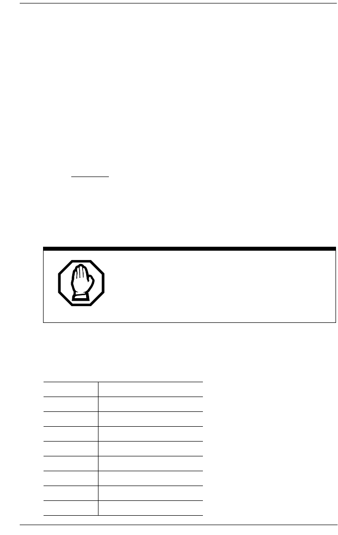
Hardware / 471
P0992638 03 Modular ICS 6.0 Installer Guide
BRI card
Loop Installer password required
The display shows the loops found on the BRI card.
Press ‘ to display the settings for individual loops on
a BRI card.
Type
Press CHANGE to select the loop type.
•If the card type is BRI-ST, the loop type can be S, or T.
•If the card type is BRI-U2 or BRI-U4, the loop type can be
LT or NT.
Lines
There are two lines for each T or NT loop.
The BRI card must be disabled in Module status
before this setting can be changed.
You can change the setting if the card has not yet been
installed in the ICS slot.
Loop Default lines
201 001-002
202 003-004
203 005-006
204 007-008
231 031-032
232 033-034
233 035-036
234 037-038

472 / Hardware
Modular ICS 6.0 Installer Guide P0992638 03
No SPIDs assignd Installer password required
T and NT loops can be assigned a system profile identifier
(SPID) as supplied by your service provider. No SPIDs are
assigned by default.
When the loop type is T, calls on the loop are handled for a
network connection only. If any other ISDN equipment is
connected to the loop, it must be configured as an S loop to
ensure proper call handling.
1. Press ADD and enter the first or second SPID assigned to
the loop.
If there are two SPIDs already assigned to the loop, ADD
will not appear until one is removed.
2. Press REMOVE to clear a SPID.
Note: Profile 2 loops do not require SPIDs.
# of B-channels Installer password required
Press CHANGE to select the number of B-channels that are
associated with the SPID: 1 or 2.
Tips - When you order an ISDN capability package that
supplies two B-channels, you may receive one or two SPIDs
from your service provider.
•If you receive one, it usually means you will configure
the SPID to use two B-channels.
•If you receive two, it usually means you will configure
each SPID with one B-channel. Check with your
service provider if you are not sure about the proper
configuration.

Hardware / 473
P0992638 03 Modular ICS 6.0 Installer Guide
Network DNs Installer password required
1. Press ≠ to display the DNs which are used with
the SPID.
2. Press ADD and enter the appropriate number to assign
additional Network DNs to the SPID.
The Modular ICS can have a maximum of 128 Network DNs
for the system. There is no limit to the number of Network
DNs for each SPID, but you cannot exceed the limit of 128
Network DNs for the system.
If the Network DN you try to enter is already assigned to a
SPID with a call type of Both, you will not be able to assign
the DN again.
If the Network DN you enter is already assigned to a SPID and
the call type is Voice or Data, it will be automatically
programmed with the unused call type. For example, if the DN
has Call type set to Voice in the previous SPID assignment, it
will be automatically set to handle Data calls when the same
DN is added to the other SPID.
Call type Installer password required
Press CHANGE to select the call type of the Network DN:
Voice, Data, or Both.
CHANGE will not appear if the Network DN is already in use by
the system and the call type will be automatically programmed
with the unused call type. For example, if the DN has Call type
set to Voice in a previous SPID assignment, it will be
automatically set to handle Data calls when the DN is entered
the second time.

474 / Hardware
Modular ICS 6.0 Installer Guide P0992638 03
D-packet servce Installer password required
1. Press ≠ to view and program D-packet service
for T or NT loops. You can have two D-packet service
configurations for each BRI card.
2. Press CHANGE to turn D-packet service for this loop on (Y)
or off (N).
Lp Installer password required
1. Select the S loop (for BRI-S/T cards) or LT loop for BRI-
U2 or BRI-U4 cards that supports the D-packet service.
2. Press CHANGE to move through a list of the loops which are
available on this card.
Note: If only one loop is available, you will not see CHANGE.
TEIs Installer password required
Press ≠ to view and program the Terminal Endpoint
Identifiers (TEIs). Each TEI is supplied by your service
provider and is associated with an ISDN D-channel packet
device.
Tips - If our service provider does not specify the call type
for each Network DN, it is probably available for both voice
and data. Check with your service provider if you are not
certain about the proper configuration.
Tips - An LT loop must already be assigned.

Hardware / 475
P0992638 03 Modular ICS 6.0 Installer Guide
No TEIs on loop Installer password required
Press ADD to program up to eight TEIs to this loop.
Sampling Installer password required
Press CHANGE to select the sampling used by an S loop:
•Fixed — if two or more S-interface devices use the loop
and the length of the loop is less than 200 m (650 ft.), select
Fixed.
•Adaptve — if two or more S-interface devices use the
loop and the length of the loop is greater than 200 m (650
ft.), select Adaptve.
If one S-interface device is using the loop, the length of the
loop can be up to 1000 m (3,250 ft.) and the rate should be set
to Adaptve.
The BRI card must be disabled under Module status in
Maintenance programming, before you can change this
setting. You can change the setting if the card has not yet been
installed in the ICS slot.
DNs on Loop Installer password required
Press ≠ to view and program the ISDN DNs assigned
to the loop.

476 / Hardware
Modular ICS 6.0 Installer Guide P0992638 03
Assign DNs Installer password required
1. Press ≠ and enter the ISDN DN you wish to
assign to this loop, or press SCAN to move through a list of
DNs already assigned to the loop.
The display shows:
•Availabl, Assigned — assigned to this loop
•*Lpnnn* — assigned as the default DN of
another loop
•Lpnnn — assigned to another loop
2. Press LIST to view the DNs assigned as ISDN DNs.
The default ISDN DN range is 667-696. For information
about changing ISDN DN type, see Changing Companion
DN type on page 425.
3. Press CHANGE to assign the DN to the loop or to remove it.
Loop DN
Press CHANGE to move through the ISDN DNs you have
assigned to the loop.
This will assign the main ISDN DN to the loop.
You can also set Loop DN to None.
Clock Src Installer password required
Systems with digital interfaces need to synchronize to the
network in order to function. Synchronization is done in a
hierarchical way, where each device/switch obtains the
network clock from the device/or switch above it in the
synchronization hierarchy and passes the network clock to the
device/switch below it in the synchronization hierarchy. The
synchronization levels are referred to as strata.

Hardware / 477
P0992638 03 Modular ICS 6.0 Installer Guide
Norstar systems are stratum 4E equipment and are usually
used as termination points in a network.
For each DTI, choose one of the following settings:
Primary reference
The DTI obtains the timing reference from the network, which
the system synchronizes to. This is the default value for the
DTI in slot 1 in the ICS. If the system is configured with a DTI
card that has been configured as PRI, the setting should be set
to Primary.
Secondary reference (Secndry)
The DTI acts as a standby reference. If there are excessive
errors on the primary reference T1 link, or the DTI designated
as primary reference fails, this DTI will obtain the timing
reference from the network, which the system synchronizes to.
This is the default value for the DTI in slot 2 in the ICS.
Timing master (TimeMst)
The DTI does not obtain timing from the network, but
transmits the systems timing to equipment connected to it.
Tips - If a BRI card becomes clock source, it will have up
to four clock sources available (T, S, U-NT, NT loops only).
Only when all four clock sources have an alarm will the card
cause a switch to the secondary or hold-over state.
BRI -T, S, and U-NT interface loops may be autonomously
powered down by the network. This will be treated as a loss
of clock source on that loop.
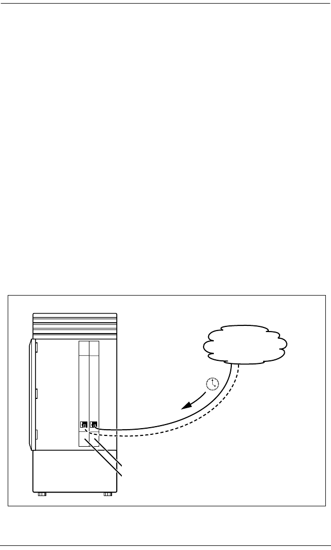
478 / Hardware
Modular ICS 6.0 Installer Guide P0992638 03
The following illustrations show some typical network
configuration and the appropriate clock source settings for
your DTIs.
Norstar connected directly to the service provider in a T1 network
The installer should ensure that clock source loops are
either not powered down or are among the last to be
powered down.
If BRI cards are used only for S-loops, a Service Card is
required only if the DTI is T1. However, a Services Card is
recommended when a T1 is not used, since the card improves
clock accuracy and performance.
If BRI cards are used off-core, they still require a connection
to the network, which requires the SC, and an on-core digital
clock source.
For more information on network synchronization, consult
the appropriate private digital network synchronization
standards.
Primary - DTI 1 obtains the timing from the service provider
Secondary - DT12 acts as a standby to obtain the timing
from the service provider
Norstar ICS
T1 or PRI
service provider
Hardware / 479
P0992638 03 Modular ICS 6.0 Installer Guide
Norstar connected to another switch or MUX in a T1 or PRI network
Norstar connected to another switch in a closed T1 or PRI network
Norstar ICS
Primary - DTI 1 obtains the timing from the network
Secondary - DTI 2 acts as a standby to obtain the timing
from the network
T1 service
provider
Other switch or MUX in network
Norstar ICS
T1 or PRI
service provider
Primary - DTI 1 obtains the timing from the network
Secondary - DT12 acts as a standby to obtain the timing
from the network
Other switch or MUX in network
T1 or PRI
service
provider
Norstar ICS Norstar or other switch
Primary - DTI 1 obtains the
timing from the T1 service
provider
Secondary - DTI 2 acts as
standby to obtain timing from
the network
Secondary - DTI 2 acts as
standby to obtain timing
from the network
Primary - DTI 1
obtains the timing
from the T1
service provider
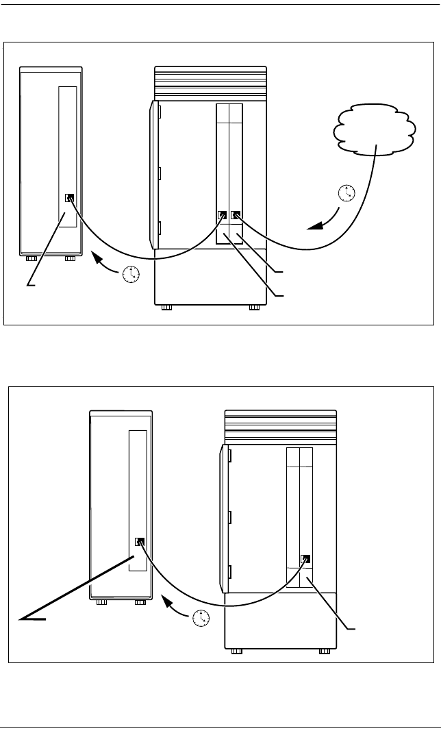
480 / Hardware
Modular ICS 6.0 Installer Guide P0992638 03
Norstar connected in a series of switches in a T1 or PRI network
Norstar connected by a T1 link to another switch in an analog
network
Norstar ICS
Primary - DTI 1 obtains the timing
from the T1 service provider
Timing master - DTI 1 transmits the
system's timing to the other switch
T1 service
provider
Norstar or other switch
Primary reference
T1 or PRI
service
provider
Primary reference
Primary - DTI 1 obtains timing
from T1 service provider
Timing Master - DT1 1 transmits
system timing to other switch
Norstar or other switch Norstar ICS
Norstar or other switch Norstar ICS
Primary - DTI
obtains timing from
other switch
Timing master -
DT1 transmits
system timing to
the other switch

Hardware / 481
P0992638 03 Modular ICS 6.0 Installer Guide
Setting the clock source for DTIs and PRIInstaller password required
Start with the display showing Hardware.
1. Press ≠.
2. Press ‘. The display shows Cards on KSU.
3. Press ≠.
4. Press ‘ until the display shows the card you
want to view.
5. Press ≠.
6. Press ‘ until the display shows ClockSrc.
7. Press CHANGE to toggle the setting.
Changing clock source may disconnect calls.
Changing the clock source for your system may
cause your system to restart itself, resulting in
dropped calls. Choose a suitable time to change
the clock source and use the Page feature to
inform people of possible service disruptions.

482 / Hardware
Modular ICS 6.0 Installer Guide P0992638 03
8. Press to exit or ‘ to continue in Hardware.
T1 or ISDN-PRI configurations
The following tables indicate proper and improper T1 or
ISDN-PRI configurations:
Valid digital trunk configurations
Invalid digital trunk configuration
Tips - In most T1 network configurations, you need one
DTI or DTI card configured as PRI in your ICS to act as a
primary reference. The only application where you might not
have a DTI or a DTI card configured as PRI designated as
primary reference is in a network where your Norstar system
is connected back-to-back with another switch using a T1 link.
If the other switch is loop-timed to your Norstar system, your
DTI or DTI card configured as PRI can be designated as a
timing master.
If your Norstar system has two DTIs, you cannot assign both
DTIs as primary reference or both DTIs as secondary
reference.
You can only have one primary reference and one secondary
reference per system. See T1 or ISDN-PRI configurations for
more information.
Option 1 Option 2 Option 3
Card 1 T1 or PRI T1 or PRI BRI-ST, BRI-U2,
BRI-U4
Secondary
Card 2
T1 or PRI BRI-ST, BRI-U2,
BRI-U4
BRI-ST, BRI-U2,
BRI-U4
Option 1
Primary
Card 1
BRI-ST, BRI-U2,
BRI-U4

Hardware / 483
P0992638 03 Modular ICS 6.0 Installer Guide
Valid mixed trunking configuration
Invalid mixed trunking configuration
Invalid configurations will raise an alarm. In these invalid
configurations, digital links are likely to suffer errors, slips,
etc.
DataMod
Mod XX:DataMod
DataMod allows you to configure the settings for any data
modules you may have on your system.
Type
The display shows the type of data module selecte d.
Secondary
Card 2
T1 or PRI
Option 1 Option 2
Primary
Card 1
T1 or PRI BRI-ST, BRI-U2,
BRI-U4
Card 2 Analog Analog
Option 1 Option 2
Card 1 Analog Analog
Secondary
Card 2
T1 or PRI BRI-ST, BRI-U2,
BRI-U4
Option 1

484 / Hardware
Modular ICS 6.0 Installer Guide P0992638 03

P0992638 03 Modular ICS 6.0 Installer Guide
Maintenance
Use Norstar Maintenance to help you understand and diagnose
system problems that occur on your Norstar system.
Maintenance includes settings to determine how the system
will deal with T1 digital lines. It also provides a means for
provisioning and testing digital lines.
The Maintenance section of programming has these headings.
You can run a Maintenance session from any working M7310,
M7324 or T7316 set.
System version displays the version number of the system
processor
Port/DN status allows you to check and change the status of
ports in your system
Module status allows you to check and change the status of
modules in your system
Sys test log displays a list of test results, event messages,
and alarm codes
Sys admin log displays a list of system initialization sessions,
invalid password attempts and password
changes
Network evt log displays a list of events and alarms
Provisioning allows you to add or remove individual T1
lines, PRI lines, and BRI loops in and out of
service
Tests allow you to test incoming T1 signals to
evaluate transmission quality, the connection
between the ICS and telephones, and the
connection between a DTI (configured as PRI)
or BRI Card and the network
CSU stats displays T1 performance information supplied
by the Channel Service Unit
Link status allows you to view status of b-channels on PRI
486 / Maintenance
Modular ICS 6.0 Installer Guide P0992638 03
Beginning a Maintenance session
1. Release all calls on your telephone.
2. Press which is the same as
. Password: displays.
3. Enter the Installer password. Terminals&Sets displays.
Three triangular indicators º appear on the vertical
display between the rows of buttons.
4. Place the programming overlay over the buttons pointed to
by the indicators º.
5. Press ‘ until the display shows Maintenance.
Tip - Only one person at a time can access a
Maintenance session.
Photocopy the Maintenance records found in
the Programming Record, and record the
information the session provides.

System version / 487
P0992638 03 Modular ICS 6.0 Installer Guide
System version
System version allows you to note the version number of the
System Processor (SP) software, which resides in the Feature
Cartridge.
Use the SP version number to determine whether you have the
latest software release, and to trace a software fault if one
occurs.
For instance:
•SP version number can indicate a Feature Cartridge
incompatibility.
•SP and telephone version numbers can indicate a
telephone version incompatibility.
•SP and functional terminal version numbers can indicate a
functional terminal incompatibility.
Checking the version of the system
To check the version number, start with the display showing
Maintenance.
1. Press ≠. System version displays.
2. Press ≠.
The display shows the version number of the SP.
3. Write the SP version number on the appropriate
Maintenance record.
4. Press –. System version displays.

488 / Port/DN status
Modular ICS 6.0 Installer Guide P0992638 03
Port/DN status
Port/DN status allows you to:
•identify any device or line connected to the system
•check the version number of a device for compatibility
with the system, for instance for an analog terminal
adapter (ATA).
•check the state of a device or line, for example, idle or busy
•disable or enable a device
•determine which port number corresponds to each DN
•determine the port number of a malfunctioning device
•determine if a malfunctioning device is incompatible with
the Norstar system
•disable a device before replacing it
Tips - You cannot disable the telephone from which you
are accessing the Maintenance session. If you try to do this, a
message appears on the display and you hear an error tone.
If you want to disable that particular telephone, conduct the
Maintenance session from another telephone.
Pick a suitable time to disable devices
Wait until after regular user hours to disable
devices to cause the least disruption to your
customers.

Port/DN status / 489
P0992638 03 Modular ICS 6.0 Installer Guide
Do not enable or disable ports at the following times:
•during the first two minutes after Startup programming
•before fiber cables are connected
If you do so, incorrect ports may be enabled or disabled. To
recover from this, disable, then enable, the affected modules
using Module status.
Port/DN status allows you to check lines and devices on the
system. Although the following procedures describe how to
check devices, you can use the same procedures to check lines.
Lines can only be disabled in Module status.
Identifying a connected device Installer password required
Start with the display showing System version.
1. Press ‘. Port/DN status displays
2. Press ≠. Show port: displays
3. Enter the port number of the device, or press DN, then enter
the directory number of the device. The display shows
device information, as illustrated in the following sample
device identification display. This identifies the device
connected to the B1 channel.
4. If there is an add-on device attached to a Norstar
telephone, such as a central answering position module or
a Busy Lamp Field, press ≠ to display the add-on
device.
5. Press >B2 to display the device connected to the B2
channel.
6. Press – until the display shows Port/DN
status.

490 / Port/DN status
Modular ICS 6.0 Installer Guide P0992638 03
Displays
Sample device identification display
The following table lists some of the device types that may
appear on the Norstar device identification display.
Explanation of device type
P104 7324 224
DEVICE >B2 STATE
This sample display indicates that port 104
has an M7324 telephone whose DN is 224.
Press DEVICE to see the device attached to the
port.
Display Explanation
7100 M7100 or T7100 set
7208 M7208 or T7208 set
7310 M7310 telephone or T7316 or T7406 Business
Series Terminal telephones
7324 M7324 telephone
RAD Remote access device
1: CAP1 First CAP module attached to an M7324
telephone
2: CAP2 Second CAP module attached to an M7324
telephone
ATA Analog Terminal Adapter or Analog Station
Module
BLF Busy Lamp Field

Port/DN status / 491
P0992638 03 Modular ICS 6.0 Installer Guide
Checking the device version number Installer password required
From the Norstar device identification display:
1. Press VERSN (if it is available).
The display shows the version number of the device.
2. Write this number on the appropriate Maintenance record.
To return to the Norstar device identification display from
the display showing the version number, do one of the
following:
•Press OK to retain the same port number. Press HEADING.
Press ‘ to see information about the next port
number (or DN if that is how you entered).
OR
•Press “ to see information about the previous
port number (or DN if that is how you entered).
Checking the state of the device Installer password required
From the Norstar device identification display.
1. Press STATE.
The display shows one of the states listed in the table that
follows. If you want, you can disable or enable the device.
Refer to Disabling a device on page 492 or Examples of
display messages on page 493.
2. Press OK to return to the device identification display.

492 / Port/DN status
Modular ICS 6.0 Installer Guide P0992638 03
How the device state is shown on the display
Disabling a device Installer password required
To disable immediately when the display indicates the device
is busy:
1. Press DISABLE. Disable at once? displays.
2. Press YES.
The system prompts the device user and disables the
device in one minute (or immediately, if the device is idle).
Press NO to leave this display without disabling the device.
Display State of device
Busy
DISABLE OK
The device is in use.
Disabling...
OK
The device is being disabled.
Enabling...
OK
The device is being enabled.
Idle
DISABLE OK
The device is not in use.
Unequipped
DISABLE OK
There is no device connected to that port.
Disabled by user
ENABLE OK
The device has been disabled by
someone running a Maintenance session.
Disabled by sys.
ENABLE OK
The device has been disabled by the
system because it is faulty or because a
test is running.
Not available
DISABLE OK
There is no state available.
Give notice that you are disabling equipment.
Inform your users well in advance that you are
going to disable their devices.

Port/DN status / 493
P0992638 03 Modular ICS 6.0 Installer Guide
Displays
The following table shows examples of the sequence of
messages that might appear on a telephone when you disable a
device.
Examples of display messages
Enabling the device Installer password required
When the display shows you that the device is disabled:
Press ENABLE. Enabling... briefly displays.
The device is immediately enabled and the display shows
Idle.
Please hang up
Maintenance test
Occurs on a busy telephone before disabling
48 seconds
until disconnect
Please hang up
In Maintenance Occurs after disabling
Tips - The display may briefly show Enabling..., then
either Disabled by sys. or Disabled by user. In this case,
the system is waiting to enable the module. This may occur after
someone has run a Maintenance session and used Module
status. You cannot enable the device until its module has been
enabled.
Individual lines cannot be disabled in
Port/DN status. To
disable a Trunk Cartridge, see Module status on page 495.

494 / Port/DN status
Modular ICS 6.0 Installer Guide P0992638 03
Returning to the beginning Installer password required
From the display showing the state of the device:
1. Press OK.
2. Press – until the you reach Port/DN status.
Module status / 495
P0992638 03 Modular ICS 6.0 Installer Guide
Module status
Module status allows you to:
•look at the inventory of Station Modules, Trunk Modules,
Data modules, and modules inside the Integrated
Communication System (ICS)
•check the number of Trunk Cartridges in a module
•check the state of the module or its cartridges
•disable or enable the module or its cartridges
•isolate any malfunctioning modules
•disable a module before replacing it
•clear a hung line by disabling and enabling the affected
Trunk Cartridge
Looking at the module inventory Installer password required
Start with the display showing Port/DN status.
1. Press ‘. The display shows Module status.
2. Press ≠. The display shows Show module:.
3. Enter the module number.
Tips - Modules 1 and 2 are located inside the ICS.
Module 1 connects telephones.
Module 2 connects Trunk Cartridges.
Tips - Norstar devices may occupy both the B1 and B2
channels. This may increase the number of devices indicated
on the module inventory display. The display is different for
Analog Station Modules (ASM) where it will show either
8 sets on ASM or 16 sets on ASM.

496 / Module status
Modular ICS 6.0 Installer Guide P0992638 03
Checking the number of Cartridges Installer password required
Start from the module inventory display, which shows the
number of Trunk Cartridges connected to the module you
chose, for example, Mod 04: 3 cards.
1. Press CARD.
If there is a Trunk Cartridge in a slot, the display shows
that four lines are connected, for example,
Card 1: 4 lines.
2. Press ‘ or “ to check for Trunk
Cartridges in the other slots.
3. Press MODULE to return to the module inventory display.
Checking the state of a module Installer password required
Start from the module inventory display, which shows the
number of Trunk Cartridges connected to the module you
chose, for example, Mod 04: 3 cards.
1. Press STATE.
The state of the module is shown on the display.
2. Press OK to return to the module inventory display.
Module or cartridge state is shown on the display
Example display State of module or cartridge
3setsbusy
DISABLE OK
There are three devices in use that are
connected to the module or cartridge.
2portsbusy
DISABLE OK
There are two ports in use that are
connected to the module or cartridge.
4linesbusy
DISABLE OK
There are four lines in use that are
connected to the module or cartridge.

Module status / 497
P0992638 03 Modular ICS 6.0 Installer Guide
Checking the state of a cartridge Installer password required
Start from the display that shows the number of lines
connected to the Trunk Cartridge you chose, for example,
Card 1: 4 lines.
1. Press STATE.
The display shows the state of the cartridge. Some
examples of this display are shown in the previous table.
2. Press ‘ or “ to check the Trunk
Cartridges connected to the other Trunk Modules.
3. If required, you can disable or enable the cartridge. Refer
to Disabling a module or its cartridges on page 498 or
Enabling a module or its cartridge on page 498.
4. Press OK to return to the display showing how many lines
are connected to the Trunk Cartridge.
Disabling...
OK
The module or cartridge is being disabled.
Enabling...
OK
The module or cartridge is being enabled.
Unequipped
DISABLE OK
There is no module or cartridge connected to
that DS-30 port.
Disabled by user
ENABLE OK
The module or cartridge has been disabled
from a Maintenance session.
Disabled by sys.
ENABLE OK
The module or cartridge has been disabled
by the system because it is faulty or because
there is a test running.
Updating state… The system is verifying the state of the
module or cartridge.
Module or cartridge state is shown on the display (Continued)
Example display State of module or cartridge

498 / Module status
Modular ICS 6.0 Installer Guide P0992638 03
Disabling a module or its cartridges Installer password required
From the display showing the state of the module or cartridge:
1. Press DISABLE. Disable at once? displays.
2. Press YES.
The system disables the module or cartridge in one minute.
If the status is idle, the system disables the module or
cartridge immediately.
Press NO to leave this display without disabling the module
or cartridge.
Enabling a module or its cartridge Installer password required
From the display showing the state of the module or cartridge:
1. Press ENABLE.
The display briefly shows Enabling....
The module or cartridge is immediately enabled.
The display then shows the state of the module or
cartridge.
Returning to the beginning Installer password required
From any display showing the state of the module or cartridge:
1. Press OK.
2. Press – until the display shows Module status.
Use Page feature prior to disabling.
Use the Page feature to inform people that you
are about to disable a module. Mention that they
may experience delays in the performance of
their devices.

System test log / 499
P0992638 03 Modular ICS 6.0 Installer Guide
System test log
The System test log shows you a list of diagnostic test results,
audits, event messages, and alarm codes. By using this feature
you can:
•check the items in the log
•check the current alarm (if there is one)
•check when each item in the log occurred
•check the number of consecutive occurrences of an event
or an alarm
•erase the log
The System test log holds a maximum of 20 items. You should
check and record these items at regular intervals. Erase the log
after dealing with all the items.
Checking the items in the log Installer password required
Start with the display showing Module status:
1. Press ‘. The display shows Sys test log.
2. Press ≠. The display shows Items in log:.
(If there is no log entry, the display shows Items in log:0
and returns to Sys test log.)
3. Press ‘ or “. The display shows a log
item.
4. Write down the item on the System test log record.
5. If the log item is an event message or an alarm code, refer
to Alarm codes on page 506 or Event messages on page
514.
6. Repeat steps 3, 4, and 5 until you have recorded all the
items.

500 / System test log
Modular ICS 6.0 Installer Guide P0992638 03
Checking the current alarm Installer password required
If you want to quickly check the highest severity alarm before
viewing all the log items, start with the display showing Items
in log:.
1. Press ALARM.
The display shows an alarm code if there is a current alarm.
If there is no current alarm, ALARM does not appear on the
display.
2. Press OK to return to Items in log:.
All alarms are recorded as items in the System test log.
Checking when each item occurred Installer password required
Start with any display showing a log item:
1. Press TIME. The display briefly shows the date and time.
2. Write the date and time on the System test log record.
Checking consecutive repetitions of an event or alarm
Installer password required
If REPEAT appears under a display showing a log item:
1. Press REPEAT.
The display shows the number of consecutive times the
event or alarm occurred.

System test log / 501
P0992638 03 Modular ICS 6.0 Installer Guide
Erasing the log Installer password required
Start with the display showing Items in log:.
1. Press ERASE. Erase log?displays.
2. Press YES.
If no new items have been added since the list was entered,
the log is erased and the display shows Lo gerased.
If new items have been added since the list was entered, the
display briefly reads Cancld-new items and returns to
the display Items in log:.
3. Press – to return to Sys test log.

502 / System administration log
Modular ICS 6.0 Installer Guide P0992638 03
System administration log
The System administration log keeps a record of
administrative events such as sessions in which a change was
made, invalid password attempts, and password changes.
You can use this feature to:
•check the items in the log
•erase the log
•check when each item in the log occurred
The System administration log holds a maximum of 10 items.
Erase the log after dealing with all the items.
Checking the items in the log
Start with the display showing Sys test log:
1. Press ‘. The display shows Sys admin log.
2. Press ≠. The display reads Items in log:. (If
there is no log entry, the display reads Items in log:0.)
3. Press ‘ or “. The display shows a log
item.
4. Write down the item on the System administration log
record.
5. Repeat steps 3 and 4 until you have recorded all the items.

System administration log / 503
P0992638 03 Modular ICS 6.0 Installer Guide
Checking the current alarm
Start with the display showing Items in log:.
1. Press ALARM. The display shows an alarm code.
If there is no current alarm, ALARM does not appear on the
display.
2. Press OK to return to the display showing Items in log:.
Checking when each item in the log occurred
Start with any display showing a log item:
1. Press TIME. The display shows the date and time.
2. Write the date and time on the System administration log
record.
Erasing the log
Start with the display showing Items in log:.
1. Press ERASE. The display shows Erase log?.
2. Press YES.
If no new items have been added since the list was entered,
the display shows Log erased.
If new items have been added since the list was entered, the
display briefly reads Cancld-new items and returns to
the display Items in log:.
3. If the display shows Log has changed, press SHOW to
show the new log, or press EXIT to return to Sys admin
log.

504 / Network evt log
Modular ICS 6.0 Installer Guide P0992638 03
Network evt log
The Network evt log keeps a record of events and alarms that
are specific to the T1 network interface.
You can:
•check the items in the log
•erase the log
•check when each item in the log occurred
The Network evt log holds a maximum of 20 items. Erase the
log after dealing with all the items.
Checking the items in the log
Start with Sys admin log on the display:
1. Press ‘. Network evt log displays.
2. Press ≠. Items in log: displays.
If there is no log entry, the display reads Items in log:0.
3. Press ‘ or “. The display shows a log
item.
4. Write down the item on the Network event log record.
5. Repeat steps 3 and 4 until you have recorded all the items.
Checking the current alarm
Start with the Items in log: on the display.
1. Press ALARM.
The display shows an alarm code if there is a current alarm.
2. Press OK to return to Items in log:.

Network evt log / 505
P0992638 03 Modular ICS 6.0 Installer Guide
Erasing the log
Start with Items in log: on the display.
1. Press ERASE.
The display shows Erase log?.
2. Press YES.
If no new items have been added since the list was entered,
the display shows Log erased.
If new items have been added since the list was entered, the
display briefly reads Cancld-new items and returns to
the display Items in log:.
3. Press – to return to Network evt log.
Checking when each item in the log occurred
Start with any display showing a log item:
1. Press TIME.
The display shows the date and time.
2. Write down the date and time on the Network event log
record.
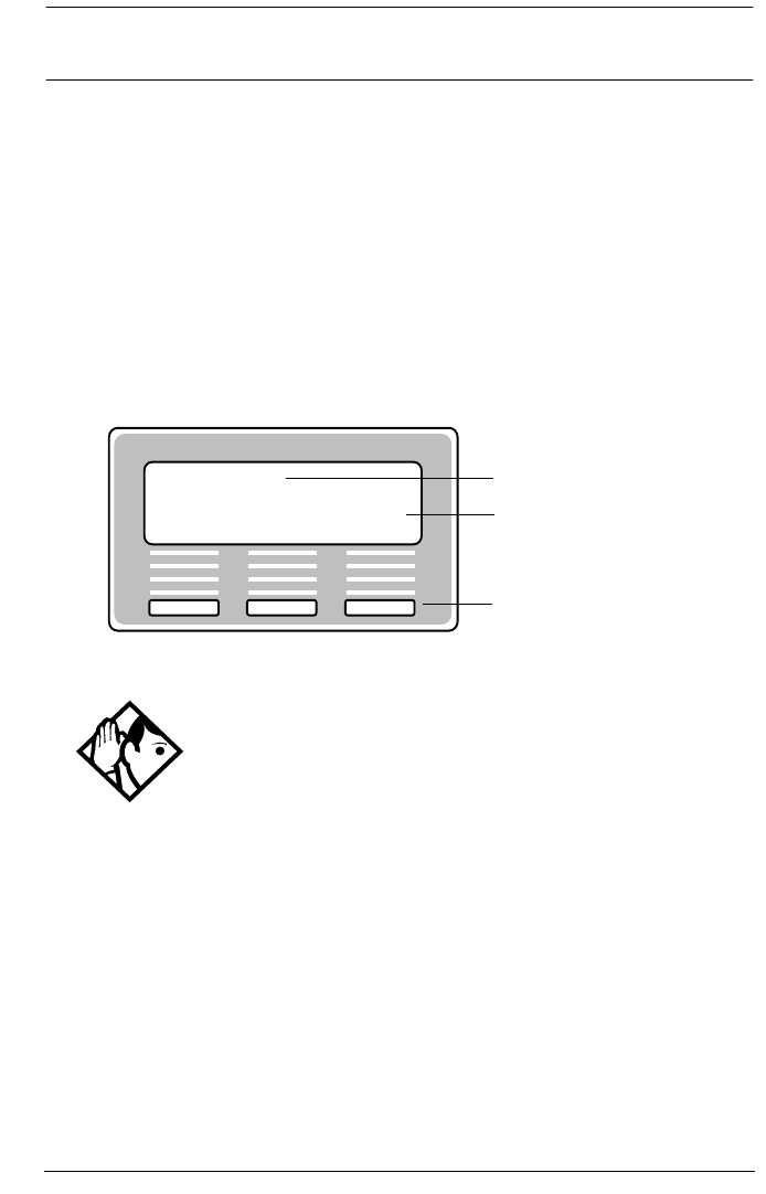
506 / Alarm codes
Modular ICS 6.0 Installer Guide P0992638 03
Alarm codes
The Norstar ICS system generates alarm codes after system
disconnections or after certain anomalies in system operation.
All alarm codes appear at the Alarm telephone and in the
System test log of a Maintenance session.
For a more complete description of alarm and event codes
consult your technical support representative. The following
figure shows an alarm code appearing on a Norstar Alarm
telephone display.
Tips - The Alarm telephone is assigned in Featr settings
of system programming.
Alarms have a higher severity than events. Attend to alarm
codes before event messages.
Alarm code information that is specific to Companion
components is included in the Modular ICS Companion
Installer Guide.
Alarm 5-2-03
Time Clear
Alarm message
Display button labels
Display button

Alarm codes / 507
P0992638 03 Modular ICS 6.0 Installer Guide
If you see an alarm code
1. Write the alarm code on the Sys test log record.
2. Determine the cause of the alarm from the following table.
3. Follow Alarm troubleshooting on page 510.
4. Press TIME to see when the alarm occurred.
5. Press CLEAR to clear the alarm.
An alarm code may not be displayed until two minutes after it
has been triggered. If the ICS is powered off when the alarm is
triggered, the alarm code is not displayed until two minutes
after the ICS is powered on.
For a complete list of Norstar alarms, refer to the Norstar
Alarm & Event Code Manual.
Displays
Example
display
Meaning Possible causes
Alarm:
10
All ICS devices
disconnected.
The last device on Norstar
bus 1 (port numbers 101-124)
has been removed.
A 25-pair cable was
disconnected from the ICS.
There is an internal ICS fault.

508 / Alarm codes
Modular ICS 6.0 Installer Guide P0992638 03
Alarm:
37 ABBC
DD
An error has occurred in
the download of a protocol
to a BRI Card.
A: the maintenance index
of the BRI
BB: a code describing the
nature of the error
C: the current download
state
DD (appears when the
error is limited to one
protocol): the two-
character product identifier
of the protocol
The BRI Card is not properly
installed.
Alarm: 40
Alarm: 41
Alarm: 42
Alarm: 43
Alarm: 44
Alarm: 45
Alarm: 46
Alarm: 47
There is a problem with the
T1 signal
The cable connecting the DTI
to the network termination
point or external CSU is
disconnected.
There is a problem with the T1
signal from the network.
Alarm:
50 X
All devices on SM
disconnected.
The last device on Norstar
bus X (port numbers
X01-X16) has been removed.
The 25-pair cable was
disconnected from the SM.
The fiber cable from the SM to
the ICS is disconnected.
The SM was powered down.
Alarm:
51 X
Trunk Module
disconnected.
All Trunk Cartridges are
disconnected from the TM on
DS-30 port X.
The TM was powered down.
The fiber cable from the TM to
the ICS is disconnected.
Example
display
Meaning Possible causes

Alarm codes / 509
P0992638 03 Modular ICS 6.0 Installer Guide
X = DS-30 port numbers, Y = Trunk Cartridge number (numbered from left to
right), and Z = Trunk port number
Alarm:
52 X Y
TC disconnected from TM Trunk Cartridge Y on DS-30
port X is disconnected from
the TM.
Alarm:
61 X Y
Incompatible Trunk
Cartridge
Trunk Cartridge Y on DS-30
port X cannot operate with the
Trunk type assigned to it in
Configuration.
Alarm:
62 X Y
Unsupported Auto-answer
setting (Loop Start TCs)
Trunk Cartridge X on DS-30
port Y does not support the
auto-answer setting.
Alarm:
63 Z
No available DTMF
receivers
DTMF receivers are busy, not
working properly, or have not
been installed.
Alarm:
68-Z
A device has been
connected to a port which
is not available for the
device type.
Power down the system and
disconnect the device from
the port identified. Reconnect
it to a valid port.
Alarm:
76 X
Data Module
disconnected.
The Data Module is
disconnected from the DM on
DS-30 port X.
The DM was powered down.
The fiber cable from the DM to
the ICS is disconnected.
Example
display
Meaning Possible causes

510 / Alarm codes
Modular ICS 6.0 Installer Guide P0992638 03
Alarm troubleshooting
Refer to the previous table before following these procedures.
Alarm: 10
1. Check to see if there is a device connected to the ICS (that
has a port number beginning with the number 1).
2. If there are no devices connected to the ICS, connect one
and then press CLEAR.
3. If there are any devices connected to the ICS, check all the
wiring associated with the devices.
4. Refer to Problems with BRI service on page 570.
Alarm: 37
1. Check that the BRI Card is properly installed.
2. Remove and re-install the BRI Card.
3. If the alarm persists, replace the BRI Card with another
BRI Card of the same type.
Alarm: 40 to Alarm: 47
1. Check the System Network evt log for events in the range
315-336 to verify the frequency of the alarms.
2. Refer to Digital Trunk Interface trouble on page 567.
Alarm: 50-X
1. Check that there is a device connected to the Station
Module, which has a port number beginning with a
number from three to eight.

Alarm codes / 511
P0992638 03 Modular ICS 6.0 Installer Guide
2. If there are no devices connected to the Station Module,
connect one and then press CLEAR.
3. If there are any devices connected to the Station Module,
check all the wiring associated with the devices.
4. Refer to Data Module down on page 575.
Alarm: 51-X
1. Check the wiring from the ICS to the TM.
2. Refer to Problems with trunk cartridges service on page
566.
Alarm: 52-X-Y
1. Follow the procedure in Problems with trunk cartridges
service on page 566.
2. If the problem persists, replace Trunk Cartridge Y on
DS-30 port X.
Refer to the previous table for the definition of X and Y.
Alarm: 61-X-Y
1. Check that the proper Trunk Cartridges are inserted in the
proper slots of the ICS or Trunk Module.
2. Enter programming and look under the Trk/Line data
heading.
Check that the Trunk Cartridge type is correctly
configured.
Check that the Trunk mode and Answer mode settings do
not conflict for every line connected to Trunk Cartridge Y.
If Trunk mode is set to unsupervised, Answer mode must
be set to manual.

512 / Alarm codes
Modular ICS 6.0 Installer Guide P0992638 03
OR
Install a Trunk Cartridge in slot Y that matches the type of
trunk you have configured.
Alarm: 62-X-Y
1. Check that the proper Trunk Cartridges are inserted in the
proper slots of the Trunk Module.
2. Enter programming and look under the Trk/Line data
heading.
Check that the Trunk mode and Answer mode settings do
not conflict for every line connected to Trunk Cartridge Y.
If Trunk mode is set to unsupervised, Answer mode must
be set to manual.
Alarm: 63-Z
1. Check that you have the required E&M Trunk Cartridges.
There should be a maximum of one for every two
auto-answer loop start lines installed in a Trunk Module.
2. Enter programming and look under the Trk/Line data
heading. Check that the Answer mode is correct for all the
loop start lines.
3. Make sure that all of your E&M trunks installed in a Trunk
Module are configured as E&M or DTMF, whichever
applies, so that the system knows the receivers are there.
4. If the problem persists, an E&M Trunk Cartridge may be
malfunctioning. Replace one E&M Trunk Cartridge at a
time until the problem is resolved.

Alarm codes / 513
P0992638 03 Modular ICS 6.0 Installer Guide
Alarm 68-Z
1. Locate the device(s) connected to port(s) not available for
that device type.
2. Power down the system.
3. Disconnect the device from the port identified.
4. Reconnect it to a valid port.
Alarm 75
1. Check the connection to your ISDN service provider.
Alarm: 76-X
1. Check the wiring from the ICS to the DM.
2. Refer to Problems with trunk cartridges service on page
566.
3. Refer to Data Module down on page 575.

514 / Event messages
Modular ICS 6.0 Installer Guide P0992638 03
Event messages
Event messages appear as items in the System administration
log or the System test log of the Maintenance session. Most of
these event messages can only be caused by an unusual
combination of events, and should rarely occur.
Each event is assigned a severity number. An S preceding this
number, S4 for example, may appear in the event message.
S9 is the most severe. If the log is full, new event messages
with a higher severity number replace existing event messages
of a lower severity. For this reason, you should check event
messages at regular intervals. You can then deal with all
messages before they are replaced.
Event message information that is specific to Companion
components is included in the Modular ICS Companion
Installer Guide.
Dealing with event messages
For every event message that you see:
1. Record the event on the appropriate Maintenance record.
2. Refer to Significant event messages.
3. To see if the event caused the Norstar system to
automatically restart, consult the table on Event Message
on page 520.

Event messages / 515
P0992638 03 Modular ICS 6.0 Installer Guide
Significant event messages
The following table lists event messages that are relevant to
Maintenance activities. The time that the message is recorded
is also provided.
Displays
Event message The event message is recorded when…
Evt:210-YYYZ S4 Loopback test YYY on Trunk Cartridge Z has
started
Evt:211-YYYZ S4 Loopback test YYY on Trunk Cartridge Z has
stopped
Evt:220-3546 S4 the Sys admin log has been cleared by the DN
(3546 in this case)
Evt:221-3546 S4 the Sys test log has been cleared by the DN (3546
in this case)
Evt:222-3546 S5 the DN (3546 in this case) enters the debugging
facility that is password protected
Evt:255 S9 administered mode is not supported by the cartridge
plugged into the slot
Evt:260-0302 S8 the ICS takes the access line on port 0302 out of
service because no current was detected
Evt:261-0302 S1 the access line on port 0302 is returned to service
after current was detected (see Evt:260)
Evt:263-302 S8 the ICS takes the E&M line on port 302 out of
service because the far end did not respond to a
disconnect signal
Evt:264-302 S1 the E&M line on port 302 is returned to service after
the far end finally responded to a disconnect signal
(see Evt:263)
Evt:265-302 S7 the E&M line on port 302 did not receive an
expected wink signal or delay dial signal from the far
end
Evt:267 S9 a data module has been disconnected
Evt:268-07 S8 Dialing filter 07 has lost data due to a fault in the
system memory

516 / Event messages
Modular ICS 6.0 Installer Guide P0992638 03
Evt:269-3546 S8 the Line/set filter for the DN (3546 in this case) has
lost data due to a fault in the system memory
Evt:299 S1 the system powers up after a power failure
Evt:327 S5 short term alarm threshold has been surpassed in
the DTI cartridge
Evt:328 S5 short term alarm threshold has been surpassed in
the DTI cartridge
Evt:329 S5 short term alarm threshold has been surpassed in
the DTI cartridge
Evt:330 S5 short term alarm threshold has been surpassed in
the DTI cartridge
Evt:336 S5 long term alarm has been surpassed in the DTI
cartridge
Evt:373 S5 the ICS restart diagnostic tool has been activated
Evt:400 S9 Startup programming is performed using
Evt:407 S2 there are no more codes for Speed Dial numbers
Evt:408 S2 there is no more memory for Speed Dial codes
Evt:412-3546 S5 the Installer password has been changed by the DN
(3546 in this case)
Evt:413-3546 S3 the System Coordinator password has been
changed by the DN (3546 in this case)
Evt:414-3546 S5 an invalid Installer password has been entered by
the DN (3546 in this case)
Evt:415-3546 S3 an invalid customer password has been entered by
the DN (3546 in this case)
Evt:416-3546 S4 programming is performed using
Evt:417-3546 S2 programming is performed using
Evt:418 S7 a DN change is successful
Evt:419 S2 the time setting has been changed
Evt:421 S8 a DN change failed
Event message The event message is recorded when…

Event messages / 517
P0992638 03 Modular ICS 6.0 Installer Guide
Evt:422-3546 S6 a length change by the DN (3546 in this case) has
been requested
Evt:423-3546 S6 an individual DN change has been requested by the
DN (3546 in this case)
Evt:441 S2 a timeout occurred while waiting for ANI or DNIS
digits to be received
Evt:442 S5 a timeout occurred while waiting for ANI or DNIS
digits to be received
Evt:453 S4 Someone entering **CONFIG
Evt:454 S5 Invalid password entered
Evt:458 S4 Call-by-Call NVRAM data is corrupt
Evt:459 S9 DN length has been changed to less than 3 digits
Evt:680 S9 wireless system is disabled
Evt:681 S9 activation or recovery code entered
Evt:683 S9 new base station configuration detected
Evt:687 S4 the data driver has received a bad call reference
Evt:688 S4 the data driver has received a bad data event
Evt:689 S4 the data driver could not allocate a new index
Evt:690 S4 no response to the ICS within 10 seconds of being
sent an initialization message
Evt:691 S4 no response to the ICS within 3 seconds
Evt:692 S4 a bad parameter value has been received in a
stimulus message from the data device
Evt:693 S3 old data to be discarded has been detected
Evt:694 S4 RADAR flow control has received a bad stimulus
message from an off-core application
Evt:695 S4 attached set denied request for a B-channel
Evt:696 S2 corrupt CLID length
Evt:697 S2 an asynchronous data report generated by SDI
module
Event message The event message is recorded when…

518 / Event messages
Modular ICS 6.0 Installer Guide P0992638 03
Event message 799
Event message 799 indicates a call processing error has
occurred on an ISDN line. The event number is followed by a
number representing the line or loop number, and a code for
the type of error.
Evt:698 S8 incorrect software key entered
EVT799-00040B
S7
a call processing error on the fourth BRI loop; see
Event message 799
on page 518.
Evt:822 S8 Alarm code 63 is sent because there are no DTMF
receivers for an incoming call
Evt:882 S9 mobility data re-evaluation sequence initiated
Evt:883 S4 an invalid dial pulse signal was received by the DTI
Evt:992 S6 auto attendant error
EVT799-XXXX YYS7 In this example, the error has occurred on line
XXX and the error code is YY.
Error
code
Meaning
01 Internal software error. Cannot acquire the B-channel from
the B-channel arbitrator.
02 Internal software error. There is no free line available for the
call.
03 A call that is not on the B-channel has been attempted.
These kind of calls are part of EKTS service, which is not
supported by this version of the software. Check with your
service provider to make sure your package does not
include EKTS service.
04 Internal software error. Failed to instantiate on the chain.
05 Internal software error. Activation procedure failed.
Event message The event message is recorded when…

Event messages / 519
P0992638 03 Modular ICS 6.0 Installer Guide
Displays
You should rarely see any event messages that are not
described in the Significant event messages on page 515. If
you do see one of these event messages, the Norstar system has
followed its normal recovery from an unusual combination of
system events. Although the problem is not a serious one,
repeated occurrences of the event number should be reported
as soon as possible.
As a result of some events, the Norstar system automatically
restarts itself. The table on the next two pages lists all the event
numbers and tells you which of these events are associated
with Norstar system restarts.
06 Internal software error. Index conversion failed.
07 Unexpected digits on a Manual answer mode line.
Configuration of the ICS and the network connection may
not match.
08 Internal software error. Cannot seize central office (CO) line
on a BRI connection.
09 Cannot get vterm (virtual terminal) from the Vterm Server.
0A Central office did not respond to the SPID initialization
request.
0B Central office has rejected the SPID. Verify your SPID
information programmed under Hardware and with your
ISDN service provider.
0C Internal software error. Already instantiated on the chain.
Error
code
Meaning

520 / Event messages
Modular ICS 6.0 Installer Guide P0992638 03
Most of these events are recorded in the Sys test log. The few
exceptions to this are recorded in the Sys admin log, as
indicated.
Event
Message
System
Restart
Event
Message
System
Restart
101-106 Yes 400 (Admin log) Yes
107 No 401-403 No
108-112 Yes 405-411 No
113 No 412-419 (Admin log) No
114-116 Yes 421-423 (Admin log) No
117 No 424-425 No
118-120 Yes 426-430 Yes
121-123 No 431 No
124-125 Yes 432 Yes
126-129 No 433 No
130 Yes 441-442 No
131-132 No 453 No
133-134 Yes 454 No
135-136 No 458-459 No
137 Yes 600-602 Yes
138-150 No 603-613 No
151 Yes 614 Yes
152 No 615-629 No
160-164 No 630 Yes
170-173 No 631-646 No
200-211 No 680 No
220 (Admin log) No 681 No
221-222 No 683 No
223 (Admin log) No 689-698 No

Event messages / 521
P0992638 03 Modular ICS 6.0 Installer Guide
224 Yes 799 No
225-228 No 800-802 No
229 (Admin log) No 803 Yes
230-235 No 804-807 No
245-248 Yes 808 Yes
250-256 No 809 No
260-271 Yes 810 Yes
280-283 No 811-820 No
285-298 Yes 823 Yes
299 No 824-825 No
327 No 851 No
328 No 882 No
329 No 883 No
330 No 900 No
336 No 940-943 No
373 No 950-989 No
Event
Message
System
Restart
Event
Message
System
Restart

522 / Provisioning BRI and PRI lines
Modular ICS 6.0 Installer Guide P0992638 03
Provisioning BRI and PRI lines
This section discusses how you put BRI and PRI lines into and
out of service.
BRI and T1 lines
Provisioning applies to BRI and T1 loops and lines. It allows
you to place loops and lines in or out of service, either before
or after the BRI Cards have been installed in the ICS.
When you provision a loop, ISDN terminals on the loop can be
used to make outgoing calls or receive incoming calls
(S or U-LT loop).
Loop lines are also available for use by the devices attached to
the system (T, S, or U-NT loop). When you are configuring a
T, S, or NT loop, you must also provision each line on the loop
to place the lines in service.
Cd1-ICS Installer password required
The card type will appear with the setting. If no card has been
installed, you can change the card type under Hardware.
1. Press ≠ to display the loops found on the card.
2. Press REMOVE to take the loop out of service.
3. If lines on the loop are busy, the display will ask if you still
want to remove the loop from service.
Press YES to go ahead.

Provisioning BRI and PRI lines / 523
P0992638 03 Modular ICS 6.0 Installer Guide
L001 Installer password required
If the loop is configured as a U-NT, T or S loop, press
≠ and ‘ to display the individual lines.
There are no lines associated with an S or U-LT loop.
1. Press REMOVE to take the line out of service.
2. If line is busy, the display will ask if you still want to
remove it from service. Press YES to go ahead.
Provisioning a T1 line Installer password required
Start with the display showing Network evt log.
1. Press ‘. Provisioning displays.
2. Select a module and card type, see Show module on page
455.
3. Press ≠. Show module: displays.
4. Enter the number of the line to be provisioned. The display
shows the line and its current status.
5. Press PORT to identify the logical port number for the line.
Lines cannot be provisioned from the PORT display. Press
LINE to return to the line number display.
6. Press ‘ to view settings for the next line number.
7. Press – until you return to Provisioning.
Provisioning a PRI line
ISDN lines are provisioned by default. For information on
adding a DTI card (configured as PRI) see Cards on KSU on
page 455.

524 / Provisioning BRI and PRI lines
Modular ICS 6.0 Installer Guide P0992638 03
Deprovisioning a line
Deprovisioning all of the lines on a DTI does not disable the
cartridge.
Disabling a PRI Channel
PRI channels can be disabled. However, there is no association
between a line number and a b-channel. Disabling a b-channel
can be done when you have fractional PRI. See Fractional PRI
on page 540.
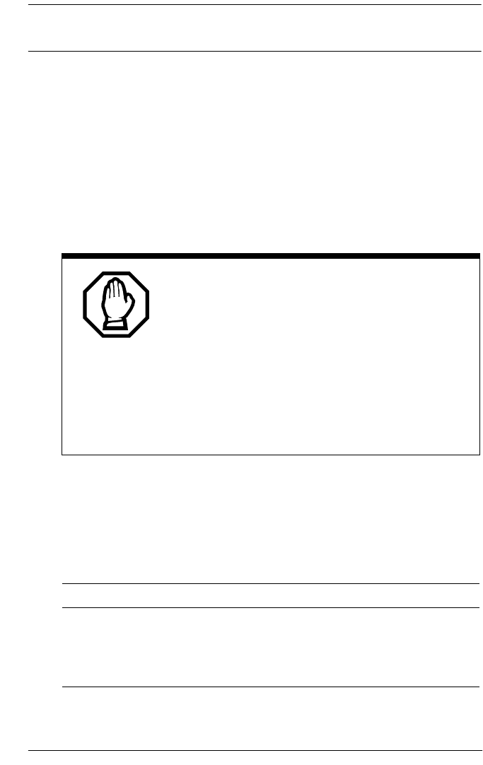
Tests / 525
P0992638 03 Modular ICS 6.0 Installer Guide
Tests
Norstar allows you to run tests which verify the integrity of the
installation wiring for the telephones.
In addition, you can evaluate the transmission quality of a BRI
loop through your service provider using a loopback test to
evaluate different aspects and segments of the T1 digital
transmission path. You can only run one loopback test at a
time on any one DTI.
Loopback tests for T1 or ISDN-PRI lines
Installer password required
The following messages may appear on the Alarm Telephone
during Loopback tests.
Choose an appropriate time to run tests.
Do not run the loopback tests while ports are
being disabled or during the first two minutes
after Startup programming. If you do, the tests
may stop running with ports still disabled. To
recover from this, unplug the ICS from the power
outlet, then plug it in again.
The loopback tests disrupt service. Do not run
tests during busy user times.
Message Explanation
EVT: 210-YYYZ Loopback test YYY on Trunk
Cartridge Z has started
EVT: 211-YYYZ Loopback test YYY on Trunk
Cartridge Z has ended
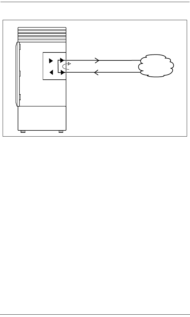
526 / Tests
Modular ICS 6.0 Installer Guide P0992638 03
Line loopback
The line loopback test loops the full 1.544 Mbps signal
received from the network back to the network. The looped
signal is regenerated without any change in the framing format
and without the removal of any bipolar violations. The line
loopback test can also be invoked and stopped remotely using
the in-band signal or via the facility data link (FDL) in
extended super frame (ESF) format.
The line loopback test must be run in coordination with the T1
or PRI service provider. Some test patterns can cause the DTI
to reset. To avoid this, start the line loopback test from your
system before the T1 or PRI service provider begins their test,
and stop the line loopback test from your system after the T1
or PRI service provider ends their test.
Norstar ICS
T1
network
Norstar ICS
T1
network
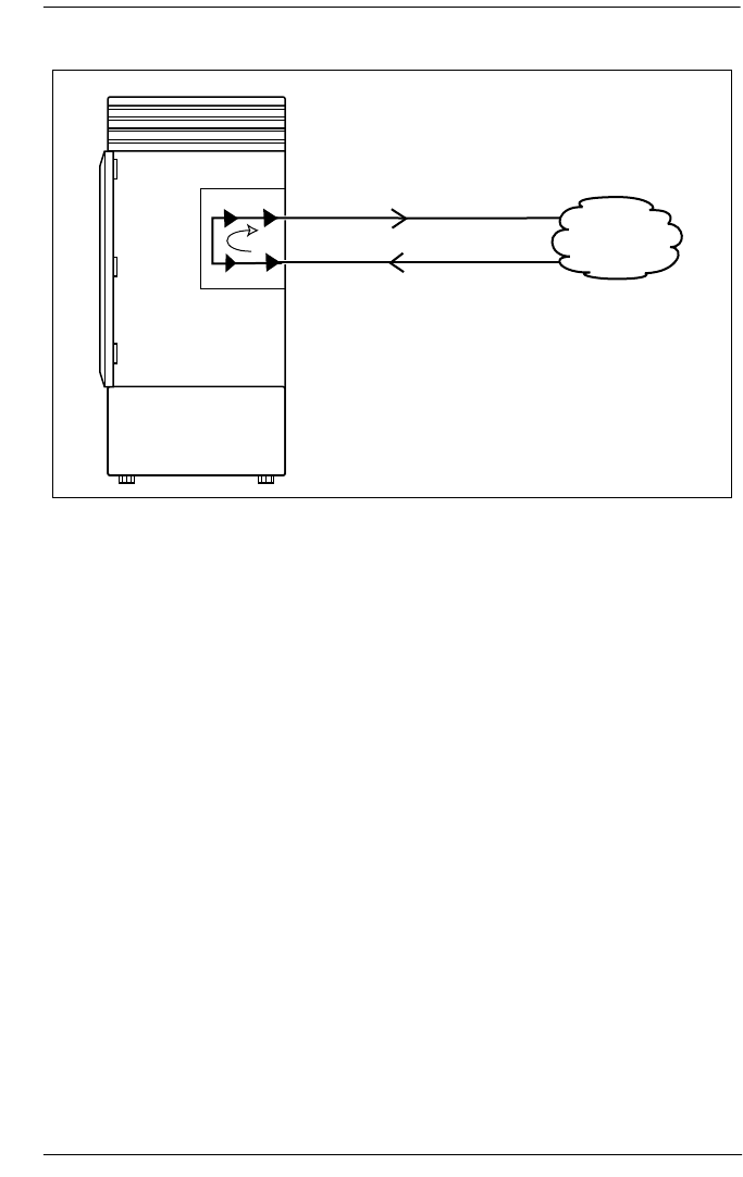
Tests / 527
P0992638 03 Modular ICS 6.0 Installer Guide
Payload loopback
The payload loopback test loops the received information bits
(192 per frame) back to the network. The payload loopback
test can also be invoked and stopped remotely via the facility
data link (FDL) in extended super frame (ESF) format.
The payload loopback test must be run in coordination with the
T1 service provider. Some test patterns can cause the DTI to
reset. To avoid this, start the payload loopback test from your
system before the T1 service provider begins their test, and
stop the payload loopback test from your system after the T1
service provider ends their test.
Norstar ICS
T1
network
Norstar ICS
T1
network

528 / Tests
Modular ICS 6.0 Installer Guide P0992638 03
Card edge loopback
The card edge loopback test loops the outgoing signal on the
DTI back to its internal received signal path. Signal paths to
the external network are disconnected.
Continuity loopback
Norstar ICS
T1
network
Norstar ICS
T1
network
Norstar ICS
T1
network
Norstar ICS
T1
network

Tests / 529
P0992638 03 Modular ICS 6.0 Installer Guide
The continuity loopback test shorts the tip and ring pair of the
receive signal path with the transmit signal path. This test
allows you to check the metallic continuity of the external
wiring.
Tests initiated from Norstar
You can start and stop Loopback tests in Maintenance
programming under the heading Loopback tests. You can
also push a button on the DTI faceplate to start and stop the
continuity test.
You can run DTE and DS30 Loopback tests to verify the SDI
data transfer capabilities. Under the Hardware heading,
ensure that the Type setting for data module is SDI before
choosing the Loopback test you will run.
Tests initiated by the central office
If the internal CSU is administered on line loopback and
payload loopback tests can also be invoked and stopped by the
central office. In order to be able to run a payload loopback
test, the DTI must be configured for extended superframe
format.

530 / Tests
Modular ICS 6.0 Installer Guide P0992638 03
Starting a loopback tests Installer password required
Start with the display showing Loopback tests:.
8. Press ≠. Show Module: displays.
9. Press ‘. Cards on KSU displays.
If you want to test cartridges on another module, press
‘ until the display shows the module.
10. Press ≠. Cd1-KSU displays.
If you want to test the second cartridge on the KSU, press
‘. The display shows Cd2-KSU.
11. Press ≠.
If there is an analog cartridge in the slot or the slot is
empty, the display shows Need digital crd.
12. Press ‘ until the display shows the test you want
to run: Continuity loopback, Line loopback, Payload
loopback, Card edge loopback.
13. Press START to begin the test. The display shows the test
name followed by running.
14. Press STOP to end the test.
Give notice that you are running a loopback
test.
Calls on all T1 or PRI lines on the DTI will be
automatically dropped when a loopback test is
invoked. Use the Page feature to notify people
using the system that a test is about to begin and
that calls will be disconnected.

Tests / 531
P0992638 03 Modular ICS 6.0 Installer Guide
Operating a Continuity loopback test Installer password required
You start the Continuity loopback test by pressing the button
on the front of the DTI. Calls on all lines on the cartridge are
automatically dropped when a loopback test is invoked.
•The red LED above the button remains on until the test is
canceled.
•Invoking a Continuity loopback test automatically cancels
any other test in progress.
•To stop the continuity loopback test, press the button on
the DTI. The red LED above the button turns off when the
test is canceled.
Loopback test for BRI lines Installer password required
The loopback test for BRI lines loops the incoming BRI
payload back to the local exchange (service provider) for
evaluation of the transmission quality. Loopback tests should
be conducted only under the guidance of the service provider,
and the results from these tests are returned to the service
provider.
You can run loopback payload tests simultaneously on
multiple loops or multiple cards. The loop must be provisioned
to perform the test. All calls on the card you are testing will be
dropped at the start of a loop payload test.
Give notice that you are running a loopback
test.
Calls on all T1 or PRI lines on the DTI will be
automatically dropped when a loopback test is
invoked. Use the Page feature to notify people
using the system that a test is about to begin and
that calls will be disconnected.

532 / Tests
Modular ICS 6.0 Installer Guide P0992638 03
Operating a payload loopback test Installer password required
Start with the display showing Loopback tests:.
15. Press ≠. Show Module: displays.
16. Enter a module number or press LIST to scroll through
modules. Cards on KSU or Card on Mod X displays.
17. If you want to test cartridges on another module, press
‘ until the display shows the module.
18. Press ≠. Cd1-KSU or Cd1-ModX displays.
If you want to test the second cartridge on the KSU, press
‘ to display Cd2-KSU or Cd1-ModX.
19. Press ≠.
•If there is an analog cartridge in the slot or the slot is
empty, the display shows Need digital crd.
•If there is a BRI cartridge with U-NT or S/T loops, the
display shows Loop nnn.
20. Press ≠. Payload loopback displays.
21. Press START to begin the test. Payload running displays.
22. Press STOP to end the test.
Note: You can exit programming or move on to other
programming or loop testing while the test is running.
All calls on a BRI loop are dropped when you
start loopback test.
While the loopback test is in progress, the BRI
lines go out of service. There is no warning from
the system. Pick an appropriate time to do a test
and warn users that they will lose any calls in
progress.

CSU stats / 533
P0992638 03 Modular ICS 6.0 Installer Guide
CSU stats
Each DTI is equipped with an internal channel service unit
(CSU). When enabled, the internal CSU monitors the quality
of the received T1 signal and provides performance statistics
and diagnostic information.
DTIs must be individually programmed to establish
parameters for collecting and measuring transmission
performance statistics by the CSU.
Statistics Installer password required
The CSU provides both performance and alarm statistics.
Three performance parameters are accumulated:
•errored seconds (ES-P)
•severely errored seconds (SES-P)
•unavailable seconds (UAS-P)
These parameters are defined as per TIA-547A. Errored
seconds are enhanced to include control slip (CS) events.
The parameters are stored for the previous 15-minute interval,
the 15-minute intervals in the last 24 hours, and the previous
24-hour interval. Only near-end performance data is recorded.
The internal CSU continuously monitors the received signal
and detects four types of transmission defects:
•any active carrier failure alarms (CFA) — loss of signal
LOS, out of frame OOF, alarm indication signal AIS,
remote alarm indication RAI
•the number of bipolar violations that occurred in the last
minute

534 / CSU stats
Modular ICS 6.0 Installer Guide P0992638 03
•any defects that occurred in the last minute — loss of
signal LOS, out of frame OOF, alarm indication signal AIS
•the number of milliseconds of short term alarms in the last
minute — loss of signal LOS, out of frame OOF, alarm
indication signal AIS, remote alarm indication RAI.
A shortterm alarm is declared when the detected defects
persist for tens of milliseconds.
A carrier failure alarm (CFA) is a duration of carrier system
outage. CFA types reported can be mapped to CFAs defined in
TIA-547A and TR62411 as follows:
The criteria for declaring and clearing the alarms is selectable
to meet those in TIA-547A or TR64211.
Checking the performance statistics Installer password required
To check the performance statistics, start with the display
showing CSU stats:
1. Press ≠. Show card: displays.
If the ICS in not equipped with DTIs, or if both cartridges
have their internal CSU setting programmed to off, the
display shows Unequipped.
2. Press or depending on which Trunk Cartridge you
are checking. Cd1-KSU or Cd2-KSU: displays.
3. Press ≠ to see the results.
Norstar TIA-547A TR62411
LOS CFA Red CFA Red CFA
OOF CFA Red CFA Red CFA
AIS CFA Red CFA AIS CFA
RAI CFA Yellow CFA Yellow CFA

CSU stats / 535
P0992638 03 Modular ICS 6.0 Installer Guide
4. Press TIMER. The display shows the date and time that the
system began collecting statistics.
5. Press ‘. Performnce stats displays.
6. Press ≠ to view the performance stats.
Current interval displays.
7. Press ≠ to display the duration of the current
interval.
OR
Press ‘ until the display shows the type of
interval statistics you want to check. Options are:
•15 min intervals for intervals in the last 24 hours,
numbered from the most recent (01) to the oldest (96).
Press ≠, then enter an interval number,
or press ‘ to view the most recent interval.
The display shows the start time of the interval.
•24 hour summary for a summary of the previous 24 hours.
Press ≠ to display the number of intervals in the
summary.
8. Press ‘. ES: displays the number of errored
seconds.
9. Press ‘. SES: displays the number of severely
errored seconds.
10. Press ‘. UAS: displays the number of unavailable
time seconds.
11. Press – until the display shows Performnce
stats.

536 / CSU stats
Modular ICS 6.0 Installer Guide P0992638 03
Checking the CSU alarms Installer password required
To check the CSU alarms, start with Performnce stats.
1. Press ‘. Alarm stats displays.
2. Press ≠. Active alarms displays.
Checking active alarms Installer password required
Start with the display showing Active alarms.
1. Press ≠. The display shows the first active alarm
or no active alarms.
2. Press ‘ or “ to cycle through the
complete list of active alarms.
3. Press – to return to Active alarms.
Checking carrier failure alarms Installer password required
Start with the display showing Active alarms.
1. Press ‘. CFA alarms displays.
2. Press ≠.
The display shows one of the following:
LOS CFA history, OOF CFA history, RAI CFA history or
AIS CFA history.
3. Press ‘ until the display shows the type of alarms
you wish to view.
4. Press ≠. The display shows the first history item
and the time that the alarm started.
5. Use ‘ and “ to move through the
history items.

CSU stats / 537
P0992638 03 Modular ICS 6.0 Installer Guide
Checking bipolar violations Installer password required
Start with Active alarms.
1. Press ‘ until you find Bipolar violatn.
2. Press ≠. The display shows the number of
bipolar violations that occurred in the last minute.
Checking short term alarms Installer password required
Start with Active alarms.
1. Press ‘ until you find ShortTerm alarms.
2. Press ≠.
The display shows the first type of shortterm alarm and the
number of milliseconds, not necessarily contiguous, it was
active in the last minute.
3. Press ‘ and “ to move through the
short term alarms.
Checking defects Installer password required
Start with Active alarms.
1. Press ‘ until you find Defects.
2. Press ≠.
The display shows the first type of defect and the number
of milliseconds, not necessarily contiguous, the hardware
reported it active in the last minute.
3. Press ‘ and “ to move through the
defects.

538 / CSU stats
Modular ICS 6.0 Installer Guide P0992638 03
Resetting all statistics Installer password required
Start with the display showing Alarm stats:
1. Press ‘. Stats log displays.
2. Press ≠. Reset stats? displays.
3. Press YES to erase all the current statistics and begin
collecting statistics again.

Diagnostic tools / 539
P0992638 03 Modular ICS 6.0 Installer Guide
Diagnostic tools
The command under this heading allows you to perform a
warm restart on your system.
1. At the Diagnostic prompt, press ≠.
Restart system? displays.
2. If you are sure you want to perform a warm start on your
system, press YES. Otherwise, press CANCEL.

540 / Link Status
Modular ICS 6.0 Installer Guide P0992638 03
Link Status
Fractional PRI
When you purchase PRI from your service provider, you can
request the number of B-channels that are allocated for you to
use. For example, you may want to use only 12 B-channels
instead of 23 B-channels. If this is your situation, you should
disable all the B-channels that you do not need.
It is recommended that the number of lines that are
deprovisioned on a DTI card (configured as PRI) be the same
as the number of B-channels that are disabled. For example
when B-channels 13-23 are disabled, you should deprovision
lines 13 to 23.
Start with the display showing Maintenance
1. Press ≠. System version displays.
2. Press ‘ until you find Link status.
3. Press ≠. Cards on KSU displays.
4. Press ≠. Cd1-KSU: PRI displays.
5. Press ≠. B channeldisplays.
6. Press ≠. You can view the status of the PRI
channel, for example: PRI:B01 Idle.
Note: When the display shows PRI:B01 Near, it means that
the channel has been disabled by Norstar.
When the display shows PRI:B01 Far, it means that
the channel has been disabled by the CO.
7. Press Enable or Disable key to change the setting for the
channel or press ‘ to move to the next
B-channel.

P0992638 03 Modular ICS 6.0 Installer Guide
Usage Metrics
Hunt groups Installer password required
This feature gives you statistical information about hunt group
calls.
From Usage Metrics, start with the display showing
Hunt groups.
1. Press ≠. Show group: displays.
2. Enter the group number. Hg1 metrics displays.
3. Press ≠. The display shows the date the
information was last cleared.
4. Press ‘. TotalCalls: displays.
The displayed value is the total number of calls received by
the hunt group, up to a maximum value of 99999.
5. Press ‘. Ans: displays.
The displayed values are the number of calls that were
answered up to a maximum value of 99999 and the
percentage of answered calls versus total calls up to a
maximum value of 999.
6. Press ‘. Avg ans: _ sec displays.
The displayed value is the average time in seconds that it
took to answer a call, up to a maximum value of 999.
7. Press ‘. Abndn: displays.
The displayed values are the number of calls that were
abandoned up to a maximum value of 99999 and the
percentage of abandoned calls versus total calls up to a
maximum value of 999.

542 / Usage Metrics
Modular ICS 6.0 Installer Guide P0992638 03
8. Press ‘. Busy: displays.
The displayed values show the number of times the hunt
group was busy up to a maximum value of 99999 and the
percentage of busy call versus total calls up to a maximum
value of 999.
9. Press ‘. Ovrfl: displays.
The displayed values show the number of calls that were
sent to the overflow position up to a maximum value of
99999 and the percentage of overflow calls versus total
calls up to a maximum value of 999.
10. Press ‘. Avg Q:_ sec displays.
The displayed value is the average time, in seconds, that
the call waited in the queue, up to a maximum value of
999.
Call-by-Call Installer password required
This feature gives you statistical information on call-by-call
limit settings for PRI when the protocol is set to call-by-call
routing.
From Usage Metrics, start with the display showing
CbC limit stats.
1. Press ≠.
The display shows the first pool (PRI-A or PRI-B) that
supports CbC routing. Press NEXT to show the other pool if
it is supported.
2. Press ≠. Service: displays.
The service that is displayed depends upon the protocol.
Press NEXT to select a different service.

Usage Metrics / 543
P0992638 03 Modular ICS 6.0 Installer Guide
3. Press ≠.
The display shows the supported call type for the selected
service.
4. Press ‘ to select the next supported call type, either
Incoming calls or Outgoing calls.
For Incoming calls press ≠.
The display shows Min denied: ___.
Press ‘. The display shows Max denied:___
For Outgoing calls press ≠.
The display shows Min denied:___. Press ‘.
The display shows Max denied:___
Note: The value for Min denied and Max denied can be from
0 to 999.
Clearing the metrics
After step 1 in the previous section, press CLR to clear the Min
and Max denied metrics values for all call types and all
supported services for that pool.

544 / Usage Metrics
Modular ICS 6.0 Installer Guide P0992638 03

P0992638 03 Modular ICS 6.0 Installer Guide
Troubleshooting
These troubleshooting procedures allow you to solve many
problems in the Norstar system.
Follow these procedures before replacing any components.
Where more than one procedure is given, the procedures
represent different options from which you can select one.
Only qualified persons should service the system.
The installation and service of this unit is to be
performed only by service personnel having appropriate
training and experience necessary to be aware of
hazards to which they are exposed in performing a task
and of measures to minimize the danger to themselves
or other persons.
Electrical shock hazards from the telecommunication
network and AC mains are possible with this equipment.
To minimize risk to service personnel and users, the
ICS must be connected to an outlet with a third-wire
ground. In addition, all unused slots should have filler
faceplates installed and the doors should be in place at
the completion of any servicing.
Service personnel must be alert to the possibility of high
leakage currents becoming available on metal system
surfaces during power line fault events near network
lines. A risk point on the ICS is the power cord earth
ground pin. These leakage currents normally safely flow
to Protective Earth ground via the power cord.
Therefore, it is mandatory that connection to an
grounded outlet is performed first and removed last
when cabling to the unit. Specifically, operations
requiring the unit to be powered down must have
the network connections (central office lines)
removed first.
546 / Troubleshooting
Modular ICS 6.0 Installer Guide P0992638 03
Troubleshooting procedures for Companion components are
included in the Modular ICS Companion Installer Guide.
Getting ready
Before you begin troubleshooting, gather all the information
that is relevant to your network configuration:
•the Modular ICS Programming Record
•records from people who use the network
•information about other hardware and non-Norstar
features within the public or private network
Notify service provider of T1 or PRI signaling
disruption.
Notify your T1 or PRI service provider before
disconnecting your T1 or PRI lines, removing power to
your system, or performing any other action that
disrupts your T1 or PRI signaling. Failure to notify your
T1 or PRI service provider may result in a loss of T1or
PRI service.
Tips - Remember that you can check many of the system
parameters without having to go into a programming session.
Use Line Profile ( ) from a T7316, an
M7310 or an M7324 set, to check programming for any line.
Use Set Profile ( ) from a T7316, an
M7310, or an M7324 telephone, to check programming for
any telephone.
Use Button Inquiry ( ) to check the buttons on a
particular telephone.

Troubleshooting / 547
P0992638 03 Modular ICS 6.0 Installer Guide
Types of problems
The problems you encounter will likely occur into one of the
following categories:
Misunderstanding a feature
A problem may be reported because a Norstar user is
unfamiliar with the operation of a given feature. You may be
able to solve the problem simply by demonstrating how to use
the feature correctly.
Programming errors
You may encounter problems caused by errors in
programming. A feature may have been programmed
incorrectly or may not have been programmed at all. Refer to
the section on programming the feature to ensure all the
parameters have been correctly programmed.
Wiring connections
Wiring problems are caused by loose, unconnected, or
incorrect wiring. Use the procedures in the section on
Checking the hardware as a guide.
Equipment defects
You may encounter problems caused by Norstar equipment
defects. See the appropriate section for problems related to the
system hardware.

548 / Troubleshooting
Modular ICS 6.0 Installer Guide P0992638 03
General troubleshooting procedure
1. Diagnose the trouble by determining:
•the types of problems users have experienced
•the frequency of the problems
•how many telephones are affected
2. Check how a feature is being used.
A problem may have been reported because of a
misunderstanding about how a feature works. Confirm that
the person who reported a problem understands the
intended use and operation of any feature in question.
3. Check for programming errors.
Check that the programming recorded in the Programming
Record is correct for the intended operation of the system,
and verify that the programming has been correctly
entered.
4. Run a Station set test ( ).
Instructions are included in the Modular ICS 6.0 System
Coordinator Guide.
5. Check the wiring and hardware connections.
6. If the problem persists, run a Maintenance session as
described in Beginning a Maintenance session on page
486.
7. If hardware is defective, replace it.
8. If the trouble requires expert advice, follow your company
procedure for obtaining assistance.
Problems with telephones / 549
P0992638 03 Modular ICS 6.0 Installer Guide
Problems with telephones
Set has faulty buttons, display, handset or other
hardware problems
Run a Station Set Test ( ).
Detailed instructions are contained in the Modular ICS 6.0
System Coordinator Guide.
Unreadable set display
If the trouble is with an M7310, T7316, or an M7324 sets
1. Press .
2. Press UP or DOWN to adjust the display to the desired level.
3. Press OK.
If the trouble is with an M7100, T7100, M7208 or T7208
sets
1. Press .
2. Press a number on the dialpad to adjust the display to the
desired level.
3. Press .
Tip - The number of contrast settings varies with the model
of telephone.

550 / Problems with telephones
Modular ICS 6.0 Installer Guide P0992638 03
If the display is still unreadable
1. Go into Maintenance in programming and disable the
problem telephone.
2. Replace the problem telephone with a working one.
3. Enable the working telephone.
Telephone dead
1. Run a Station Set Test ( ).
Detailed instructions are contained in the Modular ICS 6.0
System Coordinator Guide.
2. If more than one telephone is affected, refer to
Data Module down on page 575.
3. Check for dial tone.
4. Check the display.
5. If the problem persists, replace the telephone with a
working set of the same type. This ensures the
programming is downloaded to the new set.
6. Check the internal wiring at both the modular jack and the
distribution cross-connect. A TCM port should have
between 15 and 26 V DC across the Tip and Ring when the
telephone is disconnected.
7. Check the line cord.

Problems with telephones / 551
P0992638 03 Modular ICS 6.0 Installer Guide
Running a Maintenance session to test a dead telephone
1. Run a Maintenance session to ensure that the telephone is
not disabled. See Port/DN status on page 488.
2. Disable the port that the telephone is connected to using
Port/DN status.
3. Enable the port that the telephone is connected to using
Port/DN status.
Replacing a telephone
In a powered-up system, an existing telephone can be replaced
by a new telephone. A new telephone is one that was not
previously in service within the system.
Replacing telephones of the same type
If an existing telephone is unplugged, and a new telephone of
the same type is then plugged into the same jack, for example,
replacing a T7208 set with another T7208 set, the new
telephone acquires the programmin gand the internal number
of the old telephone. This is normally done to replace a
defective telephone.
Replacing telephones of different types
If an existing telephone is unplugged, and a new telephone of
a different type is plugged into the same jack, the new
telephone keeps the old internal number. The new telephone
receives a default profile for a telephone of its type. You then
need to program the terminal as described in the Modular ICS
6.0 System Coordinator Guide.
If the telephone being replaced has more lines than the new
telephone, automatic outgoing line selection may not work
with the Handsfree feature. A line must be selected manually.

552 / Problems with telephones
Modular ICS 6.0 Installer Guide P0992638 03
Status of a telephone that was replaced
The old telephone that was unplugged and replaced by a new
telephone loses its programming and internal number. The
internal number of the old telephone has been given to the new
telephone. The programming has either been removed or given
to the new telephone when it was plugged into the old jack.
The replaced telephone, if it is plugged back into the system,
is now treated by the system as a telephone not previously in
service.
Emergency telephone dead
1. Verify that the power at the ICS or Trunk Module is not on.
2. Verify that there is no dial tone at the emergency
telephone.
3. Check that the external line and emergency telephone
connections have been made correctly.
4. Ensure that the emergency telephone is not faulty by
connecting it directly to the external line and listening for
dial tone.
5. Verify that the ICS has a Loop Start Trunk Cartridge
installed in slot 4. Verify that the Trunk Module has a Loop
Start Trunk Cartridge installed in the left-most slot.
6. Verify that there is dial tone on lines 002 (ET1 on CD1)
and 026 (ET2 on CD2) of the ICS and on the first line of
each Trunk Module.
7. Replace the ICS if the emergency telephone is connected
to the ICS or replace the Trunk Module if the emergency
telephone is connected to the Trunk Module.

Problems with lines / 553
P0992638 03 Modular ICS 6.0 Installer Guide
Problems with lines
The troubleshooting problems listed here focus on trouble
with making calls or using lines. For problems which are
specific to BRI lines, refer to Problems with BRI service on
page 570.
Calls cannot be made (but can be received)
1. Press .
2. Press a line button.
3. If an incorrect line number or name appears, or if neither
appears, on the display, check the programming settings.
OR
If the correct line number or name appears on the display,
make sure the external lines are properly cross-connected.
4. Check external lines by attaching a test telephone directly
on the distribution block.
5. Ensure that the 25-pair cable is properly connected to the
modules or the ICS.
6. Run a Maintenance session.
7. Use Module status to verify that the module the Trunk
Cartridge is installed in is not disabled or unequipped.
8. Run a Maintenance session and disable the appropriate
ports using Port/DN status.
Charts showing external line port number defaults appear
under Wiring charts on page 241.
9. Enable the appropriate ports using Port/DN status.

554 / Problems with lines
Modular ICS 6.0 Installer Guide P0992638 03
10. If you still cannot make external calls, power down, then
power up the system. This should be done after business
hours, to avoid losing calls.
11. To check the line, contact your service provider or central
office.
Dial tone absent on external lines
1. Use Button Inquiry ( ) to display the number of
the external line you are testing.
2. Check for dial tone using a test telephone at the
connections for the external line on the distribution block.
3. Make sure that a Trunk Cartridge for the line is properly
installed in the ICS or Trunk Module.
4. Make sure that the Trunk Module fiber cable is properly
connected to the Expansion Cartridge on the ICS.
Refer to Problems with trunk cartridges service on page
566 and Trunk or Station Module down on page 574.
5. Run a Maintenance session to ensure that the line is not
disabled. See Port/DN status on page 488.
Notify service provider of T1 signaling
disruption.
Notify your T1 service provider before
disconnecting your T1 lines, removing power to
your system, or performing any other action that
disrupts your T1 signaling. Failure to notify your
T1 service provider may result in a loss of T1
service.

Problems with lines / 555
P0992638 03 Modular ICS 6.0 Installer Guide
Hung lines at a telephone
Line indicators that have been solid for a long time are the only
visible indication that lines are hung.
Possible problem
A line that has been redirected using Line Redirection may,
under some circumstances, remain busy after a call is over. If
this happens, the outgoing line for the redirection also remains
busy. You can clear this kind of hung line only at the telephone
that was used to redirect the line.
Solution
1. Enter the Button Inquiry feature code ( ) at the
telephone that was used to redirect the line.
2. Press the button of the redirected line.
3. Press SHOW or .
4. Press DROP or .
Both the redirected line and the outgoing line for the
redirection should now be cleared.
Possible problem
The supervision and/or Discon timer programming for the line
do not match the settings for the line at the central office.
Solution
Verify that your programming for the line matches the central
office settings.

556 / Problems with lines
Modular ICS 6.0 Installer Guide P0992638 03
Possible problem
Lines are still hung after all the above solutions have been
investigated or tried out.
Solution
For lines that are hung for any other reason, you will have to
run a Maintenance session.
1. Run a Maintenance session and go to Module status.
2. Disable and enable the affected Trunk Cartridge.
Follow the procedures in the General troubleshooting
procedure on page 548 before proceeding.
Auto-answer line rings at a telephone
This section describes possible problems and solutions if an
auto-answer line mistakenly rings at a telephone.
Possible problem
You configured a loop start trunk as auto-answer but the
installed hardware does not support disconnect supervision. In
this case, the symptom would be accompanied by the Alarm
62 code symptom.
Solution
Reconfigure the trunk as manual-answer.
OR
Replace the Trunk Cartridge with one that provides disconnect
supervision.

Problems with lines / 557
P0992638 03 Modular ICS 6.0 Installer Guide
Possible problem
The line is configured as auto-answer and unsupervised.
Solution
Reconfigure the line as manual-answer.
OR
Reconfigure the line as supervised.
Possible problem
The line is not equipped for disconnect supervision at the
central office.
Solution
Reconfigure the trunk as manual-answer.
Possible problem
The Discon timer setting for the Trunk Cartridge in
Trk/Line data does not match the setting for the line at the
central office.
Solution
Reconfigure the Discon timer to match the setting at the
central office.

558 / Problems with lines
Modular ICS 6.0 Installer Guide P0992638 03
Prime telephone gets misdialed calls
This section describes possible problems if the Prime
telephone is receiving calls that it should be routed elsewhere.
Possible problem
The digits sent by a switch at a central office or in the private
network did not match any Received number, the Auto DN, or
the DISA DN. The call has been routed to the prime telephone
for the incoming trunk.
Solution
1. Verify that the switch is sending the correct number of
digits for the Received number length defined in your
system.
2. Verify all the digit strings that the switch should be
sending.
3. Check that you have defined the corresponding Received
number for every target line in your system.
4. Make sure that the published telephone numbers for your
network are correct.

Problems with lines / 559
P0992638 03 Modular ICS 6.0 Installer Guide
Selected lines reads Not in service or Not available
When a user selects a line button and the set displays either
Not in service or Not available, refer to the problem
explanations in this section.
Possible problem
You have configured a line number associated with an E&M
Trunk Cartridge DTMF receiver to appear at the telephone.
Solution
Reconfigure the line so that it does not appear at any telephone
and configure another line to replace it at the telephone.
OR
Reconfigure the line as a different type and install trunk
hardware to support the new type of line.
Possible problem
The Norstar system has taken an E&M line out of service
because the far end did not respond to a disconnect signal from
the Norstar system. The symptom would be accompanied by
event code 263 in the System test log.
Solution
1. Check with the operators of the system at the far end and
find out if their system is operating.
2. Check that your system hardware is receiving signals
properly.
3. Check the trunk between your system and the far end
system for a break.
4. Check that your trunk is properly configured.
5. Run a Maintenance session and go to the heading
Module status.

560 / Problems with lines
Modular ICS 6.0 Installer Guide P0992638 03
6. Disable and enable the affected Trunk Cartridge.
Possible problem
The Norstar system has detected no response on an E&M line
from the system at the far end. The symptom will be
accompanied by Event code 265 in the System test log.
Solution
Check with the operators of the system at the far end and get
them to troubleshoot their system.
Possible problem
The line is connected to a DTI which is currently not in
service.
Solution
1. Check if the green LED on the DTI is flashing to indicate
that service is suspended.
2. Check if any yellow LEDs are on to indicate an alarm or
error condition.
3. Check if the red test LED is on to indicate that a continuity
loopback test is running.
4. Check that the cable connecting the DTI to the termination
point from the central office or network is properly
connected.
5. Check that the DTI is properly inserted in the ICS.
6. Run a Maintenance session to verify the status of the DTI.

Problems with lines / 561
P0992638 03 Modular ICS 6.0 Installer Guide
Possible problem
The line has been disabled for maintenance purposes.
Solution
Enable the line.
OR
If the line will be out of service for some time, configure
another line to replace it on the telephone.
Possible problem
The loop or line has not been provisioned.
Solution
Provision the loop or line.
Selected line pool displays: No free lines
If the user selects a line pool and the telephone displays No
free lines, refer to this section for solutions.
Possible problem
If this happens often, there are not enough lines in the line pool
to serve the number of line pool users.
Solution
If the line pool contains loop start trunks, enter programming
and move under-used loop start trunks from other line pools
into the deficient line pool.
OR
If the line pool contains E&M trunks, order more trunks from
the telephone company or private network vendor. Install
additional Trunk Cartridges of the appropriate type. In
programming, add the new trunks to the deficient line pool.

562 / Problems with optional equipment
Modular ICS 6.0 Installer Guide P0992638 03
Problems with optional equipment
Analog Terminal Adapter
1. Check the connections to the jack.
2. Check the connections to the ATA.
3. Disconnect the ATA and replace it with a working
telephone. If the telephone still works properly, the ICS
and/or the SM are operating properly.
4. Verify that the programming has been done as described in
the Programming Record and the Norstar Analog
Terminal Adapter Installation Card.
5. If the trouble seems to be in the ICS or SM, double-check
all wiring and programming options. Also refer to
Problems with BRI service on page 570 or Data Module
down on page 575.
OR
If the trouble seems to be with the ATA, disable the ATA
and replace it with a known working one.
Running a Maintenance session to test an ATA
1. Run a Maintenance session to ensure that the ATA is not
disabled. See Port/DN status on page 488.
2. Disable the port connected to the ATA using
Port/DN status.
3. Enable the port connected to the ATA using
Port/DN status.

Problems with optional equipment / 563
P0992638 03 Modular ICS 6.0 Installer Guide
Auxiliary ringer
1. If the auxiliary ringer is used for Schedules (Night,
Evening, or Lunch service), ensure that Schedules is
activated from the control telephone.
2. Check the wiring between the auxiliary ringer generator
and the ringing device. Refer to the auxiliary ringer wiring
chart.
3. Check the wiring between the auxiliary ringer generator
and the distribution block:
Auxiliary ringer wiring
4. Ensure that the auxiliary ringer contacts are operating
properly by checking with an ohmmeter across the
auxiliary ringer pin contacts listed above.
5. Check that the auxiliary ringer pin contacts are
programmed to operate in conjunction with any or all of
the features in the auxiliary ringer programming chart
shown below.
Auxiliary ringer programming
The current capacity of the Norstar relay contacts is
50 mA DC. They are designed to operate with the auxiliary
ringer generator, or equivalent.
Feature Pin
Auxiliary ring (Make) 44 (Yellow-Brown)
Auxiliary ring (Common) 19 (Brown-Yellow)
Feature Programmed in
Auxiliary ringer Terminals&Sets
Auxiliary ringer Lines
Schedules Services
564 / Problems with optional equipment
Modular ICS 6.0 Installer Guide P0992638 03
External paging
1. Use the Button Inquiry feature ( ) to verify the
feature of a programmable memory button.
2. Check the wiring between the 50-pin connector and the
paging amplifier or between the connections shown in the
external paging wiring chart.
External paging wiring
3. Test external paging to ensure that it is
working. The nominal output signal from the Norstar ICS
is 100 mV across 600 Ω.
Music on Hold/Background Music trouble
Although Music on Hold and Background Music are separate
features, they share the same wiring and customer-supplied
music source.
1. Ensure that the proper feature access code ( ) is
turned on. Adjust the volume using the volume control bar.
2. Use the Button Inquiry feature ( ) to verify the
feature on a programmable memory button.
3. If there is trouble with Music on Hold or Background
Music, check Featr settings in System prgming.
4. Check the wiring between the music source and the 50-pin
connector. See Wiring charts on page 241.
Feature Pin
Page out (Tip) 40 (Black-Slate)
Page out (Ring) 15 (Slate-Black)
Page (Make) 41 (Yellow-Blue)
Page (Common) 16 (Blue-Yellow)

Problems with optional equipment / 565
P0992638 03 Modular ICS 6.0 Installer Guide
5. Ensure that the music source is turned on, is operational,
and the volume control is set properly.
6. Any music source with a low-output impedance, less than
3,300 Ω, can be connected. The output level must be less
than one volt.

566 / Problems with trunk cartridges service
Modular ICS 6.0 Installer Guide P0992638 03
Problems with trunk cartridges
service
Check first for user problems, then wiring and programming
errors before replacing Norstar equipment.
1. Check that the cartridge is properly inserted in the ICS or
Trunk Module.
2. Run a Maintenance session to ensure that the cartridge is
not disabled.
If the problem persists:
If the Trunk Cartridge is installed in the ICS and the AC power
is present and the LED indicator on the ICS is off, replace the
ICS.
If the Trunk Cartridge is installed in a Trunk Module:
1. If AC power is present and the LED indicator on the Trunk
Module is off, replace the Trunk Module.
2. Replace the fiber cable.
3. Replace the Trunk Cartridge.
4. Replace the Expansion Cartridge.
5. Replace the ICS.
Notify service provider of T1 or PRI signaling
disruption.
Notify your T1 or PRI service provider before
disconnecting your T1 or PRI lines, removing
power to your system, or performing any other
action that disrupts your T1 or PRI signaling.
Failure to notify your T1 or PRI service provider
may result in a loss of T1 or PRI service.

Problems with trunk cartridges service / 567
P0992638 03 Modular ICS 6.0 Installer Guide
Refer to Installation on page 209 for information about
replacing components.
Digital Trunk Interface trouble
1. Run a Maintenance session to verify that the Trunk
Cartridge is enabled and that the lines are provisioned.
2. Check the LEDs on the front of the DTI:
Alarm: steady yellow LED upon LOS
Error: steady yellow LED during
Alarm: steady red LED during transmit
Error: steady yellow LED upon
Steady green LED while running
Steady red LED during
CFA, OOF CFA, or AIS CFA
Bit Error short term alarm
alarm indication signal
remote alarm indication CFA
downloaded firmware
Continuity loopback test
Receive LEDs
Transmit LEDs
In service LED
Loopback test LED

568 / Problems with trunk cartridges service
Modular ICS 6.0 Installer Guide P0992638 03
•Receive Alarm — yellow LED on indicates a problem
with the digital transmission being received. This half-
duplex link is unusable.
•Receive Error — yellow LED indicates a minor error as a
result of degraded digital transmission. Possible causes are
an ohmic connection, water ingress, or too long a loop.
•Transmit Alarm — red LED on indicates an inability to
transmit. Alarm indication signal (AIS) is being
transmitted to the terminating switch. This half-duplex
link in unusable.
•Transmit Error — yellow LED on indicates a remote
alarm indication (RAI) carrier failure alarm (CFA) is being
sent to the terminating switch. If the Transmit Alarm is not
on, this indicates a far-end or cable problem.
•In service — a flashing green LED indicates that the T1 or
PRI trunks are out of service because of a running
loopback test, or because the DTI is being initialized.
•Loopback test — red LED on while a continuity loopback
test is running.
•All LEDs flashing continuously — the DTI is being
initialized.
3. Run a Maintenance session and any loopback tests as
appropriate.
4. Check the pinout of the cable that connects the DTI to the
termination point from the T1 or PRI service provider or
the external channel service unit, and check that the cable
is properly connected.
5. Check with your T1 or PRI service provider to see if
through-fed repeaters are used on the T1 or PRI span. The
DTI does not provide the DC connection required for
through-fed repeaters.
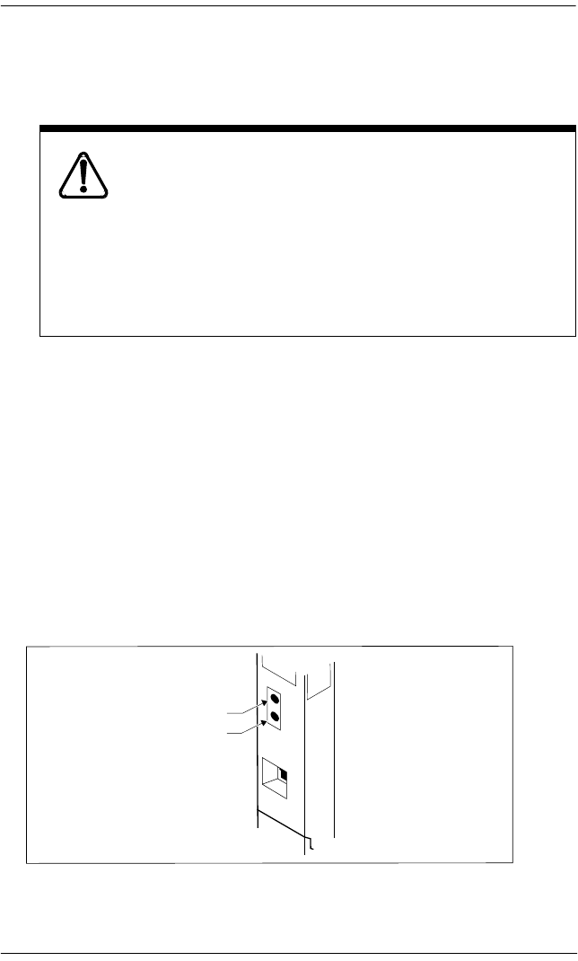
Problems with trunk cartridges service / 569
P0992638 03 Modular ICS 6.0 Installer Guide
If through-fed repeaters are used on the T1 span, disable
the internal CSU and connect the DTI to an external CSU.
6. If the problem persists, replace the DTI.
Monitoring the T1 or PRI signal
If you are finding minimal faults with the T1 or PRI signal,
you can monitor the signal to try and isolate the problem. The
monitor jack on the DTI faceplate provides non-intrusive,
bridged in-service monitoring of the T1 or PRI signal. Connect
a protocol analyzer or other test equipment into the monitor
jack to monitor the signal received from the network, and the
signal transmitted by Norstar.
Notify service provider of T1 or PRI signaling
disruption.
Notify your T1 or PRI service provider before
disconnecting your T1 or PRI lines, removing power to
your system, or performing any other action that
disrupts your T1 or PRI signaling. Failure to notify your
T1 or PRI service provider may result in a loss of T1 or
PRI service.
Receive signal
Transmit signal

570 / Problems with BRI service
Modular ICS 6.0 Installer Guide P0992638 03
Problems with BRI service
Each LED on front of a BRI-ST or BRI-U Card corresponds
with a loop, or indicates an overall state of the BRI
connections.
The BRI card is connected to the ISDN network (U loop)
but the LED for one of more loops is not lit
Possible problem
The physical connection or configuration for the network
connection is not correct (no Layer 1).
Solution
1. Verify the wiring from the network to the distribution
block.
2. Verify the wiring from the distribution block to the ICS.
3. Use a Meridian 2500 set to test for data on the BRI trunk.
4. Test the network connection by connecting Bellcore
standard terminal equipment (TE) directly to the network.
BRI Card indicators
LED status S, T or U-NT loop S or U-LT loop
on normal operation
off no synchronization
with ISDN network
no synchronization
with TE
all flashing Card is not recognized by ICS (not configured in
Hardware as a valid BRI loop).
All the LEDs on
a BRI Card are flashing
on page 571.
bottom LED only flashing ICS is downloading firmware to the card; card is
new or has changed location, or Feature
Cartridge has been upgraded

Problems with BRI service / 571
P0992638 03 Modular ICS 6.0 Installer Guide
5. Verify that the loop is provisioned.
6. Verify that the loop is properly configured, including the
proper loop type, SPIDs, and Network DNs.
7. Disable and re-enable the BRI Card.
8. Disable and enable the module for the Card.
Out of service displays when a BRI is selected
(LED for loop is lit)
Possible problem
The loop is configured incorrectly. Layer 1 is present but
Layers 2 and 3 are not working.
Solution
1. Verify that the SPIDs and Network DNs are programmed
correctly in Hardware.
2. Verify that the loop and lines are provisioned.
All the LEDs on a BRI Card are flashing
Possible problem
The card is not configured properly.
Solution
Verify that the loop is properly configured, including the
proper loop type, SPIDs, and Network DNs.

572 / Problems with BRI service
Modular ICS 6.0 Installer Guide P0992638 03
Possible problem
The card is not recognized by the ICS.
Solution
1. Verify that an Expansion Cartridge with Clocking, or
Clocking Cartridge is installed in the ICS.
2. Replace the card with another card of the same type.
Caller hears one ring and then a fast busy signal
when placing a call on a BRI line
Possible problem
CACH or EKTS, which are not supported by Modular ICS, is
included in the ISDN services package.
Solution
1. Contact your service provider and ensure that CACH or
EKTS are not part of the ISDN services package. These
services must be turned off at the switch.
2. Verify that the network DNs have been programmed
correctly, and verify the numbers with your service
provider.
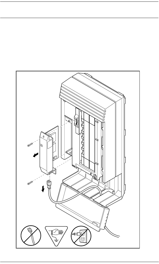
ICS down / 573
P0992638 03 Modular ICS 6.0 Installer Guide
ICS down
1. If AC power is present and the LED indicator on the ICS
is off, replace the ICS power supply.
2. Disconnect all central office and station lines from the
ICS. Power down the ICS by unplugging it.
Replacing the ICS power supply
❶
❷

574 / Trunk or Station Module down
Modular ICS 6.0 Installer Guide P0992638 03
Trunk or Station Module down
1. Run a Maintenance session to ensure that the Trunk
Module is not disabled. See Module status on page 495.
2. Disable the module using the Maintenance heading
Module status.
3. Enable the module using the Maintenance heading
Module status.
4. For Trunk Module
Check the external line by terminating a single-line
telephone directly on the distribution block, or equivalent,
which connects to the Trunk Module.
5. For Station Module
If the Station Module is still down, power down, then
power up the ICS.
If the problem persists
1. If AC power is present and the LED indicator on the Trunk
Module is off, replace the Trunk Module.
2. Replace the fiber cable.
3. Replace the Trunk Cartridge.
4. Replace the Expansion Cartridge.
5. Replace the ICS.
Refer to Installation on page 209 for information on replacing
components.

Data Module down / 575
P0992638 03 Modular ICS 6.0 Installer Guide
Data Module down
1. Run a Maintenance session to ensure that the module is
not disabled. See Module status on page 495.
2. Disable the Data Module using Module status.
3. Enable the Data Module using Module status.
4. If the Data Module is still down, power down, then power
up the ICS and the Data Module.
If the problem persists
1. If AC power is present and the LED indicator on the Data
Module is off, replace the Data Module.
2. Replace the Fiber cable.

576 / Problems for network or remote users
Modular ICS 6.0 Installer Guide P0992638 03
Problems for network or remote users
Remote feature code gets no response
Possible problem
A Norstar user has called into another Norstar system and is
trying to activate a remote feature but gets no response after
dialing the feature code.
Solution
1. Make sure that the remote caller is dialing the feature code
correctly. Use the asterisk (*) character, followed by the
feature code, to activate a remote feature.
Do not use for accessing features on a remote Norstar
system.
2. Make sure that the remote user is dialing tones, not pulses,
once the call is answered.
Dialed number gets ringback and the wrong person
Possible problem
The digits sent by a switch at a central office or in the private
network did not match any Received number, the Auto DN, or
the DISA DN. The call has been routed to the prime telephone
for the incoming trunk.
Solution
1. Verify that the switch is sending the correct number of
digits for the Received number length defined in your
system.

Problems for network or remote users / 577
P0992638 03 Modular ICS 6.0 Installer Guide
2. Verify all the digit strings that the switch should be
sending.
3. Check that you have defined the corresponding Received
number for every target line in your system.
4. Make sure that the published telephone numbers for your
network are correct.
Dialed number gets stuttered dial tone instead of
ringback
Possible problem
The remote caller has tried to reach a Norstar target line, but
has reached a trunk with DISA instead.
Alternatively, the Norstar system has mapped incoming digits
onto the DISA DN.
Solution
1. Verify all the digit strings that the switch should be
sending.
2. Check that you have defined a corresponding Received
number for every target line in your system.
3. Check that you have defined the correct DISA DN for your
system.
4. Make sure that the published telephone numbers for your
network are correct.

578 / Problems for network or remote users
Modular ICS 6.0 Installer Guide P0992638 03
Dialed number gets dial tone instead of ringback
Possible problem
The remote caller has tried to reach a Norstar target line, but
has reached the Norstar system instead. Norstar has mapped
the incoming digits onto the Auto DN.
Solution
1. Verify all the digit strings that the switch should be
sending.
2. Check that you have defined the corresponding Received
number for every target line in your system.
3. Check that you have defined the correct Auto DN for your
system.
4. Make sure that the published telephone numbers for your
network are correct.
Dialed number gets busy tone
Possible problem
The target line that the incoming digits map onto is busy, and
there is no prime telephone for the incoming trunk.
Solution
For maximum call coverage, make sure that you configure a
prime telephone for every incoming trunk.

Problems for network or remote users / 579
P0992638 03 Modular ICS 6.0 Installer Guide
Dialed number does not get through
Possible problem
The digits sent by a switch at a central office or in the private
network did not match any Received number, the Auto DN, or
the DISA DN. There is also no prime telephone assigned for
the incoming trunk. In this case, the caller may hear overflow
tone from the Norstar system or a recorded message from the
originating switch.
Solution
1. Configure a prime telephone for every incoming trunk.
2. Verify that the switch is sending the correct number of
digits for the Received number length defined in your
system.
3. Verify all the digit strings that the switch should be
sending.
4. Check that you have defined a Received number for every
target line in your system.
5. Make sure that the published telephone numbers for your
network are correct.
Possible problem
The Norstar system did not receive some or all of the incoming
digits.
Solution
1. Check that the system hardware is receiving signals
properly.
2. Verify that the switch is sending the correct number of
digits for the Received number length defined in your
system.

580 / Problems for network or remote users
Modular ICS 6.0 Installer Guide P0992638 03
3. If the switch at the far end is sending pulse signals, make
sure they are being sent at the proper rate.
Pulse digits must be 300 ms or more apart for Norstar to
receive them.
Possible problem
If remote callers are having difficulty getting through from the
public network, there may be a problem with your DID Trunk
Cartridge.
Solution
1. Connect a single-line DTMF telephone to a DID trunk
input on the DID Trunk Cartridge.
2. Use the single-line telephone to enter a Received number
that has been programmed for a target line in your system.
Listen for ringback.
3. If you do not hear ringback, check that the target line is
assigned to a telephone and that there is a prime telephone
assigned for the DID trunk.
4. If you now hear ringback, but you also hear the noise of
your unanswered call ringing, check the
cross-connections. If all the cross-connections are correct
replace the Trunk Cartridge.
Possible problem
If remote callers are having difficulty getting through from the
private network, there may be a problem with your E&M/
DISA Trunk Cartridge.
Solution
1. Check the cross-connections for the E&M/DISA Trunk
Cartridge.

Problems for network or remote users / 581
P0992638 03 Modular ICS 6.0 Installer Guide
2. If the E&M trunks are connected to another Norstar
system, make sure that connections have been made as
indicated in Installation on page 209.
3. Use the following table to check for correct voltage on the
E&M/DISA leads:
Voltages on E&M leads
Dialed DISA number gets ringback instead of
stuttered dial tone
The remote caller has dialed a DISA number, but has instead
reached a target line, or has been routed to the prime telephone
for the auto-answer trunk. The Norstar system has mapped the
incoming digits from a switch onto a target line, or has been
unable to map the digits anywhere.
Solution
1. Verify that the switch is sending the correct number of
digits for the Received number length defined in your
system.
2. Verify all the digit strings that the switch should be
sending.
3. Check that you have defined the correct DISA DN for your
system.
4. Make sure that the published telephone numbers for your
network are correct.
Leads Voltage: active Voltage: inactive
V T-R 125 mV AC on steady dial tone 0 V AC
V T1-R1 125 mV AC on steady dial tone 0 V AC
V E-SG 0 V DC to -5 V DC -48 V DC
V M-SB 0 V DC to + 2 V DC -48 V DC

582 / Problems for network or remote users
Modular ICS 6.0 Installer Guide P0992638 03
Dialed DISA number gets dial tone instead of stuttered
dial tone
Possible problem
The remote caller has dialed a DISA number, but has reached
the Norstar system instead. The Norstar system has mapped
the incoming digits from a switch onto the Auto DN.
Solution
1. Verify that the switch is sending the correct number of
digits for the Received number length defined in your
system.
2. Verify all the digit strings that the switch should be
sending.
3. Check that you have defined the correct DISA DN for your
system.
4. Make sure that the DISA DN and Auto DN are different
enough to prevent misdialing.
5. Make sure that the published telephone numbers for your
network are correct.
DISA user gets overflow tone when entering COS
password
Possible problem
The remote caller may have entered an invalid password.
Solution
Check programming under COS passwords and verify that the
caller has a valid password.

Problems for network or remote users / 583
P0992638 03 Modular ICS 6.0 Installer Guide
Possible problem
The remote caller may have entered an asterisk (*) as one of
the six digits.
Solution
Instruct remote callers to enter their COS password correctly:
enter six digits.
Possible problem
The remote caller may have entered a number sign (#) as one
of the six digits.
Solution
Instruct remote callers to enter their COS password correctly:
enter six digits. The number sign (#) may be entered after the
sixth digit, but is not required.
Possible problem
The remote caller may have waited more than 15 seconds
between entering digits.
Solution
Instruct remote callers to enter their COS password correctly:
enter six digits, and do not pause too long between digits.
Possible problem
The caller may be dialing from a rotary-dial telephone or from
a push-button telephone that uses pulse signaling.
Solution
Inform remote callers that they must dial from a push-button
telephone that uses DTMF tone signaling.

584 / Problems for network or remote users
Modular ICS 6.0 Installer Guide P0992638 03
Dialed feature code gets overflow tone
Possible problem
The remote caller does not have access to that feature.
Solution
1. If the call came in on a trunk with DISA, check the
Class of Service that is associated with the COS password
of the remote caller. If it is too restrictive, modify the
remote package assigned to the COS password, or assign
another COS password that is more suitable.
2. If the call came in on a trunk without DISA, check the
remote package that you assigned to the incoming trunk.
Make sure that it gives the appropriate access to the remote
caller.
Possible problem
The feature code is not valid.
Solution
1. Make sure that remote callers have a correct listing of the
features that are programmed for remote access.
2. Ensure that remote callers are dialing the feature code
correctly. Press followed by the feature code to activate
a remote feature.
Possible problem
The caller may be dialing on a rotary-dial telephone or on a
push-button telephone that uses pulse signaling.
Solution
Inform remote callers that they must dial from a push-button
telephone that uses DTMF tone signaling.

Problems for network or remote users / 585
P0992638 03 Modular ICS 6.0 Installer Guide
Dialed feature code gets busy tone
Possible problem
A resource that the remote feature uses may currently be in
use. For example, a remote caller trying to use the paging
feature would get a busy tone if the auxiliary speaker were
being used at the time.
Solution
If repeated attempts to use the remote feature get busy tone,
there may be a malfunction in a resource that the feature uses.
Check that the remote feature hardware is functioning
normally.
Line pool access code gets overflow tone
Possible problem
If the published line pool access code is valid, the remote caller
does not have access to that line pool.
Solution
If the incoming trunk answers with DISA, give the remote
caller a COS password that permits access to that line pool.
OR
Change the remote package for the incoming trunk so that it
permits access to that line pool.
OR
Give the remote caller a line pool access code that is permitted
within the Class of Service on the incoming trunk.

586 / Problems for network or remote users
Modular ICS 6.0 Installer Guide P0992638 03
Possible problem
If the published line pool access code is invalid, the system has
attempted, without success, to match the invalid code to a
Norstar target line internal number, and there is no prime
telephone for the auto-answer trunk.
Solution
1. Make sure that the published line pool access codes are
correct.
2. Check that the line pool access codes have been entered
correctly under Access codes in System prgming.
Possible problem
The caller may be dialing from the network on a rotary-dial
telephone or on a push-button telephone that uses pulse
signaling.
Solution
Inform remote callers that they must dial from a push-button
telephone that uses DTMF tone signaling.
Line pool access code gets ringback
Possible problem
The published line pool access code is invalid, and the system
has routed the call to the prime telephone for the incoming
trunk.
Solution
1. Make sure that the published line pool access codes are
correct.
2. Check that the line pool codes have been entered correctly
under Access codes in System prgming.

Problems for network or remote users / 587
P0992638 03 Modular ICS 6.0 Installer Guide
Line pool access code gets busy tone
Possible problem
There are not enough lines in the line pool to serve the number
of users.
Solution
If the line pool contains loop start trunks, enter programming
and move under-used loop start trunks from other line pools
into the deficient line pool.
OR
If the line pool contains E&M trunks, order more trunks from
the telephone company or private network vendor. Install
additional E&M Trunk Cartridges. In programming, add the
new trunks to the deficient line pool.
OR
Create a separate line pool for remote users only.
Possible problem
There are DID lines in the line pool.
Solution
In programming, make sure that there are no DID lines in any
of the line pools.
Dialed number gets no response
Possible problem
The remote caller, after accessing a line in a line pool, may
have started dialing before the far end was ready to receive.
Solution
Instruct remote callers to wait until they hear feedback before
entering any digits.

588 / Problems for network or remote users
Modular ICS 6.0 Installer Guide P0992638 03
Possible problem
There may be a malfunction in the line that the remote caller
accessed.
Solution
If the problem is persistent, check that all lines in the affected
line pool are functioning normally.
Possible problem
There may be a malfunction in the system that the caller is
trying to reach.
Solution
Inform the operators of the system at the far end that the dialed
number is not getting through.

P0992638 03 Modular ICS 6.0 Installer Guide
Specifications
Norstar system
Service tone cadences
Power specifications
Telephone loop specifications
Tone Cadence (seconds)
Busy 0.5 on / 0.5 off
Expensive Route 0.3 on / 0.3 off (3 bursts)
Overflow 0.25 on / 0.25 off
Ringback 2.0 on / 4.0 off
Confirmation 1.0 on / 1.0 off (three bursts followed by no tone)
Recall 1.0 on / 1.0 off (three bursts followed by steady tone)
Ring splash 0.2 on (one burst)
Characteristic ICS TM SM
Voltage V ac 110-120 110-120 110-120
Current A rms (max) 2.6 1.75 1.0
Frequency Hz 47-63 45-70 45-70
Crest factor 4.0 4.0 4.0
Characteristic Value
Loop resistance 64 ¾ (300 m of 0.5 mm wire or 1000 ft. of 24 AWG wire)
Loop length 300 m (1000 ft.) without station auxiliary power supply
790 m (2500 ft.) with station auxiliary power supply
Minimum voltage
at telephone
10 V dc

590 / Specifications
Modular ICS 6.0 Installer Guide P0992638 03
Electrical requirements
Environmental requirements
ISDN network synchronization*
* These specifications only apply when the system clock is not derived from a Digital
Trunk Interface connection to the network.
Current at
telephone (idle)
45 mA nominal
Current at
telephone (active)
80 mA maximum
Characteristic Spec/Value
Electrostatic discharge
ICS and telephones IEC 801-2 severity level 3
maximum of 15 kV with a 300¾/150 pF probe
Connectors IEC 801-2 severity level 2
Radiated immunity maximum of 5 V/m from 100 kHz to 1 GHz
Conducted immunity maximum of 3 V rms from 0.1 MHz to 30 MHz
Characteristic Spec/Value
Operating temperature range 0°C to 50°C (32°F to 122°F) IEC. 68-2-1
Tests Ad and IEC 68-2-2, Method A
Storage temperature range -50°C to 70°C (-31°F to 158°F)
IEC. 68-2-2 Test Bd
Humidity above 34°C (93°F) 5% to 95% (non-condensing)
<52 mbar of water vapor pressure
Characteristic Spec/Value
Free run clock accuracy ±32 ppm
Network synchronized clock accuracy ±5 ppm

Specifications / 591
P0992638 03 Modular ICS 6.0 Installer Guide
Digital Trunk Interface
Network interface
* These values are set in Hardware programming. See the
Hardware on page 455
for details.
DSX1 operation
* This value is set in Hardware programming. See the
Hardware on page 455
for
details.
CSU operation
* This value is set in Hardware programming. See the
Hardware on page 455
for
details.
Characteristic Spec/Value
Physical RJ48C 8-pin modular jack
Line rate 1.544 +/- 32 Mbps
Framing Superframe/extended superframe*
Line code AMI/B8ZS*
Impedance 100 ¾
Characteristic Value
Pre-equalization 0-210 m (0-700 ft.)*
Characteristic Spec/Value
Line build out 0, 7.5 or 15 dB*
Input dynamic range 0 to -26 dB (typical)
Performance reporting Simultaneous support of TR 54016 or
TIA-547A
Line loopback support Remote activation/deactivation via in-band
code or FDL as per TR 54016 or TIA-547A
Payload loopback support Remote activation/deactivation via FDL as
per TR 54016 or TIA-547A
Carrier failure alarms (CFA) Alarm indication signal (AIS), Red Yellow

592 / Specifications
Modular ICS 6.0 Installer Guide P0992638 03
Synchronization performance
Digital trunk signaling support
* These values are set in Hardware programming. See the
Hardware on page 455
for details.
Local test support
*See
Tests on page 525
for details on running these tests.
Characteristic Spec/Value
Stratum 4E
Types Options
Loop Start with answer and
disconnect supervision
OSI interval*
Pulse/DTMF dialing*
E&M Immediate start (Pulse dialing only), Wink
start, Delay start or ring-down tie line*
Pulse/DTMF dialing*
DID Immediate start (Pulse dialing only), Wink
start or Delay start*
Pulse/DTMF dialing*
Ground start
Characteristic Value
Monitor jack Bridging via Bantam jack
Line loopback activate/deactivate via maintenance*
Payload loopback activate/deactivate via maintenance*
Card edge loopback activate/deactivate via maintenance*
Continuity loopback activate/deactivate via push button on faceplate*

P0992638 03 Modular ICS 6.0 Installer Guide
Glossary
A
AbsorbLength: A setting that
determines how many of the digits in a
destination code will not be dialed by
the system. AbsorbLength is assigned
under Destination codes in
Services.
access code: Different sequences of
characters used to gain access to these
Norstar features: Line pools, Call park,
external lines, Direct-Dial telephone,
Auto DN, and DISA DN.
alarm code: A number that appears
on the alarm telephone display,
informing you that the ICS has detected
a fault in the system.
alarm telephone: A telephone that is
designated to receive reports of Norstar
system problems. This function is
usually assigned to a prime telephone,
but this can be changed under
Feature
settings in Sys prgrammng.
Analog Terminal Adapter (ATA):
A device that permits analog
telecommunication devices such as fax
machines, answering machines, and
single line telephones to be connected to
the Norstar system. Programmed
defaults for the ATA are automatically
assigned by the Norstar system.
ANSI: American National Standards
Institute.
Answer button: A telephone button
with an indicator that is used to monitor
another telephone. The answer button
indicates incoming calls destined for the
other telephone. Someone working at a
telephone with answer buttons (an
attendant, for example) can receive all
ringing and visual indication of
incoming calls for other telephones, and
answer those calls when necessary.
One telephone can have up to four
Answer buttons. An Answer button is
automatically assigned to a telephone
when that telephone is assigned an
Answer DN.
Answer DN: The internal or directory
number (DN) of a telephone that is
monitored by an Answer button. You
can assign up to four Answer DNs to a
telephone under Line Access in
Terminals and Sets programming.
Autobumping:
A feature that determines what the
system does with new Call Log items
when your Call Log is full. When
Autobumping is on, a new log entry
causes the oldest entry to be deleted. If
Autobumping is off, your Norstar
system does not log calls when your log
is full.
autodial button: A memory button
that, if programmed, provides one-touch
dialing of external or internal numbers.
autolog options:
A feature that allows you to select the
type of calls that are stored in your Call
Log. You can choose to log calls that
were not answered by anyone within the
system, to log calls that were
unanswered at this telephone but which
were answered elsewhere in the system,
to log all calls answered and not
answered at this telephone, or to not
have calls automatically logged.
Automatic Dial: A feature that allows
you to dial without having to pick up the
receiver or select a line. You must have
a prime line to use Automatic Dial.
Automatic Dial is assigned under
Dialing options in Terminals&Sets
programming.

594 / Glossary
Modular ICS 6.0 Installer Guide P0992638 03
Automatic Handsfree: A feature
which automatically activates
Handsfree operation when you make or
answer a call. Automatic Handsfree is
assigned under Handsfree in
Terminals&Sets programming.
Automatic Hold: A feature that
automatically places an active call on
hold when you select another
line.Automatic Hold (Full AutoHold)
is assigned in Lines programming.
Automatic Privacy: See Privacy.
Automatic Daylight Savings
Time: A feature that switches the
system to standard or daylight savings
time at pre-programmed times. It is
turned on or off under Daylight time
in Sys prgrmmng.
Automatic Telephone
Relocation: A feature that allows a
telephone to retain personal and system
programming when the telephone is
plugged into a different Norstar modular
jack. Automatic Telephone
Relocation is enabled under Set
relocation in Sys prgrmmng.
auxiliary ringer: A separate external
telephone ringer or bell which can be
programmed to ring when a line or a
telephone rings. An auxiliary ringer may
be programmed to ring only when the
system is in a particular schedule.
Programming of an auxiliary ringer is
done in Services programming after
the feature has been enabled under
Capabilities in Terminals&Sets
programming.
AWG: American wire gauge.
B
B channel (Bearer channel). An
ISDN standard transmission channel
used for voice or data transmission.
Base station (XC 3.0 only): A
Companion component that is mounted
on walls and ceilings to provide a radio
link to an office or other area where
Companion portable telephones are
used. Each base station houses two
radios that allow portables to send and
receive calls through the ICS. (See also
Companion Wireless)
Background Music: A feature that
allows you to hear music from the
speaker of your Norstar telephone. It is
available only if a music source has
been attached to the ICS and the feature
has been enabled under Feature
settings in Sys prgrmmng.
Basic password: A one- to six-digit
password that prevents unauthorized
access to the most commonly-used
telephone settings. The Basic password
can be assigned and changed in
Passwords programming.
Basic Rate Interface (BRI): An
ISDN interface which uses two
B channels and a D channel (2B+D).
Bearer channel: See B channel.
Business series terminals These
terminals were developed to replace the
Norstar M-series terminals. Therefore,
their functionality closely parallels the
M-series terminals.
busy lamp field (BLF): A device
with a liquid crystal display (LCD)
panel of indicators that shows the status
of up to 24 telephones in the Norstar
system. The BLF attaches to the M7310
and T7316 telephones.
button caps: Interchangeable plastic
caps that fit over the buttons of Norstar
telephones. They are used to indicate the

Glossary / 595
P0992638 03 Modular ICS 6.0 Installer Guide
features programmed onto each
programmable memory button. Button
caps are either pre-printed or have clear
windows that allow you to insert labels.
Button Inquiry:
With this feature you can check the
function of each programmable button
on your system telephone.
C
Call Duration timer:
A feature that allows you to see how
long you spent on your last call, or how
long you have been on your present call.
Call Forward:
A feature that forwards all the calls
arriving at your telephone to another
telephone in your Norstar system. To
have calls forwarded outside the system,
use Line Redirection.
Call Forward No Answer: A feature
that forwards all calls arriving at your
telephone to another designated
telephone in your Norstar system after a
specific number of rings. Call Forward
No Answer is assigned under
Capabilities in Terminals&Sets
programming.
Call Forward On Busy: A feature
that forwards all calls at your telephone
to another designated telephone if your
telephone is busy. This feature is
assigned under Capabilities in
Terminals&Sets programming.
Call Forward Override: An
automatic system feature that allows
you to call someone and ask them to
stop forwarding their calls to you.
Call Information:
Call Information allows you to display
information about incoming calls. For
external calls, you can display the caller
name, telephone number and the line
name. For an internal call, you can
display the name of the caller and the
internal number. You can obtain
information about ringing, answered, or
held calls.
Call Information Trunk Cartridge:
The Trunk Cartridge that allows you to
connect loop start trunks with Call
Information capability to the Norstar
system.
Call Log:
Enter your Call Log to view a record of
incoming calls. The log could contain
the following information for each call:
sequence number in the Call Log, name
and number of caller, long distance
indication, indication if the call was
answered, time and date of the call,
number of repeated calls from the same
source, and name of the line that the call
came in on. See Autobumping, Autolog
options, and Call Log for further
information.
Call Park:
With this feature you can place a call on
hold so that someone can retrieve it
from any other telephone in the Norstar
system by selecting an internal line and
entering a retrieval code.
The retrieval code appears on the
display of your telephone when you
park the call. You can park up to 25 calls
on the system at one time.
Call Park Callback: See Callback.
Call Park prefix: The first digit of the
retrieval code of a parked call. This digit
cannot conflict with the first digit of any
existing DNs, Line Pool access codes,
the Direct-dial digit, or the external line
access code. The default Call Park
prefix digit is 1. It may be set to none, in
which case Call Park is disabled. Call
Park prefix is assigned under Access
codes in Sys prgrmmng.
Call Pickup Directed:
A feature that allows you to answer a
call ringing at any system telephone by
entering the internal number of that

596 / Glossary
Modular ICS 6.0 Installer Guide P0992638 03
telephone before taking the call. Call
Pickup Directed is enabled under
Feature settings in Sys prgrmmng.
Call Pickup Group: See Pickup
Group.
Call Queuing:
If you have several calls waiting at your
telephone, you can invoke the Call
Queuing feature to answer them in order
of priority. Priority is given to incoming
calls, followed by callback and camped
calls.
Callback: If you park, camp,
or transfer a call to another telephone
and it is not answered there, it will ring
again at your telephone. How long the
system will wait before Callback occurs
is set under Feature settings in Sys
prgrmmng.
Camp-on:
A feature that allows you to reroute a
call to a telephone even if all the lines on
that telephone are busy. To answer a
camped call, use Call Queuing or select
a line if the camped call appears on your
telephone. Priority is given to queued
calls.
Camp timeout: The length of a delay
before a camped call is returned to the
telephone that camped the call. The
length of delay is set under Feature
settings in Sys prgrmmng.
Central answering position
(CAP): An M7324 telephone that has
been designated as a CAP under CAP
assignment in Sys prgrmmng. The
CAP provides backup answering and
can be used to monitor the telephones
within a Norstar system.
Central answering position (CAP)
module: A module connected to an
M7324 telephone which provides 48
additional buttons that can be used as
autodial buttons or feature buttons. A
maximum of two CAP modules can be
connected to a single M7324 telephone.
Centralized voice mail and Auto
Attendant: A Norstar VAM can be
configured to service other systems
connected to the Norstar where the
NVAM resides. The connection must be
made using PRI SL-1 lines with the
MCDN protocol active. Both a PRI and
an MCDN software codes (as well as
any required voice mail codes) are
required for this feature.
Channel Service Unit (CSU): A
device on the Digital Trunk Interface
that is the termination point of the T1
lines from the T1 provider. The CSU
collects statistics on the quality of the
T1 signal. The CSU ensures network
compliance with FCC rules and protects
the network from harmful signals or
voltages.
Class of Service (COS): The set of
Norstar features and lines available to
the user for a call. The Class of Service
for a call is determined by the restriction
filters and remote access packages
assigned to the telephone in Lines
programming. The Class of Service for
a call can be changed by entering a six-
digit Class of Service password.
(Internal users cannot change their
access to features with a COS password,
only their restriction filters.) Class of
Service and Class of Service
passwords are assigned in Passwords
programming. See Remote Access.
Class of Service password:
A six-digit code that allows you to
switch from your current Class of
Service to one that allows you to dial
numbers prohibited by your current
Class of Service.
cold start: When all system
programming is lost. This can happen
because you have entered the Startup

Glossary / 597
P0992638 03 Modular ICS 6.0 Installer Guide
feature code
, or
after a major event, such as an extended
power failure.
Combo Cartridge: A cartridge that
allows you to connect Trunk Modules
and Station Modules to the ICS to
expand the system capacity for trunks
and telephones. Combo Cartridges
provide six-port or 12-port expansion
and Services functionality with each
cartridge. See also Expansion Cartridge.
Companion Wireless: The name for
Nortel Networks communication
systems which use radio technology to
transmit and receive signals between its
components and the Norstar system.
Companion Wireless provides mobility
in the workplace. Calls that used to ring
just at your Norstar set can also appear
and ring at your portable.
Companion portable telephone:
Hand-held wireless sets which allow
complete mobility within the reach of
Companion base stations or an external
antenna. Portables offer many, but not
all, Norstar features and share much of
the same programming as wired desk
sets.
Conference:
A feature allows you to establish a
three-person call at your Norstar
telephone.
contrast adjustment:
Allows you to set the contrast level of
your telephone display.
control telephone: A control
telephone can place the lines for which
it has responsibility in or out of a
Service Mode.
The direct-dial telephone is a control
telephone for directing calls to the extra
direct-dial telephone. A telephone is
made a control telephone and has lines
assigned to it in Services programming.
Coordinated Dialing Plan: (CDP)
This dialing plan uses a steering code to
identify each node in a private network.
This one-digit code becomes part of the
set DN number rather than a separate
code. In this way, system A might have
codes in range 2100 to 2999, whereas
system B might have codes in range
3100 to 3999.
COS: See Class of Service.
cursor: A short horizontal line that
appears on the system telephone display
to indicate that characters can be entered
using the dialpad.
D
D channel (Data channel): An
ISDN standard transmission channel
which is packet-switched, and is used
for call setup, signalling and data
transmission.
Data channel: See D channel.
Data Communications Interface
(DCI): A Norstar device that allows you
to attach an RS-232 data device to the
Norstar system.
data terminal: A device, such as a
modem, that can be used to transfer data
instead of sound over a telephone
network. You cannot use Norstar
programming to set up such devices.
See the documentation that
accompanies the device.
date: See Show Time or Time and
Date.
defaults: The settings for all Norstar
features when the system is first
installed. Settings are changed from
their defaults in programming. In this
manual, default settings are shown in
bold text.
Delayed Ring Transfer (DRT) to
prime: After a specified number of
rings, this feature transfers an
unanswered call on an external line, to

598 / Glossary
Modular ICS 6.0 Installer Guide P0992638 03
the prime telephone associated with that
line. This feature is activated under
Feature settings in Sys prgrmmng.
destination code: A two- to seven-
digit number that the system interprets
and then translates into the digits that
you want dialed out. Both the code and
its associated dialed digits are assigned
under Routing service in Services
programming.
DID trunk: See Direct Inward Dial
trunks.
DID Trunk Cartridge: The Trunk
Cartridge that allows you to connect
DID trunks to the Norstar system.
dialing restriction: See Restriction
filter.
dialing modes:
This feature allows you to set the dialing
mode of your telephone. Norstar
supports three dialing modes:
Automatic Dial, Pre-Dial, and Standard
Dial. All three modes support on-hook
dialing, meaning you can dial a call
without picking up the receiver. The
special features of the Automatic and
Pre-Dial modes are available only when
you dial on-hook.
Digital Trunk Interface: The Trunk
Cartridge connects digital T1 AND
ISDN trunks to the Norstar system.
Direct-dial: A feature that allows you
to dial a designated telephone in your
Norstar system with a single digit, such
as the main receptionist. As many as
five direct dial sets can be established.
Each telephone in the system is assigned
to one direct-dial telephone. There is a
single, system wide digit for calling the
assigned direct-dial telephone of any
telephone. Direct-dial telephones are
established in System programming.
Telephones are assigned to a direct-dial
telephone under Capabilities in
Terminals&Sets programming.
Direct-dial #: A digit used system-
wide to call the Direct-dial telephone.
The digit is assigned under Access
codes in Sys prgrmmng.
Direct-dial number: The digit used
to call the direct-dial telephone.
Direct Inward Dial trunk: Trunks
that allow direct inward dialing from the
public network to the Norstar system.
Direct inward system access
(DISA): The feature that allows remote
users to dial directly into the Norstar
system and use Norstar features. Callers
will hear stuttered dial tone and will be
required to enter a Class of Service
password to gain access to the system.
See Remote Access.
directed pickup: See Call Pickup
Directed.
Directory number (DN): A unique
number that is automatically assigned to
each telephone or data terminal. The
DN, also referred to as an internal
number, is often used to identify a
telephone when settings are assigned
during programming.
Default DN assignments start at 221.
DISA DN: The received number
assigned to the Norstar direct inward
system access facility. If a caller dials a
number that is assigned to the
DISA DN, the caller hears stuttered dial
tone and must enter a Class of Service
password. Once the password is
accepted, the caller hears system dial
tone and can use Remote Access
features. See Remote Access.
Disconnect Supervision: A setting
that enables the Norstar system to detect
if an external caller hangs up. Once an
external caller hangs up, the Norstar
system can disconnect its line.
Disconnect Supervision is enabled
under Trunk/Line data in Lines
programming.

Glossary / 599
P0992638 03 Modular ICS 6.0 Installer Guide
display: A liquid crystal display
(LCD) on the telephone that guides you
through feature operation and
programming.
display button: The Norstar M7310
telephone and M7324 telephone and the
Business Series Terminal T7316 are
each equipped with three buttons
located directly beneath the display.
During feature operation or
programming, some or all of these
buttons may be used to provide further
options. If an option is available, it is
shown in the bottom row of the two-row
display, directly above the
corresponding display button. Display
buttons are represented in this manual as
underlined capital, such as OK.
Distinctive ring: Lines, telephones,
and hunt group DNs can be configured
with a distinctive ring that also
determines the priority of a call.
DN: See Directory number.
Do Not Disturb:
A feature that stops calls from ringing at
your telephone. Only Priority Calls will
ring at your telephone. A line button will
flash when you receive a call, but the
call will not ring.
DTMF: See Dual tone multifrequency.
dual tone multifrequency: Two
distinct telephone signaling tones used
for dialing.
DTI: See Digital Trunk Interface.
E
E&M/DISA Trunk Cartridge: The
Trunk Cartridge that allows you to
connect E&M trunks to the Norstar
system. The E&M Trunk Cartridge also
allows DISA access to the system by
providing DTMF receivers for auto-
answer trunks.
Emergency 911 dialing: The
capability to access a public emergency
response system by dialing the digits
9-1-1. State and local requirements for
support of Emergency 911 Dialing
service by Customer Premises
Equipment vary. Consult your local
telecommunications service provider
regarding compliance with applicable
laws and regulations.
emergency telephone: A single-line
telephone, also referred to as a 500/2500
telephone, that becomes active when
there is no power to the ICS.
evening schedule: See Schedules,
and Services.
event message: Event messages are
stored in the system log and displayed
during a Maintenance session. They
record a variety of events and activities
in the Norstar system.
exceptions: See Overrides.
Expansion Cartridge: A cartridge
that allows you to connect Trunk
Modules and Station Modules to the ICS
to expand system capacity for trunks
and telephones.
There are two Expansion Cartridges:
a two-port Expansion Cartridge and a
six-port Expansion Cartridge. (See also
Combo Cartridge.)
external call: A call to a destination
outside the Norstar system.
External Call Forward: See Line
Redirection.
external code: The number you dial
to get an external line. By default it is 9,
but this can be changed under
Access
codes in Sys prgrmmng. You do not
always need an external code. It is
primarily to support the M7100 and
T7100 telephones, and single-line
telephones using an Analog Terminal
Adapter.

600 / Glossary
Modular ICS 6.0 Installer Guide P0992638 03
external line: A line on your system
telephone used for making calls to
destinations outside the Norstar system.
external music source: See Music
source.
external paging: A feature you can
use to make voice announcements over
an externally-mounted loudspeaker
connected to the ICS. The external
speaker is not a Norstar component and
must be supplied by the customer.
F
feature button: Many Norstar
features are invoked by pressing the
Feature ( ) button followed by a
feature code. The feature button is also
used to exit a feature.
Feature Cartridge: A replaceable
cartridge containing the Norstar
features. The Feature Cartridge is
inserted into the ICS.
feature code: A number that is used
to activate a particular feature.
Feature programming:
Allows you to program a feature code
onto a memory button.
Forward: See Call Forward.
Full Autohold (on idle line): When
this feature is on, if you select an
available line and then do something
that selects another line, the first line is
put on hold. Full Autohold is enabled
under Trunk/Line data in Lines
programming.
Full Handsfree: See Handsfree.
G
Ground Start trunk: Ground start
trunks offer the same features as loop
start trunks, but are used when the local
service provider does not support
disconnect supervision for the digital
loop start trunks. By configuring lines as
ground start, the system will be able to
recognize when a call is released at the
far end. Ground start trunks are
provided only by a DTI.
Group Listening:
A feature that allows you to have others
in your office hear a caller through your
telephone speaker. The caller hears you
only when you speak into the receiver.
They cannot hear other people in the
office.
You can cancel Group Listen for the
current call. Group Listen is cancelled
automatically when you hang up the
Group Listen call.
H
Handsfree:
A feature you can use to make calls
without using the telephone receiver.
Full Handsfree is activated under
Capabilities in Terminals&Sets
programming. When it is activated, a
Handsfree/Mute button is automatically
assigned to the telephone.
Handsfree (HF) Answerback:
When activated, this feature
automatically turns on the microphone
at a telephone receiving a Voice Call so
that the person receiving the call can
respond without lifting the receiver. It is
activated under Capabilities in
Terminals&Sets programming.
Handsfree/Mute button: See
Handsfree.
Hardware: A section in programming
that shows what equipment has been
installed in the ICS. This section is
accessed by the installer.
headset: A head-mounted or
ear-mounted telephone receiver that is
used instead of the hand-held receiver.
Headsets are not Norstar components
and must be supplied by the customer.

Glossary / 601
P0992638 03 Modular ICS 6.0 Installer Guide
Held (Line) Reminder: A system
telephone rings and displays the
message On hold: LINENAM when an
external call has been placed on hold for
a certain period of time. The Held Line
Reminder feature and Remind delay
are set under Feature settings in Sys
prgrmmng.
HF Answerback: See Handsfree
Answerback.
Hold button:
This button is used to suspend calls so
that the person using the telephone can
perform another task without
disconnecting the caller.
Hook Switch Flash: See Link time.
Host system signaling: (Also
referred to as end-to-end signaling.)
System telephones can access a remote
system or dial a number on an alternate
carrier by means of host feature
activation, such as Link, Pause and Run/
Stop.
Hospitality The Hospitality features
allow business which use hospitality
telephones, or room-based telephones,
to control access, alarms, and
maintenance duties through the
telephones.
Hotline: This feature automatically
calls a pre-assigned number when the
telephone receiver is lifted or the
Handsfree/Mute button is pressed. A
Hotline number can be an internal or
external number. Hotline is assigned
under Capabilities in
Terminals&Sets programming.
Hunt group: The hunt groups feature
allows a group of sets to be called by a
single directory number ensuring that
calls are easily routed to the appropriate
group.
I
I/C: An abbreviation of intercom.
ICS (integrated communication
system): The central hardware
component in the Norstar system. The
ICS has its own processor and memory,
and provides a physical point of
connection for the various types of
devices, telephones, and expansion
modules used in Norstar.
The ICS can function on its own as a
basic system (with 32 system telephones
and up to 48 external lines), or with the
addition of Trunk Modules (TM) that
supports more external lines, or Station
Modules (SM) that support more system
telephones.
Installer password: A one-to six-
digit password that prevents
unauthorized access to programming.
The Installer password can be assigned
and changed in Passwords
programming.
Integrated Services Digital
Network (ISDN): A digital telephone
service that allows for a combination
voice and data connection over a single,
high-speed connection. ISDN service
can operate over the same copper
twisted-pair telephone line as analog
telephone service.
intercom button: A button that
provides access to internal lines used for
calls within a Norstar system and access
to external lines through a line pool or
external code. A telephone may be
assigned zero to eight Intercom buttons.
This is done under Line access in
Terminals&Sets programming.
intercom keys: See Intercom button.
internal line: A line on your telephone
dedicated to making calls to destinations
inside your Norstar system. An internal
line may still connect you with an
external caller if you use it to access a

602 / Glossary
Modular ICS 6.0 Installer Guide P0992638 03
line pool or to pick up a call using
Norstar call handling features such as
Call Park or Call Pickup Directed.
internal number: A number, also
referred to as a Directory Number or
DN, that identifies a Norstar telephone
or device.
internal user: Someone using a
system telephone within a Norstar
system.
ISDN: See integrated services digital
network.
ISDN DN: A directory number (DN)
used by ISDN terminal equipment
connected to the ICS. The system uses a
maximum of thirty ISDN DNs.
ISDN Call Connection Limitation
(ICCL) This feature piggybacks on the
call initiation request and acts as a check
at transit PBX points to prevent
misconfigured routes or calls with errors
from blocking channels.
K
Key service unit (KSU): See ICS.
L
Last Number Redial:
A feature that allows you to redial the
last external number you dialed.
Fixed line:
A telecommunications line between two
service points leased from a
communications carrier for private use,
usually incurring a monthly service rate.
Fixed lines setting is used solely by data
modules.
Least cost routing: See Routing
service.
line: The complete path of a voice or
data connection between one telephone
(or other device) and another.
Lines: A programming section that
allows you to assign settings to each
trunk and external line. Lines
programming can be done by an
Installer or a System Coordinator Plus.
A System Coordinator can program the
name of a line.
Line number: A number that
identifies an external line. The total
number of lines depends on how many
Trunk Modules are installed.
Line Pool:
A group of lines used for making
external calls. Line pools provide an
efficient way of giving a telephone
access to external lines without taking
up many line buttons. A line is assigned
to be part of a line pool under Trunk/
Line data in Lines programming.
Line Redirection:
A feature that allows you to redirect all
calls on an incoming line to a
destination outside the Norstar system.
Once a line is redirected it cannot be
answered within the Norstar system.
The system may be set up to give a brief
ring when a call comes in on a redirected
line, under Capabilities in
Terminals&Sets programming.
This feature differs from Call Forward
in two ways: It redirects only external
calls, not internal calls, and it redirects
calls to destinations outside the system.
Call forward redirects calls only to
destinations inside the Norstar system.
See Call Forward.
Link:
If your Norstar system is connected to a
Private Branch Exchange (PBX), you
can use a Link signal to access special
features. The Link signal can also be
included as part of a longer stored
sequence on an External Autodial
button or in a Speed Dial code. The Link
symbol (¤) uses two of the 24 spaces
in a dialing sequence.

Glossary / 603
P0992638 03 Modular ICS 6.0 Installer Guide
Long Tones:
A feature that allows you to control the
length of a tone so that you can signal
devices such as fax or answering
machines which require tones longer
than the standard 120 milliseconds.
Loop Start Trunk Cartridge: The
Trunk Cartridge that allows you to
connect loop start trunks to the Norstar
system.
Lunch schedule: See Schedules,
and Services.
M
M7000 telephone This telephone has
a no display. It does have four memory
buttons. (Note this telephone is only
supported on systems running Profile 2,
3, or 4).
M7100 telephone: A telephone with
a single line display and one
programmable memory button without
an indicator.
M7208 telephone: A telephone with
a single-line display and eight
programmable memory buttons with
indicators.
M7310 telephone: A telephone that
has a two-line display, three display
buttons, 10 programmable memory
buttons with indicators, and 12 dual
memory programmable buttons without
indicators. An M7310 can be equipped
with a Busy Lamp Field.
M7324 telephone: A telephone with
a two-line display, three display buttons,
and 24 programmable memory buttons
with indicators. An M7324 telephone
can be equipped with a CAP module.
Maintenance: A type of programming
that is used to diagnose and repair
problems in the Norstar system.
Maintenance requires no programmable
settings.
Malicious Caller ID (MCID) This
feature is a European ETSI-based
network feature that allows a user to use
record the caller
information at the service provider.
memory buttons: Buttons that can be
programmed to dial frequently used
features or numbers automatically. See
M7100/T7100, M7208/T7208, M7310,
T7316, and M7324 telephone entries for
their exact memory button
configurations.
MCDN: Meridian Customer Defined
Network is a PRI SL-1 protocol that
allows Norstar systems on a network
with a Meridian system to share some
Meridian call features.
message: A feature that allows you to
send a message to another Norstar user.
The Message feature also allows you to
know if you have any messages waiting
and maintains a Message Waiting List to
keep a record of your internal messages
and your (external) voice mail
messages.
Message Waiting Indicator: PRI
lines can provide the signal that cause
the set to display a message-waiting
message, or light a lamp on the set to
indicate a voice message. If your system
is serviced by a remote voice mail
system from a third-party vendor, the
Meridian attendant telephone uses the
MIC/MCK buttons to activate the MWI
lamp on telephones at other sites.
Modular ICS NVRAM cartridge: A
replaceable cartridge containing the
Norstar features, commonly known as
the Feature cartridge. The ICS NVRAM
cartridge is inserted into the ICS.
Modular ICS ROM software
cartridge: A PCMCIA cartridge
containing the Norstar NA-MICS 4.0
features. The ICS ROM software
cartridge is inserted into the Modular
ICS NVRAM cartridge.

604 / Glossary
Modular ICS 6.0 Installer Guide P0992638 03
Module: A component of the Norstar
0X32 key system. Includes the
Integrated Communication System,
Trunk Module and Station Module.
Module status: A heading in
Maintenance programming that shows
what types of Trunk Cartridges are
connected and whether they’re busy,
disabled, or malfunctioning.
Move Line buttons:
A feature that allows you to move
assigned lines to different buttons (with
indicators) on your telephone.
Music source: A radio or other
source of music can be connected to the
Integrated Communication System to
provide music for the Music on Hold
and Background Music features. A
music source is not part of the Norstar
system and must be supplied by the
customer.
N
Names: Names can be assigned to
System Speed Dial numbers, external
lines, telephones, and service schedules.
This is done in programming. You can
use up to 16 characters to name a
System Speed Dial number, and seven
characters to name a telephone, line, or
schedule. If a Name has not been
assigned, the line number or DN will
appear on the display instead of a name.
Network Call Diversion (NCD)
Norstar Network Call Diversion (NCD)
is a network function that allows
forwarding and redirection of calls
outside the Norstar network when using
an ETSI ISDN line. Functionality is
similar to that of External Call Forward
(ECF).
Network DN: A number supplied by
the ISDN network service provider for
ISDN terminal equipment.
Night schedule: See Schedules, and
Services.
NT1 (Network termination
type 1): A device used to connect the
U interface of a service provider and the
S or T interface (customer equipment).
The Modular ICS can act as an NT1
when equipped with a BRI-U2 or
BRI-U4 Card.
O
On hold: A setting, programmed
under Feature settings in Sys
prgrmmng, that controls whether
external callers hear music, periodic
tones, or silence when they are placed
on hold.
OPS: Off premise station.
OPX: Off premise set.
overlay: See Programming overlay.
overflow: A setting in Routing
Service that allows users to decide
what path an outgoing call will take if all
the lines used in a particular route are in
use when the call is made.
Overrides: One component of a
restriction filter. Overrides are numbers
you can dial even if they are forbidden
by a more general restriction. See
Restrictions.
P
Page:
A feature you can use to make
announcements over the Norstar
system. You can make page
announcements over the telephone
speakers and/or external speakers.
Page Time out: A setting that
controls how long a Page
Announcement can last. It can be
assigned under Feature settings in
Sys prgrmmng.

Glossary / 605
P0992638 03 Modular ICS 6.0 Installer Guide
Page zone: An area in the office that
receives internal page announcements
independently of the rest of the office.
Each page zone is identified by a
number. Telephones are assigned to
page zones under Capabilities in
Terminals&Sets programming.
Park prefix: See Call park prefix.
Park timeout: The time before an
unanswered parked call is routed back to
the telephone that parked it. Park
timeout is configured under Feature
settings in Sys prgrmmng.
Password: A password is a specific
sequence of digits that you enter to gain
access to Norstar programming, to
override dialing restrictions, or to use
remote access with DISA.
Passwords: A programming section
that allows you to assign or change COS
passwords, Call log passwords, or any
of the programming passwords. Under
Passwords programming, you can only
modify the passwords for your level of
programming.
Pause:
A feature that enters a 1.5-second delay
in a dialing sequence on an external line.
This is often required for signaling
remote devices, such as answering
machines, or when reaching through to
PBX features or host systems. The
Pause symbol (›) uses one of the 24
spaces in a dialing sequence. For pulse
dialing, inserts a 1.5 second pause
into the dialing sequence.
PBX: private branch exchange.
Pickup Group:
A telephone can be placed into one of
nine call pickup groups. A call ringing at
a telephone within a pickup group can
be picked up at any other telephone
within the same pickup group. A
telephone is assigned to a pickup group
under Capabilities in
Terminals&Sets programming.
Pool: See Line pool.
portable telephone: See Companion
portable telephone
Pre-dial: A feature that allows you to
enter a number and check it on your
telephone display before it is actually
dialed. If the number is incorrect, you
can edit it. The number is dialed only
when you pick up the receiver or select
a line.
Primary Rate Interface (PRI): An
ISDN interface which uses
23 B channels and a D channel
(23B+D).
Prime line: The line on your
telephone that is automatically selected
when you lift the receiver, press the
Handsfree/Mute button or use an
external dialing feature.
A Prime Line is assigned to a telephone
under Line access in Terminals&Sets
programming.
Prime Set (prime telephone): A
telephone that provides backup
answering for incoming calls on
external lines. The prime telephone for a
line will ring for any unanswered calls
on that line. A prime telephone is
assigned to a line under Trunk/Line
data in Lines programming.
Priority Call:
If you get a busy signal when you call
someone in your office, you can
interrupt them for an urgent call. This
feature is enabled for a telephone under
Capabilities in Terminals&Sets
programming.
Privacy: This feature determines
whether a Norstar user may select a line
in use at another telephone and join an
established call. Privacy is enabled

606 / Glossary
Modular ICS 6.0 Installer Guide P0992638 03
under Trunk/Line data in Lines
programming, but can be turned on and
off by users during individual calls.
Private line: See Private to.
Private network: A telephone
network consisting of owned or leased
telephone lines used to connect different
offices of an organization independently
of the public network.
Private Network Identifier (PNI)
this is an identifying digit or set of digits
assigned to each system in a private
network with a Meridian system. These
codes are provided by the Meridian
system administrator when the node is
brought on to the network.
Private to: Allows you to select the
telephone that will use the line
exclusively. The line cannot appear on
any other telephone, except the prime
telephone for that line. Private lines
cannot be placed into line pools.
Private lines are assigned under
Trunk/Line data in Lines
programming.
Programmed release:
A feature that performs the function of
the button in a programmed dialing
sequence.
programming: Setting the way the
Norstar system will work. Programming
includes system-wide settings and
individual telephone and line settings.
programming overlay: A paper
template that is placed over the four
memory buttons with indicators on the
M7310, T7316 or M7324 telephone
during programming. The overlay labels
indicate the special function that each of
the four buttons takes on in
programming.
public line: An external line that can
be assigned to any telephone and to
many telephones. A line is assigned as
Public under Trunk/Line data in Lines
programming.
public network: The regular
telephone network that connects most
homes and businesses.
Public Safety Answering Point
(PSAP): This is the first point of
contact a caller reaches after dialing
911.
pulse/tone dialing: An external line
setting for pulse or tone dialing. Pulse is
the traditional method of dialing used by
rotary-dial or push- button single-line
telephones. Tone dialing allows
telephones to communicate with other
devices such as answering machines.
Tone dialing is required to access the
features that PBX systems may offer or
to use another Norstar system remotely.
R
recall: See Link time.
receiver: The handset of a telephone.
receiver card: An abbreviated list of
system feature codes that is stored under
the telephone receiver. The card is
found on a perforated sheet that comes
with a system telephone.
Regression Code: Restores the
previous system security number so that
previously applied UTAM Activation
Codes and Portable Credit Codes can be
reentered to restore full system
operation. Also required in cases of
system recovery. This code cannot be
reused.
Remind delay: A feature that causes a
telephone to beep and display the
message On hold: LINENAM when a call
has been on hold for a programmable
period of time. This period is the
Remind delay.

Glossary / 607
P0992638 03 Modular ICS 6.0 Installer Guide
Remote access: The ability to dial
into a Norstar system from outside the
system and make use of selected Norstar
features. The lines, features, and dialing
capabilities available to a remote user
are determined by the Class of Service.
If the remote access line is answered
with DISA, the user must enter a Class
of Service password to gain access to
the Norstar system features.
remote access dial restriction:
See Remote restriction.
Remote capability: A subset of
Norstar features that are available to
users connected through remote access.
Remote monitoring: A feature that
allows an off-site technician with a PC
call in and troubleshoot your system
through the built-in modem.
Remote paging: This feature allows
remote users to use the Norstar paging
feature. Access to this feature is
governed by the Class of Service for the
call. See Remote Access and Class of
Service.
Remote restriction: A restriction
filter applied to a line in order to control
which digits can be dialed during an
incoming remote access call. It is the
equivalent of a set filter for a remote
user.
remote user: Someone who calls into
a Norstar system from a telephone
outside that system and uses Norstar
features or lines. See Remote Access.
Restriction filter: Through a
combination of restrictions and
overrides, restriction filters prevent
certain telephone numbers or feature
codes from being dialed. Restriction
filters can be applied to lines, sets,
specific lines on a set, and to Class of
Service passwords. The Norstar system
can handle up to 100 restriction filters.
Restriction service: A Services
section that allows you to assign
alternate dialing filters to lines,
telephones, lines on a particular
telephone, and alternate remote filters to
lines at specified times of the day and on
specified days.
restrictions: One component of a
Dialing filter. Restrictions are numbers
you cannot dial when that dialing filter
is in effect. See Exceptions.
Ring Again:
A feature that can be used when you
can't get through to someone on your
Norstar system because their telephone
is busy or there is no answer. Ring
Again instructs the Norstar system to
inform you when they hang up or next
use their telephone.
ring group: A setting under Services
that allows you to assign a number of
different telephones to ring during one
of the schedules.Up to 20 ring groups
can be programmed by an installer or a
system coordinator plus.
ring type:
A feature that allows you to select one of
four distinctive rings for your telephone.
ring volume:
A feature that allows you to set the
volume at which your telephone rings.
ringing service: A Services section
that allows you to make additional
telephones ring at specified times of the
day and on specified days.
Rls button: Ends a call in the same
way that hanging up the receiver does.
The Release button may also be used to
end programming, Maintenance
sessions, and feature operations.
Routing: See Routing service.
Routing service: A programming
section that allows outgoing calls to be
directed automatically based on the
numbers a caller dials. For Norstar

608 / Glossary
Modular ICS 6.0 Installer Guide P0992638 03
systems linked in a network, routing can
create a transparent or coordinated
dialing plan. It can also be used to direct
calls to the least expensive lines
according to a Services schedule
(sometimes called least cost routing).
Run/Stop:
A feature that creates a break point in a
programmed external dialing sequence.
When you press a programmed key, the
system dials the number up to the run/
stop. When you press it again, the
system dials the digits following the run/
stop.
S
S loop: A type of loop provided by a
BRI-ST Card. It connects the ICS to
ISDN terminal equipment which uses an
S interface.
SAPS: See station auxiliary power
supply.
Saved Number Redial:
A feature that allows you to save the
number of the external call you are on
(providing you dialed the call) so that
you can call it again later.
Schedules: Any of six different sets
of services that can be applied to your
Norstar system. A schedule can be
activated manually from a control
telephone or activated automatically at
specified times. See also Services.
Selective line redirection: See Line
Redirection.
Service modes See Services.
Service Profile Identifier: See
SPID.
Services: A programming section
that allows you to assign which
telephones ring, which restrictions
apply, and which call routing is used
during any of six different schedules.
There are three services: Ringing
service, Restriction service and Routing
service, all found in Services
programming.
set: A telephone.
Set Copy: A programming section
that allows you to copy programmable
settings from one telephone to another
of the same type. Set Copy provides two
options: duplicating System Data and
User Data, or duplicating System Data
only. Set Copy does not provide the
same copy capability as COPY, which is
more selective of the settings that can be
duplicated.
Set filter: See Restriction filter.
Set lock (telephone lock): This
feature allows you to limit the number
of features that may be used or
programmed at a telephone. Full set
lock allows very few changes or
features, Partial set lock allows some
changes and features, and No set lock
allows any change to be made and any
feature to be used. Set lock is assigned
under Capabilities in Terminals and Sets
programming.
Set relocation: See Automatic
Telephone Relocation.
shift button: A small triangular
button beside the dual memory buttons
on the upper half of the M7310
telephone. You press the shift button to
store or access features on the top half of
the dual memory buttons.
Show Time:
While on a call, accessing this feature
allows you to see the current date and
time on the Norstar telephone display.
Software keys: A programming
section used to enable the optional
Remote monitoring feature. One setting
provides a System ID, which an installer
or system coordinator plus then uses to
request three password keys from the
Nortel Customer Response Center.
Glossary / 609
P0992638 03 Modular ICS 6.0 Installer Guide
Once these three passwords have been
entered, the system will permit Remote
monitoring.
SPID (Service Profile Identifier):
A number that identifies devices
connected to an ISDN network. A
device may have more than one SPID
depending on the number of channels it
uses. SPIDs may be used to identify
terminal equipment to the ICS, or to the
service provider.
Startup programming: When a
Norstar system is first installed and
powered up, Startup programming must
be performed before any programming
can be done. Startup initializes the
system programming to defaults.
Station: An individual telephone or
other Norstar device.
Station Auxiliary Power Supply
(SAPS): A device which provides
power to a Norstar telephone that is
connected more than 300 m (975 ft.) and
less than 1200 m (3900 ft.) from the
ICS, or to a CAP module.
Station Module: A module that
allows you to connect up to 16
additional telephone to your Norstar
system.
Station set test:
A series of diagnostic tests for these
components of a Norstar telephone:
display, buttons, handset, speaker, and
power.
System coordinator: The person
responsible for customizing the Norstar
system through programming and for
helping co-workers use the Norstar
system.
System coordinator password: A
one- to six-digit password that prevents
unauthorized access to programming.
The System coordinator password can
be assigned and changed in Passwords
programming.
System coordinator plus: A
system coordinator who also performs
technical and maintenance functions for
the Norstar system.
System coordinator plus
password: A one- to six-digit
password that prevents unauthorized
access to programming. The System
coordinator plus password can be
assigned and changed in Passwords
programming.
System coordinator plus
programming: A combination of
common and installer programming
settings.
Press ,
then to access
System coordinator plus programming.
System coordinator
programming: The programming
settings that are most commonly
changed once the Norstar system is
installed.
Press ,
then to access System
coordinator programming.
system data: An option in the Set
Copy function. System Data refers to
the programmable system settings that
apply to all telephones and lines.
System programming: A
programming section that allows you to
assign and maintain certain settings on
the Norstar system. System
programming is performed by an
installer or system coordinator plus.
System speed dial code: A three-
digit code (001 to 255) that can be
programmed to dial a telephone number
up to 24 digits long. System speed dial
codes are programmed for the entire
Norstar system under the System Speed
programming heading.

610 / Glossary
Modular ICS 6.0 Installer Guide P0992638 03
System Startup: See Startup
programming.
System Startup access code: To
begin System Startup, press
. An
Installer password is required before
Startup programming can begin.
System ID: The System ID (or System
Security number) can be accessed on
any programming telephone display by
pressing , or
.
System-wide Call Appearance
(SWCA) keys to
These 16 feature
codes can be assigned to buttons with
indicators on a group of telephones to
provide call appearance for incoming
calls that can be answered by any
telephone in the group. At the same
time, the indicator displays the current
status of the call.
T
T1: Digital carrier system or line that
carries data at 1.544 Mbps.
T7000 telephone This telephone has
a no display. It does have four memory
buttons. This telephone functions in the
same way as the M7000 telephone.
(Note this telephone is only supported
on systems running Profile 2, 3, or 4).
T7100 Business Series Terminal:
A telephone with a single line display
and one programmable memory button
without an indicator.
T7208 Business Series Terminal:
A telephone with a single-line display
and eight programmable memory
buttons with indicators.
M7316 Business Series Terminal:
A telephone that has a two-line display,
three display buttons, 16 programmable
memory buttons with indicators, and 12
memory programmable buttons without
indicators.
T7406 telephone: This portable
handset functions very similarly to the
T7310 telephone. Functions and
installation are all described in separate
documentation specific to the telephone.
T loop: A type of loop provided by a
BRI-ST Card. It connects the ICS to an
ISDN network using an NT1.
Target lines: Lines used to answer
incoming calls only. A target line routes
a call according to digits it receives from
an incoming trunk. They are referred to
by line numbers in the same way as
physical lines.
TE: See Terminal equipment.
TEI (Terminal Endpoint
Identifier): A digit used to identify
devices which are using an ISDN
connection for D-channel packet
service.
Telco features: A programming
section that allows you to specify the
external telephone numbers that are
dialed by the Message feature to retrieve
voice messages, or to set up CLASS
(CMS) services for lines and sets. Telco
features are accessed by an installer or a
system coordinator plus.
Terminal Endpoint Identifier: See
TEI.
Terminal equipment (TE): A
generic term for devices that connect to
an ISDN network. Examples of ISDN
TE are ISDN telephones, computers
equipped with ISDN cards and video
terminals.
Terminals and Sets: A
programming section that allows you to
assign and change settings that apply to

Glossary / 611
P0992638 03 Modular ICS 6.0 Installer Guide
the telephones and other devices
connected to the Norstar system.
Terminals and Sets programming is
performed by an installer or a system
coordinator.
Time and date: A programming
section that allows you to manually
change time or date. The time and date
can also be changed by pressing
and entering the
Basic password or one of the
programming passwords.
Transfer:
A feature that allows you to redirect a
call to another telephone in your Norstar
system, over a network or outside your
Norstar system.
Transfer Callback: If a transferred
call is not answered after a specific
number of rings, the call will return to
the telephone that made the transfer.
The number of rings is assigned under
Feature settings in System
programming. Transfer Callback does
not apply to calls transferred externally.
Trunk: The physical connection
between the Norstar system and the
outside world using either the public
telephone system or a private network.
Trunk Answer:
A feature you can use to answer a call on
any line that has an active Ringing
service Service Mode, even if that line
does not appear on your telephone.
Trunk Answer is enabled in Services
programming.
Trunk Anti-Tromboning (TAT):
This MCDN network feature is a call-
reroute feature that works to find better
routes during a transfer of an active call.
This feature acts to prevent unnecessary
tandeming and tromboning of trunks.
This action occurs after the speech path
has been established.
Trunk Module: A module that allows
you to install additional Trunk
Cartridges in your system to provide up
to 12 additional trunks.
Trunk route optimization: (TRO)
This is a private network feature that
provides routing for forwarded calls
along the shortest or best route on the
private network.
U
U interface: A two-wire ISDN
interface used for both network
connections and terminal connections to
the ICS.
U-LT: A type of loop provided by a
BRI-U2 or BRI-U4 Card. It connects the
ICS to ISDN terminal equipment which
uses a U interface.
Uniform Dialing Plan: (UDP) This
type of dialing plan uses a location code
to identify each node on a private
network. Dialing sequence: (destination
code)+(location code)+DN.
U-NT loop: A type of loop provided
by a BRI-U2 or BRI-U4 Card. It
connects the ICS to an ISDN network.
Unsupervised line: A line for which
disconnect supervision is disabled. If an
external caller hangs up, the Norstar
system does not detect the
disconnection and does not hang up its
line. See Disconnect Supervision.
User Data: User Data is an option in
the Set Copy feature. User Data refers to
the personal settings that are unique to
an individual telephone, and are not
programmed for the system. User Data
is programmed at each telephone.
These settings, for example, include
user Speed Dial and the assignment of
programmable memory buttons.
User Filter: See Restriction filter.

612 / Glossary
Modular ICS 6.0 Installer Guide P0992638 03
User Preferences: a programming
section that allows you to assign
autodialers, user speed dial codes,
display contrast, and other settings to a
specific telephone or person. You do not
have to program these settings at the
person’s telephone. User preferences
are assigned in Terminals and Sets
programming.
User Speed Dial:
Three-digit codes (256-279) can be
programmed to dial external telephone
numbers. User Speed Dial numbers are
programmed for each telephone, and
can be used only at the telephone on
which they are programmed.
V
Voice Call:
A feature you can use to make an
announcement or begin a conversation
through the speaker of another
telephone in the Norstar system. The
telephone you call will not ring. Instead,
the person you call will hear a beep and
then your voice. Their telephone will
beep periodically to remind them that
their microphone is open.
Voice Call deny:
A feature that prevents your telephone
from receiving Voice Calls.
Voice message center: If you have
subscribed to Call Display services you
can receive visual Voice Message
Waiting Indication, providing your
telephone has a display. If you have
Voice Message Waiting Indication, you
can program the telephone numbers
required to access up to five different
Voice Message Centers. You can also
program which of the five Centers is to
be accessed by each specific line.
W
Wait for dial tone:
A feature that causes of sequence of
numbers to pause until dial tone is
present on the line before continuing to
dial. The Wait for dial tone symbol (‡)
uses two of the 24 spaces in a dialing
sequence. This feature requires a
Services or Combo Cartridge.
wireless: See Companion.

P0992638 03 Modular ICS 6.0 Installer Guide
Index
Symbols
**79743 (System ID) 293
**CONFIG ( **266344) 305
**DIALPAD ( **3425723) 300
**LINE 294
**PROFILE ( **7763453) 299
**SET (set programming) 294
**STARTUP ( **7827887) 301
**SYSID 293
**SYSID ( **79743) 453
**TIME ( **8463) 388
*7, Contrast Adjustment 549
1, message reply enh 408
811 Call Display 331
819 ONN blocking 432
Numerics
0X32
using old modules 199
1st display, programming 331
25-pair connector 225
2-way DID, PRI dialing plan 108
2-way service 109
900 CbC service
911, restrictions 324
A
absorb length, zero 374
access
controlling on a network 85
line pool programming 312
passwords for programming 278
access codes
auto DN 420
carrier codes 422
CDP 95
conflicts 95, 416
default codes 416
direct dial number
system programming 419
DISA DN 421
external code 419
line pool 102
line pool and access code
424
line pool codes 417
listing 280
long distance 375
park prefix 418
private access code 421
programming 416
remote line access 423
access package, COS 85
access services, CbC services 433
adaptive, BRI sampling 475
administrative set, Hospitality services
207
advanced private network, see APN and
MCDN
AEM
cable connections 225
see also ASM
alarm
check active 536
check current 500
codes 506
CSU 536
network evt log 504
short term 537
system administration log 503
troubleshooting 510
Alarm 10 507, 510
Alarm 37 508
Alarm 37 510
Alarm 40 508, 510
Alarm 41 508, 510
Alarm 42 508, 510
Alarm 43 508, 510
Alarm 44 508, 510
Alarm 45 508, 510
Alarm 46 508, 510
Alarm 47 508, 510
Alarm 50-X 508, 510
Alarm 51-X 508, 511
Alarm 52-X-Y 509, 511
Alarm 61-X-Y 509, 511
Alarm 62-X-Y 509, 512
Alarm 63-Z 509, 512

614 / Index
Modular ICS 6.0 Installer Guide P0992638 03
Alarm 68-Z 509, 513
Alarm 75 513
Alarm 76-X 509, 513
alarm messages
programming alarm set 406
alarm set
programming 406
alarm telephone 218
alarms
hospitality 441
Hospitality services 207
allow last number redial 328
allow redirect 318
allow saved number redial 328
alpha tagging
CLID match 409
alternate call ringing 353
analog
message reply enh 407
name and number blocking
432
trunk data settings 334
trunk type 335
analog access lines (AAL) 461
analog E&M trunks, private network 77
analog network loss treatment 461
analog station module
cable connections 225
connecting 224
message reply enh
see also analog extension module
Analog Station Module, see ASM and
AEM
analog telephones, external code 419
Analog Terminal Adapter, see ATA or
ATA2
analog trunk
E&M 77
see also loop start trunks 75
analog trunk cartridge 214
analog VSC
programming 449
ANI
E&M and DID lines on DTI 346
programming number
Winkstart 346
ANI number 334
answer calls
SWCA lines 403
answer DNs
Companion 314
programming 314
view 315
answer keys
phantom DN 409
programming 408
setting features 408
answer mode 334, 341
answer timer 460
answer with DISA 334, 342
ANY key
destination codes 369
APN
also see MCDN 121, 126
network features 111
networking features 110
using MCDN protocol
appearance
auto privacy 340
DID lines, default numbering 310
DID target line 74
E&M trunk manual-answer 78
hunt group 390
loop start trunk, manual answer 75
message waiting indication 331
network route 104
trunks 72
using internal line for private call
162
appearances
setting SWCA controls 403
SWCA keys 403
applying template 279
appr only 147, 152, 309, 315, 390
appr&ring 147, 152, 309, 315, 390
ascending mode, service provider 109
ascending, B-channel sequence 458
ASM
analog station module 466
see also AEM
verifying status 466
assign
answer DNs 314
CAP lines 311
intercom buttons 314
line pools 312
lines 309
prime line 313
assigned lines, viewing 311

Index / 615
P0992638 03 Modular ICS 6.0 Installer Guide
assigned, BRI DNs 476
ATA
accessing external lines 419
answer timer 319
device 320
for OPX applications 266
optional equipment list
programming 320
settings 318
troubleshooting 562
use 320
attn attempts 441
Attn duration 441
auto associate, SWCA 403
auto attendant, bypassing
auto DN
access codes 74
conflicts 339, 367, 420
DID trunk 83
PRI trunk 83
private network auto-answer 83
programming 420
rec’d number length 420
received number length 426
auto number identification, see ANI
auto privacy 334
F83 340
programming 340
Auto time&Date
programming 402
auto-answer
answer with DISA 342
BRI trunks 309
DID 73
disconnect supervision 341
E&M trunks 77
E&M/DISA 76
loop start trunk and DISA 75
loop start trunks 75
no DISA 75
private network 83
remote access 82
remote access trunks 81
remote restrictions 352
restriction filters 82
trunks, DISA 89
autodial, network calls 104
automatic ongoing line selection 337
automatic route selection, see routing
automatic telephone relocation
programming 267
Automatic Time and Date 402
auxiliary equipment
wiring chart 245
auxiliary ringer 271
call transfer 343
maximum voltage 271
optional equipment list 181
programming 343, 360
Terminals&Sets 318
troubleshooting 564
trunk type data 334
available, BRI DNs 476
B
B1 and B2 directory numbers 241, 242–
243
back 285
backboard 216
background music
installation 271
programming 272, 397
troubleshooting 564
backspace (bksp) button 286
back-to-back cross-connections 257
backup
maintaining records 195
backup, NRU 363
basic
answer key 408
hospitality 440
basic password
description 278
programming the password 386
basic programming
common changes 307
Basic Rate Interface, see BRI, see also
ISDN
B-channels
BRI card 472
port numbering 241
progrramming static DID 2-way
service 109
sequence, PRI 458
BchanSeq 458
BchnSeq mode, static DID and two-way
DID 109

616 / Index
Modular ICS 6.0 Installer Guide P0992638 03
Bellcore standard 212
Bellcore/National ISDN Users Forum
(NIUF) 57
BLF, M7310 only
bracket 215
break-in, MCDN 143
BRI
answer mode 341
assign DNs 476
assign lines/loops 309
assigning SPIDs to T and NT loops
472
becoming a clock source 477
BRI-ST cartridge wiring 262
BRI-U wiring 250
call type 473
card 48–53, 471–476
card programming 471
cards 249
clock source loops, power up or
down 478
DNs on loop 475
D-packet service 474
handling calls 63
internet connection 67
lines on T/NT loop 471
lines pooled 63
loop DN 476
loop type on card 471
loopback test 532
loops on card 471
LT loop (Lp) 474
name and number blocking
432
network DNs 473
network loop programming 69
network name display supporting
protocols 429
network wiring 252
number of B-channels 472
ONN blocking 450
POSTA 69
profile support 297, 298
programming lines 63
programming VSC 449
SPID 309
ST card 214
ST card wiring 249
T network wiring 252
target line, if busy 339
TEIs 474
terminal equipment 65
test network connection 211
trunk 79
trunk data settings 334
trunk module locations 467
trunk type 335
U2 card 214
U4 card 214
U-NT network wiring 252
view card 456
BRI (Basic Rate Interface)
U2 trunk modules 218
U4 trunk modules 218
BRI, see also ISDN
bridge taps 187
BRI-ST
terminating resistors 222
trunk modules 243
BRI-U2, trunk modules 243
BRI-U4, trunk modules 243
broadcast
hunt groups 393
ILG upgrade to Hunt Groups 206
broadcast ring 309
business name
network name display 431
programming 429
BusName, see business name and call
display
Busy 492
busy
busy tone 395
lines, hunt groups 395
overflow set, hunt groups 396
routes, overflow routing 379
busy lamp field, see BLF
button prgrming 289, 321
buttons
Feature 282
handsfree 282
Hold 282
programming button definitions 285
programming telephones 282
Release 282
volume control 282

Index / 617
P0992638 03 Modular ICS 6.0 Installer Guide
C
cable trough 225, 232, 274
cadence, service tone 589
call attendant, SL-1 network
call blocking, ONN programming 432
call by call
card settings 458
PRI limits 437
programming 435
programming PRI limits 437
programming service selection 436
protocols referenced with services
435
routing map table 459
routing table 365
routing, all 459
routing, incoming calls 458
routng, none 459
service selection for PRI 433
services, supporting protocols 433
supported services 433
usage metrics 542
Call by Call, see also CbC
call descriptions, public network 155
call disconnect, OSI 341
Call Display
programming 330
using CLASS assignment 330
call display
ANI number 346
CI trunk cartridge 214
order of display 331
outgoing call 316
services, customizing 330
call diversion
networks 166
call forward, hunt groups 390
call information feature 332
call information trunk cartridges
loop start signaling 76
call log
call log opt’ns 321
call log pswrds 280
information, power fail 276
password 384
resetting 405
space 332
space, available spaces 405
call park prefix, conflicts 367
call pickup, message answer enh 407
call restriction
hospitality services 440
line restrictions 350
programming filters 322
users 349
call routing
between switches 104
carrier codes 125
CDP 95, 131
CDP, Public DN 94
dialing plan
description 94
E&M dialing plans 97
external routing code 106
hunt groups 389
incoming DID calls 106
internal DID calls 106
prime set overflow 340
private network, routing codes 121
programming CbC services 436
Public DNs 124
restriction filters 103
setting up access code table 96
tandem networks 119
UDP 128
using E&M trunks 162
call setup, ISDN and OLI 315
call transfer, auxiliary ringer 343
call type, BRI card 473
call usage, monitoring set 72
call waiting indications, see also CWI
call, using destination codes 376
called ID
network name display 430, 431
programming 332
called number, OLI 315
Called Party Number, see CDN
caller features
through private network 93
through public network 92
within system 92
Caller ID set 330
caller ID, see call display services
caller identification, ANI number 346
caller information, see also CID 111
calling party, BusName, programming
429

618 / Index
Modular ICS 6.0 Installer Guide P0992638 03
calllog opt’ns 289
camp timeout, programming 398
camp-on
MCDN 142
CAP
features 411
line assignment 311
line keys 310
M7324 telephone
moving a set 412
programming 411
programming assignment 411
capabilities
listing 280
programming 317
card
answer timer 460
CO fail 460
edge loopback test 527
I/F levels 461
cards on ICS 455
cards on KSU
listing 280
show module 455, 456
carrier access code
branded outwat calls 365
conflicts 422
description 125
programming 422
carrier failure
alarms 533
standard 460
Carrier Identification Code (CIC) 422
cartridge
checking the state 497
E&M Trunk 185
enabling 498
enabling/disabling 467
inserting 221
installation 213
installation tips 217
loop start trunk 185
cause code 438
CbC
destination codes 362
dialing plan 106
incoming routing for DISA 64
network 104
Private DN over Tie 106
requirements, no CbC 105
see also call by call
service options 459
CCI, emergency transfer conditions
CCITT 278
CDN
DISA
service types 64
Target Line Receive Digit Length
64
CDP
access codes 95
call routing 95, 131
call scenarios 131
dialing plan features 412
dialing sequence 95
dialing string 130
DN range 130
DNs 94
overview 94
public DN 94
SL-1 network features
CE logo 23
central answering position, see CAP
central office, ANI/DNIS service 346
change DN type 280
change DNs 244, 280
change, button 286
changing DNs 397
Channel Service Unit, see CSU, CSU
internal
channel, disabling PRI 524
charts, wiring 241
checking the system version 487
CI trunk cartridge
installing 214
wiring chart 256
CIC (Carrier Identification Code) 422
Class of Service password, see COS
CLASS trunks 402
clear line data 456
CLI, programming in pools 316
CLID
CLID match for alpha tagging 409
CLID match 409
CLID set
network name display 431
clock
automatic date and time 402

Index / 619
P0992638 03 Modular ICS 6.0 Installer Guide
hospitality, setting time 440
clock source
becoming a source 477
description 476
network clock settings 478
primary reference 477
programming 481
sample configurations 478–481
secondary reference 477
timing master 477
clocking cartridge 52
ClockSrc 464
CO fail, TI and PRI 460
combo cartridg, installation planning 180
common dialing plan 110
common settings
list 280
programming 381
Companion
answer DN 314
changing DNs 425
equipment list 181
expansion module numbering 243
hunt group 390
installing base stations 274
interface headings 280
listing 280
programming registration password
386
services cartridges 181
software key 452
supported 31
UTAM, upgrading 196
cond pswd, programming 387
configuration programming, default
access codes 417
conflicts 427
connect wiring 237
connected name, network name display
430
connection
expansion modules 224, 239
stand alone 54
contact, external paging 273
continuity loopback test 528, 531
control circuit interface, see CCI
control set
activating services 353
assigning to lines and sets 354
programming 354
schedules 355
controlling schedules 358
coordinated dialing plan, see CDP
coordinator, system password 277
copy
COS password 382
display button 286
list of copy/not copy 292
remote access packages 424
set programming 290, 308
single, range, all 290
system data 290
telco features 330
to a group of telephones, not part of
a range 291
to a range of telephones
290
to a single telephone 290
trunk/line data 335
user data 290
COS
auto DN 420
auto-answer E&M trunk 78
auto-answer system 82
auto-answer, no DISA 75
calls answered with DISA 421
changing 85
copy 382
dialing capabilities 81
dialing filters 85
incoming remote call 85
line filter 383
maximum 382
network 85
password 74, 76
programming 382
programming tips 382
public call 156
remote access package 423
remote access with DISA 82
remote pkg 384
restrictions 74
security 85
user filter 383
with DISA 89
credit card verification 68
cross connections, E&M/DISA trunk
cartridge 258
CSU

620 / Index
Modular ICS 6.0 Installer Guide P0992638 03
alarms 536
clock source 464
connecting DTI to external 254
disabling internal CSU 237
line build 463
line coding 464
listing 280
performance statistics 534
stats 485, 533
turning off/on, disable trunk 462
customizing call display services 330
CWI, SL-1 network
cycle, park mode 399
D
data copied 292
Data Module 483
data modules, connecting 224
data not copied 292
data, call type 473
date and time, see AutoTime&Date
Daylight Savings Time, see daylight time
daylight time, programming 402
D-channel packet
service 69
service, see ISDN
TEIs 474
DDD, message reply enh, analog sets
408
D-Dial 317
debit machines 68
default destination codes
MICS 368
default password
basic 307
system coordinator 307
system coordinator plus 306
default programming, returning to 275
defaults
basic password 386
changing 304
dialing restriction 324
DN lengths 427
filters, cold start 325
Installer password 385
line numbers 468
remote access packages 424
restrictions 324
set restrictions 327
System Coordinator password 386
System Coordinator Plus password
386
delay
by number of rings 291
camp timeout 398
dial signal type 345
DRT 400
held line reminder 401
park timeout 399
transfer callback 399
delayed ring transfer
hunt groups 392
programming 400
delayed ring transfer to prime, see also
DRT
deprovisioning a line 524
descending mode 109
descending, B-channel sequence 458
desk infromation, hospitality 439
desk pswd 387
desktop conferencing 173
destination codes
conflicts 303, 339, 367, 418, 419,
420, 421
defaults for MICS 368
description 363, 367
digit absorption 370
E&M dialing plan 97
network 96
normal rte 370
numbering 96
using 74
using to make a call 376
wild card 368
wild cards 369
device
disabling 492
enabling 493
state 492
diagnostics
release reasons 438
T1 signal 533
test results, system test log 499
dial mode 334, 338
dial tone, absent on external lines 554
dialed digits
CLID match 409

Index / 621
P0992638 03 Modular ICS 6.0 Installer Guide
DID trunk 83
host delay 406
PRI trunk, matching DNs 83
dialed number identification, see DNIS
number
dialing
CDP call scenarios 131
filter, E&M trunk 88
filter, remote 87
line restrictions 350
restriction filters 86
restriction for remote callers 351
UDP call scenarios 127
unified dialing plan with line pools
338
dialing opt’ns 289, 321
dialing plan
2-way DID 108
CbC configuration 106
CDP 94
enbloc dialing 412
listing 280
network 413
prefix 415
PRI routing table 366
programming 412
public DNs 415
public network 415
shared line pools 102
transparent 94
UDP 95, 414
using E&M lines 97
using line pools 338
using public lines 96
dialing plans 94
dialing restriction
allocationed overrides 325
defaults 324
filters 350
line filter 383
line/set restriction 329
maximum length 325
maximum number 325
maximum restrictions and overrides
325
remote user 352
removing a filter 325
set restrictions 327
user filter, COS 383
wild card character 323, 368
dialing rules
interdigit timeout 416
private DN length 415
private network ID 414
dialing sequence
digit absorption, destination code
370
VSC 450
wild card 325
dialing sequence restrictions 322
dialout
programming 364
use pool 364
dialpad
entering numbers 288
installation checklist 178
password 278
programming 296, 300
programming headings 279
DID
ANI number 346
auto DN 74
auto-answer only 73
default line numbering for target
lines 310
DISA DN 74, 89
DTMF
emergency transfer 261
incoming 76
line numbers 468
line setting 337
no DISA 83
PRI lines 105, 308
prime line 313
private network features 83
remote access, DISA 81
restrictions 74
simultaneous calls 310
supervisory signaling 261
target line 74
target lines 71, 73
trunk 83
trunk cartridge 214
trunk cartridge wiring 259
trunk data settings 334
trunk description 73
trunks
DID template, target lines 80

622 / Index
Modular ICS 6.0 Installer Guide P0992638 03
DID trunk
access codes allowed 74
no prime line 74
digit absorb, destination codes 370
digital
access lines 461
DTI wiring 254
interface, clock source 476
network loss treatment 461
T1 trunks, adding 199
digital trunk
configurations 482, 483
Interface trunk, see DTI
direct dial
intrnl/extrnl 410
line selection 410
programming 410
direct dial digit
conflicts 303, 367, 418, 419, 427
programming, F1 408
Direct dial extension 409
direct dial set, extra-dial telephone 420
Direct Inward Dial trunks, see DID trunks
Direct Inward System Access, see DISA
directd pickup 401
direct-dial # 419
direct-dial number
programming 419
directory numbers
B1 and B2 241
changing 397
changing starting DN 302
conflicts 303
hunt groups 391
in a network 94
length 427
target line recieved number length
303
DISA
accessing
auto DN 420
auto-answer no DISA 75
auto-answer trunks 75
Called Party Number (CDN) 64
calling name information 430
conflicts 367
DID trunk 83
DISA DN 64
disconnect supervision 341
DN 421
E&M network 97
E&M trunk cartridge 214
E&M trunks 78
loop start trunks 75
PRI trunk 83
private networks 156
programming answer with DISA
342
programming on PRI 64
remote access trunks 81
remote callers 89
trunk cartridge wiring 258
using 75
using COS password 89
wiring chart 257
DISA DN
changing the COS password 85
conflicts 339, 421
DID trunk 74, 83
mapping to DID trunks 89
overriding filters 88
PRI trunk 83
private network auto-answer 83
public call 156
received number DN 426
received number length 421
using 74
Disabled by sys 492, 497
Disabled by user 492, 497
Disabling 492, 497
disabling
a device 492
a module 498
disconnect OSI 341
disconnect supervision
disconnect timer 460
loop start trunks 76, 82
programming trunk mode 341
T1 trunks 72
disconnect time, hardware cards 460
display buttons 285
display cntrst 289, 321
display unreadable, troubleshooting 550
distribution block, see distribution panel
distribution mode, hunt groups 393
distribution panel, connecting the wiring
237
DN hunting, see multi-line hunt

Index / 623
P0992638 03 Modular ICS 6.0 Installer Guide
DN length
at startup 303
conflicts 427
listing 280
programming 427
DND
CAP 411
leaving hunt group 390
on busy 317
DNIS number
programming
trunk/line data settings 334
Winkstart 346
DNs
assign to BRI card 476
BRI loop DN 476
BRI network DNs 473
changing 397
conflicts 418, 419
default ranges 425
defaults 417
DISA 421
entering in programming 288
hunt groups 391
ISDN 62
length 427
on loop, BRI card 475
private DN length 415
D-packet service
BRI card 474
LT loop 474
POSTA 68
POSTA for BRI 69
TEI and DN
DRT delay 400
DRT, programming 400
DTI
(T1) disconnect timer 460
B-channel sequence 458
card PRI firmware download 59
clock source 464, 476
configurations 482
connecting 237
connecting to external CSU 254
connecting to service provider 254
continuity loopback test 531
CSU line build 463
E&M network 97
framing 462
ground start trunk 72
internal CSU 463
LEDs 568
line numbers 468
loop start signaling 76
network clock settings 478
PRI 179
PRI software key 452
PRI support 65
primary reference 477
programming clock source 481
programming lines 337
secondary reference, clock source
477
selecting a PRI protocol 456
specifications 591
timing master, clock source 477
trunk 71, 214
trunk type, changing 335
wiring chart 254
DTMF
answer mode 342
dial mode 338
E&M line settings 337
on DISA 74
receivers 74, 185
dualtone multifrequency, see DTMF
E
E&M
analog, private network 77
ANI number 346
answer mode 341
answer with DISA 342
auto- manual-answer 77
dialing plan 97
DISA 78
disconnect supervised 82
disconnect timer, on card 460
DNIS number 346
for target lines 80
full auto hold 344
gain level 347
line numbers 468
line pools 336
line setting 337
line settings 337
loop start requirements 76

624 / Index
Modular ICS 6.0 Installer Guide P0992638 03
network requirements 97
private network answer mode 342
private network, no DISA 82
profile support 297, 298
remote access 81
remote access, private network 82
set filters 88
single trunk to line pool
338
trunk cartridge 185, 214
trunk cartridge cross connections
258
trunk cartridge wiring 258
trunk cartridge wiring chart 257
trunk data settings 334
trunks 71
incoming calls, DISA 78
trunks, outgoing calls 78
EAIC (equal access identifier code) 422
electrical
outlet, power bar, extension cord
184
specifications 590
third-wire ground 184
electrical connection 180
electrical requirements 184
emergency
numbers 28
transfer, DID trunk cartridge 261
emergency telephone
BRI restrictions 248
installation 265
restrictions 265
troubleshooting 552
trunk module 222
with E&M/DISA trunk cartridge 258
Enabling 492, 497
enabling
a device 493
module or its cartridges 498
enbloc dialing
description 412
dialing plan 412
enhanced answer key 408
entering numbers 288
entering software keys 454
environmental specifications 590
equal access identifier code (EAIC) 422
equipment
certification 29
installation checklist 179
installing optional equipment 271
optional auxiliary ringer installation
271
optional external paging 273
optional, external music source 272
error message, description 241
ETSI
MCID 170, 445
network call diversion 166
evening schedule 356
event messages
maintenance 514
significant 515
system restarts 519
Evt 210-YYYZ 515
Evt 211-YYYZ 515
Evt 220-3546 515
Evt 221-3546 515
Evt 222-3546 515
Evt 255 515
Evt 260-0302 515
Evt 261-0302 515
Evt 263-302 515
Evt 264-302 515
Evt 265-302 515
Evt 267 515
Evt 268-07 515
Evt 269-3546 516
Evt 299 516
Evt 327 516
Evt 328 516
Evt 329 516
Evt 330 516
Evt 336 516
Evt 373 516
Evt 400 516
Evt 407 516
Evt 408 516
Evt 412-3546 516
Evt 413-3546 516
Evt 414-3546 516
Evt 415-3546 516
Evt 416-3546 516
Evt 417-3546 516
Evt 418 516
Evt 419 516
Evt 421 516
Evt 422-3546 517

Index / 625
P0992638 03 Modular ICS 6.0 Installer Guide
Evt 423-3546 517
Evt 441 517
Evt 442 517
Evt 453 517
Evt 454 517
Evt 458 517
Evt 459 517
Evt 680 517
Evt 681 517
Evt 683 517
Evt 687 517
Evt 688 517
Evt 689 517
Evt 690 517
Evt 691 517
Evt 692 517
Evt 693 517
Evt 694 517
Evt 695 517
Evt 696 517
Evt 697 517
Evt 698 518
Evt 822 518
Evt 882 518
Evt 883 518
Evt 992 518
EVT799-XXXX YY 518
exception (see dialing restriction)
exiting the program 287
expanded system 227
expansion cabinet
clip ferrite bead 202
expansion cartridge
installation error 218
installation planning 180
not supported 186
numbering 242
six-port 228
system initialization 275
twelve-port 229
two-port 227
expansion equipment
installation checklist 180
not supported 186
expansion module
12-port cartridgge 229
6-port cartridge 228
connecting 235, 236
routing fibers 236
expansion modules
connecting 224, 235, 239
fiber cable guide 232
fiber comb 232
fiber spool holder 233
ICS door label 233
spacer 233
spacing 232
wiring 237
expired alarms, hospitality 441
extended
answer key 408
superframe (IESF) 462
extension
Direct dial 409
extension cord 184
extension wiring, S or T 268
external
CSU, connecting the DTI 254
music source, impedance 271
paging, troubleshooting 564
voice message telephone number
447
external access code
conflicts 367
external call
CAP features 411
DNIS number
host delay 406
hunt group cadencing, fixed, hunt
groups 391
external code, access codes 419
external equipment
music source 272
paging 273
external line
access code conflicts 418, 419,
427
external lines
auxiliary ringer 343
line/set restrictions 86
external music source
input levels and impedance 272
optional equipment list 181
programming 272
external paging
contacts diagram 273
external line port for talkback 273
output and input impedance 273

626 / Index
Modular ICS 6.0 Installer Guide P0992638 03
programming 273
external terminal, tandem network 119
external voice mail access, sets 331
extra-dial telephone
direct dial set 420
programming 359
F
FCC, radio/TV interference 23
featr settings 280
feature
codes, troubleshooting 584
hospitality services 207
hunt groups 206
line redirection 163
settings programming 397
settings, see also featr settings
using remotely 81
feature button 282
feature button, T7316 icon 293
feature cartridge slot 216
feature cartridge slots 199
feature codes 427
Features (Restrictions)
Link ( 71) 364
Pause ( 78) 364
Programmed Release ( *89)
364
Run/Stop ( *9) 364
Wait for Dial Tone ( 804) 364
Federal Communication Commission
(FCC) see FCC
ferrite bead 202
fiber cable management system
fiber cable guide 232
fiber comb 232
fiber spool holder 233
ICS door label 233
spacer 233
fiber cables
connecting 235
fiber comb 235
fiber spool holder 235
guide 232
installation 230–236
making connections 235
routing 236
fiber comb, description 232
fiber expansion cartridge, installation tips
217
fiber port allocation, ICS door label 233
fiber spool holder, description 233
fiber spool, using 234
fibre cable 225
file transfer 174
filter 00 324
filter 01 324
filters
default line restrictions 350
default remote restrictions 351
defaults 324
dialing sequences 322
hospitality room settings 440
line restrictions 350
maximum length 325
overrides 350
overriding 88
programming 322
remote restrictions 351
removing 325
removing restrictions 326
restriction 350
schedules 327
see also restriction service 322–
327
wild card 325
filters, see also restriction service
fixed charge dialing, see 900
fixed trunk, data settings 334
fixed, BRI sampling 475
foreign exchange (FX), CbC service 433
framing
disable trunk cartridge 462
extended superframe 462
format for T1 and PRI 462
module status, disable trunk 462
superframe 462
TI and PRI 462
full
autohold programming 344
autohold, trunk/line data 334
hospitality 440
fwd no answer 317
fwd on busy 317
FX 362
routing table 365

Index / 627
P0992638 03 Modular ICS 6.0 Installer Guide
FX, INWATS, 900, nine hundred, see
900
G
gain
high 347
normal level 347
programming 347
trunk/line data settings 334
gain level
CSU line bld 463
ground start trunk 72
grounded outlet 180
groundstart
answer mode 341
line setting 337
trunk data settings 334
Group 4 fax using ISDN applications 174
group function, naming hunt groups 396
H
handsfree
programming 317
handsfree button 282
handsfree/mute, assigned 314
hardware
clock source 476
D-channe 69
disconnect timer, cards 460
installation checklist 178
interface list 280
modules 465
power software first 189
programming 455
programming CbC services 435
setting clock source 481
software install first 189
system initialization 275
top level 305
trunk cartridges in ICS 455
heading 285
headset 181
hearing aids 28
held line reminder
delay, programming 401
programming 400
HF answerback 317
Hold
button 282
setting SWCA controls 403
hold
full autohold, programming 344
tones, music, or silence 398
hospitality
administrative set features 207
call restrictions 440
features 207
password 387
password listing 280
room set features 207
room/desk information 439
service times 440
services programming 439
setting alarms 441
user interface 280
host delay 406
hotline 318
humidity, ICS 182
hung lines 555
hunt delay 394
hunt group
page zone 390
Hunt groups
member order 391
usage metrics 541
hunt groups
adding and removing members 390
appearances 390
broadcast 393
busy tone 395
call forward override 390
delayed ring transfer 392
description of use 389
distributing hunt group calls
393
external cadencing 391
features 206, 390
hunt delay 394
hunt group DN 391
listing 280
member order 391
moving members 391
name display 430
naming the group 396
no answer 394
overflow 395
overflow set 396
priority calls 390

628 / Index
Modular ICS 6.0 Installer Guide P0992638 03
programming 391
programming options 389
queue timeout 394
queue timout 395
queue, on busy 395
ringing group 390
rotary 394
routing for busy lines 395
sequential 393
set number range 391
temporarily leaving group 390
unassigning lines 392
upgrading from ILG 206
videophones 390
I
I/F levels 461
icons on programming telephones 282
ICS
background music 397
BRI-U wiring 250
cable connections 238
cable trough 274
cards 455
door lable, description 233
emergency telephone installation
265
expansion cartridge numbering 242
expansion module spacing 232
external loop start lines wiring chart
247
feature cartridge slots 199
humidity 182
installation checklist 182
internal modules 241
minimum clearance 182
minimum distance 182
non-expanded numbering 242
primary reference 477
required equipment 179
slot, installation alarm 218
slots, diagram 216
spacing requirements for MICS-XC
183
ST interface card wiring 249
system coordinator passwords,
using 277
telephone and auxiliary equipment
wiring chart 245
telephone wiring chart 244
temperature 182
troubleshooting 570
trunk cartridge slots 455
trunk module location 467
ventilation gap 182
wiring 241
identify device connected to the system
489
identifying the system 293
Idle 492
idle line
full autohold 344
search for 337
if busy 334, 339
ILG, upgrading to Hunt Groups 206
immediate signal type 345
impedance
external pacing equipment
273
loss package settings 344
incoming
call routing, call-by-call 458
calls, loop start trunks 75
changing the COS password 85
E&M trunk, no DISA 78
target lines 80
using DID trunks 76
incoming external lines, restricting 88
indicators
power 276
telephone buttons 284
initial configuration checklist 178
initializing the system, startup
programming 301
inserting trunk and service cartridges
221
installation
cartridges 213
checklist 210
clock source loops 478
electrical requirements 184
emergency telephone 265
equipment and supplies checklist
179
expansion equipment checklist 180
expansion module spacing 232
external paging system 273

629 / Index
Modular ICS 6.0 Installer Guide P0992638 03
feature cartridge 219
fiber cables 230, 232
ICS and expansion modules
checklist 182
ISDN terminal equipment 268–270
location requirements 182
module spacer 233
music 271
Norstar telephone 265
optional equipment checklist 181
planning checklist 178
safety precautions 21–23
Installer
interface list 280
password 278, 280, 301, 385
programming 305
installing
auxiliary ringer 271
modules 215
optional equipment 271
Integrated Communication System, see
ICS
Integrated Voice Response Center 452
intercom
assigning buttons 314
button programming 311
prime line 313
intercom DNs, conflicts 367
intercom key
target lines 71, 79
interdigit timeout, dialing rules 416
interface levels 461
interference, minimum distance 182
internal CSU
internal numbers
changing 397
length 427
internal terminal, tandem network 120
internal user access features 92
internal wiring requirements 186
internal/external number, direct dial 410
international Inwats, CbC service 433
Internet access 175
internet access
ISDN router 67
Internet service provider (ISP) 67
invalid configurations, trunks 483
Invoke by hold, SWCA 403
Inwats, CbC service 433
ISD/TT, I/F levels 461
ISDN
applications 173–175
bearer capability 40
BRI card 48–53, 471
BRI card B-channels 472
BRI card call type 473
BRI card D-packet service 474
BRI card loop lines 471
BRI card loop types 471
BRI card loops 471
BRI card terminal equipment 65
BRI card, assign DNs 476
BRI card, DNs on loop 475
BRI card, loop DN 476
BRI card, LT loop 474
BRI card, network DNs 473
BRI card, sampling 475
BRI card, TEIs 474
BRI ICS wiring charts 248–251
BRI line, loopback test 532
BRI network interface wiring 252
BRI trunk 79
BRI trunk module wiring charts
262–264
BRI trunks
BRI, ST trunk modules 218
BRI, U2 trunk modules 218
BRI, U4 trunk modules 218
BRI-ST card 214
BRI-ST trunk modules 243
BRI-U2 card 214
BRI-U2 trunk modules 243
BRI-U4 card 214
BRI-U4 trunk modules 243
capabilities 37
clock source 476
clocking 52–53
data transmission speed 42
D-channel packet service 69, 474
default DNs 65
desktop conferencing using 173
devices 179
digital access lines (DAL) 461
DN 476
DN default range 425
DN range 61
DN range, default 476
equipment 173–175

630 / Index
Modular ICS 6.0 Installer Guide P0992638 03
file transfer using 174
framing format for T1 and PRI 462
Group 4 fax using 174
hardware configuration 48–52
I/F levels 461
installation programming 58
integrated X.25 PAD 68
Internet access using 175
jack and plug pin numbering 253
LAN access using 174
LAN to LAN bridging using 175
layers 39
leased line backup using 174
Loop DN, see also ISDN DN 65
loop termination 222
module port numbering 241
network DNs 473
network loop programming 69
network synchronization 52–53
OLI #, programming 315
ordering 55
planning service order 39
PRI configurations 482
PRI line setting 337
PRI trunks 71, 79
primary reference, clock source
477
profile 297, 298
profile support 297
programing PRI lines 62
programming BRI lines 63
programming BRI resources 60
programming clock source for DTI
and PRI 481
programming sequence 58
router 67
S interface 51
S loop programming 65
S loop, wiring requirements 187
S or T loop, additional power 269
S or T loop, wiring 268
S reference point 51
secondary reference, clock source
477
see also Integrated Services Digital
Network
service provider protocol 58
services and features 42
set DNs 62
software key 452
SPID 66
SPID, assigning to T and NT loops
472
standards 54
T network wiring 252
T reference point 51
telecommuting using 174
terminal equipment configuration
49–51
testing network connection 211
timing master 477
total DNs per system 65
U interface 49
U-LT loop programming 65
U-LT reference point 49
U-NT network wiring 252
U-NT reference point 50
videoconferencing and video
telephony using 173
wiring charts 248–253
wiring requirements 186
ISDN call connection limitation (ICCL),
MCDN 45, 111, 136, 602
ISDN loss plan 461
ISDN, NIUF, see Bellcore/National ISDN
Users Forum 57
J
jack
pin numbering 253
U-LT pin-out 270
wiring for terminal 268
K
key service unit (KSU), see ICS
(Integrated Communication System)
KSU cards, Hardware setting 455
L
LAN
access using ISDN applications
174
router 175
to LAN bridging ISDN applications
175
languages

Index / 631
P0992638 03 Modular ICS 6.0 Installer Guide
display 321
profile 1 297
profile 2 297
profile 3 298
profile 4 298
User Preferences 289
last dialed digits 82
leased line backup using ISDN
applications 174
least-cost routing
creating routing over private
network 377
leaving the program 287
LEDs
DTI 567
power indicators 276
lightning protectors 187
line
assign prime set 340
assignment 309
BRI, about 79
capacity of trunk cartridges 185
default line restrictions 350
deprovisioning 524
filters 86
held reminder programming 400
liine pool types 336
loopback test 526
number range 468
pool
in a dialing plan 94
troubleshooting 585
profile, reviewing programming 293
programming alarmsset 406
programming ANI number
programming answer keys 408
programming answer mode 341
programming answer with DISA
342
programming auto privacy 340
programming auxiliary ringer 343
programming CAP assignment 411
programming dial mode 338
programming dialing plan 412
programming direct dial 410
programming DNIS number
programming DTI 337
programming full autohold 344
programming gain 347
programming host delay 406
programming if busy 339
programming line restrns 350
programming link signal (link at CO)
343
programming link time 406
programming loss package 344
programming message reply enh
407
programming name 349
programming received number 339
programming remote restrns 351
programming restrictions 349
programming restrn filters 350
programming set relocation 407
programming signal type 345
programming system telco features
352
programming trunk mode 341
programming trunk type 335
programming voice msg center 352
programming, viewing the settings
294
provisioning 524
public, private to, pool 336
redirection feature 163
restriction 86
ringing service, auxiliary ringer 344
search for idle 338
selecting first line 313
target line ring 339
troubleshooting 553–561
trunk/line data, copying 335
type 336
viewing assigned lines 311
voice message routing 447
line access
listing 280
programming CbC services 435
programming for sets 308
line build, CSU 463
line buttons
loop start 76
maximum 311
no buttons 311
line coding 464
line feature, auto privacy 340
line filter 383
line keys, limits 310

632 / Index
Modular ICS 6.0 Installer Guide P0992638 03
line numbers 288, 468
line pool
access code 417, 424
access code coordination 102
access codes 337
assign 336
E&M trunk for ring again
338
limit to outgoing 336
loop start 76
PRI trunks 71, 79
prime line 313
programming line access 337
target lines 338
types 336
line pool access code 74
auto DN 74
conflicts 339, 418, 419, 420, 421,
427
programming 312
with DISA 74
line pool codes
conflicts 303, 367
line pools
dialing plan for shared pools 102
PRI 312
programming 436
programming tip 316
line redirection, calling name information
430
line restrictions
defaults 350
programming 350
remote access 74
line selection, for a direct-dial telephone
410
line settings, ringing 359
line supervision, disconnect timer, on
card 460
line type
programming pool for prime line
313
trunk/line data settings 334
line/set
filters 86
line/set restriction
filters 86
maximum 329
user filter 383
lines
assigning, hunt groups 392
BRI card 471
dialing filters 87
external codes 419
line button 63
listing 280
remote access package 423
setting auxiliary ring 271
single SPID 63
SWCA keys 403
top-level 304
trunk type data settings 334
trunk/line data programming 333
link
blocking use of 328
F71 343
outgoing restrictions 343
programming link at CO 343
link at CO 334
link signal, dialout 364
Link status 485
link status, user interface 280
link time 406
list button 286
local calling, setting up route 371
location
private access codes 95
UDP code 414
UDP private DN length 95
location requirements
installation planning 182
log
network evt 504
system administration 502
system test 499
log space
number of spaces 332
programming 332
logging calls
MCID 170, 445
long distance
adding an access code 375
carrier code 125
setting up route 373
long telephone numbers 288
longCO 345
longPBX 345
loop
BRI card 471

Index / 633
P0992638 03 Modular ICS 6.0 Installer Guide
BRI card, DNs on loop 475
line numbers 468
network programming 69
view card 456
loop DN
BRI card 65, 476
loop performance 269
loop start
answer mode 341
answer with DISA 342
as prime line 76
configuring 185
data settings 334
disconnect supervision 82, 341
E&M requirements 76
emergency telephone 265
for target lines 80
full autohold 344
line pools 336
line setting 337
loop start signalling 76
loss package settings 345
MICS-XC compatibility 77
no set lines 309
ONN blocking 451
outgoing 76
providing direct dialing capability
76
remote access 81
remote access, public network 82
trunk 75, 214
trunk cartridge wiring chart 256
trunks 71
wiring 186
wiring chart 247
loop start signalling, supporting trunk
cartridges 76
loop start trunk
auto-answer 75
incoming calls 75
loop supervision, see disconnect
supervision
loop termination
ISDN terminal 222
shorting straps 223
loop type, BRI card 471
loopback test
BRI lines 532
initiated by the central office
529
initiated from Norstar 529
starting 530
loops
no bridge taps 187
profile support 297
S or T extension wiring 268
loss level 461
loss package
descriptions 345
programming 344
trunk/line setting 334
loss/gain settings 344
lowest, park mode 399
Lp, BRI LT loop 474
LT loop
BRI card 474
D-packet service 474
lunch schedule 356
M
M1, see Meridian
M7100 telephone, accessing external
lines 419
M7310, programming telephone 282
M7324
CAP assignments 411
programming telephone 282
maintenance 280
alarm codes 506
beginning a session 486
bipolar violations 537
carrier failure alarms 536
CSU stats 533
current alarm 500
device version number 491
disabling module/cartridges 498
enabling the module/cartridges 498
event messages 514
identify device connected to system
489
module 495
network event log 504
port/DN status 488
provisioning 522
short term alarms 537
state
of a cartridge 497
of a module 496
of device 491

634 / Index
Modular ICS 6.0 Installer Guide P0992638 03
system
administration log 502
test log 499
system administration log 502
system version 487
top level 305
making a call using destination codes
376
Malicious call identification (MCID)
programming 170, 445
manual answer
E&M trunks 77
line appearances 78
loop start trunk 75
map table, call by call routing 459
maxi system
module ports 227
trunk module location 467
maximum incoming calls, CbC limits 437
maximum line buttons 311
maximum outgoing calls, CbC
programming 437
MCDN
APN network features 111
break-in 143
camp-on feature 142
ISDN call connection limitation
(ICCL) 45, 111, 136, 602
Meridian configurations 125
network call redirection information
(NCRI) 134
network features 141
see also PRI and APN
software code 110
software key 452
trunk anti-tromboning (TAT) 45,
111, 140
trunk route optimization (TRO) 138
medium, hospitality 440
mediumCO 345
mega system 227
member DNs 391
member order, hunt groups 391
memory button
CAP 411
loop start 76
Meridian
advanced private networking 121,
126
MCDN 125
networking 89
networking with SL-1
SL-1 network 125
message
reply enh programming 407
waiting indicator, see also MWI 331
messages
CAP 411
network features 141
MICS
basic password 281
behind a PBX 93
default destination codes 368
default DID line numbering 310
electrical
connection 180
ISDN DNs 65
maximum 8 modules 455
mounting the modules 215
NVRAM cartridge 192
planning checklist 178
power the system 274
power, PS1, PS2, PS3 269
private network caller features 93
private network tandem calling
(PNTC) 112
remote access caller features 92
software keys 452
software upgrade tool 193
station module 466
system coordinator password 281
system functionality 31
system internal caller features 92
system overview 188
trunk modules 467
upgrading to MICS-XC 196
MICS-XC
basic password 281
Companion software key 452
connecting expansion modules 239
default DID line numbering 310
fiber connections 235
interface headings 280
loop start trunk compatibility 77
maximum 14 modules 455
mounting the modules 215
powering the system 274
software keys 452

Index / 635
P0992638 03 Modular ICS 6.0 Installer Guide
software upgrade tool 193
station module 466
system coordinator password 281
system functionality 31
system overview 188
trunk modules 467
upgrading from MICS 196
US systems, upgrading, UTAM 196
MICS-XC, see also ICS
midi system
module ports 227
trunk module location 467
minimum clearance 182
minimum incoming calls, CbC limits 437
minimum outgoing calls, CbC
programming 437
model 289, 321
modify, NRU 363
Modular 8X24 KSU, replace with 0X32
ICS 195
Module status 485
module status
enabling/disabling cartridges 467
listing 280
modules
ASM features 466
brackets 215
BRI B-channels 472
BRI call type 473
BRI card, assign DNs 476
BRI card, DNs on loop 475
BRI card, D-packet service 474
BRI card, loop DN 476
BRI card, sampling 475
BRI loop lines 471
BRI loop types 471
BRI loops 471
BRI LT loop 474
BRI network DNs 473
BRI TEIs 474
check number of trunk cartridges
496
checking the state 496
connecting 240
connecting multiple modules 226
Data Module 483
enabling 498
fiber cable guide 232
fiber spool holder 233
hardware 465
ICS and feature cartridge slots 216
ICS door label 233
mounting 215
non-expanded numbering 242
numbering 242–243
port DNs 241
port numbers 241
power LEDs 276
show system modules 455
showing inventory 495
spacer 233
Station Module 466
troubleshooting 570–588
Trunk Module 467
verifying ports 467
verifying status of analog module
466
wiring 237
wiring charts 241
monitoring
call usage set 72
incoming call usage 309
mounting bracket 216
moving telephones 267
moving telephones, also see set
relocation
msgIndicate 320
multi-line
hunt 42
hunt groups
ordering 57
multiple modules 226
multiple target lines, broadcast ring 309
music
adjust volume of external source
272
background music 397
installation 271
license 28
on hold 398
source 25, 272
MWI, assigning to a line 331
N
name
programming for lines 349
terminals&sets 280, 320

636 / Index
Modular ICS 6.0 Installer Guide P0992638 03
trunk/line data 280
name display, ANI number 346
National ISDN standards 54
national length, profile 2 428
network
access, CbC services 433
APN features 111
APN, see also MCDN 121, 126
behind PBX 93
caller information on SL-1 111
calls within network 160
CDP call routing 131
clock source settings 478
configuration samples ??–109,
155–171
configurations 91–??
controlling access 85
COS 85
destination code number 96
E&M dialing plan 97
event log 504
external termination, tandem
network 119
internal termination, tandem
network 120
line pool access codes 102
line pool access, set 104
log, check items 505
node 82
options 92
private access codes 95
private DN length 95
private systems to Norstar system
93
private, call scenarios 159
public network to Norstar system 92
restriction filter 86
SL-1 features 110
tandem 102
tandem network 112
target line 82
test BRI network connection 211
transparent dialing plan 94
troubleshooting 576–588
user problems 576
using destination codes 96
using E&M trunks 162
using SL-1 110
Network Call Diversion 47, 165, 443,
604
Network call diversion (NCD)
programming 166
network call redirection information
(NCRI), MCDN 134
network calls
creating autodial 104
external calls 104
Network DN
BRI card 473
network DN 60
call type 473
incoming calls 63
received number 339
single SPID 63
Network evt log 485
network evt log 280
network loop programming 69
network name display
calling party name 429
connected name, receiving and
sending 430
hunt group 430
interactions 430
OLI# 430
other programming, OLI#, Called
ID, CLID set 431
private/unknown names 429
programming 431
programming BusName 429
protocols, supported 429
network services
listing 280
network specific facilities, see NSF
networking
MCDN features 141
MCDN, break-in 143
MCDN, camp-on feature 142
MCDN, ISDN call connection
limitation (ICCL) 45, 111, 136,
602
MCDN, network call redirection
(NCRI) 134
MCDN, trunk anti-tromboning (TAT)
45, 111, 140
MCDN, trunk route optimization
(TRO) 138
next 285

Index / 637
P0992638 03 Modular ICS 6.0 Installer Guide
NI-2, protocol 457
night ringing service schedule 358
night schedule 356
night service 357
nine hundred, see 900
NIUF, see Bellcore, National ISDN Users
Forum
No free lines 561
node 82
Non Volatile Read-only Memory, see
NVRAM
non-expanded system (ICS alone)
numbering 242
normal rte, destination codes 370
normal service
line restrictions 350
remote restrictions 351
Norstar
as off-premise extension 93
sets 179
starting the system 274
telephones 179
Norstar Remote Utilities, see NRU 363
Nortel Customer Response Center 452,
453
Not available 492, 559
Not in service 559
notify set, hospiality 441
NSF
extensions 457
NI-2 protocol, with CbC services
457
NT1 211, 252
stand alone connections 54
numbering, trunk module lines 205
numbers, entering 288
NVRAM cartridge
installation diagram 219
limitations 192
required equipment 179
O
occupancy, room 440
OLI#
name display 430
network name display programming
431
PRI, call display 316
programming 315
on hold 398
ONN blocking 432
819, ONN blocking 448
819 432
listing 280
loop start on BRI card 451
on BRI 450
programming 432, 448
setting up modules 450
suppression bit 450
tone 432
VSC 449
open switch interval
(OSI), description 341
disconnect timer 460
optional equipment
auxiliary ringer 271
auxiliary ringer, programming 343
external music source 272
external paging 273
installation 181
installation checklist 186
installing 271
troubleshooting 562–564
optional features
programming alarm set 406
programming answer keys 408
programming AutoTime&Date 402
programming background music
397
programming call log space 405
programming camp timeout 398
programming CAP assignments
411
programming daylight time 402
programming dialing plan 412
programming direct dial 410
programming directed pickup 401
programming DRT 400
programming DRT delay 400
programming held line remind delay
401
programming held reminder 400
programming host delay 406
programming link time 406
programming message reply enh
407

638 / Index
Modular ICS 6.0 Installer Guide P0992638 03
programming on hold 398
programming page timeout 402
programming page tone 401
programming park mode 399
programming park timeout 399
programming receiver volume 398
programming set relocation 407
programming transfer callback 399
OPX 266
OSI (open switch interval) 341
outgoing
calls, routing table 365
E&M trunks 78
external routing codes 106
host delay 406
PRI lines 105
restriction filters 86
using loop start 76
outgoing name and number block, see
ONN blocking
Outwats
carrier access codes 365
CbC service 433
routing 362
routing table 365
overflow
Hunt group 206
in queue 395
routing, schedules 379
overflow set, hunt groups 396
overlay
button definitions 285
positioning on the set
283
overrides
maximum
restriction filters 86, 350
P
packet service 69
page timeout 402
page tone 401
page zone
Capabilities 317
hunt group 390
paging
Capabilities 317
equipment connections 273
external output and input
impedance 273
park mode 399
park prefix
access codes 418
conflicts 303, 418, 419, 427
park timeout 399
pass codes, see software keys
passive bus 269
password
admin 281
basic 278, 281, 386
call log programming 384
calls answered with DISA 421
cond pswd 387
COS 74
COS user filter 383
desk pswd 387
dialpad 278
Hospitality password 387
Installer 278, 280, 301, 385
profile 278
registration 386
registration password 386
System Coordinator 278, 281, 386
System Coordinator Plus 280, 386
System Coordinator plus 306
system coordinator Plus 278
user 281
password keys, see software keys
passwords
COS, using DISA 89
interface list 280
programming 277, 278, 382
programming passwords 385
top level 304
Pause (F78) 364
payload loopback test 526
PBX, using Norstar 93
phantom circuits 269
phantom DN 409
physical trunks 309
pickup grp 317
pin number, ISDN jack 253
planning checklist, installation 178
plug pin numbering 253
PNTC
external termination 119
internal termination 120

Index / 639
P0992638 03 Modular ICS 6.0 Installer Guide
networking features 110
using SL-1
point-of-sale terminal adapter, see
POSTA
point-of-sale terminals 68
port numbering 241
port numbers 241
port, verifying module ports 467
Port/DN status 485
port/DN status 280, 488
positioning the overlays 283
POSTA
BRI 69
Bri cards, D-packet service 68
power
LEDs 275
losing call log information 276
S or T loops 269
specifications 589
system indicators 276
warm start 275
power bar 184, 274
power cords 184
powering the system
process 274
service cable connections 274
prefix
conflicts 427
public network, dialing plan 415
PRI
B channel sequence 458
BusName, network name display
429
Call-by-call services over network
104
card download 59
carrier failure, standard 460
CbC destination codes 362
CbC limits 437
CbC service selection 433
CbC trunk allocation 105
choosing lines for call 310
CO fail 460
configurations 482
configuring CbC 105
connecting to service provider 254
connecting wiring 239
dialing plan, 2-way DID 108
dialing with intercom 310
DTI 179
framing 462
invalid digital trunk configurations
482
invalid mixed trunk configurations
483
ISD/TT 461
line appearances
310
line numbers 468
line pools 312
line restriction rules 322
line setting 337
Meridian 1 networking (MCDN)
121, 126
Meridian M1 network configuration
125
network name display 429
networking 124
networking using SL-1 110
no DISA on trunk 83
no prime line 313
OLI # 316
profile support 297, 298
programming call limits 437
programming CbC services 435
programming clock source 481
programming DISA 64
programming line pools 436
programming lines 62, 308
programming routing table 366
remote access trunk 83
remote access, DISA 81
selecting a protocol 456
service types routing table 365
SL-1 networking features 110
SL-1 tandem network 112
software code 110
software key 452
suppression bit 450
target line, if busy 339
through-fed repeaters 237
trunk 71, 79
trunk data settings 334
valid digital trunk configurations
482
valid mixed trunk configurations
483
view card 456
PRI channel

640 / Index
Modular ICS 6.0 Installer Guide P0992638 03
disabling 524
PRI channel, disabling 524
PRI line
provisioning 523
PRI line, provisioning 523
PRI-A 312
PRI-B 312
Primary Rate Interface trunk, see PRI
primary reference, clock source 477
prime line
assign line pool 337
describing 313
DID 313
exception 74
external line assignment 313
intercom 313
line pool 313
no PRI 313
prime telephone 313
programming as intercom 338
programming line type pool
313
target line 313
prime set
assign DN 340
auto-answer calls 340
DRT 400
prime line 313
received number 339
trunk type data 334
priority call 317
priority, hunt group 390
PrivAccCode 421
privacy, programming auto privacy 340
private
CbC service 434
PRI protocol 456
routing table 365
private access codes
conflicts 421
network 421
UDP 95
private DN length
dialing rules 415
networking 95
Private DN, CbC over Tie 106
private line 336
private name 429
private network
additional configuration 124
auto-answer, DISA DN, Auto DN 83
call routing codes 121
CDP call routing 131
dialing plan 413
DID trunks 83
DISA 89
E&M no DISA 82
E&M trunk answer mode 342
E&M trunks 71
MCDN break-in 143
MCDN camp-on feature 142
MCDN ISDN call connection
limitation (ICCL) 45, 111, 136,
602
MCDN network call redirection
information (NCRI) 134
MCDN software key 452
MCDN trunk anti-tromboning (TAT)
45, 111, 140
MCDN trunk route optimization
(TRO) 138
PNTC call routing 116
private access code 421
private access codes 95
private network ID 414
PSTN calls 124
Public DN, CDP 94
public DNs 124
remote access 82
sample configurations 159–162
SL-1, private network tandem
calling (PNTC) 112
tie lines 156
UDP 414
using E&M trunks 162
private network tandem calling, see
PNTC
private networking (APN), see also
MCDN 121, 126
private number 332
private numbering plan, CbC dialing 106
profile
changing 299
installation checklist 178
password description 278
profile 1, North America 297
profile 2 297
profile 3 298
profile 4 298

Index / 641
P0992638 03 Modular ICS 6.0 Installer Guide
programming 296
programming headings 279
trunk cards, profile 1 297
trunk cards, profile 2 297
trunk cards, profile 3 298
trunk cards, profile 4 298
profile 1, languages 297
profile 2, languages 297
profile 3, languages 298
profile 4, languages 298
programmed release, dialout 364
programming
1st display 331
access 278
access codes 416
allow last number redial 328
allow link 328
allow saved number redial 328
analog and BRI ONN 432
analog VSC 449
ANI number
answer mode 341
answer with DISA 342
ATA ans timer 319
auto DN 420
auto privacy 340
auxiliary ringer 271, 343, 360
basic admin password 281
basic password 278, 386
BRI card 471–476
BRI lines 63
BRI resources 60
business name 431
BusName 429
busy lines, hunt groups 395
button definitions 285
call log password 384
call restrictions, hospitality 440
called ID 332
CAP assignment 411
capabilities 317
clock source for DTI and PRI 481
control telephone 354
copy trunk/liine data 335
copying telephone programming
290
COS line filter 383
COS password 382
day-to-day changes 307
dial mode 338
dialpad 278
dialpad headings 279
dialpad, CCITT 300
display buttons 285
DN length 427
DNIS number
enable/disable trunk cartridge 464
entering 306
exiting 287
external code 419
external music source 272
extra-dial telephone 359
feature settings 397
full autohold 344
gain for E&M line 347
handsfree/mute 314
hardware 455–483
hospitality cond password 387
hospitality desk password 387
hospitality password 387
hospitality services 439
hunt delay 394
hunt group function name 396
hunt groups 391
if busy 339
indicators, telephone programming
buttons 284
insaller 305
installer password 278, 385
ISDN 58
ISDN PRI lines 62
least cost routing 377
line access 308
line keys, limits 310
line name 349
line pools 336
line pools for CbC 436
line restrictions 350
line type 336
lines 333–352
lines to DTI 337
link at CO 343
log space 332
loss package 344
maintenance 485–538
ONN 432
overflow
defining set, hunt groups 396

642 / Index
Modular ICS 6.0 Installer Guide P0992638 03
overlay 283
passwords 277, 278, 382–386
PRI routing table 366
prime set 340
profile headings 279
programming overview 278
programming telephones 282
received number 339
registration password, Companion
386
release reasons 438
remote access 423
remote restrictions 351
restriction service 360
restrictions 349
reviewing lines 293
reviewing sets 293
ring delays 291
ringing groups 359
ringing service 357
routing 95
routing requirements 363
routing service 361
schedule names 355
schedule times 355
services 353–357
set lock 328
set name 431
signal type 345
software keys 452
special characters 285
startup 301–303
startup headings 279
system 277–293, 389–427
system coordinator 306
system coordinator password 278,
281, 386
system coordinator plus password
278, 386
system features 352
remote restrictions 351
restriction service 322–329
system speed dial 381
telco features 330, 352, 447
telco features (system-wide) 352
Terminals&Sets 308–332
Time&Date 388
timing for startup 301
tools 282
top-level 304
trunk answer 357, 358
trunk mode 341
trunk type 335
trunks and lines 333
user preferences 289
viewing assigned lines 311
viewing line 294
viewing updats 287
VMsg center, on lines 352
VSC for BRI 449
programming record
about the overlays 283
description 287
planning the routing service 361
routing service 365
programming system features
Caller ID set 330
progrming pswds 280
protocol
selecting 456
service provider 58
supporting call by call services 433
Provisioning 485
provisioning
DTI card 456
listing 280
T1 lines 523
PS1, power 269
PS2, power 269
PS3, power 269
PST
adapter, RS-232 interface 69
network loop programming 69
PSTN
analog access lines 461
external routing code 106
I/F levels 461
on a network 111
PSU LEDS 275
Pswd, see password
public
CbC service 433
PRI protocol 456
routing table 365
public calls, Auto DN 157
Public DN
dialing plan 415
external routing code 106

Index / 643
P0992638 03 Modular ICS 6.0 Installer Guide
private network 124
public network call scenarios 155
public networks, CDP 94
using with CDP 94
Public DN length, private networking 124
public line 336
public network
call descriptions 155–163
carrier codes 125
dialing plan 413, 415
DID trunk
DISA 89
loop start trunks 71
PNTC routing 113
using DID 158
pulse signalling 338
Q
Q, dialpad 278, 300
queue 395
queue timeout, hunt groups 394, 395
queues, Hunt groups 206
R
reallocating log space 405
Rec’d # length 426
Rec’d # length, listing 280
receive objective loudness rating
(ROLR) 461
receive, setting gain 347
received number
conflicts 339
target lines 339
trunk/line data 334
received number length
DISA DN 421
programming 426
receiver volume 398
receiver, see also handset
receiving
calling name 429
connected name 429
redirected name 429
receiving calling name 429
redirection
line redirection 163
ring 318
re-entering software keys 453
reg. pswrd 280
region 279
registration password 386
regulatory information 23
Release button
icons 282
release button 287
release reasons
listing 280
programming 438
relocating
CAP module 412
telephones 267
remind delay 401
remort access packages
COS 423
remote access
caller features 92
COS password 382
default restrictions 351
defaults 424
DID trunks 83
DISA 64
DISA DN, programming 421
E&M trunks 82
filters 87
line packages 423
line restrictions 351
listing 280
loop start trunks 75, 82
PRI trunk 83
private network 82
programming 423
public network 82
remote pkg 384
restricting 423
restricting outgoing calls 88
restrictions 76
setting link time 406
system access 81–83
through network 92
trunk types 81
users, troubleshooting 576–588
using Call by Call programming
remote access packages
copy 424
remote feature code 74
remote feature request 82
remote filters 74

644 / Index
Modular ICS 6.0 Installer Guide P0992638 03
remote line access
remote packages 423
remote line access, programming 423
remote packages 74
programming 384
remote line access 423
remote restrictions
default filters 351
filters 383
process chart 88
programming 351
repair facility 28
replacing a telephone
of different types 551
of same type 551
status 552
required equipment 179
reset logs 405
reset memory 279, 302
restore, NRU 363
restricting
line at telephone 329, 349
remote access 423
remote callers 351
telephones 322, 327
restriction
default 324–327
filters 350
service 322, 349–352
line/set 329
restriction dialing, setting up routes 380
restriction filters
assign to sets 327
auto-answer 82
call routing 103
COS 85
default line restrictions 350
network 86
overrides 86
remote restrictions 351
removing filters 326
restriction service 349
restrictions
911 324
default filters 324
hospitality services 440
lines 280
link signal 343
programming 349, 360
programming for terminals and sets
322
removing filters 325
schedules 86
see also Terminals&Sets and Lines
361
set restrictons 327
terminals&sets 280
Restrn service, list 280
retrieving
calls, park prefix 418
voice messages 447
retry intrvl 441
reusing trunk and station modules 199
reviewing line programming 293
reviewing set programming 293
RIN, see ringer equivalence number
ring again, assign E&M trunk to line pool
338
ring delay, programming 291
ring only 147, 152, 309, 390
ring transfer, hunt groups 392
ring type 289, 321
ring/call distribution, Hunt group 206
ringer equivalence number
Canada 28
US 27
ringer, auxiliary ringer 343
ringing
broadcast, hunt groups 393
hunt delay 394
rotary, hunt groups 394
sequential, hunt groups 393
target line 339
ringing group
hunt group 390
programming 359
ringing service 357
schedules 360
ringing service
auxiliary ringer 344
list 280
night schedule 358
ring group assignment 358
ringing groups 357
RJ-21
DID wiring 259
RJ2HX/CA2HA distribution block
cross connections 257

Index / 645
P0992638 03 Modular ICS 6.0 Installer Guide
ROM software cartridge 179, 219
room # 439
room condition 207
room occupancy 207, 440
room vacancy 440
room/desk information, hospitality 439
rotary 206, 394
route numbers 363
router, ISDN 67
routing
adding a long distance access code
375
carrier code 125
carrier codes 422
CDP 131
destination codes 363
dialing restrictions 380
dialout 364
for least cost routing 377
for long distance calling 373
hunt group 206
incoming DID calls 106
normal route 370
overflow 379
programming 95
programming CbC services 436
programming requirements 363
sample for local calling 371
sample for long distance calling 373
setting up leading digits 96
tandem networks 119
routing service
list 280
planning 361
programming 361
routing table
CbC service 365
checking internal dialing 361
PRI dialing plan 366
using SID 365
voice message routing, telco
features 447
Run/Stop, dialout 364
S
S interface, ISDN 51
S loop
power 269
sampling 475
S or T reference point 51
S reference point 51
safety precautions 21–23
sample configurations, private network
159
sampling
BRI card 475
S loop 475
SAPS
optional equipment list
wiring loops 187
Sched 4 356
Sched 5 356
Sched 6 356
schedules
activating services 353
assigning filters 327
control sets 355
controls 358
default line restrictions 350
default names 355
default remote restrictions 351
default times 356
night ringing service 358
overflow routing 379
remote restrictions 351
restriction service 86
ringing groups 360
SDS
secondary reference
clock source 477
security
COS 85
dialing filters 86
selective line redirection (SLR) 430
self-test, system initialization 275
sendiing calling party name 429
sending calling name 429
sending connected name 429
sequential 393
sequential mode 206
service
schedule control 358
service cartridge
installation tips 217
installing 221
service ID (SID)
service identifier, see SID

646 / Index
Modular ICS 6.0 Installer Guide P0992638 03
service profile identifier, see ISDN and
SPID
service provider
connecting T1 and PRI 254
connecting to external CSU 254
ISDN protocol 58
service time
hospitality 440
service tone cadences 589
service types 64
CbC limits 437
routing table 365
using SID 365
services
activatiing from control set 353
assigning direct dial numbers 420
call ringing, dialing restrictions, call
routing 353
cartridge, IVD services card
179
CbC selection for PRI 433
control set 354
control sets 354
evening 356
example of alternate call ringing
353
line restrictions 350
list 280
lunch 356
night 356
programming CbC services 435
programming common settings 381
programming restrn services 360
programming ringing groups 357
programming ringing sets 359
programming routing service 361
ringing service 357
ringing, auxiliary 344
Sched 4 356
Sched 5 356
Sched 6 356
schedule names 355
schedule times 355
start and stop times 355
top level 304
turning on separately 353
services card, clock source 478
set
feature and number restrictions
327
filters, description 86
filters, E&M trunks 88
profile, reviewing programming 293
user restrictions 86
set interface, programming 277
set lock 328
set name
BusName 429
network name display 431
programming 431
set relocation
deactivate 407
programming 407
relocation enabled 267
tips 267
set restriction
default 327
filters 87
lines 74
Link 328
sets
assigning target lines 309
basic password for programming
278
OLI as called # 315
programming, system coordinator
password 278
setting auxiliary ring 271
viewing telephone programming
294
shared line pools, dialing plan
102
shedule names 355
shortCO 345
shorting straps 223
shortPBX 345
show 285
show group 391
show module 455, 456
show set 147, 148, 151, 153, 308, 439
SID
routing table 365
side circuits 269
signal
method 27
programming type 345
trunk/line data settings 334
signal is immediate 338
significant event messages 515
silent, on Hold 398
simultaneous calls 310

Index / 647
P0992638 03 Modular ICS 6.0 Installer Guide
single-line telephone
emergency phone 265
off-site 266
six-port expansion cartridge 228
SL-1
MCDN software key 452
network 121, 126
network caller information 111
networking features 110
private network tandem calling 112
private PRI protocol 456
software code 110
SL-1 networking 110
slots on ICS 199
SLR, see selective line redirection
softkeys, see display buttons
software
DNIS for third-party 346
MICS and MICS-XC 31
NVRAM installation 219
software key
Companion 452
ISDN 452
software keys
entering 454
programming 452
re-entering 453
system ID 453
top level 304
user interface 280
softwarey keys
MCDN 452
space allocation, call log space
405
spacer, description 233
spacing requirements, ICS 183
special characters on display 285
specifications
CSU 591
DTI 591
electrical 590
environmental 590
power 589
service tone cadences 589
telephone loop 589
SPID
assigning to BRI 472
B channels 63
creating terminal SPID 66
defining lines 309
OLI# 316
programming ISDN terminals 62
T/NT loops, assigned 472
SrvcCode for VSC 450
ST line numbers 468
standard time, see daylight time
start and stop times, services 355
start DN
changing at startup 302
Startup 279
starting the system 274
startup 244
changing start DN 302
default filters 325
dialpad password 278
DN length settings 427
installer password 278
profile password 278
programming 301
programming headings 279
run Profile and Dialpad first
296
timing for startup 301
Startup code, installation checklist 178
startup programming 275
state of device, check 491
static DID 109
station auxillary power supply, see SAPS
Station Module 466
station module
connecting 224
fiber comb 232
installation planning 186
port numbers 241
power 275
troubleshooting 575
wiring chart 255
status, analog module 466
super 341
superframe (SF) 462
supervisory signaling, DID 261
supported upgrades 192
suppression bit 450
PRI 450
SuprsBit, ONN blocking 450
suttered dial tone 74
SWCA
defining appearance keys 403
setting controls 403
switched digital

648 / Index
Modular ICS 6.0 Installer Guide P0992638 03
CbC service 434
routing table 365
switches
matching signal types 345
switches, NSF extensions 457
Sys admin log 485
sys admin log 280
sys speed dial 280, 304
Sys test log 485
sys test log 280
SysID 280
sysID 453
system
administration log 502
basic password 278
coordinator password 278
coordinator plus password 278
network configurations 91–??
processor software 487
programming, see also system
prgrming 277–293
restarts, event messages 519
sample configurations ??–109,
155–171
test log 499, 514, 520
system admin, basic programming 281
system configuration checklist 179
system coordinator
changing the password 386
common changes 307
extra programming 306
passwords 277
programming 281
programming overlay 306
system programming 306
system coordinator plus
interface headings 280
password description 278
programming the password 386
system features, telco features,
programming 352
system ID
access 453
finding 293
software keys 453
system initialization self-test 275
system modules, view 455
system overview 188
system power, clock source loops 478
system prgrming
access codes 416
alarmset 406
answer key 408
auto DN 420
autotime&Date 402
backgrnd music 397
call log space 405
camp timeout 398
CAP assignment 411
daylight time 402
delayed ring transfer to prime(DRT)
400
dialing plan 412
direct-dial 410
directed pickup 401
DN length 427
DRT delay 400
featr settings 397
held reminder 400
hospitality services 439
message reply enh 407
on hold 398
page timeout 402
page tone 401
park mode 399
park timeout 399
programming CbC limits 437
receiver volume 398
release reasons 438
remind delay 401
remote access 423
set relocation 407
telco features 447
top level 304
transfer call back 399
user interface 280
system prgrmng
BusName 429
programming CbC services 435
system profile
choosing 296
system profile startup 296
System programming
ETSI programming 166, 170, 445
system programming
hunt groups 391
see also system prgrming
setting SWCA controls 403

Index / 649
P0992638 03 Modular ICS 6.0 Installer Guide
SWCA keys 403
system settings
Answer key 408
Automatic Time and Date 402
Direct dial extension 409
host delay 406
link time 406
system speed dial 381
system startup
timing for programming 301
warm start 275
System version 485
system version
finding 487
listing 280
system-wide call appearances, see
SWCA
T
T loop, power 269
T network, wiring 252
T reference point 51
T/NT loops
BRI lines 471
T1
adding digital trunks 199
answer mode 341
carrier failure standard 460
connecting to service provider 254
disconnect supervision 72
disconnect timer on card 460
ground start trunk mode 72
internal CSU
invalid mixed trunk configurations
483
invalid trunk configurations 482
line coding 464
line setting 337
profile support 297, 298
setting clock source 482
setting up CbC 105
signal diagnostics 533
through-fed repeaters 237
transmission performance 533
trunk data settings 334
valid mixed trunk configurations
483
valid trunk configurations 482
T7100 telephone
accessing external lines 419
T7316
programming overlay 283
programming telephone 282
talk-back paging, external line port 273
tandem network
call routing 119
shared line pools 102
target line DN
DID trunk 83
PRI trunk 83
target line number 74
target line receive digit length 64
target lines
assigning to set 309
defauld DID numbering 310
DID 71, 73
DID template 80
DID trunk 74
E&M network 97
if busy 339
incoming calls 80
incoming only 71
line pool 338
loop start and E&M 80
multiple, broadcast ring 309
no prime line 313
numbering 71, 80
received number 339
received number length 426
simultaneous calls 310
trunk data settings 334
TE, see ISDN terminal equipment
TEI
BRI card 474
default range
D-packet service
Tel #
voice message center 447
telco features
copy 330
lines 280
programming 447
programming for lines and sets 330
programming system features 352
terminals&sets 280
top level 304
voice message routing 447

650 / Index
Modular ICS 6.0 Installer Guide P0992638 03
telecommuting using ISDN applications
174
telephone
copy programming 290–293
emergency 265
emergency, single-line 265
Feature button 282
handsfree button 282
Hold button 282
installing Norstar sets 265
loop specifications 589
Release button 282
troubleshooting 549–552
voice message waiting indication
331
volume control 282
telephone loud ring amplifier
181
telephones
answer keys 408
assign prime set 340
basic password 278
button icons 282
call blocking ( 819) 432
CAP assignments 411
changing numbers 397
control sets 354
directed pickup 401
DRT on prime sets 400
equipment list 179
external access code 419
maintaining programming 267
manual-answer E&M trunks 78
maximum line buttons 311
message reply enh, programming
407
moving 267
moving tips 267
page timeout 401, 402
prime line 313
programming 282
programming an alarm set 406
programming call log space
405
programming direct dial 410
programming display buttons
programming feature settings 397
programming overlays 283
programming, system coordinator
password 278
programming, viewing the settings
294
relocation 407
selecting lines for direct dial 410
set name 320
set relocation 267
set restrictions 327
user restrictions 86
telephones, programming a direct-dial
number 419
temperature ICS 182
template
changing default 302
remote access package defaults
424
Startup 279
terminal endpoint identifier, see TEI
terminal endpoint identifiers, see TEI
terminal equipment
S or T wiring 268
U-LT jack pinout 270
U-LT wiring 270
terminal resistors 268
Terminals&Sets 308–332
capabilities 317
allow redirect 318
ATA settings 318
auxiliary ringer 318
d-dial 317
DND on busy 317
fwd no answer 317
fwd on busy 317
handsfree 317
HF answerback 317
hotline 318
page zone 317
paging 317
pickup grp 317
priority call 317
redirect ring 318
line access 308
answer DNs 314
intercom keys 314
line assignment 309
line pool access 312
OLI# 315
prime line 313
name 320
restriction filters 350

Index / 651
P0992638 03 Modular ICS 6.0 Installer Guide
restrictions 322
user prefernces 321
voice messages 448
terminals&sets 304
terminating resistors, see termination for
ISDN loop
termination for ISDN loop
description 222
shorting straps 223
testing
ISDN network connection 211
loopback tests 525
system test log 499
Tests 485
third party software, DNIS number 346
third-wire ground 184
through-fed repeaters, disable internal
CSU 237
TI
CO fail 460
connecting wiring 239
framing 462
ISD/TT 461
TIA-547A
carrier failure standard 460
Tie
calling from within the network 159
calling other nodes within the
network 160
CbC service 433
dialing plan 106
incoming calls 106
PRI lines 105
public call to private network 156
routing 362
routing table 365
time display, hospitality 440
time format, hospitality 441
time switches
time&date 304, 388
time, see AutoTime&Date
timeout
paging 402
timer
answer 460
disconnect, on card 460
times, service 440
timing master, clock source 477
timing reference, ClockSrc 464
T-loop, terminating resistors 222
toll calls over a private network 124
tones
hospitality 441
on hold 398
ONN blocking 432
paging 401
programming analog VSC 449
tools
programming 282
TR64211, carrier failure standard 460
transaction terminals 68
transfer callback 399
transmit
objective loudness 461
setting gain 347
transparent dialing plan, see also CDP
trnsfr callbk 399
TRO
SL-1 network
troubleshooting 545
alarms 510
ATA 562
auxiliary ringer 563
background music 564
DTI 567
emergency telephone 552
external paging 564
general procedure 548
line pools 585
lines 553–561
modules 566–569
network or remote users 576–588
optional equipment 562–564
replacing a telephone 551
T1 signal 569
telephones 550–552
trunk cartridge 566
trunk module 574
types of problems 547
voltages on E&M leads 581
trunk
BRI 79
cartridge
checking the state 497
number attached to a module
496
troubleshooting 566
changing trunk type 335

652 / Index
Modular ICS 6.0 Installer Guide P0992638 03
common data 335
dial mode 338
DID 73
DID, restrictions 74
disable cartridge 336
DTI 71
E&M 71, 75
ground start 72
loop start 71, 75
module troubleshooting 574
numbering 71
PRI 71, 79
prime set, overflow 340
programming received number 339
programming trunk mode 341
programming type 335
super, ans mode 341
tandeming, calling name
information 430
types 71
trunk answer, programming 358
trunk antitromboning (TAT), MCDN 45,
111, 140
trunk cards
profile 1 297
profile 2 297
profile 3 298
profile 4 298
trunk cartridge
E&M wiriing chart 257
enable/disable for programming
464
installation planning 185
installing 221
line capacity 185
mixing in a Trunk module
185
port numbers 241
programming, disable/enable 336
trunk module, E&M/DISA 258
types 214
trunk mode
data settings 334
programming 341
trunk module
BRI-ST cartridge wiring 262
connecting 224
description 467
DID trunk cartridges and RJ-21
wiring connections 259
E&M network 97
emergency telephone installation
265
line number 205
power 275
trunk route optimization (TRO), MCDN
138
trunk route optimization, see TRO
trunk type 334
trunk/line data
copying 335
user interface 280
trunks
assigning physical trunks 309
CLASS 402
MICS-XC loop start compatibility 77
operating modes 72
programming analog VSC 449
programming if busy 339
set appearances 72
trunk type data settings 334
twelve-port Expansion Cartridge 229
twinning, hunt group 390
two-port expansion cartridge 227
type, BRI card loops 471
U
U interface 49
U-2 line numbers 468
U-4 line numbers 468
UDP
call routing 128
call scenarios 127
dialing plan features 412
location code 95
overview 94
private access codes 95
private DN length 95
SL-1 network features
U-LT
jack and plug pins
270
reference point 49
wiring chart 270
unassigned 147, 152, 309, 315
Unequipped 492, 497
uninterruptible power supply (UPS) 181
universal dialing plan, see UDP
unknown name 429

Index / 653
P0992638 03 Modular ICS 6.0 Installer Guide
unkown number 332
unsupervised, programming trunk mode
341
U-NT
network wiring 252
reference point 50
updates
viewing programming 287
Updating state 497
upgrade tool 193
upgrading 193
0X32 release 1-T1 195
8X24 201
call log information lost
196
from ILG to Hunt Groups 206
MICS to MICS-XC 196
Modular 8X24 Key Service Unit
(KSU) 195
software upgrade before hardware
upgrade 189
supported upgrades 192
U.S. MICS-XC systems lose UTAM
information 196
upgrading system 189–205
US regulations 23
Usage metrics
call by call 542
Hunt groups 541
usage metrics
top level 305
user interface 280
use pool 364
use set volume 398
use sys volume 398
user call restrictions 349
user filter, line/set restriction 383
user preferences
listing 280
programming 289, 321
user restrictions 349
set 86
user speed dial
user preferences 289
user prefernces 321
V
vacancy, room 440
ventilation
ICS 182
version number, check device 491
vertical service code, see VSC
videoconferencing and video using ISDN
applications 173
videophones, hunt groups 390
view 286
view prefix 415
viewing
assigned lines 311
long telephone numbers 288
programming for a telephone 294
programming updates 287
VMsg center 352
VMsg ctr Tel#s 447
VMsg ctr tel#s 280
voice mail
external access 331
on SL-1 network 111
voice message
accessing 331
external center 447
programming 352
telephone setting 448
waiting indication 331
voice path 289
voice, call type 473
volume, system or set 398
VSC
ONN SrvcCode 450
programming for BRI 449
setting up the modules 450
VSC, analog vertical service code for
ONN blocking 449
W
wait for dial tone, dialout 364
wakeup 207
warm start 275
wild card
destination codes 368
dialing restrictions 325
wild cards
destination code 369
WinkStart signal type 345
wireless
hunt group twinning 390
wiring

654 / Index
Modular ICS 6.0 Installer Guide P0992638 03
auxiliary ringer 271
BRI-ST 249
BRI-U 250
connecting 237
cross-connect 237
ICS 248–254
ISDN S loop 187
loopback test 525
modules 240
requirements 186
wiring chart
auxiliary equipment 245
BRI 248–251
BRI trunk module 262–264
BRI-ST cartridge 262
BRI-ST wiring 249
DID trunk cartridge 259
DTI 254
E&M trunk cartridge 257
E&M/DISA trunk cartridge 257
ICS external loop start lines 247
ICS telephone 244, 245
loop start or CI trunk 256
port numbering 241
S or T extension wiring 268
S or T terminal equipment 268
station module 255
T network connection 252
trunk module with DID trunk
cartridge 260
trunk modules with E&M/DISA 258
U-LT terminal equipment 270
U-NT network 252
X
X.25, converting ISDN protocol 68
Z
Z, dialpad 278, 300
zero absorb length 374

Backup programming overlays / 655
P0992638 03
Backup programming overlays
Business
Series
Terminals
Programming
Overlay
P0914001 01
Heading
Back
Show
Next
Heading
Back Next
Show
Norstar Programming Overlay
PO698666 Issue 02
Printed in Canada

After you have finished programming,
store your Norstar Programming Overlay
in the slots provided on the back cover.
Après avoir terminé la programmation,
rangez la grille Norstar dans les fentes
prévues à cet effet à la fin de ce guide.
Cuando haya terminado de programar,
inserte en estas ranuras su Plantilla de
programación Norstar que se encuentra
en la contra tapa.
