200MD OC 12 Production Cutting Tool Catalog
User Manual: 200MD
Open the PDF directly: View PDF ![]() .
.
Page Count: 92
comprehensive training
Increased productivity equals lower cost, improved
profitability, and ultimately, survival of your business in
today’s competitive environment. The LMT Onsrud
Performance Team will work with all levels of your
operation to increase your productivity. All levels of
training, general to production-specific on the shop
floor, are only a call away!
factory technical support
LMT Onsrud provides your business with
access to our staff of highly trained professional
factory technicians. We can assist you wtih
those difficult production machining problems while
increasing your performance and productivity.
on-site trouble shooting
Correct tool selection, proper hold-down techniques,
faster feed rates, fewer and quicker set ups are
all pieces to the producivity puzzle. The LMT
Onsrud Performance Team offers tailored
solutions for problem solving and productivity gains.
custom tool design
Not only does LMT Onsrud offer the largest
selection of cutting tools for day to day operations,
but we will also design a tool for your specific
application or material. We will take your
tool requirements from the drawing board,
to sophisticated computer-aided design,
to in-house testing on our CNC router and
CNC Mill. Custom tooling made to meet
your productivity goals.
www.onsrud.com 2
Table of Contents by Material
SOFT WOOD
Cedar, Cottonwood, Pine, Redwood PAGE
10-00 14
HSS 1F O Flute Straight
28-50 17
CT 2F Flush Trim
29-50 17
CT 2F Straight Chamfer
37-50/60 18
Carbide 2F V Bottom
37-80 19
CT 2F Lettering Bits
42-00 20
CT 2F Straight Corner Round
40-000 26
HSS 1F Upcut Spiral
40-000 26
HSS 1F Downcut Spiral
40-100 27
HSS 2F Upcut Spiral
40-100 27
HSS 2F Downcut Spiral
40-50 19
CT 2F Round & Rout
52-200 29
SC 2F Spiral Upcut Wood Rout
52-200B 30
SC 2F Spiral Upcut Ball Nose
52-400* 30
SC 2F Spiral Upcut Wood Rout
52-900 32
SC 2F Upcut Heavy Duty
56-200 33
SC 2F Straight Wood Rout
57-200 35
SC 2F Downcut Spiral Wood Rout
57-200MD NEW 35
SC Marathon Wood Rout Downcut
57-400* 36
SC 2F Downcut Spiral Wood Rout
57-900 36
SC 2F Downcut Heavy Duty
60-000 37
SC 3F High Helix Chipbreaker
60-000 37
SC 3F Low Helix Chipbreaker
* Available In Metric
SOFT WOOD
Cedar, Cottonwood, Pine, Redwood PAGE
60-090* 38
SC 3F Upcut Lock Mortise
60-100MC NEW 38
SC Marathon Compression
60-100 40
SC Compression Spiral
60-100C 39
SC 2F Chipbreaker/Finisher
60-200 41
SC 3F Low Helix Finisher
60-600 42
SC 4F High Velocity Compression Spiral
60-700 42
SC 4F High Velocity Upcut Spiral
60-700 42
SC 4F High Velocity Downcut Spiral
60-800 43
SC 2F Roughers
60-900 43
SC 3F Heavy Duty Hogger
60-950 43
SC 2F Heavy Duty Chipbreaker/Finisher
61-000 44
SC 1F "O" Flute Straight
61-200 45
SC 1F Straight Wood Rout
63-200 47
SC 1F Upcut Spiral Wood Rout
64-000* 50
SC 1F Downcut Super O
65-000* 51
SC 1F Upcut Super O
72-000* 63
SC Boring Bits
77-100 64
SC 2F & 3F Taper Tools
* Available In Metric
Table of Contents
Table of Contents 2 - 13
Cutting Tool Selection Guide & Technical Data 67-70
Chiploads 71-85
Resharpening Modifications 86
Quote Request Form 87
Custom Tool Design 88
SW SW
3www.onsrud.com
Table of Contents by Material
HARD WOOD
Ash, Beech, Birch, Cherry, Mahogany, Maple,
Oak, Poplar, Teak, Walnut PAGE
12-00 14
HSS 2F V Flute Straight
28-50 17
CT 2F Flush Trim
29-50 17
CT 2F Straight Chamfer
37-50/60 18
Carbide 2F V Bottom
37-80 19
CT 2F Lettering Bits
42-00 20
CT 2F Straight Corner Round
40-000 26
HSS 1F Upcut Spiral
40-000 26
HSS 1F Downcut Spiral
40-100 27
HSS 2F Upcut Spiral
40-100 27
HSS 2F Downcut Spiral
40-50 19
CT 2F Round & Rout
48-000 28
CT 1F & 2F Straight
52-200 29
SC 2F Spiral Upcut Wood Rout
52-200B 30
SC 2F Spiral Upcut Ball Nose
52-400* 30
SC 2F Spiral Upcut Wood Rout
52-900 32
SC 2F Upcut Heavy Duty
56-200 33
SC 2F Straight Wood Rout
57-200 35
SC 2F Downcut Spiral Wood Rout
57-200MD NEW 35
SC Marathon Wood Rout Downcut
57-400* 36
SC 2F Downcut Spiral Wood Rout
57-900 36
SC 2F Downcut Heavy Duty
60-000 37
SC 3F High Helix Chipbreaker
60-000 37
SC 3F Low Helix Chipbreaker
* Available In Metric
HARD WOOD
Ash, Beech, Birch, Cherry, Mahogany, Maple,
Oak, Poplar, Teak, Walnut PAGE
60-090* 38
SC 3F Upcut Lock Mortise
60-100 40
SC Compression Spiral
60-100MC NEW 38
SC Marathon Compression
60-100C 39
SC 2F Chipbreaker/Finisher
60-200 41
SC 3F Low Helix Finisher
60-300 41
SC 2F Chipbreaker Finisher
60-350 42
SC 3F Chipbreaker Finisher
60-600 42
SC 4F High Velocity Compression Spiral
60-700 42
SC 4F High Velocity Upcut Spiral
60-700 42
SC 4F High Velocity Downcut Spiral
60-800 43
SC 2F Roughers
60-900 43
SC 3F Heavy Duty Hogger
60-950 43
SC 2F Heavy Duty Chipbreaker/Finisher
61-200 45
SC 1F Straight Wood Rout
63-200 47
SC 1F Upcut Spiral Wood Rout
64-000* 50
SC 1F Downcut Super O
65-000* 51
SC 1F Upcut Super O
72-000* 63
SC Boring Bits
77-100 64
SC 2F & 3F Taper Tools
* Available In Metric
HW HW
www.onsrud.com 4
Table of Contents by Material
MDF PAGE
28-50 17
CT 2F Flush Trim
29-50 17
CT 2F Straight Chamfer
37-50/60 18
Carbide 2F V Bottom
37-80 19
CT 2F Lettering Bits
40-50 19
CT 2F Round & Rout
42-00 20
CT 2F Straight Corner Round
47-00 20
CT 2F MDF Panel Tools
48-000 28
CT 1F & 2F Straight
52-200 29
SC 2F Spiral Upcut Wood Rout
52-200B 30
SC 2F Spiral Upcut Ball Nose
52-400* 30
SC 2F Spiral Upcut Wood Rout
52-900 32
SC 2F Upcut Heavy Duty
56-200 33
SC 2F Straight Wood Rout
57-200 35
SC 2F Downcut Spiral Wood Rout
57-200MD NEW 35
SC Marathon Wood Rout Downcut
57-400* 36
SC 2F Downcut Spiral Wood Rout
57-900 36
SC 2F Downcut Heavy Duty
60-000 37
SC 3F High Helix Chipbreaker
60-000 37
SC 3F Low Helix Chipbreaker
60-090* 38
SC 3F Upcut Lock Mortise
60-100 40
SC Compression Spiral
* Available In Metric
MDF PAGE
60-100MC NEW 38
SC Marathon Compression
60-100MW 39
SC Max Life Compression Spiral
60-100C 39
SC 2F Chipbreaker/Finisher
60-100DC 39
SC Tuff Core Compression
60-200 41
SC 3F Low Helix Finisher
60-300 41
SC 2F Chipbreaker Finisher
60-350 42
SC 3F Chipbreaker Finisher
60-600 42
SC 4F High Velocity Compression Spiral
60-700 42
SC 4F High Velocity Upcut Spiral
60-700 42
SC 4F High Velocity Downcut Spiral
60-800 43
SC 2F Roughers
60-900 43
SC 3F Heavy Duty Hogger
60-950 43
SC 2F Heavy Duty Chipbreaker/Finisher
61-200 45
SC 1F Straight Wood Rout
64-000* 50
SC 1F Downcut Super O
65-000* 51
SC 1F Upcut Super O
68-100 58
PCD 1F Compression
72-000* 63
SC Boring Bits
77-100 64
SC 2F & 3F Taper Tools
* Available In Metric
CW CW
LAMINATED PLYWOOD PAGE
27-00 16
SC 1F Laminate Trim
27-50 16
SC 2F Straight Laminate Trim
28-50 17
CT 2F Flush Trim
37-80 19
CT 2F Lettering Bits
48-000 28
CT 1F Straight
57-200MD 35
SC Marathon Wood Rout Downcut
60-100 40
SC Compression Spiral
60-100MC NEW 38
SC Marathon Compression
60-100C 39
SC 2F Chipbreaker/Finisher
60-600 42
SC 4F High Velocity Compression Spiral
68-100 58
PCD 1F Compression
72-000* 63
SC Boring Bits
77-100 64
SC 2F & 3F Taper Tools
* Available In Metric
5www.onsrud.com
Table of Contents by Material
LAMINATED CHIPBOARD PAGE
27-00 16
SC 1F Laminate Trim
27-50 16
SC 2F Straight Laminate Trim
28-50 17
CT 2F Flush Trim
37-80 19
CT 2F Lettering Bits
48-000 28
CT 1F Straight
57-200MD NEW 35
SC Marathon Wood Rout Downcut
60-100 40
SC Compression Spiral
60-100MW 39
SC Max Life Compression Spiral
60-100C 39
SC 1F Chipbreaker/Finisher
60-100DC 39
SC Tuff Core Compression
60-100MC NEW 38
SC Marathon Compression
60-600 42
SC 4F High Velocity Compression Spiral
68-100 58
PCD 1F Compression
72-000* 63
SC Boring Bits
77-100 64
SC 1F & 2F Taper Tools
* Available In Metric
LW LW
www.onsrud.com 6
Table of Contents by Material
SOFT PLYWOOD PAGE
37-50/60 18
SC 2F V Bottom
37-80 19
CT 2F Lettering Bits
40-50 19
CT 2F Round & Rout
48-000 28
CT 1F & 2F Straight
56-200 33
SC 2F Straight Wood Rout
57-200MD NEW 35
SC Marathon Wood Rout Downcut
60-000 37
SC 3F High Helix Chipbreaker
60-000 37
SC 3F Low Helix Chipbreaker
60-090* 38
SC 3F Upcut Lock Mortise
60-100MC NEW 38
SC Marathon Compression
60-100 40
SC Compression Spiral
60-100C 39
SC 2F Chipbreaker/Finisher
60-100DC 39
SC Tuff Core Compression
60-300 41
SC 2F Chipbreaker Finisher
* Available In Metric
SOFT PLYWOOD PAGE
60-350 42
SC 3F Chipbreaker Finisher
60-600 42
SC 4F High Velocity Compression Spiral
60-700 42
SC 4F High Velocity Upcut Spiral
60-700 42
SC 4F High Velocity Downcut Spiral
60-800 43
SC 2F Roughers
60-900 43
SC 3F Heavy Duty Hogger
60-950 43
SC 2F Heavy Duty Chipbreaker/Finisher
61-200 45
SC 1F Straight Wood Rout
64-000* 50
SC 1F Downcut Super O
65-000* 51
SC 1F Upcut Super O
68-100 58
PCD 1F Compression
72-000* 63
SC Boring Bits
77-100 64
SC 2F & 3F Taper Tools
* Available In Metric
CW CW
HARD PLYWOOD PAGE
60-350 42
SC 3F Chipbreaker Finisher
60-600 42
SC 4F High Velocity Compression Spiral
60-700 42
SC 4F High Velocity Upcut Spiral
60-700 42
SC 4F High Velocity Downcut Spiral
60-800 43
SC 2F Roughers
60-900 43
SC 3F Heavy Duty Hogger
60-950 43
SC 2F Heavy Duty Chipbreaker/Finisher
61-200 45
SC 1F Straight Wood Rout
64-000* 50
SC 1F Downcut Super O
65-000* 51
SC 1F Upcut Super O
68-100 58
PCD 1F Compression
72-000* 63
SC Boring Bits
77-100 64
SC 2F & 3F Taper Tools
* Available In Metric
7www.onsrud.com
Table of Contents by Material
HARD PLYWOOD PAGE
37-50/60 18
Carbide 2F V Bottom
37-80 19
CT 2F Lettering Bits
40-50 19
CT 2F Round & Rout
48-000 28
CT 1F & 2F Straight
56-200 33
SC 2F Straight Wood Rout
57-200MD NEW 35
SC Marathon Wood Rout Downcut
60-000 37
SC 3F High Helix Chipbreaker
60-000 37
SC 3F Low Helix Chipbreaker
60-090* 38
SC 3F Upcut Lock Mortise
60-100 40
SC Compression Spiral
60-100MC NEW 38
SC Marathon Compression
60-100C 39
SC 2F Chipbreaker/Finisher
60-100DC 39
SC Tuff Core Compression
60-300 41
SC 2F Chipbreaker Finisher
* Available In Metric
CW CW
www.onsrud.com 8
Table of Contents by Material
SOFT PLASTIC
ABS, Polycarbonate, Polyethylene, PVC,
Polypropylene, HDPE, Polystyrene, UHMW,
Extruded Acrylic PAGE
10-00 14
HSS 1F O Flute Straight
11-00 14
HSS 1F or 2F O Flute Straight
28-20 17
SC Double Bearing Plastic Trim
28-50 17
CT 2F Flush Trim
37-50/60 18
Carbide 2F V Bottom
40-50 19
CT 2F Round & Rout
52-200 29
SC 2F Spiral Upcut Wood Rout
52-200B/BL 30
SC 2F Ball Nose
52-400* 30
SC 2F Spiral Upcut Wood Rout
52-600 31
SC 2F Upcut "O" Flute
52-700* 31
SC 2F Upcut "O" Flute
56-430* 34
SC 2F Straight O Flute
56-600 34
SC 2F Straight "O" Flute
57-600* 36
SC 2F Downcut "O" Flute
60-000 37
SC 3F High Helix Chipbreaker
60-000 37
SC 3F Low Helix Chipbreaker
60-900 43
SC 3F Heavy Duty Hogger
61-000P 44
SC 1F "O" Flute Straight
* Available In Metric
SP SP
SOFT PLASTIC
ABS, Polycarbonate, Polyethylene, PVC,
Polypropylene, HDPE, Polystyrene, UHMW,
Extruded Acrylic PAGE
61-400* 45
SC 1F Straight
62-750 46
SC 1F Downcut "O" Flute
62-850* 46
SC 1F Downcut "O" Flute
63-500 48
SC 1F Upcut “O” Flute
63-750 49
SC 1F Upcut "O" Flute
63-850* 49
SC 1F Upcut "O" Flute
64-000* 50
SC 1F Downcut Super O
65-000* 51
SC 1F Upcut Super O
65-200B* NEW 51
SC 2F High Finish Ballnose for Plastics
65-300B NEW 51
SC 4F High Finish Ballnose for Plastics
66-000 52
SC Edge Rounding Bits
66-200 53
SC 2F Rout and Chamfer
66-300 53
SC 2F Upcut Bottom Surfacing
67-200 55
SC 3F Phenolic/Composite Cutter
67-800* 57
SC 8 Facet Drill
70-500* 62
HSS Plastic Drills
77-100 64
SC 2F & 3F Taper Tools
* Available In Metric

9www.onsrud.com
Table of Contents by Material
HARD PLASTIC
Cast Acrylic, Melamine, Nylon, PVC, Vinyl PAGE
11-00 14
HSS 1F or 2F O Flute Straight
28-20 17
SC Double Bearing Plastic Trim
37-50/60 18
Carbide 2F V Bottom
40-50 19
CT 2F Round & Rout
52-200B/BL 30
SC 2F Ball Nose
52-600 31
SC 2F Upcut "O" Flute
56-000 33
SC 2F Straight
56-000P 33
SC 2F Straight
56-430* 34
SC 2F Straight O Flute
56-450* 34
SC 2F Straight
56-600 34
SC 2F Straight "O" Flute
57-600* 36
SC 2F Downcut "O" Flute
60-000 37
SC 3F High Helix Chipbreaker
60-000 37
SC 3F Low Helix Chipbreaker
60-200 41
SC 3F Low Helix Finisher
60-900 43
SC 3F Heavy Duty Hogger
61-000P 44
SC 1F "O" Flute Straight
61-400* 45
SC 1F Straight
* Available In Metric
HARD PLASTIC
Cast Acrylic, Melamine, Nylon, PVC, Vinyl PAGE
62-700 46
SC 1F Downcut "O" Flute
62-750 46
SC 1F Downcut "O" Flute
62-800* 46
SC 1F Downcut "O" Flute
62-850* 46
SC 1F Downcut "O" Flute
63-500 48
SC 1F Upcut "O" Flute
63-700 49
SC 1F Upcut "O" Flute
63-750 49
SC 1F Upcut "O" Flute
63-800* 49
SC 1F Upcut "O" Flute
63-850* 49
SC 1F Upcut "O" Flute
64-000* 50
SC 1F Downcut Super O
65-000* 51
SC 1F Upcut Super O
66-000 52
SC Edge Rounding Bits
66-200 53
SC 2F Rout and Chamfer
66-300 53
SC 2F Upcut Bottom Surfacing
70-500* 62
HSS Plastic Drills
77-100 64
SC 2F & 3F Taper Tools
* Available In Metric
HP HP
COMPOSITE
Fiberglass, Phenolic, Reinforced Acetal PAGE
48-000 28
CT 1F & 2F Straight
52-000 29
SC 2F Spiral Upcut
53-000 32
SC 3F Straight
54-200* NEW 32
SC 3F & 4F Spiral for Glass Reinforced Plastic
56-000 33
SC 2F Straight
56-000P 33
SC 2F Straight
56-450* 34
SC 2F Straight
57-000 35
SC 2F Downcut Spiral
63-000 46
SC 1F Upcut Spiral
66-800* NEW 53
DFC Compression for Composites
66-900* NEW 54
SC High Performance Composite Router
67-000 55
SC Fiberglass Burr Bits
67-200 55
SC 3F Phenolic/Composite Cutter
67-220 NEW 56
PCD 3F Progressive Chipbreaker
67-250 55
3F Diamond Grit Tools
67-300 56
SC 2F Compression Spiral
67-400* 56
SC Un-Ruffer
67-500 56
SC Carbon Graphite Tool
67-800* 57
SC 8 Facet Drill
68-000 58
2F PCD Tipped Tools
68-200* 59
PCD 2F SERF
68-300* NEW 59
PCD 3F SERF™ Cutter
68-400* NEW 59
PCD Ballnose
68-900 60
PCD 8 Facet Drills
85-800* NEW 66
SC CFRP Drills
86-100 67
SC DFC Parabolic Drill
* Available In Metric
www.onsrud.com 10
Table of Contents by Material
CP
SPECIAL PURPOSE PAGE
37-00* 18
SC 1F 60° Engraving Tools
37-20* 18
SC 1F 30° Engraving Tools
37-70 19
CT 2F Dibond/Alucobond Folding Tool
70-100 60
CT Blade and Arbor
70-200 61
SC Flush Mount Blade
70-300 61
CT Flush Mount Blade
83-300 65
SC 2F Upcut
91-000 67
CT Spoilboard Cutter
91-100 67
Insert Spoilboard Cutter
* Available In Metric
HONEYCOMB PAGE
29-000 21
HSS Hollow Core Cutters
29-050 21
Diamond Grit Hogger
29-100/29-100B* 22
SC Honeycomb Hogger
30-000 22
Replaceable Ring Type Honeycomb Cutter
30-300 HSS 23
Integral Shank Honeycomb Hogger Cutter
30-700 23
Reduced Weight Honeycomb Cutter
31-000 24
HSS Cutter
31-100 24
HSS Honeycomb Cutter with Teeth
32-000 25
HSS Hogger
32-200 NEW 25
HSS 3 Piece Honeycomb Hogger
34-000 26
Aircraft Panel Tools
* Available In Metric
11 www.onsrud.com
Table of Contents by Material
SOLID SURFACE PAGE
37-50/60 18
Carbide 2F V Bottom
40-50 19
CT 2F Round & Rout
42-00 20
CT 2F Straight Corner Round
52-000 29
SC 2F Spiral Upcut
52-200 29
SC 2F Spiral Upcut Wood Rout
52-200B/BL 30
SC 2F Ball Nose
52-400* 30
SC 2F Spiral Upcut Wood Rout
52-600 31
SC 2F Upcut "O" Flute
52-700* 31
SC 2F Upcut "O" Flute
56-000P 33
SC 2F Straight
56-450* 34
SC 2F Straight
57-600 36
SC 2F Downcut "O" Flute
* Available In Metric
SOLID SURFACE PAGE
60-200 41
SC 3F Low Helix Finisher
62-700 46
SC 1F Downcut "O" Flute
62-750 46
SC 1F Downcut "O" Flute
62-800* 46
SC 1F Downcut "O" Flute
62-850* 46
SC 1F Downcut "O" Flute
63-700 49
SC 1F Upcut "O" Flute
63-750 49
SC 1F Upcut "O" Flute
63-800* 49
SC 1F Upcut "O" Flute
63-850* 49
SC 1F Upcut "O" Flute
64-000* 50
SC 1F Downcut Super O
65-000* 51
SC 1F Upcut Super O
66-000 52
SC Edge Rounding Bits
* Available In Metric
ALUMINUM PAGE
40-000 26
HSS 1F Upcut & Downcut Spiral
40-100 27
HSS 2F Upcut & Downcut Spiral
49-000 29
HSS 2F Steel Downcut
52-000 29
SC 2F Spiral Upcut
52-000B/BL 30
SC 2F Ball Nose
57-000 35
SC 2F Downcut Spiral
61-000 44
SC 1F "O" Flute Straight
62-600 45
SC 1F "O" Flute Downcut Spiral
63-000 46
SC 1F Upcut Spiral
63-400* NEW 47
SC 1F Upcut for Soft Aluminum
* Available In Metric
ALUMINUM PAGE
63-600 48
SC 1F "O" Flute Upcut Spiral
63-900* 50
SC 1F "O" Flute Upcut Spiral
64-000* 50
SC 1F Downcut Super O
65-000* 51
SC 1F Upcut Super O
66-300 53
SC 2F Upcut Bottom Surfacing
77-100 64
SC 2F & 3F Taper Tools
80-000 64
HSS 3F Taper Pin Router
81-000 65
HSS 2F Lo Helix
81-100 65
SC 2F Extrusion Cutter
* Available In Metric
A
SSP SSP
A
www.onsrud.com 12
Table of Contents by Material
FOAM PAGE
12-00 14
HSS 2F V Flute Straight
52-700* 31
SC 2F Upcut "O" Flute
56-000P 33
SC 2F Straight
48-000 28
CT 1F & 2F Straight
* Available In Metric
FOAM PAGE
40-550 27
HSS 4F Foam Cutters
52-550 30
SC 2F Foam Cutters
77-100 64
SC 2F & 3F Taper Tools
* Available In Metric
CONSTRUCTION MATERIAL
Drywall, RV/Mobile and Modular Housing PAGE
18-00 15
HSS 1F Straight Pilot Bit
20-00 16
HSS 1F Downcut Spiral Pilot Bit
* Available In Metric
CONSTRUCTION MATERIAL
Drywall, RV/Mobile and Modular Housing PAGE
20-10 16
HSS 1F Drywall Bit
* Available In Metric
MORTISING PAGE
60-100 40
SC Mortise Compression Spiral
* Available In Metric
MORTISING PAGE
60-090 38
SC 3F Upcut Lock Mortise
* Available In Metric
CM
DW
FP
D M
CM
DW
FP
METAL PAGE
83-300 65
SC 2F Stainless Steel Cutter
* Available In Metric
METAL DOORS PAGE
15-50 15
HSS 1F Dor Bit
15-75 15
HSS 3F Dor Bit
* Available In Metric
MT MT

13 www.onsrud.com
TABLE OF CONTENTS
10-00 HSS 1F O Flute Straight 14
11-00 HSS O Flute Straight 14
12-00 HSS 2F V Flute Straight 14
15-50 HSS 1F Steel Dor Bit 15
15-75 HSS 3F CNC Dor Bit 15
18-00 HSS 1F Straight Pilot 15
20-00 HSS 1F Downcut Spiral Pilot 16
20-10 HSS 1F Drywall Bit 16
27-00 SC 1F Laminate Trim 16
27-50 SC 2F Laminate Trim 16
28-20 SC Double-Bearing Plastic Trim 17
28-50 CT Flush Trim 17
29-50 CT Chamfer 17
37-00* SC 1F 60° Engraving Tools 18
37-20* SC 1F 30° Engraving Tools 18
37-50/60 Carbide 2F V Bottom 18
37-70 CT 2F Dibond/Alucobond 19
Folding Tool
37-80 CT 2F Lettering Bits 19
40-50 CT 2F Round & Rout 19
42-00 CT 2F Corner Round 20
47-00 CT 2F MDF Panel Bits 20
90-00 T Slot 20
29-000 HSS Hollow Core Cutters 21
29-050 Diamond Grit Hogger 21
29-100/ SC Honeycomb Hogger 22
29-100B
30-000 Replaceable Ring Type
Honeycomb Cutter 22
30-300 HSS Integral Shank
Honeycomb Hogger Cutter 23
30-700 Reduced Weight Honeycomb Cutter 23
31-000 HSS Cutter 24
31-100 HSS Honeycomb Cutter with Teeth 24
32-000 HSS Hogger 25
32-200 HSS 3 Piece Honeycomb Hogger 25
34-000 Aircraft Panel Tools 26
40-000 HSS 1F Upcut Spiral 26
40-000 HSS 1F Downcut Spiral 26
40-100 HSS 2F Upcut Spiral 27
40-100 HSS 2F Downcut Spiral 27
40-550 HSS 4F Foam Cutters 27
48-000 CT 1F Straight 28
48-000 CT 2F Straight 28
49-000 HSS 2F Steel Downcut 29
52-000 SC 2F Spiral Upcut 29
52-200 SC 2F Spiral Upcut Wood Rout 29
52-200B/BL* SC 2F Ball Nose 30
52-400* SC 2F Spiral Upcut Wood Rout 30
52-550 SC 2F Foam Cutters 30
52-600 SC 2F Upcut "O" Flute 31
52-700* SC 2F Upcut "O" Flute 31
52-900 SC 2F Upcut Heavy Duty 32
53-000 SC 3F Straight 32
54-200
SC 3F & 4F Spiral for
Glass Reinforced Plastic 32
56-000 SC 2F Straight 33
56-000P SC 2F Straight 33
56-200 SC 2F Straight Wood Rout 33
56-430* SC 2F Straight O Flute 34
56-450* SC 2F Straight 34
56-600 SC 2F Straight "O" Flute 34
57-000 SC 2F Downcut Spiral 35
57-200 SC 2F Downcut Spiral Wood Rout 35
57-200MD
SC Marathon
Wood Rout Downcut 35
57-400* SC 2F Downcut Spiral Wood Rout 36
57-600* SC 2F Downcut "O" Flute 36
57-900 SC 2F Downcut Heavy Duty 36
60-000 SC 3F High Helix Chipbreaker 37
60-000 SC 3F Low Helix Chipbreaker 37
60-090* SC 3F Upcut Lock Mortise 38
60-100
SC Compression Spiral 40
60-100C SC 2F Chipbreaker/Finisher 39
60-100MC
SC Marathon Compression 38
60-100MW SC Max Life Compression Spiral 39
60-100DC SC Tuff Core Compression 39
60-200 SC 3F Low Helix Finisher 41
60-300 SC 2F Chipbreaker Finisher 41
60-350 SC 3F Chipbreaker Finisher 42
60-600 SC 4F High Velocity 42
Compression Spiral
60-700 SC 4F High Velocity Upcut Spiral 42
60-700 SC 4F High Velocity Dwncut Spiral 42
60-800 SC 2F Roughers 43
60-900 SC 3F Heavy Duty Hogger 43
60-950 SC 2F Heavy Duty 43
Chipbreaker/Finisher
61-000 SC 1F "O" Flute Straight 44
61-000P SC 1F "O" Flute Straight 44
61-200 SC 1F Straight Wood Rout 45
61-400* SC 1F Straight 45
62-600 SC 1F "O" Flute Downcut Spiral 45
62-700 SC 1F Downcut "O" Flute 46
62-750 SC 1F Downcut "O" Flute 46
62-800* SC 1F Downcut "O" Flute 46
62-850* SC 1F Downcut "O" Flute 46
63-000 SC 1F Upcut Spiral 46
63-200 SC 1F Upcut Spiral Wood Rout 47
63-400*
SC 1F Upcut for Soft Aluminum 47
63-500 SC 1F Acrylic Tools 48
63-600 SC 1F "O" Flute Upcut Spiral 48
63-700 SC 1F Upcut "O" Flute 49
63-750 SC 1F Upcut "O" Flute 49
63-800* SC 1F Upcut "O" Flute 49
63-850* SC 1F Upcut "O" Flute 49
63-900* SC 1F "O" Flute Upcut Spiral 50
64-000* SC 1F Downcut Super O 50
65-000* SC 1F Upcut Super O 51
65-200B* SC 2F High Finish Ballnose 51
65-300B* SC 4F High Finish Ballnose 51
66-000 SC Edge Rounding Bits 52
66-200 SC 2F Rout and Chamfer 53
66-300 SC 2F Upcut Bottom Surfacing 53
66-800* DFC Compression for Composites 53
66-900* SC High Performance
Composite Router 54
67-000 SC Fiberglass Burr Bits 55
67-250 3F Diamond Grit Tools 55
67-200* SC 3F Phenolic/Composite Cutter 55
67-220
PCD 3F Phenolic/
Composite Cutter 56
67-300 SC 2F Compression Spiral 56
67-400* SC Un-Ruffer 56
67-500 SC Carbon Graphite Tool 56
67-800* SC 8 Facet Drills 57
68-000 2F PCD Tipped Tools 58
68-100 PCD 1F Compression 58
68-200* PCD 2F SERF 59
68-300* PCD 3F SERF™ Cutter 59
68-400* PCD Ballnose 59
68-900 PCD 8 Facet Drills 60
70-100 CT Blade and Arbor 60
70-200 SC Flush Mount Blade 61
70-300 CT Flush Mount Blade 61
70-500* HSS Plastic Drill 62
72-000* SC Boring Bits 63
77-100* SC 2F & 3F Taper Tools 64
80-000
HSS 3F Taper Pin Router 64
81-000
HSS 2F Lo Helix 65
81-100 SC 2F Extrusion Cutter 65
83-300 Stainless Steeel Tools 65
85-800* SC CFRP Drills 66
86-100 SC DFC Parabolic Drills 67
91-000 CT Spoilboard Cutter 67
91-100 Insert Spoilboard Cutter 67
* Available in Metric
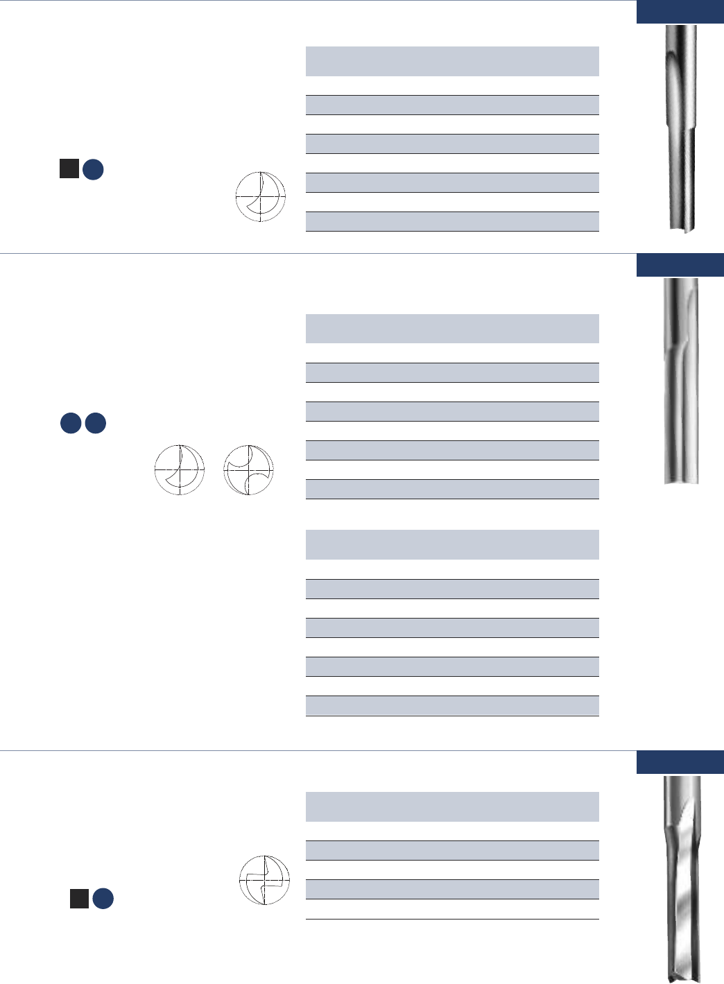
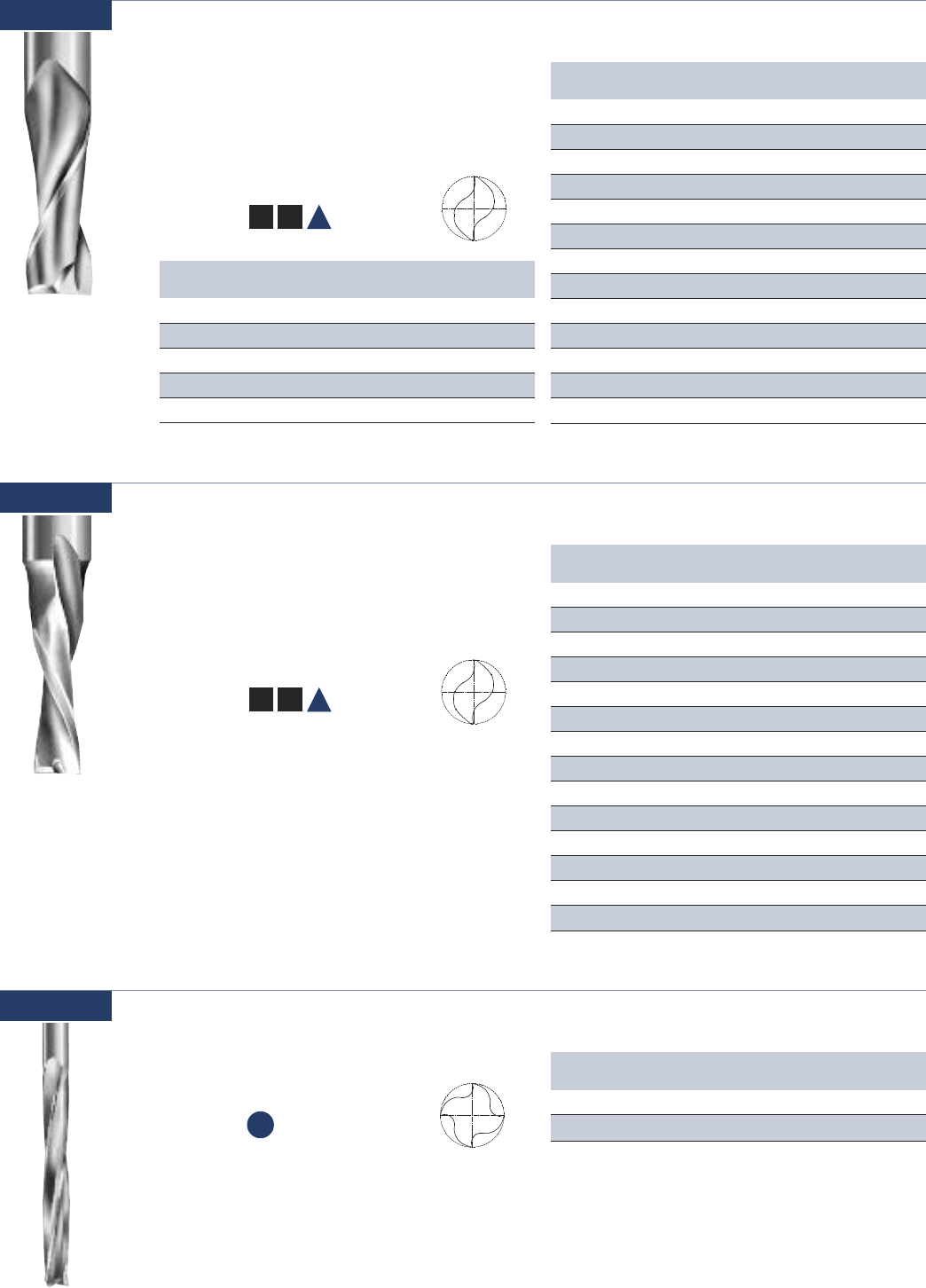
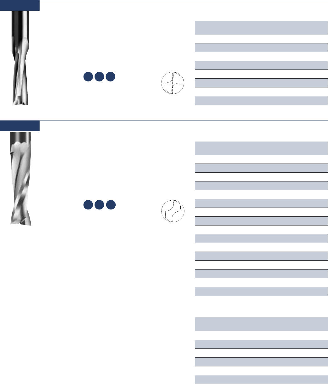
Single Flute - High Speed Steel O Flute Straight
Combines an open flute design with single flute
geometry to provide optimum chip removal at
fast feed rates. Excellent for hand-fed operations.
Single
Flute
Double
Flute
Usage ABS, polycarbonate, polyethylene, PVC,
polypropylene, polystyrene, extruded
acrylic, HDPE, UHMW, and natural wood
Material See Selection Guide - pg. 2 - 12
www.onsrud.com 14
Part Cutting Flute SHK OAL
Number DIA LGTH DIA
10-00 1/16 3/16 1/4 2
10-01 3/32 3/8 1/4 2
10-02 1/8 3/8 1/4 2
10-20 1/8 1/2 1/4 2
10-22 3/16 3/4 1/4 2
10-06 1/4 3/4 1/4 2-1/8
10-07 1/4 1 1/4 2-3/8
10-78 1/4 1-1/4 1/4 2-5/8
SW
SP
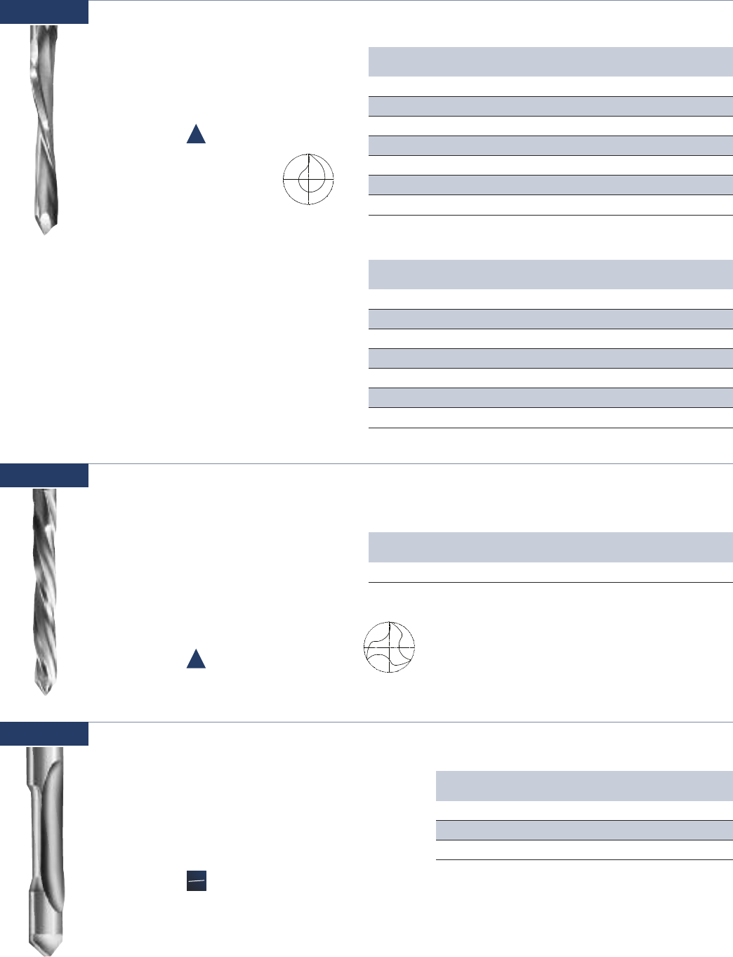
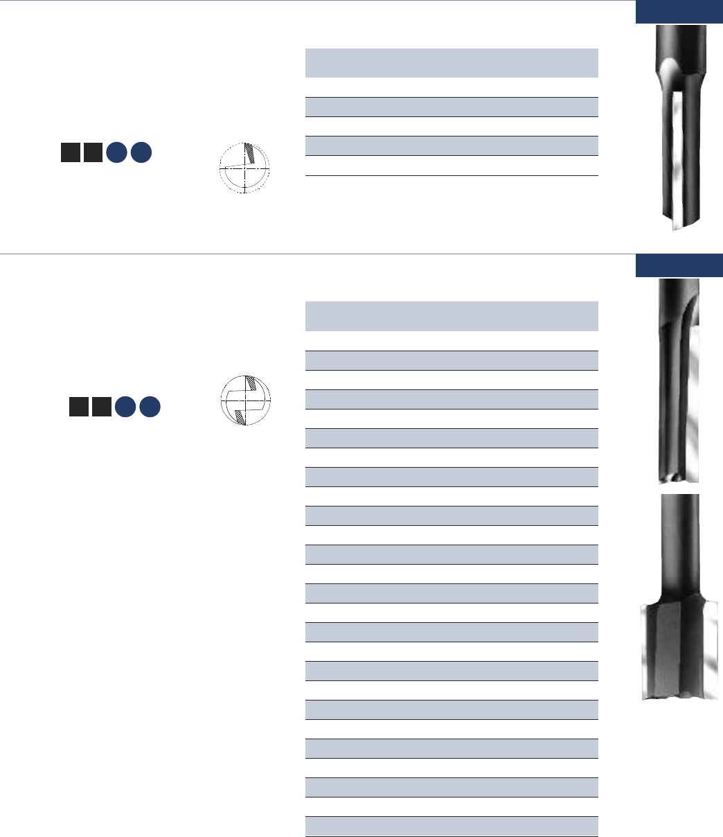
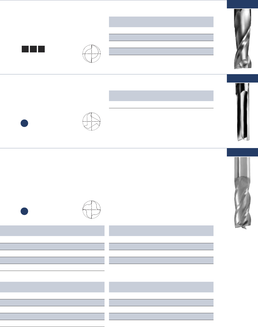
Single & Double Flute - High Speed Steel O Flute Straight
Designed for cutting softer more flexible plastics.
Single flute for faster feed rates. Double flute for
smoother finish. Excellent for hand-fed operations.
Usage ABS, polycarbonate, polyethylene,
polystyrene, PVC, polypropylene extruded
acrylic, HDPE, UHMW
Material See Selection Guide - pg. 2 - 12
Part Cutting Flute SHK OAL
Number DIA LGTH DIA
11-01 1/8 1/2 1/4 2
11-75* 1/8 5/8 1/4 3-1/4
11-03 3/16 5/8 1/4 3-1/4
11-77* 3/16 3/4 1/4 3-1/4
11-05 1/4 3/4 1/4 2-1/8
11-71* 1/4 3/4 1/4 3-1/4
11-07 1/4 1 1/4 2-3/8
11-09 3/8 1 3/8 2-1/2
SP HP
SINGLE FLUTE
Part Cutting Flute SHK OAL
Number DIA LGTH DIA
11-00 3/16 5/8 1/4 2
11-02 1/4 3/4 1/4 2-1/8
11-72* 1/4 3/4 1/4 3-1/4
11-76* 1/4 3/4 1/4 3-3/4
11-04 1/4 1 1/4 2-3/8
11-78* 1/4 2 1/4 3-1/4
11-06 3/8 1 3/8 2-1/2
11-74* 3/8 1 3/8 3-1/2
*These tools are designed and toleranced for Air Routers with guide bushing.
DOUBLE FLUTE
10-00
11-00
Part Cutting Flute SHK OAL
Number DIA LGTH DIA
12-00 1/4 3/4 1/4 2-1/8
12-79* 1/4 1 1/4 3-1/4
12-35 1/4 1 1/2 2-1/2
12-05 3/8 1 3/8 2-1/2
12-10 1/2 1-1/4 1/2 2-3/4
* These tools are designed and toleranced for Air Routers with guide bushing.
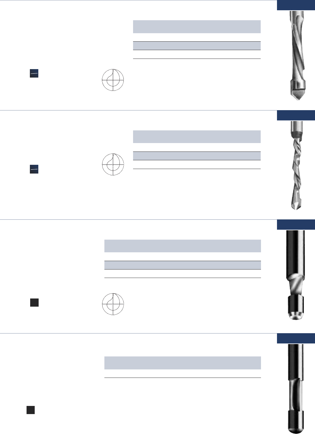
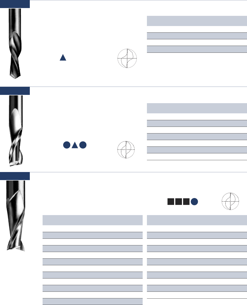
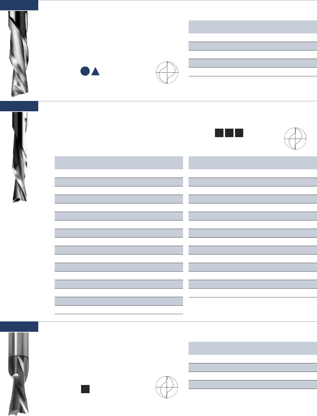
Usage Foam and natural wood
Material See Selection Guide - pg. 2 - 12
Double Flute - High Speed Steel V Flute Straight
These V flutes are often selected when a
balanced tool is critical for smooth finish.
A universal tool used in many environments.
Excellent for hand-fed applications.
HW
FP
12-00
15 www.onsrud.com
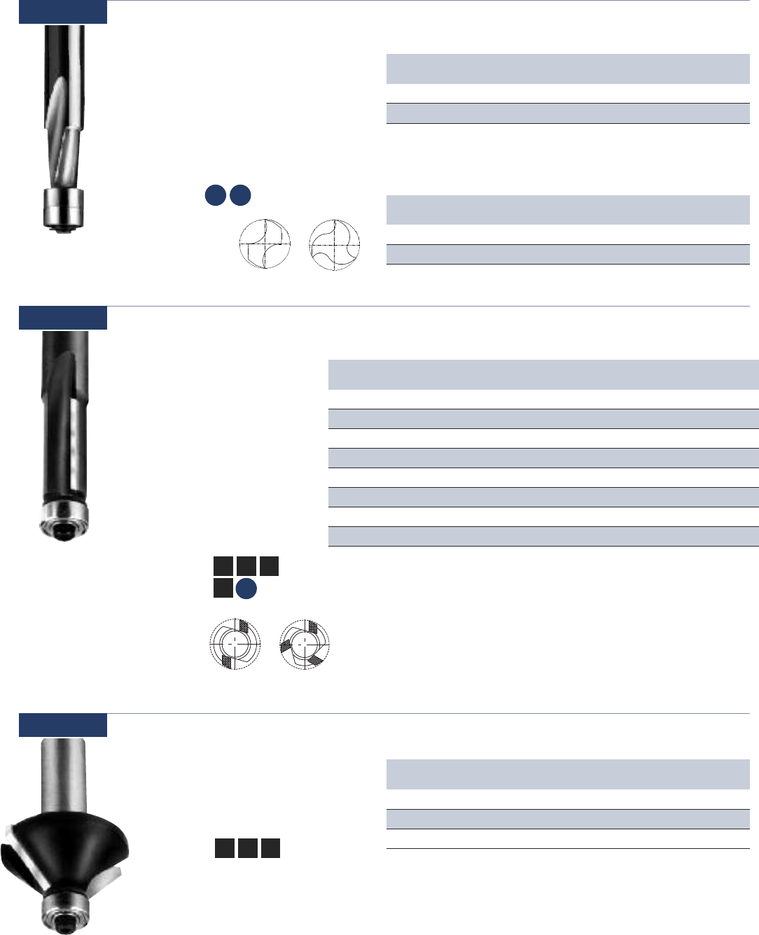
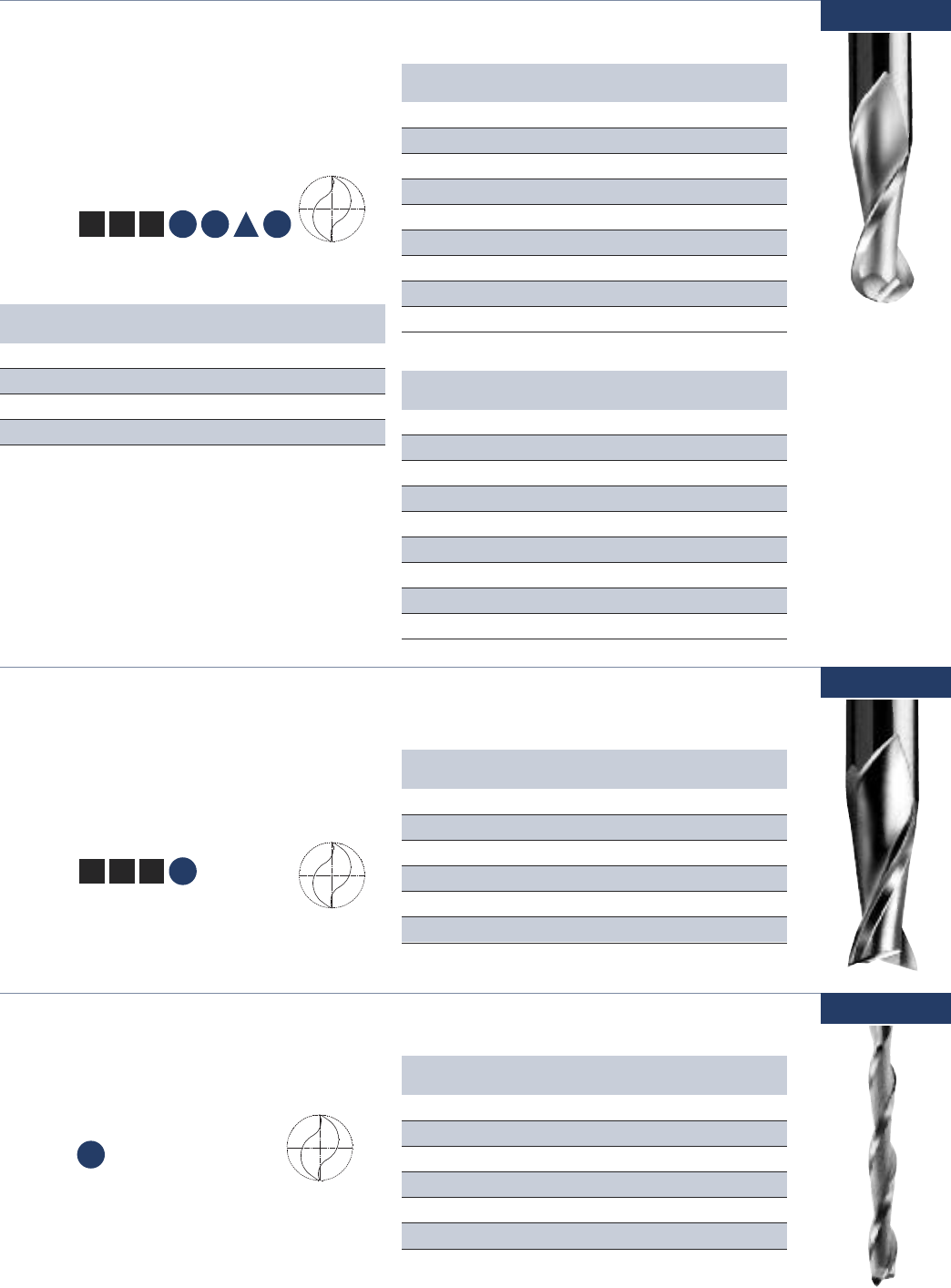
Single Flute - High Speed Steel Dor-Bits
Designed to rout steel doors.
Usage Metal clad doors
(15-50 and TIN15-50)
Fiberglass doors (TIN15-50)
Material See Selection Guide - pg. 2 - 12
Part Cutting Flute SHK OAL Door
Number DIA LGTH DIA Machine
15-52 1/2 2-1/4 1/2 5-1/4 RUVO
15-53 1/2 2-1/2 1/2 5-1/2 RUVO
15-54 1/2 2-1/2 1/2 5 ACE
15-55* 1/2 2-1/2 1/2 5-1/2 FALCON
15-57* 1/2 2-1/2 1/2 5-1/2 NORFIELD
15-60 1/2 2-1/2 1/2 5-1/2 RUVO
15-61* 1/2 2-1/2 1/2 5-1/2
HELIX ANGLE ≈ 18° - 32° *Have Flats
Part Cutting Flute SHK OAL Door
Number DIA LGTH DIA Machine
TIN15-52 1/2 2-1/4 1/2 5-1/4 RUVO
TIN15-53 1/2 2-1/2 1/2 5-1/2 RUVO
TIN15-54 1/2 2-1/2 1/2 5 ACE
TIN15-55* 1/2 2-1/2 1/2 5-1/2 FALCON
TIN15-57* 1/2 2-1/2 1/2 5-1/2 NORFIELD
TIN15-60 1/2 2-1/2 1/2 5-1/2 RUVO
TIN15-61* 1/2 2-1/2 1/2 5-1/2
*HAVE FLATS
D
TiN COATED
Part Cutting Flute SHK OAL Door
Number DIA LGTH DIA Machine
TIN15-75 1/2 3 1/2 6 KVAL
HELIX ANGLE
≈ 18°
TiN COATED
Three Flute - High Speed Steel TIN Coated CNC Dor-Bits
Downcut tools designed specifically
for machining metal clad doors in a
CNC environment. The tool geometry
facilitates piercing steel and produces
a superior cut for door lites and
hardware openings.
Usage Metal clad or fiberglass doors
Material See Selection Guide - pg. 2 - 12
D
15-50
15-75
Part Cutting Flute SHK OAL
Number DIA LGTH DIA
18-00 1/4 3/4 1/4 2-3/4
18-02 3/8 7⁄8 3/8 2-7⁄8
18-03 1/2 1 1/2 3-1/2
Usage Wood panels, vinyl coated panels, wall
board and aluminum layered materials
Material See Selection Guide - pg. 2 - 12
Single Flute - High Speed Steel Straight Pilot
Straight flute tools with boring points and pilots
are the workhorse of the mobile home, modular
home and RV industries.
18-00
CM
DW
www.onsrud.com 16
Single Flute - High Speed Steel Downcut Spiral Pilot
Spiral tools designed to push chips away
from the operator in mobile home and RV
manufacturing plants.
20-00
Usage Aluminum and plywood sandwich
panels, vinyl coated panels, wall
board, drywall and layered material
Material See Selection Guide - pg. 2 - 12
Part Cutting Flute SHK OAL
Number DIA LGTH DIA
20-00 1/4 3/4 1/4 3
20-02 3/8 1 3/8 3-7⁄16
20-03 1/2 1-1/4 1/2 4
HELIX ANGLE
≈ 21° - 38°
Part Cutting Flute SHK OAL Style
Number DIA LGTH DIA
27-00 1/4 1/4 1/4 1-1/2 Flush
27-01 1/4 1/4 1/4 1-1/2 7° Bevel
27-03 1/4 3/8 1/4 2 Flush
CM
DW
Single Flute - High Speed Steel Drywall Bit
Spiral flute tools designed to make cut outs in
drywall. Used in manufactured housing and on
site construction.
20-10
Usage Drywall cut outs
Material See Selection Guide - pg. 2 - 12
Part Cutting Flute SHK OAL
Number DIA LGTH DIA
20-10 3/16 1 1/4 3-1/4
20-11 1/8 3/4 1/8 2-1/2
20-15 1/8 1 1/8 2-1/2
HELIX ANGLE
≈ 30° - 41°
CM
DW
Single Flute - Solid Carbide Laminate Trim
Designed to trim counter tops. The
pilot bears on the finished surface and
acts as a guide to trim flush or with a
bevel. Available with boring point if
necessary to plunge and rout.
27-00
Usage Trimming laminate counter tops
and trimming plastic parts
Material See Selection Guide - pg. 2 - 12
LW
Part Cutting Flute SHK OAL Style
Number DIA LGTH DIA
27-50 1/4 7⁄16 1/4 1-5/8 Flush
Double Flute - Solid Carbide Laminate Trim
Tools with a pilot designed to give
a satin smooth finish when trimming
laminate counter tops.
Usage Trimming laminate counter
tops and trimming plastic
parts
Material See Selection Guide - pg. 2 - 12
27-50
LW
17 www.onsrud.com
Part Cutting Flute SHK OAL Flute
Number DIA LGTH DIA
28-20 1/4 3/4 1/4 32
28-25 1/2 1-1/8 1/2 42
HELIX ANGLE
≈ 11° - 30°
REPLACEMENT BEARING KITS FOR SERIES 28-20
Solid Carbide Double Bearing Plastic Trim Tool Kits
28-89 KIT for 28-20 Tool
28-88 KIT for 28-25 Tool
Solid Carbide Double-Bearing Plastic Trim
Spirals designed to trim stacked sheets
of plastic in hand-fed applications.
They use a double bearing guide to
ensure smooth cutting action around
a template.
Usage Trimming stacked sheets
plastic & laminates
Material See Selection Guide - pg. 2 - 12
28-20
SP HP
Double Flute Three Flute
Double Flute Three Flute
Part Cutting Flute SHK OAL Flute
Number DIA LGTH DIA
28-55 1/4 1 1/4 2-1/2 2
28-51 3/8 1/2 1/4 2-1/4 2
28-50 3/8 1 1/4 2-3/4 2
28-53 1/2 1/2 1/4 22
28-57 1/2 1 1/4 2-3/4 3
28-54 1/2 1 1/2 3-1/4 2
28-63 1/2 1-1/2 1/2 4-1/4 2
28-64 1/2 2 1/2 4-1/4 2
Carbide Tipped Flush Trim
Designed to provide
a smooth finished edge
on dense, abrasive and
laminated materials. A ball
bearing guide assists free
cutting action. Excellent
for hand-fed applications.
Usage Natural wood,
wood composites,
laminated and
veneered
Material
See Selection Guide - pg. 2 - 12
28-50
SW HW CW
LW
SP
Usage Natural wood and
wood composites
Material
See Selection Guide - pg. 2 - 12
Part Bevel Flute SHK OAL
Number LGTH DIA
29-51 45° 1/2 1/4 2
29-52 45° 1/2 1/2 2-1/2
29-53 25° 3/8 1/4 1-7⁄8
Double Flute - Carbide Tipped Chamfer
Provides a beveled or decorative
edge on finished parts.
29-50
SW HW CW

www.onsrud.com 18
Part TIP Angle SHK OAL
Number DIA
37-01 0.005 60 1/4 2
37-03 0.010 60 1/4 2
37-05 0.020 60 1/4 2
37-07 0.030 60 1/4 2
37-09 0.040 60 1/4 2
37-11 0.060 60 1/4 2
37-15 0.090 60 1/4 2
37-19 60 Degree Kit
Part TIP Angle SHK OAL
Number DIA
37-21 0.005 30 1/4 2
37-23 0.010 30 1/4 2
37-25 0.020 30 1/4 2
37-27 0.030 30 1/4 2
37-29 0.040 30 1/4 2
37-31 0.060 30 1/4 2
37-35 0.090 30 1/4 2
37-39 30 Degree Kit
Usage Wood, plastic, aluminum
and solid surface
Material
See Selection Guide - pg. 2 - 12
Single Flute - Solid Carbide Engraving Tools
The half round engraving tools are offered
with a wide range of tip sizes and angles to
accommodate many engraving styles.
37-00
37-20
SW HW
SP HP SSP
A
Part TIP Angle SHK OAL
Number DIA
37-05M 0.5mm 60 6mm 50mm
37-07M 0.76mm 60 6mm 50mm
37-09M 1mm 60 6mm 50mm
METRIC
Part TIP Angle SHK OAL
Number DIA
37-25M 0.5mm 30 6mm 50mm
37-27M 0.76mm 30 6mm 50mm
37-29M 1mm 30 6mm 50mm
METRIC
37-50
37-60
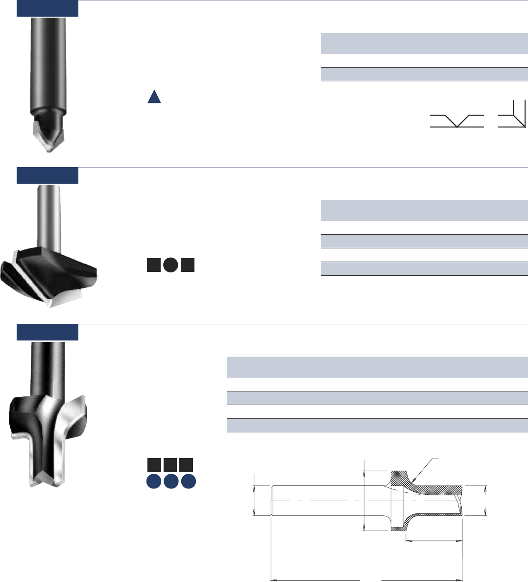
Double Flute - V Bottom
Designed for V grooving or beveling 90°.
Usage Plastic and solid surface, composites,
laminated and veneer
Material
See Selection Guide - pg. 2 - 12
Part Cutting Flute SHK OAL
Number DIA LGTH DIA
37-50 3/16 5/8 1/4 2
37-51 1/4 3/4 1/4 2
37-52 3/8 3/4 3/8 2-1/2
HELIX ANGLE ≈ 3° - 5° Shear
SOLID CARBIDE
Part Cutting Flute SHK OAL
Number DIA LGTH DIA
37-61 1/2 13⁄32 1/4 1-25 ⁄ 32
37-62 3/4 1/2 1/2 2-1/8
37-63 1 27⁄32 1/2 2-27⁄ 32
CARBIDE TIPPED
SW HW CW LW
SP HP SSP
19 www.onsrud.com
Double Flute - Carbide Tipped Folding Tool for Dibond/Alucobond
Designed for cutting aluminum/plastic sandwich
materials with 90° angle and flat bottom.
Usage Aluminum/plastic sandwich materials
Material See Selection Guide - pg. 2 - 12
Part Cutting Flute SHK OAL
Number DIA LGTH DIA
37-71 1/2 3/8 1/4 2
37-72 1/2 3/8 1/2 2
37-70
A
90° angle and .090 flat for folding material
Part Cutting Flute SHK OAL ANGLE
Number DIA LGTH DIA
37-82 1 0.856 1/2 3-1/2 60º
37-87 1-1/2 0.750 1/2 3 90º
37-92 2 0.577 1/2 3 120º
37-97 2 0.363 1/2 2-5/8 140º
Double Flute - Carbide Tipped Lettering Bits
Designed for V grooving or beveling edges of
parts. The tools are designed to cut a wide variety
of wood products and produce a clean edge.
37-80
Usage Wood
Material See Selection Guide - pg. 2 - 12
SW CW
HW
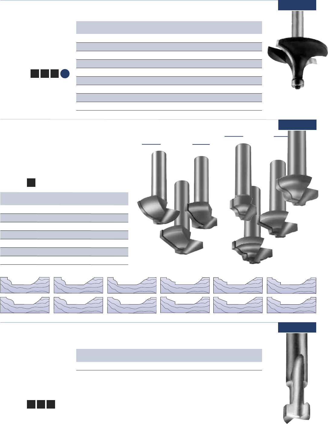
Double Flute - Carbide Tipped Round & Rout
Designed to put a radius
on the edge and dress the
stock. They will provide a
smooth finish.
40-50
Usage Natural wood,
wood composites,
plastic and
solid surface
Material
See Selection Guide - pg. 2 - 12
SW HW CW
SP HP SSP
Part Cutting Sm Cutting Flute SHK OAL RAD Material
Number DIA DIA LGTH DIA Thickness
40-50 1 1/2 .938 1/2 3-3/16 3/16 3/4
40-52 1-1/8 1/2 .937 1/2 3-3/16 1/4 3/4
40-54 1-3/8 1/2 .938 1/2 3-3/16 3/8 3/4
40-55 1-3/8 1/2 1.437 1/2 3-11/16 3/8 1-3/8
Cutting DIA
SHK DIA
Radius
Sm Cutting DIA
OAL
Flute LGTH
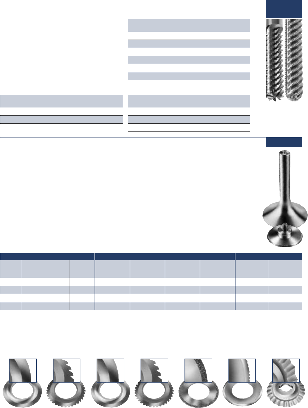
T Slot
Designed to bore a hole
and rout a T shape slot
for plaques and frames
to provide for built in wall
mounting capabilities.
90-00
Usage Natural wood,
wood composites
Material
See Selection Guide - pg. 2 - 12
SW HW CW
Part Cutting Flute Neck SHK OAL Flutes
Number DIA LGTH DIA
90-06 3/8 3/8 3/16 1/4 1-5/8 2
SOLID CARBIDE
www.onsrud.com 20
Usage Natural wood,
wood composites
and solid surface
Material
See Selection
Guide - pg. 2 - 12
Double Flute - Carbide Tipped Corner Round
Quarter round profile tools
feature up shear geometry
for better finishes.
42-00
Part Radius Cutting Flute SHK OAL
Number DIA LGTH DIA
42-10 1/8 3/4 3/8 1/4 2-1/8
42-03 5/32 13/16 15/32 1/4 2-3/32
42-01 3/16 7/8 1/2 1/4 2
42-02 1/4 1 7/16 1/4 1-29/32
42-04 5/16 1-1/8 9/16 1/4 2-1/4
42-05 3/8 1-1/4 5/8 1/4 2-1/32
42-06 1/2 1-1/2 3/4 1/4 2-5/32
42-07 1/2 1-1/2 3/4 1/2 2-11/16
42-08 3/4 2 1-1/32 1/2 3
SW HW CW
SSP
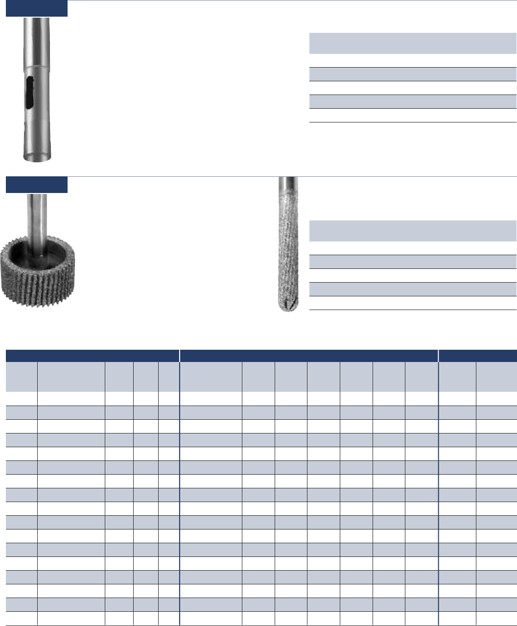
STILE BITS
PANEL BITS
TOOL COMBINATIONS
47-02 & 47-12
47-02 & 47-1047-02 & 47-14
47-04 & 47-12
47-04 & 47-10 47-04 & 47-14
Part Cutting SHK OALDescription
NumberDIA DIA
47-02 7/8 1/2 2-1/2
Bead Profile - Stile Bits
47-04 1-1/4 1/2 2-1/2
T
raditional Profile - Stile Bits
47-06 1-1/4 1/2 2-1/2
Ogee Profile - Stile Bits
47-08 1-1/4 1/2 2-1/2
Straight Profile - Stile Bits
47-10 1-1/2 1/2 2-1/2
Cove Profile - Panel Bits
47-12 1-1/2 1/2 2-1/2
Straight Profile - Panel Bits
47-14 1-1/2 1/2 2-1/2
Ogee Profile - Panel Bits
Double Flute - Carbide Tipped MDF Panel Tools
These cutters can create 12 cabinet combinations
by combining different stile and panel cutters to
get the desired shape in MDF material.
Usage MDF
MaterialSee Selection Guide - pg. 2 - 12
CW
47-00
47-06 & 47-12
47-06 & 47-1047-06 & 47-14
47-08 & 47-12
47-08 & 47-1047-08 & 47-14
21 www.onsrud.com
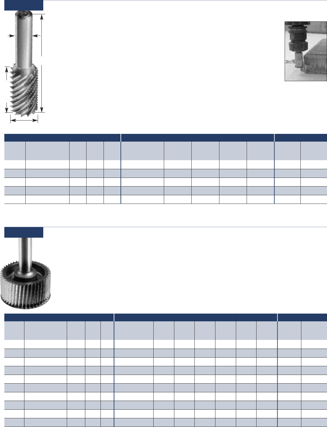
HSS Hollow Core Cutters
This specialized cutter is designed to vertically
cut the honeycomb cells producing a clean,
flag free edge. The core material will remain
attached at the bottom and can be removed
using one of our valve style honeycomb cutters.
This product along with our 31-100 or 30-000
series tools is an effective combination to create
pockets in honeycomb core and get a perfectly
clean edge.
29-000
Usage Honeycomb
Part Cutting Flute SHK OAL
Number DIA LGTH DIA
29-003 1/4 1-1/2 1/4 3-3/4
29-006 3/8 1-7/8 3/8 3-3/4
29-009 1/2 2-7/8 1/2 5
29-012 5/8 2-7/8 5/8 5
29-015 3/4 2-7/8 3/4 5
Part Cutting Flute SHK OAL
Number DIA LGTH DIA
29-053 1/4 (6.35mm) 1 1/4 1/4 4
29-058 3/8 (9.52mm) 2 1/2 1/2 4
29-063 1/2 (12.7mm) 3 1/2 5
29-068 3/4 (19.05mm) 3 1/2 5
29-074 1 (25.4mm) 2 3/4 4
Diamond Grit Hogger
Diamond grit hoggers are used on abrasive
cores (graphite, phenolic, or fiberglass) in
order to achieve long tool life. The tools are
available in a ball nose version and as a
traditional hogger capable of holding
existing honeycomb blades. A 35% weight
reduction has been designed into the larger
diameter tools resulting in better performance
on 3 or 5 axis machines.
29-050
Usage Honeycomb
Hogger Shank HSS Solid Solid Diamond HSS Adapter
Part # Cutting Diameter Depth DIA OAL Blade Diameter HSS w/Teeth Carbide Carbide Plated Saw Ring Screw
w/Teeth
29-052 1/4 (6.35mm) 1 1/4 1/4 4- --------
29-057 .345 (8.76mm) 2 1/2 1/2 4 3/8 (9.52mm) 30-016 30-316 ---- -HRD51646
29-062 .470 (11.94mm) 3 1/2 5 1/2 (12.7mm) 30-017 30-317 ---- -HRD51646
29-067 .720 (18.28mm) 3 1/2 5 3/4 (19.05mm) --30-015 30-318 -- -30-011-2
29-072 .970 (24.63mm) 1 1/2 3 1 (25.4mm) --30-012 30-313 30-113 30-213 - 30-011-2
29-0731.970 (24.63mm) 2 3/4 5 1 (25.4mm) --30-012 30-313 30-113 30-213 - 30-011-2
29-078 1.470 (37.33mm) 1 1/2 3 1 1/2 (38.10mm) --30-014 30-314 30-114 30-214 30-020-3 30-020-4
29-07911.470 (37.33mm) 2 3/4 5 1 1/2 (38.10mm) --30-014 30-314 30-114 30-214 30-020-3 30-020-4
29-083 1.742 (44.24mm) 1 1/2 3 1.772 (45mm) --30-026 30-326 30-126230-226230-020-3 30-020-4
29-08411.742 (44.24mm) 2 3/4 5 1.772 (45mm) --30-026 30-326 30-126230-226230-020-3 30-020-4
29-088 1.970 (50.03mm) 1 5/8 3 2 (50.8mm) --30-022 30-322 30-122 30-222 30-020-3 30-020-4
29-08911.970 (50.03mm) 2 3/4 5 2 (50.8mm) --30-022 30-322 30-122 30-222 30-020-3 30-020-4
29-093 2.450 (62.23mm) 1 5/8 3 2.480 (63mm) --30-036 30-336 30-136 30-236 30-030-3 30-030-4
29-095 2.970 (75.43mm) 1 3/4 3 3 (76.20mm) --30-032 30-332 30-132 30-232 30-030-3 30-030-4
29-09612.970 (75.43mm) 1 3/4 4 3 (76.20mm) --30-032 30-332 30-132 30-232 30-030-3 30-030-4
29-098 3.970 (100.83mm) 1 3/4 3 4 (101.6mm) --30-042 30-342 30-142 30-242 30-040-3 30-040-4
29-09913.970 (100.83mm) 1 3/4 4 4 (101.6mm) --30-042 30-342 30-142 30-242 30-040-3 30-040-4
1 = non-stock standard. 4 week lead time
2 = 50mm diameter honecomb blade
HONEYCOMB HOGGER CUTTING BLADE OPTIONS SPARE PARTS
BALL NOSE
See page 22 or 24 for Images of Cutting Blades
See Page 72 for Wrench and Torque Spec
www.onsrud.com 22
Solid Carbide Honeycomb Hogger (Coated)
Designed to be a versatile tool and cut most
honeycomb core materials. The solid carbide
body offers long tool life while the proven hogger
geometry shreds the core and evacuates chips.
The long flute length allows for deep pocket
applications and can also be used to surface
large areas. Hoggers are coated with ZRN.
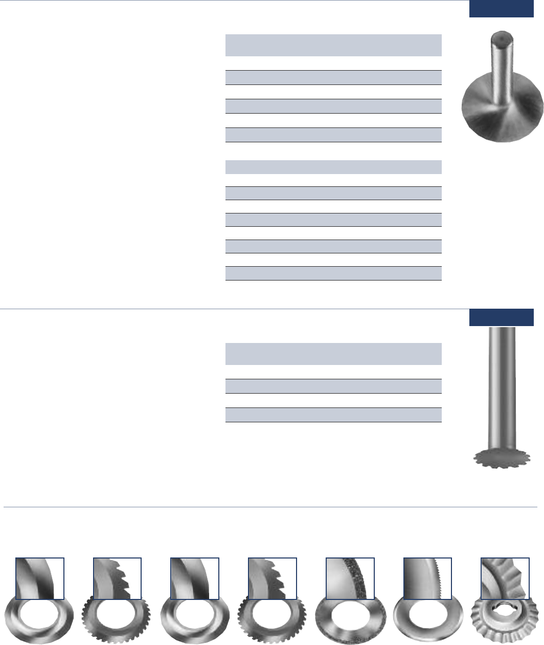
Replaceable Ring Type Honeycomb Cutter 30-000
Usage Honeycomb
Part Cutting Flute SHK OAL
Number DIA LGTH DIA
29-110 1/4 (6.35mm) 1-1/4 1/4 4
29-115 3/8 (9.52mm) 2 3/8 4
29-125 1/2 (12.7mm) 3 1/2 6
29-130 1/2 (12.7mm) 4-1/2 1/2 6-1/2
29-140 3/4 (19.05mm) 3 3/4 6
29-145 3/4 (19.05mm) 4-1/2 3/4 6-1/2
Shank Solid Carbide
Part # Blade Diameter DIA Solid Carbide with Teeth Diamond Plated HSS Saw Adapter Ring Screw
30-011 1” (25.4mm) 1/2 30-012 30-313 30-112 30-213 - 30-011-2
30-021 2” (50.8mm) 1/2 30-022 30-322 30-122 30-222 30-020-3 30-020-4
30-031 3” (76.2mm) 1/2 30-032 30-332 30-132 30-232 30-030-3 30-030-4
30-041 4” (101.6mm) 1/2 30-042 30-342 30-142 30-242 30-040-3 30-040-4
SHANK ASSEMBLY CUTTING BLADE OPTIONS SPARE PARTS
Part Cutting Flute SHK OAL
Number DIA LGTH DIA
29-120 12 (.472”) 60 12 150
29-135 16 (.629”) 80 16 150
METRIC
Part Cutting Flute SHK OAL
Number DIA LGTH DIA
29-130B 1/2 (12.7mm) 4-1/2 1/2 6-1/2
29-140B 3/4 (19.05mm) 3 3/4 6
29-145B 3/4 (19.05mm) 4-1/2 3/4 6-1/2
BALLNOSE
These tools are for contouring, carving and chamfering
cuts of .25" or less. The unique patented holding system
prevents the solid carbide blades from coming out of the
holder if it is fractured.
The HSS saw blades and the diamond plated blades dish
on the bottom so they clear the cut core finish like the
hollow ground solid carbide style rings. The solid carbide
rings may be reground several times at the factory making
them very economical to use.
The HSS saw and diamond plated blades are disposable,
offering the convenience of a constant diameter.
Usage For contouring, carving and
chamfering cuts
29-100/
29-100B
See page 22 or 24 for Images of Cutting Blades
See Page 72 for Wrench and Torque Spec
Cutting Blades for Cutters and Hoggers
PM-HSS
Wavy Ring
Solid CarbideHSS HSS with Teeth Solid Carbide
with Teeth Diamond Plated HSS Saw
23 www.onsrud.com
Hogger Shank HSS Solid Solid Diamond HSS Adapter
Part # Cutting Diameter Depth DIA OAL Blade Diameter HSS w/Teeth Carbide Carbide Plated Saw Ring Screw
w/Teeth
30-703 .345 (8.76mm) 1 1/2 3 3/8 (9.52mm) 30-016 30-316 ---- -HRD51646
30-705 .470 (11.93mm) 1 1/2 3 1/2 (12.7mm) 30-017 30-317 ---- -HRD51646
30-707 .720 (18.28mm) 1 1/2 3 3/4 (19.05mm) --30-015 30-318 -- -30-011-2
30-710 .970 (24.63mm) 1 1/2 3 1 (25.4mm) --30-012 30-313 30-113 30-213 - 30-011-2
30-715 1.470 (37.33mm) 1 1/2 3 1 1/2 (38.10mm) --30-014 30-314 30-114 30-214 30-020-3 30-020-4
30-720 1.742 (44.24mm) 1 1/2 3 1.772 (45mm) --30-026 30-326 30-126130-226130-020-3 30-020-4
30-725 1.970 (50.03mm) 1 5/8 3 2 (50.8mm) --30-022 30-322 30-122 30-222 30-020-3 30-020-4
30-730 2.450 (62.23mm) 1 5/8 3 2.480 (63mm) --30-036 30-336 30-136 30-236 30-030-3 30-030-4
30-735 2.970 (75.43mm) 1 3/4 3 3 (76.20mm) --30-032 30-332 30-132 30-232 30-030-3 30-030-4
30-740 3.970 (100.83mm) 1 3/4 3 4 (101.6mm) --30-042 30-342 30-142 30-242 30-040-3 30-040-4
1 = 50mm diameter honecomb blade
HONEYCOMB HOGGER CUTTING BLADE OPTIONS SPARE PARTS
Hogger Shank Solid Solid Diamond HSS Adapter
Part # Cutting Diameter Depth DIA OAL Blade Diameter Carbide Carbide Plated Saw Ring Screw
w/Teeth
30-310 7/8 (22.22mm) 1 1/2 1/2 3 1/2 1 (25.4mm) 30-012 30-313 30-113 30-213 - 30-011-2
30-315 1 1/4 (31.75mm) 1 1/2 1/2 3 1/2 1 1/2 (38.1mm) 30-014 30-314 30-114 30-214 30-020-3 30-020-4
30-321 1 3/4 (44.45mm) 1 1/2 1/2 3 1/2 2 (50.8mm) 30-022 30-322 30-122 30-222 30-020-3 30-020-4
30-331 2 3/4 (69.85mm) 1 1/2 3 1/2 3 (76.2mm) 30-032 30-332 30-132 30-232 30-030-3 30-030-4
30-341 3 3/4 (95.25mm) 1 3/4 3 1/2 4 (101.6mm) 30-042 30-342 30-142 30-242 30-040-3 30-040-4
Shank Diameter
Cutting Diameter
Hogger
Depth
OAL
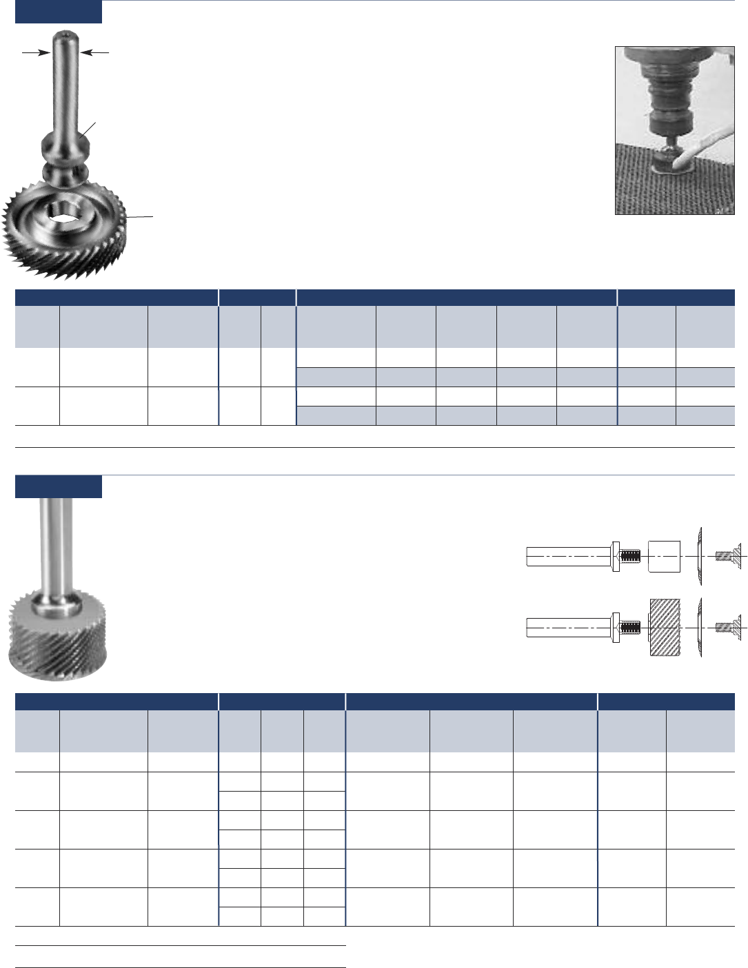
HSS Integral Shank Honeycomb Hogger Cutter
30-300
High Speed Steel Hoggers • High Speed Replaceable Saw Blade
Solid Carbide Replaceable Blade • Diamond Plated Replaceable Blade
The spiral hogger geometry ground integral to the shank allows for faster
feed rates and deeper cuts than any previous cutter. The availability of
several different blades makes this cutter suitable for most core types. The
hogger design also imparts less force as it evacuates and shreds scrap.
Usage CNC machining of honeycomb core
HONEYCOMB HOGGER CUTTING BLADE OPTIONS SPARE PARTS
Reduced Weight Honeycomb Cutter
30-700
35% weight reduction has been designed into the larger
diameter tools resulting in better performance on 3 or 5
axis machines. Part lifting and flagging have also been
reduced due to the new tooth and flute design. Existing
honeycomb blades will mount on these hoggers.
Usage CNC Machining of
Honeycomb Core
See page 22 or 24 for Images of Cutting Blades
See Page 72 for Wrench and Torque Spec
See page 22 or 24 for Images of Cutting Blades
See Page 72 for Wrench and Torque Spec
www.onsrud.com 24
High Speed Steel Cutter
Designed primarily for use on aluminum core,
offering the versatility of smaller sizes for use
on hand-held machines in field or maintenance
type repairs. This cutter offers the strength of
an integral shank and blade that has an edge
sharpness unattainable with any other material.
This sharpness and the relieved bottom yield
part surfaces that require a minimum of
preparation before bonding operation.
31-000
Usage Aluminum Core
Part Cutting SHK OAL
Number DIA DIA
31-010 1/2 1/4 2-1⁄16
31-015 3/4 1/4 2-3/32
31-020 1 1/4 2-1/8
31-025 1-1/2 1/2 2-1/4
31-030 2 1/2 2-3/4
31-040 3 1/2 2-15/16
Core Type Rating
Aluminum, Lo Density (Less than 5#/cuft) 1
Aluminum, Hi Density (More than 5#/cuft) 2
Paper 2
Paper, Reinforced N
Fiberglass N
Phenolic N
Polycarbonate N
Aramid N
1 - Excellent, 2 - Good, N - Not Recommended
High Speed Steel Honeycomb Cutter With Teeth
Small diameter honeycomb cutters were
designed to offer the flexibility of cutting
small slots or pockets in honeycomb core.
The tools are versatile and can be used on
CNC machines or hand held machines for
field or maintenance type repairs.
31-100
Usage For contouring, carving, pocketing,
and chamfer cuts
Part Cutting SHK OAL
Number DIA DIA
31-102TCN 3/8 1/4 3
31-104TCN 1/2 1/4 3
31-106TCN 5/8 1/4 3
31-108TCN 3/4 1/4 3
Cutting Blades for Cutters and Hoggers
PM-HSS
Wavy Ring
Solid CarbideHSS HSS with Teeth Solid Carbide
with Teeth Diamond Plated HSS Saw
32-200
25 www.onsrud.com
Hogger
Shank
1/2”
Hogger Shank Solid Diamond HSS Wavy HSS Adapter
Part # Cutting Diameter Depth Part # DIA Blade Diameter Carbide Plated Ring Saw Ring Screw
32-022 1.732 (44mm) .629 (16mm) 32-021 1/2 1.771 (45mm) 32-026 - 32-023 -- -
1.968 (50mm) - 32-029* - 32-027* 32-028 -
32-032 2.421 (61.5mm) .629 (16mm) 32-031 1/2 2.480 (63mm) 32-036 - 32-033 -- -
2.952 (75mm) - 32-039* - 32-037* 32-038 -
32-100 - Wrench for 32-000 Tools
See page 13 or 15 for Images of Cutting Blades
* Requires Adapter Ring
HONEYCOMB HOGGER SHANK CUTTING BLADE OPTIONS SPARE PARTS
High Speed Steel Hogger
These cutters are specifically designed for fast (low force) removal of excess
core followed by a final finish pass to obtain excellent finishes with one tool.
These cutters enable cuts of up to .60” depths in a single pass. The availability
of several different blades makes this cutter suitable for most core types.
All assemblies require a shank, hogger and blade.
32-000
Usage Fast removal of excess core
Hogger Shank OAL Solid Solid Carbide Retaining
Part # Cutting Diameter Depth Part # DIA Blade Diameter Carbide w/Teeth Spacer Screw
32-210 0.94" (23.88mm) 1" (25.4mm) 32-221 3/8" 4" 1" (25.4mm) 32-412 32-512 32-221-3 32-221-4
32-225 1.94" (49.28mm) 1" (25.4mm) 32-231 1/2" 4" 2" (50.8mm) 32-422 32-522 32-231-3 32-231-4
32-241 5/8" 4"
32-235 2.94" (74.68mm) 1" (25.4mm) 32-231 1/2" 4" 3" (76.2mm) 32-432 32-532 32-231-3 32-231-4
32-241 5/8" 4"
32-220 1.72" (43.69mm) 1" (25.4mm) 32-231 1/2" 4" 1.77" (45mm) 32-426 32-526 32-231-3 32-231-4
32-241 5/8" 4"
32-230 2.42" (61.47mm) 1" (25.4mm) 32-231 1/2" 4" 2.48" (63mm) 32-436 32-536 32-231-3 32-231-4
32-241 5/8" 4"
32-201 - Wrench for 32-200 Tools (for Shank Diameters 1/2” & 5/8”)
32-202 - Wrench for 32-200 Tools (for Shank Diameters 3/8”)
HONEYCOMB HOGGER SHANK CUTTING BLADE OPTIONS SPARE PARTS
HSS Three Piece Honeycomb Hogger (Coated)
Designed with more aggressive hogger geometry than the 32-000
series. Both the hogger and blade with teeth have a fine tooth grind
pattern resulting in increased feed rates and improved part finish.
All hoggers and blades are coated with a ZRN coating for increase
in tool life. All hogger assemblies require a shank, a hogger and a
blade. This design also allows the tool to be use without the hogger
by replacing the hogger with a spacer. Torque Spec = 18 in-lb.
Usage Fast removal of excess core
Arbor
Arbor
Spacer
Hogger Blade
Blade
Screw
Screw
See page 13 or 15 for
Images of Cutting Blades
www.onsrud.com 26
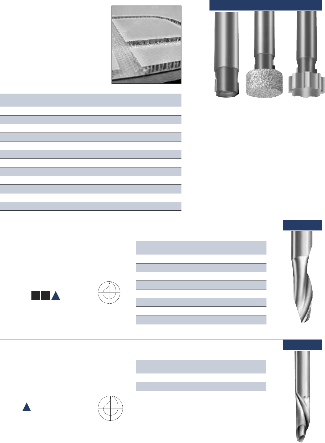
Aircraft Panel Tools
This modular tool is designed to
produce slots in composite panels
so potting compound can be applied
to strengthen the edge. This tool
consists of a PCD arbor which
accepts a diamond grit or HSS under
cutting tool to be screwed into it.
Part Cutting Flute SHK
Number DIA LGTH DIA
34-008 1/2 - 1/2 Arbor (non-cutting)
34-010 1/2 1/4 1/2 PCD Arbor
34-022 7/8 0.130 n/a Diamond Grit Cutter
34-024 7/8 0.250 n/a Diamond Grit Cutter
34-026 7/8 0.380 n/a Diamond Grit Cutter
34-028 7/8 0.500 n/a Diamond Grit Cutter
34-030 7/8 0.630 n/a Diamond Grit Cutter
34-042 7/8 0.130 n/a HSS Cutter
34-044 7/8 0.250 n/a HSS Cutter
34-046 7/8 0.380 n/a HSS Cutter
34-048 7/8 0.500 n/a HSS Cutter
34-050 7/8 0.630 n/a HSS Cutter
Usage HCC Panels
Arbor HSSDiamond
Grit
Part Cutting Flute SHK OAL
Number DIA LGTH DIA
40-001 1/8 3/8 1/4 2-5/8
40-003 3/16 5/8 1/4 2-7/8
40-005 1/4 5/8 1/4 2-3/4
40-009 1/4 3/4 1/2 3-1/4
40-021 5/16 3/4 1/2 3-1/4
40-023 5/16 1 1/2 3-1/2
40-025 21⁄64 3/4 1/2 3-1/4
40-033 3/8 1 1/2 3-1/2
HELIX ANGLE ≈19° - 32° Shear
Usage Natural wood, sheet and
stacked aluminum
Material
See Selection Guide - pg. 2 - 12
Single Flute - High Speed Steel Upcut Spiral
Designed for routing applications where speed
and chip removal are primary considerations.
They are also recommended when grooving,
slotting or blind routing.
40-000
Single Flute - High Speed Steel Downcut Spiral
Designed for through cut routing operations
where speed is the primary concern and
fixturing is such that both chips and material
are better off forced down.
40-000
Usage Sheet aluminum
Material See Selection Guide - pg. 2 - 12
Part Cutting Flute SHK OAL
Number DIA LGTH DIA
40-008 1/4 3/4 1/4 2 3/4
40-012 1/4 1 1/4 3
HELIX ANGLE ≈ 19° - 32° Shear
34-000
SW HW
A
A
27 www.onsrud.com
SW HW
A
Part Cutting Flute SHK OAL
Number DIA LGTH DIA
40-102 1/8 5/16 1/4 2-5/8
40-104 3/16 5/8 1/4 2-7/8
40-106 1/4 5/8 1/4 2-3/4
40-108 1/4 3/4 1/4 2-3/4
40-110 1/4 3/4 1/2 3-1/4
40-112* 1/4 1 1/4 3
40-158* 1/4 1 1/4 3-1/4
40-122 5/16 3/4 1/2 3-1/4
40-116 5/16 1 5/16 3
40-124 5/16 1 1/2 3-1/2
40-134 3/8 1 1/2 3-1/2
40-138 1/2 1-1/4 1/2 3-1/4
40-140 1/2 1-1/2 1/2 3-1/2
40-142 3/4 1-1/4 1/2 3-1/4
HELIX ANGLE ≈ 19° - 32° Shear
* These tools are designed and toleranced for air routers with guide bushings.
Usage Natural wood sheet &
aluminum extrusions
Material
See Selection Guide - pg. 2 - 12
Double Flute - High Speed Steel Downcut Spiral
Provides a smoother finish than single flute in
trimming and sizing. Recommended when chip
flow should be directed down to protect the finish
on the top of the material being cut.
40-100
Usage Foam
Material See Selection Guide - pg. 2 - 12
FP
Part Cutting Flute SHK OAL
Number DIA LGTH DIA
40-562 1/2 3-5/8 1/2 6
40-564 1/2 4-1/8 1/2 6-1/2
HELIX ANGLE ≈ 25°
Four Flute - High Speed Steel Upcut Spiral Foam Cutters
Designed to cut thick foam with upward chipflow.
40-550
SW HW
A
Part Cutting Flute SHK OAL
Number DIA LGTH DIA
40-107 1/4 3/4 1/4 2-3/4
40-109 1/4 3/4 1/2 3-1/4
40-111* 1/4 1 1/4 3
40-121 5/16 3/4 1/2 3-1/4
40-117 5/16 3/4 3/8 3
40-115 5/16 1 5/16 3
40-123 5/16 1 1/2 3-1/2
40-131* 3/8 1 3/8 3
40-133 3/8 1 1/2 3-1/2
40-135 3/8 1-1/4 1/2 3-3/4
40-137 1/2 1-1/4 1/2 3-1/4
40-139 1/2 1-1/2 1/2 3-1/2
40-141 3/4 1-1/4 1/2 3-1/4
HELIX ANGLE ≈ 19° - 32° Shear
* These tools are designed and toleranced for air routers with guide bushings.
Part Cutting Flute SHK OAL
Number DIA LGTH DIA
40-101 1/8 3/8 1/4 2-5/8
40-103 3/16 5/8 1/4 2-7/8
40-153 7/32 7/8 1/4 3
40-105 1/4 5/8 1/4 2-3/4
40-107 1/4 3/4 1/4 2-3/4
Usage Natural wood sheet, block
& plate aluminum
Material
See Selection Guide - pg. 2 - 12
Double Flute - High Speed Steel Upcut Spiral
Provides a smoother finish when grooving,
slotting or blind routing than do single flute
tools. Recommended when fixturing requires
upward chip removal.
40-100
www.onsrud.com 28
Usage Natural wood, wood composites,
composite plastic and foam
Material
See Selection Guide - pg. 2 - 12
Part Cutting Flute SHK OAL
Number DIA LGTH DIA
48-005 1/4 7/8 1/4 2-3/8
48-007 1/4 1 1/4 2-3/8
48-079* 1/4 1 1/4 3-1/4
48-056 3/8 1-1/4 1/2 2-3/4
48-069 1/2 1-1/2 1/2 3
* These tools are designed and toleranced for Air Routers with guide bushings.
Single Flute - Carbide Tipped Straight
Designed for general usage where faster
feed rates, free cutting action and long tool
life are essential.
48-000
HW CW
CP FP
Part Cutting Flute SHK OAL
Number DIA LGTH DIA
48-008+ 1/8 5/16 1/4 2
48-004 1/4 5/8 1/4 2-1/8
48-006 1/4 7/8 1/4 2-3/8
48-018 1/4 7/8 1/2 2-1/2
48-106 1/4 1 1/4 2-3/8
48-179* 1/4 1 1/4 3-1/4
48-017 5/16 3/4 1/2 2-1/4
48-010 5/16 1 1/4 2-1/2
48-012 3/8 3/4 1/4 2-1/4
48-036* 3/8 1 3/8 2-1/2
48-057 3/8 1 1/2 2-1/2
48-058* 3/8 1-1/4 3/8 3
48-158 3/8 1-1/4 1/2 2-3/4
48-014 1/2 3/4 1/4 2-1/8
48-072 1/2 1 1/2 2-1/2
48-076 1/2 1-1/4 1/2 2-3/4
48-080 1/2 1-1/2 1/2 3
48-081 1/2 2 1/2 4
48-183 1/2 2-1/2 1/2 4-1/2
48-015 5/8 1 1/4 2-1/4
48-086 5/8 1-1/4 1/2 2-3/4
48-016 3/4 1 1/4 2-1/4
48-088 3/4 1-1/4 1/2 3
48-215 3/4 2 3/4 4
48-096 7/8 1-1/4 1/2 2-3/4
48-100 1 1-1/4 1/2 2-3/4
+ Solid Carbide
*These tools are designed and toleranced for Air Routers with guide bushings.
Usage Natural wood, wood composites,
composite plastic and foam
Material
See Selection Guide - pg. 2 - 12
Double Flute - Carbide Tipped Straight
Designed for general usage where superior
balance and vibration free cutting provides
a smoother finish along with long tool life.
48-000
HW CW
CP FP
29 www.onsrud.com
SW HW CW
SP
Usage Fiberglass, phenolic, acetal, solid surface
and aluminum slab
Material
See Selection Guide - pg. 2 - 12
Part Cutting Flute SHK OAL
Number DIA LGTH DIA
52-040 1/8 1/2 1/4 2
52-050 5/32 9/16 1/4 2
52-060 3/16 5/8 1/4 2
52-080 1/4 3/4 1/4 2-1/2
52-100 5/16 13/16 3/8 2-1/2
52-120 3/8 7/8 3/8 2-1/2
52-160 1/2 1 1/2 3
HELIX ANGLE ≈ 30°
Double Flute - Solid Carbide Upcut Spiral
Designed as a general purpose spiral with
several times the life of their high speed
steel counterparts. They are used when
upward chip flow is preferred.
52-000
Usage Natural wood, wood composites
solid surface, and some plastic
Material
See Selection Guide - pg. 2 - 12
Part Cutting Flute SHK OAL
Number DIA LGTH DIA
52-320 3/8 1-1/8 3/8 3
52-325 3/8 1-1/4 3/8 3
52-330 3/8 1-1/4 1/2 3
52-340 7/16 1 1/2 3
52-360 1/2 1-1/8 1/2 3
52-362 1/2 1-1/4 1/2 3-1/2
52-365 1/2 1-5/8 1/2 3-1/2
52-365L 1/2 1-5/8 1/2 3-1/2
52-367 1/2 2-1/8 1/2 4
52-385 5/8 2-1/8 5/8 4
52-395 3/4 2-1/8 3/4 4
HELIX ANGLE ≈ 30° L = Left Hand Rotation
* Special Point (Improved Bottom Finish)
Double Flute - Solid Carbide Upcut Spiral Wood Rout
Designed for routing where upward chip
removal, tool rigidity, long life and high
quality finish is desired.
52-200
Part Cutting Flute SHK OAL
Number DIA LGTH DIA
52-244 1/8 1/2 1/8 2
52-240 1/8 1/2 1/4 2
52-250 5/32 5/8 1/4 2
52-260 3/16 3/4 1/4 2
52-261 3/16 3/4 1/4 2-1/2
52-280 1/4 7/8 1/4 2-1/2
52-285 1/4 1 1/4 2-1/2
52-287 1/4 1-1/8 1/4 3
52-300 5/16 1-1/8 5/16 3
52-310 5/16 1-1/8 1/2 3
52-310L 5/16 1-1/8 1/2 3
52-318* 3/8 1 3/8 3
Double Flute - High Speed Steel Downcut
These double flute downcuts with a
drill type point were developed initially as
“Aircraft Throwaway” tools. They have many
uses in trimming and routing primarily with
hand held routers.
49-000
Usage Aluminum
Material See Selection Guide - pg. 2 - 12
Part Cutting Flute SHK OAL
Number DIA LGTH DIA
49-005 1/4 9/16 1/4 2 1/2
49-001 1/4 9/16 1/4 2 3/4
49-007 1/4 9/16 1/4 3 1/4
49-003 3/8 3/4 3/8 2 1/2
THESE TOOLS ARE DESIGNED AND TOLERANCED
FOR AIR ROUTERS WITH GUIDE BUSHINGS, + .000 - .006
HELIX ANGLE ≈ 24°
CP SSP
A
A
www.onsrud.com 30
Usage Plastic, solid surface, block & plate
aluminum natural wood
and wood composite
Material
See Selection Guide - pg. 2 - 12
SW HW CW
SP HP SSP
A
Part Cutting Flute SHK OAL
Number DIA LGTH DIA
52-235B 1/16 1/4 1/8 2
52-244B 1/8 1/2 1/8 2
52-240B 1/8 1/2 1/4 2
52-260B 3/16 3/4 1/4 2
52-280B 1/4 7/8 1/4 2-1/2
52-320B 3/8 1-1/8 3/8 3
52-360B 1/2 1-1/8 1/2 3
52-386B 5/8 2-1/4 5/8 4
52-397B 3/4 2-1/2 3/4 5
Double Flute - Solid Carbide Upcut Spiral Ball Nose
Designed for carving and modeling operations.
Their improved tip geometry gives a superior cut
compared to most ballnose endmills.
52-200B/BL
Usage Natural wood, wood composites,
plastic and solid surface
Material
See Selection Guide - pg. 2 - 12
SW HW CW
SP
Double Flute - Solid Carbide Upcut Spiral Wood Rout
Designed for routing where upward chip
removal, tool rigidity, long life and high
quality finish is desired.
52-400
Part Cutting Flute ERL SHK OAL
Number DIA LGTH DIA
52-235BL 1/16 1/4 - 1/8 3
52-244BL 1/8 1/2 1-5/8 1/8 3
52-240BL 1/8 1/2 1-5/8 1/4 3
52-260BL 3/16 3/4 1-5/8 1/4 3
52-280BL 1/4 1 2-5/8 1/4 4
52-320BL 3/8 1-1/4 2-5/8 3/8 4
52-360BL 1/2 1-1/2 3-5/8 1/2 5
52-386BL 5/8 2-1/2 3-5/8 5/8 5
52-397BL 3/4 3 4-5/8 3/4 6
EXTENDED LENGTH
Part Cutting Flute SHK OAL
Number DIA LGTH DIA
52-240BM 3mm 12mm 6mm 50mm
52-280BM 6mm 22mm 6mm 64mm
52-320BM 10mm 29mm 10mm 76mm
52-360BM 12mm 29mm 12mm 76mm
METRIC
Part Cutting Flute SHK OAL
Number DIA LGTH DIA
52-410 4mm 16mm 6mm 64mm
52-411 5mm 20mm 6mm 64mm
52-412 6mm 25mm 6mm 64mm
52-414 8mm 25mm 8mm 64mm
52-416 10mm 35mm 10mm 76mm
52-418 12mm 35mm 12mm 76mm
HELIX ANGLE ≈ 30°
METRIC
Usage Foam
Material See Selection Guide - pg. 2 - 12
FP
Double Flute - Solid Carbide Upcut Foam Cutters
Foam cutters for thick material
with upward chip flow.
52-550
Part Cutting Flute SHK OAL
Number DIA LGTH DIA
52-554 1/8 1-1/8 1/4 2-1/2
52-558 3/16 1-1/8 3/16 3
52-560 3/16 1-5/8 3/16 4
52-564 1/4 2-1/4 1/4 4
52-570 5/16 3-1/8 5/16 6
52-574 3/8 3-1/2 3/8 6
HELIX ANGLE ≈ 25°
31 www.onsrud.com
Double Flute - Solid Carbide Upcut Spiral O Flute
Low helix geometry designed to cut soft
and hard plastic with a smooth finish and
upward chip flow.
52-600
Usage Soft and hard plastic, acrylic, nylon,
ABS, PE, acetal, PET, HDPE, UHMW,
polycarbonate and solid surface
Material
See Selection Guide - pg. 2 - 12
Part Cutting Flute SHK OAL
Number DIA LGTH DIA
52-622 1/4 3/8 1/4 2-1/2
52-624 1/4 3/4 1/4 2-1/2
52-638 3/8 1 3/8 3
52-650 1/2 1-1/8 1/2 3-1/2
52-652 1/2 1-5/8 1/2 3-1/2
52-655 1/2 2-1/8 1/2 4-1/2
52-660 5/8 2-1/8 5/8 5
52-664 3/4 3-1/8 3/4 6
HELIX ANGLE
≈ 11°
SP HP SSP
Double Flute - Solid Carbide Upcut Spiral O Flute
High helix geometry designed to cut soft
plastic with a smooth finish and upward chip
flow. Special point geometry for improved
bottom finish.
52-700
Usage Soft plastic, extruded acrylic, nylon,
ABS, PE, acetal, PET, HDPE, UHMW,
polycarbonate, solid surface and foam.
Material
See Selection Guide - pg. 2 - 12
Part Cutting Flute SHK OAL
Number DIA LGTH DIA
52-703 1/8 1/2 1/4 2
52-707 1/4 7/8 1/4 3
52-708 3/16 3/8 3/16 2-1/2
52-700 1/4 1-1/4 1/4 3
52-709 3/8 1 3/8 3
52-710 3/16 5/8 1/4 2-1/2
52-701 3/8 1-1/2 3/8 4
52-702 1/2 1-1/4 1/2 4
52-704 1/2 1-3/4 1/2 4
52-706 1/2 2-1/8 1/2 4
52-712 5/8 1-3/4 5/8 5
52-714 5/8 2-1/4 5/8 5
52-726 3/4 1-3/4 3/4 5
52-724 3/4 2-1/2 3/4 5
52-728 3/4 4 3/4 6-1/2
52-734 1416-1/2
HELIX ANGLE ≈ 22°
Part Cutting Flute SHK OAL
Number DIA LGTH DIA
52-742 12mm 35mm 12mm 100mm
52-744 12mm 45mm 12mm 100mm
52-746 12mm 55mm 12mm 100mm
52-752 16mm 45mm 16 mm 120mm
52-754 16mm 55mm 16mm 120mm
52-764 20mm 65mm 20mm 125mm
METRIC
SP SSP FP
www.onsrud.com 32
Double Flute - Solid Carbide Upcut Extreme Heavy Duty Standard
Developed for demanding applications where
upward chip removal, tool rigidity and long life
are essential to success.
52-900
Usage Natural wood and wood composites
Material
See Selection Guide - pg. 2 - 12
Part Cutting Flute SHK OAL
Number DIA LGTH DIA
52-910 1/4 7/8 1/4 2-1/2
52-914 1/4 1-1/4 1/4 3
52-923 3/8 1-1/8 3/8 3
52-936 1/2 1-1/4 1/2 3
HELIX ANGLE ≈ 30°
SW HW CW
Three Flute - Solid Carbide Straight
Designed for routing extremely hard materials
or when spindle RPM is lower than normal for
routing.
53-000
Usage Composites
Material See Selection Guide - pg. 2 - 12
Part Cutting Flute SHK OAL
Number DIA LGTH DIA
53-080 1/4 3/4 1/4 2-1/2
CP
Three & Four Flute - Solid Carbide Spiral
for Glass-Reinforced Plastic (Coated)
Updated line of three and four flute tools for machining glass-reinforced plastic. Geometry has been
optimized to shear the glass fibers while creating a chip which removes heat from the cut to avoid
melting of the material. Tools are coated to withstand the abrasive characteristics inherent to glass-
reinforced plastic (GRP).
54-200
Usage Fiberglass and Composites
Material See Selection Guide - pg. 2 - 12
CP
Part Cutting Flute SHK OAL FLUTES
Number DIA LGTH DIA
54-205 1/8 1/2 1/4 2-1/2 3
54-210 3/16 5/8 1/4 2-1/2 3
54-220 1/4 3/4 1/4 2-1/2 4
54-230 3/8 1-1/8 3/8 34
54-240 1/2 1-1/8 1/2 3-1/2 4
UPCUT
Part Cutting Flute SHK OAL FLUTES
Number DIA LGTH DIA
54-206 1/8 1/2 1/4 2-1/2 3
54-211 3/16 5/8 1/4 2-1/2 3
54-221 1/4 3/4 1/4 2-1/2 4
54-231 3/8 1-1/8 3/8 34
54-241 1/2 1-1/8 1/2 3-1/2 4
DOWNCUT
Part Cutting Flute SHK OAL FLUTES
Number DIA LGTH DIA
54-260 6mm 19mm 6mm 76mm 4
54-266 8mm 22mm 8mm 76mm 4
54-270 10mm 25mm 10mm 76mm 4
54-276 12mm 25mm 12mm 76mm 4
METRIC UPCUT
Part Cutting Flute SHK OAL FLUTES
Number DIA LGTH DIA
54-261 6mm 19mm 6mm 76mm 4
54-267 8mm 22mm 8mm 76mm 4
54-271 10mm 25mm 10mm 76mm 4
54-277 12mm 25mm 12mm 76mm 4
METRIC DOWNCUT
NEW

33 www.onsrud.com
Double Flute - Solid Carbide Straight
Designed specifically to rout harder,
more rigid plastics.
56-000P
Usage Foam, fiberglass, phenolic,
acrylic, nylon, PVC, ABS,
acetal and solid surface
Material
See Selection Guide - pg. 2 - 12
Part Cutting Flute SHK OAL
Number DIA LGTH DIA
56-041 1/8 1/4 1/4 2
56-061 3/16 3/8 1/4 2
56-062 3/16 5/8 1/4 2
56-062L 3/16 5/8 1/4 2
56-063* 3/16 5/8 1/4 4
56-081 1/4 3/8 1/4 2-1/2
56-082 1/4 3/4 1/4 2-1/2
56-082L 1/4 3/4 1/4 2-1/2
56-086* 1/4 1-1/4 1/4 4
56-121 3/8 5/8 3/8 2-1/2
56-122 3/8 7/8 3/8 2-1/2
56-122L 3/8 7/8 3/8 2-1/2
56-124* 3/8 1-5/8 3/8 6
56-162 1/2 1 1/2 3
56-162L 1/2 1 1/2 3
56-164* 1/2 2-1/8 1/2 6
HP CP SSP FP
Double Flute - Solid Carbide Straight Wood Rout
Provides a superior finish in a variety of
wood materials and optimum cutter life.
56-200
Usage Natural wood and
wood composites
Material
See Selection Guide - pg. 2 - 12
Part Cutting Flute SHK OAL
Number DIA LGTH DIA
56-240 1/8 1/2 1/4 2
56-250 5/32 5/8 1/4 2
56-260 3/16 3/4 1/4 2
56-270 7/32 3/4 1/4 2-1/2
56-280 1/4 7/8 1/4 2-1/2
56-285 1/4 1 1/4 2-1/2
56-287 1/4 1-1/8 1/4 3
56-300 5/16 1-1/8 5/16 3
56-310 5/16 1-1/8 1/2 3
56-320 3/8 1-1/8 3/8 3
56-330 3/8 1-1/4 1/2 3
56-360 1/2 1-1/8 1/2 3
56-365 1/2 1-5/8 1/2 3-1/2
56-390 3/4 1-5/8 3/4 4
SW CW
HW
HP CP SSP FP
Double Flute - Solid Carbide Straight
Designed to rout composite plastic.
56-000
Usage Composite plastic
Material
See Selection Guide - pg. 2 - 12
Part Cutting Flute SHK OAL
Number DIA LGTH DIA
56-040 1/8 1/2 1/4 2
56-060 3/16 5/8 1/4 2
56-080 1/4 3/4 1/4 2-1/2
56-084* 1/4 3/4 1/4 3-1/4
56-100 5/16 13/16 3/8 2-1/2
56-160 1/2 1 1/2 3
* These tools are designed
and toleranced for air routers
with guide bushings.
* These tools are designed
and toleranced for air routers
with guide bushings.
L = Left Hand Rotation

www.onsrud.com 34
SP HP
Double Flute - Solid Carbide Straight
Designed specifically to rout harder,
more rigid plastics
56-450
Double Flute - Solid Carbide Straight O Flute
Designed with free cutting O flute geometry along
with a double flute design for smooth finish.
56-430
Usage Polycarbonate, ABS, HIPS, HDPE,
PET, acrylic, polystyrene, polypropylene,
PE, PVC, acetal, UHMW
Material
See Selection Guide - pg. 2 - 12
Part Cutting Flute SHK OAL
Number DIA LGTH DIA
56-430 4 mm 16 mm 6 mm 64 mm
56-431 5 mm 20 mm 6 mm 64 mm
56-432 6 mm 25 mm 6 mm 64 mm
56-434 8 mm 25 mm 8 mm 76 mm
56-436 10 mm 35 mm 10 mm 88 mm
56-438 12 mm 35 mm 12 mm 88 mm
METRIC
HP CP SSP
Usage Phenolic, acrylic, nylon, PVC,
ABS, acetal
and solid surface
Material
See Selection Guide - pg. 2 - 12
Part Cutting Flute SHK OAL
Number DIA LGTH DIA
56-450 4 mm 16 mm 6 mm 64 mm
56-451 5 mm 20 mm 6 mm 64 mm
56-452 6 mm 25 mm 6 mm 64 mm
56-454 8 mm 25 mm 8 mm 76 mm
56-456 10 mm 35 mm 10 mm 88 mm
56-458 12 mm 35 mm 12 mm 88 mm
METRIC
Double Flute - Solid Carbide O Flute Straight
Designed with free cutting O flute geometry along
with a double flute design for smooth finish.
56-600
Usage Polycarbonate, ABS, HIPS, HDPE, PET,
acrylic, polystyrene, polypropylene, PE,
PVC, acetal, UHMW
Material
See Selection Guide - pg. 2 - 12
Part Cutting Flute SHK OAL
Number DIA LGTH DIA
56-610 1/8 5/16 1/4 2
56-612 1/8 1/2 1/4 2
56-614 1/8 5/8 1/4 4
56-616 3/16 3/8 1/4 2
56-618 3/16 5/8 1/4 2
56-620 3/16 1 1/4 4
56-624 1/4 3/8 1/4 2-1/2
56-625 1/4 1 1/4 2-1/2
56-625L 1/4 1 1/4 2-1/2
56-626 1/4 1 1/4 3-1/4
56-628 1/4 1-1/4 1/4 4
56-638 3/8 7/8 3/8 2-1/2
56-639 3/8 1 3/8 4
56-650 1/2 1 1/2 3
56-652 1/2 1 1/2 4
56-654 1/2 1-3/4 1/2 4
56-655 1/2 2-1/8 1/2 6
L = Left Hand Rotation
SP HP
35 www.onsrud.com
CP A
Double Flute - Solid Carbide Downcut Spiral
Designed as a general purpose spiral with
several times the life of their high speed
counterparts. They are used when a
downward chipflow action is preferred.
57-000
Usage Aluminum and composite plastic
Material
See Selection Guide - pg. 2 - 12
Part Cutting Flute SHK OAL
Number DIA LGTH DIA
57-040 1/8 1/2 1/4 2
57-060 3/16 5/8 1/4 2
57-080 1/4 3/4 1/4 2-1/2
57-120 3/8 7/8 3/8 2-1/2
57-160 1/2 1 1/2 3
HELIX ANGLE ≈ 30°
Usage Natural wood and wood composites
Material
See Selection Guide - pg. 2 - 12
Part Cutting Flute SHK OAL
Number DIA LGTH DIA
57-320 3/8 1-1/8 3/8 3
57-325 3/8 1-1/4 3/8 3
57-330 3/8 1-1/4 1/2 3
57-340 7/16 1 1/2 3
57-360 1/2 1-1/8 1/2 3
57-362 1/2 1-1/4 1/2 3-1/2
57-365 1/2 1-5/8 1/2 3-1/2
57-365L 1/2 1-5/8 1/2 3-1/2
57-367 1/2 2-1/8 1/2 4
57-370 17/32 1-1/8 1/2 3
57-380 5/8 1-5/8 5/8 3-1/2
57-385 5/8 2-1/8 5/8 4
57-390 3/4 1-5/8 3/4 4
57-395 3/4 2-1/8 3/4 4
57-395L 3/4 2-1/8 3/4 4
HELIX ANGLE ≈ 30° L = Left Hand Rotation
* Special Point (Improved Bottom Finish)
Double Flute - Solid Carbide Downcut Spiral Wood Rout
Designed for routing where downward chip
removal, tool rigidity, long life, and high quality
finish is desired.
57-200
Part Cutting Flute SHK OAL
Number DIA LGTH DIA
57-244 1/8 1/2 1/8 2
57-240 1/8 1/2 1/4 2
57-240L 1/8 1/2 1/4 2
57-251 5/32 1/2 1/4 2-1/2
57-250 5/32 5/8 1/4 2
57-260 3/16 3/4 1/4 2
57-261 3/16 3/4 1/4 2-1/2
57-270 7/32 3/4 1/4 2-1/2
57-280 1/4 7/8 1/4 2-1/2
57-285 1/4 1 1/4 2-1/2
57-285L 1/4 1 1/4 2-1/2
57-287 1/4 1-1/8 1/4 3
57-290 9/32 1 5/16 2-1/2
57-300 5/16 1-1/8 5/16 3
57-310 5/16 1-1/8 1/2 3
57-310L 5/16 1-1/8 1/2 3
57-318* 3/8 1 3/8 3
SW HW CW
CW
Double Flute - Marathon Wood Rout Downcut (Coated)
The longest running downcut in the industry due
to advancements in geometry and the addition of
a unique Onsrud coating.
57-200MD
Usage Wood composites
Material See Selection Guide - pg. 2 - 12
Part Cutting Flute SHK OAL
Number DIA LGTH DIA
57-278MD 1/4 3/8 1/4 2-1/2
57-279MD 1/4 5/8 1/4 2-1/2
57-317MD 3/8 7/8 3/8 3
57-359MD 1/2 7/8 1/2 3
NEW

www.onsrud.com 36
SP HP SSP
SW HW CW
Double Flute - Solid Carbide Downcut Spiral O Flute
Designed to cut plastic with a smooth finish
and downward chip flow.
57-600
Usage Acrylic, nylon, ABS, PE, acetal, PET,
HDPE, UHMW, polycarbonate and
solid surface
Material
See Selection Guide - pg. 2 - 12
Part Cutting Flute SHK OAL
Number DIA LGTH DIA
57-623 1/4 3/8 1/4 2-1/2
57-625 1/4 3/4 1/4 2-1/2
57-637 3/8 1 3/8 3
57-651 1/2 1-1/8 1/2 3-1/2
HELIX ANGLE ≈ 10-11°
Part Cutting Flute SHK OAL
Number DIA LGTH DIA
57-627 6mm 25mm 6mm 64mm
57-639 8mm 25mm 8mm 76mm
METRIC
Double Flute - Solid Carbide Downcut Extreme Heavy Duty Standard
Designed for routing where extreme loads are
placed upon the cutting tools and when extra part
hold down is required.
57-900
Usage Natural wood and
wood composites
Material
See Selection Guide - pg. 2 - 12
Part Cutting Flute SHK OAL
Number DIA LGTH DIA
57-910 1/4 7/8 1/4 2-1/2
57-921 3/8 7/8 3/8 3
57-923 3/8 1-1/8 3/8 3
57-924 3/8 1-1/4 3/8 3
57-936 1/2 1-1/4 1/2 3
57-940 1/2 1-5/8 1/2 3-1/2
HELIX ANGLE
≈ 30°
Usage Natural wood and wood composites
Material
See Selection Guide - pg. 2 - 12
SW HW CW
Double Flute - Solid Carbide Downcut Spiral Wood Rout
Designed for routing where downward chip
removal, tool rigidity, long life, and high quality
finish is desired.
57-400
Part Cutting Flute SHK OAL
Number DIA LGTH DIA
57-410 4 mm 16 mm 6 mm 64 mm
57-411 5 mm 20 mm 6 mm 64 mm
57-412 6 mm 25 mm 6 mm 64 mm
57-414 8 mm 25 mm 8 mm 64 mm
57-416 10 mm 35 mm 10 mm 76 mm
HELIX ANGLE ≈ 30°
METRIC

37 www.onsrud.com
60-000 Three Flute - Solid Carbide High Helix Hogger
Designed with unique scalloped cutting
edge design for extremely fast machining
and roughing. Faster chip removal with
upcuts. Better hold down with downcuts.
Usage Natural wood & wood
composites, hard & soft
plastic and plastic composites
Material
See Selection Guide - pg. 2 - 12
Part Cutting Flute SHK OAL
Number DIA LGTH DIA
60-001 3/8 1-1/8 3/8 3-1/2
60-005 1/2 1-1/8 1/2 3-1/2
60-007 1/2 1-5/8 1/2 4
60-009 5/8 1-5/8 5/8 4
60-011 5/8 2-1/8 5/8 5
60-017 3/4 1-5/8 3/4 4
60-019 3/4 2-1/8 3/4 5
HELIX ANGLE ≈ 30°
UPCUT
Part Cutting Flute SHK OAL
Number DIA LGTH DIA
60-002 3/8 1-1/8 3/8 3-1/2
60-006 1/2 1-1/8 1/2 3-1/2
60-008 1/2 1-5/8 1/2 4
60-012 5/8 2-1/8 5/8 5
60-018 3/4 1-5/8 3/4 4
60-020 3/4 2-1/8 3/4 5
DOWNCUT
SW HW CW
60-000 Three Flute - Solid Carbide Low Helix Hogger
Designed with unique scalloped cutting
geometry which provides extremely fast roughing,
lower horsepower requirements, longer tool life,
and reduced chipping in solid wood materials.
Usage Natural wood & wood
composites, hard & soft
plastic and plastic composites
Material
See Selection Guide - pg. 2 - 12
Part Cutting Flute SHK OAL
Number DIA LGTH DIA
60-037 3/8 1-1/8 3/8 3-1/2
60-053 1/2 1-1/8 1/2 3-1/2
60-051 1/2 1-5/8 1/2 4
60-061 5/8 2-1/8 5/8 5
60-073 3/4 1-5/8 3/4 4
60-071 3/4 2-1/8 3/4 5
HELIX ANGLE ≈ 10°
UPCUT
Part Cutting Flute SHK OAL
Number DIA LGTH DIA
60-038 3/8 1-1/8 3/8 3-1/2
60-054 1/2 1-1/8 1/2 3-1/2
60-052 1/2 1-5/8 1/2 4
60-074 3/4 1-5/8 3/4 5
60-072 3/4 2-1/8 3/4 5
DOWNCUT
SW HW CW

www.onsrud.com 38
Part Cutting Flute Max SHK OAL
Number DIA LGTH DOC DIA
60-090 5/8 2 4-1/2 5/8 6-1/2
HELIX ANGLE ≈ 30°
Three Flute - Solid Carbide Upcut Lock Mortise
The scalloped upcut cutting edge design
and extra spinback provide fast material
removal in deep cuts for horizontal and
vertical lock mortise routing.
60-090
Usage Natural wood and
wood composites
Material
See Selection Guide - pg. 2 - 12
Part Cutting Flute Max SHK OAL
Number DIA LGTH DOC DIA
60-091 16 mm 50 mm 114 mm 16 mm 170 mm
HELIX ANGLE ≈ 30°
METRIC
SW HW MTCW
Part Cutting Flute Upcut SHK OAL
Number DIA LGTH Flute LGTH DIA
60-123MC* 3/8 7/8 .200 3/8 3
60-124MC 3/8 1-1/8 .406 3/8 3
60-163MC* 1/2 7/8 .200 1/2 3
60-169MC 1/2 1-1/8 .562 1/2 3
60-171MC 1/2 1-3/8 .625 1/2 3-1/2
60-173MC* 1/2 1-3/8 .200 1/2 3-1/2
60-172MC 1/2 1-5/8 .750 1/2 4
* MORTISE COMPRESSION
TWO FLUTE
Part Cutting Flute Upcut SHK OAL
Number DIA LGTH Flute LGTH DIA
60-126MC* 3/8 7/8 .200 3/8 3
60-177MC* 1/2 1-3/8 .200 1/2 3-1/2
* MORTISE COMPRESSION
THREE FLUTE
60-100MC
Double & Three Flute - Marathon Compression Spiral (Coated)
The LMT Onsrud Marathon is the longest running
compression tool due to advancements in cutting
geometry and the addition of a unique Onsrud
coating. The coating is formulated to protect the
cutting edge from the high temperatures generated
when routing laminated and composite wood products.
Usage Double-sided laminated and
Veneerd Wood Composites
Material See Selection Guide - pg. 2 - 12
CW
NEW
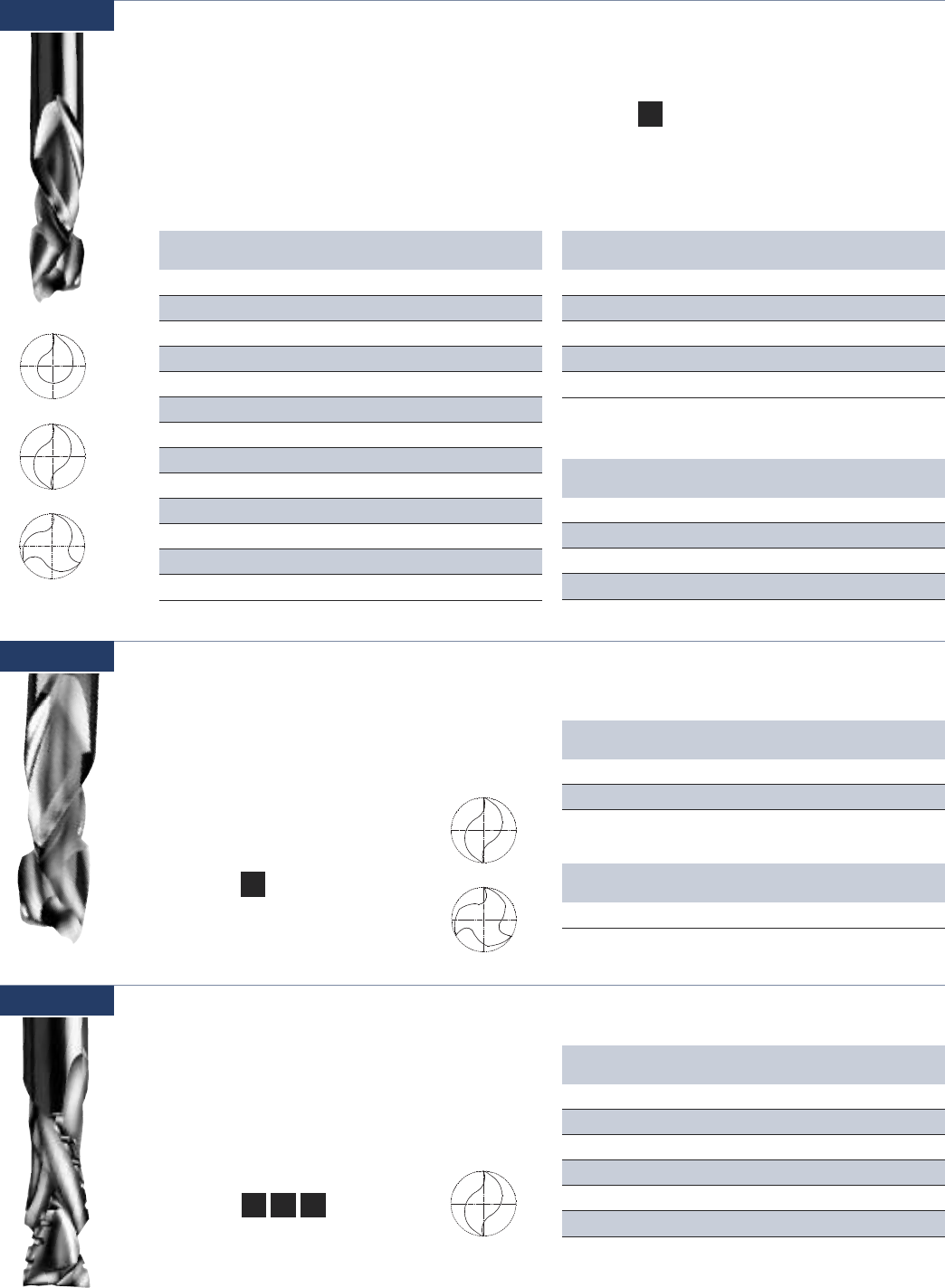
39 www.onsrud.com
Part Cutting Flute Upcut Flute SHK OAL
Number DIA LGTH LGTH DIA
60-102MW 1/8 3/8 .205 1/4 2-1/2
60-106MW 3/16 5/8 .300 1/4 2-1/2
60-111MW* 1/4 7/8 .175 1/4 2-1/2
60-120MW* 3/8 1-1/8 .200 3/8 3
60-167MW* 1/2 1-1/8 .200 1/2 3
HELIX ANGLE ≈ 30° *MORTISE COMPRESSION
SINGLE FLUTE
Part Cutting Flute Upcut Flute SHK OAL
Number DIA LGTH LGTH DIA
60-113MW* 1/4 7/8 .188 1/4 2-1/2
60-123MW* 3/8 7/8 .188 3/8 3
60-124MW 3/8 1-1/8 .406 3/8 3
60-127MW* 3/8 1-1/8 .188 3/8 3
60-163MW* 1/2 7/8 .200 1/2 3
60-169MW 1/2 1-1/8 .562 1/2 3
60-171MW 1/2 1-3/8 .625 1/2 3-1/2
60-172MW 1/2 1-5/8 .750 1/2 4
60-173MW* 1/2 1-3/8 .200 1/2 3-1/2
60-181MW 1/2 2-1/8 1 1/2 5
60-186MW 5/8 2-1/4 1 5/8 5
60-196MW 3/4 1-7/8 .750 3/4 4
60-194MW 3/4 2-1/4 1 3/4 5
HELIX ANGLE ≈ 30° *MORTISE COMPRESSION
DOUBLE FLUTE
Part Cutting Flute Upcut Flute SHK OAL
Number DIA LGTH LGTH DIA
60-125MW 3/8 1-1/8 .500 3/8 3
60-126MW* 3/8 7/8 .200 3/8 3
60-176MW* 1/2 7/8 .200 1/2 3
60-177MW* 1/2 1-3/8 .200 1/2 3-1/2
*MORTISE COMPRESSION
THREE FLUTE
Usage Double sided laminated and
vaneered materials
Material See Selection Guide - pg. 2 - 12
Single, Double & Three Flute - Solid Carbide Max Life Compression Spiral
Designed for maximum life when cutting in high-
wear applications. Unique geometries and carbides
improve the wear characteristics of the tool under
abrasive applications with superior part finish.
Mortise compressions are designed with short
upcut to allow mortise cut with downcut action.
60-100MW
LW
Single Flute
Double Flute
Three Flute
CW
Double Flute - Solid Carbide Compression Spiral
The Tuff Core is an innovative line of solid carbide
compression spirals that utilize unique dual grade
carbide. The harder outer shell is reinforced by a
tough inner core which makes the tool stronger
and reduces tool breakage.
60-100DC
Usage Double sided laminated,
and veneered materials
Material See Selection Guide - pg. 2 - 12
Part Cutting Flute Upcut Flute SHK OAL
Number DIA LGTH LGTH DIA
60-123DC* 3/8 7/8 .188 3/8 3
60-124DC 3/8 1-1/8 .406 3/8 3
DOUBLE FLUTE
Part Cutting Flute Upcut Flute SHK OAL
Number DIA LGTH LGTH DIA
60-126DC* 3/8 7/8 .200 3/8 3
* MORTISE COMPRESSION
THREE FLUTE
Double Flute
Three Flute
60-100C
Double Flute - Solid Carbide Chipbreaker/Finisher Compression Spiral
Designed to give the optimum edge finish of the
compression spiral bits along with the increased
feed rates of the chipbreaker/finisher design.
Usage Double sided laminated,
veneered, natural wood
and wood composites
Material
See Selection Guide - pg. 2 - 12
Part Cutting Flute Upcut Flute SHK OAL
Number DIA LGTH LGTH DIA
60-123C 3/8 7/8 .188 3/8 3
60-124C 3/8 1-1/8 .406 3/8 3
60-163C* 1/2 7/8 .200 1/2 3
60-169C 1/2 1-1/8 .562 1/2 3
60-171C 1/2 1-3/8 .625 1/2 3-1/2
60-172C 1/2 1-5/8 .750 1/2 4
HELIX ANGLE ≈ 30° * MORTISE COMPRESSION
HW CW LW
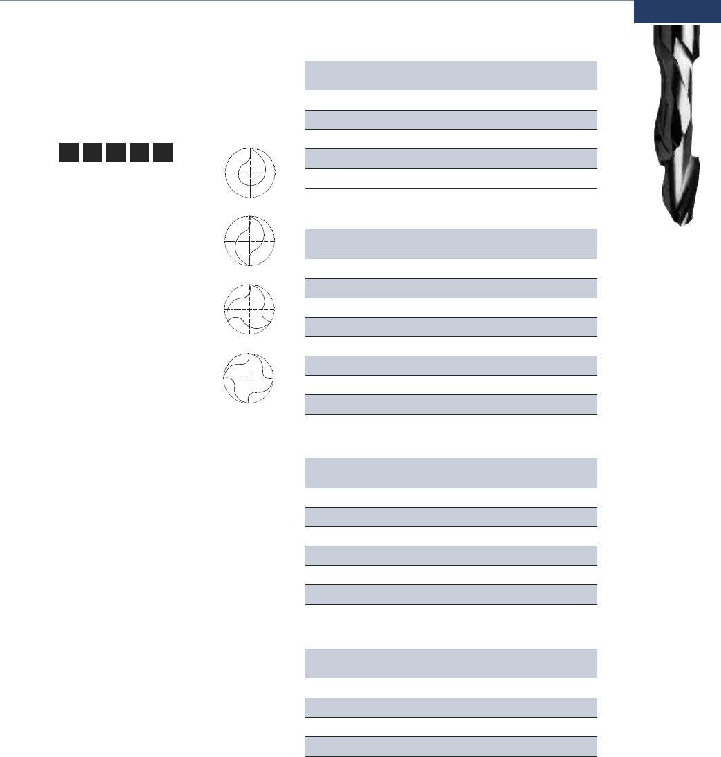
www.onsrud.com 40
Usage Double sided laminated, veneered,
natural wood and wood composites
Material
See Selection Guide - pg. 2 - 12
LW CW
Part Cutting Flute Upcut Flute SHK OAL
Number DIA LGTH LGTH DIA
60-110 1/4 7/8 .531 1/4 2-1/2
60-111* 1/4 7/8 .175 1/4 2-1/2
60-120 3/8 1-1/8 .500 3/8 3
60-160 1/2 1 .406 1/2 3
60-165 1/2 1-5/8 .781 1/2 3-1/2
HELIX ANGLE ≈ 30° *MORTISE COMPRESSION
Single, Double, Three & Four Flute - Solid Carbide Compression Spiral
Compression design for optimum edge finish on
both sides of laminated materials. Designed for
low speed applications.
60-100
Part Cutting Flute Upcut Flute SHK OAL
Number DIA LGTH LGTH DIA
60-112 1/4 7/8 .531 1/4 2-1/2
60-113* 1/4 7/8 .188 1/4 2-1/2
60-123* 3/8 7/8 .188 3/8 3
60-124 3/8 1-1/8 .406 3/8 3
60-169 1/2 1-1/8 .562 1/2 3
60-172 1/2 1-5/8 .750 1/2 4
60-173* 1/2 1-3/8 .200 1/2 3-1/2
60-186 5/8 2-1/4 1 5/8 5
HELIX ANGLE ≈ 30° * MORTISE COMPRESSION
Part Cutting Flute Upcut Flute SHK OAL
Number DIA LGTH LGTH DIA
60-125 3/8 1-1/8 .500 3/8 3
60-126* 3/8 7/8 .200 3/8 3
60-174 1/2 1-1/8 .500 1/2 3
60-175 1/2 1-5/8 .750 1/2 3-1/2
60-176* 1/2 7/8 .200 1/2 3
60-177* 1/2 1-3/8 .200 1/2 3-1/2
HELIX ANGLE ≈ 30° * MORTISE COMPRESSION
SINGLE FLUTE - SE
DOUBLE FLUTE - DE
THREE FLUTE - TE
Part Cutting Flute Upcut Flute SHK OAL
Number DIA LGTH LGTH DIA
60-563* 1/2 7/8 .200 1/2 3
60-569 1/2 1-1/8 .500 1/2 3
60-573* 1/2 1-3/8 .200 1/2 3-1/2
60-572 1/2 1-5/8 .750 1/2 4
HELIX ANGLE ≈ 30° * MORTISE COMPRESSION
FOUR FLUTE - FE
Single Flute
Double Flute
Three Flute
Four Flute
SWHW MT
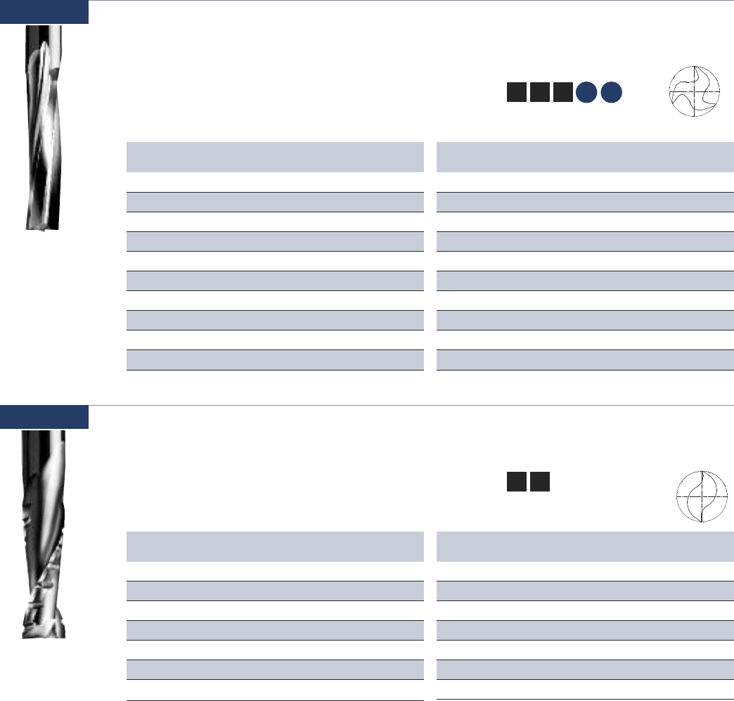
41 www.onsrud.com
Usage Natural wood, plastic, composite
plastic and solid surface
Material
See Selection Guide - pg. 2 - 12
Three Flute - Solid Carbide Low Helix Finisher
Designed for perfect balance and ultra smooth
finish over a wide speed range.
60-200
SW HW CW
HP SSP
Part Cutting Flute SHK OAL
Number DIA LGTH DIA
60-239 1/4 3/8 1/4 3
60-241 1/4 7/8 1/4 3
60-243 3/8 5/8 3/8 3
60-245 3/8 1-1/8 3/8 3
60-249 1/2 1-1/8 1/2 3-1/2
60-253 1/2 1-5/8 1/2 4
60-251 1/2 2-1/8 1/2 4-1/2
60-269 3/4 1-5/8 3/4 4
60-271 3/4 2-1/8 3/4 5
60-277 3/4 3-1/8 3/4 6
HELIX ANGLE ≈ 10°
UPCUT
Part Cutting Flute SHK OAL
Number DIA LGTH DIA
60-240 1/4 3/8 1/4 3
60-242 1/4 7/8 1/4 3
60-244 3/8 5/8 3/8 3
60-246 3/8 1-1/8 3/8 3
60-250 1/2 1-1/8 1/2 3-1/2
60-254 1/2 1-5/8 1/2 4
60-252 1/2 2-1/8 1/2 4-1/2
60-270 3/4 1-5/8 3/4 5
60-272 3/4 2-1/8 3/4 5
60-278 3/4 3-1/8 3/4 6
HELIX ANGLE ≈ 10°
DOWNCUT
Usage Natural wood and wood composites
Material See Selection Guide - pg. 2 - 12
Double Flute - Solid Carbide Chipbreaker Finisher
For faster feed rates than a conventional two flute
with a smooth finish.
60-300
HW CW
Part Cutting Flute SHK OAL
Number DIA LGTH DIA
60-307 3/8 1-1/8 3/8 3
60-311 1/2 1-1/8 1/2 3
60-313 1/2 1-5/8 1/2 3-1/2
60-317 1/2 1-7/8 1/2 3-1/2
60-315 1/2 2-1/8 1/2 4
60-321 5/8 2-1/8 5/8 4
60-325 3/4 2-1/8 3/4 4
HELIX ANGLE ≈ 30°
UPCUT
Part Cutting Flute SHK OAL
Number DIA LGTH DIA
60-308 3/8 1-1/8 3/8 3
60-312 1/2 1-1/8 1/2 3
60-314 1/2 1-5/8 1/2 3-1/2
60-318 1/2 1-7/8 1/2 3-1/2
60-316 1/2 2-1/8 1/2 4
60-322 5/8 2-1/8 5/8 4
60-326 3/4 2-1/8 3/4 4
DOWNCUT

www.onsrud.com 42
Usage Natural wood and wood composites
Material
See Selection Guide - pg. 2 - 12
Three Flute - Solid Carbide Chipbreaker Finisher
For additional balance at fast feed rates with a
smooth finish.
60-350
Part Cutting Flute SHK OAL
Number DIA LGTH DIA
60-337 3/8 1-1/8 3/8 3
60-351 1/2 1-1/8 1/2 3
60-353 1/2 1-5/8 1/2 3-1/2
60-361 5/8 1-5/8 5/8 4
60-371 3/4 1-5/8 3/4 4
60-375 3/4 3-1/8 3/4 6
HELIX ANGLE ≈ 30°
UPCUT
Part Cutting Flute SHK OAL
Number DIA LGTH DIA
60-338 3/8 1-1/8 3/8 3
60-350 1/2 1-1/8 1/2 3
60-354 1/2 1-3/8 1/2 3-1/2
60-352 1/2 1-5/8 1/2 3-1/2
60-360 5/8 1-5/8 5/8 4
60-370 3/4 1-5/8 3/4 4
60-372 3/4 2-1/4 3/4 5
60-374 3/4 3-1/8 3/4 6
DOWNCUT
SW CW
HW
Part Cutting Flute Upcut Flute SHK OAL
Number DIA LGTH LGTH DIA
60-669 1/2 1-1/8 .500 1/2 3
60-671 1/2 1-3/8 .500 1/2 3-1/2
HELIX ANGLE ≈ 30°
Usage High velocity routing of double sided
laminated and veneered, natural wood
and wood composites
Material
See Selection Guide - pg. 2 - 12
Four Flute - Solid Carbide High Velocity Compression Spiral
Combine a roughing and finishing cut in one tool
for rapid feed rates with a good finish.
60-600
SW CW
HW
LW
Usage High velocity routing of double sided
laminated and veneered, natural wood
and wood composites
Material
See Selection Guide - pg. 2 - 12
Four Flute - Solid Carbide High Velocity Upcut Spiral
Combine a roughing and finishing cut with upcut
cutting action in one tool for rapid feed rates with
a good finish.
60-700
SW CW
HW
Part Cutting Flute SHK OAL
Number DIA LGTH DIA
60-711 1/2 1-1/8 1/2 3-1/2
60-715 1/2 1-5/8 1/2 4
60-719 1/2 2-1/8 1/2 4-1/2
60-731 3/4 2-1/8 3/4 5
HELIX ANGLE ≈ 30°
UPCUT
Part Cutting Flute SHK OAL
Number DIA LGTH DIA
60-710 1/2 1-1/8 1/2 3-1/2
60-714 1/2 1-5/8 1/2 4
60-718 1/2 2-1/8 1/2 4-1/2
60-720 5/8 2-1/8 5/8 5
HELIX ANGLE ≈ 30°
DOWNCUT

43 www.onsrud.com
Usage Natural wood and wood composites
Material
See Selection Guide - pg. 2 - 12
Double Flute - Solid Carbide Rougher
Designed for use when faster feed rates cannot
be achieved, or on low horsepower machines.
60-800
Part Cutting Flute SHK OAL
Number DIA LGTH DIA
60-815 3/8 1-3/8 3/8 3-1/2
60-825 1/2 1-3/8 1/2 3-1/2
60-829 1/2 1-7/8 1/2 4
60-841 5/8 2-5/8 5/8 5
60-847 3/4 2-7/8 3/4 6
HELIX ANGLE ≈ 20°
UPCUT
Part Cutting Flute SHK OAL
Number DIA LGTH DIA
60-816 3/8 1-3/8 3/8 3-1/2
60-826 1/2 1-3/8 1/2 3-1/2
60-830 1/2 1-7/8 1/2 4
60-842 5/8 2-5/8 5/8 5
60-848 3/4 2-7/8 3/4 6
DOWNCUT
SW CW
HW
Usage Natural wood and wood composites,
plastic composites
Material
See Selection Guide - pg. 2 - 12
Three Flute - Solid Carbide Extreme Heavy Duty Hogger
Designed for heavy material removal operations
where the cutter is subject to excessive cutting
forces and finish is not a primary concern.
60-900
Part Cutting Flute SHK OAL
Number DIA LGTH DIA
60-901 3/8 1-1/8 3/8 3
60-905 1/2 1-1/8 1/2 3
60-907 1/2 1-5/8 1/2 3-1/2
60-909 1/2 2-1/8 1/2 4
60-915 3/4 2-1/8 3/4 5
HELIX ANGLE ≈ 30°
UPCUT
Part Cutting Flute SHK OAL
Number DIA LGTH DIA
60-902 3/8 1-1/8 3/8 3
60-906 1/2 1-1/8 1/2 3
60-908 1/2 1-5/8 1/2 3-1/2
60-910 1/2 2-1/8 1/2 4
60-916 3/4 2-1/8 3/4 5
DOWNCUT
SW CW
HW
Usage Natural wood and wood composites
Material
See Selection Guide - pg. 2 - 12
Double Flute - Solid Carbide Extreme Heavy Duty Chipbreaker/Finisher
Designed to be fed very fast while withstanding
excessive cutting forces and at the same time
leaving a smooth finish.
60-950
Part Cutting Flute SHK OAL
Number DIA LGTH DIA
60-951 3/8 1-1/8 3/8 3
60-955 1/2 1-1/8 1/2 3
60-957 1/2 1-5/8 1/2 3-1/2
60-959 1/2 2-1/8 1/2 4
60-965 3/4 2-1/8 3/4 5
HELIX ANGLE ≈ 30°
UPCUT
Part Cutting Flute SHK OAL
Number DIA LGTH DIA
60-950 3/8 1-1/8 3/8 3
60-954 1/2 1-1/8 1/2 3
60-956 1/2 1-5/8 1/2 3-1/2
60-958 1/2 2-1/8 1/2 4
DOWNCUT
SW CW
HW
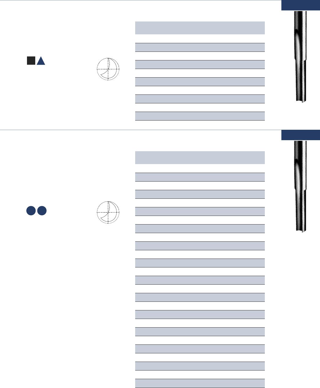
www.onsrud.com 44
SP HP
Part Cutting Flute SHK OAL
Number DIA LGTH DIA
61-040 1/8 1/2 1/4 2
61-050 5/32 9/16 1/4 2
61-060 3/16 5/8 1/4 2
61-070 7/32 5/8 1/4 2-1/2
61-080 1/4 3/4 1/4 2-1/2
61-090 9/32 3/4 3/8 2-1/2
61-100 5/16 13/16 3/8 2-1/2
61-120 3/8 7/8 3/8 2-1/2
61-140 7⁄16 1 1/2 3
61-160 1/2 1 1/2 3
Usage Natural wood and aluminum
Material
See Selection Guide - pg. 2 - 12
Single Flute - Solid Carbide Straight
Designed to combine the fast free cutting of O
flute geometry with the tool life available from
solid carbide particularly in small diameters.
61-000
A
SW
Part Cutting Flute SHK OAL
Number DIA LGTH DIA
61-041 1/8 5⁄16 1/4 2
61-044 1/8 1/2 1/8 2
61-042 1/8 1/2 1/4 2
61-042L 1/8 1/2 1/4 2
61-045 1/8 5/8 1/8 3
61-043 1/8 5/8 1/4 4
61-052 5/32 9/16 1/4 2
61-061 3/16 3/8 1/4 2
61-064 3/16 5/8 3/16 2-1/2
61-062 3/16 5/8 1/4 2
61-062L 3/16 5/8 1/4 2
61-063* 3/16 1 1/4 4
61-072 7/32 5/8 1/4 2-1/2
61-081 1/4 3/8 1/4 2-1/2
61-082 1/4 3/4 1/4 2-1/2
61-082L 1/4 3/4 1/4 2-1/2
61-083* 1/4 3/4 1/4 3-1/4
61-083L* 1/4 3/4 1/4 3-1/4
61-085* 1/4 1 1/4 3-1/4
61-084* 1/4 1-1/4 1/4 4
61-121 3/8 5/8 3/8 2-1/2
61-122 3/8 7/8 3/8 2-1/2
61-123* 3/8 1-5/8 3/8 6
61-162 1/2 1 1/2 3
61-164 1/2 1-5/8 1/2 4
61-166 1/2 2-1/8 1/2 6
*These tools are designed and toleranced for air routers with guide bushings.
L= left hand rotation
Usage Polycarbonate, polyethylene,
polypropylene, polystyrene, PVC,
extruded acrylic, HDPE, UHMW and
hard plastic
Material
See Selection Guide - pg. 2 - 12
Single Flute - Solid Carbide Straight
Designed to combine the fast free cutting of O
flute geometry with the tool life available from
solid carbide particularly in small diameters.
61-000P
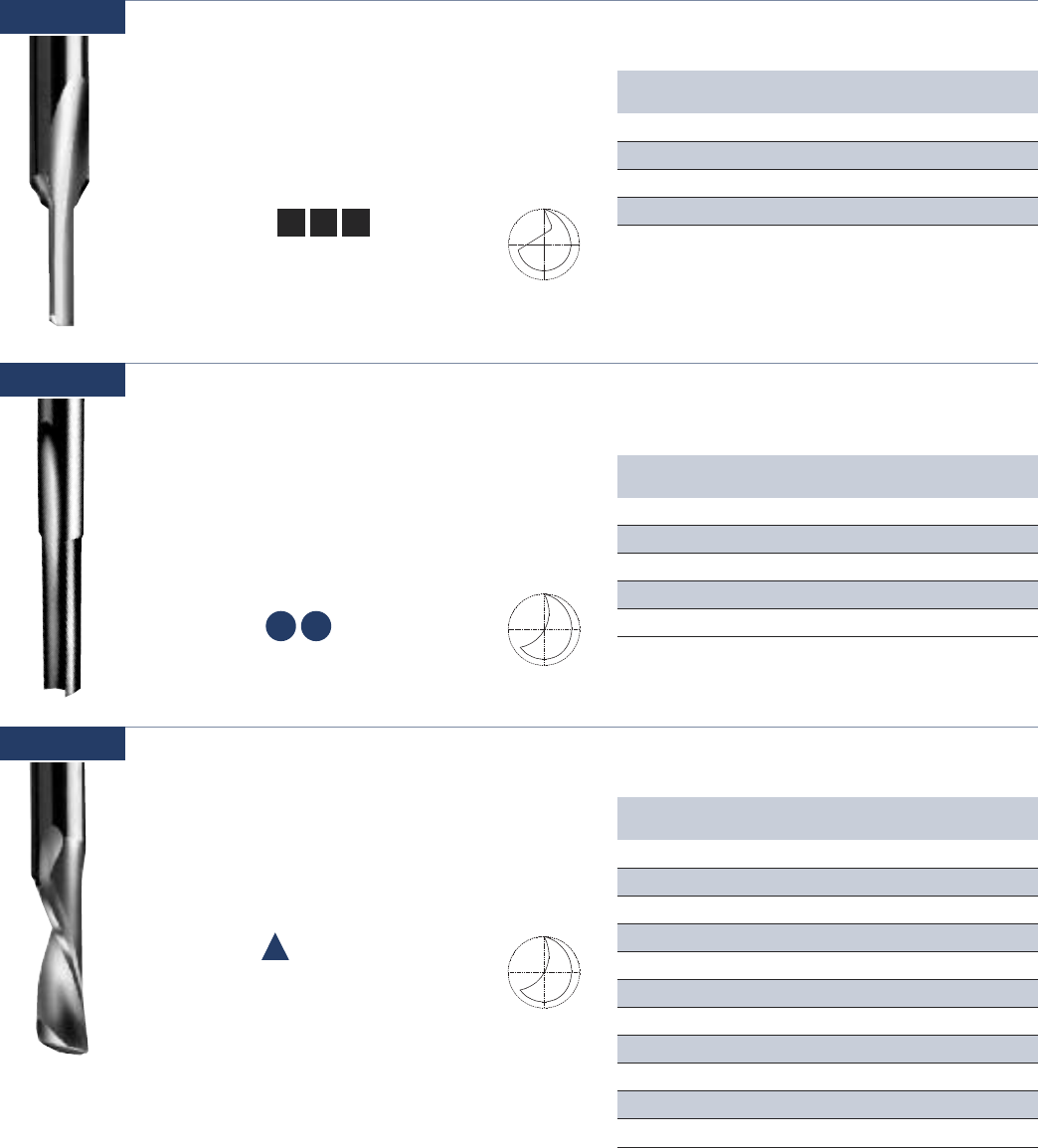
45 www.onsrud.com
SP HP
A
Usage Natural wood and wood composites
Material
See Selection Guide - pg. 2 - 12
Single Flute - Solid Carbide Straight Wood Rout
Designed to enhance operations where the
benefits of spiral action are not needed. The
single flute provides fast, free cutting with
optimum cutter life.
61-200
Part Cutting Flute SHK OAL
Number DIA LGTH DIA
61-240 1/8 1/2 1/4 2
61-280 1/4 7/8 1/4 2-1/2
61-285 1/4 1 1/4 2-1/2
61-320 3/8 1-1/8 3/8 3
SW HW CW
Usage Polycarbonate, polyethylene,
polypropylene, polystyrene, PVC,
extruded acrylic, HDPE, UHMW
and hard plastic
Material
See Selection Guide - pg. 2 - 12
Single Flute - Solid Carbide Straight
Designed to combine the fast free cutting of O
flute geometry with the tool life available from
solid carbide particularly in small diameters.
61-400
Part Cutting Flute SHK OAL
Number DIA LGTH DIA
61-410 4 mm 16 mm 6 mm 64 mm
61-411 5 mm 20 mm 6 mm 64 mm
61-412 6 mm 25 mm 6 mm 64 mm
61-414 8 mm 25 mm 8 mm 64 mm
61-418 12 mm 35 mm 12 mm 88 mm
METRIC
Usage Aluminum, plate, single & multi sheet
Material See Selection Guide - pg. 2 - 12
Single Flute - Solid Carbide Downcut Spiral O Flute
High speed cutters for machining aluminum
sheet material. These tools are optimized for
use on high-speed CNC mills, high speed
machining centers and CNC routers.
62-600
Part Cutting Flute SHK OAL
Number DIA LGTH DIA
62-602 1/16 1/4 1/8 1-1/2
62-604 1/8 1/4 1/8 1-1/2
62-606 1/8 1/4 1/4 2
62-610 1/8 1/2 1/4 2
62-614 3/16 3/8 1/4 2
62-620 1/4 3/8 1/4 2
62-622 1/4 3/4 1/4 2-1/2
62-624 1/4 1-1/4 1/4 3
62-630 5/16 3/4 1/2 3
62-625 3/8 3/4 3/8 3
62-631 1/2 1-1/8 1/2 3-1/2
HELIX ANGLE ≈ 22°
www.onsrud.com 46
HP SSP SP HP SSP
HP SSP SP HP SSP
Usage (HP): Acrylic, nylon, PVC, polycarbonate
and solid surface
(SP): HDPE, HIPS, UHMW, ABS,
polycarbonate, PE, polystyrene,
polypropylene, acetal, acrylic, PET
and solid surface
Material 62-700 62-750
62-800 62-850
Single Flute - Solid Carbide Downcut Spiral O Flute
(HP) Designed to provide a smooth finish in hard
plastics with downward chip removal.
(SP) Designed to provide provide a smooth finish
in soft plastic with downward chip removal.
62-700
62-750
62-800
62-850
Part Part Cutting Flute SHK OAL
Number Number DIA LGTH DIA
62-713* 62-763* 1/8 1/2 1/8 2
62-712* 62-762* 1/8 1/2 1/4 2
62-715* 5/32 9/16 1/4 2
62-719* 62-769* 3/16 5/8 3/16 2
62-718 62-768 3/16 5/8 1/4 2
62-725 62-775 1/4 3/4 1/4 2-1/2
62-726 62-776 1/4 1-1/4 1/4 3
62-727* 1/4 1-1/2 1/4 3
62-733 62-783 3/8 1-1/8 3/8 3
62-740 62-790 1/2 1-5/8 1/2 3-1/2
* Tool balanced by design to run at
spindle speeds up to 60,000 RPM
HARD SOFT
PLASTIC PLASTIC
Part Part Cutting Flute SHK OAL
Number Number DIA LGTH DIA
62-816* 62-866* 3mm 12mm 6mm 64mm
62-824* 62-874* 4mm 20mm 6mm 64mm
62-830 62-880 5mm 16mm 6mm 64mm
62-840 6mm 30mm 6mm 76mm
62-842* 6mm 38mm 6mm 76mm
62-844 8mm 25mm 8mm 64mm
62-846 62-896 8mm 38mm 8mm 76mm
HELIX ANGLE ≈ 21°
* Tool balanced by design to run at
spindle speeds up to 60,000 RPM
HARD SOFT METRIC
PLASTIC PLASTIC
Usage Fiberglass, phenolic
and aluminum
Material See Selection Guide - pg. 2 - 12
Single Flute - Solid Carbide Upcut Spiral
Designed for routing where upward chip
removal, tool rigidity, long life, and high
quality finish is desired.
63-000
Part Cutting Flute SHK OAL
Number DIA LGTH DIA
63-040 1/8 1/2 1/4 2
63-050 5/32 9/16 1/4 2
63-060 3/16 5/8 1/4 2
63-080 1/4 3/4 1/4 2-1/2
63-100 5/16 13/16 3/8 2-1/2
63-160 1/2 1 1/2 3
HELIX ANGLE ≈ 30°
HW
CP A

47 www.onsrud.com
Usage Natural wood and
wood composites
Material
See Selection Guide - pg. 2 - 12
Single Flute - Solid Carbide Upcut Spiral Wood Rout
Designed for routing where aggressive upward
chip removal is necessary in hand-fed or CNC
applications. Tool rigidity, long life, and high
quality finish are characteristic of these tools.
63-200
Part Cutting Flute SHK OAL
Number DIA LGTH DIA
63-240 1/8 1/2 1/4 2
63-280 1/4 7/8 1/4 2-1/2
HELIX ANGLE ≈ 30°
SW HW CW
Single Flute - Solid Carbide Upcut for Soft Aluminum (Coated)
These tools are specially designed to cut soft
grades of aluminum and create a good edge
finish. The improved cutting geometry properly
forms and evacuates the chips preventing
chip rewelding.
63-400
Usage Soft aluminum sheet,
3003 grade aluminum
Part Cutting Flute SHK OAL COATING
Number DIA LGTH DIA
63-420 3/16 1/4 1/4 2 ZRN
63-430 1/4 1/4 1/4 2 ZRN
Part Number RPM Feed Rate
63-420 10,000 80 IPM
63-430 13,250 100 IPM
63-450 10,000 80 IPM
63-460 13,250 100 IPM
CUTTING PARAMETERS
Part Cutting Flute SHK OAL COATING
Number DIA LGTH DIA
63-450 5mm 6mm 6mm 64mm ZRN
63-460 6mm 6mm 6mm 64mm ZRN
METRIC
NEW
www.onsrud.com 48
Usage Aluminum plate and single/multi sheet
aluminum
Material
See Selection Guide - pg. 2 - 12
Single Flute - Solid Carbide Upcut Spiral O Flute
High speed cutters for machining aluminum
sheet and block material. These tools are
optimized for use on high-speed CNC mills,
high speed machining centers and CNC routers.
63-600
Part Cutting Flute SHK OAL
Number DIA LGTH DIA
63-602 1/16 1/4 1/8 1-1/2
63-603 3⁄32 1/4 1/8 2
63-604 1/8 1/4 1/8 1-1/2
63-606 1/8 1/4 1/4 2
63-610 1/8 1/2 1/4 2
63-611 5/32 5/16 3/16 2
63-612 3/16 3/8 3/16 1-1/2
63-614 3/16 3/8 1/4 2
63-618 3/16 5/8 1/4 2
63-620 1/4 3/8 1/4 2
HELIX ANGLE ≈ 22°
Part Cutting Flute SHK OAL
Number DIA LGTH DIA
63-622 1/4 3/4 1/4 2-1/2
63-624 1/4 11/4 1/4 3
63-629 5/16 9/16 5/16 2-1/2
63-630 5/16 3/4 1/2 3
63-634 21/64 3/4 1/2 3
63-625 3/8 3/4 3/8 3
63-626 3/8 1-1/8 3/8 3
63-627 3/8 1-3/8 3/8 3-1/2
63-631 1/2 1-1/8 1/2 3-1/2
63-632 1/2 1-3/8 1/2 3-1/2
A
Single Flute - Solid Carbide Upcut Spiral O Flute for Acrylic
These tools are designed to cut acrylics and
achieve long tool life. Our unique cutting geometry
produces a smooth edge finish regardless if it is
cast or extruded acrylic.
63-500
Usage Acrylic
Material See Selection Guide - pg. 2 - 12
Part Cutting Flute SHK OAL
Number DIA LGTH DIA
63-505* 1/16 1/4 1/4 2
63-510 1/8 1/4 1/4 2
63-515* 1/8 1/2 1/4 2
63-520* 3/16 5/8 1/4 2
63-525 1/4 3/8 1/4 2-1/2
63-530 1/4 3/4 1/4 2-1/2
63-535 3/8 1-1/8 3/8 3
* Tool balanced by design to run at
spindle speeds up to 60,000 RPM
SP HP
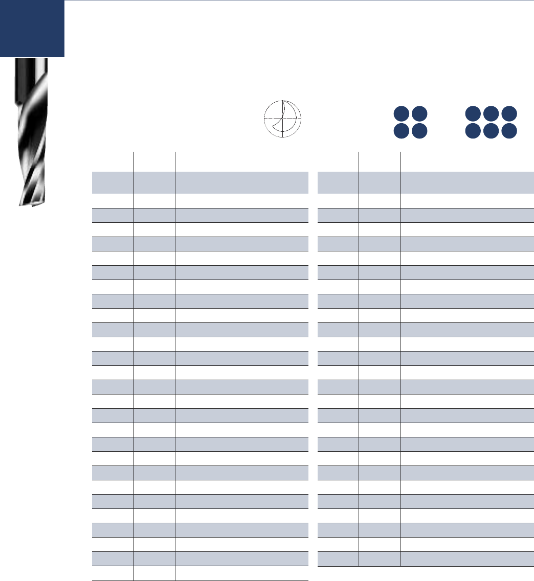
49 www.onsrud.com
HP SSP SP HP SSP
HP SSP SP HP SSP
Usage (HP): Acrylic, nylon, PVC, polycarbonate
and solid surface
(SP): HDPE, HIPS, UHMW, ABS,
polycarbonate, PE, polystyrene,
polypropylene, acetal, acrylic, PET
and solid surface
Material 63-700 63-750
63-800 63-850
Single Flute - Solid Carbide Upcut Spiral O Flute
(HP) Designed to provide a smooth finish in hard
plastics with upward chip removal.
(SP) Designed to provide a smooth finish
in soft plastic with upward chip removal.
63-700
63-750
63-800
63-850
Part Part Cutting Flute SHK OAL
Number Number DIA LGTH DIA
63-701* 63-751* 1/16 1/4 1/8 2
63-700* 63-750* 1/16 1/4 1/4 2
63-706* 1/8 5/8 1/4 2-1/2
63-707* 1/8 3/4 1/4 2-1/2
63-711* 63-761* 1/8 1/4 1/8 2
63-710* 63-760* 1/8 1/4 1/4 2
63-713* 63-763* 1/8 1/2 1/8 2
63-712* 63-762* 1/8 1/2 1/4 2
63-743** 63-793** 1/8 1/2 1/4 2
63-715* 5/32 9/16 1/4 2
63-716* 63-766* 3/16 3/8 3/16 2
63-717* 63-767* 3/16 3/8 1/4 2
63-719* 63-769* 3/16 5/8 3/16 2
63-718* 63-768* 3/16 5/8 1/4 2
63-720 7/32 3/4 1/4 2-1/2
63-724 63-774 1/4 3/8 1/4 2
63-744** 63-794** 1/4 3/4 1/4 2-1/2
63-725 63-775 1/4 3/4 1/4 2-1/2
63-726 63-776 1/4 1-1/4 1/4 3
63-727* 63-777 1/4 1-1/2 1/4 3
63-730 63-780 3/8 5/8 3/8 2-1/2
63-731 63-781 3/8 3/4 3/8 3
63-733 63-783 3/8 1-1/8 3/8 3
63-735 63-785 3/8 1-5/8 3/8 3-1/2
63-745** 63-795** 3/8 1-5/8 3/8 3-1/2
63-740 63-790 1/2 1-5/8 1/2 3-1/2
63-746** 63-796** 1/2 1-5/8 1/2 3-1/2
HELIX ANGLE ≈ 21° **Special Point for Improved Bottom Finish
HARD SOFT
PLASTIC PLASTIC
Part Part Cutting Flute SHK OAL
Number Number DIA LGTH DIA
63-802 2mm 8mm 2mm 50mm
63-804* 63-854 2mm 8mm 6mm 64mm
63-806 2.5 mm 8mm 2.5mm50mm
63-808* 2.5 mm 8mm 6mm 64mm
63-810* 63-860* 3mm 8mm 3mm 50mm
63-812* 63-862* 3mm 8mm 6mm 64mm
63-814* 63-864* 3mm 12mm 3mm 64mm
63-816* 63-866* 3mm 12mm 6mm 64mm
63-818* 4mm 8mm 4mm 64mm
63-820* 63-870* 4mm 12mm 4mm 64mm
63-822* 4mm 20mm 4mm 64mm
63-824* 63-874* 4mm 20mm 6mm 64mm
63-826* 4mm 30mm 4mm 64mm
63-828 63-878* 5mm 16mm 5mm 64mm
63-830 63-880 5mm 16mm 6mm 64mm
63-832 5mm 30mm 5mm 64mm
63-834 6mm 8mm 6mm 64mm
63-836 63-886 6mm 12mm 6mm 64mm
63-838 63-888 6mm 20mm 6mm 64mm
63-840 6mm 30mm 6mm 76mm
63-842* 63-892* 6mm 38mm 6mm 76mm
63-844 63-894* 8mm 25mm 8mm 64mm
63-846 63-896 8mm 38mm 8mm 76mm
63-848 63-898 10mm 30mm 10mm 76mm
63-849 10mm 35mm 10mm 76mm
63-847 63-897 12mm 38mm 12mm 76mm
HELIX ANGLE ≈ 21°
* Tool balanced by design to run at
spindle speeds up to 60,000 RPM
HARD SOFT METRIC
PLASTIC PLASTIC
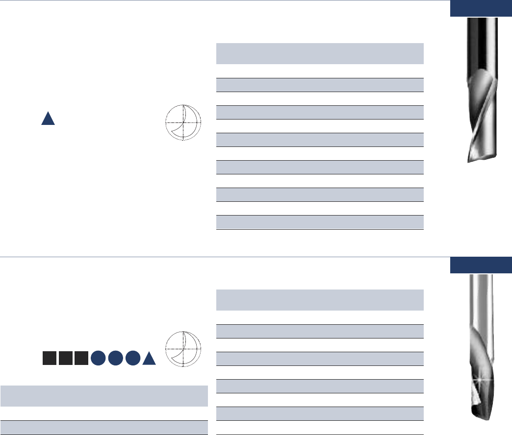
www.onsrud.com 50
Single Flute - Solid Carbide Upcut Spiral O Flute
High speed cutters for machining aluminum
sheet and block material. These tools are
optimized for use on high-speed CNC mills,
high speed machining centers and CNC routers.
63-900
Usage Aluminum plate and single/multi sheet
aluminum
Material See Selection Guide - pg. 2 - 12
Part Cutting Flute SHK OAL
Number DIA LGTH DIA
63-904 2mm 6mm 6mm 64mm
63-908 2.5mm 6mm 6mm 64mm
63-912 3mm 8mm 6mm 64mm
63-916 3mm 12mm 6mm 64mm
63-918 4mm 8mm 4mm 64mm
63-924 4mm 20mm 6mm 64mm
63-930 5mm 16mm 6mm 64mm
63-934 6mm 8mm 6mm 64mm
63-938 6mm 20mm 6mm 64mm
63-944 8mm 25mm 8mm 64mm
63-946 8mm 38mm 8mm 76mm
63-948 10mm 30mm 10mm 76mm
HELIX ANGLE ≈ 22°
A
A
METRIC
Part Cutting Flute SHK OAL
Number DIA LGTH DIA
64-012M 3mm 12mm 6mm 50mm
64-026M 6mm 32mm 6mm 76mm
HELIX ANGLE ≈ 21°
METRIC
Single Flute - Solid Carbide Downcut Spiral O Flute
The polished flute allows for razor sharp cutting
edge and easy chip evacuation. The tool is available
in a down cut spiral for improved part holding.
64-000
Usage Plastic, wood, aluminum
and solid surface
Material
See Selection Guide - pg. 2 - 12
Part Cutting Flute SHK OAL
Number DIA LGTH DIA
64-000* 1/16 1/4 1/8 2
64-012* 1/8 1/2 1/4 2
64-016* 3/16 3/8 3/16 2
64-018 3/16 5/8 1/4 2
64-024 1/4 3/8 1/4 2
64-025 1/4 3/4 1/4 2
64-026 1/4 1-1/4 1/4 3
64-031 3/8 3/4 3/8 3
64-033 3/8 1-1/8 3/8 3
HELIX ANGLE ≈ 21°
* Tool balanced by design to run at
spindle speeds up to 60,000 RPM
SW CW
SP HP SSP
HW
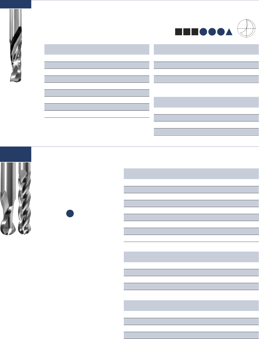
51 www.onsrud.com
Part Cutting Flute SHK OAL
Number DIA LGTH DIA
65-000M 2mm 6mm 3mm 50mm
65-018M 5mm 16mm 6mm 64mm
65-023M 6mm 16mm 6mm 64mm
65-033M 10mm 29mm 10mm 76mm
HELIX ANGLE ≈ 22°
METRIC
A
Single Flute - Solid Carbide Upcut Spiral O Flute
The polished flute allows for razor sharp cutting
edge and easy chip evacuation. The tool is available
in a upcut spiral for improved chip evacuation.
65-000
Usage Plastic, wood, aluminum
and solid surface
Material
See Selection Guide - pg. 2 - 12
Part Cutting Flute SHK OAL
Number DIA LGTH DIA
65-025 1/4 7/8 1/4 2-1/2
65-026 1/4 1-1/4 1/4 3
65-027* 1/4 1-1/2 1/4 3
65-033 3/8 1-1/8 3/8 3
* Tool balanced by design to run at spindle speeds up to 60,000 RPM
Part Cutting Flute SHK OAL
Number DIA LGTH DIA
65-000* 1/16 1/4 1/8 2
65-010* 1/8 1/4 1/4 2
65-013* 1/8 1/2 1/8 2
65-012* 1/8 1/2 1/4 2
65-019* 3/16 5/8 3/16 2
65-018* 3/16 5/8 1/4 2
65-020* 3/16 1-1/4 1/4 3
65-021* 3/16 7/8 1/4 2-1/2
65-023 1/4 5/8 1/4 2
HELIX ANGLE ≈ 21°
* Tool balanced by design to run at
spindle speeds up to 60,000 RPM
SW CW
SP HP SSP
HW
The tool’s unique geometry,
specially designed point, and
highly polished primary clearance
and flute give the tool the ability
to attain a surface finish of 28 Ra
in mechanical plastic.
Usage Plastic
Material See Selection Guide - pg. 2 - 12
Part Cutting Flute SHK OAL Flutes
Number DIA LGTH DIA
65-280B 3mm 12mm 3mm 64mm 2
65-285B 6mm 20mm 6mm 76mm 2
65-290B 8mm 25mm 8mm 76mm 2
65-295B 10mm 30mm 10mm 76mm 2
TWO FLUTE METRIC
Part Cutting Flute SHK OAL Flutes
Number DIA LGTH DIA
65-205B 1/16 1/4 1/8 22
65-210B 1/8 1/2 1/8 2-1/2 2
65-215B 3/16 1/2 1/4 2-1/2 2
65-220B 1/4 1/2 1/4 2-1/2 2
65-225B 1/4 1-1/8 1/4 32
65-235B 5/16 1/2 5/16 32
65-240B 5/16 1-1/8 5/16 32
65-250B 3/8 1-1/8 3/8 32
65-260B 1/2 1-1/8 1/2 32
TWO FLUTE
Part Cutting Flute SHK OAL Flutes
Number DIA LGTH DIA
65-310B 1/4 1/2 1/4 34
65-315B 5/16 1/2 5/16 34
65-320B 3/8 5/8 3/8 34
65-325B 1/2 3/4 1/2 34
FOUR FLUTE
SP
Two & Four Flute - High Finish Ballnose for Plastics
65-200B/
65-300B
NEW
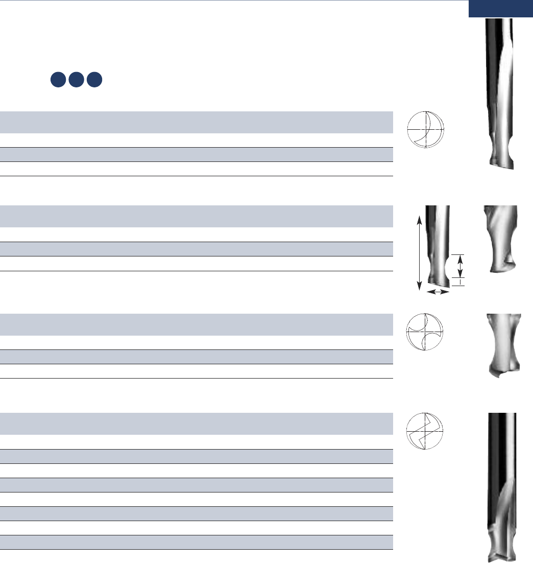
www.onsrud.com 52
Flute
Length
Usage Edge rounding of parts
Material See Selection Guide - pg. 2 - 12
Solid Carbide Edge Rounding
Designed for rounding the edge of sheets or parts. They come in both single flute and double flute.
Part Cutting Flute SHK OAL Opening Radius Small
Tip To Plastic
Number DIA LGTH DIA Flute LGTH RAD Size
66-082 1/4 3/8 1/4 2-1/2 5/32 1/8 .195 1/16 1/8
66-083 1/4 3/8 1/4 2-1/2 7/32 3/16 .180 1/16 3/16
66-084 1/4 3/8 1/4 2-1/2 9/32 1/4 .163 1/16 1/4
66-000
SINGLE FLUTE STRAIGHT O-FLUTE
Part Cutting Flute SHK OAL Opening Radius Small
Tip To Plastic
Number DIA LGTH DIA Flute LGTH RAD Size
66-085 1/4 3/8 1/4 2-1/2 5/32 1/8 .195 1/16 1/8
66-086 1/4 3/8 1/4 2-1/2 7/32 3/16 .180 1/16 3/16
66-087 1/4 3/8 1/4 2-1/2 9/32 1/4 .163 1/16 1/4
HELIX ANGLE ≈ 22°
SINGLE FLUTE SPIRAL O-FLUTE
Part Cutting Flute SHK OAL Opening Radius Small
Tip To Plastic
Number DIA LGTH DIA Flute LGTH RAD Size
66-092 1/4 3/8 1/4 2-1/2 5/32 1/8 .195 1/16 1/8
66-093 1/4 3/8 1/4 2-1/2 7/32 3/16 .180 1/16 3/16
66-094 1/4 3/8 1/4 2-1/2 9/32 1/4 .163 1/16 1/4
DOUBLE FLUTE STRAIGHT O-FLUTE
SP HP SSP
Part Cutting Flute SHK OAL Opening Radius Small
Tip To Plastic
Number DIA LGTH DIA Flute LGTH RAD Size
66-120 3/8 3/8 3/8 2-1/2 5/32 1/8 .320 1/16 1/8
66-121 3/8 3/8 3/8 2-1/2 7/32 3/16 .305 1/16 3/16
66-122 3/8 3/8 3/8 2-1/2 9/32 1/4 .288 1/16 1/4
66-123 3/8 1/2 3/8 2-1/2 13/32 3/8 .255 1/16 3/8
66-160 1/2 3/8 1/2 3 5/32 1/8 .445 1/16 1/8
66-161 1/2 3/8 1/2 3 7/32 3/16 .430 1/16 3/16
66-162 1/2 3/8 1/2 3 9/32 1/4 .413 1/16 1/4
66-163 1/2 5/8 1/2 3 17/32 1/2 .347 1/16 1/2
DOUBLE FLUTE STRAIGHT V-FLUTE
Opening
Tip to
Radius
CED
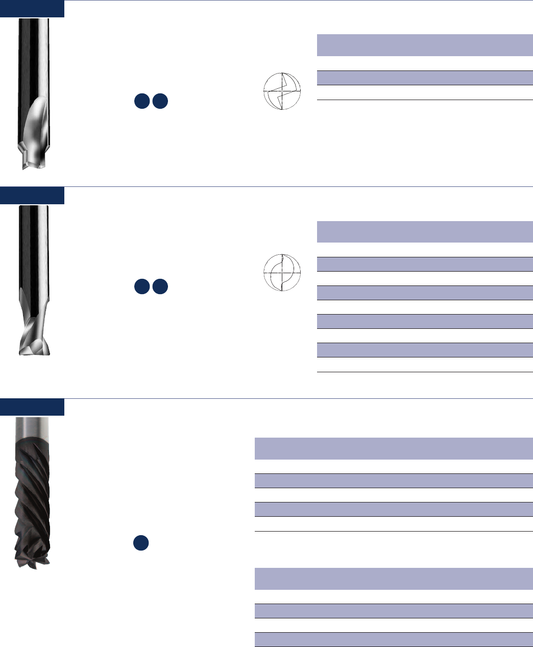
53 www.onsrud.com
Part Cutting Corner Flute SHK OAL
Number DIA Radius LGTH DIA
66-308 1/8 .020 1/4 1/4 2
66-309 1/8 .002 1/4 1/4 2
66-314 1/4 .030 3/8 1/4 2
66-315 1/4 .002 3/8 1/4 2
66-320 3/8 .030 5/8 3/8 2-1/2
66-321 3/8 .002 5/8 3/8 2-1/2
66-326 1/2 .030 7/8 1/2 3
66-327 1/2 .002 7/8 1/2 3
66-328 3/4 .040 1-1/8 3/4 4
HELIX ANGLE ≈ 30°
Double Flute - Solid Carbide Upcut Bottom Surfacing
Designed for pocketing applications where
the bottom of the pocket must be smooth.
Usage Bottom surfacing for
plastic and aluminum
Material See Selection Guide - pg. 2 - 12
SP HP
Part Cutting Flute SHK OAL Material
Number DIA LGTH DIA Thickness
66-200 1/4 3/16 3/8 2-1/4 1/8
66-204 1/4 1/4 3/8 2-1/4 3/16
66-210 3/8 5/16 1/2 3 1/4
HELIX ANGLE ≈ 0°
Double Flute - Solid Carbide Rout and Chamfer
Designed to provide up to a 1/16” top face
chamfer and a finished side edge on plastic
sheets or parts.
66-200
Usage Rout and chamfer in plastic
Material See Selection Guide - pg. 2 - 12
SP HP
66-800
66-300
Part Cutting Flute Upcut SHK OAL Flutes
Number DIA LGTH LGTH DIA
66-802DFC 1/4 3/4 .325 1/4 3-1/2 4
66-811DFC* 3/8 1 .100 3/8 44
66-814DFC 3/8 1 .340 3/8 46
66-817DFC* 1/2 1-1/8 .100 1/2 46
66-823DFC 1/2 1-1/8 .350 1/2 46
*DOWNCUT EDGE TO WITHIN .050” OF TOOL END
DFC Compression for Composites (Coated)
The diamond film coated (CVD) solid
carbide compression routers unique
geometry prevents delamination on
top and the bottom edges of the
composites. The open flute geometry
dissipates heat to prevent resin flow.
Usage Composite
Material See Selection Guide - pg. 2 - 12
Part Cutting Flute Upcut SHK OAL Flutes
Number DIA LGTH LGTH DIA
66-852DFC 6mm 20mm 7.75mm 6mm 90mm 4
66-858DFC 8mm 25mm 8mm 8mm 100mm 4
66-864DFC 10mm 25mm 8.5mm 10mm 100mm 6
66-870DFC 12mm 25mm 9mm 12mm 100mm 6
METRIC
CP
NEW
www.onsrud.com 54
66-900
High Performance Composite Router (Coated)
The new High Performance Composite Router is
designed for more efficient routing of composite
materials, in both hand-fed and in CNC applications.
Coated with AlTiN for increased tool life.
Usage Composites and fiberglass
Material See Selection Guide - pg. 2 - 12
CP
Part Point Cutting Flute SHK OAL
Number Style DIA LGTH DIA
66-901ALTIN No 1/8 1/2 1/8 1-1/2
66-902ALTIN BURR 1/8 1/2 1/8 1-1/2
66-903ALTIN Endmill 1/8 1/2 1/8 1-1/2
66-904ALTIN Drill 1/8 1/2 1/8 1-1/2
66-905ALTIN No 3/16 5/8 1/4 2
66-906ALTIN BURR 3/16 5/8 1/4 2
66-907ALTIN Endmill 3/16 5/8 1/4 2
66-908ALTIN Drill 3/16 5/8 1/4 2
66-909ALTIN No 1/4 1 1/4 3
66-910ALTIN BURR 1/4 1 1/4 3
66-911ALTIN Endmill 1/4 1 1/4 3
66-912ALTIN Drill 1/4 1 1/4 3
66-913ALTIN No 1/4 1-1/2 1/4 3-1/2
66-914ALTIN BURR 1/4 1-1/2 1/4 3-1/2
66-915ALTIN Endmill 1/4 1-1/2 1/4 3-1/2
66-916ALTIN Drill 1/4 1-1/2 1/4 3-1/2
66-917ALTIN No 1/4 2-1/8 1/4 4
66-918ALTIN BURR 1/4 2-1/8 1/4 4
66-919ALTIN Endmill 1/4 2-1/8 1/4 4
66-920ALTIN Drill 1/4 2-1/8 1/4 4
66-921ALTIN No 3/8 1 3/8 3
66-922ALTIN BURR 3/8 1 3/8 3
66-923ALTIN Endmill 3/8 1 3/8 3
66-924ALTIN Drill 3/8 1 3/8 3
66-925ALTIN No 3/8 1-5/8 3/8 3-1/2
66-926ALTIN BURR 3/8 1-5/8 3/8 3-1/2
66-927ALTIN Endmill 3/8 1-5/8 3/8 3-1/2
66-928ALTIN Drill 3/8 1-5/8 3/8 3-1/2
66-929ALTIN No 3/8 2-1/8 3/8 4
66-930ALTIN BURR 3/8 2-1/8 3/8 4
66-931ALTIN Endmill 3/8 2-1/8 3/8 4
66-932ALTIN Drill 3/8 2-1/8 3/8 4
66-933ALTIN No 1/2 1-1/8 1/2 3
66-934ALTIN BURR 1/2 1-1/8 1/2 3
66-935ALTIN Endmill 1/2 1-1/8 1/2 3
66-936ALTIN Drill 1/2 1-1/8 1/2 3
66-937ALTIN No 1/2 1-5/8 1/2 4
66-938ALTIN BURR 1/2 1-5/8 1/2 4
Part Point Cutting Flute SHK OAL
Number Style DIA LGTH DIA
66-939ALTIN Endmill 1/2 1-5/8 1/2 4
66-940ALTIN Drill 1/2 1-5/8 1/2 4
66-941ALTIN No 1/2 2-1/8 1/2 4
66-942ALTIN BURR 1/2 2-1/8 1/2 4
66-943ALTIN Endmill 1/2 2-1/8 1/2 4
66-944ALTIN Drill 1/2 2-1/8 1/2 4
66-945ALTIN No 1/2 3-1/8 1/2 5
66-946ALTIN BURR 1/2 3-1/8 1/2 5
66-947ALTIN Endmill 1/2 3-1/8 1/2 5
66-948ALTIN Drill 1/2 3-1/8 1/2 5
66-949ALTIN No 1/2 4-1/8 1/2 6
66-950ALTIN BURR 1/2 4-1/8 1/2 6
66-951ALTIN Endmill 1/2 4-1/8 1/2 6
66-952ALTIN Drill 1/2 4-1/8 1/2 6
66-971ALTIN No 4mm 16mm 6mm 50mm
66-972ALTIN BURR 4mm 16mm 6mm 50mm
66-973ALTIN Endmill 4mm 16mm 6mm 50mm
66-974ALTIN Drill 4mm 16mm 6mm 50mm
66-975ALTIN No 6mm 19mm 6mm 75mm
66-976ALTIN BURR 6mm 19mm 6mm 75mm
66-977ALTIN Endmill 6mm 19mm 6mm 75mm
66-978ALTIN Drill 6mm 19mm 6mm 75mm
66-979ALTIN No 6mm 25mm 6mm 75mm
66-980ALTIN BURR 6mm 25mm 6mm 75mm
66-981ALTIN Endmill 6mm 25mm 6mm 75mm
66-982ALTIN Drill 6mm 25mm 6mm 75mm
66-983ALTIN No 8mm 25mm 8mm 63mm
66-984ALTIN BURR 8mm 25mm 8mm 63mm
66-985ALTIN Endmill 8mm 25mm 8mm 63mm
66-986ALTIN Drill 8mm 25mm 8mm 63mm
66-987ALTIN No 10mm 25mm 10mm 75mm
66-988ALTIN BURR 10mm 25mm 10mm 75mm
66-989ALTIN Endmill 10mm 25mm 10mm 75mm
66-990ALTIN Drill 10mm 25mm 10mm 75mm
66-991ALTIN No 12mm 25mm 12mm 75mm
66-992ALTIN BURR 12mm 25mm 12mm 75mm
66-993ALTIN Endmill 12mm 25mm 12mm 75mm
66-994ALTIN Drill 12mm 25mm 12mm 75mm
NEW
Burr Point
Drill Point
End Mill Point
No Point

55 www.onsrud.com
Three Flute - Solid Carbide Phenolic Cutter
Equally adaptable to low or high spindle speed applications in any CNC machining environment.
The free cutting action of the tools provides for better finishes and significantly lower noise levels.
67-200
Usage Phenolic
Material See Selection Guide - pg. 2 - 12
CP
Solid Carbide Fiberglass Router
Designed as fiberglass routers. Their upcut/downcut
diamond design effectively shears fibrous materials.
Certain tools in the line have been further developed
to cut aramid fiber composites.
Usage Fiberglass and composites
Material See Selection Guide - pg. 2 - 12
CP
67-000
67-250
Part Cutting Flute SHK OAL
Number DIA LGTH DIA
67-003 1/8 1 1/8 2
67-010 1/4 3/4 1/4 2-1/2
67-011 1/4 1-1/8 1/4 3
67-012 1/4 1-1/4 1/4 3
67-014 1/4 1-1/2 1/4 3
67-017 1/4 2-1/8 1/4 4
67-030 3/8 7/8 3/8 2-1/2
MEDIUM BURR W/END MILL POINT
Part Cutting Flute SHK OAL
Number DIA LGTH DIA
67-080 1/4 3/4 1/4 2-1/2
67-120 3/8 7/8 3/8 2-1/2
67-160 1/2 1 1/2 3
MEDIUM BURR W/DRILL POINT
Part Cutting Flute SHK OAL
Number DIA LGTH DIA
67-023 3/8 1-5/8 3/8 3
67-027 3/8 2-1/8 3/8 4
67-031 1/2 1-1/8 1/2 3
67-033 1/2 1-5/8 1/2 4
67-037 1/2 2-1/8 1/2 4
67-039 1/2 3-1/8 1/2 5
67-065 3/4 4-1/8 3/4 6
MEDIUM BURR W/END MILL POINT
Part Cutting Flute SHK OAL
Number DIA LGTH DIA
67-254 1/4 1-1/8 1/4 3
3 FLUTE DOWNCUT DIAMOND GRIT TOOL
Part Cutting Flute SHK OAL
Number DIA LGTH DIA
67-256 1/4 1-3/8 1/4 3
67-258 3/8 1-3/8 3/8 3
3 FLUTE DOWNCUT DIAMOND GRIT TOOL
Part Cutting Flute SHK OAL
Number DIA LGTH DIA
67-206 3/8 7/8 3/8 3
67-212 1/2 1-1/8 1/2 3-1/2
67-216 1/2 2-1/8 1/2 4-1/2
DOWNCUT
Part Cutting Flute SHK OAL
Number DIA LGTH DIA
67-208 10mm 22mm 10mm 75mm
67-210 12mm 28mm 12mm 75mm
METRIC
Part Cutting Flute SHK OAL
Number DIA LGTH DIA
67-205 3/8 7/8 3/8 3
67-211 1/2 1-1/8 1/2 3
67-215 1/2 2-1/8 1/2 4
HELIX ANGLE ≈ 10°
UPCUT
Part Cutting Flute SHK OAL
Number DIA LGTH DIA
67-207 10mm 22mm 10mm 75mm
67-209 12mm 28mm 12mm 75mm
METRIC
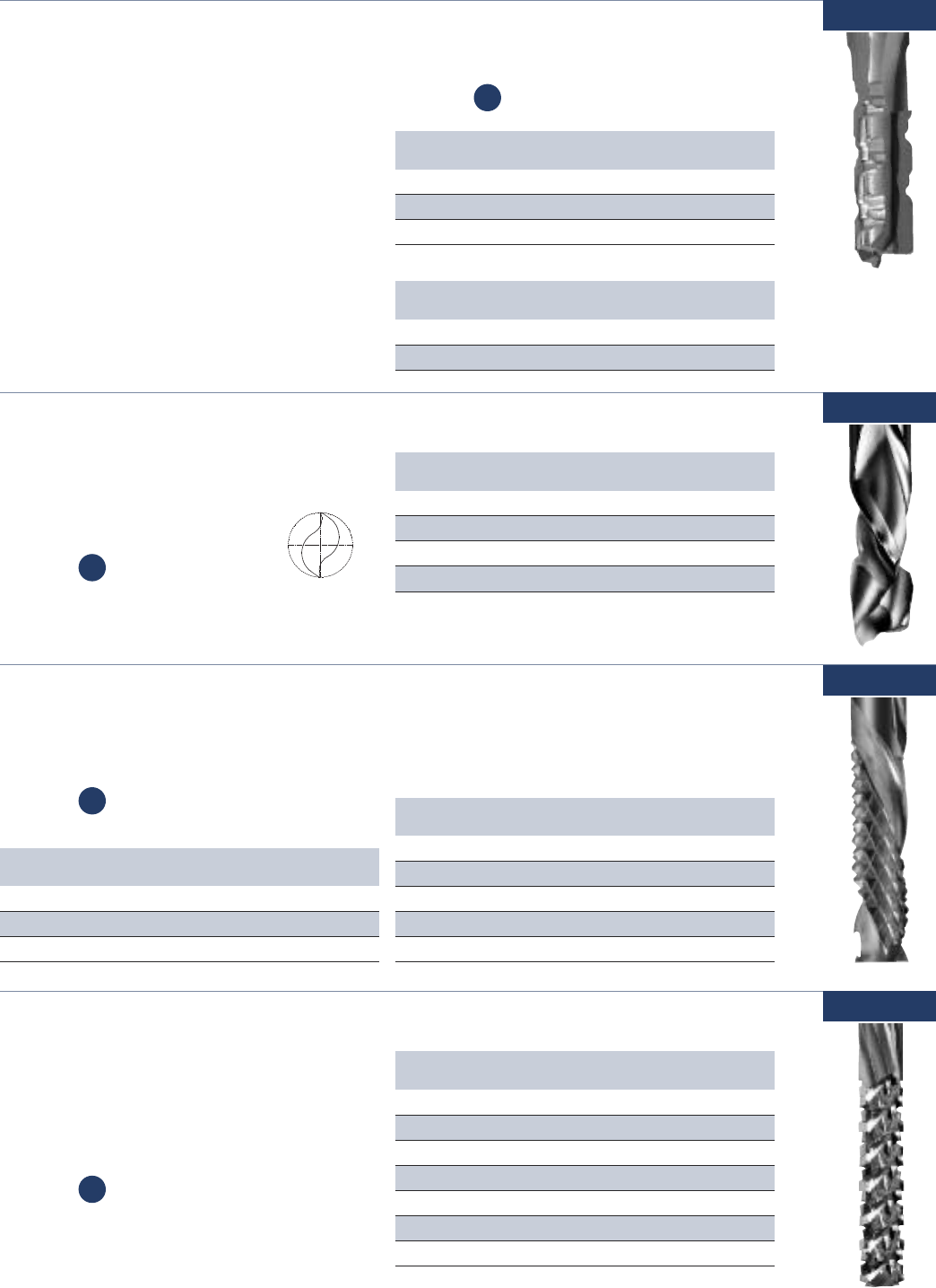
www.onsrud.com 56
Solid Carbide CG Tool (Carbon Graphite)
The geometry of these tools increases the
amount of effective cutting flutes resulting in
superior performance over a standard burr.
67-500
Usage Carbon graphite and
carbon fiber panels
Material See Selection Guide - pg. 2 - 12
Part Cutting Flute SHK OAL
Number DIA LGTH DIA
67-505 1/8 1/2 1/8 2
67-508 3/16 5/8 3/16 2
67-511 1/4 3/4 1/4 3
67-514 1/4 1-1/2 1/4 3
67-520 3/8 1-1/8 3/8 3-1/2
67-523 1/2 1-1/8 1/2 3-1/2
67-526 1/2 2-1/8 1/2 4
CP
Double Flute - Solid Carbide Compression Spiral
Compression design for fast feed and excellent
finish on both sides of the material.
67-300
Usage Composite panels and
honeycomb core
Material See Selection Guide - pg. 2 - 12
Part Cutting Flute SHK OAL Diamond Coated
Number DIA LGTH DIA Part Number
67-305 1/4 7/8 1/4 2-1/2 -
67-314 3/8 1-1/8 3/8 3 67-314DFC
67-320* 1/2 7/8 1/2 3-
67-322 1/2 1-1/8 1/2 3 67-322DFC
* = Mortise Compression HELIX ANGLE ≈ 30°
CP
Solid Carbide Un-Ruffer™PATENTED
The unique design allows for the cutting performance of a burr while achieving a good surface finish.
67-400
Usage Composite panels
Material See Selection Guide - pg. 2 - 12 Part Cutting Flute SHK OAL
Number DIA LGTH DIA
67-423 1/4 3/4 1/4 2
67-426 1/4 1 1/4 2-1/2
67-428 1/4 1 1/4 3
67-435 3/8 1 3/8 3
67-445 1/2 1 1/2 3
CP
Part Cutting Flute SHK OAL
Number DIA LGTH DIA
67-426M 6mm 25mm 6mm 64mm
67-435M 10mm 25mm 10mm 76mm
67-445M 12mm 25mm 12mm 76mm
METRIC
Part Cutting Flute SHK OAL
Number DIA LGTH DIA
67-230 10mm 12mm 10mm 76mm
67-233 12mm 20mm 12mm 100mm
METRIC
Provides superior chip control and increased tool life
when cutting dense and abrasive materials. The new
chipbreaker incorporates a unique geometry with a
PCD cutting edge to support a wide range of feed rates
and depth of cut combinations while extending the life
of the tool. This is accomplished by utilizing a distinct
Hi-Low asymmetrical chipbreaker profile which reduces
vibration and chatter, caused by harmonic imbalance,
resulting in improved surface finishes, while reducing
noise levels and wear on the tool.
67-220
Part Cutting Flute SHK OAL
Number DIA LGTH DIA
67-221 3/8 3/8 3/8 3
67-225 1/2 5/8 1/2 3
67-227 1/2 1-1/8 1/2 3
Usage Composites and phenolic
Material See Selection Guide - pg. 2 - 12
CP
Three Flute - PCD Progressive Chipbreaker for Composites
NEW

57 www.onsrud.com
Part Cutting Flute SHK OAL
Number DIA LGTH DIA
67-859 J (0.2770) 2-1/8 0.277 3-1/2
67-860 K (0.2810) 2-1/8 0.281 3-1/2
67-861 L (0.2910) 2-1/8 0.291 3-1/2
67-862 M (0.2950) 2-3/8 0.295 3-3/4
67-863 N (0.3020) 2-3/8 0.302 3-3/4
67-864 O (0.3160) 2-3/8 0.316 3-3/4
67-865 P (0.3230) 2-3/8 0.323 3-3/4
67-866 Q (0.3320) 2-1/2 0.332 4
67-867 R (0.3390) 2-1/2 0.339 4
67-868 S (0.3480) 2-1/2 0.348 4
67-869 T (0.3580) 2-1/2 0.358 4
67-870 U (0.3680) 2-3/4 0.368 4-1/4
67-871 V (0.3770) 2-3/4 0.377 4-1/4
67-872 W (0.3860) 2-7/8 0.386 4-1/2
67-873 X (0.3970) 2-7/8 0.397 4-1/2
67-874 Y (0.4040) 2-7/8 0.404 4-1/2
67-875 Z (0.4130) 2-7/8 0.413 4-1/2
Part Cutting Flute SHK OAL
Number DIA LGTH DIA
67-893 18 (0.1695) 1-5/8 0.170 2-3/4
67-894 19 (0.1660) 1-5/8 0.166 2-3/4
67-895 20 (0.1610) 1-3/8 0.161 2-1/2
67-896 21 (0.1590) 1-3/8 0.159 2-1/2
67-897 22 (0.1570) 1-3/8 0.157 2-1/2
67-898 23 (0.1540) 1-3/8 0.154 2-1/2
67-899 24 (0.1520) 1-3/8 0.152 2-1/2
67-900 25 (0.1495) 1-3/8 0.150 2-1/2
67-901 26 (0.1470) 1-3/8 0.147 2-1/2
67-902 27 (0.1440) 1-3/8 0.144 2-1/2
67-903 28 (0.1405) 1-3/8 0.141 2-1/2
67-904 29 (0.1360) 1-3/8 0.136 2-1/2
67-905 30 (0.1285) 1-1/4 0.129 2-1/4
67-906 31 (0.1200) 1-1/4 0.120 2-1/4
Part Cutting Flute SHK OAL
Number DIA LGTH DIA
67-961 3.00 (0.1181) 32 3.00 57
67-962 3.50 (0.1378) 35 3.50 64
67-963 4.00 (0.1575) 35 4.00 64
67-964 4.50 (0.1772) 41 4.50 70
67-965 5.00 (0.1969) 44 5.00 76
67-966 5.50 (0.2165) 44 5.50 76
67-967 6.00 (0.2362) 51 6.00 83
67-968 6.50 (0.2559) 51 6.50 83
67-969 7.00 (0.2756) 57 7.00 89
67-970 7.50 (0.2953) 60 7.50 95
67-971 8.00 (0.3150) 60 8.00 95
67-972 8.50 (0.3346) 64 8.50 102
67-973 9.00 (0.3543) 64 9.00 102
67-974 9.50 (0.3740) 70 9.50 108
67-975 10.00 (0.3937) 73 10.00 114
67-976 10.50 (0.4134) 73 10.50 114
67-977 11.00 (0.4331) 73 11.00 114
67-978 11.50 (0.4528) 76 11.50 121
67-979 12.00 (0.4724) 76 12.00 121
Part Cutting Flute SHK OAL
Number DIA LGTH DIA
67-807 1/8 (0.1250) 1-1/4 0.125 2-1/4
67-808 9/64 (0.1406) 1-3/8 0.140 2-1/2
67-809 5/32 (0.1563) 1-3/8 0.156 2-1/2
67-810 11/64 (0.1719) 1-5/8 0.172 2-3/4
67-811 3/16 (0.1875) 1-5/8 0.188 2-3/4
67-812 13/64 (0.2013) 1-3/4 0.203 3
67-813 7/32 (0.2188) 1-3/4 0.219 3
67-814 15/64 (0.2344) 2 0.234 3-1/4
67-815 1/4 (0.2500) 2 0.250 3-1/4
67-816 17/64 (0.2656) 2-1/8 0.266 3-1/2
67-817 9/32 (0.2813) 2-1/8 0.281 3-1/2
67-818 19/64 (0.2969) 2-3/8 0.297 3-3/4
67-819 5/16 (0.3125) 2-3/8 0.313 3-3/4
67-820 21/64 (0.3281) 2-1/2 0.328 4
67-821 11/32 (0.3438) 2-1/2 0.344 4
67-822 23/64 (0.3594) 2-1/2 0.359 4
67-823 3/8 (0.3750) 2-3/4 0.375 4-1/4
67-824 25/64 (0.3906) 2-7/8 0.391 4-1/2
67-825 13/32 (0.4063) 2-7/8 0.406 4-1/2
67-826 27/64 (0.4219) 2-7/8 0.422 4-1/2
67-827 7/16 (0.4375) 2-7/8 0.438 4-1/2
67-828 29/64 (0.4531) 3 0.453 4-3/4
67-829 15/32 (0.4688) 3 0.469 4-3/4
67-830 31/64 (0.4844) 3 0.484 4-3/4
67-831 1/2 (0.5000) 3 0.500 4-3/4
Part Cutting Flute SHK OAL
Number DIA LGTH DIA
67-850 A (0.2340) 2 0.234 3-1/4
67-851 B (0.2380) 2 0.238 3-1/4
67-852 C (0.2420) 2 0.242 3-1/4
67-853 D (0.2460) 2 0.246 3-1/4
67-854 E (0.2500) 2 0.250 3-1/4
67-855 F (0.2570) 2 0.257 3-1/4
67-856 G (0.2610) 2-1/8 0.261 3-1/2
67-857 H (0.2660) 2-1/8 0.266 3-1/2
67-858 I (0.2720) 2-1/8 0.272 3-1/2
Part Cutting Flute SHK OAL
Number DIA LGTH DIA
67-876 1 (0.2280) 1-3/4 0.228 3
67-877 2 (0.2210) 1-3/4 0.221 3
67-878 3 (0.2130) 1-3/4 0.213 3
67-879 4 (0.2090) 1-3/4 0.209 3
67-880 5 (0.2055) 1-3/4 0.206 3
67-881 6 (0.2040) 1-3/4 0.204 3
67-882 7 (0.2010) 1-3/4 0.201 3
67-883 8 (0.1990) 1-3/4 0.199 3
67-884 9 (0.1960) 1-3/4 0.196 3
67-885 10 (0.1935) 1-5/8 0.194 2-3/4
67-886 11 (0.1910) 1-5/8 0.191 2-3/4
67-887 12 (0.1890) 1-5/8 0.189 2-3/4
67-888 13 (0.1850) 1-5/8 0.185 2-3/4
67-889 14 (0.1820) 1-5/8 0.182 2-3/4
67-890 15 (0.1800) 1-5/8 0.180 2-3/4
67-891 16 (0.1770) 1-5/8 0.177 2-3/4
67-892 17 (0.1730) 1-5/8 0.173 2-3/4
X∞
X∞
What is an 8 Facet Drill?
An 8 facet drill consists of
4 cutting edges with
2 facets per cutting
edge. These facets
consist of the lip relief
and the lip clearance angle.
Solid Carbide 8 Facet Drill
Designed to reduce cutting forces and eliminating
delamination when exiting the material.
67-800
Usage Composites, Carbon fiber, mechanical
plastics, and fiber reinforced plastics
NUMBER DRILLS
LETTER DRILLS (CONT.)FRACTIONAL DRILLS
LETTER DRILLS (CONT.)
METRIC DRILLS
NUMBER DRILLS (CONT.)
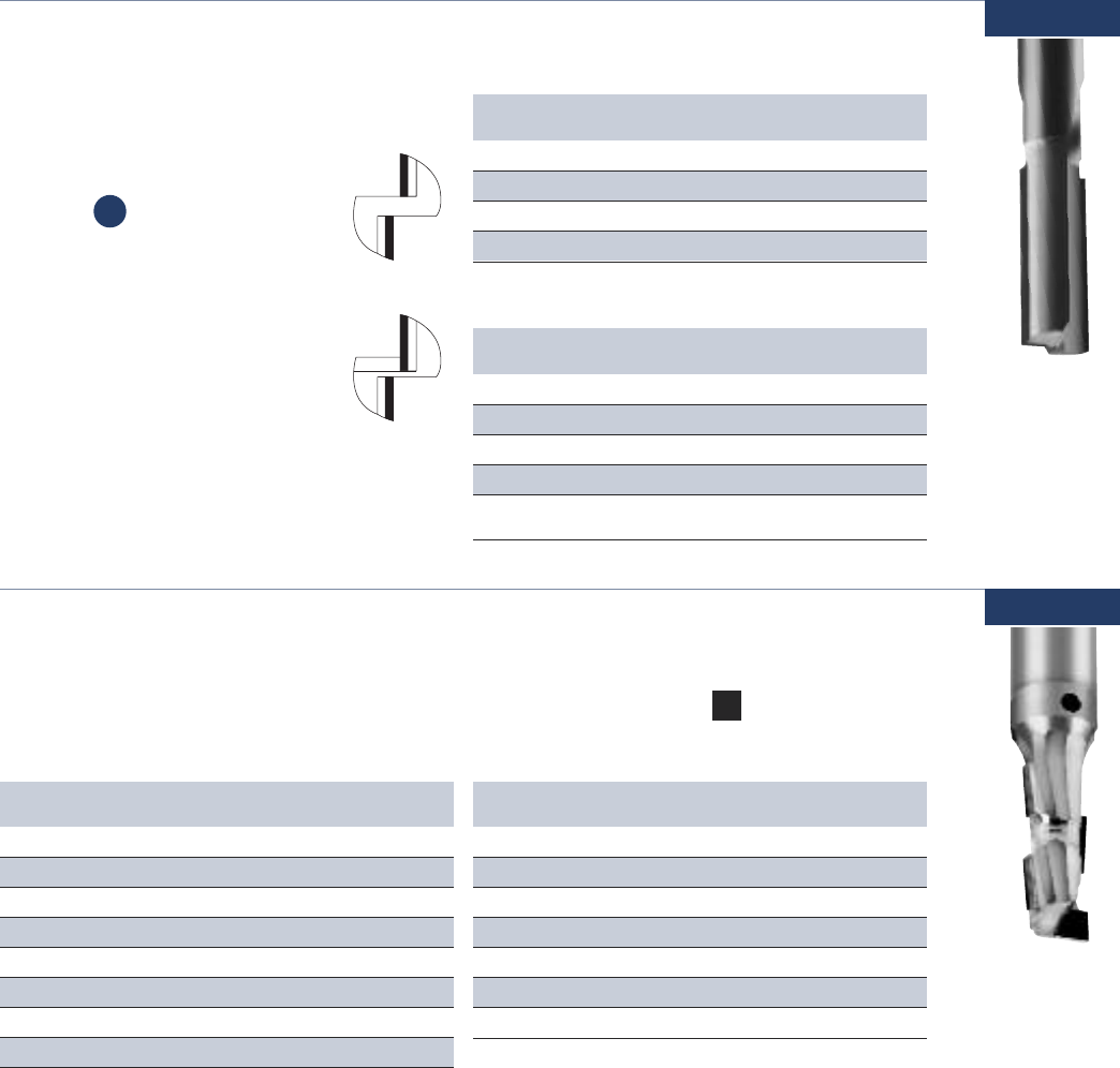
www.onsrud.com 58
Double Flute - PCD Tipped Tooling
Designed for use in abrasive materials where
cut quality and tool life are important.
68-000
Usage Composite panels
and fiberglass
Material See Selection Guide - pg. 2 - 12
Part Cutting Flute SHK OAL
Number DIA LGTH DIA
68-005 1/4 3/4 1/4 3
68-010 3/8 3/4 3/8 3
68-020 1/2 3/4 1/2 4
68-030 3/4 1 3/4 4
HELIX ANGLE ≈ 0-3°
PCD FULL FACE
Part Cutting Flute SHK OAL
Number DIA LGTH DIA
68-050 1/4 3/4 1/4 3
68-055 3/8 7/8 3/8 3
68-062 1/2 1-1/4 1/2 4
68-070 3/4 1-1/4 3/4 4
68-072 3/4 1-1/4 3/4 4
Down Shear
PCD FULL FACE with PLUNGE POINT
CP
PCD Tipped
PCD Full Face
with Plunge Point
Single Flute - PCD Compression Tool
This economical PCD compression tool will provide long tool life in
abrasive wood products. Mortise tip allowing for through cuts and
dado’s to be produced using one tool. The compression design
ensures chip free edges on the top and bottom.
68-100
Part Cutting Flute Upcut SHK OAL Flutes
Number DIA LGTH Flute LGTH DIA
68-104L* 5/8 1 0.200 5/8 3-1/2 1
68-110 5/8 1-5/8 0.200 5/8 41
68-110L* 5/8 1-5/8 0.200 5/8 41
68-106 3/4 1 0.200 3/4 41
68-106L* 3/4 1 0.200 3/4 41
68-112 3/4 1-5/8 0.200 3/4 41
68-112L* 3/4 1-5/8 0.200 3/4 41
L = Left Hand Rotation
* = Tools are not stocked and must be special ordered. Approx. 4 week lead time.
Part Cutting Flute Upcut SHK OAL Flutes
Number DIA LGTH Flute LGTH DIA
68-101 3/8 1 0.188 3/8 31
68-101L 3/8 1 0.188 3/8 31
68-100 3/8 1 0.188 1/2 31
68-100L 3/8 1 0.188 1/2 31
68-102 1/2 1 0.200 1/2 31
68-102L 1/2 1 0.200 1/2 31
68-103 1/2 1-1/4 0.200 1/2 31
68-104 5/8 1 0.200 5/8 3-1/2 1
Usage Composite wood
Material See Selection Guide - pg. 2 - 12
CW
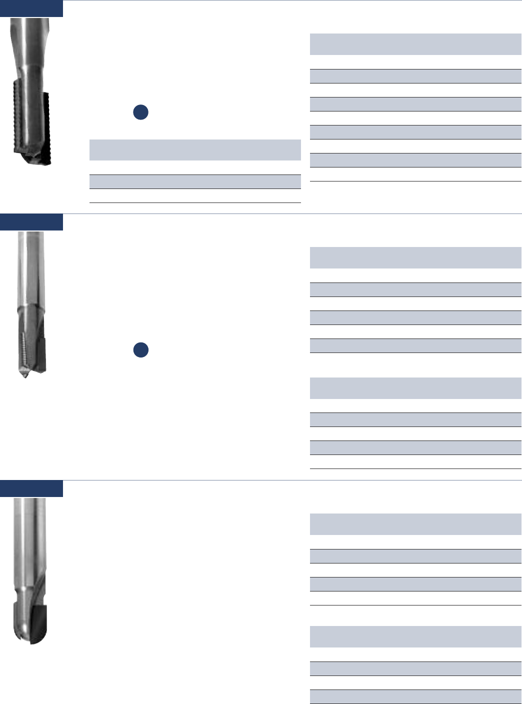
59 www.onsrud.com
Double Flute - PCD SERF™ Cutter
This tool is designed to act like a rougher and
finishing tool in one. The unique geometry
reduces the cutting forces resulting in longer
tool life, higher feed rates and reduced noise.
68-200
Usage Composites
Material See Selection Guide - pg. 2 - 12
Part Cutting Flute SHK OAL
Number DIA LGTH DIA
68-210 1/4 3/8 1/4 3
68-213 1/4 3/4 1/4 3
68-216 1/4 1 1/4 3-1/2
68-220 3/8 3/8 3/8 3
68-223 3/8 3/4 3/8 3
68-226 3/8 1 3/8 3-1/2
68-230 1/2 3/4 1/2 4
68-233 1/2 1 1/2 4
68-236 1/2 1-1/4 1/2 4
CP
Three Flute - PCD SERFIN™ Cutter
Three-Flute tool with two roughing edges that
have geometry to reduce cutting forces and
shear fibers in high-strength composite and
other fiber reinforced plastic materials. The
finishing edge cleans up after roughing cuts
to create a smooth edge on material.
68-300
Part Cutting Flute SHK OAL
Number DIA LGTH DIA
68-315 3/8 1/2 3/8 4
68-320 3/8 7/8 3/8 4
68-340 1/2 5/8 1/2 4
68-345 1/2 1 1/2 4
68-350 1/2 1-1/4 1/2 4
68-360 3/4 1-3/8 3/4 5
Usage Composites
Material See Selection Guide - pg. 2 - 12
CP
Part Cutting Flute SHK OAL
Number DIA LGTH DIA
68-310 8mm 10mm 8mm 76mm
68-325 10mm 14mm 10mm 100mm
68-330 12mm 14mm 12mm 100mm
68-335 12mm 26mm 12mm 100mm
68-355 16mm 26mm 16mm 100mm
METRIC
Part Cutting Flute SHK OAL
Number DIA LGTH DIA
68-213M 6mm 20mm 6mm 76mm
68-226M 10mm 25mm 10mm 88mm
68-236M 12mm 32mm 12mm 100mm
METRIC
NEW
Part Cutting Flute SHK OAL
Number DIA LGTH DIA
68-440 6mm 10mm 6mm 76mm
68-445 8mm 10mm 8mm 76mm
68-450 10mm 12mm 10mm 76mm
68-455 12mm 20mm 12mm 100mm
METRIC
Double Flute - PCD Ballnose
Designed for use in abrasive materials where
cut quality and tool life are important.
68-400
Part Cutting Flute SHK OAL
Number DIA LGTH DIA
68-405 1/4 3/8 1/4 2-1/2
68-410 3/8 1/2 3/8 3
68-420 1/2 5/8 1/2 4
68-425 5/8 7/8 5/8 4
68-430 3/4 1 3/4 4
Usage Composites
NEW
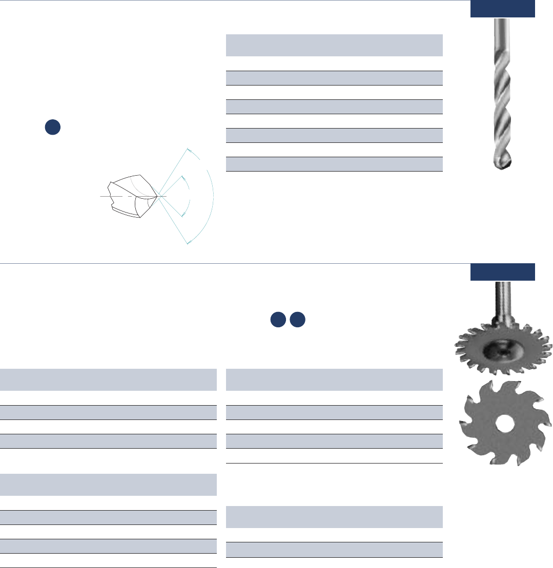
www.onsrud.com 60
PCD 8 Facet Drills
The PCD 8 facet drill works well in composite
material where long tool life and a delamination
free hole is required. The drill diameters are
oversize allowing for aircraft fasteners to extend
through the holes.
68-900
Usage Composites
Material See Selection Guide - pg. 2 - 12
Part Cutting Flute SHK OAL
Number DIA LGTH DIA
68-902 0.100 1 1/4 3
68-904 0.129 1 1/4 3
68-908 0.147 1 1/4 3
68-910 0.192 1 1/4 3
68-914 0.251 1 1/4 3
68-918 0.313 1 5/16 3
68-922 0.376 1 3/8 3
68-926 0.502 1 1/2 3
CP
Carbide Tipped Trim Blade and Arbor
Designed to trim and groove both hard and
soft plastics. These blades run in conjunction
with the blade arbors. Blades are reversible for
right or left hand rotation cutting.
70-100
Usage Hard and soft plastic
Material
See Selection Guide - pg. 2 - 12
Part Cutting Teeth Rake Kerf Grind
Number DIA
70-160 2 16 -5° .095 TCG
70-162 2-1/2 20 -5° .095 TCG
70-164 3 20 -5° .095 TCG
70-166 3-1/2 20 -5° .095 TCG
70-168 4 20 -5° .095 TCG
TCG = Triple Chip Grind
HARD PLASTIC - FAST FEED
Part Cutting OAL
Number DIA
70-180 1/2 3-1/4
70-181 1/2 4-1/2
*SEE FEED & SPEED CHART ON PAGE 59.
SAW ARBOR -
These saw arbors are designed to hold the carbide tipped saws.
Part Cutting Teeth Rake Kerf Grind
Number DIA
70-100 2 10 0° .095 TCG
70-102 2-1/2 10 0° .095 TCG
70-104 3 10 0° .095 TCG
70-108 4 10 0° .095 TCG
SOFT PLASTIC - SLOW FEED
Part Cutting Teeth Rake Kerf Grind
Number DIA
70-120 2 16 0° .095 TCG
70-122 2-1/2 20 0° .095 TCG
70-124 3 20 0° .095 TCG
70-126 3-1/2 20 0° .095 TCG
70-128 4 20 0° .095 TCG
SOFT PLASTIC - FAST FEED
SP HP
X∞
X∞
What is an 8 Facet Drill?
An 8 facet drill consists of
4 cutting edges with
2 facets per cutting
edge. These facets
consist of the lip relief
and the lip clearance angle.
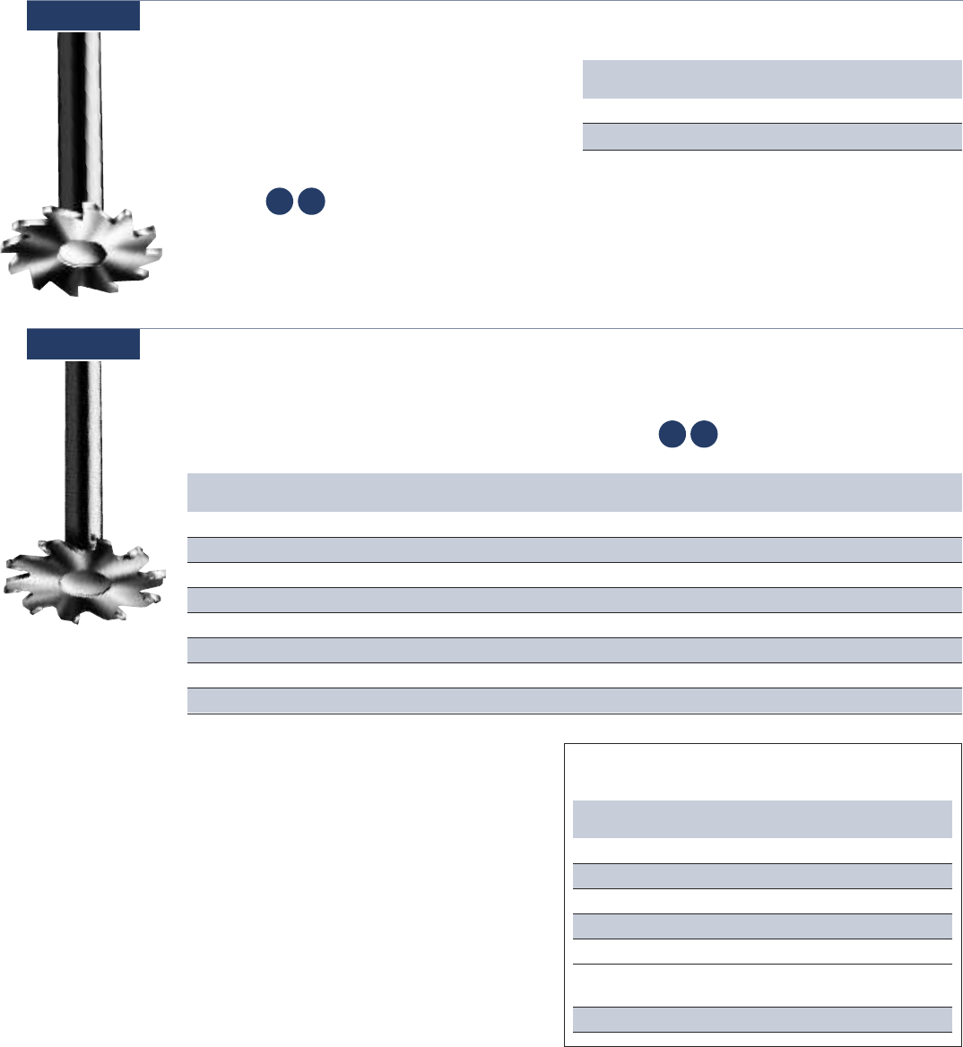
61 www.onsrud.com
Tool Cutting Max Soft Hard Fibrous
Series DIA RPM Plastic Plastic Reinfrc
70-100 2” 18,000 150 150 150
70-100 2-1/2” 16,000 150 150 150
70-100 3” 14,000 150 150 150
70-100 3-1/2” 12,000 150 150 150
70-100 4” 10,000 150 150 150
70-200 1-1/2” 14,000 150 150 150
& Smaller
70-300 2” 16,000 150 150 150
Feeds & Speeds for Blades
INCHES PER MINUTE
Part Cutting Teeth Rake SHK Kerf OAL Grind Rotation Plastic Feed
Number DIA DIA
70-300 2 10 0° 1/2 .095 4 TCG RH Soft Slow
70-302 2 10 0° 1/2 .095 4 TCG LH Soft Slow
70-320 2 16 0° 1/2 .095 4 TCG RH Soft Fast
70-322 2 16 0° 1/2 .095 4 TCG LH Soft Fast
70-340 2 10 -5° 1/2 .095 4 TCG RH Hard Slow
70-342 2 10 -5° 1/2 .095 4 TCG LH Hard Slow
70-360 2 16 -5° 1/2 .095 4 TCG RH Hard Fast
70-362 2 16 -5° 1/2 .095 4 TCG LH Hard Fast
*SEE FEED & SPEED CHART BELOW
TCG = Triple Chip Grind
Carbide Tipped Trim Blade Flush Mount
Designed for flush trimming and slotting of both
hard and soft plastics. Blades are permanently
attached to arbors and are not reversible.
Usage Hard and soft plastic
Material See Selection Guide - pg. 2 - 12
70-300
SP HP
Solid Carbide Trim Blade Flush Mount
These small diameter solid carbide arbor
mounted blades are designed for trimming and
slotting plastics. Blades are permanently attached
to arbors and are not reversible.
70-200
Usage Hard and soft plastic
Material
See Selection Guide - pg. 2 - 12
Part Cutting Collar SHK Kerf OAL Rotation
Number DIA DIA
70-204 1 9/16 1/2 .062 4 Right
70-224 1-1/4 5/8 1/2 .062 4 Right
*SEE FEED & SPEED CHART ON PAGE 59.
SP HP

www.onsrud.com 62
NO Wrapping
NO Cleaning
NO Melting
NO Surface Marring
NO Interrupted Operation
HSS Plastic Drill
Designed to produce holes in hard
and soft plastic while eliminating
edge chipping and chip wrapping.
70-500
Usage Hard and soft plastic
Material See Selection Guide - pg. 2 - 12
SP HP
WIRE DRILLS
FRACTIONAL DRILLS FRACTIONAL DRILLS (CONT.)
LETTER DRILLS
METRIC DRILLS
WIRE DRILLS
Part Cutting Flute SHK OAL
Number DIA LGTH DIA
70-714 3.00 (0.118) 41 3.00 70
70-715 3.50 (0.138) 44 3.50 73
70-716 4.00 (0.157) 54 4.00 83
70-717 4.50 (0.177) 56 4.50 86
70-718 5.00 (0.197) 62 5.00 92
70-719 5.50 (0.217) 64 5.50 95
70-720 6.00 (0.236) 70 6.00 102
70-721 6.50 (0.256) 73 6.50 105
70-722 7.00 (0.276) 73 7.00 105
70-723 7.50 (0.295) 78 7.50 111
70-724 8.00 (0.315) 81 8.00 114
70-725 8.50 (0.335) 87 8.50 121
70-726 9.00 (0.354) 89 9.00 124
70-727 9.50 (0.374) 92 9.50 127
70-728 10.00 (0.394) 95 10.00 130
70-729 10.50 (0.413) 98 10.50 133
70-730 11.00 (0.433) 103 11.00 140
70-731 11.50 (0.453) 106 11.50 143
70-732 12.00 (0.472) 111 12.00 149
70-733 12.50 (0.492) 114 12.50 152
70-734 13.00 (0.512) 114 13.00 152
70-735 13.50 (0.531) 122 13.50 168
70-736 14.00 (0.551) 122 14.00 168
70-737 14.50 (0.571) 122 14.50 168
70-738 15.00 (0.591) 132 15.00 181
70-739 15.50 (0.610) 132 15.50 181
70-740 16.00 (0.630) 132 16.00 181
70-741 16.50 (0.650) 132 16.50 181
70-742 17.00 (0.669) 143 17.00 194
70-743 17.50 (0.689) 143 17.50 194
Part Cutting Flute SHK OAL
Number DIA LGTH DIA
70-643 14 (0.182) 2-3/16 0.182 3-3/8
70-644 15 (0.180) 2-3/16 0.180 3-3/8
70-645 16 (0.177) 2-3/16 0.177 3-3/8
70-646 17 (0.173) 2-3/16 0.173 3-3/8
70-647 18 (0.170) 2-1/8 0.170 3-1/4
70-648 19 (0.166) 2-1/8 0.166 3-1/4
70-649 20 (0.161) 2-1/8 0.161 3-1/4
70-650 21 (0.159) 2-1/8 0.159 3-1/4
70-651 22 (0.157) 2 0.157 3-1/8
70-652 23 (0.154) 2 0.154 3-1/8
70-653 24 (0.152) 2 0.152 3-1/8
70-654 25 (0.150) 1-7/8 0.150 3
70-655 26 (0.147) 1-7/8 0.147 3
70-656 27 (0.144) 1-7/8 0.144 3
70-657 28 (0.141) 1-3/4 0.141 2-7/8
70-658 29 (0.136) 1-3/4 0.136 2-7/8
70-659 30 (0.129) 1-5/8 0.129 2-3/4
70-660 31 (0.120) 1-5/8 0.120 2-3/4
Part Cutting Flute SHK OAL
Number DIA LGTH DIA
70-561 61⁄64 (0.953) 3-1/8 1/2 6
70-562 31⁄32 (0.969) 3-1/8 1/2 6
70-563 63⁄64 (0.984) 3-1/8 1/2 6
Part Cutting Flute SHK OAL
Number DIA LGTH DIA
70-600 A (0.234) 2-5/8 0.234 3-7/8
70-601 B (0.238) 2-3/4 0.238 4
70-602 C (0.242) 2-3/4 0.242 4
70-603 D (0.246) 2-3/4 0.246 4
70-604 E (0.250) 2-3/4 0.250 4
70-605 F (0.257) 2-7/8 0.257 4-1/8
70-606 G (0.261) 2-7/8 0.261 4-1/8
70-607 H (0.266) 2-7/8 0.266 4-1/8
70-608 I (0.272) 2-7/8 0.272 4-1/8
70-609 J (0.277) 2-7/8 0.277 4-1/8
70-610 K (0.281) 2-15/16 0.281 4-1/4
70-611 L (0.291) 2-15/16 0.291 4-1/4
70-612 M (0.295) 3-1/16 0.295 4-3/8
70-613 N (0.302) 3-1/16 0.302 4-3/8
70-614 O (0.316) 3-3/16 0.316 4-1/2
70-615 P (0.323) 3-5/16 0.323 4-5/8
70-616 Q (0.332) 3-7/16 0.332 4-3/4
70-617 R (0.339) 3-7/16 0.339 4-3/4
70-618 S (0.348) 3-1/2 0.348 4-7/8
70-619 T (0.358) 3-1/2 0.358 4-7/8
70-620 U (0.368) 3-5/8 0.368 5
70-621 V (0.377) 3-5/8 0.377 5
70-622 W (0.386) 3-3/4 0.386 5-1/8
70-623 X (0.397) 3-3/4 0.397 5-1/8
70-624 Y (0.404) 3-7/8 0.404 5-1/4
70-625 Z (0.413) 3-15/16 0.413 5-1/4
Part Cutting Flute SHK OAL
Number DIA LGTH DIA
70-630 1 (0.228) 2-5/8 0.228 3-7/8
70-631 2 (0.221) 2-5/8 0.221 3-7/8
70-632 3 (0.213) 2-1/2 0.213 3-3/4
70-633 4 (0.209) 2-1/2 0.209 3-3/4
70-634 5 (0.206) 2-1/2 0.206 3-3/4
70-635 6 (0.204) 2-1/2 0.204 3-3/4
70-636 7 (0.201) 2-7/16 0.201 3-5/8
70-637 8 (0.199) 2-7/16 0.199 3-5/8
70-638 9 (0.196) 2-7/16 0.196 3-5/8
70-639 10 (0.194) 2-7/16 0.194 3-5/8
70-640 11 (0.191) 2-5/16 0.191 3-1/2
70-641 12 (0.189) 2-5/16 0.189 3-1/2
70-642 13 (0.185) 2-5/16 0.185 3-1/2
Part Cutting Flute SHK OAL
Number DIA LGTH DIA
70-502 1/8 (0.125) 1-1/2 1/8 2-3/4
70-503 9/64 (0.141) 1-3/4 9/64 2-7/8
70-506 5/32 (0.156) 1-15/16 5/32 3-1/8
70-509 11/64 (0.172) 1-3/4 11/64 3-1/4
70-510 3/16 (0.188) 2-1/8 3/16 3-1/2
70-511 13/64 (0.203) 2-7/16 13/64 3-5/8
70-512 7/32 (0.219) 2-1/2 7/32 3-3/4
70-513 15/64 (0.234) 2-5/8 15/64 3-7/8
70-514 1/4 (0.250) 2-7/16 1/4 4
70-515 17/64 (0.266) 2-7/8 17/64 4-1/8
70-516 9/32 (0.281) 2-15/16 9/32 4-1/4
70-517 19/64 (0.297) 3-1/16 19/64 4-3/8
70-520 5/16 (0.313) 1-3/4 1/4 3-1/8
70-521 21/64 (0.328) 3-5/16 21/64 4-5/8
70-522 11/32 (0.344) 3-7/16 11/32 4-3/4
70-523 23/64 (0.359) 3-1/2 23/64 4-7/8
70-524 3/8 (0.375) 2-1/4 1/4 4-3/8
70-525 25/64 (0.391) 3-3/4 25/64 5-1/8
70-526 13/32 (0.406) 3-7/8 13/32 5-1/8
70-527 27/64 (0.422) 3-15/16 27/64 5-3/8
70-528 7/16 (0.438) 2-1/2 1/4 4-3/4
70-529 29/64 (0.453) 4-3/16 29/64 5-5/8
70-530 15/32 (0.469) 4-5/16 15/32 5-3/4
70-531 31/64 (0.484) 4-3/8 31/64 5-7/8
70-532 1/2 (0.500) 2-5/8 1/4 5-1/8
70-533 33/64 (0.516) 3-1/8 1/2 6
70-534 17/32 (0.531) 3-1/8 1/2 6
70-535 35/64 (0.547) 3-1/8 1/2 6
70-536 9/16 (0.563) 3-1/8 1/2 6
70-537 37/64 (0.578) 3-1/8 1/2 6
70-538 19/32 (0.594) 3-1/8 1/2 6
70-539 39/64 (0.609) 3-1/8 1/2 6
70-540 5/8 (0.625) 3-1/8 1/2 6
70-541 41/64 (0.641) 3-1/8 1/2 6
70-542 21/32 (0.656) 3-1/8 1/2 6
70-543 43/64 (0.672) 3-1/8 1/2 6
70-544 11/16 (0.688) 3-1/8 1/2 6
70-545 45/64 (0.703) 3-1/8 1/2 6
70-546 23/32 (0.719) 3-1/8 1/2 6
70-547 47/64 (0.734) 3-1/8 1/2 6
70-548 3/4 (0.750) 3-1/8 1/2 6
70-549 49/64 (0.766) 3-1/8 1/2 6
70-550 25/32 (0.781) 3-1/8 1/2 6
70-551 51/64 (0.797) 3-1/8 1/2 6
70-552 13/16 (0.813) 3-1/8 1/2 6
70-553 53/64 (0.828) 3-1/8 1/2 6
70-554 27/32 (0.844) 3-1/8 1/2 6
70-555 55/64 (0.859) 3-1/8 1/2 6
70-556 7/8 (0.875) 3-1/8 1/2 6
70-557 57/64 (0.891) 3-1/8 1/2 6
70-558 29/32 (0.906) 3-1/8 1/2 6
70-559 59/64 (0.922) 3-1/8 1/2 6
70-560 15/16 (0.938) 3-1/8 1/2 6
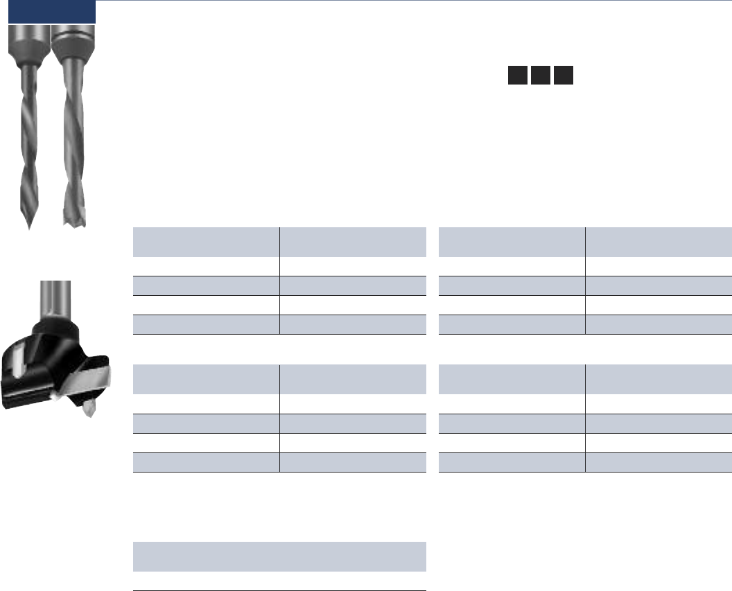
63 www.onsrud.com
Usage Wood
Material
See Selection Guide - pg. 2 - 12
Solid Carbide Boring Bits
Two style of tools are available in this series. The
brad point drill is designed to cut blind holes and
produce a clean edge on the top surface. The 60°
through drill is designed to produce through holes
while providing clean edges on both sides.
72-000
SW HW CW
Part Cutting SHK OAL Part Cutting SHK OAL
Number DIA DIA Number DIA DIA
72-001 3 10 57 72-021 3 10 70
72-005 5 10 57 72-025 5 10 70
72-009 6 10 57 72-029 6 10 70
72-013 8 10 57 72-033 8 10 70
RIGHT HAND ROTATION
BRAD POINT - designed to produce a blind hole
while preventing fraying on the top edge.
THROUGH HOLE (60° POINT) - produces a
through hole and reduces fraying on the entry
and exit edges.
Through
Hole
Brad
Point
Hinge
Part Cutting SHK OAL Part Cutting SHK OAL
Number DIA DIA Number DIA DIA
72-053 3 10 57 72-075 3 10 70
72-057 5 10 57 72-079 5 10 70
72-061 6 10 57 72-083 6 10 70
72-065 8 10 57 72-087 8 10 70
RIGHT HAND ROTATION
Part Cutting SHK OAL Part Cutting SHK OAL
Number DIA DIA Number DIA DIA
72-002 3 10 57 72-022 3 10 70
72-006 5 10 57 72-026 5 10 70
72-010 6 10 57 72-030 6 10 70
72-014 8 10 57 72-034 8 10 70
LEFT HAND ROTATION
Part Cutting SHK OAL Part Cutting SHK OAL
Number DIA DIA Number DIA DIA
72-054 3 10 57 72-076 3 10 70
72-058 5 10 57 72-080 5 10 70
72-062 6 10 57 72-084 6 10 70
72-066 8 10 57 72-088 8 10 70
LEFT HAND ROTATION
HINGE BIT - This 35mm carbide tipped bit is
designed to produce a flat bottom hole with
clean edges for hinge mounting.
Part Cutting SHK OAL
Number DIA DIA
72-097 35 10 70
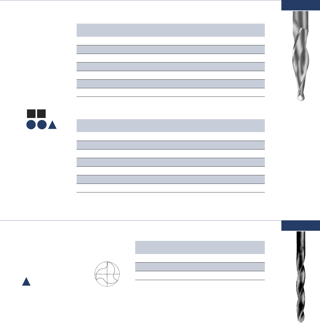
www.onsrud.com 64
METRIC
77-100
Part Cutting Flute SHK OAL Angle Radius Flutes
Number DIA LGTH DIA Per Side
77-102 1/8 1-1/2 1/4 3 1° 1/16 3
77-104 1/8 1 1/4 3 3° 1/16 3
77-106 1/8 3/4 1/4 3 5° 1/16 3
77-108 1/8 1/2 1/4 3 7° 1/16 3
77-112 1/4 2 1/2 4 3° 1/8 2
77-114 1/4 1-3/8 1/2 4 5° 1/8 2
77-116 1/4 1 1/2 4 7° 1/8 2
Part Cutting Flute SHK OAL Angle Radius Flutes
Number DIA LGTH DIA Per Side
77-102M 3mm 39mm 6mm 76mm 1° 1.5mm 3
77-104M 3mm 25mm 6mm 76mm 3° 1.5mm 3
77-106M 3mm 19mm 6mm 76mm 5° 1.5mm 3
77-108M 3mm 12mm 6mm 76mm 7° 1.5mm 3
77-112M 6mm 50mm 12mm 100mm 3° 3mm 2
77-114M 6mm 35mm 12mm 100mm 5° 3mm 2
77-116M 6mm 25mm 12mm 100mm 7° 3mm 2
Double or Three Flute Solid Carbide Taper Tools
The taper tools are
available with a variety
of taper angles and
come standard with
a ball nose point. The
tools are designed to
produce a good edge
finish in a wide variety
of materials.
Usage Wood, plastic
and aluminum
Material
See Selection
Guide - pg. 2 - 12
SW HW
SP HP A
A
Three Flute - High Speed Steel Taper Pin Router
These three flute upcuts with a tapered flute
are used for profiling and trimming primarily
in aircraft assembly operations.
80-000
Usage Aluminum
Material See Selection Guide - pg. 2 - 12
Part Cutting Flute SHK OAL
Number DIA LGTH DIA
80-001 .098 3/4 .098 2
80-002 .110 7/8 .128 2 1/4
80-003 .165 1 1/16 .1875 2 1/2
HELIX ANGLE ≈ 24°
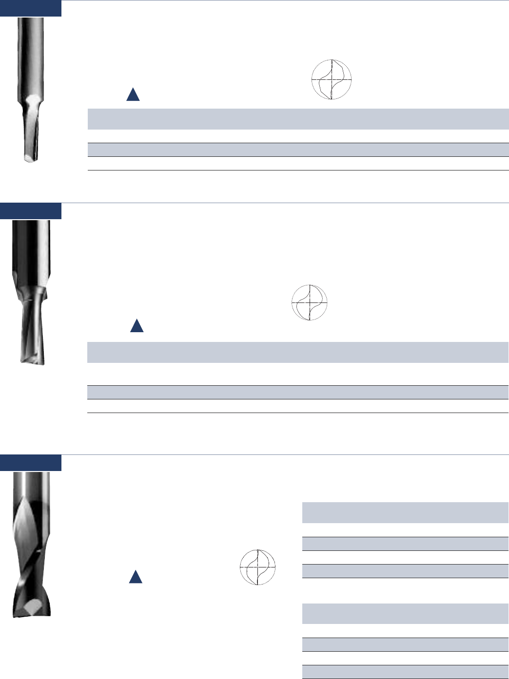
65 www.onsrud.com
M
Double Flute - Solid Carbide AlTiN Coated
Upcut Spiral for Stainless Steel
Special cutting geometry is required to cut
stainless steel and achieve decent tool life.
Onsrud has developed a line of cutters which
are capable of cutting stainless steel.
83-300
Usage Stainless Steel
Material See Selection Guide - pg. 2 - 12
Part Cutting Flute SHK OAL
Number DIA LGTH DIA
83-305AlTiN 1/8 1/4 1/8 2
83-310AlTiN 3/16 3/8 3/16 2-1/2
83-315AlTiN 1/4 3/8 1/4 2-1/2
83-320AlTiN 3/8 1/2 3/8 3
Part RPM Feedrate Depth
Number of Cut
83-305AlTiN 18,000 18 IPM .012
83-310AlTiN 12,000 20 IPM .020
83-315AlTiN 9,000 25 IPM .030
83-320AlTiN 6,010 27 IPM .045
CUTTING PARAMETERS
81-100
Part Cutting Flute ERL SHK OAL Helix Flutes CNR RAD Aluminum Machining
Number DIA LGTH DIA & DIR Chamfer Condition Environment
Tolerance +.002 ±.03 +.0000 ±.03
-.0005
81-103 5/16 13/16 - 1/2 3 10°RH 2 .02 x 45° C Wet
81-104 3/8 13/16 - 1/2 3 10°RH 2 .02 x 45° O Wet
Double Flute - Solid Carbide Spiral Extrusion Cutters
Designed for reduced vibration producing smoother
finish cuts. Extended reach during side thinning and
gage reduction. Longer tool life to reduce tool changes.
Usage Extrusion and sheet aluminum.
Optimized for use on multi-head
extrusion mills CNC mills and routers
Material See Selection Guide - pg. 2 - 12
A
Double Flute - High Speed Steel Lo Helix
These lo helix upcut spirals were developed for CNC routers used primarily in the
aircraft industry. They are designed with maximum strength of configuration to cut
T, O or combined stacks of aluminum-using coolant.
81-000
Usage Aluminum
Material See Selection Guide - pg. 2 - 12
Part Cutting Flute SHK OAL Helix ALUM
Number DIA LGTH DIA Condition
81-001 1/4 3/4 1/2 3 1/16 5° T
81-003 5/16 3/4 1/2 3 1/16 10° C
81-004 5/16 3/4 1/2 3 1/16 10° O
A

www.onsrud.com 66
Solid Carbide CFRP Drill (Coated)
The CFRP drill is designed to ensure hole quality and diameter. The “W”
point of the drill centers the drill to let the peripheral cutting edges shear
the material producing a clean, tight tolerance hole without fraying or
delamination. The drills are coated with a Diamond Like Carbon (DLC).
Usage Carbon Fiber Reinforced Plastics, Kevlar®and Composites
Material See Selection Guide - pg. 2 - 12
NUMBER DRILLSFRACTIONAL DRILLS NUMBER DRILLS (CONT.)
NEW
85-800
METRIC DRILLS
Part Cutting Flute SHK OAL
Number DIA LGTH DIA
85-961 3.00 (0.1181) 12.000 3 76
85-963 4.00 (0.1575) 12.000 4 76
85-965 5.00 (0.1969) 12.000 5 76
85-967 6.00 ( 0.2362) 12.000 6 76
85-971 8.00 (0.3150) 12.000 8 76
85-975 10.00 (0.3937) 12.000 10 76
85-979 12.00 (0.4724) 12.000 12 76
Part Cutting Flute SHK OAL
Number DIA LGTH DIA
85-807 1/8 (0.1250) 0.500 1/8 3
85-808 9/64 (0.1406) 0.500 3/16 3
85-809 5/32 (0.1563) 0.500 3/16 3
85-810 11/64 (0.1719) 0.500 3/16 3
85-811 3/16 (0.1875) 0.500 3/16 3
85-812 13/64 (0.2031) 0.500 1/4 3
85-813 7/32 (0.2188) 0.500 1/4 3
85-814 15/64 (0.2344) 0.500 1/4 3
85-815 1/4 (0.2500) 0.500 1/4 3
85-816 17/64 (0.2656) 0.500 5/16 3
85-817 9/32 (0.2813) 0.500 5/16 3
85-818 19/64 (0.2969) 0.500 5/16 3
85-819 5/16 (0.3125) 0.500 5/16 3
85-820 21/64 (0.3281) 0.500 3/8 3
85-821 11/32 (0.3438) 0.500 3/8 3
85-822 23/64 (0.3594) 0.500 3/8 3
85-823 3/8 (0.3750) 0.500 3/8 3
85-827 7/16 (0.4375) 0.500 7/16 3
85-831 1/2 (0.5000) 0.500 1/2 3
Part Cutting Flute SHK OAL
Number DIA LGTH DIA
85-876 1 (0.2280) 0.500 1/4 3
85-877 2 (0.2210) 0.500 1/4 3
85-878 3 (0.2130) 0.500 1/4 3
85-879 4 (0.2090) 0.500 1/4 3
85-880 5 (0.2055) 0.500 1/4 3
85-881 6 (0.2040) 0.500 1/4 3
85-882 7 (0.2010) 0.500 1/4 3
85-883 8 (0.1990) 0.500 1/4 3
85-884 9 (0.1960) 0.500 1/4 3
85-885 10 (0.1935) 0.500 1/4 3
85-886 11 (0.1910) 0.500 1/4 3
85-887 12 (0.1890) 0.500 1/4 3
85-888 13 (0.1850) 0.500 3/16 3
85-889 14 (0.1820) 0.500 3/16 3
85-890 15 (0.1800) 0.500 3/16 3
85-891 16 (0.1770) 0.500 3/16 3
85-892 17 (0.1730) 0.500 3/16 3
85-893 18 (0.1695) 0.500 3/16 3
85-894 19 (0.1660) 0.500 3/16 3
85-895 20 (0.1610) 0.500 3/16 3
85-896 21 (0.1590) 0.500 3/16 3
Part Cutting Flute SHK OAL
Number DIA LGTH DIA
85-897 22 (0.1570) 0.500 3/16 3
85-898 23 (0.1540) 0.500 5/32 3
85-899 24 (0.1520) 0.500 5/32 3
85-900 25 (0.1495) 0.500 5/32 3
85-901 26 (0.1470) 0.500 5/32 3
85-902 27 (0.1440) 0.500 5/32 3
85-903 28 (0.1405) 0.500 5/32 3
85-904 29 (0.1360) 0.500 5/32 3
85-905 30 (0.1285) 0.500 5/32 3
85-906 31 (0.1200) 0.500 1/8 2-1/2
85-907 32 (0.1160) 0.500 1/8 2-1/2
85-908 33 (0.1130) 0.500 1/8 2-1/2
85-909 34 (0.1110) 0.500 1/8 2-1/2
85-910 35 (0.1100) 0.500 1/8 2-1/2
85-911 36 (0.1065) 0.500 1/8 2-1/2
85-912 37 (0.1040) 0.500 1/8 2-1/2
85-913 38 (0.1015) 0.500 1/8 2-1/2
85-914 39 (0.0995) 0.500 1/8 2-1/2
85-915 40 (0.0980) 0.500 1/8 2-1/2
85-916 41 (0.0960) 0.500 1/8 2-1/2
CP
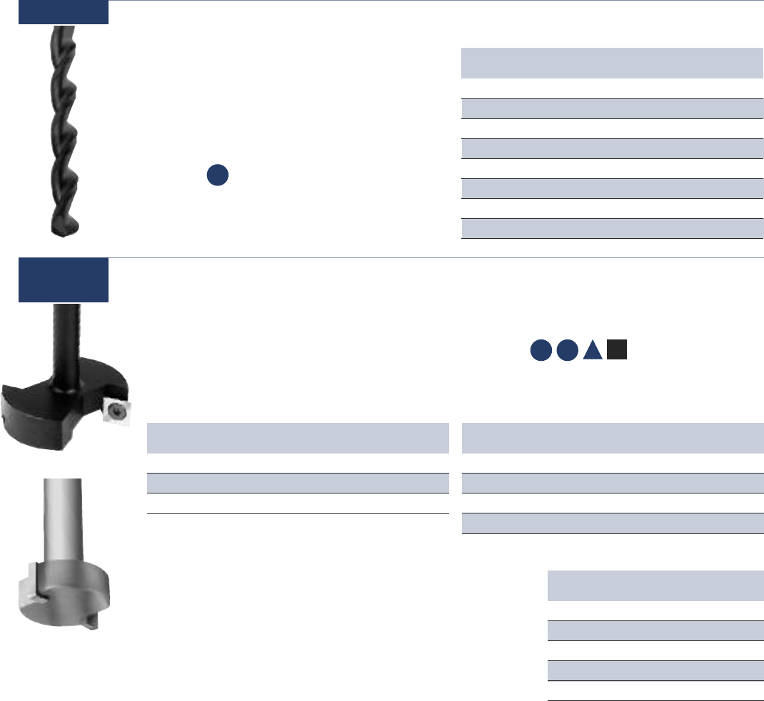
67 www.onsrud.com
Usage Aluminum, plastics and
composite wood
Material
See Selection Guide - pg. 2 - 12
Spoilboard Surfacing Cutters
Designed for surfacing MDF, particleboard
and balsa core where “flow through” or “high
flow” fixturing is employed using large capacity
vacuum pumps. This method of surfacing
spoilboards allows for much faster table planing.
Part Cutting SHK SHK # of
Number DIA DIA LGTH Wings
91-000* 1-1/4 1/2 1-1/2 2
91-102 2-1/2 1/2 22
91-106 4 3/4 2-1/4 3
* = Carbide Tipped
Note: 90-002, 90-004, 90-006 & 90-008 use 91-125 insert and 91-130 screw
90-014 use 91-127 insert and 91-130 screw
STRAIGHT
Part Cutting SHK SHK # of
Number DIA DIA LGTH Wings
91-104 2-1/2 1/2 22
91-108 4 3/4 2-1/4 3
91-112* 2-1/2 1/2 23
91-114* 4 3/4 2-1/4 3
* Radius edges excellent for plastic and aluminum surfacing.
UP-SHEAR
Part Description
Number
91-125 Insert 10/pk
91-127 Radius Insert 10/pk
91-130 Screw M4 (Old Version)
91-133 Screw M5
91-136 Wrench
These tools are dynamically balanced and approved for use on
CNC routers. Max RPM 18,000 1/8” Depth of cut MAX.
* DOC = Maximum Depth of Cut Proper running speed for
Spoilboard Surfaces: 2-1/2” diameter tools should be fed at
200-600 IPM at 12,000-16,000 RPM. 4” diameter tools should
be fed at 200-600 IPM at 12,000-14,000 RPM.
* Do Not Exceed 1/8” Depth Per Pass
ROUTER SELECTION GUIDE
The selection guide on pages 2 - 12 is a place to start making a bit selection or a place to check your current bit
selection. You should try several tools and more than one tool geometry before you settle on the best tool for you specific
router, set-up, fixturing and other environmental conditions.
How To Order – LMT Onsrud products are sold solely through industrial distribution. You may place an order through the
authorized distributor in you market area. Should you wish the name of that distributor, please call LMT Onsrud
Guarantee – LMT Onsrud products are guaranteed against defects in material and quality of manufacture when used in the
proper manner. LMT Onsrud will repair or replace tools, which have been authorized for return, if upon inspection such tools
are found to be defective due to material or manufacture.
Router Laboratory – Customers, as a routine, send us panels (2’ x 2’) with router and feed specifications several weeks prior
to the start of a new run. (We are able to duplicate most production environments in the Router Laboratory.) Armed with material,
router type, spindle speed, feed rate, set up and type of cut to be made, LMT Onsrud can make a specific tool recommendation
for test and evaluation in your operational environment. Should you have difficult-to-cut material or should you wish to verify
your current tool selection, call the LMT Onsrud Engineering Department and arrange for a Router Laboratory test.
91-000
91-100
SP HP A
CW
Insert Style
Carbide Tipped
CP
Diamond Film Coated Solid Carbide Parabolic Drill
Designed to produce a clean, delamination free
hole in composite materials. The diamond film
coated (CVD) parabolic drill is an economical
solution to PCD composite drills.
86-100
Usage Carbon fiber and other
composite materials
Material See Selection Guide - pg. 2 - 12
Part Cutting Flute SHK OAL
Number DIA LGTH DIA
86-102 0.100 1 1/4 3
86-106 0.129 1 1/4 3
86-110 0.147 1 1/4 3
86-114 0.192 1 1/4 3
86-118 0.251 1 1/4 3
86-122 0.313 1 5/16 3
86-126 0.376 1 3/8 3
86-130 0.502 1 1/2 3
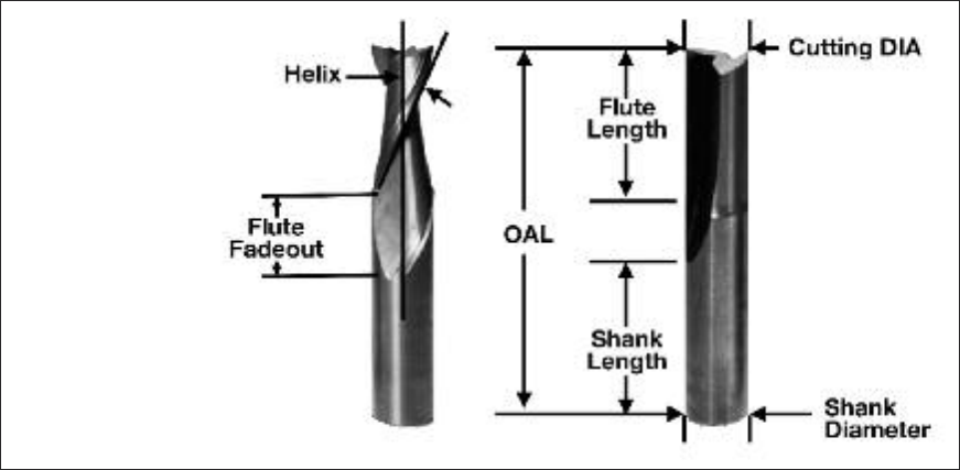
www.onsrud.com 68
Technical Data
TOOL SELECTION
TOOL MATERIAL
• Solid Carbide: Primarily used in CNC operations. Material provides best rigidity and long tool life.
• Carbide Tipped: Incorporates the wear resistance of carbide and the toughness of a HSS body-mainly hand held.
• HSS: Primarily used in hand routing. Material provides a tough body and sharper cutting edge. Good in CNC.
FLUTE GEOMETRY
• Straight flute: Offers a neutral cutting action - highest force
• Upcut flute: Provides the best surface finish and allows for good chip extraction.
May cause part lifting if vacuum or fixturing is not sufficient.
• Downcut flute: Provides a downward force which helps eliminate part lifting. Chip rewelding
MAY occur if there is no space below the part for chip expansion.
•Compression: Used for laminated materials, produces a good top and bottom finish on the part.
NUMBER OF FLUTES
• Single Flute: Allows for larger chiploads in softer materials
• Double Flute: Allows for better part finish in harder materials.
• Multiple Flutes: Allows for an even better part finish in harder materials.
Note: As the number of cutting edges increase, your feed rate should increase to prevent burning and premature tool dulling.
OPTIMIZING SPEED AND FEEDS
1. Start off using the recommended chipload and RPM for the material you are cutting.
2. Increase the feedrate until the part finish starts to decrease or you risk moving the part off the vacuum. Decrease the feed by 10%.
3. Next decrease your RPM by a set increment until your surface finish deteriorates again. Once this happens increase your RPM until
the finish is acceptable.
4. You have now optimized your speed and feed by taking the largest chip possible.
Note: This should be done in the first sheet of material to prevent tool dulling due to excessive heat.
TOOL HEAT
If a feed rate is too low, heat will be generated causing the cutting edge to break down and dull quickly. To check this, run a nest of parts and
stop the spindle. When the spindle has stopped rotating, carefully feel the tool’s temperature. It should be at or near room temperature. If the
tool is hot, review “Optimizing Speed and Feeds”.
OAL= overall length
DIA = Diameter
Basic Terms
69 www.onsrud.com
Technical Data
FIXTURING METHODS
FLOW THROUGH VACUUM
This style uses LDF (Low Density Fiberboard) or MDF (Medium Density Fiberboard) as a sacrificial surface for sheet material to be cut on.
The porous nature of LDF or MDF allows vacuum to pass through allowing the material to be held in place for machining. As parts are cut
out of the sheet material, vacuum loss starts to occur from the slot produced by the cutting tool. This can lead to part lifting or movement
especially in small parts. Cutter diameter will also influence part movement. A 1/2 diameter tool will exert 25% more lateral pressure than
a 3/8 diameter tool.
When cutting small parts in sheet material, one may want to consider tab or skin cutting to prevent part movement.
DEDICATED SPOILBOARD
Dedicated spoilboards are used for reoccurring production
runs where optimal cycle times are needed. This work hold-
ing method creates vacuum chambers in the sacrificial board
specifically to the shape of the parts being cut. This elimination
of vacuum loss relates to improved cycle times and part finish.
STEPS TO CREATE A DEDICATED SPOILBOARD:
1. Surface both sides of your MDF board
2. Lay out the part pattern on the MDF and determine quantity
that will fit.
3. Cut the part profile into the MDF board using a larger
diameter tool than would normally cut the part.
Make your slot depth 1 to 1.5 times the cutter diameter.
4. A gasket groove must be cut next inside the part profile to
create a vacuum seal. The groove should be 1/2 the gasket
material thickness to allow for proper compression.
5. A grid pattern must then be cut inside the gasket groove to
distribute the vacuum evenly through out the vacuum area.
6. Drill holes through out the pattern in the intersections
of the vacuum grid until there is no resistance on your
vacuum gage on the machine table.
7. Seal the board using rubberized coatings, polyurethane
sealers or a sanding sealer to prevent vacuum from passing
through the board in unwanted areas.
8. Apply the gasket tape.
This operations sounds time consuming. It will be for your first board. Once you become familiar making these fixtures, you will make up for it
in your cycle time reductions and part finish. A lot of headaches and problems can be resolved by using the proper work holding.
RAISED SPOILBOARD
This is generally used where secondary operations are needed and the spoilboard will interfere with the secondary tool.
Raised spoilboards are another type of fixturing that works well for routing parts such as circles from squares where the scrap or off-fall is
of such a size to be potentially harmful to the tool and or operator when it is cut free. A raised spoilboard should make sure the off-fall would
not interfere with the first and second tool and that the off-fall would be free and clear of the tool path.
SURFACING SPOILBOARDS
When creating new fixtures or using a new MDF sheet, the spoilboard must be surfaced to level the board to the machine table. This consists
using a large diameter cutter (OC 91-100 series) to quickly level the entire surface.
The following benefits will be achieved by surfacing your spoilboard:
• Leveling material to get consistent cuts.
• Remove grooves caused by routing.
• Reduce vacuum loss due to clogged pores at the material surface due to dust and chips.
• Preventing material warpage caused by humidity in summer time.
Proper Spoilboard Techniques
www.onsrud.com 70
Technical Data
COLLETING
COLLET LIFE SPAN
Collets have a life span of 3 months if used 8 hours a day. Replacing the collets will ensure your operation runs consistently and prevents tool
breakage. When inserting a tool into the collet make sure the flute fadeout does not enter the collet. This will cause run out and potentially lead to
tool breakage. To ensure proper clamping the tool shank should fill, at the minimum, 80% of the depth of the collet. If this can not be achieved, use
a collet life plug to ensure a proper clamping effect.
COLLET MAINTENANCE
Cleaning is an essential part of collet maintenance. As material is cut it causes the collet, tool holder, collet nut and spindle to become dirty.
This causes your tool to cut in an elliptical fashion which will decrease tool life and cause inconsistency in your operation. Collets, tool holder, and
collet nut should be cleaned daily using the Rust Free solvent and a brass brush (OC series 33-21 and 33-10). Refer to the critical areas diagram to
see which surfaces must be clean.
CLEANING INSTRUCTIONS
1. Spray the cleaner on the surface and allow it to soak for a minute
2. Use a brass brush to clean the surface thoroughly.
3. Rinse off using distilled alcohol. Feel the surface using your fingers
to make sure the surface is clean
4. Apply a small amount of Lubricant T-9 to prevent rusting.
TOOL BREAKAGE
If a condition arises where multiple tools should break, follow these steps to solve your problem:
1. Are you using the proper tool for the job?
2. Make sure your collets and tool holders are clean and the tool is colleted properly.
3. Check your speed and feed (is your tool hot?)
4. Is your depth of cut too excessive for the material you’re cutting?
5. Do you have any part movement?
6. Do you have ample part hold down?
7. Stop running parts and check with your distributor or Onsrud’s Technical Support.
If you have to contact your distributor or Technical Support, have the following information:
1. Machine being used.
2. Material being cut.
3. Part number of tool along with the batch number which is below the part number.
4. Speed / Feed / Depth of cut.
5. Where did the tool break (flute, shank, or in the collet)?
6. How long did the tool work before it broke?
7. Have you done this operation in the past using this tool?
CRITICAL
CLEAN
AREAS CRITICAL
CLEAN
AREAS
INSIDE
TA PER
BEARING STYLE NUTBEARING STYLE NUT
STA N DARD SPINDLE
QUICK CHANGE
BT30 TOOL HOLDER
INSIDE
TA PER

71 www.onsrud.com
Honeycomb Technical Data Sheets
HONEYCOMB CORE ALUMINUM NOMEX PAPER
Part # RPM Feed Rate RPM Feed Rate RPM Feed Rate
29-003 (1/4”) 500-10,000 100 IPM 500-10,000 120 IPM 500-10,000 120 IPM
29-006 (3/8”) 500-10,000 100 IPM 500-10,000 120 IPM 500-10,000 120 IPM
29-009 (1/2”) 500-10,000 100 IPM 500-10,000 120 IPM 500-10,000 120 IPM
29-012 (5/8”) 500-10,000 100 IPM 500-10,000 120 IPM 500-10,000 120 IPM
29-015 (3/4”) 500-10,000 100 IPM 500-10,000 120 IPM 500-10,000 120 IPM
29-000
FEEDS & SPEEDS FEED RATES SPINDLE SPEED
Core Type Solid Carbide Solid Carbide Diamond HSS DIA MAX RPM
w/Teeth Saw
Aluminum, Less than 5#/cuft 100 100 NR 150 1/4 25,000
Aluminum, More than 5#/cuft 100 100 NR 100 3/8 25,000
Paper based 400 400 NR 250 1/2 25,000
Paper, based with Fiber Reinforcement 800 800 400 150 3/4 25,000
Fiberglass 600 600 600 NR 1 25,000
Phenolic 200 200 400 NR 1-1/2 18,000
Carbon Fiber NR NR 800 NR 1-3/4 18,000
Aramid, Less than 5#/cuft 800 800 400 150 2 16,500
Aramid, More than 5#/cuft 800 800 400 NR 2-1/2 15,000
3 14,000
4 12,000
Note: 30-300 assembly requires one (1) hogger and one (1) blade
Core Type Cutter RPM Feed Rate Cut Direction
Fiberglass panels with paper core (Nomex) Diamond Grit 18,000 220 lpm Conventional
Aluminum panels with aluminum core HSS Saw 16,000 120 lpm Conventional
34-000
30-000/
30-300
30-700
32-200
SPINDLE SPEED CORE TYPE SPINDLE SPEED
DIA Max RPM Feed Rate Feed Rate Max RPM DIA
1/4 25,000 NR Aluminum, less than 5#/cuft 100 25,000 1/4
3/8 25,000 NR Aluminum, More than 5#/cuft 100 25,000 3/8
1/2 25,000 800 Paper based 400 25,000 1/2
3/4 25,000 800 Paper, based w/Fiber Reinforcement 800 25,000 3/4
1 25,000 800 Fiberglass 600
1-1/2 18,000 800 Phenolic 600
1-3/4 18,000 NR Carbon Fiber 800
2 16,500 100 Aramid, less than 5#/cuft 800
2-1/2 15,000 100 Aramid, More than 5#/cuft 800
3 14,000
4 12,000
29-050 29-100
FEEDS & SPEEDS FEED RATES SPINDLE SPEED
Core Type Solid Diamond HSS HSS HSS HSS DIA MAX RPM
Carbide Plated Saw Wavy (31-000) (31-100)
Aluminum, Less than 5#/cuft 100 NR 150 100 100-140 90-140 3/8 25,000
Aluminum, More than 5#/cuft 100 NR 100 100 70 70 1/2 25,000
Paper based 300 NR 200 300 50 50 3/4 25,000
Paper, based w/Fiber Reinforcement 400 300 600 300 100-150 100-150 1 25,000
Fiberglass NR 600 NR NR NR NR 1-1/2 25,000
Phenolic NR 600 NR NR NR NR 1-3/4 25,000
Carbon Fiber NR 800 NR NR NR NR 2 18,000
Aramid, Less than 5#/cuft 200 NR 150 200 100-150 100-150 2-1/2 18,000
Aramid, More than 5#/cuft 200 400 NR NR NR NR 3 18,000
31-000/
32-000

www.onsrud.com 72
Honeycomb Tool Wrench and Torque Spec
Screw Wrench Torque Spec
HRD51646 HRD52642 15 - 18 in-lb
30-011-2 HRD51905 15 - 18 in-lb
30-020-4 HRD51903 15 - 18 in-lb
30-030-4 HRD51904 15 - 18 in-lb
30-040-4 HRD52608 15 - 18 in-lb
32-000 Series 32-100 15 - 18 in-lb
32-221-4 32-202 18 in-lb
32-231-4 32-201 18 in-lb

73 www.onsrud.com
Soft Wood Cutting Data
DEPTH OF CUT: 1 x D Use recommended chip load
2 x D Reduce chip load by 25%
3 x D Reduce chip load by 50%
APPLICATION GOOD BETTER BEST
Single Pass 60-100 52-200/57-200
Roughing 52-700 60-000 60-850
Finishing 52-200/57-200 60-200
SW
CHIP LOAD PER TOOTH
FORMULAS: Chip Load = Feed Rate / (RPM x # of cutting edges)
Feed Rate (IPM) = RPM x # of cutting edges x chip load
Speed (RPM) = Feed Rate / (# of cutting edges x chip load)
DEFINITIONS: IPM = Inches Per Minute
IPR = Inches Per Revolution
* = 16,000 RPM
** = 15,000 RPM
Cutting Edge Diameter
Series Cut 1/16 3/32 1/8 5/32 3/16 7/32 1/4 5/16 3/8 7/16 1/2 9/16 5/8 3/4 7/8 1 1 1/8 1 1/4 1 1/2 1 3/4 2
10-00 1 x D .004-.006 .004-.006 .005-.007 .007-.009 .008-.010
37-50/60 1/2 CED .001-.003 .002-.004 .003-.005 .003-.005 .005-.007 .007-.009
37-80 1 x D .004-.006 .004-.006* .004-.006**
40-50 1 1/2 .003-.005
40-000 1 x D .002-.004 .002-.004 .003-.005 .004-.006 .004-.006 .005-.007
40-100 1 x D .005-.007 .005-.007 .005-.007 .006-.008 .006-.008 .007-.009 .008-.010 .010-.012
52-200/
57-200 1 x D .006-.008 .006-.008 .006-.008 .006-.008 .007-.009 .007-.009 .008-.010 .008-.010 .009-.011 .009-.011 .010-.012 .011-.013
52-400/
57-400 1 x D .006-.008 .006-.008 .007-.009 .007-.009 .008-.010 .009-.011
52-900 1 x D .007-.009 .008-.010 .009-.011
56-200 1 x D .004-.006 .004-.006 .005-.007 .005-.007 .006-.008 .006-.008 .007-.009 .008-.010 .010-.012
57-900 1 x D .007-.009 .008-.010 .009-.011
60-000 (LH) 1 x D .013-.015 .015-.017 .017-.019 .019-.021
60-000 (HH) 1 x D .016-.018 .018-.020 .020-.022 .022-.024
60-090 1 x D .005-.007
60-100 1 x D .011-.013 .013-.015 .015-.017 .017-.019 .019-.021 .021-.023
60-100DE 1 x D .018-.020 .020-.022 .022-.024 .024-.026 .026-.028
60-1003E 1 x D .017-.019 .019-.021
60-100C 1 x D .024-.026 .026-.028 .028-.030 .030-.032
60-100MC 1 x D .019-.021 .021-.023
60-200 1 x D .005-.007 .006-.008 .007-.009 .008-.010
60-300 1 x D .024-.026 .026-.028 .028-.030 .030-.032
60-350 1 x D .017-.019 .019-.021 .021-.023
60-500/
500M 1 x D .015-.017 .017-.019 .019-.021
60-600 1 x D .019-.021 .023-.025
60-700 1 x D .019-.021 .021-.023 .023-.025
60-800 1 x D .017-.019 .019-.021 .021-.023 .023-.025
60-900 1 x D .017-.019 .018-.020
60-950 1 x D .024-.026 .026-.028
61-000 1 x D .008-.010 .008-.010 .009-.011 .009-.011 .010-.012 .010-.012 .011-.013 .011-.013 .012-.014
61-200 1 x D .008-.010 .010-.012 .010-.012 .011-.013 .012-.014
64-000/
65-000 1 x D .001-.003 .002-.004 .003-.006 .004-.006 .005-.007
77-100 (DE) 1 x D .003-.005
77-100 (3E) 1 x D .005-.007

www.onsrud.com 74
Hard Wood Cutting Data
DEPTH OF CUT: 1 x D Use recommended chip load
2 x D Reduce chip load by 25%
3 x D Reduce chip load by 50%
APPLICATION GOOD BETTER BEST
Single Pass 52-700 52-200/57-200 60-300/60-350
Roughing 52-700 60-000 60-800/66-900
Finishing 60-300/60-350 60-200
HW
FORMULAS: Chip Load = Feed Rate / (RPM x # of cutting edges)
Feed Rate (IPM) = RPM x # of cutting edges x chip load
Speed (RPM) = Feed Rate / (# of cutting edges x chip load)
DEFINITIONS: IPM = Inches Per Minute
IPR = Inches Per Revolution
CHIP LOAD PER TOOTH
Cutting Edge Diameter
Series Cut 1/16 3/32 1/8 5/32 3/16 7/32 1/4 5/16 3/8 7/16 1/2 9/16 5/8 3/4 7/8 1 1 1/8 1 1/4 1 1/2 1 3/4 2
12-00 1 x D .002-.004 .002-.004 .003-.005 .003-.005 .004-.006 .005-.007 .005-.007 .010-.012
37-50/60 1/2 CED .002-.004 .002-.004 .002-.004 .003-.005 .005-.007 .007-.009
37-80 1 x D .004-.006 .004-.006* .004-.006**
40-50 1 1/2 .003-.005
40-000 1 x D .006-.008 .006-.008 .007-.009 .008-.010 .008-.010 .009-.007 .010-.012
40-100 1 x D .004-.006 .005-.007 .005-.007 .005-.007 .006-.008 .006-.008 .007-.009 .009-.011
48-000 1 x D .004-.006 .005-.007 .005-.007 .005-.007 .006-.008 .007-.009 .008-.010 .009-.011 .010-.012 .011-.013 .012-.014 .013-.015 .014-.016 .015-.017
52-200/
57-200 1 x D .003-.005 .003-.005 .004-.006 .004-.006 .005-.007 .005-.007 .006-.008 .006-.008 .007-.009 .007-.008 .008-.010 .009-.011
52-400/
57-400 1 x D .004-.006 .004-.006 .005-.007 .005-.007 .006-.008 .007-.009
52-900 1 x D .006-.008 .007-.009 .007-.009
56-200 1 x D .003-.005 .003-.005 .004-.006 .004-.006 .005-.007 .005-.007 .006-.008 .007-.009 .009-.011
57-900 1 x D .005-.007 .006-.008 .007-.009
60-000 (LH) 1 x D .013-.015 .014-.016 .016-.018 .017-.019
60-000 (HH) 1 x D .015-.017 .017-.019 .019-.021 .021-.023
60-090 1 x D .005-.007
60-100 1 x D .010-.012 .012-.014 .014-.016 .016-.018 .018-.020 .020-.022 .022-.024
60-100DE 1 x D .014-.016 .016-.018 .018-.020 .020-.022 .022-.024
60-1003E 1 x D .016-.018 .018-.020
60-100C 1 x D .019-.021 .021-.023 .023-.025 .025-.027
60-100MC 1 x D .019-.021 .021-.023
60-500/
500M 1 x D .013-.015 .015-.017 .016-.018
60-600 1 x D .018-.020 .022-.024
60-700 1 x D .018-.020 .020-.022 .022-.024
60-800 1 x D .017-.019 .019-.021 .021-.023 .023-.025
60-900 1 x D .015-.017 .017-.019 .019-.021
60-950 1 x D .019-.021 .021-.023
61-200 1 x D .007-.009 .009-.011 .009-.011 .010-.012
64-000/
65-000 1 x D .001-.003 .002-.004 .003-.005 .004-.006 .005-.007
77-100 (DE) 1 x D .003-.005
77-100 (3E) 1 x D .005-.007
* = 16,000 RPM
** = 15,000 RPM

75 www.onsrud.com
MDF Cutting Data
DEPTH OF CUT: 1 x D Use recommended chip load
2 x D Reduce chip load by 25%
3 x D Reduce chip load by 50%
APPLICATION GOOD BETTER BEST
Single Pass 52-200/57-200 60-300/60-350 60-100
Roughing 60-000 60-850
Finishing 60-300/60-350 60-200
CW
CHIP LOAD PER TOOTH
Cutting Edge Diameter
Series Cut 1/16 3/32 1/8 5/32 3/16 7/32 1/4 5/16 3/8 7/16 1/2 9/16 5/8 3/4 7/8 1 1 1/8 1 1/4 1 1/2 1 3/4 2
37-50/60 1/2 CED .001-.003 .001-.003 .002-.004 .003-.005 .005-.007 .007-.009
37-80 1 x D .004-.006 .004-.006* .004-.006**
40-50 1 1/2 .003-.005
47-00 1 x D .004-.006 .004-.006 .004-.006
48-000 1 x D .004-.006 .005-.007 .005-.007 .005-.007 .006-.008 .006-.008 .007-.009 .008-.010 .009-.011
52-200/
57-200 1 x D .005-.007 .005-.007 .006-.008 .006-.008 .006-.008 .006-.008 .007-.009 .007-.009 .008-.010 .008-.010 .009-.011 .009-.011
52-400/
57-400 1 x D .003-.005 .004-.006 .005-.007 .005-.007 .006-.008 .008-.010 .009-.011 .010-.012 .011-.013 .012-.014
52-900 1 x D .006-.008 .007-.009 .008-.010
56-200 1 x D .003-.005 .003-.005 .004-.006 .004-.006 .005-.007 .005-.007 .006-.008 .007-.009 .009-.011
57-900 1 x D .006-.008 .007-.009 .008-.010
60-000 (LH) 1 x D .012-.014 .013-.015 .014-.016 .016-.018
60-000 (HH) 1 x D .017-.019 .018-.020 .020-.022 .023-.025
60-090 1 x D .004-.006
60-100 1 x D .010-.012 .010-.012 .013-.015 .014-.016 .016-.018 .017-.019 .019-.021
60-100DE 1 x D .013-.015 .014-.016 .016-.018 .018-.020 .019-.021
60-1003E 1 x D .014-.016 .016-.018 .018-.020
60-100C 1 x D .017-.019 .018-.020 .020-.022 .023-.025
60-100MC 1 x D .019-.021 .021-.023
60-200 1 x D .004-.006 .005-.007 .005-.007 .006-.008
60-300 1 x D .017-.019 .018-.020 .020-.022 .023-.025
60-350 1 x D .014-.016 .016-.018 .017-.019 .019-.021
60-500/
500M 1 x D .014-.016 .016-.018 .018-.020
60-600 1 x D .020-.022 .022-.024 .024-.026
60-700 1 x D .020-.022 .022-.024 .024-.026
60-800 1 x D .017-.019 .019-.021 .021-.023 .023-.025
60-900 1 x D .017-.019 .019-.021
60-950 1 x D .017-.019 .018-.020
61-200 1 x D .007-.009 .008-.010 .009-.011 .009-.011 .010-.012 .011-.013
62-200 1 x D .010-.012 .011-.013 .012-.014 .012-.014 .013-.015 .014-.016
64-000/
65-000 1 x D .001-.003 .002-.004 .003-.005 .004-.006 .005-.007
68-100 1 x D .008-.010 .012-.014 .015-.017 .018-.020
77-100 (DE) 1 x D .003-.005
77-100 (3E) 1 x D .005-.007
FORMULAS: Chip Load = Feed Rate / (RPM x # of cutting edges)
Feed Rate (IPM) = RPM x # of cutting edges x chip load
Speed (RPM) = Feed Rate / (# of cutting edges x chip load)
DEFINITIONS: IPM = Inches Per Minute
IPR = Inches Per Revolution
* = 16,000 RPM
** = 15,000 RPM

Cutting Edge Diameter
Series Cut 1/16 1/8 5/32 3/16 7/32 1/4 5/16 3/8 7/16 1/2 9/16 5/8 3/4 7/8 1 1-1/8 1-1/4 1-1/2 2
37-50/60 1/2 CED .001-.003 .002-.004 .002-.004 .003-.005 .004-.006 .006-.008
37-80 1 x D .004-.006 .004-.006* .004-.006**
40-50 1 1/2 .003-.005
48-000 1 x D .005-.007 .005-.007 .006-.008 .006-.008 .007-.009 .008-.010 .009-.011 .010-.012 .011-.013 .012-.014 .013 - .015
56-200 1 x D .003-.005 .003-.005 .004-.006 .004-.006 .005-.007 .005-.007 .006-.008 .007-.009 .009-.011
60-000 (LH) 1 x D .014-.016 .016-.018 .018-.020 .020-.022
60-000 (HH) 1 x D .017-.019 .019-.021 .021-.023 .023-.025
60-090 1 x D .003-.005
60-100 1 x D .013-.015 .014-.016 .015-.017 .016-.018 .018-.020 .020-.022 .022-.024
60-100DE 1 x D .017-.019 .019-.021 .021-.023 .023-.025 .025-.027
60-1003E 1 x D .020-.022 .022-.024 .024-026
60-100C 1 x D .022-.024 .024-.026 .026-.028 .028-.030
60-100MC 1 x D .019-.021 .021-.023
60-300 1 x D .022-.024 .024-.026 .026-.028 .028-.030
60-350 1 x D .020-.022 .022-.024 .024-.026 .026-.028
60-500/
500M 1 x D .021-.023 .023-.025 .025-.027
60-600 1 x D .028-.030 .030-.032 .032-.034
60-700 1 x D .028-.030 .030-.032 .032-.034
60-800 1 x D .017-.019 .019-.021 .021-.023 .023-.025
60-900 1 x D .017-.019 .019-.021
60-950 1 x D .022-.024 .024-.026
61-200 1 x D .006-.008 .007-.009 .008-.010 .008-.010 .009-.011 .010-.012
64-000/
65-000 1 x D .001-.003 .002-.004 .003-.005 .004-.006 .005-.007
68-100 .010-.012 .012-.014 .017-.019 .018-.020
www.onsrud.com 76
Soft Plywood Cutting Data
DEPTH OF CUT: 1 x D Use recommended chip load
2 x D Reduce chip load by 25%
3 x D Reduce chip load by 50%
APPLICATION GOOD BETTER BEST
Single Pass 60-300/60-350 60-100 60-100C
Roughing 60-800 60-000
Finishing 60-300/60-350 60-200
CW
CHIP LOAD PER TOOTH
FORMULAS: Chip Load = Feed Rate / (RPM x # of cutting edges)
Feed Rate (IPM) = RPM x # of cutting edges x chip load
Speed (RPM) = Feed Rate / (# of cutting edges x chip load)
DEFINITIONS: IPM = Inches Per Minute
IPR = Inches Per Revolution
* = 16,000 RPM
** = 15,000 RPM

77 www.onsrud.com
Hard Plywood Cutting Data
DEPTH OF CUT: 1 x D Use recommended chip load
2 x D Reduce chip load by 25%
3 x D Reduce chip load by 50%
APPLICATION GOOD BETTER BEST
Single Pass 60-300/60-350 60-100 60-100C
Roughing 60-800 60-000
Finishing 60-300/60-350 60-200
CW
CHIP LOAD PER TOOTH
FORMULAS: Chip Load = Feed Rate / (RPM x # of cutting edges)
Feed Rate (IPM) = RPM x # of cutting edges x chip load
Speed (RPM) = Feed Rate / (# of cutting edges x chip load)
DEFINITIONS: IPM = Inches Per Minute
IPR = Inches Per Revolution
* = 16,000 RPM
** = 15,000 RPM
Cutting Edge Diameter
Series Cut 1/16 3/32 1/8 5/32 3/16 7/32 1/4 5/16 3/8 7/16 1/2 9/16 5/8 3/4 7/8 1 1 1/8 1 1/4 1 1/2 1 3/4 2
37-50/60 1/2 CED .001-.003 .001-.003 .002-.004 .003-.005 .005-.007 .007-.009
37-80 1 x D .004-.006 .004-.006* .004-.006**
40-50 1 1/2 .003-.005
48-000 1 x D .004-.006 .005-.007 .005-.007 .006-.008 .007-.009 .008-.010 .009-.011 .010-.012 .011-.013 .012-.014 .013-.015
56-200 1 x D .003-.005 .003-.005 .004-.006 .004-.006 .005-.007 .005-.007 .006-.008 .007-.009 .009-.011
60-000 (LH) 1 x D .014-.016 .016-.018 .018-.020 .020-.022
60-000 (HH) 1 x D .017-.019 .019-.021 .021-.023 .023-.025
60-090 1 x D .003-.005
60-100 1 x D .012-.018 .012-.018 .014-.016 .016-.018 .018-.020 .020-.022 .022-.024
60-100DE 1 x D .014-.016 .016-.018 .018-.020 .020-.022 .022-.024
60-1003E 1 x D .020-.022 .022-.024 .026-.028
60-100C 1 x D .019-.021 .021-.023 .023-.025 .025-.027
60-100MC 1 x D .019-.021 .021-.023
60-300 1 x D .019-.021 .021-.023 .023-.025 .025-.027
60-350 1 x D .018-.020 .020-.022 .022-.025 .024-.026
60-500/
500M 1 x D .039-.041 .043-.045 .047-.049
60-600 1 x D .027-.029 .030-.032 .032-.034
60-700 1 x D .027-.029 .029-.031 .032-.034
60-800 1 x D .017-.019 .019-.021 .021-.023 .023-.025
60-900 1 x D .017-.019 .019-.021
60-950 1 x D .019-.021 .021-.023
61-200 1 x D .005-.007 .007-.009 .007-.009 .008-.010 .009-.011
64-000/
65-000 1 x D .001-.003 .002-.004 .003-.005 .004-.006 .005-.007
68-100 1 x D .010-.012 .012-.014 .017-.019 .018-.020

Cutting Edge Diameter
Series Cut 1/8 3/16 7/32 1/4 5/16 3/8 1/2 9/16 5/8 3/4 7/8 1 1-1/8 1-1/4 1-1/2 2
37-80 1 x D .004-.006 .004 -.006* .004 -.006**
48-000 1 x D .005-.007 .005-.007 .006-.008 .006-.008 .007-.009 .008-.010 .009-.011 .010-.012 .011-.013 .012-.014 .013-.015 .014-.016
60-100 1 x D .013-.015 .014-.016 .015-.017 .016-.018 .018-.020 .019-.021 .021-.023
60-100 (DE) 1 x D .017-.019 .019-.021 .021-.023 .025-.027 .027-.029
60-100 (3E) 1 x D .020-.022 .022-.024 .024-.026
60-100C 1 x D .022-.024 .024-.026 .026-.028 .028-.030
60-100MC 1 x D .019-.021 .021-.023
60-500/500M 1 x D .021-.023 .023-.025 .025-.027
60-600 1 x D .028-.030 .030-.032 .032-.034
68-100 1 x D .008-.010 .012-.014 .016-.018 .019-.021
www.onsrud.com 78
Laminated Chipboard Cutting Data
DEPTH OF CUT: 1 x D Use recommended chip load
2 x D Reduce chip load by 25%
3 x D Reduce chip load by 50%
APPLICATION GOOD BETTER BEST
Single Pass 60-100 60-100MW 60-100MC
Roughing 60-850
LW
FORMULAS: Chip Load = Feed Rate / (RPM x # of cutting edges)
Feed Rate (IPM) = RPM x # of cutting edges x chip load
Speed (RPM) = Feed Rate / (# of cutting edges x chip load)
DEFINITIONS: IPM = Inches Per Minute
IPR = Inches Per Revolution
CHIP LOAD PER TOOTH
* = 16,000 RPM
** = 15,000 RPM

79 www.onsrud.com
FORMULAS: Chip Load = Feed Rate / (RPM x # of cutting edges)
Feed Rate (IPM) = RPM x # of cutting edges x chip load
Speed (RPM) = Feed Rate / (# of cutting edges x chip load)
DEFINITIONS: IPM = Inches Per Minute
IPR = Inches Per Revolution
CHIP LOAD PER TOOTH
Laminated Plywood Cutting Data
DEPTH OF CUT: 1 x D Use recommended chip load
2 x D Reduce chip load by 25%
3 x D Reduce chip load by 50%
APPLICATION GOOD BETTER BEST
Single Pass 60-100 60-100MW 60-100MC
Roughing 60-850
LW
* = 16,000 RPM
** = 15,000 RPM
Cutting Edge Diameter
Series Cut 1/16 3/32 1/8 5/32 3/16 7/32 1/4 5/16 3/8 7/16 1/2 9/16 5/8 3/4 7/8 1 1 1/8 1 1/4 1 1/2 1 3/4 2
37-80 1 x D .004-.006 .004-.006* .004-.006**
48-000 1 x D .004-.006 .005-.007 .005-.007 .006-.008 .006-.008 .007-.009 .009-.011 .010-.012 .011-.013 .012-.014 .013-.015 .014-.016
60-100 1 x D .013-.015 .014-.016 .015-.017 .016-.018 .018-.020 .019-.021 .021-.023
60-100DE 1 x D .015-.017 .016-.018 .018-.020 .019-.021 .021-.023
60-1003E 1 x D .018-.020 .020-.022 .022-.024
60-100C 1 x D .019-.021 .021-.023 .023-.025 .025-.027
60-100MC 1 x D .019-.021 .021-.023
60-500/
500M 1 x D .019-.021 .021-.023 .023-.025
60-600 1 x D .027-.029 .030-.032 .032-.034
68-100 1 x D .008-.010 .012-.014 .016-.018 .019-.021
77-100 (DE) 1 x D .003-.005
77-100 (3E) 1 x D .005-.007

www.onsrud.com 80
Soft Plastic Cutting Data
DEPTH OF CUT: 1 x D Use recommended chip load
2 x D Reduce chip load by 25%
3 x D Reduce chip load by 50%
* = 12,500 RPM
< 1/2” DIAMETER TOOL
APPLICATION GOOD BETTER BEST
Single Pass 61-000P 65-000 63-750
Roughing 60-000
FORMULAS: Chip Load = Feed Rate / (RPM x # of cutting edges)
Feed Rate = RPM x # of cutting edges x chip load
Speed (RPM) = Feed Rate / (# of cutting edges x chip load)
NOTE: To eliminate rewelding increase the feedrate or change to a single edge tool
If using a downcut spiral and chip rewelding occurs, cut a slot in your spoilboard to allow the chips a place to expand
Incorrect chiploads can lead to knife marks occurring
> 1/2” DIAMETER TOOL
APPLICATION GOOD BETTER BEST
Single Pass 56-600 52-700 52-600
Roughing 60-000
CHIP LOAD PER TOOTH
SP
Cutting Edge Diameter
Series Cut 1/16 3/32 1/8 5/32 3/16 7/32 1/4 5/16 3/8 7/16 1/2 9/16 5/8 3/4 7/8 1 1 1/8 1 1/4 1 1/2 1 3/4 2
10-00 1 x D .002 - .004 .004 - .006 .006 - .008 .006 - .008 .007 - .009 .008 - .010
38-50/
38-60 1 x D .001 - .003 .002 - .004 .003 - .005 .004 - .006 .005 - .007 .006 - .008 .007 - .009
52-200B/BL 1 x D .002 - .004 .002 - .004 .004 - .006 .004 - .006 .004 - .006 .006 - .008 .010 - .012 .012 - .014
52-400 1 x D .002 - .004 .003 - .005 .004 - .008 .005 - .007 .006 - .008 .007 - .009
52-600 1 x D .008 - .010 .010 - .012 .012 - .014 .014 - .016 .016 - .018
52-700 1 x D .012 - .014 .014 - .016 .016 - .018
56-430 1 x D .006 - .008 .006 - .008 .007 - .009 .008 - .010 .009 - .011
56-600 1 x D .004 - .006 .006 - .008 .008 - .010 .010 - .012 .012 - .014
57-600 1 x D .008 - .010 .010 - .012 .012 - .014 .014 - .016 .016 - .018
60-000 1 x D .004 - .006 .006 - .008 .008 - .012 .012 - .016
60-200 1 x D .004 - .006 .004 - .006 .006 - .010 .012 - .016
60-900 1 x D .004 - .006 .006 - .008
61-000P 1 x D .004 - .006 .006 - .008 .008 - .012 .014 - .018 .018 - .022
61-400 1 x D .017 - .019 .017 - .019 .018 - .020 .019 - .021 .020 - .021
62-750 1 x D .004 - .006 .006 - .008 .008 - .012 .008 - .012 .010 - .014
62-850 1 x D .004 - .006 .006 - .008 .008 - .012 .008 - .012 .010 - .014
63-500 1 x D .002 - .004 .004 - .006 .005 - .007 .006 - .008 .007 - .009
63-750 1 x D .002 - .004 .004 - .006 .006 - .008 .008 - .012 .008 - .012 .010 - .014
63-850 1 x D .002 - .004 .004 - .006 .006 - .008 .008 - .012 .008 - .012 .010 - .014
64-000/
65-000 1 x D .002 - .004 .004 - .006 .006 - .008 .008 - .012 .008 - .012
65-200B/
65-300B 1 x D .002-.003 .002-.003 .003-.004 .003-.005 .003-.005 .004-.006 .006-.008
77-100 (DE) 1 x D .005 - .007
77-100 (3E) 1 x D .008 - .010

81 www.onsrud.com
Hard Plastic Cutting Data
DEPTH OF CUT: 1 x D Use recommended chip load
2 x D Reduce chip load by 25%
3 x D Reduce chip load by 50%
< 1/2” DIAMETER TOOL
APPLICATION GOOD BETTER BEST
Single Pass 65-000 63-700 56-000P
Roughing 60-000
Finishing 60-200 75-000
FORMULAS: Chip Load = Feed Rate / (RPM x # of cutting edges)
Feed Rate (IPM) = RPM x # of cutting edges x chip load
Speed (RPM) = Feed Rate / (# of cutting edges x chip load)
DEFINITIONS: IPM = Inches Per Minute
IPR = Inches Per Revolution
NOTE: When chip rewelding occurs while cutting soft plastic, increase feedrate or go to a single edge tool.
Incorrect chiploads can result in cratering
> 1/2” DIAMETER TOOL
APPLICATION GOOD BETTER BEST
Single Pass 52-700 52-600 56-000P
Roughing 60-000
Finishing 60-200
HP
CHIP LOAD PER TOOTH
Cutting Edge Diameter
Series Cut 1/16 3/32 1/8 5/32 3/16 7/32 1/4 5/16 3/8 7/16 1/2 9/16 5/8 3/4 7/8 1 1 1/8 1 1/4 1 1/2 1 3/4 2
52-200B/BL 1 x D .002 - .004 .002 - .004 .004 - .006 .004 - .006 .004 - .006 .006 - .008 .008 - .010 .010 - .012
52-600 1 x D .006 - .008 .008 - .010 .010 - .012 .012 - .014 .014 - .016
56-000P 1 x D .002 - .004 .004 - 006 .004 - .006 .006 - .008 .008 - .010
56-430 1 x D .005 - .007 .005 - .007 .006 - .008 .007 - .009 .008 - .010
56-450 1 x D .005 - .007 .006 - .008 .007 - .009 .008 - .010
56-600 1 x D .003 - .005 .005 - .007 .007 - .009 .009- .011 .011 - .013
57-600 1 x D .006 - .008 .008 - .010 .010 - .012 .012 - .014 .014 - .016
60-000 1 x D .004 - .006 .006 - .008 .008 - .012 .012 - .016
60-200 1 x D .004 - .006 .004 - .006 .006 - .010 .012 - .016
60-900 1 x D .004 - .006 .006 - .008
61-000P 1 x D .003 - .005 .005 - .007 .007 - .011 .013 - .017 .017 - .021
61-400 1 x D .014 - .016 .014 - .016 .015 - .017 .016 - .018 .017 - .019
62-700 1 x D .006 - .008 .008 - .010 .010 - .012 .010 - .012 .012 - .016
62-750 1 x D .004 - .006 .006 - .008 .008 - .012 .008 - .012 .010 - .014
62-800 1 x D .006 - .008 .008 - .010 .010 - .012 .010 - .012 .012 - .016
62-850 1 x D .004 - .006 .006 - .008 .008 - .012 .008 - .012 .010 - .014
63-500 1 x D .002 - .004 .003 - .005 .003 - .005 .004 - .006 .005 - .007
63-700 1 x D .002 - .004 .006 - .008 .008 - .010 .010 - .012 .010 - .012 .012 - .016
63-750 1 x D .002 - .004 .004 - .006 .006 - .008 .008 - .012 .008 - .012 .010 - .014
63-800 1 x D .002 - .004 .006 - .008 .008 - .010 .010 - .012 .010 - .012 .012 - .016
63-850 1 x D .002 - .004 .004 - .006 .006 - .008 .008 - .012 .008 - .012 .010 - .014
64-000/
65-000 1 x D .002 - .004 .006 - .008 .008 - .010 .010 - .012 .010 - .012
77-000 1 x D .002 - .004 .002 - .004 .006 - .008 .008 - .012
77-100 (DE) 1 x D .005 - .007
77-100 (3E) 1 x D .008 - .010

www.onsrud.com 82
CP
Composite Cutting Data
DEPTH OF CUT: 1 x D Use recommended chip load
2 x D Reduce chip load by 25%
3 x D Reduce chip load by 50%
APPLICATION GOOD BETTER BEST
Finishing 54-200
Honeycomb 67-300 32-000 30-300
CFRP 66-900 66-800 68-300
G10/G11
Fiberglass 56-000P 67-000 54-200
Fiberglass 67-000 67-400 67-200
Phenolic 53-000P 67-200 67-220
Single Pass 56-000P 67-250 68-000
NOTE: Spindle RPM’s generally range from 9,000 - 12,000
when cutting composite materials
FORMULAS: Chip Load = Feed Rate / (RPM x # of cutting edges)
Feed Rate (IPM) = RPM x # of cutting edges x chip load
Speed (RPM) = Feed Rate / (# of cutting edges x chip load)
DEFINITIONS: IPM = Inches Per Minute
IPR = Inches Per Revolution
* = 10,000 RPM
CHIP LOAD PER TOOTH
Cutting Edge Diameter
Series Cut 1/16 3/32 1/8 5/32 3/16 7/32 1/4 5/16 3/8 7/16 1/2 9/16 5/8 3/4 7/8 1 1 1/8 1 1/4 1 1/2 1 3/4 2
48-000 1 x D .006 - .008 .006 - .008 .007 - .009 .007 - .009 .008 - .010 .009 - .011 .010 - .012 .011 - .013 .012 - .014 .013 - .015 .014 - .016 .015 - .017 .016 - .018
48-000DE 1 x D .002 - .004 .002 - .004 .003 - .005 .003 - .005 .004 - .006 .005 - .007 .006 - .008 .007 - .009 .008 - .010 .009 - .011 .010 - .012 .011 - .013 .012 - .014
52-000 1 x D .003 - .005 .003 - .005 .004 - .006 .006 - .008 .010 - .012
54-000 /
59-000 1 x D .002 - .004 .002 - .004 .002 - .004 .003 - .006 .005 - .010
54-200 1 x D .002-.004 .002-.004 .002-.004 .003-.006 .005-.010
54-300 1 x D .007 - .009 .008 - .010
55-000 /
58-000 1 x D .002 - .004 .002 - .004 .002 - .004 .003 - .006 .007 - .009
55-300 1 x D .007 - .009 .008 - .010
56-000P 1 x D .002 - .004 .002 - .004 .004 - .006 .004 - .006 .004 - .006
56-450 1 x D .002 - .005 .003 - .005 .003 - .006 .004 - .006 .005 - .007
57-000 1 x D .003 - .005 .003 - .005 .004 - .006 .006 - .008 .010 - .012
63-000 1 x D .003 - .005 .003 - .005 .003 - .005 .004 - .006 .005 - .007
66-800 1 x D .001-.002 .002-.003 .003-.004
66-900 1 x D .002-.004 .002-.004 .004-.006 .004-.006 .006-.008
67-000 1 x D .004 - .006 .004 - .006 .004 - .006
67-200 1 x D .002 - .010 .002 - .010
67-220 1 x D .001-.002 .001-.002
67-250 1 x D .002 - .004 .004 - .006 .004 - .006
67-300 1 x D .004 - .006 .006 - .008 .010 - .012
67-400 1 x D .002 - .004 .004 - .006 .004 - .006 .004 - .006
67-500 1 x D .001 - .003 .001 - .003 .002 - .004 .002 - .004 .003 - .005 .004 - .006
67-600 1 x D .002 - .004 .002 - .004 .003 - .005 .003 - .005 .004 - .006 .005 - .007
68-000 1 x D .004 - .006 .004 - .006 .004 - .006 .008 - .010
68-200 1 x D .0005 - .001 .001 - .002 .001 - .002
68-300 1 x D .001-.002 .001-.002 .004-.006

83 www.onsrud.com
A
Aluminum Cutting Data
DEPTH OF CUT: 1 x D Use recommended chip load
2 x D Reduce chip load by 25%
3 x D Reduce chip load by 50%
APPLICATION GOOD BETTER BEST
BLOCK
Single Pass 63-600 52-000 AMC
Roughing 40-000 52-000 AMC
Finishing 66-300 AMC
Slotting 63-600 52-000 AMC
Profile/Shape 52-200B AMC
SHEET
Single Pass 40-000 65-000 63-600
EXTRUSION
Single Pass 63-600 81-000 81-100
FORMULAS: Chip Load = Feed Rate / (RPM x # of cutting edges)
Feed Rate (IPM) = RPM x # of cutting edges x chip load
Speed (RPM) = Feed Rate / (# of cutting edges x chip load)
DEFINITIONS: IPM = Inches Per Minute
IPR = Inches Per Revolution
NOTE: When cutting soft aluminum a squirt of cutting fluid every now and then will help to eliminate
chip rewelding and improve surface finish
To view our complete line of
AMC Tools, reference our
Milling Tools Catalog which is
available at www.onsrud.com
CHIP LOAD PER TOOTH
* 16,000 RPM
** Aluminum Extrusion or Aluminum UAD Doors/Windows
Cutting Edge Diameter
Series Cut 1/16 3/32 1/8 5/32 3/16 7/32 1/4 5/16 3/8 7/16 1/2 9/16 5/8 3/4 7/8 1
40-000* 1 x D .005 - .007 .005 - .007 .006 - .008 .006 - .008 .007 - .009 .008 - .010
40-100 1 x D .001 - .003 .001 - .003 .002 - .004 .002 - .004 .003 - .005 .004 - .008 .006 - .008
52-000 1 x D .003 - .005 .003 - .005 .004 - .006 .006 - .008 .010 - .012
52-200B/BL 1 x D .002 - .004 .003 - .005 .003 - .005 .004 - .006 .006 - .008 .010 - .012 .012 - .014 .014 - .016
57-000* 1 x D .003 - .005 .003 - .005 .004 - .006 .006 - .008 .010 - .012
61-000 1 x D .001 - .003 .002 - .005 .002 - .005 .003 - .007 .007 - .009
62-600 1 x D .002 - .004 .002 - .004 .003 - .006 .003 - .006 .003 - .006 .004 - .008 .008 - .010
63-000 1 x D .006 - .008 .006 - .008 .007 - .009 .007 - .009 .008 - .010 .009 - .011
63-600 1 x D .002 - .004 .002 - .004 .003 - .006 .003 - .006 .003 - .006 .004 - .008 .008 - .010
63-900 1 x D .002 - .004 .002 - .004 .003 - .006 .003 - .006 .003 - .006 .004 - .008 .008 - .010
64-000/
65-000 1 x D .002 - .004 .002 - .004 .003 - .006 .003 - .006 .004 - .008
77-100(DE) .002 -.004
77-100(3E) .003 -.005
81-000 1 x D .004-.006 .004-.006
81-100 1 x D .002 - .005 .003 - .008 .003 - .008

www.onsrud.com 84
Cutting Edge Diameter
Series Cut 1/16 3/32 1/8 5/32 3/16 7/32 1/4 5/16 3/8 7/16 1/2 9/16 5/8 3/4 7/8 1 1 1/8 1 1/4 1 1/2 1 3/4 2
12-00 1 x D .0005 - .002 .0005 - .002 .001 - .003 .001 - .003 .002 - .004 .003 - .005 .004 - .006 .005 - .007 .006 - .008 .007 - .009
40-550 1 x D .004 - .006
48-000 1 x D .002 - .004 .002 - .004 .003 - .005 .003 - .005 .004 - .006 .005 - .007 .006 - .008 .007 - .009 .010 .010 - .012
52-550 1 x D .002 - .004 .002 - .004 .004 - .006 .004 - .006 .004 - .006
52-700 1 x D .002 - .004 .002 - .004 .004 - .006 .004 - .006 .004 - .006 .005 - .007 .006 - .008 .007 - .009 .010
Specialty Tool Chiploads
DEPTH OF CUT: 1 x D Use recommended chip load
2 x D Reduce chip load by 25%
3 x D Reduce chip load by 50%
FORMULAS: Chip Load = Feed Rate / (RPM x # of cutting edges)
Feed Rate (IPM) = RPM x # of cutting edges x chip load
Speed (RPM) = Feed Rate / (# of cutting edges x chip load)
DEFINITIONS: IPM = Inches Per Minute
IPR = Inches Per Revolution
CHIP LOAD PER TOOTH
Material: Foam
Material: Wood
Material: Plastic
Material: Aluminum
Cutting Edge Diameter
Series Cut 1/16 3/32 1/8 5/32 3/16 7/32 1/4 5/16 3/8 7/16 1/2 9/16 5/8 3/4 7/8 1 1 1/8 1 1/4 1 1/2 1 3/4 2
37-00/
37-20 Varies .004-.006
37-50 1/2 CED .003 - .006 .003 - .006 .003 - .006
37-60 1/2 CED .004 - .006 .004 - .006 .006 - .008 .008 - .010
37-80 Varies .001 - .003 .001 - .003 .001 - .003
Cutting Edge Diameter
Series Cut 1/16 3/32 1/8 5/32 3/16 7/32 1/4 5/16 3/8 7/16 1/2 9/16 5/8 3/4 7/8 1 1 1/8 1 1/4 1 1/2 1 3/4 2
37-00/
37-20 Varies .004-.006
37-50* 1 x D .003 - .006 .003 - .006 .003 - .006
37-60* 1 x D .004 - .006 .004 - .006 .006 - .008 .008 - .010
37-80 Varies .001 - .003 .001 - .003 .001 - .003
66-000 1 x D .004 - .008 .004 - .008 .004 - .008
66-200 1 x D .004 - .006 .006 - .008
66-300 1 x D .002 - .004 .004 - .006 .006 - .008 .006 - .008
66-350 1 x D .002 - .004 .004 - .006 .006 - .008 .006 - .008
Cutting Edge Diameter
Series Cut 1/16 3/32 1/8 5/32 3/16 7/32 1/4 5/16 3/8 7/16 1/2 9/16 5/8 3/4 7/8 1 1 1/8 1 1/4 1 1/2 1 3/4 2
37-00/
37-20 Varies .004-.006
37-80 Varies .001 - .003 .001 - .003 .001 - .003
66-200 1 x D .004 - .006 .006 - .008
66-300 1 x D .002 - .004 .004 - .006 .006 - .008 .006 - .008
66-350 1 x D .002 - .004 .004 - .006 .006 - .008 .006 - .008
77-025 1 x D .002 - .004 .002 - .004 .003 - .006 .003 - .006

85 www.onsrud.com
Solid Surface Cutting Data
DEPTH OF CUT: 1 x D Use recommended chip load
2 x D Reduce chip load by 25%
3 x D Reduce chip load by 50%
SSP
Cutting Edge Diameter
Series Cut 1/16 3/32 1/8 5/32 3/16 7/32 1/4 5/16 3/8 7/16 1/2 9/16 5/8 3/4 7/8 1
37-50 1 x D .003 - .006 .003 - .006 .003 - .006
37-60 1 x D .004 - .006 .004 - .006 .006 - .008 .008 -.010
52-000 1 x D .003 - .006 .003 - .006 .004 - .006 .008 - .010 .012 - .014
52-200B/BL 1 x D .002 - .004 .002 - .004 .002 - .004 .004 - .006 .004 - .006 .006 - .008 .008 - .010 .010 - .012
52-400 1 x D .002 - .004 .002 - .004 .003 - .005 .004 - .006 .005 - .007
52-600 1 x D .004 - .006 .006 - .008 .008 - .010 .008 - .010 .010 - .012
56-000P 1 x D .002 - .004 .002 - .004 .004 - .006 .006 - .008 .008 - .010
56-450 1 x D .002 - .004 .002 - .004 .003 - .005 .004 - .006 .005 - .007
57-000 1 x D .002 - .004 .002 - .004 .003 - .005 .004 - .006 .005 - .007
57-200 1 x D .002 - .004 .002 - .004 .003 - .005 .004 - .006 .005 - .007 .006 - .008 .007 - .009
57-400 1 x D .002 - .004 .002 - .004 .003 - .005 .004 - .006 .005 - .007 .006 - .008 .007 - .009
57-600 1 x D .004 - .006 .006 - .008 .008 - .010 .008 - .010 .010 - .012
60-200 1 x D .002 - .004 .002 - .006 .002 - .006 .004 - .008
62-700 1 x D .002 - .004 .004 - .006 .006 - .010 .006 - .010 .010 - .012
62-750 1 x D .002 - .004 .004 - .006 .006 - .010 .006 - .010 .010 - .012
62-800 1 x D .002 - .004 .004 - .006 .006 - .010 .006 - .010 .010 - .012
62-850 1 x D .002 - .004 .004 - .006 .006 - .010 .006 - .010 .010 - .012
63-700 1 x D .002 - .003 .002 - .004 .004 - .006 .006 - .010 .006 - .010 .010 - .012
63-750 1 x D .002 - .003 .002 - .004 .004 - .006 .006 - .010 .006 - .010 .010 - .012
63-800 1 x D .002 - .003 .002 - .004 .004 - .006 .006 - .010 .006 - .010 .010 - .012
63-850 1 x D .002 - .003 .002 - .004 .004 - .006 .006 - .010 .006 - .010 .010 - .012
64-000/
65-000 1 x D .002 - .004 .006 - .008 .008 - .010 .010 - .012 .010 - .012 .010 - .012
66-000 1 x D .002 - .004 .003 - .005 .004 - .006
FORMULAS: Chip Load = Feed Rate / (RPM x # of cutting edges) DEFINITIONS:
Feed Rate (IPM) = RPM x # of cutting edges x chip load IPM = Inches Per Minute
Speed (RPM) = Feed Rate / (# of cutting edges x chip load) IPR = Inches Per Revolution
CHIP LOAD PER TOOTH
Drilling Cutting Data
FORMULAS: RPM = (3.82 x SFM) / tool dia. DEFINITIONS:
Feedrate (IPM) = RPM x IPR IPM = Inches Per Minute
IPR = Inches Per Revolution
* Gang drills run at 4,500 RPM and 150 IPM
Drill Diameter
Series SFM 3 1/8 3/16 561/4 5/16 8 3/8 7/16 1/2 5/8 3/4 7/8 1
67-800 Composites 230 .001 - .003 .001 - .003 .002 - .004 .002 - .004 .003 - .005 .003 - .005 .003 - .005
68-900 Composites 230 0.001 0.0015 0.0015 0.0015
70-500 Plastic 200 .019 - .021 .021 - .023 .023 - .025 .025 - .027 .027 - .029 .029 - .031 .031 - .033 .033 - .035
72-000* Wood .009 - .011 .011 - .013 .013 - .015 .015 - .017
85-800 Composites 230 0.0005 0.0005 0.001 0.001 0.001 0.001 0.001
86-100 Composites 165 0.001 0.0015 0.0015 0.0015
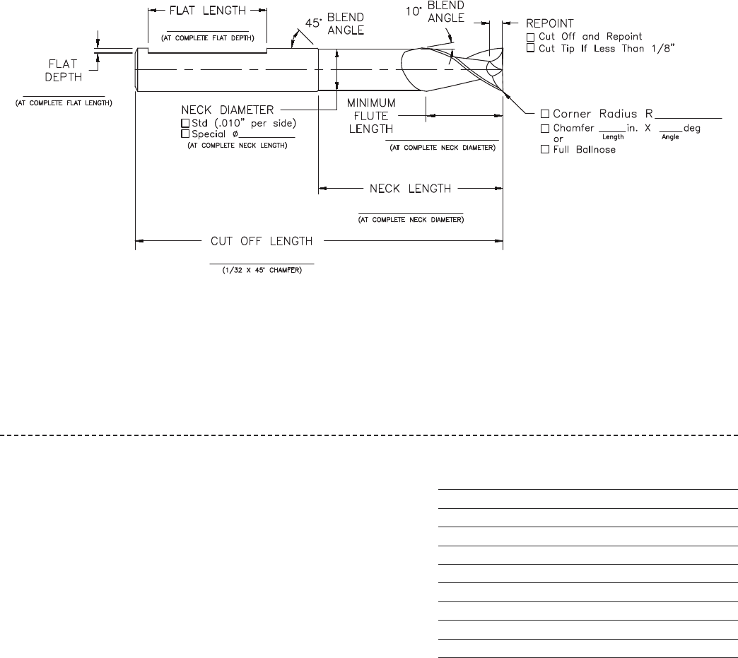
www.onsrud.com 86
MODIFICATIONS
DISTRIBUTOR ______________________
DISTRIBUTOR NUMBER ______________________
DISTRIBUTOR PO NUMBER ______________________
DATE _________________
TOOL TO BE MODIFIED (PART NUMBER) _________________
QUANTITY _________________
SALES ORDER NUMBER _________________
FORM COMPLETED BY _________________
NOTES: __________________________________________________________________________________________________
__________________________________________________________________________________________________
__________________________________________________________________________________________________
__________________________________________________________________________________________________
Tool Modification Instructions
• Complete form
• Fax to Onsrud with purchase order number.
• Orders must be received before 2:30 PM (Central time)
in order to ship the following day.
• You will receive a confirmation fax
• Any modifications over 5 pieces will be treated as a special tool.
TOOL MODIFICATION
Part Number Description
BALLNOSE RADIUS: _____________
RADIUS DIAMETER: ___________
CHAMFER CUT OFF AND CHAMFER
CUT-REPOINT CUT OFF TIP AND REPOINT
CUT-TIP CUT OFF TIP UNDER 1/8
*ERL/SPNBCK CEL RQD: _____ DIA: _____
FLAT FLATS ON SHANK
REPOINT-1/8 REPOINT LESS THAN 1/8"
MODIFICATION FORM
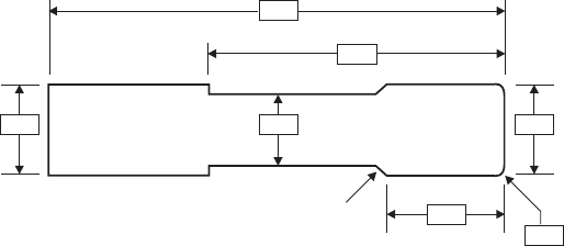
87 www.onsrud.com
SD CDND
OL
NL
LoC
CR
Transition
Grind
CUTTING TOOL QUOTE REQUEST FORM
1081 S. Northpoint Blvd. • Waukegan, Illinois 60085 • Phone (847) 362-1560 • Fax (800) 557-6720 • www.onsrud.com
*Starred Items = Required information
*Distributor Name____________________________________________ *Distributor's Reference Number ___________________
*Distributor Address ___________________________________________________________________________________________
*Contact ____________________________________________________ *Email Address __________________________________
*Telephone __________________________________________________ *Fax ___________________________________________
End User Name _______________________________________________ Customer Reference Number ________________________
End User Address_____________________________________________________________________________________________
Contact _____________________________________________________ Email Address ____________________________________
Telephone __________________________________________________________ Fax _________________________________________________
*Material being machined ______________________________________ Hardness _______________________________________
Machine type (Check all that apply):CNC Router CNC Mill Inverted Air Router Hand Other
If other, describe _______________________________________________________________________________________________
H.P.= _________________________________________________
Max. Spindle Speed ____________________________________________ Coolant Type _____________________________________
*Tool Material: HSS Solid Carbide Carbide Tip Powder Metal PCD Full Face PCD Tip Other
If other, describe _______________________________________________________________________________________________
*Flute Style: Spiral Up Spiral “O” Up Straight “V” Flute Compression
Spiral Down Spiral “O” Down Straight “O” Flute Morise Compression
*Flute Form: Rougher Chipbrk/Finisher Finisher Other
*Point Geometry: Square Ball Nose Drill Point Other
Center Cutting Non-Center Cutting
*If other, describe _____________________________________________________________________________________________
*Tool Similar To: ______________________________________________________________________________________________
Cutting Diameter (CED) _________________________________
Cutting Length (CEL) ___________________________________
Shank Diameter (SHK) __________________________________
Overall Length (OAL) ___________________________________
Neck Diameter (ND) ____________________________________
Neck Radius (NL) ______________________________________
Corner Radius (CR) ____________________________________
Coolant Through Yes No
Transition Grind Needed ________________________________
Flat Y / N What Type? ________________________________
Coating Types: TiN TiCN AlTiN Diamond Grit ZrN TiAlN DFC Diamond “Like” Other
If other, describe _______________________________________________________________________________________________
*Quantities Needed: __________________________________________________________________________________________
Minimum is 6 pieces
Any Target Pricing? ____________________________________________________________________________________________
Distributor / End User?
Additional Notes: ______________________________________________________________________________________________
____________________________________________________________________________________________________________
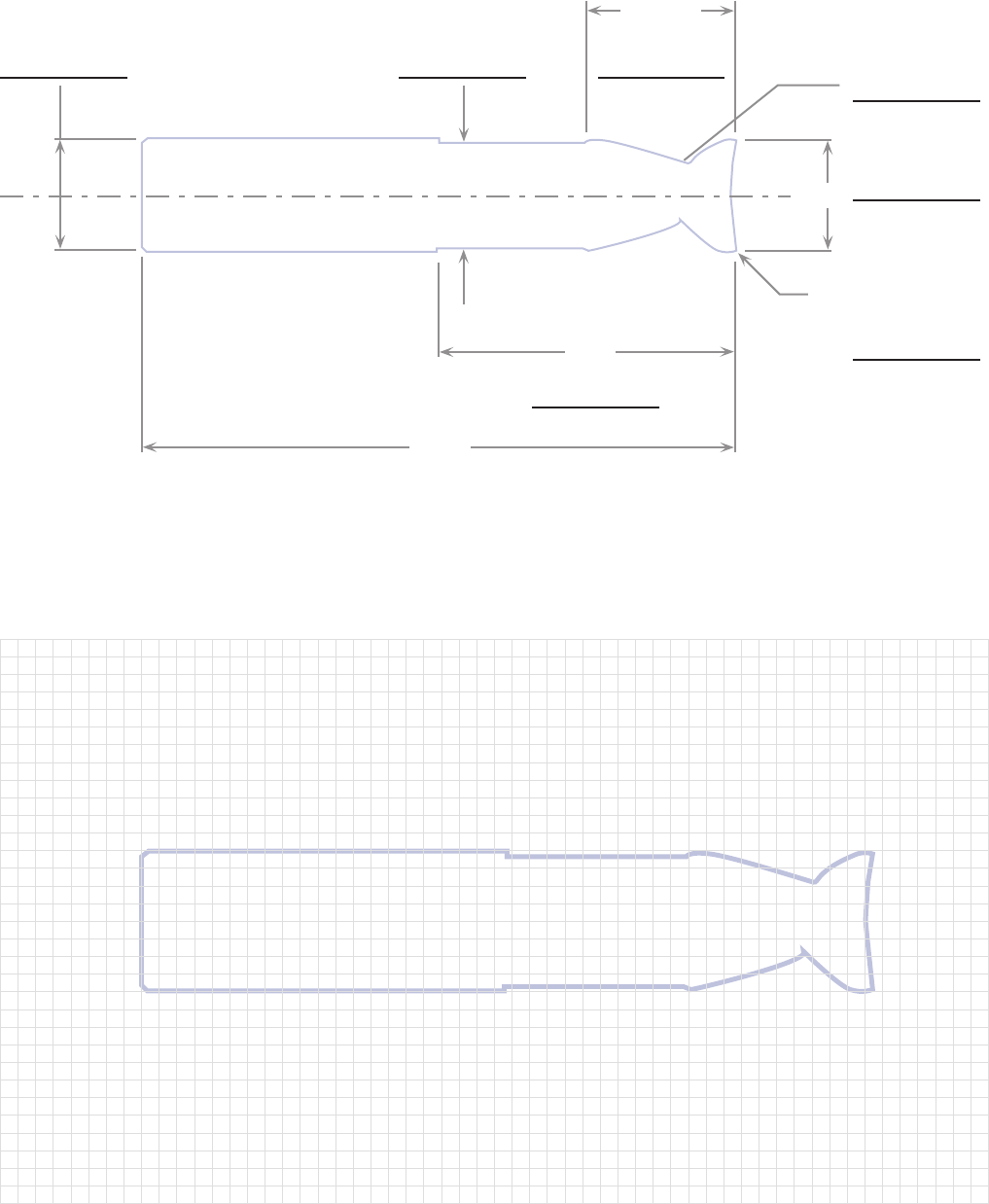
www.onsrud.com 88
Cutting Tool Design
ERL DIA
ERL
FLUTE
LENGTH
OAL
SHANK DIA
CORNER RADIUS
°HELIX RH/LH
CED

89 www.onsrud.com
NOTES

LMT Onsrud Terms & Conditions
Shipping - F.O.B. Waukegan, IL. All shipments ground unless otherwise specified.
Claims – Any claims for shortage, damage or loss must be made within 30 days of
invoice date. United Parcel Service is a preferred method of shipment because of
reliability and ease of tracing problem shipments.
Guarantee - Our products are guaranteed against defects in material and quality of
manufacture when used in the proper manner. If tools are returned and found to be
defective, we will repair or replace the tools. Continued tool breakage caused by improper
tool usage without the knowledge of LMT Onsrud’s technical staff is not a condition
for return and replacement of such tools.
Errors - LMT Onsrud, LP cannot be held responsible for incorrect parts made with our
products due to mislabeling or defect.
Return Goods Policy – No merchandise can be returned without prior authorization.
Credit will not be issued for merchandise returned without a return authorization number.
Product must be a current revision catalog item in new and saleable condition. All returns
subject to a 15% restocking fee or offsetting order of equal value.
Specials - LMT Onsrud, LP has the right to over or under ship by 10% all specials.
Special orders less than 10 pieces are subject to +/- 1 piece. Specials and modified
tools are not returnable for credit. Specials cancelled will be assessed an in-process
charge based on the status of the order and expenses incurred at the time of
cancellation. If a special tool has been completed, the tool will be shipped and the
price quoted will be billed.
Safety Precautions – Cutting tools should only be used to perform operations that are
compatible with the original tool design. Safety glasses and other appropriate safety
equipment should be worn by all people in the vicinity of tool use.
Prices & Terms - All prices and terms are subject to change without notice. All orders are
subject to acceptance at LMT Onsrud.

LMT Onsrud LP
1081 S. Northpoint Blvd.
Waukegan, IL 60085
TOLL FREE +1 800 234 1560
www.onsrud.com
ISO 9001 Certified
Printed in USA/Catalog OC-12
Distributed By:
