OEM7 Commands And Logs Reference Manual
User Manual:
Open the PDF directly: View PDF ![]() .
.
Page Count: 1065 [warning: Documents this large are best viewed by clicking the View PDF Link!]
- Figures
- Tables
- Customer Support
- Foreword
- Chapter 1 Messages
- Chapter 2 Core Commands
- 2.1 Command Formats
- 2.2 Command Settings
- 2.3 Factory Defaults
- 2.4 Command Reference
- 2.5 ADJUST1PPS
- 2.6 ALIGNAUTOMATION
- 2.7 ANTENNAPOWER
- 2.8 ASSIGN
- 2.9 ASSIGNALL
- 2.10 ASSIGNLBANDBEAM
- 2.11 AUTH
- 2.12 AUTOSURVEY
- 2.13 BASEANTENNAPCO
- 2.14 BASEANTENNAPCV
- 2.15 BASEANTENNATYPE
- 2.16 BDSECUTOFF
- 2.17 BESTVELTYPE
- 2.18 CANCONFIG
- 2.19 CCOMCONFIG
- 2.20 CLOCKADJUST
- 2.21 CLOCKCALIBRATE
- 2.22 CLOCKOFFSET
- 2.23 CNOUPDATE
- 2.24 COMCONTROL
- 2.25 DATADECODESIGNAL
- 2.26 DATUM
- 2.27 DGPSTXID
- 2.28 DIFFCODEBIASCONTROL
- 2.29 DLLTIMECONST
- 2.30 DNSCONFIG
- 2.31 DUALANTENNAPORTCONFIG
- 2.32 DYNAMICS
- 2.33 ECHO
- 2.34 ECUTOFF
- 2.35 ELEVATIONCUTOFF
- 2.36 ETHCONFIG
- 2.37 EVENTINCONTROL
- 2.38 EVENTOUTCONTROL
- 2.39 EXTERNALCLOCK
- 2.40 FILEAUTOTRANSFER
- 2.41 FILECONFIG
- 2.42 FILEDELETE
- 2.43 FILEMEDIACONFIG
- 2.44 FILEROTATECONFIG
- 2.45 FILETRANSFER
- 2.46 FIX
- 2.47 FIXPOSDATUM
- 2.48 FORCEGALE6CODE
- 2.49 FORCEGLOL2CODE
- 2.50 FORCEGPSL2CODE
- 2.51 FREQUENCYOUT
- 2.52 FRESET
- 2.53 GALECUTOFF
- 2.54 GENERATEALIGNCORRECTIONS
- 2.55 GENERATEDIFFCORRECTIONS
- 2.56 GENERATERTKCORRECTIONS
- 2.57 GGAQUALITY
- 2.58 GLIDEINITIALIZATIONPERIOD
- 2.59 GLOECUTOFF
- 2.60 HDTOUTTHRESHOLD
- 2.61 HEADINGOFFSET
- 2.62 ICOMCONFIG
- 2.63 INTERFACEMODE
- 2.64 IONOCONDITION
- 2.65 IPCONFIG
- 2.66 IPSERVICE
- 2.67 ITBANDPASSCONFIG
- 2.68 ITDETECTCONFIG
- 2.69 ITFRONTENDMODE
- 2.70 ITPROGFILTCONFIG
- 2.71 ITSPECTRALANALYSIS
- 2.72 J1939CONFIG
- 2.73 LOCKOUT
- 2.74 LOCKOUTSYSTEM
- 2.75 LOG
- 2.76 LOGIN
- 2.77 LOGOUT
- 2.78 LUA
- 2.79 MAGVAR
- 2.80 MARKCONTROL
- 2.81 MEDIAFORMAT
- 2.82 MODEL
- 2.83 MOVINGBASESTATION
- 2.84 NAVICECUTOFF
- 2.85 NMEAFORMAT
- 2.86 NMEATALKER
- 2.87 NMEAVERSION
- 2.88 NTRIPCONFIG
- 2.89 NTRIPSOURCETABLE
- 2.90 NVMRESTORE
- 2.91 NVMUSERDATA
- 2.92 PDPFILTER
- 2.93 PDPMODE
- 2.94 PGNCONFIG
- 2.95 POSAVE
- 2.96 POSTIMEOUT
- 2.97 PPPBASICCONVERGEDCRITERIA
- 2.98 PPPCONVERGEDCRITERIA
- 2.99 PPPDYNAMICS
- 2.100 PPPDYNAMICSEED
- 2.101 PPPRESET
- 2.102 PPPSEED
- 2.103 PPPSOURCE
- 2.104 PPPTIMEOUT
- 2.105 PPSCONTROL
- 2.106 PPSCONTROL2
- 2.107 PROFILE
- 2.108 PSRDIFFSOURCE
- 2.109 PSRDIFFSOURCETIMEOUT
- 2.110 PSRDIFFTIMEOUT
- 2.111 QZSSECUTOFF
- 2.112 RADARCONFIG
- 2.113 RAIMMODE
- 2.114 REFERENCESTATIONTIMEOUT
- 2.115 RESET
- 2.116 RFINPUTGAIN
- 2.117 RTKANTENNA
- 2.118 RTKASSIST
- 2.119 RTKASSISTTIMEOUT
- 2.120 RTKDYNAMICS
- 2.121 RTKINTEGERCRITERIA
- 2.122 RTKMATCHEDTIMEOUT
- 2.123 RTKNETWORK
- 2.124 RTKPORTMODE
- 2.125 RTKQUALITYLEVEL
- 2.126 RTKRESET
- 2.127 RTKSOURCE
- 2.128 RTKSOURCETIMEOUT
- 2.129 RTKSVENTRIES
- 2.130 RTKTIMEOUT
- 2.131 SAVECONFIG
- 2.132 SAVEETHERNETDATA
- 2.133 SBASCONTROL
- 2.134 SBASECUTOFF
- 2.135 SBASTIMEOUT
- 2.136 SELECTCHANCONFIG
- 2.137 SEND
- 2.138 SENDHEX
- 2.139 SERIALCONFIG
- 2.140 SERIALPROTOCOL
- 2.141 SETADMINPASSWORD
- 2.142 SETAPPROXPOS
- 2.143 SETAPPROXTIME
- 2.144 SETBASERECEIVERTYPE
- 2.145 SETBESTPOSCRITERIA
- 2.146 SETDIFFCODEBIASES
- 2.147 SETIONOTYPE
- 2.148 SETNAV
- 2.149 SETROVERID
- 2.150 SETTIMEBASE
- 2.151 SETTROPOMODEL
- 2.152 SETUTCLEAPSECONDS
- 2.153 SOFTLOADCOMMIT
- 2.154 SOFTLOADDATA
- 2.155 SOFTLOADRESET
- 2.156 SOFTLOADSETUP
- 2.157 SOFTLOADSREC
- 2.158 STATUSCONFIG
- 2.159 STEADYLINE
- 2.160 STEADYLINEDIFFERENTIALTIMEOUT
- 2.161 SURVEYPOSITION
- 2.162 THISANTENNAPCO
- 2.163 THISANTENNAPCV
- 2.164 THISANTENNATYPE
- 2.165 TRACKSV
- 2.166 TUNNELESCAPE
- 2.167 UALCONTROL
- 2.168 UNASSIGN
- 2.169 UNASSIGNALL
- 2.170 UNDULATION
- 2.171 UNLOCKOUT
- 2.172 UNLOCKOUTALL
- 2.173 UNLOCKOUTSYSTEM
- 2.174 UNLOG
- 2.175 UNLOGALL
- 2.176 USBSTICKEJECT
- 2.177 USERDATUM
- 2.178 USEREXPDATUM
- 2.179 USERI2CREAD
- 2.180 USERI2CWRITE
- 2.181 UTMZONE
- 2.182 WIFIAPCHANNEL
- 2.183 WIFIAPIPCONFIG
- 2.184 WIFIAPPASSKEY
- 2.185 WIFIMODE
- Chapter 3 Logs
- 3.1 Log Types
- 3.2 Log Reference
- 3.3 ALIGNBSLNENU
- 3.4 ALIGNBSLNXYZ
- 3.5 ALIGNDOP
- 3.6 ALMANAC
- 3.7 AUTHCODES
- 3.8 AVEPOS
- 3.9 BDSALMANAC
- 3.10 BDSCLOCK
- 3.11 BDSEPHEMERIS
- 3.12 BDSIONO
- 3.13 BDSRAWNAVSUBFRAME
- 3.14 BESTPOS
- 3.15 BESTSATS
- 3.16 BESTUTM
- 3.17 BESTVEL
- 3.18 BESTXYZ
- 3.19 BSLNXYZ
- 3.20 CHANCONFIGLIST
- 3.21 CLOCKMODEL
- 3.22 CLOCKSTEERING
- 3.23 DUALANTENNAHEADING
- 3.24 ETHSTATUS
- 3.25 FILELIST
- 3.26 FILESTATUS
- 3.27 FILESYSTEMCAPACITY
- 3.28 FILESYSTEMSTATUS
- 3.29 FILETRANSFERSTATUS
- 3.30 GALALMANAC
- 3.31 GALCLOCK
- 3.32 GALCNAVRAWPAGE
- 3.33 GALFNAVEPHEMERIS
- 3.34 GALFNAVRAWPAGE
- 3.35 GALINAVEPHEMERIS
- 3.36 GALINAVRAWWORD
- 3.37 GALIONO
- 3.38 GLMLA
- 3.39 GLOALMANAC
- 3.40 GLOCLOCK
- 3.41 GLOEPHEMERIS
- 3.42 GLORAWALM
- 3.43 GLORAWEPHEM
- 3.44 GLORAWFRAME
- 3.45 GLORAWSTRING
- 3.46 GPALM
- 3.47 GPGGA
- 3.48 GPGGALONG
- 3.49 GPGLL
- 3.50 GPGRS
- 3.51 GPGSA
- 3.52 GPGST
- 3.53 GPGSV
- 3.54 GPHDT
- 3.55 GPHDTDUALANTENNA
- 3.56 GPRMB
- 3.57 GPRMC
- 3.58 GPSEPHEM
- 3.59 GPVTG
- 3.60 GPZDA
- 3.61 HEADING2
- 3.62 HEADINGRATE
- 3.63 HEADINGSATS
- 3.64 HWMONITOR
- 3.65 IONUTC
- 3.66 IPSTATS
- 3.67 IPSTATUS
- 3.68 ITBANDPASSBANK
- 3.69 ITDETECTSTATUS
- 3.70 ITFILTTABLE
- 3.71 ITPROGFILTBANK
- 3.72 ITPSDFINAL
- 3.73 J1939STATUS
- 3.74 LBANDBEAMTABLE
- 3.75 LBANDTRACKSTAT
- 3.76 LOGLIST
- 3.77 LUAFILELIST
- 3.78 LUAFILESYSTEMSTATUS
- 3.79 LUAOUTPUT
- 3.80 LUASTATUS
- 3.81 MARKPOS, MARK2POS, MARK3POS and MARK4POS
- 3.82 MARKTIME, MARK2TIME, MARK3TIME and MARK4TIME
- 3.83 MASTERPOS
- 3.84 MATCHEDPOS
- 3.85 MATCHEDSATS
- 3.86 MATCHEDXYZ
- 3.87 MODELFEATURES
- 3.88 NAVICALMANAC
- 3.89 NAVICEPHEMERIS
- 3.90 NAVICIONO
- 3.91 NAVICRAWSUBFRAME
- 3.92 NAVICSYSCLOCK
- 3.93 NAVIGATE
- 3.94 NMEA Standard Logs
- 3.95 NOVATELXOBS
- 3.96 NOVATELXREF
- 3.97 OCEANIXINFO
- 3.98 OCEANIXSTATUS
- 3.99 PASSCOM, PASSAUX, PASSUSB, PASSETH1, PASSICOM, PASSNCOM
- 3.100 PASSTHROUGH
- 3.101 PDPPOS
- 3.102 PDPSATS
- 3.103 PDPVEL
- 3.104 PDPXYZ
- 3.105 PORTSTATS
- 3.106 PPPPOS
- 3.107 PPPSATS
- 3.108 PROFILEINFO
- 3.109 PSRDOP
- 3.110 PSRDOP2
- 3.111 PSRPOS
- 3.112 PSRSATS
- 3.113 PSRVEL
- 3.114 PSRXYZ
- 3.115 QZSSALMANAC
- 3.116 QZSSEPHEMERIS
- 3.117 QZSSIONUTC
- 3.118 QZSSRAWALMANAC
- 3.119 QZSSRAWCNAVMESSAGE
- 3.120 QZSSRAWEPHEM
- 3.121 QZSSRAWSUBFRAME
- 3.122 RAIMSTATUS
- 3.123 RANGE
- 3.124 RANGECMP
- 3.125 RANGECMP2
- 3.126 RANGECMP4
- 3.127 RANGEGPSL1
- 3.128 RAWALM
- 3.129 RAWCNAVFRAME
- 3.130 RAWEPHEM
- 3.131 RAWGPSSUBFRAME
- 3.132 RAWGPSWORD
- 3.133 RAWSBASFRAME
- 3.134 RAWSBASFRAME2
- 3.135 REFSTATION
- 3.136 REFSTATIONINFO
- 3.137 ROVERPOS
- 3.138 RTCMV3 Standard Logs
- 3.139 RTKASSISTSTATUS
- 3.140 RTKDOP
- 3.141 RTKDOP2
- 3.142 RTKPOS
- 3.143 RTKSATS
- 3.144 RTKVEL
- 3.145 RTKXYZ
- 3.146 RXCONFIG
- 3.147 RXSTATUS
- 3.148 RXSTATUSEVENT
- 3.149 SAFEMODESTATUS
- 3.150 SATVIS2
- 3.151 SATXYZ2
- 3.152 SAVEDSURVEYPOSITIONS
- 3.153 SBAS0
- 3.154 SBAS1
- 3.155 SBAS2
- 3.156 SBAS3
- 3.157 SBAS4
- 3.158 SBAS5
- 3.159 SBAS6
- 3.160 SBAS7
- 3.161 SBAS9
- 3.162 SBAS10
- 3.163 SBAS12
- 3.164 SBAS17
- 3.165 SBAS18
- 3.166 SBAS24
- 3.167 SBAS25
- 3.168 SBAS26
- 3.169 SBAS27
- 3.170 SBAS32
- 3.171 SBAS33
- 3.172 SBAS34
- 3.173 SBAS35
- 3.174 SBAS45
- 3.175 SBASALMANAC
- 3.176 SOFTLOADSTATUS
- 3.177 SOURCETABLE
- 3.178 TERRASTARINFO
- 3.179 TERRASTARSTATUS
- 3.180 TIME
- 3.181 TIMESYNC
- 3.182 TRACKSTAT
- 3.183 TRANSFERPORTSTATUS
- 3.184 UPTIME
- 3.185 USERI2CRESPONSE
- 3.186 VALIDMODELS
- 3.187 VERIPOSINFO
- 3.188 VERIPOSSTATUS
- 3.189 VERSION
- 3.190 WIFIAPSETTINGS
- Chapter 4 SPAN Commands
- 4.1 ALIGNMENTMODE
- 4.2 ASYNCHINSLOGGING
- 4.3 CONNECTIMU
- 4.4 EXTERNALPVAS
- 4.5 HEAVEFILTER
- 4.6 INPUTGIMBALANGLE
- 4.7 INSALIGNCONFIG
- 4.8 INSCALIBRATE
- 4.9 INSCOMMAND
- 4.10 INSSEED
- 4.11 INSTHRESHOLDS
- 4.12 INSZUPT
- 4.13 RELINSAUTOMATION
- 4.14 RELINSCONFIG
- 4.15 SETALIGNMENTVEL
- 4.16 SETHEAVEWINDOW
- 4.17 SETIMUPORTPROTOCOL
- 4.18 SETIMUSPECS
- 4.19 SETINITAZIMUTH
- 4.20 SETINSPROFILE
- 4.21 SETINSROTATION
- 4.22 SETINSTRANSLATION
- 4.23 SETINSUPDATE
- 4.24 SETMAXALIGNMENTTIME
- 4.25 SETRELINSOUTPUTFRAME
- 4.26 SETUPSENSOR
- 4.27 SETWHEELPARAMETERS
- 4.28 TAGNEXTMARK
- 4.29 TIMEDEVENTPULSE
- 4.30 WHEELVELOCITY
- Chapter 5 SPAN Logs
- 5.1 Logs with INS or GNSS Data
- 5.2 BESTGNSSPOS
- 5.3 BESTGNSSVEL
- 5.4 CORRIMUDATA
- 5.5 CORRIMUDATAS
- 5.6 DELAYEDHEAVE
- 5.7 GIMBALLEDPVA
- 5.8 HEAVE
- 5.9 IMURATECORRIMUS
- 5.10 IMURATEPVA
- 5.11 IMURATEPVAS
- 5.12 INSATT
- 5.13 INSATTQS
- 5.14 INSATTS
- 5.15 INSATTX
- 5.16 INSCALSTATUS
- 5.17 INSCONFIG
- 5.18 INSPOS
- 5.19 INSPOSS
- 5.20 INSPOSX
- 5.21 INSPVA
- 5.22 INSPVAS
- 5.23 INSPVAX
- 5.24 INSSEEDSTATUS
- 5.25 INSSPD
- 5.26 INSSPDS
- 5.27 INSSTDEV
- 5.28 INSSTDEVS
- 5.29 INSUPDATESTATUS
- 5.30 INSVEL
- 5.31 INSVELS
- 5.32 INSVELX
- 5.33 MARK1PVA, MARK2PVA, MARK3PVA and MARK4PVA
- 5.34 PASHR
- 5.35 RAWIMU
- 5.36 RAWIMUS
- 5.37 RAWIMUSX
- 5.38 RAWIMUX
- 5.39 RELINSPVA
- 5.40 SYNCHEAVE
- 5.41 SYNCRELINSPVA
- 5.42 TAGGEDMARK1PVA, TAGGEDMARK2PVA, TAGGEDMARK3PVA and TAGGEDMARK4PVA
- 5.43 TIMEDWHEELDATA
- 5.44 TSS1
- 5.45 VARIABLELEVERARM
- 5.46 WHEELSIZE
- Chapter 6 Responses
- APPENDIX A Example of Bit Parsing a RANGECMP4 Log
- A.1 Reference Log Decoding
- A.1.1 Reference Header
- A.1.2 Reference Satellite and Signal Block: GPS
- A.1.3 Reference Measurement Block Header: GPS
- A.1.4 Reference Measurement Block: GPS
- A.1.5 Reference Primary Signal Measurement Block: GPS PRN 10 – L1CA
- A.1.6 Reference Secondary Signals Measurement Block: GPS PRN 10 – L2Y
- A.1.7 Reference Third Signals Measurement Block: GPS PRN 10 – L5Q
- A.1.8 Reference Satellite and Signal Block: GLONASS
- A.1.9 Reference Measurement Block Header: GLONASS PRN 38
- A.1.10 Reference Primary Signal Measurement Block: GLONASS PRN 38 – L1CA
- A.2 Differential Log Decoding
- A.2.1 Differential Header
- A.2.2 Differential Satellite and Signal Block
- A.2.3 Differential Measurement Block Header
- A.2.4 Differential Measurement Block
- A.2.5 Differential Primary Signal Measurement Block GPS PRN 10 – L1CA
- A.2.6 Differential Secondary Signals Measurement Block GPS PRN 10 – L2Y
- A.2.7 Differential Third Signals Measurement Block GPS PRN 10 – L5Q
- A.1 Reference Log Decoding

OM-20000169 v7 September 2018
OEM7®
Commands and Logs
Reference Manual

OEM7 Commands and Logs Reference Manual v7 2
OEM7 Commands and Logs Reference Manual
Publication Number: OM-20000169
Revision Level: v7
Revision Date: September 2018
Firmware Versions:
l7.05 / OM7MR0500RN0000
lPP7 07.05 / EP7PR0500RN0000
Proprietary Notice
Information in this document is subject to change without notice and does not represent a com-
mitment on the part of NovAtel Inc. The information contained within this manual is believed to
be true and correct at the time of publication.
NovAtel, ALIGN, GLIDE, GrafNav/GrafNet, Inertial Explorer, NovAtel CORRECT, OEM7, PwrPak7,
RELAY, SPAN, STEADYLINE, VEXXIS and Waypoint are registered trademarks of NovAtel Inc.
NovAtel Connect, OEM719, OEM729, OEM7500, OEM7600, OEM7700, OEM7720 and RTK ASSIST
are trademarks of NovAtel Inc.
All other brand names are trademarks of their respective holders.
© Copyright 2018 NovAtel Inc. All rights reserved. Unpublished rights reserved under Inter-
national copyright laws.

OEM7 Commands and Logs Reference Manual v7 3
Table of Contents
Figures
Tables
Customer Support
Foreword
Chapter 1 Messages
1.1 ASCII 27
1.2 Abbreviated ASCII 29
1.3 Binary 29
1.4 Description of ASCII and Binary Logs with Short Headers 40
1.5 Message Responses 41
1.5.1 Abbreviated ASCII Response 41
1.5.2 ASCII Response 41
1.5.3 Binary Response 41
1.6 GLONASS Slot and Frequency Numbers 43
1.6.1 PRN Numbers 44
1.7 GPS Reference Time Status 45
1.8 Message Time Stamps 46
1.9 Decoding of the GPS Reference Week Number 47
1.10 32-Bit CRC 47
Chapter 2 Core Commands
2.1 Command Formats 51
2.1.1 Optional Parameters 51
2.2 Command Settings 51
2.3 Factory Defaults 52
2.4 Command Reference 52
2.5 ADJUST1PPS 53
2.6 ALIGNAUTOMATION 61
2.7 ANTENNAPOWER 63
2.8 ASSIGN 65
2.9 ASSIGNALL 68
2.10 ASSIGNLBANDBEAM 71
2.11 AUTH 73
2.12 AUTOSURVEY 76
2.13 BASEANTENNAPCO 79
2.14 BASEANTENNAPCV 81
2.15 BASEANTENNATYPE 82
2.16 BDSECUTOFF 93
2.17 BESTVELTYPE 95
2.18 CANCONFIG 96
2.19 CCOMCONFIG 98
2.20 CLOCKADJUST 101
2.21 CLOCKCALIBRATE 103
2.22 CLOCKOFFSET 106
2.23 CNOUPDATE 107

OEM7 Commands and Logs Reference Manual v7 4
2.24 COMCONTROL 108
2.25 DATADECODESIGNAL 111
2.26 DATUM 115
2.27 DGPSTXID 122
2.28 DIFFCODEBIASCONTROL 123
2.29 DLLTIMECONST 124
2.30 DNSCONFIG 127
2.31 DUALANTENNAPORTCONFIG 128
2.32 DYNAMICS 129
2.33 ECHO 131
2.34 ECUTOFF 134
2.35 ELEVATIONCUTOFF 136
2.36 ETHCONFIG 139
2.37 EVENTINCONTROL 141
2.38 EVENTOUTCONTROL 143
2.39 EXTERNALCLOCK 146
2.40 FILEAUTOTRANSFER 149
2.41 FILECONFIG 151
2.42 FILEDELETE 153
2.43 FILEMEDIACONFIG 154
2.44 FILEROTATECONFIG 155
2.45 FILETRANSFER 159
2.46 FIX 161
2.47 FIXPOSDATUM 165
2.48 FORCEGALE6CODE 166
2.49 FORCEGLOL2CODE 167
2.50 FORCEGPSL2CODE 169
2.51 FREQUENCYOUT 171
2.52 FRESET 174
2.53 GALECUTOFF 177
2.54 GENERATEALIGNCORRECTIONS 179
2.55 GENERATEDIFFCORRECTIONS 181
2.56 GENERATERTKCORRECTIONS 182
2.57 GGAQUALITY 184
2.58 GLIDEINITIALIZATIONPERIOD 186
2.59 GLOECUTOFF 187
2.60 HDTOUTTHRESHOLD 189
2.61 HEADINGOFFSET 190
2.62 ICOMCONFIG 191
2.63 INTERFACEMODE 193
2.63.1 SPAN Systems 193
2.64 IONOCONDITION 199
2.65 IPCONFIG 200
2.66 IPSERVICE 202
2.67 ITBANDPASSCONFIG 204
2.68 ITDETECTCONFIG 206
2.69 ITFRONTENDMODE 208
2.70 ITPROGFILTCONFIG 210
2.71 ITSPECTRALANALYSIS 212
2.72 J1939CONFIG 216

OEM7 Commands and Logs Reference Manual v7 5
2.73 LOCKOUT 218
2.74 LOCKOUTSYSTEM 219
2.75 LOG 220
2.75.1 Binary 222
2.75.2 ASCII 225
2.76 LOGIN 226
2.77 LOGOUT 228
2.78 LUA 229
2.79 MAGVAR 231
2.80 MARKCONTROL 234
2.81 MEDIAFORMAT 237
2.82 MODEL 238
2.83 MOVINGBASESTATION 239
2.84 NAVICECUTOFF 241
2.85 NMEAFORMAT 243
2.86 NMEATALKER 246
2.87 NMEAVERSION 248
2.88 NTRIPCONFIG 249
2.89 NTRIPSOURCETABLE 251
2.90 NVMRESTORE 252
2.91 NVMUSERDATA 253
2.92 PDPFILTER 254
2.92.1 GLIDE Position Filter 254
2.93 PDPMODE 256
2.94 PGNCONFIG 257
2.95 POSAVE 258
2.96 POSTIMEOUT 260
2.97 PPPBASICCONVERGEDCRITERIA 261
2.98 PPPCONVERGEDCRITERIA 262
2.99 PPPDYNAMICS 263
2.100 PPPDYNAMICSEED 264
2.101 PPPRESET 266
2.102 PPPSEED 267
2.103 PPPSOURCE 269
2.104 PPPTIMEOUT 271
2.105 PPSCONTROL 272
2.106 PPSCONTROL2 275
2.107 PROFILE 278
2.108 PSRDIFFSOURCE 280
2.109 PSRDIFFSOURCETIMEOUT 283
2.110 PSRDIFFTIMEOUT 284
2.111 QZSSECUTOFF 285
2.112 RADARCONFIG 287
2.113 RAIMMODE 289
2.113.1 Detection strategy 289
2.113.2 Isolation strategy 289
2.114 REFERENCESTATIONTIMEOUT 291
2.115 RESET 292
2.116 RFINPUTGAIN 293
2.117 RTKANTENNA 295

OEM7 Commands and Logs Reference Manual v7 6
2.118 RTKASSIST 297
2.119 RTKASSISTTIMEOUT 298
2.120 RTKDYNAMICS 300
2.121 RTKINTEGERCRITERIA 301
2.122 RTKMATCHEDTIMEOUT 303
2.123 RTKNETWORK 304
2.124 RTKPORTMODE 307
2.125 RTKQUALITYLEVEL 309
2.126 RTKRESET 310
2.127 RTKSOURCE 311
2.128 RTKSOURCETIMEOUT 313
2.129 RTKSVENTRIES 314
2.130 RTKTIMEOUT 315
2.131 SAVECONFIG 316
2.132 SAVEETHERNETDATA 317
2.133 SBASCONTROL 319
2.134 SBASECUTOFF 322
2.135 SBASTIMEOUT 323
2.136 SELECTCHANCONFIG 324
2.137 SEND 328
2.138 SENDHEX 330
2.139 SERIALCONFIG 331
2.140 SERIALPROTOCOL 334
2.141 SETADMINPASSWORD 336
2.142 SETAPPROXPOS 337
2.143 SETAPPROXTIME 338
2.144 SETBASERECEIVERTYPE 340
2.145 SETBESTPOSCRITERIA 341
2.146 SETDIFFCODEBIASES 342
2.147 SETIONOTYPE 344
2.148 SETNAV 346
2.149 SETROVERID 348
2.150 SETTIMEBASE 349
2.151 SETTROPOMODEL 351
2.152 SETUTCLEAPSECONDS 352
2.153 SOFTLOADCOMMIT 353
2.154 SOFTLOADDATA 354
2.155 SOFTLOADRESET 355
2.156 SOFTLOADSETUP 356
2.157 SOFTLOADSREC 358
2.158 STATUSCONFIG 359
2.159 STEADYLINE 361
2.160 STEADYLINEDIFFERENTIALTIMEOUT 363
2.161 SURVEYPOSITION 364
2.162 THISANTENNAPCO 367
2.163 THISANTENNAPCV 368
2.164 THISANTENNATYPE 369
2.165 TRACKSV 370
2.166 TUNNELESCAPE 372
2.167 UALCONTROL 374

OEM7 Commands and Logs Reference Manual v7 7
2.168 UNASSIGN 376
2.169 UNASSIGNALL 378
2.170 UNDULATION 379
2.171 UNLOCKOUT 381
2.172 UNLOCKOUTALL 382
2.173 UNLOCKOUTSYSTEM 383
2.174 UNLOG 384
2.174.1 Binary 384
2.174.2 ASCII 385
2.175 UNLOGALL 386
2.176 USBSTICKEJECT 387
2.177 USERDATUM 388
2.178 USEREXPDATUM 390
2.179 USERI2CREAD 393
2.180 USERI2CWRITE 395
2.181 UTMZONE 398
2.182 WIFIAPCHANNEL 400
2.183 WIFIAPIPCONFIG 401
2.184 WIFIAPPASSKEY 402
2.185 WIFIMODE 403
Chapter 3 Logs
3.1 Log Types 404
3.1.1 Log Type Examples 404
3.2 Log Reference 405
3.3 ALIGNBSLNENU 406
3.4 ALIGNBSLNXYZ 408
3.5 ALIGNDOP 410
3.6 ALMANAC 411
3.7 AUTHCODES 414
3.8 AVEPOS 416
3.9 BDSALMANAC 418
3.10 BDSCLOCK 420
3.11 BDSEPHEMERIS 422
3.12 BDSIONO 425
3.13 BDSRAWNAVSUBFRAME 427
3.14 BESTPOS 428
3.15 BESTSATS 437
3.16 BESTUTM 441
3.17 BESTVEL 444
3.18 BESTXYZ 447
3.19 BSLNXYZ 450
3.20 CHANCONFIGLIST 452
3.21 CLOCKMODEL 456
3.22 CLOCKSTEERING 459
3.23 DUALANTENNAHEADING 462
3.24 ETHSTATUS 464
3.25 FILELIST 465
3.26 FILESTATUS 467
3.27 FILESYSTEMCAPACITY 469

OEM7 Commands and Logs Reference Manual v7 8
3.28 FILESYSTEMSTATUS 471
3.29 FILETRANSFERSTATUS 473
3.30 GALALMANAC 475
3.31 GALCLOCK 477
3.32 GALCNAVRAWPAGE 479
3.33 GALFNAVEPHEMERIS 480
3.34 GALFNAVRAWPAGE 482
3.35 GALINAVEPHEMERIS 483
3.36 GALINAVRAWWORD 486
3.37 GALIONO 487
3.38 GLMLA 488
3.39 GLOALMANAC 491
3.40 GLOCLOCK 494
3.41 GLOEPHEMERIS 496
3.42 GLORAWALM 500
3.43 GLORAWEPHEM 502
3.44 GLORAWFRAME 504
3.45 GLORAWSTRING 506
3.46 GPALM 507
3.47 GPGGA 510
3.48 GPGGALONG 513
3.49 GPGLL 515
3.50 GPGRS 517
3.51 GPGSA 519
3.52 GPGST 521
3.53 GPGSV 523
3.54 GPHDT 525
3.55 GPHDTDUALANTENNA 526
3.56 GPRMB 527
3.57 GPRMC 530
3.58 GPSEPHEM 532
3.59 GPVTG 536
3.60 GPZDA 538
3.61 HEADING2 539
3.62 HEADINGRATE 542
3.63 HEADINGSATS 544
3.64 HWMONITOR 547
3.65 IONUTC 550
3.66 IPSTATS 552
3.67 IPSTATUS 553
3.68 ITBANDPASSBANK 555
3.69 ITDETECTSTATUS 557
3.70 ITFILTTABLE 559
3.71 ITPROGFILTBANK 563
3.72 ITPSDFINAL 565
3.73 J1939STATUS 568
3.74 LBANDBEAMTABLE 570
3.75 LBANDTRACKSTAT 572
3.76 LOGLIST 575
3.76.1 Binary 575

OEM7 Commands and Logs Reference Manual v7 9
3.76.2 ASCII 576
3.77 LUAFILELIST 578
3.78 LUAFILESYSTEMSTATUS 580
3.79 LUAOUTPUT 581
3.80 LUASTATUS 582
3.81 MARKPOS, MARK2POS, MARK3POS and MARK4POS 583
3.82 MARKTIME, MARK2TIME, MARK3TIME and MARK4TIME 586
3.83 MASTERPOS 589
3.84 MATCHEDPOS 591
3.85 MATCHEDSATS 594
3.86 MATCHEDXYZ 596
3.87 MODELFEATURES 598
3.88 NAVICALMANAC 602
3.89 NAVICEPHEMERIS 604
3.90 NAVICIONO 607
3.91 NAVICRAWSUBFRAME 609
3.92 NAVICSYSCLOCK 610
3.93 NAVIGATE 612
3.94 NMEA Standard Logs 615
3.95 NOVATELXOBS 618
3.96 NOVATELXREF 619
3.97 OCEANIXINFO 620
3.98 OCEANIXSTATUS 622
3.99 PASSCOM, PASSAUX, PASSUSB, PASSETH1, PASSICOM, PASSNCOM 624
3.100 PASSTHROUGH 629
3.101 PDPPOS 630
3.102 PDPSATS 632
3.103 PDPVEL 634
3.104 PDPXYZ 635
3.105 PORTSTATS 637
3.106 PPPPOS 639
3.107 PPPSATS 641
3.108 PROFILEINFO 643
3.109 PSRDOP 645
3.110 PSRDOP2 647
3.111 PSRPOS 648
3.112 PSRSATS 650
3.113 PSRVEL 652
3.114 PSRXYZ 654
3.115 QZSSALMANAC 657
3.116 QZSSEPHEMERIS 659
3.117 QZSSIONUTC 662
3.118 QZSSRAWALMANAC 664
3.119 QZSSRAWCNAVMESSAGE 666
3.120 QZSSRAWEPHEM 667
3.121 QZSSRAWSUBFRAME 668
3.122 RAIMSTATUS 669
3.123 RANGE 672
3.124 RANGECMP 680
3.125 RANGECMP2 685

OEM7 Commands and Logs Reference Manual v7 10
3.126 RANGECMP4 693
3.127 RANGEGPSL1 706
3.128 RAWALM 708
3.129 RAWCNAVFRAME 710
3.130 RAWEPHEM 711
3.131 RAWGPSSUBFRAME 713
3.132 RAWGPSWORD 715
3.133 RAWSBASFRAME 716
3.134 RAWSBASFRAME2 718
3.135 REFSTATION 720
3.136 REFSTATIONINFO 722
3.137 ROVERPOS 724
3.138 RTCMV3 Standard Logs 726
3.138.1 Legacy Observable Messages 726
3.138.2 MSM Observable Messages 726
3.138.3 Station and Antenna Messages 728
3.138.4 Ephemeris Messages 729
3.139 RTKASSISTSTATUS 731
3.140 RTKDOP 733
3.141 RTKDOP2 735
3.142 RTKPOS 736
3.143 RTKSATS 739
3.144 RTKVEL 741
3.145 RTKXYZ 743
3.146 RXCONFIG 746
3.147 RXSTATUS 748
3.148 RXSTATUSEVENT 762
3.149 SAFEMODESTATUS 764
3.150 SATVIS2 767
3.151 SATXYZ2 770
3.152 SAVEDSURVEYPOSITIONS 773
3.153 SBAS0 775
3.154 SBAS1 776
3.155 SBAS2 777
3.156 SBAS3 780
3.157 SBAS4 782
3.158 SBAS5 784
3.159 SBAS6 786
3.160 SBAS7 789
3.161 SBAS9 792
3.162 SBAS10 794
3.163 SBAS12 796
3.164 SBAS17 798
3.165 SBAS18 800
3.166 SBAS24 802
3.167 SBAS25 805
3.168 SBAS26 809
3.169 SBAS27 811
3.170 SBAS32 813
3.171 SBAS33 816

OEM7 Commands and Logs Reference Manual v7 11
3.172 SBAS34 818
3.173 SBAS35 820
3.174 SBAS45 822
3.175 SBASALMANAC 824
3.176 SOFTLOADSTATUS 826
3.177 SOURCETABLE 829
3.178 TERRASTARINFO 832
3.179 TERRASTARSTATUS 835
3.180 TIME 837
3.181 TIMESYNC 840
3.182 TRACKSTAT 841
3.183 TRANSFERPORTSTATUS 843
3.184 UPTIME 845
3.185 USERI2CRESPONSE 846
3.186 VALIDMODELS 849
3.187 VERIPOSINFO 851
3.188 VERIPOSSTATUS 853
3.189 VERSION 854
3.190 WIFIAPSETTINGS 857
Chapter 4 SPAN Commands
4.1 ALIGNMENTMODE 861
4.2 ASYNCHINSLOGGING 863
4.3 CONNECTIMU 864
4.4 EXTERNALPVAS 866
4.5 HEAVEFILTER 870
4.6 INPUTGIMBALANGLE 871
4.7 INSALIGNCONFIG 873
4.8 INSCALIBRATE 876
4.9 INSCOMMAND 879
4.10 INSSEED 880
4.11 INSTHRESHOLDS 882
4.12 INSZUPT 883
4.13 RELINSAUTOMATION 884
4.14 RELINSCONFIG 886
4.15 SETALIGNMENTVEL 888
4.16 SETHEAVEWINDOW 889
4.17 SETIMUPORTPROTOCOL 890
4.18 SETIMUSPECS 891
4.19 SETINITAZIMUTH 893
4.20 SETINSPROFILE 894
4.21 SETINSROTATION 896
4.22 SETINSTRANSLATION 899
4.23 SETINSUPDATE 902
4.24 SETMAXALIGNMENTTIME 903
4.25 SETRELINSOUTPUTFRAME 904
4.26 SETUPSENSOR 906
4.27 SETWHEELPARAMETERS 908
4.28 TAGNEXTMARK 909
4.29 TIMEDEVENTPULSE 910

OEM7 Commands and Logs Reference Manual v7 12
4.30 WHEELVELOCITY 912
Chapter 5 SPAN Logs
5.1 Logs with INS or GNSS Data 915
5.2 BESTGNSSPOS 916
5.3 BESTGNSSVEL 919
5.4 CORRIMUDATA 921
5.5 CORRIMUDATAS 923
5.6 DELAYEDHEAVE 925
5.7 GIMBALLEDPVA 926
5.8 HEAVE 928
5.9 IMURATECORRIMUS 929
5.10 IMURATEPVA 931
5.11 IMURATEPVAS 933
5.12 INSATT 935
5.13 INSATTQS 937
5.14 INSATTS 939
5.15 INSATTX 940
5.16 INSCALSTATUS 945
5.17 INSCONFIG 947
5.18 INSPOS 951
5.19 INSPOSS 952
5.20 INSPOSX 953
5.21 INSPVA 955
5.22 INSPVAS 957
5.23 INSPVAX 959
5.24 INSSEEDSTATUS 962
5.25 INSSPD 964
5.26 INSSPDS 966
5.27 INSSTDEV 968
5.28 INSSTDEVS 970
5.29 INSUPDATESTATUS 972
5.30 INSVEL 976
5.31 INSVELS 977
5.32 INSVELX 978
5.33 MARK1PVA, MARK2PVA, MARK3PVA and MARK4PVA 980
5.34 PASHR 982
5.35 RAWIMU 984
5.36 RAWIMUS 1004
5.37 RAWIMUSX 1008
5.38 RAWIMUX 1012
5.39 RELINSPVA 1015
5.40 SYNCHEAVE 1018
5.41 SYNCRELINSPVA 1019
5.42 TAGGEDMARK1PVA, TAGGEDMARK2PVA, TAGGEDMARK3PVA and
TAGGEDMARK4PVA 1022
5.43 TIMEDWHEELDATA 1024
5.44 TSS1 1026
5.45 VARIABLELEVERARM 1028
5.46 WHEELSIZE 1029

OEM7 Commands and Logs Reference Manual v7 13
Chapter 6 Responses
APPENDIX A Example of Bit Parsing a RANGECMP4 Log
A.1 Reference Log Decoding 1040
A.1.1 Reference Header 1041
A.1.2 Reference Satellite and Signal Block: GPS 1041
A.1.3 Reference Measurement Block Header: GPS 1042
A.1.4 Reference Measurement Block: GPS 1043
A.1.5 Reference Primary Signal Measurement Block: GPS PRN 10 – L1CA 1044
A.1.6 Reference Secondary Signals Measurement Block: GPS PRN 10 – L2Y 1046
A.1.7 Reference Third Signals Measurement Block: GPS PRN 10 – L5Q 1048
A.1.8 Reference Satellite and Signal Block: GLONASS 1050
A.1.9 Reference Measurement Block Header: GLONASS PRN 38 1052
A.1.10 Reference Primary Signal Measurement Block: GLONASS PRN 38 – L1CA 1053
A.2 Differential Log Decoding 1055
A.2.1 Differential Header 1055
A.2.2 Differential Satellite and Signal Block 1056
A.2.3 Differential Measurement Block Header 1057
A.2.4 Differential Measurement Block 1058
A.2.5 Differential Primary Signal Measurement Block GPS PRN 10 – L1CA 1059
A.2.6 Differential Secondary Signals Measurement Block GPS PRN 10 – L2Y 1061
A.2.7 Differential Third Signals Measurement Block GPS PRN 10 – L5Q 1063

OEM7 Commands and Logs Reference Manual v7 14
Figures
Figure 1: Byte Arrangements 26
Figure 2: 1PPS Alignment 54
Figure 3: ADJUST1PPS Connections 57
Figure 4: Pulse Width and 1PPS Coherency 172
Figure 5: Illustration of Magnetic Variation and Correction 232
Figure 6: TTL Pulse Polarity 234
Figure 7: Moving Base Station ‘Daisy Chain’ Effect 240
Figure 8: Using the SEND Command 329
Figure 9: Illustration of SETNAV Parameters 346
Figure 10: Illustration of Undulation 379
Figure 11: The WGS84 ECEF Coordinate System 449
Figure 12: Navigation Parameters 612
Figure 13: Pass Through Log Data 627
Figure 14: Channel Tracking Example 675

OEM7 Commands and Logs Reference Manual v7 15
Tables
Table 1: Field Type 25
Table 2: ASCII Message Header Structure 28
Table 3: Binary Message Header Structure 30
Table 4: Detailed Port Identifier 31
Table 5: Available Port Types 39
Table 6: Short ASCII Message Header Structure 40
Table 7: Short Binary Message Header Structure 40
Table 8: Binary Message Response Structure 42
Table 9: Binary Message Sequence 43
Table 10: PRN Numbers for Commands and Logs 44
Table 11: GPS Reference Time Status 45
Table 12: COM Port Signals Available for 1PPS 54
Table 13: ADJUST1PPS Mode 59
Table 14: Channel State 67
Table 15: Channel System 69
Table 16: L-Band Assignment Option 72
Table 17: AUTH Command State 74
Table 18: Frequency Type 80
Table 19: Antenna Type 83
Table 20: Radome Type 91
Table 21: Velocity Types 95
Table 22: CAN Port Speed 96
Table 23: CAN Protocol 100
Table 24: Tx, DTR and RTS Availability 110
Table 25: GNSS Signal Default and Configurability 111
Table 26: Signal Type (DATADECODESIGNAL) 113
Table 27: Reference Ellipsoid Constants 116
Table 28: Datum Transformation Parameters 117
Table 29: Signal Type 125
Table 30: User Dynamics 130
Table 31: Communications Port Identifiers 132
Table 32: Clock Type 148
Table 33: Pre-Defined Values for Oscillators 148
Table 34: FIX Parameters 162
Table 35: Fix Types 163
Table 36: GLONASS L2 Code Type 167
Table 37: Signals Tracked – Channel Configuration and L2type Option 168
Table 38: GPS L2 Code Type 169

Tables
OEM7 Commands and Logs Reference Manual v7 16
Table 39: Signals Tracked – Channel Configuration and L2type Option 170
Table 40: FRESET Target 175
Table 41: Serial Port Interface Modes 196
Table 42: RF Path Selection 206
Table 43: Frequency Bands 209
Table 44: Mode 209
Table 45: Programmable Filter ID 211
Table 46: Programmable Filter Mode 211
Table 47: Data Sources for PSD Samples 213
Table 48: Frequency Types 214
Table 49: FFT Sizes 215
Table 50: NMEA Talkers 247
Table 51: Profile Option 279
Table 52: DGPS Type 281
Table 53: Response Modes 288
Table 54: RAIM Mode Types 290
Table 55: Network RTK Mode 304
Table 56: System Types 320
Table 57: SBAS Time Out Mode 323
Table 58: COM Port Identifiers 333
Table 59: Parity 333
Table 60: Handshaking 333
Table 61: Ports Supporting RS-422 335
Table 62: Selection Type 341
Table 63: Ionospheric Correction Models 344
Table 64: System Used for Timing 350
Table 65: Available Set Up Commands 357
Table 66: STEADYLINE Mode 362
Table 67: TRACKSV Command Condition 371
Table 68: User Accuracy Level Supplemental Position Types and NMEA Equivalents 374
Table 69: UTM Zone Commands 399
Table 70: Log Type Triggers 404
Table 71: Position Averaging Status 417
Table 72: Data Source 427
Table 73: Solution Status 431
Table 74: Position or Velocity Type 432
Table 75: GPS and GLONASS Signal-Used Mask 434
Table 76: Galileo and BeiDou Signal-Used Mask 435
Table 77: Extended Solution Status 435
Table 78: Supplemental Position Types and NMEA Equivalents 436

Tables
OEM7 Commands and Logs Reference Manual v7 17
Table 79: Observation Statuses 438
Table 80: BESTSATS GPS Signal Mask 439
Table 81: BESTSATS GLONASS Signal Mask 440
Table 82: BESTSATS Galileo Signal Mask 440
Table 83: BESTSATS BeiDou Signal Mask 440
Table 84: Definitions 449
Table 85: CHANCONFIGLIST Signal Type 453
Table 86: Clock Model Status 458
Table 87: Clock Source 460
Table 88: Steering State 461
Table 89: File Type 466
Table 90: Mass Storage Device 468
Table 91: File Status 468
Table 92: Mass Storage Status 472
Table 93: File Transfer Status 474
Table 94: Kp UTC Leap Second Descriptions 495
Table 95: GLONASS Ephemeris Flags Coding 499
Table 96: P1 Flag Range Values 499
Table 97: GPS Quality Indicators 512
Table 98: Position Precision of NMEA Logs 516
Table 99: NMEA Positioning System Mode Indicator 529
Table 100: URA Variance 535
Table 101: Solution Source 541
Table 102: Satellite System 545
Table 103: HWMONITOR Status Table 548
Table 104: DDC Filter Type 561
Table 105: ITFILTTable Status Word 561
Table 106: Filter Switches 562
Table 107: Spectral Analysis Status Word 566
Table 108: Node Status 569
Table 109: L-Band Signal Tracking Status 573
Table 110: File System Status 580
Table 111: Lua Data Source 581
Table 112: Script Status 582
Table 113: Feature Status 599
Table 114: Feature Type 600
Table 115: GNSS Time Scales 611
Table 116: Navigation Data Type 614
Table 117: Oceanix Subscription Type 621
Table 118: Oceanix Subscription Details Mask 621

Tables
OEM7 Commands and Logs Reference Manual v7 18
Table 119: Oceanix Region Restriction 621
Table 120: Decoder Data Synchronization State 622
Table 121: Region Restriction Status 623
Table 122: Position Type 640
Table 123: Status Word 644
Table 124: Integrity Status 670
Table 125: Protection Level Status 670
Table 126: Channel Tracking Status 675
Table 127: Tracking State 677
Table 128: Correlator Type 678
Table 129: RINEX Mappings 678
Table 130: Range Record Format (RANGECMP only) 681
Table 131: StdDev-PSR Values 683
Table 132: Satellite Block of the Range Record Format (RANGECMP2 only) 686
Table 133: Signal Block of the Range Record Format (RANGECMP2 only) 687
Table 134: Std Dev PSR Scaling 688
Table 135: Std Dev ADR Scaling 689
Table 136: L1/E1/B1 Scaling 690
Table 137: Signal Type (only in RANGECMP2) 691
Table 138: Header 695
Table 139: Satellite and Signal Block 696
Table 140: Measurement Block Header 697
Table 141: Primary Reference Signal Measurement Block 698
Table 142: Secondary Reference Signals Measurement Block 699
Table 143: Primary Differential Signal Measurement Block 700
Table 144: Secondary Differential Signals Measurement Block 701
Table 145: Signal Bit Mask 702
Table 146: Lock Time 703
Table 147: ADR Std Dev 704
Table 148: Pseudorange Std Dev 705
Table 149: Base Station Status 721
Table 150: Station Type 721
Table 151: Legacy Observable Messages 726
Table 152: MSM Type Descriptions 727
Table 153: MSM Log Names 727
Table 154: MSM Message IDs 728
Table 155: Station and Antenna Messages 729
Table 156: Ephemeris Messages 729
Table 157: Receiver Error 751
Table 158: Receiver Status 753

Tables
OEM7 Commands and Logs Reference Manual v7 19
Table 159: Version Bits 755
Table 160: Auxiliary 1 Status 755
Table 161: Auxiliary 2 Status 757
Table 162: Auxiliary 3 Status 758
Table 163: Antenna Gain State 759
Table 164: Auxiliary 4 Status 760
Table 165: Status Word 763
Table 166: Event Type 763
Table 167: Safe Mode States 765
Table 168: Evaluation of UDREI 779
Table 169: Evaluation of UDREI 814
Table 170: SBAS Subsystem Types 825
Table 171: SoftLoad Status Type 826
Table 172: TerraStar Subscription Type 833
Table 173: TerraStar Subscription Details Mask 833
Table 174: TerraStar Region Restriction 834
Table 175: Decoder Data Synchronization State 836
Table 176: TerraStar Local Area Status 836
Table 177: TerraStar Geogating Status 836
Table 178: USB Detection Type 843
Table 179: USB Mode 844
Table 180: Error Code 847
Table 181: Operation Mode Code 848
Table 182: Veripos Operating Mode 851
Table 183: Veripos Subscription Details Mask 852
Table 184: Decoder Data Synchronization State 853
Table 185: Component Types 855
Table 186: VERSION Log Field Formats 856
Table 187: Wi-Fi Band 858
Table 188: Wi-Fi Security Protocol 858
Table 189: Wi-Fi Encryption Type 858
Table 190: Regulatory Region 859
Table 191: IMU Type 865
Table 192: EXTERNALPVAS Updates Mask 868
Table 193: EXTERNALPVAS Options Mask 869
Table 194: COM Ports 887
Table 195: Rotational Offset Types 897
Table 196: Translation Offset Types 900
Table 197: Translation Input Frame 901
Table 198: Inertial Solution Status 936

Tables
OEM7 Commands and Logs Reference Manual v7 20
Table 199: Extended Solution Status 941
Table 200: Alignment Indication 943
Table 201: NVM Seed Indication 944
Table 202: Offset Type 946
Table 203: Source Status 946
Table 204: Injection Status 963
Table 205: Validity Status 963
Table 206: Heading Update Values 973
Table 207: INS Update Status 974
Table 208: iIMU-FSAS IMU Status 986
Table 209: HG1700 IMU Status 987
Table 210: LN200 IMU Status 989
Table 211: ISA-100C IMU Status 990
Table 212: IMU-CPT IMU Status 991
Table 213: IMU-KVH1750 IMU Status 993
Table 214: HG1900 and HG1930 IMU Status 994
Table 215: HG4930 IMU Status 996
Table 216: ADIS16488 and IMU-IGM-A1 IMU Status 997
Table 217: STIM300 and IMU-IGM-S1 IMU Status 999
Table 218: µIMU IMU Status 1000
Table 219: G320N IMU Status 1002
Table 220: Raw IMU Scale Factors 1006
Table 221: Response Messages 1030

OEM7 Commands and Logs Reference Manual v7 21
Customer Support
NovAtel Knowledge Base
If you have a technical issue, visit the NovAtel Support page at www.novatel.com/support.
Through the Support page, you can contact Customer Support, find papers and tutorials or down-
load current manuals and the latest firmware.
Before Contacting Customer Support
Before you contact NovAtel Customer Support about a software problem, perform the following
steps:
If logging data over an RS-232 serial cable, ensure that the configured baud rate can sup-
port the data bandwidth (see SERIALCONFIG command). NovAtel recommends a min-
imum suggested baud rate of 230400 bps.
1. Log the following data to a file on your computer for 15 minutes:
RXSTATUSB onchanged
RAWEPHEMB onchanged
GLORAWEPHEMB onchanged
BESTPOSB ontime 1
RANGEB ontime 1
RXCONFIGA once
VERSIONA once
For SPAN systems, add the following logs to the above list in the file created on your com-
puter:
RAWIMUSXB onnew
INSUPDATESTATUSB onnew
INSPVAXB ontime 1
INSCONFIGA once
2. Send the data file to NovAtel Customer Support: support@novatel.com
3. You can also issue a FRESET command to the receiver to clear any unknown settings.
The FRESET command will erase all user settings. You should know your configuration
(by requesting the RXCONFIGA log) and be able to reconfigure the receiver before you
send the FRESET command.
If you are having a hardware problem, send a list of the troubleshooting steps taken and the res-
ults.
Contact Information
Log a support request with NovAtel Customer Support using one of the following methods:
Log a Case and Search Knowledge:

Customer Support
OEM7 Commands and Logs Reference Manual v7 22
Website: www.novatel.com/support
Log a Case, Search Knowledge and View Your Case History: (login access required)
Web Portal: https://novatelsupport.force.com/community/login
E-mail:
support@novatel.com
Telephone:
U.S. and Canada:1-800-NOVATEL (1-800-668-2835)
International:+1-403-295-4900

OEM7 Commands and Logs Reference Manual v7 23
Foreword
This manual describes each command and log the OEM7 family of receivers are capable of
accepting or generating. Sufficient detail is provided so you can understand the purpose, syntax
and structure of each command or log. You will also be able to communicate with the receiver,
enabling you to effectively use and write custom interfacing software for specific applications.
Related Documents and Information
OEM7 products include the following:
lSatellite Based Augmentation System (SBAS) signal functionality
lSupport for all current and upcoming GNSS constellations
lL-Band capability including TerraStar licensed based corrections
lNational Marine Electronics Association (NMEA) standards, a protocol used by GNSS receiv-
ers to transmit data
lDifferential Global Positioning System (DGPS)
lReal-Time Kinematic (RTK)
For more information on these components, refer the Support page on our website at www.nova-
tel.com/support. For introductory information on GNSS technology, refer to our An Introduction
to GNSS book found at www.novatel.com/an-introduction-to-gnss/
This manual does not address any of the receiver hardware attributes or installation inform-
ation. Consult the OEM7 Installation and Operation User Manual for information about these top-
ics. Furthermore, should you encounter any functional, operational or interfacing difficulties
with the receiver, refer to the NovAtel web site for warranty and support information.
Prerequisites
As this reference manual is focused on the OEM7 family commands and logging protocol, it is
necessary to ensure the receiver has been properly installed and powered up according to the
instructions outlined in the companion OEM7 Installation and Operation User Manual for OEM7
receivers.
Logs and Commands Defaults and Structure
lThe factory defaults for commands and logs are shown after the syntax but before the
example in the command or log description.
lThe letter H in the Binary Byte or Binary Offset columns of the commands and logs tables rep-
resents the header length for that command or log, see Binary on page29.
lThe number following 0x is a hexadecimal number.
lDefault values shown in command tables indicate the assumed values when optional para-
meters have been omitted. Default values do not imply the factory default settings.
lParameters surrounded by [and ] are optional in a command or are required for only some
instances of the command depending on the values of other parameters.
lText displayed between < and > indicates the entry of a keystroke in the case of the com-
mand or an automatic entry in the case of carriage return <CR> and line feed <LF> in data
output.
lIn tables where no values are given they are assumed to be reserved for future use.
lStatus words in ASCII logs are output as hexadecimal numbers and must be converted to bin-
ary format (and in some cases then also to decimal) to parse the fields because they are not

Foreword
OEM7 Commands and Logs Reference Manual v7 24
fixed in 4-bits boundary. For an example of this type of conversion, see the RANGE log,
Table 126: Channel Tracking Status on page675.
lConversions and their binary or decimal results are always read from right to left. For a com-
plete list of hexadecimal, binary and decimal equivalents, refer to the Unit Conversion
information available on our website at www.novatel.com/support/search/.
lASCII log examples may be split over several lines for readability. In reality, only a single
[CR][LF] pair is transmitted at the end of an ASCII log.
You can download the most up-to-date version of this manual along with any addenda from the
Support section of the NovAtel website.

OEM7 Commands and Logs Reference Manual v7 25
Chapter 1 Messages
The receiver handles incoming and outgoing NovAtel data in three different message formats:
Abbreviated ASCII, ASCII and Binary. This allows for a great deal of versatility in the way the
OEM7 family of receivers can be used. All NovAtel commands and logs can be entered, trans-
mitted, output or received in any of the three formats. The receiver also supports RTCMV3,
NOVATELX and NMEA format messaging.
When entering an ASCII or abbreviated ASCII command to request an output log, the message
type is indicated by the character appended to the end of the message name. ‘A’ indicates the
message is ASCII and ‘B’ indicates binary. No character means the message is Abbreviated
ASCII. When issuing binary commands, the output message type is dependent on the bit format
in the message’s binary header (refer to Binary on page29).
Table 1: Field Type below below, describes the field types used in the description of messages.
Type
Binary
Size
(bytes)
Description
Char 1
The char type is an 8-bit integer in the range -128 to +127. This integer value
may be the ASCII code corresponding to the specified character. In ASCII or
Abbreviated ASCII this comes out as an actual character
UChar 1 The uchar type is an 8-bit unsigned integer. Values are in the range from +0 to
+255. In ASCII or Abbreviated ASCII this comes out as a number
Short 2 The short type is 16-bit integer in the range -32768 to +32767
UShort 2 The same as short except it is not signed. Values are in the range from +0 to
+65535
Long 4 The long type is 32-bit integer in the range -2147483648 to +2147483647
ULong 4 The same as long except it is not signed. Values are in the range from +0 to
+4294967295
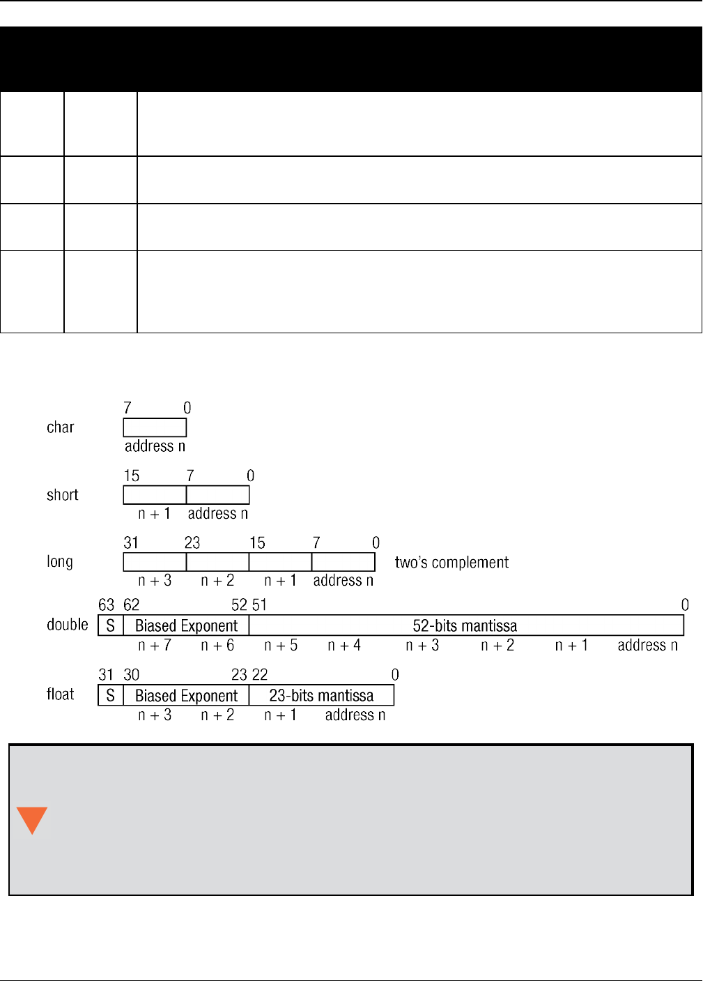
Double 8
The double type contains 64-bits: 1 for sign, 11 for the exponent and 52 for the
mantissa. Its range is ±1.7E308 with at least 15 digits of precision. This is IEEE
754
Float 4
The float type contains 32-bits: 1 for the sign, 8 for the exponent and 23 for
the mantissa. Its range is ±3.4E38 with at least 7 digits of precision. This is
IEEE 754
Enum 4
A 4-byte enumerated type beginning at zero (an unsigned long). In binary, the
enumerated value is output. In ASCII or Abbreviated ASCII, the enumeration
label is spelled out
Table 1: Field Type
Chapter 1 Messages
OEM7 Commands and Logs Reference Manual v7 26
Type
Binary
Size
(bytes)
Description
GPSec 4
This type has two separate formats dependent on whether you requested a
binary or an ASCII format output. For binary, the output is in milliseconds and
is a long type. For ASCII, the output is in seconds and is a float type
Hex n Hex is a packed, fixed length (n) array of bytes in binary but in ASCII or
Abbreviated ASCII is converted into 2 character hexadecimal pairs
Hex
Ulong 4An unsigned, 32-bit integer in hexadecimal format. Values are in the range
from +0 to +4294967295
String n
String is a variable length array of bytes that is null-terminated in the binary
case and additional bytes of padding are added to maintain 4-byte alignment.
The maximum byte length for each String field is shown in the row in the log or
command tables
Figure 1: Byte Arrangements
Byte Arrangements above shows the arrangement of bytes, within each field type, when
used by IBM PC computers. All data sent to or from the OEM7 family of receivers is
ordered least significant bit (LSB) first (little-endian). This is opposite to the most sig-
nificant bit first (big-endian) ordering that is shown in Byte Arrangements above. Data is
then stored in the receiver LSB first. For example, in char type data, the LSB is bit 0 and
the most significant bit (MSB) is bit 7. See Table 126: Channel Tracking Status on
page675 for a more detailed example.

Chapter 1 Messages
OEM7 Commands and Logs Reference Manual v7 27
1.1 ASCII
ASCII messages are readable by both the user and a computer. The structures of all ASCII mes-
sages follow the general conventions as noted here:
1. The lead code identifier for each record is '#'.
2. Each log or command is of variable length depending on amount of data and formats.
3. All data fields are delimited by a comma ',' with two exceptions:
lThe first exception is the last header field which is followed by a ‘;’ to denote the start of
the data message.
lThe second exception is the last data field, which is followed by a * to indicate end of
message data.
4. Each log ends with a hexadecimal number preceded by an asterisk and followed by a line ter-
mination using the carriage return and line feed characters.
For example:
*1234ABCD[CR][LF]. This value is a 32-bit CRC of all bytes in the log, excluding the '#' iden-
tifier and the asterisk preceding the eight CRC digits.
See 32-Bit CRC on page47 for the algorithm used to generate the CRC.
5. The receiver only accepts the following ASCII characters.
lcharacters between space (ASCII value 32) and '~' (ASCII value 126) inclusive,
lvertical tab (ASCII value 9)
lline feed (ASCII value 10)
lhorizontal tab (ASCII value 11)
lcarriage return (ASCII value 13)
Other values are discarded and can lead to unexpected results.
6. An ASCII string is one field and is surrounded by double quotation marks.
For example:
“ASCII string”. If separators are surrounded by quotation marks then the string is still one
field and the separator will be ignored (example, “xxx,xxx” is one field). Double quotation
marks within a string are not allowed.
7. If the receiver detects an error parsing an input message, it returns an error response mes-
sage. See Responses on page1030 for a list of response messages from the receiver.
Message Structure:
header; data field..., data field..., data field... *xxxxxxxx [CR][LF]
The ASCII message header structure is described in Table 2: ASCII Message Header Structure
on the next page.

Chapter 1 Messages
OEM7 Commands and Logs Reference Manual v7 28
Field Field
Name
Field
Type Description
Ignored
on
Input
1 Sync Char Sync character. The ASCII message is always preceded by
a single ‘#’ symbol N
2 Message Char The ASCII name of the log or command N
3 Port Char
The name of the port from which the log was generated.
The string is made up of the port name followed by an _x
where x is a number from 1 to 31 denoting the virtual
address of the port. If no virtual address is indicated, it is
assumed to be address 0
Y
4Sequence
#Long
Used for multiple related logs. It is a number that counts
down from N-1 to 0, where 0 means it is the last one of the
set. Most logs only come out one at a time in which case
this number is 0
N
5% Idle
Time Float The minimum percentage of time the processor is idle,
calculated once per second Y
6Time
Status Enum The value indicates the quality of the GPS reference time
(see Table 11: GPS Reference Time Status on page45) Y
7 Week Ulong GPS reference week number Y
8 Seconds GPSec Seconds from the beginning of the GPS reference week;
accurate to the millisecond level Y
9Receiver
Status Ulong
An eight digit hexadecimal number representing the status
of various hardware and software components of the
receiver (see Table 158: Receiver Status on page753)
Y
10 Reserved Ulong Reserved for internal use. Y
11
Receiver
S/W
Version
Ulong A value (0 - 65535) representing the receiver software
build number Y
12 ; Char The character indicates the end of the header N
Table 2: ASCII Message Header Structure
Example Log:
#RAWEPHEMA,COM1,0,35.0,SATTIME,1364,496230.000,02100000,97b7,2310;30,1364,
496800,8b0550a1892755100275e6a09382232523a9dc04ee6f794a0000090394ee,
8b0550a189aa6ff925386228f97eabf9c8047e34a70ec5a10e486e794a7a,
8b0550a18a2effc2f80061c2fffc267cd09f1d5034d3537affa28b6ff0eb*7a22f279

Chapter 1 Messages
OEM7 Commands and Logs Reference Manual v7 29
1.2 Abbreviated ASCII
This message format is designed to make entering and viewing commands and logs simple. The
data is represented as simple ASCII characters, separated by spaces or commas and arranged
in an easy to understand format. There is no 32-bit CRC for error detection because it is meant
for viewing by the user.
Example Command:
log com1 loglist
Resultant Log:
<LOGLIST COM1 0 69.0 FINE 0 0.000 00240000 206d 0
< 4
< COM1 RXSTATUSEVENTA ONNEW 0.000000 0.000000 NOHOLD
< COM2 RXSTATUSEVENTA ONNEW 0.000000 0.000000 NOHOLD
< COM3 RXSTATUSEVENTA ONNEW 0.000000 0.000000 NOHOLD
< COM1 LOGLIST ONCE 0.000000 0.000000 NOHOLD
The array of 4 entries are offset from the left hand side and start with ‘<’.
1.3 Binary
Binary messages are strictly machine readable format. They are ideal for applications where the
amount of data transmitted is fairly high. Due to the inherent compactness of binary as opposed
to ASCII data, messages are much smaller. The smaller message size allows a larger amount of
data to be transmitted and received by the receiver’s communication ports. The structure of all
binary messages follows the general conventions as noted here:
1. Basic format of:
lHeader: 3 Sync bytes plus 25-bytes of header information. The header length is variable
as fields may be appended in the future. Always check the header length.
lCRC: 4 bytes
lData: variable
2. The 3 Sync bytes will always be:
Byte Hex Decimal
First AA 170
Second 44 68
Third 12 18
3. The CRC is a 32-bit CRC (see 32-Bit CRC on page47 for the CRC algorithm) performed on all
data including the header.
4. The header is in the format shown in Table 3: Binary Message Header Structure on the next
page.

Chapter 1 Messages
OEM7 Commands and Logs Reference Manual v7 30
Field Field
Name
Field
Type Description Binary
Bytes
Binary
Offset
Ignored
on
Input
1 Sync Char Hexadecimal 0xAA 1 0 N
2 Sync Char Hexadecimal 0x44 1 1 N
3 Sync Char Hexadecimal 0x12 1 2 N
4Header
Lgth Uchar Length of the header 1 3 N
5Message
ID Ushort
This is the Message ID number of the
log (see the command or log
descriptions for the Message ID values
of individual commands or logs)
2 4 N
6Message
Type Char
Bits 0-4 = Measurement source1
Bits 5-6 = Format
00 = Binary
01 = ASCII
10 = Abbreviated ASCII, NMEA
11 = Reserved
Bit 7 = Response bit (see Message
Responses on page41)
0 = Original Message
1 = Response Message
1 6 N
7Port
Address Uchar
See Table 4: Detailed Port Identifier on
the next page (decimal values >=32
may be used) (lower 8-bits only) 2
1 7 N 3
8Message
Length Ushort
The length in bytes of the body of the
message, not including the header nor
the CRC
2 8 N
Table 3: Binary Message Header Structure
1Bits 0-4 are used to indicate the measurement source. For dual antenna receivers, if bit 0 is set, the log is from
the secondary antenna.
2The 8-bit size means you will only see 0xA0 to 0xBF when the top bits are dropped from a port value greater than
8-bits. For example, ASCII port USB1 will be seen as 0xA0 in the binary output.
3Recommended value is THISPORT (binary 192).

Chapter 1 Messages
OEM7 Commands and Logs Reference Manual v7 31
Field Field
Name
Field
Type Description Binary
Bytes
Binary
Offset
Ignored
on
Input
9 Sequence Ushort
Used for multiple related logs. It is a
number that counts down from N-1 to 0
where N is the number of related logs
and 0 means it is the last one of the set.
Most logs only come out one at a time
in which case this number is 0
2 10 N
10 Idle Time Uchar
Time the processor is idle, calculated
once per second. Take the time (0 -
200) and divide by two to give the
percentage of time (0 - 100%)
1 12 Y
11 Time
Status Enum
Indicates the quality of the GPS
reference time (see Table 11: GPS
Reference Time Status on page45).
1113 N 2
12 Week Ushort GPS reference week number 2 14 N
13 ms GPSec Milliseconds from the beginning of the
GPS reference week 4 16 N
14 Receiver
Status Ulong
32-bits representing the status of
various hardware and software
components of the receiver (see Table
158: Receiver Status on page753)
4 20 Y
15 Reserved Ushort Reserved for internal use 2 24 Y
16
Receiver
S/W
Version
Ushort A value (0 - 65535) representing the
receiver software build number 2 26 Y
ASCII Port
Name
Hex Port
Value
Decimal Port
Value Description
NO_PORTS 0 0 No ports specified
COM1_ALL 1 1 All virtual ports for COM1
COM2_ALL 2 2 All virtual ports for COM2
COM3_ALL 3 3 All virtual ports for COM3
Table 4: Detailed Port Identifier
1This ENUM is not 4-bytes long but, as indicated in the table, is only 1-byte.
2Fields 12 and 13 (Week and ms) are ignored if Field 11 (Time Status) is invalid. In this case, the current receiver
time is used. The recommended values for the three time fields are 0, 0, 0.

Chapter 1 Messages
OEM7 Commands and Logs Reference Manual v7 32
ASCII Port
Name
Hex Port
Value
Decimal Port
Value Description
THISPORT_ALL 6 6 All virtual ports for the current port
FILE_ALL 7 7 All virtual ports for logging to file
ALL_PORTS 8 8 All virtual ports for all ports
USB1_ALL d 13 All virtual ports for USB1
USB2_ALL e 14 All virtual ports for USB2
USB3_ALL f 15 All virtual ports for USB3
AUX_ALL 10 16 All virtual ports for the AUX
COM4_ALL 13 19 All virtual ports for COM4
ETH1_ALL 14 20 All virtual ports for ETH1
IMU_ALL 15 21 All virtual ports for IMU
ICOM1_ALL 17 23 All virtual ports for ICOM1
ICOM2_ALL 18 24 All virtual ports for ICOM2
ICOM3_ALL 19 25 All virtual ports for ICOM3
NCOM1_ALL 1a 26 All virtual ports for NCOM1
NCOM2_ALL 1b 27 All virtual ports for NCOM2
NCOM3_ALL 1c 28 All virtual ports for NCOM3
ICOM4_ALL 1d 29 All virtual ports for ICOM4
WCOM1_ALL 1e 30 All virtual ports for WCOM1
COM1 20 32 COM1, virtual port 0
COM1_1 21 33 COM1, virtual port 1
...
COM1_31 3f 63 COM1, virtual port 31
COM2 40 64 COM2, virtual port 0
COM2_1 41 65 COM1, virtual port 1
...
COM2_31 5f 95 COM2, virtual port 31
COM3 60 96 COM3, virtual port 0

Chapter 1 Messages
OEM7 Commands and Logs Reference Manual v7 33
ASCII Port
Name
Hex Port
Value
Decimal Port
Value Description
COM3_1 61 97 COM3, virtual port 1
...
COM3_31 7f 127 COM3, virtual port 31
SPECIAL a0 160 Unknown port, virtual port 0
SPECIAL_1 a1 161 Unknown port, virtual port1
...
SPECIAL_31 bf 191 Unknown port, virtual port 31
THISPORT c0 192 Current COM port, virtual port 0
THISPORT_1 c1 193 Current COM port, virtual port 1
...
THISPORT_31 df 223 Current COM port, virtual port 31
FILE e0 224 Virtual port 0 for logging to file
FILE_1 e1 225 Virtual port 1 for logging to file
...
FILE_31 ff 255 Virtual port 31 for logging to file
USB1 5a0 1440 USB1, virtual port 0
USB1_1 5a1 1441 USB1, virtual port 1
...
USB1_31 5bf 1471 USB1, virtual port 31
USB2 6a0 1696 USB2, virtual port 0
USB2_1 6a1 1967 USB2, virtual port 1
...
USB2_31 6bf 1727 USB2, virtual port 31
USB3 7a0 1952 USB3, virtual port 0
USB3_1 7a1 1953 USB3, virtual port 1
...
USB3_31 7bf 1983 USB port 3, virtual port 31

Chapter 1 Messages
OEM7 Commands and Logs Reference Manual v7 34
ASCII Port
Name
Hex Port
Value
Decimal Port
Value Description
AUX 8a0 2208 AUX port, virtual port 0
AUX_1 8a1 2209 AUX port, virtual port 1
...
AUX_31 8bf 2239 AUX port, virtual port 31
COM4 ba0 2976 COM4, virtual port 0
COM4_1 ba1 2977 COM4, virtual port 1
...
COM4_31 bbf 3007 COM4, virtual port 31
ETH1 ca0 3232 ETH1, virtual port 0
ETH1_1 ca1 3233 ETH1, virtual port 1
...
ETH1_31 cbf 3263 ETH1, virtual port 31
IMU da0 3488 IMU, virtual port 0
IMU_1 da1 3489 IMU, virtual port 1
...
IMU_31 dbf 3519 IMU, virtual port 31
ICOM1 fa0 4000 ICOM1, virtual port 0
ICOM1_1 fa1 4001 ICOM1, virtual port 1
...
ICOM1_31 fbf 4031 ICOM1, virtual port 31
ICOM2 10a0 4256 ICOM2, virtual port 0
ICOM2_1 10a1 4257 ICOM2, virtual port 1
...
ICOM2_31 10bf 4287 ICOM2, virtual port 31
ICOM3 11a0 4512 ICOM3, virtual port 0
ICOM3_1 11a1 4513 ICOM3, virtual port 1
...

Chapter 1 Messages
OEM7 Commands and Logs Reference Manual v7 35
ASCII Port
Name
Hex Port
Value
Decimal Port
Value Description
ICOM3_31 11bf 4543 ICOM3, virtual port 31
NCOM1 12a0 4768 NCOM1, virtual port 0
NCOM1_1 12a1 4769 NCOM1, virtual port 1
...
NCOM1_31 12bf 4799 NCOM1, virtual port 31
NCOM2 13a0 5024 NCOM2, virtual port 0
NCOM2_1 13a1 5025 NCOM2, virtual port 1
...
NCOM2_31 13bf 5055 NCOM2, virtual port 31
NCOM3 14a0 5280 NCOM3, virtual port 0
NCOM3_1 14a1 5281 NCOM3, virtual port 1
...
NCOM3_31 14bf 5311 NCOM3, virtual port 31
ICOM4 15a0 5536 ICOM4, virtual port 0
ICOM4_1 15a1 5537 ICOM4, virtual port 1
...
ICOM4_31 15bf 5567 ICOM4, virtual port 31
WCOM1 16a0 5792 WCOM1, virtual port 0
WCOM1_1 16a1 5793 WCOM1, virtual port 1
...
WCOM1_31 16bf 5823 WCOM1, virtual port 31
COM5_ALL 16c0 5824 All virtual ports for COM5
COM6_ALL 16c1 5825 All virtual ports for COM6
BT1_ALL 16c2 5826 All virtual ports for the Bluetooth
device
COM7_ALL 16c3 5827 All virtual ports for COM7
COM8_ALL 16c4 5828 All virtual ports for COM8

Chapter 1 Messages
OEM7 Commands and Logs Reference Manual v7 36
ASCII Port
Name
Hex Port
Value
Decimal Port
Value Description
COM9_ALL 16c5 5829 All virtual ports for COM9
COM10_ALL 16c6 5830 All virtual ports for COM10
CCOM1_ALL 16c7 5831 All virtual ports for CCOM1
CCOM2_ALL 16c8 5832 All virtual ports for CCOM2
CCOM3_ALL 16c9 5833 All virtual ports for CCOM3
CCOM4_ALL 16ca 5834 All virtual ports for CCOM4
CCOM5_ALL 16cb 5835 All virtual ports for CCOM5
CCOM6_ALL 16cc 5836 All virtual ports for CCOM6
ICOM5_ALL 16cf 5839 All virtual ports for ICOM5
ICOM6_ALL 16d0 5840 All virtual ports for ICOM6
ICOM7_ALL 16d1 5841 All virtual ports for ICOM7
SCOM1_ALL 16d2 5842 All virtual ports for SCOM1
SCOM2_ALL 16d3 5843 All virtual ports for SCOM2
SCOM3_ALL 16d4 5844 All virtual ports for SCOM3
SCOM4_ALL 16d5 5845 All virtual ports for SCOM4
COM5 17a0 6048 COM5, virtual port 0
COM5_1 17a1 6049 COM5, virtual port 1
...
COM5_31 17bf 6079 COM5, virtual port 31
COM6 18a0 6304 COM6, virtual port 0
COM6_1 18a1 6305 COM6, virtual port 1
...
COM6_31 18bf 6335 COM6, virtual port 31
BT1 19a0 6560 Bluetooth device, virtual port 0
BT1_1 19a1 6561 Bluetooth device, virtual port 1
...
BT1_31 19bf 6591 Bluetooth device, virtual port 31

Chapter 1 Messages
OEM7 Commands and Logs Reference Manual v7 37
ASCII Port
Name
Hex Port
Value
Decimal Port
Value Description
COM7 1aa0 6816 COM7, virtual port 0
COM7_1 1aa1 6817 COM7, virtual port 1
...
COM7_31 1abf 6847 COM7, virtual port 31
COM8 1ba0 7072 COM8, virtual port 0
COM8_1 1ba1 7073 COM8, virtual port 1
...
COM8_31 1bbf 7103 COM8, virtual port 31
COM9 1ca0 7328 COM9, virtual port 0
COM9_1 1ca1 7329 COM9, virtual port 1
...
COM9_31 1cbf 7359 COM9, virtual port 31
COM10 1da0 7584 COM10, virtual port 0
COM10_1 1da1 7585 COM10, virtual port 1
...
COM10_31 1dbf 7615 COM10, virtual port 31
CCOM1 1ea0 7840 CAN COM1, virtual port 0
CCOM1_1 1ea1 7841 CAN COM1, virtual port 1
...
CCOM1_31 1ebf 7871 CAN COM1, virtual port 31
CCOM2 1fa0 8096 CAN COM2, virtual port 0
CCOM2_1 1fa1 8097 CAN COM2, virtual port 1
...
CCOM2_31 1fbf 8127 CAN COM2, virtual port 31
CCOM3 20a0 8352 CAN COM3, virtual port 0
CCOM3_1 20a1 8353 CAN COM3, virtual port 1
...

Chapter 1 Messages
OEM7 Commands and Logs Reference Manual v7 38
ASCII Port
Name
Hex Port
Value
Decimal Port
Value Description
CCOM3_31 20bf 8383 CAN COM3, virtual port 31
CCOM4 21a0 8608 CAN COM4, virtual port 0
CCOM4_1 21a1 8609 CAN COM4, virtual port 1
...
CCOM4_31 21bf 8639 CAN COM4, virtual port 31
CCOM5 22a0 8864 CAN COM5, virtual port 0
CCOM5_1 22a1 8865 CAN COM5, virtual port 1
...
CCOM5_31 22bf 8895 CAN COM5, virtual port 31
CCOM6 23a0 9120 CAN COM6, virtual port 0
CCOM6_1 23a1 9121 CAN COM6, virtual port 1
...
CCOM6_31 23bf 9151 CAN COM6, virtual port 31
ICOM5 26a0 9888 ICOM5, virtual port 0
ICOM5_1 26a1 9889 ICOM5, virtual port 1
...
ICOM5_31 26bf 9919 ICOM5, virtual port 31
ICOM6 27a0 10144 ICOM6, virtual port 0
ICOM6_1 27a1 10145 ICOM6, virtual port 1
...
ICOM6_31 27bf 10175 ICOM6, virtual port 31
ICOM7 28a0 10400 ICOM7, virtual port 0
ICOM7_1 28a1 10401 ICOM7, virtual port 1
...
ICOM7_31 28bf 10431 ICOM7, virtual port 31
SCOM1 29a0 10656 SCOM1, virtual port 0
SCOM1_1 29a1 10657 SCOM1, virtual port 1
Chapter 1 Messages
OEM7 Commands and Logs Reference Manual v7 39
ASCII Port
Name
Hex Port
Value
Decimal Port
Value Description
...
SCOM1-31 29bf 10687 SCOM1, virtual port 31
SCOM2 2aa0 10912 SCOM2, virtual port 0
SCOM2_1 2aa1 10913 SCOM2, virtual port 1
...
SCOM2_31 2abf 10943 SCOM2, virtual port 31
SCOM3 2ba0 11168 SCOM3, virtual port 0
SCOM3_1 2ba1 11169 SCOM3, virtual port 1
...
SCOM3_31 2bbf 11199 SCOM3, virtual port 31
SCOM4 2ca0 11424 SCOM4, virtual port 0
SCOM4_1 2ca1 11425 SCOM4, virtual port 1
...
SCOM4_31 2cbf 11455 SCOM4, virtual port 31
COM1_ALL, COM2_ALL, COM3_ALL, COM4_ALL, COM5_ALL, THISPORT_ALL, FILE_ALL,
ALL_PORTS, USB1_ALL, USB2_ALL, USB3_ALL, AUX_ALL, ETH1_ALL, ICOM1_ALL,
ICOM2_ALL, ICOM3_ALL, ICOM4_ALL, ICOM5_ALL, ICOM6_ALL, ICOM7_ALL, CCOM1_ALL,
CCOM2_ALL, CCOM3_ALL, CCOM4_ALL, CCOM5_ALL, CCOM6_ALL, NCOM1_ALL, NCOM2_
ALL, NCOM3_ALL, SCOM1_ALL, SCOM2_ALL, SCOM3_ALL, SCOM4_ALL and WCOM1_ALL
are only valid for the UNLOGALL command.
The ports available vary based on the receiver.
Table 5: Available Port Types below provides examples of where each port type might be used.
Port
Type Description Example of where it might be used
AUX Auxiliary
"serial" ports An additional UART serial port available only on certain platforms
Table 5: Available Port Types

Chapter 1 Messages
OEM7 Commands and Logs Reference Manual v7 40
Port
Type Description Example of where it might be used
BTx Bluetooth ports These ports are used to connect over Bluetooth devices, when the
receiver is equipped with a BT device
COMx Serial Port UART serial ports. Used when there is a physical RS-232 or RS-422
connection to the receiver
ICOMx Internet ports These ports are used when establishing TCP or UDP connections to the
receiver over a network
NCOMx NTRIP ports These ports are used when establishing NTRIP connections to the
receiver over a network
SCOMx Script ports Ports used by the Scripted User Interface (i.e. Lua)
USBx USB "serial"
ports
When the receiver is connected to an external host through USB, these
ports are available
WCOMx Web Server
port
Ports used by Web Server applications, for receivers equipped with a
web server
1.4 Description of ASCII and Binary Logs with Short Headers
These logs are set up in the same way as normal ASCII or binary logs except a normal ASCII or
binary header is replaced with a short header (see Table 6: Short ASCII Message Header Struc-
ture below and Table 7: Short Binary Message Header Structure below).
Field Field Name Field Type Description
1 % Char % symbol
2 Message Char This is the name of the log
3 Week Number Ushort GNSS week number
4 Milliseconds GPSec Seconds from the beginning of the GNSS week
(Same byte arrangement as a Float type)
Table 6: Short ASCII Message Header Structure
Field Field
Name
Field
Type Description Binary
Bytes
Binary
Offset
1 Synch Char Hex 0xAA 1 0
2 Synch Char Hex 0x44 1 1
3 Synch Char Hex 0x13 1 2
Table 7: Short Binary Message Header Structure

Chapter 1 Messages
OEM7 Commands and Logs Reference Manual v7 41
Field Field
Name
Field
Type Description Binary
Bytes
Binary
Offset
4Message
Length Uchar Message length, not including header
or CRC 1 3
5 Message ID Ushort Message ID number 2 4
6Week
Number Ushort GNSS week number 2 6
7 Milliseconds GPSec
Milliseconds from the beginning of the
GNSS week
(Same byte arrangement as a Long
type)
4 8
1.5 Message Responses
By default, if you input a message you get back a response. If desired, the INTERFACEMODE
command (see page 193) can be used to disable response messages. The response will be in the
exact format you entered the message (that is, binary input = binary response).
1.5.1 Abbreviated ASCII Response
Just the leading '<' followed by the response string, for example: <OK.
1.5.2 ASCII Response
Full header with the message name being identical except ending in an 'R' (for response). The
body of the message consists of a 40 character string for the response string. For example:
#BESTPOSR,COM1,0,67.0,FINE,1028,422060.400,02000000,a31b,0;"OK" *b867caad
1.5.3 Binary Response
Similar to an ASCII response except that it follows the binary protocols, see Table 8: Binary
Message Response Structure on the next page.
Table 9: Binary Message Sequence on page43 is an example of the sequence for requesting and
then receiving BESTPOSB. The example is in hex format. When you enter a hex command, you
may need to add a ‘\x’ or ‘0x’ before each hex pair, depending on your code. For example:
0xAA0x440x120x1C0x010x000x02 and so on.

Chapter 1 Messages
OEM7 Commands and Logs Reference Manual v7 42
Field Field
Name
Field
Type Description Binary
Bytes
Binary
Offset
B
I
N
A
R
Y
H
E
A
D
E
R
1 Sync Char Hexadecimal 0xAA 1 0
2 Sync Char Hexadecimal 0x44 1 1
3 Sync Char Hexadecimal 0x12 1 2
4Header
Lgth Uchar Length of the header 1 3
5Message
ID Ushort Message ID number 2 4
6Message
Type Char Bit 7 = Response Bit
1 = Response Message 1 6
7Port
Address Uchar See Table 4: Detailed Port Identifier on
page31 1 7
8Message
Length Ushort The length in bytes of the body of the message
(not including the CRC) 2 8
9 Sequence Ushort Normally 0 2 10
10 Idle Time Uchar Idle time 1 12
11 Time
Status Enum Table 11: GPS Reference Time Status on
page45 1113
12 Week Ushort GPS reference week number 2 14
13 ms GPSec Milliseconds into GPS reference week 4 16
14 Receiver
Status Ulong Table 158: Receiver Status on page753 4 20
15 Reserved Ushort Reserved 2 24
16
Receiver
S/W
Version
Ushort Receiver software build number 2 26
I
D17 Response
ID Enum
The enumeration value corresponding to the
message response (Table 221: Response
Messages on page1030)
4 28
H
E
X
18 Response Hex
String containing the ASCII response in hex
coding to match the ID above (for example,
0x4F4B = OK)
variable 32
Table 8: Binary Message Response Structure
1This ENUM is not 4-bytes long but as indicated in the table is only 1 byte.

Chapter 1 Messages
OEM7 Commands and Logs Reference Manual v7 43
Direction Sequence Data
To
Receiver
LOG
Command
Header
AA44121C 01000240 20000000 1D1D0000 29160000 00004C00 55525A80
LOG
Parameters
20000000 2A000000 02000000 00000000 0000F03F 00000000 00000000
00000000
Checksum 2304B3F1
From
Receiver
LOG
Response
Header
AA44121C 01008220 06000000 FFB4EE04 605A0513 00004C00 FFFF5A80
LOG
Response
Data
01000000 4F4B
Checksum DA8688EC
From
Receiver
BESTPOSB
Header
AA44121C 2A000220 48000000 90B49305 B0ABB912 00000000
4561BC0A
BESTPOSB
Data
00000000 10000000 1B0450B3 F28E4940 16FA6BBE 7C825CC0 0060769F
449F9040 A62A82C1 3D000000 125ACB3F CD9E983F DB664040
00303030 00000000 00000000 0B0B0000 00060003
Checksum 42DC4C48
Table 9: Binary Message Sequence
1.6 GLONASS Slot and Frequency Numbers
When a PRN in a log is in the range 38 to 61, then that PRN represents a GLONASS Slot Number
where the Slot Number shown is the actual GLONASS Slot Number plus 37.
Similarly, the GLONASS Frequency shown in logs is the actual GLONASS Frequency plus 7.
For example:
<RANGE COM1 0 82.0 FINESTEERING 1729 155076.000 02004000 5103 11465
46
31 0 24514687.250 0.064 -128825561.494675 0.010 3877.473 45.0 563.310
18109c04
...
46 5 24097664.754 0.213 -128680178.570435 0.014 -3740.543 40.6 10098.600
08119e44
'''
8 0 39844800.076 0.043 -160438471.200694 0.013 -392.547 42.5 12038.660
00349c84
where 31 and 8 are GPS satellites and 46 is a GLONASS satellite. Its actual GLONASS Slot Num-
ber is 9 and its frequency is -2.

Chapter 1 Messages
OEM7 Commands and Logs Reference Manual v7 44
Refer to PRN Numbers below for more information about GLONASS PRN numbers. Also, refer to
An Introduction to GNSS available on our website for more information.
1.6.1 PRN Numbers
The PRN and SVID ranges for the logs and commands that use them are shown in the following
table.
Command/Log GPS
PRN
SBAS
PRN
SBAS
QZSS
L1-SAIF
PRN
GLONASS
Slot
Galileo
SVID
QZSS
PRN
BDS
PRN
NavIC
PRN
ASSIGN 1-32 120-
158 183-192 38-61 1-36 193-
202 1-30 1-7
ASSIGNALL 1-32 120-
158 183-192 38-61 1-36 193-
202 1-30 1-7
LOCKOUT 1-32 120-
158 183-192 38-61 - 193-
202 - 1-7
SBASCONTROL -120-
158 183-192 - - - - -
TRACKSV 1-32 120-
158 183-192 38-61 1-36 193-
202 1-30 1-7
UNLOCKOUT 1-32 120-
158 183-192 38-61 - 193-
202 - 1-7
RANGE 1-32 120-
158 183-192 38-61 1-36 193-
202 1-30 1-7
RANGECMP 1-32 120-
158 183-192 38-61 1-36 193-
202 1-30 1-7
RANGECMP2 1-32 120-
158 183-192 1-24 1-36 193-
202 1-30 1-7
RANGECMP4 1-32 120-
158 183-192 1-24 1-36 193-
202 1-30 1-7
RANGEGPSL1 1-32 - - - - - - -
SATVIS2 1-32 120-
158 183-192 1-24 1-36 193-
202 1-30 1-7
TRACKSTAT 1-32 120-
158 183-192 38-61 1-36 193-
202 1-30 1-7
Table 10: PRN Numbers for Commands and Logs

Chapter 1 Messages
OEM7 Commands and Logs Reference Manual v7 45
1.7 GPS Reference Time Status
All reported receiver times are subject to a qualifying time status. The status indicates how well
a time is known (see Table 11: GPS Reference Time Status below).
GPS Reference Time
Status (Decimal)
GPS Reference Time
Status
(ASCII)
Description
20 UNKNOWN Time validity is unknown
60 APPROXIMATE Time is set approximately
80 COARSEADJUSTING Time is approaching coarse precision
100 COARSE This time is valid to coarse precision
120 COARSESTEERING Time is coarse set and is being steered
130 FREEWHEELING Position is lost and the range bias cannot be
calculated
140 FINEADJUSTING Time is adjusting to fine precision
160 FINE Time has fine precision
170 FINEBACKUPSTEERING Time is fine set and is being steered by the
backup system
180 FINESTEERING Time is fine set and is being steered
200 SATTIME Time from satellite. Only used in logs containing
satellite data such as ephemeris and almanac
Table 11: GPS Reference Time Status
There are several distinct states the receiver goes through.
When the CLOCKADJUST command (see page 101) is enabled:
lUNKNOWN (initial state)
lCOARSESTEERING (initial coarse time set)
lFINESTEERING (normal operating state)
lFINEBACKUPSTEERING (when the backup system is used for a time)
lFREEWHEELING (when range bias becomes unknown)
When the CLOCKADJUST command (see page 101) is disabled:
lUNKNOWN (initial state)
lCOARSE (initial coarse time set)
lFINE (normal operating state)
On startup and before any satellites are tracked, the receiver can not possibly know the current
time. As such, the receiver time starts counting at GPS reference week 0 and second 0.0. The
time status flag is set to UNKNOWN.

Chapter 1 Messages
OEM7 Commands and Logs Reference Manual v7 46
If time is input to the receiver using the SETAPPROXTIME command (see page 338), the time
status will be APPROXIMATE.
After the first ephemeris is decoded, the receiver time is set to a resolution of ±10 milliseconds.
This state is qualified by the COARSE or COARSESTEERING time status flag depending on the
state of the CLOCKADJUST switch (for more information, refer to the CLOCKADJUST command
on page101).
Once a position is known and range biases are being calculated, the internal clock model will
begin modeling the range biases also known as the receiver clock offset.
Modeling will continue until the model is a good estimation of the actual receiver clock behavior.
At this time, the receiver time will again be adjusted, this time to an accuracy of ±1 micro-
second. This state is qualified by the FINE time status flag.
The final logical time status flag depends on whether CLOCKADJUST is enabled or not. If
CLOCKADJUST is disabled, the time status flag will never improve on FINE. The time will only be
adjusted again to within ±1 microsecond if the range bias gets larger than ±250 milliseconds. If
CLOCKADJUST is enabled, the time status flag is set to FINESTEERING and the receiver time is
continuously updated (steered) to minimize the receiver range bias.
If a solution cannot be computed with the primary satellite system, it will attempt to use a
backup system (if available). When the backup system is used and time is computed, the time
status is set to FINEBACKUPSTEERING. If the position is lost and the range bias cannot be cal-
culated, the time status is degraded to FREEWHEELING.
See also Message Time Stamps below and the SETTIMEBASE command on page349.
1.8 Message Time Stamps
All NovAtel format messages generated by the OEM7 family of receivers have a GPS reference
time stamp in their header. GPS reference time is referenced to UTC with zero point defined as
midnight on the night of January 5, 1980. The time stamp consists of the number of weeks since
that zero point and the number of seconds since the last week number change (0 to 604,799).
GPS reference time differs from UTC time since leap seconds are occasionally inserted into UTC
and GPS reference time is continuous. In addition, a small error (less than 1 microsecond) can
exist in synchronization between UTC and GPS reference time. The TIME log reports both GNSS
and UTC time and the offset between the two.
The data in synchronous logs (for example, RANGE, BESTPOS, TIME) are based on a periodic
measurement of satellite pseudoranges. The time stamp on these logs is the receiver estimate
of GPS reference time at the time of the measurement. A synchronous log with trigger ONTIME 1
can be used in conjunction with the 1PPS signal to provide relative accuracy better than 250 ns.
Other log types (asynchronous and polled) are triggered by an external event and the time in the
header may not be synchronized to the current GPS reference time. Logs that contain satellite
broadcast data (for example, ALMANAC, GPSEPHEM) have the transmit time of their last sub-
frame in the header. In the header of differential time matched logs (for example,
MATCHEDPOS) is the time of the matched reference and local observation that they are based
on. Logs triggered by a mark event (for example, MARKEDPOS, MARKTIME) have the estimated
GPS reference time of the mark event in their header. In the header of polled logs (for example,
LOGLIST, PORTSTATS, VERSION) is the approximate GPS reference time when their data was

Chapter 1 Messages
OEM7 Commands and Logs Reference Manual v7 47
generated. However, when asynchronous logs are triggered ONTIME, the time stamp will rep-
resent the time the log was generated and not the time given in the data.
For more information about log types, see Log Types on page404.
1.9 Decoding of the GPS Reference Week Number
The GPS reference week number provided in the raw satellite data is the 10 least significant bits
(or 8 least significant bits in the case of the almanac data) of the full week number. When the
receiver processes the satellite data, the week number is decoded in the context of the current
era and therefore is computed as the full week number starting from week 0 or January 6, 1980.
Therefore, in all log headers and decoded week number fields, the full week number is given.
Only in raw data, such as the data field of the RAWALM log (see page 708) or the subframe field
of the RAWEPHEM log (see page 711), will the week number remain as the 10 (or 8) least sig-
nificant bits.
1.10 32-Bit CRC
The ASCII and Binary OEM7 family message formats all contain a 32-bit CRC for data veri-
fication. This allows the user to ensure the data received (or transmitted) is valid with a high
level of certainty.
The C functions below may be implemented to generate the CRC of a block of data.
#define CRC32_POLYNOMIAL 0xEDB88320L
/* --------------------------------------------------------------------------
Calculate a CRC value to be used by CRC calculation functions.
-------------------------------------------------------------------------- */
unsigned long CRC32Value(int i) {
int j;
unsigned long ulCRC;
ulCRC =i;
for (j=8;j>0; j-- ) {
if (ulCRC &1)
ulCRC =(ulCRC >> 1)^CRC32_POLYNOMIAL;
else
ulCRC >>= 1;
}
return ulCRC;
}
/* --------------------------------------------------------------------------
Calculates the CRC-32 of a block of data all at once
ulCount - Number of bytes in the data block
ucBuffer - Data block
-------------------------------------------------------------------------- */
unsigned long CalculateBlockCRC32(unsigned long ulCount, unsigned char
*ucBuffer ) {
unsigned long ulTemp1;
unsigned long ulTemp2;
unsigned long ulCRC =0;
while (ulCount-- != 0){
ulTemp1 =(ulCRC >> 8)&0x00FFFFFFL;
ulTemp2 =CRC32Value( ((int)ulCRC ^ *ucBuffer++ ) & 0xFF );

Chapter 1 Messages
OEM7 Commands and Logs Reference Manual v7 48
ulCRC =ulTemp1 ^ulTemp2;
}
return(ulCRC );
}
The NMEA checksum is an XOR of all the bytes (including delimiters such as ',' but exclud-
ing the * and $) in the message output. It is therefore an 8-bit and not a 32-bit check-
sum.
Not all logs may be available. Every effort is made to ensure examples are correct, however, a
checksum may be created for promptness in publication. In this case it will appear as ‘9999’.
Example:
BESTPOSB and BESTPOSA from an OEM7 family receiver.
Binary Log Message:
0xAA, 0x44, 0x12, 0x1C, 0x2A, 0x00, 0x02, 0x20, 0x48, 0x00, 0x00, 0x00,
0x90, 0xB4, 0x93, 0x05, 0xB0, 0xAB, 0xB9, 0x12, 0x00, 0x00, 0x00, 0x00,
0x45, 0x61, 0xBC, 0x0A, 0x00, 0x00, 0x00, 0x00, 0x10, 0x00, 0x00, 0x00,
0x1B, 0x04, 0x50, 0xB3, 0xF2, 0x8E, 0x49, 0x40, 0x16, 0xFA, 0x6B, 0xBE,
0x7C, 0x82, 0x5C, 0xC0, 0x00, 0x60, 0x76, 0x9F, 0x44, 0x9F, 0x90, 0x40,
0xA6, 0x2A, 0x82, 0xC1, 0x3D, 0x00, 0x00, 0x00, 0x12, 0x5A, 0xCB, 0x3F,
0xCD, 0x9E, 0x98, 0x3F, 0xDB, 0x66, 0x40, 0x40, 0x00, 0x30, 0x30, 0x30,
0x00, 0x00, 0x00, 0x00, 0x00, 0x00, 0x00, 0x00, 0x0B, 0x0B, 0x00, 0x00,
0x00, 0x06, 0x00, 0x03, 0x42, 0xdc,0x4c,0x48
Below is a demonstration of how to generate the CRC from both ASCII and BINARY messages
using the function described above.
When you pass the data into the code that follows, exclude the checksum shown in bold
italics above. It is 42dc4c48.
Binary Checksum Calculation:
#include <stdio.h>
#include <string.h>
#include <inttypes.h>
void main() {
// Expect checksum 0x42, 0xDC, 0x4C, 0x48 (42dc4c48)
unsigned char buffer[] = {0xAA,0x44,0x12,0x1C,0x2A,0x00,0x02,0x20,
0x48,0x00,
0x00,0x00,0x90,0xB4,0x93,0x05,0xB0,0xAB,
0xB9,0x12,
0x00,0x00,0x00,0x00,0x45,0x61,0xBC,0x0A,
0x00,0x00,
0x00,0x00,0x10,0x00,0x00,0x00,0x1B,0x04,
0x50,0xB3,

Chapter 1 Messages
OEM7 Commands and Logs Reference Manual v7 49
0xF2,0x8E,0x49,0x40,0x16,0xFA,0x6B,0xBE,
0x7C,0x82,
0x5C,0xC0,0x00,0x60,0x76,0x9F,0x44,0x9F,
0x90,0x40,
0xA6,0x2A,0x82,0xC1,0x3D,0x00,0x00,0x00,
0x12,0x5A,
0xCB,0x3F,0xCD,0x9E,0x98,0x3F,0xDB,0x66,
0x40,0x40,
0x00,0x30,0x30,0x30,0x00,0x00,0x00,0x00,
0x00,0x00,
0x00,0x00,0x0B,0x0B,0x00,0x00,0x00,0x06,
0x00,0x03};
//Note that the CRC on the binary data will be little-endian ordered.
unsigned long CRCle =CalculateBlockCRC32(sizeof(buffer), buffer);
//big-endian users (such as x86 users) may swap endianness as follows
unsigned long CRCbe =__builtin_bswap32(CRCle);
printf("\n\n%s %lx \n", "Computed binary checksum (little-endian): ",
CRCle);
printf("%s %" PRIx64 "\n", "Computed binary checksum (big-endian): ",
CRCbe);
}
Note that the above checksum function (CalculateBlockCRC32) must also be included to
execute this code.
ASCII Log Message:
#BESTPOSA,COM1,0,78.0,FINESTEERING,1427,325298.000,00000000,6145,2748;
SOL_COMPUTED,SINGLE,51.11678928753,-114.03886216575,1064.3470,-16.2708,
WGS84,2.3434,1.3043,4.7300,"",0.000,0.000,7,7,0,0,0,06,0,03*9c9a92bb
The checksum for this log is given above, it is 9c9a92bb.
ASCII:
#include <stdio.h>
#include <string.h>
void main() {
//Remember to escape " characters as \"
char *msgBlock =
"BESTPOSA,COM1,0,78.0,FINESTEERING,1427,325298.000,00000000,\
6145,2748;SOL_COMPUTED,SINGLE,51.11678928753,-114.03886216575,\
1064.3470,-
16.2708,WGS84,2.3434,1.3043,4.7300,\"\",0.000,0.000,7,7,0,0,0,06,0,03";
unsigned long CRC =CalculateBlockCRC32(strlen(msgBlock),(unsigned
char*)msgBlock);

Chapter 1 Messages
OEM7 Commands and Logs Reference Manual v7 50
printf("\n%s %s\n", "Demonstrating CRC computed for the block:",
msgBlock);
printf("\n\n%s %lu\n", "CRC32 in Decimal is: ", CRC);
printf("%s %lx\n", "CRC32 in Hex is: ", CRC);
}
Note that the above checksum function (CalculateBlockCRC32) must also be included to
execute this code.

OEM7 Commands and Logs Reference Manual v7 51
Chapter 2 Core Commands
The commands used to configure the OEM7 receiver and GNSS functions are described in the fol-
lowing sections.
For information about SPAN specific commands, refer to the SPAN Commands on page860.
2.1 Command Formats
The receiver accepts commands in 3 formats as described in Messages on page25:
lAbbreviated ASCII
lASCII
lBinary
Abbreviated ASCII is the easiest to use for your input. The other two formats include a CRC for
error checking and are intended for use when interfacing with other electronic equipment.
The following are examples of the same command in each format:
Abbreviated ASCII Example:
LOG COM1 BESTPOSB ONTIME 1[CR]
ASCII Example:
#LOGA,THISPORT,0,0,UNKNOWN,0,0.0,0,0,0;COM1,BESTPOSB,ONTIME,1.000000,0.000000,N
OHOLD*ec9ce601[CR]
Binary Example:
AA44121C 010000C0 20000000 00FF0000 00000000 00000000 00000000 20000000
2A000000 02000000 00000000 0000F03F 00000000 00000000 00000000 34D32DC1
2.1.1 Optional Parameters
Many commands have nested optional parameters where an optional parameter requires the
optional parameter before it to be present. This is noted in the Abbreviated ASCII Syntax as:
Command [OPT_1 [OPT_2 [OPT_3]]]
In this syntax example, OPT_1 and OPT_2 must be provided if you want to provide a value for
OPT_3. These leading two options are required even if you want to use the defaults for OPT_1
and OPT_2.
2.2 Command Settings
There are several ways to determine the current command settings of the receiver:
1. Request an RXCONFIG log (see page 746). This log provides a listing of all commands
issued to the receiver and their parameter settings. It also provides the most complete
information.
2. For some specific commands, logs are available to indicate all their parameter settings. The
LOGLIST log (see page 575) shows all active logs in the receiver beginning with the LOG
Chapter 2 Core Commands
OEM7 Commands and Logs Reference Manual v7 52
command (see page 220).
3. Request a log of the specific command of interest to show the parameters last entered for
that command. The format of the log produced is exactly the same as the format of the spe-
cific command with updated header information.
Requesting a log for specific command is useful for most commands. For
commands repeated with different parameters (for example, SERIALCONFIG and
LOG), only the most recent set of parameters used is shown. To view all sets of
parameters, try method 1 or 2 above.
Abbreviated ASCII Example:
log fix
<FIX COM1 0 45.0 FINE 1114 151898.288 00200000 dbfd 33123
<NONE -10000.00000000000 -10000.00000000000 -10000.0000
2.3 Factory Defaults
When the receiver is first powered up or after a FRESET command (see page 174), all com-
mands revert to their factory default settings. When you use a command without specifying its
optional parameters, it may have a different command default than the factory default. The
SAVECONFIG command (see page 316) can be used to save these defaults. Use the
RXCONFIG log (see page 746) to reference any default command and log settings.
Ensure that all windows, other than the Console window, are closed in NovAtel’s Connect user
interface application before you issue the SAVECONFIG command (see page 316).
FRESET STANDARD causes all previously stored user configurations saved to non-volat-
ile memory to be erased (including Saved Config, Saved Almanac, Saved Ephemeris and
L-Band-related data, excluding subscription information).
2.4 Command Reference
When a command is used without specifying its optional parameters, it may have a different
command default than the factory default. Factory default settings for individual commands are
stated in the following commands, organized alphabetically by command name.

Chapter 2 Core Commands
OEM7 Commands and Logs Reference Manual v7 53
2.5 ADJUST1PPS
Adjusts the receiver clock
Platform: OEM719, OEM729, OEM7500, OEM7600, OEM7700, OEM7720, PwrPak7,
SPAN CPT7
Use this command to adjust the receiver clock or as part of the procedure to transfer time
between receivers. The number of pulses per second (PPS) is always set to 1 Hz with this com-
mand. It is typically used when the receiver is not adjusting its own clock and is using an
external reference frequency.
To disable the automatic clock adjustment, refer to the CLOCKADJUST command on page101.
To configure the receiver to use an external reference oscillator, see the EXTERNALCLOCK
command on page146.
The ADJUST1PPS command can be used to:
lManually shift the phase of the clock
lAdjust the phase of the clock so the output 1PPS signal matches an external signal
lSet the receiver clock close to that of another GNSS receiver
lSet the receiver clock exactly in phase of another GNSS receiver
1. The resolution of the clock synchronization is 20 ns.
2. To adjust the 1PPS output, when the receiver’s internal clock is being used and the
CLOCKADJUST command is enabled, use the CLOCKOFFSET command on
page106.
3. If the 1PPS rate is adjusted, the new rate does not start until the next second
begins.
Figure 2: 1PPS Alignment on the next page shows the 1PPS alignment between a Fine and a
Warm Clock receiver. See also the TIMESYNC log on page840 and the Transfer Time Between
Receivers section in the OEM7 Installation and Operation User Manual.
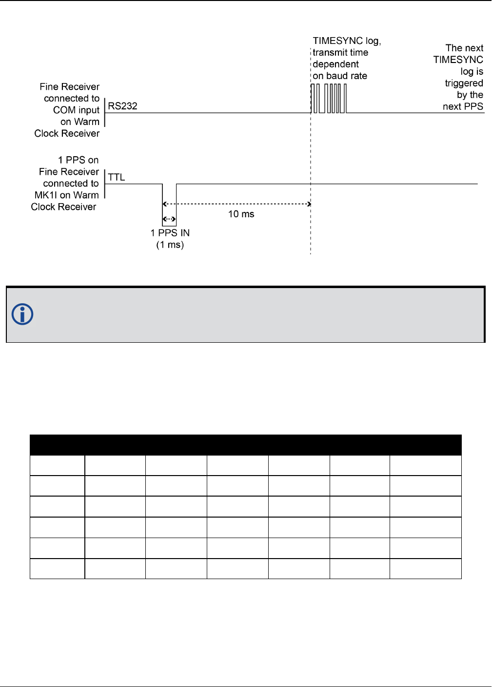
Chapter 2 Core Commands
OEM7 Commands and Logs Reference Manual v7 54
Figure 2: 1PPS Alignment
The 1PPS is obtained from different receivers in different ways.
In Figure 2: 1PPS Alignment above, the examples are for the transfer of time. If you
need position, you must be tracking satellites and your receiver must have a valid
almanac.
Alternatively, the 1PPS signal can be set up to be output on a COM port using the COMCONTROL
command (see page 108). The accuracy of the 1PPS is less using this method, but may be more
convenient in some circumstances.
OEM719 OEM729 OEM7600 OEM7700 OEM7720 PwrPak7 SPAN CPT7
COM1 Tx COM1 Tx COM1 Tx COM1 Tx COM1 Tx COM1 Tx COM1 Tx
COM2 Tx COM2 Tx COM2 Tx COM2 Tx COM2 Tx COM2 Tx COM2 Tx
COM2 RTS COM2 RTS COM2 RTS COM2 RTS
COM3 Tx COM3 Tx COM3 Tx COM3 Tx COM3 Tx
COM4 Tx COM4 Tx COM4 Tx
COM5 Tx COM5 Tx COM5 Tx
Table 12:
COM Port Signals Available for 1PPS
To find out the time of the last 1PPS output signal, use the TIMESYNCA/B output message (see
the TIMESYNC log on page840) which can be output serially on any available COM port, for
example:
LOG COM1 TIMESYNCA ONTIME 1

Chapter 2 Core Commands
OEM7 Commands and Logs Reference Manual v7 55
Message ID: 429
Abbreviated ASCII Syntax:
ADJUST1PPS mode [period] [offset]
Factory Default:
ADJUST1PPS OFF
ASCII Example:
ADJUST1PPS MARK CONTINUOUS 250
Use the ADJUST1PPS command to synchronize two OEM7 cards in a primary/secondary
relationship to a common external clock.
At the Primary Receiver:
LOG COM2 TIMESYNCa ONTIME 1
interfacemode com2 novatel novatel none
clockadjust DISABLE
EXTERNALCLOCK OCXO 10mhz (choose rubidium, cesium or user instead and choose
5MHz instead if necessary)
At the Secondary Receiver:
interfacemode com2 novatel novatel none
CLOCKADJUST DISABLE
adjust1pps mark (or markwithtime or time depending on your connection (see Fig-
ure 3: ADJUST1PPS Connections on page57)
EXTERNALCLOCK OCXO 10mhz (you can choose rubidium, cesium or user instead and
choose 5MHz instead if necessary)
Connections:
Null modem cable connected from Primary COM2 to Secondary COM2
OCXO signal sent through a splitter to feed both the Primary and Secondary external
clock inputs
Primary 1PPS connected to Secondary MKI
Connect everything before applying power. If power is applied and the OEM7 receivers
have acquired satellites before the OCXO and/or 1PPS = MKI is set up, the times
reported by the TIMESYNC logs still diverge. Note that after the clock model was
stabilized at state 0, the time difference between the Primary and Secondary reported by
the TIMESYNC log was less than 10 ns.
When connecting two receivers to transfer time, disable responses on the COM port used
to connect the receivers by issuing the following command on both receivers:
interfacemode com2 novatel novatel none

Chapter 2 Core Commands
OEM7 Commands and Logs Reference Manual v7 56
The following examples are for the transfer of time. If you need position, you must be
tracking satellites and your receiver must have a valid almanac.
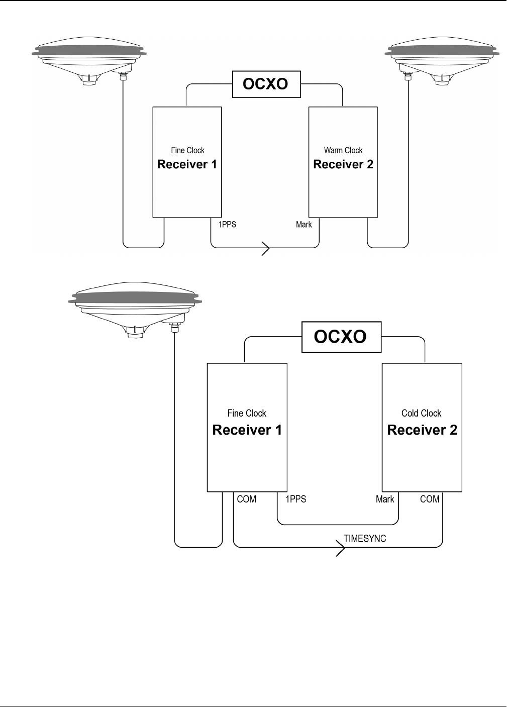
Chapter 2 Core Commands
OEM7 Commands and Logs Reference Manual v7 57
Figure 3: ADJUST1PPS Connections
adjust1pps mark (if Receiver 2 is not in coarsetime, the input is ignored)
adjust1pps markwithtime (will get to finetime)
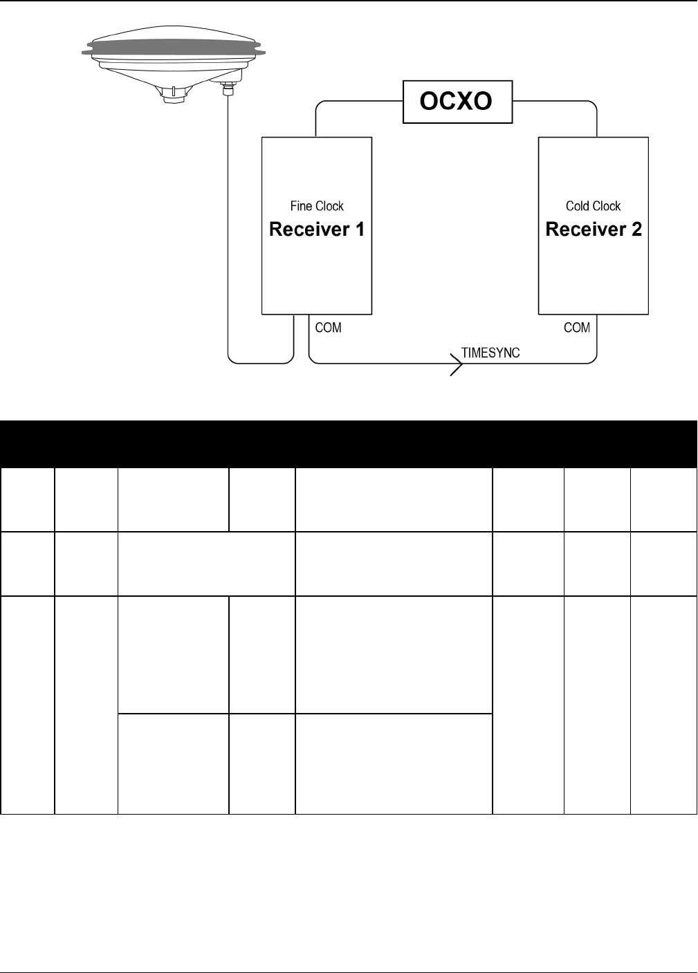
Chapter 2 Core Commands
OEM7 Commands and Logs Reference Manual v7 58
adjust1pps time (will only get to coarsetime)
Field Field
Type ASCII Value Binary
Value Description Format Binary
Bytes
Binary
Offset
1
ADUST
1PPS
header
- -
Command header. See
Messages on page25 for
more information.
- H 0
2 mode
See Table 13:
ADJUST1PPS Mode on
the next page
Sets the ADJUST1PPS
mode. Enum 4 H
3 period
ONCE 0
The time is synchronized
only once (default). The
ADJUST1PPS command
must be reissued if
another synchronization is
required Enum 4 H+4
CONTINUOUS 1
The time is continuously
monitored and the
receiver clock is corrected
if an offset of more than
50 ns is detected

Chapter 2 Core Commands
OEM7 Commands and Logs Reference Manual v7 59
Field Field
Type ASCII Value Binary
Value Description Format Binary
Bytes
Binary
Offset
4 offset -2147483648 to
+2147483647 (ns)
Allows the operator to
shift the Secondary clock
in 20 ns increments. In
MANUAL mode, this
command applies an
immediate shift of this
offset in ns to the receiver
clock. In MARK and
MARKWITHTIME mode,
this offset shifts the
receiver clock with
respect to the time of
arrival of the MK1I event.
If this offset is zero, the
Secondary aligns its 1PPS
to that of the signal
received in its MK1I port.
For example, if this value
was set to 50, then the
Secondary would set its
1PPS 50 ns ahead of the
input signal and if this
value was set to -100 then
the would set its clock to
100 ns behind the input
signal. Typically, this
offset is used to correct
for cable delay of the
1PPS signal (default=0)
Long 4 H+8
ASCII Value Binary
Value Description
OFF 0 Disables ADJUST1PPS
MANUAL 1
Immediately shifts the receivers time by the offset field in ns. The
period field has no effect in this mode. This command does not affect
the clock state
Table 13: ADJUST1PPS Mode

Chapter 2 Core Commands
OEM7 Commands and Logs Reference Manual v7 60
ASCII Value Binary
Value Description
MARK12
Shifts the receiver time to align its 1PPS with the signal received in the
MK1I port adjusted by the offset field in ns. The effective shift range is
± 0.5 s
MARKWITHTIME
23
Shifts the receiver time to align its 1PPS with the signal received in the
MK1I port adjusted by the offset field in ns, and sets the receiver TOW
and week number, to that embedded in a received TIMESYNC log
(see page 840). Also sets the receiver Time Status to that embedded in
the TIMESYNC log (see page 840), which must have arrived between
800 and 1000 ms prior to the MK1I event (presumably the 1PPS from
the Primary), or it is rejected as an invalid message
TIME 4
If the receiver clock is not at least COARSEADJUSTED, this command
enables the receiver to COARSE adjust its time upon receiving a valid
TIMESYNC log (see page 840) in any of the ports. The clock state
embedded in the TIMESYNC log (see page 840) must be at least FINE
or FINESTEERING before it is considered. The receiver does not use
the MK1I event in this mode
1Only the MK1I input can be used to synchronize the 1PPS signal. Synchronization cannot be done using the MK2I
input offered on some receivers.
2It is presumed that the TIMESYNC log (see page 840) was issued by a Primary GNSS receiver within 1000 ms
but not less than 800 ms, of the last 1PPS event, see Figure 2: 1PPS Alignment on page54 and TIMESYNC on
page840. Also refer to the Transfer Time Between Receivers section in the OEM7 Installation and Operation User
Manual.
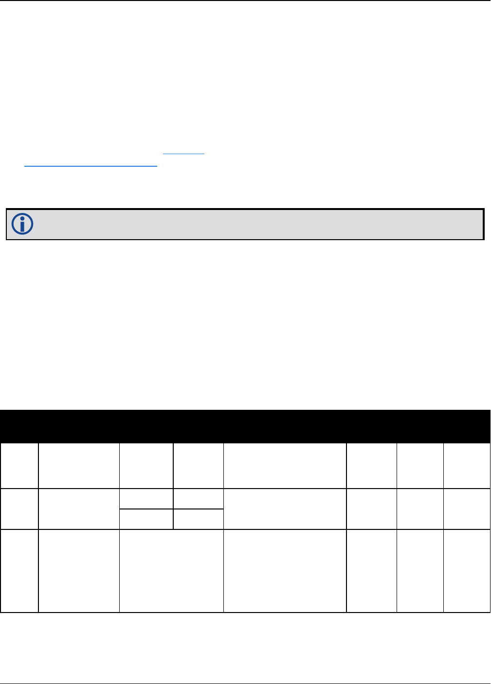
Chapter 2 Core Commands
OEM7 Commands and Logs Reference Manual v7 61
2.6 ALIGNAUTOMATION
Configures ALIGN plug-and-play feature
Platform: OEM719, OEM729, OEM7500, OEM7600, OEM7700, OEM7720, PwrPak7,
SPAN CPT7
This command configures the ALIGN plug and play feature. Use this command to enable/disable
the plug and play feature, to set the rover COM port to which master is connected, to set the
baud rate for communication, to set the intended operation rate using this command and to
enable/disable sending the HEADINGEXTB/HEADINGEXT2B back to the Master receiver. Refer to
the NovAtel application note APN-048 for details on HEADINGEXT (available on our website at
www.novatel.com/support/).
On issuing this command at the ALIGN Rover, the Rover will automatically sync with the Master
and configure it to send corrections at the specified baud rate and specified data rate.
This command should only be issued at ALIGN Rover.
Message ID: 1323
Abbreviated ASCII Syntax:
ALIGNAUTOMATION option [comport] [baudrate] [datarate] [headingextboption]
[interfacemode]
Factory Default:
ALIGNAUTOMATION disable
Example:
ALIGNAUTOMATION enable com2 230400 10 ON
Field Field Type ASCII
Value
Binary
Value Description Format Binary
Bytes
Binary
Offset
1
ALIGN
AUTOMATION
header
- -
Command header. See
Messages on page25
for more information.
- H 0
2 option ENABLE 1 Enable or disable the
plug-and-play feature Enum 4 H
DISABLE 0
3 comport COM1, COM2 or
COM3
Rover COM port to
which master is
connected (Table 58:
COM Port Identifiers
on page333)
(default=COM2)
Enum 4 H+4

Chapter 2 Core Commands
OEM7 Commands and Logs Reference Manual v7 62
Field Field Type ASCII
Value
Binary
Value Description Format Binary
Bytes
Binary
Offset
4 baudrate
9600, 19200,
38400, 57600,
115200, 230400 or
460800
Intended baud rate for
data transmission
(default=230400)
Ulong 4 H+8
5 datarate 1, 2, 4, 5, 10 or
20
Rate (in Hz) at which
heading output is
required (default=10
Hz)
Ulong 4 H+12
6headingextb
option
OFF 0 Enable or disable
sending
HEADINGEXTB/
HEADINGEXT2B back
to the Master
(default=ON)
Enum 4 H+16
ON 1
7 interfacemode
See Table 41:
Serial Port
Interface Modes on
page196
Serial port interface
mode
(default=None)
Enum 4 H+20
Chapter 2 Core Commands
OEM7 Commands and Logs Reference Manual v7 63
2.7 ANTENNAPOWER
Controls power to the antenna
Platform: OEM719, OEM729, OEM7500, OEM7600, OEM7700, OEM7720, PwrPak7,
SPAN CPT7
This command enables or disables the supply of electrical power from the internal power source
of the receiver to the Low Noise Amplifier (LNA) of an active antenna. Refer to the OEM7 Install-
ation and Operation User Manual for further information about supplying power to the antenna.
There are several bits in the receiver status that pertain to the antenna (see Table 158:
Receiver Status on page753). These bits indicate whether the antenna is powered and whether
it is open circuited or short circuited.
Message ID: 98
Abbreviated ASCII Syntax:
ANTENNAPOWER switch
Factory Default:
ANTENNAPOWER ON
ASCII Examples:
ANTENNAPOWER ON
ANTENNAPOWER OFF
If a short circuit or other problem causes an overload of the current supplied to the
antenna, the receiver hardware shuts down the power supplied to the antenna. To
restore power, power cycle the receiver. The Receiver Status word, available in the
RXSTATUS log (see page 748), provides more information about the cause of the prob-
lem.
Field Field Type ASCII Value Binary
Value Description Format Binary
Bytes
Binary
Offset
1ANTENNAPOWER
header - -
Command
header. See
Messages on
page25 for
more
information.
- H 0

Chapter 2 Core Commands
OEM7 Commands and Logs Reference Manual v7 64
Field Field Type ASCII Value Binary
Value Description Format Binary
Bytes
Binary
Offset
2 switch
OFF 0
Disables
antenna power
On OEM7720 and
PwrPak7D,
disables antenna
power for both
antennas
Enum 4 H
ON 1
Enables antenna
power
On OEM7720 and
PwrPak7D,
enables antenna
power for both
antennas
PRIMARY_
ON_
SECONDARY_
OFF
3
Enables primary
antenna power
and disables
secondary
antenna power
Note: OEM7720
and PwrPak7D
only.
PRIMARY_
OFF_
SECONDARY_
ON
4
Disables
primary antenna
power and
enables
secondary
antenna power
Note: OEM7720
and PwrPak7D
only

Chapter 2 Core Commands
OEM7 Commands and Logs Reference Manual v7 65
2.8 ASSIGN
Assigns a channel to a PRN
Platform: OEM719, OEM729, OEM7500, OEM7600, OEM7700, OEM7720, PwrPak7,
SPAN CPT7
1. The ASSIGN command should only be used by advanced users.
2. Assigning SV channel sets the forced assignment bit in the channel tracking
status field which is reported in the RANGE and TRACKSTAT logs.
3. Assigning a PRN to a SV channel does not remove the PRN from the search space
of the automatic searcher; only the SV channel is removed (that is, the searcher
may search and lock onto the same PRN on another channel). See Table 10:
PRN Numbers for Commands and Logs on page44 for the PRN available for the
ASSIGN command.
4. GLONASS SVs cannot be assigned if there is no information on GLONASS fre-
quencies and matching slot numbers.
This command may be used to aid in the initial acquisition of a satellite by manually overriding
the automatic satellite/channel assignment and reacquisition processes. The command specifies
that the indicated tracking channel search for a specified satellite, at a specified Doppler fre-
quency, within a specified Doppler window.
The instruction remains in effect for the specified SV channel and PRN, even if the assigned satel-
lite subsequently sets. If the satellite Doppler offset of the assigned SV channel exceeds that spe-
cified by the window parameter of the ASSIGN command, the satellite may never be acquired
or reacquired. If a PRN has been assigned to a channel and the channel is currently tracking that
satellite, when the channel is set to AUTO tracking, the channel immediately idles and returns to
automatic mode.
To cancel the effects of ASSIGN, issue one of the following:
lThe ASSIGN command with the state set to AUTO
lThe UNASSIGN command (see page 376)
lThe UNASSIGNALL command (see page 378)
These immediately return SV channel control to the automatic search engine
Message ID: 27
Abbreviated ASCII Syntax:
ASSIGN channel [state] [prn [Doppler [Doppler window]]]
ASCII Example 1:
ASSIGN 0 ACTIVE 29 0 2000
In example 1, the first SV channel is searching for satellite PRN 29 in a range from -2000 Hz to
2000 Hz until the satellite signal is detected.
ASCII Example 2:
ASSIGN 11 28 -250 0

Chapter 2 Core Commands
OEM7 Commands and Logs Reference Manual v7 66
SV channel 11 is searching for satellite PRN 28 at an offset of -250 Hz only.
ASCII Example 3:
ASSIGN 11 IDLE
SV channel 11 is idled and does not attempt to search for satellites.
OEM7 cards have 4 channels available for SBAS. They automatically use the healthy GEO
satellites with the highest elevations. Use the ASSIGN command to enter a GEO PRN
manually.
For dual antenna receivers, when using the ASSIGN command for SV channels on the
primary antenna, the SV channel count goes from 0 to N-1, where N is the number of
channels in the primary antenna channel configuration. When using the ASSIGN com-
mand for channels on the secondary antenna, the SV channel count begins at N and goes
to N+(M-1), where M is the number of channels in the secondary antenna SV channel
configuration.
Field Field
Type
ASCII
Value
Binary
Value Description Format Binary
Bytes
Binary
Offset
1ASSIGN
header - -
Command header. See
Messages on page25 for
more information.
- H 0
2 channel
0 to n-1, where n is
the maximum
number of channels
in the current
channel
configuration
Desired SV channel number
where channel 0 is the first
SV channel. The last channel
depends on the model
configuration
Ulong 4 H
3 state
Refer to Table 14:
Channel State on
the next page
Set the SV channel state. If a
value is not given, the
default of ACTIVE is used
when the additional optional
parameters are entered
Enum 4 H+4
4 prn
Refer to PRN
Numbers on
page44
Optional satellite PRN
number. A value must be
entered unless the state
parameter is IDLE or AUTO
Ulong 4 H+8

Chapter 2 Core Commands
OEM7 Commands and Logs Reference Manual v7 67
Field Field
Type
ASCII
Value
Binary
Value Description Format Binary
Bytes
Binary
Offset
5 Doppler -100 000 to
100 000 Hz
Current Doppler offset of the
satellite
(default=0)
Note: Satellite motion,
receiver antenna motion and
receiver clock frequency
error must be included in the
calculation of Doppler
frequency
Long 4 H+12
6Doppler
window 0 to 10 000 Hz
Error or uncertainty in the
Doppler estimate above.
(default=4500)
Note: This is a ± value.
Example: 500 for ± 500 Hz
Ulong 4 H+16
Binary ASCII Description
0 IDLE Set the SV channel to not track any satellites
1 ACTIVE1Set the SV channel active (default)
2 AUTO Tell the receiver to automatically assign PRN numbers to channels
Table 14: Channel State
1A PRN number is required when using the ACTIVE channel state in this command.
Chapter 2 Core Commands
OEM7 Commands and Logs Reference Manual v7 68
2.9 ASSIGNALL
Assigns all channels to a PRN
Platform: OEM719, OEM729, OEM7500, OEM7600, OEM7700, OEM7720, PwrPak7,
SPAN CPT7
The ASSIGNALL command should only be used by advanced users.
This command is used to override the automatic satellite/channel assignment and reacquisition
processes for all receiver channels with manual instructions.
Message ID: 28
Abbreviated ASCII Syntax:
ASSIGNALL [system][state][prn [Doppler [Doppler window]]]
ASCII Example 1:
ASSIGNALL GLONASS IDLE
In example 1, all GLONASS channels are idled, essentially stopping the receiver from tracking
GLONASS.
ASCII Example 2:
ASSIGNALL GLONASS AUTO
In example 2, all GLONASS channels are enabled in auto mode. This enables the receiver to auto-
matically assign channels to track the available GLONASS satellites.
This command is the same as ASSIGN except that it affects all SV channels of the spe-
cified system.
These command examples are only applicable to specific receiver models.
If the system field is used with this command and the receiver has no channels
configured with that channel system, the command is rejected.
Field Field
Type
ASCII
Value
Binary
Value Description Format Binary
Bytes
Binary
Offset
1
ASSIGN-
ALL
header
- -
Command header. See
Messages on page25 for more
information.
- H 0

Chapter 2 Core Commands
OEM7 Commands and Logs Reference Manual v7 69
Field Field
Type
ASCII
Value
Binary
Value Description Format Binary
Bytes
Binary
Offset
2 system
See Table 15:
Channel System
below
System that SV channel is
tracking. If no value is
specified, the value defaults to
ALL
Enum 4 H
3 state
Refer to Table
14: Channel
State on
page67)
Set the SV channel state Enum 4 H+4
4 prn
Refer to PRN
Numbers on
page44
Optional satellite PRN code. A
value must be entered if the
state parameter is neither IDLE
or AUTO
Ulong 4 H+8
5 Doppler -100 000 to
100 000 Hz
Current Doppler offset of the
satellite
(default=0)
Note: Satellite motion,
receiver antenna motion and
receiver clock frequency error
must be included in the
calculation of Doppler
frequency.
Long 4 H+12
6Doppler
window 0 to 10 000 Hz
Error or uncertainty in the
Doppler estimate above.
(default=4500)
Note: This is a ± value
Example, 500 for ± 500 Hz
Ulong 4 H+16
Binary ASCII Description
3 ALL All systems
99 GPS GPS system
100 SBAS SBAS system
101 GLONASS GLONASS system
102 GALILEO GALILEO system
103 BeiDou BeiDou system
Table 15: Channel System

Chapter 2 Core Commands
OEM7 Commands and Logs Reference Manual v7 70
Binary ASCII Description
104 QZSS QZSS system
105 NAVIC NavIC system
GLONASS SVs cannot be assigned if there is no information on GLONASS frequencies
and matching slot numbers.

Chapter 2 Core Commands
OEM7 Commands and Logs Reference Manual v7 71
2.10 ASSIGNLBANDBEAM
Configure L-Band tracking
Platform: OEM719, OEM729, OEM7500, OEM7600, OEM7700, OEM7720, PwrPak7,
SPAN CPT7
This command assigns TerraStar or Veripos beams to the L-Band channels based on the defined
L-Band assignment option.
Logging the ASSIGNLBANDBEAM command may not display the correct values. To
access the actual beam name, frequency and baud rate values, log the
LBANDTRACKSTAT log (see page 572) or if the beam name is known, log the
LBANDBEAMTABLE log (see page 570) and find the associated frequency and baud
rate.
Message ID: 1733
Abbreviated ASCII Syntax:
ASSIGNLBANDBEAM [option] [name] [frequency] [baudrate] [Dopplerwindow]
Factory Default:
ASSIGNLBANDBEAM idle
ASCII Examples:
ASSIGNLBANDBEAM auto
ASSIGNLBANDBEAM 98W
ASSIGNLBANDBEAM manual 98w 1545865000 1200
Field Field Type Description Format Binary
Bytes
Binary
Offset
1ASSIGNLBAND
BEAM header
Command header. See Messages on
page25 for more information. - H 0
2 Option
Assignment option (see Table 16: L-Band
Assignment Option on the next page)
(manual=default)
Enum 4 H
3 Name Beam name (empty string=default) Char[8] 8 H+4
4 Frequency Beam frequency in Hz (0=default) Ulong 4 H+12
5 Baud rate Data baud rate (0=default) Ulong 4 H+16
6Doppler
window Doppler window to search (6000=default) Ulong 4 H+20

Chapter 2 Core Commands
OEM7 Commands and Logs Reference Manual v7 72
ASCII Binary Description
IDLE 0 Idle all L-Band channels
AUTO 1
The receiver searches for multiple L-Band beams on the L-Band channels
based on AUTO selection criteria.
If the receiver position is known, the AUTO selection criteria is a ranking of
granted access L-Band beams by descending elevation angle.
If the receiver position is not known, the AUTO selection criteria is a ranking of
granted access L-Band beams in the order they appear in the stored beam
table (see the LBANDBEAMTABLE log on page570).
MANUAL 2 The receiver assigns the specified beam on the first L-BAND channel and
makes the other L-BAND channels IDLE.
Table 16: L-Band Assignment Option
Chapter 2 Core Commands
OEM7 Commands and Logs Reference Manual v7 73
2.11 AUTH
Authorization code for different model
Platform: OEM719, OEM729, OEM7500, OEM7600, OEM7700, OEM7720, PwrPak7,
SPAN CPT7
This command is used to add or remove authorization codes from the receiver. Authorization
codes are used to authorize models of software for a receiver. Models control the functionality
the receiver provides. The RECEIVER is capable of keeping track of 24 authorization codes at
one time. The MODEL command (see page 238) can then be used to switch between authorized
models. The VALIDMODELS command (see page 849) lists the current available models in the
receiver. The AUTHCODES log (see page 414) lists all Authorization codes entered into the
receiver. This simplifies the use of multiple software models on the same receiver.
If there is more than one valid model in the receiver, the receiver either uses the model of the
last auth code entered via the AUTH command or the model that was selected by the MODEL
command, whichever was done last. Adding an Authorization Code or using the MODEL com-
mand causes an automatic reset of the receiver. Removing an Authorization Code does not
cause a reset.
Removing an authorization code will cause the receiver to permanently lose this inform-
ation.
Message ID: 49
Abbreviated ASCII Syntax:
AUTH [state] part1 part2 part3 part4 part5 model [date]
Input Example:
AUTH add T48JF2,W25DBM,JH46BJ,2WGHMJ,8JW5TW,G2SR0RCCR,101114
AUTH erase_table PW5W2B,WW5TM9,WW2PCZ,WW3M4H,WW4HPG,ERASE_AUTH
When you are ready to upgrade from one model to another, call 1-800-NOVATEL to speak
with our Customer Support/Sales Personnel, who can provide the authorization code that
unlocks the additional features of your GNSS receiver. This procedure can be performed
at your work site and takes only a few minutes.
Receiver models can also be downgraded. This is a two step handshaking process and is
best performed in a location with e-mail access.
Field Field
Type
ASCII
Value
Binary
Value Description Format Binary
Bytes
Binary
Offset
1AUTH
header - -
Command header.
See Messages on
page25 for more
information.
- H 0

Chapter 2 Core Commands
OEM7 Commands and Logs Reference Manual v7 74
Field Field
Type
ASCII
Value
Binary
Value Description Format Binary
Bytes
Binary
Offset
2 state
See Table 17: AUTH
Command State
below
Auth code function
to perform Enum 4 H
3 part1 6 character ASCII
string
Authorization code
section 1
String
[max. 16] Variable1H+4
4 part2 6 character ASCII
string
Authorization code
section 2
String
[max.16] Variable1H+20
5 part3 6 character ASCII
string
Authorization code
section 3
String
[max. 16] Variable1H+36
6 part4 6 character ASCII
string
Authorization code
section 4
String
[max. 16] Variable1H+52
7 part5 6 character ASCII
string
Authorization code
section 5
String
[max. 16] Variable1H+68
8 model Alpha
numeric
Null
terminated
Model name of the
receiver
String
[max. 16] Variable1H+84
9 date Numeric Null
terminated
Expiry date entered
as yymmdd in
decimal
String
[max 7] Variable1Variable
ASCII Binary Description
REMOVE 0
Remove the authcode from the system
For this parameter, the Part1-Part5 fields can be entered as 0
0 0 0 0, and only the model name entered.
ADD 1 Add the authcode to the system (default)
ADD_
DOWNLOAD 4 Add the authcode to the system (Deprecated: Use ADD instead)
Table 17: AUTH Command State
1In the binary case, each string field needs to be NULL terminated and additional bytes of padding added to
maintain 4-byte alignment, up to the maximum defined by the string size. The next defined field starts
immediately at the next 4-byte alignment following the NULL.
Chapter 2 Core Commands
OEM7 Commands and Logs Reference Manual v7 75
ASCII Binary Description
ERASE_
TABLE 7
Erase all auth codes from the system. Requires a special auth code to
prevent against accidental erasing.
The special auth code required for this option is:
PW5W2B,WW5TM9,WW2PCZ,WW3M4H,WW4HPG,ERASE_
AUTH
CLEAN_
TABLE 8
Remove all invalidated auth codes from the system.
When an auth code is removed, it is simply invalidated and so it still uses
one of the 24 spaces reserved for auth codes in the receiver. Use the
CLEAN_TABLE option to free up the spaces from removed auth codes.
The special auth code required for this option is:
4DR69H,G369W8,34MNJJ,5NHXCJ,GW7C75,CLEAN_AUTH

Chapter 2 Core Commands
OEM7 Commands and Logs Reference Manual v7 76
2.12 AUTOSURVEY
Survey for accurate position
Platform: OEM719, OEM729, OEM7500, OEM7600, OEM7700, OEM7720, PwrPak7,
SPAN CPT7
The AUTOSURVEY command uses position averaging to automatically determine the position
for a base station.
When the AUTOSURVEY command is sent, the receiver starts position averaging. The position
averaging continues until a specified accuracy level is met or until the specified survey time
expires. When position averaging is complete, the calculated position is saved as the fix position
for the base station. This calculated position is then used when transmitting differential cor-
rections to the rover.
If the FIX command is entered by a user, the SAVECONFIG command must then be
issued to save to NVM. If the FIX command is issued by the AUTOSURVEY feature, the
SAVECONFIG command does not need to be issued, because it is automatically saved
to NVM.
On subsequent power ups or resets, an AUTOSURVEY runs to determine if the base station has
moved. As the AUTOSURVEY runs, the average position calculated is compared to the saved fix
position. If the average position is within the AUTOSURVEY tolerance setting, the receiver
assumes it has not moved and uses the previously saved fix position. If the average position is
outside of the AUTOSURVEY tolerance setting, the receiver assumes it has moved and will con-
tinue calculating a position average until the accuracy level is met or until the specified survey
time expires.
The surveyed positions saved using the AUTOSURVEY command can be viewed using the
SAVEDSURVEYPOSITIONS log on page773. Surveyed positions can be added or deleted using
the SURVEYPOSITION command on page364.
Message ID: 1795
Abbreviated ASCII Syntax:
AUTOSURVEY control [time] [accuracy] [tolerance] [save_nvm] [position_id]
Input Example:
In the following example, the receiver is set up to survey its position for up to 24 hours or until
the averaged position accuracy is 10 cm. On subsequent power ups at the same location, the sur-
vey will terminate as soon as the receiver determines the position is within 4 m of its surveyed
position. Once the receiver has fixed its position, it will transmit RTCMV3 corrections over
COM2.
SERIALCONFIG COM2 115200 N 8 1 N ON
INTERFACEMODE COM2 NONE RTCMV3 OFF
LOG COM2 RTCM1004 ONTIME 1
LOG COM2 RTCM1012 ONTIME 1
LOG COM2 RTCM1006 ONTIME 10

Chapter 2 Core Commands
OEM7 Commands and Logs Reference Manual v7 77
LOG COM2 RTCM1033 ONTIME 10
LOG COM2 RTCM1019 ONTIME 120
AUTOSURVEY ENABLE 1440 .1 4
SAVECONFIG
Field Field Type ASCII
Value
Binary
Value Description Format Binary
Bytes
Binary
Offset
1AUTOSURVEY
header - -
Command header. See
Messages on page25 for
more information.
- H 0
2 control
disable 0
Disables the self-survey
feature and halts any self-
survey related activity
(default = disable) Enum 4 H
enable 1 Enables the self-survey
feature
3 time 1 - 6000 minutes
Maximum amount of time
to perform self-survey
(default = 1440 minutes)
Ulong 4 H+4
4 accuracy 0 - 100 metres
Desired horizontal
standard deviation
(default = 0.1 metres)
Float 4 H+8
5 tolerance 3 - 100 metres
Maximum distance
between calculated
position and saved
position. During the self-
survey, if the distance
between the calculated
position and the
previously surveyed
position is less than this
value, the previous
position is used.
(default = 10 metres)
Float 4 H+12
6 save_nvm
OFF 0 Do not save position in
NVM Enum 4 H+16
ON 1 Save position in NVM
(default = ON)

Chapter 2 Core Commands
OEM7 Commands and Logs Reference Manual v7 78
Field Field Type ASCII
Value
Binary
Value Description Format Binary
Bytes
Binary
Offset
7 position_id 4 character
string
ID for the saved position.
If the ID is not specified
or if the ID is entered as
"AUTO", receiver
automatically generates a
unique ID for the position
Note: This ID is the ID for
the surveyed position, not
the station ID set using
the DGPSTXID command
on page122.
String
[5] 51H+20
1In the binary case, each string field needs to be NULL terminated and additional bytes of padding added to
maintain 4-byte alignment, up to the maximum defined by the string size. The next defined field starts
immediately at the next 4-byte alignment following the NULL.

Chapter 2 Core Commands
OEM7 Commands and Logs Reference Manual v7 79
2.13 BASEANTENNAPCO
Sets the PCO model of the base receiver
Platform: OEM719, OEM729, OEM7500, OEM7600, OEM7700, OEM7720, PwrPak7,
SPAN CPT7
Use the BASEANTENNAPCO command to set the Phase Center Offsets (PCO) for a given fre-
quency on the remote base receiver from which this receiver is receiving corrections. The Off-
sets are defined as North, East and Up from the Antenna Reference Point to the Frequency Phase
Center in millimetres.
Message ID: 1415
Abbreviated ASCII Syntax:
BASEANTENNAPCO Frequency NorthOffset EastOffset UpOffset [CorrectionType
[StationId]]
ASCII Example:
BASEANTENNAPCO GPSL1 0.61 1.99 65.64
Field Field Type ASCII
Value
Binary
Value Description Format Binary
Bytes
Binary
Offset
1BASEANTENNAPCO
header - -
Command header.
See Messages on
page25 for more
information.
- H 0
2 Frequency
See Table 18:
Frequency Type
on the next page
The frequency that
the phase center
offsets are valid for.
Enum 4 H
3 NorthOffset
NGS standard Phase
Center North Offset
in millimetres.
Double 8 H+4
4 EastOffset
NGS standard Phase
Center East Offset in
millimetres.
Double 8 H+12
5 UpOffset
NGS standard Phase
Center Up Offset in
millimetres.
Double 8 H+20
6 CorrectionType
See Table 52:
DGPS Type on
page281
Correction type
(default = AUTO) Enum 4 H+28
7 StationID Char [8] or ANY
ID string for the
base station
(default = ANY)
Char 8 H+32

Chapter 2 Core Commands
OEM7 Commands and Logs Reference Manual v7 80
Value Name Description
0 GPSL1 GPS L1 frequency
1 GPSL2 GPS L2 frequency
2 GLONASSL1 GLONASS L1 frequency
3 GLONASSL2 GLONASS L2 frequency
5 GPSL5 GPS L5 frequency
7 GALILEOE1 Galileo E1 frequency
8 GALILEOE5A Galileo E5a frequency
9 GALILEOE5B Galileo E5b frequency
10 GALILEOALTBOC Galileo AltBOC frequency
11 BEIDOUB1 BeiDou B1 frequency
12 BEIDOUB2 BeiDou B2 frequency
13 QZSSL1 QZSS L1 frequency
14 QZSSL2 QZSS L2 frequency
15 QZSSL5 QZSS L5 frequency
16 QZSSL6 QZSS L6 frequency
17 GALILEOE6 Galileo E6 frequency
18 BEIDOUB3 BeiDou B3 frequency
Table 18: Frequency Type

Chapter 2 Core Commands
OEM7 Commands and Logs Reference Manual v7 81
2.14 BASEANTENNAPCV
Sets the PCV model of the base receiver
Platform: OEM719, OEM729, OEM7500, OEM7600, OEM7700, OEM7720, PwrPak7,
SPAN CPT7
Use the BASEANTENNAPCV command to set the Phase Center Variation (PCV) for a given fre-
quency on the remote base receiver from which this receiver is receiving corrections. The Phase
Center Variation entries follow the NGS standard and correspond to the phase elevation at 5
degree increments starting at 90 degrees and decreasing to 0.
Message ID: 1416
Abbreviated ASCII Syntax:
BASEANTENNAPCV Frequency [PCVArray [CorrectionType [StationId]]]
ASCII Example:
BASEANTENNAPCV GPSL1 0.00 -0.020 -0.07 -0.15 -0.24 -0.34 -0.43 -0.51 -0.56 -
0.61 -0.65 -0.69 -0.69 -0.62 -0.44 -0.13 0.28 0.70 1.02
Field Field Type ASCII
Value
Binary
Value Description Format Binary
Bytes
Binary
Offset
1BASEANTENNAPCV
header - -
Command header.
See Messages on
page25 for more
information.
- H 0
2 Frequency
See Table 18:
Frequency Type
on the previous
page
The frequency for
which the phase
center variations are
valid.
Enum 4 H
3 PCVArray
NGS standard 19
element array of
phase center
variations, in
millimetres, in 5
degree elevation
increments from 90
to 0. Defaults to zero
for all elevation
increments.
Double
[19] 152 H+4
4 CorrectionType
See Table 52:
DGPS Type on
page281
Correction type
(default = AUTO) Enum 4 H+156
5 StationID Char [8] or ANY ID string
(default = ANY) Char 8 H+160

Chapter 2 Core Commands
OEM7 Commands and Logs Reference Manual v7 82
2.15 BASEANTENNATYPE
Sets the antenna type of the base receiver
Platform: OEM719, OEM729, OEM7500, OEM7600, OEM7700, OEM7720, PwrPak7,
SPAN CPT7
Use the BASEANTENNATYPE command to set the antenna type of the remote base receiver
from which this receiver is receiving corrections. The Antenna Type and Radome Type are the
NGS names for the antenna.
When the antenna type is set using this command, the receiver will look up and use the
Phase Center Variations and Phase Center Offsets from an internal table.
Message ID: 1419
Abbreviated ASCII Syntax:
BASEANTENNATYPE AntennaType [RadomeType] [CorrectionType] [StationId]
ASCII Example:
BASEANTENNATYPE NOV702
Field Field Type ASCII
Value
Binary
Value Description Format Binary
Bytes
Binary
Offset
1BASEANTENNATYPE
header - -
Command header.
See Messages on
page25 for more
information.
- H 0
2 AntennaType
See Table 19:
Antenna Type on
the next page
NGS Antenna Name Enum 4 H
3 RadomeType
See Table 20:
Radome Type on
page91
NGS Radome Name
(default = NONE) Enum 4 H+4
4 CorrectionType
See Table 52:
DGPS Type on
page281
Correction type
(default = AUTO) Enum 4 H+8
5 StationID Char [8] or ANY ID string
(default = ANY) Char 8 H+12
The latest information can be obtained from the National Geodetic Survey (NGS) site
www.ngs.noaa.gov/ANTCAL.

Chapter 2 Core Commands
OEM7 Commands and Logs Reference Manual v7 83
Value Name Description
0 NONE No antenna model
2 AUTO Determine the antenna model from the RTK corrections
(Not valid for THISANTENNATYPE)
3 AERAT2775_43
4 AOAD_M_B
5 AOAD_M_T AOAD/M_T
6 AOAD_M_TA_NGS AOAD/M_TA_NGS
7 APSAPS-3
8 ASH700228A
9 ASH700228B
10 ASH700228C
11 ASH700228D
12 ASH700228E
13 ASH700699.L1
14 ASH700700.A
15 ASH700700.B
16 ASH700700.C
17 ASH700718A
18 ASH700718B
19 ASH700829.2
20 ASH700829.3
21 ASH700829.A
22 ASH700829.A1
23 ASH700936A_M
24 ASH700936B_M
25 ASH700936C_M
26 ASH700936D_M
Table 19: Antenna Type

Chapter 2 Core Commands
OEM7 Commands and Logs Reference Manual v7 84
Value Name Description
27 ASH700936E
28 ASH700936E_C
29 ASH700936F_C
30 ASH701008.01B
31 ASH701073.1
32 ASH701073.3
33 ASH701933A_M
34 ASH701933B_M
35 ASH701933C_M
36 ASH701941.1
37 ASH701941.2
38 ASH701941.A
39 ASH701941.B
40 ASH701945B_M
41 ASH701945C_M
42 ASH701945D_M
43 ASH701945E_M
44 ASH701945G_M
45 ASH701946.2
46 ASH701946.3
47 ASH701975.01A
48 ASH701975.01AGP
49 JAV_GRANT-G3T
50 JAV_RINGANT_G3T
51 JAVRINGANT_DM
52 JNSMARANT_GGD
53 JPLD/M_R
54 JPLD/M_RA_SOP

Chapter 2 Core Commands
OEM7 Commands and Logs Reference Manual v7 85
Value Name Description
55 JPSLEGANT_E
56 JPSODYSSEY_I
57 JPSREGANT_DD_E
58 JPSREGANT_SD_E
59 LEIAR10
60 LEIAR25
61 LEIAR25.R3
62 LEIAR25.R4
63 LEIAS05
64 LEIAX1202GG
65 LEIAS10
66 LEIAX1203+GNSS
67 LEIAT202+GP
68 LEIAT202-GP
69 LEIAT302+GP
70 LEIAT302-GP
71 LEIAT303
72 LEIAT502
73 LEIAT503
74 LEIAT504
75 LEIAT504GG
76 LEIATX1230
77 LEIATX1230+GNSS
78 LEIATX1230GG
79 LEIAX1202
80 LEIGG02PLUS
81 LEIGS08
82 LEIGS09

Chapter 2 Core Commands
OEM7 Commands and Logs Reference Manual v7 86
Value Name Description
83 LEIGS12
84 3S-02-TSADM
85 3S-02-TSATE
86 LEIGS15
87 LEIMNA950GG
88 LEISR299_INT
89 LEISR399_INT
90 LEISR399_INTA
91 MAC4647942
92 MPL_WAAS_2224NW
93 MPL_WAAS_2225NW
94 MPLL1_L2_SURV
95 NAVAN2004T
96 NAVAN2008T
97 NAX3G+C
98 NOV_WAAS_600
99 NOV501
100 NOV501+CR
101 NOV502
102 NOV502+CR
103 NOV503+CR
104 NOV531
105 NOV531+CR
106 NOV600
107 NOV702
108 NOV702GG
109 NOV750.R4
110 SEN67157596+CR

Chapter 2 Core Commands
OEM7 Commands and Logs Reference Manual v7 87
Value Name Description
111 SOK_RADIAN_IS
112 SOK502
113 SOK600
114 SOK702
115 SPP571212238+GP
116 STXS9SA7224V3.0
117 TOP700779A
118 TOP72110
119 TPSCR.G3
120 TPSCR3_GGD
121 TPSCR4
122 TPSG3_A1
123 TPSHIPER_GD
124 TPSHIPER_GGD
125 TPSHIPER_LITE
126 TPSHIPER_PLUS
127 TPSLEGANT_G
128 TPSLEGANT2
129 TPSLEGANT3_UHF
130 TPSODYSSEY_I
131 TPSPG_A1
132 TPSPG_A1+GP
133 TRM14177.00
134 TRM14532.00
135 TRM14532.10
136 TRM22020.00+GP
137 TRM22020.00-GP
138 TRM23903.00

Chapter 2 Core Commands
OEM7 Commands and Logs Reference Manual v7 88
Value Name Description
139 TRM27947.00+GP
140 TRM27947.00-GP
141 TRM29659.00
142 TRM33429.00+GP
143 TRM33429.00-GP
144 TRM33429.20+GP
145 TRM39105.00
146 TRM41249.00
147 TRM41249USCG
148 TRM4800
149 TRM55971.00
150 TRM57970.00
151 TRM57971.00
152 TRM5800
153 TRM59800.00
154 TRM59800.80
155 TRM59900.00
156 TRMR8_GNSS
157 TRMR8_GNSS3
158 ASH701023.A
159 CHCC220GR
160 CHCC220GR2
161 CHCX91+S
162 GMXZENITH10
163 GMXZENITH20
164 GMXZENITH25
165 GMXZENITH25PRO
166 GMXZENITH35

Chapter 2 Core Commands
OEM7 Commands and Logs Reference Manual v7 89
Value Name Description
167 JAVRINGANT_G5T
168 JAVTRIUMPH_1M
169 JAVTRIUMPH_1MR
170 JAVTRIUMPH_2A
171 JAVTRIUMPH_LSA
172 JNSCR_C146-22-1
173 JPSREGANT_DD_E1
174 JPSREGANT_DD_E2
175 JPSREGANT_SD_E1
176 JPSREGANT_SD_E2
177 LEIAR20
178 LEIGG03
179 LEIGS08PLUS
180 LEIGS14
181 LEIICG60
182 NOV533+CR
183 NOV703GGG.R2
184 NOV750.R5
185 RNG80971.00
186 SEPCHOKE_B3E6
187 SEPCHOKE_MC
188 STXS10SX017A
189 STXS8PX003A
190 STXS9PX001A
191 TIAPENG2100B
192 TIAPENG2100R
193 TIAPENG3100R1
194 TIAPENG3100R2

Chapter 2 Core Commands
OEM7 Commands and Logs Reference Manual v7 90
Value Name Description
195 TPSCR.G5
196 TPSG5_A1
197 TPSPN.A5
198 TRM55970.00
199 TRMR10
200 TRMR4-3
201 TRMR6-4
202 TRMR8-4
203 TRMR8S
204 TRMSPS985
205 AERAT1675_120
206 ITT3750323
207 NOV702GGL
208 NOV704WB
209 ARFAS1FS
210 CHAPS9017
211 CHCI80
212 GMXZENITH15
213 HXCCGX601A
214 IGAIG8
215 LEICGA60
216 LEIGS15.R2
217 LEIGS16
218 MVEGA152GNSSA
219 SEPALTUS_NR3
220 SJTTL111
221 SOKGCX3
222 SOKSA500

Chapter 2 Core Commands
OEM7 Commands and Logs Reference Manual v7 91
Value Name Description
223 STHCR3-G3
224 STXS9I
225 TPSCR.G5C
226 TPSHIPER_HR
227 TPSHIPER_HR+PS
228 TRM105000.10
229 TRM115000.00
230 TRM115000.10
231 TRMR2
232 TWIVP6000
233 TWIVP6050_CONE
234 JAVTRIUMPH_2A+G
235 JAVTRIUMPH_2A+P
236 LEIGS18
237 LEIGG04PLUS
238 STXS800
239 STXS800A
240 NOV850
241 TRM159800.00
242 TRM159900.00
Value Name
0 NONE
1 SPKE
2 SNOW
3 SCIS
4 SCIT
5 OLGA
Table 20: Radome Type

Chapter 2 Core Commands
OEM7 Commands and Logs Reference Manual v7 92
Value Name
6 PFAN
7 JVDM
8 LEIT
9 LEIC
10 LEIS
11 MMAC
12 NOVS
13 TPSH
14 CONE
15 TPSD
16 TCWD
17 UNAV
18 TZGD
19 CHCD
20 JAVC
21 LEIM
22 NOVC
23 ARFC
24 HXCS
25 JVGR
26 STHC
27 DUTD

Chapter 2 Core Commands
OEM7 Commands and Logs Reference Manual v7 93
2.16 BDSECUTOFF
Sets elevation cut-off angle for BeiDou satellites
Platform: OEM719, OEM729, OEM7500, OEM7600, OEM7700, OEM7720, PwrPak7,
SPAN CPT7
This command is used to set the elevation cut-off angle for tracked BeiDou satellites. The
receiver does not start automatically searching for a BeiDou satellite until it rises above the cut-
off angle (when satellite position is known). Tracked satellites that fall below the cut-off angle
are no longer tracked unless they are manually assigned (see the ASSIGN command on
page65).
In either case, satellites below the BDSECUTOFF angle are eliminated from the internal position
and clock offset solution computations.
This command permits a negative cut-off angle; it could be used in these situations:
lThe antenna is at a high altitude, and thus can look below the local horizon
lSatellites are visible below the horizon due to atmospheric refraction
Care must be taken when using BDSECUTOFF command because the signals from
lower elevation satellites are traveling through more atmosphere and are therefore
degraded. Use of satellites below 5 degrees is not recommended.
Use the ELEVATIONCUTOFF command on page136 to set the cut-off angle for all other
systems.
For dual antenna receivers, this command applies to both the primary and secondary
antennas.
Message ID: 1582
Abbreviated ASCII Syntax:
BDSECUTOFF angle
Factory Default:
BDSECUTOFF 5.0
ASCII Example:
BDSECUTOFF 10.0

Chapter 2 Core Commands
OEM7 Commands and Logs Reference Manual v7 94
Field Field Type ASCII
Value
Binary
Value Description Format Binary
Bytes
Binary
Offset
1BDSECUTOFF
header - -
Command header. See
Messages on page25 for
more information.
- H 0
2 angle ±90.0 degrees Elevation cut-off angle
relative to horizon Float 4 H

Chapter 2 Core Commands
OEM7 Commands and Logs Reference Manual v7 95
2.17 BESTVELTYPE
Sets the velocity used in the BESTVEL and GPVTG logs
Platform: OEM719, OEM729, OEM7500, OEM7600, OEM7700, OEM7720, PwrPak7,
SPAN CPT7
This command configures the source of the velocity that is output in the BESTVEL and GPVTG
logs. Set the type to something other than BESTPOS when an unchanging velocity source with
specific characteristics is needed.
The Doppler velocity is the highest-availability, lowest-latency velocity available from the
receiver. Due to its low latency, it is also the noisiest velocity.
Message ID: 1678
Abbreviated ASCII Syntax:
BESTVELTYPE mode
Factory Default:
BESTVELTYPE bestpos
ASCII Example:
BESTVELTYPE doppler
Field Field Type Description Format Binary
Bytes
Binary
Offset
1BESTVELTYPE
header
Command header. See Messages on
page25 for more information. - H 0
2 mode Velocity type (see Table 21: Velocity
Types below) Enum 4 H
ASCII Binary Description
BESTPOS 1 Use the velocity from the same positioning filter that is being used to fill
BESTPOS and GPGGA
DOPPLER 2 Always fill BESTVEL using Doppler-derived velocities
Table 21: Velocity Types

Chapter 2 Core Commands
OEM7 Commands and Logs Reference Manual v7 96
2.18 CANCONFIG
Configure CAN ports
Platform: OEM719, OEM729, OEM7500, OEM7600, OEM7700, OEM7720, PwrPak7,
SPAN CPT7
Use the CANCONFIG command to configure the hardware parameters of the CAN ports.
Message ID: 884
Abbreviated ASCII Syntax:
CANCONFIG port switch [speed]
Factory Default:
CANCONFIG CAN1 OFF 250K
CANCONFIG CAN2 OFF 250K
ASCII Example:
CANCONFIG CAN1 OFF 500K
Field Field Type ASCII
Value
Binary
Value Description Format Binary
Bytes
Binary
Offset
1CANCONFIG
header - -
Command header. See
Messages on page25 for
more information.
- H 0
2 port CAN1 1 Physical CAN port ID Enum 4 H
CAN2 2
3 switch ON 1 Sets the port to be On or
Off the CAN bus Enum 4 H+4
OFF 0
4 speed
See Table 22:
CAN Port Speed
below
Physical CANport speed
(bits per second)
(default = 250K
Enum 4 H+8
The CAN port must be set to OFF (using CANCONFIG <port> OFF) before the port speed
can be changed.
ASCII Value Binary Value
10K 0
20K 1
Table 22: CAN Port Speed

Chapter 2 Core Commands
OEM7 Commands and Logs Reference Manual v7 97
ASCII Value Binary Value
50K 2
100K 3
125K 4
250K 5
500K 6
1M 7

Chapter 2 Core Commands
OEM7 Commands and Logs Reference Manual v7 98
2.19 CCOMCONFIG
Configure the CAN COM port
Platform: OEM719, OEM729, OEM7500, OEM7600, OEM7700, OEM7720, PwrPak7,
SPAN CPT7
Bind a CAN communication port to a J1939 node (see J1939CONFIG command on page216)
and specify the CAN protocol, PGN, priority and address for messages transmitted and received
over the CCOM port.
Message ID: 1902
Abbreviated ASCII Syntax:
CCOMCONFIG port node protocol [pgn [priority [address]]]
Factory Default:
CCOMCONFIG ccom1 node1 J1939 61184 7 fe
CCOMCONFIG ccom2 node2 J1939 61184 7 fe
CCOMCONFIG ccom3 node1 J1939 126720 7 fe
CCOMCONFIG ccom4 none none 0 0 0
CCOMCONFIG ccom5 none none 0 0 0
CCOMCONFIG ccom6 none none 0 0 0
ASCII Example :
ccomconfig ccom1 node1 j1939 1792 6 1b
Field Field Type ASCII
Value
Binary
Value Description Format Binary
Bytes
Binary
Offset
1CCOMCONFIG
Header - -
Command header. See
Messages on page25 for
more information.
- H 0
2 port
CCOM1 38
Name of CCOM port Enum 4 H
CCOM2 39
CCOM3 40
CCOM4 41
CCOM5 42
CCOM6 43
3 node
NODE1 1 The J1939 node to use.
This binds a CCOM port to
the CAN NAME/address
associated with the node.
Enum 4 H+4
NODE2 2

Chapter 2 Core Commands
OEM7 Commands and Logs Reference Manual v7 99
Field Field Type ASCII
Value
Binary
Value Description Format Binary
Bytes
Binary
Offset
4 protocol
See Table 23:
CAN Protocol on
the next page
CAN transport protocol to
use Enum 4 H+8
5 pgn 0 - 131071
Any valid PGN as defined
by the J1939 protocol.
All messages transmitted
over this CCOM port will
contain this PGN value.
Only messages with this
PGN will be received on
this CCOM port
Note: This value is
ignored if the protocol is
NMEA2000.
Ulong 4 H+12
6 priority 0-7
Default CAN message
priority for transmitted
messages. (Priority 0 is
the highest priority)
Note: This value is
ignored if the protocol is
NMEA2000.
Uchar 1 H+16
7 address 00 – FF
00 – FD:
Transmit and receive
messages to/from this
address only
FE:
Transmit and receive
message to/from the
address of the first
message received
FF:
Broadcast messages and
receive messages from
all addresses.
Note: This value is
ignored if the protocol is
NMEA2000.
Hex 1 H+17

Chapter 2 Core Commands
OEM7 Commands and Logs Reference Manual v7 100
Binary ASCII Description
2 J1939 J1939 single packet
3 NMEA2000 NMEA2000 (single packet, multi-packet, fast packet)
5 ISO11783 ISO 11783 transport protocol
Table 23: CAN Protocol

Chapter 2 Core Commands
OEM7 Commands and Logs Reference Manual v7 101
2.20 CLOCKADJUST
Enables clock adjustments
Platform: OEM719, OEM729, OEM7500, OEM7600, OEM7700, OEM7720, PwrPak7,
SPAN CPT7
All oscillators have some inherent drift. By default, the receiver attempts to steer the receiver’s
clock to accurately match GPS reference time. Use the CLOCKADJUST command to disable this
function. The TIME log can then be used to monitor clock drift.
1. The CLOCKADJUST command should only be used by advanced users.
2. If the CLOCKADJUST command is ENABLED and the receiver is configured to use an
external reference frequency (set in the EXTERNALCLOCK command (see page 146)
for an external clock - TCXO, OCXO, RUBIDIUM, CESIUM, or USER), then the clock
steering process takes over the VARF output pins and may conflict with a previously
entered FREQUENCYOUT command (see page 171).
3. When using the EXTERNALCLOCK and CLOCKADJUST commands together, issue the
EXTERNALCLOCK command (see page 146) first to avoid losing satellites.
4. When disabled, the range measurement bias errors continue to accumulate with clock
drift.
5. Pseudorange, carrier phase and Doppler measurements may jump if the
CLOCKADJUST mode is altered while the receiver is tracking.
6. When disabled, the time reported on all logs may be offset from GPS reference time.
The 1PPS output may also be offset. The amount of this offset may be determined
from the TIME log (see page 837).
7. A discussion on GPS reference time may be found in GPS Reference Time Status on
page45.
Message ID: 15
Abbreviated ASCII Syntax:
CLOCKADJUST switch
Factory Default:
CLOCKADJUST ENABLE
ASCII Example:
CLOCKADJUST DISABLE
The CLOCKADJUST command can be used to calibrate an internal oscillator. Disable the
CLOCKADJUST mode in order to find out what the actual drift is from the internal oscil-
lator. Watch the CLOCKMODEL log to see the drift rate and adjust the oscillator until the
drift stops.

Chapter 2 Core Commands
OEM7 Commands and Logs Reference Manual v7 102
Field Field Type ASCII
Value
Binary
Value Description Format Binary
Bytes
Binary
Offset
1CLOCKADJUST
header - -
Command header. See
Messages on page25
for more information.
- H 0
2 switch
DISABLE 0 Disallow adjustment of
internal clock Enum 4 H
ENABLE 1 Allow adjustment of
internal clock

Chapter 2 Core Commands
OEM7 Commands and Logs Reference Manual v7 103
2.21 CLOCKCALIBRATE
Adjusts clock steering parameters
Platform: OEM719, OEM729, OEM7500, OEM7600, OEM7700, OEM7720, PwrPak7,
SPAN CPT7
This command is used to adjust the control parameters of the clock steering loop. The receiver
must be enabled for clock steering before these values can take effect. Refer to the
CLOCKADJUST command on page101 to enable or disable clock steering.
To disable the clock steering process, issue the CLOCKADJUST DISABLE command.
The current values used by the clock steering process are listed in the CLOCKSTEERING com-
mand (see page 459).
The values entered using the CLOCKCALIBRATE command are saved to non-volatile
memory (NVM). To restore the values to their defaults, the FRESET CLKCALIBRATION
command must be used. Issuing FRESET without the CLKCALIBRATION parameter will
not clear the values (see FRESET command on page174 for more details).
Message ID: 430
Abbreviated ASCII Syntax:
CLOCKCALIBRATE [mode] [period] [pulsewidth] [slope] [bandwidth]
ASCII Example:
CLOCKCALIBRATE AUTO
The receiver by default steers its INTERNAL VCTCXO but can be commanded to control
an EXTERNAL reference oscillator. Use the EXTERNALCLOCK command (see page 146)
to configure the receiver to use an external reference oscillator. If the receiver is con-
figured for an external reference oscillator and configured to adjust its clock, then the
clock steering loop attempts to steer the external reference oscillator through the use of
the VARF signal. Note that the clock steering control process conflicts with the manual
FREQUENCYOUT command (see page 171). It is expected that the VARF signal is used
to provide a stable reference voltage by the use of a filtered charge pump type circuit
(not supplied).
Field Field
Type
ASCII
Value
Binary
Value Description Format Binary
Bytes
Binary
Offset
1
CLOCK
CALIBRATE
header
- -
Command header. See
Messages on page25 for
more information.
- H 0

Chapter 2 Core Commands
OEM7 Commands and Logs Reference Manual v7 104
Field Field
Type
ASCII
Value
Binary
Value Description Format Binary
Bytes
Binary
Offset
2 mode
SET 0
Sets the period, pulsewidth,
slope and bandwidth values
into NVM for the currently
selected steered oscillator
(INTERNAL or EXTERNAL)
Enum 4 H
AUTO 1
Forces the receiver to do a
clock steering calibration to
measure the slope (change in
clock drift rate with a 1 bit
change in pulse width) and
required pulsewidth to zero
the clock drift rate. After the
calibration, these values
along with the period and
bandwidth are entered into
NVM and are then used from
this point forward on the
selected oscillator
OFF 2
Terminates a calibration
process currently underway
(default)
3 period 0 to 262144
Signal period in 10 ns steps.
Frequency Output =
100,000,000 / Period
(default=11000)
Ulong 4 H+4
4 pulsewidth
The valid range
for this
parameter is
10% to 90% of
the period
Sets the initial pulse width
that should provide a near
zero drift rate from the
selected oscillator being
steered. The valid range for
this parameter is 10% to
90% of the period. If this
value is not known, (in the
case of a new external
oscillator) then it should be
set to ½ the period and the
mode should be set to AUTO
to force a calibration
(default=6600)
Ulong 4 H+8

Chapter 2 Core Commands
OEM7 Commands and Logs Reference Manual v7 105
Field Field
Type
ASCII
Value
Binary
Value Description Format Binary
Bytes
Binary
Offset
5 slope
This value should correspond
to how much the clock drift
changes with a 1 bit change
in the pulsewidth m/s/bit.
The default values for the
slope used for the INTERNAL
and EXTERNAL clocks is -2.0
and -0.01 respectively. If this
value is not known, then its
value should be set to 1.0
and the mode should be set
to AUTO to force a
calibration. Once the
calibration process is
complete and using a slope
value of 1.0, the receiver
should be recalibrated using
the measured slope and
pulsewidth values (see the
CLOCKSTEERING log on
page459). This process
should be repeated until the
measured slope value
remains constant (less than a
5% change)
(default=0.774)
Float 4 H+12
6 bandwidth
This is the value used to
control the smoothness of the
clock steering process.
Smaller values result in
slower and smoother
changes to the receiver
clock. Larger values result in
faster responses to changes
in oscillator frequency and
faster start up clock pull in.
The default values are 0.03
and 0.001 Hz respectively for
the INTERNAL and EXTERNAL
clocks
(default=0.03)
Float 4 H+16
Chapter 2 Core Commands
OEM7 Commands and Logs Reference Manual v7 106
2.22 CLOCKOFFSET
Adjusts for delay in 1PPS output
Platform: OEM719, OEM729, OEM7500, OEM7600, OEM7700, OEM7720, PwrPak7,
SPAN CPT7
This command is used to remove a delay in the PPS output. The PPS signal is delayed from the
actual measurement time due to two major factors:
lA delay in the signal path from the antenna to the receiver
lAn intrinsic delay through the RF and digital sections of the receiver
The second delay is automatically accounted for by the receiver using a nominal value determ-
ined for each receiver type. However, since the delay from the antenna to the receiver cannot
be determined by the receiver, an adjustment cannot automatically be made. The
CLOCKOFFSET command can be used to adjust for this delay.
Message ID: 596
Abbreviated ASCII Syntax:
CLOCKOFFSET offset
Factory Default:
CLOCKOFFSET 0
ASCII Example:
CLOCKOFFSET -15
There may be small variances in the delays for each cable or card. The CLOCKOFFSET
command can be used to characterize each setup. For example, for a cable with a delay
of 10 ns, the offset can be set to -10 to remove the delay from the PPS output.
Field Field Type ASCII
Value
Binary
Value Description Format Binary
Bytes
Binary
Offset
1CLOCKOFFSET
header - -
Command header. See
Messages on page25 for
more information.
- H 0
2 offset ±200 Specifies the offset in
nanoseconds Long 4 H

Chapter 2 Core Commands
OEM7 Commands and Logs Reference Manual v7 107
2.23 CNOUPDATE
Sets the C/No update rate
Platform: OEM719, OEM729, OEM7500, OEM7600, OEM7700, OEM7720, PwrPak7,
SPAN CPT7
This command is used to set the C/No update rate.
Message ID: 849
Abbreviated ASCII Syntax:
CNOUPDATE rate
Factory Default:
CNOUPDATE default
ASCII Example:
CNOUPDATE 20Hz
Use the CNOUPDATE command for higher resolution update rate of the C/No meas-
urements of the incoming GNSS signals. By default, the C/No values are calculated at
approximately 4 Hz but this command allows you to increase that rate to 20 Hz.
Field Field Type ASCII
Value
Binary
Value Description Format Binary
Bytes
Binary
Offset
1CNOUPDATE
header - -
Command header. See
Messages on page25 for
more information.
- H 0
2 rate
DEFAULT 0 C/No update rate:
0 = Turn off C/No
enhancement
default = 4 Hz
1 = 20 Hz C/No updates
Enum 4 H
20HZ 1

Chapter 2 Core Commands
OEM7 Commands and Logs Reference Manual v7 108
2.24 COMCONTROL
Controls the serial port hardware control lines
Platform: OEM719, OEM729, OEM7500, OEM7600, OEM7700, OEM7720, PwrPak7,
SPAN CPT7
This command is used to control the hardware control lines of the serial communication (COM)
ports. The TOGGLEPPS mode of this command is typically used to supply a timing signal to a
host PC computer by using the RTS and DTR lines. The accuracy of controlling the COM control
signals is better than 900 µs. The other modes are typically used to control custom peripheral
devices.
1. If handshaking is disabled, any of these modes can be used without affecting regular
serial communications through the selected COM port. However, if handshaking is
enabled, it may conflict with handshaking of the selected COM port, causing unex-
pected results.
2. The PULSEPPSLOW control type cannot be issued for a TX signal.
3. Only PULSEPPSHIGH, FORCEHIGH and FORCELOW control types can be used for a TX
signal.
Message ID: 431
Abbreviated ASCII Syntax:
COMCONTROL [port] [signal] [control]
Factory Default:
COMCONTROL COM1 RTS DEFAULT
COMCONTROL COM2 RTS DEFAULT
COMCONTROL COM3 RTS DEFAULT
COMCONTROL COM4 RTS DEFAULT
COMCONTROL COM5 RTS DEFAULT
ASCII Example 1:
SERIALCONFIG COM1 9600 N 8 1 N (to disable handshaking)
COMCONTROL COM1 RTS FORCELOW
ASCII Example 2:
COMCONTROL COM1 RTS TOGGLEPPS
COMCONTROL COM2 RTS TOGGLEPPS
COMCONTROL COM3 RTS TOGGLEPPS
ASCII Example 3:
To set a break condition on COM1:
COMCONTROL COM1 TX FORCELOW
A break condition remains in effect until it is cleared. To clear a break condition on COM1:
COMCONTROL COM1 TX DEFAULT

Chapter 2 Core Commands
OEM7 Commands and Logs Reference Manual v7 109
or
COMCONTROL COM1 TX FORCEHIGH
Field Field
Type ASCII Value Binary
Value Description Format Binary
Bytes
Binary
Offset
1
COM
CONTROL
header
- -
Command header.
See Messages on
page25 for more
information.
- H 0
2 port
COM1 1
Serial port to control. Enum 4 H
COM2 2
COM3 3
COM4 19
COM5 31
3 signal
RTS 0 COM signal to control.
The controllable COM
signals are RTS, DTR
and TX. (Default =
RTS)
See also Table 24:
Tx, DTR and RTS
Availability on the
next page
Enum 4 H+4DTR 1
TX 2

Chapter 2 Core Commands
OEM7 Commands and Logs Reference Manual v7 110
Field Field
Type ASCII Value Binary
Value Description Format Binary
Bytes
Binary
Offset
4 control
DEFAULT 0
Disables this
command and returns
the COM signal to its
default state (Default)
Enum 4 H+8
FORCEHIGH 1 Immediately forces
the signal high
FORCELOW 2 Immediately forces
the signal low
TOGGLE 3
Immediately toggles
the current sate of the
signal
TOGGLEPPS 4
Toggles the state of
the selected signal
within 900 μs after
each 1PPS event. The
state change of the
signal lags the 1PPS
by an average value
of 450 μs. The delay
of each pulse varies
by a uniformly
random amount less
than 900 μs
PULSEPPSLOW 5
Pulses the line low at
a 1PPS event and to
high 1 ms after it. Not
for TX
PULSEPPSHIGH 6
Pulses the line high
for 1 ms at the time
of a 1PPS event
Tx Available On DTR Available On RTS Available On
OEM719 COM1, COM2, COM3 N/A N/A
OEM729 COM1, COM2, COM3 N/A COM1 and COM2
OEM7600 COM1, COM2, COM3, COM4, COM5 N/A COM2
OEM7700 COM1, COM2, COM3, COM4, COM5 N/A COM2
OEM7720 COM1, COM2, COM3, COM4, COM5 N/A COM2
Table 24: Tx, DTR and RTS Availability

Chapter 2 Core Commands
OEM7 Commands and Logs Reference Manual v7 111
2.25 DATADECODESIGNAL
Enable/Disable navigation data decoding for GNSS signal
Platform: OEM719, OEM729, OEM7500, OEM7600, OEM7700, OEM7720, PwrPak7,
SPAN CPT7
Use this command to enable or disable framing and decoding of the navigation message for each
GNSS signal. When disabled, the receiver will no longer output raw frame data, ephemeris or
almanac data from that signal. Signals which do not yet have the built in capability to output raw
frame data are not configurable. Note that if a primary signal such as GPSL1CA is disabled, it
may cause the receiver to no longer function normally because this signal’s data is essential for
setting receiver time and computing positions.
The default setting for each GNSS signal, and which signals can be configured, is available in
Table 25: GNSS Signal Default and Configurability below. The table also lists if the signal's nav-
igation message is used to compute the satellite position. For the binary value and a longer
description for each signal, see Table 29: Signal Type on page125.
Signal Primary
Signal Default Configurable Used for satellite
positioning
GPSL1C No Disabled No No
GPSL1CA Yes Enabled Yes Yes
GPSL2Y No Disabled No No
GPSL2C No Disabled Yes No
GPSL2P No Disabled No No
GPSL5 No Disabled Yes No
GLOL1CA Yes Enabled Yes Yes
GLOL2CA No Disabled No No
GLOL2P No Disabled No No
GLOL3 No Disabled No No
SBASL1 No Enabled Yes Yes
SBASL5 No Enabled Yes Yes
GALE1 Yes Enabled Yes Yes
GALE5A No Enabled Yes No
GALE5B No Enabled Yes Yes
GALALTBOC No Disabled No No
Table 25: GNSS Signal Default and Configurability

Chapter 2 Core Commands
OEM7 Commands and Logs Reference Manual v7 112
Signal Primary
Signal Default Configurable Used for satellite
positioning
GALE6B No Enabled Yes No
GALE6C No Enabled Yes No
BDSB1C No Disabled No No
BDSB1D1 Yes Enabled Yes Yes
BDSB1D2 Yes Enabled Yes Yes
BDSB2A No Disabled No No
BDSB2D1 No Disabled No No
BDSB2D2 No Disabled No No
BDSB3D1 No Disabled No No
BDSB3D2 No Disabled No No
QZSSL1C No Disabled No No
QZSSL1CA Yes Enabled Yes Yes
QZSSL2C No Disabled Yes No
QZSSL5 No Disabled Yes No
QZSSL6 No Disabled No No
NAVICL5SPS Yes Enabled Yes Yes
Message ID: 1532
Abbreviated ASCII Syntax:
DATADECODESIGNAL signaltype switch
Abbreviated ASCII Example:
DATADECODESIGNAL GPSL2C enable
Field Field Type ASCII
Value
Binary
Value Description Format Binary
Bytes
Binary
Offset
1
DATADECODE
SIGNAL
header
- -
Command
header. See
Messages on
page25 for more
information.
- H 0

Chapter 2 Core Commands
OEM7 Commands and Logs Reference Manual v7 113
Field Field Type ASCII
Value
Binary
Value Description Format Binary
Bytes
Binary
Offset
2 signal type
See Table 26: Signal
Type
(DATADECODESIGNAL)
below
GNSS Signal
Type Enum 4 H
3 switch Disable 0 Enable or disable
the data decoding Enum 4 H+4
Enable 1
Value (Binary) Signal (ASCII) Description
33 GPSL1CA GPS L1 C/A-code
69 GPSL2C GPS L2 C/A-code
70 GPSL2P GPS L2 P-code
103 GPSL5 GPS L5
2177 GLOL1CA GLONASS L1 C/A-code
2211 GLOL2CA GLONASS L2 C/A-code
2212 GLOL2P GLONASS L2 P-code
2662 GLOL3 GLONASS L3
4129 SBASL1 SBAS L1
4194 SBASL5 SBAS L5
16737 LBAND LBAND
10433 GALE1 Galileo E1
10466 GALE5A Galileo E5A
10499 GALE5B Galileo E5B
10565 GALE6C Galileo E6C
10572 GALE6B Galileo E6B
12673 BDSB1D1 BeiDou B1 with D1 navigation data
12674 BDSB1D2 BeiDou B1 with D2 navigation data
12803 BDSB2D1 BeiDou B2 with D1 navigation data
Table 26: Signal Type (DATADECODESIGNAL)

Chapter 2 Core Commands
OEM7 Commands and Logs Reference Manual v7 114
Value (Binary) Signal (ASCII) Description
12804 BDSB2D2 BeiDou B2 with D2 navigation data
12877 BDSB3D1 BeiDou B3 with D1 navigation data
12880 BDSB3D2 BeiDou B3 with D2 navigation data
12979 BDSB1C BeiDou B1C
13012 BDSB2A BeiDou B2a
14753 QZSSL1CA QZSS L1 C/A-code
14787 QZSSL2C QZSS L2 C/A-code
14820 QZSSL5 QZSS L5
19073 NAVICL5SPS NavIC L5 SPS

Chapter 2 Core Commands
OEM7 Commands and Logs Reference Manual v7 115
2.26 DATUM
Chooses a datum name type
Platform: OEM719, OEM729, OEM7500, OEM7600, OEM7700, OEM7720, PwrPak7,
SPAN CPT7
This command is used to select the geodetic datum for operation of the receiver. If not set, the
factory default value is wgs84. See the USERDATUM command (see page 388) for user defin-
able datums. The datum you select causes all position solutions to be based on that datum.
The transformation for the WGS84 to Local used in the OEM7 family is the Bursa-Wolf trans-
formation or reverse Helmert transformation. In the Helmert transformation, the rotation of a
point is counter clockwise around the axes. In the Bursa-Wolf transformation, the rotation of a
point is clockwise. Therefore, the reverse Helmert transformation is the same as the Bursa-
Wolf.
See Table 28: Datum Transformation Parameters on page117 for a complete listing of all avail-
able predefined datums. The offsets in the table are from the local datum to WGS84.
Message ID: 160
Abbreviated ASCII Syntax:
DATUM datum
Factory Default:
DATUM wgs84
ASCII Example:
DATUM CSRS
Also, as an example, you can achieve spatial integrity with Government of Canada maps and sur-
veys if the coordinates are output using the CSRS datum (Datum ID# 64).
Table 27: Reference Ellipsoid Constants on the next page contains the internal ellipsoid and
transformation parameters used in the receiver. The values contained in these tables were
derived from the following dma reports:
1 TR 8350.2 Department of Defense World Geodetic System 1984 and Relationships
with Local Geodetic Systems - Revised March 1, 1988
2 TR8350.2B Supplement to Department of Defense World Geodetic System 1984
Technical Report - Part II - Parameters, Formulas, and Graphics for the
Practical Application of WGS84 - December 1, 1987
3 TR 8350.2 Department of Defense World Geodetic System 1984 National Imagery
and Mapping Agency Technical Report, Third Addition, Amendment 1 -
January 3, 2000
By default, NovAtel receivers output positions in WGS84, with the following exceptions:
EGNOS, TerraStar and Veripos use ITRF2008, which is coincident with WGS84 at about
the decimetre level.

Chapter 2 Core Commands
OEM7 Commands and Logs Reference Manual v7 116
Field Field
Type
ASCII
Value
Binary
Value Description Format Binary
Bytes
Binary
Offset
1DATUM
header - -
Command header. See
Messages on page25
for more information.
- H 0
2Datum
Type
See Table 28: Datum
Transformation
Parameters on the next
page
The datum to use Enum 4 H
ELLIPSOID ID
CODE a (metres) 1/f f
Airy 1830 AW 6377563.396 299.3249646 0.00334085064038
Modified Airy AM 6377340.189 299.3249646 0.00334085064038
Australian National AN 6378160.0 298.25 0.00335289186924
Bessel 1841 BR 6377397.155 299.1528128 0.00334277318217
Clarke 1866 CC 6378206.4 294.9786982 0.00339007530409
Clarke 1880 CD 6378249.145 293.465 0.00340756137870
Everest (India 1830) EA 6377276.345 300.8017 0.00332444929666
Everest (Brunei & E.Malaysia) EB 6377298.556 300.8017 0.00332444929666
Everest (W.Malaysia &
Singapore) EE 6377304.063 300.8017 0.00332444929666
Geodetic Reference System 1980 RF 6378137.0 298.257222101 0.00335281068118
Helmert 1906 HE 6378200.0 298.30 0.00335232986926
Hough 1960 HO 6378270.0 297.00 0.00336700336700
International 1924 IN 6378388.0 297.00 0.00336700336700
Parameters of the Earth PZ-90.02 6378136.0 298.26 0.00335280374302
South American 1969 SA 6378160.0 298.25 0.00335289186924
World Geodetic System 1972 WD 6378135.0 298.26 0.00335277945417
World Geodetic System 1984 WE 6378137.0 298.257223563 0.00335281066475
Table 27: Reference Ellipsoid Constants

Chapter 2 Core Commands
OEM7 Commands and Logs Reference Manual v7 117
The default user datum is WGS84.
See also the USERDATUM command (see page 388) and USEREXPDATUM
command (see page 390).
The following logs report the datum used according to the Datum ID column:
lBESTPOS log (see page 428)
lBESTUTM log (see page 441)
lMATCHEDPOS log (see page 591)
lPSRPOS log (see page 648)
Datum
ID# NAME DX1DY1DZ1DATUM DESCRIPTION ELLIPSOID
1 ADIND -162 -12 206 This datum has been updated, see
ID# 652Clarke 1880
2 ARC50 -143 -90 -294 ARC 1950 (SW & SE Africa) Clarke 1880
3 ARC60 -160 -8 -300 This datum has been updated, see
ID# 662Clarke 1880
4 AGD66 -133 -48 148 Australian Geodetic Datum 1966 Australian
National
5 AGD84 -134 -48 149 Australian Geodetic Datum 1984 Australian
National
6 BUKIT -384 664 -48 Bukit Rimpah (Indonesia) Bessel 1841
7 ASTRO -104 -129 239 Camp Area Astro (Antarctica) International
1924
8 CHATM 175 -38 113 Chatham 1971 (New Zealand) International
1924
9 CARTH -263 6 431 Carthage (Tunisia) Clarke 1880
10 CAPE -136 -108 -292 CAPE (South Africa) Clarke 1880
11 DJAKA -377 681 -50 Djakarta (Indonesia) Bessel 1841
12 EGYPT -130 110 -13 Old Egyptian Helmert 1906
Table 28: Datum Transformation Parameters
1The DX, DY and DZ offsets are from your local datum to WGS84.
2The updated datum have the new x, y and z translation values updated to the latest numbers. The old datum
values can still be used for backwards compatibility.

Chapter 2 Core Commands
OEM7 Commands and Logs Reference Manual v7 118
Datum
ID# NAME DX1DY1DZ1DATUM DESCRIPTION ELLIPSOID
13 ED50 -87 -98 -121 European 1950 International
1924
14 ED79 -86 -98 -119 European 1979 International
1924
15 GUNSG -403 684 41 G. Segara (Kalimantan - Indonesia) Bessel 1841
16 GEO49 84 -22 209 Geodetic Datum 1949 (New Zealand) International
1924
17 GRB36 375 -111 431 Do not use. Use ID# 76 instead2Airy 1830
18 GUAM -100 -248 259 Guam 1963 (Guam Island) Clarke 1866
19 HAWAII 89 -279 -183 Do not use. Use ID# 77 or ID# 81
instead3Clarke 1866
20 KAUAI 45 -290 -172 Do not use. Use ID# 78 or ID# 82
instead3Clarke 1866
21 MAUI 65 -290 -190 Do not use. Use ID# 79 or ID# 83
instead3Clarke 1866
22 OAHU 56 -284 -181 Do not use. Use ID# 80 or ID# 84
instead3Clarke 1866
23 HERAT -333 -222 114 Herat North (Afghanistan) International
1924
24 HJORS -73 46 -86 Hjorsey 1955 (Iceland) International
1924
25 HONGK -156 -271 -189 Hong Kong 1963 International
1924
26 HUTZU -634 -549 -201 This datum has been updated, see
ID# 682
International
1924
27 INDIA 289 734 257 Do not use. Use ID# 69 or ID# 70
instead3Everest (EA)
28 IRE65 506 -122 611 Do not use. Use ID# 71 instead3Modified Airy
29 KERTA -11 851 5 Kertau 1948 (West Malaysia and
Singapore) Everest (EE)
1The DX, DY and DZ offsets are from your local datum to WGS84.
2Use the corrected datum only (with the higher ID#) as the old datum is incorrect.

Chapter 2 Core Commands
OEM7 Commands and Logs Reference Manual v7 119
Datum
ID# NAME DX1DY1DZ1DATUM DESCRIPTION ELLIPSOID
30 KANDA -97 787 86 Kandawala (Sri Lanka) Everest (EA)
31 LIBER -90 40 88 Liberia 1964 Clarke 1880
32 LUZON -133 -77 -51 Do not use. Use ID# 72 instead3Clarke 1866
33 MINDA -133 -70 -72 This datum has been updated, see
ID# 732Clarke 1866
34 MERCH 31 146 47 Merchich (Morocco) Clarke 1880
35 NAHR -231 -196 482 This datum has been updated, see
ID# 742Clarke 1880
36 NAD83 0 0 0 N. American 1983 (Includes Areas 37-
42) GRS-80
37 CANADA -10 158 187 N. American Canada 1927 Clarke 1866
38 ALASKA -5 135 172 N. American Alaska 1927 Clarke 1866
39 NAD27 -8 160 176 N. American Conus 1927 Clarke 1866
40 CARIBB -7 152 178 This datum has been updated, see
ID# 752Clarke 1866
41 MEXICO -12 130 190 N. American Mexico Clarke 1866
42 CAMER 0 125 194 N. American Central America Clarke 1866
43 MINNA -92 -93 122 Nigeria (Minna) Clarke 1880
44 OMAN -346 -1 224 Oman Clarke 1880
45 PUERTO 11 72 -101 Puerto Rica and Virgin Islands Clarke 1866
46 QORNO 164 138 -189 Qornoq (South Greenland) International
1924
47 ROME -255 -65 9 Rome 1940 Sardinia Island International
1924
48 CHUA -134 229 -29 South American Chua Astro
(Paraguay)
International
1924
49 SAM56 -288 175 -376 South American (Provisional 1956) International
1924
1The DX, DY and DZ offsets are from your local datum to WGS84.

Chapter 2 Core Commands
OEM7 Commands and Logs Reference Manual v7 120
Datum
ID# NAME DX1DY1DZ1DATUM DESCRIPTION ELLIPSOID
50 SAM69 -57 1 -41 South American 1969 S. American
1969
51 CAMPO -148 136 90 S. American Campo Inchauspe
(Argentina)
International
1924
52 SACOR -206 172 -6 South American Corrego Alegre
(Brazil)
International
1924
53 YACAR -155 171 37 South American Yacare (Uruguay) International
1924
54 TANAN -189 -242 -91 Tananarive Observatory 1925
(Madagascar)
International
1924
55 TIMBA -689 691 -46 This datum has been updated, see
ID# 852Everest (EB)
56 TOKYO -128 481 664 This datum has been updated, see
ID# 862Bessel 1841
57 TRIST -632 438 -609 Tristan Astro 1968 (Tristan du Cunha) International
1924
58 VITI 51 391 -36 Viti Levu 1916 (Fiji Islands) Clarke 1880
59 WAK60 101 52 -39 This datum has been updated, see
ID# 672Hough 1960
60 WGS72 0 0 4.5 World Geodetic System - 72 WGS72
61 WGS84 0 0 0 World Geodetic System - 84 WGS84
62 ZANDE -265 120 -358 Zanderidj (Surinam) International
1924
63 USER 0 0 0 User Defined Datum Defaults User
64 CSRS Time-variable 7 parameter transformation
65 ADIM -166 -15 204 Adindan (Ethiopia, Mali, Senegal &
Sudan)2Clarke 1880
66 ARSM -160 -6 -302 ARC 1960 (Kenya, Tanzania)2Clarke 1880
67 ENW 102 52 -38 Wake-Eniwetok (Marshall Islands)2Hough 1960
1The DX, DY and DZ offsets are from your local datum to WGS84.

Chapter 2 Core Commands
OEM7 Commands and Logs Reference Manual v7 121
Datum
ID# NAME DX1DY1DZ1DATUM DESCRIPTION ELLIPSOID
68 HTN -637 -549 -203 Hu-Tzu-Shan (Taiwan)2International
1924
69 INDB 282 726 254 Indian (Bangladesh)3Everest (EA)
70 INDI 295 736 257 Indian (India, Nepal)3Everest (EA)
71 IRL 506 -122 611 Ireland 1965 3Modified Airy
72 LUZA -133 -77 -51 Luzon (Philippines excluding
Mindanoa Is.)3, 2Clarke 1866
73 LUZB -133 -79 -72 Mindanoa Island2Clarke 1866
74 NAHC -243 -192 477 Nahrwan (Saudi Arabia)2Clarke 1880
75 NASP -3 142 183 N. American Caribbean2Clarke 1866
76 OGBM 375 -111 431 Great Britain 1936 (Ordinance
Survey)3Airy 1830
77 OHAA 89 -279 -183 Hawaiian Hawaii3Clarke 1866
78 OHAB 45 -290 -172 Hawaiian Kauaii3Clarke 1866
79 OHAC 65 -290 -190 Hawaiian Maui3Clarke 1866
80 OHAD 58 -283 -182 Hawaiian Oahu3Clarke 1866
81 OHIA 229 -222 -348 Hawaiian Hawaii3International
1924
82 OHIB 185 -233 -337 Hawaiian Kauai3International
1924
83 OHIC 205 -233 -355 Hawaiian Maui3International
1924
84 OHID 198 -226 -347 Hawaiian Oahu3International
1924
85 TIL -679 669 -48 Timbalai (Brunei and East Malaysia)
19482Everest (EB)
86 TOYM -148 507 685 Tokyo (Japan, Korea and Okinawa)2Bessel 1841
1The DX, DY and DZ offsets are from your local datum to WGS84.
2The original LUZON values are the same as for LUZA but the original has an error in the code.

Chapter 2 Core Commands
OEM7 Commands and Logs Reference Manual v7 122
2.27 DGPSTXID
Sets DGPS station ID
Platform: OEM719, OEM729, OEM7500, OEM7600, OEM7700, OEM7720, PwrPak7,
SPAN CPT7
This command is used to set the station ID value for the receiver when it is transmitting cor-
rections. This allows for the easy identification of which base station was the source of the data.
For example, if you want to compare RTCM and RTCMV3 corrections, you would be easily able to
identify their base stations by first setting their respective DGPSTXID values.
Message ID: 144
Abbreviated ASCII Syntax:
DGPSTXID type ID
Factory Default:
DGPSTXID auto ANY
ASCII Examples:
DGPSTXID RTCM 2 - using an RTCM type and ID
DGPSTXID CMR 30 - using a CMR type and ID
DGPSTXID CMR ANY - using the default CMR ID
DGPSTXID RTCA d36d - using an RTCA type and ID
DGPSTXID RTCMV3 2050 - using an RTCMV3 type and ID
Field Field
Type
ASCII
Value
Binary
Value Description Format Binary
Bytes
Binary
Offset
1DGPSTXID
header - -
Command header. See
Messages on page25 for
more information.
- H 0
2 type
RTCM 0
See Table 52: DGPS Type
on page281 Enum 4 H
RTCA 1
CMR 2
AUTO 10
RTCMV3 13
3 ID Char[5]
Base Station ID String
See Table 52: DGPS Type
on page281
Char[5] 8 H+4

Chapter 2 Core Commands
OEM7 Commands and Logs Reference Manual v7 123
2.28 DIFFCODEBIASCONTROL
Enables /disables satellite differential code biases
Platform: OEM719, OEM729, OEM7500, OEM7600, OEM7700, OEM7720, PwrPak7,
SPAN CPT7
The purpose of the differential code biases is to correct pseudorange errors that affect the L1/L2
ionospheric corrections. This command enables or disables the biases. A set of biases is
included in the firmware and use of the biases is enabled by default. See also the
SETDIFFCODEBIASES command on page342.
Message ID: 913
Abbreviated ASCII Syntax:
DIFFCODEBIASCONTROL switch
Factory Default:
DIFFCODEBIASCONTROL enable
Example:
DIFFCODEBIASCONTROL disable
Field Field Type ASCII
Value
Binary
Value Description Format Binary
Bytes
Binary
Offset
1
DIFFCODEBIAS
CONTROL
header
- -
Command header. See
Messages on page25
for more information.
- H 0
2 switch
DISABLE 0 Disable the differential
code bias Enum 4 H
ENABLE 1 Enable the differential
code bias

Chapter 2 Core Commands
OEM7 Commands and Logs Reference Manual v7 124
2.29 DLLTIMECONST
Sets carrier smoothing
Platform: OEM719, OEM729, OEM7500, OEM7600, OEM7700, OEM7720, PwrPak7,
SPAN CPT7
This command sets the amount of carrier smoothing performed on the code measurements. An
input value of 100 corresponds to approximately 100 seconds of smoothing. Upon issuing the
command, the locktime (amount of continuous tracking in seconds) for all tracking satellites is
reset to zero and each code smoothing filter is restarted. You must wait for at least the length of
smoothing time for the new smoothing constant to take full effect. The optimum setting for this
command depends on the application.
1. This command may not be suitable for every GNSS application.
2. When using DLLTIMECONST in differential mode with the same receivers, the same set-
ting should be used at both the base and rover station. If the base and rover stations
use different types of receivers, it is recommended that you use the command default
value at each receiver (DLLTIMECONST <signaltype> 100).
3. There are several considerations when using the DLLTIMECONST command:
lThe attenuation of low frequency noise (multipath) in pseudorange measurements
lThe effect of time constants on the correlation of phase and code observations
lThe rate of “pulling-in” of the code tracking loop (step response)
lThe effect of ionospheric divergence on carrier smoothed pseudorange (ramp
response)
4. To get unsmoothed psuedorange measurements, choose 0 as the time constant.
The primary reason for applying carrier smoothing to the measured pseudoranges is to
mitigate the high frequency noise inherent in all code measurements. Adding more
carrier smoothing by increasing the DLLTIMECONST value filters out lower frequency
noise, including some multipath frequencies.
There are also some adverse effects of higher DLLTIMECONST values on some
performance aspects of the receiver. Specifically, the time constant of the tracking loop
is directly proportional to the DLLTIMECONST value and affects the degree of dependence
between the carrier phase and pseudorange information. Carrier phase smoothing of the
code measurements (pseudoranges) is accomplished by introducing data from the
carrier tracking loops into the code tracking system. Phase and code data, collected at a
sampling rate greater than about 3 time constants of the loop, are correlated (the
greater the sampling rate, the greater the correlation). This correlation is not relevant if
only positions are logged from the receiver, but is an important consideration if the data
is combined in some other process such as post-mission carrier smoothing. Also, a
narrow bandwidth in a feedback loop impedes the ability of the loop to track step
functions. Steps in the pseudorange are encountered during initial lock-on of the satellite
and when working in an environment conductive to multipath. A low DLLTIMECONST
value allows the receiver to effectively adapt to these situations.

Chapter 2 Core Commands
OEM7 Commands and Logs Reference Manual v7 125
Also, increased carrier smoothing may cause problems when satellite signals are
strongly affected by the ionosphere. The rate of divergence between the pseudoranges
and phase-derived ranges is greatest when a satellite is low in the sky since the GPS
signal must travel through a much “thicker” ionosphere. The tracking error of the
receiver is greatest at these times when a lot of carrier smoothing is implemented. In
addition, changing periods of ionospheric activity (diurnal changes and the 11-year cycle)
influences the impact of large DLLTIMECONST values. It is important to realize that the
advantages of carrier smoothing do not come without some trade off in receiver
performance. The factory default DLLTIMECONST value of 100 was selected as an
optimal compromise of the above considerations. For the majority of applications, this
default value should be appropriate. However, the flexibility exists to adjust the
parameter for specific applications by users who are familiar with the consequences.
Message ID: 1011
Abbreviated ASCII Syntax:
DLLTIMECONST signaltype timeconst
Factory Defaults:
DLLTIMECONST <signaltype> 100
Example:
DLLTIMECONST GPSL2C 100
Field Field Type ASCII
Value
Binary
Value Description Format Binary
Bytes
Binary
Offset
1DLLTIMECONST
header - -
Command header. See
Messages on page25 for
more information.
- H 0
2 signal type
See Table 29:
Signal Type
below
Signal type Enum 4 H
3 time const Time constant (sec) Ulong 4 H+4
Value (Binary) Signal (ASCII) Description
33 GPSL1CA GPS L1 C/A-code
47 GPSL1CP GPS L1C P-code
68 GPSL2Y GPS L2 P(Y)-code
Table 29: Signal Type

Chapter 2 Core Commands
OEM7 Commands and Logs Reference Manual v7 126
Value (Binary) Signal (ASCII) Description
69 GPSL2C GPS L2 C/A-code
70 GPSL2P GPS L2 P-code
103 GPSL5 GPS L5
2177 GLOL1CA GLONASS L1 C/A-code
2211 GLOL2CA GLONASS L2 C/A-code
2212 GLOL2P GLONASS L2 P-code
2662 GLOL3 GLONASS L3
4129 SBASL1 SBAS L1
4194 SBASL5 SBAS L5
10433 GALE1 Galileo E1
10466 GALE5A Galileo E5A
10499 GALE5B Galileo E5B
10532 GALALTBOC Galileo ALT-BOC
10565 GALE6C Galileo E6C
10572 GALE6B Galileo E6B
12673 BDSB1D1 BeiDou B1 with D1 navigation data
12674 BDSB1D2 BeiDou B1 with D2 navigation data
12803 BDSB2D1 BeiDou B2 with D1 navigation data
12804 BDSB2D2 BeiDou B2 with D2 navigation data
12877 BDSB3D1 BeiDou B3 with D1 navigation data
12880 BDSB3D2 BeiDou B3 with D2 navigation data
12979 BDSB1C BeiDou B1C
13012 BDSB2A BeiDou B2a
14753 QZSSL1CA QZSS L1 C/A-code
14760 QZSSL1CP QZSS L1C P-code
14787 QZSSL2C QZSS L2 C/A-code
14820 QZSSL5 QZSS L5
14891 QZSSL6P QZSS L6P
19073 NAVICL5SPS NavIC L5 SPS

Chapter 2 Core Commands
OEM7 Commands and Logs Reference Manual v7 127
2.30 DNSCONFIG
Manually configures Ethernet DNS servers
Platform: OEM729, OEM7600, OEM7700, OEM7720, PwrPak7, SPAN CPT7
This command is part of the Ethernet set up. It is used to configure the Domain Name Servers
(DNS) so that host names can be used instead of IP addresses.
The DNSCONFIG command configures a DNS server for the Ethernet interface, ETHA.
The DNSCONFIG command will fail if the IP address for the Ethernet interface, ETHA, is
configured to use DHCP. Ensure the IP address for the Ethernet interface is configured to
use a static IP address before entering the DNSCONFIG command.
When using DHCP, the DNS server received using DHCP is used and the DNS server
configured by DNSCONFIG is ignored.
Message ID: 1244
Abbreviated ASCII Syntax:
DNSCONFIG NumDNSSservers IP
Factory Default:
DNSCONFIG 0
ASCII Example:
DNSCONFIG 1 192.168.1.5
Field Field Type ASCII
Value
Binary
Value Data Description Format Binary
Bytes
Binary
Offset
1DNSCONFIG
Header - -
Command header.
See Messages on
page25 for more
information.
- H 0
2 NumDNSServers
0 0 Number of DNS
servers
If this field is set to
0, an IPaddress is
not required.
Enum 4 H
1 1
3 IP ddd.ddd.
ddd.ddd
IP address of
primary DNS server
String
[16]
variable
1H+4
1In the binary case, each string field needs to be NULL terminated and additional bytes of padding added to
maintain 4-byte alignment, up to the maximum defined by the string size. The next defined field starts
immediately at the next 4-byte alignment following the NULL.

Chapter 2 Core Commands
OEM7 Commands and Logs Reference Manual v7 128
2.31 DUALANTENNAPORTCONFIG
Select Dual Antenna Source Port
Platform: OEM719, OEM729, OEM7500, OEM7600, OEM7700, OEM7720, PwrPak7,
SPAN CPT7
This command was replaced in OEM7 firmware version 7.04 (OM7MR0400RN0000). If
the receiver is using OEM 7.04 or later, use the INSALIGNCONFIG command on
page873.
When the SPAN system is configured for dual antenna, it automatically attempts to connect to an
ALIGN capable rover to establish dual antenna corrections. It also attempts to re-establish these
corrections should they stop.
The default port for connecting to the ALIGN rover is COM2. If an IMU is connected to COM2,
COM1 is used instead.
This command is used to designate a different serial port to be used for dual antenna pos-
itioning, or to disable this automatic configuration altogether. If automatic configuration is dis-
abled, dual antenna corrections can still be used, but ALIGN corrections must be manually
configured.
Message ID: 1356
Abbreviated ASCII Syntax:
DUALANTENNAPORTCONFIG Port_Selection
Abbreviated ASCII Example:
DUALANTENNAPORTCONFIG COM3
Field Field Type ASCII
Value
Binary
Value Description Binary
Format
Binary
Bytes
Binary
Offset
1
DUALANTENNA
PORTCONFIG
header
- -
Command header. See
Messages on page25 for
more information.
- h 0
2 Port_Selection
0 NOPORT Specify which serial port
should be used to
communicate with an
external ALIGN capable
receiver.
Selecting NOPORT
disables automatic dual
antenna configuration.
Enum 4 H
1 COM1
2 COM2
3 COM3
19 COM4
31 COM5

Chapter 2 Core Commands
OEM7 Commands and Logs Reference Manual v7 129
2.32 DYNAMICS
Tunes receiver parameters
Platform: OEM719, OEM729, OEM7500, OEM7600, OEM7700, OEM7720, PwrPak7,
SPAN CPT7
This command is used to adjust the receiver dynamics to that of an application. It is used to
optimally tune receiver parameters.
The DYNAMICS command adjusts the Tracking State transition time out value of the receiver,
see Table 127: Tracking State on page677. When the receiver loses the position solution, see
Table 73: Solution Status on page431, it attempts to steer the tracking loops for fast reac-
quisition (5 s time-out by default). The DYNAMICS command adjusts this time-out value, effect-
ively increasing the steering time. The three states AIR, LAND or FOOT set the time-out to 5, 10
or 20 seconds respectively.
The DYNAMICS command should only be used by advanced users. The default of AUTO
should not be changed except under very specific conditions.
Message ID: 258
Abbreviated ASCII Syntax:
DYNAMICS settings
Factory Default:
DYNAMICS auto
Example:
DYNAMICS FOOT
Field Field
Type
ASCII
Value
Binary
Value Description Format Binary
Bytes
Binary
Offset
1DYNAMICS
header - -
Command header. See
Messages on page25 for
more information.
- H 0
2 settings
See Table 30:
User Dynamics on
the next page
Receiver dynamics based
on the current
environment
Enum 4 H
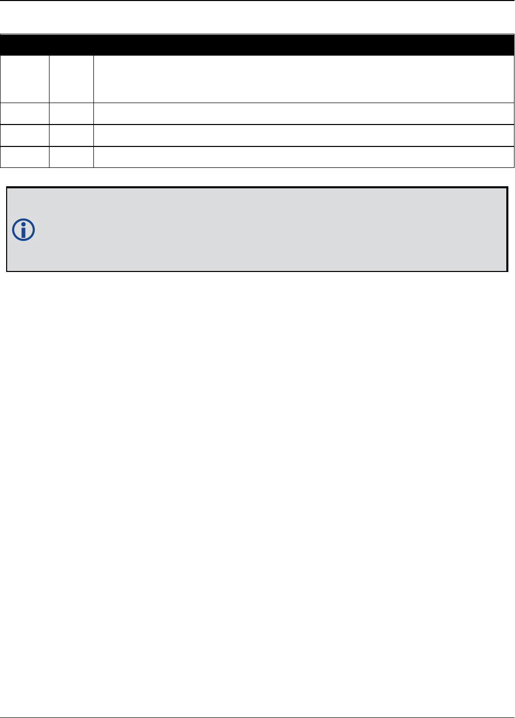
Chapter 2 Core Commands
OEM7 Commands and Logs Reference Manual v7 130
Binary ASCII Description
0 AIR
Receiver is in an aircraft or a land vehicle, for example a high speed train, with
velocity greater than 110 km/h (30 m/s). This is also the most suitable dynamic
for a jittery vehicle at any speed.
1 LAND Receiver is in a stable land vehicle with velocity less than 110 km/h (30 m/s).
2 FOOT Receiver is being carried by a person with velocity less than 11 km/h (3 m/s).
3 AUTO Receiver monitors dynamics and adapts behavior accordingly
Table 30: User Dynamics
Qualifying North American Solar Challenge cars annually weave their way through
1000’s of miles between the US and Canada. GNSS keeps them on track through many
intersections on secondary highways and gives the Calgary team constant intelligence
on the competition’s every move. In this case, with average speeds of 46 miles/hour
and at times a jittery vehicle, AIR is the most suitable dynamic.

Chapter 2 Core Commands
OEM7 Commands and Logs Reference Manual v7 131
2.33 ECHO
Sets port echo
Platform: OEM719, OEM729, OEM7500, OEM7600, OEM7700, OEM7720, PwrPak7,
SPAN CPT7
This command is used to set a port to echo.
Message ID: 1247
Abbreviated ASCII Syntax:
ECHO [port] echo
Factory Default:
ECHO COM1 OFF
ECHO COM2 OFF
ECHO COM3 OFF(not supported on OEM719)
ECHO COM4 OFF(OEM7600, OEM7700 and OEM7720 only)
ECHO COM5 OFF(OEM7600, OEM7700 and OEM7720 only)
ECHO USB1 OFF
ECHO USB2 OFF
ECHO USB3 OFF
ECHO ICOM1 OFF(not supported on OEM719)
ECHO ICOM2 OFF(not supported on OEM719)
ECHO ICOM3 OFF(not supported on OEM719)
ECHO ICOM4 OFF(not supported on OEM719)
ECHO ICOM5 OFF(not supported on OEM719)
ECHO ICOM6 OFF(not supported on OEM719)
ECHO ICOM7 OFF(not supported on OEM719)
ECHO SCOM1 OFF
ECHO SCOM2 OFF
ECHO SCOM3 OFF
ECHO SCOM4 OFF
ASCII Example:
ECHO COM1 ON
ECHO ON

Chapter 2 Core Commands
OEM7 Commands and Logs Reference Manual v7 132
Field Field
Type
ASCII
Value
Binary
Value Description Format Binary
Bytes
Binary
Offset
1ECHO
Header - -
Command header. See
Messages on page25 for
more information.
- H 0
2 port
See Table 31:
Communications Port
Identifiers below
Port to configure
(default = THISPORT) Enum 4 H
3 echo OFF 0 Sets port echo to off Enum 4 H+4
ON 1 Sets port echo to on
ASCII Port Name Binary Value
ALL 8
BT1 33
CCOM1 38
CCOM2 39
CCOM3 40
CCOM4 41
CCOM5 42
CCOM6 43
COM1 1
COM2 2
COM3 3
COM4 19
COM5 31
COM6 32
COM7 34
COM8 35
COM9 36
Table 31: Communications Port
Identifiers

Chapter 2 Core Commands
OEM7 Commands and Logs Reference Manual v7 133
ASCII Port Name Binary Value
COM10 37
ETH1 20
FILE 7
ICOM1 23
ICOM2 24
ICOM3 25
ICOM4 29
ICOM5 46
ICOM6 47
ICOM7 48
IMU 21
NCOM1 26
NCOM2 27
NCOM3 28
NOPORT 0
SCOM1 49
SCOM2 50
SCOM3 51
SCOM4 52
THISPORT 6
USB1 13
USB2 14
USB3 15
WCOM1 30

Chapter 2 Core Commands
OEM7 Commands and Logs Reference Manual v7 134
2.34 ECUTOFF
Sets satellite elevation cut-off for GPS Satellites
Platform: OEM719, OEM729, OEM7500, OEM7600, OEM7700, OEM7720, PwrPak7,
SPAN CPT7
This command is used to set the elevation cut-off angle for tracked GPS satellites. The receiver
does not start automatically searching for a GPS satellite until it rises above the cut-off angle
(when satellite position is known). Tracked satellites that fall below the cut-off angle are no
longer tracked unless they are manually assigned (see the ASSIGN command on page65).
In either case, satellites below the ECUTOFF angle are eliminated from the internal position and
clock offset solution computations.
This command permits a negative cut-off angle; it could be used in these situations:
lThe antenna is at a high altitude, and thus can look below the local horizon
lSatellites are visible below the horizon due to atmospheric refraction
Care must be taken when using ECUTOFF command because the signals from lower
elevation satellites are traveling through more atmosphere and are therefore degraded.
Use of satellites below 5 degrees is not recommended.
Use the ELEVATIONCUTOFF command (see page 136) to set the cut-off angle for any
system.
For dual antenna receivers, this command applies to both the primary and secondary
antennas.
Message ID: 50
Abbreviated ASCII Syntax:
ECUTOFF angle
Factory Default:
ECUTOFF 5.0
ASCII Example:
ECUTOFF 10.0

Chapter 2 Core Commands
OEM7 Commands and Logs Reference Manual v7 135
Field Field
Type
ASCII
Value
Binary
Value Description Format Binary
Bytes
Binary
Offset
1ECUTOFF
header - -
Command header. See
Messages on page25 for more
information.
- H 0
2 angle ±90.0 degrees Elevation cut-off angle relative
to horizon Float 4 H
A low elevation satellite is a satellite the receiver tracks just above the horizon.
Generally, a satellite is considered low elevation if it is between 0 and 15 degrees
above the horizon.
There is no difference between the data transmitted from a low elevation satellite
and that transmitted from a higher elevation satellite. However, differences in the
signal path of a low elevation satellite make their use less desirable. Low elevation
satellite signals have more error due to the increased amount of atmosphere they
must travel through. In addition, signals from low elevation satellites don't fit the
assumption that a signal travels in air nearly the same as in a vacuum. As such,
using low elevation satellites in the solution results in greater position
inaccuracies.
The elevation cut-off angle is specified with ECUTOFF to ensure that noisy, low
elevation satellite data below the cut-off is not used in computing a position. If
post-processing data, it is still best to collect all data (even that below the cut-off
angle). Experimenting with different cut-off angles can then be done to provide the
best results. In cases where there are not enough satellites visible, a low elevation
satellite may actually help in providing a useful solution.

Chapter 2 Core Commands
OEM7 Commands and Logs Reference Manual v7 136
2.35 ELEVATIONCUTOFF
Sets the elevation cut-off angle for tracked satellites
Platform: OEM719, OEM729, OEM7500, OEM7600, OEM7700, OEM7720, PwrPak7,
SPAN CPT7
The ELEVATIONCUTOFF command is used to set the elevation cut-off angle for tracked satel-
lites. The receiver does not start automatically searching for a satellite until it rises above the
cut-off angle (when the satellite position is known). Tracked satellites that fall below the cut-off
angle are no longer tracked unless they are manually assigned (refer to the ASSIGN command
on page65).
In either case, satellites below the elevation cut-off angle are eliminated from the internal pos-
ition and clock offset solution computations.
This command permits a negative cut-off angle and can be used in the following situations:
lThe antenna is at a high altitude and thus can look below the local horizon
lSatellites are visible below the horizon due to atmospheric refraction
Care must be taken when using ELEVATIONCUTOFF command because the signals
from lower elevation satellites are traveling through more atmosphere and are there-
fore degraded. Use of satellites below 5 degrees is not recommended.
This command combines the following commands into one convenient command:
ECUTOFF,GLOECUTOFF,GALECUTOFF,QZSSECUTOFF,SBASECUTOFF,
BDSECUTOFF and NAVICECUTOFF.
For dual antenna receivers, this command applies to both the primary and secondary
antennas.
A low elevation satellite is a satellite the receiver tracks just above the horizon. Generally,
a satellite is considered low elevation if it is between 0 and 15 degrees above the horizon.
There is no difference between the data transmitted from a low elevation satellite and that
transmitted from a higher elevation satellite. However, differences in the signal path of a
low elevation satellite make their use less desirable. Low elevation satellite signals have
more error due to the increased amount of atmosphere they must travel through. In
addition, signals from low elevation satellites don't fit the assumption that a signal travels
in air nearly the same as in a vacuum. As such, using low elevation satellites in the solution
results in greater position inaccuracies.
The elevation cut-off angle is specified with the ELEVATIONCUTOFF command to ensure
that noisy, low elevation satellite data below the cut-off is not used in computing a
position. If post-processing data, it is still best to collect all data (even that below the
cutoff angle). Experimenting with different cut-off angles can then be done to provide the
best results. In cases where there are not enough satellites visible, a low elevation
satellite may actually help in providing a useful solution.

Chapter 2 Core Commands
OEM7 Commands and Logs Reference Manual v7 137
Message ID: 1735
Abbreviated ASCII Syntax:
ELEVATIONCUTOFF Constellation Angle [Reserved]
Factory default:
ELEVATIONCUTOFF ALL 5.0 0
ASCII Example:
ELEVATIONCUTOFF GPS 5
ELEVATIONCUTOFF ALL 5
Field Field Type ASCII
Value
Binary
Value Description Format Binary
Bytes
Binary
Offset
1
ELEVATION
CUTOFF
header
- -
Command header. See
Messages on page25 for
more information.
- H 0

Chapter 2 Core Commands
OEM7 Commands and Logs Reference Manual v7 138
Field Field Type ASCII
Value
Binary
Value Description Format Binary
Bytes
Binary
Offset
2 Constellation
GPS 0
Sets the cut-off angle
for GPS Constellation
satellites only.
Enum 4 H
GLONASS 1
Sets the cut-off angle
for GLONASS
constellation satellites
only.
SBAS 2
Sets the cut-off angle
for SBAS constellation
satellites only.
GALILEO 5
Sets the cut-off angle
for Galileo constellation
satellites only.
BEIDOU 6
Sets the cut-off angle
for BeiDou constellation
satellites only.
QZSS 7
Sets the cut-off angle
for QZSS constellation
satellites only.
NAVIC 9
Sets the cut-off angle
for NavIC constellation
satellites only.
ALL 32
Sets the cut-off angle
for all satellites
regardless of the
constellation.
3 Angle ±90.0 degrees Elevation cut-off angle
relative to the horizon. Float 4 H+4
4 Reserved 0 Reserved Field
(optional) Ulong 4 H+8

Chapter 2 Core Commands
OEM7 Commands and Logs Reference Manual v7 139
2.36 ETHCONFIG
Configures Ethernet physical layer
Platform: OEM729, OEM7600, OEM7700, OEM7720, PwrPak7, SPAN CPT7
This command is used to configure the Ethernet physical layer.
Message ID: 1245
Abbreviated ASCII Syntax:
ETHCONFIG interface_name [speed] [duplex] [crossover] [power_mode]
Factory Default:
ETHCONFIG etha auto auto auto powerdown(OEM7 receiver cards)
ETHCONFIG etha auto auto auto auto(PwrPak7)
ASCII Example:
ETHCONFIG etha 100 full mdix normal
Field Field Type ASCII Value Binary
Value Description Format Binary
Bytes
Binary
Offset
1ETHCONFIG
Header - -
Command header.
See Messages on
page25 for more
information.
- H 0
2interface_
name ETHA 2 Name of the Ethernet
interface Enum 4 H
3 speed
AUTO 1
Auto-negotiate speed
(default)
AUTO is the
recommended value
for the speed
parameter.
If setting speed to
AUTO, duplex must
be set to AUTO at the
same time otherwise
a “parameter 3 out of
range” error occurs.
Enum 4 H+4
10 2 Force 10BaseT
100 3 Force 100BaseT

Chapter 2 Core Commands
OEM7 Commands and Logs Reference Manual v7 140
Field Field Type ASCII Value Binary
Value Description Format Binary
Bytes
Binary
Offset
4 duplex
AUTO 1
Auto-negotiate
duplex (default)
If setting duplex to
AUTO, speed must be
set to AUTO at the
same time otherwise
a “parameter 3 out of
range” error occurs.
Enum 4 H+8
HALF 2 Force half duplex
FULL 3 Force full duplex
5 crossover
AUTO 1 Auto-detect
crossover (default)
Enum 4 H+12MDI 2 Force MDI (straight
through)
MDIX 3 Force MDIX
(crossover)
6power_
mode
AUTO 1 Energy detect mode
(default for PwrPak7)
Enum 4 H+16
POWERDOWN 2
Soft power down
mode (default for
OEM7 receiver cards)
NORMAL 3 Normal mode
The crossover parameter is ignored on OEM7 receivers, as the hardware automatically
detects the cable connection and configures the interface for proper communication. For
backwards compatibility, the crossover options are still accepted, but have no functional
impact.

Chapter 2 Core Commands
OEM7 Commands and Logs Reference Manual v7 141
2.37 EVENTINCONTROL
Controls Event-In input triggers
Platform: OEM719, OEM729, OEM7500, OEM7600, OEM7700, OEM7720, PwrPak7,
SPAN CPT7
This command controls up to four Event-In input triggers. Each input can be used as an event
strobe.
When used as an event strobe, an accurate GPS time or position is applied to the rising or falling
edge of the input event pulse (refer to the MARKTIME, MARK2TIME, MARK3TIME and
MARK4TIME log on page586, MARKPOS, MARK2POS, MARK3POS and MARK4POS log on
page583 or MARK1PVA, MARK2PVA, MARK3PVA and MARK4PVA log on page980). Each
input strobe is usually associated with a separate device, therefore different solution output
lever arm offsets can be applied to each strobe. When used as an Event Input Trigger, it is pos-
sible to overwhelm the receiver with a very high rate of input events that impacts the per-
formance of the receiver. For this reason, the receiver internally throttles the rate at which it
responds to input events. The limit is 200 Hz.
Message ID: 1637
Abbreviated ASCII Syntax:
EVENTINCONTROL mark switch [polarity] [t_bias] [t_guard]
ASCII Example:
EVENTINCONTROL MARK1 ENABLE
Field Field
Type
ASCII
Value
Binary
Value Description Format Binary
Bytes
Binary
Offset
1
EVENTIN
CONTROL
header
- -
Command header. See
Messages on page25 for
more information.
- H 0
2 mark
MARK1 0 Choose which Event-In
Mark to change. This value
must be specified.
Note: MARK3 and MARK4
are available only on
OEM7600, OEM7700 and
OEM7720 receivers.
Enum 4 H
MARK2 1
MARK3 2
MARK4 3
3 switch
DISABLE 0 Disables Event Input
Enum 4 H+4
EVENT 1 Enables Event Input
ENABLE 3
A synonym for the EVENT
option (for compatibility
with previous releases)

Chapter 2 Core Commands
OEM7 Commands and Logs Reference Manual v7 142
Field Field
Type
ASCII
Value
Binary
Value Description Format Binary
Bytes
Binary
Offset
4 polarity NEGATIVE 0 Negative polarity (default) Enum 4 H+8
POSITIVE 1 Positive polarity
5 t_bias
default: 0
minimum: -
999,999,999
maximum:
999,999,999
A constant time bias in
nanoseconds can be
applied to each event
pulse. Typically this is used
to account for a
transmission delay.
This field is not used if the
switch field is set to
COUNT.
Long 4 H+12
6 t_guard
default: 4
minimum: 2
maximum:
3,599,999
The time guard specifies
the minimum number of
milliseconds between
pulses. This is used to
coarsely filter the input
pulses.
If Field 3 is COUNT, this
field is not used.
Ulong 4 H+16
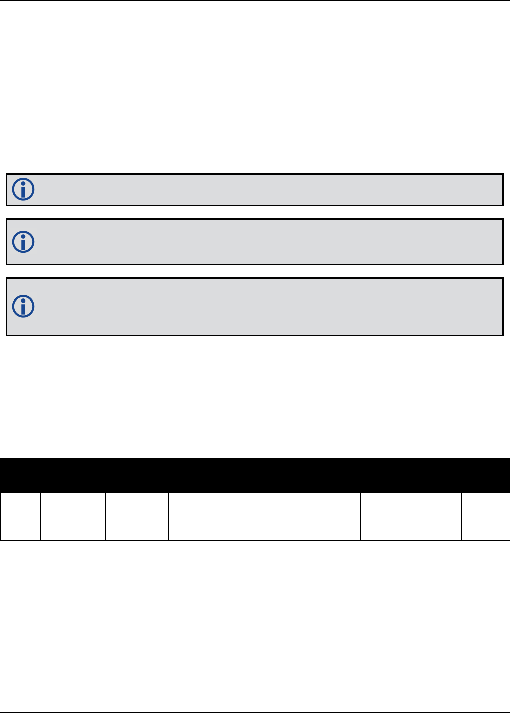
Chapter 2 Core Commands
OEM7 Commands and Logs Reference Manual v7 143
2.38 EVENTOUTCONTROL
Control Event-Out properties
Platform: OEM719, OEM729, OEM7500, OEM7600, OEM7700, OEM7720, PwrPak7,
SPAN CPT7
This command configures up to seven Event-Out output strobes. The event strobes toggle
between 3.3 V and 0 V. The pulse consists of two periods: one active period followed by a not act-
ive period. The start of the active period is synchronized with the top of the GNSS time second
and the signal polarity determines whether the active level is 3.3 V or 0 V. The not active period
immediately follows the active period and has the alternate voltage.
The outputs that are available vary according to the platform.
A 100 MHz clock is used internally to create these output signals. As a result, all period
values are limited to 10 ns steps.
The EVENTOUT outputs cannot synchronize with GPS time until the receiver reaches
FINESTEERING time status. As the receiver transitions to GPS time, there may be addi-
tional, unexpected pulses on the EVENTOUT signals.
Message ID: 1636
Abbreviated ASCII Syntax:
EVENTOUTCONTROL mark switch [polarity] [active_period] [non_active_period]
ASCII Example:
EVENTOUTCONTROL MARK3 ENABLE
Field Field
Type
ASCII
Value
Binary
Value Description Format Binary
Bytes
Binary
Offset
1
EVENTOUT
CONTROL
header
- -
Command header. See
Messages on page25 for
more information.
- H 0

Chapter 2 Core Commands
OEM7 Commands and Logs Reference Manual v7 144
Field Field
Type
ASCII
Value
Binary
Value Description Format Binary
Bytes
Binary
Offset
2 mark
MARK1 0 Choose which Event-Out
Mark to change. This
value must be specified.
Note: On OEM719 and
OEM729 receivers, only
MARK1 is available.
Note: On OEM7600,
OEM7700 and OEM7720
receivers, only MARK1
through MARK4 are
available.
Enum 4 H
MARK2 1
MARK3 2
MARK4 3
MARK5 4
MARK6 5
MARK7 6
3 switch DISABLE 0 Disables the Event output Enum 4 H+4
ENABLE 1 Enables the Event output
4 polarity
NEGATIVE 0
Negative polarity (active
= 0V)
(default) Enum 4 H+8
POSITIVE 1 Positive polarity (active =
3.3V)
5active_
perioda
default:
500,000,000
minimum: 10
maximum:
999,999,990
Active period of the Event
Out signal in
nanoseconds.
10ns steps must be used.
Note: If the value
entered is not a multiple
of 10, it will be rounded
down to the nearest 10
ns.
Ulong 4 H+12
aThe sum of the active period and inactive period should total 1,000,000,000 ns. If the total exceeds one full
second, the active period duration will be as given and the inactive period will be the remainder of the second.
Alternately, the sum of the active and inactive periods may be less than 1,000,000,000 ns, but should divide
evenly into 1,000,000,000 ns. For example, if the active period is 150,000,000 and the inactive period is
50,000,000, the sum of the periods is 200,000,000 ns which divides evenly into one full second.
If the sum is less than one full second and not an even multiple, the last active or inactive period is stretched or
truncated to equal one full second.
A 100 MHz clock is used internally to create these output signals. As a result, all period values are limited to 10
ns steps.

Chapter 2 Core Commands
OEM7 Commands and Logs Reference Manual v7 145
Field Field
Type
ASCII
Value
Binary
Value Description Format Binary
Bytes
Binary
Offset
6
non_
active_
perioda
default:
500,000,000
minimum: 10
maximum:
999,999,990
Non-active period of the
Event Out signal in
nanoseconds.
10 ns steps must be used.
Note: If the value
entered is not a multiple
of 10, it will be rounded
down to the nearest 10
ns.
Ulong 4 H+16
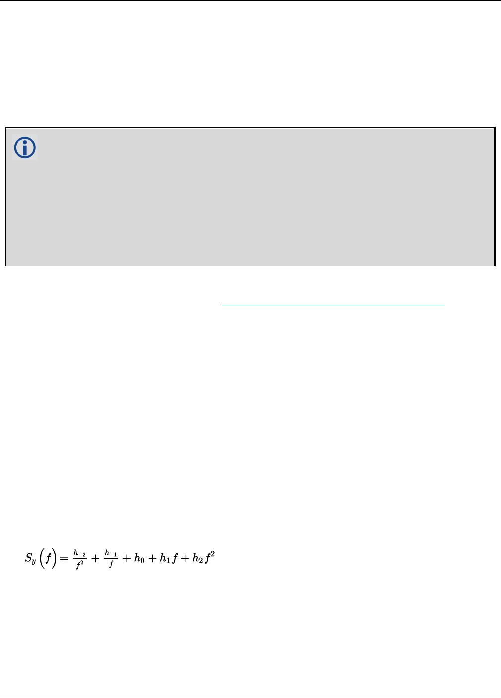
Chapter 2 Core Commands
OEM7 Commands and Logs Reference Manual v7 146
2.39 EXTERNALCLOCK
Sets external clock parameters
Platform: OEM729
The EXTERNALCLOCK command is used to enable the OEM7 card to operate with an optional
external oscillator. You are able to optimally adjust the clock model parameters of these receiv-
ers for various types of external clocks.
1. This command affects the interpretation of the CLOCKMODEL log.
2. If the EXTERNALCLOCK command is enabled and set for an external clock (TCXO,
OCXO, RUBIDIUM, CESIUM or USER) and the CLOCKADJUST command (see page
101) is ENABLED, then the clock steering process takes over the VARF output pins and
may conflict with a previously entered FREQUENCYOUT command (see page 171). If
clocksteering is not used with the external oscillator, the clocksteering process must
be disabled by using the CLOCKADJUST disable command.
3. When using the EXTERNALCLOCK command and CLOCKADJUST command together,
issue the EXTERNALCLOCK command first to avoid losing satellites.
There are three steps involved in using an external oscillator:
1. Follow the procedure outlined in the OEM7 Installation and Operation User Manual to connect
an external oscillator to the OEM7.
2. Using the EXTERNALCLOCK command, select a standard oscillator and its operating fre-
quency.
3. Using the CLOCKADJUST command, disable the clocksteering process if external clock-
steering is not used.
An unsteered oscillator can be approximated by a three-state clock model, with two states rep-
resenting the range bias and range bias rate, and a third state assumed to be a Gauss-Markov
(GM) process representing the range bias error generated from satellite clock dither. The third
state is included because the Kalman filter assumes an (unmodeled) white input error. The sig-
nificant correlated errors produced by satellite clock dither are obviously not white and the
Markov process is an attempt to handle this kind of short term variation.
The internal units of the new clock model’s three states (offset, drift and GM state) are metres,
metres per second and metres. When scaled to time units for the output log, these become
seconds, seconds per second and seconds, respectively.
The user has control over 3 process noise elements of the linear portion of the clock model.
These are the h0, h-1 and h-2 elements of the power law spectral density model used to describe
the frequency noise characteristics of oscillators:
where fis the sampling frequency and Sy(f) is the clock’s power spectrum. Typically only h0, h-
1, and h-2 affect the clock’s Allan variance and the clock model’s process noise elements.
Before using an optional external oscillator, several clock model parameters must be set. There
are default settings for a Voltage-Controlled Temperature-Compensated Crystal Oscillator
(VCTCXO), Ovenized Crystal Oscillator (OCXO), Rubidium and Cesium standard, which are given

Chapter 2 Core Commands
OEM7 Commands and Logs Reference Manual v7 147
in Table 32: Clock Type on the next page. You may alternatively choose to supply customized
settings.
The EXTERNALCLOCK command determines whether the receiver uses its own internal
temperature-compensated crystal oscillator or that of an external oscillator as a
frequency reference. It also sets which clock model is used for an external oscillator.
To force the OEM7 to use the internal oscillator, use the EXTERNALCLOCK disable
command and physically disconnect the external oscillator input. Do not use the
EXTERNALCLOCK OCXO, CESIUM, RUBIDIUM or USER parameters if there is no external
oscillator connected to the OEM7.
Message ID: 230
Abbreviated ASCII Syntax:
EXTERNALCLOCK clocktype [freq] [h0[h-1[h-2]]]
Factory Default:
EXTERNALCLOCK disable
ASCII Examples:
EXTERNALCLOCK USER 10MHZ 1.0167e-23 6.87621e-25 8.1762e-26
EXTERNALCLOCK TCXO 5MHZ
Field Field
Type
ASCII
Value
Binary
Value Description Format Binary
Bytes
Binary
Offset
1
EXTERNAL
CLOCK
header
- -
Command header. See
Messages on page25 for
more information.
- H 0
2 clocktype
See Table 32:
Clock Type on
the next page
Clock type Enum 4 H
3 freq
5MHz 1 Optional frequency. If a value
is not specified, the default is
5 MHz
Enum 4 H+4
10MHz 2
4h01.0 e-35 to
1.0 e-18
Optional timing standards.
These fields are only valid
when the USER clocktype is
selected. Do not use h values
with VCTCXO, OCXO, CESIUM
or RUBIDIUM clock types. The
h values for these options are
fixed, see Table 33: Pre-
Defined Values for Oscillators
on the next page
(default=0.0)
Double 8 H+8
5h-1 1.0 e-35 to
1.0 e-18 Double 8 H+16
6h-2 1.0 e-35 to
1.0 e-18 Double 8 H+24

Chapter 2 Core Commands
OEM7 Commands and Logs Reference Manual v7 148
ASCII Binary Description
DISABLE 0
Turns the external clock input off, reverts back to the on-board VCTCXO.
When used in a binary command, use the parameter defaults (i.e. freq=1,
h0=0, h-1=0, h-2=0).
TCXO 1 Sets the predefined values for a VCTCXO
OCXO 2 Sets the predefined values for an OCXO
RUBIDIUM 3 Sets the predefined values for a rubidium oscillator
CESIUM 4 Sets the predefined values for a cesium oscillator
USER 5 Defines custom process noise elements
Table 32: Clock Type
Clock Type h0h-1 h-2
VCTCXO 1.0 e-21 1.0 e-20 1.0 e-20
OCXO 2.51 e-26 2.51 e-23 2.51 e-22
Rubidium 1.0 e-23 1.0 e-22 1.3 e-26
Cesium 2.0 e-20 7.0 e-23 4.0 e-29
Table 33: Pre-Defined Values for Oscillators

Chapter 2 Core Commands
OEM7 Commands and Logs Reference Manual v7 149
2.40 FILEAUTOTRANSFER
Enables/Disables automatic file transfer
Platform: PwrPak7
Use this command to configure the automatic transfer function from internal memory to an
external USB stick. If the mode is set to COPY or MOVE, all log files, except the file currently
being logged to, will be automatically transferred to a USB stick when the USB stick is inserted.
This command will transfer all recorded log files to the USB stick provided the USB stick has
enough free space to hold all the data. Files too large to fit in the remaining space on the
USB stick are skipped.
The command must be issued before the USB stick is inserted. If the command is not issued
first, the USB stick must be removed and reinserted to trigger the auto transfer.
The status of the transfer can be viewed by logging the FILETRANSFERSTATUS log (see page
473).
A transfer in progress can be canceled by issuing the FILETRANSFER CANCEL command.
The settings for this command can be saved using the SAVECONFIG command (see page 316).
Message ID: 2135
Abbreviated ASCII Syntax:
FILEAUTOTRANSFER [FileAutoTransferMode]
ASCII Example:
FILEAUTOTRANSFER COPY
Field Field Type ASCII
Value
Binary
Value Description Binary
Format
Binary
Bytes
Binary
Offset
1FILEAUTOTRANSFER
header - -
Command header.
See Messages on
page25 for more
information.
- H 0
2 FileAutoTransferMode
1 OFF
Automatic
copy/move is
disabled (default)
Ulong 4 H
2 COPY Automatically
copies all files
3 MOVE
Automatically
copies all files and
then deletes them
from internal
memory after a
successful copy

Chapter 2 Core Commands
OEM7 Commands and Logs Reference Manual v7 150
For the fastest transfer of files to an external memory stick, it is recommended that log-
ging to a file be stopped.
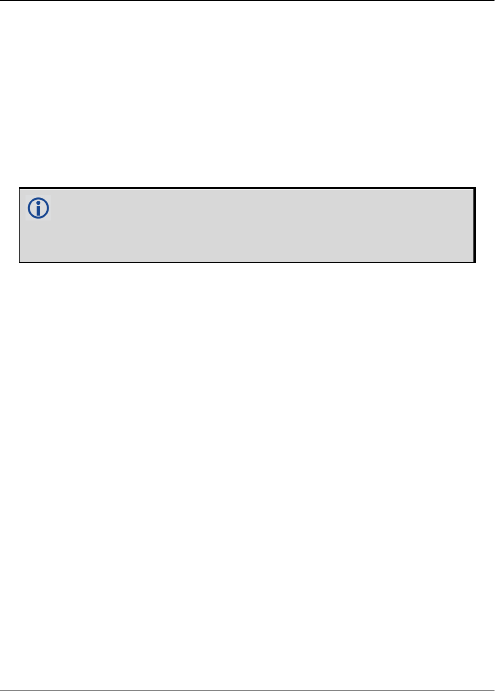
Chapter 2 Core Commands
OEM7 Commands and Logs Reference Manual v7 151
2.41 FILECONFIG
Open or close a log file
Platform: OEM719, OEM729, OEM7500, OEM7600, OEM7700, OEM7720, PwrPak7,
SPAN CPT7
To record logs, log requests are sent to the FILE port. Before the logs sent to the FILEport can
be saved in a file, the file must be opened using the FILECONFIG command.
When configured to be open, a log file will be opened when the active file media is ready and has
sufficient space. Once a log file is opened, any logs requested for the FILE port are recorded to
the file.
Use the FILESTATUS log (see page 467) to determine the state of the log file.
The file media is separately configured:
lOn core cards, this is always USBSTICK, which is the only media available.
lOn Enclosure products, the active file media is configured using a product-spe-
cific command, such as FILEMEDIACONFIG command on page154.
When a file is opened, the file name is automatically generated based on the following format:
<PSN>_<INDEX>.LOG
where:
l<PSN> is the PSN of the receiver
l<INDEX> is a number from 1 to 511.
The lowest number that produces an unused file name is selected. If there is no such
number available, the FILESTATUS log (see page 467) will report an error.
The number is not zero-padded (i.e. the sequence is as follows: 1,2, ... ,9,10,11,12, ...
,99,100, ... , 510,511).
When a file is closed and the receiver has a valid time, the file is renamed based on the fol-
lowing format:
<PSN>_<UTC Date>_<UTC Time>.LOG
where:
l<PSN> is the PSN of the receiver
l<UTC_Date> is the UTC date in the format YYYY-MM-DD
l<UTC_Time> is the UTC time in the format HH-MM-SS
Example file name: NOV12001200A_2017-01-10_12-14-34.LOG
When a file is closed, but the receiver does not have a valid time, the file is left with its auto-
matically generated name.
Other Notes:
lThe FILE port represents the internal logging to flash memory. It has a NOVATEL Interface
Mode - output only, no input is possible.
lOnly logs that are published after the log file is open are recorded.

Chapter 2 Core Commands
OEM7 Commands and Logs Reference Manual v7 152
lOnly one log file can be open at a time.
lLogs requested to the FILE port are still produced even if the log file is closed; however the
logs are not recorded. (This is similar to requesting logs to COM4 when there's no cable on
COM4.) If a new log file is opened, recording of the previously requested logs continues with
the new file.
lWhen a file is closed, the log file is renamed to the format <PSN>_<UTC Date>_<UTC
Time>.LOG, where the UTC time is the time when the file is closed. If the time is not avail-
able, the file is not renamed. If there is already a file with the intended name, the file is not
renamed.
lAfter closing a file, the file system will be flushed to ensure that all data is written to the
media.
lA disk is considered "full" when is has <= 10 MB of free space. This buffer is left in place to
allow the system time and space to open up a new file if required.
Message ID: 2116
Abbreviated ASCII Syntax:
FILECONFIG FileOperation
Factory Default:
FILECONFIG CLOSE
Example:
FILECONFIG OPEN
Field Field Type ASCII
Value
Binary
Value Description Format Binary
Bytes
Binary
Offset
1FILECONFIG
header - -
Command header. See
Messages on page25 for
more information.
- H 0
2 FileOperation 1 OPEN Open (create) a new
logging file Enum 4 H
2 CLOSE Close the logging file

Chapter 2 Core Commands
OEM7 Commands and Logs Reference Manual v7 153
2.42 FILEDELETE
Deletes files from the currently selected mass storage device
Platform: OEM719, OEM729, OEM7500, OEM7600, OEM7700, OEM7720, PwrPak7,
SPAN CPT7
Use this command to delete a single file, or use the wild card symbol (*) to delete all files, from
the logging directory of the currently selected file media. This command will not delete a file if it
is currently open for logging. Use the FILESTATUS log (see page 467) to determine the state of
the log file.
The wild card symbol deletes all files in the directory. It cannot be used to delete a sub-
set of the files in the directory. For example, the command FILEDELETE *.LOG will be
rejected by the receiver.
The file media is separately configured:
lOn receiver cards, the file media is always USBSTICK, which is the only media available.
lOn enclosure products, the active file media is configured using a product-specific command,
such as FILEMEDIACONFIG command (see page 154).
The list of files stored on the currently selected file media can be retrieved using the FILELIST
log on page465.
Message ID: 2190
Abbreviated ASCII Syntax:
FILEDELETE FileName
Example:
FILEDELETE NMNE17130016A_2017-12-11_18-17-06.LOG– Delete the file
NMNE17130016A_2017-12-11_18-17-06.LOG
Field Field Type Description Format Binary
Bytes
Binary
Offset
1FILEDELETE
header
Command header. See Messages on
page25 for more information. H 0
2 FileName Name of file to delete, or the wild card
symbol (*)
String
(Max
128)
variable
1H
1In the binary case, each string field needs to be NULL terminated and additional bytes of padding added to
maintain 4-byte alignment, up to the maximum defined by the string size. The next defined field starts
immediately at the next 4-byte alignment following the NULL.

Chapter 2 Core Commands
OEM7 Commands and Logs Reference Manual v7 154
2.43 FILEMEDIACONFIG
Specify the file media
Platform: PwrPak7
Use this command to specify which storage media is used for File operations.
To determine what storage device is currently being used for File operations, log this command.
For example:
LOG FILEMEDIACONFIG
On OEM7 receiver cards, the file media is always USBSTICK, which is the only media
available.
On PwrPak7 products, the active file media is configured using the FILEMEDIACONFIG
command.
Message ID: 2117
Abbreviated ASCII Syntax:
FILEMEDIACONFIG MassStorage
ASCII Example:
FILEMEDIACONFIG INTERNAL_FLASH– Use internal flash as the media
FILEMEDIACONFIG USBSTICK– Use a USB stick as the media
Field Field Type ASCII
Value
Binary
Value Description Format Binary
Bytes
Binary
Offset
1FILEMEDIACONFIG
header - -
Command
header. See
Messages on
page25 for more
information.
- H 0
2 MassStorageDevice
1 USBSTICK
Use a USB stick
as the mass
storage device
Enum 4 H
2INTERNAL_
FLASH
Use Internal
storage as the
mass storage
device

Chapter 2 Core Commands
OEM7 Commands and Logs Reference Manual v7 155
2.44 FILEROTATECONFIG
Set the maximum size and duration of a log file
Platform: OEM719, OEM729, OEM7500, OEM7600, OEM7700, OEM7720, PwrPak7,
SPAN CPT7
Use this command to configure the maximum size and duration for a log file. This command also
configures the action taken when the log file media is full.
A file rotation is when a new file is opened, the currently opened file is closed and logging on the
FILE port is rerouted to this new file. There is no data loss during this process and individual logs
within the file are not spread between log files.
Message ID: 2133
Abbreviated ASCII Syntax:
FILEROTATECONFIG [MaxFileTime] [MaxFileSize] [DiskFullAction]
Factory Default:
FILEROTATECONFIG 0 4096 STOP
Example:
FILEROTATECONFIG 2 4096 STOP
The file is left open for 2 hours or until the file size reaches 4096 MB. When the log file media
is full, the file is closed.
FILEROTATECONFIG 4 4096 OVERWRITE
The file is left open for 4 hours or until the file size reaches 4096 MB. When the log media file
is full, the oldest file on the log media file will be deleted.
Field Field Type ASCII
Value
Binary
Value Description Format Binary
Bytes
Binary
Offset
1
FILEROTATE
CONFIG
header
- -
Command header.
See Messages on
page25 for more
information.
- H 0
2 MaxFileTime 0 to 24
Maximum number of
hours to leave a file
open before
triggering a file
rotation.
Set to 0 for no
maximum time.
Maximum value is 24.
Default is 0.
Ushort 2 H

Chapter 2 Core Commands
OEM7 Commands and Logs Reference Manual v7 156
Field Field Type ASCII
Value
Binary
Value Description Format Binary
Bytes
Binary
Offset
3 MaxFileSize 1 to 4096
Maximum number of
mega bytes (MB) for
the file size. A file
rotation is triggered
when the file is within
1 MB of this size.
Maximum value is
4096 MB
Default is 4096 MB (4
GB).
Ushort 2 H+2

Chapter 2 Core Commands
OEM7 Commands and Logs Reference Manual v7 157
Field Field Type ASCII
Value
Binary
Value Description Format Binary
Bytes
Binary
Offset
4 DiskFullAction 0 STOP
Stops logging when
the file media has 1
MB of free space or
less.
Default is STOP.
Enum 4 H+4

Chapter 2 Core Commands
OEM7 Commands and Logs Reference Manual v7 158
Field Field Type ASCII
Value
Binary
Value Description Format Binary
Bytes
Binary
Offset
1 OVERWRITE
Deletes the oldest log
file when the file
media has 10 MB of
free space or less.
To be selected for
deletion a file must
satisfy these
requirements:
lThe file must use
the
FILECONFIG
command (see
page 151) file
name format.
lThe <PSN>
value must
match the cur-
rent receiver.
File age is
determined using the
FILECONFIG
command (see page
151) file name
format.
lTemporary files
(i.e. those with
an <INDEX>
value) are con-
sidered oldest.
Such files will be
sorted by their
<INDEX> value
with lower val-
ues considered
older.
lNon-temporary
files will be sor-
ted by the date
reported in the
file format.

Chapter 2 Core Commands
OEM7 Commands and Logs Reference Manual v7 159
2.45 FILETRANSFER
Copy files from internal memory
Platform: PwrPak7
Use this command to copy files from internal memory to a USBstick. This command can also be
used to cancel the file transfer in progress.
This command returns a response immediately to show that the copy/move operation
started. However, the actual transfer of files will take some time. Use the
FILETRANSFERSTATUS log (see page 473) to monitor the status of the file transfer.
To view the names of the files in memory, log the FILELIST log (see page 465).
Message ID: 2109
Abbreviated ASCII Syntax:
FILETRANSFER FileTransferOperation <FileName>
ASCII Examples:
FILETRANSFER COPY ALL– Copies all files on internal memory
FILETRANSFER MOVE BMHR16460033T_2017-3-16_21-18-48.log
FILETRANSFER CANCEL– Cancels file transfer operation
Field Field Type ASCII
Value
Binary
Value Description Binary
Format
Binary
Bytes
Binary
Offset
1FILETRANSFER
header - -
Command
header. See
Messages on
page25 for more
information.
- H 0
2 FileTransferOperation
1 COPY Copy the file
Enum 4 H
2 MOVE
Copy the file and
then delete file
from internal
memory
3 CANCEL
Cancels the file
transfer
currently in
progress

Chapter 2 Core Commands
OEM7 Commands and Logs Reference Manual v7 160
Field Field Type ASCII
Value
Binary
Value Description Binary
Format
Binary
Bytes
Binary
Offset
3 FileName
The name of the
file to be moved
or copied.
To move or copy
all of the files on
internal memory,
use ALL.
String Variable H+4
When a FILETRANSFER CANCEL ALL command is issued, the file currently being trans-
ferred, and any pending files, are not transferred to the destination media. Any files
already transferred are unaffected.

Chapter 2 Core Commands
OEM7 Commands and Logs Reference Manual v7 161
2.46 FIX
Constrains to fixed height or position
Platform: OEM719, OEM729, OEM7500, OEM7600, OEM7700, OEM7720, PwrPak7,
SPAN CPT7
This command is used to fix height or position to the input values. For various applications, fix-
ing these values can assist in improving acquisition times and accuracy of position or cor-
rections. For example, fixing the position is a requirement for differential base stations as it
provides the reference position to base the differential corrections from.
If you enter a FIXPOSDATUM command (see page 165), the FIX command is then issued
internally with the FIXPOSDATUM command (see page 165) values translated to WGS84. It is
the FIX command that appears in the RXCONFIG log. If the FIX command or the
FIXPOSDATUM command (see page 165) are used, their newest values overwrite the internal
FIX values.
1. It is strongly recommended that the FIX POSITION entered be accurate to within a few
metres. This level of accuracy can be obtained from a receiver using single point pos-
itioning once 5 or 6 satellites are being tracked.
2. FIX POSITION should only be used for base station receivers. Applying FIX POSITION
to a rover switches it from RTK mode to a fixed position mode. Applying FIX POSITION
to the rover does not speed up ambiguity resolution.
3. Any setting other than FIX POSITION disables output of differential corrections unless
the MOVINGBASESTATION command (see page 239) is set to ENABLE.
4. You can fix the position of the receiver using latitude, longitude and height in Mean Sea
Level (MSL) or ellipsoidal parameters depending on the UNDULATION setting. The fact-
ory default for the UNDULATION command (see page 379) setting is EGM96, where
the height entered in the FIX command is set as MSL height. If you change the
UNDULATION setting to USER 0, the height entered in the FIX command is set as
ellipsoidal height (refer to Table 34: FIX Parameters on the next page).
Error checking is performed on the entered fixed position by the integrity monitor. Depending on
the result of this check, the position can be flagged with the following statuses.
lSOL_COMPUTED: The entered position has been confirmed by measurement.
lPENDING: Insufficient measurements are available to confirm the entered position.
lINTEGRITY_WARNING: First level of error when an incorrect position has been entered. The
fixed position is off by approximately 25-50 meters.
lINVALID_FIX: Second level of error when an inaccurate position has been entered. The fixed
position is off by a gross amount.
An incorrectly entered fixed position will be flagged either INTEGRITY_WARNING or
INVALID_FIX. This will stop output of differential corrections or RTK measurements and
can affect the clock steering and satellite signal search. Checks on the entered fixed pos-
ition can be disabled using the RAIMMODE command (see page 289).
Message ID: 44
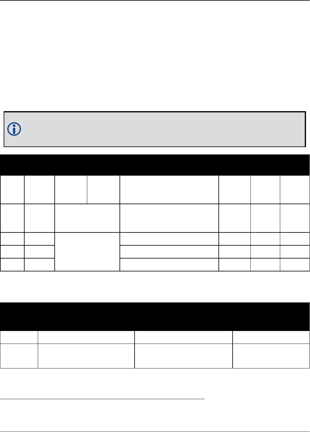
Chapter 2 Core Commands
OEM7 Commands and Logs Reference Manual v7 162
Abbreviated ASCII Syntax:
FIX type [param1 [param2 [param3]]]
Factory Default:
FIX none
ASCII Example:
FIX none
FIX HEIGHT 4.567
FIX position 51.116 -114.038 1065.0
In order to maximize the absolute accuracy of RTK rover positions, the base station
coordinates must be fixed to their known position using the FIX POSITION [lat][lon]
[hgt] command.
Field Field
Type
ASCII
Value
Binary
Value Description Format Binary
Bytes
Binary
Offset
1FIX
header - -
Command header. See
Messages on page25 for
more information.
- H 0
2 type
See Table 35: Fix
Types on the next
page
Fix type Enum 4 H
3 param1
See Table 34: FIX
Parameters below
Parameter 1 Double 8 H + 4
4 param2 Parameter 2 Double 8 H + 12
5 param3 Parameter 3 Double 8 H + 20
ASCII
Type
Name
Parameter 1 Parameter 2 Parameter3
AUTO Not used Not used Not used
HEIGHT Default MSL height 1
(-1000 to 20000000 m) Not used Not used
Table 34: FIX Parameters
1See also Note #4 above.

Chapter 2 Core Commands
OEM7 Commands and Logs Reference Manual v7 163
ASCII
Type
Name
Parameter 1 Parameter 2 Parameter3
NONE Not used Not used Not used
POSITION
Lat (-90 to 90 degrees)
where a ‘-’ sign denotes
south and a ‘+’ sign denotes
north
Lon (-360 to 360 degrees)
where a ‘-’ sign denotes west
and a ‘+’ sign denotes east
Default MSL height 1
(-1000to20000000m)
For a discussion on height, refer to An Introduction to GNSS available on our website.
ASCII
Name
Binary
Value Description
NONE 0 Unfix. Clears any previous FIX commands
AUTO 1
Configures the receiver to fix the height at the last calculated value if the
number of satellites available is insufficient for a 3-D solution. This provides
a 2-D solution. Height calculation resumes when the number of satellites
available allows a 3-D solution
HEIGHT 2
Configures the receiver in 2-D mode with its height constrained to a given
value. This command is used mainly in marine applications where height in
relation to mean sea level may be considered to be approximately constant.
The height entered using this command is referenced to the mean sea level,
see the BESTPOS log on page428 (is in metres). The receiver is capable of
receiving and applying differential corrections from a base station while fix
height is in effect. The fix height command overrides any previous FIX
HEIGHT or FIX POSITION command.
Note: This command only affects pseudorange corrections and solutions.
Table 35: Fix Types

Chapter 2 Core Commands
OEM7 Commands and Logs Reference Manual v7 164
ASCII
Name
Binary
Value Description
POSITION 3
Configures the receiver with its position fixed. This command is used when it
is necessary to generate differential corrections.
For both pseudorange and differential corrections, this command must be
properly initialized before the receiver can operate as a GNSS base station.
Once initialized, the receiver computes differential corrections for each
satellite being tracked. The computed differential corrections can then be
output to rover stations using the RTCMV3 differential corrections data log
format. See the OEM7 Installation and Operation User Manual for information
about using the receiver for differential applications.
The values entered into the fix position command should reflect the precise
position of the base station antenna phase center. Any errors in the fix
position coordinates directly bias the corrections calculated by the base
receiver.
The receiver performs all internal computations based on WGS84 and the
DATUM command (see page 115) is defaulted as such. The datum in which
you choose to operate (by changing the DATUM command (see page 115)) is
internally converted to and from WGS84. Therefore, all differential
corrections are based on WGS84, regardless of your operating datum.
The FIX POSITION command overrides any previous FIX HEIGHT or FIX
POSITION command settings.

Chapter 2 Core Commands
OEM7 Commands and Logs Reference Manual v7 165
2.47 FIXPOSDATUM
Sets position in a specified datum
Platform: OEM719, OEM729, OEM7500, OEM7600, OEM7700, OEM7720, PwrPak7,
SPAN CPT7
This command is used to set the FIX position in a specific datum. The input position is trans-
formed into the same datum as that in the receiver’s current setting. The FIX command (see
page 161) is then issued internally with the FIXPOSDATUM command values. It is the FIX com-
mand (see page 161) that appears in the RXCONFIG log (see page 746). If the FIX command
(see page 161) or the FIXPOSDATUM command are used, their newest values overwrite the
internal FIX values.
Message ID: 761
Abbreviated ASCII Syntax:
FIXPOSDATUM datum lat lon height
Factory Default:
fix none
ASCII Example:
FIXPOSDATUM USER 51.11633810554 -114.03839550586 1048.2343
Use the FIXPOSDATUM command in a survey to fix the position with values from
another known datum, rather than manually transforming them into WGS84.
Field Field
Type
ASCII
Value
Binary
Value Description Format Binary
Bytes
Binary
Offset
1
FIXPOS
DATUM
header
- -
Command header. See
Messages on page25 for
more information.
- H 0
2 datum
See Table 28: Datum
Transformation
Parameters on
page117
Datum ID Enum 4 H
3 lat ±90 Latitude (degrees) Double 8 H+4
4 lon ±360 Longitude (degrees) Double 8 H+12
5 height -1000 to 20000000 Mean sea level (MSL)
height (m) Double 8 H+20
For a discussion on height, refer to An Introduction to GNSS available on our website.

Chapter 2 Core Commands
OEM7 Commands and Logs Reference Manual v7 166
2.48 FORCEGALE6CODE
Force receiver to track Galileo E6C or E6B signal
Platform:OEM719, OEM729, OEM7700, PwrPak7
Use this command to force Galileo E6 channels to track E6B or E6C.
Message ID: 2222
Abbreviated ASCII Syntax:
FORCEGALE6CODE E6codetype
Factory Default:
FORCEGALE6CODE E6B
Field Field Type ASCII
Value
Binary
Value Description Format Binary
Bytes
Binary
Offset
1 FORCEGALE6CODE - -
Command header.
See Messages on
page25 for more
information.
- H 0
2 E6codetype E6B 0 Galileo E6 code type
(default = E6B) Enum 4 H
E6C 1

Chapter 2 Core Commands
OEM7 Commands and Logs Reference Manual v7 167
2.49 FORCEGLOL2CODE
Forces receiver to track GLONASS satellite L2 P or L2 C/A code
Platform: OEM719, OEM729, OEM7500, OEM7600, OEM7700, OEM7720, PwrPak7,
SPAN CPT7
This command is used to force the receiver to track GLONASS satellite L2 P-code or L2 C/A code.
This command has no effect if the channel configuration contains both GLONASS L2 P and L2 C/A
channels.
Message ID: 1217
Abbreviated ASCII Syntax:
FORCEGLOL2CODE L2type
Factory Default:
FORCEGLOL2CODE default
ASCII Example:
FORCEGLOL2CODE p
Field Field
Type
ASCII
Value
Binary
Value Description Format Binary
Bytes
Binary
Offset
1
FORCEGLO
L2CODE
header
- -
Command header. See
Messages on page25 for
more information.
- H 0
2 L2type
See Table 36:
GLONASS L2 Code
Type below
GLONASS L2 code type Enum 4 H
Binary ASCII Description
1 P L2 P-code or L2 Precise code
2 C L2 C/A code or L2 Coarse/Acquisition code
3 DEFAULT Set to channel default
Table 36: GLONASS L2 Code Type
The following table lists which L2 signal is tracked based on the channel configuration and the
setting used for the L2type parameter.

Chapter 2 Core Commands
OEM7 Commands and Logs Reference Manual v7 168
Channel Configuration for L2 Signal
L2type Setting
P C DEFAULT
L2 P C P
L2C P C C
L2PL2C Both Both Both
Table 37: Signals Tracked – Channel Configuration and
L2type Option

Chapter 2 Core Commands
OEM7 Commands and Logs Reference Manual v7 169
2.50 FORCEGPSL2CODE
Forces receiver to track GPS satellite L2 P or L2C code
Platform: OEM719, OEM729, OEM7500, OEM7600, OEM7700, OEM7720, PwrPak7,
SPAN CPT7
This command is used to force the receiver to track GPS L2 P-code or L2C code. AUTO tells the
receiver to use L2C code type if available and L2 P-code if L2C code is not available. This com-
mand has no effect if the channel configuration contains both GPS L2 P and L2 C channels.
Message ID: 796
Abbreviated ASCII Syntax:
FORCEGPSL2CODE L2type
Factory Default:
FORCEGPSL2CODE default
ASCII Example:
FORCEGPSL2CODE p
Field Field
Type
ASCII
Value
Binary
Value Description Format Binary
Bytes
Binary
Offset
1
FORCEGPS
L2CODE
header
- -
Command header. See
Messages on page25 for
more information.
- H 0
2 L2type
See Table 38:
GPS L2 Code
Type below
GPS L2 code type Enum 4 H
Binary ASCII Description
0 AUTO
Receiver uses the L2C if available and L2 P otherwise. An exception is when
the receiver is doing RTK positioning. In that case, AUTO changes the L2 code
type being tracked to match the L2 code type found in the base station
corrections, which ensures the greatest number of satellites are used in the
solution.
1 P L2 P-code or L2 Precise code
2 C L2C code or L2 Civilian code
3 DEFAULT Set to channel default
Table 38: GPS L2 Code Type
The following table lists which L2 signal is tracked based on the channel configuration and the
setting used for the L2type parameter.

Chapter 2 Core Commands
OEM7 Commands and Logs Reference Manual v7 170
Channel
Configuration
for L2 Signal
L2type Setting
Auto P C DEFAULT
L2 C if available, P(Y) otherwise P(Y) C P(Y)
L2C C if available, P(Y) otherwise P(Y) C C
L2P C if available, P(Y) otherwise P(Y) C P(Y)
L2AUTO C if available, P(Y) otherwise P(Y) C C if available, P(Y) otherwise
L2PL2C Both Both Both Both
Table 39: Signals Tracked – Channel Configuration and L2type Option
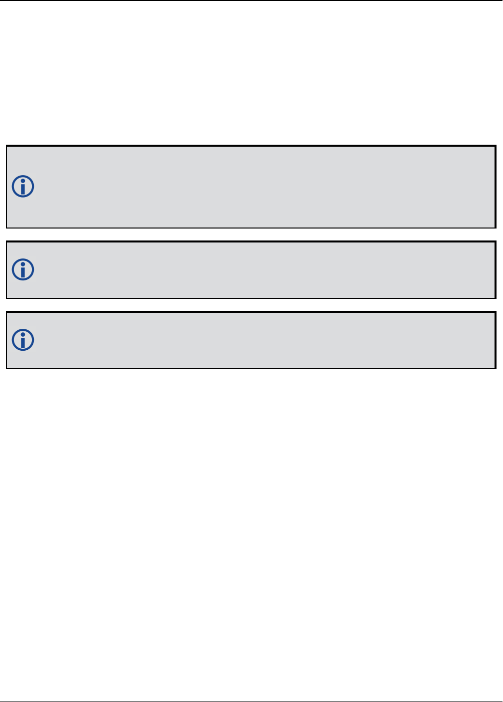
Chapter 2 Core Commands
OEM7 Commands and Logs Reference Manual v7 171
2.51 FREQUENCYOUT
Sets output pulse train available on VARF
Platform: OEM719, OEM729, OEM7500, OEM7600, OEM7700, OEM7720, PwrPak7,
SPAN CPT7
This command is used to set the output pulse train available on the Variable Frequency (VARF)
or EVENT_OUT1 pin. The output waveform is coherent with the 1PPS output, see the usage note
and Figure 4: Pulse Width and 1PPS Coherency on the next page.
If the CLOCKADJUST command (see page 101) command is ENABLED and the receiver
is configured to use an external reference frequency (set in the EXTERNALCLOCK com-
mand (see page 146) for an external clock - TCXO, OCXO, RUBIDIUM, CESIUM, or
USER), then the clock steering process takes over the VARF output pins and may conflict
with a previously entered FREQUENCYOUT command.
Figure 4: Pulse Width and 1PPS Coherency on the next page shows how the chosen pulse
width is frequency locked but not necessarily phase locked when using ENABLE option.
To synchronize the phase, use ENABLESYNC option.
The EVENTOUT outputs cannot synchronize with GPS time until the receiver reaches
FINESTEERING time status. As the receiver transitions to GPS time, there may be addi-
tional, unexpected pulses on the EVENTOUT signals.
Message ID: 232
Abbreviated ASCII Syntax:
FREQUENCYOUT [switch] [pulsewidth] [period]
Factory Default:
FREQUENCYOUT disable
ASCII Example:
FREQUENCYOUT ENABLE 2 4
This example generates a 50% duty cycle 25 MHz square wave.
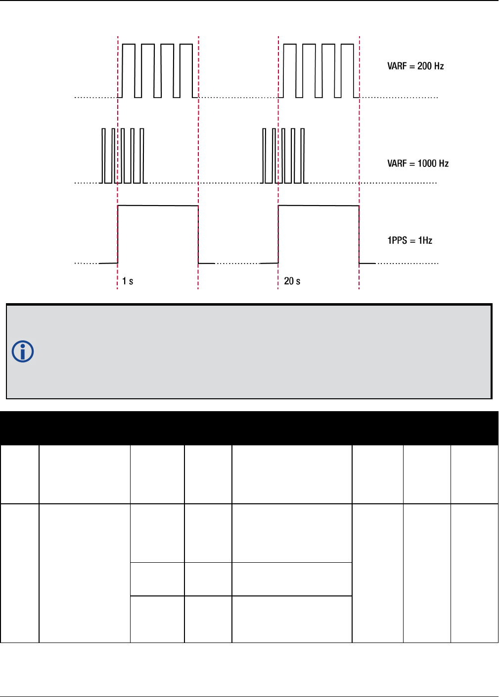
Chapter 2 Core Commands
OEM7 Commands and Logs Reference Manual v7 172
Figure 4: Pulse Width and 1PPS Coherency
When using ENABLE option, the VARF and 1PPS are not necessarily in phase as described
in Figure 4: Pulse Width and 1PPS Coherency above. To align the phase of the VARF with
the 1PPS, use the ENABLESYNC option and the VARF phase will be synchronized to the
leading edge of the 1PPS pulse. Note that if the VARF and 1PPS frequencies are not even
multiples of each other, this may cause the VARF to have a shorter cycle pulse prior to
each 1PPS pulse. 1PPS is not affected.
Field Field Type ASCII
Value
Binary
Value Description Format Binary
Bytes
Binary
Offset
1FREQUENCYOUT
header - -
Command header.
See Messages on
page25 for more
information.
- H 0
2 switch
DISABLE 0
Disable causes the
output to be fixed low
(if NONE specified,
defaults to DISABLE)
Enum 4 H
ENABLE 1 Enables customized
frequency output
ENABLE
SYNC 2
Enable customized
frequency output
synchronized to PPS

Chapter 2 Core Commands
OEM7 Commands and Logs Reference Manual v7 173
Field Field Type ASCII
Value
Binary
Value Description Format Binary
Bytes
Binary
Offset
3 pulsewidth (0 to 1073741823)
Number of 10 ns
steps for which the
output is high.
Duty cycle =
pulsewidth / period. If
pulsewidth is greater
than or equal to the
period, the output is a
high DC signal. If
pulsewidth is 1/2 the
period, then the
output is a square
wave (default = 0)
Ulong 4 H+4
4 period (0 to 1073741823)
Signal period in 10 ns
steps.
Frequency Output =
100,000,000 / Period
(default = 0)
Ulong 4 H+8

Chapter 2 Core Commands
OEM7 Commands and Logs Reference Manual v7 174
2.52 FRESET
Clears selected data from NVM and reset
Platform: OEM719, OEM729, OEM7500, OEM7600, OEM7700, OEM7720, PwrPak7,
SPAN CPT7
This command is used to clear data which is stored in non-volatile memory. Such data includes
the almanac, ephemeris, and any user specific configurations. The commands, ephemeris,
almanac, and L-Band related data, excluding the subscription information, can be cleared by
using the STANDARD target. The receiver is forced to reset.
FRESET STANDARD (which is also the default) causes most commands, ephemeris,
GNSS and almanac data previously saved to NVM to be erased.
The FRESET STANDARD command will erase all user settings. You should know your
configuration (by requesting the RXCONFIG log on page746) and be able to reconfigure
the receiver before you send the FRESET command.
Message ID: 20
Abbreviated ASCII Syntax:
FRESET [target]
Input Example:
FRESET COMMAND
Field Field
Type
ASCII
Value
Binary
Value Description Format Binary
Bytes
Binary
Offset
1FRESET
header - -
Command header. See
Messages on page25 for
more information.
- H 0
2 target
See Table 40:
FRESET Target on
the next page
What data is to be reset by
the receiver (default =
STANDARD)
Enum 4 H

Chapter 2 Core Commands
OEM7 Commands and Logs Reference Manual v7 175
If you are receiving no data or random data from your receiver, try the following before
contacting NovAtel:
lVerify that the receiver is tracking satellites by logging the TRACKSTAT log (see
page 841) and checking that the receiver is tracking at least four satellites.
lCheck the integrity and connectivity of power and data cables
lVerify the baud rate settings of the receiver and terminal device (your PC, data log-
ger or laptop)
lSwitch COM ports
lIssue the FRESET command.
Binary ASCII Description
0 STANDARD
Resets commands (except CLOCKCALIBRATION and MODEL),
ephemeris and almanac (default).
Also resets all L-Band related data except for the subscription
information.
Does not reset the Ethernet settings or stored Profile configurations.
1 COMMAND Resets the stored commands (saved configuration)
2 GPSALMANAC Resets the stored GPS almanac
3 GPSEPHEM Resets the stored GPS ephemeris
4 GLOEPHEM Resets the stored GLONASS ephemeris
5 MODEL Resets the currently selected model
10 USERDATA Resets the user data saved using the NVMUSERDATA command
(see page 253)
11 CLKCALIBRATION Resets the parameters entered using the CLOCKCALIBRATE
command (see page 103)
20 SBASALMANAC Resets the stored SBAS almanac
21 LAST_POSITION Resets the position using the last stored position
31 GLOALMANAC Resets the stored GLONASS almanac
39 GALFNAV_EPH Resets the stored GALFNAV ephemeris
40 GALINAV_EPH Resets the stored GALINAV ephemeris
45 GALFNAV_ALM Resets the stored GALFNAV almanac
46 GALINAV_ALM Resets the stored GALINAV almanac
Table 40: FRESET Target

Chapter 2 Core Commands
OEM7 Commands and Logs Reference Manual v7 176
Binary ASCII Description
52 PROFILEINFO Resets the stored profile configurations
54 QZSSALMANAC Resets the QZSS almanac
55 QZSSEPHEMERIS Resets the QZSS ephemeris
57 BDSALMANAC Resets the BeiDou almanac
58 BDSEPHEMERIS Resets the BeiDou ephemeris
60 USER_ACCOUNTS Resets the admin password to the default (the receiver PSN)
64 ETHERNET Resets the stored Ethernet settings
85 SRTK_
SUBSCRIPTIONS Resets the Secure RTK Subscription data stored on the rover receiver
87 NAVICEPHEMERIS Resets the NavIC ephemeris
88 NAVICALMANAC Resets the NavIC almanac

Chapter 2 Core Commands
OEM7 Commands and Logs Reference Manual v7 177
2.53 GALECUTOFF
Sets elevation cut-off angle for Galileo satellites
Platform: OEM719, OEM729, OEM7500, OEM7600, OEM7700, OEM7720, PwrPak7,
SPAN CPT7
This command is used to set the elevation cut-off angle for tracked Galileo satellites. The
receiver does not start automatically searching for a satellite until it rises above the cut-off
angle (when satellite position is known). Tracked satellites that fall below the cut-off angle are
no longer tracked unless they were manually assigned (see the ASSIGN command on page65).
In either case, satellites below the GALECUTOFF angle are eliminated from the internal position
and clock offset solution computations.
This command permits a negative cut-off angle and can be used in the following situations:
lThe antenna is at a high altitude and thus look below the local horizon
lSatellites are visible below the horizon due to atmospheric refraction
Care must be taken when using GALECUTOFF because the signals from lower elevation
satellites are traveling through more atmosphere and are therefore degraded. Use of
satellites below 5 degrees is not recommended.
Use the ELEVATIONCUTOFF command (see page 136) to set the cut-off angle for any
system.
For dual antenna receivers, this command applies to both the primary and secondary
antennas.
Message ID: 1114
Abbreviated ASCII Syntax:
GALECUTOFF angle
Factory Default:
GALECUTOFF 5.0
ASCII Example:
GALECUTOFF 10.0

Chapter 2 Core Commands
OEM7 Commands and Logs Reference Manual v7 178
Field Field Type ASCII
Value
Binary
Value Description Format Binary
Bytes
Binary
Offset
1GALECUTOFF
header - -
Command header. See
Messages on page25 for
more information.
- H 0
2 angle ±90.0 degrees Elevation cut-off angle
relative to horizon Float 4 H

Chapter 2 Core Commands
OEM7 Commands and Logs Reference Manual v7 179
2.54 GENERATEALIGNCORRECTIONS
Configure ALIGN Master
Platform: OEM719, OEM729, OEM7500, OEM7600, OEM7700, OEM7720, PwrPak7,
SPAN CPT7
This command is used to configure the ALIGN Master and starts sending out ALIGN corrections
through the specified port. This command is like sending the following commands to the Master,
assuming the use of a serial port and default ALIGN corrections:
unlogall [port]
fix none
movingbasestation enable
interfacemode [port] novatel rtca
serialconfig [port] [baud] N 8 1 N ON
log [port] rtcaobs3 ontime [rate = 1/ obsreqrate]
log [port] rtcarefext ontime [rate = 1/ refextreqrate]
Message ID: 1349
Abbreviated ASCII Syntax:
GENERATEALIGNCORRECTIONS port [baud] [obsreqrate] [refextreqrate]
[interfacemode]
ASCII Example:
GENERATEALIGNCORRECTIONS COM2 230400 10 10
Field Field Type ASCII
Value
Binary
Value Description Format Binary
Bytes
Binary
Offset
1
GENERATEALIGN
CORRECTIONS
header
- -
Command header.
See Messages on
page25 for more
information.
- H 0
2 port
See Table 31:
Communications Port
Identifiers on
page132
Port identifier
(default =
THISPORT)
Enum 4 H
3 baud
9600, 19200, 38400,
57600, 115200,
230400 or 460800
Communication
baud rate (bps)
(default = 9600)
Ulong 4 H+4
4 obsreqrate 1, 2, 4, 5, 10, 20, 50
or 100
RTCAOBS3 data
rate in Hz
(default = 1)
Ulong 4 H+8
5 refextreqrate 0, 1, 2, 4, 5, 10, 20,
50 or 100
RTCAREFEXT data
rate in Hz
(default = 1)
Ulong 4 H+12

Chapter 2 Core Commands
OEM7 Commands and Logs Reference Manual v7 180
Field Field Type ASCII
Value
Binary
Value Description Format Binary
Bytes
Binary
Offset
6 interfacemode
RTCA 3 Correction
interface mode
(default = RTCA)
Enum 4 H+16
NOVATELX 35

Chapter 2 Core Commands
OEM7 Commands and Logs Reference Manual v7 181
2.55 GENERATEDIFFCORRECTIONS
Sends a preconfigured set of differential corrections
Platform: OEM719, OEM729, OEM7500, OEM7600, OEM7700, OEM7720, PwrPak7,
SPAN CPT7
This command is used to configure the receiver to send a preconfigured set of differential pseu-
dorange corrections.
Message ID: 1296
Abbreviated ASCII Syntax:
GENERATEDIFFCORRECTIONS mode port
ASCII Example:
GENERATEDIFFCORRECTIONS rtcm com2
Preconfigured set of differential corrections sent when RTCM:
RTCM1 ontime 1
RTCM31 ontime 1
RTCM3 ontime 10
Preconfigured set of differential corrections sent when RTCA:
RTCA1 ontime 1
RTCAREF ontime 10
Field Field Type ASCII
Value
Binary
Value Description Format Binary
Bytes
Binary
Offset
1
GENERATEDIFF
CORRECTIONS
header
- -
Command header. See
Messages on page25
for more information.
- H 0
2 mode
RTCM 2 Serial port interface
mode identifier. See
Table 41: Serial Port
Interface Modes on
page196
Enum 4 H
RTCA 3
3 port
See Table 58:
COM Port
Identifiers on
page333
Port to configure Enum 4 H+4

Chapter 2 Core Commands
OEM7 Commands and Logs Reference Manual v7 182
2.56 GENERATERTKCORRECTIONS
Sends a preconfigured set of RTK corrections
Platform: OEM719, OEM729, OEM7500, OEM7600, OEM7700, OEM7720, PwrPak7,
SPAN CPT7
This command is used to configure the receiver to send a preconfigured set of RTK (carrier
phase) corrections.
Message ID: 1260
Abbreviated ASCII Syntax:
GENERATERTKCORRECTIONS mode port
ASCII Example:
GENERATERTKCORRECTIONS rtcmv3 com2
Preconfigured set of differential corrections sent when RTCM:
RTCM1819 ontime 1
RTCM3 ontime 10
RTCM22 ontime 10
RTCM23 ontime 60
RTCM24 ontime 60
Preconfigured set of differential corrections sent when RTCMV3:
RTCM1004 ontime 1
RTCM1012 ontime 1
RTCM1006 ontime 10
RTCM1008 ontime 10
RTCM1033 ontime 10
Preconfigured set of differential corrections sent when RTCA:
RTCAOBS2 ontime 1
RTCAREF ontime 10
Preconfigured set of differential corrections sent when CMR:
CMROBS ontime 1
CMRGLOOBS ontime 1
CMRREF ontime 10
Preconfigured set of differential corrections sent when NOVATELX COM2:
NOVATELXOBS ontime 1

Chapter 2 Core Commands
OEM7 Commands and Logs Reference Manual v7 183
Field Field Type ASCII
Value
Binary
Value Description Format Binary
Bytes
Binary
Offset
1
GENERATERTK
CORRECTIONS
header
- -
Command header.
See Messages on
page25 for more
information.
- H 0
2 mode
RTCM 2 Serial port interface
mode identifier. For
more information,
see Table 41: Serial
Port Interface Modes
on page196
Enum 4 H
RTCA 3
CMR 4
RTCMV3 14
NOVATELX 35
3 port
See Table 58: COM
Port Identifiers on
page333
Port to configure Enum 4 H+4
For information about the RTCM, RTCA and CMR messages, refer to the official standards
document for those messages.

Chapter 2 Core Commands
OEM7 Commands and Logs Reference Manual v7 184
2.57 GGAQUALITY
Customizes the GPGGA GPS quality indicator
Platform: OEM719, OEM729, OEM7500, OEM7600, OEM7700, OEM7720, PwrPak7,
SPAN CPT7
This command is used to customize the NMEA GPGGA GPS quality indicator. See also the
GPGGA log on page510.
Message ID: 691
Abbreviated ASCII Syntax:
GGAQUALITY #entries pos_type quality
Input Example 1:
GGAQUALITY 1 waas 2
Makes the WAAS solution type show 2 as the quality indicator.
Input Example 2:
GGAQUALITY 2 waas 2 NARROW_FLOAT 3
Makes the WAAS solution type show 2 and the NARROW_FLOAT solution type show 3, as their
quality indicators.
Input Example 3:
GGAQUALITY 0
Sets all the quality indicators back to the default.
Some solution types, see Table 74: Position or Velocity Type on page432, share a qual-
ity indicator. For example, converged PPP and NARROW_FLOAT all share an indicator of
5. This command can be used to customize an application to have unique indicators for
each solution type. Sets all the quality indicators back to the default. Refer to Table 97:
GPS Quality Indicators on page512.
Field Field Type ASCII
Value
Binary
Value Description Format Binary
Bytes
Binary
Offset
1GGAQUALITY
header - -
Command header. See
Messages on page25 for
more information.
- H 0
2 #entries 0-20
The number of position
types that are being
remapped (20 max)
Ulong 4 H

Chapter 2 Core Commands
OEM7 Commands and Logs Reference Manual v7 185
Field Field Type ASCII
Value
Binary
Value Description Format Binary
Bytes
Binary
Offset
3 pos_type
See Table 74:
Position or
Velocity Type on
page432
The position type that is
being remapped Enum 4 H+4
4 quality
See Table 97:
GPS Quality
Indicators on
page512
The remapped quality
indicator value that will
appear in the GPGGA log
for this position type
Ulong 4 H+8
... Next solution type and quality indicator set, if applicable Variable

Chapter 2 Core Commands
OEM7 Commands and Logs Reference Manual v7 186
2.58 GLIDEINITIALIZATIONPERIOD
Configures the GLIDE initialization period
Platform: OEM719, OEM729, OEM7500, OEM7600, OEM7700, OEM7720, PwrPak7,
SPAN CPT7
This command sets the initialization period for Relative PDP (GLIDE) when pseudorange meas-
urements are used more heavily. During the initialization period, the PDP output position is not
as smooth as during full GLIDE operation, but it helps to get better absolute accuracy at the
start. The longer this period is, the better the absolute accuracy that can be attained. The max-
imum period that can be set through GLIDEINITIALIZATIONPERIOD is 1200 seconds.
Message ID: 1760
Abbreviated ASCII Syntax:
GLIDEINITIALIZATIONPERIOD initialization
Factory Default:
GLIDEINITIALIZATIONPERIOD 300
ASCII Example:
GLIDEINITIALIZATIONPERIOD 100
Field Field Type ASCII
Value
Binary
Value Description Binary
Format
Binary
Bytes
Binary
Offset
1GLIDEINITIALIZATION
PERIOD header - -
Command
header. See
Messages on
page25 for more
information.
- H 0
2 initialization 0 -1200 s
Initialization
period for GLIDE
in seconds
Double 8 H

Chapter 2 Core Commands
OEM7 Commands and Logs Reference Manual v7 187
2.59 GLOECUTOFF
Sets GLONASS satellite elevation cut-off
Platform: OEM719, OEM729, OEM7500, OEM7600, OEM7700, OEM7720, PwrPak7,
SPAN CPT7
This command is used to set the elevation cut-off angle for tracked GLONASS satellites. The
receiver does not start automatically searching for a satellite until it rises above the cut-off
angle (when satellite position is known). Tracked satellites that fall below the cut-off angle are
no longer tracked unless they were manually assigned (see the ASSIGN command on page65).
In either case, satellites below the GLOECUTOFF angle are eliminated from the internal position
and clock offset solution computations.
This command permits a negative cut-off angle and can be used in the following situations:
lThe antenna is at a high altitude and can look below the local horizon
lSatellites are visible below the horizon due to atmospheric refraction
Care must be taken when using GLOECUTOFF because the signals from lower elevation
satellites are traveling through more atmosphere and are therefore degraded. Use of
satellites below 5 degrees is not recommended.
Use the ELEVATIONCUTOFF command (see page 136) to set the cut-off angle for any
system.
For dual antenna receivers, this command applies to both the primary and secondary
antennas.
Message ID: 735
Abbreviated ASCII Syntax:
GLOECUTOFF angle
Factory Default:
GLOECUTOFF 5.0
ASCII Example:
GLOECUTOFF 0

Chapter 2 Core Commands
OEM7 Commands and Logs Reference Manual v7 188
Field Field Type ASCII
Value
Binary
Value Description Format Binary
Bytes
Binary
Offset
1GLOECUTOFF
header - -
Command header. See
Messages on page25 for
more information.
- H 0
2 angle ±90.0 degrees Elevation cut-off angle
relative to horizon Float 4 H

Chapter 2 Core Commands
OEM7 Commands and Logs Reference Manual v7 189
2.60 HDTOUTTHRESHOLD
Controls GPHDT log output
Platform: OEM719, OEM729, OEM7500, OEM7600, OEM7700, OEM7720, PwrPak7,
SPAN CPT7
This command is used to control the output of the NMEA GPHDT log (see page 525). It sets a
heading standard deviation threshold. Only heading information with a standard deviation less
than this threshold can be output into a GPHDT message.
Message ID: 1062
Abbreviated ASCII Syntax:
HDTOUTTHRESHOLD thresh
Factory Default:
HDTOUTTHRESHOLD 2.0
ASCII Example:
HDTOUTTHRESHOLD 12.0
Field Field Type ASCII
Value
Binary
Value Description Format Binary
Bytes
Binary
Offset
1HDTOUTTHRESHOLD
header - -
Command header.
See Messages on
page25 for more
information.
- H 0
2 thresh 0.0 - 180.0
Heading standard
deviation threshold
(degrees)
Float 4 H

Chapter 2 Core Commands
OEM7 Commands and Logs Reference Manual v7 190
2.61 HEADINGOFFSET
Adds heading and pitch offset values
Platform: OEM719, OEM729, OEM7500, OEM7600, OEM7700, OEM7720, PwrPak7,
SPAN CPT7
This command is used to add an offset in the heading and pitch values of the HEADING2 log
(see page 539) and GPHDT log (see page 525).
Message ID: 1082
Abbreviated ASCII Syntax:
HEADINGOFFSET headingoffsetindeg [pitchoffsetindeg]
Factory Default:
HEADINGOFFSET 0 0
ASCII Example:
HEADINGOFFSET 2 -1
Field Field Type ASCII
Value
Binary
Value Description Format Binary
Bytes
Binary
Offset
1HEADINGOFFSET
header - -
Command header.
See Messages on
page25 for more
information.
- H 0
2 headingoffsetindeg -180.0 - 180.0
Offset added to
heading output
(degrees). Default=0
Float 4 H
3 pitchoffsetindeg -90.0 - 90.0
Offset added to pitch
output (degrees).
Default=0
Float 4 H+4
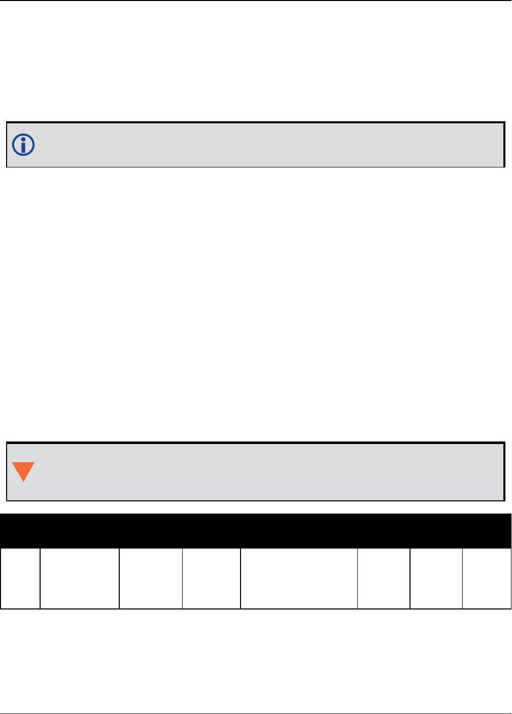
Chapter 2 Core Commands
OEM7 Commands and Logs Reference Manual v7 191
2.62 ICOMCONFIG
Configures IP virtual COM port
Platform: OEM729, OEM7600, OEM7700, OEM7720, PwrPak7, SPAN CPT7
This command is used for Ethernet set up and to configure the transport/application layer of the
configuration.
Access to the ICOM ports can be restricted by turning on ICOM security using the
IPSERVICE command (see page 202).
Message ID: 1248
Abbreviated ASCII Syntax:
ICOMCONFIG [port] protocol [endpoint[bindinterface]]
Factory Default:
ICOMCONFIG ICOM1 TCP :3001
ICOMCONFIG ICOM2 TCP :3002
ICOMCONFIG ICOM3 TCP :3003
ICOMCONFIG ICOM4 TCP :3004
ICOMCONFIG ICOM5 TCP :3005
ICOMCONFIG ICOM6 TCP :3006
ICOMCONFIG ICOM7 TCP :3007
ASCII Example:
ICOMCONFIG ICOM1 TCP :2000 All
Due to security concerns, configuring and enabling ICOM ports should only be done to
receivers on a closed system, that is, board-to-board. NovAtel is not liable for any secur-
ity breaches that may occur if not used on a closed system.
Field Field Type ASCII
Value
Binary
Value Data Description Format Binary
Bytes
Binary
Offset
1ICOMCONFIG
Header - -
Command header.
See Messages on
page25 for more
information.
- H 0

Chapter 2 Core Commands
OEM7 Commands and Logs Reference Manual v7 192
Field Field Type ASCII
Value
Binary
Value Data Description Format Binary
Bytes
Binary
Offset
2 port
THISPORT 6
Name of the port
(default =
THISPORT).
Enum 4 H
ICOM1 23
ICOM2 24
ICOM3 25
ICOM4 29
ICOM5 46
ICOM6 47
ICOM7 48
3 protocol
DISABLED 1 Will disable the
service
Enum 4 H+4
TCP 2 Use Raw TCP
UDP 3 Use Raw UDP
4 endpoint
Host:Port
For example:
10.0.3.1:8000
mybase.com:3000
Endpoint to wait on,
or to connect to
where host is a host
name or IP address
and port is the
TCP/UDP port
number. If host is
blank, act as a
server
String
[80]
variable
1H+8
5 bindInterface ALL
(default) 1
Not supported. Set
to ALL for future
compatibility.
Enum 4 H+88
1In the binary case, each string field needs to be NULL terminated and additional bytes of padding added to
maintain 4-byte alignment, up to the maximum defined by the string size. The next defined field starts
immediately at the next 4-byte alignment following the NULL.

Chapter 2 Core Commands
OEM7 Commands and Logs Reference Manual v7 193
2.63 INTERFACEMODE
Sets receive or transmit modes for ports
Platform: OEM719, OEM729, OEM7500, OEM7600, OEM7700, OEM7720, PwrPak7,
SPAN CPT7
This command is used to specify what type of data a particular port on the receiver can transmit
and receive. The receive type tells the receiver what type of data to accept on the specified port.
The transmit type tells the receiver what kind of data it can generate. For example, to accept
RTCMV3 differential corrections, set the receive type on the port to RTCMV3.
It is also possible to disable or enable the generation or transmission of command responses for
a particular port. Disabling of responses is important for applications where data is required in a
specific form and the introduction of extra bytes may cause problems, i.e., RTCA, RTCM,
RTCMV3 or CMR. Disabling a port prompt is also useful when the port is connected to a modem
or other device that responds with data the RECEIVER does not recognize.
For applications running in specific interface modes, see Table 41: Serial Port Interface
Modes on page196, please set the appropriate interface modes before sending or receiv-
ing corrections. It is important that the port interface mode matches the data being
received on that port. Mismatches between the interface mode and received data can
result in CPU overloads.
When INTERFACEMODE port NONE NONE OFF is set, the specified port is disabled from inter-
preting any input or output data. Therefore, no commands or differential corrections are
decoded by the specified port. When GENERIC is set for a port, it is also disabled but data can be
passed through the disabled port and be output from an alternative port using the pass-through
logs PASSCOM, PASSAUX and PASSUSB. See PASSCOM, PASSAUX, PASSUSB, PASSETH1,
PASSICOM, PASSNCOM on page624 for details on these logs along with the Operation chapter in
the OEM7 Installation and Operation User Manual for information about pass-through logging.
See also the SERIALCONFIG command on page331.If you intend to use the SERIALCONFIG
command (see page 331), ensure you do so before the INTERFACEMODE command on each
port. The SERIALCONFIG command (see page 331) can remove the INTERFACEMODE com-
mand setting if the baud rate is changed after the interface mode is set. You should also turn
break detection off using the SERIALCONFIG command (see page 331) to stop the port from
resetting because it is interpreting incoming bits as a break command. If such a reset happens,
the Interface mode will be set back to the default NOVATEL mode for both input and output.
2.63.1 SPAN Systems
The INTERFACEMODE of the receiver is also configured for the serial port dedicated to the IMU.
This mode changes automatically upon sending a CONNECTIMU command (see page 864) and
the change is reflected when logging this command. This is normal operation.
When the CONNECTIMU command (see page 864) is used to configure the IMU con-
nected to the receiver, the correct interface mode for the IMU port is automatically set.
The IMU port should not be altered using the INTERFACEMODE command in normal
operation. Doing so may result in the loss of IMU communication.

Chapter 2 Core Commands
OEM7 Commands and Logs Reference Manual v7 194
Message ID: 3
Abbreviated ASCII Syntax:
INTERFACEMODE [port] rxtype txtype [responses]
Factory Default:
INTERFACEMODE COM1 NOVATEL NOVATEL ON
INTERFACEMODE COM2 NOVATEL NOVATEL ON
INTERFACEMODE COM3 NOVATEL NOVATEL ON
INTERFACEMODE AUX NOVATEL NOVATEL ON
INTERFACEMODE USB1 NOVATEL NOVATEL ON
INTERFACEMODE USB2 NOVATEL NOVATEL ON
INTERFACEMODE USB3 NOVATEL NOVATEL ON
INTERFACEMODE ICOM1 NOVATEL NOVATEL ON
INTERFACEMODE ICOM2 NOVATEL NOVATEL ON
INTERFACEMODE ICOM3 NOVATEL NOVATEL ON
INTERFACEMODE ICOM4 NOVATEL NOVATEL ON
INTERFACEMODE ICOM5 NOVATEL NOVATEL ON
INTERFACEMODE ICOM6 NOVATEL NOVATEL ON
INTERFACEMODE ICOM7 NOVATEL NOVATEL ON
INTERFACEMODE NCOM1 RTCMV3 NONE OFF
INTERFACEMODE NCOM2 RTCMV3 NONE OFF
INTERFACEMODE NCOM3 RTCMV3 NONE OFF
INTERFACEMODE CCOM1 NOVATELBINARY NOVATELBINARY ON
INTERFACEMODE CCOM2 NOVATELBINARY NOVATELBINARY ON
INTERFACEMODE CCOM3 AUTO NOVATEL OFF
INTERFACEMODE CCOM4 AUTO NOVATEL OFF
INTERFACEMODE CCOM5 AUTO NOVATEL OFF
INTERFACEMODE CCOM6 AUTO NOVATEL OFF
INTERFACEMODE SCOM1 NOVATEL NOVATEL ON
INTERFACEMODE SCOM2 NOVATEL NOVATEL ON
INTERFACEMODE SCOM3 NOVATEL NOVATEL ON
INTERFACEMODE SCOM4 NOVATEL NOVATEL ON
ASCII Example 1:
INTERFACEMODE COM1 RTCMV3 NOVATEL ON
ASCII Example 2:
INTERFACEMODE COM2 MRTCA NONE

Chapter 2 Core Commands
OEM7 Commands and Logs Reference Manual v7 195
Are NovAtel receivers compatible with others on the market?
All GNSS receivers output two solutions: position and time. The manner in which they
output them makes each receiver unique. Most geodetic and survey grade receivers
output the position in electronic form (typically RS-232), which makes them compatible
with most computers and data loggers. All NovAtel receivers have this ability. However,
each manufacturer has a unique way of formatting the messages. A NovAtel receiver is
not directly compatible with a Trimble or Ashtech receiver (which are also incompatible
with each other) unless everyone uses a standard data format.
However, there are several standard data formats available. For position and navigation
output there is the NMEA format. Real-time differential corrections use RTCM or RTCA
format. For receiver code and phase data RINEX format is often used. NovAtel and all
other major manufacturers support these formats and can work together using them.
The NovAtel format measurement logs can be converted to RINEX using the utilities
provided in NovAtel Connect.
Field Field Type ASCII
Value
Binary
Value Description Format Binary
Bytes
Binary
Offset
1INTERFACEMODE
header - -
Command header.
See Messages on
page25 for more
information.
- H 0
2 port
See Table 31:
Communications
Port Identifiers on
page132
Serial port
identifier
(default =
THISPORT)
Enum 4 H
3 rxtype
See Table 41:
Serial Port
Interface Modes on
the next page
Receive interface
mode Enum 4 H+4
4 txtype
See Table 41:
Serial Port
Interface Modes on
the next page
Transmit interface
mode Enum 4 H+8
5 responses
OFF 0 Turn response
generation off
Enum 4 H+12
ON 1
Turn response
generation on
(default)

Chapter 2 Core Commands
OEM7 Commands and Logs Reference Manual v7 196
Binary
Value ASCII Value Description
0 NONE The port accepts/generates nothing. The port is disabled
1 NOVATEL The port accepts/generates NovAtel commands and logs
2 RTCM The port accepts/generates RTCM corrections
3 RTCA The port accepts/generates RTCA corrections
4 CMR The port accepts/generates CMR corrections
5 Reserved
6 Reserved
7 IMU This port supports communication with a NovAtel supported IMU.
8 RTCMNOCR
When RTCMNOCR is used as the txtype, the port generates RTCM
corrections without the CR/LF appended.
When RTCMNOCR is used as the rxtype, the port accepts RTCM
corrections with or without the CR/LF appended.
9 Reserved
10 TCOM1
INTERFACEMODE tunnel modes. To configure a full duplex tunnel,
configure the baud rate on each port. Once a tunnel is established,
the baud rate does not change. Special characters, such as a
BREAK condition, do not route across the tunnel transparently and
the serial port is altered, see the SERIALCONFIG command on
page331. Only serial ports may be in a tunnel configuration:
COM1, COM2, COM3 or AUX may be used.
For example, configure a tunnel at 115200 bps between COM1 and
AUX:
SERIALCONFIG AUX 115200
SERIALCONFIG COM1 115200
INTERFACEMODE AUX TCOM1 NONE OFF
INTERFACEMODE COM1 TAUX NONE OFF
The tunnel is fully configured to receive/transmit at a baud rate of
115200 bps
11 TCOM2
12 TCOM3
13 TAUX 1
14 RTCMV3 The port accepts/generates RTCM Version 3.0 corrections
Table 41: Serial Port Interface Modes
1Only available on specific models.

Chapter 2 Core Commands
OEM7 Commands and Logs Reference Manual v7 197
Binary
Value ASCII Value Description
15 NOVATELBINARY
The port only accepts/generates binary messages. If an ASCII
command is entered when the mode is set to binary only, the
command is ignored. Only properly formatted binary messages
are responded to and the response is a binary message
16-17 Reserved
18 GENERIC
The port accepts/generates nothing. The SEND command (see
page 328) or SENDHEX command (see page 330) from another
port generate data on this port. Any incoming data on this port can
be seen with PASSCOM logs on another port, see PASSCOM,
PASSAUX, PASSUSB, PASSETH1, PASSICOM, PASSNCOM log
on page624
19 IMARIMU This port supports communication with an iMAR IMU.
20 MRTCA The port accepts/generates Modified Radio Technical Commission
for Aeronautics (MRTCA) corrections
21-22 Reserved
23 KVHIMU This port supports communication with a KVH CG5100 IMU.
24-26 Reserved
27 AUTO
For auto-detecting different RTK correction formats and incoming
baud rate (over serial ports).
The change of baud rate will not appear when SERIALCONFIG is
logged as this shows the saved baud rate for that port.
28-34 Reserved
35 NOVATELX The port accepts/generates NOVATELX corrections
36-40 Reserved
41 KVH1750IMU This port supports communication with a KVH 17xx series IMU.
42-45 Reserved
46 TCCOM1 CCOM1 Tunnel
47 TCCOM2 CCOM2 Tunnel
48 TCCOM3 CCOM3 Tunnel
49 NOVATELMINBINARY NovAtel binary message with a minimal header.
Only available for CCOM ports.
50 TCCOM4 CCOM4 Tunnel

Chapter 2 Core Commands
OEM7 Commands and Logs Reference Manual v7 198
Binary
Value ASCII Value Description
51 TCCOM5 CCOM5 Tunnel
52 TCCOM6 CCOM6 Tunnel
53-57 Reserved
60 TSCOM1 SCOM1 Tunnel
61 TSCOM2 SCOM2 Tunnel
62 TSCOM3 SCOM3 Tunnel
63 TSCOM4 SCOM4 Tunnel
64 LUA Lua stdin/stdout/stderr.
Use the LUA PROMPT command to set this Interface Mode.

Chapter 2 Core Commands
OEM7 Commands and Logs Reference Manual v7 199
2.64 IONOCONDITION
Sets ionospheric condition
Platform: OEM719, OEM729, OEM7500, OEM7600, OEM7700, OEM7720, PwrPak7,
SPAN CPT7
This command is used to change the level of ionosphere activity that is assumed by the RTK pos-
itioning algorithms.
Only advanced users should use this command.
Message ID: 1215
Abbreviated ASCII Syntax:
IONOCONDITION mode
Factory Default:
IONOCONDITION AUTO
ASCII Example:
IONOCONDITION normal
Field Field Type ASCII
Value
Binary
Value Description Format Binary
Bytes
Binary
Offset
1IONOCONDITION
header - -
Command header.
See Messages on
page25 for more
information.
H
2 mode
quiet 0
Receiver assumes a
low level of
ionosphere activity
Enum 4 H
normal 1
Receiver assumes a
medium level of
ionosphere activity
disturbed 2
Receiver assumes a
high level of
ionosphere activity
AUTO 10
Receiver monitors
the ionosphere
activity and adapts
behavior
accordingly

Chapter 2 Core Commands
OEM7 Commands and Logs Reference Manual v7 200
2.65 IPCONFIG
Configures network IP settings
Platform: OEM729, OEM7600, OEM7700, OEM7720, PwrPak7, SPAN CPT7
This command is used to configure static/dynamic TCP/IP properties for the Ethernet con-
nection.
In addition to configuring an IP address and netmask for the interface, this command
also includes a gateway address.
Message ID: 1243
Abbreviated ASCII Syntax:
IPCONFIG [interface_name] address_mode [IP_address [netmask [gateway]]]
Factory Default:
IPCONFIG ETHA DHCP
ASCII Examples:
IPCONFIG ETHA STATIC 192.168.74.10 255.255.255.0 192.168.74.1
Field Field
Type
ASCII
Value
Binary
Value Description Format Binary
Bytes
Binary
Offset
1IPCONFIG
Header - -
Command header. See
Messages on page25 for
more information.
- H 0
2interface
name ETHA 2
Name of the Ethernet
interface
(default = ETHA)
Enum 4 H
3address
mode
DHCP 1 Use Dynamic IP address Enum 4 H+4
STATIC 2 Use Static IP address
4IP
address
ddd.ddd.ddd.ddd
(For example:
10.0.0.2)
IP Address-decimal dot
notation
String
[16]
variable
1H+8
5 netmask
ddd.ddd.ddd.ddd
(For example:
255.255.255.0)
Netmask-decimal dot
notation
String
[16]
variable
1H+24
1In the binary case, each string field needs to be NULL terminated and additional bytes of padding added to
maintain 4-byte alignment, up to the maximum defined by the string size. The next defined field starts
immediately at the next 4-byte alignment following the NULL.

Chapter 2 Core Commands
OEM7 Commands and Logs Reference Manual v7 201
Field Field
Type
ASCII
Value
Binary
Value Description Format Binary
Bytes
Binary
Offset
6 gateway
ddd.ddd.ddd.ddd
(For example:
10.0.0.1)
Gateway-decimal dot
notation
String
[16]
variable
1H+40
Chapter 2 Core Commands
OEM7 Commands and Logs Reference Manual v7 202
2.66 IPSERVICE
Configure availability of networks ports/services
Platform: OEM729, OEM7600, OEM7700, OEM7720, PwrPak7, SPAN CPT7
Use the IPSERVICE command to configure the availability of specific network ports/services.
When disabled, the service does not accept incoming connections.
On most OEM7 receivers, the FTP Server is disabled by default. The exception is the
PwrPak7 which has FTP enabled by default.
We have found two problems in the Microsoft®FTP clients contained within the Internet
Explorer®and Edge browsers which make them unsuitable for retrieving files from a
NovAtel receiver. When using a Windows®computer to transfer files off a NovAtel
receiver, we suggest using a 3rd party FTP client.
Message ID: 1575
Abbreviated ASCII Syntax:
IPSERVICE IPService switch
Factory Default:
IPSERVICE WEB_SERVER DISABLE (OEM719 and OEM7500)
IPSERVICE WEB_SERVER ENABLE (OEM729, OEM7600 OEM7700 and OEM7720)
IPSERVICE SECURE_ICOM DISABLE
ASCII Example:
IPSERVICE FTP_SERVER ENABLE
Field Field
Type
ASCII
Value
Binary
Value Description Format Binary
Bytes
Binary
Offset
1IPSERVICE
header - -
Command header. See
Messages on page25 for
more information.
- H 0

Chapter 2 Core Commands
OEM7 Commands and Logs Reference Manual v7 203
Field Field
Type
ASCII
Value
Binary
Value Description Format Binary
Bytes
Binary
Offset
2 ipservice
NO_
PORT 0 No port
Enum 4 H
FTP_
SERVER 1
FTP server port.
For most OEM7 receivers
the default = DISABLE.
For the PwrPak7 the
default = ENABLE.
WEB_
SERVER 2
Web server port
For most OEM7 receivers
the default = ENABLE.
For the OEM7500 and
OEM719 the default =
DISABLE.
SECURE_
ICOM 3
Enables or disables
security on ICOM ports.
When security is enabled,
a login is required as part
of the connection process
(see the LOGIN command
on page226).
Default= DISABLE
Note: Security in this
sense means users must
supply a name and
password before being
allowed to enter
commands on the ICOM
ports. It does not mean
there is data encryption
3 switch
DISABLE 0 Disable the IP service
specified. Enum 4 H+4
ENABLE 1 Enable the IP service
specified.

Chapter 2 Core Commands
OEM7 Commands and Logs Reference Manual v7 204
2.67 ITBANDPASSCONFIG
Enable and configure bandpass filter on receiver
Platform: OEM719, OEM729, OEM7500, OEM7600, OEM7700, OEM7720, PwrPak7,
SPAN CPT7
Use this command to apply a bandpass filter at a certain frequency to mitigate interference in
the pass band of GNSS signals. The ITBANDPASSBANK log (see page 555) provides inform-
ation on the allowable configuration settings for each frequency band. The bandpass filter is sym-
metrical in nature, which means that specifying one cutoff frequency will apply a cutoff on both
the low side and high side of the spectrum center frequency. Only one filter can be applied for
each signal.
On OEM7720 and PwrPak7D receivers, any filter enabled for GPS L2 or GLONASS L2 on
the secondary antenna will be applied to both GPS L2 and GLONASS L2. For this reason,
care must be taken to avoid attenuating the signals with a bandpass filter that is too nar-
row in bandwidth. The recommended maximum lower cutoff frequency is 1221 MHz. The
recommended minimum upper cutoff frequency is 1254 MHz.
Message ID: 1999
Abbreviated ASCII Syntax:
ITBANDPASSCONFIG frequency switch [cutofffrequency]
ASCII Example:
ITBANDPASSCONFIG gpsl5 enable 1165.975
Field Field Type ASCII
Value
Binary
Value Description Format Binary
Bytes
Binary
Offset
1ITBANDPASS
CONFIG header - -
Command header.
See Messages on
page25 for more
information.
- H 0
2 frequency
See Table 48:
Frequency Types
on page214
Set the frequency
band on which to
apply the filter
Enum 4 H
3 switch DISABLE 0 Disable filter Enum 4 H+4
ENABLE 1 Enable filter

Chapter 2 Core Commands
OEM7 Commands and Logs Reference Manual v7 205
Field Field Type ASCII
Value
Binary
Value Description Format Binary
Bytes
Binary
Offset
4 cutofffrequency
Cut off frequency for
band pass filter
(MHz).
(default = 0)
Refer to
ITBANDPASSBANK
log (see page 555) for
the allowable values.
Float 4 H+8

Chapter 2 Core Commands
OEM7 Commands and Logs Reference Manual v7 206
2.68 ITDETECTCONFIG
Enable interference detection on receiver
Platform: OEM719, OEM729, OEM7500, OEM7600, OEM7700, OEM7720, PwrPak7,
SPAN CPT7
This command is used to enable or disable interference detection on the receiver. It is applic-
able to both Spectral Analysis Detection and Statistical Analysis Detection at the same time.
Detection can be enabled on all RF paths, only one RF path (L1, L2, or L5), or no RF paths. By
default, only the RF paths connecting to the first antenna are enabled.
Message ID: 2143
Abbreviated ASCII Syntax:
ITDETECTCONFIG RFPath [reserved1] [reserved2] [reserved3]
Factory Default:
ITDETECTCONFIG all
ASCII Example:
ITDETECTCONFIG L1
ITDETECTCONFIG none
Field Field Type ASCII
Value
Binary
Value Description Format Binary
Bytes
Binary
Offset
1ITDETECTCONFIG
header - -
Command header. See
Messages on page25
for more information.
- H 0
2 RFPath
See Table 42:
RF Path
Selection below
RF path selected for
detection. By default,
all paths are turned
on. The receiver will
cycle through all
active paths.
Enum 4 H
3 reserved1 0 Reserved parameter Ulong 4 H+4
4 reserved2 0 Reserved parameter Ulong 4 H+8
5 reserved3 0 Reserved parameter Ulong 4 H+12
ASCII Value Binary Value Description
NONE 0 Turn off detection on all paths
ALL 1 Turn on detection on all paths (cycle through all active paths)
Table 42: RF Path Selection

Chapter 2 Core Commands
OEM7 Commands and Logs Reference Manual v7 207
ASCII Value Binary Value Description
L1 2 Turn on detection only on L1 path
L2 3 Turn on detection only on L2 path
L5 4 Turn on detection only on L5 path

Chapter 2 Core Commands
OEM7 Commands and Logs Reference Manual v7 208
2.69 ITFRONTENDMODE
Configure the front end mode settings
Platform: OEM719, OEM729, OEM7500, OEM7600, OEM7700, OEM7720, PwrPak7,
SPAN CPT7
Use this command to configure the front end mode for the L1, L2 and L5 RF paths to use the
default third-order CIC mode or HDR (High Dynamic Range) mode. The HDR mode is used in an
interference environment to obtain best interference rejection in general. However, the power
consumption will increase in this mode.
Message ID: 2039
Abbreviated ASCII Syntax:
ITFRONTENDMODE frequency mode
Factory Default
ITFRONTENDMODE L1 cic3
ITFRONTENDMODE L2 cic3
ITFRONTENDMODE LBAND cic3
ITFRONTENDMODE L5 cic3
ASCII Example:
ITFRONTENDMODE L1 hdr
On the OEM7500, the default mode for all frequency bands is HDR.
Field Field Type ASCII
Value
Binary
Value Description Format Binary
Bytes
Binary
Offset
1ITFRONTENDMODE
header - -
Command header.
See Messages on
page25 for more
information.
- H 0
2 frequency
See Table 43:
Frequency Bands
on the next page
Set the frequency
band for
adjustment
Enum 4 H
3 mode
See Table 44:
Mode on the next
page
Select the desired
mode Enum 4 H+4

Chapter 2 Core Commands
OEM7 Commands and Logs Reference Manual v7 209
Binary Value ASCII Value Description
2 L1 Selects the L1 frequency
3 L2 Selects the L2 frequency
4 LBAND Selects the L-Band frequency
5 L5 Selects the L5 frequency
Table 43: Frequency Bands
Binary Value ASCII Value Description
0 CIC3 3rd order CIC (CIC3) mode (default)
1 HDR High Dynamic Range (HDR) mode
Table 44: Mode

Chapter 2 Core Commands
OEM7 Commands and Logs Reference Manual v7 210
2.70 ITPROGFILTCONFIG
Enable and configure filtering on the receiver
Platform: OEM719, OEM729, OEM7500, OEM7600, OEM7700, OEM7720, PwrPak7,
SPAN CPT7
Use this command to set the programmable filter to be either a notch filter or a bandpass filter
to mitigate interference in the pass band of GNSSsignals. The notch filter is used to attenuate a
very narrow band of frequencies (specified by the notch width) around the center frequency.
The bandpass filter is symmetrical in nature, which means that specifying one cutoff frequency
will apply a cutoff on both the low side and high side of the spectrum center frequency.
The ITPROGFILTBANK log (see page 563) provides information on the allowable configuration
settings for the programmable filter (i.e. the allowable settings for the notch filter and bandpass
filter) for each frequency band. Only one filter can be applied for each frequency.
Message ID: 2000
Abbreviated ASCII Syntax:
ITPROGFILTCONFIG frequency filterid switch [filtermode] [cutofffreq]
[notchwidth]
ASCII Example:
ITPROGFILTCONFIG gpsl1 pf0 enable notchfilter 1580 1
Field Field Type ASCII
Value
Binary
Value Description Format Binary
Bytes
Binary
Offset
1
ITPROGFILT
CONFIG
header
- -
Command header. See
Messages on page25
for more information.
- H 0
2 frequency
See Table 48:
Frequency Types on
page214
Set the frequency band
on which to apply the
filter
Enum 4 H
3 filterid
See Table 45:
Programmable
Filter ID on the next
page
Select the filter ID to
use Enum 4 H+4
4 switch DISABLE 0 Disable the filter Enum 4 H+8
ENABLE 1 Enable the filter
5 filtermode
See Table 46:
Programmable
Filter Mode on the
next page
Configure the type of
filter to use
(default = NONE)
Enum 4 H+12

Chapter 2 Core Commands
OEM7 Commands and Logs Reference Manual v7 211
Field Field Type ASCII
Value
Binary
Value Description Format Binary
Bytes
Binary
Offset
6 cutofffreq
Center frequency for
notch filter or cut off
frequency for bandpass
filter (MHz).
Refer to
ITPROGFILTBANK log
(see page 563) for the
allowable values.
(default = 0)
Float 4 H+16
7 notchwidth
Notch width (MHz).
Refer to
ITPROGFILTBANK log
(see page 563) for the
allowable values.
(default = 0)
Float 4 H+20
Binary Value ASCII Value Description
0 PF0 Programmable Filter 0
1 PF1 Programmable Filter 1
Table 45: Programmable Filter ID
Binary
Value ASCII Value Description
0 NOTCHFILTER Configure the filter as a notch filter
1 BANDPASSFILTER Configure the filter as a bandpass filter
2 NONE
Turn off filter
If the switch parameter is set to ENABLED while the filtermode
parameter is set to NONE, the system will return a parameter out of
range message.
Table 46: Programmable Filter Mode

Chapter 2 Core Commands
OEM7 Commands and Logs Reference Manual v7 212
2.71 ITSPECTRALANALYSIS
Enable and configure spectral analysis on receiver
Platform: OEM719, OEM729, OEM7500, OEM7600, OEM7700, OEM7720, PwrPak7,
SPAN CPT7
Use this command to view the spectrum in a range of frequencies. The ITSPECTRALANALYSIS
command enables and configures the spectral analysis. The spectrum is viewed by plotting the
PSD samples in the ITPSDFINAL log (see page 565). The FFT windowing used is Hanning.
Decreasing the update period or increasing the FFT size will impact receiver idle time.
The idle time should be monitored to prevent adverse effects on receiver performance.
Message ID: 1967
Abbreviated ASCII Syntax:
ITSPECTRALANALYSIS mode [frequency] [updateperiod] [FFTsize] [timeavg]
[subcarrier_integration]
Factory Default:
ITSPECTRALANALYSIS off
ASCII Example:
ITSPECTRALANALYSIS predecimation gpsl1 100 16k 0 0
Field Field Type ASCII
Value
Binary
Value Description Format Binary
Bytes
Binary
Offset
1
ITSPECTRAL
ANALYSIS
header
- -
Command header. See
Messages on page25 for
more information.
- H 0
2 mode
See Table 47:
Data Sources for
PSD Samples on
the next page
Set the view mode Enum 4 H
3 frequency
See Table 48:
Frequency
Types on
page214
Set the frequency band to
view Enum 4 H+4

Chapter 2 Core Commands
OEM7 Commands and Logs Reference Manual v7 213
Field Field Type ASCII
Value
Binary
Value Description Format Binary
Bytes
Binary
Offset
4 updateperiod 50 to 100000
The spectrum update rate
in milliseconds
The update period is
limited by the FFT size
chosen. For 32k the
minimum update period is
100 ms and for 64k the
minimum update period is
200 ms.
(default = 1000)
Ulong 4 H+8
5 FFTsize
See Table 49:
FFT Sizes on
page215
The frequency resolution
of the spectrum
(default = 1k)
Enum 4 H+12
6 timeavg 0 to 50 Time averaging window in
seconds (default = 10) Ulong 4 H+16
7subcarrier_
integration 1 to 1024
The sliding window
average over a number of
FFT samples
(default = 5)
Ulong 4 H+20
Binary
Value ASCII Value Description
0 OFF Disable spectral analysis
1 PREDECIMATION
Perform spectrum analysis on the pre-decimated spectrum.
This can be used to see a wide view of the spectrum for an RF path
(L1, L2 or L5).
2 POSTDECIMATION
Perform spectrum analysis on the post-decimated spectrum.
This is narrower than predecimation and is used to see the
spectrum for a given signal.
3 POSTFILTER
Perform spectrum analysis on the post-filtered spectrum.
This can be used when either bandpass or notch filters have been
enabled to see the spectrum after the filters are applied.
Table 47: Data Sources for PSD Samples

Chapter 2 Core Commands
OEM7 Commands and Logs Reference Manual v7 214
Binary Value ASCII Value Description
0 GPSL1 GPS L1 frequency
1 GPSL2 GPS L2 frequency
2 GLONASSL1 GLONASS L1 frequency
3 GLONASSL2 GLONASS L2 frequency
4 Reserved
5 GPSL5 GPSL5 frequency
61LBAND Inmarsat L-Band frequency
7 GALILEOE1 Galileo E1 frequency
8 GALILEOE5A Galileo E5A frequency
9 GALILEOE5B Galileo E5B frequency
10 GALILEOALTBOC Galileo AltBOC frequency
11 BEIDOUB1 BeiDou B1 frequency
12 BEIDOUB2 BeiDou B2 frequency
13 QZSSL1 QZSS L1 frequency
14 QZSSL2 QZSS L2 frequency
15 QZSSL5 QZSS L5 frequency
16 QZSSL6 QZSS L6 frequency
17 GALILEOE6 Galileo E6 frequency
18 BEIDOUB3 BeiDou B3 frequency
19 GLONASSL3 GLONASS L3 frequency
20 NAVICL5 NavIC L5 frequency
21 BEIDOUB1C BeiDou B1C frequency
22 BEIDOUB2A BeiDou B2a frequency
Table 48: Frequency Types
The post-decimation spectrum is not available for the Galileo AltBOC frequency. Only the
pre-decimation spectrum is available for Galileo AltBOC.
1Must first enable L-Band using the ASSIGNLBANDBEAM command.

Chapter 2 Core Commands
OEM7 Commands and Logs Reference Manual v7 215
Binary Value ASCII Value Description
0 1K 1K FFT, 1024 samples
1 2K 2K FFT, 2048 samples
2 4K 4K FFT, 4096 samples
3 8K 8K FFT, 8192 samples
4 16K 16K FFT, 16384 samples
5 32K 32K FFT, 32768 samples
6 64K 64K FFT, 65536 samples
Table 49: FFT Sizes
The 64k FFT is not available in post-decimation or post-filter modes.

Chapter 2 Core Commands
OEM7 Commands and Logs Reference Manual v7 216
2.72 J1939CONFIG
Configure CAN network-level parameters
Platform: OEM719, OEM729, OEM7500, OEM7600, OEM7700, OEM7720, PwrPak7,
SPAN CPT7
Use this command to configure the CAN J1939 network-level parameters (NAME, etc).
Issuing this command may initiate a CAN 'Address Claim' procedure. The status of the node and
address claim are reported in the J1939STATUS log (see page 568).
Once a "node" is configured using J1939CONFIG, and the "port" is configured to ON using
CANCONFIG "port" ON, J1939CONFIG "node" cannot be entered again until the "port" is con-
figured to "OFF" using CANCONFIG "port" OFF. (See the CANCONFIG command on page96
Message ID: 1903
Abbreviated ASCII Syntax:
J1939CONFIG node port [pref_addr [alt_addr_range_start] [alt_addr_range_end]
[mfgcode] [industry] [devclass] [devinstance] [func] [funcinstance]
[ECUinstance]]
Factory Default:
J1939CONFIG NODE1 CAN1 1C 0 FD 305 2 0 0 23 0 0
J1939CONFIG NODE2 CAN2 1C 0 FD 305 2 0 0 23 0 0
ASCII Example :
J1939CONFIG NODE1 CAN1 AA 0 FD 305 2 0 0 23 0 0
Field Field Type ASCII
Value
Binary
Value Description Format Binary
Bytes
Binary
Offset
1J1939CONFIG
header - -
Command header. See
Messages on page25 for
more information.
- H 0
2 node NODE1 1 Identifies the J1939 Node
(i.e. CAN NAME) Enum 4 H
NODE2 2
3 port CAN1 1 Physical CAN port to use Enum 4 H+4
CAN2 2
4 pref_addr 0x0 - 0xFD
Preferred CAN address.
The receiver attempts to
claim this address
(default = 0x0)
Ulong 4 H+8

Chapter 2 Core Commands
OEM7 Commands and Logs Reference Manual v7 217
Field Field Type ASCII
Value
Binary
Value Description Format Binary
Bytes
Binary
Offset
5alt_addr_
range_start 0x0 - 0xFD
When the pref_addr
cannot be claimed, the
receiver attempts to claim
an address from this
range.
(default: 0x0)
Ulong 4 H+12
6alt_addr_
range_end 0x0 - 0xFD
End of alternative address
range.
(default: 0xFD)
Ulong 4 H+16
7 mfgcode 0-2047
NAME: Manufacturer
Code. Refer to ISO 11783-
5.
(default: 0)
Ulong 4 H+20
8 industry 0 - 7 NAME: Industry Group
(default: 2) Ulong 4 H+24
9 devclass 0 - 127 NAME: Device Class
(default: 0) Ulong 4 H+28
10 devinstance 0 - 15
NAME: Device Class
Instance
(default: 0)
Ulong 4 H+32
11 func 0 - 255 NAME: Function
(default: 23) Ulong 4 H+36
12 funcinstance 0 - 31 NAME: Function instance
(default: 0) Ulong 4 H+40
13 ECUinstance 0 - 7 NAME: ECU Instance
(default: 0) Ulong 4 H+44
Due to current limitations in the CAN stack, NODE1 can only be associated with CAN1
and NODE2 can only be associated with CAN2. A mismatch combination results in an
'invalid parameter' error.
Node statistics are reported in the J1939STATUS log (see page 568).

Chapter 2 Core Commands
OEM7 Commands and Logs Reference Manual v7 218
2.73 LOCKOUT
Prevents the receiver from using a satellite
Platform: OEM719, OEM729, OEM7500, OEM7600, OEM7700, OEM7720, PwrPak7,
SPAN CPT7
This command is used to prevent the receiver from using a satellite in the solution com-
putations.
The LOCKOUT command does not prevent the receiver from tracking an undesirable
satellite.
LOCKOUT command and UNLOCKOUT command (see page 381) can be used with GPS,
GLONASS, SBAS and QZSS PRNs.
This command must be repeated for each satellite to be locked out. See also the UNLOCKOUT
command on page381 and UNLOCKOUTALL command on page382.
Message ID: 137
Abbreviated ASCII Syntax:
LOCKOUT prn
Input Example:
LOCKOUT 8
The LOCKOUT command removes one or more satellites from the solution while leaving
other satellites available.
Field Field
Type
ASCII
Value
Binary
Value Description Format Binary
Bytes
Binary
Offset
1LOCKOUT
header - -
Command header. See
Messages on page25 for more
information.
- H 0
2 prn
Refer to PRN
Numbers on
page44
Unique identifier for the
satellite being locked out Ulong 4 H

Chapter 2 Core Commands
OEM7 Commands and Logs Reference Manual v7 219
2.74 LOCKOUTSYSTEM
Prevents the receiver from using a system
Platform: OEM719, OEM729, OEM7500, OEM7600, OEM7700, OEM7720, PwrPak7,
SPAN CPT7
This command is used to prevent the receiver from using satellites in a system in the solution
computations.
The LOCKOUTSYSTEM command does not prevent the receiver from tracking an
undesirable satellite.
This command must be repeated for each system to be locked out. See also the
UNLOCKOUTSYSTEM command on page383 and UNLOCKOUTALL command on page382.
Message ID: 871
Abbreviated ASCII Syntax:
LOCKOUTSYSTEM system
Factory Defaults:
LOCKOUTSYSTEM galileo
LOCKOUTSYSTEM sbas
LOCKOUTSYSTEM navic
The LOCKOUTSYSTEM command removes one or more systems from the solution
while leaving other systems available.
Field Field Type ASCII
Value
Binary
Value Description Format Binary
Bytes
Binary
Offset
1LOCKOUTSYSTEM
header - -
Command header.
See Messages on
page25 for more
information.
- H 0
2 system
See Table 102:
Satellite System
on page545
A single satellite
system to be locked
out
Enum 4 H

Chapter 2 Core Commands
OEM7 Commands and Logs Reference Manual v7 220
2.75 LOG
Requests logs from the receiver
Platform: OEM719, OEM729, OEM7500, OEM7600, OEM7700, OEM7720, PwrPak7,
SPAN CPT7
Many different types of data can be logged using different methods of triggering the log events.
Every log element can be directed to any combination of the receiver’s ports. The ontime trigger
option requires the addition of the period parameter. See Logs on page404 for further inform-
ation and a complete list of data log structures. The LOG command tables in this section show
the binary format followed by the ASCII command format.
The optional parameter [hold] prevents a log from being removed when the UNLOGALL com-
mand (see page 386), with its defaults, is issued. To remove a log which was invoked using the
[hold] parameter requires the specific use of the UNLOG command (see page 384). To remove
all logs that have the [hold] parameter, use the UNLOGALL command (see page 386) with the
held field set to 1.
The [port] parameter is optional. If [port] is not specified, [port] is defaulted to the port that the
command was received on.
1. The OEM7 family of receivers can handle 80 simultaneous log requests. If an attempt
is made to log more than 80 logs at a time, the receiver responds with an Insufficient
Resources error. Note that RXSTATUSEVENTA logs are requested on most ports by
default and these logs count against the 80.
2. The user is cautioned that each log requested requires additional CPU time and
memory buffer space. Too many logs may result in lost data and low CPU idle time.
Receiver overload can be monitored using the idle-time field and buffer overload bits
of the Receiver Status in any log header.
3. Only the MARKPOS, MARK2POS, MARK3POS and MARK4POS log (see page 583),
MARKTIME, MARK2TIME, MARK3TIME and MARK4TIME log (see page 586) and
‘polled’ log types are generated, on the fly, at the exact time of the mark. Syn-
chronous and asynchronous logs output the most recently available data.
4. Use the ONNEW trigger with the MARKPOS, MARK2POS, MARK3POS and
MARK4POS log (see page 583) and MARKTIME, MARK2TIME, MARK3TIME and
MARK4TIME log (see page 586).
5. Polled log types do not all allow fractional offsets.
6. If ONTIME trigger is used with asynchronous logs, the time stamp in the log does not
necessarily represent the time the data was generated but rather the time when the
log is transmitted.
7. Published logs are not placed in a queue if there is no physical or virtual connection
when the log is generated. Thus, a log requested ONNEW or ONCHANGED that is in
SAVECONFIG may not be received if it is published before connections are made. This
can happen if there's no cable connected or if the communication protocol has not been
established yet (e.g. CAN, Ethernet, USB, etc).
Message ID: 1
Abbreviated ASCII Syntax:

Chapter 2 Core Commands
OEM7 Commands and Logs Reference Manual v7 221
LOG [port] message ONNEW
LOG [port] message ONCHANGED
LOG [port] message ONTIME period [offset [hold]]
LOG [port] message ONNEXT
LOG [port] message ONCE
LOG [port] message ONMARK
Factory Default:
LOG COM1 RXSTATUSEVENTA ONNEW
LOG COM2 RXSTATUSEVENTA ONNEW
LOG COM3 RXSTATUSEVENTA ONNEW
LOG AUX RXSTATUSEVENTA ONNEW
LOG USB1 RXSTATUSEVENTA ONNEW
LOG USB2 RXSTATUSEVENTA ONNEW
LOG USB3 RXSTATUSEVENTA ONNEW
LOG ICOM1 RXSTATUSEVENTA ONNEW
LOG ICOM2 RXSTATUSEVENTA ONNEW
LOG ICOM3 RXSTATUSEVENTA ONNEW
LOG ICOM4 RXSTATUSEVENTA ONNEW
LOG ICOM5 RXSTATUSEVENTA ONNEW
LOG ICOM6 RXSTATUSEVENTA ONNEW
LOG ICOM7 RXSTATUSEVENTA ONNEW
Abbreviated ASCII Example 1:
LOG COM1 BESTPOS ONTIME 7 0.5 HOLD
The above example shows BESTPOS logging to com port 1 at 7 second intervals and offset by
0.5 seconds (output at 0.5, 7.5, 14.5 seconds and so on). The [hold] parameter is set so that log-
ging is not disrupted by the UNLOGALL command (see page 386).
To send a log once, the trigger option can be omitted.
Abbreviated ASCII Example 2:
LOG COM1 BESTPOS ONCE
Using the NovAtel Connect utility there are two ways to initiate data logging from the
receiver's serial ports. Either enter the LOG command in the Console window or use the
interface provided in the Logging Control window. Ensure the Power Settings on the com-
puter are not set to go into Hibernate or Standby modes. Data is lost if one of these
modes occurs during a logging session.

Chapter 2 Core Commands
OEM7 Commands and Logs Reference Manual v7 222
2.75.1 Binary
Field Field
Type Binary Value Description Format Binary
Bytes
Binary
Offset
1
LOG
(binary)
header
See Table 3: Binary
Message Header
Structure on page30
This field contains the
message header - H 0
2 port
See Table 4:
Detailed Port
Identifier on page31
Output port Enum 4 H
3 message Any valid message
ID
Message ID of the log to
output Ushort 2 H+4
4message
type
Bits 0-4 =
Measurement
source1
Bits 5-6 = Format
00 = Binary
01 = ASCII
10 = Abbreviated
ASCII, NMEA
11 = Reserved
Bit 7 = Response Bit
(Binary Response on
page41)
0 = Original
Message
1 = Response
Message
Message type of log Char 1 H+6
5 Reserved Char 1 H+7
1Bits 0-4 are used to indicate the measurement source. For dual antenna receivers, if bit 0 is set, the log is from
the secondary antenna.

Chapter 2 Core Commands
OEM7 Commands and Logs Reference Manual v7 223
Field Field
Type Binary Value Description Format Binary
Bytes
Binary
Offset
6 trigger
0 = ONNEW
Does not output current
message but outputs when
the message is updated
(not necessarily changed)
Enum 4 H+8
1=ONCHANGED
Outputs the current
message and then
continues to output when
the message is changed
2 = ONTIME Output on a time interval
3 = ONNEXT Output only the next
message
4 = ONCE
Output only the current
message (default). If no
message is currently
present, the next message
is output when available.
5 = ONMARK
Output when a pulse is
detected on the mark 1
input, MK1I 1 2
1Refer to the Technical Specifications appendix in the OEM7 Installation and Operation User Manual for more
details on the MK1I pin. ONMARK only applies to MK1I. Events on MK2I (if available) do not trigger logs when
ONMARK is used. Use the ONNEW trigger with the MARKTIME, MARK2TIME, MARKPOS or MARK2POS logs.
2Once the 1PPS signal has hit a rising edge, for both MARKPOS and MARKTIME logs, a resolution of both
measurements is 10 ns. As for the ONMARK trigger for other logs that measure latency, for example RANGE and
POSITION logs such as BESTPOS, it takes typically 20-30 ms (50 ms maximum) for the logs to output information
from the 1PPS signal. Latency is the time between the reception of the 1PPS pulse and the first byte of the
associated log. See also the MARKPOS, MARK2POS, MARK3POS and MARK4POS log on page583 and the
MARKTIME, MARK2TIME, MARK3TIME and MARK4TIME log on page586.

Chapter 2 Core Commands
OEM7 Commands and Logs Reference Manual v7 224
Field Field
Type Binary Value Description Format Binary
Bytes
Binary
Offset
7 period
Valid values for the
high rate logging are
0.05, 0.1, 0.2, 0.25
and 0.5. For logging
slower than 1 Hz any
integer value is
accepted
Log period (for ONTIME
trigger) in seconds
If the value entered is
lower than the minimum
measurement period, the
command will be rejected.
See Appendix A in the
OEM7 Installation and
Operation User Manual for
the maximum raw
measurement rate to
calculate the minimum
period.
Double 8 H+12
8 offset
Offset for period
(ONTIME trigger) in
seconds. To log data
at 1 second, after
every minute, set
the period to 60 and
the offset to 1
A valid value is any integer
(whole number) smaller
than the period.
These decimal values, on
their own, are also valid:
0.1, 0.2, 0.25 or 0.5, as
well as any multiple of the
maximum logging rate
defined by the receiver
model. The offset cannot
be smaller than the
minimum measurement
period supported by the
model.
Double 8 H+20
9 hold
0 = NOHOLD
Allow log to be removed by
the UNLOGALL command
(see page 386)
Enum 4 H+28
1 = HOLD
Prevent log from being
removed by the default
UNLOGALL command (see
page 386)

Chapter 2 Core Commands
OEM7 Commands and Logs Reference Manual v7 225
2.75.2 ASCII
Field Field
Name ASCII Value Description Format
1
LOG
(ASCII)
header
-
This field contains the command name or the
message header depending on whether the
command is abbreviated ASCII or ASCII
respectively
-
2 port
Table 4:
Detailed Port
Identifier on
page31
Output port
(default = THISPORT) Enum
3 message
Any valid
message name,
with an optional
A or B suffix
Message name of log to output Char []
4 trigger
ONNEW Output when the message is updated (not
necessarily changed)
Enum
ONCHANGED Output when the message is changed
ONTIME Output on a time interval
ONNEXT Output only the next message
ONCE Output only the current message (default)
ONMARK Output when a pulse is detected on the mark 1
input, MK1I 2, 3
5 period
Any positive
double value
larger than the
receiver’s
minimum raw
measurement
period
Log period (for ONTIME trigger) in seconds
(default = 0)
If the value entered is lower than the minimum
measurement period, the command will be
rejected. See Appendix A in the OEM7 Installation
and Operation User Manual for the maximum raw
measurement rate to calculate the minimum
period.
Double
6 offset
Any positive
double value
smaller than the
period
Offset for period (ONTIME trigger) in seconds. If
you want to log data, at 1 second after every
minute, set the period to 60 and the offset to 1
(default = 0)
Double
7 hold
NOHOLD To be removed by the UNLOGALL command (see
page 386) (default) Enum
HOLD Prevent log from being removed by the default
UNLOGALL command (see page 386)
Chapter 2 Core Commands
OEM7 Commands and Logs Reference Manual v7 226
2.76 LOGIN
Start a secure ICOM/SCOM connection to the receiver
Platform: OEM729, OEM7600, OEM7700, OEM7720, PwrPak7, SPAN CPT7
When ICOM/SCOM ports have security enabled (see the IPSERVICE command on page202), a
session to the ICOM/SCOM port can be established but commands are refused until a valid
LOGIN command is issued. Both the UserName and Password are required. The LOGIN com-
mand checks the supplied credentials against known UserNames/Passwords and determines if
the login is successful or not. A successful login permits the secured ICOM/SCOM command inter-
preter to accept further commands and returns OK. An unsuccessful login does not release the
secured ICOM/SCOM command interpreter and returns Login Failed.
Entering a LOGIN command on any command port other than the ICOM/SCOM port has no
effect, regardless of whether the UserName/Password is correct. In this case, the appropriate
response (OK or Login Failed) is returned, but there is no effect on the command interpreter.
When security is enabled, access to the port is restricted unless a valid name and pass-
word are supplied. It does not mean there is data encryption enabled. Username is
case-insensitive and password is case-sensitive.
Message ID: 1671
Abbreviated ASCII Syntax:
LOGIN [commport] UserName Password
ASCII Example:
LOGIN ADMIN ADMINPASSWORD
Field Field
Type
ASCII
Value
Binary
Value Description Format Binary
Bytes
Binary
Offset
1LOGIN
header - -
Command header. See
Messages on page25 for
more information.
- H 0

Chapter 2 Core Commands
OEM7 Commands and Logs Reference Manual v7 227
Field Field
Type
ASCII
Value
Binary
Value Description Format Binary
Bytes
Binary
Offset
2 commport
ICOM1 23
The ICOM or SCOM port to
log into.
This is an optional
parameter.
If no value is entered, logs
in to the ICOM port
currently being used.
(default=THISPORT)
Enum 4 H
ICOM2 24
ICOM3 25
ICOM4 29
ICOM5 46
ICOM6 47
ICOM7 48
SCOM1 49
SCOM2 50
SCOM3 51
SCOM4 52
3 username
Provide the user name for
the login command.
The user name is not case
sensitive.
String
[32]
variable
1H+4
4 password
Provide the password for
the user name. The
password is case sensitive
String
[28]
variable
1variable
1In the binary case, each string field needs to be NULL terminated and additional bytes of padding added to
maintain 4-byte alignment, up to the maximum defined by the string size. The next defined field starts
immediately at the next 4-byte alignment following the NULL.

Chapter 2 Core Commands
OEM7 Commands and Logs Reference Manual v7 228
2.77 LOGOUT
End a secure ICOM/SCOM session started using the LOGIN
command
Platform: OEM729, OEM7600, OEM7700, OEM7720, PwrPak7, SPAN CPT7
Use the LOGOUT command to sign out of an ICOM/SCOM connection after a user has suc-
cessfully logged in using the LOGIN command. After the sending the LOGOUT command, the
ICOM/SCOM connection will not accept further commands, other than a new LOGIN command.
The session itself is not ended. This only applies to ICOM/SCOM ports that have had security
enabled (see the IPSERVICE command on page202).
Message ID: 1672
Abbreviated ASCII Syntax:
LOGOUT [commport]
ASCII Example:
LOGOUT
Field Field
Type
ASCII
Value
Binary
Value Description Format Binary
Bytes
Binary
Offset
1LOGOUT
header - -
Command header. See
Messages on page25 for
more information.
- H 0
2 commport
ICOM1 23
The ICOM or SCOM port from
which to log out. This is an
optional parameter. If no
value is entered, logs out
from the ICOM/SCOM port
currently being used.
Enum 4 H
ICOM2 24
ICOM3 25
ICOM4 29
ICOM5 46
ICOM6 47
ICOM7 48
SCOM1 49
SCOM2 50
SCOM3 51
SCOM4 52

Chapter 2 Core Commands
OEM7 Commands and Logs Reference Manual v7 229
2.78 LUA
Configure Lua Interpreter
Platform: OEM719, OEM729, OEM7500, OEM7600, OEM7700, OEM7720, PwrPak7,
SPAN CPT7
Use this command to configure the execution of the Lua interpreter on the receiver. Scripts that
appear within the LUAFILELIST log (see page 578) can be executed by the Lua interpreter.
Message ID: 2049
Abbreviated ASCII Syntax:
LUA option [LuaInterpreterArguments]
Abbreviated ASCII Example:
lua start "printarguments.lua 1 2 3 4 5"
Field Field Type ASCII
Value
Binary
Value Description Format Binary
Bytes
Binary
Offset
1 Lua header - -
Command header. See
Messages for more
information.
- H 0
2 option
START 1
Start the Lua
interpreter in the
background. The file
descriptors stdout,
stdin and stderr will not
be accessible outside
the receiver.
Enum 4 H
PROMPT 2
Start the Lua
interpreter in
interactive mode and
connect stdout, stdio
and stderr to the port
on which the command
was entered. The
INTERFACEMODE of
that port will be
changed to LUA for
both RX and TX.

Chapter 2 Core Commands
OEM7 Commands and Logs Reference Manual v7 230
Field Field Type ASCII
Value
Binary
Value Description Format Binary
Bytes
Binary
Offset
3LuaInterpreter
Arguments STRING
String containing Lua
interpreter options
including the name of
the script file to run
and arguments to pass
to the script.
This string must be
enclosed in quotes if it
contains any spaces.
String arguments
within the field must
be enclosed by single
quotes.
String
[400] Variable H+4
The format of the Lua Interpreter Arguments is as follows as adapted from the standard Lua 5.3
interpreter:
[options] [script [args]]
Available options are:
-e statexecute string 'stat'
-ienter interactive mode after executing 'script'.
(This is added to the arguments when using the PROMPT option of the
LUA command)
-l namerequire library 'name'

Chapter 2 Core Commands
OEM7 Commands and Logs Reference Manual v7 231
2.79 MAGVAR
Sets a magnetic variation correction
Platform: OEM719, OEM729, OEM7500, OEM7600, OEM7700, OEM7720, PwrPak7,
SPAN CPT7
The receiver computes directions referenced to True North (also known as geodetic north). The
Magnetic Variation Correction command (MAGVAR) is used to navigate in agreement with mag-
netic compass bearings. The correction value entered here causes the "bearing" field of the nav-
igate log to report bearing in degrees Magnetic. The receiver computes the magnetic variation
correction when using the auto option. See Figure 5: Illustration of Magnetic Variation and Cor-
rection on the next page.
The receiver calculates values of magnetic variation for given values of latitude, longitude and
time using the International Geomagnetic Reference Field (IGRF) 2015 spherical harmonic coef-
ficients and IGRF time corrections to the harmonic coefficients. (IGRF-2015 is also referred to
as IGRF-12.) The model is intended for use up to the year 2020. The receiver will compute for
years beyond 2020 but accuracy may be reduced.
Message ID: 180
Abbreviated ASCII Syntax:
MAGVAR type [correction [std dev]]
Factory Default:
MAGVAR correction 0 0
ASCII Example 1:
MAGVAR AUTO
ASCII Example 2:
MAGVAR CORRECTION 15 0
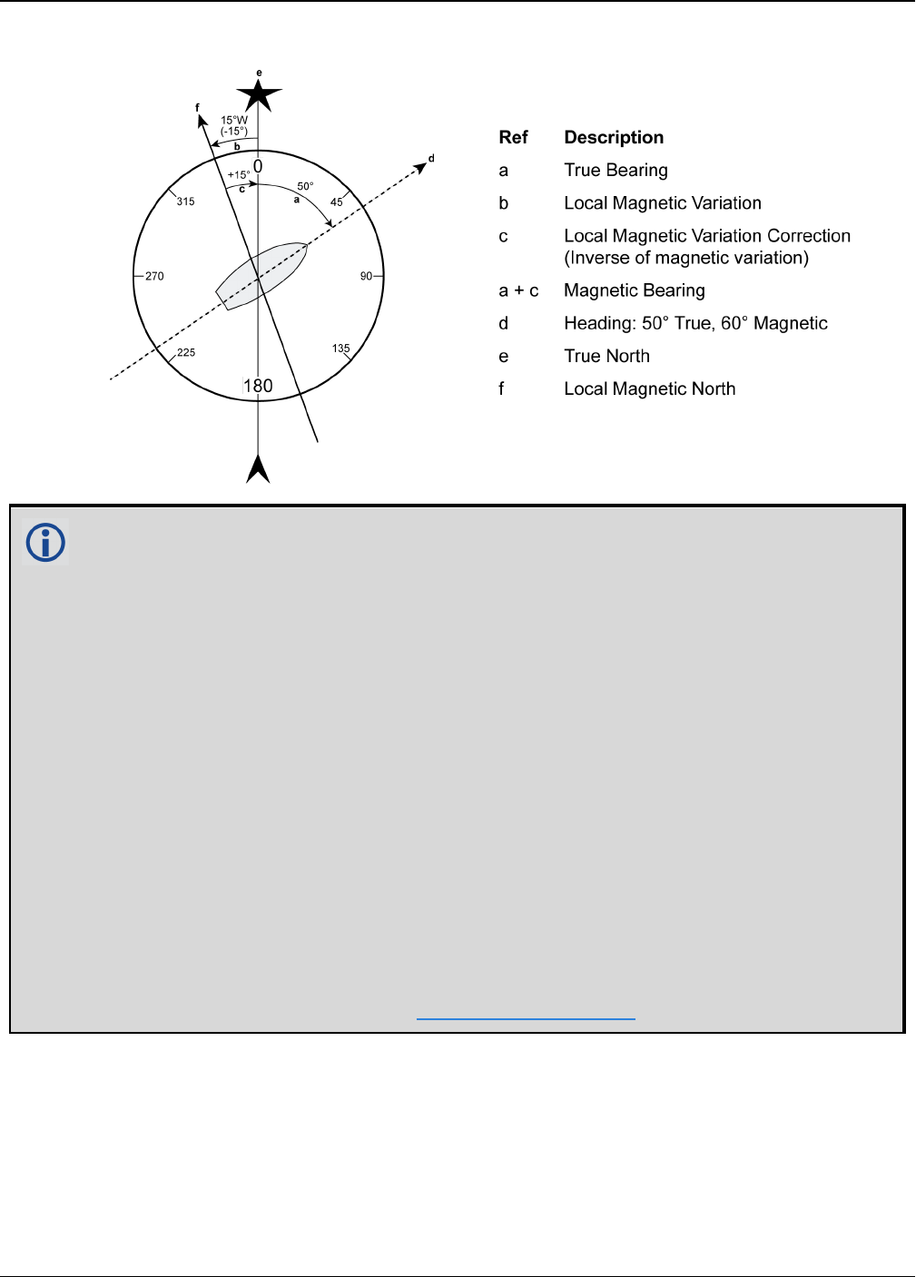
Chapter 2 Core Commands
OEM7 Commands and Logs Reference Manual v7 232
Figure 5: Illustration of Magnetic Variation and Correction
How does GNSS determine what Magnetic North is? Do the satellites transmit a database
or some kind of look up chart to determine the declination for your given latitude and
longitude? How accurate is it?
Magnetic North refers to the location of the Earth's Magnetic North Pole. Its position is
constantly changing in various cycles over centuries, years and days. These rates of
change vary and are not well understood. However, we are able to monitor the changes.
True North refers to the earth's spin axis, that is, at 90° north latitude or the location
where the lines of longitude converge. The position of the spin axis does not vary with
respect to the Earth.
The locations of these two poles do not coincide. Thus, a relationship is required between
these two values for users to relate GNSS bearings to their compass bearings. This value
is called the magnetic variation correction or declination.
GNSS does not determine where Magnetic North is nor do the satellites provide magnetic
correction or declination values. However, OEM7 receivers store this information
internally in look up tables so that when you specify that you want to navigate with
respect to Magnetic North, this internal information is used. These values are also
available from various information sources such as the United States Geological Survey
(USGS). The USGS produces maps and has software which enables the determination of
these correction values. By identifying your location (latitude and longitude), you can
obtain the correction value. Refer to An Introduction to GNSS available on our website.

Chapter 2 Core Commands
OEM7 Commands and Logs Reference Manual v7 233
Field Field
Type
ASCII
Value
Binary
Value Description Format Binary
Bytes
Binary
Offset
1MAGVAR
header - -
Command header. See
Messages on page25
for more information.
- H 0
2 type
AUTO 0 Use IGRF corrections
Enum 4 H
CORRECTION 1 Use the correction
supplied
3 correction ± 180.0 degrees
Magnitude of correction
(Required field if type
= Correction)
Float 4 H+4
4 std_dev ± 180.0 degrees
Standard deviation of
correction
(default = 0)
Float 4 H+8
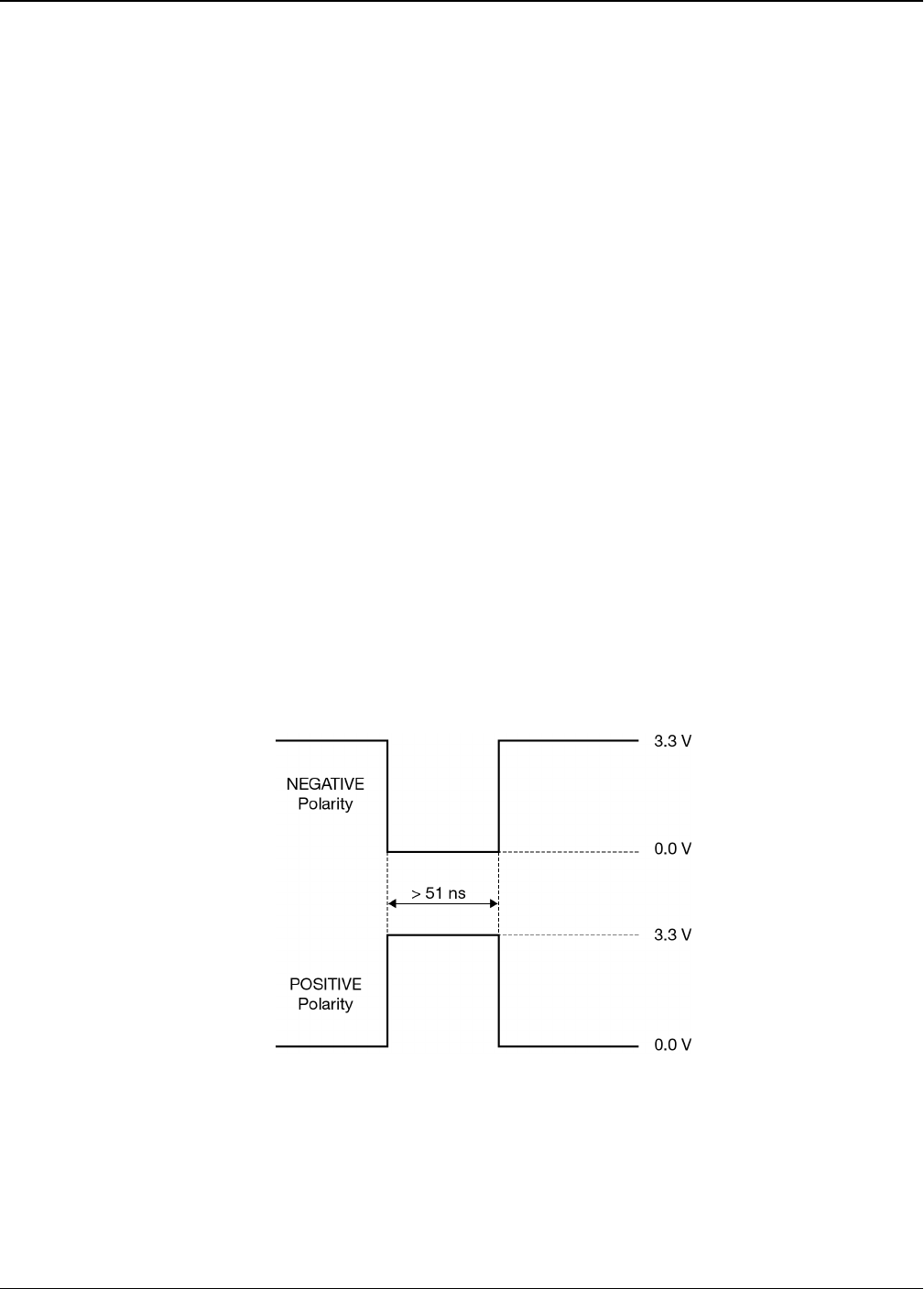
Chapter 2 Core Commands
OEM7 Commands and Logs Reference Manual v7 234
2.80 MARKCONTROL
Controls processing of mark inputs
Platform: OEM719, OEM729, OEM7500, OEM7600, OEM7700, OEM7720, PwrPak7,
SPAN CPT7
This command is used to control the processing of the mark inputs. Using this command, the
mark inputs can be enabled or disabled, polarity can be changed and a time offset and guard
against extraneous pulses can be added.
The MARKPOS and MARKTIME logs have their outputs (and extrapolated time tags) pushed into
the future (relative to the mark input (MKI) event) by the amount entered into the time bias
field. In almost all cases, this value is set to 0, which is also the default setting (see MARKPOS,
MARK2POS, MARK3POS and MARK4POS on page583 and MARKTIME, MARK2TIME, MARK3TIME
and MARK4TIME on page586).
Message ID: 614
Abbreviated ASCII Syntax:
MARKCONTROL signal [switch [polarity [timebias [timeguard]]]]
Factory Default:
MARKCONTROL MARK1 ENABLE
MARKCONTROL MARK2 ENABLE
ASCII Example:
MARKCONTROL MARK1 ENABLE NEGATIVE 50 100
Figure 6: TTL Pulse Polarity

Chapter 2 Core Commands
OEM7 Commands and Logs Reference Manual v7 235
If using an external device, such as a camera, connect the device to the receiver’s I/O
port. Use a cable that is compatible to both the receiver and the device. A MARKIN pulse
can be a trigger from the device to the receiver. See also the MARKPOS, MARK2POS,
MARK3POS and MARK4POS command on page583 and the MARKTIME,
MARK2TIME, MARK3TIME and MARK4TIME command on page586.
Field Field Type ASCII
Value
Binary
Value Description Format Binary
Bytes
Binary
Offset
1MARKCONTROL
header - -
Command header.
See Messages on
page25 for more
information.
- H 0
2 signal
MARK1 0
Specifies which mark
input the command
should be applied to.
Set to MARK1 for the
Event1 input, MARK2
for Event2, MARK3
for Event3 and
MARK4 for Event4. All
of the mark inputs
have 10 K pull-up
resistors to 3.3 V and
are leading edge
triggered
MARK3 and MARK4
are available only on
the OEM7600,
OEM7700 and
OEM7720
Enum 4 H
MARK2 1
MARK3 2
MARK4 3
3 switch
DISABLE 0
Disables or enables
processing of the
mark input signal for
the input specified. If
DISABLE is selected,
the mark input signal
is ignored (default =
ENABLE)
Enum 4 H+4
ENABLE 1

Chapter 2 Core Commands
OEM7 Commands and Logs Reference Manual v7 236
Field Field Type ASCII
Value
Binary
Value Description Format Binary
Bytes
Binary
Offset
4 polarity
NEGATIVE 0
Optional field to
specify the polarity of
the pulse to be
received on the mark
input. See Figure 6:
TTL Pulse Polarity on
page234 for more
information (default=
NEGATIVE)
Enum 4 H+8
POSITIVE 1
5 timebias Any valid long
value
Optional value to
specify an offset, in
nanoseconds, to be
applied to the time
the mark input pulse
occurs (default =0)
Long 4 H+12
6 timeguard
default: 4
minimum: 2
Any valid Ulong
value larger than
the receiver’s
minimum raw
measurement
period 1
Optional field to
specify a time period,
in milliseconds,
during which
subsequent pulses
after an initial pulse
are ignored
Ulong 4 H+16
1See Appendix A in the OEM7 Installation and Operation User Manual for the maximum raw measurement rate to
determine the minimum period. If the value entered is lower than the minimum measurement period, the value is
ignored and the minimum period is used.
Chapter 2 Core Commands
OEM7 Commands and Logs Reference Manual v7 237
2.81 MEDIAFORMAT
Format the media for PwrPak7
Platform: PwrPak7
Formats the specified media as FAT32, using PwrPak7 specific cluster size and other para-
meters.
Only the internal flash memory can be formatted.
Entering this command results in complete loss of all data stored on the media.
Entering this command initiates the format operation. An error is reported if formatting could
not be initiated, for example due to the media being disconnected.
Formatting progress can be observed using the FILESYSTEMSTATUS log on page471, which
will report BUSY, followed by MOUNTED.
The receiver may reboot in the process.
Message ID: 2128
Abbreviated ASCII Syntax:
MEDIAFORMAT MassStorage
Example:
MEDIAFORMAT INTERNAL_FLASH
Field Field Type ASCII
Value
Binary
Value Description Format Binary
Bytes
Binary
Offset
1MEDIAFORMAT
header - -
Command header.
See Messages on
page25 for more
information.
- H 0
2 MassStorage INTERNAL_
FLASH 4
Format the internal
memory in the
PwrPak7.
Enum 4 H
Chapter 2 Core Commands
OEM7 Commands and Logs Reference Manual v7 238
2.82 MODEL
Switches to a previously authorized model
Platform: OEM719, OEM729, OEM7500, OEM7600, OEM7700, OEM7720, PwrPak7,
SPAN CPT7
This command is used to switch the receiver between models previously added with the AUTH
command (see page 73). When the MODEL command is issued, the receiver saves the specified
model as the active model. The active model is now used on every subsequent start up. The
MODEL command causes an automatic reset.
Use the VALIDMODELS log (see page 849) to output a list of available models on the receiver.
Use the VERSION log (see page 854) to output the active model. Use the AUTHCODES log (see
page 414) to output a list of the auth codes present on the receiver.
If the MODEL command is used to switch to an expired model, the receiver will reset
and enter into an error state. Switch to a valid model to continue.
Message ID: 22
Abbreviated ASCII Syntax:
MODEL model
Input Example:
MODEL D2LR0RCCR
NovAtel uses the term models to refer to and control different levels of functionality in
the receiver firmware. For example, a receiver may be purchased with an L1 only cap-
ability and be easily upgraded at a later time to a more feature intensive model, like
L1/L2 dual-frequency. All that is required to upgrade is an authorization code for the
higher model and the AUTH command (see page 73). Reloading the firmware or return-
ing the receiver for service to upgrade the model is not required. Upgrades are available
from NovAtel Customer Support.
Field Field
Type
ASCII
Value
Binary
Value Description Format Binary
Bytes
Binary
Offset
1MODEL
header - -
Command header. See
Messages on page25 for
more information.
- H 0
2 model
Max 16 character null-
terminated string
(including the null)
Model name
String
[max
16]
Variable
1H
1In the binary case, each string field needs to be NULL terminated and additional bytes of padding added to
maintain 4-byte alignment, up to the maximum defined by the string size. The next defined field starts
immediately at the next 4-byte alignment following the NULL.

Chapter 2 Core Commands
OEM7 Commands and Logs Reference Manual v7 239
2.83 MOVINGBASESTATION
Enables the use of a moving base station
Platform: OEM719, OEM729, OEM7500, OEM7600, OEM7700, OEM7720, PwrPak7,
SPAN CPT7
This command is used to enable or disable a receiver from transmitting corrections without a
fixed position.
The moving base function allows you to obtain a centimeter level xyz baseline estimate when
the base station and possibly the rover are moving. It is very similar to normal RTK, with one
stationary base station and a moving rover (refer to Transmitting and Receiving Corrections sec-
tion of the Operation chapter in the OEM7 Installation and Operation User Manual). The BSLNXYZ
log is an asynchronous ‘matched’ log that can be logged with the onchanged trigger to provide
an accurate baseline between the base and rover.
Due to the latency of the reference station position messages, the following logs are not recom-
mended to be used when in moving baseline mode: BESTXYZ, GPGST, MARKPOS, MARK2POS,
MATCHEDPOS, MATCHEDEYZ, RTKPOS and RTKXYZ. The position error of these logs could
exceed 100 m, depending on the latency of the reference station position message. If a rover
position is required during moving basestation mode, then PSRPOS is recommended.
The MOVINGBASESTATION command must be used to allow the base to transmit messages
without a fixed position.
1. Use the PSRPOS position log at the rover. It provides the best accuracy and standard
deviations when the MOVINGBASESTATION mode is enabled.
2. This command supports RTCM V3 operation.
3. RTCM V3 support includes GPS + GLONASS operation.
Message ID: 763
Abbreviated ASCII Syntax:
MOVINGBASESTATION switch
Factory Default:
MOVINGBASESTATION disable
ASCII Example:
MOVINGBASESTATION ENABLE
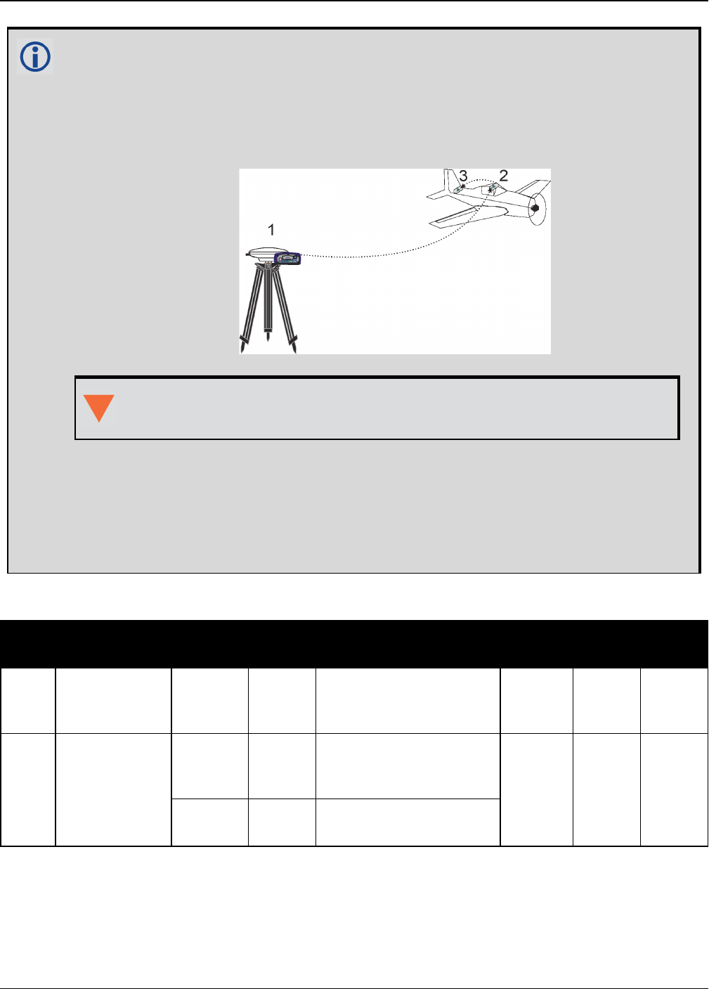
Chapter 2 Core Commands
OEM7 Commands and Logs Reference Manual v7 240
Consider the case where there is a fixed base, an airplane flying with a moving base
station near its front and a rover station at its tail end.
Corrections can be sent between the receivers in a ‘daisy chain’ effect, where the fixed
base station sends corrections to the moving base station, which in turn can send
corrections to the rover.
Figure 7: Moving Base Station ‘Daisy Chain’ Effect
When using this method, the position type is only checked at the fixed base
station. Moving base stations will continue to operate under any conditions.
This command is useful for moving base stations doing RTK positioning at sea. A rover
station is used to map out local areas (for marking shipping lanes, hydrographic
surveying and so on), while the base station resides on the control ship. The control ship
may not move much (parked at sea), but there is a certain amount of movement due to
the fact that it is floating in the ocean. By using the MOVINGBASESTATION command,
the control ship is able to use RTK positioning and move to new survey sites.
Field Field Type ASCII
Value
Binary
Value Description Format Binary
Bytes
Binary
Offset
1
MOVING
BASESTATION
header
- -
Command header. See
Messages on page25
for more information.
- H 0
2 switch
DISABLE 0
Do not transmit
corrections without a
fixed position Enum 4 H
ENABLE 1 Transmit corrections
without a fixed position
Chapter 2 Core Commands
OEM7 Commands and Logs Reference Manual v7 241
2.84 NAVICECUTOFF
Sets elevation cut-off angle for NavIC satellites
Platform: OEM719, OEM729, OEM7500, OEM7600, OEM7700, OEM7720, PwrPak7,
SPAN CPT7
This command is used to set the elevation cut-off angle for tracked NavIC satellites. The
receiver does not start automatically searching for a NavIC satellite until it rises above the cut-
off angle (when satellite position is known). Tracked satellites that fall below the cut-off angle
are no longer tracked unless they are manually assigned (see the ASSIGN command on
page65).
In either case, satellites below the NAVICECUTOFF angle are eliminated from the internal pos-
ition and clock offset solution computations.
This command permits a negative cut-off angle; it could be used in these situations:
lThe antenna is at a high altitude, and thus can look below the local horizon
lSatellites are visible below the horizon due to atmospheric refraction
Care must be taken when using NAVICECUTOFF command because the signals from
lower elevation satellites are traveling through more atmosphere and are therefore
degraded. Use of satellites below 5 degrees is not recommended.
Use the ELEVATIONCUTOFF command on page136 to set the cut-off angle for all other
systems.
For dual antenna receivers, this command applies to both the primary and secondary
antennas.
Message ID: 2134
Abbreviated ASCII Syntax:
NAVICECUTOFF angle
Factory Default:
NAVICECUTOFF 5.0
ASCII Example:
NAVICECUTOFF 10.0

Chapter 2 Core Commands
OEM7 Commands and Logs Reference Manual v7 242
Field Field Type ASCII
Value
Binary
Value Description Format Binary
Bytes
Binary
Offset
1NAVICECUTOFF
header - -
Command header. See
Messages on page25 for
more information.
- H 0
2 angle ±90.0 degrees Elevation cut-off angle
relative to horizon Float 4 H

Chapter 2 Core Commands
OEM7 Commands and Logs Reference Manual v7 243
2.85 NMEAFORMAT
Customize NMEA output
Platform: OEM719, OEM729, OEM7500, OEM7600, OEM7700, OEM7720, PwrPak7,
SPAN CPT7
Use the NMEAFORMAT command to customize the NMEA GPGGA and GPGGALONG output.
Modifying the NMEA output will make it not compliant with the NMEA standard.
Message ID: 1861
Abbreviated ASCII Syntax:
NMEAFORMAT field format
Factory Default:
NMEAFORMAT GGA_LATITUDE 9.4
NMEAFORMAT GGA_LONGITUDE 10.4
NMEAFORMAT GGA_ALTITUDE .2
NMEAFORMAT GGALONG_LATITUDE 12.7
NMEAFORMAT GGALONG_LONGITUDE 13.7
NMEAFORMAT GGALONG_ALTITUDE .3
Example:
The following settings increase the precision of the GPGGA latitude and longitude fields:
NMEAFORMAT GGA_LATITUDE 11.6
NMEAFORMAT GGA_LONGITUDE 12.6
The following settings decrease the precision of the GPGGALONG latitude and longitude fields:
NMEAFORMAT GGALONG_LATITUDE 11.6
NMEAFORMAT GGALONG_LONGITUDE 12.6
The following setting stops the undulation fields of the GPGGALONG log being filled, making a log
like the GPGGARTK log that was in NovAtel's OEM6 firmware:
NMEAFORMAT GGALONG_UNDULATION !0
Field Field
Type ASCII Value Binary
Value Description Format Binary
Bytes
Binary
Offset
1
NMEA
FORMAT
Header
- -
Command header. See
Messages on page25 for
more information.
- H 0

Chapter 2 Core Commands
OEM7 Commands and Logs Reference Manual v7 244
Field Field
Type ASCII Value Binary
Value Description Format Binary
Bytes
Binary
Offset
2 Field
GGA_
LATITUDE 0 GPGGA latitude field
Enum 4 H
GGA_
LONGITUDE 1 GPGGA longitude field
GGA_
ALTITUDE 2GPGGA altitude (height)
field
GGA_
UNDULATION 3 GPGGA undulation field
GGALONG_
LATITUDE 10 GPGGALONG latitude
field
GGALONG_
LONGITUDE 11 GPGGALONG longitude
field
GGALONG_
ALTITUDE 12 GPGGALONG altitude
(height) field
GGALONG_
UNDULATION 13 GPGGALONG undulation
field

Chapter 2 Core Commands
OEM7 Commands and Logs Reference Manual v7 245
Field Field
Type ASCII Value Binary
Value Description Format Binary
Bytes
Binary
Offset
3 Format Char[8]
The Format field has a
syntax similar to the
printf function commonly
found in programming
languages. The format
is:
!x.y
Where:
yis the number of
digits to display after
the decimal point
xsets the minimum
field width including
the decimal point. X
is optional if ! is not
used. If the value
requires fewer digits
than x, leading zeros
are added to the out-
put.
!forces the field
width to x. ! is
optional. If a value
exceeds the per-
mitted width, the
value will be sat-
urated. If ! is used, y
must be less than x.
Examples (GGA_
LATITUDE):
.5 = 5106.98120
2.3 = 5106.981
7.1 = 05107.0
!7.2 = 5106.98
!7.3 = 999.999
Char[8] 8 H+4
Chapter 2 Core Commands
OEM7 Commands and Logs Reference Manual v7 246
2.86 NMEATALKER
Sets the NMEA talker ID
Platform: OEM719, OEM729, OEM7500, OEM7600, OEM7700, OEM7720, PwrPak7,
SPAN CPT7
This command is used to alter the behavior of the NMEA talker ID. The talker is the first 2 char-
acters after the $sign in the log header of the GPGLL, GPGRS, GPGSA, GPGST, GPGSV, GPRMB,
GPRMC, GPVTG and GPZDA log outputs. The other NMEA logs are not affected by the
NMEATALKER command.
On SPAN systems, the GPGGA position is always based on the position solution from the
BESTPOS log which incorporate GNSS + INS solutions as well.
The default GPS NMEA messages (NMEATALKER GP) include specific information about only
the GPS satellites that have a 'GP' talker solution, even when GLONASS satellites are present.
As well, the default GPS NMEA message outputs GP as the talker ID regardless of the position
type given in position logs such as BESTPOS. The NMEATALKER AUTO command changes this
behavior so that the NMEA messages include all satellites in the solution and the talker ID
changes according to those satellites.
If NMEATALKER is set to auto and there are both GPS and GLONASS satellites in the solution,
two sentences with the GN talker ID are output. The first sentence contains information about
the GPS and the second sentence on the GLONASS satellites in the solution.
If NMEATALKER is set to auto and there are only GLONASS satellites in the solution, the talker
ID of this message is GL.
If the solution comes from SPAN, the talker ID is IN.
Message ID: 861
Abbreviated ASCII Syntax:
NMEATALKER id
Factory Default:
NMEATALKER gp
ASCII Example:
NMEATALKER auto

Chapter 2 Core Commands
OEM7 Commands and Logs Reference Manual v7 247
Field Field Type ASCII
Value
Binary
Value Description Format Binary
Bytes
Binary
Offset
1NMEATALKER
header - -
Command header. See
Messages on page25 for
more information.
- H 0
2 ID
GP 0 GPS (GP) only
Enum 4 H
AUTO 1 GPS, Inertial (IN) and/or
GLONASS
The NMEATALKER command only affects NMEA logs that are capable of a GPS output. For
example, GLMLA is a GLONASS-only log and the output will always use the GL talker.
Table 50: NMEA Talkers below shows the NMEA logs and whether they use GPS (GP),
GLONASS (GL), Galileo (GA) or combined (GN) talkers with NMEATALKER AUTO.
Log Talker IDs
GLMLA GL
GPALM GP
GPGGA GP
GPGLL GP or GL or GA or GN
GPGRS GP or GL or GA or GN
GPGSA GP or GL or GA or GN
GPGST GP or GL or GA or GN
GPGSV GP and GL and GA
GPRMB GP or GL or GA or GN
GPRMC GP or GL or GA or GN
GPVTG GP or GL or GA or GN
GPZDA GP
Table 50: NMEA Talkers

Chapter 2 Core Commands
OEM7 Commands and Logs Reference Manual v7 248
2.87 NMEAVERSION
Sets the NMEA Version for Output
Platform: OEM719, OEM729, OEM7500, OEM7600, OEM7700, OEM7720, PwrPak7,
SPAN CPT7
Use this command to set the output version of NMEA messages.
Message ID: 1574
Abbreviated ASCII Syntax:
NMEAVERSION Version
Factory Defaults:
NMEAVERSION V31
ASCII Example:
NMEAVERSION V41
Field Field Type ASCII
Value
Binary
Value Description Format Binary
Bytes
Binary
Offset
1NMEAVERSION
header - -
Command header. See
Messages on page25 for
more information.
- H 0
2 Version
V31 0
NMEA messages will be
output in NMEA version
3.10 format. Enum 4 H
V41 1
NMEA messages will be
output in NMEA version
4.10 format.
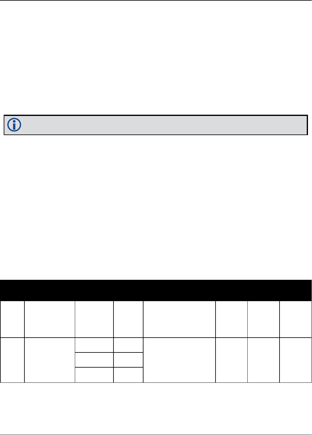
Chapter 2 Core Commands
OEM7 Commands and Logs Reference Manual v7 249
2.88 NTRIPCONFIG
Configures NTRIP
Platform: OEM729, OEM7600, OEM7700, OEM7720, PwrPak7, SPAN CPT7
This command sets up and configures NTRIP communication.
Message ID: 1249
Abbreviated ASCII Syntax:
NTRIPCONFIG port type [protocol [endpoint [mountpoint [username [password
[bindinterface]]]]]]
Mountpoint, username and password are all set up on the caster.
Factory Default:
NTRIPCONFIG ncom1 disabled
NTRIPCONFIG ncom2 disabled
NTRIPCONFIG ncom3 disabled
NTRIPCONFIG ncomX disabled
ASCII Example:
NTRIPCONFIG ncom1 client v1 :2000 calg0
ASCII example (NTRIP client):
NTRIPCONFIG ncom1 client v2 192.168.1.100:2101 RTCM3 calgaryuser calgarypwd
ASCII example (NTRIP server):
NTRIPCONFIG ncom1 server v1 192.168.1.100:2101 RTCM3 "" casterpwd
Field Field Type ASCII
Value
Binary
Value Description Format Binary
Bytes
Binary
Offset
1NTRIPCONFIG
Header - -
Command header.
See Messages on
page25 for more
information.
- H 0
2 port
NCOM1 26 Name of the port see
Table 31:
Communications Port
Identifiers on
page132
Enum 4 HNCOM2 27
NCOM3 28

Chapter 2 Core Commands
OEM7 Commands and Logs Reference Manual v7 250
Field Field Type ASCII
Value
Binary
Value Description Format Binary
Bytes
Binary
Offset
3 type
DISABLED 1
NTRIP type Enum 4 H+4CLIENT 2
SERVER 3
4 protocol V1 1 Protocol (default V1) Enum 4 H+8
V2 2
5 endpoint Max 80 character
string
Endpoint to wait on
or to connect to
where host is a
hostname or IP
address and port is
the TCP/UDP port
number (default =
80)
String
[80]
variable
1H+12
6 mountpoint Max 80 character
string
Which mount point to
use
String
[80]
variable
1variable
7 user name Max 30 character
string Login user name String
[30]
variable
1variable
8 password Max 30 character
string Password String
[30]
variable
1variable
9 bindInterface ALL
(default) 1
Not supported. Set to
ALL for future
compatibility.
Enum 4 variable
1In the binary case, each string field needs to be NULL terminated and additional bytes of padding added to
maintain 4-byte alignment, up to the maximum defined by the string size. The next defined field starts
immediately at the next 4-byte alignment following the NULL.

Chapter 2 Core Commands
OEM7 Commands and Logs Reference Manual v7 251
2.89 NTRIPSOURCETABLE
Set NTRIPCASTER ENDPONTS
Platform: OEM729, OEM7600, OEM7700, OEM7720, PwrPak7, SPAN CPT7
This command is used to set the NTRIPCASTER ENDPOINTS to be used for the SOURCETABLE
log (see page 829).
Message ID: 1343
Abbreviated ASCII Syntax:
NTRIPSOURCETABLE endpoint [reserved1] [reserved2]
Factory Default:
NTRIPSOURCETABLE none
ASCII Example:
NTRIPSOURCETABLE hera.novatel.com:2101
NTRIPSOURCETABLE 198.161.64.11:2101
Field Field Type ASCII
Value
Binary
Value Description Format Binary
Bytes
Binary
Offset
1
NTRIP
SOURCETABLE
header
-
Command header. See
Messages on page25 for
more information.
- H 0
2 Endpoint Max 80
character string
Endpoint, in format of
host:port, to connect to
where the host is a
hostname or IP address
and port is the TCP/IP
port number
String
[80]
variable
1H
3 Reserved1 Reserved Reserved Ulong 4 variable
4 Reserved2 Reserved Reserved Ulong 4 variable
1In the binary case, each string field needs to be NULL terminated and additional bytes of padding added to
maintain 4-byte alignment, up to the maximum defined by the string size. The next defined field starts
immediately at the next 4-byte alignment following the NULL.
Chapter 2 Core Commands
OEM7 Commands and Logs Reference Manual v7 252
2.90 NVMRESTORE
Restores NVM data after an NVM failure
Platform: OEM719, OEM729, OEM7500, OEM7600, OEM7700, OEM7720, PwrPak7,
SPAN CPT7
This command is used to restore Non-Volatile Memory (NVM) data after a NVM Fail error. This
failure is indicated by bit 15 of the receiver error word being set (see also RXSTATUS command
on page748 and RXSTATUSEVENT command on page762). If corrupt NVM data is detected,
the receiver remains in the error state and continues to flash an error code on the Status LED
until the NVMRESTORE command is issued (refer to the chapter on Built-In Status Tests in the
OEM7 Installation and Operation User Manual for further explanation).
If you have more than one auth code and the saved model is lost, then the model may need to
be entered using the MODEL command or it is automatically saved in NVM on the next start up.
If the almanac was lost, a new almanac is automatically saved when the next complete almanac
is received (after approximately 15 minutes of continuous tracking). If the user configuration
was lost, it has to be reentered by the user. This could include communication port settings.
The factory default for the COM ports is 9600, n, 8, 1.
After entering the NVMRESTORE command and resetting the receiver, the communications link
may have to be reestablished at a different baud rate from the previous connection.
Message ID: 197
Abbreviated ASCII Syntax:
NVMRESTORE
The possibility of NVM failure is extremely remote, however, if it should occur it is likely
that only a small part of the data is corrupt. This command is used to remove the corrupt
data and restore the receiver to an operational state. The data lost could be the user con-
figuration, almanac, model or other reserved information.

Chapter 2 Core Commands
OEM7 Commands and Logs Reference Manual v7 253
2.91 NVMUSERDATA
Write User Data to NVM
Platform: OEM719, OEM729, OEM7500, OEM7600, OEM7700, OEM7720, PwrPak7,
SPAN CPT7
This command writes the data provided in the data array to NVM. This data can be retrieved by
issuing the command LOG NVMUSERDATA.
The user data is maintained through power cycles and a standard FRESET command (see page
174). To clear the user data, use the FRESET USERDATA command.
The user data may be deleted if the NVMRESTORE command (see page 252) is sent.
NVMRESTORE should be used with caution and is meant for use only in the event of a
NVM receiver error.
Message ID: 1970
Abbreviated ASCII Syntax:
NVMUSERDATA N DATA
Field Field Type Binary
Value Description Binary
Format
Binary
Bytes
Binary
Offset
1NVMUSERDATA
header -Command header. See Messages
on page25 for more information. - H 0
2 N - Number of bytes of data to follow Ulong 4 H
3 DATA -
User input data up to a maximum
of 2000 bytes.
Data is entered in hexadecimal
values with no separators
between the values. For example,
1a2b3c4e
Uchar 2000 H+4

Chapter 2 Core Commands
OEM7 Commands and Logs Reference Manual v7 254
2.92 PDPFILTER
Enables, disables or resets the PDP filter
Platform: OEM719, OEM729, OEM7500, OEM7600, OEM7700, OEM7720, PwrPak7,
SPAN CPT7
This command is used to enable, disable or reset the Pseudorange/Delta-Phase (PDP) filter. The
main advantages of the PDP implementation are:
lSmooths a jumpy position
lBridges outages in satellite coverage (the solution is degraded from normal but there is at
least a reasonable solution without gaps)
Enable the PDP filter to output the PDP solution in the BESTPOS log (see
page 428), BESTVEL log (see page 444) and NMEA Standard Logs on
page615.
Refer to the Operation chapter of the OEM7 Installation and Operation User
Manual for information on configuring your receiver for PDP or GLIDE®
operation.
2.92.1 GLIDE Position Filter
GLIDE is a mode of the PDP1filter that optimizes the position for consistency over time rather
than absolute accuracy. This is ideal in clear sky conditions where the user needs a tight,
smooth and consistent output. The GLIDE filter works best with SBAS. The PDP filter is smoother
than a least squares solution but is still noisy in places. The GLIDE filter produces a very smooth
solution with relative rather than absolute position accuracy. There should typically be less than
1 centimeter difference in error from epoch to epoch. GLIDE also works in single point and DGPS
VBS modes. See also the PDPMODE command on page256 and the PDPPOS log on page630,
PDPVEL log on page634 and PDPXYZ log on page635.
Message ID: 424
Abbreviated ASCII Syntax:
PDPFILTER switch
Factory Default:
PDPFILTER disable
ASCII Example:
PDPFILTER enable
1Refer also to our application note APN038 on Pseudorange/Delta-Phase (PDP), available on our website a
www.novatel.com/support/search.

Chapter 2 Core Commands
OEM7 Commands and Logs Reference Manual v7 255
Field Field
Type
ASCII
Value
Binary
Value Description Format Binary
Bytes
Binary
Offset
1PDPFILTER
header - -
Command header. See
Messages on page25 for
more information.
- H 0
2 switch
DISABLE 0 Disable the PDP filter.
Enum 4 H
ENABLE 1 Enable the PDP filter.
RESET 2
Reset the PDP filter. A
reset clears the filter
memory so that the PDP
filter can start over

Chapter 2 Core Commands
OEM7 Commands and Logs Reference Manual v7 256
2.93 PDPMODE
Selects the PDP mode and dynamics
Platform: OEM719, OEM729, OEM7500, OEM7600, OEM7700, OEM7720, PwrPak7,
SPAN CPT7
This command is used to select the mode and dynamics of the PDP filter.
The PDPFILTER ENABLE command (see the PDPFILTER command on page254) must
be entered before the PDPMODE command.
It is recommended that the ionotype be left at AUTO when using either normal mode PDP
or GLIDE. See also the SETIONOTYPE command on page344.
Message ID: 970
Abbreviated ASCII Syntax:
PDPMODE mode dynamics
Factory Default:
PDPMODE normal auto
ASCII Example:
PDPMODE relative dynamic
Field Field
Type
ASCII
Value
Binary
Value Description Format Binary
Bytes
Binary
Offset
1PDPMODE
header - -
Command header. See
Messages on page25 for
more information.
- H 0
2 mode
NORMAL 0
In relative mode, GLIDE
performance is optimized
to obtain a consistent error
in latitude and longitude
over time periods of 15
minutes or less, rather than
to obtain the smallest
absolute position error. See
also GLIDE Position Filter
on page254 for GLIDE
mode additional
information
Enum 4 H
RELATIVE 1
GLIDE 3
3 dynamics
AUTO 0 Auto detect dynamics mode
Enum 4 H+4STATIC 1 Static mode
DYNAMIC 2 Dynamic mode

Chapter 2 Core Commands
OEM7 Commands and Logs Reference Manual v7 257
2.94 PGNCONFIG
Configure NMEA2000 PGNs.
Platform: OEM719, OEM729, OEM7500, OEM7600, OEM7700, OEM7720, PwrPak7,
SPAN CPT7
Use this command to configure the PGNs of the proprietary NMEA 2000 fast-packet messages
the OEM7 receivers produce.
The receiver must be reset after issuing a SAVECONFIG command (see page 316) for all the
configuration changes to take affect.
Message ID: 1892
Abbreviated ASCII Syntax:
PGNCONFIG message_id pgn priority
Factory Default:
PGNCONFIG INSPVACMP 130816 7
PGNCONFIG INSPVASDCMP 130817 7
ASCII Example:
PGNCONFIG INSPVACMP 129500 3
This example sets the INSPVACMP message to PGN 129500 with priority 3.
Field Field Type ASCII Value Binary
Value Description Format Binary
Bytes
Binary
Offset
1PGNCONFIG
Header - -
Command header.
See Messages on
page25 for more
information.
- H 0
2 message_id INSPVACMP 1889 NovAtel message
ID Ulong 4 H
INSPVASDCMP 1890
3 pgn 0 to 4294967295 PGN to use for
message_id Ulong 4 H+4
4 priority 0 - 7 CAN priority to use Uchar 1 H+8

Chapter 2 Core Commands
OEM7 Commands and Logs Reference Manual v7 258
2.95 POSAVE
Implements base station position averaging
Platform: OEM719, OEM729, OEM7500, OEM7600, OEM7700, OEM7720, PwrPak7,
SPAN CPT7
This command implements position averaging for base stations. Position averaging continues for
a specified number of hours or until the estimated averaged position error is within specified
accuracy limits. Averaging stops when the time limit or the horizontal standard deviation limit or
the vertical standard deviation limit is achieved. When averaging is complete, the FIX
POSITION command is automatically invoked. See the FIX command on page161.
If differential logging is initiated, then issue the POSAVE command followed by the
SAVECONFIG command (see page 316). The receiver averages positions after every power on
or reset. It then invokes the FIX POSITION command to enable it to send differential cor-
rections.
Message ID: 173
Abbreviated ASCII Syntax:
POSAVE state [maxtime [maxhstd [maxvstd]]]
Factory Default:
POSAVE off
ASCII Example 1:
POSAVE on 24 1 2
ASCII Example 2:
POSAVE OFF
Field Field
Type
ASCII
Value
Binary
Value Description Format Binary
Bytes
Binary
Offset
1POSAVE
header - -
Command header. See
Messages on page25 for more
information.
- H 0
2 state ON 1 Enable position averaging Enum 4 H
OFF 0 Disable position averaging
3 maxtime 0.01 - 100
hours
Maximum amount of time that
positions are to be averaged
(default=0.01)
Float 4 H+4
4 maxhstd 0 - 100 m
Desired horizontal standard
deviation
(default = 0.0)
Float 4 H+8

Chapter 2 Core Commands
OEM7 Commands and Logs Reference Manual v7 259
Field Field
Type
ASCII
Value
Binary
Value Description Format Binary
Bytes
Binary
Offset
5 maxvstd 0 - 100 m
Desired vertical standard
deviation
(default = 0.0)
Float 4 H+12
The POSAVE command can be used to establish a new base station, in any form of sur-
vey or RTK data collection, by occupying a site and averaging the position until either a
certain amount of time has passed or position accuracy has reached a user specified
level. User specified requirements can be based on time or horizontal or vertical quality
of precision.
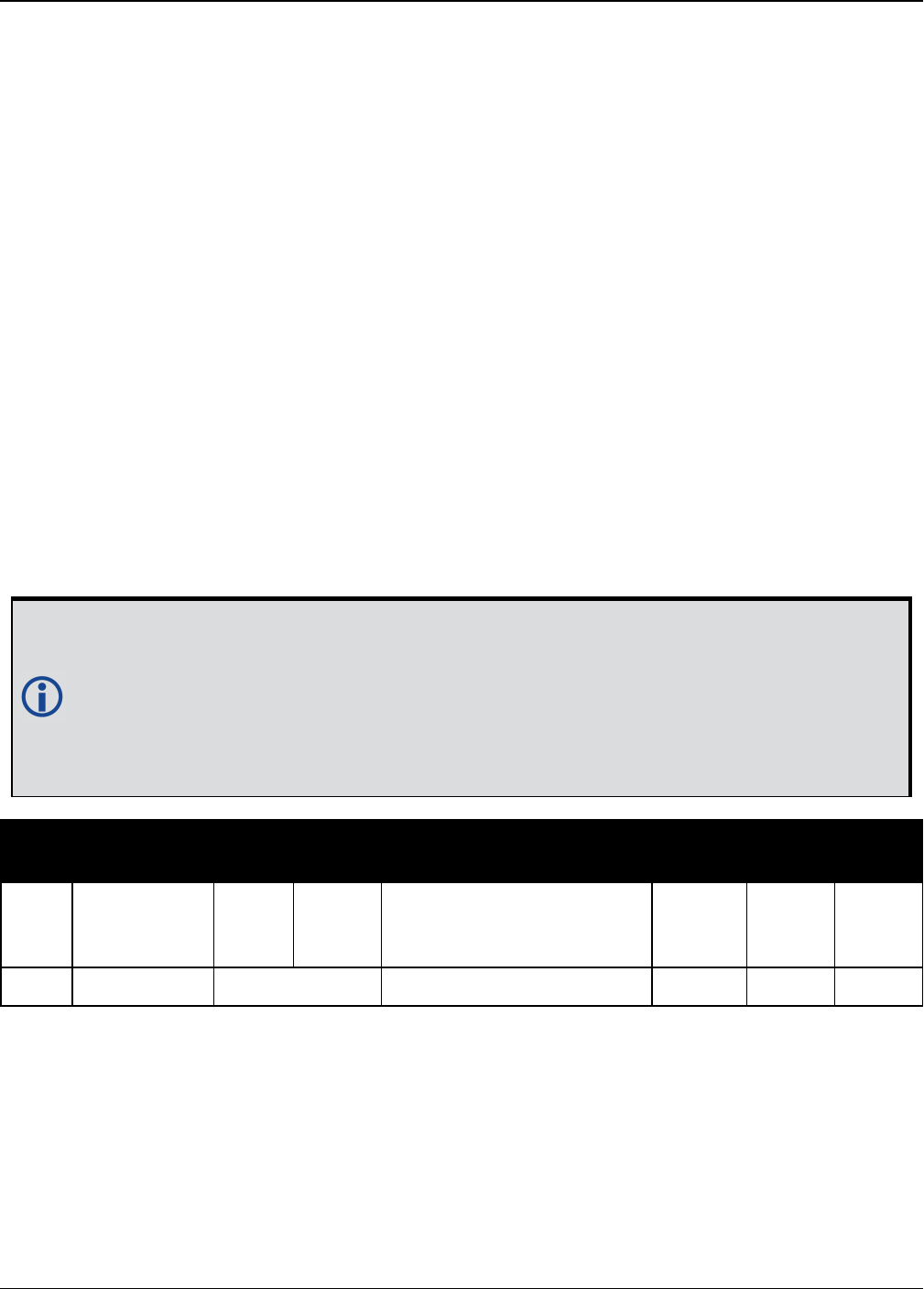
Chapter 2 Core Commands
OEM7 Commands and Logs Reference Manual v7 260
2.96 POSTIMEOUT
Sets the position time out
Platform: OEM719, OEM729, OEM7500, OEM7600, OEM7700, OEM7720, PwrPak7,
SPAN CPT7
This commands is used to set the time out value for the position calculation in seconds.
In position logs, for example BESTPOS log (see page 428) or PSRPOS log (see page 648),
when the position time out expires, the Position Type field is set to NONE. Other field values in
these logs remain populated with the last available position data. Also, the position is no longer
used in conjunction with the almanac to determine what satellites are visible.
Message ID: 612
Abbreviated ASCII Syntax:
POSTIMEOUT sec
Factory Default:
POSTIMEOUT 600
ASCII Example:
POSTIMEOUT 1200
When performing data collection in a highly dynamic environment (for example, urban
canyons or in high speed operations), you can use POSTIMEOUT to prevent the
receiver from outputting calculated positions that are too old. Use POSTIMEOUT to
force the receiver position type to NONE. This ensures that the position information
being used in the BESTPOS log (see page 428) or PSRPOS log (see page 648) is based
on a recent calculation. All position calculations are then recalculated using the most
recent satellite information.
Field Field Type ASCII
Value
Binary
Value Description Format Binary
Bytes
Binary
Offset
1POSTIMEOUT
header - -
Command header. See
Messages on page25 for
more information.
- H 0
2 sec 0-86400 Time out in seconds Ulong 4 H

Chapter 2 Core Commands
OEM7 Commands and Logs Reference Manual v7 261
2.97 PPPBASICCONVERGEDCRITERIA
Configures decision for PPP Basic convergence
Platform: OEM719, OEM729, OEM7500, OEM7600, OEM7700, OEM7720, PwrPak7,
SPAN CPT7
The PPPBASICCONVERGEDCRITERIA command sets the threshold that determines if the solu-
tion has converged for lower accuracy PPP solutions. These are the PPP solutions reported with
the PPP_BASIC and PPP_BASIC_CONVERGING position types.
The convergence threshold for high-accuracy PPP solutions (reported with PPP and PPP_
CONVERGING position types) is set using the PPPCONVERGEDCRITERIA command
(see page 262).
Relaxing the convergence threshold shortens the time before a PPP solution is reported
as converged. However, it does not alter solution behavior. During the initial PPP solu-
tion period, the positions can have decimeter error variation. Only relax the con-
vergence threshold if the application can tolerate higher solution variability.
Message ID: 1949
Abbreviated ASCII Syntax:
PPPBASICCONVERGEDCRITERIA criteria tolerance
Factory Default:
PPPBASICCONVERGEDCRITERIA horizontal_stddev 0.60
ASCII Example:
PPPBASICCONVERGEDCRITERIA total_stddev 0.45
Field Field Type ASCII Value Binary
Value Description Format Binary
Bytes
Binary
Offset
1
PPPBASIC
CONVERGED
CRITERIA
header
- -
Command header.
See Messages on
page25 for more
information.
- H 0
2 Criteria
TOTAL_
STDDEV 1Use the total, 3D,
standard deviation
Enum 4 H
HORIZONTAL_
STDDEV 2
Use the horizontal,
2D, standard
deviation
3 Tolerance Tolerance (m) Float 4 H+4
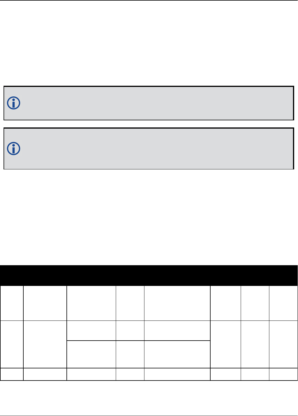
Chapter 2 Core Commands
OEM7 Commands and Logs Reference Manual v7 262
2.98 PPPCONVERGEDCRITERIA
Configures decision for PPP convergence
Platform: OEM719, OEM729, OEM7500, OEM7600, OEM7700, OEM7720, PwrPak7,
SPAN CPT7
The PPPCONVERGEDCRITERIA command sets the threshold that determines if the solution
has converged for high-accuracy PPP solutions. These are the PPP solutions reported with the
PPP and PPP_CONVERGING position types.
The convergence threshold for lower accuracy PPP solutions (reported with PPP_BASIC
and PPP_BASIC_CONVERGING position types) is set using the
PPPBASICCONVERGEDCRITERIA command (see page 261).
Relaxing the convergence threshold shortens the time before a PPP solution is reported
as converged. However, it does not alter solution behavior. During the initial PPP solu-
tion period, the positions can have decimeter error variation. Only relax the con-
vergence threshold if the application can tolerate higher solution variability.
Message ID: 1566
Abbreviated ASCII Syntax:
PPPCONVERGEDCRITERIA criteria tolerance
Factory Default:
PPPCONVERGEDCRITERIA horizontal_stddev 0.32
ASCII Example:
PPPCONVERGEDCRITERIA total_stddev 0.15
Field Field Type ASCII Value Binary
Value Description Format Binary
Bytes
Binary
Offset
1
PPP
CONVERGED
CRITERIA
header
- -
Command header.
See Messages on
page25 for more
information.
- H 0
2 Criteria
TOTAL_
STDDEV 1Use the total, 3D,
standard deviation
Enum 4 H
HORIZONTAL_
STDDEV 2
Use the horizontal,
2D, standard
deviation
3 Tolerance Tolerance (m) Float 4 H+4

Chapter 2 Core Commands
OEM7 Commands and Logs Reference Manual v7 263
2.99 PPPDYNAMICS
Sets the PPP dynamics mode
Platform: OEM719, OEM729, OEM7500, OEM7600, OEM7700, OEM7720, PwrPak7,
SPAN CPT7
This command configures the dynamics assumed by the PPP filter. AUTO detects the antenna
dynamics and adapts filter operation accordingly.
The automatic dynamics detection may be fooled by very slow, “creeping” motion,
where the antenna consistently moves less than 2 cm/s. In such cases, the mode should
explicitly be set to DYNAMIC.
Message ID: 1551
Abbreviated ASCII Syntax:
PPPDYNAMICS mode
Factory Default:
PPPDYNAMICS dynamic
ASCII Example:
PPPDYNAMICS auto
Field Field Type ASCII
Value
Binary
Value Description Format Binary
Bytes
Binary
Offset
1PPPDYNAMICS
header - -
Command header. See
Messages on page25
for more information.
- H 0
2 Mode
AUTO 0
Automatically
determines dynamics
mode Enum 4 H
STATIC 1 Static mode
DYNAMIC 2 Dynamic mode

Chapter 2 Core Commands
OEM7 Commands and Logs Reference Manual v7 264
2.100 PPPDYNAMICSEED
Seed the PPP filter in any platform motion state
Platform: OEM719, OEM729, OEM7500, OEM7600, OEM7700, OEM7720, PwrPak7,
SPAN CPT7
This command enables seeding of the PPP engine regardless of the receiver motion state. Accur-
ate seeds can be used to improve initial PPP convergence and re-convergence following signal
outages.
The seed position given by the PPPDYNAMICSEED command must be in a datum consistent
with the PPP corrections that are in use. For NovAtel CORRECT with PPP, the datum is ITRF2008.
The dynamic seed’s time must refer to receiver time and cannot be more than 15 seconds in the
past. A valid PPP solution (the PPPPOS log (see page 639) solution status is SOL_COMPUTED)
must have been computed for the same epoch as the seed in order for the seed to be used.
See the PPPSEED command on page267 for stationary-only seeding and for other control over
seeding.
Message ID: 2071
Abbreviated ASCII Syntax:
PPPDYNAMICSEED week seconds latitude longitude height northing_std_dev
easting_std_dev height_std_dev [northing_easting_covariance] [northing_
height_covariance] [easting_height_covariance]
Example :
PPPDYNAMICSEED 1817 247603 51.2086442297 -113.9810263055 1071.859 0.02 0.02
0.04
Field Field Type ASCII
Value
Binary
Value Description Format Binary
Bytes
Binary
Offset
1PPPDYNAMICSEED
header - -
Command header.
See Messages on
page25 for more
information.
H 0
2 week 0-9999 GPS Week number Ulong 4 H
3 seconds 0-604800 Number of seconds
into GPS week Ulong 4 H+4
4 latitude ±90 Latitude (degrees) Double 8 H+8
5 longitude ±180 Longitude (degrees) Double 8 H+16
6 height > -2000.0 Ellipsoidal height
(metres) Double 8 H+24
7 northing_std_dev Northing standard
deviation (metres) Float 4 H+32

Chapter 2 Core Commands
OEM7 Commands and Logs Reference Manual v7 265
Field Field Type ASCII
Value
Binary
Value Description Format Binary
Bytes
Binary
Offset
8 easting_std_dev Easting standard
deviation (metres) Float 4 H+36
9 height_std_dev
Ellipsoidal height
standard deviation
(metres)
Float 4 H+40
10 northing_easting_
covariance
Covariance between
northing and easting
components (metres)
Float 4 H+44
11 northing_height_
covariance
Covariance between
northing and height
components (metres)
Float 4 H+48
12 easting_height_
covariance
Covariance between
easting and height
components (metres)
Float 4 H+52

Chapter 2 Core Commands
OEM7 Commands and Logs Reference Manual v7 266
2.101 PPPRESET
Reset the PPP filter
Platform: OEM719, OEM729, OEM7500, OEM7600, OEM7700, OEM7720, PwrPak7,
SPAN CPT7
This command resets the PPP filter. After a reset, the PPP filter is restored to its initial state and
PPP convergence will start over.
If deletion of the NVM-saved PPP seed information is also required, then a PPPSEED
CLEAR command must be applied before the PPPRESET command. See the PPPSEED
command on the next page.
Message ID: 1542
Abbreviated ASCII Syntax:
PPPRESET [Option]
ASCII Example :
PPPRESET
Field Field
Type
ASCII
Value
Binary
Value Description Binary
Bytes
Binary
Format
Binary
Offset
1PPPRESET
header - -
Command header. See
Messages on page25 for
more information.
- H 0
2 Option FILTER 1
Reset the PPP filter.
This is an optional parameter.
(default = FILTER)
4 Enum H

Chapter 2 Core Commands
OEM7 Commands and Logs Reference Manual v7 267
2.102 PPPSEED
Control the seeding of the PPP filter
Platform: OEM719, OEM729, OEM7500, OEM7600, OEM7700, OEM7720, PwrPak7,
SPAN CPT7
The PPPSEED command controls the seeding of the PPP filter. Accurate position seeding can
accelerate PPP convergence.
PPPSEED SET is used to explicitly specify a seed position. The seed position must be in a
datum consistent with the PPP corrections that will be used. For NovAtel CORRECT with PPP, this
is ITRF2008. The PPPSEED SET command can only be used to give seed positions for stationary
platforms. If the platform is moving, use the PPPDYNAMICSEED command (see page 264).
Caution must be exercised when using PPPSEED SET. While a good seed position can
accelerate convergence, a bad seed position hurts performance. In some cases, a bad
seed can prevent a solution from ever converging to a correct position. In other cases, a
bad seed might be rejected immediately. In still other cases, the filter might operate
with it for a time period only to reject it later. In this case, the filter position is partially
reset, with a corresponding discontinuity in the PPP position.
PPPSEED STORE and RESTORE are intended to simplify seeding in operations where the
antenna does not move between power-down and power-up. For example, in agricultural oper-
ations a tractor might be stopped in a field at the end of a day and then re-started the next day
in the same position. Before the receiver is powered-down, the current PPP position could be
saved to NVM using the PPPSEED STORE command, and then that position applied as a seed
after power-up using PPPSEED RESTORE.
PPPSEED AUTO automates the STORE and RESTORE process. When this option is used, the PPP
filter automatically starts using the stopping position of the previous day. For this command to
work, the PPPDYNAMICS command (see page 263) setting must be AUTO so that the receiver
can determine when it is static, or the filter must explicitly be told it is static using
PPPDYNAMIC STATIC. Additionally, in order for the receiver to recall the saved seed, the
PPPSEED AUTO command should be saved to NVM using the SAVECONFIG command (see
page 316).
Message ID: 1544
Abbreviated ASCII Syntax:
PPPSEED option [latitude] [longitude] [height] [northing_std._dev.]
[easting_std._dev.] [height_std._dev.]
ASCII Example:
PPPSEED set 51.11635322441 -114.03819311672 1064.5458 0.05 0.05 0.05

Chapter 2 Core Commands
OEM7 Commands and Logs Reference Manual v7 268
Field Field
Type
ASCII
Value
Binary
Value Description Format Binary
Bytes
Binary
Offset
1PPPSEED
header - -
Command header. See
Messages on page25 for
more information.
- H 0
2 option
CLEAR 0
Resets the stored seed, and
prevents any auto seeding
from occurring.
Enum 4 H
SET 1
Immediately apply the
specified co-ordinates as a
seed position.
STORE 2
Store the current PPP
position in NVM for use as a
future seed.
RESTORE 3
Retrieve and apply a seed
position that was previously
saved in NVM via the STORE
or AUTO options.
AUTO 4 Automatically store and
restore PPP seed positions.
3 latitude ±90 Latitude (degrees) Double 8 H+4
4 longitude ±180 Longitude (degrees) Double 8 H+12
5 height > -2000.0 Ellipsoidal height (metres) Double 8 H+20
6northing
std. dev.
Northing standard deviation
(metres) Float 4 H+28
7easting
std. dev.
Easting standard deviation
(metres) Float 4 H+32
8height
std. dev.
Ellipsoidal height standard
deviation (metres) Float 4 H+36
9 Reserved Float 4 H+40

Chapter 2 Core Commands
OEM7 Commands and Logs Reference Manual v7 269
2.103 PPPSOURCE
Specifies the PPP correction source
Platform: OEM719, OEM729, OEM7500, OEM7600, OEM7700, OEM7720, PwrPak7,
SPAN CPT7
This command determines what corrections the PPP filter will use. When transitioning between
explicitly specified sources, there can be some delay between this command being accepted and
the source specified in the PPP solution changing.
The AUTO source behavior is subject to change.
Message ID: 1707
Abbreviated ASCII Syntax:
PPPSOURCE source
Factory Default:
PPPSOURCE auto
ASCII Example:
PPPSOURCE none
Field Field Type ASCII
Value
Binary
Value Description Format Binary
Bytes
Binary
Offset
1PPPSOURCE
header - -
Command header.
See Messages on
page25 for more
information.
- H 0

Chapter 2 Core Commands
OEM7 Commands and Logs Reference Manual v7 270
Field Field Type ASCII
Value
Binary
Value Description Format Binary
Bytes
Binary
Offset
2 source
NONE 0
Reject all
PPPcorrections.
Disable the PPP filter
Enum 4 H
TERRASTAR 1 Only accept TerraStar
PPP corrections
VERIPOS 2 Only accept Veripos
PPP corrections
TERRASTAR_
L8
Only accept
TerraStar-L PPP
corrections
TERRASTAR_
C10
Only accept
TerraStar-C PPP
corrections
AUTO 100
Automatically select
and use the best
corrections

Chapter 2 Core Commands
OEM7 Commands and Logs Reference Manual v7 271
2.104 PPPTIMEOUT
Sets the maximum age of the PPP corrections
Platform: OEM719, OEM729, OEM7500, OEM7600, OEM7700, OEM7720, PwrPak7,
SPAN CPT7
This command sets the maximum age of the corrections used in the PPP filter. Corrections older
than the specified duration are not applied to the receiver observations and uncorrected obser-
vations are not used in the filter.
Message ID: 1560
Abbreviated ASCII Syntax:
PPPTIMEOUT delay
Factory Default:
PPPTIMEOUT 360
ASCII Example:
PPPTIMEOUT 120
Field Field Type ASCII
Value
Binary
Value Description Format Binary
Bytes
Binary
Offset
1PPPTIMEOUT
header - -
Command header. See
Messages on page25 for
more information.
- H 0
2 delay 5 to 900 s Maximum corrections age Ulong 4 H

Chapter 2 Core Commands
OEM7 Commands and Logs Reference Manual v7 272
2.105 PPSCONTROL
Controls the PPS output
Platform: OEM719, OEM729, OEM7500, OEM7600, OEM7700, OEM7720, PwrPak7,
SPAN CPT7
This command provides a method for controlling the polarity, period and pulse width of the PPS
output on the OEM7. The PPS output can also be disabled using this command.
This command is used to setup the PPS signal coming from the receiver. For example, to
take measurements such as temperature or pressure, in synch with your GNSS data, the
PPS signal can be used to trigger measurements in other devices.
The leading edge of the 1 PPS pulse is always the trigger/reference. For example:
PPSCONTROL ENABLE NEGATIVE
generates a normally high, active low pulse with the falling edge as the reference, while:
PPSCONTROL ENABLE POSITIVE
generates a normally low, active high pulse with the rising edge as the reference.
The pulse width is user-adjustable. The adjustable pulse width feature supports trig-
gers/systems that need longer, or shorter, pulse widths than the default to register the pulse
enabling a type of GPIO line for manipulation of external hardware control lines.
The switch states allow more control over disabling/enabling the PPS. The ENABLE_FINETIME
switch prevents the PPS from being enabled until FINE or FINESTEERING time status has been
reached. The ENABLE_FINETIME_MINUTEALIGN switch is similar to ENABLE_FINETIME with
caveat that the PPS will still not be enabled until the start of the next 60 seconds (a 1 minute
modulus) after FINE or FINESTEERING time status has been reached.
If the value of a field shared with PPSCONTROL2 is changed in PPSCONTROL, the value
of that field is also changed in PPSCONTROL2. For example, if the polarity is changed
using the PPSCONTROL command, the polarity is also changed in PPSCONTROL2 com-
mand.
Message ID: 613
Abbreviated ASCII Syntax:
PPSCONTROL [switch [polarity [period [pulsewidth]]]]
Factory Default:
PPSCONTROL enable negative 1.0 1000
ASCII Example:
PPSCONTROL enable positive 0.5 2000

Chapter 2 Core Commands
OEM7 Commands and Logs Reference Manual v7 273
Field Field Type ASCII Value Binary
Value Description Format Binary
Bytes
Binary
Offset
1PPSCONTROL
header - -
Command header.
See Messages on
page25 for more
information.
- H 0
2 switch
DISABLE 0 Disable the PPS
Enum 4 H
ENABLE 1 Enable the PPS
(default)
ENABLE_
FINETIME 2
Enable the PPS only
when FINE or
FINESTEERING
time status has
been reached
ENABLE_
FINETIME_
MINUTEALIGN
3
Enable the PPS only
when FINE or
FINESTEERING
time status has
been reached AND
the start of the
next 60 seconds (1
minute modulus)
has occurred
3 polarity
NEGATIVE 0
Optional field to
specify the polarity
of the pulse to be
generated on the
PPS output. See
Figure 6: TTL Pulse
Polarity on
page234 for more
information
(default=
NEGATIVE)
Enum 4 H+4
POSITIVE 1
4 period
0.05, 0.1, 0.2, 0.25,
0.5, 1.0, 2.0,
3.0,...20.0
Optional field to
specify the period
of the pulse, in
seconds
(default=1.0)
Double 8 H+8

Chapter 2 Core Commands
OEM7 Commands and Logs Reference Manual v7 274
Field Field Type ASCII Value Binary
Value Description Format Binary
Bytes
Binary
Offset
5 pulsewidth
Any positive value less
than or equal to half the
period
Optional field to
specify the pulse
width of the PPS
signal in
microseconds. This
value should
always be less than
or equal to half the
period
(default=1000)
Ulong 4 H+16
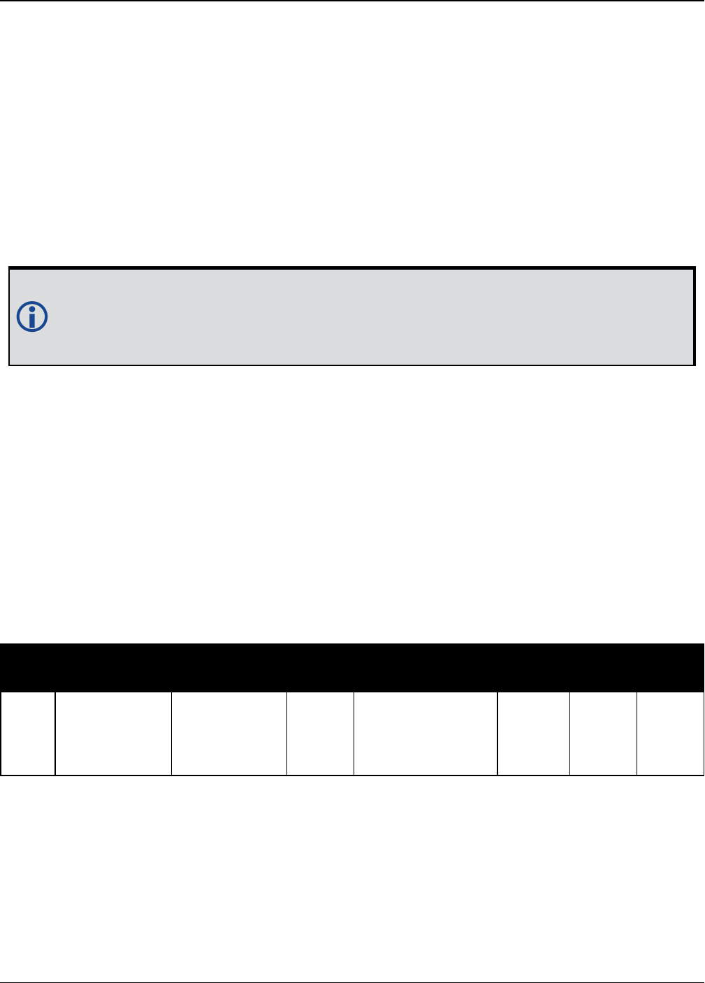
Chapter 2 Core Commands
OEM7 Commands and Logs Reference Manual v7 275
2.106 PPSCONTROL2
Controls polarity, period, pulse width and estimated error limit of the
PPS output
Platform: OEM719, OEM729, OEM7500, OEM7600, OEM7700, OEM7720, PwrPak7,
SPAN CPT7
The PPSCONTROL2 command provides a method for controlling the polarity, period, pulse
width, and estimated error limit of the PPS output on the OEM7. The PPS output can also be dis-
abled using this command.
This command is identical to the PPSCONTROL command (see page 272) with the addition of a
new parameter that represents the Estimated Error Limit.
If the value of a field shared with PPSCONTROL is changed in PPSCONTROL2, the value
of that field is also changed in PPSCONTROL. For example, if the polarity is changed
using the PPSCONTROL2 command, the polarity is also changed in PPSCONTROL com-
mand.
The estimated error limit sets an allowable ± range for the clock offset. The PPS output is only
enabled when the clock offset is within this range.
Message ID: 1740
Abbreviated ASCII Syntax:
PPSCONTROL2 [switch [polarity [period [pulsewidth [estimatederrorlimit]]]]]
Factory default:
PPSCONTROL2 enable negative 1.0 1000 0
ASCII Example:
PPSCONTROL2 enable_finetime positive 0.5 2000 10
Field Field Type ASCII Value Binary
Value Description Format Binary
Bytes
Binary
Offset
1PPSCONTROL2
header - -
Command header.
See Messages on
page25 for more
information.
- H 0

Chapter 2 Core Commands
OEM7 Commands and Logs Reference Manual v7 276
Field Field Type ASCII Value Binary
Value Description Format Binary
Bytes
Binary
Offset
2 switch
DISABLE 0 Disable the PPS
Enum 4 H
ENABLE 1 Enable the PPS
(default)
ENABLE_
FINETIME 2
Enable the PPS
only when FINE or
FINESTEERING
time status has
been reached
ENABLE_
FINETIME_
MINUTEALIGN
3
Enable the PPS
only when FINE or
FINESTEERING
time status has
been reached AND
the start of the
next 60 seconds
(1 minute
modulus) has
occurred
3 polarity
NEGATIVE 0
Optional field to
specify the
polarity of the
pulse to be
generated on the
PPS output. See
Figure 6: TTL
Pulse Polarity on
page234 for more
information
(default =
NEGATIVE).
Enum 4 H+4
POSITIVE 1
4 period
0.05, 0.1, 0.2, 0.25,
0.5, 1.0, 2.0,
3.0,...20.0
Optional field to
specify the period
of the pulse in
seconds (default
= 1.0).
Double 8 H+8

Chapter 2 Core Commands
OEM7 Commands and Logs Reference Manual v7 277
Field Field Type ASCII Value Binary
Value Description Format Binary
Bytes
Binary
Offset
5 pulse width
Any value less than or
equal to half the pulse
period in microseconds.
Optional field to
specify the pulse
width of the PPS
signal in
microseconds.
This value should
always be equal
to half the period
(default = 1000).
Ulong 4 H+16
6estimated
error limit
0 to 2147483647 in
nanoseconds
Optional field to
specify the ±
estimated error
limit (in
nanoseconds) for
the clock offset
(default = 0). The
PPS output is only
enabled when the
clock offset is
within this limit.
An estimated
error limit of 0
removes the
estimated error
limit restraint on
the PPS.
Long 4 H+20

Chapter 2 Core Commands
OEM7 Commands and Logs Reference Manual v7 278
2.107 PROFILE
Profile in Non-Volatile Memory (NVM)
Platform: OEM719, OEM729, OEM7500, OEM7600, OEM7700, OEM7720, PwrPak7,
SPAN CPT7
This command is used to configure multiple profiles in the NVM at receiver startup. The output is
in the PROFILEINFO log (see page 643).
Message ID: 1411
Abbreviated ASCII Syntax:
PROFILE Option Name [command]
ASCII Examples:
PROFILE create Base
PROFILE createelement Base “log com1 versiona”
PROFILE createelement Base “serialconfig com2 115200”
PROFILE createelement Base “log com2 rtca1 ontime 1”
PROFILE activate Base
Field Field
Type
ASCII
Value
Binary
Value Description Format Binary
Bytes
Binary
Offset
1PROFILE
header - -
Command header. See
Messages on page25
for more information.
- H 0
2 Option
Refer to Table 51:
Profile Option on
the next page
Profile options Enum 4 H
3 Name Profile name String
[Max20]
variable
1H+4
4 Command Profile command String
[Max200]
variable
1variable
1In the binary case, each string field needs to be NULL terminated and additional bytes of padding added to
maintain 4-byte alignment, up to the maximum defined by the string size. The next defined field starts
immediately at the next 4-byte alignment following the NULL.

Chapter 2 Core Commands
OEM7 Commands and Logs Reference Manual v7 279
Restrictions:
1. Only supports up to a maximum of 9 profiles.
2. Only supports up to a maximum of 20 commands per profile.
3. Only supports up to a maximum of 200 characters long for each command.
4. Only supports up to a maximum of 1500 characters for all commands in one profile.
5. If one of the profiles is activated, the SAVECONFIG functionality is disabled.
6. All profiles are deleted by a FRESET PROFILEINFO command (see the FRESET com-
mand on page174).
7. The receiver resets after a profile is activated.
8. Some commands optionally accept a port parameter and will default to THISPORT if no
port is provided (e.g.LOG command). Since the commands in a profile are not sent
from a port THISPORT is undefined in this case. When adding such commands to a pro-
file, be sure to specify the port for the command rather than letting the command use
the default, which may result in incorrect behavior.
9. Commands that lead to a reset of the receiver are rejected by the PROFILE command
(see page 278).
Binary ASCII Description
0 Reserved
1 CREATE Create a profile
2 DELETE Delete an existing profile
3 CREATEELEMENT Create an element in an existing profile
4 DELETEELEMENT Delete an existing element in an existing profile
5 ACTIVATE Activate an existing profile
6 DEACTIVATE Deactivate a running profile
Table 51: Profile Option

Chapter 2 Core Commands
OEM7 Commands and Logs Reference Manual v7 280
2.108 PSRDIFFSOURCE
Sets the pseudorange differential correction source
Platform: OEM719, OEM729, OEM7500, OEM7600, OEM7700, OEM7720, PwrPak7,
SPAN CPT7
This command is used to identify which base station to accept differential corrections from. This
is useful when the receiver is receiving corrections from multiple base stations. See also the
RTKSOURCE command on page311.
1. When a valid PSRDIFFSOURCE command is received, the current correction is
removed immediately rather than in the time specified in the
(PSRDIFFSOURCETIMEOUT command (see page 283)).
2. To use L-Band differential corrections, an L-Band receiver and NovAtel Correct with
PPP service or use of a DGPS service is required. Contact NovAtel for details.
3. For ALIGN users: the ALIGN rover will not use RTK corrections automatically to do
PSRDIFF positioning, as ALIGN is commonly used with a moving base. If you have a
static base and want a PSRDIFF position, at the ALIGN rover, set the PSRDIFFSOURCE
to RTK.
Message ID: 493
Abbreviated ASCII Syntax:
PSRDIFFSOURCE type [id]
Factory Default:
PSRDIFFSOURCE auto ANY
ASCII Examples:
1. Enable only SBAS:
RTKSOURCE NONE
PSRDIFFSOURCE SBAS
SBASCONTROL ENABLE AUTO
2. Enable RTK and PSRDIFF from RTCM, with a fall-back to SBAS:
RTKSOURCE RTCM ANY
PSRDIFFSOURCE RTCM ANY
SBASCONTROL ENABLE AUTO
3. Disable all corrections:
RTKSOURCE NONE
PSRDIFFSOURCE none

Chapter 2 Core Commands
OEM7 Commands and Logs Reference Manual v7 281
Since several errors affecting signal transmission are nearly the same for two receivers
near each other on the ground, a base at a known location can monitor the errors and
generate corrections for the rover to use. This method is called Differential GPS and is
used by surveyors to obtain submetre accuracy.
Major factors degrading GPS signals, which can be removed or reduced with differential
methods, are atmospheric, satellite orbit errors and satellite clock errors. Errors not
removed include receiver noise and multipath.
Field Field Type ASCII
Value
Binary
Value Description Format Binary
Bytes
Binary
Offset
1PSRDIFFSOURCE
header - -
Command header. See
Messages on page25
for more information.
- H 0
2 type
See Table 52:
DGPS Type
below
ID Type. All types
(except NONE) may
revert to SBAS (if
enabled) or SINGLE
position types. See
Table 74: Position or
Velocity Type on
page432 1
Enum 4 H
3 Base station ID Char [5] or ANY ID string Char[5] 8 2H+4
Binary ASCII Description
0 RTCM RTCM ID: 0 ≤ RTCM ID ≤ 1023 or ANY
1 RTCA RTCA ID: A four character string containing only alpha (a-z) or numeric
characters (0-9) or ANY
2 CMR3CMR ID: 0 ≤ CMR ID ≤ 31 or ANY
3 Reserved
4 Reserved
Table 52: DGPS Type
1If ANY is chosen, the receiver ignores the ID string. Specify a Type when using base station IDs.
2In the binary log case, an additional 3 bytes of padding are added to maintain 4-byte alignment.
3This cannot be used in the PSRDIFFSOURCE command.

Chapter 2 Core Commands
OEM7 Commands and Logs Reference Manual v7 282
Binary ASCII Description
5 SBAS1
In the PSRDIFFSOURCE command, when enabled, SBAS such as WAAS,
EGNOS and MSAS, forces the use of SBAS as the pseudorange differential
source. SBAS is able to simultaneously track two SBAS satellites and
incorporate the SBAS corrections into the position to generate differential
quality position solutions. An SBAS-capable receiver permits anyone within
the area of coverage to take advantage of its benefits.
If SBAS is set in the RTKSOURCE command (see page 311), it can not
provide carrier phase positioning and returns an error
6RTK4In the PSRDIFFSOURCE command, RTK enables using RTK correction types
for PSRDIFF positioning. The correction type used is determined by the
setting of the RTKSOURCE command (see page 311)
10 AUTO4
In the PSRDIFFSOURCE command, AUTO means that if any correction
format is received then it will be used. If multiple correction formats are
available, then RTCMV3 and RTK will be preferred over SBAS messages. If
RTCMV3 and RTK are all available then the type of the first received
message will be used.
In the RTKSOURCE command (see page 311), AUTO means that both the
NovAtel RTK filter is enabled. The NovAtel RTK filter selects the first
received RTCMV3 message.
11 NONE4Disables all differential correction types
12 Reserved
13 RTCMV3 3,
2RTCM Version 3.0 ID: 0 ≤ RTCMV3 ID ≤ 4095 or ANY
14 NOVATELX NovAtel proprietary message format ID: A four character string containing
alpha (a-z) or numeric characters (0-9) or ANY
All PSRDIFFSOURCE entries fall back to SBAS (except NONE).
1Available only with the PSRDIFFSOURCE command.
2Base station ID parameter is ignored.

Chapter 2 Core Commands
OEM7 Commands and Logs Reference Manual v7 283
2.109 PSRDIFFSOURCETIMEOUT
Sets pseudorange differential correction source timeout
Platform: OEM719, OEM729, OEM7500, OEM7600, OEM7700, OEM7720, PwrPak7,
SPAN CPT7
When multiple differential correction sources are available, this command allows the user to set
a time in seconds, that the receiver will wait before switching to another differential source, if
corrections from the original source are lost.
Message ID: 1449
Abbreviated ASCII Syntax:
PSRDIFFSOURCETIMEOUT option [timeout]
Factory Default:
PSRDIFFSOURCETIMEOUT AUTO
ASCII Example:
PSRDIFFSOURCETIMEOUT auto
PSRDIFFSOURCETIMEOUT set 180
Field Field Type ASCII
Value
Binary
Value Description Format Binary
Bytes
Binary
Offset
1PSRDIFFSOURCE
TIMEOUT header - -
Command header. See
Messages on page25
for more information.
- H 0
2 option AUTO 1 Use AUTO or SET to set
the time Enum 4 H
SET 2
3 timeout 0 to 3600 sec Specify the timeout
(default=0) Ulong 4 H+4

Chapter 2 Core Commands
OEM7 Commands and Logs Reference Manual v7 284
2.110 PSRDIFFTIMEOUT
Sets maximum age of pseudorange differential data
Platform: OEM719, OEM729, OEM7500, OEM7600, OEM7700, OEM7720, PwrPak7,
SPAN CPT7
This command is used to set the maximum age of pseudorange differential correction data to
use when operating as a rover station. Received pseudorange differential correction data, older
than the specified time, is ignored. This time out period also applies to differential corrections
generated from RTK corrections.
The RTCA Standard for scat-i stipulates that the maximum age of differential correction
messages cannot be greater than 22 seconds. Therefore, for RTCA rover users, the
recommended PSRDIFF delay setting is 22.
Message ID: 1450
Abbreviated ASCII Syntax:
PSRDIFFTIMEOUT delay
Factory Default:
PSRDIFFTIMEOUT 300
ASCII Example:
PSRDIFFTIMEOUT 60
Field Field
Type
ASCII
Value
Binary
Value Description Format Binary
Bytes
Binary
Offset
1
PRSDIFF
TIMEOUT
header
- -
Command header. See
Messages on page25 for more
information.
- H 0
2 delay 2 to 1000 s Maximum pseudorange
differential age Ulong 4 H
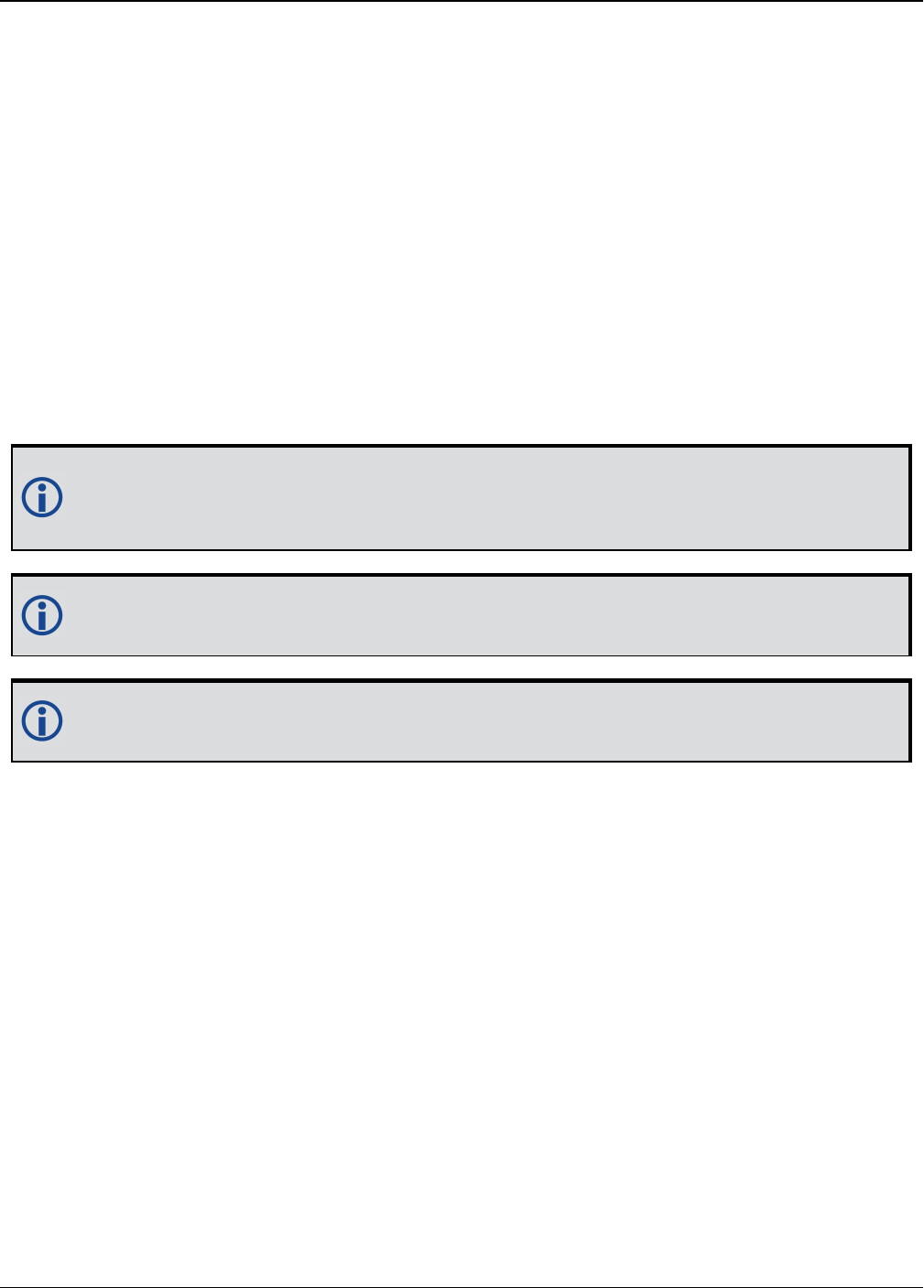
Chapter 2 Core Commands
OEM7 Commands and Logs Reference Manual v7 285
2.111 QZSSECUTOFF
Sets QZSS satellite elevation cutoff
Platform: OEM719, OEM729, OEM7500, OEM7600, OEM7700, OEM7720, PwrPak7,
SPAN CPT7
This command is used to set the elevation cut-off angle for tracked QZSS satellites. The receiver
does not start automatically searching for a QZSS satellite until it rises above the cut-off angle
(when satellite position is known). Tracked satellites that fall below the cut-off angle are no
longer tracked unless they are manually assigned (see the ASSIGN command on page65).
In either case, satellites below the QZSSECUTOFF angle are eliminated from the internal pos-
ition and clock offset solution computations.
This command permits a negative cut-off angle; it could be used in these situations:
lThe antenna is at a high altitude, and thus can look below the local horizon
lSatellites are visible below the horizon due to atmospheric refraction
Care must be taken when using QZSSECUTOFF command because the signals from
lower elevation satellites are traveling through more atmosphere and are therefore
degraded. Use of satellites below 5 degrees is not recommended.
Use the ELEVATIONCUTOFF command (see page 136) to set the cut-off angle for any
system.
For dual antenna receivers, this command applies to both the primary and secondary
antennas.
Message ID: 1350
Abbreviated ASCII Syntax:
QZSSECUTOFF angle
Factory Default:
QZSSECUTOFF 5.0
ASCII Example
QZSSECUTOFF 10.0

Chapter 2 Core Commands
OEM7 Commands and Logs Reference Manual v7 286
Field Field Type ASCII
Value
Binary
Value Description Format Binary
Bytes
Binary
Offset
1QZSSECUTOFF
header - -
Command header. See
Messages on page25 for
more information.
- H 0
2 angle ±90 degrees Elevation cutoff angle
relative to the horizon Float 4 H

Chapter 2 Core Commands
OEM7 Commands and Logs Reference Manual v7 287
2.112 RADARCONFIG
Configure the Emulated Radar Output
Platform: OEM719, OEM729, OEM7500, OEM7600, OEM7700, OEM7720, PwrPak7,
SPAN CPT7
Use this command to configure the Emulated Radar (ER) output.
The ER signal is output on the VARF or EVENT_OUT1 pin of the receiver.
Message ID: 1878
Abbreviated ASCIISyntax:
RADARCONFIG switch [frequency_step [update_rate [response_mode
[threshold]]]]
Factory Default:
radarconfig disable
ASCIIExample:
radarconfig enable 26.11 5hz 2 3.5
Field Field Type ASCII
Value
Binary
Value Description Format Binary
Bytes
Binary
Offset
1RADARCONFIG
header - -
Command header. See
Messages on page25
for more information.
- H 0
2 switch
DISABLE 0 Disables radar
emulation Enum 4 H
ENABLE 1 Enables radar
emulation
3 freq_step
10.06
16.32
26.11
28.12
34.80
36.11
Frequency step per
kilometer per hour.
(default = 36.11
Hz/kph)
Double 8 H+4

Chapter 2 Core Commands
OEM7 Commands and Logs Reference Manual v7 288
Field Field Type ASCII
Value
Binary
Value Description Format Binary
Bytes
Binary
Offset
4 update_rate
1HZ 1
Rate at which the
output frequency is
adjusted
(default = 10HZ)1
Enum 4 H+12
2HZ 2
5HZ 5
10HZ 10
20HZ 20
5 resp_mode
See Table 53:
Response Modes
below
Specify how responsive
radar emulation is to
changes in velocity
(Default = 500)1
Integer 4 H+16
6 threshold 2 to 50 kph
The speed threshold at
which to switch
between response
mode 1000 and
response mode 500.
The threshold is only
applicable when the
response mode is set
to 2.
(default = 5 kph)
Double 8 H+20
Mode Description
1 Immediate. This results in the lowest latency at the cost of higher noise
2Automatically switch between 1000 and 500 depending on speed. When speed is below the
Threshold parameter, use Response Mode 500. Otherwise, use Response Mode 1000.
500 Signal is minimally smoothed resulting in low latency but increased noise.
1000 Output signal is smoothed over a smaller window resulting in less latency than 2000 and
less noise than 500.
2000 Output signal is smoothed to reduce noise at the cost of higher latency
Table 53: Response Modes
1The number of samples used for smoothing depends on both the update_rate and resp_mode parameters. For
instance, if the update_rate is 5 Hz and the resp_mode is 2000 ms, the number of samples used will be 10.

Chapter 2 Core Commands
OEM7 Commands and Logs Reference Manual v7 289
2.113 RAIMMODE
Configures RAIM mode
Platform: OEM719, OEM729, OEM7500, OEM7600, OEM7700, OEM7720, PwrPak7,
SPAN CPT7
This command is used to configure Receiver Autonomous Integrity Monitoring (RAIM) operation.
This command uses RTCA MOPS characteristics which defines the positioning accuracy require-
ments for airborne lateral navigation (LNAV) and vertical navigation (VNAV) at 3 stages of
flight:
1. En route travel
2. Terminal (within range of air terminal)
3. Non-precision approach
In order to ensure that the required level of accuracy is available in these phases of flight, MOPS
requires the computation of protection levels (HPL and VPL). MOPS has the following definitions
that apply to NovAtel’s RAIM feature:
Horizontal Protection Level (HPL) is a radius of the circle in the horizontal plane. Its center
is at the true position, that describes the region, assured to contain the indicated horizontal pos-
ition. It is the horizontal region where the missed alert and false alert requirements are met
using autonomous fault detection.
Vertical Protection Level (VPL) is half the length of the segment on the vertical axis. Its cen-
ter is at the true position, that describes the region, assured to contain the indicated vertical pos-
ition when autonomous fault detection is used.
Horizontal Alert Limit (HAL) is a radius of the circle in the horizontal plane. Its center is at
the true position, that describes the region, required to contain the indicated horizontal position
with the required probability.
Vertical Alert Limit (VAL) is half the length of the segment on the vertical axis. Its center is
at the true position, that describes the region, required to contain the indicated vertical position
with certain probability.
Probability of False Alert (Pfa)is a false alert defined as the indication of a positioning fail-
ure, when a positioning failure has not occurred (as a result of false detection). A false alert
would cause a navigation alert.
2.113.1 Detection strategy
NovAtel’s RAIM detection strategy uses the weighted Least-Squares Detection (LSA) method.
This method computes a solution using a LSA and is based on the sum of squares of weighted
residuals. It is a comparison between a root sum of squares of residuals and a decision
threshold to determine a pass/fail decision.
2.113.2 Isolation strategy
NovAtel RAIM uses the maximum residual method. Logically it is implemented as a second part
of Fault Detection and Exclusion (FDE) algorithm for LSA detection method. Weighted LSA resid-
uals are standardized individually and the largest residual is compared to a decision threshold.
If it is more than the threshold, the observation corresponding to this residual is declared faulty.
Message ID: 1285

Chapter 2 Core Commands
OEM7 Commands and Logs Reference Manual v7 290
Abbreviated ASCII Syntax:
RAIMMODE mode [hal [val [pfa]]]
Factory Default:
RAIMMODE default
Input Example:
RAIMMODE user 100 100 0.01
RAIMMODE terminal
Field Field
Type
ASCII
Value
Binary
Value Description Format Binary
Bytes
Binary
Offset
1RAIMMODE
Header - -
Command header. See
Messages on page25 for
more information.
- H 0
2 MODE See Table 54: RAIM Mode Types below Enum 4 H
3 HAL 5 ≤ HAL ≤
9999.99
Horizontal alert limit (m)
(Default = 0.0) Double 8 H+4
4 VAL 5 ≤ VAL ≤
9999.99
Vertical alert limit (m)
(Default = 0.0) Double 8 H+12
5 PFA (Pfa) = 1e-7≤
Pfa ≤ 0.25
Probability of false alert
(Default = 0.0) Double 8 H+20
Binary ASCII Description
0 DISABLE Do not do integrity monitoring of least squares solution
1 USER User will specify alert limits and probability of false alert
2 DEFAULT Use NovAtel RAIM (default)
3 APPROACH Default numbers for non-precision approach navigation modes are used -
HAL = 556 m (0.3 nm), VAL =50 m for LNAV/VNAV
4 TERMINAL Default numbers forterminal navigation mode are used - HAL = 1855 m (1
nm), no VAL requirement
5 ENROUTE Default numbers for enroute navigation mode are used - HAL = 3710 m (2
nm), no VAL requirement
Table 54: RAIM Mode Types

Chapter 2 Core Commands
OEM7 Commands and Logs Reference Manual v7 291
2.114 REFERENCESTATIONTIMEOUT
Sets timeout for removing previously stored base stations
Platform: OEM719, OEM729, OEM7500, OEM7600, OEM7700, OEM7720, PwrPak7,
SPAN CPT7
This command sets how long the receiver will retain RTK base station co-ordinates. Shorter dur-
ations might be required if the receiver is operating in a VRS RTK network that recycles base sta-
tion IDs quickly.
Message ID: 2033
Abbreviated ASCII Syntax:
REFERENCESTATIONTIMEOUT option [timeout]
Factory Default:
REFERENCESTATIONTIMEOUT AUTO
ASCII Example:
REFERENCESTATIONTIMEOUT SET 90
Field Field Type ASCII
Value
Binary
Value Description Format Binary
Bytes
Binary
Offset
1REFERENCESTATION
TIMEOUT header - -
Command header.
See Messages on
page25 for more
information.
- H 0
2 option
AUTO 1
Sets the Timeout to
90 seconds1
The Timeout field is
optional for AUTO
and has no effect
Enum 4 H
SET 2
Must set the
timeout value using
the Timeout field
0 is not accepted
when using the SET
option
3 timeout 1 to 3600 s Specify the time Ulong 4 H+4
1This behavior is subject to change.
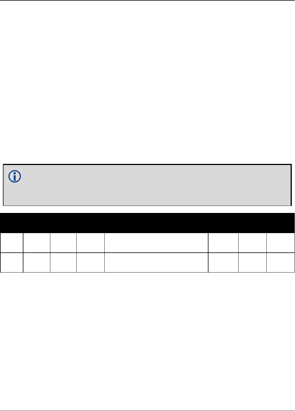
Chapter 2 Core Commands
OEM7 Commands and Logs Reference Manual v7 292
2.115 RESET
Performs a hardware reset
Platform: OEM719, OEM729, OEM7500, OEM7600, OEM7700, OEM7720, PwrPak7,
SPAN CPT7
This command performs a hardware reset. The receiver configuration reverts either to the fact-
ory default, if no user configuration was saved or the last SAVECONFIG settings. Refer to the
FRESET command on page174 and SAVECONFIG command on page316.
The optional delay field is used to set the number of seconds the receiver is to wait before reset-
ting.
Message ID: 18
Abbreviated ASCII Syntax:
RESET [delay]
Input Example
RESET 30
The RESET command can be used to erase any unsaved changes to the receiver
configuration.
Unlike the FRESET command on page174, the RESET command does not erase data
stored in the NVM, such as Almanac and Ephemeris data.
Field Field
Type
ASCII
Value
Binary
Value Description Format Binary
Bytes
Binary
Offset
1RESET
header - - Command header. See Messages
on page25 for more information. - H 0
2delay
(0-60)
Seconds to wait before resetting
(default = 0) Ulong 4 H
Chapter 2 Core Commands
OEM7 Commands and Logs Reference Manual v7 293
2.116 RFINPUTGAIN
Configure the Calibrated Antenna Gain (CAG)
Platform: OEM719, OEM729, OEM7500, OEM7600, OEM7700, OEM7720, PwrPak7,
SPAN CPT7
Use this command to select the mode (AUTO or MANUAL) of setting the CAG for the purpose of
interference detection.
If auto mode is used, the receiver will automatically compute the CAG at start up. In this case it
is assumed that the receiver is powered up with its antenna connected and no interference is
present.
If the antenna is changed, either reset the receiver or reissue this command to allow
receiver to re-compute the CAG.
If manual mode is used, the CAG input by the user is used by the receiver to detect interference.
The CAG is defined to be the cascaded RF gain before receiver input plus LNA noise figure (NF),
counting active antenna LNA gain, in-line amplifier, RF cable or distribution loss prior to receiver
input connector.
A typical GNSS active antenna (of reasonable quality) has a noise figure of ~2dB (dominated by
the LNA in an active antenna).
RFINPUTGAIN = Cascaded Gain before receiver + LNA NF
For advanced users.
If using this command in manual mode, the antenna gain must be accurately measured
when the system is not experiencing any interference. If an erroneous CAG is injected,
the interference detection performance can be degraded.
Message ID: 2155
Abbreviated ASCII Syntax:
RFINPUTGAIN RFPath [mode] [CAG]
Factory Default:
RFINPUTGAIN L1 AUTO
RFINPUTGAIN L2 AUTO
RFINPUTGAIN L5 AUTO
ASCII Example:
RFINPUTGAIN L1 MANUAL 30
RFINPUTGAIN L2 30

Chapter 2 Core Commands
OEM7 Commands and Logs Reference Manual v7 294
Field Field Type ASCII
Value
Binary
Value Description Format Binary
Bytes
Binary
Offset
1RFINPUTGAIN
header - -
Command header. See
Messages on page25 for
more information.
- H 0
2 RFPath
L1 2
RF path selection Enum 4 HL2 3
L5 5
3 mode
AUTO 0 Calibrated Antenna Gain
(CAG) mode.
Default = MANUAL
Enum 4 H+4
MANUAL 1
4 CAG 0.0-100.0
Calibrated Antenna Gain
value
If the mode is MANUAL,
a value for CAG must be
entered.
Float 4 H+8

Chapter 2 Core Commands
OEM7 Commands and Logs Reference Manual v7 295
2.117 RTKANTENNA
Specifies L1 phase center (PC) or ARP and enables/disables PC
modeling
Platform: OEM719, OEM729, OEM7500, OEM7600, OEM7700, OEM7720, PwrPak7,
SPAN CPT7
Use this command to specify whether to use L1 phase center or Antenna Reference Point (ARP)
positioning.
There is also an option to apply phase center variation modeling. If there are any conditions that
make a selected mode impossible, the solution status in the position log will indicate an error or
warning.
L1 ARP offsets and L2 ARP offsets can be entered using the BASEANTENNAPCO command on
page79 and THISANTENNAPCO command on page367. Phase center variation parameters
can be entered using the BASEANTENNAPCV command on page81 and THISANTENNAPCV
command on page368.
Error states occur if either the rover does not have the necessary antenna information entered
or the base is not sending sufficient information to work in the requested mode. An example of
these error conditions is:
lPosition reference to the ARP is requested but no rover antenna model is available
Message ID: 858
Abbreviated ASCII Syntax:
RTKANTENNA posref pcv
Factory Default:
RTKANTENNA unknown disable
ASCII Example:
RTKANTENNA arp enable
This command is used for high precision RTK positioning allowing application of antenna
offset and phase center variation parameters.
Field Field Type ASCII
Value
Binary
Value Description Format Binary
Bytes
Binary
Offset
1RTKANTENNA
header - -
Command header. See
Messages on page25
for more information.
- H 0

Chapter 2 Core Commands
OEM7 Commands and Logs Reference Manual v7 296
Field Field Type ASCII
Value
Binary
Value Description Format Binary
Bytes
Binary
Offset
2 posref
L1PC 0 L1 phase center
position reference
Enum 4 HARP 1 ARP position reference
UNKNOWN 2 Unknown position
reference
3 pcv DISABLE 0 Disable PCV modeling Enum 4 H+4
ENABLE 1 Enable PCV modeling
4 Reserved Bool 4 H+8
5 Reserved Bool 4 H+12
Chapter 2 Core Commands
OEM7 Commands and Logs Reference Manual v7 297
2.118 RTKASSIST
Enable or disable RTK ASSIST
Platform: OEM719, OEM729, OEM7500, OEM7600, OEM7700, OEM7720, PwrPak7,
SPAN CPT7
This command enables or disables RTK ASSIST.
RTK ASSIST uses L-Band-delivered corrections to enable RTK operation to continue for extended
durations if RTK corrections are lost. In order to use RTK ASSIST, a receiver with L-Band track-
ing capability and RTK ASSIST capability is needed. The duration of RTK ASSIST operation can
be limited using the RTKASSISTTIMEOUT command (see page 298).
When active, RTK ASSIST is shown in the RTKPOS and BESTPOS extended solution status field
(see Table 77: Extended Solution Status on page435). The active status and further details on
the RTK ASSIST status are available through the RTKASSISTSTATUS log on page731.
For reliable RTK ASSIST performance, the RTK base station position must be within 1
metre of its true WGS84 position.
Message ID: 1985
Abbreviated ASCII Syntax:
RTKASSIST switch
Factory Default:
RTKASSIST enable
ASCII Example:
RTKASSIST disable
Field Field
Type
ASCII
Value
Binary
Value Description Format Binary
Bytes
Binary
Offset
1RTKASSIST
header - -
Command header. See
Messages on page25 for
more information.
- H 0
2 switch DISABLE 0 Disable RTK ASSIST Enum 4 H
ENABLE 1 Enable RTK ASSIST

Chapter 2 Core Commands
OEM7 Commands and Logs Reference Manual v7 298
2.119 RTKASSISTTIMEOUT
Set the maximum RTK ASSIST duration
Platform: OEM719, OEM729, OEM7500, OEM7600, OEM7700, OEM7720, PwrPak7,
SPAN CPT7
This command sets how long the receiver will report an RTK solution when RTK is being main-
tained by RTK ASSIST. The maximum permitted duration of RTK ASSIST operation is determ-
ined by the subscription and receiver model. Values less than the subscription limit can be set
using the RTKASSISTTIMEOUT command.
When RTK ASSIST is active, the RTKTIMEOUT command is disregarded. The maximum
time that RTK will continue past an RTK corrections outage is controlled by
RTKASSISTTIMEOUT.
Message ID: 2003
Abbreviated ASCII Syntax:
RTKASSISTTIMEOUT limit_type [limit_value]
Factory Default:
RTKASSISTTIMEOUT SUBSCRIPTION_LIMIT
ASCII Example:
RTKASSISTTIMEOUT USER_LIMIT 900
Field Field
Type ASCII Value Binary
Value Description Format Binary
Bytes
Binary
Offset
1
RTKASSIST
TIMEOUT
header
- -
Command header.
See Messages on
page25 for more
information.
- H 0
2 limit_type
SUBSCRIPTION
_LIMIT 0
Use maximum
permitted duration
limit.
Enum 4 H
USER_LIMIT 1
The maximum RTK
ASSIST duration is
user set, up to the
limit permitted by
the subscription and
model.

Chapter 2 Core Commands
OEM7 Commands and Logs Reference Manual v7 299
Field Field
Type ASCII Value Binary
Value Description Format Binary
Bytes
Binary
Offset
3 limit_value
Time out value in
seconds.
Only valid for the
USER_LIMIT Limit
Type.
Ulong 4 H+4
Chapter 2 Core Commands
OEM7 Commands and Logs Reference Manual v7 300
2.120 RTKDYNAMICS
Sets the RTK dynamics mode
Platform: OEM719, OEM729, OEM7500, OEM7600, OEM7700, OEM7720, PwrPak7,
SPAN CPT7
This command is used to specify how the receiver looks at the data. There are three modes:
STATIC, DYNAMIC and AUTO. The STATIC mode forces the RTK software to treat the rover sta-
tion as though it were stationary.
DYNAMIC mode forces the software to treat the rover as though it were in motion. If the
receiver is undergoing very slow, steady motion (<2.5 cm/s for more than 5 seconds), use
DYNAMIC mode (as opposed to AUTO) to prevent inaccurate results and possible resets.
For reliable performance, the antenna should not move more than 1-2 cm when in
STATIC mode.
Message ID: 183
Abbreviated ASCII Syntax:
RTKDYNAMICS mode
Factory Default:
RTKDYNAMICS dynamic
ASCII Example:
RTKDYNAMICS static
Use the STATIC option to decrease the time required to fix ambiguities and reduce the
amount of noise in the position solution. If STATIC mode is used when the antenna is not
static, the receiver will have erroneous solutions and unnecessary RTK resets.
Field Field Type ASCII
Value
Binary
Value Description Format Binary
Bytes
Binary
Offset
1RTKDYNAMICS
header - -
Command header. See
Messages on page25
for more information.
- H 0
2 mode
AUTO 0
Automatically
determines dynamics
mode Enum 4 H
STATIC 1 Static mode
DYNAMIC 2 Dynamic mode

Chapter 2 Core Commands
OEM7 Commands and Logs Reference Manual v7 301
2.121 RTKINTEGERCRITERIA
Report inaccurate fixed-integer RTK positions with float solution
type
Platform: OEM719, OEM729, OEM7500, OEM7600, OEM7700, OEM7720, PwrPak7,
SPAN CPT7
This command forces a fixed-integer RTK position to be reported as float if the estimated solu-
tion standard deviation exceeds a threshold.
Normally, a fixed-integer solution is very accurate. However, in some rarely-occurring situ-
ations, even a fixed-integer solution can become inaccurate; for example, if the DOP is high due
to satellites not being visible. In such cases, the accuracy of the RTK solution might be worse
than what is customarily expected from a fixed-integer solution. The RTKINTEGERCRITERIA
command changes the solution type of these high standard deviation integer solutions to their
float equivalent. NARROW_INT, for instance, becomes NARROW_FLOAT. Depending on the
GGAQUALITY command setting, this will also impact the NMEA GGA quality flag.
Message ID: 2070
Abbreviated ASCII Syntax:
RTKINTEGERCRITERIA criteria threshold
Factory Default:
RTKINTEGERCRITERIA TOTAL_STDDEV 1.0
ASCII Example:
RTKINTEGERCRITERIA HORIZONTAL_STDDEV 0.25
Field Field Type ASCII Value Binary
Value Description Format Binary
Bytes
Binary
Offset
1
RTKINTEGER
CRITERIA
header
- -
Command header.
See Messages on
page25 for more
information.
- H 0
2 criteria
TOTAL_
STDDEV 1
Test the threshold
against the
estimated total, 3D,
standard deviation
Enum 4 H
HORIZONTAL_
STDDEV 2
Test the threshold
against the
estimated
horizontal standard
deviation

Chapter 2 Core Commands
OEM7 Commands and Logs Reference Manual v7 302
Field Field Type ASCII Value Binary
Value Description Format Binary
Bytes
Binary
Offset
3 threshold 0.01 m and higher
Estimated solution
standard deviation
(m) required for
solution to be
reported as integer
Float 4 H+4

Chapter 2 Core Commands
OEM7 Commands and Logs Reference Manual v7 303
2.122 RTKMATCHEDTIMEOUT
Sets RTK filter reset time after corrections are lost
Platform: OEM719, OEM729, OEM7500, OEM7600, OEM7700, OEM7720, PwrPak7,
SPAN CPT7
This command sets the length of time the receiver continues to use the last RTK correction data
once the corrections stop. Once this time is reached, the RTK filter is reset.
Message ID: 1447
Abbreviated ASCII Syntax:
RTKMATCHEDTIMEOUT timeout
ASCII Example:
RTKMATCHEDTIMEOUT 180
Factory Default
RTKMATCHEDTIMEOUT 300
Field Field Type ASCII
Value
Binary
Value Description Format Binary
Bytes
Binary
Offset
1
RTKMATCHED
TIMEOUT
header
- -
Command header. See
Messages on page25 for
more information.
- H 0
2 timeout 1 to 3600 s Time out period Ulong 4 H

Chapter 2 Core Commands
OEM7 Commands and Logs Reference Manual v7 304
2.123 RTKNETWORK
Specifies the RTK network mode
Platform: OEM719, OEM729, OEM7500, OEM7600, OEM7700, OEM7720, PwrPak7,
SPAN CPT7
Network RTK uses permanent base station installations, allowing kinematic GNSS users to
achieve centimetre accuracies, without the need of setting up a GNSS base station, at a known
site. This command sets the RTK network mode for a specific network. For more details on Net-
work RTK, refer to the application note APN-041 Network RTK, available on our website a
www.novatel.com/support/search.
Message ID: 951
Abbreviated ASCII Syntax:
RTKNETWORK mode [network#]
Factory Default:
RTKNETWORK AUTO
Input Example:
RTKNETWORK imax
Field Field Type ASCII
Value
Binary
Value Description Format Binary
Bytes
Binary
Offset
1RTKNETWORK
header - -
Command header. See
Messages on page25 for
more information.
- H 0
2 mode
Table 55:
Network RTK
Mode below
RTK network mode. The
factory default is auto
where the receiver
switches to the first
available network RTK
source
Enum 4 H
3 network# 0 to
4294967295
Specify a number for the
network
(default = 0)
Ulong 4 H+4
Binary ASCII Description
0 DISABLE Single reference station RTK mode. All received network RTK corrections are
ignored.
Table 55: Network RTK Mode

Chapter 2 Core Commands
OEM7 Commands and Logs Reference Manual v7 305
Binary ASCII Description
1-4 Reserved
5 VRS
The Virtual Reference Station (VRS) or Virtual Base Station (VBS) idea
introduced by Trimble, is that a base station is artificially created in the
vicinity of a rover receiver. All baseline length dependent errors, such as
abnormal troposphere variation, ionospheric disturbances and orbital errors,
are reduced for this VRS. The rover receiving VRS information has a lower
level of these errors than a distant base station. The VRS is calculated for a
position, supplied by the rover during communication start up, with
networking software. The VRS position can change if the rover is far away
from the initial point. The format for sending the rover’s position is standard
NMEA format. Most rovers receive VRS data, for a calculated base station,
within a couple of metres away.
The VRS approach requires bi-directional communication for supplying the
rover’s position to the networking software.
6 IMAX
The iMAX idea, introduced by Leica Geosystems, is that networking software
corrections, based on the rover’s position, are calculated as with VRS.
However, instead of calculating the base station observations for the provided
position or another position closer to the base station, original observation
information is corrected with the calculated corrections and broadcast. VRS
works so that although the rover is unaware of the errors the VRS is taking
care of, there still might be ionospheric remains in the base station
observations. iMAX provides actual base station position information. The
rover may assume the base station is at a distance and open its settings for
estimation of the remaining ionospheric residuals. The iMAX method may
trigger the rover to open its settings further than required, since the
networking software removes at least part of the ionospheric disturbances.
However, compared to VRS above, this approach is safer since it notifies the
rover when there might be baseline length dependent errors in the
observation information. iMAX requires bi-directional communication to the
networking software for supplying the base station observation information.
7 FKP
The FKP method delivers the information from a base station network to the
rover. No precise knowledge of the rover’s position is required for providing
the correct information. The corrections are deployed as gradients to be used
for interpolating to the rover’s actual position.

Chapter 2 Core Commands
OEM7 Commands and Logs Reference Manual v7 306
Binary ASCII Description
8 MAX
The basic principle of the master-auxiliary concept is to provide, in compact
form, as much of the information from the network and the errors it is
observing to the rover as possible. With more information about the state and
distribution of the dispersive and non-dispersive errors across the network,
the rover is able to use more intelligent algorithms in the determination of its
position solution. Each supplier of reference station software will have their
own proprietary algorithms for modeling or estimating these error sources.
The rover system can decide to use or to neglect the network RTK information,
depending on its own firmware algorithm performance.
9 Reserved
10 AUTO
Default value, assume single base. If network RTK corrections are detected
then the receiver will switch to the appropriate mode. iMAX and VRS can only
be detected using RTCMV3, however, it is not possible to distinguish between
iMAX or VRS. If iMAX or VRS is detected, then iMAX will be assumed.
Chapter 2 Core Commands
OEM7 Commands and Logs Reference Manual v7 307
2.124 RTKPORTMODE
Assigns the port for RTK and ALIGN messages
Platform: OEM719, OEM729, OEM7500, OEM7600, OEM7700, OEM7720, PwrPak7,
SPAN CPT7
This command only applies to receivers with both RTK and ALIGN enabled.
A rover receiver with RTK and ALIGN enabled can receive RTK and ALIGN corrections at the
same time. However, the two different sources (RTK and ALIGN) must be sent to different ports.
Use the RTKPORTMODE command to route correction feeds to different ports. RTK and ALIGN
can be routed to any user specified ports.
Failing to specify the mode for the incoming source could cause unexpected behavior of RTK or
ALIGN.
Ports configured using the RTKPORTMODE command must also be configured using the
INTERFACEMODE command (see page 193).
Message ID: 1936
Abbreviated ASCII Syntax:
RTKPORTMODE [port] mode
Factory Default:
RTKPORTMODE COM1 RTK
RTKPORTMODE COM2 RTK
RTKPORTMODE COM3 RTK
RTKPORTMODE COM4 RTK
RTKPORTMODE COM5 RTK
RTKPORTMODE COM6 RTK
RTKPORTMODE ICOM1 RTK
RTKPORTMODE ICOM2 RTK
RTKPORTMODE ICOM3 RTK
RTKPORTMODE ICOM4 RTK
RTKPORTMODE ICOM5 RTK
RTKPORTMODE ICOM6 RTK
RTKPORTMODE ICOM7 RTK
RTKPORTMODE NCOM1 RTK
RTKPORTMODE NCOM2 RTK
RTKPORTMODE NCOM3 RTK

Chapter 2 Core Commands
OEM7 Commands and Logs Reference Manual v7 308
RTKPORTMODE USB1 RTK
RTKPORTMODE USB2 RTK
RTKPORTMODE USB3 RTK
RTKPORTMODE WCOM1 RTK
RTKPORTMODE BT1 RTK
RTKPORTMODE AUX RTK
RTKPORTMODE CCOM1 RTK
RTKPORTMODE CCOM2 RTK
RTKPORTMODE CCOM3 RTK
RTKPORTMODE CCOM4 RTK
RTKPORTMODE CCOM5 ALIGN
RTKPORTMODE CCOM6 RTK
ASCII Example:
RTKPORTMODE COM2 RTK
RTKPORTMODE COM3 ALIGN
Field Field Type ASCII
Value
Binary
Value Description Format Binary
Bytes
Binary
Offset
1RTKPORTMODE
header - -
Command header.
See Messages on
page25 for more
information.
- H 0
2 Port
See Table 31:
Communications
Port Identifiers on
page132
Port identifier
(default =
THISPORT)
Enum 4 H
3 Mode RTK 0 Mode for this port Enum 4 H+4
ALIGN 1

Chapter 2 Core Commands
OEM7 Commands and Logs Reference Manual v7 309
2.125 RTKQUALITYLEVEL
Sets an RTK quality mode
Platform: OEM719, OEM729, OEM7500, OEM7600, OEM7700, OEM7720, PwrPak7,
SPAN CPT7
Use this command to select an RTK quality mode.
Message ID: 844
Abbreviated ASCII Syntax:
RTKQUALITYLEVEL mode
Factory Default:
RTKQUALITYLEVEL normal
ASCII Example:
RTKQUALITYLEVEL extra_safe
The EXTRA_SAFE mode is needed in areas where the signal is partially blocked and the
position solution in NORMAL mode shows NARROW_INT even though the real position
solution is out by several metres. Using EXTRA_SAFE in these environments means the
solution will be slower getting to NARROW_INT but it is less likely to be erroneous.
Field Field Type ASCII
Value
Binary
Value Description Format Binary
Bytes
Binary
Offset
1RTKQUALITY-
LEVEL header - -
Command header. See
Messages on page25 for
more information.
- H 0
2 mode
NORMAL 1 Set the RTK quality level
mode to Normal RTK Enum 4 H
EXTRA_
SAFE 4Set the RTK quality level
mode to Extra Safe RTK

Chapter 2 Core Commands
OEM7 Commands and Logs Reference Manual v7 310
2.126 RTKRESET
Reset the RTK filter
Platform: OEM719, OEM729, OEM7500, OEM7600, OEM7700, OEM7720, PwrPak7,
SPAN CPT7
This command resets the RTK filter and causes the AdVanceRTK filter to undergo a complete
reset, forcing the system to restart the ambiguity resolution calculations.
Message ID: 2082
Abbreviated ASCII Syntax:
RTKRESET [Switch]
Example :
RTKRESET
Field Field
Type
ASCII
Value
Binary
Value Description Format Binary
Byte
Binary
Offset
1RTKRESET
header - -
Command header. See
Messages on page25 for
more information.
- H 0
2 Switch FILTER 1 Reset the RTK filter.
This is an optional parameter Enum 4 H

Chapter 2 Core Commands
OEM7 Commands and Logs Reference Manual v7 311
2.127 RTKSOURCE
Sets the RTK correction source
Platform: OEM719, OEM729, OEM7500, OEM7600, OEM7700, OEM7720, PwrPak7,
SPAN CPT7
This command is used to identify from which base station to accept RTK (RTCMV3) differential
corrections. This is useful when the receiver is receiving corrections from multiple base sta-
tions. See also the PSRDIFFSOURCE command on page280.
Message ID: 494
Abbreviated ASCII Syntax:
RTKSOURCE type [id]
Factory Default:
RTKSOURCE auto ANY
ASCII Examples:
1. Specify the format before specifying the base station IDs:
RTKSOURCE RTCM3 5
RTKSOURCE RTCMV3 6
2. Select only SBAS:
RTKSOURCE NONE
PSRDIFFSOURCE SBAS
SBASCONTROL ENABLE AUTO
3. Enable RTK and PSRDIFF from RTCM, with a fall-back to SBAS:
RTKSOURCE RTCMV3 ANY
PSRDIFFSOURCE RTCMV3 ANY
SBASCONTROL ENABLE AUTO
Consider an agricultural example where a farmer has their own RTCM base station set
up but due to either obstructions or radio problems, occasionally experiences loss of cor-
rections. By specifying a fall back to SBAS, the farmer could set up their receiver to use
transmitted RTCM corrections when available but fall back to SBAS.
Field Field Type ASCII
Value
Binary
Value Description Format Binary
Bytes
Binary
Offset
1RTKSOURCE
header - -
Command header. See
Messages on page25 for
more information.
- H 0

Chapter 2 Core Commands
OEM7 Commands and Logs Reference Manual v7 312
Field Field Type ASCII
Value
Binary
Value Description Format Binary
Bytes
Binary
Offset
2 type
See Table 52:
DGPS Type on
page281
ID Type 1Enum 4 H
3Base station
ID Char [4] or ANY ID string Char[5] 8 2H+4
1If ANY chosen, the receiver ignores the ID string. Specify a type when using base station IDs.
2In the binary log case, an additional 3 bytes of padding are added to maintain 4-byte alignment.

Chapter 2 Core Commands
OEM7 Commands and Logs Reference Manual v7 313
2.128 RTKSOURCETIMEOUT
Sets RTK correction source timeout
Platform: OEM719, OEM729, OEM7500, OEM7600, OEM7700, OEM7720, PwrPak7,
SPAN CPT7
When multiple RTK correction sources are available, this command allows the user to set a time,
in seconds, that the receiver will wait before switching to another RTK correction source if cor-
rections from the original source are lost.
Message ID: 1445
Abbreviated ASCII Syntax:
RTKSOURCETIMEOUT option [timeout]
Factory Default:
RTKSOURCETIMEOUT AUTO
ASCII Example:
RTKSOURCETIMEOUT auto
RTKSOURCETIMEOUT set 180
Field Field Type ASCII
Value
Binary
Value Description Format Binary
Bytes
Binary
Offset
1
RTKSOURCE
TIMEOUT
header
- -
Command header. See
Messages on page25 for
more information.
- H 0
2 option
AUTO 1
Sets the timeout according
to network type or other
self-detected conditions.
Timeout field is optional for
AUTO and has no effect Enum 4 H
SET 2
Sets the timeout to the
value entered in the timeout
field.
3 timeout 1 to 3600 s
(maximum)
Specify the time
0 is not accepted if SET is
entered in the option field
(default=0 for the AUTO
option)
Ulong 4 H+4

Chapter 2 Core Commands
OEM7 Commands and Logs Reference Manual v7 314
2.129 RTKSVENTRIES
Sets number of satellites in corrections
Platform: OEM719, OEM729, OEM7500, OEM7600, OEM7700, OEM7720, PwrPak7,
SPAN CPT7
This command sets the number of satellites (at the highest elevation) that are transmitted in the
RTK corrections from a base station receiver. This is useful when the amount of bandwidth avail-
able for transmitting corrections is limited.
Message ID: 92
Abbreviated ASCII Syntax:
RTKSVENTRIES number
Factory Default:
RTKSVENTRIES 24
ASCII Example:
RTKSVENTRIES 7
GPS devices have enabled many transit and fleet authorities to provide Automatic
Vehicle Location (AVL). AVL systems track the position of individual vehicles and relay
that data back to a remote dispatch location that can store or better utilize the
information. Consider the implementation of an AVL system within a police department,
to automatically log and keep track of the location of each cruiser. Typically a fleet uses
a 9600 bps connection where AVL data is relayed back to headquarters. The limited
bandwidth of the radio must be shared amongst the AVL and other systems in multiple
cruisers.
When operating with a low baud rate radio transmitter (9600 or lower), especially over a
long distance, the AVL system could limit the number of satellites for which corrections
are sent using the RTKSVENTRIES command.
Field Field Type ASCII
Value
Binary
Value Description Format Binary
Bytes
Binary
Offset
1RTKSVENTRIES
header - -
Command header. See
Messages on page25 for
more information.
- H 0
2 number 4-24
The number of SVs to be
transmitted in correction
messages
Ulong 4 H
Chapter 2 Core Commands
OEM7 Commands and Logs Reference Manual v7 315
2.130 RTKTIMEOUT
Sets maximum age of RTK data
Platform: OEM719, OEM729, OEM7500, OEM7600, OEM7700, OEM7720, PwrPak7,
SPAN CPT7
This command is used to set the maximum age of RTK data to use when operating as a rover sta-
tion. RTK data received that is older than the specified time is ignored.
When RTK ASSIST is active, the RTKTIMEOUT command is disregarded. The maximum
time that RTK will continue past an RTK corrections outage is controlled by the settings
in the RTKASSISTTIMEOUT command (see page 298).
Message ID: 910
Abbreviated ASCII Syntax:
RTKTIMEOUT delay
Factory Default:
RTKTIMEOUT 60
ASCII Example (rover):
RTKTIMEOUT 20
Field Field Type ASCII
Value
Binary
Value Description Format Binary
Bytes
Binary
Offset
1RTKTIMEOUT
header - -
Command header. See
Messages on page25 for
more information.
- H 0
2 delay 5 to 60 s Maximum RTK data age Ulong 4 H

Chapter 2 Core Commands
OEM7 Commands and Logs Reference Manual v7 316
2.131 SAVECONFIG
Save current configuration in NVM
Platform: OEM719, OEM729, OEM7500, OEM7600, OEM7700, OEM7720, PwrPak7,
SPAN CPT7
This command saves the present configuration in Non-Volatile Memory (NVM). The configuration
includes the current log settings, FIX settings, port configurations and so on. The output is in the
RXCONFIG log (see page 746). See also the FRESET command on page174.
If using the SAVECONFIG command in NovAtel Connect, ensure that you have all win-
dows other than the Console window closed. Otherwise, log requests used for the various
windows are saved as well. This will result in unnecessary data being logged.
Message ID: 19
Abbreviated ASCII Syntax:
SAVECONFIG
Field Field Type ASCII
Value
Binary
Value Description Format Binary
Bytes
Binary
Offset
1SAVECONFIG
header - -
Command header. See
Messages on page25 for
more information.
- H 0

Chapter 2 Core Commands
OEM7 Commands and Logs Reference Manual v7 317
2.132 SAVEETHERNETDATA
Save the configuration data associated with an Ethernet interface
Platform: OEM729, OEM7600, OEM7700, OEM7720, PwrPak7, SPAN CPT7
Saving the configuration data for an Ethernet interface allows the interface to start auto-
matically at boot time and be configured with either a static IP address or to obtain an address
using DHCP. The SAVEETHERNETDATA command saves the configuration for the interface pre-
viously entered using the ETHCONFIG command (see page 139), IPCONFIG command (see
page 200) and DNSCONFIG command (see page 127). The configuration data that is saved will
survive a RESET command (see page 292) and FRESET command (see page 174). To clear the
Ethernet interface configuration data, the FRESET ETHERNET command is used. It is not neces-
sary to issue the SAVECONFIG command (see page 316) to save the Ethernet interface con-
figuration data. In fact, if SAVECONFIG is used to save the ETHCONFIG,IPCONFIG and
DNSCONFIG commands, the configuration saved by SAVEETHERNETDATA will take pre-
cedence over the SAVECONFIG configuration.
Message ID: 1679
Abbreviated ASCII Syntax:
SAVEETHERNETDATA [Interface]
ASCII Example:
ETHCONFIG ETHA AUTO AUTO AUTO AUTO
IPCONFIG ETHA STATIC 192.168.8.11 255.255.255.0 192.168.8.1
DNSCONFIG 1 192.168.4.200
SAVEETHERNETDATA ETHA
Field Field Type ASCII
Value
Binary
Value Description Format Binary
Bytes
Binary
Offset
1SAVEETHERNET
DATA header - -
Command header. See
Messages on page25 for
more information.
- H 0
2 Interface ETHA 2
The Ethernet interface to
save the configuration
data for. The default is
ETHA.
Enum 4 H
Note that the configurations set using the ICOMCONFIG command (see page 191) and
NTRIPCONFIG command (see page 249) are not saved by the SAVEETHERDATA command.
The following factory default ICOM configurations can be used if Ethernet access to the receiver
is required immediately after the receiver is RESET or FRESET.
ICOMCONFIG ICOM1 TCP :3001
ICOMCONFIG ICOM2 TCP :3002
ICOMCONFIG ICOM3 TCP :3003
ICOMCONFIG ICOM4 TCP :3004
ICOMCONFIG ICOM5 TCP :3005


Chapter 2 Core Commands
OEM7 Commands and Logs Reference Manual v7 319
2.133 SBASCONTROL
Sets SBAS test mode and PRN
Platform: OEM719, OEM729, OEM7500, OEM7600, OEM7700, OEM7720, PwrPak7,
SPAN CPT7
This command is used to dictate how the receiver tracks and uses correction data from Satellite
Based Augmentation Systems (SBAS).
To enable the position solution corrections, issue the SBASCONTROL ENABLE command. The
receiver does not, by default, attempt to track or use any SBAS signals satellites unless told to
do so by the SBASCONTROL command. When in AUTO mode, if the receiver is outside the
defined satellite system’s corrections grid, it reverts to ANY mode and chooses a system based
on other criteria.
The “testmode” parameter in the example provides a method to use a particular satellite even if
it is currently operating in test mode. The recommended setting for tracking satellites operating
in test mode is ZEROTOTWO. On a simulator, you may want to leave this parameter off or spe-
cify NONE explicitly.
When using the SBASCONTROL command to direct the receiver to use a specific correction
type, the receiver begins to search for and track the relevant GEO PRNs for that correction type
only.
The receiver can be forced to track a specific PRN using the ASSIGN command (see page 65).
The receiver can also be forced to use the corrections from a specific SBAS PRN using the
SBASCONTROL command.
Disable stops the corrections from being used.
Message ID: 652
Abbreviated ASCII Syntax:
SBASCONTROL switch [system] [prn] [testmode]
Factory Default:
SBASCONTROL disable
ASCII Example:
SBASCONTROL enable waas
Field Field Type ASCII
Value
Binary
Value Description Format Binary
Bytes
Binary
Offset
1SBASCONTROL
header - -
Command header.
See Messages on
page25 for more
information.
- H 0

Chapter 2 Core Commands
OEM7 Commands and Logs Reference Manual v7 320
Field Field Type ASCII
Value
Binary
Value Description Format Binary
Bytes
Binary
Offset
2 switch
DISABLE 0
Receiver does not
use the SBAS
corrections it
receives (default) Enum 4 H
ENABLE 1
Receiver uses the
SBAS corrections
it receives
3 system See Table 56: System
Types below
Choose the SBAS
the receiver will
use
Enum 4 H+4
4 prn
0Receiver uses any
PRN (default)
Ulong 4 H+8
120-158 and 183-187
Receiver uses
SBAS corrections
only from this PRN
5 testmode
NONE 0
Receiver
interprets Type 0
messages as they
are intended (as
do not use)
(default)
Enum 4 H+12
ZEROTOTWO 1
Receiver
interprets Type 0
messages as Type
2 messages
IGNOREZERO 2
Receiver ignores
the usual
interpretation of
Type 0 messages
(as do not use)
and continues
ASCII Binary Description
NONE 0 Does not use any SBAS satellites
(Default for SBASCONTROL DISABLE)
Table 56: System Types

Chapter 2 Core Commands
OEM7 Commands and Logs Reference Manual v7 321
ASCII Binary Description
AUTO 1
Automatically determines satellite system to use and prevents the receiver
from using satellites outside of the service area
(Default for SBASCONTROL ENABLE)
ANY 2 Uses any and all SBAS satellites found
WAAS 3 Uses only WAAS satellites
EGNOS 4 Uses only EGNOS satellites
MSAS 5 Uses only MSAS satellites
GAGAN 6 Uses only GAGAN satellites
QZSS 7 Uses only QZSS SAIF signals
Chapter 2 Core Commands
OEM7 Commands and Logs Reference Manual v7 322
2.134 SBASECUTOFF
Sets SBAS satellite elevation cut-off
Platform: OEM719, OEM729, OEM7500, OEM7600, OEM7700, OEM7720, PwrPak7,
SPAN CPT7
This command sets the elevation cut-off angle for tracked SBAS satellites. The receiver does not
start automatically searching for an SBAS satellite until it rises above the cut-off angle (when
satellite position is known). Tracked SBAS satellites that fall below the cut-off angle are no
longer tracked unless they are manually assigned (see the ASSIGN command on page65).
This command permits a negative cut-off angle and can be used in the following situations:
lThe antenna is at a high altitude and can look below the local horizon
lSatellites are visible below the horizon due to atmospheric refraction
Use the ELEVATIONCUTOFF command (see page 136) to set the cut-off angle for any
system.
Message ID: 1000
Abbreviated ASCII Syntax:
SBASECUTOFF angle
Factory Default:
SBASECUTOFF -5.0
ASCII Example:
SBASECUTOFF 10.0
Field Field Type ASCII
Value
Binary
Value Description Format Binary
Bytes
Binary
Offset
1SBASECUTOFF
header - -
Command header. See
Messages on page25 for
more information.
- H 0
2 angle ±90.0 degrees Elevation cut-off angle
relative to horizon Float 4 H

Chapter 2 Core Commands
OEM7 Commands and Logs Reference Manual v7 323
2.135 SBASTIMEOUT
Sets the SBAS position time out
Platform: OEM719, OEM729, OEM7500, OEM7600, OEM7700, OEM7720, PwrPak7,
SPAN CPT7
This command is used to set the amount of time the receiver remains in an SBAS position if it
stops receiving SBAS corrections.
Message ID: 1001
Abbreviated ASCII Syntax:
SBASTIMEOUT mode [delay]
Factory Default:
SBASTIMEOUT auto
ASCII Example:
SBASTIMEOUT set 100
When the time out mode is AUTO, the time out delay is 180 s.
Field Field Type ASCII
Value
Binary
Value Description Format Binary
Bytes
Binary
Offset
1SBASTIMEOUT
header - -
Command header. See
Messages on page25 for
more information.
- H 0
2 mode
See Table 57:
SBAS Time Out
Mode below
Time out mode Enum 4 H
3 delay 2 to 1000 s Maximum SBAS position
age (default=180) Double 8 H+4
4 Reserved Double 8 H+12
Binary ASCII Description
0 Reserved
1 AUTO Set the default value (180 s)
2 SET Set the delay in seconds
Table 57: SBAS Time Out Mode

Chapter 2 Core Commands
OEM7 Commands and Logs Reference Manual v7 324
2.136 SELECTCHANCONFIG
Sets the channel configuration
Platform: OEM719, OEM729, OEM7500, OEM7600, OEM7700, OEM7720, PwrPak7,
SPAN CPT7
Some software models come with support for more than one channel configuration, which can
be verified by logging CHANCONFIGLIST log (see page 452). The SELECTCHANCONFIG com-
mand is used to pick a different channel configuration. If a different channel configuration is
selected via the SELECTCHANCONFIG command, the receiver resets and starts up with the
new configuration. The Set in Use number in the CHANCONFIGLIST log (see page 452)
changes as a result.
After a FRESET, the channel configuration is reset to 1.
Message ID: 1149
Abbreviated ASCII Syntax:
SELECTCHANCONFIG chanconfigsetting
Factory Default:
SELECTCHANCONFIG 1
ASCII Example:
SELECTCHANCONFIG 2
Field Field Type ASCII
Value
Binary
Value Description Format Binary
Bytes
Binary
Offset
1SELECTCHANCONFIG
header - -
Command
header. See
Messages on
page25 for
more
information.
- H 0
2 chanconfigsetting
1 to n
where n is the number
of channel
configurations in the
CHANCONFIGLIST
log (see page 452)
Channel
configuration
to use
Ulong 4 H

Chapter 2 Core Commands
OEM7 Commands and Logs Reference Manual v7 325
Below is a use case example of the SELECTCHANCONFIG command. Abbreviated ASCII
commands and logs are used to better illustrate the example.
1. LOG CHANCONFIGLIST to show what the channel configuration options are and which
channel configuration set is being used.
CHANCONFIGLIST COM1 0 69.5 FINESTEERING 2005 317450.284 02000000
d1c0 14860
1 5
7
16 GPSL1L2PL5
4 QZSSL1CAL2CL5
4 SBASL1
14 GLOL1L2
16 GALE1E5B
22 BEIDOUB1B2
3 LBAND
7
16 GPSL1L2
4 QZSSL1CAL2C
4 SBASL1
14 GLOL1L2
16 GALE1E5B
22 BEIDOUB1B2
3 LBAND
7
16 GPSL1L2PL2CL5
4 QZSSL1CAL2CL5
4 SBASL1
14 GLOL1L2PL2C
16 GALE1E5AE5BALTBOC
22 BEIDOUB1B2
3 LBAND
8
16 GPSL1L2PL2CL5
4 QZSSL1CAL2CL5
4 SBASL1L5
14 GLOL1L2PL2C
16 GALE1E5AE5BALTBOC
22 BEIDOUB1B2B3
7 NAVICL5
3 LBAND
8
16 GPSL1L2PL2CL5L1C
4 QZSSL1CAL2CL5L1CL6
4 SBASL1L5
14 GLOL1L2PL2CL3
11 GALE1E5AE5BALTBOCE6
16 BEIDOUB1B1CB2B3
7 NAVICL5
3 LBAND

Chapter 2 Core Commands
OEM7 Commands and Logs Reference Manual v7 326
2. There are two options given for the model and the first channel configuration set is cur-
rently being used.
3. If the user would like to use the third channel configuration set enter,
SELECTCHANCONFIG 3 command.
4. The receiver receives the command and resets. At startup, the third channel con-
figuration set is configured.
5. To verify that setting has changed, enter LOG CHANCONFIGLIST.
CHANCONFIGLIST COM1 0 69.5 FINESTEERING 2005 317450.284 02000000
d1c0 14860
1 5
7
16 GPSL1L2PL5
4 QZSSL1CAL2CL5
4 SBASL1
14 GLOL1L2
16 GALE1E5B
22 BEIDOUB1B2
3 LBAND
7
16 GPSL1L2
4 QZSSL1CAL2C
4 SBASL1
14 GLOL1L2
16 GALE1E5B
22 BEIDOUB1B2
3 LBAND
7
16 GPSL1L2PL2CL5
4 QZSSL1CAL2CL5
4 SBASL1
14 GLOL1L2PL2C
16 GALE1E5AE5BALTBOC
22 BEIDOUB1B2
3 LBAND
8
16 GPSL1L2PL2CL5
4 QZSSL1CAL2CL5
4 SBASL1L5
14 GLOL1L2PL2C
16 GALE1E5AE5BALTBOC
22 BEIDOUB1B2B3
7 NAVICL5
3 LBAND
8
16 GPSL1L2PL2CL5L1C
4 QZSSL1CAL2CL5L1CL6
4 SBASL1L5
14 GLOL1L2PL2CL3
11 GALE1E5AE5BALTBOCE6

Chapter 2 Core Commands
OEM7 Commands and Logs Reference Manual v7 327
16 BEIDOUB1B1CB2B3
7 NAVICL5
3 LBAND
6. This log shows that the third set is selected. To further verify, enter LOG TRACKSTAT
to show all the configured channels.

Chapter 2 Core Commands
OEM7 Commands and Logs Reference Manual v7 328
2.137 SEND
Sends an ASCII message to a COM port
Platform: OEM719, OEM729, OEM7500, OEM7600, OEM7700, OEM7720, PwrPak7,
SPAN CPT7
This command is used to send ASCII printable data from any of the COM or USB ports to a spe-
cified communications port. This is a one time command, therefore the data message must be
preceded by the SEND command and followed by <CR> each time data is sent. If the data
string contains delimiters (that is, spaces, commas, tabs and so on), the entire string must be
contained within double quotation marks. Carriage return and line feed characters (for example,
0x0D, 0x0A) are appended to the sent ASCII data.
Message ID: 177
Abbreviated ASCII Syntax:
SEND [port] data
ASCII Example
SEND com1 “log com1 rtcaobs ontime 5”
Scenario: Assume you are operating receivers as base and rover stations. It could also
be assumed that the base station is unattended but operational and you wish to control it
from the rover station. From the rover station, you could establish the data link and com-
mand the base station receiver to send differential corrections.
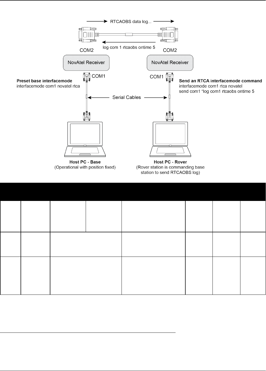
Chapter 2 Core Commands
OEM7 Commands and Logs Reference Manual v7 329
Figure 8: Using the SEND Command
Field Field
Type
ASCII
Value
Binary
Value Description Format Binary
Bytes
Binary
Offset
1SEND
header - -
Command header.
See Messages on
page25 for more
information.
- H 0
2 port
See Table 4: Detailed
Port Identifier on
page31
Output port
(default=THISPORT) Enum 4 H
3 message
Max 100 character string
(99 typed visible chars
and a null char added by
the firmware
automatically)
ASCII data to send
String
[max
100]
Variable
1H+4
1In the binary case, each string field needs to be NULL terminated and additional bytes of padding added to
maintain 4-byte alignment, up to the maximum defined by the string size. The next defined field starts
immediately at the next 4-byte alignment following the NULL.

Chapter 2 Core Commands
OEM7 Commands and Logs Reference Manual v7 330
2.138 SENDHEX
Send non-printable characters in hex pairs
Platform: OEM719, OEM729, OEM7500, OEM7600, OEM7700, OEM7720, PwrPak7,
SPAN CPT7
This command is like the SEND command (see page 328) except it is used to send non-printable
characters expressed as hexadecimal pairs. Carriage return and line feed characters (for
example, 0x0D, 0x0A) will not be appended to the sent data and so must be explicitly added to
the data if needed.
Message ID: 178
Abbreviated ASCII Syntax:
SENDHEX [port] length data
Input Example:
SENDHEX COM1 6 143Ab5910D0A
Field Field
Type
ASCII
Value
Binary
Value Description Format Binary
Bytes
Binary
Offset
1SENDHEX
header - -
Command header.
See Messages on
page25 for more
information.
- H 0
2 port See Table 4: Detailed
Port Identifier on page31
Output port
(default=THISPORT) Enum 4 H
3 length 0 - 700 Number of hex pairs Ulong 4 H+4
4 message
limited to a 700
maximum string (1400
pair hex). Even number
of ASCII characters from
set of 0-9, A-F. No
spaces are allowed
between pairs of
characters
Data
String
[max
700]
Variable
aH+8
aIn the binary case, each string field needs to be NULL terminated and additional bytes of padding added to
maintain 4-byte alignment, up to the maximum defined by the string size. The next defined field starts
immediately at the next 4-byte alignment following the NULL.

Chapter 2 Core Commands
OEM7 Commands and Logs Reference Manual v7 331
2.139 SERIALCONFIG
Configures serial port settings
Platform: OEM719, OEM729, OEM7500, OEM7600, OEM7700, OEM7720, PwrPak7,
SPAN CPT7
This command is used to configure the receiver’s asynchronous serial port communications
drivers.
1. Also refer to the ECHO command on page131.
2. The SERIALCONFIG command can be used as a log to confirm settings.
3. The entire content of the current log is sent before pausing due to the receipt of the
XOFF character.
The current SERIALCONFIG port configuration can be reset to its default state by sending it two
hardware break signals of 250 milliseconds each, spaced by fifteen hundred milliseconds (1.5
seconds) with a pause of at least 250 milliseconds following the second break. This will:
lStop the logging of data on the current port (see the UNLOGALL command on page386)
lClear the transmit and receive buffers on the current port
lReturn the current port to its default settings (see Factory Defaults on page52 for details)
lSet the interface mode to NovAtel for both input and output (see the INTERFACEMODE com-
mand on page193)
This break detection can be disabled using the SERIALCONFIG command.
1. The COMCONTROL command (see page 108) may conflict with handshaking of the
selected COM port. If handshaking is enabled, then unexpected results may occur.
2. Baud rates higher than 115,200 bps are not supported by standard PC hardware. Spe-
cial PC hardware may be required for higher rates, including 230400 bps and 460800
bps. Avoid having COM ports of two receivers connected together using baud rates that
do not match. Data transmitted through a port operating at a slower baud rate may be
misinterpreted as break signals by the receiving port if it is operating at a higher baud
rate because data transmitted at the lower baud rate is stretched relative to the higher
baud rate. In this case, configure the receiving port to break detection disabled using
the SERIALCONFIG command.
Use the SERIALCONFIG command before using the INTERFACEMODE command on
each port. Turn break detection off using the SERIALCONFIG command to stop the port
from resetting because it is interpreting incoming bits as a break command.
Message ID: 1246
Abbreviated ASCII Syntax:
SERIALCONFIG [port] baud [parity[databits[stopbits[handshaking[break]]]]]

Chapter 2 Core Commands
OEM7 Commands and Logs Reference Manual v7 332
Factory Defaults:
SERIALCONFIG COM1 9600 N 8 1 N ON
SERIALCONFIG COM2 9600 N 8 1 N ON
SERIALCONFIG COM3 9600 N 8 1 N ON
SERIALCONFIG COM4 9600 N 8 1 N ON
SERIALCONFIG COM5 9600 N 8 1 N ON
ASCII Example:
SERIALCONFIG com1 9600 n 8 1 n off
Field Field Type ASCII
Value
Binary
Value Description Format Binary
Bytes
Binary
Offset
1SERIALCONFIG
Header - -
Command header.
See Messages on
page25 for more
information.
- H 0
2 port
See Table 58: COM
Port Identifiers on
the next page
Port to configure
(default =
THISPORT)
Enum 4 H
3 bps/baud
2400, 4800, 9600,
19200, 38400,
57600, 115200,
230400 and 460800
Communication
baud rate (bps). Ulong 4 H+4
4 parity See Table 59: Parity
on the next page Parity Enum 4 H+8
5 databits 7 or 8 Number of data bits
(default = 8) Ulong 4 H+12
6 stopbits 1 or 2 Number of stop bits
(default = 1) Ulong 4 H+16
7 handshake1
See Table 60:
Handshaking on the
next page
Handshaking Enum 4 H+20
8 break
OFF 0 Disable break
detection Enum 4 H+24
ON 1 Enable break
detection (default)
1The OEM719 does not support hardware handshaking. Only transmit and receive lines exist for the OEM719
ports.

Chapter 2 Core Commands
OEM7 Commands and Logs Reference Manual v7 333
Binary ASCII Description Applicable Receiver
1 COM1 COM port 1 OEM719, OEM729, OEM7600, OEM7700, OEM7720,
PwrPak7, SPAN CPT7
2 COM2 COM port 2 OEM719, OEM729, OEM7600, OEM7700, OEM7720,
PwrPak7, SPAN CPT7
3 COM3 COM port 3 OEM729, OEM7600, OEM7700, OEM7720, PwrPak7
6 THISPORT The current COM
port
OEM719, OEM729, OEM7600, OEM7700, OEM7720,
PwrPak7, SPAN CPT7
19 COM4 COM port 4 OEM7700, OEM7600, OEM7720
21 IMU IMU COM port dependent on hardware configuration
31 COM5 COM port 5 OEM7700, OEM7600, OEM7720
32 COM6 COM port 6
33 BT1 Bluetooth COM
port dependent on hardware configuration
34 COM7 COM port 7
35 COM8 COM port 8
36 COM9 COM port 9
37 COM10 COM port 10
Table 58: COM Port Identifiers
Binary ASCII Description
0 N No parity (default)
1 E Even parity
2 O Odd parity
Table 59: Parity
Binary ASCII Description
0 N No handshaking (default)
1 XON XON/XOFF software handshaking
2 CTS CTS/RTS hardware handshaking
Table 60: Handshaking

Chapter 2 Core Commands
OEM7 Commands and Logs Reference Manual v7 334
2.140 SERIALPROTOCOL
Sets the protocol to be used by a serial port
Platform: OEM729, PwrPak7
On some OEM7 receiver cards, selected ports can support either RS-232 or RS-422 signaling pro-
tocol. The default protocol is RS-232. The SERIALPROTOCOL command is used to select the
protocol (RS-232 or RS-422) supported on the port.
RS-422/RS-232 selection is available only on COM1 of the OEM729 or COM1 and COM2 on
the PwrPak7.
Message ID: 1444
Abbreviated ASCII Syntax:
SERIALPROTOCOL port protocol
ASCII Example:
SERIALPROTOCOL COM1 RS422
Field Field
Type
ASCII
Value
Binary
Value Description Format Binary
Bytes
Binary
Offset
1
SERIAL
PROTOCOL
header
- -
Command header. See
Messages on page25 for
more information.
- H 0
2 port
See Table 61: Ports
Supporting RS-422
on the next page
Select the COM port on
which the protocol is
being set.
The port that can be
entered depends on the
hardware platform being
used.
Enum 4 H
3 protocol
RS232 0 Set the port to use RS-
232 protocol Enum 4 H+4
RS422 1 Set the port to use RS-
422 protocol
After switching a COM port from RS-232 to RS-422, send a carriage return (CR) on the
newly configured port to flush the buffer prior to sending new commands on the port.

Chapter 2 Core Commands
OEM7 Commands and Logs Reference Manual v7 335
OEM7 Receiver Type Allowable Ports Binary Value
OEM719 None
OEM729 COM1 1
OEM7600 None
OEM7700 None
OEM7720 None
PwrPak7, PwrPak7-E1,
PwrPak7D, PwrPak7D-E1
COM1 1
COM2 2
Table 61: Ports Supporting RS-422

Chapter 2 Core Commands
OEM7 Commands and Logs Reference Manual v7 336
2.141 SETADMINPASSWORD
Sets the administration password
Platform: OEM729, OEM7600, OEM7700, OEM7720, PwrPak7, SPAN CPT7
This command sets the administration password used to log into various web services.
lThe administration password is required for Secure ICOM access.
The default admin password is the receiver‘s PSN. For OEM7 enclosures, such as the PwrPak7,
the default password is the enclosure PSN. The enclosure PSN is shown on the label on the bot-
tom of the enclosure and in the ENCLOSURE line in the VERSION log (see page 854). The default
password should be changed before connecting the receiver to a network.
Message ID: 1579
Abbreviated ASCII Syntax:
SETADMINPASSWORD oldpassword newpassword
Input example
SETADMINPASSWORD ABC123 XYZ789
Field Field Type ASCII
Value
Binary
Value Description Format Binary
Bytes
Binary
Offset
1
SETADMIN
PASSWORD
header
- -
Command header.
See Messages on
page25 for more
information.
- H 0
2 OldPassword Maximum 28
character string Previous password. String
[28] variable1H
3 NewPassword Maximum 28
character string New password. String
[28] variable1variable
This password can be restored to default (the receiver‘s PSN) by issuing the FRESET
USER_ACCOUNTS command (see FRESET on page174).
1In the binary case, each string field needs to be NULL terminated and additional bytes of padding added to
maintain 4-byte alignment, up to the maximum defined by the string size. The next defined field starts
immediately at the next 4-byte alignment following the NULL.
Chapter 2 Core Commands
OEM7 Commands and Logs Reference Manual v7 337
2.142 SETAPPROXPOS
Sets an approximate position
Platform: OEM719, OEM729, OEM7500, OEM7600, OEM7700, OEM7720, PwrPak7,
SPAN CPT7
This command sets an approximate latitude, longitude and height in the receiver. Estimating
these parameters, when used in conjunction with an approximate time (see the
SETAPPROXTIME command on the next page), can improve satellite acquisition times and
Time To First Fix (TTFF). For more information about TTFF and Satellite Acquisition, refer to An
Introduction to GNSS available on our website.
The horizontal position entered should be within 200 km of the actual receiver position. The
approximate height is not critical and can normally be entered as zero. If the receiver cannot cal-
culate a valid position within 2.5 minutes of entering an approximate position, the approximate
position is ignored.
The approximate position is not visible in any position logs. It can be seen by issuing a
SETAPPROXPOS log.
Message ID: 377
Abbreviated ASCII Syntax:
SETAPPROXPOS lat lon height
Input Example:
SETAPPROXPOS 51.116 -114.038 0
For an example on the use of this command, refer to the SETAPPROXTIME command
on the next page.
Field Field Type ASCII
Value
Binary
Value Description Format Binary
Bytes
Binary
Offset
1SETAPPROXPOS
header - -
Command header. See
Messages on page25 for
more information.
- H 0
2 Lat ± 90 degrees Approximate latitude Double 8 H
3 Lon ± 180 degrees Approximate longitude Double 8 H+8
4 Height -1000 to
+20000000 m Approximate height Double 8 H+16
Chapter 2 Core Commands
OEM7 Commands and Logs Reference Manual v7 338
2.143 SETAPPROXTIME
Sets an approximate GPS reference time
Platform: OEM719, OEM729, OEM7500, OEM7600, OEM7700, OEM7720, PwrPak7,
SPAN CPT7
This command sets an approximate time in the receiver. The receiver uses this time as system
time until a coarse time can be acquired. This can be used in conjunction with an approximate
position (see the SETAPPROXPOS command on the previous page) to improve Time To First
Fix (TTFF). For more information TTFF and Satellite Acquisition, refer to An Introduction to
GNSS available on our website.
The time entered should be within 10 minutes of the actual GPS reference time. If the
week number entered does not match the broadcast week number, the receiver resets
once it is tracking.
Message ID: 102
Abbreviated ASCII Syntax:
SETAPPROXTIME week sec
Input Example:
SETAPPROXTIME 1930 501232
Upon power up, the receiver does not know its position or time and therefore cannot use
almanac information to aid satellite acquisition. You can set an approximate GPS
reference time using the SETAPPROXPOS command (see page 337).
Approximate time and position may be used in conjunction with a current almanac to aid
satellite acquisition. See the table below for a summary of the OEM7 family commands
used to inject an approximated time or position into the receiver:
Approximate Command
Time SETAPPROXTIME
Position SETAPPROXPOS
Base station aiding can help in these environments. A set of ephemerides can be injected
into a rover station by broadcasting the RTCAEPHEM message from a base station. This is
also useful in environments where there is frequent loss of lock. GPS ephemeris is three
frames long within a sequence of five frames. Each frame requires 6 s of continuous lock
to collect the ephemeris data. This gives a minimum of 18 s and a maximum of 36 s
continuous lock time or when no recent ephemerides (new or stored) are available.

Chapter 2 Core Commands
OEM7 Commands and Logs Reference Manual v7 339
Field Field Type ASCII
Value
Binary
Value Description Format Binary
Bytes
Binary
Offset
1SETAPPROXTIME
header - -
Command header. See
Messages on page25
for more information.
- H 0
2 week 0-9999 GPS reference week
number Ulong 4 H
3 sec 0-604800 Number of seconds into
GPS reference week Double 8 H+4

Chapter 2 Core Commands
OEM7 Commands and Logs Reference Manual v7 340
2.144 SETBASERECEIVERTYPE
Sets base receiver type
Platform: OEM719, OEM729, OEM7500, OEM7600, OEM7700, OEM7720, PwrPak7,
SPAN CPT7
This command allows the user to specify the base receiver type to aid GLONASS ambiguity fix-
ing in RTK. It can be used as a substitute for RTCM1033 messages that contains the information
on the base receiver type. This command should be issued to the Rover.
An incorrect base type setting can significantly impair ambiguity resolution.
Message ID: 1374
Abbreviated ASCII Syntax:
SETBASERECEIVERTYPE base_type
Factory Default:
SETBASERECEIVERTYPE unknown
ASCII Example:
SETBASERECEIVERTYPE novatel
Field Field Type ASCII
Value
Binary
Value Description Format Binary
Bytes
Binary
Offset
1SETBASERECEIVER
TYPE header - -
Command header.
See Messages on
page25 for more
information.
- H 0
2 base_type
unknown 0 Unknown Base
Enum 4 H
novatel 1 NovAtel Base
trimble 2 Trimble Base
topcon 3 Topcon Base
magellan 4 Magellan Base
leica 5 Leica Base

Chapter 2 Core Commands
OEM7 Commands and Logs Reference Manual v7 341
2.145 SETBESTPOSCRITERIA
Sets selection criteria for BESTPOS
Platform: OEM719, OEM729, OEM7500, OEM7600, OEM7700, OEM7720, PwrPak7,
SPAN CPT7
Use this command to set the criteria for the BESTPOS log (see page 428) and choose between
2D and 3D standard deviation to obtain the best position from the BESTPOS log (see page 428).
It also allows you to specify the number of seconds to wait before changing the position type.
This delay provides a single transition that ensures position types do not skip back and forth.
The SETBESTPOSCRITERIA command is also used as the basis for the UALCONTROL
command (see page 374) standard deviations.
Message ID: 839
Abbreviated ASCII Syntax:
SETBESTPOSCRITERIA type [delay]
Factory Default:
SETBESTPOSCRITERIA pos3d 0
Input Example:
SETBESTPOSCRITERIA pos2d 5
Field Field Type ASCII
Value
Binary
Value Description Format Binary
Bytes
Binary
Offset
1
SETBESTPOS
CRITERIA
header
- -
Command header. See
Messages on page25 for
more information.
- H 0
2 type
See Table 62:
Selection Type
below
Select a 2D or 3D standard
deviation type to obtain the
best position from the
BESTPOS log
Enum 4 H
3 delay 0 to 100 s
Set the number of seconds
to wait before changing the
position type. Default=0
Ulong 4 H+4
ASCII Binary Description
POS3D 0 3D standard deviation
POS2D 1 2D standard deviation
Table 62: Selection Type

Chapter 2 Core Commands
OEM7 Commands and Logs Reference Manual v7 342
2.146 SETDIFFCODEBIASES
Sets satellite differential code biases
Platform: OEM719, OEM729, OEM7500, OEM7600, OEM7700, OEM7720, PwrPak7,
SPAN CPT7
Changing the biases may negatively affect positioning accuracy. NovAtel recommends
that only advanced users modify the biases.
Use this command to set the differential code biases that correct pseudorange errors affecting
the L1/L2 ionospheric corrections. Bias values are restricted to between -10 ns and +10 ns. A set
of biases is included in the firmware and use of the biases is enabled by default. See also the
DIFFCODEBIASCONTROL command on page123.
The receiver uses the C/A code on L1 and the P code on L2 to calculate a dual-frequency iono-
spheric correction. However, the GNSS clock corrections are broadcast as if the P codes on both
L1 and L2 are used to calculate this correction. The biases account for the differences between
the P and C/A codes on L1 and improve the estimate of the ionospheric correction.
The biases are calculated by the International GNSS Service (IGS). Calculation details, analysis
and results are available at http://aiuws.unibe.ch/spec/dcb.php. The most recent 30 day aver-
age bias values can be downloaded from ftp://ftp.unibe.ch/aiub/CODE/CODE_FULL.DCB.
Message ID: 687
Abbreviated ASCII Syntax:
SETDIFFCODEBIASES bias_type biases
ASCII Example:
<SETDIFFCODEBIASES COM1 2 91.0 UNKNOWN 0 0.470 02440020 365b 32768
<GPS_C1P1 1.302 -1.326 1.360 1.649 1.357 1.586 0.776 -0.079 -0.123 0.888 -
0.321 0.718 0.527 -0.720 1.193 -1.331 0.828 -1.061 -2.497 -2.106 -1.979 -2.747
-0.254 1.202 -0.716 0.077 -0.180 -1.059 1.269 -0.481 0.734 1.516 0.000 0.000
0.000 0.000 0.000 0.000 0.000 0.000
<SETDIFFCODEBIASES COM1 1 91.0 UNKNOWN 0 0.471 02440020 365b 32768
<GLONASS_C1P1 -0.092 0.381 0.581 1.033 0.642 -0.561 0.794 0.899 0.380 -0.832
-0.358 -0.606 -2.181 0.023 1.135 0.346 0.009 0.384 -1.394 0.224 -0.022 -0.824 -
0.133 -0.437 0.000 0.608 0.000 0.000 0.000 0.000 0.000 0.000 0.000 0.000 0.000
0.000 0.000 0.000 0.000 0.000
<SETDIFFCODEBIASES COM1 0 91.0 UNKNOWN 0 0.473 02440020 365b 32768
<GPS_C2P2 1.358 0.000 -0.381 0.000 -0.344 -0.707 0.306 -1.068 0.624 1.480
0.000 -0.401 0.000 0.000 -0.169 0.0 00 0.236 0.000 0.000 0.000 0.000 0.000
0.000 0.051 -0.711 1.082 -0.128 0.000 -0.101 -0.483 -0.630 -0.015 0.000 0.0 00
0.000 0.000 0.000 0.000 0.000 0.000

Chapter 2 Core Commands
OEM7 Commands and Logs Reference Manual v7 343
Field Field Type ASCII
Value
Binary
Value Description Format Binary
Bytes
Binary
Offset
1
SETDIFFCODE
BIASES
header
- -
Command header.
See Messages on
page25 for more
information.
- H 0
2 bias_type
GPS_C1P1 0
Code pair to which
biases refer Enum 4 H
GPS_C2P2 1
GLONASS_
C1P1 2
3 biases -10 to +10 ns Array of 40 biases
(ns)
Float
[40] 160 H+4
Chapter 2 Core Commands
OEM7 Commands and Logs Reference Manual v7 344
2.147 SETIONOTYPE
Enables ionospheric models
Platform: OEM719, OEM729, OEM7500, OEM7600, OEM7700, OEM7720, PwrPak7,
SPAN CPT7
Use this command to set which ionospheric corrections model the receiver should use. If the
selected model is not available, the receiver reverts to AUTO.
L1 only models automatically use SBAS ionospheric grid corrections, if available.
Message ID: 711
Abbreviated ASCII Syntax:
SETIONOTYPE model
Factory Default:
SETIONOTYPE auto
ASCII Example:
SETIONOTYPE Klobuchar
An ionotype of AUTO is recommended for PDP and GLIDE.
Field Field
Type
ASCII
Value
Binary
Value Description Format Binary
Bytes
Binary
Offset
1
SETIONO-
TYPE
header
- -
Command header. See
Messages on page25 for
more information.
- H 0
2 model
See Table 63:
Ionospheric
Correction Models
below
Choose an ionospheric
corrections model Enum 4 H
ASCII Binary Description
NONE 0 Don’t use ionosphere modeling
KLOBUCHAR 1 Use the Klobuchar model broadcast by GPS
Table 63: Ionospheric Correction Models

Chapter 2 Core Commands
OEM7 Commands and Logs Reference Manual v7 345
ASCII Binary Description
GRID 2 Use the SBAS grid model
L1L2 3 Use the L1/L2 model
AUTO 4 Automatically determine the ionospheric model to use
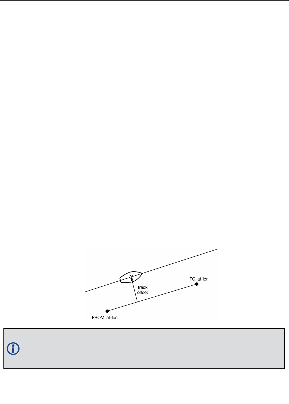
Chapter 2 Core Commands
OEM7 Commands and Logs Reference Manual v7 346
2.148 SETNAV
Sets start and destination waypoints
Platform: OEM719, OEM729, OEM7500, OEM7600, OEM7700, OEM7720, PwrPak7,
SPAN CPT7
This command permits entry of one set of navigation waypoints (see Figure 9: Illustration of
SETNAV Parameters below). The origin (from) and destination (to) waypoint coordinates
entered are considered on the ellipsoidal surface of the current datum (default wgs84). Once
SETNAV has been set, monitor the navigation calculations and progress by observing messages
in the NAVIGATE log (see page 612).
Track offset is the perpendicular distance from the great circle line drawn between the from lat-
lon and to lat-lon waypoints. It establishes the desired navigation path or track, that runs par-
allel to the great circle line, which now becomes the offset track, and is set by entering the track
offset value in metres. A negative track offset value indicates that the offset track is to the left
of the great circle line track. A positive track offset value (no sign required) indicates the offset
track is to the right of the great circle line track (looking from origin to destination). See Figure
9: Illustration of SETNAV Parameters below for clarification.
Message ID: 162
Abbreviated ASCII Syntax:
SETNAV fromlat fromlon tolat tolon trackoffset from-point to-point
Factory Default:
SETNAV 90.0 0.0 90.0 0.0 0.0 from to
ASCII Example:
SETNAV 51.1516 -114.16263 51.16263 -114.1516 -125.23 FROM TO
Figure 9: Illustration of SETNAV Parameters
Consider the case of setting waypoints in a deformation survey along a dam. The sur-
veyor enters the From and To point locations, on either side of the dam using the
SETNAV command. They then use the NAVIGATE log messages to record progress and
show where they are in relation to the From and To points.

Chapter 2 Core Commands
OEM7 Commands and Logs Reference Manual v7 347
Field Field
Type
ASCII
Value
Binary
Value Description Format Binary
Bytes
Binary
Offset
1SETNAV
header - -
Command header. See
Messages on page25 for
more information.
- H 0
2 fromlat ± 90 degrees
Origin latitude in units of
degrees/decimal degrees.
A negative sign for South
latitude. No sign for North
latitude
Double 8 H
3 fromlon ± 180 degrees
Origin longitude in units of
degrees/decimal degrees.
A negative sign for West
longitude. No sign for East
longitude
Double 8 H+8
4 tolat ± 90 degrees Destination latitude in units
of degrees/decimal degrees Double 8 H+16
5 tolon ± 180 degrees
Destination longitude in
units of degrees/decimal
degrees
Double 8 H+24
6 trackoffset ± 1000 km
Waypoint great circle line
offset (in metres)
establishes offset track.
Positive indicates right of
great circle line and
negative indicates left of
great circle line
Double 8 H+32
7 from-point 5 characters
maximum ASCII origin station name String
[max 5]
Variable
1H+40
8 to-point 5 characters
maximum
ASCII destination station
name
String
[max 5]
Variable
1Variable
1In the binary case, each string field needs to be NULL terminated and additional bytes of padding added to
maintain 4-byte alignment, up to the maximum defined by the string size. The next defined field starts
immediately at the next 4-byte alignment following the NULL.
Chapter 2 Core Commands
OEM7 Commands and Logs Reference Manual v7 348
2.149 SETROVERID
Set ID for ALIGN rovers
Platform: OEM719, OEM729, OEM7500, OEM7600, OEM7700, OEM7720, PwrPak7,
SPAN CPT7
This command sets the Rover ID output in the ROVERPOS log (see page 724), HEADING2 log
(see page 539), ALIGNBSLNXYZ log (see page 408) and ALIGNBSLNENU log (see page 406).
The default value for the ID is set using the last six characters of the receiver PSN Number. For
example, if the receiver PSN number is DAB07170027, ID is set as R027, i.e., 17 is represented
as R and last three characters are filled in as is. The fourth last character is ignored.
It is not guaranteed that each receiver will have a unique auto-generated ID. Use this
command to set the ID in case the auto-generated ID overlaps with other rovers. It is the
user’s responsibility to ensure each receiver ID is unique (if they own multiple receiv-
ers). If the ID overlaps, use this command to set the ID.
Message ID: 1135
Abbreviated ASCII Syntax:
SETROVERID rovid
Factory Default:
If the receiver PSN is: DAB07170027
SETROVERID R027
Input Example
SETROVERID rov1
Field Field Type ASCII
Value
Binary
Value Description Format Binary
Bytes
Binary
Offset
1SETROVERID
header - -
Command header. See
Messages on page25 for
more information.
- H 0
2 ID
4 Character
String e.g.,
ROV1
ID String (maximum 4
characters plus NULL)
String
[5] 51H
1In the binary case, each string field needs to be NULL terminated and additional bytes of padding added to
maintain 4-byte alignment, up to the maximum defined by the string size. The next defined field starts
immediately at the next 4-byte alignment following the NULL.

Chapter 2 Core Commands
OEM7 Commands and Logs Reference Manual v7 349
2.150 SETTIMEBASE
Sets primary and backup systems for time base
Platform: OEM719, OEM729, OEM7500, OEM7600, OEM7700, OEM7720, PwrPak7,
SPAN CPT7
This command configures the primary and backup steering system(s) for timing. The primary
system is the system that the receiver steers the clock to. Upon startup, the primary system
must be present long enough to steer the clock to be valid once, otherwise, the backup system
cannot be used. The backup system is used whenever the primary system is not present.
Message ID: 1237
Abbreviated ASCII Syntax:
SETTIMEBASE primarysystem numbackups[system[timeout]]
Factory Default:
For GLONASS only receiver:
SETTIMEBASE Glonass 0
For GPS capable receiver:
SETTIMEBASE GPS 1 AUTO 0
For BeiDou only receiver:
SETTIMEBASE beidou 0
Input Example:
SETTIMEBASE gps 1 glonass 30
Field Field Type ASCII
Value
Binary
Value Description Format Binary
Bytes
Binary
Offset
1SETTIMEBASE
header - -
Command header. See
Messages on page25 for
more information.
- H 0
2 primarysystem
Table 64:
System Used for
Timing on the
next page
The primary system for
steering the receiver
clock
Enum 4 H

Chapter 2 Core Commands
OEM7 Commands and Logs Reference Manual v7 350
Field Field Type ASCII
Value
Binary
Value Description Format Binary
Bytes
Binary
Offset
3 numbackups 0 or 4
The number of records
to follow.
Note: When more than
one backup system is
specified, the backup
systems are selected
according to numeric
order.
Ulong 4 H+4
4 system1
Table 64:
System Used for
Timing below
The system to be used
for backup Enum 4 H+8
5timeout10 to
+4294967295
(seconds)
Duration that the backup
system is used to steer
the clock. 0 means
ongoing
Ulong 4 H+12
Binary ASCII
0 GPS
1 GLONASS
2 GALILEO
3 BEIDOU
4 NAVIC
99 AUTO2
Table 64: System Used for Timing
1The system and timeout fields can repeat.
2AUTO is used only as a backup system (not available for primary system field).

Chapter 2 Core Commands
OEM7 Commands and Logs Reference Manual v7 351
2.151 SETTROPOMODEL
Sets Troposphere model
Platform: OEM719, OEM729, OEM7500, OEM7600, OEM7700, OEM7720, PwrPak7,
SPAN CPT7
This command sets the troposphere model used to correct ranges used in the PSRPOS and
PDPPOS solutions.
Message ID: 1434
Abbreviated ASCII Syntax:
SETTROPOMODEL model
Factory Default:
SETTROPOMODEL auto
Input Example:
SETTROPOMODEL none
Disabling the troposphere model may negatively affect positioning accuracy. NovAtel
recommends that only advanced users modify this setting.
Field Field Type ASCII
Value
Binary
Value Description Format Binary
Bytes
Binary
Offset
1SETTROPOMODEL
header - -
Command header. See
Messages on page25
for more information.
- H 0
2 model
NONE 1
Do not apply any
troposphere
corrections Enum 4 H
AUTO 2 Automatically use an
appropriate model

Chapter 2 Core Commands
OEM7 Commands and Logs Reference Manual v7 352
2.152 SETUTCLEAPSECONDS
Sets future leap seconds
Platform: OEM719, OEM729, OEM7500, OEM7600, OEM7700, OEM7720, PwrPak7,
SPAN CPT7
This command allows the user to force the UTC offset to be updated according to the input date.
Leap seconds will occur at the end of the UTC day specified. The receiver will use the leap
second set by this command until a leap second can be obtained over the air.
Message ID: 1150
Abbreviated ASCII Syntax:
SETUTCLEAPSECONDS seconds [futureweeknumber [futuredaynumber
[futureseconds]]]
Input Example:
SETUTCLEAPSECONDS 18 1929 7 18
Field Field Type ASCII
Value
Binary
Value Description Format Binary
Bytes
Binary
Offset
1
SETUTCLEAP
SECONDS
header
- -
Command header. See
Messages on page25 for
more information.
- H 0
2 Seconds10- Current UTC leap second Ulong 4 H
3Futureweek
number 0-10000
GPS Week when future
leap seconds will take
effect
Ulong 4 H+4
4Futureday
number 1-7
Day of the week when
future leap seconds will
take effect
Ulong 4 H+8
5 Futureseconds 0-
Future leap second offset
that will take effect at the
end of the
futuredaynumber of the
futureweeknumber
Ulong 4 H+12
1This value will only be applied if the UTC status in the TIME log is not Valid.

Chapter 2 Core Commands
OEM7 Commands and Logs Reference Manual v7 353
2.153 SOFTLOADCOMMIT
Completes the SoftLoad process
Platform: OEM719, OEM729, OEM7500, OEM7600, OEM7700, OEM7720, PwrPak7,
SPAN CPT7
This command completes the SoftLoad process by verifying the downloaded image and activ-
ating it. Refer to the OEM7 Installation and Operation User Manual for more information about
the SoftLoad process.
This command can only be sent to the receiver when the SOFTLOADSTATUS log (see page 826)
reports READY_FOR_DATA.
After issuing the SOFTLOADCOMMIT command the user must wait for the OK or ERROR com-
mand response before proceeding. This response is guaranteed to be output from the receiver
within 300 seconds from the time the command was received by the receiver. If an error
response is returned, consult the SOFTLOADSTATUS log on page826 for more detail.
Message ID: 475
Abbreviated ASCII Syntax:
SOFTLOADCOMMIT
Input Example:
SOFTLOADCOMMIT
Field Field Type ASCII
Value
Binary
Value Description Format Binary
Bytes
Binary
Offset
1SOFTLOADCOMMIT
header - -
Command header.
See Messages on
page25 for more
information.
- H 0
2 Reserved - Reserved. Set to 1 in
the binary case Enum 4 H

Chapter 2 Core Commands
OEM7 Commands and Logs Reference Manual v7 354
2.154 SOFTLOADDATA
Sends firmware image data to the receiver for the SoftLoad process
Platform: OEM719, OEM729, OEM7500, OEM7600, OEM7700, OEM7720, PwrPak7,
SPAN CPT7
This command is only valid in binary mode.
This command is used to upload data to the receiver for the SoftLoad process. Refer to the OEM7
Installation and Operation User Manual for more information about the SoftLoad process.
After each SOFTLOADDATA command, the user must wait for the OK or ERROR command
response before proceeding. This response is guaranteed to be output from the receiver within
15 seconds from the time the command was received by the receiver. If an error response is
returned, consult the SOFTLOADSTATUS log on page826 for more detail.
This command can only be sent to the receiver after the SOFTLOADSREC command (see page
358) or SOFTLOADSETUP command (see page 356) have sent the content of the S0 records
from the start of a firmware *.shex file. In these cases, the SOFTLOADSTATUS log (see page
826) reports READY_FOR_SETUP or READY_FOR_DATA.
Message ID: 1218
Abbreviated ASCII Syntax:
Not applicable
Field Field Type Binary
Value Description Format Binary
Bytes
Binary
Offset
1SOFTLOADDATA
header - NovAtel binary message header - H 0
2 offset - Offset of the data within the
downloaded image Ulong 4 H
3 data length -
Number of bytes of data. This
must match the number of bytes
contained within the “data” field
Ulong 4 H+4
4 data - Incoming data up to a maximum
of 4096 bytes Uchar 4096 H+8

Chapter 2 Core Commands
OEM7 Commands and Logs Reference Manual v7 355
2.155 SOFTLOADRESET
Initiates a new SoftLoad process
Platform: OEM719, OEM729, OEM7500, OEM7600, OEM7700, OEM7720, PwrPak7,
SPAN CPT7
This command restarts the SoftLoad process. Refer to the OEM7 Installation and Operation User
Manual for more information about the SoftLoad process.
The command does not affect the flash and does not reset the receiver.
The SOFTLOADRESET command can be issued at any time. If it is issued while a SoftLoad pro-
cess is currently in progress then that process is terminated and a new one is started. After the
SOFTLOADRESET command is processed the SOFTLOADSTATUS log will report a status of
READY_FOR_SETUP.
After issuing the SOFTLOADRESET command the user must wait for the OK or ERROR command
response before proceeding. This response is guaranteed to be output from the receiver within
300 seconds from the time the command was received by the receiver. If an error response is
returned, consult the SOFTLOADSTATUS log on page826 for more detail.
Message ID: 476
Abbreviated ASCII Syntax:
SOFTLOADRESET
Input Example:
SOFTLOADRESET
Field Field Type ASCII
Value
Binary
Value Description Format Binary
Bytes
Binary
Offset
1SOFTLOADRESET
header - -
Command header. See
Messages on page25
for more information.
- H 0
2 Reserved - - Reserved. Set to 1 in
the binary case Enum 4 H

Chapter 2 Core Commands
OEM7 Commands and Logs Reference Manual v7 356
2.156 SOFTLOADSETUP
Sends configuration information to the receiver for the SoftLoad
process
Platform: OEM719, OEM729, OEM7500, OEM7600, OEM7700, OEM7720, PwrPak7,
SPAN CPT7
The SOFTLOADSETUP command can be used in place of the SOFTLOADSREC command when
sending S0 Records. This command is meant to be used if the user requires that the entire
SoftLoad process be performed in binary, but can also be used in ASCII or abbreviated ASCII.
The examples below are given in abbreviated ASCII for simplicity.
Refer to the OEM7 Installation and Operation User Manual for more information about the
SoftLoad process.
This command can only be sent to the receiver when the SOFTLOADSTATUS log reports READY_
FOR_SETUP.
After each SOFTLOADSETUP command, the user must wait for the OK or ERROR command
response before proceeding. This response is guaranteed to be output from the receiver within
15 seconds from the time the command was received by the receiver. If an error response is
returned, consult the SOFTLOADSTATUS log on page826 for more detail.
NovAtel S0 records use the following format: S0~X~<<DATA>>, where Xis the Setup Type
and <<DATA>> is a NULL terminated string. To convert from S0 record to the
SOFTLOADSETUP command, convert the Setup Type to the appropriate Setup type enumeration,
as described in Table 65: Available Set Up Commands on the next page, and copy the
<<DATA>> string in to the Setup data string.
Message ID: 1219
Abbreviated ASCII Syntax:
SOFTLOADSETUP setuptype setupdata
Input Example:
SOFTLOADSETUP datatype "APP"
Field Field
Type
ASCII
Value
Binary
Value Description Format Binary
Bytes
Binary
Offset
1
SOFTLOAD
SETUP
header
- -
Command header. See
Messages on page25 for
more information.
- H 0
2 Setup type
See Table 65:
Available Set
Up Commands
on the next
page
The type of setup command Enum 4 H

Chapter 2 Core Commands
OEM7 Commands and Logs Reference Manual v7 357
Field Field
Type
ASCII
Value
Binary
Value Description Format Binary
Bytes
Binary
Offset
3 Setup data - -
ASCII setup data string. See
Table 65: Available Set Up
Commands below for details
on this data. This data can be
pulled from the S0 records of
the hex file being loaded
onto the receiver. If the
ASCII form of this command
is used, this string must be
enclosed in double quotes
(““)
String
[512]
variable
1H+4
Binary ASCII Description
1 Platform
Comma separated list of platforms supported by the data to be uploaded. This
corresponds to S0~P~. For example, the S-Record
S0~P~OEM729,OEM7700,OEM719, translates to SOFTLOADSETUP PLATFORM
"OEM729,OEM7700,OEM719"
2 Version
Version of the data to be uploaded. This corresponds to S0~V~. For example,
the S-Record S0~V~OMP070400RN0000, translates to SOFTLOADSETUP
VERSION "OMP070400RN0000"
3 Datatype
Intended data block for the data to be uploaded. This corresponds to S0~T~.
For example, the S-Record S0~T~APP, translates to SOFTLOADSETUP
DATATYPE "APP"
4 Authcode
PSN and AUTH code for the data to be uploaded. The format is:
PSN:AuthCode.Note that since there are commas within the AuthCode, double
quotes must surround the PSN:AuthCode string. For example:
SOFTLOADSETUP AUTHCODE "BFN10260115:
T48JF2,W25DBM,JH46BJ,2WGHMJ,8JW5TW,G2SR0RCCR,101114"
Table 65: Available Set Up Commands
1In the binary case, each string field needs to be NULL terminated and additional bytes of padding added to
maintain 4-byte alignment, up to the maximum defined by the string size. The next defined field starts
immediately at the next 4-byte alignment following the NULL.

Chapter 2 Core Commands
OEM7 Commands and Logs Reference Manual v7 358
2.157 SOFTLOADSREC
Sends an S-Record to the receiver for the SoftLoad process
Platform: OEM719, OEM729, OEM7500, OEM7600, OEM7700, OEM7720, PwrPak7,
SPAN CPT7
Use this command to send S-Records to the receiver for the SoftLoad process. Refer to the
OEM7 Installation and Operation User Manual for more information about the SoftLoad process.
After each SOFTLOADDATA command, the user must wait for the OK or ERROR command
response before proceeding. This response is guaranteed to be output from the receiver within
15 seconds from the time the command was received by the receiver. If an error response is
returned, consult the SOFTLOADSTATUS log on page826 for more detail.
This command can only be sent to the receiver when the SOFTLOADSTATUS log reports READY_
FOR_SETUP or READY_FOR_DATA.
Message ID: 477
Abbreviated ASCII Syntax:
SOFTLOADSREC s-record
Input Example:
SOFTLOADSREC “S30900283C10FAA9F000EF”
Field Field Type ASCII
Value
Binary
Value Description Format Binary
Bytes
Binary
Offset
1SOFTLOADSREC
header - -
Command header. See
Messages on page25
for more information.
- H 0
2 SREC -
ASCII S-Record string
copites from firmware
*.shex file
String
[515]
variable
1H
3 Reserved - 1 Reserved. Set to 1 in
the binary case Ulong 4 variable
1In the binary case, each string field needs to be NULL terminated and additional bytes of padding added to
maintain 4-byte alignment, up to the maximum defined by the string size. The next defined field starts
immediately at the next 4-byte alignment following the NULL.

Chapter 2 Core Commands
OEM7 Commands and Logs Reference Manual v7 359
2.158 STATUSCONFIG
Configures RXSTATUSEVENT mask fields
Platform: OEM719, OEM729, OEM7500, OEM7600, OEM7700, OEM7720, PwrPak7,
SPAN CPT7
This command is used to configure the various status mask fields in the RXSTATUSEVENT log
(see page 762). These masks can modify whether various status fields generate errors or event
messages when they are set or cleared.
Receiver Errors automatically generate event messages. These event messages are output in
RXSTATUSEVENT log (see page 762). It is also possible to have status conditions trigger event
messages to be generated by the receiver. This is done by setting/clearing the appropriate bits
in the event set/clear masks. The set mask tells the receiver to generate an event message
when the bit becomes set. Likewise, the clear mask causes messages to be generated when a
bit is cleared. To disable all these messages without changing the bits, simply UNLOG the
RXSTATUSEVENT log (see page 762) on the appropriate ports. Refer also to the Built in Status
Tests chapter in the OEM7 Installation and Operation User Manual.
Message ID: 95
Abbreviated ASCII Syntax:
STATUSCONFIG type word mask
Factory Default:
STATUSCONFIG PRIORITY STATUS 0
STATUSCONFIG PRIORITY AUX1 0x00000008
STATUSCONFIG PRIORITY AUX2 0
STATUSCONFIG SET STATUS 0x00000000
STATUSCONFIG SET AUX1 0
STATUSCONFIG SET AUX2 0
STATUSCONFIG CLEAR STATUS 0x00000000
STATUSCONFIG CLEAR AUX1 0
STATUSCONFIG CLEAR AUX2 0
ASCII Example:
STATUSCONFIG SET STATUS 0028A51D
The receiver gives the user the ability to determine the importance of the status bits. In
the case of the Receiver Status, setting a bit in the priority mask causes the condition to
trigger an error. This causes the receiver to idle all channels, set the ERROR strobe line,
flash an error code on the status LED, turn off the antenna (LNA power) and disable the
RF hardware, the same as if a bit in the Receiver Error word is set. Setting a bit in an
Auxiliary Status priority mask causes that condition to set the bit in the Receiver Status
word corresponding to that Auxiliary Status.

Chapter 2 Core Commands
OEM7 Commands and Logs Reference Manual v7 360
Field Field Type ASCII
Value
Binary
Value Description Format Binary
Bytes
Binary
Offset
1STATUSCONFIG
header - -
Command header.
See Messages on
page25 for more
information.
- H 0
2 type
PRIORITY 0 Replace the Priority
mask
Enum 4 HSET 1 Replace the Set mask
CLEAR 2 Replace the Clear
mask
3 word
STATUS 1 Receiver Status word
Enum 4 H+4
AUX1 2 Auxiliary 1 Status
word
AUX2 3 Auxiliary 2 Status
word
AUX3 4 Auxiliary 3 Status
word
AUX4 5 Auxiliary 4 Status
word
4 mask 8 digit
hexadecimal
The hexadecimal bit
mask Ulong 4 H+8

Chapter 2 Core Commands
OEM7 Commands and Logs Reference Manual v7 361
2.159 STEADYLINE
Configures position mode matching
Platform: OEM719, OEM729, OEM7500, OEM7600, OEM7700, OEM7720, PwrPak7,
SPAN CPT7
The STEADYLINE®functionality helps mitigate the discontinuities that often occur when a GNSS
receiver changes positioning modes. The effect is especially evident when a receiver transitions
from an RTK position mode solution to a lower accuracy “fall back” solution, such as DGPS,
WAAS+GLIDE or even autonomous GLIDE. Smooth transitions are particularly important for agri-
cultural steering applications where sudden jumps may be problematic.
The STEADYLINE internally monitors the position offsets between all the positioning modes
present in the receiver. When the receiver experiences a position transition, the corresponding
offset is applied to the output position to limit a potential real position jump. When the original
accurate position type returns, the STEADYLINE algorithm will slowly transition back to the new
accurate position at a default rate of 0.005 m/s. This creates a smoother pass-to-pass relative
accuracy at the expense of a possible degradation of absolute accuracy.
For example, a receiver can be configured to do both RTK and GLIDE. If this receiver has a fixed
RTK position and experiences a loss of correction data causing the loss of the RTK solution it will
immediately apply the offset between the two position modes and uses the GLIDE position sta-
bility to maintain the previous trajectory. Over time the GLIDE (or non-RTK) position will exper-
ience some drift. Once the RTK position is achieved again the receiver will start using the RTK
positions for position stability and will slowly transition back to the RTK positions at a default
rate of 0.005 m/s.
If the position type is OUT_OF_BOUNDS (see the UALCONTROL command on page374) then
STEADYLINE is reset.
Message ID: 1452
Abbreviated ASCII Syntax:
STEADYLINE mode [transition_time]
Factory Default:
STEADYLINE disable
ASCII Example:
STEADYLINE prefer_accuracy 100
Field Field Type ASCII
Value
Binary
Value Description Format Binary
Bytes
Binary
Offset
1STEADYLINE
header - -
Command header. See
Messages on page25 for
more information.
- H 0

Chapter 2 Core Commands
OEM7 Commands and Logs Reference Manual v7 362
Field Field Type ASCII
Value
Binary
Value Description Format Binary
Bytes
Binary
Offset
2 mode
See Table 66:
STEADYLINE
Mode below
STEADYLINE mode Enum 4 H
3Transition
time
Time over which solutions
will transition in seconds.
The minimum rate of
change is 0.005 m/s
regardless of this
parameter.
Ulong 4 H+4
ASCII Binary Description
DISABLE 0 Disable STEADYLINE (default)
MAINTAIN 1
Maintain the relative offset of the solution. There is no discontinuity in the
position solution when the reference position type changes. Any offset in
the position is maintained.
TRANSITION 2
Transition, at a user-configurable rate. There is no discontinuity in the
position solution when the reference position type changes. The position
will slowly transition to the new reference position type over the time
period specified by the Transition time parameter.
RESET 3 Reset the saved offsets
PREFER_
ACCURACY 4
TRANSITION when changing from less accurate reference positioning type
to more accurate reference positioning type. MAINTAIN when changing
from more accurate reference positioning type to a less accurate
reference positioning type.
UAL 5
For use with the UALCONTROL command (see page 374):
TRANSITION when the position type is in WARNING MAINTAIN when the
position type is in OPERATIONAL DISABLE when the position type is OUT_
OF_BOUNDS
Table 66: STEADYLINE Mode

Chapter 2 Core Commands
OEM7 Commands and Logs Reference Manual v7 363
2.160 STEADYLINEDIFFERENTIALTIMEOUT
Sets how long the receiver will report RTK/PPP after corrections are
lost
Platform: OEM719, OEM729, OEM7500, OEM7600, OEM7700, OEM7720, PwrPak7,
SPAN CPT7
Use this command to set how long STEADYLINE will report RTK or PPP solutions after a loss of
corrections. If able, STEADYLINE will report an RTK or PPPsolution until this timeout expires or
until the RTK/PPP timeout expires, whichever is higher.
For example:
lIf the RTKTIMEOUT is 60 seconds and the STEADYLINEDIFFERENTIALTIMEOUT is 300
seconds, STEADYLINE will report an RTK solution for 300 seconds.
lIf the RTKTIMEOUT is 60 seconds and the STEADYLINEDIFFERENTIALTIMEOUT is 30
seconds, STEADYLINE will report an RTK solution for 60 seconds.
Message ID: 2002
Abbreviated ASCII Syntax:
STEADYLINEDIFFERENTIALTIMEOUT timeout
Factory Default:
STEADYLINEDIFFERENTIALTIMEOUT 60
ASCII Example:
STEADYLINEDIFFERENTIALTIMEOUT 300
Field Field Type ASCII
Value
Binary
Value Description Format Binary
Bytes
Binary
Offset
1
STEADYLINE
DIFFERENTIALTIMEOUT
header
- -
Command
header. See
Messages on
page25 for
more
information.
- H 0
2 timeout 5 to 1200 Timeout period
in seconds Float 4 H

Chapter 2 Core Commands
OEM7 Commands and Logs Reference Manual v7 364
2.161 SURVEYPOSITION
Saves or deletes a surveyed position
Platform: OEM719, OEM729, OEM7500, OEM7600, OEM7700, OEM7720, PwrPak7,
SPAN CPT7
Use this command to add or delete a surveyed position saved in the receiver NVM.
The surveyed positions added or deleted with this command are used in conjunction with the
AUTOSURVEY command on page76.
Message ID: 1952
Abbreviated ASCII Syntax:
SURVEYPOSITION option id [latitude] [longitude] [height] [tolerance]
ASCII Examples:
SURVEYPOSITION save auto 51.116 -114.038 1065.0 10.0
SURVEYPOSITION delete cal2
Field Field
Type
ASCII
Value
Binary
Value Description Format Binary
Bytes
Binary
Offset
1
SURVEY
POSITION
header
- -
Command header. See
Messages on page25 for
more information.
- H 0
2 option
SAVE 1 Save the surveyed position in
the receiver NVM Enum 4 H
DELETE 2 Delete the surveyed position
from the receiver NVM

Chapter 2 Core Commands
OEM7 Commands and Logs Reference Manual v7 365
Field Field
Type
ASCII
Value
Binary
Value Description Format Binary
Bytes
Binary
Offset
3 id 4 character
string
ID for the saved position
When saving a position,
"AUTO" can be entered and
the receiver will
automatically generate a
unique ID for the position.
"AUTO" cannot be used when
deleting a position.
To determine the ID for a
saved position, use the
SAVEDSURVEYPOSITIONS
log on page773.
Note: In the Binary case, the
IDstring must be null
terminated and additional
bytes of padding must be
added to make the total
length of the field 8 bytes.
String
[5] 8 H+4
4 latitude -90 to 90
Latitude of the position in
degrees
(default=0.0)
A "-" sign denotes south and
a "+" sign denotes north
Double 8 H+12
5 longitude -360 to 360
Longitude of the position in
degrees
(default=0)
A "-" sign denotes west and a
"+" sign denotes east
Double 8 H+20
6 height -1000 to
20000000
Mean Sea Level height of the
position in metres
(default=0.0)
Double 8 H+28

Chapter 2 Core Commands
OEM7 Commands and Logs Reference Manual v7 366
Field Field
Type
ASCII
Value
Binary
Value Description Format Binary
Bytes
Binary
Offset
7 tolerance 3 - 100
Position tolerance in metres
(default=10.0)
The maximum distance
between the position
calculated during an self-
survey and the saved
position. During the self-
survey, if the distance
between the calculated
position and the previously
surveyed position is less than
this value, the previous
position is used.
Double 8 H+36

Chapter 2 Core Commands
OEM7 Commands and Logs Reference Manual v7 367
2.162 THISANTENNAPCO
Sets the PCO model of this receiver
Platform: OEM719, OEM729, OEM7500, OEM7600, OEM7700, OEM7720, PwrPak7,
SPAN CPT7
Use the THISANTENNAPCO command to set the Phase Center Offsets (PCO) for the given fre-
quency of this receiver. The Offsets are defined as North, East and Up from the Antenna Refer-
ence Point to the Frequency Phase Center in mm.
Message ID: 1417
Abbreviated ASCII Syntax:
THISANTENNAPCO Frequency[NorthOffset][EastOffset][UpOffset]
ASCII Example:
THISANTENNAPCO GPSL1 0.61 1.99 65.64
Field Field Type ASCII
Value
Binary
Value Description Format Binary
Bytes
Binary
Offset
1THISANTENNAPCO
header - -
Command header.
See Messages on
page25 for more
information.
- H 0
2 Frequency
See Table 18:
Frequency Type
on page80
The frequency for
which the phase
center offsets are
valid.
Enum 4 H
3 North Offset
NGS standard Phase
Center North Offset
(millimetres).1
Double 8 H+4
4 East Offset
NGS standard Phase
Center East Offset
(millimetres).1
Double 8 H+12
5 Up Offset
NGS standard Phase
Center Up Offset
(millimetres).1
Double 8 H+20
1Enter values as per the NGS standards and tables to define which direction is plus or minus.

Chapter 2 Core Commands
OEM7 Commands and Logs Reference Manual v7 368
2.163 THISANTENNAPCV
Sets the PCV model of this receiver
Platform: OEM719, OEM729, OEM7500, OEM7600, OEM7700, OEM7720, PwrPak7,
SPAN CPT7
Use the THISANTENNAPCV command to set the Phase Center Variation (PVC) for the given fre-
quency of this receiver. The Phase Center Variation entries follow the NGS standard and cor-
respond to the phase elevation at 5 degree increments starting at 90 degrees and decreasing to
0.
Message ID: 1418
Abbreviated ASCII Syntax:
THISANTENNAPCV Frequency[PCVArray]
ASCII Example:
THISANTENNAPCV GPSL1 0.00 -0.020 -0.07 -0.15 -0.24 -0.34 -0.43 -0.51 -0.56 -
0.61 -0.65 -0.69 -0.69 -0.62 -0.44 -0.13 0.28 0.70 1.02
Field Field Type ASCII
Value
Binary
Value Description Format Binary
Bytes
Binary
Offset
1THISANTENNAPCV
header - -
Command header.
See Messages on
page25 for more
information.
- H 0
2 Frequency
See Table 18:
Frequency Type
on page80
The frequency for
which the phase
center variations is
valid.
Enum 4 H
3 PCV Array
NGS standard 19
Element array of
Phase Center
Variations for phase
variation for 5 degree
elevation increments
starting at 90 degrees
and decreasing to 0.
The variances are
entered in
millimetres.
Double
Array
[19]
152 H+4

Chapter 2 Core Commands
OEM7 Commands and Logs Reference Manual v7 369
2.164 THISANTENNATYPE
Sets the antenna type of this receiver
Platform: OEM719, OEM729, OEM7500, OEM7600, OEM7700, OEM7720, PwrPak7,
SPAN CPT7
Use the THISANTENNATYPE command to set the antenna type of this receiver. The antenna
type and radome type are the NGS names for the antenna.
When antenna type is set using this command, the receiver will look up and use the
Phase Center Variations and Phase Center Offsets from an internal table.
Message ID: 1420
Abbreviated ASCII Syntax:
THISANTENNATYPE AntennaType [RadomeType]
ASCII Example:
THISANTENNATYPE NOV702
Field Field Type ASCII
Value
Binary
Value Description Format Binary
Bytes
Binary
Offset
1THISANTENNATYPE
header - -
Command header.
See Messages on
page25 for more
information.
- H 0
2 antenna type
See Table 19:
Antenna Type on
page83
NGS Antenna Name Enum 4 H
3 radome type
See Table 20:
Radome Type on
page91
NGS Radome Name Enum 4 H+4

Chapter 2 Core Commands
OEM7 Commands and Logs Reference Manual v7 370
2.165 TRACKSV
Overrides automatic satellite assignment criteria
Platform: OEM719, OEM729, OEM7500, OEM7600, OEM7700, OEM7720, PwrPak7,
SPAN CPT7
This command is used to override the automatic satellite/channel assignment for all satellites
with manual instructions.
Message ID: 1326
Abbreviated ASCII Syntax:
TRACKSV system SVID condition
Factory Default:
GPS, GLONASS, GALILEO, QZSS, BeiDou and NavIC default = GOODHEALTH
SBAS default = ANYHEALTH
TRACKSV QZSS 198 NEVER
TRACKSV QZSS 202 NEVER
QZSS 198 and QZSS 202 are excluded because they are defined as test PRNs in the
QZSS ICD.
Input Example:
TRACKSV GALILEO 0 ANYHEALTH
For dual antenna receivers, this command applies to both the primary and secondary
antennas.
Field Field
Type
ASCII
Value
Binary
Value Description Format Binary
Bytes
Binary
Offset
1TRACKSV
header - -
Command header. See
Messages on page25 for
more information.
- H 0
2 System
See Table 102:
Satellite System on
page545
System that the SVID
belongs to Enum 4 H
3 SVID Refer to PRN
Numbers on page44
Satellite SVID number
"0" is allowed and applies
to all SVIDs for the
specified system type
Ulong 4 H+4

Chapter 2 Core Commands
OEM7 Commands and Logs Reference Manual v7 371
Field Field
Type
ASCII
Value
Binary
Value Description Format Binary
Bytes
Binary
Offset
4 Condition
See Table 67:
TRACKSV Command
Condition below
Tracking condition Enum 4 H+8
Binary ASCII Description
1 NEVER Never track this satellite
2 GOODHEALTH Track this satellite if the health is indicated as healthy in both the
almanac and ephemeris
3 ANYHEALTH Track this satellite regardless of health status
4 ALWAYS Always track this satellite
Table 67: TRACKSV Command Condition

Chapter 2 Core Commands
OEM7 Commands and Logs Reference Manual v7 372
2.166 TUNNELESCAPE
Breaks out of an established tunnel
Platform: OEM719, OEM729, OEM7500, OEM7600, OEM7700, OEM7720, PwrPak7,
SPAN CPT7
The tunnel escape sequence feature allows you to break out of a tunnel between two ports by
sending a predefined sequence of bytes through the tunnel in-line with the data stream.
Use the TUNNELESCAPE command to specify the tunnel escape sequence. The escape
sequence is applied independently to all active tunnels. Use the SAVECONFIG command (see
page 316) to save the escape sequence in case of a power cycle.
This command is used to define an escape sequence that, when detected in a byte stream
between any two COM (or AUX) ports, resets the interface mode to NOVATEL NOVATEL on
those ports. The baud rate and other port parameters remain unaffected.
The TUNNELESCAPE command accepts three parameters. The first is the switch parameter
with ENABLE or DISABLE options. The second is the length parameter. It is a number from 1 to
8 and must be present if the switch parameter is set to ENABLE. The third parameter, esc seq,
consists of a series of pairs of digits representing hexadecimal numbers, where the number of
pairs are equal to the value entered for the second parameter. The series of hexadecimal pairs
of digits represent the escape sequence. The receiver detects a sequence in a tunnel exactly as
it was entered.
For example, the command TUNNELESCAPE ENABLE 4 61626364 searches for the bytes rep-
resenting “abcd” in a tunnel stream. TUNNELESCAPE ENABLE 3 AA4412 searches for the
NovAtel binary log sync bytes.
You must first set up a tunnel. For example, create a tunnel between COM1 and COM2 by enter-
ing INTERFACEMODE COM1 TCOM2 NONE OFF. The commands can be entered in any order.
1. All bytes, leading up to and including the escape sequence, pass through the tunnel
before it is reset. Therefore, the escape sequence is the last sequence of bytes that
passes through the tunnel. Configure the receiver to detect and interpret the escape
sequence. For example, use this information to reset equipment or perform a shut-
down process.
2. The receiver detects the escape sequence in all active tunnels in any direction.
3. Create tunnels using the INTERFACEMODE command (see page 193).
Message ID: 962
Abbreviated ASCII Syntax:
TUNNELESCAPE switch length escseq
Factory Default:
TUNNELESCAPE disable 0
ASCII Example:
TUNNELESCAPE enable 1 aa

Chapter 2 Core Commands
OEM7 Commands and Logs Reference Manual v7 373
Field Field Type ASCII
Value
Binary
Value Description Format Binary
Bytes
Binary
Offset
1TUNNELESCAPE
header - -
Command header. See
Messages on page25
for more information.
H 0 -
2 switch DISABLE 0 Enable or disable the
tunnel escape mode Enum 4 H
ENABLE 1
3 length 1 to 8 Specifies the number
of hex bytes to follow Ulong 4 H+4
4 escseq
Escape sequence
where Hex pairs are
entered without
spaces, for example,
AA4412
Uchar
[8] 8 H+8
If using the SAVECONFIG command (see page 316) in NovAtel Connect, ensure all win-
dows other than the Console window are closed. If open, NovAtel Connect also saves log
commands used for its various windows. This results in unnecessary data being logged.
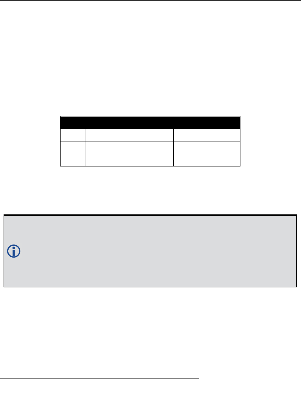
Chapter 2 Core Commands
OEM7 Commands and Logs Reference Manual v7 374
2.167 UALCONTROL
Setup User Accuracy levels
Platform: OEM719, OEM729, OEM7500, OEM7600, OEM7700, OEM7720, PwrPak7,
SPAN CPT7
The UALCONTROL command is used to define User Accuracy Levels. User accuracy levels are
user defined standard deviations thresholds, used to determine solution acceptability. Issuing
the UALCONTROL command causes the BESTPOS and GPGGA solution types to be controlled via
the specified thresholds, rather than by the solution source or mode. The new solution types are
described in the table below.
Value BESTPOS Position Type1NMEA Equivalent2
70 OPERATIONAL 4
71 WARNING 5
72 OUT_OF_BOUNDS 1
Table 68: User Accuracy Level Supplemental Pos-
ition Types and NMEA Equivalents
The SETBESTPOSCRITERIA command (see page 341) determines which standard deviations
are compared against the provided thresholds. When using the STEADYLINE command (see
page 361) together with the UALCONTROL command, the UAL setting is recommended. Refer
to Table 66: STEADYLINE Mode on page362 for mode details.
UAL is useful for applications that rely upon specific solutions types being present in the
BESTPOS or GPGGA logs. For example, if an agricultural steering system commonly
requires an RTK fixed GPGGA solution type (4) to operate, and interruptions in RTK con-
ventionally cause the GPGGA to switch to another solution type. This causes the steering
system to disengage. However, while using STEADYLINE, solutions with fixed RTK
accuracy can be maintained by GLIDE even if RTK is interrupted. UALCONTROL can be
used to ensure that the required solution type is maintained through such interruptions,
permitting the steering system to function continuously.
Message ID: 1627
Abbreviated ASCII Syntax:
UALCONTROL Action [Operational_limit] [Warning_limit]
Factory Default:
UALCONTROL disable
ASCII Example:
1As reported in the BESTPOS log (see page 428).
2Refers to the GPGGA quality indicator (see GPGGA on page510 for details).

Chapter 2 Core Commands
OEM7 Commands and Logs Reference Manual v7 375
UALCONTROL enable 0.10 0.20
Field Field Type ASCII
Value
Binary
Value Description Format Binary
Bytes
Binary
Offset
1UALCONTROL
header - -
Command header. See
Messages on page25 for
more information.
- H 0
2 Action
DISABLE 0 Disables this feature
Enum 4 H
ENABLE 1
Replace BESTPOS and
GPGGA position types
with OPERATIONAL,
WARNING or OUT_OF_
BOUNDS based on the
entered standard
deviations (refer to
Table 68: User Accuracy
Level Supplemental
Position Types and NMEA
Equivalents on the
previous page)
CLEAR 2
Disable this feature and
reset the entered
standard deviations.
3Operational
Limit
Standard deviation in
metres to report
OPERATIONAL
Double 8 H+4
4Warning
Limit
Standard deviation in
metres to report
WARNING
Note: OUT_OF_BOUND
reports when the
standard deviation
exceeds this value
Double 8 H+12
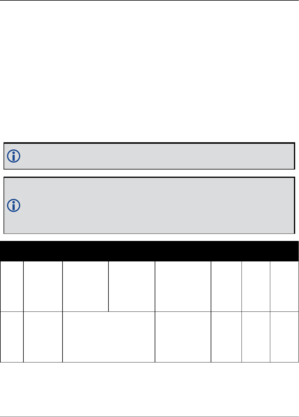
Chapter 2 Core Commands
OEM7 Commands and Logs Reference Manual v7 376
2.168 UNASSIGN
Unassigns a previously assigned channel
Platform: OEM719, OEM729, OEM7500, OEM7600, OEM7700, OEM7720, PwrPak7,
SPAN CPT7
This command cancels a previously issued ASSIGN command (see page 65) and the SV channel
reverts to automatic control (the same as ASSIGN AUTO).
Message ID: 29
Abbreviated ASCII Syntax:
UNASSIGN channel [state]
Input Example:
UNASSIGN 11
Issuing the UNASSIGN command to a channel that was not previously assigned by the
ASSIGN command (see page 65) has no effect.
For dual antenna receivers, when using the UNASSIGN command for SV channels on the
primary antenna, the SV channel count goes from 0 to N-1, where N is the number of
channels in the primary antenna channel configuration. When using the UNASSIGN com-
mand for channels on the secondary antenna, the SV channel count begins at N and goes
to N+(M-1), where M is the number of channels in the secondary antenna SV channel
configuration.
Field Field
Type
ASCII
Value
Binary
Value Description Format Binary
Bytes
Binary
Offset
1UNASSIGN
header - -
Command
header. See
Messages on
page25 for
more
information.
- H 0
2 channel
0 to n, where n is the
number of the last channel in
the current channel
configuration
Channel number
reset to
automatic
search and
acquisition
mode
Ulong 4 H

Chapter 2 Core Commands
OEM7 Commands and Logs Reference Manual v7 377
Field Field
Type
ASCII
Value
Binary
Value Description Format Binary
Bytes
Binary
Offset
3 state
These return SV channel
control to the automatic
search engine immediately
(see Table 14: Channel
State on page67)
Set the SV
channel state
(currently
ignored)
Enum 4 H+4

Chapter 2 Core Commands
OEM7 Commands and Logs Reference Manual v7 378
2.169 UNASSIGNALL
Unassigns all previously assigned channels
Platform: OEM719, OEM729, OEM7500, OEM7600, OEM7700, OEM7720, PwrPak7,
SPAN CPT7
This command cancels all previously issued ASSIGN commands for all SV channels (same as
ASSIGNALL AUTO). Tracking and control for each SV channel reverts to automatic mode.
Message ID: 30
Abbreviated ASCII Syntax:
UNASSIGNALL [system]
Input Example:
UNASSIGNALL GPS
Issuing the UNASSIGNALL command has no effect on channels that were not previously
assigned using the ASSIGN command (see page 65).
Field Field Type ASCII
Value
Binary
Value Description Format Binary
Bytes
Binary
Offset
1UNASSIGNALL
header - -
Command header. See
Messages on page25 for
more information.
- H 0
2 system
See Table 15:
Channel System
on page69
System that will be
affected by the
UNASSIGNALL
command (default = ALL)
Enum 4 H
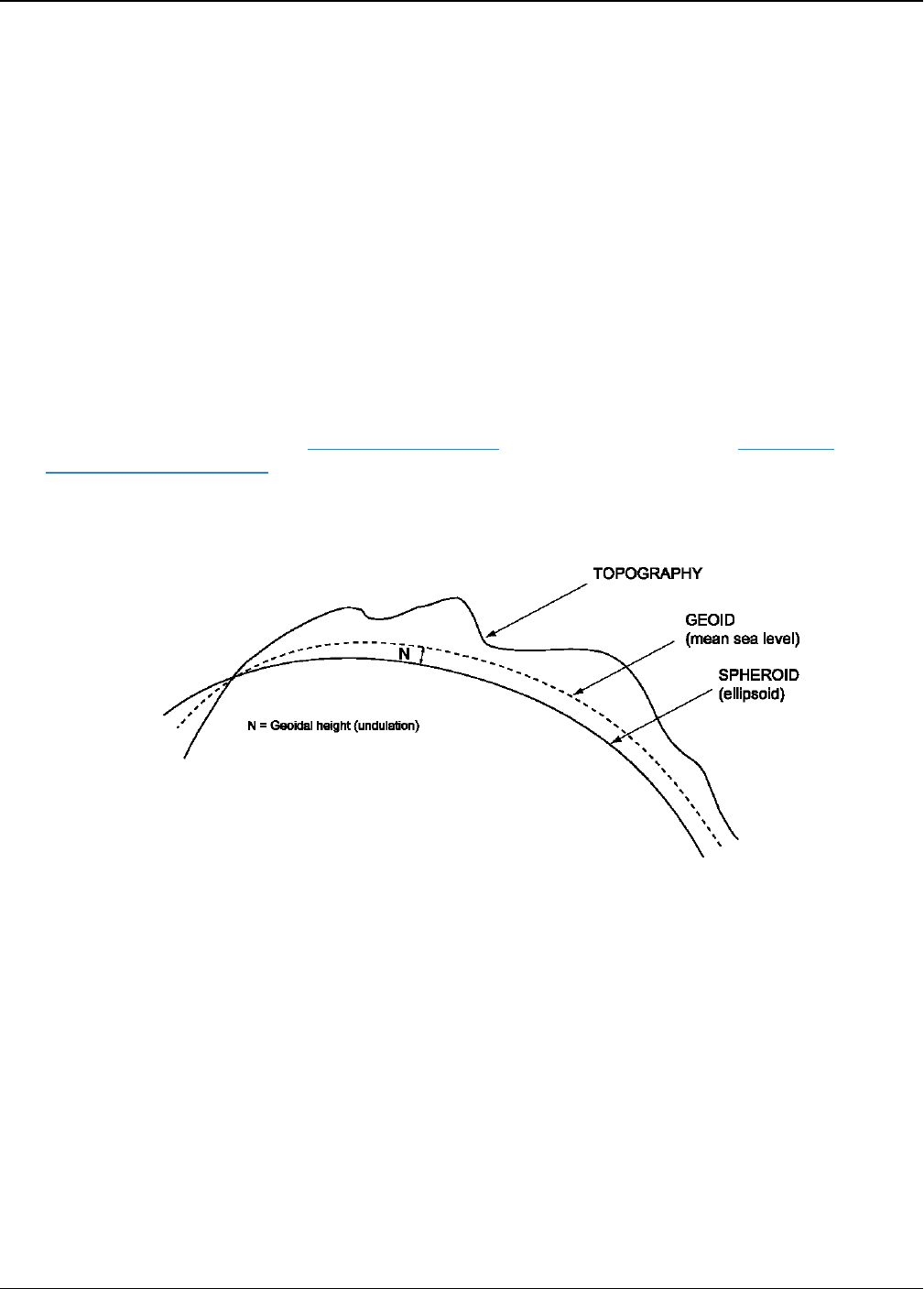
Chapter 2 Core Commands
OEM7 Commands and Logs Reference Manual v7 379
2.170 UNDULATION
Chooses undulation
Platform: OEM719, OEM729, OEM7500, OEM7600, OEM7700, OEM7720, PwrPak7,
SPAN CPT7
This command permits you to enter a specific geoidal undulation value. In the option field, the
EGM96 table provides ellipsoid heights at a 0.5° by 0.5° spacing while the OSU89B is imple-
mented at a 2° by 3° spacing. In areas of rapidly changing elevation, you could be operating
somewhere within the 2° by 3° grid with an erroneous height. EGM96 provides a more accurate
model of the ellipsoid which results in a denser grid of heights. It is also more accurate because
the accuracy of the grid points themselves has also improved from OSU89B to EGM96. For
example, the default grid (EGM96) is useful where there are underwater canyons, steep drop-
offs or mountains.
The undulation values reported in the position logs are in reference to the ellipsoid of the chosen
datum.
Refer to the application note APN-006 Geoid Issue, available on our website www.nova-
tel.com/support/search/ for a description of the relationships in Figure 10: Illustration of Undu-
lation below.
Figure 10: Illustration of Undulation
Message ID: 214
Abbreviated ASCII Syntax:
UNDULATION option [separation]
Factory Default:
UNDULATION egm96 0.0000
ASCII Example 1:
UNDULATION osu89b
ASCII Example 2:
UNDULATION USER -5.599999905

Chapter 2 Core Commands
OEM7 Commands and Logs Reference Manual v7 380
Field Field Type ASCII
Value
Binary
Value Description Format Binary
Bytes
Binary
Offset
1UNDULATION
header - -
Command header. See
Messages on page25 for
more information.
- H 0
2 option
USER 1 Use the user specified
undulation value
Enum 4 HOSU89B 2 Use the OSU89B
undulation table
EGM96 3 Use global geoidal height
model EGM96 table
3 separation ±1000.0 m
The undulation value
(required for the USER
option) (default = 0.000)
Float 4 H+4

Chapter 2 Core Commands
OEM7 Commands and Logs Reference Manual v7 381
2.171 UNLOCKOUT
Reinstates a satellite in the solution
Platform: OEM719, OEM729, OEM7500, OEM7600, OEM7700, OEM7720, PwrPak7,
SPAN CPT7
This command allows a satellite which has been previously locked out (LOCKOUT command on
page218) to be reinstated in the solution computation. If more than one satellite is to be rein-
stated, this command must be reissued for each satellite reinstatement.
Message ID: 138
Abbreviated ASCII Syntax:
UNLOCKOUT prn
Input Example:
UNLOCKOUT 8
The UNLOCKOUT command is used to reinstate a satellite while leaving other locked out
satellites unchanged.
This command can be used for GPS, GLONASS, SBAS and QZSS.
Field Field Type ASCII
Value
Binary
Value Description Format Binary
Bytes
Binary
Offset
1UNLOCKOUT
header - -
Command header. See
Messages on page25 for
more information.
- H 0
2 prn
Refer to PRN
Numbers on
page44
A single satellite PRN
number to be reinstated Ulong 4 H

Chapter 2 Core Commands
OEM7 Commands and Logs Reference Manual v7 382
2.172 UNLOCKOUTALL
Reinstates all previously locked out satellites
Platform: OEM719, OEM729, OEM7500, OEM7600, OEM7700, OEM7720, PwrPak7,
SPAN CPT7
This command allows all satellites which have been previously locked out (LOCKOUT command
on page218 or LOCKOUTSYSTEM command on page219) to be reinstated in the solution com-
putation.
Message ID: 139
Abbreviated ASCII Syntax:
UNLOCKOUTALL
Input Example:
UNLOCKOUTALL
Field Field Type ASCII
Value
Binary
Value Description Format Binary
Bytes
Binary
Offset
1UNLOCKOUTALL
header - -
Command header. See
Messages on page25 for
more information.
- H 0

Chapter 2 Core Commands
OEM7 Commands and Logs Reference Manual v7 383
2.173 UNLOCKOUTSYSTEM
Reinstates previously locked out system
Platform: OEM719, OEM729, OEM7500, OEM7600, OEM7700, OEM7720, PwrPak7,
SPAN CPT7
This command allows a system which has been previously locked out (refer to the
LOCKOUTSYSTEM command on page219) to be reinstated in the solution computation.
If more than one system is to be reinstated, this command must be reissued for each
system reinstatement.
Message ID: 908
Abbreviated ASCII Syntax:
UNLOCKOUTSYSTEM system
Input Example:
UNLOCKOUTSYSTEM glonass
The UNLOCKOUTSYSTEM command is used to reinstate a system while leaving other
locked out systems unchanged.
Field Field Type ASCII
Value
Binary
Value Description Format Binary
Bytes
Binary
Offset
1
UNLOCKOUT
SYSTEM
header
- -
Command header. See
Messages on page25 for
more information.
- H 0
2 system
See Table 102:
Satellite System
on page545
A single satellite system
to be reinstated Enum 4 H

Chapter 2 Core Commands
OEM7 Commands and Logs Reference Manual v7 384
2.174 UNLOG
Removes a log from logging control
Platform: OEM719, OEM729, OEM7500, OEM7600, OEM7700, OEM7720, PwrPak7,
SPAN CPT7
This command is used to remove a specific log request from the system.
Message ID: 36
Abbreviated ASCII Syntax:
UNLOG [port] message
Input Example:
UNLOG com1 bestposa
UNLOG bestposa
The UNLOG command is used to remove one or more logs while leaving other logs
unchanged.
2.174.1 Binary
Field Field
Name Binary Value Description Format Binary
Bytes
Binary
Offset
1
UNLOG
(binary)
header
(See Table 3: Binary Message
Header Structure on page30)
This field
contains the
message
header
- H 0
2 port
See Table 4: Detailed Port
Identifier on page31 (decimal
port values greater than 16 may
be used)
Port to which
log is being
sent
Enum 4 H
3 message Any valid message ID
Message ID
of log to
output
Ushort 2 H+4

Chapter 2 Core Commands
OEM7 Commands and Logs Reference Manual v7 385
Field Field
Name Binary Value Description Format Binary
Bytes
Binary
Offset
4message
type
Bits 0-4 = Reserved
Bits 5-6 = Format
00 = Binary
01 = ASCII
10 = Abbreviated ASCII,
NMEA
11 = Reserved
Bit 7 = Response Bit (Message
Responses on page41)
0 = Original Message
1 = Response Message
Message type
of log Char 1 H+6
5 Reserved Char 1 H+7
2.174.2 ASCII
Field Field
Type
ASCII
Value
Binary
Value Description Format Binary
Bytes
Binary
Offset
1
UNLOG
(ASCII)
header
- -
This field contains the
command name or the
message header depending
on whether the command
is abbreviated ASCII or
ASCII, respectively
- H 0
2 port
See Table 4:
Detailed Port
Identifier on
page31 (decimal
port values greater
than 16 may be
used)
Port to which log is being
sent
(default = THISPORT)
Enum 4 H
3 message Message
Name N/A Message Name of log to be
disabled Ulong 4 H+4

Chapter 2 Core Commands
OEM7 Commands and Logs Reference Manual v7 386
2.175 UNLOGALL
Removes all logs from logging control
Platform: OEM719, OEM729, OEM7500, OEM7600, OEM7700, OEM7720, PwrPak7,
SPAN CPT7
If [port] is specified, this command disables all logs on the specified port only. All other ports
are unaffected. If [port] is not specified this command defaults to the ALL_PORTS setting.
Message ID: 38
Abbreviated ASCII Syntax:
UNLOGALL [port] [held]
Input Example:
UNLOGALL com2_15
UNLOGALL true
The UNLOGALL command is used to remove all log requests currently in use.
Field Field
Type
ASCII
Value
Binary
Value Description Format Binary
Bytes
Binary
Offset
1UNLOGALL
header - -
Command header.
See Messages on
page25 for more
information.
- H 0
2 port
See Table 4: Detailed Port
Identifier on page31
(decimal values greater
than 16 may be used)
Port to clear
(default = ALL_
PORTS)
Enum 4 H
3 held
FALSE 0
Does not remove
logs with the HOLD
parameter
(default)
Bool 4 H+4
TRUE 1
Removes
previously held
logs, even those
with the HOLD
parameter

Chapter 2 Core Commands
OEM7 Commands and Logs Reference Manual v7 387
2.176 USBSTICKEJECT
Prepare a USB stick for removal
Platform: OEM719, OEM729, OEM7500, OEM7600, OEM7700, OEM7720, PwrPak7,
SPAN CPT7
Use this command to unmount the USB stick and prepare it for safe physical removal.
This command may fail with a Busy error if there is an ongoing USB stick mounting or unmount-
ing operation.
The FILETRANSFERSTATUS log (see page 473) indicates the USBSTICK UNMOUNTED status
when it is safe to physically remove the stick. This may take up to 10 seconds.
Message ID: 2115
Abbreviated ASCII Syntax:
USBSTICKEJECT
Example:
USBSTICKEJECT
Field Field Type ASCIIValue Binary
Value Description Format Binary
Bytes
Binary
Offset
1USBSTICKEJECT
header - -
Command
header. See
Messages on
page25 for more
information.
- H 0

Chapter 2 Core Commands
OEM7 Commands and Logs Reference Manual v7 388
2.177 USERDATUM
Sets user customized datum
Platform: OEM719, OEM729, OEM7500, OEM7600, OEM7700, OEM7720, PwrPak7,
SPAN CPT7
This command permits entry of customized ellipsoidal datum parameters. This command is used
in conjunction with the DATUM command (see page 115). If used, the command default setting
for USERDATUM is WGS84.
When the USERDATUM command is entered, the USEREXPDATUM command on page390 is
then issued internally with the USERDATUM command values. It is the USEREXPDATUM com-
mand that appears in the RXCONFIG log (see page 746). If the USEREXPDATUM command or
USERDATUM command are used, their newest values overwrite the internal USEREXPDATUM
values.
The transformation for the WGS84 to Local used in the OEM7 family is the Bursa-Wolf trans-
formation or reverse Helmert transformation. In the Helmert transformation, the rotation of a
point is counter clockwise around the axes. In the Bursa-Wolf transformation, the rotation of a
point is clockwise. Therefore, the reverse Helmert transformation is the same as the Bursa-
Wolf.
Message ID: 78
Abbreviated ASCII Syntax:
USERDATUM semimajor flattening dx dy dz rx ry rz scale
Factory Default:
USERDATUM 6378137.0 298.2572235628 0.0 0.0 0.0 0.0 0.0 0.0 0.0
ASCII Example:
USERDATUM 6378206.400 294.97869820000 -12.0000 147.0000 192.0000 0.0000
0.0000 0.0000 0.000000000
Use the USERDATUM command in a survey to fix the position with values from another
known datum so that the GNSS calculated positions are reported in the known datum
rather than WGS84.
Field Field Type ASCII
Value
Binary
Value Description Format Binary
Bytes
Binary
Offset
1USERDATUM
header - -
Command header. See
Messages on page25 for
more information.
- H 0
2 semimajor 6300000.0 -
6400000.0
Datum Semi-major Axis (a)
(metres) Double 8 H

Chapter 2 Core Commands
OEM7 Commands and Logs Reference Manual v7 389
Field Field Type ASCII
Value
Binary
Value Description Format Binary
Bytes
Binary
Offset
3 flattening 290.0 - 305.0 Reciprocal Flattening,
1/f = a/(a-b) Double 8 H+8
4 dx ± 2000.0 Datum offsets from local to
WGS84. These are the
translation values between
the user datum and WGS84
(internal reference)
(metres)
Double 8 H+16
5 dy ± 2000.0 Double 8 H+24
6 dz ± 2000.0 Double 8 H+32
7 rx ± 10.0 radians Datum rotation angle about
X, Y and Z. These values
are the rotation from your
local datum to WGS84. A
positive sign is for counter
clockwise rotation and a
negative sign is for
clockwise rotation
Double 8 H+40
8 ry ± 10.0 radians Double 8 H+48
9 rz ± 10.0 radians Double 8 H+56
10 scale ± 10.0 ppm
Scale value is the
difference in ppm between
the user datum and WGS84
Double 8 H+64

Chapter 2 Core Commands
OEM7 Commands and Logs Reference Manual v7 390
2.178 USEREXPDATUM
Set custom expanded datum
Platform: OEM719, OEM729, OEM7500, OEM7600, OEM7700, OEM7720, PwrPak7,
SPAN CPT7
Like the USERDATUM command, this command allows you to enter customized ellipsoidal
datum parameters. However, USEREXPDATUM literally means user expanded datum which
allows additional datum information such as velocity offsets and time constraints. The 7 expan-
ded parameters are rates of change of the initial 7 parameters. These rates of change affect the
initial 7 parameters over time relative to the Reference Date provided by the user.
This command is used in conjunction with the DATUM command (see page 115). If this com-
mand is used without specifying any parameters, the command defaults to WGS84. If a
USERDATUM command is entered, the USEREXPDATUM command is then issued internally
with the USERDATUM command values (USERDATUM command on page388). It is the
USEREXPDATUM command that appears in the RXCONFIG log. If the USEREXPDATUM or the
USERDATUM command are used, their newest values overwrite the internal USEREXPDATUM
values.
Message ID: 783
Abbreviated ASCII Syntax:
USEREXPDATUM semimajor flattening dx dy dz rx ry rz scale xvel yvel zvel
xrvel yrvel zrvel scalev refdate
Factory Default:
USEREXPDATUM 6378137.0 298.25722356280 0.0 0.0 0.0 0.0 0.0 0.0 0.0 0.0 0.0
0.0 0.0 0.0 0.0 0.0 0.0
ASCII Example:
USEREXPDATUM 6378137.000 298.25722356280 0.000000000 0.000000000 0.000000000
0.00000000 0.000000000 0.000000000 0.000000000 0.000000000 0.000000000
0.000000000 0.0000 0.000000000 0.000000000 0.000000000 0.000000000
Use the USEREXPDATUM command in a survey to fix the position with values from
another known datum so that the GPS calculated positions are reported in the known
datum rather than WGS84. For example, it is useful for places like Australia, where the
continent is moving several centimetres a year relative to WGS84. With
USEREXPDATUM you can also input the velocity of the movement to account for drift
over the years.

Chapter 2 Core Commands
OEM7 Commands and Logs Reference Manual v7 391
Field Field Type ASCII
Value
Binary
Value Description Format Binary
Bytes
Binary
Offset
1USEREXPDATUM
header - -
Command header. See
Messages on page25
for more information.
- H 0
2 semimajor 6300000.0 -
6400000.0 m
Datum semi-major axis
(a) in metres Double 8 H
3 flattening 290.0 - 305.0 Reciprocal Flattening,
1/f = a/(a-b) Double 8 H+8
4 dx ± 2000.0 m Datum offsets from
local to WGS84. These
are the translation
values between the user
datum and WGS84
(internal reference)
Double 8 H+16
5 dy ± 2000.0 m Double 8 H+24
6 dz ± 2000.0 m Double 8 H+32
7 rx ± 10.0 radians Datum rotation angle
about X, Y and Z. These
values are the rotation
from your local datum
to WGS84. A positive
sign is for counter
clockwise rotation and a
negative sign is for
clockwise rotation
Double 8 H+40
8 ry ± 10.0 radians Double 8 H+48
9 rz ± 10.0 radians Double 8 H+56
10 scale ± 10.0 ppm
Scale value is the
difference in ppm
between the user datum
and WGS84
Double 8 H+64
11 xvel ± 2000.0 m/yr Velocity vector along X-
axis Double 8 H+72
12 yvel ± 2000.0 m/yr Velocity vector along Y-
axis Double 8 H+80
13 zvel ± 2000.0 m/yr Velocity vector along Z-
axis Double 8 H+88
14 xrvel ± 10.0
radians/yr
Change in the rotation
about X over time Double 8 H+96
15 yrvel ± 10.0
radians/yr
Change in the rotation
about Y over time Double 8 H+104
16 zrvel ± 10.0
radians/yr
Change in the rotation
about Z over time Double 8 H+112

Chapter 2 Core Commands
OEM7 Commands and Logs Reference Manual v7 392
Field Field Type ASCII
Value
Binary
Value Description Format Binary
Bytes
Binary
Offset
17 scalev ± 10.0 ppm/yr Change in scale from
WGS84 over time Double 8 H+120
18 refdate 0.0 year
Reference date of
parameters
Example:
2011.00 = Jan 1, 2011
2011.19 = Mar 11, 2011
Double 8 H+128
Chapter 2 Core Commands
OEM7 Commands and Logs Reference Manual v7 393
2.179 USERI2CREAD
Read data from devices on the I2C bus
Platform: OEM7600, OEM7700, OEM7720
Use this command to read data from devices on the I2C bus.
This command only applies to OEM7 receivers that have I2C signals available on the
interface connector. The compatible receivers are listed in the Platform section above.
The USERI2CRESPONSE log (see page 846) can be used to check the completion or status of
the read operation. An optional user defined Transaction ID can be provided to help synchronize
requests with responses in the USERI2CRESPONSE log (see page 846). This command is
primarily intended to be used by Lua applications that need to interact with external devices.
Reading from an I2C device requires a device address, to distinguish which physical device is to
be accessed, a register within the device, and the expected number of bytes to be read. Depend-
ing on the type of I2C device, register addresses can be 1 to 4 bytes in length, so the actual num-
ber of bytes for the register address must be specified.
For some I2C devices there are no registers within the device. In this case, the Register Address
Length is 0 and no bytes are supplied for the Register Address.
The USERI2CREAD command is flexible to handle all of these situations.
Message ID: 2232
Abbreviated ASCII Syntax:
USERI2CREAD DeviceAddress RegisterAddressLen RegisterAddress RequestReadLen
[TransactionID]
Examples:
USERI2CREAD 70 1 AB 12 1234
USERI2CREAD 74 3 ABCDEF 234 5678
USERI2CREAD 74 0 234 5678
Field Field Type Description Format Binary
Bytes
Binary
Offset
1USERI2CREAD
header
Command header. See Messages for
more information. - H 0

Chapter 2 Core Commands
OEM7 Commands and Logs Reference Manual v7 394
Field Field Type Description Format Binary
Bytes
Binary
Offset
2 DeviceAddress
The 7 bit address of the I2C device.
Valid values are 0 through 127.
For ASCII and Abbreviated commands,
this field is a hexadecimal string of two
digits. There is no 0x prefix and spaces
are not allowed in the string.
Uchar 11H
3 RegisterAddressLen The length of the register address that
follows. Valid values are 0 through 4. Ulong 4 H+4
4 RegisterAddress
The actual address of the register to be
read. The number of bytes here must
match the RegisterAddressLen. In
particular, when RegisterAddressLen is
0, this field is empty (even for a binary
command)
For ASCII and Abbreviated commands,
this field is a hexadecimal string of two
digits for each byte in the register
address. There is no 0x prefix and
spaces are not allowed in the string.
Uchar
Array X1H+8
5 RequestReadLen
The length of data expected to be
retrieved from the device. Valid values
are 1 through 256.
Ulong 4 H+122
6 TransactionID
An optional user provided ID for this
transaction. Default = 0.
This transaction ID will be copied to the
USERI2CRESPONSE log (see page
846) created for this read operation.
Ulong 4 H+163
1In the binary case, additional bytes of padding are added after this field to maintain 4-byte alignment for the fields
that follow.
2H+8 if X=0
3H+12 if X=0

Chapter 2 Core Commands
OEM7 Commands and Logs Reference Manual v7 395
2.180 USERI2CWRITE
Write data to device on I2C bus
Platform: OEM7600, OEM7700, OEM7720
Use this command to write data to devices on the I2C bus.
This command only applies to OEM7 receivers that have I2C signals available on the
interface connector. The compatible receivers are listed in the Platform section above.
The USERI2CRESPONSE log (see page 846) can be used to check the completion or status of
the write operation. An optional user defined Transaction ID can be provided to help synchronize
requests with responses in the USERI2CRESPONSE log (see page 846). This command is
primarily intended to be used by Lua applications that need to interact with external devices.
Writing to an I2C device requires a device address, to distinguish which physical device is to be
accessed, a register within the device and the data. Depending on the type of I2C device,
register addresses can be 1 to 4 bytes in length, and so the actual number of bytes for the
register address must be specified.
For some I2C devices there are no registers within the device. In this case, the Register Address
Length is 0, and no bytes are supplied for the Register Address.
For some other I2C devices, write operations are done in two stages:
1. The first stage sends a write command with a register address, but no data. This is a dummy
write to set the register within the device for write operations that follow.
2. The second stage sends a write command with no register address, but does send a stream
of data.
The USERI2CWRITE command is flexible to handle all of these situations.
Message ID: 2233
Abbreviated ASCII Syntax:
USERI2CWRITE DeviceAddress RegisterAddressLen RegisterAddress
WriteDataLength WriteData [TransactionID]
Examples:
USERI2CWRITE 70 1 AB 12 3132333435363738393A3B3C 1234
USERI2CWRITE 74 3 ABCDED 5 1234567890 1234
USERI2CWRITE 40 0 5 1234567890 1234
USERI2CWRITE 40 2 AABB 0 1234 (a dummy write)

Chapter 2 Core Commands
OEM7 Commands and Logs Reference Manual v7 396
Field Field Type Description Format Binary
Bytes
Binary
Offset
1USERI2CWRITE
header
Command header. See Messages
for more information. - H 0
2 DeviceAddress
The 7 bit address of the I2C
device. Valid values 0 through
127.
For ASCII and Abbreviated
commands, this field is a
hexadecimal string of two digits.
There is no 0x prefix and spaces
are not allowed in the string.
Uchar 11H
3 RegisterAddressLen
The length of the register
address that follows. Valid values
are 0 through 4.
Ulong 4 H+4
4 RegisterAddress
The actual address of the register
to be written. The number of
bytes here must match the
RegisterAddressLen. In
particular, when
RegisterAddressLen is 0, this
field is empty (even for a binary
command)
For ASCII and Abbreviated
commands, this field is a
hexadecimal string of two digits
for each byte in the register
address. There is no 0x prefix
and spaces are not allowed in the
string.
Uchar
Array X1H+8
5 WriteDataLength
The length of data to be written
in bytes. Valid values are 0
through 256.
Ulong 4 H+122
1In the binary case, additional bytes of padding are added after this field to maintain 4-byte alignment for the fields
that follow.
2H+8 if X=0

Chapter 2 Core Commands
OEM7 Commands and Logs Reference Manual v7 397
Field Field Type Description Format Binary
Bytes
Binary
Offset
6 WriteData
The data to be written. The
number of bytes in this data
block must match the
WriteDataLength. In particular,
when WriteDataLength is 0, this
field is empty.
For ASCII and Abbreviated
commands, this field is a
hexadecimal string of two digits
for each byte in the data block.
There is no 0x prefix and spaces
are not allowed in the string.
Data is streamed to the device as
a series of bytes in the order
provided.
Uchar
Array Y1H+162
7 TransactionID
An optional user provided ID for
this transaction. Default = 0.
This transaction ID will be copied
to the USERI2CRESPONSE log
(see page 846) created for this
write operation.
Ulong 4 H+16+4*INT
((Y+3)/4)3
1In the binary case, additional bytes of padding are added after this field to maintain 4-byte alignment for the fields
that follow.
2H+12 if X=0
3H+12+4*INT((Y+3)/4) if X=0
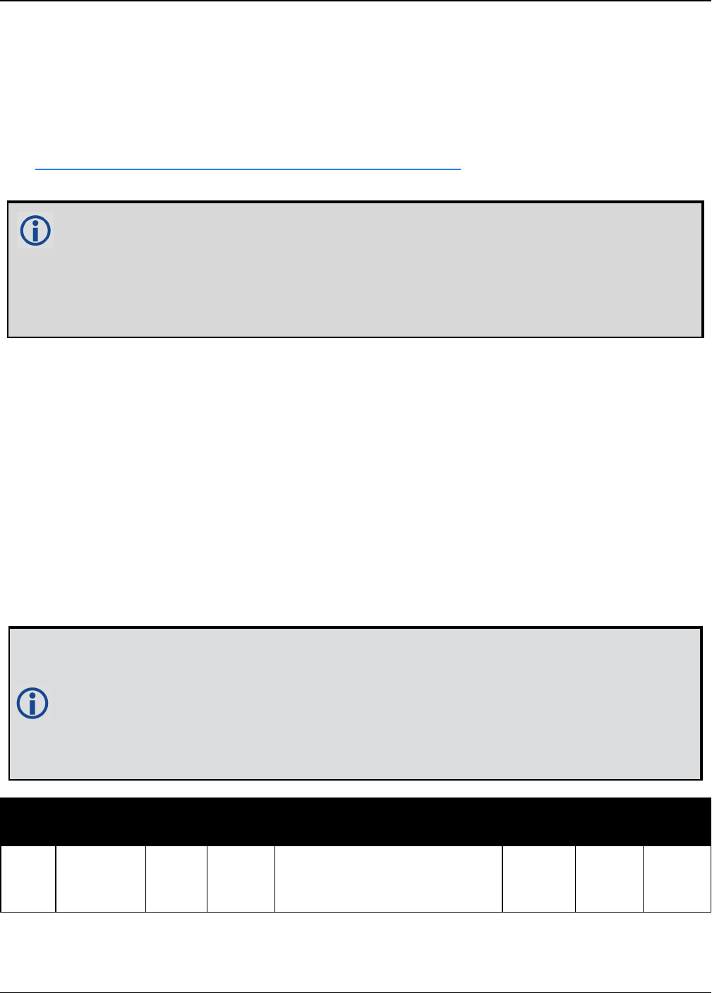
Chapter 2 Core Commands
OEM7 Commands and Logs Reference Manual v7 398
2.181 UTMZONE
Sets UTM parameters
Platform: OEM719, OEM729, OEM7500, OEM7600, OEM7700, OEM7720, PwrPak7,
SPAN CPT7
This command sets the UTM persistence, zone number or meridian. Refer to
earth-info.nga.mil/GandG/coordsys/grids/referencesys.html for more information and a world
map of UTM zone numbers.
1. The latitude limits of the UTM System are 80°S to 84°N, so if your position is outside
this range, the BESTUTM log (see page 441) outputs a northing, easting and height of
0.0, along with a zone letter of “*” and a zone number of 0, so that it is obvious that
the data in the log is dummy data.
2. If the latitude band is X, then the Zone number should not be set to 32, 34 or 36. These
zones were incorporated into other zone numbers and do not exist.
Message ID: 749
Abbreviated ASCII Syntax:
UTMZONE command [parameter]
Factory Default:
UTMZONE auto 0
ASCII Example 1:
UTMZONE SET 10
ASCII Example 2:
UTMZONE CURRENT
The UTM grid system is displayed on all National Topographic Series (NTS) of Canada
maps and United States Geological Survey (USGS) maps. On USGS 7.5-minute quad-
rangle maps (1:24,000 scale), 15-minute quadrangle maps (1:50,000, 1:62,500, and
standard-edition 1:63,360 scales) and Canadian 1:50,000 maps the UTM grid lines are
drawn at intervals of 1,000 metres and are shown either with blue ticks at the edge of
the map or by full blue grid lines. On USGS maps at 1:100,000 and 1:250,000 scale and
Canadian 1:250,000 scale maps a full UTM grid is shown at intervals of 10,000 metres.
Field Field
Type
ASCII
Value
Binary
Value Description Format Binary
Bytes
Binary
Offset
1UTMZONE
header - -
Command header. See
Messages on page25 for
more information.
- H 0

Chapter 2 Core Commands
OEM7 Commands and Logs Reference Manual v7 399
Field Field
Type
ASCII
Value
Binary
Value Description Format Binary
Bytes
Binary
Offset
2 command See Table 69: UTM Zone Commands below Enum 4 H
3 parameter See Table 69: UTM Zone Commands below Long 4 H+4
Binary ASCII Description
0 AUTO
UTM zone default that automatically sets the central meridian and does not
switch zones until it overlaps by the set persistence. This a spherical
approximation to the earth unless you are at the equator (default = 0) (m)
1 CURRENT Same as UTMZONE AUTO with infinite persistence of the current zone. The
parameter field is not used
2 SET
Sets the central meridian based on the specified UTM zone. A zone includes
its western boundary, but not its eastern boundary, Meridian. For example,
zone 12 includes (108°W, 114°W) where 108° < longitude < 114°
3 MERIDIAN
Sets the central meridian as specified in the parameter field. In the
BESTUTM log (see page 441), the zone number is output as 61 to indicate
the manual setting (zones are set by pre-defined central meridians not user-
set ones)
Table 69: UTM Zone Commands
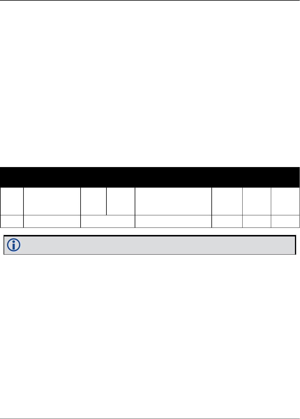
Chapter 2 Core Commands
OEM7 Commands and Logs Reference Manual v7 400
2.182 WIFIAPCHANNEL
Set the channel for the Wi-Fi access point
Platform: PwrPak7
Use this command to set the operating channel for the Wi-Fi module when operating as an
access point. The new channel will be used the next time the WIFIMODE AP command is
received.
Message ID: 2091
Abbreviated ASCII Syntax:
WIFIAPCHANNEL channel
Factory Default:
WIFIAPCHANNEL 11
Example:
WIFIAPCHANNEL 6
Field Field Type ASCII
Value
Binary
Value Description Format Binary
Value
Binary
Offset
1WIFIAPCHANNEL
header - -
Command header. See
Messages on page25
for more information.
- H 0
2 channel 1-14 802.11 channel Long 4 H
For best performance, choose one of the non-overlapping channels: 1, 6, or 11.

Chapter 2 Core Commands
OEM7 Commands and Logs Reference Manual v7 401
2.183 WIFIAPIPCONFIG
Set the IP address and netmask for the Wi-Fi access point
Platform: PwrPak7
Use this command to set the Wi-Fi IP address and netmask for Wi-Fi module when operating as
an access point. The new network configuration takes effect the next time the WIFIMODE AP
command is received.
Message ID: 2096
Abbreviated ASCII Syntax:
WIFIAPIPCONFIG ip_address ip_netmask
Factory Default:
WIFIAPIPCONFIG 192.168.19.1 255.255.255.0
Example:
WIFIAPIPCONFIG 192.162.55.20 255.255.0.0
Field Field Type ASCII
Value
Binary
Value Description Format Binary
Bytes
Binary
Offset
1WIFIAPIPCONFIG
header - -
Command header.
See Messages on
page25 for more
information.
- H 0
2 ip_address Null-terminated
ASCII string
IP address, dot
decimal format
String
[16] Variable H
3 ip_netmask Null-terminated
ASCII string
IP netmask, dot
decimal format
(optional)
Default
=255.255.255.0
String
[16] Variable Variable

Chapter 2 Core Commands
OEM7 Commands and Logs Reference Manual v7 402
2.184 WIFIAPPASSKEY
Set Wi-Fi access point passkey
Platform: PwrPak7
Use this command to set the WPA2 PSK ASCII passkey for the Wi-Fi module when the receiver is
operating as an access point.
The default passkey is printed on the receiver label.
The new passkey takes effect the next time the WIFIMODE AP command is received.
The term passkey and password are the same.
Message ID: 2090
Abbreviated ASCII Syntax:
WIFIAPPASSKEY passkey
Factory Default:
The default passkey/password is printed on the receiver label.
Example:
WIFIAPPASSKEY "bysP3zE6SZmFQeyd"
Field Field Type ASCII
Value
Binary
Value Description Format Binary
Bytes
Binary
Offset
1WIFIAPPASSKEY
header - -
Command header.
See Messages on
page25 for more
information.
- H 0
2 passkey
Null-terminated
ASCII string, 8 to
64 characters
WPA2 PSK ASCII
passkey
String
[65] Variable H

Chapter 2 Core Commands
OEM7 Commands and Logs Reference Manual v7 403
2.185 WIFIMODE
Configure the receiver Wi-Fi mode
Platform: PwrPak7
Use this command to enable or disable Wi-Fi on the receiver.
Message ID: 2144
Abbreviated ASCII Syntax:
WIFIMODE mode
Factory Default:
WIFIMODE AP
Example:
WIFIMODE OFF
Field Field
Type
ASCII
Value
Binary
Value Description Format Binary
Bytes
Binary
Offset
1WIFIMODE
header - -
Command header. See
Messages on page25 for
more information.
- H 0
2 mode
OFF 0 Power off the Wi-Fi module
Enum 4 H
AP 1 Configure the Wi-Fi module
as an Access Point (AP)
ON 3
Supply power to the Wi-Fi
module, but do not configure
it.
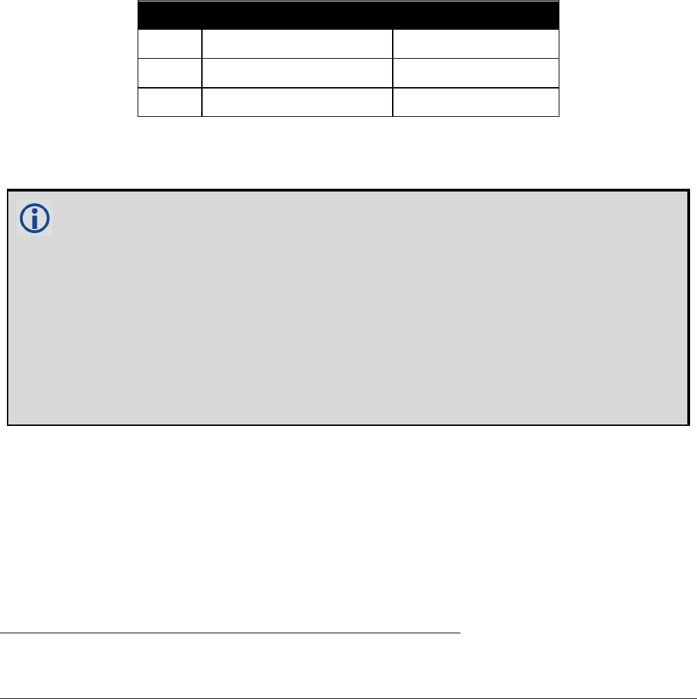
OEM7 Commands and Logs Reference Manual v7 404
Chapter 3 Logs
3.1 Log Types
See the LOG command on page220, for details about requesting logs.
The receiver is capable of generating three type of logs: synchronous, asynchronous and polled.
The data for synchronous logs is generated on a regular schedule. In order to output the most
current data as soon as it is available, asynchronous data is generated at irregular intervals. The
data in polled logs is generated on demand. The following table outlines the log types and the
valid triggers to use:
Type Recommended Trigger Illegal Trigger
Synch ONTIME ONNEW, ONCHANGED
Asynch ONCHANGED or ONCE -
Polled ONCE or ONTIME aONNEW, ONCHANGED
Table 70: Log Type Triggers
See Message Time Stamps on page46 for information about how the message time stamp is set
for each type of log.
1. The OEM7 family of receivers can handle 80 logs at a time. If an attempt is made to
log more than 80 logs at a time, the receiver responds with an Insufficient Resources
error.
2. Asynchronous logs, such as MATCHEDPOS, should only be logged ONCHANGED. Other-
wise, the most current data is not output when it is available. This is especially true of
the ONTIME trigger, which may result in inaccurate time tags.
3. Use the ONNEW trigger with the MARKTIME or MARKPOS logs.
4. Before the output of fields for ASCII and binary logs, there is an ASCII or binary
header respectively. See Table 2: ASCII Message Header Structure on page28 and
Table 3: Binary Message Header Structure on page30. There is no header information
before Abbreviated ASCII output, see Abbreviated ASCII on page29.
3.1.1 Log Type Examples
For polled logs, the receiver only supports an offset that is:
lsmaller than the logging period
ldecimal values that are a multiple of the maximum logging rate defined by the receiver
model. For more information see the LOG command on page220.
The following are valid examples for a polled log:
log portstats ontime 4 2
aPolled log types do not allow fractional offsets and cannot do ontime rates faster than 1 Hz.

Chapter 3 Logs
OEM7 Commands and Logs Reference Manual v7 405
log version once
For polled logs, the following examples are invalid:
log serialconfig ontime 1 2[offset is larger than the logging period]
log serialconfig ontime 4 1.5[offset is not an integer]
For synchronous and asynchronous logs, the receiver supports any offset that is:
lsmaller than the logging period
la multiple of the minimum logging period
For example, if the receiver supports 20 Hz logging, the minimum logging period is 1/20 Hz or
0.05 s. The following are valid examples for a synchronous or asynchronous log, on a receiver
that can log at rates up to 20 Hz:
log bestpos ontime 1[1 Hz]
log bestpos ontime 1 0.1
log bestpos ontime 1 0.90
log avepos ontime 1 0.95
log avepos ontime 2[0.5 Hz]
log avepos ontime 2 1.35
log avepos ontime 2 1.75
For synchronous and asynchronous logs, the following examples are invalid:
log bestpos ontime 1 0.08[offset is not a multiple of the minimum logging period]
log bestpos ontime 1 1.05[offset is larger than the logging period]
3.2 Log Reference
Logs are the mechanism used to extract information from the receiver.

Chapter 3 Logs
OEM7 Commands and Logs Reference Manual v7 406
3.3 ALIGNBSLNENU
ENU baselines using ALIGN
Platform: OEM719, OEM729, OEM7500, OEM7600, OEM7700, OEM7720, PwrPak7,
SPAN CPT7
This log outputs the RTK quality ENU baselines from ALIGN. The XYZ baselines (output in
ALIGNBSLNXYZ log) are rotated relative to master position (output in MASTERPOS) to compute
ENU baselines.
On dual antenna receivers, the ALIGNBSLNENU log is not available for the secondary
antenna input.
Message ID: 1315
Log Type: Asynch
Recommended Input:
log alignbslnenua onnew
ASCII Example:
#ALIGNBSLNENUA,COM1,0,29.0,FINESTEERING,1629,259250.000,02040000,100b,39448;SO
L_COMPUTED,NARROW_INT,4.1586,-1.9197,-
0.0037,0.0047,0.0050,0.0062,"0092","AAAA",22,16,16,16,0,01,0,33*11e1d4c0
Field Field type Description Format Binary
Bytes
Binary
Offset
1 ALIGNBSLNENU Log header. See Messages on page25 for
more information. H 0
2 sol stat Solution status, see Table 73: Solution
Status on page431
Enum 4 H
3 pos type Position type, see Table 74: Position or
Velocity Type on page432 Enum 4 H+4
4 East East Baseline (relative to master position)
in metres Double 8 H+8
5 North North Baseline (relative to master
position) in metres Double 8 H+16
6 Up Up Baseline (relative to master position) in
metres Double 8 H+24
7 East σ East Baseline standard deviation in metres Float 4 H+32
8 North σ North Baseline standard deviation in
metres Float 4 H+36

Chapter 3 Logs
OEM7 Commands and Logs Reference Manual v7 407
Field Field type Description Format Binary
Bytes
Binary
Offset
9 Up σ Up Baseline standard deviation in metres Float 4 H+40
10 Rover id
Rover Receiver ID
Set using the SETROVERID command (see
page 348) on the Rover
e.g., setroverid RRRR
Char[4] 4 H+44
11 Master id
Master Receiver ID
Set using the DGPSTXID command (see
page 122) on the Master
Default: AAAA
Char[4] 4 H+48
12 #SVs Number of satellites tracked Uchar 1 H+52
13 #solnSVs Number of satellites in solution Uchar 1 H+53
14 #obs Number of satellites above elevation mask
angle Uchar 1 H+54
15 #multi Number of satellites above elevation mask
angle with L2, B2 Uchar 1 H+55
16 Reserved Hex 1 H+56
17 ext sol stat Extended solution status, see Table 77:
Extended Solution Status on page435 Hex 1 H+57
18
Galileo and
BeiDou sig
mask
Galileo and BeiDou signals used mask (see
Table 76: Galileo and BeiDou Signal-Used
Mask on page435)
Hex 1 H+58
19
GPS and
GLONASS sig
mask
GPS and GLONASS signals used mask (see
Table 75: GPS and GLONASS Signal-Used
Mask on page434)
Hex 1 H+59
20 xxxx 32-bit CRC (ASCII and Binary only) Hex 4 H+60
21 [CR][LF] Sentence Terminator (ASCII only) - - -

Chapter 3 Logs
OEM7 Commands and Logs Reference Manual v7 408
3.4 ALIGNBSLNXYZ
XYZ baselines using ALIGN
Platform: OEM719, OEM729, OEM7500, OEM7600, OEM7700, OEM7720, PwrPak7,
SPAN CPT7
This log outputs the RTK quality XYZ baselines from ALIGN.
On dual antenna receivers, the ALIGNBSLNXYZ log is not available for the secondary
antenna input.
Message ID: 1314
Log Type: Asynch
Recommended Input:
log alignbslnxyza onnew
ASCII Example:
#ALIGNBSLNXYZA,COM1,0,29.0,FINESTEERING,1629,259250.000,02040000,9d28,39448;SO
L_COMPUTED,NARROW_INT,3.1901,-
3.0566,1.2079,0.0050,0.0054,0.0056,"0092","AAAA",22,16,16,16,0,01,0,33*ac372198
Field Field type Description Format Binary
Bytes
Binary
Offset
1 ALIGNBSLNXYZ Log header. See Messages on page25 for
more information. H 0
2 sol stat Solution status, see Table 73: Solution
Status on page431 Enum 4 H
3 pos type Position type, see Table 74: Position or
Velocity Type on page432 Enum 4 H+4
4 dX X Baseline in metres Double 8 H+8
5 dY Y Baseline in metres Double 8 H+16
6 dZ Z Baseline in metres Double 8 H+24
7 dX σ X Baseline standard deviation in metres Float 4 H+32
8 dY σ Y Baseline standard deviation in metres Float 4 H+36
9 dZ σ Z Baseline standard deviation in metres Float 4 H+40

Chapter 3 Logs
OEM7 Commands and Logs Reference Manual v7 409
Field Field type Description Format Binary
Bytes
Binary
Offset
10 Rover id
Rover Receiver ID
Set using SETROVERID command (see
page 348) on the Rover
e.g. SETROVERID RRRR
Uchar
[4] 4 H+44
11 Master id
Master Receiver Id
Set using the DGPSTXID command (see
page 122) on the Master
Default: AAAA
Uchar
[4] 4 H+48
12 #SVs Number of satellites tracked Uchar 1 H+52
13 #solnSVs Number of satellites in solution Uchar 1 H+53
14 #obs Number of satellites above elevation mask
angle Uchar 1 H+54
15 #multi Number of satellites above elevation mask
angle with L2, B2 Uchar 1 H+55
16 Reserved Hex 1 H+56
17 ext sol stat Extended solution status, see Table 77:
Extended Solution Status on page435 Hex 1 H+57
18
Galileo and
BeiDou sig
mask
Galileo and BeiDou signals used mask (see
Table 76: Galileo and BeiDou Signal-Used
Mask on page435)
Hex 1 H+58
19
GPS and
GLONASS sig
mask
GPS and GLONASS signals used mask (see
Table 75: GPS and GLONASS Signal-Used
Mask on page434)
Hex 1 H+59
20 xxxx 32-bit CRC (ASCII and Binary only) Hex 4 H+60
21 [CR][LF] Sentence Terminator (ASCII only) - - -

Chapter 3 Logs
OEM7 Commands and Logs Reference Manual v7 410
3.5 ALIGNDOP
Calculated DOP values
Platform: OEM719, OEM729, OEM7500, OEM7600, OEM7700, OEM7720, PwrPak7,
SPAN CPT7
This log outputs the DOP computed using the satellites used in the heading solution. This log
comes out at a default 1 Hz rate. Additional logs may be output not on the even second if the
DOP changes and ALIGN is operating at greater than 1 Hz.
Message ID: 1332
Log Type: Asynch
Recommended Input:
log aligndopa onnew
ASCII Example:
#ALIGNDOPA,COM1,0,22.5,FINESTEERING,1629,259250.000,02040000,de2d,39448;1.6160,
1.2400,0.6900,0.9920,0.7130,10.0,16,4,32,23,10,7,20,13,30,16,47,43,46,53,54,44,
45*90a72971
Field Field
type Description Format Binary
Bytes
Binary
Offset
1 ALIGNDOP Log header. See Messages on page25 for
more information. H 0
2 GDOP Geometric DOP Float 4 H
3 PDOP Position DOP Float 4 H+4
4 HDOP Horizontal DOP Float 4 H+8
5 HTDOP Horizontal and time DOP Float 4 H+12
6 TDOP Time DOP Float 4 H+16
7 Elev mask Elevation mask angle Float 4 H+20
8 #sats Number of satellites to follow Ulong 4 H+24
9 sats Satellites in use at time of calculation Ulong 4 H+28
10 Next sat offset = H+28+(#sats * 4)
11 xxxx 32-bit CRC (ASCII and Binary only) Hex 4
H+28+
(#sats *
4)
12 [CR][LF] Sentence terminator (ASCII only) - - -

Chapter 3 Logs
OEM7 Commands and Logs Reference Manual v7 411
3.6 ALMANAC
Decoded GPS Almanac
Platform: OEM719, OEM729, OEM7500, OEM7600, OEM7700, OEM7720, PwrPak7,
SPAN CPT7
This log contains the decoded GPS almanac parameters from subframes four and five, as
received from the satellite, with the parity information removed and appropriate scaling
applied. For more information about almanac data, refer to the GPS SPS Signal Specification.
The OEM7 family of receivers automatically save almanacs in their Non-Volatile Memory (NVM),
so creating an almanac boot file is not necessary.
Message ID: 73
Log Type: Asynch
Recommended Input:
log almanaca onchanged
ASCII Example:
#ALMANACA,COM1,0,54.0,SATTIME,1364,409278.000,02000000,06de,2310;
29,
1,1364,589824.0,6.289482e-03,-7.55460039e-09,-2.2193421e+00,-1.7064776e+00,-
7.94268362e-01,4.00543213e-05,3.63797881e-12,1.45856541e-
04,2.6560037e+07,4.45154034e-02,1,0,0,FALSE,
2,1364,589824.0,9.173393e-03,-8.16033991e-
09,1.9308788e+00,1.9904300e+00,6.60915023e-01,-1.62124634e-
05,0.00000000,1.45860023e-04,2.6559614e+07,8.38895743e-03,1,0,0,FALSE,
3,1364,589824.0,7.894993e-03,-8.04604944e-09,7.95206128e-01,6.63875501e-01,-
2.00526792e-01,7.91549683e-05,3.63797881e-12,1.45858655e-04,2.6559780e+07,-
1.59210428e-02,1,0,0,TRUE,
...
28,1364,589824.0,1.113367e-02,-7.87461372e-09,-1.44364969e-01,-
2.2781989e+00,1.6546425e+00,3.24249268e-05,0.00000000,1.45859775e-
04,2.6559644e+07,1.80122900e-02,1,0,0,FALSE,
29,1364,589824.0,9.435177e-03,-7.57745849e-09,-2.2673888e+00,-9.56729511e-
01,1.1791713e+00,5.51223755e-04,1.09139364e-11,1.45855297e-
04,2.6560188e+07,4.36225787e-02,1,0,0,FALSE,
30,1364,589824.0,8.776665e-03,-8.09176563e-09,-1.97082451e-
01,1.2960786e+00,2.0072936e+00,2.76565552e-05,0.00000000,1.45849410e-
04,2.6560903e+07,2.14517626e-03,1,0,0,FALSE*de7a4e45

Chapter 3 Logs
OEM7 Commands and Logs Reference Manual v7 412
The speed at which the receiver locates and locks onto new satellites is
improved if the receiver has approximate time and position, as well as an
almanac. This allows the receiver to compute the elevation of each satellite so
it can tell which satellites are visible and their Doppler offsets, improving
Time to First Fix (TTFF).
Field Field type Description Format Binary
Bytes
Binary
Offset
1 ALMANAC Log header. See Messages on page25 for
more information. H 0
2 #messages
The number of satellite PRN almanac
messages to follow. Set to zero until
almanac data is available
Long 4 H
3 PRN Satellite PRN number for current message
(dimensionless) Ulong 4 H+4
4 week Almanac reference week (GPS reference
week number) Ulong 4 H+8
5 seconds Almanac reference time (seconds into the
week) Double 8 H+12
6 ecc Eccentricity (dimensionless) Double 8 H+20
7 ώ Rate of right ascension (radians/second) Double 8 H+28
8ωoRight ascension (radians) Double 8 H+36
9 ω Argument of perigee (radians) Double 8 H+44
10 MoMean anomaly of reference time (radians) Double 8 H+52
11 afo Clock aging parameter (seconds) Double 8 H+60
12 af1 Clock aging parameter (seconds/second) Double 8 H+68
13 N0Computed mean motion (radians/second) Double 8 H+76
14 A Semi-major axis (metres) Double 8 H+84
15 incl-angle Angle of inclination relative to 0.3 π
(radians) Double 8 H+92
16 SV config Satellite configuration Ulong 4 H+100
17 health-prn SV health from Page 25 of subframe 4 or 5
(6 bits) Ulong 4 H+104
18 health-alm SV health from almanac (8 bits) Ulong 4 H+108

Chapter 3 Logs
OEM7 Commands and Logs Reference Manual v7 413
Field Field type Description Format Binary
Bytes
Binary
Offset
19 antispoof
Anti-spoofing on?
0 = FALSE
1 = TRUE
Bool 4 H+112
20... Next PRN offset = H + 4 + (#messages x 112)
21 xxxx 32-bit CRC (ASCII and Binary only) Hex 4
H + 4 +
(112 x
#messages)
22 [CR][LF] Sentence terminator (ASCII only) - - -

Chapter 3 Logs
OEM7 Commands and Logs Reference Manual v7 414
3.7 AUTHCODES
List of authorization codes
Platform: OEM719, OEM729, OEM7500, OEM7600, OEM7700, OEM7720, PwrPak7,
SPAN CPT7
This log contains all authorization codes (auth codes) entered into the system since the last com-
plete firmware reload. Signature authorization codes will be maintained through a SoftLoad. The
log also indicates the status of the firmware signature. For more information about firmware sig-
natures see the “Upgrading Using the AUTH Command” section of the OEM7 Installation and
Operation User Manual.
The following situations will cause an authorization code to be marked invalid:
lAuthorization Code is for a different receiver
lAuthorization Code has expired
lAuthorization Code was entered incorrectly
If you require new authorization codes, contact NovAtel Customer Service.
Message ID: 1348
Log Type: Polled
Recommended Input:
log authcodesa once
ASCII Example:
#AUTHCODESA,COM1,0,80.5,UNKNOWN,0,10.775,024c0000,2ad2,12143;VALID,2,SIGNATURE,
TRUE,"63F3K8,MX43GD,T4BJ2X,924RRB,BZRWBT,D2SB0G550",STANDARD,TRUE,"CJ43M9,2RNDB
H,F3PDK8,N88F44,8JMKK9,D2SB0G550"*6f778e32
Field Field type Description Format Binary
Bytes
Binary
Offset
1AUTHCODES
header
Log header. See Messages on
page25 for more information. H 0
2AUTHCODES
Signature Status
Status of the Firmware Signature
1 = NONE
2 = INVALID
3 = VALID
4 = RESERVED
5 = HIGH_SPEED
Enum 4 H
3Number of Auth
Codes
# of Auth Codes to follow
(max is 24) Ulong 4 H+4

Chapter 3 Logs
OEM7 Commands and Logs Reference Manual v7 415
Field Field type Description Format Binary
Bytes
Binary
Offset
4 Auth code type
1=STANDARD
2=SIGNATURE
3=EMBEDDED
Enum 4 H+8
5 Valid TRUE if the Auth Code has been
verified Bool 4 H+12
6Auth Code
String ASCII String of the Auth Code
String
[max
80]
variable
1H+16
7... Next AuthCode = H+8+ (#AuthCodes*variable)
8 xxxx 32-bit CRC (ASCII and Binary
only) Hex 4
H+8+
(#AuthCodes*
variable)
9 [CR][LF] Sentence terminator (ASCII only) - - -
1In the binary case, each string field needs to be NULL terminated and additional bytes of padding added to
maintain 4-byte alignment, up to the maximum defined by the string size. The next defined field starts
immediately at the next 4-byte alignment following the NULL.

Chapter 3 Logs
OEM7 Commands and Logs Reference Manual v7 416
3.8 AVEPOS
Position averaging
Platform: OEM719, OEM729, OEM7500, OEM7600, OEM7700, OEM7720, PwrPak7,
SPAN CPT7
When position averaging is underway, the various fields in the AVEPOS log contain the para-
meters being used in the position averaging process. Table 71: Position Averaging Status on the
next page shows the possible position averaging status values seen in field #8 of the AVEPOS
log table.
See the description of the POSAVE command on page258. For general positioning information,
refer to An Introduction to GNSS available on our website.
Asynchronous logs should only be logged ONCHANGED. Otherwise, the most current
data is not output when it is available. This is especially true of the ONTIME trigger,
which may cause inaccurate time tags to result.
Message ID: 172
Log Type: Asynch
Recommended Input:
log aveposa onchanged
ASCII Example:
#AVEPOSA,COM1,0,48.5,FINESTEERING,1364,492100.000,82000000,e3b4,2310;51.1163558
9900,-
114.03833558937,1062.216134356,1.7561,0.7856,1.7236,INPROGRESS,2400,2*72a550c1
When a GNSS position is computed, there are four unknowns being solved: latitude,
longitude, height and receiver clock offset (often just called time). The solutions for each
of the four unknowns are correlated to satellite positions in a complex way. Since
satellites are above the antenna (none are below) there is a geometric bias. Therefore,
geometric biases are present in the solutions and affect the computation of height. These
biases are called DOPs (Dilution Of Precision). Smaller biases are indicated by low DOP
values. VDOP (Vertical DOP) pertains to height. Most of the time, VDOP is higher than
HDOP (Horizontal DOP) and TDOP (Time DOP). Therefore, of the four unknowns, height is
the most difficult to solve. Many GNSS receivers output the Standard Deviations (SD) of
the latitude, longitude and height. Height often has a larger value than the other two.
Accuracy is based on statistics and reliability is measured in percent. When a receiver
states it can measure height to one metre, this is an accuracy. Usually this is a one
sigma value (one SD). A one sigma value for height has a reliability of 68%. In other
words, the error is less than one metre 68% of the time. For a more realistic accuracy,
double the one sigma value (one metre) and the result is 95% reliability (error is less
than two metres 95% of the time). Generally, GNSS heights are 1.5 times poorer than
horizontal positions. See also GPGST log on page521 for CEP and RMS definitions.

Chapter 3 Logs
OEM7 Commands and Logs Reference Manual v7 417
Field Field
type Description Format Binary
Bytes
Binary
Offset
1AVEPOS
header
Log header. See Messages on page25 for
more information. H 0
2 lat Average WGS84 latitude (degrees) Double 8 H
3 lon Average WGS84 longitude (degrees) Double 8 H+8
4 hgt Average height above sea level (m) Double 8 H+16
5 lat σ Estimated average standard deviation of
latitude solution element (m) Float 4 H+24
6 lon σ Estimated average standard deviation of
longitude solution element (m) Float 4 H+28
7 hgt σ Estimated average standard deviation of
height solution element (m) Float 4 H+32
8 posave Position averaging status (see Table 71:
Position Averaging Status below) Enum 4 H+36
9 ave time Elapsed time of averaging (s) Ulong 4 H+40
10 #samples Number of samples in the average Ulong 4 H+44
11 xxxx 32-bit CRC (ASCII and Binary only) Hex 4 H+48
12 [CR][LF] Sentence terminator (ASCII only) - - -
Binary ASCII Description
0 OFF Receiver is not averaging
1 INPROGRESS Averaging is in progress
2 COMPLETE Averaging is complete
Table 71: Position Averaging Status
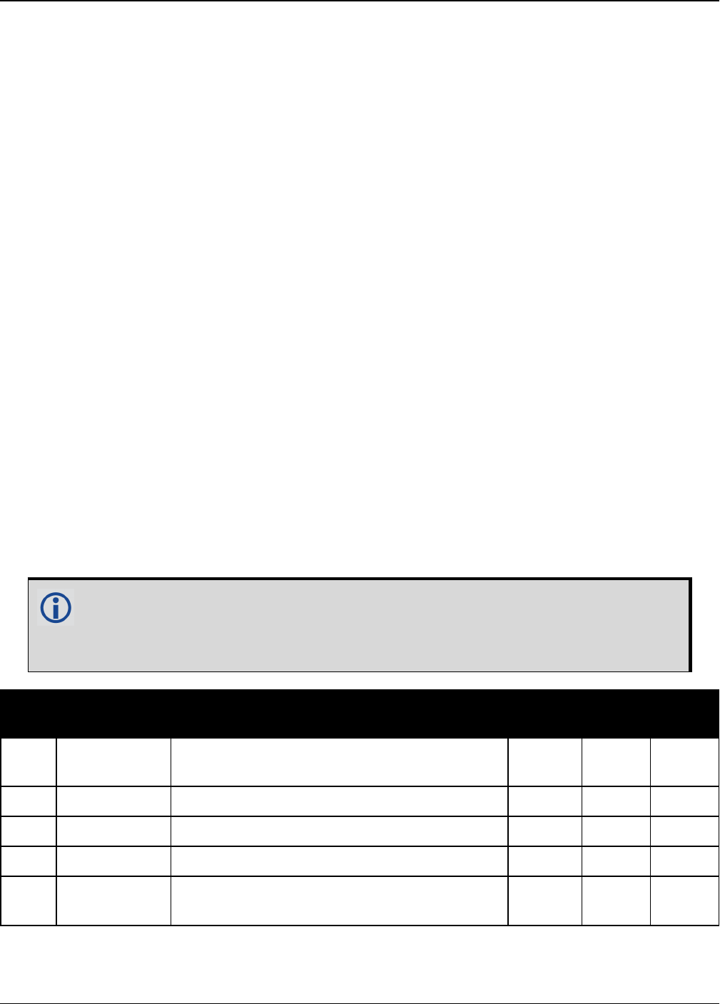
Chapter 3 Logs
OEM7 Commands and Logs Reference Manual v7 418
3.9 BDSALMANAC
Decoded BDS Almanac
Platform: OEM719, OEM729, OEM7500, OEM7600, OEM7700, OEM7720, PwrPak7,
SPAN CPT7
This log contains the decoded BeiDou almanac parameters, with the parity information removed
and appropriate scaling applied. Multiple messages are transmitted, one for each SV almanac
collected. For more information about almanac data, refer to the BDS Signal Specification.
The OEM7 family of receivers automatically save almanacs in their Non-Volatile Memory (NVM),
so creating an almanac boot file is not necessary.
Message ID: 1584
Log Type: Asynch
Recommended Input:
log bdsalmanaca onchanged
ASCII Example:
#BDSALMANACA,COM1,13,88.5,SATTIME,1727,518438.000,02000000,24ad,44226;1,371,245
760,6493.394531,2.9134750366e-04,-2.289514637,-0.021819903,-
2.456844003,1.30291141e-09,2.7785425443e-02,-1.096725e-04,2.18279e-
11,0*77017e1b
...
#BDSALMANACA,COM1,0,88.5,SATTIME,1727,518108.000,02000000,24ad,44226;14,371,217
088,5282.558105,1.4486312866e-03,-2.970093901,2.846651891,1.512957087,-
6.91457373e-09,1.7820542434e-02,7.438660e-05,0.00000,d8*ce944672
The speed at which the receiver locates and locks onto new satellites is improved if
the receiver has approximate time and position, as well as an almanac. This allows
the receiver to compute the elevation of each satellite so it can tell which satellites
are visible and their Doppler offsets, improving Time to First Fix (TTFF).
Field Field Type Description Format Binary
Bytes
Binary
Offset
1BDSALMANAC
header
Log header. See Messages on page25 for
more information. H 0
2 satellite ID Satellite ID/ranging code Ulong 4 H
3 week Week number Ulong 4 H+4
4 toa Time of almanac (seconds) Ulong 4 H+8
5 RootA Square root of semi-major axis (sqrt
(metres)) Double 8 H+12

Chapter 3 Logs
OEM7 Commands and Logs Reference Manual v7 419
Field Field Type Description Format Binary
Bytes
Binary
Offset
6 ecc Eccentricity (dimensionless) Double 8 H+20
7 ω Argument of perigee (radians) Double 8 H+28
8M0Mean anomaly at reference time (radians) Double 8 H+36
9 Ω
Longitude of ascending node of orbital of
plane computed according to reference time
(radians)
Double 8 H+44
10 Ώ Rate of right ascension (radians/second) Double 8 H+52
11 δiCorrection of orbit reference inclination at
reference time (radians) Double 8 H+60
12 a0Constant term of clock correction polynomial
(seconds) Double 8 H+68
13 a1Linear term of clock correction polynomial
(seconds/seconds) Double 8 H+76
14 health Satellite health information Ulong 4 H+84
15 xxxx 32-bit CRC (ASCII and Binary only) Hex 4 H+88
16 [CR][LF] Sentence terminator (ASCII only) - - -

Chapter 3 Logs
OEM7 Commands and Logs Reference Manual v7 420
3.10 BDSCLOCK
BeiDou time parameters
Platform: OEM719, OEM729, OEM7500, OEM7600, OEM7700, OEM7720, PwrPak7,
SPAN CPT7
This log contains time parameters transmitted by the BeiDou satellites. These parameters can
be used to calculated the offset between BeiDou time (BDT) and other time frames.
Message ID: 1607
Log Type: Asynch
Recommended Input:
log bdsclocka onchanged
ASCII Example:
#BDSCLOCKA,COM1,0,80.0,SATTIME,1730,193994.000,02000000,3b16,44290;
-9.313225746154785e-010,-8.881784197001252e-016,2,6,0,2,
0.000000000000000e+000,0.000000000000000e+000,0.000000000000000e+000,
0.000000000000000e+000,0.000000000000000e+000,0.000000000000000e+000
*84820676
Field Field
Type Description Format Binary
Bytes
Binary
Offset
1BDSCLOCK
header
Log header. See Messages on page25 for more
information. H 0
2A0UTC BDT clock bias relative to UTC (seconds) Double 8 H
3A1UTC BDT clock rate relative to UTC
(seconds/second) Double 8 H+8
4ΔTLS Delta time due to leap seconds before the new
leap second is effective (seconds) Short 2 H+16
5WNLSF Week number of the new leap second Ushort 2 H+18
6 DN Day number of week of the new leap second Ushort 2 H+20
7ΔTLSF Delta time due to leap seconds after the new
leap second effective Short 2 H+22
8A0GPS BDT clock bias relative to GPS time (seconds) Double 8 H+24
9A1GPS BDT clock rate relative to GPS time
(seconds/second) Double 8 H+32
10 A0Gal BDT clock bias relative to Galileo time
(seconds) Double 8 H+40

Chapter 3 Logs
OEM7 Commands and Logs Reference Manual v7 421
Field Field
Type Description Format Binary
Bytes
Binary
Offset
11 A1Gal BDT clock rate relative to Galileo time
(seconds/second) Double 8 H+48
12 A0GLO BDT clock bias relative to GLONASS time
(seconds) Double 8 H+56
13 A1GLO BDT clock rate relative to GLONASS time
(seconds/second) Double 8 H+64
14 xxxx 32-bit CRC (ASCII and Binary only) Ulong 4 H+72
15 [CR][LF] Sentence terminator (ASCII only) - - -

Chapter 3 Logs
OEM7 Commands and Logs Reference Manual v7 422
3.11 BDSEPHEMERIS
Decoded BDS ephemeris
Platform: OEM719, OEM729, OEM7500, OEM7600, OEM7700, OEM7720, PwrPak7,
SPAN CPT7
This log contains a single set of BDS ephemeris parameters with appropriate scaling applied.
Multiple messages are transmitted, one for each SV ephemeris collected.
Message ID: 1696
Log Type: Asynch
Recommended Input:
log bdsephemerisa onchanged
ASCII Example:
#BDSEPHEMERISA,COM1,0,82.5,SATTIME,1774,162464.000,02000000,2626,45436;13,418,2
.00,1,8.20e-09,3.10e-09,11,162000,2.33372441e-04,5.73052716e-12,8.53809211e-
19,12,162000,5282.609060,2.3558507673e-03,3.122599126,4.1744595973e-09,-
0.654635278,1.950232658e+00,-6.98564812e-09,9.5674299203e-01,3.164417525e-
10,4.325527698e-06,8.850824088e-06,179.3593750,87.5312500,7.171183825e-
08,1.024454832e-08*d8b97536
Field Field Type Description Format Binary
Bytes
Binary
Offset
1BDSEPHEMERIS
header
Log header. See Messages on page25 for
more information. H 0
2 satellite ID ID/ranging code Ulong 4 H
3 Week Week number Ulong 4 H+4
4 URA User range accuracy (metres). This is the
evaluated URAI/URA lookup-table value. Double 8 H+8
5 health 1
Autonomous satellite health flag. 0 means
broadcasting satellite is good and 1 means
not.
Ulong 4 H+16
6 tgd1 Equipment group delay differential for the
B1 signal (seconds) Double 8 H+20
7 tgd2 Equipment group delay differential for the
B2 signal (seconds) Double 8 H+28
8 AODC Age of data, clock Ulong 4 H+36
9 toc Reference time of clock parameters
(seconds) Ulong 4 H+40

Chapter 3 Logs
OEM7 Commands and Logs Reference Manual v7 423
Field Field Type Description Format Binary
Bytes
Binary
Offset
10 a0Constant term of clock correction
polynomial (seconds) Double 8 H+44
11 a1Linear term of clock correction polynomial
(seconds/seconds) Double 8 H+52
12 a2Quadratic term of clock correction
polynomial (seconds/seconds^2) Double 8 H+60
13 AODE Age of data, ephemeris Ulong 4 H+68
14 toe Reference time of ephemeris parameters
(seconds) Ulong 4 H+72
15 RootA Square root of semi-major axis (sqrt
(metres)) Double 8 H+76
16 ecc Eccentricity (dimensionless) Double 8 H+84
17 ω Argument of perigee (radians) Double 8 H+92
18 ΔN Mean motion difference from computed
value (radians/second) Double 8 H+100
19 M0Mean anomaly at reference time (radians) Double 8 H+108
20 Ω0
Longitude of ascending node of orbital of
plane computed according to reference
time (radians)
Double 8 H+116
21 Ώ Rate of right ascension (radians/second) Double 8 H+124
22 i0Inclination angle at reference time
(radians) Double 8 H+132
23 IDOT Rate of inclination angle (radians/second) Double 8 H+140
24 cuc Amplitude of cosine harmonic correction
term to the argument of latitude (radians) Double 8 H+148
25 cus Amplitude of sine harmonic correction
term to the argument of latitude (radians) Double 8 H+156
26 crc Amplitude of cosine harmonic correction
term to the orbit radius (metres) Double 8 H+164
27 crs Amplitude of sine harmonic correction
term to the orbit radius (metres) Double 8 H+172
28 cic Amplitude of cosine harmonic correction
term to the angle of inclination (radians) Double 8 H+180

Chapter 3 Logs
OEM7 Commands and Logs Reference Manual v7 424
Field Field Type Description Format Binary
Bytes
Binary
Offset
29 cis Amplitude of sine harmonic correction
term to the angle of inclination (radians) Double 8 H+188
30 xxxx 32-bit CRC (ASCII and Binary only) Ulong 4 H+196
31 [CR][LF] Sentence terminator (ASCII only) - - -

Chapter 3 Logs
OEM7 Commands and Logs Reference Manual v7 425
3.12 BDSIONO
BeiDou Klobuchar ionosphere delay model
Platform: OEM719, OEM729, OEM7500, OEM7600, OEM7700, OEM7720, PwrPak7,
SPAN CPT7
This log contains the Klobuchar ionosphere model parameters transmitted by the BeiDou satel-
lites.
Message ID: 1590
Log Type: Asynch
Recommended Input:
log bdsionoa onchanged
ASCII Example:
#BDSIONOA,COM1,0,80.0,SATTIME,1734,58094.000,02080000,1956,44836;6,
2.607703208923340e-008,4.097819328308105e-007,-3.695487976074218e-006,
7.212162017822263e-006,69632.0,360448.0,-524288.0,-327680.0*69c2a6c6
Field Field
Type Description Format Binary
Bytes
Binary
Offset
1BDSIONO
Header
Log header. See Messages on page25 for
more information. H 0
2 ID Transmitting satellite ID Ulong 4 H
3 α0 Klobuchar cosine curve amplitude constant
term (seconds) Double 8 H+4
4 α1 Klobuchar cosine curve amplitude first-order
term (seconds/π)Double 8 H+12
5 α2 Klobuchar cosine curve amplitude second-
order term (seconds/π2) Double 8 H+20
6 α3 Klobuchar cosine curve amplitude third-
order term (seconds/π3) Double 8 H+28
7 β0 Klobuchar cosine curve period constant term
(seconds) Double 8 H+36
8 β1 Klobuchar cosine curve period first-order
term (seconds/π)Double 8 H+44
9 β2 Klobuchar cosine curve period second-order
term (seconds/π2) Double 8 H+52
10 β3 Klobuchar cosine curve period third-order
term (seconds/π3) Double 8 H+60

Chapter 3 Logs
OEM7 Commands and Logs Reference Manual v7 426
Field Field
Type Description Format Binary
Bytes
Binary
Offset
11 xxxx 32-bit CRC (ASCII and Binary only) Ulong 4 H+68
12 [CR][LF] Sentence terminator (ASCII only) - - -

Chapter 3 Logs
OEM7 Commands and Logs Reference Manual v7 427
3.13 BDSRAWNAVSUBFRAME
Raw BeiDou subframe data
Platform: OEM719, OEM729, OEM7500, OEM7600, OEM7700, OEM7720, PwrPak7,
SPAN CPT7
This log contains the raw BeiDou subframe data with parity bits removed. Only subframes that
have passed the parity check are output.
Message ID: 1695
Log Type: Asynch
Recommended Input:
log bdsrawnavsubframea onchanged
ASCII Example:
#BDSRAWNAVSUBFRAMEA,COM1,0,85.5,SATTIME,1774,162554.000,02000000,88f3,45436;84,
13,B1D1,1,e24049ebb2b00d113c685207c4d0ee9fd1bf364e41f8f4b57003268c*6b1f478b
Field Field Type Description Format Binary
Bytes
Binary
Offset
1BDSRAWNAVSUBFRAME
header
Log header. See Messages on
page25 for more information. H 0
2 signal channel Signal channel number Ulong 4 H
3 satellite ID Satellite ID Ulong 4 H+4
4 data source Source of data (refer to Table 72:
Data Source below) Enum 4 H+8
5 subframe ID Subframe identifier Ulong 4 H+12
6 raw subframe data Framed raw navigation bits Hex[28] 28 H+16
7 xxxx 32-bit CRC (ASCII and Binary
only) Hex 4 H+44
8 [CR][LF] Sentence terminator (ASCII only) - - -
ASCII Binary Description
B1D1 0 Data is from a B1/D1 signal
B1D2 1 Data is from a B1/D2 signal
B2D1 65536 Data is from a B2/D1 signal
B2D2 65537 Data is from a B2/D2 signal
Table 72: Data Source

Chapter 3 Logs
OEM7 Commands and Logs Reference Manual v7 428
3.14 BESTPOS
Best position
Platform: OEM719, OEM729, OEM7500, OEM7600, OEM7700, OEM7720, PwrPak7,
SPAN CPT7
When positioning with GNSS, there are four parameters being solved for: latitude, longitude,
height and receiver clock offset from GPS time. The quality of the solution for all four para-
meters depends on the geometry of where the satellites are with respect to the antenna (and
receiver). The strength of the positioning geometry is indicated by Dilution of Precision (DOP)
values, with lower DOP numbers indicating better geometry. Because all the GNSS satellites are
above terrestrial receivers, the VDOP (vertical DOP) is the largest DOP value. This is why the
reported standard deviation for height is usually larger than for latitude or longitude.
Accuracy is based on statistics and reliability is measured in percentages. When a receiver
states it can measure height to one metre, this is an accuracy measure. Usually this is a one
sigma value (one SD). A one sigma value for height has a reliability of 68%. In other words, the
error is less than one metre 68% of the time. For a more realistic accuracy, double the one
sigma value (one metre) and the result is 95% reliability (error is less than two metres 95% of
the time). Generally, GNSS heights are 1.5 times poorer than horizontal positions. See also the
note in the GPGST log on page521 for CEP and RMS definitions.
This log contains the best position computed by the receiver. In addition, it reports several
status indicators, including differential age, which is useful in predicting anomalous behavior
brought about by outages in differential corrections. A differential age of 0 indicates that no dif-
ferential correction was used.
SPAN Systems
On systems with SPAN enabled, this log contains the best available combined GNSS and
Inertial Navigation System (INS - if available) position (in metres) computed by the
receiver.
With the system operating in an RTK mode, BESTPOS reflects the latest low-latency solution for
up to 60 seconds after reception of the last base station observation. After this 60 second period,
the position reverts to the best solution available and the degradation in accuracy is reflected in
the standard deviation fields. If the system is not operating in RTK mode, pseudorange dif-
ferential solutions continue for the time specified in the PSRDIFFTIMEOUT command (see
page 284). If the receiver is SPAN enabled, the GNSS+INS combined solution is also a candidate
for BESTPOS output.

Chapter 3 Logs
OEM7 Commands and Logs Reference Manual v7 429
The RTK system in the receiver provides two kinds of position solutions. The Matched
RTK position is computed with buffered observations, so there is no error due to the
extrapolation of base station measurements. This provides the highest accuracy solution
possible at the expense of some latency which is affected primarily by the speed of the
differential data link. The MATCHEDPOS log (see page 591) contains the matched RTK
solution and can be generated for each processed set of base station observations.
The Low-Latency RTK position is computed from the latest local observations and
extrapolated base station observations. This supplies a valid RTK position with the lowest
latency possible at the expense of some accuracy. The degradation in accuracy is
reflected in the standard deviation and is summarized in An Introduction to GNSS
available on our website. The amount of time that the base station observations are
extrapolated is in the "differential age" field of the position log. The Low-Latency RTK
system extrapolates for 60 seconds. The RTKPOS log (see page 736) contains the Low-
Latency RTK position when valid, and an "invalid" status when a Low-Latency RTK
solution could not be computed. The BESTPOS log contains either the low-latency RTK,
PPP or pseudorange-based position, whichever has the smallest standard deviation.
Multi-frequency GNSS receivers offer two major advantages over single-frequency
equipment:
lIonospheric errors, inherent in all GNSS observations, can be modeled and sig-
nificantly reduced by combining satellite observations made on two different fre-
quencies.
lObservations on two frequencies allow for faster ambiguity resolution times.
In general, multi-frequency GNSS receivers provide a faster, more accurate and more
reliable solution than single-frequency equipment. They do, however, cost significantly
more and so it is important for potential GNSS buyers to carefully consider their current
and future needs.
Different positioning modes have different maximum logging rates, which are also
controlled by model option. The maximum rates are: 100 Hz for RTK, 100 Hz for
pseudorange based positioning, 20 Hz for GLIDE (PDP) and 20 Hz for PPP.
BESTPOS always outputs positions at the antenna phase center.
Message ID: 42
Log Type: Synch
Recommended Input:
log bestposa ontime 1
ASCII Example 1:
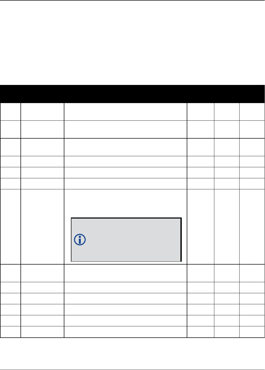
Chapter 3 Logs
OEM7 Commands and Logs Reference Manual v7 430
#BESTPOSA,COM1,0,90.5,FINESTEERING,1949,403742.000,02000000,b1f6,32768;SOL_
COMPUTED,SINGLE,51.11636937989,-114.03825348307,1064.533,-
16.9000,WGS84,1.3610,1.0236,2.4745,"",0.000,0.000,19,19,19,19,00,06,00,33*6e08f
a22
ASCII Example 2:
#BESTPOSA,COM1,0,78.5,FINESTEERING,1419,336208.000,02000040,6145,2724;SOL_
COMPUTED,NARROW_INT,51.11635910984,-114.03833105168,1063.8416,-
16.2712,WGS84,0.0135,0.0084,0.0172,"AAAA",1.000,0.000,8,8,8,8,0,01,0,03*3d9fbd4
8
Field Field type Description Format Binary
Bytes
Binary
Offset
1BESTPOS
header
Log header. See Messages on page25 for
more information. H 0
2 sol stat Solution status, see Table 73: Solution
Status on the next page Enum 4 H
3 pos type Position type, see Table 74: Position or
Velocity Type on page432 Enum 4 H+4
4 lat Latitude (degrees) Double 8 H+8
5 lon Longitude (degrees) Double 8 H+16
6 hgt Height above mean sea level (metres) Double 8 H+24
7 undulation
Undulation - the relationship between the
geoid and the ellipsoid (m) of the chosen
datum
When using a datum other than
WGS84, the undulation value
also includes the vertical shift
due to differences between the
datum in use and WGS84.
Float 4 H+32
8 datum id# Datum ID number (see Table 28: Datum
Transformation Parameters on page117) Enum 4 H+36
9 lat σ Latitude standard deviation (m) Float 4 H+40
10 lon σ Longitude standard deviation (m) Float 4 H+44
11 hgt σ Height standard deviation (m) Float 4 H+48
12 stn id Base station ID Char[4] 4 H+52
13 diff_age Differential age in seconds Float 4 H+56

Chapter 3 Logs
OEM7 Commands and Logs Reference Manual v7 431
Field Field type Description Format Binary
Bytes
Binary
Offset
14 sol_age Solution age in seconds Float 4 H+60
15 #SVs Number of satellites tracked Uchar 1 H+64
16 #solnSVs Number of satellites used in solution Uchar 1 H+65
17 #solnL1SVs Number of satellites with L1/E1/B1 signals
used in solution Uchar 1 H+66
18 #solnMultiSVs Number of satellites with multi-frequency
signals used in solution Uchar 1 H+67
19 Reserved Hex 1 H+68
20 ext sol stat Extended solution status (see Table 77:
Extended Solution Status on page435) Hex 1 H+69
21
Galileo and
BeiDou sig
mask
Galileo and BeiDou signals used mask (see
Table 76: Galileo and BeiDou Signal-Used
Mask on page435)
Hex 1 H+70
22
GPS and
GLONASS sig
mask
GPS and GLONASS signals used mask (see
Table 75: GPS and GLONASS Signal-Used
Mask on page434)
Hex 1 H+71
23 xxxx 32-bit CRC (ASCII and Binary only) Hex 4 H+72
24 [CR][LF] Sentence terminator (ASCII only) - - -
Binary ASCII Description
0 SOL_COMPUTED Solution computed
1INSUFFICIENT_
OBS Insufficient observations
2NO_
CONVERGENCE No convergence
3 SINGULARITY Singularity at parameters matrix
4 COV_TRACE Covariance trace exceeds maximum (trace > 1000 m)
5 TEST_DIST Test distance exceeded (maximum of 3 rejections if distance >10 km)
6 COLD_START Not yet converged from cold start
Table 73: Solution Status
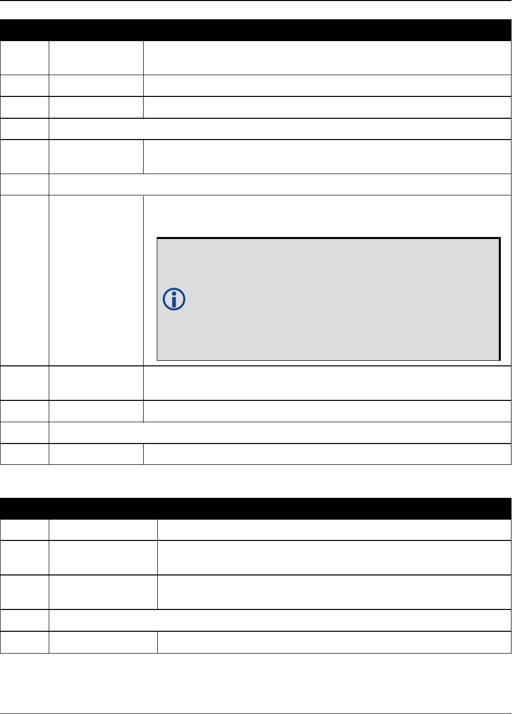
Chapter 3 Logs
OEM7 Commands and Logs Reference Manual v7 432
Binary ASCII Description
7 V_H_LIMIT Height or velocity limits exceeded (in accordance with export licensing
restrictions)
8 VARIANCE Variance exceeds limits
9 RESIDUALS Residuals are too large
10-12 Reserved
13 INTEGRITY_
WARNING Large residuals make position unreliable
14-17 Reserved
18 PENDING
When a FIX position command is entered, the receiver computes its
own position and determines if the fixed position is valid
PENDING implies there are not enough satellites currently
tracked to verify if the FIX POSITION entered into the
receiver is valid. Under normal conditions, you should
only see PENDING for a few seconds on power up before
the GNSS receiver has locked onto its first few satellites.
If your antenna is obstructed (or not plugged in) and you
have entered a FIX POSITION command, then you may
see PENDING indefinitely.
19 INVALID_FIX The fixed position, entered using the FIX position command, is not
valid
20 UNAUTHORIZED Position type is unauthorized
21 Reserved
22 INVALID_RATE The selected logging rate is not supported for this solution type.
Binary ASCII Description
0 NONE No solution
1 FIXEDPOS Position has been fixed by the FIX position command or by
position averaging.
2 FIXEDHEIGHT Position has been fixed by the FIX height or FIX auto command
or by position averaging
3 Reserved
4 FLOATCONV Solution from floating point carrier phase ambiguities
Table 74: Position or Velocity Type

Chapter 3 Logs
OEM7 Commands and Logs Reference Manual v7 433
Binary ASCII Description
5 WIDELANE Solution from wide-lane ambiguities
6 NARROWLANE Solution from narrow-lane ambiguities
7 Reserved
8DOPPLER_
VELOCITY Velocity computed using instantaneous Doppler
9-15 Reserved
16 SINGLE Single point position
17 PSRDIFF Pseudorange differential solution
18 WAAS Solution calculated using corrections from an SBAS
19 PROPAGATED Propagated by a Kalman filter without new observations
20-31 Reserved
32 L1_FLOAT Floating L1 ambiguity solution
33 IONOFREE_FLOAT Floating ionospheric-free ambiguity solution
34 NARROW_FLOAT Floating narrow-lane ambiguity solution
35-47 Reserved
48 L1_INT Integer L1 ambiguity solution
49 WIDE_INT Integer wide-lane ambiguity solution
50 NARROW_INT Integer narrow-lane ambiguity solution
51 RTK_DIRECT_INS RTK status where the RTK filter is directly initialized from the INS
filter
52 INS_SBAS INS calculated position corrected for the antenna
53 INS_PSRSP INS pseudorange single point solution – no DGPS corrections
54 INS_PSRDIFF INS pseudorange differential solution
55 INS_RTKFLOAT INS RTK floating point ambiguities solution
56 INS_RTKFIXED INS RTK fixed ambiguities solution
57-67 Reserved
68 PPP_CONVERGING Converging TerraStar-C solution
69 PPP Converged TerraStar-C solution

Chapter 3 Logs
OEM7 Commands and Logs Reference Manual v7 434
Binary ASCII Description
70 OPERATIONAL Solution accuracy is within UAL operational limit
71 WARNING Solution accuracy is outside UAL operational limit but within
warning limit
72 OUT_OF_BOUNDS Solution accuracy is outside UAL limits
73 INS_PPP_
CONVERGING
INS NovAtel CORRECT Precise Point Positioning (PPP) solution
converging
74 INS_PPP INS NovAtel CORRECT PPP solution
77 PPP_BASIC_
CONVERGING Converging TerraStar-L solution
78 PPP_BASIC Converged TerraStar-L solution
79 INS_PPP_BASIC
_CONVERGING INS NovAtel CORRECT PPP basic solution converging
80 INS_PPP_BASIC INS NovAtel CORRECT PPP basic solution
NovAtel CORRECT®with PPP requires access to a suitable correction stream, delivered
either through L-Band or the Internet. For L-Band delivered TerraStar or Veripos ser-
vice, an L-Band capable receiver and software model is required, along with a sub-
scription to the desired service. Contact NovAtel for TerraStar and Veripos subscription
details.
Bit Mask Description
0 0x01 GPS L1 used in Solution
1 0x02 GPS L2 used in Solution
2 0x04 GPS L5 used in Solution
3 0x08 Reserved
4 0x10 GLONASS L1 used in Solution
5 0x20 GLONASS L2 used in Solution
6 0x40 GLONASS L3 used in Solution
7 0x80 Reserved
Table 75: GPS and GLONASS Signal-
Used Mask

Chapter 3 Logs
OEM7 Commands and Logs Reference Manual v7 435
Bit Mask Description
0 0x01 Galileo E1 used in Solution
1 0x02 Galileo E5A used in Solution
2 0x04 Galileo E5B used in Solution
3 0x08 Galileo ALTBOC used in Solution
4 0x10 BeiDou B1 used in Solution
5 0x20 BeiDou B2 used in Solution
6 0x40 BeiDou B3 used in Solution
7 0x80 Reserved
Table 76: Galileo and BeiDou Signal-Used
Mask
Bit Mask Description
0 0x01
If an RTK solution: NovAtel CORRECT solution has been verified
If a PDP solution: solution is GLIDE
Otherwise: Reserved
1-3 0x0E
Pseudorange Iono Correction
0 = Unknown or default Klobuchar model
1 = Klobuchar Broadcast
2 = SBAS Broadcast
3 = Multi-frequency Computed
4 = PSRDiff Correction
5 = NovAtel Blended Iono Value
4 0x10 RTK ASSIST active
5 0x20
0 - No antenna warning
1 - Antenna information is missing
See the RTKANTENNA command on page295
6-7 0xC0 Reserved
Table 77: Extended Solution Status

Chapter 3 Logs
OEM7 Commands and Logs Reference Manual v7 436
Value Documented Enum Name NMEA Equivalent
68 PPP_CONVERGING 2
69 PPP 5
70 OPERATIONAL 4
71 WARNING 5
72 OUT_OF_BOUNDS 1
77 PPP_BASIC_CONVERGING 1
78 PPP_BASIC 2
Table 78: Supplemental Position Types and NMEA
Equivalents

Chapter 3 Logs
OEM7 Commands and Logs Reference Manual v7 437
3.15 BESTSATS
Satellites used in BESTPOS
Platform: OEM719, OEM729, OEM7500, OEM7600, OEM7700, OEM7720, PwrPak7,
SPAN CPT7
This log lists the used and unused satellites for the corresponding BESTPOS solution. It also
describes the signals of the used satellites or reasons for exclusions.
Message ID: 1194
Log Type: Synch
Recommended Input:
log bestsats ontime 1
Abbreviated ASCII Example:
<BESTSATS COM1 0 57.5 FINESTEERING 1729 12132.000 02000000 95e7 11487
< 26
< GPS 3 GOOD 00000003
< GPS 5 GOOD 00000003
...
< GPS 26 GOOD 00000003
< GPS 28 GOOD 00000003
< GLONASS 3+5 GOOD 00000003
< GLONASS 4+6 GOOD 00000003
...
< GLONASS 23+3 GOOD 00000003
< GLONASS 24+2 GOOD 00000003
< BEIDOU 6 GOOD 00000003
< BEIDOU 9 GOOD 00000003
...
< BEIDOU 12 GOOD 00000003
<BEIDOU 13 GOOD 00000003
Field Field
type Description Format Binary
Bytes
Binary
Offset
1BESTSATS
header
Log header. See Messages on page25 for
more information. H 0
2 #entries Number of records to follow Ulong 4 H
3 System See Table 102: Satellite System on page545 Enum 4 H+4

Chapter 3 Logs
OEM7 Commands and Logs Reference Manual v7 438
Field Field
type Description Format Binary
Bytes
Binary
Offset
4Satellite
ID
In binary logs, the satellite ID field is 4 bytes.
The 2 lowest-order bytes, interpreted as a
USHORT, are the system identifier: for
instance, the PRN for GPS, or the slot for
GLONASS. The 2 highest-order bytes are the
frequency channel for GLONASS, interpreted
as a SHORT and zero for all other systems.
In ASCII and abbreviated ASCII logs, the
satellite ID field is the system identifier. If the
system is GLONASS and the frequency channel
is not zero, then the signed channel is
appended to the system identifier. For
example, slot 13, frequency channel -2 is
output as 13-2.
Ulong 4 H+8
5 Status Satellite status. See Table 79: Observation
Statuses below Enum 4 H+12
6Signal
mask
See Table 80: BESTSATS GPS Signal Mask on
the next page, Table 81: BESTSATS GLONASS
Signal Mask on page440, Table 82:
BESTSATS Galileo Signal Mask on page440
and Table 83: BESTSATS BeiDou Signal Mask
on page440
Hex 4 H+16
7 Next satellite offset = H + 4 + (#entries x 16)
8 xxxx 32-bit CRC (ASCII and Binary only) Hex 4
H+4
(#entries
x 16)
9 [CR][LF] Sentence terminator (ASCII only) - - -
Value Name Description
0 GOOD Observation is good
1 BADHEALTH Satellite is flagged as bad health in ephemeris or almanac
2 OLDEPHEMERIS Ephemeris >3 hours old
6 ELEVATIONERROR Satellite was below the elevation cutoff
7 MISCLOSURE Observation was too far from predicted value
Table 79: Observation Statuses

Chapter 3 Logs
OEM7 Commands and Logs Reference Manual v7 439
Value Name Description
8 NODIFFCORR No differential correction available
9 NOEPHEMERIS No ephemeris available
10 INVALIDIODE IODE used is invalid
11 LOCKEDOUT Satellite has been locked out
12 LOWPOWER Satellite has low signal power
13 OBSL2 An L2 observation not directly used in the solution
15 UNKNOWN Observation was not used because it was of an unknown type
16 NOIONOCORR No ionosphere delay correction was available
17 NOTUSED Observation was not used in the solution
18 OBSL1 An L1 observation not directly used in the solution
19 OBSE1 An E1 observation not directly used in the solution
20 OBSL5 An L5 observation not directly used in the solution
21 OBSE5 An E5 observation not directly used in the solution
22 OBSB2 A B2 observation not directly used in the solution
23 OBSB1 A B1 observation not directly used in the solution
24 OBSB3 A B3 observation not directly used in the solution
25 NOSIGNALMATCH Signal type does not match
26 SUPPLEMENTARY Observation contributes supplemental information to the solution
99 NA No observation available
100 BAD_INTEGRITY Observation was an outlier and was eliminated from the solution
101 LOSSOFLOCK Lock was broken on this signal
102 NOAMBIGUITY No RTK ambiguity type resolved
Bit Mask Description
0 0x01 GPS L1 used in Solution
1 0x02 GPS L2 used in Solution
2 0x04 GPS L5 used in Solution
Table 80: BESTSATS GPS Signal Mask

Chapter 3 Logs
OEM7 Commands and Logs Reference Manual v7 440
Bit Mask Description
0 0x01 GLONASS L1 used in Solution
1 0x02 GLONASS L2 used in Solution
2 0x04 GLONASS L3 used in Solution
Table 81: BESTSATS GLONASS Signal Mask
Bit Mask Description
0 0x01 Galileo E1 used in Solution
1 0x02 Galileo E5A used in Solution
2 0x04 Galileo E5B used in Solution
3 0x08 Galileo ALTBOC used in Solution
Table 82: BESTSATS Galileo Signal Mask
Bit Mask Description
0 0x01 BeiDou B1 used in Solution
1 0x02 BeiDou B2 used in Solution
2 0X04 BeiDou B3 used in Solution
Table 83: BESTSATS BeiDou Signal Mask
Chapter 3 Logs
OEM7 Commands and Logs Reference Manual v7 441
3.16 BESTUTM
Best available UTM data
Platform: OEM719, OEM729, OEM7500, OEM7600, OEM7700, OEM7720, PwrPak7,
SPAN CPT7
This log contains the best available position computed by the receiver in UTM coordinates.
See also the UTMZONE command on page398 and the BESTPOS log on page428.
The latitude limits of the UTM System are 80°S to 84°N. If your position is outside this
range, the BESTUTM log outputs a northing, easting and height of 0.0, along with a zone
letter of ‘*’and a zone number of 0, to indicate that the data in the log is unusable.
Refer to http://earth-info.nga.mil/GandG/coordsys/grids/referencesys.html for more
information and a world map of UTM zone numbers.
Message ID: 726
Log Type: Synch
Recommended Input:
log bestutma ontime 1
ASCII Example:
#BESTUTMA,COM1,0,73.0,FINESTEERING,1419,336209.000,02000040,eb16,2724;SOL_
COMPUTED,NARROW_INT,11,U,5666936.4417,707279.3875,1063.8401,-
16.2712,WGS84,0.0135,0.0084,0.0173,"AAAA",1.000,0.000,8,8,8,8,0,01,0,03*a6d0632
1
Field Field type Description Format Binary
Bytes
Binary
Offset
1BESTUTM
header
Log header. See Messages on page25 for
more information. H 0
2 sol status Solution status, see Table 73: Solution Status
on page431 Enum 4 H
3 pos type Position type, see Table 74: Position or
Velocity Type on page432 Enum 4 H+4
4 z# Longitudinal zone number Ulong 4 H+8
5 zletter Latitudinal zone letter Ulong 4 H+12
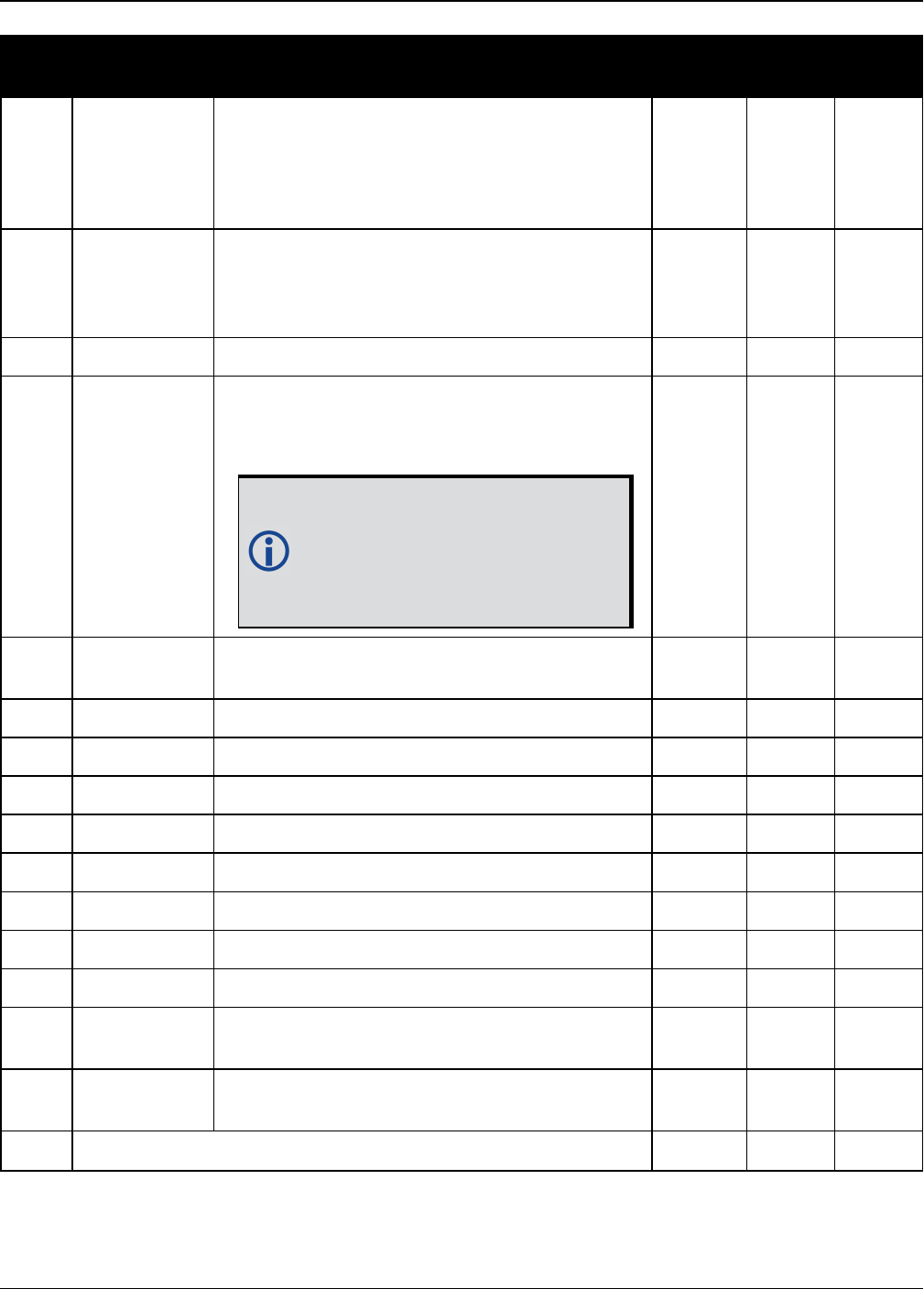
Chapter 3 Logs
OEM7 Commands and Logs Reference Manual v7 442
Field Field type Description Format Binary
Bytes
Binary
Offset
6 northing
Northing (m) where the origin is defined as
the equator in the northern hemisphere and
as a point 10000000 metres south of the
equator in the southern hemisphere (that is, a
‘false northing’ of 10000000 m)
Double 8 H+16
7 easting
Easting (m) where the origin is 500000 m
west of the central meridian of each
longitudinal zone (that is, a ‘false easting’ of
500000 m)
Double 8 H+24
8 hgt Height above mean sea level (m) Double 8 H+32
9 undulation
Undulation - the relationship between the
geoid and the ellipsoid (m) of the chosen
datum
When using a datum other than
WGS84, the undulation value
also includes the vertical shift
due to differences between the
datum in use and WGS84.
Float 4 H+40
10 datum id# Datum ID number (see Table 28: Datum
Transformation Parameters on page117) Enum 4 H+44
11 N σ Northing standard deviation (m) Float 4 H+48
12 E σ Easting standard deviation (m) Float 4 H+52
13 hgt σ Height standard deviation (m) Float 4 H+56
14 stn id Base station ID Char[4] 4 H+60
15 diff_age Differential age in seconds Float 4 H+64
16 sol_age Solution age in seconds Float 4 H+68
17 #SVs Number of satellites tracked Uchar 1 H+72
18 #solnSVs Number of satellite vehicles used in solution Uchar 1 H+73
19 #ggL1 Number of GPS plus GLONASS plus BDS
L1/B1 used in solution Uchar 1 H+74
20 #solnMultiSV Number of satellites with L1/E1/B1 signals
used in solution Uchar 1 H+75
21 Reserved Uchar 1 H+76

Chapter 3 Logs
OEM7 Commands and Logs Reference Manual v7 443
Field Field type Description Format Binary
Bytes
Binary
Offset
22 ext sol stat Extended solution status (see Table 77:
Extended Solution Status on page435) Hex 1 H+77
23
Galileo and
BeiDou sig
mask
Galileo and BeiDou signals used mask (see
Table 76: Galileo and BeiDou Signal-Used
Mask on page435)
Hex 1 H+78
24
GPS and
GLONASS sig
mask
GPS and GLONASS signals used mask (see
Table 75: GPS and GLONASS Signal-Used
Mask on page434)
Hex 1 H+79
25 xxxx 32-bit CRC (ASCII and Binary only) Hex 4 H+80
26 [CR][LF] Sentence terminator (ASCII only) - - -
Chapter 3 Logs
OEM7 Commands and Logs Reference Manual v7 444
3.17 BESTVEL
Best available velocity data
Platform: OEM719, OEM729, OEM7500, OEM7600, OEM7700, OEM7720, PwrPak7,
SPAN CPT7
This log contains the best available velocity information computed by the receiver. In addition, it
reports a velocity status indicator, which is needed to determine whether or not the cor-
responding data is valid. The velocities calculated by the receiver can have a latency associated
with them. When present, the velocity time of validity is the time tag in the log minus the
latency value.
The velocity is typically from the same source used in the BESTPOS solution. For
example, if the BESTPOS is from the pseudorange filter, then the BESTVEL velocity type
is the same as for PSRVEL. However, a specific velocity source can be chosen. See the
BESTVELTYPE command on page95.
In a BESTVEL log, the actual speed and direction of the receiver antenna over ground is
provided. The receiver does not determine the direction a vessel, craft or vehicle is poin-
ted (heading) but rather the direction of motion of the GNSS antenna relative to ground.
The RTK, PDP and PPP velocities are computed from the average change in position over the
time interval between consecutive solutions. As such, they are an average velocity based on the
time difference between successive position computations and not an instantaneous velocity at
the BESTVEL time tag. The velocity latency to be subtracted from the time tag is normally half
the time between filter updates. Under default operation, the positioning filters are updated at a
rate of 2 Hz. This average velocity translates into a velocity latency of 0.25 seconds. To reduce
the latency, increase the update rate of the positioning filter being used by requesting the
BESTVEL or BESTPOS messages at a rate higher than 2 Hz. For example, a logging rate of 10 Hz
would reduce the velocity latency to 0.05 seconds.
If the velocity in the BESTVEL log comes from the pseudorange filter, it has been computed from
instantaneous Doppler measurements. You know that you have an instantaneous Doppler
derived velocity solution when the velocity type is PSRDIFF, WAAS or DOPPLER_VELOCITY. The
instantaneous Doppler derived velocity has low latency and is not position change dependent. If
you change your velocity quickly, you can see this in the DOPPLER_VELOCITY solution. Under typ-
ically seen dynamics with minimal jerk, the velocity latency is zero. Under extreme, high-jerk
dynamics, the latency cannot be well represented: it will still be reported as being zero, but may
be as high as 0.15 seconds. Such dynamics are typically only seen in simulated trajectories.
Message ID: 99
Log Type: Synch
Recommended Input:
log bestvela ontime 1
ASCII Example:

Chapter 3 Logs
OEM7 Commands and Logs Reference Manual v7 445
#BESTVELA,COM1,0,61.0,FINESTEERING,1337,334167.000,02000000,827b,1984;SOL_
COMPUTED,PSRDIFF,0.250,4.000,0.0206,227.712486,0.0493,0.0*0e68bf05
Field Field
type Description Format Binary
Bytes
Binary
Offset
1BESTVEL
header
Log header. See Messages on page25 for more
information. H 0
2sol
status
Solution status, see Table 73: Solution Status on
page431 Enum 4 H
3 vel type Velocity type, see Table 74: Position or Velocity
Type on page432 Enum 4 H+4
4 latency
A measure of the latency in the velocity time tag
in seconds. It should be subtracted from the time
to give improved results (s)
Float 4 H+8
5 age Differential age in seconds Float 4 H+12
6 hor spd Horizontal speed over ground, in metres per
second Double 8 H+16
7 trk gnd Actual direction of motion over ground (track over
ground) with respect to True North, in degrees Double 8 H+24
8 vert spd
Vertical speed, in metres per second, where
positive values indicate increasing altitude (up)
and negative values indicate decreasing altitude
(down)
Double 8 H+32
9 Reserved Float 4 H+40
10 xxxx 32-bit CRC (ASCII and Binary only) Hex 4 H+44
11 [CR][LF] Sentence terminator (ASCII only) - - -

Chapter 3 Logs
OEM7 Commands and Logs Reference Manual v7 446
Velocity (speed and direction) calculations are computed from either Doppler or carrier
phase measurements rather than from pseudorange measurements. Typical speed
accuracies are around 0.03m/s (0.07 mph, 0.06 knots).
Direction accuracy is derived as a function of the vehicle speed. A simple approach would
be to assume a worst case 0.03 m/s cross-track velocity that would yield a direction
error function something like:
d (speed) = tan-1(0.03/speed)
For example, if you are flying in an airplane at a speed of 120 knots or 62 m/s, the
approximate directional error will be:
tan-1 (0.03/62) = 0.03 degrees
Consider another example applicable to hiking at an average walking speed of 3 knots or
1.5 m/s. Using the same error function yields a direction error of about 1.15 degrees.
You can see from both examples that a faster vehicle speed allows for a more accurate
heading indication. As the vehicle slows down, the velocity information becomes less and
less accurate. If the vehicle is stopped, a GNSS receiver still outputs some kind of
movement at speeds between 0 and 0.5 m/s in random and changing directions. This
represents the noise and error of the static position.
In a navigation capacity, the velocity information provided by your GNSS receiver is as,
or more, accurate than that indicated by conventional instruments as long as the vehicle
is moving at a reasonable rate of speed. It is important to set the GNSS measurement
rate fast enough to keep up with all major changes of the vehicle's speed and direction.
It is important to keep in mind that although the velocity vector is quite accurate in terms
of heading and speed, the actual track of the vehicle might be skewed or offset from the
true track by plus or minus 0 to 1.8 metres as per the standard positional errors.

Chapter 3 Logs
OEM7 Commands and Logs Reference Manual v7 447
3.18 BESTXYZ
Best available cartesian position and velocity
Platform: OEM719, OEM729, OEM7500, OEM7600, OEM7700, OEM7720, PwrPak7,
SPAN CPT7
This log contains the receiver’s best available position and velocity in ECEF coordinates. The pos-
ition and velocity status fields indicate whether or not the corresponding data is valid. See Fig-
ure 11: The WGS84 ECEF Coordinate System on page449, for a definition of the ECEF
coordinates.
See also the BESTPOS log on page428 and BESTVEL log on page444.
These quantities are always referenced to the WGS84 ellipsoid, regardless of the use of
the DATUM command (see page 115) or USERDATUM command (see page 388).
Message ID: 241
Log Type: Synch
Recommended Input:
log bestxyza ontime 1
ASCII Example:
#BESTXYZA,COM1,0,55.0,FINESTEERING,1419,340033.000,02000040,d821,2724;SOL_
COMPUTED,NARROW_INT,-1634531.5683,-
3664618.0326,4942496.3270,0.0099,0.0219,0.0115,SOL_COMPUTED,NARROW_INT,0.0011,-
0.0049,-
0.0001,0.0199,0.0439,0.0230,"AAAA",0.250,1.000,0.000,12,11,11,11,0,01,0,33*e9ea
feca
Field Field type Description Format Binary
Bytes
Binary
Offset
1BESTXYZ
header
Log header. See Messages on page25 for
more information. H 0
2 P-sol status Solution status, see Table 73: Solution
Status on page431 Enum 4 H
3 pos type Position type, see Table 74: Position or
Velocity Type on page432 Enum 4 H+4
4 P-X Position X-coordinate (m) Double 8 H+8
5 P-Y Position Y-coordinate (m) Double 8 H+16
6 P-Z Position Z-coordinate (m) Double 8 H+24
7 P-X σ Standard deviation of P-X (m) Float 4 H+32

Chapter 3 Logs
OEM7 Commands and Logs Reference Manual v7 448
Field Field type Description Format Binary
Bytes
Binary
Offset
8 P-Y σ Standard deviation of P-Y (m) Float 4 H+36
9 P-Z σ Standard deviation of P-Z (m) Float 4 H+40
10 V-sol status Solution status, see Table 73: Solution
Status on page431 Enum 4 H+44
11 vel type Velocity type, see Table 74: Position or
Velocity Type on page432 Enum 4 H+48
12 V-X Velocity vector along X-axis (m/s) Double 8 H+52
13 V-Y Velocity vector along Y-axis (m/s) Double 8 H+60
14 V-Z Velocity vector along Z-axis (m/s) Double 8 H+68
15 V-X σ Standard deviation of V-X (m/s) Float 4 H+76
16 V-Y σ Standard deviation of V-Y (m/s) Float 4 H+80
17 V-Z σ Standard deviation of V-Z (m/s) Float 4 H+84
18 stn ID Base station identification Char[4] 4 H+88
19 V-latency
A measure of the latency in the velocity time
tag in seconds. It should be subtracted from
the time to give improved results
Float 4 H+92
20 diff_age Differential age in seconds Float 4 H+96
21 sol_age Solution age in seconds Float 4 H+100
22 #SVs Number of satellites tracked Uchar 1 H+104
23 #solnSVs Number of satellite vehicles used in solution Uchar 1 H+105
24 #ggL1 Number of GPS plus GLONASS plus BDS
L1/B1 used in solution Uchar 1 H+106
25 #solnMultiSVs Number of satellites with L1/E1/B1 signals
used in solution Uchar 1 H+107
26 Reserved Char 1 H+108
27 ext sol stat Extended solution status (see Table 77:
Extended Solution Status on page435) Hex 1 H+109
28
Galileo and
BeiDou sig
mask
Galileo and BeiDou signals used mask (see
Table 76: Galileo and BeiDou Signal-Used
Mask on page435)
Hex 1 H+110
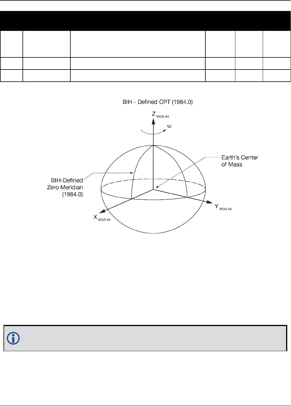
Chapter 3 Logs
OEM7 Commands and Logs Reference Manual v7 449
Field Field type Description Format Binary
Bytes
Binary
Offset
29
GPS and
GLONASS sig
mask
GPS and GLONASS signals used mask (see
Table 75: GPS and GLONASS Signal-Used
Mask on page434)
Hex 1 H+111
30 xxxx 32-bit CRC (ASCII and Binary only) Hex 4 H+112
31 [CR][LF] Sentence terminator (ASCII only) - - -
Figure 11: The WGS84 ECEF Coordinate System
Origin= Earth's center of mass
Z-Axis= Parallel to the direction of the Conventional Terrestrial Pole (CTP) for polar motion, as
defined by the Bureau International de l'Heure (BIH) on the basis of the coordinates
adopted for the BIH stations.
X-Axis = Intersection of the WGS 84 Reference Meridian Plane and the plane of the CTP's Equator,
the Reference Meridian being parallel to the Zero Meridian defined by the BIH on the basis
of the coordinates adopted for the BIH stations.
Y-Axis = Completes a right-handed, earth-centered, earth-fixed (ECEF) orthogonal coordinate
system, measured in the plane of the CTP Equator, 90° East of the X-Axis.
Table 84: Definitions
These definitions are analogous to the BIH Defined Conventional Terrestrial System
(CTS), or BTS, 1984.0.

Chapter 3 Logs
OEM7 Commands and Logs Reference Manual v7 450
3.19 BSLNXYZ
RTK XYZ baseline
Platform: OEM719, OEM729, OEM7500, OEM7600, OEM7700, OEM7720, PwrPak7,
SPAN CPT7
This log contains the receiver’s RTK baseline in ECEF coordinates. The position status field indic-
ates whether or not the corresponding data is valid. See Figure 11: The WGS84 ECEF Coordinate
System on the previous page for a definition of the ECEF coordinates.
The BSLNXYZ log comes from time-matched base and rover observations such as in the
MATCHEDXYZ log on page596.
Asynchronous logs, such as BSLNXYZ, should only be logged ONCHANGED. Otherwise,
the most current data is not output when it is available. This is especially true of the
ONTIME trigger, which may cause inaccurate time tags to result.
Message ID: 686
Log Type: Asynch
Recommended Input:
log bslnxyza onchanged
ASCII Example:
#BSLNXYZA,COM1,0,59.5,FINESTEERING,1419,340033.000,02000040,5b48,2724;SOL_
COMPUTED,NARROW_INT,0.0012,0.0002,-
0.0004,0.0080,0.0160,0.0153,"AAAA",12,12,12,12,0,01,0,33*1a8a1b65
Field Field type Data Description Format Binary
Bytes
Binary
Offset
1BSLNXYZ
header
Log header. See Messages on page25 for
more information. H 0
2 sol status Solution status, see Table 73: Solution
Status on page431 Enum 4 H
3 bsln type Baseline type, see Table 74: Position or
Velocity Type on page432 Enum 4 H+4
4 B-X X-axis offset (m) Double 8 H+8
5 B-Y Y-axis offset (m) Double 8 H+16
6 B-Z Z-axis offset (m) Double 8 H+24
7 B-X σ Standard deviation of B-X (m) Float 4 H+32
8 B-Y σ Standard deviation of B-Y (m) Float 4 H+36

Chapter 3 Logs
OEM7 Commands and Logs Reference Manual v7 451
Field Field type Data Description Format Binary
Bytes
Binary
Offset
9 B-Z σ Standard deviation of B-Z (m) Float 4 H+40
10 stn ID Base station identification Char[4] 4 H+44
11 #SVs Number of satellites tracked Uchar 1 H+48
12 #solnSVs Number of satellite vehicles used in solution Uchar 1 H+49
13 #ggL1 Number of GPS plus GLONASS plus BDS
L1/B1 used in solution Uchar 1 H+50
14 #solnMultiSVs Number of satellites with L1/E1/B1 signals
used in solution Uchar 1 H+51
15 Reserved Uchar 1 H+52
16 ext sol stat Extended solution status (see Table 77:
Extended Solution Status on page435) Hex 1 H+53
17
Galileo and
BeiDou sig
mask
Galileo and BeiDou signals used mask (see
Table 76: Galileo and BeiDou Signal-Used
Mask on page435)
Hex 1 H+54
18
GPS and
GLONASS sig
mask
GPS and GLONASS signals used mask (see
Table 75: GPS and GLONASS Signal-Used
Mask on page434)
Hex 1 H+55
19 xxxx 32-bit CRC (ASCII and Binary only) Hex 4 H+56
20 [CR][LF] Sentence terminator (ASCII only) - - -

Chapter 3 Logs
OEM7 Commands and Logs Reference Manual v7 452
3.20 CHANCONFIGLIST
Channel configuration list
Platform: OEM719, OEM729, OEM7500, OEM7600, OEM7700, OEM7720, PwrPak7,
SPAN CPT7
This log provides the channel configuration list including the number of channels and signal
types. If more than one channel configuration is available, then it can be switched using the
SELECTCHANCONFIG command (see page 324).
Message ID: 1148
Log Type: Polled
Recommended Input:
log chanconfiglista once
Abbreviated ASCII Example:
CHANCONFIGLIST COM1 2 73.5 FINESTEERING 1783 585128.718 02000040 d1c0 12793
4 4
6
12 GPSL1L2PL5
2 QZSSL1CAL2CL5
2 SBASL1
10 GLOL1L2
9 GALE1E5AE5BALTBOC
10 BEIDOUB1B2
6
10 GPSL1L2PL2CL5
2 QZSSL1CAL2CL5
2 SBASL1
8 GLOL1L2PL2C
8 GALE1E5AE5BALTBOC
8 BEIDOUB1B2
6
12 GPSL1L2PL5
2 QZSSL1CAL2CL5
2 SBASL1L5
10 GLOL1L2
9 GALE1E5AE5BALTBOC
9 BEIDOUB1B2
6
9 GPSL1L2PL2CL5
2 QZSSL1CAL2CL5
2 SBASL1L5
8 GLOL1L2PL2C
8 GALE1E5AE5BALTBOC
9 BEIDOUB1B2

Chapter 3 Logs
OEM7 Commands and Logs Reference Manual v7 453
Field Field type Description Format Binary
Bytes
Binary
Offset
1CHANCONFIGLIST
header
Log header. See Messages on page25
for more information. H 0
2 SetInUse
Current channel configuration being
used. For example, if SetInUse is 2 then
the second channel configuration listed
in this log is the current channel
configuration
Ulong 4 H
3 #chanconfigs Number of channel configurations to
follow Ulong 4 H+4
4 #signaltypes Total number of signal types in this
channel configuration Ulong 4 H+8
5 NumChans Number of channels for individual signal
type Ulong 4 H+12
6 SignalType See Table 85: CHANCONFIGLIST Signal
Type below Ulong 4 H+16
7 Next chanconfig offset = H + 8+ (#chanconfigs * (4 + (#signaltypes * 8)))
8 xxxx 32-bit CRC (ASCII and Binary only) Hex 4 variable
9 [CR][LF] Sentence terminator (ASCII only) - - -
Value Name Description
0 GPSL1 GPS L1 C/A signal
1 GPSL1L2 GPS L1 C/A and L2P(Y) signal
4 SBASL1 SBAS L1 C/A signal
5 GPSL5 GPS L5 signal
6 GPSL1L2C GPS L1 C/A and L2C signal
7 GPSL1L2AUTO GPS L1 C/A and L2 P(Y) or L2C signal
8 GLOL1L2 GLONASS L1 C/A and L2P signal
9 LBAND L-Band signal
10 GLOL1 GLONASS L1 C/A signal
Table 85: CHANCONFIGLIST Signal Type

Chapter 3 Logs
OEM7 Commands and Logs Reference Manual v7 454
Value Name Description
11 GALE1 Galileo E1 signal
12 GALE5A Galileo E5a signal
13 GALE5B Galileo E5b signal
14 GALALTBOC Galileo E5 AltBOC signal
15 BEIDOUB1 BeiDou B1 signal
16 GPSL1L2PL2C GPS L1 C/A, L2 P(Y), and L2C signal
17 GPSL1L5 GPS L1 C/A and L5 signal
18 SBASL1L5 SBAS L1 C/A and L5 signal
19 GPSL1L2PL2CL5 GPS L1 C/A, L2 P(Y), L2C, and L5 signal
20 GPSL1L2PL5 GPS L1 C/A, L2 P(Y), and L5 signal
21 GALE1E5AE5B Galileo E1, E5a, and E5b signal
22 GALE1E5AE5BALTBOC Galileo E1, E5a, E5b, and E5 AltBOC signal
23 GALE1E5A Galileo E1 and E5a signal
24 GLOL1L2C GLONASS L1 C/A and L2C signal
25 GLOL1L2PL2C GLONASS L1 C/A, L2 P, and L2C signal
26 QZSSL1CA QZSS L1 C/A signal
27 QZSSL1CAL2C QZSS L1 C/A and L2C signal
28 QZSSL1CAL2CL5 QZSS L1 C/A, L2C, and L5 signal
29 QZSSL1CAL5 QZSS L1 C/A and L5 signal
30 BEIDOUB1B2 BeiDou B1 and B2I/B2a signal
31 GALE1E5B Galileo E1 and E5b signal
32 BEIDOUB1B3 BeidDou B1, B3
33 BEIDOUB3 BeiDou B3
34 BEIDOUB1B2B3 BeiDou B1, B2I/B2a and B3 signal
35 GALE1E5AE5BALTBOCE6 Galileo E1, E5A, E5B, AltBOC, E6
36 GPSL1L2PL2CL5L1C GPS L1CA, L2P, L2C, L5, L1C
37 QZSSL1CAL2CL5L1C QZSS L1CA, L2C, L5, L1C
38 QZSSL1CAL2CL5L1CL6 QZSS L1CA, L2C, L5, L1C, L6

Chapter 3 Logs
OEM7 Commands and Logs Reference Manual v7 455
Value Name Description
39 GLOL1L3 GLONASS L1CA, L3
40 GLOL3 GLONASS L3
41 GLOL1L2PL2CL3 GLONASS L1CA, L2P, L2CA, L3
42 GPSL1L2PL2CL1C GPS L1CA, L2P, L2C, L1C
43 QZSSL1CAL2CL1C QZSS L1CA, L2C, L1C
44 NAVICL5 NavIC L5
45 BEIDOUB1C BeiDou B1C
46 BEIDOUB1B1C BeiDou B1I, B1C
47 BEIDOUB1B1CB2B3 BeiDou B1I, B1C, B2I/B2a, B3
48 BEIDOUB1B1CB2 BeiDou B1I, B1C, B2I/B2a
Configurations with BeiDou B2 will automatically track either the B2I or B2a signal
provided that the receiver RF supports both frequencies. Phase 2 BDS satellites transmit
B2I but not B2a, while phase 3 satellites transmit B2a but not B2I.
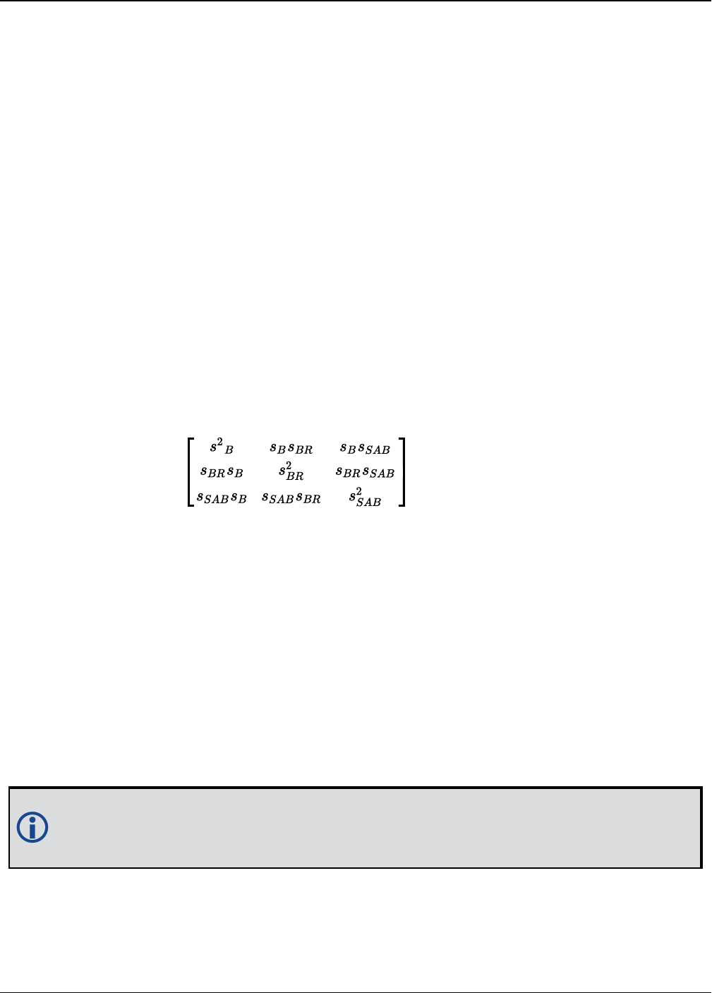
Chapter 3 Logs
OEM7 Commands and Logs Reference Manual v7 456
3.21 CLOCKMODEL
Current clock model status
Platform: OEM719, OEM729, OEM7500, OEM7600, OEM7700, OEM7720, PwrPak7,
SPAN CPT7
The CLOCKMODEL log contains the current clock model status of the receiver.
Monitoring the CLOCKMODEL log allows you to determine the error in your receiver reference
oscillator as compared to the GNSS satellite reference.
All logs report GPS reference time not corrected for local receiver clock error. To derive the
closest GPS reference time, subtract the clock offset from the GPS reference time reported. The
clock offset can be calculated by dividing the value of the range bias given in field 6 of the
CLOCKMODEL log by the speed of light (c).
The following symbols are used throughout this section:
B = range bias (m)
BR = range bias rate (m/s)
SAB = Gauss-Markov process representing range bias error due to satellite clock dither (m)
The standard clock model now used is as follows:
clock parameters array = [BBRSAB]
covariance matrix =
Message ID: 16
Log Type: Synch
Recommended Input:
log clockmodela ontime 1
ASCII Example:
#CLOCKMODELA,COM1,0,52.0,FINESTEERING,1364,489457.000,82000000,98f9,2310;VALID,
0,489457.000,489457.000,7.11142843e+00,6.110131956e-03,-
4.93391151e+00,3.02626565e+01,2.801659017e-02,-2.99281529e+01,2.801659017e-
02,2.895779736e-02,-1.040643538e-02,-2.99281529e+01,-1.040643538e-
02,3.07428979e+01,2.113,2.710235665e-02,FALSE*3d530b9a
The CLOCKMODEL log can be used to monitor the clock drift of an internal oscillator once
the CLOCKADJUST mode has been disabled. Watch the CLOCKMODEL log to see the drift
rate and adjust the oscillator until the drift stops.

Chapter 3 Logs
OEM7 Commands and Logs Reference Manual v7 457
Field Field type Description Format Binary
Bytes
Binary
Offset
1CLOCKMODEL
header
Log header. See Messages on page25 for
more information. H 0
2 clock status
Clock model status as computed from current
measurement data, see Table 86: Clock
Model Status on the next page
Enum 4 H
3 reject Number of rejected range bias
measurements Ulong 4 H+4
4 noise time GPS reference time of last noise addition GPSec 4 H+8
5 update time GPS reference time of last update GPSec 4 H+12
6
parameters Clock correction parameters (a 1x3 array of
length 3), listed left-to-right Double
8 H+16
7 8 H+24
8 8 H+32
9
cov data Covariance of the straight line fit (a 3x3
array of length 9), listed left-to-right by rows Double
8 H+40
10 8 H+48
11 8 H+56
12 8 H+64
13 8 H+72
14 8 H+80
15 8 H+88
16 8 H+96
17 8 H+104
18 range bias Last instantaneous measurement of the
range bias (metres) Double 8 H+112
19 range bias
rate
Last instantaneous measurement of the
range bias rate (m/s) Double 8 H+120
20 Reserved Bool 4 H+128
21 xxxx 32-bit CRC (ASCII and Binary only) Hex 4 H+132
22 [CR][LF] Sentence terminator (ASCII only) - - -

Chapter 3 Logs
OEM7 Commands and Logs Reference Manual v7 458
Clock Status (Binary) Clock Status (ASCII) Description
0 VALID The clock model is valid
1 CONVERGING The clock model is near validity
2 ITERATING The clock model is iterating towards validity
3 INVALID The clock model is not valid
Table 86: Clock Model Status
Chapter 3 Logs
OEM7 Commands and Logs Reference Manual v7 459
3.22 CLOCKSTEERING
Clock steering status
Platform: OEM719, OEM729, OEM7500, OEM7600, OEM7700, OEM7720, PwrPak7,
SPAN CPT7
The CLOCKSTEERING log is used to monitor the current state of the clock steering process. All
oscillators have some inherent drift. By default the receiver attempts to steer the receiver clock
to accurately match GPS reference time. If for some reason this is not desired, this behavior can
be disabled using the CLOCKADJUST command (see page 101).
If the CLOCKADJUST command (see page 101) is ENABLED and the receiver is con-
figured to use an external reference frequency (set in the EXTERNALCLOCK command
(see page 146)), then the clock steering process takes over the VARF output pins and
may conflict with a previously entered FREQUENCYOUT command (see page 171).
Message ID: 26
Log Type: Asynch
Recommended Input:
log clocksteeringa onchanged
ASCII Example:
#CLOCKSTEERINGA,COM1,0,56.5,FINESTEERING,1337,394857.051,02000000,0f61,1984;INT
ERNAL,SECOND_ORDER,4400,1707.554687500,0.029999999,-2.000000000,-
0.224,0.060*0e218bbc
To configure the receiver to use an external reference oscillator, see the
EXTERNALCLOCK command on page146.
Field Field type Description Format Binary
Bytes
Binary
Offset
1CLOCKSTEERING
header
Log header. See Messages on page25 for
more information. H 0
2 source Clock source, see Table 87: Clock Source
on the next page Enum 4 H
3 steering state Steering state, see Table 88: Steering
State on page461 Enum 4 H+4

Chapter 3 Logs
OEM7 Commands and Logs Reference Manual v7 460
Field Field type Description Format Binary
Bytes
Binary
Offset
4 period
Period of the FREQUENCYOUT signal used
to control the oscillator, refer to the
FREQUENCYOUT command on page171.
This value is set using the
CLOCKCALIBRATE command (see page
103)
Ulong 4 H+8
5 pulse width
Current pulse width of the
FREQUENCYOUT signal. The starting point
for this value is set using the
CLOCKCALIBRATE command (see page
103). The clock steering loop continuously
adjusts this value in an attempt to drive
the receiver clock offset and drift terms to
zero
Double 8 H+12
6 bandwidth
The current band width of the clock
steering tracking loop in Hz. This value is
set using the CLOCKCALIBRATE
command (see page 103)
Double 8 H+20
7 slope
The current clock drift change in m/s/bit
for a 1 LSB pulse width. This value is set
using the CLOCKCALIBRATE command
(see page 103)
Float 4 H+28
8 offset
The last valid receiver clock offset
computed (m). It is the same as Field #
18 of the CLOCKMODEL log on page456
Double 8 H+32
9 drift rate
The last valid receiver clock drift rate
received (m/s). It is the same as Field #
19 of the CLOCKMODEL log (see page
456)
Double 8 H+40
10 xxxx 32-bit CRC (ASCII and Binary only) Hex 4 H+48
11 [CR][LF] Sentence terminator (ASCII only) - - -
Binary ASCII Description
0 INTERNAL The receiver is currently steering its internal VCTCXO using an internal VARF
signal
1 EXTERNAL The receiver is currently steering an external oscillator using the external
VARF signal
Table 87: Clock Source

Chapter 3 Logs
OEM7 Commands and Logs Reference Manual v7 461
Binary ASCII Description
0FIRST_
ORDER
Upon start-up, the clock steering task adjusts the VARF pulse width to
reduce the receiver clock drift rate to below 1 ms using a 1st order control
loop. This is the normal start-up state of the clock steering loop.
1SECOND_
ORDER
Once the receiver has reduced the clock drift to below 1 m/s, it enters a
second order control loop and attempts to reduce the receiver clock offset
to zero. This is the normal runtime state of the clock steering process.
2CALIBRATE_
HIGH
This state corresponds to when the calibration process is measuring at the
"High" pulse width setting.
The CALIBRATE_HIGH state is only seen if you force the receiver to do a
clock steering calibration using the CLOCKCALIBRATE command (see
page 103). With the CLOCKCALIBRATE command (see page 103), you
can force the receiver to calibrate the slope and center pulse width of the
currently selected oscillator, to steer. The receiver measures the drift rate
at several "High" and "Low" pulse width settings.
3CALIBRATE_
LOW
This state corresponds to when the calibration process is measuring at the
"Low" pulse width setting.
The CALIBRATE_LOW state is only seen if you force the receiver to do a
clock steering calibration using the CLOCKCALIBRATE command (see
page 103). With the CLOCKCALIBRATE command (see page 103), you
can force the receiver to calibrate the slope and center pulse width of the
currently selected oscillator, to steer. The receiver measures the drift rate
at several "High" and "Low" pulse width settings.
4CALIBRATE_
CENTER
This state corresponds to the "Center" calibration process. Once the center
has been found, the modulus pulse width, center pulse width, loop
bandwidth and measured slope values are saved in NVM and are used from
now on for the currently selected oscillator (INTERNAL or EXTERNAL).
After the receiver has measured the "High" and "Low" pulse width setting,
the calibration process enters a "Center calibration" process where it
attempts to find the pulse width required to zero the clock drift rate.
Table 88: Steering State

Chapter 3 Logs
OEM7 Commands and Logs Reference Manual v7 462
3.23 DUALANTENNAHEADING
Synchronous heading information for dual antenna product
Platform: OEM7720, PwrPak7D, PwrPak7D-E1, SPAN CPT7
The heading is the angle from True North of the primary antenna to secondary antenna vector in
a clockwise direction.
You must have an ALIGN capable, dual antenna receiver to use this log.
Message ID: 2042
Log Type: Synch
Recommended Input:
log dualantennaheadinga ontime 1
ASCII Example:
#DUALANTENNAHEADINGA,UNKNOWN,0,66.5,FINESTEERING,1949,575614.000,02000000,d426,
32768;SOL_COMPUTED,NARROW_INT,-
1.000000000,255.538528442,0.006041416,0.0,0.043859947,0.052394450,"J56X",24,18,
18,17,04,01,00,33*1f082ec5
Field Field type Description Binary
Format
Binary
Bytes
Binary
Offset
1
DUALANTENNA
HEADING
header
Log header. See Messages on page25 for
more information. - H 0
2 sol stat Solution status, see Table 73: Solution
Status on page431 Enum 4 H
3 pos type Position type, see Table 74: Position or
Velocity Type on page432 Enum 4 H+4
4 length
Baseline length in metres
For ALIGN Heading models, this field is -1.
For ALIGN Relative Positioning models with
a fixed position, this field is -1.
For ALIGN Relative Positioning models, this
field is the baseline length in metres, unless
the position is fixed.
Float 4 H+8
5 heading Heading in degrees (0° to 359.999°) Float 4 H+12
6 pitch Pitch (±90 degrees) Float 4 H+16

Chapter 3 Logs
OEM7 Commands and Logs Reference Manual v7 463
Field Field type Description Binary
Format
Binary
Bytes
Binary
Offset
7 Reserved Float 4 H+20
8 hdg std dev Heading standard deviation in degrees Float 4 H+24
9 ptch std dev Pitch standard deviation in degrees Float 4 H+28
10 stn ID Station ID string Char[4] 4 H+32
11 #SVs Number of satellites tracked Uchar 1 H+36
12 #solnSVs Number of satellites in solution Uchar 1 H+37
13 #obs Number of satellites above the elevation
mask angle Uchar 1 H+38
14 #multi Number of satellites above the mask angle
with L2 Uchar 1 H+39
15 sol source Solution source (see Table 101: Solution
Source on page541) Hex 1 H+40
16 ext sol stat Extended solution status (see Table 77:
Extended Solution Status on page435) Hex 1 H+41
17
Galileo and
BeiDou sig
mask
Galileo and BeiDou signals used mask (see
Table 76: Galileo and BeiDou Signal-Used
Mask on page435)
Hex 1 H+42
18
GPS and
GLONASS sig
mask
GPS and GLONASS signals used mask (see
Table 75: GPS and GLONASS Signal-Used
Mask on page434)
Hex 1 H+43
19 xxxx 32-bit CRC (ASCII and Binary only) Hex 4 H+44
20 [CR][LF] Sentence terminator (ASCII only) - - -

Chapter 3 Logs
OEM7 Commands and Logs Reference Manual v7 464
3.24 ETHSTATUS
Current Ethernet status
Platform: OEM729, OEM7600, OEM7700, OEM7720, PwrPak7, SPAN CPT7
This log provides the current status of the Ethernet ports.
Message ID: 1288
Log Type: Polled
Recommended Input:
log ethstatusa once
ASCII Example:
#ETHSTATUSA,COM1,0,89.5,FINESTEERING,1609,500138.174,02000000,e89d,6259;1,ETHA,
"00-21-66-00-05-A2",100_FULL*98d86b04
Field Field Type Description Format Binary
Bytes
Binary
Offset
1ETHSTATUS
header
Log header. See Messages on page25
for more information. - H 0
2#of
interfaces Number of records to follow Ulong 4 H
3 interface Name of the Ethernet interface (e.g.,
ETHA) Enum 4 H+4
4 MAC address An identifier assigned to the network
adapters or network interface card
String
[18]
variable
aH+8
5interface
configuration
Current connectivity, speed and duplex
settings of the Ethernet interface Enum 4 H+26
6... Next interface = H+4+(# of interfaces * 26)
7 xxxx 32-bit CRC (ASCII and Binary only) Hex 4
H+4+(# of
interfaces *
26)
8 [CR][LF] Sentence terminator (ASCII only) - - -
Refer to the ETHCONFIG command (see page 139) for enum values.
aIn the binary case, each string field needs to be NULL terminated and additional bytes of padding added to
maintain 4-byte alignment, up to the maximum defined by the string size. The next defined field starts
immediately at the next 4-byte alignment following the NULL.

Chapter 3 Logs
OEM7 Commands and Logs Reference Manual v7 465
3.25 FILELIST
Display the storage media contents
Platform: OEM719, OEM729, OEM7500, OEM7600, OEM7700, OEM7720, PwrPak7,
SPAN CPT7
Use this log to display the root directory of the active media. A log is produced for each file and
directory in the root directory.
The active media is set with the FILEMEDIACONFIG command on page154.
Message ID: 2100
Log Type: Asynch
Recommended Input:
log filelista
ASCII Example:
#FILELISTA,COM1,0,95.0,UNKNOWN,0,77428.011,024c4009,e8c9,32768;USBSTICK,0,20161
117,104430,"blah.txt"*a212a600
#FILELISTA,COM1,1,94.5,UNKNOWN,0,77428.011,024c4009,e8c9,32768;USBSTICK,0,19700
101,0,"BMHR15470145U_1930_501232.LOG"*d12f9c46
Field Field Type Description Format Binary
Bytes
Binary
Offset
1 FILELIST header Log header. See Messages on
page25 for more information. - H 0
2 MassStorageDevice
Mass Storage Device
See Table 90: Mass Storage Device
on page468
Enum 4 H
3 FileType The type of entry for this log. See
Table 89: File Type on the next page Enum 4 H+4
4 FileSize File Size (in Bytes) Ulong 4 H+8
5 ChangeDate Date of the last change Ulong 4 H+12
6 ChangeTime Time of last change Ulong 4 H+16
7 FileName Name of the file or directory File
Name STRING Variable H + 20 String Variable H+20
8 xxxx 32-bit CRC (ASCII and Binary only) Hex 4 Variable
9 [CR][LF] Sentence terminator (ASCII only) - - -

Chapter 3 Logs
OEM7 Commands and Logs Reference Manual v7 466
Binary ASCII Description
0 NONE Indicates there are no entries in the selected media
1 FILE File
2 DIR Directory
Table 89: File Type
When there no files or directories on the specified media, a single FILELIST log is out-
put with FileType set to NONE and file information set to 0and empty strings.

Chapter 3 Logs
OEM7 Commands and Logs Reference Manual v7 467
3.26 FILESTATUS
Displays the state of the data log file
Platform: OEM719, OEM729, OEM7500, OEM7600, OEM7700, OEM7720, PwrPak7,
SPAN CPT7
Use this log to display the current state of the data log file. Typically the FILESTATUSlog is
used to determine if the log file is open for writing or closed. However, it also shows any error
that has occurred.
Message ID: 2127
Log Type: Asynch
Recommended Input:
log filestatusa
ASCII Example
#FILESTATUSA,USB3,0,75.0,FINESTEERING,1983,171080.615,02104020,4dbd,14434;INTER
NAL_FLASH,CLOSED,"",0,14039057,15754462,""*7de99c77
Field Field Type Description Format Binary
Bytes
Binary
Offset
1 FILESTATUS Header
Log header. See
Messages on page25
for more information.
- H 0
2 MassStorageDevice
The type of recording
device
See Table 90: Mass
Storage Device on the
next page.
Enum 4 H
3 FileStatus
File status
See Table 91: File
Status on the next
page.
Enum 4 H+4
4 FileName Filename of the log file
Fixed
UCHAR
Array
MAX_
FILENAME_
LENGTH
(MFL)
H+8
5 FileSize File Size (bytes) Ulong 4 H+MFL+8
6 MediaRemainingCapacity Remaining capacity on
the storage media (kb) Ulong 4 H+MFL+12
7 MediaTotalCapacity Total capacity of the
storage media (kb) Ulong 4 H+MFL+16

Chapter 3 Logs
OEM7 Commands and Logs Reference Manual v7 468
Field Field Type Description Format Binary
Bytes
Binary
Offset
8 ErrorMsg Error Message String Variable H+MFL+20
9 xxxx 32-bit CRC (ASCII and
Binary only) Hex 4 Variable
10 [CR][LF] Sentence terminator
(ASCII only) - - -
Binary ASCII Description
1 USBSTICK USB mass storage device
2 RAMDRIVE -
3 NO_STORAGE No mass storage
4 INTERNAL_FLASH Internal eMMC flash
Table 90: Mass Storage Device
Binary ASCII Description
0 OPEN Log file is open
1 CLOSED Log file is closed
3 ERROR An error has occurred
5 PENDING Operation during initialization state
Table 91: File Status

Chapter 3 Logs
OEM7 Commands and Logs Reference Manual v7 469
3.27 FILESYSTEMCAPACITY
Displays storage capacity available
Platform: OEM719, OEM729, OEM7500, OEM7600, OEM7700, OEM7720, PwrPak7,
SPAN CPT7
Use this log to check the amount of storage capacity available in both the internal and external
storage.
Message ID: 2137
Log Type: Polled
Recommended Input:
log filesystemcapacity
Abbreviated ASCII Example:
<FILESYSTEMCAPACITY COM1 0 92.0 UNKNOWN 0 2736.008 0244c009 fded 32768
<2
<USBSTICK 31546671104 688128
<INTERNAL_FLASH 14735147008 12288
ASCII Example:
#FILESYSTEMCAPACITYA,COM1,0,92.0,UNKNOWN,0,2767.008,0244c009,fded,32768;2,USBST
ICK,31546671104,688128,INTERNAL_FLASH,14735147008,12288*8a8d384b
The INTERNAL_FLASH is only present on the PwrPak7.
Field FieldType Description Format Binary
Bytes
Binary
Offset
1FILESYSTEMCAPACITY
header
Log header. See Messages on
page25 for more information. - H 0
2 #Dev Number of device with data to
follow Ulong 4 H
3 MassStorageDevice
File system type (recording
device)
See Table 90: Mass Storage
Device on the previous page
Enum 4 H+4
4 TotalStorage Total storage on device in bytes Ulong 8 H+8
5 UsedStorage Amount of storage used on the
device in bytes Ulong 8 H+16
6 Next device offset = H+4+(#Dev x 20)

Chapter 3 Logs
OEM7 Commands and Logs Reference Manual v7 470
Field FieldType Description Format Binary
Bytes
Binary
Offset
7 xxxx 32-bit CRC (ASCII and Binary
only) Hex 4
H+4+
(#Dev x
20)
8 [CR][LF] Sentence terminator (ASCII only) - - -

Chapter 3 Logs
OEM7 Commands and Logs Reference Manual v7 471
3.28 FILESYSTEMSTATUS
Display state of recording media
Platform: OEM719, OEM729, OEM7500, OEM7600, OEM7700, OEM7720, PwrPak7,
SPAN CPT7
This log displays the current state of the recording media. It can be used to determine the state
of the file system, such as any mounting errors.
When logging the FILESYSTEMSTATUS log, use the ONNEW or ONCHANGED log trig-
ger.
Message ID: 2104
Log Type: Asynch
Recommended Input:
log filesystemstatusa onchanged
Abbreviated ASCII Example:
<FILESYSTEMSTATUS COM1 1 91.5 UNKNOWN 0 5.387 02000020 143c 32768
<USBSTICK MOUNTED 3862430 ""
<FILESYSTEMSTATUS COM1 0 91.5 COARSESTEERING 1953 153609.680 02000020 143c
32768
<INTERNAL_FLASH MOUNTED 14756709 ""
Field Field Type Description Format Binary
Bytes
Binary
Offset
1FILESYSTEMSTATUS
header
Log header. See Messages on
page25 for more information. - H 0
2 MassStorageDevice
Recording Device
See Table 90: Mass Storage Device
on page468
Enum 4 H
3 MassStorageStatus
Media Status
See Table 92: Mass Storage Status
on the next page
Enum 4 H+4
4 TotalCapacity Media total capacity (in kB) Ulong 4 H+8
5 ErrorMsg Error Message String Variable H+12
6 xxxx 32-bit CRC (ASCII and Binary only) Hex 4 Variable
7 [CR][LF] Sentence Terminator (ASCII only) - - -

Chapter 3 Logs
OEM7 Commands and Logs Reference Manual v7 472
Binary ASCII Description
0 UNMOUNTED Mass storage unmounted
1 MOUNTED Mass storage mounted
2 BUSY Mass storage busy. i.e. formatting
3 ERROR Mounting error
4 MOUNTING Mass storage is being mounted
5 UNMOUNTING Mass storage is being unmounted
Table 92: Mass Storage Status

Chapter 3 Logs
OEM7 Commands and Logs Reference Manual v7 473
3.29 FILETRANSFERSTATUS
Display the current state of a file transfer
Platform: PwrPak7
This log contains the current state of a file transfer from the internal memory to a USBstick.
This logs also indicates any file transfer errors that may have occurred.
Message ID: 2101
Log Type: Asynch
Recommended Input:
log filetransferstatusa onchanged
ASCIIExample:
<FILETRANSFERSTATUS COM1 0 38.0 FINESTEERING 1953 248960.848 02440020 ce81
32768 TRANSFERRING 0 4096035 "NPP714520001W_2017-06-10_01-16-20.LOG" ""
<FILETRANSFERSTATUS COM1 0 88.5 FINESTEERING 1953 248961.853 02000020 ce81
32768 TRANSFERRING 1138 4096035 "NPP714520001W_2017-06-10_01-16-20.LOG" ""
<FILETRANSFERSTATUS COM1 0 17.5 FINESTEERING 1953 248962.853 02000020 ce81
32768 TRANSFERRING 2277 4096035 "NPP714520001W_2017-06-10_01-16-20.LOG" ""
...
Field Field Type Description Format Binary
Bytes
Binary
Offset
1FILETRANSFERSTATUS
header
Log header. See Messages on
page25 for more information. - H 0
2 File Transfer Status
The status of the file transfer. See
Table 93: File Transfer Status on
the next page.
Enum 4 H
3 Total Transferred Total amount of data transferred.
(kbytes) Ulong 4 H+4
4 Total Transfer Size Total size of the data to transfer.
(kbytes) Ulong 4 H+8
5 Filename Name of the file that is currently
transferring. String Variable H+12
6 Error Msg Error message
(if an error occurred) String Variable Variable
7 xxxx 32-bit CRC (ASCII and Binary
only) Hex 4 Variable
8 [CR][LF] Sentence terminator (ASCIIonly) - - -

Chapter 3 Logs
OEM7 Commands and Logs Reference Manual v7 474
Binary Value ASCII Value Description
1 NONE There is no file transfer in progress
2 TRANSFERRING There is an active file transfer
3 FINISHED The transfer has been successfully completed
4 ERROR An error occurred during the transfer
5 CANCELLED A user cancelled the active file transfer
Table 93: File Transfer Status

Chapter 3 Logs
OEM7 Commands and Logs Reference Manual v7 475
3.30 GALALMANAC
Decoded Galileo Almanac
Platform: OEM719, OEM729, OEM7500, OEM7600, OEM7700, OEM7720, PwrPak7,
SPAN CPT7
This log contains the decoded Galileo almanac parameters from Galileo navigation messages.
Multiple messages are transmitted, one for each satellite ID with data.
The OEM7 family of receivers automatically save almanacs in their Non-Volatile Memory (NVM),
so creating an almanac boot file is not necessary.
Message ID: 1120
Log Type: Asynch
Recommended Input:
log galalmanaca onchanged
ASCII Example:
#GALALMANACA,COM1,3,83.5,SATTIME,1769,333371.000,02000020,131f,45362;
19,FALSE,TRUE,0,0,0,0,10,745,332400.000,1.221e-04,-5.486e-09,
2.757e+00,2.038e+00,-1.226e+00,-1.1444e-05,0.000,2.539e-02,-1.457e-02
*5c77f44b
#GALALMANACA,COM1,2,83.5,SATTIME,1769,333399.000,02000020,131f,45362;
20,FALSE,TRUE,0,0,0,0,10,745,332400.000,1.831e-04,-5.486e-09,
2.757e+00,1.542e+00,-3.1734e-02,4.8084e-03,9.495e-10,2.539e-02,
-1.457e-02*3530e391
#GALALMANACA,COM1,1,83.5,SATTIME,1769,333939.000,02000020,131f,45362;
11,FALSE,TRUE,0,0,0,0,11,745,333000.000,6.104e-05,-5.120e-09,
6.6412e-01,2.396e+00,-1.032e+00,5.1498e-05,1.091e-11,3.125e-02,
-1.764e-02*afa0f631
#GALALMANACA,COM1,0,83.5,SATTIME,1769,333941.000,02000020,131f,45362;
12,FALSE,TRUE,0,0,0,0,11,745,333000.000,1.526e-04,-5.120e-09,
6.6412e-01,-2.392e+00,-1.818e+00,6.4850e-05,1.091e-11,3.516e-02,
-1.764e-02*ef41e1b2
The speed at which the receiver locates and locks onto new satellites is improved if
the receiver has approximate time and position, as well as an almanac. This allows
the receiver to compute the elevation of each satellite so it can tell which satellites
are visible and their Doppler offsets, improving Time to First Fix (TTFF).
Field Field Type Description Format Binary
Bytes
Binary
Offset
1GALALMANAC
header
Log header. See Messages on page25 for
more information. H 0

Chapter 3 Logs
OEM7 Commands and Logs Reference Manual v7 476
Field Field Type Description Format Binary
Bytes
Binary
Offset
2 SatId Satellite ID Ulong 4 H
3 FNAVReceived Indicates FNAV almanac data received Bool 4 H+4
4 INAVReceived Indicates INAV almanac data received Bool 4 H+8
5 E1BHealth E1B health status bits (only valid if
INAVReceived is TRUE) Uchar 1 H+12
6 E5aHealth E5a health status bits (only valid if
FNAVReceived is TRUE) Uchar 1 H+13
7 E5bHealth E5b health status bits (only valid if
INAVReceived is TRUE) Uchar 1 H+14
8 Reserved Uchar 1 H+15
9 IODa Almanac issue of data Ulong 4 H+16
10 Weeks Almanac reference week Ulong 4 H+20
11 Seconds Almanac reference time of week (seconds
for ASCII, milliseconds for binary) GPSec 4 H+24
12 Ecc Eccentricity (dimensionless) Double 8 H+28
13 OmegaDot Rate of right ascension (radians/second) Double 8 H+36
14 Omega0 Right ascension (radians) Double 8 H+44
15 Omega Argument of perigee (radians) Double 8 H+52
16 M0 Mean anomaly at ref time (radians) Double 8 H+60
17 Af0 Satellite clock correction bias (seconds) Double 8 H+68
18 Af1 Satellite clock correction linear
(seconds/second) Double 8 H+76
19 DeltaRootA Difference with respect to the square root of
the nominal semi-major axis (sqrt(metres)) Double 8 H+84
20 DeltaI Inclination at reference time relative to I0 =
56 deg Double 8 H+92
21 xxxx 32-bit CRC (ASCII and Binary only) Hex 4 H+100
22 [CR][LF] Sentence terminator (ASCII only) - - -

Chapter 3 Logs
OEM7 Commands and Logs Reference Manual v7 477
3.31 GALCLOCK
Galileo clock information
Platform: OEM719, OEM729, OEM7500, OEM7600, OEM7700, OEM7720, PwrPak7,
SPAN CPT7
This log contains the Galileo time information.
This log is populated from both the INAV and FNAV messages. Depending on the data
source, it is possible that the time in the header of the log is earlier than the time in a
previous log. This is expected behavior.
Message ID: 1121
Log Type: Asynch
Recommended Input:
log galclocka onchanged
ASCII Example:
#GALCLOCKA,COM1,0,84.5,SATTIME,1769,336845.000,02000020,c6cf,45362;
8.381903172e-09,-3.5527137e-15,16,259200,233,28,7,16,-3.5216e-09,
-1.776e-14,345600,41*186e9085
Field Field
Type Description Format Binary
Bytes
Binary
Offset
1GALCLOCK
header
Log header. See Messages on page25 for more
information. H 0
2 A0 Constant term of polynomial Double 8 H
3 A1 1st order term of polynomial Double 8 H+8
4 DeltaTls Leap second count before leap second
adjustment Long 4 H+16
5 Tot UTC data reference time of week (seconds) Ulong 4 H+20
6 WNt UTC data reference week number Ulong 4 H+24
7 WNlsf Week number of leap second adjustment Ulong 4 H+28
8 DN Day number at the end of which a leap second
adjustment becomes effective Ulong 4 H+32
9 DeltaTlsf Leap second count after leap second adjustment Long 4 H+36
10 A0g Constant term of the polynomial describing the
difference between Galileo and GPS time Double 8 H+40

Chapter 3 Logs
OEM7 Commands and Logs Reference Manual v7 478
Field Field
Type Description Format Binary
Bytes
Binary
Offset
11 A1g Rate of change of offset the offset between
Galileo and GPS time Double 8 H+48
12 T0g Reference time for GGTO data Ulong 4 H+56
13 WN0g Week number of GGTO reference Ulong 4 H+60
14 xxxx 32-bit CRC (ASCII and Binary only) Hex 4 H+64
15 [CR][LF] Sentence terminator (ASCII only) - - -

Chapter 3 Logs
OEM7 Commands and Logs Reference Manual v7 479
3.32 GALCNAVRAWPAGE
Galileo raw CNAV page
Platform: OEM719, OEM729, OEM7500, OEM7700, OEM7720, PwrPak7, SPAN CPT7
This log provides Galileo raw C-NAV page data from Galileo E6 signals.
The GALCNAVRAWPAGE log is not output by default. To receive this log, data decoding
for E6B/E6C must be enabled using the DATADECODESIGNAL command (see page
111) the specific signal.
Message ID: 2239
Log Type: Asynch
Recommended Input:
log galcnavrawpage onnew
Abbreviated ASCII Example:
<GALCNAVRAWPAGE USB1 0 49.5 SATTIME 1997 145162.000 02040020 ab53 32768
<319 30 2761
2b26bcef0c04f6711bf86137086a12c14f87c07b4c6aa4de04bceb8612c34c691bfabceceb86bce
d4f851bfb0c074c68613604bff48448d33487
Field Field Type Description Format Binary
Bytes
Binary
Offset
1GALCNAVRAWPAGE
header
Log header. See Messages on
page25 for more information. - H 0
2 signal channel Signal channel providing the bits Ulong 4 H
3 PRN Satellite PRN number Ulong 4 H+4
4 Page ID The page ID Ulong 4 H+8
5 data Raw CNAV page data HEX
[58] 58 H+12
6 xxxx 32-bit CRC (ASCII and Binary only) Hex 4 h+70
7 [CR][LF] Sentence terminator (ASCII only) - - -

Chapter 3 Logs
OEM7 Commands and Logs Reference Manual v7 480
3.33 GALFNAVEPHEMERIS
Decoded Galileo FNAV Ephemeris
Platform: OEM719, OEM729, OEM7500, OEM7600, OEM7700, OEM7720, PwrPak7,
SPAN CPT7
The GALFNAVEPHEMERIS log contains the Galileo FNAV ephemeris information. Multiple mes-
sages are transmitted, one for each satellite ID with date.
Message ID: 1310
Log Type: Asynch
Recommended Input:
log galfnavephemerisa onchanged
ASCII Example:
#GALFNAVEPHEMERISA,COM2,0,82.5,SATTIME,1874,148850.000,02400000,02cd,
32768;22,0,0,0,0,118,122,0,147600,147600,-6.101167919e-01,3.1687e-09,
4.478077171e-04,5.44059147e+03,9.639218456e-01,6.4610e-10,
2.329679501e-01,2.55827293e+00,-5.5577315e-09,1.0207e-06,8.2552e-06,
1.611e+02,2.313e+01,4.0978e-08,-1.8626e-09,1.335504232e-03,
1.768257e-10,0.0,2.561e-09*d02e28ca
Field Field
Type Description Format Binary
Bytes
Binary
Offset
1
GALFNAV
EPHEMERIS
header
Log header. See Messages on page25 for more
information. H 0
2 SatId Satellite identifier Ulong 4 H
3 E5aHealth E5a health status bits Uchar 1 H+4
4 E5aDVS E5a data validity status Uchar 1 H+5
5 Reserved Uchar 1 H+6
6 Reserved Uchar 1 H+7
7 IODnav Issue of data ephemeris Ushort 2 H+8
8 SISA Index Signal in space accuracy (unitless) Uchar 1 H+10
9 Reserved Uchar 1 H+11
10 T0e Ephemeris reference time (s) Ulong 4 H+12
11 T0c Clock correction data reference time of week
from the F/NAV message (s) Ulong 4 H+16
12 M0 Mean anomaly at ref time (radians) Double 8 H+20

Chapter 3 Logs
OEM7 Commands and Logs Reference Manual v7 481
Field Field
Type Description Format Binary
Bytes
Binary
Offset
13 DeltaN Mean motion difference (radians/s) Double 8 H+28
14 Ecc Eccentricity (unitless) Double 8 H+36
15 RootA Square root of semi-major axis Double 8 H+44
16 I0 Inclination angle at ref time (radians) Double 8 H+52
17 IDot Rate of inclination angle (radians/s) Double 8 H+60
18 Omega0 Longitude of ascending node of orbital plane at
weekly epoch (radians) Double 8 H+68
19 Omega Argument of perigee (radians) Double 8 H+76
20 OmegaDot Rate of right ascension (radians/s) Double 8 H+84
21 Cuc Amplitude of the cosine harmonic correction
term to the argument of latitude (radians) Double 8 H+92
22 Cus Amplitude of the sine harmonic correction term
to the argument of latitude (radians) Double 8 H+100
23 Crc Amplitude of the cosine harmonic correction
term to the orbit radius (m) Double 8 H+108
24 Crs Amplitude of the sine harmonic correction term
to the orbit radius (m) Double 8 H+116
25 Cic Amplitude of the cosine harmonic correction
term to the angle of inclination (radians) Double 8 H+124
26 Cis Amplitude of the sine harmonic correction term
to the angle of inclination (radians) Double 8 H+132
27 Af0 SV clock bias correction coefficient from the
F/NAV message (s) Double 8 H+140
28 Af1 SV clock drift correction coefficient from the
F/NAV message (s/s) Double 8 H+148
29 Af2 SV clock drift rate correction coefficient from
the F/NAV message (s/s^2) Double 8 H+156
30 E1E5aBGD E1, E5a broadcast group delay Double 8 H+164
31 xxxx 32-bit CRC (ASCII and Binary only) Hex 4 H+172
32 [CR][LF] Sentence terminator (ASCII only) - - -

Chapter 3 Logs
OEM7 Commands and Logs Reference Manual v7 482
3.34 GALFNAVRAWPAGE
Raw Galileo FNAV page data
Platform: OEM719, OEM729, OEM7500, OEM7600, OEM7700, OEM7720, PwrPak7,
SPAN CPT7
This log contains the raw Galileo FNAV page data.
Message ID: 1413
Log Type: Asynch
Recommended Input:
log galfnavrawpagea onchanged
ASCII Example:
#GALFNAVRAWPAGEA,USB3,0,85.0,SATTIME,1680,434410.000,02000008,d4fb,
43274;56,11,0b818df50ad5ffc151001baffdaa04d5dae655e17affc8a41a83aa
*5955b14d
Field Field Type Description Format Binary
Bytes
Binary
Offset
1GALFNAVRAWPAGE
header
Log header. See Messages on
page25 for more information. H 0
2 signal channel Signal channel providing the data Ulong 4 H
3 SVID SVID of transmitting satellite Ulong 4 H+4
4 raw frame data Raw F/NAV page (214 bits). Does not
include CRC or Tail bits Hex[27] 27 H+8
5 xxxx 32-bit CRC (ASCII and Binary only) Hex 4 H+35
6 [CR][LF] Sentence terminator (ASCII only) - - -

Chapter 3 Logs
OEM7 Commands and Logs Reference Manual v7 483
3.35 GALINAVEPHEMERIS
Decoded Galileo INAV Ephemeris
Platform: OEM719, OEM729, OEM7500, OEM7600, OEM7700, OEM7720, PwrPak7,
SPAN CPT7
The GALINAVEPHEMERIS log contains the Galileo INAV ephemeris information. Multiple mes-
sages are transmitted, one for each SVID with date.
Message ID: 1309
Log Type: Asynch
Recommended Input:
log galinavephemerisa onchanged
ASCII Example:
#GALINAVEPHEMERISA,COM1,10,82.0,SATTIME,1930,494134.000,02000020,dbe9,
32768;1,0,0,0,0,0,0,0,0,54,107,1,493200,493200,2.98962614e+00,
2.7990e-09,1.763084438e-04,5.44061901e+03,9.996620695e-01,-2.8608e-10,
-2.52251354e+00,-1.37786826e+00,-5.7041662e-09,-3.7253e-09,3.8184e-06,
2.773e+02,4.6875e-01,-7.0781e-08,4.6566e-08,3.960891627e-05,
-9.904966e-12,0.0,-6.752e-09,-7.683e-09*b575a8b9
#GALINAVEPHEMERISA,COM1,9,82.0,SATTIME,1930,511405.000,02000020,dbe9,
32768;2,0,0,0,0,0,0,0,0,81,107,3,509400,509400,1.23345967e+00,
2.9637e-09,2.852674806e-04,5.44061650e+03,9.996659901e-01,-2.3537e-10,
-2.52264339e+00,-7.551901559e-01,-5.8113135e-09,5.2713e-07,2.4810e-06,
3.021e+02,1.034e+01,-1.3039e-08,1.8626e-09,-2.745073289e-07,
1.705303e-13,0.0,-8.149e-09,-9.546e-09*6df98c07
#GALINAVEPHEMERISA,COM1,8,82.0,SATTIME,1930,511384.000,02000020,dbe9,
32768;8,0,0,0,0,0,0,0,0,83,107,3,510600,510600,1.19121266e+00,
3.0755e-09,1.157049555e-04,5.44062434e+03,9.581430032e-01,-2.9858e-10,
1.66547803e+00,7.075104782e-01,-5.5223729e-09,-1.5851e-06,1.2502e-05,
6.706e+01,-3.447e+01,5.5879e-09,-5.7742e-08,4.641003208e-03,
3.982876e-10,0.0,-1.048e-08,-1.211e-08*99c692a8
...
#GALINAVEPHEMERISA,COM1,1,82.0,SATTIME,1930,511405.000,02000020,dbe9,
32768;26,0,0,0,0,0,0,0,0,83,107,1,510600,510600,-1.25500637e+00,2.9951
e-09,2.602027962e-04,5.44060480e+03,9.688215634e-01,3.7894e-10,-4.2237
68063e-01,-2.61686286e+00,-5.6309488e-09,-4.0233e-07,8.1658e-06,1.711e
+02,-8.500e+00,-1.3039e-08,-3.1665e-08,5.767530005e-03,4.148148e-10,
0.0,-6.985e-10,-9.313e-10*0e6670f3
#GALINAVEPHEMERISA,COM1,0,82.0,SATTIME,1930,511405.000,02000020,dbe9,
32768;30,0,0,0,0,0,0,0,0,83,107,1,510600,510600,-2.836817871e-01,
2.9558e-09,2.358634956e-04,5.44061465e+03,9.972253278e-01,-1.9894e-10,
-2.51793093e+00,1.101770916e-01,-5.7991701e-09,7.0594e-07,2.4680e-06,
3.045e+02,1.675e+01,-1.8626e-08,5.0291e-08,4.957979254e-03,
3.988703e-10,0.0,-4.889e-09,-5.821e-09*4513b897

Chapter 3 Logs
OEM7 Commands and Logs Reference Manual v7 484
Field Field
Type Description Format Binary
Bytes
Binary
Offset
1
GALINAV
EPHEMERIS
header
Log Header H 0
2 SatId Satellite identifier Ulong 4 H
3 E5bHealth E5b health status bits Uchar 1 H+4
4 E5bDVS E5b data validity status Uchar 1 H+5
5 Reserved Uchar 1 H+6
6 Reserved Uchar 1 H+7
7 E1bHealth E1b health status bits Uchar 1 H+8
8 E1bDVS E1b data validity status Uchar 1 H+9
9 Reserved Uchar 1 H+10
10 Reserved Uchar 1 H+11
11 IODnav Issue of data ephemeris Ushort 2 H+12
12 SISA Index Signal in space accuracy (unitless) Uchar 1 H+14
13 INAV
Source
Identifies the source signal:
0 = Unknown
1 = E1b
2 = E5b
3 = E1b and E5b
Uchar 1 H+15
14 T0e Ephemeris reference time (s) Ulong 4 H+16
15 T0c Clock correction data reference time of week
from the I/NAV message (s) Ulong 4 H+20
16 M0 Mean anomaly at ref time (radians) Double 8 H+24
17 DeltaN Mean motion difference (radians/s) Double 8 H+32
18 Ecc Eccentricity (unitless) Double 8 H+40
19 RootA Square root of semi-major axis Double 8 H+48
20 I0 Inclination angle at ref time (radians) Double 8 H+56
21 IDot Rate of inclination angle (radians/s) Double 8 H+64
22 Omega0 Longitude of ascending node of orbital plane at
weekly epoch (radians) Double 8 H+72

Chapter 3 Logs
OEM7 Commands and Logs Reference Manual v7 485
Field Field
Type Description Format Binary
Bytes
Binary
Offset
23 Omega Argument of perigee (radians) Double 8 H+80
24 OmegaDot Rate of right ascension (radians/s) Double 8 H+88
25 Cuc Amplitude of the cosine harmonic correction
term to the argument of latitude (radians) Double 8 H+96
26 Cus Amplitude of the sine harmonic correction term
to the argument of latitude (radians) Double 8 H+104
27 Crc Amplitude of the cosine harmonic correction
term to the orbit radius (m) Double 8 H+112
28 Crs Amplitude of the sine harmonic correction term
to the orbit radius (m) Double 8 H+120
29 Cic Amplitude of the cosine harmonic correction
term to the angle of inclination (radians) Double 8 H+128
30 Cis Amplitude of the sine harmonic correction term
to the angle of inclination (radians) Double 8 H+136
31 Af0 SV clock bias correction coefficient from the
I/NAV message (s) Double 8 H+144
32 Af1 SV clock drift correction coefficient from the
I/NAV message (s/s) Double 8 H+152
33 Af2 SV clock drift rate correction coefficient from
the I/NAV message (s/s^2) Double 8 H+160
34 E1E5aBGD E1, E5a broadcast group delay Double 8 H+168
35 E1E5bBGD E1, E5b broadcast group delay Double 8 H+176
36 xxxx 32-bit CRC (ASCII and Binary only) Hex 4 H+184
37 [CR][LF] Sentence terminator (ASCII only) - - -

Chapter 3 Logs
OEM7 Commands and Logs Reference Manual v7 486
3.36 GALINAVRAWWORD
Raw Galileo INAV word data
Platform: OEM719, OEM729, OEM7500, OEM7600, OEM7700, OEM7720, PwrPak7,
SPAN CPT7
This log contains the raw Galileo INAV word data.
Message ID: 1414
Log Type: Asynch
Recommended Input:
log galinavrawworda onchanged
ASCII Example:
#GALINAVRAWWORDA,USB3,0,84.5,SATTIME,1680,434401.000,02000008,884b,
43274;55,11,GALE1,0b81e655e17a26eb5237d7d20088ffc9*dcb4bedb
Field Field Type Description Format Binary
Bytes
Binary
Offset
1GALINAVRAWWORD
header
Log header. See Messages on
page25 for more information. H 0
2 signal channel Signal channel providing data Ulong 4 H
3 SVID SVID of transmitting satellite Ulong 4 H+4
4 signal type Signal Type as defined in Table 29:
Signal Type on page125 Enum 4 H+8
5 raw frame data Raw I/NAV word (128 bits) Hex[16] 16 H+12
6 xxxx 32-bit CRC (ASCII and Binary only) Hex 4 H+28
7 [CR][LF] Sentence terminator (ASCII only) - - -

Chapter 3 Logs
OEM7 Commands and Logs Reference Manual v7 487
3.37 GALIONO
Decoded Galileo ionospheric corrections
Platform: OEM719, OEM729, OEM7500, OEM7600, OEM7700, OEM7720, PwrPak7,
SPAN CPT7
This log contains the decoded Galileo ionospheric corrections.
Message ID: 1127
Log Type: Asynch
Recommended Input:
log galionoa onchanged
ASCII Example:
#GALIONOA,COM1,0,81.5,SATTIME,1930,512134.000,02000020,d22e,32768;
6.03e+01,-2.344e-02,-3.9368e-03,0,0,0,0,0*f50fae69
Field Field
Type Description Format Binary
Bytes
Binary
Offset
1GALIONO
header
Log header. See Messages on page25 for
more information. H 0
2 Ai0 Effective ionization level 1st order
parameter (sfu) Double 8 H
3 Ai1 Effective ionization level 2st order
parameter (sfu/degree) Double 8 H+8
4 Ai2 Effective ionization level 3st order
parameter (sfu/degree2)Double 8 H+16
5 SF1 Ionospheric disturbance flag for region 1 Uchar 1 H+24
6 SF2 Ionospheric disturbance flag for region 2 Uchar 1 H+25
7 SF3 Ionospheric disturbance flag for region 3 Uchar 1 H+26
8 SF4 Ionospheric disturbance for flag region 4 Uchar 1 H+27
9 SF5 Ionospheric disturbance for flag region 5 Uchar 1 H+28
10 xxxx 32-bit CRC (ASCII and Binary only) Hex 4 H+29
11 [CR][LF] Sentence terminator (ASCII only) - - -

Chapter 3 Logs
OEM7 Commands and Logs Reference Manual v7 488
3.38 GLMLA
NMEA GLONASS Almanac data
Platform: OEM719, OEM729, OEM7500, OEM7600, OEM7700, OEM7720, PwrPak7,
SPAN CPT7
This log outputs almanac data for GLONASS satellites. Multiple sentences are transmitted, one
for each satellite.
The following relationships enable translation between the NMEA GLONASS satellite IDs,
the NovAtel GLONASS PRN IDs, and the GLONASS slot numbers:
NMEA GLONASS satellite ID = GLONASS slot number + 64
NovAtel GLONASS PRN ID = GLONASS slot number + 37
= NMEA GLONASS satellite ID - 27
Message ID: 859
Log Type: Asynch
Recommended Input:
log glmlaa onchanged
ASCII Example:
$GLMLA,16,01,65,1176,07,0496,4c,5ff2,8000,34c05e,0e93e8,04b029,001fa2,099,213*6
8
$GLMLA,16,02,66,1176,01,12e3,4c,42cc,8000,34c08e,10fae9,02f48c,00224e,099,003*6
4
$GLMLA,16,03,67,1176,8c,08f6,4a,ef4d,8000,34c051,13897b,00d063,001b09,099,000*6
3
$GLMLA,16,04,68,1176,06,116b,48,3a00,8000,34c09d,02151f,0e49e8,00226e,099,222*6
3
$GLMLA,16,05,70,1176,01,140f,49,45c4,8000,34c0bc,076637,0a3e40,002214,099,036*3
7
$GLMLA,16,06,71,1176,05,0306,4c,5133,8000,34c025,09bda7,085d84,001f83,099,21d*6
E
$GLMLA,16,07,72,1176,06,01b1,4c,4c19,8000,34c021,0c35a0,067db8,001fca,099,047*3
D
$GLMLA,16,08,74,1176,84,076b,45,7995,8000,34c07b,104b6d,0e1557,002a38,099,040*3
5
$GLMLA,16,09,78,1176,84,066c,46,78cf,8000,34c07b,0663f0,1a6239,0029df,099,030*3
8
$GLMLA,16,10,79,1176,80,0afc,45,8506,8000,34c057,08de48,1c44ca,0029d7,099,000*6
B
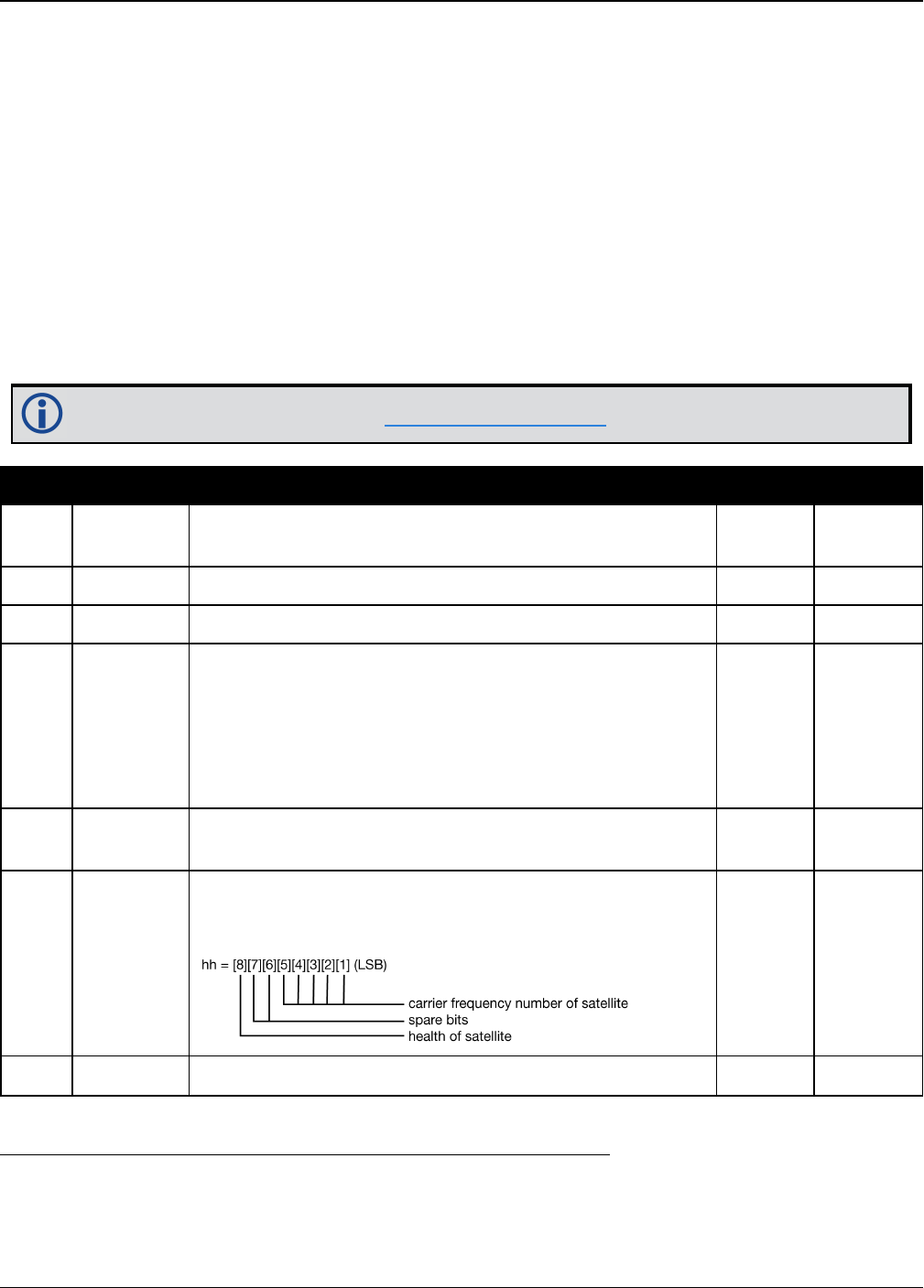
Chapter 3 Logs
OEM7 Commands and Logs Reference Manual v7 489
$GLMLA,16,11,82,1176,8a,12d3,0f,e75d,8000,34be85,10aea6,1781b7,00235a,099,207*6
E
$GLMLA,16,12,83,1176,03,0866,0f,6c08,8000,34c009,11f32e,18839d,002b22,099,214*3
6
$GLMLA,16,13,85,1176,88,01a6,0d,9dc9,8000,34bff8,031887,02da1e,002838,099,242*6
D
$GLMLA,16,14,86,1176,8a,00e1,0e,4b15,8000,34c016,058181,010433,0027f0,099,227*6
F
$GLMLA,16,15,87,1176,03,0383,0f,824c,8000,34bfda,081864,1104ea,002b04,099,00c*6
0
$GLMLA,16,16,88,1176,02,0821,0f,8ac8,8000,34c05b,0a8510,12dcb6,002b6f,099,020*3
F
Refer to the GLONASS section of An Introduction to GNSS available on our website.
Field Structure Description Symbol Example
1 $GLMLA Log header. See Messages on page25 for more
information. $GLMLA
2 #alm Number of NMEA almanac messages in the set x.x 16
3 alm# Current message number x.x 13
4 slot
Slot number for satellite (65-96)
The NMEA GLONASS PRN numbers are 64 plus the
GLONASS slot number. Current slot numbers are 1 to
24 which give the range 65 to 88. PRN numbers 89 to 96
are available if slot numbers above 24 are allocated to
on-orbit spares.
xx 85
5 N Calendar day count within the four year period from the
last leap year x.x 1176
6 hlth & freq
Health and frequency for satellite
Health and carrier frequency numbers are represented
in this 2-character Hex field as: hh 88
7 ecc Eccentricity 1hhhh 01a6
1The LSB of the Hex data field corresponds to the LSB of the word indicated in the Table 4.3 of the GLONASS
Interface Control Document, 1995. If the number of available bits in the Hex field is greater than the word, the
MSB (upper bits) are unused and filled with zeroes.

Chapter 3 Logs
OEM7 Commands and Logs Reference Manual v7 490
Field Structure Description Symbol Example
8 ΔTdot Rate of change of orbital period (s/orbital period2)1hh 0d
9 w Argument of perigee (PZ-90.02), in radians 1hhhh 9dc9
10 t16MSB Clock offset, in seconds 1hhhh 8000
11 ΔT Correction to the mean value of the Draconian period
(s/orbitalperiod) 1hhhhhh 34bff8
12 tπ GLONASS Time of ascending node equator crossing, in
seconds 1hhhhhhh 031887
13 l Longitude of ascending node equator crossing (PZ-
90.02), in radians 1hhhhhhh 02da1e
14 Δi Correction to nominal inclination, in radians 1hhhhhhh 002838
15 t12LSB Clock offset, in seconds 1hhh 099
16 t Coarse value of the time scale shift 1hhh 242
17 xxxx 32-bit CRC (ASCII and Binary only) Hex *6D
18 [CR][LF] Sentence terminator (ASCII only) - [CR][LF]
Chapter 3 Logs
OEM7 Commands and Logs Reference Manual v7 491
3.39 GLOALMANAC
Decoded GLONASS Almanac
Platform: OEM719, OEM729, OEM7500, OEM7600, OEM7700, OEM7720, PwrPak7,
SPAN CPT7
The GLONASS almanac reference time and week are in GPS reference time coordinates.
GLONASS ephemeris information is available through the GLOEPHEMERIS command (see page
496).
Nominal orbit parameters of the GLONASS satellites are as follows:
lDraconian period - 11 hours 15 minutes 44 seconds (see fields 14 and 15 in the following
table)
lOrbit altitude - 19100 km
lInclination - 64.8 (see field 11)
lEccentricity - 0 (see field 12)
The OEM7 family of receivers automatically save almanacs in their Non-Volatile Memory (NVM),
so creating an almanac boot file is not necessary.
The speed at which the receiver locates and locks onto new satellites is improved if
the receiver has approximate time and position, as well as an almanac. This allows
the receiver to compute the elevation of each satellite so it can tell which satellites
are visible and their Doppler offsets, improving Time to First Fix (TTFF).
Message ID: 718
Log Type: Asynch
Recommended Input:
log gloalmanaca onchanged
ASCII Example:
#GLOALMANACA,COM1,0,52.5,SATTIME,1364,410744.000,02000000,ba83,2310;
24,
1364,336832.625,1,2,0,0,2018.625000000,-2.775537500,0.028834045,
0.001000404,2.355427500,-2656.076171875,0.000000000,0.000091553,
1364,341828.437,2,1,0,0,7014.437500000,-3.122226146,0.030814438,
0.004598618,1.650371580,-2656.160156250,0.000061035,0.000095367,
1364,347002.500,3,12,0,0,12188.500000000,2.747629236,0.025376596,
0.002099991,-2.659059822,-2656.076171875,-0.000061035,-0.000198364,
1364,351887.125,4,6,0,0,17073.125000000,2.427596502,0.030895332,
0.004215240,1.438586358,-2656.167968750,-0.000061035,0.000007629,
.
.
.

Chapter 3 Logs
OEM7 Commands and Logs Reference Manual v7 492
1364,364031.187,23,11,0,1,29217.187500000,0.564055522,0.030242192,
0.001178741,2.505278248,-2655.957031250,0.000366211,0.000019073,
1364,334814.000,24,3,0,1,0.000000000,0.000000000,0.000000000,
0.000000000,0.000000000,0.000000000,0.000000000,0.000000000
*4dc981c7
Field Field type Description Format Binary
Bytes
Binary
Offset
1GLOALMANAC
header
Log header. See Messages on page25 for
more information. H 0
2 #recs
The number of GLONASS almanac records to
follow. Set to zero until almanac data is
available
Long 4 H
3 week GPS reference week, in weeks Ulong 4 H+4
4 time GPS reference time, in milliseconds (binary
data) or seconds (ASCII data) GPSec 4 H+8
5 slot Slot number for satellite, ordinal Uchar 1 H+12
6 frequency Frequency for satellite, ordinal (frequency
channels are in the range -7 to +6) Char 1 H+13
7 sat type
Satellite type where
0 = GLO_SAT
1 = GLO_SAT_M (M type)
2 = GLO_SAT_K (K type)
Uchar 1 H+14
8 health
Satellite status where
0 = OPERATIONAL
1 = MALFUNCTION
Uchar 1 H+15
9 TlambdaN GLONASS Time of ascending node equator
crossing, in seconds Double 8 H+16
10 lambdaN Longitude of ascending node equator crossing
(PZ-90.02), in radians Double 8 H+24
11 deltaI Correction to nominal inclination, in radians Double 8 H+32
12 ecc Eccentricity Double 8 H+40
13 ArgPerig Argument of perigee (PZ-90.02), in radians Double 8 H+48
14 deltaT Correction to the mean value of the
Draconian period (s/orbital period) Double 8 H+56

Chapter 3 Logs
OEM7 Commands and Logs Reference Manual v7 493
Field Field type Description Format Binary
Bytes
Binary
Offset
15 deltaTD Rate of change of orbital period (s/orbital
period2)Double 8 H+64
16 tau Clock offset, in seconds Double 8 H+72
17 Next message offset = H + 4 + (#recs x 76)
18 xxxx 32-bit CRC (ASCII and Binary only) Ulong 4
H+4+
(76 x
#recs)
19 [CR][LF] Sentence terminator (ASCII only) - - -

Chapter 3 Logs
OEM7 Commands and Logs Reference Manual v7 494
3.40 GLOCLOCK
GLONASS clock information
Platform: OEM719, OEM729, OEM7500, OEM7600, OEM7700, OEM7720, PwrPak7,
SPAN CPT7
This log contains the time difference information between GPS and GLONASS time as well as
status flags. The status flags are used to indicate the type of time processing used in the least
squares adjustment. GPS and GLONASS time are both based on the Universal Time Coordinated
(UTC) time scale with some adjustments. GPS reference time is continuous and does not include
any of the leap second adjustments to UTC applied since 1980. The result is that GPS reference
time currently leads UTC time by 15 seconds.
GLONASS time applies leap seconds but is also three hours ahead to represent Moscow time.
The nominal offset between GPS and GLONASS time is therefore due to the three hour offset
minus the leap second offset. As well as the nominal offset, there is a residual offset on the
order of nanoseconds which must be estimated in the least squares adjustment. The GLONASS-
M satellites broadcasts this difference in the navigation message.
This log also contains information from the GLONASS navigation data relating GLONASS time to
UTC.
Message ID: 719
Log Type: Asynch
Recommended Input:
log gloclocka onchanged
ASCII Example:
#GLOCLOCKA,COM1,0,54.5,SATTIME,1364,411884.000,02000000,1d44,2310;
0,0.000000000,0.000000000,0,0,-0.000000275,792,-0.000001207,
0.000000000,0.000000000,0*437e9afaf
Field Field
type Description Format Binary
Bytes
Binary
Offset
1GLOCLOCK
header
Log header. See Messages on page25 for more
information. H 0
2
Reserved
Ulong 4 H
3 Double 8 H+4
4 Double 8 H+12
5 sat type
Satellite type where
0 = GLO_SAT
1 = GLO_SAT_M (M type)
2 = GLO_SAT_K (K type)
Uchar 1 H+20

Chapter 3 Logs
OEM7 Commands and Logs Reference Manual v7 495
Field Field
type Description Format Binary
Bytes
Binary
Offset
6N4Four-year interval number starting from 1996 Uchar 1 1H+21
7τGPS Correction to GPS time relative to GLONASS
time Double 8 H+24
8NAGLONASS calendar day number within a four
year period beginning since the leap year, in
days
Ushort 21H+32
9τCGLONASS time scale correction to UTC(SU)
given at beginning of day N4, in seconds Double 8 H+36
10 b1 Beta parameter 1st order term Double 8 H+44
11 b2 Beta parameter 2nd order term Double 8 H+52
12 Kp
Kp provides notification of the next expected
leap second. For more information, see Table
94: Kp UTC Leap Second Descriptions below
Uchar 1 H+60
13 xxxx 32-bit CRC (ASCII and Binary only) Ulong 4 H+61
14 [CR][LF] Sentence terminator (ASCII only) - - -
Kp Information on UTC Leap Second2
00 No UTC update for this quarter
01 UTC update of plus 1 second at the end of current quarter
11 UTC update of minus 1 second at end of current quarter
Table 94: Kp UTC Leap Second Descriptions
1In the binary log case, additional bytes of padding are added to maintain 4-byte alignment.
2Based on GLONASS ICD version 5.1, 2008.

Chapter 3 Logs
OEM7 Commands and Logs Reference Manual v7 496
3.41 GLOEPHEMERIS
Decoded GLONASS ephemeris
Platform: OEM719, OEM729, OEM7500, OEM7600, OEM7700, OEM7720, PwrPak7,
SPAN CPT7
This log contains GLONASS ephemeris information. GLONASS ephemerides are referenced to
the PZ90.02 geodetic datum. No adjustment between the GPS and GLONASS reference frames
are made for positioning. Multiple messages are transmitted, one for each SVID with data.
Message ID: 723
Log Type: Asynch
Recommended Input:
log gloephemerisa onchanged
Example:
#GLOEPHEMERISA,COM1,3,49.0,SATTIME,1364,413624.000,02000000,6b64,2310;
43,8,1,0,1364,413114000,10786,792,0,0,87,0,9.0260864257812500e+06,
-6.1145468750000000e+06,2.2926090820312500e+07,1.4208841323852539e+03,
2.8421249389648438e+03,1.9398689270019531e+02,0.00000000000000000,
-2.79396772384643555e-06,-2.79396772384643555e-06,2.12404876947402954e
-04,-1.396983862e-08,-3.63797880709171295e-12,78810,3,15,0,12*a02ce18b
#GLOEPHEMERISA,COM1,2,49.0,SATTIME,1364,413626.000,02000000,6b64,2310;
44,11,1,0,1364,413116000,10784,792,0,0,87,13,-1.2882617187500000e+06,
-1.9318657714843750e+07,1.6598909179687500e+07,9.5813846588134766e+02,
2.0675134658813477e+03,2.4769935607910156e+03,2.79396772384643555e-06,
-3.72529029846191406e-06,-1.86264514923095703e-06,6.48368149995803833e
-05,-4.656612873e-09,3.63797880709171295e-12,78810,3,15,3,28*e2d5ef15
#GLOEPHEMERISA,COM1,1,49.0,SATTIME,1364,413624.000,02000000,6b64,2310;
45,13,0,0,1364,413114000,10786,0,0,0,87,0,-1.1672664062500000e+07,
-2.2678505371093750e+07,4.8702343750000000e+05,-1.1733341217041016e+02,
1.3844585418701172e+02,3.5714883804321289e+03,2.79396772384643555e-06,
-2.79396772384643555e-06,0.00000000000000000,-4.53162938356399536e-05,
5.587935448e-09,-2.36468622460961342e-11,78810,0,0,0,8*c15abfeb
#GLOEPHEMERISA,COM1,0,49.0,SATTIME,1364,413624.000,02000000,6b64,2310;
59,17,0,0,1364,413114000,10786,0,0,0,87,0,-2.3824853515625000e+05,
-1.6590188964843750e+07,1.9363733398437500e+07,1.3517074584960938e+03,
-2.2859592437744141e+03,-1.9414072036743164e+03,1.86264514923095703e-0
6,-3.72529029846191406e-06,-1.86264514923095703e-06,7.9257413744926452
6e-05,4.656612873e-09,2.72848410531878471e-12,78810,0,0,0,12*ed7675f5

Chapter 3 Logs
OEM7 Commands and Logs Reference Manual v7 497
Field Field type Description Format Binary
Bytes
Binary
Offset
1
GLO
EPHEMERIS
header
Log header. See Messages on page25 for more
information. H 0
2 sloto
Slot information offset - PRN identification
(Slot + 37). This is also called SLOTO in
Connect
Ushort 2 H
3 freqo Frequency channel offset for satellite in the
range 0 to 20 Ushort 2 H+2
4 sat type
Satellite type where
0 = GLO_SAT
1 = GLO_SAT_M (M type)
2 = GLO_SAT_K (K type)
Uchar 1 H+4
5 Reserved 1 H+5
6 e week Reference week of ephemeris (GPS reference
time) Ushort 2 H+6
7 e time Reference time of ephemeris (GPS reference
time) (ms) Ulong 4 H+8
8 t offset
Integer seconds between GPS and GLONASS
time. A positive value implies GLONASS is
ahead of GPS reference time.
Ulong 4 H+12
9 Nt Calendar number of day within 4 year interval
starting at Jan 1 of a leap year Ushort 2 H+16
10 Reserved 1 H+18
11 1 H+19
12 issue 15 minute interval number corresponding to
ephemeris reference time Ulong 4 H+20
13 healtha
Ephemeris health where
0-3 = GOOD
4-15 = BAD
Ulong 4 H+24
aThe last four bits of this field are used to describe the health.
Bit 0-2: Bn
Bit 3: In
All other bits are reserved and set to 0.

Chapter 3 Logs
OEM7 Commands and Logs Reference Manual v7 498
Field Field type Description Format Binary
Bytes
Binary
Offset
14 pos x X coordinate for satellite at reference time (PZ-
90.02) (metres) Double 8 H+28
15 pos y Y coordinate for satellite at reference time (PZ-
90.02) (metres) Double 8 H+36
16 pos z Z coordinate for satellite at reference time (PZ-
90.02) (metres) Double 8 H+44
17 vel x X coordinate for satellite velocity at reference
time (PZ-90.02) (metres/s) Double 8 H+52
18 vel y Y coordinate for satellite velocity at reference
time (PZ-90.02) (metres/s) Double 8 H+60
19 vel z Z coordinate for satellite velocity at reference
time (PZ-90.02), (metres/s) Double 8 H+68
20 LS acc x X coordinate for lunisolar acceleration at
reference time (PZ-90.02), (metres/s/s) Double 8 H+76
21 LS acc y Y coordinate for lunisolar acceleration at
reference time (PZ-90.02) (metres/s/s) Double 8 H+84
22 LS acc z Z coordinate for lunisolar acceleration at
reference time (PZ-90.02) (metres/s/s) Double 8 H+92
23 tau_n Correction to the nth satellite time t_n relative
to GLONASS time t_c (seconds) Double 8 H+100
24 delta_tau_
n
Time difference between navigation RF signal
transmitted in L2 sub-band and navigation RF
signal transmitted in L1 sub-band by nth
satellite (seconds)
Double 8 H+108
25 gamma Frequency correction (seconds/second) Double 8 H+116
26 Tk Time of frame start (since start of GLONASS
day) (seconds) Ulong 4 H+124
27 P Technological parameter Ulong 4 H+128
28 Ft User range Ulong 4 H+132
29 age Age of data (days) Ulong 4 H+136
30 Flags Information flags, see Table 95: GLONASS
Ephemeris Flags Coding on the next page Ulong 4 H+140
31 xxxx 32-bit CRC (ASCII and Binary only) Ulong 4 H+144
32 [CR][LF] Sentence terminator (ASCII only) - - -

Chapter 3 Logs
OEM7 Commands and Logs Reference Manual v7 499
Nibble
Number Bit Description Range Values Hex
Value
N0
0P1 Flag - Time interval between adjacent
iISSUE (fb) values
See Table 96: P1 Flag
Range Values below
00000001
1 00000002
2P2 Flag - Oddness or Evenness of iISSUE
(fb) value
0 = even
1 = odd 00000004
3P3 Flag - Number of satellites with almanac
information within current subframe
0 = four
1 = five 00000008
N-1
through
N-7
4
...
31
Reserved
Table 95: GLONASS Ephemeris Flags Coding
State Description
00 0 minutes
01 30 minutes
10 45 minutes
11 60 minutes
Table 96: P1 Flag
Range Values

Chapter 3 Logs
OEM7 Commands and Logs Reference Manual v7 500
3.42 GLORAWALM
Raw GLONASS Almanac data
Platform: OEM719, OEM729, OEM7500, OEM7600, OEM7700, OEM7720, PwrPak7,
SPAN CPT7
This log contains the raw almanac subframes as received from the GLONASS satellite.
Message ID: 720
Log Type: Asynch
Recommended Input:
log glorawalma onchanged
Example:
#GLORAWALMA,COM1,0,44.5,SATTIME,1364,419924.000,02000000,77bb,2310;
1364,419954.069,54,
0563100000a4000000006f,0,
0681063c457a12cc0419be,0,
075ff807e2a69804e0040b,0,
0882067fcd80141692d6f2,0,
09433e1b6676980a40429b,0,
0a838d1bfcb4108b089a8c,0,
0bec572f9c869804f05882,0,
...
06950201e02e13d3819564,0,
07939a4a16fe97fe814ad0,0,
08960561cecc13b0014613,0,
09469a5d70c69802819466,0,
0a170165bed413b704d416,0,
0b661372213697fd41965a,0,
0c18000000000000000006,0,
0d00000000000000000652,0,
0e000000000000000000d0,0*b516623b
Field Field type Description Format Binary
Bytes
Binary
Offset
1GLORAWALM
header
Log header. See Messages on page25 for
more information. H 0
2 week GPS reference week, in weeks Ulong 4 H
3 time GPS reference time, in milliseconds
(binary data) or seconds (ASCII data) GPSec 4 H+4
4 #recs Number of records to follow Ulong 4 H+8
5 string GLONASS data string String
[11] 11 H+12

Chapter 3 Logs
OEM7 Commands and Logs Reference Manual v7 501
Field Field type Description Format Binary
Bytes
Binary
Offset
6 Reserved Uchar 1 H+23
7 Next record offset = H+8+(#recs x 12)
8 xxxx 32-bit CRC (ASCII and Binary only) Ulong 4 H+12+
(#recsx12)
9 [CR][LF] Sentence terminator (ASCII only) - - -

Chapter 3 Logs
OEM7 Commands and Logs Reference Manual v7 502
3.43 GLORAWEPHEM
Raw GLONASS Ephemeris data
Platform: OEM719, OEM729, OEM7500, OEM7600, OEM7700, OEM7720, PwrPak7,
SPAN CPT7
This log contains the raw ephemeris frame data as received from the GLONASS satellite.
Message ID: 792
Log Type: Asynch
Recommended Input:
log glorawephema onchanged
Example:
#GLORAWEPHEMA,COM1,3,47.0,SATTIME,1340,398653.000,02000000,332d,2020;
38,9,0,1340,398653.080,4,0148d88460fc115dbdaf78,0,0218e0033667aec83af
2a5,0,038000b9031e14439c75ee,0,0404f22660000000000065,0*17f3dd17
…
#GLORAWEPHEMA,COM1,0,47.0,SATTIME,1340,398653.000,02000000,332d,2020;
41,13,0,1340,398653.078,4,0108d812532805bfa1cd2c,0,0208e0a36e8e0952b1
11da,0,03c02023b68c9a32410958,0,0401fda44000000000002a,0*0b237405
Field Field type Description Format Binary
Bytes
Binary
Offset
1GLORAWEPHEM
header
Log header. See Messages on page25
for more information. H 0
2 sloto
Slot information offset - PRN
identification (Slot + 37). Ephemeris
relates to this slot and is also called
SLOTO in NovAtel Connect
Ushort 2 H
3 freqo Frequency channel offset in the range 0
to 20 Ushort 2 H+2
4 sigchan Signal channel number Ulong 4 H+4
5 week GPS reference week, in weeks Ulong 4 H+8
6 time GPS reference time, in milliseconds
(binary data) or seconds (ASCII data) GPSec 4 H+12
7 #recs Number of records to follow Ulong 4 H+16
8 string GLONASS data string String
[11] 11 H+20

Chapter 3 Logs
OEM7 Commands and Logs Reference Manual v7 503
Field Field type Description Format Binary
Bytes
Binary
Offset
9 Reserved Uchar 1 H+31
10 Next record offset = H+20+(#recs x 12)
11 xxxx 32-bit CRC (ASCII and Binary only) Ulong 4 H+20+
(#recsx12)
12 [CR][LF] Sentence terminator (ASCII only) - - -

Chapter 3 Logs
OEM7 Commands and Logs Reference Manual v7 504
3.44 GLORAWFRAME
Raw GLONASS frame data
Platform: OEM719, OEM729, OEM7500, OEM7600, OEM7700, OEM7720, PwrPak7,
SPAN CPT7
This log contains the raw GLONASS frame data as received from the GLONASS satellite. Multiple
messages are transmitted, one for each SVID with data.
Message ID: 721
Log Type: Asynch
Recommended Input:
log glorawframea onchanged
Example:
#GLORAWFRAMEA,COM1,19,53.0,SATTIME,1340,398773.000,02000000,8792,2020;
3,39,8,1340,398773.067,44,44,15,0148dc0b67e9184664cb35,0,
0218e09dc8a3ae8c6ba18d,0,
…
0f00000000000000000000,0*11169f9e
…
#GLORAWFRAMEA,COM1,0,53.0,SATTIME,1340,398713.000,02000000,8792,2020;
1,41,13,1340,398713.077,36,36,15,0108da12532805bfa1cded,0,
0208e0a36e8e0952b111da,0,03c02023b68c9a32410958,0,
…
0f6efb59474697fd72c4e2,0*0a6267c8
Field Field type Description Format Binary
Bytes
Binary
Offset
1GLORAWFRAME
header
Log header. See Messages on page25 for
more information. H 0
2 frame# Frame number Ulong 4 H
3 sloto
Slot information offset - PRN identification
(Slot + 37). Ephemeris relates to this slot
and is also called SLOTO in NovAtel
Connect.
Ushort 2 H+4
4 freqo Frequency channel offset in the range 0 to
20 Ushort 2 H+6
5 week GPS Week, in weeks Ulong 4 H+8
6 time GPS Time, in milliseconds (binary data) or
seconds (ASCII data) GPSec 4 H+12
7 frame decode Frame decoder number Ulong 4 H+16

Chapter 3 Logs
OEM7 Commands and Logs Reference Manual v7 505
Field Field type Description Format Binary
Bytes
Binary
Offset
8 sigchan Signal channel number Ulong 4 H+20
9 #recs Number of records to follow Ulong 4 H+24
10 string GLONASS data string String
[11] 11 H+28
11 Reserved Uchar 1 H+39
12 Next record offset = H+28+ (#recs x 12)
13 xxxx 32-bit CRC (ASCII and Binary only) Ulong 4
H
+28+
(#recs
x 12)
14 [CR][LF] Sentence terminator (ASCII only) - - -

Chapter 3 Logs
OEM7 Commands and Logs Reference Manual v7 506
3.45 GLORAWSTRING
Raw GLONASS string
Platform: OEM719, OEM729, OEM7500, OEM7600, OEM7700, OEM7720, PwrPak7,
SPAN CPT7
This log contains the raw string data as received from the GLONASS satellite.
Message ID: 722
Log Type: Asynch
Recommended Input:
log glorawstringa onchanged
Example:
#GLORAWSTRINGA,COM1,0,51.0,SATTIME,1340,399113.000,02000000,50ac,2020;
4,6,061000000000000000004f,0*5b215fb2
Field Field type Description Format Binary
Bytes
Binary
Offset
1GLORAWSTRING
header
Log header. See Messages on page25
for more information. H 0
2 slot Slot identification Uchar 1 H
3 freq Frequency channel (frequency channels
are in the range -7 to +13) Char 1 H+1
4 string GLONASS data string Hex[11] 11 H+2
5 Reserved Uchar 1 H+13
6 xxxx 32-bit CRC (ASCII and Binary only) Ulong 4 H+14
7 [CR][LF] Sentence terminator (ASCII only) - - -

Chapter 3 Logs
OEM7 Commands and Logs Reference Manual v7 507
3.46 GPALM
Almanac data
Platform: OEM719, OEM729, OEM7500, OEM7600, OEM7700, OEM7720, PwrPak7,
SPAN CPT7
This log outputs raw almanac data for each GPS satellite PRN contained in the broadcast mes-
sage. A separate record is logged for each PRN, up to a maximum of 32 records. GPALM outputs
these messages without waiting for a valid almanac. Instead, it uses a UTC time, calculated with
default parameters. In this case, the UTC time status (see the TIME log on page837) is set to
WARNING since it may not be one hundred percent accurate. When a valid almanac is available,
the receiver uses the real parameters. UTC time is then set to VALID. It takes a minimum of
12.5 minutes to collect a complete almanac following receiver boot-up. In the case of a
GLONASS capable receiver, the UTC offset can be determined once the GLONASS ephemeris is
decoded, which takes about 50 seconds. If an almanac was stored in NVM, the stored values are
reported in the GPALM log once time is set on the receiver.
To obtain copies of ICD-GPS-200, refer to ARINC on our website at www.nova-
tel.com/support/knowledge-and-learning/published-papers-and-documents/standards-
and-references/. NMEA contact information is also located there.
Message ID: 217
Log Type: Asynch
Recommended Input:
log gpalm onchanged
Example:
$GPALM,28,01,01,1337,00,305a,90,1b9d,fd5b,a10ce9,ba0a5e,2f48f1,cccb76,006,001*2
7
$GPALM,28,02,02,1337,00,4aa6,90,0720,fd50,a10c5a,4dc146,d89bab,0790b6,fe4,000*7
0
.
.
.
$GPALM,28,24,26,1337,00,878c,90,1d32,fd5c,a10c90,1db6b6,2eb7f5,ce95c8,00d,000*2
3
$GPALM,28,25,27,1337,00,9cde,90,07f2,fd54,a10da5,adc097,562da3,6488dd,00e,000*2
F
$GPALM,28,26,28,1337,00,5509,90,0b7c,fd59,a10cc4,a1d262,83e2c0,3003bd,02d,000*7
8
$GPALM,28,27,29,1337,00,47f7,90,1b20,fd58,a10ce0,d40a0b,2d570e,221641,122,006*7
D
Chapter 3 Logs
OEM7 Commands and Logs Reference Manual v7 508
$GPALM,28,28,30,1337,00,4490,90,0112,fd4a,a10cc1,33d10a,81dfc5,3bdb0f,178,004*2
8
See the The NMEA (National Marine Electronics Association) has defined standards that
specify how electronic equipment for marine users communicate. GNSS receivers are
part of this standard and the NMEA has defined the format for several GNSS data logs
otherwise known as 'sentences'. on page510 that applies to all NMEA logs.
Field Structure Description Symbol Example
1 $GPALM Log header. See Messages on page25 for more
information. $GPALM
2 # msg Total number of messages logged. Set to zero until
almanac data is available x.x 17
3 msg # Current message number1x.x 17
4 PRN Satellite PRN number:
GPS = 1 to 32 xx 28
5 GPS wk GPS reference week number x.x 653
6 SV hlth SV health, bits 17-24 of each almanac page2hh 00
7 ecc
e, eccentricity3
A quantity defined for a conic section
where e=0 is a circle, e=1 is an ellipse,
0<e<1 is a parabola and e>1 is a hyper-
bola.
hhhh 3EAF
8alm ref
time to a almanac reference time 3hh 87
9 incl angle (sigma)i, inclination angle 3hhhh OD68
10 omegadot OMEGADOT, rate of right ascension 3hhhh FD30
11 rt axis (A)1/2, root of semi-major axis 3hhhhhh A10CAB
1Variable length integer, 4-digits maximum from (2) most significant binary bits of Subframe 1, Word 3 reference
Table 20-I, ICD-GPS-200, Rev. B, and (8) least significant bits from subframe 5, page 25, word 3 reference Table
20-I, ICD-GPS-200.
2Reference paragraph 20.3.3.5.1.3, Table 20-VII and Table 20-VIII, ICD-GPS-200, Rev. B.
3Reference Table 20-VI, ICD-GPS-200, Rev. B for scaling factors and units.

Chapter 3 Logs
OEM7 Commands and Logs Reference Manual v7 509
Field Structure Description Symbol Example
12 omega
omega, argument of perigee 3
A measurement along the orbital path from the
ascending node to the point where the SV is closest to
the Earth, in the direction of the SV's motion.
hhhhhh 6EE732
13 long asc
node (OMEGA)°, longitude of ascension node 3hhhhhh 525880
14 Mo Mo, mean anomaly 3hhhhhh 6DC5A8
15 af0 af0, clock parameter 3hhh 009
16 af1 af1, clock parameter 3hhh 005
17 *xx Check sum *hh *37
18 [CR][LF] Sentence terminator [CR][LF]

Chapter 3 Logs
OEM7 Commands and Logs Reference Manual v7 510
3.47 GPGGA
GPS fix data and undulation
Platform: OEM719, OEM729, OEM7500, OEM7600, OEM7700, OEM7720, PwrPak7,
SPAN CPT7
This log contains time, position and fix related data of the GNSS receiver. See also Table 98:
Position Precision of NMEA Logs on page516.
The GPGGA log outputs these messages without waiting for a valid almanac. Instead, it uses a
UTC time, calculated with default parameters. In this case, the UTC time status (see the TIME
log on page837) is set to WARNING since it may not be one hundred percent accurate. When a
valid almanac is available, the receiver uses the real parameters. Then the UTC time status is
set to VALID.
The GPGGA log can be customized using the NMEAFORMAT command (see page 243).
Message ID: 218
Log Type Synch
Recommended Input:
log gpgga ontime 1
Example:
$GPGGA,134658.00,5106.9792,N,11402.3003,W,2,09,1.0,1048.47,M,-
16.27,M,08,AAAA*60
The NMEA (National Marine Electronics Association) has defined standards that specify
how electronic equipment for marine users communicate. GNSS receivers are part of
this standard and the NMEA has defined the format for several GNSS data logs otherwise
known as 'sentences'.
Each NMEA sentence begins with a '$' followed by a two-letter prefix identifying the type
of sending device (for example 'GP', 'GL' or ‘GN’), followed by a sequence of letters that
define the type of information contained in the sentence. Data contained within the
sentence is separated by commas and the sentence is terminated with a two digit
checksum followed by a carriage return/line feed. Here is an example of a NMEA
sentence describing time, position and fix related data:
$GPGGA,134658.00,5106.9792,N,11402.3003,W,2,09,1.0,1048.47,M,
-16.27,M,08,AAAA*60
The GPGGA sentence shown above and other NMEA logs are output the same no matter
what GNSS receiver is used, providing a standard way to communicate and process
GNSS information. For more information about NMEA, see the NMEATALKER command
on page246.

Chapter 3 Logs
OEM7 Commands and Logs Reference Manual v7 511
Field Structure Description Symbol Example
1 $GPGGA Log header. See Messages on page25
for more information. $GPGGA
2 utc
UTC time status of position
(hours/minutes/seconds/ decimal
seconds)
hhmmss.ss 202134.00
3 lat Latitude (DDmm.mm) llll.ll 5106.9847
4 lat dir Latitude direction (N = North, S =
South) a N
5 lon Longitude (DDDmm.mm) yyyyy.yy 11402.2986
6 lon dir Longitude direction (E = East, W =
West) a W
7 quality refer to Table 97: GPS Quality
Indicators on the next page x 1
8 # sats Number of satellites in use. May be
different to the number in view xx 10
9 hdop Horizontal dilution of precision x.x 1.0
10 alt Antenna altitude above/below mean sea
level x.x 1062.22
11 a-units Units of antenna altitude (M = metres) M M
12 undulation Undulation - the relationship between
the geoid and the WGS84 ellipsoid x.x -16.271
13 u-units Units of undulation (M = metres) M M
14 age
Age of correction data (in seconds)
The maximum age reported here is
limited to 99 seconds.
xx
(empty when no
differential data is
present)
15 stn ID Differential base station ID xxxx
(empty when no
differential data is
present)
16 *xx Check sum *hh *48
17 [CR][LF] Sentence terminator [CR][LF]

Chapter 3 Logs
OEM7 Commands and Logs Reference Manual v7 512
Indicator Description
0 Fix not available or invalid
1Single point
Converging PPP(TerraStar-L)
2
Pseudorange differential
Converged PPP (TerraStar-L)
Converging PPP (TerraStar-C)
4 RTK fixed ambiguity solution
5RTK floating ambiguity solution
Converged PPP (TerraStar-C)
6 Dead reckoning mode
7 Manual input mode (fixed position)
8 Simulator mode
9 WAAS (SBAS)1
Table 97: GPS Quality Indicators
Refer to the BESTPOS log (see page 428) and Table 78: Supplemental Position Types
and NMEA Equivalents on page436.
1An indicator of 9 has been temporarily set for SBAS (NMEA standard for SBAS not decided yet). This indicator can
be customized using the GGAQUALITY command.
Chapter 3 Logs
OEM7 Commands and Logs Reference Manual v7 513
3.48 GPGGALONG
Fix data, extra precision and undulation
Platform: OEM719, OEM729, OEM7500, OEM7600, OEM7700, OEM7720, PwrPak7,
SPAN CPT7
This log contains, time, position, undulation and fix related data of the GNSS receiver. This is
output as a GPGGA log but the GPGGALONG log differs from the normal GPGGA log by its extra
precision. See also Table 98: Position Precision of NMEA Logs on page516.
The GPGGALONG log outputs these messages without waiting for a valid almanac. Instead, it
uses a UTC time, calculated with default parameters. In this case, the UTC time status is set to
WARNING since it may not be one hundred percent accurate. When a valid almanac is available,
the receiver uses the real parameters. Then the UTC time status is set to VALID.
The GPGGALONG log can be customized using the NMEAFORMAT command (see page
243).
Message ID: 521
Log Type: Synch
Recommended Input:
log gpggalong ontime 1
Example 1:
$GPGGA,181126.00,5106.9802863,N,11402.3037304,W,7,11,0.9,1048.234,M,-
16.27,M,,*51
Example 2:
$GPGGA,134658.00,5106.9802863,N,11402.3037304,W,2,09,1.0,1048.234,M,-
16.27,M,08,AAAA
See the Note in the GPGGA log (see page 510) that applies to all NMEA logs.
Field Structure Description Symbol Example
1 $GPGGALONG Log header $GPGGA
2 utc
UTC time status of position
(hours/minutes/seconds/ decimal
seconds)
hhmmss.ss 202126.00
3 lat Latitude (DDmm.mm) llll.ll 5106.9847029
4 lat dir Latitude direction (N = North, S =
South) a N

Chapter 3 Logs
OEM7 Commands and Logs Reference Manual v7 514
Field Structure Description Symbol Example
5 lon Longitude (DDDmm.mm) yyyyy.yy 11402.2986286
6 lon dir Longitude direction (E = East, W =
West) a W
7 GPS qual Refer to Table 97: GPS Quality
Indicators on page512 x 1
8 # sats
Number of satellites in use (00-12).
May be different to the number in
view
xx 10
9 hdop Horizontal dilution of precision x.x 1.0
10 alt Antenna altitude above/below msl x.x 1062.376
11 units Units of antenna altitude (M =
metres) M M
12 undulation Undulation - the relationship between
the geoid and the WGS84 ellipsoid x.x -16.271
13 u-units Units of undulation (M = metres) M M
14 age
Age of Differential GPS data (in
seconds)
The maximum age reported here is
limited to 99 seconds.
xx
10
(empty when no
differential data is
present)
15 stn ID Differential base station ID, 0000-
1023 xxxx
AAAA
(empty when no
differential data is
present)
16 *xx Check sum *hh *48
17 [CR][LF] Sentence terminator [CR][LF]
Refer to the BESTPOS log (see page 428) and Table 78: Supplemental Position Types
and NMEA Equivalents on page436.
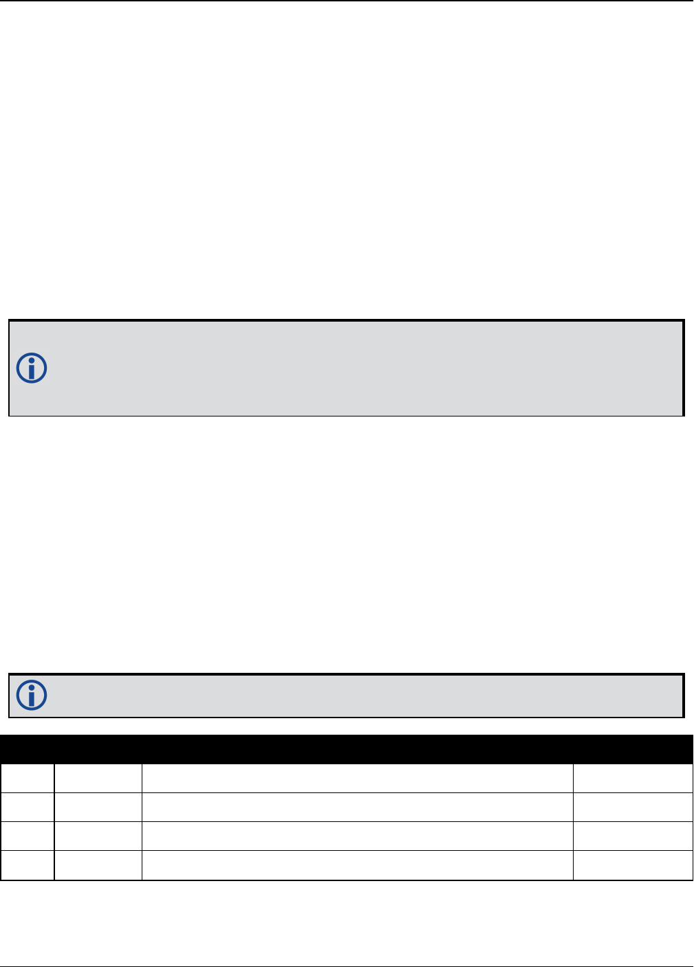
Chapter 3 Logs
OEM7 Commands and Logs Reference Manual v7 515
3.49 GPGLL
Geographic position
Platform: OEM719, OEM729, OEM7500, OEM7600, OEM7700, OEM7720, PwrPak7,
SPAN CPT7
This log contains latitude and longitude of present vessel position, time of position fix and
status.
Table 98: Position Precision of NMEA Logs on the next page compares the position precision of
selected NMEA logs.
The GPGLL log outputs these messages without waiting for a valid almanac. Instead, it uses a
UTC time, calculated with default parameters. In this case, the UTC time status (see the TIME
log on page837) is set to WARNING since it may not be one hundred percent accurate. When a
valid almanac is available, the receiver uses the real parameters. Then the UTC time status is
set to VALID.
If the NMEATALKER command (see page 246) is set to AUTO, the talker (the first 2
characters after the $sign in the log header) is set to GP (GPS satellites only), GL
(GLONASS satellites only) or GN (satellites from both systems) or GA (Galileo satellites
only).
Message ID: 219
Log Type: Synch
Recommended Input:
log gpgll ontime 1
Example 1 (GPS only):
$GPGLL,5107.0013414,N,11402.3279144,W,205412.00,A,A*73
Example 2 (Combined GPS and GLONASS):
$GNGLL,5107.0014143,N,11402.3278489,W,205122.00,A,A*6E
See the Note in the GPGGA log (see page 510) that applies to all NMEA logs.
Field Structure Description Example
1 $GPGLL Log header. See Messages on page25 for more information. $GPGLL
2 lat Latitude (DDmm.mm) 5106.7198674
3 lat dir Latitude direction (N = North, S = South) N
4 lon Longitude (DDDmm.mm) 11402.3587526

Chapter 3 Logs
OEM7 Commands and Logs Reference Manual v7 516
Field Structure Description Example
5 lon dir Longitude direction (E = East, W = West) W
6 utc UTC time status of position (hours/minutes/seconds/decimal
seconds) 220152.50
7data
status Data status: A = Data valid, V = Data invalid A
8 mode ind Positioning system mode indicator, see Table 99: NMEA
Positioning System Mode Indicator on page529 A
9 *xx Check sum *1B
10 [CR][LF] Sentence terminator [CR][LF]
NMEA Log Latitude
(# of decimal places)
Longitude
(# of decimal places)
Altitude
(# of decimal places)
GPGGA 4 4 2
GPGGALONG 7 7 3
GPGLL 7 7 N/A
GPRMC 7 7 N/A
Table 98: Position Precision of NMEA Logs

Chapter 3 Logs
OEM7 Commands and Logs Reference Manual v7 517
3.50 GPGRS
GPS range residuals for each satellite
Platform: OEM719, OEM729, OEM7500, OEM7600, OEM7700, OEM7720, PwrPak7,
SPAN CPT7
Range residuals can be computed in two ways, and this log reports those residuals. Under mode
0, residuals output in this log are used to update the position solution output in the GPGGA mes-
sage. Under mode 1, the residuals are recomputed after the position solution in the GPGGA mes-
sage is computed. The receiver computes range residuals in mode 1. An integrity process using
GPGRS would also require GPGGA (for position fix data), GPGSA (for DOP figures) and GPGSV
(for PRN numbers) for comparative purposes.
The GPGRS log outputs these messages without waiting for a valid almanac. Instead, it uses a
UTC time, calculated with default parameters. In this case, the UTC time status (see the TIME
log on page837) is set to WARNING since it may not be one hundred percent accurate. When a
valid almanac is available, the receiver uses the real parameters. Then the UTC time status is
set to VALID.
1. If the range residual exceeds ± 99.9, then the decimal part is dropped. Maximum
value for this field is ± 999. The sign of the range residual is determined by the order
of parameters used in the calculation as follows:
range residual = calculated range - measured range
2. If the NMEATALKER command (see page 246) is set to AUTO, the talker (the first 2
characters after the $sign in the log header) is set to GP (GPS satellites only), GL
(GLONASS satellites only) or GN (satellites from both systems) or GA (Galileo satel-
lites only).
Message ID: 220
Log Type: Synch
Recommended Input:
log gpgrs ontime 1
Example 1 (GPS only):
$GPGRS,142406.00,1,-1.1,-0.1,1.7,1.2,-2.0,-0.5,1.2,-1.2,-0.1,,,*67
Example 2 (Combined GPS and GLONASS):
$GNGRS,143209.00,1,-0.2,-0.5,2.2,1.3,-2.0,-1.3,1.3,-0.4,-1.2,-0.2,,*72
$GNGRS,143209.00,1,1.3,-6.7,,,,,,,,,,*73
See the Note in the GPGGA log (see page 510) that applies to all NMEA logs.

Chapter 3 Logs
OEM7 Commands and Logs Reference Manual v7 518
Field Structure Description Symbol Example
1 $GPGRS Log header. See Messages on page25 for more
information. $GPGRS
2 utc UTC time status of position
(hours/minutes/seconds/decimal seconds) hhmmss.ss 192911.0
3 mode
Mode 0= residuals were used to calculate the
position given in the matching GGA line (apriori)
(not used by OEM7 receivers)
Mode 1= residuals were recomputed after the
GGA position was computed (preferred mode)
x 1
4 -
15 res
Range residuals for satellites used in the
navigation solution. Order matches order of PRN
numbers in GPGSA
x.x,x.x,.....
-13.8,-
1.9,11.4,-
33.6,0.9,
6.9,-
12.6,0.3,0.6,
-22.3
16 *xx Check sum *hh *65
17 [CR][LF] Sentence terminator [CR][LF]
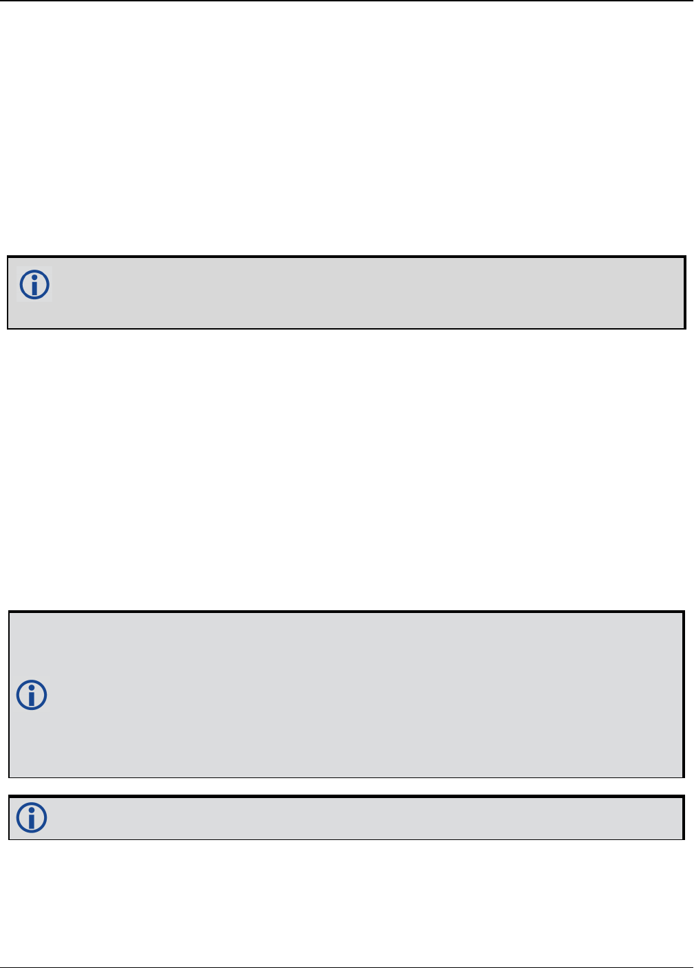
Chapter 3 Logs
OEM7 Commands and Logs Reference Manual v7 519
3.51 GPGSA
GPS DOP and active satellites
Platform: OEM719, OEM729, OEM7500, OEM7600, OEM7700, OEM7720, PwrPak7,
SPAN CPT7
This log contains GNSS receiver operating mode, satellites used for navigation and DOP values.
The GPGSA log outputs these messages without waiting for a valid almanac. Instead, it uses a
UTC time, calculated with default parameters. In this case, the UTC time status (see the TIME
log on page837) is set to WARNING since it may not be one hundred percent accurate. When a
valid almanac is available, the receiver uses the real parameters. Then the UTC time status is
set to VALID.
If the NMEATALKER command (see page 246) is set to AUTO, the talker (the first 2 char-
acters after the $sign in the log header) is set to GP (GPS satellites only), GL (GLONASS
satellites only), or GN (satellites from both systems) or GA (Galileo satellites only).
Message ID: 221
Log Type: Synch
Recommended Input:
log gpgsa ontime 1
Example 1 (GPS only):
$GPGSA,M,3,17,02,30,04,05,10,09,06,31,12,,,1.2,0.8,0.9*35
Example 2 (Combined GPS and GLONASS):
$GNGSA,M,3,17,02,30,04,05,10,09,06,31,12,,,1.2,0.8,0.9*2B
$GNGSA,M,3,87,70,,,,,,,,,,,1.2,0.8,0.9*2A
The DOPs provide a simple characterization of the user satellite geometry. DOP is
related to the volume formed by the intersection points of the user satellite vectors, with
the unit sphere centered on the user. Larger volumes give smaller DOPs. Lower DOP val-
ues generally represent better position accuracy. The role of DOP in GNSS positioning is
often misunderstood. A lower DOP value does not automatically mean a low position
error. The quality of a GNSS derived position estimate depends upon both the meas-
urement geometry as represented by DOP values and range errors caused by signal
strength, ionospheric effects, multipath and so on.
See the Note in the GPGGA log (see page 510) that applies to all NMEA logs.

Chapter 3 Logs
OEM7 Commands and Logs Reference Manual v7 520
Field Structure Description Symbol Example
1 $GPGSA Log header. See Messages on page25 for more
information. $GPGSA
2 mode MA A = Automatic 2D/3D
M = Manual, forced to operate in 2D or 3D M M
3 mode 123 Mode: 1 = Fix not available; 2 = 2D; 3 = 3D x 3
4 -
15 prn
PRN numbers of satellites used in solution (null for
unused fields), total of 12 fields
GPS = 1 to 32
SBAS = 33 to 64 (add 87 for PRN number)
GLO = 65 to 96 1
xx,xx,.....
18,03,13,
25,16,
24,12,
20,,,,
16 pdop Position dilution of precision x.x 1.5
17 hdop Horizontal dilution of precision x.x 0.9
18 vdop Vertical dilution of precision x.x 1.2
19 *xx Check sum *hh *3F
20 [CR][LF] Sentence terminator [CR][LF]
1The NMEA GLONASS PRN numbers are 64 plus the GLONASS slot number. Current slot numbers are 1 to 24
which give the range 65 to 88. PRN numbers 89 to 96 are available if slot numbers above 24 are allocated to on-
orbit spares.

Chapter 3 Logs
OEM7 Commands and Logs Reference Manual v7 521
3.52 GPGST
Pseudorange measurement noise statistics
Platform: OEM719, OEM729, OEM7500, OEM7600, OEM7700, OEM7720, PwrPak7,
SPAN CPT7
This log contains pseudorange measurement noise statistics are translated in the position
domain in order to give statistical measures of the quality of the position solution.
This log reflects the accuracy of the solution type used in the BESTPOS log (see page 428) and
GPGGA log (see page 510), except for the RMS field. The RMS field, since it specifically relates
to pseudorange inputs, does not represent carrier-phase based positions. Instead it reflects the
accuracy of the pseudorange position which is given in the PSRPOS log (see page 648).
The GPGST log outputs these messages without waiting for a valid almanac. Instead, it uses a
UTC time, calculated with default parameters. In this case, the UTC time status (see the TIME
log on page837) is set to WARNING since it may not be one hundred percent accurate. When a
valid almanac is available, the receiver uses the real parameters. Then the UTC time status is
set to VALID.
If the NMEATALKER command (see page 246) is set to AUTO, the talker (the first 2
characters after the $sign in the log header) is set to GP (GPS satellites only), GL
(GLONASS satellites only) or GN (satellites from both systems) or GA (Galileo satellites
only).
Message ID: 222
Log Type: Synch
Recommended Input:
log gpgst ontime 1
Example 1 (GPS only):
$GPGST,141451.00,1.18,0.00,0.00,0.0000,0.00,0.00,0.00*6B
Example 2 (Combined GPS and GLONASS):
$GNGST,143333.00,7.38,1.49,1.30,68.1409,1.47,1.33,2.07*4A

Chapter 3 Logs
OEM7 Commands and Logs Reference Manual v7 522
1. See the Note in the GPGGA log (see page 510) that applies to all NMEA logs.
2. Accuracy is based on statistics, reliability is measured in percent. When a receiver can
measure height to one metre, this is an accuracy. Usually this is a one sigma value
(one SD). A one sigma value for height has a reliability of 68%, that is, the error is
less than one metre 68% of the time. For a more realistic accuracy, double the one
sigma value (1 m) and the result is 95% reliability (error is less than 2 m 95% of the
time). Generally, GNSS heights are 1.5 times poorer than horizontal positions.
As examples of statistics, the GPGST message and NovAtel performance specifications
use Root Mean Square (RMS). Specifications may be quoted in CEP:
lRMS - root mean square (a probability level of 68%)
lCEP - circular error probable (the radius of a circle such that 50% of a set of
events occur inside the boundary)
Field Structure Description Symbol Example
1 $GPGST Log header. See Messages on page25 for more
information. $GPGST
2 utc UTC time status of position
(hours/minutes/seconds/ decimal seconds) hhmmss.ss 173653.00
3 rms
RMS value of the standard deviation of the range
inputs to the navigation process. Range inputs
include pseudoranges and DGPS corrections
x.x 2.73
4 smjr std Standard deviation of semi-major axis of error
ellipse (m) x.x 2.55
5 smnr std Standard deviation of semi-minor axis of error
ellipse (m) x.x 1.88
6 orient Orientation of semi-major axis of error ellipse
(degrees from true north) x.x 15.2525
7 lat std Standard deviation of latitude error (m) x.x 2.51
8 lon std Standard deviation of longitude error (m) x.x 1.94
9 alt std Standard deviation of altitude error (m) x.x 4.30
10 *xx Check sum *hh *6E
11 [CR][LF] Sentence terminator [CR][LF]

Chapter 3 Logs
OEM7 Commands and Logs Reference Manual v7 523
3.53 GPGSV
GPS satellites in view
Platform: OEM719, OEM729, OEM7500, OEM7600, OEM7700, OEM7720, PwrPak7,
SPAN CPT7
This log contains the number of GPS SVs in view, PRN numbers, elevation, azimuth and SNR
value. Four satellites maximum per message. When required, additional satellite data sent in 2
or more messages (a maximum of 9). The total number of messages being transmitted and the
current message being transmitted are indicated in the first two fields.
The GPGSV log outputs these messages without waiting for a valid almanac. Instead, it uses a
UTC time, calculated with default parameters. In this case, the UTC time status (see the TIME
log on page837) is set to WARNING since it may not be one hundred percent accurate. When a
valid almanac is available, the receiver uses the real parameters. Then the UTC time status is
set to VALID.
1. Satellite information may require the transmission of multiple messages. The first
field specifies the total number of messages, minimum value 1. The second field iden-
tifies the order of this message (message number), minimum value 1.
2. If the NMEATALKER command (see page 246) is set to AUTO, the talker (the first 2
characters after the $sign in the log header) is set to GP (GPS satellites only) or GL
(GLONASS satellites only) or GN (satellites from both systems) or GA (Galileo satel-
lites only). Each system is output in a separate message.
3. The ID setting in the NMEATALKER command (see page 246) controls the satellites
reported in this log. If the NMEATALKER ID is set to GP, only GPS satellites are repor-
ted in this log. If the NMEATALKER ID is set to AUTO, all satellites in view are reported.
4. A variable number of 'PRN-Elevation-Azimuth-SNR' sets are allowed up to a maximum
of four sets per message. Null fields are not required for unused sets when less than
four sets are transmitted.
Message ID: 223
Log Type: Synch
Recommended Input:
log gpgsv ontime 1
Example (Including GPS and GLONASS sentences):
$GPGSV,3,1,11,18,87,050,48,22,56,250,49,21,55,122,49,03,40,284,47*78
$GPGSV,3,2,11,19,25,314,42,26,24,044,42,24,16,118,43,29,15,039,42*7E
$GPGSV,3,3,11,09,15,107,44,14,11,196,41,07,03,173,*4D
$GLGSV,2,1,06,65,64,037,41,66,53,269,43,88,39,200,44,74,25,051,*64
$GLGSV,2,2,06,72,16,063,35,67,01,253,*66

Chapter 3 Logs
OEM7 Commands and Logs Reference Manual v7 524
The GPGSV log can be used to determine which GPS satellites are currently available to
the receiver. Comparing the information from this log to that in the GPGSA log shows if
the receiver is tracking all available satellites.
See also the Note in the GPGGA log (see page 510) that applies to all NMEA logs.
Field Structure Description Symbol Example
1 $GPGSV Log header. See Messages on page25 for more
information. $GPGSV
2 # msgs Total number of messages (1-9) x 3
3 msg # Message number (1-9) x 1
4 # sats
Total number of satellites in view. May be different
than the number of satellites in use (see also the
GPGGA log on page510)
xx 09
5 prn
Satellite PRN number
GPS = 1 to 32
SBAS = 33 to 64 (add 87 for PRN#s)
GLO = 65 to 96 1
xx 03
6 elev Elevation, degrees, 90 maximum xx 51
7 azimuth Azimuth, degrees True, 000 to 359 xxx 140
8 SNR SNR (C/No) 00-99 dB, null when not tracking xx 42
...
...
...
...
...
...
Next satellite PRN number, elev, azimuth, SNR,
...
Last satellite PRN number, elev, azimuth, SNR,
variable *xx Check sum *hh *72
variable [CR][LF] Sentence terminator [CR][LF]
1The NMEA GLONASS PRN numbers are 64 plus the GLONASS slot number. Current slot numbers are 1 to 24
which give the range 65 to 88. PRN numbers 89 to 96 are available if slot numbers above 24 are allocated to on-
orbit spares.
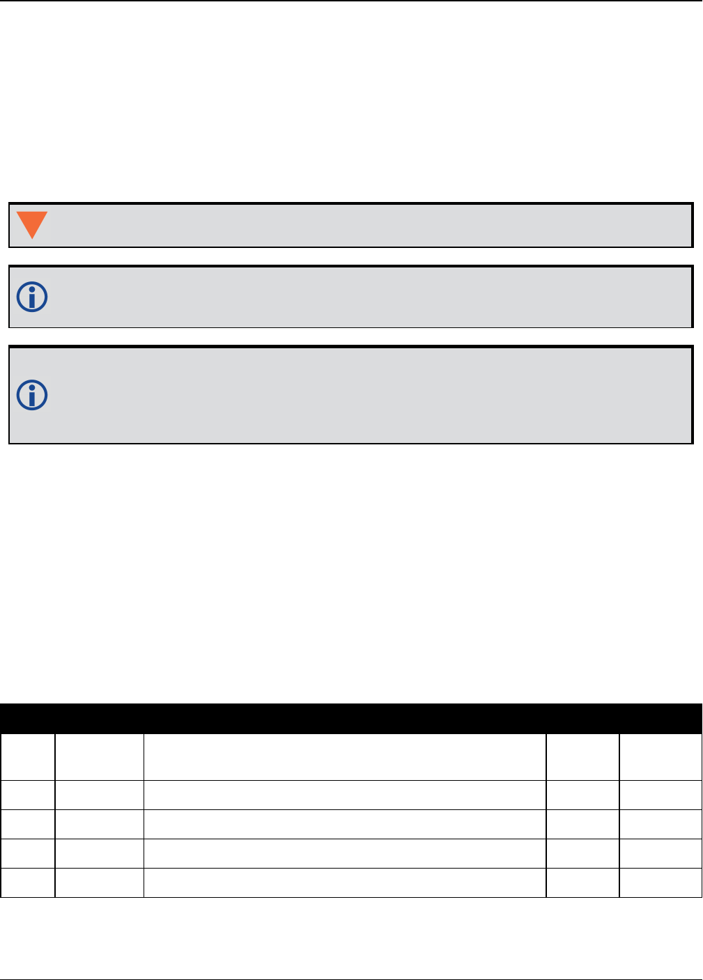
Chapter 3 Logs
OEM7 Commands and Logs Reference Manual v7 525
3.54 GPHDT
NMEA heading log
Platform: OEM719, OEM729, OEM7500, OEM7600, OEM7700, OEM7720, PwrPak7,
SPAN CPT7
This log contains actual vessel heading in degrees True (from True North). See also a descrip-
tion of heading in the HEADING2 log on page539. You can also set a standard deviation
threshold for this log, see the HDTOUTTHRESHOLD command on page189.
You must have an ALIGN capable receiver to use this log.
The GPHDT log can only be logged using the ONCHANGED trigger. Other triggers, such
as ONTIME are not accepted.
If the NMEATALKER command (see page 246) is set to AUTO, the talker (the first 2
characters after the $sign in the log header) is set to GP (GPS satellites only), GL
(GLONASS satellites only) or GN (satellites from both systems) or GA (Galileo satellites
only).
Message ID: 1045
Log Type: Asynch
Recommended Input:
log gphdt onchanged
Example 1 (GPS only):
$GPHDT,75.5664,T*36
Example 2 (Combined GPS and GLONASS):
$GNHDT,75.5554,T*45
Field Structure Description Symbol Example
1 $GPHDT Log header. See Messages on page25 for more
information. $GPHDT
2 heading Heading in degrees x.x 75.5554
3 True Degrees True T T
4 *xx Check sum *hh *36
5 [CR][LF] Sentence terminator [CR][LF]
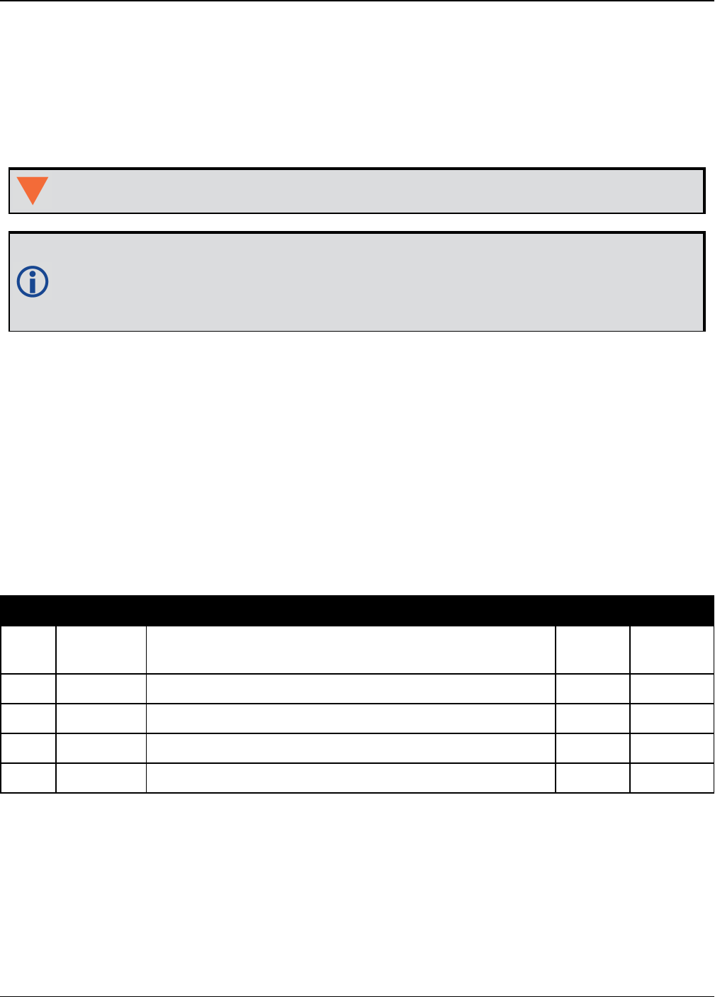
Chapter 3 Logs
OEM7 Commands and Logs Reference Manual v7 526
3.55 GPHDTDUALANTENNA
Synchronous NMEA heading log
Platform: OEM7720, PwrPak7D, PwrPak7D-E1, SPAN CPT7
This log contains actual vessel heading in degrees True (from True North). It provide the same
information as the GPHDT log (see page 525), but with synchronous output.
You must have an ALIGN capable, dual antenna receiver to use this log.
If the NMEATALKER command (see page 246) is set to AUTO, the talker (the first 2
characters after the $sign in the log header) is set to GP (GPS satellites only), GL
(GLONASS satellites only) or GN (satellites from both systems) or GA (Galileo satellites
only).
Message ID: 2045
Log Type: Synch
Recommended Input:
log gphdtdualantenna ontime 1
Example 1 (GPS only):
$GPHDT,75.5664,T*36
Example 2 (Combined GPS and GLONASS):
$GNHDT,75.5554,T*45
Field Structure Description Symbol Example
1 $GPHDT Log header. See Messages on page25 for more
information. $GPHDT
2 heading Heading in degrees x.x 75.5554
3 True Degrees True T T
4 *xx Check sum *hh *36
5 [CR][LF] Sentence terminator [CR][LF]
Chapter 3 Logs
OEM7 Commands and Logs Reference Manual v7 527
3.56 GPRMB
Navigation information
Platform: OEM719, OEM729, OEM7500, OEM7600, OEM7700, OEM7720, PwrPak7,
SPAN CPT7
This log contains navigation data from present position to a destination waypoint. The des-
tination is set active by the receiver SETNAV command (see page 346).
The GPRMB log outputs these messages without waiting for a valid almanac. Instead, it uses a
UTC time, calculated with default parameters. In this case, the UTC time status (see the TIME
log on page837) is set to WARNING since it may not be one hundred percent accurate. When a
valid almanac is available, the receiver uses the real parameters. Then the UTC time status is
set to VALID.
Message ID: 224
Log Type: Synch
Recommended Input:
log gprmb ontime 1
Example 1 (GPS only):
$GPRMB,A,5.14,L,FROM,TO,5109.7578000,N,11409.0960000,W,5.1,303.0,-0.0,V,A*6F
Example 2 (Combined GPS and GLONASS):
$GNRMB,A,5.14,L,FROM,TO,5109.7578000,N,11409.0960000,W,5.1,303.0,-0.0,V,A*71
If the NMEATALKER command (see page 246) is set to AUTO, the talker (the first 2
characters after the $sign in the log header) is set to GP (GPS satellites only), GL
(GLONASS satellites only) or GN (satellites from both systems) or GA (Galileo satellites
only).
See the Note in the GPGGA log (see page 510) that applies to all NMEA logs.
Field Structure Field Description Symbol Example
1 $GPRMB Log header. See Messages on page25 for more
information. $GPRMB
2data
status
Data status: A = data valid; V = navigation
receiver warning A A

Chapter 3 Logs
OEM7 Commands and Logs Reference Manual v7 528
Field Structure Field Description Symbol Example
3 xtrack
Cross track error
Represents the track error from the intended
course
If the cross track error exceeds 9.99
NM, displays 9.99.
One nautical mile (NM) = 1,852
metres.
x.x 5.14
4 dir
Direction to steer to get back on track (L/R)
Direction to steer is based on the sign of the
crosstrack error, that is,
L = xtrack error (+)
R = xtrack error (-)
a L
5 origin ID Origin waypoint ID 1c--c FROM
6 dest ID Destination waypoint ID 1c--c TO
7 dest lat Destination waypoint latitude (DDmm.mm) 1llll.ll 5109.7578000
8 lat dir Latitude direction (N = North, S = South) 1a N
9 dest lon Destination waypoint longitude (DDDmm.mm) 1yyyyy.yy 11409.0960000
10 lon dir Longitude direction (E = East, W = West) 1a W
11 range
Range to destination, nautical miles
If the range to destination exceeds
999.9 NM, displays 999.9.
x.x 5.1
12 bearing Bearing to destination, degrees True x.x 303.0
13 vel Destination closing velocity, knots x.x -0.0
14 arr status
Arrival status:
A = perpendicular passed
V = destination not reached or passed
A V
1Fields 5, 6, 7, 8, 9, and 10 are tagged from the SETNAV command (see page 346).

Chapter 3 Logs
OEM7 Commands and Logs Reference Manual v7 529
Field Structure Field Description Symbol Example
15 mode ind Positioning system mode indicator, see Table 99:
NMEA Positioning System Mode Indicator below a A
16 *xx Check sum *hh *6F
17 [CR][LF] Sentence terminator [CR][LF]
Mode Indicator
A Autonomous
D Differential
E Estimated (dead reckoning) mode
M Manual input
N Data not valid
Table 99: NMEA Positioning System
Mode Indicator
Chapter 3 Logs
OEM7 Commands and Logs Reference Manual v7 530
3.57 GPRMC
GPS specific information
Platform: OEM719, OEM729, OEM7500, OEM7600, OEM7700, OEM7720, PwrPak7,
SPAN CPT7
This log contains time, date, position, track made good and speed data provided by the GPS nav-
igation receiver. RMC and RMB are the recommended minimum navigation data to be provided
by a GNSS receiver.
A comparison of the position precision between this log and other selected NMEA logs can be
seen in Table 98: Position Precision of NMEA Logs on page516.
The GPRMC log outputs these messages without waiting for a valid almanac. Instead, it uses a
UTC time, calculated with default parameters. In this case, the UTC time status (see the TIME
log on page837) is set to WARNING since it may not be one hundred percent accurate. When a
valid almanac is available, the receiver uses the real parameters. Then the UTC time status is
set to VALID.
If the NMEATALKER command (see page 246) is set to AUTO, the talker (the first 2
characters after the $sign in the log header) is set to GP (GPS satellites only), GL
(GLONASS satellites only) or GN (satellites from both systems) or GA (Galileo satellites
only).
Message ID: 225
Log Type: Synch
Recommended Input:
log gprmc ontime 1
Example 1 (GPS):
$GPRMC,144326.00,A,5107.0017737,N,11402.3291611,W,0.080,323.3,210307,0.0,E,A*20
Example 2 (Combined GPS and GLONASS):
$GNRMC,143909.00,A,5107.0020216,N,11402.3294835,W,0.036,348.3,210307,0.0,E,A*31
See the Note in the GPGGA log (see page 510) that applies to all NMEA logs.
Field Structure Field Description Symbol Example
1 $GPRMC Log header. See Messages on page25 for more
information. $GPRMC
2 utc UTC of position hhmmss.ss 144326.00

Chapter 3 Logs
OEM7 Commands and Logs Reference Manual v7 531
Field Structure Field Description Symbol Example
3 pos status Position status (A = data valid, V = data
invalid) A A
4 lat Latitude (DDmm.mm) llll.ll 5107.0017737
5 lat dir Latitude direction: (N = North, S = South) a N
6 lon Longitude (DDDmm.mm) yyyyy.yy 11402.3291611
7 lon dir Longitude direction: (E = East, W = West) a W
8 speed Kn Speed over ground, knots x.x 0.080
9 track true Track made good, degrees True x.x 323.3
10 date Date: dd/mm/yy xxxxxx 210307
11 mag var
Magnetic variation, degrees
Note that this field is the actual magnetic
variation and will always be positive. The
direction of the magnetic variation is always
positive.
x.x 0.0
12 var dir
Magnetic variation direction E/W
Easterly variation (E) subtracts from True
course.
Westerly variation (W) adds to True course.
a E
13 mode ind
Positioning system mode indicator, see Table
99: NMEA Positioning System Mode Indicator
on page529
a A
14 *xx Check sum *hh *20
15 [CR][LF] Sentence terminator [CR][LF]

Chapter 3 Logs
OEM7 Commands and Logs Reference Manual v7 532
3.58 GPSEPHEM
Decoded GPS ephemerides
Platform: OEM719, OEM729, OEM7500, OEM7600, OEM7700, OEM7720, PwrPak7,
SPAN CPT7
This log contains a single set of GPS ephemeris parameters.
Message ID: 7
Log Type: Asynch
Recommended Input:
log gpsephema onchanged
ASCII Example:
#GPSEPHEMA,COM1,12,59.0,SATTIME,1337,397560.000,02000000,9145,1984;3,397560.0,0
,99,99,1337,1337,403184.0,2.656004220e+07,4.971635660e-09,-
2.752651501e+00,7.1111434372e-03,6.0071892571e-01,2.428889275e-06,1.024827361e-
05,1.64250000e+02,4.81562500e+01,1.117587090e-08,-7.078051567e-
08,9.2668266314e-01,-1.385772009e-10,-2.098534041e+00,-8.08319384e-
09,99,403184.0,-4.190951586e-09,2.88095e-05,3.06954e-
12,0.00000,TRUE,1.458614684e-04,4.00000000e+00*0f875b12
#GPSEPHEMA,COM1,11,59.0,SATTIME,1337,397560.000,02000000,9145,1984;25,397560.0,
0,184,184,1337,1337,403200.0,2.656128681e+07,4.897346851e-
09,1.905797220e+00,1.1981436634e-02,-1.440195331e+00,-1.084059477e-
06,6.748363376e-06,2.37812500e+02,-1.74687500e+01,1.825392246e-07,-
1.210719347e-07,9.5008501632e-01,2.171519024e-10,2.086083072e+00,-8.06140722e-
09,184,403200.0,-7.450580597e-09,1.01652e-04,9.09495e-
13,0.00000,TRUE,1.458511425e-04,4.00000000e+00*18080b24
...
#GPSEPHEMA,COM1,0,59.0,SATTIME,1337,397560.000,02000000,9145,1984;1,397560.0,0,
224,224,1337,1337,403200.0,2.656022490e+07,3.881233098e-
09,2.938005195e+00,5.8911956148e-03,-1.716723741e+00,-2.723187208e-
06,9.417533875e-06,2.08687500e+02,-5.25625000e+01,9.126961231e-08,-
7.636845112e-08,9.8482911735e-01,1.325055194e-10,1.162012787e+00,-7.64138972e-
09,480,403200.0,-3.259629011e-09,5.06872e-06,2.04636e-
12,0.00000,TRUE,1.458588731e-04,4.00000000e+00*97058299
The GPSEPHEM log can be used to monitor changes in the orbits of GPS satellites.
To obtain copies of ICD-GPS-200, refer to the GPS website (www.gps.gov) .

Chapter 3 Logs
OEM7 Commands and Logs Reference Manual v7 533
Field Field
type Description Format Binary
Bytes
Binary
Offset
1GPSEPHEM
header
Log header. See Messages on page25 for more
information. H 0
2 PRN Satellite PRN number Ulong 4 H
3 tow Time stamp of subframe 1 (seconds) Double 8 H+4
4 health Health status - a 6-bit health code as defined in
ICD-GPS-200 Ulong 4 H+12
5 IODE1 Issue of ephemeris data 1 Ulong 4 H+16
6 IODE2 Issue of ephemeris data 2 Ulong 4 H+20
7 week toe week number (computed from Z count
week) Ulong 4 H+24
8 z week
Z count week number. This is the week number
from subframe 1 of the ephemeris. The ‘toe
week’ (field #7) is derived from this to account
for rollover
Ulong 4 H+28
9 toe Reference time for ephemeris (seconds) Double 8 H+32
10 A Semi-major axis (metres) Double 8 H+40
11 ΔN Mean motion difference (radians/second) Double 8 H+48
12 M0Mean anomaly of reference time (radians) Double 8 H+56
13 ecc
Eccentricity, dimensionless
- quantity defined for a conic section where e=
0 is a circle, e = 1 is a parabola, 0<e<1 is an
ellipse and e>1 is a hyperbola
Double 8 H+64
14 ω
Argument of perigee (radians)
- measurement along the orbital path from the
ascending node to the point where the SV is
closest to the Earth, in the direction of the SV's
motion
Double 8 H+72
15 cuc Argument of latitude (amplitude of cosine,
radians) Double 8 H+80
16 cus Argument of latitude (amplitude of sine,
radians) Double 8 H+88
17 crc Orbit radius (amplitude of cosine, metres) Double 8 H+96
18 crs Orbit radius (amplitude of sine, metres) Double 8 H+104

Chapter 3 Logs
OEM7 Commands and Logs Reference Manual v7 534
Field Field
type Description Format Binary
Bytes
Binary
Offset
19 cic Inclination (amplitude of cosine, radians) Double 8 H+112
20 cis Inclination (amplitude of sine, radians) Double 8 H+120
21 I0Inclination angle at reference time, radians Double 8 H+128
22 I0Rate of inclination angle, radians/second Double 8 H+136
23 ωoRight ascension, radians Double 8 H+144
24 ώ Rate of right ascension, radians/second Double 8 H+152
25 iodc Issue of data clock Ulong 4 H+160
26 toc SV clock correction term, seconds Double 8 H+164
27 tgd Estimated group delay difference, seconds Double 8 H+172
28 af0 Clock aging parameter (seconds) Double 8 H+180
29 af1 Clock aging parameter, (seconds/second) Double 8 H+188
30 af2 Clock aging parameter,
(seconds/second/second) Double 8 H+196
31 AS
Anti-spoofing on:
0 = FALSE
1 = TRUE
Bool 4 H+204
32 N
Corrected mean motion (radians/second)
This field is computed by the
receiver.
Double 8 H+208
33 URA
User Range Accuracy variance (metres2)
The ICD specifies that the URA index
transmitted in the ephemerides can be
converted to a nominal standard deviation value
using an algorithm listed there. We publish the
square of the nominal value (variance). The
correspondence between the original URA index
and the value output is shown in Table 100:
URA Variance on the next page
Double 8 H+216
34 xxxx 32-bit CRC (ASCII and Binary only) Ulong 4 H+224
35 [CR][LF] Sentence terminator (ASCII only) - - -

Chapter 3 Logs
OEM7 Commands and Logs Reference Manual v7 535
Index Value (m) A: Standard Deviations (m) Variance: A2(m2)
0 2.0 4
1 2.8 7.84
2 4.0 16
3 5.7 32.49
4 8 64
5 11.3 127.69
6 16.0 256
7 32.0 1024
8 64.0 4096
9 128.0 16384
10 256.0 65536
11 512.0 262144
12 1024.0 1048576
13 2048.0 4194304
14 4096.0 16777216
15 8192.0 67108864
Table 100: URA Variance
Chapter 3 Logs
OEM7 Commands and Logs Reference Manual v7 536
3.59 GPVTG
Track made good and ground speed
Platform: OEM719, OEM729, OEM7500, OEM7600, OEM7700, OEM7720, PwrPak7,
SPAN CPT7
This log contains the track made good and speed relative to the ground.
The GPVTG log outputs these messages without waiting for a valid almanac. Instead, it uses a
UTC time, calculated with default parameters. In this case, the UTC time status (see the TIME
log on page837) is set to WARNING since it may not be one hundred percent accurate. When a
valid almanac is available, the receiver uses the real parameters. Then the UTC time status is
set to VALID.
Message ID: 226
Log Type: Synch
Recommended Input:
log gpvtg ontime 1
Example 1 (GPS only):
$GPVTG,172.516,T,155.295,M,0.049,N,0.090,K,D*2B
Example 2 (Combined GPS and GLONASS):
$GNVTG,134.395,T,134.395,M,0.019,N,0.035,K,A*33
If the NMEATALKER command (see page 246) is set to AUTO, the talker (the first 2
characters after the $sign in the log header) is set to GP (GPS satellites only), GL
(GLONASS satellites only) or GN (satellites from both systems).
See the Note in the GPGGA log (see page 510) that applies to all NMEA logs.
Field Structure Description Symbol Example
1 $GPVTG Log header. See Messages on page25 for more
information. $GPVTG
2 track true Track made good, degrees True x.x 24.168
3 T True track indicator T T
4 track mag
Track made good, degrees Magnetic;
Track mag = Track true + (MAGVAR correction)
See the MAGVAR command on page231
x.x 24.168

Chapter 3 Logs
OEM7 Commands and Logs Reference Manual v7 537
Field Structure Description Symbol Example
5 M Magnetic track indicator M M
6 speed Kn Speed over ground, knots x.x 0.4220347
7 N Nautical speed indicator (N = Knots) N N
8 speed Km Speed, kilometres/hour x.x 0.781608
9 K Speed indicator (K = km/hr) K K
10 mode ind Positioning system mode indicator, see Table 99:
NMEA Positioning System Mode Indicator on page529 a A
11 *xx Check sum *hh *7A
12 [CR][LF] Sentence terminator [CR][LF]
Chapter 3 Logs
OEM7 Commands and Logs Reference Manual v7 538
3.60 GPZDA
UTC time and date
Platform: OEM719, OEM729, OEM7500, OEM7600, OEM7700, OEM7720, PwrPak7,
SPAN CPT7
The GPSZDA log outputs the UTC date and time. If no valid almanac is stored in the receiver, a
default UTC offset is used to generate the time until a new almanac is downloaded. If the offset
is not up-to-date, this initial UTC time may be incorrect until the new almanac is present.
Message ID: 227
Log Type: Synch
Recommended Input:
log gpzda ontime 1
Example:
$GPZDA,143042.00,25,08,2005,,*6E
See the Note in the GPGGA log (see page 510) that applies to all NMEA logs.
Field Structure Description Symbol Example
1 $GPZDA Log header. See Messages on page25 for
more information. $GPZDA
2 utc UTC time status hhmmss.ss 220238.00
3 day Day, 01 to 31 xx 15
4 month Month, 01 to 12 xx 07
5 year Year xxxx 1992
6 null
Local zone description—not available
Local time zones are not sup-
ported by OEM7 family
receivers.
Fields 6 and 7 are always
null.
xx (empty when no
data is present)
7 null Local zone minutes description—not
available xx (empty when no
data is present)
8 *xx Check sum *hh *6F
9 [CR][LF] Sentence terminator [CR][LF]
Chapter 3 Logs
OEM7 Commands and Logs Reference Manual v7 539
3.61 HEADING2
Heading information with multiple rovers
Platform: OEM719, OEM729, OEM7500, OEM7600, OEM7700, OEM7720, PwrPak7,
SPAN CPT7
The heading is the angle from True North of the base to rover vector in a clockwise direction.
This log can be output at both Master and Rover ends.
An ALIGN capable receiver is required to use this log.
Asynchronous logs, such as HEADING2, should only be logged ONCHANGED or ONNEW
otherwise the most current data is not available or included in the output. An example of
this occurrence is in the ONTIME trigger. If this trigger is not logged ONNEW or
ONCHANGED, it may cause inaccurate time tags.
The HEADING2 log is dictated by the output frequency of the master receiver sending out
RTCAOBS2, RTCAOBS3 or NovAtelXObs messages. HEADING2 supports 20 Hz output
rate. Ensure sufficient radio bandwidth is available between the ALIGN Master and the
ALIGN Rover.
Message ID: 1335
Log Type: Asynch
Recommended Input:
log heading2a onnew
ASCII Example:
#HEADING2A,COM1,0,39.5,FINESTEERING,1622,422892.200,02040000,f9bf,6521;SOL_
COMPUTED,NARROW_INT,0.927607417,178.347869873,-
1.3037414550.0,0.261901051,0.391376048,"R222","AAAA",18,17,17,16,0,01,0,33*7be8
36f6
Field Field
type Description Binary
Format
Binary
Bytes
Binary
Offset
1HEADING2
header
Log header. See Messages on page25 for more
information. H 0
2 sol stat Solution status, see Table 73: Solution Status
on page431 Enum 4 H
3 pos type Position type, see Table 74: Position or Velocity
Type on page432 Enum 4 H+4

Chapter 3 Logs
OEM7 Commands and Logs Reference Manual v7 540
Field Field
type Description Binary
Format
Binary
Bytes
Binary
Offset
4 length
Baseline length in metres
For ALIGN Heading models with position access,
this field is -1.
For ALIGN Heading models without position
access, this field is only the decimal portion of
the baseline in metres.
For ALIGN Relative Positioning models receiving
corrections from a master with a fixed position,
this field is -1.
For ALIGN Relative Positioning models receiving
corrections from a master in moving baseline
mode, this field is the complete baseline length
in metres.
Float 4 H+8
5 heading Heading in degrees (0° to 359.999°) Float 4 H+12
6 pitch Pitch (±90 degrees) Float 4 H+16
7 Reserved Float 4 H+20
8hdg std
dev Heading standard deviation in degrees Float 4 H+24
9ptch std
dev Pitch standard deviation in degrees Float 4 H+28
10 rover stn
ID
Rover Receiver ID
Set using the SETROVERID command (see
page 348) on the Rover
e.g. setroverid RRRR
Char[4] 4 H+32
11 Master stn
ID
Master Receiver ID
Set using the DGPSTXID command (see page
122) on the Master
Default: AAAA
Char[4] 4 H+36
12 #SVs Number of satellites tracked Uchar 1 H+40
13 #solnSVs Number of satellites in solution Uchar 1 H+41
14 #obs Number of satellites above the elevation mask
angle Uchar 1 H+42
15 #multi Number of satellites above the mask angle with
L2 Uchar 1 H+43

Chapter 3 Logs
OEM7 Commands and Logs Reference Manual v7 541
Field Field
type Description Binary
Format
Binary
Bytes
Binary
Offset
16 sol source Solution source (see Table 101: Solution Source
below) Hex 1 H+44
17 ext sol
stat
Extended solution status (see Table 77:
Extended Solution Status on page435) Uchar 1 H+45
18
Galileo
and
BeiDou sig
mask
Galileo and BeiDou signals used mask (see
Table 76: Galileo and BeiDou Signal-Used Mask
on page435)
Hex 1 H+46
19
GPS and
GLONASS
sig mask
GPS and GLONASS signals used mask (see Table
75: GPS and GLONASS Signal-Used Mask on
page434)
Hex 1 H+47
20 xxxx 32-bit CRC (ASCII and Binary only) Hex 4 H+48
21 [CR][LF] Sentence terminator (ASCII only) - - -
Bit Mask Description
0-1 0x03 Reserved
2-3 0x0C
Source antenna
0 = Primary antenna
1 = Secondary antenna
4-7 0xF0 Reserved
Table 101: Solution Source

Chapter 3 Logs
OEM7 Commands and Logs Reference Manual v7 542
3.62 HEADINGRATE
Heading rate information
Platform: OEM719, OEM729, OEM7500, OEM7600, OEM7700, OEM7720, PwrPak7,
SPAN CPT7
This log provides rate of change for the heading parameters. The heading is the angle from True
North of the base to rover vector in a clockwise direction.
You must have an ALIGN capable receiver to use this log.
Message ID: 1698
Log Type: Asynch
Recommended Input:
log headingratea onchanged
ASCII Example:
#HEADINGRATEA,UNKNOWN,0,60.0,FINESTEERING,1873,411044.700,02040008,c53a,32768;S
OL_COMPUTED,NARROW_INT,0.025000000,0.000000000,-
0.308837891,0.575313330,0.000000000,1.264251590,1.663657904,0.0,"748M","725U",0
0,0,0,0*66f97b96
Field Field type Description Format Binary
Bytes
Binary
Offset
1HEADINGRATE
header
Log header. See Messages on page25 for
more information. H 0
2 sol stat Solution status, see Table 73: Solution
Status on page431 Enum 4 H
3 pos type Position type, see Table 74: Position or
Velocity Type on page432 Enum 4 H+4
4 latency
A measure of the latency in the velocity
time tag in seconds. It should be subtracted
from the time to give improved results.
Float 4 H+8
5 length rate
Rate of change of the baseline length in m/s.
For Z ALIGN rovers, this field outputs the
decimal portion of the baseline rate.
Float 4 H+12
6 heading rate Rate of change of the heading in degrees/s Float 4 H+16
7 pitch rate Rate of change of the pitch in degrees/s Float 4 H+20

Chapter 3 Logs
OEM7 Commands and Logs Reference Manual v7 543
Field Field type Description Format Binary
Bytes
Binary
Offset
8length rate std
dev Baseline rate standard deviation in m/s Float 4 H+24
9heading rate
std dev
Heading rate standard deviation in
degrees/s Float 4 H+28
10 pitch rate std
dev Pitch rate standard deviation in degrees/s Float 4 H+32
11 Reserved Float 4 H+36
12 rover stn ID
Rover Receiver ID
Set using the SETROVERID command (see
page 348) on the Rover receiver. For
example, setroverid RRRR.
Uchar 4 H+40
13 master stn ID
Master Receiver ID
Set using the DGPSTXID command (see
page 122) on the Master receiver. Default:
AAAA
Uchar 4 H+44
14 sol source Solution source (see Table 101: Solution
Source on page541) Hex 1 H+48
15 Reserved Uchar 1 H+49
16 Reserved Uchar 1 H+50
17 Reserved Uchar 1 H+51
18 xxxx 32-bit CRC (ASCII and Binary only) Hex 4 H+52
19 [CR][LF] Sentence terminator (ASCII only) - - -

Chapter 3 Logs
OEM7 Commands and Logs Reference Manual v7 544
3.63 HEADINGSATS
Satellite used in heading solution
Platform: OEM719, OEM729, OEM7500, OEM7600, OEM7700, OEM7720, PwrPak7,
SPAN CPT7
This log provides information on the satellites that are used in a heading solution.
The HEADINGSATS log can only be used from the ALIGN rover.
Message ID: 1316
Log Type: Asynch
Recommended Input:
log headingsatsa onnew
ASCII Example:
#HEADINGSATSA,COM1,0,26.0,FINESTEERING,1625,344654.600,02000008,f5b0,6569;17,GP
S,31,GOOD,00000003,GPS,23,GOOD,00000003,GPS,30,GOOD,00000003,GPS,16,GOOD,000000
03,GPS,20,GOOD,00000003,GPS,25,GOOD,00000003,GPS,4,GOOD,00000003,GPS,24,GOOD,00
000003,GPS,11,GOOD,00000003,GPS,32,GOOD,00000003,GPS,14,GOOD,00000003,GLONASS,2
0+2,GOOD,00000003,GLONASS,14-7,GOOD,00000001,GLONASS,2-
4,GOOD,00000003,GLONASS,13-2,GOOD,00000003,GLONASS,12-
1,GOOD,00000003,GLONASS,19+3,GOOD,00000001*15ec53a6
Field Field type Description Format Binary
Bytes
Binary
Offset
1 HEADINGSATS Log header. See Messages on page25 for
more information. H 0
2 #entries Number of records to follow Ulong 4 H
3 System Refer to Table 102: Satellite System on
the next page. Enum 4 H+4

Chapter 3 Logs
OEM7 Commands and Logs Reference Manual v7 545
Field Field type Description Format Binary
Bytes
Binary
Offset
4 Satellite ID
In binary logs, the satellite ID field is 4
bytes. The 2 lowest-order bytes,
interpreted as a USHORT, are the system
identifier: for instance, the PRN for GPS,
or the slot for GLONASS. The 2 highest-
order bytes are the frequency channel for
GLONASS, interpreted as a SHORT and
zero for all other systems.
In ASCII and abbreviated ASCII logs, the
satellite ID field is the system identifier.
If the system is GLONASS and the
frequency channel is not zero, then the
signed channel is appended to the system
identifier. For example, slot 13,
frequency channel -2 is output as 13-2
Ulong 4 H+8
5 Status see Table 79: Observation Statuses on
page438 Enum 4 H+12
6 Signal Mask
see
Table 80: BESTSATS GPS Signal Mask on
page439,
Table 81: BESTSATS GLONASS Signal
Mask on page440,
Table 82: BESTSATS Galileo Signal Mask
on page440,
Table 83: BESTSATS BeiDou Signal Mask
on page440
Hex 4 H+16
7 Next satellite offset = H + 4 + (#sat x 16)
8 xxxx 32-bit CRC (ASCII and Binary only) Hex 4 H+4+
(#satx16)
9 [CR][LF] Sentence Terminator (ASCII only) - - -
Binary Value ASCII Mode Name
0 GPS
1 GLONASS
2 SBAS
Table 102: Satellite System

Chapter 3 Logs
OEM7 Commands and Logs Reference Manual v7 546
Binary Value ASCII Mode Name
5 Galileo
6 BeiDou
7 QZSS
9 NAVIC

Chapter 3 Logs
OEM7 Commands and Logs Reference Manual v7 547
3.64 HWMONITOR
Monitor hardware levels
Platform: OEM719, OEM729, OEM7500, OEM7600, OEM7700, OEM7720, PwrPak7,
SPAN CPT7
This log allows the user to monitor temperature, antenna current and voltages.
Message ID: 963
Log Type: Polled
Recommended Input:
log hwmonitora ontime 10
ASCII Example:
#HWMONITORA,COM1,0,90.5,FINESTEERING,1928,153778.000,02000020,52db,32768;7,43.2
84492493,100,0.000000000,200,5.094994068,700,1.195970654,800,3.279609442,f00,1.
811965823,1100,44.017093658,1600*52beac4b
Field Field Type Description Format Binary
Bytes
Binary
Offset
1HWMONITOR
header
Log header. See Messages on
page25 for more information. H 0
2#
measurements
Number of measurements to
follow Ulong 4 H
3 reading
Temperature, antenna current or
voltage reading
Units:
lDegree Celsius for Tem-
perature
lAmps for Antenna Current
lVolts for Voltage
Float 4 H+4
4 status See Table 103: HWMONITOR
Status Table on the next page HexUlong 4 H+8
5... Next reading offset = H + 4 + (# measurements x 8)
6 xxxx 32-bit CRC (ASCII and Binary
only) Hex 4
H+4+
(#
measurements
x 8)
7 [CR][LF] Sentence Terminator (ASCII only) - - -

Chapter 3 Logs
OEM7 Commands and Logs Reference Manual v7 548
Bits Description Applicable
Platforms
0-7
Boundary Limit Status (Hex):
0x00 = Value falls within acceptable bounds
0x01 = Value is under the lower warning limit
0x02 = Value is under the lower error limit
0x03 = Value is over the upper warning limit
0x04 = Value is over the upper error limit
8-
15 Reading Type (Hex):
0x00 = Reserved
0x01 = Temperature
A temperature sensor is located on the receiver and provides
the approximate temperature of the PCB surface near critical
components (for example, CPU, TCXO) (degrees Celsius)
All
0x02 = Antenna Current
The amount of current being drawn by the active antenna
(mA)
OEM719, OEM729,
OEM7600, OEM7700,
OEM7720, PwrPak7,
SPAN CPT7
0x06 = Digital Core 3V3 Voltage
Internal regulator output voltage supplying a key component
on the receivers (Volts)
All except OEM7720
0x06 = 3.3V Supply Voltage (Volts) OEM7720
0x07 = Antenna Voltage
OEM719, OEM729,
OEM7600, OEM7700,
OEM7720, PwrPak7,
SPAN CPT7
0x08 = Digital 1V2 Core Voltage
Internal regulator output voltage supplying a key component
on the receiver (Volts)
All
0x0F = Regulated Supply Voltage
Internal regulator output voltage supplying a key component
on the receiver (Volts)
All except OEM7720
0x0F = Supply Voltage
Voltage applied to Pins 1 and 2 of the main connector OEM7720
Table 103: HWMONITOR Status Table

Chapter 3 Logs
OEM7 Commands and Logs Reference Manual v7 549
Bits Description Applicable
Platforms
0x11 = 1V8 All
0x16 = Secondary Temperature
A second temperature sensor is located on the receiver PCB
(degrees Celsius)
OEM719, OEM729,
OEM7600, OEM7700,
OEM7720, PwrPak7,
SPAN CPT7
0x17 = Peripheral Core Voltage
OEM719, OEM729,
OEM7600, OEM7700,
OEM7720, PwrPak7,
SPAN CPT7
0x18 = Secondary Antenna Current
OEM7720, PwrPak7D,
PwrPak7D-E1, SPAN
CPT7
0x19 = Secondary Antenna Voltage
OEM7720, PwrPak7D,
PwrPak7D-E1, SPAN
CPT7
Chapter 3 Logs
OEM7 Commands and Logs Reference Manual v7 550
3.65 IONUTC
Ionospheric and UTC data
Platform: OEM719, OEM729, OEM7500, OEM7600, OEM7700, OEM7720, PwrPak7,
SPAN CPT7
This log contains the Ionospheric Model parameters (ION) and the Universal Time Coordinated
parameters (UTC).
Message ID: 8
Log Type: Asynch
Recommended Input:
log ionutca onchanged
ASCII Example:
#IONUTCA,COM1,0,58.5,FINESTEERING,1337,397740.107,02000000,ec21,1984;1.21071934
7000122e-08,2.235174179077148e-08,-5.960464477539062e-08,-1.192092895507812e-
07,1.003520000000000e+05,1.146880000000000e+05,-6.553600000000000e+04,-
3.276800000000000e+05,1337,589824,-1.2107193470001221e-08,-3.907985047e-
14,1355,7,13,14,0*c1dfd456
The Receiver-Independent Exchange (RINEX1a) format is a broadly accepted, receiver
independent format for storing GPS data. It features a non-proprietary ASCII file format
that can be used to combine or process data generated by receivers made by different
manufacturers.
Use the NovAtel’s Convert utility to produce RINEX files from NovAtel receiver data files.
For the best results, the NovAtel receiver input data file should contain the logs as
specified in the NovAtel Firmware and Software chapter of the OEM7 Installation and
Operation User Manual including IONUTC.
Field Field
type Description Format Binary
Bytes
Binary
Offset
1IONUTC
header
Log header. See Messages on page25 for
more information. H 0
2 a0 Alpha parameter constant term Double 8 H
3 a1 Alpha parameter 1st order term Double 8 H+8
4 a2 Alpha parameter 2nd order term Double 8 H+16
5 a3 Alpha parameter 3rd order term Double 8 H+24
aRefer to the U.S. National Geodetic Survey website at: www.ngs.noaa.gov/CORS/data.shtml.

Chapter 3 Logs
OEM7 Commands and Logs Reference Manual v7 551
Field Field
type Description Format Binary
Bytes
Binary
Offset
6 b0 Beta parameter constant term Double 8 H+32
7 b1 Beta parameter 1st order term Double 8 H+40
8 b2 Beta parameter 2nd order term Double 8 H+48
9 b3 Beta parameter 3rd order term Double 8 H+56
10 utc wn UTC reference week number Ulong 4 H+64
11 tot Reference time of UTC parameters Ulong 4 H+68
12 A0 UTC constant term of polynomial Double 8 H+72
13 A1 UTC 1st order term of polynomial Double 8 H+80
14 wn lsf Future week number Ulong 4 H+88
15 dn Day number (the range is 1 to 7 where
Sunday = 1 and Saturday = 7) Ulong 4 H+92
16 deltat ls Delta time due to leap seconds Long 4 H+96
17 deltat lsf Future delta time due to leap seconds Long 4 H+100
18 Reserved 4 H+104
19 xxxx 32-bit CRC (ASCII and Binary only) Hex 4 H+108
20 [CR][LF] Sentence terminator (ASCII only) - - -

Chapter 3 Logs
OEM7 Commands and Logs Reference Manual v7 552
3.66 IPSTATS
IP statistics
Platform: OEM729, OEM7600, OEM7700, OEM7720, PwrPak7, SPAN CPT7
This log contains the current IP interface statistics.
Message ID: 1669
Log Type: Polled
Recommended Input:
log ipstatsa
ASCII Example:
#IPSTATSA,COM1,0,70.5,FINESTEERING,1749,328376.337,02000020,0d94,45068;1,CELL,0
,526,526*01c4847c
Field Field
Type Description Format Binary
Bytes
Binary
Offset
1IPSTATS
header
Log header. See Messages on page25
for more information. H 0
2 #Interface Number of records to follow. Ulong 4 H
3Physical
Interface
IP Interface Type
1 = ALL
2 = ETHA
Enum 4 H+4
4 Reserved Ulong 4 H+8
5Receive
Bytes Total number of bytes received Ulong 4 H+12
6Transmit
Bytes Total number of bytes transmitted Ulong 4 H+16
7 Next reading offset = H+4+(#Interface * 16)
8 xxxx 32-bit CRC (ASCII and Binary only) Hex 4
H+4+
(#Interface *
16)
9 [CR][LF] Sentence terminator (ASCII only) - - -

Chapter 3 Logs
OEM7 Commands and Logs Reference Manual v7 553
3.67 IPSTATUS
Current network configuration status
Platform: OEM729, OEM7600, OEM7700, OEM7720, PwrPak7, SPAN CPT7
This log provides the configuration of IP address, netmask, gateway and a list of DNS servers
currently in use.
Message ID: 1289
Log Type: Polled
Recommended Input:
log ipstatusa once
ASCII Example:
#IPSTATUSA,COM1,0,90.5,FINESTEERING,1609,500464.121,02000000,7fe2,6259;1,ETHA,"
10.4.44.131","255.255.255.0","10.4.44.1",1,"198.161.72.85"*ec22236c
Field Field
Type Description Format Binary
Bytes
Binary
Offset
1IPSTATUS
Header
Log header. See Messages on page25 for
more information. - H 0
2 #IPrec Number of records to follow Ulong 4 H
3 interface Name of the network interface
2 = ETHA Enum 4 H+4
4 IP address IP Address-decimal dot notation String
[16]
variable
1H+8
5 netmask Netmask-decimal dot notation String
[16]
variable
1H+24
6 gateway
Gateway-decimal dot notation
This is the default gateway that is
currently in use by the receiver.
String
[16]
variable
1H+40
7... Next reading offset = H+4+(#IPrec * 52)
8 #dnsserver Number of DNS Servers to follow Ulong 4
H+4+
(#IPrec x
52)
1In the binary case, each string field needs to be NULL terminated and additional bytes of padding added to
maintain 4-byte alignment, up to the maximum defined by the string size. The next defined field starts
immediately at the next 4-byte alignment following the NULL.

Chapter 3 Logs
OEM7 Commands and Logs Reference Manual v7 554
Field Field
Type Description Format Binary
Bytes
Binary
Offset
9server IP
address IP address-decimal dot notation String
[16]
variable
1
H+4+
(#IPrec x
52)+4
10... Next reading offset = H+4+(#IPrec * 52)+4+(#dnsserver * 16)
11 xxxx 32-bit CRC (ASCII and Binary only) Hex 4
H+4+
(#IPrec x
52)+4+
(#dnsserver
x 16)
12 [CR][LF] Sentence terminator (ASCII only) - - -

Chapter 3 Logs
OEM7 Commands and Logs Reference Manual v7 555
3.68 ITBANDPASSBANK
Allowable band pass filter configurations
Platform: OEM719, OEM729, OEM7500, OEM7600, OEM7700, OEM7720, PwrPak7,
SPAN CPT7
The ITBANDPASSBANK log provides information on the allowable configurations for each fre-
quency when applying a bandpass filter. The current filters in use can be seen with the
ITFILTTABLE log on page559.
Message ID: 2022
Log Type: Asynch
Recommended Input:
log itbandpassbanka once
Abbreviated ASCII Example:
<ITBANDPASSBANK USB1 0 87.5 FINESTEERING 1933 346809.694 12000020 fb2e 14137
5
GPSL5 1164.3750 1173.1250 1178.1250 1186.8750 0.05
GALILEOE5B 1195.6250 1204.3750 1209.3750 1218.1250 0.05
BEIDOUB1 1551.2500 1560.0000 1565.0000 1573.7500 0.05
BEIDOUB2 1195.6250 1204.3750 1209.3750 1218.1250 0.05
QZSSL5 1164.3750 1173.1250 1178.1250 1186.8750 0.05
Field Field Type Description Format Binary
Bytes
Binary
Offset
1ITBANDPASSBANK
header
Log header. See Messages on
page25 for more information. - H 0
2 # of entries Number of entries to follow Ulong 4 H
3 frequency See Table 48: Frequency Types on
page214 Enum 4 H+4
4min lower
frequency cutoff
The minimum frequency cutoff at the
lower end (MHz) Float 4 H+8
5max lower
frequency cutoff
The maximum frequency cutoff at
the lower end (MHz) Float 4 H+12
6min upper
frequency cutoff
The minimum frequency cutoff at the
upper end (MHz) Float 4 H+16
7max upper
frequency cutoff
The maximum frequency cutoff at
the upper end (MHz) Float 4 H+20
8 frequency step The minimum cut off frequency
resolution (MHz) Float 4 H+24

Chapter 3 Logs
OEM7 Commands and Logs Reference Manual v7 556
Field Field Type Description Format Binary
Bytes
Binary
Offset
9 Next entry offset = H + 4 + (#entries * 24)
10 xxxx 32-bit CRC (ASCII and Binary only) Ulong 4
H+4+
(#entries
* 24)
11 [CR][LF] Sentence terminator (ASCII only) - - -

Chapter 3 Logs
OEM7 Commands and Logs Reference Manual v7 557
3.69 ITDETECTSTATUS
Interference detection status
Platform: OEM719, OEM729, OEM7500, OEM7600, OEM7700, OEM7720, PwrPak7,
SPAN CPT7
This log lists all of the detected interferences from all active paths where interference detection
is enabled.
This log should be used with the onchanged trigger only.
Message ID: 2065
Log Type: Asynch
Recommended Input:
log itdetectstatus onchanged
ASCII Example
#ITDETECTSTATUSA,USB2,0,74.0,FINESTEERING,1982,430605.267,0200c000,7fdb,32768;3
,L1,STATISTICANALYSIS,-
0.718,29.167,0.126,12.797,00000000,00000000,00000000,L2,SPECTRUMANALYSIS,1249.9
61,71.191,-56.769,-
132.907,00000000,00000000,00000000,L2,SPECTRUMANALYSIS,1289.512,1.978,-75.967,-
138.493,00000000,00000000,00000000*5e83b175
Field Field Type Description Format Binary
Bytes
Binary
Offset
1ITDETECTSTATUS
header
Log header. See Messages on page25
for more information. - H 0
2 # of entries Number of interferences to follow Ulong 4 H
3 RF Path
RF path for this entry.
2 = L1
3 = L2
5 = L5
Enum 4 H+4
4Interference
detection type
Interference detection type for this
entry.
0 = SPECTRALANALYSIS
1 = STATISTICALANALYSIS
Enum 4 H+8

Chapter 3 Logs
OEM7 Commands and Logs Reference Manual v7 558
Field Field Type Description Format Binary
Bytes
Binary
Offset
5 Parameter 1
The first parameter of the
interference.
For SPECTRALANALYSIS type, this is
the center frequency in MHz.
For STATISTICALANALYSIS type, this
is reserved.
Float 4 H+12
6 Parameter 2
The second parameter of the
interference.
For SPECTRALANALYSIS type, this is
the bandwidth in MHz.
For STATISTICALANALYSIS type, this
is reserved.
Float 4 H+16
7 Parameter 3
The third parameter of the
interference.
For SPECTRALANALYSIS type, this is
the estimated power in dBm of the
interference.
For STATISTICALANALYSIS type, this
is reserved.
Float 4 H+20
8 Parameter 4
The fourth parameter of the
interference.
For SPECTRALANALYSIS type, this is
the highest estimated power spectrum
density in dBmHz of the interference.
For STATISTICALANALYSIS type this is
reserved.
Float 4 H+24
9 Reserved 1 Reserved Ulong 4 H+28
10 Reserved 2 Reserved Ulong 4 H+32
11 Reserved 3 Reserved Ulong 4 H+36
12 Next interference signal offset = H + 4 + (#entries * 36)
13 xxxx 32-bit CRC (ASCII and Binary only) Ulong 4
H=4+
(#entries
* 36)
14 [CR][LF] Sentence terminator (ASCII only) - - -

Chapter 3 Logs
OEM7 Commands and Logs Reference Manual v7 559
3.70 ITFILTTABLE
Filter configuration for each frequency
Platform: OEM719, OEM729, OEM7500, OEM7600, OEM7700, OEM7720, PwrPak7,
SPAN CPT7
The ITFILTTABLE log contains the filter configuration summary for each frequency. It lists which
bandpass or notch filters are enabled and how each is configured.
Message ID: 1991
Log Type: Asynch
Recommended Input:
log itfilttablea once
ASCII Example:
#ITFILTTABLEA,USB2,0,80.5,FINESTEERING,1923,232588.825,12000000,35d0,32768;
13,
GPSL1,8,CIC3,00000001,DISABLE,0.0000,0.0000,1,
ENABLE,PF0,NOTCHFILTER,1572.2500,1577.7500,1.000,
GPSL2,4,CIC3,00000000,DISABLE,0.0000,0.0000,0,
GLONASSL1,9,CIC3,00000000,DISABLE,0.0000,0.0000,0,
GLONASSL2,5,CIC3,00000000,DISABLE,0.0000,0.0000,0,
GPSL5,0,CIC3,00000000,DISABLE,0.0000,0.0000,0,
…
QZSSL1,8,CIC3,00000001,DISABLE,0.0000,0.0000,1,
ENABLE,PF0,NOTCHFILTER,1572.2500,1577.7500,1.000,
QZSSL2,4,CIC3,00000000,DISABLE,0.0000,0.0000,0,
QZSSL5,0,CIC3,00000000,DISABLE,0.0000,0.0000,0*3ca84167
Field Field Type Description Format Binary
Bytes
Binary
Offset
1ITFILTTABLE
header
Log header. See Messages on page25 for
more information. - H 0
2 # entries Number of records with information to follow Ulong 4 H
3 frequency The frequency at which the filter is applied.
See Table 48: Frequency Types on page214 Enum 4 H+4
4 Encoder ID ID of the digital path used by this frequency Ulong 4 H+8
5DDC filter
type
The DDC filter type (see Table 104: DDC
Filter Type on page561) Enum 4 H+12

Chapter 3 Logs
OEM7 Commands and Logs Reference Manual v7 560
Field Field Type Description Format Binary
Bytes
Binary
Offset
6 status word
Filter warning limit status. Raise a warning
flag if the filter is placed too close to the
center frequency of the GNSS signal (see
Table 105: ITFILTTable Status Word on the
next page)
Ulong 4 H+16
7 switch Filter is enabled or disabled (see Table 106:
Filter Switches on page562) Enum 4 H+20
8lower cut off
frequency Cut off frequency at the lower end (MHz) Float 4 H+24
9upper cut off
frequency Cut off frequency at the upper end (MHz) Float 4 H+28
10 # prog
filters Number of programmable filters applied Ulong 4 H+32
11 switch Filter is enabled or disabled (see Table 106:
Filter Switches on page562) Enum 4 H+36
12 prog filter
ID
The programmable filter ID (see Table 45:
Programmable Filter ID on page211) Enum 4 H+40
13 mode
Programmable filter mode (notch filter or
bandpass) (see Table 46: Programmable
Filter Mode on page211)
Enum 4 H+44
14 lower cut off
frequency Cut off frequency at the lower end (MHz) Float 4 H+48
15 upper cut off
frequency Cut off frequency at the upper end (MHz) Float 4 H+52
16 notch width Width of notch filter (MHz) Float 4 H+56
17 Next programmable filter – variable binary offset
18 Next frequency – variable binary offset
19 xxxx 32-bit CRC (ASCII and Binary only) Ulong 4 variable
20 [CR][LF] Sentence terminator (ASCII only) - - -

Chapter 3 Logs
OEM7 Commands and Logs Reference Manual v7 561
Binary ASCII
0 PASSTHROUGH
1 CIC1
2 CIC2
3 CIC3
4 HALFBAND
Table 104: DDC Filter Type
Nibble Bit Mask Description Range Value
N0
0 0x00000001
First enabled filter 0 = Within acceptable limit
1 = Warning
1 0x00000002
2 0x00000004
3 0x00000008
N1
4 0x00000010
5 0x00000020
6 0x00000040
7 0x00000080
N2
8 0x00000100
Second enabled filter 0 = Within acceptable limit
1 = Warning
9 0x00000200
10 0x00000400
11 0x00000800
N3
12 0x00001000
13 0x00002000
14 0x00004000
15 0x00008000
Table 105: ITFILTTable Status Word

Chapter 3 Logs
OEM7 Commands and Logs Reference Manual v7 562
Nibble Bit Mask Description Range Value
N4
16 0x00010000
Third enabled filter 0 = Within acceptable limit
1 = Warning
17 0x00020000
18 0x00040000
19 0x00080000
N5
20 0x00100000
21 0x00200000
22 0x00400000
23 0x00800000
N6
24 0x01000000
Fourth enabled filter 0 = Within acceptable limit
1 = Warning
25 0x02000000
26 0x04000000
27 0x08000000
N7
28 0x10000000
29 0x20000000
30 0x40000000
31 0x80000000
Binary Value ASCII Value Description
0 DISABLE Filter disabled
1 ENABLE Filter enabled
Table 106: Filter Switches

Chapter 3 Logs
OEM7 Commands and Logs Reference Manual v7 563
3.71 ITPROGFILTBANK
Allowable filter configurations
Platform: OEM719, OEM729, OEM7500, OEM7600, OEM7700, OEM7720, PwrPak7,
SPAN CPT7
The ITPROGFILTBANK log provides information on the allowable configurations for the pro-
grammable filter for each frequency when applying either a notch filter or bandpass filter. The
current filters in use can be seen with the ITFILTTABLE log on page559.
Message ID: 2023
Log Type: Asynch
Recommended Input:
log itprogfiltbanka once
Abbreviated ASCII Example:
<ITPROGFILTBANK USB1 0 88.0 FINESTEERING 1933 346362.985 12000020 3696 14137
12
GPSL1 5
NOTCHFILTER 1563.0000 1574.0000 1576.0000 1587.0000 0.05 0.15
NOTCHFILTER 1563.7500 1573.6000 1576.4000 1586.2500 0.05 0.50
NOTCHFILTER 1564.0500 1573.3000 1576.7000 1585.9500 0.05 1.00
NOTCHFILTER 1565.7500 1571.7000 1578.3000 1584.2500 0.05 2.50
BANDPASSFILTER 1563.7500 1572.5000 1577.5000 1586.2500 0.05 0.00
GPSL2 5
NOTCHFILTER 1215.5000 1226.5000 1228.5000 1239.5000 0.05 0.15
NOTCHFILTER 1216.2500 1226.1000 1228.9000 1238.7500 0.05 0.50
NOTCHFILTER 1216.5500 1225.8000 1229.2000 1238.4500 0.05 1.00
NOTCHFILTER 1218.2500 1224.2000 1230.8000 1236.7500 0.05 2.50
BANDPASSFILTER 1216.2500 1225.0000 1230.0000 1238.7500 0.05 0.00
GLONASSL1 5
NOTCHFILTER 1589.5625 1600.5625 1602.5625 1613.5625 0.05 0.15
NOTCHFILTER 1590.3125 1600.1625 1602.9625 1612.8125 0.05 0.50
NOTCHFILTER 1590.6125 1599.8625 1603.2625 1612.5125 0.05 1.00
NOTCHFILTER 1592.3125 1598.2625 1604.8625 1610.8125 0.05 2.50
BANDPASSFILTER 1590.3125 1599.0625 1604.0625 1612.8125 0.05 0.00
...
Field Field Type Description Format Binary
Bytes
Binary
Offset
1ITPROGFILTBANK
header
Log header. See Messages on page25
for more information. - H 0
2 # entries Number of entries to follow Ulong 4 H

Chapter 3 Logs
OEM7 Commands and Logs Reference Manual v7 564
Field Field Type Description Format Binary
Bytes
Binary
Offset
3 frequency See Table 48: Frequency Types on
page214 Enum 4 H+4
4 # prog filters Number of programmable filters
applied with information to follow Ulong 4 H+8
5 mode
Programmable filter mode (notch filter
or bandpass)
(see Table 46: Programmable Filter
Mode on page211)
Enum 4 H+12
6min lower
frequency cutoff
The minimum frequency cutoff at the
lower end (MHz) Float 4 H+16
7max lower
frequency cutoff
The maximum frequency cutoff at the
lower end (MHz) Float 4 H+20
8min upper
frequency cutoff
The minimum frequency cutoff at the
upper end (MHz) Float 4 H+24
9max upper
frequency cutoff
The maximum frequency cutoff at the
upper end (MHz) Float 4 H+28
10 frequency step The minimum cut off frequency
resolution (MHz) Float 4 H+32
11 notch width Width of notch filter (MHz) Float 4 H+36
12 Next programmable filter – variable binary offset
13 Next frequency – variable binary offset
14 xxxx 32-bit CRC (ASCII and Binary only) Ulong 4 variable
15 [CR][LF] Sentence terminator (ASCII only)
Chapter 3 Logs
OEM7 Commands and Logs Reference Manual v7 565
3.72 ITPSDFINAL
Processed power spectral density
Platform: OEM719, OEM729, OEM7500, OEM7600, OEM7700, OEM7720, PwrPak7,
SPAN CPT7
The ITPSDFINAL log contains the samples for the spectral analysis. The rate and size is set by
the update period and the FFT size respectively when issuing the ITSPECTRALANALYSIS com-
mand (see page 212). The number of samples in each log is calculated by dividing the FFT
samples by 2. For instance, FFT size of 1K will have 1 log with 512 samples; FFT size of 64K will
have 32 logs with 1024 samples. This is due to the symmetrical nature of the FFT samples. The
output logs can be grouped together through the sequence number of the log header.
PSD samples are compressed into 2 byte samples to reduce log sizes. The range of values that
can be displayed is -200 dBm to +56 dBm with a 1/256 resolution. The following steps should be
performed on the PSD samples in this log to convert them back into dBm units for display pur-
poses:
1. Divide the sample by 256.0
2. Subtract 200
As the data rate for the ITPSDFINAL log is dictated by the updateperiod parameter in the
ITSPECTRALANALYSIS command (see page 212), do not use ONTIME to log this mes-
sage. Instead use ONNEW to log ITPSDFINAL.
The pre-decimation spectrum shows the absolute power in dBm. The post-decimation
and post-filter spectrum shows the signal magnitude in relative power (dB).
The reported spectrum level can be interpreted in an unit of dBm / RBW (resolution band-
width) referred to the receiver input.
For the L1/L2/L5 path, RBW in Hz = 2e8/ FFT size.
Message ID: 1968
Log Type: Asynch
Recommended Input:
log itpsdfinalb onnew
ASCII Example
#ITPSDFINALA,UNKNOWN,0,66.0,FINESTEERING,1891,166978.221,02040000,b79a,32768;13
10752,1531.250,195312.500,512,28033,30370,30225,29190,27254,29521,32694,33025,2
8553,28902,29060,26663,30267,30054,
…
34027,38038,31082,29418,28805,27373,27869,28847,28331,31901,30251,33625,33625*0
00b928d

Chapter 3 Logs
OEM7 Commands and Logs Reference Manual v7 566
Field Field Type Description Format Binary
Bytes
Binary
Offset
1ITPSDFINAL
header
Log header. See Messages on page25 for
more information. - H 0
2 status word
Status word containing information about the
configuration of the spectral analysis (see
Table 107: Spectral Analysis Status Word
below)
Ulong 4 H
3frequency
start
Frequency represented by first data sample
(MHz) Float 4 H+4
4 step size Frequency step for each subsequent data
sample (Hz) Float 4 H+8
5 # samples Number of spectral density samples Ulong 4 H+12
6 sample Power spectral density sample Ushort 2 H+16
7 Next sample = H+16+(2*#samples)
8 xxxx 32-bit CRC (ASCII and Binary only) Ulong 4
H+16+
(2*#
samples)
9 [CR][LF] Sentence terminator (ASCII only) - - -
Nibble Bit Mask Description Range Value
N0
0 0x00000001
Frequency 0 – 20
See Table 48: Frequency Types on page214
1 0x00000002
2 0x00000004
3 0x00000008
N1
4 0x00000010
5 0x00000020
Data Source
0–3
See Table 47: Data Sources for PSD Samples on
page213
6 0x00000040
7 0x00000080
Table 107: Spectral Analysis Status Word

Chapter 3 Logs
OEM7 Commands and Logs Reference Manual v7 567
Nibble Bit Mask Description Range Value
N2
8 0x00000100
FFT Size 0–6
See Table 49: FFT Sizes on page215
9 0x00000200
10 0x00000400
11 0x00000800
Subcarrier
Window 0 – 30 samples
N3
12 0x00001000
13 0x00002000
14 0x00004000
15 0x00008000
N4
16 0x00010000
17 0x00020000
Time Average
Window 0 – 100 seconds
18 0x00040000
19 0x00080000
N5
20 0x00100000
21 0x00200000
22 0x00400000
23 0x00800000
N6
24 0x01000000
25 0x02000000
Reserved
26 0x04000000
27 0x08000000
N7
28 0x10000000
29 0x20000000
30 0x40000000
31 0x80000000

Chapter 3 Logs
OEM7 Commands and Logs Reference Manual v7 568
3.73 J1939STATUS
Status of CAN J1939 Node
Platform: OEM719, OEM729, OEM7500, OEM7600, OEM7700, OEM7720, PwrPak7,
SPAN CPT7
This logs reports the status of J1939 node, specifically J1939 Address Claim function (initiated
using the J1939CONFIG command (see page 216)).
This log displays the status only for nodes that have been set.
Message ID: 1907
Log Type: Asynch
Recommended Input:
LOG J1939STATUSA ONCHANGED
ASCII Examples:
#J1939STATUSA,COM1,1,81.0,UNKNOWN,0,0.000,02004020,e9ce,32768;NODE1,DISABLED,0,
FE*637c7f
#J1939STATUSA,COM1,0,81.0,UNKNOWN,0,0.000,02004020,e9ce,32768;NODE2,DISABLED,0,
FE*c41af5ee
Field Field Type Description Format Binary
Bytes
Binary
Offset
1J1939STATUS
header
Log header. See Messages on page25 for
more information. - H 0
2 node J1939 Node. The node can be either NODE1
or NODE2. Enum 4 H
3 status Node status. See Table 108: Node Status on
the next page Enum 4 H+4
4 count
Number of attempts that were made to claim
address.
This will be 1 when the preferred address is
used and may be more if the alternate range
is used.
Ulong 4 H+8
5 address
Claimed CAN Address.
0xFE (NULL address) if the address could not
be negotiated.
Uchar 1 H+12
6 xxxx 32-bit CRC (ASCII and Binary only) Hex 4 H+13
7 [CR][LF] Sentence Terminator (ASCII only) - - -

Chapter 3 Logs
OEM7 Commands and Logs Reference Manual v7 569
Value ASCII Description
1 DISABLED Address claim activity is not taking place. The node does not have J1939
enabled.
2 CLAIMING Address claim procedure is in progress.
3 CLAIMED Address claimed successfully. Ready for data transfer.
4 FAILED Address claim was not successful. No further activity is taking place.
Table 108: Node Status

Chapter 3 Logs
OEM7 Commands and Logs Reference Manual v7 570
3.74 LBANDBEAMTABLE
List of L-Band beams
Platform: OEM719, OEM729, OEM7500, OEM7600, OEM7700, OEM7720, PwrPak7,
SPAN CPT7
This log lists the TerraStar and Veripos L-Band beams known to the receiver.
Message ID: 1718
Log Type: Asynch
Recommended Input:
log lbandbeamtablea onchanged
Abbreviated ASCII Example:
<LBANDBEAMTABLE COM1 0 74.5 UNKNOWN 0 0.151 02440000 f3b2 45228
< 7
< "AORE" "A" 1539982500 1200 -15.50 1
< "AORW" "B" 1539892500 1200 -54.00 1
< "IOR" "C" 1539902500 1200 64.50 1
< "POR" "D" 1539942500 1200 178.00 1
< "25E" "E" 1539882500 1200 25.00 1
< "143.5E" "F" 1539992500 1200 143.50 1
< "98W" "G" 1539902500 1200 -98.00 1
Field Field type Description Format Binary
Bytes
Binary
Offset
1LBANDBEAMTABLE
header
Log header. See Messages on page25
for more information. H 0
2 #entries Number of records to follow Ulong 4 H
3 Name Beam/transmitting satellite name Char[8] 8 H+4
4 Reserved Char[8] 8 H+12
5 Frequency Frequency (Hz) Ulong 4 H+20
6 Baud Baud rate (bps) Ulong 4 H+24
7 Longitude Transmitting satellite longitude
(degrees) Float 4 H+28
8 Access
Beam service availability flag
0 = Denied
1 = Granted
Ulong 4 H+32
9 Next beam offset = H + 4 + (#entries * 32)

Chapter 3 Logs
OEM7 Commands and Logs Reference Manual v7 571
Field Field type Description Format Binary
Bytes
Binary
Offset
10 xxxx 32-bit CRC (ASCII and Binary only) Ulong 4
H+4+
(#entries
* 32)
11 [CR][LF] Sentence terminator (ASCII only) - - -

Chapter 3 Logs
OEM7 Commands and Logs Reference Manual v7 572
3.75 LBANDTRACKSTAT
L-Band Beams status
Platform: OEM719, OEM729, OEM7500, OEM7600, OEM7700, OEM7720, PwrPak7,
SPAN CPT7
This log reports the L-Band tracking and Viterbi decoding status for the tracked L-Band beams.
The maximum logging rate for LBANDTRACKSTAT is 2 Hz.
Message ID: 1201
Log Type: Synch
Recommended Input:
log lbandtrackstata ontime 1
ASCII Example:
#LBANDTRACKSTATA,COM1,0,55.0,FINESTEERING,1986,508568.000,03000000,
29fd,32768;3,
"98W",1539902500,1200,974c,00c2,0,118.555,41.413,3.6993,69389.711,
1321664,113,113,169172992,11973,0.0001,
"AORW",1539892500,1200,974c,00c2,0,175.236,39.222,2.7057,1832707.625,
34908672,366868,253025,173342720,44042933,0.0057,
"POR",1539942500,1200,974c,00c2,0,-115.333,33.383,1.4153,54592.406,
1039808,47156,14616,133095424,5786206,0.1199*d009640f
Field Field type Description Format Binary
Bytes
Binary
Offset
1LBANDTRACKSTAT
header
Log header. See Messages on page25
for more information. H 0
2 #entries Number of records to follow Ulong 4 H
3 Name Beam/transmitting satellite name Char[8] 8 H+4
4 Frequency Frequency assigned to this L-Band
beam (Hz) Ulong 4 H+12
5 Baud rate Baud rate of assigned beam Ushort 2 H+16
6 ID Service ID of the assigned beam Ushort 2 H+18
7 Status
Tracking status word. See Table 109:
L-Band Signal Tracking Status on the
next page
Ushort 2 H+20
8 Reserved Reserved Ushort 2 H+22

Chapter 3 Logs
OEM7 Commands and Logs Reference Manual v7 573
Field Field type Description Format Binary
Bytes
Binary
Offset
9 Doppler Signal Doppler (Hz) Float 4 H+24
10 C/No Carrier to noise density ratio (dB-Hz) Float 4 H+28
11 Phase std. dev. Phase error standard deviation
(cycles) Float 4 H+32
12 Lock time Lock time (seconds) Float 4 H+36
13 Unique word bits Total unique word bits Ulong 4 H+40
14 Bad unique word
bits Bad unique word bits Ulong 4 H+44
15 Bad unique words Bad unique words Ulong 4 H+48
16 Viterbi symbols Total Viterbi symbols Ulong 4 H+52
17 Corrected Viterbi Corrected Viterbi symbols Ulong 4 H+56
18 Bit error rate Estimated pre-Viterbi Bit Error Rate
(BER) Float 4 H+60
19 Next entry offset = H + 4 + (#entries x 60)
20 xxxx 32-bit CRC (ASCII and Binary only) Hex 4
H+4+
(#entries
x 60)
21 [CR][LF] Sentence terminator (ASCII only) - - -
Nibble Bit Mask Description Range Value
0 0x0001
Tracking State
0 = Searching,
1 = Pull-in,
2 = Tracking,
3 = Idle
N0 1 0x0002
2 0x0004 Reserved
3 0x0008
Table 109: L-Band Signal Tracking Status

Chapter 3 Logs
OEM7 Commands and Logs Reference Manual v7 574
Nibble Bit Mask Description Range Value
N1
4 0x0010
5 0x0020
6 0x0040 Bit Timing Lock 0 = Not Locked,
1 = Locked
7 0x0080 Phase Locked 0 = Not Locked,
1 = Locked
N2
8 0x0100 DC Offset Unlocked 0 = Good,
1 = Warning
9 0x0200 AGC Unlocked 0 = Good,
1 = Warning
10 0x0400
Reserved
11 0x0800
N3
12 0x1000
13 0x2000
14 0x4000
15 0x8000 Error 0 = Good,
1 = Error
Chapter 3 Logs
OEM7 Commands and Logs Reference Manual v7 575
3.76 LOGLIST
List of system logs
Platform: OEM719, OEM729, OEM7500, OEM7600, OEM7700, OEM7720, PwrPak7,
SPAN CPT7
This log outputs a list of log entries in the system. The following tables show the binary and
ASCII output. See also the RXCONFIG log on page746 for a list of current command settings.
Message ID: 5
Log Type: Polled
Recommended Input:
log loglista once
ASCII Example:
#LOGLISTA,COM1,0,60.5,FINESTEERING,1337,398279.996,02000000,c00c,1984; 8,
COM1,RXSTATUSEVENTA,ONNEW,0.000000,0.000000,HOLD,
COM2,RXSTATUSEVENTA,ONNEW,0.000000,0.000000,HOLD,
COM3,RXSTATUSEVENTA,ONNEW,0.000000,0.000000,HOLD,
USB1,RXSTATUSEVENTA,ONNEW,0.000000,0.000000,HOLD,
USB2,RXSTATUSEVENTA,ONNEW,0.000000,0.000000,HOLD,
USB3,RXSTATUSEVENTA,ONNEW,0.000000,0.000000,HOLD,
COM1,BESTPOSA,ONTIME,10.000000,0.000000,NOHOLD,
COM1,LOGLISTA,ONCE,0.000000,0.000000,NOHOLD*5b29eed3
Do not use undocumented logs or commands. Doing so may produce errors and void your
warranty.
3.76.1 Binary
Field Field type Description Format Binary
Bytes
Binary
Offset
1
LOGLIST
(binary)
header
Log header. See Messages on
page25 for more information. H 0
2 #logs Number of messages to follow,
maximum = 80 Ulong 4 H
3 port Output port, see Table 4: Detailed
Port Identifier on page31 Enum 4 H+4
4 message Message ID of the log Ushort 2 H+8

Chapter 3 Logs
OEM7 Commands and Logs Reference Manual v7 576
Field Field type Description Format Binary
Bytes
Binary
Offset
5 message type
Bits 0-4 = Reserved
Bits 5-6 = Format
00 = Binary
01 = ASCII
10 = Abbreviated ASCII, NMEA
11 = Reserved
Bit 7 = Response Bit (see Message
Responses on page41)
0 = Original Message
1 = Response Message
Char 1 H+10
6 Reserved Char 1 H+11
7 trigger
0 = ONNEW
1 = ONCHANGED
2 = ONTIME
3 = ONNEXT
4 = ONCE
5 = ONMARK
Enum 4 H+12
8 period Log period for ONTIME Double 8 H+16
9 offset Offset for period (ONTIME trigger) Double 8 H+24
10 hold 0 = NOHOLD
1 = HOLD Enum 4 H+32
11... Next log offset = H + 4 + (#logs x 32)
variable xxxx 32-bit CRC Hex 4
H+4+
(#logs x
32)
3.76.2 ASCII
Field Field type Description Format
1
LOGLIST
(ASCII)
header
Log header. See Messages on page25 for more information.
2 #port Number of messages to follow, maximum = 80 Long
3 port Output port, see Table 4: Detailed Port Identifier on page31 Enum
4 message Message name of log with no suffix for abbreviated ASCII, an
A suffix for ASCII and a B suffix for binary Char []

Chapter 3 Logs
OEM7 Commands and Logs Reference Manual v7 577
Field Field type Description Format
5 trigger
ONNEW
ONCHANGED
ONTIME
ONNEXT
ONCE
ONMARK
Enum
6 period Log period for ONTIME Double
7 offset Offset for period (ONTIME trigger) Double
8 hold NOHOLD
HOLD Enum
9... Next port
variable xxxx 32-bit CRC Hex
variable [CR][LF] Sentence terminator -

Chapter 3 Logs
OEM7 Commands and Logs Reference Manual v7 578
3.77 LUAFILELIST
List available Lua scripts
Platform: OEM719, OEM729, OEM7500, OEM7600, OEM7700, OEM7720, PwrPak7,
SPAN CPT7
This sequenced log informs the user of the available scripts, obtained from the ISO loaded onto
the receiver. The size of the file, last change date in yyyymmdd format, last change time in
hhmmss format, and path to the files are printed as well.
Message ID: 2151
Log Type: Polled
Recommended Input:
LOG LUAFILELIST
Abbreviated ASCII Example:
[COM1]<LUAFILELIST COM1 6 89.5 UNKNOWN 0 4.000 02444020 b447 14635
<0 20180202 151403 "/lua/uppercase.lua"
<LUAFILELIST COM1 5 90.5 UNKNOWN 0 4.000 02444020 b447 14635
<2706 20180129 152042 "/lua/debugloop.lua"
<LUAFILELIST COM1 4 90.5 UNKNOWN 0 4.000 02444020 b447 14635
<4692 20180202 110107 "/lua/parsetime.lua"
<LUAFILELIST COM1 3 90.5 UNKNOWN 0 4.000 02444020 b447 14635
<4764 20180205 105415 "/lua/scom_rx.lua"
<LUAFILELIST COM1 2 90.5 UNKNOWN 0 4.000 02444020 b447 14635
<3728 20180202 104830 "/lua/scomtunnel.lua"
<LUAFILELIST COM1 1 90.5 UNKNOWN 0 4.000 02444020 b447 14635
<3044 20180201 144849 "/lua/scriptargs.lua"
<LUAFILELIST COM1 0 90.5 UNKNOWN 0 4.000 02444020 b447 14635
<2337 20180129 155140 "/lua/sendtocom2.lua"
Field Field Type Description Format Binary
Bytes
Binary
Offset
1LUAFILELIST
header
Log header. See Messages for more
information. - H 0
2 Size File size (in Bytes) Ulong 4 H
3 Date
Last change date
When viewed as a string, the date is of the
form YYYYMMDD. So, numerically, the date is
(Year * 10000) + (Month * 100) + (Day).
Ulong 4 H+4
4 Time
Last change time
When viewed as a string, the time is
HHMMSS. So, numerically, the time is (Hour
* 10000) + (Minute * 100) + (Second).
Ulong 4 H+8

Chapter 3 Logs
OEM7 Commands and Logs Reference Manual v7 579
Field Field Type Description Format Binary
Bytes
Binary
Offset
5 Path
The path to the Lua script
The maximum length of this string is 256
bytes.
String Variable H+12

Chapter 3 Logs
OEM7 Commands and Logs Reference Manual v7 580
3.78 LUAFILESYSTEMSTATUS
Query mount status of Lua scripts
Platform: OEM719, OEM729, OEM7500, OEM7600, OEM7700, OEM7720, PwrPak7,
SPAN CPT7
Use this log to query the mount status of the ISO image that contains the Lua scripts loaded on
to the receiver.
Message ID: 2150
Log Type: Asynch
Recommended Input:
LOG LUAFILESYSTEMSTATUS
Abbreviated ASCII Example:
<LUAFILESYSTEMSTATUS COM1 0 90.0 UNKNOWN 0 0.204 02444020 b8f8 14635
<MOUNTED ""
Field Field Type Description Format Binary
Bytes
Binary
Offset
1LUAFILESYSTEMSTATUS
header
Log header. See Messages for
more information. H 0
2 Status
The status of the file system. See
Table 110: File System Status
below.
Enum 4 H
3 Error
String that indicates the error
message if mounting fails
The maximum length of this
string is 52 bytes.
String Variable H+4
Value Description
1 UNMOUNTED
2 MOUNTED
3 BUSY
4 ERROR
5 UNMOUNTING
6 MOUNTING
Table 110: File Sys-
tem Status

Chapter 3 Logs
OEM7 Commands and Logs Reference Manual v7 581
3.79 LUAOUTPUT
Output stderr and stdout from the Lua interpreter
Platform: OEM719, OEM729, OEM7500, OEM7700, OEM7720, PwrPak7, SPAN CPT7
Use this log to output stderr and stdout messages from the Lua interpreter.
Message ID: 2240
Log Type: Asynch
Recommended Input:
LOG LUAOUTPUT ONNEW
Abbreviated ASCII Example:
<LUAOUTPUT 0 346044.929
<1 0 STDOUT "Lua 5.3.4Copyright (C) 1994-2017 Lua.org, PUC-Rio"
<LUAOUTPUT 0 346044.987
<2 0 STDOUT "> "
Field Field Type Description Format Binary
Bytes
Binary
Offset
1LUAOUTPUT
header
Log header. See Messages for more
information. - H 0
2Sequence
Number
Running number of each LUAOUTPUT log
produced by the system Ulong 4 H
3Executor
Number Lua Executor Number that produced the data Ulong 4 H+4
4Data
Source See Table 111: Lua Data Source below Enum 4 H+8
5 Data
NULL-terminated string containing a single
line of data from stderr or stdout. This string
is not terminated with a carriage return or
line feed.
This string contains only printable characters.
The maximum length of this string is 128
bytes.
String Variable H+12
Binary ASCII Description
0 STDOUT Data is from stdout
1 STDERR Data is from stderr
Table 111: Lua Data Source
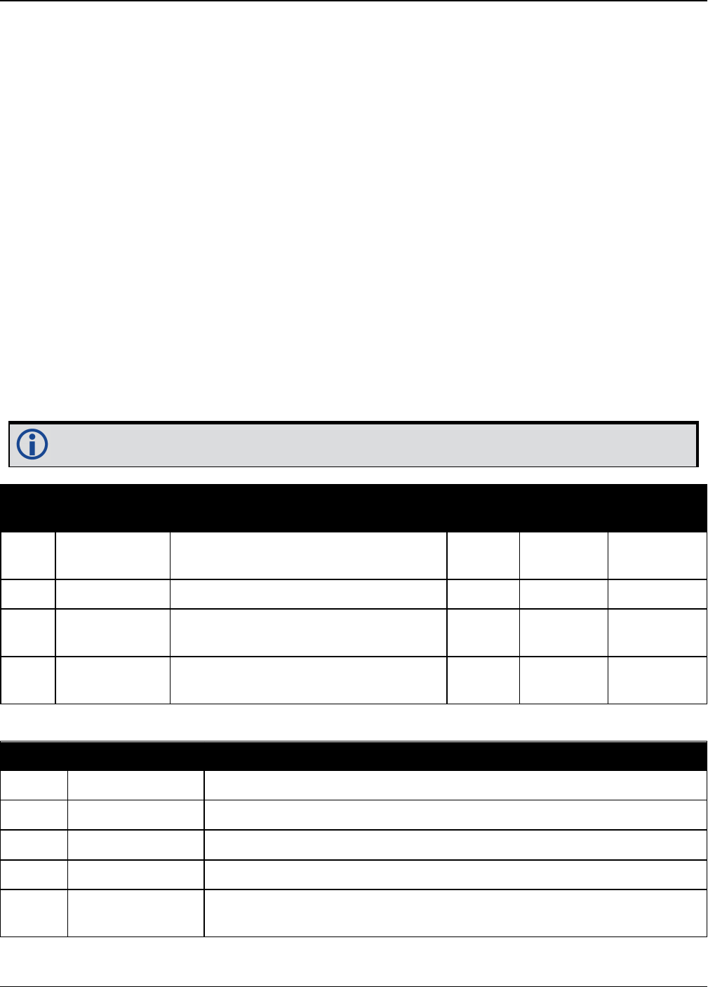
Chapter 3 Logs
OEM7 Commands and Logs Reference Manual v7 582
3.80 LUASTATUS
Display status of Lua scripts
Platform: OEM719, OEM729, OEM7500, OEM7600, OEM7700, OEM7720, PwrPak7,
SPAN CPT7
Use this log to determine what scripts are running on the receiver and whether the scripts have
exited or encountered errors.
Message ID: 2181
Log Type: Collection
Recommended Input:
LOG LUASTATUS
Abbreviated ASCII Example:
[COM1]<LUASTATUS COM1 1 84.5 FINESTEERING 1963 402110.866 02400000 2e18 32768
<0 "icom_rx.lua 127.0.0.1 3001" EXECUTING
<LUASTATUS COM1 0 84.5 FINESTEERING 1963 402110.866 02400000 2e18 32768
<1 "" NOT_STARTED
The example above is for the projected log output for two executors.
Field Field Type Description Format Binary
Bytes
Binary
Format
1LUASTATUS
header
Log header. See Messages for more
information. H 0
2 Number Executor number Ulong 4 H
3 Script Script and arguments String
[256] Variable H+4
4 Status Script status. See Table 112: Script
Status below. Enum 4 Variable
Binary ASCII Description
0 NOT_STARTED There is no script running on the executor
1 EXECUTING The script is running
2 COMPLETED The script completed successfully
3 SCRIPT_ERROR The script exited with an error
4EXECUTOR_
ERROR
The script executor encountered an error while attempting to run the
script
Table 112: Script Status

Chapter 3 Logs
OEM7 Commands and Logs Reference Manual v7 583
3.81 MARKPOS, MARK2POS, MARK3POS and MARK4POS
Position at time of mark input event
Platform: OEM719, OEM729, OEM7500, OEM7600, OEM7700, OEM7720, PwrPak7,
SPAN CPT7
This log contains the estimated position of the antenna when a pulse is detected at a mark input.
MARKPOS is generated when a pulse occurs on the MK1I input. MARK2POS is generated when a
pulse occurs on the MK2I input. MARK3POS is generated when a pulse occurs on the MK3I input
(OEM7600, OEM7700 and OEM7720 only). MARK4POS is generated when a pulse occurs on the
MK4I input (OEM7600, OEM7700 and OEM7720 only). Refer to the product specific Technical Spe-
cifications appendices in the OEM7 Installation and Operation User Manual for mark input pulse
specifications and the location of the mark input pins.
The position at the mark input pulse is extrapolated using the last valid position and velocities.
The latched time of mark impulse is in GPS reference weeks and seconds into the week. The res-
olution of the latched time is 10 ns. See also the notes on MARKPOS in the MARKTIME,
MARK2TIME, MARK3TIME and MARK4TIME log on page586.
Message ID: 181 (MARKPOS)
615 (MARK2POS)
1738 (MARK3POS)
1739 (MARK4POS)
Log Type: Asynch
Recommended Input:
log markposa onnew
1. Use the ONNEW trigger with the MARKTIME or MARKPOS logs.
2. Refer to the Technical Specifications appendix in the OEM7 Installation and Operation
User Manual for more details on the MK1I pin. ONMARK only applies to MK1I. Events
on MK2I (if available) do not trigger logs when ONMARK is used. Use the ONNEW trig-
ger with the MARKTIME, MARK2TIME, MARKPOS or MARK2POS logs.
3. Once the 1PPS signal has hit a rising edge, for both MARKPOS and MARKTIME logs, a
resolution of both measurements is 10 ns. As for the ONMARK trigger for other logs
that measure latency, for example RANGE and POSITION logs such as BESTPOS, it
takes typically 20-30 ms (50 ms maximum) for the logs to output information from the
1PPS signal. Latency is the time between the reception of the 1PPS pulse and the first
byte of the associated log. See also the MARKTIME, MARK2TIME, MARK3TIME
and MARK4TIME log on page586.
Abbreviated ASCII Example:
<MARKPOS COM1 0 89.0 FINESTEERING 1670 413138.000 02000020 c223 42770 SOL_
COMPUTED SINGLE 51.11289233689 -114.02932170726 1018.9653 1049.4915 BUKIT
1.9372 1.1981 4.0909 "" 0.000 0.000 19 18 18 18 0 06 0 33
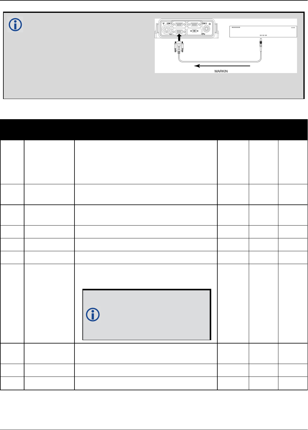
Chapter 3 Logs
OEM7 Commands and Logs Reference Manual v7 584
Consider the case where you have a
user point device such as video
equipment. Connect the device to the
receiver’s I/O port using a cable that is
compatible to both the receiver and the
device. Refer to your device’s
documentation for information about
connectors and cables. The arrow
along the cable in the figure below indicates a MARKIN pulse, from the user device on the
right to the receiver I/O port.
Field Field type Description Format Binary
Bytes
Binary
Offset
1
MARKPOS/
MARK2POS/
MARK3POS/
MARK4POS
header
Log header. See Messages on page25 for
more information. H 0
2 sol status Solution status (see Table 73: Solution
Status on page431) Enum 4 H
3 pos type Position type (see Table 74: Position or
Velocity Type on page432) Enum 4 H+4
4 lat Latitude (degrees) Double 8 H+8
5 lon Longitude (degrees) Double 8 H+16
6 hgt Height above mean sea level (m) Double 8 H+24
7 undulation
Undulation - the relationship between the
geoid and the WGS84 ellipsoid (m)
When using a datum other than
WGS84, the undulation value
also includes the vertical shift
due to differences between the
datum in use and WGS84.
Float 4 H+32
8 datum id# Datum ID number (refer to Table 28: Datum
Transformation Parameters on page117) Enum 4 H+36
9 lat σ Latitude standard deviation (m) Float 4 H+40
10 lon σ Longitude standard deviation (m) Float 4 H+44

Chapter 3 Logs
OEM7 Commands and Logs Reference Manual v7 585
Field Field type Description Format Binary
Bytes
Binary
Offset
11 hgt σ Height standard deviation (m) Float 4 H+48
12 stn id Base station ID Char[4] 4 H+52
13 diff_age Differential age in seconds Float 4 H+56
14 sol_age Solution age in seconds Float 4 H+60
15 #SVs Number of satellites tracked Uchar 1 H+64
16 #solnSVs Number of satellite vehicles used in solution Uchar 1 H+65
17 #ggL1 Number of satellites with L1/E1/B1 signals
used in solution Uchar 1 H+66
18 #solnMultiSVs Number of satellites with multi-frequency
signals used in solution Uchar 1 H+67
19 Reserved Uchar 1 H+68
20 ext sol stat Extended solution status (see Table 77:
Extended Solution Status on page435) Hex 1 H+69
21
Galileo and
BeiDou sig
mask
Galileo and BeiDou signals used mask (see
Table 76: Galileo and BeiDou Signal-Used
Mask on page435)
Hex 1 H+70
22
GPS and
GLONASS sig
mask
GPS and GLONASS signals used mask (see
Table 75: GPS and GLONASS Signal-Used
Mask on page434)
Hex 1 H+71
23 xxxx 32-bit CRC (ASCII and Binary only) Hex 4 H+72
24 [CR][LF] Sentence terminator (ASCII only) - - -

Chapter 3 Logs
OEM7 Commands and Logs Reference Manual v7 586
3.82 MARKTIME, MARK2TIME, MARK3TIME and MARK4TIME
Time of mark input event
Platform: OEM719, OEM729, OEM7500, OEM7600, OEM7700, OEM7720, PwrPak7,
SPAN CPT7
This log contains the time of the leading edge of the detected mark input pulse.
lMARKTIME is generated when a pulse occurs on a MK1I input
lMARK2TIME is generated when a pulse occurs on a MK2I input
lMARK3TIME is generated when a pulse occurs on a MK3I input (OEM7600, OEM7700 and
OEM7720 only)
lMARK4TIME is generated when a pulse occurs on a MK4I input (OEM7600, OEM7700 and
OEM7720 only)
Refer to the Technical Specifications appendix in the OEM7 Installation and Operation User
Manual for mark input pulse specifications and the location of the mark input pins. The res-
olution of this measurement is 10 ns.
1. Use the ONNEW trigger with the MARKTIME or the MARKPOS logs.
2. Only the MARKPOS logs, MARKTIME logs and ‘polled’ log types are generated ‘on the
fly’ at the exact time of the mark. Synchronous and asynchronous logs output the most
recently available data.
3. Refer to the Technical Specifications appendix in the OEM7 Installation and Operation
User Manual for more details on the MK1I pin. ONMARK only applies to MK1I. Events
on MK2I (if available) do not trigger logs when ONMARK is used. Use the ONNEW trig-
ger with the MARKTIME, MARK2TIME, MARKPOS or MARK2POS logs.
4. Once the 1PPS signal has hit a rising edge, for both MARKPOS and MARKTIME logs, a
resolution of both measurements is 10 ns. As for the ONMARK trigger for other logs
that measure latency, for example RANGE and POSITION logs such as BESTPOS, it
takes typically 20-30 ms (50 ms maximum) for the logs to output information from the
1PPS signal. Latency is the time between the reception of the 1PPS pulse and the first
byte of the associated log. See also the MARKPOS, MARK2POS, MARK3POS and
MARK4POS log on page583.
Message ID: 231(MARKTIME)
616(MARK2TIME)
1075 (MARK3TIME)
1076 (MARK4TIME)
Log Type: Asynch
Recommended Input:
log marktimea onnew
ASCII Example:
#MARKTIMEA,COM1,0,77.5,FINESTEERING,1358,422621.000,02000000,292e,2214;1358,422
621.000000500,-1.398163614e-08,7.812745577e-08,-14.000000002,VALID*d8502226

Chapter 3 Logs
OEM7 Commands and Logs Reference Manual v7 587
These logs allow you to measure the time when events are occurring in other devices
(such as a video recorder). See also the MARKCONTROL command on page234.
GPS reference time is the receiver’s estimate of the true GPS system time. GPS ref-
erence time can be found in the header of the log. The relationship between GPS ref-
erence time and true GPS system time is:
GPS system time = GPS reference time - offset
Field Field type Description Format Binary
Bytes
Binary
Offset
1
MARKTIME/
MARK2TIME/
MARK3TIME/
MARK4TIME
header
Log header. See Messages on page25 for
more information. H 0
2 week GPS reference week number Long 4 H
3 seconds
Seconds into the week as measured from the
receiver clock, coincident with the time of
electrical closure on the Mark Input port
Double 8 H+4
4 offset
Receiver clock offset, in seconds. A positive
offset implies that the receiver clock is ahead
of GPS system time. To derive GPS system
time, use the following formula:
GPS system time = GPS reference time -
(offset)
Where GPS reference time can be obtained
from the log header
Double 8 H+12
5 offset std Standard deviation of receiver clock offset (s) Double 8 H+20
Chapter 3 Logs
OEM7 Commands and Logs Reference Manual v7 588
Field Field type Description Format Binary
Bytes
Binary
Offset
6 utc offset
This field represents the offset of GPS system
time from UTC time (s), computed using
almanac parameters. UTC time is GPS
reference time plus the current UTC offset
minus the receiver clock offset.
UTC time = GPS reference time - offset +
UTC offset
0 indicates that UTC time is
unknown because there is no
almanac available in order to
acquire the UTC offset.
Double 8 H+28
7 status Clock model status, see Table 86: Clock
Model Status on page458 Enum 4 H+36
8 xxxx 32-bit CRC (ASCII and Binary only) Ulong 4 H+40
9 [CR][LF] Sentence terminator (ASCII only) - - -
Chapter 3 Logs
OEM7 Commands and Logs Reference Manual v7 589
3.83 MASTERPOS
Master Position using ALIGN
Platform: OEM719, OEM729, OEM7500, OEM7600, OEM7700, OEM7720, PwrPak7,
SPAN CPT7
ALIGN generates distance and bearing information between a Master and Rover receiver. This
log outputs the position information of the master when using the ALIGN feature. This log can be
output from both Y and Z ALIGN models and can be output at both Master and Rover ends.
You must have an ALIGN capable receiver to use this log.
1. ALIGN is useful for obtaining the relative directional heading of a vessel/body, sep-
aration heading between two vessels/bodies or heading information with moving base
and pointing applications.
2. The log can be output at both Y and Z model Rover if it is receiving the RTCAREFEXT or
NovAtelXRef message from the Master. The log can be output at any Master if the
Master is receiving HEADINGEXTB or HEADINGEXT2B from the Rover. Refer to the
NovAtel application note APN-048 for details on HEADINGEXT (available on our web-
site at www.novatel.com/support/.)
3. MASTERPOS logging is dictated by the output frequency of the RTCAREFEXT or
NovAtelXRef output frequency.
Message ID: 1051
Log Type: Asynch
Recommended Input:
log masterposa onchanged
ASCII Example:
#MASTERPOSA,COM1,0,21.5,FINESTEERING,1544,340322.000,02000008,5009,4655;SOL_
COMPUTED,NARROW_INT,51.11604599076,-114.03855412002,1055.7756,
16.9000,WGS84,0.0090,0.0086,0.0143,"AAAA",0.0,0.0,13,13,13,12,0,0,0,0*a72e8d3f
Asynchronous logs, such as MASTERPOS, should only be logged ONCHANGED or ONNEW
otherwise, the most current data is not output when it is available. This is especially true
of the ONTIME trigger, which may cause inaccurate time tags to result.
Field Field Type Description Format Binary
Bytes
Binary
Offset
1MASTERPOS
header
Log header. See Messages on page25 for
more information. H 0

Chapter 3 Logs
OEM7 Commands and Logs Reference Manual v7 590
Field Field Type Description Format Binary
Bytes
Binary
Offset
2 sol stat Solution Status, see Table 73: Solution Status
on page431 Enum 4 H
3 pos type Position Type see Table 74: Position or
Velocity Type on page432 Enum 4 H+4
4 lat Master WGS84 Latitude in degrees Double 8 H+8
5 long Master WGS84 Longitude in degrees Double 8 H+16
6 hgt Master MSL Height in metres Double 8 H+24
7 undulation Undulation in metres Float 4 H+32
8 datum id# WGS84 (default) (refer to Table 28: Datum
Transformation Parameters on page117) Enum 4 H+36
9 lat σ Latitude standard deviation in metres Float 4 H+40
10 long σ Longitude standard deviation in metres Float 4 H+44
11 hgt σ Height standard deviation in metres Float 4 H+48
12 stn id Receiver ID can be set using the DGPSTXID
command (see page 122) Char[4] 4 H+52
13 Reserved Float 4 H+56
14 Float 4 H+60
15 #SVs Number of satellite vehicles tracked Uchar 1 H+64
16 #solnSVs Number of satellite vehicles used in solution Uchar 1 H+65
17 #obs Number of satellites with L1/E1/B1 signals
used in solution Uchar 1 H+66
18 #multi Number of satellites with multi-frequency
signals used in solution Uchar 1 H+67
19 sol source Solution source (see Table 101: Solution
Source on page541) Hex 1 H+68
20
Reserved
Uchar 1 H+69
21 Uchar 1 H+70
22 Uchar 1 H+71
23 xxxx 32-bit CRC (ASCII and Binary only) HEX 1 H+72
24 [CR][LF] Sentence Terminator (ASCII only) - - -

Chapter 3 Logs
OEM7 Commands and Logs Reference Manual v7 591
3.84 MATCHEDPOS
Matched RTK position
Platform: OEM719, OEM729, OEM7500, OEM7600, OEM7700, OEM7720, PwrPak7,
SPAN CPT7
This log represents positions that have been computed from time matched base and rover obser-
vations. There is no base extrapolation error on these positions because they are based on buf-
fered measurements, that is, they lag real time by some amount depending on the latency of the
data link. If the rover receiver has not been enabled to accept RTK differential data or is not actu-
ally receiving data leading to a valid solution, this is shown in fields #2 (sol status) and #3 (pos
type).
This log provides the best accuracy in static operation. For lower latency in kinematic operation,
see the RTKPOS log (see page 736) or BESTPOS log (see page 428). The data in the logs
changes only when a base observation (RTCMv3) changes.
A good message trigger for this log is onchanged. Then, only positions related to unique base sta-
tion messages are produced and the existence of this log indicates a successful link to the base.
Asynchronous logs, such as MATCHEDPOS, should only be logged ONCHANGED oth-
erwise the most current data is not output when it is available. This is especially true of
the ONTIME trigger, which may cause inaccurate time tags to result.
The RTK system in the receiver provides two kinds of position solutions. The Matched
RTK position is computed with buffered observations, so there is no error due to the
extrapolation of base station measurements. This provides the highest accuracy solution
possible at the expense of some latency which is affected primarily by the speed of the
differential data link. The MATCHEDPOS log contains the matched RTK solution and can
be generated for each processed set of base station observations.
The Low-Latency RTK position is computed from the latest local observations and
extrapolated base station observations. This supplies a valid RTK position with the lowest
latency possible at the expense of some accuracy. The degradation in accuracy is
reflected in the standard deviation and is summarized in An Introduction to GNSS
available on our website. The amount of time that the base station observations are
extrapolated is in the "differential age" field of the position log. The Low-Latency RTK
system extrapolates for 60 seconds. The RTKPOS log (see page 736) contains the Low-
Latency RTK position when valid, and an "invalid" status when a Low-Latency RTK
solution could not be computed. The BESTPOS log (see page 428) contains either the
low-latency RTK, PPP or pseudorange-based position, whichever has the smallest
standard deviation.
Message ID: 96
Log Type: Asynch
Recommended Input:
log matchedposa onchanged
Chapter 3 Logs
OEM7 Commands and Logs Reference Manual v7 592
ASCII Example:
#MATCHEDPOSA,COM1,0,63.0,FINESTEERING,1419,340034.000,02000040,2f06,2724;SOL_
COMPUTED,NARROW_INT,51.11635908660,-114.03833102484,1063.8400,-
16.2712,WGS84,0.0140,0.0075,0.0174,"AAAA",0.000,0.000,12,12,12,12,0,01,0,33*fea
c3a3a
Measurement precision is different from the position computation precision. Meas-
urement precision is a value that shows how accurately the actual code or carrier phase
is measured by the GNSS receiver. Position precision is a value that shows the accuracy
of the position computation made from the code and/or carrier phase measurements.
The P-code L2 measurement precision is not as good as the C/A measurement precision
because the NovAtel GNSS receiver is a civilian grade GPS device and does not have dir-
ect access to the decrypted military L2 P(Y) code. This means that NovAtel’s semi-code-
less P-code L2 measurements are noisier than the civilian band C/A code
measurements. Refer to the OEM7 Installation and Operation User Manual for the tech-
nical specification of the OEM7 card.
Field Field type Description Format Binary
Bytes
Binary
Offset
1MATCHEDPOS
header
Log header. See Messages on page25 for
more information. H 0
2 sol status Solution status (see Table 73: Solution
Status on page431) Enum 4 H
3 pos type Position type (see Table 74: Position or
Velocity Type on page432) Enum 4 H+4
4 lat Latitude (degrees) Double 8 H+8
5 lon Longitude (degrees) Double 8 H+16
6 hgt Height above mean sea level (m) Double 8 H+24
7 undulation
Undulation - the relationship between the
geoid and the WGS84 ellipsoid (m)
When using a datum other than
WGS84, the undulation value
also includes the vertical shift
due to differences between the
datum in use and WGS84.
Float 4 H+32
8 datum id# Datum ID number (see Table 28: Datum
Transformation Parameters on page117) Enum 4 H+36
9 lat σ Latitude standard deviation (m) Float 4 H+40

Chapter 3 Logs
OEM7 Commands and Logs Reference Manual v7 593
Field Field type Description Format Binary
Bytes
Binary
Offset
10 lon σ Longitude standard deviation (m) Float 4 H+44
11 hgt σ Height standard deviation (m) Float 4 H+48
12 stn id Base station ID Char[4] 4 H+52
13 Reserved Float 4 H+56
14 Float 4 H+60
15 #SVs Number of satellites tracked Uchar 1 H+64
16 #solnSVs Number of satellite vehicles used in solution Uchar 1 H+65
17 #ggL1 Number of satellites with L1/E1/B1 signals
used in solution Uchar 1 H+66
18 #solnMultiSVs Number of satellites with multi-frequency
signals used in solution Uchar 1 H+67
19 Reserved Hex 1 H+68
20 ext sol stat Extended solution status (see Table 77:
Extended Solution Status on page435) Hex 1 H+69
21
Galileo and
BeiDou sig
mask
Galileo and BeiDou signals used mask (see
Table 76: Galileo and BeiDou Signal-Used
Mask on page435)
Hex 1 H+70
22
GPS and
GLONASS sig
mask
GPS and GLONASS signals used mask (see
Table 75: GPS and GLONASS Signal-Used
Mask on page434)
Hex 1 H+71
23 xxxx 32-bit CRC (ASCII and Binary only) Hex 4 H+72
24 [CR][LF] Sentence terminator (ASCII only) - - -

Chapter 3 Logs
OEM7 Commands and Logs Reference Manual v7 594
3.85 MATCHEDSATS
Satellites used in MATCHEDPOS solution
Platform: OEM719, OEM729, OEM7500, OEM7600, OEM7700, OEM7720, PwrPak7,
SPAN CPT7
This log lists the used and unused satellites for the corresponding MATCHEDPOS solution. It also
describes the signals of the used satellites and reasons for exclusions.
Message ID: 1176
Log Type: Asynch
Recommended Input:
log matchedsats onchanged
Abbreviated ASCII Example:
<MATCHEDSATS COM1 0 60.5 FINESTEERING 1728 524924.000 02000000 b555 11487
< 24
< GPS 3 GOOD 00000003
< GPS 5 GOOD 00000003
...
< GPS 23 GOOD 00000003
< GPS 30 GOOD 00000003
< GLONASS 1+1 GOOD 00000003
< GLONASS 2-4 GOOD 00000003
...
< GLONASS 21+4 GOOD 00000003
< BEIDOU 6 GOOD 00000003
< BEIDOU 11 GOOD 00000003
...
< BEIDOU 12 GOOD 00000003
< BEIDOU 13 GOOD 00000003
Field Field type Description Format Binary
Bytes
Binary
Offset
1MATCHEDSATS
header
Log header. See Messages on page25 for
more information. H 0
2 #entries Number of records to follow Ulong 4 H
3 system See Table 102: Satellite System on
page545 Enum 4 H+4
4 Satellite ID Satellite identifier Ulong 4 H+8
5 Status Satellite status (Table 79: Observation
Statuses on page438) Enum 4 H+12

Chapter 3 Logs
OEM7 Commands and Logs Reference Manual v7 595
Field Field type Description Format Binary
Bytes
Binary
Offset
6 Signal mask
See Table 80: BESTSATS GPS Signal Mask
on page439, Table 81: BESTSATS
GLONASS Signal Mask on page440, Table
82: BESTSATS Galileo Signal Mask on
page440, and Table 83: BESTSATS BeiDou
Signal Mask on page440
Hex 4 H+16
7 Next satellite offset = H + 4 + (#sat x 16)
8 xxxx 32-bit CRC (ASCII and Binary only) Hex 1
H+4+
(#sat x
16)
9 [CR][LF] Sentence terminator (ASCII only) - - -
Chapter 3 Logs
OEM7 Commands and Logs Reference Manual v7 596
3.86 MATCHEDXYZ
Matched RTK Cartesian position
Platform: OEM719, OEM729, OEM7500, OEM7600, OEM7700, OEM7720, PwrPak7,
SPAN CPT7
This log contains the receiver’s matched position in ECEF coordinates. It represents positions
that have been computed from time matched base and rover observations. There is no base sta-
tion extrapolation error on these positions because they are based on buffered measurements,
that is, they lag real time, by some amount, depending on the latency of the data link. If the
rover receiver has not been enabled to accept RTK differential data or is not actually receiving
data leading to a valid solution, this is reflected by the code shown in field #2 (solution status)
and #3 (position type). See Figure 11: The WGS84 ECEF Coordinate System on page449 for a
definition of the ECEF coordinates.
This log provides the best accuracy in static operation. For lower latency in kinematic operation,
see the BESTXYZ log (see page 447) or RTKXYZ log (see page 743). The data in the logs
changes only when a base observation (RTCMv3) changes.
The time stamp in the header is the time of the matched observations that the computed pos-
ition is based on and not the current time.
Message ID: 242
Log Type: Asynch
Recommended Input:
log matchedxyza onchanged
Asynchronous logs, such as MATCHEDXYZ, should only be logged ONCHANGED otherwise
the most current data is not output when it is available. This is especially true of the
ONTIME trigger, which may cause inaccurate time tags to result.
ASCII Example:
#MATCHEDXYZA,COM1,0,62.5,FINESTEERING,1419,340035.000,02000040,b8ed,2724;SOL_
COMPUTED,NARROW_INT,-1634531.5703,-
3664618.0321,4942496.3280,0.0080,0.0159,0.0154,"AAAA",12,12,12,12,0,01,0,33*e4b
84015
Field Field type Description Format Binary
Bytes
Binary
Offset
1MATCHEDXYZ
header
Log header. See Messages on page25 for
more information. H 0
2 P-sol status Solution status, see Table 73: Solution
Status on page431 Enum 4 H

Chapter 3 Logs
OEM7 Commands and Logs Reference Manual v7 597
Field Field type Description Format Binary
Bytes
Binary
Offset
3 pos type Position type, see Table 74: Position or Velo-
city Type on page432 Enum 4 H+4
4 P-X Position X-coordinate (m) Double 8 H+8
5 P-Y Position Y-coordinate (m) Double 8 H+16
6 P-Z Position Z-coordinate (m) Double 8 H+24
7 P-X σ Standard deviation of P-X (m) Float 4 H+32
8 P-Y σ Standard deviation of P-Y (m) Float 4 H+36
9 P-Z σ Standard deviation of P-Z (m) Float 4 H+40
10 stn ID Base station ID Char[4] 4 H+44
11 #SVs Number of satellites tracked Uchar 1 H+48
12 #solnSVs Number of satellite vehicles used in solution Uchar 1 H+49
13 #ggL1 Number of satellites with L1/E1/B1 signals
used in solution Uchar 1 H+50
14 #solnMultiSVs Number of satellites with multi-frequency
signals used in solution Uchar 1 H+51
15 Reserved Char 1 H+52
16 ext sol stat Extended solution status (see Table 77:
Extended Solution Status on page435) Hex 1 H+53
17
Galileo and
BeiDou sig
mask
Galileo and BeiDou signals used mask (see
Table 76: Galileo and BeiDou Signal-Used
Mask on page435)
Hex 1 H+54
18
GPS and
GLONASS sig
mask
GPS and GLONASS signals used mask (see
Table 75: GPS and GLONASS Signal-Used
Mask on page434)
Hex 1 H+55
19 xxxx 32-bit CRC (ASCII and Binary only) Hex 4 H+56
20 [CR][LF] Sentence terminator (ASCII only) - - -

Chapter 3 Logs
OEM7 Commands and Logs Reference Manual v7 598
3.87 MODELFEATURES
States features available for current loaded model
Platform: OEM719, OEM729, OEM7500, OEM7600, OEM7700, OEM7720, PwrPak7,
SPAN CPT7
The MODELFEATURES log states the features available for the current loaded model.
To see which satellite systems are available for the current model, use the CHANCONFIGLIST
log (see page 452).
Most features have a boolean state: authorized or unauthorized. However, some have more com-
plex licensed states with varying degrees of capability.
This log is best viewed in Abbreviated ASCII.
Message ID: 1329
Log Type: Polled
Recommended Input:
log modelfeatures once
Abbreviated ASCII Example:
<MODELFEATURES COM1 0 92.5 COARSESTEERING 2007 237316.648 02400000 141a 14898
<20
<1HZ MAX_MSR_RATE
<0HZ MAX_POS_RATE
<SINGLE ANTENNA
<AUTHORIZED NTRIP
<UNAUTHORIZED IMU
<UNAUTHORIZED INS
<UNAUTHORIZED MEAS_OUTPUT
<UNAUTHORIZED DGPS_TX
<UNAUTHORIZED RTK_TX
<UNAUTHORIZED RTK_FLOAT
<UNAUTHORIZED RTK_FIXED
<UNAUTHORIZED PPP
<UNAUTHORIZED LOW_END_POSITIONING
<UNAUTHORIZED RAIM
<UNAUTHORIZED ALIGN_HEADING
<UNAUTHORIZED ALIGN_RELATIVE_POS
<UNAUTHORIZED API
<UNAUTHORIZED INTERFERENCE_MITIGATION
<UNAUTHORIZED RTKASSIST
<UNAUTHORIZED SCINTILLATION

Chapter 3 Logs
OEM7 Commands and Logs Reference Manual v7 599
Field Field type Description Format Binary
Bytes
Binary
Offset
1MODELFEATURES
header
Log header. See Messages on
page25 for more information. - H 0
2 # Feature Number of features in list Ulong 4 H
3 Feature Status
Licensing status of feature
See Table 113: Feature Status
below
Enum 4 H+4
4 Feature Type
Type of feature
See Table 114: Feature Type on the
next page
Enum 4 H+8
5... Next feature = H+4+(# Feature x 8)
6 xxxx 32-bit CRC (ASCII and Binary only) Ulong 4
H+4+(#
Feature x
8)
7 [CR][LF] Sentence terminator (ASCII only) - - -
Value Name Description
0 AUTHORIZED The feature is authorized
1 UNAUTHORIZED The feature is unauthorized
2 0Hz Disables output of POS logs
6 20Hz Maximum logging rate for POS or MSR logs is 20 Hz
8 100Hz Maximum logging rate for POS or MSR logs is 100 Hz
9 RATE_INVALID Option bits don't correspond to a valid rate
15 STANDARD SPAN Standard Model
20 COMMERCIAL_MEMS IMU Grade-Commercial MEMS
21 TACTICAL IMU Grade-Tactical
22 HIGH_GRADE_TACTICAL IMU Grade-High Grade Tactical
23 NAVIGATION IMU Grade-Navigation
25 SINGLE Single antenna
Table 113: Feature Status

Chapter 3 Logs
OEM7 Commands and Logs Reference Manual v7 600
Value Name Description
26 DUAL Dual antenna
30 LITE SPAN Lite Model
33 CONSUMER_MEMS IMU Grade-Consumer MEMS
Value Name Description
0 MAX_MSR_RATE Maximum measurement logging rate
1 MAX_POS_RATE Maximum position logging rate
3 MEAS_OUTPUT Output of raw measurements (phase and pseudorange)
4 DGPS_TX Transmission of DGPS (non RTK) corrections
5 RTK_TX Transmission of RTK corrections
6 RTK_FLOAT RTK float positioning
7 RTK_FIXED RTK fixed positioning
8 RAIM Extended RAIM
9LOW_END_
POSITIONING GLIDE and TerraStar-L positioning
10 ALIGN_HEADING Heading
11 ALIGN_RELATIVE_POS Heading and Relative Positioning
12 API Lua Scripted User Interface (formerly User Application API)
15 NTRIP NTRIP Server/Client
19 PPP TerraStar-C positioning
20 SCINTILLATION Scintillation
22 INS Inertial (SPAN)
23 IMU IMU Grade
26
FEATURE_
INTERFERENCE_
MITIGATION
Interference Mitigation
28 ANTENNA Number of antenna enabled on the receiver
29 GENERIC_IMU SPAN Generic IMU Interface
30 INS_PLUS_PROFILES SPAN Plus Profiles
Table 114: Feature Type

Chapter 3 Logs
OEM7 Commands and Logs Reference Manual v7 601
Value Name Description
31 HEAVE SPAN Heave Option
32 RELATIVE_INS SPAN Relative INS
999 MODEL_INVALID If a bad model is loaded, MODELFEATURES will contain one
entry: MODEL_INVALID STATUS_INVALID

Chapter 3 Logs
OEM7 Commands and Logs Reference Manual v7 602
3.88 NAVICALMANAC
Decoded NavIC Almanac
Platform: OEM719, OEM729, OEM7500, OEM7600, OEM7700, OEM7720, PwrPak7,
SPAN CPT7
This log contains the decoded NavIC almanac parameters from NavIC navigation messages. Mul-
tiple messages are transmitted, one for each satellite ID with data.
The OEM7 family of receivers automatically save almanacs in their Non-Volatile Memory (NVM),
so creating an almanac boot file is not necessary.
Message ID: 2122
Log Type: Asynch
Recommended Input:
log navicalmanaca onchanged
ASCII Example:
#NAVICALMANACA,COM1,4,69.5,SATTIME,1943,158160.000,02000020,fb6e,32768
;919,0.001982212,86400,0.075264303,8.457495146e-10,6493.383789062,
1.327344662,2.996060720,2.542881375,-0.000580788,7.275957614e-12,
6,0,0,5*05cfbc62
#NAVICALMANACA,COM1,3,69.5,SATTIME,1943,156276.000,02000020,fb6e,32768
;919,0.001962662,0,0.509411950,2.742971399e-10,6493.538574219,
1.844826864,3.107479183,-3.001633760,-0.000161171,-5.093170330e-11,
4,0,0,7*8fbd9e3a
#NAVICALMANACA,COM1,2,69.5,SATTIME,1943,158148.000,02000020,fb6e,32768
;919,0.001979351,86400,0.499982612,2.400099974e-10,6493.359375000,
-1.300198895,-3.061969089,0.047002130,0.000025749,-3.637978807e-12,
5,0,0,5*be12ffa2
#NAVICALMANACA,COM1,1,69.5,SATTIME,1943,157620.000,02000020,fb6e,32768
;919,0.001854897,86400,0.509561753,1.371485699e-10,6493.388671875,
1.842267109,3.032190537,2.385950946,0.000114441,-5.456968211e-11,
2,0,0,5*b64cf69c
#NAVICALMANACA,COM1,0,69.5,SATTIME,1943,156804.000,02000020,fb6e,32768
;919,0.000161171,86400,0.076541746,1.142904749e-09,6493.613281250,
1.349937548,0.783248119,0.142653098,0.000204086,-8.003553376e-11,
7,0,0,7*495808b9
The speed at which the receiver locates and locks onto new satellites is
improved if the receiver has approximate time and position, as well as an
almanac. This allows the receiver to compute the elevation of each satellite so
it can tell which satellites are visible and their Doppler offsets, improving
Time to First Fix (TTFF).

Chapter 3 Logs
OEM7 Commands and Logs Reference Manual v7 603
Field Field Type Description Format Binary
Bytes
Binary
Offset
1NAVICALMANAC
header
Log header. See Messages on page25 for
more information. - H 0
2 WNa
Week number for the almanac since the
IRNSS system time start epoch (August
22nd 1999)
Ulong 4 H
3 Ecc Eccentricity (dimensionless) Double 8 H+4
4 Toa Time of Almanac (sec) Ulong 4 H+12
5 I0 Inclination angel (radians) Double 8 H+16
6 OmegaDot Rate of RAAN (radians/sec) Double 8 H+24
7 RootA Square root of semi-major axis(sqrt
(metres)) Double 8 H+32
8 Omega0 Longitude of ascending node (LAN)
(radians) Double 8 H+40
9 Omega Argument of perigee (radians) Double 8 H+48
10 M0 Mean Anomaly (radians) Double 8 H+56
11 Af0 Clock bias A0 (sec) Double 8 H+64
12 Af1 Clock Drift A1 (sec/sec) Double 8 H+72
13 AlmSVID PRN ID for Almanac Ulong 4 H+80
14 InterSigCorr Inter Signal Correction (sec) Ulong 4 H+84
15 Spare Ulong 4 H+88
16 PRN Satellite Identifier Ulong 4 H+92
17 xxxx 32-bit CRC (ASCII and Binary only) Hex 4 H+96
18 [CR][LF] Sentence terminator (ASCII only) - - -

Chapter 3 Logs
OEM7 Commands and Logs Reference Manual v7 604
3.89 NAVICEPHEMERIS
Decoded NavIC Ephemeris
Platform: OEM719, OEM729, OEM7500, OEM7600, OEM7700, OEM7720, PwrPak7,
SPAN CPT7
This log contains NavIC ephemeris parameters with the appropriate scaling applied. Multiple
messages are transmitted, one for each SV ephemeris collected.
Message ID: 2123
Log Type: Asynch
Recommended Input:
log navicephemerisa onchanged
ASCII Example:
#NAVICEPHEMERISA,COM1,5,74.0,SATTIME,1943,255984.000,02000020,01fa,
32768;2,919,1.05838757e-04,-5.63886715e-11,0.00000000,0,252000,
-1.86e-09,3.2829938927e-09,11,0,0,0,1.922249794e-06,1.032650471e-05,
2.011656761e-07,4.097819328e-08,-230.9375000,66.1250000,
-5.239503961e-10,0,1.900019163,252000,1.8492219970e-03,6493.385761,
1.842761896e+00,3.027013584,-2.94012247e-09,5.0965660552e-01,0,0,0
*d2f4c9a5
#NAVICEPHEMERISA,COM1,4,74.0,SATTIME,1943,255984.000,02000020,01fa,
32768;6,919,-5.79587650e-04,1.02318154e-11,0.00000000,1,252000,
-1.86e-09,8.5817860373e-09,11,0,0,0,-1.282989979e-05,2.417713404e-06,
1.974403858e-07,2.644956112e-07,-83.3125000,-395.3125000,
-5.535944880e-10,0,2.050709297,252000,1.9699299010e-03,6493.408867,
1.328589850e+00,2.996532035,-7.66746224e-09,7.5298187077e-02,0,0,0
*50cdb388
...
#NAVICEPHEMERISA,COM1,0,74.0,SATTIME,1943,255984.000,02000020,01fa,
32768;7,919,1.90386083e-04,-8.28777047e-11,0.00000000,1,255024,
-1.40e-09,6.3988379659e-09,252,0,0,0,-8.992850780e-06,
-1.732259989e-06,-9.313225746e-08,-2.235174179e-08,60.1250000,
-266.1875000,-3.928735076e-10,0,-0.445949980,255024,2.4348858278e-04,
6493.269802,1.351327715e+00,1.099632488,-5.54308803e-09,
7.6573741924e-02,0,0,0*01bf330e
Field Field Type Description Format Binary
Bytes
Binary
Offset
1NAVICEPHEMERIS
header
Log header. See Messages on page25
for more information. - H 0
2 PRN Satellite Identifier (1 to 7) Ulong 4 H

Chapter 3 Logs
OEM7 Commands and Logs Reference Manual v7 605
Field Field Type Description Format Binary
Bytes
Binary
Offset
3 WN Week number since the IRNSS system
time start epoch (August 22nd 1999) Ulong 4 H+4
4 Af0 Clock bias (sec) Double 8 H+8
5 Af1 Clock drift (sec/sec) Double 8 H+16
6 Af2 Clock drift rate (sec/sec2)Double 8 H+24
7 URA SV Accuracy Ulong 4 H+32
8 toc Reference time for the satellite clock
corrections (sec) Ulong 4 H+36
9 TGD Total group delay (sec) Double 8 H+40
10 DeltaN Mean motion difference (radian/sec) Double 8 H+48
11 IODEC Issue of data ephemeris and clock Ulong 4 H+56
12 Reserved Ulong 4 H+60
13 L5 Health
Health status of navigation data on L5
SPS signal
0=OK; 1=bad
Ulong 4 H+64
14 S Health
Health status of navigation data on S
SPS signal
0=OK; 1=bad
Ulong 4 H+68
15 Cuc
Amplitude of the cosine harmonic
correction term to the argument of
latitude (radians)
Double 8 H+72
16 Cus
Amplitude of the sine harmonic
correction term to the argument of
latitude (radians)
Double 8 H+80
17 Cic
Amplitude of the cosine harmonic
correction term to the angle of
inclination (radians)
Double 8 H+88
18 Cis
Amplitude of the sine harmonic
correction term to the angle of
inclination (radians)
Double 8 H+96
19 Crc
Amplitude of the cosine harmonic
correction term to the orbit radius
(metres)
Double 8 H+104

Chapter 3 Logs
OEM7 Commands and Logs Reference Manual v7 606
Field Field Type Description Format Binary
Bytes
Binary
Offset
20 Crs
Amplitude of the sine harmonic
correction term to the orbit radius
(metres)
Double 8 H+112
21 IDOT Rate of inclination angle (radians/sec) Double 8 H+120
22 Spare Ulong 4 H+128
23 M0 Mean anomaly (radians) Double 8 H+132
24 toe Time of ephemeris (sec) Ulong 4 H+140
25 Ecc Eccentricity (dimensionless) Double 8 H+144
26 RootA Square root of semi-major axis (sqrt
(metres)) Double 8 H+152
27 Omega0 Longitude of ascending node (radians) Double 8 H+160
28 Omega Argument of perigee (radians) Double 8 H+168
29 OmegaDot Rate of RAAN (radians/sec) Double 8 H+176
30 I0 Inclination angle (radians) Double 8 H+184
31 Spare Ulong 4 H+192
32 Alert flag
The utilization of navigation data shall be
at the users’ own risk.
1=Alert; 0=OK )
Ulong 4 H+196
33 AutoNav flag
When set to 1, satellite is in AutoNav
mode.
Satellite broadcasts primary navigation
parameters from AutoNav data sets with
no uplink from ground for maximum of 7
days
Ulong 4 H+200
34 xxxx 32-bit CRC (ASCII and Binary only) Hex 4 H+204
35 [CR][LF] Sentence terminator (ASCII only) - - -

Chapter 3 Logs
OEM7 Commands and Logs Reference Manual v7 607
3.90 NAVICIONO
NavIC ionospheric coefficients parameters
Platform: OEM719, OEM729, OEM7500, OEM7600, OEM7700, OEM7720, PwrPak7,
SPAN CPT7
This log contains NavIC ionospheric coefficients parameters. Ionospheric error correction for
single frequency (L5) users of the NavIC are provided through a set of eight coefficients. The cor-
rection coefficients are:
l4 Alpha Coefficients (αn; n=0,1,2,3)
These are the coefficients of the cubic polynomial representing the amplitude of the positive
cosine curve in the cosine model approximation of ionospheric delay.
l4 Beta Coefficients (βn; n=0,1,2,3)
These are the coefficients of the cubic polynomial representing the period of the positive
cosine curve in the cosine model approximation of ionospheric delay.
Message ID: 2124
Log Type: Asynch
Recommended Input:
log navicionoa onchanged
ASCII Example:
#NAVICIONOA,COM1,0,92.5,SATTIME,1944,166272.000,02000020,56c0,32768;
5,2.980232238769531e-08,3.874301910400390e-07,-2.562999725341796e-06,
-7.510185241699216e-06,558.0,168.0,-2286.0,2286.0,0*2b250bbd
Field Field Type Description Format Binary
Bytes
Binary
Offset
1NAVICIONO
header
Log header. See Messages on page25 for more
information. - H 0
2 PRN Satellite Identifier of the transmitting NavIC
SV (from 1 to 7) Ulong 4 H
3 Alpha 0 Coefficient of the amplitude of the vertical
delay constant term (sec) Double 8 H+4
4 Alpha 1 Coefficient of the amplitude of the vertical
delay first-order term (sec/semi-circle) Double 8 H+12
5 Alpha 2 Coefficient of the amplitude of the vertical
delay second-order term (sec/(semi-circle)2)Double 8 H+20
6 Alpha 3 Coefficient of the amplitude of the vertical
delay third-order term (sec/(semi-circle)3)Double 8 H+28

Chapter 3 Logs
OEM7 Commands and Logs Reference Manual v7 608
Field Field Type Description Format Binary
Bytes
Binary
Offset
7 Beta 0 The coefficient of a cubic equation representing
the period of the model constant term (sec) Double 8 H+36
8 Beta 1
The coefficient of a cubic equation representing
the period of the model first-order term
(sec/semi-circle)
Double 8 H+44
9 Beta 2
The coefficient of a cubic equation representing
the period of the model second-order term
(sec/(semi-circle)2)
Double 8 H+52
10 Beta 3
The coefficient of a cubic equation representing
the period of the model third-order term (sec/
(semi-circle)3)
Double 8 H+60
11 Spare Ulong 4 H+68
12 xxxx 32-bit CRC (ASCII and Binary only) Hex 4 H+72
13 [CR][LF] Sentence terminator (ASCII only) - - -

Chapter 3 Logs
OEM7 Commands and Logs Reference Manual v7 609
3.91 NAVICRAWSUBFRAME
Raw NavIC subframe data
Platform: OEM719, OEM729, OEM7500, OEM7600, OEM7700, OEM7720, PwrPak7,
SPAN CPT7
This log contains the raw NavIC subframe data with parity bits removed. Only subframes that
have passed the parity check are output.
Message ID: 2105
Log Type: Asynch
Recommended Input:
log navicrawsubframea onchanged
ASCII Example:
#NAVICRAWSUBFRAMEA,COM1,0,72.5,SATTIME,1943,159168.000,02000020,76af,32768;182,
7,1,8b19e883971a005bf4880009ab3f400eac0af84f7541befff78018e6d7e1dfacd1*88c2ba19
#NAVICRAWSUBFRAMEA,COM1,0,72.5,SATTIME,1943,159168.000,02000020,76af,32768;177,
2,1,8b19e883970e8fc3f8500009ab3f00087f0af8415e4232800f7fd9eb8650b7b630*c7e27e82
#NAVICRAWSUBFRAMEA,COM1,0,72.5,SATTIME,1943,159168.000,02000020,76af,32768;181,
6,1,8b19e88397b3e73401600009ab3f0012370af84f550327c032800ad1d9da339260*0bb7b256
#NAVICRAWSUBFRAMEA,COM1,0,72.5,SATTIME,1943,159168.000,02000020,76af,32768;180,
5,1,8b19e88397036703ff1c0049ab3fc009b10af84fe7e3773ffd7fd6d8f5fddc4181*f42f59ab
Field Field Type Description Format Binary
Bytes
Binary
Offset
1NAVICRAWSUBFRAME
header
Log header. See Messages on
page25 for more information. - H 0
2 Signal channel Signal channel providing the data Ulong 4 H
3 PRN Satellite Identifier of transmitting
NavIC SV (from 1 to 7) Ulong 4 H+4
4 Subframe Id Subframe ID Ulong 4 H+8
5 Raw subframe data Raw subframe data (262 bits).
Does not include CRC or Tail bits Hex[33] 33 H+12
6 xxxx 32-bit CRC (ASCII and Binary only) Hex 4 H+45
7 [CR][LF] Sentence terminator (ASCII only) - - -

Chapter 3 Logs
OEM7 Commands and Logs Reference Manual v7 610
3.92 NAVICSYSCLOCK
NavIC clock parameters
Platform: OEM719, OEM729, OEM7500, OEM7600, OEM7700, OEM7720, PwrPak7,
SPAN CPT7
This log provides the NavIC system time offset with respect to UTC, UTC (NPLI) and other GNSS
times such as GPS, GALILEO, GLONASS.
Message ID: 2125
Log Type: Asynch
Recommended Input:
log navicsysclocka onchanged
ASCII Example:
#NAVICSYSCLOCKA,COM1,0,93.0,SATTIME,1944,166320.000,02000020,3dfd,
32768;7,-7.625203579664230e-09,-1.598721155460225e-14,
0.000000000000000e+00,18,32508,920,905,7,18,2,2.149608917534351e-07,
-5.151434834260726e-14,-1.998997755520149e-19,32508,920,0*f6617e67
Field Field Type Description Format Binary
Bytes
Binary
Offset
1NAVICSYSCLOCK
header
Log header. See Messages on page25 for
more information. H 0
2 PRN Satellite Identifier of the transmitting
NavIC SV (from 1 to 7) Ulong 4 H
3A0utc Bias coefficient of the NavIC time scale
relative to the UTC time scale (sec) Double 8 H+4
4A1utc Drift coefficient of the NavIC time scale
relative to the UTC time scale (sec/sec) Double 8 H+12
5A2utc
Drift rate coefficient of the NavIC time
scale relative to the UTC time scale
(sec/sec2)
Double 8 H+20
6ΔtLS Current or past leap second count (sec) Long 4 H+28
7Toutc Time data reference time of week (sec) Ulong 4 H+32
8WNoutc Time data reference week number (week) Ulong 4 H+36
9WNLSF Leap second reference week number
(week) Ulong 4 H+40
10 DN Leap second reference day number (days) Ulong 4 H+44

Chapter 3 Logs
OEM7 Commands and Logs Reference Manual v7 611
Field Field Type Description Format Binary
Bytes
Binary
Offset
11 ΔtLSF Current or future leap second count (sec) Long 4 H+48
12 GNSSID
Timescale for the time offsets with
respect to NavIC (Table 115: GNSS Time
Scales below)
Ulong 4 H+52
13 A0 Bias coefficient of the NavIC time scale
relative to the GNSS time scale (sec) Double 8 H+56
14 A1 Drift coefficient of the NavIC time scale
relative to the GNSS time scale (sec/sec) Double 8 H+64
15 A2
Drift rate correction coefficient of the
NavIC time scale relative to the GNSS
time scale (sec/sec2)
Double 8 H+72
16 Tot Time data reference time of week (sec) Ulong 4 H+80
17 WNot Time data reference week number (week) Ulong 4 H+84
18 Spare Ulong 4 H+88
19 xxxx 32-bit CRC (ASCII and Binary only) Hex 4 H+92
20 [CR][LF] Sentence terminator (ASCII only) - - -
GNSS ID Time Scale
0 GPS
1 GALILEO
2 GLONASS
3-6 Reserved
7 UTC (NPLI)
Table 115: GNSS Time
Scales
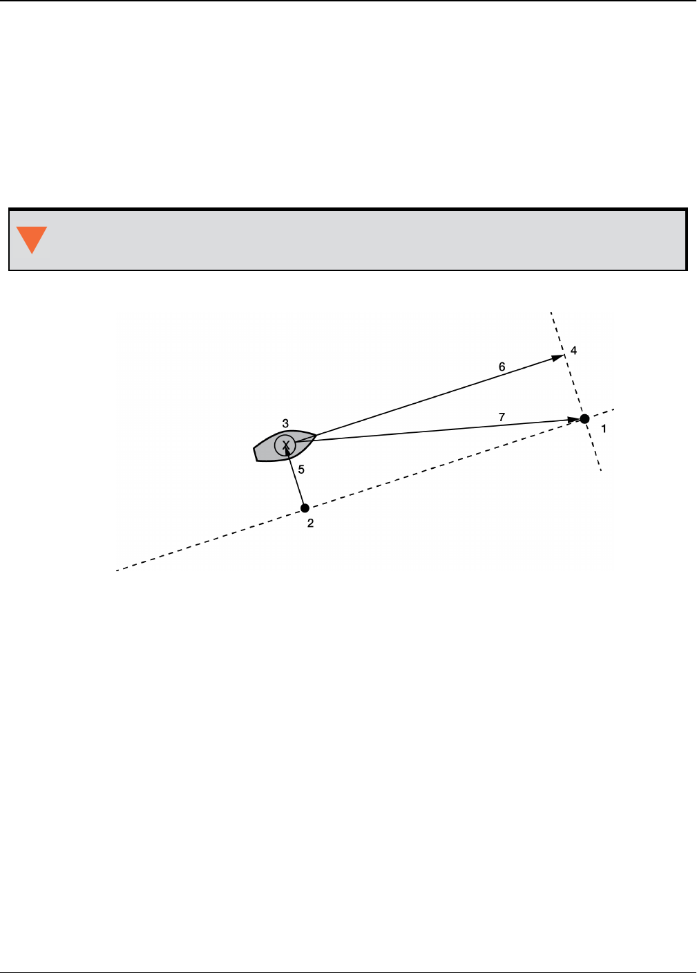
Chapter 3 Logs
OEM7 Commands and Logs Reference Manual v7 612
3.93 NAVIGATE
User navigation data
Platform: OEM719, OEM729, OEM7500, OEM7600, OEM7700, OEM7720, PwrPak7,
SPAN CPT7
This log reports the status of the waypoint navigation progress. It is used in conjunction with the
SETNAV command (see page 346).
See the figure below for an illustration of navigation parameters.
The SETNAV command (see page 346) must be enabled before valid data will be repor-
ted from this log.
Figure 12: Navigation Parameters
Reference Description
1 TO lat-lon
2 X-Track perpendicular reference point
3 Current GPS position
4 A-Track perpendicular reference point
5 X-Track (cross track)
6 A-Track (along track)
7 Distance and bearing from 3 to 1
Message ID: 161
Log Type: Sync
Recommended Input:
log navigatea ontime 1
ASCII Example:

Chapter 3 Logs
OEM7 Commands and Logs Reference Manual v7 613
#NAVIGATEA,COM1,0,56.0,FINESTEERING,1337,399190.000,02000000,aece,1984;SOL_
COMPUTED,PSRDIFF,SOL_
COMPUTED,GOOD,9453.6278,303.066741,133.7313,9577.9118,1338,349427.562*643cd4e2
Use the NAVIGATE log in conjunction with the SETNAV command (see page 346) to tell
you where you currently are with relation to known To and From points. You can find a
specific latitude, longitude or height knowing from where you started. For example, a
backpacker could use these two commands to program a user supplied graphical dis-
play, on a digital GPS compass, to show their progress as they follow a defined route.
Field Field
Type Description Format Binary
Bytes
Binary
Offset
1NAVIGATE
header
Log header. See Messages on page25 for more
information. H 0
2 sol status Solution status, see Table 73: Solution Status
on page431 Enum 4 H
3 pos type Position type, see Table 74: Position or Velocity
Type on page432 Enum 4 H+4
4 vel status Velocity status, see Table 73: Solution Status on
page431 Enum 4 H+8
5 nav type Navigation data type (see Table 116: Navigation
Data Type on the next page) Enum 4 H+12
6 distance
Straight line horizontal distance from current
position to the destination waypoint, in metres
(see Figure 12: Navigation Parameters on the
previous page). This value is positive when
approaching the waypoint and becomes negative
on passing the waypoint
Double 8 H+16
7 bearing
Direction from the current position to the
destination waypoint, in degrees, with respect to
True North (or magnetic if corrected for
magnetic variation by the MAGVAR command
on page231)
Double 8 H+24
8along
track
Horizontal track distance from the current
position to the closest point on the waypoint
arrival perpendicular; expressed in metres. This
value is positive when approaching the waypoint
and becomes negative on passing the waypoint
Double 8 H+32

Chapter 3 Logs
OEM7 Commands and Logs Reference Manual v7 614
Field Field
Type Description Format Binary
Bytes
Binary
Offset
9 xtrack
The horizontal distance (perpendicular track
error), from the vessel's present position to the
closest point on the great circle line, that joins
the FROM and TO waypoints. If a "track offset"
has been entered in the SETNAV command (see
page 346), xtrack is the perpendicular error
from the "offset track". Xtrack is expressed in
metres. Positive values indicate the current
position is right of the Track, while negative
offset values indicate left
Double 8 H+40
10 eta week
Estimated GPS reference week number at time
of arrival at the "TO" waypoint, along track
arrival perpendicular based on current position
and speed, in units of GPS reference weeks. If
the receiving antenna is moving at a speed of
less than 0.1 m/s, in the direction of the
destination, the value in this field is "9999"
Ulong 4 H+48
11 eta secs
Estimated GPS seconds into week at time of
arrival at destination waypoint along track
arrival perpendicular, based on current position
and speed, in units of GPS seconds into the
week. If the receiving antenna is moving at a
speed of less than 0.1 m/s in the direction of the
destination, the value in this field is "0.000"
Double 8 H+52
12 xxxx 32-bit CRC (ASCII and Binary only) Ulong 4 H+60
13 [CR][LF] Sentence terminator (ASCII only) - - -
Binary ASCII Description
0 GOOD Navigation is good
1 NOVELOCITY Navigation has no velocity
2 BADNAV Navigation calculation failed for an unknown reason
3 FROM_TO_SAME “From” is too close to “To” for computation
4 TOO_CLOSE_TO_TO Position is too close to “To” for computation
5 ANTIPODAL_WAYPTS Waypoints are antipodal on surface
Table 116: Navigation Data Type
Chapter 3 Logs
OEM7 Commands and Logs Reference Manual v7 615
3.94 NMEA Standard Logs
Platform: OEM719, OEM729, OEM7500, OEM7600, OEM7700, OEM7720, PwrPak7,
SPAN CPT7
This log contains NMEA logs.
GLMLA GLONASS Almanac Data
GPALM Almanac Data
GPGGA Global Position System Fix Data and Undulation
GPGGALONG GPS Fix Data, Extra Precision and Undulation
GPGLL Geographic Position
GPGRS GPS Range Residuals for Each Satellite
GPGSA GPS DOP on Active Satellites
GPGST Pseudorange Measurement Noise Statistics
GPGSV GPS Satellites in View
GPHDT NMEA Heading Log (ALIGN)
GPRMB Navigation Information
GPRMC GPS Specific Information
GPVTG Track Made Good and Ground Speed
GPZDA UTC Time and Date
The NMEA log structures follow format standards as adopted by the National Marine Electronics
Association. The reference document used is "Standard For Interfacing Marine Electronic
Devices NMEA 0183 Version 3.01". For further information, refer to the Standards and Refer-
ences section of our website www.novatel.com/support/. The following table contains excerpts
from Table 6 of the NMEA Standard which defines the variables for the NMEA logs. The actual
format for each parameter is indicated after the description.
See the Note in the GPGGA log (see page 510) that applies to all NMEA logs.
1. Spaces may only be used in variable text fields.
2. A negative sign "-" (HEX 2D) is the first character in a Field if the value is negative.
The sign is omitted if the value is positive.
3. All data fields are delimited by a comma (,).
4. Null fields are indicated by no data between two commas (,,). Null fields indicate
invalid data or no data available.
5. The NMEA Standard requires that message length be limited to 82 characters.
Field Type Symbol Definition
Special Format Fields

Chapter 3 Logs
OEM7 Commands and Logs Reference Manual v7 616
Field Type Symbol Definition
Status A
Single character field:
A = Yes, Data Valid, Warning Flag Clear
V = No, Data Invalid, Warning Flag Set
Latitude llll.ll
Fixed/Variable length field:
degrees|minutes.decimal - 2 fixed digits of degrees, 2 fixed digits of
mins and a variable number of digits for decimal-fraction of mins.
Leading zeros always included for degrees and mins to maintain fixed
length. The decimal point and associated decimal-fraction are optional
if full resolution is not required
Longitude yyyyy.yy
Fixed/Variable length field:
degrees|minutes.decimal - 3 fixed digits of degrees, 2 fixed digits of
mins and a variable number of digits for decimal-fraction of mins.
Leading zeros always included for degrees and mins to maintain fixed
length. The decimal point and associated decimal-fraction are optional
if full resolution is not required
Time hhmmss.ss
Fixed/Variable length field:
hours|minutes|seconds.decimal - 2 fixed digits of hours, 2 fixed digits
of mins, 2 fixed digits of seconds and variable number of digits for
decimal-fraction of seconds. Leading zeros always included for hours,
mins and seconds to maintain fixed length. The decimal point and
associated decimal-fraction are optional if full resolution is not
required.
Defined field
Some fields are specified to contain predefined constants, most often
alpha characters. Such a field is indicated in this standard by the
presence of one or more valid characters. Excluded from the list of
allowable characters are the following which are used to indicate field
types within this standard:
"A", "a", "c", "hh", "hhmmss.ss", "llll.ll", "x", "yyyyy.yy"
Numeric Value Fields
Variable
numbers x.x
Variable length integer or floating numeric field. Optional leading and
trailing zeros. The decimal point and associated decimal-fraction are
optional if full resolution is not required
(example: 73.10 = 73.1 = 073.1 = 73)
Fixed HEX
field hh___ Fixed length HEX numbers only, MSB on the left
Information Fields
Variabletext c--c Variable length valid character field

Chapter 3 Logs
OEM7 Commands and Logs Reference Manual v7 617
Field Type Symbol Definition
Fixed alpha
field aa___ Fixed length field of uppercase or lowercase alpha characters
Fixed
number field xx___ Fixed length field of numeric characters
Fixed text
field cc___ Fixed length field of valid characters

Chapter 3 Logs
OEM7 Commands and Logs Reference Manual v7 618
3.95 NOVATELXOBS
NovAtel proprietary RTK correction
Platform: OEM719, OEM729, OEM7500, OEM7600, OEM7700, OEM7720, PwrPak7,
SPAN CPT7
NOVATELX is a combined observation and reference station message used to transmit RTK cor-
rections. This is a proprietary message and supports sending data for all systems.
Message ID: 1618
Log Type: Synch
Recommended Input:
log com2 novatelxobs ontime 1
To calculate the size of the NOVATELXOBS messages, use the following formula.
Size = 168 + s * (6 + p * (54 + f*33) )
where:
s = number of systems (maximum 8)
p = number of PRN per system (maximum 64)
f = number of signals data per PRN – 1 (maximum 10 signals possible)
Example size calculations:
lFor 2 systems (GPS and GLONASS), 12 PRN per system, and 2 signals per satellite (L1CA,
L2PY)
Size = 168 + 2 * (6 + 12 * (54 + 33))
= 2268 bits per second
= 284 bytes + NovAtelXHeader (8 bytes)
lFor 3 systems (GPS, BEIDOU and GLONASS), 12 PRN per system, and 2 signals per satellite
(L1CA, L2PY)
Size = 168 + 3 * (6 + 12 * (54 + 33))
= 3318 bits per second
= 415 bytes + NovAtelXHeader (8 bytes)
lFor 3 systems (GPS, BEIDOU and GLONASS), 12 PRN per system, and 3 signals per satellite
(L1CA, L2PY, L2C)
Size = 168 + 3 * (6 + 12 * (54 + 2*33))
= 4506 bits per second
= 564 bytes + NovAtelXHeader (8 bytes)

Chapter 3 Logs
OEM7 Commands and Logs Reference Manual v7 619
3.96 NOVATELXREF
NovAtel proprietary reference station message for use in ALIGN
Platform: OEM719, OEM729, OEM7500, OEM7600, OEM7700, OEM7720, PwrPak7,
SPAN CPT7
NOVATELXREF is a proprietary extended reference station message for use in ALIGN con-
figurations only. This message enables the output of the MASTERPOS log (see page 589),
ROVERPOS log (see page 724) and ALIGNBSLNENU log (see page 406) on the rover.
Message ID: 1620
Log Type: Synch
Recommended Input:
log com2 novatelxref ontime 1

Chapter 3 Logs
OEM7 Commands and Logs Reference Manual v7 620
3.97 OCEANIXINFO
Oceanix subscription information
Platform: OEM719, OEM729, OEM7500, OEM7600, OEM7700, OEM7720, PwrPak7,
SPAN CPT7
This log contains details on the Oceanix subscription.
Message ID: 2159
Log Type: Asynch
Recommended Input:
log oceanixinfoa onchanged
ASCII Example:
#OCEANIXINFOA,COM1,0,83.0,FINESTEERING,1987,253328.270,02040020,9ce8,14635;"QU2
42:3004:3631",TERM,80001803,44,2018,0,NEARSHORE*de2b56e3
Field Field Type Description Format Binary
Bytes
Binary
Offset
1OCEANIXINFO
header
Log header. See Messages on page25 for
more information. H 0
2 PAC Product activation code Char
[16] 16 H
3 Type Subscription type (see Table 117: Oceanix
Subscription Type on the next page) Enum 4 H+16
4Subscription
permissions
Services permitted by the subscription (see
Table 118: Oceanix Subscription Details
Mask on the next page)
Note: Bits in the Reserved areas of this field
may be set, but the Reserved bits should be
ignored.
Hex 4 H+20
5Service End
Day
The day of the year when the subscription
ends.
Service ends at 00:00 UTC on this day.
Ulong 4 H+24
6Service End
Year Year that the subscription ends. Ulong 4 H+28
7 Reserved Ulong 4 H+32
8Region
restriction
For region restricted subscriptions, the type
of region restriction (see Table 119:
Oceanix Region Restriction on the next page)
Enum 4 H+36

Chapter 3 Logs
OEM7 Commands and Logs Reference Manual v7 621
Field Field Type Description Format Binary
Bytes
Binary
Offset
9 xxxx 32-bit CRC (ASCII and Binary only) Ulong 4 H+40
10 [CR][LF] Sentence terminator (ASCII only) - - -
ASCII Binary Description
UNASSIGNED 0 Decoder has not had an assigned operating mode
TERM 1 Term subscription
MODEL 5 Reserved
BUBBLE 100 Receiver is operating in an Oceanix-permitted subscription-
free bubble
INCOMPATIBLE_
SUBSCRIPTION 104 Subscription is incompatible with this version of firmware
Table 117: Oceanix Subscription Type
Bit Mask Description
0 0x00000001 Reserved
1 0x00000002 Oceanix - H service
2-31 0xFFFFFFFC Reserved
Table 118: Oceanix Subscription
Details Mask
ASCII Binary Description
NONE 0 Oceanix operation has no region restrictions
GEOGATED 1 Oceanix operation is limited to land regions. GEOGATED is also the default
value reported if there is no subscription
NEARSHORE 3 Oceanix operation is limited to land and near shore (coastal) regions
Table 119: Oceanix Region Restriction

Chapter 3 Logs
OEM7 Commands and Logs Reference Manual v7 622
3.98 OCEANIXSTATUS
Oceanix decoder and subscription status
Platform: OEM719, OEM729, OEM7500, OEM7600, OEM7700, OEM7720, PwrPak7,
SPAN CPT7
This log containsstatus information for theOceanix decoder and subscription.
Message ID: 2160
Log Type: Asynch
Recommended Input:
log oceanixstatusa onchanged
ASCII Example:
#OCEANIXSTATUSA,COM1,0,89.0,FINESTEERING,1982,315542.430,03000020,049a,32768;EN
ABLE,LOCKED,IN_REGION*954083ea
Field Field Type Description Format Binary
Bytes
Binary
Offset
1OCEANIXSTATUS
header
Log header. See Messages on page25 for
more information. H 0
2 Access
Access status.
ENABLE (1) if the subscription is valid.
DISABLE (0) otherwise
Enum 4 H
3 Sync state
Decoder data synchronization state (see
Table 120: Decoder Data Synchronization
State below)
Enum 4 H+4
4Region
restriction status
Region restriction status (see Table 121:
Region Restriction Status on the next
page)
Enum 4 H+8
5 xxxx 32-bit CRC (ASCII and Binary only) Ulong 4 H+12
6 [CR][LF] Sentence terminator (ASCII only) - - -
ASCII Binary Description
NO_SIGNAL 0 None of the decoders have received data in the last 30 seconds
SEARCH 1 At least one decoder is receiving data and is searching for the format
LOCKED 2 At lease one decoder has locked onto the format
Table 120: Decoder Data Synchronization State

Chapter 3 Logs
OEM7 Commands and Logs Reference Manual v7 623
ASCII Binary Description
UNKNOWN 0 Region restriction status cannot be determined
IN_REGION 1 Receiver is within the permitted region
OUT_OF_REGION 2 Receiver is outside the permitted region
Table 121: Region Restriction Status

Chapter 3 Logs
OEM7 Commands and Logs Reference Manual v7 624
3.99 PASSCOM, PASSAUX, PASSUSB, PASSETH1, PASSICOM,
PASSNCOM
Redirects data
Platform: OEM719, OEM729, OEM7500, OEM7600, OEM7700, OEM7720, PwrPak7,
SPAN CPT7
The pass-through logging feature enables the receiver to redirect any ASCII or binary data,
input at a specified port, to any specified receiver port. It allows the receiver to perform bi-dir-
ectional communications with other devices such as a modem, terminal or another receiver. See
also the INTERFACEMODE command on page193.
There are many pass through logs: PASSCOM1, PASSCOM2, PASSCOM3, PASSCOM4,
PASSCOM5, PASSCOM6, PASSAUX, PASSETH1, PASSICOM1, PASSICOM2, PASSICOM3,
PASSICOM4, PASSICOM5, PASSICOM6, PASSICOM7, PASSNCOM1, PASSNCOM2, PASSNCOM3
allow for redirection of data that is arriving at COM1, COM2, COM3, virtual COM1, virtual COM2
or AUX. PASSCOM4 and PASSCOM5 are only available on OEM7600, OEM7700 and OEM7720
receivers. The AUX port is available on some products. PASSUSB1, PASSUSB2, PASSUSB3 are
used to redirect data from USB1, USB2 or USB3. PASSETH1 is only available on receivers sup-
porting Ethernet and can be used to redirect data from ETH1.
A pass through log is initiated the same as any other log, that is, log [to-port] [data-type] [trig-
ger]. However, pass-through can be more clearly specified as: log [to-port] [from-port-AB]
[onchanged]. Now, the [from-port-AB] field designates the port which accepts data (that is,
COM1, COM2, COM3, COM4, COM5, COM6, AUX, USB1, USB2 or USB3) as well as the format in
which the data is logged by the [to-port] (A for ASCII or B for Binary).
To pass through data arriving on all ports, use the PASSTHROUGH log (see page 629).
When the [from-port-AB] field is suffixed with an [A], all data received by that port is redirected
to the [to-port] in ASCII format and logs according to standard NovAtel ASCII format. There-
fore, all incoming ASCII data is redirected and output as ASCII data. However, any binary data
received is converted to a form of ASCII hexadecimal before it is logged.
When the [from-port-AB] field is suffixed with a [B], all data received by that port is redirected
to the [to-port] exactly as it is received. The log header and time tag adhere to standard NovAtel
Binary format followed by the pass through data as it was received (ASCII or binary).
Pass through logs are best utilized by setting the [trigger] field as onchanged or onnew.
If the data being injected is ASCII, then the data is grouped together with the following rules:
lblocks of 80 characters
lany block of characters ending in a <CR>
lany block of characters ending in a <LF>
lany block remaining in the receiver code when a timeout occurs (100 ms)
If the data being injected is binary or the port INTERFACEMODE mode is set to GENERIC, then
the data is grouped as follows:
lblocks of 80 bytes
lany block remaining in the receiver code when a timeout occurs (100 ms)

Chapter 3 Logs
OEM7 Commands and Logs Reference Manual v7 625
If a binary value is encountered in an ASCII output, then the byte is output as a hexadecimal
byte preceded by a backslash and an x. For example 0A is output as \x0A. An actual ‘\’ in the
data is output as \\. The output counts as one pass through byte although it is four characters.
The first character of each pass-through record is time tagged in GPS reference weeks and
seconds.
PASSAUX Message ID: 690
PASSCCOM1 Message ID: 1893
PASSCCOM2 MessageID:1894
PASSCCOM3 Message ID: 1895
PASSCCOM4 Message ID: 1930
PASSCCOM5 Message ID: 1937
PASSCCOM6 Message ID: 1938
PASSCOM1 Message ID: 233
PASSCOM2 Message ID: 234
PASSCOM3 Message ID: 235
PASSCOM4 Message ID: 1384
PASSCOM5 Message ID: 1576
PASSCOM6 Message ID: 1577
PASSCOM7 Message ID: 1701
PASSCOM8 Message ID: 1702
PASSCOM9 Message ID: 1703
PASSCOM10 Message ID: 1704
PASSETH1 Message ID: 1209
PASSICOM1 Message ID: 1250
PASSICOM2 Message ID: 1251
PASSICOM3 Message ID: 1252
PASSICOM4 Message ID: 1385
PASSICOM5 Message ID: 2119
PASSICOM6 Message ID: 2120
PASSICOM7 Message ID: 2121
PASSNCOM1 Message ID: 1253
PASSNCOM2 Message ID: 1254
PASSNCOM3 Message ID: 1255
PASSUSB1 Message ID: 607
PASSUSB2 Message ID: 608
PASSUSB3 Message ID: 609
Log Type: Asynch
Recommended Input:
log passcom1a onchanged

Chapter 3 Logs
OEM7 Commands and Logs Reference Manual v7 626
Asynchronous logs should only be logged ONCHANGED otherwise the most current data
is not output when it is available. This is especially true of the ONTIME trigger, which
may cause inaccurate time tags to result.
ASCII Example 1:
#PASSCOM2A,COM1,0,59.5,FINESTEERING,1337,400920.135,02000000,2b46,1984;80,
#BESTPOSA,COM3,0,80.0,FINESTEERING,1337,400920.000,02000000,4ca6,1899;SOL_
COMPUT*f9dfab46
#PASSCOM2A,COM1,0,64.0,FINESTEERING,1337,400920.201,02000000,2b46,1984;80,ED,SI
NGLE,51.11636326036,-114.03824210485,1062.6015,-
16.2713,WGS84,1.8963,1.0674*807fd3ca
#PASSCOM2A,COM1,0,53.5,FINESTEERING,1337,400920.856,02000000,2b46,1984;49,,2.28
62,"",0.000,0.000,9,9,0,0,0,0,0,0*20b24878\x0d\x0a*3eef4220
#PASSCOM1A,COM1,0,53.5,FINESTEERING,1337,400922.463,02000000,13ff,1984;17,
unlog passcom2a\x0d\x0a*ef8d2508
ASCII Example 2:
#PASSCOM2A,COM1,0,53.0,FINESTEERING,1337,400040.151,02000000,2b46,1984;
80,\x99A\x10\x04\x07yN&\xc6\xea\xf10\x00\x01\xde\x00\x00\x10\xfe\xbf
\xfe1\xfe\x9c\xf4\x03\xe2\xef\x9f\x1f\xf3\xff\xd6\xff\xc3_A~z\xaa
\xfe\xbf\xf9\xd3\xf8\xd4\xf4-\xe8kHo\xe2\x00>\xe0QOC>\xc3\x9c\x11\xff
\x7f\xf4\xa1\xf3t\xf4'\xf4xvo\xe6\x00\x9d*dcd2e989
In the example, note that ‘~’ is a printable character.
For example, you could connect two OEM7 family receivers together via their COM1
ports such as in the Figure 13: Pass Through Log Data on the next page (a rover station
to base station scenario). If the rover station is logging BESTPOSA data to the base sta-
tion, it is possible to use the pass through logs to pass through the received BESTPOSA
data to a disk file (let's call it diskfile.log) at the base station host PC hard disk.
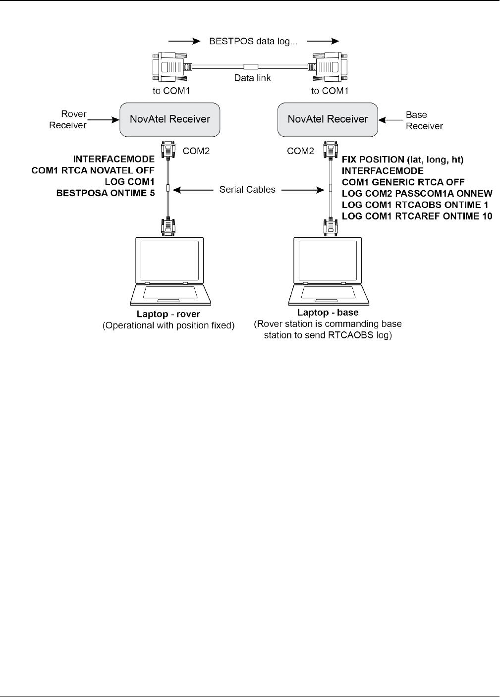
Chapter 3 Logs
OEM7 Commands and Logs Reference Manual v7 627
Figure 13: Pass Through Log Data
Under default conditions, the two receivers "chatter" back and forth with the Invalid Command
Option message (due to the command interpreter in each receiver not recognizing the command
prompts of the other receiver). The chattering in turn causes the accepting receiver to transmit
new pass through logs with the response data from the other receiver. To avoid the chattering
problem, use the INTERFACEMODE command (see page 193) on the accepting port to disable
error reporting from the receiving port command interpreter.
If the accepting port's error reporting is disabled by INTERFACEMODE, the BESTPOSA data
record passes through and creates two records.
The reason that two records are logged from the accepting receiver is the first record was ini-
tiated by receipt of the BESTPOSA first terminator <CR>. The second record followed in
response to the BESTPOSA second terminator <LF>.
Note the time interval between the first character received and the terminating <LF> can be cal-
culated by differencing the two GPS reference time tags. This pass through feature is useful for
time tagging the arrival of external messages. These messages can be any user related data.
When using this feature for tagging external events, it is recommended that the rover receiver
be disabled from interpreting commands so the receiver does not respond to the messages,
using the INTERFACEMODE command (see page 193).
If the BESTPOSB binary log data is input to the accepting port (log com2 passcom1a onchanged),
the BESTPOSB binary data at the accepting port is converted to a variation of ASCII hexadecimal
before it is passed through to com2 port for logging.

Chapter 3 Logs
OEM7 Commands and Logs Reference Manual v7 628
Field Field Type Description Format Binary
Bytes
Binary
Offset
1PASSCOM
header
Log header. See Messages on page25 for
more information. H 0
2 #bytes Number of bytes to follow Ulong 4 H
3 data Message data Char
[80] 80 H+4
4 xxxx 32-bit CRC (ASCII and Binary only) Ulong 4 H+4+
(#bytes)
5 [CR][LF] Sentence terminator (ASCII only) - - -

Chapter 3 Logs
OEM7 Commands and Logs Reference Manual v7 629
3.100 PASSTHROUGH
Redirected data from all ports
Platform: OEM719, OEM729, OEM7500, OEM7600, OEM7700, OEM7720, PwrPak7,
SPAN CPT7
This log outputs pass through data from all receiver ports. The behavior is the same as the port
specific pass though logs described in PASSCOM, PASSAUX, PASSUSB, PASSETH1, PASSICOM,
PASSNCOM on page624.
Message ID: 1342
Log Type: Asynch
Recommended Input:
log passthrougha onchanged
ASCII Example:
#PASSTHROUGHA,COM1,0,73.0,FINESTEERING,1625,165965.067,02040008,5fa3,
39275;USB1,80,i\xd3\x00\x87>\xb0\x00'\x91\xb3"\xa0D?\xaa\xb2\x00\x07op
\x18@\x05\xe9\xd4\x08\xe7\x03\x7f\xfd\x18{\x80w\xff\xf2N_cy\x11\x80\
x0bC\xdc\x01@\x00\xdfr\xb1`\x873\xff\x81]\x7f\xe3\xff\xea\x83v\x08M\
xd8?\xfcr\xf7\x01\x18\x00\x17\x1d2\xd1\xd1b\x00*5cb8bd9a
Field Field type Description Format Binary
Bytes
Binary
Offset
1PASSTHROUGH
header
Log header. See Messages on
page25 for more information. H 0
2 Port See Table 58: COM Port Identifiers
on page333 Enum 4 H
3 #bytes Number of bytes to follow Ulong 4 H+4
4 data Message data Char
[80] 80 H+8
5 xxxx 32-bit CRC (ASCII and Binary only) Ulong 4 H+8+#bytes
6 [CR][LF] Sentence terminator (ASCII only) - - -

Chapter 3 Logs
OEM7 Commands and Logs Reference Manual v7 630
3.101 PDPPOS
PDP filter position
Platform: OEM719, OEM729, OEM7500, OEM7600, OEM7700, OEM7720, PwrPak7,
SPAN CPT7
The PDPPOS log contains the receiver position computed by the receiver with the PDP filter
enabled. See also the PDPFILTER command on page254.
Message ID: 469
Log Type: Synch
Recommended Input:
log pdpposa ontime 1
ASCII Example:
#PDPPOSA,COM1,0,75.5,FINESTEERING,1431,494991.000,02040000,a210,35548; SOL_
COMPUTED,SINGLE,51.11635010310,-114.03832575772,1065.5019,-
16.9000,WGS84,4.7976,2.0897,5.3062,"",0.000,0.000,8,8,0,0,0,0,0,0*3cbfa646
Field Field
type Description Format Binary
Bytes
Binary
Offset
1PDPPOS
header
Log header. See Messages on page25 for more
information. H 0
2 sol status Solution status (refer to Table 73: Solution
Status on page431) Enum 4 H
3 pos type Position type (refer to Table 74: Position or
Velocity Type on page432) Enum 4 H+4
4 lat Latitude (degrees) Double 8 H+8
5 lon Longitude (degrees) Double 8 H+16
6 hgt Height above mean sea level (m) Double 8 H+24
7 undulation
Undulation - the relationship between the geoid
and the WGS84 ellipsoid (m)
When using a datum other than
WGS84, the undulation value also
includes the vertical shift due to dif-
ferences between the datum in use
and WGS84.
Float 4 H+32
8 datum id# Datum ID number (refer to Table 28: Datum
Transformation Parameters on page117) Enum 4 H+36

Chapter 3 Logs
OEM7 Commands and Logs Reference Manual v7 631
Field Field
type Description Format Binary
Bytes
Binary
Offset
9 lat σ Latitude standard deviation (m) Float 4 H+40
10 lon σ Longitude standard deviation (m) Float 4 H+44
11 hgt σ Height standard deviation (m) Float 4 H+48
12 stn id Base station ID Char[4] 4 H+52
13 diff_age Differential age in seconds Float 4 H+56
14 sol_age Solution age in seconds Float 4 H+60
15 #sats Number of satellites tracked Uchar 1 H+64
16 #sats soln Number of satellites in the solution Uchar 1 H+65
17
Reserved
Uchar 1 H+66
18 Uchar 1 H+67
19 Hex 1 H+68
20 ext sol
stat
Extended solution status (see Table 77:
Extended Solution Status on page435) Hex 1 H+69
21
Galileo
and
BeiDou
sig mask
Galileo and BeiDou signals used mask (see Table
76: Galileo and BeiDou Signal-Used Mask on
page435)
Hex 1 H+70
22
GPS and
GLONASS
sig mask
GPS and GLONASS signals used mask (see Table
75: GPS and GLONASS Signal-Used Mask on
page434)
Hex 1 H+71
23 xxxx 32-bit CRC (ASCII and Binary only) Hex 4 H+72
24 [CR][LF] Sentence terminator (ASCII only) - - -

Chapter 3 Logs
OEM7 Commands and Logs Reference Manual v7 632
3.102 PDPSATS
Satellites used in PDPPOS solution
Platform: OEM719, OEM729, OEM7500, OEM7600, OEM7700, OEM7720, PwrPak7,
SPAN CPT7
This log lists the used and unused satellites for the corresponding PDPPOS solution. It also
describes the signals of the used satellites and reasons for exclusions.
Message ID: 1234
Log Type: Synch
Recommended Input:
log pdpsatsa ontime 1
Abbreviated ASCII Example:
<PDPSATS COM1 0 80.0 FINESTEERING 1690 603073.000 02000008 be33 43488
<21
<GPS 11 GOOD 00000001
<GPS 27 GOOD 00000001
...
<GPS 1 GOOD 00000001
<GPS 7 GOOD 00000001
<SBAS 133 NOTUSED 00000000
<SBAS 138 NOTUSED 00000000
<SBAS 135 NOTUSED 00000000
<GLONASS 10-7 GOOD 00000001
<GLONASS 21+4 GOOD 00000001
...
<GLONASS 12-1 GOOD 00000001
<GLONASS 11 GOOD 00000001
Field Field
type Description Format Binary
Bytes
Binary
Offset
1PDPSATS
header
Log header. See Messages on page25 for more
information. H 0
2 #entries Number of records to follow Ulong 4 H
3 system See Table 102: Satellite System on page545 Enum 4 H+4
4Satellite
ID Satellite identifier Ulong 4 H+8
5 Status Satellite status (see Table 79: Observation
Statuses on page438) Enum 4 H+12

Chapter 3 Logs
OEM7 Commands and Logs Reference Manual v7 633
Field Field
type Description Format Binary
Bytes
Binary
Offset
6Status
mask
See Table 80: BESTSATS GPS Signal Mask on
page439, Table 81: BESTSATS GLONASS Signal
Mask on page440, Table 82: BESTSATS Galileo
Signal Mask on page440, and Table 83:
BESTSATS BeiDou Signal Mask on page440
Hex 4 H+16
7 Next satellite offset = H+4+(#sat x 16)
8 xxxx 32-bit CRC (ASCII and Binary only) Ulong 4
H+4+
(#sat x
16)
9 [CR][LF] Sentence terminator (ASCII only) - - -

Chapter 3 Logs
OEM7 Commands and Logs Reference Manual v7 634
3.103 PDPVEL
PDP filter velocity
Platform: OEM719, OEM729, OEM7500, OEM7600, OEM7700, OEM7720, PwrPak7,
SPAN CPT7
The PDPVEL log contains the pseudorange velocity computed by the receiver with the PDP filter
enabled. See also the PDPFILTER command on page254.
Message ID: 470
Log Type: Synch
Recommended Input:
log pdpvela ontime 1
ASCII Example:
#PDPVELA,COM1,0,75.0,FINESTEERING,1430,505990.000,02000000,b886,2859;SOL_
COMPUTED,SINGLE,0.150,0.000,27.4126,179.424617,-0.5521,0.0*7746b0fe
Field Field
type Description Format Binary
Bytes
Binary
Offset
1PDPVEL
header
Log header. See Messages on page25 for more
information. H 0
2sol
status
Solution status (refer to Table 73: Solution Status
on page431) Enum 4 H
3vel
type
Velocity type (refer to Table 74: Position or
Velocity Type on page432) Enum 4 H+4
4 latency
A measure of the latency in the velocity time tag in
seconds. It should be subtracted from the time to
give improved results
Float 4 H+8
5 age Differential age in seconds Float 4 H+12
6 hor spd Horizontal speed over ground, in metres per
second Double 8 H+16
7 trk gnd Actual direction of motion over ground (track over
ground) with respect to True North, in degrees Double 8 H+24
8 height
Height in metres where positive values indicate
increasing altitude (up) and negative values
indicate decreasing altitude (down)
Double 8 H+32
9 Reserved Float 4 H+40
10 xxxx 32-bit CRC (ASCII and Binary only) Ulong 4 H+44
11 [CR]
[LF] Sentence terminator (ASCII only) - - -

Chapter 3 Logs
OEM7 Commands and Logs Reference Manual v7 635
3.104 PDPXYZ
PDP filter Cartesian position and velocity
Platform: OEM719, OEM729, OEM7500, OEM7600, OEM7700, OEM7720, PwrPak7,
SPAN CPT7
The PDPXYZ log contains the Cartesian position in X, Y and Z coordinates as computed by the
receiver with the PDP filter enabled. See also the PDPFILTER command on page254.
Message ID: 471
Log Type: Synch
Recommended Input:
log pdpxyza ontime 1
ASCII Example:
#PDPXYZA,COM1,0,75.5,FINESTEERING,1431,494991.000,02040000,33ce,35548;SOL_
COMPUTED,SINGLE,-1634531.8128,-
3664619.4862,4942496.5025,2.9036,6.1657,3.0153,SOL_COMPUTED,SINGLE,-2.5588e-
308,-3.1719e-308,3.9151e-
308,0.0100,0.0100,0.0100,"",0.150,0.000,0.000,8,8,0,0,0,0,0,0*a20dbd4f
Field Field
type Description Format Binary
Bytes
Binary
Offset
1PDPXYZ
header
Log header. See Messages on page25 for more
information. H 0
2P-sol
status
Solution status (refer to Table 73: Solution
Status on page431) Enum 4 H
3 pos type Position type (refer to Table 74: Position or
Velocity Type on page432) Enum 4 H+4
4 P-X Position X-coordinate (m) Double 8 H+8
5 P-Y Position Y-coordinate (m) Double 8 H+16
6 P-Z Position Z-coordinate (m) Double 8 H+24
7 P-X σ Standard deviation of P-X (m) Float 4 H+32
8 P- Y σ Standard deviation of P-Y (m) Float 4 H+36
9 P-Z σ Standard deviation of P-Z (m) Float 4 H+40
10 V-sol
status
Solution status (refer to Table 73: Solution
Status on page431) Enum 4 H+44
11 vel type Velocity type (refer to Table 74: Position or
Velocity Type on page432) Enum 4 H+48

Chapter 3 Logs
OEM7 Commands and Logs Reference Manual v7 636
Field Field
type Description Format Binary
Bytes
Binary
Offset
12 V-X Velocity vector along X-axis (m) Double 8 H+52
13 V-Y Velocity vector along Y-axis (m) Double 8 H+60
14 V-Z Velocity vector along Z-axis (m) Double 8 H+68
15 V-X σ Standard deviation of V-X (m) Float 4 H+76
16 V-Y σ Standard deviation of V-Y (m) Float 4 H+80
17 V-Z σ Standard deviation of V-Z (m) Float 4 H+84
18 stn ID Base station ID Char[4] 4 H+88
19 V-latency
A measure of the latency in the velocity time tag
in seconds. It should be subtracted from the
time to give improved results
Float 4 H+92
20 diff_age Differential age in seconds Float 4 H+96
21 sol_age Solution age in seconds Float 4 H+100
22 #sats Number of satellite vehicles tracked Uchar 1 H+104
23 #sats soln Number of satellite vehicles used in solution Uchar 1 H+105
24
Reserved
Uchar 1 H+106
25 Uchar 1 H+107
26 Uchar 1 H+108
27 ext sol
stat
Extended solution status (see Table 77:
Extended Solution Status on page435) Hex 1 H+109
28
Galileo
and
BeiDou sig
mask
Galileo and BeiDou signals used mask (see
Table 76: Galileo and BeiDou Signal-Used Mask
on page435)
Hex 1 H+110
29
GPS and
GLONASS
sig mask
GPS and GLONASS signals used mask (see Table
75: GPS and GLONASS Signal-Used Mask on
page434)
Hex 1 H+111
30 xxxx 32-bit CRC (ASCII and Binary only) Hex 4 H+112
31 [CR][LF] Sentence terminator (ASCII only) - - -
Chapter 3 Logs
OEM7 Commands and Logs Reference Manual v7 637
3.105 PORTSTATS
Port statistics
Platform: OEM719, OEM729, OEM7500, OEM7600, OEM7700, OEM7720, PwrPak7,
SPAN CPT7
This log conveys various status parameters of the receiver’s communication ports. The receiver
maintains a running count of a variety of status indicators of the data link. This log outputs a
report of those indicators.
Message ID: 72
Log Type: Polled
Recommended Input:
log portstatsa once
ASCII example:
#PORTSTATSA,USB1,0,69.5,FINESTEERING,1971,489026.000,02004020,a872,14434;29,COM
1,0,3109742555,0,0,435636653,0,0,0,0,COM2,0,207,0,0,32,0,0,0,0,COM3,0,207,0,0,3
2,0,0,0,0,FILE,0,0,0,0,0,0,0,0,0,USB1,175513,21321491,175513,0,0,0,0,0,0,USB2,0
,0,0,0,0,0,0,0,0,USB3,0,0,0,0,0,0,0,0,0,COM4,139542424,189379232,139542424,0,69
771230,0,0,0,0,ICOM1,0,0,0,0,0,0,0,0,0,ICOM2,0,0,0,0,0,0,0,0,0,ICOM3,0,0,0,0,0,
0,0,0,0,NCOM1,0,0,0,0,0,0,0,0,0,NCOM2,0,0,0,0,0,0,0,0,0,NCOM3,0,0,0,0,0,0,0,0,0
,ICOM4,0,0,0,0,0,0,0,0,0,WCOM1,0,394864554,0,0,0,0,0,0,0,COM5,0,6,0,0,4,0,0,0,0
,CCOM1,0,0,0,0,0,0,0,0,0,CCOM2,0,0,0,0,0,0,0,0,0,CCOM3,0,0,0,0,0,0,0,0,0,CCOM4,
0,0,0,0,0,0,0,0,0,CCOM5,0,0,0,0,0,0,0,0,0,CCOM6,0,0,0,0,0,0,0,0,0,ICOM5,0,0,0,0
,0,0,0,0,0,ICOM6,0,0,0,0,0,0,0,0,0,ICOM7,0,0,0,0,0,0,0,0,0*b9c28761
Parity and framing errors occur for COM ports if poor transmission lines are encountered
or if there is an incompatibility in the data protocol. If errors occur, you may need to con-
firm the bit rate, number of data bits, number of stop bits and parity of both the transmit
and receiving ends. Characters may be dropped when the CPU is overloaded.
Field Field type Description Format Binary
Bytes
Binary
Offset
1PORTSTATS
header
Log header. See Messages on page25 for
more information. H 0
2 #port Number of ports with information to follow Long 4 H
3 port Refer to Table 31: Communications Port
Identifiers on page132 Enum 4 H+4
4 rx chars Total number of characters received
through this port Ulong 4 H+8

Chapter 3 Logs
OEM7 Commands and Logs Reference Manual v7 638
Field Field type Description Format Binary
Bytes
Binary
Offset
5 tx chars Total number of characters transmitted
through this port Ulong 4 H+12
6 acc rx chars Total number of accepted characters
received through this port Ulong 4 H+16
7dropped rx
chars Number of software overruns in receive Ulong 4 H+20
8 interrupts Number of interrupts on this port Ulong 4 H+24
9 breaks Number of breaks (only for serial ports) Ulong 4 H+28
10 par err Number of parity errors (only for serial
ports) Ulong 4 H+32
11 frame err Number of framing errors (only for serial
ports) Ulong 4 H+36
12 rx overruns Number of hardware overruns in receive Ulong 4 H+40
13 Next port offset = H+4+(#port x 40)
14 xxxx 32-bit CRC (ASCII and Binary only) Ulong 4
H+4+
(#port x
40)
15 [CR][LF] Sentence terminator (ASCII only) - - -

Chapter 3 Logs
OEM7 Commands and Logs Reference Manual v7 639
3.106 PPPPOS
PPP filter position
Platform: OEM719, OEM729, OEM7500, OEM7600, OEM7700, OEM7720, PwrPak7,
SPAN CPT7
This log contains the position solution computed by the PPP filter.
Message ID: 1538
Log Type: Synch
Recommended Input:
log pppposa ontime 1
ASCII Example:
#PPPPOSA,COM1,0,80.0,FINESTEERING,1735,345300.000,02000000,6f47,44027;SOL_
COMPUTED,PPP,51.11635350286,-114.03819287079,1064.5365,-
16.9000,WGS84,0.0375,0.0460,0.0603,"0",4.000,0.000,12,12,12,12,0,00,00,03*ef17d
668
Field Field type Description Format Binary
Bytes
Binary
Offset
1PPPPOS
header
Log header. See Messages on page25 for
more information. H 0
2 Status Solution status (see Table 73: Solution
Status on page431) Enum 4 H
3 Type Position type (see Table 122: Position Type
on the next page) Enum 4 H+4
4 lat Latitude (degrees) Double 8 H+8
5 lon Longitude (degrees) Double 8 H+16
6 hgt Height above mean sea level (m) Double 8 H+24
7 undulation Undulation - the relationship between the
geoid and the WGS84 ellipsoid (m)aFloat 4 H+32
8 datum id# Datum ID number (see Table 28: Datum
Transformation Parameters on page117) Enum 4 H+36
9 lat σ Latitude standard deviation (m) Float 4 H+40
10 lon σ Longitude standard deviation (m) Float 4 H+44
aWhen using a datum other than WGS84, the undulation value also includes the vertical shift due to differences
between the datum in use and WGS84.

Chapter 3 Logs
OEM7 Commands and Logs Reference Manual v7 640
Field Field type Description Format Binary
Bytes
Binary
Offset
11 hgt σ Height standard deviation (m) Float 4 H+48
12 stn id Base station ID Char[4] 4 H+52
13 diff_age Differential age in seconds Float 4 H+56
14 sol_age Solution age in seconds Float 4 H+60
15 #SVs Number of satellites tracked Uchar 1 H+64
16 #solnSVs Number of satellites vehicles used in
solution Uchar 1 H+65
17 #ggL1 Number of GPS plus GLONASS plus BDS
L1/B1 used in solution Uchar 1 H+66
18 #solnMultiSVs Number of satellites with multi-frequency
signals used in solution Uchar 1 H+67
19 Reserved Hex 1 H+68
20 ext sol stat Extended solution status (see Table 77:
Extended Solution Status on page435) Hex 1 H+69
21 Reserved Hex 1 H+70
22
GPS and
GLONASS sig
mask
GPS and GLONASS signals used mask (see
Table 75: GPS and GLONASS Signal-Used
Mask on page434 or Table 76: Galileo and
BeiDou Signal-Used Mask on page435)
Hex 1 H+71
23 xxxx 32-bit CRC (ASCII and Binary only) Ulong 4 H+72
24 [CR][LF] Sentence terminator (ASCII only) - - -
ASCII Binary Description
NONE 0 No solution
PPP_CONVERGING 68 Converging TerraStar-C solution
PPP 69 Converged TerraStar-C solution
PPP_BASIC_CONVERGING 77 Converging TerraStar-L solution
PPP_BASIC 78 Converged TerraStar-L solution
Table 122: Position Type

Chapter 3 Logs
OEM7 Commands and Logs Reference Manual v7 641
3.107 PPPSATS
Satellites used in the PPPPOS solution
Platform: OEM719, OEM729, OEM7500, OEM7600, OEM7700, OEM7720, PwrPak7,
SPAN CPT7
This log lists the used and unused satellites for the corresponding PPPPOS solution. It also
describes the signals of the used satellites and reasons for exclusions.
Message ID: 1541
Log Type: Synch
Recommended Input:
log pppsatsa ontime 1
Abbreviated ASCII Example:
<PPPSATS COM1 0 80.0 FINESTEERING 1735 345300.000 02000000 ce3f 44027
<12
<GPS 3 GOOD 00000003
<GPS 5 GOOD 00000003
<GPS 6 GOOD 00000003
<GPS 7 GOOD 00000003
<GPS 8 GOOD 00000003
<GPS 10 GOOD 00000003
<GPS 13 GOOD 00000003
<GPS 16 GOOD 00000003
<GPS 19 GOOD 00000003
<GPS 23 GOOD 00000003
<GPS 26 GOOD 00000003
<GPS 28 GOOD 00000003
Field Field
type Description Format Binary
Bytes
Binary
Offset
1PPPSATS
header
Log header. See Messages on page25 for more
information. H 0
2 #entries Number of records to follow Ulong 4 H
3 System Satellite system (see Table 102: Satellite
System on page545) Enum 4 H+4

Chapter 3 Logs
OEM7 Commands and Logs Reference Manual v7 642
Field Field
type Description Format Binary
Bytes
Binary
Offset
4Satellite
ID
In binary logs, the satellite ID field is 4 bytes.
The 2 lowest-order bytes, interpreted as a
USHORT, are the system identifier: for
instance, the PRN for GPS, or the slot for
GLONASS. The 2 highest-order bytes are the
frequency channel for GLONASS, interpreted as
a SHORT and zero for all other systems.
In ASCII and abbreviated ASCII logs, the
satellite ID field is the system identifier. If the
system is GLONASS and the frequency channel
is not zero, then the signed channel is appended
to the system identifier. For example, slot 13,
frequency channel -2 is output as 13-2.
Ulong 4 H+8
5 Status Satellite status (see Table 79: Observation
Statuses on page438) Enum 4 H+12
6Signal
Mask
Signals used in the solution (see Table 80:
BESTSATS GPS Signal Mask on page439, Table
81: BESTSATS GLONASS Signal Mask on
page440, Table 82: BESTSATS Galileo Signal
Mask on page440 and Table 83: BESTSATS
BeiDou Signal Mask on page440)
Hex 4 H+16
7 Next satellite offset = H + 4 + (#entries x 16)
8 xxxx 32-bit CRC (ASCII and Binary only) Ulong 4
H+4+
(#entries
x 16)
9 [CR][LF] Sentence terminator (ASCII only) - - -

Chapter 3 Logs
OEM7 Commands and Logs Reference Manual v7 643
3.108 PROFILEINFO
Profile information in NVM
Platform: OEM719, OEM729, OEM7500, OEM7600, OEM7700, OEM7720, PwrPak7,
SPAN CPT7
This log outputs a list of Profiles in the system. Refer also to the PROFILE command on
page278.
A list may consist of a maximum of 20 profiles.
Message ID: 1412
Log Type: Polled
Recommended Input:
log profileinfoa onchanged
ASCII Examples:
#PROFILEINFOA,COM1,0,84.0,UNKNOWN,0,17539.339,024c0020,ae3a,10526;
"BASE",0,2,
"LOG VERSION",
"SERIALCONFIG COM2 230400"*0ad5cda5
Field Field Type Description Format Binary
Bytes
Binary
Offset
1PROFILEINFO
header
Log header. See Messages on page25
for more information. - H 0
2 Name Profile Name String
[Max 20]
variable
1H
3 Status Word Refer toTable 123: Status Word on the
next page Ulong 4 variable
4# of
Commands
Number of commands assigned to the
Profile Ulong 4 variable
5 Command Profile command String
[Max 150]
variable
1variable
6 Next command offset = variable
7 xxxx 32-bit CRC (ASCII and Binary only) Ulong 4 variable
8 [CR][LF] Sentence terminator (ASCII only) - - -
1In the binary case, each string field needs to be NULL terminated and additional bytes of padding added to
maintain 4-byte alignment, up to the maximum defined by the string size. The next defined field starts
immediately at the next 4-byte alignment following the NULL.

Chapter 3 Logs
OEM7 Commands and Logs Reference Manual v7 644
Bit # Mask Description
0 0x00000001 Activate Flag
(0 – Deactivate (default), 1 –Activate)
1 – 3 0x0000000E Reserved
4 0x00000010 Command 1 validation Flag
(0 – Valid (default), 1 – Invalid)
5 0x00000020 Command 2 validation Flag
6 0x00000040 Command 3 validation Flag
7 0x00000080 Command 4 validation Flag
8 0x00000100 Command 5 validation Flag
9 0x00000200 Command 6 validation Flag
10 0x00000400 Command 7 validation Flag
11 0x00000800 Command 8 validation Flag
12 0x00001000 Command 9 validation Flag
13 0x00002000 Command 10 validation Flag
14 0x00004000 Command 11 validation Flag
15 0x00008000 Command 12 validation Flag
16 0x00010000 Command 13 validation Flag
17 0x00020000 Command 14 validation Flag
18 0x00040000 Command 15 validation Flag
19 0x00080000 Command 16 validation Flag
20 0x00100000 Command 17 validation Flag
21 0x00200000 Command 18 validation Flag
22 0x00400000 Command 19 validation Flag
23 0x00800000 Command 20 validation Flag
24 - 31 0xFF000000 Reserved
Table 123: Status Word
Chapter 3 Logs
OEM7 Commands and Logs Reference Manual v7 645
3.109 PSRDOP
DOP values for the satellites used in the PSR solution
Platform: OEM719, OEM729, OEM7500, OEM7600, OEM7700, OEM7720, PwrPak7,
SPAN CPT7
The PSRDOP log contains the Dilution Of Precision (DOP) values for the satellites being used in
the PSR solution. The PSR DOPs are updated every 60 seconds or whenever the satellites used in
the PSR solution changes.
DOP values are a measure of the solution strength. Essentially, the DOPs reflect the geometry of
the satellites used in the solution. Solutions with good counts of well-distributed satellites will
have low DOPs and should be accurate and reliable. Solutions with fewer or poorly-distributed
satellites will have high DOPs and be less accurate and reliable. As a rough guideline, PDOP val-
ues less than 4 imply a solution with reasonable geometry.
There can be many reasons for high DOP values. The most common reason is that there are
obstructions limiting satellite visibility. Even if satellites are visible and being tracked they
might still not be used in the solution if, for example, they are unhealthy or there are not cor-
rections available for them. The PSRSATS log (see page 650) will inform which satellites are
being tracked and explain why a tracked satellite is not used in the solution.
The DOPs do not consider that different satellites or signals will be weighted differently in the
solution. Therefore, they do not completely reflect the solution quality. Ultimately, the standard
deviations reported in the PSRPOS log (see page 648) are the best reflection of the solution
accuracy.
1. If a satellite is locked out using the LOCKOUT command (see page 218), it will still
show in the prn list but it will be significantly deweighted in the dop calculation.
2. The vertical dilution of precision can be calculated by:
vdop = √pdop2 - hdop2
3. If the DOP is not yet calculated, a default value of 9999.0 is displayed.
Message ID: 174
Log Type: Asynch
Recommended Input:
log psrdopa onchanged
ASCII Example:
#PSRDOPA,COM1,0,56.5,FINESTEERING,1337,403100.000,02000000,768f,1984;1.9695,1.7
613,1.0630,1.3808,0.8812,5.0,10,14,22,25,1,24,11,5,20,30,7*106de10a
Field Field
type Format Binary
Bytes
Binary
Offset
1PSRDOP
header
Log header. See Messages on page25 for more
information. H 0

Chapter 3 Logs
OEM7 Commands and Logs Reference Manual v7 646
Field Field
type Format Binary
Bytes
Binary
Offset
2 gdop
Geometric dilution of precision - assumes 3D
position and receiver clock offset (all 4
parameters) are unknown
Float 4 H
3 pdop Position dilution of precision - assumes 3D position
is unknown and receiver clock offset is known Float 4 H+4
4 hdop Horizontal dilution of precision. Float 4 H+8
5 htdop Horizontal position and time dilution of precision. Float 4 H+12
6 tdop
Time dilution of precision - assumes 3D position is
known and only the receiver clock offset is
unknown
Float 4 H+16
7 cutoff GPS elevation cut-off angle Float 4 H+20
8 #PRN Number of satellites PRNs to follow Long 4 H+24
9 PRN PRN of SV PRN tracking, null field until position
solution available Ulong 4 H+28
10... Next PRN offset = H+28+(#prn x 4)
11 xxxx 32-bit CRC (ASCII and Binary only) Ulong 4
H+28+
(#prn
x 4)
12 [CR]
[LF] Sentence terminator (ASCII only) - - -

Chapter 3 Logs
OEM7 Commands and Logs Reference Manual v7 647
3.110 PSRDOP2
DOP values for the satellites used in the PSR solution
Platform: OEM719, OEM729, OEM7500, OEM7600, OEM7700, OEM7720, PwrPak7,
SPAN CPT7
The PSRDOP2 log contains the Dilution Of Precision (DOP) values for the satellites being used in
the PSR solution. This log is similar to the PSRDOP log (see page 645) but contains the per-sys-
tem TDOPs; see the PSRDOP log for more information on the DOPs.
Message ID: 1163
Log Type: Asynch
Recommended Input:
log psrdop2a onchanged
ASCII Example:
#PSRDOP2A,COM1,0,89.5,FINESTEERING,1613,164820.000,02000008,0802,39031;1.6740,1
.3010,0.6900,1.1030,2,GPS,0.6890,GLONASS,0.7980*5dd123d0.
Field Field
type Description Format Binary
Bytes
Binary
Offset
1PSRDOP2
header
Log header. See Messages on page25 for
more information. H 0
2 GDOP
Geometric dilution of precision - assumes 3D
position and receiver clock offset (all 4
parameters) are unknown
Float 4 H
3 PDOP
Position dilution of precision - assumes 3D
position is unknown and receiver clock offset
is known
Float 4 H+4
4 HDOP Horizontal dilution of precision Float 4 H+8
5 VDOP Vertical dilution of precision Float 4 H+12
6 #systems Number of systems Ulong 4 H+16
7 system See Table 64: System Used for Timing on
page350 Enum 4 H+20
8 TDOP Time dilution of precision Float 4 H+24
9 Next satellite offset = H+20+(#systems x 8)
10 xxxx 32-bit CRC (ASCII and Binary only) Hex 4
H+20+
(#systems
x 8)
11 [CR][LF] Sentence terminator (ASCII only) - - -

Chapter 3 Logs
OEM7 Commands and Logs Reference Manual v7 648
3.111 PSRPOS
Pseudorange position
Platform: OEM719, OEM729, OEM7500, OEM7600, OEM7700, OEM7720, PwrPak7,
SPAN CPT7
This log contains the position computed by the receiver, along with three status flags. In addi-
tion, it reports other status indicators, including differential age, which is useful in predicting
anomalous behavior brought about by outages in differential corrections.
Message ID: 47
Log Type: Synch
Recommended Input:
log psrposa ontime 1
ASCII Example:
#PSRPOSA,COM1,0,58.5,FINESTEERING,1419,340037.000,02000040,6326,2724;SOL_
COMPUTED,SINGLE,51.11636177893,-114.03832396506,1062.5470,-
16.2712,WGS84,1.8532,1.4199,3.3168,"",0.000,0.000,12,12,0,0,0,06,0,33*d200a78c
There are DGPS use cases in which the base receiver is not maintained or controlled by
the positioning user. For example, the US Coast Guard operates a differential correction
service which broadcasts GPS differential corrections over marine radio beacons. As a
user, all you need is a marine beacon receiver and a GNSS receiver to achieve
positioning accuracy of less than 1 metre. In this case, the Coast Guard owns and
operates the base receiver at known coordinates. Other examples of users appearing to
use only one GNSS receiver include FM radio station correction services, privately owned
radio transmitters and corrections carried by communication satellites. Some of the
radio receivers have built-in GNSS receivers and combined antennas, so they even
appear to look as one self contained unit.
The major factors degrading GPS signals which can be removed or reduced with
differential methods are the atmosphere, ionosphere, satellite orbit errors, and satellite
clock errors. Some errors which are not removed include receiver noise and multipath.
Field Field type Description Format Binary
Bytes
Binary
Offset
1PSRPOS
header
Log header. See Messages on page25 for
more information. H 0
2 sol status Solution status (see Table 73: Solution Status
on page431) Enum 4 H
3 pos type Position type (see Table 74: Position or
Velocity Type on page432) Enum 4 H+4

Chapter 3 Logs
OEM7 Commands and Logs Reference Manual v7 649
Field Field type Description Format Binary
Bytes
Binary
Offset
4 lat Latitude (degrees) Double 8 H+8
5 lon Longitude (degrees) Double 8 H+16
6 hgt Height above mean sea level (m) Double 8 H+24
7 undulation Undulation - the relationship between the
geoid and the WGS84 ellipsoid (m) aFloat 4 H+32
8 datum id# Datum ID number (see Table 28: Datum
Transformation Parameters on page117) Enum 4 H+36
9 lat σ Latitude standard deviation (m) Float 4 H+40
10 lon σ Longitude standard deviation (m) Float 4 H+44
11 hgt σ Height standard deviation (m) Float 4 H+48
12 stn id Base station ID Char[4] 4 H+52
13 diff_age Differential age in seconds Float 4 H+56
14 sol_age Solution age in seconds Float 4 H+60
15 #SVs Number of satellites tracked Uchar 1 H+64
16 #solnSVs Number of satellite vehicles used in solution Uchar 1 H+65
17
Reserved
Uchar 1 H+66
18 Uchar 1 H+67
19 Hex 1 H+68
20 ext sol stat Extended solution status (see Table 77:
Extended Solution Status on page435) Hex 1 H+69
21
Galileo and
BeiDou sig
mask
Galileo and BeiDou signals used mask (see
Table 76: Galileo and BeiDou Signal-Used
Mask on page435)
Hex 1 H+70
22
GPS and
GLONASS
sig mask
GPS and GLONASS signals used mask (see
Table 75: GPS and GLONASS Signal-Used
Mask on page434)
Hex 1 H+71
23 xxxx 32-bit CRC (ASCII and Binary only) Hex 4 H+72
24 [CR][LF] Sentence terminator (ASCII only) - - -
aWhen using a datum other than WGS84, the undulation value also includes the vertical shift due to differences
between the datum in use and WGS84.

Chapter 3 Logs
OEM7 Commands and Logs Reference Manual v7 650
3.112 PSRSATS
Satellites used in PSRPOS solution
Platform: OEM719, OEM729, OEM7500, OEM7600, OEM7700, OEM7720, PwrPak7,
SPAN CPT7
This log lists the used and unused satellites for the corresponding PSRPOS solution. It also
describes the signals of the used satellites and reasons for exclusions.
Message ID: 1162
Log Type: Synch
Recommended Input:
log psrsats ontime 1
Abbreviated ASCII Example:
<PSRSATS COM1 0 80.0 FINESTEERING 1729 154910.000 02004000 fea4 11465
<20
<GPS 31 GOOD 00000003
<GPS 14 GOOD 00000003
<GPS 22 GOOD 00000003
<GPS 11 GOOD 00000003
<GPS 1 GOOD 00000003
<GPS 32 GOOD 00000003
<GPS 18 GOOD 00000003
<GPS 24 GOOD 00000003
<GPS 19 GOOD 00000003
<GLONASS 24+2 GOOD 00000003
<GLONASS 10-7 GOOD 00000003
<GLONASS 9-2 GOOD 00000003
<GLONASS 2-4 GOOD 00000003
<GLONASS 1+1 GOOD 00000003
<GLONASS 11 GOOD 00000003
<GLONASS 17+4 GOOD 00000003
<GLONASS 18-3 GOOD 00000003
<GALILEO 12 LOCKEDOUT 00000000
<GALILEO 11 LOCKEDOUT 00000000
<BEIDOU 8 GOOD 00000003
Field Field
type Description Format Binary
Bytes
Binary
Offset
1PSRSATS
header
Log header. See Messages on page25 for more
information. H 0
2 #entries Number of records to follow Ulong 4 H
3 system See Table 102: Satellite System on page545 Enum 4 H+4

Chapter 3 Logs
OEM7 Commands and Logs Reference Manual v7 651
Field Field
type Description Format Binary
Bytes
Binary
Offset
4Satellite
ID Satellite identifier Ulong 4 H+8
5 Status Satellite status (see Table 79: Observation
Statuses on page438) Enum 4 H+12
6Signal
mask
See Table 80: BESTSATS GPS Signal Mask on
page439, Table 81: BESTSATS GLONASS Signal
Mask on page440, Table 82: BESTSATS Galileo
Signal Mask on page440, and Table 83:
BESTSATS BeiDou Signal Mask on page440
Hex 4 H+16
7 Next satellite offset = H+4+(#sat x 16)
8 xxxx 32-bit CRC (ASCII and Binary only) Hex 4
H+4+
(#sat x
16)
9 [CR][LF] Sentence terminator (ASCII only) - - -
Chapter 3 Logs
OEM7 Commands and Logs Reference Manual v7 652
3.113 PSRVEL
Pseudorange velocity
Platform: OEM719, OEM729, OEM7500, OEM7600, OEM7700, OEM7720, PwrPak7,
SPAN CPT7
In the PSRVEL log the actual speed and direction of the receiver antenna over ground is
provided. The velocity measurements sometimes have a latency associated with them. The time
of validity is the time tag in the log minus the latency value.
In a PSRVEL log, the actual speed and direction of the receiver antenna over ground is
provided. The receiver does not determine the direction a vessel, craft or vehicle is poin-
ted (heading) but rather the direction of motion of the GNSS antenna relative to ground.
The velocity in the PSRVEL log is determined by the pseudorange filter. Velocities from the pseu-
dorange filter are calculated from the Doppler.
The velocity status indicates varying degrees of velocity quality. To ensure healthy velocity, the
velocity sol-status must also be checked. If the sol-status is non-zero, the velocity is likely
invalid. It should be noted that the receiver does not determine the direction a vessel, craft, or
vehicle is pointed (heading), but rather the direction of the motion of the GPS antenna relative to
the ground.
The latency of the instantaneous Doppler velocity is always 0.15 seconds. The latency rep-
resents an estimate of the delay caused by the tracking loops under acceleration of approx-
imately 1 G. For most users, the latency can be assumed to be zero (instantaneous velocity).
Message ID: 100
Log Type: Synch
Recommended Input:
log psrvela ontime 1
ASCII Example:
#PSRVELA,COM1,0,52.5,FINESTEERING,1337,403362.000,02000000,658b,1984;SOL_
COMPUTED,PSRDIFF,0.250,9.000,0.0698,26.582692,0.0172,0.0*a94e5d48
Consider the case where vehicles are leaving a control center. The control center’s
coordinates are known but the vehicles are on the move. Using the control center’s pos-
ition as a reference, the vehicles are able to report where they are with PSRPOS and
their speed and direction with PSRVEL at any time.

Chapter 3 Logs
OEM7 Commands and Logs Reference Manual v7 653
Field Field
type Description Format Binary
Bytes
Binary
Offset
1PSRVEL
header
Log header. See Messages on page25 for more
information. H 0
2sol
status
Solution status, see Table 73: Solution Status on
page431 Enum 4 H
3vel
type
Velocity type, see Table 74: Position or Velocity
Type on page432 Enum 4 H+4
4 latency
A measure of the latency in the velocity time tag in
seconds. It should be subtracted from the time to
give improved results
Float 4 H+8
5 age Differential age in seconds Float 4 H+12
6 hor spd Horizontal speed over ground, in metres per
second Double 8 H+16
7 trk gnd Actual direction of motion over ground (track over
ground) with respect to True North, in degrees Double 8 H+24
8vert
spd
Vertical speed, in metres per second, where
positive values indicate increasing altitude (up) and
negative values indicate decreasing altitude (down)
Double 8 H+32
9 Reserved Float 4 H+40
10 xxxx 32-bit CRC (ASCII and Binary only) Ulong 4 H+44
11 [CR]
[LF] Sentence terminator (ASCII only) - - -

Chapter 3 Logs
OEM7 Commands and Logs Reference Manual v7 654
3.114 PSRXYZ
Pseudorange Cartesian position and velocity
Platform: OEM719, OEM729, OEM7500, OEM7600, OEM7700, OEM7720, PwrPak7,
SPAN CPT7
This log contains the receiver’s pseudorange position and velocity in ECEF coordinates. The pos-
ition and velocity status field’s indicate whether or not the corresponding data is valid. See Fig-
ure 11: The WGS84 ECEF Coordinate System on page449 for a definition of the ECEF
coordinates.
The velocity status indicates varying degrees of velocity quality. To ensure healthy velocity, the
velocity sol-status must also be checked. If the sol-status is non-zero, the velocity is likely
invalid. It should be noted that the receiver does not determine the direction a vessel, craft or
vehicle is pointed (heading) but rather the direction of the motion of the GNSS antenna relative
to the ground.
The latency of the instantaneous Doppler velocity is always 0.15 seconds. The latency rep-
resents an estimate of the delay caused by the tracking loops under acceleration of approx-
imately 1 G. For most users, the latency can be assumed to be zero (instantaneous velocity).
Message ID: 243
Log Type: Synch
Recommended Input:
log psrxyza ontime 1
ASCII Example:
#PSRXYZA,COM1,0,58.5,FINESTEERING,1419,340038.000,02000040,4a28,2724;SOL_
COMPUTED,SINGLE,-1634530.7002,-
3664617.2823,4942495.5175,1.7971,2.3694,2.7582,SOL_COMPUTED,DOPPLER_
VELOCITY,0.0028,0.0231,-
0.0120,0.2148,0.2832,0.3297,"",0.150,0.000,0.000,12,12,0,0,0,06,0,33*4fdbcdb1
The instantaneous Doppler is the measured Doppler frequency which consists of the
satellite's motion relative to the receiver (Satellite Doppler + User Doppler) and the
clock (local oscillator) drift.
Field Field
type Description Format Binary
Bytes
Binary
Offset
1PSRXYZ
header
Log header. See Messages on page25 for more
information. H 0
2P-sol
status
Solution status, see Table 73: Solution Status
on page431 Enum 4 H

Chapter 3 Logs
OEM7 Commands and Logs Reference Manual v7 655
Field Field
type Description Format Binary
Bytes
Binary
Offset
3 pos type Position type, see Table 74: Position or Velocity
Type on page432 Enum 4 H+4
4 P-X Position X-coordinate (m) Double 8 H+8
5 P-Y Position Y-coordinate (m) Double 8 H+16
6 P-Z Position Z-coordinate (m) Double 8 H+24
7 P-X σ Standard deviation of P-X (m) Float 4 H+32
8 P-Y σ Standard deviation of P-Y (m) Float 4 H+36
9 P-Z σ Standard deviation of P-Z (m) Float 4 H+40
10 V-sol
status
Solution status, see Table 73: Solution Status
on page431 Enum 4 H+44
11 vel type Velocity type, see Table 74: Position or Velocity
Type on page432 Enum 4 H+48
12 V-X Velocity vector along X-axis (m/s) Double 8 H+52
13 V-Y Velocity vector along Y-axis (m/s) Double 8 H+60
14 V-Z Velocity vector along Z-axis (m/s) Double 8 H+68
15 V-X σ Standard deviation of V-X (m/s) Float 4 H+76
16 V-Y σ Standard deviation of V-Y (m/s) Float 4 H+80
17 V-Z σ Standard deviation of V-Z (m/s) Float 4 H+84
18 stn ID Base station ID Char[4] 4 H+88
19 V-latency
A measure of the latency in the velocity time tag
in seconds. It should be subtracted from the
time to give improved results
Float 4 H+92
20 diff_age Differential age in seconds Float 4 H+96
21 sol_age Solution age in seconds Float 4 H+100
22 #SVs Number of satellites tracked Uchar 1 H+104
23 #solnSVs Number of satellite vehicles used in solution Uchar 1 H+105
24
Reserved
Char 1 H+106
25 Char 1 H+107
26 Char 1 H+108

Chapter 3 Logs
OEM7 Commands and Logs Reference Manual v7 656
Field Field
type Description Format Binary
Bytes
Binary
Offset
27 ext sol
stat
Extended solution status (see Table 77:
Extended Solution Status on page435) Hex 1 H+109
28
Galileo
and
BeiDou sig
mask
Galileo and BeiDou signals used mask (see
Table 76: Galileo and BeiDou Signal-Used Mask
on page435)
Hex 1 H+110
29
GPS and
GLONASS
sig mask
GPS and GLONASS signals used mask (see Table
75: GPS and GLONASS Signal-Used Mask on
page434)
Hex 1 H+111
30 xxxx 32-bit CRC (ASCII and Binary only) Hex 4 H+112
31 [CR][LF] Sentence terminator (ASCII only) - - -
Chapter 3 Logs
OEM7 Commands and Logs Reference Manual v7 657
3.115 QZSSALMANAC
Decoded QZSS Almanac parameters
Platform: OEM719, OEM729, OEM7500, OEM7600, OEM7700, OEM7720, PwrPak7,
SPAN CPT7
This log contains the decoded almanac parameters as received from the satellite with the parity
information removed and appropriate scaling applied.
The OEM7 family of receivers automatically save almanacs in their Non-Volatile Memory (NVM),
so creating an almanac boot file is not necessary.
For more information about QZSS almanac data, refer to the Interface Specifications for
QZSS at http://qzss.go.jp/en/technical/ps-is-qzss/ps-is-qzss.html.
Message ID: 1346
Log Type: Asynch
Recommended Input:
log qzssalmanaca onchanged
ASCII Example:
#QZSSALMANACA,COM1,0,89.5,SATTIME,1642,148584.000,02000008,67d2,39655;
1,
193,1642,208896.0,7.587582e-02,-2.94869425e-09,-1.4441238e+00,
-1.5737385e+00,1.7932513e+00,0.00000000,0.00000000,7.29336435e-05,
4.2159360e+07,7.11809030e-01,7,7*fb648921
The speed at which the receiver locates and locks onto new satellites is improved if
the receiver has approximate time and position, as well as an almanac. This allows
the receiver to compute the elevation of each satellite so it can tell which satellites
are visible and their Doppler offsets, improving Time to First Fix (TTFF).
Field Field Type Description Format Binary
Bytes
Binary
Offset
1QZSSALMANAC
Header
Log header. See Messages on page25
for more information. H 0
2 #messages
Number of satellite PRN almanac
messages to follow. Set to zero until
almanac data is available
Ulong 4 H
3 PRN Satellite PRN number for current
message (dimensionless) Ulong 4 H+4
4 week Almanac reference week Ulong 4 H+8

Chapter 3 Logs
OEM7 Commands and Logs Reference Manual v7 658
Field Field Type Description Format Binary
Bytes
Binary
Offset
5 seconds Almanac reference time (s) Double 8 H+12
6 ecc
Eccentricity (dimensionless) defined
for a conic section where
e = 0 is a circle,
e = 1 is a parabola,
0 < e < 1 is an ellipse
e > 1 is a hyperbola
Double 8 H+20
7 ώ Rate of right ascension (radians/s) Double 8 H+28
8ω0Right, ascension (radians) Double 8 H+36
9 ω
Argument of perigee (radians)
measurement along the orbital path
from the ascending node to the point
where the SV is closest to the Earth, in
the direction of the SV's motion
Double 8 H+44
10 M0Mean anomaly of reference time
(radians) Double 8 H+52
11 af0 Clock aging parameter (s) Double 8 H+60
12 af1 Clock aging parameter (s/s) Double 8 H+68
13 N Corrected mean motion (radians/s) Double 8 H+76
14 A Semi-major axis (m) Double 8 H+84
15 inclination
angle Angle of inclination Double 8 H+92
16 health-prn SV health from Page 25 of subframe 4
or 5 (6 bits) Ulong 4 H+100
17 health-alm SV health from almanac (8 bits) Ulong 4 H+104
18 Next PRN offset = H+4+(#messages x 104)
19 xxxx 32-bit CRC (ASCII and Binary only) Ulong 4
H+4+
(#messages
x 104)
20 [CR][LF] Sentence terminator (ASCII only) - - -

Chapter 3 Logs
OEM7 Commands and Logs Reference Manual v7 659
3.116 QZSSEPHEMERIS
Decoded QZSS parameters
Platform: OEM719, OEM729, OEM7500, OEM7600, OEM7700, OEM7720, PwrPak7,
SPAN CPT7
This log contains a single set of QZSS ephemeris parameters.
Message ID: 1336
Log Type: Asynch
Recommended Input:
log qzssephemerisa onchanged
ASCII Example:
#QZSSEPHEMERISA,COM1,0,93.5,SATTIME,1642,153690.000,02000008,1e9d,
39655;193,153690.000000000,7,201,201,1642,1642,154800.000000000,
4.216030971806980e+07,2.115802417e-09,-2.152109479,0.075863329,
-1.573817810,-0.000007546,0.000009645,-177.375000000,-219.875000000,
-0.000000797,-0.000002151,0.711859299,-2.978695503e-10,-1.443966112,
-1.636139580e-09,713,154800.000000000,-5.122274160e-09,-0.000000163,
1.250555215e-12,0.000000000,FALSE,0.000072933,4.000000000,0,0,0,0
*fbb52c7f
Field Field Type Description Format Binary
Bytes
Binary
Offset
1QZSSEPHEMERIS
header
Log header. See Messages on page25 for
more information. H 0
2 PRN Satellite PRN number Ulong 4 H
3 tow Time stamp of subframe 0 (s) Double 8 H+4
4 health Health status - a 6-bit health code as
defined in QZSS Interface Specification Ulong 4 H+12
5 IODE1 Issue of ephemeris data 1 Ulong 4 H+16
6 IODE2 Issue of ephemeris data 2 Ulong 4 H+20
7 week GPS reference week number Ulong 4 H+24
8 z week
Z count week number. This is the week
number from subframe 1 of the
ephemeris. The ‘toe week’ (field #7) is
derived from this to account for rollover
Ulong 4 H+28
9 toe Reference time for ephemeris (s) Double 8 H+32
10 A Semi-major axis (m) Double 8 H+40

Chapter 3 Logs
OEM7 Commands and Logs Reference Manual v7 660
Field Field Type Description Format Binary
Bytes
Binary
Offset
11 ΔN Mean motion difference (radians/s) Double 8 H+48
12 M0Mean anomaly of reference time (radius) Double 8 H+56
13 ecc
Eccentricity (dimensionless) quantity
defined for a conic section where
e = 0 is a circle,
e = 1 is a parabola,
0<e<1 is an ellipse
e>1 is a hyperbola
Double 8 H+64
14 ω
Argument of perigee (radians)
measurement along the orbital path from
the ascending node to the point where the
SV is closest to the Earth, in the direction
of the SV's motion
Double 8 H+72
15 cuc Argument of latitude (amplitude of
cosine, radians) Double 8 H+80
16 cus Argument of latitude (amplitude of sine,
radians) Double 8 H+88
17 crc Orbit radius (amplitude of cosine,
metres) Double 8 H+96
18 crs Orbit radius (amplitude of sine, metres) Double 8 H+104
19 cic Inclination (amplitude of cosine, radians) Double 8 H+112
20 cis Inclination (amplitude of sine, radians) Double 8 H+120
21 I0Inclination angle at reference time
(radians) Double 8 H+128
22 İ Rate of inclination angle (radians/s) Double 8 H+136
23 ω0Right ascension (radians) Double 8 H+144
24 ώ Rate of right ascension (radians/s) Double 8 H+152
25 iodc Issue of data clock Ulong 4 H+160
26 toc SV clock correction term (s) Double 8 H+164
27 tgd Estimated group delay difference (s) Double 8 H+172
28 afo Clock aging parameter (s) Double 8 H+180
29 af1 Clock aging parameter (s/s) Double 8 H+188

Chapter 3 Logs
OEM7 Commands and Logs Reference Manual v7 661
Field Field Type Description Format Binary
Bytes
Binary
Offset
30 af2 Clock aging parameter (s/s/s) Double 8 H+196
31 AS
Anti-spoofing on:
0= FALSE
1=TRUE
Enum 4 H+204
32 N Corrected mean motion (radians/s) Double 8 H+208
33 URA
User Range Accuracy variance, m2. The
ICD specifies that the URA index
transmitted in the ephemerides can be
converted to a nominal standard
deviation value using an algorithm listed
there. We publish the square of the
nominal value (variance)
Double 8 H+216
34 Fit Interval
Curve fit interval:
0 = Ephemeris data are effective for 2
hours
1 = Ephemeris data are effective for
more than 2 hours
Uchar 1 H+224
35 Reserved Uchar 1 H+225
36 Reserved Uchar 1 H+226
37 Reserved Uchar 1 H+227
38 xxxx 32-bit CRC (ASCII and Binary only) Ulong 4 H+228
39 [CR][LF] Sentence terminator (ASCII only) - - -

Chapter 3 Logs
OEM7 Commands and Logs Reference Manual v7 662
3.117 QZSSIONUTC
QZSS ionospheric and time information
Platform: OEM719, OEM729, OEM7500, OEM7600, OEM7700, OEM7720, PwrPak7,
SPAN CPT7
This log contains the Ionospheric Model parameters (ION) and the Universal Time Coordinated
parameters (UTC) for QZSS.
Message ID: 1347
Log Type: Asynch
Recommended Input:
log qzssionutca onchanged
ASCII Example:
#QZSSIONUTCA,COM1,0,94.0,FINESTEERING,1642,153300.565,02480008,158b,
39655;1.396983861923218e-08,-6.705522537231444e-8,
0.000000000000000e+000,1.788139343261719e-07,8.396800000000000e+04,
7.536640000000000e+05,-7.864320000000000e+05,-6.946816000000000e+06,
1642,307200,-5.5879354476928711e-09,5.329070518e-15,1768,4,15,15,0
*0204eec1
Field Field Type Description Format Binary
Bytes
Binary
Offset
1QZSSIONUTC
Header
Log header. See Messages on page25
for more information. H 0
2 a0 Alpha parameter constant term Double 8 H
3 a1 Alpha parameter 1st order term Double 8 H+8
4 a2 Alpha parameter 2nd order term Double 8 H+16
5 a3 Alpha parameter 3rd order term Double 8 H+24
6 b0 Beta parameter constant term Double 8 H+32
7 b1 Beta parameter 1st order term Double 8 H+40
8 b2 Beta parameter 2nd order term Double 8 H+48
9 b3 Beta parameter 3rd order term Double 8 H+56
10 utc wn UTC reference week number Ulong 4 H+64
11 tot Reference time of UTC parameters Ulong 4 H+68
12 A0 UTC constant term of polynomial Double 8 H+72
13 A1 UTC 1st order term of polynomial Double 8 H+80

Chapter 3 Logs
OEM7 Commands and Logs Reference Manual v7 663
Field Field Type Description Format Binary
Bytes
Binary
Offset
14 wn lsf Future week number Ulong 4 H+88
15 dn
Day number
(the range is 1 to 7 where Sunday=1 and
Saturday=7)
Ulong 4 H+92
16 deltat ls Delta time due to leap seconds Long 4 H+96
17 deltat lsf Future delta time due to leap seconds Long 4 H+100
18 Reserved 4 H+104
19 xxxx 32-bit CRC (ASCII and Binary only) Ulong 4 H+108
20 [CR][LF] Sentence terminator (ASCII only) - - -

Chapter 3 Logs
OEM7 Commands and Logs Reference Manual v7 664
3.118 QZSSRAWALMANAC
Raw QZSS almanac data
Platform: OEM719, OEM729, OEM7500, OEM7600, OEM7700, OEM7720, PwrPak7,
SPAN CPT7
This log contains the undecoded almanac subframes as received from the QZSS satellite.
Message ID: 1345
Log Type: Asynch
Recommended Input:
log qzssrawalmanaca onchanged
ASCII Example:
#QZSSRAWALMANACA,COM1,0,93.5,SATTIME,1642,153300.000,02480008,64c4,39655;1642,
208896.000,7,
1,8b000031c390c1820e33d007fefe07cae831c5293ebfe15049104a000001,
51,8b000031c613f3336a1fffffffffffffffffffffffffffffffffff000000,
49,8b000031cd90f14e6a7cf3cf1cf1cf3cf3c73cf1cf1cf3cf3cf3cf000002,
50,8b000031ce14f24e6a0cf3cf1df1cfffffffffffffffffffffffff000002,
56,8b000031d511f80ff70003292ef496000006fffffffa4b6a0fe8040f0002,
52,8b000031e692f4a00a0fff83f060f2080180082082082082082002080381,
53,8b000031e717f58082082082082082082082082082082082082082082080
*ca4596f9ŀ
The OEM7 family of receivers automatically saves almanacs in their Non-Volatile
Memory (NVM), therefore creating an almanac boot file is not necessary.
Field Field Type Description Format Binary
Bytes
Binary
Offset
1
QZSSRAW
ALMANAC
header
Log header. See Messages on page25
for more information. H 0
2 ref week Almanac reference week number Ulong 4 H
3 ref secs Almanac reference time, in milliseconds
(binary data) or seconds (ASCII data) GPSec 4 H+4
4 #subframes Number of subframes to follow Ulong 4 H+8

Chapter 3 Logs
OEM7 Commands and Logs Reference Manual v7 665
Field Field Type Description Format Binary
Bytes
Binary
Offset
5 svid
SV ID (satellite vehicle ID)
A value between 1 and 32 for the SV ID
indicates the PRN of the satellite. Any
other values indicate the page ID.
SV ID 1 to 10 corresponds to QZSS PRN
193 to 202. Refer to QZSS Interface
Specification for more details.
Hex 2 H+12
6 data Subframe page data Hex 30 H+14
7 Next subframe offset = H+12+(#subframe x 32)
8 xxxx 32-bit CRC (ASCII and Binary only) Hex 4
H+12+
(#subframes
x 32)
9 [CR][LF] Sentence terminator (ASCII only) - - -

Chapter 3 Logs
OEM7 Commands and Logs Reference Manual v7 666
3.119 QZSSRAWCNAVMESSAGE
Raw QZSS L2C and L5 CNAV message
Platform: OEM719, OEM729, OEM7500, OEM7600, OEM7700, OEM7720, PwrPak7,
SPAN CPT7
This log provides the raw QZSS L2C and L5 CNAV message.
The QZSSRAWCNAVMESSAGE log is not output by default. To receive this log, data
decoding for QZSSL2C or QZSSL5 must be enabled using the DATADECODESIGNAL
command (see page 111) for the specific signal.
Message ID: 1530
Log Type: Collection
Recommended Input:
log qzssrawcnavmessage onnew
ASCII Example:
#QZSSRAWCNAVMESSAGEA,COM1,0,66.5,SATTIME,1902,405696.000,02000020,20f7,13677;40
,193,10,8b04a84110edc2a346a97d311c3ff854620220004eba94f1313134f005530056c9da0cc
c2300*1f2abac5
Field Field type Description Format Binary
Bytes
Binary
Offset
1QZSSRAWCNAVMESSAGE
header
Log header. See Messages on
page25 for more information. - H 0
2 signal channel Signal channel providing the bits Ulong 4 H
3 PRN QZSS satellite PRN number Ulong 4 H+4
4 message ID CNAV message ID Ulong 4 H+8
5 data CNAV raw message data Hex[38] 38 H+12
6 xxxx 32-bit CRC (ASCII and Binary
only) Hex 4 H+50
7 [CR][LF] Sentence terminator (ASCII
only) - - -

Chapter 3 Logs
OEM7 Commands and Logs Reference Manual v7 667
3.120 QZSSRAWEPHEM
QZSS Raw ephemeris information
Platform: OEM719, OEM729, OEM7500, OEM7600, OEM7700, OEM7720, PwrPak7,
SPAN CPT7
This log contains the raw binary information for subframes one, two and three from the satellite
with the parity information removed. Each subframe is 240 bits long (10 words - 24 bits each)
and the log contains a total 720 bits (90 bytes) of information (240 bits x 3 subframes). This
information is preceded by the PRN number of the satellite from which it originated. This mes-
sage is not generated unless all 10 words from all 3 frames have passed parity.
Message ID: 1331
Log Type: Asynch
Recommended Input:
log qzssrawephema onnew
ASCII Example:
#QZSSRAWEPHEMA,COM1,0,84.5,SATTIME,1642,230580.000,02000008,2f9e,39655;
193,1642,234000,8b00004b0f879aa01c8000000000000000000000f6df3921fe0005
fffdbd,8b00004b1009dfd2bb1ec493a98277e8fd26d924d5062dcae8f5b739210e,8b
00004b108ffe5bc52864ae00591d003b8b02b6bfe13f3affe2afdff1e7*d2bd151e
Field Field Type Description Format Binary
Bytes
Binary
Offset
1QZSSRAWEPHEM
header
Log header. See Messages on page25
for more information. H 0
2 prn Satellite PRN number Ulong 4 H
3 ref week Ephemeris reference week number Ulong 4 H+4
4 ref secs Ephemeris reference time (s) Ulong 4 H+8
5 subframe1 Subframe 1 data Hex 30 H+12
6 subframe2 Subframe 2 data Hex 30 H+42
7 subframe3 Subframe 3 data Hex 30 H+72
8 xxxx 32-bit CRC (ASCII and Binary only) Ulong 4 H+102
9 [CR][LF] Sentence terminator (ASCII only) - - -

Chapter 3 Logs
OEM7 Commands and Logs Reference Manual v7 668
3.121 QZSSRAWSUBFRAME
Raw QZSS subframe data
Platform: OEM719, OEM729, OEM7500, OEM7600, OEM7700, OEM7720, PwrPak7,
SPAN CPT7
This log contains the raw QZSS subframe data.
A raw QZSS subframe is 300 bits in total, 10 words of 30 bits each. This includes the parity 6 bits
at the end of each word, for a total of 60 parity bits. Note that in Field #4, the ‘data’ field below,
the 60 parity bits are stripped out and only the raw subframe data remains, for a total of 240
bits. There are two bytes added onto the end of this 30 byte packed binary array to pad out the
entire data structure to 32 bytes in order to maintain 4 byte alignment.
Message ID: 1330
Log Type: Asynch
Recommended Input:
log qzssrawsubframea onnew
ASCII Example:
#QZSSRAWSUBFRAMEA,COM1,0,85.5,SATTIME,1642,230604.000,02000008,e56b,39655;193,5
,8b00004b11970637984efbf7fd4d0fa10ca49631ace140740a08fe0dfd43,65*6a7b9123
Field Field Type Description Format Binary
Bytes
Binary
Offset
1
QZSSRAW
SUBFRAME
header
Log header. See Messages on page25 for
more information. H 0
2 PRN Satellite PRN number Ulong 4 H
3 subframe ID Subframe ID Ulong 4 H+4
4 data Raw subframe data Hex
[30] 32aH+8
5 chan Signal channel number that the frame
was decoded on Ulong 4 H+40
6 xxxx 32-bit CRC (ASCII and Binary only) Ulong 4 H+44
7 [CR][LF] Sentence terminator - - -
aIn the binary log case, an additional 2 bytes of padding are added to maintain 4-byte alignment.

Chapter 3 Logs
OEM7 Commands and Logs Reference Manual v7 669
3.122 RAIMSTATUS
RAIM status
Platform: OEM719, OEM729, OEM7500, OEM7600, OEM7700, OEM7720, PwrPak7,
SPAN CPT7
This log provides information on Receiver Autonomous Integrity Monitoring (RAIM) status (refer
to the RAIMMODE command on page289).
Message ID: 1286
Log Type: Synch
Recommended Input:
log raimstatusa ontime 1
ASCII Example:
#RAIMSTATUSA,COM1,0,88.5,FINESTEERING,1837,268443.500,02040008,bf2d,32768;DEFAU
LT,PASS,NOT_AVAILABLE,0.000,NOT_AVAILABLE,0.000,1,GLONASS,10-7*6504be7b
Field Field Type Description Format Binary
Bytes
Binary
Offset
1RAIMSTATUS
Header
Log header. See Messages on page25 for
more information. - H 0
2 RAIM Mode RAIM mode (refer to Table 54: RAIM Mode
Types on page290) Enum 4 H
3Integrity
status
Integrity Status (see Table 124: Integrity
Status on the next page) Enum 4 H+4
4 HPL status
Horizontal protection level status (see Table
125: Protection Level Status on the next
page)
Enum 4 H+8
5 HPL Horizontal protection level (m) Double 8 H+12
6 VPL status
Vertical protection level status (see Table
125: Protection Level Status on the next
page)
Enum 4 H+20
7 VPL Vertical protection level (m) Double 8 H+24
8 #SVs Number of excluded satellites Ulong 4 H+32
9 System Satellite system (see Table 102: Satellite
System on page545) Enum 4 H+36

Chapter 3 Logs
OEM7 Commands and Logs Reference Manual v7 670
Field Field Type Description Format Binary
Bytes
Binary
Offset
10 Satellite ID
In binary logs, the satellite ID field is 4 bytes.
The 2 lowest order bytes, interpreted as a
USHORT, are the system identifier. For
instance, the PRN for GPS or the slot for
GLONASS. The 2 highest-order bytes are the
frequency channel for GLONASS, interpreted
as a SHORT and zero for all other systems.
In ASCII and abbreviated ASCII logs, the
satellite ID field is the system identifier. If
the system is GLONASS and the frequency
channel is not zero, then the signed channel is
appended to the system identifier. For
example, slot 13, frequency channel -2 is
output as 13-2
Ulong 4 H+40
11 Next offset field = H+36+(#SVs * 8)
12 xxxx 32-bit CRC (ASCII and Binary only) Ulong 4
H+36
+
(#SVs
* 8)
13 [CR][LF] Sentence terminator (ASCII only)
Binary ASCII Description
0NOT_
AVAILABLE
RAIM is unavailable because either there is no solution or because the
solution is unique, that is, there is no redundancy
1 PASS RAIM succeeded. Either there were no bad observations or the bad
observations were successfully removed from the solution
2 FAIL RAIM detected a failure and was unable to isolate the bad observations
Table 124: Integrity Status
Binary ASCII Description
0NOT_
AVAILABLE
When RAIM is not available for example, after issuing a FRESET command
(see page 174) or when there are not enough satellites tracked to produce
the required redundant observations
Table 125: Protection Level Status

Chapter 3 Logs
OEM7 Commands and Logs Reference Manual v7 671
Binary ASCII Description
1 PASS
Current protection levels are below alert limits, meaning positioning
accuracy requirements are fulfilled
HPL < HAL
VPL < VAL
2 ALERT
Current protection levels are above alert limits, meaning required
positioning accuracy cannot be guaranteed by RAIM algorithm
HPL ≥ HAL
VPL ≥ VAL

Chapter 3 Logs
OEM7 Commands and Logs Reference Manual v7 672
3.123 RANGE
Satellite range information
Platform: OEM719, OEM729, OEM7500, OEM7600, OEM7700, OEM7720, PwrPak7,
SPAN CPT7
The RANGE log contains the channel measurements for the currently tracked satellites. When
using this log, please keep in mind the constraints noted along with the description.
It is important to ensure that the receiver clock has been set. This can be monitored by the bits
in the Receiver Status field of the log header. Large jumps in pseudorange as well as Accu-
mulated Doppler Range (ADR) occur as the clock is being adjusted. If the ADR measurement is
being used in precise phase processing, it is important not to use the ADR if the "parity known"
flag, in the ch-tr-status field, is not set as there may exist a half (1/2) cycle ambiguity on the
measurement. The tracking error estimate of the pseudorange and carrier phase (ADR) is the
thermal noise of the receiver tracking loops only. It does not account for possible multipath
errors or atmospheric delays.
If multiple signals are being tracked for a given PRN, an entry for each signal, with the same
PRN, appears in the RANGE logs. As shown in Table 126: Channel Tracking Status on page675,
these entries can be differentiated by bits 21-25, which indicate the signal type of the obser-
vation.
For dual antenna receivers, a RANGE_1 log can be requested to get RANGE data from the
second antenna. As described in Table 3: Binary Message Header Structure on page30,
the message type indicates the log is from the second antenna. To request an ASCII log
enter RANGEA_1, and for a binary log enter RANGEB_1.
Message ID: 43
Log Type: Synch
Recommended Input:
log rangea ontime 30
Abbreviated ASCII Example:
<RANGE COM1 0 82.0 FINESTEERING 1729 155076.000 02004000 5103 11465
46
31 0 24514687.250 0.064 -128825561.494675 0.010 3877.473 45.0 563.310 18109c04
31 0 24514688.765 0.096 -100383546.734328 0.010 3021.415 39.8 558.900 02309c0b
14 0 20345286.178 0.047 -106915249.491005 0.008 90.799 47.6 10283.130 08109c24
14 0 20345282.367 0.130 -83310588.842026 0.008 70.753 44.0 10276.900 01303c2b
22 0 20789170.556 0.038 -109247823.573628 0.007 -1421.169 49.4 15829.450
18109c44
22 0 20789164.279 0.138 -85128150.759123 0.007 -1107.404 43.6 15822.400
11303c4b
11 0 21977065.699 0.057 -115490261.964920 0.009 1235.428 46.0 5831.400 18109c64
11 0 21977062.220 0.201 -89992401.903056 0.011 962.671 40.3 5823.900 11303c6b
1 0 23109644.678 0.073 -121441999.794897 0.011 2971.250 43.8 3239.620 18109ca4
1 0 23109646.769 0.073 -94630142.467139 0.011 2315.261 42.1 3233.420 02309cab
1 0 23109647.385 0.009 -90687226.778371 0.009 2218.538 48.9 3237.080 01d03ca4

Chapter 3 Logs
OEM7 Commands and Logs Reference Manual v7 673
32 0 23839782.353 0.133 -125278916.608912 0.022 3033.561 38.7 2193.280 18109cc4
32 0 23839781.295 0.363 -97619939.025504 0.026 2363.815 35.1 2184.900 11303ccb
18 0 22923322.792 0.062 -120462840.747702 0.009 -2710.945 45.3 20493.260
18109d04
18 0 22923320.071 0.350 -93867119.471860 0.012 -2112.426 35.5 20484.400
11303d0b
24 0 23708761.188 0.111 -124590391.778428 0.015 -2376.459 40.2 10643.820
08109d24
24 0 23708763.572 0.065 -97083440.180816 0.015 -1851.788 43.1 10639.420
02309d2b
24 0 23708765.724 0.009 -93038305.697497 0.008 -1774.807 49.1 10641.680
01d03d24
19 0 23739234.067 0.078 -124750470.392697 0.013 -2778.561 43.3 12263.180
08109d64
19 0 23739230.131 0.250 -97208136.646475 0.014 -2165.115 38.4 12255.400
01303d6b
61 9 22189063.544 0.155 -118654856.801346 0.011 -3985.235 43.3 13310.882
08119e04
61 9 22189063.246 0.055 -92287085.024614 0.011 -3099.631 37.6 13303.964
00b13e0b
47 0 21209673.567 0.147 -113059527.680842 0.011 -804.710 43.8 7342.680 08119e24
47 0 21209679.575 0.043 -87935228.320976 0.011 -625.886 39.7 7334.968 00b13e2b
46 5 24097664.754 0.213 -128680178.570435 0.014 -3740.543 40.6 10098.600
08119e44
46 5 24097669.137 0.048 -100084595.729257 0.015 -2909.311 38.8 10082.838
10b13e4b
39 3 21484445.079 0.161 -114645140.076744 0.012 2864.162 43.0 4463.150 18119e64
39 3 21484447.532 0.046 -89168467.325722 0.013 2227.683 39.1 4453.468 10b13e6b
38 8 19445896.471 0.101 -103949483.524466 0.008 -389.973 47.1 11640.260
18119e84
38 8 19445897.101 0.048 -80849619.556577 0.009 -303.312 38.8 11632.974 00b13e8b
48 7 21301665.694 0.166 -113829687.684616 0.011 3143.656 42.8 3778.910 08119ea4
48 7 21301667.294 0.054 -88534230.502244 0.012 2445.068 37.8 3770.968 10b13eab
54 11 20899591.029 0.131 -111837944.708346 0.009 -401.734 44.8 7155.190
18119ec4
54 11 20899589.241 0.024 -86985062.942139 0.009 -312.461 44.8 7146.970 10b13ecb
55 4 23127316.661 0.318 -123455195.443877 0.020 3067.787 37.1 1588.420 18119ee4
55 4 23127321.850 0.032 -96020732.562183 0.021 2386.060 42.3 1580.442 00b13eeb
12 0 26239080.161 0.048 -137887256.553732 0.015 -2696.802 47.6 11527.710
48539c24
12 0 26239085.285 0.012 -102967750.707625 0.013 -2013.883 46.8 11523.770
41933c24
12 0 26239083.219 0.011 -105653860.401460 0.013 -2066.457 47.3 11523.712
42333c24
12 0 26239094.196 0.019 -104310841.607718 0.014 -2040.204 42.7 11522.970
42933c24
11 0 25589806.061 0.045 -134475330.397885 0.013 -729.686 48.0 4974.653 48539c64
11 0 25589809.285 0.010 -100419891.315177 0.012 -545.179 47.8 4969.770 41933c64
11 0 25589806.124 0.010 -103039536.069621 0.011 -559.405 48.0 4969.734 42333c64
11 0 25589818.004 0.017 -101729751.744395 0.013 -552.305 43.7 4967.060 42933c64
8 0 39844800.850 0.077 -207482308.002186 0.018 -507.335 37.4 12048.980 18149c84

Chapter 3 Logs
OEM7 Commands and Logs Reference Manual v7 674
8 0 39844800.076 0.043 -160438471.200694 0.013 -392.547 42.5 12038.660 00349c84
Field Field
type Description Format Binary
Bytes
Binary
Offset
1RANGE
header
Log header. See Messages on page25 for more
information. H 0
2 # obs Number of observations with information to
follow 1Ulong 4 H
3 PRN/slot Satellite PRN number of range measurement
Refer to PRN Numbers on page44 Ushort 2 H+4
4 glofreq (GLONASS Frequency + 7) (see GLONASS Slot
and Frequency Numbers section of this manual) Ushort 2 H+6
5 psr Pseudorange measurement (m) Double 8 H+8
6 psr σ Pseudorange measurement standard deviation
(m) Float 4 H+16
7 adr Carrier phase, in cycles (accumulated Doppler
range) Double 8 H+20
8 adr σ Estimated carrier phase standard deviation
(cycles) Float 4 H+28
9 dopp Instantaneous carrier Doppler frequency (Hz) Float 4 H+32
10 C/No Carrier to noise density ratio
C/No = 10[log10(S/N0)] (dB-Hz) Float 4 H+36
11 locktime Number of seconds of continuous tracking (no
cycle slipping) Float 4 H+40
12 ch-tr-
status
Tracking status (see Table 126: Channel
Tracking Status on the next page and the
example in Figure 14: Channel Tracking
Example on the next page)
Ulong 4 H+44
13... Next PRN offset = H + 4 + (#obs x 44)
variable xxxx 32-bit CRC (ASCII and Binary only) Ulong 4
H+4+
(#obs
x 44)
variable [CR][LF] Sentence terminator (ASCII only) - - -
1Satellite PRNs may have multiple lines of observations, one for each signal tracked.
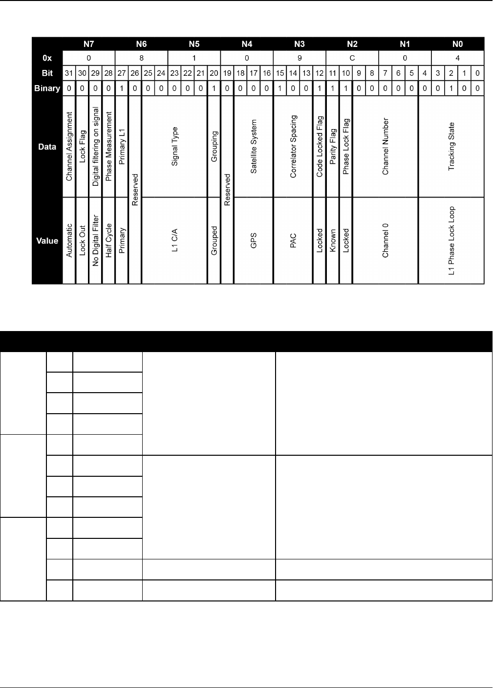
Chapter 3 Logs
OEM7 Commands and Logs Reference Manual v7 675
Figure 14: Channel Tracking Example
Nibble Bit Mask Description Range Value
N0
0 0x00000001
Tracking state
0-23,
see Table 127: Tracking State on
page677
1 0x00000002
2 0x00000004
3 0x00000008
N1
4 0x00000010
5 0x00000020
SV channel number (n-1) (0 = first, n = last)
n depends on the receiver
6 0x00000040
7 0x00000080
N2
8 0x00000100
9 0x00000200
10 0x00000400 Phase lock flag 0 = Not locked , 1 = Locked
11 0x00000800 Parity known flag 0 = Not known, 1 = Known
Table 126: Channel Tracking Status

Chapter 3 Logs
OEM7 Commands and Logs Reference Manual v7 676
Nibble Bit Mask Description Range Value
N3
12 0x00001000 Code locked flag 0 = Not locked, 1 = Locked
13 0x00002000
Correlator type
0-7,
see Table 128: Correlator Type on
page678
14 0x00004000
15 0x00008000
N4
16 0x00010000
Satellite system
0 = GPS
1 = GLONASS
2 = SBAS
3 = Galileo
4 = BeiDou
5 = QZSS
6 = NavIC
7 = Other
17 0x00020000
18 0x00040000
19 0x00080000 Reserved
20 0x00100000 Grouping 0 = Not grouped, 1 = Grouped
21 0x00200000
Signal type
(Dependent on satellite
system above)
GPS:
0 = L1C/A
5 = L2P
9 = L2P (Y), semi-
codeless
14 = L5 (Q)
16 = L1C (P)
17 = L2C (M)
GLONASS:
0 = L1C/A
1 = L2C/A
5 = L2P
6 = L3 (Q)
BeiDou:
0 = B1 (I) with D1
data
1 = B2 (I) with D1
data
2 = B3 (I) with D1
data
4 = B1 (I) with D2
data
5 = B2 (I) with D2
data
6 = B3 (I) with D2
data
7 = B1C (P)
9 = B2a (P)
Galileo:
2 = E1 (C)
6 = E6B
7 = E6C
12 = E5a (Q)
17 = E5b (Q)
20 = E5AltBOC
(Q)
QZSS:
0 = L1C/A
14 = L5 (Q)
16 = L1C (P)
17 = L2C (M)
27 = L6P
SBAS:
0 = L1C/A
6 = L5 (I)
NavIC:
0 = L5 SPS
Other:
19 = L-Band
N5 22 0x00400000
23 0x00800000
24 0x01000000
N6 25 0x02000000
26 0x04000000 Reserved

Chapter 3 Logs
OEM7 Commands and Logs Reference Manual v7 677
Nibble Bit Mask Description Range Value
27 0x08000000 Primary L1 channel 0 = Not primary, 1 = Primary
N7
28 0x10000000 Carrier phase
measurement 1
0 = Half Cycle Not Added
1 = Half Cycle Added
29 0x20000000 Digital filtering on signal 0 = No digital filter
1 = Digital filter
30 0x40000000 PRN lock flag 20 = PRN Not Locked Out
1 = PRN Locked Out
31 0x80000000 Channel assignment 0 = Automatic, 1 = Forced
State Description
0 Idle
1 Sky Search
2 Wide frequency band pull-in
3 Narrow frequency band pull-in
4 Phase lock loop
6 Channel steering
7 Frequency lock loop
9 Channel alignment
10 Code search
11 Aided phase lock loop
23 Side peak detection
Table 127: Tracking State
1This bit is zero until the parity is known and the parity known flag (bit 11) is set to 1.
After a loss of lock, there is a half cycle ambiguity on the ADR (carrier phase) until enough navigation data has
been decoded to determine the correct phase of the carrier. At the point this is determined, the "parity known"
and "half cycle added" flags will get set. If the half cycle flag is set to 1, it indicates that a half cycle was added to
the ADR to correct an inverted phase.
2A PRN can be locked out using the LOCKOUT command.

Chapter 3 Logs
OEM7 Commands and Logs Reference Manual v7 678
State Description
0 N/A
1 Standard correlator: spacing = 1 chip
2 Narrow Correlator: spacing < 1 chip
3 Reserved
4 Pulse Aperture Correlator (PAC)
5-6 Reserved
Table 128: Correlator Type
GNSS
System
Frequency
Band Frequency
Observation Codes
Signal
Type
Pseudo
Range
Carrier
Phase Doppler Signal
Strength
GPS
L1 1575.42 L1CA C1C L1C D1C S1C
L1C(P) C1L L1L D1L S1L
L2 1227.6
L2C(M) C2S L2S D2S S2S
L2P L2P C2P D2P S2P
L2P(Y) C2W L2W D2W S2W
L5 1176.45 L5(Q) C5Q L5Q D5Q S5Q
GLONASS
G1 1598.0625-
1609.3125 L1CA C1C L1C D1C S1C
G2 1242.9375-
1251.6875
L2CA C2C L2C D2C S2C
L2P C2P L2P D2P S2P
G3 1202.025 L3(Q) C3Q L3Q D3Q S3Q
Galileo
E1 1575.42 E1C C1C L1C D1C S1C
E5a 1176.45 E5a(Q) C5Q L5Q D5Q S5Q
E5b 1207.14 E5b(Q) C7Q L7Q D7Q S7Q
E5
(E5a+E5b) 1191.795 E5AltBOC
(Q) C8Q L8Q D8Q S8Q
E6 1278.75 E6C C6C L6C D6C S6C
Table 129: RINEX Mappings

Chapter 3 Logs
OEM7 Commands and Logs Reference Manual v7 679
GNSS
System
Frequency
Band Frequency
Observation Codes
Signal
Type
Pseudo
Range
Carrier
Phase Doppler Signal
Strength
SBAS L1 1575.42 L1CA C1C L1C D1C S1C
L5 1176.45 L5(I) C5I L5I D5I S5I
QZSS
L1 1575.42 L1CA C1C L1C D1C S1C
L1C(P) C1L L1L D1L S1L
L2 1227.6 L2C(M) C2S L2S D2S S2S
L5 1176.45 L5(Q) C5Q L5Q D5Q S5Q
L6 1278.75 L6(P) C6L L6L D6L S6L
BeiDou
B1 1561.098 B1(I) C2I L2I D2I S2I
B1C 1575.42 B1C(P) C1P L1P D1P S1P
B2 1207.14 B2(I) C7I L7I D7I S7I
B2a 1176.45 B2a(P) C5P L5P D5P S5P
B3 1268.52 B3(I) C6I L6I D6I S6I
NavIC L5 1176.45 L5SPS C5A L5A D5A S5A

Chapter 3 Logs
OEM7 Commands and Logs Reference Manual v7 680
3.124 RANGECMP
Compressed version of the RANGE log
Platform: OEM719, OEM729, OEM7500, OEM7600, OEM7700, OEM7720, PwrPak7,
SPAN CPT7
This log contains the RANGE data in a compressed format.
For dual antenna receivers, a RANGECMP_1 log can be requested to get RANGECMP data
from the second antenna. As described in Table 3: Binary Message Header Structure on
page30, the message type indicates the log is from the second antenna. To request an
ASCII log enter RANGECMPA_1, and for a binary log enter RANGECMPB_1.
Message ID: 140
Log Type: Synch
Recommended Input:
log rangecmpa ontime 10
ASCII Example:
#RANGECMPA,COM1,0,63.5,FINESTEERING, 1429,226780.000,02000000,9691,2748;
26,
049c10081857f2df1f4a130ba2888eb9600603a709030000,
0b9c3001225bf58f334a130bb1e2bed473062fa609020000,
449c1008340400e0aaa9a109a7535bac2015cf71c6030000,
4b9c300145030010a6a9a10959c2f09120151f7166030000,
...
0b9d301113c8ffefc284000c6ea051dbf3089da1a0010000,
249d1018c6b7f67fa228820af2e5e39830180ae1a8030000,
2b9d301165c4f8ffb228820a500a089f31185fe0a8020000,
449d1018be18f41f2aacad0a1a934efc40074ecf88030000,
4b9d301182b9f69f38acad0a3e3ac28841079fcb88020000,
849d101817a1f95f16d7af0a69fbe1fa401d3fd064030000,
8b9d30112909fb2f20d7af0a9f24a687521ddece64020000,
249e1118af4e0470f66d4309a0a631cd642cf5b821320000,
2b9eb110a55903502f6e4309ee28d1ad032c7cb7e1320000,
849e1118b878f54f4ed2aa098c35558a532bde1765220000,
8b9eb110abcff71f5ed2aa09cb6ad0f9032b9d16c5220000*0eeead18

Chapter 3 Logs
OEM7 Commands and Logs Reference Manual v7 681
Consider the case where commercial vehicles are leaving a control center. The control
center’s coordinates are known but the vehicles are on the move. Using the control
center’s position as a reference, the vehicles are able to report where they are at any
time. Post-processed information gives more accurate comparisons.
Post-processing can provide post mission position and velocity using raw GNSS collected
from the vehicles. The logs necessary for post-processing include:
RANGECMPB ONTIME 1
RAWEPHEMB ONCHANGED
This is an example of data collection for post-processing. OEM7 based output is
compatible with post-processing software from NovAtel’s Waypoint Products. Refer to
our website at www.novatel.com/support/ for more details.
Field Field
Type Description Format Binary
Bytes
Binary
Offset
1RANGECMP
header
Log header. See Messages on page25 for more
information. H 0
2 #obs Number of satellite observations with
information to follow Ulong 4 H
31st range
record
Compressed range log in format of Table 130:
Range Record Format (RANGECMP only) below Hex 24 H+4
4 Next rangecmp offset = H+4 (#obs x 24)
5 xxxx 32-bit CRC (ASCII and Binary only) Ulong 4
H+4+
(#obs
x 24)
6 [CR][LF] Sentence terminator (ASCII only) - - -
Data Description
Bits
first
to
last
Length
(bits)
Scale
Factor Units
Channel
Tracking
Status
Channel tracking status word 0-31 32
see Table
126:
Channel
Tracking
Status on
page675
-
Table 130: Range Record Format (RANGECMP only)

Chapter 3 Logs
OEM7 Commands and Logs Reference Manual v7 682
Data Description
Bits
first
to
last
Length
(bits)
Scale
Factor Units
Doppler
Frequency Instantaneous carrier Doppler frequency 32-
59 28 1/256 Hz
Pseudorange
(PSR) Pseudorange measurement 60-
95 36 1/128 m
ADR
ADR (Accumulated Doppler Range) is
calculated as follows:
ADR_ROLLS = (RANGECMP_PSR /
WAVELENGTH + RANGECMP_ADR) / MAX_
VALUE
Round to the closest integer
IF (ADR_ROLLS ≤ 0)
ADR_ROLLS = ADR_ROLLS - 0.5
ELSE
ADR_ROLLS = ADR_ROLLS + 0.5
At this point integerise ADR_ROLLS
CORRECTED_ADR = RANGECMP_ADR -
(MAX_VALUE*ADR_ROLLS)
where
ADR has units of cycles
WAVELENGTH = 0.1902936727984 for GPS
L1
WAVELENGTH = 0.2442102134246 for GPS
L2
MAX_VALUE = 8388608
Note: GLONASS satellites emit L1 and L2
carrier waves at a satellite-specific
frequency, refer to the GLONASS section of
An Introduction to GNSS available on our
website
96-
127 32 1/256 cycles
StdDev-PSR Pseudorange measurement standard
deviation
128-
131 4
See Table
131:
StdDev-
PSR Values
on the next
page
m
StdDev-ADR ADR measurement standard deviation 132-
135 4 (n+1)/512 cycles

Chapter 3 Logs
OEM7 Commands and Logs Reference Manual v7 683
Data Description
Bits
first
to
last
Length
(bits)
Scale
Factor Units
PRN/Slot Refer to PRN Numbers on page44 136-
143 8 1 -
Lock Time
Number of seconds of continuous tracking
(no cycle slipping)
This field is constrained to a maximum
value of 2,097,151 which represents a lock
time of 65535.96875 s (2097151 ¸ 32).
144-
164 21 1/32 s
C/No
Carrier to noise density ratio
The C/No is constrained to a value between
20-51 dB-Hz. Thus, if it is reported that
C/No = 20 dB-Hz, the actual value could be
less. Likewise, if it is reported that C/No =
51, the true value could be greater.
165-
169 5 (20+n) dB-Hz
GLONASS
Frequency
number
GLONASS Frequency number 170-
175 n+7 1
Reserved 176-
191 16
Code StdDev-PSR(m)
0 0.050
1 0.075
2 0.113
3 0.169
4 0.253
5 0.380
6 0.570
7 0.854
8 1.281
9 2.375
Table 131: StdDev-PSR Values

Chapter 3 Logs
OEM7 Commands and Logs Reference Manual v7 684
Code StdDev-PSR(m)
10 4.750
11 9.500
12 19.000
13 38.000
14 76.000
15 152.000

Chapter 3 Logs
OEM7 Commands and Logs Reference Manual v7 685
3.125 RANGECMP2
Compressed version of the RANGE log
Platform: OEM719, OEM729, OEM7500, OEM7600, OEM7700, OEM7720, PwrPak7,
SPAN CPT7
This log contains the RANGE data in a compressed format to handle more channels and different
channel types than the RANGECMP log.
For dual antenna receivers, a RANGECMP2_1 log can be requested to get RANGECMP2
data from the second antenna. As described in Table 3: Binary Message Header Struc-
ture on page30, the message type indicates the log is from the second antenna. To
request an ASCII log enter RANGECMP2A_1, and for a binary log enter RANGECMP2B_1.
Message ID: 1273
Log Type: Synch
Recommended Input:
log rangecmp2a ontime 10
Example:
#RANGECMP2A,COM1,0,84.5,FINESTEERING,1681,163457.000,02000020,1fe3,
10526;634,000d00f4fddf05920620e1ffff2979e806e81301c8ffe4ffff03106b5a50
a902c8ff01100054f6bd05410720e1ffff2996ea0e90fb01e2ffe4ffff030e0d656816
03e3ff020400acdcd605c40320e1ffff697b080e9859801300e4ffff4310c94fb8c701
14000317002c554685260520e1ffff295f4412b0ad03c4ffe4ffff03d5a60d18c705c4
ff0401008452b08583f92fe1ffff2998ac65302c800000e4ffff03f32edf784b000000
0520000c8500056cfd2fe1ffff295fa40dd04a822300e4ffff03b8242a58f802230006
1f00c0081385effb2fe1ffff295fc408a83884f8ffe4ffff03b8861608c286f8ff081e
008cb25105970520e1ffff295c2604989483ceffe4ffff03f2862f489006cfff091400
3027e204930020e1ffff695e4407188602ddffe4ffff43b8241480c903ddff0a0e0050
e3e305d3f92fe1ffff2979c89c506d800700e4ffff030f4bdd603a8006000b1900d8f3
cc8543fb2fe1ffff297a280950f2002500e4ffff03f1286880e8022500140118341c0f
0581f92fe1ffff299d4404d02401f2ffe4ffff03920c2f900d82faff160d158cfa6b85
400820e1ffff69baa600b83d02d9ffe4ffff03734a4380ea04ceff170b178874ef0409
fa2fe1ffff299d6409d01904e6ffe4ffff0374ea31304d87daff180213c8039884fd00
20e1ffff697fe401007082d4ffe4ffff033b0616688084c4ff19131a5cdc9585f9fe2f
e1ffff69b8c80e08e5800200e4ffff0357c830a8d001ebff1b0c16a45ca384c80220e1
ffff697f6401888a04efffe4ffff033a463d605e8802001c031c905434051d0720e1ff
ff299cc60b18e881f3ffe4ffff0339462d38e182fbff231050f05e6406b9fd1fe6ffff
6998080f1013801300*61b80516

Chapter 3 Logs
OEM7 Commands and Logs Reference Manual v7 686
Field Field Type Description Format Binary
Bytes
Binary
Offset
1RANGECMP2
header
Log header. See Messages on page25 for
more information. H 0
2 # bytes Number of bytes in the compressed binary
range data1Uchar 4 H
3 RangeData
Compressed binary range data in the format of
Table 132: Satellite Block of the Range Record
Format (RANGECMP2 only) below and Table
133: Signal Block of the Range Record Format
(RANGECMP2 only) on the next page 2
Uchar #bytes H+4
4 xxxx 32-bit CRC (ASCII and binary only) Hex 4
H+4+
(#
bytes)
5 [CR][LF] Sentence terminator (ASCII only) - - -
Data Description
Bits
first
to
last
Length
(bits)
Scale
Factor Units
SV Channel
Number Receiver SV channel number 0-7 8 - -
Satellite
Identifier
Satellite identifier specific to the satellite
system
Refer to PRN Numbers on page44
8-15 8 - -
GLONASS
Frequency
Identifier
GLONASS frequency channel offset by +7 16-
19 4 (7+Ch#) -
Satellite
System
Identifier
Defined in Table 102: Satellite System on
page545
20-
24 5 - Enum
Reserved 25 1 - -
Table 132: Satellite Block of the Range Record Format (RANGECMP2 only)
1Maximum is 2880 bytes for 120 channels; maximum 5760 for 240 channels.
2The compressed binary range data is organized into satellite blocks, one for each satellite. Each satellite block is
followed by a variable number of signal blocks corresponding to the same satellite. For example, a Satellite Block
for GPS PRN 17 may be followed by two Signal Blocks for the L1 C/A and L2C signals.

Chapter 3 Logs
OEM7 Commands and Logs Reference Manual v7 687
Data Description
Bits
first
to
last
Length
(bits)
Scale
Factor Units
Pseudorange
Base
Pseudorange base value to be combined with
PSR Diff and Phaserange Diff in each following
Signal Block
26-
54 29 1 m
Doppler
Base
Doppler base value to be combined with the
Scaled Doppler Diff value in each following
Signal Block
55-
75 21 1 Hz
Number of
Signal
Blocks
The number of Signal Blocks to follow this
Satellite Block. See Table 133: Signal Block of
the Range Record Format (RANGECMP2 only)
below for Signal Block definition
76-
79 4 - -
Data Description
Bits
first
tolast
Length
(bits)
Scale
Factor Units
Signal Type Defined in Table 137: Signal Type
(only in RANGECMP2) on page691 0-4 5 - Enum
Phase Lock Phase Lock: 0 = Not locked, 1 = Locked 5 1 - Bool
Parity Known Parity Known: 0 = Not known, 1 =
Known 6 1 - Bool
Code Lock Code Lock: 0 = Not locked, 1 = Locked 7 1 - Bool
Locktime
Time of continuous tracking with no
cycle slips. The locktime value
saturates at a maximum of 131071 ms
8-24 17 1 ms
Correlator
Type
Correlator type: (see Table 128:
Correlator Type on page678) 25-28 4 - Enum
Primary
Signal
Primary signal: 0 = Not primary,
1 = Primary 29 1 - Bool
Carrier Phase
Measurement
Carrier phase measurement:
0 = Half cycle not added, 1 = Half cycle
added
30 1 - Bool
Reserved 31 1 - -
C/No Carrier to Noise density ratio 32-36 5 (20 + n) dB-Hz
Table 133: Signal Block of the Range Record Format (RANGECMP2 only)

Chapter 3 Logs
OEM7 Commands and Logs Reference Manual v7 688
Data Description
Bits
first
tolast
Length
(bits)
Scale
Factor Units
StdDev PSR
Pseudorange Standard Deviation
(defined Table 134: Std Dev PSR
Scaling below)
37-40 4
Bit Field
in Table
134: Std
Dev PSR
Scaling
below
-
StdDev ADR
Carrier-Phase Standard Deviation
(defined Table 135: Std Dev ADR
Scaling on the next page)
41-44 4
Bit Field
in Table
135: Std
Dev ADR
Scaling
on the
next
page
-
PSR Diff
Pseudorange Diff to be combined with
Pseudorange base i.e.,
PSR = PSRBase + PSRDiff/128
45-58 14 1/128 m
(unsigned)
Phaserange
Diff
Phaserange Diff to be combined with
Pseudorange Base i.e.,
ADR = PSRBase +
PhaserangeDiff/2048
59-78 20 1/2048 m
(unsigned)
Scaled
Doppler Diff1
Doppler Diff to be combined with
Doppler Base. Note that all Doppler
values are scaled to the L1/E1
equivalent value. (refer to Table 136:
L1/E1/B1 Scaling on page690) i.e.,
Doppler = (DopplerBase +
ScaledDopplerDiff/256)/L1ScaleFactor
79-95 17 1/256 Hz
(signed)
PSR Std Dev Bit Field Value Represented Std Dev (m)
0 0.02
1 0.03
2 0.045
Table 134: Std Dev PSR Scaling
1The Scaled Doppler Diff field is the only field in the RANGECMP2 that should be parsed as Two's Complement.
The most significant byte (MSB) determines whether the number will be positive (< 0x7) or negative (> 0x7).
Two's complement should be applied prior to AND, right bit shift computations.

Chapter 3 Logs
OEM7 Commands and Logs Reference Manual v7 689
PSR Std Dev Bit Field Value Represented Std Dev (m)
3 0.066
4 0.099
5 0.148
6 0.22
7 0.329
8 0.491
9 0.732
10 1.092
11 1.629
12 2.43
13 3.625
14 5.409
15 >5.409
ADR Std Dev Bit Field Value Represented Std Dev (cycles)
0 0.00391
1 0.00521
2 0.00696
3 0.00929
4 0.01239
5 0.01654
6 0.02208
7 0.02947
8 0.03933
9 0.05249
10 0.07006
11 0.09350
12 0.12480
Table 135: Std Dev ADR Scaling

Chapter 3 Logs
OEM7 Commands and Logs Reference Manual v7 690
ADR Std Dev Bit Field Value Represented Std Dev (cycles)
13 0.16656
14 0.22230
15 >0.22230
Satellite System Signal Type L1/E1/B1 Scale Factor
GPS
L1CA 1.0
L2Y 154/120
L2C 154/120
L5Q 154/115
GLONASS
L1CA 1.0
L2CA 9/7
L2P 9/7
SBAS L1CA 1.0
L5I 154/115
Galileo
E1 1.0
E5A 154/115
E5B 154/118
AltBOC 154/116.5
E6C 154/125
E6B 154/125
QZSS
L1CA 1.0
L2C 154/120
L5Q 154/115
L6P 154/125
LBAND LBAND 1.0
Table 136: L1/E1/B1 Scaling

Chapter 3 Logs
OEM7 Commands and Logs Reference Manual v7 691
Satellite System Signal Type L1/E1/B1 Scale Factor
BDS
B1 1.0
B1C 1526/1540
B2 1526/1180
B2a 1526/1150
B3 1526/1240
NAVIC L5SPS 1.0
Satellite System Signal Type Value
GPS
L1CA 1
L2Y 4
L2CM 5
L5Q 7
L1C 15
GLONASS
L1CA 1
L2CA 3
L2P 4
L3Q 6
SBAS L1CA 1
L5I 2
Galileo
E1C 1
E5AQ 2
E5BQ 3
AltBOCQ 4
E6C 5
E6B 12
Table 137: Signal Type (only in RANGECMP2)

Chapter 3 Logs
OEM7 Commands and Logs Reference Manual v7 692
Satellite System Signal Type Value
QZSS
L1CA 1
L2CM 3
L5Q 4
L1C 8
L6P 11
LBAND LBAND 1
BDS
B1D1I 1
B1D2I 2
B2D1I 3
B2D2I 4
B3D1I 13
B3D2I 14
B1CP 19
B2AP 20
NAVIC L5SPS 1

Chapter 3 Logs
OEM7 Commands and Logs Reference Manual v7 693
3.126 RANGECMP4
Highly compressed version of the RANGE log
Platform: OEM719, OEM729, OEM7500, OEM7600, OEM7700, OEM7720, PwrPak7,
SPAN CPT7
This log contains the RANGE data in a more heavily compressed format compared to the
RANGECMP2 log.
For dual antenna receivers, a RANGECMP4_1 log can be requested to get RANGECMP4
data from the second antenna. As described in Table 3: Binary Message Header Struc-
ture on page30, the message type indicates the log is from the second antenna. To
request an ASCII log enter RANGECMP4A_1, and for a binary log enter RANGECMP4B_1.
Message ID: 2050
Log Type: Synch
Recommended Input:
log rangecmp4a ontime 10
Example:
#RANGECMP4A,COM1,0,81.5,FINESTEERING,1921,228459.000,00000020,fb0e,
32768;627,630032090851000000009200dbbf7d8306f822d0a3b2bc897f0010d35042
8cf31228ea9f7300040050ff5e641cb7c7463d2a00b6a4644f6e5ee2a0fe530a00fe1f
829dcfe4cf30d52abaf37f94e01621cd8d8c04a0bafcaf00e43b0761690064e7bfe90f
11ce8710a4eb2b573202607403fc28e647c6fe9f550118007a9d839c2680ebfedff687
6be81150411adbc972feef4686c483f30a09f01773ff0b0050d8b8a843f41576b94100
440e1e4f59ace54fffca2700fc1f62e14720f4facba64affbf9c52ff39ce4b3eef9f14
fd0f00244387d00d80fefabfeb0fb3cf456ae97542d410fc9ffab7f601e73580e5efda
ff0f00a0b33991fc072ccbaa99ff134efa9fd0dc684bfc61f0fffeff60b02000000000
8004c0ff3fa0b2f724f7e1eee889e9fb9f3977c0437391ab135877fe0b00301edf93f4
bd63c62850fdbf8527e6e5cd438e3a208400e0ff43bb6f5fc2101c75b058daff375c5e
a4378f51940022eeffff0fe1c97dcda81887c83a63007c9d5a7ed65ce6f901427bffff
3f9c04f735db1d55294a3bfc5f35ccc66df318c412181400140060eedbd7285feaf6a6
53f9bf9fc7fe27cd653633c0b5fcffff03197b4f8228d4e59d0cfbffa731b2f73b07e9
b68078f47f0000a9be7dcdcc51898da269fe839b6191ab9cc67701f21000fc3f0001a1
000000008002c03fb4362793b9bfeb657dfcffe6badabb9a4375b77f5bff1fed87bce6
4454a98ae16c14ff4fec6f7a48f3206b03e8040138fbd0023d225492cd7679a4ffa562
3b08810e42bf05fce17fa41f9a9ccfc8e2626231edf2ff208a1225ce6150204067febf
ef030100000000000028000ca9cc8728bb3306e68af97f921cfce3e632f0d1cf8300c8
f701*6de99eb7

Chapter 3 Logs
OEM7 Commands and Logs Reference Manual v7 694
Field Field Type Description Format Binary
Bytes
Binary
Offset
1RANGECMP4
header
Log header. See Messages on page25 for
more information. - H 0
2 # bytes Number of bytes in the compressed binary
Range Data. Uchar 4 H
3 Range Data
The compressed binary range data is
organized into satellite system blocks which
break down into measurement blocks for each
active signal within each system. Refer to the
following tables for more details about this
format:
Table 138: Header on the next page (sent
once)
Table 139: Satellite and Signal Block on
page696 (sent once per satellite system bit
set to 1 in the GNSS Field found in Table 138:
Header on the next page)
Table 140: Measurement Block Header on
page697 (sent once for each bit set to 1 in the
Satellites Field found in Table 139: Satellite
and Signal Block on page696)
Table 141: Primary Reference Signal
Measurement Block on page698 and Table
142: Secondary Reference Signals
Measurement Block on page699, or Table
143: Primary Differential Signal Measurement
Block on page700 and Table 144: Secondary
Differential Signals Measurement Block on
page701, Measurement Block (sent for each
bit set to 1 in the Included Signals Field for a
given satellite found in Table 139: Satellite
and Signal Block on page696)
The byte data is received MSB
first so each group of bytes (as
defined by the number of needed
bits) must be swapped prior to
processing.
Uchar #
bytes H+4
4 xxxx 32-bit CRC (ASCII only) Hex 4
H+4+
(#
bytes)
5 [CR][LF] Sentence terminator (ASCII only) - - -
Chapter 3 Logs
OEM7 Commands and Logs Reference Manual v7 695
Data
Name Description Bits Scale
Factor
GNSS
Indicates which satellite system data is encoded and in what order. When
the bit is set the satellite data is included. Data for each system is
encoded sequentially:
Bit 0 = GPS
Bit 1 = GLONASS
Bit 2 = SBAS
Bit 5 = Galileo
Bit 6 = BeiDou
Bit 7 = QZSS
Bit 9 = NavIC
L-Band channels are not reported.
16 1
Bit Sum: 16
This block is sent once per message
Table 138: Header

Chapter 3 Logs
OEM7 Commands and Logs Reference Manual v7 696
Data
Name Range Description Bits Scale
Factor
Satellites 0…
1.84467E+19
Indicates which satellites are present for this system
and their order in the message. Each PRN is
represented by a bit. (Bit 0 = PRN 1, Bit 1 = PRN 2, …)
Notes:
lManually assigned channels are not reported.
lGLONASS Satellite: This value represents the Slot
ID of the satellite (range of 1 to 24 where Bit 0 =
Slot ID 1). In the event the Slot ID is between 43
and 63, the actual GLONASS Slot ID has not yet
been determined and has been replaced with a tem-
porary Slot ID calculated using the GLONASS Fre-
quency Number. See the GLONASS Frequency
Number field in Table 140: Measurement Block
Header on the next page for more details.
lSBAS Satellite PRNs 120 to 158 are offset by 120.
(Bit 0 = PRN 120, Bit 1 = 121, …)
lSBAS Satellite PRNs 183 to 187 are offset by 130
lQZSS Satellite PRNs are offset by 193
64 1
Signals 0… 65535
Indicates which signals are present for this system and
their order in the message. Each signal is represented
by a bit as defined in Table 145: Signal Bit Mask on
page702.
16 1
Included
Signals 0… mxn
A two dimensional field to tell the decoder which signals
are present for each of the satellites.
m= The number of rows equals the number of bits set
to 1 found in the Satellites field. (Maximum number of
PRNs in the satellite system)
n= The number of columns equals the number of bits
set to 1 found in the Signals field. (Maximum number of
Signals in the satellite system)
mxn
Bit Sum: 80 + mxn
This block is sent once for each bit set to 1 in the GNSS field found in Table 138:
Header on the previous page.
Table 139: Satellite and Signal Block
Chapter 3 Logs
OEM7 Commands and Logs Reference Manual v7 697
Data
Name Range Description Bits Scale
Factor
Data
Format
Flag
0… 1
Identifies what type of Measurement Block will be used:
0 = Reference
(Table 141: Primary Reference Signal Measurement Block
on the next page and Table 142: Secondary Reference
Signals Measurement Block on page699)
1 = Differential
(Table 143: Primary Differential Signal Measurement Block
on page700 and Table 144: Secondary Differential Signals
Measurement Block on page701)
1 1
Ref Data
Block ID 0… 7
This ID identifies to which reference data the Differential
Data is linked. This value is incremented by 1 each time a
new Reference Measurement Block is used.
3 1
GLONASS
Frequency
Number
0… 20
(-7 to
+13)
These bits are only present for GLONASS satellites in the
Reference Data. This represents the GLONASS Frequency
Number which identifies the frequency offset of the carrier
frequency. The value will appear as a number between 0
and 20 which directly translates into a frequency offset
number between -7 to +13.
If the GLONASS Slot ID is unknown, a temporary Slot ID for
this satellite will be set between 43 and 63 based on the
GLONASS Frequency Number:
PRN = 63 – GLONASS Frequency Number
The GLONASS Frequency Number used in this
calculation is the 0 to 20 value, not the adjus-
ted -7 to +13 value.
5 1
Bit Sum:
4 (Non-
GLONASS)
9 (GLONASS)
This block is sent once for each bit set to 1 in the Satellites field found in Table 139:
Satellite and Signal Block on the previous page.
Table 140: Measurement Block Header

Chapter 3 Logs
OEM7 Commands and Logs Reference Manual v7 698
Data Name Range Description Bits Scale
Factor
Parity Flag 0… 1 0 = Parity Unknown
1 = Parity Known 1 1
½ Cycle Flag 0… 1 0 = Half Cycle Not Added
1 = Half Cycle Added 1 1
C/No 0… 63.95 C/No 11 0.05 dBHz
Lock Time 0… 15 The Lock Time – See Table 146: Lock
Time on page703 4 1
Pseudorange
Std Dev 0… 15
The Pseudorange Standard Deviation (m)
– See Table 148: Pseudorange Std Dev on
page705
4 1
ADR Std Dev 0… 15 The ADR Standard Deviation (cycles) –
See Table 147: ADR Std Dev on page704 4 1
Primary
Pseudorange
0…
68719476.74
The Pseudo Range of the 1st signal
(Signals field in Table 139: Satellite and
Signal Block on page696).
If this value equals (237-1) =
137438953471, it represents a signal that
is not locked.
37 0.0005 m
PhaseRange –
Primary
Pseudorange
±419.4303
(2’s Complement)
If this value equals –(223-1) = -4194304,
it represents the signal is not locked.
23 0.0001 m
Primary
Doppler
+/-
3355.4431
(2’s Complement)
If this value equals –(226-1) = -33554432,
it represents an invalid Doppler.
26 0.0001
m/s
Bit Sum: 111
This block is sent once for the first bit set to 1 in the Included Signals field found in
Table 139: Satellite and Signal Block on page696.
For any bits set to 1 after the first bit set to 1, refer to Table 142: Secondary Refer-
ence Signals Measurement Block on the next page.
This table is for Reference blocks only, as indicated by the Data Format Flag (see
Table 140: Measurement Block Header on the previous page).
Table 141: Primary Reference Signal Measurement Block

Chapter 3 Logs
OEM7 Commands and Logs Reference Manual v7 699
Data Name Range Description Bits Scale
Factor
Parity Flag 0… 1 0 = Parity Unknown
1 = Parity Known 1 1
½ Cycle Flag 0… 1 0 = Half Cycle Not Added
1 = Half Cycle Added 1 1
C/No Indicator 0… 63.95 C/No 11 0.05 dBHz
Lock Time 0… 15 The Lock Time – See Table 146: Lock
Time on page703 4 1
Pseudorange Std
Dev 0… 15
The Pseudorange Standard Deviation
(m) – See Table 148: Pseudorange
Std Dev on page705
4 1
ADR Std Dev 0… 15
The ADR Standard Deviation (cycles) –
See Table 147: ADR Std Dev on
page704
4 1
Pseudorange –
Primary Signal
Pseudorange
±262.1435
(2’s Complement)
If this value equals –(220-1) = -
524288, it indicates the signal is not
locked.
20 0.0005 m
Phaserange –
Pseudorange ±419.4303
(2’s Complement)
If this value equals –(223-1) = -
4194304, it indicates the signal is not
locked.
23 0.0001 m
Doppler –
Primary Doppler ±0.8191
(2’s Complement)
If this value equals –(214-1) = -8192,
it indicates an invalid Doppler.
14 0.0001 m/s
Bit Sum: 82
This block is sent once for each bit set to 1 after the first bit set to 1 in the Included
Signals field found in Table 139: Satellite and Signal Block on page696.
This table is for Reference blocks only, as indicated by the Data Format Flag (see
Table 140: Measurement Block Header on page697).
Table 142: Secondary Reference Signals Measurement Block

Chapter 3 Logs
OEM7 Commands and Logs Reference Manual v7 700
Data Name Range Description Bits Scale
Factor
Parity Flag 0… 1 0 = Parity Unknown
1 = Parity Known 1 1
½ Cycle Flag 0… 1 0 = Half Cycle Not Added
1 = Half Cycle Added 1 1
C/No 0… 63.95 C/No 11 0.05
dBHz
Lock Time 0… 15 The Lock Time – See Table 146: Lock Time on
page703 4 1
Pseudorange
Std Dev 0… 15 The Pseudorange Standard Deviation (m) – See Table
148: Pseudorange Std Dev on page705 4 1
ADR Std Dev 0… 15 The ADR Standard Deviation (cycles) – See Table 147:
ADR Std Dev on page704 4 1
Pseudorange
– Predicted
Pseudorange
±131.0715
(2’s Complement)
If this value equals –(219-1) = -262144, it indicates a
signal that is not locked.
The Predicted Pseudorange = reference pseudorange
plus (the reference doppler x time difference between
the reference log and the differential log). The
Reference log and Differential logs used must contain
matching Ref Data Block ID references (Table 140:
Measurement Block Header on page697).
19 0.0005
m
Phaserange
– Predicted
Phaserange
±3.2767
(2’s Complement)
If this value equals –(216-1) = -32768, it indicates the
signal is not locked.
The Predicted Phaserange = reference phaserange
plus (the reference doppler x time difference between
the reference log and the differential log). The
Reference log and Differential logs used must contain
matching Ref Data Block ID references (Table 140:
Measurement Block Header on page697).
16 0.0001
m
Table 143: Primary Differential Signal Measurement Block

Chapter 3 Logs
OEM7 Commands and Logs Reference Manual v7 701
Data Name Range Description Bits Scale
Factor
Doppler –
Reference
Doppler
±13.1071
(2’s Complement)
If this value equals –(218-1) = -131072, it indicates an
invalid Doppler.
The Reference Doppler is the Doppler for that PRN and
for that signal from the Reference log. The Reference
log and Differential logs used must contain matching
Ref Data Block ID references (Table 140:
Measurement Block Header on page697).
18 0.0001
m/s
Bit Sum: 78
This block is sent once for each bit set to 1 after the first bit set to 1 in the Included
Signals field found in Table 139: Satellite and Signal Block on page696.
For any bits set to 1 after the first bit set to 1, refer to Table 144: Secondary Dif-
ferential Signals Measurement Block below.
This table is for Differential blocks only, as indicated by the Data Format Flag (see
Table 140: Measurement Block Header on page697).
Data Name Range Description Bits Scale
Factor
Parity Flag 0… 1 0 = Parity Unknown
1 = Parity Known 1 1
½ Cycle Flag 0… 1 0 = Half Cycle Not Added
1 = Half Cycle Added 1 1
C/No 0… 63.95 C/No 11 0.05
dBHz
Lock Time 0… 15 The Lock Time – See Table 146: Lock Time on
page703 4 1
Pseudorange
Std Dev 0… 15 The Pseudorange Standard Deviation (m) – See Table
148: Pseudorange Std Dev on page705 4 1
ADR Std Dev 0… 15 The ADR Std Dev (cycles)– See Table 147: ADR Std
Dev on page704 4 1
Table 144: Secondary Differential Signals Measurement Block
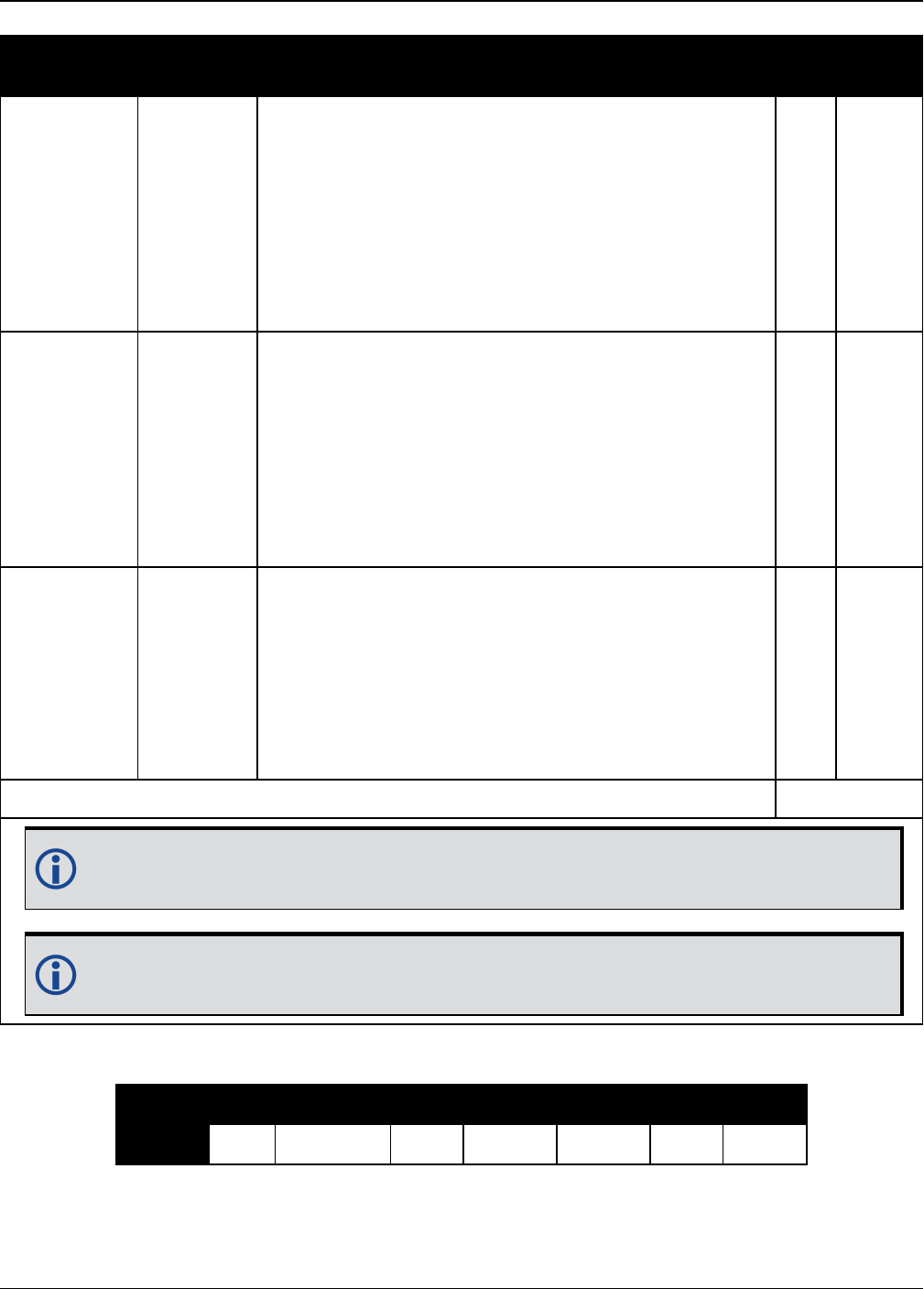
Chapter 3 Logs
OEM7 Commands and Logs Reference Manual v7 702
Data Name Range Description Bits Scale
Factor
Pseudorange
– Predicted
Pseudorange
±131.0715
(2’s Complement)
If this value equals –(219-1) = -262144, it indicates
the signal is not locked.
The Predicted Pseudorange = reference pseudorange
plus (the reference doppler x time difference between
the reference log and the differential log). The
Reference log and Differential logs used must contain
matching Ref Data Block ID references (Table 140:
Measurement Block Header on page697).
19 0.0005
m
Phaserange
– Predicted
Phaserange
±3.2767
(2’s Complement)
If this value equals –(216-1) = -32768, it indicates the
signal is not locked.
The Predicted Phaserange = reference phaserange
plus (the reference doppler x time difference between
the reference log and the differential log). The
Reference log and Differential logs used must contain
matching Ref Data Block ID references (Table 140:
Measurement Block Header on page697).
16 0.0001
m
Doppler –
Reference
Doppler
±13.1071
(2’s Complement)
If this value equals –(214-1) = -8192, it indicates an
invalid Doppler.
The Reference Doppler is the Doppler for that PRN and
for that signal from the Reference log. The Reference
log and Differential logs used must contain matching
Ref Data Block ID references (Table 140:
Measurement Block Header on page697).
14 0.0001
m/s
Bit Sum: 74
This block is sent once for each bit set to 1 after the first bit set to 1 in the Included
Signals field found in Table 139: Satellite and Signal Block on page696.
This table is for Differential blocks only, as indicated by the Data Format Flag (see
Table 140: Measurement Block Header on page697).
GPS GLONASS SBAS Galileo BeiDou QZSS NavIC
Bit 1 L1CA L1CA L1CA E1 B1 L1CA L5SPS
Table 145: Signal Bit Mask

Chapter 3 Logs
OEM7 Commands and Logs Reference Manual v7 703
GPS GLONASS SBAS Galileo BeiDou QZSS NavIC
Bit 2 L5I E5A B1GEO
Bit 3 L2CA E5B B2 L2C
Bit 4 L2Y L2P ALTBOC B2GEO L5Q
Bit 5 L2C E6C B3
Bit 6 L2P L3 B3GEO
Bit 7 L5Q B1CP
Bit 8 L1C
Bit 9 B2AP
Bit 10
Bit 11 L6P
Bit 12 E6B
Bit 13
Bit 14
Bit15 L1C
Indicator
(i)
Minimum Lock Time
(ms)
Range of Indicated Lock Times
(t represents the Lock Time)
(ms)
0 0 0 ≤ t < 16
1 16 16 ≤ t < 32
2 32 32 ≤ t < 64
3 64 64 ≤ t < 128
4 128 128 ≤ t < 256
5 256 256 ≤ t < 512
6 512 512 ≤ t < 1024
7 1024 1024 ≤ t < 2048
8 2048 2048 ≤ t < 4096
9 4096 4096 ≤ t < 8192
Table 146: Lock Time

Chapter 3 Logs
OEM7 Commands and Logs Reference Manual v7 704
Indicator
(i)
Minimum Lock Time
(ms)
Range of Indicated Lock Times
(t represents the Lock Time)
(ms)
10 8192 8192 ≤ t < 16384
11 16384 16384 ≤ t < 32768
12 32768 32768 ≤ t < 65536
13 65536 65536 ≤ t < 131072
14 131072 131072 ≤ t < 262144
15 262144 262144 ≤ t
ADR Std Dev (cycles)
0 ≤ 0.0039
1 ≤ 0.0052
2 ≤ 0.0070
3 ≤ 0.0093
4 ≤ 0.0124
5 ≤ 0.0165
6 ≤ 0.0221
7 ≤ 0.0295
8 ≤ 0.0393
9 ≤ 0.0525
10 ≤ 0.0701
11 ≤ 0.0935
12 ≤ 0.1248
13 ≤ 0.1666
14 ≤ 0.2223
15 > 0.2223
Table 147: ADR Std Dev

Chapter 3 Logs
OEM7 Commands and Logs Reference Manual v7 705
Pseudorange Std Dev (m)
0 ≤ 0.020
1 ≤ 0.030
2 ≤ 0.045
3 ≤ 0.066
4 ≤ 0.099
5 ≤ 0.148
6 ≤ 0.220
7 ≤ 0.329
8 ≤ 0.491
9 ≤ 0.732
10 ≤ 1.092
11 ≤ 1.629
12 ≤ 2.430
13 ≤ 3.625
14 ≤ 5.409
15 > 5.409
Table 148: Pseudorange Std Dev
For more information about decoding the RANGECMP4 log, refer to Example of Bit Pars-
ing a RANGECMP4 Log on page1038.

Chapter 3 Logs
OEM7 Commands and Logs Reference Manual v7 706
3.127 RANGEGPSL1
L1 version of the RANGE log
Platform: OEM719, OEM729, OEM7500, OEM7600, OEM7700, OEM7720, PwrPak7,
SPAN CPT7
This log is identical to the RANGE log (see page 672) except that it only includes L1 GPS obser-
vations.
Message ID: 631
Log Type: Synch
Recommended Input:
log rangegpsl1a ontime 30
ASCII Example:
#RANGEGPSL1A,COM1,0,57.0,FINESTEERING,1337,404766.000,02000000,5862,
1984;
10,
14,0,21773427.400,0.037,-114420590.433332,0.006,2408.171,49.9,
14963.280,18109c04,
22,0,24822942.668,0.045,-130445851.055756,0.009,-3440.031,48.0,
22312.971,08109c24,
25,0,20831000.299,0.033,-109468139.214586,0.006,1096.876,50.7,
7887.840,08109c44,
1,0,20401022.863,0.032,-107208568.887106,0.006,-429.690,51.1,
10791.500,18109c64,
24,0,23988223.932,0.074,-126058964.619453,0.013,2519.418,43.8,
493.550,18109c84,
11,0,22154466.593,0.043,-116423014.826717,0.007,-1661.273,48.4,
11020.952,08109ca4,
5,0,24322401.516,0.067,-127815012.260616,0.012,-1363.596,44.6,
6360.282,18109cc4,
20,0,22294469.347,0.043,-117158267.467388,0.008,2896.813,48.5,
4635.968,08109ce4,
30,0,23267589.649,0.051,-122271969.418761,0.009,822.194,47.0,
4542.270,08109d04,
23,0,24975654.673,0.058,-131247903.805678,0.009,3395.097,45.9,
406.762,18109d24*be4b7d70

Chapter 3 Logs
OEM7 Commands and Logs Reference Manual v7 707
Since the RANGEGPSL1 log includes only L1 GPS observations, it is smaller in size
than the RANGE log which contains entries for multiple systems and signals. Use
the RANGEGPSL1 log when data throughput is limited and you are only interested in
GPS L1 range data. For GPS L1 only models, RANGE and RANGEGPSL1 logs are
identical.
Field Field type Description Format Binary
Bytes
Binary
Offset
1RANGEGPSL1
header
Log header. See Messages on page25 for
more information. H 0
2 # obs Number of L1 observations with information
to follow Long 4 H
3 PRN Satellite PRN number of range measurement
(1-32) Ushort 2 H+4
4 Reserved Ushort 2 H+6
5 psr Pseudorange measurement (m) Double 8 H+8
6 psr std Pseudorange measurement standard
deviation (m) Float 4 H+16
7 adr Carrier phase, in cycles (accumulated
Doppler range) Double 8 H+20
8 adr std Estimated carrier phase standard deviation
(cycles) Float 4 H+28
9 dopp Instantaneous carrier Doppler frequency (Hz) Float 4 H+32
10 C/No Carrier to noise density ratio
C/No = 10[log10(S/N0)] (dB-Hz) Float 4 H+36
11 locktime Number of seconds of continuous tracking (no
cycle slipping) Float 4 H+40
12 ch-tr-status Tracking status (see Table 126: Channel
Tracking Status on page675) Ulong 4 H+44
13... Next PRN offset = H + 4 + (#obs x 44)
14 xxxx 32-bit CRC (ASCII and Binary only) Ulong 4
H+4+
(#obs
x 44)
15 [CR][LF] Sentence terminator (ASCII only) - - -

Chapter 3 Logs
OEM7 Commands and Logs Reference Manual v7 708
3.128 RAWALM
Raw GPS Almanac data
Platform: OEM719, OEM729, OEM7500, OEM7600, OEM7700, OEM7720, PwrPak7,
SPAN CPT7
This log contains the undecoded GPS almanac subframes as received from the satellite. For
more information about Almanac data, refer to An Introduction to GNSS available on our web-
site.
Message ID: 74
Log Type: Asynch
Recommended Input:
log rawalma onchanged
ASCII Example:
#RAWALMA,COM1,0,56.0,SATTIME,1337,405078.000,02000000,cc1b,1984;1337,589824.000
,43,
3,8b04e4839f35433a5590f5aefd3900a10c9aaa6f40187925e50b9f03003f,
27,8b04e483a1325b9cde9007f2fd5300a10da5562da3adc0966488dd01001a,
4,8b04e483a1b44439979006e2fd4f00a10d15d96b3b021e6c6c5f23feff3c,
28,8b04e483a3b05c5509900b7cfd5800a10cc483e2bfa1d2613003bd050017,
5,8b04e483a43745351c90fcb0fd4500a10d8a800f0328067e5df8b6100031,
57,8b04e483a6337964e036d74017509f38e13112df8dd92d040605eeaaaaaa,
6,8b04e483a6b54633e390fa8bfd3f00a10d4facbc80b322528f62146800ba,
29,8b04e483a8b05d47f7901b20fd5700a10ce02d570ed40a0a2216412400cb,
7,8b04e483a935476dee90fb94fd4300a10d93aba327b7794ae853c02700ba,
...
1,8b04e483d8b641305a901b9dfd5a00a10ce92f48f1ba0a5dcccb7500003b,
25,8b04e483dab25962259004fcfd4c00a10dc154eee5c555d7a2a5010d000d,
2,8b04e483db37424aa6900720fd4f00a10c5ad89baa4dc1460790b6fc000f,
26,8b04e483dd305a878c901d32fd5b00a10c902eb7f51db6b6ce95c701fff4*83cae97a
The OEM7 family of receivers automatically saves almanacs in their Non-Volatile
Memory (NVM), therefore creating an almanac boot file is not necessary.
Field Field type Description Format Binary
Bytes
Binary
Offset
1RAWALM
header
Log header. See Messages on page25
for more information. H 0
2 ref week Almanac reference week number Ulong 4 H
3 ref secs Almanac reference time (ms) GPSec 4 H+4
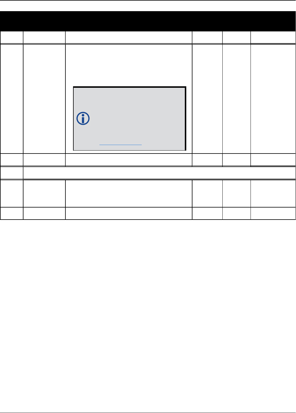
Chapter 3 Logs
OEM7 Commands and Logs Reference Manual v7 709
Field Field type Description Format Binary
Bytes
Binary
Offset
4 #subframes Number of subframes to follow Ulong 4 H+8
5 svid
SV ID (satellite vehicle ID)
A value between 1 and 32 for the SV ID
indicates the PRN of the satellite. Any
other values indicate the page ID.
See section 20.3.3.5.1.1,
Data ID and SV ID, of ICD-
GPS-200C for more details.
To obtain copies of ICD-
GPS-200, refer to the
GPSwebsite
(www.gps.gov/).
Ushort 2 H+12
6 data Subframe page data Hex 30 H+14
7... Next subframe offset = H+12+(#subframe x 32)
8 xxxx 32-bit CRC (ASCII and Binary only) Hex 4
H+12+
(#subframes
x 32)
9 [CR][LF] Sentence terminator (ASCII only) - - -

Chapter 3 Logs
OEM7 Commands and Logs Reference Manual v7 710
3.129 RAWCNAVFRAME
Raw GPSCNAV frame data
Platform: OEM719, OEM729, OEM7500, OEM7600, OEM7700, OEM7720, PwrPak7,
SPAN CPT7
This log provides raw frame data from signals which contain the CNAV message (L2C, L5).
The RAWCNAVFRAME log is not output by default. To receive this log, data decoding for
L2C or L5 must be enabled using the DATADECODESIGNAL command (see page 111)
for the specific signal.
Message ID: 1066
Log Type: Asynch
Recommended Input:
log rawcnavframea onnew
ASCII Example:
#RAWCNAVFRAMEA,COM1,0,63.0,SATTIME,1902,431718.000,02000020,ee56,13677;17,6,11,
8b18b8c892cd499a403d89d3a5bfc05f500a1fff6007dff412e017a3c029ccff5d6001fc9a70*0d
ddab32
Field Field type Description Format Binary
Bytes
Binary
Offset
1RAWCNAVFRAME
header
Log header. See Messages on page25
for more information. H 0
2 signal channel Signal channel providing the bits Ulong 4 H
3 PRN Satellite PRN number Ulong 4 H+4
4 frame ID frame ID Ulong 4 H+8
5 data Raw frame data Hex[38] 38 H+12
6 xxxx 32-bit CRC (ASCII and Binary only) Hex 4 H+50
7 [CR][LF] Sentence terminator (ASCII only) - - -

Chapter 3 Logs
OEM7 Commands and Logs Reference Manual v7 711
3.130 RAWEPHEM
Raw GPSephemeris
Platform: OEM719, OEM729, OEM7500, OEM7600, OEM7700, OEM7720, PwrPak7,
SPAN CPT7
This log contains the raw binary information for subframes one, two and three from the GPS
satellite L1 C/A signal with the parity information removed. Each subframe is 240 bits long (10
words - 24 bits each) and the log contains a total 720 bits (90 bytes) of information (240 bits x 3
subframes). This information is preceded by the PRN number of the satellite from which it ori-
ginated. This message is not generated unless all 10 words from all 3 frames have passed par-
ity.
Ephemeris data whose Time of Ephemeris (TOE) is older than six hours is not shown. Multiple
logs are output, one for each GPS satellite with collected ephemeris information.
Message ID: 41
Log Type: Asynch
Recommended Input:
log rawephema onnew
ASCII Example:
#RAWEPHEMA,COM1,15,60.5,FINESTEERING,1337,405297.175,02000000,97b7,198
4;3,1337,403184,8b04e4818da44e50007b0d9c05ee664ffbfe695df763626f00001b
03c6b3,8b04e4818e2b63060536608fd8cdaa051803a41261157ea10d2610626f3d,8b
04e4818ead0006aa7f7ef8ffda25c1a69a14881879b9c6ffa79863f9f2*0bb16ac3
...
#RAWEPHEMA,COM1,0,60.5,SATTIME,1337,405390.000,02000000,97b7,1984;1,13
37,410400,8b04e483f7244e50011d7a6105ee664ffbfe695df9e1643200001200aa92
,8b04e483f7a9e1faab2b16a27c7d41fb5c0304794811f7a10d40b564327e,8b04e483
f82c00252f57a782001b282027a31c0fba0fc525ffac84e10a06*c5834a5b
A way to use only one receiver and achieve better than 1 metre accuracy is to use
precise orbit and clock files. Three types of GPS ephemeris, clock and earth orientation
solutions are compiled by an elaborate network of GNSS receivers around the world all
monitoring the satellite characteristics. IGS rapid orbit data is processed to produce files
that correct the satellite clock and orbit parameters. Since there is extensive processing
involved, these files are available on a delayed schedule from the US National Geodetic
Survey at: www.ngs.noaa.gov/orbits
Precise ephemeris files are available today to correct GPS data which was collected a
few days ago. All you need is one GNSS receiver and a computer to process on. Replace
the ephemeris data with the precise ephemeris data and post-process to correct range
values.

Chapter 3 Logs
OEM7 Commands and Logs Reference Manual v7 712
Field Field type Description Format Binary
Bytes
Binary
Offset
1RAWEPHEM
header
Log header. See Messages on page25 for
more information. H 0
2 PRN Satellite PRN number Ulong 4 H
3 ref week Ephemeris reference week number Ulong 4 H+4
4 ref secs Ephemeris reference time (s) Ulong 4 H+8
5 subframe1 Subframe 1 data Hex[30] 30 H+12
6 subframe2 Subframe 2 data Hex[30] 30 H+42
7 subframe3 Subframe 3 data Hex[30] 30 H+72
8 xxxx 32-bit CRC (ASCII and Binary only) Hex 4 H+102
9 [CR][LF] Sentence terminator (ASCII only) - - -
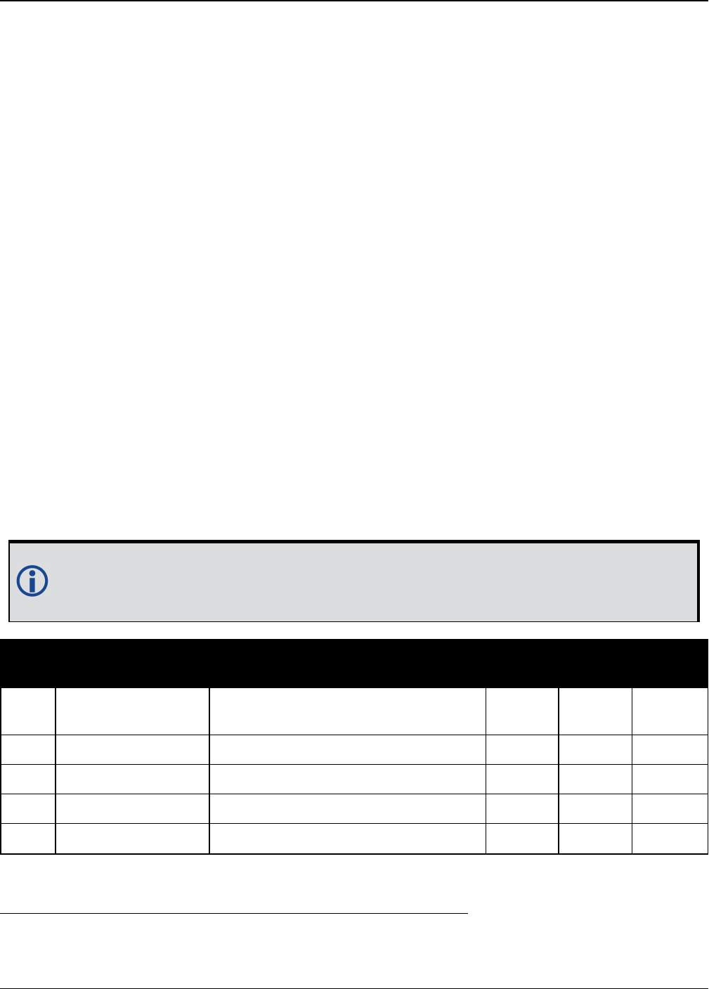
Chapter 3 Logs
OEM7 Commands and Logs Reference Manual v7 713
3.131 RAWGPSSUBFRAME
Raw GPSsubframe data
Platform: OEM719, OEM729, OEM7500, OEM7600, OEM7700, OEM7720, PwrPak7,
SPAN CPT7
This log contains the raw GPS subframe data.
A raw GPS subframe is 300 bits in total. This includes the parity bits which are interspersed with
the raw data ten times in six bit chunks, for a total of 60 parity bits. Note Field #5, below, has
these 60 parity bits stripped out and only the raw subframe data remains, for a total of 240 bits.
Message ID: 25
Log Type: Asynch
Recommended Input:
log rawgpssubframea onnew
ASCII Example:
#RAWGPSSUBFRAMEA,COM1,59,62.5,SATTIME,1337,405348.000,02000000,f690,1984;2,22,4
,8b04e483f3b17ee037a3732fe0fc8ccf074303ebdf2f6505f5aaaaaaaaa9,2*41e768e4
...
#RAWGPSSUBFRAMEA,COM1,35,62.5,SATTIME,1337,405576.000,02000000,f690,1984;4,25,2
,8b04e48406a8b9fe8b364d786ee827ff2f062258840ea4a10e20b964327e,4*52d460a7
...
#RAWGPSSUBFRAMEA,COM1,0,62.5,SATTIME,1337,400632.000,02000000,f690,1984;20,9,3,
8b04e4826aadff3557257871000a26fc34a31d7a300bede5ffa3de7e06af,20*55d16a4a
The RAWGPSSUBFRAME log can be used to receive the data bits with the parity bits
stripped out. Alternately, you can use the RAWGPSWORD log (see page 715) to receive
the parity bits in addition to the data bits.
Field Field type Description Format Binary
Bytes
Binary
Offset
1RAWGPSSUBFRAME
header
Log header. See Messages on
page25 for more information. H 0
2 decode # Frame decoder number Long 4 H
3 PRN Satellite PRN number Ulong 4 H+4
4 subframe id Subframe ID Ulong 4 H+8
5 data Raw subframe data Hex[30] 321H+12
1In the binary log case, an additional 2 bytes of padding are added to maintain 4-byte alignment.

Chapter 3 Logs
OEM7 Commands and Logs Reference Manual v7 714
Field Field type Description Format Binary
Bytes
Binary
Offset
6 signal channel Signal channel number that the
frame was decoded on Ulong 4 H+44
7 xxxx 32-bit CRC (ASCII and Binary only) Ulong 4 H+48
8 [CR][LF] Sentence terminator (ASCII only) - - -
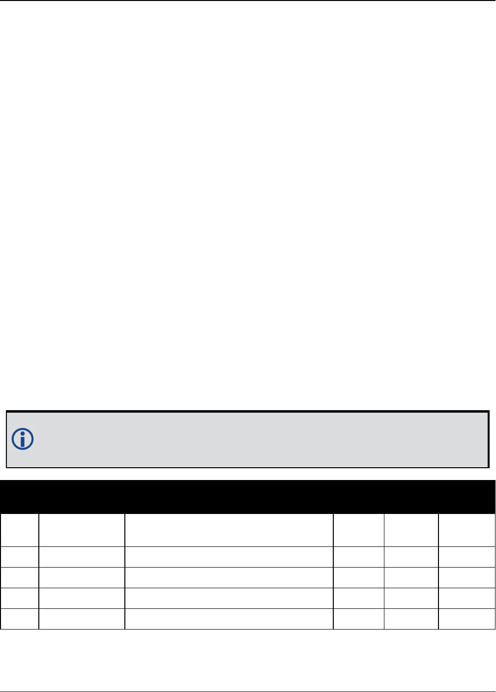
Chapter 3 Logs
OEM7 Commands and Logs Reference Manual v7 715
3.132 RAWGPSWORD
Raw GPSnavigation word
Platform: OEM719, OEM729, OEM7500, OEM7600, OEM7700, OEM7720, PwrPak7,
SPAN CPT7
This message contains the framed GPS raw navigation words. Each log contains a new 30 bit nav-
igation word (in the least significant 30 bits), plus the last 2 bits of the previous word (in the
most significant 2 bits). The 30 bit navigation word contains 24 bits of data plus 6 bits of parity.
The GPS reference time stamp in the log header is the time the first bit of the 30 bit navigation
word was received. Only navigation data that has passed parity checking appears in this log.
One log appears for each PRN being tracked every 0.6 seconds if logged ONNEW or
ONCHANGED.
Message ID: 407
Log Type: Asynch
Recommended Input:
log rawgpsworda onnew
ASCII Example:
#RAWGPSWORDA,COM1,0,58.5,FINESTEERING,1337,405704.473,02000000,9b16,1984;14,7ff
9f5dc*8e7b8721
...
#RAWGPSWORDA,COM1,0,57.0,FINESTEERING,1337,405783.068,02000000,9b16,1984;1,93fe
ff8a*6dd62c81
...
#RAWGPSWORDA,COM1,0,55.5,FINESTEERING,1337,405784.882,02000000,9b16,1984;5,ffff
f8ce*a948b4de
The RAWGPSWORD log can be used to receive the parity bits in addition to the data bits.
Alternately, you can use the RAWGPSSUBFRAME log which already has the parity bits
stripped out
Field Field type Description Format Binary
Bytes
Binary
Offset
1RAWGPSWORD
header
Log header. See Messages on page25
for more information. H 0
2 PRN Satellite PRN number Ulong 4 H
3 nav word Raw navigation word Hex[4] 4 H+4
4 xxxx 32-bit CRC (ASCII and Binary only) Ulong 4 H+8
5 [CR][LF] Sentence terminator (ASCII only) - - -
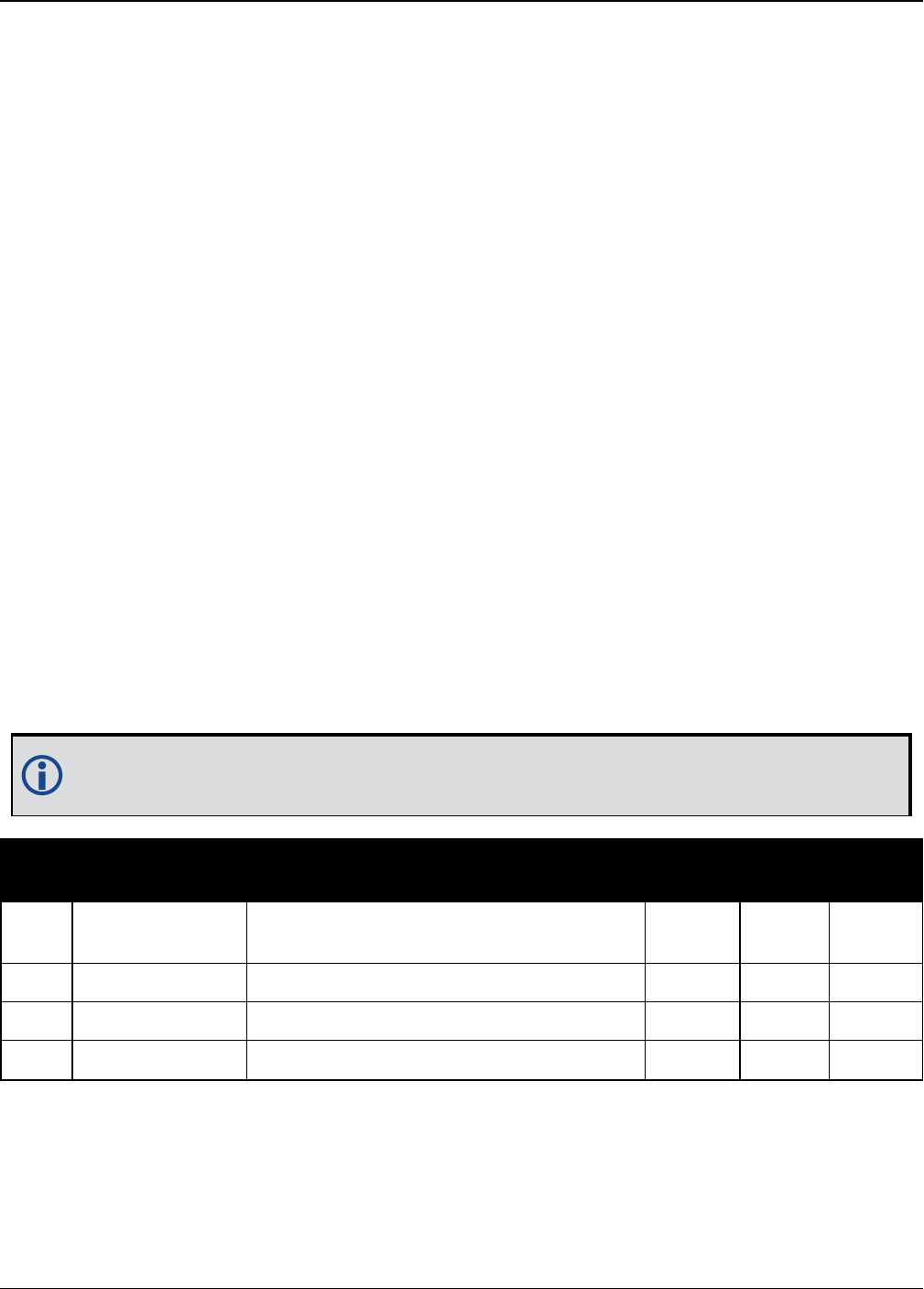
Chapter 3 Logs
OEM7 Commands and Logs Reference Manual v7 716
3.133 RAWSBASFRAME
Raw SBAS frame data
Platform: OEM719, OEM729, OEM7500, OEM7600, OEM7700, OEM7720, PwrPak7,
SPAN CPT7
This log contains the raw SBAS frame data of 226 bits (8-bit preamble, 6-bit message type and
212 bits of data but without a 24-bit CRC). Only frame data with a valid preamble and CRC are
reported.
Message ID: 973
Log Type: Asynch
Recommended Input:
log rawsbasframea onnew
ASCII Example:
#RAWSBASFRAMEA,COM1,0,91.0,SATTIME,1610,341534.000,02000000,58e4,38637;32,133,4
,c6115ffc00000c009ffc07004c089ffdffdffdffdfff957bbb6bffffc0,32*5afc5f95
#RAWSBASFRAMEA,COM1,0,91.0,SATTIME,1610,341535.000,02000000,58e4,38637;32,133,2
,53084007ff9fffffc03002c0000f0009ffc004005ffd6b961e39b9fb80,32*db5dfa62
#RAWSBASFRAMEA,COM1,0,91.0,SATTIME,1610,341535.000,02000000,58e4,38637;35,135,2
,53084007ff9fffffc03002c0000f0009ffc004005ffd6b961e39b9fb80,35*b72ff2a0
...
#RAWSBASFRAMEA,COM1,0,90.0,SATTIME,1610,341539.000,02000000,58e4,38637;34,138,3
,9a0c4000009ffc009ffdffc007fb9ffdffc0000040315b9bb96fb95680,34*cb050361
The RAWSBASFRAME log output contains all the raw data required for an application to
compute its own SBAS correction parameters.
Field Field type Description Format Binary
Bytes
Binary
Offset
1RAWSBASFRAME
header
Log header. See Messages on page25 for
more information. H 0
2 decode # Frame decoder number Ulong 4 H
3 PRN SBAS satellite PRN number Ulong 4 H+4
4 SBAS frame ID SBAS frame ID Ulong 4 H+8

Chapter 3 Logs
OEM7 Commands and Logs Reference Manual v7 717
Field Field type Description Format Binary
Bytes
Binary
Offset
5 raw frame data Raw SBAS frame data. There are 226 bits
of data and 6 bits of padding Hex[29] 321H+12
6 signal channel Signal channel number that the frame
was decoded on Ulong 4 H+44
7 xxxx 32-bit CRC (ASCII and Binary only) Ulong 4 H+48
8 [CR][LF] Sentence terminator (ASCII only) - - -
1In the binary log case, an additional 3 bytes of padding are added to maintain 4-byte alignment.
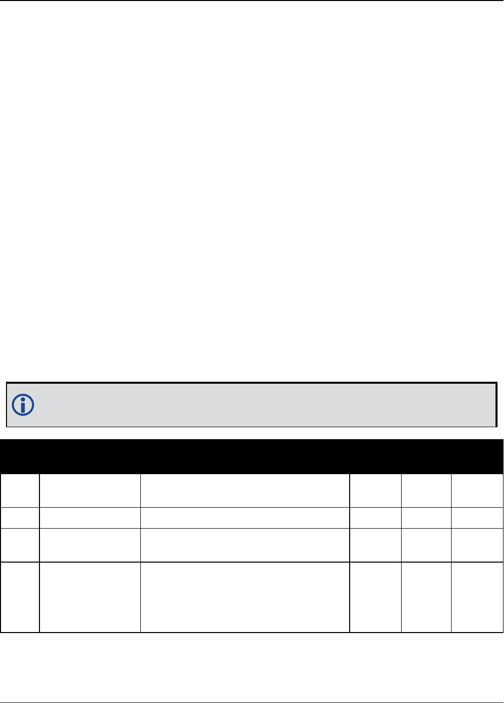
Chapter 3 Logs
OEM7 Commands and Logs Reference Manual v7 718
3.134 RAWSBASFRAME2
Raw SBAS frame data 2
Platform: OEM719, OEM729, OEM7500, OEM7600, OEM7700, OEM7720, PwrPak7,
SPAN CPT7
This log contains the raw SBAS frame data of 226 bits (8-bit preamble, 6-bit message type and
212 bits of data but without a 24-bit CRC). It also contains the transmitted frequency. Only
frame data with a valid preamble and CRC are reported.
Message ID: 2185
Log Type: Asynch
Recommended Input:
log rawsbasframe2a onnew
ASCII Example:
#RAWSBASFRAME2A,COM1,0,77.5,SATTIME,1977,514394.000,02000020,b39f,32768;135,209
,2,1,0,3,c60d4009ffc018001ffc005ffdfffffbff9ffc00bfed79db9bb95b9540*9a75ce69
#RAWSBASFRAME2A,COM1,0,77.5,SATTIME,1977,514394.000,02000020,b39f,32768;138,207
,2,1,0,4,c6125ffdffc005ffffffffbfe3fb9ffdffdffdffdfffba3956abffffc0*9324a574
#RAWSBASFRAME2A,COM1,0,77.5,SATTIME,1977,514395.000,02000020,b39f,32768;135,208
,1,0,0,4,53125ffdffc011ffc000007fe3fb5ffdffdffdffdfffba3956abffffc0*69490ac5
#RAWSBASFRAME2A,COM1,0,78.5,SATTIME,1977,514395.000,02000020,b39f,32768;138,206
,1,0,0,3,530c7ff9ffc017ff9fffff9ffdfffffbfedffc003fe579db9bb95b9540*c7ca1531
The RAWSBASFRAME2 log output contains all the raw data required for an application
to compute its own SBAS correction parameters.
Field Field Type Description Format Binary
Bytes
Binary
Offset
1RAWSBASFRAME2
header
Log header. See Messages on page25
for more information. H 0
2 PRN SBAS satellite PRN number Ulong 4 H
3 signal channel Signal channel number that the frame
was decoded on Ulong 4 H+4
4SBAS Signal
Source
Identifies the source of the SBAS
signal:
1 – SBASL1CA
2 – SBASL5I
Uchar 1 H+8

Chapter 3 Logs
OEM7 Commands and Logs Reference Manual v7 719
Field Field Type Description Format Binary
Bytes
Binary
Offset
5SBAS Preamble
Type
Identifies what preamble was used
when tracking the SBAS signal:
0 – SBASL1CA 8-bit Preamble
1 – SBASL5I 8-bit Preamble
Uchar 1 H+9
6 Reserved Ushort 2 H+10
7 SBAS frame ID SBAS frame ID Ulong 4 H+12
8 data Raw SBAS frame data. There are 226
bits of data and 6 bits of padding Hex[29] 321H+16
9 xxxx 32-bit CRC (ASCII and Binary only) Ulong 4 H+48
10 [CR][LF] Sentence terminator (ASCII only) - - -
1In the binary log case, an additional 3 bytes of padding are added to maintain 4-byte alignment.

Chapter 3 Logs
OEM7 Commands and Logs Reference Manual v7 720
3.135 REFSTATION
Base station position and health
Platform: OEM719, OEM729, OEM7500, OEM7600, OEM7700, OEM7720, PwrPak7,
SPAN CPT7
This log contains the ECEF Cartesian position of the base station as received through the RTCMV3
message. It also features a time tag, the health status of the base station and the station ID.
This information is set at the base station using the FIX command (see page 161) and the
DGPSTXID command (see page 122). See Figure 11: The WGS84 ECEF Coordinate System on
page449 for a definition of the ECEF coordinates.
The base station health, Field #6, may be one of 8 values (0 to 7). Values 0 through 5 indicate
the scale factor that is multiplied with the satellite UDRE one-sigma differential error values.
Below are values 0 to 5 and their corresponding UDRE scale factors:
0: 1 (Health OK)0.752: 0.53: 0.34: 0.25: 0.1
The base station health field only applies to RTCM base stations. A value of 6 means the base sta-
tion transmission is not monitored and a value of 7 means that the base station is not working.
Message ID: 175
Log Type: Asynch
Recommended Input:
log refstationa onchanged
ASCII Example:
#REFSTATIONA,COM1,0,66.5,FINESTEERING,1364,490401.124,82000000,4e46,2310;000000
00,-1634532.443,-3664608.907,4942482.713,0,RTCMV3,"AAAA"*1e2a0508
Field Field type Description Format Binary
Bytes
Binary
Offset
1REFSTATION
header
Log header. See Messages on page25 for
more information. H 0
2 status
Status of the base station information (see
Table 149: Base Station Status on the next
page)
Ulong 4 H
3 x ECEF X value (m) Double 8 H+4
4 y ECEF Y value (m) Double 8 H+12
5 z ECEF Z value (m) Double 8 H+20
6 health Base station health, see the description at the
start of this section Ulong 4 H+28
7 stn type Station type (see Table 150: Station Type on
the next page) Enum 4 H+32
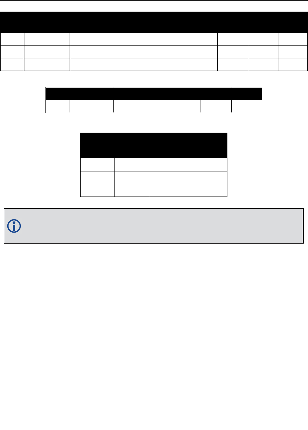
Chapter 3 Logs
OEM7 Commands and Logs Reference Manual v7 721
Field Field type Description Format Binary
Bytes
Binary
Offset
8 stn ID Base station ID Char[5] 81H+36
9 xxxx 32-bit CRC (ASCII and Binary only) Ulong 4 H+44
10 [CR][LF] Sentence terminator (ASCII only) - - -
Bit # Mask Description Bit = 0 Bit = 1
0 0x00000001 Validity of the base station Valid Invalid
Table 149: Base Station Status
Base Station Type
Description
Binary ASCII
0 NONE Base station is not used
1 - 3 Reserved
4 RTCMV3 Base station is RTCMV3
Table 150: Station Type
The REFSTATION log can be used for checking the operational status of a remotely loc-
ated base station. You can verify that the base station is operating properly without trav-
eling to it. This is especially useful for RTK work on long baselines.
1In the binary log case, an additional 3 bytes of padding are added to maintain 4-byte alignment.

Chapter 3 Logs
OEM7 Commands and Logs Reference Manual v7 722
3.136 REFSTATIONINFO
Base Station position information
Platform: OEM719, OEM729, OEM7500, OEM7600, OEM7700, OEM7720, PwrPak7,
SPAN CPT7
This is an extended version of the REFSTATION log with latitude, longitude and ellipsoidal height
of the base station in WGS84. In addition to the base station position, ARP height, antenna model
name and antenna serial number are available if provided by the base station only through
RTCMV3.
Message ID: 1325
Log Type: Asynch
Recommended Input:
log refstationinfoa onchanged
ASCII Example:
#REFSTATIONINFOA,USB1,0,89.5,EXACT,0,0.000,02000040,d38f,6782;
51.116375174,-114.038254922,1048.502830628,WGS84,1.234,0,RTCMV3,
"0","702GG","NVH05410007"*bedf8ece
Field Field type Description Format Binary
Bytes
Binary
Offset
1REFSTATIONINFO
header
Log header. See Messages on page25
for more information. H 0
2 latitude Latitude (degrees) Double 8 H
3 longitude Longitude (degrees) Double 8 H+8
4 height Ellipsoidal Height (m) Double 8 H+16
5 datum
Datum ID number (WGS84) (refer to
Table 28: Datum Transformation
Parameters on page117)
Enum 4 H+24
6 ARP height Base Antenna ARP (m) Float 4 H+28
7 health Base Station Health, see Table 149:
Base Station Status on the previous page Ulong 4 H+32
8 Ref Stn Type Base Station Type, see (Table 150:
Station Type on the previous page) Enum 4 H+36
9 stn ID Base Station ID Char[5] 8aH+40
aIn the binary log case, an additional 3 bytes of padding are added to maintain 4-byte alignment.

Chapter 3 Logs
OEM7 Commands and Logs Reference Manual v7 723
Field Field type Description Format Binary
Bytes
Binary
Offset
10 Ant Model Base Antenna Model Name Char
[32] 32 H+48
11 Ant Serial Base Antenna Serial Number Char
[32] 32 H+80
12 xxxx 32-bit CRC (ASCII and Binary only) Ulong 4 H+112
13 [CR][LF] Sentence terminator (ASCII only) - - -
Chapter 3 Logs
OEM7 Commands and Logs Reference Manual v7 724
3.137 ROVERPOS
Position using ALIGN
Platform: OEM719, OEM729, OEM7500, OEM7600, OEM7700, OEM7720, PwrPak7,
SPAN CPT7
ALIGN generates distance and bearing information between a master and rover receiver. This
log outputs the position information of the rover when using the ALIGN feature. This log can only
be output from a Y ALIGN model and can be output at both Master and Rover ends.
You must have an ALIGN capable receiver to use this log.
lALIGN is useful for obtaining the relative directional heading of a vessel/body, sep-
aration heading between two vessels/bodies, or heading information with moving
base and pointing applications.
lThe log can be output at the Y model Rover only if it is receiving the RTCAREFEXT
message from the Master. The log can be output at any Master if the Master is receiv-
ing HEADINGEXTB from the Rover. Refer to the NovAtel application note APN-048 for
details on HEADINGEXT (available at www.novatel.com/support/).
lROVERPOS is dependent on the output frequency of the RTCAREFEXT message from
the master to the rover.
lOn dual antenna receivers, the ROVERPOS log outputs the position for the sec-
ondary antenna input.
Message ID: 1052
Log Type: Asynch
Recommended Input:
log roverposa onchanged
ASCII Example:
#ROVERPOSA,COM1,0,21.5,FINESTEERING,1544,340322.000,02000008,7453,4655;SOL_
COMPUTED,NARROW_INT,51.11605565964,-114.03854655975,1055.8559,-
16.9000,WGS84,0.0130,0.0122,0.0206,"RRRR",0.0,0.0,13,12,12,11,0,0,0,0*635b3a1c
Asynchronous logs, such as ROVERPOS, should only be logged ONCHANGED or ONNEW
otherwise the most current data is not output when it is available. This is especially true
of the ONTIME trigger, which may cause inaccurate time tags to result.

Chapter 3 Logs
OEM7 Commands and Logs Reference Manual v7 725
Field Field
Type Description Format Binary
Bytes
Binary
Offset
1ROVERPOS
header
Log header. See Messages on page25 for more
information. H 0
2 sol stat Solution Status, see Table 73: Solution Status
on page431 Enum 4 H
3 pos type Position Type see Table 74: Position or Velocity
Type on page432 Enum 4 H+4
4 lat Rover WGS84 Latitude in degrees Double 8 H+8
5 long Rover WGS84 Longitude in degrees Double 8 H+16
6 hgt Rover MSL Height in metres Double 8 H+24
7 undulation Undulation in metres Float 4 H+32
8 datum id# WGS84 (default) (refer to Table 28: Datum
Transformation Parameters on page117) Enum 4 H+36
9 lat σ Latitude standard deviation in metres Float 4 H+40
10 long σ Longitude standard deviation in metres Float 4 H+44
11 hgt σ Height standard deviation in metres Float 4 H+48
12 stn id Rover ID (default = “RRRR”) Char[4] 4 H+52
13 Reserved Float 4 H+56
14 Reserved Float 4 H+60
15 #SVs Number of satellite tracked Uchar 1 H+64
16 #solnSVs Number of satellite in solution Uchar 1 H+65
17 #obs Number of satellites above elevation mask
angle Uchar 1 H+66
18 #multi Number of satellites above the mask angle with
L2, B2 Uchar 1 H+67
19
Reserved
Hex 1 H+68
20 Uchar 1 H+69
21 Uchar 1 H+70
22 Uchar 1 H+71
23 xxxx 32-bit CRC (ASCII and Binary only) Hex 1 H+72
24 [CR][LF] Sentence Terminator (ASCII only) - - -

Chapter 3 Logs
OEM7 Commands and Logs Reference Manual v7 726
3.138 RTCMV3 Standard Logs
Platform: OEM719, OEM729, OEM7500, OEM7600, OEM7700, OEM7720, PwrPak7,
SPAN CPT7
NovAtel’s RTCMv3 logs are implementations of the messages described by the RTCM SC-104
committee’s “Differential GNSS (Global Navigation Satellite Systems) Services – Version 3”
standard. These messages are primarily intended to support RTK operations. They are also an
alternative raw data format to NovAtel’s proprietary messages.
The RTCMv3 logs can be divided into several categories that are described below. An RTK base
station must minimally transmit one or more observable message, together with one or more
station and antenna message. The GENERATERTKCORRECTIONS command on page182 illus-
trates an appropriate set of messages and is an easy way to configure logging.
Example Input:
interfacemode com2 none RTCMV3
fix position 51.1136 -114.0435 1059.4
thisantennatype NOV702
log com2 rtcm1006 ontime 10
log com2 rtcm1033 ontime 10 2
log com2 rtcm1004 ontime 1
log com2 rtcm1012 ontime 1
3.138.1 Legacy Observable Messages
The legacy observable messages contain GPS and GLONASS code and phase observables. The
extended messages additionally contain the C/N0.
Log Name Message ID Description
RTCM1001 772 GPS L1-only observables, basic
RTCM1002 774 GPS L1-only observables, extended
RTCM1003 776 GPS L1/L2 basic observables, basic
RTCM1004 770 GPS L1/L2 basic observables, extended
RTCM1009 885 GLONASS L1-only observables, basic
RTCM1010 887 GLONASS L1-only observables, extended
RTCM1011 889 GLONASS L1/L2 basic observables, basic
RTCM1012 891 GLONASS L1/L2 basic observables, extended
Table 151: Legacy Observable Messages
3.138.2 MSM Observable Messages
The Multiple Signal Messages (MSM) are observable messages for all current GNSS systems.
They provide a standardized framework for message content and are designed to support future

Chapter 3 Logs
OEM7 Commands and Logs Reference Manual v7 727
systems and signals.
Sending legacy (1001-1004 and 1009-1012) and MSM messages in the same stream can
cause problems for remote RTK users and is not recommended.
Each GNSS system has a set of seven MSM types numbered from 1 to 7. The MSM type for each
GNSS system provides the same generic information. Generally, as the MSM number increases,
more information is available in the messages. For example, MSM1 for each GNSS system
provides the code measurements for the system, while MSM3 provides both the code and phase.
The information encoded in each MSM variant is described in Table 152: MSM Type Descriptions
below for the descriptions of each of the seven MSM types. For RTK operations, MSM3 is min-
imally recommended.
Message Description
MSM1 Provides the code measurements.
MSM2 Provides the phase measurements.
MSM3 Provides the data from MSM1 (code) and MSM2 (phase) in a single message.
MSM4 Provides all the data from MSM3 (code and phase) and adds the CNR measurements.
MSM5 Provides all the data from MSM4 (code, phase and CNR) and adds the doppler
measurements.
MSM6 Provides the same information as MSM4, but has extended resolution on the
measurements.
MSM7 Provides the same information as MSM5, but has extended resolution on the
measurements.
Table 152: MSM Type Descriptions
Table 153: MSM Log Names below lists the MSM message name and Table 154: MSM Message
IDs on the next page lists the message IDs.
Message GPS GLONASS Galileo QZSS BeiDou
MSM1 RTCM1071 RTCM1081 RTCM1091 RTCM1111 RTCM1121
MSM2 RTCM1072 RTCM1082 RTCM1092 RTCM1112 RTCM1122
MSM3 RTCM1073 RTCM1083 RTCM1093 RTCM1113 RTCM1123
MSM4 RTCM1074 RTCM1084 RTCM1094 RTCM1114 RTCM1124
MSM5 RTCM1075 RTCM1085 RTCM1095 RTCM1115 RTCM1125
MSM6 RTCM1076 RTCM1086 RTCM1096 RTCM1116 RTCM1126
MSM7 RTCM1077 RTCM1087 RTCM1097 RTCM1117 RTCM1127
Table 153: MSM Log Names

Chapter 3 Logs
OEM7 Commands and Logs Reference Manual v7 728
Message GPS GLONASS Galileo QZSS BeiDou
MSM1 1472 1479 1486 1648 1592
MSM2 1473 1480 1487 1649 1593
MSM3 1474 1481 1488 1650 1594
MSM4 1475 1482 1489 1651 1595
MSM5 1476 1483 1490 1652 1596
MSM6 1477 1484 1491 1653 1597
MSM7 1478 1485 1492 1654 1598
Table 154: MSM Message IDs
3.138.3 Station and Antenna Messages
The station and antenna messages listed in Table 155: Station and Antenna Messages on the
next page provide the base station’s coordinates and hardware. Remote RTK users require this
information so that they can position themselves relative to a base station.
lMessage Type 1005 provides the Earth-Centered, Earth-Fixed (ECEF) coordinates of the
Antenna Reference Point (ARP). The ARP is an explicit physical point on the antenna, typ-
ically the center of its base. It is related to the antenna phase center from where the meas-
urements are emitted via the Phase Center Offsets (PCOs). The PCOs can be set using the
THISANTENNAPCO command (see page 367) or THISANTENNATYPE command (see page
369). If the PCOs are not set, then the coordinates transmitted by Message types 1005 and
1006 will be those that the receiver is fixed to by the FIX command (see page 161).
lMessage Type 1006 is the same as 1005 but additionally provides the antenna height. This
value is always set to zero by the receiver firmware.
lMessage Type 1007 provides the base station antenna type. Conventionally, the antenna
name from the International GNSS Service (IGS) is used. The antenna name can be set
using the THISANTENNATYPE command (see page 369).
lMessage Type 1008 is the same as 1007 but additionally provides the antenna serial number.
The serial number is always set to null by the receiver firmware.
lMessage Type 1033, like message types 1007 and 1008, also provides the antenna inform-
ation. Message type 1033 additionally provides the receiver type and firmware version. The
primary use of this information is to more-easily enable RTK rovers to fix their GLONASS
ambiguities. This information is filled automatically and appropriately by the receiver firm-
ware.
For a receiver operating as an RTK base station, the recommended messages to transmit are
1006 and 1033. With these messages remote RTK users have all the information describing the
base station.

Chapter 3 Logs
OEM7 Commands and Logs Reference Manual v7 729
Log
Name
Message
ID
RTCM Message
Type Description
RTCM1005 765 1005 Stationary RTK Base Station Antenna Reference Point
(ARP)
RTCM1006 768 1006 Stationary RTK Base Station ARP with Antenna Height
RTCM1007 852 1007 Extended Antenna Descriptor and Setup Information
RTCM1008 854 1008 Extended Antenna Reference Station Description and
Serial Number
RTCM1033 1097 1033 Receiver and antenna descriptors
Table 155: Station and Antenna Messages
3.138.4 Ephemeris Messages
The ephemeris messages listed in Table 156: Ephemeris Messages below provide the satellite
ephemerides. For RTK operations this information is optional, as RTK rovers will be downloading
their own ephemerides directly from the satellites.
There are two messages for each ephemeris type. For the messages logged ONTIME (e.g. LOG
RTCM1019 ONTIME 10) a single satellite’s ephemeris is output at each ONTIME interval. The eph-
emerides will be cycled through in numerical order. For the messages logged ONCHANGED
(e.g., LOG RTCM1019ASYNC ONCHANGED), new or changed ephemerides will be output as soon
as they are available.
Log Name Message
ID
RTCM Message
Type Description
RTCM1019 893 1019 GPS Ephemerides, logged ONTIME
RTCM1019ASYNC 2088 1019 GPS Ephemerides, logged ONCHANGED
RTCM1020 895 1020 GLONASS Ephemerides, logged ONTIME
RTCM1020ASYNC 2089 1020 GLONASS Ephemerides, logged
ONCHANGED
RTCM1042 2171 1042 BeiDou Ephemerides, logged ONTIME
RTCM1042ASYNC 2170 1042 BeiDou Ephemerides, logged ONCHANGED
RTCM1044 2177 1044 QZSS Ephemerides, logged ONTIME
RTCM1044ASYNC 2176 1044 QZSS Ephemerides, logged ONCHANGED
RTCM1045 2173 1045 Galileo F/NAV Ephemerides, logged
ONTIME
Table 156: Ephemeris Messages

Chapter 3 Logs
OEM7 Commands and Logs Reference Manual v7 730
Log Name Message
ID
RTCM Message
Type Description
RTCM1045ASYNC 2172 1045 Galileo F/NAV Ephemerides, logged
ONCHANGED
RTCM1046 2175 1046 Galileo I/NAV Ephemerides, logged
ONTIME
RTCM1046ASYNC 2174 1046 Galileo I/NAV Ephemerides, logged
ONCHANGED

Chapter 3 Logs
OEM7 Commands and Logs Reference Manual v7 731
3.139 RTKASSISTSTATUS
RTK ASSIST status
Platform: OEM719, OEM729, OEM7500, OEM7600, OEM7700, OEM7720, PwrPak7,
SPAN CPT7
This log provides information on the state of RTK ASSIST.
RTK ASSIST operates in two modes: coast and full assist. The RTKASSISTSTATUS log reports
which mode is currently available. Coast mode is available as soon as the RTK ASSIST cor-
rections are received from the L-Band satellite, while full assist mode requires a convergence
period. In coast mode, position error growth during RTK correction outages is slightly worse
than in full assist mode and RTK will not resume following a full signal outage until after RTK cor-
rections are restored. Full assist gives the lowest position error growth during RTK correction
outages, and makes it possible for RTK to resume even if there are complete GNSS signal out-
ages during the RTK ASSIST period.
The RTK ASSIST ACTIVE state reported in the RTKASSISTSTATUS log is also reported in the
RTKPOS and BESTPOS extended solution status field. See Table 77: Extended Solution Status on
page435.
The RTKASSISTSTATUS log reports the time remaining in the RTK ASSIST ACTIVE state. Once
RTK ASSIST becomes active, the remaining time will count down from the time out set by the
RTKASSISTTIMEOUT command (see page 298) .
The corrections age reported in the RTKASSISTSTATUS log should typically be below 30
seconds. If the age exceeds this value, then L-Band tracking is likely being degraded. The most
likely cause of degraded L-Band tracking are obstructions between the antenna and the L-Band
satellite.
Message ID: 2048
Log Type: Synch
Recommended Input:
log rtkassiststatusa ontime 5
ASCII Example:
#RTKASSISTSTATUSA,COM1,0,80.0,FINESTEERING,1932,491359.000,02000020,80fe,46672;
ACTIVE,ASSIST,969.0,14.0*26e32616
Field Field type Description Format Binary
Bytes
Binary
Offset
1RTKASSISTSTATUS
header
Log header. See Messages on page25
for more information. H 0
2 State
State:
INACTIVE (0)
ACTIVE (1)
Enum 4 H

Chapter 3 Logs
OEM7 Commands and Logs Reference Manual v7 732
Field Field type Description Format Binary
Bytes
Binary
Offset
3 Mode
Mode:
UNAVAILABLE (0)
COAST (1)
ASSIST (2)
Enum 4 H+4
4 Remaining time Time remaining in seconds Float 4 H+8
5 Corrections age
Age of the RTK ASSIST corrections in
seconds. Maximum value of 120
seconds.
Float 4 H+12
6 xxxx 32-bit CRC (ASCII and Binary only) Hex 4 H+16
7 [CR][LF] Sentence terminator (ASCII only) - - -

Chapter 3 Logs
OEM7 Commands and Logs Reference Manual v7 733
3.140 RTKDOP
DOP values for the satellites used in the RTK solution
Platform: OEM719, OEM729, OEM7500, OEM7600, OEM7700, OEM7720, PwrPak7,
SPAN CPT7
The RTKDOP log contains the Dilution Of Precision (DOP) values for the satellites being used in
the RTK solution. Note that unlike the PSRDOP log (see page 645), the RTKDOP log is syn-
chronous. DOP values will be calculated at the requested rate, up to a maximum rate of 1 Hz.
DOP values are a measure of the solution strength. Essentially, the DOPs reflect the geometry of
the satellites used in the solution. Solutions with good counts of well-distributed satellites will
have low DOPs and should be accurate and reliable. Solutions with fewer or poorly-distributed
satellites will have high DOPs and be less accurate and reliable. As a rough guideline, PDOP val-
ues less than 4 imply a solution with reasonable geometry.
There can be many reasons for high DOP values. The most common reason is that there are
obstructions limiting satellite visibility. Even if satellites are visible and being tracked they
might still not be used in the solution if, for example, they are unhealthy or there aren't cor-
rections available for them. The RTKSATS log (see page 739) will inform which satellites are
being tracked and explain why a tracked satellite is not used in the solution.
The DOPs do not consider that different satellites or signals will be weighted differently in the
solution. Therefore, they do not completely reflect the solution quality. Ultimately, the standard
deviations reported in the RTKPOS log (see page 736) are the best reflection of the solution
accuracy.
Message ID: 952
Log Type: Synch
Recommended Input:
log rtkdopa ontime 10
ASCII Example:
#RTKDOPA,COM1,0,60.0,FINESTEERING,1449,446982.000,02000008,b42b,3044;2.3386,1.9
856,0.9407,1.5528,1.2355,10.0,11,21,58,6,7,10,16,18,24,26,29,41*85f8338b
Field Field
type Description Format Binary
Bytes
Binary
Offset
1RTKDOP
header
Log header. See Messages on page25 for
more information. H 0
2 GDOP Geometric DOP Float 4 H
3 PDOP Position DOP Float 4 H+4
4 HDOP Horizontal DOP Float 4 H+8
5 HTDOP Horizontal and Time DOP Float 4 H+12

Chapter 3 Logs
OEM7 Commands and Logs Reference Manual v7 734
Field Field
type Description Format Binary
Bytes
Binary
Offset
6 TDOP Time DOP Float 4 H+16
7 elev mask GPS elevation mask angle Float 4 H+20
8 #sats Number of satellites to follow Ulong 4 H+24
9 sats Satellites in use at time of calculation Ulong 4 H+28
10 Next satellite offset = H+28+(#sats * 4)
11 xxxx 32-bit CRC (ASCII and Binary only) Ulong 4 H+28+
(#sats * 4)
12 [CR][LF] Sentence terminator (ASCII only) - - -

Chapter 3 Logs
OEM7 Commands and Logs Reference Manual v7 735
3.141 RTKDOP2
DOP values for the satellites used in the RTK solution
Platform: OEM719, OEM729, OEM7500, OEM7600, OEM7700, OEM7720, PwrPak7,
SPAN CPT7
The RTKDOP2 log contains the Dilution Of Precision (DOP) values for the satellites being used in
the RTK solution. This log is similar to the RTKDOP log (see page 733) but contains the per-sys-
tem TDOPs; see the RTKDOP log for more information on the DOPs.
Message ID: 1172
Log Type: Synch
Recommended Input:
log rtkdop2a ontime 10
ASCII Example:
#RTKDOP2A,COM1,0,80.0,FINESTEERING,1690,601478.000,02000008,ab50,43488;1.5000,1
.1850,0.6580,0.9850,2,GPS,0.6530,GLONASS,0.6490*c5f1a25f
Field Field type Description Format Binary
Bytes
Binary
Offset
1RTKDOP2
header
Log header. See Messages on page25 for
more information. H 0
2 GDOP Geometric DOP Float 4 H
3 PDOP Position DOP Float 4 H+4
4 HDOP Horizontal DOP Float 4 H+8
5 VDOP Vertical DOP Float 4 H+12
6 #systems Number of entries to follow Ulong 4 H+16
7 system See Table 64: System Used for Timing on
page350 Enum 4 H+20
8 TDOP Time DOP (Dilution of Precision) Float 4 H+24
9 Next satellite offset = H+20+(#systems * 8)
10 xxxx 32-bit CRC (ASCII and Binary only) Hex 4
H+20+
(#systems
* 8)
11 [CR][LF] Sentence terminator (ASCII only) - - -

Chapter 3 Logs
OEM7 Commands and Logs Reference Manual v7 736
3.142 RTKPOS
RTK low latency position data
Platform: OEM719, OEM729, OEM7500, OEM7600, OEM7700, OEM7720, PwrPak7,
SPAN CPT7
This log contains the low latency RTK position computed by the receiver, along with two status
flags. In addition, it reports other status indicators, including differential age, which is useful in
predicting anomalous behavior brought about by outages in differential corrections. This log is
recommended for kinematic operation. Better accuracy can be obtained in static operation with
the MATCHEDPOS log (see page 591).
With the system operating in an RTK mode, this log reflects if the solution is a good RTK low
latency solution (from extrapolated base station measurements) or invalid. A valid RTK low
latency solution is computed for up to 60 seconds after reception of the last base station obser-
vation. The degradation in accuracy, due to differential age, is reflected in the standard devi-
ation fields, and is summarized in the Standards and References section of our website
www.novatel.com/support/. See also the DGPSTXID command (see page 122).
The RTK system in the receiver provides two kinds of position solutions. The Matched
RTK position is computed with buffered observations, so there is no error due to the
extrapolation of base station measurements. This provides the highest accuracy solution
possible at the expense of some latency which is affected primarily by the speed of the
differential data link. The MATCHEDPOS log (see page 591) contains the matched RTK
solution and can be generated for each processed set of base station observations.
The Low-Latency RTK position is computed from the latest local observations and
extrapolated base station observations. This supplies a valid RTK position with the lowest
latency possible at the expense of some accuracy. The degradation in accuracy is
reflected in the standard deviation and is summarized in An Introduction to GNSS
available on our website. The amount of time that the base station observations are
extrapolated is in the "differential age" field of the position log. The Low-Latency RTK
system extrapolates for 60 seconds. The RTKPOS log contains the Low-Latency RTK
position when valid, and an "invalid" status when a Low-Latency RTK solution could not
be computed. The BESTPOS log (see page 428) contains either the low-latency RTK, PPP
or pseudorange-based position, whichever has the smallest standard deviation.
Message ID: 141
Log Type: Synch
Recommended Input:
log rtkposa ontime 1
ASCII Example:
#RTKPOSA,COM1,0,54.5,FINESTEERING,1419,340040.000,02000040,176e,2724;SOL_
COMPUTED,NARROW_INT,51.11635911294,-114.03833103654,1063.8336,-
16.2712,WGS84,0.0179,0.0096,0.0174,"AAAA",1.000,0.000,12,11,11,11,0,01,0,33*0ad
b3e47
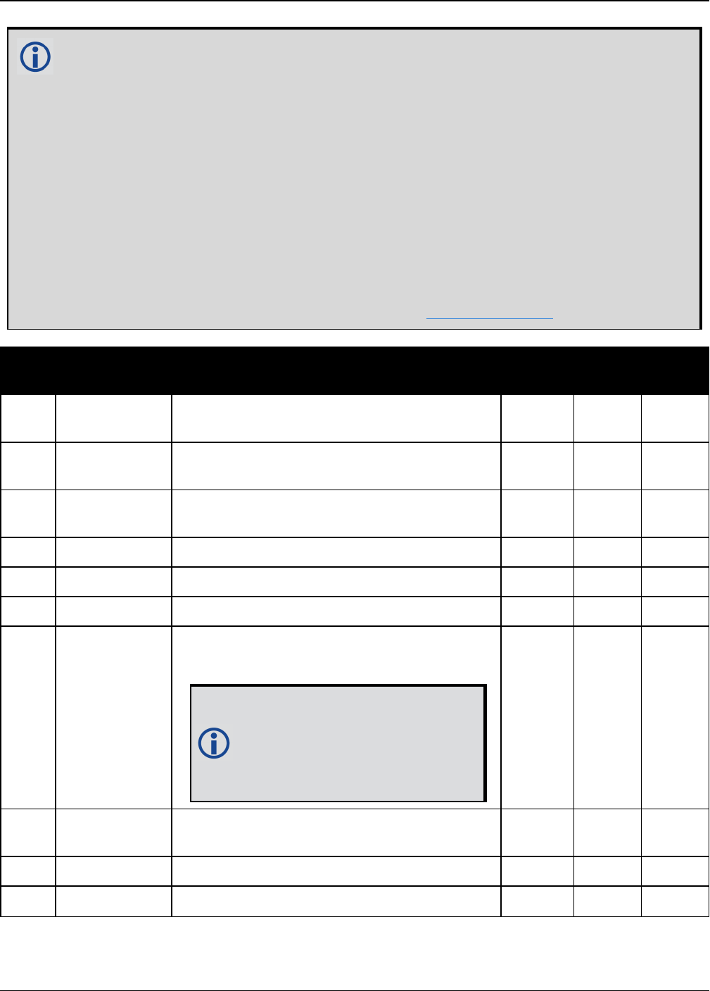
Chapter 3 Logs
OEM7 Commands and Logs Reference Manual v7 737
Consider the case of a racing car, on a closed circuit, requiring RTK operation. In this
situation, you would have to send live data to the pits using a radio link.
RTK operation enables live centimeter level position accuracy. When answers are
required in the field, the base station must transmit information to the rover in real-time.
For RTK operation, extra equipment such as radios are required to transmit and receive
this information. The base station has a corresponding base radio and the rover station
has a corresponding rover radio.
Post-processing can provide post-mission position and velocity data using raw GNSS data
collected from the car. The logs necessary for post-processing include:
RANGECMPB ONTIME 1
RAWEPHEMB ONNEW
These are examples of data collection for post-processing, and real-time operation.
OEM7-based output is compatible with post-processing software from the NovAtel’s
Waypoint Products Group or refer to our website at www.novatel.com for more details.
Field Field type Description Format Binary
Bytes
Binary
Offset
1RTKPOS
header
Log header. See Messages on page25 for
more information. H 0
2 sol status Solution status (see Table 73: Solution
Status on page431) Enum 4 H
3 pos type Position type (see Table 74: Position or
Velocity Type on page432) Enum 4 H+4
4 lat Latitude (degrees) Double 8 H+8
5 lon Longitude (degrees) Double 8 H+16
6 hgt Height above mean sea level (m) Double 8 H+24
7 undulation
Undulation - the relationship between the
geoid and the WGS84 ellipsoid (m)
When using a datum other than
WGS84, the undulation value
also includes the vertical shift
due to differences between the
datum in use and WGS84.
Float 4 H+32
8 datum id# Datum ID number (see Table 28: Datum
Transformation Parameters on page117) Enum 4 H+36
9 lat σ Latitude standard deviation (m) Float 4 H+40
10 lon σ Longitude standard deviation (m) Float 4 H+44

Chapter 3 Logs
OEM7 Commands and Logs Reference Manual v7 738
Field Field type Description Format Binary
Bytes
Binary
Offset
11 hgt σ Height standard deviation (m) Float 4 H+48
12 stn id Base station ID Char[4] 4 H+52
13 diff_age Differential age in seconds Float 4 H+56
14 sol_age Solution age in seconds Float 4 H+60
15 #SVs Number of satellites tracked Uchar 1 H+64
16 #solnSVs Number of satellites vehicles used in
solution Uchar 1 H+65
17 #ggL1 Number of satellites with L1/E1/B1 signals
used in solution Uchar 1 H+66
18 #solnMultiSVs Number of satellites with multi-frequency
signals used in solution Uchar 1 H+67
19 Reserved Hex 1 H+68
20 ext sol stat Extended solution status (see Table 77:
Extended Solution Status on page435) Hex 1 H+69
21
Galileo and
BeiDou sig
mask
Galileo and BeiDou signals used mask (see
Table 76: Galileo and BeiDou Signal-Used
Mask on page435)
Hex 1 H+70
22
GPS and
GLONASS sig
mask
GPS and GLONASS signals used mask (see
Table 75: GPS and GLONASS Signal-Used
Mask on page434)
Hex 1 H+71
23 xxxx 32-bit CRC (ASCII and Binary only) Hex 4 H+72
24 [CR][LF] Sentence terminator (ASCII only) - - -

Chapter 3 Logs
OEM7 Commands and Logs Reference Manual v7 739
3.143 RTKSATS
Satellites used in RTKPOS solution
Platform: OEM719, OEM729, OEM7500, OEM7600, OEM7700, OEM7720, PwrPak7,
SPAN CPT7
This log lists the used and unused satellites for the corresponding RTKPOS solution. It also
describes the signals of the used satellites and reasons for exclusions.
Message ID: 1174
Log Type: Synch
Recommended Input:
log rtksats ontime 1
Abbreviated ASCII Example:
<RTKSATS COM1 0 60.5 FINESTEERING 1728 524924.000 02000000 95e7 11487
<24
<GPS 3 GOOD 00000003
<GPS 5 GOOD 00000003
...
<GPS 23 GOOD 00000003
<GPS 30 GOOD 00000003
<GLONASS 1+1 GOOD 00000003
<GLONASS 2-4 GOOD 00000003
...
<GLONASS 20+2 GOOD 00000003
<GLONASS 21+4 GOOD 00000003
<BEIDOU 6 GOOD 00000003
<BEIDOU 11 GOOD 00000003
...
<BEIDOU 12 GOOD 00000003
<BEIDOU 13 GOOD 00000003
Field Field
type Description Format Binary
Bytes
Binary
Offset
1RTKSATS
header
Log header. See Messages on page25 for more
information. H 0
2 #entries Number of records to follow Ulong 4 H
3 system Satellite system (refer to Table 102: Satellite
System on page545) Enum 4 H+4
4Satellite
ID Satellite identifiers Ulong 4 H+8
5 Status Satellite status. See Table 79: Observation
Statuses on page438 Enum 4 H+12

Chapter 3 Logs
OEM7 Commands and Logs Reference Manual v7 740
Field Field
type Description Format Binary
Bytes
Binary
Offset
6Signal
mask
See Table 80: BESTSATS GPS Signal Mask on
page439, Table 81: BESTSATS GLONASS Signal
Mask on page440, Table 82: BESTSATS Galileo
Signal Mask on page440, and Table 83:
BESTSATS BeiDou Signal Mask on page440
Hex 4 H+16
7 Next satellite offset = H+4+(#sat x 16)
8 xxxx 32-bit CRC (ASCII and Binary only) Hex 4
H+4+
(#sat x
16)
9 [CR][LF] Sentence terminator (ASCII only) - - -
Chapter 3 Logs
OEM7 Commands and Logs Reference Manual v7 741
3.144 RTKVEL
RTK velocity
Platform: OEM719, OEM729, OEM7500, OEM7600, OEM7700, OEM7720, PwrPak7,
SPAN CPT7
This log contains the RTK velocity information computed by the receiver. In addition, it reports a
velocity status indicator that is useful in indicating whether or not the corresponding data is valid
and differential age is useful in predicting anomalous behavior brought about by outages in dif-
ferential corrections. The velocity measurements sometimes have a latency associated with
them. The time of validity is the time tag in the log minus the latency value.
Velocities from the RTK filter are calculated from the delta-position. In RTKVEL, the velo-
city type is the same as the position type.
In an RTKVEL log, the actual speed and direction of the receiver antenna over ground is
provided. The receiver does not determine the direction a vessel, craft or vehicle is poin-
ted (heading) but rather the direction of motion of the GNSS antenna relative to ground.
With the system operating in an RTK mode, this log reflects if the solution is a good RTK low
latency solution (from extrapolated base station measurements) or invalid. A valid RTK low
latency solution is computed for up to 60 seconds after reception of the last base station obser-
vation.
The velocity is computed from consecutive RTK low latency updates. As such, it is an average
velocity based on the time difference between successive position computations and not an
instantaneous velocity at the RTKVEL time tag. The velocity latency to be subtracted from the
time tag is normally half the time between filter updates. Under default operation, the RTK low
latency filter is updated at a rate of 2 Hz. This translates into a velocity latency of 0.25 seconds.
The latency can be reduced by increasing the update rate of the RTK low latency filter by request-
ing the BESTVEL, RTKVEL, BESTPOS or RTKPOS messages at a rate higher than 2 Hz. For
example, a logging rate of 10 Hz would reduce the velocity latency to 0.05 seconds. For integ-
ration purposes, the velocity latency should be applied to the record time tag.
Message ID: 216
Log Type: Synch
Recommended Input:
log rtkvela ontime 1
ASCII Example:
#RTKVELA,COM1,0,43.5,FINESTEERING,1364,496137.000,02100000,71e2,2310;SOL_
COMPUTED,NARROW_INT,0.250,1.000,0.0027,207.645811,0.0104,0.0*f551cc42

Chapter 3 Logs
OEM7 Commands and Logs Reference Manual v7 742
Consider the case of an unmanned aircraft. A base station must send differential cor-
rection data to the remote aircraft. In this type of application, the aircraft’s radio may
pass the differential solution, for example RTKVEL, to the positioning system so it can
process it and generate precise position information for the flight controls.
Field Field
type Description Format Binary
Bytes
Binary
Offset
1RTKVEL
header
Log header. See Messages on page25 for more
information. H 0
2sol
status
Solution status, see Table 73: Solution Status on
page431 Enum 4 H
3vel
type
Velocity type, see Table 74: Position or Velocity
Type on page432 Enum 4 H+4
4 latency
A measure of the latency in the velocity time tag in
seconds. It should be subtracted from the time to
give improved results
Float 4 H+8
5 age Differential age in seconds Float 4 H+12
6 hor spd Horizontal speed over ground, in metres per
second Double 8 H+16
7 trk gnd Actual direction of motion over ground (track over
ground) with respect to True North, in degrees Double 8 H+24
8vert
spd
Vertical speed, in metres per second, where
positive values indicate increasing altitude (up) and
negative values indicate decreasing altitude (down)
Double 8 H+32
9 Reserved Float 4 H+40
10 xxxx 32-bit CRC (ASCII and Binary only) Ulong 4 H+44
11 [CR]
[LF] Sentence terminator (ASCII only) - - -

Chapter 3 Logs
OEM7 Commands and Logs Reference Manual v7 743
3.145 RTKXYZ
RTK Cartesian position and velocity
Platform: OEM719, OEM729, OEM7500, OEM7600, OEM7700, OEM7720, PwrPak7,
SPAN CPT7
This log contains the receiver’s low latency position and velocity in ECEF coordinates. The pos-
ition and velocity status fields indicate whether or not the corresponding data is valid. See Fig-
ure 11: The WGS84 ECEF Coordinate System on page449 for a definition of the ECEF
coordinates.
The velocity measurements have a latency associated with them. The time of validity is the time
tag in the log minus the latency value.
With the system operating in an RTK mode, this log reflects if the solution is a good RTK low
latency solution (from extrapolated base station measurements) or invalid. A valid RTK low
latency solution is computed for up to 60 seconds after reception of the last base station obser-
vation. The degradation in accuracy due to differential age is reflected in the standard deviation
fields, and is summarized in the Standards and References section of our website www.nova-
tel.com/support/. See also the DGPSTXID command (see page 122).
The velocity is computed from consecutive RTK low latency updates. As such, it is an average
velocity based on the time difference between successive position computations and not an
instantaneous velocity at the RTKVEL time tag. The velocity latency to be subtracted from the
time tag is normally half the time between filter updates. Under default operation, the RTK low
latency filter is updated at a rate of 2 Hz. This translates into a velocity latency of 0.25 seconds.
The latency can be reduced by increasing the update rate of the RTK low latency filter by request-
ing the BESTXYZ message at a rate higher than 2 Hz. For example, a logging rate of 10 Hz would
reduce the velocity latency to 0.05 seconds. For integration purposes, the velocity latency
should be applied to the record time tag.
See also the BESTXYZ log on page447 and MATCHEDXYZ log on page596.
Message ID: 244
Log Type: Synch
Recommended Input:
log rtkxyza ontime 1
ASCII Example:
#RTKXYZA,COM1,0,56.0,FINESTEERING,1419,340041.000,02000040,3d88,2724;SOL_
COMPUTED,NARROW_INT,-1634531.5666,-
3664618.0291,4942496.3230,0.0099,0.0219,0.0115,SOL_COMPUTED,NARROW_
INT,0.0030,0.0003,-
0.0016,0.0198,0.0438,0.0230,"AAAA",0.250,1.000,0.000,12,11,11,11,0,01,0,33*0497
d146

Chapter 3 Logs
OEM7 Commands and Logs Reference Manual v7 744
Field Field type Description Format Binary
Bytes
Binary
Offset
1RTKXYZ
header
Log header. See Messages on page25 for
more information. H 0
2 P-sol status Solution status, see Table 73: Solution
Status on page431 Enum 4 H
3 pos type Position type, see Table 74: Position or
Velocity Type on page432 Enum 4 H+4
4 P-X Position X-coordinate (m) Double 8 H+8
5 P-Y Position Y-coordinate (m) Double 8 H+16
6 P-Z Position Z-coordinate (m) Double 8 H+24
7 P-X σ Standard deviation of P-X (m) Float 4 H+32
8 P-Y σ Standard deviation of P-Y (m) Float 4 H+36
9 P-Z σ Standard deviation of P-Z (m) Float 4 H+40
10 V-sol status Solution status, see Table 73: Solution
Status on page431 Enum 4 H+44
11 vel type Velocity type, see Table 74: Position or
Velocity Type on page432 Enum 4 H+48
12 V-X Velocity vector along X-axis (m) Double 8 H+52
13 V-Y Velocity vector along Y-axis (m) Double 8 H+60
14 V-Z Velocity vector along Z-axis (m) Double 8 H+68
15 V-X σ Standard deviation of V-X (m) Float 4 H+76
16 V-Y σ Standard deviation of V-Y (m) Float 4 H+80
17 V-Z σ Standard deviation of V-Z (m) Float 4 H+84
18 stn ID Base station identification Char[4] 4 H+88
19 V-latency
A measure of the latency in the velocity time
tag in seconds. It should be subtracted from
the time to give improved results
Float 4 H+92
20 diff_age Differential age in seconds Float 4 H+96
21 sol_age Solution age in seconds Float 4 H+100
22 #SVs Number of satellites tracked Uchar 1 H+104
23 #solnSVs Number of satellite vehicles used in solution Uchar 1 H+105

Chapter 3 Logs
OEM7 Commands and Logs Reference Manual v7 745
Field Field type Description Format Binary
Bytes
Binary
Offset
24 #ggL1 Number of satellites with L1/E1/B1 signals
used in solution Uchar 1 H+106
25 #solnMultiSVs Number of satellites with multi-frequency
signals used in solution Uchar 1 H+107
26 Reserved Char 1 H+108
27 ext sol stat Extended solution status (see Table 77:
Extended Solution Status on page435) Hex 1 H+109
28
Galileo and
BeiDou sig
mask
Galileo and BeiDou signals used mask (see
Table 76: Galileo and BeiDou Signal-Used
Mask on page435)
Hex 1 H+110
29
GPS and
GLONASS sig
mask
GPS and GLONASS signals used mask (see
Table 75: GPS and GLONASS Signal-Used
Mask on page434)
Hex 1 H+111
30 xxxx 32-bit CRC (ASCII and Binary only) Ulong 4 H+112
31 [CR][LF] Sentence terminator (ASCII only) - - -

Chapter 3 Logs
OEM7 Commands and Logs Reference Manual v7 746
3.146 RXCONFIG
Receiver configuration
Platform: OEM719, OEM729, OEM7500, OEM7600, OEM7700, OEM7720, PwrPak7,
SPAN CPT7
This log is used to output a list of all current command settings. When requested, an RXCONFIG
log is output for each setting. See also the LOGLIST log on page575 for a list of currently active
logs. One log is output for each current command.
Message ID: 128
Log Type: Collection
Recommended Input:
log rxconfiga once
ASCII Example1:
#RXCONFIGA,COM1,71,47.5,APPROXIMATE,1337,333963.260,02000000,f702,1984;
#ADJUST1PPSA,COM1,71,47.5,APPROXIMATE,1337,333963.260,02000000,f702,1984;OFF,ON
CE,0*ba85a20b*91f89b07
#RXCONFIGA,COM1,70,47.5,APPROXIMATE,1337,333963.398,02000000,f702,1984;
#ANTENNAPOWERA,COM1,70,47.5,APPROXIMATE,1337,333963.398,02000000,f702,1984;ON*d
12f6135*8f8741be
#RXCONFIGA,COM1,69,47.5,APPROXIMATE,1337,333963.455,02000000,f702,1984;
#CLOCKADJUSTA,COM1,69,47.5,APPROXIMATE,1337,333963.455,02000000,f702,1984;ENABL
E*0af36d92*b13280f2
...
#RXCONFIGA,COM1,7,47.5,APPROXIMATE,1337,333966.781,02000000,f702,1984;
#STATUSCONFIGA,COM1,7,47.5,APPROXIMATE,1337,333966.781,02000000,f702,1984;CLEAR
,AUX2,0*a6141e28*d0bba9f2
#RXCONFIGA,COM1,2,47.5,APPROXIMATE,1337,333967.002,02000000,f702,1984;
#SBASECUTOFFA,COM1,2,47.5,APPROXIMATE,1337,333967.002,02000000,f702,1984;-
5.000000000*b9b11096*2e8b77cf
#RXCONFIGA,COM1,1,47.5,FINESTEERING,1337,398382.787,02000000,f702,1984;
#LOGA,COM1,1,47.5,FINESTEERING,1337,398382.787,02000000,f702,1984;COM1,MARKPOSA
,ONNEW,0.000000,0.000000,NOHOLD*a739272d*6692c084
#RXCONFIGA,COM1,0,47.5,FINESTEERING,1337,400416.370,02000000,f702,1984;
1The embedded CRCs are flipped to make the embedded messages recognizable to the receiver. For example,
consider the first embedded message above.
91f89b07:10010001111110001001101100000111
11100000110110010001111110001001:e0d91f89
The CRC is really e0d91f89.

Chapter 3 Logs
OEM7 Commands and Logs Reference Manual v7 747
#LOGA,COM1,0,47.5,FINESTEERING,1337,400416.370,02000000,f702,1984;COM2,PASSCOM2
A,ONCHANGED,0.000000,0.000000,NOHOLD*55fc0c62*17086d18
Do not use undocumented commands or logs! Doing so may produce errors and void your
warranty.
The RXCONFIG log can be used to ensure your receiver is correctly setup for your applic-
ation.
Field Field
type Description Format Binary
Bytes
Binary
Offset
1RXCONFIG
header
Log header. See Messages on page25 for
more information. - H 0
2 e header Embedded header - h H
3 e msg Embedded message Varied a H+h
4 e xxxx
Embedded (inverted) 32-bit CRC (ASCII and
Binary only). The embedded CRC is inverted
so that the receiver does not recognize the
embedded messages as messages to be
output but continues with the RXCONFIG
message. If you wish to use the messages
output from the RXCONFIG log, simply flip
the embedded CRC around for individual
messages
Ulong 4 H+h+a
5 xxxx 32-bit CRC (ASCII and Binary only) Hex 4 H+h+a+4
6 [CR][LF] Sentence terminator (ASCII only) - - -

Chapter 3 Logs
OEM7 Commands and Logs Reference Manual v7 748
3.147 RXSTATUS
Receiver status
Platform: OEM719, OEM729, OEM7500, OEM7600, OEM7700, OEM7720, PwrPak7,
SPAN CPT7
This log conveys various status parameters of the GNSS receiver system. These include the
Receiver Status and Error words which contain several flags specifying status and error con-
ditions. If an error occurs (shown in the Receiver Error word), the receiver idles all channels,
turns off the antenna and disables the RF hardware as these conditions are considered to be
fatal errors. The log contains a variable number of status words to allow for maximum flexibility
and future expansion.
The receiver gives the user the ability to determine the importance of the status bits. In the case
of the Receiver Status, setting a bit in the priority mask causes the condition to trigger an error.
This causes the receiver to idle all channels, turn off the antenna and disable the RF hardware,
the same as if a bit in the Receiver Error word is set. Setting a bit in an Auxiliary Status priority
mask causes that condition to set the bit in the Receiver Status word corresponding to that Aux-
iliary Status. See also the STATUSCONFIG command on page359.
Field #4, the receiver status word as represented in Table 158: Receiver Status on
page753, is also in Field #8 of the header. See the ASCII Example below and Table 158:
Receiver Status on page753 for clarification.
Refer also to the chapter on Built-In Status Tests in the OEM7 Installation and Operation
User Manual.
Message ID: 93
Log Type: Asynch
Recommended Input:
log rxstatusa onchanged
Abbreviated ASCII Example:
#RXSTATUS COM1 0 90.5 FINESTEERING 1740 232531.278 02000020 2AE1 44913
00000000 4(Receiver Error)
02000020 00000000 00000000 00000000(Receiver Status)
00040080 00001008 00000000 00000000(Aux1 Status)
00000000 00000000 00000000 00000000(Aux2 Status)
02000000 00000000 00000000 00000000(Aux3 Status)
00000000 00000000 00000000 00000000(Aux4 Status)

Chapter 3 Logs
OEM7 Commands and Logs Reference Manual v7 749
Receiver errors automatically generate event messages. These event messages are
output in RXSTATUSEVENT logs. It is also possible to have status conditions trigger event
messages to be generated by the receiver. This is done by setting/clearing the
appropriate bits in the event set/clear masks. The set mask tells the receiver to generate
an event message when the bit becomes set. Likewise, the clear mask causes messages
to be generated when a bit is cleared. See the STATUSCONFIG command on page359
for details.
If you wish to disable all these messages without changing the bits, simply UNLOG the
RXSTATUSEVENT logs on the appropriate ports. See the UNLOG command on
page384.
Field Field
type Description Format Binary
Bytes
Binary
Offset
1RXSTATUS
header
Log header. See Messages on page25 for more
information. H 0
2 error
Receiver error (see Table 157: Receiver Error
on page751). A value of zero indicates no
errors
Ulong 4 H
3 # stats
Number of status codes (including Receiver
Status). Each status code consists of 4 fields,
the status, priority mask, event set mask and
event clear mask. Each set is repeated for each
status type.
Note that for clarity, the Receiver Status,
Auxiliary1 Status, Auxiliary 2 Status, Auxiliary3
Status and Auxiliary4 status are listed
separately in this message
Ulong 4 H+4
4 rxstat Receiver status word (see Table 158: Receiver
Status on page753) Ulong 4 H+8
5 rxstat pri
Receiver status priority mask, which can be set
using the STATUSCONFIG command on
page359
Ulong 4 H+12
6 rxstat set
Receiver status event set mask, which can be
set using the STATUSCONFIG command on
page359
Ulong 4 H+16
7rxstat
clear
Receiver status event clear mask, which can be
set using the STATUSCONFIG command on
page359
Ulong 4 H+20
8 aux1stat Auxiliary 1 status word (see Table 160:
Auxiliary 1 Status on page755) Ulong 4 H+24

Chapter 3 Logs
OEM7 Commands and Logs Reference Manual v7 750
Field Field
type Description Format Binary
Bytes
Binary
Offset
9aux1stat
pri
Auxiliary 1 status priority mask, which can be
set using the STATUSCONFIG command on
page359
Ulong 4 H+28
10 aux1stat
set
Auxiliary 1 status event set mask, which can be
set using the STATUSCONFIG command on
page359
Ulong 4 H+32
11 aux1stat
clear
Auxiliary 1 status event clear mask, which can
be set using the STATUSCONFIG command on
page359
Ulong 4 H+36
12 aux2stat Auxiliary 2 status word (see Table 161:
Auxiliary 2 Status on page757) Ulong 4 H+40
13 aux2stat
pri
Auxiliary 2 status priority mask, which can be
set using the STATUSCONFIG command on
page359
Ulong 4 H+44
14 aux2stat
set
Auxiliary 2 status event set mask, which can be
set using the STATUSCONFIG command on
page359
Ulong 4 H+48
15 aux2stat
clear
Auxiliary 2 status event clear mask, which can
be set using the STATUSCONFIG command on
page359
Ulong 4 H+52
16 aux3stat Auxiliary 3 status word (see Table 162:
Auxiliary 3 Status on page758) Ulong 4 H+56
17 aux3stat
pri
Auxiliary 3 status priority mask, which can be
set using the STATUSCONFIG command on
page359
Ulong 4 H+60
18 aux3stat
set
Auxiliary 3 status event set mask, which can be
set using the STATUSCONFIG command on
page359
Ulong 4 H+64
19 aux3stat
clear
Auxiliary 3 status event clear mask, which can
be set using the STATUSCONFIG command on
page359
Ulong 4 H+68
20 aux4stat Auxiliary 4 status word (see Table 164:
Auxiliary 4 Status on page760) Ulong 4 H+72
21 aux4stat
pri
Auxiliary 4 status priority mask, which can be
set using the STATUSCONFIG command on
page359
Ulong 4 H+76

Chapter 3 Logs
OEM7 Commands and Logs Reference Manual v7 751
Field Field
type Description Format Binary
Bytes
Binary
Offset
22 aux4stat
set
Auxiliary 4 status event set mask, which can be
set using the STATUSCONFIG command on
page359
Ulong 4 H+80
23 aux4stat
clear
Auxiliary 4 status event clear mask, which can
be set using the STATUSCONFIG command on
page359
Ulong 4 H+84
24 xxxx 32-bit CRC (ASCII and Binary only) Ulong 4 H+88
25 [CR][LF] Sentence terminator (ASCII only) - - -
Nibble Bit Mask Description
Bit
=
0
Bit
= 1
N0
0 0x00000001
Dynamic Random Access Memory (DRAM) status
RAM failure on an OEM7 card may also be indicated by a
flashing red LED.
OK Error
1 0x00000002 Invalid firmware OK Error
2 0x00000004 ROM status OK Error
3 0x00000008 Reserved
N1
4 0x00000010 Electronic Serial Number (ESN) access status OK Error
5 0x00000020 Authorization code status OK Error
6 0x00000040 Reserved
7 0x00000080 Supply voltage status OK Error
N2
8 0x00000100 Reserved
9 0x00000200 Temperature status (as compared against acceptable
limits) OK Error
10 0x00000400 MINOS status OK Error
11 0x00000800
PLL RF status. Error with an RF PLL. See AUX2 status bits
(Table 161: Auxiliary 2 Status on page757) for
individual PLLstatus
OK Error
Table 157: Receiver Error

Chapter 3 Logs
OEM7 Commands and Logs Reference Manual v7 752
Nibble Bit Mask Description
Bit
=
0
Bit
= 1
N3
12 0x00001000
Reserved13 0x00002000
14 0x00004000
15 0x00008000 NVM status OK Error
N4
16 0x00010000 Software resource lim exceeded OK Error
17 0x00020000 Model invalid for this receiver OK Error
18 0x00040000 Reserved
19 0x00080000
N5
20 0x00100000 Remote loading has begun No Yes
21 0x00200000 Export restriction OK Error
22 0x00400000 Safe Mode OK Error
23 0x00800000
Reserved
N6
24 0x01000000
25 0x02000000
26 0x04000000
27 0x08000000
N7
28 0x10000000
29 0x20000000
30 0x40000000
31 0x80000000 Component hardware failure OK Error

Chapter 3 Logs
OEM7 Commands and Logs Reference Manual v7 753
Nibble Bit Mask Description Bit = 0 Bit = 1
N0
0 0x00000001 Error flag, see Table 157: Receiver
Error on page751 No error Error
1 0x00000002 Temperature status Within
specifications Warning
2 0x00000004 Voltage supply status OK Warning
3 0x00000008
Primary antenna power status
See the ANTENNAPOWER
command on page63
Powered Not powered
N1
4 0x00000010 LNA Failure OK Failure
5 0x00000020
Primary antenna open circuit flag
This flag is only available on certain
products.
OK Open, antenna
disconnected
6 0x00000040
Primary antenna short circuit flag
This flag is only available on certain
products.
OK Short circuit
detected
7 0x00000080
CPU overload flag
This flag is only available on certain
products.
No overload Overload
N2
8 0x00000100
COM port transmit buffer overrun.
See AUX2 status bits (Table 161:
Auxiliary 2 Status on page757) for
individual COM port status
OK COM buffer
overrun
9 0x00000200 Reserved
10 0x00000400
11 0x00000800
Link overrun flag
This flag indicates if any of the USB,
ICOM, CCOM, NCOM or File ports
are overrun. See AUX1, AUX2 and
AUX3 status bits (Table 160:
Auxiliary 1 Status on page755,
Table 161: Auxiliary 2 Status on
page757 or Table 162: Auxiliary 3
Status on page758) for the specific
port for which the buffer is overrun.
No overrun Overrun
Table 158: Receiver Status

Chapter 3 Logs
OEM7 Commands and Logs Reference Manual v7 754
Nibble Bit Mask Description Bit = 0 Bit = 1
N3
12 0x00001000
Input overrun flag
This flag is set if any of the receiver
ports (COM, USB, ICOM or NCOM)
experience an input overrun.
No overrun Overrun
13 0x00002000 Aux transmit overrun flag No overrun Overrun
14 0x00004000
Antenna gain state
See the AUX3 status bits (Table 162:
Auxiliary 3 Status on page758) for
the antenna gain status.
OK Out of range
15 0x00008000
Jammer Detected.
See the AUX1 status bits (Table 160:
Auxiliary 1 Status on the next
page)for individual RF status
OK Jammer
Detected
N4
16 0x00010000 INS reset flag No INS reset INS reset
17 0x00020000 IMU communication failure No error No IMU
communication
18 0x00040000 GPSalmanac flag/UTC known Valid Invalid
19 0x00080000 Position solution flag Valid Invalid
N5
20 0x00100000 Position fixed flag, see the FIX
command on page161 Not fixed Fixed
21 0x00200000 Clock steering status Enabled Disabled
22 0x00400000 Clock model flag Valid Invalid
23 0x00800000 External oscillator locked flag Unlocked Locked
N6
24 0x01000000 Software resource OK Warning
25
0x06000000
Version bit 0 See Table 159: Version Bits on
the next page
26 Version bit 1 See Table 159: Version Bits on
the next page
27 0x08000000 Tracking mode Normal
tracking HDR tracking
N7
28 0x10000000 Digital Filtering Enabled Disabled Enabled
29 0x20000000 Auxiliary 3 status event flag No event Event
30 0x40000000 Auxiliary 2 status event flag No event Event
31 0x80000000 Auxiliary 1 status event flag No event Event

Chapter 3 Logs
OEM7 Commands and Logs Reference Manual v7 755
Bit 25 Bit 26 Description
0 0 Interpret Status/Error Bits as OEM6 or earlier format
1 0 Interpret Status/Error Bits as OEM7 format
0 1 Reserved for a future version
1 1 Reserved for a future version
Table 159: Version Bits
Nibble Bit Mask Description Bit = 0 Bit = 1
N0
0 0x00000001 Jammer detected on RF1 OK Jammer
detected
1 0x00000002 Jammer detected on RF2 OK Jammer
detected
2 0x00000004 Jammer detected on RF3 OK Jammer
detected
3 0x00000008 Position averaging Off On
N1
4 0x00000010 Jammer detected on RF4 OK Jammer
detected
5 0x00000020 Jammer detected on RF5 OK Jammer
detected
6 0x00000040 Jammer detected on RF6 OK Jammer
detected
7 0x00000080 USB connection status Connected Not
connected
N2
8 0x00000100 USB1 buffer overrun flag No
overrun Overrun
9 0x00000200 USB2 buffer overrun flag No
overrun Overrun
10 0x00000400 USB3 buffer overrun flag No
overrun Overrun
11 0x00000800 Reserved
Table 160: Auxiliary 1 Status

Chapter 3 Logs
OEM7 Commands and Logs Reference Manual v7 756
Nibble Bit Mask Description Bit = 0 Bit = 1
N3
12 0x00001000 Profile Activation Bit OK Error
13 0x00002000 Throttled Ethernet Reception OK Throttled
14 0x00004000 Reserved
15 0x00008000 Reserved
N4
16 0x00010000 Reserved
17 0x00020000 Reserved
18 0x00040000 Ethernet not connected Connected Not
connected
19 0x00080000 ICOM1 buffer overrun flag No
overrun Overrun
N5
20 0x00100000 ICOM2 buffer overrun flag No
overrun Overrun
21 0x00200000 ICOM3 buffer overrun flag No
overrun Overrun
22 0x00400000 NCOM1 buffer overrun flag No
overrun Overrun
23 0x00800000 NCOM2 buffer overrun flag No
overrun Overrun
N6
24 0x01000000 NCOM3 buffer overrun flag No
overrun Overrun
25 0x02000000 Reserved
26 0x04000000 Reserved
27 0x08000000 Reserved
N7
28 0x10000000 Reserved
29 0x20000000 Reserved
30 0x40000000 Reserved
31 0x80000000
IMU measurement outlier detected.
Indicates when the SPAN system has
detected an outlier in the IMUperformance.
May be treated as a notice unless the issue
persists.
OK Outlier
detected

Chapter 3 Logs
OEM7 Commands and Logs Reference Manual v7 757
Nibble Bit Mask Description Bit = 0 Bit = 1
N0
0 0x00000001 SPI Communication Failure OK Error
1 0x00000002 I2C Communication Failure OK Error
2 0x00000004 COM4 buffer overrun flag No
overrun Buffer Overrun
3 0x00000008 COM5 buffer overrun flag No
overrun Buffer Overrun
N1
4 0x00000010 Reserved
5 0x00000020 Reserved
6 0x00000040 Reserved
7 0x00000080 Reserved
N2
8 0x00000100 Reserved
9 0x00000200 COM1 buffer overrun flag OK Buffer Overrun
10 0x00000400 COM2 buffer overrun flag OK Buffer Overrun
11 0x00000800 COM3 buffer overrun flag OK Buffer Overrun
N3
12 0x00001000 PLL RF1 unlock flag OK PLL Unlock
13 0x00002000 PLL RF2 unlock flag OK PLL Unlock
14 0x00004000 PLL RF3 unlock flag OK PLL Unlock
15 0x00008000 PLL RF4 unlock flag OK PLL Unlock
N4
16 0x00010000 PLL RF5 unlock flag OK PLL Unlock
17 0x00020000 PLL RF6 unlock flag OK PLL Unlock
18 0x00040000 CCOM1 buffer overrun OK Buffer Overrun
19 0x00080000 CCOM2 buffer overrun OK Buffer Overrun
N5
20 0x00100000 CCOM3 buffer overrun OK Buffer Overrun
21 0x00200000 CCOM4 buffer overrun OK Buffer Overrun
22 0x00400000 CCOM5 buffer overrun OK Buffer Overrun
23 0x00800000 CCOM6 buffer overrun OK Buffer Overrun
Table 161: Auxiliary 2 Status

Chapter 3 Logs
OEM7 Commands and Logs Reference Manual v7 758
Nibble Bit Mask Description Bit = 0 Bit = 1
N6
24 0x01000000 ICOM4 buffer overrun OK Buffer Overrun
25 0x02000000 ICOM5 buffer overrun OK Buffer Overrun
26 0x04000000 ICOM6 buffer overrun OK Buffer Overrun
27 0x08000000 ICOM7 buffer overrun OK Buffer Overrun
N7
28 0x10000000
Secondary antenna power status
See the ANTENNAPOWER
command (see page 63)
Powered Not Powered
29 0x20000000
Secondary antenna open circuit
This flag is only available on certain
products
OK Open, antenna
disconnected
30 0x40000000
Secondary antenna short circuit
This flag is only available on certain
products
OK Short circuit
detected
31 0x80000000 Reset loop detected OK Reset Detected
Nibble Bit Mask Description Bit = 0 Bit = 1
N0
0 0x00000001
SCOM buffer overrun flag.
This flag is set if any of the SCOM ports
(SCOM1 – SCOM4) experience overrun.
No
overrun Overrun
1 0x00000002 WCOM1 buffer overrun flag No
overrun Overrun
2 0x00000004 FILE buffer overrun flag No
overrun Overrun
3 0x00000008 Reserved
N1
4 0x00000010 Antenna 1 Gain State Table 163: Antenna Gain
State on the next page
5 0x00000020
6 0x00000040 Antenna 2 Gain State Table 163: Antenna Gain
State on the next page
7 0x00000080
N2
8 0x00000100
Reserved
9 0x00000200
10 0x00000400
11 0x00000800
Table 162: Auxiliary 3 Status

Chapter 3 Logs
OEM7 Commands and Logs Reference Manual v7 759
Nibble Bit Mask Description Bit = 0 Bit = 1
N3
12 0x00001000
Reserved
13 0x00002000
14 0x00004000
15 0x00008000
N4
16 0x00010000
Reserved
17 0x00020000
18 0x00040000
19 0x00080000
N5
20 0x00100000
Reserved
21 0x00200000
22 0x00400000
23 0x00800000
N6
24 0x01000000
Reserved
25 0x02000000
26 0x04000000
27 0x08000000
N7
28 0x10000000 Reserved
29 0x20000000 Web content is corrupt or does not exist Content is
OK
Error with
content
30 0x40000000 RF Calibration Data is present and in
error Data is OK Data has an
error
31 0x80000000 RF Calibration Data is present No data
found
Data exists
and has no
errors
Bits4-5
or
Bits6-7
Description
00 Antenna Gain in range
Table 163: Antenna Gain State

Chapter 3 Logs
OEM7 Commands and Logs Reference Manual v7 760
Bits4-5
or
Bits6-7
Description
01
Antenna Gain Low
This state indicates that the input signal is very weak (under -160 dBm/Hz). It can
indicate the antenna is not operating correctly, the antenna is not suitable for NovAtel
receivers, or there is no antenna connected.
10
Antenna Gain High.
This state indicates that the input signal is very strong (above -120 dBm/Hz). This can
be caused by a strong in-band interference or by too much signal gain or too many LNAs
cascaded in the path.
11
Antenna Gain Anomaly.
This state indicates that an anomaly has been detected for the input signal. It can be
caused by strong in-band or out-of-band interference, or by the antenna being
disconnected/changed during operation.
Nibble Bit Mask Description Bit = 1
N0
0 0x00000001
GNSS Tracked Status
<60% of available
satellites are tracked
well
1 0x00000002
<15% of available
satellites are tracked
well
2 0x00000004 Reserved
3 0x00000008
N1
4 0x00000010
Reserved
5 0x00000020
6 0x00000040
7 0x00000080
N2
8 0x00000100
Reserved
9 0x00000200
10 0x00000400
11 0x00000800
Table 164: Auxiliary 4 Status

Chapter 3 Logs
OEM7 Commands and Logs Reference Manual v7 761
Nibble Bit Mask Description Bit = 1
N3
12 0x00001000 Clock freewheeling due to bad position
integrity Clock freewheeling
13 0x00002000 Reserved
14 0x00004000 Usable RTK Corrections
Percentage of expected measurements which
have timely RTK corrections (latency <20
seconds)
<60% of expected
corrections available
15 0x00008000 <15% of expected
corrections available
N4
16 0x00010000 Bad RTK Geometry PDOP >5.0
17 0x00020000 Reserved
18 0x00040000
19 0x00080000 Long RTK Baseline Baseline >50 km
N5
20 0x00100000 Poor RTK COM Link (poor correction quality) Corrections quality
≤60%
21 0x00200000 Poor ALIGN COM Link (poor correction quality) Corrections quality
≤60%
22 0x00400000 GLIDE Not Active GLIDE not active
23 0x00800000 Bad PDP Geometry PDOP >5.0
N6
24 0x01000000 No TerraStar Subscription No subscription
25 0x02000000
Reserved26 0x04000000
27 0x08000000
N7
28 0x10000000 Bad PPP Geometry PDOP >5.0
29 0x20000000 Reserved
30 0x40000000 No INS Alignment No alignment
31 0x80000000 INS not converged Not converged
Only GPS and GLONASS are considered in the Auxiliary 4 status word states.
For bits relating to RTK, ALIGN or INS, the bits will only be set if the receiver has that
type of positioning is enabled via Auth Code.

Chapter 3 Logs
OEM7 Commands and Logs Reference Manual v7 762
3.148 RXSTATUSEVENT
Status event indicator
Platform: OEM719, OEM729, OEM7500, OEM7600, OEM7700, OEM7720, PwrPak7,
SPAN CPT7
This log is used to output event messages as indicated in the RXSTATUS log (see page 748). An
event message is automatically generated for all receiver errors, which are indicated in the
receiver error word. In addition, event messages can be generated when other conditions,
which are indicated in the receiver status and auxiliary status words, are met. Whether or not an
event message is generated under these conditions is specified using the STATUSCONFIG com-
mand (see page 359).
On start-up, the receiver is set to log RXSTATUSEVENTA ONNEW HOLD on all ports. You can
remove this message using the UNLOG command (see page 384). To remove this log using an
UNLOGALL command (see page 386), you must use the True option.
Logging RXSTATUSEVENT on all ports is a factory default setting. If it is unlogged, the
RXSTATUSEVENT log will not be collected until the next start-up. After a start-up, logging
RXSTATUSEVENT on all ports will start again.
See also the chapter on Built-In Status Tests in the OEM7 Installation and Operation User
Manual.
Message ID: 94
Log Type: Asynch
Recommended Input:
log rxstatuseventa onchanged
ASCII Example 1:
#RXSTATUSEVENTA,COM1,0,17.0,FREEWHEELING,1337,408334.510,02480000,b967,1984;STA
TUS,19,SET,"No Valid Position Calculated"*6de945ad
ASCII Example 2:
#RXSTATUSEVENTA,COM1,0,41.0,FINESTEERING,1337,408832.031,03000400,b967,1984;STA
TUS,10,SET,"COM3 Transmit Buffer Overrun"*5b5682a9
When a fatal event occurs (for example, in the event of a receiver hardware failure), a
bit is set in the receiver error word, part of the RXSTATUS log (see page 748) to indic-
ate the cause of the problem. Bit 0 is set in the receiver status word to show that an
error occurred, the error strobe is driven high and the LED flashes red and yellow show-
ing an error code. An RXSTATUSEVENT log is generated on all ports to show the cause of
the error. Receiver tracking is disabled at this point but command and log processing
continues to allow you to diagnose the error. Even if the source of the error is corrected
at this point, the receiver must be reset to resume normal operation.

Chapter 3 Logs
OEM7 Commands and Logs Reference Manual v7 763
Field Field type Description Format Binary
Bytes
Binary
Offset
1RXSTATUSEVENT
header
Log header. See Messages on page25 for
more information. H 0
2 word
The status word that generated the event
message (see Table 165: Status Word
below)
Enum 4 H
3 bit position
Location of the bit in the status word (see
Table 158: Receiver Status on page753,
Table 160: Auxiliary 1 Status on
page755, Table 161: Auxiliary 2 Status
on page757 or Table 162: Auxiliary 3
Status on page758
Ulong 4 H+4
4 event Event type (see Table 166: Event Type
below) Enum 4 H+8
5 description This is a text description of the event or
error
Char
[32] 32 H+12
6 xxxx 32-bit CRC (ASCII and Binary only) Ulong 4 H+44
7 [CR][LF] Sentence terminator (ASCII only) - - -
Binary ASCII Description
0 ERROR Receiver Error word,
see Table 157: Receiver Error on page751
1 STATUS Receiver Status word,
see Table 158: Receiver Status on page753
2 AUX1 Auxiliary 1 Status word,
see Table 160: Auxiliary 1 Status on page755
3 AUX2 Auxiliary 2 Status word
see Table 161: Auxiliary 2 Status on page757
4 AUX3 Auxiliary 3 Status word
see Table 162: Auxiliary 3 Status on page758
Table 165: Status Word
Binary ASCII Description
0 CLEAR Bit was cleared
1 SET Bit was set
Table 166: Event Type

Chapter 3 Logs
OEM7 Commands and Logs Reference Manual v7 764
3.149 SAFEMODESTATUS
Safe Mode Status
Platform: OEM719, OEM729, OEM7500, OEM7600, OEM7700, OEM7720, PwrPak7,
SPAN CPT7
This log provides additional information about the state of the receiver in the event that the Safe
Mode error bit and/or Reset Loop Detected status bit are set in the RXSTATUS log (see page
748).
The data within this log is set at receiver start up and will not change over time.
Message ID: 2060
Log Type: Asynch
Recommended Input:
log SAFEMODESTATUSA once
Abbreviated ASCII Example:
#SAFEMODESTATUSA,COM1,0,89.0,UNKNOWN,0,0.000,024c0020,8e55,32768;SAFE_MODE_
OK,0,"Normal Operation."*29c7d28a
Field Field Type Description Binary
Format
Binary
Bytes
Binary
Offset
1SAFEMODESTATUS
header
Log header. See Messages on page25
for more information. - H 0
2 Status Safe Mode State. See Table 167: Safe
Mode States on the next page Enum 4 H
3 Reset Count Number of resets since power up or a
successful boot Ulong 4 H+4
4 Description String for additional information about
the Safe Mode State String 80 H+8
5 xxxx 32-bit CRC (ASCII and Binary only) Ulong 4 H+88
6 [CR][LF] Sentence terminator (ASCII only) - - -

Chapter 3 Logs
OEM7 Commands and Logs Reference Manual v7 765
Value State
Safe
Mode
Error
Bit
Reset
Loop
Detected
Bit
Notes Recovery Steps
0 SAFE_MODE_OK 0 0 Normal Operation. No
reset loop detected. No action required
1SAFE_MODE_
WARNING 0 1
An unexpected reset was
detected. The receiver will
operate as normal
No action required
2
SAFE_MODE_
DISABLE_
SATELLITE_DATA
0 1
Satellite Navigation Data
previously saved to NVM is
ignored in this state. As
the receiver continues to
track GNSS satellites, new
data will be downloaded.
There may be some delay
in initial satellite
acquisition as this will
effectively be a Cold Start,
but the receiver will
otherwise operate as
normal.
No action required
3
SAFE_MODE_
DISABLE_
NON_
COMMUNICATION_
NVM
1 1
All data previously saved
to NVM that is not related
to communication is
ignored in this state.
Communication ports
(COM, USB, ICOM, etc.)
will remain in the
configuration previously
saved by SAVECONFIG
allowing the user to take
corrective action.
Depending on what
NVM data is
causing the
problem, a
FRESET may
resolve the issue.
If a standard
FRESET does not
resolve the issue,
see the FRESET
command on
page174 for other
NVM targets that
may be causing
the issue and could
be removed.
Table 167: Safe Mode States

Chapter 3 Logs
OEM7 Commands and Logs Reference Manual v7 766
Value State
Safe
Mode
Error
Bit
Reset
Loop
Detected
Bit
Notes Recovery Steps
4
SAFE_MODE_
DISABLE_
ALL_NVM
1 1
All data previously saved
to NVM is ignored in this
state.
See recovery steps
for SAFE_MODE_
DISABLE_
NON_
COMMUNICATION_
NVM.
5
SAFE_MODE_
DISABLE_
AUTH
1 1
All data previously saved
to NVM and all Auth Codes
are ignored in this state.
Use the AUTH
REMOVE
command to
remove the
offending Auth
Code. The
AUTHCODES log
(see page 414) can
be used to
determine what
Auth Codes are
currently loaded.
6SAFE_MODE_
FAILED 1 1
All data previously saved
to NVM and all Auth Codes
are ignored in this state.
This state is
unexpected. The
recovery steps for
other states may
apply.
7
SAFE_MODE_
UNEXPECTED_
MAIN_FIRMWARE
1 0 or 1
An error related to main
firmware loading
occurred.
Reload the main
firmware.

Chapter 3 Logs
OEM7 Commands and Logs Reference Manual v7 767
3.150 SATVIS2
Satellite visibility
Platform: OEM719, OEM729, OEM7500, OEM7600, OEM7700, OEM7720, PwrPak7,
SPAN CPT7
This log contains satellite visibility data for all available systems with additional satellite and
satellite system information. One log is output for each available satellite system.
1. The SATVIS2 log is meant to provide a brief overview. The satellite positions and velo-
cities used in the computation of this log are based on Almanac orbital parameters, not
the higher precision Ephemeris parameters.
2. In the SATVIS2 log output, there may be double satellite number entries. These are
GLONASS antipodal satellites in the same orbit plane separated by 180 degrees lat-
itude. Refer to the GLONASS section of An Introduction to GNSS available on our web-
site.
3. The SATVIS2 log is generated every 10 seconds. If the log is requested at a faster rate
than ontime 10, it will only be output every 10 seconds.
Message ID: 1043
Log Type: Asynch
Recommended Input:
log satvis2a onchanged
Abbreviated ASCII Example:
<SATVIS2 COM1 5 70.0 FINESTEERING 1729 166550.000 02000000 a867 44263
<GPS TRUE TRUE 31
<32 0 71.1 177.8 -1183.650 -1184.441
<20 0 66.2 265.9 462.684 461.894
...
<26 0 -78.7 246.3 805.272 804.481
<9 0 -79.0 7.3 -930.480 -931.271
<SATVIS2 COM1 4 70.0 FINESTEERING 1729 166550.000 0200000 a867 44263
<GLONASS TRUE TRUE 24
<3+5 0 75.2 326.1 1088.078 1087.272
<13-2 0 61.4 188.2 2243.727 2242.923
...
<9-2 0 -72.3 6.3 -1384.534 -1385.337
<7+5 0 -81.2 146.3 -666.742 -667.548
<SATVIS2 COM1 0 70.0 FINESTEERING 1729 166550.000 02000000 a867 44263
<BEIDOU TRUE TRUE 14
<11 0 2.6 342.2 -711.023 -711.807
<12 0 -5.0 297.0 -2407.877 -2408.661
...
<10 216 -79.3 254.5 122.316 121.532
<13 216 -81.5 51.2 76.611 75.827

Chapter 3 Logs
OEM7 Commands and Logs Reference Manual v7 768
Field Field
type Description Format Binary
Bytes
Binary
Offset
1SATVIS2
header
Log header. See Messages on page25 for more
information. H 0
2Satellite
System
GNSS satellite system identifier. See Table 102:
Satellite System on page545 Enum 4 H
3 sat vis
Is satellite visibility valid?
0 = FALSE
1 = TRUE
Enum 4 H+4
4almanac
flag
Was complete GNSS almanac used?
0 = FALSE
1 = TRUE
Enum 4 H+8
5 #sat Number of satellites with data to follow Ulong 4 H+12
6Satellite
ID
In binary logs, the satellite ID field is 4 bytes. The
2 lowest order bytes, interpreted as a USHORT,
are the system identifier: for instance, the PRN
for GPS or the slot for GLONASS. The 2 highest-
order bytes are the frequency channel for
GLONASS, interpreted as a SHORT and zero for all
other systems. In ASCII and abbreviated ASCII
logs, the satellite ID field is the system identifier.
If the system is GLONASS and the frequency
channel is not zero, then the signed channel is
appended to the system identifier. For example,
slot 13, frequency channel -2 is output as 13-2
For more information, refer to PRN Numbers on
page44
Ulong 4 H+16
7 health
Satellite health
Satellite health values may be found
in the applicable Interface Control
Document for each system.
Ulong 4 H+20
8 elev Elevation (degrees) Double 8 H+24
9 az Azimuth (degrees) Double 8 H+32

Chapter 3 Logs
OEM7 Commands and Logs Reference Manual v7 769
Field Field
type Description Format Binary
Bytes
Binary
Offset
10 true
Doppler
Theoretical Doppler of satellite - the expected
Doppler frequency based on a satellite's motion
relative to the receiver. It is computed using the
satellite's coordinates and velocity along with the
receiver's coordinates and velocity (Hz)
Double 8 H+40
11 apparent
Doppler
Apparent Doppler for this receiver - the same as
Theoretical Doppler above but with clock drift
correction added (Hz)
Double 8 H+48
12 Next satellite offset = H + 16 + (#sat x 40)
13 xxxx 32-bit CRC (ASCII and Binary only) Ulong 4
H+16+
(#sat x
40)
14 [CR][LF] Sentence terminator (ASCII only) - - -

Chapter 3 Logs
OEM7 Commands and Logs Reference Manual v7 770
3.151 SATXYZ2
Satellite positions in ECEF Cartesian coordinates
Platform: OEM719, OEM729, OEM7500, OEM7600, OEM7700, OEM7720, PwrPak7,
SPAN CPT7
When combined with a RANGE log, this data set contains the decoded satellite information neces-
sary to compute the solution: satellite coordinates (ECEF WGS84), satellite clock correction,
ionospheric corrections and tropospheric corrections. See the calculation examples in the usage
box below. Only those satellites used in the corresponding PSRPOS solution are reported here.
See also Figure 11: The WGS84 ECEF Coordinate System on page449.
Message ID: 1451
Log Type: Synch
Recommended Input:
log satxyz2 ontime 1
Abbreviated ASCII Example:
<SATXYZ2 COM1 0 83.5 FINESTEERING 1686 489605.000 02000040 7513 43391
<18
<GPS 1 -15502299.3828 1012325.6443 21538404.8435 76246.262 6.990 3.395 0.0
0.0
<GPS 19 -25806091.5135 -6923139.1454 1709844.1975 -78547.421 5.734 9.238
0.0 0.0
<GPS 12 20368857.0090 -5772890.2153 15912912.0724 20118.104 2.415 12.239
0.0 0.0
...
<GLONASS 23+3 -22246787.0962 -4287240.2873 11721201.0046 -116210.453 6.928
4.205 0.0 0.0
<GLONASS 7+5 4586441.8834 -14896106.2729 20222034.1193 -6061.174 1.636
2.529 0.0 0.0
<GLONASS 8+6 -12121452.4145 -4467306.1322 21995556.9720 -7165.609 0.350
2.586 0.0 0.0

Chapter 3 Logs
OEM7 Commands and Logs Reference Manual v7 771
The OEM7 family use positive numbers for ionospheric and tropospheric corrections. A
positive clock offset indicates the clock is running ahead of the reference time. Positive
ionospheric and tropospheric corrections are added to the geometric ranges or
subtracted from the measured pseudoranges. For example:
P = p + pd + c(dT - dt) + d(ion) + d(trop) + Ep
is equivalent to
P - c(dT - dt) - d(ion) - d(trop) = p + pd + Ep
where
P = measured pseudorange
p = geometric range
pd = orbit error
dt = satellite clock offset
dT = receiver clock offset
d (ion) = ionospheric delay
d (trop) = tropospheric delay
c = speed of light
Ep = noise and multipath
Field Field
Type Description Format Binary
Bytes
Binary
Offset
1SATXYZ2
header
Log header. See Messages on page25 for
more information. - H 0
2 #sat Number of satellites to follow Ulong 4 H
3 System Satellite system (refer to Table 102:
Satellite System on page545) Enum 4 H+4
4Satellite
ID Satellite ID Ulong 4 H+8
5 X Satellite X co-ordinates (ECEF,m) Double 8 H+12
6 Y Satellite Y co-ordinates (ECEF,m) Double 8 H+20
7 Z Satellite Z co-ordinates (ECEF,m) Double 8 H+28
8 clk corr Satellite clock correction (m) Double 8 H+36
9 iono delay Ionosphere delay (m) Double 8 H+44
10 tropo
delay Troposphere delay (m) Double 8 H+52
11 Reserved1 Double 8 H+60
12 Reserved2 Double 8 H+68
13 Next satellite offset = H+4+(#sat x 72)

Chapter 3 Logs
OEM7 Commands and Logs Reference Manual v7 772
Field Field
Type Description Format Binary
Bytes
Binary
Offset
14 xxxx 32-bit CRC (ASCII and Binary only) Ulong 4
H+4+
(#sat x
72)
15 [CR][LF] Sentence terminator (ASCII only)

Chapter 3 Logs
OEM7 Commands and Logs Reference Manual v7 773
3.152 SAVEDSURVEYPOSITIONS
Saved surveyed positions
Platform: OEM719, OEM729, OEM7500, OEM7600, OEM7700, OEM7720, PwrPak7,
SPAN CPT7
This log lists the surveyed positions saved on the receiver.
A surveyed position is saved using the AUTOSURVEY command (see page 76) or
SURVEYPOSITION command (see page 364).
Message ID: 1951
Log Type: Polled
Recommended Input:
log savedsurveypositions once
Abbreviated ASCII Example:
<SAVEDSURVEYPOSITIONS COM1 0 82.5 FINESTEERING 2003 313938.731 02000008 ddf2
32768
<3
<"MN01" 51.00000000000 100.00000000000 150.0000
<"TST1" 90.00000000000 90.00000000000 90.0000
<"MON1" 45.00000000000 45.00000000000 45.0000
Field Field Type Description Format Binary
Bytes
Binary
Offset
1
SAVEDSURVEY
POSITIONS
header
Log header. See Messages on page25
for more information. H 0
2 #Positions Number of records to follow. Ulong 4 H
3 Position ID
ID for the saved position.
Note: In the Binary case, the IDstring
must be null terminated and additional
bytes of padding must be added to
make the total length of the field 8
bytes.
String 8 H+4
4 Latitude
Latitude of the position
(-90 to 90 degrees) where a ‘-’ sign
denotes south and a ‘+’ sign denotes
north
Double 8 H+12

Chapter 3 Logs
OEM7 Commands and Logs Reference Manual v7 774
Field Field Type Description Format Binary
Bytes
Binary
Offset
5 Longitude
Longitude of the position
(-360 to 360 degrees) where a ‘-’ sign
denotes west and a ‘+’ sign denotes
east
Double 8 H+20
6 Height Mean Sea Level height of the position in
metres Double 8 H+28
7 Next reading offset = H+4+(#Positions * 32)
8 xxxx 32-bit CRC (ASCII and Binary only) Hex 4
H+4+
(#Positions
* 32)
9 [CR][LF] Sentence terminator (ASCII only) - - -
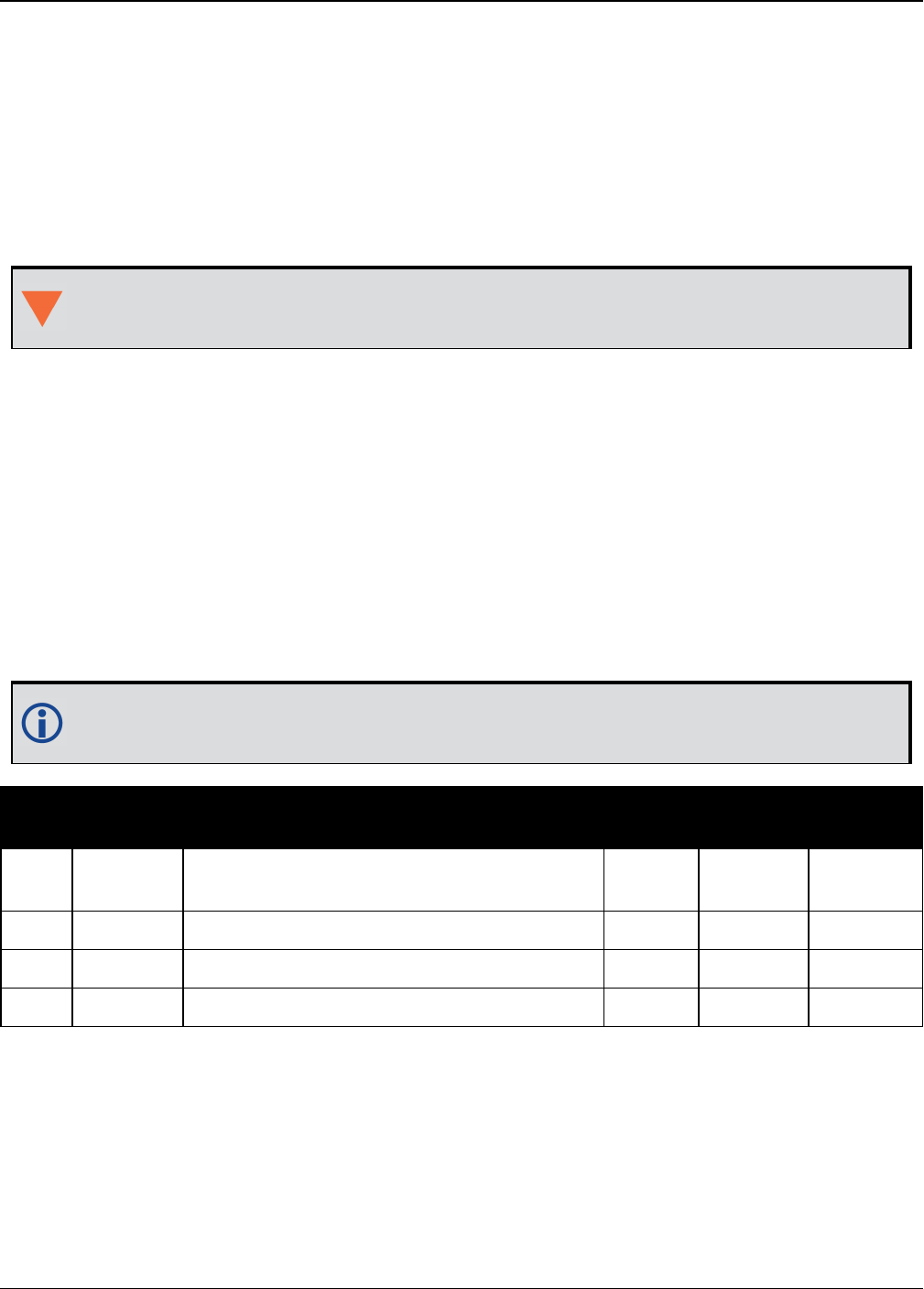
Chapter 3 Logs
OEM7 Commands and Logs Reference Manual v7 775
3.153 SBAS0
Do not use for safety applications
Platform: OEM719, OEM729, OEM7500, OEM7600, OEM7700, OEM7720, PwrPak7,
SPAN CPT7
This message specifies the PRNif GEO transmitting SBAS corrections is operating in test mode,
and should not be used for safety applications for a period of time outlined in the SBAS signal
specification.
The GEO transmitting SBAS corrections is operating in test mode, and should not be used
for safety-of-life applications.
See how the SBAS0 message relates to the SBAS testing modes in the SBASCONTROL com-
mand on page319.
Message ID: 976
Log Type: Asynch
Recommended Input:
log SBAS0a onchanged
ASCII Example:
#SBAS0A,COM1,0,68.5,SATTIME,1093,161299.000,02040020,7d6a,209;122*e9a5ab08
Although the SBAS was designed for aviation users, it supports a wide variety of non-avi-
ation uses including agriculture, surveying, recreation, and surface transportation.
Field Field
type Description Format Binary
Bytes
Binary
Offset
1SBAS0
header
Log header. See Messages on page25 for
more information. H 0
2 prn Source PRN message - also PRN not to use Ulong 4 H
3 xxxx 32-bit CRC (ASCII and Binary only) Ulong 4 H+4
4 [CR][LF] Sentence terminator (ASCII only) - - -
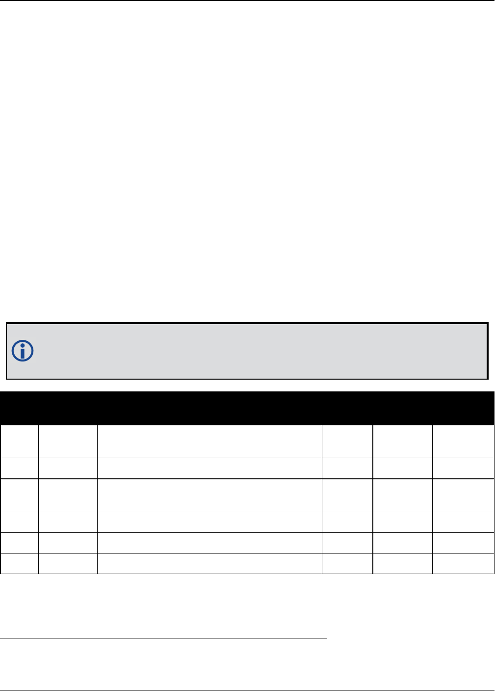
Chapter 3 Logs
OEM7 Commands and Logs Reference Manual v7 776
3.154 SBAS1
PRN mask assignments
Platform: OEM719, OEM729, OEM7500, OEM7600, OEM7700, OEM7720, PwrPak7,
SPAN CPT7
The PRN mask is given in SBAS1. The transition of the PRN mask to a new one (which will be
infrequent) is controlled with the 2-bit IODP, which sequences to a number between 0 and 3. The
same IODP appears in the applicable SBAS2, SBAS3, SBAS4, SBAS5, SBAS7, SBAS24 and
SBAS25 messages (SBAS32, SBAS33, SBAS34, SBAS35 and SBAS45). This transition would prob-
ably only occur when a new satellite is launched or when a satellite fails and is taken out of ser-
vice permanently. A degraded satellite may be flagged as a “don’t use” satellite temporarily.
Message ID: 977
Log Type: Asynch
Recommended Input:
log SBAS1a onchanged
ASCII Example:
#SBAS1A,COM1,0,24.5,SATTIME,1337,415802.000,02000000,5955,1984;134,ffeffffe0000
000000000000000000400400000000000000000000,2*3633cf7b
Each raw SBAS frame gives data for a specific frame decoder number. The SBAS1 mes-
sage can be logged to view the data breakdown of SBAS frame 1 which contains inform-
ation about the PRN mask assignment.
Field Field
type Description Format Binary
Bytes
Binary
Offset
1SBAS1
header
Log header. See Messages on page25 for
more information. H 0
2 prn Source PRN of message Ulong 4 H
3 mask PRN bit mask Uchar
[27] 28 1H+4
4 iodp Issue of PRN mask data Ulong 4 H+32
5 xxxx 32-bit CRC (ASCII and Binary only) Ulong 4 H+36
6 [CR][LF] Sentence terminator (ASCII only) - - -
1In the binary log case, an additional 1 byte of padding is added to maintain 4-byte alignment.

Chapter 3 Logs
OEM7 Commands and Logs Reference Manual v7 777
3.155 SBAS2
Fast correction slots 0-12
Platform: OEM719, OEM729, OEM7500, OEM7600, OEM7700, OEM7720, PwrPak7,
SPAN CPT7
SBAS2 are fast corrections for slots 0-12 in the mask of SBAS1. This message may or may not
come when SBAS is in testing mode (see the SBASCONTROL command on page319 for
details).
Message ID: 982
Log Type: Asynch
Recommended Input:
log SBAS2a onchanged
ASCII Example:
#SBAS2A,COM1,0,29.0,SATTIME,1337,415925.000,02000000,e194,1984;134,2,2,3,-
3,5,1,2047,-2,2047,2047,2047,2047,2047,-
3,2,5,11,7,8,14,8,14,14,14,14,14,6,12*8d8d2e1c
Each raw SBAS frame gives data for a specific frame decoder number. The SBAS2 mes-
sage can be logged to view the data breakdown of SBAS frame 2 which contains inform-
ation about fast correction slots 0-12.
Field Field
type Description Format Binary
Bytes
Binary
Offset
1SBAS2
header
Log header. See Messages on page25 for more
information. H 0
2 prn Source PRN of message Ulong 4 H
3 iodf Issue of fast corrections data Ulong 4 H+4
4 iodp Issue of PRN mask data Ulong 4 H+8

Chapter 3 Logs
OEM7 Commands and Logs Reference Manual v7 778
Field Field
type Description Format Binary
Bytes
Binary
Offset
5 prc0
prc(i):
Fast corrections
(-2048 to +2047) for the PRN in slot i (i = 0-12)
Long 4 H+12
6 prc1 Long 4 H+16
7 prc2 Long 4 H+20
8 prc3 Long 4 H+24
9 prc4 Long 4 H+28
10 prc5 Long 4 H+32
11 prc6 Long 4 H+36
12 prc7 Long 4 H+40
13 prc8 Long 4 H+44
14 prc9 Long 4 H+48
15 prc10 Long 4 H+52
16 prc11 Long 4 H+56
17 prc12 Long 4 H+60
18 udre0
udre(i):
User differential range error indicator for the
PRN in slot i (i = 0-12)
See Table 168: Evaluation of UDREI on the next
page for scaling information.
Ulong 4 H+64
19 udre1 Ulong 4 H+68
20 udre2 Ulong 4 H+72
21 udre3 Ulong 4 H+76
22 udre4 Ulong 4 H+80
23 udre5 Ulong 4 H+84
24 udre6 Ulong 4 H+88
25 udre7 Ulong 4 H+92
26 udre8 Ulong 4 H+96
27 udre9 Ulong 4 H+100
28 udre10 Ulong 4 H+104
29 udre11 Ulong 4 H+108
30 udre12 Ulong 4 H+112
31 xxxx 32-bit CRC (ASCII and Binary only) Ulong 4 H+116
32 [CR]
[LF] Sentence terminator (ASCII only) - - -

Chapter 3 Logs
OEM7 Commands and Logs Reference Manual v7 779
UDREI 1UDRE metres σ2i.udre metres2
0 0.75 0.0520
1 1.0 0.0924
2 1.25 0.1444
3 1.75 0.2830
4 2.25 0.4678
5 3.0 0.8315
6 3.75 1.2992
7 4.5 1.8709
8 5.25 2.5465
9 6.0 3.3260
10 7.5 5.1968
11 15.0 20.7870
12 50.0 230.9661
13 150.0 2078.695
14 Not Monitored Not Monitored
15 Do Not Use Do Not Use
Table 168: Evaluation of UDREI
1The s2UDRE broadcast in SBAS2, SBAS3, SBAS4, SBAS5, SBAS6 and SBAS24 applies at a time prior to or at the
time of applicability of the associated corrections.
Chapter 3 Logs
OEM7 Commands and Logs Reference Manual v7 780
3.156 SBAS3
Fast corrections slots 13-25
Platform: OEM719, OEM729, OEM7500, OEM7600, OEM7700, OEM7720, PwrPak7,
SPAN CPT7
SBAS3 are fast corrections for slots 13-25 in the mask of SBAS1.
Message ID: 987
Log Type: Asynch
Recommended Input:
log SBAS3a onchanged
ASCII Example:
#SBAS3A,COM1,0,17.0,SATTIME,1337,415990.000,02000000,bff5,1984;134,1,2,2047,0,2
047,2047,-21,-4,2047,2047,-
1,0,2,2047,6,14,5,14,14,11,5,14,14,5,7,5,14,8*a25aebc5
Each raw SBAS frame gives data for a specific frame decoder number. The SBAS3 mes-
sage can be logged to view the data breakdown of SBAS frame 3 which contains inform-
ation about fast correction slots 13-25.
Field Field
type Description Format Binary
Bytes
Binary
Offset
1SBAS3
header
Log header. See Messages on page25 for more
information. H 0
2 prn Source PRN of message Ulong 4 H
3 iodf Issue of fast corrections data Ulong 4 H+4
4 iodp Issue of PRN mask data Ulong 4 H+8

Chapter 3 Logs
OEM7 Commands and Logs Reference Manual v7 781
Field Field
type Description Format Binary
Bytes
Binary
Offset
5 prc13
prc(i):
Fast corrections (-2048 to +2047) for the PRN
in slot i (i = 13-25)
Long 4 H+12
6 prc14 Long 4 H+16
7 prc15 Long 4 H+20
8 prc16 Long 4 H+24
9 prc17 Long 4 H+28
10 prc18 Long 4 H+32
11 prc19 Long 4 H+36
12 prc20 Long 4 H+40
13 prc21 Long 4 H+44
14 prc22 Long 4 H+48
15 prc23 Long 4 H+52
16 prc24 Long 4 H+56
17 prc25 Long 4 H+60
18 udre13
udre(i):
User differential range error indicator for the
PRN in slot i (i = 13-25)
See Table 168: Evaluation of UDREI on
page779 for scaling information.
Ulong 4 H+64
19 udre14 Ulong 4 H+68
20 udre15 Ulong 4 H+72
21 udre16 Ulong 4 H+76
22 udre17 Ulong 4 H+80
23 udre18 Ulong 4 H+84
24 udre19 Ulong 4 H+88
25 udre20 Ulong 4 H+92
26 udre21 Ulong 4 H+96
27 udre22 Ulong 4 H+100
28 udre23 Ulong 4 H+104
29 udre24 Ulong 4 H+108
30 udre25 Ulong 4 H+112
31 xxxx 32-bit CRC (ASCII and Binary only) Ulong 4 H+116
32 [CR][LF] Sentence terminator (ASCII only) - - -
Chapter 3 Logs
OEM7 Commands and Logs Reference Manual v7 782
3.157 SBAS4
Fast correction slots 26-38
Platform: OEM719, OEM729, OEM7500, OEM7600, OEM7700, OEM7720, PwrPak7,
SPAN CPT7
SBAS4 are fast corrections for slots 26-38 in the mask of SBAS1.
Message ID: 992
Log Type: Asynch
Recommended Input:
log SBAS4a onchanged
ASCII Example:
#SBAS4A,COM1,0,58.0,SATTIME,1093,163399.000,02000020,b4b0,209;122,0,3,2047,3,-
1,2047,2047,2047,-3,-1,5,3,3,2047,2,14,3,3,14,14,14,6,3,4,5,4,14,3*2e0894b1
Each raw SBAS frame gives data for a specific frame decoder number. The SBAS4 mes-
sage can be logged to view the data breakdown of SBAS frame 4 which contains inform-
ation about fast correction slots 26-38.
Field Field
type Description Format Binary
Bytes
Binary
Offset
1SBAS4
header
Log header. See Messages on page25 for more
information. H 0
2 prn Source PRN of message Ulong 4 H
3 iodf Issue of fast corrections data Ulong 4 H+4
4 iodp Issue of PRN mask data Ulong 4 H+8

Chapter 3 Logs
OEM7 Commands and Logs Reference Manual v7 783
Field Field
type Description Format Binary
Bytes
Binary
Offset
5 prc26
prc(i):
Fast corrections (-2048 to +2047) for the PRN
in slot i (i = 26-38)
Long 4 H+12
6 prc27 Long 4 H+16
7 prc28 Long 4 H+20
8 prc29 Long 4 H+24
9 prc30 Long 4 H+28
10 prc31 Long 4 H+32
11 prc32 Long 4 H+36
12 prc33 Long 4 H+40
13 prc34 Long 4 H+44
14 prc35 Long 4 H+48
15 prc36 Long 4 H+52
16 prc37 Long 4 H+56
17 prc38 Long 4 H+60
18 udre26
udre(i):
User differential range error indicator for the
PRN in slot i (i = 26-38)
See Table 168: Evaluation of UDREI on
page779 for scaling information.
Ulong 4 H+64
19 udre27 Ulong 4 H+68
20 udre28 Ulong 4 H+72
21 udre29 Ulong 4 H+76
22 udre30 Ulong 4 H+80
23 udre31 Ulong 4 H+84
24 udre32 Ulong 4 H+88
25 udre33 Ulong 4 H+92
26 udre34 Ulong 4 H+96
27 udre35 Ulong 4 H+100
28 udre36 Ulong 4 H+104
29 udre37 Ulong 4 H+108
30 udre38 Ulong 4 H+112
31 xxxx 32-bit CRC (ASCII and Binary only) Ulong 4 H+116
32 [CR][LF] Sentence terminator (ASCII only) - - -

Chapter 3 Logs
OEM7 Commands and Logs Reference Manual v7 784
3.158 SBAS5
Fast correction slots 39-50
Platform: OEM719, OEM729, OEM7500, OEM7600, OEM7700, OEM7720, PwrPak7,
SPAN CPT7
SBAS5 are fast corrections for slots 39-50 in the mask of SBAS1.
Message ID: 994
Log Type: Asynch
Recommended Input:
log SBAS5a onchanged
ASCII Example:
#SBAS5A,COM1,0,72.5,SATTIME,1093,161480.000,02040020,31d4,209;122,1,3,-
7,2047,2047,2047,-4,2047,2047,2047,9,2047,2047,-3,-
2,11,14,14,14,4,14,14,14,5,14,14,4,2*2bf0109b
Each raw SBAS frame gives data for a specific frame decoder number. The SBAS5 mes-
sage can be logged to view the data breakdown of SBAS frame 5 which contains inform-
ation about fast correction slots 39-50.
Field Field
type Description Format Binary
Bytes
Binary
Offset
1SBAS5
header
Log header. See Messages on page25 for more
information. H 0
2 prn Source PRN of message Ulong 4 H
3 iodf Issue of fast corrections data Ulong 4 H+4
4 iodp Issue of PRN mask data Ulong 4 H+8

Chapter 3 Logs
OEM7 Commands and Logs Reference Manual v7 785
Field Field
type Description Format Binary
Bytes
Binary
Offset
5 prc39
prc(i):
Fast corrections (-2048 to +2047) for the PRN
in slot i (i = 39-50)
Long 4 H+12
6 prc40 Long 4 H+16
7 prc41 Long 4 H+20
8 prc42 Long 4 H+24
9 prc43 Long 4 H+28
10 prc44 Long 4 H+32
11 prc45 Long 4 H+36
12 prc46 Long 4 H+40
13 prc47 Long 4 H+44
14 prc48 Long 4 H+48
15 prc49 Long 4 H+52
16 prc50 Long 4 H+56
17 prc51 (Invalid, do not use) Long 4 H+60
18 udre39
udre(i):
User differential range error indicator for the
PRN in slot i (i = 39-50)
See Table 168: Evaluation of UDREI on
page779 for scaling information.
Ulong 4 H+64
19 udre40 Ulong 4 H+68
20 udre41 Ulong 4 H+72
21 udre42 Ulong 4 H+76
22 udre43 Ulong 4 H+80
23 udre44 Ulong 4 H+84
24 udre45 Ulong 4 H+88
25 udre46 Ulong 4 H+92
26 udre47 Ulong 4 H+96
27 udre48 Ulong 4 H+100
28 udre49 Ulong 4 H+104
29 udre50 Ulong 4 H+108
30 udre51 (Invalid, do not use) Ulong 4 H+112
31 xxxx 32-bit CRC (ASCII and Binary only) Ulong 4 H+116
32 [CR][LF] Sentence terminator (ASCII only) - - -
Chapter 3 Logs
OEM7 Commands and Logs Reference Manual v7 786
3.159 SBAS6
Integrity message
Platform: OEM719, OEM729, OEM7500, OEM7600, OEM7700, OEM7720, PwrPak7,
SPAN CPT7
SBAS6 is the integrity information message. Each message includes an IODF for each fast cor-
rections message. The σ2UDRE information for each block of satellites applies to the fast cor-
rections with the corresponding IODF.
Message ID: 995
Log Type: Asynch
Recommended Input:
log SBAS6a onchanged
ASCII Example:
#SBAS6A,COM1,0,57.5,SATTIME,1093,273317.000,02000020,526a,209;122,3,3,3,3,9,14,
14,2,3,10,2,14,14,3,14,14,5,14,14,7,14,14,14,14,14,14,3,3,14,14,14,14,3,15,11,1
1,15,0,0,0,0,0,0,0,0,0,0,0,0,0,0,0,0,0,0*925a2a9b
Each raw SBAS frame gives data for a specific frame decoder number. The SBAS6 mes-
sage can be logged to view the data breakdown of SBAS frame 6 which contains inform-
ation about the integrity message.
Field Field
type Description Format Binary
Bytes
Binary
Offset
1SBAS6
header
Log header. See Messages on page25 for more
information. H 0
2 prn Source PRN of message Ulong 4 H
3 iodf2 Issue of fast corrections data Ulong 4 H+4
4 iodf3 Issue of fast corrections data Ulong 4 H+8
5 iodf4 Issue of fast corrections data Ulong 4 H+12
6 iodf5 Issue of fast corrections data Ulong 4 H+16
7 udre0
udre(i):
User differential range error indicator for the
PRN in slot i (i = 0-50)
See Table 168: Evaluation of UDREI on
page779 for scaling information.
Ulong 4 H+20
8 udre1 Ulong 4 H+24

Chapter 3 Logs
OEM7 Commands and Logs Reference Manual v7 787
Field Field
type Description Format Binary
Bytes
Binary
Offset
9 udre2 Ulong 4 H+28
10 udre3 Ulong 4 H+32
11 udre4 Ulong 4 H+36
12 udre5 Ulong 4 H+40
13 udre6 Ulong 4 H+44
14 udre7 Ulong 4 H+48
15 udre8 Ulong 4 H+52
16 udre9 Ulong 4 H+56
17 udre10 Ulong 4 H+60
18 udre11 Ulong 4 H+64
19 udre12 Ulong 4 H+68
20 udre13 Ulong 4 H+72
21 udre14 Ulong 4 H+76
22 udre15 Ulong 4 H+80
23 udre16 Ulong 4 H+84
24 udre17 Ulong 4 H+88
25 udre18 Ulong 4 H+92
26 udre19 Ulong 4 H+96
27 udre20 Ulong 4 H+100
28 udre21 Ulong 4 H+104
29 udre22 Ulong 4 H+108
30 udre23 Ulong 4 H+112
31 udre24 Ulong 4 H+116
32 udre25 Ulong 4 H+120
33 udre26 Ulong 4 H+124
34 udre27 Ulong 4 H+128
35 udre28 Ulong 4 H+132

Chapter 3 Logs
OEM7 Commands and Logs Reference Manual v7 788
Field Field
type Description Format Binary
Bytes
Binary
Offset
36 udre29 Ulong 4 H+136
37 udre30 Ulong 4 H+140
38 udre31 Ulong 4 H+144
39 udre32 Ulong 4 H+148
40 udre33 Ulong 4 H+152
41 udre34 Ulong 4 H+156
42 udre35 Ulong 4 H+160
43 udre36 Ulong 4 H+164
44 udre37 Ulong 4 H+168
45 udre38 Ulong 4 H+172
46 udre39 Ulong 4 H+176
47 udre40 Ulong 4 H+180
48 udre41 Ulong 4 H+184
49 udre42 Ulong 4 H+188
50 udre43 Ulong 4 H+192
51 udre44 Ulong 4 H+196
52 udre45 Ulong 4 H+200
53 udre46 Ulong 4 H+204
54 udre47 Ulong 4 H+208
55 udre48 Ulong 4 H+212
56 udre49 Ulong 4 H+216
58 udre50 Ulong 4 H+220
58 udre51 (Invalid, do not use) Ulong 4 H+224
59 xxxx 32-bit CRC (ASCII and Binary only) Ulong 4 H+228
60 [CR][LF] Sentence terminator (ASCII only) - - -

Chapter 3 Logs
OEM7 Commands and Logs Reference Manual v7 789
3.160 SBAS7
Fast correction degradation
Platform: OEM719, OEM729, OEM7500, OEM7600, OEM7700, OEM7720, PwrPak7,
SPAN CPT7
The SBAS7 message specifies the applicable IODP, system latency time and fast degradation
factor indicator for computing the degradation of fast and long term corrections.
Message ID: 996
Log Type: Asynch
Recommended Input:
log SBAS7a onchanged
ASCII Example:
#SBAS7A,COM1,0,36.5,SATTIME,1337,416367.000,02000000,12e3,1984;122,1,2,0,15,15,
15,15,15,15,15,15,15,15,15,15,15,15,15,15,15,15,15,15,15,15,15,15,15,15,15,15,1
5,15,15,15,0,0,0,0,0,0,0,0,0,0,0,0,0,0,0,0,0,0,0*827a7364
Each raw SBAS frame gives data for a specific frame decoder number. The SBAS7 mes-
sage can be logged to view the data breakdown of SBAS frame 7 which contains inform-
ation about fast correction degradation.
Field Field
type Description Format Binary
Bytes
Binary
Offset
1SBAS7
header
Log header. See Messages on page25 for
more information. H 0
2 prn Source PRN of message Ulong 4 H
3 latency System latency (s) Ulong 4 H+4
4 iodp Issue of PRN mask data Ulong 4 H+8
5 spare bits Unused spare bits Ulong 4 H+12
6 aI(0)
aI(i):
Degradation factor indicator for the PRN in
slot i (i = 0-50)
Ulong 4 H+16
7 aI(1) Ulong 4 H+20
8 aI(2) Ulong 4 H+24
9 aI(3) Ulong 4 H+28
10 aI(4) Ulong 4 H+32

Chapter 3 Logs
OEM7 Commands and Logs Reference Manual v7 790
Field Field
type Description Format Binary
Bytes
Binary
Offset
11 aI(5) Ulong 4 H+36
12 aI(6) Ulong 4 H+40
13 aI(7) Ulong 4 H+44
14 aI(8) Ulong 4 H+48
15 aI(9) Ulong 4 H+52
16 aI(10) Ulong 4 H+56
17 aI(11) Ulong 4 H+60
18 aI(12) Ulong 4 H+64
19 aI(13) Ulong 4 H+68
20 aI(14) Ulong 4 H+72
21 aI(15) Ulong 4 H+76
22 aI(16) Ulong 4 H+80
23 aI(17) Ulong 4 H+84
24 aI(18) Ulong 4 H+88
25 aI(19) Ulong 4 H+92
26 aI(20) Ulong 4 H+96
27 aI(21) Ulong 4 H+100
28 aI(22) Ulong 4 H+104
29 aI(23) Ulong 4 H+108
30 aI(24) Ulong 4 H+112
31 aI(25) Ulong 4 H+116
32 aI(26) Ulong 4 H+120
33 aI(27) Ulong 4 H+124
34 aI(28) Ulong 4 H+128
35 aI(29) Ulong 4 H+132
36 aI(30) Ulong 4 H+136
37 aI(31) Ulong 4 H+140

Chapter 3 Logs
OEM7 Commands and Logs Reference Manual v7 791
Field Field
type Description Format Binary
Bytes
Binary
Offset
38 aI(32) Ulong 4 H+144
39 aI(33) Ulong 4 H+148
40 aI(34) Ulong 4 H+152
41 aI(35) Ulong 4 H+156
42 aI(36) Ulong 4 H+160
43 aI(37) Ulong 4 H+164
44 aI(38) Ulong 4 H+168
45 aI(39) Ulong 4 H+172
46 aI(40) Ulong 4 H+176
47 aI(41) Ulong 4 H+180
48 aI(42) Ulong 4 H+184
49 aI(43) Ulong 4 H+188
50 aI(44) Ulong 4 H+192
51 aI(45) Ulong 4 H+196
52 aI(46) Ulong 4 H+200
53 aI(47) Ulong 4 H+204
54 aI(48) Ulong 4 H+208
55 aI(49) Ulong 4 H+212
56 aI(50) Ulong 4 H+216
57 aI(51) (Invalid, do not use) Ulong 4 H+220
58 xxxx 32-bit CRC (ASCII and Binary only) Ulong 4 H+224
59 [CR][LF] Sentence terminator (ASCII only) - - -
Chapter 3 Logs
OEM7 Commands and Logs Reference Manual v7 792
3.161 SBAS9
GEO navigation message
Platform: OEM719, OEM729, OEM7500, OEM7600, OEM7700, OEM7720, PwrPak7,
SPAN CPT7
SBAS9 provides the GEO navigation message representing the position, velocity and accel-
eration of the geostationary satellite, in ECEF coordinates and its apparent clock time and fre-
quency offsets.
Also included is the time of applicability, an Issue of Data (IOD) and an accuracy exponent
(URA) representing the estimated accuracy of the message. The time offset and time drift are
with respect to SBAS Network Time. Their combined effect is added to the estimate of the satel-
lite’s transmit time.
Message ID: 997
Log Type: Asynch
Recommended Input:
log SBAS9a onchanged
ASCII Example:
#SBAS9A,COM1,0,38.0,SATTIME,1337,416426.000,02000000,b580,1984;122,175,70848,2,
24802064.1600,-34087313.9200,-33823.2000,1.591250000,0.107500000,0.6080000,-
0.0000750,-0.0001125,0.000187500,-2.235174179e-08,9.094947018e-12*636051d2
Each raw SBAS frame gives data for a specific frame decoder number. The SBAS9 mes-
sage can be logged to view the data breakdown of SBAS frame 9 which contains the GEO
navigation message.
Field Field
type Description Format Binary
Bytes
Binary
Offset
1SBAS9
header
Log header. See Messages on page25 for
more information. H 0
2 prn Source PRN of message Ulong 4 H
3 iodn Issue of GEO navigation data Ulong 4 H+4
4t0Time of applicability Ulong 4 H+8
5 ura URA value Ulong 4 H+12
6 x ECEF x coordinate (m) Double 8 H+16
7 y ECEF y coordinate (m) Double 8 H+24
8 z ECEF z coordinate (m) Double 8 H+32

Chapter 3 Logs
OEM7 Commands and Logs Reference Manual v7 793
Field Field
type Description Format Binary
Bytes
Binary
Offset
9 xvel X rate of change (m/s) Double 8 H+40
10 yvel Y rate of change (m/s) Double 8 H+48
11 zvel Z rate of change (m/s) Double 8 H+56
12 xaccel X rate of rate change (m/s2)Double 8 H+64
13 yaccel Y rate of rate change (m/s2)Double 8 H+72
14 zaccel Z rate of rate change (m/s2)Double 8 H+80
15 af0 Time offset (s) Double 8 H+88
16 af1 Time drift (s) Double 8 H+96
17 xxxx 32-bit CRC (ASCII and Binary only) Ulong 4 H+104
18 [CR][LF] Sentence terminator (ASCII only) - - -

Chapter 3 Logs
OEM7 Commands and Logs Reference Manual v7 794
3.162 SBAS10
Degradation factor
Platform: OEM719, OEM729, OEM7500, OEM7600, OEM7700, OEM7720, PwrPak7,
SPAN CPT7
The fast corrections, long term corrections and ionospheric corrections are all provided in the
SBAS10 message.
Message ID: 978
Log Type: Asynch
Recommended Input:
log SBAS10a onchanged
ASCII Example:
#SBAS10A,COM1,0,35.5,SATTIME,1337,416469.000,02000000,c305,1984;122,54,38,76,25
6,152,100,311,83,256,6,0,300,292,0,1,0000000000000000000000*8884d248
Each raw SBAS frame gives data for a specific frame decoder number. The SBAS10 mes-
sage can be logged to view the data breakdown of SBAS frame 10 which contains inform-
ation about degradation factors.
Field Field
type Description Format Binary
Bytes
Binary
Offset Scaling
1SBAS10
header
Log header. See Messages on page25
for more information. H 0 -
2 prn Source PRN of message Ulong 4 H -
3brcc Estimated noise and round off error
parameter Ulong 4 H+4 0.002
4cltc_lsb Maximum round off due to the least
significant bit (lsb) of the orbital clock Ulong 4 H+8 0.002
5cltc_vl Velocity error bound Ulong 4 H+12 0.00005
6iltc_vl Update interval for v=1 long term Ulong 4 H+16 -
7cltc_v0 Bound on update delta Ulong 4 H+20 0.002
8iltc_v1 Minimum update interval v = 0 Ulong 4 H+24 -
9cgeo_lsb Maximum round off due to the lsb of
the orbital clock Ulong 4 H+28 0.0005
10 cgeo_v Velocity error bound Ulong 4 H+32 0.00005

Chapter 3 Logs
OEM7 Commands and Logs Reference Manual v7 795
Field Field
type Description Format Binary
Bytes
Binary
Offset Scaling
11 igeo Update interval for GEO navigation
message Ulong 4 H+36 -
12 cer Degradation parameter Ulong 4 H+40 0.5
13 ciono_
step
Bound on ionospheric grid delay
difference Ulong 4 H+44 0.001
14 iiono Minimum ionospheric update interval Ulong 4 H+48 -
15 ciono_
ramp Rate of ionospheric corrections change Ulong 4 H+52 0.000005
16 rssudre User differential range error flag Ulong 4 H+56 -
17 rssiono Root sum square flag Ulong 4 H+60 -
18 spare
bits Spare 88 bits, possibly GLONASS Hex[11] 11 H+64 -
19 xxxx 32-bit CRC (ASCII and Binary only) Ulong 4 H+75 -
20 [CR]
[LF] Sentence terminator (ASCII only) - - - -

Chapter 3 Logs
OEM7 Commands and Logs Reference Manual v7 796
3.163 SBAS12
SBAS network time and UTC
Platform: OEM719, OEM729, OEM7500, OEM7600, OEM7700, OEM7720, PwrPak7,
SPAN CPT7
SBAS12 contains information bits for the UTC parameters and UTC time standard from which an
offset is determined. The UTC parameters correlate UTC time with the SBAS network time
rather than with GPS reference time.
Message ID: 979
Log Type: Asynch
Recommended Input:
log SBAS12a onchanged
Each raw SBAS frame gives data for a specific frame decoder number. The SBAS12 mes-
sage can be logged to view the data breakdown of SBAS frame 12 which contains inform-
ation about time parameters.
Field Field type Description Format Binary
Bytes
Binary
Offset
1SBAS12
header
Log header. See Messages on page25 for
more information. H 0
2 prn Source PRN of message Ulong 4 H
3A1Time drift (s/s) Double 8 H+4
4A0Time offset (s) Double 8 H+12
5 seconds Seconds into the week (s) Ulong 4 H+20
6 week Week number Ushort 2 H+24
7dtls Delta time due to leap seconds Short 2 H+26
8wnlsf Week number, leap second future Ushort 2 H+28
9 dn Day of the week (the range is 1 to 7 where
Sunday = 1 and Saturday = 7) Ushort 2 H+30
10 dtlsf Delta time, leap second future Ushort 2 H+32
11 utc id UTC type identifier Ushort 2 H+34
12 gpstow GPS reference time of the week Ulong 4 H+36
13 gpswn GPS de-modulo week number Ulong 4 H+40

Chapter 3 Logs
OEM7 Commands and Logs Reference Manual v7 797
Field Field type Description Format Binary
Bytes
Binary
Offset
14 glo
indicator
Is GLONASS information present?
0 = FALSE
1 = TRUE
Enum 4 H+44
15 Reserved array of hexabytes for GLONASS Char
[10] 121H+48
16 xxxx 32-bit CRC (ASCII and Binary only) Ulong 4 H+60
17 [CR][LF] Sentence terminator (ASCII only) - - -
1In the binary log case, an additional 2 bytes of padding are added to maintain 4-byte alignment.
Chapter 3 Logs
OEM7 Commands and Logs Reference Manual v7 798
3.164 SBAS17
GEO Almanac message
Platform: OEM719, OEM729, OEM7500, OEM7600, OEM7700, OEM7720, PwrPak7,
SPAN CPT7
Almanacs for all GEOs are broadcast periodically to alert you of their existence, location, the
general service provided, status and health.
Unused almanacs have a PRN number of 0 and should be ignored, see ASCII Example
below.
Message ID: 980
Log Type: Asynch
Recommended Input:
log SBAS17a onchanged
ASCII Example:
#SBAS17A,COM1,0,84.5,SATTIME,1610,514149.000,02000000,896c,39061;135,3,0,135,
0,-11536200,-40536600,-260000,0,0,0,0,138,0,-12521600,-40258400,
0,0,0,0,0,133,0,-5551000,-41774200,-1248000,0,0,120,82112*2be5146f
Each raw SBAS frame gives data for a specific frame decoder number. The SBAS17 mes-
sage can be logged to view the data breakdown of SBAS frame 17 which contains GEO
almanacs.
Field Field
type Description Format Binary
Bytes
Binary
Offset
1SBAS17
header
Log header. See Messages on page25 for
more information. H 0
2 prn Source PRN of message Ulong 4 H
3 #ents Number of almanac entries with
information to follow Ulong 4 H+4
4 data id Data ID type Ushort 2 H+8
5 entry prn PRN for this entry Ushort 2 H+10
6 health Health bits Ushort 41H+12
1In the binary log case, an additional 2 bytes of padding is added to maintain 4-byte alignment.

Chapter 3 Logs
OEM7 Commands and Logs Reference Manual v7 799
Field Field
type Description Format Binary
Bytes
Binary
Offset
7 x ECEF x coordinate (m) Long 4 H+16
8 y ECEF y coordinate (m) Long 4 H+20
9 z ECEF z coordinate (m) Long 4 H+24
10 x vel X rate of change (m/s) Long 4 H+28
11 y vel Y rate of change (m/s) Long 4 H+32
12 z vel Z rate of change (m/s) Long 4 H+36
13... Next entry = H+8+(#ents x 32)
14 t0 Time of day in seconds (0 to 86336)
Scaling = 64 Ulong 4 H+8+
(#ents x 32)
15 xxxx 32-bit CRC (ASCII and Binary only) Ulong 4 H+12+
(#ents x 32)
16 [CR][LF] Sentence terminator (ASCII only) - - -
Chapter 3 Logs
OEM7 Commands and Logs Reference Manual v7 800
3.165 SBAS18
IGP mask
Platform: OEM719, OEM729, OEM7500, OEM7600, OEM7700, OEM7720, PwrPak7,
SPAN CPT7
The ionospheric delay corrections are broadcast as vertical delay estimates, at specified iono-
spheric grid points (IGPs), applicable to a signal on L1. The predefined IGPs are contained in 11
bands (numbered 0 to 10). Bands 0-8 are vertical bands on a Mercator projection map and bands
9-10 are horizontal bands on a Mercator projection map. Since it is impossible to broadcast IGP
delays for all possible locations, a mask is broadcast to define the IGP locations providing the
most efficient model of the ionosphere at the time.
Message ID: 981
Log Type: Asynch
Recommended Input:
log SBAS18a onchanged
ASCII Example:
#SBAS18A,COM1,0,33.0,SATTIME,1337,417074.000,02000000,f2c0,1984;122,4,2,2,0000f
fc0007fc0003ff0000ff80007fe0007fe0003ff0000ff80,0*b1ed353e
Each raw SBAS frame gives data for a specific frame decoder number. The SBAS18 mes-
sage can be logged to view the data breakdown of SBAS frame 18 which contains inform-
ation about ionospheric grid points.
Field Field
type Description Format Binary
Bytes
Binary
Offset
1SBAS18
header
Log header. See Messages on page25 for more
information. H 0
2 prn Source PRN of message Ulong 4 H
3 #bands Number of bands broadcast Ulong 4 H+4
4band
num
Specific band number that identifies which of the
11 IGP bands the data belongs to Ulong 4 H+8
5 iodi Issue of ionospheric data Ulong 4 H+12
6igp
mask IGP mask Uchar
[26] 28aH+16
aIn the binary log case, an additional 2 bytes of padding are added to maintain 4-byte alignment.

Chapter 3 Logs
OEM7 Commands and Logs Reference Manual v7 801
Field Field
type Description Format Binary
Bytes
Binary
Offset
7spare
bit One spare bit Ulong 4 H+44
8 xxxx 32-bit CRC (ASCII and Binary only) Ulong 4 H+48
9 [CR][LF] Sentence terminator (ASCII only) - - -
Chapter 3 Logs
OEM7 Commands and Logs Reference Manual v7 802
3.166 SBAS24
Mixed fast/slow corrections
Platform: OEM719, OEM729, OEM7500, OEM7600, OEM7700, OEM7720, PwrPak7,
SPAN CPT7
If there are 6 or fewer satellites in a block, they may be placed in this mixed correction mes-
sage. There is a fast data set for each satellite and a UDRE indicator. Each message also con-
tains an IODP indicating the associated PRN mask.
The fast correction (PRC) has a valid range of -2048 to +2047. If the range is exceeded, a don’t
use indication is inserted into the user differential range error indicator (UDREI) field, see Table
168: Evaluation of UDREI on page779. You should ignore extra data sets not represented in the
PRN mask.
The time of applicability (T0) of the PRC is the start of the epoch of the WNT second that is coin-
cident with the transmission at the GEO satellite of the first bit of the message block.
Message ID: 983
Log Type: Asynch
Recommended Input:
log SBAS24a onchanged
ASCII Example:
#SBAS24A,COM1,0,34.0,SATTIME,1337,417108.000,02000000,0a33,1984;134,2047,2047,2
047,2047,-1,-
2,14,14,14,14,11,14,2,2,0,0,1,0,0,0,0,0,0,0,0,0,0,0,0,0,0,0*76ff954b
Each raw SBAS frame gives data for a specific frame decoder number. The SBAS24 mes-
sage can be logged to view the data breakdown of SBAS frame 24 which contains mixed
fast/slow corrections.
Field Field
type Description Format Binary
Bytes
Binary
Offset Scaling
1SBAS24
header
Log header. See Messages
on page25 for more
information.
H 0 -
2 prn Source PRN of message Ulong 4 H -

Chapter 3 Logs
OEM7 Commands and Logs Reference Manual v7 803
Field Field
type Description Format Binary
Bytes
Binary
Offset Scaling
3 prc0
prc(i):
Fast corrections (-2048 to
+2047) for the PRN in slot i
(i = 0-5)
Long 4 H+4 -
4 prc1 Long 4 H+8 -
5 prc2 Long 4 H+12 -
6 prc3 Long 4 H+16 -
7 prc4 Long 4 H+20 -
8 prc5 Long 4 H+24 -
9 udre0
udre(i):
User differential range
error indicator for the PRN
in slot i
(i = 0-5)
Ulong 4 H+28
See Table 168:
Evaluation of UDREI
on page779
10 udre1 Ulong 4 H+32
11 udre2 Ulong 4 H+36
12 udre3 Ulong 4 H+40
13 udre4 Ulong 4 H+44
14 udre5 Ulong 4 H+48
15 iodp Issue of PRN mask data Ulong 4 H+52 -
16 block id Associated message type Ulong 4 H+56
17 iodf Issue of fast corrections
data Ulong 4 H+60 -
18 spare Spare value Ulong 4 H+64 -
19 vel Velocity code flag Ulong 4 H+68 -
20 mask1 Index into PRN mask (Type
1) Ulong 4 H+72 -
21 iode1 Issue of ephemeris data Ulong 4 H+76 -
22 dx1 Delta x (ECEF) Long 4 H+80 0.125
23 dy1 Delta y (ECEF) Long 4 H+84 0.125
24 dz1 Delta z (ECEF) Long 4 H+88 0.125
25 daf0 Delta af0 clock offset Long 4 H+92 2-31
26 mask2 Second index into PRN
mask (Type 1) Ulong 4 H+96 -
27 iode2 Second issue of ephemeris
data Ulong 4 H+100 -

Chapter 3 Logs
OEM7 Commands and Logs Reference Manual v7 804
Field Field
type Description Format Binary
Bytes
Binary
Offset Scaling
28 ddx Delta delta x (ECEF) Long 4 H+104 2-11
29 ddy Delta delta y (ECEF) Long 4 H+108 2-11
30 ddz Delta delta z (ECEF) Long 4 H+112 2-11
31 daf1 Delta af1 clock offset Long 4 H+116 2-39
32 t0Applicable time of day Ulong 4 H+120 16
33 iodp Issue of PRN mask data Ulong 4 H+124 -
34 corr
spare
Spare value when velocity
code is equal to 0 Ulong 4 H+128 -
35 xxxx 32-bit CRC (ASCII and
Binary only) Ulong 4 H+132 -
36 [CR]
[LF]
Sentence terminator (ASCII
only) - - - -

Chapter 3 Logs
OEM7 Commands and Logs Reference Manual v7 805
3.167 SBAS25
Long term slow satellite corrections
Platform: OEM719, OEM729, OEM7500, OEM7600, OEM7700, OEM7720, PwrPak7,
SPAN CPT7
SBAS25 provides error estimates for slow varying satellite ephemeris and clock errors with
respect to WGS-84 ECEF coordinates.
Message ID: 984
Log Type: Asynch
Recommended Input:
log SBAS25a onchanged
ASCII Example:
#SBAS25A,COM1,0,37.5,SATTIME,1337,417193.000,02000000,b8ff,1984;134,1,19,25,-
1,-3,0,-15,0,0,0,1,-1,-2,4465,2,0,1,0,0,0,0,0,0,0,0,0,0,0,0,0,0,0*81685317
Each raw SBAS frame gives data for a specific frame decoder number. The SBAS25 mes-
sage can be logged to view the data breakdown of SBAS frame 25 which contains long
term slow satellite corrections.
Field Field
type Description Format Binary
Bytes
Binary
Offset Scaling
1SBAS25
header
Log header. See Messages on
page25 for more information. H 0 -
2 prn Source PRN of message Ulong 4 H -
31st half
vel Velocity code flag (0 or 1) Ulong 4 H+4 -
41st half
mask1 Index into PRN mask (Type 1) Ulong 4 H+8 -
51st half
iode1 Issue of ephemeris data Ulong 4 H+12 -
61st half
dx1 Delta x (ECEF) Long 4 H+16 0.125
71st half
dy1 Delta y (ECEF) Long 4 H+20 0.125
81st half
dz1 Delta z (ECEF) Long 4 H+24 0.125

Chapter 3 Logs
OEM7 Commands and Logs Reference Manual v7 806
Field Field
type Description Format Binary
Bytes
Binary
Offset Scaling
91st half af0 Delta af0 clock offset Long 4 H+28 2-31
10 1st half
mask2
Second index into PRN mask (Type
1)
Dummy value when velocity code =
1
Ulong 4 H+32 -
11 1st half
iode2
Second issue of ephemeris data
Dummy value when velocity code =
1
Ulong 4 H+36 -
12 1st half
ddx
Delta delta x (ECEF) when velocity
code = 1
Delta x (dx) when velocity code = 0
Long 4 H+40 2-11
13 1st half
ddy
Delta delta y (ECEF) when velocity
code = 1
Delta y (dy) when velocity code = 0
Long 4 H+44 2-11
14 1st half
ddz
Delta delta z (ECEF) when velocity
code = 1
Delta z (dz) when velocity code = 0
Long 4 H+48 2-11
15 1st half af1
Delta af1 clock offset when velocity
code = 1
Delta af0 clock offset when velocity
code = 0
Long 4 H+52 2-39
16 1st half t0
Applicable time of day
Dummy value when velocity code =
0
Ulong 4 H+56 16
17 1st half
iodp Issue of PRN mask data Ulong 4 H+60 -
18 1st half
corr spare
Spare value when velocity code = 0
Dummy value when velocity code =
1
Ulong 4 H+64 -
19 2nd half
vel Velocity code flag (0 or 1) Ulong 4 H+68 -
20 2nd half
mask1 Index into PRN mask (Type 1) Ulong 4 H+72 -
21 2nd half
iode1 Issue of ephemeris data Ulong 4 H+76 -

Chapter 3 Logs
OEM7 Commands and Logs Reference Manual v7 807
Field Field
type Description Format Binary
Bytes
Binary
Offset Scaling
22 2nd half
dx1 Delta x (ECEF) Long 4 H+80 0.125
23 2nd half
dy1 Delta y (ECEF) Long 4 H+84 0.125
24 2nd half
dz1 Delta z (ECEF) Long 4 H+88 0.125
25 2nd half
af0
Delta af0 clock offset Long 4 H+92 2-31
26 2nd half
mask2
Second index into PRN mask (Type
1)
Dummy value when velocity code =
1
Ulong 4 H+96 -
27 2nd half
iode2
Second issue of ephemeris data
Dummy value when velocity code =
1
Ulong 4 H+100 -
28 2nd half
ddx
Delta delta x (ECEF) when velocity
code = 1
Delta x (dx) when velocity code = 0
Long 4 H+104 2-11
29 2nd half
ddy
Delta delta y (ECEF) when velocity
code = 1
Delta y (dy) when velocity code = 0
Long 4 H+108 2-11
30 2nd half
ddz
Delta delta z (ECEF) when velocity
code = 1
Delta z (dz) when velocity code = 0
Long 4 H+112 2-11
31 2nd half
af1
Delta af1 clock offset when velocity
code = 1
Delta af0 clock offset when velocity
code = 0
Long 4 H+116 2-39
32 2nd half t0
Applicable time of day
Dummy value when velocity code =
0
Ulong 4 H+120 16
33 2nd half
iodp Issue of PRN mask data Ulong 4 H+124 -
34 2nd half
corr spare
Spare value when velocity code = 0
Dummy value when velocity code =
1
Ulong 4 H+128 -

Chapter 3 Logs
OEM7 Commands and Logs Reference Manual v7 808
Field Field
type Description Format Binary
Bytes
Binary
Offset Scaling
35 xxxx 32-bit CRC (ASCII and Binary only) Ulong 4 H+132 -
36 [CR][LF] Sentence terminator (ASCII only) - - - -
Chapter 3 Logs
OEM7 Commands and Logs Reference Manual v7 809
3.168 SBAS26
Ionospheric delay corrections
Platform: OEM719, OEM729, OEM7500, OEM7600, OEM7700, OEM7720, PwrPak7,
SPAN CPT7
SBAS26 provides vertical delays (relative to an L1 signal) and their accuracy at geographically
defined IGPs identified by the BAND NUMBER and IGP number. Each message contains a band
number and a block ID, which indicates the location of the IGPs in the respective band mask.
Message ID: 985
Log Type: Asynch
Recommended Input:
log SBAS26a onchanged
ASCII Example:
#SBAS26A,COM1,0,38.0,SATTIME,1337,417243.000,02000000,ec70,1984;134,1,2,15,27,1
1,25,11,23,11,19,11,16,11,16,12,15,13,16,13,29,14,30,13,27,11,27,11,24,11,19,11
,16,12,2,0*3b6d6806
Each raw SBAS frame gives data for a specific frame decoder number. The SBAS26 mes-
sage can be logged to view the data breakdown of SBAS frame 26 which contains iono-
spheric delay corrections
Field Field
type Description Format Binary
Bytes
Binary
Offset
1SBAS26
header
Log header. See Messages on page25 for
more information. H 0
2 prn Source PRN of message Ulong 4 H
3 band num Band number Ulong 4 H+4
4 block id Block ID Ulong 4 H+8
5 #pts Number of grid points with information to
follow Ulong 4 H+12
6igpvde
IGP vertical delay estimates
Scaling = 0.125 Ulong 4 H+16
7 givei Grid ionospheric vertical error indicator Ulong 4 H+20
8... Next #pts entry = H + 16 + (#pts x 8)

Chapter 3 Logs
OEM7 Commands and Logs Reference Manual v7 810
Field Field
type Description Format Binary
Bytes
Binary
Offset
9 iodi Issue of data - ionosphere Ulong 4 H+16+
(#pts x 8)
10 spare 7 spare bits Ulong 4 H+20+
(#pts x 8)
11 xxxx 32-bit CRC (ASCII and Binary only) Ulong 4 H+24+
(#pts x 8)
12 [CR][LF] Sentence terminator (ASCII only) - - -

Chapter 3 Logs
OEM7 Commands and Logs Reference Manual v7 811
3.169 SBAS27
SBAS service message
Platform: OEM719, OEM729, OEM7500, OEM7600, OEM7700, OEM7720, PwrPak7,
SPAN CPT7
SBAS27 messages apply only to the service provider transmitting the message. The number of
service messages indicates the total number of unique SBAS27 messages for the current IODS.
Each unique message for that IODS includes a sequential message number. The IODS is incre-
mented in all messages, each time that any parameter in any SBAS27 message is changed.
Message ID: 986
Log Type: Asynch
Recommended Input:
log SBAS27a onchanged
Each raw SBAS frame gives data for a specific frame decoder number. The SBAS27 mes-
sage can be logged to view the data breakdown of SBAS frame 27 which contains inform-
ation about SBAS service messages.
Field Field type Description Format Binary
Bytes
Binary
Offset
1SBAS27
header
Log header. See Messages on page25 for
more information. H 0
2 prn Source PRN of message Ulong 4 H
3 iods Issue of slow corrections data Ulong 4 H+4
4 #messages Low-by-one count of messages Ulong 4 H+8
5message
num Low-by-one message number Ulong 4 H+12
6priority
code Priority code Ulong 4 H+16
7dudre
inside Delta user differential range error - inside Ulong 4 H+20
8dudre
outside Delta user differential range error -outside Ulong 4 H+24
9... #reg Number of regions with information to
follow Ulong 4 H+28
10 lat1 Coordinate 1 latitude Long 4 H+32

Chapter 3 Logs
OEM7 Commands and Logs Reference Manual v7 812
Field Field type Description Format Binary
Bytes
Binary
Offset
11 lon1 Coordinate 1 longitude Long 4 H+36
12 lat2 Coordinate 2 latitude Long 4 H+40
13 lon2 Coordinate 2 longitude Long 4 H+44
14 shape Shape where: 0 = triangle, 1 = square Ulong 4 H+48
15 Next #reg entry = H+32+(#reg x 20)
16 Reserved Ulong 4
H+32+
(#reg x
20)
17 xxxx 32-bit CRC (ASCII and Binary only) Ulong 4
H+36+
(#reg x
20)
18 [CR][LF] Sentence terminator (ASCII only) - - -

Chapter 3 Logs
OEM7 Commands and Logs Reference Manual v7 813
3.170 SBAS32
Fast correction slots 0-10
Platform: OEM719, OEM729, OEM7500, OEM7600, OEM7700, OEM7720, PwrPak7,
SPAN CPT7
SBAS32 are fast corrections for slots 0-10 in the mask of SBAS1, see SBAS1 log on page776.
Message ID: 988
Log Type: Asynch
Recommended Input:
log SBAS32a onchanged
ASCII Example:
#SBAS32A,COM2,0,70.5,FINE,1295,153284.000,02000240,18e9,34461;209,0,0,-
8097,0,0,0,0,-947,0,-2128,0,2570,14,0,14,14,14,14,0,14,0,14,0*58778ae5
Field Field
type Description Format Binary
Bytes
Binary
Offset
1SBAS32
header
Log header. See Messages on page25 for
more information. H 0
2 prn Source PRN of message Ulong 4 H
3 iodp Issue of PRN mask data Ulong 4 H+4
4 prc0
prc(i):
Fast corrections (-2048 to +2047) for the PRN
in slot i (i = 0-10)
Long 4 H+8
5 prc1 Long 4 H+12
6 prc2 Long 4 H+16
7 prc3 Long 4 H+20
8 prc4 Long 4 H+24
9 prc5 Long 4 H+28
10 prc6 Long 4 H+32
11 prc7 Long 4 H+36
12 prc8 Long 4 H+40
13 prc9 Long 4 H+44
14 prc10 Long 4 H+48

Chapter 3 Logs
OEM7 Commands and Logs Reference Manual v7 814
Field Field
type Description Format Binary
Bytes
Binary
Offset
15 udre0
udre(i):
User differential range error indicator for the
PRN in slot i (i = 0-10)
See Table 169: Evaluation of UDREI below
for scaling information
Ulong 4 H+52
16 udre1 Ulong 4 H+56
17 udre2 Ulong 4 H+60
18 udre3 Ulong 4 H+64
19 udre4 Ulong 4 H+68
20 udre5 Ulong 4 H+72
21 udre6 Ulong 4 H+76
22 udre7 Ulong 4 H+80
23 udre8 Ulong 4 H+84
24 udre9 Ulong 4 H+88
25 udre10 Ulong 4 H+92
26 xxxx 32-bit CRC (ASCII and Binary only) Ulong 4 H+96
27 [CR][LF] Sentence terminator (ASCII only) - - -
UDREI UDRE Metres
0 0.01
1 0.02
2 0.03
3 0.05
4 0.10
5 0.15
6 0.20
7 0.25
8 0.30
9 0.35
10 0.40
Table 169: Evaluation
of UDREI

Chapter 3 Logs
OEM7 Commands and Logs Reference Manual v7 815
UDREI UDRE Metres
11 0.45
12 0.50
13 0.60
14 Not Monitored
15 Do Not Use
Chapter 3 Logs
OEM7 Commands and Logs Reference Manual v7 816
3.171 SBAS33
Fast correction slots 11-21
Platform: OEM719, OEM729, OEM7500, OEM7600, OEM7700, OEM7720, PwrPak7,
SPAN CPT7
SBAS33 are fast corrections for slots 11-21.
Message ID: 989
Log Type: Asynch
Recommended Input:
log SBAS33a onchanged
ASCII Example:
#SBAS33A,COM2,0,47.5,FINE,1295,158666.000,03000240,b23e,34461;209,0,0,-
3343,0,0,0,-533,0,0,0,0,0,14,0,14,14,14,0,14,14,14,14,14*6d890f5f
Each raw mask frame gives data for a specific frame decoder number. The SBAS33 mes-
sage can be logged to view the data breakdown of SBAS frame 33 which contains inform-
ation about correction slots 11-21.
Field Field
type Description Format Binary
Bytes
Binary
Offset
1SBAS33
header
Log header. See Messages on page25 for
more information. H 0
2 prn Source PRN of message Ulong 4 H
3 iodp Issue of PRN mask data Ulong 4 H+4

Chapter 3 Logs
OEM7 Commands and Logs Reference Manual v7 817
Field Field
type Description Format Binary
Bytes
Binary
Offset
4 prc11
prc(i):
Fast corrections (-2048 to +2047) for the PRN
in slot i (i = 11-21)
Long 4 H+8
5 prc12 Long 4 H+12
6 prc13 Long 4 H+16
7 prc14 Long 4 H+20
8 prc15 Long 4 H+24
9 prc16 Long 4 H+28
10 prc17 Long 4 H+32
11 prc18 Long 4 H+36
12 prc19 Long 4 H+40
13 prc20 Long 4 H+44
14 prc21 Long 4 H+48
15 udre11
udre(i):
User differential range error indicator for the
PRN in slot i (i = 11-21)
See Table 169: Evaluation of UDREI on
page814 for scaling information
Ulong 4 H+52
16 udre12 Ulong 4 H+56
17 udre13 Ulong 4 H+60
18 udre14 Ulong 4 H+64
19 udre15 Ulong 4 H+68
20 udre16 Ulong 4 H+72
21 udre17 Ulong 4 H+76
22 udre18 Ulong 4 H+80
23 udre19 Ulong 4 H+84
24 udre20 Ulong 4 H+88
25 udre21 Ulong 4 H+92
26 xxxx 32-bit CRC (ASCII and Binary only) Ulong 4 H+96
27 [CR][LF] Sentence terminator (ASCII only) - - -

Chapter 3 Logs
OEM7 Commands and Logs Reference Manual v7 818
3.172 SBAS34
Fast correction slots 22-32
Platform: OEM719, OEM729, OEM7500, OEM7600, OEM7700, OEM7720, PwrPak7,
SPAN CPT7
SBAS34 are fast corrections for slots 22-32 in the mask of SBAS1, see SBAS1 log on page776.
Message ID: 990
Log Type: Asynch
Recommended Input:
log SBAS34a onchanged
ASCII Example:
#SBAS34A,COM2,0,73.0,FINE,1295,226542.000,02000040,1be8,34461;209,0,5879,0,0,0,
0,2687,0,10922,10922,10922,10922,0,14,14,14,14,0,14,15,15,15,15*3aeb74be
Each raw mask frame gives data for a specific frame decoder number. The SBAS34 mes-
sage can be logged to view the data breakdown of SBAS frame 34 which contains inform-
ation about fast correction slots 22-32.
Field Field
type Description Format Binary
Bytes
Binary
Offset
1SBAS34
header
Log header. See Messages on page25 for
more information. H 0
2 prn Source PRN of message Ulong 4 H
3 iodp Issue of PRN mask data Ulong 4 H+4

Chapter 3 Logs
OEM7 Commands and Logs Reference Manual v7 819
Field Field
type Description Format Binary
Bytes
Binary
Offset
4 prc22
prc(i):
Fast corrections (-2048 to +2047) for the PRN
in slot i (i = 22-32)
Long 4 H+8
5 prc23 Long 4 H+12
6 prc24 Long 4 H+16
7 prc25 Long 4 H+20
8 prc26 Long 4 H+24
9 prc27 Long 4 H+28
10 prc28 Long 4 H+32
11 prc29 Long 4 H+36
12 prc30 Long 4 H+40
13 prc31 Long 4 H+44
14 prc32 Long 4 H+48
15 udre22
udre(i):
User differential range error indicator for the
PRN in slot i (i = 22-32)
See Table 169: Evaluation of UDREI on
page814 for scaling information
Ulong 4 H+52
16 udre23 Ulong 4 H+56
17 udre24 Ulong 4 H+60
18 udre25 Ulong 4 H+64
19 udre26 Ulong 4 H+68
20 udre27 Ulong 4 H+72
21 udre28 Ulong 4 H+76
22 udre29 Ulong 4 H+80
23 udre30 Ulong 4 H+84
24 udre31 Ulong 4 H+88
25 udre32 Ulong 4 H+92
26 xxxx 32-bit CRC (ASCII and Binary only) Ulong 4 H+96
27 [CR][LF] Sentence terminator (ASCII only) - - -
Chapter 3 Logs
OEM7 Commands and Logs Reference Manual v7 820
3.173 SBAS35
Fast correction slots 33-43
Platform: OEM719, OEM729, OEM7500, OEM7600, OEM7700, OEM7720, PwrPak7,
SPAN CPT7
SBAS35 are fast corrections for slots 33-43 in the mask of SBAS1, see SBAS1 log on page776.
Message ID: 991
Log Type: Asynch
Recommended Input:
log SBAS35a onchanged
Each raw mask frame gives data for a specific frame decoder number. The SBAS35 mes-
sage can be logged to view the data breakdown of SBAS frame 35 which contains inform-
ation about fast correction slots 33-43.
Field Field
type Description Format Binary
Bytes
Binary
Offset
1SBAS35
header
Log header. See Messages on page25 for
more information. H 0
2 prn Source PRN of message Ulong 4 H
3 iodp Issue of PRN mask data Ulong 4 H+4
4 prc33
prc(i):
Fast corrections (-2048 to +2047) for the PRN
in slot i (i = 33-43)
Long 4 H+8
5 prc34 Long 4 H+12
6 prc35 Long 4 H+16
7 prc36 Long 4 H+20
8 prc37 Long 4 H+24
9 prc38 Long 4 H+28
10 prc39 Long 4 H+32
11 prc40 Long 4 H+36
12 prc41 Long 4 H+40
13 prc42 Long 4 H+44
14 prc43 Long 4 H+48

Chapter 3 Logs
OEM7 Commands and Logs Reference Manual v7 821
Field Field
type Description Format Binary
Bytes
Binary
Offset
15 udre33
udre(i):
User differential range error indicator for the
PRN in slot i (i = 33-43)
See Table 169: Evaluation of UDREI on
page814 for scaling information
Ulong 4 H+52
16 udre34 Ulong 4 H+56
17 udre35 Ulong 4 H+60
18 udre36 Ulong 4 H+64
19 udre37 Ulong 4 H+68
20 udre38 Ulong 4 H+72
21 udre39 Ulong 4 H+76
22 udre40 Ulong 4 H+80
23 udre41 Ulong 4 H+84
24 udre42 Ulong 4 H+88
25 udre43 Ulong 4 H+92
26 xxxx 32-bit CRC (ASCII and Binary only) Ulong 4 H+96
27 [CR][LF] Sentence terminator (ASCII only) - - -

Chapter 3 Logs
OEM7 Commands and Logs Reference Manual v7 822
3.174 SBAS45
Slow corrections
Platform: OEM719, OEM729, OEM7500, OEM7600, OEM7700, OEM7720, PwrPak7,
SPAN CPT7
Each SBAS45 message contains a 2-bit IODP indicating the associated PRN mask.
The time of applicability (T0) of the PRC is the start of the epoch of the WNT second that is coin-
cident with the transmission at the satellite of the first bit of the message block.
Message ID: 993
Log Type: Asynch
Recommended Input:
log SBAS45a onchanged
ASCII Example:
#SBAS45A,COM2,0,73.0,FINE,1295,228498.000,02000040,c730,34461;209,23,32,197,-
116,206,-1,-6,-3,-5546,3488,25,148,262,-312,867,4,3,0,2513,3488,0*02d6e0d5
Each raw mask frame gives data for a specific frame decoder number. The SBAS45 mes-
sage can be logged to view the data breakdown of SBAS frame 45 which contains inform-
ation about slow corrections.
Field Field
type Description Format Binary
Bytes
Binary
Offset Scaling
1SBAS45
header
Log header. See Messages on
page25 for more information. H 0 -
2 prn Source PRN of message Ulong 4 H -
3 mask1 Index into PRN mask (Type 1) Ulong 4 H+4 -
4 iode1 Issue of ephemeris data Ulong 4 H+8 -
5 dx1 Delta x (ECEF) Long 4 H+12 0.125
6 dy1 Delta y (ECEF) Long 4 H+16 0.125
7 dz1 Delta z (ECEF) Long 4 H+20 0.125
8 ddx1 Delta delta x (ECEF) Long 4 H+24 2-11
9 ddy1 Delta delta y (ECEF) Long 4 H+28 2-11
10 ddz1 Delta delta z (ECEF) Long 4 H+32 2-11
11 daf01 Delta af0 clock offset Long 4 H+36 2-31

Chapter 3 Logs
OEM7 Commands and Logs Reference Manual v7 823
Field Field
type Description Format Binary
Bytes
Binary
Offset Scaling
12 t01Applicable time of day Ulong 4 H+40 16
13 mask2 Second index into PRN mask (Type 1) Ulong 4 H+44 -
14 iode2 Second issue of ephemeris data Ulong 4 H+48 -
15 dx2 Delta x (ECEF) Long 4 H+52 0.125
16 dy2 Delta y (ECEF) Long 4 H+56 0.125
17 dz2 Delta z (ECEF) Long 4 H+60 0.125
18 ddx2 Delta delta x (ECEF) Long 4 H+64 2-11
19 ddy2 Delta delta y (ECEF) Long 4 H+68 2-11
20 ddz2 Delta delta z (ECEF) Long 4 H+72 2-11
21 daf02 Delta af0 clock offset Long 4 H+76 2-31
22 t02Applicable time of day Ulong 4 H+80 16
23 iodp Issue of PRN mask data Ulong 4 H+84 -
24 xxxx 32-bit CRC (ASCII and Binary only) Ulong 4 H+88 -
25 [CR][LF] Sentence terminator (ASCII only) - - - -

Chapter 3 Logs
OEM7 Commands and Logs Reference Manual v7 824
3.175 SBASALMANAC
SBAS Almanac collection
Platform: OEM719, OEM729, OEM7500, OEM7600, OEM7700, OEM7720, PwrPak7,
SPAN CPT7
This log contains a collection of all current SBAS almanacs that have been decoded by the
receiver and may contain almanac data for multiple PRNs. The SBASALMANAC log is populated
by the GEO Almanac Message Type 17 which is available in the SBAS17 log (see page 798).
These PRNs are broken out into individual SBAS almanac entries for this message and output
individually. If multiple SBAS subsystems (e.g., WAAS, EGNOS, GAGAN, MSAS) are tracked,
this message will include almanac data collected from each with the subsystem identified in
each message entry. The almanac data contains all of the information required to compute the
satellite position as well as health and status information.
The OEM7 family of receivers automatically save almanacs in their Non-Volatile Memory (NVM),
so creating an almanac boot file is not necessary.
Message ID: 1425
Log Type: Asynch
Recommended Input:
Log SBASALMANACA onchanged
ASCII Example:
#SBASALMANACA,COM1,2,80.0,SATTIME,1672,411186.000,02000020,84d8,43119;133,WAAS,
65600,0,0,-5571800,-41758600,-1456000,0,0,120*22da17e8
#SBASALMANACA,COM1,1,80.0,SATTIME,1672,411186.000,02000020,84d8,43119;135,WAAS,
65600,0,0,-28758600,-30825600,0,0,0,0*dd122ca1
#SBASALMANACA,COM1,0,80.0,SATTIME,1672,411186.000,02000020,84d8,43119;138,WAAS,
65600,0,0,-12547600,-40248000,0,0,0,0*89c6c51c
Field Field Type Description Format Binary
Bytes
Binary
Offset
1SBASALMANAC
Header
Log header. See Messages on page25 for
more information. H 0
2 Satellite ID Satellite ID Ulong 4 H
3 Variant System variant (refer to Table 170: SBAS
Subsystem Types on the next page) Enum 4 H + 4
4 Time Time of day (s) Ulong 4 H + 8
5 Data ID Data identification Ushort 2 H + 12
6 Health Satellite health Ushort 2 H + 14
7 X ECEF X coordinate (m) Long 4 H + 16

Chapter 3 Logs
OEM7 Commands and Logs Reference Manual v7 825
Field Field Type Description Format Binary
Bytes
Binary
Offset
8 Y ECEF Y coordinate (m) Long 4 H + 20
9 Z ECEF Z coordinate (m) Long 4 H + 24
10 X Velocity X rate of change (m/s) Long 4 H + 28
11 Y Velocity Y rate of change (m/s) Long 4 H + 32
12 Z Velocity Z rate of change (m/s) Long 4 H + 36
13 CRC 32-bit CRC (ASCII and binary only) Ulong 4 H + 40
14 [CR][LF] Sentence terminator (ASCII only) - - -
ASCII Binary Description
NONE 0 No system
UNKNOWN 1 Unknown system
WAAS 2 WAAS system
EGNOS 3 EGNOS system
MSAS 4 MSAS system
GAGAN 5 GAGAN system
QZSS 7 QZSS System
Table 170: SBAS Subsystem Types
Chapter 3 Logs
OEM7 Commands and Logs Reference Manual v7 826
3.176 SOFTLOADSTATUS
Describes the status of the SoftLoad process
Platform: OEM719, OEM729, OEM7500, OEM7600, OEM7700, OEM7720, PwrPak7,
SPAN CPT7
This log describes the status of the SoftLoad process.
Status values >= 16 (ERROR) indicate that an error has occurred during the loading pro-
cess. Status < 16 (ERROR) are part of normal SoftLoad operation.
Message ID: 1235
Log Type: Asynch
Recommended Input:
log softloadstatusa onchanged
ASCII Example:
#SOFTLOADSTATUSA,COM1,0,97.5,UNKNOWN,0,0.113,024c0001,2d64,10481;NOT_
STARTED*827fdc04
Field Field Type Description Format Binary
Bytes
Binary
Offset
1SOFTLOADSTATUS
header
Log header. See Messages on page25
for more information. - H 0
2 status Status of the SoftLoad process see
Table 171: SoftLoad Status Type below Enum 4 H
3 xxxx 32-bit CRC (ASCII and Binary only) Ulong 4 H+4
4 [CR][LF] Sentence terminator (ASCII only) - - -
Value Name Description
1 NOT_STARTED SoftLoad process has not begun
2READY_FOR_
SETUP
SoftLoad process is ready to receive setup information in the form of
the SOFTLOADSETUP command or SOFTLOADSREC command with
S0 records. Once sufficient setup data has been sent, the process is
also ready for the SOFTLOADDATA command
Table 171: SoftLoad Status Type

Chapter 3 Logs
OEM7 Commands and Logs Reference Manual v7 827
Value Name Description
3READY_FOR_
DATA
SoftLoad process is ready to receive data in the form of the
SOFTLOADDATA command or SOFTLOADSREC command with S3
records. Once all data has been sent, send the SOFTLOADCOMMIT
command
4 DATA_VERIFIED SoftLoad data has passed CRC. This status occurs after a
SOFTLOADCOMMIT command
5WRITING_
FLASH
SoftLoad data is being written to flash. This status occurs after a
SOFTLOADCOMMIT command. During a firmware upload, the
receiver may remain in this state for 300 seconds or longer
6 WROTE_FLASH SoftLoad data has been written to flash
7WROTE_
AUTHCODE The embedded AuthCode was successfully written
8 COMPLETE SoftLoad process has completed. The next step is to send the RESET
command to reset the receiver
9VERIFYING_
DATA SoftLoad is verifying the downloaded image
10
COPIED_
SIGNATURE_
AUTH
Signature AuthCodes have been copied from the current firmware to
the downloaded firmware.
11
WROTE_
TRANSACTION_
TABLE
The downloaded firmware has been activated and will be executed if
the receiver is reset. This status is effectively identical to COMPLETE.
16 ERROR Indicates an internal error in the SoftLoad process. This error is not
expected to occur. Contact NovAtel Customer Support for assistance.
17 RESET_ERROR Error resetting SoftLoad. Reset the receiver and restart the SoftLoad
process.
18 BAD_SRECORD A bad S Record was received. Ensure that S Records are enclosed in
double quotes within the SOFTLOADSREC command (see page 358).
19 BAD_PLATFORM This data cannot be loaded onto this platform. Ensure that the correct
*.shex file for the platform is being used.
20 BAD_MODULE This module cannot be loaded with SoftLoad. This file must be loaded
using WinLoad or a similar loader.
21 BAD_
AUTHCODE Bad AuthCode received for this PSN
22 NOT_READY_
FOR_SETUP
ASOFTLOADSETUP command was entered before a
SOFTLOADRESET command or after a SOFTLOADDATA command

Chapter 3 Logs
OEM7 Commands and Logs Reference Manual v7 828
Value Name Description
23 NO_MODULE
No data type was entered before a SOFTLOADDATA command was
received. Set the data type using the SOFTLOADSETUP command or
SOFTLOADSREC command with an "S0~T~" S Record.
24 NO_PLATFORM
No platform was entered before a SOFTLOADDATA command was
received. Set the platform using the SOFTLOADSETUP command or
SOFTLOADSREC command with an "S0~P~" S Record.
25 NOT_READY_
FOR_DATA
ASOFTLOADDATA command was received but the receiver was not
ready for it
26 MODULE_
MISMATCH
The SoftLoad data module was changed in the middle of loading.
Restart the SoftLoad process using the SOFTLOADRESET command
(see page 355).
27 OUT_OF_
MEMORY
SoftLoad has run out of RAM to store the incoming data. Reset the
receiver and restart the SoftLoad process.
28 DATA_OVERLAP
SoftLoad data has overlapped. Ensure that the correct address and
length is set in the SOFTLOADDATA command or SOFTLOADSREC
command.
29 BAD_IMAGE_
CRC
CRC of the downloaded image has failed. Ensure that all content from
the *.shex file has been successfully downloaded.
30 IMAGE_
OVERSIZE The downloaded image is too big for the intended data module
31 AUTHCODE_
WRITE_ERROR An error occurred when writing the embedded AuthCode to flash
32 BAD_FLASH_
ERASE
Erasing of the flash failed. This could indicate a failure in the flash
hardware.
33 BAD_FLASH_
WRITE
Writing to the flash failed. This could indicate a failure in the flash
hardware.
34 TIMEOUT SoftLoad time out has occurred
35 INCOMPATIBLE_
FLASH Application image that does not support the onboard flash rejected

Chapter 3 Logs
OEM7 Commands and Logs Reference Manual v7 829
3.177 SOURCETABLE
NTRIP source table entries
Platform: OEM729, OEM7600, OEM7700, OEM7720, PwrPak7, SPAN CPT7
This log outputs the NTRIP SOURCETABLE entries from the NTRIPCASTER set by the
NTRIPSOURCETABLE command (see page 251). The entry data field in the first entry is always
the header of the retrieved SOURCETABLE. The entry data field in the last entry is always a
string “ENDSOURCETABLE” which indicates the end of the source table. Entries in between these
fields are the real SOURCETABLE entries.
Message ID: 1344
Log Type: Polled
Recommended Input:
log sourcetablea once
ASCII Example:
#SOURCETABLEA,COM1,17,84.0,COARSESTEERING,1933,497547.000,02400020,71dd,32768;"
hera.novatel.com:2101",0,0,"HTTP/1.1 200 OK;Ntrip-Version: Ntrip/2.0;Ntrip-
Flags: st_filter,st_auth,st_match,st_strict,rtsp,plain_rtp;Server: NTRIP
Caster/2.0.15;Date: Fri, 27 Jan 2017 18:12:01 GMT;Connection: close;Content-
Type: gnss/sourcetable;Content-Length: 2057"*87a7d39d
#SOURCETABLEA,COM1,16,84.0,COARSESTEERING,1933,497547.000,02400020,71dd,32768;"
hera.novatel.com:2101",0,0,"CAS;hera.novatel.ca;80,2101;NovAtel;NovAtel;0;CAN;5
1;-115;http://www.novatel.com"*e3ec11a0
#SOURCETABLEA,COM1,15,84.0,COARSESTEERING,1933,497547.000,02400020,71dd,32768;"
hera.novatel.com:2101",0,0,"NET;GREF;NovAtel;B;N;http://novatel.com;none;novate
l.com;none"*2a6b50eb
#SOURCETABLEA,COM1,14,84.0,COARSESTEERING,1933,497547.000,02400020,71dd,32768;"
hera.novatel.com:2101",0,0,"STR;novatel_rtcmv3;Office Roof DL1L2;RTCM 3.0;1033
(10),1005(10),1019(60),1020(60),1003(1),1011(1);2;GPS+GLO;NovAtel;CAN;51;-
115;0;0;NovAtel OEM628;none;B;N;9600;Test"*8a7c760f
#SOURCETABLEA,COM1,13,84.0,COARSESTEERING,1933,497547.000,02400020,71dd,32768;"
hera.novatel.com:2101",0,0,"STR;novatel_rtcm;Office Roof DL1L2;RTCM 2.3;1(1),3
(10),31(1),32(10);0;GPS+GLO;NovAtel;CAN;51;-115;0;0;NovAtel
OEM628;none;B;N;9600;Test"*08c57cb7
#SOURCETABLEA,COM1,12,84.0,COARSESTEERING,1933,497547.000,02400020,71dd,32768;"
hera.novatel.com:2101",0,0,"STR;novatel_rtca;Office Roof DL1L2;RTCA;RTCAREF
(10),RTCA1(1),RTCAEPHEM(60);0;GPS;NovAtel;CAN;51;-115;0;0;NovAtel
OEM628;none;B;N;9600;Test"*006997bc
#SOURCETABLEA,COM1,11,84.0,COARSESTEERING,1933,497547.000,02400020,71dd,32768;"
hera.novatel.com:2101",0,0,"STR;novatel_cmr;Office Roof DL1L2;CMR;CMRREF
(10),CMROBS(1),CMRGLOOBS(1);2;GPS+GLO;NovAtel;CAN;51;-115;0;0;NovAtel
OEM628;none;B;N;9600;Test"*0955ccb7

Chapter 3 Logs
OEM7 Commands and Logs Reference Manual v7 830
#SOURCETABLEA,COM1,10,84.0,COARSESTEERING,1933,497547.000,02400020,71dd,32768;"
hera.novatel.com:2101",0,0,"STR;novatel_rtcaobs2;Office Roof DL1L2;RTCA;rtcaref
(10),rtcaobs2(1),rtcaephem(60);2;GPS+GLO;NovAtel;CAN;51;-115;0;0;NovAtel
OEM628;none;B;N;9600;Test"*426e39a5
#SOURCETABLEA,COM1,9,84.0,COARSESTEERING,1933,497547.000,02400020,71dd,32768;"h
era.novatel.com:2101",0,0,"STR;novatel_cmrplus;Office Roof DL1L2;CMR+;cmrplus
(1),cmrobs(1),cmrgloobs(1);2;GPS+GLO;NovAtel;CAN;51;-115;0;0;NovAtel
OEM628;none;B;N;9600;Test"*2d5ba56e
#SOURCETABLEA,COM1,8,84.0,COARSESTEERING,1933,497547.000,02400020,71dd,32768;"h
era.novatel.com:2101",0,0,"STR;novatel_rtcm2021;Office Roof DL1L2;RTCM 2.3;3
(10),2021(1);2;GPS+GLO;NovAtel;CAN;51;-115;0;0;NovAtel
OEM628;none;B;N;9600;Test"*d82df5de
#SOURCETABLEA,COM1,7,84.0,COARSESTEERING,1933,497547.000,02400020,71dd,32768;"h
era.novatel.com:2101",0,0,"STR;novatel_1819;Office Roof DL1L2;RTCM 2.3;3(10),22
(10),23(60),24(60),1819(1);2;GPS+GLO;NovAtel;CAN;51;-115;0;0;NovAtel
OEM628;none;B;N;9600;Test"*7aead153
#SOURCETABLEA,COM1,6,84.0,COARSESTEERING,1933,497547.000,02400020,71dd,32768;"h
era.novatel.com:2101",0,0,"STR;novatel_rtcaobs;Office Roof DL1L2;RTCA;rtcaref
(10),rtcaobs(1),rtcaephem(60);2;GPS+GLO;NovAtel;CAN;51;-115;0;0;NovAtel
OEM628;none;B;N;9600;Test"*530a51c4
#SOURCETABLEA,COM1,5,84.0,COARSESTEERING,1933,497547.000,02400020,71dd,32768;"h
era.novatel.com:2101",0,0,"STR;novatel_novatelx;Office
Roof;NovatelX;novatelobs;2;GPS+GLO;NovAel;CAN;51;-114;0;0;NovAtel
OEM628;none;B;N;9600;Test"*4438c2e2
#SOURCETABLEA,COM1,4,84.0,COARSESTEERING,1933,497547.000,02400020,71dd,32768;"h
era.novatel.com:2101",0,0,"STR;Hyderabad1;hyderabad
test1;unknown;unknown;2;GPS+GLO;NovAtel;INDIA;17;78;0;0;NovAtel
OEM628;none;B;N;9600;Test"*de6c19f0
#SOURCETABLEA,COM1,3,84.0,COARSESTEERING,1933,497547.000,02400020,71dd,32768;"h
era.novatel.com:2101",0,0,"STR;Hyderabad2;hyderabad
test1;unknown;unknown;2;GPS+GLO;NovAtel;INDIA;17;78;0;0;NovAtel
OEM628;none;B;N;9600;Test"*27e9eee1
#SOURCETABLEA,COM1,2,84.0,COARSESTEERING,1933,497547.000,02400020,71dd,32768;"h
era.novatel.com:2101",0,0,"STR;Hyderabad3;hyderabad
test1;unknown;unknown;2;GPS+GLO;NovAtel;INDIA;17;78;0;0;NovAtel
OEM628;none;B;N;9600;Test"*3ed5941b
#SOURCETABLEA,COM1,1,84.0,COARSESTEERING,1933,497547.000,02400020,71dd,32768;"h
era.novatel.com:2101",0,0,"STR;Hyderabad4;hyderabad
test1;unknown;unknown;2;GPS+GLO;NovAtel;INDIA;17;78;0;0;NovAtel
OEM628;none;B;N;9600;Test"*a3a188e2
#SOURCETABLEA,COM1,0,84.0,COARSESTEERING,1933,497547.000,02400020,71dd,32768;"h
era.novatel.com:2101",0,0,"ENDSOURCETABLE"*7758fba9

Chapter 3 Logs
OEM7 Commands and Logs Reference Manual v7 831
Field Field Type Description Format Binary
Bytes
Binary
Offset
1SOURCETABLE
header
Log header. See Messages on
page25 for more information. H 0
2 endpoint NTRIPCASTER Endpoint
String with varied
length up to 80
bytes
a1H
3 Reserved1 reserved Ulong 4 H+a
4 Reserved2 reserved Ulong 4 H+a+4
5 Entry data Source table entry data
String with varied
length up to 512
bytes
b1H+a+8
6 xxxx 32-bit CRC (ASCII and binary
only) Ulong 4 H+a+b+8
7 [CR][LF] Sentence terminator (ASCII
only) - - -
1In the binary case, each string field needs to be NULL terminated and additional bytes of padding added to
maintain 4-byte alignment, up to the maximum defined by the string size. The next defined field starts
immediately at the next 4-byte alignment following the NULL.

Chapter 3 Logs
OEM7 Commands and Logs Reference Manual v7 832
3.178 TERRASTARINFO
TerraStar subscription information
Platform: OEM719, OEM729, OEM7500, OEM7600, OEM7700, OEM7720, PwrPak7,
SPAN CPT7
This log contains details on the TerraStar subscription.
Message ID: 1719
Log Type: Asynch
Recommended Input:
log terrastarinfoa onchanged
ASCII Example:
#TERRASTARINFOA,COM1,0,65.5,UNKNOWN,0,1.168,02040008,E776,13260;"QR391:3006:617
9",TERM,00000301,167,2015,0,NONE,0.00000,0.00000,0*7E4A9EC0
Field Field type Description Format Binary
Bytes
Binary
Offset
1
TERRASTAR
INFO
header
Log header. See Messages on page25 for
more information. H 0
2 PAC Product activation code Char
[16] 16 H
3 Type Subscription type (see Table 172: TerraStar
Subscription Type on the next page) Enum 4 H+16
4Subscription
permissions
Services permitted by the subscription (see
Table 173: TerraStar Subscription Details
Mask on the next page)
Note: Bits in the Reserved areas of this field
may be set, but the Reserved bits should be
ignored.
Hex 4 H+20
5Service End
Day
Day of the year when the subscription ends.
Service ends at 00:00 UTC on this day.
For example, if the TerraStar service end
date/time is 2015-06-15 00:01:05 HRS UTC
(DOY = 166), then the Service End DOY will
indicate it as 167 and Service End Year will
indicate it as 2015.
Ulong 4 H+24
6Service End
Year Year that subscription ends Ulong 4 H+28
7 Reserved Ulong 4 H+32

Chapter 3 Logs
OEM7 Commands and Logs Reference Manual v7 833
Field Field type Description Format Binary
Bytes
Binary
Offset
8Region
restriction
For region restricted subscriptions, the type of
region restriction (see Table 174: TerraStar
Region Restriction on the next page)
Enum 4 H+36
9Center point
latitude
For local area subscriptions, the center point
latitude (degrees) Float 4 H+40
10 Center point
longitude
For local area subscriptions, the center point
longitude (degrees) Float 4 H+44
11 Radius
For local area subscriptions, the maximum
permitted distance from center point
(kilometers)
Ulong 4 H+48
12 xxxx 32-bit CRC (ASCII and Binary only) Ulong 4 H+52
13 [CR][LF] Sentence terminator (ASCII only) - - -
ASCII Binary Description
UNASSIGNED 0 Decoder has not had an assigned operating mode
TERM 1 Term subscription
MODEL 5 Receiver is operating with an RTK assist enabled model and there is
not an active TerraStar subscription installed
BUBBLE 100 Receiver is operating in a TerraStar-permitted subscription-free
bubble
INCOMPATIBLE_
SUBSCRIPTION 104 Subscription is incompatible with this version of firmware
Table 172: TerraStar Subscription Type
Bit Mask Description
0-8 0x000001FF Reserved
9 0x00000200 TerraStar-C service
10 0x00000400 TerraStar-L service
11 0x00000800 RTK ASSIST service
12 0x00001000 RTK ASSIST PRO service
13 0x00002000 TerraStar-C PRO service
14-31 0xFFFFC000 Reserved
Table 173: TerraStar Subscription Details
Mask

Chapter 3 Logs
OEM7 Commands and Logs Reference Manual v7 834
ASCII Binary Description
NONE 0 TerraStar operation has no region restrictions.
GEOGATED 1 TerraStar operation limited to on-land
GEOGATED is also the default value reported if there is no subscription
LOCAL_AREA 2 TerraStar operation limited to radius from local area center point
NEARSHORE 3 TerraStar operation limited to on land and near shore (coastal) regions
Table 174: TerraStar Region Restriction

Chapter 3 Logs
OEM7 Commands and Logs Reference Manual v7 835
3.179 TERRASTARSTATUS
TerraStar decoder and subscription status
Platform: OEM719, OEM729, OEM7500, OEM7600, OEM7700, OEM7720, PwrPak7,
SPAN CPT7
This log contains status information for the TerraStar decoder and subscription.
Message ID: 1729
Log Type: Asynch
Recommended Input:
log terrastarstatusa onchanged
ASCII Example:
#TERRASTARSTATUSA,COM1,0,49.5,FINESTEERING,1769,332336.443,02000000,fdc1,12602;
ENABLE,LOCKED,0,DISABLED,ONSHORE*555155a5
Field Field type Description Format Binary
Bytes
Binary
Offset
1
TERRASTAR
STATUS
header
Log header. See Messages on page25 for more
information. H 0
2 Access Access status. ENABLE (1) if the subscription is
valid; DISABLE (0) otherwise Enum 4 H
3 Sync state
Decoder data synchronization state (see Table
175: Decoder Data Synchronization State on
the next page)
Enum 4 H+4
4 Reserved Ulong 4 H+8
5Local area
status
For local-area subscriptions, indicates if the
receiver is within the permitted area (see
Table 176: TerraStar Local Area Status on the
next page)
Enum 4 H+12
6Geogating
status
Geogating status (see Table 177: TerraStar
Geogating Status on the next page) Enum 4 H+16
7 xxxx 32-bit CRC (ASCII and Binary only) Ulong 4 H+20
8 [CR][LF] Sentence terminator (ASCII only) - - -

Chapter 3 Logs
OEM7 Commands and Logs Reference Manual v7 836
ASCII Binary Description
NO_SIGNAL 0 None of the decoders have received data in the last 30 seconds
SEARCH 1 At least one decoder is receiving data and is searching for the format
LOCKED 2 At lease one decoder has locked onto the format
Table 175: Decoder Data Synchronization State
ASCII Binary Description
DISABLED 0 The subscription is not restricted to a local area.
This is also the value when there is no subscription.
WAITING_FOR_POSITION 1 Waiting for a position
RANGE_CHECK 16 Checking position against local area region restriction
IN_RANGE 129 Receiver is within the permitted local area
OUT_OF_RANGE 130 Receiver is outside the permitted local area
POSITION_TOO_OLD 255 Position is too old
Table 176: TerraStar Local Area Status
ASCII Binary Description
DISABLED 0
The subscription is restricted to a local area or there is no region
restriction.
This is also the value when there is no subscription.
WAITING_FOR_
POSITION 1 Waiting for a position
ONSHORE 129 Receiver is over land
OFFSHORE 130 Receiver is over water
POSITION_TOO_OLD 255 Position is too old
PROCESSING 1000 Geogater is determining status
Table 177: TerraStar Geogating Status

Chapter 3 Logs
OEM7 Commands and Logs Reference Manual v7 837
3.180 TIME
Time data
Platform: OEM719, OEM729, OEM7500, OEM7600, OEM7700, OEM7720, PwrPak7,
SPAN CPT7
This log provides several time related pieces of information including receiver clock offset and
UTC time and offset. It can also be used to determine any offset in the PPS signal relative to GPS
reference time.
To find any offset in the PPS signal, log the TIME log 'ontime' at the same rate as the PPS output.
For example, if the PPS output is configured to output at a rate of 0.5 seconds (see the
PPSCONTROL command on page272) log the TIME log 'ontime 0.5' as follows:
log time ontime 0.5
The TIME log offset field can then be used to determine any offset in PPS output relative to GPS
reference time.
GPS reference time is the receiver’s estimate of the true GPS system time. GPS ref-
erence time can be found in the header of the TIME log. The relationship between GPS
reference time and true GPS system time is:
GPS system time = GPS reference time - offset
Message ID: 101
Log Type: Synch
Recommended Input:
log timea ontime 1
ASCII Example:
#TIMEA,COM1,0,86.5,FINESTEERING,1930,428348.000,02000020,9924,32768;VALID,1.667
187222e-10,9.641617960e-10,-18.00000000000,2017,1,5,22,58,50000,VALID*2a066e78

Chapter 3 Logs
OEM7 Commands and Logs Reference Manual v7 838
1. Consider the case where you used the ADJUST1PPS command (see page 53) to syn-
chronize two receivers in a primary/secondary relationship to a common external
clock. You can use the TIME log after the clock model status is valid to monitor the
time difference between the Primary and Secondary receivers.
2. The header of the TIME log gives you the GPS reference time (the week number since
January 5th, 1980) and the seconds into that week. The TIME log outputs the UTC off-
set (offset of GPS system time from UTC time) and the receiver clock offset from GPS
system time.
If you want the UTC time in weeks and seconds, take the week number from the header.
Then take the seconds into that week, also from the header, and add the correction to the
seconds using the 2 offsets. Ensure not to go negative or rollover (go over the total
number of seconds, 604800, in a week). In the case of a rollover, add a week and the left
over seconds become the seconds into this new week. If negative, subtract a week and
the remainder from the seconds of that week become the seconds into this new week.
For example:
TIME COM1 0 73.5 FINESTEERING 1432 235661.000 02000000 9924 2616 VALID
-0.000000351 0.000000214 -14.00000000106 2007 6 19 17 27 27000 VALID
From the time information above:
GPS reference time = 1432 (GPS reference week), 235661.000 (GPS seconds) from
the header.
From the description in UTC offset row in the following table:
UTC time = GPS reference time - offset + UTC offset
UTC time
= week 1432, 235661.000 s – (- 0.000000351 (offset) ) - 14.00000000106 (UTC off-
set)
= week 1432, seconds 235647.00000034994
Field Field
type Description Format Binary
Bytes
Binary
Offset
1TIME
header
Log header. See Messages on page25 for more
information. H 0
2clock
status
Clock model status (not including current
measurement data), see Table 86: Clock Model
Status on page458
Enum 4 H

Chapter 3 Logs
OEM7 Commands and Logs Reference Manual v7 839
Field Field
type Description Format Binary
Bytes
Binary
Offset
3 offset
Receiver clock offset in seconds from GPS
system time. A positive offset implies that the
receiver clock is ahead of GPS system time. To
derive GPS system time, use the following
formula:
GPS system time = GPS reference time - offset.
The GPS reference time can be obtained from the
log header.
Double 8 H+4
4 offset std Receiver clock offset standard deviation (s) Double 8 H+12
5 utc offset
The offset of GPS system time from UTC time,
computed using almanac parameters. UTC time
is GPS reference time plus the current UTC offset
minus the receiver clock offset:
UTC time = GPS reference time - offset + UTC
offset
Double 8 H+20
6 utc year UTC year Ulong 4 H+28
7 utcmonth UTC month (0-12)
If UTC time is unknown, the value for month is 0. Uchar 1 H+32
8 utc day UTC day (0-31)
If UTC time is unknown, the value for day is 0. Uchar 1 H+33
9 utc hour UTC hour (0-23) Uchar 1 H+34
10 utc min UTC minute (0-59) Uchar 1 H+35
11 utc ms UTC millisecond (0-60999)
Maximum of 60999 when leap second is applied. Ulong 4 H+36
12 utc status
UTC status
0 = Invalid
1 = Valid
2 = Warning1
Enum 4 H+40
13 xxxx 32-bit CRC (ASCII and Binary only) Ulong 4 H+44
14 [CR][LF] Sentence terminator (ASCII only) - - -
1Indicates that the leap second value is used as a default due to the lack of an almanac.

Chapter 3 Logs
OEM7 Commands and Logs Reference Manual v7 840
3.181 TIMESYNC
Synchronize time between GNSS receivers
Platform: OEM719, OEM729, OEM7500, OEM7600, OEM7700, OEM7720, PwrPak7,
SPAN CPT7
The TIMESYNC log is used in conjunction with the ADJUST1PPS command (see page 53) to syn-
chronize the time between GNSS receivers.
Message ID: 492
Log Type: Synch
Recommended Input:
log timesynca ontime 1
ASCII Example:
#TIMESYNCA,COM1,0,46.0,FINESTEERING,1337,410095.000,02000000,bd3f,1984;1337,410
095000,FINESTEERING*aa2025db
The time data embedded in this log represents the time of the most recent 1PPS signal.
The receiver issues this log from a communications port within 200 ms of the last 1PPS
event. The 200 ms value is a "worst case scenario.” Refer to Figure 2: 1PPS Alignment
on page54 to see the alignment between a Fine and a Cold Clock receiver. Also refer to
the Transfer Time Between Receivers section in the OEM7 Installation and Operation
User Manual.
Field Field
type Description Format Binary
Bytes
Binary
Offset
1TIMESYNC
header
Log header. See Messages on page25 for more
information. H 0
2 week GPS reference week number Ulong 4 H
3 ms Number of milliseconds into the GPS reference
week Ulong 4 H+4
4time
status
GPS reference time Status, see Table 11: GPS
Reference Time Status on page45 Enum 4 H+8
5 xxxx 32-bit CRC (ASCII and Binary only) Ulong 4 H+12
6 [CR][LF] Sentence terminator (ASCII only) - - -
Chapter 3 Logs
OEM7 Commands and Logs Reference Manual v7 841
3.182 TRACKSTAT
Tracking status
Platform: OEM719, OEM729, OEM7500, OEM7600, OEM7700, OEM7720, PwrPak7,
SPAN CPT7
The TRACKSTAT log contains an entry for each channel. If there are multiple signal channels for
one satellite (for example L1, L2 P(Y), L2C, and L5 for GPS), then there will be multiple entries
for that satellite.
As shown in Table 126: Channel Tracking Status on page675 these entries can be differentiated
by bit 20, which is set if there are multiple observables for a given satellite, and bits 21-25,
which denote the signal type for the observation.
A zero in the PRN/slot of the TRACKSTAT log indicates the channel should be considered idle with
the exception of those for GLONASS. A GLONASS channel should only be considered idle if the
tracking state is 0 in the channel tracking status word.
For dual antenna receivers, a TRACKSTAT_1 log can be requested to get TRACKSTAT
data from the second antenna. As described in Table 3: Binary Message Header Struc-
ture on page30, the message type indicates the log is from the second antenna. To
request an ASCII log enter TRACKSTATA_1 and for a binary log enter TRACKSTATB_1.
Message ID: 83
Log Type: Synch
Recommended Input:
log trackstata ontime 1
ASCII Example:
#TRACKSTATA,COM1,0,49.5,FINESTEERING,1337,410139.000,02000000,457c,1984;SOL_
COMPUTED,PSRDIFF,5.0,30,
1,0,18109c04,21836080.582,-2241.711,50.087,1158.652,0.722,GOOD,0.973,
1,0,11309c0b,21836083.168,-1746.788,42.616,1141.780,0.000,OBSL2,0.000,
30,0,18109c24,24248449.644,-2588.133,45.237,939.380,-0.493,GOOD,0.519,
30,0,11309c2b,24248452.842,-2016.730,38.934,939.370,0.000,OBSL2,0.000,
...
14,0,18109da4,24747286.206,-3236.906,46.650,1121.760,-0.609,GOOD,0.514,
14,0,11309dab,24747288.764,-2522.270,35.557,1116.380,0.000,OBSL2,0.000,
0,0,0c0221c0,0.000,0.000,0.047,0.000,0.000,NA,0.000,
0,0,0c0221e0,0.000,0.000,0.047,0.000,0.000,NA,0.000*255a732e
Field Field Type Description Format Binary
Bytes
Binary
Offset
1TRACKSTAT
header
Log header. See Messages on page25 for
more information. H 0

Chapter 3 Logs
OEM7 Commands and Logs Reference Manual v7 842
Field Field Type Description Format Binary
Bytes
Binary
Offset
2 sol status Solution status (see Table 73: Solution Status
on page431) Enum 4 H
3 pos type Position type (see Table 74: Position or
Velocity Type on page432) Enum 4 H+4
4 cutoff GPS tracking elevation cut-off angle Float 4 H+8
5 # chans Number of hardware channels with
information to follow Ulong 4 H+12
6 PRN/slot Satellite PRN number of range measurement
Refer to PRN Numbers on page44 Short 2 H+16
7 glofreq (GLONASS Frequency + 7), see GLONASS Slot
and Frequency Numbers on page43 Short 2 H+18
8 ch-tr-status Channel tracking status (see Table 126:
Channel Tracking Status on page675) Ulong 4 H+20
9 psr
Pseudorange (m) - if this field is zero but the
channel tracking status in the previous field
indicates that the card is phase locked and
code locked, the pseudorange has not been
calculated yet
Double 8 H+24
10 Doppler Doppler frequency (Hz) Float 4 H+32
11 C/No Carrier to noise density ratio (dB-Hz) Float 4 H+36
12 locktime Number of seconds of continuous tracking (no
cycle slips) Float 4 H+40
13 psr res Pseudorange residual from pseudorange filter
(m) Float 4 H+44
14 reject
Range reject code from pseudorange filter
(see Table 79: Observation Statuses on
page438)
Enum 4 H+48
15 psr weight Pseudorange filter weighting Float 4 H+52
16... Next PRN offset = H+16+(#chans x 40)
17 xxxx 32-bit CRC (ASCII and Binary only) Ulong 4
H+16
(#chans
x 40)
18 [CR][LF] Sentence terminator (ASCII only) - - -

Chapter 3 Logs
OEM7 Commands and Logs Reference Manual v7 843
3.183 TRANSFERPORTSTATUS
Display the state of the USB transfer port
Platform: PwrPak7
This log displays the current state of the USB transfer port.
Message ID: 2114
Log Type: Asynch
Recommended Input:
log transferportstatusa onchanged
ASCII Example:
#TRANSFERPORTSTATUSA,COM1,0,86.5,UNKNOWN,0,10.551,02100000,4b3f,32768;USBSTICK,
HOST*9f7ad7be
Field Field Type Description Format Binary
Bytes
Binary
Offset
1TRANSFERPORTSTATUS
header
Log header. See Messages on
page25 for more information. - H 0
2 USB Detection Type
Type of connection detected
See Table 178: USB Detection
Type below
Enum 4 H
3 USB Mode
Current USB operation mode
See Table 179: USB Mode on the
next page
Enum 4 H+4
4 xxxx 32-bit CRC (ASCII and Binary
only) Hex 4 H+8
5 [CR][LF] Sentence terminator (ASCII only) - - -
Binary ASCII Description
0 NONE Nothing is detected
1 USBSTICK A flash drive is detected
2 PC A computer is detected
3 ERROR This is an error state
Table 178: USB Detection Type

Chapter 3 Logs
OEM7 Commands and Logs Reference Manual v7 844
Binary ASCII Description
0 DEVICE The USBport is in device mode
1 HOST The USB port is in host mode
2 OTG The USB port is in OTG mode
3 INVALID The USBport is in an invalid mode
4 NONE The USBport is not in an operation mode
5 TRANSITION The USB port operation mode is transitioning
Table 179: USB Mode
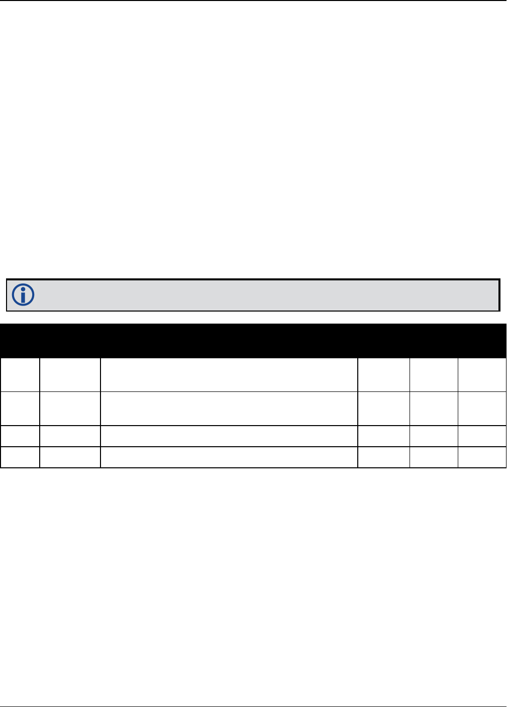
Chapter 3 Logs
OEM7 Commands and Logs Reference Manual v7 845
3.184 UPTIME
Report the running time of the receiver
Platform: OEM719, OEM729, OEM7500, OEM7600, OEM7700, OEM7720, PwrPak7,
SPAN CPT7
This log reports the number of seconds the receiver's firmware has been running, after the
application of power or after the completion of a reset.
Message ID: 1777
Log Type: Polled
Recommended Input:
log uptime once
ASCII Example:
#UPTIMEA,COM1,0,80.0,FINESTEERING,1928,495123.000,02000020,27d2,32768;151639*01
3e11a7
151639 seconds since power-on = 42.1 hours.
Field Field
Type Description Format Binary
Bytes
Binary
Offset
1UPTIME
header
Log header. See Messages on page25 for more
information. - H 0
2 Uptime The number of seconds the receiver has been
running after a power up or reset. Ulong 4 H
3 xxxx 32-bit CRC (ASCII and Binary only) Hex 4 H+4
4 [CR][LF] Sentence terminator (ASCII only) - - -

Chapter 3 Logs
OEM7 Commands and Logs Reference Manual v7 846
3.185 USERI2CRESPONSE
Status of USERI2CREAD or USERI2CWRITE Command
Platform: OEM7600, OEM7700, OEM7720
This log reports the status of a previously executed USERI2CREAD or USERI2CWRITE com-
mand. There is one log emitted for each command that is executed.
For the USERI2CREAD command (see page 393), this log outputs the data read from the device
on the I2C bus and the status of the read operation.
For the USERI2CWRITE command (see page 395), the status of the write operation is reported
and the data field will always be 0.
Message ID: 2234
Recommended Input:
log USERI2CRESPONSE onnew
Abbreviated ASCII Example 1:
USERI2CREAD 70 4 aabbccdd 12 6789
<USERI2CRESPONSE COM1 0 84.0 FINESTEERING 1994 257885.895 02000000 e3f6 32768
<70 aabbccdd OK READ 6789 12 000102030405060708090a0b
Abbreviated ASCII Example 2:
USERI2CWRITE 70 3 aabbcc 8 0001020304050607 12345
<USERI2CRESPONSE COM1 0 84.0 FINESTEERING 1994 257885.895 02000000 e3f6 32768
<70 aabbcc OK WRITE 12345 0
Field Field Type Description Format Binary
Bytes
Binary
Offset
1USERI2CRESPONSE
header
Log header. See Messages for more
information. - H 0
2 DeviceAddress
The 7 bit address of the I2C device.
Valid values are 0 through 127.
For ASCII and Abbreviated
commands, this field is a hexadecimal
string of two digits. There is no 0x
prefix and spaces are not allowed in
the string.
Uchar 11H
1In the binary case, additional bytes of padding are added after this field to maintain 4-byte alignment for the fields
that follow.

Chapter 3 Logs
OEM7 Commands and Logs Reference Manual v7 847
Field Field Type Description Format Binary
Bytes
Binary
Offset
3 RegisterAddress
The actual register address used for
the operation. This is a ULONG value
in hexadecimal format (without 0x
prefix).
Ulong 4 H+4
4 ErrorCode Error code for the operation. See
Table 180: Error Code below. Enum 4 H+8
5 OperationMode
Operation mode code. See Table 181:
Operation Mode Code on the next
page.
Enum 4 H+12
6 TransactionID This is the copy of Transaction ID
provided to the command. Ulong 4 H+16
7 ReadDataLength
For a Read operation, this is the actual
number of bytes read from the I2C
device.
For a Write operation, this value is
always zero.
Ulong 4 H+20
8 ReadData
For a Read operation, this is the data
read from the device. For ASCII logs
this field is displayed as a string of
hexadecimal digits, with two digits per
byte. The first byte retrieved from the
I2C device is the first byte displayed
and so on.
The maximum size of this field is 256
bytes.
When ReadDataLength is zero, this
field will be empty.
HEXBYTE
ARRAY Y H+24
Binary ASCII Description
0 OK I2C transaction is successful
1 IN_PROGRESS I2C transaction is currently in progress
2 DATA_TRUNCATION I2C transaction read data was truncated
3 BUS_BUSY I2C bus is busy
4 NO_DEVICE_REPLY No device replied to the I2C transaction request
5 BUS_ERROR I2C bus error or bus arbitration lost
Table 180: Error Code

Chapter 3 Logs
OEM7 Commands and Logs Reference Manual v7 848
Binary ASCII Description
6 TIMEOUT I2C transaction has timed out
7 UNKNOWN_FAILURE I2C transaction has an unexplained failure
Binary ASCII Description
0 NONE No Operation
1 READ Read Operation
2 WRITE Write Operation
3 SHUTDOWN Shut down Operation
Table 181: Operation Mode Code

Chapter 3 Logs
OEM7 Commands and Logs Reference Manual v7 849
3.186 VALIDMODELS
Valid model information
Platform: OEM719, OEM729, OEM7500, OEM7600, OEM7700, OEM7720, PwrPak7,
SPAN CPT7
This log gives a list of valid authorized models available and expiry date information.
If a model has no expiry date, it reports the year, month and day fields as 0, 0 and 0 respect-
ively.
Message ID: 206
Log Type: Asynch
Recommended Input:
log validmodelsa once
ASCII Example:
#VALIDMODELSA,COM1,0,92.0,FINESTEERING,1610,499139.682,02000000,342f,6293;1,"D2
LR0RCCR",0,0,0*d0580c1b
Use the VALIDMODELS log to output a list of available models for the receiver. Use the
AUTH command (see page 73), to add a model and the MODEL command (see page
238) to change the currently active model. See the VERSION log on page854 for the cur-
rently active model
Field Field type Description Format Binary
Bytes Binary Offset
1VALIDMODELS
header
Log header. See Messages on
page25 for more information. H 0
2 #mod Number of models with
information to follow Ulong 4 H
3 model Model name String
[Max16]
Variable
1H+4
4 expyear Expiry year Ulong 4 Variable
Max: H+20
5 expmonth Expiry month Ulong 4 Variable
Max: H+24
1In the binary case, each string field needs to be NULL terminated and additional bytes of padding added to
maintain 4-byte alignment, up to the maximum defined by the string size. The next defined field starts
immediately at the next 4-byte alignment following the NULL.

Chapter 3 Logs
OEM7 Commands and Logs Reference Manual v7 850
Field Field type Description Format Binary
Bytes Binary Offset
6 expday Expiry day Ulong 4 Variable:
Max: H+28
7... Next model offset = H+4+(#mod x variable [max:28])
8 xxxx 32-bit CRC (ASCII and Binary only) Ulong 4
H+4+
(#mod x
variable
[max:28])
9 [CR][LF] Sentence terminator (ASCII only) - - -

Chapter 3 Logs
OEM7 Commands and Logs Reference Manual v7 851
3.187 VERIPOSINFO
Veripos subscription information
Platform: OEM719, OEM729, OEM7500, OEM7600, OEM7700, OEM7720, PwrPak7,
SPAN CPT7
This log contains details on the Veripos subscription.
Message ID: 1728
Log Type: Asynch
Recommended Input:
log veriposinfoa onchanged
ASCII Example:
#VERIPOSINFOA,COM2,0,60.5,FINESTEERING,1779,176287.725,02044008,31fa,12740;3203
25,NCC_CONTROLLED,00000101,"Q"*26a9f04e
Field Field type Description Format Binary
Bytes
Binary
Offset
1VERIPOSINFO
header
Log header. See Messages on page25 for
more information. H 0
2Serial
number Receiver serial number Ulong 4 H
3 Mode Operating mode (see Table 182: Veripos
Operating Mode below) Enum 4 H+4
4 Details
Subscription details (refer to Table 183:
Veripos Subscription Details Mask on the
next page)
Hex 4 H+8
5 Service code Veripos service code Char[4] 4 H+12
6 xxxx 32-bit CRC (ASCII and Binary only) Ulong 4 H+16
7 [CR][LF] Sentence terminator (ASCII only) - - -
ASCII Binary Description
UNASSIGNED 0 Decoder has not had an assigned operating mode
NCC_
CONTROLLED 7Decoder operation disabled by a command from the Network Control
Center (NCC)
NO_DISABLE 8 Decoder operation not disabled
Table 182: Veripos Operating Mode

Chapter 3 Logs
OEM7 Commands and Logs Reference Manual v7 852
ASCII Binary Description
BUBBLE 100 Decoder is operating in a Veripos permitted subscription-free bubble
MODEL_DENIED 101 Decoder operation is not permitted on the current firmware model
Bit Mask Description
0 0x001 Subscription permits differential positioning
8 0x100 Subscription permits Apex PPP positioning
Table 183: Veripos Subscription Details Mask

Chapter 3 Logs
OEM7 Commands and Logs Reference Manual v7 853
3.188 VERIPOSSTATUS
Veripos decoder and subscription status
Platform: OEM719, OEM729, OEM7500, OEM7600, OEM7700, OEM7720, PwrPak7,
SPAN CPT7
This log contains status information for the Veripos decoder and subscription.
Message ID: 1730
Log Type: Asynch
Recommended Input:
log veriposstatusa onchanged
ASCII Example:
#VERIPOSSTATUSA,COM2,0,62.0,FINESTEERING,1779,176955.656,02004008,0719,12740;EN
ABLE,LOCKED*7c5f85ae
Field Field type Description Format Binary
Bytes
Binary
Offset
1VERIPOSSTATUS
header
Log header. See Messages on page25 for
more information. H 0
2 Access
Access status. ENABLE (1) if the
subscription is valid; DISABLE (0)
otherwise
Enum 4 H
3 Sync state
Decoder data synchronization state (see
Table 184: Decoder Data Synchronization
State below)
Enum 4 H+4
4 xxxx 32-bit CRC (ASCII and Binary only) Ulong 4 H+8
5 [CR][LF] Sentence terminator (ASCII only) - - -
ASCII Binary Description
NO_SIGNAL 0 None of the decoders have received data in the last 30 seconds
SEARCH 1 At least one decoder is receiving data and is searching for the format
LOCKED 2 At lease one decoder has locked onto the format
Table 184: Decoder Data Synchronization State
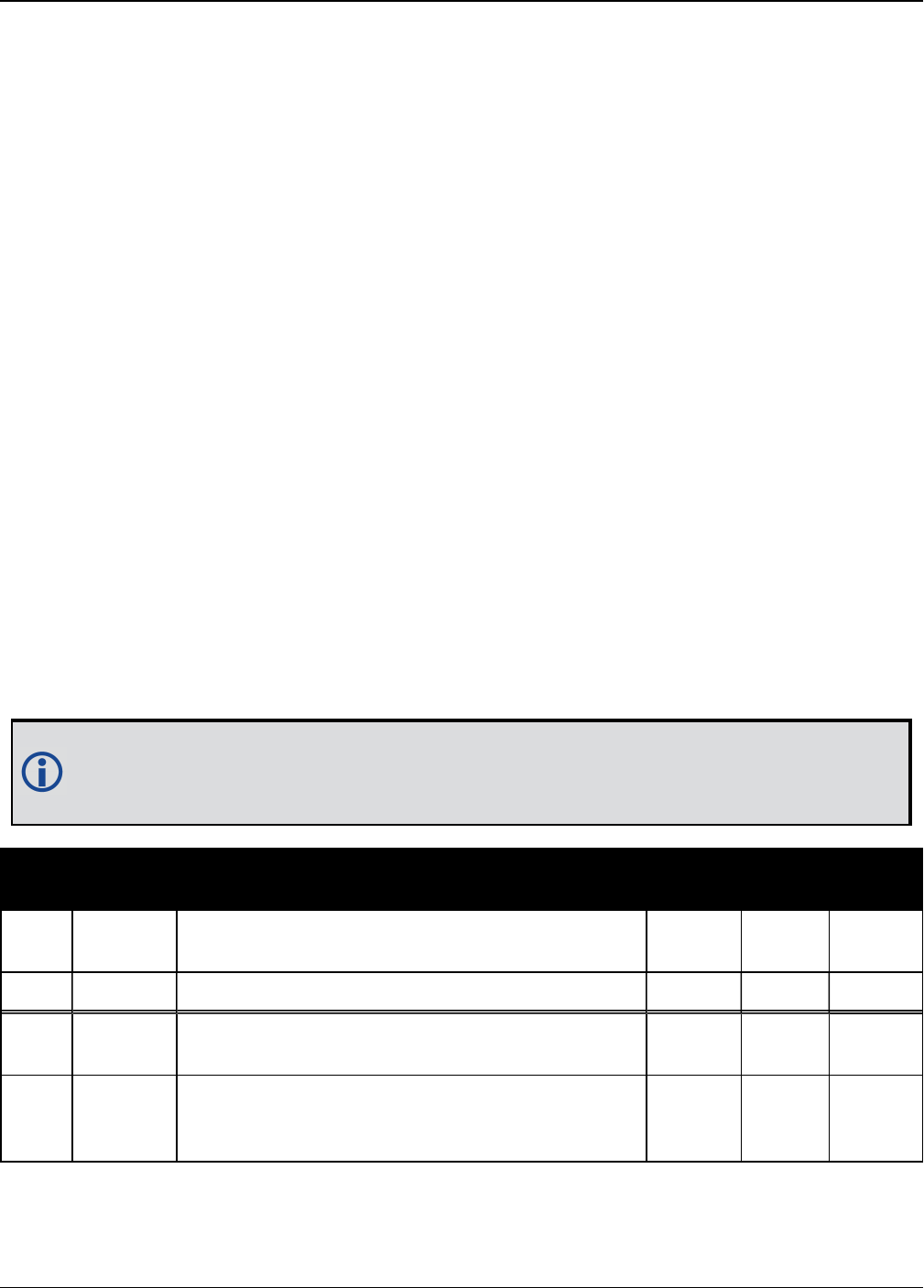
Chapter 3 Logs
OEM7 Commands and Logs Reference Manual v7 854
3.189 VERSION
Version information
Platform: OEM719, OEM729, OEM7500, OEM7600, OEM7700, OEM7720, PwrPak7,
SPAN CPT7
This log contains the version information for all components of a system. When using a standard
receiver, there is only one component in the log.
A component may be hardware (for example, a receiver or data collector) or firmware in the
form of applications or data (for example, data blocks for height models or user applications).
See Table 186: VERSION Log Field Formats on page856 for details on the format of key fields.
See also the VALIDMODELS log on page849.
Message ID: 37
Log Type: Polled
Recommended Input:
log versiona once
ASCII Example:
[COM1]<VERSION COM1 0 97.0 UNKNOWN 0 200.384 024c0009 3681 13662
<2
<GPSCARD "CFNPNNTVN" "BMGX15360001Z" "OEM729-0.00H" "OM7MR0000RN0000"
"OM7BR0000AB0001" "2015/Dec/14" "19:23:28"
<OEM7FPGA "" "" "" "OMV070000DN0008" "" "" ""
The VERSION log is a useful log as a first communication with your receiver. Once con-
nected, using NovAtel Connect or HyperTerminal, log VERSION and check that the output
makes sense. Also, ensure that you have the receiver components you expected.
Field Field
type Description Format Binary
Bytes
Binary
Offset
1VERSION
header
Log header. See Messages on page25 for more
information. H 0
2 # comp Number of components (cards, and so on) Long 4 H
3 type Component type (see Table 185: Component
Types on the next page) Enum 4 H+4
4 model
OEM7 firmware model number
e.g., G1SBOGTTO indicates the receiver’s current
model functionality
Char
[16] 16 H+8

Chapter 3 Logs
OEM7 Commands and Logs Reference Manual v7 855
Field Field
type Description Format Binary
Bytes
Binary
Offset
5 psn Product serial number Char
[16] 16 H+24
6hw
version
Hardware version, see Table 186: VERSION Log
Field Formats on the next page
Char
[16] 16 H+40
7sw
version
Firmware software version, see Table 186:
VERSION Log Field Formats on the next page
Char
[16] 16 H+56
8boot
version
Boot code version, see Table 186: VERSION Log
Field Formats on the next page
Char
[16] 16 H+72
9comp
date
Firmware compile date, see Table 186:
VERSION Log Field Formats on the next page
Char
[12] 12 H+88
10 comp
time
Firmware compile time, see Table 186:
VERSION Log Field Formats on the next page
Char
[12] 12 H+100
11... Next component offset = H + 4 + (#comp x 108)
12 xxxx 32-bit CRC (ASCII and Binary only) Ulong 4
H+4+
(#comp
x 108)
13 [CR][LF] Sentence terminator (ASCII only) - - -
Binary ASCII Description
0 UNKNOWN Unknown component
1 GPSCARD OEM7 family component
2 CONTROLLER Reserved
3 ENCLOSURE OEM card enclosure
4-7 Reserved
8 USERINFO Application specific information
12-17 Reserved
18 RADIO UHF radio component
19 WWW_CONTENT Web Server content
20 Reserved
21 OEM7FPGA OEM7 FPGA version
Table 185: Component Types

Chapter 3 Logs
OEM7 Commands and Logs Reference Manual v7 856
Binary ASCII Description
27 EMBEDDED_AUTH Embedded Auth Code data
981073920 (0x3A7A0000) DB_HEIGHTMODEL Height/track model data
981073930 (0x3A7A000A) DB_LUA_SCRIPTS Lua Script ISO Image
Field Type Field Format (ASCII) Description
hw version P-R
Hardware version:
P = hardware platform (for example, OEM719)
R = hardware revision (for example, 00)
swversion OM7MRFFMMRN0000
Software Version:
OM7 = product family
M = image type (main firmware)
R = Signature and symbols
FF = feature release number
MM = maintenance release number
RN = Firmware version and distribution permits
0000 = Minor release indicator
bootversion OM7BRFFMMRN0000
Boot Version:
OM7 = product family
B = image type (boot)
R = Signature and symbols
FF = feature release
MM = the maintenance release number
RN = Signature and symbols
comp date YYYY/Mmm/DD
YYYY = year
Mmm = month
DD = day (1 - 31)
comp time HH:MM:SS
HH = hour
MM = minutes
SS = seconds
Table 186: VERSION Log Field Formats

Chapter 3 Logs
OEM7 Commands and Logs Reference Manual v7 857
3.190 WIFIAPSETTINGS
Display the Wi-Fi access point configuration
Platform: PwrPak7
Use this log to display the Wi-Fi access point configuration. If the access point is not currently
operational, the log reports the access point configuration to be applied the next time the
WIFIMODE AP command is received.
The term passkey and password are the same.
Message ID: 2093
Log Type: Polled
Recommended Input:
LOG WIFIAPSETTINGS
ASCII Example:
#WIFIAPSETTINGSA,COM1,0,77.5,FINESTEERING,2007,167962.000,02000000,fc0e,14693;"
PwrPak7-
NMNE16470005M","12345678",2P4GHZ,WPA2,CCMP,US,11,"2d:43:5a:63:79:6f"*546c6f08
Field Field Type Description Format Binary
Bytes
Binary
Offset
1WIFIAPSETTINGS
header
Log header. See Messages on page25
for more information. - H 0
2 SSID SSID of the AP
String
[Max
33]
Variable H
3 passkey Passkey of the AP
String
[Max
65]
Variable Variable
4 band Wi-Fi operating band. See Table 187:
Wi-Fi Band on the next page. Enum 4 Variable
5 security protocol
Wireless security protocol. See Table
188: Wi-Fi Security Protocol on the
next page.
Enum 4 Variable
6 encryption
Wireless encryption type. See Table
189: Wi-Fi Encryption Type on the next
page.
Enum 4 Variable
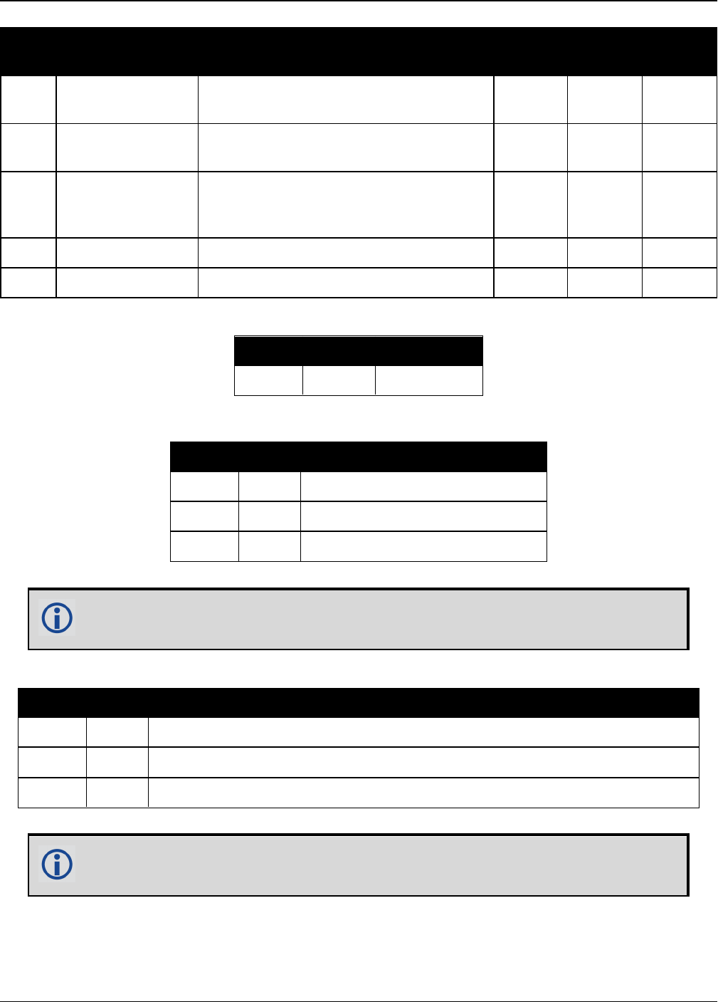
Chapter 3 Logs
OEM7 Commands and Logs Reference Manual v7 858
Field Field Type Description Format Binary
Bytes
Binary
Offset
7 region Regulatory region. See Table 190:
Regulatory Region on the next page. Enum 4 Variable
8 channel Wireless channel used by access point
to communicate with connected clients. Int 4 Variable
9 BSSID BSSID of the AP (MAC of the Wi-Fi
interface)
String
[Max
18]
Variable Variable
10 xxxx 32-bit CRC (ASCII or Binary only) Hex 4 Variable
11 [CR][LF] Sentence terminator (ASCII only) - - -
Binary ASCII Description
1 2P4GHZ 2.4 GHz
Table 187: Wi-Fi Band
Binary ASCII Description
1 OPEN Open network (No security)
2 WPA Wi-Fi Protected Access
3 WPA2 Wi-Fi Protected Access version 2
Table 188: Wi-Fi Security Protocol
NovAtel Wi-Fi access points only support the WPA2 security protocol. As a result,
the WIFIAPSETTINGS log will only report WPA2.
Binary ASCII Description
1 OPEN Open (no encryption)
2 TKIP Temporal Key Integrity Protocol (used with WPA)
3 CCMP AES-based CCMP (Cipher Chaining Message Authentication) used with WPA2
Table 189: Wi-Fi Encryption Type
NovAtel Wi-Fi access points only support the WPA2 security protocol. As a result,
the WIFIAPSETTINGS log will only report CCMP.

Chapter 3 Logs
OEM7 Commands and Logs Reference Manual v7 859
Binary ASCII Description
0 None
Receiver has not been configured to comply with any regional regulatory
requirements. Wireless components (e.g. Wi-Fi) will not operate. Contact
NovAtel Customer Support.
1 US United States
2 EU Europe
3 AU Australia
4 JP Japan
5 NZ New Zealand
6 BR Brazil
Table 190: Regulatory Region


Chapter 4 SPAN Commands
OEM7 Commands and Logs Reference Manual v7 861
4.1 ALIGNMENTMODE
Set the Alignment Mode
Platform: OEM719, OEM729, OEM7500, OEM7600, OEM7700, OEM7720, PwrPak7,
SPAN CPT7
Use this command to set the alignment method used to initialize the SPAN system.
The default ALIGNMENTMODE is AUTOMATIC. In this mode, the first available method to align is
used.
Sending the ALIGNMENTMODE command manually overrides the AUTOMATIC setting and
changes the options available to complete an alignment.
Message ID: 1214
Abbreviated ASCII Syntax:
ALIGNMENTMODE mode
Abbreviated ASCII Example:
ALIGNMENTMODE AIDED_TRANSFER
Field Field Type ASCII
Value
Binary
Value Description Binary
Format
Binary
Bytes
Binary
Offset
1ALIGNMENTMODE
header - -
Command
header. See
Messages on
page25 for more
information.
- H 0
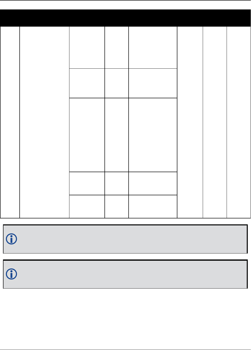
Chapter 4 SPAN Commands
OEM7 Commands and Logs Reference Manual v7 862
Field Field Type ASCII
Value
Binary
Value Description Binary
Format
Binary
Bytes
Binary
Offset
2 mode
UNAIDED 0
Static coarse
alignment or
kinematic
alignment
methods are
available.
Enum 4 H
AIDED_
TRANSFER 2
Seed the initial
azimuth estimate
from the ALIGN
solution.
AUTOMATIC 3
Seed the full
attitude from the
ALIGN solution,
perform a
regular static
coarse alignment
or perform a
kinematic
alignment,
whichever is
possible first.
STATIC 4
Static coarse
alignment
method only.
KINEMATIC 5
Kinematic
alignment
method only.
If the ALIGNMENTMODE selected can use a kinematic alignment (UNAIDED,
KINEMATIC or AUTOMATIC), the SETINSROTATION command on page896 must be
sent to the receiver regardless of system configuration and IMU orientation.
NVM Seed injected (see the INSSEED command on page880) and commanded (see
SETINITAZIMUTH command on page893) alignments are valid for all alignment
modes and will supersede all other options if valid and available.

Chapter 4 SPAN Commands
OEM7 Commands and Logs Reference Manual v7 863
4.2 ASYNCHINSLOGGING
Enable Asynchronous INS Logs
Platform: OEM719, OEM729, OEM7500, OEM7600, OEM7700, OEM7720, PwrPak7,
SPAN CPT7
Use this command to enable or disable the asynchronous INS logs (IMURATECORRIMUS and
IMURATEPVAS).
The asynchronous INS logs are highly advanced logs for users of SPAN on OEM7. The
rate controls that limit the output of logs are not applicable to these logs, allowing the
user to drive the idle time to zero.
Users of the IMURATECORRIMUS log (see page 929) or IMURATEPVAS log (see page
933) should be limited to those who must have full rate INS solution data, or full rate
corrected IMU data, without possible shifts in log time that are present in the
synchronous version of these logs.
The asynchronous INS logs are only available at the full rate of the IMU.
Message ID: 1363
Abbreviated ASCII Syntax:
ASYNCHINSLOGGING switch
Abbreviated ASCII Example:
ASYNCHINSLOGGING ENABLE
Field Field Type ASCII
Value
Binary
Value Description Binary
Format
Binary
Bytes
Binary
Offset
1
ASYNCHINS
LOGGING
header
- -
Command header. See
Messages on page25 for
more information.
- H 0
2 Switch
DISABLE 0 Enable or disable the
asynchronous INS logs.
The default value is
DISABLE.
Enum 4 H
ENABLE 1

Chapter 4 SPAN Commands
OEM7 Commands and Logs Reference Manual v7 864
4.3 CONNECTIMU
Connects an IMU to a Port
Platform: OEM719, OEM729, OEM7500, OEM7600, OEM7700, OEM7720, PwrPak7,
SPAN CPT7
Use this command to specify the type of IMU connected to the receiver and the receiver port
used by the IMU.
Message ID: 1428
Abbreviated ASCII Syntax:
CONNECTIMU IMUPort IMUType
Abbreviated ASCII Example:
CONNECTIMU COM2 LN200
Field Field Type ASCII
Value
Binary
Value Description Binary
Format
Binary
Bytes
Binary
Offset
1CONNECTIMU
header - -
Command header. See
Messages on page25 for
more information.
- H 0
2 IMUPort1
COM1 1 IMU Port is COM port 1
Enum 4 H
COM2 2 IMU Port is COM port 2
COM3 3 IMU Port is COM port 3
SPI 7 IMUPort is the SPIport
COM4 19 IMUPort is COM port 4
COM5 31 IMU Port is COM port 5
3 IMUType
See Table 191:
IMU Type on the
next page
IMU Type Enum 4 H+4
SPI is available only on the OEM7500, OEM7600, OEM7700, and OEM7720.
COM4 and COM5 are available only on the OEM7600, OEM7700 and OEM7720.
1The IMU-ISA-100C, IMU-FSAS, IMU-HG1900, IMU-LN200, IMU-µIMU, IMU-CPT and IMU-KVH1750 use RS-422
protocol and must be connected to a receiver port that is configured to use RS-422. Refer to the OEM7 Installation
and Operation User Manual for information about which receiver ports support RS-422 and instructions for
enabling RS-422.

Chapter 4 SPAN Commands
OEM7 Commands and Logs Reference Manual v7 865
Binary ASCII Description
0 UNKNOWN Unknown IMU type (default)
1 HG1700_AG11 Honeywell HG1700 AG11
4 HG1700_AG17 Honeywell HG1700 AG17
5 HG1900_CA29 Honeywell HG1900 CA29
8 LN200 Northrop Grumman LN200/LN200C
11 HG1700_AG58 Honeywell HG1700 AG58
12 HG1700_AG62 Honeywell HG1700 AG62
13 IMAR_FSAS iMAR iIMU-FSAS
16 KVH_COTS KVH CPT IMU
20 HG1930_AA99 Honeywell HG1930 AA99
26 ISA100C Northrop Grumman Litef ISA-100C
27 HG1900_CA50 Honeywell HG1900 CA50
28 HG1930_CA50 Honeywell HG1930 CA50
31 ADIS16488 Analog Devices ADIS16488
32 STIM300 Sensonor STIM300
33 KVH_1750 KVH1750 IMU
41 EPSON_G320 Epson G320N
52 LITEF_MICROIMU Northrop Grumman Litef µIMU-IC
56 STIM300D Sensonor STIM300, Direct Connection
58 HG4930_AN01 Honeywell HG4930 AN01
Table 191: IMU Type
The IMU Type field also supports the legacy ASCIIvalues that contain the "IMU_" prefix.
For example, LN200 or IMU_LN200.
IMUs recently added as SPAN supported devices, such as the LITEF_MICROIMU and
STIM300D, do not support the "IMU_" prefix.
Values not shown in this table are reserved.
Chapter 4 SPAN Commands
OEM7 Commands and Logs Reference Manual v7 866
4.4 EXTERNALPVAS
Enter PVA Update
Platform: OEM719, OEM729, OEM7500, OEM7600, OEM7700, OEM7720, PwrPak7,
SPAN CPT7
This command should only be used by advanced users of GNSS/INS.
The standard deviations entered using this command must be representative of actual
input error.
The EXTERNALPVAS command uses a short header if the command is entered in ASCII
or Binary.
This command allows a user to provide full position, velocity and attitude updates, in any com-
bination, to the INS. The user can also provide height or attitude only updates, along with Zero
Velocity Updates (ZUPTs). These position and velocity updates are entered in local level frame
or ECEF.
The default input frame is ECEF. Updates are entered in ECEF unless Local Level is spe-
cified using the OptionsMask parameter.
Message ID: 1463
Abbreviated ASCII Syntax:
EXTERNALPVAS Position1 Position2 Position3 Velocity1 Velocity2 Velocity3
Attitude1 Attitude2 Attitude3 PosStdDev1 PosStdDev2 PosStdDev3 VelStdDev1
VelStdDev2 VelStdDev3 AttStdDev1 AttStdDev2 AttStdDev3 UpdateMask
OptionsMask
Abbreviated ASCII Example:
EXTERNALPVAS 51.13495816 -114.03232307 1064.5895 -10.4502 0.2485 -0.09598
1.3152366 -3.6474718 179.5885212 0.01 0.01 0.01 0.01 0.01 0.01 0.1 0.1 0.1
C020 1
Field Field Type ASCII
Value
Binary
Value Description Binary
Format
Binary
Bytes
Binary
Offset
1EXTERNALPVAS
header - -
Command header. See
Messages on page25 for
more information.
- H 0

Chapter 4 SPAN Commands
OEM7 Commands and Logs Reference Manual v7 867
Field Field Type ASCII
Value
Binary
Value Description Binary
Format
Binary
Bytes
Binary
Offset
2 Position1
Latitude in degrees or
ECEF X-coordinate in
metres
Double 8 H
3 Position2
Longitude in degrees or
ECEF Y-coordinate in
metres
Double 8 H+8
4 Position3 Height or ECEF Z-
coordinate in metres Double 8 H+16
5 Velocity1
North velocity or velocity
along the X-axis in
metres/second
Float 4 H+24
6 Velocity2
East velocity or velocity
along the Y-axis in
metres/second
Float 4 H+28
7 Velocity3
Up velocity or velocity
along the Z-axis in
metres/second
Float 4 H+32
8 Attitude1 Pitch in local level in
degrees Float 4 H+36
9 Attitude2 Roll in local level in
degrees Float 4 H+40
10 Attitude3 Azimuth in local level in
degrees Float 4 H+44
11 PosStdDev1 Position1 standard
deviation in metres Float 4 H+48
12 PosStdDev2 Position2 standard
deviation in metres Float 4 H+52
13 PosStdDev3 Position3 standard
deviation in metres Float 4 H+56
14 VelStdDev1
Velocity1 standard
deviation in
metres/second
Float 4 H+60
15 VelStdDev2
Velocity2 standard
deviation in
metres/second
Float 4 H+64

Chapter 4 SPAN Commands
OEM7 Commands and Logs Reference Manual v7 868
Field Field Type ASCII
Value
Binary
Value Description Binary
Format
Binary
Bytes
Binary
Offset
16 VelStdDev3
Velocity3 standard
deviation in
metres/second
Float 4 H+68
17 AttStdDev1 Attitude1 standard
deviation in degrees Float 4 H+72
18 AttStdDev2 Attitude2 standard
deviation in degrees Float 4 H+76
19 AttStdDev3 Attitude3 standard
deviation in degrees Float 4 H+80
20 UpdateMask
This mask selects which
updates are applied.
Setting a bit applies the
update and more than
one update can be
applied at one time.
See Table 192:
EXTERNALPVAS Updates
Mask below.
HEX
Ulong 4 H+84
21 OptionsMask
This mask selects the
update options. See
Table 193:
EXTERNALPVAS Options
Mask on the next page.
HEX
Ulong 4 H+88
Bit Mask Description
0 0x00001 Reserved
1 0x00002 Reserved
2 0x00004 ZUPT Update. No fields required in the EXTERNALPVAS command for this update.
3 0x00008 Reserved
4 0x00010 Reserved
5 0x00020
External Position Update.
This update is entered using Position1 to Position3 in the EXTERNALPVAS
command.
Table 192: EXTERNALPVAS Updates Mask

Chapter 4 SPAN Commands
OEM7 Commands and Logs Reference Manual v7 869
Bit Mask Description
6 0x00040 Reserved
7 0x00080 Reserved
8 0x00100 Reserved
9 0x00200 Reserved
10 0x00400 Reserved
11 0x00800 Reserved
12 0x01000 Reserved
13 0x02000 Reserved
14 0x04000
External Velocity Update.
This update is entered using Velocity1 to Velocity3 in the EXTERNALPVAS
command.
15 0x08000
External Attitude Update.
This update is entered using Attitude1 to Attitude3 in the EXTERNALPVAS
command.
16 0x10000 External Heading Update.
This update is entered using Attitude3 in the EXTERNALPVAS command.
17 0x20000 External Height Update.
This update is entered using Position3 in the EXTERNALPVAS command.
If both the External Position Update and External Height Update bits are set, only the
External Position Update will be applied.
If both the External Attitude Update and External Heading Update bits are set, only the
External Attitude Update will be applied.
Bit Mask Description
0 0x1 If this bit is set, the position and velocity input frame is set to local level.
If cleared, the input frame is ECEF.
1 0x2 If this bit is set, the heading update is set relative.
If cleared, the heading update is absolute.
Table 193: EXTERNALPVAS Options Mask

Chapter 4 SPAN Commands
OEM7 Commands and Logs Reference Manual v7 870
4.5 HEAVEFILTER
Enables or Disables Heave Filtering
Platform: OEM719, OEM729, OEM7500, OEM7600, OEM7700, OEM7720, PwrPak7,
SPAN CPT7
Use this command to enable or disable the filter used for heave processing.
To configure the length of the heave filter, use the SETHEAVEWINDOW command (see
page 889).
Message ID: 1427
Abbreviated ASCII Syntax:
HEAVEFILTER switch
Abbreviated ASCII Example:
HEAVEFILTER ENABLE
Field Field Type ASCII
Value
Binary
Value Description Binary
Format
Binary
Bytes
Binary
Offset
1HEAVEFILTER
header - -
Command header. See
Messages on page25 for
more information.
- H 0
2 switch DISABLE 0 Disables the Heave
filter. Enum 4 H
ENABLE 1 Enables the Heave filter.

Chapter 4 SPAN Commands
OEM7 Commands and Logs Reference Manual v7 871
4.6 INPUTGIMBALANGLE
Input Gimbal Angles into the Receiver
Platform: OEM719, OEM729, OEM7500, OEM7600, OEM7700, OEM7720, PwrPak7,
SPAN CPT7
Use this command to input information about the current mount gimbal angles. Gimbal angles
are the angle from the locked mount frame to the current gimbal location. They are input in the
mount body frame. See OEM7 SPAN Installation and Operation User Manual for details on frame
definitions.
It is very important to follow the order of rotations (Z, X, Y) when determining the rota-
tions from the locked mount frame to the current gimbal location.
Message ID: 1317
Abbreviated ASCII Syntax:
INPUTGIMBALANGLE XAngle YAngle ZAngle [XUncert] [YUncert] [ZUncert]
Abbreviated ASCII Examples:
INPUTGIMBALANGLE 0.003 -0.1234 12.837
INPUTGIMBALANGLE 0.003 -0.1234 12.837 0.001 0.001 0.005
Field Field Type ASCII
Value
Binary
Value Description Binary
Format
Binary
Bytes
Binary
Offset
1INPUTGIMBAL
ANGLE header - -
Command header. See
Messages on page25 for
more information.
- H 0
2 X Angle ±180
Right hand rotation from
the locked mount frame X
axis to the current gimbal
location in degrees.
Double 8 H
3 Y Angle ±180
Right hand rotation from
the locked mount frame Y
axis to the current gimbal
location in degrees.
Double 8 H+8
4 Z Angle ±180
Right hand rotation from
the locked mount frame Z
axis to the current gimbal
location to in degrees.
Double 8 H+16
4 X Uncertainty 0 – 180
Uncertainty of X rotation
in degrees.
Default is 0
Double 8 H+24

Chapter 4 SPAN Commands
OEM7 Commands and Logs Reference Manual v7 872
Field Field Type ASCII
Value
Binary
Value Description Binary
Format
Binary
Bytes
Binary
Offset
5 Y Uncertainty 0 – 180
Uncertainty of Y rotation
in degrees.
Default is 0
Double 8 H+32
6 Z Uncertainty 0 – 180
Uncertainty of Z rotation
in degrees.
Default is 0
Double 8 H+40
Chapter 4 SPAN Commands
OEM7 Commands and Logs Reference Manual v7 873
4.7 INSALIGNCONFIG
Configure ALIGN Parameters for SPAN Receiver
Platform: OEM719, OEM729, OEM7500, OEM7600, OEM7700, OEM7720, PwrPak7,
SPAN CPT7
This command is not available on the systems using firmware 7.03.04 and earlier. On
these systems, use the DUALANTENNAPORTCONFIG command on page128.
When the SPAN system is configured for dual antenna, it automatically attempts to connect to an
ALIGN capable rover to establish dual antenna corrections. It also attempts to re-establish these
corrections should they stop.
Use the INSALIGNCONFIG command to configure ALIGN for a SPAN master receiver to a sec-
ondary rover receiver.
Important
lBy default, the receiver is configured to use COM2 for both the master and
rover receivers for ALIGN communication.
lWhen using ICOM ports, the Ethernet settings on the SPAN master and rover
receiver must be manually configured.
lThe master and rover ports must be the same interface type (i.e. Serial to
Serial or Ethernet to Ethernet).
lThe INSALIGNCONFIG command can be used to set the output rate for dual
antenna receivers (e.g. OEM7720). In these cases, the port configuration fields
are ignored.
Message ID: 2163
Abbreviated ASCII Syntax:
INSALIGNCONFIG masterport [roverport] [baudrate] [outputrate]
Abbreviated ASCII Example:
INSALIGNCONFIG COM1 COM2 230400 5
Field Field Type ASCII
Value
Binary
Value Description Format Binary
Bytes
Binary
Offset
1INSALIGNCONFIG
header - -
Command header.
See Messages on
page25 for more
information.
- H 0

Chapter 4 SPAN Commands
OEM7 Commands and Logs Reference Manual v7 874
Field Field Type ASCII
Value
Binary
Value Description Format Binary
Bytes
Binary
Offset
2 masterport
NOPORT 0
Specify which COM
port on the master
receiver to use to
communicate with
an external ALIGN
capable receiver.
Selecting NOPORT
disables automatic
dual antenna
configuration.
Enum 4 H
COM1 1
COM2 2
COM3 3
COM4 19
COM5 31
ICOM1 23
ICOM2 24
ICOM3 25
ICOM4 29
ICOM5 46
ICOM6 47
ICOM7 48
3 roverport
COM1 1
Specify which rover
COM port is
connected to the
master receiver
(Default = COM2)
Enum 4 H+4
COM2 2
COM3 3
COM4 19
COM5 31
ICOM1 23
ICOM2 24
ICOM3 25
ICOM4 29
ICOM5 46
ICOM6 47
ICOM7 48
4 baudrate
57600, 115200,
230400, or
460800
Baud rate for
communication
(Default = 230400)
Ulong 4 H+8

Chapter 4 SPAN Commands
OEM7 Commands and Logs Reference Manual v7 875
Field Field Type ASCII
Value
Binary
Value Description Format Binary
Bytes
Binary
Offset
5 outputrate 1, 2, 4, 5, 10
The data rate, in Hz,
in which ALIGN will
be output
(Default = 1 Hz)
Ulong 4 H+12
6 Reserved – Reserved Ulong 4 H+16
The SPAN filter only requires ALIGN updates at 1 Hz. Increasing the output rate (using
the outputrate field) does not increase performance, it only provides ALIGN logs at
higher rates.
Chapter 4 SPAN Commands
OEM7 Commands and Logs Reference Manual v7 876
4.8 INSCALIBRATE
Initiate calibration of the INS offsets
Platform: OEM719, OEM729, OEM7500, OEM7600, OEM7700, OEM7720, PwrPak7,
SPAN CPT7
Use this command to initiate the calibration of INS offsets.
The RBV calibration requires a valid RBV estimate to be entered prior to initializing the
calibration. See the SETINSROTATION command on page896 for details on entering a
RBV estimate.
For optimal SPAN performance when using Dual Antenna with SPAN, an ALIGN offset cal-
ibration is required for each unique installation. This calibration refines the IMU to
antenna baseline angular offset from the initial estimate derived from the input lever
arms.
Message ID: 1882
Abbreviated ASCII Syntax:
INSCALIBRATE Offset [Trigger] [SDThreshold]
Abbreviated ASCII Example:
INSCALIBRATE RBV NEW 1.0
Field Field Type ASCII
Value
Binary
Value Description Binary
Format
Binary
Bytes
Binary
Offset
1INSCALIBRATE
header - -
Command header. See
Messages on page25 for
more information.
- H 0

Chapter 4 SPAN Commands
OEM7 Commands and Logs Reference Manual v7 877
Field Field Type ASCII
Value
Binary
Value Description Binary
Format
Binary
Bytes
Binary
Offset
2 Offset
ANT1 1
Use this option to set the
INS calibration offset
from the IMU to the
primary GNSS antenna
Note: The ANT1 option is
available only on IMU
Grade 2 or higher IMUs.
See Models and Features
in the OEM7 SPAN
Installation and
Operation User Manual.Enum 4 H
ALIGN 8
Use this option to set the
INS calibration offset
from the IMU Body frame
to ALIGN frame rotation.
RBV 11
Use this option to set the
INS calibration offset
from the IMU Body frame
to Vehicle frame rotation.
3 Trigger
STOP 0
Ends the INS calibration
and uses the current
estimate for the RBV
offsets
Enum 4 H+4
NEW 1
Begins a new single line
calibration, overwriting
any previous input or
cumulative average
offset values
ADD 2
Adds a new path.
Only valid for multi-path
RBV calibrations
RESET 3
Resets the calibration
process and restores the
RBV offsets to previous
user input values

Chapter 4 SPAN Commands
OEM7 Commands and Logs Reference Manual v7 878
Field Field Type ASCII
Value
Binary
Value Description Binary
Format
Binary
Bytes
Binary
Offset
4 SDThreshold
Standard Deviation
Threshold
(default for lever arm
calibration = 0.10 m)
(default for RBV
calibration = 0.5
degrees)
Float 4 H+8

Chapter 4 SPAN Commands
OEM7 Commands and Logs Reference Manual v7 879
4.9 INSCOMMAND
INS Control Command
Platform: OEM719, OEM729, OEM7500, OEM7600, OEM7700, OEM7720, PwrPak7,
SPAN CPT7
Use this command to enable or disable INS. When INS is disabled, no INS position, velocity or
attitude is output (however IMU data is still available). Also, INS aiding of tracking reacquisition
is disabled. If the command is used to disable INS and then re-enable it, the INS system has to
go through its alignment procedure (equivalent to issuing a RESET command). See the relevant
SPAN User Manual for information about the SPAN alignment procedures.
Message ID: 379
Abbreviated ASCII Syntax:
INSCOMMAND action
Abbreviated ASCII Example:
INSCOMMAND ENABLE
Field Field
Type
ASCII
Value
Binary
Value Description Binary
Format
Binary
Bytes
Binary
Offset
1
INS
COMMAND
header
- -
Command header. See
Messages on page25 for
more information.
- H 0
2 Action
RESET 0
Resets the GNSS/INS
alignment and restarts the
alignment initialization.
Enum 4 H
DISABLE 1 Disables INS navigation.
ENABLE 2
Enables INS navigation
where alignment
initialization starts again.
START_
NO_
TIME
3
Raw IMU data will begin to
flow upon system startup.
IMU data collection can
begin before the receiver
has a GNSS solution.
(default)
START_
FINE_
TIME
4
RAWIMU data will only be
output after the system
reaches FINESTEERING.

Chapter 4 SPAN Commands
OEM7 Commands and Logs Reference Manual v7 880
4.10 INSSEED
Enable or disable last known SPAN solution
This command enables or disables the saving and restoration of the last known SPAN solution
from NVM.
Message ID: 1906
Abbreviated ASCII Syntax:
INSSEED Command [Validation]
Abbreviated ASCII Example:
INSSEED ENABLE
Field Field
Type
ASCII
Value
Binary
Value Description Binary
Format
Binary
Bytes
Binary
Offset
1INSSEED
Header - -
Command header. See
Messages on page25 for
more information.
- H 0
2 Command
DISABLE 0 Disable the INS seed
functionality
Enum 4 H
ENABLE 1 Enable the INS seed
functionality
CLEAR 2
Clear the currently saved
seed value so it will not be
used until re-saved
Chapter 4 SPAN Commands
OEM7 Commands and Logs Reference Manual v7 881
Field Field
Type
ASCII
Value
Binary
Value Description Binary
Format
Binary
Bytes
Binary
Offset
3 Validation
VALIDATE 0
Validate INS Seed data
using GNSS solution before
injecting (default)
Enum 4 H+4
INJECT 1
Force an NVM seed value
(if available) to be used,
without any motion
validation.
Using this
option to
force the seed
to be used can
result in an
unstable INS
solution if the
vehicle has
moved. For
advanced
users only.
4 Reserved Ulong 4 H+8
5 Reserved Ulong 4 H+12

Chapter 4 SPAN Commands
OEM7 Commands and Logs Reference Manual v7 882
4.11 INSTHRESHOLDS
Change the INS_HIGH_VARIANCE Threshold
Platform: OEM719, OEM729, OEM7500, OEM7600, OEM7700, OEM7720, PwrPak7,
SPAN CPT7
The INSTHRESHOLDS command allows you to customize the criteria by which the system
reports the inertial solution status. This criteria is used to determine whether the solution status
is reported as INS_SOLUTION_GOOD or INS_HIGH_VARIANCE.
This command is especially useful in situations where the system dynamics are known to be chal-
lenging or the SPAN system is using a lower grade IMU.
Message ID: 1448
Abbreviated ASCII Syntax:
INSTHRESHOLDS ThresholdConfiguration
Abbreviated ASCII Example:
INSTHRESHOLDS DEFAULT
Field Field Type ASCII
Value
Binary
Value Description Binary
Format
Binary
Bytes
Binary
Offset
1INSTHRESHOLDS
header - -
Command header.
See Messages on
page25 for more
information.
- H 0
2Threshold
Configuration
DEFAULT 0 Standard INS status
threshold settings
Enum 4 H
LOW 1
Low INS status
threshold settings
(only checks the
Attitude standard
deviation)
3 Reserved Double 8 H+4
4 Reserved Double 8 H+12
5 Reserved Double 8 H+20

Chapter 4 SPAN Commands
OEM7 Commands and Logs Reference Manual v7 883
4.12 INSZUPT
Request Zero Velocity Update
Platform: OEM719, OEM729, OEM7500, OEM7600, OEM7700, OEM7720, PwrPak7,
SPAN CPT7
Use this command to manually perform a Zero Velocity Update (ZUPT).
NovAtel’s SPAN Technology System does ZUPTs automatically. It is not necessary to use this
command under normal circumstances.
This command should only be used by advanced users of GNSS/INS and only when the
system is truly stationary.
Applying a ZUPT while moving will result in severe instability of the solution.
Message ID: 382
Abbreviated ASCII Syntax:
INSZUPT
Field Field
Type
ASCII
Value
Binary
Value Description Binary
Format
Binary
Bytes
Binary
Offset
1INSZUPT
header - -
Command header. See
Messages on page25 for more
information.
- H 0
2
Reserved
This parameter is optional when using abbreviated ASCII
syntax.
BOOL 4 H
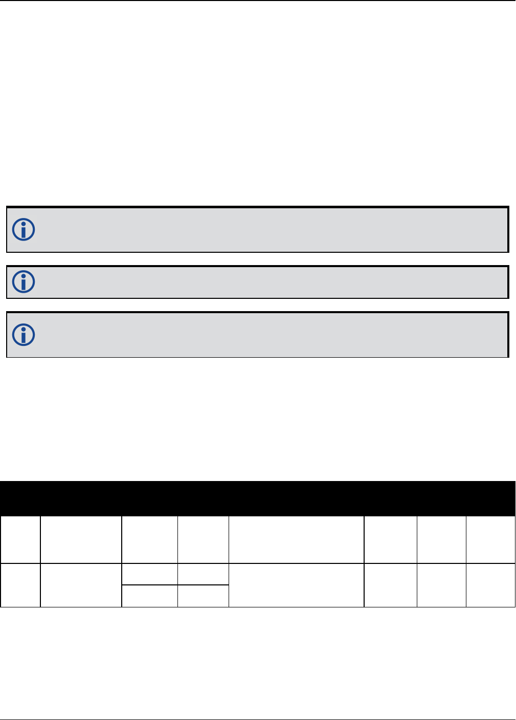
Chapter 4 SPAN Commands
OEM7 Commands and Logs Reference Manual v7 884
4.13 RELINSAUTOMATION
Enables Relative INS on the Rover
Platform: OEM719, OEM729, OEM7500, OEM7600, OEM7700, OEM7720, PwrPak7,
SPAN CPT7
Use this command to configure the Relative INS plug and play feature on the rover receiver.
RELINSAUTOMATION enables/disables the plug and play feature, sets the rover COM port to
which the master receiver is connected, sets the baud rate for communication, sets the cor-
rection transfer rate and enables/disables sending the HEADINGEXTB/HEADINGEXT2B log back
to the master receiver.
On issuing this command at the rover receiver, the rover will automatically sync with the master
receiver and configure it to send corrections at the specified baud rate and specified data rate.
The recommended method for configuring Relative INS is to use the RELINSCONFIG
command (see page 886).
This command should only be issued at the rover receiver.
if the rover receiver is not connected to the master receiver using a serial COM port, use
the RELINSCONFIG command (see page 886).
Message ID: 1763
Abbreviated ASCII Syntax:
RELINSAUTOMATION option [comport] [baudrate] [datarate] [headingextboption]
Abbreviated ASCII Example:
RELINSAUTOMATION enable com2 230400 10 on
Field Field Type ASCII
Value
Binary
Value Description Binary
Format
Binary
Bytes
Binary
Offset
1
RELINS
AUTOMATION
header
- -
Command header. See
Messages on page25
for more information.
- H 0
2 option ENABLE 0 Enables or disables the
plug and play feature. Enum 4 H
DISABLE 1

Chapter 4 SPAN Commands
OEM7 Commands and Logs Reference Manual v7 885
Field Field Type ASCII
Value
Binary
Value Description Binary
Format
Binary
Bytes
Binary
Offset
3 comport
COM1 1 The COM port on the
rover receiver to which
the master receiver is
connected.
(default = COM2)
Enum 4 H+4COM2 2
COM3 3
4 baudrate
9600, 19200,
38400, 57600,
115200, 230400,
460800
The baud rate used for
communication between
the master and rover
receivers.
Ulong 4 H+8
5 datarate 1, 2, 4, 5, 10 or
20 Hz
The rate at which
corrections are
transferred between the
receivers.
(default =10 Hz)
Ulong 4 H+12
6heading
extboption
ON
OFF
Enables or disables
sending the
HEADINGEXTB/
HEADINGEXT2B log
back to the master
receiver.
(default = ON)
Enum 4 H+16

Chapter 4 SPAN Commands
OEM7 Commands and Logs Reference Manual v7 886
4.14 RELINSCONFIG
Configure Relative INS
Platform: OEM719, OEM729, OEM7500, OEM7600, OEM7700, OEM7720, PwrPak7,
SPAN CPT7
Use this command to configure Relative INS on this receiver.
Message ID: 1797
Abbreviated ASCII Syntax:
RELINSCONFIG enable rxtype [port] [baud] [rateinhz]
Abbreviated ASCII Example:
RELINSCONFIG ENABLE ROVER COM2 230400 10
Field Field
Type
ASCII
Value
Binary
Value Description Binary
Format
Binary
Bytes
Binary
Offset
1
RELINS
CONFIG
header
- -
Command header. See
Messages on page25 for
more information.
- H 0
2 enable DISABLE 0 Enables or disables the
Relative INS functionality. Enum 4 H
ENABLE 1
3 rxtype
ROVER 1 Defines the receiver as the
master or rover in a Relative
INS configuration.
Enum 4 H+4
MASTER 2
4 port
See Table 194:
COM Ports on the
next page
Communication port used to
communicate with the other
receiver. (default = COM2)
Enum 4 H+8
5 baud
9600, 19200,
38400, 57600,
115200, 230400,
460800
The baud rate used for
communication between the
master and rover receivers.
(default = 230400)
Ulong 4 H+12
6 rateinhz 1, 2, 4, 5, 10 or 20
Hz
The rate at which
corrections are transferred
between the receivers.
(default =10 Hz)
Ulong 4 H+16

Chapter 4 SPAN Commands
OEM7 Commands and Logs Reference Manual v7 887
Decimal ASCII Description
1 COM1 COM port 1
2 COM2 COM port 2
3 COM3 COM port 3
13 USB1 USB port 1
14 USB2 USB port 2
15 USB3 USB port 3
19 COM4 COM port 4
23 ICOM1 IP virtual COM port 1
24 ICOM2 IP virtual COM port 2
25 ICOM3 IP virtual COM port 3
29 ICOM4 IP virtual COM port 4
31 COM5 COM port 5
46 ICOM5 IP virtual COM port 5
47 ICOM6 IP virtual COM port 6
48 ICOM7 IP virtual COM port 7
49 SCOM1 Scripted application COM port 1
50 SCOM2 Scripted application COM port 2
51 SCOM3 Scripted application COM port 3
52 SCOM4 Scripted application COM port 4
Table 194: COM Ports

Chapter 4 SPAN Commands
OEM7 Commands and Logs Reference Manual v7 888
4.15 SETALIGNMENTVEL
Set the Minimum Kinematic Alignment Velocity
Platform: OEM719, OEM729, OEM7500, OEM7600, OEM7700, OEM7720, PwrPak7,
SPAN CPT7
Use the SETALIGNMENTVEL command to adjust the minimum required velocity for a kin-
ematic alignment.
Useful in cases, such as helicopters, where alignment velocity should be increased to prevent a
poor alignment before the vehicle/aircraft is able to flight straight and level.
Message ID: 1397
Abbreviated ASCII Syntax:
SETALIGNMENTVEL velocity
Abbreviated ASCII Example
SETALIGNMENTVEL 5.0
Field Field Type ASCII
Value
Binary
Value Description Binary
Format
Binary
Bytes
Binary
Offset
1SETALIGNMENTVEL
header - -
Command
header. See
Messages on
page25 for more
information.
- H 0
2 Velocity
Minimum:
0.2 m/s
(Default
is 5 m/s)
The minimum
velocity, in m/s,
required to
kinematically
align.
Double 8 H

Chapter 4 SPAN Commands
OEM7 Commands and Logs Reference Manual v7 889
4.16 SETHEAVEWINDOW
Set Heave Filter Length
Platform: OEM719, OEM729, OEM7500, OEM7600, OEM7700, OEM7720, PwrPak7,
SPAN CPT7
Use this command to control the length of the heave filter. This filter determines the heave (ver-
tical displacement) of the IMU, relative to a long term level surface.
Message ID: 1383
Abbreviated ASCII Syntax:
SETHEAVEWINDOW filterlength
Abbreviated ASCII Example:
SETHEAVEWINDOW 35
Field Type ASCII
Value
Binary
Value Description Binary
Format
Binary
Bytes
Binary
Offset
1
SETHEAVE
WINDOW
header
- -
Command header. See
Messages on page25 for
more information.
- H 0
2Filter
Length
Integer
(1 – 300
s)
(default
= 20 s)
This filter length will be
used in the heave filter.
Typically, set the filter
length to 5 x wave period
Long 4 H

Chapter 4 SPAN Commands
OEM7 Commands and Logs Reference Manual v7 890
4.17 SETIMUPORTPROTOCOL
Sets the Protocol Used for the IMU Serial Port
Platform: OEM719, OEM729, OEM7500, OEM7600, OEM7700, OEM7720, PwrPak7,
SPAN CPT7
Use the SETIMUPORTPROTOCOL command to change the IMU serial port to use either RS-232
or RS-422 protocol. This overrides the default configured internally when the CONNECTIMU
command is sent.
Before changing the IMU serial port protocol:
1. Make sure the receiver port connected to the IMU is capable of RS-422 protocol.
Refer to the OEM7 Installation and Operation User Manual for information about
the receiver serial ports.
2. The IMU data message is input into the receiver at that particular protocol.
Message ID: 1767
Abbreviated ASCII Syntax:
SETIMUPORTPROTOCOL SerialProtocol
Abbreviated ASCII Example:
SETIMUPORTPROTOCOL RS422
Field Field Type ASCII
Value
Binary
Value Description Binary
Format
Binary
Bytes
Binary
Offset
1
SETIMUPORT
PROTOCOL
header
- -
Command header. See
Messages on page25 for
more information.
- H 0
2Serial
Protocol
RS232
RS422
The protocol for the IMU
serial port. Enum 4 H

Chapter 4 SPAN Commands
OEM7 Commands and Logs Reference Manual v7 891
4.18 SETIMUSPECS
Specify Error Specifications and Data Rate
Platform: OEM719, OEM729, OEM7500, OEM7600, OEM7700, OEM7720, PwrPak7,
SPAN CPT7
This command should only be used by advanced users of GNSS/INS.
Use the SETIMUSPECS command to specify the error specifications and data rate for the
desired IMU. If the default specs for the supported models are different than the unit used then
this command can be used to override the default values.
This command is only available for the following IMUs:
lHoneywell HG1930 (default specifications are for the AA99/CA50 model)
lHoneywell HG1900 (default specifications are for the CA29/CA50 model)
Message ID: 1295
Abbreviated ASCII Syntax:
SETIMUSPECS DataRate AccelBias AccelVRW GyroBias GyroARW AccelSFError
GyroSFError [DataLatency]
Abbreviated ASCII Example: (iMAR-FSAS Specs)
SETIMUSPECS 200 1 .0198 0.75 0.0028 300 300 2.5
Field Field Type ASCII
Value
Binary
Value Description Binary
Format
Binary
Bytes
Binary
Offset
1SETIMUSPECS
header - -
Command header. See
Messages on page25 for
more information.
- H 0
2 Data Rate 100Hz to
400Hz Data rate of the IMU Ushort 2 H
3 Accel Bias - Total accelerometer bias
in milli-g Double 8 H+2
4 Accel VRW - Accelerometer velocity
random walk in m/s/rt-hr Double 8 H+10
5 Gyro Bias - Total gyroscope bias in
deg/hr Double 8 H+18
6 Gyro ARW - Gyroscope angular
random walk in deg/rt-hr Double 8 H+26

Chapter 4 SPAN Commands
OEM7 Commands and Logs Reference Manual v7 892
Field Field Type ASCII
Value
Binary
Value Description Binary
Format
Binary
Bytes
Binary
Offset
7Accel Scale
Factor Error >0
Accelerometer scale
factor error in parts per
million. Optional.
Default = 1000ppm.
Ulong 4 H+34
8Gyro Scale
Factor Error >0
Gyroscopic scale factor
error in parts per million.
Optional.
Default = 1000ppm.
Ulong 4 H+38
9 Data Latency >0
Time delay in milliseconds
from the time of validity
of the IMU data to the
time the input pulse is
received by the SPAN
enabled receiver. This
may include filtering
delays, processing delays
and transmission times
depending on the timing
method (TOV, ASYNC,
SYNC) and the internal
IMU handling. Optional.
Default = 0.0.
Double 8 H+42
10 Reserved - Reserved Ulong 4 H+50
11 CRC - 32-bit CRC Hex 4 H+54
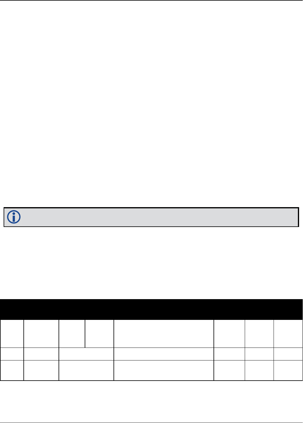
Chapter 4 SPAN Commands
OEM7 Commands and Logs Reference Manual v7 893
4.19 SETINITAZIMUTH
Set Initial Azimuth and Standard Deviation
Platform: OEM719, OEM729, OEM7500, OEM7600, OEM7700, OEM7720, PwrPak7,
SPAN CPT7
Use this command to start SPAN operation with a previously known azimuth. Azimuth is the
weakest component of a coarse alignment and is also the easiest to know from an external
source (i.e., like the azimuth of roadway). When using this command, SPAN operation through
alignment will appear the same as with a usual coarse alignment. Roll and pitch is determined
using averaged gyro and accelerometer measurements. The input azimuth is used rather than
what is computed by the normal coarse alignment routine.
lInput azimuth values must be accurate for good system performance.
lSending SETINITAZIMUTH resets the SPAN filter. Following realignment, vehicle dynamics
are required for the filter to re-converge. Bridging performance is poor before filter con-
vergence.
lThe entered azimuth angle is with respect to the configured output frame. This is generally
the vehicle frame unless a User Frame offset has been configured using the
SETINSROTATION command (see page 896). All offsets should be entered before entering
the SETINITAZIMUTH command.
lThis command is not save configurable and must be re-entered after each start-up. The com-
mand can be entered at any time and will be used automatically when the system is ready to
begin alignment.
Azimuth is positive in a clockwise direction when looking towards the z-axis origin.
Message ID: 863
Abbreviated ASCII Syntax:
SETINITAZIMUTH azimuth azSTD
Abbreviated ASCII Example:
SETINITAZIMUTH 90 5
Field Field
Type
ASCII
Value
Binary
Value Description Binary
Format
Binary
Bytes
Binary
Offset
1
SETINIT
AZIMUTH
header
- -
Command header. See
Messages on page25 for more
information.
- H 0
2 azimuth 0 to 360 Input azimuth angle (degrees) Double 8 H
3 azSTD 1 to 25 Input azimuth standard
deviation angle (degrees) Float 4 H+8

Chapter 4 SPAN Commands
OEM7 Commands and Logs Reference Manual v7 894
4.20 SETINSPROFILE
Sets filter behavior depending on system environment
Platform: OEM719, OEM729, OEM7500, OEM7600, OEM7700, OEM7720, PwrPak7,
SPAN CPT7
This command sets specific filter behavior depending on the environment the system is installed
in. The DEFAULT profile is the legacy setting from earlier SPAN products. The other profiles
make changes specific to that environment.
The BASIC INS Profiles are available to all SPAN software models, but the enhanced con-
figurations, denoted by "PLUS", are restricted by the SPAN model. The enhanced configurations
allow for enhanced profile behavior such as Dead Reckoning for land and Heave for marine. See
the OEM7 SPAN Installation and Operation User Manual for a detailed description of each pro-
file's effect.
Message ID: 1944
Abbreviated ASCII Syntax:
SETINSPROFILE profile
Abbreviated ASCIIExample:
SETINSPROFILE LAND_BASIC
Field Field Type ASCII
Value
Binary
Value Description Binary
Format
Binary
Bytes
Binary
Offset
1SETINSPROFILE
Header - -
Command
header. See
Messages on
page25 for more
information.
- H 0

Chapter 4 SPAN Commands
OEM7 Commands and Logs Reference Manual v7 895
Field Field Type ASCII
Value
Binary
Value Description Binary
Format
Binary
Bytes
Binary
Offset
2 Profile
DEFAULT 0
Default INS
profile with
standard SPAN
behavior.
Enum 4 H
LAND_BASIC 1 Basic INS profile
for land vehicles
MARINE_
BASIC 2
Basic INS profile
for marine
vehicles
FIXEDWING_
BASIC 3
Basic INS profile
for fixed wing
aircraft
Reserved 4 Reserved
VTOL_BASIC 5
Basic INS profile
for vertical
takeoff and
landing vehicles
(UAVs,
helicopters, etc.)
RAIL_BASIC 6 Basic INS profile
for trains
LAND_PLUS 33
Enhanced INS
profile for land
vehicles. Enables
Dead Reckoning.
Requires INS
Enhanced Profile
Model.
MARINE_
PLUS 34
Enhanced INS
profile for marine
vehicles. Enables
Heave. Requires
INS Enhanced
Profile Model.
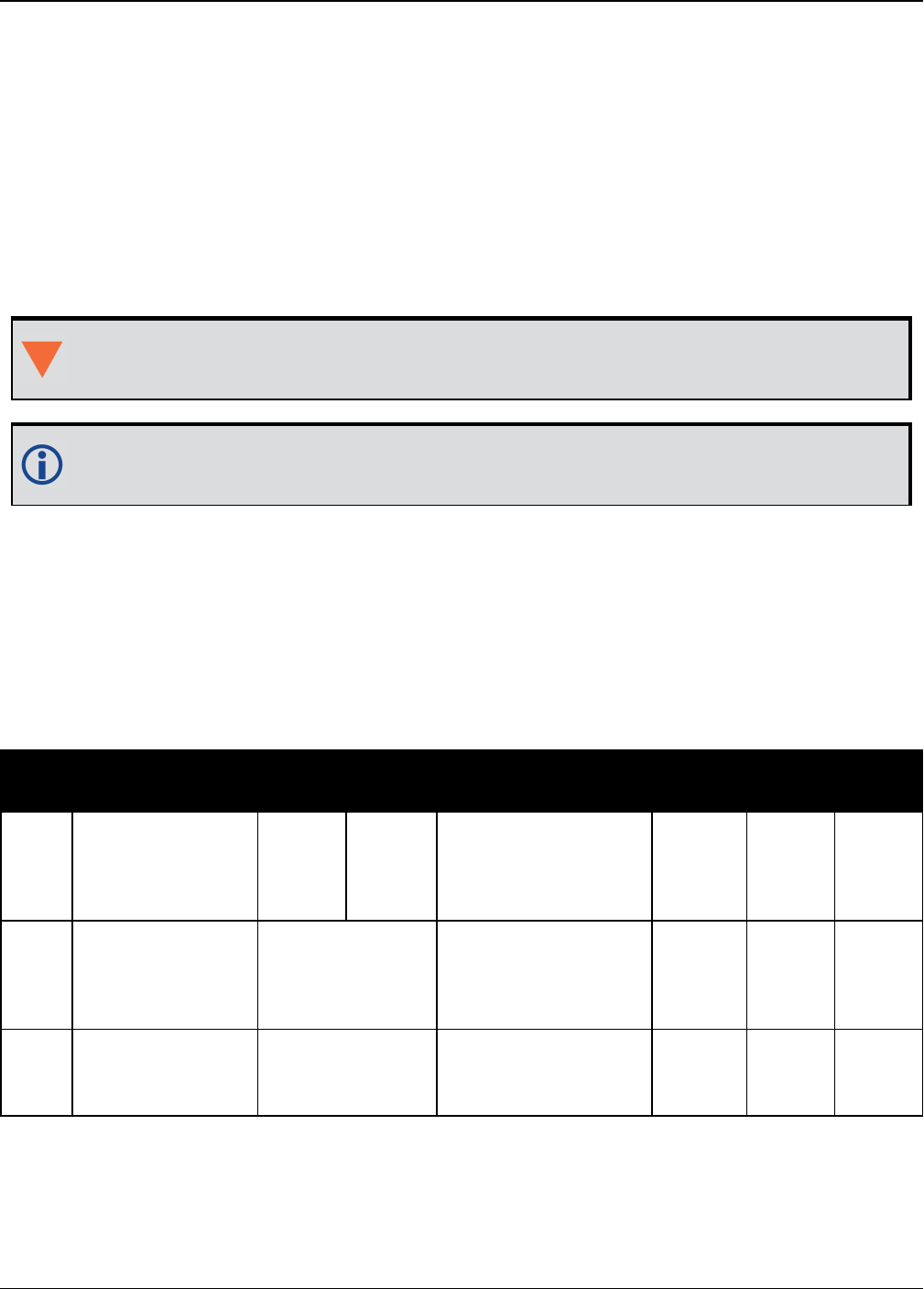
Chapter 4 SPAN Commands
OEM7 Commands and Logs Reference Manual v7 896
4.21 SETINSROTATION
Specifies rotational offsets between the IMU frame and other
reference frames
Platform: OEM719, OEM729, OEM7500, OEM7600, OEM7700, OEM7720, PwrPak7,
SPAN CPT7
Use the SETINSROTATION command to specify rotational offsets between the IMU frame and
other reference frames, such as the vehicle frame or an ALIGN baseline. Offsets must be
entered as the rotation from the IMU body frame, to the frame of interest. The order of rotations
is Z, X, Y. All rotations are right handed.
It is very important to follow the order of rotations (Z, X, Y) when determining the rota-
tions from IMU body frame to frame of interest.
To specify translational offsets between frames, see the SETINSTRANSLATION com-
mand on page899.
Message ID: 1921
Abbreviated ASCII Syntax:
SETINSROTATION INSRotation XRotation YRotation ZRotation [XRotationSD]
[YRotationSD] [ZRotationSD]
Abbreviated ASCII Example:
SETINSROTATION RBV 0 0 90 0.0 0.0 0.0
Field Field Type ASCII
Value
Binary
Value Description Binary
Format
Binary
Bytes
Binary
Offset
1SETINSROTATION
Header - -
Command header.
See Messages on
page25 for more
information.
- H 0
2 INS Rotation
Table 195:
Rotational Offset
Types on the
next page
Rotational offset to
be set. Enum 4 H
3 XRotation ±180
X rotation offset
from IMU origin
(degrees)
Float 4 H+4

Chapter 4 SPAN Commands
OEM7 Commands and Logs Reference Manual v7 897
Field Field Type ASCII
Value
Binary
Value Description Binary
Format
Binary
Bytes
Binary
Offset
4 YRotation ±180
Y rotation offset
from IMU origin
(degrees)
Float 4 H+8
5 ZRotation ±180
Z rotation offset
from IMU origin
(degrees)
Float 4 H+12
6 XRotationSD 0 to 45
Optional X rotation
offset standard
deviation (degrees)
Default: 0.0
Float 4 H+16
7 YRotationSD 0 to 45
Optional Y
translation offset
standard deviation
(degrees) Default:
0.0
Float 4 H+20
8 ZRotationSD 0 to 45
Optional Z
translation offset
standard deviation
(degrees) Default:
0.0
Float 4 H+24
9 Reserved Long 4 H+28
ASCII
Value
Binary
Value Description
USER 4
Rotation from the IMU body frame to the user output frame.
This offset shifts the attitude information in the INSPVA, INSPOS, INSVEL,
INSATT, and INSSPD logs, along with their short header and extended versions.
MARK1 5 Rotation from the IMU body frame to the desired output for MARK1.
This offset rotates the attitude information in the MARK1PVA log.
MARK2 6 Rotation from the IMU body frame to the desired output for MARK2.
This offset rotates the attitude information in the MARK2PVA log.
Table 195: Rotational Offset Types

Chapter 4 SPAN Commands
OEM7 Commands and Logs Reference Manual v7 898
ASCII
Value
Binary
Value Description
ALIGN 8
Rotation from the IMU body frame to an ALIGN dual antenna solution.
When using a dual antenna ALIGN solution with SPAN, this offset
will be calculated automatically if translational offsets to both the
primary and secondary GNSS antennas are provided using the
SETINSTRANSLATION command on the next page.
MARK3 9 Rotation from the IMU body frame to the desired output for MARK3.
This offset rotates the attitude information in the MARK3PVA log.
MARK4 10 Rotation from the IMU body frame to the desired output for MARK4.
This offset rotates the attitude information in the MARK4PVA log.
RBV 11 Rotation from the IMU body frame to the vehicle frame.
RBM 12 Rotation from the IMU body frame to the gimbal mount body frame.

Chapter 4 SPAN Commands
OEM7 Commands and Logs Reference Manual v7 899
4.22 SETINSTRANSLATION
Specifies translational offsets between the IMU frame and other
reference frames
Platform: OEM719, OEM729, OEM7500, OEM7600, OEM7700, OEM7720, PwrPak7,
SPAN CPT7
Use the SETINSTRANSLATION command to specify translational offsets between the IMU
frame and other reference frames, including GNSS antennas or the desired output frame. Off-
sets must be entered as the vector from the IMU, to the frame or position of interest. Offsets
can be entered either in the IMU body frame, or the vehicle frame; offsets in the vehicle frame
will be automatically rotated into the IMU body frame using the best available IMU Body to
Vehicle Rotation (RBV).
For details on entering the RBV rotation or other angular offsets, see the SETINSROTATION
command on page896.
Message ID: 1920
Abbreviated ASCII Syntax:
SETINSTRANSLATION INSTranslation XTranslation YTranslation ZTranslation
[XTranslationSD] [YTranslationSD] [ZTranslationSD] [InputFrame]
Abbreviated ASCII Example:
SETINSTRANSLATION USER 1.0 2.0 3.0 0.05 0.05 0.05 VEHICLE
Field Field Type ASCII
Value
Binary
Value Description Binary
Format
Binary
Bytes
Binary
Offset
1
SETINS
TRANSLATION
Header
- -
Command header.
See Messages on
page25 for more
information.
- H 0
2 InsTranslation
See Table 196:
Translation Offset
Types on the next
page
Translation offset to
be set Enum 4 H
3 XTranslation ±100 X translation offset
from IMU origin (m) Float 4 H+4
4 YTranslation ±100 Y translation offset
from IMU origin (m) Float 4 H+8
5 ZTranslation ±100 Z translation offset
from IMU origin (m) Float 4 H+12
6 XTranslationSD 0 to 10
Optional X translation
offset standard
deviation (m)
Float 4 H+16

Chapter 4 SPAN Commands
OEM7 Commands and Logs Reference Manual v7 900
Field Field Type ASCII
Value
Binary
Value Description Binary
Format
Binary
Bytes
Binary
Offset
7 YTranslationSD 0 to 10
Optional Y translation
offset standard
deviation (m)
Float 4 H+20
8 ZTranslationSD 0 to 10
Optional Z translation
offset standard
deviation (m)
Float 4 H+24
9 InputFrame
Table 197:
Translation Input
Frame on the next
page
Optional input frame
for translation offset
values
Enum 4 H+48
For the ANT1, ANT2, EXTERNAL and GIMBAL translations, the standard deviation defaults
are set to 10% of the translation value (up to a max of 10 metres).
If you are uncertain of the standard deviation values for an offset, err on the side of a
larger standard deviation.
ASCII
Value
Binary
Value Description
ANT1 1 Offset from the IMU center of navigation to the phase center of the primary
GNSS antenna.
ANT2 2 Offset from the IMU center of navigation to the phase center of the
secondary GNSS antenna.
EXTERNAL 3
Offset from the IMU center of navigation to the external position source
location.
This offset type is for use with the EXTERNALPVAS command (see page
866).
USER 4
Translation from the IMU center of navigation to the user output location.
This offset shifts the position and velocity information in the INSPVA,
INSPOS, INSVEL, INSATT, and INSSPD logs, along with their short header
and extended versions.
MARK1 5 Translation from the IMU center of navigation to the MARK1 output location.
This offset shifts the position and velocity information in the MARK1PVA log.
Table 196: Translation Offset Types

Chapter 4 SPAN Commands
OEM7 Commands and Logs Reference Manual v7 901
ASCII
Value
Binary
Value Description
MARK2 6 Translation from the IMU center of navigation to the MARK2 output location.
This offset shifts the position and velocity information in the MARK2PVA log.
GIMBAL 7 Translation from the IMU center of navigation to the gimbal mount center of
rotation.
MARK3 9 Translation from the IMU center of navigation to the MARK3 output location.
This offset shifts the position and velocity information in the MARK3PVA log.
MARK4 10 Translation from the IMU center of navigation to the MARK4 output location.
This offset shifts the position and velocity information in the MARK4PVA log.
ASCII
Value
Binary
Value Description
IMUBODY 0 Offset is provided in the IMU enclosure frame.
Default: IMUBODY
VEHICLE 1
Offset is provided in the vehicle frame.
Offsets entered in the vehicle frame will be automatically rotated into the
IMU frame using the best available RBV (rotation from IMU Body to Vehicle)
information when required.
Vehicle frame offsets should only be used if the RBV is known accurately,
either though user measurement or calibration.
The order of entry for vehicle frame offsets and the RBV rotation does not
matter.
Table 197: Translation Input Frame

Chapter 4 SPAN Commands
OEM7 Commands and Logs Reference Manual v7 902
4.23 SETINSUPDATE
Enable/Disable INS Filter Updates
This command should only be used by advanced users of GNSS+INS.
Platform: OEM719, OEM729, OEM7500, OEM7600, OEM7700, OEM7720, PwrPak7,
SPAN CPT7
Use this command to enable or disable the available INS filter updates.
Message ID: 1821
Abbreviated ASCII Syntax:
SETINSUPDATE INSUpdate Trigger
Abbreviated ASCII Example:
SETINSUPDATE ZUPT DISABLE
Field Field Type ASCII
Value
Binary
Value Description Binary
Format
Binary
Bytes
Binary
Offset
1SETINSUPDATE
header - -
Command header.
See Messages on
page25 for more
information.
- H 0
2 INSUpdate
POS 0 Position updates
Enum 4 H
ZUPT 1 Zero velocity updates
PSR 2 Pseudorange updates
ADR 3 Carrier phase updates
DOPPLER 4 Doppler updates
ALIGN 5 Heading updates
DMI 6
Distance measuring
instrument (wheel
sensor) updates
3 Trigger
DISABLE 0
Disable the INS
update specified in the
INSUpdate field. Enum 4 H+4
ENABLE 1
Enable the INS update
specified in the
INSUpdate field.

Chapter 4 SPAN Commands
OEM7 Commands and Logs Reference Manual v7 903
4.24 SETMAXALIGNMENTTIME
Set a Time Limit for Static Course Alignment
Platform: OEM719, OEM729, OEM7500, OEM7600, OEM7700, OEM7720, PwrPak7,
SPAN CPT7
Use this command to set a maximum time limit allowed for static coarse alignments. Coarse
alignments typically take under 60 seconds, but in heavy vibration conditions they can take
much longer trying to compensate for the vibration induced noise. This command is used to cap
the time to a specific length.
This command is for advanced users only.
Alignment accuracy cannot be guaranteed if the alignment time is capped using this com-
mand.
Message ID: 1800
Abbreviated ASCII Syntax:
SETMAXALIGNMENTTIME switch [duration]
Abbreviated ASCII Example:
SETMAXALIGNMENTTIME ENABLE 90
Field Field Type ASCII
Value
Binary
Value Description Binary
Format
Binary
Bytes
Binary
Offset
1
SETMAX
ALIGNMENTTIME
header
- -
Command header.
See Messages on
page25 for more
information.
- H 0
2 switch
DISABLE 0 Disables the static
alignment time limit. Enum 4 H
ENABLE 1 Enables the static
alignment time limit.
3 duration 30 - 300
Maximum static
alignment time in
seconds. Default is
180.
Ulong 4 H+4

Chapter 4 SPAN Commands
OEM7 Commands and Logs Reference Manual v7 904
4.25 SETRELINSOUTPUTFRAME
Sets the Relative INS Output Frame
Platform: OEM719, OEM729, OEM7500, OEM7600, OEM7700, OEM7720, PwrPak7,
SPAN CPT7
Use this command to change the frame of the output solution provided in the RELINSPVA and
SYNCRELINSPVA logs. See RELINSPVA log on page1015 and SYNCRELINSPVA log on
page1019 for information about these logs.
See OEM7 SPAN Installation and Operation User Manual for information about the Relative INS
functionality.
Message ID: 1775
Abbreviated ASCII Syntax:
SETRELINSOUTPUTFRAME OutputFrame [DiffCriteria]
Abbreviated ASCII Example:
SETRELINSOUTPUTFRAME ECEF TRUE
Field Field Type ASCII
Value
Binary
Value Description Binary
Format
Binary
Bytes
Binary
Offset
1
SETRELINS
OUTPUTFRAME
header
- -
Command header.
See Messages on
page25 for more
information.
- H 0
2 OutputFrame
ROVER 1
Frame of the output
solution in the
RELINSPVA and
SYNCRELINSPVA
logs.
ROVER – the output
frame of the rover
INS solution
MASTER – the
output frame of the
master INS solution
ECEF – Earth
Centered Earth
Fixed
LOCALLEVEL – Local
level
The default is the
ROVER.
Enum 4 H
MASTER 2
ECEF 3
LOCALLEVEL 4

Chapter 4 SPAN Commands
OEM7 Commands and Logs Reference Manual v7 905
Field Field Type ASCII
Value
Binary
Value Description Binary
Format
Binary
Bytes
Binary
Offset
3 DiffCriteria
FALSE 0
The delta solution is
computed as Rover
minus Master.
(default) Bool 1 H+4
TRUE 1
The delta solution is
computed as Master
minus Rover.

Chapter 4 SPAN Commands
OEM7 Commands and Logs Reference Manual v7 906
4.26 SETUPSENSOR
Add a new sensor object
Platform: OEM719, OEM729, OEM7500, OEM7600, OEM7700, OEM7720, PwrPak7,
SPAN CPT7
Use this command to add a new sensor object to the system. A sensor object consists of an ID,
an Event_Out line and an Event_In line. This is intended as a simplified way to set up triggering
to and from a sensor rather than configuring all connections independently. It also allows for
event pulses to be sent to a sensor at specific GPS times (see the TIMEDEVENTPULSE com-
mand on page910).
Message ID: 1333
Abbreviated ASCII Syntax:
SETUPSENSOR SensorID EventOut OPP OAP EventIn EIC IPP ITB MITG
Abbreviated ASCII Example:
SETUPSENSOR SENSOR3 MARK1 POSITIVE 2 MARK4 EVENT POSITIVE 0 2
Field Field
Type
ASCII
Value
Binary
Value Description Binary
Format
Binary
Bytes
Binary
Offset
1
SETUP
SENSOR
header
- -
Command header. See
Messages on page25 for
more information.
- H 0
2Sensor
ID
SENSOR1 0
The sensor to configure. Enum 4 HSENSOR2 1
SENSOR3 2
3 EventOut
MARK1 0
Associate a specific MARK
Event_Out line to this
sensor configuration.
Enum 4 H+4
MARK2 1
MARK3 2
MARK4 3
4 OPP NEGATIVE 0 Mark output pulse polarity Enum 4 H+8
POSITIVE 1
5 OAP 2 - 500
Mark output active period in
milliseconds.
Value must be divisible by
2.
Ulong 4 H+12

Chapter 4 SPAN Commands
OEM7 Commands and Logs Reference Manual v7 907
Field Field
Type
ASCII
Value
Binary
Value Description Binary
Format
Binary
Bytes
Binary
Offset
6 EventIn
MARK1 0
Associate a specific MARK
Event_In line to this sensor
configuration.
Enum 4 H+16
MARK2 1
MARK3 2
MARK4 3
7 EIC DISABLE 0 Event in control Enum 4 H+20
EVENT 1
8 IPP NEGATIVE 0 Mark input pulse polarity Enum 4 H+24
POSITIVE 1
9 ITB -99999999 to
99999999
Mark input time bias in
milliseconds Long 4 H+28
10 ITG 2 to 3599999 Mark input time guard in
milliseconds Ulong 4 H+32
The Event_In and Event_Out options available are dependent on the receiver used in the
SPANsystem. For information about the Event lines supported, see the Strobe Spe-
cifications for the receiver in the OEM7 SPAN Installation and Operation User Manual.
MARK3 and MARK4 are available only on SPAN systems with an OEM7600, OEM7700 or
OEM7720 receiver.

Chapter 4 SPAN Commands
OEM7 Commands and Logs Reference Manual v7 908
4.27 SETWHEELPARAMETERS
Set Wheel Parameters
Platform: OEM719, OEM729, OEM7500, OEM7600, OEM7700, OEM7720, PwrPak7,
SPAN CPT7
The SETWHEELPARAMETERS command can be used when wheel sensor data is available. It
gives the filter a good starting point for the wheel size scale factor.
Message ID: 847
Abbreviated ASCII Syntax:
SETWHEELPARAMETERS ticks circ reserved
Abbreviated ASCII Example:
SETWHEELPARAMETERS 58 1.96 1.0
Field Field Type ASCII
Value
Binary
Value Description Binary
Format
Binary
Bytes
Binary
Offset
1
SETWHEEL
PARAMETERS
header
- -
Command header. See
Messages on page25 for
more information.
- H 0
2 Ticks 1-10000 Number of ticks per
revolution Ushort 41H
3 Circ 0.1-100 Wheel circumference (m)
(default = 1.96 m) Double 8 H+4
4 Reserved - Reserved field. Set to 1.0
on input. Double 8 H+12
Fields 2 and 3 are used with an estimated scale factor to determine the distance
traveled.
1In the binary log case, an additional 2 bytes of padding are added to maintain 4 byte alignment.

Chapter 4 SPAN Commands
OEM7 Commands and Logs Reference Manual v7 909
4.28 TAGNEXTMARK
Tags the Next Incoming Mark Event
Platform: OEM719, OEM729, OEM7500, OEM7600, OEM7700, OEM7720, PwrPak7,
SPAN CPT7
Use this command to tag the next incoming mark event on the selected mark with a 32-bit num-
ber. This is available in the TAGGEDMARK1PVA, TAGGEDMARK2PVA, TAGGEDMARK3PVA
and TAGGEDMARK4PVA log (see page 1022) to easily associate the PVA log with a supplied
event.
Message ID: 1257
Abbreviated ASCII Syntax:
TAGNEXTMARK Mark Tag
Abbreviated ASCII Example:
TAGNEXTMARK MARK1 1234
Field Field Type ASCII
Value
Binary
Value Description Binary
Format
Binary
Bytes
Binary
Offset
1TAGNEXTMARK
header - -
Command header. See
Messages on page25 for
more information.
- H 0
2 Mark
MARK1 0
Event line Enum 4 H
MARK2 1
MARK3 2
MARK4 3
3 Tag - - Tag for next mark event Ulong 4 H+4
The Mark options available are dependent on the receiver used in the SPANsystem. For
information about the Event lines supported, see the Strobe Specifications for the
receiver in the OEM7 SPAN Installation and Operation User Manual.

Chapter 4 SPAN Commands
OEM7 Commands and Logs Reference Manual v7 910
4.29 TIMEDEVENTPULSE
Add a new camera event
Platform: OEM719, OEM729, OEM7500, OEM7600, OEM7700, OEM7720, PwrPak7,
SPAN CPT7
Use this command to add a new camera event to the system. TIMEDEVENTPULSE sends a
pulse on the sensor MARK output at the selected GPS time and sets the trigger on the sensor
MARK input to be tagged with an event ID (see the TAGGEDMARK1PVA, TAGGEDMARK2PVA,
TAGGEDMARK3PVA and TAGGEDMARK4PVA log on page1022). The lines connected to each
sensor are configured using the SETUPSENSOR command (see page 906).
A maximum of 10 unprocessed events can be buffered into the system. A
TIMEDEVENTPULSE command must be entered at least 1 second prior to the reques-
ted event time.
Message ID: 1337
Abbreviated ASCII Syntax:
TIMEDEVENTPULSE SensorID GPSWeek GPSSeconds [Event ID]
Abbreviated ASCII Example:
TIMEDEVENTPULSE -1 1617 418838 100
Field Field
Type
ASCII
Value
Binary
Value Description Binary
Format
Binary
Bytes
Binary
Offset
1
TIMED
EVENT
PULSE
header
- -
Command header. See
Messages on page25
for more information.
- H 0
2Sensor
ID
ALL -1
(0xFFFFFFFF)
The sensor(s) affected
by the trigger
command.
The decimal
representation of the
combination of bits 0-2
can be used to select a
combination of active
sensors (e.g. 5 [101]
will select sensors 1
and 3).
Long 4 H
SENSOR1 0x01
SENSOR2 0x02
SENSOR3 0x04
3GPS
Week 0 - MAX Ulong The GPS week that
triggers the event. Ulong 4 H+4

Chapter 4 SPAN Commands
OEM7 Commands and Logs Reference Manual v7 911
Field Field
Type
ASCII
Value
Binary
Value Description Binary
Format
Binary
Bytes
Binary
Offset
4GPS
Seconds 0 - 604800
The GPS week seconds
that triggers the
event.
Double 8 H+8
5Event
ID 0- MAX Ulong
The event's identifier,
used to tag the
TAGGEDMARKxPVA
logs if a sensor input is
enabled.
Optional
Default = 0
Ulong 4 H+16
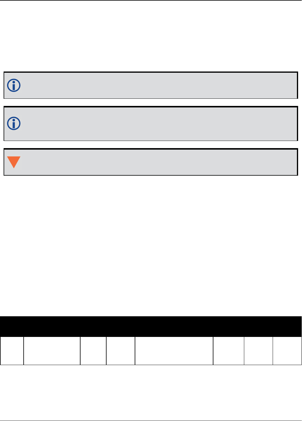
Chapter 4 SPAN Commands
OEM7 Commands and Logs Reference Manual v7 912
4.30 WHEELVELOCITY
Wheel Velocity for INS Augmentation
Platform: OEM719, OEM729, OEM7500, OEM7600, OEM7700, OEM7720, PwrPak7,
SPAN CPT7
Use the WHEELVELOCITY command to input wheel sensor data into the OEM7 receiver.
This command should be used only if the wheel sensor cannot be directly connected to a
wheel sensor port in the SPAN system.
When wheel sensor data is entered using this command, only the Cumulative Ticks/s
value is used by the system. Values entered for Wheel Velocity and Float Wheel Velocity
are not used at this time.
This command should be input at 1 Hz and synced to the receiver 1 Hz PPS for optimized
performance.
Message ID: 504
Abbreviated ASCII Example:
WHEELVELOCITY 123 8 10 0 0 0 0 40
WHEELVELOCITY 123 8 10 0 0 0 0 80
WHEELVELOCITY 123 8 10 0 0 0 0 120
The examples above are for a vehicle traveling at a constant velocity with these wheel sensor
characteristics:
lWheel Circumference = 2 m
lVehicle Velocity (assumed constant for this example) = 10 m/s
lTicks Per Revolution = 8
lCumulative Ticks Per Second = (10 m/s)*(8 ticks/rev)/(2 m/rev) = 40
lLatency between 1PPS and measurement from wheel sensor hardware = 123 ms
Field Field Type ASCII
Value
Binary
Value Description Format Binary
Bytes
Binary
Offset
1WHEELVELOCITY
header - -
Command header. See
Messages on page25
for more information.
- H 0

Chapter 4 SPAN Commands
OEM7 Commands and Logs Reference Manual v7 913
Field Field Type ASCII
Value
Binary
Value Description Format Binary
Bytes
Binary
Offset
2 Latency
A measure of the
latency in the velocity
time tag in ms.
Ushort 2 H
3 Ticks/rev Number of ticks per
revolution Ushort 2 H+2
4 Wheel Velocity Short wheel velocity in
ticks/s Ushort 2 H+4
5 Reserved Ushort 2 H+6
6Float Wheel
Velocity
Float wheel velocity in
ticks/s Float 4 H+8
7 Reserved Ulong 4 H+12
8 Reserved Ulong 4 H+16
9Cumulative
Ticks/s
Cumulative number of
ticks/s Ulong 4 H+20

OEM7 Commands and Logs Reference Manual v7 914
Chapter 5 SPAN Logs
The SPAN specific logs follow the same general logging scheme as normal OEM7 Family logs.
They are available in ASCII or binary formats and are defined as being either synchronous or
asynchronous. All the logs in this chapter are used only with the SPAN system.
For information on other available logs and output logging, refer to Logs on page404.
One difference from the standard OEM7 Family logs is there are two possible headers for the
ASCII and binary versions of the logs. Which header is used for a given log is described in the
log definitions in this chapter. The reason for the alternate short headers is that the normal
OEM7 binary header is quite long at 28 bytes. This is nearly as long as the data portion of many
of the INS logs and creates excess storage and baud rate requirements. Note that the INS
related logs contain a time tag within the data block in addition to the time tag in the header.
The time tag in the data block should be considered the exact time of applicability of the data.
All INS Position, Velocity and Attitude logs can be obtained at a rate of up to 200 Hz. The stand-
ard deviation and update logs are available once per second.
Each ASCII log ends with a hexadecimal number preceded by an asterisk and
followed by a line termination using the carriage return and line feed characters,
for example, *1234ABCD[CR][LF]. This value is a 32-bit CRC of all bytes in the
log, excluding the '#’ or ‘%’ identifier and the asterisk preceding the four checksum
digits. See also Description of ASCII and Binary Logs with Short Headers on
page40.
Table 198: Inertial Solution Status on page936 shows the status values included in the INS pos-
ition, velocity and attitude output logs. If the IMU is connected properly and a good status value
is not being received, check the hardware setup to ensure it is properly connected. This situation
can be recognized in the RAWIMU data by observing accelerometer and gyro values which are
not changing with time.
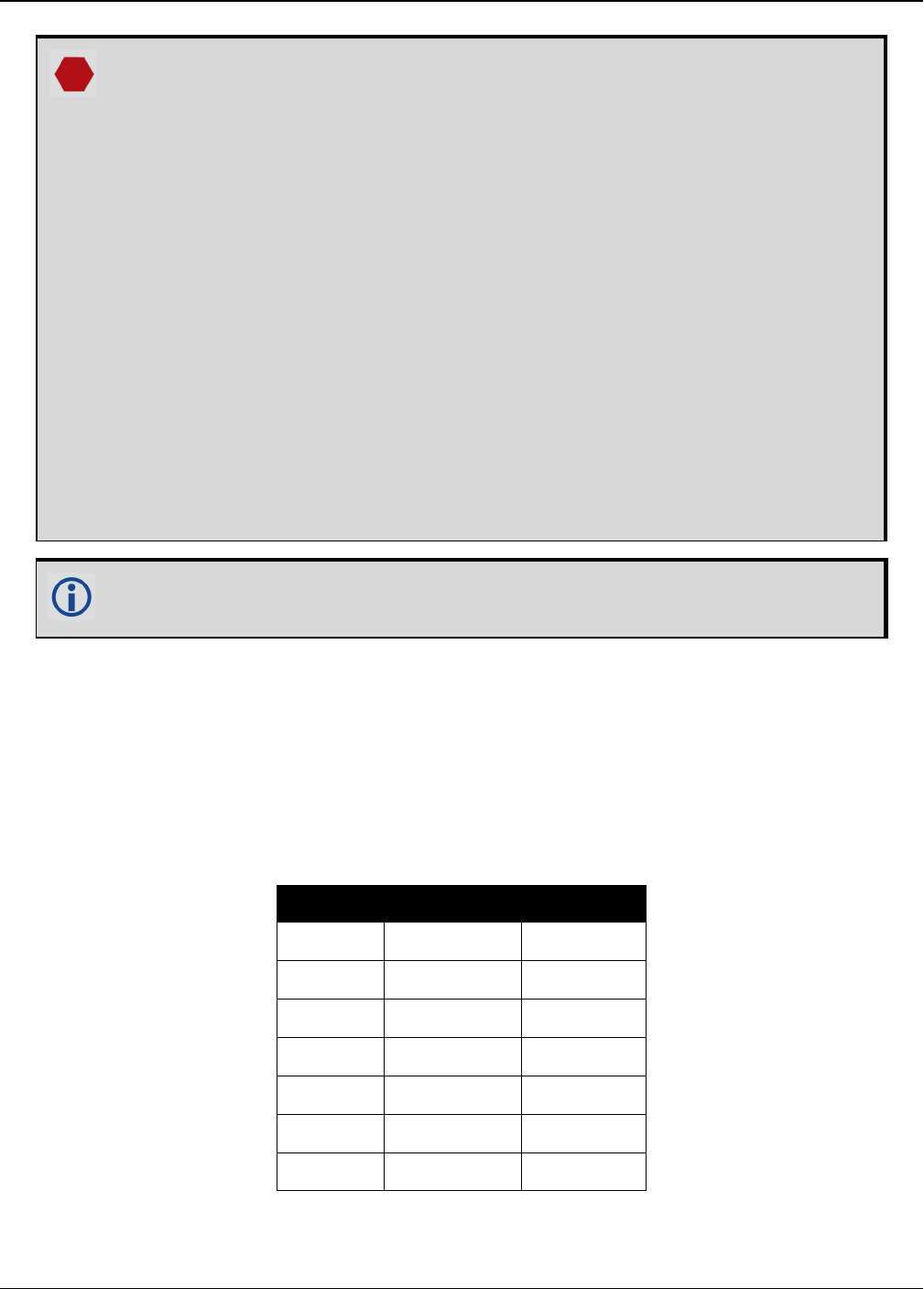
Chapter 5 SPAN Logs
OEM7 Commands and Logs Reference Manual v7 915
Logging Restriction Important Notice
Logging excessive amounts of high rate data can overload the system. When
configuring the output for SPAN, NovAtel recommends that only one high rate
(>50Hz) message be configured for output at a time. It is possible to log more than
one message at high rates, but doing so could have negative impacts on the
system. Also, if logging 100/125/200Hz data, always use the binary format.
For optimal performance, log only one high rate output at a time. These logs could
be:
lRaw data for post processing
RAWIMUXSB ONNEW (100, 125 or 200 Hz depending on IMU)
lRAWIMU logs are not valid with the ONTIME trigger. The raw IMU obser-
vations contained in these logs are sequential changes in velocity and rota-
tion. As such, you can only use them for navigation if they are logged at
their full rate.
lReal time INS solution
INSPVASB ONTIME 0.01 or 0.005 (maximum rate equals the IMU rate)
lOther possible INS solution logs available at high rates are: INSPOSSB,
INSVELSB, INSATTSB
The periods available when using the ONTIME trigger are 0.005 (200 Hz), 0.01 (100
Hz), 0.02 (50 Hz), 0.05, 0.1, 0.2, 0.25, 0.5, 1, and any integer number of seconds.
5.1 Logs with INS or GNSS Data
There are several logs in the system designed to output the best available solution as well as
many logs that output only a specific solution type (PSR, RTK, INS, etc). The table below lists
the logs that can provide either a GNSS solution or an INS solution. Most of these derive from
the solution the system picks as the best solution. SPAN systems also have a secondary best
solution that derives from the GNSS solution only (BESTGNSSPOS log (see page 916) and
BESTGNSSVEL log (see page 919)). The position output from these logs is at the phase center
of the antenna.
Log Log Format GNSS/INS
BESTPOS NovAtel YES
BESTVEL NovAtel YES
BESTUTM NovAtel YES
BESTXYZ NovAtel YES
GPGGA NMEA YES
GPGLL NMEA YES
GPVTG NMEA YES
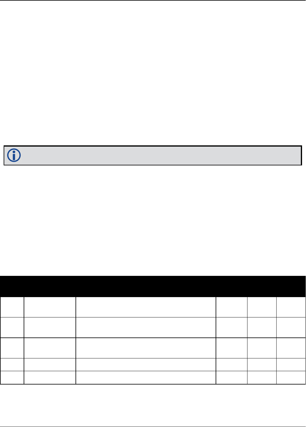
Chapter 5 SPAN Logs
OEM7 Commands and Logs Reference Manual v7 916
5.2 BESTGNSSPOS
Best GNSS Position
Platform: OEM719, OEM729, OEM7500, OEM7600, OEM7700, OEM7720, PwrPak7,
SPAN CPT7
This log contains the best available GNSS position (without INS) computed by the receiver. In
addition, it reports several status indicators, including differential age, which is useful in pre-
dicting anomalous behavior brought about by outages in differential corrections. A differential
age of 0 indicates that no differential correction was used.
With the system operating in an RTK mode, this log reflects the latest low latency solution for up
to 60 seconds after reception of the last base station observations. After this 60 second period,
the position reverts to the best solution available and the degradation in accuracy is reflected in
the standard deviation fields. If the system is not operating in an RTK mode, pseudorange dif-
ferential solutions continue for the time specified in the PSRDIFFTIMEOUT command (see
page 284).
BESTGNSSPOS always outputs positions at the antenna phase center.
Message ID: 1429
Log Type: Synch
Recommended Input:
log bestgnssposa ontime 1
ASCII Example:
#BESTGNSSPOSA,COM1,0,92.5,FINESTEERING,1692,332119.000,02000000,8505,43521;SOL_
COMPUTED,SINGLE,51.11635530655,-114.03819448382,1064.6283,-
16.9000,WGS84,1.2612,0.9535,2.7421,"",0.000,0.000,11,11,11,11,0,06,00,03*52d3f7
c0
Field Field type Data Description Format Binary
Bytes
Binary
Offset
1BESTGNSSPOS
Header
Log header. See Messages on page25 for
more information. - H 0
2 Sol Status Solution status, see Table 73: Solution
Status on page431 Enum 4 H
3 Pos Type Position type, see Table 74: Position or
Velocity Type on page432 Enum 4 H+4
4 Lat Latitude (degrees) Double 8 H+8
5 Lon Longitude (degrees) Double 8 H+16

Chapter 5 SPAN Logs
OEM7 Commands and Logs Reference Manual v7 917
Field Field type Data Description Format Binary
Bytes
Binary
Offset
6 Hgt Height above mean sea level (metres) Double 8 H+24
7 Undulation
Undulation - the relationship between the
geoid and the ellipsoid (m) of the chosen
datum
When using a datum other than
WGS84, the undulation value
also includes the vertical shift
due to differences between the
datum in use and WGS84.
Float 4 H+32
8 Datum ID Datum ID (refer Table 28: Datum
Transformation Parameters on page117) Enum 4 H+36
9 Lat σ Latitude standard deviation (metres) Float 4 H+40
10 Lon σ Longitude standard deviation (metres) Float 4 H+44
11 Hgt σ Height standard deviation (metres) Float 4 H+48
12 Stn ID Base station ID Char[4] 4 H+52
13 Diff_age Differential age in seconds Float 4 H+56
14 Sol_age Solution age in seconds Float 4 H+60
15 #SVs Number of satellites tracked Uchar 1 H+64
16 #solnSVs Number of satellite solutions used in
solution Uchar 1 H+65
17 #solnL1SVs Number of satellites with L1/E1/B1 signals
used in solution Uchar 1 H+66
18 #solnMultiSVs Number of satellites with multi-frequency
signals used in solution Uchar 1 H+67
19 Reserved Uchar 1 H+68
20 ext sol stat Extended solution status (see Table 77:
Extended Solution Status on page435) Hex 1 H+69
21
Galileo and
BeiDou sig
mask
Galileo and BeiDou signals used mask (see
Table 76: Galileo and BeiDou Signal-Used
Mask on page435)
Hex 1 H+70

Chapter 5 SPAN Logs
OEM7 Commands and Logs Reference Manual v7 918
Field Field type Data Description Format Binary
Bytes
Binary
Offset
22
GPS and
GLONASS sig
mask
GPS and GLONASS signals used mask (see
Table 75: GPS and GLONASS Signal-Used
Mask on page434)
Hex 1 H+71
23 xxxx 32-bit CRC (ASCII and Binary only) Hex 4 H+72
24 [CR][LF] Sentence terminator (ASCII only) - - -

Chapter 5 SPAN Logs
OEM7 Commands and Logs Reference Manual v7 919
5.3 BESTGNSSVEL
Best Available GNSS Velocity Data
Platform: OEM719, OEM729, OEM7500, OEM7600, OEM7700, OEM7720, PwrPak7,
SPAN CPT7
This log contains the best available GNSS velocity information (without INS) computed by the
receiver. In addition, it reports a velocity status indicator, which is useful to indicate whether or
not the corresponding data is valid. The velocity measurements sometimes have a latency asso-
ciated with them. The time of validity is the time tag in the log minus the latency value.
The velocity is typically computed from the average change in pseudorange over the time inter-
val or the RTK Low Latency filter. As such, it is an average velocity based on the time difference
between successive position computations and not an instantaneous velocity at the
BESTGNSSVEL time tag. The velocity latency to be subtracted from the time tag is normally half
the time between filter updates. Under default operation, the positioning filters are updated at a
rate of 2 Hz. This translates into a velocity latency of 0.25 seconds. The latency is reduced by
increasing the update rate of the positioning filter used by requesting the BESTGNSSVEL or
BESTGNSSPOS messages at a rate higher than 2 Hz. For example, a logging rate of 10 Hz
reduces the velocity latency to 0.005 seconds. For integration purposes, the velocity latency
should be applied to the record time tag.
A valid solution with a latency of 0.0 indicates the instantaneous Doppler measurement was
used to calculate velocity.
Message ID: 1430
Log Type: Synch
Recommended Input:
log bestgnssvela ontime 1
ASCII Example:
#BESTGNSSVELA,COM1,0,91.5,FINESTEERING,1692,332217.000,02000000,00b0,43521;SOL_
COMPUTED,DOPPLER_VELOCITY,0.150,0.000,0.0168,323.193320,0.0232,0.0*159c13ad
Field Field type Data Description Format Binary
Bytes
Binary
Offset
1BESTGNSSVEL
Header
Log header. See Messages on page25 for
more information. - H 0
2 Sol Status Solution status, see Table 73: Solution
Status on page431 Enum 4 H
3 Vel Type Velocity type, see Table 74: Position or
Velocity Type on page432 Enum 4 H+4
4 Latency
A measure of the latency in the velocity time
tag in seconds. It should be subtracted from
the time to give improved results.
Float 4 H+8

Chapter 5 SPAN Logs
OEM7 Commands and Logs Reference Manual v7 920
Field Field type Data Description Format Binary
Bytes
Binary
Offset
5 Age Differential age Float 4 H+12
6 Hor Spd Horizontal speed over ground, in metres per
second Double 8 H+16
7 Trk Gnd
Actual direction of motion over ground
(track over ground) with respect to True
North, in degrees
Double 8 H+24
8 Vert Spd
Vertical speed, in metres per second, where
positive values indicate increasing altitude
(up) and negative values indicate decreasing
altitude (down)
Double 8 H+32
9 Reserved Float 4 H+40
10 xxxx 32-bit CRC (ASCII and Binary only) Hex 4 H+44
11 [CR][LF] Sentence terminator (ASCII only) - - -
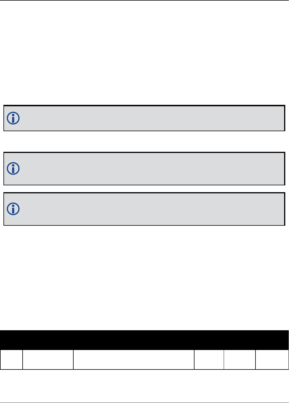
Chapter 5 SPAN Logs
OEM7 Commands and Logs Reference Manual v7 921
5.4 CORRIMUDATA
Corrected IMU Measurements
Platform: OEM719, OEM729, OEM7500, OEM7600, OEM7700, OEM7720, PwrPak7,
SPAN CPT7
The CORRIMUDATA log contains the RAWIMU data corrected for gravity, the earth’s rotation and
estimated sensor errors. The values in this log are incremental values, accumulated over the log-
ging interval of CORRIMUDATA, in units of radians for the attitude rate and m/s for the accel-
erations. Data output is not in the IMU Body frame, but is automatically rotated into the user
configured output frame (configured with the SETINSROTATION command (see page 896),
default Vehicle frame).
The short header format, CORRIMUDATAS, is recommended, as it is for all high data
rate logs.
CORRIMUDATA can be logged with the ONTIME trigger, up to a rate of 200 Hz.
Since the CORRIMUDATA log is synchronous, if you log at a rate less than full data rate
of the IMU, the corrected IMU data is accumulated to match the requested time interval.
For asynchronous, full rate data, see the IMURATECORRIMUS log on page929.
To obtain the instantaneous rates of acceleration (in m/s/s) or rotation (in rad/s) from
the output values of measurements per sample rate (m/s/sample and rad/sample), mul-
tiply the output values by the CORRIMUDATA logging rate in Hz.
Message ID: 812
Log Type: Synch
Recommended Input:
log corrimudatab ontime 0.01
Example log:
#CORRIMUDATAA,COM1,0,77.5,FINESTEERING,1769,237601.000,02000020,bdba,12597;1769
,237601.000000000,-
0.000003356,0.000002872,0.000001398,0.000151593,0.000038348,-
0.000078820*1f7eb709
Field Field Type Description Format Binary
Bytes
Binary
Offset
1CORRIMUDATA
Header
Log header. See Messages on page25
for more information. - H 0

Chapter 5 SPAN Logs
OEM7 Commands and Logs Reference Manual v7 922
Field Field Type Description Format Binary
Bytes
Binary
Offset
2 Week GNSS week Ulong 4 H+
3 Seconds GNSS seconds from week start Double 8 H+4
4 PitchRate About x axis rotation (right-handed)
(rad/sample) Double 8 H+12
5 RollRate About y axis rotation (right-handed)
(rad/sample) Double 8 H+20
6 YawRate About z axis rotation (right-handed)
(rad/sample) Double 8 H+28
7 LateralAcc INS Lateral Acceleration (along x axis)
(m/s/sample) Double 8 H+36
8 LongitudinalAcc INS Longitudinal Acceleration (along y
axis) (m/s/sample) Double 8 H+44
9 VerticalAcc INS Vertical Acceleration (along z axis)
(m/s/sample) Double 8 H+52
10 xxxx 32-bit CRC Hex 4 H+56
11 [CR][LF] Sentence Terminator (ASCII only) - - -

Chapter 5 SPAN Logs
OEM7 Commands and Logs Reference Manual v7 923
5.5 CORRIMUDATAS
Short Corrected IMU Measurements
Platform: OEM719, OEM729, OEM7500, OEM7600, OEM7700, OEM7720, PwrPak7,
SPAN CPT7
This log is the short header version of the CORRIMUDATA log (see page 921).
To obtain the instantaneous rates of acceleration (in m/s/s) or rotation (in rad/s) from
the output values of measurements per sample rate (m/s/sample and rad/sample), mul-
tiply the output values by the CORRIMUDATAS logging rate in Hz.
Message ID: 813
Log Type: Synch
Recommended Input:
log corrimudatasb ontime 0.01
Example log:
%CORRIMUDATASA,1581,341553.000;1581,341552.997500000,-0.000000690,-
0.000001549,0.000001654,0.000061579,-0.000012645,-0.000029988*770c6232
Field Field Type Description Format Binary
Bytes
Binary
Offset
1CORRIMUDATAS
Header
Log header. See Messages on page25
for more information. - H 0
2 Week GNSS week Ulong 4 H+
3 Seconds GNSS seconds from week start Double 8 H+4
4 PitchRate About x-axis rotation (right-handed)
(rad/sample) Double 8 H+12
5 RollRate About y-axis rotation (right-handed)
(rad/sample) Double 8 H+20
6 YawRate About z-axis rotation (right-handed)
(rad/sample) Double 8 H+28
7 LateralAcc INS Lateral Acceleration (along x-axis)
(m/s/sample) Double 8 H+36
8 LongitudinalAcc INS Longitudinal Acceleration (along y-
axis) (m/s/sample) Double 8 H+44
9 VerticalAcc INS Vertical Acceleration (along z-axis)
(m/s/sample) Double 8 H+52

Chapter 5 SPAN Logs
OEM7 Commands and Logs Reference Manual v7 924
Field Field Type Description Format Binary
Bytes
Binary
Offset
10 xxxx 32-bit CRC Hex 4 H+56
11 [CR][LF] Sentence Terminator (ASCII only) - - -

Chapter 5 SPAN Logs
OEM7 Commands and Logs Reference Manual v7 925
5.6 DELAYEDHEAVE
Delayed Heave Filter
Platform: OEM719, OEM729, OEM7500, OEM7600, OEM7700, OEM7720, PwrPak7,
SPAN CPT7
This log contains the value of the delayed heave filter. The delayed heave value differs from the
heave value in that delayed heave uses forward and backward smoothing, while heave uses
backward smoothing only.
The heave filter must be enabled using the HEAVEFILTER command (see page 870) before this
log is available.
The DELAYEDHEAVE log is output with default values and the current time stamp when
the HEAVEFILTER is DISABLED.
When the HEAVEFILTER is ENABLED, the DELAYEDHEAVE log will not be output until the
heave window conditions (see the SETHEAVEWINDOW command on page889) have
been met.
Message ID: 1709
Log Type: Synch
Recommended Input:
log delayedheavea ontime 0.1
ASCII example:
#DELAYEDHEAVEA,COM1,0,72.0,FINESTEERING,1769,237598.000,02000020,27a3,12597;0.0
00080643,0.086274510*85cdb46d
Field Field Type Description Format Binary
Bytes
Binary
Offset
1DELAYEDHEAVE
Header
Log header. See Messages on page25
for more information. - H 0
2 Delayed Heave Delayed heave value Double 8 H
3 Std. Dev. Standard deviation of the delayed
heave value Double 8 H+8
4 xxxx 32-bit CRC (ASCII and Binary only) Hex 4 H+16
5 [CR][LF] Sentence Terminator (ASCII only) - - -

Chapter 5 SPAN Logs
OEM7 Commands and Logs Reference Manual v7 926
5.7 GIMBALLEDPVA
Display Gimballed Position
Platform: OEM719, OEM729, OEM7500, OEM7600, OEM7700, OEM7720, PwrPak7,
SPAN CPT7
Use the GIMBALLEDPVA log to view the re-calculated position, velocity and attitude of the gim-
bal null position whenever a new INPUTGIMBALANGLE command (see page 871) is received.
Message ID: 1321
Log Type: Asynch
Recommended Input:
log gimballedpvaa onnew
ASCII Example:
#GIMBALLEDPVAA,COM1,0,93.5,FINESTEERING,1635,320568.514,02000000,0000,407;1635,
320568.514000000,51.116376614,-114.038259915,1046.112025828,-0.000291756,-
0.000578067,0.030324466,-0.243093917,-0.127718304,19.495023227, INS_ALIGNMENT_
COMPLETE*32fbb61b
Field Field Type Description Format Binary
Bytes
Binary
Offset
1GIMBALLEDPVA
Header
Log header. See Messages on page25 for
more information. - H 0
2 Week GPS week Ulong 4 H
3 Seconds Seconds from week start Double 8 H+4
4 Latitude WGS84 latitude in degrees Double 8 H+12
5 Longitude WGS84 longitude in degrees Double 8 H+20
6 Height WGS84 ellipsoidal height Double 8 H+28
7 North Velocity Velocity in a northerly direction Double 8 H+36
8 East Velocity Velocity in an easterly direction Double 8 H+44
9 Up Velocity Velocity in an upward direction Double 8 H+52
10 Roll Right-handed rotation from local level
around the y-axis in degrees Double 8 H+60
11 Pitch Right-handed rotation from local level
around the x-axis in degrees Double 8 H+68
12 Azimuth Right-handed rotation from local level
around the z-axis in degrees Double 8 H+76


Chapter 5 SPAN Logs
OEM7 Commands and Logs Reference Manual v7 928
5.8 HEAVE
Heave Filter Log
Platform: OEM719, OEM729, OEM7500, OEM7600, OEM7700, OEM7720, PwrPak7,
SPAN CPT7
This log provides vessel heave computed by the integrated heave filter. Refer also to inform-
ation in the SETHEAVEWINDOW command on page889. This log is asynchronous, but is avail-
able at approximately 10 Hz.
You must have an inertial solution to use this log.
The heave filter must be enabled using the HEAVEFILTER command (see page 870), before this
log is available.
Message ID: 1382
Log Type: Asynch
Recommended Input:
log heavea onnew
Example:
#HEAVEA,USB1,0,38.5,FINESTEERING,1630,232064.599,02000000,a759,6696;1630,232064
.589885392,0.086825199*93392cb4
Field Field Type Description Format Binary
Bytes
Binary
Offset
1HEAVE
Header
Log header. See Messages on page25 for
more information. - H 0
2 Week GNSS Week Ulong 4 H
3Seconds into
Week Seconds from week start Double 8 H+4
4 Heave Instantaneous heave in metres Double 8 H+12
5 xxxx 32-bit CRC (ASCII, Binary and Short
Binary only) Hex 4 H+20
6 [CR][LF] Sentence Terminator (ASCII Only) - - -
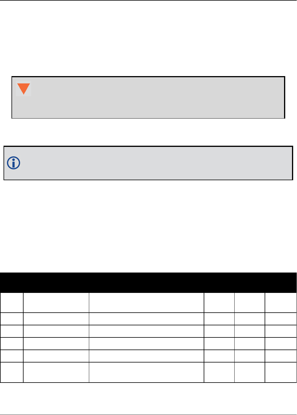
Chapter 5 SPAN Logs
OEM7 Commands and Logs Reference Manual v7 929
5.9 IMURATECORRIMUS
Asynchronous Corrected IMU Data
Platform: OEM719, OEM729, OEM7500, OEM7600, OEM7700, OEM7720, PwrPak7,
SPAN CPT7
This log provides the same information as the CORRIMUDATAS log (see page 923), but is avail-
able asynchronously at the full rate of the IMU.
Using this log consumes significant system resources and should only be used by
experienced users.
However, using this log consumes less resources than logging the synchronous
CORRIMUDATAS log at the same rate.
To use this log, asynchronous logging must be enabled. See the ASYNCHINSLOGGING com-
mand on page863.
To obtain the instantaneous rates of acceleration (in m/s/s) or rotation (in rad/s) from
the output values of measurements per sample rate (m/s/sample and rad/sample), mul-
tiply the output values by the IMU data rate in Hz.
Message ID: 1362
Log Type: Asynch
Recommended Input:
log imuratecorrimus
Example log:
%IMURATECORRIMUSA,1581,341553.000;1581,341552.997500000,-0.000000690,-
0.000001549,0.000001654,0.000061579,-0.000012645,-0.000029988*770c6232
Field Field Type Description Format Binary
Bytes
Binary
Offset
1IMURATECORRIMUS
Header
Log header. See Messages on
page25 for more information. - H 0
2 Week GNSS week Ulong 4 H+
3 Seconds GNSS seconds from week start Double 8 H+4
4 PitchRate About x axis rotation (rad/sample) Double 8 H+12
5 RollRate About y axis rotation (rad/sample) Double 8 H+20
6 YawRate About z axis rotation (right-handed)
(rad/sample) Double 8 H+28

Chapter 5 SPAN Logs
OEM7 Commands and Logs Reference Manual v7 930
Field Field Type Description Format Binary
Bytes
Binary
Offset
7 LateralAcc INS Lateral Acceleration (along x-
axis) (m/s/sample) Double 8 H+36
8 LongitudinalAcc INS Longitudinal Acceleration (along
y-axis) (m/s/sample) Double 8 H+44
9 VerticalAcc INS Vertical Acceleration (along z-
axis)(m/s/sample) Double 8 H+52
10 xxxx 32-bit CRC Hex 4 H+56
11 [CR][LF] Sentence Terminator (ASCII only) - - -

Chapter 5 SPAN Logs
OEM7 Commands and Logs Reference Manual v7 931
5.10 IMURATEPVA
Asynchronous INS Position, Velocity and Attitude
This log provides the same information as the INSPVA log (see page 955), but is available asyn-
chronously at the full rate of the IMU.
Using this log consumes significant system resources and should only be used by
experienced users.
However, using this log consumes less resources than logging the synchronous INSPVA
log at the same rate.
To use this log, asynchronous logging must be enabled. See the ASYNCHINSLOGGING com-
mand on page863.
Message ID: 1778
Log Type: Asynch
Recommended Input:
log imuratepvaa onnew
ASCII Example:
#IMURATEPVAA,COM1,0,57.0,FINESTEERING,1802,320345.180,02000000,9b1f,12987;1802,
320345.180000030,51.11695246671,-114.03897779953,1047.6905,-
0.2284,0.0076,0.2227,0.160588332,-0.039823409,269.988184416,INS_ALIGNMENT_
COMPLETE*f60016a6
Field Field Type Description Format Binary
Bytes
Binary
Offset
1IMURATEPVA
Header
Log header. See Messages on page25
for more information. - H 0
2 Week GNSS Week Ulong 4 H
3 Seconds Seconds from week start Double 8 H+4
4 Latitude Latitude (WGS84) [degrees] Double 8 H+12
5 Longitude Longitude (WGS84) [degrees] Double 8 H+20
6 Height Ellipsoidal Height (WGS84) [m] Double 8 H+28
7North
Velocity
Velocity in a northerly direction (a -ve
value implies a southerly direction)
[m/s]
Double 8 H+36
8 East Velocity Velocity in an easterly direction (a -ve
value implies a westerly direction) [m/s] Double 8 H+44

Chapter 5 SPAN Logs
OEM7 Commands and Logs Reference Manual v7 932
Field Field Type Description Format Binary
Bytes
Binary
Offset
9 Up Velocity Velocity in an up direction [m/s] Double 8 H+52
10 Roll Right-handed rotation from local level
around y-axis in degrees Double 8 H+60
11 Pitch Right-handed rotation from local level
around x-axis in degrees Double 8 H+68
12 Azimuth
Left-handed rotation around z-axis in
degrees clockwise from North
This is the inertial azimuth calculated
from the IMU gyros and the SPAN filters.
Double 8 H+76
13 Status INS Status, see Table 198: Inertial
Solution Status on page936 Enum 4 H+84
14 xxxx 32-bit CRC Hex 4 H+88
15 [CR][LF] Sentence Terminator (ASCII only) - - -

Chapter 5 SPAN Logs
OEM7 Commands and Logs Reference Manual v7 933
5.11 IMURATEPVAS
Asynchronous INS Position, Velocity and Attitude
Platform: OEM719, OEM729, OEM7500, OEM7600, OEM7700, OEM7720, PwrPak7,
SPAN CPT7
This log provides the same information as the INSPVAS log (see page 957), but is available
asynchronously at the full rate of the IMU.
Using this log consumes significant system resources and should only be used by
experienced users.
However, using this log consumes less resources than logging the synchronous INSPVAS
log at the same rate.
To use this log, asynchronous logging must be enabled. See the ASYNCHINSLOGGING com-
mand on page863.
Message ID: 1305
Log Type: Asynch
Recommended Input:
log imuratepvas
ASCII Example:
%IMURATEPVASA,1264,144059.000;1264,144059.002135700,51.116680071,-
114.037929194,515.286704183,277.896368884,84.915188605,-
8.488207941,0.759619515,-2.892414901,6.179554750,INS_ALIGNMENT_
COMPLETE*855d6f76
Field Field Type Description Format Binary
Bytes
Binary
Offset
1IMURATEPVAS
Header
Log header. See Messages on page25 for
more information. - H 0
2 Week GNSS Week Ulong 4 H
3 Seconds Seconds from week start Double 8 H+4
4 Latitude Latitude (WGS84) Double 8 H+12
5 Longitude Longitude (WGS84) Double 8 H+20
6 Height Ellipsoidal Height (WGS84) [m] Double 8 H+28
7 North Velocity Velocity in a northerly direction (a -ve value
implies a southerly direction) [m/s] Double 8 H+36

Chapter 5 SPAN Logs
OEM7 Commands and Logs Reference Manual v7 934
Field Field Type Description Format Binary
Bytes
Binary
Offset
8 East Velocity Velocity in an easterly direction (a -ve value
implies a westerly direction) [m/s] Double 8 H+44
9 Up Velocity Velocity in an up direction [m/s] Double 8 H+52
10 Roll Right-handed rotation from local level
around y-axis in degrees Double 8 H+60
11 Pitch Right-handed rotation from local level
around x-axis in degrees Double 8 H+68
12 Azimuth Left-handed rotation around z-axis in
degrees clockwise from North Double 8 H+76
13 Status INS Status, see Table 198: Inertial Solution
Status on page936 Enum 4 H+84
14 xxxx 32-bit CRC Hex 4 H+88
15 [CR][LF] Sentence Terminator (ASCII only) - - -

Chapter 5 SPAN Logs
OEM7 Commands and Logs Reference Manual v7 935
5.12 INSATT
INS Attitude
Platform: OEM719, OEM729, OEM7500, OEM7600, OEM7700, OEM7720, PwrPak7,
SPAN CPT7
This log contains the most recent attitude measurements computed by the SPAN filter. This atti-
tude definition may not correspond to other definitions of the terms pitch, roll and azimuth. By
default, the output attitude is with respect to the vehicle frame. If the attitude output is desired
with respect to another frame of reference, use the SETINSROTATION USER command (see
the SETINSROTATION command on page896) to configure the user output frame offset rota-
tion.
Message ID: 263
Log Type: Synch
Recommended Input:
log insatta ontime 1
ASCII Example:
#INSATTA,USB2,0,14.5,FINESTEERING,1541,487970.000,02040000,5b35,37343;1541,4879
70.000549050,1.876133508,-4.053672765,328.401460897,INS_SOLUTION_GOOD*ce4ac533
Field Field
Type Description Format Binary
Bytes
Binary
Offset
1INSATT
Header
Log header. See Messages on page25 for more
information. - H 0
2 Week GNSS Week Ulong 4 H
3Seconds
into Week Seconds from week start Double 8 H+4
4 Roll Right-handed rotation from local level around
y-axis in degrees. Double 8 H+12
5 Pitch Right-handed rotation from local level around
x-axis in degrees. Double 8 H+20
6 Azimuth
Left-handed rotation around z-axis in degrees
clockwise from North.
This is the inertial azimuth calculated from the
IMU gyros and the SPAN filters.
Double 8 H+28
7 Status INS status, see Table 198: Inertial Solution
Status on the next page. Enum H+36
8 xxxx 32-bit CRC (ASCII, Binary and Short Binary
only) Hex H+40
9 [CR][LF] Sentence terminator (ASCII only) - - -

Chapter 5 SPAN Logs
OEM7 Commands and Logs Reference Manual v7 936
Binary ASCII Description
0 INS_INACTIVE IMU logs are present, but the alignment routine has not started; INS is
inactive.
1 INS_ALIGNING INS is in alignment mode.
2INS_HIGH_
VARIANCE
The INS solution is in navigation mode but the azimuth solution
uncertainty has exceeded the threshold. The default threshold is 2
degrees for most IMUs. The solution is still valid but you should
monitor the solution uncertainty in the INSSTDEV log (see page 968).
You may encounter this state during times when the GNSS, used to aid
the INS, is absent.
The INS solution uncertainty contains outliers and the solution
may be outside specifications.1The solution is still valid but you
should monitor the solution uncertainty in the INSSTDEV log (see
page 968). It may be encountered during times when GNSS is
absent or poor.
3
INS_
SOLUTION_
GOOD
The INS filter is in navigation mode and the INS solution is good.
6
INS_
SOLUTION_
FREE
The INS filter is in navigation mode and the GNSS solution is suspected
to be in error.
This may be due to multipath or limited satellite visibility. The inertial
filter has rejected the GNSS position and is waiting for the solution
quality to improve.
7
INS_
ALIGNMENT_
COMPLETE
The INS filter is in navigation mode, but not enough vehicle dynamics
have been experienced for the system to be within specifications.
8DETERMINING_
ORIENTATION INS is determining the IMU axis aligned with gravity.
9WAITING_
INITIALPOS
The INS filter has determined the IMU orientation and is awaiting an
initial position estimate to begin the alignment process.
10 WAITING_
AZIMUTH
The INS filer has orientation, initial biases, initial position and valid
roll/pitch estimated. Will not proceed until initial azimuth is entered.
11 INITIALIZING_
BIASES
The INS filter is estimating initial biases during the first 10 seconds of
stationary data.
12 MOTION_
DETECT The INS filter has not completely aligned, but has detected motion.
Table 198: Inertial Solution Status
1The solution uncertainty threshold levels can be adjusted using the INSTHRESHOLDS command on page882.

Chapter 5 SPAN Logs
OEM7 Commands and Logs Reference Manual v7 937
5.13 INSATTQS
Short INS Quaternion Attitude
Platform: OEM719, OEM729, OEM7500, OEM7600, OEM7700, OEM7720, PwrPak7,
SPAN CPT7
This log contains the attitude from the INSATT log, but the rotation from local level is given as a
Quaternion rather than Euler Angles. The quaternion takes the form:
The element w is the rotational component, defining the magnitude of the rotation to be per-
formed. The elements x, y, and z are the vector portion of the rotation, which define the axis
about which the rotation is to be performed.
If θ is the rotational angle, and the axis of rotation is defined by the vector , then
the elements of the quaternion can be written as:
Message ID: 2118
Log Type: Synch
Recommended Input:
log insattqsa ontime 1
ASCII Example:
%INSATTQSA,1943,425090.000;1943,425090.000000000,0.706276782,0.001974400,-
0.001083571,-0.707932225,INS_ALIGNMENT_COMPLETE*552d93f0
Field Field Type Description Format Binary
Bytes
Binary
Offset
1INSATTQS
Header
Log header. See Messages on page25 for
more information. - H 0
2 Week GNSS Week Ulong 4 H
3Seconds into
Week Seconds from week start Double 8 H+4
4 Quaternionw Quaternion rotation from local level, w
component Double 8 H+12

Chapter 5 SPAN Logs
OEM7 Commands and Logs Reference Manual v7 938
Field Field Type Description Format Binary
Bytes
Binary
Offset
5 Quaternion x Quaternion rotation from local level, x
component Double 8 H+20
6 Quaternion y Quaternion rotation from local level, y
component Double 8 H+28
7 Quaternion z Quaternion rotation from local level, z
component Double 8 H+36
8 Status INS status, see Table 198: Inertial
Solution Status on page936 Enum 4 H+44
9 xxxx 32-bit CRC (ASCII, Binary and Short
Binary only) Hex 4 H+48
10 [CR][LF] Sentence Terminator (ASCII only) - - -

Chapter 5 SPAN Logs
OEM7 Commands and Logs Reference Manual v7 939
5.14 INSATTS
Short INS Attitude
Platform: OEM719, OEM729, OEM7500, OEM7600, OEM7700, OEM7720, PwrPak7,
SPAN CPT7
This log is the short header version of the INSATT log (see page 935).
Message ID: 319
Log Type: Synch
Recommended Input:
log insattsa ontime 1
ASCII Example:
%INSATTSA,1541,487975.000;1541,487975.000549050,2.755452422,-
4.127365126,323.289778434,INS_SOLUTION_GOOD*ba08754f
Field Field
Type Description Format Binary
Bytes
Binary
Offset
1INSATTS
Header
Log header. See Messages on page25 for more
information. - H 0
2 Week GNSS Week Ulong 4 H
3Seconds
into Week Seconds from week start Double 8 H+4
4 Roll Right-handed rotation from local level around
y-axis in degrees Double 8 H+12
5 Pitch Right-handed rotation from local level around
x-axis in degrees Double 8 H+20
6 Azimuth
Left-handed rotation around z-axis in degrees
clockwise from North
This is the inertial azimuth calculated from the
IMU gyros and the SPAN filters.
Double 8 H+28
7 Status INS status, see Table 198: Inertial Solution
Status on page936 Enum 4 H+36
8 xxxx 32-bit CRC (ASCII, Binary and Short Binary
only) Hex 4 H+40
9 [CR][LF] Sentence terminator (ASCII only) - - -

Chapter 5 SPAN Logs
OEM7 Commands and Logs Reference Manual v7 940
5.15 INSATTX
Inertial Attitude – Extended
Platform: OEM719, OEM729, OEM7500, OEM7600, OEM7700, OEM7720, PwrPak7,
SPAN CPT7
This log includes the information from the INSATT log (see page 935), as well as information
about the attitude standard deviation. The position type and solution status fields indicate
whether or not the corresponding data is valid.
The INSATTX log is a large log and is not recommend for high rate logging.
If you want to use high rate logging, log the INSATTS log at a high rate and the
INSSTDEVS log ontime 1.
Message ID: 1457
Log Type: Synch
Recommended Input:
log insattxa ontime 1
ASCII Example:
#INSATTXA,COM1,0,81.0,FINESTEERING,1690,494542.000,02000040,5d25,43441;INS_
ALIGNMENT_COMPLETE,INS_PSRSP,1.137798832,-
0.163068414,135.754208544,0.017797431,0.017861038,3.168394804,4,0*f944b004
Field Field
Type Description Format Binary
Bytes
Binary
Offset
1INSATTX
Header
Log header. See Messages on page25 for more
information. H 0
2 INS Status
Solution status
See Table 198: Inertial Solution Status on
page936
Enum 4 H
3 Pos Type
Position type
See Table 74: Position or Velocity Type on
page432
Enum 4 H+4
4 Roll Roll in Local Level (degrees) Double 8 H+8
5 Pitch Pitch in Local Level (degrees) Double 8 H+16
6 Azimuth
Azimuth in Local Level (degrees)
This is the inertial azimuth calculated from the
IMU gyros and the SPAN filters.
Double 8 H+24
7 Roll σ Roll standard deviation (degrees) Float 4 H+32

Chapter 5 SPAN Logs
OEM7 Commands and Logs Reference Manual v7 941
Field Field
Type Description Format Binary
Bytes
Binary
Offset
8 Pitch σ Pitch standard deviation (degrees) Float 4 H+36
9 Azimuth σ Azimuth standard deviation (degrees) Float 4 H+40
10 Ext sol
stat
Extended solution status
See Table 199: Extended Solution Status
below
Hex 4 H+44
11
Time
Since
Update
Elapsed time since the last ZUPT or position
update (seconds) Ushort 2 H+48
11 xxxx 32-bit CRC (ASCII and Binary only) Hex 4 H+50
12 [CR][LF] Sentence terminator (ASCII only) - - -
Nibble Bit Mask Description Range Value
N0
0 0x00000001 Position update 0 = Unused
1 = Used
1 0x00000002 Phase update 0 = Unused
1 = Used
2 0x00000004 Zero velocity update 0 = Unused
1 = Used
3 0x00000008 Wheel sensor update 0 = Unused
1 = Used
N1
4 0x00000010 ALIGN (heading)
update
0 = Unused
1 = Used
5 0x00000020 External position
update
0 = Unused
1 = Used
6 0x00000040 INS solution
convergence flag
0 = Not converged
1 = Converged
7 0x00000080 Doppler update 0 = Unused
1 = Used
Table 199: Extended Solution Status

Chapter 5 SPAN Logs
OEM7 Commands and Logs Reference Manual v7 942
Nibble Bit Mask Description Range Value
N2
8 0x00000100 Pseudorange update 0 = Unused
1 = Used
9 0x00000200 Velocity update 0 = Unused
1 = Used
10 0x00000400 Reserved
11 0x00000800 Dead reckoning
update
0 = Unused
1 = Used
N3
12 0x00001000 Phase wind up update 0 = Unused
1 = Used
13 0x00002000 Course over ground
update
0 = Unused
1 = Used
14 0x00004000 External velocity
update
0 = Unused
1 = Used
15 0x00008000 External attitude
update
0 = Unused
1 = Used
N4
16 0x00010000 External heading
update
0 = Unused
1 = Used
17 0x00020000 External height
update
0 = Unused
1 = Used
18 0x00040000 Reserved
19 0x00080000 Reserved
N5
20 0x00100000 Rover position update 0 = Unused
1 = Used
21 0x00200000 Rover position update
type
0 = Non-RTK update
1 = RTK integer update
22 0x00400000 Reserved
23 0x00800000 Reserved

Chapter 5 SPAN Logs
OEM7 Commands and Logs Reference Manual v7 943
Nibble Bit Mask Description Range Value
N6
24 0x01000000 Turn on biases
estimated
0 = Static turn-on biases not estimated
(starting from zero)
1 = Static turn-on biases estimated
25 0x02000000 Alignment direction
verified
0 = Not verified
1 = Verified
26 0x04000000 Alignment Indication
1
0 = Not set, 1 = Set
Refer to Table 200: Alignment Indication
below
27 0x08000000 Alignment Indication
2
0 = Not set, 1 = Set
Refer to Table 200: Alignment Indication
below
N7
28 0x10000000 Alignment Indication
3
0 = Not set, 1 = Set
Refer to Table 200: Alignment Indication
below
29 0x20000000 NVM Seed Indication
1
0 = Not set, 1 = Set
Refer to Table 201: NVM Seed Indication on
the next page
30 0x40000000 NVM Seed Indication
2
0 = Not set, 1 = Set
Refer to Table 201: NVM Seed Indication on
the next page
31 0x80000000 NVM Seed Indication
3
0 = Not set, 1 = Set
Refer to Table 201: NVM Seed Indication on
the next page
Bits 26-28 Values Hex Value Completed Alignment Type
000 0x00 Incomplete Alignment
001 0x01 Static
010 0x02 Kinematic
011 0x03 Dual Antenna
100 0x04 User Command
101 0x05 NVM Seed
Table 200: Alignment Indication

Chapter 5 SPAN Logs
OEM7 Commands and Logs Reference Manual v7 944
Bit 29-
31
Values
Hex
Value NVM Seed Type
000 0x00 NVM Seed Inactive
001 0x01 Seed stored in NVM is invalid
010 0x02 NVM Seed failed validation check
011 0x03 NVM Seed is pending validation (awaiting GNSS)
100 0x04 NVM Seed Injected (includes error model data)
101 0x05 NVM Seed data ignored due to a user-commanded filter reset or
configuration change
110 0x06 NVM Seed error model data injected
Table 201: NVM Seed Indication

Chapter 5 SPAN Logs
OEM7 Commands and Logs Reference Manual v7 945
5.16 INSCALSTATUS
Offset calibration status
Platform: OEM719, OEM729, OEM7500, OEM7600, OEM7700, OEM7720, PwrPak7,
SPAN CPT7
This log reports the status and estimated values of the currently running offset calibration.
Message ID: 1961
Log Type: Asynch
Abbreviated ASCII Syntax:
log inscalstatus onchanged
ASCII Example:
#INSCALSTATUSA,COM1,0,80.0,FINESTEERING,1880,317815.012,02000000,a4f2,32768;RBV
,0.0000,-180.0000,-90.0000,45.0000,45.0000,45.0000,INS_CONVERGING,1*e0b3152d
Field Field Type Description Binary
Format
Binary
Bytes
Binary
Offset
1INSCALSTATUS
header
Log header. See Messages on page25 for
more information. - H 0
2 Offset Type Type of offset (see Table 202: Offset Type
on the next page). Enum 4 H
3 X axis offset IMU body frame X-axis offset (m/degrees). Float 4 H+4
4 Y axis offset IMU body frame Y-axis offset (m/degrees). Float 4 H+8
5 Z axis offset IMU body frame Z-axis offset (m/degrees). Float 4 H+12
6 X uncertainty IMU body frame X-axis offset uncertainty
(m/degrees). Float 4 H+16
7 Y uncertainty IMU body frame Y-axis offset uncertainty
(m/degrees). Float 4 H+20
8 Z uncertainty IMU body frame Z-axis offset uncertainty
(m/degrees). Float 4 H+24
9 Source Status
Source from which offset values originate
(see Table 203: Source Status on the next
page).
Enum 4 H+28
10
Multi-line
Calibration
Count
Counter for number of completed
calibrations cumulatively averaged. Ulong 4 H+32
11 xxxx 32-bit CRC (ASCII and Binary only). Hex 4 H+36
12 [CR][LF] Sentence terminator (ASCII only). - - -

Chapter 5 SPAN Logs
OEM7 Commands and Logs Reference Manual v7 946
Units for the axis offset and uncertainty values (fields 3-8) are in metres for trans-
lational offset components and degrees for rotational offset components.
Binary ASCII Description
1 ANT1 Primary IMU to antenna lever arm
8 ALIGN Align offset
11 RBV IMU body to vehicle offset
Table 202: Offset Type
Binary ASCII Description
1 FROM_NVM Offset values originate from saved parameters in NVM
2 CALIBRATING Offset values originate from a currently running calibration process
3 CALIBRATED Offset values originate from a completed calibration process
4FROM_
COMMAND Offset values originate from a user command
5 RESET Offset values originate from a system reset
6FROM_DUAL_
ANT Offset values originate from a dual antenna Align solution
7INS_
CONVERGING
Offset values originate from initial input values. Calibration process on
hold until INS solution is converged.
8INSUFFICIENT_
SPEED
Offset values originate from a currently running calibration process.
Further estimation on hold due to insufficient speed.
9HIGH_
ROTATION
Offset values originate from a currently running calibration process.
Further estimation on hold due to high vehicle rotations.
Table 203: Source Status

Chapter 5 SPAN Logs
OEM7 Commands and Logs Reference Manual v7 947
5.17 INSCONFIG
Determine required settings for post-processing or system analysis
Platform: OEM719, OEM729, OEM7500, OEM7600, OEM7700, OEM7720, PwrPak7,
SPAN CPT7
This log is the single message required to determine all required settings for post-processing or
system analysis. This log is asynchronous and published for any change to the included fields. It
is intended to be recorded occasionally though it could be updated frequently at system startup.
Message ID: 1945
Log Type: Polled
Recommended Input:
log insconfig onchanged
ASCII Example:
#INSCONFIGA,COM1,0,71.0,COARSESTEERING,1931,517331.006,02400000,6d7a,
32768;EPSON_G320,6,50,20,DEFAULT,00ffd1bf,AUTOMATIC,ROVER,FALSE,
00000000,0,0,0,0,0,0,0,0,0,1,ANT1,IMUBODY,0.0540,0.0699,-0.0346,0.0200,
0.0200,0.0200,FROM_NVM,1,RBV,IMUBODY,180.0000,0.0000,90.0000,5.0000,
5.0000,5.0000,FROM_COMMAND*b1233ac4
Field Field Type Description Binary
Format
Binary
Bytes
Binary
Offset
1INSCONFIG
Header
Command header. See Messages on
page25 for more information. - H 0
2 IMU Type IMU type Enum 4 H
3 Mapping Mapping / Orientation Uchar 1 H+4
4
Initial
Alignment
Velocity
Minimum Alignment Velocity entered by
the user.
Note: Velocity (m/s) is scaled by 10 for
10cm/s precision
Uchar 1 H+5
5Heave
Window
Length of the heave window in seconds (if
set) Ushort 2 H+6
6 Profile Profile setting (see the SETINSPROFILE
command on page894) Enum 4 H+8
7Enabled
Updates Enabled update types Hex 4 H+12
8Alignment
Mode
Alignment mode configured on the system
(see the ALIGNMENTMODE command on
page861)
Enum 4 H+16

Chapter 5 SPAN Logs
OEM7 Commands and Logs Reference Manual v7 948
Field Field Type Description Binary
Format
Binary
Bytes
Binary
Offset
9
Relative INS
Output
Frame
The user specified output frame of the
Relative INS Vector (see
SETRELINSOUTPUTFRAME command
on page904)
If not specified, the default value
appears.
Enum 4 H+20
10
Relative INS
Output
Direction
The User specified Output direction of the
Relative INS Vector (From or To Master-
Rover) (see the
SETRELINSOUTPUTFRAME command
on page904).
If not specified, the default value
appears. TRUE if From Master, FALSE
(Default) if From Rover
Bool 4 H+24
11 INS Receiver
Status
Lower byte- INS Reset. Corresponds
numerically to the INS Reset as described
by the INSResetEnum
Second byte-
= 0x01 if an IMU Communication Error
(Receiver status bit 17).
= 0x00 otherwise.
Other values are reserved for future use.
Upper 2 bytes - reserved.
Hex 4 H+28
12 INS Seed
Enabled
INS Seed Enable setting
(see the INSSEED command on
page880)
Enabled = 1, Disabled = 0
Uchar 1 H+32
13 INS Seed
Validation
INS Seed Validation setting
(see the INSSEED command on
page880)
Uchar 1 H+33
14 Reserved 1 N/A 2 H+34
15 Reserved 2 N/A 4 H+36
16 Reserved 3 N/A 4 H+40
17 Reserved 4 N/A 4 H+44
18 Reserved 5 N/A 4 H+48
19 Reserved 6 N/A 4 H+52

Chapter 5 SPAN Logs
OEM7 Commands and Logs Reference Manual v7 949
Field Field Type Description Binary
Format
Binary
Bytes
Binary
Offset
20 Reserved 7 N/A 4 H+56
21 Number of
Translations Number of translation entries to follow Ulong 4 H+60
22 Translation Translation to follow (see Table 196:
Translation Offset Types on page900) Enum 4 variable
23 Frame Frame of translation (IMUBODY or
VEHICLE) Enum 4 variable
24 X Offset X Offset Float 4 variable
25 Y Offset Y Offset Float 4 variable
26 Z Offset Z Offset Float 4 variable
27 XUncertainty X Uncertainty Float 4 variable
28 YUncertainty Y Uncertainty Float 4 variable
29 ZUncertainty Z Uncertainty Float 4 variable
30 Translation
Source
Source of translation (see Table 203:
Source Status on page946) Enum 4 variable
Next Translation
variable Number of
Rotations Number of rotation entries to follow Ulong 4 variable
variable Rotation Rotation to follow (see Table 195:
Rotational Offset Types on page897) Enum 4 variable
variable Frame Frame of rotation (IMUBODY or VEHICLE) Enum 4 variable
variable X Rotation X Rotation Float 4 variable
variable Y Rotation Y Rotation Float 4 variable
variable Z Rotation Z Rotation Float 4 variable
variable X Rotation
Std Dev
X Rotation offset standard deviation
(degrees) Float 4 variable
variable Y Rotation
STD Dev
Y Rotation offset standard deviation
(degrees) Float 4 variable
variable Z Rotation
STD Dev
Z Rotation offset standard deviation
(degrees) Float 4 variable

Chapter 5 SPAN Logs
OEM7 Commands and Logs Reference Manual v7 950
Field Field Type Description Binary
Format
Binary
Bytes
Binary
Offset
variable Rotation
Source
Source of rotation (see Table 203: Source
Status on page946) Enum 4 variable
Next Rotation
variable xxxx 32-bit CRC (ASCII and Binary only) Hex 4 variable
[CR][LF] Sentence terminator (ASCII only) - - -

Chapter 5 SPAN Logs
OEM7 Commands and Logs Reference Manual v7 951
5.18 INSPOS
INS Position
Platform: OEM719, OEM729, OEM7500, OEM7600, OEM7700, OEM7720, PwrPak7,
SPAN CPT7
This log contains the most recent position measurements in WGS84 coordinates and includes an
INS status indicator. The log reports the position at the IMU center, unless the
SETINSTRANSLATION USER command was issued. See the SETINSTRANSLATION command
on page899.
This log provides the position information in WGS84.
Message ID: 265
Log Type: Synch
Recommended Input:
log insposa ontime 1
ASCII Example:
#INSPOSA,USB2,0,18.0,FINESTEERING,1541,487977.000,02040000,17cd,37343;1541,
487977.000549050,51.121315135,-114.042311349,1038.660737046,INS_SOLUTION_GOOD
*2fffd557
Field Field Type Description Format Binary
Bytes
Binary
Offset
1INSPOS
Header
Log header. See Messages on page25 for
more information. - H 0
2 Week GNSS Week Ulong 4 H
3Seconds
into Week Seconds from week start Double 8 H+4
4 Latitude Latitude (WGS84) Double 8 H+12
5 Longitude Longitude (WGS84) Double 8 H+20
6 Height Ellipsoidal Height (WGS84) [m] Double 8 H+28
7 Status INS status, see Table 198: Inertial
Solution Status on page936 Enum 4 H+36
8 xxxx 32-bit CRC (ASCII, Binary and Short
Binary only) Hex 4 H+40
9 [CR][LF] Sentence terminator (ASCII only) - - -

Chapter 5 SPAN Logs
OEM7 Commands and Logs Reference Manual v7 952
5.19 INSPOSS
Short INS Position
Platform: OEM719, OEM729, OEM7500, OEM7600, OEM7700, OEM7720, PwrPak7,
SPAN CPT7
This log is the short header version of the INSPOS log (see page 951).
This log provides the position information in WGS84.
Message ID: 321
Log Type: Synch
Recommended Input:
log inspossa ontime 1
ASCII Example:
%INSPOSSA,1541,487916.000;1541,487916.000549050,51.115797277,-114.037811065,
1039.030700122,INS_SOLUTION_GOOD*5ca30894
Field Field Type Description Format Binary
Bytes
Binary
Offset
1INSPOSS
Header
Log header. See Messages on page25 for
more information. - H 0
2 Week GNSS Week Ulong 4 H
3Seconds
into Week Seconds from week start Double 8 H+4
4 Latitude Latitude (WGS84) Double 8 H+12
5 Longitude Longitude (WGS84) Double 8 H+20
6 Height Ellipsoidal Height (WGS84) [m] Double 8 H+28
7 Status INS status, see Table 198: Inertial
Solution Status on page936 Enum 4 H+36
8 xxxx 32-bit CRC (ASCII, Binary and Short
Binary only) Hex 4 H+40
9 [CR][LF] Sentence terminator (ASCII only) - - -
Chapter 5 SPAN Logs
OEM7 Commands and Logs Reference Manual v7 953
5.20 INSPOSX
Inertial Position – Extended
Platform: OEM719, OEM729, OEM7500, OEM7600, OEM7700, OEM7720, PwrPak7,
SPAN CPT7
This log includes the information from the INSPOS log, as well as information about the position
standard deviation. The position type and solution status fields indicate whether or not the cor-
responding data is valid.
The INSPOSX log is a large log and is not recommend for high rate logging.
If you want to use high rate logging, log the INSPOSS log at a high rate and the
INSSTDEVS log ontime 1.
This log provides the position information in the user datum.
To determine the datum being used, log the BESTPOS log.
Message ID: 1459
Log Type: Synch
Recommended Input:
log insposxa ontime 1
ASCII example:
#INSPOSXA,COM1,0,79.0,FINESTEERING,1690,493465.000,02000040,7211,43441;INS_
SOLUTION_GOOD,INS_PSRSP,51.11637750859,-
114.03826206294,1049.1191,0.4883,0.4765,0.8853,3,0*dee048ab
Field Field Type Description Format Binary
Bytes
Binary
Offset
1INSPOSX
Header
Log header. See Messages on page25 for
more information. H 0
2 INS Status
Solution status
See Table 198: Inertial Solution Status on
page936
Enum 4 H
3 Pos Type
Position type
See Table 74: Position or Velocity Type
on page432
Enum 4 H+4
4 Lat Latitude Double 8 H+8
5 Long Longitude Double 8 H+16
6 Height Height above sea level (m) Double 8 H+24

Chapter 5 SPAN Logs
OEM7 Commands and Logs Reference Manual v7 954
Field Field Type Description Format Binary
Bytes
Binary
Offset
7 Undulation Undulation (m) Float 4 H+32
8 Lat σ Latitude standard deviation Float 4 H+36
9 Long σ Longitude standard deviation Float 4 H+34
10 Height σ Height standard deviation Float 4 H+44
11 Ext sol stat
Extended solution status
See Table 199: Extended Solution Status
on page941
Hex 4 H+48
11 Time Since
Update
Elapsed time since the last ZUPT or
position update (seconds) Ushort 2 H+52
12 xxxx 32-bit CRC (ASCII and Binary only) Hex 4 H+54
13 [CR][LF] Sentence terminator (ASCII only) - - -
The INS covariance and standard deviation values reported by the SPAN filter are an
estimate of the Inertial filter solution quality. In lower accuracy GNSS position modes,
such as SINGLE or WAAS (see Table 74: Position or Velocity Type on page432), the pos-
ition covariance and standard deviation values can appear to become optimistic com-
pared with the absolute GNSS accuracy. This is due to the INS filter’s ability to smooth
short term noise in the GNSS solution, although the overall position error envelope still
reflects the GNSS accuracy. Therefore, if the desired application requires absolute GNSS
position accuracy, it is recommended to also monitor GNSS position messages such as
BESTGNSSPOS (see BESTGNSSPOS log on page916).

Chapter 5 SPAN Logs
OEM7 Commands and Logs Reference Manual v7 955
5.21 INSPVA
INS Position, Velocity and Attitude
Platform: OEM719, OEM729, OEM7500, OEM7600, OEM7700, OEM7720, PwrPak7,
SPAN CPT7
This log allows INS position, velocity and attitude, with respect to the SPAN frame, to be col-
lected in one log, instead of using three separate logs. Refer to the INSATT log (see page 935)
for an explanation of how the SPAN frame may differ from the IMU enclosure frame.
This log provides the position information in WGS84.
Message ID: 507
Log Type: Synch
Recommended Input:
log inspvaa ontime 1
ASCII Example:
#INSPVAA,COM1,0,31.0,FINESTEERING,1264,144088.000,02040000,5615,1541;1264,14408
8.002284950,51.116827527,-
114.037738908,401.191547167,354.846489850,108.429407241,-
10.837482850,1.116219952,-3.476059035,7.372686190,INS_ALIGNMENT_
COMPLETE*af719fd9
Field Field
Type Description Format Binary
Bytes
Binary
Offset
1INSPVA
Header
Log header. See Messages on page25 for more
information. - H 0
2 Week GNSS Week Ulong 4 H
3 Seconds Seconds from week start Double 8 H+4
4 Latitude Latitude (WGS84) [degrees] Double 8 H+12
5 Longitude Longitude (WGS84) [degrees] Double 8 H+20
6 Height Ellipsoidal Height (WGS84) [m] Double 8 H+28
7North
Velocity
Velocity in a northerly direction (a -ve value
implies a southerly direction) [m/s] Double 8 H+36
8East
Velocity
Velocity in an easterly direction (a -ve value
implies a westerly direction) [m/s] Double 8 H+44
9Up
Velocity Velocity in an up direction [m/s] Double 8 H+52

Chapter 5 SPAN Logs
OEM7 Commands and Logs Reference Manual v7 956
Field Field
Type Description Format Binary
Bytes
Binary
Offset
10 Roll Right-handed rotation from local level around
y-axis in degrees Double 8 H+60
11 Pitch Right-handed rotation from local level around
x-axis in degrees Double 8 H+68
12 Azimuth
Left-handed rotation around z-axis in degrees
clockwise from North
This is the inertial azimuth calculated from the
IMU gyros and the SPAN filters.
Double 8 H+76
13 Status INS Status, see Table 198: Inertial Solution
Status on page936 Enum 4 H+84
14 xxxx 32-bit CRC Hex 4 H+88
15 [CR][LF] Sentence Terminator (ASCII only) - - -

Chapter 5 SPAN Logs
OEM7 Commands and Logs Reference Manual v7 957
5.22 INSPVAS
Short INS Position, Velocity and Attitude
Platform: OEM719, OEM729, OEM7500, OEM7600, OEM7700, OEM7720, PwrPak7,
SPAN CPT7
This log is the short header version of the INSPVA log (see page 955).
This log provides the position information in WGS84.
Message ID: 508
Log Type: Synch
Recommended Input:
log inspvasa ontime 1
ASCII Example:
%INSPVASA,1264,144059.000;1264,144059.002135700,51.116680071,-
114.037929194,515.286704183,277.896368884,84.915188605,-
8.488207941,0.759619515,-2.892414901,6.179554750,INS_ALIGNMENT_
COMPLETE*855d6f76
Field Field
Type Description Format Binary
Bytes
Binary
Offset
1INSPVAS
Header
Log header. See Messages on page25 for more
information. - H 0
2 Week GNSS Week Ulong 4 H
3 Seconds Seconds from week start Double 8 H+4
4 Latitude Latitude (WGS84) [degrees] Double 8 H+12
5 Longitude Longitude (WGS84) [degrees] Double 8 H+20
6 Height Ellipsoidal Height (WGS84) [m] Double 8 H+28
7North
Velocity
Velocity in a northerly direction (a -ve value
implies a southerly direction) [m/s] Double 8 H+36
8East
Velocity
Velocity in an easterly direction (a -ve value
implies a westerly direction) [m/s] Double 8 H+44
9Up
Velocity Velocity in an up direction [m/s] Double 8 H+52
10 Roll Right-handed rotation from local level around
y-axis in degrees Double 8 H+60

Chapter 5 SPAN Logs
OEM7 Commands and Logs Reference Manual v7 958
Field Field
Type Description Format Binary
Bytes
Binary
Offset
11 Pitch Right-handed rotation from local level around
x-axis in degrees Double 8 H+68
12 Azimuth
Left-handed rotation around z-axis in degrees
clockwise from north
This is the inertial azimuth calculated from the
IMU gyros and the SPAN filters.
Double 8 H+76
13 Status INS Status, see Table 198: Inertial Solution
Status on page936 Enum 4 H+84
14 xxxx 32-bit CRC Hex 4 H+88
15 [CR][LF] Sentence Terminator (ASCII only) - - -
Chapter 5 SPAN Logs
OEM7 Commands and Logs Reference Manual v7 959
5.23 INSPVAX
Inertial PVA – Extended
Platform: OEM719, OEM729, OEM7500, OEM7600, OEM7700, OEM7720, PwrPak7,
SPAN CPT7
This log includes the information from the INSPVA log, as well as information about the position
standard deviation. The position type and solution status fields indicate whether or not the cor-
responding data is valid.
The INSPVAX log is a large log and is not recommend for high rate logging.
If you want to use high rate logging, log the INSPVAS log at a high rate and the
INSSTDEVS log ontime 1.
This log provides the position information in the user datum.
To determine the datum being used, log the BESTPOS log.
Message ID: 1465
Log Type: Synch
Recommended Input:
log inspvaxa ontime 1
ASCII example:
#INSPVAXA,COM1,0,73.5,FINESTEERING,1695,309428.000,02000040,4e77,43562;INS_
SOLUTION_GOOD,INS_PSRSP,51.11637873403,-114.03825114994,1063.6093,-16.9000,-
0.0845,-0.0464,-
0.0127,0.138023492,0.069459386,90.000923268,0.9428,0.6688,1.4746,0.0430,0.0518,
0.0521,0.944295466,0.944567084,1.000131845,3,0*e877c178
Field Field
Type Data Description Format Binary
Bytes
Binary
Offset
1INSPVAX
Header
Log header. See Messages on page25 for
more information. H 0
2 INS Status
Solution status
See Table 198: Inertial Solution Status on
page936
Enum 4 H
3 Pos Type
Position type
See Table 74: Position or Velocity Type on
page432
Enum 4 H+4
4 Lat Latitude (degrees) Double 8 H+8

Chapter 5 SPAN Logs
OEM7 Commands and Logs Reference Manual v7 960
Field Field
Type Data Description Format Binary
Bytes
Binary
Offset
5 Long Longitude (degrees) Double 8 H+16
6 Height Height above mean sea level (m) Double 8 H+24
7 Undulation Undulation (m) Float 4 H+32
8 North Vel North velocity (m/s) Double 8 H+36
9 East Vel East velocity (m/s) Double 8 H+44
10 Up Vel Up velocity (m/s) Double 8 H+52
11 Roll Roll in Local Level (degrees) Double 8 H+60
12 Pitch Pitch in Local Level (degrees) Double 8 H+68
13 Azimuth
Azimuth in Local Level (degrees)
This is the inertial azimuth calculated from the
IMU gyros and the SPAN filters.
Double 8 H+76
14 Lat σ Latitude standard deviation (m) Float 4 H+84
15 Long σ Longitude standard deviation (m) Float 4 H+88
16 Height σ Height standard deviation (m) Float 4 H+92
17 North Vel σ North velocity standard deviation (m/s) Float 4 H+96
18 East Vel σ East velocity standard deviation (m/s) Float 4 H+100
19 Up Vel σ Up velocity standard deviation (m/s) Float 4 H+104
20 Roll σ Roll standard deviation (degrees) Float 4 H+108
21 Pitch σ Pitch standard deviation (degrees) Float 4 H+112
22 Azimuth σ Azimuth standard deviation (degrees) Float 4 H+116
23 Ext sol stat
Extended solution status
See Table 199: Extended Solution Status on
page941
Hex 4 H+120
24 Time Since
Update
Elapsed time since the last ZUPT or position
update (seconds) Ushort 2 H+124
25 xxxx 32-bit CRC (ASCII and Binary only) Hex 4 H+126
26 [CR][LF] Sentence terminator (ASCII only) - - -

Chapter 5 SPAN Logs
OEM7 Commands and Logs Reference Manual v7 961
The INS covariance and standard deviation values reported by the SPAN filter are an
estimate of the Inertial filter solution quality. In lower accuracy GNSS position modes,
such as SINGLE or WAAS (see Table 74: Position or Velocity Type on page432), the pos-
ition covariance and standard deviation values can appear to become optimistic com-
pared with the absolute GNSS accuracy. This is due to the INS filter’s ability to smooth
short term noise in the GNSS solution, although the overall position error envelope still
reflects the GNSS accuracy. Therefore, if the desired application requires absolute GNSS
position accuracy, it is recommended to also monitor GNSS position messages such as
BESTGNSSPOS (see BESTGNSSPOS log on page916).

Chapter 5 SPAN Logs
OEM7 Commands and Logs Reference Manual v7 962
5.24 INSSEEDSTATUS
Status of INS Seed
This log reports the current status of the INS Seed. See the OEM7 SPAN Installation and Oper-
ation User Manual for more information about an INS Seed.
Message ID: 2129
Log Type: Asynch
Abbreviated ASCII Syntax:
log insseedstatusa onnew
Example:
#INSSEEDSTATUSA,COM3,0,66.0,FINESTEERING,1945,315811.009,02040020,9fd0,32768;IN
JECTED,ALLVALID,-0.098151498,0.298816800,95.888587952,-
1634544.0523482216522098,-3664556.8064546003006399,4942534.6315599447116256,-
16.9000,0,0,0,0*f353470c
Field Field Type Description Format Binary
Bytes
Binary
Offset
1INSSEEDSTATUS
header
Command header. See Messages on
page25 for more information. - H 0
2 Injection Status
Status of the INS Seed being injected into
the solution. See Table 204: Injection
Status on the next page
Enum 4 H
3 Validity Status
Flag to indicate if current seed data in
NVM is valid. See Table 205: Validity
Status on the next page
Bool 4 H+4
4 Pitch IMU frame pitch angle (degrees) Float 4 H+8
5 Roll IMU frame roll angle (degrees) Float 4 H+12
6 Azimuth IMU frame azimuth angle (degrees) Float 4 H+16
7 PositionX ECEF-based x-coordinate Double 8 H+20
8 PositionY ECEF-based y-coordinate Double 8 H+28
9 PositionZ ECEF-based z-coordinate Double 8 H+36
10 Undulation Geoid undulation Float 4 H+44
11 Reserved Ulong 4 H+48
12 Reserved Ulong 4 H+52
13 Reserved Ulong 4 H+56

Chapter 5 SPAN Logs
OEM7 Commands and Logs Reference Manual v7 963
Field Field Type Description Format Binary
Bytes
Binary
Offset
14 Reserved Ulong 4 H+60
15 xxxx 32-bit CRC (ASCII and Binary only) Hex 4 H+64
16 [CR][LF] Sentence Terminator (ASCII only) - - -
Binary ASCII Description
0 NOT_INITIALIZED INS Seed has not been injected into the solution
1 INVALID Valid INS Seed was not found in non-volatile memory
2 FAILED INS Seed has failed validation and has been discarded
3 PENDING INS Seed is awaiting validation
4 INJECTED INS Seed alignment data has successfully been injected
(including error model data)
5 IGNORED INS Seed was pending, but has been ignored due to a user
commanded filter reset or configuration change
6 ERRORMODELINJECTED INS Seed error model data has successfully been injected
Table 204: Injection Status
Binary ASCII Description
0 INVALID INS Seed in NVM is not valid
1 ALLVALID INS Seed in NVM is valid
2 ERRORMODELVALID INS Seed error model in NVM is valid (alignment data is not valid)
Table 205: Validity Status

Chapter 5 SPAN Logs
OEM7 Commands and Logs Reference Manual v7 964
5.25 INSSPD
INS Speed
Platform: OEM719, OEM729, OEM7500, OEM7600, OEM7700, OEM7720, PwrPak7,
SPAN CPT7
This log contains the most recent speed measurements in the horizontal and vertical directions
and includes an INS status indicator.
Message ID: 266
Log Type: Synch
Recommended Input:
log insspda ontime 1
ASCII Example:
#INSSPDA,USB2,0,20.0,FINESTEERING,1541,487969.000,02040000,7832,37343;1541,4879
69.000549050,329.621116190,14.182070674,-0.126606551,INS_SOLUTION_GOOD
*c274fff2
Field Field
Type Description Format Binary
Bytes
Binary
Offset
1INSSPD
Header
Log header. See Messages on page25 for more
information. - H 0
2 Week GNSS Week Ulong 4 H
3Seconds
into Week Seconds from week start Double 8 H+4
4 Trk gnd
Actual direction of motion over ground (track
over ground) with respect to True North, in
degrees
The track over ground is determined by
comparing the current position determined from
the GNSS/INS solution with the previously
determined position.
Track over ground is best used when the vehicle
is moving. When the vehicle is stationary,
position error can make the direction of motion
appear to change randomly.
Double 8 H+12
5Horizontal
Speed
Magnitude of horizontal speed in m/s where a
positive value indicates forward movement and
a negative value indicates reverse movement.
Double 8 H+20

Chapter 5 SPAN Logs
OEM7 Commands and Logs Reference Manual v7 965
Field Field
Type Description Format Binary
Bytes
Binary
Offset
6Vertical
Speed
Magnitude of vertical speed in m/s where a
positive value indicates speed upward and a
negative value indicates speed downward.
Double 8 H+28
7 Status INS status, see Table 198: Inertial Solution
Status on page936 Enum 4 H+36
8 xxxx 32-bit CRC (ASCII, Binary and Short Binary only) Hex 4 H+40
9 [CR][LF] Sentence terminator (ASCII only) - - -

Chapter 5 SPAN Logs
OEM7 Commands and Logs Reference Manual v7 966
5.26 INSSPDS
Short INS Speed
Platform: OEM719, OEM729, OEM7500, OEM7600, OEM7700, OEM7720, PwrPak7,
SPAN CPT7
This log is the short header version of the INSSPD log (see page 964).
Message ID: 323
Log Type: Synch
Recommended Input:
log insspdsa ontime 1
ASCII Example:
%INSSPDSA,1541,487975.000;1541,487975.000549050,323.101450813,9.787233999,-
0.038980077,INS_SOLUTION_GOOD*105ba028
Field Field
Type Description Format Binary
Bytes
Binary
Offset
1INSSPDS
Header
Log header. See Messages on page25 for more
information. - H 0
2 Week GNSS Week Ulong 4 H
3Seconds
into Week Seconds from week start Double 8 H+4
4 Trk gnd
Actual direction of motion over ground (track
over ground) with respect to True North, in
degrees.
The track over ground is determined by
comparing the current position determined from
the GNSS/INS solution with the previously
determined position.
Track over ground is best used when the vehicle
is moving. When the vehicle is stationary,
position error can make the direction of motion
appear to change randomly.
Double 8 H+12
5Horizontal
Speed
Magnitude of horizontal speed in m/s where a
positive value indicates forward movement and
a negative value indicates reverse movement.
Double 8 H+20
6Vertical
Speed
Magnitude of vertical speed in m/s where a
positive value indicates speed upward and a
negative value indicates speed downward.
Double 8 H+28

Chapter 5 SPAN Logs
OEM7 Commands and Logs Reference Manual v7 967
Field Field
Type Description Format Binary
Bytes
Binary
Offset
7 Status INS status, see Table 198: Inertial Solution
Status on page936 Enum 4 H+36
8 xxxx 32-bit CRC (ASCII, Binary and Short Binary only) Hex 4 H+40
9 [CR][LF] Sentence terminator (ASCII only) - - -

Chapter 5 SPAN Logs
OEM7 Commands and Logs Reference Manual v7 968
5.27 INSSTDEV
INS PVA standard deviations
Platform: OEM719, OEM729, OEM7500, OEM7600, OEM7700, OEM7720, PwrPak7,
SPAN CPT7
This log displays the INS PVA standard deviations.
Message ID: 2051
Log Type: Synch
Abbreviated ASCII Syntax:
log insstdev ontime 1
ASCII Example:
#INSSTDEVA,COM1,0,78.0,FINESTEERING,1907,233990.000,02000020,3e6d,32768;0.4372,
0.3139,0.7547,0.0015,0.0015,0.0014,3.7503,3.7534,5.1857,26000005,0,0,01ffd1bf,0
*3deca7d2
Field Field Type Description Binary
Format
Binary
Bytes
Binary
Offset
1INSSTDEV
Header
Log header. See Messages on page25
for more information. - H 0
2 Latitude σ Latitude standard deviation (m) Float 4 H
3 Longitude σ Longitude standard deviation (m) Float 4 H+4
4 Height σ Height standard deviation (m) Float 4 H+8
5North
Velocity σ
North velocity standard deviation
(m/s) Float 4 H+12
6East
Velocity σ East velocity standard deviation (m/s) Float 4 H+16
7Up Velocity
σUp velocity standard deviation (m/s) Float 4 H+20
8 Roll σ Roll standard deviation (degrees) Float 4 H+24
9 Pitch σ Pitch standard deviation (degrees) Float 4 H+28
10 Azimuth σ Azimuth standard deviation (degrees) Float 4 H+32
11 Ext sol stat
Extended solution status
See Table 199: Extended Solution
Status on page941
Ulong 4 H+36

Chapter 5 SPAN Logs
OEM7 Commands and Logs Reference Manual v7 969
Field Field Type Description Binary
Format
Binary
Bytes
Binary
Offset
12 Time Since
Update
Elapsed time since the last ZUPT or
position update (seconds) Ushort 2 H+40
13 Reserved Ushort 2 H+42
14 Reserved Ulong 4 H+44
15 Reserved Ulong 4 H+48
16 xxxx 32-bit CRC (ASCII and Binary only). Hex 4 H+52
17 [CR][LF] Sentence terminator (ASCII only). - - -

Chapter 5 SPAN Logs
OEM7 Commands and Logs Reference Manual v7 970
5.28 INSSTDEVS
Short INS PVA standard deviations
Platform: OEM719, OEM729, OEM7500, OEM7600, OEM7700, OEM7720, PwrPak7,
SPAN CPT7
This log is the short header version of the INSSTDEV log (see page 968).
Message ID: 2052
Log Type: Synch
Abbreviated ASCII Syntax:
log insstdevs ontime 1
ASCII Example:
%INSSTDEVSA,1907,233990.000;0.4372,0.3139,0.7547,0.0015,0.0015,0.0014,3.7503,3.
7534,5.1857,26000005,0,0,01ffd1bf,0*2c967ced
Field Field Type Description Binary
Format
Binary
Bytes
Binary
Offset
1INSSTDEV
Header
Log header. See Messages on page25
for more information. - H 0
2 Latitude σ Latitude standard deviation (m) Float 4 H
3 Longitude σ Longitude standard deviation (m) Float 4 H+4
4 Height σ Height standard deviation (m) Float 4 H+8
5North
Velocity σ
North velocity standard deviation
(m/s) Float 4 H+12
6East
Velocity σ East velocity standard deviation (m/s) Float 4 H+16
7Up Velocity
σUp velocity standard deviation (m/s) Float 4 H+20
8 Roll σ Roll standard deviation (degrees) Float 4 H+24
9 Pitch σ Pitch standard deviation (degrees) Float 4 H+28
10 Azimuth σ Azimuth standard deviation (degrees) Float 4 H+32
11 Ext sol stat
Extended solution status
See Table 199: Extended Solution
Status on page941
Ulong 4 H+36
12 Time Since
Update
Elapsed time since the last ZUPT or
position update (seconds) Ushort 2 H+40

Chapter 5 SPAN Logs
OEM7 Commands and Logs Reference Manual v7 971
Field Field Type Description Binary
Format
Binary
Bytes
Binary
Offset
13 Reserved Ushort 2 H+42
14 Reserved Ulong 4 H+44
15 Reserved Ulong 4 H+48
16 xxxx 32-bit CRC (ASCII and Binary only). Hex 4 H+52
17 [CR][LF] Sentence terminator (ASCII only). - - -

Chapter 5 SPAN Logs
OEM7 Commands and Logs Reference Manual v7 972
5.29 INSUPDATESTATUS
INS Update Status
Platform: OEM719, OEM729, OEM7500, OEM7600, OEM7700, OEM7720, PwrPak7,
SPAN CPT7
This log provides the most recent INS update information. It provides information about what
updates were performed in the INS filter at the last update epoch and a wheel sensor status
indicator.
Message ID: 1825
Log Type: Asynch
Recommended Input:
log insupdatestatus onchanged
ASCII Example:
#INSUPDATESTATUSA,COM2,0,76.0,FINESTEERING,1934,149288.000,02000000,78f1,32768;
SINGLE,0,0,0,INACTIVE,INACTIVE,00000005,00ffd1bf,0,0*d6b7ee02
Field Field Type Description Format Binary
Bytes
Binary
Offset
1
INSUPDATE
STATUS
Header
Log header. See Messages on page25 for
more information. - H 0
2 PosType
Type of GNSS solution used for the last INS
filter update.
See Table 74: Position or Velocity Type on
page432
Enum 4 H
3 NumPSR Number of raw pseudorange observations
used in the last INS filter update. Integer 4 H+4
4 NumADR Number of raw phase observations used in
the last INS filter update. Integer 4 H+8
5 NumDOP Number of raw doppler observations used in
the last INSfilter update. Integer 4 H+12

Chapter 5 SPAN Logs
OEM7 Commands and Logs Reference Manual v7 973
Field Field Type Description Format Binary
Bytes
Binary
Offset
6DMI Update
Status
Distance measurement instrument (wheel
sensor) status
0 = INACTIVE
1 = ACTIVE
2 = USED
3 = UNSYNCED
4 = BAD_MISC
5 = HIGH_ROTATION
6 = DISABLED
7 = ZUPT
Enum 4 H+16
7
Heading
Update
Status
Status of the heading update during the last
INS filter update.
See Table 206: Heading Update Values
below
Enum 4 H+20
8 Ext sol stat
Extended solution status
See Table 199: Extended Solution Status on
page941
Ulong 4 H+24
9INS Update
Options
INS Update Options mask.
See Table 207: INS Update Status on the
next page
Ulong 4 H+28
10 Reserved Ulong 4 H+32
11 Reserved Ulong 4 H+36
12 xxxx 32-bit CRC (ASCII, Binary and Short Binary
only) Hex 4 H+40
13 [CR][LF] Sentence terminator (ASCII only) - - -
Binary ASCII Description
0 INACTIVE A heading update was not available.
1 ACTIVE
Heading updates are running, but the epoch is not used as an update. When
all other rejection criteria pass, a heading update will still only be applied
once every 5 seconds (20 seconds when stationary).
2 USED The update for that epoch was taken.
5
HEADING_
UPDATE_
BAD_MISC
Heading updates are running, but was not performed this epoch due to a
large disagreement with filter estimates.
Table 206: Heading Update Values

Chapter 5 SPAN Logs
OEM7 Commands and Logs Reference Manual v7 974
Nibble Bit Mask Description Range Value
N0
0 0x00000001 Position update 0 = Disabled
1 = Enabled
1 0x00000002 Phase update 0 = Disabled
1 = Enabled
2 0x00000004 Zero velocity update 0 = Disabled
1 = Enabled
3 0x00000008 Wheel sensor update 0 = Disabled
1 = Enabled
N1
4 0x00000010 ALIGN (heading) update 0 = Disabled
1 = Enabled
5 0x00000020 External position update 0 = Disabled
1 = Enabled
6 0x00000040 Reserved
7 0x00000080 Doppler update 0 = Disabled
1 = Enabled
N2
8 0x00000100 Pseudorange update 0 = Disabled
1 = Enabled
9 0x00000200 Velocity update 0 = Disabled
1 = Enabled
10 0x00000400 Reserved
11 0x00000800 Dead reckoning update 0 = Disabled
1 = Enabled
N3
12 0x00001000 Phase wind up update 0 = Disabled
1 = Enabled
13 0x00002000 Course over ground update 0 = Disabled
1 = Enabled
14 0x00004000 External velocity update 0 = Disabled
1 = Enabled
15 0x00008000 External attitude update 0 = Disabled
1 = Enabled
Table 207: INS Update Status

Chapter 5 SPAN Logs
OEM7 Commands and Logs Reference Manual v7 975
Nibble Bit Mask Description Range Value
N4
16 0x00010000 External heading update 0 = Disabled
1 = Enabled
17 0x00020000 External height update 0 = Disabled
1 = Enabled
18 0x00040000 Reserved
19 0x00080000 Reserved

Chapter 5 SPAN Logs
OEM7 Commands and Logs Reference Manual v7 976
5.30 INSVEL
INS Velocity
Platform: OEM719, OEM729, OEM7500, OEM7600, OEM7700, OEM7720, PwrPak7,
SPAN CPT7
This log contains the most recent North, East and Up velocity vector values, with respect to the
local level frame and also includes an INS status indicator.
Message ID: 267
Log Type: Synch
Recommended Input:
log insvela ontime 1
ASCII Example:
#INSVELA,USB1,0,19.0,FINESTEERING,1543,236173.000,02000000,9c95,37343;1543,2361
73.002500000,14.139471871,-0.070354464,-0.044204369,INS_SOLUTION_GOOD*3c37c0fc
Field Field Type Description Format Binary
Bytes
Binary
Offset
1INSVEL
Header
Log header. See Messages on page25 for
more information. - H 0
2 Week GNSS Week Ulong 4 H
3Seconds
into Week Seconds from week start Double 8 H+4
4North
Velocity Velocity North in m/s Double 8 H+12
5East
Velocity Velocity East in m/s Double 8 H+20
6 Up Velocity Velocity Up in m/s Double 8 H+28
7 Status INS status, see Table 198: Inertial
Solution Status on page936 Enum 4 H+36
8 xxxx 32-bit CRC (ASCII, Binary and Short
Binary only) Hex 4 H+40
9 [CR][LF] Sentence terminator (ASCII only) - - -

Chapter 5 SPAN Logs
OEM7 Commands and Logs Reference Manual v7 977
5.31 INSVELS
Short INS Velocity
Platform: OEM719, OEM729, OEM7500, OEM7600, OEM7700, OEM7720, PwrPak7,
SPAN CPT7
This log is the short header version of the INSVEL log (see page 976).
Message ID: 324
Log Type: Synch
Recommended Input:
log insvelsa ontime 1
ASCII Example:
%INSVELSA,1921,152855.200;1921,152855.200000000,0.1077,-9.8326,-0.1504,INS_
SOLUTION_GOOD*efd71f65
Field Field Type Description Format Binary
Bytes
Binary
Offset
1INSVELS
Header
Log header. See Messages on page25 for
more information. - H 0
2 Week GNSS Week Ulong 4 H
3Seconds
into Week Seconds from week start Double 8 H+4
4North
Velocity Velocity North m/s Double 8 H+12
5East
Velocity Velocity East m/s Double 8 H+20
6 Up Velocity Velocity Up m/s Double 8 H+28
7 Status INS status, see Table 198: Inertial
Solution Status on page936 Enum 4 H+36
8 xxxx 32-bit CRC (ASCII, Binary and Short
Binary only) Hex 4 H+40
9 [CR][LF] Sentence terminator (ASCII only) - - -

Chapter 5 SPAN Logs
OEM7 Commands and Logs Reference Manual v7 978
5.32 INSVELX
Inertial Velocity – Extended
Platform: OEM719, OEM729, OEM7500, OEM7600, OEM7700, OEM7720, PwrPak7,
SPAN CPT7
This log includes the information from the INSVEL log, as well as information about the velocity
standard deviation. The position type and solution status fields indicate whether or not the cor-
responding data is valid.
The INSVELX log is a large log and is not recommend for high rate logging.
If you want to use high rate logging, log the INSVELS log at a high rate and the
INSSTDEVS log ontime 1.
Message ID: 1458
Log Type: Synch
Recommended Input:
log insvelxa ontime 1
ASCII example:
#INSVELXA,COM1,0,80.0,FINESTEERING,1690,494394.000,02000040,1f8e,43441;INS_
ALIGNMENT_COMPLETE,INS_
PSRSP,0.0086,0.0015,0.0215,0.0549,0.0330,0.0339,3,0*ec33e372
Field Field Type Description Format Binary
Bytes
Binary
Offset
1INSVELX
Header
Log header. See Messages on page25 for
more information. H 0
2 INS Status
Solution status
See Table 198: Inertial Solution Status on
page936
Enum 4 H
3 Pos Type
Position type
See Table 74: Position or Velocity Type
on page432
Enum 4 H+4
4 North Vel North velocity (m/s) Double 8 H+8
5 East Vel East velocity (m/s) Double 8 H+16
6 Up Vel Up velocity (m/s) Double 8 H+24
7 North Vel σ North velocity standard deviation (m/s) Float 4 H+32
8 East Vel σ East velocity standard deviation (m/s) Float 4 H+36

Chapter 5 SPAN Logs
OEM7 Commands and Logs Reference Manual v7 979
Field Field Type Description Format Binary
Bytes
Binary
Offset
9 Up Vel σ Up velocity standard deviation (m/s) Float 4 H+40
10 Ext sol stat
Extended solution status
See Table 199: Extended Solution Status
on page941
Hex 4 H+44
11 Time Since
Update
Elapsed time since the last ZUPT or
position update (seconds) Ushort 2 H+48
11 xxxx 32-bit CRC (ASCII and Binary only) Hex 4 H+50
12 [CR][LF] Sentence terminator (ASCII only) - - -

Chapter 5 SPAN Logs
OEM7 Commands and Logs Reference Manual v7 980
5.33 MARK1PVA, MARK2PVA, MARK3PVA and MARK4PVA
Position, Velocity and Attitude at Mark Input Event
Platform: OEM719, OEM729, OEM7500, OEM7600, OEM7700, OEM7720, PwrPak7,
SPAN CPT7
These logs output position, velocity and attitude information, with respect to the SPAN frame,
when an event is received on the Mark input. If the SETINSTRANSLATION command (see page
899) and SETINSROTATION command (see page 896) has been entered with a MARKx para-
meter, the MARKxPVA log will contain the solution translated, and then rotated, by the values
provided in the commands (e.g. SETINSTRANSLATIONMARK1 and
SETINSROTATIONMARK1 commands for the MARK1PVA log). See the
SETINSTRANSLATION command on page899 and SETINSROTATION command on page896.
The MARKxPVA logs available are dependent on the receiver used in the SPANsystem.
For information about the Event lines supported, see the Strobe Specifications for the
receiver in the OEM7 SPAN Installation and Operation User Manual.
Message ID: 1067 (MARK1PVA)
1068 (MARK2PVA)
1118 (MARK3PVA)
1119 (MARK4PVA)
Log Type: Synch
Recommended Input:
log mark1pva onnew
log mark2pva onnew
log mark3pva onnew
log mark4pva onnew
Abbreviated ASCII Example:
#MARK1PVAA,COM1,0,74.5,FINESTEERING,1732,247231.455,02040020,5790,
12002;1732,247231.454623850,51.11693182283,-114.03885213810,1047.4525,
0.0004,0.0004,-0.0006,0.847121689,1.124640813,278.577037489,
INS_SOLUTION_GOOD*5a6b060e
#MARK2PVAA,COM1,0,74.5,FINESTEERING,1732,247232.271,02040020,2425,
12002;1732,247232.271459820,51.11693179023,-114.03885206704,1047.4529,
0.0004,-0.0011,-0.0007,0.837101074,1.134127754,278.346498557,
INS_SOLUTION_GOOD*08209ec0
#MARK3PVAA,COM1,0,74.5,FINESTEERING,1732,247232.271,02040020,2425,
12002;1732,247232.271459820,51.11693179023,-114.03885206704,1047.4529,
0.0004,-0.0011,-0.0007,0.837101074,1.134127754,278.346498557,
INS_SOLUTION_GOOD*08209ec0
#MARK4PVAA,COM1,0,74.5,FINESTEERING,1732,247232.271,02040020,2425,
12002;1732,247232.271459820,51.11693179023,-114.03885206704,1047.4529,

Chapter 5 SPAN Logs
OEM7 Commands and Logs Reference Manual v7 981
0.0004,-0.0011,-0.0007,0.837101074,1.134127754,278.346498557,
INS_SOLUTION_GOOD*08209ec0
Field Field
Type Description Format Binary
Bytes
Binary
Offset
1MARKxPVA
Header
Log header. See Messages on page25 for more
information. - H 0
2 Week GNSS Week at Mark input Ulong 4 H
3 Seconds Seconds from week at Mark input Double 8 H+4
4 Latitude Latitude (WGS84) at Mark input Double 8 H+12
5 Longitude Longitude (WGS84) at Mark input Double 8 H+20
6 Height Height (WGS84) at Mark input (m) Double 8 H+28
7North
Velocity
Velocity in a northerly direction (a -ve value
implies a southerly direction) at Mark input
(m/s)
Double 8 H+36
8East
Velocity
Velocity in an easterly direction (a -ve value
implies a westerly direction) at Mark input
(m/s)
Double 8 H+44
9Up
Velocity Velocity in an up direction at Mark input (m/s) Double 8 H+52
10 Roll Right-handed rotation from local level around
y-axis in degrees at Mark input Double 8 H+60
11 Pitch Right-handed rotation from local level around
x-axis in degrees at Mark input Double 8 H+68
12 Azimuth Left-handed rotation around z-axis in degrees
clockwise from North at Mark input Double 8 H+76
13 Status INS Status, see Table 198: Inertial Solution
Status on page936 at Mark input Enum 4 H+84
14 xxxx 32-bit CRC Hex 4 H+88
15 [CR][LF] Sentence Terminator (ASCII only) - - -

Chapter 5 SPAN Logs
OEM7 Commands and Logs Reference Manual v7 982
5.34 PASHR
NMEA, Inertial Attitude Data
Platform: OEM719, OEM729, OEM7500, OEM7600, OEM7700, OEM7720, PwrPak7,
SPAN CPT7
The PASHR log uses a UTC time, calculated with default parameters, to output NMEA messages
without waiting for a valid almanac. The UTC time status is set to WARNING since it may not be
100% accurate. When a valid almanac is available, the receiver uses the real parameters and
sets the UTC time to VALID. For more information about NMEA, refer to NMEA Standard Logs on
page615. The PASHR log contains only INS derived attitude information and is only filled when
an inertial solution is available.
As of firmware version 7.03.00, an INS status flag (field 12) has been added to the
PASHR log. This change was made to match the industry accepted form of the message.
Previous firmware versions on OEM7 and OEM6 do not output this field.
Message ID: 1177
Log Type: Synch
Recommended Input:
log pashr ontime 1
Example:
$PASHR,,,,,,,,,,0,0*74 (empty)
$PASHR,200345.00,78.00,T,-3.00,+2.00,+0.00,1.000,1.000,1.000,1,1*32
Field Structure Description Symbol Example
1 $PASHR Log header. See Messages on page25 for more
information. --- $PASHR
2 Time UTC Time hhmmss.ss 195124.00
3 Heading
Heading value in decimal degrees
The heading is the inertial azimuth calculated from
the IMU gyros and the SPAN filters.
HHH.HH 305.30
4True
Heading T displayed if heading is relative to true north. T T
5 Roll Roll in decimal degrees.
The ± sign will always be displayed. RRR.RR +0.05
6 Pitch Pitch in decimal degrees.
The ± sign will always be displayed. PPP.PP -0.13

Chapter 5 SPAN Logs
OEM7 Commands and Logs Reference Manual v7 983
Field Structure Description Symbol Example
7 Reserved ------ ---- ----
8Roll
Accuracy Roll standard deviation in decimal degrees. rr.rrr 0.180
9Pitch
Accuracy Pitch standard deviation in decimal degrees. pp.ppp 0.185
10 Heading
Accuracy Heading standard deviation in decimal degrees. hh.hhh 4.986
11 GPS Update
Quality Flag
0 = No position
1 = All non-RTK fixed integer positions
2 = RTK fixed integer position
1 1
12 INS Status
Flag
0 = All SPAN Pre-Alignment INSStatus
1 = All SPAN Post-Alignment INS Status - These
include:
INS_ALIGNMENT_COMPLETE, INS_SOLUTION_
GOOD, INS_HIGH_VARIANCE, INS_SOLUTION_
FREE
1 1
13 Checksum Checksum *XX *2B
14 [CR][LF] Sentence terminator [CR][LF]
Chapter 5 SPAN Logs
OEM7 Commands and Logs Reference Manual v7 984
5.35 RAWIMU
Raw IMU Data
Platform: OEM719, OEM729, OEM7500, OEM7600, OEM7700, OEM7720, PwrPak7,
SPAN CPT7
This log contains an IMU status indicator and the measurements from the accelerometers and
gyros with respect to the IMU enclosure frame. If logging this data, consider the RAWIMUS log
(see page 1004) to reduce the amount of data.
The change in velocity (acceleration) and angle (rotation rate) scale factors for each
IMU type can be found in Table 220: Raw IMU Scale Factors on page1006. Multiply the
appropriate scale factor by the count value for the velocity (field 5-7) and angle (field 8-
10) increments.
To obtain acceleration in m/s/s or rotation rate in rad/s, multiply the velocity/rotation
increments by the output rate of the IMU (e.g., 100 Hz for HG1700, HG1900, HG1930
and HG4930; 200 Hz for ISA-100C, iMAR-FSAS, LN200, KVH1750 and ADIS16488; 125
Hz for STIM300 and G320N).
The units of acceleration and rotation rate will depend on the IMU Scale Factors.
Message ID: 268
Log Type: Asynch
Recommended Input:
log rawimua onnew
ASCII Example:
#RAWIMUA,COM1,0,68.5,FINESTEERING,1724,219418.009,024c0040,6125,30019;1724,2194
18.008755000,00000077,64732,56,298,8,28,-3*7378486f
Field Field
Type Description Format Binary
Bytes
Binary
Offset
1RAWIMU
Header
Log header. See Messages on page25 for more
information. - H 0
2 Week GNSS Week Ulong 4 H
3
Seconds
into
Week
Seconds from week start Double 8 H+4

Chapter 5 SPAN Logs
OEM7 Commands and Logs Reference Manual v7 985
Field Field
Type Description Format Binary
Bytes
Binary
Offset
4IMU
Status
The status of the IMU. This field is given in a fixed
length (n) array of bytes in binary but in ASCII or
Abbreviated ASCII is converted into 2 character
hexadecimal pairs.
For the raw IMU status, see one of the following
tables:
lTable 208: iIMU-FSAS IMU Status on the
next page
lTable 209: HG1700 IMU Status on page987
lTable 210: LN200 IMU Status on page989
lTable 211: ISA-100C IMU Status on page990
lTable 212: IMU-CPT IMU Status on page991
lTable 213: IMU-KVH1750 IMU Status on
page993
lTable 214: HG1900 and HG1930 IMU Status
on page994
lTable 215: HG4930 IMU Status on page996
lTable 216: ADIS16488 and IMU-IGM-A1 IMU
Status on page997
lTable 217: STIM300 and IMU-IGM-S1 IMU
Status on page999
lTable 218: µIMU IMU Status on page1000
lTable 219: G320N IMU Status on page1002
Also refer to Interface Control Documentation as
provided by Honeywell or Northrop Grumman.
Hex
Ulong 4 H+12
5Z Accel
Output Change in velocity count along z axis Long 4 H+16
6
- (Y
Accel
Output)
- (Change in velocity count along y axis)
A negative value implies the output is along the
positive y-axis marked on the IMU. A positive
value implies the change is in the direction
opposite to that of the y-axis marked on the IMU.
Long 4 H+20
7X Accel
Output Change in velocity count along x axis Long 4 H+24
8Z Gyro
Output
Change in angle count around z axis.
Right-handed Long 4 H+28

Chapter 5 SPAN Logs
OEM7 Commands and Logs Reference Manual v7 986
Field Field
Type Description Format Binary
Bytes
Binary
Offset
9
- (Y
Gyro
Output)
- (Change in angle count around y axis).
Right-handed
A negative value implies the output is along the
positive y-axis marked on the IMU. A positive
value implies the change is in the direction
opposite to that of the y-axis marked on the IMU.
Long 4 H+32
10 X Gyro
Output
Change in angle count around x axis.
Right-handed Long 4 H+36
11 xxxx 32-bit CRC (ASCII, Binary and Short Binary only) Hex 4 H+40
12 [CR][LF] Sentence terminator (ASCII only) - - -
Nibble Bit Mask Description Range Value
N0
0 0x00000001
Reserved
1 0x00000002
2 0x00000004
3 0x00000008
N1
4 0x00000010 Gyro warm-up 0 = Passed, 1 = Failed
5 0x00000020 Gyro self-test active 0 = Passed, 1 = Failed
6 0x00000040 Gyro status bit set 0 = Passed, 1 = Failed
7 0x00000080 Gyro time-out command interface 0 = Passed, 1 = Failed
N2
8 0x00000100 Power-up built-in test (PBIT) 0 = Passed, 1 = Failed
9 0x00000200 Reserved
10 0x00000400 Interrupt 0 = Passed, 1 = Failed
11 0x00000800 Reserved
N3
12 0x00001000 Warm-up 0 = Passed, 1 = Failed
13 0x00002000 Reserved
14 0x00004000
15 0x00008000 Initiated built-in test (IBIT) 0 = Passed, 1 = Failed
Table 208: iIMU-FSAS IMU Status

Chapter 5 SPAN Logs
OEM7 Commands and Logs Reference Manual v7 987
Nibble Bit Mask Description Range Value
N4
16 0x00010000 Reserved
17 0x00020000
18 0x00040000 Accelerometer 0 = Passed, 1 = Failed
19 0x00080000 Accelerometer time-out 0 = Passed, 1 = Failed
N5
20 0x00100000 Reserved
21 0x00200000 Gyro initiated BIT 0 = Passed, 1 = Failed
22 0x00400000 Gyro self-test 0 = Passed, 1 = Failed
23 0x00800000 Gyro time-out 0 = Passed, 1 = Failed
N6
24 0x01000000 Analog-to-Digital (AD) 0 = Passed, 1 = Failed
25 0x02000000 Test mode 0 = Passed, 1 = Failed
26 0x04000000 Software 0 = Passed, 1 = Failed
27 0x08000000 RAM/ROM 0 = Passed, 1 = Failed
N7
28 0x10000000 Reserved
29 0x20000000 Operational 0 = Passed, 1 = Failed
30 0x40000000 Interface 0 = Passed, 1 = Failed
31 0x80000000 Interface time-out 0 = Passed, 1 = Failed
Nibble Bit Mask Description Range Value
N0
0 0x00000001 Reserved
1 0x00000002 Reserved
2 0x00000004 Reserved
3 0x00000008 Reserved
N1
4 0x00000010 IMU Status 0 = Passed, 1 = Failed
5 0x00000020 IMU Status 0 = Passed, 1 = Failed
6 0x00000040 IMU Status 0 = Passed, 1 = Failed
7 0x00000080 IMU Status 0 = Passed, 1 = Failed
Table 209: HG1700 IMU Status

Chapter 5 SPAN Logs
OEM7 Commands and Logs Reference Manual v7 988
Nibble Bit Mask Description Range Value
N2
8 0x00000100 Reserved
9 0x00000200 Reserved
10 0x00000400 Reserved
11 0x00000800 Reserved
N3
12 0x00001000 Reserved
13 0x00002000 Reserved
14 0x00004000 Reserved
15 0x00008000 Reserved
N4
16 0x00010000 Reserved
17 0x00020000 Reserved
18 0x00040000 Reserved
19 0x00080000 Reserved
N5
20 0x00100000 Reserved
21 0x00200000 Reserved
22 0x00400000 Reserved
23 0x00800000 Reserved
N6
24 0x01000000 Reserved
25 0x02000000 Reserved
26 0x04000000 Reserved
27 0x08000000 IMU Status 0 = Passed, 1= Failed
N7
28 0x10000000 IMU Status 0 = Passed, 1 = Failed
29 0x20000000 IMU Status 0 = Passed, 1 = Failed
30 0x40000000 IMU Status 0 = Passed, 1 = Failed
31 0x80000000 IMU Status 0 = Passed, 1 = Failed

Chapter 5 SPAN Logs
OEM7 Commands and Logs Reference Manual v7 989
Nibble Bit Mask Description Range Value
N0
0 0x00000001 IMU Status 0 = Passed, 1 = Failed
1 0x00000002 IMU Status 0 = Passed, 1 = Failed
2 0x00000004 IMU Status 0 = Passed, 1 = Failed
3 0x00000008 IMU Status 0 = Passed, 1 = Failed
N1
4 0x00000010 IMU Status 0 = Passed, 1 = Failed
5 0x00000020 IMU Status 0 = Passed, 1 = Failed
6 0x00000040 IMU Status 0 = Passed, 1 = Failed
7 0x00000080 IMU Status 0 = Passed, 1 = Failed
N2
8 0x00000100 IMU Status 0 = Passed, 1 = Failed
9 0x00000200 IMU Status 0 = Passed, 1 = Failed
10 0x00000400 IMU Status 0 = Passed, 1 = Failed
11 0x00000800 IMU Status 0 = Passed, 1 = Failed
N3
12 0x00001000 IMU Status 0 = Passed, 1 = Failed
13 0x00002000 IMU Status 0 = Passed, 1 = Failed
14 0x00004000 IMU Status 0 = Passed, 1 = Failed
15 0x00008000 Reserved
N4
16 0x00010000 Reserved
17 0x00020000 Reserved
18 0x00040000 Reserved
19 0x00080000 Reserved
N5
20 0x00100000 Reserved
21 0x00200000 Reserved
22 0x00400000 Reserved
23 0x00800000 Reserved
Table 210: LN200 IMU Status

Chapter 5 SPAN Logs
OEM7 Commands and Logs Reference Manual v7 990
Nibble Bit Mask Description Range Value
N6
24 0x01000000 IMU Status 0 = Passed, 1 = Failed
25 0x02000000 IMU Status 0 = Passed, 1 = Failed
26 0x04000000 IMU Status 0 = Passed, 1 = Failed
27 0x08000000 IMU Status 0 = Passed, 1 = Failed
N7
28 0x10000000 IMU Status 0 = Passed, 1 = Failed
29 0x20000000 Reserved
30 0x40000000 IMU Status 0 = Passed, 1 = Failed
31 0x80000000 Reserved
Nibble Bit Mask Description Range Value
N0
0 0x00000001 Maintenance Indication 0 = Normal,
1 = System Maintenance Indicator
1 0x00000002 Accelerometers Invalid 0 = Normal, 1 = Invalid
2 0x00000004 Accelerometer X Warning 0 = Normal, 1 = Warning
3 0x00000008 Accelerometer Y Warning 0 = Normal, 1 = Warning
N1
4 0x00000010 Accelerometer Z Warning 0 = Normal, 1 = Warning
5 0x00000020 Accelerometer X NOGO 0 = Normal, 1 = NOGO
6 0x00000040 Accelerometer Y NOGO 0 = Normal, 1 = NOGO
7 0x00000080 Accelerometer Z NOGO 0 = Normal, 1 = NOGO
N2
8 0x00000100 Reset Occurred 0 = Normal,
1 = First Message after ISA-100C Reset
9 0x00000200 Gyroscopes Invalid 0 = Normal, 1 = Invalid
10 0x00000400 Gyroscope X Warning 0 = Normal, 1 = Warning
11 0x00000800 Gyroscope Y Warning 0 = Normal, 1 = Warning
Table 211: ISA-100C IMU Status

Chapter 5 SPAN Logs
OEM7 Commands and Logs Reference Manual v7 991
Nibble Bit Mask Description Range Value
N3
12 0x00001000 Gyroscope Z Warning 0 = Normal, 1 = Warning
13 0x00002000 Gyroscope X NOGO 0 = Normal, 1 = NOGO
14 0x00004000 Gyroscope Y NOGO 0 = Normal, 1 = NOGO
15 0x00008000 Gyroscope Z NOGO 0 = Normal, 1 = NOGO
N4
16 0x00010000
IMU temperature reading as follows:
Signed 2-byte value (SHORT)
1 LSB = 3.90625e-3 Celsius
Temperature Range +/- 128 Celsius
17 0x00020000
18 0x00040000
19 0x00080000
N5
20 0x00100000
21 0x00200000
22 0x00400000
23 0x00800000
N6
24 0x01000000
25 0x02000000
26 0x04000000
27 0x08000000
N7
28 0x10000000
29 0x20000000
30 0x40000000
31 0x80000000
Nibble Bit Mask Description Range Value
N0
0 0x00000001 Gyro X Status 1 = Valid, 0 = Invalid
1 0x00000002 Gyro Y Status 1 = Valid, 0 = Invalid
2 0x00000004 Gyro Z Status 1 = Valid, 0 = Invalid
3 0x00000008 Unused Set to 0
Table 212: IMU-CPT IMU Status

Chapter 5 SPAN Logs
OEM7 Commands and Logs Reference Manual v7 992
Nibble Bit Mask Description Range Value
N1
4 0x00000010 Accelerometer X Status 1 = Valid, 0 = Invalid
5 0x00000020 Accelerometer Y Status 1 = Valid, 0 = Invalid
6 0x00000040 Accelerometer Z Status 1 = Valid, 0 = Invalid
7 0x00000080 Unused Set to 0
N2
8 0x00000100
IMU Data Sequence Counter read in a Ushort.
Note: Increments for each message and resets to 0 after 127.
9 0x00000200
10 0x00000400
11 0x00000800
N3
12 0x00001000
13 0x00002000
14 0x00004000
15 0x00008000
N4
16 0x00010000
Unused
17 0x00020000
18 0x00040000
19 0x00080000
N5
20 0x00100000
21 0x00200000
22 0x00400000
23 0x00800000
N6
24 0x01000000
25 0x02000000
26 0x04000000
27 0x08000000
N7
28 0x10000000
29 0x20000000
30 0x40000000
31 0x80000000

Chapter 5 SPAN Logs
OEM7 Commands and Logs Reference Manual v7 993
Nibble Bit Mask Description Range Value
N0
0 0x00000001 Gyro X Status 1 = Valid, 0 = Invalid
1 0x00000002 Gyro Y Status 1 = Valid, 0 = Invalid
2 0x00000004 Gyro Z Status 1 = Valid, 0 = Invalid
3 0x00000008 Unused Set to 0
N1
4 0x00000010 Accelerometer X Status 1 = Valid, 0 = Invalid
5 0x00000020 Accelerometer Y Status 1 = Valid, 0 = Invalid
6 0x00000040 Accelerometer Z Status 1 = Valid, 0 = Invalid
7 0x00000080 Unused Set to 0
N2
8 0x00000100
IMU Data Sequence Counter read in a Ushort.
Note: Increments for each message and resets to 0 after 127.
9 0x00000200
10 0x00000400
11 0x00000800
N3
12 0x00001000
13 0x00002000
14 0x00004000
15 0x00008000
Table 213: IMU-KVH1750 IMU Status

Chapter 5 SPAN Logs
OEM7 Commands and Logs Reference Manual v7 994
Nibble Bit Mask Description Range Value
N4
16 0x00010000
IMU temperature reading as follows:
Signed 2-byte value (SHORT)
Rounded to the nearest degree
Example:
<RAWIMU COM1 0 75.0 FINESTEERING 1813 514207.000 00000020
fa9a 45836 1813 514207.000000000 00260077 32164 -47 -305 1 -10
0
IMU status = 00260077
Temperatures bytes = 0026
Decimal value = 38 degrees C
17 0x00020000
18 0x00040000
19 0x00080000
N5
20 0x00100000
21 0x00200000
22 0x00400000
23 0x00800000
N6
24 0x01000000
25 0x02000000
26 0x04000000
27 0x08000000
N7
28 0x10000000
29 0x20000000
30 0x40000000
31 0x80000000
Nibble Bit Mask Description Range Value
N0
0 0x00000001
Reserved
1 0x00000002
2 0x00000004
3 0x00000008
N1
4 0x00000010 IMU Status 0 = Passed, 1 = Failed
5 0x00000020 IMU Status 0 = Passed, 1 = Failed
6 0x00000040 IMU Status 0 = Passed, 1 = Failed
7 0x00000080 IMU Status 0 = Passed, 1 = Failed
Table 214: HG1900 and HG1930 IMU Status

Chapter 5 SPAN Logs
OEM7 Commands and Logs Reference Manual v7 995
Nibble Bit Mask Description Range Value
N2
8 0x00000100
Reserved
9 0x00000200
10 0x00000400
11 0x00000800
N3
12 0x00001000
Reserved
13 0x00002000
14 0x00004000
15 0x00008000
N4
16 0x00010000
Reserved
17 0x00020000
18 0x00040000
19 0x00080000
N5
20 0x00100000
Reserved
21 0x00200000
22 0x00400000
23 0x00800000
N6
24 0x01000000 IMU Status 0 = Passed, 1 = Failed
25 0x02000000 Reserved
26 0x04000000 IMU Status 0 = Passed, 1 = Failed
27 0x08000000 IMU Status 0 = Passed, 1 = Failed
N7
28 0x10000000 IMU Status 0 = Passed, 1 = Failed
29 0x20000000 IMU Status 0 = Passed, 1 = Failed
30 0x40000000 IMU Status 0 = Passed, 1 = Failed
31 0x80000000 Reserved

Chapter 5 SPAN Logs
OEM7 Commands and Logs Reference Manual v7 996
Nibble Bit Mask Description Range Value
N0
0 0x00000001 IMU Status 0 = Passed, 1 = Failed
1 0x00000002 Reserved
2 0x00000004
3 0x00000008 Gyro Status 0 = Passed, 1 = Failed
N1
4 0x00000010 Accelerometer Status 0 = Passed, 1 = Failed
5 0x00000020 Reserved
6 0x00000040 IMU Status 0 = Passed, 1 = Failed
7 0x00000080 Reserved
N2
8 0x00000100
Reserved
9 0x00000200
10 0x00000400
11 0x00000800
N3
12 0x00001000
Reserved
13 0x00002000
14 0x00004000
15 0x00008000
N4
16 0x00010000
Reserved
17 0x00020000
18 0x00040000
19 0x00080000
N5
20 0x00100000
Reserved
21 0x00200000
22 0x00400000
23 0x00800000
Table 215: HG4930 IMU Status

Chapter 5 SPAN Logs
OEM7 Commands and Logs Reference Manual v7 997
Nibble Bit Mask Description Range Value
N6
24 0x01000000
Reserved
25 0x02000000
26 0x04000000
27 0x08000000
N7
28 0x10000000
Reserved
29 0x20000000
30 0x40000000
31 0x80000000
Nibble Bit Mask Description Range Value
N0
0 0x00000001 Alarm Status Flag
1 0x00000002 Reserved
2 0x00000004
3 0x00000008 SPI Communication Error 0 = Passed, 1 = Failed
N1
4 0x00000010 Sensor Over-Range
0 = Passed,
1 = One of more sensors over-
ranged
5 0x00000020 Initial Self Test Failure 0 = Passed, 1= Failed
6 0x00000040 Flash Memory Failure 0 = Passed, 1 = Failed
7 0x00000080 Processing Overrun 0 = Passed, 1 = Failed
N2
8 0x00000100 Self Test Failure – X-axis gyro 0 = Passed, 1 = Failed
9 0x00000200 Self Test Failure – Y-axis gyro 0 = Passed, 1 = Failed
10 0x00000400 Self Test Failure – Z-axis gyro 0 = Passed, 1 = Failed
11 0x00000800 Self Test Failure – X-axis
accelerometer 0 = Passed, 1 = Failed
Table 216: ADIS16488 and IMU-IGM-A1 IMU Status

Chapter 5 SPAN Logs
OEM7 Commands and Logs Reference Manual v7 998
Nibble Bit Mask Description Range Value
N3
12 0x00001000 Self Test Failure – Y-axis
accelerometer 0 = Passed, 1 = Failed
13 0x00002000 Self Test Failure – Z-axis 0 = Passed, 1 = Failed
14 0x00004000 Reserved
15 0x00008000
N4
16 0x00010000
IMU temperature reading as follows:
Signed 2-byte value (SHORT)
25ºC = 0x0000
1 LSB = 0.00565ºC
17 0x00020000
18 0x00040000
19 0x00080000
N5
20 0x00100000
21 0x00200000
22 0x00400000
23 0x00800000
N6
24 0x01000000
25 0x02000000
26 0x04000000
27 0x08000000
N7
28 0x10000000
29 0x20000000
30 0x40000000
31 0x80000000

Chapter 5 SPAN Logs
OEM7 Commands and Logs Reference Manual v7 999
Nibble Bit Mask Description Range Value
N0
0 0x00000001
Gyro status
0 = OK, 1 = X-channel
1 0x00000002 0 = OK, 1 = Y-channel
2 0x00000004 0 = OK, 1 = Z-channel
3 0x00000008 0 = OK, 1 = Error in measurement channel
(Bits 0-2 flag the error channels)
N1
4 0x00000010 0 = OK, 1 = Overload
(Bits 0-2 flag the error channels)
5 0x00000020 0 = OK, 1 = Outside operating conditions
6 0x00000040 0 = OK, 1 = Startup
7 0x00000080 0 = OK, 1 = System integrity error
N2
8 0x00000100
Accelerometer Status
0 = OK, 1 = X-channel
9 0x00000200 0 = OK, 1 = Y-channel
10 0x00000400 0 = OK, 1 = Z-channel
11 0x00000800 0 = OK, 1 = Error in measurement channel
(Bits 0-2 flag the error channels)
N3
12 0x00001000 0 = OK, 1 = Overload
(Bits 0-2 flag the error channels)
13 0x00002000 0 = OK, 1 = Outside operating conditions
14 0x00004000 0 = OK, 1 = Startup
15 0x00008000 0 = OK, 1 = System integrity error
Table 217: STIM300 and IMU-IGM-S1 IMU Status

Chapter 5 SPAN Logs
OEM7 Commands and Logs Reference Manual v7 1000
Nibble Bit Mask Description Range Value
N4
16 0x00010000
Temperature of the X gyro sensor
0ºC = 0x0000
1 LSB = 2-8 ºC
17 0x00020000
18 0x00040000
19 0x00080000
N5
20 0x00100000
21 0x00200000
22 0x00400000
23 0x00800000
N6
24 0x01000000
25 0x02000000
26 0x04000000
27 0x08000000
N7
28 0x10000000
29 0x20000000
30 0x40000000
31 0x80000000
Nibble Bit Mask Description Range Value
N0
0 0x00000001 Reset Acknowledged 0 = Normal, 1 = Reset
1 0x00000002 Gyros Not Initialized 0 = Normal, 1 = Not Initialized
2 0x00000004 Gyro X Warning 0 = Normal, 1 = Warning
3 0x00000008 Gyro Y Warning 0 = Normal, 1 = Warning
N1
4 0x00000010 Gyro Z Warning 0 = Normal, 1 = Warning
5 0x00000020 Gyro X NOGO 0 = Normal, 1 = NOGO
6 0x00000040 Gyro Y NOGO 0 = Normal, 1 = NOGO
7 0x00000080 Gyro Z NOGO 0 = Normal, 1 = NOGO
Table 218: µIMU IMU Status

Chapter 5 SPAN Logs
OEM7 Commands and Logs Reference Manual v7 1001
Nibble Bit Mask Description Range Value
N2
8 0x00000100 Reserved
9 0x00000200 Accels Not Initialized 0 = Normal, 1 = Not Initialized
10 0x00000400 Accel X Warning 0 = Normal, 1 = Warning
11 0x00000800 Accel Y Warning 0 = Normal, 1 = Warning
N3
12 0x00001000 Accel Z Warning 0 = Normal, 1 = Warning
13 0x00002000 Accel X NOGO 0 = Normal, 1 = NOGO
14 0x00004000 Accel Y NOGO 0 = Normal, 1 = NOGO
15 0x00008000 Accel Z NOGO 0 = Normal, 1 = NOGO
N4
16 0x00010000
IMU temperature reading as follows:
Signed 2-byte value (SHORT)
1 LSB = 3.90625e^-3 ºC
Temperature Range +/- 128 ºC
17 0x00020000
18 0x00040000
19 0x00080000
N5
20 0x00100000
21 0x00200000
22 0x00400000
23 0x00800000
N6
24 0x01000000
25 0x02000000
26 0x04000000
27 0x08000000
N7
28 0x10000000
29 0x20000000
30 0x40000000
31 0x80000000

Chapter 5 SPAN Logs
OEM7 Commands and Logs Reference Manual v7 1002
Nibble Bit Mask Description Range Value
N0
0 0x00000001 Error All 0 = Normal, 1 = Sensor Failure
1 0x00000002
Reserved
2 0x00000004
3 0x00000008
N1
4 0x00000010
5 0x00000020
6 0x00000040
7 0x00000080
N2
8 0x00000100
9 0x00000200 Accel Z - New Data New Data = 1, No Data = 0
10 0x00000400 Accel Y - New Data New Data = 1, No Data = 0
11 0x00000800 Accel X - New Data New Data = 1, No Data = 0
N3
12 0x00001000 Gyro Z - New Data New Data = 1, No Data = 0
13 0x00002000 Gyro Y - New Data New Data = 1, No Data = 0
14 0x00004000 Gyro X - New Data New Data = 1, No Data = 0
15 0x00008000 Temperature - New Data New Data = 1, No Data = 0
Table 219: G320N IMU Status

Chapter 5 SPAN Logs
OEM7 Commands and Logs Reference Manual v7 1003
Nibble Bit Mask Description Range Value
N4
16 0x00010000
IMU Temperature reading as follows:
Temperature = [(-0.0037918 * (A - 2634)) + 25] Celsius
A: Temperature Sensor output data (decimal)
17 0x00020000
18 0x00040000
19 0x00080000
N5
20 0x00100000
21 0x00200000
22 0x00400000
23 0x00800000
N6
24 0x01000000
25 0x02000000
26 0x04000000
27 0x08000000
N7
28 0x10000000
29 0x20000000
30 0x40000000
31 0x80000000
Chapter 5 SPAN Logs
OEM7 Commands and Logs Reference Manual v7 1004
5.36 RAWIMUS
Short Raw IMU Data
Platform: OEM719, OEM729, OEM7500, OEM7600, OEM7700, OEM7720, PwrPak7,
SPAN CPT7
This log is the short header version of the RAWIMU log (see page 984).
The change in velocity (acceleration) and angle (rotation rate) scale factors for each
IMU type can be found in Table 220: Raw IMU Scale Factors on page1006. Multiply the
appropriate scale factor by the count value for the velocity (field 5-7) and angle (field 8-
10) increments.
To obtain acceleration in m/s/s or rotation rate in rad/s, multiply the velocity/rotation
increments by the output rate of the IMU (e.g., 100 Hz for HG1700, HG1900, HG1930
and HG4930; 200 Hz for ISA-100C, iMAR-FSAS, LN200, KVH1750 and ADIS16488; 125
Hz for STIM300 and G320N).
The units of acceleration and rotation rate will depend on the IMU Scale Factors.
Message ID: 325
Log Type: Asynch
Recommended Input:
log rawimusa onnew
ASCII Example:
%RAWIMUSA,1105,425384.180;1105,425384.156166800,111607,43088060,430312,-
3033352,-132863,186983,823*5aa97065
Field Field
Type Description Format Binary
Bytes
Binary
Offset
1RAWIMUS
Header
Log header. See Messages on page25 for more
information. - H 0
2 Week GNSS Week Ulong 4 H
3Seconds
into Week Seconds from week start Double 8 H+4

Chapter 5 SPAN Logs
OEM7 Commands and Logs Reference Manual v7 1005
Field Field
Type Description Format Binary
Bytes
Binary
Offset
4IMU
Status
The status of the IMU. This field is given in a
fixed length (n) array of bytes in binary but in
ASCII or Abbreviated ASCII is converted into 2
character hexadecimal pairs.
For the raw IMU status, see one of the following
tables:
lTable 208: iIMU-FSAS IMU Status on
page986
lTable 209: HG1700 IMU Status on page987
lTable 210: LN200 IMU Status on page989
lTable 211: ISA-100C IMU Status on
page990
lTable 212: IMU-CPT IMU Status on
page991
lTable 213: IMU-KVH1750 IMU Status on
page993
lTable 214: HG1900 and HG1930 IMU Status
on page994
lTable 215: HG4930 IMU Status on page996
lTable 216: ADIS16488 and IMU-IGM-A1
IMU Status on page997
lTable 217: STIM300 and IMU-IGM-S1 IMU
Status on page999
lTable 218: µIMU IMU Status on page1000
lTable 219: G320N IMU Status on page1002
Also refer to Interface Control Documentation as
provided by Honeywell or Northrop Grumman.
Hex
Ulong 4 H+12
5Z Accel
Output Change in velocity count along z axis Long 4 H+16
6- (Y Accel
Output)
- (Change in velocity count along y axis)
A negative value implies the output is along the
positive y-axis marked on the IMU. A positive
value implies the change is in the direction
opposite to that of the y-axis marked on the
IMU.
Long 4 H+20
7X Accel
Output Change in velocity count along x axis Long 4 H+24

Chapter 5 SPAN Logs
OEM7 Commands and Logs Reference Manual v7 1006
Field Field
Type Description Format Binary
Bytes
Binary
Offset
8Z Gyro
Output
Change in angle count around z axis
Right-handed Long 4 H+28
9- (Y Gyro
Output)
- (Change in angle count around y axis)
Right-handed
A negative value implies the output is along the
positive y-axis marked on the IMU. A positive
value implies the change is in the direction
opposite to that of the y-axis marked on the
IMU.
Long 4 H+32
10 X Gyro
Output
Change in angle count around x axis
Right-handed Long 4 H+36
11 xxxx 32-bit CRC (ASCII, Binary and Short Binary only) Hex 4 H+40
12 [CR][LF] Sentence terminator (ASCII only) - - -
Gyroscope Scale Factor Acceleration Scale Factor
HG1700-AG58
HG1900-CA29/CA50
HG1930-AA99/CA50
2.0-33 rad/LSB 2.0-27 ft/s/LSB
HG1700-AG62 2.0-33 rad/LSB 2.0-26 ft/s/LSB
HG4930-AN01 2.0-33 rad/LSB 2.0-29 ft/s/LSB
IMU-CPT
IMU-KVH1750 0.1 / (3600.0x256.0) rad/LSB 0.05/215 m/s/LSB
IMU-FSAS 0.1x 2-8 arcsec/LSB 0.05 x 2-15 m/s/LSB
LN-200 2-19 rad/LSB 2-14 m/s/LSB
ISA-100C
µIMU
1.0e-9 rad/LSB 2.0e-8 m/s/LSB
ADIS16488
IMU-IGM-A1
720/231 deg/LSB 200/231 m/s/LSB
STIM300
IMU-IGM-S1
2-21 deg/LSB 2-22 m/s/LSB
Table 220: Raw IMU Scale Factors

Chapter 5 SPAN Logs
OEM7 Commands and Logs Reference Manual v7 1007
Gyroscope Scale Factor Acceleration Scale Factor
G320N (0.008/65536)/125 deg/s/LSB (0.200/65536)/125 mG/s/LSB1
11 G = 9.8065 m/s2

Chapter 5 SPAN Logs
OEM7 Commands and Logs Reference Manual v7 1008
5.37 RAWIMUSX
IMU Data Extended
Platform: OEM719, OEM729, OEM7500, OEM7600, OEM7700, OEM7720, PwrPak7,
SPAN CPT7
This is the short header version of the extended RAWIMUX log intended for use with post-pro-
cessing. The extended version includes IMU information that is used by the NovAtel Inertial
Explorer post-processing software.
The change in velocity (acceleration) and angle (rotation rate) scale factors for each
IMU type can be found in Table 220: Raw IMU Scale Factors on page1006. Multiply the
appropriate scale factor by the count value for the velocity (field 7-9) and angle (field
10-12) increments.
To obtain acceleration in m/s/s or rotation rate in rad/s, multiply the velocity/rotation
increments by the output rate of the IMU (e.g., 100 Hz for HG1700, HG1900, HG1930
and HG4930; 200 Hz for ISA-100C, iMAR-FSAS, LN200, KVH1750 and ADIS16488; 125
Hz for STIM300 and G320N).
The units of acceleration and rotation rate will depend on the IMU Scale Factors.
Message ID: 1462
Log Type: Asynch
Recommended Input:
log rawimusxb onnew
ASCII example:
%RAWIMUSXA,1692,484620.664;00,11,1692,484620.664389000,00801503,43110635,-
817242,-202184,-215194,-41188,-9895*a5db8c7b
Field Field
Type Description Format Binary
Bytes
Binary
Offset
1RAWIMUSX
Header
Log header. See Messages on page25 for more
information. (short) - H 0
2 IMU Info
IMU Info Bits
Bit 0: If set, an IMU error was detected. Check
the IMU Status field for details.
Bit 1: If set, the IMU data is encrypted and
should not be used.
Bits 2 to 7: Reserved
Hex
Uchar 1 H


Chapter 5 SPAN Logs
OEM7 Commands and Logs Reference Manual v7 1010
Field Field
Type Description Format Binary
Bytes
Binary
Offset
6 IMU Status
The status of the IMU. This field is given in a
fixed length (n) array of bytes in binary but in
ASCII or Abbreviated ASCII is converted into 2
character hexadecimal pairs.
For the raw IMU status, see one of the
following tables:
lTable 208: iIMU-FSAS IMU Status on
page986
lTable 209: HG1700 IMU Status on
page987
lTable 210: LN200 IMU Status on page989
lTable 211: ISA-100C IMU Status on
page990
lTable 212: IMU-CPT IMU Status on
page991
lTable 213: IMU-KVH1750 IMU Status on
page993
lTable 214: HG1900 and HG1930 IMU
Status on page994
lTable 215: HG4930 IMU Status on
page996
lTable 216: ADIS16488 and IMU-IGM-A1
IMU Status on page997
lTable 217: STIM300 and IMU-IGM-S1 IMU
Status on page999
lTable 218: µIMU IMU Status on page1000
lTable 219: G320N IMU Status on
page1002
Also refer to Interface Control Documentation
as provided by Honeywell or Northrop
Grumman.
Hex
Ulong 4 H+12
7 Z Accel Change in velocity count along Z-axis. Long 4 H+16

Chapter 5 SPAN Logs
OEM7 Commands and Logs Reference Manual v7 1011
Field Field
Type Description Format Binary
Bytes
Binary
Offset
8 -(Y Accel)
- (Change in velocity count along y-axis.)
A negative value implies the output is along the
positive y-axis marked on the IMU. A positive
value implies the change is in the direction
opposite to that of the y-axis marked on the
IMU.
Long 4 H+20
9 X Accel Change in velocity count along x axis. Long 4 H+24
10 Z Gyro Change in angle count around z axis.
Right-handed Long 4 H+28
11 -(Y Gyro)
- (Change in angle count around y axis.)
Right-handed
A negative value implies the output is along the
positive y-axis marked on the IMU. A positive
value implies the change is in the direction
opposite to that of the y-axis marked on the
IMU.
Long 4 H+32
12 X Gyro Change in angle count around x axis.
Right-handed Long 4 H+36
13 XXXX 32-bit CRC (ASCII, Binary, and Short Binary
only) Hex 4 H+40
14 [CR][LF] Sentence terminator (ASCII only) - - -
Chapter 5 SPAN Logs
OEM7 Commands and Logs Reference Manual v7 1012
5.38 RAWIMUX
IMU Data Extended
Platform: OEM719, OEM729, OEM7500, OEM7600, OEM7700, OEM7720, PwrPak7,
SPAN CPT7
This log is an extended version of the RAWIMU log intended for use with post-processing. The
extended version includes IMU information that is used by the NovAtel Inertial Explorer post-pro-
cessing software.
The change in velocity (acceleration) and angle (rotation rate) scale factors for each
IMU type can be found in Table 220: Raw IMU Scale Factors on page1006. Multiply the
appropriate scale factor by the count value for the velocity (field 7-9) and angle (field
10-12) increments.
To obtain acceleration in m/s/s or rotation rate in rad/s, multiply the velocity/rotation
increments by the output rate of the IMU (e.g., 100 Hz for HG1700, HG1900, HG1930
and HG4930; 200 Hz for ISA-100C, iMAR-FSAS, LN200, KVH1750 and ADIS16488; 125
Hz for STIM300 and G320N).
The units of acceleration and rotation rate will depend on the IMU Scale Factors.
Message ID: 1461
Log Type: Asynch
Recommended Input:
log rawimuxb onnew
ASCII example:
#RAWIMUXA,COM1,0,81.5,FINESTEERING,1691,410338.819,024c0020,3fd1,43495;00,5,169
1,410338.818721000,00170705,-113836,-464281,43146813,89,11346,181*01cd06bf
Field Field
Type Description Format Binary
Bytes
Binary
Offset
1RAWIMUX
Header
Log header. See Messages on page25 for more
information. - H 0
2 IMU Info
IMU Info Bits
Bit 0: If set, an IMU error was detected. Check
the IMU Status field for details.
Bit 1: If set, the IMU data is encrypted and
should not be used.
Bits 2 to 7: Reserved
Hex
Uchar 1 H

Chapter 5 SPAN Logs
OEM7 Commands and Logs Reference Manual v7 1013
Field Field
Type Description Format Binary
Bytes
Binary
Offset
3 IMU Type IMU Type identifier.
See Table 191: IMU Type on page865. Uchar 1 H+1
4GNSS
Week GNSS Week Ushort 2 H+2
5
GNSS
Week
Seconds
Seconds from week start Double 8 H+4
6IMU
Status
The status of the IMU. This field is given in a
fixed length (n) array of bytes in binary but in
ASCII or Abbreviated ASCII is converted into 2
character hexadecimal pairs.
For the raw IMU status, see one of the following
tables:
lTable 208: iIMU-FSAS IMU Status on
page986
lTable 209: HG1700 IMU Status on page987
lTable 210: LN200 IMU Status on page989
lTable 211: ISA-100C IMU Status on
page990
lTable 212: IMU-CPT IMU Status on
page991
lTable 213: IMU-KVH1750 IMU Status on
page993
lTable 214: HG1900 and HG1930 IMU Status
on page994
lTable 215: HG4930 IMU Status on page996
lTable 216: ADIS16488 and IMU-IGM-A1
IMU Status on page997
lTable 217: STIM300 and IMU-IGM-S1 IMU
Status on page999
lTable 218: µIMU IMU Status on page1000
lTable 219: G320N IMU Status on page1002
Also refer to Interface Control Documentation as
provided by Honeywell or Northrop Grumman.
Hex
Ulong 4 H+12
7 Z Accel Change in velocity count along Z-axis. Long 4 H+16

Chapter 5 SPAN Logs
OEM7 Commands and Logs Reference Manual v7 1014
Field Field
Type Description Format Binary
Bytes
Binary
Offset
8 -(Y Accel)
- (Change in velocity count along y-axis.)
A negative value implies the output is along the
positive y-axis marked on the IMU. A positive
value implies the change is in the direction
opposite to that of the y-axis marked on the
IMU.
Long 4 H+20
9 X Accel Change in velocity count along x axis. Long 4 H+24
10 Z Gyro Change in angle count around z axis.
Right-handed Long 4 H+28
11 -(Y Gyro)
- (Change in angle count around y axis.)
Right-handed
A negative value implies the output is along the
positive y-axis marked on the IMU. A positive
value implies the change is in the direction
opposite to that of the y-axis marked on the
IMU.
Long 4 H+32
12 X Gyro Change in angle count around x axis.
Right-handed Long 4 H+36
13 XXXX 32-bit CRC (ASCII, Binary, and Short Binary
only) Hex 4 H+40
14 [CR][LF] Sentence terminator (ASCII only) - - -

Chapter 5 SPAN Logs
OEM7 Commands and Logs Reference Manual v7 1015
5.39 RELINSPVA
Relative INSPVA log
Platform: OEM719, OEM729, OEM7500, OEM7600, OEM7700, OEM7720, PwrPak7,
SPAN CPT7
This log provides the relative offset between the Master and Rover Inertial Solutions. The output
solution provides the offset of where the local station is with respect to the other station.
Message ID: 1446
Log Type: Asynch
Recommended Input:
LOG RELINSPVAA ONNEW
ASCII example:
#RELINSPVAA,COM1,0,61.0,FINESTEERING,1805,245074.000,02000000,2338,45757;BODY,9
.285958662,-0.755483058,0.079229338,0.001739020,-
0.000126304,0.001525848,0.321033045,0.669367786,4.466250181,0.000000000,"b81V",
INS_ALIGNMENT_COMPLETE,"B20C",INS_ALIGNMENT_COMPLETE,NARROW_
INT,00000000*a114ce3c
Field Field Type Description Format Binary
Bytes
Binary
Offset
1RELINSPVA
Header
Log header. See Messages on page25 for
more information. - H 0
2Output
Frame
The current output frame (IMU body, ECEF or
local level frame).
The output frame is specified using the
SETRELINSOUTPUTFRAME command (see
page 904)
Enum 4 H
3 DeltaPosX
Difference in the position between the two
receivers (m).
The position difference is relative to the
output frame:
BODY = along the X-axis
ECEF = along the X-axis
Local level = Northing
Double 8 H+4

Chapter 5 SPAN Logs
OEM7 Commands and Logs Reference Manual v7 1016
Field Field Type Description Format Binary
Bytes
Binary
Offset
4 DeltaPosY
Difference in the position between the two
receivers (m).
The position difference is relative to the
output frame:
BODY = along the Y-axis
ECEF = along the Y-axis
Local level = Easting
Double 8 H+12
5 DeltaPosZ
Difference in the position between the two
receivers (m).
The position difference is relative to the
output frame:
BODY = along the Z-axis
ECEF = along the Z-axis
Local level = Up
Double 8 H+20
6 DeltaVelX
Difference in velocity between the two
receivers (m/s).
The position difference is relative to the
output frame:
BODY = along the X-axis
ECEF = along the X-axis
Local level = Northing
Double 8 H+28
7 DeltaVelY
Difference in velocity between two receivers
(m/s).
The position difference is relative to the
output frame:
BODY = along the Y-axis
ECEF = along the Y-axis
Local level = Easting
Double 8 H+36
8 DeltaVelZ
Difference in velocity between the two
receivers (m/s).
The position difference is relative to the
output frame:
BODY = along the Z-axis
ECEF = along the Z-axis
Local level = Up
Double 8 H+44
9 DeltaRoll Difference in roll between the two receivers
(degrees). Double 8 H+52
10 DeltaPitch Difference in pitch between the two receivers
(degrees). Double 8 H+60

Chapter 5 SPAN Logs
OEM7 Commands and Logs Reference Manual v7 1017
Field Field Type Description Format Binary
Bytes
Binary
Offset
11 DeltaHeading Difference in heading between the two
receivers (degrees). Double 8 H+68
12 Diff Age Differential age in seconds. Float 4 H+76
13 Rover ID Rover receiver ID string. Char[4] 4 H+80
14 Rover
INSStatus
INS status of the rover receiver.
See Table 198: Inertial Solution Status on
page936
Enum 4 H+84
15 Master ID Master receiver ID string. Char[4] 4 H+88
16 Master
INSStatus
INS status of the master receiver.
See Table 198: Inertial Solution Status on
page936
Enum 4 H+92
17 RTK Status
Status of the current RTK vector between
master and rover.
See Table 74: Position or Velocity Type on
page432
Enum 4 H+96
18 ExtStatus Extended solution status. See Table 199:
Extended Solution Status on page941 Hex 4 H+100
20 xxxx 32-bit CRC (ASCII and Binary only) Hex 4 H+104
21 [CR][LF] Sentence terminator (ASCII only) - - -

Chapter 5 SPAN Logs
OEM7 Commands and Logs Reference Manual v7 1018
5.40 SYNCHEAVE
Synchronous Log Containing the Instantaneous Heave Value
Platform: OEM719, OEM729, OEM7500, OEM7600, OEM7700, OEM7720, PwrPak7,
SPAN CPT7
Synchronous heave is available up to the rate of the IMU. It can also be logged 'on time' at
lower rates.
This log also includes information about the estimated accuracy of the heave value through the
standard deviation of the heave.
You must have an inertial solution to use this log. The heave filter must be enabled using the
HEAVEFILTER command (see page 870), before this log is available.
Message ID: 1708
Log Type: Synch
Recommended Input:
log syncheavea ontime 0.05
ASCII example:
#SYNCHEAVEA,COM1,0,50.0,FINESTEERING,1770,245720.925,02000020,552e,12622;-
0.045410579,0.436800622*b8c14286
Field Field Type Description Format Binary
Bytes
Binary
Offset
1SYNCHEAVE
Header
Log header. See Messages on page25 for
more information. - H 0
2 Heave Instantaneous heave value (metres) Double 8 H
3 Std. Dev. Standard deviation of the heave value
(metres) Double 8 H+8
4 xxxx 32-bit CRC (ASCII and Binary only) Hex 4 H+16
5 [CR][LF] Sentence Terminator (ASCII only) - - -

Chapter 5 SPAN Logs
OEM7 Commands and Logs Reference Manual v7 1019
5.41 SYNCRELINSPVA
Synchronous Relative INSPVA log
Platform: OEM719, OEM729, OEM7500, OEM7600, OEM7700, OEM7720, PwrPak7,
SPAN CPT7
This log provides the relative offset between the master and rover inertial solutions. The output
solution provides the offset of where the local station is with respect to the other station.
This log is designed to provide synchronous, relative Position, Velocity and Attitude
information, propagating the information between matched corrections between the mas-
ter and remote solutions. It is highly recommended that the highest rate of corrections
be used at all times for the most precise and robust performance.
Message ID: 1743
Log Type: Synch
Recommended Input:
LOG SYNCRELINSPVAA ONTIME 1
ASCII example:
#SYNCRELINSPVAA,COM1,0,72.5,FINESTEERING,1805,247243.000,02000000,e9c7,13005;BO
DY,8.141080733,-2.779177478,2.045421773,-0.001464009,-
0.001038329,0.002323548,0.409467974,0.715633909,-
6.204731538,0.000000000,"B81V",INS_ALIGNMENT_COMPLETE,"B20C",INS_ALIGNMENT_
COMPLETE,INS_PSRSP,00000000*e270f5c8
Field Field Type Description Format Binary
Bytes
Binary
Offset
1SYNCRELINSPVA
Header
Log header. See Messages on page25 for
more information. - H 0
2 Output Frame
The current output frame (IMU body, ECEF
or local level frame).
The output frame is specified using the
SETRELINSOUTPUTFRAME command
(see page 904)
Enum 4 H
3 DeltaPosX
Difference in the position between the two
receivers (m).
The position difference is relative to the
output frame:
BODY = along the X-axis
ECEF = along the X-axis
Local level = Northing
Double 8 H+4

Chapter 5 SPAN Logs
OEM7 Commands and Logs Reference Manual v7 1020
Field Field Type Description Format Binary
Bytes
Binary
Offset
4 DeltaPosY
Difference in the position between the two
receivers (m).
The position difference is relative to the
output frame:
BODY = along the Y-axis
ECEF = along the Y-axis
Local level = Easting
Double 8 H+12
5 DeltaPosZ
Difference in the position between the two
receivers (m).
The position difference is relative to the
output frame:
BODY = along the Z-axis
ECEF = along the Z-axis
Local level = Up
Double 8 H+20
6 DeltaVelX
Difference in velocity between the two
receivers (m/s).
The position difference is relative to the
output frame:
BODY = along the X-axis
ECEF = along the X-axis
Local level = Northing
Double 8 H+28
7 DeltaVelY
Difference in velocity between two
receivers (m/s).
The position difference is relative to the
output frame:
BODY = along the Y-axis
ECEF = along the Y-axis
Local level = Easting
Double 8 H+36
8 DeltaVelZ
Difference in velocity between the two
receivers (m/s).
The position difference is relative to the
output frame:
BODY = along the Z-axis
ECEF = along the Z-axis
Local level = Up
Double 8 H+44
9 DeltaRoll Difference in roll between the two
receivers (degrees). Double 8 H+52
10 DeltaPitch Difference in pitch between the two
receivers (degrees). Double 8 H+60

Chapter 5 SPAN Logs
OEM7 Commands and Logs Reference Manual v7 1021
Field Field Type Description Format Binary
Bytes
Binary
Offset
11 DeltaHeading Difference in heading between the two
receivers (degrees). Double 8 H+68
12 Diff Age Differential age in seconds. Float 4 H+76
13 Rover ID Rover receiver ID string. Char[4] 4 H+80
14 Rover INSStatus
INS status of the rover receiver.
See Table 198: Inertial Solution Status on
page936
Enum 4 H+84
15 Master ID Master receiver ID string. Char[4] 4 H+88
16 Master
INSStatus
INS status of the master receiver.
See Table 198: Inertial Solution Status on
page936
Enum 4 H+92
17 RTK Status
Status of the current RTK vector between
master and rover.
See Table 74: Position or Velocity Type
on page432
Enum 4 H+96
18 ExtStatus
Extended solution status.
See Table 199: Extended Solution Status
on page941
Hex 4 H+100
20 xxxx 32-bit CRC (ASCII and Binary only) Hex 4 H+104
21 [CR][LF] Sentence terminator (ASCII only) - - -

Chapter 5 SPAN Logs
OEM7 Commands and Logs Reference Manual v7 1022
5.42 TAGGEDMARK1PVA, TAGGEDMARK2PVA,
TAGGEDMARK3PVA and TAGGEDMARK4PVA
Position, Velocity and Attitude at a Tagged Mark Request
Platform:OEM719, OEM729, OEM7500, OEM7600, OEM7700, OEM7720, PwrPak7,
SPAN CPT7
TAGGEDMARKxPVA contains the same information as MARKxPVA with the addition of a
unique identifying number (tag).
The TAGGEDMARKxPVA logs available are dependent on the receiver used in the
SPANsystem. For information about the Event lines supported, see the Strobe Spe-
cifications for the receiver in the OEM7 SPAN Installation and Operation User Manual.
The user specifies a TAG for the upcoming TAGGEDMARKxPVA via the TAGNEXTMARK com-
mand (see page 909). That tag shows up at the end of this message, which is otherwise identical
to the MARKXPVA message.
Message ID: 1258 (TAGGEDMARK1PVA)
1259 (TAGGEDMARK2PVA)
1327 (TAGGEDMARK3PVA)
1328 (TAGGEDMARK4PVA)
Log Type: Synch
Recommended Input:
log taggedmark1pva onnew
log taggedmark2pva onnew
log taggedmark3pva onnew
log taggedmark4pva onnew
Abbreviated ASCII Example:
#TAGGEDMARK1PVAA,COM1,0,63.0,FINESTEERING,1732,247787.965,024c0020,ae1e,12002;1
732,247787.964913500,51.11693231436,-
114.03884974751,1046.9481,0.0001,0.0007,0.0004,1.090392628,0.766828598,244.4139
50146,INS_SOLUTION_GOOD,1234*34fda4f4
#TAGGEDMARK2PVAA,COM1,0,73.0,FINESTEERING,1732,248347.693,020500a0,2ab3,12002;1
732,248347.692695400,51.11693017508,-
114.03884746120,1046.3929,0.0009,0.0014,0.0015,0.559580646,1.121028629,255.5411
53133,INS_SOLUTION_GOOD,1234*1e97dd88
#TAGGEDMARK3PVAA,COM1,0,73.0,FINESTEERING,1732,248347.693,020500a0,2ab3,12002;1
732,248347.692695400,51.11693017508,-
114.03884746120,1046.3929,0.0009,0.0014,0.0015,0.559580646,1.121028629,255.5411
53133,INS_SOLUTION_GOOD,1234*1e97dd88

Chapter 5 SPAN Logs
OEM7 Commands and Logs Reference Manual v7 1023
#TAGGEDMARK4PVAA,COM1,0,73.0,FINESTEERING,1732,248347.693,020500a0,2ab3,12002;1
732,248347.692695400,51.11693017508,-
114.03884746120,1046.3929,0.0009,0.0014,0.0015,0.559580646,1.121028629,255.5411
53133,INS_SOLUTION_GOOD,1234*1e97dd88
Field Field Type Description Format Binary
Bytes
Binary
Offset
1TAGGEDMARKxPVA
Header
Log header. See Messages on page25
for more information. - H 0
2 Week GNSS Week at Mark request Ulong 4 H
3 Seconds into Week GNSS Seconds at Mark request Double 8 H+4
4 Latitude Latitude at Mark request Double 8 H+12
5 Longitude Longitude at Mark request Double 8 H+20
6 Height Height at Mark request Double 8 H+28
7 North Velocity North Velocity at Mark request Double 8 H+36
8 East Velocity East Velocity at Mark request Double 8 H+44
9 Up Velocity Up Velocity at Mark request Double 8 H+52
10 Roll Roll at Mark request Double 8 H+60
11 Pitch Pitch at Mark request Double 8 H+68
12 Azimuth Azimuth at Mark request Double 8 H+76
13 Status INS Status at Mark request Enum 4 H+84
14 Tag
Tag ID from the TAGNEXTMARK
command (see page 909), if any
(default = 0)
Ulong 4 H+88
15 xxxx 32-bit CRC (ASCII, Binary and Short
Binary only) Hex 4 H+92
16 [CR][LF] Sentence Terminator (ASCII only) - - -
Chapter 5 SPAN Logs
OEM7 Commands and Logs Reference Manual v7 1024
5.43 TIMEDWHEELDATA
Timed Wheel Data
Platform: OEM719, OEM729, OEM7500, OEM7600, OEM7700, OEM7720, PwrPak7,
SPAN CPT7
This log contains time stamped wheel sensor data. The time stamp in the header is the time of
validity for the wheel data and not the time the TIMEDWHEELDATA log was output.
See the relevant SPAN User Manual for information about wheel sensor messages.
Depending on the method used to connect the wheel sensor (through an IMU using a UIC,
an IMU in an IMU Enclosure (IMU-ISA-100C, IMU-HG1900, IMU-ENC-LN200 or IMU-
µIMU-IC), an IMU-FSAS or an IMU-CPT, or directly into an IMU-IGM enclosure), either
field 3 or field 4 of the log will be filled for wheel velocity. They are equivalent, but are
filled differently depending on what data is provided to SPAN.
Note that neither velocity value is used by the SPAN filter. Rather, the SPAN filter uses
cumulative ticks per second.
Message ID: 622
Log Type: Asynch
Recommended Input:
log timedwheeldataa onnew
ASCII Example:
%TIMEDWHEELDATAA,1393,411345.001;58,0,215.814910889,0,0,1942255*3b5fa236
This example is from the iMAR iMWS wheel sensor.
Field Field Type Description Format Binary
Bytes
Binary
Offset
1TIMEDWHEELDATA
Header
Log header. See Messages on page25
for more information. (short header) - H 0
2 Ticks Per Rev Number of ticks per revolution Ushort 2 H
3 Wheel Vel Wheel velocity in counts/s Ushort 2 H+2
4 fWheel Vel Float wheel velocity in counts/s Float 4 H+4
5Reserved Ulong 4 H+8
6 Ulong 4 H+12
7 Cumulative Ticks Number of ticks Long 4 H+16

Chapter 5 SPAN Logs
OEM7 Commands and Logs Reference Manual v7 1025
Field Field Type Description Format Binary
Bytes
Binary
Offset
8 xxxx 32-bit CRC (ASCII, Binary and Short
Binary only) Hex 4 H+20
9 [CR][LF] Sentence terminator (ASCII only) - - -

Chapter 5 SPAN Logs
OEM7 Commands and Logs Reference Manual v7 1026
5.44 TSS1
TSS1 Protocol for Heave, Roll and Pitch
Platform: OEM719, OEM729, OEM7500, OEM7600, OEM7700, OEM7720, PwrPak7,
SPAN CPT7
This log provides heave, roll and pitch information in TSS1 protocol.
This message is in a different format than any other log output by the SPAN system.
To use this log, make sure that Heave is enabled (see the HEAVEFILTER command (see
page 870)) and the INS status is greater than INS_ALIGNMENT_COMPLETE
Message ID: 1456
Log Type: Synch
Recommended Input:
log tss1a ontime 1
Message Format:
:XXAAAASMHHHHQMRRRRSMPPPP<CR><LF>
ASCII Example:
:00FFCA -0003F-03250319
Field Field Type Description Symbol Example
1 TSS1 Header Log header. See Messages on page25 for more
information. - 0
2Horizontal
Acceleration
Horizontal acceleration from 0 to 9.81m/s2.
Shown as a one byte unsigned hex number where
the least significant bit = 3.83 cm/s2.
XX 00
3Vertical
Acceleration
Vertical acceleration from -20.48 to +20.48 m/s2.
Shown as a two byte hex number where the least
significant bit = 0.0625 cm/s2.
AAAA FFCA
4Space
Character A space delimiter. S
5Heave
Polarity
Space if positive.
Minus sign (-) if negative. M -

Chapter 5 SPAN Logs
OEM7 Commands and Logs Reference Manual v7 1027
Field Field Type Description Symbol Example
6 Heave
Heave value from -99.99 to +99.99 m.
Shown as a four digit integer where the least
significant bit = 0.01 m.
HHHH 0003
7 Status Flag F if INS Active.
H if INS has not completed an alignment. Q F
8 Roll Polarity Space if positive.
Minus sign (-) if negative. M -
9 Roll
Roll value from -99.99 to +99.99 degrees.
Shown as a four digit integer where the least
significant bit = 0.01 degrees.
RRRR 0325
10 Space
Character A space delimiter. S
11 Pitch Polarity Space if positive.
Minus sign (-) if negative. M
12 Pitch
Pitch value from -99.99 to +99.99 degrees.
Shown as a four digit integer where the least
significant bit = 0.01 degrees.
PPPP 0319
13 [CR][LF] Sentence terminator <CR><LF>

Chapter 5 SPAN Logs
OEM7 Commands and Logs Reference Manual v7 1028
5.45 VARIABLELEVERARM
Display Variable Lever Arm Details
Platform: OEM719, OEM729, OEM7500, OEM7600, OEM7700, OEM7720, PwrPak7,
SPAN CPT7
Use this log to redisplay the re-calculated variable lever arm whenever a new
INPUTGIMBALANGLE command is received. This message is output in the IMU body frame.
Message ID: 1320
Log Type: Asynch
Recommended Input:
log variableleverarma onnew
ASCII Example:
#VARIABLELEVERARMA,SPECIAL,0,81.5,FINESTEERING,1614,495820.512,42040000,0000,32
0;-0.0959421909646755,0.1226971902356540,1.1319295452903300,
0.0100057787272846,0.0122604827412661,0.1131929545290330*9611d3c6
Field Field Type Description Format Binary
Bytes
Binary
Offset
1VARIABLELEVERARM
Header
Log header. See Messages on
page25 for more information. - H 0
2 XOffset IMU body frame x-axis offset Double 8 H
3 YOffset IMUbody frame y-axis offset Double 8 H+8
4 ZOffset IMU body frame z-axis offset Double 8 H+16
5 XUncert X-axis uncertainty in metres Double 8 H+24
6 YUncert Y-axis uncertainty in metres Double 8 H+32
7 ZUncert Z-axis uncertainty in metres Double 8 H+40
8 xxxx 32-bit CRC (ASCII, Binary and Short
Binary only) Hex 4 H+48
9 [CR][LF] Sentence terminator (ASCII only) - - -

Chapter 5 SPAN Logs
OEM7 Commands and Logs Reference Manual v7 1029
5.46 WHEELSIZE
Wheel Size
Platform: OEM719, OEM729, OEM7500, OEM7600, OEM7700, OEM7720, PwrPak7,
SPAN CPT7
This log contains wheel sensor information.
The inertial filter models the size of the wheel to compensate for changes in wheel cir-
cumference due to hardware or environmental changes. The default wheel size is 1.96 m. A
scale factor to this default size is modeled in the filter and this log contains the current estimate
of the wheel size.
Message ID: 646
Log Type: Asynch
Recommended Input:
log wheelsizea onnew
ASCII Example:
#WHEELSIZEA,COM3,0,44.0,FINESTEERING,0,0.000,02000000,85f8,33738;1.025108123,2.
009211922,0.000453791*b65d28e6
Field Field Type Description Format Binary
Bytes
Binary
Offset
1WHEELSIZE
Header
Log header. See Messages on page25 for
more information. - H 0
2 Scale Wheel sensor scale factor Double 8 H
3 Circum Wheel circumference (m) Double 8 H+8
4 Var Variance of circumference (m2)Double 8 H+16
5 xxxx 32-bit CRC (ASCII, Binary and Short
Binary only) Hex 4 H+24
6 [CR][LF] Sentence terminator (ASCII only) - - -

OEM7 Commands and Logs Reference Manual v7 1030
Chapter 6 Responses
The receiver is capable of outputting several responses for various conditions. Most responses
are error messages to indicate when something is not correct.
The output format of the messages is dependent on the format of the input command. If the com-
mand is input as abbreviated ASCII, the output will be abbreviated ASCII. The same rule applies
for both ASCII and binary formats.
ASCII Message
Binary
Message
ID
Meaning
OK 1 Command was received correctly
Requested log does not
exist 2 The log requested does not exist
Not enough resources in
system 3The request has exceeded a limit (for example, the
maximum number of logs are being generated)
Data packet doesn’t
verify 4 Data packet is not verified
Command failed on
receiver 5Command did not succeed in accomplishing requested
task
Invalid Message ID 6 The input message ID is not valid
Invalid Message. Field
= x 7 Field xof the input message is not correct
Invalid Checksum 8The checksum of the input message is not correct. Only
applies to ASCII and binary format messages.
Message missing field 9 A field is missing from the input message
Array size for field x
exceeds max 10 Field xcontains more array elements than allowed
parameter x is out of
range 11 Field xof the input message is outside the acceptable
limits
Message Id already
exists in system 12 Message Id already exists in system
Debug token unknown 13 Debug token unknown
Trigger x not valid for
this log 14 Trigger type xis not valid for this type of log
Authcode table full -
Reload Software 15 Too many authcodes are stored in the receiver. The
receiver firmware must be reloaded
Table 221: Response Messages

Chapter 6 Responses
OEM7 Commands and Logs Reference Manual v7 1031
ASCII Message
Binary
Message
ID
Meaning
Invalid date format 16 This error is related to the inputting of authcodes.
Indicates the date attached to the code is not valid
Invalid Authcode
entered 17 The authcode entered is not valid
No matching model to
remove 18 The model requested for removal does not exist
Not valid Auth code for
that Model 19 The model attached to the authcode is not valid
Channel is invalid 20 The selected channel is invalid
Requested rate is
invalid 21 The requested rate is invalid
Word has no mask for
this type 22 The word has no mask for this type of log
Channels locked due to
error 23 Channels are locked due to error
Injected time invalid 24 Injected time is invalid
Com port not supported 25 The COM or USB port is not supported
Message is incorrect 26 The message is invalid
Invalid PRN 27 The PRN is invalid
PRN not locked out 28 The PRN is not locked out
PRN lockout list is
full 29 PRN lockout list is full
PRN already locked out 30 The PRN is already locked out
Message timed out 31 Message timed out
Unknown COM port
requested 33 Unknown COM or USB port requested
Hex string not
formatted correctly 34 Hex string not formatted correctly
Invalid baud rate 35 The baud rate is invalid
Message is invalid for
this model 36 Message is invalid for this model of receiver

Chapter 6 Responses
OEM7 Commands and Logs Reference Manual v7 1032
ASCII Message
Binary
Message
ID
Meaning
Could Not Save
Configuration 38 Could Not Save Configuration
Too Many Configuration
Items 39 Too Many Configuration Items
Command only valid if
in NVM Fail mode 40 Command is only valid if NVM is in fail mode
Invalid offset 41 The offset is invalid
File conflict 43 File conflict
File not found 44 File not found
File open 45 File open
File not open 46 File not open
Invalid DOS FileName 47 Invalid DOS File name
File channel in use 48 File channel in use
File close fail 50 File close fail
Disk not present 51 Disk not present
Disk error 52 Disk error
Disk full 53 Disk full
NVM Write Fail 74 NVM Write Fail
NVM Read Fail 75 NVM Read Fail
Not allowed for input 77 Not allowed for input
Maximum number of user
messages reached 78 Maximum number of user messages has been reached
User message decryption
failed 79 User message decryption failed
GPS precise time is
already known 84 GPS precise time is already known
The message could not
be created 87 The message could not be created
Not enough memory to
start application 113 Not enough memory to start application

Chapter 6 Responses
OEM7 Commands and Logs Reference Manual v7 1033
ASCII Message
Binary
Message
ID
Meaning
No data available 114 No data available
Invalid handshaking 117 Invalid handshaking
Message name already
exists 118 Message name already exists
Invalid message name 119 Invalid message name
The datatype is invalid 120 The data type is invalid
Message ID is reserved 121 Message ID is reserved
Message size too large 122 Message size too large
Invalid Security Key 126 Invalid security key
Hardware not available 127 Hardware not available
Requested pulse width
is invalid 131 Requested pulse width is invalid
Coarse time is not
achieved yet 133 Coarse time is not achieved yet
Invalid Config Code 134 Invalid Config Code
ConfigCode table full -
Reload Software 135 Config Code table is full. Reload the software.
Unknown Object Type 136 Unknown object type
This operation is not
valid at this time 137 This operation is not valid at this time
User VARF in use 140 User VARF in use
Must enable CLOCKADJUST 141 Must enable CLOCKADJUST. See the CLOCKADJUST
command on page101 for information about enabling.
Disk busy 142 Disk busy
Invalid Word Input
Argument 143 Invalid Word Input Argument
Parameter %d is not
valid for this model 148 The parameter specified is not valid for this model
ZUPT DISABLED BY USER 149
An INSZUPT command (see page 883) was sent after a
SETINSUPDATE ZUPT command was used to disable
the use of ZUPTs.

Chapter 6 Responses
OEM7 Commands and Logs Reference Manual v7 1034
ASCII Message
Binary
Message
ID
Meaning
IMU SPECS LOCKED FOR
THIS IMU TYPE 150
SPAN allows the default specifications for a select few
IMUs to be modified to support different variants.
However, most IMU specifications are not allowed to
change.
Invalid interface mode.
Parameter %d 151 The specified Interface mode parameter is not valid.
COMMAND INVALID FOR
THIS IMU 154
The entered command cannot be used with the
configured IMU.
For example, the INSCALIBRATE ANT1 command is
not valid for lower quality IMUs.
IMU protocol is locked
for this IMU type 155 IMU protocol is locked for this IMU type
IMU TYPE IS NOT
SUPPORTED WITH CURRENT
MODEL
157 A firmware model upgrade is required to use the
requested IMU (CONNECTIMU command on page864).
Trigger start time is
invalid 159 Trigger start time is invalid
Sensor is not
initialized 160 Sensor is not initialized
TRIGGER BUFFER IS FULL 161
The TIMEDEVENTPULSE command (see page 910) limit
of 10 events has been reached, and a new event cannot
be set until an event is cleared.
Board has not achieved
finesteering 162 The receiver has not achieved finesteering
SETUPSENSOR COMMAND IS
LOCKED 163
The SETUPSENSOR command (see page 906) command
cannot be modified because there are remaining trigger
events queued.
Invalid Profile Name 165 Invalid Profile Name
Maximum Number Profiles
Exceeded 166 The maximum number of profiles is exceeded
Failed To Delete
Profile 167 Failed to delete the profile
Profile Name Already
Exists 168 Profile name already exists

Chapter 6 Responses
OEM7 Commands and Logs Reference Manual v7 1035
ASCII Message
Binary
Message
ID
Meaning
Total Profile Commands
Size Over Limit 169 Total Profile commands size over limit
Cannot Change Profile
When Activated 170 Cannot change a Profile when it is activated
Signature Authcode Copy
Fail 171 Signature Authcode copy fail
Maximum Number of
Profile Commands
Exceeded
172 The maximum number of PROFILE commands exceeded
Profile Active, Could
Not Save Configuration 173 Profile active, could not save configuration
Current PPP position
has bad status and
cannot be used for
seeding
178 Current PPP position has bad status and cannot be used
for seeding
PPP seed position
failed integrity check 179 PPP seed position failed integrity check
Invalid password 180 Invalid password
Too many files 181 Too many files
Encryption key output
is not allowed 186 Encryption key output is not allowed
Secure port requires
login 187 Secure port requires login
NMEA2000/J1939 stack is
already running on the
CAN port
188 NMEA2000/J1939 stack is already running on the CAN
port
No saved PPP seed
position 191 No saved PPP seed position
System type is invalid
for this model 192 System type is invalid for this model
Command is not
supported for this
model
193 Command is not supported for this model
Position Averaging Not
Started 194 Position averaging not started

Chapter 6 Responses
OEM7 Commands and Logs Reference Manual v7 1036
ASCII Message
Binary
Message
ID
Meaning
Not in GLIDE mode 200 Not in GLIDE mode
PPP seeding invalid in
forced dynamics mode 201 PPP seeding invalid in forced dynamics mode
Wrong combination of
parameters 202 Wrong combination of parameters
Invalid Calibration
Request 203 Invalid calibration request
Active Gimbal Detected 204 Active gimbal detected
Authcode table full -
Use auth erase_table 205
Authcode table full. An authcode must be removed
before another authcode can be added.
Refer to the AUTH command (see page 73) for
instructions on removing authcodes and cleaning up the
authcode table.
Profile Not Running -
Profile should be
activated
206 Profile not running - Profile should be activated
ID provided is already
in use 208 ID provided is already in use
ID provided does not
exist 209 ID provided does not exist
Calibration already in
progress 210 Calibration already in progress
Filter cannot be
enabled due to channel
speed settings
211 Filter cannot be enabled due to channel speed settings
Notch Filter and
Frequency are
mismatching
212 Notch filter and frequency are mismatching
Filter can not cascade 213 Filter can not cascade
There is no RF filter
applied 214 There is no RF filter applied
ID provided should be 4
character long 215 ID provided should be 4 characters long

Chapter 6 Responses
OEM7 Commands and Logs Reference Manual v7 1037
ASCII Message
Binary
Message
ID
Meaning
Invalid subscription
code 216 Invalid subscription code
Subscription table full 217 Subscription table full
Network id does not
match subscription code 218 Network ID does not match the subscription code
Subscription not found 219 Subscription not found
Subscription not active 220 Subscription not active
Cannot activate expired
subscription 221 Cannot activate expired subscription
Maximum number of logs
exceeded. No new log
added.
222 Maximum number of logs exceeded. No new log added.
Seed is too far in the
past 223 Seed is too far in the past
Final log request must
use the ONCE trigger 224 Final log request must use the ONCE trigger
Estimated RBV must be
entered first 227 Initial RBV estimate is required before RBV calibration

OEM7 Commands and Logs Reference Manual v7 1038
APPENDIX A Example of Bit Parsing a RANGECMP4
Log
The following takes a sample RANGECMP4 log and breaks it down into its raw components.
Data was captured in both RANGE and in RANGECMP4 logs which are shown here for reference.
These logs were captured at a rate of 4 Hz such that the Reference and Differential parts of the
RANGECMP4 could be explained.
Some of the RANGECMP4 values will have some very slight differences (at the millicycle
level) compared to the equivalent RANGE log data due to truncating the double values
into integers.
Here are two RANGE logs to reference against once the RANGECMP4 logs have been determined:
RANGE COM1 0 88.5 FINESTEERING 1919 507977.000 02000020 5103 32768
22
27 0 21761200.335 0.036 -114355879.993103 0.006 1121.758 50.0 876.785
18109c04
27 0 21761202.795 0.128 -89108485.029683 0.007 874.097 44.2 862.386
11303c0b
27 0 21761200.306 0.007 -85395622.838987 0.004 837.685 51.7 865.845
01d03c04
21 0 21214757.684 0.027 -111484302.588995 0.005 -1107.624 52.6 888.968
08109c24
21 0 21214757.049 0.122 -86870882.607297 0.006 -863.084 44.6 874.389
01303c2b
10 0 21540290.811 0.027 -113194996.162910 0.005 2288.688 52.6 889.905
08109c44
10 0 21540293.632 0.110 -88203904.731314 0.006 1783.394 45.6 868.725
01303c4b
10 0 21540289.869 0.006 -84528728.138216 0.004 1709.022 53.0 872.386
01d03c44
15 0 21776375.653 0.032 -114435625.391762 0.007 -1814.485 50.9 879.586
18109c64
15 0 21776376.038 0.129 -89170616.457446 0.007 -1413.886 44.1 862.706
11303c6b
18 0 20493192.703 0.031 -107692454.149639 0.007 212.747 51.1 891.550
08109c84
18 0 20493191.933 0.105 -83916195.494946 0.007 165.777 45.9 874.710
01303c8b
61 9 20375330.794 0.104 -108956045.737322 0.006 -3039.481 46.8 891.931
08119ca4
61 9 20375332.806 0.083 -84743599.055547 0.007 -2364.042 34.0 876.813
00b13cab
55 4 22748433.080 0.146 -121432681.638722 0.009 4061.119 43.9 416.032
18119cc4
55 4 22748438.602 0.021 -94447660.068923 0.009 3158.651 46.0 415.562
00b13ccb

APPENDIX A Example of Bit Parsing a RANGECMP4 Log
OEM7 Commands and Logs Reference Manual v7 1039
38 8 19781617.845 0.058 -105744080.698106 0.004 -2024.611 51.8 893.563
18119ce4
38 8 19781623.453 0.032 -82245418.313339 0.005 -1574.698 42.2 878.833
00b13ceb
39 3 19968976.955 0.055 -106558290.405759 0.004 2248.713 52.3 875.210
08119d04
39 3 19968980.676 0.019 -82878686.553631 0.005 1749.000 46.9 870.890
00b13d0b
54 11 19507573.213 0.059 -104388964.028915 0.005 1289.410 51.8 894.613
08119d24
54 11 19507576.477 0.017 -81191427.275619 0.004 1002.874 48.0 878.832
10b13d2b
RANGE COM1 0 88.5 FINESTEERING 1919 507977.250 02000020 5103 32768
22
27 0 21761146.982 0.036 -114355599.642256 0.006 1121.140 49.9 877.035
18109c04
27 0 21761149.447 0.122 -89108266.573995 0.007 873.616 44.6 862.636
11303c0b
27 0 21761146.957 0.007 -85395413.484293 0.004 837.294 51.8 866.095
01d03c04
21 0 21214810.390 0.027 -111484579.560955 0.005 -1108.100 52.6 889.218
08109c24
21 0 21214809.754 0.120 -86871098.429369 0.005 -863.454 44.8 874.639
01303c2b
10 0 21540181.949 0.027 -113194424.080322 0.005 2288.176 52.6 890.155
08109c44
10 0 21540184.767 0.111 -88203458.952394 0.006 1782.995 45.4 868.975
01303c4b
10 0 21540181.003 0.006 -84528300.928648 0.004 1708.751 53.0 872.636
01d03c44
15 0 21776461.990 0.032 -114436079.084785 0.006 -1814.956 50.9 879.836
18109c64
15 0 21776462.375 0.129 -89170969.984233 0.007 -1414.253 44.1 862.956
11303c6b
18 0 20493182.598 0.031 -107692401.054068 0.007 212.183 51.2 891.800
08109c84
18 0 20493181.833 0.110 -83916154.122137 0.007 165.338 45.6 874.960
01303c8b
61 9 20375472.914 0.104 -108956805.696703 0.006 -3040.142 46.9 892.181
08119ca4
61 9 20375474.924 0.084 -84744190.134355 0.007 -2364.555 33.9 877.063
00b13cab
55 4 22748242.897 0.150 -121431666.427728 0.009 4060.804 43.7 416.282
18119cc4
55 4 22748248.421 0.021 -94446870.460803 0.009 3158.405 46.0 415.812
00b13ccb
38 8 19781712.549 0.059 -105744586.938646 0.004 -2025.149 51.8 893.813
18119ce4
38 8 19781718.158 0.032 -82245812.055601 0.005 -1575.117 42.3 879.083
00b13ceb

APPENDIX A Example of Bit Parsing a RANGECMP4 Log
OEM7 Commands and Logs Reference Manual v7 1040
39 3 19968871.615 0.055 -106557728.318448 0.004 2248.162 52.3 875.460
08119d04
39 3 19968875.343 0.019 -82878249.374953 0.005 1748.571 46.8 871.140
00b13d0b
54 11 19507512.994 0.059 -104388641.780659 0.005 1288.778 51.7 894.863
08119d24
54 11 19507516.256 0.016 -81191176.637999 0.005 1002.383 48.1 879.082
10b13d2b
Here are the equivalent RANGECMP4 logs which will be broken down into their individual com-
ponents:
#RANGECMP4A,COM1,0,88.5,FINESTEERING,1919,507977.000,02000020,fb0e,
32768;295,030000421204000000009200df7688831f611fd87ca0b03a00638bbdf7b8
2f49b080fd0ec0ff1f091f8214ff4d4d00a1009cbf1751f6911f5141f87fd9571a96db
d7040c8090f87f0080fcf722fe9bfa8a49a8ff4f299d7f96fb9afefc771800fcffd006
3f02cde01f3c7dd3ffb75240886f5fa2b0ff91f57f00003edf8b78868c882878014065
dbf7d3ed6b722680d5fc0f00a4c08730fe7fecf8bffa3f003008000000002001f03fa0
19f8136a11273649b8fcefab9c434c7b89e71560dbfe070030b2e04fd841f33125320b
80b0ecefa5ee21243ac0bb03e0ffc36a813fb13bbe5791a0f5ff9e3bdbffbb87f0cb80
64f03f0000e4b67dd15bc5f4a50a3a006ca72fdee53ec86405b2c0fffa3fa450f725d5
bfed7c49b1fb0fb16b45a87a9adb0740cbfe0700*7DD8F893
#RANGECMP4A,COM1,0,88.5,FINESTEERING,1919,507977.250,02000020,fb0e,
32768;239,030000421204000000009200dff688831f6102005500e70162dc977c0040
15c07988840f6101803a805921cedf8b80002011207080e5f6351f003804081c2200be
0808005c01620808725f93028057801822dae0476000a00f207180fef6251700e80340
1c62f3bdc8060052013009986f5f22020054004ca2053ec408005401ca870180410000
0000000980ff6306fec408004801de07c8692f5102805180f721b2e04f600040152081
804ef7102500600540202205fe040a0086013a0938780f61020061804e224edbdb6800
2010c0498030f7411d0018047812a2d47d090a004c01a609c8544f62028052006a02
*48E189A2
A.1 Reference Log Decoding
The RANGECMP4 log at time 507977.0 will be decoded first:
#RANGECMP4A,COM1,0,88.5,FINESTEERING,1919,507977.000,02000020,fb0e,
32768;295,030000421204000000009200df7688831f611fd87ca0b03a00638bbdf7b8
2f49b080fd0ec0ff1f091f8214ff4d4d00a1009cbf1751f6911f5141f87fd9571a96db
d7040c8090f87f0080fcf722fe9bfa8a49a8ff4f299d7f96fb9afefc771800fcffd006
3f02cde01f3c7dd3ffb75240886f5fa2b0ff91f57f00003edf8b78868c882878014065
dbf7d3ed6b722680d5fc0f00a4c08730fe7fecf8bffa3f003008000000002001f03fa0
19f8136a11273649b8fcefab9c434c7b89e71560dbfe070030b2e04fd841f33125320b
80b0ecefa5ee21243ac0bb03e0ffc36a813fb13bbe5791a0f5ff9e3bdbffbb87f0cb80
64f03f0000e4b67dd15bc5f4a50a3a006ca72fdee53ec86405b2c0fffa3fa450f725d5
bfed7c49b1fb0fb16b45a87a9adb0740cbfe0700*7DD8F893
Since this log falls on a whole second (507977.000), it is a Reference log.
At the start of the RANGECMP4 log is the identifier for how many bytes are in the log. In this
case, there are 295 bytes. The rest of the message is compressed binary data and is transmitted
as LSB first so the bytes must be swapped before processing.
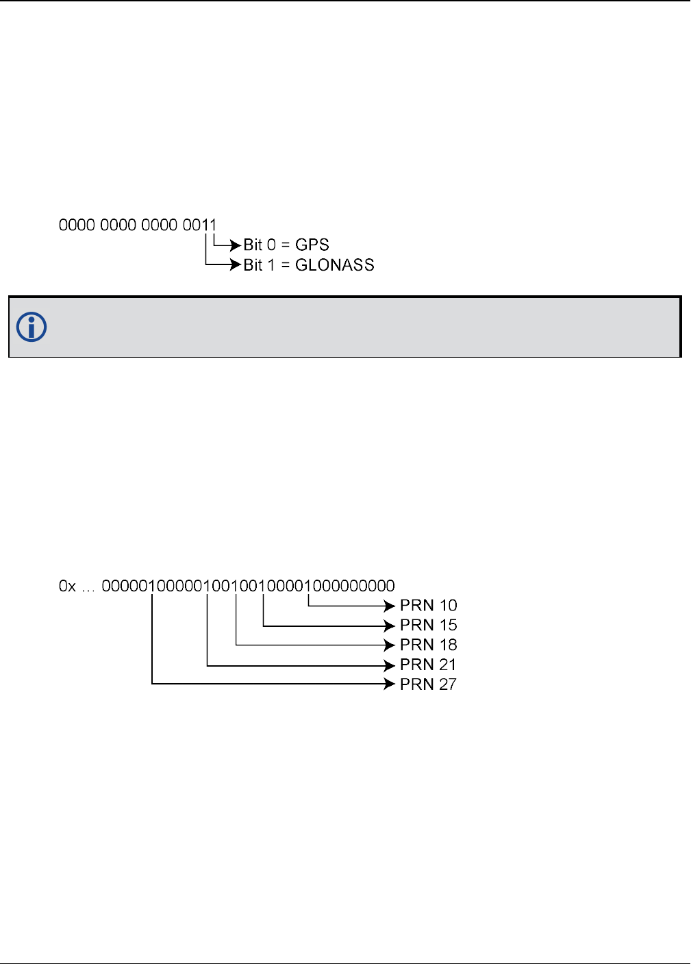
APPENDIX A Example of Bit Parsing a RANGECMP4 Log
OEM7 Commands and Logs Reference Manual v7 1041
A.1.1 Reference Header
The Reference Header is sent once per message. See Table 138: Header on page695 in the
RANGECMP4 log section.
Decoding the bits starting with the first bytes:
GNSS Field (16 bits)
lGrab the first 2 bytes (16 bits) = 0x0300
lSwap the bytes = 0x0003
l0x0003 in binary form = 0000 0000 0000 0011
In this example the receiver was configured to track only GPS and GLONASS systems. If
other systems had been in the configuration and tracked, they would have shown here.
A.1.2 Reference Satellite and Signal Block: GPS
This block is sent once for each bit set to 1 in the GNSS field (See Table 138: Header on
page695). As identified by the above GNSS field, the first system (right to left) is the GPS Sys-
tem. Use Table 139: Satellite and Signal Block on page696 to determine what satellites and sig-
nals data are contained in this GPS system:
GPS Satellites field (64 bits)
lGrab the next 8 bytes (64 bits) = 0x0042120400000000
lSwap the bytes = 0x0000000004124200
l0x0000000004124200 in binary form =
lThe 1’s above identify that there are 5 tracking GPS PRNs.
GPS Signals field (16 bits)
lGrab the next 2 bytes (16 bits) = 0x9200
lSwap the bytes = 0x0092
l0x0092 in binary form =
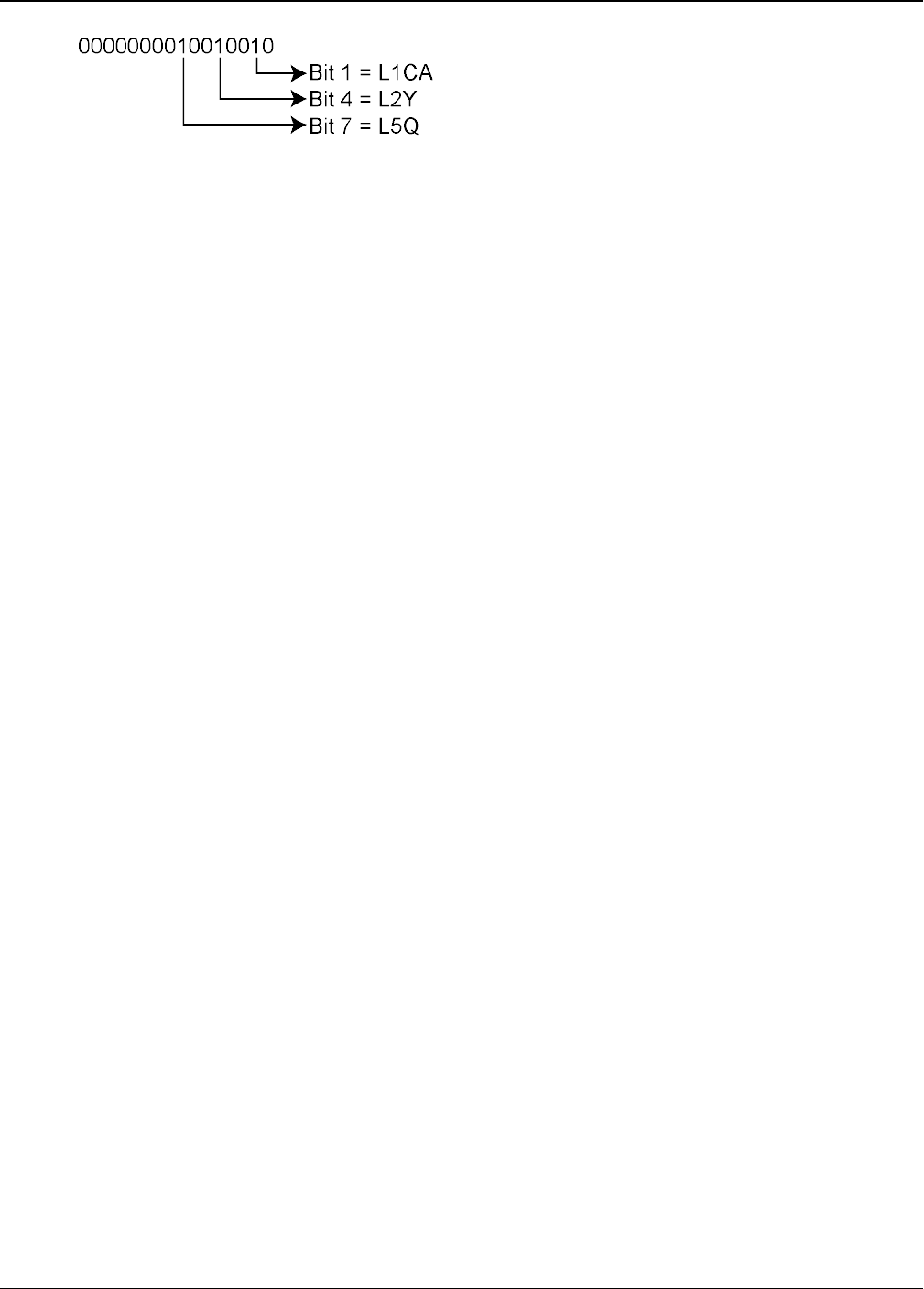
APPENDIX A Example of Bit Parsing a RANGECMP4 Log
OEM7 Commands and Logs Reference Manual v7 1042
lThe 1’s above identify that there are 3 tracking GPS signals: L1CA, L2Y, and L5Q.
GPS Included Signals field (5 PRNs x 3 Signals = 15 bits – Therefore need 2 bytes)
lUp to the point of processing the Included Signals field, the bytes are aligned such that the
bits start and end within each batch of bytes. After processing this step, it is quite common
for the Included Signals Field (mxn matrix) to not be divisible by 8 so bytes not processed
will need to be carried over to the next section depending on the size of the matrix.
lGrab the next 2 bytes (16 bits) = 0xdf76
lSwap the bytes = 0x76df
l0x76df in binary form = 0111011011011111
lOnly need 15 of the 16 bits = X111011011011111
lThis bit string breaks down into 5 rows (PRNs) and 3 columns (signals) as specified by the
mxn (PRN x signals) parameters. Take the bit string and break it up into sets of 3 starting at
the MSB. This will result with the lowest PRN being at the bottom row of the stack and the
first signal (L1CA) being the far right column.
111
011
011
011
111
lThis stack can be further broken apart to identify the PRNs vs. their Signals:
PRNL5QL2YL1CA
27111
21011
18011
15011
10111
A.1.3 Reference Measurement Block Header: GPS
This block is sent once for each bit set to 1 in the Satellites field found in Table 139: Satellite
and Signal Block on page696. Now that the PRN’s signals have been determined, the next step
is to determine the specifics of the first PRN (10) and its list of signals (L1CA, L2Y, L5Q). Work-
ing from bottom right to upper left of the PRN/Signal chart above, each 1 represents a signal for
a PRN. Use Table 140: Measurement Block Header on page697 to determine the contents of
each field:
GPS PRN 10 (first PRN found in the Satellites field)
We will grab enough bytes to process the whole Measurement Block Header. If this was a
GLONASS System, a total of 9 bits would be required for this step (1 bit for the Data Format
Flag, 3 bits for the Ref Data Block ID, plus 5 bits for the GLONASS Frequency Number). Since
this is a GPS system, only 4 bits in total are required (1 bit for the Data Format Flag and 3 bits
for the Ref Data Block ID).
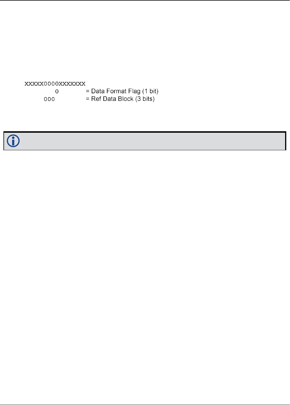
APPENDIX A Example of Bit Parsing a RANGECMP4 Log
OEM7 Commands and Logs Reference Manual v7 1043
There was 1 bit not processed in the last byte so that byte will be carried forward. Only 4 bits
need to be looked at for this step so grab the next byte as well:
lUse the last byte (0x76) plus the next byte (0x88)= 0x7688
lSwap the bytes = 0x8876
l0x8876 in binary form = 1000100001110110
lIgnore the 7 processed bits from the last step = 100010000XXXXXXX
lIgnore the 5 MSB bits leaving 4 bits for processing =
The Data Format Flag identifies that this batch of data is Reference (0) data.
The Ref Data Block ID is 0x000.
The 5 MSBs have not been processed so this byte will be carried forward.
The Data Format Flag identifies if the upcoming data is Reference or Differential data. By default
every log that was published on a whole second will always be Reference logs. Logs between
seconds will be Differential logs but could be Reference logs depending on the compression cal-
culations. If a discontinuity occurred that made it impossible for a Differential calculation to fit
within the Differential Constraints, it will revert to a Reference log.
A.1.4 Reference Measurement Block: GPS
This block is sent once for each bit set to 1 in the Included Signals Field found in Table 139:
Satellite and Signal Block on page696. Use Table 141: Primary Reference Signal Measurement
Block on page698 and Table 142: Secondary Reference Signals Measurement Block on
page699 to determine the contents of each field:
A Measurement Block for a single PRN will look like the following:
Primary Parity Flag
Primary ½ Cycle Slip Flag
Primary C/No
Primary Lock Time
Primary Pseudorange Std Deviation
Primary Phaserange Std Deviation
Primary Pseudorange
Primary Phaserange - Primary Pseudorange (determines the Phaserange for the 1st Signal)
Primary Doppler
2nd Parity Flag
2nd ½ Cycle Slip Flag
2nd C/No

APPENDIX A Example of Bit Parsing a RANGECMP4 Log
OEM7 Commands and Logs Reference Manual v7 1044
2nd Lock Time
2nd Pseudorange Std Deviation
2nd Phaserange Std Deviation
2nd Pseudorange - Primary Pseudorange (determines the Pseudorange for the 2nd Signal
2nd Phaserange - 2nd Pseudorange (determines the Phaserange for the 2nd Signal)
2nd Doppler - Primary Doppler (determines the Doppler for the 2nd Signal)
3rd Parity Flag
3rd ½ Cycle Slip Flag
3rd C/No
3rd Lock Time
3rd Pseudorange Std Deviation
3rd Phaserange Std Deviation
3rd Pseudorange - Primary Pseudorange (determines the Pseudorange for the 3rd Signal
3rd Phaserange - 3rd Pseudorange (determines the Phaserange for the 3rd Signal)
3rd Doppler - Primary Doppler (determines the Doppler for the 3rd Signal)
…
A.1.5 Reference Primary Signal Measurement Block: GPS PRN 10 – L1CA
The next bytes collected will be for the GPS PRN 10 - L1CA signal data. This is the primary signal
of the PRN since it is the first signal. As a result, its Measurement Block consists of 111 bits as
listed in Table 141: Primary Reference Signal Measurement Block on page698. Since 111 bits
takes up a lot of space, these bits will be split into two groups from Table 141: Primary Refer-
ence Signal Measurement Block on page698: the top 25 bits for signal info followed by the bot-
tom 86 bits for signal data.
The signal info section (top 25 bits) is processed as follows:
lWith 5 bits left unprocessed from the previous byte, we calculate 25 – 5 = 20 bits which
rounds up to 3 bytes. Therefore the previous last byte (0x88) plus the next 3 bytes will be
needed.
lUse the last byte (0x88) plus grab 3 bytes (x831f61) = 0x88831f61
lSwap the bytes = 0x611f8388
l0x611f8388 in binary form = 01100001000111111000001110001000
lThe previous step used the 3 LSBs = 01100001000111111000001110001XXX
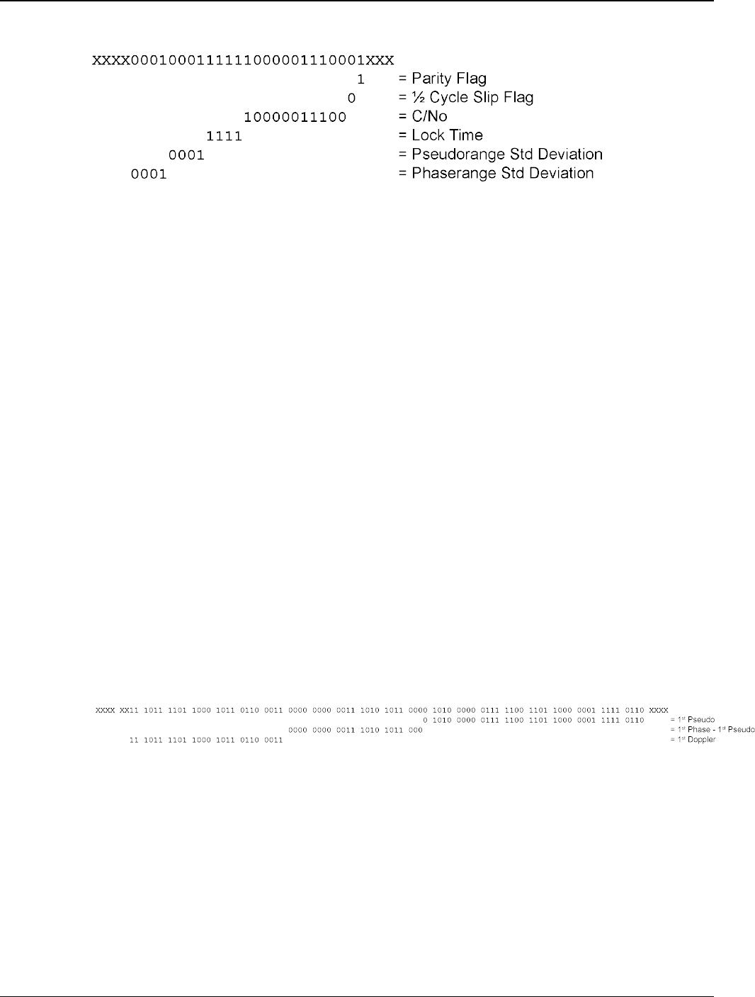
APPENDIX A Example of Bit Parsing a RANGECMP4 Log
OEM7 Commands and Logs Reference Manual v7 1045
l25 bits are needed so ignore the 4 MSBs =
lParity flag is a 1 (Parity Known)
l½ Cycle Slip flag is a 0 (Cycle Slip Not Present)
lC/No is:
0x10000011100b = 1052 x Scaling Factor of 0.05
= 52.60 dBHz
lThe Lock Time value is:
0x1111b = 15 which means that this signal has been locked for 262144 ms or more.
lThe Pseudorange Std Deviation value is:
0x0001b = 1 which means: 0.020 m < PSR Std Dev <= 0.030 m using Table 148: Pseu-
dorange Std Dev on page705.
lThe ADR Std Deviation value is:
0x0001b = 1 which means: 0.0039 < ADR Std Dev <= 0.0052 cycles using Table 147: ADR
Std Dev on page704.
The signal data section (bottom 86 bits) is processed as follows:
lWith 4 bits unprocessed from the previous byte, we calculate 86 – 4 = 82 bits = 11 bytes (2
bits will not be processed in the last byte).
lUse the last byte (0x61) plus grab 11 bytes (0x1fd87ca0b03a00638bbdf7)
= 0x611fd87ca0b03a00638bbdf7
lSwap the bytes = 0xf7bd8b63003ab0a07cd81f61
l0xf7bd8b63003ab0a07cd81f61 in binary form =
111 0111 1011 1101 1000 1011 0110 0011 0000 0000 0011 1010 1011 0000 1010 0000
0111 1100 1101 1000 0001 1111 0110 0001
lOnly need 86 bits. Ignore last 4 LSBs and first 6 MSBs =
lUse Table 141: Primary Reference Signal Measurement Block on page698 to identify if a 2’s
Complement Conversion is needed as well as what Scale Factor should be used before these
binary numbers are used in the following calculations.
lThe 1st (Primary) Pseudorange is processed by:
1st Pseudorange = 0x0101000000111110011011000000111110110b x Scaling Factor
1st Pseudorange = 43080581622 x 0.0005
L1CA Pseudorange for PRN 10= 21540290.811 m
lThe 1st (Primary) Phaserange is a 2’s Complement number (as identified by the Range

APPENDIX A Example of Bit Parsing a RANGECMP4 Log
OEM7 Commands and Logs Reference Manual v7 1046
column in Table 141: Primary Reference Signal Measurement Block on page698) so it is pro-
cessed in the following manner:
1st Phaserange – 1st Pseudorange = 2’s Complement(0x00000000001110101011000b) *
Scaling Factor
1st Phaserange – 21540290.811 m = 7512 * 0.0001
L1CA Phaserange = 21540291.5622 m
lConvert this to ADR to check against the original RANGE log:
ADR = 1st Phaserange * Frequency * (-1)/Speed Of Light
ADR = 21540291.5622 m * 1575420000 Hz * (-1)/299792458 m/s
L1CA ADR for PRN 10 = -113194996.1627158 cycles
In the range logs, PSR and ADR have opposite signs.
lThe 1st (Primary) Doppler is a 2’s Complement number (as identified by the Range column in
Table 141: Primary Reference Signal Measurement Block on page698) so it is processed in
the following manner:
1st Doppler(m/s) = 2’s Complement(0x11101111011000101101100011b) x Scaling Factor
1st Doppler(m/s) = -4,355,229 x 0.0001
L1CA Doppler(m/s) = -435.5229 m/s
Convert the Doppler to Hz:
1st Doppler(Hz) = 1st Doppler(m/s) x Frequency * (-1)/Speed Of Light
L1CA Doppler(Hz) for PRN 10 = 2288.6883 Hz
1st Doppler(Hz) = -435.5229 m/s x 1575420000 Hz * (-1)/299792458 m/s
A.1.6 Reference Secondary Signals Measurement Block: GPS PRN 10 – L2Y
Signal L1CA was the 1st signal (Primary Signal) of the three PRN 10 signals found in this
RANGECMP4 log data. L1CA’s data is now used to determine the L2Y’s signals data. Since this is
the second signal block of this PRN, its data will be processed by using Table 142: Secondary
Reference Signals Measurement Block on page699.
With 6 bits left unprocessed from the previous byte, we will require 82 – 6 = 76 bits which
rounds up to 10 bytes.
lUse the last byte (0xf7) plus grab the next 10 bytes (0xb82f49b080fd0ec0ff1f)
= 0xf7b82f49b080fd0ec0ff1f
lSwap the bytes = 0x1fffc00efd80b0492fb8f7
l0x1fffc00efd80b0492fb8f7 in binary form =
0001 1111 1111 1111 1100 0000 0000 1110 1111 1101 1000 0000 1011 0000 0100 1001 0010
1111 1011 1000 1111 0111
lOnly need 78 bits. The 2 LSBs are ignored as they were already processed above and the 4
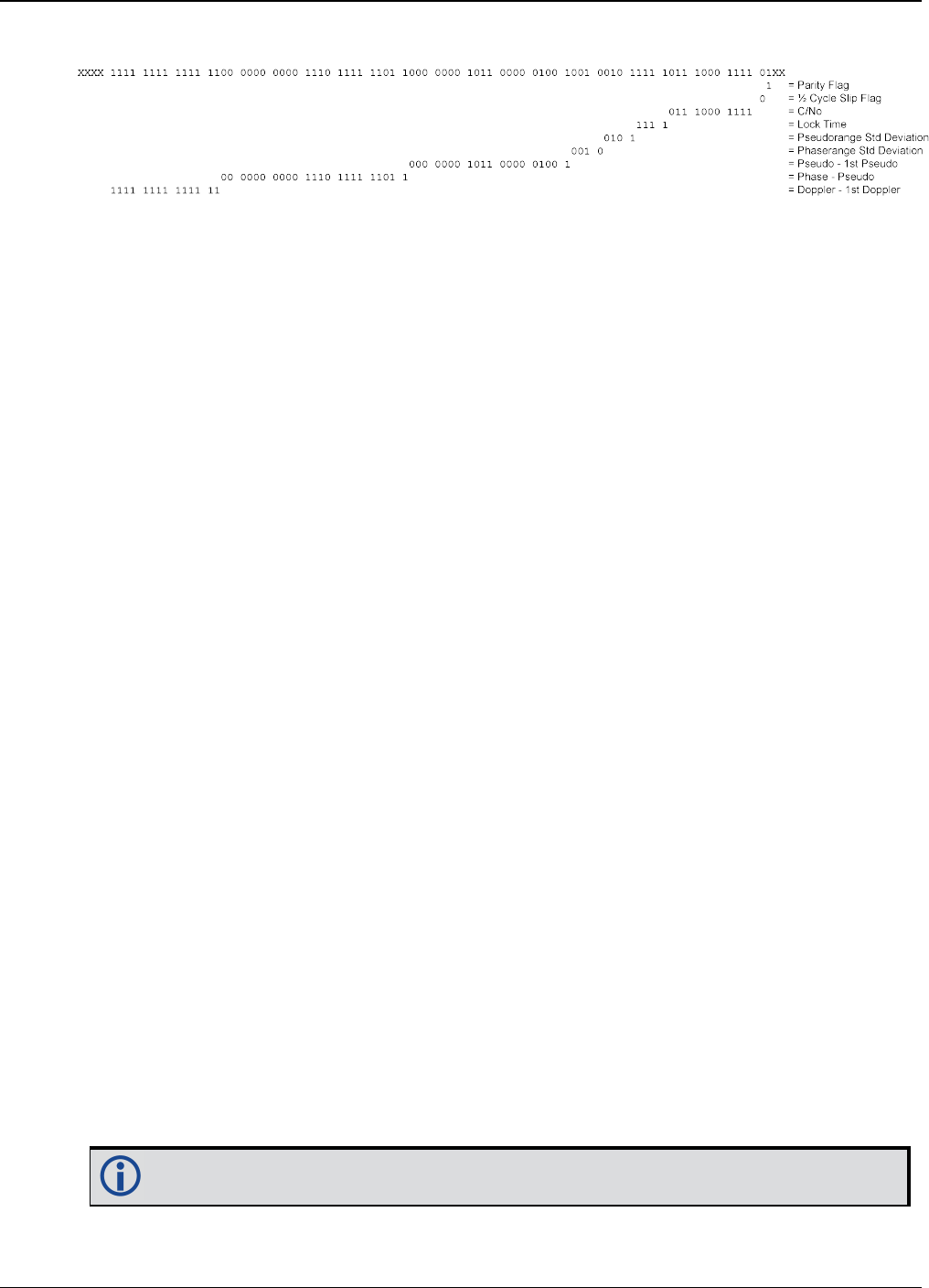
APPENDIX A Example of Bit Parsing a RANGECMP4 Log
OEM7 Commands and Logs Reference Manual v7 1047
MSBs are ignored so there is a total of 82 bits to process
Use Table 142: Secondary Reference Signals Measurement Block on page699 to identify if a 2’s
Complement Conversion is needed as well as what Scale Factor should be used before these bin-
ary numbers are used in the following calculations.
lParity flag is a 1 (Parity Known)
l½ Cycle Slip flag is a 0 (Cycle Slip Not Present)
lC/No is:
0x01110001111b = 911 x Scaling factor of 0.05
= 45.55 dBHz
lThe Lock Time value is:
0x1111b = 15 which means that this signal has been locked for 262144 ms or more.
lThe Pseudorange Std Deviation value is:
0x0101b = 5 which means: 0.099 m < PSR Std Dev <= 0.148 m using Table 148: Pseu-
dorange Std Dev on page705.
lThe ADR Std Deviation value is:
0x0010b = 2 which means: 0.0052 < ADR Std Dev <= 0.0070 cycles using Table 147: ADR
Std Dev on page704.
lThe L2Y Pseudorange is a 2’s Complement number (as identified by the Range column in
Table 142: Secondary Reference Signals Measurement Block on page699) so it is processed
in the following manner:
Pseudorange – 1st Pseudorange = 2’s Complement(0x00000001011000001001b) x Scaling
Factor
Pseudorange – 21540290.811 m = 5641 x 0.0005
2Y Pseudorange = 21540293.6315 m
lThe L2Y Phaserange is a 2’s Complement number (as identified by the Range column in Table
142: Secondary Reference Signals Measurement Block on page699) so it is calculated in the
following manner:
Phaserange – Pseudorange = 2’s Complement(0x00000000001110111111011b) * Scaling
Factor
Phaserange – 21540293.6315 m = 7675 * 0.0001
L2Y Phaserange = 21540294.399 m
lConvert this to ADR to check against the original RANGE log:
ADR = Phaserange * Frequency * (-1)/Speed Of Light
ADR = 21540294.399 m * 1227600000 Hz * (-1)/299792458 m/s
L2Y ADR for PRN 10 = -88203904.73002626 cycles
In the range logs, PSR and ADR have opposite signs.

APPENDIX A Example of Bit Parsing a RANGECMP4 Log
OEM7 Commands and Logs Reference Manual v7 1048
lThe L2Y Doppler is a 2’s Complement number (as identified by the Range Column in Table
142: Secondary Reference Signals Measurement Block on page699) so it is calculated in the
following manner:
Doppler(m/s) – 1st Doppler(m/s) = 2’s Complement(0x11111111111111b) x Scaling Factor
Doppler(m/s) – (-435.5229 m/s) = (-1) x 0.0001
L2Y Doppler(m/s) = -435.5228 m/s
Convert the Doppler to Hz:
Doppler(Hz) = Doppler(m/s) x Frequency * (-1)/Speed Of Light
Doppler(Hz) = -435.5228 m/s x 1227600000 Hz * (-1)/299792458 m/s
L2Y Doppler(Hz) for PRN 10 = 1783.3938 Hz
A.1.7 Reference Third Signals Measurement Block: GPS PRN 10 – L5Q
Signal L1CA was the 1st signal (Primary Signal) of the three PRN 10 signals found in this
RANGECMP4 log data. L1CA’s data is now used to determine the L5Q’s signals data. Since this is
the third signal block of this PRN, its data will be processed using Table 142: Secondary Refer-
ence Signals Measurement Block on page699.
With 4 bits left unprocessed from the previous byte, we will require 82 – 4 = 78 bits which
rounds up to 10 bytes.
lUse the last byte (0x1f) plus grab the next 10 bytes (0x091f8214ff4d4d00a100)
= 0x1f091f8214ff4d4d00a100
lSwap the bytes = 0x00a1004d4dff14821f091f
l0x00a1004d4dff14821f091f in binary form =
0000 0000 1010 0001 0000 0000 0100 1101 0100 1101 1111 1111 0001 0100 1000 0010 0001
1111 0000 1001 0001 1111
lOnly need 78 bits. The 4 LSBs are ignored as they were already processed above and the 2
MSBs are ignored so there is a total of 82 bits to process
Use Table 142: Secondary Reference Signals Measurement Block on page699 to identify if a 2’s
Complement Conversion is needed as well as what Scale Factor should be used before these bin-
ary numbers are used in the following calculations.
lParity flag is a 1 (Parity Known)
l½ Cycle Slip flag is a 0 (Cycle Slip Not Present)
lC/No is:
0x10000100100b = 1060 x Scaling Factor of 0.05
= 53.00 dBHz
lThe Lock Time value is:
0x1111b = 15 which means that this signal has been locked for 262144 ms or more.
lThe Pseudorange Std Deviation value is:
0x0000b = 0 which means: PSR Std Dev <= 0.020 m using Table 148: Pseudorange Std Dev
APPENDIX A Example of Bit Parsing a RANGECMP4 Log
OEM7 Commands and Logs Reference Manual v7 1049
on page705.
lThe ADR Std Deviation value is:
0x0001b = 1 which means: 0.0039 < ADR Std Dev <= 0.0052 cycles using Table 147: ADR
Std Dev on page704.
lThe L5Q Pseudorange is a 2’s Complement number (as identified by Range column in Table
142: Secondary Reference Signals Measurement Block on page699) so it is processed in the
following manner:
Pseudorange – 1st Pseudorange = 2’s Complement(0x11111111100010100100b) x Scaling
Factor
Pseudorange – 21540290.811 m = (-1884) x 0.0005
L5Q Pseudorange = 21540289.869 m
lThe L5Q Phaserange is a 2’s Complement number (as identified by the Range column in
Table 142: Secondary Reference Signals Measurement Block on page699) so it is calculated
in the following manner:
Phaserange – Pseudorange = 2’s Complement(0x00000000010011010100110b) * Scaling
Factor
Phaserange – 21540289.869 m = 9894 * 0.0001
L5Q Phaserange = 21540290.8584 m
lConvert this to ADR to check against the original RANGE log:
ADR = Phaserange * Frequency * (-1)/Speed Of Light
ADR = 21540290.8584 m * 1176450000 Hz * (-1)/299792458 m/s
L5Q ADR for PRN 10 = -84528728.13886692 cycles
In the range logs, PSR and ADR have opposite signs.
lThe L5Q Doppler is a 2’s Complement number (as identified by the Range column Table 142:
Secondary Reference Signals Measurement Block on page699) so it is calculated in the fol-
lowing manner:
Doppler(m/s) – 1st Doppler(m/s) = 2’s Complement(0x00000010100001b) x Scaling Factor
Doppler(m/s) – (-435.5229 m/s) = 80 x 0.0001
L5Q Doppler(m/s) = -435.5149 m/s
Convert the Doppler to Hz:
Doppler(Hz) = Doppler(m/s) x Frequency * (-1)/Speed Of Light
Doppler(Hz) = -435.5149 m/s x 1176450000 Hz * (-1)/299792458 m/s
L5Q Doppler(Hz) for PRN 10 = 1709.054 Hz
This concludes the processing of the signals present for PRN 10.
The next PRN as identified in the GPS Included Signals Field is PRN 15 with 2 signals. Processing
of this data would be handled as described above, starting with the 4 bit Measurement Block fol-
lowed by the individual signals. This would be followed by PRN 18, 21, and 27. Processing these
remaining PRNs and their signals would use up the next 870 bits as shown below:
Bits required for remaining GPS PRNs and Signals:
PRN 15

APPENDIX A Example of Bit Parsing a RANGECMP4 Log
OEM7 Commands and Logs Reference Manual v7 1050
l4 bits Measurement Block header
l111 bits - 1st Signal
l82 bits - 2nd Signal
PRN 18
l4 bits Measurement Block header
l111 bits - 1st Signal
l82 bits - 2nd Signal
PRN 21
l4 bits Measurement Block header
l111 bits - 1st Signal
l82 bits - 2nd Signal
PRN 27
l4 bits Measurement Block header
l111 bits - 1st Signal
l82 bits - 2nd Signal
l82 bits - 3rd Signal
Total = 870 bits
There are 2 bits left unprocessed from the last byte of PRN 10’s processing so 868 more bits
(109 bytes) are required. After processing the remaining GPS data, there will be 4 bits left from
the last byte to start off the next system (GLONASS as identified by the GNSS field in the
Header).
After the last GPS bit, the GLONASS system will then be processed since it was identified as the
next system by the GNSS field in the Header.
A.1.8 Reference Satellite and Signal Block: GLONASS
This block is sent once for each bit set to 1 in the GNSS field found in Table 138: Header on
page695. As identified by the above GNSS field, the second system (right to left) is the
GLONASS System. Use Table 139: Satellite and Signal Block on page696 to determine what
satellites slots and signals data are contained in this GLONASS System:
GLONASS Satellites field (64 bits)
lGrab the next 8 bytes (64 bits) = 0x3f0030080000000020
lSwap the bytes = 0x20000000000830003f
l0x20000000000830003f in binary form =
001000000000000000000000000000000000000000001000001100000000000000111111
lMask out the used 4 LSBs =
00100000000000000000000000000000000000000000100000110000000000000011XXXX
lDetermine the required 64 bits =
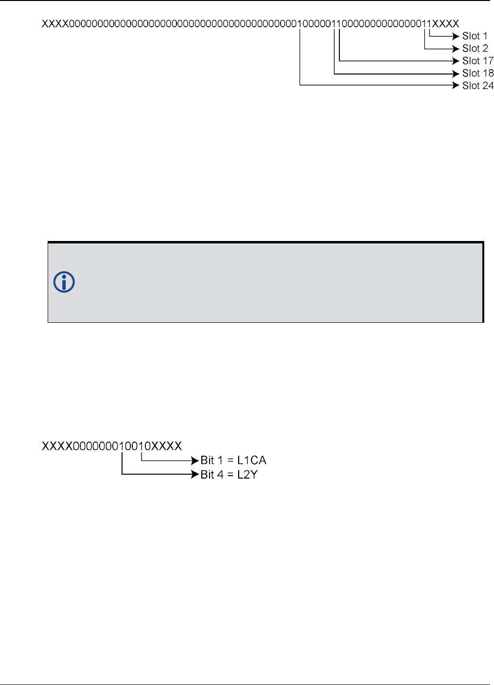
APPENDIX A Example of Bit Parsing a RANGECMP4 Log
OEM7 Commands and Logs Reference Manual v7 1051
lThe 1’s above identify that there are 5 tracking GLONASS Slots.
lThe present GLONASS satellite PRNs/Slot ID’s (when between 1 to 24) are therefore (37 +
Slot ID):
Slot 1 = PRN 38
Slot 2 = PRN 39
Slot 17 = PRN 54
Slot 18 = PRN 55
Slot 24 = PRN 61
If the GLONASS Slot ID was between 43 and 64, this would represent a
GLONASS satellite that has an unknown Slot ID and is instead assigned a tem-
porary one based upon 64 minus the unadjusted GLONASS Frequency Number
(0 to 20). This Slot ID will be updated once the actual PRN/Slot ID has been
determined.
GLONASS Signals field (16 bits)
lAppend the next 2 bytes (0x01f0) to the last byte (0x20) = 0x2001f0
lSwap the bytes = 0x0f0120
l0x0f0120 in binary form = 11110000000100100000
lIgnore the processed bits = 1111000000010010XXXX
lDetermine the required 16 bits =
lThe 1’s above identify that there are 2 tracking GLONASS signals: L1CA and L2P.
GLONASS Included Signals field (5 Slot ID’s x 2 Signals = 10 bits)
lAppend the next byte (0x3f) to the last byte (0xf0) = 0xf03f
lSwap the bytes = 0x3ff0
l0x3ff0in binary form = 0011111111110000
lIgnore the processed bits = 001111111111XXXX
lDetermine the required 10 bits = XX1111111111XXXX
lThis bit string breaks down into 5 rows (Slots) and 2 columns (signals) as specified by the
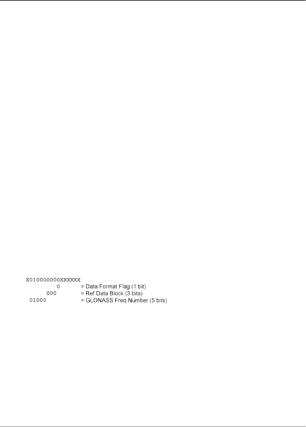
APPENDIX A Example of Bit Parsing a RANGECMP4 Log
OEM7 Commands and Logs Reference Manual v7 1052
mxn (Slot IDs x signals) parameters. Take the bit string and break it up into sets of 2 start-
ing at the MSB. This will result with the lowest Slot ID being at the bottom row of the stack
and the first signal (L1CA) being the far right column.
11
11
11
11
11
lThis stack can be further broken apart to identify the Slot ID’s vs. their Signals:
SLOTL2PL1CA
2411
1811
1711
211
111
A.1.9 Reference Measurement Block Header: GLONASS PRN 38
(Slot 1 which was the first Slot found in the Satellites Field)
We will grab enough bytes to process the whole Measurement Block Header. Since this is a
GLONASS System, a total of 9 bits will be required for this step (1 bit for the Data Format Flag, 3
bits for the Ref Data Block ID, plus 5 bits for the GLONASS Frequency Number).
With 2 bits left unprocessed from the previous byte, we will require 9 – 2 = 7 bits which rounds
up to 1 byte:
lUse the last byte (0x3f) plus the next byte (0xa0)= 0x3fa0
lSwap the bytes = 0xa03f
l0xa03f in binary form = 1010000000111111
lIgnore the 6 processed bits from the last step = 1010000000XXXXXX
lIgnore the 1 MSB bits leaving 9 bits for processing =
The Data Format Flag identifies that this batch of data is Reference (0) data.
The Ref Data Block ID is 0x000.
The GLONASS Frequency Number is 8 (adjusted to 1). When calculating the GLONASS Carrier fre-
quency, this value (0 to 20) will be adjusted to its -7 to +13 value and then multiplied by that fre-
quencies delta. Note that this field only appears in the Reference data and will not be found in
the Differential data.
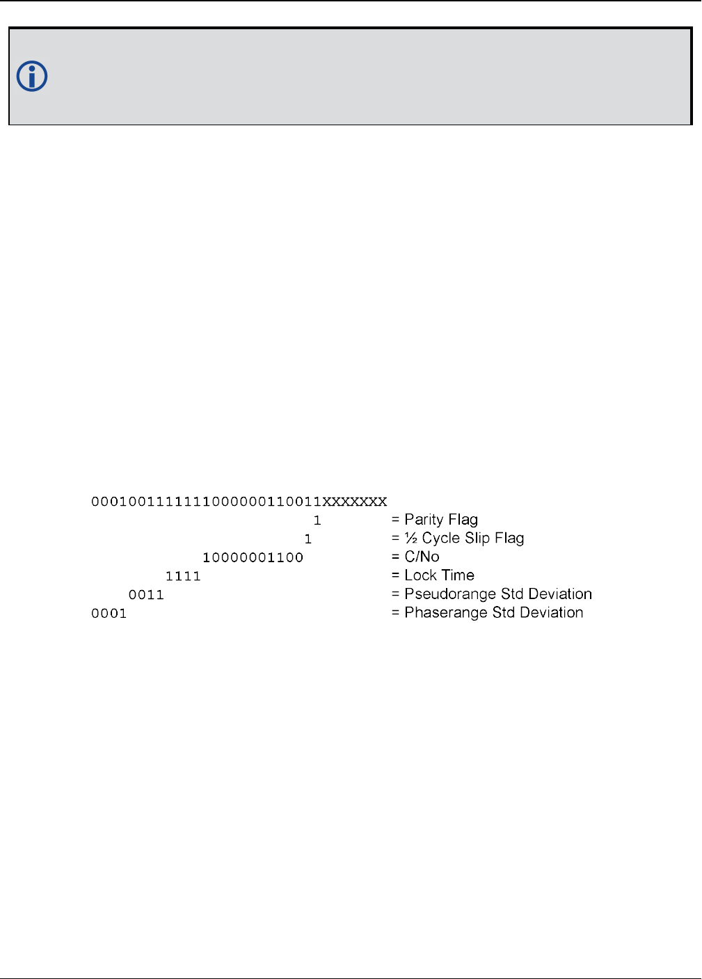
APPENDIX A Example of Bit Parsing a RANGECMP4 Log
OEM7 Commands and Logs Reference Manual v7 1053
Special Case: When the Slot ID is between 43 and 63, the Slot ID of the GLONASS satel-
lite is unknown. In order to keep track of which satellite it is for these calculations, the
Frequency Number is used to assign this GLONASS Satellite a temporary Slot ID based
on the GLONASS Frequency Numbers binary value of 0 to 20.
A.1.10 Reference Primary Signal Measurement Block: GLONASS PRN 38 –
L1CA
The next bytes collected will be for the GLONASS PRN 38 - L1CA signal data. This is the primary
signal of the satellite since it is the first signal. As a result, its Measurement Block consists of
111 bits as listed in Table 141: Primary Reference Signal Measurement Block on page698.
Since 111 bits takes up a lot of space, these bits will be split into two groups from Table 141:
Primary Reference Signal Measurement Block on page698: the top 25 bits for signal info fol-
lowed by the bottom 86 bits for signal data.
The signal info section (top 25 bits) is processed as follows:
lWith 1 bit left unprocessed from the previous byte, we calculate 25 – 1 = 24 bits which
equals 3 bytes. Therefore the previous last byte (0xa0) plus the next 3 bytes will be needed.
lUse the last byte (0xa0) plus grab 3 bytes (x19f813) = 0xa019f813
lSwap the bytes = 0x13f819a0
l0x13f819a0 in binary form = 00010011111110000001100110100000
lThe previous step used the 7 LSBs = 0001001111111000000110011XXXXXXX
lNeed 25 bits which is exactly what is left over:
lParity flag is a 1 (Parity Known)
l½ Cycle Slip flag is a 1 (Cycle Slip Present)
lC/No is:
0x10000001100b = 1036 x Scaling factor of 0.05
= 51.80 dBHz
lThe Lock Time value is:
0x1111b = 15 which means that this signal has been locked for 262144 ms or more.
lThe Pseudorange Std Deviation value is:
0x0011b = 3 which means: 0.045 m < PSR Std Dev <= 0.066 m using Table 148: Pseu-
dorange Std Dev on page705.
lThe ADR Std Deviation value is:
0x0001b = 1 which means: 0.0039 < ADR Std Dev <= 0.0052 cycles using Table 147: ADR
Std Dev on page704.
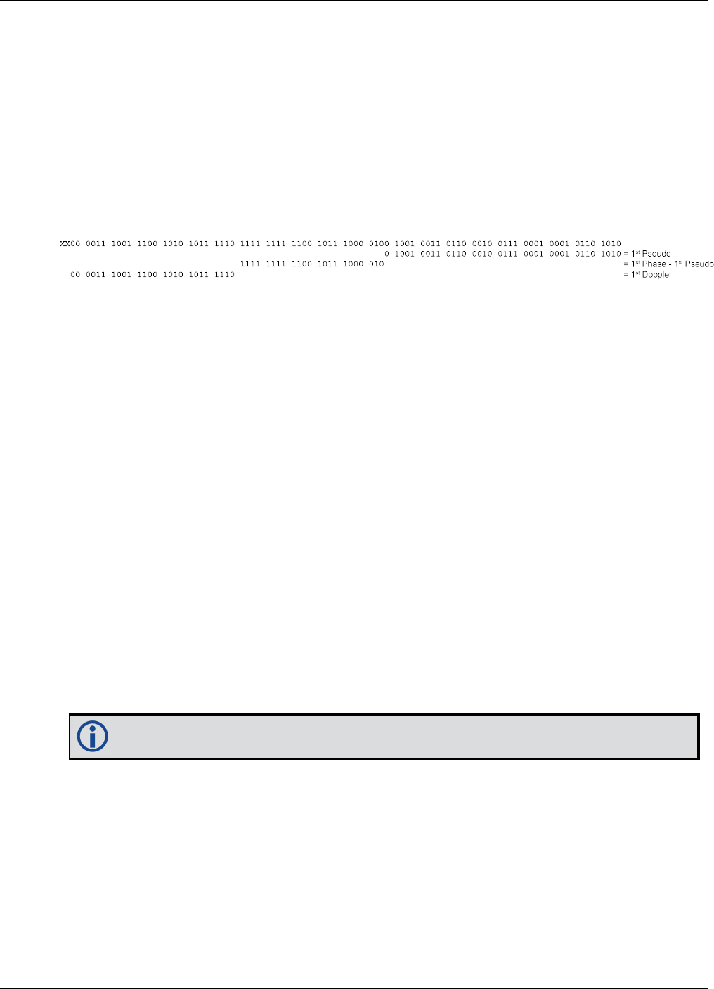
APPENDIX A Example of Bit Parsing a RANGECMP4 Log
OEM7 Commands and Logs Reference Manual v7 1054
The signal data section (bottom 86 bits) is processed as follows:
lWith no unprocessed bits from the previous byte, we need 86 bits which rounds up to 11
bytes.
lGrab 11 bytes = 0x6a11273649b8fcefab9c43
lSwap the bytes = 0x439cabeffcb8493627116a
l0x439cabeffcb8493627116a in binary form =
0100 0011 1001 1100 1010 1011 1110 1111 1111 1100 1011 1000 0100 1001 0011 0110
0010 0111 0001 0001 0110 1010
lOnly need 86 bits. Ignore first 2 MSBs =
lUse Table 141: Primary Reference Signal Measurement Block on page698 to identify if a 2’s
Complement Conversion is needed as well as what Scale Factor should be used before these
binary numbers are used in the following calculations.
lThe 1st (Primary) Pseudorange is processed by:
1st Pseudorange = 0x0100100110110001001110001000101101010b x Scaling Factor
1st Pseudorange = 39563235690 x 0.0005
L1CA Pseudorange for PRN 38 = 19781617.845 m
lThe 1st (Primary) Phaserange is a 2’s Complement number (as identified by the Range
column in Table 141: Primary Reference Signal Measurement Block on page698) so it is pro-
cessed in the following manner:
1st Phaserange – 1st Pseudorange = 2’s Complement(0x11111111110010111000010b) *
Scaling Factor
1st Phaserange – 19781617.845 m = -6718 * 0.0001
L1CA Phaserange = 19781617.1732 m
lConvert this to ADR to check against the original RANGE log:
ADR = 1st Phaserange * (Carrier Frequency + Frequency Number * 562500 Hz) * (-1)/Speed
Of Light
ADR = 19781617.1732 m * (1602000000 Hz + 1 * 562500 Hz) * (-1)/299792458 m/s
ADR = 19781617.1732 m * 1602562500 Hz * (-1)/299792458 m/s
L1CA ADR for PRN 38 = -105744080.6970745 cycles
In the range logs, PSR and ADR have opposite signs.
lThe 1st (Primary) Doppler is a 2’s Complement number (as identified by the Range column in
Table 141: Primary Reference Signal Measurement Block on page698) so it is processed in
the following manner:
1st Doppler(m/s) = 2’s Complement(0x00001110011100101010111110b) x Scaling Factor
1st Doppler(m/s) = 3787454 m/s x 0.0001
L1CA Doppler(m/s) = 378.7454 m/s
Convert the Doppler to Hz:
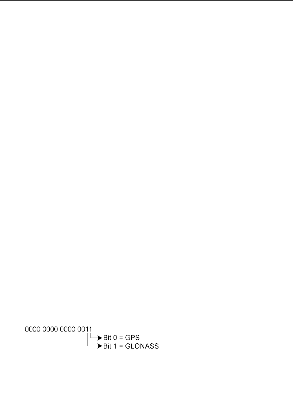
APPENDIX A Example of Bit Parsing a RANGECMP4 Log
OEM7 Commands and Logs Reference Manual v7 1055
1st Doppler(Hz) = 1st Doppler(m/s) x (Carrier Frequency + Frequency Number * 562500
Hz) * (-1)/Speed Of Light
1st Doppler(Hz) = 378.7454 m/s x (1602000000 Hz + 1 * 562500 Hz) * (-1)/299792458 m/s
1st Doppler(Hz) = 378.7454 m/s x 1602562500 Hz * (-1)/299792458 m/s
L1CA Doppler(Hz) for PRN 38 = -2024.6112 Hz
The rest of the GLONASS Reference Signals are handled in a similar manner as described in the
above GPS section.
A.2 Differential Log Decoding
Logs not falling on a whole second are most likely Differential logs which are processed dif-
ferently than the Reference logs. It is possible for a sub-second RANGECMP4 log to be a Refer-
ence log if the data contained within it did not fit the tight Differential Compression
requirements.
Differential logs use the reference data of the same signal unlike reference logs which uses the
first signal to define the other signals.
The next RANGECMP4 log is at time 507977.250:
#RANGECMP4A,COM1,0,88.5,FINESTEERING,1919,507977.250,02000020,fb0e,
32768;239,030000421204000000009200dff688831f6102005500e70162dc977c0040
15c07988840f6101803a805921cedf8b80002011207080e5f6351f003804081c2200be
0808005c01620808725f93028057801822dae0476000a00f207180fef6251700e80340
1c62f3bdc8060052013009986f5f22020054004ca2053ec408005401ca870180410000
0000000980ff6306fec408004801de07c8692f5102805180f721b2e04f600040152081
804ef7102500600540202205fe040a0086013a0938780f61020061804e224edbdb6800
2010c0498030f7411d0018047812a2d47d090a004c01a609c8544f62028052006a02
*48E189A2
At the start of the RANGECMP4 log is the identifier for how many bytes are in the log. In this
case, there are 239 bytes (just under 20% less than a Reference Log). The rest of the message
is compressed binary data and is transmitted as LSB first so the bytes must be swapped before
processing.
A.2.1 Differential Header
The Differential Header is sent once per message (See Table 138: Header on page695).
Decoding the bits starting with the first bytes:
GNSS field (16 bits)
lGrab the first 2 bytes (16 bits) = 0x0300
lSwap the bytes = 0x0003
l0x0003 in binary form =
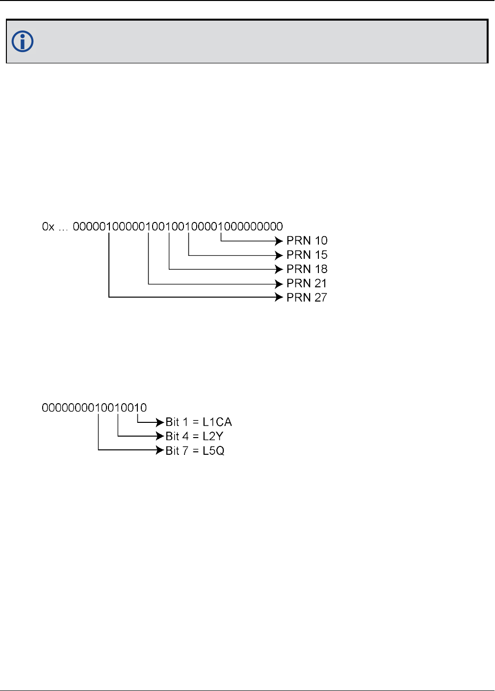
APPENDIX A Example of Bit Parsing a RANGECMP4 Log
OEM7 Commands and Logs Reference Manual v7 1056
In this example the receiver was configured to track only GPS and GLONASS systems. If
other systems had been in the configuration and tracked, they would have shown here.
A.2.2 Differential Satellite and Signal Block
This block is sent once for each bit set to 1 in the GNSS field found in Table 138: Header on
page695. As identified by the above GNSS field, the first system (right to left) is the GPS Sys-
tem. Use Table 139: Satellite and Signal Block on page696 to determine what satellites and sig-
nals data are contained in this GPS System:
GPS Satellites field (64 bits)
lGrab the next 8 bytes (64 bits) = 0x0042120400000000
lSwap the bytes = 0x…0000000004124200
l0x0000000004124200 in binary form =
lThe 1’s above identify that there are 5 tracking GPS PRNs.
GPS Signals field (16 bits)
lGrab the next 2 bytes (16 bits) = 0x9200
lSwap the bytes = 0x0092
l0x0092 in binary form =
lThe 1’s above identify that there are 3 tracking GPS signals: L1CA, L2Y, and L5Q.
GPS Included Signals field (5 PRNs x 3 Signals = 15 bits – therefore need 2 bytes)
Up to the point of processing the Included Signals field, the bytes are aligned such that the bits
start and end within each batch of bytes. After processing this step, it is quite common for the
Included Signals field (mxn matrix) to not be divisible by 8 so bytes not processed will need to
be carried over to the next section depending on the size of the matrix.
lGrab the next 2 bytes (16 bits) = 0xdff6
lSwap the bytes = 0xf6df
l0xf6df in binary form = 1111011011011111
lOnly need 15 of the 16 bits = X111011011011111
lThis bit string breaks down into 5 rows (PRNs) and 3 columns (signals) as specified by the

APPENDIX A Example of Bit Parsing a RANGECMP4 Log
OEM7 Commands and Logs Reference Manual v7 1057
mxn (PRN x signals) parameters. Take the bit string and break it up into sets of 3 starting at
the MSB. This will result with the lowest PRN being at the bottom row of the stack and the
first signal (L1CA) being the far right column.
111
011
011
011
111
lThis stack can be further broken apart to identify the PRNs vs. their Signals:
PRNL5QL2YL1CA
27111
21011
18011
15011
10111
A.2.3 Differential Measurement Block Header
This block is sent once for each bit set to 1 in the Satellites field found in Table 139: Satellite
and Signal Block on page696. Now that the PRN’s signals have been determined, the next step
is to determine the specifics of the first PRN (10) and its list of signals (L1CA, L2Y, L5Q). Work-
ing from bottom right to upper left of the PRN/Signal chart above, each 1 represents a signal for
a PRN. Use Table 140: Measurement Block Header on page697 to determine the contents of
each field:
GPS PRN 10 (first PRN found in the Satellites field)
We will grab enough bytes to process the whole Measurement Block Header. If this was a
GLONASS system, a total of 9 bits would be required at this step (1 bit for the Data Format Flag,
3 bits for the Ref Data Block ID, plus 5 bits for the GLONASS Frequency Number). Since this is a
GPS system, only 4 bits in total are required (1 bit for the Data Format Flag and 3 bits for the
Ref Data Block ID).
There was 1 bit not processed in the last byte so that byte will be carried forward. Only 4 bits
need to be looked at for this step so grab the next byte as well:
lUse the last byte (0xf6) plus the next byte (0x88)= 0xf688
lSwap the bytes = 0x88f6
l0x88f6 in binary form = 1000 1000 1111 0110
lIgnore the processed bits from the last step = 1000 1000 1XXX XXXX
lIgnore the 5 MSB bits leaving 4 bits for processing =
The Data Format Flag identifies that this batch of data is Differential (1) data.
The Ref Data Block ID is 0x000. The Ref Data Block ID here identifies that this differential data
will be calculated from the Reference data that had a Ref Data Block ID equaling 000 (which was
determined in the RANGECMP4 log at time 507977.00 seconds).

APPENDIX A Example of Bit Parsing a RANGECMP4 Log
OEM7 Commands and Logs Reference Manual v7 1058
The 5 MSBs have not been processed so this byte will be carried forward.
Logs between seconds will be Differential logs but could be Reference logs depending on the com-
pression calculations. If a discontinuity occurred that made it impossible for a Differential cal-
culation to fit within the Differential Constraints, it will revert to a Reference log.
A.2.4 Differential Measurement Block
This block is sent once for each bit set to 1 in the Included Signals field found in Table 139:
Satellite and Signal Block on page696. Use Table 143: Primary Differential Signal Measurement
Block on page700 and Table 144: Secondary Differential Signals Measurement Block on
page701 to determine the contents of each field:
A Measurement Block for a single PRN will look like the following:
Primary Parity Flag
Primary ½ Cycle Slip Flag
Primary C/No
Primary Lock Time
Primary Pseudorange Std Deviation
Primary Phaserange Std Deviation
Primary Pseudorange
Primary Phaserange - Primary Pseudorange (determines the Phaserange for the 1st Signal)
Primary Doppler
2nd Parity Flag
2nd ½ Cycle Slip Flag
2nd C/No
2nd Lock Time
2nd Pseudorange Std Deviation
2nd Phaserange Std Deviation
2nd Pseudorange - Primary Pseudorange (determines the Pseudorange for the 2nd Signal
2nd Phaserange – 2nd Pseudorange (determines the Phaserange for the 2nd Signal)
2nd Doppler – Primary Doppler (determines the Doppler for the 2nd Signal)
3rd Parity Flag
3rd ½ Cycle Slip Flag
3rd C/No
3rd Lock Time
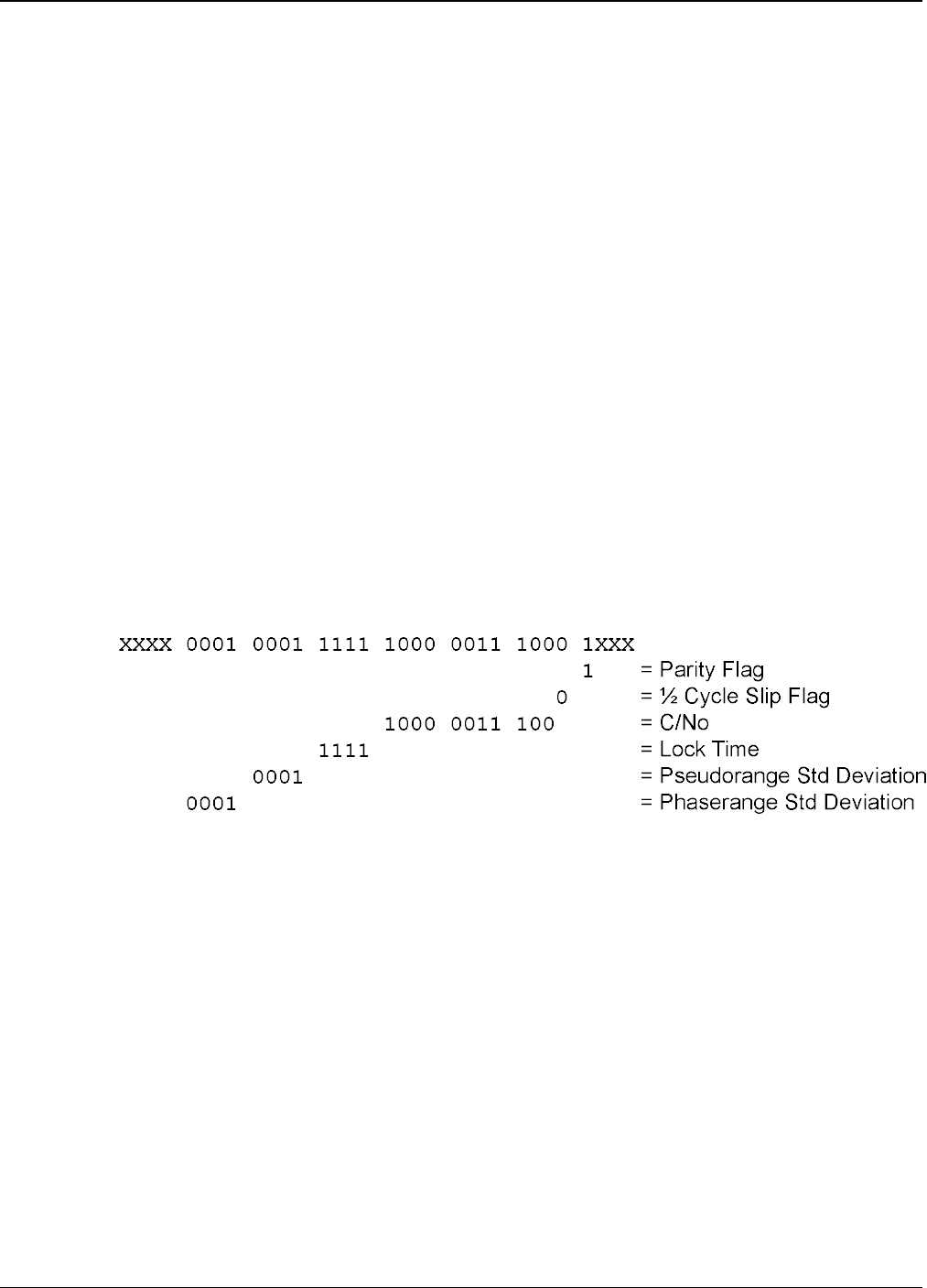
APPENDIX A Example of Bit Parsing a RANGECMP4 Log
OEM7 Commands and Logs Reference Manual v7 1059
3rd Pseudorange Std Deviation
3rd Phaserange Std Deviation
3rd Pseudorange - Primary Pseudorange (determines the Pseudorange for the 3rd Signal
3rd Phaserange – 3rd Pseudorange (determines the Phaserange for the 3rd Signal)
3rd Doppler – Primary Doppler (determines the Doppler for the 3rd Signal)
…
A.2.5 Differential Primary Signal Measurement Block GPS PRN 10 – L1CA
The next bytes collected will be for the GPS PRN 10 - L1CA signal data. Since this is the primary
signal of the PRN, its Measurement Block consists of 78 bits as listed in Table 143: Primary Dif-
ferential Signal Measurement Block on page700.
The signal info section (top 25 bits) is processed as follows:
lWith 5 bits left from the previous byte, we calculate 25 – 5 = 20 bits which rounds up to 3
bytes. Therefore the previous last byte (0x88) plus the next 3 bytes will be needed.
lUse the last byte (0x88) plus grab 3 bytes (x831f61) = 0x88831f61
lSwap the bytes = 0x611f8388
l0x611f8388 in binary form
= 0110 0001 0001 1111 1000 0011 1000 1000
lOnly need 25 bits. The last byte uses the 5 MSBs and the first byte ignores the 4 MSBs
lParity flag is a 1 (Parity Known)
l½ Cycle Slip flag is a 0 (Cycle Slip Not Present)
lC/No is:
0x10000011100b = 1052 x Scaling factor of 0.05
= 52.60 dBHz
lThe Lock Time value is:
0x1111b = 15 which means that this signal has been locked for 262144 ms or more.
lThe Pseudorange Std Deviation value is:
0x0001b = 1 which means: 0.020 m < PSR Std Dev <= 0.030 m using Table 148: Pseu-
dorange Std Dev on page705.
lThe ADR Std Deviation value is:
0x0001b = 1 which means: 0.0039 < ADR Std Dev <= 0.0052 cycles using Table 147: ADR
Std Dev on page704Table 10.
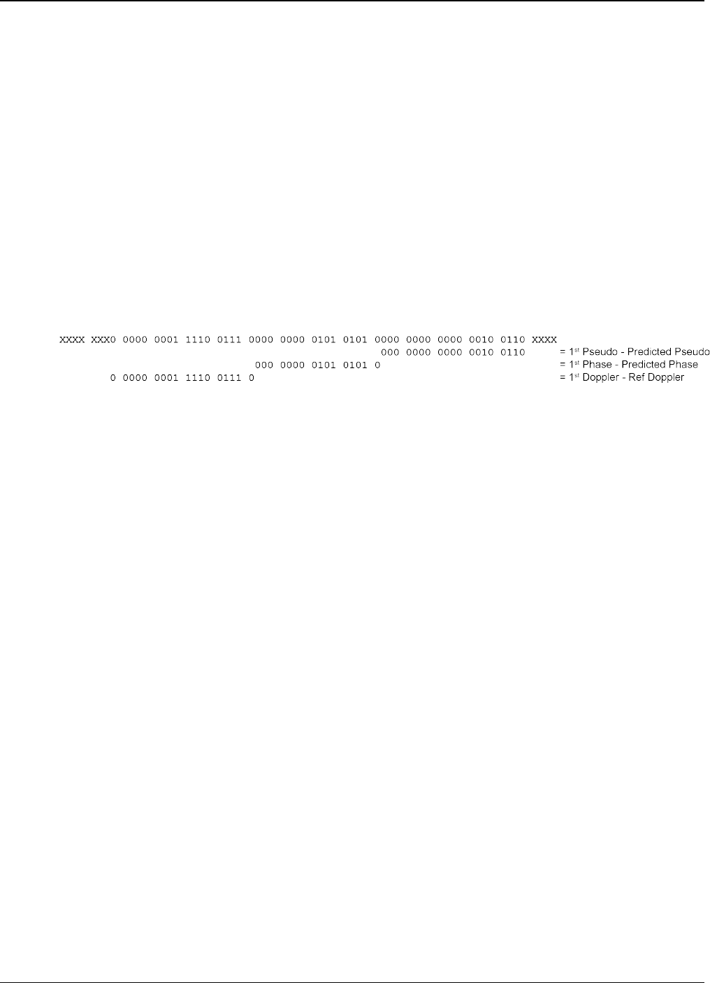
APPENDIX A Example of Bit Parsing a RANGECMP4 Log
OEM7 Commands and Logs Reference Manual v7 1060
lFor the following calculations, the time difference between the Differential Log and the Refer-
ence log is 0.25 seconds as shown below:
Time Difference = Current Log Time – Reference log Time
= 507977.250 - 507977.000
= 0.250 seconds
The signal data section (bottom 53 bits) is processed as follows:
lWith 4 bits unprocessed from the previous byte, we calculate 53 – 4 = 49 bits = 7 bytes (7
bits will not be processed in the last byte).
lUse the last byte (0x61) plus grab 7 bytes (0x02005500e70162)
= 0x6102005500e70162
lSwap the bytes = 0x6201e70055000261
l0x6201e70055000261 in binary form =
0110 0010 0000 0001 1110 0111 0000 0000 0101 0101 0000 0000 0000 0010 0110 0001
lOnly need 53 bits. Ignore last 4 LSBs and first 7 MSBs =
lUse Table 143: Primary Differential Signal Measurement Block on page700 to identify if a
2’s Complement Conversion is needed as well as what Scale Factor should be used before
these binary numbers are used in the following calculations.
lThe 1st (Primary) Differential Pseudorange is processed by:
Predicted Pseudorange = Reference 1st Pseudorange + (1st Doppler x TimeDifference)
= 21540181.930275 m
= 21540290.811 m + ((-435.5229 m/s) x 0.250 s)
1st DiffPseudorange – Predicted Pseudorange = 0x0000000000000100110b x Scaling Factor
1st DiffPseudorange – 21540181.930275 m = 38 x 0.0005
L1CA Pseudorange for PRN 10 = 21540181.949275 m
lThe 1st (Primary) Differential Phaserange is a 2’s Complement number (as identified by the
Range column in Table 143: Primary Differential Signal Measurement Block on page700) so
it is processed in the following manner:
Predicted Phaserange = Reference 1st DiffPhaserange + (1st Doppler x TimeDifference)
= 21540291.5622 m + ((-435.5229 m/s) x 0.250 s)
= 21540182.681475 m
1st DiffPhaserange – Predicted Phaserange = 2’s Complement(0x0000000010101010b) *
Scaling Factor
1st DiffPhaserange – 21540182.681475 m = 170 * 0.0001
L1CA Phaserange = 21540182.698475 m
lConvert this to ADR to check against the original RANGE log:
ADR = 1st DifPhaserange * Frequency * (-1)/Speed Of Light
ADR = 21540182.698475 m * 1575420000 Hz * (-1)/299792458 m/s
L1CA ADR for PRN 10 = -113194424.0799796 cycles
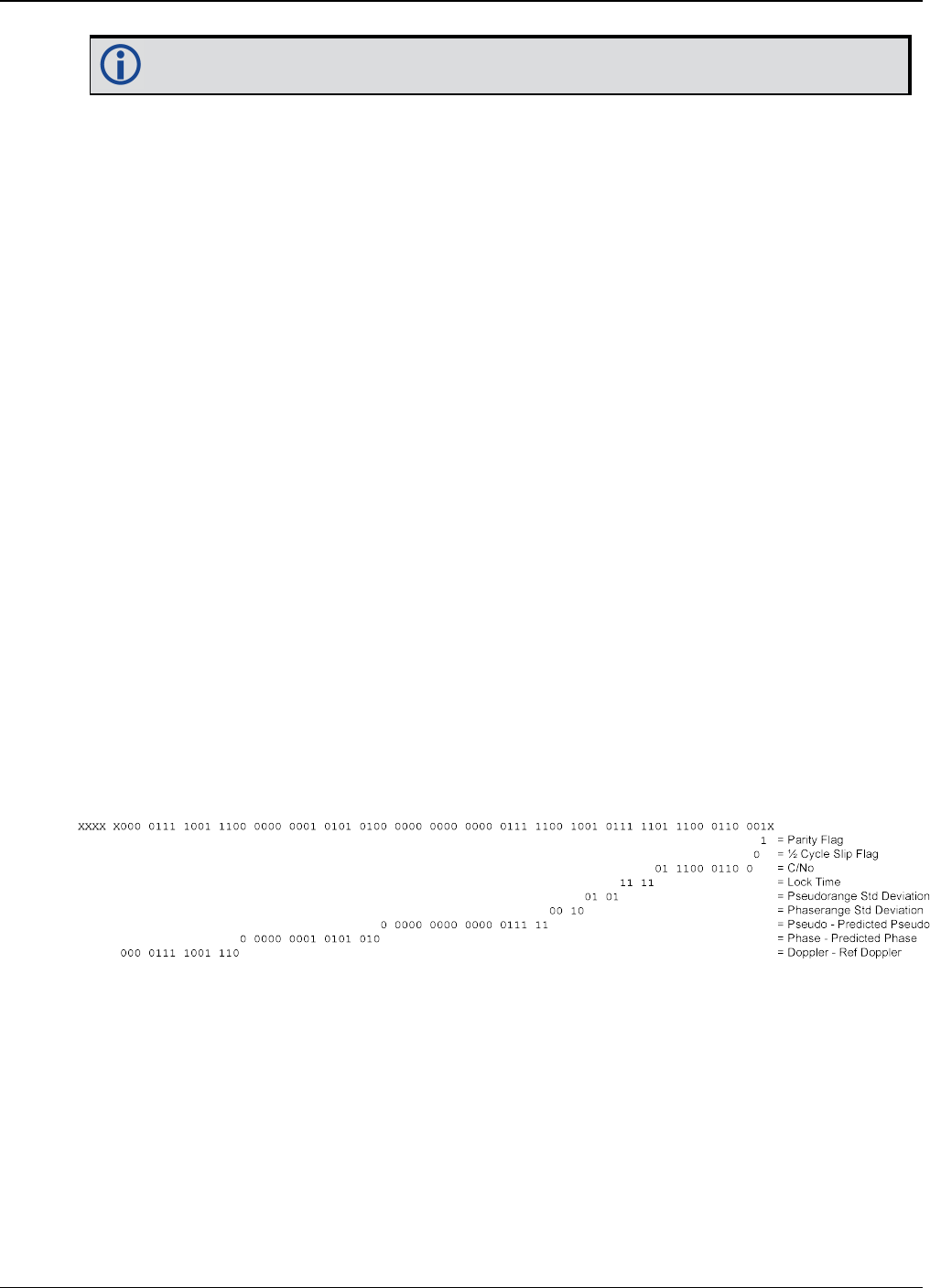
APPENDIX A Example of Bit Parsing a RANGECMP4 Log
OEM7 Commands and Logs Reference Manual v7 1061
In the range logs, PSR and ADR have opposite signs.
lThe 1st (Primary) Differential Doppler is a 2’s Complement number (as identified by the
Range column in Table 143: Primary Differential Signal Measurement Block on page700) so
it is processed in the following manner:
1st DiffDoppler(m/s)- Reference 1st Doppler = 2’s Complement(0x000000001111001110b) x
Scaling Factor
1st DiffDoppler(m/s) – (-435.5229 m/s) = 974 x 0.0001
L1CA Doppler(m/s) = -435.4255 m/s
Convert the Doppler to Hz:
1st DiffDoppler(Hz) = 1st DiffDoppler(m/s) x Frequency * (-1)/Speed Of Light
1st DiffDoppler(Hz) = -435.4255 m/s x 1575420000 Hz * (-1)/299792458 m/s
L1CA Doppler(Hz) for PRN 10 = 2288.1764464 Hz
A.2.6 Differential Secondary Signals Measurement Block GPS PRN 10 –
L2Y
Unlike Reference logs which always reflect back to the initial signal for their computations, Dif-
ferential logs uses the last Reference log data of the same signal for its calculations.
lWith 7 bits unprocessed from the previous byte, we will require 74 – 7 = 67 bits which
rounds up to 9 bytes.
lUse the last byte (0x62) plus grab the next 9 bytes (0xdc977c004015c07988)
= 0x62dc977c004015c07988
lSwap the bytes = 0x8879c01540007c97dc62
l0x8879c01540007c97dc62 in binary form =
1000 1000 0111 1001 1100 0000 0001 0101 0100 0000 0000 0000 0111 1100 1001 0111
1101 1100 0110 0010
lOnly need 74 bits. The 1 LSB is ignored as it was already processed above and the 5
MSBs are ignored so there is a total of 74 bits to process
lParity flag is a 1 (Parity Known)
l½ Cycle Slip flag is a 0 (Cycle Slip Not Present)
lC/No is:
0x01110001100b = 908 x Scaling Factor of 0.05
= 45.4 dBHz
lThe Lock Time value is:
0x1111b = 15 which means that this signal has been locked for 262144 ms or more.
lThe Pseudorange Std Deviation value is:

APPENDIX A Example of Bit Parsing a RANGECMP4 Log
OEM7 Commands and Logs Reference Manual v7 1062
0x0101b = 5 which means: 0.099 m < PSR Std Dev <= 0.148 m using Table 148: Pseu-
dorange Std Dev on page705.
lThe ADR Std Deviation value is:
0x0010b = 2 which means: 0.0052 < ADR Std Dev <= 0.0070 cycles using Table 147: ADR
Std Dev on page704.
lThe L2Y Pseudorange is a 2’s Complement number (as identified by the Range column in
Table 144: Secondary Differential Signals Measurement Block on page701) so it is pro-
cessed in the following manner:
Predicted Pseudorange = Reference 2nd Pseudorange + (2nd Doppler x TimeDifference)
= 21540293.6315 m + ((-435.523 m/s) x 0.250 s)
= 21540184.75075 m
DiffPseudorange – Predicted Pseudorange = 2’s Complement(0x0000000000000011111b) x
Scaling Factor
DiffPseudorange – 21540184.75075 m = 31 x 0.0005
L2Y Pseudorange = 21540184.76625 m
lThe L2Y Phaserange is a 2’s Complement number (as identified by the Range column in Table
144: Secondary Differential Signals Measurement Block on page701) so it is calculated in
the following manner:
Predicted Phaserange = Reference 2nd DiffPhaserange + (2nd Doppler x TimeDifference)
= 21540294.399 m + ((-435.523 m/s) x 0.250 s)
= 21540185.51825 m
DiffPhaserange – Predicted Phaserange = 2’s Complement(0x0000000010101010b) * Scaling
Factor
DiffPhaserange – 21540185.51825 m = 170 * 0.0001
L2Y Phaserange = 21540185.53525 m
lConvert this to ADR to check against the original RANGE log:
ADR = Phaserange * Frequency * (-1)/Speed Of Light
ADR = 21540185.53525 m * 1227600000 Hz * (-1)/299792458 m/s
L2Y ADR for PRN 10 = -88203458.95116848 cycles
In the range logs, PSR and ADR have opposite signs.
lThe L2Y Doppler is a 2’s Complement number (as identified by the Range column in Table
144: Secondary Differential Signals Measurement Block on page701) so it is calculated in
the following manner:
DiffDoppler(m/s) – Ref 2nd Doppler(m/s) = 2’s Complement(0x00001111001110b) x Scaling
Factor
DiffDoppler(m/s) – (-435.5229 m/s) = (974) x 0.0001
L2Y Doppler(m/s) = -435.4255 m/s
Convert the Doppler to Hz:
Doppler(Hz) = Doppler(m/s) x Frequency * (-1)/Speed Of Light
Doppler(Hz) = -435.4255 m/s x 1227600000 Hz * (-1)/299792458 m/s
L2Y Doppler(Hz) for PRN 10 = 1782.994633 Hz
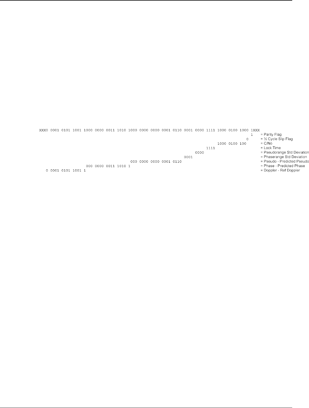
APPENDIX A Example of Bit Parsing a RANGECMP4 Log
OEM7 Commands and Logs Reference Manual v7 1063
A.2.7 Differential Third Signals Measurement Block GPS PRN 10 – L5Q
Unlike Reference logs which always reflect back to the initial signal for their computations, Dif-
ferential logs uses the last Reference log data of the same signal for its calculations.
lWith 3 bits unprocessed from the previous byte, we will require 74 – 3 = 71 bits which
rounds up to 9 bytes.
lUse the last byte (0x88) plus grab the next 9 bytes (0x 840f6101803a805921)
= 0x88840f6101803a805921
lSwap the bytes = 0x2159803a8001610f8488
l0x2159803a8001610f8488 in binary form =
0010 0001 0101 1001 1000 0000 0011 1010 1000 0000 0000 0001 0110 0001 0000 1111
1000 0100 1000 1000
lOnly need 74 bits. The 3 LSBs are ignored as they were already processed and the 3
MSBs are ignored so there is a total of 74 bits to process
lParity flag is a 1 (Parity Known)
l½ Cycle Slip flag is a 0 (Cycle Slip Not Present)
lC/No is:
0x10000100100b = 1060 x Scaling factor of 0.05
= 53.0 dBHz
lThe Lock Time value is:
0x1111b = 15 which means that this signal has been locked for 262144 ms or more.
lThe Pseudorange Std Deviation value is:
0x0000b = 0 which means: PSR Std Dev <= 0.020 m using Table 148: Pseudorange Std Dev
on page705.
lThe ADR Std Deviation value is:
0x0001b = 1 which means: 0.0039 < ADR Std Dev <= 0.0052 cycles using Table 147: ADR
Std Dev on page704.
lThe L5Q Pseudorange is a 2’s Complement number (as identified by the Range column in
Table 144: Secondary Differential Signals Measurement Block on page701) so it is pro-
cessed in the following manner:
Predicted Pseudorange = Reference 3rd Pseudorange + (3rd Doppler x TimeDifference)
= 21540289.869 m + ((-435.5149 m/s) x 0.250 s)
= 21540180.990275 m
DiffPseudorange – Predicted Pseudorange = 2’s Complement(0x000 0000 0000 0001 0110b)
x Scaling Factor
DiffPseudorange – 21540180.990275 m = 22 x 0.0005
L5Q Pseudorange = 21540181.001275 m
lThe L5Q Phaserange is a 2’s Complement number (as identified by the Range column in

APPENDIX A Example of Bit Parsing a RANGECMP4 Log
OEM7 Commands and Logs Reference Manual v7 1064
Table 144: Secondary Differential Signals Measurement Block on page701) so it is cal-
culated in the following manner:
Predicted Phaserange = Reference 3rd DiffPhaserange + (3rd Doppler x TimeDifference)
= 21540290.8584 m + ((-435.5149 m/s) x 0.250 s)
= 21540181.979675 m
DiffPhaserange – Predicted Phaserange = 2’s Complement(0x0000000001110101b) * Scaling
Factor
DiffPhaserange – 21540181.979675 m = 117 * 0.0001
L5Q Phaserange = 21540181.991375 m
lConvert this to ADR to check against the original RANGE log:
ADR = Phaserange * Frequency * (-1)/Speed Of Light
ADR = 21540181.991375 m * 1176450000 Hz * (-1)/299792458 m/s
L5Q ADR for PRN 10 = -84528300.92127641 cycles
In the range logs, PSR and ADR have opposite signs.
lThe L5Q Doppler is a 2’s Complement number (as identified by the Range column in Table
144: Secondary Differential Signals Measurement Block on page701) so it is calculated in
the following manner:
DiffDoppler(m/s) – Ref 3rd Doppler(m/s) = 2’s Complement(0x00001010110011b) x Scaling
Factor
DiffDoppler(m/s) – (-435.5149 m/s) = 691 x 0.0001
L5Q Doppler(m/s) = -435.4458 m/s
Convert this to Hz:
Doppler(Hz) = Doppler(m/s) x Frequency * (-1)/Speed Of Light
Doppler(Hz) = -435.4458 m/s x 1176450000 Hz * (-1)/299792458 m/s
L5Q Doppler(Hz) for PRN 10 = 1708.78285 Hz
This concludes the decoding of the Differential Log for PRN 10 (signals L1CA, L2Y, and L5Q). The
rest of the decoding for the other PRNs and systems are handled in the same manner.

OEM7 Commands and Logs Reference Manual v7 1065
