P5423W 01 P5423W_121008WJ 121008WJ
User Manual: P5423W_121008WJ
Open the PDF directly: View PDF ![]() .
.
Page Count: 22

1-86 6 -556-2757
F AX : 1-866-873-3531
W e striv e t o ensur e tha t ou r product s ar e o f th e highes t quality
an d fre e o f manufacturin g defect s o r missin g parts . Howev e r , if
yo u hav e an y problem s wit h you r ne w product,
D O NO T RETUR N I T T O TH E S T ORE ,
pleas e contac t u s tol l fre e @:
O r writ e to:
Escal a d e Spor t s
Cust o me r Servi c e Depa r tme n t
P .O . Bo x 8 8 9
Evansvill e I N 47706
Y ou r Mode l Numbe r _____ _ ________ _ ______
P5423W
hav e you r mode l numbe r whe n inquirin g abou t parts.
pooltables@escaladesports.com
Please
Dat e Cod e ________________________
2-P5423W- -WJ
© 201 2 Escalad e Sports Fo r Custome r Servic e Cal l 1-866-556-2757
Whe n contactin g Escalad e Sport s pleas e provid e you r mode l numbe r , d at e
cod e (i f a pplicable ) an d par t n umbe r i f requestin g a replacemen t part . T hes e
number s ar e locate d o n th e product , packaging , an d t hi s owner s m anual .
1
All Rights Reserved.
Purchase Date ________________________
PLEASE RETAIN THIS INSTRUCTION MANUAL FOR FUTURE REFERENCE
© 2012 Escalade Sports For Customer Service Call 1-866-556-2757
2
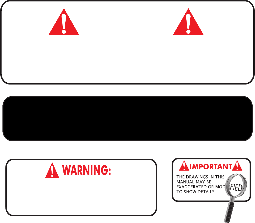
CAUTION
THE SPRAY ADHESIVEUSED FOR APPLYINGPLAYFIELD CLOTH IS EXTREMELY FLAMMABLEANDUNDER
PRESSURE
! CAREFULLY READ CAUTIONS ON SPRAY ADHESIVECONTAINER ! KEEPOUT OF THEREACH OF
CHILDREN ! DO NOT USE OR STORENEARHEAT SOURCE ,FLAMES ,SPARKS OR WHENSMOKING ! WORK
AREAMUSTBEWELLVENTILATED
. OPENDOORS AND WINDOWSWHENUSINGSPRAY ADHESIVE .
To ensuresafety, do not attempttoassemblesystemwithoutfollowinginstruc-
tionscarefully. Properandcompleteassembly, use,andsupervision is essentialfor
proper operation and to reduce the risk of accident or injury.Ahigh prob-
ability of serious injury exists if this system is not installed, maintained, and
operated properly.
NOTE: This table adds weight to any floor. Be sure floor can withstand this kind of weight.
If floor sags, table will be impossible to level.
•Philips Screwdriver
•Putty Knife
•Needle Nose Plyers
•Adjustable Wrench
•Small Hammer
•Carpenters Level
•Ratchet with socket
•Tape Measure
•Sanding Block
•Scissors or Sharp Knife
Tools Needed: (Not Included)
READ AND FOLLOW ALL ASSEMBLY, OPERATION, AND
SAFETY INSTRUCTIONS CAREFULLY. AT LEAST TWO
ADULTS ARE NEEDED TO PUT THIS TABLE
TOGETHER.
All Rights Reserved.
•12mm Socket or End Wrench
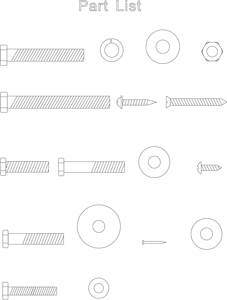
Pa r t Li s t
H14 - Pocket Nail
(36 pcs)
© 201 2 Escalad e Sports Fo r Custome r Servic e Cal l 1-866-556-2757
3
H5 - 3/8” x 3” Bolt
(8 pcs)
H7 - F5 x 1-3/4”
Phillips Flat Head Screw
(16 pcs)
H1 - 3/8” x 2-1/4” Bolt
(8 pcs)
H2 - 3/8” Lock
Washer (16 pcs)
H3 - 3/8” x 25mm
Flat Washer (32 pcs)
H12 - 5/16” x 1-5/8” Bolt
(18 pcs)
H13 - 5/16” x 32mm
Flat Washer (18 pcs)
H8 - 5/16” x 1-1/4” Bolt
(8 pcs)
H9 - 5/16” x 1-3/4” Bolt
(12 pcs) H10 - 5/16” x 23mm
Flat Washer (12 pcs)
H4 - 3/8” Hex Nut
(16 pcs)
H6 - WP/4 x 1”
Phillips Washer
Head Screw
(12 pcs)
All Rights Reserved.
(To Scale)
H11 - T4 x 15mm
Phillips Round Head
Screw (24 pcs)
H15 - 5/16” x 23mm
Flat Washer
(8 pcs)
H16 - 1/4” x 1-1/2” Bolt
(4 pcs)
H17 - 1/4” x 15mm
Flat Washer (4 pcs)
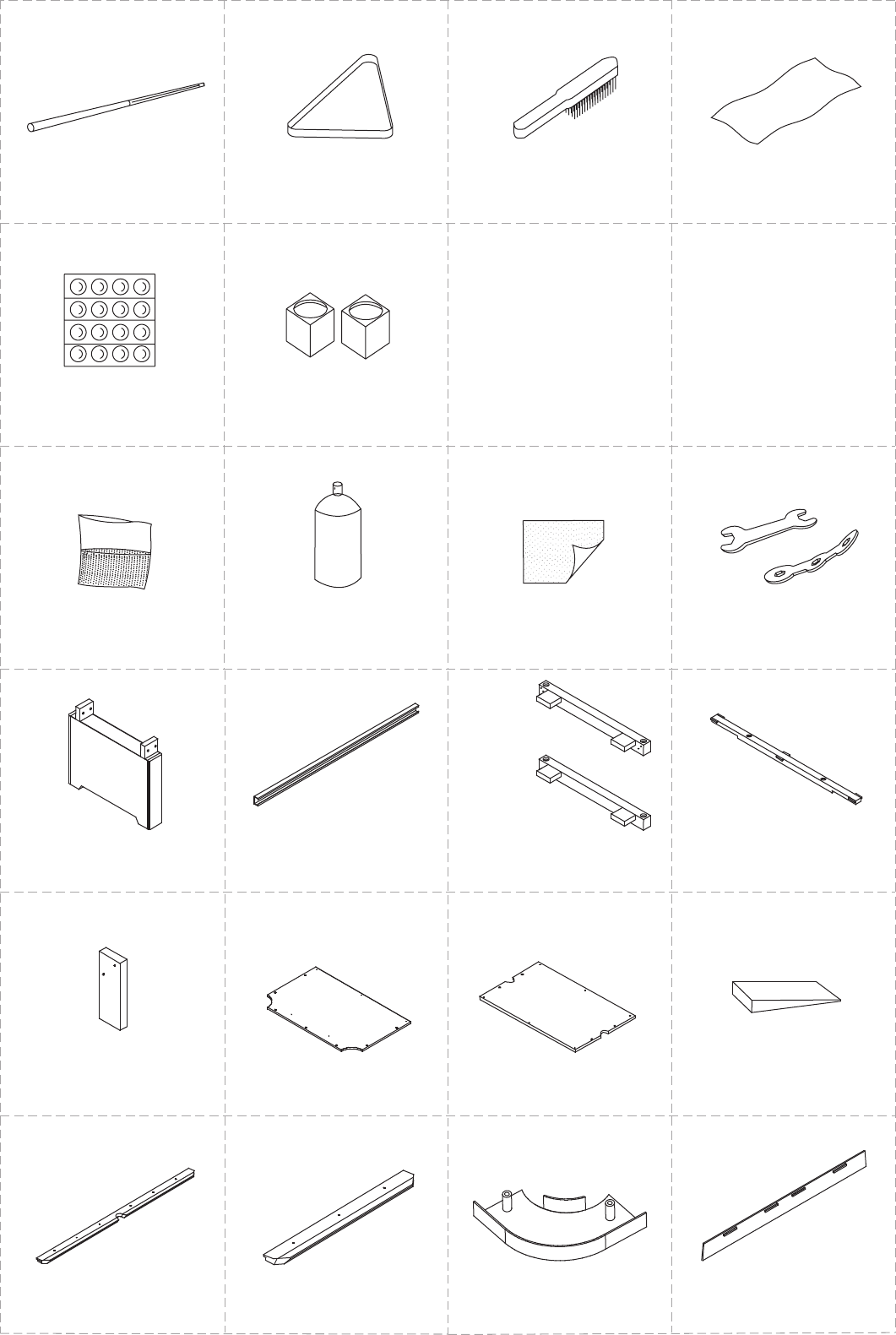
T1 T2 T3 T4
A1 A2 A3 A4
A5 A6
Cu e Stic k
2 Pcs
T riangl e
1 P c
Playfield Cloth Brush
1 P c
Playfield Cloth
1 P c
Billiar d Bal l
1 Se t
Cue Chalk
2 Pc s
© 201 2 Escalad e Sports Fo r Custome r Servic e Cal l 1-866-556-2757
4
Playfield Grout Kit
1 Pc 1 P c
Playfield Cloth to Playfield
- Spray Adhesive -
1 Pc
Sand Paper for Dried Grout
1 Set
Wrench
All Rights Reserved.
P1 P2 P3A P4
P5 P6 - Slatron
P6S - Slate
P7 - Slatron
P7S - Slate
P8
P9 P10 P11 P12
Leg
2 Pcs 2 Pcs
Main Metal Beam
2 Pcs
End Slat
2 Pcs
Middle Slat
End Board
2 Pcs 2 Pcs
End Play Bed
1 Pc
Middle Play Bed 8 Pcs
Shim
Side Top Rail
2 Pcs 2 Pcs
End Top Rail
4 Pcs
Corner Cap
2 Pcs
Side Apron
Can also use playing cards (not included)
or Slate / Slatron Shims
P3B
NOTE: For P5
Installation.
NOTE: For P16
Installation.
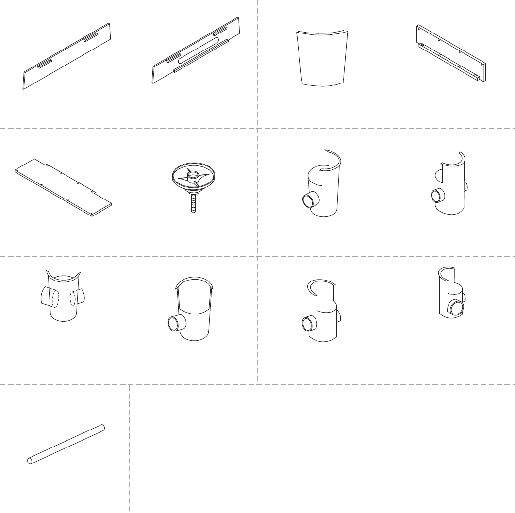
P21 P22 P23 P24
P13 P14 P15 P16
P17 P18
End Apron
1 Pc
End Apron with Ball
Return Opening
1 P c
Corner Post
4 Pcs
Ball Return Tray Board
1Pc
© 201 2 Escalad e Sports Fo r Custome r Servic e Cal l 1-866-556-2757
5
All Rights Reserved.
P25
Ball Return Tube
4 Pcs
Ball Return
Support Board
1 Pc
Leg Leveler
4Pcs
P19 P20
Right Corner Pocket
1Pc
Right Middle Pocket
1Pc
Right Corner Pocket
NOTE: Attach this pocket on
same end as P14 Apron with
Ball Return Opening
1Pc 1Pc
Left Middle Pocket
1Pc
Left Corner Pocket
1Pc
Left Corner Pocket
NOTE: Attach this pocket on
same end as P14 Apron with
Ball Return Opening
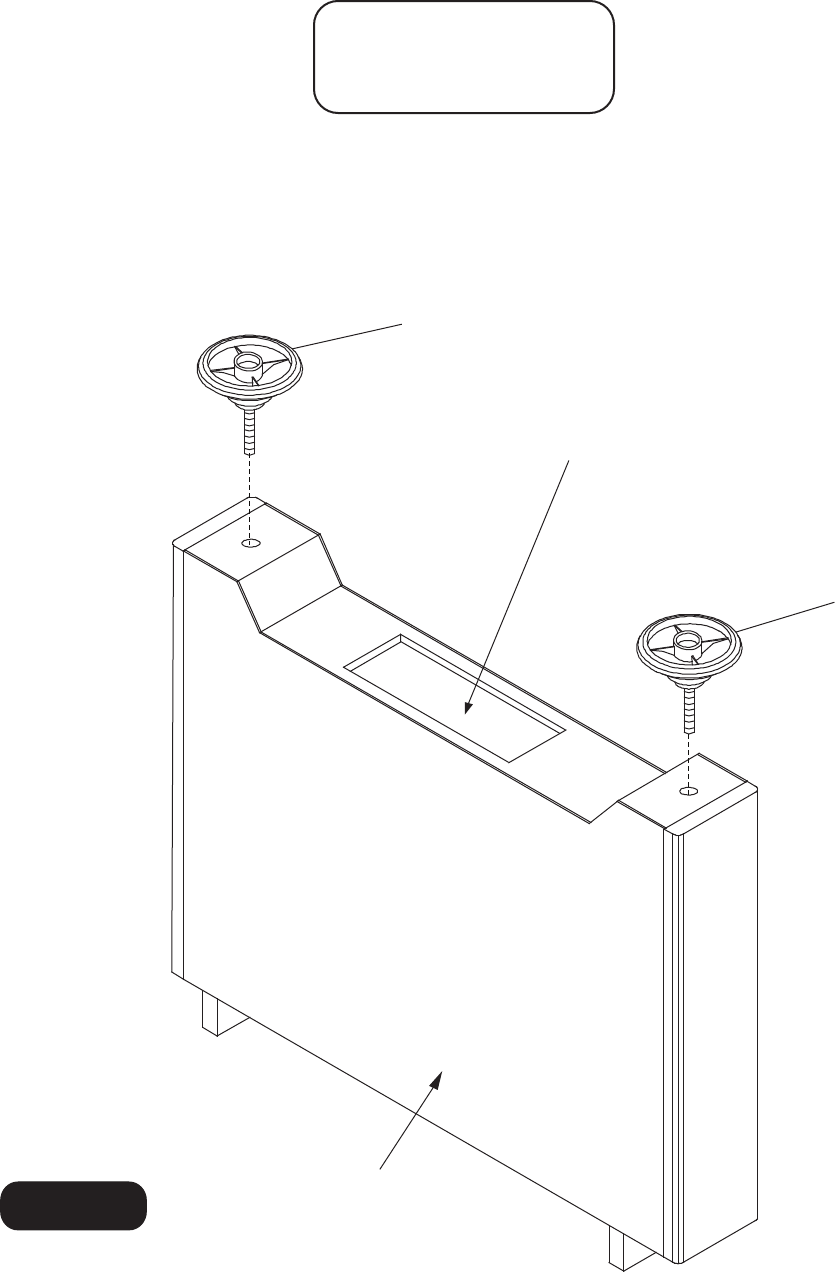
ST E P 1 :
6
© 201 2 Escalad e Sports Fo r Custome r Servic e Cal l 1-866-556-2757
Thread P18 Leg Levelers into P1 Leg as shown in Figure 1. .
P18
P1
P18
Figure 1
All Rights Reserved.
P ARTS REQUIRED:
2 pcs - P1 Leg
4 pcs - P18 Leg Leveler
Note: Remove Parts Box, Leg Levelers,
Plastic Pockets and Spray Glue from
inside both Legs.
P16 Ball Return Support Board
P3A & P3B End Slat
SAME
DIMENSION
P4
P4
7
© 201 2 Escalad e Sports Fo r Custome r Servic e Cal l 1-866-556-2757
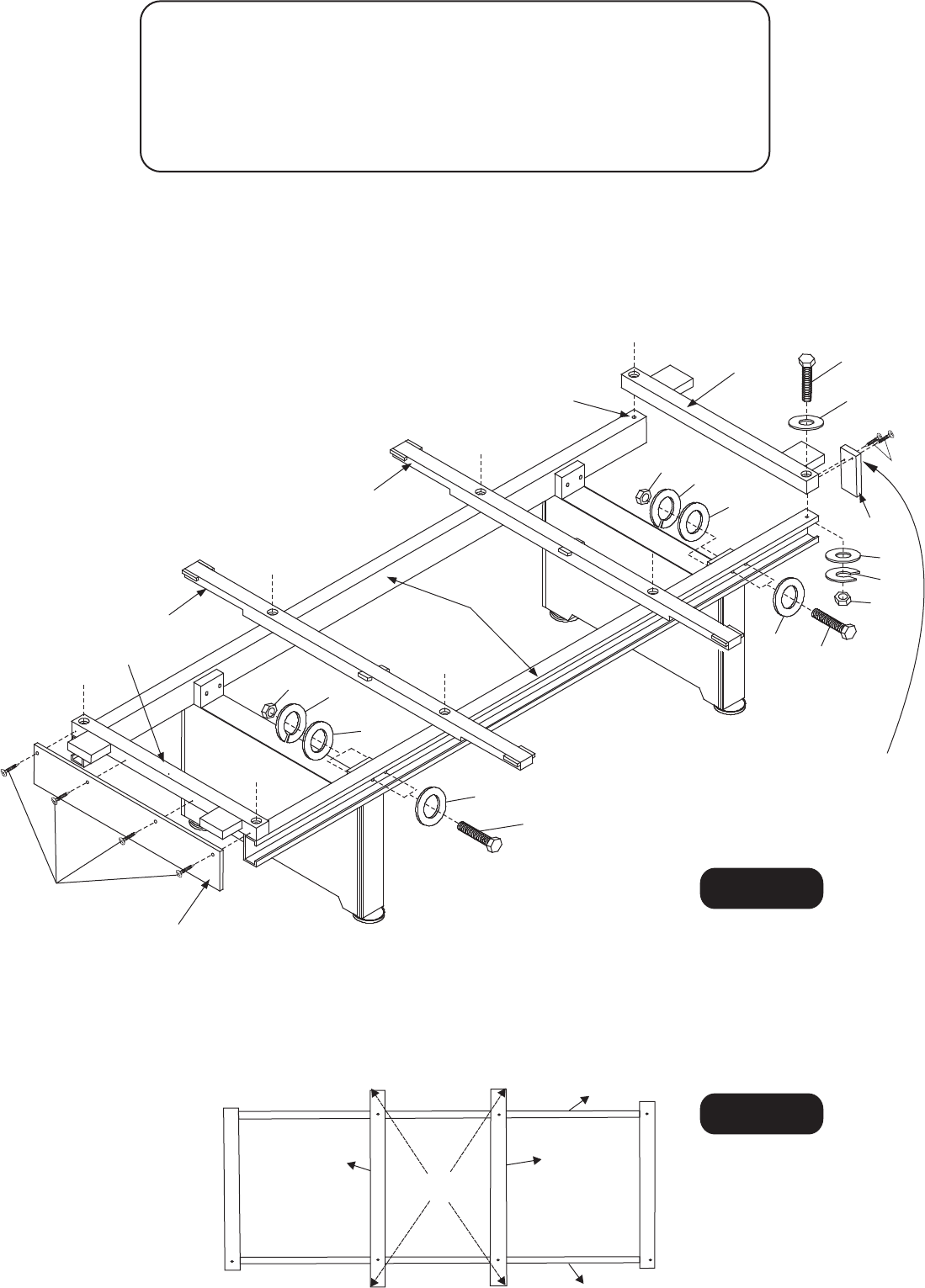
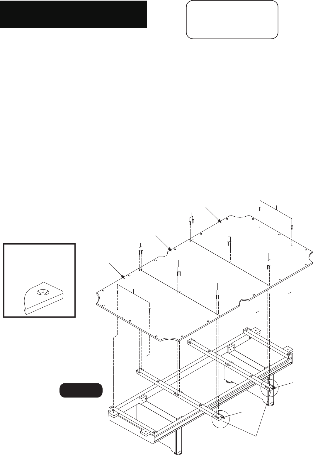
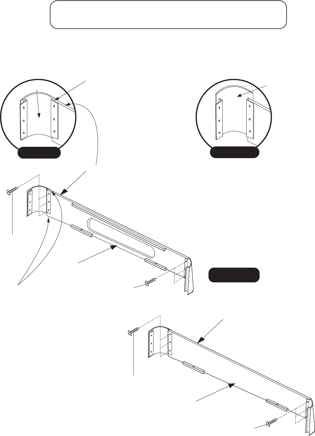
ST E P 2 :
Attach each P2 Main Metal Beam to P1 Leg assembly as shown Figure 2 using H1 Bolts, H3 Washers,
H2 Lock Washers and H4 Hex Nuts. Use the T4 Wrench to assemble the hardware. Do not tighten
hardware at this time. Place P3 A and P3B End Slats and P4 Middle Slats across P2 Main Beams and
attach using H5 Bolts, H3 washers, H2 Lock Washers and H4 Hex Nuts as shown in Figure 2.
Attach P5 End Boards to P3A End Slat using pre-drilled pilot holes with H6 Screws as shown in Figure 2.
Attach P16 Ball Return Support Board to P3B End Slat using pre-drilled pilot holes with H6 Screws as
shown in Figure 2.
H2
H1
H3
H4
P4
P4
P2
H4 H2
H1
H3
STEP 3:
Square up P4 Slats by measuring diagonally as show in Figure 3. Diagonal measurements should be
the same within 1/8". If the frame is not square, adjustment can be made by moving table beams P2 in
opposite directions. Once the frame is square, tighten all hardware.
Figure 3
All Rights Reserved.
H3
H3
PARTS REQUIRED:
8 pcs - H1 Bolt
16 pcs - H2 Lock Washer
32 pcs - H3 Washer
16 pcs - H4 Hex Nut
8 pcs - H5 Bolt
2 pcs - P2 Main Metal Beam
2 pcs -
2 pcs - P4 Middle Slat
2 pcs - P5 End Board
1 pc -
1 set - T4 Wrench
P2
P2
H5
H3
H4
H3
H2
P3A
IMPORTANT NOTE:
Make sure holes are located on the
top of both P2 Main Metal Beams.
Note: P5 End Boards must be
8 pcs - H6 Screw
flush or slightly lower than top
of P3A End Slats.
P3B
H6
P5
Figure 2
H6
P16
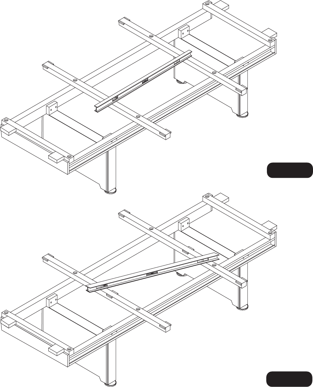
STE P 4 :
Us e a carpente r ’ s leve l t o leve l tabl e a s clos e a s possible . It i s easie r t o d o i t no w rather than
after the Play Bed is on the frame. To determine the highest corner of the frame place the
level in following two positions. First check the table from end to end as shown in Figure 4.
Then check the table at an angle as shown in
Can also use playing cards for Slate / Slatron Shimming - not included.
Figure 5.
8
© 201 2 Escalad e Sports Fo r Custome r Servic e Cal l 1-866-556-2757
Figure 4
Figure 5
All Rights Reserved.
9
© 201 2 Escalad e Sports Fo r Custome r Servic e Cal l 1-866-556-2757
Figure 8
All Rights Reserved.
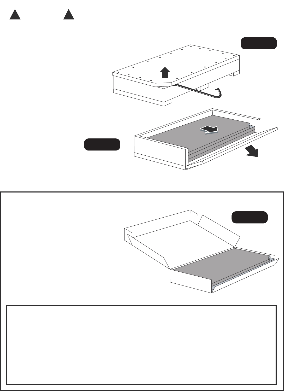
UNBOX I N G TH E SL A T E (Slat e t a b l e s o nl y: )
! !
CAUTIO N AFTE R CR A T E P A R T S AR E REM O VED , B EN D NA I L S O R S T AP L E S O VE R W I T H A
HAM M E R A T O NCE ! U S E CAUT IO N WHE N HAND LI N G CR A T E P A R TS !
I t i s n o w t im e t o u ncr a t e t h e s l a t e pi e c e s .
W i t h a c la w hamme r o r c ro w ba r , p r y o f f c ra t e
to p a t t h e notche d corne r . ( Se e )
Remov e t h e fron t rai l o f th e crate . S lid e th e slat e
ou t th e f ron t o f th e crate .
FIGUR E 6
B E CAREFU L NO T T O DAMAG E SL A T E
INSIDE ! SL A T E I S BRITTL E AN D CA N
B E EASI L Y DAMAGE D I F HI T O R PRIE D
AGAINST !
(FIGUR E 7 )
UNBOXIN G TH E SL A TRO N (Slatro n t able s only: )
I t i s no w t im e t o unbo x th e slatro n pieces .
B E CAREFU L NO T T O DAMAG E SL A TRO N
INSIDE ! SL A TRO N CA N B E EASI L Y DAMA -
GE D I F HI T O R PRIE D A GAINST !
(Se e FIGUR E 8 )
I f th e edge s o f you r Slatro n h a s “fuzz ” o n it ,
lightl y san d t o r emov e wit h sandpape r
provide d i n t h e playbe d kit .
IMPOR T ANT !
Th e s heet s o f s latro n ma y no t b e completel y fla t whe n
remove d f ro m t h e shippin g carton . Thi s i s normal . Onc e
the y hav e bee n place d o n th e t abl e fram e an d securel y
fastene d down , the y wil l becom e straigh t an d f lat .
Figure 6
Figure 7
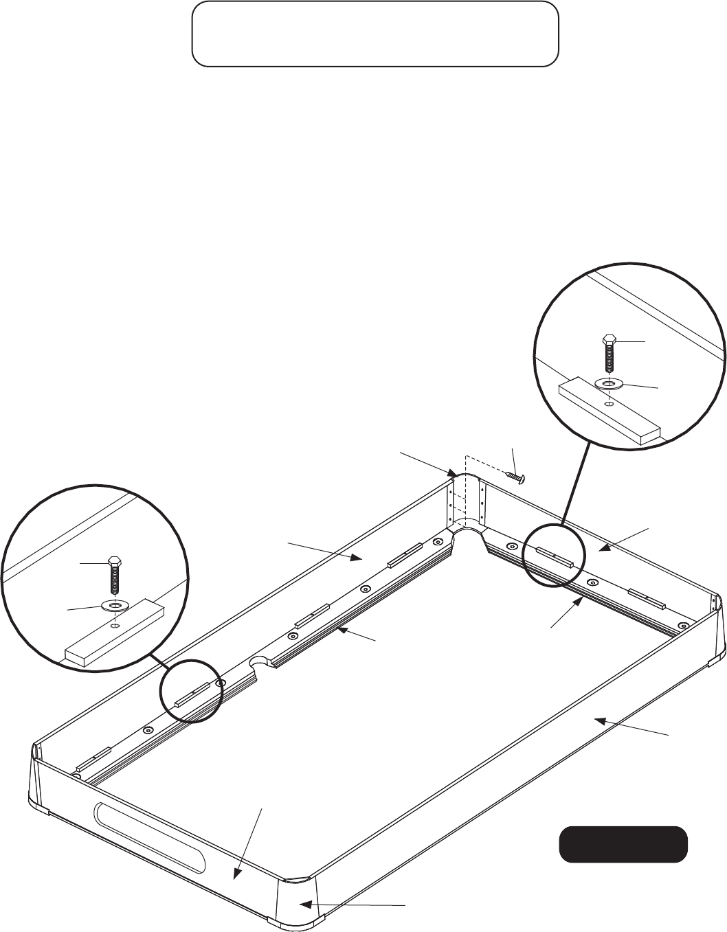
THE FOLLOWING STEPREQUIRES
THEHELP OF ANOTHERADULT!
STEP 5:
You cantellthe top side of theplayfieldsections by thebevelededge of thepocket openings
andthecountersunkmountingholes. The bevelededgesand the countersunkholes must
face
up. (SeeDetail A)
muchasyoucan.Theplayfieldsectionsare51incheswide.TheP4 Middle Slats are 51 inches
long, The play bed sections should be flush with the P4 Middle Slats on both sides of
table.
Thissteprequirestwoadults! WARNING:
REMEMBER: Be surecountersunkholes in theplayfieldfaceup!
B) Secure center section P7 to long slats P4 with screws H7 into countersunk holes.
importantthattheedges of the threepieces of playfieldare flushandsquare.
DO NOTOVERTIGHTENSCREWS!
PlaceendPlayBedsection P6 onto slats.Be sure they are square,in line and butted up
tight
against centersection P7.Secure end section P6 to beams using screws H7 into
countersunk holes.
DO NOTOVERTIGHTENSCREWS. NOTE:If necessary,shim underneath
TOP OF PLAY BEDMUSTBEPRECISELY LEVEL! EDGES MUSTBEEVENWITH ONE
ANOTHER!
Be surethattheside
of thetabletop
sectionswith the
countersinkaround
eachholeface up
Detail A
10
© 2012 Escalade Sports For Customer Service Call 1-866-556-2757
H7
H7
H7
H7
H7
H7
P6
P7
P6
P4
P4
A) Place center section P7 on the two long slats P4.If edges do not align exactly,center playfield as
Note:It is
Play Bed where they join together to obtain a smooth,even surface.Shims are provided in the slate
bed kit.
Figure 9
H7
H7
PARTS REQUIRED:
16 pcs - H7 Screw
2 pcs - P6 End Play Bed
1 pcs - P7 Middle Play Bed
All Rights Reserved.
Playbed sections must be flush with
P4 Middle Slats on both side of table.
Note: See next page for
Playfield Shimming Instructions.
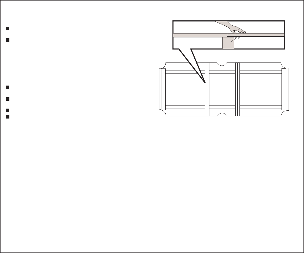
SHIMMINGINSTRUCTIONS
GeneralRules
Accomplishtheleveling of the playingsurface with
as few shims as possible.
Do not tap withahammer or tighten screws
unreasonably tight. You will not be able to compress
the playing surface. You mustshim up the playing
surfacetolevel. Shims are meant onlytoraisethe
low places at the seams and ends. Very short and
low places should be grouted. Do not assume the
floor is level. Most leveling canbeaccomplished by
workingwith theframe.
If using power tools be sure to use only enough
torque to reasonably tighten screws.
Seams can bestbechecked by passingyourfinger
overthe seamand feeling if it is flush.
Allscrewsmustbetightenedafter shimming.
No two sets of PlayBedareexactlyalike.Some
setsrequire moreorless shimmingthanothers.
Shim
Top of playingsurface
mustbeflush at seams!
STEPBYSTEPSHIMMING
A) Be suretableissetinitsfinallocation.
B) Tablemustbeaslevel as possiblebeforeshimming.Largedifferencesinlevelness must
be corrected by raising or loweringframewithincludedleglevelers or shimstock
C) Tightendownalltheplayingsurfacemountingscrews.
D) Checkwithacarpenter’s level to determinewhereplayfield is lowonends, and use finger
tipstolocateunevenspots at the seams.Loosenscrewsatthesepointsandsee if
playfieldcomes up to flush.Ifso, detachindividualshims from the sheetshippedwith this
tableandplaceundertheseareas.
E) Layastraightedgeacrossseamstobesureplayfieldpiecesareatthesameheight.
F) After top surface of playfield is flatandlevel,allscrewsmustbesnuggeddown in tight
position.Check thesescrewsbeforeproceeding to
thenext step.
.
DO NOTASSUMEFLOOR IS LEVEL!
Place shims next to screws.
DO NOTOVER-TIGHTENSCREWS!
GROUTING INSTRUCTIONSFORPLAY BED
-
-
-
-
-
Cleantop of playfieldwithadampcloth.Allowenoughtimefor
topsectionstodry thoroughlybeforestartingthenext step.
Asmallcontainer of grouthasbeenprovidedfor fillingcountersinksandsmallimperfections in the
tableseams.Empty1/3ofgroutintoamixingcontainer. Add1teaspoon of waterandstir-addvery
smallquantities of groutorwatertoachieveathickpaste. Whenmixed,groutshould beathick
pastethatwillnotdrip off puttyknife.Ifyoudogetgrouttoo thin,slowlyaddmorepowder.
Usingaputtyknife,fillbothseamsandthe fourcountersunkholes in thecenterplayfieldarea.
(Onlythe fourcountersunkholes in thecenterofthe tableneed to be filledsince the otherholes
will be covered by the rails.)Donotuse moregroutthanyouneed.
Letgroutdry. Readtherest of thismanualwhileyouwait!
Usingamediumgritsandpaperandsandingblock,sandthe filledareassmoothandflat.
Re-grout if youstillfindlowplaces
at countersunkholes or seams.
DO NOTUSE TOO MUCH WATER!
RECHECKTHESEAREASTOMAKESURETHEYAREFLAT.
11
© 2012 Escalade Sports For Customer Service Call 1-866-556-2757
P8
All Rights Reserved.
( use deck of cards for shimming, not included )
( use deck of cards for shimming, not included )
! !
WARNING
DO NOTSMOKE WHILE WORKING
WITHCONTACTCEMENT!READ LABEL
ON CEMENTCONTAINERCAREFULLY!
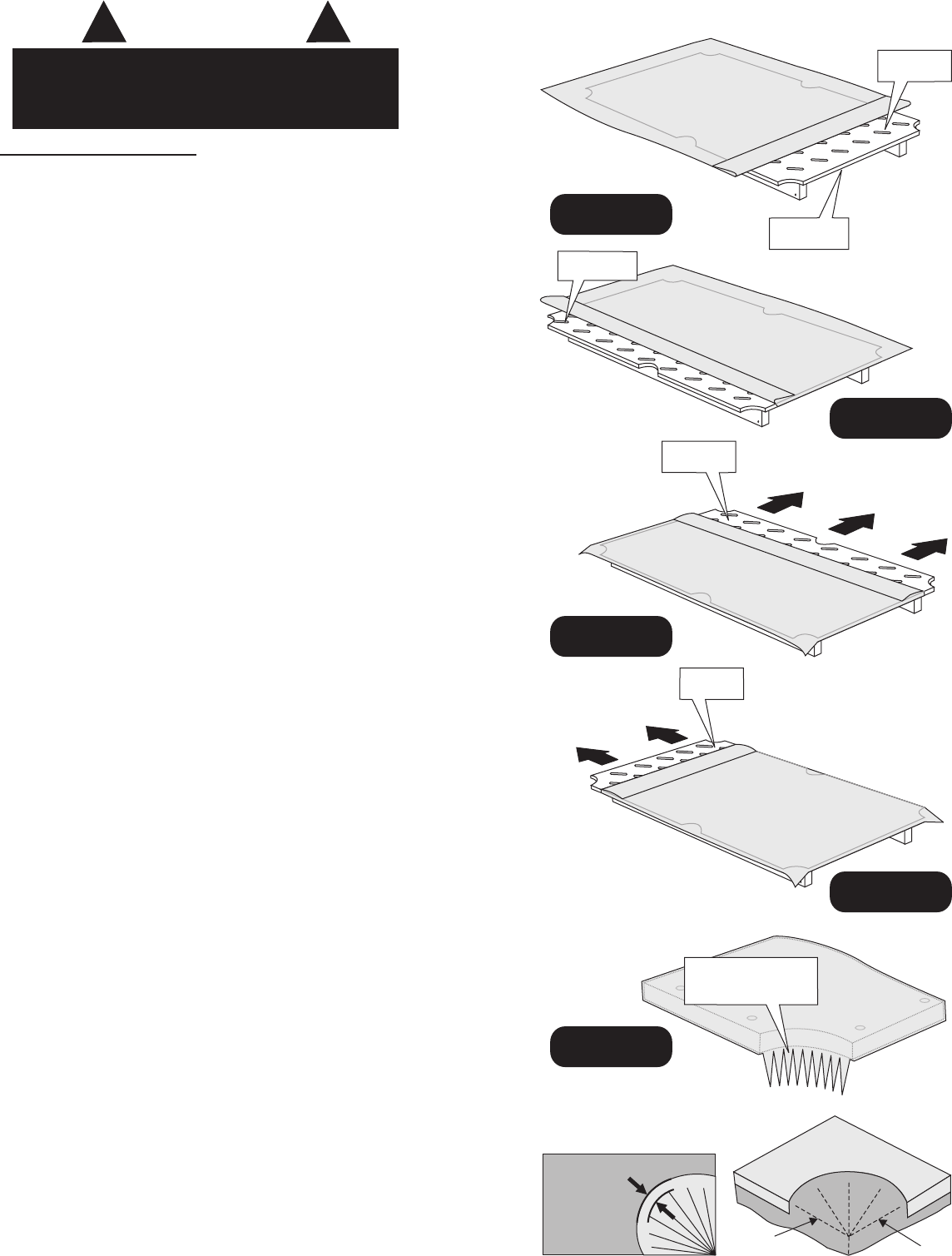
Applyingthe cloth:
1. MakesurePlay Bed is dry and free of dust.
Beforesprayingadhesive,cutaportion of the shipping
cartontouse asashield to preventcementoverspray.
2. Placeclothover PlayBedwithequaloverhang on allsides.
3. FoldclothawayfromendtoexposePlayBed for yourfirst
glueapplication.Applycontactcementtotopsurface inaband
4incheswide on thisend.(See
Spray cementsmoothlyandevenly. Allowcementtobecome
tacky, waitatleast one minute.
4. Foldclothbackover the table.Withfirmevenpressure, press
clothonto the areathathasbeencoatedwithcement. Smooth
clothdownandoveredges.
5. FoldclothawayfromsidetoexposePlayBed for yourse-
condglueapplication.(See ). Applycementtothe
sideinthe samemanner as yourfirstglueapplication.Allow
cementtobecome tacky, waitatleast one minute.
6. Foldclothbackovertable.Withfirmevenpressure, press
clothonto the areathathasbeencoatedwithcement. Smooth
clothdownandoveredges.
7. FoldclothawayfromothersidetoexposePlayBed for your
thirdglueapplication.(See ). Applycementtothis
sideinthe samemanner. Allowcementtobecome tacky, wait
at least one minute.
8. Stretch the clothacrossthewidthandovertheedge of the table.
9. FoldclothawayfromotherendtoexposePlayBed for your
fourthglueapplication.(See ) Applycementtothis
endinthesame manner. Allowcementtobecome tacky, wait at
least one minute.
10.Makeafinalstretchalongthelength of and overtheedge of
the table,stretchhardenough to work out allwrinkles. (See
) If clothisnotsmooth,liftandre-apply.
Rubbingfingerslightlyacrossclothshouldnotmake
clothmove.
11. Locatecenterofpocket opening.(Seeand ) Using
sharpscissors,makeastraightcut.Next, cut to pocket edge
to formpieshapes. (See ) Dividethesepieshapes in
half. As you do,thepieshapesbegin to relax to allowfor
placement. You may needtomakeadditionalcuts.
12.Sprayadhesive on the underneathsideoftheplay-bedaround
pocket facetoadhere the cloth.Makesurenottogetoverspray
of glue on table.Allowcementtobecome tacky, waitatleast
oneminute.Stretch the pieshapesdownandunderthepocket
opening.Press the clothagainst the cementontheunderside
of thePlayBed.Besureentirepieshape is fullyattached
to underneathside of table.
NOTE:
NOTE:Cloth may seemsmall but it willstretchagreatdeal.
FIGURE 10) Coat edge also.
FIGURE11
FIGURE 12
STRETCHHARDENOUGH TO TAKEOUT WRINKLES,BUT
NOT SO HARDTHAT THECLOTHSLIPS.
FIGURE 13
FIGURE 14
NOTE:
Detail A B
detail B
FirstGlue
Application
Sprayglue on
edge of slatetoo.
SecondGlue
Application
Third Glue
Application FIRST
STRETCH
FourthGlue
Application
FINAL
STRETCH
Cut withscissors.
Clothshouldcover
pocket edges.
CENTER
CUT
DIVIDE
IN HALF DIVIDE
IN HALF
CUT TO
POCKET
EDGES CUT TO
POCKET
EDGES
Detail B
Detail A
DO NOT
CUTANY
CLOSER
THAN3/4”
12
© 2012 Escalade Sports For Customer Service Call 1-866-556-2757
Figure 10
Figure 11
Figure 12
Figure 13
Figure 14
All Rights Reserved.
STEP 6:
P9
P10
NOTE:
Allpartsare
upside down
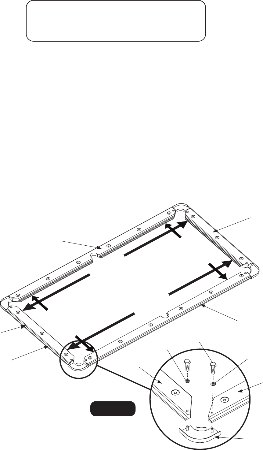
Onaclean level surface, lay each P9 Side Top Rail and P10 End Top Rail face down as shown in Figure 15.
Next, lay each P11 Corner Cap face down and attach using H8 Bolts with H15 Flat Washers as shown in
Figure 15 and Detail A. Do not tighten H8 Bolts at this time.
Next, Measure from the outer edge of cushion rubber, on each side of P10 End Top Rail to other end of P10
End Top Rail . These two measurements must be the same in order for this rail assembly to be a perfect
rectangle and should measure approx 87 5/8". This measurement may vary slightly from 87 5/8", but both
measurements must be the same. Hold each P10 End Top Rail down with your hand and tighten H8 Bolts - in
the end top rail only. Check to see that both measurements are still the same.
Next, Measure from the outer edge of cushion rubber, on each end of P9 Side Top Rail to other end of P9 Side
Top Rail. These two measurements must be the same in order for this rail assembly to be a perfect rectangle
and should measure approx 43 1/2". This measurement may vary slightly from 43 1/2", but both measurements
must be the same. Hold each P9 Side Top Rail down with your hand and tighten H8 Bolts - in side top rail only.
Check to see that both measurements are still the same.
Lastly, Check all (4) measurements to insure this assembly is a perfect rectangle and double check that all
corner cap bolts are tight.
13
© 2012 Escalade Sports For Customer Service Call 1-866-556-2757
PARTS REQUIRED:
8 pcs - H8 Bolt 2 pcs - P10 End Top Rail
8 pcs - H15 Flat Washer 4 pcs - P11 Corner Cap
2 pcs - P9 Side Top Rail
Figure 15
All Rights Reserved.
P9
P10
H8
H15
H15
P11
P10
P9
Approx 87 5/8”
Approx 43 1/2”
Approx 43 1/2”
Approx 87 5/8”
Approx 43 1/2”
14
©2012 Escalade Sports For Customer Service Call 1-866-556-2757
All Rights Reserved.
STEP 7:
Slide and attach each P15 Corner Post onto the end of each P13 and P14 End Apron using H11 Screws as
shown in Figure 16A. Tighten, but do not strip out H11 Screws.
IMPORTANT NOTE: Study and assemble parts exactly as per Figure 16A.
PARTS REQUIRED:
12 pcs - H11 Screw 1 pc - P14 End Apron with Ball Return Opening
1 pc - P13 End Apron 4 pcs - P15 Corner Post
NOTE: BE SURE EACH
CORNER POST IS FLUSH
WITH END APRON.
P14
P15
H11
H11
H11
H11
P13
NOTE: SILVER EDGE TRIM
AT UPWARD POSITION.
Figure 16A
P15
CORRECT INCORRECT
NOTE: SILVER EDGE TRIM
AT UPWARD POSITION.
NOTE: BE SURE CORNER
CAP IS COMPLETELY
PUSHED ONTO END APRON.
15
©2012 Escalade Sports For Customer Service Call 1-866-556-2757
All Rights Reserved.
Figure 16B
H9
H10
P13
P12
P14
P12
STEP 8:
With the rail assembly face down, attach P12 Side Aprons using H9 Bolts with H10 Washers (see inset). Do not
tighten yet.
Next, attach previous assemblies P13 and P14 End Aprons flush against the bottom of the P10 End Top Rail and
align using threaded inserts on the underside of each rail. Attach P13 and P14 End Apron assembly using H9
Bolts with H10 Washers (see inset). Do not tighten yet.
Be sure each P15 Corner Post is flush with each P12 Side Apron, then attach using H11 Screws.
Tighten, but do not strip out H11 Screws.
Lastly, tighten all H9 Apron Bolts.
PARTS REQUIRED:
12 pcs - H9 Bolt 12 pcs - H11 Screw
12 pcs - H10 Washer 2 pcs - P12 Side Apron
H11
P10
P9
P15
P15
H9
H10
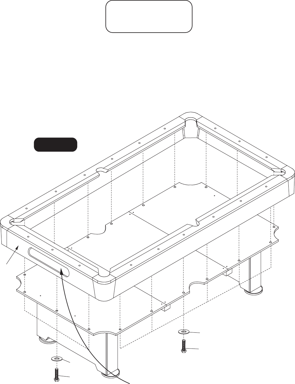
STEP 9:
16
© 2012 Escalade Sports For Customer Service Call 1-866-556-2757
With the help of four adults, carefully rotate the rail and apron assembly and then place over the play
bed as shown. From the underside of the table, insert H12 Bolts with H13 Washers up through the
play bed and into the threaded inserts of each rail. Be sure the rail assembly is aligned with the play
bed and pockets, then tighten all bolts.
H13
H12
H13
H12
Figure 17
PARTS REQUIRED:
18 pcs - H12 Bolt
18 pcs - H13 Washer
All Rights Reserved.
Important Note : Once Rail and Apron assembly is placed onto the playfield - carefully sight down
onto each pocket opening and adjust rail and apron assembly equal to all six pocket openings
before tightening H12 bolts.
IMPORTANT NOTE: Make sure this P14 End Apron with Ball
Return Opening is on same end as P16 Ball Return Support
Board assembled in STEP 2.
P14
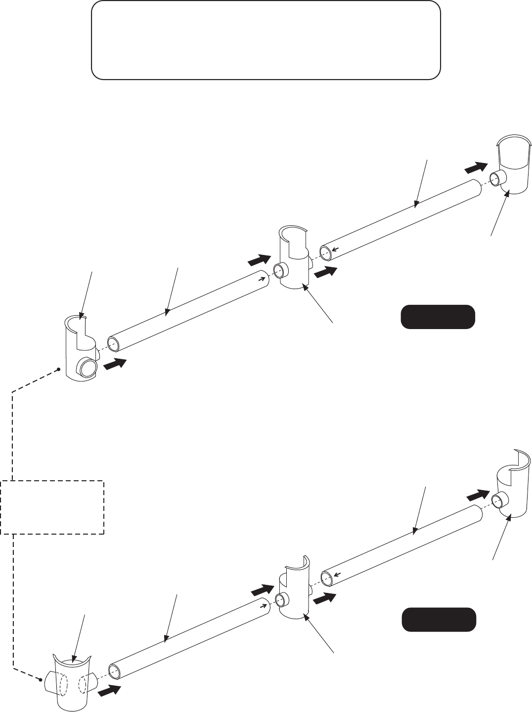
STEP10:
17
© 2012 Escalade Sports For Customer Service Call 1-866-556-2757
Connect P22 Left Corner Pocket, P23 Left Middle Pocket and P24 Left Corner Pocket with P25
Ball Return Tubes as shown in Figure 18.
Connect P19 Right Corner Pocket, P20 Right Middle Pocket and P21 Right Corner Pocket with
P25 Ball Return Tubes as shown in Figure 19.
PARTS REQUIRED:
1 pc - P19 Right Corner Pocket 1 pc - P22 Left Corner Pocket
1 pc - P20 Right Middle Pocket 1 pc - P23 Left Middle Pocket
1 pc - P21 Right Corner Pocket 1 pc - P24 Left Corner Pocket
4 pcs - P25 Ball Return Tube
All Rights Reserved.
Figure 19
P21
P25
P25
P20
P19
Figure 18
P24
P23
P22
P25
P25
Tube goes inside
Tube goes outside
Tube goes inside
Tube goes outside
BALL RETURN
OPENING - END
OF TABLE
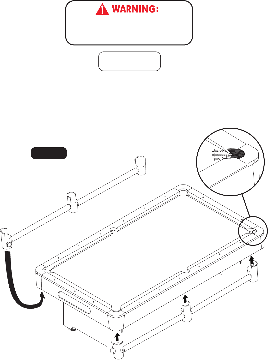
STEP11:
18
© 2012 Escalade Sports For Customer Service Call 1-866-556-2757
Insert Right Pocket Return and Left Pocket Return from previous assembly STEP 10 into the drop
pocket openings from underside of the table. Fasten pockets using six H14 Nails per pocket. Hold the
nails with needle nose pliers and tap them in with a small hammer. Once the nails have started into
plastic, hammer them completely into the rails until heads are flush with plastic as shown Figure 20.
Important Note: All H14 pocket nails must be tapped completely into place - otherwise - damage to the
billiard balls may occur.
PARTS REQUIRED:
36 pcs - H14 Pocket Nail
All Rights Reserved.
Figure 20
THIS STEP REQUIRES THREE OR MORE ADULTS.
VERY CAREFULLY INSERT RIGHT POCKET RETURN AND
LEFT POCKET RETURN INTO THE DROP POCKET OPENINGS
FROM UNDERSIDE OF THE TABLE.
H14
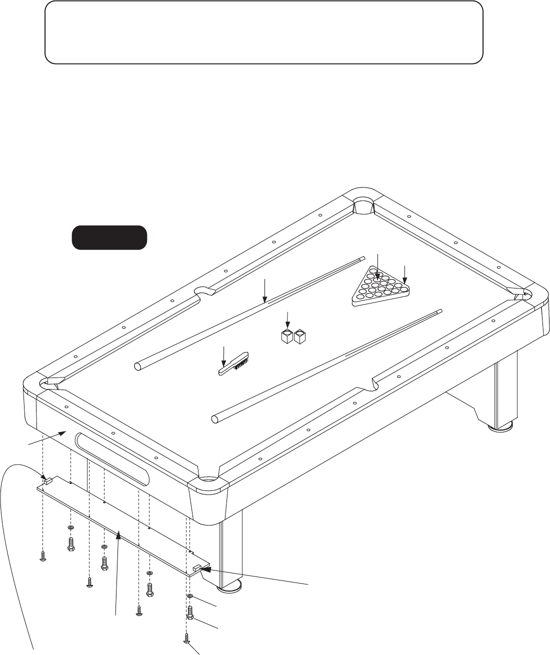
STEP12:
19
© 2012 Escalade Sports For Customer Service Call 1-866-556-2757
Attach P17 Ball Return Tray Board onto P16 Ball Return Support Board using H16 Bolts and H17 Washers
as shown in Figure 21.
Attach P17 Ball Return Tray Board onto P14 End Apron with Opening Ball Return Trim using H6 Screws
as shown in Figure 21. Tighten, but do not strip out H6 Screws.
PARTS REQUIRED:
4 pcs - H6 Screw 1 pc - P17 Ball Return Tray Board 1 pc - A3 Brush
4 pcs - H16 Bolt 2 pcs - A1 Cue Stick 1 set - A5 Billiard Ball
4 pcs - H17 Washer 1 pc - A2 Triangle 2 pcs - A6 Chalk
All Right Reserved.
Figure 21
H6
H17
P14
P17
A5
A3
A6
A1
A2
Note: Small wooden block on this upper side.
H16
Note: Small wooden block
on this upper side.

20
© 201 2 Escalad e Sports Fo r Custome r Servic e Cal l 1-866-556-2757
All Rights Reserved.
Congratulations! You have now assembled your pool table. Please note the Care
and Use instructions below to insure many years of trouble free use of your pool
table.
CARE AND USE OF YOUR POOL TABLE
1. Use spray furniture polish to clean all exterior surfaces of your pool table.
2. Use the table brush provided to clean the cloth on the table.
3. Use a carpenters level to properly level table using the leg levelers.
4. This product is intended for INDOOR use only.
5. DO NOT sit, climb or lean on the table.
6. DO NOT drag the table when moving it. This will damage the legs.
7. DO NOT set drinks on the table.
8. The purchase of a billiard table cover will help protect and keep your table
clean while not is use.

P5423WWJH1
P5423WWJH2
P5423WWJH3
P5423WWJH4
P5423WWJH5
P5423WWJH6
P5423WWJH7
P5423WWJH8
P5423WWJH9
P5423WWJH10
P5423WWJH11
P5423WWJH12
P5423WWJH13
P5423WWJH14
P5423WWJH15
P5423WWJH16
P5423WWJH17
P5423WWJT1
P5423WWJT2
P5423WWJT3
P5423WWJT4
P5423WWJA1
P5423WWJA2
P5423WWJA3
P5423WWJA4
P5423WWJA5
P5423WWJA6
P5423WWJP1
P5423WWJP2
P5423WWJP3A
P5423WWJP3B
P5423WWJP4
P5423WWJP5
P5423WWJP6
P5423WWJP6S
P5423WWJP7
P5423WWJP7S
P5423WWJP8
P5423WWJP9
P5423WWJP10
P5423WWJP11
P5423WWJP12
P5423WWJP13
P5423WWJP14
P5423WWJP15
P5423WWJP16
P5423WWJP17
P5423WWJP18
P5423WWJP19
P5423WWJP20
P5423WWJP21
P5423WWJP22
P5423WWJP23
P5423WWJP24
P5423WWJP25
P5423WWJK1
P5423WWJM1
8
16
32
16
8
12
16
8
12
12
24
18
18
36
8
4
4
1
1
1
1
2
1
1
1
1
2
2
2
1
1
2
2
2
2
1
1
8
2
2
4
2
1
1
4
1
1
4
1
1
1
1
1
1
4
1
1
PART # KEY # DESCRIPTION QTY.
H1
H2
H3
H4
H5
H6
H7
H8
H9
H10
H11
H12
H13
H14
H15
H16
H17
T1
T2
T3
T4
A1
A2
A3
A4
A5
A6
P1
P2
P3A
P3B
P4
P5
P6
P6S
P7
P7S
P8
P9
P10
P11
P12
P13
P14
P15
P16
P17
P18
P19
P20
P21
P22
P23
P24
P25
K1
M1
PARTS LIST FOR MODEL # P5423W
21
© 2012 Escalad e Sports Fo r Custome r Servic e Cal l 1-866-556-2757
3/8” x 2-1/4” Bolt
3/8” Lock Washer
3/8” x 25mm Flat Washer
3/8” Hex Nut
3/8” x 3” Bolt
WP/4 x 1” Phillips Washer Head Screw
F5 x 1-3/4” Phillips Flat Head Screw
5/16” x 1-1/4” Bolt
5/16” x 1-3/4” Bolt
5/16” x 23mm Flat Washer
T4 x 15mm Phillips Round Head Screw
5/16” x 1-5/8” Bolt
5/16” x 32mm Flat Washer
Pocket Nail
5/16“ x 23mm Flat Washer
1/4” x 1-1/2” Bolt
1/4” x 15mm Flat Washer
Playfield Grout Kit
Playfield Cloth to Playfield - Spray Adhesive
Sand Paper for Dried Grout
Wrench (set)
Cue Stick
Triangle
Playfield Cloth Brush
Playfield Cloth
Billiard Ball
Cue Chalk
Leg
Main Metal Beam
End Slat (Note: For P5 Installation)
End Slat (Note: For P16 Installation)
Middle Slat
End Board
End Play Bed Slatron (P2000W)
End Play Bed Slate (809-551)
Middle Play Bed Slatron (P2000W)
Middle Play Bed Slate (809-551)
Shim
Side Top Rail
End Top Rail
Corner Cap
Side Apron
End Apron
End Apron with Ball Return Opening
Corner Post
Ball Return Support Board
Ball Return Tray Board
Leg Leveler
Right Corner Pocket
Right Middle Pocket
Right Corner Pocket
Left Corner Pocket
Left Middle Poket
Left Corner Pocket
Ball Return Tube
Hardware Kit
Owner’s Manual
All Rights Reserved.
This customer warranty extends to the original owner, on the purchase of any ESCALADE SPORTS
Product (hereinafter referred as the "Product").
This Product is warranted to the original owner, foraperiod of 90 days from the
original purchase.
ESCALADE SPORTS warrants to the original owner, this product to be free
from defects in material and workmanship when used for the intended purpose under normal use and
conditions. THIS WARRANTY IS VOID IF THE PRODUCT HAS BEEN DAMAGED BY ACCIDENT,
UNREASONABLE USE, NEGLIGENCE, IMPROPER SERVICE, FAILURE TO FOLLOW INSTRUCTIONS
PROVIDED WITH THE PRODUCT OR OTHER CAUSES NOT ARISING OUT OF DEFECTS IN MATERIAL
AND WORKMANSHIP.
During the above 90 day warranty period, ESCALADE SPORTS shall
provide replacement components or replace withacomparable product at our choosing. If product is
defective under normal use and proper care, please contact our Customer Service Dept.
Other than shipping requirements no charge will be made for such replacement of in-warranty Products.
Some states do not allow the exclusion or limitation of implied warranties or consequential or incidental
damages, so the above limitations or exclusions may not apply to you.
This warranty gives you specific legal rights and you may also have other rights which
may vary from state to state.
WARRANTY DURATION:
WARRANTY COVERAGE:
WARRANTY REPLACEMENT:
LEGAL REMEDIES:
1-866-556-2757/Customer Service Dept.
Or Write us at:
Escalade® Sports, Inc.-P.O. Box 889, Evansville, IN 47706
Attn: Customer Service Dept.
Or E-mail us at:
customerservice@escaladesports.com
ANY IMPLIED WARRANTIES ARISING OUT OF THIS SALE,
INCLUDING BUT NOT LIMITED TO THE IMPLIED WARRANTIES OF MERCHANTABILITY
AND FITNESS FOR A PARTICULAR PURPOSE, ARE LIMITED IN DURATION TO THE
ABOVE 90 DAY PERIOD. ESCALADE SPORTS SHALL NOT BE LIABLE FOR LOSS OF
USE OF THE PRODUCT OR OTHER CONSEQUENTIAL OR INCIDENTAL COSTS,
EXPENSES OR DAMAGES INCURRED BY THE CONSUMER OF ANY OTHER USE.
WARRANTY DISCLAIMERS:
90 DAY LIMITED WARRANTY
22
© 2012 Escalade Sports For Customer Service Call 1-866-556-2757
All Rights Reserved.
WARRANTY ON SLATE/SLATRON™ SURFACE
Manufacturer warrants for five (5) years from the date of purchase for the Slatron™ and ten (10) years for
slate, Escalade Sports will repair the playing surface of this table, free of charge, if it fails to remain flat,
within a tolerance of + or – 30/1000 of an inch, measuring from any flat plane within the playing
surface. NOTE: Cloth not included in warranty. Should this product become defective due to material or
workmanship within period, contact the Customer Service Department. This warranty is not transferable
and does not cover normal wear and tear, or damage caused by improper handling, installation or use of
this product. This warranty is also void if product is in any way abused, damaged, or modified from its
original state, or if used for other than indoor residential use. This warranty gives the consumer specific
legal rights, and may have other rights which may vary from state to state.
