Panasonic CRT Television TC 14A12P 20B12
TC-20B12 to the manual 29c049cd-dbfc-4765-aad5-3de438ffb3d3
User Manual: Panasonic CRT Television TC-14A12P
Open the PDF directly: View PDF ![]() .
.
Page Count: 42
Service Manual
Order DCS - AGO2002 - 003 - MS
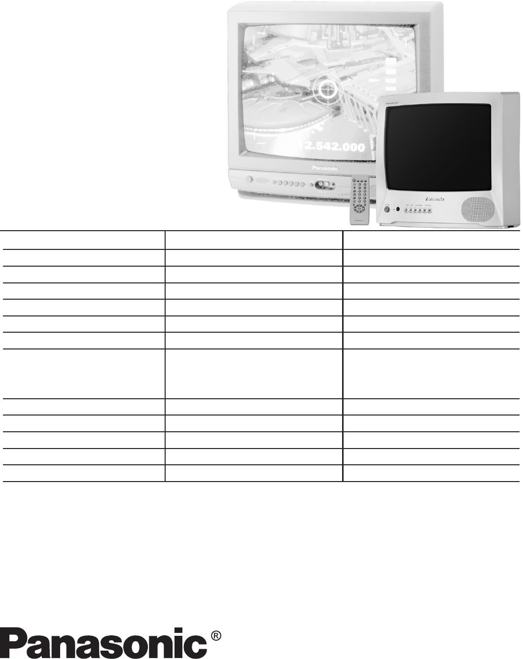
Color Television
TC-14A12P
TC-20B12
BR2L chassis
TELEVISION
Power source
Consumption
Antenna input jack
Color systems
Tuning system
Channel capability
Picture tube (visual diagonal)
Audio system
Video input jack
Dimension (width, height, depth)
Weight
TC-14A12P
110/220 V AC, 60 Hz automatic switch
55 W
75 W - VHF/UHF/Cable
NTSC/PAL-N/AUTO/PAL-M
F.S.T.
2 to 13 (VHF)
14 to 69 (UHF)
1 to 125 (Cable)
33 cm
3 W max (RMS)
1 (back of unit)
370 x 349 x 374 mm
9,6 kg
Supplied Accessories:
• 1 Remote Control Transmitter
• 1 300Ω/75Ω Aerial Adaptor
• 2 “AA” type batteries
• 1 Internal antenna (for TC-14A12P only)
Specifications
Specifications are subject to change without notice. Weight and dimensions shown are approximate.
Remote Control Transmiter:
Power Source 3V (2 AA type batteries)
Infrared Length 9500 A (Angstron)
Number of Buttons 29 keys
Dimensions (W x H x D) (54 x 27 x 135) mm
TC-20B12
110/220 V AC, 60 Hz automatic switch
69 W
75 W - VHF/UHF/Cable
NTSC/PAL-N/AUTO/PAL-M
F.S.T.
2 to 13 (VHF)
14 to 69 (UHF)
1 to 125 (Cable)
48 cm
3 W max (RMS)
1 (back of unit)
502 x 455 x 471 mm
17 kg

TC-14A12P / TC-20B12
- 2 -
WARNING
This service information is designed for experienced repair technicians only and is not designed for use by the general public.
It does not contain warnings or cautions to advise non-technician individuals of potential dangers in attempting to service a product.
Products powered by electricity should be serviced or repared only by experienced professional technicians.
Any attempt to service or repair the product deal with in this service information by anyone could result in serious injury or death.
Contents
General Guidelines ..................................................................... 02
Operation Guide ......................................................................... 03
IC 601 - Pins and Functions ..................................................... 15
IC601 and IC451 Voltage Table ................................................ 17
IC601 - Block Diagram .............................................................. 18
General Summary .................................................................... 19
Service Adjustments and Calibrations
Service Mode .............................................................................. 20
How to operate the DAC controls ............................................. 20
EQUIPMENT REQUIRED .......................................................... 21
AGC RF CALIBRATION ............................................................. 21
BUZZ (SOUND CIRCUIT) .......................................................... 21
ANODE AND HEATER VOLTAGE CONFIRMATION ............... 21
PAL COLOR OUTPUT SIGNAL ADJUSTMENT ...................... 21
NTSC SUB-TINT CALIBRATION ............................................... 22
PROTECTION CIRCUIT (SHUTDOWN) ................................... 22
CONFIRMATION OF OPERATION ........................................... 22
WHITE QUALITY CALIBRATION .............................................. 22
VERTICAL DEFLECTION .......................................................... 22
CALIBRATION AND CONFIRMATION ...................................... 22
CRT CUT OFF CALIBRATION .................................................. 23
WHITE BALANCE CALIBRATION ............................................. 23
SUB-BRIGHTNESS CALIBRATION ........................................... 23
FOCUS CALIBRATION .............................................................. 23
COLOR PURITY ADJUSTMENT ............................................... 24
CONVERGENCE CALIBRATION ............................................... 24
EEPROM - Memory Maps ......................................................... 25
Power Source Voltages .............................................................. 25
Main Board Schematic Diagram ................................................ 26
CRT Board Schematic Diagram ................................................ 27
Main Board Conductor view ...................................................... 28
Waveform .................................................................................... 32
Parts Location ............................................................................. 35
Packing and Acessories ............................................................. 36
Replacement Mechanical Parts List .......................................... 36
Replacement Electrical Parts List .............................................. 37
General Guidelines
An Isolation Transformer should always be used during the
servicing of a receiver whose chassis is not isolated from the AC
power line. Use a transformer of adequate power rating as this
protects the technician from accidents resulting in personal injury
from electrical shocks. It will also protect the Receiver from being
damaged by accidental shorting that may occur during servicing.
When servicing, observe the original lead dress, especially in
the high voltage circuit. Replace all damaged parts (also parts
that show signs of overheating.)
Always Replace Protective Devices, such as fishpaper, isolation
resistors and capacitors, and shields after servicing the Receiver.
Use only manufacturers recommended rating for fuses, circuit
breakers, etc.
High potentials are present when this Receiver is operating.
Operation of the Receiver without the rear cover introduces
danger from electrical shock. Servicing should not be performed
by anyone who is not thoroughly familiar with the necessary
precautions when servicing high-voltage equipment.
Extreme care should be practiced when Handling the Picture
Tube. Rough handling may cause it to implode due to
atmospheric pressure (14.7 lbs per sq. in). Do not sick or scratch
the glass or subject it to any undue pressure. When handling,
use safety goggles and heavy gloves for protection. Discharge
the picture tube by shorting the anode to chassis ground (not to
the cabinet or to other mounting hardware). When discharging,
connect cold ground (i.e. dag ground lead) to the anode with a
well insulated wire or use a grounding probe.
Avoid prolonged exposure at close range to unshielded areas of
the picture tube to prevent exposure to X-ray radiation.
The Test Picture Tube used for servicing the chassis at the bench
should incorporate safety glass and magnetic shielding. The
safety glass provides shieldinf for the tube viewing area against
X-ray radiation as well as implosion. The magnetic shield limits
X-ray radiation around the bell of the picture tube in addition to
restricting magnetic effects. When using a picture tube test jig
for service, ensure that the jig is capable of handling 31kV without
causing X-ray radiation.
Before returning a serviced receiver to the owner, the service
technician must thoroughly test the unit to ensure that is
completely safe to operatore. Do not use a line isolation
transformer when testing.
Operation Guide
TC-14A12P / TC-20B12
- 3 -
ENGLISHENGLISH
ENGLISHENGLISH
ENGLISH
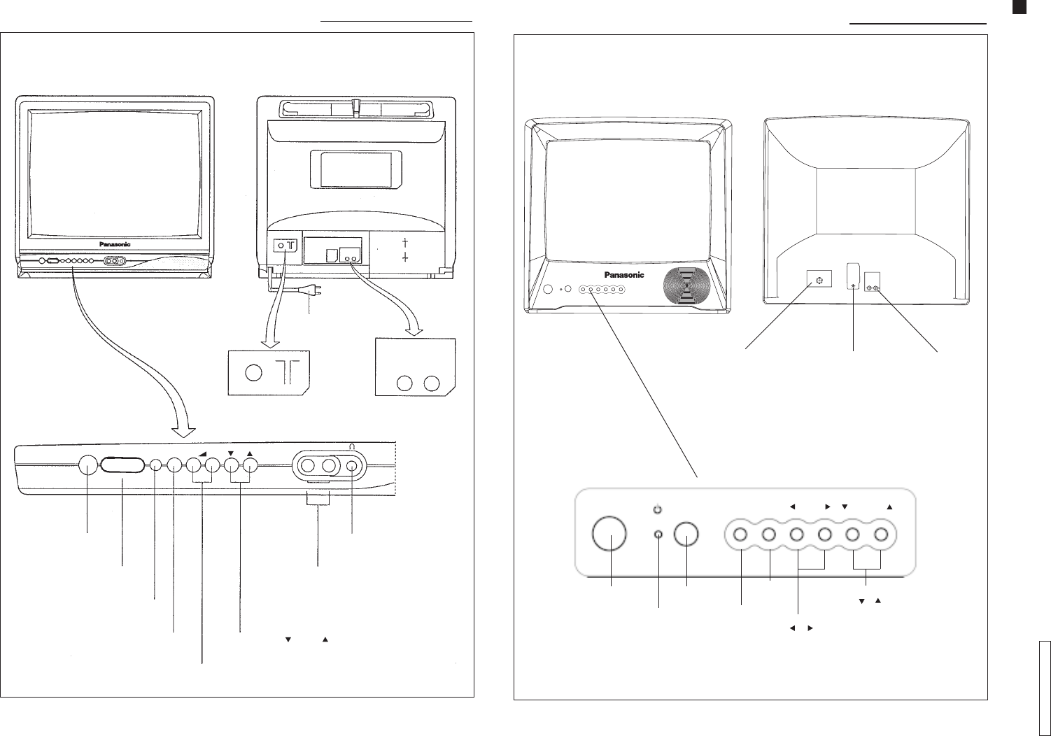
Location of Controls (TC-20B12)Location of Controls (TC-20B12)
Location of Controls (TC-20B12)Location of Controls (TC-20B12)
Location of Controls (TC-20B12)
Antenna
input jack
Power cable
Front viewFront view
Front viewFront view
Front view Back viewBack view
Back viewBack view
Back view
Audio/video
input jack
POWER
Power switch
Audio/Video input
Remote control sensor
(FUNC) function button
TV/AV button
Volume Down ( – ) or Up ( + ) buttons
FUNC TV/AV +VIDEO AUDIO
Earphone output
Channel Down ( ) or Up ( ) buttons
AUDIO VIDEO
AV/IN
–
Antenna
input jack Power supply
cord output
Location of Controls (TC-14A12P)Location of Controls (TC-14A12P)
Location of Controls (TC-14A12P)Location of Controls (TC-14A12P)
Location of Controls (TC-14A12P)
Front viewFront view
Front viewFront view
Front view Back viewBack view
Back viewBack view
Back view
Audio/video
input jack
POWER FUNC TV/AV VOLUME
Power switch
Stand by
indicator
Remote
control sensor Function
button
TV/VCR
button
CHANNEL
Volume buttons
( ) ( )
Channel buttons
( ) ( )
Operation Guide
TC-14A12P / TC-20B12
- 4 -
ENGLISHENGLISH
ENGLISHENGLISH
ENGLISH
Location of ControlsLocation of Controls
Location of ControlsLocation of Controls
Location of Controls
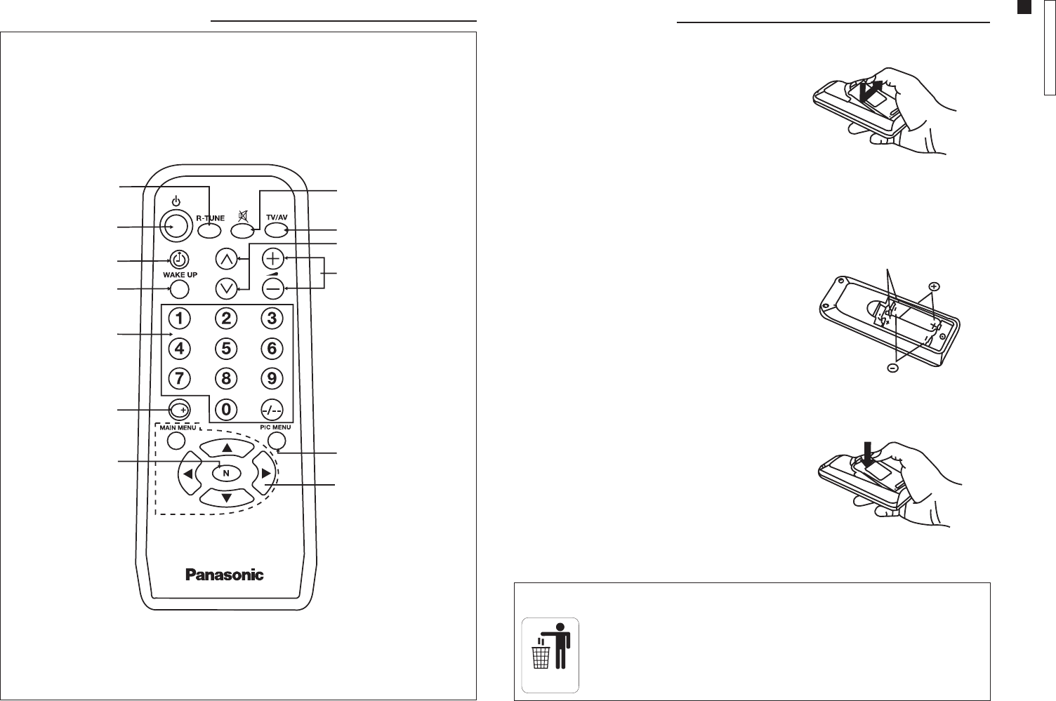
REMOTE CONTROLREMOTE CONTROL
REMOTE CONTROLREMOTE CONTROL
REMOTE CONTROL
R-TUNER-TUNE
R-TUNER-TUNE
R-TUNE
POWERPOWER
POWERPOWER
POWER
TIMERTIMER
TIMERTIMER
TIMER
WW
WW
WAKE-UPAKE-UP
AKE-UPAKE-UP
AKE-UP
CHANNELCHANNEL
CHANNELCHANNEL
CHANNEL
KEYBOARDKEYBOARD
KEYBOARDKEYBOARD
KEYBOARD
RECALLRECALL
RECALLRECALL
RECALL
PICTURE NORMPICTURE NORM
PICTURE NORMPICTURE NORM
PICTURE NORM
MUTEMUTE
MUTEMUTE
MUTE
TV/VCRTV/VCR
TV/VCRTV/VCR
TV/VCR
CHANNEL SELECTIONCHANNEL SELECTION
CHANNEL SELECTIONCHANNEL SELECTION
CHANNEL SELECTION
VOLUMEVOLUME
VOLUMEVOLUME
VOLUME
MAIN MENU ANDMAIN MENU AND
MAIN MENU ANDMAIN MENU AND
MAIN MENU AND
MENU NAMENU NA
MENU NAMENU NA
MENU NAVIGAVIGA
VIGAVIGA
VIGATIONTION
TIONTION
TION
PICTURE MENUPICTURE MENU
PICTURE MENUPICTURE MENU
PICTURE MENU
Remote ControlRemote Control
Remote ControlRemote Control
Remote Control
Installing the BatteriesInstalling the Batteries
Installing the BatteriesInstalling the Batteries
Installing the Batteries
1. Remove the battery compartment cover
from the back of the remote control, by
pressing the lock down and pulling the
cover out.
2. Install the batteries in the compartment
(polarities (+) and (-) must be correct).
3. To replace, fit both cover lugs into the
compartment slots and press the lock to
close.
Battery replacement precautionsBattery replacement precautions
Battery replacement precautionsBattery replacement precautions
Battery replacement precautions
1. Batteries must be replaced as a pair.
2. Do not combine a used battery with a
new one.
3. Do not mix battery types
(example: “zinc carbon” with
“alkaline”).
4. Do not attempt to charge, short-circuit,
disassemble, heat, or burn used
batteries.
5. Remove the batteries if the remote
control transmitter will not be used
for a long period of time.
1
2
3
Two “AA” batteries
Note:Note:
Note:Note:
Note:
Dispose of the batteries in the domestic trash.
This remote control transmitter uses two “R6” (AA) batteries.
DOMESTIC
TRASH
Operation Guide
TC-14A12P / TC-20B12
- 5 -
ENGLISHENGLISH
ENGLISHENGLISH
ENGLISH
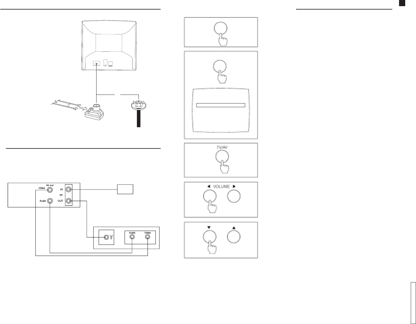
ConnectionConnection
ConnectionConnection
Connection
VCRVCR
VCRVCR
VCR
To connect a VCR, proceed as follows:
1. Connect the VCR
audio and video
output terminals to
the audio and
video input jacks,
located on the
back of the unit.
2. Press the TV/AV
button to select the
AV mode. Turn the
VCR ON.
3. Press the button
again to return to
the TV mode.
NOTE:NOTE:
NOTE:NOTE:
NOTE:
To use the video game, connect the video game audio and video output terminals to
the audio and video input jacks on the TV.
Connection cables are not supplied.
Outdoor Antenna ConnectionOutdoor Antenna Connection
Outdoor Antenna ConnectionOutdoor Antenna Connection
Outdoor Antenna Connection
For proper sound and picture reception,
an outdoor antenna, a proper cable
(75 ohms coaxial cable or 300 ohms twin
cable) and an appropriate terminal
(75 ohms) are required.
Your local service representative can
help you obtain the adequate system
and accessories for antennas.
Installation procedures different from
those presented here or any
modification of existing systems or
required accessories, as well as all
expenses involved in such actions,
shall be considered as the owner’s
sole responsibility.
InstallationInstallation
InstallationInstallation
Installation
300 to
75 ohms
matching
transformer
(supplied)
300 ohms
twin cable 75 ohms
coaxial
cable
VCR back view (only for illustration purpose)
TV back view (only for illustration purpose)
OutdoorOutdoor
OutdoorOutdoor
Outdoor
antennaantenna
antennaantenna
antenna
or
Operation of TV ControlsOperation of TV Controls
Operation of TV ControlsOperation of TV Controls
Operation of TV Controls
1. Power SwitchPower Switch
Power SwitchPower Switch
Power Switch
Press this switch to turn the unit ON. Press again to
turn it OFF.
2. Function ButtonFunction Button
Function ButtonFunction Button
Function Button
Press this button to access the PRESET
menu.
Press it continuously to select a menu function, as
shown in the illustration.
To exit the PRESET menu, press the function button
continuously.
(For more details, refer to PRESET menu.)
3. TV/ATV/A
TV/ATV/A
TV/AV ButtonV Button
V ButtonV Button
V Button
Press this button to select the desired input.
4. VV
VV
Volume Buttonsolume Buttons
olume Buttonsolume Buttons
olume Buttons
Press the left or right button for the desired listening
level.
5. Channel ButtonsChannel Buttons
Channel ButtonsChannel Buttons
Channel Buttons
Press these buttons to select the desired channel.
POWER
FUNC
CHANNEL
CH
PRESET
CH SELECT DIRECT
ANTENNA CABLE
AUTO TUNE
MANUAL TUNE
COLOR SYS AUTO
FINE TUNE
SKIP OFF
55
Operation Guide
TC-14A12P / TC-20B12
- 6 -
ENGLISHENGLISH
ENGLISHENGLISH
ENGLISH
General OperationGeneral Operation
General OperationGeneral Operation
General Operation
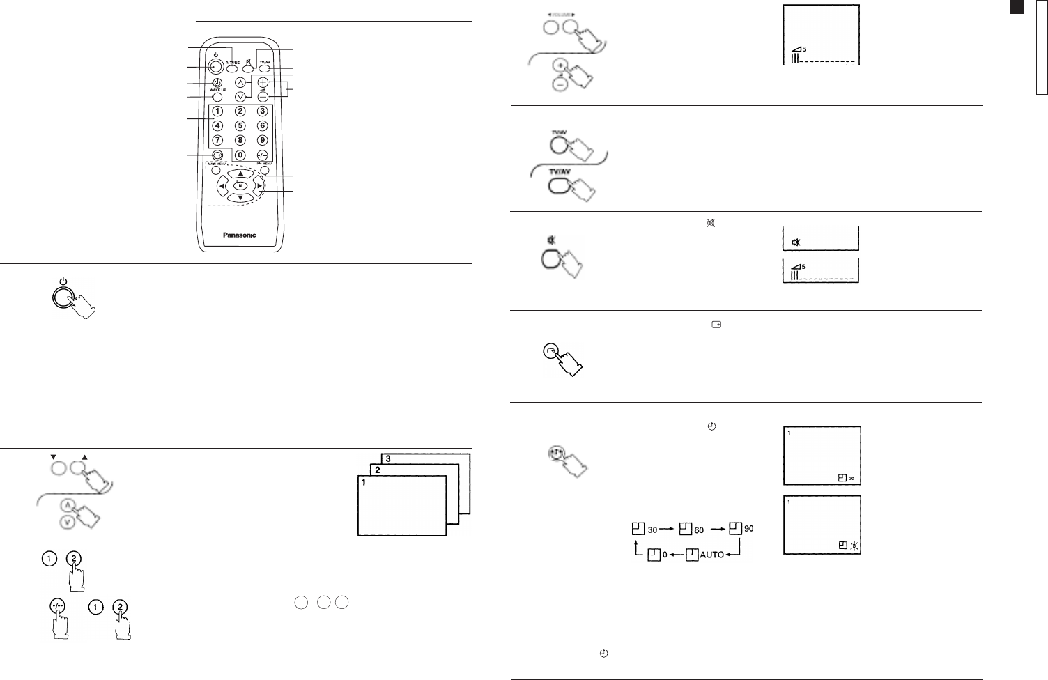
Power Button (O stand by mode)Power Button (O stand by mode)
Power Button (O stand by mode)Power Button (O stand by mode)
Power Button (O stand by mode)
To turn the unit ON with this button, the power switch on the TV panel must
be ON. To turn it OFF, press the button again (stand by mode). If the unit
was turned OFF with the remote control (stand by mode), it is also possible
to turn it ON by pressing either channel button.
Note:Note:
Note:Note:
Note:
• Leaving the unit in the stand by mode will not cause any damages and
energy consumption is minimum.
• It is recommended to turn the unit OFF periodically by using the TV
power switch. When the unit is turned ON again after 30 minutes, the
demagnetization circuit of picture tube is activated.
• If the unit is to be left unused for a long period of time, turn it OFF by
using the TV power switch, disconnect the antenna and unplug the AC
power supply cord.
Channel ButtonsChannel Buttons
Channel ButtonsChannel Buttons
Channel Buttons
Press these buttons to select the
programmed channels.
1.1.
1.1.
1.
2.2.
2.2.
2.
3.3.
3.3.
3. Channel Keyboard for Direct Selection (Memory Position)Channel Keyboard for Direct Selection (Memory Position)
Channel Keyboard for Direct Selection (Memory Position)Channel Keyboard for Direct Selection (Memory Position)
Channel Keyboard for Direct Selection (Memory Position)
Press these buttons to select the desired channel.
To select channels with two figures, press the -/-- button and then press the
buttons corresponding to the channel number.
Example: For channel 12, press -/-- , 1 , 2
To select channels with three figures, press the buttons corresponding to
the channel number.
Note:Note:
Note:Note:
Note:For selecting channels with three figures, the CH SELECT CH SELECT
CH SELECT CH SELECT
CH SELECT
function must be in DIRECTDIRECT
DIRECTDIRECT
DIRECT mode, and the ANTENNA ANTENNA
ANTENNA ANTENNA
ANTENNA mode in
CABLECABLE
CABLECABLE
CABLE (Refer to Tuning Procedures - Channel Selection and
Antenna Mode).
11
11
1
88
88
8
33
33
3
1313
1313
13
66
66
6
55
55
5
22
22
2
44
44
4
99
99
9
1414
1414
14
1111
1111
11
77
77
7
1010
1010
10
1212
1212
12
CHANNEL
VV
VV
Volume Buttons olume Buttons
olume Buttons olume Buttons
olume Buttons (+, –)(+, –)
(+, –)(+, –)
(+, –)
Press these buttons to adjust
the listening level.
Time indication will flash
to indicate the last three
remaining minutes prior to
turn OFF.
Recall Button ( Recall Button (
Recall Button ( Recall Button (
Recall Button ( ) )
) )
)
Press this button to review the selected system.
Press it again to disable this function.
Mute Button ( Mute Button (
Mute Button ( Mute Button (
Mute Button ( ) )
) )
)
Press this button to quickly
reduce sound level. Press it
again to restore sound.
The mute indicator (red) will
be displayed.
TV/ATV/A
TV/ATV/A
TV/AV ButtonV Button
V ButtonV Button
V Button
Press this button to select TV or video input.
Note:Note:
Note:Note:
Note:
A numerical and
graphic indication will
be displayed. The
numerical indication
ranges from zero (no
sound) to 63 (maximum
level).
Note:Note:
Note:Note:
Note:
• When AUTO is selected, the unit will turn OFF automatically (stand by mode) 5 minutes after the TV station
broadcast is finished.
• This function (AUTO) will not operate when the VCR (AV) mode is selected.
To cancel the TIMER ( ), select “0” (zero) by pressing the TIMER button, or turn the unit OFF by using the power
switch on the TV panel.
TT
TT
Timer Button ( imer Button (
imer Button ( imer Button (
imer Button ( ) )
) )
)
This TV can be programmed to
turn OFF after a certain period
of time.
Press this button repeatedly for
automatic turn OFF after 30, 60
or 90 minutes, as desired.
4.4.
4.4.
4.
5.5.
5.5.
5.
6.6.
6.6.
6.
7.7.
7.7.
7.
8.8.
8.8.
8.
Operation Guide
TC-14A12P / TC-20B12
- 7 -
ENGLISHENGLISH
ENGLISHENGLISH
ENGLISH
General OperationGeneral Operation
General OperationGeneral Operation
General Operation
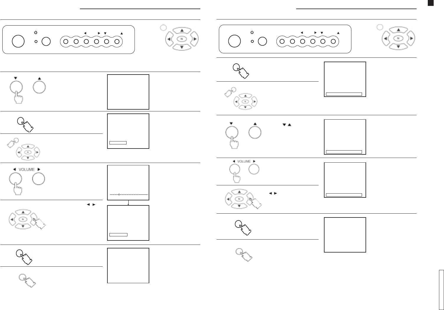
PICTURE MENU PICTURE MENU
PICTURE MENU PICTURE MENU
PICTURE MENU ButtonButton
ButtonButton
Button
Press this button to select the picture menu sequentially, as shown below:
On screen Function
DYNAMIC For bright places. This setting selects a higher level of brightness
and contrast.
STANDARD For places with normal levels of luminosity. This setting selects a
normal level of brightness and contrast.
SOFT For dark places. This setting selects a reduced level of
brightness and contrast.
9.9.
9.9.
9.
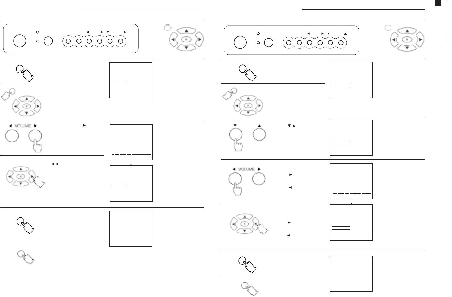
WAKE-UP WAKE-UP
WAKE-UP WAKE-UP
WAKE-UP ButtonButton
ButtonButton
Button
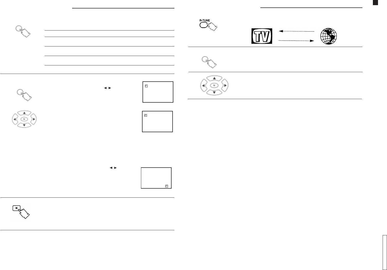
1. Press the WAKE-UP button.
2. Press the menu navigation buttons ( / ) to set the
WAKE-UP feature.
The time can be set in increments of 10 minutes.
3. Set the time and turn the unit OFF by using the remote
control (stand by mode).
If the unit is turned OFF with the remote control (stand by
mode) and the WAKE-UP feature set, the led on the TV
panel will flash.
The unit will be turned ON automatically at the selected
time.
Note:Note:
Note:Note:
Note:
• The WAKE-UP feature can be programmed up to
12 hours.
• When the unit is turned ON by the WAKE-UP feature, the
TIMER will be set automatically to turn it OFF in
90 minutes. Press any button to cancel the TIMER.
4. To cancel the WAKE-UP feature:
4.1 Turn the unit OFF by using the power switch on the TV
panel.
4.2 Press the menu navigation buttons ( / ) during the
WAKE-UP indication until OFF is displayed.
4.3 Press the N (Picture norm) button while the WAKE-UP
mode is displayed.
10.10.
10.10.
10.
PIC MENUPIC MENU
PIC MENUPIC MENU
PIC MENU
WAKE UPWAKE UP
WAKE UPWAKE UP
WAKE UP
11.11.
11.11.
11. N (Picture norN (Picture nor
N (Picture norN (Picture nor
N (Picture norm) Buttonm) Button
m) Buttonm) Button
m) Button
Press this button to reset picture setting levels (color, brightness, contrast, etc.) or
sound (tone, AVL*), back to the factory preset level.
NotNot
NotNot
Notee
ee
e::
::
:
• For this function to operate, picture and sound setting menu must be activated.
* Refer to page 22.
WAKE UP TIMER OFF
99
WAKE UP TIMER 00:10
99
WAKE UP TIMER
90
General OperationGeneral Operation
General OperationGeneral Operation
General Operation
12.12.
12.12.
12. R-TUNE R-TUNE
R-TUNE R-TUNE
R-TUNE ButtonButton
ButtonButton
Button
Press this button to instantly switch between the last two channels selected.
MAIN MENU MAIN MENU
MAIN MENU MAIN MENU
MAIN MENU ButtonButton
ButtonButton
Button
Press this button to access the icon menu on the screen.
Menu navigation buttonsMenu navigation buttons
Menu navigation buttonsMenu navigation buttons
Menu navigation buttons
MAIN MENUMAIN MENU
MAIN MENUMAIN MENU
MAIN MENU
13.13.
13.13.
13.
14.14.
14.14.
14.
Operation Guide
TC-14A12P / TC-20B12
- 8 -
ENGLISHENGLISH
ENGLISHENGLISH
ENGLISH
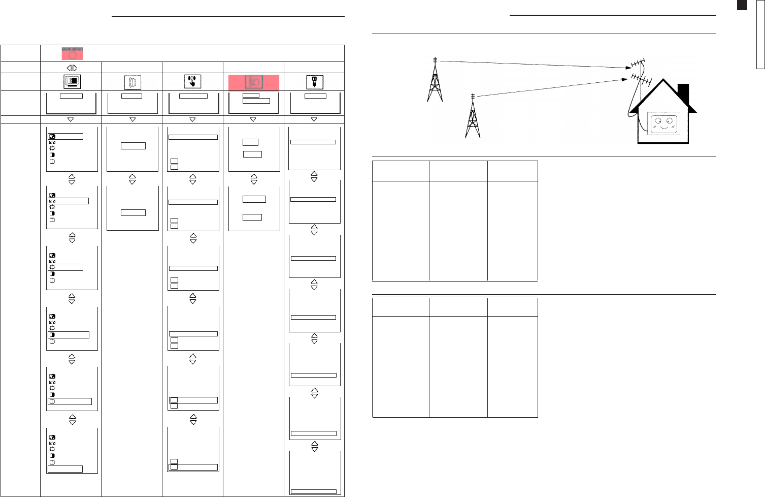
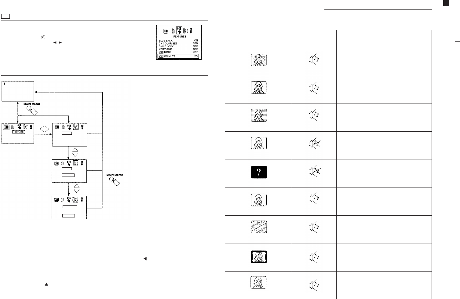
Main Menu ListMain Menu List
Main Menu ListMain Menu List
Main Menu List
When the MAIN MENU button is pressed, the icon menu is displayed. This gives access to picture, sound, function,
language and setup icons.
Press
Icon
Screen
indication
Select
Screen
indication
(example)
Press
[
[
BLUE BACK ON
CH COLOR SET STD
CHILD LOCK OFF
VCR/GAME OFF
CC MODE OFF
CC ON MUTE NO
BLUE BACK ON
CH COLOR SET STD
CHILD LOCK OFF
VCR/GAME OFF
CC MODE OFF
CC ON MUTE NO
BLUE BACK ON
CH COLOR SET STD
CHILD LOCK OFF
VCR/GAME OFF
CC MODE OFF
CC ON MUTE NO
BLUE BACK ON
CH COLOR SET STD
CHILD LOCK OFF
VCR/GAME OFF
CC MODE OFF
CC ON MUTE NO
BLUE BACK ON
CH COLOR SET STD
CHILD LOCK OFF
VCR/GAME OFF
CC MODE OFF
CC ON MUTE NO
BLUE BACK ON
CH COLOR SET STD
CHILD LOCK OFF
VCR/GAME OFF
CC MODE OFF
CC ON MUTE NO
TONE LOW
AVL ON
TONE LOW
AVL ON
MENU DYNAMIC
32 COLOR
32 NTSC-TINT
32 BRIGHT
63 CONTRAST
32 SHARPNESS
COLOR TEMP. STD
MENU DYNAMIC
32 COLOR
32 NTSC-TINT
32 BRIGHT
63 CONTRAST
32 SHARPNESS
COLOR TEMP. STD
MENU DYNAMIC
32 COLOR
32 NTSC-TINT
32 BRIGHT
63 CONTRAST
32 SHARPNESS
COLOR TEMP. STD
MENU DYNAMIC
32 COLOR
32 NTSC-TINT
32 BRIGHT
63 CONTRAST
32 SHARPNESS
COLOR TEMP. STD
MENU DYNAMIC
32 COLOR
32 NTSC-TINT
32 BRIGHT
63 CONTRAST
32 SHARPNESS
COLOR TEMP. STD
MENU DYNAMIC
32 COLOR
32 NTSC-TINT
32 BRIGHT
63 CONTRAST
32 SHARPNESS
COLOR TEMP. STD
5
CH 5 PRESET
CH SELECT DIRECT
ANTENNA TV
AUTO TUNE
MANUAL TUNE
COLOR SYS AUTO
FINE TUNE
SKIP OFF
5
CH 5 PRESET
CH SELECT DIRECT
ANTENNA TV
AUTO TUNE
MANUAL TUNE
COLOR SYS AUTO
FINE TUNE
SKIP OFF
5
CH 5 PRESET
CH SELECT DIRECT
ANTENNA TV
AUTO TUNE
MANUAL TUNE
COLOR SYS AUTO
FINE TUNE
SKIP OFF
5
CH 5 PRESET
CH SELECT DIRECT
ANTENNA TV
AUTO TUNE
MANUAL TUNE
COLOR SYS AUTO
FINE TUNE
SKIP OFF
5
CH 5 PRESET
CH SELECT DIRECT
ANTENNA TV
AUTO TUNE
MANUAL TUNE
COLOR SYS AUTO
FINE TUNE
SKIP OFF
5
CH 5 PRESET
CH SELECT DIRECT
ANTENNA TV
AUTO TUNE
MANUAL TUNE
COLOR SYS AUTO
FINE TUNE
SKIP OFF
5
CH 5 PRESET
CH SELECT DIRECT
ANTENNA TV
AUTO TUNE
MANUAL TUNE
COLOR SYS AUTO
FINE TUNE
SKIP OFF
PICTURE SOUND FEATURES PRESET
IDIOMA
PORTUGUÊS
ESPAÑOL
ENGLISH
IDIOMA
PORTUGUÊS
ESPAÑOL
ENGLISH
LANGUAGE
PORTUGUÊS
ESPAÑOL
ENGLISH
Tuning ProceduresTuning Procedures
Tuning ProceduresTuning Procedures
Tuning Procedures
Selection of channels by positionSelection of channels by position
Selection of channels by positionSelection of channels by position
Selection of channels by position
When the channel selection is in POSITION mode, the
tuned channels in AUTO TUNE mode, will be
memorized according to the program number.
Program Channel Selected
number exhibition channel
122
244
366
488
51010
61212
71414
81616
91818
10 20 20
Program Channel Selected
number exhibition channel
1––
222
3––
444
5––
666
7––
888
9––
10 10 10
Channel SelectionChannel Selection
Channel SelectionChannel Selection
Channel Selection
Select the most familiar channel visualization pattern.
Direct Channel SelectionDirect Channel Selection
Direct Channel SelectionDirect Channel Selection
Direct Channel Selection
When the channel selection is in DIRECT mode, the
tuned channels in AUTO TUNE mode, will be
memorized according to the TV station number.
channel 02
channel 04
channel 06
channel 08
channel 10
channel 12 channel 14
channel 16
channel 18
channel 20
Operation Guide
TC-14A12P / TC-20B12
- 9 -
ENGLISHENGLISH
ENGLISHENGLISH
ENGLISH
Tuning ProceduresTuning Procedures
Tuning ProceduresTuning Procedures
Tuning Procedures
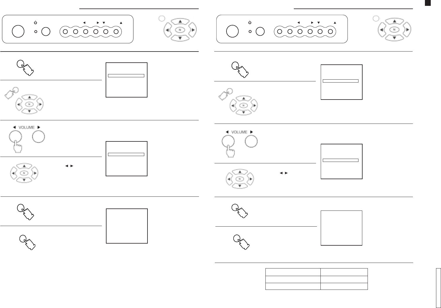
Press the FUNC (Function)
button and select
CH SELECT
(Channel selection)
in the PRESET menu.
1.1.
1.1.
1. FUNC
“Remote control”
FUNC TV/AV VOLUME CHANNEL
OR
MAIN MENUMAIN MENU
MAIN MENUMAIN MENU
MAIN MENU
Channel Selection ModeChannel Selection Mode
Channel Selection ModeChannel Selection Mode
Channel Selection Mode
After selecting CH SELECT
(Channel selection), press
the VOLUME button to
select POSITION or DIRECT.
2.2.
2.2.
2.
Note:Note:
Note:Note:
Note:
• The POSITION mode
allows you to memorize
100 positions (0 ~ 99).
• The DIRECT mode allows
you to memorize
125 positions (1 ~ 125).
MAIN MENUMAIN MENU
MAIN MENUMAIN MENU
MAIN MENU
Press the MAIN MENU
button and by pressing
the navigation buttons,
select PRESET and then
CH SELECT (Channel
selection).
Press the FUNC (Function)
button until the setup
menu is no longer
displayed.
3.3.
3.3.
3.
To restore normal
condition.
FUNC
Press the MAIN MENU
button until the setup menu
is no longer displayed.
MAIN MENUMAIN MENU
MAIN MENUMAIN MENU
MAIN MENU
CH SELECT
(Channel selection)
screen
POWER
Press the navigation
button ( / ) to select
POSITION or DIRECT.
5
CH 5
PRESET
CH SELECT POSITION
ANTENNA CABLE
AUTO TUNE
MANUAL TUNE
COLOR SYS AUTO
FINE TUNE
SKIP OFF
5
CH 5
PRESET
CH SELECT POSITION
ANTENNA CABLE
AUTO TUNE
MANUAL TUNE
COLOR SYS AUTO
FINE TUNE
SKIP OFF
ANTENNA ModeANTENNA Mode
ANTENNA ModeANTENNA Mode
ANTENNA Mode
Press the FUNC (Function)
button and select
ANTENNA in the PRESET
menu. ANTENNA screen
1.1.
1.1.
1. FUNC
Press the VOLUME button
to select TV or CABLE.
2.2.
2.2.
2.
MAIN MENUMAIN MENU
MAIN MENUMAIN MENU
MAIN MENU Press the MAIN MENU
button and by pressing
the navigation buttons,
select PRESET and then
ANTENNA.
Press the FUNC (Function)
button until the setup
menu is no longer
displayed.
3.3.
3.3.
3.
To restore normal
condition.
FUNC
Press the navigation
button ( / ) to select TV
or CABLE.
Press the MAIN MENU
button until the setup
menu is no longer
displayed.
Tuning ProceduresTuning Procedures
Tuning ProceduresTuning Procedures
Tuning Procedures
“Remote control”
POWER FUNC TV/AV VOLUME CHANNEL
OR
MAIN MENUMAIN MENU
MAIN MENUMAIN MENU
MAIN MENU
MAIN MENUMAIN MENU
MAIN MENUMAIN MENU
MAIN MENU
Channel CapabilityChannel Capability
Channel CapabilityChannel Capability
Channel Capability
ANTENNA MODE CHANNEL CAPABILITY
TV VHF: 2 ~ 13, UHF: 14 ~ 69
CABLE CABLE: 1 ~125
The antenna mode
indicator will
change as shown.
TVTV
TVTV
TV
CABLECABLE
CABLECABLE
CABLE
×
5
CH 5
PRESET
CH SELECT DIRECT
ANTENNA TV
AUTO TUNE
MANUAL TUNE
COLOR SYS AUTO
FINE TUNE
SKIP OFF
5
CH 5
PRESET
CH SELECT DIRECT
ANTENNA TV
AUTO TUNE
MANUAL TUNE
COLOR SYS AUTO
FINE TUNE
SKIP OFF
Operation Guide
TC-14A12P / TC-20B12
- 10 -
ENGLISHENGLISH
ENGLISHENGLISH
ENGLISH
Press the VOLUME
button to start auto tuning.
Press the MAIN MENU button
and by pressing the
navigation buttons, select
PRESET and then AUTO TUNE
(Auto tuning).
Press the FUNC (Function)
button until the setup
menu is no longer
displayed.
“Remote control”
AUTO TUNE (Auto turning)
screen
Press the FUNC (Function)
button and select AUTO TUNE
in the PRESET menu.
Beginning of channel
searching.
Optimum tuning position is
memorized
automatically.
1.1.
1.1.
1.
2.2.
2.2.
2.
3.3.
3.3.
3.
Press the navigation button
( / ) to start auto tuning.
To restore normal
condition.
Press the MAIN MENU
button until the setup
menu is no longer
displayed.
FUNC
FUNC
MAIN MENUMAIN MENU
MAIN MENUMAIN MENU
MAIN MENU
MAIN MENUMAIN MENU
MAIN MENUMAIN MENU
MAIN MENU
Tuning ProceduresTuning Procedures
Tuning ProceduresTuning Procedures
Tuning Procedures
Auto Tuning ModeAuto Tuning Mode
Auto Tuning ModeAuto Tuning Mode
Auto Tuning Mode
POWER
FUNC TV/AV VOLUME CHANNEL
OR
MAIN MENUMAIN MENU
MAIN MENUMAIN MENU
MAIN MENU
5
CH 5
PRESET
CH SELECT DIRECT
ANTENNA TV
AUTO TUNE
MANUAL TUNE
COLOR SYS AUTO
FINE TUNE
SKIP OFF
5
AUTO TUNE
5
CH 5
PRESET
CH SELECT DIRECT
ANTENNA TV
AUTO TUNE
MANUAL TUNE
COLOR SYS AUTO
FINE TUNE
SKIP OFF
0
Tuning ProceduresTuning Procedures
Tuning ProceduresTuning Procedures
Tuning Procedures
Manual Tuning ModeManual Tuning Mode
Manual Tuning ModeManual Tuning Mode
Manual Tuning Mode
“Remote control”
Press the FUNC (Function)
button and select MANUAL
TUNE (Manual tuning) in the
PRESET menu.
Press the CHANNEL
button ( /
) to select
the position you want
to memorize.
Press the MAIN MENU
button until the setup
menu is no longer
displayed.
MANUAL TUNE
(Manual tuning) screen
Select the desired
channel.
Beginning of channel
searching.
Optimum tuning
position is memorized
automatically.
To restore normal
condition.
1.1.
1.1.
1.
2.2.
2.2.
2.
3.3.
3.3.
3.
4.4.
4.4.
4.
Press the MAIN MENU
button and by pressing the
navigation buttons, select
PRESET and then MANUAL
TUNE (Manual tuning).
Press the FUNC (Function)
button until the setup
menu is no longer
displayed.
POWER FUNC TV/AV VOLUME CHANNEL
OR
FUNC
FUNC
MAIN MENUMAIN MENU
MAIN MENUMAIN MENU
MAIN MENU
MAIN MENUMAIN MENU
MAIN MENUMAIN MENU
MAIN MENU
MAIN MENUMAIN MENU
MAIN MENUMAIN MENU
MAIN MENU
Press the VOLUME button
to start manual tuning.
Volume ( ) searches
channels in increasing
order.
Volume ( ) searches
channels in decreasing
order.
Press the right or left
navigation button to
start manual tuning.
Button ( ) searches
channels in increasing
order.
Button ( ) searches
channels in decreasing
order.
CHANNEL
5
CH 5
PRESET
CH SELECT DIRECT
ANTENNA TV
AUTO TUNE
MANUAL TUNE
COLOR SYS AUTO
FINE TUNE
SKIP OFF
5
CH 5
PRESET
CH SELECT DIRECT
ANTENNA TV
AUTO TUNE
MANUAL TUNE
COLOR SYS AUTO
FINE TUNE
SKIP OFF
5
MANUAL TUNE
5
CH 5
PRESET
CH SELECT DIRECT
ANTENNA TV
AUTO TUNE
MANUAL TUNE
COLOR SYS AUTO
FINE TUNE
SKIP OFF
Operation Guide
TC-14A12P / TC-20B12
- 11 -
ENGLISHENGLISH
ENGLISHENGLISH
ENGLISH
Tuning ProceduresTuning Procedures
Tuning ProceduresTuning Procedures
Tuning Procedures
Fine Tuning ModeFine Tuning Mode
Fine Tuning ModeFine Tuning Mode
Fine Tuning Mode
In normal reception conditions, this feature should not be used. However, in areas where reception is poor, or if
constant interference occurs, it may improve picture and sound quality.
Press the CHANNEL
button to select a
channel.
Press the FUNC (Function)
button and select
FINE TUNE (Fine tuning) in
the PRESET menu.
Press the VOLUME button
and adjust to improve
picture quality.
Press the MAIN MENU button
until the setup menu is no
longer displayed.
Select the desired
channel.
To restore normal
condition.
Note:Note:
Note:Note:
Note:
To cancel fine tuning,
perform manual tuning
procedures for the
desired channel.
AFC feature is disabled.
The “
n
” indicator is
displayed on the left of
channel number.
Beginning of fine tuning.
FINE TUNE (Fine tuning)
screen
1.1.
1.1.
1.
2.2.
2.2.
2.
3.3.
3.3.
3.
4.4.
4.4.
4.
Press the MAIN MENU
button and by pressing the
navigation buttons, select
PRESET and then FINE TUNE
(Fine tuning).
Press the FUNC (Function)
button until the setup menu
is no longer displayed.
POWER FUNC TV/AV VOLUME
OR
MAIN MENUMAIN MENU
MAIN MENUMAIN MENU
MAIN MENU
FUNC
FUNC
MAIN MENUMAIN MENU
MAIN MENUMAIN MENU
MAIN MENU
MAIN MENUMAIN MENU
MAIN MENUMAIN MENU
MAIN MENU
“Remote control”
Press the navigation ( / )
button and adjust to
improve picture quality.
CHANNEL
5
5
CH 5
PRESET
CH SELECT DIRECT
ANTENNA TV
AUTO TUNE
MANUAL TUNE
COLOR SYS AUTO
FINE TUNE
SKIP OFF
5
FINE TUNE
5
CH 5
PRESET
CH SELECT DIRECT
ANTENNA TV
AUTO TUNE
MANUAL TUNE
COLOR SYS AUTO
FINE TUNE
SKIP OFF
CHANNEL
Tuning ProceduresTuning Procedures
Tuning ProceduresTuning Procedures
Tuning Procedures
Channel Skip ModeChannel Skip Mode
Channel Skip ModeChannel Skip Mode
Channel Skip Mode
Press the FUNC (Function)
button and select SKIP in the
PRESET menu.
Press the VOLUME button
and select ON.
Press the MAIN MENU button
until the setup menu is no
longer displayed.
SKIP screen
To restore normal
condition.
OFF will change to ON.
1.1.
1.1.
1.
2.2.
2.2.
2.
3.3.
3.3.
3.
4.4.
4.4.
4.
Press the navigation button
( / ) and select ON.
Press the MAIN MENU button
and by pressing the
navigation buttons, select
PRESET and then SKIP.
Press the FUNC (Function)
button until the setup
menu is no longer
displayed.
POWER FUNC TV/AV VOLUME
OR
FUNC
MAIN MENUMAIN MENU
MAIN MENUMAIN MENU
MAIN MENU
FUNC
MAIN MENUMAIN MENU
MAIN MENUMAIN MENU
MAIN MENU
MAIN MENUMAIN MENU
MAIN MENUMAIN MENU
MAIN MENU
“Remote control”
Note:Note:
Note:Note:
Note:
When SKIP is ON, the channel cannot be selected by using the channel buttons.
Press the CHANNEL
button ( / ) to select the
channel you want to skip.
CHANNEL
CHANNEL
5
CH 5
PRESET
CH SELECT DIRECT
ANTENNA TV
AUTO TUNE
MANUAL TUNE
COLOR SYS AUTO
FINE TUNE
SKIP OFF
5
CH 5
PRESET
CH SELECT DIRECT
ANTENNA TV
AUTO TUNE
MANUAL TUNE
COLOR SYS AUTO
FINE TUNE
SKIP OFF
5
CH 5
PRESET
CH SELECT DIRECT
ANTENNA TV
AUTO TUNE
MANUAL TUNE
COLOR SYS AUTO
FINE TUNE
SKIP ON
Operation Guide
TC-14A12P / TC-20B12
- 12 -
ENGLISHENGLISH
ENGLISHENGLISH
ENGLISH
Tuning ProceduresTuning Procedures
Tuning ProceduresTuning Procedures
Tuning Procedures
Color System ModeColor System Mode
Color System ModeColor System Mode
Color System Mode
Press the FUNC (Function)
button and select COLOR
SYS in the PRESET menu.
Press the VOLUME button
repeatedly to select the
desired system.
COLOR SYS screen
The color system will
change as shown:
1.1.
1.1.
1.
2.2.
2.2.
2.
3.3.
3.3.
3.
AUTOAUTO
AUTOAUTO
AUTO
NTSCNTSC
NTSCNTSC
NTSC
Press the MAIN MENU
button and by pressing
the navigation buttons,
select PRESET and then
COLOR SYS.
Press the FUNC (Function)
button until the setup menu
is no longer displayed.
PAL-NPAL-N
PAL-NPAL-N
PAL-N
Press the MAIN MENU
button until the setup menu
is no longer displayed.
POWER
FUNC TV/AV VOLUME
OR
FUNC
MAIN MENUMAIN MENU
MAIN MENUMAIN MENU
MAIN MENU
FUNC
MAIN MENUMAIN MENU
MAIN MENUMAIN MENU
MAIN MENU
MAIN MENUMAIN MENU
MAIN MENUMAIN MENU
MAIN MENU
“Remote control”
PAL-MPAL-M
PAL-MPAL-M
PAL-M
Press the navigation button
( / ) repeatedly to
select the desired system.
To restore normal
condition.
CHANNEL
5
CH 5
PRESET
CH SELECT DIRECT
ANTENNA TV
AUTO TUNE
MANUAL TUNE
COLOR SYS AUTO
FINE TUNE
SKIP OFF
5
CH 5
PRESET
CH SELECT DIRECT
ANTENNA TV
AUTO TUNE
MANUAL TUNE
COLOR SYS AUTO
FINE TUNE
SKIP OFF
Picture MenuPicture Menu
Picture MenuPicture Menu
Picture Menu
Important NoteImportant Note
Important NoteImportant Note
Important Note
If picture menu is active and the N (Picture norm) button is pressed, picture settings will be reset to factory setup
levels.
Supplementary Remote Control OperationsSupplementary Remote Control Operations
Supplementary Remote Control OperationsSupplementary Remote Control Operations
Supplementary Remote Control Operations
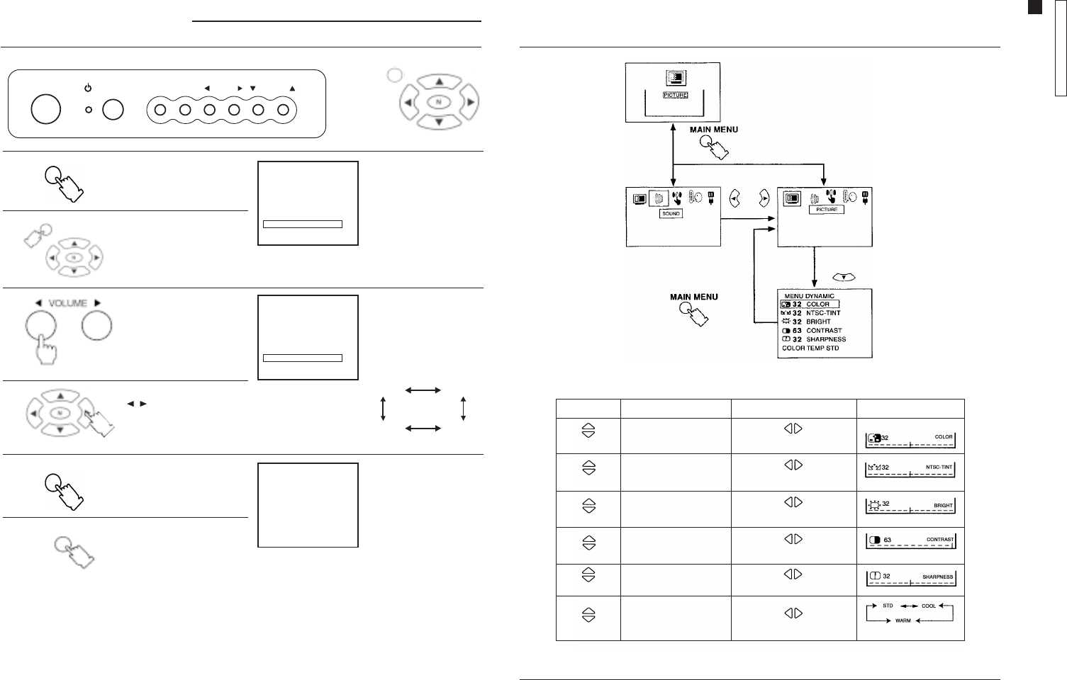
Picture menuPicture menu
Picture menuPicture menu
Picture menu
To select functions vertically or horizontally, press the navigation buttons.
PressPress
PressPress
Press IndicatorIndicator
IndicatorIndicator
Indicator
EffectEffect
EffectEffect
Effect
ItemItem
ItemItem
Item
Select COLORCOLOR
COLORCOLOR
COLOR
BRIGHTBRIGHT
BRIGHTBRIGHT
BRIGHT
CONTRASTCONTRAST
CONTRASTCONTRAST
CONTRAST
SHARPNESSSHARPNESS
SHARPNESSSHARPNESS
SHARPNESS
COLOR TEMPCOLOR TEMP
COLOR TEMPCOLOR TEMP
COLOR TEMP. STD. STD
. STD. STD
. STD
Decrease Increase
Select
Select
Select
Select
Select
Greenish Reddish
Decrease Increase
Decrease Increase
Darker Brighter
NTSC-TINTNTSC-TINT
NTSC-TINTNTSC-TINT
NTSC-TINT
Operation Guide
TC-14A12P / TC-20B12
- 13 -
ENGLISHENGLISH
ENGLISHENGLISH
ENGLISH
Sound MenuSound Menu
Sound MenuSound Menu
Sound Menu
Supplementary Remote Control OperationsSupplementary Remote Control Operations
Supplementary Remote Control OperationsSupplementary Remote Control Operations
Supplementary Remote Control Operations
AA
AA
AVL (VL (
VL (VL (
VL (Automatic VAutomatic V
Automatic VAutomatic V
Automatic Volume Levellingolume Levelling
olume Levellingolume Levelling
olume Levelling))
))
)
This feature restricts sound volume to a preset level, when broadcast sound levels differ between programs and
commercials.
Important NoteImportant Note
Important NoteImportant Note
Important Note
If sound menu is active and the N (Picture norm) button is pressed, sound settings will be reset to factory setup
levels.
Sound MenuSound Menu
Sound MenuSound Menu
Sound Menu
To select functions vertically or horizontally, press the navigation buttons.
PressPress
PressPress
Press IndicadorIndicador
IndicadorIndicador
Indicador
EffectEffect
EffectEffect
Effect
ItemItem
ItemItem
Item
TONE STDTONE STD
TONE STDTONE STD
TONE STD
Select
Select
AA
AA
AVL ONVL ON
VL ONVL ON
VL ON
ON Ö
OFF
Decrease Ö
Increase
STD HIGH
LOW
AA
AA
AVL ONVL ON
VL ONVL ON
VL ON
Ö
Ö Ö Ö
OFF OFF
OFF OFF
OFF C1C1
C1C1
C1 C2C2
C2C2
C2 T1T1
T1T1
T1 T2T2
T2T2
T2
T4T4
T4T4
T4 T3T3
T3T3
T3 C4C4
C4C4
C4 C3C3
C3C3
C3
Ö Ö Ö Ö
CCCC
CCCC
CC
MODE (Mode/Closed Caption) MODE (Mode/Closed Caption)
MODE (Mode/Closed Caption) MODE (Mode/Closed Caption)
MODE (Mode/Closed Caption)
Press the navigation button ( / ) to select an option
as shown below:
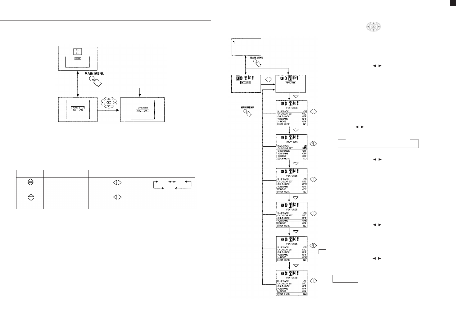
BLUE BACK (Blue screen)BLUE BACK (Blue screen)
BLUE BACK (Blue screen)BLUE BACK (Blue screen)
BLUE BACK (Blue screen)
When this feature is activated, the screen will turn blue if there is
no input of a TV station signal, when the signal is weak, or when
the picture is excessively snowy. To avoid excessive noise, sound
level is reduced to zero.
Press the navigation button ( / ) to select
ON Ö
OFF.
Note:Note:
Note:Note:
Note:
This feature should be disabled by selecting OFF in the following
situations:
1. When the program signal is weak or when the picture is
excessively snowy.
2. When reproducing a video tape in FF or REW mode.
CH COLOR SET (Individual color channel setting)CH COLOR SET (Individual color channel setting)
CH COLOR SET (Individual color channel setting)CH COLOR SET (Individual color channel setting)
CH COLOR SET (Individual color channel setting)
Color intensity may vary among TV stations. This feature allows
you to individually adjust color settings for each station. Press the
navigation button ( / ) to adjust as follows:
CHILD CHILD
CHILD CHILD
CHILD LOCKLOCK
LOCKLOCK
LOCK
Press the navigation button ( / ) to select
ON Ö
OFF.
Note:Note:
Note:Note:
Note:
1. When the channel is locked, the screen turns blue and sound
level is reduced to zero.
2. When the FUNC (Function) button is pressed, the indication
CHILD LOCK ON will be displayed. No setting function can be
accessed.
3. When the unit is turned ON while in a locked channel, the
indication CHILD LOCK ON will be displayed to remind you
that this feature is activated.
VCR/GAMEVCR/GAME
VCR/GAMEVCR/GAME
VCR/GAME
Press the navigation button ( / ) to select
ON Ö
OFF.
When this feature is ON, brightness and contrast are set to
optimum picture levels.
Supplementary Remote Control OperationsSupplementary Remote Control Operations
Supplementary Remote Control OperationsSupplementary Remote Control Operations
Supplementary Remote Control Operations
Features MenuFeatures Menu
Features MenuFeatures Menu
Features Menu
To select functions vertically or horizontally, press the navigation buttons.
Õ
STDSTD
STDSTD
STD
HIGHHIGH
HIGHHIGH
HIGH LOWLOW
LOWLOW
LOW
Ö Ö
Õ
Õ
Õ
Operation Guide
TC-14A12P / TC-20B12
- 14 -
ENGLISHENGLISH
ENGLISHENGLISH
ENGLISH
Hotel ModeHotel Mode
Hotel ModeHotel Mode
Hotel Mode
This feature is very useful in hotels or when the owner does not want other people to change setting levels.
When activated, only CHANNEL, VOLUME, PICTURE MENU, RECALL, MUTE, TV/AV buttons will operate.
Supplementary Remote Control OperationsSupplementary Remote Control Operations
Supplementary Remote Control OperationsSupplementary Remote Control Operations
Supplementary Remote Control Operations
ON MUTE (Mute/Closed Caption)ON MUTE (Mute/Closed Caption)
ON MUTE (Mute/Closed Caption)ON MUTE (Mute/Closed Caption)
ON MUTE (Mute/Closed Caption)
This feature will function only when:
1. Mode/CC feature is OFF.
2. The MUTE button ( ) is pressed on the remote control.
Press the navigation button ( / ) to select an option as shown below:
LanguageLanguage
LanguageLanguage
Language
To select functions vertically or
horizontally, press the navigation
buttons.
Ö
NO NO
NO NO
NO C1C1
C1C1
C1 C2C2
C2C2
C2
C4C4
C4C4
C4 C3C3
C3C3
C3
Ö Ö
Õ
Õ
Ö
To activate::
::
:
1. Adjust sound level.
2. Press the TIMER button on the remote control and
set it to 30 minutes.
3. Press and hold the RECALL button.
4. Press the CHANNEL ( ) button on the TV
panel.
To exit Hotel mode:
Press the VOLUME ( ) button on the TV panel and the
TIMER button on the remote control simultaneously.
cccc
cccc
cc
IDIOMA
PORTUGUÊS
ESPAÑOL
ENGLISH
IDIOMA
PORTUGUÊS
ESPAÑOL
ENGLISH
LANGUAGE
PORTUGUÊS
ESPAÑOL
ENGLISH
Troubleshooting ChartTroubleshooting Chart
Troubleshooting ChartTroubleshooting Chart
Troubleshooting Chart
Before you call for service, determine the symptoms and make a few simple checks, as shown below.
Snowy picture Noisy sound
Multiple image Normal sound
Interference Noisy sound
Normal picture No sound
No picture No sound
No color Normal sound
No video Low sound
Colored blotches Normal sound
No color Noisy sound
Antenna location and/or connection
SIGNALSSIGNALS
SIGNALSSIGNALS
SIGNALS
PicturePicture
PicturePicture
Picture SoundSound
SoundSound
Sound CheckCheck
CheckCheck
Check
Antenna location and/or connection
Electrical appliances,
lights, cars
and motorcycles
Volume
(check if mute control is
activated on the remote control)
Check that the AC power cord is plugged into
the AC outlet.
Unit has not been turned ON.
Brightness/contrast and audio control settings
(Check by pressing the power switch.)
Color control settings
Perform channel tuning procedure again.
Unit was relocated while it was ON.
Improper color system
TC-14A12P / TC-20B12
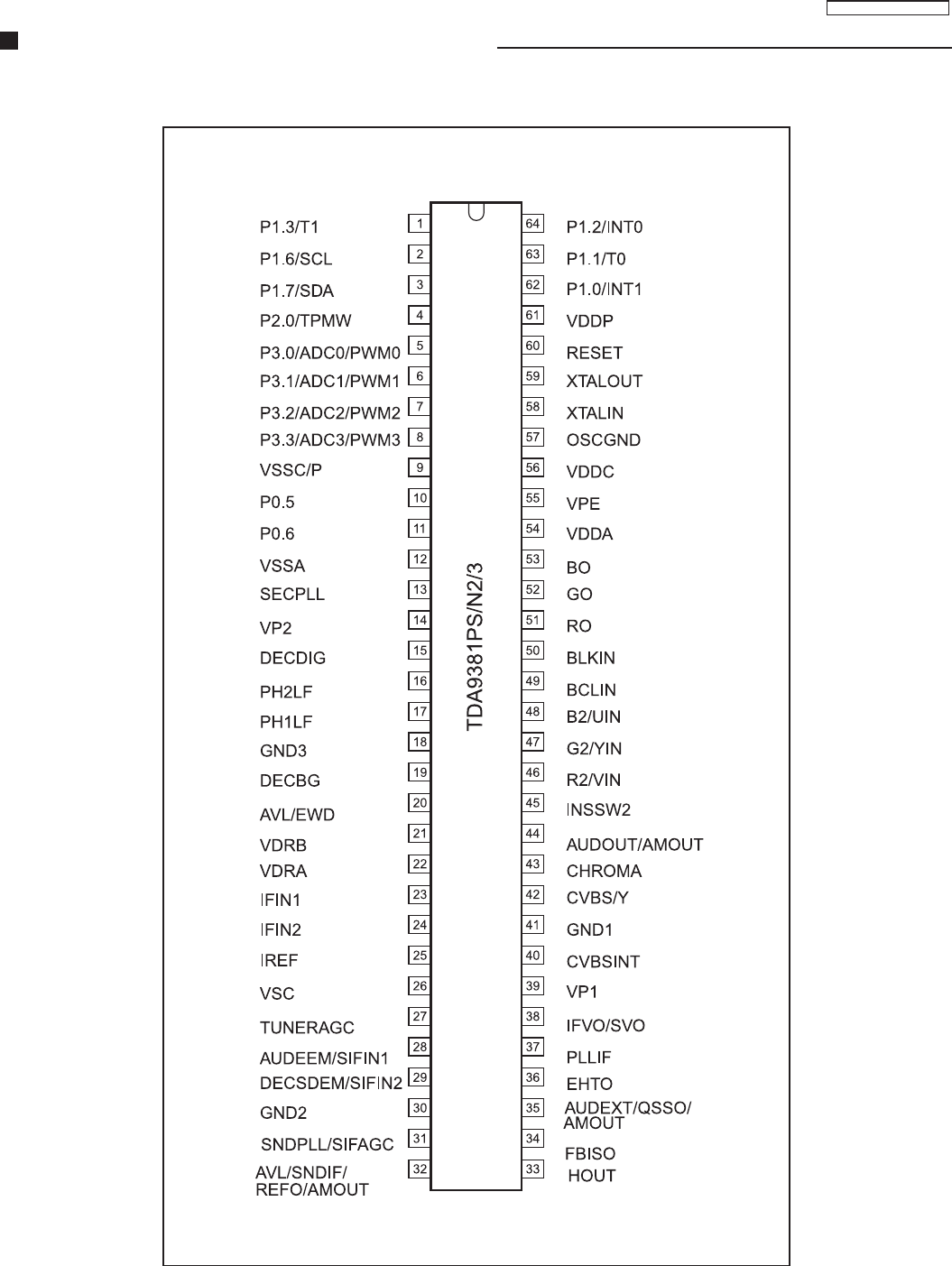
- 15 -
IC601 (TDA9381PS/N2/3) - Pins and Functions

TC-14A12P / TC-20B12
- 16 -
IC601 - Pins and Functions
P1.3/T1 1 port 1.3 or Counter/Timer 1 input
P1.6/SCL 2 port 1.6 or I 2 C-bus clock line
P1.7/SDA 3 port 1.7 or I 2 C-bus data line
P2.0/TPWM 4 port 2.0 or Tuning PWM output
P3.0/ADC0/PWM0 5 port 3.0 or ADC0 input or PWM0 output
P3.1/ADC1/PWM1 6 port 3.1 or ADC1 input or PWM1 output
P3.2/ADC2/PWM2 7 port 3.2 or ADC2 input or PWM2 output
P3.3/ADC3/PWM3 8 port 3.3 or ADC3 input or PWM3 output
VSSC/P 9 digital ground for m-Controller core and periphery
P0.5 10 port 0.5 (8 mA current sinking capability for direct drive of LEDs)
P0.6 11 port 0.6 (8 mA current sinking capability for direct drive of LEDs)
VSSA 12 analog ground of Teletext decoder and digital ground of TV-processor
SECPLL 13 SECAM PLL decoupling
VP2 14 2 nd supply voltage TV-processor (+8V)
DECDIG 15 decoupling digital supply of TV-processor
PH2LF 16 phase-2 filter
PH1LF 17 phase-1 filter
GND3 18 ground 3 for TV-processor
DECBG 19 bandgap decoupling
AVL/EWD (1) 20 Automatic Volume Levelling /East-West drive output
VDRB 21 vertical drive B output
VDRA 22 vertical drive A output
IFIN1 23 IF input 1
IFIN2 24 IF input 2
IREF 25 reference current input
VSC 26 vertical sawtooth capacitor
TUNERAGC 27 tuner AGC output
AUDEEM/SIFIN1 (1) 28 audio deemphasis or SIF input 1
DECSDEM/SIFIN2 (1) 29 decoupling sound demodulator or SIF input 2
GND2 30 ground 2 for TV processor
SNDPLL/SIFAGC (1) 31 narrow band PLL filter /AGC sound IF
AVL/SNDIF/REF0/ 32 Automatic Volume Levelling / sound IF input / subcarrier reference output /AM output
AMOUT (1) (non controlled)
HOUT 33 horizontal output
FBISO 34 flyback input/sandcastle output
AUDEXT/ 35 external audio input /QSS intercarrier out /AM audio output (non controlled)
QSSO/AMOUT (1)
EHTO 36 EHT/overvoltage protection input
PLLIF 37 IF-PLL loop filter
IFVO/SVO 38 IF video output / selected CVBS output
VP1 39 main supply voltage TV-processor (+8 V)
CVBSINT 40 internal CVBS input
GND1 41 ground 1 for TV-processor
CVBS/Y 42 external CVBS/Y input
CHROMA 43 chrominance input (SVHS)
AUDOUT /AMOUT (1) 44 audio output /AM audio output (volume controlled)
INSSW2 45 2 nd RGB / YUV insertion input
R2/VIN 46 2 nd R input / V (R-Y) input
G2/YIN 47 2 nd G input / Y input
B2/UIN 48 2 nd B input / U (B-Y) input
BCLIN 49 beam current limiter input / (V-guard input, note 2)
Nome Nº Descrição
TC-14A12P / TC-20B12
- 17 -
IC601 - Pins and Functions
Nome Nº Descrição
BLKIN 50 black current input / (V-guard input, note 2)
RO 51 Red output
GO 52 Green output
BO 53 Blue output
VDDA 54 analog supply of Teletext decoder and digital supply of TV-processor (3.3 V)
VPE 55 OTP Programming Voltage
VDDC 56 digital supply to core (3.3 V)
OSCGND 57 oscillator ground supply
XTALIN 58 crystal oscillator input
XTALOUT 59 crystal oscillator output
RESET 60 reset
VDDP 61 digital supply to periphery (+3.3 V)
P1.0/INT1 62 port 1.0 or external interrupt 1 input
P1.1/T0 63 port 1.1 or Counter/Timer 0 input
P1.2/INT0 64 port 1.2 or external interrupt 0 input
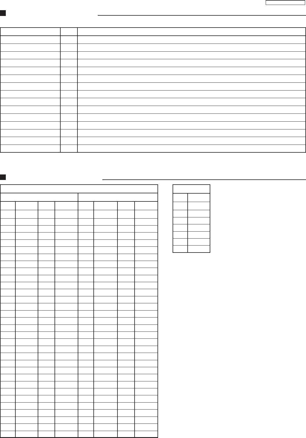
IC601
POWER ON STAND-BY
Pin Voltage Pin Voltage Pin Voltage Pin Voltage
1 3,2V 33 0,6V 1 0V 33 0,9V
2 NC 34 0,8V 2 4,8V 34 0V
3 NC 35 3,8V 3 4,8V 35 1,9V
4 3,3V 36 4,4V 4 0V 36 3,3V
5 0V 37 2,8V 5 4,8V 37 2,2V
6 3,3V 38 3,2V 6 3,3V 38 3,2V
7 3,3V 39 7,8V 7 3,3V 39 5V
8 3,3V 40 4,5V 8 3,3V 40 2,7V
9 0V 41 0V 9 0V 41 0V
10 0V 42 4,5V 10 0V 42 2,4V
11 2,2V 43 0V 11 4,6V 43 0V
12 0V 44 3,5V 12 0V 44 2,2V
13 2,3V 45 0V 13 1,7V 45 0V
14 7,8V 46 0V 14 5,1V 46 0V
15 4,9V 47 0V 15 3,4V 47 0V
16 3,4V 48 0V 16 1,7V 48 0V
17 3,7V 49 2,5V 17 1,7V 49 2V
18 0V 50 5,3V 18 0V 50 3,3V
19 4V 51 3,4V 19 3,2V 51 0,8V
20 0V 52 3,3V 20 0,3V 52 0,8V
21 2,1V 53 3,3V 21 1,3V 53 0,9V
22 2,2V 54 3,3V 22 1,1V 54 3,3V
23 1,8V 55 0V 23 1,6V 55 0V
24 1,8V 56 3,3V 24 1,6V 56 3,3V
25 3,8V 57 0V 25 2,5V 57 0V
26 4,4V 58 nc 26 2,2V 58 1,6V
27 4,1V 59 nc 27 4V 59 1,6V
28 3,2V 60 nc 28 1,8V 60 0V
29 2,3V 61 3,3V 29 0,9V 61 3,3V
30 0V 62 0V 30 0V 62 0V
31 2,3V 63 1,6V 31 1V 63 0V
32 2,5V 64 4,6V 32 1,1V 64 4,8
IC601 / IC451 - Voltage Table
IC451
Pin Voltage
1 3,2V
2NC
3NC
4 3,3V
50V
6 3,3V
7 3,3V
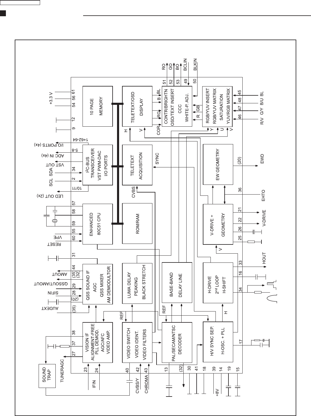
TC-14A12P / TC-20B12
- 18 -
IC601 - Block Diagram
TC-14A12P / TC-20B12
- 19 -
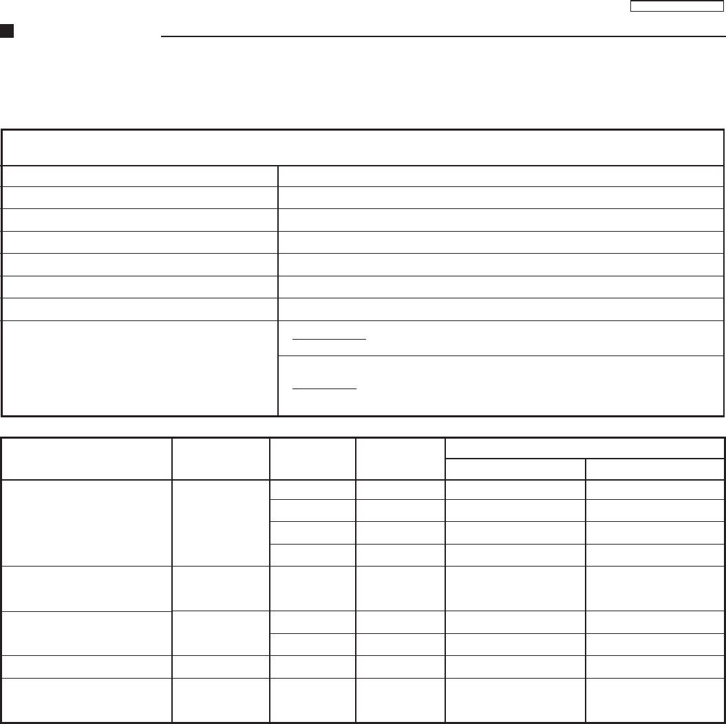
General Summary
CONFIGURATION
COLOUR SYSTEM PAL-M / NTSC / PAL-N (PAL-M 50Hz)
POWER SOURCE CA Automatic Voltage Selection 110 - 240V AC, 60Hz
MEMORY 100 positions
TUNING RANGE 181 channels
On Screen Display Language English / Spanish / Portuguese
Áudio System Mono
Vertical Magnetic Field -0.1 ±0.03 (BRASIL)
Colour Temperature TC-14A12P: (High Light) x= 0.260±0.01, y=0.265 ±0.01, Y=300 (nit)
(Low Light) x= 0.243±0.01, y=0.255 ±0.01, Y=6.5 (nit)
TC-20B12: (High Light) x= 0.270±0.01, y=0.275 ±0.01, Y=155 (nit)
(Low Light) x= 0.245±0.01, y=0.235 ±0.01, Y=7.0 (nit)
+B Voltage
Buzz
PAL colour sign optput
NTSC colour sign output
Anode (EHT) voltage
002
007
009
010
008
TPA 12
TPA 11
TPA 10
TPA21
A22-2
or PA41
TPL2
TPL1
TPL1
CRT
anode
D
C
C
140.5 ± 1.5 (V)
8 ± 1 (V)
5± 1 (V)
215 ± 15 (V)
0.5 (Vp-p)
2.45 ± 0.1 (Vo-p)
2.45 ± 0.5 (Vo-p)
1.2 ± 0.5 (Vo-p)
24.5 +0.7 (Kv)
24.5 – 1.5 (kV)
140.5 ± 1.5 (V)
8 ± 1 (V)
5± 1 (V)
215 ± 15 (V)
0.5 (Vp-p)
2.45 ± 0.1 (Vo-p)
2.45 ± 0.5 (Vo-p)
1.2 ± 0.5 (Vo-p)
26.5 +0.7 (Kv)
26.5 – 1.5 (kV)
Contents Reference Test Point Adjustment
Point
Specifications
TC-14A12P TC-20B12
- 20 -
TC-14A12P / TC-20B12
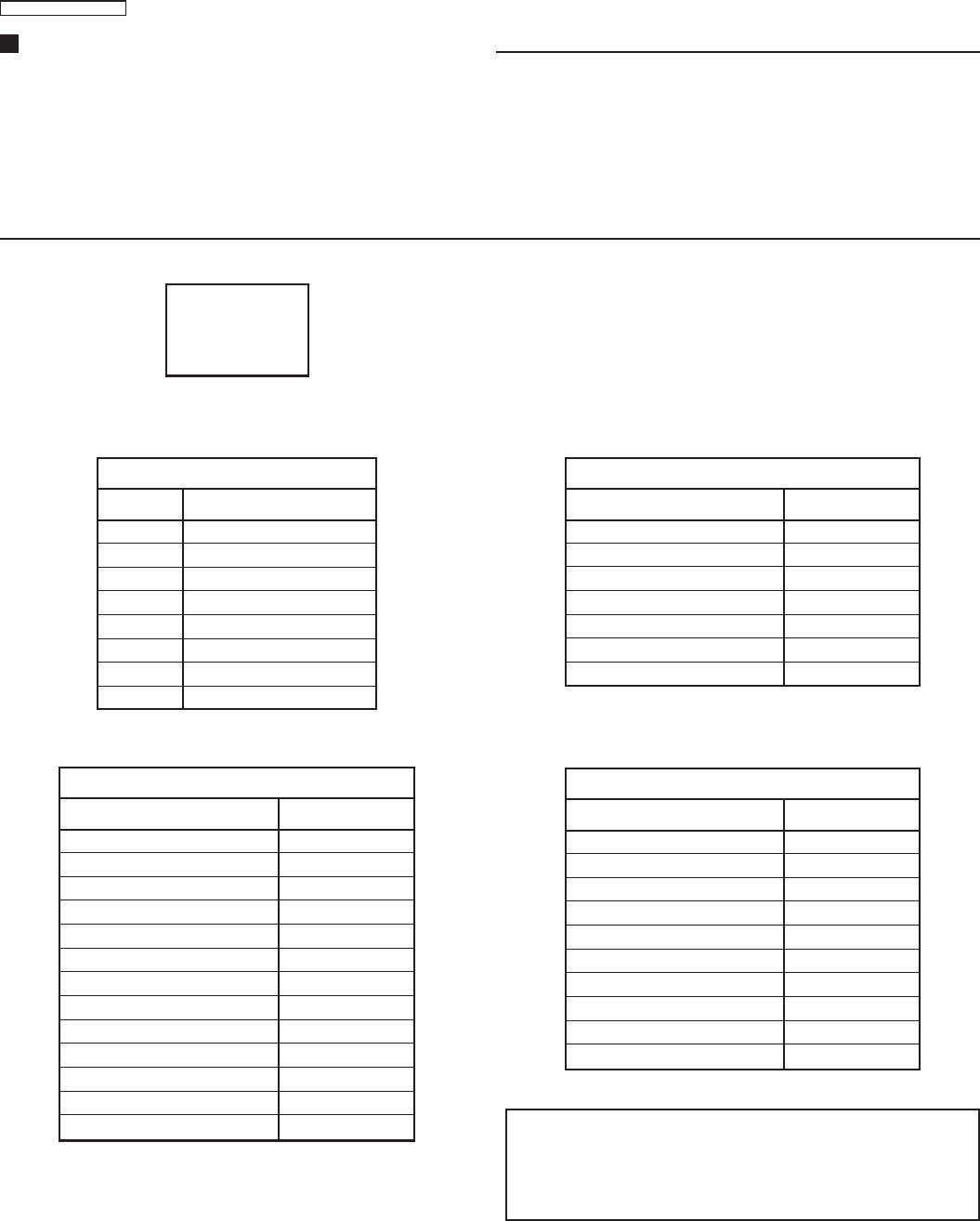
Service Adjustments and Calibrations
TO ENTER IN THE SERVICE MODE:
1. Adjust the volume for the minimum.
2. Adjustment the “OFF TIMER” function for 30 minutes.
3. Simultaneously press the “RECALL“ button of the remote
control unit and the “VOLUME DOWN“ button on the TV set.
After some seconds, the TV enters the SERVICE MODE and
the “CHK1” expression should appear on the screen.
1
2
3
4
5
6
7
8
CHK1 OPTIONS
OPTIONS PAR
C 1
0 0
0 0
3 3
8 0
0 0
0 0
0 0
RF-AGC 31
CONTRAST 63
COLOUR 32
SUB-COLOUR 32
NTSC-TINT 32
SUB-NTSC-TINT 30
BRIGHT 32
OPTIONS PAR
CHK2 OPTIONS
V-SLOPE 37
V-SHIFT 50Hz 2
V-SHIFT 60Hz 1
V-AMP 50Hz 16
V-AMP 60Hz 16
H-SHIFT 36
S-CORR 50Hz 18
S-CORR 60HZ 18
V-ZOOM 50 Hz 5
V-ZOOM 60 Hz 7
OSD H-POS 3
OSD V-POS 50 Hz 28
OSD V-POS 60 Hz 21
OPTIONS PAR
CHK3 OPTIONS
R-CUT 31
G-CUT 32
BRIGHT 32
SUB-BRIGHT 31
CONTRAST 63
SUB-CONTRAST 21
R-DR 19
G-DR 31
B-DR 38
RGB CONTRAST 6
OPTIONS PAR
CHK4 OPTIONS
ADJUSTMENTS IN THE CHK1 MODE: ADJUSTMENTS IN THE CHK2 MODE:
ADJUSTMENTS IN THE CHK3 MODE:
• To select the options, press “4” to move forward and “ 3 “ to
go back.
• Select the option and make the adjustment pressing the
“VOL_” or “ VOL+” keys.
• To memorize the adjustment press “0” (CHK1 mode only).
NOTE:
ADJUSTMENTS IN THE CHK4 MODE:
CHK1←→CHK2
↑ ↑↑ ↑
↑ ↑↑ ↑
↑ ↑
↓ ↓↓ ↓
↓ ↓↓ ↓
↓ ↓
CHK4←→CHK3
• To turn off AKB (blue OSD), press “5”. To turn on AKB (white OSD), press “5” of the remote control unit.
• After end of the adjustments, press the “NORMAL” key “ or turn of the unit to return to the normal mode of TV.
• To do data memory maintenance, simultaneously press “ MUTE” on the remote control and “VOL_” on the TV set when it is in
SERVICE MODE . To select the memory address, press “4” to move forward or “3” to go back.)
TO EXIT SERVICE MODE AND RETURN TO THE NORMAL
STATE:
Press the “NORMAL” key on the remote control unit or turn off
the unit.
HOW TO OPERATE THE “DAC” CONTROLS IN THE BR3L CHASSIS
To change from “CHK1” to “CHK2” mode and following, press
“2” to move forward and “1” to go back.
- 21 -
TC-14A12P / TC-20B12
Service Adjustments and Calibrations
TEST EQUIPMENT
To do all of these electrical adjustments, the following equipment
is required:
• Dual-Trace Oscilloscope
Voltage Range: 0.001 V to 50 V/Div.
Frequency Range: DC to 50 MHz
Probes: 10:1, 1:1
• NTSC Video Pattern Generator
• DVM (Digital Volt Meter)
• MTS/SAP Signal Generator
• (TV Multi-Channel Sound Modulator (U.S.A.))
• Plastic Tip Driver and Non-Metal Driver
• Isolation Transformer (Variable)
• Degaussing Coil
• White Pattern Generator
• Audio Generator
AGC RF CALIBRATION
1. PREPARATION:
1.1. Receive a color bar pattern and assure a RF input signal of
75Ω opened, channel 13 (211.25 MHz).
1.2. Connect the digital multimeter in TPA 15.
2. CALIBRATION:
2.1. Select the option “RF AGC” in the “CHK2” service mode.
2.2. Adjust RF AGC to 2.2±0.1V in TPA20.
3.3. Increase the input level by +2 dB and confirm that the voltage
decrease.
Tuner ENV56D75G3R TEDH9-301A
Level 69dB mV 69dB mV
VIF DETECTOR OUTPUT LEVEL CONFIRMATION
1. CALIBRATION:
1.1. Install the chassis in the VIF calibration JIG and receive a
color bar pattern with 63 dBU (75Ω opened).
1.2. Connect the oscilloscope to TPA33.
1.3. Confirm that the video output signal is within a range of 1.05
± 0.15 Vp-p in TPA33.
BUZZ (SOUND CIRCUIT)
1. PREPARATION:
1.1. Connect the oscilloscope with a 7kHz filter between TPA41
and ground or between the speaker’s terminals
1.2. Adjust the sound volume to the maximum.
1.3. Set “TONE” to “NORMAL” and “AVL” turned off.
2. CONFIRMATION:
2.1. Receive a color bar pattern channel 2, with local frequency
adjusted and the AFC turned on (Channel with sound bearer and
without modulation).
2.2. Assure that the width in the buzzing waveform is smaller than
500 m Vp-p.
ANODE AND HEATER VOLTAGE CONFIRMATION
1. PREPARATION:
1.1. Receive a crosshatch pattern.
2.2. Adjust the bunch current in zero. (0 beam)
3.3. Adjust “SCREEN VR” and “CONTRAST” to minimum.
2. CONFIRMATION:
2.1. Connect a voltage meter between TPA12 and ground. Confirm
that the voltage +B is within a range of 140.5V± 1.5V
2.2. Connect a high frequency voltage meter (VRMS.) among the
heater, and confirm that the reads tension is within a range of 6.3
± 0.24 (VRMS)
2.3. Connect the high voltage meter in the CRT anode pin, and
confirm that the high voltage is within a range of [A]:
• TC-14A12P [A]=24.5 +0.7kV _1.5kV
• TC-20B12 [A]=26.5 +0.7kV _1.5kV
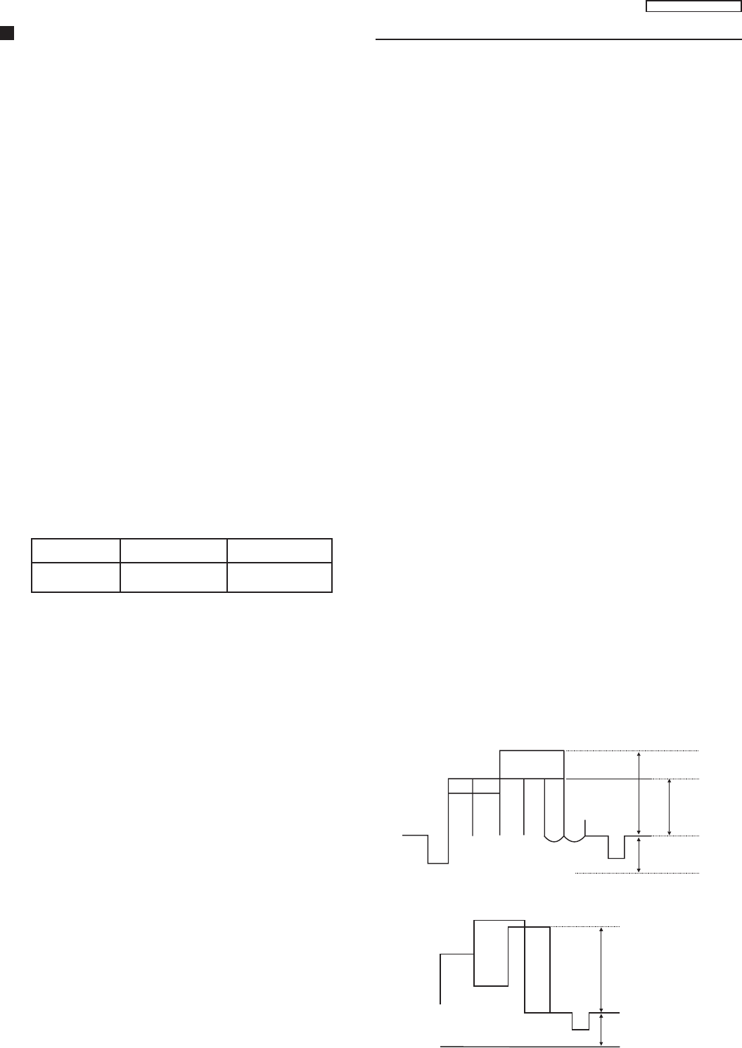
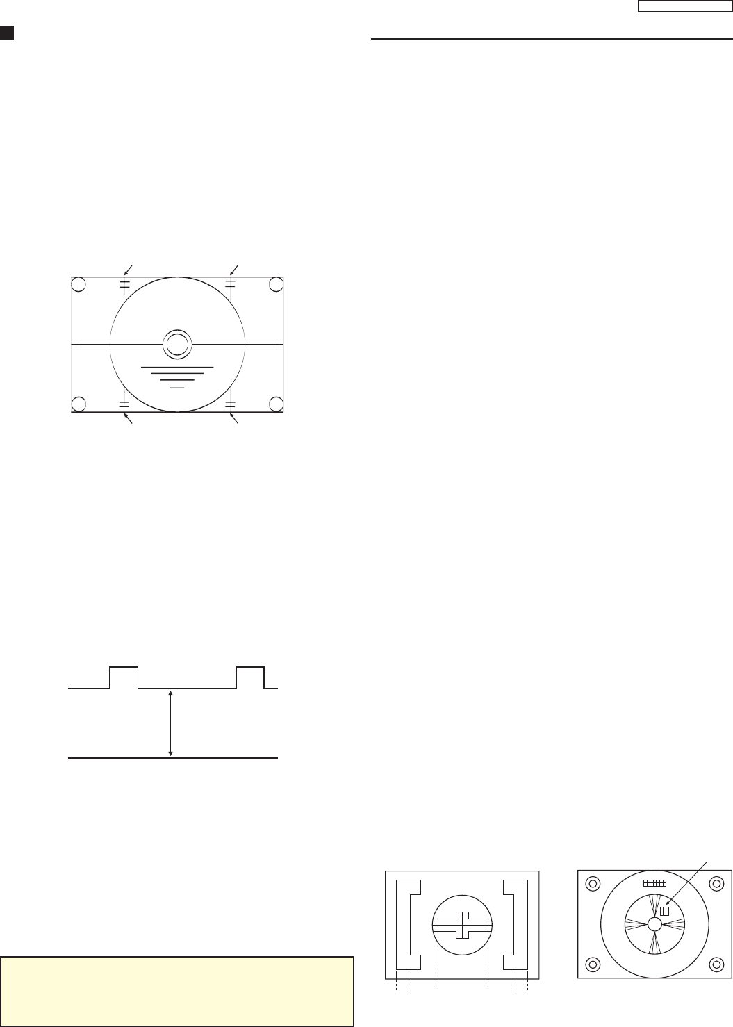
PAL COLOR OUTPUT SIGNAL ADJUSTMENT
1. PREPARATION:
1.1. Receive a color bar pattern and adjust the local frequency.
1.2. Adjust “IMAGE” to DYNAMIC NORMAL, “CONTRAST” to 63
and “SUB-CONTRAST” to 21.
1.3. Adjust the “COLOR FOR CHANNEL” level to NORMAL.
1.4. Set the CHK2 service mode option, press “5” on the remote
control unit and confirm that OSD becomes blue (AKB turned off).
1.5. Connect a short circuit jumper between TPA10 and TPA20.
1.6. Adjust [A] for 2.3 ± 0.2V through the BRIGHT control variation
in the test point TPL2.
1.7. Fix G-DRIVE GAIN, R-DRIVE GAIN and B-DRIVE GAIN data
in 1FH or 31 DAC.
2. CALIBRATION:
2.1. Connect the oscilloscope in TPL2 (G-OUT) with a 10KΩ
resistor and adjust “CONTRAST”, so that the waveform in [B] it is
of 2.6±0.1V according to fig. 1.
2. Adjust “SUB-COLOR” to obtain 2,45±0.1V in [D] according to
fig. 1.
3. Connect the oscilloscope in TPL1 (R-OUT) a 10KΩ resistor in
and confirm that the waveform in [C] it is of 2.45±0.1V according
to fig. 2.
4. Remove the jumper between TPA10 and TPA20, press “5” and
confirm that OSD becomes white (AKB turned on).
A=2.3±0.2Vp-p
BD
Fig. 1
A=2.3±0.2Vp-p
C
Fig. 2
- 22 -
TC-14A12P / TC-20B12
Service Adjustments and Calibrations
NTSC SUB-TINT CALIBRATION
1. PREPARATION:
1.1. Connect the oscilloscope to TPL1 (R OUT) in serie with a
10KΩ resistor.
1.2. Receive a rainbow pattern through VIDEO IN.
1.3. Adjust “IMAGE” to DYNAMIC NORMAL.
1.4. Adjust “COLOR FOR CHANNEL” to NORMAL.
1.5. Set the CHK2 service mode option, press “5” on the remote
control unit and confirm that OSD becomes blue (AKB turned off).
1.6. Connect a short circuit jumper between TPA10 and TPA20.
2. CALIBRATION:
2.1. Adjust [C] for 5.0±0.2V through the BRIGHT control variation
according to fig. 1.
2.2. Adjust the NTSC SUB-TINT level according to fig. 1 positions
2, 3 and 4.
2.3. Remove the jumper , press “5” and confirm that OSD becomes
white (AKB turned on).
Fig. 1
Fig. 2
PROTECTION CIRCUIT (SHUTDOWN)
CONFIRMATION OF OPERATION
1. PREPARATION:
1.1. Receive a crosshatch pattern.
1.2. Adjust CONTRAST and BRIGHT controls to minimum.
2. CONFIRMATION:
2.1. Connect the voltmeter in TPA22 and confirm that the voltage
is smaller than [A].
2.2. Connect a DC source in TPA22 and confirm that the protection
circuit doesn't act when the voltage is [B].
2.3. Confirm that the protection circuit acts with smaller voltage
than [C].
Condition 14 inches 20 inches
A 19,67V 21,18V
B 20,66V 22,31V
C 22,49V 24,37V
C
0V
1 2 3 4 5 6 7 8 9 10
WHITE QUALITY CALIBRATION
1. PREPARATION:
1.1. Adjust the HELMHOLTZ device to local magnetic field. Hori-
zontal: 0 ± 0.003 X 10⁻⁴T
1.2. Receive a white purity pattern.
1.3. Adjust CONTRAST and BRIGHT controls to maximum.
1.4. Previously adjust the CONVERGENCE.
1.5. Fully degauss the CRT by using an external degaussing coil.
2. CALIBRATION:
2.1. Adjust the magnetic field in 0.4x10⁻⁴T (400 mG), and check
the white quality with the CRT turned to EAST and to WEST.
2.2. Receive a red pattern, adjust the COLOR control to maximum
and confirm the purity adjustment.
2.3. If purity error is found at the CRT corners, to apply magnetic
tapes to correct it, fully degauss the CRT again and repeat the
steps 1 and 2. Don't use this magnetic tapes on the internal side
of the yoke.
2.4. Receive a white purity pattern, adjust the COLOR control to
maximum and confirm the purity adjustment.
VERTICAL DEFLECTION
CALIBRATION AND CONFIRMATION
1. PREPARATION:
1.1. Adjust the HELMHOLTZ device to the local magnetic field
1.2. Adjust IMAGE to DYNAMIC NORMAL.
2. CONFIRMATION AND CALIBRATION S-CORR :
• CONFIRMATION IN 50HZ
2.1. Receive a PAL-N Philips pattern
2.2. Confirm that S-CORR 50Hz is in [18] DAC.
• CONFIRMATION IN 60HZ
2.3. Receive a monoscope pattern.
2.4. Confirm that S-CORR 60Hz is in [18] DAC.
• V-SLOPE CALIBRATION
2.5. Receive a monoscope pattern.
2.6. Adjust V_SLOPE so that the beginning of the black part of
the image be aligned with the center of the CRT as below.
3. VERTICAL CENTRALIZATION 50 HZ CALIBRATION
3.1. Receive a PAL-N Philips pattern
3.2 Adjust V-SHIFT 50Hz so that Philips pattern’s center it is in
the CRT center.
4. VERTICAL CENTRALIZATION 60 HZ CALIBRATION
4.1. Receive a monoscope pattern.
4.2. Adjust V-SHIFT 60Hz so that the monoscope pattern’s it is in
the CRT center
B
C
2 3 4 A:B = 1:2
CRT
CENTER
- 23 -
TC-14A12P / TC-20B12
Service Adjustments and Calibrations
5. VERTICAL HEIGHT (V-AMP 50HZ) CALIBRATION
5.1. Receive a PAL-N Philips pattern.
5.2. Adjust V-AMP-50Hz so that the Philips pattern’s circle height
be the same dimension of the width.
6. VERTICAL HEIGHT (V-AMP 60HZ) CALIBRATION
6.1. Receive a monoscope pattern.
6.2. Adjust V-AMP-60Hz so that:
[C] and [D] (see below) be 1.9~2.2 (typical 2.0) for 14 inches and
1.5~2.0 for 20 inches.
[A] and [B] be 1.5~2.3 (typical 2.0) for 14 inches and 1.5~1.6 for
20 inches.
6.3. Memorize in EEPROM.
CRT CUT OFF CALIBRATION
1. PREPARATION:
1.1. Receive a monoscope pattern.
1.2. Position DACs with the data below:
• BRT AND S-BRT = 32H.
• RGB CONTRAST = 06H for 14 inches and 07H for 20 inches.
• SUB-CONTRAST = 21H
• R,G,B DRIVE = 31H
• R,G CUT = 31H
1.3. Press “5” (AKB OFF) and confirm that OSD becomes blue.
1.4. Connect the oscilloscope in TPL7 and adjust BRT to obtain
130V in the figure below.
1.5 Adjust screen to minimum.
1.6. Press “5” (AKB ON) and confirm that OSD becomes white.
WHITE BALANCE CALIBRATION
1. PREPARATION:
1.1. This adjustment should be accomplished after 30 minutes of
heating.
1.2. Receive a white balance. (This sign should contain burst sign).
1.3. Position DAC of MENU OF IMAGE for DYNAMIC NORMAL.
1.4. Fully degauss the CRT by using an external degaussing coil.
1.5. Position the color analyzer in contact with the face of CRT.
• Assure that the CUT OFF voltage calibration has been done.
• If the value in the color analyzer is below Y(H) date, adjust
CONTRAST for 32 and connect a short circuit jumper between
TPA10 and TPA20.
AB
CD
130V
0V
2. CALIBRATION:
[1] LOW LIGHT CALIBRATION
1. Adjust S-BRT, so that Y = Y(L).
2. Adjust R-CUT OFF, so that x = x(L).
3. Adjust G-CUT OFF, so that y = y(L).
[2] HIGH LIGHT CALIBRATION
1. Adjust S-BRT, so that Y = Y(H).
2. Adjust R-DRIVE, so that x = x(H).
3. Adjust B-DRIVE, so that y = y(H).
[3] Repeat the procedures [1] and [2].
SUB-BRIGHTNESS CALIBRATION
1. PREPARATION:
1.1. Receive a windows pattern.
1.2. Position MENU OF IMAGE in DYNAMIC NORMAL.
2. CALIBRATION:
2.1. Position the color analyzer in an low light image area of CRT.
2.2. Adjust S-BRT <CHK 5>, so that Y=5.5 ± 0.2.
SUB-CONTRAST CALIBRATION
1. PREPARATION:
1.1. Receive a windows pattern.
1.2. Position MENU OF IMAGE in DYNAMIC NORMAL.
2. CALIBRATION:
2.1. Position the color analyzer in an hight light image area of CRT.
2. Adjust the SUB-CONTRAST <CHK 4>, so that Y=300±10 for
14 inches and Y=160±10 for 20 inches.
3. If it is impossible to obtain the adjustment above, adjust the
SUB-CONTRAST <CHK 4> and confirm the SUB-BRIGHTNESS
adjustment.
FOCUS CALIBRATION
1. PREPARATION:
• Assure that the SUB-BRIGHTNESS adjustment has been
done.
1.1. Receive a Philips or monoscope pattern.
1.2. Position MENU OF IMAGE in DYNAMIC NORMAL.
2. CALIBRATION:
2.1. Adjust the FOCUS variable resistor.
1 2 3 3 2 1
4
Using the Philips pattern:
• Take as reference to 3rd vertical
line.
Using the monoscope pattern:
• In the number 4
- 24 -
TC-14A12P / TC-20B12
Service Adjustments and Calibrations
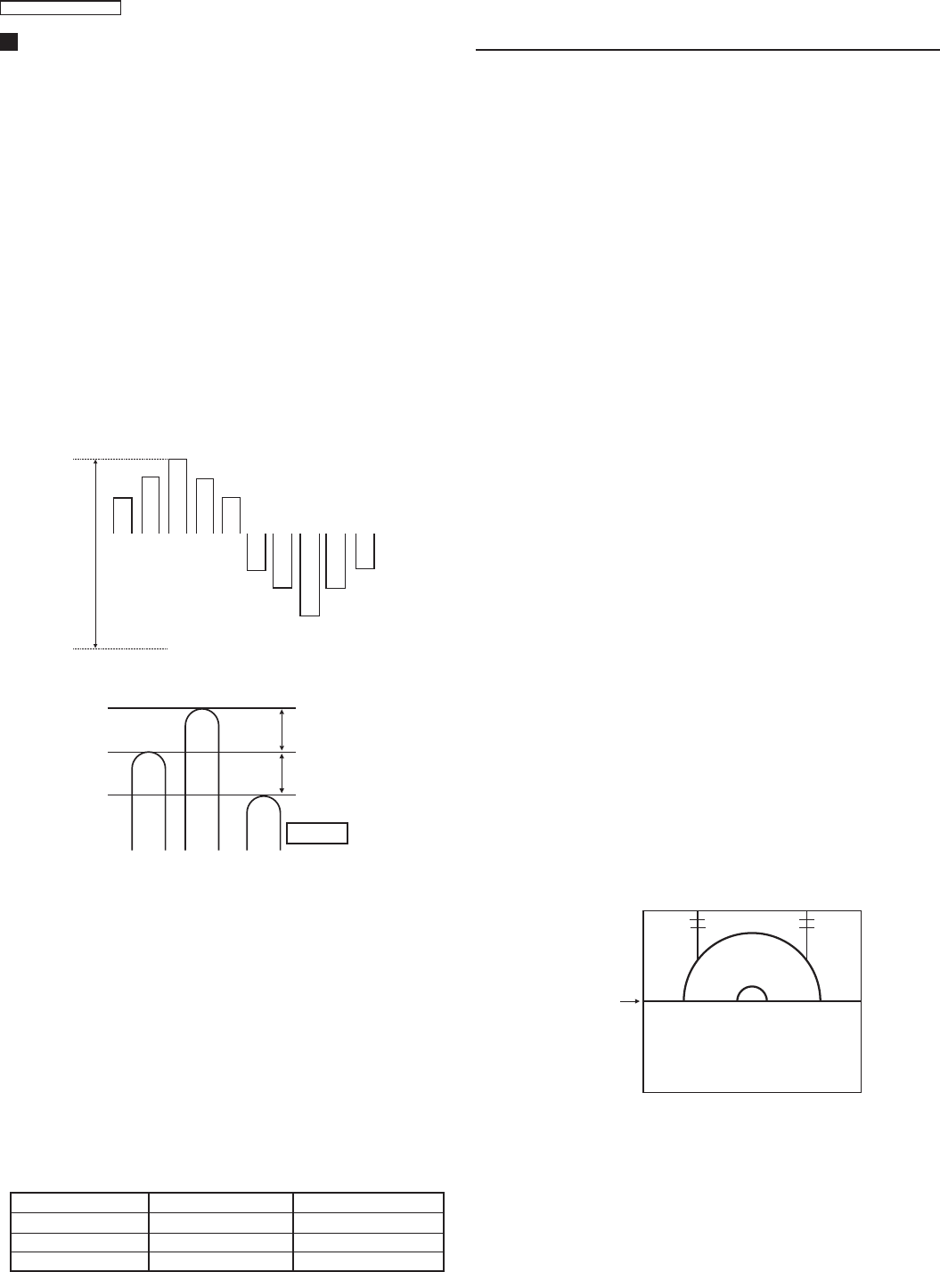
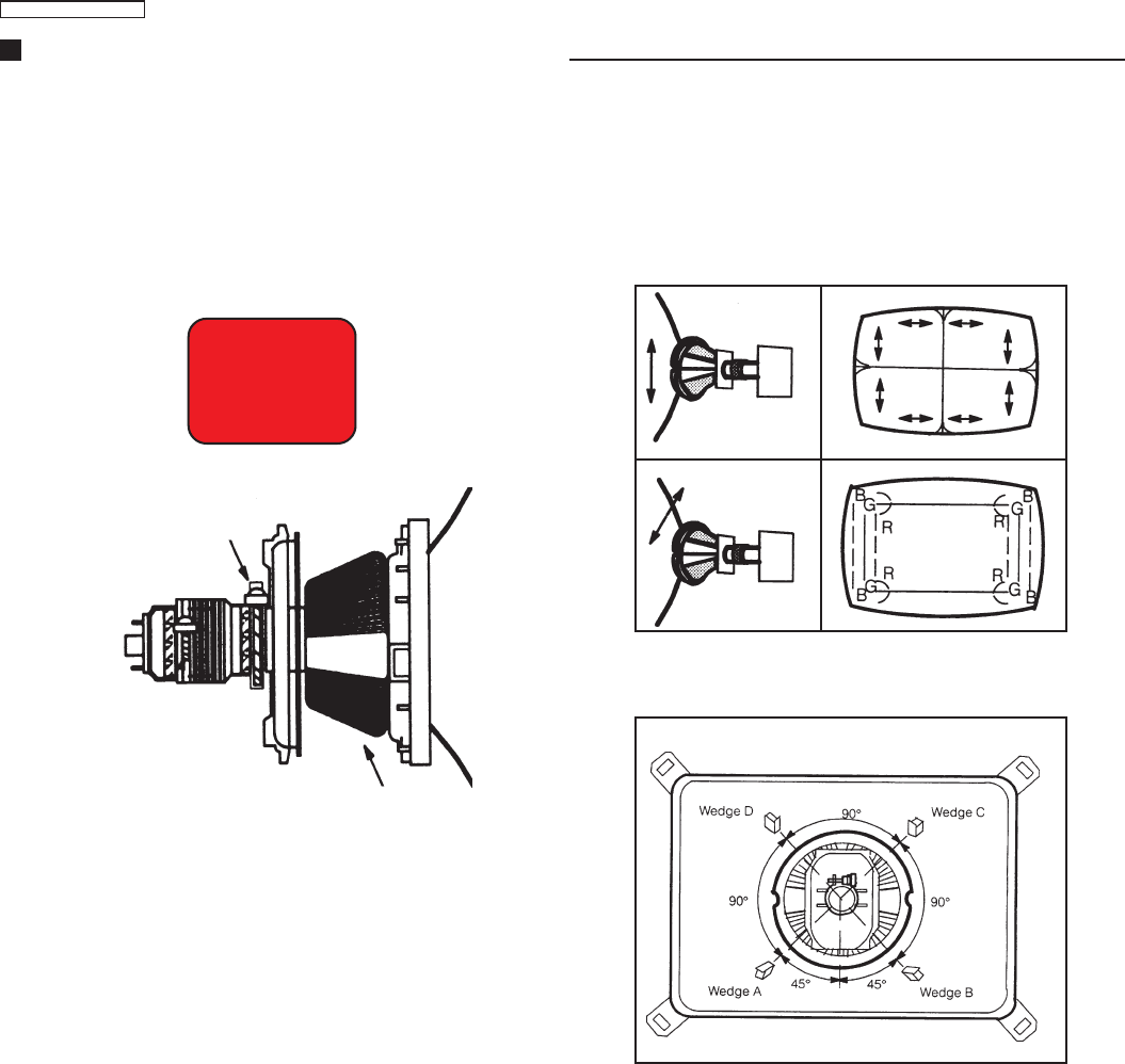
COLOR PURITY ADJUSTMENT
1. Position the CRT face turned to east or west.
2. Set Bright and Contrast controls to their maximum positions.
3. Leave the set heating up for 60 minutes at white screen.
4. Fully degauss the picture tube by using an external degauss coil.
5. Apply a red pattern.
6. Loose a clamp screw for the deflection yoke and move it forward
or backward until a uniform red screen is obtained.
7. Adjust rougly the Low Light controls and make sure that a uniform
white field is obtained.
8. Tighten the clamp screw.
Uniform red screen
CONVERGENCE CALIBRATION
1. Receive a crosshatch pattern and set Contrast control to the
maximum position.
2. Adjust Bright control to obtain a clear pattern.
3. Remove the DY wedges and slightly tilt the deflection yoke to
the vertically and horizontally to obtain the good overall
convergence.
4. Fix the deflection yoke by reinserting the DY wedges as showed
below.
5. If purity error is found, repeat “Color Purity” adjustment
Notes:
• Wedge A showed above should be fixed within a range of 45° to
the left of the vertical line shown.
• After inserting wedge A, insert wedges B, C and D. The wedges
should be set 90° apart from each other.
• Be certain that the four wedges are firmly fixed and the Deflection
Yoke is tightly clamped in place.
Otherwise the Deflection Yoke may shift its position and cause a
loss of convercence and purity.
Vertical
Horizontal
BGR
RGB
B
G
R
R
G
B
CRT
Screw for deflection yoke
Deflection yoke
BACKWAD FORWARD
à
à
TC-14A12P / TC-20B12
- 25 -
00 01 02 03 04 05 06 07 08 09 0A 0B 0C 0D 0E 0F
00 02 00 06 01 00 06 02 00 06 03 00 06 04 00 06 05
10 00 06 06 00 06 07 00 06 08 00 06 09 00 06 0A 00
20 06 0B 00 06 0C 00 06 0D 00 06 0E 00 06 0F 00 06
30 10 00 06 11 00 06 12 00 06 13 00 06 14 00 06 15
40 00 06 16 00 06 17 00 06 18 00 06 19 00 06 1A 00
50 06 1B 00 06 1C 00 06 1D 00 06 1E 00 06 1F 00 06
60 20 00 06 21 00 06 22 00 06 23 00 06 24 00 06 25
70 00 06 26 00 06 27 00 06 28 00 06 29 00 06 2A 00
80 06 2B 00 06 2C 00 06 2D 00 06 2E 00 06 2F 00 06
90 30 00 06 31 00 06 32 00 06 33 00 06 34 00 06 35
A0 00 06 36 00 06 37 00 06 38 00 06 39 00 06 3A 00
B0 06 3B 00 06 3C 00 06 3D 00 06 3E 00 06 3F 00 06
C0 40 00 06 41 00 06 42 00 06 43 00 06 44 00 06 45
D0 00 06 46 00 06 47 00 06 48 00 06 49 00 06 4A 00
E0 06 4B 00 06 4C 00 06 4D 00 06 4E 00 06 4F 00 06
F0 50 00 06 51 00 06 52 00 06 53 00 06 54 00 06 55
00 01 02 03 04 05 06 07 08 09 0A 0B 0C 0D 0E 0F
00 00 06 56 00 06 57 00 06 58 00 06 59 00 06 5A 00
10 06 5B 00 06 5C 00 06 5D 00 06 5E 00 06 5F 00 06
20 60 00 06 61 00 06 62 00 06 63 00 06 64 00 06 65
30 00 06 66 00 06 67 00 06 68 00 06 69 00 06 6A 00
40 06 6B 00 06 6C 00 06 6D 00 06 6E 00 06 6F 00 06
50 70 00 06 71 00 06 72 00 06 73 00 06 74 00 06 75
60 00 06 76 00 06 77 00 06 78 00 06 79 00 06 7A 00
70 06 7B 00 06 7C 00 06 7D 00 06 00 00 00 00 00 00
80 00 00 00 00 00 00 00 00 00 00 00 00 00 00 00 00
90 00 00 00 00 00 00 00 00 00 00 00 00 00 00 00 00
A0 06 00 00 00 00 00 00 00 00 00 00 00 00 00 00 00
B0 00 00 00 00 00 00 00 00 00 00 00 00 00 00 00 00
C0 00 00 00 00 00 00 00 00 00 00 00 00 00 00 00 00
D0 00 00 00 00 00 00 00 00 00 00 00 00 00 00 00 00
E0 00 00 00 00 00 00 00 00 00 00 00 00 00 00 00 00
F0 00 00 00 00 00 00 00 00 00 00 00 00 00 00 00 00
EEPROM X A0 address (0XX)
EEPROM X A2 address (1XX)
00 01 02 03 04 05 06 07 08 09 0A 0B 0C 0D 0E 0F
00 02 00 A5 5A 00 01 00 00 00 08 00 04 00 00 01 00
10 00 00 00 00 00 00 00 00 20 00 00 00 00 00 00 00
20 00 00 00 00 00 00 00 00 00 00 00 00 00 00 00 00
30 00 00 00 00 00 00 00 00 00 00 00 00 00 00 00 00
40 00 00 00 00 00 00 00 00 00 00 00 00 00 00 00 00
50 20 20 20 3F 2D 20 20 20 2D 20 1E 20 20 23 20 00
60 00 00 01 00 00 00 00 00 00 00 00 00 00 00 00 00
70 00 00 00 00 00 00 00 00 00 00 00 00 00 00 90 D0
80 20 20 20 3F OP 20 20 20 2D 20 1E 20 20 23 1E 01
90 00 00 00 00 00 00 00 00 00 00 00 00 00 00 00 00
A0 00 00 00 00 00 00 00 00 00 00 00 00 00 00 00 00
B0 03 1C 15 00 00 00 00 00 00 00 00 00 00 00 00 00
C0 00 00 00 00 00 00 00 00 00 00 00 00 00 00 00 00
D0 0C 05 0C 04 00 00 00 00 00 00 00 00 00 00 00 00
E0 00 00 00 00 00 00 00 00 C1 00 00 33 80 00 00 01
F0 00 00 18 20 15 1A 00 00 00 00 00 00 00 A5 3F A5
EEPROM X A4 address (2XX)
00 01 02 03 04 05 06 07 08 09 0A 0B 0C 0D 0E 0F
00 00 00 00 00 00 00 00 00 00 00 00 00 00 00 00 00
10 00 00 00 00 00 00 00 00 00 00 00 00 00 00 00 00
20 00 00 00 00 00 00 00 00 00 00 00 00 00 00 00 00
30 1B 20 00 22 17 1A 0F 0F 2B 24 1F 12 20 19 1F 1F
40 1F 1F 1F 00 06 00 00 00 10 29 C0 00 2A 00 34 2C
50 30 21 02 4A OP 44 00 00 00 00 00 00 FE 00 00 00
60 02 FF 1C 12 19 00 00 00 00 00 00 00 00 00 00 00
70 00 00 00 00 00 00 00 00 10 00 00 00 00 00 00 00
80 00 00 00 00 00 00 00 0E 11 0D 06 0C 07 0C 02 00
90 09 00 OP 00 00 00 00 0A F8 FD 00 00 00 00 00 03
A0 01 03 02 03 03 00 34 00 00 00 2C 63 03 00 20 30
B0 CA 49 4B 00 33 00 00 FF FC 04 05 05 03 F8 OP F2
C0 20 07 4F 40 40 00 00 00 00 00 00 00 00 00 00 00
D0 00 00 00 00 00 00 00 00 00 00 00 00 00 00 00 00
E0 00 00 00 00 00 00 00 00 00 00 00 00 00 00 00 00
F0 00 00 00 00 00 00 00 00 00 00 00 00 00 00 00 11
EEPROM X A6 address (3XX)
Power Source Voltages
EEPROM - Memory Maps
Click here to play the Power Source Voltages presentation (MS PowerPoint is necessary)
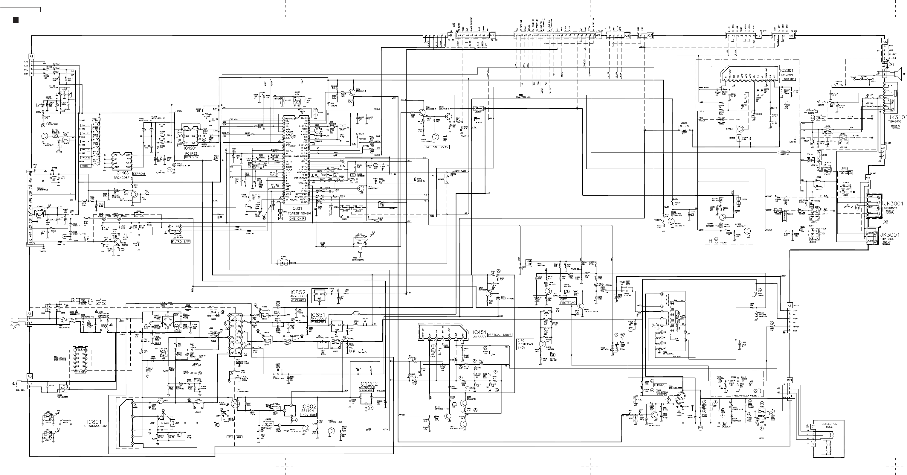
TC-14A12P / TC-20B12
- 26 -
Main Board Schematic Diagram - TC-14A12P / TC-20B12
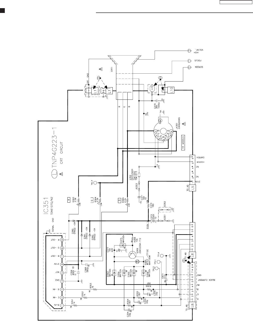
TC-14A12P / TC-20B12
- 27 -
CRT - Board Schematic Diagram

TC-14A12P / TC-20B12
- 28 -
Main Board Conductor View (left / component side)
1
2
3
4
5
6
ABCD
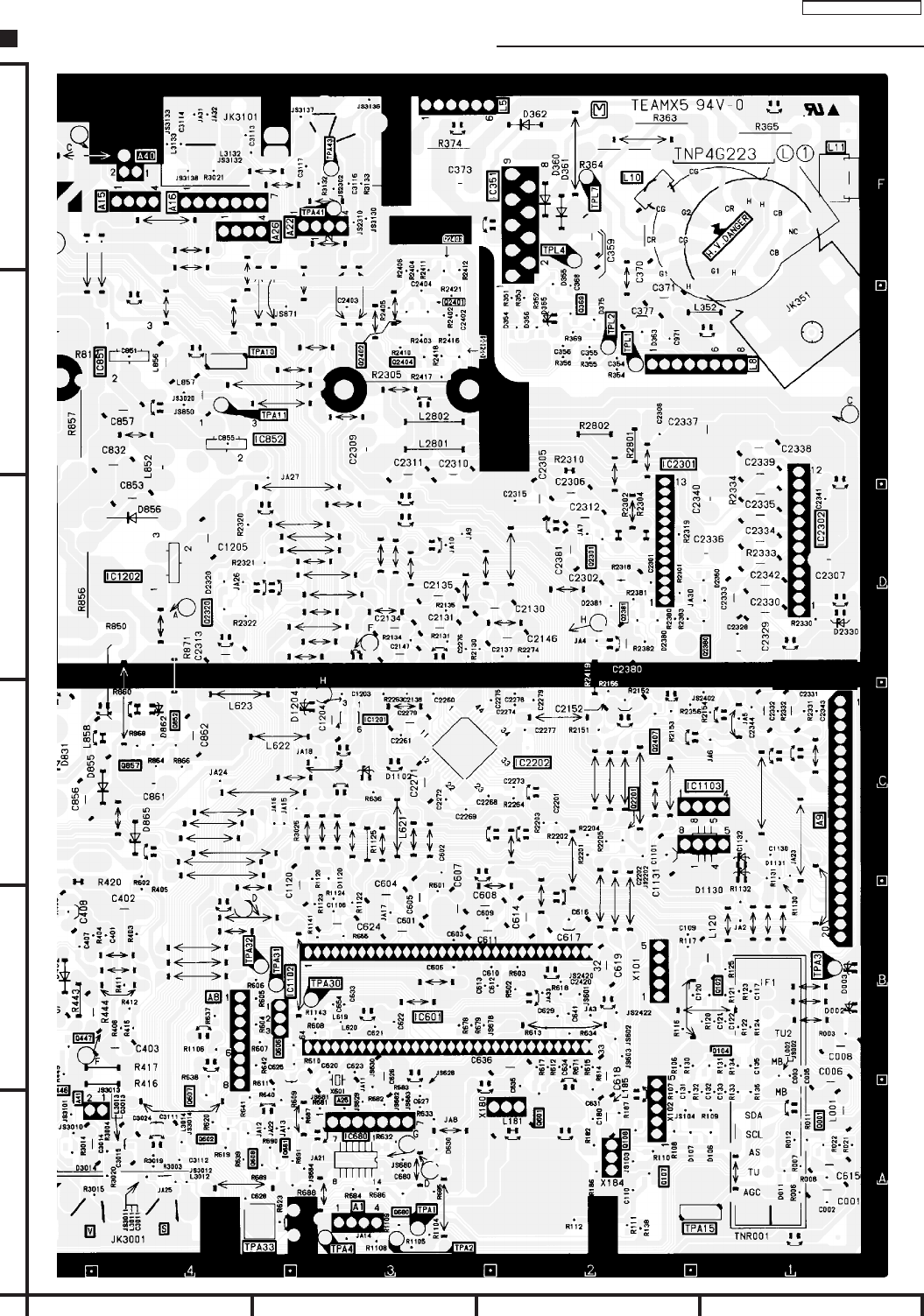
TC-14A12P / TC-20B12
- 29 -
Main Board Conductor View (right / component side)
A
1
2
3
4
5
6
BCD
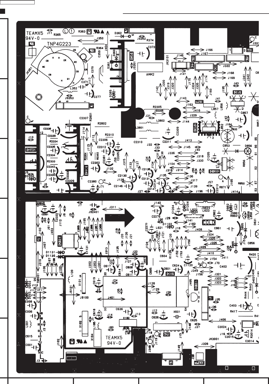
TC-14A12P / TC-20B12
- 30 -
Main Board Conductor View (left / foil side)
A
1
2
3
4
5
6
BCD
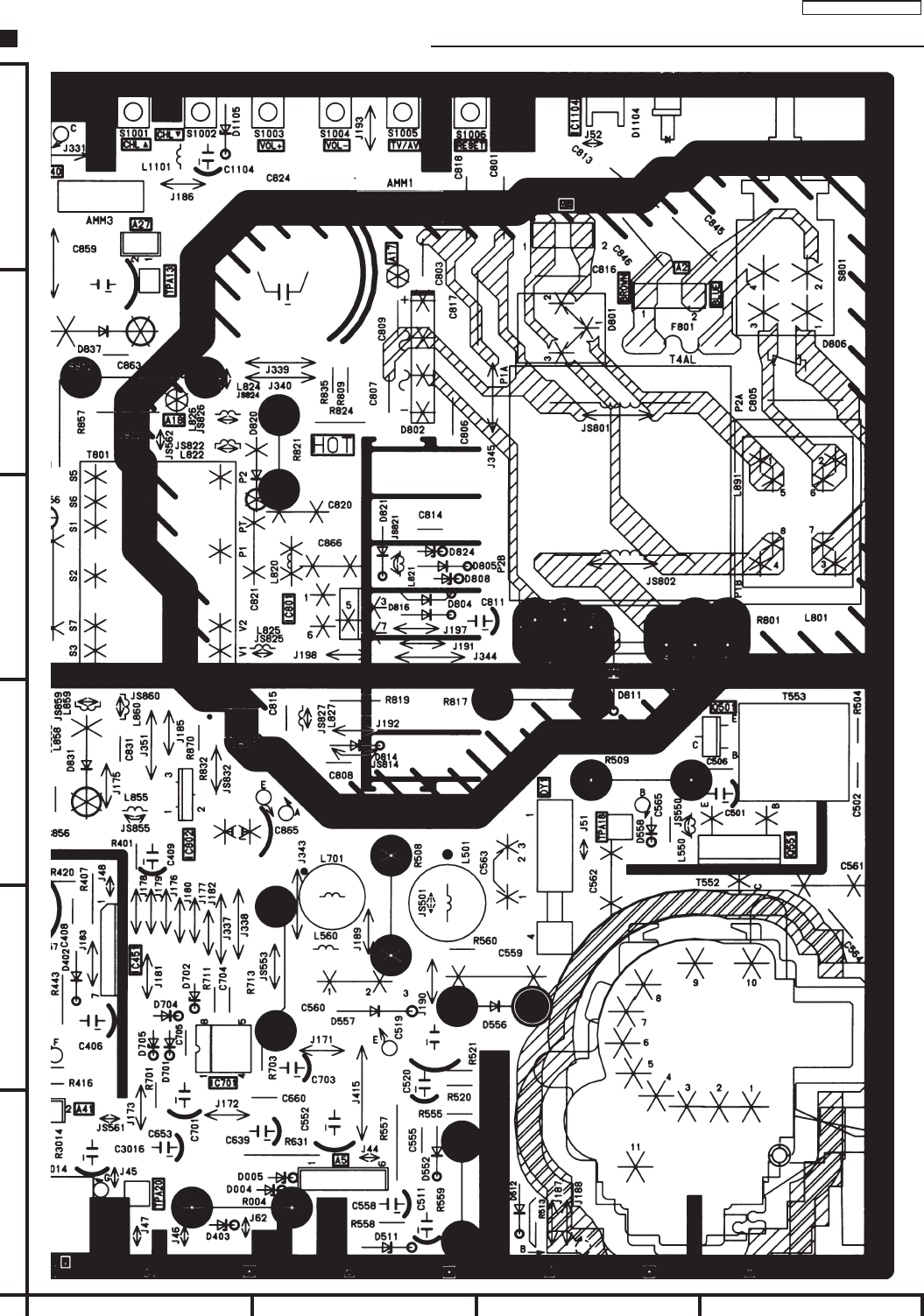
TC-14A12P / TC-20B12
- 31 -
Main Board Conductor View (right / foil side)
A
1
2
3
4
5
6
BCD
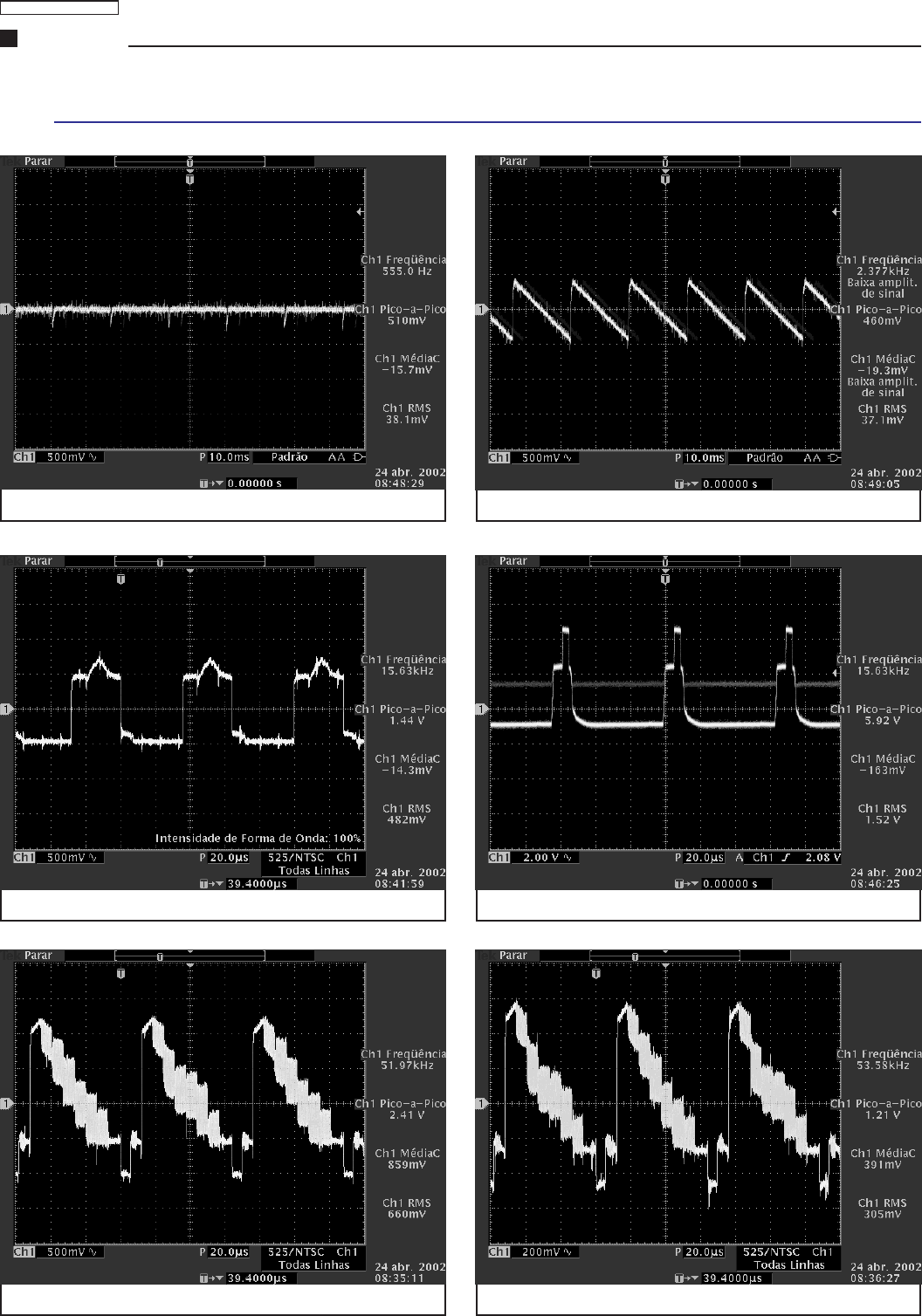
TC-14A12P / TC-20B12
- 32 -
IC601
Waveform
All the waveforms had read with 127V power source and receiving a colorbar pattern.
Pino 21 Pino 22
Pino 33 Pino 34
Pino 38 Pino 40
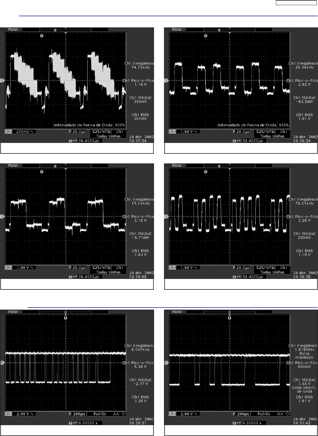
TC-14A12P / TC-20B12
- 33 -
Pino 42 Pino 51
Pino 52 Pino 53
IC601
TNR001
Pino SCL Pino SDA

TC-14A12P / TC-20B12
- 34 -
IC451 X101
Q501 Q551
Pino 01 (tensão de rede: 127V)Pino 01 (tensão de rede: 220V)
Pino 02 Pino 01
IC801
Coletor Coletor
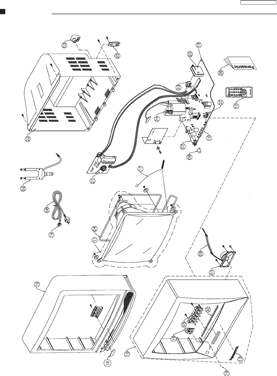
TC-14A12P / TC-20B12
- 35 -
Parts Location
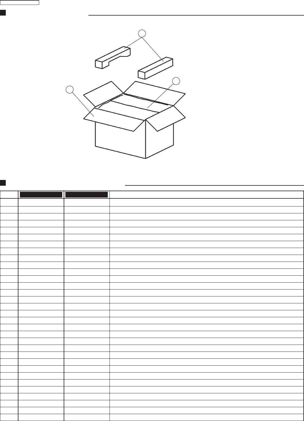
TC-14A12P / TC-20B12
- 36 -
01 EASZ9D03A8 EASZ9D03A8 SPEAKER 16Ω, 3W
02 TSA8108-6K TSA8108-6K TELESCOPIC ANTENNA
03 S-U5012 S-U5012 75Ω ADAPTOR
04 TLK2B20001A TLK2B14001A DEGAUSSING COIL
05 TBX2B864 TBX2B861-1 6 POSITIONS BUTTON
06 TBX2B846-1 TBX2B862-1 POWER BUTTON
07 ESB92DA1B ESB92DA1B POWER SWITCH
08 TSX2B1421SB TSX2B1421SB AC CABLE
09 TXAJTA22CB20A12 TXAJTA22CB14A12 2 WAY CONNECTOR (SPEAKER)
10 EVQ11G05R EVQ11G05R SWITCHES - S1001 ~ 1006
11 A48EAK01X094R A34EAK01X094R PICTURE TUBE
12 TNQ2B2901 TNQ2B2901 REMOTE CONTROLLER
13 TBM4G3003 TBM4G3008 PANASONIC BADGE
14 TMM2B202-1 TMM2B202-1 AC CABLE HOLDER
15 TXFKY20B12 TXFKY14A12P ASSEMBLED CABINET
16 TKK2B0309 TKK2B0307 LED GUIDE
17 TXF3A20C7-1 TXF3A14C7 MALHA P/ ATERRAMENTO
18 TKP2B11191-2 TKP2B11221 LENS PANEL
19 TZGNPAL20B12 TZGNPAL14A12P ASSEMBLED PCB
20 TEDH9-301A TEDH9-301A TUNER
21 330550044K2F 330620065 CRT SOCKET
22 TXITKU2B21403-5 TXITKU2B22301-1 REAR COVER
23 TJB16664 TJB16664 AV TERMINAL (JK3001)
24 KFT3AA428F KFT2AA427F FLY BACK
25 - - - - - - o - - - - - - TKP2B11161-2 AC CABLE HOLDER ( CINZA )
26 TXPTKY2B1003-1 TXPTKY2B1801-1 CABINET
27 - - - - - - o - - - - - - TJB4G605 AV TERMINAL (JK3101)
28 TQB2B0128 TQB2B0128 OPERATING INSTRUCTIONS
29 TPC2B4960 TPC2B1300 PACKING CASE PAPER
30 TPD2B735-1 TPD2B760 FILLERS
31 TPE2B4016 TPE2B4017 POLY BAG
32 - - - - - - o - - - - - - TMK2B720 CUSHION
Replacement Mechanical Parts List
Ref.No. TC-20B12 Description
TC-14A12P
Packing and Acessories
30
29
31

TC-14A12P / TC-20B12
- 37 -
Replacement Electrical Parts List
TZGNPAL20B12 TZGNPAL14A12P ASSEMBLED PCB
C001 ECEA1CKA220B ECEA1CKA220B CAP. ELETROL. 22 µF 16,0 V
C002 ECJ2VF1H104Z ECJ2VF1H104Z CAP. CER. SMD 100 nF 50,0 V
C005 ECJ2VF1H104Z ECJ2VF1H104Z CAP. CER. SMD 100 nF 50,0 V
C006 ECA1AM331B ECA1AM331B CAP. ELETROL. 330 µF 10,0 V
C008 ECEA1HKA010B ECEA1HKA010B CAP. ELETROL. 1 µF 50,0 V
C117 ECJ2VB1H103J ECJ2VB1H103J CAP. CER. SMD 10 nF 50,0 V
C354 ECJ2VC1H330J ECJ2VC1H330J CAP. CER. SMD 33 PF 50,0 V
C355 ECJ2VC1H330J ECJ2VC1H330J CAP. CER. SMD 33 PF 50,0 V
C356 ECJ2VC1H330J ECJ2VC1H330J CAP. CER. SMD 33 PF 50,0 V
C359 ECQM4104KZB ECQM4104KZB CAP. POLIÉSTER 100 nF 400,0 V
C368 ECJ2VC1H561J ECJ2VC1H561J CAP. CER. SMD 560 PF 50,0 V
C370 ECKW3D102KBP ECKW3D102KBP CAP. CER. 1 nF 2.000,0 V
C371 ECEA1CN100UB ECEA1CN100UB CAP. ELETROL. BIPOLAR 10 µF 16,0 V
C373 ECA2EM100B ECA2EM100B CAP. ELETROL. 10 µF 250,0 V
C377 ECA1CM221B ECA1CM221B CAP. ELETROL. 220 µF 16,0 V
C401 ECJ2VC1H222J ECJ2VC1H222J CAP. CER. SMD 2.200 PF 50,0 V
C402 ECA1VM222E ECA1VM222E CAP. ELETROL. 2.200 µF 35,0 V
C403 ECA1HM220B ECA1HM220B CAP. ELETROL. 22 µF 50,0 V
C406 ECA1HM101B ECA1HM101B CAP. ELETROL. 100 µF 50,0 V
C408 ECQV1H274JM3 ECQV1H274JM3 CAP. POLIESTER 270 nF 50,0 V
C409 ECA1HM330B ECA1HM330B CAP. ELETROL. 33 µF 50,0 V
C502 ECKR2H821KB5 ECKR2H821KB5 CAP. CER. 820 PF 500,0 V
C504 ECJ2VB1H681K ECJ2VB1H681K CAP. CER. SMD 680 PF 50,0 V
C506 ECCR2H100D5 ECCR2H100D5 CAP. CER. 10 PF 100,0 V
C511 ECA1VM101B ECA1VM101B CAP. ELETROL. 100 µF 35,0 V
C519 ECA160V33UE ECA160V33UE CAP. ELETROL. 33 µF 160,0 V
C520 ECA0JM221B ECA0JM221B CAP. ELETROL. 220 µF 6,3 V
C552 ECA2EM100B ECA2EM100B CAP. ELETROL. 10 µF 250,0 V
C555 ECKR2H471KB5 ECKR2H471KB5 CAP. CER. 470 PF 500,0 V
C558 ECA2CMR47B ECA2CMR47B CAP. ELETROL. 0,47 µF 160,0 V
C559 ECWH16822JVB ECWH16822JVB CAP. POLYPROPYLENE . 8,20 nF 1.600 V
C560 - - - - o - - - - ECQM4273JZW CAP. POLIESTER 27 nF 400,0 V
C560 ECQM4333JZ - - - - o - - - - CAP. POLIESTER 33 nF 400,0 V
C561 ECKW3D821JBN - - - - o - - - - CAP. CER. 820 PF 2.000,0 V
C561 - - - - o - - - - ECKD3D221JBP CAP. CER. 220 PF 2.000,0 V
C562 ECKW3D471JBN - - - - o - - - - CAP. CER. 470 PF 2.000,0 V
C562 - - - - o - - - - ECKW3D681JBN CAP. CER. 680 PF 2.000,0 V
C563 ECWF2394JSR - - - - o - - - - CAP. POLYPROPYLENE 390 nF 250,0 V
C563 - - - - o - - - - ECWF2224JBB CAP. POLYPROPYLENE 220 nF 250,0 V
C565 ECQP1H183JZ3 - - - - o - - - - CAP.POLYPROPYLENE 18 nF 50,0 V
C565 - - - - o - - - - ECQP1H223JZ3 CAP.POLYPROPYLENE 22 nF 50,0 V
C570 ECJ2VC1H560J - - - - o - - - - CAP. CER. SMD 56 PF 50,0 V
C570 - - - - o - - - - ECJ2VC1H470J CAP. CER. SMD 47 PF 50,0 V
C601 ECEA1CKA101B ECEA1CKA101B CAP. ELETROL. 100 µF 16,0 V
C602 ECJ2YB1H104K ECJ2YB1H104K CAP. CER. SMD 100 nF 50,0 V
C603 ECJ2VB1H472K ECJ2VB1H472K CAP. CER. SMD 4.700 PF 50,0 V
C604 ECQV1H224JM3 ECQV1H224JM3 CAP. POLIÉSTER 220 nF 50,0 V
C605 ECQV1H224JM3 ECQV1H224JM3 CAP. POLIÉSTER 220 nF 50,0 V
C606 ECJ2VC1H222J ECJ2VC1H222J CAP. CER. SMD 2.200 PF 50,0 V
C607 ECEA1HKA010B ECEA1HKA010B CAP. ELETROL. 1 µF 50,0 V
C608 ECEA1HKA2R2B ECEA1HKA2R2B CAP. ELETROL. 2,20 µF 50,0 V
C609 ECJ2YB1H104K ECJ2YB1H104K CAP. CER. SMD 100 nF 50,0 V
C610 ECJ2VB1H103J ECJ2VB1H103J CAP. CER. SMD 10 nF 50,0 V
C611 ECEA1HKAR22B ECEA1HKAR22B CAP. ELETROL. 0,22 µF 50,0 V
C612 ECJ2VB1H472K ECJ2VB1H472K CAP. CER. SMD 4.700 PF 50,0 V
C613 ECJ2VB1H472K ECJ2VB1H472K CAP. CER. SMD 4.700 PF 50,0 V
C614 ECQV1H104JM3 ECQV1H104JM3 CAP. POLIÉSTER 100 nF 50,0 V
C615 ECQV1H224JM3 ECQV1H224JM3 CAP. POLIÉSTER 220 nF 50,0 V
C616 ECJ2VB1H392K ECJ2VB1H392K CAP. CER. SMD 3.900 PF 50,0 V
C617 ECEA1CKA100B ECEA1CKA100B CAP. ELETROL. 10 µF 16,0 V
C618 ECKR1H681KB5 ECKR1H681KB5 CAP. CER. 680 PF 50,0 V
C620 ECJ2VC1H470J ECJ2VC1H470J CAP. CER. SMD 47 PF 50,0 V
C621 ECJ2VB1H471K ECJ2VB1H471K CAP. CER. SMD 470 PF 50,0 V
C622 ECJ2VF1H104Z ECJ2VF1H104Z CAP. CER. SMD 100 nF 50,0 V
C623 ECJ2VC1H270J ECJ2VC1H270J CAP. CER. SMD 27 PF 50,0 V
C624 ECEA1CKA100B ECEA1CKA100B CAP. ELETROL. 10 µF 16,0 V
C625 ECA0JM221B ECA0JM221B CAP. ELETROL. 220 µF 6,3 V
C627 ECJ2YB1H473K ECJ2YB1H473K CAP. CER. SMD 47 nF 50,0 V
C628 ECJ2YB1H473K ECJ2YB1H473K CAP. CER. SMD 47 nF 50,0 V
C629 ECJ2YB1H104K ECJ2YB1H104K CAP. CER. SMD 100 nF 50,0 V
C631 ECJ2VB1H222K ECJ2VB1H222K CAP. CER. SMD 2.200 PF 50,0 V
C633 ECJ2VF1C105Z ECJ2VF1C105Z CAP. CER. SMD 1 µF 16,0 V
C634 ECJ2VF1C105Z ECJ2VF1C105Z CAP. CER. SMD 1 µF 16,0 V
C635 ECJ2VF1H104Z ECJ2VF1H104Z CAP. CER. SMD 100 nF 50,0 V
C636 ECEA1CKA101B ECEA1CKA101B CAP. ELETROL. 100 µF 16,0 V
C639 ECA1HM220B ECA1HM220B CAP. ELETROL. 22 µF 50,0 V
C641 ECJ2VC1H100C ECJ2VC1H100C CAP. CER. SMD 10 PF 50,0 V
C653 ECEA1CKA100B ECEA1CKA100B CAP. ELETROL. 10 µF 16,0 V
C660 ECQV1H105JM3 ECQV1H105JM3 CAP. POLIÉSTER 1 µF 50,0 V
C801 ECKCNA331MB7 ECKCNA331MB7 CAP. CER. 330 PF 4.000,0 V
C802 ECKCNA152ME7 ECKCNA152ME7 CAP. CER. 1,50 nF 4.000,0 V
C803 ECKWAE472ZE ECKWAE472ZE CAP. CER. 4,70 nF 250VAC
C805 ECQU2A224BN9 ECQU2A224BN9 CAP. POLYPROPYLENE 220 nF 100,0 V
C806 ECKWAE472ZE ECKWAE472ZE CAP. CER. 4,70 nF 250VAC
C807 ECKWAE472ZE ECKWAE472ZE CAP. CER. 4,70 nF 250VAC
C808 ECQB1H681JM3 ECQB1H681JM3 CAP. POLIÉSTER 680 PF 50,0 V
C809 ECKWAE472ZE ECKWAE472ZE CAP. CER. 4,70 nF 250VAC
C811 F2A1V330A085 F2A1V330A085 CAP. ELETROL. 33 µF 35,0 V
C813 ECKCNA332ME7 ECKCNA332ME7 CAP. CER. 3,30 nF 4.000,0 V
C814 ECKR1H471KB5 ECKR1H471KB5 CAP. CER. 470 PF 50,0 V
C815 ECQB1H392JM3 ECQB1H392JM3 CAP. POLIÉSTER 3,90 nF 50,0 V
C817 ECQU2A224BN9 ECQU2A224BN9 CAP. POLYPROPYLENE 220 nF 100,0 V
C818 ECKCNA331MB7 ECKCNA331MB7 CAP. CER. 330 PF 4.000,0 V
C820 ECKW3D122KBP ECKW3D122KBP CAP. CER. 1,20 nF 2.000,0 V
C821 ECKD3A472KBP ECKD3A472KBP CAP. CER. 4,70 nF 1.000,0 V
C824 F2B2G221A012 F2B2G221A012 CAP. ELETROL. 220 µF 400,0 V
C831 ECKR3A271KBP ECKR3A271KBP CAP. CER. 270 PF 1.000,0 V
C832 F2A1C471A116 F2A1C471A116 CAP. ELETROL. 470 µF 16,0 V
C840 ECJ2YB1C474K ECJ2YB1C474K CAP. CER. SMD 470 nF 16,0 V
C841 ECJ2YB1A824K ECJ2YB1A824K CAP. CER. SMD 820 nF 10,0 V
C851 ECJ2VF1C105Z ECJ2VF1C105Z CAP. CER. SMD 1 µF 16,0 V
C853 ECKR2H151KB5 ECKR2H151KB5 CAP. CER. 150 PF 500,0 V
C855 ECJ2VF1C105Z ECJ2VF1C105Z CAP. CER. SMD 1 µF 16,0 V
C856 ECKR2H151KB5 ECKR2H151KB5 CAP. CER. 150 PF 500,0 V
C857 ECA1CM471B ECA1CM471B CAP. ELETROL. 470 µF 16,0 V
C859 F2A1V681A096 F2A1V681A096 CAP. ELETROL. 680 µF 35,0 V
C861 ECA1VM102E ECA1VM102E CAP. ELETROL. 1.000 µF 35,0 V
C861 ECA1VM102B ECA1VM102B CAP. ELETROL. 1.000 µF 35,0 V
C862 ECEA1VKA100B ECEA1VKA100B CAP. ELETROL. 10 µF 35,0 V
C863 ECKR2H271KB5 ECKR2H271KB5 CAP. CER. 270 PF 500,0 V
C865 F2A2C680A021 F2A2C680A021 CAP. ELETROL. 68 µF 160,0 V
C866 ECKW3D221JBP ECKW3D221JBP CAP. CER. 220 PF 2.000,0 V
C971 ECJ2VF1H103Z ECJ2VF1H103Z CAP. CER. SMD 10 nF 50,0 V
C1101 ECJ2VF1H104Z ECJ2VF1H104Z CAP. CER. SMD 100 nF 50,0 V
C1103 ECJ2VC1H331J ECJ2VC1H331J CAP. CER. SMD 330 PF 50,0 V
C1104 ECA1CM101B ECA1CM101B CAP. ELETROL. 100 µF 16,0 V
C1105 ECJ2VF1H104Z ECJ2VF1H104Z CAP. CER. SMD 100 nF 50,0 V
C1106 ECJ2VF1H104Z ECJ2VF1H104Z CAP. CER. SMD 100 nF 50,0 V
C1120 ECA1HM4R7B ECA1HM4R7B CAP. ELETROL. 4,70 µF 50,0 V
C1130 ECJ2VC1H560J ECJ2VC1H560J CAP. CER. SMD 56 PF 50,0 V
C1131 ECA0JM221B ECA0JM221B CAP. ELETROL. 220 µF 6,3 V
C1132 ECJ2VC1H560J ECJ2VC1H560J CAP. CER. SMD 56 PF 50,0 V
C1203 ECJ2VF1H104Z ECJ2VF1H104Z CAP. CER. SMD 100 nF 50,0 V
C1204 ECEA1CKA101B ECEA1CKA101B CAP. ELETROL. 100 µF 16,0 V
C1205 ECA1CM101B ECA1CM101B CAP. ELETROL. 100 µF 16,0 V
C2301 ECJ2VB1H103K ECJ2VB1H103K CAP. CER. SMD 10 nF 50,0 V
C2302 ECA1CM100B ECA1CM100B CAP. ELETROL. 10 µF 16,0 V
C2305 ECA1CM100B ECA1CM100B CAP. ELETROL. 10 µF 16,0 V
C2306 ECA1CM470B ECA1CM470B CAP. ELETROL. 47 µF 16,0 V
C2307 ECA1VM102E ECA1VM102E CAP. ELETROL. 1.000 µF 35,0 V
C2307 ECA1VM102B ECA1VM102B CAP. ELETROL. 1.000 µF 35,0 V
C2308 ECJ2VF1H103Z ECJ2VF1H103Z CAP. CER. SMD 10 nF 50,0 V
C2309 ECA1EM471B ECA1EM471B CAP. ELETROL. 470 µF 25,0 V
C2310 ECQV1H224JM3 ECQV1H224JM3 CAP. POLIÉSTER 220 nF 50,0 V
C2311 ECQV1H224JM3 ECQV1H224JM3 CAP. POLIÉSTER 220 nF 50,0 V
C2312 ECA1VM470B ECA1VM470B CAP. ELETROL. 47 µF 35,0 V
C2313 ECA1HM3R3B ECA1HM3R3B CAP. ELETROL. 3,30 µF 50,0 V
Ref. No. TC-20B12 TC-20A12P Description Ref. No. TC-20B12 TC-20A12P Description
MAIN BOARD
CAPACITORS
TC-14A12P / TC-20B12
- 38 -
C2380 ECA1CM101B ECA1CM101B CAP. ELETROL. 100 µF 16,0 V
C3111 ECJ2VC1H561K ECJ2VC1H561K CAP. CER. SMD 560 PF 50,0 V
C3113 ECJ2VC1H561K ECJ2VC1H561K CAP. CER. SMD 560 PF 50,0 V
C3116 ECJ2VB1H103J CAP. CER. SMD 10 nF 50,0 V
C3117 ECJ2VB1H103J CAP. CER. SMD 10 nF 50,0 V
D002 MTZJT-7716A MTZJT-7716A DIODO ZENER 16,0 V 1/2 W 5,0 mA
D003 MTZJT-7716A MTZJT-7716A DIODO ZENER 16,0 V 1/2 W 5,0 mA
D004 MTZJT-7730D MTZJT-7730D DIODO ZENER 30,0 V 0,5 W 5,0 mA
D005 MTZJT-7730D MTZJT-7730D DIODO ZENER 30,0 V 0,5 W 5,0 mA
D354 MA152KTX MA152KTX DIODO CHAVEAMENTO SMD
D355 MA152KTX MA152KTX DIODO CHAVEAMENTO SMD
D356 MA152KTX MA152KTX DIODO CHAVEAMENTO SMD
D360 ERA2204V3 ERA2204V3 DIODO CHAVEAMENTO
D361 ERA2204V3 ERA2204V3 DIODO CHAVEAMENTO
D362 ERA2204V3 ERA2204V3 DIODO CHAVEAMENTO
D363 MA152KTX MA152KTX DIODO CHAVEAMENTO SMD
D365 MTZJT-7710C MTZJT-7710C DIODO ZENER 9,9 V 0,5 W 5,0 mA
D375 MA152KTX MA152KTX DIODO CHAVEAMENTO SMD
D402 D1NF60V70 D1NF60V70 DIODO RETIFICADOR
D403 MTZJT-7733B MTZJT-7733B DIODO ZENER 33,0 V 1/2 W 5,0 mA
D511 MA4108JTA MA4108JTA DIODO ZENER 10,8 V 0,37 W
D512 MA171TA5 MA171TA5 DIODO CHAVEAMENTO
D520 MA152KTX MA152KTX DIODO CHAVEAMENTO SMD
D551 MA3047HTX MA3047HTX DIODO ZENER SMD 4,7 V 1/10 W
D552 D1NF60V70 D1NF60V70 DIODO RETIFICADOR
D555 MA152KTX MA152KTX DIODO CHAVEAMENTO SMD
D556 ERB06-15V1 ERB06-15V1 DIODO RETIFICADOR
D557 RU2AMV1 RU2AMV1 DIODO CHAVEAMENTO
D558 MA185TA5 MA185TA5 DIODO CHAVEAMENTO
D603 MA152KTX MA152KTX DIODO CHAVEAMENTO SMD
D606 MA152KTX MA152KTX DIODO CHAVEAMENTO SMD
D630 MA3056HTX MA3056HTX DIODO ZENER SMD 5,8 V 1/10 W
D660 MA152WKTX MA152WKTX DIODO CHAVEAMENTO SMD
D801 TAP2B0001 TAP2B0001 POSISTOR 7 Ω
D802 D4SB80 D4SB80 DIODO RETIFICADOR
D804 AG01ZV0 AG01ZV0 DIODO RETIFICADOR
D805 AG01ZV0 AG01ZV0 DIODO RETIFICADOR
D806 ERZV10V621CS ERZV10V621CS VARISTOR
D807 TLP721FD4GR-BR TLP721FD4GR-BR PHOTO ACOPLADOR
D808 MTZJT-7712B MTZJT-7712B DIODO ZENER 12,0 V 1/2 W
D811 AM01AV1 AM01AV1 DIODO RETIFICADOR
D814 MA182TA5 MA182TA5 DIODO CHAVEAMENTO
D816 AG01ZV0 AG01ZV0 DIODO RETIFICADOR
D820 ERA22-10G1 ERA22-10G1 DIODO CHAVEAMENTO
D824 MA4068MTA MA4068MTA DIODO ZENER 6,8 V 1/4 W
D831 RU4AMLF-M1 RU4AMLF-M1 DIODO CHAVEAMENTO
D837 S3L60P1520 S3L60P1520 DIODO CHAVEAMENTO
D855 AG01ZV0 AG01ZV0 DIODO RETIFICADOR
D856 RN1ZLF-A1 RN1ZLF-A1 DIODO CHAVEAMENTO
D862 MTZJT-7710A MTZJT-7710A DIODO ZENER 9,6 V 1/2 W 5,0 mA
D865 MTZJT-7724B MTZJT-7724B DIODO ZENER 24,0 V 1/2 W 5,0 mA
D1101 MA152KTX MA152KTX DIODO CHAVEAMENTO SMD
D1102 MTZJT-775.6A MTZJT-775.6A DIODO ZENER 5,4 V 1/2 W 5,0 mA
D1104 EL333ID/S928 EL333ID/S928 DIODO LED
D1104 TMW2B210 TMW2B210 SUPORTE DO LED
D1105 MTZJT-777.5C MTZJT-777.5C DIODO ZENER 7,5 V 1/2 W
D1130 MTZJT-775.6C MTZJT-775.6C DIODO ZENER 5,7 V 0,5 W
D1131 MTZJT-775.6C MTZJT-775.6C DIODO ZENER 5,7 V 0,5 W
D1204 MTZJT-775.6B MTZJT-775.6B DIODO ZENER 5,6 V 0,5 W 5,0 mA
D2320 MA152KTX MA152KTX DIODO CHAVEAMENTO SMD
D2380 MA152KTX MA152KTX DIODO CHAVEAMENTO SMD
D2381 MA152KTX MA152KTX DIODO CHAVEAMENTO SMD
F801 XBA2C40TR0 XBA2C40TR0 FUSIVEL 4A 250V
IC351 TDA6107Q/N2 TDA6107Q/N2 CIRCUITO INTEGRADO
IC451 AN5539 AN5539 CIRCUITO INTEGRADO
IC601 TDA9381PS/N2/3H TDA9381PS/N2/3H MICROCONTROLLER
IC801 STRW6654LF02 STRW6654LF02 CI REGULADOR DE TENSÃO
IC802 SE140N SE140N CI DETECTOR DE VOLTAGEM=10V
IC851 AN7805LB AN7805LB IC REGULADOR DE VOLTAGEM 4 V
IC852 AN78M08LB AN78M08LB IC - REGULADOR DE VOLTAGEM
IC1103 BR24C08F-E2 BR24C08F-E2 CI SMD MEMORIA EEPROM 8K
IC1104 GP1U282Q GP1U282Q CI RECEPTOR COTROL REMOTO
IC1201 PQ1R33 PQ1R33 CIRCUITO INTEGRADO SMD REG.3V
IC1202 AN7805LB AN7805LB IC REGULADOR DE VOLTAGEM 4 V
IC2301 LA4289N LA4289N CIRCUITO INTEGRADO SAÍDA DE AUDIO
JA2 ERJ3GEY0R00V ERJ3GEY0R00V RES. METALIC FILM SMD 0 Ω
JA3 ERJ3GEY0R00V ERJ3GEY0R00V RES. METALIC FILM SMD 0 Ω
JA4 ERJ3GEY0R00V ERJ3GEY0R00V RES. METALIC FILM SMD 0 Ω
JA5 ERJ3GEY0R00V ERJ3GEY0R00V RES. METALIC FILM SMD 0 Ω
JA7 ERJ3GEY0R00V ERJ3GEY0R00V RES. METALIC FILM SMD 0 Ω
JA8 ERJ3GEY0R00V ERJ3GEY0R00V RES. METALIC FILM SMD 0 Ω
JA9 ERJ3GEY0R00V ERJ3GEY0R00V RES. METALIC FILM SMD 0 Ω
JA10 ERJ3GEY0R00V ERJ3GEY0R00V RES. METALIC FILM SMD 0 Ω
JA11 ERJ3GEY0R00V ERJ3GEY0R00V RES. METALIC FILM SMD 0 Ω
JA12 ERJ3GEY0R00V - - - - o - - - - RES. METALIC FILM SMD 0 Ω
JA14 ERJ3GEY0R00V ERJ3GEY0R00V RES. METALIC FILM SMD 0 Ω
JA15 ERJ3GEY0R00V ERJ3GEY0R00V RES. METALIC FILM SMD 0 Ω
JA16 ERJ3GEY0R00V ERJ3GEY0R00V RES. METALIC FILM SMD 0 Ω
JA17 ERJ3GEY0R00V ERJ3GEY0R00V RES. METALIC FILM SMD 0 Ω
JA18 ERJ3GEY0R00V ERJ3GEY0R00V RES. METALIC FILM SMD 0 Ω
JA20 ERJ3GEY0R00V ERJ3GEY0R00V RES. METALIC FILM SMD 0 Ω
JA25 ERJ3GEY0R00V ERJ3GEY0R00V RES. METALIC FILM SMD 0 Ω
JA27 ERJ3GEY0R00V ERJ3GEY0R00V RES. METALIC FILM SMD 0 Ω
JA30 ERJ3GEY0R00V ERJ3GEY0R00V RES. METALIC FILM SMD 0 Ω
JA31 ERJ3GEY0R00V ERJ3GEY0R00V RES. METALIC FILM SMD 0 Ω
JA32 ERJ3GEY0R00V ERJ3GEY0R00V RES. METALIC FILM SMD 0 Ω
JA33 ERJ3GEY0R00V ERJ3GEY0R00V RES. METALIC FILM SMD 0 Ω
JS002 ERJ3GEY0R00V ERJ3GEY0R00V RES. METALIC FILM SMD 0 Ω
JS2302 ERJ3GEY0R00V ERJ3GEY0R00V RES. METALIC FILM SMD 0 Ω
JS2310 ERJ3GEY0R00V ERJ3GEY0R00V RES. METALIC FILM SMD 0 Ω
JS3012 ERJ3GEY0R00V ERJ3GEY0R00V RES. METALIC FILM SMD 0 Ω
JS3130 ERJ3GEY0R00V ERJ3GEY0R00V RES. METALIC FILM SMD 0 Ω
JS3132 ERJ3GEY0R00V ERJ3GEY0R00V RES. METALIC FILM SMD 0 Ω
JS3136 - - - - o - - - - ERJ3GEY0R00V RES. METALIC FILM SMD 0 Ω
JS3137 - - - - o - - - - ERJ3GEY0R00V RES. METALIC FILM SMD 0 Ω
JS551 ERJ3GEY0R00V ERJ3GEY0R00V RES. METALIC FILM SMD 0 Ω
JS554 ERJ3GEY0R00V ERJ3GEY0R00V RES. METALIC FILM SMD 0 Ω
JS557 ERJ3GEY0R00V ERJ3GEY0R00V RES. METALIC FILM SMD 0 Ω
JS558 ERJ3GEY0R00V ERJ3GEY0R00V RES. METALIC FILM SMD 0 Ω
JS601 ERJ3GEY0R00V ERJ3GEY0R00V RES. METALIC FILM SMD 0 Ω
JS628 ERJ3GEY0R00V ERJ3GEY0R00V RES. METALIC FILM SMD 0 Ω
JS629 ERJ3GEY0R00V ERJ3GEY0R00V RES. METALIC FILM SMD 0 Ω
JS630 ERJ3GEY0R00V ERJ3GEY0R00V RES. METALIC FILM SMD 0 Ω
JS678 ERJ3GEY0R00V ERJ3GEY0R00V RES. METALIC FILM SMD 0 Ω
JS680 ERJ3GEY0R00V ERJ3GEY0R00V RES. METALIC FILM SMD 0 Ω
JS850 ERJ3GEY0R00V ERJ3GEY0R00V RES. METALIC FILM SMD 0 Ω
JS871 ERJ3GEY0R00V ERJ3GEY0R00V RES. METALIC FILM SMD 0 Ω
L001 TALV35VB100K TALV35VB100K BOBINA DE PICO 10 µH
L181 TALV35VB6R8K TALV35VB6R8K BOBINA DE PICO 6,80 µH
L352 EXCELSA24T EXCELSA24T FERRITE Z=20 Ω(100MHZ)
L501 ELH5L4115 - - - - o - - - - BOBINA LINEARIDADE
L501 ELH5LZ43Z - - - - o - - - - BOBINA DE LINEARIDADE 50,50 µH
L550 TSKA125 TSKA125 BEAD CORE SMD
L560 EXCELDR35V EXCELDR35V BOBINA DE PICO Z=80 Ω(100MHZ)
L619 TSK1045 TSK1045 BEAD CORE SMD
L620 TSK1045 TSK1045 BEAD CORE SMD
L621 EXCELSA39V EXCELSA39V FERRITE Z=80 Ω(100MHZ)
L801 ELF21V012A ELF21V012A FILTRO DE LINHA
L820 EXCELDR35C EXCELDR35C BOBINA DE PICO Z= 80 Ω(100 MHZ)
L852 TALL08N101KA TALL08N101KA BOBINA DE PICO 100 µH
L856 TALV35VB1R5K TALV35VB1R5K BOBINA DE PICO 1,50 µH
L857 TALV35VB1R5K TALV35VB1R5K BOBINA DE PICO 1,50 µH
L1101 TALV35VB331K TALV35VB331K BOBINA DE PICO 330 µH
Q369 2SA1235A-T12 2SA1235A-T12 TRANSISTOR SMD
Q401 2SA1235A-T12 2SA1235A-T12 TRANSISTOR SMD
Q445 2SC3326ATX 2SC3326ATX TRANSISTOR SMD NPN 0,1 W
Q446 2SC3052-T12 2SC3052-T12 TRANSISTOR SMD NPN 0,1 W
Q447 2SC3052-T12 2SC3052-T12 TRANSISTOR SMD NPN 0,1 W
Ref. No. TC-20B12 TC-20A12P Description Ref. No. TC-20B12 TC-20A12P Description
DIODES
FUSE
INTEGRATED CIRCUITS
JUMPERS
COILS
TRANSISTORS

TC-14A12P / TC-20B12
- 39 -
Q501 2SC4212HLB 2SC4212HLB TRANSISTOR DE POTÊNCIA NPN
Q520 2SB792ATX 2SB792ATX TRANSISTOR SMD PNP 0,2 W
Q551 2SD2539LB306 2SD2539LB306 TRANSISTOR DE POTENCIA
Q601 2SA1235A-T12 2SA1235A-T12 TRANSISTOR SMD
Q602 2SC3052-T12 2SC3052-T12 TRANSISTOR SMD NPN 0,1 W
Q603 2SA1235A-T12 2SA1235A-T12 TRANSISTOR SMD
Q605 2SC3052-T12 2SC3052-T12 TRANSISTOR SMD NPN 0,1 W
Q606 2SC3052-T12 2SC3052-T12 TRANSISTOR SMD NPN 0,1 W
Q852 2SC3052-T12 2SC3052-T12 TRANSISTOR SMD NPN 0,1 W
Q857 2SC3052-T12 2SC3052-T12 TRANSISTOR SMD NPN 0,1 W
Q1101 2SC3052-T12 2SC3052-T12 TRANSISTOR SMD NPN 0,1 W
Q2320 2SA1235A-T12 2SA1235A-T12 TRANSISTOR SMD
Q2380 2SC3052-T12 2SC3052-T12 TRANSISTOR SMD NPN 0,1 W
Q2381 2SA1235A-T12 2SA1235A-T12 TRANSISTOR SMD
R003 ERJ3GEYJ100V ERJ3GEYJ100V RES. METALIC FILM SMD 10 Ω 1/10 W
R004 ERG3FJ822H ERG3FJ822H RES. METALIC FILM 8,20 kΩ
R006 ERJ3GEYJ273V ERJ3GEYJ273V RES. METALIC FILM SMD 27 kΩ 1/10 W
R007 ERJ3GEYJ472V ERJ3GEYJ472V RES. METALIC FILM SMD 4,70 kΩ 1/10 W
R008 ERJ3GEYJ681V ERJ3GEYJ681V RES. METALIC FILM SMD 680 Ω 1/10 W
R182 ERJ3GEYJ221V ERJ3GEYJ221V RES. METALIC FILM SMD 220 Ω 1/10 W
R351 ERJ3EKF1001V ERJ3EKF1001V RES. METALIC FILM SMD 1 kΩ 1/16 W
R352 ERJ3EKF1001V ERJ3EKF1001V RES. METALIC FILM SMD 1 kΩ 1/16 W
R353 ERJ3EKF1001V ERJ3EKF1001V RES. METALIC FILM SMD 1 kΩ 1/16 W
R354 ERJ3EKF7870V ERJ3EKF7870V RES. METALIC FILM SMD 787 Ω 1/16 W
R355 ERJ3EKF7870V ERJ3EKF7870V RES. METALIC FILM SMD 787 Ω 1/16 W
R356 ERJ3EKF7870V ERJ3EKF7870V RES. METALIC FILM SMD 787 Ω 1/16 W
R363 ERC12GK222V ERC12GK222V RES. CARBONO 2,20 kΩ 1/2 W
R364 ERC12GK222V ERC12GK222V RES. CARBONO 2,20 kΩ 1/2 W
R365 ERC12GK222V ERC12GK222V RES. CARBONO 2,20 kΩ 1/2 W
R369 ERJ3GEYJ103V ERJ3GEYJ103V RES. METALIC FILM SMD 10 kΩ 1/10 W
R374 ERQ12AJ181P ERQ12AJ181P FUSISTOR 180 Ω 1/2 W
R401 ERDS2TJ1R5T - - - - o - - - - RES. CARBONO 1,50 Ω 1/4 W
R401 - - - - o - - - - ERDS2TJ1R8T RES. CARBONO 1,80 Ω 1/4 W
R402 ERJ3GEYJ103V ERJ3GEYJ103V RES. METALIC FILM SMD 10 kΩ 1/10 W
R403 ERJ3GEYJ182V - - - - o - - - - RES. METALIC FILM SMD 1,80 kΩ 1/10 W
R403 - - - - o - - - - ERJ3GEYJ332V RES. METALIC FILM SMD 3,30 kΩ 1/10 W
R404 ERJ3EKF2701V ERJ3EKF2701V RES. METALIC FILM SMD 2,70 kΩ 1/16 W
R405 ERJ3GEYJ222V - - - - o - - - - RES. METALIC FILM SMD 2,20 kΩ 1/10 W
R405 - - - - o - - - - ERJ3GEYJ272V RES. METALIC FILM SMD 2,70 kΩ 1/10 W
R406 ERJ3GEYJ1R0V ERJ3GEYJ1R0V RES. METALIC FILM SMD 1 Ω 1/10 W
R407 ERDS1TJ331T - - - - o - - - - RES. CARBONO 330 Ω 0,5 1/2 W
R407 - - - - o - - - - ERDS1TJ221T RES. CARBONO 220 Ω 1/2 W
R408 ERJ3GEY0R00V ERJ3GEY0R00V RES. METALIC FILM SMD 0 Ω
R409 ERJ3GEYJ823V ERJ3GEYJ823V RES. METALIC FILM SMD 82 kΩ 1/10 W
R411 ERJ3GEYJ182V - - - - o - - - - RES. METALIC FILM SMD 1,80 kΩ 1/10 W
R411 - - - - o - - - - ERJ3GEYJ472V RES. METALIC FILM SMD 4,70 kΩ 1/10 W
R412 ERJ3GEYJ332V - - - - o - - - - RES. METALIC FILM SMD 3,30 kΩ 1/10 W
R412 - - - - o - - - - ERJ3GEYJ562V RES. METALIC FILM SMD 5,60 kΩ 1/10 W
R415 ERJ3GEYJ431V - - - - o - - - - RES. METALIC FILM SMD 430 Ω 1/10 W
R415 - - - - o - - - - ERJ3GEYJ621V RES. METALIC FILM SMD 620 Ω 1/10 W
R416 ERDS1TJ1R0T ERDS1TJ1R0T RES. CARBONO 1 Ω 1/2 W
R417 ERDS1TJ1R0T - - - - o - - - - RES. CARBONO 1 Ω 1/2 W
R420 ERDS2TJ562T ERDS2TJ562T RES. CARBONO 5,60 kΩ 1/4 W
R443 ERDS1TJ152T - - - - o - - - - RES. CARBONO 1,50 kΩ 1/2 W
R443 - - - - o - - - - ERDS1TJ132T RES. CARBONO 1,30 kΩ 1/2 W
R444 ERG1SJ182E ERG1SJ182E RES. METALIC FILM 1,80 kΩ
R445 ERJ3GEYJ473V ERJ3GEYJ473V RES. METALIC FILM SMD 47 kΩ 1/10 W
R446 ERJ3GEYJ473V ERJ3GEYJ473V RES. METALIC FILM SMD 47 kΩ 1/10 W
R447 ERJ3GEYJ472V ERJ3GEYJ472V RES. METALIC FILM SMD 4,70 kΩ 1/10 W
R448 ERJ3GEYJ242V ERJ3GEYJ242V RES. METALIC FILM SMD 2,40 Ω 1/10 W
R449 ERJ3GEYJ152V ERJ3GEYJ152V RES. METALIC FILM SMD 1,50 kΩ 1/10 W
R502 ERJ3GEYJ182V ERJ3GEYJ182V RES. METALIC FILM SMD 1,80 kΩ 1/10 W
R503 ERJ3GEY0R00V ERJ3GEY0R00V RES. METALIC FILM SMD 0 Ω
R504 ERG2SJ682E ERG2SJ682E RES. METALIC FILM 6,80 kΩ
R507 ERJ3GEYJ101V ERJ3GEYJ101V RES. METALIC FILM SMD 100 Ω 1/10 W
R508 ERG3FJ102H - - - - o - - - - RES. METALIC FILM 1 kΩ 3 W
R508 - - - - o - - - - ERG3FJ182H RES. METALIC FILM 1,80 kΩ 3 W
R509 - - - - o - - - - ERG3FJ182H RES. METALIC FILM 1,80 kΩ 3 W
R509 ERG3FJ122H - - - - o - - - - RES. METALIC FILM 1,20 kΩ 3 W
R511 ERJ6ENF1801V - - - - o - - - - RES. METALIC FILM SMD 1,80 kΩ 1/10 W
R511 - - - - o - - - - ERJ6ENF1201V RES. METALIC FILM SMD 1,20 kΩ 1/10 W
R512 ERJ6ENF1911V - - - - o - - - - RES. METALIC FILM SMD 1,91 kΩ 1/10 W
R512 - - - - o - - - - ERJ6ENF1101V RES. METALIC FILM SMD 1,10 kΩ 1/10 W
R513 ERQ14AJ100P ERQ14AJ100P FUSISTOR 10 Ω 1/4 W
R520 ERX12SJ3R0E - - - - o - - - - RES. METALIC FILM 3 Ω 1/2 W
R520 - - - - o - - - - ERX12SJ3R3E RES. METALIC FILM 3,30 Ω 1/2 W
R521 ERX12SJ3R0E - - - - o - - - - RES. METALIC FILM 3 Ω 1/2 W
R521 - - - - o - - - - ERX12SJ3R3E RES. METALIC FILM 3,30 Ω 1/2 W
R522 ERJ3GEYJ123V ERJ3GEYJ123V RES. METALIC FILM SMD 12 kΩ 1/10 W
R523 ERJ3GEYJ103V ERJ3GEYJ103V RES. METALIC FILM SMD 10 kΩ 1/10 W
R524 ERJ3GEYJ104V ERJ3GEYJ104V RES. METALIC FILM SMD 100 kΩ 1/10 W
R525 ERJ3GEYJ392V ERJ3GEYJ392V RES. METALIC FILM SMD 3,90 kΩ 1/10 W
R553 ERJ3GEYJ223V ERJ3GEYJ223V RES. METALIC FILM SMD 22 kΩ 1/10 W
R555 ERQ14AJ2R0E ERQ14AJ2R0E FUSISTOR 2 Ω 1/4 W
R557 ER050PKF1473 - - - - o - - - - RES. METALIC FILM 147 kΩ 1/2 W
R557 - - - - o - - - - ER050PKF1743 RES. METALIC FILM AXIAL 174 kΩ 1/2 W
R558 ERDS2TJ223T ERDS2TJ223T RES. CARBONO 22 kΩ 1/4 W
R559 ERQ1CJP2R7S - - - - o - - - - FUSISTOR 2,70 Ω 1 W
R559 - - - - o - - - - ERQ1CJP2R2S FUSISTOR 2,20 Ω 1 W
R560 ERG1SJ102E - - - - o - - - - RES. METALIC FILM 1 kΩ 1 W
R601 ERJ3GEYJ153V ERJ3GEYJ153V RES. METALIC FILM SMD 15 kΩ 1/10 W
R602 ERJ3EKF3001V ERJ3EKF3001V RES. METALIC FILM SMD 3 kΩ 1/16 W
R603 ERJ3GEYJ393V ERJ3GEYJ393V RES. METALIC FILM SMD 39 kΩ 1/10 W
R604 ERJ3GEYJ101V ERJ3GEYJ101V RES. METALIC FILM SMD 100 Ω 1/10 W
R605 ERJ3GEYJ101V ERJ3GEYJ101V RES. METALIC FILM SMD 100 Ω 1/10 W
R606 ERJ3GEYJ101V ERJ3GEYJ101V RES. METALIC FILM SMD 100 Ω 1/10 W
R607 ERJ3GEYJ103V ERJ3GEYJ103V RES. METALIC FILM SMD 10 kΩ 1/10 W
R608 ERJ3GEYJ332V ERJ3GEYJ332V RES. METALIC FILM SMD 3,30 kΩ 1/10 W
R609 ERJ3GEYJ332V ERJ3GEYJ332V RES. METALIC FILM SMD 3,30 kΩ 1/10 W
R610 ERJ3GEYJ103V ERJ3GEYJ103V RES. METALIC FILM SMD 10 kΩ 1/10 W
R611 ERJ3GEYJ472V ERJ3GEYJ472V RES. METALIC FILM SMD 4,70 kΩ 1/10 W
R612 ERJ3GEYJ102V ERJ3GEYJ102V RES. METALIC FILM SMD 1 kΩ 1/10 W
R613 ERJ3GEYJ391V ERJ3GEYJ391V RES. METALIC FILM SMD 390 Ω 1/10 W
R614 ERJ3GEYJ392V ERJ3GEYJ392V RES. METALIC FILM SMD 3,90 kΩ 1/10 W
R615 ERJ3GEYJ102V ERJ3GEYJ102V RES. METALIC FILM SMD 1 kΩ 1/10 W
R616 ERJ3GEYJ392V ERJ3GEYJ392V RES. METALIC FILM SMD 3,90 kΩ 1/10 W
R617 ERJ6GEYJ181V ERJ6GEYJ181V RES. METALIC FILM SMD 180 Ω 1/8 W
R618 ERJ3GEYJ184V ERJ3GEYJ184V RES. METALIC FILM SMD 180 kΩ 1/10 W
R619 ERJ3GEYJ121V ERJ3GEYJ121V RES. METALIC FILM SMD 120 Ω 1/10 W
R620 ERJ3GEYJ121V ERJ3GEYJ121V RES. METALIC FILM SMD 120 Ω 1/10 W
R621 ERJ3GEYJ103V ERJ3GEYJ103V RES. METALIC FILM SMD 10 kΩ 1/10 W
R622 ERJ3GEYJ103V ERJ3GEYJ103V RES. METALIC FILM SMD 10 kΩ 1/10 W
R623 ERJ3GEYJ331V ERJ3GEYJ331V RES. METALIC FILM SMD 330 Ω 1/10 W
R624 ERJ3GEYJ103V ERJ3GEYJ103V RES. METALIC FILM SMD 10 kΩ 1/10 W
R625 ERJ3GEYJ222V ERJ3GEYJ222V RES. METALIC FILM SMD 2,20 kΩ 1/10 W
R626 ERJ3GEYJ104V ERJ3GEYJ104V RES. METALIC FILM SMD 100 kΩ 1/10 W
R627 ERJ3GEYJ683V ERJ3GEYJ683V RES. METALIC FILM SMD 68 kΩ 1/10 W
R628 ERJ3GEYJ563V ERJ3GEYJ563V RES. METALIC FILM SMD 56 kΩ 1/10 W
R629 ERJ3GEYJ154V ERJ3GEYJ154V RES. METALIC FILM SMD 150 kΩ 1/10 W
R630 ERJ3EKF1802V ERJ3EKF1802V RES. METALIC FILM SMD 18 kΩ 1/16 W
R631 ER050PKF5603 ER050PKF5603 RES. METALIC FILM 560 kΩ 1/2 W
R632 ERJ3GEYJ750V ERJ3GEYJ750V RES. METALIC FILM SMD 75 Ω 1/10 W
R633 ERJ3GEYJ470V ERJ3GEYJ470V RES. METALIC FILM SMD 47 Ω 1/10 W
R634 ERJ3GEYJ822V ERJ3GEYJ822V RES. METALIC FILM SMD 8,20 kΩ 1/10 W
R635 ERJ3GEYJ561V ERJ3GEYJ561V RES. METALIC FILM SMD 560 Ω 1/10 W
R636 ERJ3GEYJ562V ERJ3GEYJ562V RES. METALIC FILM SMD 5,60 kΩ 1/10 W
R643 ERJ3GEYJ272V ERJ3GEYJ272V RES. METALIC FILM SMD 2,70 kΩ 1/10 W
R655 ERJ3GEYJ103V ERJ3GEYJ103V RES. METALIC FILM SMD 10 kΩ 1/10 W
R660 ERJ3GEYJ274V ERJ3GEYJ274V RES. METALIC FILM SMD 270 kΩ 1/10 W
R661 ERJ3GEYJ103V ERJ3GEYJ103V RES. METALIC FILM SMD 10 kΩ 1/10 W
R662 ERJ3GEYJ333V ERJ3GEYJ333V RES. METALIC FILM SMD 33 kΩ 1/10 W
R801 ERF5ZK2R2 ERF5ZK2R2 RESISTOR DE FIO CIMENTADO 2,20 Ω 5 W
R806 ERJ3GEYJ222V ERJ3GEYJ222V RES. METALIC FILM SMD 2,20 kΩ 1/10 W
R807 ERJ6GEYJ152V ERJ6GEYJ152V RES. METALIC FILM SMD 1,50 kΩ 1/8 W
R809 ERX12SJR39E ERX12SJR39E RES. METALIC FILM 0,39 Ω 1/2 W
R811 ERJ3GEYJ681V ERJ3GEYJ681V RES. METALIC FILM SMD 680 Ω 1/10 W
R812 ERD75TAJ825 ERD75TAJ825 RES. CARBONO 8,20 MΩ 3/4 W
R814 ERJ3GEYJ332V ERJ3GEYJ332V RES. METALIC FILM SMD 3,30 kΩ 1/10 W
R817 ERG3FJ183H ERG3FJ183H RES. METALIC FILM 18 kΩ 3 W
R819 ERDS1TJ220T ERDS1TJ220T RES. CARBONO 22 Ω 1/2 W
R821 ERG2SJS333H ERG2SJS333H RES. METALIC FILM 33 kΩ 2W
R824 ERDS1TJ624T ERDS1TJ624T RES. CARBONO 620 kΩ 1/2 W
R825 ERJ3GEYJ473V ERJ3GEYJ473V RES. METALIC FILM SMD 47 kΩ 1/10 W
Ref. No. TC-20B12 TC-20A12P Description Ref. No. TC-20B12 TC-20A12P Description
RESISTORS
TC-14A12P / TC-20B12
- 40 -
R832 ERDS1TJ152T ERDS1TJ152T RES. CARBONO 1,50 kΩ 1/2 W
R835 ERX12SJR39E ERX12SJR39E RES. METALIC FILM 0,39 Ω 1/2 W
R850 ERQ12HKR68P ERQ12HKR68P FUSISTOR 0,68 Ω 1/2 W
R856 ERQ12HJ1R5P ERQ12HJ1R5P FUSISTOR 1,50 Ω 1/2 W
R857 ERQ12HKR82P ERQ12HKR82P FUSISTOR 0,82 Ω 1/2 W
R864 ERJ3GEYJ103V ERJ3GEYJ103V RES. METALIC FILM SMD 10 kΩ 1/10 W
R866 ERJ3GEYJ472V ERJ3GEYJ472V RES. METALIC FILM SMD 4,70 kΩ 1/10 W
R868 ERJ3GEYJ242V ERJ3GEYJ242V RES. METALIC FILM SMD 2,40 Ω 1/10 W
R870 ER0S2THF2201 ER0S2THF2201 RES. CARBONO 2,20 kΩ 1/4 W
R871 ERDS1TJ223T ERDS1TJ223T RES. CARBONO 22 kΩ 1/2 W
R1016 ERJ3EKF1651V ERJ3EKF1651V RES. METALIC FILM SMD 1,65 kΩ 1/16 W
R1017 ERJ3EKF2151V ERJ3EKF2151V RES. METALIC FILM SMD 2,15 kΩ 1/16 W
R1018 ERJ3EKF3091V ERJ3EKF3091V RES. METALIC FILM SMD 3,09 kΩ 1/16 W
R1019 ERJ3EKF4421V ERJ3EKF4421V RES. METALIC FILM SMD 4,42 kΩ 1/16 W
R1020 ERJ3EKF7501V ERJ3EKF7501V RES. METALIC FILM SMD 7,50 kΩ 1/16 W
R1021 ERJ3EKF1871V ERJ3EKF1871V RES. METALIC FILM SMD 1,87 kΩ 1/16 W
R1022 ERJ3GEYJ100V ERJ3GEYJ100V RES. METALIC FILM SMD 10 Ω 1/10 W
R1101 ERJ3GEYJ332V ERJ3GEYJ332V RES. METALIC FILM SMD 3,30 kΩ 1/10 W
R1104 ERJ3GEYJ562V ERJ3GEYJ562V RES. METALIC FILM SMD 5,60 kΩ 1/10 W
R1105 ERJ3GEYJ562V ERJ3GEYJ562V RES. METALIC FILM SMD 5,60 kΩ 1/10 W
R1106 ERJ3GEYJ102V ERJ3GEYJ102V RES. METALIC FILM SMD 1 kΩ 1/10 W
R1108 ERJ3GEYJ101V ERJ3GEYJ101V RES. METALIC FILM SMD 100 Ω 1/10 W
R1109 ERJ3GEYJ101V ERJ3GEYJ101V RES. METALIC FILM SMD 100 Ω 1/10 W
R1117 ERJ3GEYJ471V ERJ3GEYJ471V RES. METALIC FILM SMD 470 Ω 1/10 W
R1120 ERJ3GEYJ432V ERJ3GEYJ432V RES. METALIC FILM SMD 4,30 kΩ 1/10 W
R1122 ERJ3GEYJ332V ERJ3GEYJ332V RES. METALIC FILM SMD 3,30 kΩ 1/10 W
R1124 ERJ3GEY0R00V ERJ3GEY0R00V RES. METALIC FILM SMD 0 Ω
R1125 ERDS2TJ560T ERDS2TJ560T RES. CARBONO 56 Ω 1/4 W
R1130 ERJ3GEYJ101V ERJ3GEYJ101V RES. METALIC FILM SMD 100 Ω 1/10 W
R1131 ERJ3GEYJ101V ERJ3GEYJ101V RES. METALIC FILM SMD 100 Ω 1/10 W
R1132 ERJ3GEYJ101V ERJ3GEYJ101V RES. METALIC FILM SMD 100 Ω 1/10 W
R1140 ERJ3EKF1002V ERJ3EKF1002V RES. METALIC FILM SMD 10 kΩ 1/16 W
R1141 ERJ3GEYJ562V ERJ3GEYJ562V RES. METALIC FILM SMD 5,60 kΩ 1/10 W
R2022 ERJ3GEYJ104V ERJ3GEYJ104V RES. METALIC FILM SMD 100 kΩ 1/10 W
R2301 ERJ3GEYJ562V ERJ3GEYJ562V RES. METALIC FILM SMD 5,60 kΩ 1/10 W
R2304 ERDS2TJ222T ERDS2TJ222T RES. CARBONO 2,20 kΩ 1/4 W
R2305 ERQ2CJP8R2S ERQ2CJP8R2S FUSISTOR 8,20 Ω 2 W
R2310 ERDS2TJ1R0T ERDS2TJ1R0T RES. CARBONO 1 Ω 1/4 W
R2318 ERJ3GEYJ332V ERJ3GEYJ332V RES. METALIC FILM SMD 3,30 kΩ 1/10 W
R2319 ERJ3GEYJ102V ERJ3GEYJ102V RES. METALIC FILM SMD 1 kΩ 1/10 W
R2320 ERJ3GEYJ102V ERJ3GEYJ102V RES. METALIC FILM SMD 1 kΩ 1/10 W
R2321 ERJ3GEYJ682V ERJ3GEYJ682V RES. METALIC FILM SMD 6,80 kΩ 1/10 W
R2322 ERJ3GEYJ153V ERJ3GEYJ153V RES. METALIC FILM SMD 15 kΩ 1/10 W
R2380 ERJ3GEYJ151V ERJ3GEYJ151V RES. METALIC FILM SMD 150 Ω 1/10 W
R2381 ERJ3GEYJ102V ERJ3GEYJ102V RES. METALIC FILM SMD 1 kΩ 1/10 W
R2382 ERJ3GEYJ102V ERJ3GEYJ102V RES. METALIC FILM SMD 1 kΩ 1/10 W
R2383 ERJ3GEYJ103V ERJ3GEYJ103V RES. METALIC FILM SMD 10 kΩ 1/10 W
R2419 ERDS2TJ680T ERDS2TJ680T RES. CARBONO 68 Ω 1/4 W
R3132 ERJ3GEYJ221V RES. METALIC FILM SMD 220 Ω 1/10 W
R3133 ERJ3GEYJ221V RES. METALIC FILM SMD 220 Ω 1/10 W
S1001 EVQ11G05R EVQ11G05R CHAVE DE TOQUE
S1002 EVQ11G05R EVQ11G05R CHAVE DE TOQUE
S1003 EVQ11G05R EVQ11G05R CHAVE DE TOQUE
S1004 EVQ11G05R EVQ11G05R CHAVE DE TOQUE
S1005 EVQ11G05R EVQ11G05R CHAVE DE TOQUE
S1006 EVQ11G05R EVQ11G05R CHAVE DE TOQUE
S801 ESB92DA1B ESB92DA1B CHAVE INTERRUPTORA
T552 KFT3AA428F FLY BACK
T552 KFT2AA427F FLY BACK
T553 ETH19Y70AY ETH19Y70AY TRANSFORMADOR DRIVER
T801 TLP4GA020D TLP4GA020D TRANSFORMADOR CHOPER
TNR001 TEDH9-301A TEDH9-301A SELETOR DE CANAIS
X101 M1971M M1971M FILTRO SAW 45,75 MHZ
X180 EFCT4R5MW5 EFCT4R5MW5 FILTRO TRAP CER. 4,50 MHZ
X601 TSSA010 TSSA010 CRISTAL PIEZOELETRICO 12.000 MHZ
Ref. No. TC-20B12 TC-20A12P Description Ref. No. TC-20B12 TC-20A12P Description
SWITCHES
TRANSFORMERS
TUNER
CRISTALS
A1 BJP11V04-AP BJP11V04-AP BASE DE PINOS 4P
A22 BJP11V02-AP BJP11V02-AP PORTA TERMINAL MACHO
A5-L5 TXAJTA5CB14A12 TXAJTA5CB14A12 CONECTOR 3 VIAS
A8-L8 TXAJTA8CB20A12 TXAJTA8CB14A12 CONECTOR 6 VIAS
F801-L TP00351-51 TP00351-51 SUPORTE DE FUSÍVEL
F801-R TP00351-51 TP00351-51 SUPORTE DE FUSÍVEL
JK3001 TJB16664 TJB16664 AV TERMINAL
JK3101 TJB4G605 - - - - o - - - - AV TERMINAL
JK351 330550044K2F - - - - o - - - - SOCKET (CRT 20")
JK351 - - - - o - - - - 330620065 SOCKET (CRT 14")
OTHERS
Panasonic do Brasil Ltda.
CS GROUP - TECHNICAL SUPPORT
