P4K Maintenance And Administration Manual Perception 4000 Mainteinance & R2.0 PERCEPTION4000 R2
User Manual: Perception 4000 Mainteinance & Administration Manual R2.0 www.TelecomUserGuides.com Access User Guides, Manuals and Brochures
Open the PDF directly: View PDF ![]() .
.
Page Count: 582 [warning: Documents this large are best viewed by clicking the View PDF Link!]
- Title
- Trademarks
- Table of Contents
- Introduction
- Chapter 1 - Operation
- Chapter 2 - Examples
- Chapter 3 - Commands
- Account Code Assignment (CMD 348)
- ACD Agent Assignment (CMD 356)
- ACD Group Assignment (CMD 355)
- ACD Group Parameter Assignment (CMD 357)
- ACD Status Display & Remote Logout (CMD 358)
- Alarm/Fault Display and Reset (CMD 160)
- Area Code Restriction Tables (CMD 341)
- Announcement Pattern Assignment (CMD 353)
- Area/Office Code Restriction Tables (CMD 339)
- Attendant Feature Key Assignment (CMD 371)
- Attendant Group Assignment (CMD 372)
- Attendant Incoming Call Priority Assignment (CMD 373)
- Attendant Password Assignment (CMD 375)
- Attendant Position Assignment (CMD 370)
- Authorization Code Assignment (CMD 349)
- Autodial Number Display (CMD 324)
- Call Forwarding Destination Display (CMD 325)
- Call Pickup Group Assignment (CMD 346)
- Canned Text/Advisory Message CReateion (CMD 328)
- Class of Service Assignment (CMD 334)
- Clock Provider Assignemnt (CMD 417)
- Clock Reset (CMD 121)
- Common Carrier Assignment (CMD 344)
- Coordinated Numbering Plan Assignment (CMD 303)
- Country Code Assignment (CMD 335)
- Country Code Restriction Tables (CMD 338)
- Crash Dump Display (CMD 164)
- Data Hunting Assignment (CMD 366)
- Data Interface Parameter Assignment (CMD 361)
- Data Station Assignment (CMD 360)
- Data Station Parameter Assignment (CMD 362)
- Data Structure Display (CMD 167)
- Data Structure DIsplay 2 (CMD 169)
- Destination Restriction Level Assignment (CMD 337)
- Device Service Status (CMD 208)
- Dialing Definition (CMD 317)
- Dictation Group/Machine Assignment (CMD 401)
- DID/CCSA/DNIS ACD Parameter Assignment (CMD 359)
- DID/CCSA/DNIS DISA LDN Assignment (CMD 315)
- DID/CCSA/DNIS LDN Assignment (CMD 316)
- DID/CCSA/DNIS Trunk Group Assignment (CMD 314)
- Digital Carrier Channel Assignment (CMD 413)
- Disk File Manipulation (CMD 152)
- DTMF Receiver Assignment (CMD 416)
- Emergency Call Destination Assignment (CMD 345)
- Exception Restriction Tables (CMD 340)
- Facility Restriction Level Profile Assignment (CMD 387)
- File Consolidation (CMD 153)
- File Dump (CMD 151)
- Forced Account Code Toll-free Tables (CMD 352)
- Group Speed Calling List Assignment (CMD 351)
- Group Speed Calling Membership Assignment (CMD 350)
- High Usage Data Destination Assignment (CMD 368)
- I/O Port Assignment (CMD 415)
- I/O Port Configuration Assignment (CMD 414)
- Initiate Switchover (CMD 102)
- Interchangeable Office Code Table (CMD 318)
- Intercom Group Member Display (CMD 333)
- Internal Call Alternate Routing Assignment (CMD 374)
- ISDN Channel Group Assignment (CMD 423)
- ISDN Channel Group Hunting Assignment (CMD 424)
- ISDN IPRC and IPRI Card Assignment (CMD 422)
- ISDN Service Min/Max Assignment (CMD 425)
- ISDN Trunk Group Parameter Assignment (CMD 421)
- LCR Area Code Routing Assignment (CMD 381)
- LCR Area Office Code Routing Assignment (CMD 382)
- LCR Country Code Routing assignment (CMD 380)
- LCR DIgit Translation Profile Assignment (CMD 386)
- LCR Routing Table Assignment (CMD 383)
- LCR Special Routing Assignment (CMD 384)
- LCR/Authorization TZ Change Assignment (CMD 343)
- Label Print (CMD 312)
- Logical Line Call Forward Assignment (CMD 322)
- M&A Security Level and Access Assignment (CMD 403)
- Memory Test (CMD 144)
- Miscellaneous Device Assignment (CMD 400)
- Modem Pool Assignment (CMD 347)
- Name Dialing Assignment (CMD 367)
- Night Bell Assignment (CMD 405)
- Numbering Plan Assignment (CMD 300)
- Patch Report (CMD 143)
- Private/Hotline Assignments (CMD 332)
- Redundancy Selection Assignment (CMD 410)
- SMDR Configuration Assignment (CMD 409)
- Secondary Line Appearances Display (CMD 327)
- Station Assignment (CMD 330)
- Station Feature Key Assignment (CMD 331)
- Station Feature Key Pattern Assignment (CMD 320)
- Station Hunting Assignment (CMD 342)
- Station-Level Parameter Assignment (CMD 329)
- System DISA Security Code Assignment (CMD 321)
- System Holiday Assignment (CMD 404)
- System Inventory (CMD 210)
- System Number Summary (CMD 326)
- System Option Flag Assignment (CMD 408)
- System Speed Calling Assignment (CMD 402)
- System Timer Assignment (CMD 407)
- T-1 Clock Provider Selection Assignment (CMD 412)
- Terminal Maintenance (CMD 206)
- Time Activated Command Programming (CMD 110)
- Time Zone Assignment (CMD 336)
- Timeout Routing Destination Assignment (CMD 323)
- Trace Setup (CMD 168)
- Traffic Measurement Object Assignemnt (CMD 902)
- Traffic Measurement Setup Assignment (CMD 900)
- Traffic Measurement Time Zone Assignment (CMD 901)
- Trunk Assignment (CMD 313)
- Trunk Group Assignment (CMD 310)
- Trunk Group Parameter Assignment (CMD 420)
- Trunk Group Routing Assignment (CMD 307)
- Trunk Group Toll-free Tables (CMD 311)
- Trunk Hunting Assignment (CMD 309)
- Trunk PP Parameter Change (CMD 364)
- Trunk Routing Assignment (CMD 308)
- Trunk -to-Trunk Connection Assignment (CMD 305)
- UCD Group Assignment (CMD 354)
- UNP Routing Assignment (CMD 302)
- Uniform Numbering Plan Assignment (CMD 301)
- Voice Paging/Code-call Assignment (CMD 319)
- Chapter 4 - Error and Information Messages
- Appendix A - Field Parameter Input Characters
- Appendix B - Maintenance & Administration Commands
- Appendix C - Maintenance & Administration Features
- Appendix D - Line Preference Field

PERCEPTION 4000
© COPYRIGHT 1993 TOSHIBA AMERICA INFORMATION SYSTEMS, INC.
All rights reserved. No part of this manual may be reproduced in any form or by any means — graphic,
electronic, or mechanical, including recording, taping, photocopying, or the use of information retrieval
systems — without express written permission of the publisher of this material.
MAINTENANCE & ADMINISTRATION MANUAL
Release 2.0
PERCEPTION 4000
Issue 2, December 1993
SECTION 4000-014-000
Item Number: P4K-MA-MT/ADMR2
4047004
P4K R2 M&A ____________
Serial Number

PERCEPTION 4000
TRADEMARKS
The following trademarks are used in this document:
■PERCEPTION®: registered trademark of Toshiba America Information Systems, Inc.
■ExpressWriter, P351, and PS321: trademarks of Toshiba America Information Systems, Inc.
■IBM and Proprinter: registered trademarks of International Business Machines Corporation
In accordance with U.S. Copyright Law, a license may be required from the American Society of Composers,
Authors and Publishers, or other similar organization, if radio or television broadcasts are used for the Music-on-
Hold feature of this telecommunications system. Toshiba America Information Systems, Inc. disclaims any liability
arising out of the failure to obtain such a license.
Certain state and federal laws regulate the monitoring of calls without the knowledge of parties involved. Prior to
performing any method of call monitoring, any such regulations should be identified and complied with. Toshiba
America Information Systems, Inc. disclaims any liability arising out of the failure to comply with such regulations.
Toshiba America Information Systems, Inc. reserves the right to change any of this information including, but not
limited to, product characteristics and operating specifications without prior notice.

Table of Contents
PERCEPTION 4000 TABLE OF CONTENTS
SUBJECT PAGE
INTRODUCTION
General Description.......................................................................................................... vii
Purpose ............................................................................................................................ vii
Organization ..................................................................................................................... vii
How to Use This Manual................................................................................................... vii
Conventions Used in the Manual.................................................................................. viii
CHAPTER 1OPERATION ......................................................................................................................... 1-1
Security Levels .................................................................................................................1-1
Initiating an M&A Session................................................................................................. 1-1
Login............................................................................................................................. 1-1
Change Log.................................................................................................................. 1-2
On-line Help...................................................................................................................... 1-2
Command Category..................................................................................................... 1-2
MMI Tutorial.................................................................................................................. 1-2
System Messages........................................................................................................ 1-3
Control Keys................................................................................................................. 1-3
Command Invocation........................................................................................................ 1-3
Predefined Keys................................................................................................................ 1-4
Formatting Keys ........................................................................................................... 1-4
Control Keys................................................................................................................. 1-8
Field Parameter Input ....................................................................................................... 1-9
Keyword........................................................................................................................ 1-9
Decimal ........................................................................................................................ 1-10
Decimal with Fixed Length ........................................................................................... 1-10
Hexadecimal................................................................................................................. 1-10
Text............................................................................................................................... 1-10
Dialing Digits ................................................................................................................ 1-10
Dialing Digits Plus * and #............................................................................................ 1-10
DN Type........................................................................................................................ 1-10
EQ Type........................................................................................................................ 1-11
Range Indicator............................................................................................................ 1-11
Increment Indicator....................................................................................................... 1-11
Scope Indicator ............................................................................................................ 1-12
Field Indicator............................................................................................................... 1-13
Undefined Data Indicator.............................................................................................. 1-13
Command Prompt ........................................................................................................ 1-13
Moving Between Command Levels .................................................................................. 1-14
Row/Field Operation Format............................................................................................. 1-14
Data Entry Mode............................................................................................................... 1-16
Setup Mode ......................................................................................................................1-17
Ranges......................................................................................................................... 1-17
Fixed Values................................................................................................................. 1-18
Interactive Mode........................................................................................................... 1-19
Add Operation...................................................................................................................1-20
Delete Operation............................................................................................................... 1-21
Modify Operation .............................................................................................................. 1-22
Display Operation ............................................................................................................. 1-24
Help Operation..................................................................................................................1-24
ISS 2, SECTION 4000-014-000
i

PERCEPTION 4000 TABLE OF CONTENTS
ISS 2, SECTION 4000-014-000
SUBJECT PAGE
CHAPTER 1OPERATION (continued)
Help Hierarchy Structure .............................................................................................. 1-25
Terminating an M&A Session ........................................................................................... 1-28
CHAPTER 2EXAMPLES........................................................................................................................... 2-1
Station Assignment (CMD 330) ........................................................................................ 2-1
Operations.................................................................................................................... 2-2
Parameters................................................................................................................... 2-3
Examples of ADD Operations ...................................................................................... 2-7
Examples of DELETE Operations................................................................................ 2-10
Examples of MODIFY Operations................................................................................ 2-13
Examples of DISPLAY Operations ............................................................................... 2-15
How to Use the <ESC> Key ......................................................................................... 2-19
How to Use the <CONTROL-W> Command................................................................ 2-22
HELP Examples ........................................................................................................... 2-22
COMMAND Selection Level..................................................................................... 2-22
OPERATION Selection Level................................................................................... 2-25
PARAMETER Selection Level.................................................................................. 2-30
CHAPTER 3COMMANDS......................................................................................................................... 3-1
Command Format............................................................................................................. 3-1
Command Name (Numeric ID).................................................................................... 3-1
Prerequisite Commands............................................................................................... 3-1
Operations.................................................................................................................... 3-1
Parameters................................................................................................................... 3-1
System Error Messages............................................................................................... 3-1
Comments.................................................................................................................... 3-2
Related Commands...................................................................................................... 3-2
Command Notations......................................................................................................... 3-2
Maintenance & Administration Commands....................................................................... 3-2
Account Code Assignment (CMD 348).................................. 3-5
ACD Agent Assignment (CMD 356).................................. 3-7
ACD Group Assignment (CMD 355).................................. 3-11
ACD Group Parameter Assignment (CMD 357).................................. 3-17
ACD Status Display and Remote Logout (CMD 358).................................. 3-21
Alarm/Fault Display and Reset (CMD 160).................................. 3-25
Announcement Pattern Assignment (CMD 353).................................. 3-32
Area Code Restriction Tables (CMD 341).................................. 3-38
Area/Office Code Restriction Tables (CMD 339).................................. 3-41
Attendant Feature Key Assignment (CMD 371).................................. 3-44
Attendant Group Assignment (CMD 372).................................. 3-48
Attendant Incoming Call Priority Assignment (CMD 373).................................. 3-55
Attendant Password Assignment (CMD 375).................................. 3-58
Attendant Position Assignment (CMD 370).................................. 3-61
Authorization Code Assignment (CMD 349).................................. 3-68
Autodial Number Display (CMD 324).................................. 3-72
Call Forwarding Destination Display (CMD 325).................................. 3-76
ii

PERCEPTION 4000 TABLE OF CONTENTS
SUBJECT PAGE
CHAPTER 3COMMANDS (continued)
Call Pickup Group Assignment (CMD 346).................................. 3-79
Canned Text/Advisory Message Creation (CMD 328).................................. 3-82
Class of Service Assignment (CMD 334).................................. 3-85
Clock Provider Assignment (CMD 417).................................. 3-89
Clock Reset (CMD 121).................................. 3-91
Common Carrier Assignment (CMD 344).................................. 3-95
Coordinated Numbering Plan Assignment (CMD 303).................................. 3-97
Country Code Assignment (CMD 335).................................. 3-99
Country Code Restriction Tables (CMD 338).................................. 3-101
Crash Dump Display (CMD 164).................................. 3-104
Data Hunting Assignment (CMD 366).................................. 3-106
Data Interface Parameter Assignment (CMD 361).................................. 3-109
Data Station Assignment (CMD 360).................................. 3-115
Data Station Parameter Assignment (CMD 362).................................. 3-122
Data Structure Display (CMD 167).................................. 3-127
Data Structure Display 2 (CMD 169).................................. 3-130
Destination Restriction Level Assignment (CMD 337).................................. 3-132
Device Service Status (CMD 208).................................. 3-135
Dialing Definition (CMD 317).................................. 3-140
Dictation Group/Machine Assignment (CMD 401).................................. 3-144
DID/CCSA/DNIS ACD Parameter Assignment (CMD 359).................................. 3-147
DID/CCSA/DNIS DISA LDN Assignment (CMD 315).................................. 3-150
DID/CCSA/DNIS LDN Assignment (CMD 316).................................. 3-153
DID/CCSA/DNIS Trunk Group Assignment (CMD 314).................................. 3-158
Digital Carrier Channel Assignment (CMD 413).................................. 3-163
Disk File Manipulation (CMD 152).................................. 3-169
DTMF Receiver Assignment (CMD 416).................................. 3-176
Emergency Call Destination Assignment (CMD 345).................................. 3-178
Exception Restriction Tables (CMD 340).................................. 3-181
Facility Restriction Level Profile Assignment (CMD 387).................................. 3-184
File Consolidation (CMD 153).................................. 3-186
File Dump (CMD 151).................................. 3-188
Forced Account Code Toll-free Tables (CMD 352).................................. 3-190
Group Speed Calling List Assignment (CMD 351).................................. 3-193
Group Speed Calling Membership Assignment (CMD 350).................................. 3-195
High Usage Data Destination Assignment (CMD 368).................................. 3-198
I/O Port Assignment (CMD 415).................................. 3-200
I/O Port Configuration Assignment (CMD 414).................................. 3-203
Initiate Switchover (CMD 102).................................. 3-207
Interchangeable Office Code Table (CMD 318).................................. 3-209
Intercom Group Member Display (CMD 333).................................. 3-212
Internal Call Alternate Routing Assignment (CMD 374).................................. 3-214
ISDN Channel Group Assignment (CMD 423).................................. 3-217
ISDN Channel Group Hunting Assignment (CMD 424).................................. 3-221
ISDN IPRC and IPRI Card Assignment (CMD 422).................................. 3-224
ISDN Service Min/Max Assignment (CMD 425).................................. 3-229
ISDN Trunk Group Parameter Assignment (CMD 421).................................. 3-234
LCR Area Code Routing Assignment (CMD 381).................................. 3-237
ISS 2, SECTION 4000-014-000
iii

PERCEPTION 4000 TABLE OF CONTENTS
ISS 2, SECTION 4000-014-000
SUBJECT PAGE
CHAPTER 3 COMMANDS (continued)
LCR Area/Office Code Routing Assignment (CMD 382).................................. 3-239
LCR Country Code Routing Assignment (CMD 380).................................. 3-242
LCR Digit Translation Profile Assignment (CMD 386).................................. 3-245
LCR Routing Table Assignment (CMD 383).................................. 3-249
LCR Special Routing Assignment (CMD 384).................................. 3-254
LCR/Authorization TZ Change Assignment (CMD 343).................................. 3-257
Label Print (CMD 312).................................. 3-260
Logical Line Call Forward Assignment (CMD 322).................................. 3-262
M&A Security Level and Access Assignment (CMD 403).................................. 3-264
Memory Test (CMD 144).................................. 3-267
Miscellaneous Device Assignment (CMD 400).................................. 3-269
Modem Pool Assignment (CMD 347).................................. 3-272
Name Dialing Assignment (CMD 367).................................. 3-277
Night Bell Assignment (CMD 405).................................. 3-280
Numbering Plan Assignment (CMD 300).................................. 3-283
Private/Hotline Assignments (CMD 332).................................. 3-289
Redundancy Selection Assignment (CMD 410).................................. 3-293
SMDR Configuration Assignment (CMD 409).................................. 3-295
Secondary Line Appearances Display (CMD 327).................................. 3-298
Station Assignment (CMD 330).................................. 3-301
Station Feature Key Assignment (CMD 331).................................. 3-312
Station Feature Key Pattern Assignment (CMD 320).................................. 3-322
Station Hunting Assignment (CMD 342).................................. 3-328
Station-Level Parameter Assignment (CMD 329).................................. 3-333
System DISA Security Code Assignment (CMD 321).................................. 3-338
System Holiday Assignment (CMD 404).................................. 3-341
System Inventory (CMD 210).................................. 3-344
System Number Summary (CMD 326).................................. 3-350
System Option Flag Assignment (CMD 408).................................. 3-354
System Speed Calling Assignment (CMD 402).................................. 3-359
System Timer Assignment (CMD 407).................................. 3-362
T-1 Clock Provider Selection Assignment (CMD 412).................................. 3-367
Terminal Maintenance (CMD 206).................................. 3-369
Time Activated Command Programming (CMD 110).................................. 3-377
Time Zone Assignment (CMD 336).................................. 3-381
Timeout Routing Destination Assignment (CMD 323).................................. 3-385
Trace Setup (CMD 168).................................. 3-387
Traffic Measurement Object Assignment (CMD 902).................................. 3-391
Traffic Measurement Setup Assignment (CMD 900).................................. 3-394
Traffic Measurement Time Zone Assignment (CMD 901).................................. 3-397
Trunk Assignment (CMD 313).................................. 3-400
Trunk Group Assignment (CMD 310).................................. 3-406
Trunk Group Parameter Assignment (CMD 420).................................. 3-414
Trunk Group Routing Assignment (CMD 307).................................. 3-418
Trunk Group Toll-free Tables (CMD 311).................................. 3-422
Trunk Hunting Assignment (CMD 309).................................. 3-425
Trunk PP Parameter Change (CMD 364).................................. 3-428
Trunk Routing Assignment (CMD 308).................................. 3-431
Trunk-to-Trunk Connection Assignment (CMD 305).................................. 3-434
iv

PERCEPTION 4000 TABLE OF CONTENTS
SUBJECT PAGE
CHAPTER 3 COMMANDS (continued)
UCD Group Assignment (CMD 354).................................. 3-438
UNP Routing Assignment (CMD 302).................................. 3-442
Uniform Numbering Plan Assignment (CMD 301).................................. 3-445
Voice Paging/Code Call Assignment (CMD 319).................................. 3-448
CHAPTER 4ERROR AND INFORMATION MESSAGES.......................................................................... 4-1
Message Format............................................................................................................... 4-1
Common Error Messages................................................................................................. 4-1
Individual Command Error Messages............................................................................... 4-4
APPENDIX AFIELD PARAMETER INPUT CHARACTERS .......................................................... Appendix A-1
APPENDIX BMAINTENANCE & ADMINISTRATION COMMANDS.............................................. Appendix B-1
APPENDIX CMAINTENANCE & ADMINISTRATION FEATURES ................................................ Appendix C-1
APPENDIX DLINE PREFERENCE FIELD (PREF) (CMD 331)..................................................... Appendix D-1
GLOSSARY................................................................................................................................... Glossary-1
INDEX............................................................................................................................................ Index-1
FIGURES
FIGURE TITLE PAGE
1-1 Command Header................................................................................................................. 1-4
1-2 Hierarchy Levels.................................................................................................................... 1-5
1-3 ESCAPE Key Loop Operation............................................................................................... 1-6
1-4 Range Indicator..................................................................................................................... 1-11
1-5 Increment Indicator ............................................................................................................... 1-12
1-6 Scope Indicator..................................................................................................................... 1-12
1-7 Undefined Data Indicator ...................................................................................................... 1-13
1-8 Command Prompt ................................................................................................................ 1-13
1-9 Key Parameters..................................................................................................................... 1-14
1-10 Example of Data Entry/Setup Mode...................................................................................... 1-15
1-11 Example of <CONTROL-W> Display .................................................................................... 1-16
1-12 Example of Data Entry Mode................................................................................................ 1-16
1-13 Use of Ranges ...................................................................................................................... 1-18
1-14 Fixed Values - ADD Operation.............................................................................................. 1-18
1-15 Fixed Values - DISPLAY Operation....................................................................................... 1-19
1-16 Interactive Mode (1) .............................................................................................................. 1-19
1-17 Interactive Mode (2) .............................................................................................................. 1-20
ISS 2, SECTION 4000-014-000
v

PERCEPTION 4000 TABLE OF CONTENTS
ISS 2, SECTION 4000-014-000
FIGURE TITLE PAGE
1-18 ADD Operation...................................................................................................................... 1-20
1-19 ADD Confirmation.................................................................................................................1-21
1-20 DELETE Operation - Busy Options....................................................................................... 1-21
1-21 DELETE Confirmation........................................................................................................... 1-22
1-22 MODIFY Operation - Busy Options....................................................................................... 1-23
1-23 MODIFY Operation - Wait Options........................................................................................ 1-23
1-24 DISPLAY Operation .............................................................................................................. 1-24
1-25 Release, Version, Date ......................................................................................................... 1-25
1-26 HELP Menu, Command Level............................................................................................... 1-26
1-27 HELP Menu, Operation Level ............................................................................................... 1-27
1-28 HELP Screen, Row/Field Level............................................................................................. 1-27
2-1 ADD Operation - Data Entry Mode ....................................................................................... 2-8
2-2 ADD Operation - Setup Mode with Confirmation .................................................................. 2-8
2-3 ADD Operation - Setup Mode without Confirmation ............................................................. 2-9
2-4 ADD Operation - Setup Mode - Individual Entries ................................................................ 2-10
2-5 DELETE Operation - Data Entry Mode................................................................................. 2-11
2-6 DELETE Operation - Setup Mode......................................................................................... 2-12
2-7 DELETE Operation - Setup Mode - Forced Idle.................................................................... 2-12
2-8 MODIFY Operation - Data Entry Mode................................................................................. 2-13
2-9 MODIFY Operation - Setup Mode (1) ................................................................................... 2-14
2-10 MODIFY Operation - Setup Mode (2) ................................................................................... 2-15
2-11 DISPLAY Operation - Complete Database List..................................................................... 2-16
2-12 DISPLAY Operation - Specific Attributes Selected ............................................................... 2-17
2-13 DISPLAY Operation - Ranges/Fixed Values (1) ................................................................... 2-17
2-14 DISPLAY Operation - Ranges/Fixed Values (2).................................................................... 2-18
2-15 DISPLAY Operation - Subset of Text Entry .......................................................................... 2-18
2-16 <ESC> Key - Data Entry Mode ............................................................................................. 2-19
2-17 <ESC> Key - MODIFY Operation, Setup Mode .................................................................... 2-20
2-18 <ESC> Key - DELETE Operation, Setup Mode .................................................................... 2-21
2-19 <CONTROL-W> Operation - Data Entry Mode..................................................................... 2-22
2-20 <CONTROL-W> Operation - Setup Mode ............................................................................ 2-22
2-21 Entry into HELP Operation - Command Level ...................................................................... 2-23
2-22 HELP Menu - Command Level ............................................................................................. 2-23
2-23 Command Categories........................................................................................................... 2-23
2-24 List of Specific Commands ................................................................................................... 2-24
2-25 Specific Command Main Menu............................................................................................. 2-24
2-26 General Command Information............................................................................................. 2-25
2-27 Exit from HELP Operation..................................................................................................... 2-25
2-28 Entry into HELP Operation - Operation Level ....................................................................... 2-25
2-29 Command Operations Menu................................................................................................. 2-26
2-30 MODIFY Operation Information ............................................................................................ 2-26
2-31 Field Parameter Menus......................................................................................................... 2-27
2-32 MODIFY Operation - Field Parameter Menu......................................................................... 2-28
2-33 Field Parameter Description.................................................................................................. 2-28
2-34 Stepping Up the Hierarchy Levels......................................................................................... 2-29
2-35 Parameter Level HELP Screen ............................................................................................. 2-30
3-1 Previous/Current Buffers....................................................................................................... 3-31
3-1a Key Positions......................................................................................................................... 3-74
3-2 Key Positions - PERCEPTION 4000 Digital Telephones....................................................... 3-315
vi

PERCEPTION 4000 TABLE OF CONTENTS
FIGURE TITLE PAGE
3-3 Key Positions - Electronic and DKT Digital Telephones ........................................................ 3-316
3-4 Key Positions - AD1, AD2 Devices........................................................................................ 3-317
ISS 2, SECTION 4000-014-000
vii

PERCEPTION 4000
ISS 2, SECTION 4000-014-000
viii
This page left blank intentionally

ix
Introduction
PERCEPTION 4000 INTRODUCTION
GENERAL DESCRIPTION
The PERCEPTION 4000 system provides various Maintenance and Administration (M&A) commands. These
commands print out notification on potential or actual component failures, system usage reports, database
reports, and diagnostic reports. The commands also allow you access to database attributes and system control
parameters for modification purposes. A local or remote maintenance port is used to input the commands.
The Man-Machine Interface (MMI) referred to in this document is the means by which the user interacts with the
M&A console. Through this interaction, you may define facility access, feature access, and terminal attributes for
voice stations, data stations, attendant consoles, and trunks. In addition, you may monitor system features,
reports, and alarm conditions.
This manual assumes that the M&A command user has a good working knowledge of telecommunications terms,
technology, and the needs of end users. We recommend that you attend and successfully complete one of the
courses on the PERCEPTION 4000 product line, at the technical level, prior to performing maintenance or
administrative operations.
PURPOSE
This manual is meant to help maintenance and administrative personnel gain an understanding of the
PERCEPTION 4000 M&A commands used for defining system features and hardware.
For more information regarding your system hardware or interfacing with the PERCEPTION 4000 PBX system,
refer to the PERCEPTION 4000 Database Programming Manual, Installation and Troubleshooting Manual,
Installation Provisioning Manual, and Installation Site Guide.
ORGANIZATION
This manual is divided into four main sections. The first section provides an overview of the Man-Machine
Interface operation. Step-by-step instructions are provided, detailing how to initiate an M&A session, use the on-
line help feature, and invoke M&A commands. Section two shows several examples of M&A operations to assist
you in understanding MMI operation. The third section lists and describes the M&A commands. Section four lists
all system error and information messages.
Appendices provide additional information such as listings of valid field parameters, and listings of commands,
both by their ASCII character abbreviations, and their their M&A feature numbers.
HOW TO USE THIS MANUAL
To understand the operation of the M&A console, we recommend that you read through Chapter 1. In this section,
procedures show you how to:
■Initiate an M&A session
■Login to the system
■Invoke commands
■Use formatting and control keys
■Move between command levels
ISS 2, SECTION 4000-014-000

x
PERCEPTION 4000 INTRODUCTION
ISS 2, SECTION 4000-014-000
■Access on-line help menus
■Enter data in the Data Entry, Setup, and Interactive modes
■Perform ADD, DELETE, MODIFY, and DISPLAY operations
■Terminate an M&A session
Once you are familiar with MMI and the console operation, Chapter 2 reinforces what you have learned. After
reviewing the sample operations, you will be ready to proceed with actual command interaction.
CONVENTIONS USED IN THE MANUAL
In the chapters that follow, several types of notation have been used to differentiate between operations, fields,
data entry, and keys.
■Maintenance and administration operations appear in all capital letters:
ADD, DELETE, MODIFY, DISPLAY
■Fields, which appear in Data Entry and Setup modes, are printed with quotation marks around them in
descriptive text:
The "EQUIP #" field....
or
"AUTH CODE" is a required field.
■Field parameters, or data input, are shown bolded and capitalized:
When set to YES, an audible alarm goes off...
or
When ASY is entered .....
■Bolded, capitalized words enclosed in the less than (<) and greater than (>) signs signify keys on the M&A
console keyboard:
<CONTROL-D>
<RETURN>
<TAB>

Chapter 1
PERCEPTION 4000 OPERATION
ISS 2, SECTION 4000-014-000
1-1
SECURITY LEVELS
PERCEPTION 4000 Maintenance and Administration (M&A) has four
different levels of security:
■Manufacturer (Toshiba)
■Vendor/distributor
■End-user
■Tenant levels
Access to each operational level is determined by an M&A user's security
password. A separate security password can be assigned to each level.
Each command in the M&A system is assigned to a particular category of
information on one of the four security levels.
An M&A user can access any M&A commands that are assigned to his/her
level of security, as well as those commands that are available to any
lower security levels. Access to specific operations within commands can
also be defined. For example, one M&A user may be allowed to modify
command data, while another M&A user may only be allowed to display
existing information.
The privilege hierarchy follows the order above: Toshiba personnel have
the most capabilities, while tenants have the least. Higher privilege levels
may modify/display the security codes of any level below them.
INITIATING AN M&A SESSION
The <RETURN> key acts as an "enter information" control and is pressed
to initiate an M&A session. This key is also pressed after each command
or user response to a prompt to indicate the end of data input. All keys
other than the <RETURN> key are ignored while the M&A system is idle.
LOGIN
Before accessing M&A commands, you must login to the system with an
assigned security code, or "password". After pressing the <RETURN> key
to initiate an M&A session, the screen displays the message, "SECURITY
CODE=". Type in your password. Note that the cursor does not move, nor
is the password displayed on the screen.
If an invalid password is entered, an error message displays. After a third
unsuccessful attempt to login, the M&A system ignores input from the
requesting device for a period of three minutes. This measure is taken to
prevent an unauthorized user from breaking the security codes to gain
access to the system.
1. Press <RETURN>.
1. After pressing the <RETURN>
key, the message, "SECURITY
CODE=", displays.
2. Enter your security code and
press <RETURN>. The prompt
"COMMAND=" displays.
ISS 2, SECTION 4000-014-000

PERCEPTION 4000 OPERATION
ISS 2, SECTION 4000-014-000
1-2
CHANGE LOG
The Change Log file records all modifications made to the system at the
maintenance console, and all feature registrations such as Call Forwarding
destinations, Do Not Disturb, etc. These modifications are collected into a
temporary buffer. Contents of the buffer are saved into a Change Log file
when the buffer becomes full, when the day changes (i.e., midnight of
each day), or when a logout from an M&A session occurs, either from a
logout command or when the M&A terminal times out due to inactivity.
When the Change Log file reaches 80 to 85 percent capacity, a warning
message appears on the maintenance console alerting the system
administrator of the condition. If 90 percent capacity is reached, a warning
message is printed for every "buffer-to-file" movement. These messages
allow the administrator to make plans to perform a file consolidation, which
permanently records all of the changes and modifications.
Upon performing a file consolidation, the Change Log file is written to the
system disk for permanent storage, and then cleared. At the next system
start-up, the modified database on the system disk is loaded into memory
and the Change Log file is ready to record any new changes.
ON-LINE HELP
If assistance is required while in an M&A session, press the “?” (SHIFT-/)
key. The present level of operation determines what appears on the
display screen. The first level of operation, the Command Level, provides
four different categories of assistance:
■Command Category
■MMI Tutorial
■System Messages
■Control Keys
COMMAND CATEGORY
To find information on a specific command, select the Command Category
option. A list of available categories based on your security level displays
on the screen. This display is in the form of a menu. Select a category and
the system produces a “Command List.” After choosing a command, a
menu displays offering general information or specific operational
information. The menu hierarchy continues with the Operation Level and
finally to specific fields within each operation.
MMI TUTORIAL
This category gives a brief explanation of M&A commands.
SYSTEM MESSAGES
1. Press <?>.

PERCEPTION 4000 OPERATION
ISS 2, SECTION 4000-014-000
1-3
The system provides error and information messages during an M&A
session. The System Messages category explains the format used for
these messages.
CONTROL KEYS
The M&A program provides control key operation to perform various
functions, such as <CONTROL-D> to delete a field. The Control Keys
Help option lists the control sequences and their functions.
Refer to the "HELP Operation" section later in this chapter for more
detailed information on the many levels of assistance available to you.
COMMAND INVOCATION
To invoke a command, respond to the "COMMAND=" prompt with the
appropriate command identifier, then press the <RETURN> key. The
command identifier is a multi-key input that consists of a three-digit
identifier or a command keyword. As an example, the I/O Port Assignment
command is identified as either 415 or as I/O_PORT_ASSIGN.
Using a Numeric ID
COMMAND=415 <C/R>
COMMAND NAME: I/O_PORT_ASSIGN
OPERATION=
Using a Command Keyword
COMMAND=I/O_PORT_ASSIGN <C/R>
COMMAND NUMBER: 415
OPERATION=
If a command keyword is used, only the characters that make the keyword
unique are required. Since the keyword for command 414 (I/O Port
Configuration Assignment) is I/O_PORT_CONFIG, when entering this
command, I/O_PORT_C must be entered to differentiate it from
I/O_PORT_A(SSIGN).
The identifier cannot be used as part of any other input and must be
terminated with the <RETURN> key. A command identifier is available at
the "COMMAND=" prompt level only.
The system verifies the level of access for the requested command and, if
permitted, accesses the command and prompts you for the operation type:
"OPERATION=". After entering the operation to be performed, the system
again checks the access level. If you are permitted READ_ONLY access,
then DISPLAY and ? (HELP) will be the only operations available.
Standard operations include:
1. "COMMAND=" XXXXXX...
2. Press <RETURN>.

PERCEPTION 4000 OPERATION
ISS 2, SECTION 4000-014-000
1-4
ADD
DELETE
MODIFY
DISPLAY
? (HELP)
Additional operations exist for special diagnostic and maintenance
commands:
ALARMS CREATE INSTALL
BACKUP ENABLE REMOVE
RESTORE DISABLE PASSWORD
BUSY FORMAT RESET
IDLE FREE SETUP
COMPARE INIT (Initialize) SWAP
COPY INS (In Service) SWITCH
COUNTS OOS (Out-of-Service)
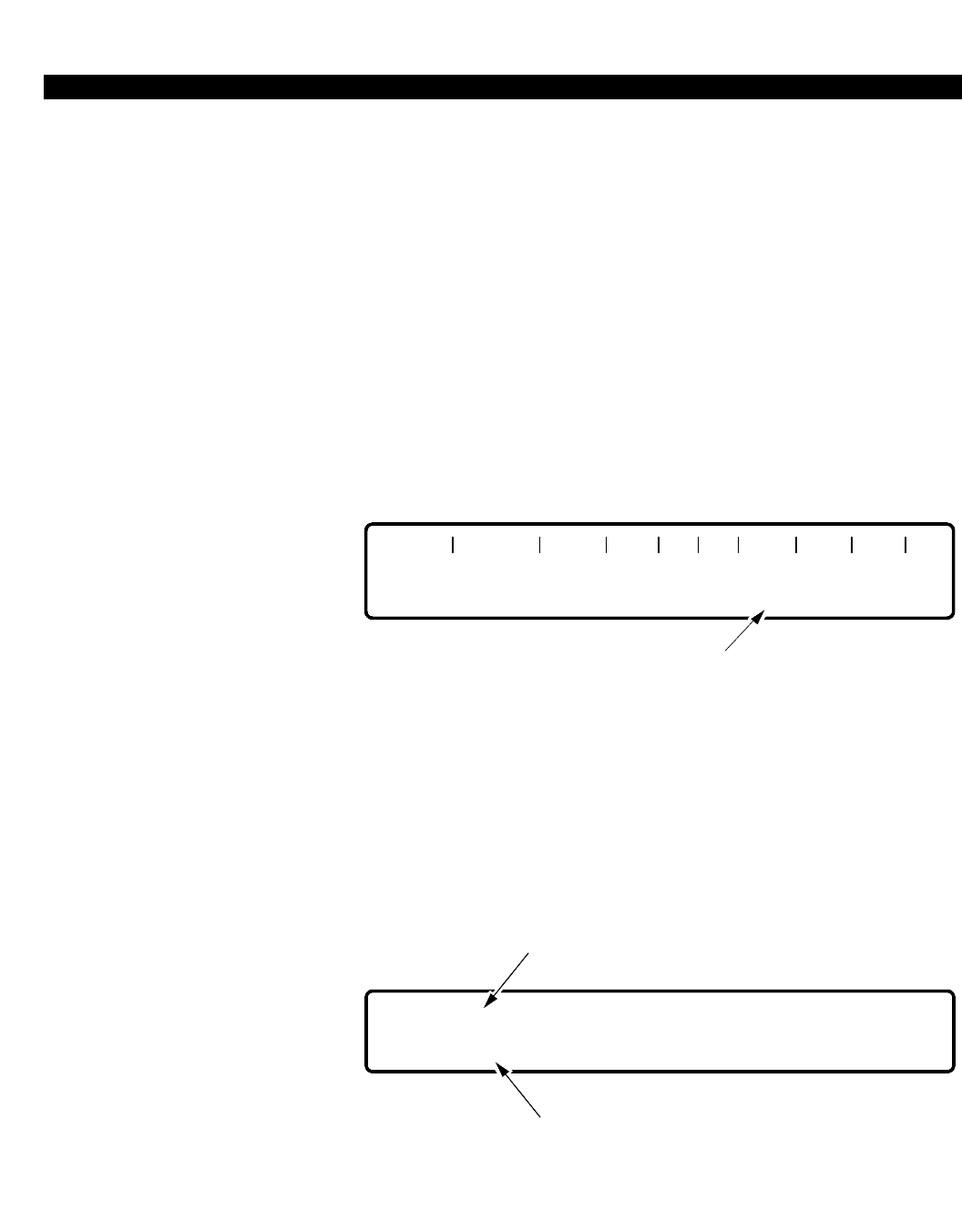
Once you have entered an operation keyword, the system displays a
command header, which is comprised of a set of fields that are separated
by a “|” symbol. These fields form columns in which the data is to be
entered. Figure 1-1 shows the command header for the Area Code
Restriction command.
Figure 1-1
Command Header
The command header also acts as a guide and prompts you as to what
information is expected in each field.
PREDEFINED KEYS
Predefined keys are provided to give you added power. These keys
include Formatting Keys and Control Keys.
FORMATTING KEYS
Formatting keys consist of either a single key, (i.e., <TAB>) or a
combination of keystrokes, (i.e.,<SHIFT-2>). These keys are used to:
■Move between command input fields.
■Correct the input line.
■Abort long printouts/displays.
■Move between operations.
■Terminate a data input line.
The following paragraphs describe the formatting keys used in the
TRGN DRL TYPE AC AC AC AC AC . . .
PERCEPTION 4000 OPERATION
ISS 2, SECTION 4000-014-000
1-5
implementation of PERCEPTION 4000 M&A commands.
Carriage Return
<C/R>, <RETURN>, or <ENTER> is a single key entry used to indicate
the end of data input and to automatically execute a command. It is
available at all levels of the command hierarchy.
Escape
<ESC> is a multi-key entry which consists of the keys <SHIFT-2> on a
standard keyboard. <ESC> is used to abort from the current hierarchy
level to the next level up, or to cancel (correct) the current line of input. For
example, during a DISPLAY operation, <ESC> is used to abort the display
of a large set of data (i.e., halt the printout of a list of items).
NOTE: An <ESC> key on standard keyboards does not equate to an
escape operation.
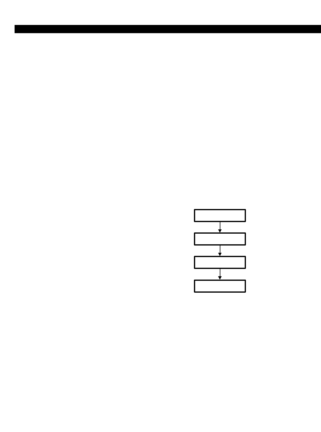
The system's hierarchy levels are illustrated in the following figure.
Figure 1-2
Hierarchy Levels
An exception to this hierarchical order is the DISPLAY command, which
moves directly from the Operation level to Setup mode, thereby bypassing
Data Entry mode. Discussion of Data Entry and Setup modes can be
found later in this chapter.
The <ESC> key is available at all levels of the command hierarchy except
at the Command Level.
Pressing the <ESC> key while the cursor is at the beginning of a 'clear
line' moves you back to the previous level of operation. A 'clear line' occurs
after each hierarchical prompt or when the cursor is at the far left field in
Data Entry and Setup modes. If <ESC> is entered in Data Entry or Setup
mode, an informational message displays indicating that the current input
line was aborted.
Note that the system displays a message indicating what the current
ISS 2, SECTION 4000-014-000
COMMAND LEVEL
OPERATION LEVEL
DATA ENTRY MODE
SETUP MODE
PERCEPTION 4000 OPERATION
ISS 2, SECTION 4000-014-000
1-6
hierarchical level is:
COMMAND=
OPERATION=
DATA ENTRY MODE:
SETUP MODE:
Certain rules apply to use of the <ESC> key. Rules 1 and 2 apply to
escapes within loop fields; Rule 3 applies at all times; and Rule 4 applies
only when the resource is unavailable for modification/removal.
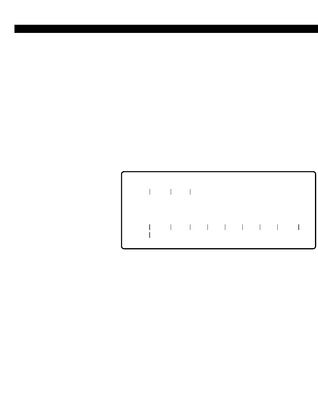
Rule 1 Pressing <ESC> while in the interactive mode in a loop
operation provides two options:
■To continue the current loop operation, skipping this entry.
or
■To abort the current loop operation.
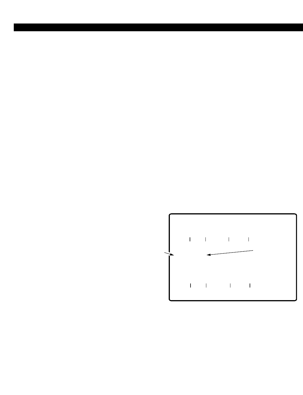
If the current loop operation is not the prime loop, after
<ESC> is pressed, the system asks whether to continue with
prime loop entries, or to abort the prime loop. Figure 1-3
illustrates use of the <ESC> key in a multi-loop operation.
Figure 1-3
ESCAPE Key Loop Operation
The system asks whether the current loop (DEV) should
be aborted or should continue:
CONTINUE (C/R) OR ABORT THE SECOND LOOP (<ESC>) = <ESC>
Pressing <C/R> continues the operation, skipping this
entry. Pressing <ESC> aborts the loop and displays the
following message:
COMMAND =
COMMAND NAME: DICTATION_ASSIGN
OPERATION = ADD
CONFIRM EACH MODIFICATION (YES/NO) = NO
GRP# DEV EQUIP# NAME
401
<CONTROL-P>
SETUP MODE:
2:
71:
8 <CR>
PRIME ENTITIES TO BE ADDED: 6
ENDING VALUE: 7
CONTINUE (C/R), ABORT (<ESC>) = <C/R>
INTERACTIVE MODE:
GRP# DEV EQUIP # NAME
2
21
260401 <C/R>
<ESC>
PRIME
LOOP SECOND LOOP

PERCEPTION 4000 OPERATION
ISS 2, SECTION 4000-014-000
1-7
CONTINUE (C/R) OR ABORT THE PRIME LOOP (<ESC>) = <ESC>
DATA ENTRY MODE:
The operation is aborted and the system returns to Data
Entry mode.
Rule 2 Pressing <ESC> on a 'clear line' moves the hierarchical
level up one level, such as from Setup mode to Data Entry
mode, from Data Entry mode to the OPERATION level, or
from the OPERATION level to the COMMAND level.
Rule 3 Whenever you abort from data input or halt the system
from carrying out a task, such as displaying a report, an
abort message displays confirming that the request has
been carried out.
Rule 4 If an entity is unavailable at the time of a modification/
removal request, the system asks whether a "FORCE TO
IDLE" or a "WAIT WHEN IDLE" state should be posted. If
"FORCE TO IDLE" is selected, the entity is made idle and
the modification/removal request is carried out. If "WAIT
WHEN IDLE" is selected, the system waits for the entity to
become idle, and then carries out the modification/
removal request. An <ESC> may be performed to abort
the waiting process and display a message giving the
options to force or abort the operation. Pressing <ESC>
again aborts the request and places the console in Data
Entry mode.
Operation of the <ESC> key within Data Entry and Setup modes is
described below.
■Data Entry Mode
1. On a 'clear line' - takes you back to the OPERATION level.
2. Within an input line - lets you re-enter the current input line.
■Setup Mode
1. On a 'clear line' - takes you back to Data Entry mode.
2. Within an input line - lets you re-enter the current input line (if a
loop is not started or from a loop field).
3. Within a loop field on an input line - aborts the current loop and
goes to the next higher loop or to Data Entry mode.
Refer to the example, "How to Use the <ESC> Key" in Chapter 2 for
further information on using <ESC> in the various levels of commands.

PERCEPTION 4000 OPERATION
ISS 2, SECTION 4000-014-000
1-8
Tab
<TAB> is a single key entry used to terminate input in the current field and
to move to the first column of the next field. This key is the same as
pressing <CONTROL-I>. A <TAB> may also be entered to skip fields
when entering data in Data Entry or Setup modes.
Immediate Help (?)
<?> is implemented the moment it is pressed. Its function is to store the
input entered so far, display an information menu based on both the
command hierarchy and/or field that the question mark was entered in,
process the help request, redisplay the data entered prior to the help
request, and continue to accept input. The operation is available at all
levels of the command hierarchy. Chapter 2 illustrates several HELP
operations.
CONTROL KEYS
Special control keys have been defined to expand the power of the Man-
Machine Interface (MMI). When entering a control sequence, hold the
<CONTROL> key down while pressing the second key. Control keys and
their functions are described below.
Control-D
<CONTROL-D> deletes the original contents of a field in a MODIFY
operation. However, not every field in the MODIFY operation has the
delete option. Each command specifies which fields accept <CONTROL-
D> input.
Control-P
<CONTROL-P> is used to enter Setup mode from Data Entry mode.
Within Setup mode you may establish a set of conditions/instructions that
the system will use to perform the current operation, such as adding a
group of stations with identical parameters.
Control-S
<CONTROL-S> stops the display on the output device. The command
does not abort the process; it provides a method to halt the output,
examine it, and then resume it (with a <CONTROL-Q>) without affecting
the system. This command is available in all levels of the command
hierarchy, but is most often used during a DISPLAY operation.
Control-Q
<CONTROL-Q> resumes output that was halted when the <CONTROL-
S> keys were pressed. This command is available at all levels of the
command hierarchy, but is most often used during a DISPLAY operation.

PERCEPTION 4000 OPERATION
ISS 2, SECTION 4000-014-000
1-9
Control-F
<CONTROL-F> is used in Data Entry or Setup mode to duplicate the
value used in the same field on the previous input line. After entering
<CONTROL-F> the system automatically displays the value and tabs over
to the next available field in the operation. In Setup mode, this control
sequence is used on the second line of data input.
Control-R
<CONTROL-R> is used in Data Entry or Setup mode to duplicate the
values from the previous input line for the remaining fields on the current
input line. The system automatically displays the values under each of the
remaining fields. In Setup mode, this control sequence is used on the
second line of data input.
Control-W
<CONTROL-W> redisplays the most recent system prompt and/or
command header and the current line of input. The command is
implemented immediately but does not affect the current line of input. If
the cursor is on a 'clear line' then only the system prompt or command
header is displayed. If <CONTROL-W> is entered within an operation, the
command header displays along with the current input line. This command
is available at all levels of the command hierarchy. Several <CONTROL-
W> operations are illustrated in Chapter 2 under "How to Use the
<CONTROL-W> Command".
FIELD PARAMETER INPUT
M&A commands accept various forms of data input. These data types are
listed as: Keyword, Decimal, Decimal with fixed length, Hexadecimal, Text,
Dialing Digits, Dialing Digits plus * and #, DN Type, or EQ Type. The
following paragraphs describe these data types along with the various field
parameters used in the M&A commands.
Note that HELP messages for individual operations display what specific
data type is expected for each field.
Appendix A provides a complete listing of valid field parameter input
characters.
KEYWORD
A keyword field parameter is composed of a letter or digit followed by up to
19 additional letters, digits, or the "_" character. A keyword must contain at
least the minimum number of characters that will uniquely distinguish it
from the other keywords defined for the selected field. For example, if the
keywords for a field are: AAA, AAB, ABB, and BBB, the minimum

PERCEPTION 4000 OPERATION
ISS 2, SECTION 4000-014-000
1-10
characters that could be entered to select each keyword are: AAA, AAB,
AB, and B respectively.
DECIMAL
The decimal field parameter is composed of a set of digits (0to 9). The
maximum number of digits permitted is unique to the command and the
operation.
DECIMAL WITH FIXED LENGTH
This field parameter indicates that a fixed amount of digits must be input.
For example, in the System Speed Calling Assignment command (CMD
402), the "INDX" field requires a three-digit code, with valid input of 001 to
999. All three digits must be entered to be valid.
HEXADECIMAL
The hexadecimal field parameter is composed of a set of digits (0-9)
and/or the letters: A, B, C, D, E, or F.
TEXT
A text field parameter is composed of a set of ASCII characters (digits,
letters, and/or symbols), with the exception of the comma (,), hyphen (-),
and colon (:). As an example, in the ACD Agent Assignment command
(CMD 356), the format for the "NAME" field is zero to nine ASCII
characters in length including spaces and punctuation.
DIALING DIGITS
Dialing digits include the numbers 0to 9, and specify a destination
number. The maximum number of digits permitted is unique to the
command and the operation.
DIALING DIGITS PLUS * AND #
In addition to the numbers 0to 9, the characters *and #are used when
programming telephone functions, such as dial tone detection and timed
pauses.
DN TYPE
The Directory Number (DN Type) field parameter is the same as the
dialing digits field parameter.
PERCEPTION 4000 OPERATION
ISS 2, SECTION 4000-014-000
1-11
EQ TYPE
Each line or trunk is assigned to a circuit on a line card. The Equipment
Number field parameter (EQ Type) defines the hardware location of the
connection, and is five or six digits in length. The first one or two digits (1
to 10) represent the shelf number; the next two digits represent the card
slot number; and the last two digits represent the circuit number.
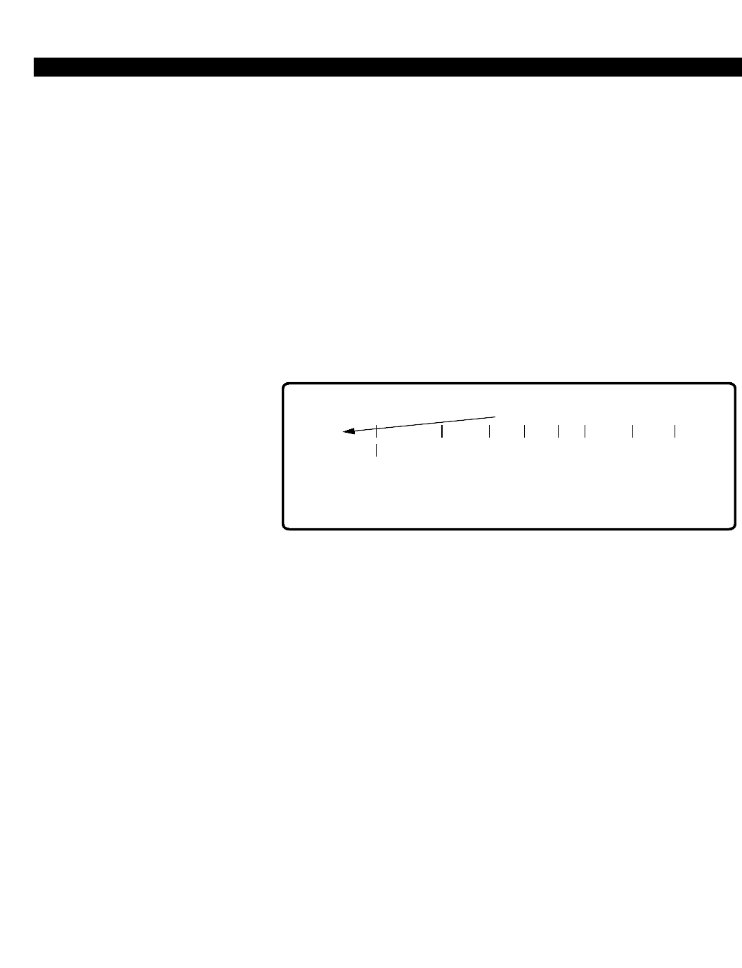
RANGE INDICATOR
The range indicator (:) terminates input in a field and indicates that the
next line of input will contain the upper/lower range value of the field. This
parameter is used in numeric data fields and only in Setup mode. After
entering the range indicator, the cursor positions itself in the next field and
waits for data input.
Figure 1-4
Range Indicator
If the range value on the second line is less than the range value on the
first input line, the system re-arranges the low and high values internally
and displays them incrementally.
The default increment for a field is determined by the system. To change
the increment value, enter a comma after the range value in the second
input line, and enter the increment value on the third line (see the following
section entitled "Increment Indicator").
In addition, range indicators may define the bounds of loop fields versus
displaying a 'range' of values. DELETE and DISPLAY operations may use
ranges, whereas other operations may use looping.
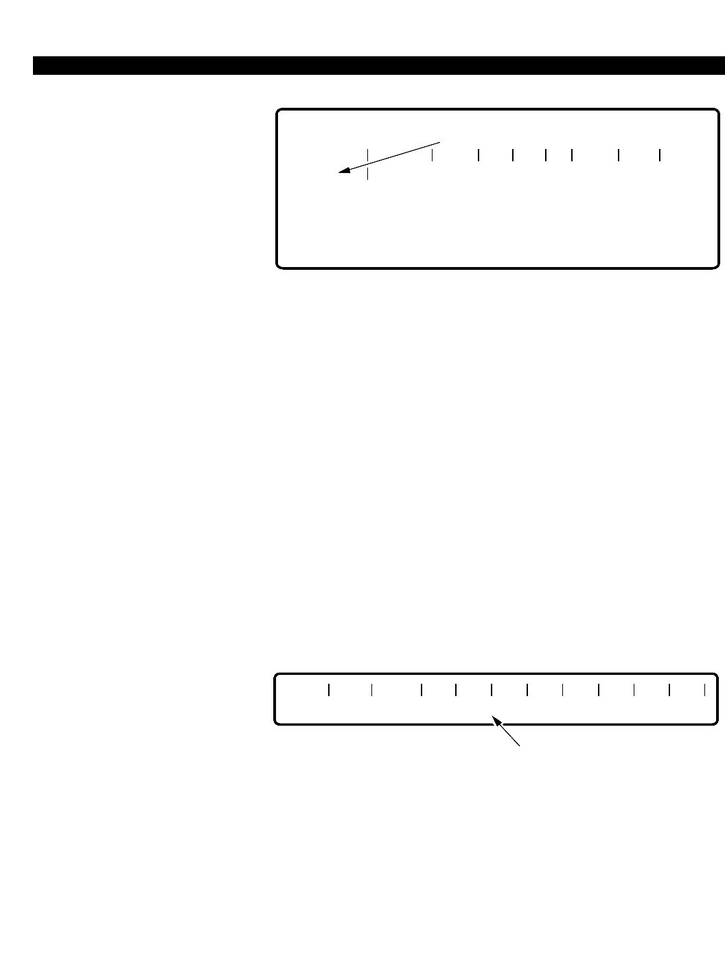
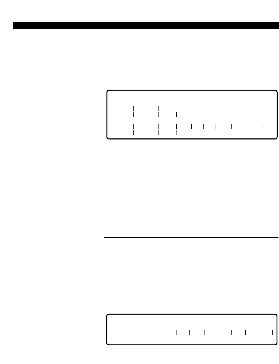
INCREMENT INDICATOR
The increment indicator (,), used in Setup mode, terminates input in a field
and indicates that the next line of input will contain the value to use to
increment the field. This parameter is only used in fields with range
indicators and must be entered after the range value in the second input
line. The default value is 1. Figure 1-5 illustrates an increment operation.
SETUP MODE:
PRIME ENTITIES TO BE MODIFIED: 8
ENDING VALUE: 10510
CONTINUE (C/R), ABORT (<ESC>) =
10503:
10510
RANGE INDICATOR
2010 NO NO RNG YES . . . .
PERCEPTION 4000 OPERATION
ISS 2, SECTION 4000-014-000
1-12
Figure 1-5
Increment Indicator
If the increment value being used does not match the last value when the
range cycle completes, the system displays how many operations will take
place and what the last value will actually be. The option of aborting the
requested sequence or continuing the operation is given. In a DISPLAY
operation, however, after entering the increment indicator, the system
automatically displays the requested information without any notification of
number of entities to be displayed or ending value.
The (,) acts like a <TAB> key in that it automatically moves the cursor to
the beginning of the next field if another loop field is in the command
header.
SCOPE INDICATOR
The scope indicator (-) terminates input in a field and indicates that the
input value in the next field will contain the upper/lower value of the field.
This parameter is used in ADD and DELETE operations.
As an example, the Area/Office Code Restriction Tables (CMD 339) may
use the scope indicator as shown in Figure 1-6.
Figure 1-6
Scope Indicator
The scope indicator includes all office codes from 500 to 600 in area code
312.
Differences between the scope and range fields are:
■Increment of the scope field is always 1.
■The scope parameter is used in both the Data Entry and Setup
modes. However, the range field can only be used in Setup mode.
SETUP MODE:
PRIME ENTITIES TO BE MODIFIED: 4
ENDING VALUE: 10509
CONTINUE (C/R), ABORT (<ESC>) =
10503:
10510,
2
INCREMENT INDICATOR
2010 NO NO RNG YES . . . .
TRGN DRL TYPE AC OC OC OC OC OC OC OC
2 12 DNY 312 500 - 600
SCOPE INDICATOR
PERCEPTION 4000 OPERATION
ISS 2, SECTION 4000-014-000
1-13
■Scope input is not allowed in a DISPLAY operation, though output may
appear in scope-type format.
FIELD INDICATOR
The field indicator (|) is displayed by the system and is used as a field
separation indicator to aid in lining up the cursor under the proper field. All
input lines within an operation terminate with the field indicator displayed.
UNDEFINED DATA INDICATOR
The undefined data indicator (.) is used by the system during report
displays to indicate fields for which no data has been defined. The
character occurs in non-text, optional input or locked fields and displays
across the entire field, as shown in the "EXT" field in the Station
Assignment command (CMD 330) in Figure 1-7.
Figure 1-7
Undefined Data Indicator
COMMAND PROMPT
The command prompt (=), which is displayed by the system, acts as a
ready indicator notifying you that the system is ready to receive input. This
indicator is not a field parameter. The prompt is used at the COMMAND
and the OPERATION hierarchical levels, as illustrated in the following
figure.
Figure 1-8
Command Prompt
EQUIP # PRM DN TYPE PAT A1 A2 EXT RNG COS . . .
10401
10402 5001
5002 2010
2010 NO
NO ........
........
NO
NO RNG
RNG
UNDEFINED
DATA INDICATORS
3
3. . .
. . .
1
1
COMMAND PROMPT
COMMAND = 330
COMMAND NAME: STA_ASSIGN
OPERATION = ADD
COMMAND PROMPT

PERCEPTION 4000 OPERATION
ISS 2, SECTION 4000-014-000
1-14
MOVING BETWEEN COMMAND LEVELS
Various methods are available for moving between the levels of commands
in an M&A session.
■To go from the COMMAND level to the OPERATION level, enter the
three-digit command identifier or the command keyword and press
<RETURN>.
■To go from the OPERATION level into Data Entry mode, enter the
operation desired, such as ADD, DELETE, or MODIFY, and press
<RETURN>.
■To go into Setup mode, press <CONTROL-P> on a 'clear line' while in
Data Entry mode.
■On a 'clear line' in Setup mode, press <ESC> to return to Data Entry
mode in ADD, DELETE, and MODIFY operations.
■On a 'clear line' in Data Entry mode, press <ESC> to return to the
"OPERATION=" prompt.
■To go to the "COMMAND=" prompt level, press <ESC> at the
"OPERATION=" prompt.
Access to each command and operation is restricted based on your
security code. If access to a command is denied, the system displays an
error message and returns to the "COMMAND=" prompt. If access to an
operation is denied, the system displays an error message and returns to
the "OPERATION=" prompt.
ROW/FIELD OPERATION FORMAT
The following is a general explanation of the row/field operation format.
Certain operations may vary from this explanation in one or more
particulars, and exceptions are mentioned in the appropriate command/
operation description.
Operations in row/field format use one or more entities, called key
parameters. Examples of key parameters include directory numbers,
equipment numbers, and group numbers. Figure 1-9 shows the key
parameters (EQUIP # and TGN) in the row/field format for the "Trunk
Assignment" command (CMD 313).
Figure 1-9
Key Parameters
EQUIP # TGN ORG TERM SIG CO SUP TYP ST DT . . .
KEY PARAMETERS
PERCEPTION 4000 OPERATION
ISS 2, SECTION 4000-014-000
1-15
After selecting a specific command and operation, the system may ask a
series of questions based on the operation. Once these are answered, a
command header is displayed. The command header, as shown in Figure
1-9, serves as both a prompt and a guide. The column headings denote
categories of attributes relevant to the selected command and operation.
At this point, you are in Data Entry mode (Setup mode for the DISPLAY
operation). From Data Entry mode you may request HELP, enter the
desired data one entity at a time, or go to Setup mode by using the
<CONTROL-P> command.
The response to the command header is a command line which consists
of entries in the fields designated by the command header. The command
line may be up to 80 characters long and consist of a single row of
information in Data Entry mode and up to three rows in Setup mode (as
illustrated in Figure 1-10).
Figure 1-10
Example of Data Entry/Setup Mode
The exact length of input depends on the length and number of fields in
the command header.
To move from one field to the next, press the <TAB> key or use one of the
two automatic duplicate data commands (<CONTROL-F> or <CONTROL-
R>). When any of these keys are used to move to the next field, a vertical
bar (|) displays between the two fields and the cursor moves to the first
column of the next field; or, the remaining fields are duplicated and the
carriage return is automatically implemented, depending on the control
sequence entered.
When the command line is complete, press <RETURN> to enter the
information into the system. In Setup mode, the line is examined to
determine if additional information is to be entered. For example, one of
the entries in a field might end with a ":" which indicates that the
upper/lower range value will be entered on the next command line. The
system waits for the next command line input and then examines it. If still
more input is expected, the system will again wait for input. This continues
until all input has been entered or there is an error in the command line.
DATA ENTRY MODE:
<CONTROL-P>
SETUP MODE:
10405 2020 <C/R>
10506:
10516,
2
NO 15 . . .
PERCEPTION 4000 OPERATION
ISS 2, SECTION 4000-014-000
1-16
The system evaluates the command line for correctness only after the
entire line has been entered, and, if incorrect, indicates the specific field
entries that are invalid.
You can request the system to redisplay the command header by entering
a <CONTROL-W> without additional input under the first field. Figure 1-11
illustrates operation of a <CONTROL-W> entry.
Figure 1-11
Example of <CONTROL-W> Display
In a DISPLAY operation, by entering a <TAB> and a <RETURN> on the
'clear line' under the command header, all information for the command is
displayed. See the first example in Chapter 2 under "Examples of
DISPLAY Operations" for an illustration of <TAB> key operation.
Help is available for an operation by pressing <?> after the
"OPERATION=" prompt. For detailed information about the data expected
for a field, select the summary option from the HELP menu.
In general, the following operations are available for each command: ADD,
DELETE, MODIFY, and DISPLAY.
DATA ENTRY MODE
In this mode, data is entered on a single entity basis. A command header
is displayed upon entering Data Entry mode from the "OPERATION="
prompt. Ranges and increments are not allowed, but scope-type input is
allowed. A single line of input is used to indicate the modifications to be
made to the entity. The modification takes place immediately after the
<RETURN> key is pressed (if the input line passes the validation checks).
All fields that are required to have input in them for this command must be
entered on this single input line, as illustrated in Figure 1-12.
Figure 1-12
Example of Data Entry Mode
1. At the "COMMAND=" prompt ,
enter the command keyword or
numeric ID.
The "OPERATION=" prompt
appears.
2. Enter the operation type.
Data Entry mode is activated.
NOTE: If a DISPLAY operation is
entered, the system automatically
goes into Setup mode, bypassing
Data Entry mode.
DATA ENTRY MODE:
10404
EQUIP # PRM DN TYPE PAT A1 A2 EXT RNG COS . . .
5016
10405 2020 <CONTROL-W>
10405 2020
DATA ENTRY MODE:
TRGN DRL TYPE AC OC OC OC OC OC OC OC
2 12 DNY 312 500 - 600 <CR>

PERCEPTION 4000 OPERATION
ISS 2, SECTION 4000-014-000
1-17
You may correct a line of input or abort by using the <ESC> key. If <ESC>
is entered on a 'clear line', the system exits the current operation and goes
to the "OPERATION=" prompt level. Refer to Chapter 2 for examples of
Data Entry mode operation.
SETUP MODE
In Setup mode, you may enter ranges, increments, and/or fixed values.
The system uses these entries to automatically assign values to some or
all of the fields. Up to three lines of data may be entered in Setup mode.
Valid input is listed with each command description in Chapter 3. If an
incorrect range or value is entered, an error message appears.
Upon completion of all instruction lines necessary to perform the
operation, the system validates any ranges entered, displays how many
repetitions of the first loop will take place, indicates what the final value for
the first loop's range will be, and prompts whether these conditions match
the request. Figure 1-5 (under "Increment Indicator") illustrates a Setup
mode operation.
If you do not abort from Setup mode at this time, the system may prompt
you for additional conditions based on the operation, such as whether to
confirm the modification prior to performing it. The system then
automatically performs the operation.
The following are rules for Setup mode:
RANGES
Rule 1 Ranges must remain within the scope of the controlling loop
in ADD, DELETE, MODIFY, and DISPLAY operations.
Rule 2 In a DISPLAY operation, ranges are used as a limiting factor
in fixed form numeric field(s).
In the following figure, entries in the "EQUIP #" field apply to Rule 1, while
entries in the "PRM DN" field apply to Rule 2.
1. On a 'clear line' in Data Entry
mode, press <CONTROL-P>.
Setup mode is activated.
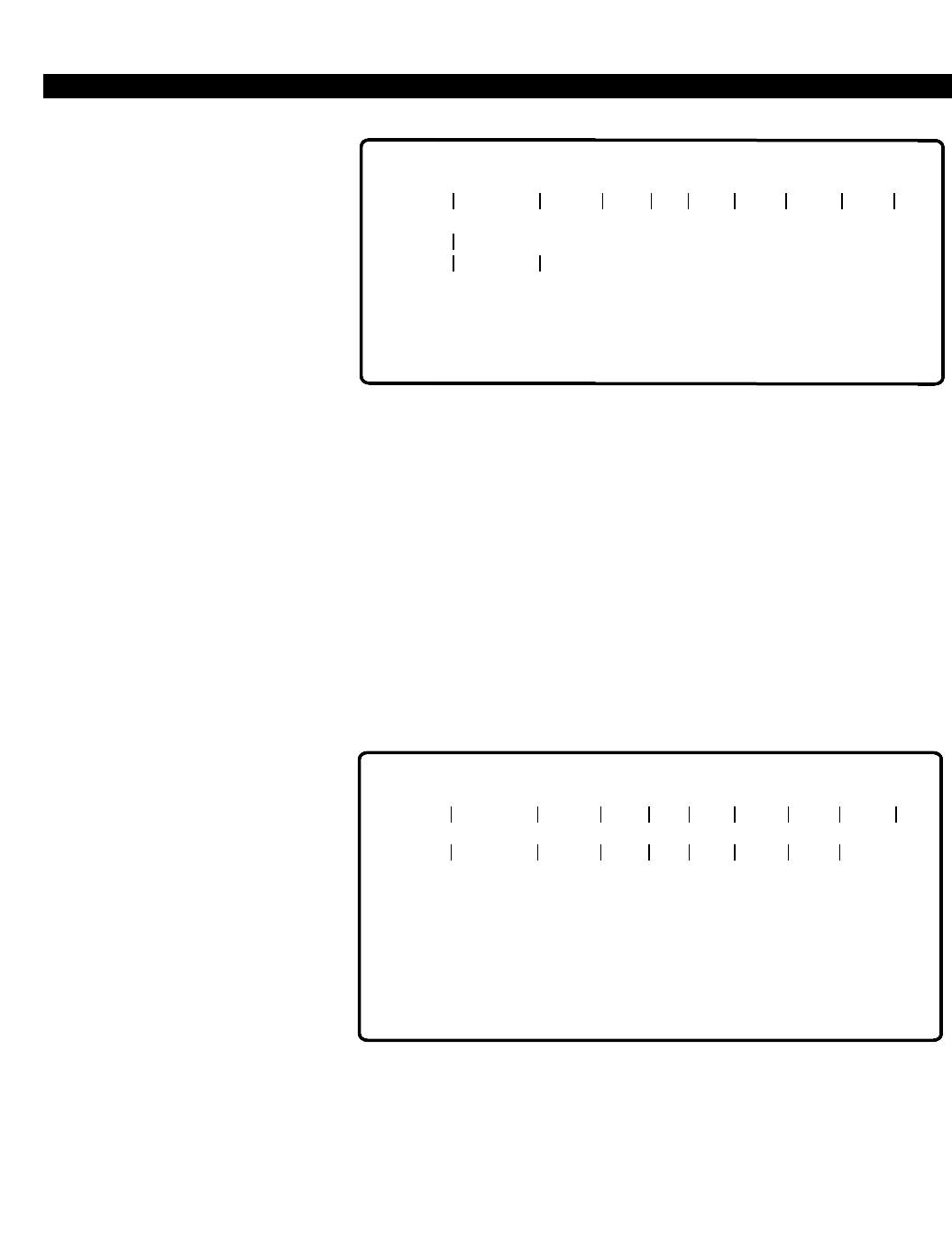
PERCEPTION 4000 OPERATION
ISS 2, SECTION 4000-014-000
1-18
PERCEPTION 4000 OPERATION
Figure 1-13
Use of Ranges
Only "EQUIP #"s 10101 through 10502 with a "PRM DN" between 5005
and 5035 display.
FIXED VALUES
In ADD and MODIFY operations, fixed values cannot be changed
interactively. For example, Figure 1-14 illustrates an ADD operation where
Add-on modules 1 and 2 (A1 and A2) and Data Security (SEC) are set to
NO for equipment numbers being added to the system. In addition, the
"RNG" field is set to RNG for all devices. When the command is executed,
these fields cannot be modified. To make any changes, you must re-enter
the device "EQUIP #" to be changed and enter the appropriate data.
Figure 1-14
Fixed Values - ADD Operation
In a DISPLAY operation, fixed values are used as limiting factors in any
attribute or loop field. Figure 1-15 illustrates a fixed value entry in a
DISPLAY operation.
SETUP MODE:
EQUIP # PRM DN TYPE PAT A1 A2 EXT RNG COS . . .
10505
10506
10507
10508
10509
10510
5065
5076
5085
5095
5105
5115
2020
2020
2020
2010
2020
2010
NO
NO
NO
NO
NO
NO
. . .
. . .
. . .
. . .
. . .
. . .
<C/R>
<C/R>
NO
NO
NO
NO
NO
NO
RNG
RNG
RNG
RNG
RNG
RNG
2
2
2
3
2
3
10505:
10510
. . .
. . .
. . .
. . .
. . .
. . .
RNGNO NO
2
2
2
1
2
1
10101:
10502
SETUP MODE:
EQUIP # PRM DN TYPE PAT A1 A2 EXT RNG COS . . .
5005:
5035 <CR>
10404
10405
10501
10502
5015
5016
5025
5035
1
2
1
1
2020
2010
2010
NO
NO
NO
NO
NO
NO
NO
NO
3
2
3
2
. . .
. . .
. . .
. . .
RNG
RNG
RNG
RNG
. . .
. . .
. . .
. . .
2010
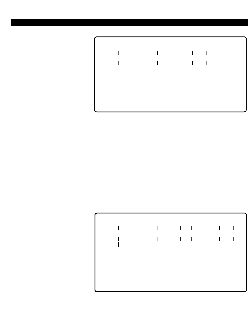
PERCEPTION 4000 OPERATION
ISS 2, SECTION 4000-014-000
1-19
Figure 1-15
Fixed Values - DISPLAY Operation
Only "EQUIP #"s between 10501 and 10510 are displayed.
If an <ESC> is entered in the middle of an input line in Setup mode, the
current input line is ignored, an abort message is displayed, and the cursor
moves to the far left column on the next line.
INTERACTIVE MODE
Setup mode is interactive in an ADD operation. When adding a number of
stations/equipment with the same parameters, this mode assists in
speeding up the process. The first line of input includes the parameters to
be set for all of the stations/equipment being added. Figures 1-16 and
1-17 illustrate interactive mode operation.
* The cursor stops here and waits for input.
Figure 1-16
Interactive Mode (1)
SETUP MODE:
EQUIP # PRM DN TYPE PAT A1 A2 EXT RNG COS . . .
10505
10506
10507
10508
10509
10510
5065
5076
5085
5095
5105
5115
2020
2020
2020
2010
2020
2010
2
2
2
1
2
1
. . .
. . .
. . .
. . .
. . .
. . .
<C/R>
<C/R>
NO
NO
NO
NO
NO
NO
RNG
RNG
RNG
RNG
RNG
RNG
2
2
2
3
2
3
10501:
10510
. . .
. . .
. . .
. . .
. . .
. . .
NO
NO
NO
NO
NO
NO
SETUP MODE:
EQUIP # PRM DN TYPE PAT A1 A2 EXT RNG COS . . .
<C/R>
10507:
10509
PRIME ENTITIES TO BE ADDED: 3
ENDING VALUE: 10509
CONTINUE (C/R), ABORT (<ESC>) =
2010 3 . . .
CONFIRM EACH ADD (YES/NO) = NO <C/R>
10507 *
NONO
<C/R> 1
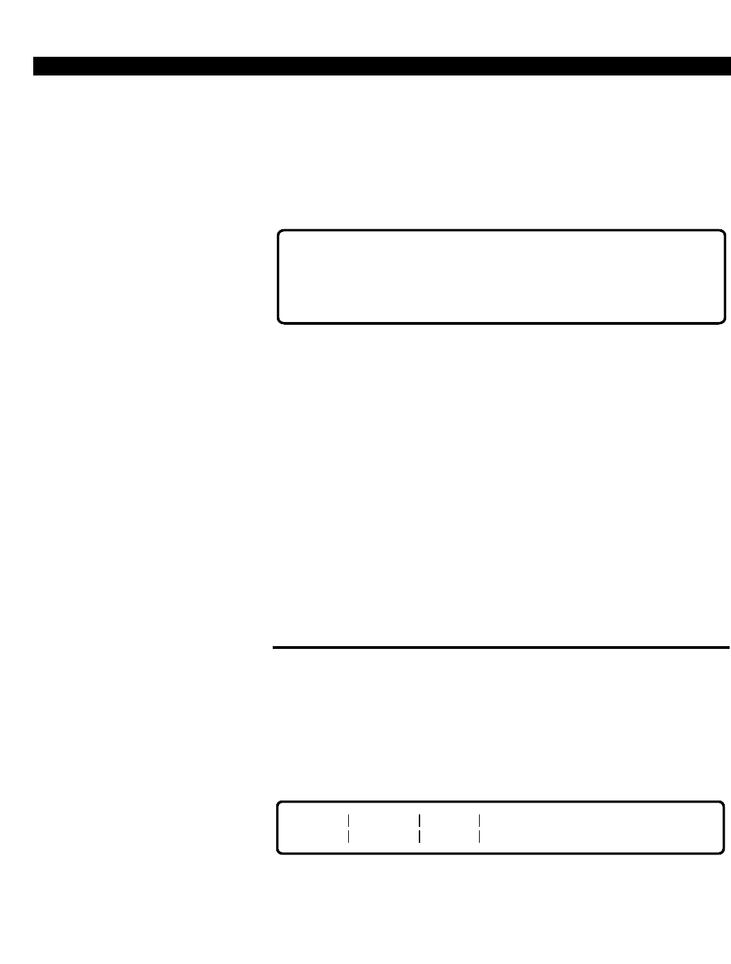
PERCEPTION 4000 OPERATION
ISS 2, SECTION 4000-014-000
1-20
Enter the "PRM DN" and press <TAB>. The cursor moves to the next valid
empty field (RNG) and waits for input. After each empty field is filled in or
tabbed over (->), the system fills in the balance of the input line with
predefined values and moves the cursor to the end of the line. Press
<C/R> and the cursor automatically positions itself in the first column
under the "PRM DN" field for the next "EQUIP #".
Figure 1-17
Interactive Mode (2)
Looping within the operation is carried out by the MMI. You are not
permitted to alter a loop sequence while in the Interactive mode.
The <ESC> key may be used to correct a line of input or abort from a loop.
Refer to the "Formatting Keys" section earlier in this chapter for more
complete details on use of the <ESC> key.
If Interactive mode completes naturally, or aborts because of an error
condition or use of the <ESC> key, the system automatically goes to Data
Entry mode.
NOTE: A message displays every time a transition from one mode to
another occurs, or when the <ESC> key is pressed.
Refer to Chapter 2 for examples of Setup mode operations.
ADD OPERATION
Upon entering ADD at the "OPERATION=" prompt, the system goes into
Data Entry mode and displays the command header. In this mode, single
entity/attribute adds may be performed. Figure 1-18 is an example of an
ADD operation for the Miscellaneous Device Assignment command (CMD
400).
Figure 1-18
ADD Operation
The option of going into Setup mode in an ADD operation is available for
most M&A commands by pressing <CONTROL-P> from a 'clear line' state.
In this mode you may define a sequence of installations that are to be
1. At the "OPERATION=" prompt,
enter ADD.
2. Press <RETURN>.
DEV EQUIP # USAGE
AM02 011207 ACD <C/R>
DATA ENTRY MODE:
10507
10508
10509
5065 ->
5069 ->
5085 ->
2010
2010
2010
->
->
->
3
3
3
. . .
. . .
. . .
<C/R>
<C/R>
<C/R>
NO
NO
NO
NO
NO
NO
YES
YES
YES
. . .
. . .
. . .
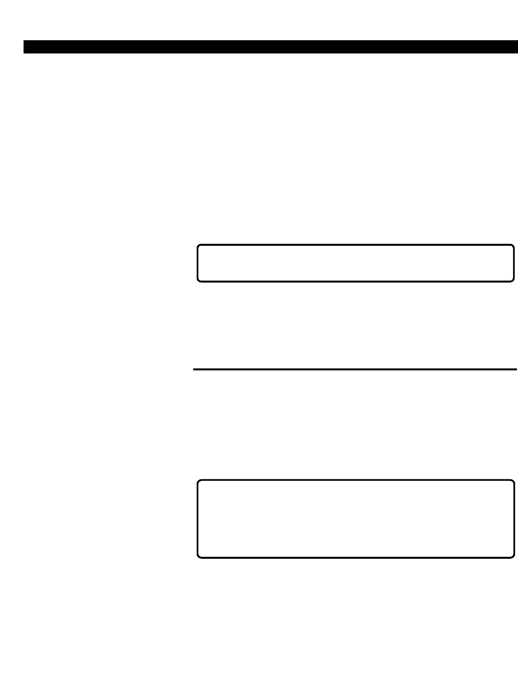
PERCEPTION 4000 OPERATION
ISS 2, SECTION 4000-014-000
1-21
performed automatically by the system. The data entered at this level
determines if any interactive entry will take place.
Once all input of command lines have been made, the system
automatically performs the operation. If ranges were entered in any of the
loop fields, the system first displays a message as to how many entities
will be added and then asks whether a confirmation prompt should appear
after every loop is incremented.
If you select the confirmation option, each command line is displayed,
followed by a prompt asking whether or not you wish to perform the install
as listed. An example of this, using the Station Assignment command,
(CMD 330) is illustrated in Figure 1-19.
Figure 1-19
ADD Confirmation
Upon completion, the system automatically returns to Data Entry mode.
Note that any error condition encountered aborts the system to Data Entry
mode. Refer to Chapter 2 for examples of the ADD operation.
DELETE OPERATION
Upon entering the DELETE operation from the "OPERATION=" prompt,
the system goes into Data Entry mode and displays the appropriate
command header. Single entity/attribute deletions may be performed in
this mode. If the entity is unavailable for removal, the system displays the
message shown in Figure 1-20.
Figure 1-20
DELETE Operation - Busy Options
The option of going into Setup mode in a DELETE operation is available
for most M&A commands by pressing <CONTROL-P> from a 'clear line'
state. In this mode you may define a sequence of deletions that are to be
performed automatically by the system. Upon completing input of all
command lines, the system automatically executes the commands. If
ranges were entered in any of the loop fields, the system displays how
1. At the "OPERATION=" prompt,
enter DELETE.
2. Press <RETURN>.
(YES/NO) =
10507 5065 -> 2010 YES 3 . . . <C/R>NO NO -> ->
EQUIPMENT IN USE:
1. FORCE TO IDLE
2. WAIT FOR IDLE
<ESC> CANCEL REMAINING REMOVAL REQUESTS
ACTION =_
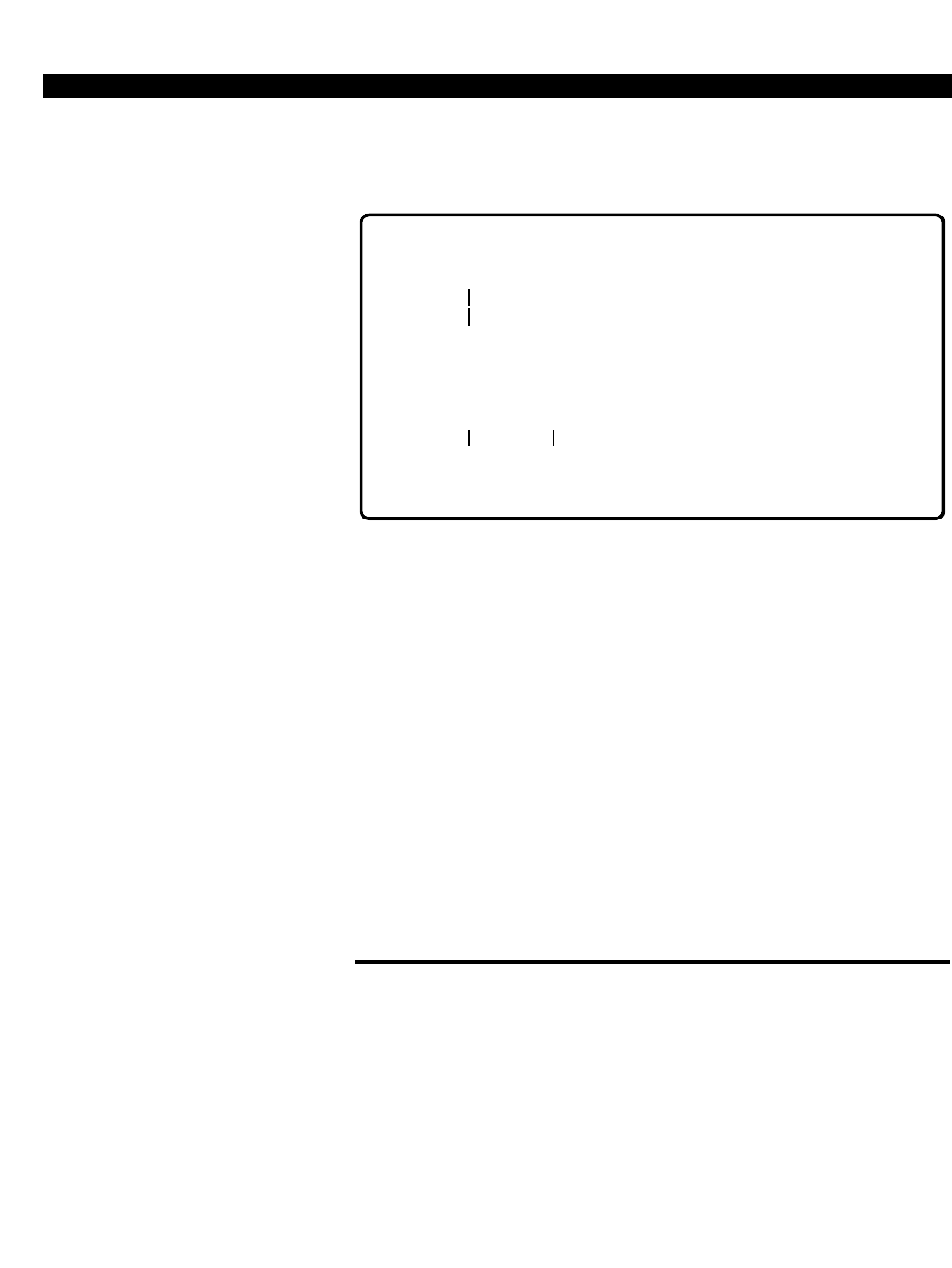
PERCEPTION 4000 OPERATION
ISS 2, SECTION 4000-014-000
1-22
many entities will be deleted, displays the ending value, and prompts to
continue or abort, as illustrated in Figure 1-21.
Figure 1-21
DELETE Confirmation
Enter YES if this station is to be deleted, or NO if this station is to be
saved, then press <RETURN>. Once all command lines have been
executed, the system automatically goes to Data Entry mode.
If an entity is in use or busy, the system displays the options to 'Force to
Idle', 'Wait for Idle', or 'Cancel Remaining Removal Requests'. If "WAIT
FOR IDLE" is selected, the system waits for the entity to become idle, and
then carries out the removal request. An <ESC> may be performed to
abort the waiting process and display a message giving the options to
force or abort the DELETE operation. Pressing <ESC> again aborts the
request and places the console in Data Entry mode.
An error condition also aborts the operation and returns the session to
Data Entry mode, as determined by each command/operation.
Refer to Chapter 2 for examples of the DELETE operation.
MODIFY OPERATION
When first entering the MODIFY operation from the "OPERATION="
prompt, the system asks whether to confirm each modification and
whether the Original/New values for the entity (primary field) should be
displayed. After entering a YES or NO in response to these inquiries,
press <RETURN>. The command header displays and the system enters
Data Entry mode.
Individual field modifications may be performed in this mode. Both the
entity and at least one other field must be entered. When input is
completed, press <RETURN> to automatically execute the modifications.
1. At the "OPERATION=" prompt,
enter MODIFY.
2. Press <RETURN>.
"CONFIRM EACH
MODIFICATION (YES/NO) ="
"DISPLAY ORIGINAL VALUES
(YES/NO)="
<CONTROL-P>
SETUP MODE:
10503:
10505
PRIME ENTITIES TO BE DELETED: 3
ENDING VALUE: 10505
CONTINUE (C/R), ABORT (<ESC>) = <C/R>
EQUIP #
10503
(YES/NO) =
PRM DN
Y <C/R>
PERCEPTION 4000 OPERATION
ISS 2, SECTION 4000-014-000
1-23
If the entity is unavailable for the modification, the system responds with
the options shown in Figure 1-22.
Figure 1-22
MODIFY Operation - Busy Options
The option of going into Setup mode in a MODIFY operation is available
for most M&A commands by pressing <CONTROL-P> from a 'clear line'
state. In Setup mode, you may define a sequence of modifications that are
to be performed automatically by the system. Note that interactive data
entry is not permitted in a MODIFY operation.
Upon completing input of all command lines in Setup mode, the system
automatically executes the commands, displaying each command line as it
is executed, if specified. If an entity is in use or busy, the program halts
and displays the options to wait, skip, or force the modification. If "WAIT
FOR IDLE" is selected, the system waits for the entity to become idle, and
then carries out the modification. An <ESC> may be performed to abort
the waiting process and display a message giving the options to force or
abort the MODIFY operation, as illustrated in Figure 1-23. Pressing
<ESC> again aborts the request and places the console in Data Entry
mode.
Figure 1-23
MODIFY Operation - Wait Options
If the <ESC> key is entered prior to modification of the waiting entities, the
system cancels the modification request for those entities. Once all
command lines have been executed, the system automatically goes to
Data Entry mode.
If an error condition occurs, the system asks whether to continue with the
next modification or to abort the operation and return the session to Data
Entry mode.
Refer to Chapter 2 for examples of the MODIFY operation.
"DISPLAY NEW VALUES
(YES/NO)="
1. FORCE TO IDLE
2. WAIT FOR IDLE
<ESC> CANCEL REMAINING MODIFICATION REQUESTS
ACTION =_
1. FORCE TO IDLE
<ESC> ABORT THE MODIFICATION
ACTION =_

PERCEPTION 4000 OPERATION
ISS 2, SECTION 4000-014-000
1-24
DISPLAY OPERATION
Upon entering the DISPLAY operation from the "OPERATION=" prompt,
the appropriate command header displays and the system goes into Setup
mode, bypassing Data Entry mode. In Setup mode, you may define a
sequence of entities that are to be displayed on the output device. After
completing input of the command lines and pressing <RETURN>, the
system automatically executes the commands. If ranges are entered in
any of the fields, the system uses these values to limit the scope of the
search algorithm. Figure 1-24 illustrates a DISPLAY operation.
Figure 1-24
DISPLAY Operation
In this example, all 2020-type devices with a Class of Service between 1
and 9 are displayed.
Any values entered in Setup mode must exactly match the configuration
for the entity in order for the entity to be displayed. Only entities in which
every condition matches are displayed.
The system automatically returns to Setup mode after listing the requested
data. <ESC> may be pressed at any time to cancel the display and return
to Setup mode.
Pressing the <TAB> and <RETURN> keys on a 'clear line' causes all
information in the database for the command to display.
Refer to Chapter 2 for more examples of the DISPLAY operation.
HELP OPERATION
The HELP operation is a menu driven hierarchical system of text
information. Each level of the hierarchy contains more detailed information
than the preceding level. Access to the HELP feature is via the <?> control
key. When this key is entered, the system interrupts the current input and
1. At the "OPERATION=" prompt,
enter DISPLAY.
2. Press <RETURN>.
1. Press <?>.
SETUP MODE:
EQUIP # PRM DN TYPE PAT A1 A2 EXT RNG COS . . .
10405
10504
10513
10514
5015
5055
5166
5170
2020
2020
2020
2020
2
2
2
2
. . . . .
. . . . .
. . . . .
. . . . .
RNG
RNG
RNG
RNG
. . .
. . .
. . .
. . .
3
2
2
3
2020 1:
9<C/R>
<C/R>
NO
NO
NO
NO
NO
NO
NO
NO

PERCEPTION 4000 OPERATION
ISS 2, SECTION 4000-014-000
1-25
goes into a HELP menu. Upon exiting the HELP operation, the system
redisplays the last input line up to the interruption (<?> entry) and allows
you to resume input at that point.
HELP HIERARCHY STRUCTURE
The hierarchy of the HELP operation follows the same hierarchy as the
Maintenance Console Operation in that there are three distinct levels of
access and capability:
■Command Selection
■Operation Selection
■Parameter Selection
After each selection is made from a menu, a new menu displays with a set
of options. These options note specific details about the selected menu
item, or additional information regarding a specific operation, entity, or
attribute display. To access an adjacent hierarchical level, you must move
back up the hierarchy to the point from which the path to the new item may
be accessed. Access to commands is based on the security code entered
at login time.
Release Number, Version Number, and Date
This information indicates the current release number, version number,
date, and time that the system program module was created, and displays
along with each HELP menu, as illustrated in the following figure.
Figure 1-25
Release, Version, Date
Command Selection Level
The Command Selection level, accessed by pressing the <?> key after the
"COMMAND=" prompt, provides access to a list of command categories,
plus other pertinent information. See Figure 1-26.
Release X.X
Version X.X.X Day Month Date and Time

PERCEPTION 4000 OPERATION
ISS 2, SECTION 4000-014-000
1-26
PERCEPTION 4000 OPERATION
Figure 1-26
HELP Menu, Command Level
The Command Category provides a list of the available categories, such
as administrative commands, station commands, trunk commands, or
maintenance commands. The system only displays help for those
commands which you are authorized to access, as based on your entered
security code. The lists of command categories, commands, and
operations in the menus are adjusted accordingly. Once a specific
command is selected, the system loads the overlay file for the command
from the disk.
Operation Selection Level
This help level, as illustrated in Figure 1-27, provides information about
operations and field parameters available for the selected command.
The system only displays help for those operations which you are
authorized to access, based on your entered security code. The lists of
operations and fields in the submenus are adjusted accordingly.
Information about other commands is not available from this level.
COMMAND = ?
HELP MENU
Release X.X
Version X.X.X Day Month Date and Time
Select one item:
1. Command Category
2. MMI Tutorial
3. System Messages
4. Control Keys
Q. Quit Help Operation
ITEM NUMBER =
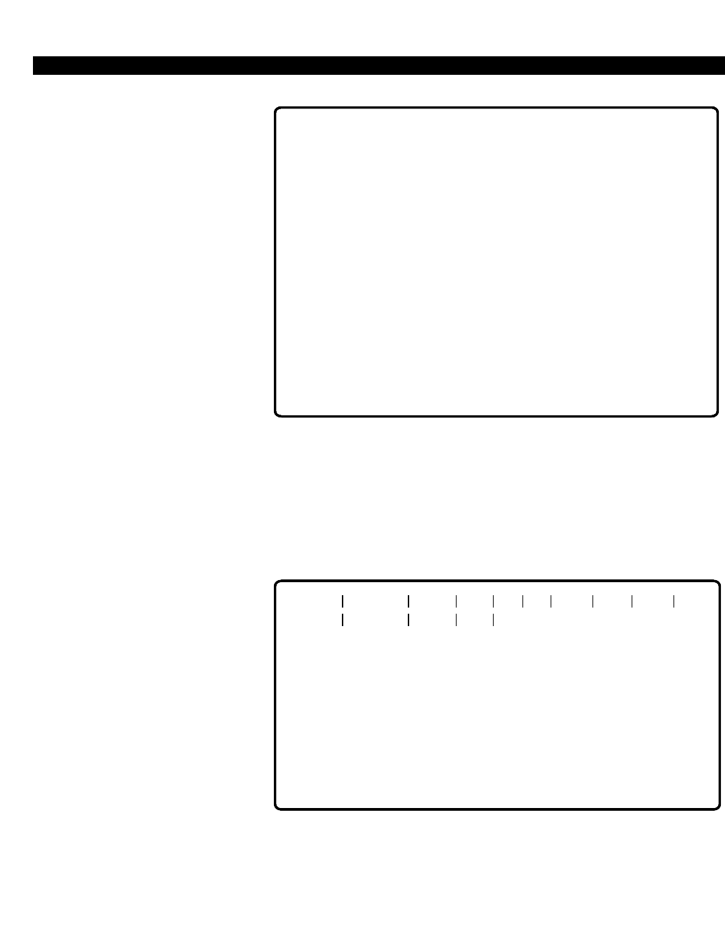
PERCEPTION 4000 OPERATION
ISS 2, SECTION 4000-014-000
1-27
Figure 1-27
HELP Menu, Operation Level
Parameter Selection Level
This help level provides specific information about the selected field.
Figure 1-28 shows a parameter-level help screen.
Figure 1-28
HELP Screen, Row/Field Level
Information about other operations or commands is not available from this
level of the help hierarchy.
Refer to Chapter 2 for more examples of the HELP operation.
OPERATION = ?
HELP MENU
Release X.X
Version X.X.X Day Month Date and Time
Select one item:
Command ID: (cmd366)
1. ADD
2. DELETE
3. MODIFY
4. DISPLAY
5. Field Parameters
Q. Quit Help Operation
ITEM NUMBER =
EQUIP # PRM DN TYPE PAT A1 A2 EXT RNG COS . . .
11101
Add-On Module Number 1 (A1)
Type:
Value:
Format:
Keyword:
Required:
Range:
Loop Field:
20104220 1
NO - No Add-On
M1 - Add-On module 20 keys type
M2 - Add-On module 60 keys type
ADD operation only for PERCEPTION 40xx telephone types
Not allowed
Not allowed
Keyword
Not allowed
N/A
?

PERCEPTION 4000 OPERATION
ISS 2, SECTION 4000-014-000
TERMINATING AN M&A SESSION
To terminate a session and return the M&A system to the idle state, enter
LOGOUT or 0(zero) in response to the "COMMAND=" prompt and then
press the <RETURN> key. The system responds with a logout message. If
you leave the terminal without logging out, the system terminates the
session after approximately one to thirty minutes (depending on the
system parameter) and automatically displays an information message.
1-28
1. At the "COMMAND=" prompt,
enter LOGOUT or 0.
2. Press <RETURN>.

Chapter 2
PERCEPTION 4000 EXAMPLES
Examples of how to use the Maintenance and Administration (M&A) Man-Machine Interface (MMI) are presented
in this chapter. The Station Assignment command is used to illustrate the various operations.
STATION ASSIGNMENT (CMD 330)
The Station Assignment command is the primary command in assigning stations to the system. This command
defines the station's prime directory number, establishes linkage to a hardware circuit, instructs the system on
what type of station this is (digital, electronic, analog single-line) and defines terminal-level and prime-line
attributes. The Station-Level Parameter Assignment command (CMD 329) is also required to complete
fundamental station information. Multi-line devices also require the Station Feature Key Assignment command
(CMD 331) for further definition.
Attributes defined/modified with this command include:
Equipment Number EQUIP #
Prime Directory Number PRM DN
Station Type TYPE
Add-on Module #1 (20/60 key) A1
Add-on Module #2 (20/60 key) A2
Analog Extension EXT
Ring Option RNG
Data Security SEC
Class of Service COS
Destination Restriction Level DRL
Facility Restriction Level Profile FRL
LCR Queue Priority Level QPL
Answer Position ANSPOS
Station Group Number GRP
Station Owner's Name NAME
Department Name DEPT
NOTES:
1. If the station's "TYPE" field is an ID10 or ID20 (digital telephone with DIU), the station must be assigned to a
DSTI card configured for 2B operation, thereby allowing for simultaneous voice and data communications.
2. If the station's "TYPE" field is a 2010 or 2020 (digital telephone without DIU), the station may be assigned to
a DSTI card configured for 1B or 2B operation. When installed on a DSTI card configured for 2B operation, a
'2B' device (ID10 or ID20) must already be assigned to the card.
3. If a 10-key or 20-key digital telephone is selected in the "TYPE" field (2010 or 2020) and installed on a DSTI
card configured for 2B operation, the circuit's data channel is ignored by the system.
4. In a MODIFY operation, a '2B' device may not be changed to a '1B' device.
ISS 2, SECTION 4000-014-000
2-1
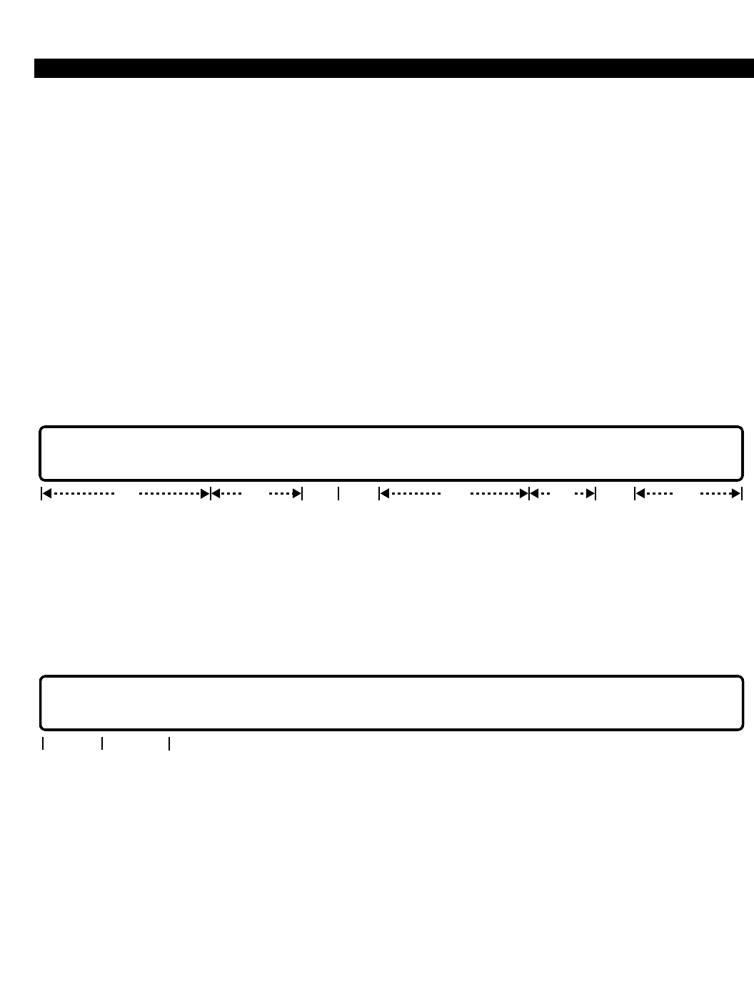
PERCEPTION 4000 EXAMPLES
ISS 2, SECTION 4000-014-000
OPERATIONS
Available operations: ADD
DELETE
MODIFY
DISPLAY
? (HELP)
The following sections describe the function and required data fields for each operation. Abbreviations used
include:
req - Data is required in this field.
opt - Data is optional in this field.
locked - This field is not available for modification.
ADD
The ADD operation assigns a station port to a spare equipment port location. You are required to enter the
minimum amount of data that defines the station port. The directory number (PRM DN) selected must meet the
constraints established for prime directory numbers. Loops are permitted so that you may set up large numbers of
station ports with one operation.
DELETE
This operation changes a station port to a spare equipment port. The equipment number is required. Looping is
allowed in the “EQUIP #” field to expedite the deletion of large numbers of ports. If the station has secondary
directory numbers assigned to its line(s) or key(s), all of the secondary directory numbers must be removed
through the Station Feature Key Assignment command (CMD 331) prior to performing this operation. The station
must also be removed from group associations such as hunting, speed calling, ACD, etc. If the station's "TYPE" is
an ID10 or ID20 (digital telephone with integrated DIU), the data station must be deleted first.
2-2
req
EQUIP # | PRM DN | TYPE | PAT | A1 | A2 | EXT | RNG | COS | DRL | FRL | QPL | ANSPOS | SRG | NAME | DEPT
req optopt locked opt locked opt
EQUIP # | PRM DN |
opt
req
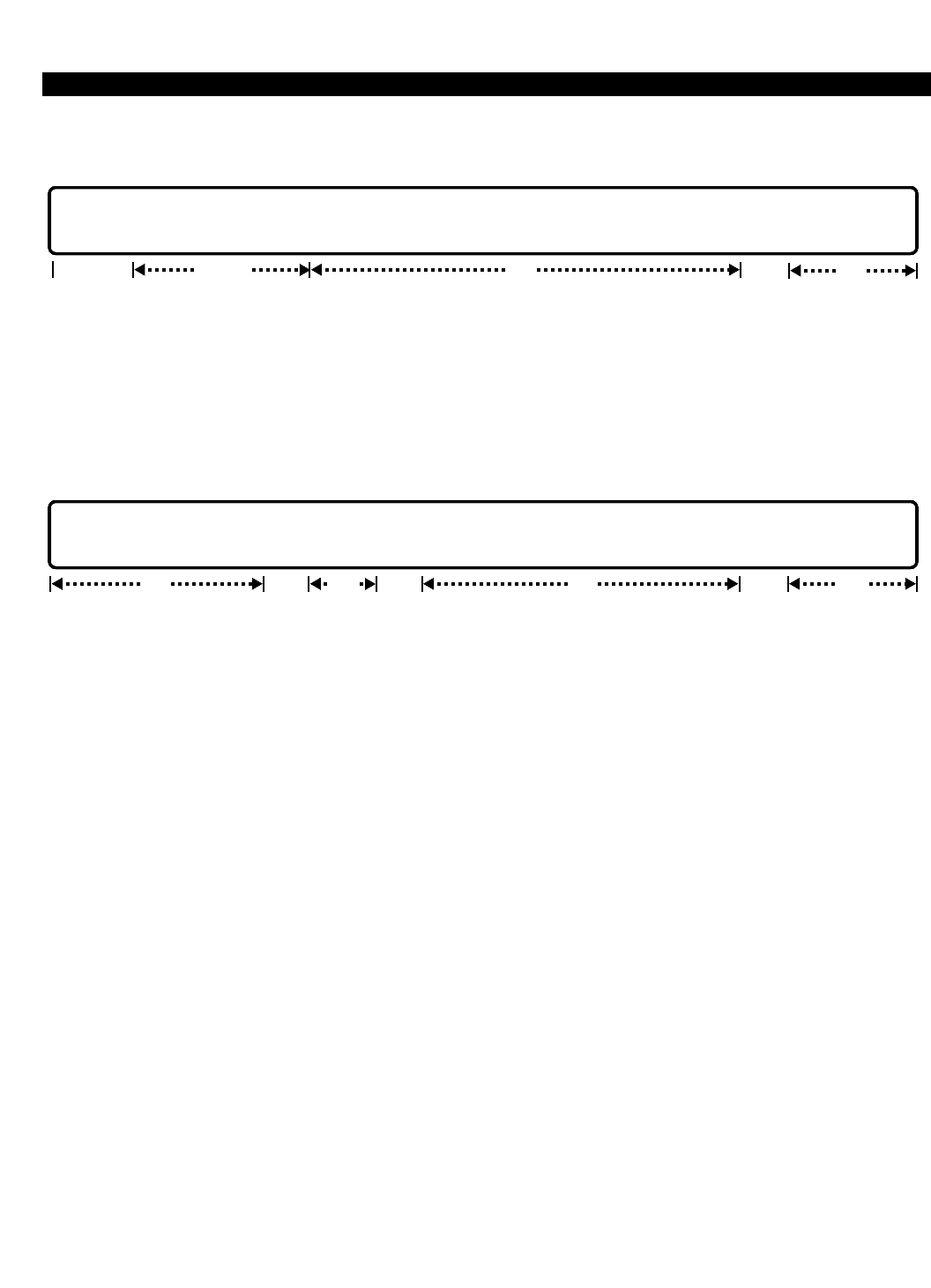
PERCEPTION 4000 EXAMPLES
MODIFY
Station attributes are modified with this operation. The "EQUIP #" field is the only required field. The “PRM DN”
field, though optional, cannot be modified; this field may be skipped over during a MODIFY operation, or the
existing prime DN may be entered. Before changing attributes of a station, review the NOTES at the beginning of
this command.
DISPLAY
All station equipment ports that meet the conditions established for each field may be displayed. Ranges are
permitted in any field that accepts numeric input, (i.e., COS, DRL, FRL, etc.). The “EQUIP #” field is the only loop
field for this operation.
PARAMETERS
Each field parameter is described in this section. Any variations for a particular operation are noted separately.
Equipment Location (EQUIP #)
TYPE: EQ Type
FORMAT: 5 or 6 digits
VALUE: (0)10101 - 101416 *
KEYWORD: Not allowed
REQUIRED: ADD, DELETE, and MODIFY operations
RANGE: Allowed in a DISPLAY operation only
LOOP FIELD: ADD, DELETE, and DISPLAY operations
* Use the following chart to determine valid ranges for various types of equipment.
For BSTI and DSTI equipment cards, the following ranges apply:
Digits Range Hardware
First digit(s) (0)1~10 Shelf no.
Second two digits 01~11, 13 Card slot no.
Last two digits 01~16 Circuit no.
NOTE: Slot 13 is unavailable if the card is a 2B type.
ISS 2, SECTION 4000-014-000
2-3
optreq locked locked opt
EQUIP # | PRM DN | TYPE | PAT | A1 | A2 | EXT | RNG | COS | DRL | FRL | QPL | ANSPOS | SRG | NAME | DEPT
opt locked opt optlocked
EQUIP # | PRM DN | TYPE | PAT | A1 | A2 | EXT | RNG | COS | DRL | FRL | QPL | ANSPOS | SRG | NAME | DEPT
locked opt

PERCEPTION 4000 EXAMPLES
ISS 2, SECTION 4000-014-000
For an EKTI or XSTI card, the following are valid ranges:
Digits Range Hardware
First digit(s) (0)1~10 Shelf no.
Second two digits 01~14 Card slot no.
Last two digits 01~08 Circuit no.
Prime Directory Number (PRM DN)
TYPE: DN Type
FORMAT: 1 to 5 digits
VALUE: 0 to 99999
KEYWORD: Not allowed
REQUIRED: ADD operation only
RANGE: Allowed in a DISPLAY operation only
LOOP FIELD: Not allowed
Station Type (TYPE)
TYPE: Keyword
FORMAT: Predefined ASCII characters
VALUE: Not allowed
KEYWORDS: 2010 - 10-key digital telephone
2020 - 20-key digital telephone
ID10 - 10-key digital telephone with Digital Interface Unit
ID20 - 20-key digital telephone with Digital Interface Unit
ANLG - Analog telephone
ANMW - Analog telephone with Message Waiting
AVMS - Analog VMS port
EK01 - Electronic telephone with 1 line key and 3 fixed keys
EK10 - Electronic telephone with 10 flexible keys and 4 fixed keys
EK20 - Electronic telephone with 20 flexible keys and 4 fixed keys
EK2D - Electronic telephone with 20 flexible keys, 4 fixed keys, and display
DK10 - DKT digital telephone with 10 flexible keys
DK1D - DKT digital telephone with 10 flexible keys and display
DK20 - DKT digital telephone with 20 flexible keys
DK2D - DKT digital telephone with 20 flexible keys and display
REQUIRED: ADD operation only
RANGE: Not allowed
LOOP FIELD: Not allowed
Pattern Number of Template for Position of Feature Keys (PAT)
TYPE: Decimal
FORMAT: 1 digit
VALUE: 1 to 4
RANGE: Not allowed
LOOP FIELD: Not allowed
2-4

PERCEPTION 4000 EXAMPLES
First Add-on Module Type (A1)
TYPE: Keyword
FORMAT: Predefined ASCII characters
VALUE: Not allowed
KEYWORDS: M1 - 20-key Add-on Module
M2 - 60-key Add-on Module (three 20-key modules)
NO - No Add-on Module
REQUIRED: ADD operation for digital telephones only
RANGE: Not allowed
LOOP FIELD: Not allowed
Second Add-on Module Type (A2)
TYPE: Keyword
FORMAT: Predefined ASCII characters
VALUE: Not allowed
KEYWORDS: M1 - 20-key Add-on Module
M2 - 60-key Add-on Module (Reserved for future use)
NO - No Add-on Module
REQUIRED: ADD operation for digital telephones only
RANGE: Not allowed
LOOP FIELD: Not allowed
Analog Extension (EXT) (Reserved for future use)
TYPE: Keyword
FORMAT: Predefined ASCII characters
VALUE: Not allowed
KEYWORDS: EXT - Digital Telephone Extension
NON - Non-extension
REQUIRED: ADD operation (for analog telephones only)
RANGE: Not allowed
LOOP FIELD: Not allowed
Ringing Option (RNG)
TYPE: Keyword
FORMAT: Predefined ASCII characters
VALUE: Not allowed
KEYWORDS: RNG - Ring (All devices default to RNG when added to the system.)
NRG - No Ring
REQUIRED: ADD operation (For analog telephones with an extension)
RANGE: Not allowed
LOOP FIELD: Not allowed
ISS 2, SECTION 4000-014-000
2-5

PERCEPTION 4000 EXAMPLES
ISS 2, SECTION 4000-014-000
Class of Service (COS)
TYPE: Decimal
FORMAT: 1 or 2 digits
VALUE: 1 to 64
KEYWORDS: Not allowed
REQUIRED: ADD operation only
RANGE: Allowed in a DISPLAY operation only
LOOP FIELD: Not allowed
Destination Restriction Level (DRL)
TYPE: Decimal
FORMAT: 1 or 2 digits
VALUE: 1 to 16
KEYWORDS: Not allowed
REQUIRED: ADD operation only
RANGE: Allowed in a DISPLAY operation only
LOOP FIELD: Not allowed
Facility Restriction Level Profile (FRL)
TYPE: Decimal
FORMAT: 1 or 2 digits
VALUE: 1 to 32
KEYWORDS: Not allowed
REQUIRED: ADD operation only
RANGE: Allowed in a DISPLAY operation only
LOOP FIELD: Not allowed
Queue Priority Level (QPL)
TYPE: Decimal
FORMAT: 1 digit
VALUE: 1 to 8
KEYWORDS: Not allowed
REQUIRED: ADD operation only
RANGE: Allowed in a DISPLAY operation only
LOOP FIELD: Not allowed
Answer Position (ANSPOS)
TYPE: DN Type / Keyword
FORMAT: 1 to 5 digits / Predefined ASCII characters
VALUE: 0 to 99999 / NON
KEYWORDS: NON - No answer position is selected
REQUIRED: N/A
RANGE: Allowed in a DISPLAY operation only
LOOP FIELD: Not allowed
2-6

PERCEPTION 4000 EXAMPLES
Station Group Number (GRP) (Reserved for future use)
TYPE: Decimal
FORMAT: 1 or 2 digits
VALUE: 1 to 16
KEYWORDS: Not allowed
REQUIRED: ADD operation only
RANGE: Allowed in a DISPLAY operation only
LOOP FIELD: Not allowed
Station Name (NAME)
TYPE: Text
FORMAT: 0 to 9 ASCII characters (excluding a colon [:], comma [,], or dash [-])
VALUE: Text
KEYWORDS: Not allowed
REQUIRED: N/A
RANGE: Not allowed
LOOP FIELD: Not allowed
Department Name (DEPT)
TYPE: Text
FORMAT: 0 to 4 ASCII characters (excluding a colon [:], comma [,], or dash [-])
VALUE: Text
KEYWORDS: Not allowed
REQUIRED: N/A
RANGE: Not allowed
LOOP FIELD: Not allowed
EXAMPLES OF ADD OPERATIONS
When first entering an ADD operation the system is in Data Entry mode. In this mode installations of individual
stations are performed. A complete command line, without ranges or automatic increments, must be entered.
Note that "EXT" and "GRP" are locked fields and are therefore skipped over by the system. In the first example,
the ADD operation is selected and the system immediately goes into Data Entry mode. The example continues
with some basic installations.
NOTES:
1. Each input line is terminated with a Carriage Return (<C/R>), not shown.
2. User entered data is shown in Boldface type.
3. An arrow (->) indicates a <TAB>.
ISS 2, SECTION 4000-014-000
2-7
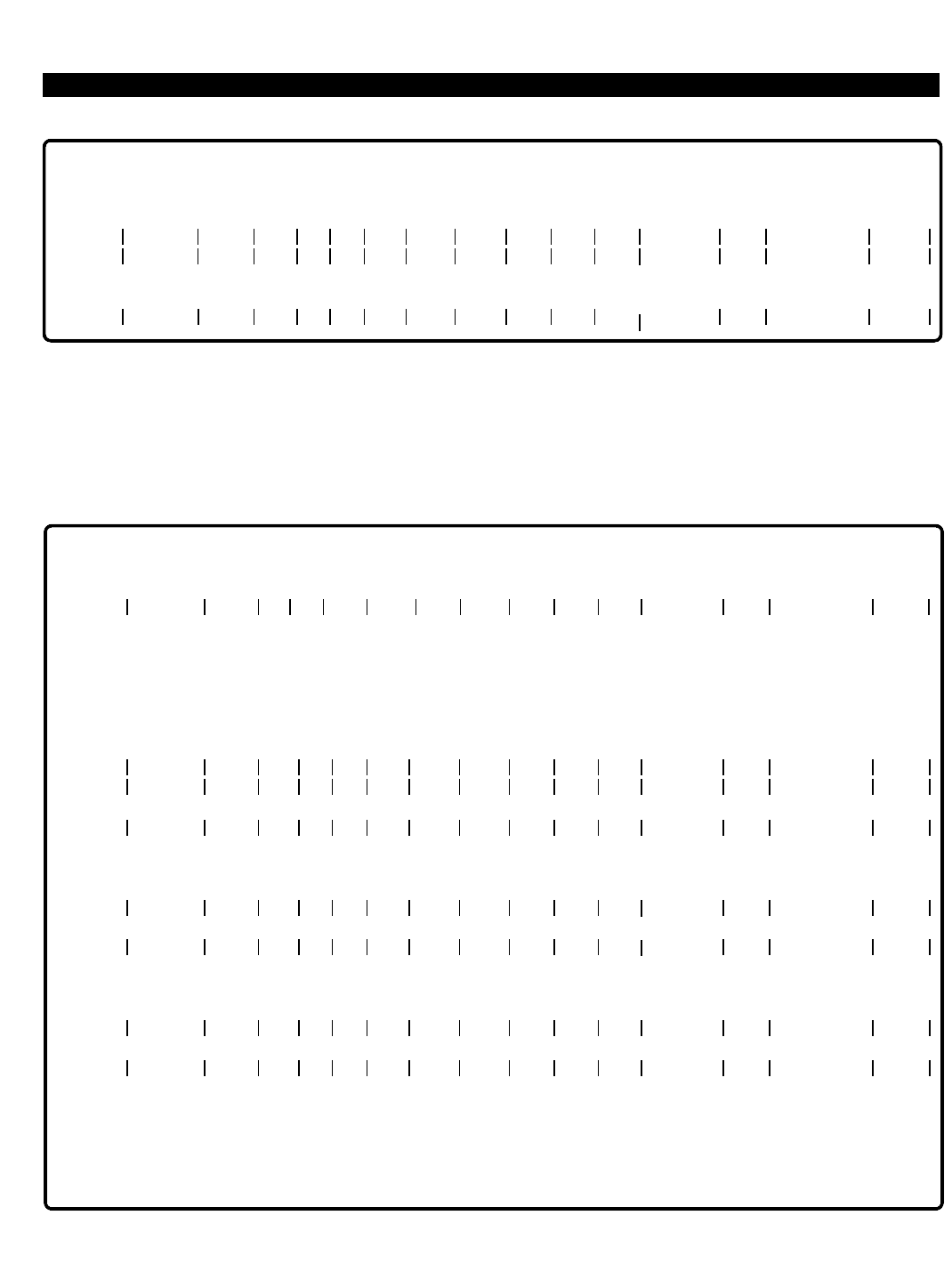
PERCEPTION 4000 EXAMPLES
ISS 2, SECTION 4000-014-000
Figure 2-1
ADD Operation - Data Entry Mode
To go from Data Entry to Setup mode, enter a <CONTROL-P> on a 'clear line'. If ranges are used, the option is
available to confirm each add while the system executes the commands. If any of the required fields are left
empty, the cursor goes to the first column in the empty field and waits for data input. Upon execution of all
commands, the system automatically returns to Data Entry mode.
Figure 2-2
ADD Operation - Setup Mode with Confirmation
2-8
<CONTROL-P>
SETUP MODE:
10507:
10509 2010 NO NO YES 3 5 4 3 1000 PRCH
PRIME ENTITIES TO BE ADDED: 3
ENDING VALUE: 10509
CONTINUE (C/R), ABORT (<ESC>) =
CONFIRM EACH ADD (YES/NO) = <C/R>
YES <C/R>
EQUIP # PRM DN TYPE PAT A1 A2 EXT RNG COS DRL FRL QPL ANSPOS GRP NAME DEPT
10507 5065 2010 NO NO 3 5 4 3 1000 EXAMPLE A PRCH
10507 5065 2010 NO NO 3 5 4 3 1000 EXAMPLE A PRCH
(YES/NO) = Y <C/R>
10508 5069 2010 NO NO 3 5 4 3 1000 EXAMPLE B PRCH
10508 5069 2010 NO NO 3 5 4 3 1000 EXAMPLE B PRCH
(YES/NO) = Y <C/R>
10509 5085 2010 NO NO 3 5 4 3 1000 EXAMPLE C PRCH
10509 5085 2010 NO NO 3 5 4 3 1000 EXAMPLE C PRCH
(YES/NO) = Y <C/R>
DATA ENTRY MODE:
ENTER NEW LINE
->
RNG
->
RNG
->
RNG
->
1
1
1
1
1
1
OPERATION = ADD <C/R>
(Data Entry Mode)
10503 5055 2010 NO NO 3 5 4 3 1000 EXAMPLE 1 ACCT
ENTER NEW LINE
10505 5052 2020 NO NO 2 2 1 2 1000 EXAMPLE 2 ACCT
EQUIP # PRM DN TYPE PAT A1 A2 EXT RNG COS DRL FRL QPL ANSPOS GRP NAME DEPT
RNG
->
1
1
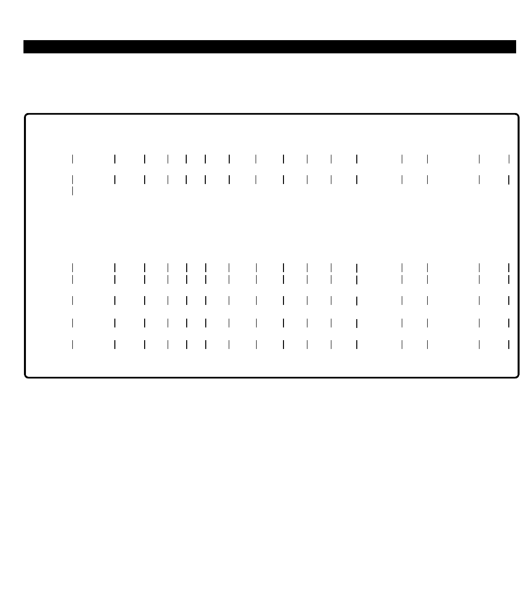
PERCEPTION 4000 EXAMPLES
In the following example, four stations are added to the system, all having the same attributes. "PRM DN" is the
only field requiring individual data entry. This operation does not request confirmation after each addition.
Figure 2-3
ADD Operation - Setup Mode without Confirmation
In the following example, four stations with varying attributes are added to the system. The cursor automatically
goes to the first column in each field requiring data input. After entering data, press the <TAB> key to go to the
next field. This operation does not request confirmation after each addition.
ISS 2, SECTION 4000-014-000
2-9
<CONTROL-P>
SETUP MODE:
10511: 2010 NO NO 3 6 5 2 1002
<CONTROL-W> (Optional)
10514
PRIME ENTITIES TO BE ADDED: 4
ENDING VALUE: 10514
CONTINUE (C/R), ABORT (<ESC>) =
CONFIRM EACH ADDITION (YES/NO) =
<C/R>
NO <C/R>
10511 5170 2010 NO NO 3 6 5 2 1002
10512 5169 2010 NO NO 3 6 5 2 1002
10513 5168 2010 NO NO 3 6 5 2 1002
10514 5167 2010 NO NO 3 6 5 2 1002
DATA ENTRY MODE:
EQUIP # PRM DN TYPE PAT A1 A2 EXT RNG COS DRL FRL QPL ANSPOS GRP NAME DEPT
EQUIP # PRM DN TYPE PAT A1 A2 EXT RNG COS DRL FRL QPL ANSPOS GRP NAME DEPT
->
RNG
RNG
RNG
RNG
1
1
1
1
1
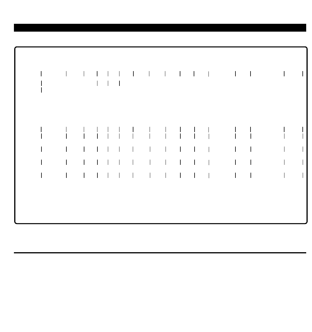
PERCEPTION 4000 EXAMPLES
ISS 2, SECTION 4000-014-000
Figure 2-4
ADD Operation - Setup Mode - Individual Entries
EXAMPLES OF DELETE OPERATIONS
Minimum information essential to the DELETE operation is the equipment number. When first entering a DELETE
operation the system is in Data Entry mode. In this mode removal of individual stations is performed. The
equipment number, without ranges or automatic increments, must be entered.
NOTES:
1. Each input line is terminated with a Carriage Return (<C/R>), not shown.
2. User entered data is shown in Boldface type.
2-10
<CONTROL-P>
SETUP MODE:
10601:
<CONTROL-W> (Optional)
10604
PRIME ENTITIES TO BE ADDED: 4
ENDING VALUE: 10604
CONTINUE (C/R), ABORT (<ESC>) =
CONFIRM EACH ADDITION (YES/NO) =
<C/R>
NO <C/R>
10601 5601 2010 NO NO 15 8 5 2 1002 STA 5601
10602 5602 2010 NO NO 3 6 4 2 1002 STA 5602
10603 5603 2020 NO NO 3 6 4 1 1004 STA 5603
10604 5604 2020 NO NO 1 2 1 1 1004 STA 5604
DATA ENTRY MODE:
ACCT
ACCT
ADMN
ADMN
ENTER NEW LINE
<ESC>
OPERATION =
EQUIP # PRM DN TYPE PAT A1 A2 EXT RNG COS DRL FRL QPL ANSPOS GRP NAME DEPT
EQUIP # PRM DN TYPE PAT A1 A2 EXT RNG COS DRL FRL QPL ANSPOS GRP NAME DEPT
->
->
->
->
NO NO
1
1
2
2
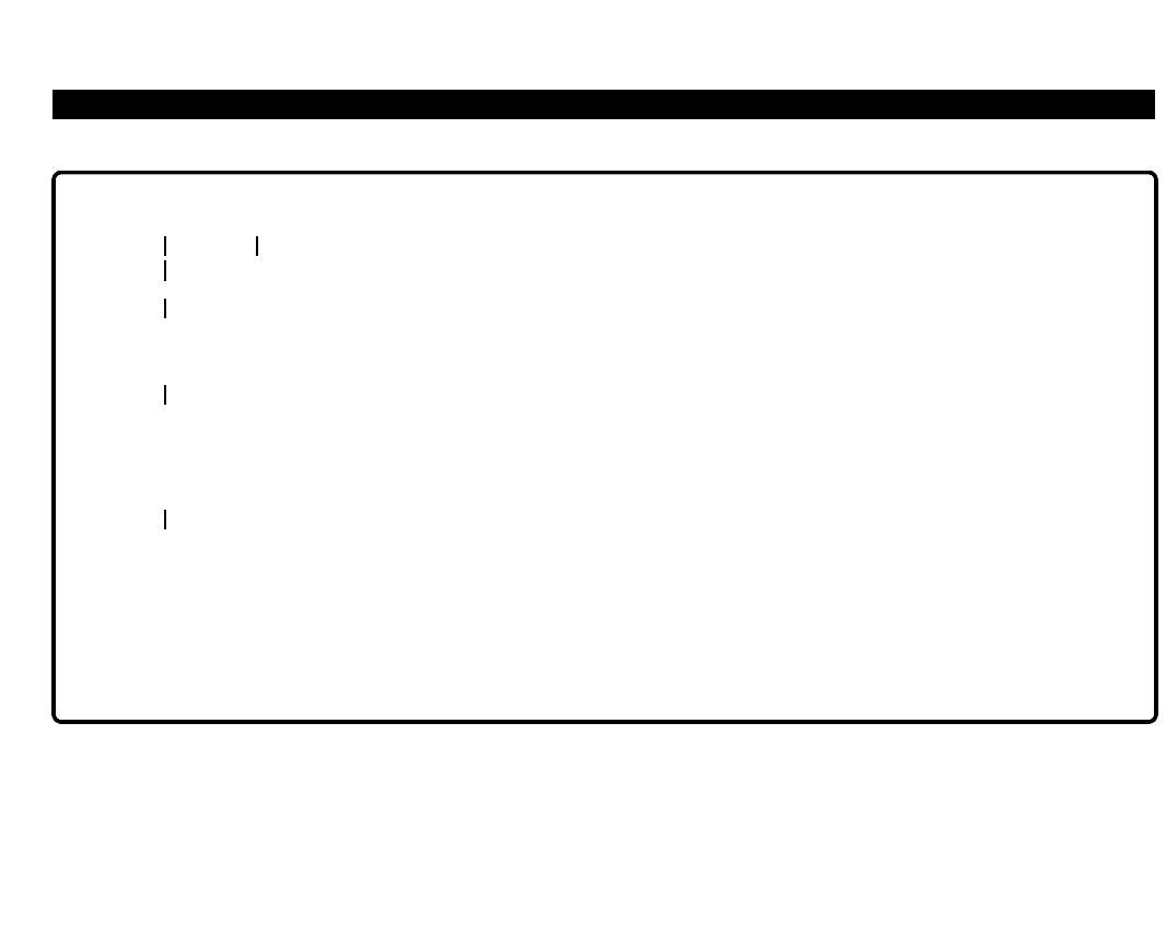
PERCEPTION 4000 EXAMPLES
Figure 2-5
DELETE Operation - Data Entry Mode
To go from Data Entry to Setup mode, enter a <CONTROL-P> on a 'clear line'. If ranges are used, the option is
available to confirm each DELETE operation while the system executes the commands. Upon completion of all
removals, the system automatically returns to Data Entry mode. Note that an error condition or an 'abort'
operation causes the system to return to Data Entry mode also.
ISS 2, SECTION 4000-014-000
2-11
OPERATION =
CONFIRM EACH MODIFICATION (YES/NO) =
10503
10503
(YES/NO) =
ENTER NEW LINE
DELETE <C/R> Y <C/R>
EQUIP # PRM DN
YES <C/R>
10504
10504
(YES/NO) = YES <C/R>
ENTER NEW LINE
10507
EQUIPMENT IN USE:
1.
2.
<ESC>
ACTION = 2 <C/R>
ENTER NEW LINE
FORCE TO IDLE
REMOVE WHEN IDLE
CANCEL REMAINING REMOVAL REQUESTS

PERCEPTION 4000 EXAMPLES
ISS 2, SECTION 4000-014-000
Figure 2-6
DELETE Operation - Setup Mode
The system waits for EQUIP # 10504 to become idle. If the entity continues to be busy, press the <ESC> key.
After a period of time, the following message appears:
Figure 2-7
DELETE Operation - Setup Mode - Forced Idle
Equipment number 10504 is forced to the idle state and deleted.
2-12
<CONTROL-P>
SETUP MODE:
10503:
10505
PRIME ENTITIES TO BE DELETED: 3
ENDING VALUE: 10505
CONTINUE (C/R), ABORT (<ESC>) = <C/R>
EQUIP # PRM DN
10503
(YES/NO) = Y <C/R>
10504
EQUIPMENT IN USE:
1. FORCE TO IDLE
2. REMOVE WHEN IDLE
<ESC> CANCEL REMAINING REMOVAL REQUESTS
ACTION = 2 <C/R>
10505
(YES/NO) = Y <C/R>
EQUIPMENT BUSY:
1
<ESC>
FORCE
ABORT
ACTION = 1 <C/R>
ENTER NEW LINE
<ESC>
OPERATION =
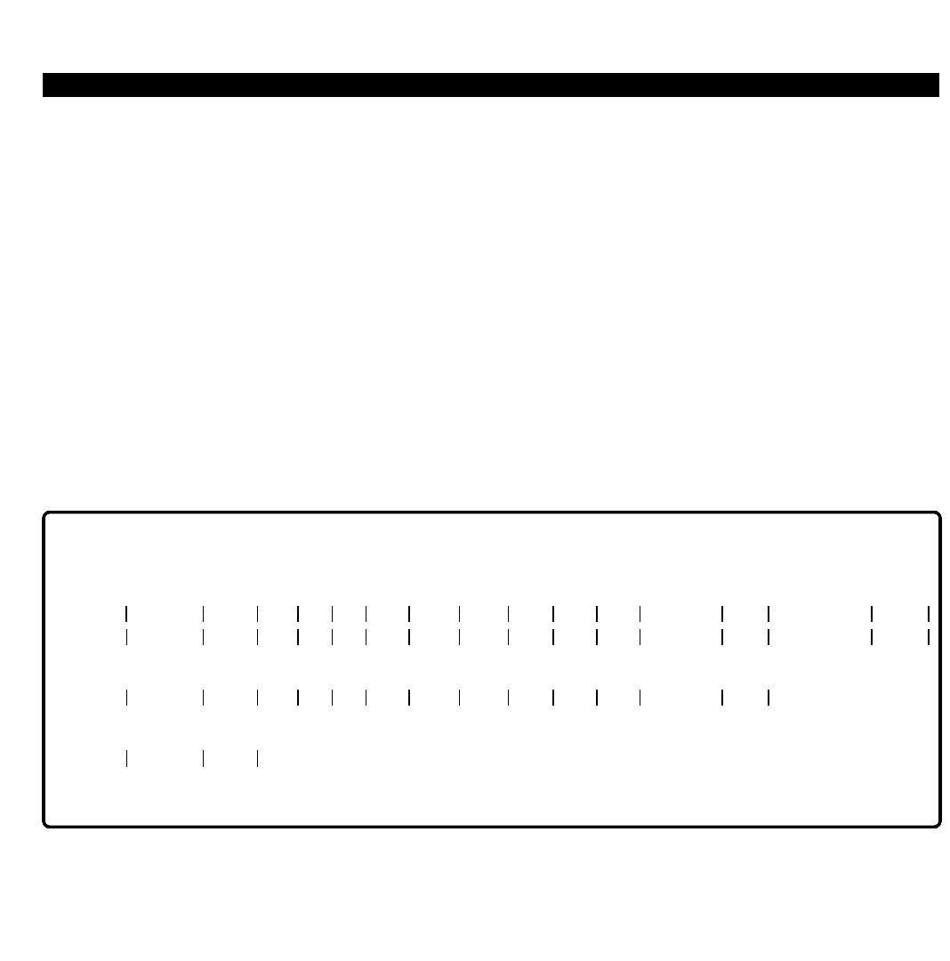
PERCEPTION 4000 EXAMPLES
EXAMPLES OF MODIFY OPERATIONS
Minimum data essential for the modification of a station device is the equipment number and data for at least one
other field. Modifications are made only in those fields where data is entered. All other fields remain unchanged.
In the following examples minimum data has been included. In the examples, the "EXT" and "GRP" fields are
locked fields and therefore left blank.
When first entering a MODIFY operation the system is in Data Entry mode. In this mode modifications to
individual stations are performed. The system asks whether confirmation is required for each modification, and
whether the original and/or new values should be displayed. In Data Entry mode a complete command line,
without ranges or automatic increments, must be entered.
NOTES:
1. Each input line is terminated with a Carriage Return (<C/R>), not shown.
2. User entered data is shown in Boldface type.
3. An arrow (->) indicates a <TAB>.
Figure 2-8
MODIFY Operation - Data Entry Mode
To go from Data Entry to Setup mode, enter a <CONTROL-P> on a 'clear line'. Upon completion of all
modifications, the system automatically returns to Data Entry mode.
ISS 2, SECTION 4000-014-000
2-13
OPERATION =
CONFIRM EACH MODIFICATION (YES/NO) =
DISPLAY ORIGINAL VALUES =
DISPLAY NEW VALUES =
MODIFY <C/R> NO <C/R>
NO <C/R>
NO <C/R>
NO NO 5 2 M EXMPLE DOC
ENTER NEW LINE
10402 31
10401
ENTER NEW LINE
10405 2020
ENTER NEW LINE
<ESC>
EQUIP # PRM DN TYPE PAT A1 A2 EXT RNG COS DRL FRL QPL ANSPOS GRP NAME DEPT
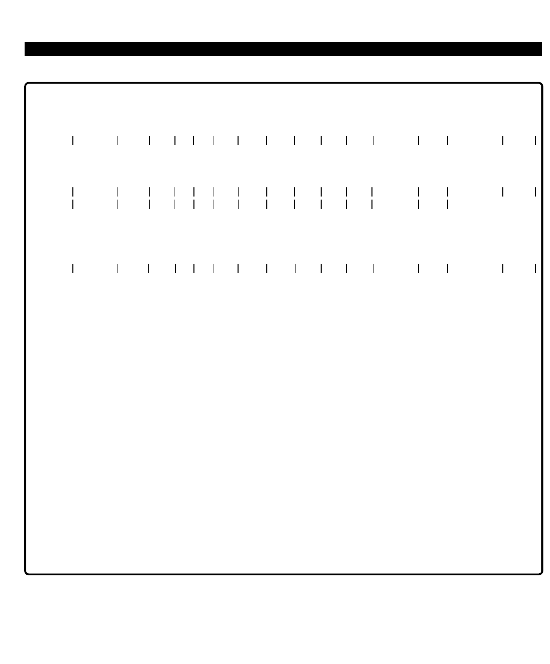
PERCEPTION 4000 EXAMPLES
ISS 2, SECTION 4000-014-000
Figure 2-9
MODIFY Operation - Setup Mode (1)
In Figure 2-9, modifications were made to equipment numbers 10507 through 10510. The "DRL" and "ANSPOS"
fields were changed to 15 and 1003 respectively. Original and new values were displayed, and a confirmation was
requested after each modification was made.
2-14
OPERATION =
CONFIRM EACH MODIFICATION (YES/NO) =
DISPLAY ORIGINAL VALUES =
DISPLAY NEW VALUES =
MODIFY <C/R> YES <C/R>
YES <C/R>
YES <C/R>
<CONTROL-P>
<CONTROL-W> (Optional)
SETUP MODE:
10507:
10510 15 1003
PRIME ENTITIES TO BE MODIFIED: 4
ENDING VALUE: 10510
CONTINUE (C/R), ABORT (<ESC>) = <C/R>
OLD:
10507 5085 2020 NO NO . . . RNG 2 2 1 2 1000 STA 10507
NEW:
10507 5085 2020 NO NO . . . RNG 2 15 1 2 1003 STA 10507
(YES/NO) =
OLD:
10508 5095 2010 NO NO . . . RNG 3 5 4 6 1000 STA 10508
NEW:
10508 5095 2010 NO NO . . . RNG 3 15 4 6 1003 STA 10508
YES <C/R>
(YES/NO) =
OLD:
10509 5105 2010 NO NO . . . RNG 3 5 4 6 1000 STA 10509
NEW:
10509 5105 2010 NO NO . . . RNG 3 15 4 6 1003 STA 10509
YES <C/R>
(YES/NO) =
OLD:
10510 5115 2010 NO NO . . . RNG 3 5 4 6 1000 STA 10510
NEW:
10510 5115 2010 NO NO . . . RNG 3 15 4 6 1003 STA 10510
YES <C/R>
(YES/NO) =
DATA ENTRY MODE:
YES <C/R>
ENTER NEW LINE
<ESC>
EQUIP # PRM DN TYPE PAT A1 A2 EXT RNG COS DRL FRL QPL ANSPOS GRP NAME DEPT
EQUIP # PRM DN TYPE PAT A1 A2 EXT RNG COS DRL FRL QPL ANSPOS GRP NAME DEPT
EQUIP # PRM DN TYPE PAT A1 A2 EXT RNG COS DRL FRL QPL ANSPOS GRP NAME DEPT
->
. . .
. . .
. . .
. . .
. . .
. . .
. . .
. . .
2
2
1
1
1
1
1
1
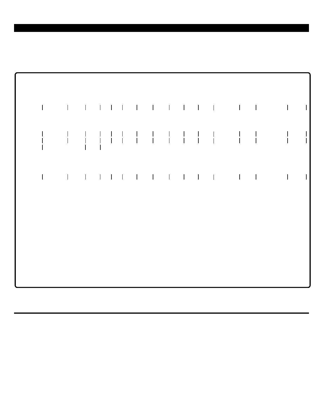
PERCEPTION 4000 EXAMPLES
In the final MODIFY operation example, three entities are modified with confirmation for each modification and
display of original values. Display of new values is not requested.
Figure 2-10
MODIFY Operation - Setup Mode (2)
EXAMPLES OF DISPLAY OPERATIONS
All fields in a DISPLAY operation are optional. Data that is output in a DISPLAY report is controlled by setting
conditions in any of the optional fields. All of the conditions specified must be met before the 'equipment' displays
on the output device.
Ranges may be entered in each of the numeric fields to set lower and upper limits to the values that are to be
displayed. If no data is entered, the minimum and maximum values for the field are set automatically. A single
number may be entered in a numeric field, thereby limiting output to equipment that matches the number for that
field. For fields that expect 'keywords' such as the "TYPE" field, if no data is entered the system displays all types.
If data is entered in this field, then only equipment matching the 'keyword' displays.
ISS 2, SECTION 4000-014-000
2-15
OPERATION =
CONFIRM EACH MODIFICATION (YES/NO) =
DISPLAY ORIGINAL VALUES =
DISPLAY NEW VALUES =
MODIFY <C/R> YES <C/R>
YES <C/R>
NO <C/R>
<CONTROL-P>
<CONTROL-W> (Optional)
SETUP MODE:
10512:
10514 1003
PRIME ENTITIES TO BE MODIFIED: 2
ENDING VALUE: 10514
CONTINUE (C/R), ABORT (<ESC>) = <C/R>
OLD:
10512 5165 2010 NO NO . . . RNG 3 6 5 2 1002
EQUIP # PRM DN TYPE PAT A1 A2 EXT RNG COS DRL FRL QPL ANSPOS GRP NAME DEPT
EQUIP # PRM DN TYPE PAT A1 A2 EXT RNG COS DRL FRL QPL ANSPOS GRP NAME DEPT
EQUIP # PRM DN TYPE PAT A1 A2 EXT RNG COS DRL FRL QPL ANSPOS GRP NAME DEPT
OLD:
10513 5166 2020 NO NO . . . RNG 2 5 1 4 1002
(YES/NO) = YES <C/R>
. . .
. . .
OLD:
10514 5170 2020 NO NO . . . RNG 2 5 1 4 1002
(YES/NO) = YES <C/R>
. . .
(YES/NO) = YES <C/R>
DATA ENTRY MODE:
ENTER NEW LINE
<ESC>
OPERATION =
1
2
2

PERCEPTION 4000 EXAMPLES
ISS 2, SECTION 4000-014-000
For 'text' fields, like the 'keyword' fields, if no data is entered, the match is always successful. If data is entered,
the characters entered must exactly match a subset of the characters stored for the equipment. For example, by
entering AD in the "DEPT" field in the following examples, all stations with the department name of ADMN display.
If the character sequence entered exactly matches the same sequence of characters within the text string stored
for the equipment, the entire text string is considered as having been matched and the equipment is displayed (if
all other conditions have been successfully matched). Leading and trailing spaces are ignored.
To display a complete listing of the data base, enter a <TAB> and press <RETURN>. The following figures
illustrate various DISPLAY operations.
NOTES:
1. Each input line is terminated with a Carriage Return (<C/R>), not shown.
2. User entered data is shown in Boldface type.
Figure 2-11
DISPLAY Operation - Complete Database List
2-16
OPERATION = DISPLAY <C/R>
<TAB>
SETUP MODE:
<C/R>
5001
5002
5003
5016
5015
5025
5035
5045
5055
5065
5075
5085
5095
5105
5115
5125
5165
5166
5170
5185
5186
2010
2010
2010
2010
2020
2010
2010
2010
2020
2020
2020
2020
2010
2010
2010
2010
2010
2020
2020
2010
2020
. . .
. . .
. . .
. . .
. . .
. . .
. . .
. . .
. . .
. . .
. . .
. . .
. . .
. . .
. . .
. . .
. . .
. . .
. . .
. . .
. . .
3
3
3
3
3
3
3
3
2
2
2
2
3
3
3
3
3
2
2
3
2
5
1
5
5
5
5
5
5
2
2
2
15
15
15
15
5
6
5
5
6
5
3
3
3
3
3
3
3
3
2
2
2
2
6
6
6
3
2
4
4
2
4
1000
1000
1000
1000
1000
1000
1000
1000
1000
1000
1000
1003
1003
1003
1003
1000
1003
1003
1003
1003
1003
MOD EXMPL
STA 10402
STA 10403
STA 10404
STA 10405
STA 10501
STA 10502
STA 10503
STA 10504
STA 10505
STA 10506
STA 10507
STA 10508
STA 10509
STA 10510
STA 10511
STA 10512
STA 10513
STA 10514
STA 10515
STA 10516
RNG
RNG
RNG
RNG
RNG
RNG
RNG
RNG
RNG
RNG
RNG
RNG
RNG
RNG
RNG
RNG
RNG
RNG
RNG
RNG
RNG
DOC
DOC
DOC
ADMN
ADMN
ADMN
ADMN
ACCT
ADMN
ACCT
ACCT
PRCH
PRCH
PRCH
MFG
MFG
ENG
ENG
ENG
ACCT
ACCT
10401
10402
10403
10404
10405
10501
10502
10503
10504
10505
10506
10507
10508
10509
10510
10511
10512
10513
10514
10515
10516
NO
NO
NO
NO
NO
NO
NO
NO
NO
NO
NO
NO
NO
NO
NO
NO
NO
NO
NO
NO
NO
2
4
4
4
4
4
4
4
1
1
1
1
4
4
4
4
5
1
1
5
1
NO
NO
NO
NO
NO
NO
NO
NO
NO
NO
NO
NO
NO
NO
NO
NO
NO
NO
NO
NO
NO
EQUIP # PRM DN TYPE PAT A1 A2 EXT RNG COS DRL FRL QPL ANSPOS GRP NAME DEPT
SETUP MODE:
EQUIP # PRM DN TYPE PAT A1 A2 EXT RNG COS DRL FRL QPL ANSPOS GRP NAME DEPT
. . .
. . .
. . .
. . .
. . .
. . .
. . .
. . .
. . .
. . .
. . .
. . .
. . .
. . .
. . .
. . .
. . .
. . .
. . .
. . .
. . .
1
1
1
1
2
1
1
1
2
2
2
2
1
1
1
1
1
2
2
1
2
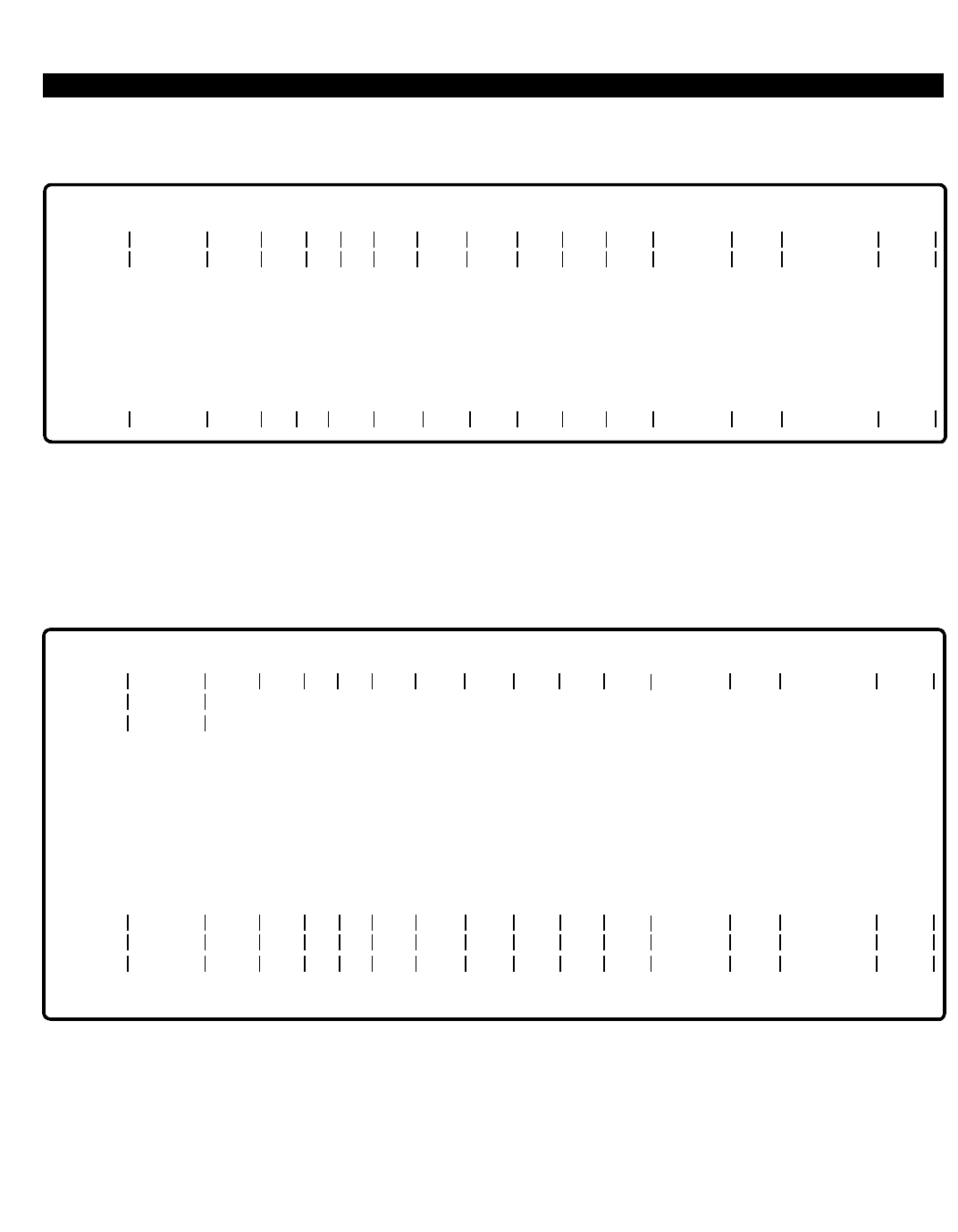
PERCEPTION 4000 EXAMPLES
In the following example, all entities with NO "SEC", a "DRL" of 15, and "ANSPOS" 1003 display.
Figure 2-12
DISPLAY Operation - Specific Attributes Selected
Figure 2-13 illustrates use of ranges in DISPLAY operations. In the first example, "PRM DNs" in the range 5005 to
5055 display. In the second example, equipment numbers between 10401 and 10505 having an "FRL" of 1and
an "ANSPOS" of 1000 display.
Figure 2-13
DISPLAY Operation - Ranges/Fixed Values (1)
Note that only one entity between 10401 and 10505 has an "FRL" of 1and an "ANSPOS" of 1000.
ISS 2, SECTION 4000-014-000
2-17
SETUP MODE:
10507
10508
10509
10510
5085
5095
5105
5115
2020
2010
2010
2010
NO
NO
NO
NO
2
3
3
3
15
15
15
15
1
4
4
4
2
6
6
6
1003
1003
1003
1003
STA 10507
STA 10508
STA 10509
STA 10510
NO
NO
NO
NO
RNG
RNG
RNG
RNG
PRCH
PRCH
PRCH
MFG
15 1003
. . .
. . .
. . .
. . .
SETUP MODE:
EQUIP # PRM DN TYPE PAT A1 A2 EXT RNG COS DRL FRL QPL ANSPOS GRP NAME DEPT
EQUIP # PRM DN TYPE A1 A2 EXT RNG SEC COS DRL FRL QPL ANSPOS GRP NAME DEPT
. . .
. . .
. . .
. . .
2
1
1
1
SETUP MODE:
10404
10405
10501
10502
10503
10504
5016
5015
5025
5035
5045
5055
2010
2020
2010
2010
2010
2020
NO
NO
NO
NO
NO
NO
. . .
. . .
. . .
. . .
. . .
. . .
3
3
3
3
3
2
5
5
5
5
5
2
4
4
4
4
4
1
3
3
3
3
3
2
1000
1000
1000
1000
1000
1000
STA 10404
STA 10405
STA 10501
STA 10502
STA 10503
STA 10504
ADMN
ADMN
ADMN
ADMN
ACCT
ADMN
5005:
5055
NO
NO
NO
NO
NO
NO
RNG
RNG
RNG
RNG
RNG
RNG
EQUIP # PRM DN TYPE PAT A1 A2 EXT RNG COS DRL FRL QPL ANSPOS GRP NAME DEPT
SETUP MODE:
EQUIP # PRM DN TYPE PAT A1 A2 EXT RNG COS DRL FRL QPL ANSPOS GRP NAME DEPT
10401:
. . .
. . .
. . .
. . .
. . .
. . .
10505
10504 5055 2020 NO . . . 2 2 1 2 1000 STA 10504 ADMNNO RNG . . .
1 1000
1
2
1
1
1
2
2
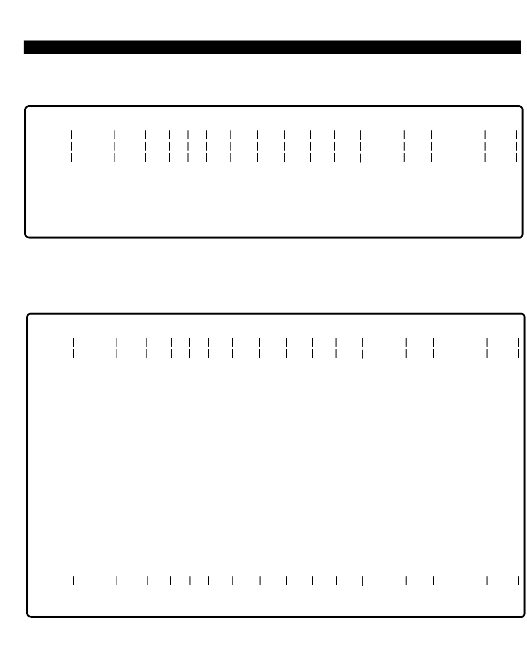
PERCEPTION 4000 EXAMPLES
ISS 2, SECTION 4000-014-000
The following example displays all 2020-type stations with data security and a COS between 1and 9.
Figure 2-14
DISPLAY Operation - Ranges/Fixed Values (2)
In the final example, a subset of the current text entries is entered in the "NAME" field to display all entities with a
name beginning with STA 105.
Figure 2-15
DISPLAY Operation - Subset of Text Entry
2-18
SETUP MODE:
2020
10405
10504
10513
10514
10516
5015
5055
5166
5170
5186
2020
2020
2020
2020
2020
NO
NO
NO
NO
NO
. . .
. . .
. . .
. . .
. . .
3
2
2
2
2
5
2
5
5
5
4
1
1
1
1
3
2
4
4
4
1000
1000
1003
1003
1003
STA 10405
STA 10504
STA 10513
STA 10514
STA 10516
NO
NO
NO
NO
NO
ADMN
ADMN
ENG
ENG
ACCT
EQUIP # PRM DN TYPE PAT A1 A2 EXT RNG COS DRL FRL QPL ANSPOS GRP NAME DEPT
1:
9
. . .
. . .
. . .
. . .
. . .
RNG
RNG
RNG
RNG
RNG
2
2
2
2
2
SETUP MODE:
10501
10502
10503
10504
10505
10506
10507
10508
10509
10510
10511
10512
10513
10514
10515
10516
5025
5035
5045
5055
5065
5075
5085
5095
5105
5115
5125
5165
5166
5170
5185
5186
2010
2010
2010
2020
2020
2020
2020
2010
2010
2010
2010
2010
2020
2020
2010
2020
NO
NO
NO
NO
NO
NO
NO
NO
NO
NO
NO
NO
NO
NO
NO
NO
. . .
. . .
. . .
. . .
. . .
. . .
. . .
. . .
. . .
. . .
. . .
. . .
. . .
. . .
. . .
. . .
3
3
3
2
2
2
2
3
3
3
3
3
2
2
3
2
5
5
5
2
2
2
15
15
15
15
5
6
5
5
6
5
4
4
4
1
1
1
1
4
4
4
4
5
1
1
5
1
3
3
3
2
2
2
2
6
6
6
3
2
4
4
2
4
1000
1000
1000
1000
1000
1000
1003
1003
1003
1003
1000
1003
1003
1003
1003
1003
STA 10501
STA 10502
STA 10503
STA 10504
STA 10505
STA 10506
STA 10507
STA 10508
STA 10509
STA 10510
STA 10511
STA 10512
STA 10513
STA 10514
STA 10515
STA 10516
NO
NO
NO
NO
NO
NO
NO
NO
NO
NO
NO
NO
NO
NO
NO
NO
ADMN
ADMN
ACCT
ADMN
ACCT
ACCT
PRCH
PRCH
PRCH
MFG
MFG
ENG
ENG
ENG
ACCT
ACCT
EQUIP # PRM DN TYPE PAT A1 A2 EXT RNG COS DRL FRL QPL ANSPOS GRP NAME DEPT
. . .
. . .
. . .
. . .
. . .
. . .
. . .
. . .
. . .
. . .
. . .
. . .
. . .
. . .
. . .
. . .
RNG
RNG
RNG
RNG
RNG
RNG
RNG
RNG
RNG
RNG
RNG
RNG
RNG
RNG
RNG
RNG
STA 105
SETUP MODE:
<ESC>
OPERATION =
EQUIP # PRM DN TYPE PAT A1 A2 EXT RNG COS DRL FRL QPL ANSPOS GRP NAME DEPT
1
1
1
2
2
2
2
1
1
1
1
1
2
2
1
2
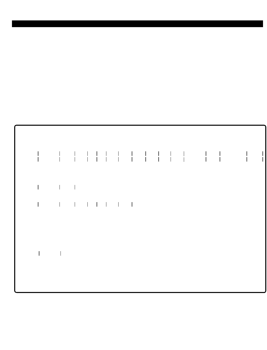
PERCEPTION 4000 EXAMPLES
HOW TO USE THE <ESC> KEY
An <ESC> key on the M&A terminal is a multikey entry which consists of the keys <SHIFT-2>.
In these examples, MODIFY and DELETE operations are used to demonstrate various methods for aborting from
any of the operation modes. In a DISPLAY operation, the <ESC> key is used to halt output of a report.
NOTE: A <C/R> is not needed after an <ESC> is entered.
The system immediately acts upon receiving the <ESC> key; the current input line aborts, an abort message
appears on the output device, and the cursor goes to the far left column on the next input line. The system
remains in the current operation unless the key is pressed on a 'clear line'. The following figures show examples
of <ESC> key operation.
Figure 2-16
<ESC> Key - Data Entry Mode
In the previous example, when the <ESC> key is pressed the first time the input line is aborted and then re-
entered. The second instance shows that when the <ESC> key is pressed on a 'clear line' the current MODIFY
operation is aborted and the system goes up one hierarchy level to the Operation level. Next, a DELETE
operation is entered, however, it is then aborted. "EQUIP #" 10514 is not deleted. The system prompts "ENTER
NEW LINE" while remaining in the DELETE operation mode.
ISS 2, SECTION 4000-014-000
2-19
2010
EQUIP # PRM DN TYPE PAT A1 A2 EXT RNG COS DRL FRL QPL ANSPOS GRP NAME DEPT
3
10404
OLD:
10404
5016
5016 NO . . . 5 4 3
1003
1000 STA 10404NO ADMN. . .RNG
OPERATION = MODIFY <C/R>
CONFIRM EACH MODIFICATION (YES/NO) = NO <C/R>
DISPLAY ORIGINAL VALUE = YES <C/R>
DISPLAY NEW VALUE = NO <C/R>
2020
10405
I00201 - Input Line Aborted
ENTER NEW LINE
2010
2020 3
10405
OLD:
10405 5015 NO . . . 5 4 3 1000 STA 10405NO ADMN. . .RNG
<ESC>
<ESC>
ENTER NEW LINE
OPERATION = DELETE <C/R>
CONFIRM EACH MODIFICATION (YES/NO) = YES <C/R>
EQUIP # PRM DN
10514
10514
(YES/NO) = <ESC>
ENTER NEW LINE
1
2
1
2
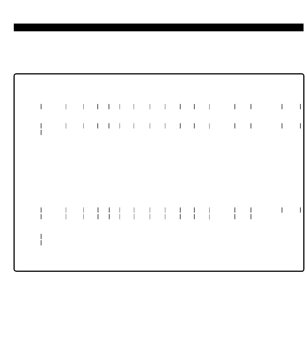
PERCEPTION 4000 EXAMPLES
ISS 2, SECTION 4000-014-000
The following example shows escape operations while in Setup mode. In the first instance, <ESC> aborts the
current MODIFY request and returns the system to Data Entry mode. The second <ESC> operation aborts the
current line of data input and returns the cursor to a 'clear line' while remaining in Setup mode.
Figure 2-17
<ESC> Key - MODIFY Operation, Setup Mode
In a DELETE operation, when the system encounters an "Equipment In Use" situation, you have the option of
forcing the equipment to the idle state, waiting until the equipment becomes idle, or canceling the remaining
removal requests by pressing <ESC>.
If "WAIT FOR IDLE" is selected, the system waits for the entity to become idle, and then carries out the removal
request. An <ESC> may be performed to abort the waiting process. After pressing the <ESC> key, a timeout
occurs and a message displays giving the options to force or abort the DELETE operation. Pressing <ESC>
again aborts the request and places the console in Data Entry mode. Figure 2-18 illustrates <ESC> key usage in
DELETE operations.
2-20
EQUIP # PRM DN TYPE PAT A1 A2 EXT RNG COS DRL FRL QPL ANSPOS GRP NAME DEPT
10507:
10510
PRIME ENTITIES TO BE MODIFIED: 4
ENDING VALUE: 10510
CONTINUE (C/R), ABORT (<ESC>) = <ESC>
G00401 - Operation Aborted
DATA ENTRY MODE:
15 1003
OPERATION = MODIFY <C/R>
CONFIRM EACH MODIFICATION (YES/NO) = NO <C/R>
DISPLAY ORIGINAL VALUE = YES <C/R>
DISPLAY NEW VALUE = NO <C/R>
ENTER NEW LINE
<CONTROL-P>
SETUP MODE:
<CONTROL-W> (Optional)
<CONTROL-P>
SETUP MODE:
EQUIP # PRM DN TYPE PAT A1 A2 EXT RNG COS DRL FRL QPL ANSPOS GRP NAME DEPT
10512:
Input Line Aborted
10514:
10516
PRIME ENTITIES TO BE MODIFIED: 3
ENDING VALUE: 10516
CONTINUE (C/R), ABORT (<ESC>) =
1003 <ESC>

PERCEPTION 4000 EXAMPLES
Figure 2-18
<ESC> Key - DELETE Operation, Setup Mode
ISS 2, SECTION 4000-014-000
2-21
OPERATION = DELETE <C/R>
CONFIRM EACH MODIFICATION (YES/NO) = NO <C/R>
EQUIP # PRM DN
<CONTROL-P>
SETUP MODE:
10503:
10505
PRIME ENTITIES TO BE DELETED: 3
ENDING VALUE: 10505
CONTINUE (C/R), ABORT (<ESC>) = <ESC>
DATA ENTRY MODE:
ENTER NEW LINE
<CONTROL-P>
SETUP MODE:
10503:
10505
PRIME ENTITIES TO BE DELETED: 3
ENDING VALUE: 10505
CONTINUE (C/R), ABORT (<ESC>) = <C/R>
EQUIP # PRM DN
10504
EQUIPMENT IN USE:
1.
2.
<ESC>
FORCE TO IDLE
REMOVE WHEN IDLE
CANCEL REMAINING REMOVAL REQUESTS
ACTION = <ESC>
DATA ENTRY MODE:
ENTER NEW LINE
<CONTROL-P>
SETUP MODE:
10509:
10516
PRIME ENTITIES TO BE DELETED: 8
ENDING VALUE: 10516
CONTINUE (C/R), ABORT (<ESC>) = <C/R>
EQUIP # PRM DN
10513
EQUIPMENT BUSY:
1.
2.
<ESC>
FORCE TO IDLE
REMOVE WHEN IDLE
CANCEL REMAINING REMOVAL REQUESTS
ACTION = 2 <C/R> . . . . <ESC>
10513
EQUIPMENT BUSY:
1.
<ESC> FORCE TO IDLE
ABORT OPERATION
ACTION = <ESC>
DATA ENTRY MODE:
ENTER NEW LINE
<ESC>
OPERATION =
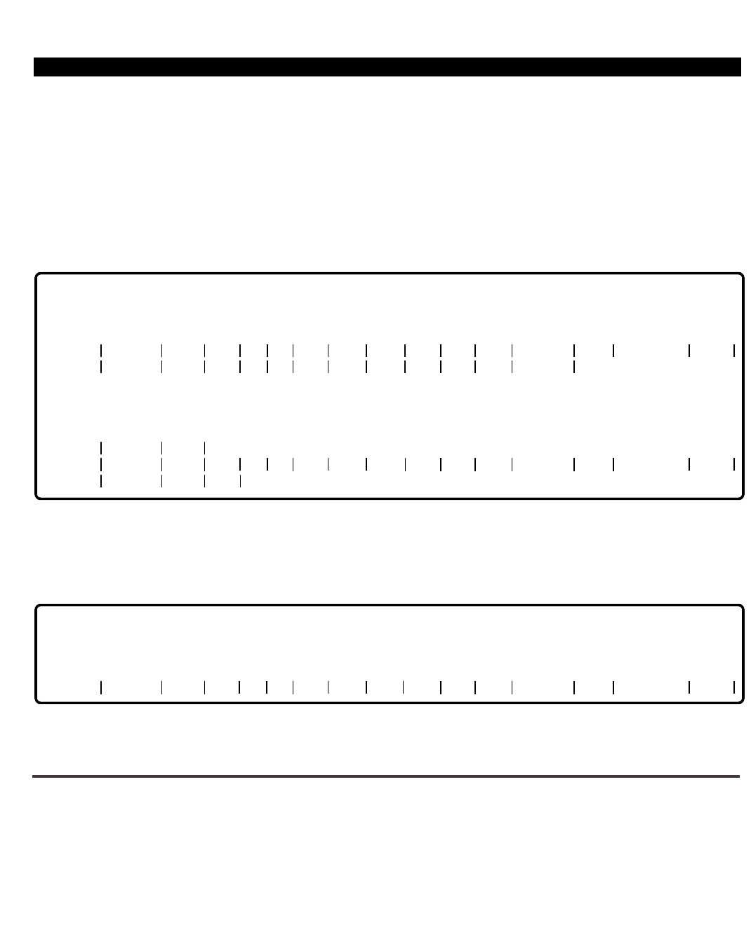
PERCEPTION 4000 EXAMPLES
ISS 2, SECTION 4000-014-000
HOW TO USE THE <CONTROL-W> COMMAND
In this example, the MODIFY operation is used to demonstrate how to use the "Refresh Last Prompt" command
(<CONTROL-W>). If entered on a 'clear line', the command redisplays the command header. If the command is
entered within an input line, both the command header and the current input line are redisplayed. The mode in
which the command is entered is not altered. <CONTROL-W> is useful in displaying the command header prior
to producing a report or to reaffirm the location of a particular field. The following figures illustrate <CONTROL-
W> operation.
* The cursor would be relocated here after redisplaying the header and current input line.
Figure 2-19
<CONTROL-W> Operation - Data Entry Mode
Figure 2-20
<CONTROL-W> Operation - Setup Mode
HELP EXAMPLES
Following are several examples to illustrate the various HELP levels.
COMMAND SELECTION LEVEL
The first set of figures illustrate a typical HELP session with the entry point from the COMMAND selection level.
2-22
(YES/NO) = Y <C/R>
10405
EQUIP # PRM DN TYPE PAT A1 A2 EXT RNG COS DRL FRL QPL ANSPOS GRP NAME DEPT
10405 2020 <CONTROL-W>
2020 *
OPERATION = MODIFY <C/R>
CONFIRM EACH MODIFICATION (YES/NO) = YES
DISPLAY ORIGINAL VALUES = NO
DISPLAY NEW VALUES = NO
ENTER NEW LINE
EQUIP # PRM DN TYPE PAT A1 A2 EXT RNG COS DRL FRL QPL ANSPOS GRP NAME DEPT
10404 5016 1003
2
ENTER NEW LINE
<CONTROL-P>
SETUP MODE:
<CONTROL-W>
EQUIP # PRM DN TYPE PAT A1 A2 EXT RNG COS DRL FRL QPL ANSPOS GRP NAME DEPT

PERCEPTION 4000 EXAMPLES
Figure 2-21
Entry into HELP Operation - Command Level
The system immediately goes into HELP operation mode.
Figure 2-22
HELP Menu - Command Level
Figure 2-23
Command Categories
ISS 2, SECTION 4000-014-000
2-23
Release X.X
Version X.X.X Day Month Date and Time
Select one item:
1. Command Category
2. MMI Tutorial
3. System Messages
4. Control Keys
Q. Quit Help Operation
ITEM NUMBER = 1 <C/R>
HELP MENU
COMMAND = ?
Release X.X
Version X.X.X Day Month Date and Time
Select one item:
1. ADMINISTRATION
3. LCR
5. DATA
7. DIALING
9. LOGOUT
11. NETWORK
13. STATION
15. TRUNK
Q. Quit Help Operation
U. Go Up One Hierarchy Level
ITEM NUMBER = 5 <C/R>
HELP MENU
2. APPLICATION PROCESSOR
4. ATTENDANT
6. DIAGNOSTIC
8. FAULT
10. MAINTENANCE
12. RESTRICT
14. SYSTEM
16. UTILITY

PERCEPTION 4000 EXAMPLES
ISS 2, SECTION 4000-014-000
Item 5 (DATA) produces a list of the names and identifiers for every command available for the selected category.
Figure 2-24
List of Specific Commands
At this point the command overlay may need to be loaded from the disk into the system. Therefore, there may be
a slight delay, unless the selected command has already been loaded.
Figure 2-25
Specific Command Main Menu
2-24
Release X.X
Version X.X.X Day Month Date and Time
Select one item:
1. DATA_ASSIGN
2. DATA_HUNTING
3. DATA_INT_PARAMETERS
4. DATA_STA_PARAMETERS
5. HIGH_USAGE_DATA
6. MODEM_POOL_ASSIGN
7. NAME_DIALING
Q. Quit Help Operation
U. Go Up One Hierarchy Level
ITEM NUMBER = 2 <C/R>
HELP MENU
(360)
(366)
(361)
(362)
(368)
(347)
(367)
Release X.X
Version X.X.X Day Month Date and Time
Select one item:
Command ID: (cmd366)
1. General Information
2. Operations
Q. Quit Help Operation
U. Go Up One Hierarchy Level
ITEM NUMBER = 1 <C/R>
HELP MENU

PERCEPTION 4000 EXAMPLES
Figure 2-26
General Command Information
Figure 2-27
Exit from HELP Operation
OPERATION SELECTION LEVEL
The following examples show a typical HELP session with the entry point from the OPERATION selection level. If
the command overlay needs to be loaded from the disk into the system, there may be some delay, unless the
selected command has already been loaded.
Figure 2-28
Entry into HELP Operation - Operation Level
ISS 2, SECTION 4000-014-000
2-25
Data Hunting Assignment Command (cmd366)
- to ADD, DELETE, MODIFY, and DISPLAY Data Hunt groups
Coverage:
Data Hunt Group Number, Group Name, Pilot Directory Number
Member Number, and Member Directory Number
Dependency:
1)
2)
Prerequisite commands:
- Data Station Assignment (cmd360)
This command may be needed by:
- Name Dialing Assignment (cmd367)
Release X.X
Version X.X.X Day Month Date and Time
Select one item:
Command ID: (cmd366)
ITEM NUMBER =
COMMAND = Q <C/R>
HELP MENU
1. General Information
2. Operations
Q. Quit Help Operation
U. Go Up One Hierarchy Level
COMMAND =
COMMAND NUMBER: 366
OPERATION = ?
DATA_HUNTING <C/R>
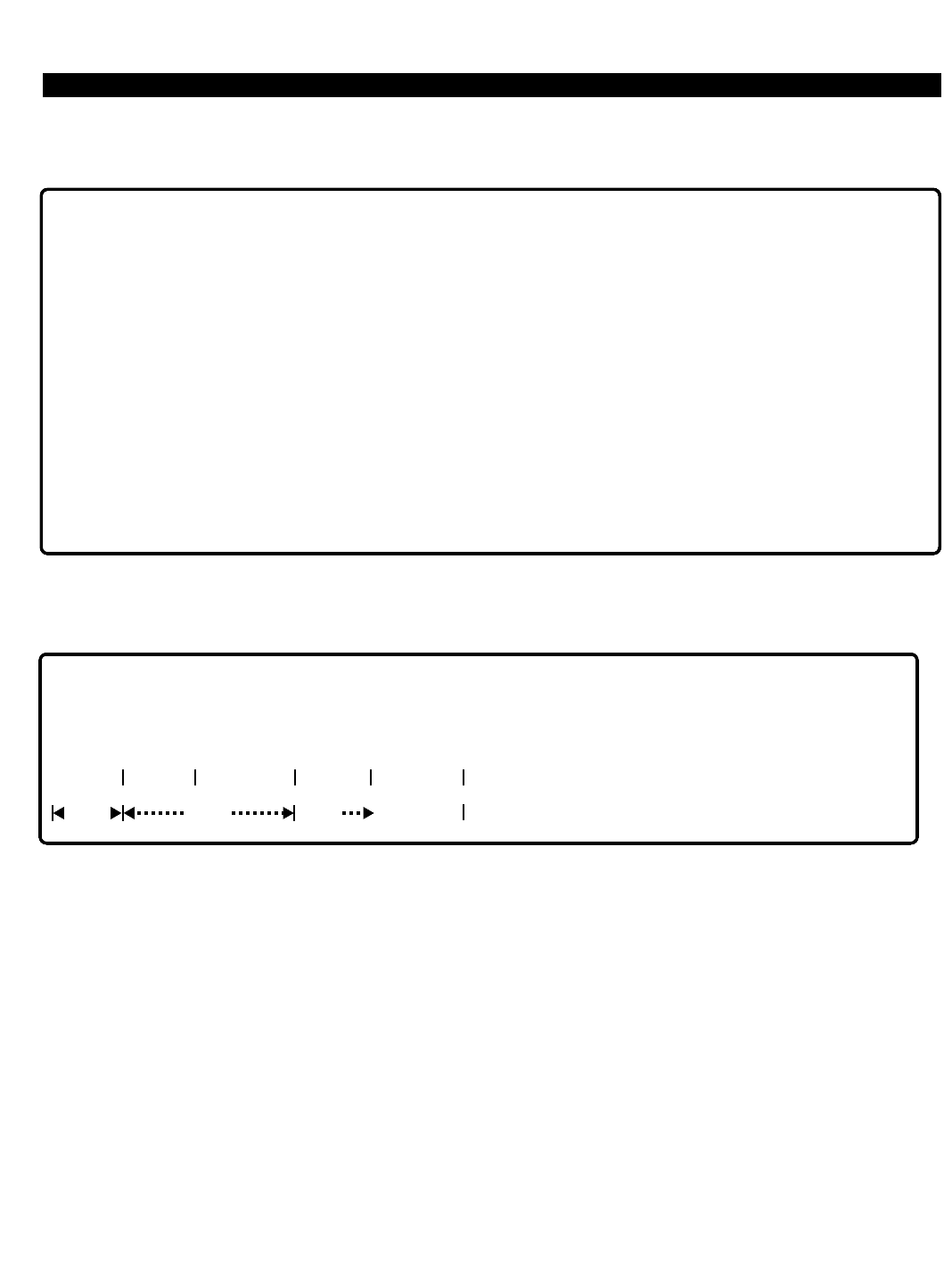
PERCEPTION 4000 EXAMPLES
ISS 2, SECTION 4000-014-000
The system immediately goes into the HELP operation mode.
Figure 2-29
Command Operations Menu
Figure 2-30
MODIFY Operation Information
The notation under the "MEM #" and "MEM DN" fields (OPT ---> OPT) indicates that a relationship exists between
the two fields. If data is entered in the "MEM #" field, data must be entered in the "MEM DN" field. If the "MEM #"
field is left empty, data must not be entered in the "MEM DN" field.
2-26
Release X.X
Version X.X.X Day Month Date and Time
Select one item:
Command ID: (cmd366)
ITEM NUMBER = 3 <C/R>
HELP MENU
1. ADD
2. DELETE
3. MODIFY
4. DISPLAY
5. Field Parameters
Q. Quit Help Operation
req opt
MODIFY:
— To modify a data hunt group or attributes for group
Form:
GRP # NAME PILOT DN MEM # MEM DN
opt opt

PERCEPTION 4000 EXAMPLES
Figure 2-31
Field Parameter Menus
ISS 2, SECTION 4000-014-000
2-27
Release X.X
Version X.X.X Day Month Date and Time
Select one item:
Command ID: (cmd366)
ITEM NUMBER =
HELP MENU
1. ADD
2. DELETE
3. MODIFY
4. DISPLAY
5. Field Parameters
Q. Quit Help Operation
5 <C/R>
Command ID: (cmd366)
ITEM NUMBER =
HELP MENU
1. ADD Field Parameters
2. DELETE Field Parameters
3. MODIFY Field Parameters
4. DISPLAY Field Parameters
Q. Quit Help Operation
U. Go Up One Hierarchy Level
3 <C/R>
Release X.X
Version X.X.X Day Month Date and Time
Select one item:

PERCEPTION 4000 EXAMPLES
ISS 2, SECTION 4000-014-000
Figure 2-32
MODIFY Operation - Field Parameter Menu
Figure 2-33
Field Parameter Description
2-28
Release X.X
Version X.X.X Day Month Date and Time
Select one item:
Command ID: (cmd366)
1. GRP #
2. NAME
3. PILOT DN
4. MEM#
5. MEM DN
Q. Quit Help Operation
U. Go Up One Hierarchy Level
ITEM NUMBER = 2 <C/R>
HELP MENU
Data Hunt Group Name (NAME)
Type:
Value:
Format:
Keyword:
Required:
Range:
Loop Field:
ASCII
Text
0 to 9 ASCII characters
Not allowed
N/A
Not allowed
Not allowed
-
- Delete token (^D) is allowed in a MODIFY operation
The Data Hunt Group Name does not need to be specified for a Data Hunt Group

PERCEPTION 4000 EXAMPLES
Figure 2-34
Stepping Up the Hierarchy Levels
ISS 2, SECTION 4000-014-000
2-29
Release X.X
Version X.X.X Day Month Date and Time
Select one item:
Command ID: (cmd366)
ITEM NUMBER =
HELP MENU
1. GRP #
2. NAME
3. PILOT DN
4. MEM #
5. MEM DN
Q. Quit Help Operation
U. Go Up One Hierarchy Level
U <C/R>
Command ID: (cmd366)
ITEM NUMBER =
HELP MENU
1. ADD
2. DELETE
3. MODIFY
4. DISPLAY
Q. Quit Help Operation
U. Go Up One Hierarchy Level
U <C/R>
Command ID: (cmd366)
HELP MENU
1. ADD
2. DELETE
3. MODIFY
4. DISPLAY
5. Field Parameters
Q. Quit Help Operation
Release X.X
Version X.X.X Day Month Date and Time
Select one item:
Field Parameters
Field Parameters
Field Parameters
Field Parameters
Release X.X
Version X.X.X Day Month Date and Time
Select one item:
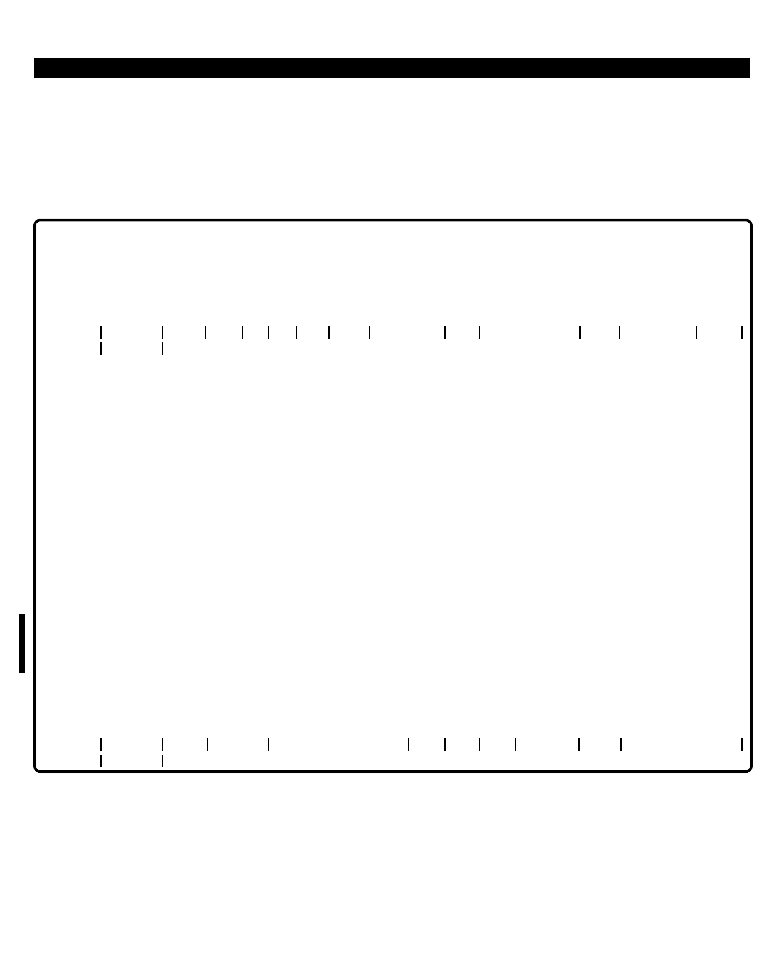
PERCEPTION 4000 EXAMPLES
ISS 2, SECTION 4000-014-000
PARAMETER SELECTION LEVEL
This example shows a typical HELP session with the entry point from the parameter selection level; MODIFY
operation. Upon entry of the "?", the system immediately goes into HELP operation mode and automatically
displays information for that field. You may tab over to any field that is not locked for HELP information.
Figure 2-35
Parameter Level HELP Screen
You may now complete the MODIFY operation for the STATION_ASSIGN command, or abort and return to the
"OPERATION=" command level.
2-30
Station Type (TYPE)
Type:
Value:
Format:
Keyword:
Required:
Range:
Loop Field:
COMMAND = 330 <C/R>
COMMAND NAME: STA_ASSIGN
OPERATION = MODIFY <C/R>
CONFIRM EACH MODIFICATION (YES/NO) = NO
DISPLAY ORIGINAL VALUES = YES
DISPLAY NEW VALUES = YES
EQUIP # PRM DN TYPE PAT A1 A2 EXT RNG COS DRL FRL QPL ANSPOS GRP NAME DEPT
11101 4220 ?
Keyword
Not allowed
N/A
2010
2020
ID10
ID20
ANLG
ANMW
AVMS
EK01
EK10
EK20
EK2D
DK10
DK1D
DK20
DK2D
ADD operation only
Not allowed
Not allowed
- 10-key digital telephone
- 20-key digital telephone
- 10-key digital telephone with DIU
- 20-key digital telephone with DIU
- Analog telephone
- Analog telephone with Message Waiting
- Analog telephone with VMS port
- Electronic telephone with 1 line key and 3 fixed keys
- Electronic telephone with 10 flexible keys and 4 fixed keys
- Electronic telephone with 20 flexible keys and 4 fixed keys
- Electronic telephone with 20 flexible keys, 4 fixed keys, and display
- DKT digital telepholne with 10 flexible keys
- DKT digital telephone with 10 flexible keys and display
- DKT digital telephone with 20 flexible keys
- DKT digital telephone with 20 flexible keys and display
EQUIP # PRM DN TYPE PAT A1 A2 EXT RNG COS DRL FRL QPL ANSPOS GRP NAME DEPT
11101 4220 *

Chapter 3
PERCEPTION 4000 COMMANDS
The PERCEPTION 4000 Maintenance & Administration (M&A) commands are detailed in this chapter.
COMMAND FORMAT
Commands are presented in the following format:
COMMAND NAME (NUMERIC ID)
The numeric ID following the command name is a three-digit identifier used to call up the command on the M&A
console. A brief description follows the command name line. The command keyword and category name are then
listed. Note that commands may be addressed by either their keyword or their numeric ID.
Command Keyword: An alternative input used to call up the command on the M&A console
Category Name: Specifies the command category, such as a Station, Trunk, or Attendant Console
command
PREREQUISITE COMMANDS
Any commands that must be executed prior to the current command are listed in this section. For example, before
programming the ACD Group Parameter Assignment command (CMD 357), the ACD group number must be
assigned with the ACD Group Assignment command (CMD 355). Therefore, CMD 355 is listed as a prerequisite
for CMD 357.
OPERATIONS
Each applicable operation is explained, and the row/field-level command header for the operation is illustrated.
Parameters for the command are designated as required (req), optional (opt), locked, or output only.
PARAMETERS
Each field parameter is defined in this section. The field's type of input is listed, such as decimal input, text,
keywords, etc. Additional information includes input format, values, whether the field is a loop field, and whether
ranges are permitted in this field. All commands having a MODIFY operation and no ADD operation contain
default values. However, not all commands with ADD operations have defaults.
SYSTEM ERROR MESSAGES
Error and information messages pertaining to the command are listed in this section. These messages include
indications of incorrect input, informational matter, and system messages. A complete listing of all system error
messages appears in Chapter 4.
ISS 2, SECTION 4000-014-000
3-1

PERCEPTION 4000 COMMANDS
ISS 2, SECTION 4000-014-000
COMMENTS (Optional)
This optional section provides additional information pertinent to the command.
RELATED COMMANDS (Optional)
Commands which may be required to achieve full realization for a given application are listed. For example, in the
Announcement Pattern Assignment command (CMD 353), announcement pattern numbers are assigned and
defined for up to 50 patterns. Since these pattern numbers may be used in the ACD Group Parameter
Assignment command (CMD 357), CMD 357 is listed under related commands for CMD 353.
COMMAND NOTATIONS
The following abbreviations, symbols, or notations are used in the commands:
req = Data is required in this field.
opt = Data is optional in this field.
output only = Data is displayed in this field. Input is not accepted.
locked = This field is reserved for future use.
---> = Indicates that a relationship exists between a secondary key and one or more
attributes. A secondary key must be entered if the related attribute is being
selected.
MAINTENANCE & ADMINISTRATION COMMANDS
Following is a list of the M&A commands for Man-Machine Interface (MMI) operation. Appendix B lists the
commands by their Numeric IDs.
Command Name Numeric Command Keyword
ID
Account Code Assignment 348 ACCOUNT_CODE_ASSIGN
ACD Agent Assignment 356 ACD_AGENT_ASSIGN
ACD Group Assignment 355 ACD_GROUP_ASSIGN
ACD Group Parameter Assignment 357 ACD_PARAMETERS
ACD Status Display and Remote Logout 358 ACD_DISP_LOGOUT
Alarm/Fault Display and Reset 160 ALM/FAULT_DISP/RESET
Announcement Pattern Assignment 353 ANNOUNCEMENT_PAT
Area Code Restriction Tables 341 AC_RESTRICT
Area/Office Code Restriction Tables 339 AC/OC_RESTRICT_TBL
Attendant Feature Key Assignment 371 ATT_KEY_ASSIGN
Attendant Group Assignment 372 ATT_GROUP_ASSIGN
Attendant Incoming Call Priority Assignment 373 CALL_PRIORITY_ASSIGN
Attendant Password Assignment 375 ATT_PASSWORDS
Attendant Position Assignment 370 ATT_POSITION_ASSIGN
Authorization Code Assignment 349 AUTHORIZATION_CODES
Autodial Number Display 324 AUTO_DIAL_DISP
3-2

PERCEPTION 4000 COMMANDS
Call Forwarding Destination Display 325 CALL_FORWARD_DISP
Call Pickup Group Assignment 346 CALL_PICKUP
Canned Text/Advisory Message Creation 328 MESSAGE_ASSIGN
Class of Service Assignment 334 CLASS_OF_SERVICE
Clock Provider Assignment 417 CLOCK_PROVIDER
Clock Reset 121 CLOCK_RESET
Common Carrier Assignment 344 COMMON_CARRIERS
Coordinated Numbering Plan Assignment 303 CNP_ASSIGN
Country Code Assignment 335 CC_ASSIGN
Country Code Restriction Tables 338 CC_RESTRICT
Crash Dump Display 164 CRASH_DUMP_DISP
Data Hunting Assignment 366 DATA_HUNTING
Data Interface Parameter Assignment 361 DATA_INT_PARAMETERS
Data Station Assignment 360 DATA_ASSIGN
Data Station Parameter Assignment 362 DATA_STA_PARAMETERS
Data Structure Display 167 DATA_STRUCTURE_DISP
Data Structure Display 2 169 DATA_STRUCTURE_DISP2
Destination Restriction Level Assignment 337 DRL_ASSIGN
Device Service Status 208 DEVICE_STATUS
Dialing Definition 317 DIALING_DEFINITION
Dictation Group/Machine Assignment 401 DICTATION_ASSIGN
DID/CCSA/DNIS ACD Parameter Assignment 359 DID/CCSA/DNIS_ACD
DID/CCSA/DNIS DISA LDN Assignment 315 DID/CCSA_DISA
DID/CCSA/DNIS LDN Assignment 316 DID/CCSA_LDN
DID/CCSA/DNIS Trunk Group Assignment 314 DID/CCSA_TG_ASSIGN
Digital Carrier Channel Assignment 413 DIGITAL_CARRIER
Disk File Manipulation 152 FILE_MANIPULATION
DTMF Receiver Assignment 416 DTMF_RECEIVER_ASSIGN
Emergency Call Destination Assignment 345 EMERGENCY_CALL
Exception Restriction Tables 340 EXCEPT_RESTRICT
Facility Restriction Level Profile Assignment 387 FRLP_ASSIGN
File Consolidation 153 FILE_CONSOLIDATION
File Dump 151 FILE_DUMP
Forced Account Code Toll-free Tables 352 FAC_TF_TABLE
Group Speed Calling List Assignment 351 GROUP_SC_LIST
Group Speed Calling Member Assignment 350 GROUP_SC_MEMBERS
High Usage Data Destination Assignment 368 HIGH_USAGE_DATA
I/O Port Assignment 415 I/O_PORT_ASSIGN
I/O Port Configuration Assignment 414 I/O_PORT_CONFIG
Initiate Switchover 102 SWITCHOVER
Interchangeable Office Code Table 318 IOC_TABLE
Intercom Group Member Display 333 INTERCOM_DISPLAY
Internal Call Alternate Routing Assignment 374 INT_CALL_ALT_ROUTING
ISDN Channel Group Assignment 423 CGN_ASSIGN
ISDN Channel Group Hunting 424 CGN_HUNTING
ISDN IPRC and IPRI Card Assignment 422 IPRC_IPRI_ASSIGN
ISDN Service Min/Max Assignment 425 SERVICE_MIN/MAX
ISDN Trunk Group Parameter Assignment 421 ISDN_TRK_GRP_PARA
LCR Area Code Routing Assignment 381 AC_ROUTING
LCR Area/Office Code Routing Assignment 382 AC/OC_ROUTING
LCR Country Code Routing Assignment 380 CC_ROUTING
ISS 2, SECTION 4000-014-000
3-3

PERCEPTION 4000 COMMANDS
ISS 2, SECTION 4000-014-000
LCR Digit Translation Profile Assignment 386 LCR_DIGIT_PROFILES
LCR Routing Table Assignment 383 LCR_ROUTE_ASSIGN
LCR Special Routing Assignment 384 LCR_SPECIAL_ROUTING
LCR/Authorization TZ Change Assignment 343 LCR/AUTH_TZ
Label Print 312 LABEL_PRINT
Logical Line Call Forward Assignment 322 LLINE_CALL_FORWARD
M&A Security Level and Access Assignment 403 M/A_SECURITY_ASSIGN
Memory Test 144 MEMORY_TEST
Miscellaneous Device Assignment 400 MISC_DEVICE_ASSIGN
Modem Pool Assignment 347 MODEM_POOL_ASSIGN
Name Dialing Assignment 367 NAME_DIALING
Night Bell Assignment 405 NIGHT_BELL_ASSIGN
Numbering Plan Assignment 300 NUMBERING_PLAN
Patch Report 143 PATCH_REPORT
Private/Hotline Assignment 332 PVT/HOT_ASSIGN
Redundancy Selection Assignment 410 REDUNDANCY_ASSIGN
SMDR Configuration Assignment 409 SMDR_ASSIGN
Secondary Line Appearances Display 327 SECONDARY_LINE_DISP
Station Assignment 330 STA_ASSIGNMENT
Station Feature Key Assignment 331 STA_KEY_ASSIGN
Station Feature Key Pattern Assignment 320 STA_KEY_PATTERN
Station Hunting Assignment 342 STA_HUNTING
Station-Level Parameter Assignment 329 STA_PARAMETERS
System DISA Security Code Assignment 321 DISA_CODES
System Holiday Assignment 404 HOLIDAY_ASSIGN
System Inventory 210 SYS_INVENTORY
System Number Summary 326 SYS_NUM_PLAN
System Option Flag Assignment 408 SYS_OPTION_ASSIGN
System Speed Calling Assignment 402 SYS_SC_ASSIGN
System Timer Assignment 407 SYS_TIMER_ASSIGN
T-1 Clock Provider Selection Assignment 412 T1_CLOCK_ASSIGN
Terminal Maintenance 206 TERMINAL_MAINT
Time Activated Command Programming 110 TIME_ACT_COM
Time Zone Assignment 336 TZ_ASSIGN
Timeout Routing Destination Assignment 323 TIMEOUT_ROUTING
Trace Setup 168 TRACE_SETUP
Traffic Measurement Object Assignment 902 TRAFFIC_OBJECT
Traffic Measurement Setup Assignment 900 TRAFFIC_SETUP
Traffic Measurement Time Zone Assignment 901 TRAFFIC_TIME_ZONE
Trunk Assignment 313 TK_ASSIGN
Trunk Group Assignment 310 TG_ASSIGN
Trunk Group Parameter Assignment 420 TG_PARAMETER
Trunk Group Routing Assignment 307 TG_ROUTING
Trunk Group Toll-free Tables 311 TG_TF_TABLES
Trunk Hunting Assignment 309 TRUNK_HUNTING
Trunk PP Parameter Change 364 TRUNK_PARAMETER_CHANGE
Trunk Routing Assignment 308 TRUNK_ROUTING
Trunk-to-Trunk Connection Assignment 305 TRUNK_CONNECTIONS
UCD Group Assignment 354 UCD_GROUP_ASSIGN
UNP Routing Assignment 302 UNP_ROUTING
Uniform Numbering Plan Assignment 301 UNP_ASSIGN
Voice Paging/Code-Call Assignment 319 VP/CC_ASSIGN
3-4
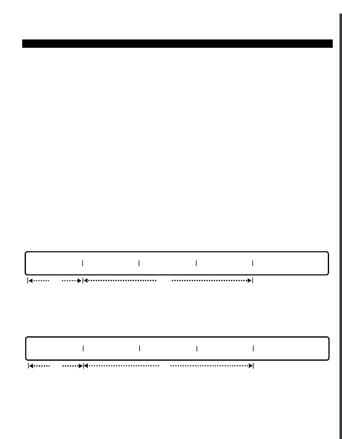
PERCEPTION 4000 COMMANDS
ACCOUNT CODE ASSIGNMENT
The Account Code Assignment command is used to display, add, or delete assigned system account codes.
Command Keyword: ACCOUNT_CODE_ASSIGN
Category Name: Station
PREREQUISITE COMMANDS
Numbering Plan Assignment CMD 300
OPERATIONS
Available operations: ADD
DELETE
DISPLAY
The function and required data fields for each operation are described as follows:
ADD
This operation is used to add account codes to the system's database table.
DELETE
ThIs operation is used to delete account codes from the system's database table. If ALL is entered in the first
field, then all account codes will be removed. Confirmation must be given prior to the removal of the account
codes.
ISS 2, SECTION 4000-014-000
ACCOUNT CODE ASSIGNMENT (CMD 348)
3-5
req
ACCOUNT CODE ACCOUNT CODE ACCOUNT CODE ACCOUNT CODE
opt
req
ACCOUNT CODE ACCOUNT CODE ACCOUNT CODE ACCOUNT CODE
opt

PERCEPTION 4000 COMMANDS
ISS 2, SECTION 4000-014-000
ACCOUNT CODE ASSIGNMENT (CMD 348)
DISPLAY
ThIs operation is used to display account codes in the database table. If <TAB> is entered in the first field, then
all account codes in the database will be displayed.
PARAMETERS
This section defines input permitted for each field. Any variations for a particular operation are noted separately.
FIELD: ACCOUNT CODE
TYPE: Decimal
FORMAT: All account codes must have the same length (length is defined in CMD 300)
VALUE: Up to a maximum of 15 digits
RANGE: Not allowed
Keyword: ALL - All account codes will be deleted (for DELETE operation only)
This field is used to add, delete, or display the system's account codes. In ADD operation, the entry of new
account codes will add them to the system database. Each entered account code must be the length assigned in
CMD 300. In DELETE operation, either specific account codes can be entered for deletion, or the keyword ALL
can be entered to delete all account codes at once. If ALL is entered, then the system will ask for a confirmation
prior to actually deleting the codes. In DISPLAY operation, a <TAB> can be entered to display all assigned
account codes, or a prefix can be entered to display a specific group of account codes. For example, to display all
account codes that begin with the numbers "20," simply enter 20 in the first "ACCOUNT CODE" field.
SYSTEM MESSAGES
The following error messages are unique to this command.
C34800 - No match
C34801 - Account code already defined
C34802 - Account code not found
C34803 - No space
C34804 - Account code's length does not agree with preassigned length (CMD 300)
C34805 - Invalid account code
I34806 - Accessing and sorting
3-6
ACCOUNT CODE ACCOUNT CODE ACCOUNT CODE ACCOUNT CODE
opt
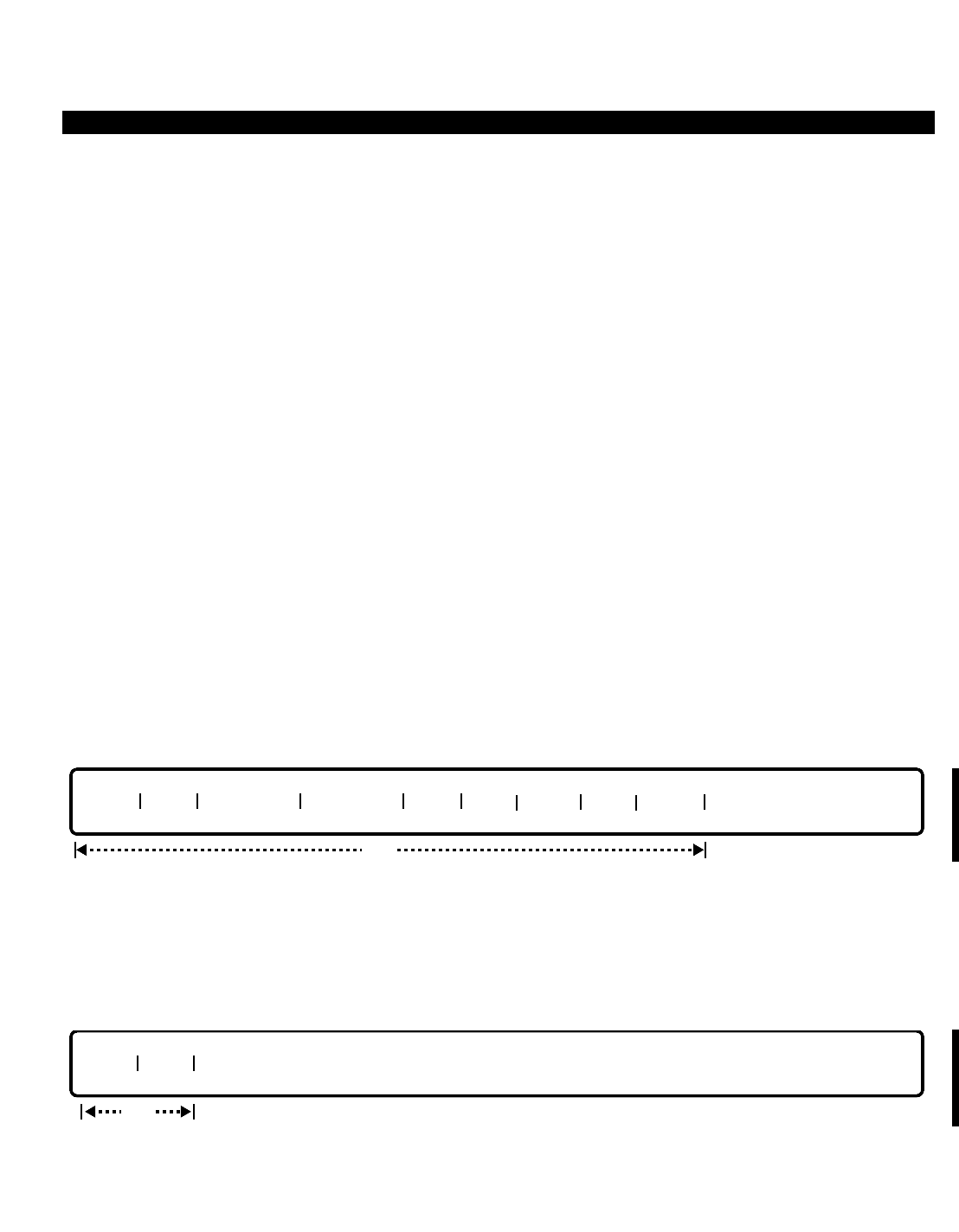
PERCEPTION 4000 COMMANDS
ACD AGENT ASSIGNMENT (CMD 356)
The ACD Agent Assignment command assigns agent ID codes and names to an Automatic Call Distribution
(ACD) group. In addition, the command defines whether the agent may perform an intra-ACD group call pickup,
and whether a given agent may be picked up by another agent in the same group.
Command Keyword: ACD_AGENT_ASSIGN
Category Name: Station
PREREQUISITE COMMAND
ACD Group Assignment (CMD 355)
OPERATIONS
Available operations: ADD
DELETE
MODIFY
DISPLAY
The function and required data fields for each operation are described in this section.
ADD
The ADD operation adds an Agent ID code, call Pick-up flag, call Picked-up flag, and Agent’s name to the
specified ACD Group Number. The COS, DRL, FRLP, and QPL fields are assigned to determine an agent’s
outgoing call placement capabilities.
DELETE
This operation deletes an Agent ID code (call Pick-up flag, call Picked-up flag, and the Agent’s name) from the
specified ACD Group Number.
req
GRP# AGT
req
GRP# AGT PU1 FLAG PU2 FLAG COS DRL FRLP QPL NAME
ISS 2, SECTION 4000-014-000
ACD AGENT ASSIGNMENT (CMD 356)
3-7
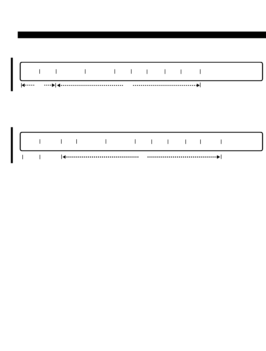
PERCEPTION 4000 COMMANDS
ISS 2, SECTION 4000-014-000
ACD AGENT ASSIGNMENT (CMD 356)
MODIFY
This operation modifies the call Pick-up flag, call Picked-up flag, and/or the Agent’s name of the specified Agent
ID and ACD Group Number.
DISPLAY
The DISPLAY operation shows the status of the Call Pick-up Flag, Call Picked-up Flag, Agent’s Name, and the
Agent ID of the ACD Group Number. The "INDEX" field is an output only field and does not accept data input.
PARAMETERS
Each field parameter is described in this section. Any variations for a particular operation are noted separately.
FIELD: GRP# (ACD Group Number)
TYPE: Decimal
FORMAT: 1 or 2 digits
VALUE: 1 to 32 (or up to maximum system configuration)
LOOP: Allowed (Primary loop for ADD and DISPLAY operations)
RANGE: Not allowed
The "GRP #", assigned by the ACD Group Assignment command (CMD 355), is required for
ADD, DELETE, and MODIFY operations. This is a loop field in DISPLAY and ADD operations. If
a <TAB> is entered in this field in a DISPLAY operation, all agents in all ACD groups are
displayed.
FIELD: AGT (Agent Identification Code)
TYPE: Decimal with fixed length / Keyword
FORMAT: 3 digits / Predefined ASCII characters
VALUE: 000 to 999
LOOP: Allowed (Secondary loop for a DISPLAY operation)
RANGE: Not allowed
Keyword: ALL
This field represents the ID codes which are used for referencing each agent. The "AGT" field is
GRP# INDEX AGT PU1 FLAG PU2 FLAG COS DRL FRLP QPL NAME
opt
lockedopt
req
GRP# AGT PU1 FLAG PU2 FLAG COS DRL FRLP QPL NAME
opt
3-8

PERCEPTION 4000 COMMANDS
required for ADD, DELETE, and MODIFY operations. This is a loop field in a DISPLAY operation.
If a <TAB> is entered, any existing table of Group Numbers and Agents displays. In a DELETE
operation, if ALL is entered, all agent IDs in the specified group are removed.
FIELD: PU1 FLAG (Call Pick-up Flag One)
TYPE: Keyword
FORMAT: Predefined ASCII characters
Keywords: ALW - Pick-up is allowed
DNY - Pick-up is denied
Agents are allowed or denied access to the Intra-group Call Pickup feature with this field. "PU1
FLAG" is required in an ADD operation, and optional in MODIFY and DISPLAY operations.
FIELD: PU2 FLAG (Call Pick-up Flag Two)
TYPE: Keyword
FORMAT: Predefined ASCII characters
Keywords: ALW - Pick-up is allowed
DNY - Pick-up is denied
This field defines whether an agent's call may be picked up by another agent in the same group,
and is required for an ADD operation and optional for MODIFY and DISPLAY operations.
FIELD: COS (Agent Class of Service)
TYPE: Decimal
FORMAT: 2 digits
VALUE: 1 to 64
RANGE: Allowed for DISPLAY operation only
LOOP: Not allowed
This field should be defined when a new agent is added, by using the ADD operation. If no value
is entered in this field, then the default value of 64 will be assigned.
FIELD: DRL (Agent Destination Restriction Level)
TYPE: Decimal
FORMAT: 2 digits
VALUE: 1 to 16 (or up to maximum system configuration)
RANGE: Allowed for DISPLAY operation only
LOOP: Not allowed
This field should be defined when a new agent is added, by using the ADD operation. If no value
is entered in this field, then the default value of 16 will be assigned.
FIELD: FRLP (Agent Facility Restriction Level Profile)
TYPE: Decimal
FORMAT: 2 digits
VALUE: 1 to 32 (or up to maximum system configuration)
RANGE: Allowed for DISPLAY operation only
LOOP: Not allowed
ISS 2, SECTION 4000-014-000
ACD AGENT ASSIGNMENT (CMD 356)
3-9

PERCEPTION 4000 COMMANDS
ISS 2, SECTION 4000-014-000
ACD AGENT ASSIGNMENT (CMD 356)
This field should be defined when a new agent is added, by using the ADD operation. If no value
is entered in this field, then the default value of 32 will be assigned.
FIELD: QPL (Agent Queue Priority Level)
TYPE: Decimal
FORMAT: 1 digit
VALUE: 1 to 8
RANGE: Allowed for DISPLAY operation only
LOOP: Not allowed
This field should be defined when a new agent is added, by using the ADD operation. If no value
is entered in this field, then the default value of 8 will be assigned.
FIELD: NAME (Agent Name)
TYPE: Text
FORMAT: 0 to 9 ASCII characters (including spaces and punctuation)
Each agent ID code may be assigned an agent name which appears on displays and reports.
This field is required for an ADD operation, and is optional for MODIFY and DISPLAY operations.
FIELD: INDEX (Index Number)
TYPE: Decimal (Output only)
FORMAT: 1 to 3 digits
VALUE: 1 to 128
This 'output only' field appears in a DISPLAY operation only and is for the convenience of the
M&A supervisor. The number acts as a counter, its value does not indicate an actual position or
set any priority for data entered in this command.
SYSTEM ERROR MESSAGES
The following error messages are unique to this command.
C35600 - Agent identification code is already assigned
C35601 - Agent identification code is not found
C35602 - Number of agents exceeds the configured allowance
C35603 - Group number’s LCPU number is not defined
C35604 - Group number is not defined
C35605 - No agent identification code was assigned in ACD group
C35606 - Agent identification code is still login
C35607 - Cannot delete group; member(s) are still login
3-10
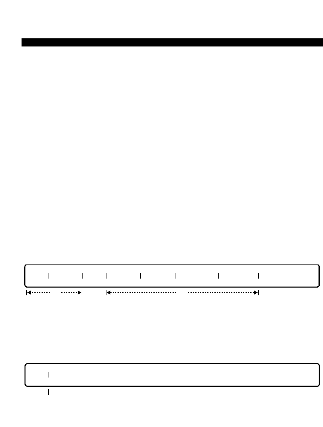
PERCEPTION 4000 COMMANDS
ACD GROUP ASSIGNMENT (CMD 355)
The Automatic Call Distribution (ACD) Group Assignment command defines various ACD group attributes as well
as provides the system with information about group and queue size so memory may be allocated. Up to 32 ACD
groups may be assigned in the system.
Command Keyword: ACD_GROUP_ASSIGN
Category Name: Station
PREREQUISITE COMMANDS
There are no prerequisites for this command.
OPERATIONS
Available operations: ADD
DELETE
MODIFY
DISPLAY
The function and required data fields for each operation are described as follows:
ADD
This operation adds an ACD group and specifies several group attributes. Except for the "NAME", all of the
attributes are required when defining a new group. The "PILOT DN" is a unique number which must not conflict
with any other numbering plan in the system. Looping is permitted for the "GRP#" field since the ADD operation
has the 'interactive mode' feature. Various fields can be entered interactively.
DELETE
This operation deletes an ACD group which has already been defined in the system. The "GRP#" field is
required. After entering this field, a confirmation message is given before deletion of the group. Looping is
allowed for this field. A DELETE operation is available only when the group is in after-shift mode.
req
GRP#
req
GRP# PILOT DN NAME SUP PWD GRP MON MAX TERMS MAX CALLS
reqopt
ISS 2, SECTION 4000-014-000
ACD GROUP ASSIGNMENT (CMD 355)
3-11
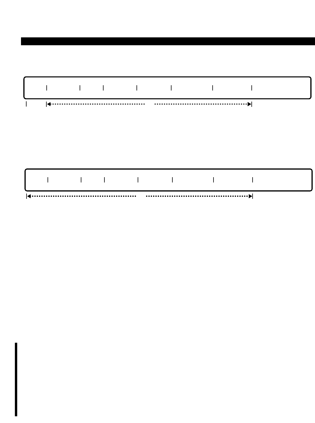
PERCEPTION 4000 COMMANDS
ISS 2, SECTION 4000-014-000
ACD GROUP ASSIGNMENT (CMD 355)
MODIFY
This operation modifies the attributes of an ACD group. "GRP#" is the only required field and can be specified in
ranges. The remaining fields are optional and do not accept range input. At least one of the optional fields must
be entered to perform a MODIFY operation.
DISPLAY
This operation displays ACD group attributes that are related to this command. Looping is allowed in the "GRP#"
field and ranges are permitted in the "MAX TERMS" and "MAX CALLS" fields. If a <TAB> is entered in the first
field, all of the ACD groups along with their attributes are displayed.
PARAMETERS
Each field parameter is described in this section. Any variations for a particular operation are noted separately.
FIELD: GRP# (ACD Group Number)
TYPE: Decimal
FORMAT: 1 or 2 digits
VALUE: 1 to 32 (or to the maximum system configuration)
LOOP: Allowed in ADD, DELETE, and DISPLAY operations
This field defines the ACD group number and is required for ADD, DELETE, and MODIFY
operations. Values are from 1 to 32. If a <TAB> is entered for this field in a DISPLAY operation,
the existing table of Group Numbers displays.
When assigning ACD group numbers, it is important to note the relationship between these
numbers and the PERCEPTION 4000 System’s Local Central Processing Units (LCPUs). The
correct assignment of these numbers will help ensure that ACD calls are not dropped when a
system is equipped with redundant processing and a system switchover occurs.
ACD agent stations are installed in the system via the Station Assignment command (CMD 330).
After a station has been installed, it has an identifying equipment number (e.g., 40108), indicating
the Modular Line/Trunk Unit (4), the card slot (01), and the circuit (08) to which it is assigned. A
station’s assigned equipment number determines the LCPU (1 ~ 3) which controls it, since each
LCPU in the system controls specific Modular Line/Trunk Units (shelves). This relationship is
detailed in the following table:
GRP# PILOT DN NAME SUP PWD GRP MON MAX TERMS MAX CALLS
opt
req
GRP# PILOT DN NAME SUP PWD GRP MON MAX TERMS MAX CALLS
opt
3-12
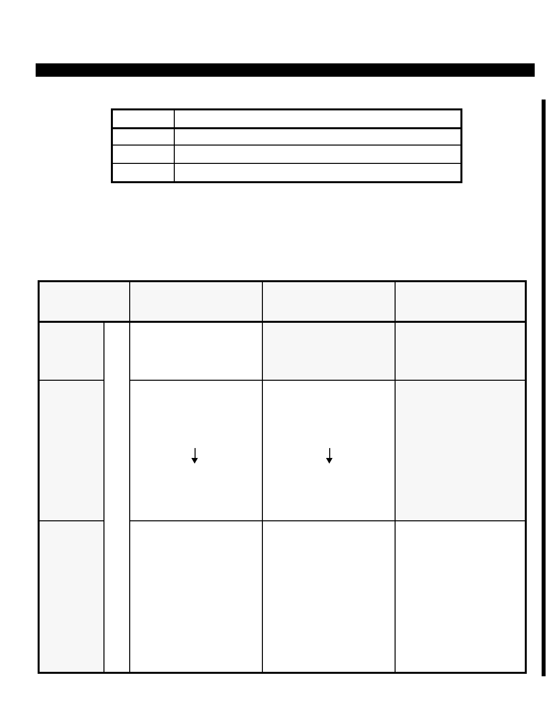
PERCEPTION 4000 COMMANDS
ISS 2, SECTION 4000-014-000
ACD GROUP ASSIGNMENT (CMD 355)
3-13
The number of LCPUs used in a system determines how various ACD groups are supported.
Each agent station must be assigned to an ACD group that is supported by the agent station’s
own LCPU. The agent station’s equipment number (identifying shelf number) must correlate with
its supportive LCPU and its assigned agent group number. The relationship between LCPUs,
ACD groups, and shelves is as follows:
LCPU(X) Modular Line/Trunk Units (Shelves) Controlled by LCPU(X)
1 1 ~ 4
2 5 ~ 8
3 9 ~ 10
System
Size
LCPU1
Shelves Supported:
1 ~ 4
LCPU2
Shelves Supported:
5 ~ 8
LCPU3
Shelves Supported:
9 ~ 10
1 LCPU
System
ACD Groups Supported:
1 ~ 32
(All groups are supported
by LCPU1)
ACD Groups Supported:
1
3
5
7
31
(All odd-numbered
groups are supported
by LCPU2)
ACD Groups Supported:
1
4
7
10
13
16
19
22
25
28
31
ACD Groups Supported:
2
4
6
8
32
(All even-numbered
groups are supported
by LCPU2)
ACD Groups Supported:
2
5
8
11
14
17
20
23
26
29
32
ACD Groups Supported:
3
6
9
12
15
18
21
24
27
30
2 LCPU
System
3 LCPU
System
ACD AGENT GROUP SUPPORT ALLOCATION

PERCEPTION 4000 COMMANDS
ISS 2, SECTION 4000-014-000
ACD GROUP ASSIGNMENT (CMD 355)
The following three examples should help illustrate the relationship between LCPUs, ACD
groups, and agent station equipment numbers (shelves).
EXAMPLE 1: ■Agent station’s equipment number = 40108
■Number of LCPUs in system = 1
■(Station is supported by LCPU1)
■Assign agent station to any ACD group 1 ~ 32.
EXAMPLE 2: ■Agent station’s equipment number = 40108
■Number of LCPUs in system = 2
■(Station is supported by LCPU1)
■Assign agent station to any odd-numbered ACD group 1 ~ 31.
EXAMPLE 3: ■Agent station’s equipment number = 40108
■Number of LCPUs in system = 3
■(Station is supported by LCPU1)
■Assign agent station to ACD group number 1, 4, 7, 10, 13, 16, 19, 22,
25, 28, or 31.
FIELD: PILOT DN (Pilot Directory Number)
TYPE: DN Type
FORMAT: 1 to 5 digits
VALUE: 0 to 99999
LOOP: Not allowed
RANGE: Not allowed
The ACD group pilot number is defined with this field. This is the only entry point into the ACD
group. The number must not conflict with other numbers and access codes in the system's
numbering plan, and must not have a physical device counterpart.
FIELD: NAME (Group Name)
TYPE: Text
FORMAT: 0 to 9 ASCII characters
An optional group name may be assigned to each ACD group. This name is displayed by the
internal calling party (if display equipped) and may be up to nine alphanumeric ASCII characters
in length. Embedded spaces are allowed.
FIELD: SUP PWD (Supervisor Password)
TYPE: Dialing Digits
FORMAT: 1 to 8 digits
VALUE: 0 to 99999999
LOOP: Not allowed
RANGE: Not allowed
Each ACD group may be configured with an ACD supervisor. Generally, the supervisor monitors
and assists agents via his/her telephone. The "SUP PWD" field defines the password the
supervisor must enter when logging into the ACD group.
3-14

PERCEPTION 4000 COMMANDS
FIELD: GRP MON (Supervisor Intergroup Monitor Flag)
TYPE: Keyword
FORMAT: Predefined ASCII characters
Keywords: YES - Supervisor intergroup monitor feature enabled
NO - Supervisor intergroup monitor feature disabled
A supervisor is allowed to monitor agents in other groups. This capability provides the supervisor
with a listen-only path. An optional low warning tone can be provided to the agent-side of the call
only if defined so in the system database (refer to the System Option Flag Assignment command,
CMD 408).
FIELD: MAX TERMS (Maximum Number of Agent Terminals)
TYPE: Decimal
FORMAT: 1 or 2 digits
VALUE: 1 to 64 (or to the maximum system configuration)
LOOP: Not allowed
RANGE: Allowed in a DISPLAY operation only
This field, along with the next field (MAX CALLS), allocates memory for the ACD group. The
"MAX TERMS" field sets the upper limit for the number of agents that belong to the group.
FIELD: MAX CALLS (Maximum Number of Calls Handled Simultaneously)
TYPE: Decimal
FORMAT: 1 to 3 digits
VALUE: 1 to 100
LOOP: Not allowed
RANGE: Allowed in a DISPLAY operation only
This field defines the number of calls that may be handled by a group (including queued, ringing,
and connected calls).
SYSTEM ERROR MESSAGES
The following error messages are unique to this command.
C35500 - ACD Group is already defined
C35501 - ACD Group is not defined
C35502 - Pilot directory number conflicts with another DN or access code
C35503 - Check value of maximum calls
C35504 - Not enough free LDNs
C35505 - Number of active calls exceeds allowable maximum
C35506 - Some agents are still active/login; wait and try again later
C35507 - Agent(s) are login but in unavailable mode; try again later
C35508 - Supervisor password digits can only be 0 - 9
C35509 - Check input in fields 2 through 7
D35510 - Add customer group DB failed in LCPU
D35511 - Change password failed in LCPU
D35512 - Change monitor flag failed in LCPU
D35513 - Change maximum terminal failed in LCPU
ISS 2, SECTION 4000-014-000
ACD GROUP ASSIGNMENT (CMD 355)
3-15

PERCEPTION 4000 COMMANDS
ISS 2, SECTION 4000-014-000
ACD GROUP ASSIGNMENT (CMD 355)
D35514 - Add group/supervisor LDN failed in LCPU
D35515 - Not enough space to add agent LDNs in LCPU
D35516 - Write pilot DN failed in LCPU
D35517 - Write group to LCPU mapping failed in LCPU
D35518 - Remove agent LDN failed in LCPU
D35519 - Remove pilot DN failed in LCPU
C35520 - Supervisor is still active/logged in
C35521 - Supervisor/Agents are still active/logged in
COMMENTS
A DELETE operation in this command removes all data input through the ACD Agent Assignment command
(CMD 356) and the ACD Group Parameter Assignment command (CMD 357).
RELATED COMMANDS
ACD Agent Assignment (CMD 356)
ACD Group Parameter Assignment (CMD 357)
Authorization Code Assignment (CMD 349)
Internal Call Alternate Routing Assignment (CMD 374)
Station Hunting Assignment (CMD 342)
System Option Flag Assignment (CMD 408)
Trunk Group Routing Assignment (CMD 307)
Trunk Routing Assignment (CMD 308)
3-16

PERCEPTION 4000 COMMANDS
ACD GROUP PARAMETER ASSIGNMENT (CMD 357)
The ACD Group Parameter Assignment command provides numerous ACD group-related information to the
system.
Command Keyword: ACD_PARAMETERS
Category Name: Station
PREREQUISITE COMMAND
ACD Group Assignment (355)
If data is entered in the "DAY DEST" and/or "NIT DEST" fields, then an appropriate command may be
required for assignment of the ACD group, UCD group, or voice directory number:
Attendant Group Assignment (CMD 372)
Attendant Position Assignment (CMD 370)
Station Hunting Assignment (CMD 342)
UCD Group Assignment (CMD 354)
If data is entered in the "AP#" field, the following command are required:
Announcement Pattern Assignment (CMD 353)
Miscellaneous Device Assignment (CMD 400)
OPERATIONS
Available operations: MODIFY
DISPLAY
The function and required data fields for each operation are described as follows:
MODIFY
This operation modifies the attributes of the specified ACD group. "GRP#" is a required field, while all remaining
fields are optional.
opt req
GRP# DAY DEST NIT DEST ALM TON ALM ON ALM OFF INT FLG AP# WRK TMR
ISS 2, SECTION 4000-014-000
ACD GROUP PARAMETER ASSIGNMENT (CMD 357)
3-17

PERCEPTION 4000 COMMANDS
ISS 2, SECTION 4000-014-000
ACD GROUP PARAMETER ASSIGNMENT (CMD 357)
DISPLAY
This operation displays the attributes of the specified ACD group. All fields are optional.
PARAMETERS
Each field parameter is described in this section. Any variations for a particular operation are noted separately.
FIELD: GRP# (ACD Group Number)
TYPE: Decimal
FORMAT: 1 or 2 digits
VALUE: 1 to 32 (or to the maximum system configuration)
LOOP: Allowed in a DISPLAY operation only
The ACD group number is assigned with the ACD Group Assignment command (CMD 355). In
this command (CMD 357), the group number serves as the primary key for the attributes defined
in the following fields. In a DISPLAY operation, "GRP#" is a loop field. If a <TAB> is entered, all
groups in the system display.
FIELD: DAY DEST (Daytime Overflow Destination)
TYPE: DN Type
FORMAT: 1 to 5 digits
VALUE: 0 to 99999
This field provides the directory number of the ACD or UCD group to which calls will overflow.
This field must be another ACD or UCD group.
FIELD: NIT DEST (Nighttime Overflow Destination)
TYPE: DN Type
FORMAT: 1 to 5 digits
VALUE: 0 to 99999
This field determines where the call overflows to if the ACD group is in NIGHT (after shift) mode.
This destination can be any legal voice directory number in the system.
FIELD: ALM TON (Audible Indication of Queue-size Alarm)
TYPE: Keyword
FORMAT: Predefined ASCII characters
DEFAULT: NO
Keywords: YES - Audible Alarm Indicator enabled
NO - Audible Alarm Indicator disabled
The ACD group may produce audible and visual alarms at the supervisor's station if enabled in
opt
GRP# DAY DEST NIT DEST ALM TON ALM ON ALM OFF INT FLG AP# WRK TMR
3-18

PERCEPTION 4000 COMMANDS
the "ALM TON" field. When set to YES, an audible alarm goes off when a certain queue size is
exceeded. In addition, the LED associated with the supervisor's <ALARM> flexible feature key
lights up when an alarm condition occurs. Pressing the <ALARM> key disables the audible
alarm, but continues to display the LED indication until the queue size drops below a lower
threshold setting. If the audible alarm is not shut off by the supervisor, the alarm would continue
until the lower threshold was met. If this field is set to NO, the LED indication is still provided by
the system.
FIELD: ALM ON (Queue-size Threshold to Turn the Alarm On)
TYPE: Decimal
FORMAT: 1 to 3 digits
VALUE: 1 to 100
DEFAULT: 0
This field determines the upper threshold which must be passed to cause an alarm. The value
entered (1 to 100) indicates the number of calls waiting in queue that will cause an alarm
condition. Note that this field must not exceed the value entered in the "MAX CALLS" field in the
ACD Group Assignment command (CMD 355). The "ALM ON" field can be deleted by pressing
<CONTROL-D> in a MODIFY operation.
FIELD: ALM OFF (Queue-size Threshold to Turn the Alarm Off)
TYPE: Decimal
FORMAT: 1 to 3 digits
VALUE: 1 to 100
DEFAULT: 0
This field sets the lower threshold which must be met to turn off the queue-size alarm. The value
entered must be low enough as to not allow the alarm to be enabled and disabled quickly on a
continuing basis. Call holding time, work time, and the number of agents should be configured
when determining the alarm threshold levels. The "ALM OFF" field can be deleted by pressing
<CONTROL-D> in a MODIFY operation.
FIELD: INT FLG (Internal Call Restriction Flag)
TYPE: Keyword
FORMAT: Predefined ASCII characters
DEFAULT: ALW
Keywords: ALW - Internal calls are allowed to the ACD group
DNY - Internal calls are denied to the ACD group
This flag determines whether internal calls and internal call transfers are permitted to a given
ACD group. If set to DNY, only direct trunk calls or those calls transferred by the attendant are
allowed to enter the ACD group.
FIELD: AP# (Announcement Pattern Number)
TYPE: Decimal
FORMAT: 1 or 2 digits
VALUE: 1 to 50
DEFAULT: 1
ISS 2, SECTION 4000-014-000
ACD GROUP PARAMETER ASSIGNMENT (CMD 357)
3-19

PERCEPTION 4000 COMMANDS
ISS 2, SECTION 4000-014-000
ACD GROUP PARAMETER ASSIGNMENT (CMD 357)
This field defines which announcement pattern will be used by this ACD group for calls which are
being held in queue (refer to the Announcement Pattern Assignment command, CMD 353). The
pattern defines what announcements, music, etc. are presented to a caller waiting in queue for
the next available ACD agent.
FIELD: WRK TMR (After Call Work Timer)
TYPE: Decimal
FORMAT: 1 to 3 digits
VALUE: 0 to 255 (seconds)
DEFAULT: 0
This field assigns the number of seconds the system waits immediately following the end of an
ACD call before presenting another waiting call to the ACD agent. By holding the next call, the
system provides the agent with free time to fill out forms and perform paperwork associated with
each call. During this period the agent is unavailable for calls. This period is referred to as 'work
time'. If work time is not desired, this timer should be set to zero.
SYSTEM ERROR MESSAGES
The following error messages are unique to this command.
C35700 - Check ACD group number
C35701 - Check day time overflow destination
C35702 - Check night time overflow destination
C35703 - Alarm-on Q-size exceeds the allowable maximum
C35704 - Alarm-off Q-size exceeds the allowable maximum
C35705 - Alarm-on value should be greater than Alarm-off value
C35706 - Announcement pattern number is not defined
C35707 - Announcement pattern is not for ACD use
RELATED COMMANDS
Miscellaneous Device Assignment (CMD 400)
Station Feature Key Assignment (CMD 331)
3-20

PERCEPTION 4000 COMMANDS
ACD STATUS DISPLAY AND REMOTE LOGOUT (CMD 358)
The ACD Status Display and Remote Logout command allows an ACD supervisor to display logged-in
information about one or more ACD agents or ACD supervisors. Logged-in agent information that is displayed
includes the agent's name, identification code, ACD group number, logged-in location (the prime directory number
and station equipment number of the utilized station), key method (dedicated or traveling), and current status
(idle, busy, or logout pending). Logged-in supervisor information includes the supervisor's ACD group number,
prime directory number, station location, and current status.
This command also allows an ACD supervisor to remotely logout one or more ACD agents. The remote logout
operation can be performed regardless of the agent's current status. If remote logout is performed while an agent
is busy, then the logout will not take effect (is pending) until the busy status ends.
Command Keyword: ACD_DISP_LOGOUT
Category Name: ACD
PREREQUISITE COMMANDS
ACD Group Assignment (CMD 355)
ACD Agent Assignment (CMD 356)
OPERATIONS
Available operations:
DISPLAY
LOGOUT
The function and required data fields for each operation are described as follows:
DISPLAY
This operation is used to display logged-in information about one or more ACD agents or ACD supervisors.
Display information applies only to logged-in agents and supervisors; no data is displayed for those
agents/supervisors who are not currently logged in. The "TYPE" field in this operation is required. If a <TAB> is
entered in the "GRP" field, information regarding all logged-in agents and or supervisors will be displayed.
req
TYPE GRP# AGT NAME PRM DN EQUIP# DED/TRA STATUS
opt
ISS 2, SECTION 4000-014-000
ACD STATUS DISPLAY AND REMOTE LOGOUT (CMD 358)
3-21
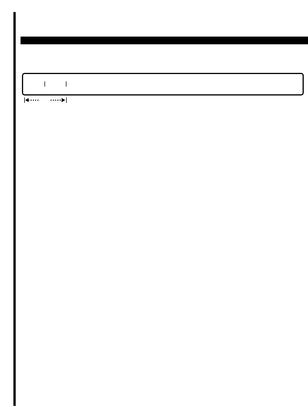
PERCEPTION 4000 COMMANDS
ISS 2, SECTION 4000-014-000
ACD STATUS DISPLAY AND REMOTE LOGOUT (CMD 358)
LOGOUT
ThIs operation is used to logout a specific ACD agent or all agents contained in an ACD group. If the keyword
ALL is entered in the "AGT" field, all agents in the specified group will be logged out.
PARAMETERS
This section defines input permitted for each field. Any variations for a particular operation are noted separately.
FIELD: TYPE
TYPE: Keyword
FORMAT: Preassigned ASCII characters
Keyword: AGT - Agent type
SUP - Supervisor type
BOTH - Both agent and supervisor types
The "TYPE" field is used for DISPLAY operation only. By entering the appropriate keyword, all currently logged-in
ACD agents and/or supervisors will be displayed.
FIELD: GRP# (ACD Group Number)
TYPE: Decimal
FORMAT: 1 or 2 digits
VALUE: 1 - 32 (based on system configuration)
RANGE: Not allowed
LOOP: Not Allowed
The "GRP#" field is required to perform ACD agent or supervisor logout operation.
FIELD: AGT (Agent Identification Code)
TYPE: Decimal
FORMAT: 3 digits
VALUE: 000 - 999
RANGE: Not allowed
LOOP: Allowed in DISPLAY operation only
The "AGT" field is required to perform remote logout. In the DISPLAY operation, the "AGT" field does not apply
when "TYPE" is assigned as supervisor (SUP).
FIELD: NAME
TYPE: Text
FORMAT: 0 - 9 characters in length, including spaces and punctuation
The "NAME" field applies only in the DISPLAY operation when "TYPE" has been assigned as agent (AGT). This
GRP# AGT#
req
3-22

PERCEPTION 4000 COMMANDS
field does not apply when "TYPE" has been assigned as supervisor (SUP).
FIELD: PRM DN (Prime Directory Number)
TYPE: Decimal
FORMAT: 1 or 5 digits
VALUE: 000 - 999
RANGE: Allowed in DISPLAY operation only
This field indicates the prime directory number of the station at which the ACD agent or ACD supervisor is
currently logged in.
FIELD: EQUIP# (Equipment number of station at which agent/supervisor is logged in)
TYPE: Decimal
FORMAT: 1 or 2 digits
VALUE: 10101 to 101416
RANGE: Allowed in DISPLAY operation only
LOOP: Not Allowed
This field indicates the equipment number of the station at which that ACD agent or ACD supervisor is currently
logged in. The first one or two digits of the displayed equipment number represent the shelf number; the second
two digits represent the card slot number; and the last two digits represent the circuit number on the utilized
circuit card.
FIELD: DED/TRA (Key Method—Dedicated/Traveling)
TYPE: Keyword
FORMAT: Preassigned ASCII characters
Keyword: DED - Agent used the LOG key on the station to login
TRA - Agent used the prime line key and the ACD access code to login
This field does not apply in the DISPLAY operation when 'TYPE" has been assigned as supervisor (SUP).
FIELD: STATUS (Logged-in Status)
TYPE: Keyword
FORMAT: Preassigned ASCII characters
Keyword: IDLE - Available or unavailable
BUSY - Talking or in After Call Work mode
PEND - Logout Pending
This field indicates the current status of the logged-in ACD agent or supervisor station.
SYSTEM MESSAGES
The following error messages are unique to this command.
C35801 - Group number is not defined
C35802 - Agent identification number is not found
C35803 - Agent has logged out
C35804 - Supervisor is not found
ISS 2, SECTION 4000-014-000
ACD STATUS DISPLAY AND REMOTE LOGOUT (CMD 358)
3-23

PERCEPTION 4000 COMMANDS
ISS 2, SECTION 4000-014-000
ACD STATUS DISPLAY AND REMOTE LOGOUT (CMD 358)
C35805 - Failed to read prime directory number
C35806 - Failed to read device number
C35807 - Failed to read supervisor LDN
C35808 - Failed to read supervisor STN
C35809 - Agent is not logged in
3-24

PERCEPTION 4000 COMMANDS
ALARM/FAULT DISPLAY AND RESET (CMD 160)
The Alarm/Fault Display and Reset command displays the current status of alarm indicators (red, green and
orange LEDs) on the system panel, displays the current and/or previous system fault/alarm peg count buffer(s),
and resets the peg count buffer. The status of these alarm indicators is either ON or OFF which indicates whether
or not the system is operating under normal conditions. Faults that cause an alarm to be turned ON can be
viewed by this command. Alarm indicators can also be reset with this command.
The system maintains two buffers, one for the current time period and the other for the previous period. These
buffers keep peg counts of the faults on every severity level, up to the maximum of 32 levels. An alarm turns ON if
a corresponding fault is encountered. Once an alarm is turned ON, it remains ON until the fault is recovered or a
switch-over operation takes place.
Command Keyword: ALM/FAULT_DISP/RESET
Category Name: Fault
PREREQUISITE COMMANDS
There are no prerequisites for this command.
OPERATIONS
Available operations: ALARMS
RESET
COUNTS
The function and required data fields for each operation are described in this section.
ALARMS
This operation displays the current status of seven alarm indicators on the system panel. The status of these
alarm indicators is either ON or OFF indicating whether or not the system is operating under normal conditions.
No input data is required; all of the fields are used for output only. A <TAB> must be entered to activate this
operation.
RESET
A RESET operation performs the following functions:
■Time stamps the current system date and time indicating the end of the current peg-count buffer.
■Copies the current buffer to the previous buffer.
output only
NORM MJ-1 MJ-2 MN RMC TEMP PFT
ISS 2, SECTION 4000-014-000
ALARM/FAULT DISPLAY AND RESET (CMD 160)
3-25
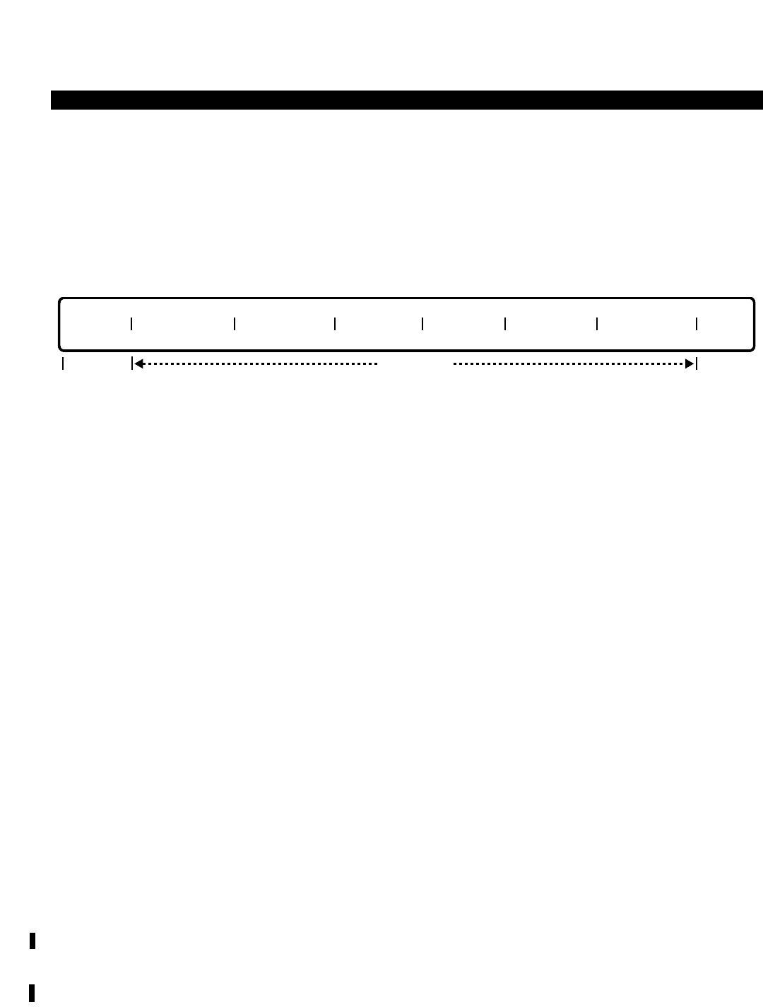
PERCEPTION 4000 COMMANDS
ISS 2, SECTION 4000-014-000
ALARM/FAULT DISPLAY AND RESET (CMD 160)
■Clears the current buffer.
■Time stamps the current buffer indicating the beginning of a new peg-count.
No header is provided, and no input data is required. However, a <TAB> must be entered to activate this
operation.
COUNTS
This operation displays the current and/or previous system fault/alarm peg count buffer(s). Input of the
Current/Previous Buffer field is optional. When both buffers are to be displayed, enter a <TAB> and/or press
<RETURN>. To display a specific buffer, enter a valid keyword (CUR for the Current buffer and PRE for the
Previous buffer). The remaining fields are output fields only.
PARAMETERS
Each field parameter is described in this section. Any variations for a particular operation are noted separately.
FIELD: NORM (System Operation Status)
TYPE: Output only (either ON or OFF)
LED: Green
When this alarm is ON, the system is operating under normal conditions. When OFF, the system
is in off-line mode, or a fault has occurred.
FIELD: MJ-1 (Major Alarm One)
TYPE: Output only (either ON or OFF)
LED: Red
If this alarm is ON, it indicates that a critical external condition has occurred. If a Power,
Emergency, or Temperature alarm turns ON, this indicator turns ON also.
FIELD: MJ-2 (Major Alarm Two)
TYPE: Output only (either ON or OFF)
LED: Red
This indicator turns ON if one of the following internal conditions occurs:
1. System bus timeout occurred due to the MCPU, LCPU, TSW, or disk access.
2. Watchdog timer timeout.
3. System switchover.
4. MCPU clock failure.
5. Main processor (MCPU) failure.
6. Main memory failure.
output only
BUFFER START DATE START TIME END DATE END TIME SEV LEVEL PEG COUNT
opt
3-26

PERCEPTION 4000 COMMANDS
7. Time switch failure.
8. Tone generator failure.
9. Memory space (buffer) is full and unavailable for a time period exceeding the predefined
time threshold (e.g. exceeded N minutes).
10. Shelf processor failure.
11. Shelf memory failure.
12. Data highway failure.
13. More than 33% of the TDM hiways on two shelves have failed.
14. Initial system load or automatic reload failed.
15. Handshake between the MCPU and LCPU failed.
16. Download from MCPU to LCPU failed.
17. Any kind of disk failure.
18. Communications between the MCPU and miscellaneous cards failed.
19. Application processor failure.
FIELD: MN (Minor Alarm)
TYPE: Output only (either ON or OFF)
LED: Orange
This indicator turns ON whenever one of the following conditions is encountered:
1. Control component failure - due to one of the following conditions:
■Performance of any service device is reduced below 66% of its full capacity.
■Downloading or handshaking from a PC to the terminal controller has failed.
■PC initialization has failed.
■Less than 33% of the TDM hiways on two shelves have failed.
■Memory allocation for working space (e.g. buffer or queue) has failed.
■Inconsistent data is detected.
■An unexpected interruption has occurred.
■The stack overflowed (e.g. caused by endless recursive procedure calls).
■An attempt to access memory through an invalid pointer has occurred (caused by
incorrect pointer allocation or release).
■An attempt was made to execute an invalid instruction.
2. Peripheral device failure - due to one of the following conditions:
■More than 8% but less than 33% of installed equipment of the same type on one shelf
has failed.
■More than 8% but less than 33% of installed equipment of the same type on the whole
system has failed.
3. Miscellaneous failure - due to one of the following conditions:
■An L/T shelf power unit has failed.
■A disk file is full (e.g. fault log file or change log file).
FIELD: RMC (Remote Supervision Status)
TYPE: Output only (either ON or OFF)
LED: Green
ISS 2, SECTION 4000-014-000
ALARM/FAULT DISPLAY AND RESET (CMD 160)
3-27

PERCEPTION 4000 COMMANDS
ISS 2, SECTION 4000-014-000
ALARM/FAULT DISPLAY AND RESET (CMD 160)
When the "RMC" indicator turns ON, it indicates that local/remote maintenance work is in
progress.
FIELD: TEMP (Temperature Failure Alarm)
TYPE: Output only (either ON or OFF)
LED: Red
If the cabinet temperature passes the system shut-down threshold, this indicator turns ON.
FIELD: PFT (Power Failure Transfer Alarm)
TYPE: Output only (either ON or OFF)
LED: Red
When the "PFT" indicator is OFF, the power supply is operating under normal conditions. If a
power failure transfer occurs, this indicator turns ON.
FIELD: BUFFER
TYPE: Keyword
FORMAT: Predefined ASCII characters
Keywords: CUR - Current Buffer
PRE - Previous Buffer
The Current/Previous Buffer field is an optional field. By entering a <TAB> and/or <RETURN>,
both the current and the previous buffers display.
FIELD: START DATE/TIME (Date/Time to Start Counting)
TYPE: Decimal (Output only)
FORMAT: MMDDYY HHMM
VALUE: MM is the month from 01 to 12
DD is the day from 01 to 31
YY is the year from 00 to 99
HH is the hour from 00 to 23
MM is the minute from 00 to 59
These fields contain the date and time of the system clock showing the time the specified buffer
began updating its peg-count counters. Data in these fields is used to compare with data in the
"END DATE/TIME" fields to determine the duration of the associated buffer. The "START
DATE/TIME" of the Previous Buffer is either IPL time (Initial Program Load) or the date and time
of the previous RESET operation. On the Current Buffer, however, this data is the date and time
of the most recent RESET operation. Refer to Figure 3-1 later in this section.
FIELD: END DATE/TIME (Date/Time to Stop Counting)
TYPE: Decimal (Output only)
FORMAT: MMDDYY HHMM
VALUE: MM is the month from 01 to 12
DD is the day from 01 to 31
YY is the year from 00 to 99
HH is the hour from 00 to 23
MM is the minute from 00 to 59
3-28

PERCEPTION 4000 COMMANDS
These fields contain the date and time of the system clock showing the time the specified buffer
updated its peg-count counters. Data in these fields is used to compare with data in the "START
DATE/TIME" fields to determine the duration of the associated buffer. The "END DATE/TIME" of
the Previous Buffer is the date and time of the most recent RESET operation. On the Current
Buffer, this data is the system's current date and time. Refer to Figure 3-1 later in this section.
FIELD: SEV LEVEL (Fault Severity Level)
TYPE: Decimal (Output only)
FORMAT: 1 or 2 digits
VALUE: 1 to 32
This field, which appears in a COUNTS operation only, contains the specific severity level index
number associated with each counter in the "PEG COUNT" field, and is generated automatically
by the system. Refer to the Severity Level Table later in this section.
FIELD: PEG COUNT (Count of the Corresponding Fault)
TYPE: Decimal (Output only)
Data in this field corresponds to the data in the "SEV LEVEL" field. When faults are encountered
in any of the 32 Fault Severity Levels, those faults are counted and displayed in the "PEG
COUNT" field opposite the corresponding level in the "SEV LEVEL" field. For example, if seven
faults are encountered at Severity Level 3, then the "SEV LEVEL" output would be 3 and the
"PEG COUNT" output would be 7.
Data in this field increments by one automatically when a fault is detected in the current peg-
count buffer and the associated alarm LED turns ON. This field appears in a COUNTS operation
only.
SYSTEM ERROR MESSAGES
The following error messages are unique to this command.
C16000 - Database recovered
C16001 - Alarm display request failed
C16002 - Alarm reset request failed
C16003 - Alarm reset timeout
COMMENTS
Alarm indicators on the on-premises alarm panel are turned ON whenever a corresponding alarm on the local
alarm panel is ON.
Severity Level Table
There are 32 severity levels reserved for fault messages generated by the corresponding module (maintenance,
diagnostic, operational tasks). A specific severity level number is included in each error message to describe the
error category. Following is a list of the severity levels.
ISS 2, SECTION 4000-014-000
ALARM/FAULT DISPLAY AND RESET (CMD 160)
3-29

PERCEPTION 4000 COMMANDS
ISS 2, SECTION 4000-014-000
ALARM/FAULT DISPLAY AND RESET (CMD 160)
Severity Definition
Level
001 MJ alarm turns ON when failure occurs once and executes EMA (emergency procedures)
002 MN alarm turns ON when failure occurs once and executes EMA
003 MJ alarm turns ON when failure occurs 5 times and executes EMA
004 MJ alarm turns ON when failure occurs 30 times and executes EMA
005 MJ alarm turns ON when failure occurs 40 times and executes EMA
006 MJ alarm turns ON when failure occurs 50 times and executes EMA
007 MJ alarm turns ON when failure occurs 0x7fff times and executes EMA
008 MJ alarm turns ON when failure occurs once; if it happens 5 times, then DDCC becomes
out of service
009 Both MJ and MN alarms turn ON when failure occurs once
010 MJ alarm turns ON when failure occurs once
011 Not defined
::
015 Not defined
016 MN alarm turns ON when failure occurs once and executes EMA if this failure occurs 5
times continually
017 MN alarm turns ON when failure occurs once and executes EMA if this failure occurs N
times continually
018 MN alarm turns ON when failure occurs once and MJ alarm turns ON if this failure occurs
100 times continually
019 MN alarm turns ON when failure occurs once; if it happens 5 times, then DDCC becomes
out of service
020 MN alarm turns ON when failure occurs once
021 Not defined
::
028 Not defined
029 Only failure message
030 Information message for result of some process
031 Not defined
032 Not defined
Reset Time and Fault Peg Count Buffers Format
When the system first comes up (power-on), two buffers are allocated to keep the peg count of the faults
whenever they are detected. Detected faults are kept in the current peg count buffer at the appropriate severity
level, and transferred to the previous peg count buffer whenever the fault reset is initiated by a RESET operation.
There are 32 counters associated with 32 severity levels per buffer. A RESET operation moves the current fault
peg count buffer to the previous buffer, clears the current buffer, and updates the RESET date and time for later
use to determine the duration of the Current/Previous buffer period.
3-30
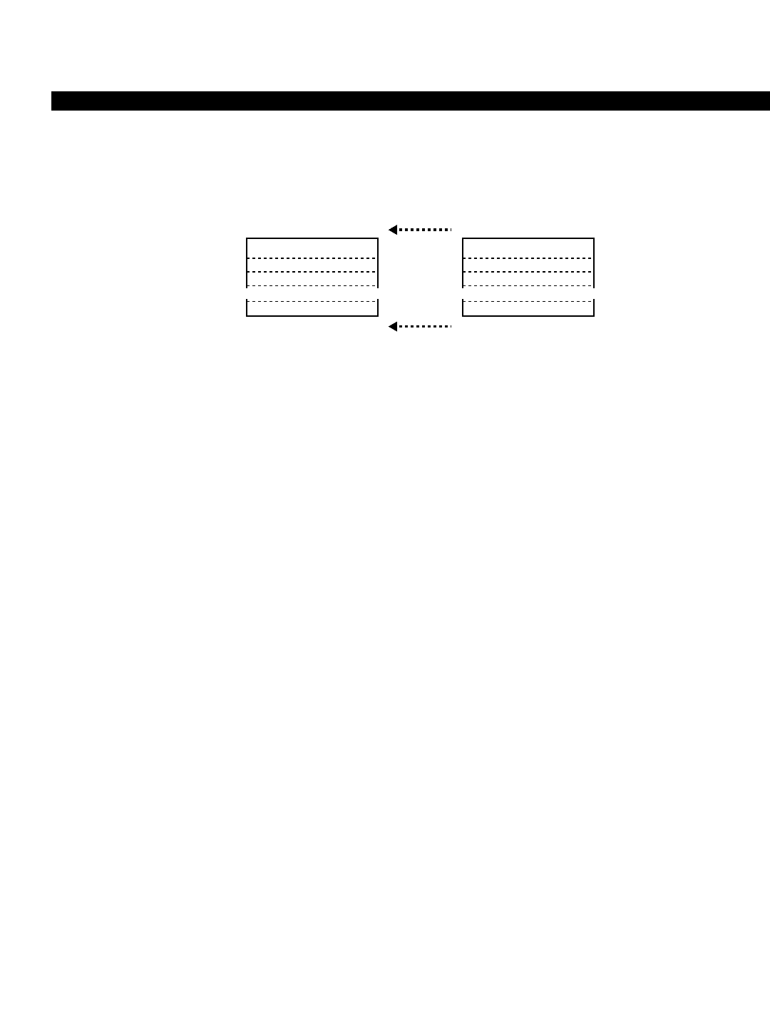
PERCEPTION 4000 COMMANDS
Figure 3-1
Previous/Current Buffers
NOTES:
1. Both the "Last" and the "Previous Reset Time" fields are the system clock at IPL time (Initial Program Load)
when the system first powers-up. All counters associated with the 32 severity levels, in both the Current
and Previous buffers, are initialized to 0.
2. When a fault is detected, the corresponding counter of the Current buffer updates (increments by 1).
3. Whenever a RESET is performed, by this command, the Current buffer moves to the Previous buffer. The
"Last Reset Time" and the system's Current Time become the "Previous Reset Time" and "Last Reset
Time" of the Previous buffer respectively.
Peg-Count Counter Size/Overflow
When a peg-count counter overflows, the buffer retains the highest count number for each severity level, the
overflow flag ignores any additional counts, and the Fault Log/Print feature receives a warning message.
PREVIOUS BUFFER CURRENT BUFFER
Previous Reset Time
Peg Counts
Last Reset Time
Sev Level 1
2
3
~
32
"
"
"
Last Reset Time
Peg Counts
Current Time
"
"
"
~~~~
ISS 2, SECTION 4000-014-000
ALARM/FAULT DISPLAY AND RESET (CMD 160)
3-31
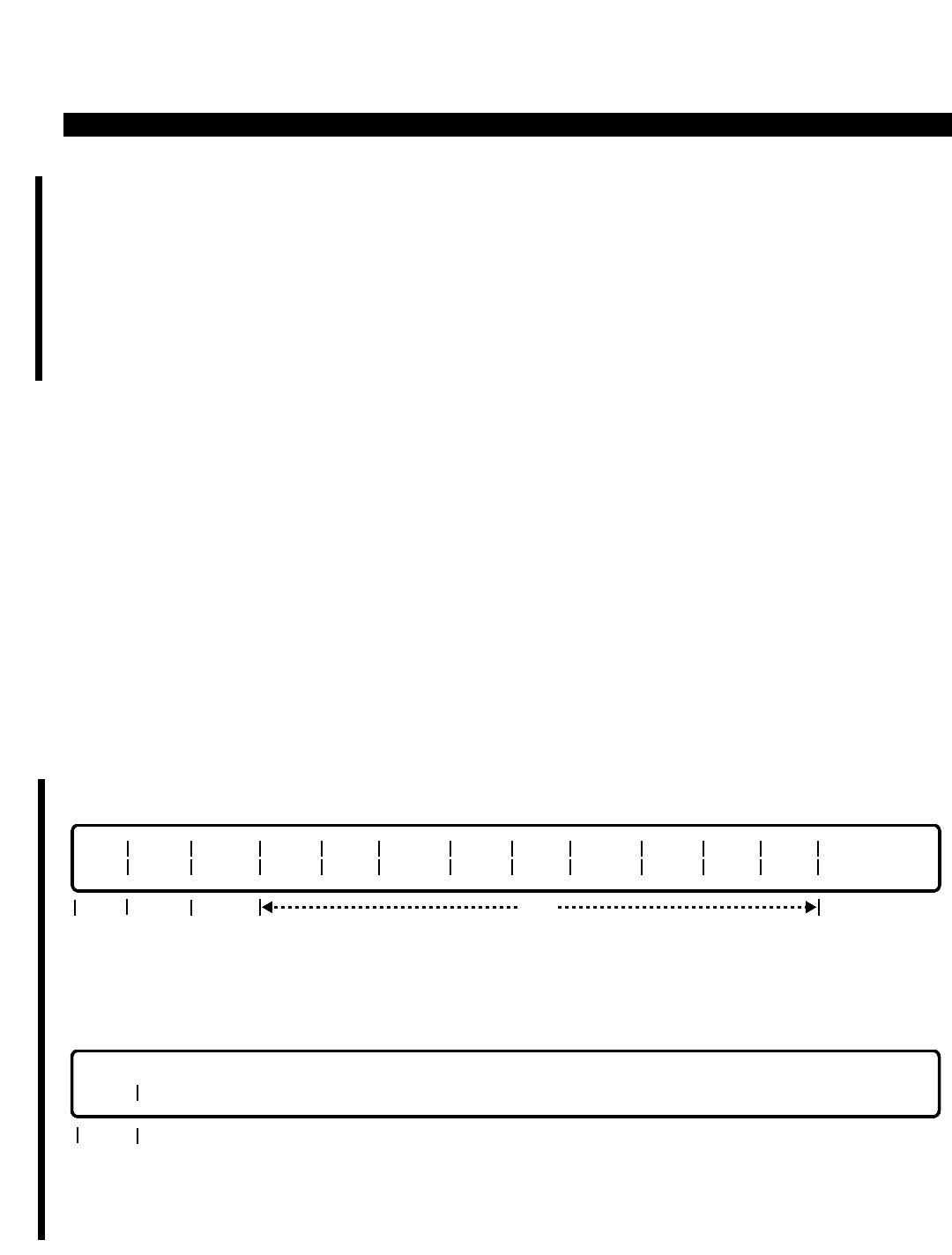
PERCEPTION 4000 COMMANDS
ISS 2, SECTION 4000-014-000
ANNOUNCEMENT PATTERN ASSIGNMENT (CMD 353)
ANNOUNCEMENT PATTERN ASSIGNMENT (CMD 353)
The Automatic Call Distribution (ACD) and Uniform Call Distribution (UCD) features both have queuing
capabilities which offer the caller the chance to hear recorded announcements and Music-on-Hold a number of
times at preset intervals and in different sequences. This capability can be tailored for each group, thereby
allowing announcements to provide caller-sensitive material. The Announcement Pattern Assignment command
(CMD 353) provides the means by which these patterns may be defined and applied to all desired groups.
Command Keyword: ANNOUNCEMENT_PAT
Category Name: Station
PREREQUISITE COMMAND
Miscellaneous Device Assignment (CMD 400)
OPERATIONS
Available operations: ADD
DELETE
MODIFY
DISPLAY
The function and required data fields for each operation are described in this section.
ADD
This operation adds announcement patterns to the system. "AP#" and "ANN 1 NUM" are required fields.
DELETE
This operation deletes an announcement pattern from the system. "AP#" is a required field.
req
AP#
optreqoptreq
AP# RING
TIME ANN 1
NUM INT1
TIME #1
CYC ANN 2
NUM INT2
TIME #2
CYC ANN 3
NUM INT3
TIME #3
CYC 2&3
CYC
3-32
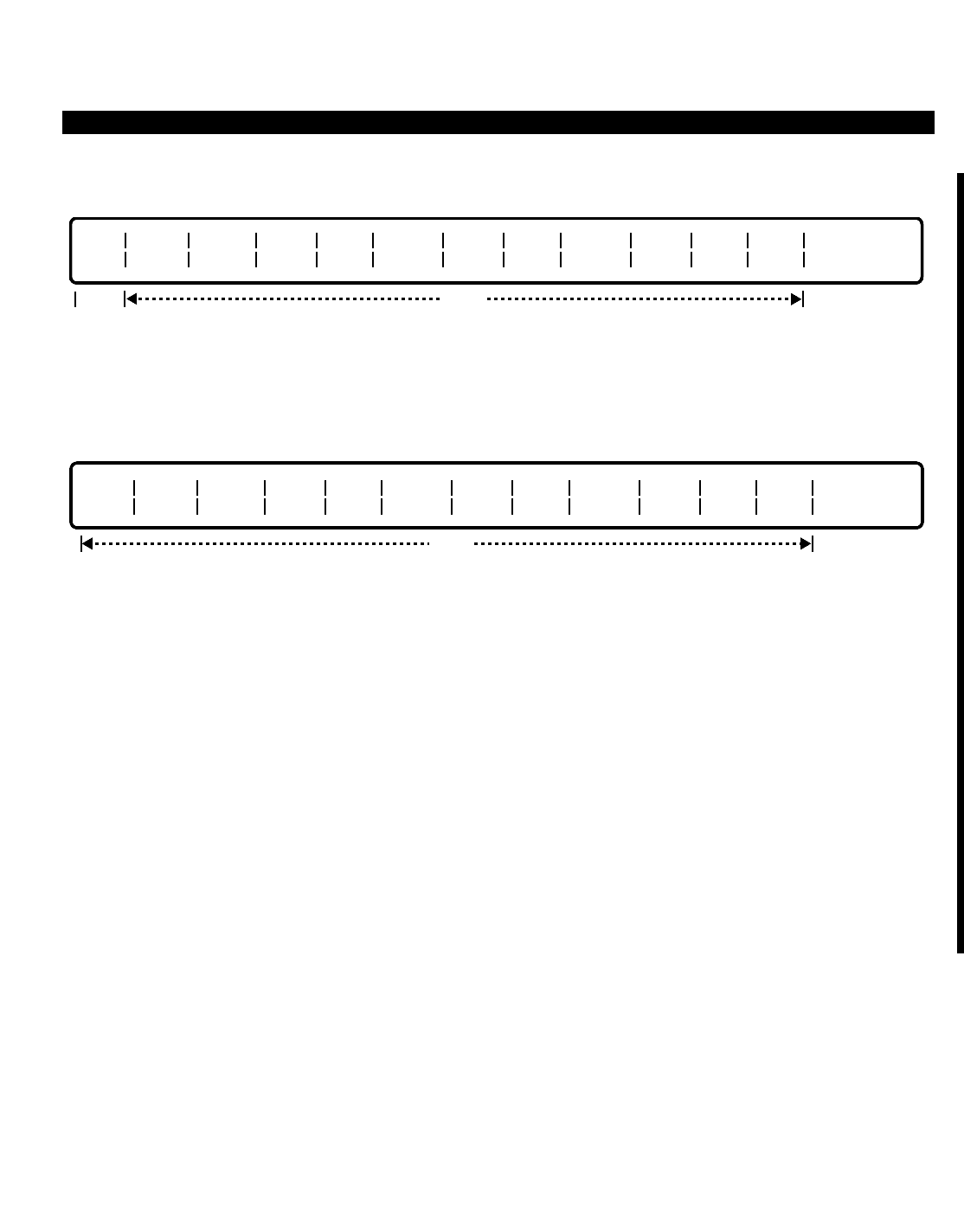
PERCEPTION 4000 COMMANDS
MODIFY
This operation modifies the attributes of an announcement pattern. "AP#" is a required field, while the remaining
fields are optional.
DISPLAY
This operation displays announcement patterns. All of the fields are optional. "AP#" is a loop field. If a <TAB> is
entered in this field, all announcement patterns are displayed.
PARAMETERS
Each field parameter is described in this section. Any variations for a particular operation are noted separately.
FIELD: AP# (Announcement Pattern Number)
TYPE: Decimal
FORMAT: 1 or 2 digits
VALUE: 1 to 50
RANGES: Not allowed
LOOP: Allowed in a DISPLAY operation only
The system supports up to 50 announcement patterns. The pattern number acts as an index
which provides linkage to ACD and UCD groups (refer to the ACD Group Parameter Assignment
command - CMD 357, and the UCD Group Assignment command - CMD 354).
FIELD: RING TIME (Length of the Ring)
TYPE: Decimal
FORMAT: 1 or 2 digits
VALUE: 1 to 60 (seconds)
RANGE: Not allowed
LOOP: Not allowed
The "RING TIME" is the length of time the caller receives ringback tone before an announcement
plays.
opt
AP# RING
TIME ANN 1
NUM INT1
TIME #1
CYC ANN 2
NUM INT2
TIME #2
CYC ANN 3
NUM INT3
TIME #3
CYC 2&3
CYC
optreq
AP# RING
TIME ANN 1
NUM INT1
TIME #1
CYC ANN 2
NUM INT2
TIME #2
CYC ANN 3
NUM INT3
TIME #3
CYC 2&3
CYC
ISS 2, SECTION 4000-014-000
ANNOUNCEMENT PATTERN ASSIGNMENT (CMD 353)
3-33

PERCEPTION 4000 COMMANDS
ISS 2, SECTION 4000-014-000
ANNOUNCEMENT PATTERN ASSIGNMENT (CMD 353)
FIELD: ANN 1 NUM (Announcement Number 1)
TYPE: Keyword
FORMAT: Predefined ASCII characters
RANGE: Not allowed
LOOP: Not allowed
Keywords: AM01 ~ AM64
This field, required in an ADD operation, defines which announcement machine will be used to
provide the first announcement.
FIELD: INT1 TIME (Interval of Time Between Announcements)
TYPE: Decimal
FORMAT: 1 to 3 digits
VALUE: 1 to 120 (seconds)
RANGE: Not allowed
LOOP: Not allowed
This field defines in seconds how long Music-on-Hold (or quiet tone if Music-on-Hold is not
provided by the system) plays before cycling back to Announcement Number 1 or proceeding on
to Announcement Number 2. The "INT1 TIME" field can be deleted by pressing <CONTROL-D>
in a MODIFY operation.
FIELD: #1 CYC (Number of Cycles of Announcement Number 1)
TYPE: Decimal
FORMAT: 1 or 2 digits
VALUE: 0 to 9 or 00 to 09
RANGE: Not allowed
LOOP: Not allowed
This field defines the number of times Announcement Number 1 is cycled. The maximum
definable number of cycles is nine. If this field is set to zero, the system cycles Announcement
Number 1 and the Interval of Time Between Announcements indefinitely. If this field is left
undefined, the announcement plays only one time.
If a definite number of cycles is defined and there is no definition for Announcement Number 2,
the system continues to keep the caller connected to Music-on-Hold or quiet tone. The "#1 CYC"
field can be deleted by pressing <CONTROL-D> in a MODIFY operation.
FIELD: ANN 2 NUM (Announcement Number 2)
TYPE: Keyword
FORMAT: Predefined ASCII characters
Keywords: AM01 ~ AM64
This field defines which announcement machine will be used to provide the second
announcement, and may only be defined if "ANN 1 NUM" is defined. The "ANN 2 NUM" field can
be deleted by pressing <CONTROL-D> in a MODIFY operation. If a delete is performed in this
field, the next two fields (INT2 TIME and #2 CYC) must also be deleted.
3-34

PERCEPTION 4000 COMMANDS
FIELD: INT2 TIME (Interval of Time Between Announcements)
TYPE: Decimal
FORMAT: 1 to 3 digits
VALUE: 1 to 120 (seconds)
RANGE: Not allowed
LOOP: Not allowed
This field defines in seconds how long Music-on-Hold (or quiet tone if Music-on-Hold is not
provided by the system) plays before cycling back to Announcement Number 2 or proceeding on
to Announcement Number 3. The "INT2 TIME" field can be deleted by pressing <CONTROL-D>
in a MODIFY operation.
FIELD: #2 CYC (Number of Cycles of Announcement Number 2)
TYPE: Decimal
FORMAT: 1 or 2 digits
VALUE: 0 to 9 or 00 to 09
RANGE: Not allowed
LOOP: Not allowed
This field defines the number of times Announcement Number 2 is cycled. The maximum
definable number of cycles is nine. If this field is set to zero, the system cycles Announcement
Number 2 and the Interval of Time Between Announcements (INT2 TIME) indefinitely. If this field
is left undefined, the announcement plays only one time.
If a definite number of cycles is defined and there is no definition for Announcement Number 3,
the system continues to keep the caller connected to Music-on-Hold or quiet tone. The "#2 CYC"
field can be deleted by pressing <CONTROL-D> in a MODIFY operation.
FIELD: ANN 3 NUM (Announcement Number 3)
TYPE: Keyword
FORMAT: Predefined ASCII characters
Keywords: AM01 ~ AM64
This field defines which announcement machine will be used to provide the third announcement,
and may only be defined if "ANN 2 NUM" was defined. The "ANN 3 NUM" field can be deleted by
pressing <CONTROL-D> in a MODIFY operation.
If this field is not entered or is to be deleted, the "INT3 TIME" and "#3 CYC" fields must not be
entered.
FIELD: INT3 TIME (Interval of Time Between Announcements)
TYPE: Decimal
FORMAT: 1 to 3 digits
VALUE: 1 to 120 (seconds)
RANGE: Not allowed
LOOP: Not allowed
ISS 2, SECTION 4000-014-000
ANNOUNCEMENT PATTERN ASSIGNMENT (CMD 353)
3-35

PERCEPTION 4000 COMMANDS
ISS 2, SECTION 4000-014-000
ANNOUNCEMENT PATTERN ASSIGNMENT (CMD 353)
This field defines in seconds how long Music-on-Hold (or quiet tone if Music-on-Hold is not
provided by the system) plays before cycling back to Announcement Number 3 or proceeding to
cycle both announcement numbers 2 and 3 again. The "INT3 TIME" field can be deleted by
pressing <CONTROL-D> in a MODIFY operation.
FIELD: #3 CYC (Number of Cycles of Announcement Number 3)
TYPE: Decimal
FORMAT: 1 or 2 digits
VALUE: 0 to 9 or 00 to 09
RANGE: Not allowed
LOOP: Not allowed
This field defines the number of times Announcement Number 3 is cycled. The maximum
definable number of cycles is nine. If this field is set to zero, the system cycles Announcement
Number 3 and the Interval of Time Between Announcements (INT3 TIME) indefinitely. If this field
is left undefined, the announcement plays only one time. The "#3 CYC" field can be deleted by
pressing <CONTROL-D> in a MODIFY operation.
FIELD: 2&3 CYC (Cycle Announcements 2 and 3)
TYPE: Decimal
FORMAT: 1 or 2 digits
VALUE: 0 to 9 or 00 to 09
RANGE: Not allowed
LOOP: Not allowed
Providing "#3 CYC" is not set for infinite cycling, this field cycles announcements 2 and 3
(including their respective music times and cycling instructions) for up to nine times or indefinitely.
If set to a defined cycle, music or quiet tone is provided indefinitely upon cycle completion. The
announcements are cycled infinitely if zero is entered.
SYSTEM ERROR MESSAGES
The following error messages are unique to this command.
C35300 - Pattern already exists
C35301 - Pattern is not defined
C35302 - Input announcement 2
C35303 - Input announcement 3
C35304 - Enter both announcements
C35305 - Deletion of announcement 2 is not allowed
C35306 - Deletion of announcement 3 is not allowed
C35307 - Delete all information regarding announcement 2
C35308 - Delete all information regarding announcement 3
C35309 - Announcement number is not defined
C35310 - Memory for patterns is at system maximum
C35311 - Number of announcement machines exceeds system maximum
3-36

PERCEPTION 4000 COMMANDS
COMMENTS
If the Announcement 1 cycle is set to zero, the remaining fields regarding Announcements 2 and 3 are ignored if
entered.
If the Announcement 2 cycle is set to zero, the remaining fields regarding Announcement 3 are ignored if entered.
If the "2&3 CYC" field is entered, both the "ANN 2 NUM" and "ANN 3 NUM" fields must be entered or in the
database.
If Announcement 2 or 3 is to be deleted, the interval time and cycle for that announcement must be deleted also.
Announcement 2 cannot be entered unless Announcement 1 is entered or already exists in the database.
Announcement 3 cannot be entered unless Announcement 2 is entered or already exists in the database.
If music is to be presented to the caller with no announcements, only the first "INT TIME" field needs to be filled in
and the "#1 CYC" field set to infinite cycling.
RELATED COMMANDS
ACD Group Assignment (CMD 355)
ACD Group Parameter Assignment (CMD 357)
DID/CCSA Trunk Group Assignment (CMD 314)
Trunk Group Routing Assignment (CMD 307)
Trunk Routing Assignment (CMD 308)
UCD Group Assignment (CMD 354)
ISS 2, SECTION 4000-014-000
ANNOUNCEMENT PATTERN ASSIGNMENT (CMD 353)
3-37

PERCEPTION 4000 COMMANDS
ISS 2, SECTION 4000-014-000
AREA CODE RESTRICTION TABLES (CMD 341)
AREA CODE RESTRICTION TABLES (CMD 341)
The Area Code Restriction Tables contain a list of area codes which may be allowed or denied depending on the
specified "TYPE". This is the means by which calling into entire area codes can be controlled. Area code tables
are defined for each Trunk Restriction Group/Destination Restriction Level combination (but not when either
"TRGN" or "DRL" = 1). Trunk Restriction Groups and DRLs are assigned through the Trunk Group Assignment
command (CMD 310).
Each table may be specified as an ALW (allow) or DNY (deny) table. This way the fewest number of codes can be
entered and accomplish the same purpose. For example, if all area codes but two are to be allowed, it is easier to
build a deny table and enter only two codes versus building an allow table and entering all but two codes.
Command Keyword: AC_RESTRICT
Category Name: Restrict
PREREQUISITE COMMANDS
There are no prerequisites for this command.
OPERATIONS
Available operations: ADD
DELETE
DISPLAY
The function and required data fields for each operation are described in this section.
ADD
This operation adds area code(s) to the Area Code Restriction table for a specific TRGN/DRL. Ranges are
permitted in the “TRGN” and “DRL” fields. The “TYPE” field can be changed only when all of the area codes are
deleted from the table.
DELETE
opt
TRGN DRL TYPE AC AC AC AC AC AC AC AC AC AC AC AC
req
opt
TRGN DRL TYPE AC AC AC AC AC AC AC AC AC AC AC AC
req
3-38

PERCEPTION 4000 COMMANDS
This operation deletes area code(s) from the Area Code Restriction table. Ranges are permitted in the “TRGN”
(or “DRL”) field when deleting the same area code in several Area Code Restriction tables.
DISPLAY
This operation displays one or more Area Code Restriction tables. Input for all of the fields is optional. If no data is
entered in any of these fields, all of the Area Code Restriction tables in the system display.
PARAMETERS
Each field parameter is described in this section. Any variations for a particular operation are noted separately.
FIELD: TRGN (Trunk Restriction Group Number)
TYPE: Decimal
FORMAT: 1 digit
VALUE: 2 to 8 (or to the maximum number of trunk groups configured in the system)
LOOP: Primary loop field, and allowed in all of the operations.
This field assigns restriction numbers to trunk groups. Note that Trunk Restriction Group 1 is
defined as “unrestricted” and recommended for TIE trunk groups and trunk interfaces to
peripheral auxiliary equipment.
FIELD: DRL (Destination Restriction Level)
TYPE: Decimal
FORMAT: 1 or 2 digits
VALUE: 2 to 16 (or to the maximum system configuration)
LOOP: Secondary loop field, and allowed in all of the operations.
When "DRL" is 1, all calls are allowed regardless of which Trunk Restriction Group Number
(TRGN) is in use. Therefore, there is no Area/Office Code Restriction table associated with it.
Refer to the Destination Restriction Level Assignment command (CMD 337) for information on
DRLs.
FIELD: TYPE (Area Code Restriction Type)
TYPE: Keyword
FORMAT: Predefined ASCII characters
Keywords: ALW - Listed area codes are allowed
DNY - Listed area codes are denied
The "TYPE" field defines whether area codes are accessible to the caller. If ALW (or DNY) is
entered, calls to the area codes listed are allowed (or denied).
opt
TRGN DRL TYPE AC AC AC AC AC AC AC AC AC AC AC AC
ISS 2, SECTION 4000-014-000
AREA CODE RESTRICTION TABLES (CMD 341)
3-39

PERCEPTION 4000 COMMANDS
ISS 2, SECTION 4000-014-000
AREA CODE RESTRICTION TABLES (CMD 341)
FIELD: AC (Area Code)
TYPE: Decimal with fixed length
FORMAT: 3 digits in the form N Y X (where N = 2 to 9, Y = 0 or 1, and X = 0 to 9)
VALUE: 200 to 919
RANGE: Allowed in a DISPLAY operation
Area codes entered in this field are either allowed or denied depending on the keyword entered in
the “TYPE” field.
SYSTEM ERROR MESSAGES
The following error messages are unique to this command.
C34100 - Check trunk restriction group number range
C34101 - Area code(s), Ni..Nj are already in table
C34102 - Area code(s), Ni..Nj are not in table
RELATED COMMAND
Area/Office Code Restriction Tables (CMD 339)
3-40

PERCEPTION 4000 COMMANDS
AREA/OFFICE CODE RESTRICTION TABLES (CMD 339)
The Area/Office Code Restriction Tables contain a list of area and office codes which may be allowed or denied
depending on the specified "TYPE". This is the means by which local and long distance dialing (according to
North American Dialing Plan conventions) can be controlled. Area code/office code tables are defined for each
Trunk Restriction Group/ Destination Restriction Level combination (but not when either "TRGN" or "DRL" = 1).
Trunk Restriction Groups and DRLs are assigned through the Trunk Group Assignment command (CMD 310).
Each table may be specified as an ALW (allow) or DNY (deny) table. This way the fewest number of codes can be
entered and accomplish the same purpose. For example, if all office codes but two are to be allowed, it is easier
to build a deny table and enter only two codes versus building an allow table and entering all but two codes.
Command Keyword: AC/OC_RESTRICT_TBL
Category Name: Restrict
PREREQUISITE COMMANDS
There are no prerequisites for this command.
OPERATIONS
Available operations: ADD
DELETE
DISPLAY
The function and required data fields for each operation are described as follows:
ADD
This operation adds area and office codes to the Area/Office Code Restriction table. Ranges are permitted both
in the “TRGN” and “DRL” fields when adding the same area and office codes for several DRLs in a trunk
restriction group, or in the same DRL for several trunk restriction groups. Ranges are also permitted in the “OC”
fields.
opt
TRGN DRL TYPE AC OC OC OC OC OC OC OC OC OC OC
req
ISS 2, SECTION 4000-014-000
AREA/OFFICE CODE RESTRICTION TABLES (CMD 339)
3-41
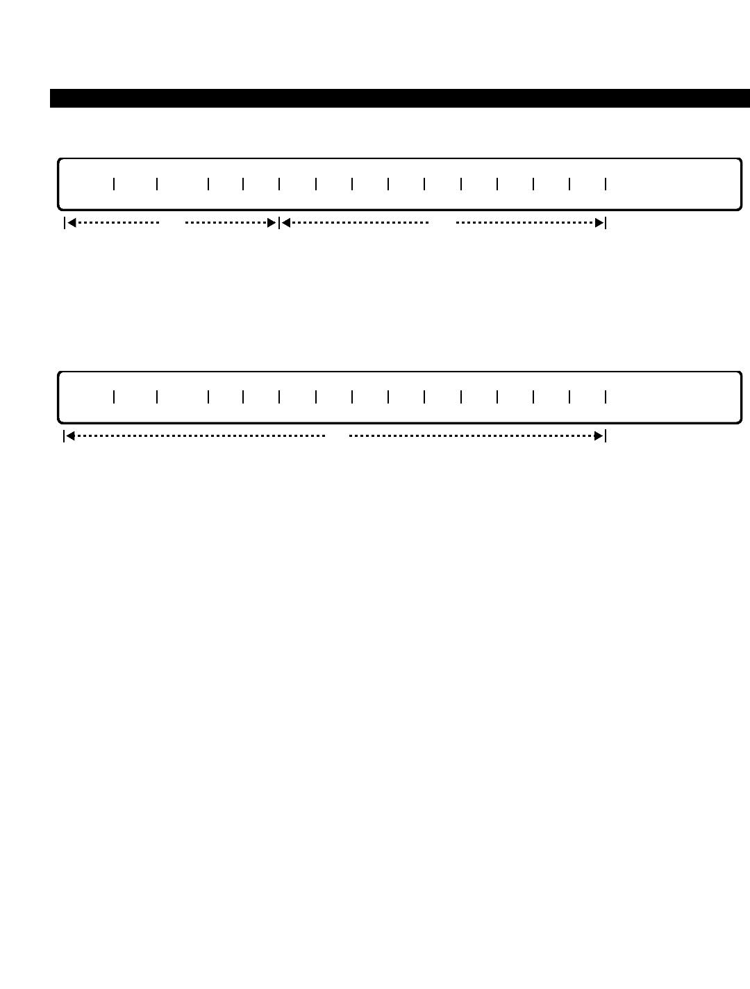
PERCEPTION 4000 COMMANDS
ISS 2, SECTION 4000-014-000
AREA/OFFICE CODE RESTRICTION TABLES (CMD 339)
DELETE
This operation deletes area/office codes from the Area/Office Code Restriction table. Ranges are permitted when
deleting a number of area and office codes. When using ranges, a confirmation is requested before deleting any
of the codes.
DISPLAY
This operation displays the Area/Office Code Restriction table. If no data is entered in any of the optional fields,
all of the Area/Office Code Restriction tables are displayed. Ranges are permitted in all fields except the “TYPE”
field.
PARAMETERS
Each field parameter is described in this section. Any variations for a particular operation are noted separately.
FIELD: TRGN (Trunk Restriction Group number)
TYPE: Decimal
FORMAT: 1 digit
VALUE: 2 to 8 (or to the maximum number of trunk groups configured in the system)
LOOP: Primary loop field, and allowed in all of the operations
This field assigns restriction numbers to trunk groups. Note that Trunk Restriction Group 1 is
defined as “unrestricted”, and is recommended for TIE trunk groups and trunk interfaces to
peripheral auxiliary equipment.
FIELD: DRL (Destination Restriction Level)
TYPE: Decimal
FORMAT: 1 or 2 digits
VALUE: 2 to 16 (or to the maximum system configuration)
LOOP: Secondary loop field, and allowed in all of the operations
When "DRL" is 1, all calls are allowed regardless of what trunk restriction group number (TRGN)
is used. Refer to the Destination Restriction Level Assignment command (CMD 337) for
information on DRLs.
FIELD: TYPE (Office Code Restriction Type)
TYPE: Keyword
opt
TRGN DRL TYPE AC OC OC OC OC OC OC OC OC OC OC
opt
TRGN DRL TYPE AC OC OC OC OC OC OC OC OC OC OC
req
3-42

PERCEPTION 4000 COMMANDS
FORMAT: Predefined ASCII characters
Keywords: ALW - Allow access to listed office codes
DNY - Deny access to listed office codes
The "TYPE" field defines whether area codes are accessible to the caller. If the keyword, ALW is
entered, all of the office codes in this Area/Office Code Restriction table are allowed to be
accessed. Otherwise, they are denied.
FIELD: AC (Area Code)
TYPE: Decimal with fixed length
FORMAT: 3 digits in the form N Y X (where N = 2 to 9, Y = 0 or 1, and X = 0 to 9)
VALUE: 200 to 919
LOOP: Third loop field, and allowed in all of the operations
Each area code may have some office codes allowed and some denied. The Area/Office Code
Restriction table can be represented by a list of either allowed or denied codes. For example, if
most office codes in an area code are allowed, with a few exceptions, it is easier to enter a listing
of denied ("TYPE" = DNY) office codes, rather than inputting a listing of allowed ("TYPE" = ALW)
office codes.
FIELD: OC (Office Code)
TYPE: Decimal with fixed length
FORMAT: 3 digits in the form NXX (Where N = 2 to 9, and X = 0 to 9)
VALUE: 200 to 999
RANGE: Allowed in a DISPLAY operation
SCOPE: Allowed in ADD and DELETE operations
Office codes entered in this field are either allowed or denied depending on the keyword entered
in the “TYPE” field.
SYSTEM ERROR MESSAGES
The following error messages are unique to this command.
C33900 - Check trunk restriction group number range
C33901 - Area code/office code table undefined
C33902 - Office code NNN is incorrect
I33903 - Area code/office code table is full
C33904 - Dash should not be used in last scope field N
C33905 - Missing data in scope type field of field N
RELATED COMMAND
Area Code Restriction Tables (CMD 341)
ISS 2, SECTION 4000-014-000
AREA/OFFICE CODE RESTRICTION TABLES (CMD 339)
3-43

PERCEPTION 4000 COMMANDS
ISS 2, SECTION 4000-014-000
ATTENDANT FEATURE KEY ASSIGNMENT (CMD 371)
ATTENDANT FEATURE KEY ASSIGNMENT (CMD 371)
Each attendant console in the system has twenty-four flexible feature keys which may be defined for an array of
various functions. This command (CMD 371) modifies or displays the definitions of those feature keys for one or
more specified attendant consoles.
Although all types of keys may be assigned to the attendant console, it is important to note that unless the
attendant has access to certain trunk groups or features in their Class of Service definition (CMD 334), use of the
key may be denied by call processing once the key is assigned to the console.
Command Keyword: ATT_KEY_ASSIGN
Category Name: Attendant
PREREQUISITE COMMANDS
Attendant Group Assignment (CMD 372) (The Attendant Group Assignment command is required
if ICI keys are assigned to the attendant console.)
Attendant Position Assignment (CMD 370)
Numbering Plan Assignment (CMD 330)
OPERATIONS
Available operations: MODIFY
DISPLAY
The function and required data fields for each operation are described in this section.
MODIFY
This operation modifies the definitions of feature keys for one or more attendants. Ranges are not permitted in
any of the fields. A MODIFY operation may be performed only when the attendant is in the "position busy" mode.
DISPLAY
opt
ATT DN POS DEF 1 DEF 2
req
req
ATT DN POS DEF 1 DEF 2
opt
3-44

PERCEPTION 4000 COMMANDS
This operation displays the definitions of feature keys of one or more specified attendants. Entering a directory
number in the “ATT DN” field lists previously defined or undefined feature keys on the attendant console. For
viewing a specific key, the key position must be entered. Ranges are permitted in the “POS” field only.
PARAMETERS
Each field parameter is described in this section. Any variations for a particular operation are noted separately.
FIELD: ATT DN (Attendant Directory Number)
TYPE: DN Type
FORMAT: 1 to 5 digits
VALUE: 0 to 99999
RANGE: Not allowed
LOOP: Not allowed
Each attendant has a unique directory number which must not conflict with any other numbering
plan in the system.
FIELD: POS (Key Assignment Position Number)
TYPE: Decimal
FORMAT: 1 or 2 digits
VALUE: 1 to 24
RANGE: Allowed in a DISPLAY operation only
LOOP: Allowed
Each feature must be assigned to a key position. Following is a matrix showing the flexible
feature key positions on the attendant console.
FIELD: DEF 1 (Key Assignment Definition 1)
TYPE: Keyword
FORMAT: Predefined ASCII characters
Keywords: ADL - Autodial
AEE - Attendant End-to-End Signaling
BLF - BLF (Busy Lamp Flag) Control
CC - Code Calling Access
CCMM - Code Calling Retrieval (Meet Me)
CONF - Eight Party Conference
HELP - HELP key
ICI - Incoming Call Identification
LND - Last Number Redial
OVF - Attendant Overflow Control
PR_A - Attendant Parked Page Retrieval
PR_S - Voice Paging Retrieval-System
1
4
7
10
2
5
8
11
3
6
9
12
13
16
19
22
14
17
20
23
15
18
21
24
ISS 2, SECTION 4000-014-000
ATTENDANT FEATURE KEY ASSIGNMENT (CMD 371)
3-45

PERCEPTION 4000 COMMANDS
ISS 2, SECTION 4000-014-000
ATTENDANT FEATURE KEY ASSIGNMENT (CMD 371)
PRGM - Program Mode Key
SYSD - System Speed Dialing
SPLT - Split
SPVS - Supervise
TGAC - Trunk Group Access Code
UNA - Night Answer Access
UND - Undefined
VP_E - Voice Paging Access-Emergency
VP_S - Voice Paging Access-System
VP_Z - Voice Paging Access-Zone
VPMM - Voice Paging Retrieval-Zone (Meet Me)
This field provides the feature key definition. A total of 10 feature keys may be assigned as
Incoming Call Identification (ICI) keys. ICI keys are defined at the attendant group level through
the Attendant Group Assignment command (CMD 372).
The <SPLT>, <CONF>, <VP_Z> (if an <ADL> key is used) and <SPVS> keys should be
assigned; otherwise, attendant traffic handling is not at its fullest potential.
The number of keys assigned to multiple key features (Autodial and Trunk Group Access Code) is
limited to 20.
FIELD: DEF 2 (Key Assignment Definition 2)
TYPE: Decimal
FORMAT: 1 to 3 digits
VALUES: 1 to 10 (ICI keys)
0 to 9 or 00 to 99 (CC, CCMM, VP_Z)
1 to 3 digits (TGAC)
RANGE: Not allowed
Secondary key definition information is provided in this field, such as trunk access codes for trunk
group keys or zone numbers for code calls or voice paging. These definitions must comply with
the postdialing digit length as defined in the Numbering Plan Assignment command
(CMD 300).
Data in this field is required only if the CC, CCMM, VP_Z, TGAC, or ICI keyword is entered in the
“DEF 1” field. The relationship between the data in the “DEF 1” field and this field is described as
follows:
* If assigning a general access key, the zone number is optional and must be manually input by
the attendant after pressing the feature key. Valid ranges for zone numbers depend on the
length of the "LEN PD1" setting in the Numbering Plan Assignment command (CMD 300). If
CC
CCMM
VP_Z
TGAC
ICI
0-9 or 00-99
0-9 or 00-99
0-9 or 00-99
1 to 3 digits
1-10
Zone Number*
Zone Number*
Zone Number*
Trunk Access Code
ICI Number
"DEF 1" Field "DEF 2" Field
3-46

PERCEPTION 4000 COMMANDS
"LEN PD1" is set to 1, ranges are from 0 to 9; if set to 2, ranges are from 00 to 99.
SYSTEM ERROR MESSAGES
The following error messages are unique to this command.
C37100 - Invalid attendant directory number
C37101 - An access code is required in DEF 2 field
C37102 - Invalid incoming call number
C37103 - Attendant directory number has not been defined
C37104 - Invalid zone number
C37105 - DEF 1 and DEF 2 exceeds the allowable maximum
C37106 - DEF 1 and DEF 2 have already been defined
C37107 - The specified incoming call key does not exist
C37108 - DEF 1 and DEF 2 do not match
C37109 - Autodial keys exceed the allowable maximum
C37110 - An ICI category number is required in DEF 2 field
ISS 2, SECTION 4000-014-000
ATTENDANT FEATURE KEY ASSIGNMENT (CMD 371)
3-47
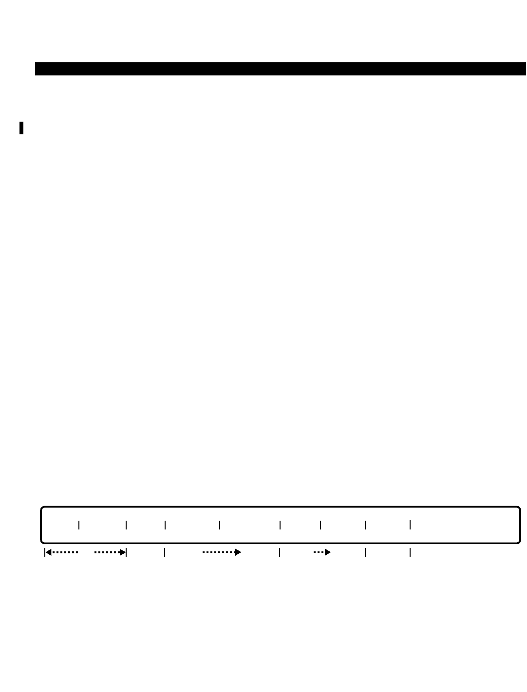
PERCEPTION 4000 COMMANDS
ISS 2, SECTION 4000-014-000
ATTENDANT GROUP ASSIGNMENT (CMD 372)
ATTENDANT GROUP ASSIGNMENT (CMD 372)
The PERCEPTION 4000 supports up to 30 attendant groups. Any number of attendants may belong to an
attendant group (up to the system maximum number of consoles); however, an attendant position may belong to
only one attendant group. The attendant group must be defined prior to assigning individual attendant consoles
and their related information. Attendant positions are assigned using the Attendant Position Assignment
command (CMD 370)
Attendants belonging to an attendant group share the call load presented to the group via the attendant group
directory number. Incoming call priority for all attendants in the group is defined at the attendant group level.
Command Keyword: ATT_GROUP_ASSIGN
Category Name: Attendant
PREREQUISITE COMMAND
Night Bell Assignment (CMD 405) (If data is entered in the "OVF DEST" field, this command is
required.)
OPERATIONS
Available operations: ADD
DELETE
MODIFY
DISPLAY
The function and required data fields for each operation are described in this section.
ADD
This operation creates one or more attendant groups in the PERCEPTION 4000 system. The attendant group
number and directory number must be unique. The attendant group directory number must not conflict with any
numbering plan in the system. A loop is permitted when adding a number of attendant groups with the same
attributes.
opt
GRP# ATG DN NAME OVF TMR OVF DEST ICI NO ICI CAT CALLS
opt
opt
optopt
req opt
3-48

PERCEPTION 4000 COMMANDS
DELETE
This operation removes an attendant group from the PERCEPTION 4000 system. Entering either the attendant
group number or attendant directory number is sufficient. All of the attendants in an attendant group must be
removed before deleting the group. When the last attendant of an attendant group is removed, the status of that
attendant group must be changed accordingly. Looping is permitted when deleting a number of attendant groups,
however a confirmation is requested by the system before it deletes each group.
MODIFY
This operation changes the attributes of one or more attendant groups. Entering data in either the "GRP#" or the
"ATG DN" field is sufficient in a MODIFY operation. If data is entered in both of these fields, and if the "ATG DN"
does not match the one in the database, the directory number attributes are not allowed to be changed and the
input line is rejected. If this occurs, use the DELETE operation to delete the "ATG DN", then use the ADD
operation to enter a new directory number. Looping is permitted when modifying a number of attendant groups.
DISPLAY
This operation displays the attributes of one or more attendant groups. There are no required input data fields for
this operation. If no data is entered into any of these fields, the attributes of all attendant groups in the system
display. Looping is permitted in the "GRP#" field, and ranges are permitted in fields that accepts numeric input,
such as the “ATG DN” and "OVF DEST" fields, with the exception of the "CALLS" field.
PARAMETERS
Each field parameter is described in this section. Any variations for a particular operation are noted separately.
FIELD: GRP# (Attendant Group Number)
TYPE: Decimal
GRP# ATG DN NAME OVF TMR OVF DEST ICI NO ICI CAT CALLS
opt
GRP# ATG DN NAME OVF TMR OVF DEST ICI NO ICI CAT
opt opt
optoptopt
optreq reqopt
GRP# ATG DN
optreq reqopt
ISS 2, SECTION 4000-014-000
ATTENDANT GROUP ASSIGNMENT (CMD 372)
3-49
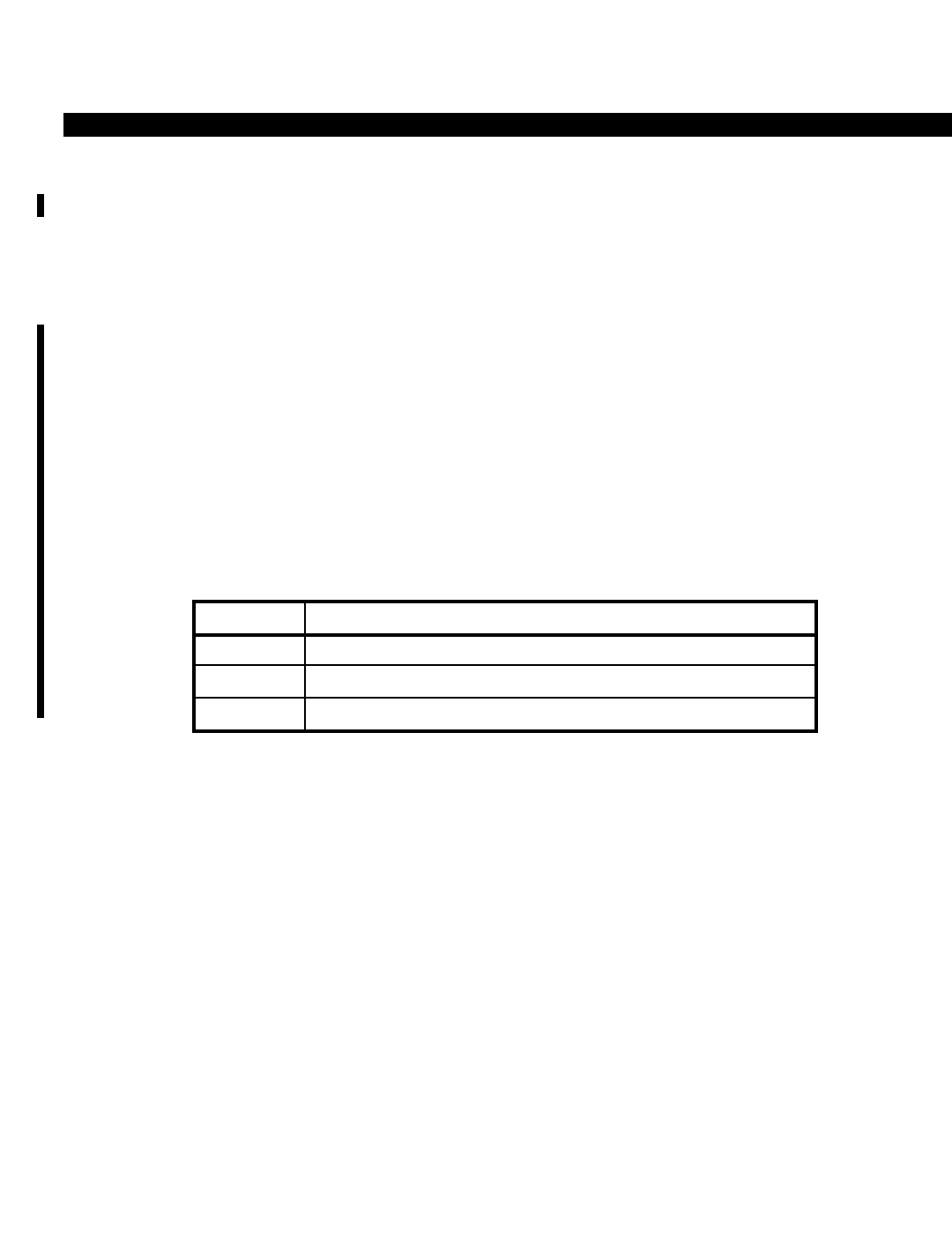
PERCEPTION 4000 COMMANDS
ISS 2, SECTION 4000-014-000
ATTENDANT GROUP ASSIGNMENT (CMD 372)
FORMAT: 1 or 2 digits
VALUE: 1 to 30
RANGE: Not allowed
LOOP: Allowed in all operations
This field assigns the attendant group number.
When assigning attendant console group numbers, it is important to note the relationship
between these numbers and the PERCEPTION 4000 system’s Local Central Processing Units
(LCPUs). The correct assignment of these numbers will help ensure that calls to the attendant
are not dropped if a redundant system performs a switchover to the standby side.
Attendant consoles are installed in the system via the Attendant Position Assignment command
(CMD 370). After an attendant console has been installed, it has an identifying equipment
number (e.g., 40108) indicating the Modular Line/Trunk Unit (4), the card slot (01), and the circuit
(08) to which it is assigned. A console’s assigned equipment number determines the LCPU (1 ~
3) which controls it, since each LCPU in the system controls specific Modular Line/Trunk Units
(shelves):
LCPU(X) Modular Line/Trunk Units (Shelves) Controlled by LCPU(X)
1 1 ~ 4
2 5 ~ 8
3 9 ~ 10
3-50

PERCEPTION 4000 COMMANDS
The number of LCPUs in a system determines how many attendant groups can be supported. A
1-LCPU system supports up to ten attendant groups; a 2-LCPU system may have up to 20
attendant groups; and a 3-LCPU system may have up to 30 attendant groups. These attendant
groups are allocated among the various LCPUs as follows:
The following three examples should help illustrate the relationship between LCPUs, attendant
groups, and attendant console equipment numbers.
EXAMPLE 1: ■Attendant console equipment number: 30203
■Number of LCPUs in system: 1
■(Attendant console is supported by LCPU1)
■Assign attendant console to any attendant group 1 ~ 10.
EXAMPLE 2: ■Attendant console equipment number: 60203
■Number of LCPUs in system: 2
■(Attendant console is supported by LCPU2)
■Assign attendant console to any attendant group 11 ~ 20.
EXAMPLE 3: ■Attendant console equipment number: 90203
■Number of LCPUs in system: 3
■(Attendant console is supported by LCPU3)
■Assign attendant console to any attendant group 21 ~ 30.
System
Size LCPU1
Shelves Supported:
1 ~ 4
LCPU2
Shelves Supported:
5 ~ 8
LCPU3
Shelves Supported:
9 ~ 10
1 LCPU
System
Attendant Groups
Supported:
1 ~ 10
Attendant Groups
Supported:
1 ~ 10
Attendant Groups
Supported:
1 ~ 10
2 LCPU
System
3 LCPU
System
ATTENDANT GROUP SUPPORT ALLOCATION
Attendant Groups
Supported:
11 ~ 20
Attendant Groups
Supported:
11 ~ 20
Attendant Groups
Supported:
21 ~ 30
ISS 2, SECTION 4000-014-000
ATTENDANT GROUP ASSIGNMENT (CMD 372)
3-51

PERCEPTION 4000 COMMANDS
ISS 2, SECTION 4000-014-000
ATTENDANT GROUP ASSIGNMENT (CMD 372)
FIELD: ATG DN (Attendant Group Directory Number)
TYPE: DN Type
FORMAT: 1 to 5 digits
VALUE: 0 to 99999
RANGE: Allowed in a DISPLAY operation
LOOP: Not allowed
Each attendant group must be assigned a unique directory number which does not conflict with
other directory numbers or any feature access codes defined in the system numbering plan. This
directory number is dialed by system users to receive service from an attendant in the attendant
group.
FIELD: NAME (Attendant Group Name)
TYPE: Text
FORMAT: 0 to 9 ASCII characters
The name of the attendant group (up to 9 ASCII characters in length) may be assigned with this
field. The name displays on other attendant consoles and display equipped stations when dialing
the attendant group directory number. Embedded spaces are allowed in this field.
FIELD: OVF TMR (Attendant Overflow Timer)
TYPE: Decimal
FORMAT: 1 to 3 digits
VALUE: 5 to 180 (seconds)
RANGE: Allowed in a DISPLAY operation only
LOOP: Not allowed
Data in this field determines the amount of time a call spends in the attendant call holding area
before going to the overflow number. The default value is 32 seconds. The minimum and
maximum overflow times are 5 and 180 seconds, respectively. This value may be adjusted in 1
second intervals. If an overflow time is entered in this field, an overflow destination must be
entered in the "OVF DEST" field.
FIELD: OVF DEST (Overflow Destination)
TYPE: Keyword
FORMAT: Predefined ASCII characters
Keywords: BL01 ~ BL64
NON - No Overflow Destination
The overflow destination field defines the night bell to which overflow calls are directed. The
system supports up to 64 night bells, however overflow calls may be directed to only one night
bell per attendant group. The keyword NON may be used in a MODIFY operation only.
FIELD: ICI NO (ICI Category Number)
TYPE: Decimal
FORMAT: 1 or 2 digits
VALUE: 1 to 10
RANGE: Allowed in a DISPLAY operation only
3-52

PERCEPTION 4000 COMMANDS
This field and the “ICI CAT” field define incoming call keys. A maximum of 10 ICI categories may
be defined for an attendant group. During a MODIFY operation, if a number is assigned in this
field, a keyword must be entered in the “ICI CAT” field.
Any ICI key definition may appear on multiple consoles within the same attendant group. These
calls allow the attendant to answer the oldest call of a particular ICI category type by pressing the
associated ICI key instead of answering the call via the ANSWER fixed key. Once the ICI
categories are defined in this command, they may be placed on the various attendant consoles
using the Attendant Feature Key Assignment command (CMD 371).
FIELD: ICI CAT (ICI Category Assignment)
TYPE: Keyword / Decimal with Fixed Length
FORMAT: Predefined ASCII characters / 3 digits
VALUE: 001 to 256
Keywords: ATT - Attendant Group Calls
DATT - Directed Attendant Calls
EMR1 - Emergency 1
EMR2 - Emergency 2
EMR3 - Emergency 3
EMR4 - Emergency 4
ICPT - Intercepts
IPC - Interposition Calls
LHR - Long Hold Recall
NAR - No Answer Recall
Values: 001~256 - Trunk groups 001~256 (or to the maximum system configuration)
One ICI category is assigned to each ICI key. During a MODIFY operation, whenever an ICI key
number is entered in the “ICI NO” field, one of the above keywords must be entered in this field.
The same keyword cannot be assigned more than once for another ICI key.
ICI assignment is not required if the attendant group does not wish any attendants to have the ICI
answering capability.
FIELD: CALLS (Number of Calls Per Attendant)
TYPE: Decimal
FORMAT: 1 or 2 digits
VALUE: 2 to 32
RANGE: Not allowed
LOOP: Not allowed
The "CALLS" field defines the number of calls per attendant allowed in the attendant group call-
waiting queue (including talking, parked, and ringing/in-queue calls). The total queue size is
dependent on the number of attendants assigned to the same group directory number (set up
with the Attendant Position Assignment command, CMD 370), and the number of calls allowed
per attendant (CALLS). Note that a call that is being transferred or processed (where two or more
parties besides the attendant are involved) counts as one call. The queue size can be calculated
as follows:
ISS 2, SECTION 4000-014-000
ATTENDANT GROUP ASSIGNMENT (CMD 372)
3-53

PERCEPTION 4000 COMMANDS
ISS 2, SECTION 4000-014-000
ATTENDANT GROUP ASSIGNMENT (CMD 372)
Attendant group call-waiting queue size = Number of attendants with the same ATG DN,
times the number of calls per attendant (CALLS).
For example, if three attendants are assigned to an ATG DN, and the "CALLS" field is set to 8,
then the queue size is 3 x 8 (for a total of 24 calls waiting in queue). All three attendants in the
group share the same queue, since they belong to the same Attendant Group Directory Number.
However, each attendant is not restricted to only eight calls; for example, at a given time, if the
number of calls in the queue is 20, then each attendant console displays 20 calls waiting.
A <TAB> entered in the "CALLS" field during an ADD operation defaults the field to a value of 32
(which is the maximum allowed).
SYSTEM ERROR MESSAGES
The following error messages are unique to this command.
C37200 - Attendant group number has not been defined
C37201 - Attendant group number is required
C37202 - Attendant group DN has not been defined
C37203 - Attendant group DN has already been defined
C37204 - Attendant group DN is required
C37205 - Invalid Attendant group DN
C37206 - Invalid group name
C37207 - Overflow timer is required
C37208 - Invalid overflow timer
C37209 - Overflow destination is out of range
C37210 - Overflow destination is required
C37211 - Invalid overflow destination
C37212 - Incoming key number is required
C37213 - Incoming call category has already been defined
C37214 - Incoming call category is required
C37215 - Invalid incoming call category
C37216 - Attendant group number or DN is required
C37217 - Attendant has already been defined
C37218 - Attendant group has already been defined
C37219 - Cannot re-assign a new value in field 8
I37220 - Warning: Undefined night bell in field #5
C37221 - Cannot modify attendant group directory number
RELATED COMMANDS
Attendant Feature Key Assignment (CMD 371)
Attendant Incoming Call Priority Assignment (CMD 373)
Attendant Position Assignment (CMD 370)
Internal Call Alternate Routing Assignment (CMD 374)
Station Assignment (CMD 330)
Trunk Group Assignment (CMD 310)
3-54
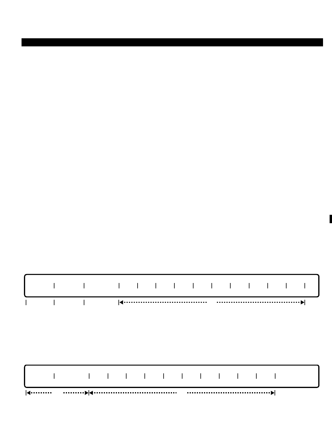
PERCEPTION 4000 COMMANDS
ATTENDANT INCOMING CALL PRIORITY ASSIGNMENT (CMD 373)
Each attendant group may have up to 18 levels of priority for queuing incoming calls. Each desired priority level
may be assigned any number of incoming call categories. Note that assigning all 18 of the priority levels is not
necessary. All categories assigned to a given priority level are queued on a first-in/first-out basis within that
priority level.
Command Keyword: CALL_PRIORITY_ASSIGN
Category Name: Attendant
PREREQUISITE COMMAND
Attendant Group Assignment (CMD 372)
OPERATIONS
Available operations: ADD
DELETE
MODIFY
DISPLAY
The function and required data fields for each operation are described in this section.
ADD
This operation assigns the recall handling option of an attendant group, and the incoming call categories to
different priorities for the specified attendant group. The Attendant Group Directory Number (ATG DN) and the
Priority Level (PRIORITY) are required fields, while all other fields are optional.
DELETE
This operation deletes incoming call categories from individual priority levels of the specified attendant group. The
Attendant Group Directory Number (ATG DN) and the Priority Level (PRIORITY) are required fields, while all
opt
ATG DN PRIORITY CAT CAT CAT CAT CAT CAT CAT CAT CAT CAT
req
opt
ATG DN RECALL PRIORITY CAT CAT CAT CAT CAT CAT CAT CAT CAT CAT
reqreq opt
ISS 2, SECTION 4000-014-000
ATTENDANT INCOMING CALL PRIORITY ASSIGNMENT (CMD 373)
3-55
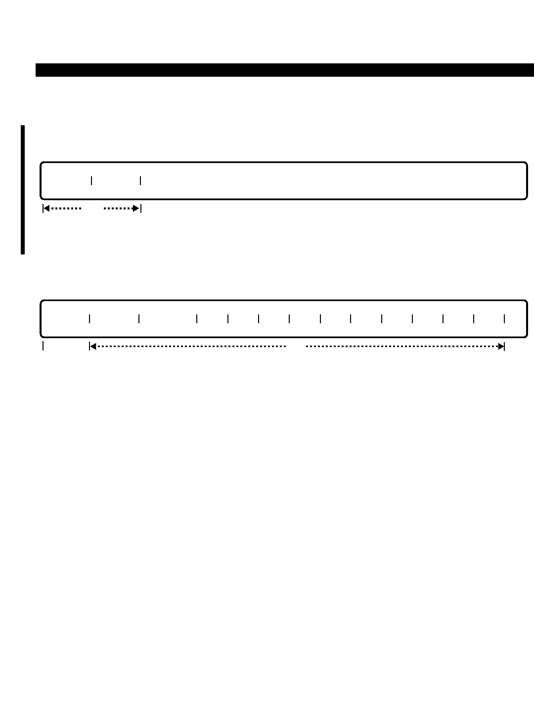
PERCEPTION 4000 COMMANDS
ISS 2, SECTION 4000-014-000
ATTENDANT INCOMING CALL PRIORITY ASSIGNMENT (CMD 373)
3-56
other fields are optional.
MODIFY
This operation is used to modify the recall type of a specific attendant console. Recalls can be directed either
back to the extending individual attendant or to its attendant group.
DISPLAY
This operation displays the recall handling option and incoming call categories assigned to each priority level of
the specified attendant group. The attendant group directory number is required for this operation, while all other
fields are optional. If no data is entered in the optional fields, all incoming call categories and priority levels for the
specified attendant group directory number are displayed.
PARAMETERS
Each field parameter is described in this section. Any variations for a particular operation are noted separately.
FIELD: ATG DN (Attendant Group Directory Number)
TYPE: DN Type
FORMAT: 1 to 5 digits
VALUE: 0 to 99999
RANGE: Not allowed
LOOP: Not allowed
This field selects which attendant group is about to be defined.
FIELD: RECALL (Recall Handling Option)
TYPE: Keyword
FORMAT: Predefined ASCII characters
Keywords: GRP - Recall to Attendant Group
IND - Recall to Extending Attendant
The recall handling flag determines how general recalls are handled. These may be defined to
recall to the extending attendant only or recall to the attendant group. This field does not concern
opt
ATG DN RECALL PRIORITY CAT CAT CAT CAT CAT CAT CAT CAT CAT CAT
req
req
ATG DN RECALL

PERCEPTION 4000 COMMANDS
ISS 2, SECTION 4000-014-000
ATTENDANT INCOMING CALL PRIORITY ASSIGNMENT (CMD 373)
3-57
itself with local physical recalls such as a call recalling from a locked loop. Those calls may only
be processed by the attendants themselves.
FIELD: PRIORITY (Priority Level)
TYPE: Decimal
FORMAT: 1 or 2 digits
VALUE: 1 to 18
RANGE: Not allowed
LOOP: Not allowed
This field sets the desired priority level for incoming calls. If first-in/first-out queuing is desired, all
incoming call categories are placed in priority one, as queuing within each priority level is
handled in a first-in/first-out manner.
FIELD: CAT (Incoming Call Category)
TYPE: Keyword / Decimal with Fixed Length
FORMAT: Predefined ASCII characters / 3 digits
VALUE: 001 to 256
Keywords: ATT - Attendant Group Calls
DATT - Directed Attendant Calls
EMR3 - Emergency 3
EMR4 - Emergency 4
ICPT - Intercepts
IPC - Interposition Calls
LHR - Long Hold Recall
NAR - No Answer Recall
Values: 001~256 - Trunk groups 001~256 (or to the maximum system configuration)
Any trunk group number or categories listed above can be assigned to a given priority level.
There is no limit to the number of categories assigned to a given level, however an incoming call
category may be assigned to only one priority level.
SYSTEM ERROR MESSAGES
The following error messages are unique to this command.
C37300 - Attendant group DN has not been defined
C37301 - XXXX is not defined for priority N
C37302 - Category has already been defined
C37303 - Too many categories
C37304 - Trunk group number has not been defined
C37305 - At least one category must be entered
NOTE: In error message C37301, XXXX = EMR3, EMR4, ATT, DATT, etc.; N = 1 to 18.

PERCEPTION 4000 COMMANDS
ISS 2, SECTION 4000-014-000
ATTENDANT PASSWORD ASSIGNMENT (CMD 375)
ATTENDANT PASSWORD ASSIGNMENT (CMD 375)
The PERCEPTION 4000 system supports up to 64 attendant passwords. Each password may be assigned an
identification code which identifies the attendant using the console.
Command Keyword: ATT_PASSWORDS
Category Name: Attendant
PREREQUISITE COMMANDS
There are no prerequisites for this command.
OPERATIONS
Available operations: ADD
DELETE
MODIFY
DISPLAY
The function and required data fields for each operation are described in this section.
ADD
This operation adds an attendant password to the attendant password log table. The "SMDR ID" field is
equivalent to an operator ID number, and must be unique for each password in the log table. Ranges and loops
are not permitted in this operation.
DELETE
This operation deletes one or more attendant passwords from the attendant password log table. Looping is
permitted when deleting a group of passwords, though a confirmation is required before each password is
deleted.
INDEX
req
INDEX ATT PSWD SMDR ID
req
3-58
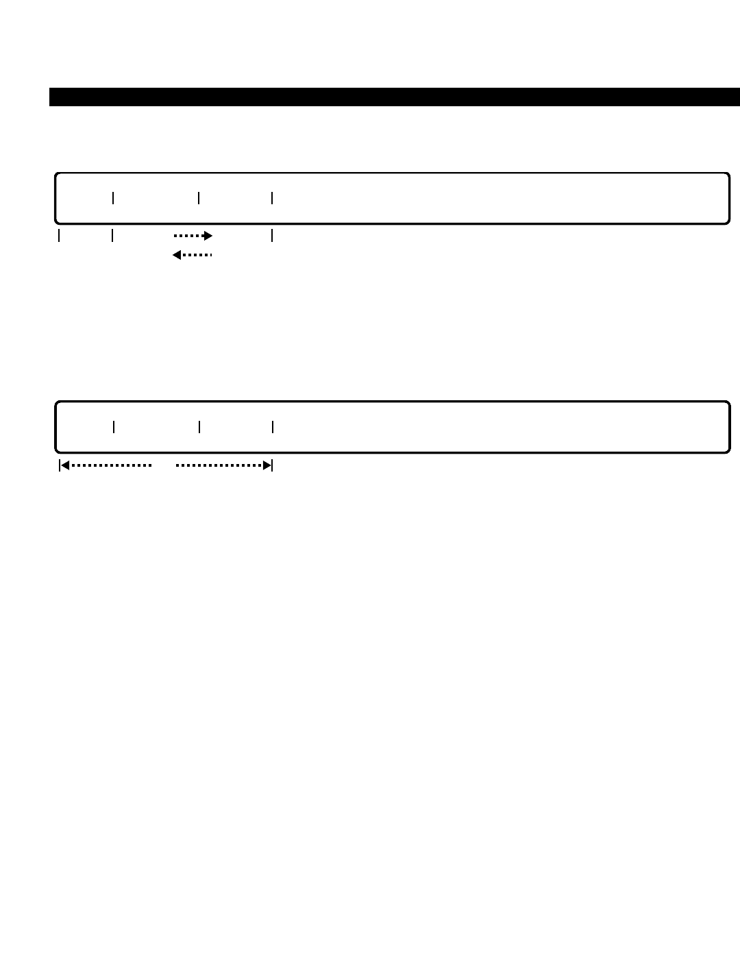
PERCEPTION 4000 COMMANDS
MODIFY
This operation changes an attendant password or SMDR ID code. The SMDR ID code is equivalent to an
operator ID number, and must be unique for each password. The "ATT PSWD" or "SMDR ID" field is required,
along with the "INDEX" field. Ranges and loops are not permitted.
DISPLAY
This operation displays one or more attendant passwords. If no data is entered in any of the fields, all of the
attendant passwords in the attendant log table are displayed. Loop fields and ranges are permitted in this
operation.
PARAMETERS
Each field parameter is described in this section. Any variations for a particular operation are noted separately.
FIELD: INDEX (Index Number)
TYPE: Decimal
FORMAT: 1 or 2 digits
VALUE: 1 to 64
LOOP: Allowed in DELETE and DISPLAY operations
"INDEX" is an entry number in the attendant password log table and is provided for the
administrator's convenience. If the index number is deleted, the corresponding attendant
password is removed from the table.
FIELD: ATT PSWD (Attendant Password)
TYPE: Text
FORMAT: 1 to 8 numerical characters
VALUE: 0 to 99999999
LOOP: Not allowed
RANGE: Not allowed
Passwords may be up to eight numerical characters in length. Leading and trailing zeros are
significant.
INDEX ATT PSWD SMDR ID
opt
INDEX ATT PSWD SMDR ID
req req opt
opt req
ISS 2, SECTION 4000-014-000
ATTENDANT PASSWORD ASSIGNMENT (CMD 375)
3-59

PERCEPTION 4000 COMMANDS
ISS 2, SECTION 4000-014-000
ATTENDANT PASSWORD ASSIGNMENT (CMD 375)
FIELD: SMDR ID (SMDR ID Code)
TYPE: Decimal
FORMAT: 1 or 2 digits
VALUE: 0 to 99
LOOP: Not allowed
RANGE: Allowed in ADD, MODIFY, and DISPLAY operations
The SMDR identification code field assigns a one or two digit code to each password so the
attendant may be identified on the SMDR call record. This code must be unique for each
password; therefore it may not be used for multiple passwords.
SYSTEM ERROR MESSAGES
The following error messages are unique to this command.
C37500 - Index number is out of range
C37501 - Index number has not been defined
C37502 - Index number has already been defined
C37503 - Attendant password has already been defined
C37504 - Attendant password is required
C37505 - SMDR ID has already been defined
C37506 - SMDR ID is required
C37507 - Attendant password or SMDR ID is required
C37508 - Invalid attendant password
RELATED COMMAND
Attendant Position Assignment (CMD 370)
3-60

PERCEPTION 4000 COMMANDS
ATTENDANT POSITION ASSIGNMENT (CMD 370)
The Attendant Position Assignment command installs or removes an attendant console from the PERCEPTION
4000 system. This command also modifies or displays existing attendant console attributes.
Command Keyword: ATT_POSITION_ASSIGN
Category Name: Attendant
PREREQUISITE COMMAND
Attendant Group Assignment (CMD 372)
OPERATIONS
Available operations: ADD
DELETE
MODIFY
DISPLAY
The function and required data fields for each operation are described in this section.
ADD
This operation installs one or more attendant consoles in the system. The equipment number and attendant
directory number must be unique and must not conflict with any other numbering plan in the system. An attendant
group must be created before an attendant can be assigned to it.
DELETE
This operation deletes an attendant console from the system. The equipment number or attendant directory
number must be entered. Ranges are not permitted. A confirmation is required when removing the last attendant
from an attendant group. When the last attendant of an attendant group is removed, the status of that attendant
group must be changed accordingly. Deletion of an attendant position will also undefine all feature keys assigned
optreq reqopt
EQUIP # ATT DN
req
EQUIP # ATT DN NAME GRP DN COS DRL FRLP QPL ROB EMR RNG PSWD TYPE AUD
optreq lockedopt
ISS 2, SECTION 4000-014-000
ATTENDANT POSITION ASSIGNMENT (CMD 370)
3-61
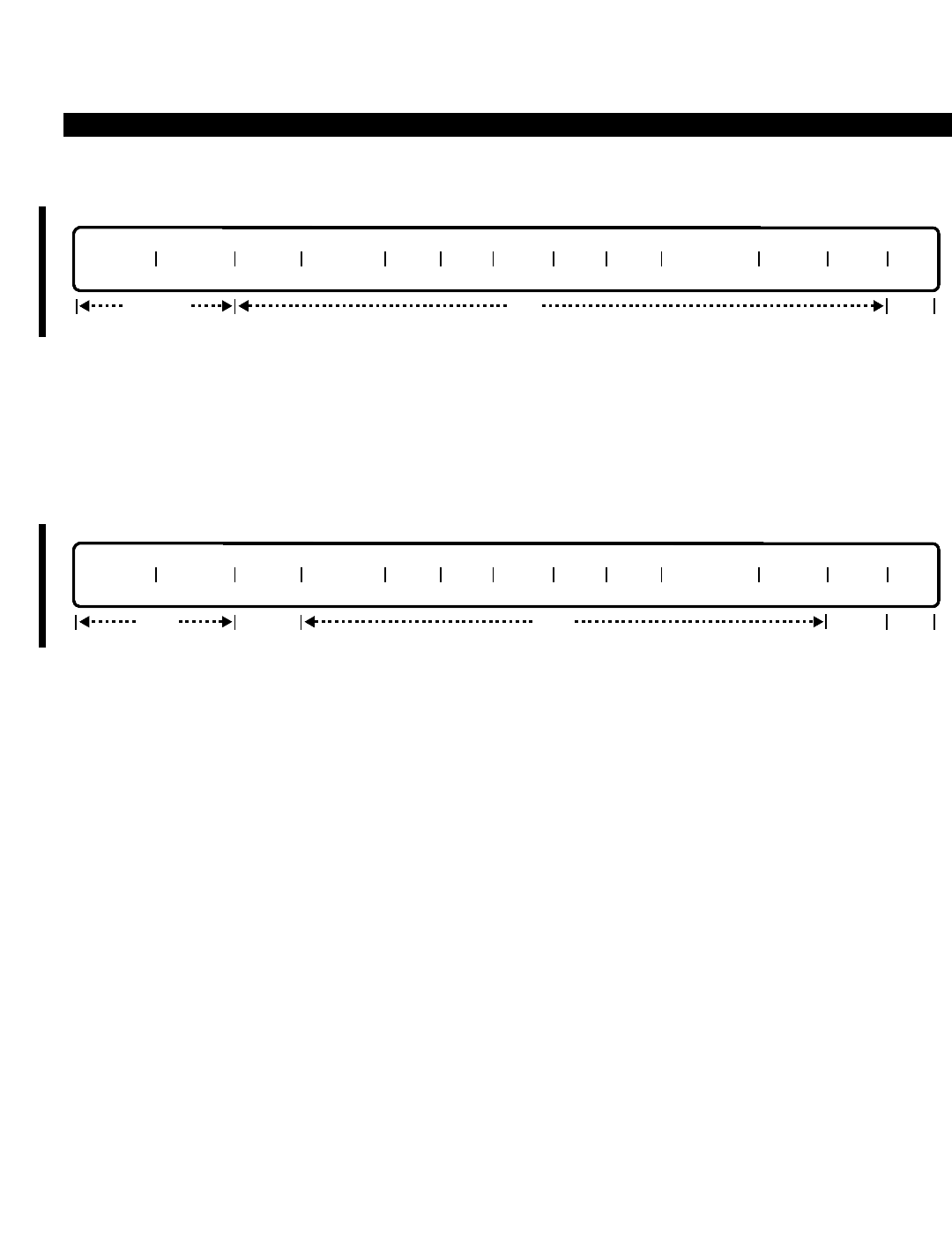
PERCEPTION 4000 COMMANDS
ISS 2, SECTION 4000-014-000
ATTENDANT POSITION ASSIGNMENT (CMD 370)
to that position through the Attendant Feature Key Assignment command (CMD 371).
This operation modifies attributes of one or more existing attendant consoles in the system. Input is required in
the "EQUIP #" or the "ATT DN" field. The "ATT DN" and "GRP DN" fields may not be modified. If an entry is made
in either of these fields, the entry must match the data in the database. To modify an attendant/attendant group
directory number, perform a DELETE operation to delete the original directory number, then use the ADD
operation to enter a new number.
DISPLAY
This operation displays attributes of one or more existing attendant consoles. All fields are optional. If no data is
entered in any of the fields, the attributes of all of the attendant consoles in the system display. Ranges are
permitted in all fields.
PARAMETERS
Each field parameter is described in this section. Any variations for a particular operation are noted separately.
FIELD: EQUIP # (Equipment Number)
TYPE: EQ Type
FORMAT: 5 or 6 digits
VALUE: (0)10101 to 101316 *
RANGE: Not allowed
LOOP: Allowed in all operations
* Use the following chart to determine valid ranges for various types of equipment.
Digits Range Hardware
First digit(s) (0)1~10 Shelf no.
Second two digits 01~11, 13 Card slot no.
Last two digits 01~16 Circuit no.
Each attendant console is assigned to a circuit on a digital line card (DSTI). The "EQUIP #" field
defines the location of the connection. The first digit(s) represents the shelf number, the next two
digits represent the card slot number, and finally, the last two digits represent the circuit number.
req
EQUIP # ATT DN NAME GRP DN COS DRL FRLP QPL ROB EMR RNG PSWD TYPE AUD
optreq lockedopt
opt
EQUIP # ATT DN NAME GRP DN COS DRL FRLP QPL ROB EMR RNG PSWD TYPE AUD
req/opt locked
3-62
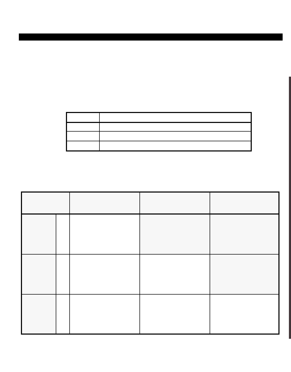
PERCEPTION 4000 COMMANDS
NOTE: Attendant consoles may only be installed on DSTI cards configured for 1B operation,
and may be used to establish the 1B card configuration if it is the first assignment made to the
DSTI card.
When installing attendant consoles, it is important to note the relationship between the console’s
assigned equipment number, its controlling LCPU, and its assigned attendant group number.
LCPU support is allocated among the PERCEPTION 4000 system’s Modular Line/Trunk Units
(shelves) as follows:
Those attendant consoles which are to be in the same attendant group need to be assigned to
equipment locations that will be supported by the same LCPU. This is because different LCPUs
support different attendant groups, as noted in the following table:
System
Size LCPU1
Shelves Supported:
1 ~ 4
LCPU2
Shelves Supported:
5 ~ 8
LCPU3
Shelves Supported:
9 ~ 10
1 LCPU
System Attendant Groups
Supported:
1 ~ 10
2 LCPU
System
3 LCPU
System
ATTENDANT GROUP SUPPORT ALLOCATION
Attendant Groups
Supported:
1 ~ 10
Attendant Groups
Supported:
1 ~ 10
Attendant Groups
Supported:
11 ~ 20
Attendant Groups
Supported:
11 ~ 20
Attendant Groups
Supported:
21 ~ 30
LCPU(X) Modular Line/Trunk Units (Shelves) Controlled by LCPU(X)
1 1 ~ 4
2 5 ~ 8
3 9 ~ 10
ISS 2, SECTION 4000-014-000
ATTENDANT POSITION ASSIGNMENT (CMD 370)
3-63

PERCEPTION 4000 COMMANDS
ISS 2, SECTION 4000-014-000
ATTENDANT POSITION ASSIGNMENT (CMD 370)
FIELD: ATT DN (Attendant Directory Number)
TYPE: DN Type
FORMAT: 1 to 5 digits
VALUE: 0 to 99999
RANGE: Allowed in a DISPLAY operation only
LOOP: Not allowed
Each attendant console must be assigned a unique directory number so that the attendant can
be dialed directly. This number must not conflict with any other directory numbers or feature
access codes in the system's numbering plan. The "ATT DN" cannot be modified. To change the
directory number, delete the original number, then add a new directory number.
FIELD: NAME (Attendant Name)
TYPE: Text
FORMAT: 0 to 9 ASCII characters
This optional field allows you to enter an attendant position name of up to nine ASCII characters.
Embedded spaces are allowed. The name entered here displays on the attendant console and
on display-equipped stations when individually addressing the attendant.
FIELD: GRP DN (Attendant Group Directory Number)
TYPE: DN Type
FORMAT: 1 to 5 digits
VALUE: 0 to 99999
RANGE: Allowed in a DISPLAY operation only
LOOP: Not allowed
The attendant group directory number is first defined through the Attendant Group Assignment
command (CMD 372). This directory number is dialed by system users to receive service from an
attendant in the attendant group. The "GRP DN" cannot be modified. To change the directory
number, delete the original number, then add a new directory number.
FIELD: COS (Class of Service)
TYPE: Decimal
FORMAT: 1 or 2 digits
VALUE: 1 to 64
RANGE: Allowed in a DISPLAY operation only
LOOP: Not allowed
The "COS" field determines what features and facilities are available for an attendant console.
The COS table is set up with the Class of Service Assignment command (CMD 334).
FIELD: DRL (Destination Restriction Level)
TYPE: Decimal
FORMAT: 1 or 2 digits
VALUE: 1 to 16 (or to the maximum system configuration)
RANGE: Allowed in a DISPLAY operation only
LOOP: Not allowed
The "DRL" field determines restrictions on outgoing calls. The DRL table is set up with the
Destination Restriction Level Assignment command (CMD 337).
3-64

PERCEPTION 4000 COMMANDS
FIELD: FRLP (Facility Restriction Level Profile)
TYPE: Decimal
FORMAT: 1 or 2 digits
VALUE: 1 to 32 (or to the maximum system configuration)
RANGE: Allowed in a DISPLAY operation only
LOOP: Not allowed
The "FRLP" field establishes the relationship between the originator's' facility restriction level
profile number and the facility restriction levels assigned to various routes within each least cost
routing route table. The FRLP table is set up with the Facility Restriction Level Profile Assignment
command (CMD 387).
FIELD: QPL (Queue Priority Level)
TYPE: Decimal
FORMAT: 1 digit
VALUE: 1 to 8
RANGE: Allowed in a DISPLAY operation only
LOOP: Not allowed
The "QPL" field determines the queuing priority level for outgoing trunk calls when trunk queuing
is set to 'priority queuing' with the System Option Flag Assignment command (CMD 408).
Commands related to this field include the LCR Routing Table Assignment command (CMD 383)
and the LCR Special Routing Assignment command (CMD 384).
FIELD: ROB (Ring Over Busy Flag)
TYPE: Keyword
FORMAT: Predefined ASCII characters
Keywords: YES - Enable Ring Over Busy signal
NO - Disable Ring Over Busy signal
This field enables/disables a muted ringing signal at the console when a new call comes in while
the attendant is already engaged in processing a call.
FIELD: EMR RNG (Emergency Call Ringing Flag)
TYPE: Keyword
FORMAT: Predefined ASCII characters
Keywords: YES - Enable Emergency Call Ringing
NO - Disable Emergency Call Ringing
When an emergency call terminates at the attendant console, the console starts to ring at full
volume.
FIELD: PSWD (Attendant Password Requirement)
TYPE: Keyword
FORMAT: Predefined ASCII characters
Keywords: YES - Password required
NO - Password not required
ISS 2, SECTION 4000-014-000
ATTENDANT POSITION ASSIGNMENT (CMD 370)
3-65

PERCEPTION 4000 COMMANDS
ISS 2, SECTION 4000-014-000
ATTENDANT POSITION ASSIGNMENT (CMD 370)
The attendant console may be designated to require the attendant to enter a password prior to
the system allowing the console to exit the position busy mode and return to call processing. The
"PSWD" field controls whether or not a password is required by the attendant. Attendant
passwords are set up through the Attendant Password Assignment command (CMD 375) and
must be defined to enable this feature.
FIELD: TYPE (Terminal Type)
TYPE: Keyword
FORMAT: Predefined ASCII characters
DEFAULT: EGA
Keywords: EGA - Enhanced Graphic Adaptor
EL - Electroluminescent Display Unit
This field indicates the type of display terminal that is to be used with the PERCEPTION 4000
attendant console base unit. Either terminal type provides the attendant with the same display
information, although a color EGA terminal can provide color displays.
FIELD: AUD (Key Depression Audible Response)
TYPE: Keyword
FORMAT: Predefined ASCII characters
Keywords: YES - Enable Audible Key Depression
NO - Disable Audible Key Depression
This field determines whether a confirmation tone is output when a key is pressed. Currently this
is a locked field set to "YES."
SYSTEM ERROR MESSAGES
The following error messages are unique to this command.
C37000 - Equipment number is already assigned to another device
C37001 - Attendant directory number has already been defined
C37002 - Invalid attendant directory number
C37003 - Attendant group directory number has not been defined
C37004 - Input exceeds the number of possible attendants in the system
C37005 - The specified attendant does not exist
C37006 - Equipment number and directory number do not match
C37007 - Equipment number or attendant directory number is required
C37008 - Not a DSTI card type
I37010 - Are you sure you want to remove last attendant from attendant group?
I37011 - Remove this attendant?
C37012 - Cannot assign more attendants to attendant groups
C37013 - Cannot assign more attendants to shelves
C37014 - Cannot modify attendant group directory number
C37015 Cannot modify attendant directory number
C37016 Attendant call queue has L calls; try again when it is M or less (L and M are values between 1
and 320)
C37017 Attendant call queue has N calls; try again when it is empty (N is a value betwen 1 and 32)
3-66

PERCEPTION 4000 COMMANDS
RELATED COMMANDS
Attendant Feature Key Assignment (CMD 371)
Attendant Incoming Call Priority Assignment (CMD 373)
Attendant Password Assignment (CMD 375)
Class of Service Assignment (CMD 334)
Destination Restriction Level Assignment (CMD 337)
Facility Restriction Level Profile Assignment (CMD 387)
Internal Call Alternate Routing Assignment (CMD 374)
LCR Routing Table Assignment (CMD 383)
LCR Special Routing Information (CMD 384)
Station Assignment (CMD 330)
System Option Flag Assignment (CMD 408)
ISS 2, SECTION 4000-014-000
ATTENDANT POSITION ASSIGNMENT (CMD 370)
3-67

PERCEPTION 4000 COMMANDS
ISS 2, SECTION 4000-014-000
AUTHORIZATION CODE ASSIGNMENT (CMD 349)
AUTHORIZATION CODE ASSIGNMENT (CMD 349)
The PERCEPTION 4000 supports up to 1024 authorization codes. Each authorization code changes the Class of
Service definition, Destination Restriction Level, Facility Restriction Level Profile, Queue Priority Level, and
answering position from what is in effect for the station, data device, attendant, DISA, or incoming TIE trunk at the
time of authorization code registration. The same authorization code can be used on any device which is
assigned the above attributes. The Authorization Code Assignment command adds, deletes, modifies, and
displays these codes.
Command Keyword: AUTHORIZATION_CODES
Category Name: Station
PREREQUISITE COMMANDS
Numbering Plan Assignment (CMD 300)
If "ANSPOS" is defined, one of the following commands may be needed:
ACD Group Assignment (CMD 355)
Attendant Group Assignment (CMD 372)
Attendant Position Assignment (CMD 370)
Station Hunting Assignment (CMD 342)
UCD Group Assignment (CMD 354)
OPERATIONS
Available operations: ADD
DELETE
MODIFY
DISPLAY
The function and required data fields for each operation are described in this section.
ADD
This operation adds authorization codes to the table. All fields, except the "SMDR ID", "ANSPOS", and "S RG"
fields, are required.
req
AUTH CODE SMDR ID COS DRL FRLP QPL ANSPOS RG
lockedoptreq opt
3-68
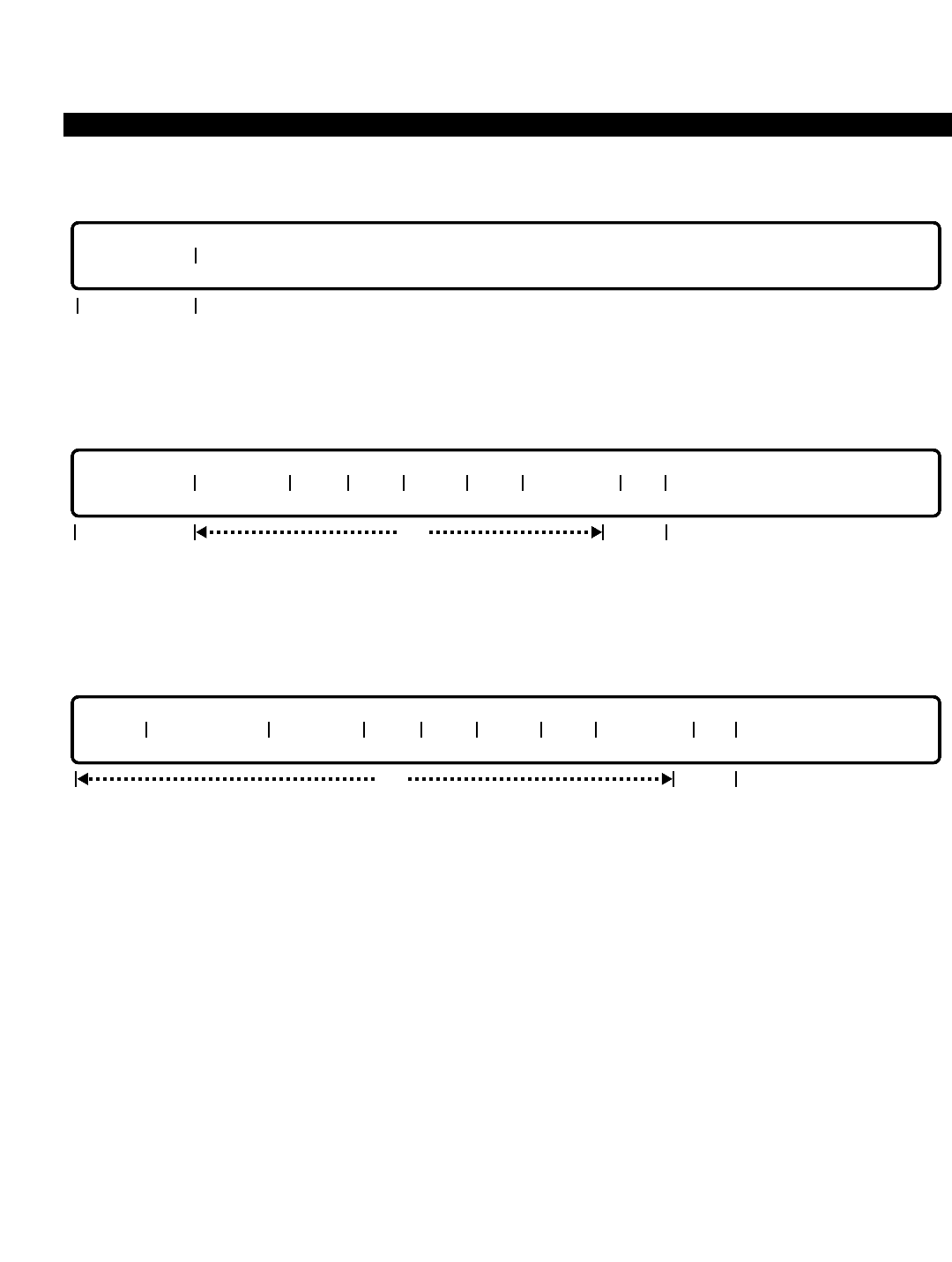
PERCEPTION 4000 COMMANDS
DELETE
This operation deletes an authorization code from the table. "AUTH CODE" is a required field.
MODIFY
This operation modifies the attributes of an authorization code. "AUTH CODE" is a required field, while the
remaining fields are optional, with the exception of the "S RG" field which is a locked field.
DISPLAY
This operation displays authorization codes and their attributes. Ranges are permitted in all of the fields, except
the "SMDR ID" and "S RG" fields.
PARAMETERS
Each field parameter is described in this section. Any variations for a particular operation are noted separately.
FIELD: INDEX
TYPE: Decimal
FORMAT: 1 to 4 digits
VALUE: 1 to 1024
RANGE: Allowed in a DISPLAY operation only
This field is used in a DISPLAY operation only, and is for the convenience of the M&A supervisor.
The PERCEPTION 4000's database does not support indexed authorization codes.
opt
INDEX AUTH CODE SMDR ID COS DRL FRLP QPL ANS POS RG
locked
opt
AUTH CODE SMDR ID COS DRL FRLP QPL ANS POS RG
lockedreq
AUTH CODE
req
ISS 2, SECTION 4000-014-000
AUTHORIZATION CODE ASSIGNMENT (CMD 349)
3-69

PERCEPTION 4000 COMMANDS
ISS 2, SECTION 4000-014-000
AUTHORIZATION CODE ASSIGNMENT (CMD 349)
FIELD: AUTH CODE (Authorization Code)
TYPE: Decimal
FORMAT: 1 to 8 digits
VALUE: 1 to 99999999
Each code can be up to eight digits in length (set with the "LEN PD1" field in the Numbering Plan
Assignment command, CMD 300). All authorization codes must be of the same length. This field
is required for ADD, DELETE, and MODIFY operations.
FIELD: SMDR ID (SMDR Identification Code)
TYPE: Text
FORMAT: 0 to 5 ASCII characters
Each authorization code has a corresponding SMDR identification code to identify which caller
used the system without disclosing the actual authorization code, thereby breaching security.
SMDR ID codes are optional and are not required.
FIELD: COS (Class of Service)
TYPE: Decimal
FORMAT: 1 or 2 digits
VALUE: 1 to 64
RANGE: Allowed in a DISPLAY operation only
The COS table is set up with the Class of Service Assignment command (CMD 334). This field is
required for an ADD operation.
FIELD: DRL (Destination Restriction Level)
TYPE: Decimal
FORMAT: 1 or 2 digits
VALUE: 1 to 16
RANGE: Allowed in a DISPLAY operation only
The DRL table is set up with the Destination Restriction Level Assignment command (CMD 337).
This field is required for an ADD operation.
FIELD: FRLP (Facility Restriction Level Profile)
TYPE: Decimal
FORMAT: 1 or 2 digits
VALUE: 1 to 32
RANGE: Allowed in a DISPLAY operation only
The FRLP table is set up with the Facility Restriction Level Profile Assignment command (CMD
387). This field is required for an ADD operation.
FIELD: QPL (Queue Priority Level)
TYPE: Decimal
FORMAT: 1 digit
VALUE: 1 to 8
RANGE: Allowed in a DISPLAY operation only
3-70

PERCEPTION 4000 COMMANDS
Commands related to this field include the LCR Routing Table Assignment command (CMD 383)
and the LCR Special Routing Assignment command (CMD 384). This field is required for an ADD
operation.
FIELD: ANSPOS (Answer Position)
TYPE: DN Type
FORMAT: 1 to 5 digits
VALUE: 0 to 99999
RANGE: Allowed in a DISPLAY operation only
This field is optional, but when used, data input must be one of the following:
Attendant Hunt Group Pilot
Attendant Group ACD Pilot
Station UCD Pilot
FIELD: RG (Voice/Data Restriction Group) (Reserved for future use.)
TYPE: Decimal
FORMAT: 1 or 2 digits
VALUE: 1 to 16
RANGE: Not allowed
This is a locked field. No input is accepted.
SYSTEM ERROR MESSAGES
The following error messages are unique to this command.
C34900 - Invalid dial 0 destination
C34901 - Invalid authorization code
C34902 - Authorization code already exists
C34903 - Authorization code does not exist
C34904 - Invalid authorization code length
C34905 - SMDR identification code maximum is 5 characters
C34906 - Number of authorization codes has reached system maximum.
RELATED COMMANDS
Class of Service Assignment (CMD 334)
Destination Restriction Level Assignment (CMD 337)
Facility Restriction Level Profile Assignment (CMD 387)
LCR Routing Table Assignment (CMD 383)
LCR Special Routing Assignment (CMD 384)
ISS 2, SECTION 4000-014-000
AUTHORIZATION CODE ASSIGNMENT (CMD 349)
3-71

PERCEPTION 4000 COMMANDS
ISS 2, SECTION 4000-014-000
AUTODIAL NUMBER DISPLAY (CMD 324)
AUTODIAL NUMBER DISPLAY (CMD 324)
This command displays the current destination numbers of preregistered Autodial keys on telephones and/or add-
on modules. In addition, the command allows the system administrator to modify destination numbers on Autodial
keys. Note that the Autodial keys are assigned with the Station Feature Key Assignment command (CMD 331).
Command Keyword: AUTO_DIAL_DISP
Category Name: Station
PREREQUISITE COMMANDS
Station Assignment (CMD 330)
Station Feature Key Assignment (CMD 331)
OPERATIONS
Available operations: MODIFY
DISPLAY
The function and required data fields for each operation are described in this section.
MODIFY
The MODIFY operation is used to add or change a preregistered destination for a specified Autodial key. All fields
are required, except for the "LS DEV" and "LS POS" fields. However, if line selection is programmed into the
Autodial sequence, then data is required in both the "LS DEV" and "LS POS" fields.
DISPLAY
This operation displays the preregistered destinations of all Autodial keys for a specified prime directory number.
The optional fields may be used to provide selected information.
PRM DN | PRM DEV | ADL POS | LS DEV | LS POS | DESTINATION |
req opt
PRM DN | PRM DEV | ADL POS | LS DEV | LS POS | DESTINATION |
req opt req
opt
3-72

PERCEPTION 4000 COMMANDS
PARAMETERS
Each field parameter is described in this section. Any variations for a particular operation are noted separately.
FIELD: PRM DN (Prime Directory Number)
TYPE: DN Type
FORMAT: 1 to 5 digits
VALUE: 1 to 99999
LOOP: Not allowed
The "PRM DN" field, which is required in both the MODIFY and DISPLAY operations, specifies
the prime directory number for the device containing the Autodial keys.
FIELD: PRM DEV (Primary Device)
TYPE: Keyword
FORMAT: Predefined ASCII characters
Keywords: 4000 - PERCEPTION 4000 Telephone
EKT - Electronic Telephone
DKT - DKT Digital Telephone
AD1 - Add-on Module 1 (20-key or 60-key [60-key = three 20-key modules])
AD2 - Add-on Module 2 (20-key)
The "PRM DEV" field indicates the primary device containing the Autodial key to be modified or
displayed. This field is required in a MODIFY operation, and optional in a DISPLAY operation.
FIELD: ADL POS (Autodial Key Position)
TYPE: Decimal
FORMAT: 1 or 2 digits
VALUE: 1 to 10 (10-key digital and electronic telephones)
1 to 20 (20-key digital and electronic telephones, 20-key add-on modules)
1 to 60 (60-key add-on module [three 20-key modules])
RANGE: Allowed in a DISPLAY operation
This field, which indicates the position of the Autodial key on the "PRM DEV", is required in a
MODIFY operation and optional in a DISPLAY operation. The key position is programmed with
the Station Feature Key Assignment command (CMD 331). Refer to Figure 3-1a for illustrations
of primary device key positions.
FIELD: LS DEV (Line Selection Device)
TYPE: Keyword
FORMAT: Predefined ASCII characters
Keywords: 4000 - PERCEPTION 4000 Digital Telephone
EKT - Electronic Telephone
DKT - DKT Digital Telephone
AD1 - Add-on Module 1 (20-key or 60-key [60-key = three 20-key modules])
AD2 - Add-on Module 2 (20-key)
On multi-line telephones and telephones with add-on modules, a secondary line may be used by
an Autodial key to place a call. The "LS DEV" field defines the device containing the secondary
ISS 2, SECTION 4000-014-000
AUTODIAL NUMBER DISPLAY (CMD 324)
3-73
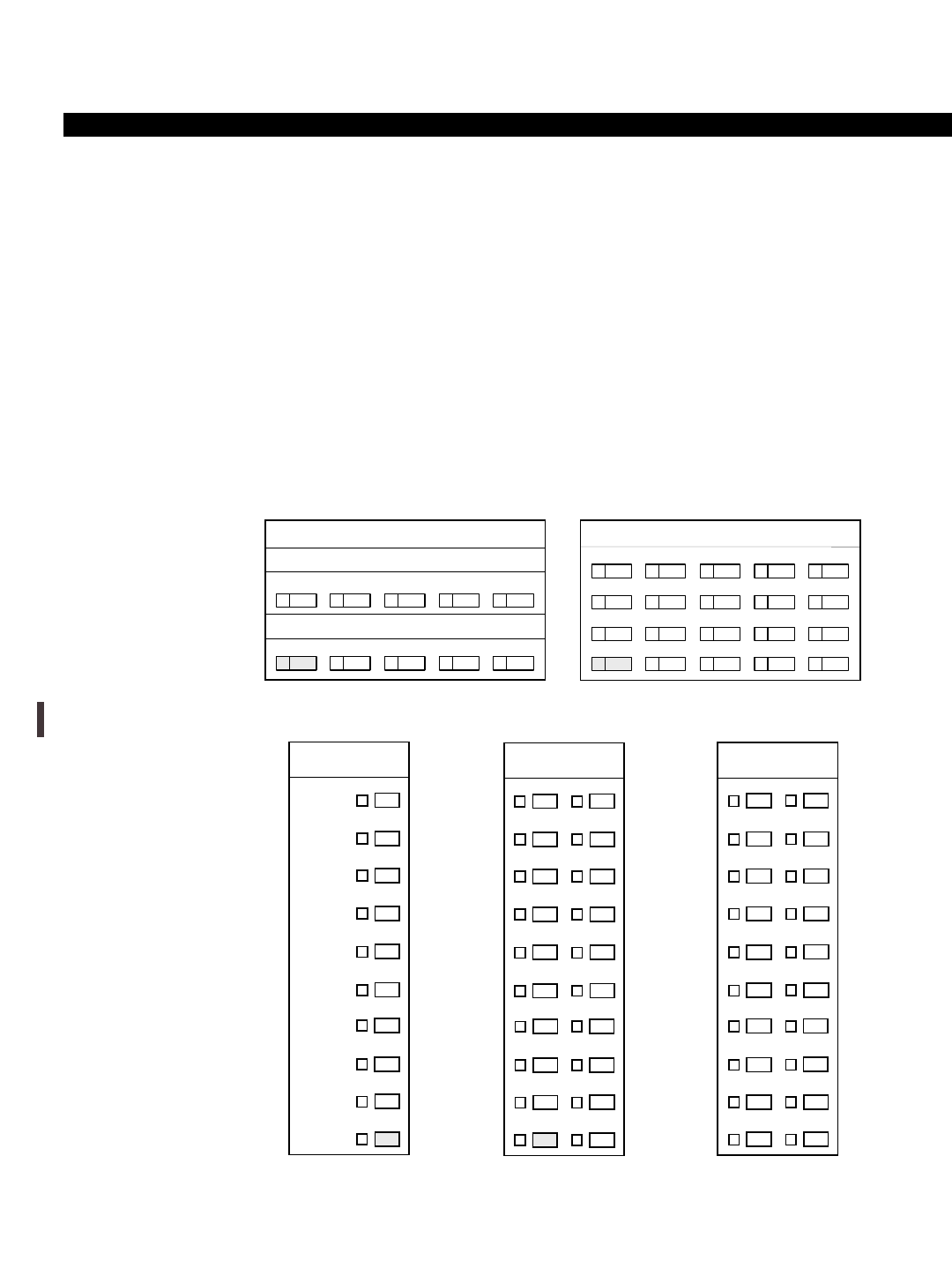
PERCEPTION 4000 COMMANDS
ISS 2, SECTION 4000-014-000
AUTODIAL NUMBER DISPLAY (CMD 324)
line. If there is no line selection programmed into the Autodial sequence associated with the
selected ADL key, this field is left blank.
FIELD: LS POS (Line Selection Key Position)
TYPE: Decimal
FORMAT: 1 or 2 digits
VALUE: 1 to 10 (10-key digital and DKT/electronic telephones)
1 to 20 (20-key digital and DKT/electronic telephones, 20-key add-on modules)
1 to 60 (60-key add-on module [three 20-key modules])
RANGE: Not allowed
This field, which is required if an entry is made in the "LS DEV" field, indicates the position of the
prime or secondary line key on the line selection device (i.e., PERCEPTION 4000 digital
telephone, electronic telephone, or add-on module).
Figure 3-2
Key Positions
NOTE: The shaded areas in the figures designate default prime directory number locations.
3-74
10
5
9
4
8
3
7
2
6
1
20
15
10
5
19
14
9
4
18
13
8
3
17
12
7
2
16
11
6
1
PERCEPTION 4000
10-Key Digital Telephone PERCEPTION 4000
20-Key Digital Telephone
9
10
7
8
5
6
3
4
2
1
19
20
17
18
15
16
14
13
12
11
9
10
7
8
5
6
4
3
2
1
10-Key DKT or
Electronic Telephone 20-Key DKT or
Electronic Telephone
12
11
14
13
16
15
17
18
19
20
2
1
4
3
6
5
7
8
9
10
Add-on Module

PERCEPTION 4000 COMMANDS
FIELD: DESTINATION (Autodial Destination Digits)
TYPE: Dialing Digits
FORMAT: 1 to 24 digits
VALUE: 0 to 9
RANGE: Not allowed
This field specifies the internal or external destination directory number for the specified Autodial
key. Valid destinations include an attendant, station, or off-premises directory number. The
"DESTINATION" is required in a MODIFY operation, and optional in a DISPLAY operation.
SYSTEM ERROR MESSAGES
The following error messages are unique to this command.
C32400 - Terminal does not exist in LCPU
C32401 - Directory number does not exist
C32402 - Specified key number is not an Autodial key
C32403 - Specified key number is out of range
C32404 - Device type does not match with terminal type
C32405 - Specified line selection is not a line key
C32406 - Secondary line key position is required
C32407 - Not an Autodial destination
C32408 - Line selection device does not match with terminal type
ISS 2, SECTION 4000-014-000
AUTODIAL NUMBER DISPLAY (CMD 324)
3-75
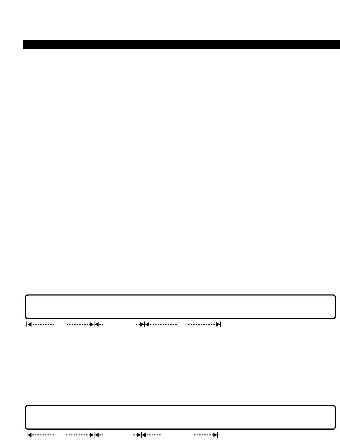
PERCEPTION 4000 COMMANDS
ISS 2, SECTION 4000-014-000
CALL FORWARDING DESTINATION DISPLAY (CMD 325)
CALL FORWARDING DESTINATION DISPLAY (CMD 325)
This command displays all of the Preregistered Call Forwarding (PRCF) keys for a specified prime directory
number, or displays only the currently active Call Forwarding key. Additionally, the command specifies the Call
Forwarding type and destination numbers assigned to the keys. The command also allows the system
administrator to modify the destination numbers of PRCF keys, or activate/deactivate a Call Forwarding feature
for a specified prime directory number. Note that Call Forward keys are assigned with the Station Feature Key
Assignment command (CMD 331) and programmed by the station user.
Command Keyword: CALL_FORWARD_DISP
Category Name: Station
PREREQUISITE COMMANDS
Station Assignment (CMD 330)
Station Feature Key Assignment (CMD 331)
OPERATIONS
Available operations: MODIFY
DISPLAY
The function and required data fields for each operation are described in this section.
MODIFY
The MODIFY operation adds or changes the destination number of a preregistered key, or activates/deactivates
call forwarding for the specified Call Forward feature ("TYPE" field). "DEV" and "POS" field input is required if a
Preregistered Call Forwarding key (PCF) is selected in the "PCF/ACF" field. When the Active Call Forward key
(ACF) is selected, then the "DEV" and "POS" fields are "locked;" if data is entered in either field, an error
message appears.
DISPLAY
PCF/ACF | PRM DN | DEV | POS | TYPE | DESTINATION |
req opt or N/A output only
PCF/ACF | PRM DN | DEV | POS | TYPE | DESTINATION |
req req or N/A req
3-76

PERCEPTION 4000 COMMANDS
This operation displays the preregistered or currently-active Call Forwarding destinations for a specified prime
directory number. The optional fields may be used to provide selected information for PRCFs.
PARAMETERS
Each field parameter is described in this section. Any variations for a particular operation are noted separately.
FIELD: PCF/ACF (Preregistered/Active Call Forward Type)
TYPE: Keyword
FORMAT: Predefined ASCII characters
Keywords: PCF - Preregistered Call Forward Keys
ACF - Active Call Forward Feature
The "PCF/ACF" field indicates the type of information to be modified/displayed: either
Preregistered Call Forward (PRCF) keys for the specified prime directory number, or only the
currently Active Call Forward feature. This field is required in both the MODIFY and DISPLAY
operations.
FIELD: PRM DN (Prime Directory Number)
TYPE: DN Type
FORMAT: 1 to 5 digits
VALUE: 1 to 99999
LOOP: Not allowed
The "PRM DN" field, which is required, specifies the prime directory number of the device
containing the Call Forward keys.
FIELD: DEV (Preregistered Call Forward Device)
TYPE: Keyword
FORMAT: Predefined ASCII characters
Keywords: 4000 - PERCEPTION 4000 Telephone
EKT - Electronic Telephone
DKT - DKT Digital Telephone
AD1 - Add-on Module 1 (20-key or 60-key [60-key = three 20-key modules])
AD2 - Add-on Module 2 (20-key)
The "DEV" field indicates the device containing the PRCF keys. This field is required in a
MODIFY operation when PCF is selected in the "PCF/ACF" field. When ACF is selected, the
"DEV" field is "locked."
FIELD: POS (PRCF Key Position Number)
TYPE: Decimal
FORMAT: 1 or 2 digits
VALUE: 1 to 10 (10-key digital and electronic telephones)
1 to 20 (20-key digital and electronic telephones, 20-key add-on modules)
1 to 60 (60-key add-on module [three 20-key modules])
RANGE: Allowed in a DISPLAY operation
ISS 2, SECTION 4000-014-000
CALL FORWARDING DESTINATION DISPLAY (CMD 325)
3-77

PERCEPTION 4000 COMMANDS
ISS 2, SECTION 4000-014-000
CALL FORWARDING DESTINATION DISPLAY (CMD 325)
This field indicates the position of the PRCF keys on the "DEV", and is required in a MODIFY
operation when PCF is selected in the "PCF/ACF" field. When ACF is selected, the "POS" field is
"locked". Refer to the Station Feature Key Assignment command (CMD 331) for illustrations of
primary device key positions.
FIELD: TYPE (Call Forward Type)
TYPE: Keyword
FORMAT: Predefined ASCII characters
Keywords: CFAC - Call Forward all Calls
CFBN - Call Forward Busy/No Answer
CFNA - Call Forward No Answer
This field selects the Call Forward type assigned to the prime directory number ("PRM DN" field)
for PRCF keys. If ACF is entered in the "PCF/ACF" field, this field is used to deactivate the
currently active key by entering a <CONTROL-D>. In a DISPLAY operation, the "TYPE" field is
an 'output only' field.
FIELD: DESTINATION (Call Forward Destination Number)
TYPE: Dialing Digits
FORMAT: 1 to 24 digits
VALUE: 0 to 9
RANGE: Not allowed
This field specifies the internal or external destination directory number for the specified Call
Forward key. Valid destinations include an attendant, station, or off-premises directory number.
The "DESTINATION" cannot be deleted; it can only be added or changed.
SYSTEM ERROR MESSAGES
The following error messages are unique to this command.
C32500 - Terminal does not exist in LCPU
C32501 - Directory number does not exist
C32502 - Specified key number is not a preregistered Call Forward key
C32503 - Key number is out of range
C32504 - Device type does not match with terminal type
C32505 - There is no call forward activation
C32506 - Device is not required; enter a <TAB> in this field
C32507 - Position number is not required; enter a <TAB> in this field
C32508 - Device is required for PCF selection
C32509 - Position number is required for PCF selection
C32510 - Destination is not required; enter a <TAB> in this field
C32511 - Destination is required
C32512 - Not allowed to delete preregistered call forwarding
C32513 - Destination does not exist
C32514 - Directory number is a multiple line number
C32515 - Directory number is an originate-only station
C32516 - Terminal is in feature registration mode, please try again
3-78

PERCEPTION 4000 COMMANDS
CALL PICKUP GROUP ASSIGNMENT (CMD 346)
The Call Pickup Group command defines memberships in the system's call pickup groups. This information is
necessary for both the Group Call Pickup and the Directed Group Call Pickup features. Directed Group Call
Pickup does not require the calling or called party to be assigned pickup group membership. A maximum of 512
members per system may be assigned to Call Pickup Groups.
Command Keyword: CALL_PICKUP
Category Name: Station
PREREQUISITE COMMAND
Station Assignment (CMD 330)
OPERATIONS
Available operations: ADD
DELETE
MODIFY
DISPLAY
The function and required data fields for each operation are described in this section.
ADD
This operation adds call pickup group names or member directory numbers. Loops are allowed in the “GRP#” and
“INDEX” fields.
DELETE
This operation deletes call pickup members. To delete all members in a group, enter the keyword ALL in the
“MEM DN” field. Loops are allowed in the “GRP#” field.
GRP# MEM DN
req
GRP# NAME INDEX MEM DN
optreq req
ISS 2, SECTION 4000-014-000
CALL PICKUP GROUP ASSIGNMENT (CMD 346)
3-79

PERCEPTION 4000 COMMANDS
ISS 2, SECTION 4000-014-000
CALL PICKUP GROUP ASSIGNMENT (CMD 346)
MODIFY
This operation modifies call pickup group names.
DISPLAY
This operation displays call pickup group names and members. Looping is allowed in the “GRP#” field. If no data
is entered in any of the fields, all of the call pickup group names and members are displayed.
PARAMETERS
Each field parameter is described in this section. Any variations for a particular operation are noted separately.
FIELD: GRP# (Call Pickup Group Number)
TYPE: Decimal
FORMAT: 1 to 3 digits
VALUE: 1 to 128
LOOP: Allowed in all operations
This field assigns a number to a Call Pickup Group. Up to 128 groups with a maximum of four
members in each group may be defined. Note that the system allows 512 members per system
with a maximum of 32 members per group. Group members must be voice stations only. Stations
may belong to only one call pickup group.
FIELD: NAME (Group Name)
TYPE: Text
FORMAT: 0 to 9 ASCII characters
This field assigns a name to the designated group number. Embedded spaces are allowed.
FIELD: INDEX (Member Index Number)
TYPE: Decimal
FORMAT: 1 or 2 digits
VALUE: 1 to 32
LOOP: Allowed in an ADD operation
GRP# NAME INDEX MEM DN
output
only
opt opt
GRP# NAME
req
3-80

PERCEPTION 4000 COMMANDS
Index numbers are assigned to each designated call pickup group member with this field. A call
pickup search is made from the lowest index number to the highest. Thus, ordering is important,
such as when a group pickup or directed group pickup is requested by a party and multiple
telephones within that group are ringing, the lowest numbered (index number) ringing telephone
is picked up first.
FIELD: MEM DN (Pickup Group Member Directory Number)
TYPE: DN Type / Keyword
FORMAT: 1 to 5 digits / Predefined ASCII characters
VALUE: 0 to 99999
RANGE: Allowed in a DISPLAY operation
Keyword: ALL
Assign members to a group in the order in which the group should be searched for a ringing call.
This feature does not look for the longest ringing call, but rather does a sequential search of this
table. In a DELETE operation, if the keyword ALL is entered, all of the members of the given call
pickup group are deleted.
SYSTEM ERROR MESSAGES
The following error messages are unique to this command.
C34600 - Not a station directory number
C34601 - Table is full
C34602 - Directory number is already in an other pickup group
C34603 - Directory number not found
C34604 - Directory number is already in the pickup group
C34605 - Directory number is a private line
C34606 - Directory number is not a prime DN
C34607 - No space left to add new members
ISS 2, SECTION 4000-014-000
CALL PICKUP GROUP ASSIGNMENT (CMD 346)
3-81

PERCEPTION 4000 COMMANDS
ISS 2, SECTION 4000-014-000
CANNED TEXT/ADVISORY MESSAGE CREATION (CMD 328)
CANNED TEXT/ADVISORY MESSAGE CREATION (CMD 328)
This command is used to modify canned text and advisory message information that appears on Perception 4000
HDT2020SD telephones and on the Perception 4000 attendant console display. The command is also used to
modify attendant console identification information that appears on the console's electroluminescent (EL) display
unit. This is typically company-specific information, including the name, address, and telephone number of the
Toshiba distributor or end-user customer. Additionally, this command is used to modify the greeting that is sent
whenever a data call is connected through the Perception 4000 system.
Command Keyword: MESSAGE_ASSIGN
Category Name: Station
PREREQUISITE COMMANDS
There are no prerequisites for this command.
OPERATIONS
Available operations: DISPLAY
MODIFY
The function and required data fields for each operation are described as follows:
DISPLAY:
This operation is used to display current canned text, advisory messages, attendant EL display text, and/or the
system's data call greeting.
MODIFY:
This operation is used to modify the contents of canned text, advisory messages, attendant console EL display
text, and/or the system's data call greeting.
req
TYPE INX MESSAGE TEXT
opt
opt
TYPE INX MESSAGE TEXT
req
3-82

PERCEPTION 4000 COMMANDS
PARAMETERS
This section defines input permitted for each field. Any variations for a particular operation are noted separately.
FIELD: TYPE (Message Type)
TYPE: Keyword
FORMAT: Preassigned ASCII characters
Keywords: CAN - Canned text
ADV - Advisory messages
ATT - Attendant EL display text
DAT - System message for data calls
This field is used to specify the type of message that is to be modified.
FIELD: INX (Index Number)
TYPE: Decimal
FORMAT: 1 decimal digit
VALUE; 1 - 8 for canned text and advisory messages
1 - 3 for attendant EL display text
1 - 2 for system message for data calls
RANGE: Not allowed
LOOP: Allowed in DISPLAY operation only
This field specifies which specific text line or advisory message (1 - 8) is to be modified; which type of EL display
information (1 - 3); or which system message for data calls (1 - 2) is to be modified.
FIELD: MESSAGE TEXT
TYPE: ASCII characters
FORMAT: Canned text and advisory messages: 30 characters maximum
Attendant EL display messages and system message for data calls: 70 characters maximum
This field is used to indicate: the canned text and advisory message information that will appear on Perception
4000 HDT2020SD telephones and attendant console; additional attendant EL display information; and the system
message for incoming data calls.
Up to eight text messages and eight advisory messages can be programmed. Once programmed, text messages
can be sent from an HDT2020SD telephone(via soft key operaton) when calling another HDT2020SD telephone.
A text message provides the called party with a brief message about the nature of the call (e.g., "Please see me,"
"Returned your Call," etc.). Text messages are displayed on the called HDT2020SD when the called party scrolls
through his/her telephone messages via soft key operation.
Advisory messages can be programmed at any HDT2020SD telephone to provide calling HDT2020SD
telephones or a calling attendant console about the whereabouts of the called party (e.g., "In a Meeting," "Out to
Lunch," etc.). An advisory message is set at an HDT2020SD telephone via soft key operation and remains set
until canceled from the station.
Attendant console EL display messages typically indicate the name, address, and telephone number of the end-
user company. This information customizes the attendant console for each customer site and serves as a
convenient reference for the attendant operator.
ISS 2, SECTION 4000-014-000
CANNED TEXT/ADVISORY MESSAGE CREATION (CMD 328)
3-83

PERCEPTION 4000 COMMANDS
ISS 2, SECTION 4000-014-000
CANNED TEXT/ADVISORY MESSAGE CREATION (CMD 328)
The system message for data calls will be conveyed to a calling data party after connection to a data device. The
system message informs the calling party that he/she has reached the appropriate destination. For example,
when placing a data call to Toshiba, the message may state: "Welcome to Toshiba Data Services."
SYSTEM MESSAGES
The following error messages are unique to this command.
C32800 - Invalid message length
C32801 - Index is out of range
3-84

PERCEPTION 4000 COMMANDS
CLASS OF SERVICE ASSIGNMENT (CMD 334)
Up to 64 classes of service may be defined in the system. Each Class of Service (COS) defines a set of facility
and feature access capabilities. One of these classes is then assigned to each voice or data station, attendant
console, and trunk group designated with DISA or an incoming TIE trunk.
Most capabilities defined by COS are useful to all of the above device/facility types. However a few are unique,
such as the 'Do-not-Disturb Override' feature which may only be assigned to attendants. In these cases where the
capability may be assigned to a station or data device as well, the system understands the limitation and will not
allow the capability to be effected by a station user, even if it exists in its COS definition. This allows greater
flexibility in the configuration of definitions.
It is suggested that the administrator go over the organizational structure of the company and develop groups of
common users which logically fit together in terms of telephone needs and privilege levels. After these groups are
defined and needs/privileges known, a COS definition may be assigned to each group, then the definitions may
be applied to stations, consoles, etc.
Command Keyword: CLASS_OF_SERVICE
Category Name: System
PREREQUISITE COMMANDS
There are no prerequisites for this command.
OPERATIONS
Available operations: ADD
DELETE
DISPLAY
The function and required data fields for each operation are described in this section.
ADD
This operation modifies the definition of one or more existing classes of service by adding new feature(s) to
it/them. Fields 1 and 2 are required fields. Scopes are allowed in Fields 2 through 14 to facilitate the addition of a
large number of features
opt
COS FNO FNO FNO FNO FNO FNO FNO FNO FNO FNO FNO FNO FNO FNO
req
ISS 2, SECTION 4000-014-000
CLASS OF SERVICE ASSIGNMENT (CMD 334)
3-85

PERCEPTION 4000 COMMANDS
ISS 2, SECTION 4000-014-000
CLASS OF SERVICE ASSIGNMENT (CMD 334)
DELETE
This operation modifies the definition of a COS by deleting feature(s) in the COS. Fields 1 and 2 are required
fields. Scopes are allowed in Fields 2 through 14 to facilitate the deletion of a large number of features.
DISPLAY
This operation displays part or all of the COS table, depending on input in the “FNO” fields. If no data is entered,
the system displays the complete COS table. Ranges are permitted in all of the fields.
PARAMETERS
Each field parameter is described in this section. Any variations for a particular operation are noted separately.
FIELD: COS (Class of Service)
TYPE: Decimal
FORMAT: 1 or 2 digits
VALUE: 1 to 64
RANGE: Not allowed
LOOP: Allowed
This field specifies the appropriate class of service that is to be displayed or modified.
FIELD: FNO (Feature Number)
TYPE: Decimal
FORMAT: 1 to 3 digits
VALUE: 1 to 334
RANGE: Allowed in a DISPLAY operation
SCOPE: Allowed in ADD and DELETE operations
Feature numbers pertaining to COS are entered in this field. Values from 1 to 256 are actual
trunk group numbers, however, trunk groups 129 to 256 are reserved for systems configured
above the standard default of 128. Values from 257 to 334 represent features. Following is a list
of valid entries.
opt
COS FNO FNO FNO FNO FNO FNO FNO FNO FNO FNO FNO FNO FNO FNO
COS FNO FNO FNO FNO FNO FNO FNO FNO FNO FNO FNO FNO FNO FNO
optreq
3-86

PERCEPTION 4000 COMMANDS
Feature Decimal Value
Attendant Break-in 332
Attendant End-to End Signaling 345
Attendant Parked Page Retrieval 333
Call Forward - All Calls Key 271
Call Forward - Busy/No Answer Key 272
Call Forward - No Answer Key 273
Call Fwd - All Calls Register 295
Call Fwd - Busy/No Ans Register 296
Call Fwd - No Answer Register 297
Call Pickup - Directed 284
Code Calling Access 258
Code Calling Retrieval 267
Data Privacy 312
Dictation Machine Access - Direct 264
Dictation Machine Access - Group 263
* Direct Trunk Access - Trunk Group 1 1
* Direct Trunk Access - Trunk Group nnn nnn (nnn is greater than 1 and less than 256)
* Direct Trunk Access - Trunk Group 256 256
Do Not Disturb Key 270
Do Not Disturb Registration 288
Eight Party Conference Access 313
ISDN CPN Presentation Allowed 342
ISDN CPN Presentation Restricted 343
Night Answer Access 269
Trunk-to-Trunk Connection 257
Trunk Verification from Station 334
Voice Paging Access - Emergency 261
Voice Paging Access - System 260
Voice Paging Access - Zone 259
Voice Paging Retrieval - System 266
Voice Paging Retrieval - Zone 265
* If the type of trunk group is defined as a private line, the corresponding feature number is not
under COS control.
SYSTEM ERROR MESSAGES
The following error messages are unique to this command.
C33400 - Check for a valid feature number
C33401 - Invalid tenant number
C33402 - Invalid Class of Service number
C33403 - Feature number is out of range
C33404 - Missing data in scope type field in field N
ISS 2, SECTION 4000-014-000
CLASS OF SERVICE ASSIGNMENT (CMD 334)
3-87

PERCEPTION 4000 COMMANDS
ISS 2, SECTION 4000-014-000
CLASS OF SERVICE ASSIGNMENT (CMD 334)
3-88
RELATED COMMANDS
Attendant Position Assignment (CMD 370)
Authorization Code Assignment (CMD 349)
Data Station Assignment (CMD 360)
Station Assignment (CMD 330)
Trunk Group Assignment (CMD 310)
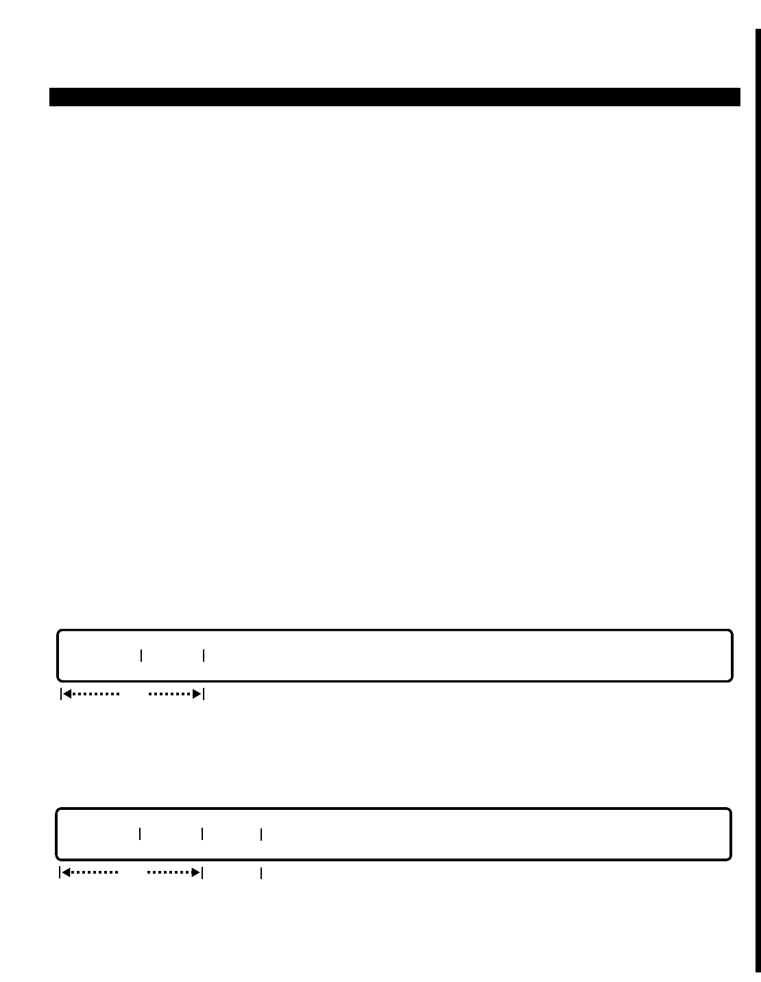
PERCEPTION 4000 COMMANDS
CLOCK PROVIDER ASSIGNMENT (CMD 417)
The Clock Provider Assignment command is used to assign a priority level to the clock contained on the T1/DS1
Digital Trunk Interface (TTRI) card or the ISDN Primary Rate Controller (IPRC) card. The assigned priority level
indicates whether the TTRI/IPRC card's clock is to always serve as the dominant clock in a networking
arrangement, or if another clock is to receive preference. Preference levels ranging from 1 (highest priority) to 60
(lowest priority) can be assigned to the TTRI/IPRC clock.
Command Keyword: CLOCK_PROVIDER
Category Name: System
PREREQUISITE COMMANDS
ISDN IPRC and IPRI Card Assignment (CMD 422)
Digital Carrier Channel Assignment (CMD 413)
OPERATIONS
Available operations: MODIFY
DISPLAY
The function and required data fields for each operation are described as follows:
MODIFY
This operation is used to change the priority level of the clock provider on TTRI or IPRI circuit cards.
DISPLAY
ThIs operation is used to display the priority levels of the clock provider on TTRI or IPRI circuit cards.
opt
PRIORITY CARD# TYPE
output only
req
PRIORITY CARD#
ISS 2, SECTION 4000-014-000
CLOCK PROVIDER ASSIGNMENT (CMD 417)
3-89

PERCEPTION 4000 COMMANDS
ISS 2, SECTION 4000-014-000
CLOCK PROVIDER ASSIGNMENT (CMD 417)
PARAMETERS
This section defines input permitted for each field. Any variations for a particular operation are noted separately.
FIELD: PRIORITY
TYPE: Decimal/Keyword
FORMAT: 1 to 2 digits
VALUE: 1 to 60/No
RANGE: Not allowed
LOOP: Allowed in DISPLAY operation only
The "PRIORITY" field indicates the priority level of the clock provider on the TTRI or IPRC circuit card. Lower
values indicate higher priority levels (1 is the highest priority; 60 is the lowest). An entry of NO indicates that no
priority is assigned.
FIELD: CARD #
TYPE: Decimal
FORMAT: 3 to 4 digits
VALUE: 102 to 1012
RANGE: Allowed in DISPLAY operation only
LOOP: Not allowed
This field indicates the equipment location of the TTRI or IPRC card. The first one or two digits represent the
number of the shelf containing the card (1~10), and the last two digits represent the card slot number (01~12).
FIELD: TYPE
TYPE: Keyword
FORMAT: Preassigned ASCII characters
Keyword: TTRI—T1/DS1 Digital Trunk Interface
IPRC—ISDN Primary Rate Controller
This field appears only in the DISPLAY operation. No input is required.
SYSTEM MESSAGES
The following error messages are unique to this command.
I41700 - Warning: Please try later; database is reserved
C41701 - This card is the clock provider
C41702 - Check card number
C41703 - Check priority level
C41704 - TTRI/IPRC card is not installed
C41705 - No ccd data (update ccd data by using CMD 422)
C41706 - To search NOT PROVIDER card, enter <TAB>
3-90
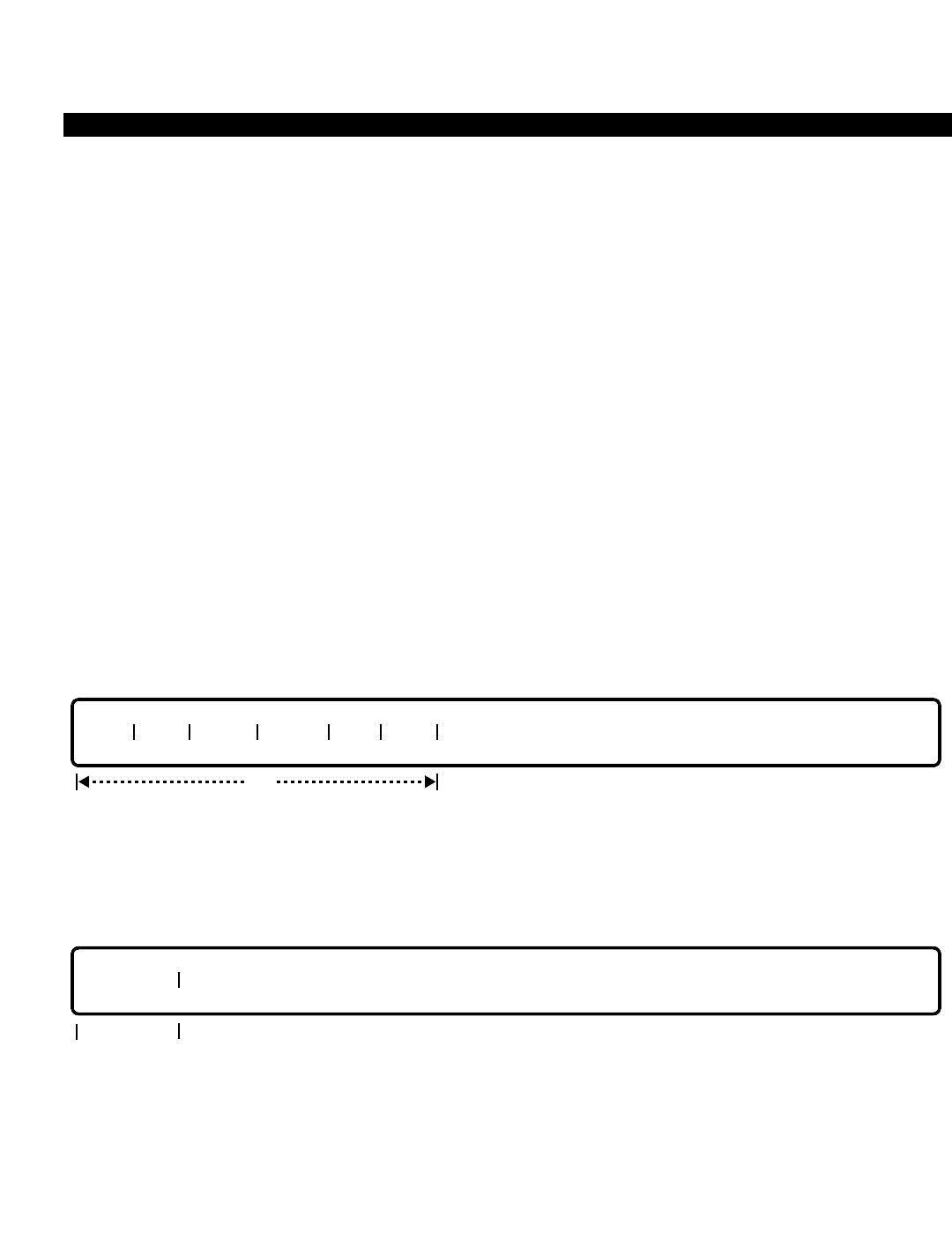
PERCEPTION 4000 COMMANDS
CLOCK RESET (CMD 121)
The system's date and time may be reset or displayed with this command.
Command Keyword: CLOCK_RESET
Category Name: Maintenance
PREREQUISITE COMMANDS
There are no prerequisites for this command.
OPERATIONS
Available operations: RESET
DISPLAY
The function and required data fields for each operation are described in this section.
RESET
This operation resets the system's date and time. All of the fields are optional. When an optional field is not
specified, and a <TAB> is entered in that field, the current data is treated as the default value.
DISPLAY
To display the system's current date and time, press the <TAB> key and the <RETURN> key. Output is presented
in the following format:
WWW MMM DD, YY hh:mm:ss
WWW = Three ASCII characters that identify the day of the week.
Note that the day of the week is calculated automatically by the system.
output only
CLOCK
opt
MON DAY YEAR HOUR MIN SEC
ISS 2, SECTION 4000-014-000
CLOCK RESET (CMD 121)
3-91

PERCEPTION 4000 COMMANDS
ISS 2, SECTION 4000-014-000
CLOCK RESET (CMD 121)
Mon = Monday Fri = Friday
Tue = Tuesday Sat = Saturday
Wed = Wednesday Sun = Sunday
Thu = Thursday
MMM = Three ASCII characters that identify the month of the year
Jan = January Jul = July
Feb = February Aug = August
Mar = March Sep = September
Apr = April Oct = October
May = May Nov = November
Jun = June Dec = December
DD = 2 digits (01-31) day of the month
YY = 2 digits (00-99) last 2 digits of the current year
hh = 2 digits (00-23) military hour of the day
mm = 2 digits (00-59) minute of the hour
ss = 2 digits (00-59) second of the minute.
Example: Mon Apr 1, 91 10:30:25
PARAMETERS
Each field parameter is described in this section. Any variations for a particular operation are noted separately.
FIELD: MON (Month of the Year)
TYPE: Keyword / Decimal
FORMAT: Predefined ASCII characters / 1 or 2 digits
VALUE: 1 to 12
RANGES: Not allowed
Keywords Decimal Values
JAN 1
FEB 2
MAR 3
APR 4
MAY 5
JUN 6
JUL 7
AUG 8
SEP 9
OCT 10
NOV 11
DEC 12
Input in this field may be either a keyword or a decimal value. Entering a <TAB> causes the
current month to be treated as the default value.
3-92

PERCEPTION 4000 COMMANDS
FIELD: DAY (Day of the Month)
TYPE: Decimal
FORMAT: 1 or 2 digits
VALUE: 1 to 31
RANGE: Not allowed
There is a maximum of 31 days per month. Entering a <TAB> in this field causes the current day
to be treated as the default value.
FIELD: YEAR (Last Two Digits of the Year)
TYPE: Decimal with fixed length
FORMAT: 2 digits
VALUE: 00 to 99
RANGE: Not allowed
This field requires a 2-digit value to indicate the last two digits of the year. Entering a <TAB> in
this field causes the current year to be treated as the default value.
FIELD: HOUR (Hour of the Day)
TYPE: Decimal
FORMAT: 1 or 2 digits
VALUE: 0 to 23
RANGE: Not allowed
The hour of the day is indicated in military time. For example, 1:00 PM is entered as 13, 2:00 PM
as 14, etc. Entering a <TAB> in this field causes the current hour to be treated as the default
value.
FIELD: MIN (Minute of the Hour)
TYPE: Decimal
FORMAT: 1 or 2 digits
VALUE: 0 to 59
RANGE: Not allowed
Minutes are entered in this field. Entering a <TAB> causes the current minute to be treated as
the default value.
FIELD: SEC (Second of the Minute)
TYPE: Decimal
FORMAT: 1 or 2 digits
VALUE: 0 to 59
RANGE: Not allowed
Seconds are entered in this field. Entering a <TAB> causes the current second to be used as the
default value.
ISS 2, SECTION 4000-014-000
CLOCK RESET (CMD 121)
3-93

PERCEPTION 4000 COMMANDS
ISS 2, SECTION 4000-014-000
CLOCK RESET (CMD 121)
FIELD: CLOCK (The System's Date and Time)
TYPE: Output only
Entering a <TAB> and a <C/R> in this field in a DISPLAY operation causes the system's current
date and time to display.
SYSTEM ERROR MESSAGES
The following error messages are unique to this command.
C12100 - Clock set error
COMMENTS
The Traffic Measurement process (CMD 901) may not be activated at the preselected activation time due to a
clock reset.
The SMDR record of current calls (CMD 409) may be generated with a conflicting call duration field due to a clock
reset.
The scheduled switch-over process (CMD 102) may not be activated if the clock is set to a date and time beyond
the predetermined switch-over date and time.
When a clock reset is performed, the system sends a transmission to the ACD/MIS application processor
resetting its clock also.
3-94

PERCEPTION 4000 COMMANDS
COMMON CARRIER ASSIGNMENT (CMD 344)
The common carrier definition table defines a '10XXX' (equal access) code for each common carrier in the
system, up to 10 carriers. These carriers are used by the Least Cost Routing program as required.
Command Keyword: COMMON_CARRIERS
Category Name: Trunk
PREREQUISITE COMMANDS
There are no prerequisites for this command.
OPERATIONS
Available operations: MODIFY
DISPLAY
The function and required data fields for each operation are described in this section.
MODIFY
This operation modifies the common carrier definition table. The "10XXX CODE" field is a delete field for this
operation. When modifying a carrier code, the new code must not already exist in the table.
DISPLAY
This operation displays all common carriers defined for the system. Ranges are permitted in the "INDEX" field
only.
opt
INDEX 10XXX CODE
req
INDEX 10XXX CODE
ISS 2, SECTION 4000-014-000
COMMON CARRIER ASSIGNMENT (CMD 344)
3-95

PERCEPTION 4000 COMMANDS
ISS 2, SECTION 4000-014-000
COMMON CARRIER ASSIGNMENT (CMD 344)
PARAMETERS
Each field parameter is described in this section. Any variations for a particular operation are noted separately.
FIELD: INDEX (Index Number)
TYPE: Decimal
FORMAT: 1 or 2 digits
VALUE: 1 to 10
LOOP: Allowed in a DISPLAY operation only
There are 10 index numbers, each of which may be assigned one equal access code.
FIELD: 10XXX CODE (Common Carrier Definition)
TYPE: Decimal with fixed length
FORMAT: 5 digits
VALUE: 10000 to 10999
RANGE: Not allowed
The first two numbers entered in this field must be a 1followed by a 0. This field is a delete field
in a MODIFY operation.
SYSTEM ERROR MESSAGE
The following error message is unique to this command.
C34400 - Carrier code input already exists in database
RELATED COMMAND
LCR Routing Table Assignment (CMD 383)
3-96

PERCEPTION 4000 COMMANDS
COORDINATED NUMBERING PLAN ASSIGNMENT (CMD 303)
The Coordinated Numbering Plan (CNP) is one of two means provided to route calls in a private network
environment. This method automatically selects the proper trunk group based on steering digits dialed by the
user. To the user, the steering digits are seen as part of the total number such that they are unaware they are
selecting a TIE trunk group. This command defines each TIE trunk group the steering digits select when placing a
call.
Command Keyword: CNP_ASSIGN
Category Name: Dialing
PREREQUISITE COMMAND
Trunk Group Assignment (CMD 310)
OPERATIONS
Available operations: ADD
DELETE
DISPLAY
The function and required data fields for each operation are described in this section.
ADD
This operation adds steering digits to trunk groups. Those digits may not be shared among the trunk groups.
DELETE
This operation deletes steering digits for a trunk group.
opt
TGN STDGT STDGT STDGT STDGT STDGT STDGT STDGT STDGT STDGT STDGT
req
opt
TGN STDGT STDGT STDGT STDGT STDGT STDGT STDGT STDGT STDGT STDGT
req
ISS 2, SECTION 4000-014-000
COORDINATED NUMBERING PLAN ASSIGNMENT (CMD 303)
3-97

PERCEPTION 4000 COMMANDS
ISS 2, SECTION 4000-014-000
COORDINATED NUMBERING PLAN ASSIGNMENT (CMD 303)
DISPLAY
This operation displays steering digits for trunk groups. If no data is entered in any of the fields, steering digits for
all of the trunk groups display.
PARAMETERS
Each field parameter is described in this section. Any variations for a particular operation are noted separately.
FIELD: TGN (Trunk Group Number)
TYPE: Decimal
FORMAT: 1 to 3 digits
VALUE: 1 to 256 (or to the maximum system configuration)
LOOP: Allowed in a DISPLAY operation
RANGE: Not allowed
This field selects the trunk group number to be assigned steering digits.
FIELD: STDGT (Steering Digits)
TYPE: DN Type
FORMAT: 1 to 5 digits
VALUE: 0 to 99999
LOOP: Not allowed
RANGE: Allowed in a DISPLAY operation
There is no limit to the number of steering digits which may be assigned to a trunk group. A
steering digit may not be shared among trunk groups. Ambiguity may not exist among steering
digits or among other members of the system's numbering plan. For example, steering digits '72'
and '7230', or '678' and '6782', may not co-exist in the numbering plan.
SYSTEM ERROR MESSAGES
The following error messages are unique to this command.
C30300 - STDGTs in fields N..N are already used
C30301 - No space to add steering digits from field N
C30302 - STDGTs in fields N..N are not found
C30303 - Trunk group number is not a TIE type
C30304 - Trunk group number is not defined
C30305 - Trunk group number is defined as incoming (INC) type
C30306 - Same STDGTs in fields N..N
NOTE: "N" is from 2 to 11
opt
TGN STDGT STDGT STDGT STDGT STDGT STDGT STDGT STDGT STDGT STDGT
3-98
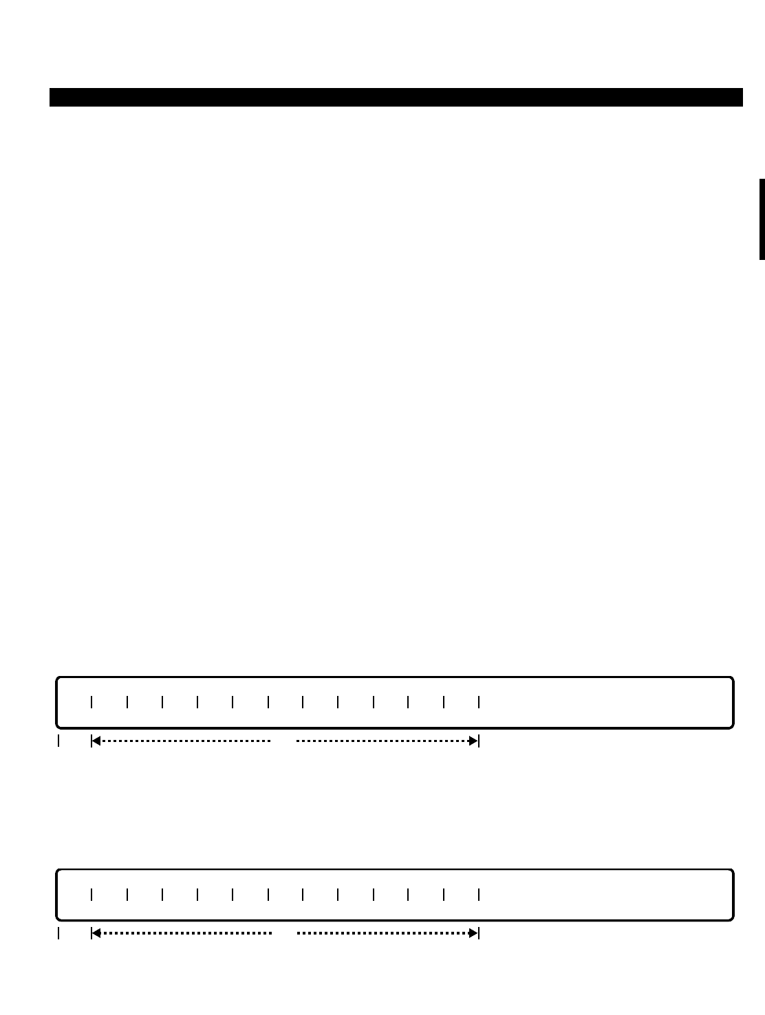
PERCEPTION 4000 COMMANDS
COUNTRY CODE ASSIGNMENT (CMD 335)
The Country Code Definition Table defines all of the country codes that are to be used by system users. The table
is initially blank and should be filled in with specific country codes. Information regarding country codes is typically
included in the white pages of a local telephone directory or can be obtained from local telephone companies or
long distance carriers. Once defined, the country code table should be reviewed periodically to ensure that it is
up-to-date with international dialing conventions.
This table is consulted when international calls are made via direct dialing for purposes of verifying the validity of
the number dialed, least cost routing, and restriction purposes.
Command Keyword: CC_ASSIGN
Category Name: Dialing
PREREQUISITE COMMANDS
There are no prerequisites for this command.
OPERATIONS
Available operations: ADD
DELETE
DISPLAY
The function and required data fields for each operation are described in this section.
ADD
This operation adds country codes to the Country Code Assignment Table. Scope entries are permitted in all of
the fields.
DELETE
This operation deletes country codes from the Country Code Assignment Table. Scope entries are permitted in all
of the fields.
opt
CC CC CC CC CC CC CC CC CC CC CC CC
req
opt
CC CC CC CC CC CC CC CC CC CC CC CC
req
ISS 2, SECTION 4000-014-000
COUNTRY CODE ASSIGNMENT (CMD 335)
3-99

PERCEPTION 4000 COMMANDS
ISS 2, SECTION 4000-014-000
COUNTRY CODE ASSIGNMENT (CMD 335)
DISPLAY
This operation displays all of the country codes in the Country Code Assignment Table that meet the conditions
established for each field. If no data is input in any of the fields, then all of the country codes display. To halt the
display, you may press <CONTROL-S>, or press <ESC> (<SHIFT-2>) to abort the display. Ranges are permitted
in all fields.
PARAMETERS
Each field parameter is described in this section. Any variations for a particular operation are noted separately.
FIELD: CC (Country Code)
TYPE: Decimal
FORMAT: 1 to 3 digits
VALUE: 1 to 999
RANGE: Allowed in a DISPLAY operation
SCOPE: Allowed in ADD and DELETE operations
The Country Code parameter is used by the system in the call handling process. According to the
CCITT (International Telegraph and Telephone Consultative Committee), the first country code
digit cannot start with a zero.
SYSTEM ERROR MESSAGES
The following error messages are unique to this command.
C33500 - Country code(s) already exist or are invalid
C33501 - Table full; cannot add more country code(s) at NNN
C33502 - Country code not found
C33503 - Check field format
C33504 - Country code conflicts with the table
RELATED COMMANDS
Country Code Restriction Tables (CMD 338)
LCR Country Code Routing Assignment (CMD 380)
opt
CC CC CC CC CC CC CC CC CC CC CC CC
3-100

PERCEPTION 4000 COMMANDS
COUNTRY CODE RESTRICTION TABLES (CMD 338)
The Country Code Restriction command contains a list of country codes which may be allowed or denied
depending on the specified "TYPE". This is the means by which international direct dialing can be controlled.
Country code tables are defined for each Trunk Restriction Group/Destination Restriction Level combination (but
not when either "TRGN" or "DRL" = 1). Trunk Restriction Groups and DRLs are assigned through the Trunk
Group Assignment command (CMD 310).
Each country code table may be specified as an ALW (allow) or DNY (deny) table. This way the fewest number of
codes can be entered and accomplish the same purpose. For example, if all country codes but two are to be
allowed, it is easier to build a deny table and enter only two codes versus building an allow table and entering all
but two codes.
Command Keyword: CC_RESTRICT
Category Name: Restrict
PREREQUISITE COMMANDS
Country Code Assignment (CMD 335)
Trunk Group Assignment (CMD 310)
OPERATIONS
Available operations: ADD
DELETE
DISPLAY
The function and required data fields for each operation are described in this section.
ADD
This operation adds country codes to the Country Code Restriction Table. Data is required in the “TRGN”, “DRL”,
and “TYPE” fields, along with the first "CC" field. The remaining “CC” fields are optional. Loops are permitted in
the “TRGN” and “DRL” fields when adding the same country code for several DRLs in a trunk restriction group, or
in the same DRL for several trunk restriction groups. Scopes are permitted in all of the “CC” fields.
req
TRGN DRL TYPE CC CC CC CC CC CC CC CC CC CC
opt
ISS 2, SECTION 4000-014-000
COUNTRY CODE RESTRICTION TABLES (CMD 338)
3-101
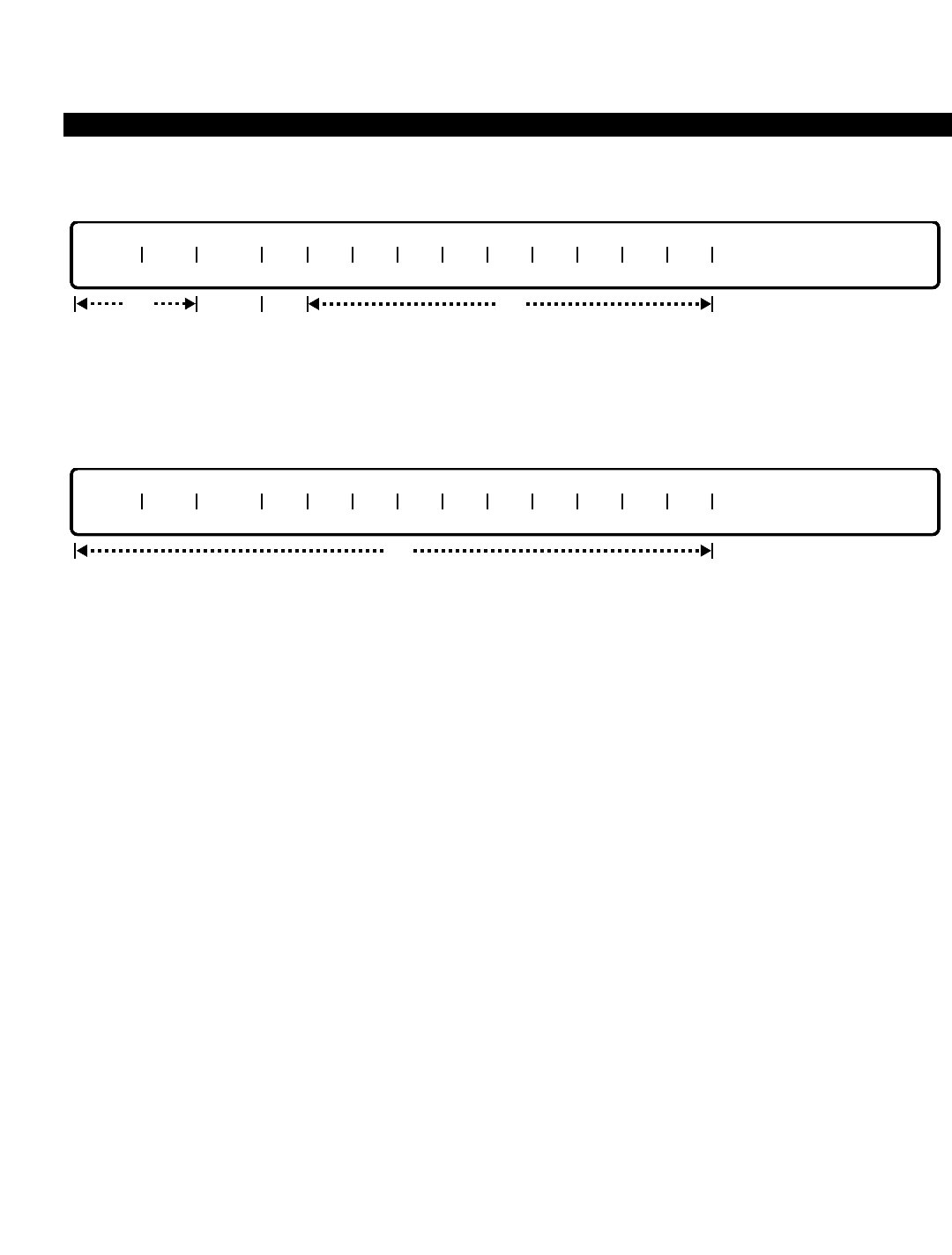
PERCEPTION 4000 COMMANDS
ISS 2, SECTION 4000-014-000
COUNTRY CODE RESTRICTION TABLES (CMD 338)
DELETE
This operation deletes country codes from the Country Code Restriction Table. Loops and scopes are permitted
when deleting a number of the tables, or a number of country codes in a Country Code Restriction Table.
DISPLAY
This operation displays the Country Code Restriction Table(s). All of the fields are optional. If no data is entered in
any of these fields, all of the Country Code Restriction Tables display. Ranges are permitted in all of the fields
except the “TYPE” field.
PARAMETERS
Each field parameter is described in this section. Any variations for a particular operation are noted separately.
FIELD: TRGN (Trunk Restriction Group Number)
TYPE: Decimal
FORMAT: 1 digit
VALUE: 2 to 8 (or to the maximum system configuration)
LOOP: Primary loop field, allowed in ADD and DELETE operations
Trunk Restriction Group 1 is defined as “unrestricted” and is recommended for TIE trunk groups.
The definition of each restriction group number can be displayed by issuing a DRL_ASSIGN
command (CMD 337).
FIELD: DRL (Destination Restriction Level)
TYPE: Decimal
FORMAT: 1 or 2 digits
VALUE: 2 to 16 (or to the maximum system configuration)
LOOP: Secondary loop field, and allowed in ADD and DELETE operations
When "DRL" is 1, all calls are allowed regardless of what trunk restriction group number (TRGN)
is being used.
TRGN DRL TYPE CC CC CC CC CC CC CC CC CC CC
opt
TRGN DRL TYPE CC CC CC CC CC CC CC CC CC CC
opt
req opt req
3-102

PERCEPTION 4000 COMMANDS
FIELD: TYPE (Table Type)
TYPE: Keyword
FORMAT: Predefined ASCII characters
Keywords: ALW - Allow access to listed country codes
DNY - Deny access to listed country codes
If the keyword, ALW (or DNY), is entered, calls to any country code in this Country Code
Restriction table are allowed (or denied).
FIELD: CC (Country Code)
TYPE: Decimal
FORMAT: 1 to 3 digits
VALUE: 1 to 999
SCOPE: Allowed in ADD and DELETE operations
RANGE: Allowed in a DISPLAY operation
Country codes entered in this field are either allowed or denied depending on the keyword
entered in the “TYPE” field of the specified TRGN and DRL.
SYSTEM ERROR MESSAGES
The following error messages are unique to this command.
C33800 - Table type does not match the table type defined originally
C33801 - Country code(s) already exist in restricted country code table
C33802 - Table full; cannot add more country code(s) at NNN
C33803 - Country code is not in system country code definition table
C33804 - Invalid trunk restriction group number
C33805 - Invalid destination restriction level
C33806 - Invalid country code
RELATED COMMAND
Destination Restriction Level (DRL) Assignment (CMD 337)
ISS 2, SECTION 4000-014-000
COUNTRY CODE RESTRICTION TABLES (CMD 338)
3-103
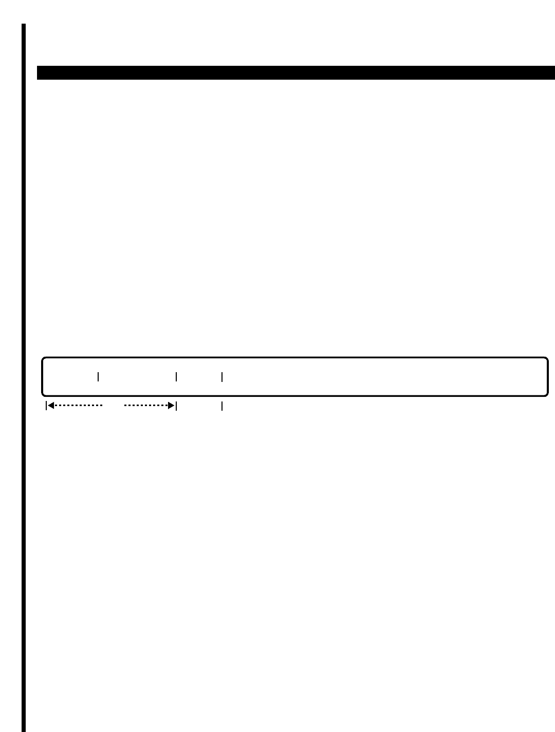
PERCEPTION 4000 COMMANDS
ISS 2, SECTION 4000-014-000
CRASH DUMP DISPLAY (CMD 164)
CRASH DUMP DISPLAY (CMD 164)
The Crash Dump Display command displays historical system crash information, as well as virtual machine
information, as enabled through the System Software Virtual Machine History command (CMD 168). The
displayed information is helpful in system debugging.
Command Keyword: CRASH_DUMP_DISP
Category Name: Maintenance
OPERATIONS
Available operations: DISPLAY
The function and required data fields for each operation are described as follows:
DISPLAY:
This operation displays historical information about system crashes or about the virtual machine specified in the
System Software Virtual Machine History command (CMD 168).
PARAMETERS
This section defines input permitted for each field. Any variations for a particular operation are noted separately.
FIELD: OBJECT
TYPE: Keyword
FORMAT: Predefined ASCII characters
Keywords: FPCRASH - Failure Processor Crash
OSCRASH - Operating System Crash
1CALL - One Call Initialization Crash
VMHIST - Virtual Machine History
req
OBJECT PARAMETER BRIEF
opt
3-104

PERCEPTION 4000 COMMANDS
FIELD: PARAMETER
TYPE: Keyword
FORMAT: Predefined ASCII characters
Object: FPCRASH | Object: 1CALL
OSCRASH | VMHIST
|
Keywords: (S) MCPU | Keywords: (S) SSC (S) TSC (S) ASC
(S) LPU1 | (S) KSU1 (S) KSU2 (S) KSU3
(S) LPU2 | (S) ACD1 (S) ACD2 (S) ACD3
(S) LPU3 | (S) SLU1 (S) SLU2 (S) SLU3
(S) MCOM | (S) HDT1 (S) HDT2 (S) HDT3
| (S) DIU1 (S) DIU2 (S) DIU3
| (S) TTC1 (S) TTC2 (S) TTC3
| (S) AGC1 (S) AGC2 (S) AGC3
| (S) ATC1 (S) ATC2 (S) ATC3
| (S) ITTC1 (S) ITTC2 (S) ITTC3
| (S) LCOM1 (S) LCOM2 (S) LCOM3
Keywords are dependent on the entry in the previous field (OBJECT). The numbers in the
keywords represent LCPU numbers, and the 'S' in front of the keywords designates a standby
side crash dump.
FIELD: BRIEF
TYPE: Keyword
FORMAT: Predefined ASCII characters
Keywords: YES - Only pertinent information is displayed
NO - All information is displayed
This field is optional. If no entry is made, the field defaults to YES and displays only pertinent
information. After printing out the displayed information, verify the time and date stamp. If it is
correct, then set this field as NO to display all information. Any questions or requests for
information regarding display/printout data should be addressed to Toshiba Technical Support by
calling (800) 777-4873.
SYSTEM MESSAGES
The following error messages are unique to this command.
C16400 - Invalid parameter for object input
C16401 - MCPU database read error
C16402 - LCPU database read error
C16403 - LCPU is out of service
C16404 - Standby side is not installed
C16405 - Standby side read failed
ISS 2, SECTION 4000-014-000
CRASH DUMP DISPLAY (CMD 164)
3-105
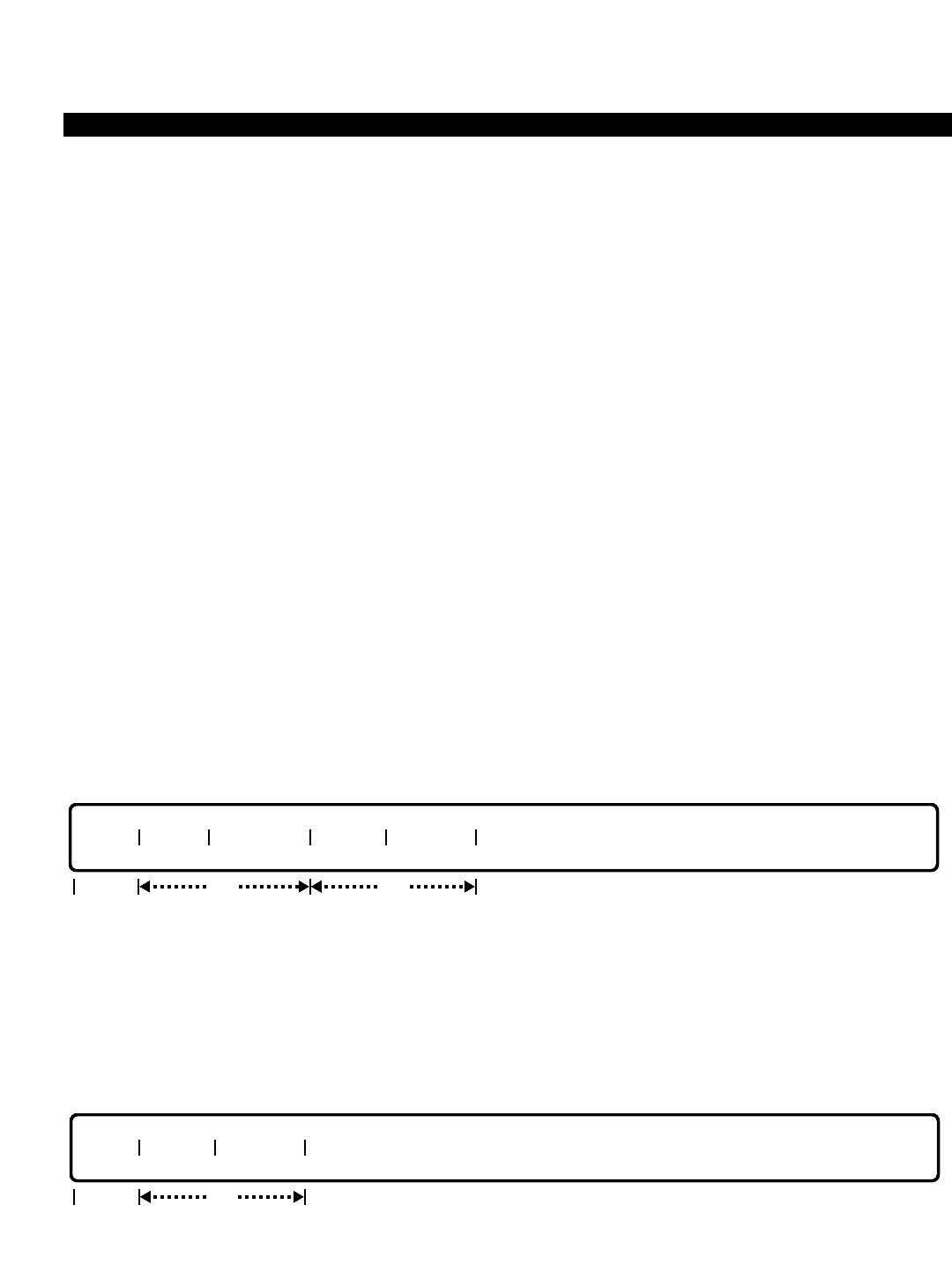
PERCEPTION 4000 COMMANDS
ISS 2, SECTION 4000-014-000
DATA HUNTING ASSIGNMENT (CMD 366)
DATA HUNTING ASSIGNMENT (CMD 366)
The PERCEPTION 4000 supports up to 32 data hunt groups, each of which may have up to 64 members. A data
device may belong to one data hunt group only, and a data hunt group may not be a member of another data hunt
group. Data hunt groups use the distributed hunting method. Only physical devices may be assigned as
members.
Command Keyword: DATA_HUNTING
Category Name: Data
PREREQUISITE COMMAND
Data Station Assignment (CMD 360)
OPERATIONS
Available operations: ADD
DELETE
MODIFY
DISPLAY
The function and required data fields for each operation are described in this section.
ADD
This operation creates a new group or adds in a member directory number. Required fields include "GRP #",
"MEM #", and "MEM DN". When creating a new group, the "PILOT DN" must be input. The member directory
number is limited to being a member of only one data hunt group. Loops are allowed in the "GRP #" and the
"MEM #" fields. When a new member number is added, all of the following members move one step backward
accordingly.
DELETE
This operation deletes a data hunt group or a member directory number. The "GRP #" field is required. To delete
a whole group, enter the keyword ALL in the "MEM #" field. Looping is allowed in the "MEM #" field.
GRP# MEM # MEM DN
optreq
req
GRP# NAME PILOT DN MEM # MEM DN
optreq
3-106
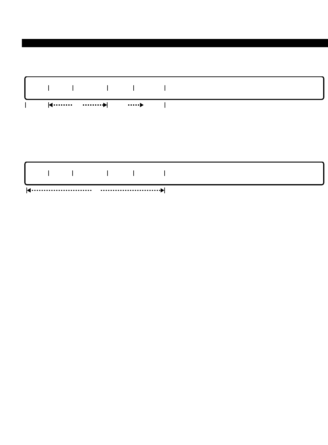
PERCEPTION 4000 COMMANDS
MODIFY
This operation changes the "NAME", "PILOT DN", or the "MEM DN" field. An entry in "GRP #" is required. If the
"MEM DN" field is being modified, the "MEM #" field must be entered.
DISPLAY
This operation displays all of the data hunt groups and their members that meet the conditions established in
each field. Loops are permitted in the "GRP #" and "MEM #" fields. Ranges are permitted in the "MEM DN" field.
PARAMETERS
Each field parameter is described in this section. Any variations for a particular operation are noted separately.
FIELD: GRP # (Group Number)
TYPE: Decimal
FORMAT: 1 or 2 digits
VALUE: 1 to 32
LOOP: Allowed in DISPLAY and ADD operations only
This field assigns a number to the data hunt group, and is the primary field for data hunt group
assignment.
FIELD: NAME (Group Name)
TYPE: Text
FORMAT: 0 to 9 ASCII characters
The "NAME" field is optional, and may contain a name corresponding to the data hunt group
number. This name displays to the calling party. Note that embedded spaces are allowed.
FIELD: PILOT DN (Pilot Directory Number)
TYPE: DN Type
FORMAT: 1 to 5 digits
VALUE: 0 to 99999
This field marks an entry point into the data hunt group. Individual members may be directly
addressed, but, if their device is busy, the system does not perform a hunting procedure.
The pilot directory number must not conflict with any other directory number or access code in
the system, and is not related to any physical device.
opt
GRP# NAME PILOT DN MEM # MEM DN
GRP# NAME PILOT DN MEM # MEM DN
optreq optopt
ISS 2, SECTION 4000-014-000
DATA HUNTING ASSIGNMENT (CMD 366)
3-107

PERCEPTION 4000 COMMANDS
ISS 2, SECTION 4000-014-000
DATA HUNTING ASSIGNMENT (CMD 366)
FIELD: MEM # (Member Index Number)
TYPE: Decimal / Keyword
FORMAT: 1 or 2 digits / Predefined ASCII characters
VALUE: 1 to 64 / ALL
LOOPS: Allowed in DISPLAY, ADD, and DELETE operations
The index is a tool for adding a member to a specific place in the data hunt group table. Hunting
follows this ordering, from the lowest to the highest number (index number) and then wraps
around to the lowest number again. Distributed hunting rules apply for idle device selection. The
keyword ALL may be entered in a DELETE operation to remove all members in a specified
group.
FIELD: MEM DN (Member Directory Number)
TYPE: DN Type
FORMAT: 1 to 5 digits
VALUE: 0 to 99999
RANGE: Allowed in a DISPLAY operation only
The member directory number can be a member of only one data hunt group, and must be a
data station number.
SYSTEM ERROR MESSAGES
The following error messages are unique to this command.
C36600 - Input member directory number
C36601 - Group is already full
C36602 - Member directory number is not defined in the system
C36603 - Pilot directory number mismatch
C36604 - Group name mismatch
C36605 - Group is empty
C36606 - Member number is not in group
C36607 - Member directory number is not in group
C36608 - Inconsistent member number/directory number pair
C36609 - Pilot directory number is already in use
C36610 - Member number is required
C36611 - Member number is not continuous in group
C36612 - Member directory number is already in another data hunt group
C36613 - Cannot use this directory number
C36614 - Input pilot directory number
C36615 - Group name is too long
C36616 - The data hunting member cannot be in permanent connection.
C36617 - Failed to convert LDN to LTN.
C36618 - Failed to send a transaction to LPU side.
RELATED COMMAND
Name Dialing Assignment (CMD 367)
3-108
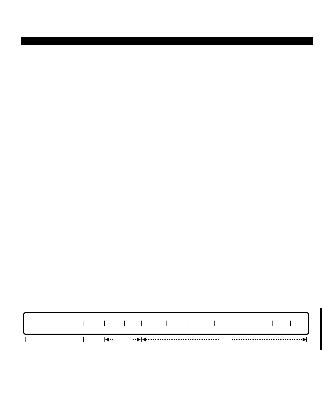
PERCEPTION 4000 COMMANDS
DATA INTERFACE PARAMETER ASSIGNMENT (CMD 361)
Both integrated and Stand-alone Data Interface Units (DIUs) require a number of parameters be specified
concerning data transmission and signaling. The Data Interface Parameter Assignment command assigns a
number of these parameters.
Because these parameters apply not only to DIUs configured as Data Communications Equipment (DCE - those
which interface directly to a printer, host computer, data terminal, etc.), but also to Data Terminal Equipment (DTE
- Stand-alone DIUs used in modem pools), the primary key may be a modem pool number instead of an
equipment number. This insures that all DIUs in a modem pool receive like configuration to ensure compatibility.
Note that equipment numbers are still required for most DIUs acting as DCE-type equipment.
Additional parameters, mostly applicable to asynchronous mode, are defined through the Data Station Parameter
Assignment command (CMD 362).
Command Keyword: DATA_INT_PARAMETERS
Category Name: Data
PREREQUISITE COMMANDS
Data Station Assignment (CMD 360)
Modem Pool Assignment (CMD 347)
OPERATIONS
Available operations: MODIFY
DISPLAY
The function and required data fields for each operation are described in this section.
MODIFY
This operation changes data interface parameter selection of one or more data stations. “EQ/MP #” is a required
field. “SYN/ASY”, "EMU", and “CLK” are locked fields, while the remaining fields are optional. Loops are permitted
in the “EQ/MP #” field when changing a number of data stations with the same parameter selections.
opt
EQ/MP # SYN/ASY DPLX EMU CLK SPEED PRTY DATA B STOP DTR DSR RTS CTS
lockedlockedreq opt
ISS 2, SECTION 4000-014-000
DATA INTERFACE PARAMETER ASSIGNMENT (CMD 361)
3-109
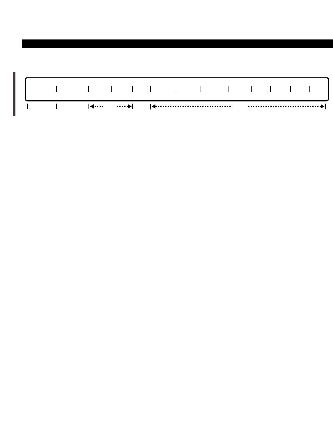
PERCEPTION 4000 COMMANDS
ISS 2, SECTION 4000-014-000
DATA INTERFACE PARAMETER ASSIGNMENT (CMD 361)
DISPLAY
This operation displays data interface parameters of one or more data stations. “SYN/ASY” and “CLK” are locked
fields. Input in the remaining fields is optional. If no data is entered in any of these fields, the data interface
parameters of all configuration profiles in the system display. Loops are permitted in the “EQ/MP #” field.
PARAMETERS
Each field parameter is described in this section. Any variations for a particular operation are noted separately.
FIELD: EQ/MP # (Equipment/Modem Pool Number)
TYPE: EQ Type / Decimal
FORMAT: 5 or 6 digits / 1 or 2 digits
VALUE: (0)10101 to 101316 (for EQ#) / 1 to 32 (for MP#)
LOOP: Allowed in DISPLAY and MODIFY operations
The equipment and modem pool numbers are assigned with the Data Station Assignment (CMD
360) and Modem Pool Assignment (CMD 347) commands respectively. This field selects the
appropriate data device to be modified or displayed.
FIELD: SYN/ASY (Synchronous/Asynchronous)
TYPE: Keyword
FORMAT: Predefined ASCII characters
Keywords: SYN - Synchronous
ASY - Asynchronous
This parameter defines the communication mode used to interface to the data device. Other
parameters, such as speed and duplex, are necessary to completely define the communication
interface of the DIU. ASY is the default value. This is a locked field.
NOTE: Only asynchronous mode (ASY) is supported at this time.
FIELD: DPLX (Full/Half Duplex)
TYPE: Keyword
FORMAT: Predefined ASCII characters
Keywords: HDX - Half Duplex
FDX - Full Duplex
In full duplex operation, two-way data traffic can be exchanged between the DIU and the data
device at the same time. In half duplex operation, only alternate data exchange is allowed. FDX
is the default value.
opt
EQ/MP # SYN/ASY DPLX EMU CLK SPEED PRTY DATA B STOP DTR DSR RTS CTS
opt
lockedopt locked
3-110

PERCEPTION 4000 COMMANDS
FIELD: EMU (DTE/DCE Emulation)
TYPE: Keyword
FORMAT: Predefined ASCII characters
Keywords: DCE - DIU functions as a DCE (Data Communications Equipment)
DTE - DIU functions as a DTE (Data Terminal Equipment)
When DCE is selected, the DIU functions as a DCE (null modem) to interface to a DTE device
such as a CRT. When DTE is selected, the DIU performs DTE logical functions over the DIU
female connector. DCE is the default value for DCE mode, and DTE is the default value for DTE
mode. This is a locked field in the MODIFY operation.
FIELD: CLK (Clock Selection)
TYPE: Keyword
FORMAT: Predefined ASCII characters
Keywords: ICLK - Internal Clock (System's Main Clock) (Reserved)
XCLK - External Clock (Reserved)
NON - No Clock
This parameter defines the source of the transmit clock used in synchronous mode only. When
ASY is entered in the “SYN/ASY” field, NON must be entered in this field. NON is the default
value. This is a locked field.
NOTE: Only asynchronous communications, "No Clock" is supported at this time.
FIELD: SPEED (Speed Selection in bits per second [bps])
TYPE: Keyword
FORMAT: Predefined ASCII characters
Keywords: AUTO - Auto Detect (For asynchronous only)
50 - 50 bps ( " )
75 - 75 bps ( " )
110 - 110 bps ( " )
300 - 300 bps ( " )
600 - 600 bps (For asynchronous and synchronous)
1200 - 1200 bps ( " )
2400 - 2400 bps ( " )
4800 - 4800 bps ( " )
9600 - 9600 bps ( " )
19200 - 19200 bps ( " )
This parameter defines the data transfer speed across the communications interface. When
AUTO is selected, the DIU assumes 8 bits per character with NO parity, or 7 data bits plus
odd/even parity detection. AUTO is the default value for DCE mode. For DTE mode, only 300,
600, 1200, 2400, 4800, and 9600 are valid.1200 is the default for DTE mode.
ISS 2, SECTION 4000-014-000
DATA INTERFACE PARAMETER ASSIGNMENT (CMD 361)
3-111

PERCEPTION 4000 COMMANDS
ISS 2, SECTION 4000-014-000
DATA INTERFACE PARAMETER ASSIGNMENT (CMD 361)
FIELD: PRTY (Parity Selection)
TYPE: Keyword
FORMAT: Predefined ASCII characters
Keywords: EVEN - Even parity
ODD - Odd parity
DET - Detect parity (Detect and check either odd or even parity)
NO - No parity (i.e., no parity check)
This parameter defines the parity used in the data character to be transmitted or received over
the communications interface. ODD, EVEN or DET can only be used when "DATA B" is set to 7
data bits. NO is the default value.
FIELD: DATA B (Data Bit Selection)
TYPE: Keyword
FORMAT: Predefined ASCII characters
Keywords: 7BIT - 7 data bits
8BIT - 8 data bits
This parameter defines the number of data bits in a single character transmitted over the
communications interface. If 8BIT is selected, ODD, EVEN or DET cannot be specified in the
"PRTY" field. 8BIT is the default value.
FIELD: STOP (Stop Bit Selection)
TYPE: Keyword
FORMAT: Predefined ASCII characters
Keywords: 1BIT - 1 stop bit
2BIT - 2 stop bits
This parameter defines the number of stop bit(s) in a single character transmitted over the
communications interface. 1BIT is the default value.
FIELD: DTR (Detect Terminal Ready Signal Treatment)
TYPE: Keyword
FORMAT: Predefined ASCII characters
Keywords: DET - Detect DTR
HI - Consider DTR high at all times
NON - No DTR treatment
This parameter defines the treatment of the “Device Ready” condition normally provided by the
DTR interface lead. For a DIU functioning as a DTE, NON must be selected. For a DIU
functioning as a DCE, either DET or HI must be selected. DET is the default value for DCE mode,
and NON is the default for DTE mode.
3-112

PERCEPTION 4000 COMMANDS
FIELD: DSR (Data Set Ready Signal Treatment)
TYPE: Keyword
FORMAT: Predefined ASCII characters
Keywords: DET - Detect DSR
HI - Consider DSR high at all times
NON - No DSR treatment
This parameter defines the treatment of the Data Set Ready (DSR) signal when the DIU
functions as a DTE. If the DIU is functioning as a DCE, NON must be selected. If the DIU is
functioning as a DTE, either DET or HI must be selected. DET is the default value for DTE mode,
and NON is the default for DCE mode.
FIELD: RTS (Request To Send Signal Treatment)
TYPE: Keyword
FORMAT: Predefined ASCII characters
Keywords: DET - Detect RTS
HI - Consider RTS high at all times
NON - No RTS treatment
This parameter defines the treatment of the Request To Send (RTS) signal from the DTE. If the
DIU is functioning as a DTE, NON must be selected. If the DIU is functioning as a DCE, either
DET or HI must be selected. For full duplex operation, with the DIU functioning as a DCE, HI
must be selected. DET is the default value for DCE mode, and NON is the default for DTE mode.
FIELD: CTS (Clear To Send Signal Treatment)
TYPE: Keyword
FORMAT: Predefined ASCII characters
Keywords: DET - Detect CTS
HI - Consider CTS high at all times
NON - No CTS treatment
This parameter defines the treatment of the Clear To Send (CTS) signal when the DIU functions
as a DTE. If the DIU is functioning as a DCE, NON must be selected. If the DIU is functioning as
a DTE, either DET or HI must be selected. DET is the default value for DTE mode, and NON is
the default for DCE mode.
SYSTEM ERROR MESSAGES
The following error messages are unique to this command.
C36100 - Check equipment or modem pool number
C36101 - Check parity bit
C36102 - Empty modem pool
C36103 - Check DTE/DCE mode in EMU field
C36104 - Check input in SPEED field
C36105 - Cannot modify; EMU is in DTE mode
ISS 2, SECTION 4000-014-000
DATA INTERFACE PARAMETER ASSIGNMENT (CMD 361)
3-113

PERCEPTION 4000 COMMANDS
ISS 2, SECTION 4000-014-000
DATA INTERFACE PARAMETER ASSIGNMENT (CMD 361)
C36106 - Cannot modify; EMU is in DCE mode
C36107 - Check DTR field\n"
C36108 - DIU-DCE is in permanent connection; no modification is allowed
C36109 - The equipment number is assigned for another device or is invalid
COMMENTS
When one or more parameters for a modem pool ID is modified, data communication characteristics for all of the
data terminals which are grouped in the same modem pool are changed.
Data parameters of a configuration profile are divided into two parts—data interface and data station parameters.
The data interface parameters are defined by this command, and the data station parameters are defined by the
Data Station Parameter Assignment command (CMD 362).
RELATED COMMAND
Data Station Parameter Assignment (CMD 362)
3-114

PERCEPTION 4000 COMMANDS
DATA STATION ASSIGNMENT (CMD 360)
The Data Station Assignment command installs or removes one or more data stations from the PERCEPTION
4000 system. This command also modifies and displays the attributes of one or more data stations.
Command Keyword: DATA_ASSIGN
Category Name: Data
PREREQUISITE COMMANDS
Modem Pool Assignment (CMD 347)
Station Assignment (CMD 330) (Command 330 is required if ITG or LGP is selected in
the "TYPE" field.)
OPERATIONS
Available operations: ADD
DELETE
MODIFY
DISPLAY
The function and required data fields for each operation are described in this section.
ADD
This operation adds one or more data stations to the system. Integrated DIUs use the same equipment number
as the supporting telephone, however Stand-alone DIUs must be assigned a unique equipment number.
The equipment number and DIU directory number must be unique. The DIU directory number must not conflict
with any other directory number or access code in the system.
DELETE
The DELETE operation removes one or more data stations from the system. Entering the equipment number is
sufficient. When removing a number of data stations, ranges are permitted, and a confirmation is required before
each data station is deleted. Removing a data station is not allowed if a data call is in progress on that station.
EQUIP # DIU DN
optreq
req
EQUIP # DIU DN TYPE AS DN DEF MDM COS DRL FRLP QPL DRG ANS NAME
opt
opt locked reqreq
ISS 2, SECTION 4000-014-000
DATA STATION ASSIGNMENT (CMD 360)
3-115
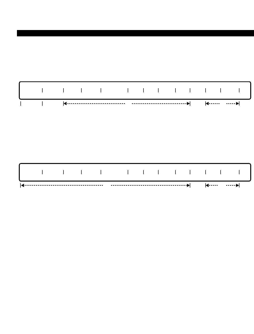
PERCEPTION 4000 COMMANDS
ISS 2, SECTION 4000-014-000
DATA STATION ASSIGNMENT (CMD 360)
Prior to the removal of a data station, the memberships or relationship of all logical groupings with the station
must be removed first. Note that the data hunting group order is altered upon removal of a data station.
MODIFY
This operation modifies the attributes of one or more data stations. Ranges are permitted in the equipment
number field when modifying a number of data stations with the same attributes. “EQUIP #” is the only required
field for this operation. In a MODIFY operation, a <CONTROL-D> may be entered to delete the current value in
the "NAME" field.
DISPLAY
This operation displays the attributes of one or more data stations. All of the fields are optional, with the exception
of the "DRG" field. If no data is entered in any of these fields, attributes of all data stations in the system display.
Ranges are permitted in any field that accepts numeric input, such as “DIU DN”, “AS DN”, etc.
PARAMETERS
Each field parameter is described in this section. Any variations for a particular operation are noted separately.
FIELD: EQUIP # (Equipment Number)
TYPE: EQ Type
FORMAT: 5 or 6 digits
VALUE: (0)10101 to 101316 *
LOOP: Allowed in all operations
* Use the following chart to determine valid ranges.
Digits Range Hardware
First digit(s) (0)1~10 Shelf no.
Second two digits 01~11, 13 Card slot no.
Last two digits 01~16 Circuit no.
NOTE: Slot 13 is unavailable if the card is a 2B type.
opt
EQUIP # DIU DN TYPE AS DN DEF MDM COS DRL FRLP QPL DRG ANS NAME
optlocked
opt
EQUIP # DIU DN TYPE AS DN DEF MDM COS DRL FRLP QPL DRG ANS NAME
optlockedreq output
only
3-116

PERCEPTION 4000 COMMANDS
Each DIU is assigned to a circuit on a digital line card (DSTI). If this is an integrated DIU, it uses
the same equipment number as used by the supporting telephone, as assigned in the Station
Assignment Command (CMD 330). For Stand-alone DIUs, the equipment number is defined as
follows.
The first digit(s) represents the shelf number, the next two digits represent the card slot number,
and the last two digits represent the circuit number.
NOTES:
1. Stand-alone DIUs may be installed on DSTI cards configured for 1B or 2B operation. When
installed on a DSTI card configured for 2B operation, a '2B' device must already be assigned
to the card.
2. If installed on a DSTI card configured for 2B operation, the circuit's voice channel is ignored
by the system.
FIELD: DIU DN (DIU Directory Number)
TYPE: DN Type
FORMAT: 1 to 5 digits
VALUE: 0 to 99999
RANGE: Allowed in a DISPLAY operation only
LOOP: Not allowed
Each data station must be assigned a unique directory number which does not conflict with any
other directory number or access code in the system. The DIU directory number is addressable
only by other data stations in the system and incoming data trunk calls. This field is an output
only field in a MODIFY operation.
FIELD: TYPE (DIU Type)
TYPE: Keyword
FORMAT: Predefined ASCII characters
Keywords: SAL - Stand-alone data station
ITG - Integrated data station
LGP - Logically Paired (Reserved for future use)
This field defines the DIU as a Stand-alone or integrated device.
FIELD: AS DN (Associate Directory Number)
TYPE: DN Type
FORMAT: 1 to 5 digits
VALUE: 0 to 99999
RANGE: Allowed in a DISPLAY operation only
The associate directory number corresponds to the Prime Directory Number (PRM DN) entered
in the Station Assignment command (CMD 330). If the DIU is integrated, the prime directory
number of the digital telephone must be entered in this field.
During an ADD operation, the following relationship exists between the “TYPE” and “AS DN”
fields:
ISS 2, SECTION 4000-014-000
DATA STATION ASSIGNMENT (CMD 360)
3-117

PERCEPTION 4000 COMMANDS
ISS 2, SECTION 4000-014-000
DATA STATION ASSIGNMENT (CMD 360)
"TYPE" "AS DN" Field
Field
SAL "AS DN" must not be entered.
ITG "AS DN" is optional; if entered, must be ITG voice DN.
FIELD: DEF MDM (Default Modem Pool)
TYPE: Decimal
FORMAT: 1 or 2 digits
VALUE: 1 to 32
RANGE: Allowed in a DISPLAY operation only
The default modem pool defines what modem pool will automatically be selected for incoming
trunk calls, either directly routed by the inward routing tables or via transfer from an attendant.
This field also defines automatic modem pool selection for outgoing trunk calls unless overridden
manually or preprogrammed through other M&A commands, such as the High Usage Data
Destination Assignment command (CMD 368). The modem pool should be compatible with the
terminating data interface unit's configuration.
FIELD: COS (Class of Service)
TYPE: Decimal
FORMAT: 1 or 2 digits
VALUE: 1 to 64
RANGE: Allowed in a DISPLAY operation only
The Class of Service determines what features are available for a data station.
FIELD: DRL (Destination Restriction Level)
TYPE: Decimal
FORMAT: 1 or 2 digits
VALUE: 1 to 16 (or to the maximum system configuration)
RANGE: Allowed in a DISPLAY operation only
The Destination Restriction Level determines the restrictions on the outgoing calling pattern.
FIELD: FRLP (Facility Restriction Level Profile)
TYPE: Decimal
FORMAT: 1 or 2 digits
VALUE: 1 to 32 (or to the maximum system configuration)
RANGE: Allowed in a DISPLAY operation only
The Facility Restriction Level determines the facilities available to the caller.
FIELD: QPL (Queue Priority Level)
TYPE: Decimal
FORMAT: 1 digit
VALUE: 1 to 8
RANGE: Allowed in a DISPLAY operation only
The "QPL" field determines the queuing priority level for the DIU.
3-118

PERCEPTION 4000 COMMANDS
FIELD: DRG (Data Restriction Group)
TYPE: Decimal
FORMAT: 1 or 2 digits
VALUE: 1 to 16
RANGE: Not allowed
The Station-to-Station restriction levels do not affect any outgoing call restrictions or incoming
trunk call restrictions. (Currently this is a locked field.)
FIELD: ANS (Answer Method)
TYPE: Keyword
FORMAT: Predefined ASCII characters
Keywords: AUTO - Auto-answer
DTE - DTE answer method
NON - Neither
This field determines what type of answering method the DIU will use–either AUTO (such as for
printers), DTE (for devices controlling the DTR signal), or NON (used for interactive operation).
When interfacing with a host computer port, either AUTO or DTE should be set, depending on
the application.
FIELD: NAME (Directory Name)
TYPE: Text
FORMAT: 0 to 9 ASCII characters
Each data station may optionally be assigned a unique name. During a DISPLAY operation, if
only the beginning part of the name is entered in this field, a list of directory names with the same
beginning characters displays. Embedded spaces are allowed. In a MODIFY operation, a
<CONTROL-D> may be entered to delete the current value.
SYSTEM ERROR MESSAGES
C36000 - DIU directory number conflicts with existing number or access code
C36001 - Specified equipment number is a group member
C36002 - No LTN is available
C36003 - No LDN is available
D36004 - Add DN-LDN relation failed
D36005 - Failed to remove this DN from DA tree
D36006 - Add DN-LDN relation failed
D36007 - Failed to remove DN-LDN Relationship
D36008 - Failed to release the deletion LDN
D36009 - Failed to release the deletion LTN
C36010 - DIU directory number does not match
D36011 - Failed to add KSU-LDN relationship
D36012 - Failed to add KSU member
D36013 - Failed to remove KSU Member
D36014 - Failed to remove KSU-LDN relationship
C36015 - Card type does not match
ISS 2, SECTION 4000-014-000
DATA STATION ASSIGNMENT (CMD 360)
3-119

PERCEPTION 4000 COMMANDS
ISS 2, SECTION 4000-014-000
DATA STATION ASSIGNMENT (CMD 360)
C36016 - Cannot add card to this card slot
C36017 - Number of DIUs is up to system maximum
C36018 - Cannot install DSTI/BSTI/PBRC in slot 12 or 14
C36019 - Cannot install DSTI-2B in an even card slot
C36020 - Cannot install DSTI-2B in card slots 11 - 14
C36021 - Cannot install T1 in an odd card slot
C36022 - Cannot install T1 in card slot 14
C36023 - Check associated directory number input
C36024 - DIU directory number already exists
C36025 - Check existence of modem pool identification
C36026 - Missing operation specified
D36027 - LDN-to-LTN conversion failed
C36028 - Check specified DIU directory number
C36029 - Check specified DIU type
C36030 - Specified data station does not exist
C36031 - Specified equipment number is already in use
D36032 - DIU logic pairing failed
D36033 - Addition of LDN to KSU failed
D36034 - Removal of LDN from KSU failed
C36035 - Must remove SDDN key
C36036 - Substate is not valid
C36037 - Specified DIU does not exist
C36038 - Data directory number already exists
C36039 - Must assign data directory number
D36040 - Addition of data line failed
D36041 - Read phone attributes failed
C36042 - Logic pair already exists
C36043 - DDN key does not exist
D36044 - Removal of data line failed
D36045 - Removal of logic pair failed
D36046 - Addition of DIU attributes failed
D36047 - Modification of DIU attributes failed
D36048 - Addition of DIU failed
C36049 - Check specified equipment number
D36050 - Removal of DIU failed
D36051 - Directory number registration failed
C36052 - Database has recovered
C36053 - Recovering database
C36054 - Equipment number has been used or reserved
C36055 - Permanent connection exists
C36056 - Write authorization attributes failed
RELATED COMMANDS
Class of Service Assignment (CMD 334)
Data Hunt Assignment (CMD 366)
Data Interface Parameter Assignment (CMD 361)
Data Station Parameter Assignment (CMD 362)
Destination Restriction Level Assignment (CMD 337)
3-120

PERCEPTION 4000 COMMANDS
Facility Restriction Level Profile Assignment (CMD 387)
High Usage Data Destination Assignment (CMD 368)
Name Dialing Assignment (CMD 367)
Station Feature Key Assignment (CMD 331)
ISS 2, SECTION 4000-014-000
DATA STATION ASSIGNMENT (CMD 360)
3-121

PERCEPTION 4000 COMMANDS
ISS 2, SECTION 4000-014-000
DATA STATION PARAMETER ASSIGNMENT (CMD 362)
DATA STATION PARAMETER ASSIGNMENT (CMD 362)
Both integrated and Stand-alone Data Interface Units (DIUs) require a number of parameters be specified
concerning communication protocol. The Data Station Parameter Assignment command assigns a number of
these parameters. All data station parameters are applicable to asynchronous data communication.
Because these parameters apply not only to DIUs configured as Data Communications Equipment (DCE - those
which interface directly to a printer, host computer, data terminal, etc.), but also to Data Terminal Equipment (DTE
- Stand-alone DIUs used in modem pools), the primary key may be a modem pool number instead of an
equipment number. This insures that all DIUs in a modem pool receive like configuration to ensure compatibility.
Note that equipment numbers are still required for most DIUs acting as DCE-type equipment.
Additional parameters, applicable to data transmission and signaling, are defined through the Data Interface
Parameter Assignment command (CMD 361).
Command Keyword: DATA_STA_PARAMETERS
Category Name: Data
PREREQUISITE COMMANDS
Data Station Assignment (CMD 360)
Modem Pool Assignment (CMD 347)
OPERATIONS
Available operations: MODIFY
DISPLAY
The function and required data fields for each operation are described in this section.
MODIFY
This operation changes data station parameter selections of one or more data stations. Loops are permitted in
the “EQ/MP #” field when changing a number of data stations with the same parameter selection.
opt
EQ/MP # ECHO FLOW BRK AUTO DC EDIT B SP CANCEL DSPL UCI D UCI
req
3-122

PERCEPTION 4000 COMMANDS
DISPLAY
This operation displays data station parameters of one or more data stations. All of the fields are optional. If no
data is entered in any of these fields, attributes of all data stations in the system display. Loops are permitted in
the “EQ/MP #” field.
PARAMETERS
Each field parameter is described in this section. Any variations for a particular operation are noted separately.
FIELD: EQ/MP # (Equipment/Modem Pool Number)
TYPE: EQ Type / Decimal
FORMAT: 5 or 6 digits / 1 or 2 digits
VALUE: (0)10101 to 101316 (for EQ#) / 1 to 32 (for MP#)
LOOP: Allowed in DISPLAY and MODIFY operations
The equipment and modem pool numbers are assigned with the Data Station Assignment (CMD
360) and Modem Pool Assignment (CMD 347) commands respectively. This field selects the
appropriate data device to be modified or displayed.
FIELD: ECHO (Local Echo Selection)
TYPE: Keyword
FORMAT: Predefined ASCII characters
Keywords: ECHO - DIU local echo
NON - No local echo
This parameter defines local echo capability. Local echo selection is applicable only if the "UCI"
field is ON. ECHO is the default value for DCE mode, and NON is the default for DTE mode and
cannot be changed.
FIELD: FLOW (Flow Control Selection)
TYPE: Keyword
FORMAT: Predefined ASCII characters
Keywords: CFC - Character flow control
NFC - No flow control
RCFC - RTS/CTS flow control
This parameter defines the control of data flow across the communication interface. When NFC is
selected, flow control between data devices is transparent to the DIU. When CFC (or RCFC) is
selected, the XON and XOFF character flow control (or RTS/CTS) is detected and honored by
the DIU. CFC is the default value.
opt
EQ/MP # ECHO FLOW BRK AUTO DC EDIT B SP CANCEL DSPL UCI D UCI
ISS 2, SECTION 4000-014-000
DATA STATION PARAMETER ASSIGNMENT (CMD 362)
3-123

PERCEPTION 4000 COMMANDS
ISS 2, SECTION 4000-014-000
DATA STATION PARAMETER ASSIGNMENT (CMD 362)
FIELD: BRK (Break Handling)
TYPE: Keyword
FORMAT: Predefined ASCII characters
Keywords: PT - Pass through
PTD - Pass through then disconnect
This parameter defines treatment upon detection of a “BREAK” condition. The DIU usually
detects the “breaking” (of the communications line) and relates it to the distant end. In addition,
when PTD is selected, the DIU initiates the data call clearing sequence. PT is the default value.
FIELD: AUTO DC (Automatic Disconnect)
TYPE: Keyword
FORMAT: Predefined ASCII characters
Keywords: ENB - Enable Auto Disconnect
DIS - Disable Auto Disconnect
This parameter defines the disconnection criteria of the communications link between the DIU
and the attached device. When ENB is selected, the DIU disconnects the link by turning off the
DTR/DSR signal as a result of data call clearing. Also, when the DIU detects dropping of the
DTR/DSR signal from the attached device, it initiates the data call clearing procedure. ENB is the
default value.
FIELD: EDIT (Local Editing Selection)
TYPE: Keyword
FORMAT: Predefined ASCII characters
Keywords: ENB - Enable Local Editing
DIS - Disable Local Editing
This parameter defines local editing capabilities. Local editing is applicable only when the UCI
field is set to ON. If ENB is entered in this field, data entered in the “B SP”, “CANCEL”, and
“DSPL” fields must be 001-127 (representing the associated ASCII character). ENB is the default
value for DCE mode, and DIS is the default for DTE mode and cannot be changed.
FIELD: B SP (Backspace Character)
TYPE: Decimal
FORMAT: 1 to 3 digits
VALUE: 0 to 127
Values: 0 - Disable function
1 to 127 - Character in decimal value
The Backspace function is available when local editing is enabled in the “EDIT” field. When the
Backspace character is enabled, you may correct a typing error by pressing the Backspace key
and then retyping the correct character. Note that a different value (except 0) must be entered in
each of the editing character fields (B SP, CANCEL, and DSPL) since more than one function
may not be assigned to a key. 0is the default value for the DIU in a modem-DIU pair. 2
(<CONTROL-B>) is the default value for the others.
3-124

PERCEPTION 4000 COMMANDS
FIELD: CANCEL (Cancel Character)
TYPE: Decimal
FORMAT: 1 to 3 digits
VALUE: 0 to 127
Values: 0 - Disable function
1 to 127 - Character in decimal value
The Cancel function is available when local editing is enabled in the “EDIT” field. When the
Cancel character is enabled, you may cancel or “empty” the contents of the DIU receive buffer so
that you can re-enter the input data. Note that a different value (except 0) must be entered in
each of the editing character fields (B SP, CANCEL, and DSPL) since more than one function
may not be assigned to a key. 0is the default value for the DIU in a modem-DIU pair. 24
(<CONTROL-X>) is the default value for the others.
FIELD: DSPL (Display Character)
TYPE: Decimal
FORMAT: 1 to 3 digits
VALUE: 0 to 127
Values: 0 - Disable function
1 to 127 - Character in decimal value
The Display function is available when local editing is enabled in the “EDIT” field. When the
Display function is enabled, you may display the contents of the DIU receive buffer. Note that a
different value (except 0) must be entered in each of the editing character fields (B SP, CANCEL,
and DSPL) since more than one function may not be assigned to a key. 0is the default value for
the DIU in a modem-DIU pair. 18 (<CONTROL-R>) is the default value for the others.
FIELD: UCI (User Command Interface)
TYPE: Keyword
FORMAT: Predefined ASCII characters
Keywords: ON - Enable UCI function
OFF - Disable UCI function
This field allows use of the local editing characters. When ON is entered in this field, Local Echo
Selection, Local Editing Selection, the Backspace Character, the Cancel Character, and the
Display Character are available. If this field is set to OFF, the previous parameters must be
disabled. OFF is the default value for the DIU in a modem-DIU pair. ON is the default value for
the others.
FIELD: D UCI (Dial Up User Command Interface)
TYPE: Keyword
FORMAT: Predefined ASCII characters
Keywords: ON - Enable Dial Up UCI function
OFF - Disable Dial Up UCI function
The Dial Up UCI flag applies only in DIU-DCE mode. When the flag is ON, the "UCI" flag must be
ON, DTR treatment must be HI, and "AUTO DC" must be ENB. In DTE mode, the value in this
field is OFF and not changeable. OFF is the default value for the DTE/DCE modes.
ISS 2, SECTION 4000-014-000
DATA STATION PARAMETER ASSIGNMENT (CMD 362)
3-125

PERCEPTION 4000 COMMANDS
ISS 2, SECTION 4000-014-000
DATA STATION PARAMETER ASSIGNMENT (CMD 362)
SYSTEM ERROR MESSAGES
The following error messages are unique to this command.
C36200 - Check equipment or modem pool number
C36201 - Value in Backspace, Cancel, Display Character fields cannot be 0
C36202 - <CR> or ^P (Control P) are reserved
C36203 - Duplicated value in two or more fields
C36204 - Value in local echo selection has to be NON
C36205 - Value in local editing selection has to be DIS
C36206 - Value in Backspace, Cancel, Display Character fields has to be 0
C36207 - Value in Dial Up UCI field has to be OFF
C36208 - Check local edit selection
C36209 - Check local echo selection
C36210 - Empty modem pool
C36211 - Check input in Backspace Character field
C36212 - Check input in Cancel Character field
C36213 - Check input in Display Character field
C36214 - Check input in UCI field
C36215 - Check input in Dial Up UCI field
C36216 - Check AUTO DC field
C36217 - D UCI field conflicts with DTR setting in command 361
C36218 - D UCI field conflicts with AUTO DC and/or UCI setting
C36219 - DIU-DCE is in permanent connection; no modification is allowed
RELATED COMMAND
Data Interface Parameter Assignment (CMD 361)
3-126
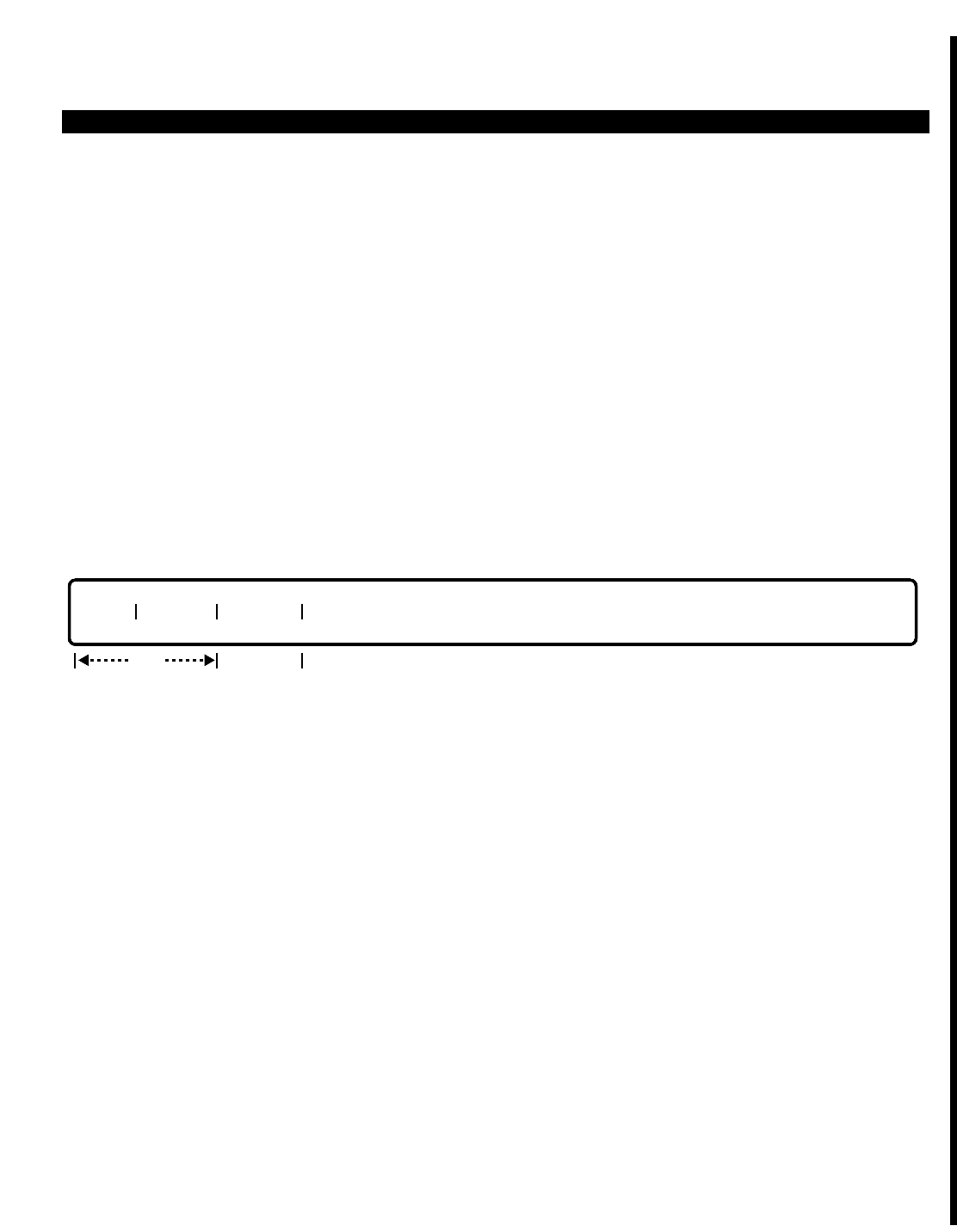
PERCEPTION 4000 COMMANDS
DATA STRUCTURE DISPLAY (CMD 167)
The Data Structure Display command allows an M&A user to display certain items in selected data structure
blocks used by system software. This command is used to assist in the software debugging process.
Command Keyword: DATA_STRUCTURE_DISP
Category Name: Utility
OPERATIONS
Available operations: DISPLAY
The function and required data fields for each operation are described as follows:
DISPLAY
This operation displays specific data items in the system data structures as specified in the command fields.
PARAMETERS
This section defines input permitted for each field. Any variations for a particular operation are noted separately.
FIELD: TYPE (Type of data)
TYPE: Keyword
FORMAT: Preassigned ASCII characters
Keywords: STA - Station Data
ACD - Automatic Call Distribution Data
SYS - System Information
The "TYPE" field specifies the type of data to display. This is a required field.
FIELD: PARA 1 (Parameter 1)
TYPE: Decimal or keyword
FORMAT: 1 to 5 digits; preassigned ASCII characters
VALUE; 0 to 99999
RANGE: Not allowed
TYPE PARA 1 PARA 2
opt
req
ISS 2, SECTION 4000-014-000
DATA STRUCTURE DISPLAY (CMD 167)
3-127

PERCEPTION 4000 COMMANDS
ISS 2, SECTION 4000-014-000
DATA STRUCTURE DISPLAY (CMD 167)
Keywords: MCPUCP - ACD call processing information on MCPU side
LCPUCP - ACD call processing information on LCPU side
GCB - ACD group control block information
LTN - ACD logical terminal number information
LDN - ACD logical directory number information
LSB - LDN status block information
CID - Call ID information
This field defines a specific area of information which is used in accessing the desired station or
ACD data. If STA is entered in the "TYPE" field, then a prime directory number should be entered
(the prime directory uniquely identifies each station and is assigned to a station with the Station
Assignment command [CMD 330]).
If ACD is selected in the "TYPE" field, then either an ACD agent ID or one of the the command's
keywords should be entered.
FIELD: PARA 2 (Parameter 2)
TYPE: Decimal or keyword
FORMAT: 1 to system-configured maximum; preassigned ASCII characters
RANGE: Not allowed
Keywords: BRF - Display a small amount of information about station type
DTL - Display a more detailed amount of information about station
type, including a dump of related data structure areas
ALL - Display information about all ACD groups
SYS - Display ACD system-level information
The "PARA 2" field is an optional field that specifies the amount of information displayed about
the selected data type. If STA is entered in the "TYPE" field, then either BRF or DTL can be
entered in the "PARA 2" field. If not specified, the default is BRF. If ACD is selected in the
"TYPE" field,and MCPUCP is entered in the "PARA 1" field, then either SYS or a specific number
of ACD groups can be entered (1 to system-configured maximum); the default is SYS. If
LCPUCP is entered in the "PARA 1" field, then only the SYS keyword can be entered; the default
is SYS. If either GCB, LTN, or LDN is entered in the "PARA 1" field, then either ALL or a specific
number of ACD groups can be entered (1 to system-configured maximum). Entries of either LSB
or CID in the "PARA 1" field require no "PARA 2" field entry. All of these various entry options are
summarized below:
TYPE PARA 1 PARA 2
STA 0 - 99999 BRF, DTL
ACD MCPUCP SYS, 1-max group
ACD LCPUCP SYS
ACD GCB ALL, 1-max group
ACD LTN ALL, 1-max group
ACD LDN ALL, 1-max group
ACD 000 - 999 ALL, 1-max group
SYS LSB
SYS CID
3-128

PERCEPTION 4000 COMMANDS
SYSTEM MESSAGES
The following error messages are unique to this command.
C16700 - Prime directory number does not exist
C16701 - MCPU database Read error (LDN attributes)
C16702 - MCPU database Read error (LPU number)
C16703 - MCPU database Read error (SSC state number)
C16704 - MCPU database Read error (LDN record address)
C16705 - MCPU database Read error (SLSB record address)
C16707 - MCPU database Read error (OFHCAMP record address)
C16707 - MCPU database Read error (ONHCAMP record address)
C16708 - HDT data not available for pilot directory numbers
C16709 - Data does not exist for virtual pilot directory numbers
C16710 - Check input in PARA 1 field
C16711 - Check input in PARA 2 field
C16712 - ACD group is not defined
ISS 2, SECTION 4000-014-000
DATA STRUCTURE DISPLAY (CMD 167)
3-129

PERCEPTION 4000 COMMANDS
ISS 2, SECTION 4000-014-000
DATA STRUCTURE DISPLAY 2 (CMD 169)
DATA STRUCTURE DISPLAY 2 (CMD 169)
The Data Structure Display 2 command is an extension of the Data Structure Display command (CMD 167). The
Data Structure Display 2 command allows an M&A user to display certain items in selected data structure blocks
used by system software. This command is used to assist in the software debugging process.
Command Keyword: DATA_STRUCTURE_DISP2
Category Name: Utility
OPERATIONS
Available operations: DISPLAY
The function and required data fields for each operation are described as follows:
DISPLAY
This operation displays specific data items in the system data structures as specified in the command fields.
PARAMETERS
This section defines input permitted for each field. Any variations for a particular operation are noted separately.
FIELD: TYPE (Type of data)
TYPE: Keyword
FORMAT: Preassigned ASCII characters
Keywords: ATT - Attendant Data
The "TYPE" field specifies the type of data to display. This is a required field.
FIELD: PARA 1 (Parameter 1)
TYPE: Decimal or keyword
FORMAT: 1 to 5 digits; preassigned ASCII characters
VALUE; 0 to 99999
RANGE: Not allowed
Keywords: IND - Individual attendant information in MCPU and LCPU
LDN - Attendant LDN information in MCPU and LCPU
GRP - Attendant group information in MCPU and LCPU
TYPE PARA 1 PARA 2
req
3-130

PERCEPTION 4000 COMMANDS
This field defines a specific area of information which is used in accessing the desired attendant
console informaiton.
FIELD: PARA 2 (Parameter 2)
TYPE: Decimal
FORMAT: 1 to 5 digits
RANGE: Not allowed
The "PARA 2" field is used to enter an attendant or attendant group directory number. If IND is
entered in the "PARA 1" field, then an individual attendant directory number should be entered in
the "PARA 2" field. If either LDN or GRP is entered in the "PARA 1" field, then and attendant
group directory number should be entered in the "PARA 2" field.
SYSTEM MESSAGES
The following error messages are unique to this command.
C16900 - Attendant directory number has not been defined
C16901 - Attendant group directory number has not been defined
C16902 - Convert equipment error
C16903 - Read LCPU data timeout
D16904 - LCPU number does not match with the one in transaction
C16905 - Address error (address 0xNNNNNNNNN)
D16906 - Read MCPU error
D16907 - Invalid LDN
ISS 2, SECTION 4000-014-000
DATA STRUCTURE DISPLAY 2 (CMD 169)
3-131

PERCEPTION 4000 COMMANDS
ISS 2, SECTION 4000-014-000
DESTINATION RESTRICTION LEVEL ASSIGNMENT (CMD 337)
DESTINATION RESTRICTION LEVEL ASSIGNMENT (CMD 337)
Destination Restriction Levels (DRLs) control outgoing calls made via direct trunk group access. This type of
dialing restriction may also be used by Least Cost Routing if set in the system options (System Option Flags
command, CMD 408). The Destination Restriction Level Assignment command displays or modifies the non-toll-
free call allowance or denial of DRLs in a trunk restriction group (TRGN). This command also provides
information on whether or not the exceptional allow/deny, country code, area code, and area/office code tables
are available for the given DRL and TRGN.
Command Keyword: DRL_ASSIGN
Category Name: Restrict
PREREQUISITE COMMANDS
There are no prerequisites for this command.
OPERATIONS
Available operations: MODIFY
DISPLAY
The function and required data fields for each operation are described in this section.
MODIFY
This operation changes the non-toll-free call allowance/denial of one or more trunk restriction groups. Loops are
permitted in the “TRGN” and “DRL” fields.
DISPLAY
This operation displays the non-toll-free call allowance/denial of one or more trunk restriction groups, and shows
whether or not the except allowance/denial, country code, area code, and area/office code tables are available for
the given "DRL" and "TRGN". No input data field is required. If no data is entered in any of the fields, all DRLs of
every trunk restriction group in the system display. Ranges are permitted in the “TRGN” and “DRL” fields.
TRGN DRL NON TF EXCEPT DNY EXCEPT ALW CC TBL AC/OC TBL AC TBL
opt output only
TRGN DRL NON TF
req opt
3-132

PERCEPTION 4000 COMMANDS
PARAMETERS
Each field parameter is described in this section. Any variations for a particular operation are noted separately.
FIELD: TRGN (Trunk Restriction Group Number)
TYPE: Decimal
FORMAT: 1 digit
VALUE: 2 to 8 (or to the maximum system configuration)
LOOP: Allowed in DISPLAY and MODIFY operations
RANGE: Allowed in a DISPLAY operation only
Up to seven trunk restriction groups can be defined in the system.
FIELD: DRL (Destination Restriction Level)
TYPE: Decimal
FORMAT: 1 or 2 digits
VALUE: 2 to 16 (or to the maximum system configuration)
LOOP: Allowed in DISPLAY and MODIFY operations.
Values for "DRL" are from 2 to 16.
FIELD: NON TF (Non “Toll free” Calling Zone Allowance/Denial)
TYPE: Keyword
FORMAT: Predefined ASCII characters
Keywords: ALW - Allow non-toll-free calls
DNY - Deny non-toll-free calls
If ALW is entered, restrictions on these calls are controlled by other restriction tables. When DNY
is entered, calls to destinations outside of the toll-free calling zone are denied.
FIELD: EXCEPT DNY (Exceptional Destination Restriction Denial Table)
TYPE: Keyword
FORMAT: Predefined ASCII characters
Keywords: YES - Table exists
NO - Table does not exist
This field is for output only in a DISPLAY operation. Refer to the Exceptional Restriction Tables
command (CMD 340).
FIELD: EXCEPT ALW (Exceptional Destination Restriction Allowance Table)
TYPE: Keyword
FORMAT: Predefined ASCII characters
Keywords: YES - Table exists
NO - Table does not exist
This field is for output only in a DISPLAY operation. Refer to the Exceptional Restriction Tables
command (CMD 340).
ISS 2, SECTION 4000-014-000
DESTINATION RESTRICTION LEVEL ASSIGNMENT (CMD 337)
3-133

PERCEPTION 4000 COMMANDS
ISS 2, SECTION 4000-014-000
DESTINATION RESTRICTION LEVEL ASSIGNMENT (CMD 337)
FIELD: CC TBL (Country Code Restriction Table)
TYPE: Keyword
FORMAT: Predefined ASCII characters
Keywords: YES - Table exists
NO - Table does not exist
This field is for output only in a DISPLAY operation. Refer to the Country Code Restriction Tables
command (CMD 338).
FIELD: AC/OC TBL (Area Code/Office Code Restriction Table)
TYPE: Keyword
FORMAT: Predefined ASCII characters
Keywords: YES - Table exists
NO - Table does not exist
This field is for output only in a DISPLAY operation. Refer to the Area/Office Code Restriction
Tables command (CMD 339)
FIELD: AC TBL (Area Code Restriction Table)
TYPE: Keyword
FORMAT: Predefined ASCII characters
Keywords: YES - Table exists
NO - Table does not exist
This field is for output only in a DISPLAY operation. Refer to the Area Code Restriction Tables
command (CMD 341).
SYSTEM ERROR MESSAGES
The following error message is unique to this command.
C33700 - Check trunk restriction group number range
RELATED COMMANDS
Area Code Restriction Tables (CMD 341)
Area/Office Code Restriction Tables (CMD 339)
Country Code Restriction Tables (CMD 338)
Exceptional Restriction Tables (CMD 340)
System Option Flag Assignment (CMD 408)
Trunk Group Assignment (CMD 310)
Trunk Group Toll-free Tables (CMD 311)
3-134
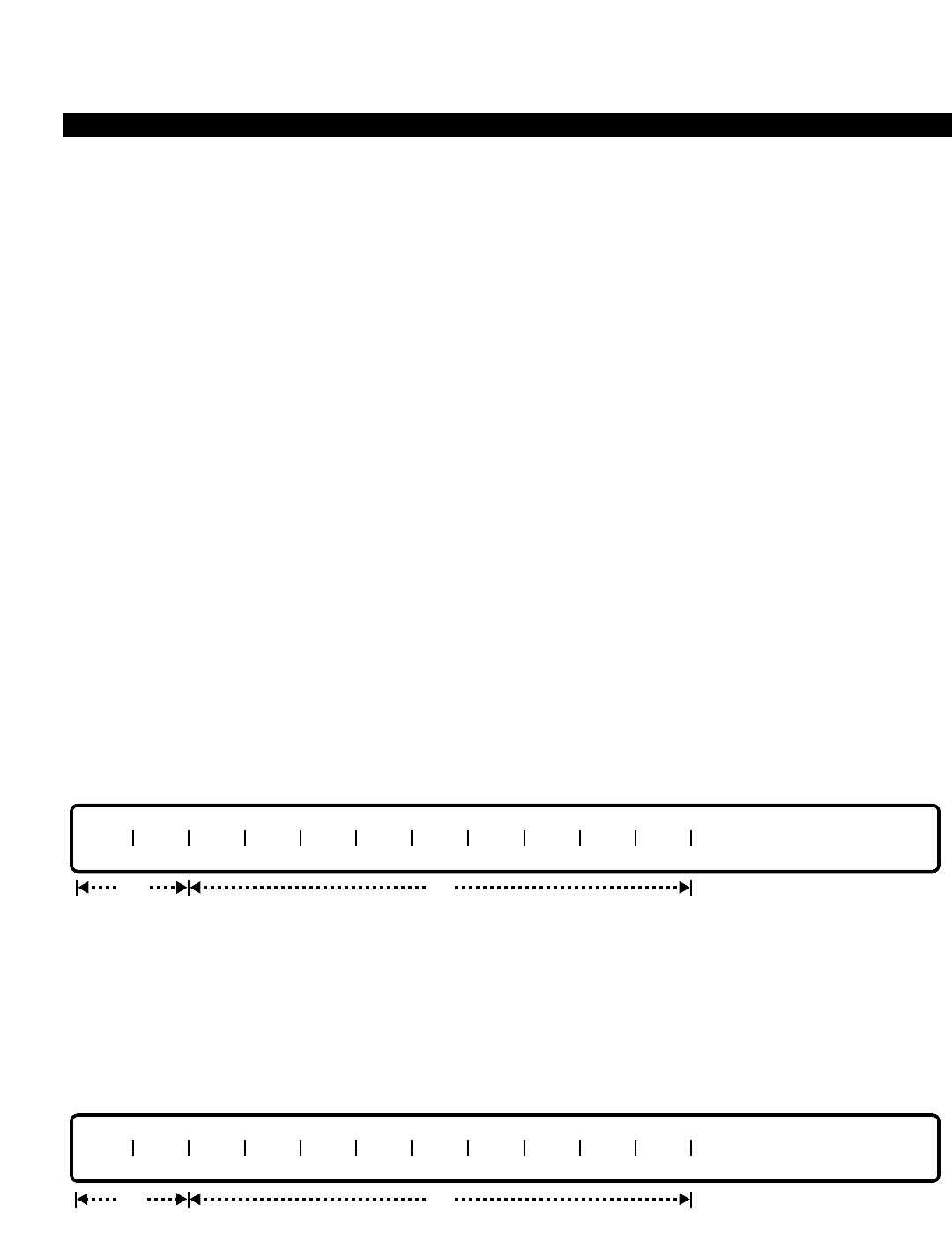
PERCEPTION 4000 COMMANDS
DEVICE SERVICE STATUS (CMD 208)
The Device Service Status command places the Stand-by side, or a device on the Active or Stand-by side, in/out
of service. This command also installs/removes device(s) from the system either on the Active or the Stand-by
side.
Command Keyword: DEVICE_STATUS
Category Name: Maintenance
PREREQUISITE COMMANDS
There are no prerequisites for this command.
OPERATIONS
Available operations: INSTALL
REMOVE
INS
OOS
DISPLAY
The function and required data fields for each operation are described in this section.
INSTALL
This operation installs device(s) on the system either on the Active or the Stand-by side. At least one device must
be entered in a “DEV” field. When a device is installed, it must then be placed into service with an INS operation.
For the Active side of the system, LPU2, LPU3, and ETSW should be assigned, if used. If a redundant system
side is being used, HDD, FDD, DDCC, MCPU, LPU1, and BTSW should be assigned. Also, if used on the
redundant side, LPU2, LPU3, and ETSW should be assigned.
REMOVE
SIDE DEV DEV DEV DEV DEV DEV DEV DEV DEV DEV
optreq
SIDE DEV DEV DEV DEV DEV DEV DEV DEV DEV DEV
optreq
ISS 2, SECTION 4000-014-000
DEVICE SERVICE STATUS (CMD 208)
3-135

PERCEPTION 4000 COMMANDS
ISS 2, SECTION 4000-014-000
DEVICE SERVICE STATUS (CMD 208)
This operation removes device(s) from the system either on the Active or the Stand-by side. At least one device
must be entered in a “DEV” field. A device must be placed out of service with an OOS operation before it can be
removed from the system.
INS
This operation puts the whole Stand-by side or a device on the Active or Stand-by side in service. To put the
Stand-by side in service, enter SBY in the “SIDE” field and no data in the “DEV” field.
OOS
This operation puts the Stand-by side or a device on the system out of service. To put the Stand-by side out of
service, enter SBY in the “SIDE” field and no data in the “DEV” field.
DISPLAY
This operation displays the status of one or all of the devices on the Active, Stand-by, or both sides. The "SIDE"
field is required, while the remaining fields are output fields only. The status displays as either 'INS' if the card is
installed, 'OOS' if the card is installed and configured but not synchronized, or '---' if the card is not installed and
not configured.
PARAMETERS
Each field parameter is described in this section. Any variations for a particular operation are noted separately.
FIELD: SIDE (Active/Stand-by Side)
TYPE: Keyword
FORMAT: Predefined ASCII characters
SIDE MCPU LPU1 LPU2 LPU3 BTSW ETSW DDCC HDD FDD MCLK MISC
req
output only
SIDE DEV
optreq
SIDE DEV
optreq
3-136

PERCEPTION 4000 COMMANDS
Keywords: ACT - Active Side
SBY - Stand-by Side
BOTH - Both Sides
SIDEA - Side A
SIDEB - Side B
This field is required for all operations. Sides A and B are the physical locations of the processing
equipment. Note that either side (A or B) may be the Active or Stand-by side.
FIELD: DEV (Name of a Device)
TYPE: Keyword
FORMAT: Predefined ASCII characters
Keywords: MCPU - Main CPU & Memory
LPU1 - Local CPU & Memory #1
LPU2 - Local CPU & Memory #2
LPU3 - Local CPU & Memory #3
BTSW - Basic Time Division Switching
ETSW - Extended Time Division Switching
DDCC - Disk Drive Common Controller
HDD - Hard Disk Drive
FDD - Floppy Disk Drive
MCLK - Main Clock
MISC - Miscellaneous Card Type
For INSTALL/REMOVE Operations:
If ACT is entered in the “SIDE” field, only LPU1, LPU2 and/or ETSW can be entered. If
SBY is entered in the “SIDE” field, all of the listed keywords except MCLK and MISC can be
entered.
For INS/OOS Operations:
MCPU can be entered only when "SIDE" is set to SBY. HDD and FDD can be entered
regardless of which side it is. None of the remaining keywords are allowed.
FIELD: MCPU (Main CPU)
TYPE: Keyword (Output only)
FORMAT: Predefined ASCII characters
Keywords: INS - The card is in-service
OOS - The card is out of service
--- - The card is not installed and not configured
This field, appearing in a DISPLAY operation, indicates the status of the MCPU card.
FIELD: LPU1,2,3 (Local CPU #1,2,3)
TYPE: Keyword (Output only)
FORMAT: Predefined ASCII characters
ISS 2, SECTION 4000-014-000
DEVICE SERVICE STATUS (CMD 208)
3-137

PERCEPTION 4000 COMMANDS
ISS 2, SECTION 4000-014-000
DEVICE SERVICE STATUS (CMD 208)
Keywords: INS - In-service
OOS - Out of service
--- - The card is not installed and not configured
These fields, appearing in a DISPLAY operation, indicate the status of the local CPU cards.
FIELD: BTSW (Basic Time Division Switching)
TYPE: Keyword (Output only)
FORMAT: Predefined ASCII characters
Keywords: INS - In-service
OOS - Out of service
--- - The card is not installed and not configured
This field, appearing in a DISPLAY operation, indicates the status of the BTSW card.
FIELD: ETSW (Extended Time Division Switching)
TYPE: Keyword (Output only)
FORMAT: Predefined ASCII characters
Keywords: INS - In-service
OOS - Out of service
--- - The card is not installed and not configured
This field, appearing in a DISPLAY operation, indicates the status of the ETSW card.
FIELD: DDCC (Disk Drive Controller)
TYPE: Keyword (Output only)
FORMAT: Predefined ASCII characters
Keywords: INS - In-service
OOS - Out of service
--- - The card is not installed and not configured
This field, appearing in a DISPLAY operation, indicates the status of the DDCC card.
FIELD: HDD (Hard Disk Drive)
TYPE: Keyword (Output only)
FORMAT: Predefined ASCII characters
Keywords: INS - In-service
OOS - Out of service
--- - The card is not installed and not configured
This field, appearing in a DISPLAY operation, indicates the status of the HDD card.
FIELD: FDD (Floppy Disk Drive)
TYPE: Keyword (Output only)
FORMAT: Predefined ASCII characters
3-138

PERCEPTION 4000 COMMANDS
Keywords: INS - In-service
OOS - Out of service
--- - The card is not installed and not configured
This field, appearing in a DISPLAY operation, indicates the status of the FDD card.
FIELD: MCLK (Main Clock)
TYPE: Keyword (Output only)
FORMAT: Predefined ASCII characters
Keywords: INS - In-service
OOS - Out of service
--- - The card is not installed and not configured
This field, appearing in a DISPLAY operation, indicates the status of the MCLK card.
FIELD: MISC (Miscellaneous Card)
TYPE: Keyword (Output only)
FORMAT: Predefined ASCII characters
Keywords: INS - In-service
OOS - Out of service
--- - The card is not installed and not configured
This field, appearing in a DISPLAY operation, indicates the status of the MISC card. "MISC" is
the only card in a single/redundant system.
SYSTEM ERROR MESSAGES
The following error messages are unique to this command.
C20800 - Device has already been installed
C20801 - Device has already been removed
C20802 - Device is already in service
C20803 - Device is already out of service
C20804 - Cannot register device
C20805 - Does not match system configuration
C20806 - Program/data transfer
C20807 - No response
C20808 - Failed to send message to SYC
C20809 - Failed to set timer
C20810 - Stand-by side no response
C20811 - Regulated by SYM
C20812 - Failed to receive message from SYC
C20813 - BOTH is not an allowed keyword in this operation
C20814 - Stand-by side setup timeout
C20815 - Stand-by side is out of service
ISS 2, SECTION 4000-014-000
DEVICE SERVICE STATUS (CMD 208)
3-139
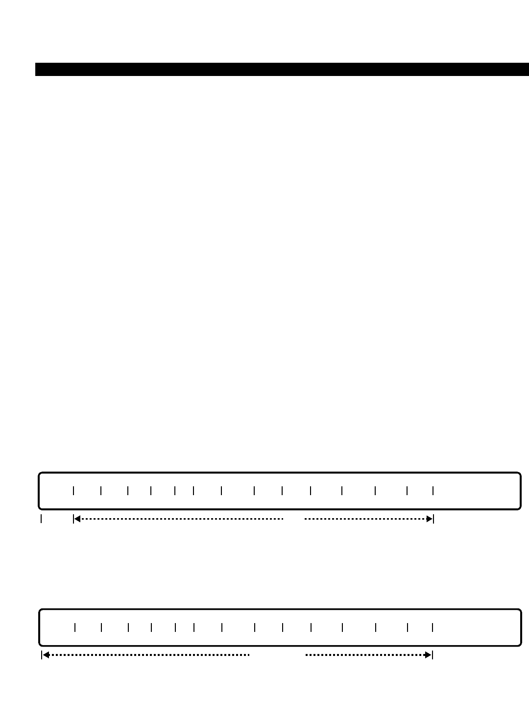
PERCEPTION 4000 COMMANDS
ISS 2, SECTION 4000-014-000
DIALING DEFINITION (CMD 317)
DIALING DEFINITION (CMD 317)
This command defines dialing groups used in the Trunk Group Assignment command (CMD 310) and the Least
Cost Routing Special Routing Assignment command (CMD 384). Dialing Group 1 is used for TIE lines and
interfaces to peripheral equipment where standard dialing does not exist. Private networks many times use
unconventional dialing which would require the use of Dialing Group 1.
Special dialing definition groups include the operator and long distance operator prefix, international operator
prefix, IDDD access code, toll prefix, local directory assistance, telephone repair number, emergency access
code, and interchangeable office code recognition.
Command Keyword: DIALING_DEFINITION
Category Name: Dialing
PREREQUISITE COMMANDS
There are no prerequisites for this command.
OPERATIONS
Available operations: MODIFY
DISPLAY
The function and required data fields for each operation are described in this section.
MODIFY
This operation modifies the special dialing codes of one or more dialing definition groups. The Dialing Group
Number (GRP#) is required. Ranges are permitted in the “GRP#” field.
DISPLAY
This operation displays the special dialing codes of all three dialing definition groups. No input data is required,
and all the fields are output only fields.
output only
GRP# OPP LOP IOP IAC TP LDA REPR BUS EMR AUX1 AUX2 AUX3 IOC
optreq
GRP# OPP LOP IOP IAC TP LDA REPR BUS EMR AUX1 AUX2 AUX3 IOC
3-140

PERCEPTION 4000 COMMANDS
PARAMETERS
Each field parameter is described in this section. Any variations for a particular operation are noted separately.
FIELD: GRP# (Dialing Group Number)
TYPE: Decimal
FORMAT: 1 digit
VALUE: 2 to 4
RANGE: Allowed in a MODIFY operation
The system supports three dialing groups. Dialing group 1 allows undefined dialing.
FIELD: OPP (Operator Prefix)
TYPE: Dialing Digits (i.e., 001 is not the same as 01 or 1)
FORMAT: 1 to 3 dialed digits
VALUE: 0 to 999
RANGE: Not allowed
The default value of the operator prefix is 0.
FIELD: LOP (Long Distance Operator Prefix)
TYPE: Dialing Digits (i.e., 001 is not the same as 01 or 1)
FORMAT: 1 to 3 dialed digits
VALUE: 0 to 999
RANGE: Not allowed
The default value of the long distance operator prefix is 00.
FIELD: IOP (International Operator Prefix)
TYPE: Dialing Digits (i.e., 001 is not the same as 01 or 1)
FORMAT: 1 to 3 dialed digits
VALUE: 0 to 999
RANGE: Not allowed
The default value of the international operator prefix is 01.
FIELD: IAC (International Direct Dialing [IDDD] Access Code)
TYPE: Dialing Digits (i.e., 001 is not the same as 01 or 1)
FORMAT: 1 to 3 dialed digits
VALUE: 0 to 999
RANGE: Not allowed
The default value of the IDDD access code is 011.
FIELD: TP (Toll Prefix)
TYPE: Dialing Digits (i.e., 001 is not the same as 01 or 1)
FORMAT: 1 to 3 dialed digits
VALUE: 0 to 999
RANGE: Not allowed
The default value of the toll prefix is 1.
ISS 2, SECTION 4000-014-000
DIALING DEFINITION (CMD 317)
3-141

PERCEPTION 4000 COMMANDS
ISS 2, SECTION 4000-014-000
DIALING DEFINITION (CMD 317)
FIELD: LDA (Local Directory Assistance)
TYPE: Dialing Digits (i.e., 001 is not the same as 01 or 1)
FORMAT: 1 to 3 dialed digits
VALUE: 0 to 999
RANGE: Not allowed
The default value of local directory assistance is 411.
FIELD: REPR (Telephone Repair)
TYPE: Dialing Digits (i.e., 001 is not the same as 01 or 1)
FORMAT: 1 to 3 dialed digits
VALUE: 0 to 999
RANGE: Not allowed
The default value of the telephone repair number is 611.
FIELD: BUS (Telephone Business Office)
TYPE: Dialing Digits (i.e., 001 is not the same as 01 or 1)
FORMAT: 1 to 3 digits
VALUE: 0 to 999
RANGE: Not allowed
The default value of the telephone business office is 811.
FIELD: EMR (Emergency Access)
TYPE: Dialing Digits (i.e., 001 is not the same as 01 or 1)
FORMAT: 1 to 3 dialed digits
VALUE: 0 to 999
RANGE: Not allowed
The default value of the emergency number is 911.
FIELD: AUX1, 2, 3 (Auxiliary Definition 1, 2, and 3) (Reserved for future use)
TYPE: Dialing Digits (i.e., 001 is not the same as 01 or 1)
FORMAT: 1 to 3 dialed digits
VALUE: 0 to 999
RANGE: Not allowed
These fields are for future use.
FIELD: IOC (Interchangeable Office Code Recognition)
TYPE: Keyword
FORMAT: Predefined ASCII characters
Keywords: ITP - Identifiable by toll prefix before area code
ITO - Identifiable by timeout
NON - No interchangeable office codes
This field defines whether interchangeable office codes exist for the trunk groups using this
dialing group, and if so, how they are identified - by toll prefix usage before the area code (ITP) or
3-142

PERCEPTION 4000 COMMANDS
by timeout after 10 or 11 digits are dialed (ITO). Interchangeable office codes are defined as
office codes which have a '0' or '1' as a middle digit, making them appear as area codes (NYX -
where N is a digit 2-9, Y is the digit 1 or 0, and X is a digit 0-9). Interchangeable office codes are
defined in the Interchangeable Office Code Table command (CMD 318).
SYSTEM ERROR MESSAGES
The following error messages are unique to this command.
C31700 - Check dialing group number range
C31701 - Same value exists in two or more fields
RELATED COMMANDS
Interchangeable Office Code Table (CMD 318)
LCR Special Routing Assignment (CMD 384)
Trunk Group Assignment (CMD 310)
ISS 2, SECTION 4000-014-000
DIALING DEFINITION (CMD 317)
3-143

PERCEPTION 4000 COMMANDS
ISS 2, SECTION 4000-014-000
DICTATION GROUP/MACHINE ASSIGNMENT (CMD 401)
DICTATION GROUP/MACHINE ASSIGNMENT (CMD 401)
The Dictation Machine Assignment command configures dictation machine groups as well as installs dictation
machines on standard trunk circuits. The PERCEPTION 4000 supports up to 16 dictation machine groups; each
group may be configured with a maximum of eight dictation machines.
Command Keyword: DICTATION_ASSIGN
Category Name: System
PREREQUISITE COMMAND
Trunk Group Assignment (CMD 310)
OPERATIONS
Available operations: ADD
DELETE
DISPLAY
The function and required data fields for each operation are described in this section.
ADD
This operation adds a dictation machine and its device identifier to a dictation machine group. Loops are allowed
in the “GRP#” and “DEV” fields.
DELETE
This operation deletes a dictation machine from a dictation machine group. Loops are allowed in the “GRP#” and
“DEV” fields.
req
GRP# DEV EQUIP #
opt
req
GRP# DEV EQUIP # NAME
opt
3-144
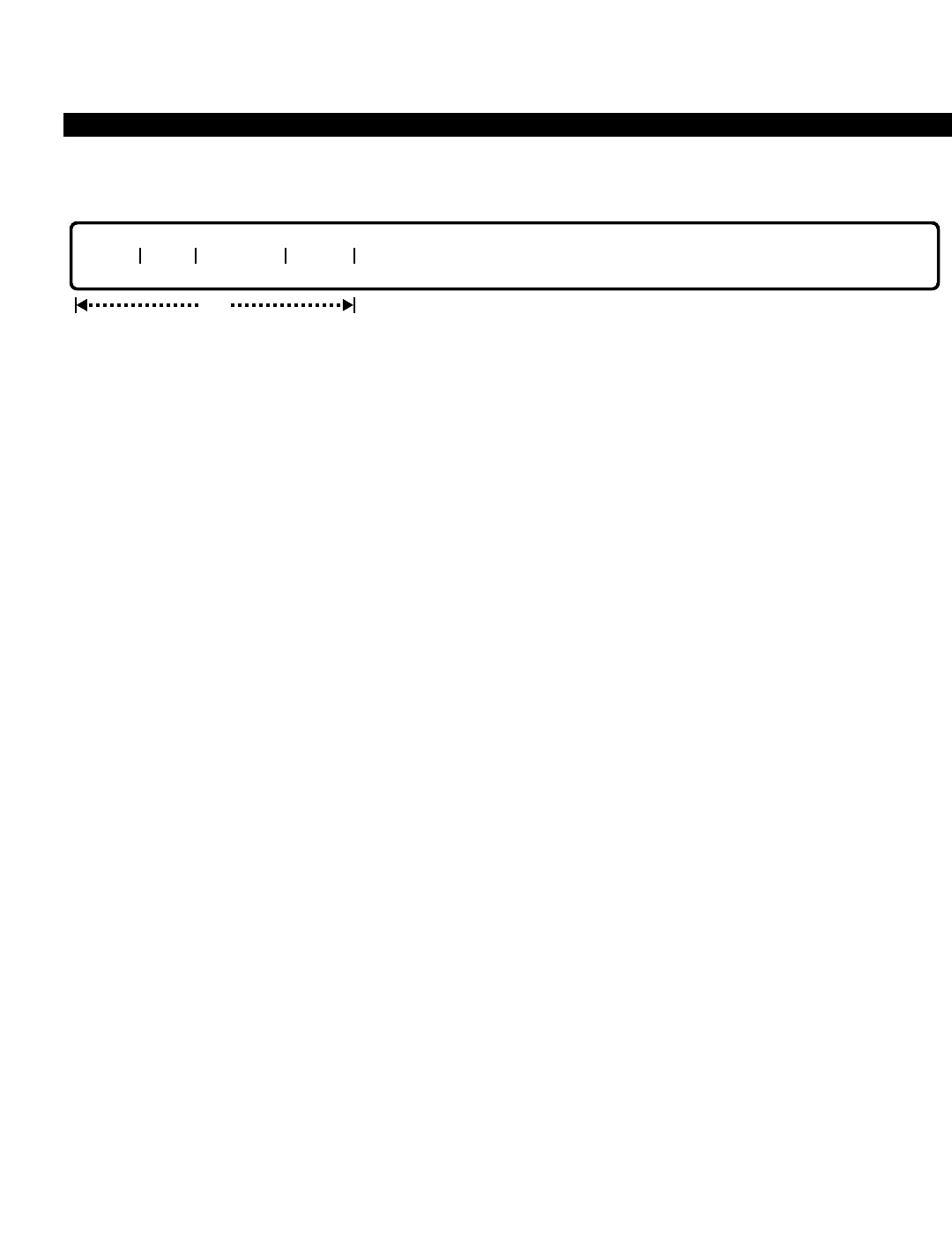
PERCEPTION 4000 COMMANDS
DISPLAY
This operation displays the dictation machine group and its associated dictation machines. Loops are allowed in
the “GRP#” and “DEV” fields. If no data is entered in any of the fields, all of the dictation groups display.
PARAMETERS
Each field parameter is described in this section. Any variations for a particular operation are noted separately.
FIELD: GRP# (Dictation Machine Group Number)
TYPE: Decimal
FORMAT: 1 or 2 digits
VALUE: 1 to 16
LOOPS: Allowed in ADD/DELETE/DISPLAY operations
This field identifies the group to be assigned. Dictation machine groups are defined in the Trunk
Group Assignment command (CMD 310).
FIELD: DEV (Device Identifier)
TYPE: Decimal
FORMAT: 1 digit
VALUE: 1 to 8
RANGES: Allowed in ADD/DELETE/DISPLAY operations
This field is an index numbering of the machines in the group. Note that the dictation machine
groups hunt from the lowest index number to the highest, therefore if ordering is important, this
sequence should be observed.
FIELD: EQUIP # (Equipment Number)
TYPE: EQ Type
FORMAT: 5 or 6 digits
VALUE: (0)10101-101408 *
RANGE: Allowed in a DISPLAY operation
* Use the following chart to determine valid ranges for dictation machines.
For BSTI equipment cards, the following ranges apply:
Digits Range Hardware
First digit(s) (0)1~10 Shelf no.
Second two digits 01~11, 13 Card slot no.
Last two digits 01~16 Circuit no.
opt
GRP# DEV EQUIP # NAME
ISS 2, SECTION 4000-014-000
DICTATION GROUP/MACHINE ASSIGNMENT (CMD 401)
3-145

PERCEPTION 4000 COMMANDS
ISS 2, SECTION 4000-014-000
DICTATION GROUP/MACHINE ASSIGNMENT (CMD 401)
For XSTI equipment cards, the following ranges apply:
Digits Range Hardware
First digit(s) (0)1~10 Shelf no.
Second two digits 01~14 Card slot no.
Last two digits 01~08 Circuit no.
This field assigns each dictation machine in the group to a standard analog line circuit (BSTI or
XSTI) card. A trunk group supporting dictation machine group usage must also be defined, even
if an analog line circuit is used (refer to the Trunk Group Assignment command, CMD 310).
FIELD: NAME (Dictation Machine's Device Name)
TYPE: Text
FORMAT: 0 to 9 ASCII characters
This field defines the dictation machine's device name, up to a maximum of 9 ASCII
characters/numbers including punctuation and spaces.
SYSTEM ERROR MESSAGES
The following error messages are unique to this command.
C40100 - Check dictation machine group number range
C40101 - Check device number range
C40102 - Device has already been installed
C40103 - Device not found
C40104 - Dictation machine group is not defined
C40105 - Card or equipment number is assigned to another device
C40106 - Equipment number is not a dictation machine card type
C40107 - Dictation machine's device name exceeds 14 characters
C40108 - Remove hunting sequence before deleting dictation machine
RELATED COMMAND
Trunk Hunting Assignment (CMD 309)
3-146
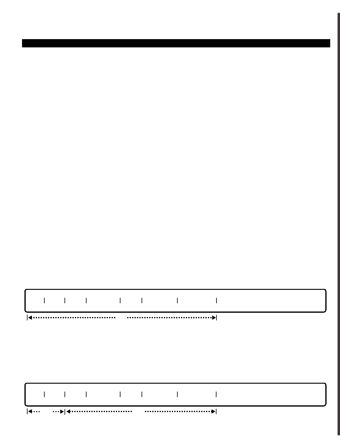
PERCEPTION 4000 COMMANDS
DID/CCSA/DNIS ACD PARAMETER ASSIGNMENT (CMD 359)
The DID/CCSA/DNISACD Parameter Assignment command is used to define listed directory numbers (LDNs)
and their associated routing destinations. Routing choices are DID, CCSA, DNIS with a non-ISDN trunk group,
and DNIS/DDI with an ISDN trunk group.
Command Keyword: DID/CCSA/DNIS_ACD
Category Name: Trunk
PREREQUISITE COMMANDS
Trunk Group Assignment (CMD 310)
Trunk Group Parameter Assignment (CMD 420)
DID/CCSA/DNIS Trunk Group Assignment (CMD 314)
DID/CCSA/DNIS LDN Assignment (CMD 316)
OPERATIONS
Available operations:
DISPLAY
MODIFY
The function and required data fields for each operation are described as follows:
DISPLAY
This operation is used to display the parameters of one or more existing LDNs. The DISPLAY operation requires
no data input. If a <TAB> is entered in the "TGN" field, information regarding all LDNs for all trunk groups in the
PERCEPTION 4000 system will be displayed.
MODIFY:
ThIs operation is used to modify the attributes of an existing LDN. Required input information includes the LDN
and its associated trunk group number ("TGN").
TGN LDN IQP1 IQP TMR IQP2 OVF TMR LDN NAME
opt
req
TGN LDN IQP1 IQP TMR IQP2 OVF TMR LDN NAME
opt
ISS 2, SECTION 4000-014-000
DID/CCSA/DNIS ACD PARAMETER ASSIGNMENT (CMD 359)
3-147

PERCEPTION 4000 COMMANDS
ISS 2, SECTION 4000-014-000
DID/CCSA/DNIS ACD PARAMETER ASSIGNMENT (CMD 359)
PARAMETERS
This section defines input permitted for each field. Any variations for a particular operation are noted separately.
FIELD: TGN (Trunk Group Number)
TYPE: Decimal
FORMAT: 1 to 3 digits
VALUE: 1 to 256 (or maximum system configuration)
RANGE: Not allowed
LOOP: Allowed in DISPLAY operation only
The specified TGN must be either: a DID, CCSA, or DNIS trunk; or an ISDN trunk with DNIS/DID inward mode.
FIELD: LDN (Listed Directory Number)
TYPE: Decimal
FORMAT: 2 to 15 digits
VALUE: 00 to 999999999999999
RANGE: Allowed in DISPLAY operation only
LOOP: Not allowed
The entered LDN must have been previously defined via the DID/CCSA LDN Assignment command (CMD 316).
FIELD: IQP1 (First Incoming ACD Call Queuing Priority)
TYPE: Decimal
FORMAT: 1 to 2 digits
VALUE: 1 to 16
RANGE: Allowed in DISPLAY operation only
LOOP: Not allowed
The "IQP1" field defines how the incoming LDN call will be treated in an ACD environment. If a value of 1is
entered in this field, then the incoming call will receive the highest level of priority and be placed at the front of the
ACD queue. If 16 is entered, the call will receive the lowest level of priority treatment. Values in between 1 and 16
can be entered to provide intermediate levels of treatment. If a <Ctrl> D is entered in the "IQP1" field when the
"IQP TMR" and "IQP2" have not been defined, then the "IQP1" value will be deleted.
FIELD: IQP TMR (Incoming ACD Call Queuing Priority Timer)
TYPE: Decimal
FORMAT: 1 to 4 digits
VALUE: 1 to 9999, in seconds
RANGE: Allowed in DISPLAY operation only
LOOP: Not allowed
The "IQP TMR" field entry assigns the period of time that an incoming LDN call will wait in queue prior to being
repositioned per the "IQP2" field entry. If "IQP2" is defined, then the "IQP TMR" must also be assigned. If a
<Ctrl> D is entered in the "IPQ TMR" field, then both the "IQP TMR" and "IQP2" field entries will be deleted.
When defined, the "IPQ TMR" value should be less than the value of the overflow timer "OVF TMR."
FIELD: IQP2 (Second Incoming ACD Call Queuing Priority)
TYPE: Decimal
FORMAT: 1 or 2 digits
VALUE: 1 to 16
3-148

PERCEPTION 4000 COMMANDS
RANGE: Allowed in DISPLAY operation only
LOOP: Not allowed
This field defines the new priority level that is assigned to an incoming LDN call after waiting in an ACD queue for
a period longer than that set in the "IQP TMR" field. If the "IQP TMR" field is defined, then the "IQP2" field should
also be defined. If a <Ctrl> D is entered in the "IQP2" field, then both the "IQP2" and "IQP TMR" field entries will
be deleted. The entered "IQP2" value should be less than or equal to the "IQP1" value.
FIELD: OVF TMR (ACD Overflow Timer)
TYPE: Decimal
FORMAT: 1 to 4 digits
VALUE: 1 to 9999
RANGE: Allowed in DISPLAY operation only
LOOP: Not Allowed
This field assigns the period of time that an incoming LDN call will wait at the new ("IQP2") priority level before
being routed to an alternative destination (the assigned overflow destination for the ACD group). The "OVF TMR"
value should always be greater than the "IQP TMR"" value (unless the overflow timer is set at 0). If a <Ctrl> D is
entered in the "OVF TMR" field, then the "OVF TMR" value will be deleted.
FIELD: LDN NAME (Listed Directory Number Name)
TYPE: Text
FORMAT: up to 14 ASCII characters
This field defines the name associated with the LDN. Assigned LDN names enable LDN call recipients to receive
a descriptive indication of each incoming LDN call. This aids in call answering procedures and is particularly
helpful in an ACD environment.
SYSTEM MESSAGES
The following error messages are unique to this command.
C35900 - Undefined trunk group number
C35901 - Check trunk group number range
C35902 - The specified LDN does not exist
C35903 - IQP2 must be smaller than IQP1
C35904 - Trunk type is not DID, CCSA, or DNIS
C35905 - ISDN trunk group with DNIS/DDI inward mode is not allowed
C35906 - Overflow timer must be greater than Queing Priority Timer
C35907 - IQP2 field has been defined; IQP TMR should also be defined
C35908 - IQP TMR has been defined; IQP2 field should also be defined
C35911 - Deletion not allowed; check IQP2 and IQP TMR entries
ISS 2, SECTION 4000-014-000
DID/CCSA/DNIS ACD PARAMETER ASSIGNMENT (CMD 359)
3-149
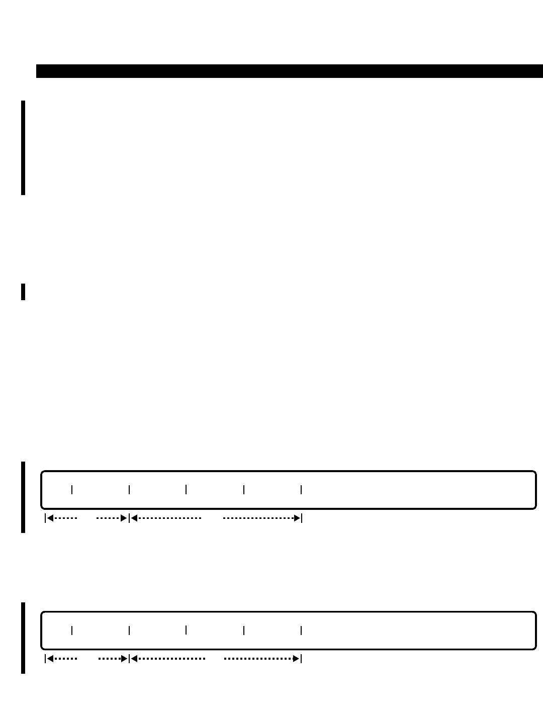
PERCEPTION 4000 COMMANDS
ISS 2, SECTION 4000-014-000
DID/CCSA/DNIS DISA LDN ASSIGNMENT (CMD 315)
DID/CCSA/DNIS DISA LDN ASSIGNMENT (CMD 315)
Each defined DID, CCSA, and DNIS non-ISDN trunk group, as well as each inward mode DDI/DNIS ISDN trunk
may have listed directory numbers (LDNs) assigned for Direct Inward System Access (DISA). This command
defines the DISA table for the trunk groups. The use of DISA enables outside callers to call the system via one of
the LDNs and, after entering an optional security code and/or authorization code, to access system features and
facilities.
Command Keyword: DID/CCSA_DISA
Category Name: Trunk
PREREQUISITE COMMANDS
DID/CCSA/DNIS Trunk Group Assignment (CMD 314)
Trunk Group Assignment (CMD 310)
OPERATIONS
Available operations: ADD
DELETE
DISPLAY
The function and required data fields for each operation are described in this section.
ADD
This operation creates a new group or adds a DISA LDN to an existing group. Data is required in the "TGN" and
the first "DISA LDN" fields. Looping is allowed in the "TGN" field.
DELETE
This operation deletes a "TGN" or an "DISA LDN". Data is required in the "TGN" and the first "DISA LDN" fields.
Looping is allowed in the "TGN" field. To delete the entire TGN, enter ALL in any of the "DISA LDN" fields.
req
TGN DISA LDN DISA LDN DISA LDN DISA LDN
opt
req
TGN DISA LDN DISA LDN DISA LDN DISA LDN
opt
3-150
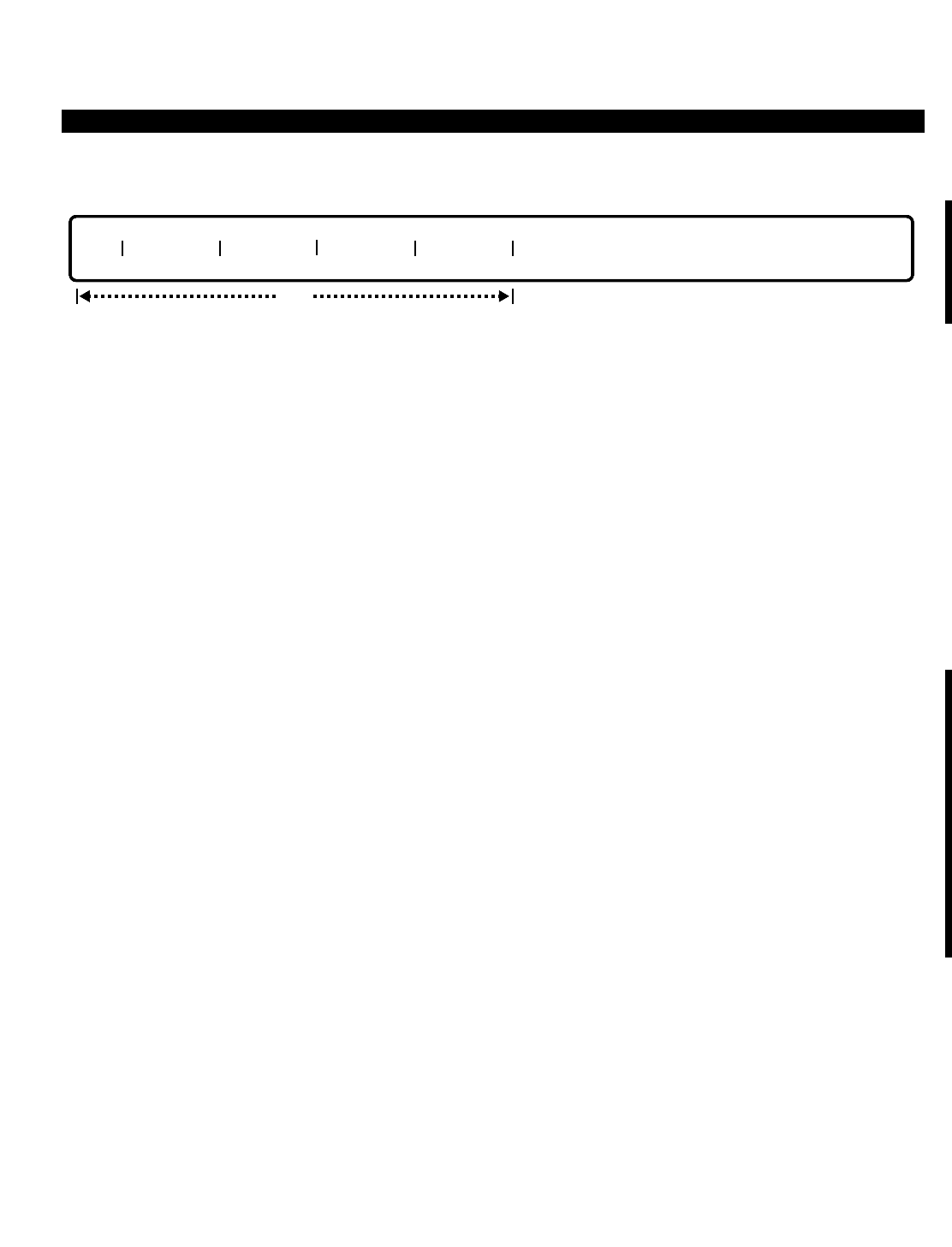
PERCEPTION 4000 COMMANDS
DISPLAY
This operation displays all trunk groups and their DISA LDN’s that meet the conditions established in each field.
Looping is permitted in the "TGN" field.
PARAMETERS
Each field parameter is described in this section. Any variations for a particular operation are noted separately.
FIELD: TGN (Trunk Group Number)
TYPE: Decimal
FORMAT: 1 to 3 digits
VALUE: 1 to 256 (or to the maximum system configuration)
LOOPS: Allowed in all operations
Valid entries are the actual trunk group numbers which were pre-defined as DID/CCSA trunk
groups in the Trunk Group Assignment command (CMD 310).
FIELD: DISA LDN (Direct Inward System Access Listed Directory Number)
TYPE: Decimal / Keyword
FORMAT: 2 to 7 digits for DID, CCSA, or DNIS non-ISDN trunks
2 to 15 digits for DDI or DNIS ISDN trunks
Predefined ASCII characters
VALUE: 00 to 999999999999999 / ALL (for a DELETE operation only)
RANGE: Allowed in a DISPLAY operation only
This field indicates the listed directory number for the trunk group. Each DISA LDN is unique in
its group. However, since trunk groups are independent of each other, each DISA LDN can be in
more than one group. All the DISA LDNs in the same group have the same number of digits. For
DID/CCSA/DNIS non-ISDN trunk groups, the number of digits in the "DISA LDN" field must be
the same as the trunk group's digit length. The keyword ALL may be entered in any of the "DISA
LDN" fields to delete an entire TGN.
SYSTEM ERROR MESSAGES
The following error messages are unique to this command.
C31500 - Check input format in field N
C31501 - Group is not defined as DID/CCSA
C31502 - Length of LDN in field N does not match length sent from CO
C31503 - Not enough space to add LDN(s)
C31504 - Input LDN in field N is already in group
C31505 - Input LDN in field N is not in group
C31506 - The same LDNs exist in fields Ni...Nj
TGN DISA LDN DISA LDN DISA LDN DISA LDN
opt
ISS 2, SECTION 4000-014-000
DID/CCSA/DNIS DISA LDN ASSIGNMENT (CMD 315)
3-151

PERCEPTION 4000 COMMANDS
ISS 2, SECTION 4000-014-000
DID/CCSA/DNIS DISA LDN ASSIGNMENT (CMD 315)
C31507 - Trunk group should be a non-ISDN type
C31508 - LDN has been defined in Command 316 already
NOTE: N is from 2 to 9.
COMMENTS
Each DID/CCSA/DNIS non-ISDN trunk group and each DDI/DNIS mode ISDN trunk group can only have one
LDN table.
Each LDN must be unique within its own trunk group. However, because each trunk group is independent of
others, an LDN can be assigned to more than one trunk group.
All of the LDNs contained in the same DID/CCSA/DNIS non-ISDN trunk group must have the same number of
digits. The length of each of these LDNs must be the same as the non-ISDN turnk group's digit length.
RELATED COMMANDS
DID/CCSA/DNIS LDN Assignment (CMD 316)
Trunk Group Routing Assignment (CMD 307)
Trunk Routing Assignment (CMD 308)
3-152

PERCEPTION 4000 COMMANDS
DID/CCSA/DNIS LDN ASSIGNMENT (CMD 316)
The DID/CCSA LDN Assignment command specifies the unique routing defined for a non-DISA Listed Directory
Number (LDN). Up to 32 non-DISA LDNs are allowed per DID/CCSA/DNIS trunk group. Each LDN may be
assigned unique routing for each of up to four time zones. The structure and relationships of the three route
choices to each time zone to each LDN parallels that used in the Trunk Routing Assignment (CMD 308) and
Trunk Group Routing Assignment (CMD 307) commands. Refer to these commands for a discussion of these
relationships and parameter issues.
If an LDN for the DID/CCSA trunk group receives no definition in a time zone(s), the call will go unanswered.
Command Keyword: DID/CCSA_LDN
Category Name: Trunk
PREREQUISITE COMMANDS
DID/CCSA/DNIS Trunk Group Assignment (CMD 314)
Trunk Group Assignment (CMD 310)
If a route choice is defined, the following appropriate commands may be needed:
ACD Group Assignment (CMD 355)
Announcement Pattern Assignment (CMD 353)
Attendant Group Assignment (CMD 372)
Attendant Position Assignment (CMD 370)
Miscellaneous Device Assignment (CMD 400)
Night Bell Assignment (CMD 405)
Station Assignment (CMD 330)
Station Hunting Assignment (CMD 342)
System Speed Calling Assignment (CMD 402)
UCD Group Assignment (CMD 354)
OPERATIONS
Available operations: ADD
DELETE
MODIFY
DISPLAY
The function and required data fields for each operation are described in this section.
ISS 2, SECTION 4000-014-000
DID/CCSA/DNIS LDN ASSIGNMENT (CMD 316)
3-153
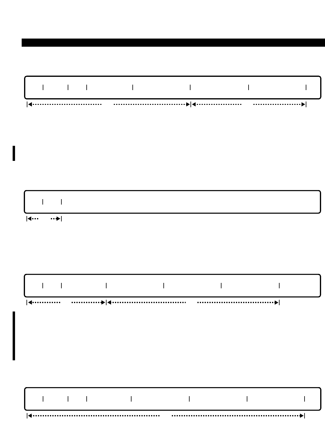
PERCEPTION 4000 COMMANDS
ISS 2, SECTION 4000-014-000
DID/CCSA/DNIS LDN ASSIGNMENT (CMD 316)
ADD
This operation creates a new group or adds a listed directory number to a group. The first five fields (TGN,
INDEX, LDN, TIME ZONE #, and ROUTE CHOICE 1) are required, and the last two are optional. Loops are
allowed in the "TGN" and "INDEX" fields. A loop in the "INDEX" field is used for adding several LDNs. Its value
does not indicate the actual position to be added in the group. The number of digits in the "LDN" field must be the
same as the DID/CCSA/DNIS non-ISDN trunk group’s digit length. For ISDN trunk groups, the number of digits
can range from 2 to 15 digits.
DELETE
This operation deletes a "TGN" or "LDN". Both the "TGN" and the "LDN" fields are required. Looping is allowed in
the "TGN" field. To delete a trunk group, enter ALL in the "LDN" field.
MODIFY
This operation changes the conversion scheme and assigned LDNs with their associated routing destinations of
one or more DID/CCSA/DNIS (incoming) trunk groups. The "TGN", "LDN", and "TIME ZONE #" fields are
required. Delete fields are allowed in the "ROUTE CHOICE 1/2/3" fields. The number of digits in the "LDN" field
must be the same as the DID/CCSA/DNIS non-ISDN trunk group’s digit length. For ISDN trunk groups, the
number of digits can range from 2 to 15 digits. In a MODIFY operation, an LDN can be removed or its associated
routing destination can be changed.
DISPLAY
TGN INDEX LDN TIME ZONE # ROUTE CHOICE 1 ROUTE CHOICE 2 ROUTE CHOICE 3
opt
req
TGN LDN TIME ZONE # ROUTE CHOICE 1 ROUTE CHOICE 2 ROUTE CHOICE 3
opt
req
TGN LDN
req
TGN INDEX LDN TIME ZONE # ROUTE CHOICE 1 ROUTE CHOICE 2 ROUTE CHOICE 3
opt
3-154

PERCEPTION 4000 COMMANDS
This operation displays all trunk groups and their LDNs that meet the conditions established in each field. Loops
are permitted in the "TGN", "INDEX", and "TIME ZONE #" fields. The "INDEX" field displays the actual position of
the "LDN" in the database.
PARAMETERS
Each field parameter is described in this section. Any variations for a particular operation are noted separately.
FIELD: TGN (Trunk Group Number)
TYPE: Decimal
FORMAT: 1 to 3 digits
VALUE: 1 to 256 (or to the maximum system configuration)
LOOP: Allowed in ADD, DELETE, and DISPLAY operations
Valid entries are the actual trunk group numbers which were pre-defined as DID/CCSA/DNIS/DDI
trunk groups in the Trunk Group Assignment command (CMD 310).
FIELD: INDEX (Index for LDN Field)
TYPE: Decimal
FORMAT: 1 or 2 digits
VALUE: 1 to 256
LOOP: Allowed in DISPLAY and ADD operations
This field is used as a counter in ADD and DISPLAY operations. Its value does not indicate an
actual position in a trunk group or set any priority for data entered in this command.
FIELD: LDN (Listed Directory Number)
TYPE: Decimal / Keyword
FORMAT: 2 to 7 digits for DID, CCSA, or DNIS non-ISDN trunks
2 to 15 digits for DDI or DNIS ISDN trunks
Predefined ASCII characters
VALUE: 00 to 999999999999999 / ALL (for a DELETE operation only)
LOOP: Not allowed
This field contains the listed directory number for the trunk group. Each "LDN" is unique in its
group. However, since each trunk group is independent of each other, an "LDN" can be in more
than one group. All the "LDN"s in the same group have the same number of digits. ALL may be
entered in this field in a DELETE operation when deleting all of the listed directory numbers.
FIELD: TIME ZONE # (Time Zone Number)
TYPE: Decimal
FORMAT: 1 digit
VALUE: 1 to 4
LOOP: Allowed in a DISPLAY operation only
This field contains the time zone number for each LDN entry in a group. The number specifies
the routing destination. In a DISPLAY operation, this field is the third loop field in the command
header.
ISS 2, SECTION 4000-014-000
DID/CCSA/DNIS LDN ASSIGNMENT (CMD 316)
3-155

PERCEPTION 4000 COMMANDS
ISS 2, SECTION 4000-014-000
DID/CCSA/DNIS LDN ASSIGNMENT (CMD 316)
FIELD: ROUTE CHOICE 1/2/3
TYPE: Dialing Digits / Keyword
FORMAT: 1 to 5 digits
VALUE: 0 to 99999
Keywords: AP01 ~ AN50 Announcement Pattern Number
BL01 ~ BL64 Night Bell Number
"ROUTE CHOICE 1" can be one of the following:
a) Individual attendant console directory number
b) Attendant group directory number
c) Station number
d) Announcement device
e) Hunt group pilot number
f) UCD group pilot number
g) ACD group pilot number
h) Night bell
i) Speed Calling code—1 ~ 3 digit Speed Calling access code, plus desired 3-digit Speed
Calling code
"ROUTE CHOICE 2" has the same options as "ROUTE CHOICE 1". However, to utilize "ROUTE
CHOICE 2", "ROUTE CHOICE 1" must be defined as an attendant or attendant group.
"ROUTE CHOICE 3" has the same options as "ROUTE CHOICE 1", with the exception of the
attendant and attendant group options. To utilize "ROUTE CHOICE 3", both "ROUTE CHOICE 1"
and "2" must be defined as an attendant or attendant group or mix thereof.
A <CONTROL-D> may be entered in these fields during a MODIFY operation to delete current
data. Note, however, that using a <CONTROL-D> is dependent on the relationships between the
route choices as described above.
SYSTEM ERROR MESSAGES
The following error messages are unique to this command.
C31600 - Group is not defined as DID/CCSA
C31601 - Group is full
C31602 - Group is empty
C31603 - Check input format in field N
C31604 - Length of input LDN is not correct
C31605 - Input LDN is already in group
C31606 - Input LDN is not in group
C31607 - Input announcement pattern is undefined
C31608 - Input night bell is undefined
C31609 - Invalid announcement pattern
C31610 - Invalid directory number
C31611 - Check combination of routing destinations
C31612 - Input any route choice
3-156

PERCEPTION 4000 COMMANDS
C31613 - Input LDN time zone is already in group
C31614 - Input LDN time zone is not found in group
C31615 - Undefined trunk group number
C31616 - DID/CCSA/DNIS/DDI trunk group attributes are not assigned
I31617 - Warning: Undefined data in Route Choice
C31618 - LDN has been defined in Command 315 already
COMMENTS
Each DID/CCSA/DNIS non-ISDN trunk group and each DDI/DNIS mode ISDN trunk group can only have one
LDN table.
Each LDN must be unique within its own trunk group. However, because each trunk group is independent of
others, an LDN can be assigned to more than one trunk group.
All of the LDNs contained in the same DID/CCSA/DNIS non-ISDN trunk group must have the same number of
digits. The length of each of these LDNs must be the same as the non-ISDN trunk group's digit length.
An LDN can be removed or its associated routing destination can be changed by using the MODIFY operation.
Prior to making either or these modifications, ensure that no calls are either on-hold or in-progress for the LDN.
A station that is assigned to either a DID/CCSA/DNIS non-ISDN trunk or a DDI/DNIS mode ISDN trunk should
not have a class of service designating Inward Restriction or Origination Only, since such a station cannot receive
incoming calls.
RELATED COMMANDS
DID/CCSA/DNIS DISA LDN Assignments (CMD 315)
Trunk Group Routing Assignment (CMD 307)
Trunk Routing Assignment (CMD 308)
ISS 2, SECTION 4000-014-000
DID/CCSA/DNIS LDN ASSIGNMENT (CMD 316)
3-157
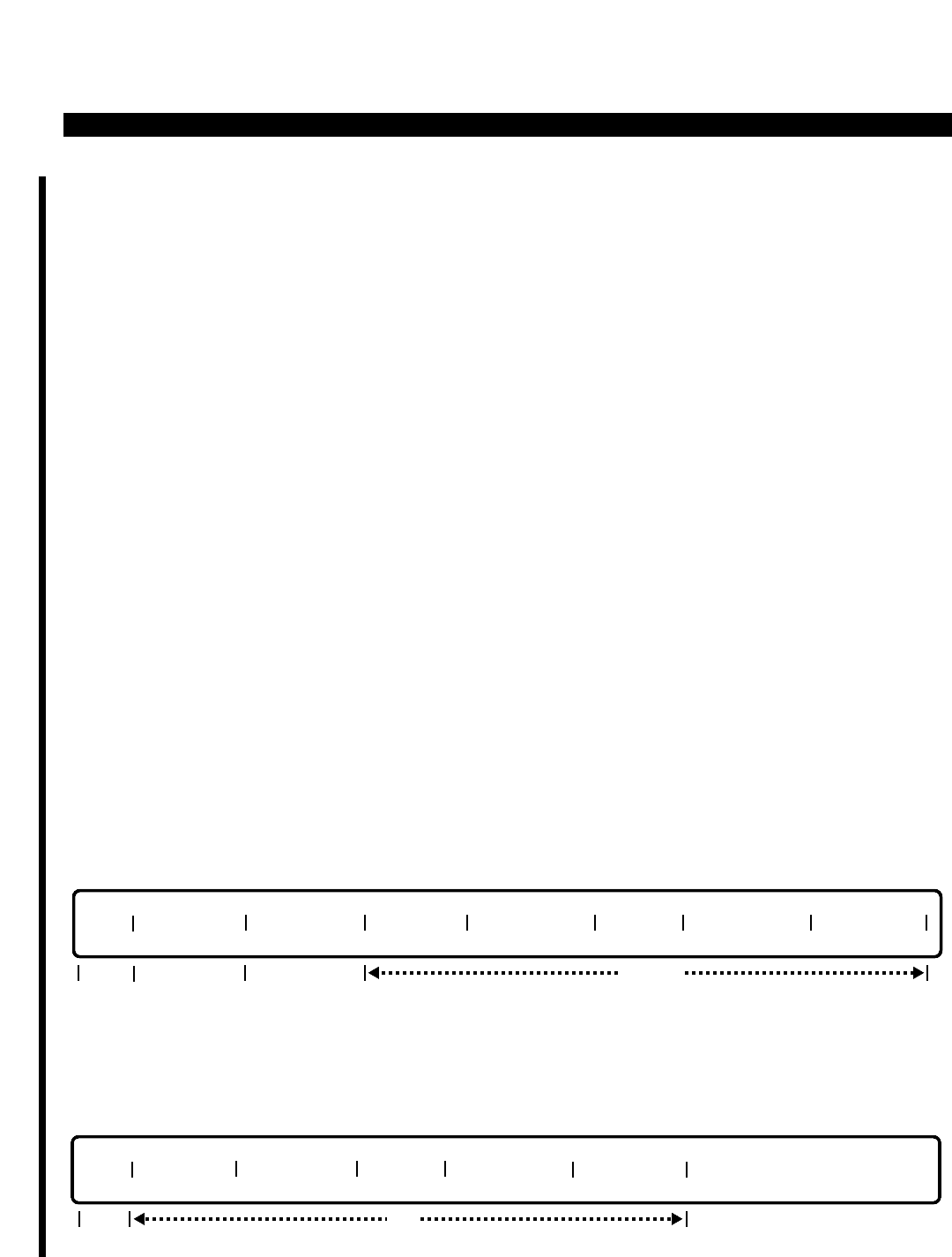
PERCEPTION 4000 COMMANDS
ISS 2, SECTION 4000-014-000
DID/CCSA/DNIS TRUNK GROUP ASSIGNMENT (CMD 314)
DID/CCSA/DNIS TRUNK GROUP ASSIGNMENT (CMD 314)
This command is used to define DID/CCSA/DNIS non-ISDN trunk groups as well as DDI/DNIS ISDN trunk
groups. Most calls are routed by the PERCEPTION 4000 system after receiving a series of digits over a
DID/CCSA/DNIS/DDI trunk, and then deleting and/or appending some digits in order to route the call to a station
or other terminal.
Command Keyword: DID/CCSA_TG_ASSIGN
Category Name: Trunk
PREREQUISITE COMMANDS
Announcement Pattern Assignment (CMD 353)
Attendant Position Assignment (CMD 370)
ISDN Trunk Group Parameter Assignment (CMD 421)
Night Bell Assignment (CMD 405)
Trunk Group Assignment (CMD 310)
OPERATIONS
Available operations: ADD
MODIFY
DELETE
DISPLAY
The function and required data fields for each operation are described in this section.
ADD
This operation assigns attributes to the specified DID/CCSA/DNIS/DDI trunk group. Data is required in all of the
fields except the "INTER ALT" field.
MODIFY
TGN CO DIGIT KEPT DIGIT PREFIX INTER TYPE INTER ALT
optreq
TGN ORG DIGIT NEW DIGIT CO DIGIT KEPT DIGIT PREFIX INTER TYPE INTER ALT
opt/req
reqreq opt
3-158
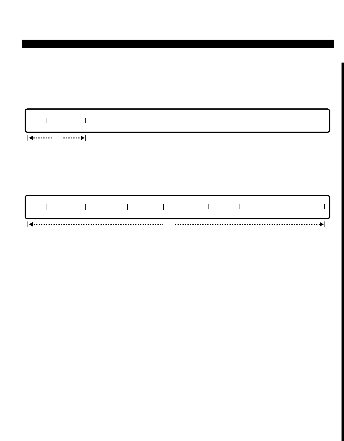
PERCEPTION 4000 COMMANDS
This operation changes the attribute(s) of one or more DID/CCSA/DNIS/DDI trunk groups. Input is required in the
first field only.
DELETE
This operation is used to delete one or more pairs of original and new digit strings for a DID/CCSA/DNIS/DDI
trunk group. Both the trunk group number and the original digit string must be entered.
DISPLAY
This operation displays information for one or all DID/CCSA/DNIS/DDI trunk groups. Looping is allowed in the
"TGN" field.
PARAMETERS
Each field parameter is described in this section. Any variations for a particular operation are noted separately.
FIELD: TGN (Trunk Group Number)
TYPE: Decimal
FORMAT: 1 to 3 digits
VALUE: 1 to 256 (or to the maximum system configuration)
LOOP: Allowed in a DISPLAY operation
Valid entries are the actual trunk group numbers which were pre-defined as DID/CCSA/DNIS/DDI
trunk groups in the Trunk Group Assignment command (CMD 310).
FIELD: ORG DIGIT (Original Digits)
TYPE: Decimal / Keyword
FORMAT: 1 to 7 digits or predefined ASCII characters
VALUE: 0 to 9999999 or Keyword NON
RANGE: Allowed in a DISPLAY operation only
This field applies only to DID and CCSA non-ISDN trunks and is used to specify the original
digits that are received from the central office (CO). When these digits are received by the
PERCEPTION 4000, they will be translated to new digits (as assigned in the "NEW DIGIT" field).
Up to 32 unique pairs of original and new digits can be defined for a trunk group. If pairs of
TGN ORG DIGIT NEW DIGIT CO DIGIT KEPT DIGIT PREFIX INTER TYPE INTER ALT
opt
TGN ORG DIGIT
req
ISS 2, SECTION 4000-014-000
DID/CCSA/DNIS TRUNK GROUP ASSIGNMENT (CMD 314)
3-159

PERCEPTION 4000 COMMANDS
ISS 2, SECTION 4000-014-000
DID/CCSA/DNIS TRUNK GROUP ASSIGNMENT (CMD 314)
original/new digits are not required, then either a <TAB> or the keyword NON can be entered.
When assigning DNIS or DDI trunk groups, enter the keyword NON, or skip past this field by
entering a <TAB>.
FIELD: NEW DIGIT (New Digits)
TYPE: Decimal / Keyword
FORMAT: 1 to 7 digits or predefined ASCII characters
VALUE: 0 to 9999999 or Keyword NON
RANGE: Allowed in a DISPLAY operation only
This field applies only to DID and CCSA non-ISDN trunks. When the digits received from the CO
match the digits assigned in the "ORG DIGIT" field, the PERCEPTION 4000 system
automatically translates the digits to assigned new values. Up to 32 unique pairs of original and
new digits can be defined for a trunk group. If pairs of original/new digits are not required, then
either a <TAB> or the keyword NON can be entered. However, if digits have been entered in the
"ORG DIGIT" field, then new digits or NON must be entered. When assigning DNIS or DDI trunk
groups, enter the keyword NON, or skip past this field by entering a <TAB>.
FIELD: CO DIGIT (Central Office Sending Digits)
TYPE: Decimal
FORMAT: 1 digit
VALUE: 2 to 7
RANGE: Allowed in a DISPLAY operation only
This field specifies the predetermined number of digits to be sent by the central office. This field
is not required by DNIS/DDI ISDN trunks.
FIELD: KEPT DIGIT (Number of Digits to be Kept)
TYPE: Decimal / Keyword
FORMAT: 1 or 2 digits
VALUE: 1 to 7 for DID/CCSA/DNIS non-ISDN trunks
1 to 15 for DNIS/DDI ISDN trunks
Predefined ASCII characters
RANGE: Allowed in a DISPLAY operation only
Keywords: NON - No received CO digits will be kept
ALL - All received CO digits will be kept
This field specifies the number of digits to be kept after receiving a digit string from the central
office. For non-ISDN trunks, the value entered in this field should be less than or equal to the
value entered in the "CO DIGIT" field. When entering the keyword ALL, all CO digits specified in
the "CO DIGIT" field will be kept. When entering a <TAB> or the keyword NON, none of the
specified CO digits will be kept. For ISDN trunks other than DDI/DNIS ISDN trunks, either a
<TAB> or the keyword NON.
FIELD: PREFIX (Digit String to be Added)
TYPE: Decimal / Keyword
FORMAT: 1 to 5 digits or predefined ASCII characters
VALUE: 0 to 99999 or Keyword NON
RANGE: Not allowed
3-160

PERCEPTION 4000 COMMANDS
This field specifies the digit string to be added at the front of the received CO digit string. This
field does not apply for DNIS trunk groups; in this case, either a <TAB> or the keyword NON
should be entered. NON can also be entered as a null prefix string for other trunk types.
FIELD: INTER TYPE (Intercept Treatment Type)
TYPE: Decimal / Keyword
FORMAT: 1 to 5 digits / Predefined ASCII characters
VALUE: 0 to 99999
RANGE: Allowed in a DISPLAY operation only
Keywords: AP01 ~ AP50
This field defines the device or attendant which will perform vacant number intercept treatment
for the specified DID/CCSA/DNIS/DDI trunk group. Attendants, attendant groups, and
announcement patterns are valid definitions. Keywords indicate announcement pattern numbers
(AP01 to AP50), and digit input indicates an attendant or attendant group directory number (0 to
99999).
FIELD: INTER ALT (Alternate Intercept Treatment)
TYPE: Keyword
FORMAT: Predefined ASCII characters
Keywords: BL01 ~ BL64
This field is used to specify an alternate intercept plan for the DID/CCSA/DNIS/DDI trunk group, if
the first-choice attendant/attendant group is in the position busy mode. A night bell device
number (BL01 ~ BL64) may be entered for the specified DID/CCSA/DNIS/DDI trunk group. No
entry is needed if an announcement pattern number (AN01 ~AN64) has been specified in the
"INTER TYPE" field. If a <Control D> is entered in this field, then the existing alternate intercept
treatment will be deleted.
SYSTEM ERROR MESSAGES
The following error messages are unique to this command.
C31400 - Trunk group number is not a DID/CCSA type
C31401 - Directory number listed as intercept type is not an attendant or attendant group DN
C31402 - Announcement pattern number listed as intercept type is not available for DID treatment
C31403 - Night bell listed as intercept alternate is not available
C31404 - This trunk group number is already assigned
C31405 - This trunk group number is not yet assigned
C31406 - Remove DISA LDN member before changing CO sending digits
C31407 - Number of deleted digits cannot exceed CO sending digits
C31408 - Added digit string overflow
C31409 - Original/new/kept/added digits do not apply to DNIS trunk groups
C31410 - Original digits are not unique for this trunk group
C31411 - Delete intercept alternate before modifying intercept treatment type
C31412 - Number of kept digits cannot exceed the number of CO sending digits
C31413 - Added and kept digits do not apply to DNIS trunk groups
ISS 2, SECTION 4000-014-000
DID/CCSA/DNIS TRUNK GROUP ASSIGNMENT (CMD 314)
3-161

PERCEPTION 4000 COMMANDS
ISS 2, SECTION 4000-014-000
DID/CCSA/DNIS TRUNK GROUP ASSIGNMENT (CMD 314)
C31414 - CO digits are not required for an ISDN trunk group
C31415 - Intercept treatment type must be specified
C31416 - Original/new digit combinations are invalid
C31417 - Original/new digits are not found
C31418 - No space exists for original/new digits to be added for this trunk group
C31419 - Only decimal digits (0, 1, ... 9) are allowed as original/new digits
C31420 - Kept digits may be needed
C31421 - Check trunk group's night bell number
C31422 - CO digits are required for non-ISDN trunk groups
COMMENTS
The announcement pattern specified in the "INTER TYPE" field must have already been assigned.
The night bell specified in the "INTER ALT" field must have already been assigned.
Each trunk that is assigned to a group must already be defined as either a DID, CCSA, or DNIS non-ISDN trunk
or as a DDI or DNIS ISDN trunk.
RELATED COMMANDS
DID/CCSA/DNIS DISA LDN Assignment (CMD 315)
DID/CCSA/DNIS LDN Assignment (CMD 316)
Internal Call Alternate Routing Assignment (CMD 374)
System Option Flag Assignment (CMD 408)
Trunk Group Routing Assignment (CMD 307)
Trunk Routing Assignment (CMD 308)
3-162

PERCEPTION 4000 COMMANDS
DIGITAL CARRIER CHANNEL ASSIGNMENT (CMD 413)
The Digital Carrier Channel Assignment command defines the individual channel characteristics of the T-1 carrier.
The T-1 card uses 24 time slots in the system. Therefore only a trunk card, electronic telephone line card, or
analog off-premises extension card can be used in the same highway with this card.
Command Keyword: DIGITAL_CARRIER
Category Name: Trunk
PREREQUISITE COMMAND
Trunk Group Assignment (CMD 310)
OPERATIONS
Available operations: ADD
DELETE
MODIFY
DISPLAY
The function and required data fields for each operation are described in this section.
ADD
This operation adds digital carrier channel(s) to a T-1 card. Up to 24 T-1 cards may be assigned per system.
Looping is allowed in the "EQUIP #" field.
DELETE
This operation removes digital carrier channel(s) from a T-1 card. The “EQUIP #” field is required, and looping is
allowed. When the last trunk of a trunk group or the last channel in a T-1 card is about to be removed, a warning
is given.
EQUIP #
req
EQUIP # TGN SIG ST STOUT DBNK DT ORG TERM RSPV DISA SPD NAME
optreq optreq opt locked
ISS 2, SECTION 4000-014-000
DIGITAL CARRIER CHANNEL ASSIGNMENT (CMD 413)
3-163
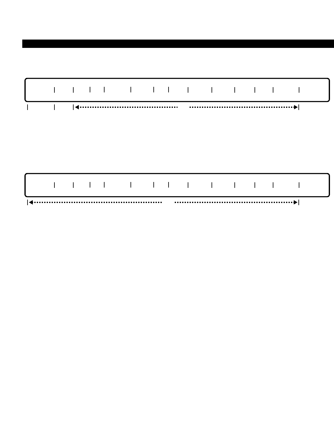
PERCEPTION 4000 COMMANDS
ISS 2, SECTION 4000-014-000
DIGITAL CARRIER CHANNEL ASSIGNMENT (CMD 413)
MODIFY
This operation modifies a digital carrier channel’s attributes. If the T-1 card that this equipment number resides on
is a clock provider, it is necessary to switch the clock provider to another card before this operation can proceed
(refer to the T-1 Clock Provider Selection Assignment command (CMD 412)).
DISPLAY
This operation displays all of the digital carrier channel equipment number(s) that meet the conditions established
for each field. Looping is permitted in the "EQUIP #" field.
PARAMETERS
Each field parameter is described in this section. Any variations for a particular operation are noted separately.
FIELD: EQUIP # (Equipment Number)
TYPE: EQ Type
FORMAT: 5 or 6 digits
VALUE: (0)10201 to 101224 *
LOOP: Allowed in ADD, DELETE, and DISPLAY operations
* Use the following chart to determine valid ranges for various types of equipment.
For TTRI equipment cards, only the even-numbered card slots are used:
Digits Range Hardware
First digit(s) (0)1~10 Shelf no.
Second two digits 02, 04, 06, 08, 10, 12 Card slot no.
Last two digits 01~24 Channel no.
The T-1 card is placed in the second slot of the desired highway. The equipment number reflects
the shelf number, slot number, and channel number.
EQUIP # TGN SIG ST STOUT DBNK DT ORG TERM RSPV DISA SPD NAME
opt
EQUIP # TGN SIG ST STOUT DBNK DT ORG TERM RSPV DISA SPD NAME
optreq locked
3-164

PERCEPTION 4000 COMMANDS
FIELD: TGN (Trunk Group Number)
TYPE: Decimal
FORMAT: 1 to 3 digits
VALUE: 1 to 256 (or to the maximum system configuration)
RANGE: Allowed in a DISPLAY operation only
This field defines the trunk group number for the digital carrier channel. The trunk group number
cannot be modified.
FIELD: SIG (Signaling Type)
TYPE: Keyword
FORMAT: Predefined ASCII characters
Keywords: GND - Ground Start CO
LP - Loop Start CO
DID - Direct Inward Dialing
EM - TIE E&M Trunk
DMI - TIE DMI
The signaling field determines whether the digital channel emulates a loop, ground, DID, E&M
TIE, or DMI TIE trunk. The signaling type must be compatible with the trunk group type. If the
trunk group type is a CO, FX, or WATS line, the signaling type must be set to a ground or loop
start. A DID line must be set to DID, E&M lines must be associated with a TIE trunk group, and
DMI must be associated with a DMI trunk group. Note that DMI is not supported at this time.
FIELD: ST (Start Method)
TYPE: Keyword
FORMAT: Predefined ASCII characters
Keywords: IMM - Immediate Start
WNK - Wink Start
DLY - Delay Dial
TIM - Timeout
AUT - Automatic
This field defines the start method used for the digital carrier channel. IMM, WNK, and DLY are
used for both DID and E&M signaling. Additionally, E&M may use TIM. If signaling is set to DMI,
this field defines the start method of incoming calls only. Valid options for DMI signaling are WNK
and AUTO. Loop and ground start signaling uses the TIM start method only.
FIELD: STOUT (Start Method for Outgoing Calls)
TYPE: Keyword
FORMAT: Predefined ASCII characters
Keywords: IMM - Immediate Start
WNK - Wink Start
DLY - Delay Dial
TIM - Timeout
AUT - Automatic
ISS 2, SECTION 4000-014-000
DIGITAL CARRIER CHANNEL ASSIGNMENT (CMD 413)
3-165

PERCEPTION 4000 COMMANDS
ISS 2, SECTION 4000-014-000
DIGITAL CARRIER CHANNEL ASSIGNMENT (CMD 413)
The outgoing-call start method field is used for DMI signaling only.
FIELD: DBNK (D-bank Equivalent)
TYPE: Keyword
FORMAT: Predefined ASCII characters
Keywords: FXS - Foreign Exchange Subscriber
SAS - Special Access Subscriber
The "D BANK" field specifies the digital carrier channel as a Foreign Exchange Subscriber or a
Special Access Subscriber. This field is only used when the channel is designated as a CO trunk
(loop or ground start signaling).
FIELD: DT (Dial Tone)
TYPE: Keyword
FORMAT: Predefined ASCII characters
Keywords: DT - Dial Tone Return
STR - Silence Tone Return
This field defines whether dial tone or silence is returned. Only DMI and E&M TIE trunks can be
defined for the silence option.
FIELD: ORG (Originating Dial Mode)
TYPE: Keyword
FORMAT: Predefined ASCII characters
Keywords: DP10 - DP 10 PPS
DTMF - DTMF Receiver
This field defines whether dial pulse (10 pulses per second) or DTMF signaling will be emulated
by the digital carrier channel.
FIELD: TERM (Terminating Dial Mode)
TYPE: Keyword
FORMAT: Predefined ASCII characters
Keywords: DP10 - DP 10 PPS
DTMF - DTMF Receiver
NON - Not applicable
This field defines the terminating dial mode for the digital carrier channel, which can be dial pulse
(10 pulses per second) or DTMF.
FIELD: RSPV (CO Supervision Type)
TYPE: Keyword
FORMAT: Predefined ASCII characters
Keywords: CLD - Called Party Disconnect
CLG - Calling Party Disconnect
3-166

PERCEPTION 4000 COMMANDS
EPD - Either Party Disconnect
NON - No Supervision
This field defines release supervision provided by the Central Office or distant switch. This
information is important to the system in determining whether an unsupervised Trunk-to-Trunk
connection may be formed using the digital carrier channel.
If the "SIG" field is set to DID, EM, or DMI, this field should be set to NON. If a channel
terminates to a peripheral equipment device, the CO supervision type should be NON. “First
Party Disconnect” is also referred to as “Either Party Disconnect”.
FIELD: DISA (DISA Flag)
TYPE: Keyword
FORMAT: Predefined ASCII characters
Keywords: YES - DISA flag is on
NO - DISA flag is off
This field flags the channel as a Direct Inward System Access trunk. Outgoing only channels
cannot be designated for DISA usage.
FIELD: SPD (Transmission Speed) (Reserved for Toshiba Global Network System)
TYPE: Keyword
FORMAT: Predefined ASCII characters
Keywords: 16K - 16 k bps
64K - 64 k bps
The speed field determines the transmission speed over the channel.
FIELD: NAME (Channel Name)
TYPE: Text
FORMAT: 0 to 14 characters/numbers
LOOP: Not allowed in this field
The channel (trunk) may be assigned an optional name designation which is displayed to
attendants and display station users when the trunk is accessed by or terminated to the device.
The name may be up to 14 alphanumeric characters in length. Embedded spaces are allowed.
SYSTEM ERROR MESSAGES
The following error messages are unique to this command.
C41300 - Card type or equipment number is already in use
C41301 - Undefined trunk group number
C41302 - Number of trunks in trunk group number exceeds maximum
C41303 - Trunk group number cannot be modified
C41304 - Signaling is not compatible
C41305 - Start method is not compatible
ISS 2, SECTION 4000-014-000
DIGITAL CARRIER CHANNEL ASSIGNMENT (CMD 413)
3-167

PERCEPTION 4000 COMMANDS
ISS 2, SECTION 4000-014-000
DIGITAL CARRIER CHANNEL ASSIGNMENT (CMD 413)
C41306 - Check start method for outgoing call
C41307 - Check dial tone
C41308 - Check the dial mode
C41309 - DISA must have EPD or CLG release supervision
C41310 - DISA is for incoming and bothway
C41311 - No DISA flag for given trunk group number
C41312 - Channel name exceeds 9 alphanumeric characters
C41313 - Download PP data failed
C41314 - Check input format in field 4 or 5
C41315 - Check input format in field 8 or 9
C41316 - Channel has already been installed
C41317 - Undefined equipment number
C41318 - Number of T-1 cards exceeds system maximum
I41319 - Warning: This is the last trunk to be removed from trunk group
C41320 - Clock provider cannot be modified
I41320 - Warning: Equipment number is the last channel removed from T1 card
C41321 - Remove hunting sequence before deleting trunks
C41322 - Private feature key still exists
I41322 - Warning: Please try later; database is reserved
C41323 - Failed to read LCPU database
C41324 - Trunk group number should be non-ISDN type
I41324 - Warning: Equipment number is the last channel removed from T-1 card
C41325 - Trunk cannot be assigned to a dictation machine trunk group
C41326 - Clock provider cannot be deleted
C41327 - Clock database is full
I41328 - Warning: Please try later, database is reserved
COMMENTS
Channel 24 is available to the T-1 carrier only when channel-associated signaling is used.
A channel may belong to only one trunk group.
Before adding a channel to a T-1 card, the card type must first be defined as a T-1 type. There are up to 24 T-1
cards per system.
A warning will be given when the last trunk or channel of a trunk group is about to be removed from a T1 card.
RELATED COMMANDS
T-1 Clock Provider Selection Assignment (CMD 412)
Trunk Assignment (CMD 313)
Trunk Hunting Assignment (CMD 309)
3-168

PERCEPTION 4000 COMMANDS
DISK FILE MANIPULATION (CMD 152)
The Disk File Manipulation command utilizes and manages storage space on a hard disk or a floppy diskette. It
also organizes files on the disks. In addition, the command provides BACKUP and RESTORE functions. The
BACKUP function copies a collection of files from the hard disk to floppy diskettes for the purpose of backing up
files in case of a system failure. The RESTORE function copies the files on the backup floppy diskettes back to
the hard disk. The structure, content, and attributes of these restored files are those of the original files at the time
they were backed up.
Command Keyword: FILE_MANIPULATION
Category Name: Maintenance
PREREQUISITE COMMANDS
There are no prerequisites for this command.
OPERATIONS
Available operations: BACKUP
RESTORE
COMPARE
COPY
CREATE
DELETE
DISPLAY
FORMAT
FREE
The function and required data fields for each operation are described in this section.
BACKUP
This operation copies the operational programs, database, change notes, and other necessary data files from the
hard disk to floppy diskettes for a backup.
The BACKUP process, controlled by a utility program, writes a header to the backup diskette containing
information such as the current timestamp, operator identifier, and release number. The utility program then looks
for the specified file type and copies those files from the hard disk to the diskette.
When a diskette is full, a message requesting insertion of another diskette displays. Again, a header is written on
the next diskette. The BACKUP process continues until all of the files are copied.
HARD DISK DRIVE BACKUP DRIVE RELEASE NO FILE TYPE
req
ISS 2, SECTION 4000-014-000
DISK FILE MANIPULATION (CMD 152)
3-169
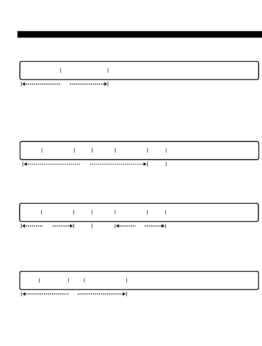
PERCEPTION 4000 COMMANDS
ISS 2, SECTION 4000-014-000
DISK FILE MANIPULATION (CMD 152)
RESTORE
The RESTORE operation is also controlled by the utility program and is the reverse process of a BACKUP. It
begins with reading the header on the backup diskette and displaying that information. Then, permission to
continue the RESTORE process is requested. If the RESTORE process is permitted, all of the backup files are
copied to the hard disk, diskette by diskette. Error messages are displayed if any errors are detected.
COMPARE
This operation compares two files (4 bytes at a time) and displays the differences if any differences occur.
COPY
This operation makes a duplicate copy (FILENAME2) of an existing file (FILENAME1). A COPY operation copies
only one file at a time.
CREATE
This operation creates a new file on the specified drive.
DRIVE FILENAME VER SIZE IN KBYTES
req
DRIVE1 FILENAME1 VER1 DRIVE2 FILENAME2 VER2
req optreqopt
DRIVE1 FILENAME1 VER1 DRIVE2 FILENAME2 VER2
req opt
BACKUP DRIVE HARD DISK DRIVE
req
3-170

PERCEPTION 4000 COMMANDS
DELETE
This operation removes one or more files from the specified drive. A confirmation is requested before a file is
deleted. To delete a specific file, enter the drive number and filename, then press <RETURN>. The "VER" field is
optional. To delete all files on a drive, enter the drive number and press the <TAB> key twice.
DISPLAY
This operation displays a list of files on a disk, along with the creation date, total number of blocks, and file size in
kilobytes of each file. The "DRIVE" field is required, and the "FILE NAME" and "VER" fields are optional. The
remaining fields are output only fields.
FORMAT
This operation divides a hard disk or a floppy diskette into addressable data storage areas. Any data on the
disk/diskette is erased with this operation.
FREE
This operation provides information about storage space usage on a hard disk or a floppy diskette. Information
includes the percentage of unused disk space and the size of the largest available segment.
DISK DRIVE PERCENTAGE UNUSED LARGEST UNUSED SEG
opt output only
DISK DRIVE
req
DRIVE FILENAME VER TIMESTAMP # BLOCKS SIZE IN KBYTES
opt output onlyreq
DRIVE FILENAME VER
optreq
ISS 2, SECTION 4000-014-000
DISK FILE MANIPULATION (CMD 152)
3-171

PERCEPTION 4000 COMMANDS
ISS 2, SECTION 4000-014-000
DISK FILE MANIPULATION (CMD 152)
PARAMETERS
Each field parameter is described in this section. Any variations for a particular operation are noted separately.
FIELD: HARD DISK DRIVE
TYPE: Keyword
FORMAT: Predefined ASCII characters
OPERATIONS: BACKUP, RESTORE
Keywords: HDA - Hard Disk Drive of Side A
HDB - Hard Disk Drive of Side B
This field contains a logical name of the hard disk drive.
FIELD: BACKUP DRIVE
TYPE: Keyword
FORMAT: Predefined ASCII characters
OPERATIONS: BACKUP, RESTORE
Keywords: FDA - Floppy Disk Drive of Side A
FDB - Floppy Disk Drive of Side B
This field contains a logical name of the floppy disk drive.
FIELD: RELEASE NO
TYPE: Decimal
FORMAT: 1 to 3 digits
VALUE: 0 to 999
OPERATIONS: BACKUP
The release number is the software release version number.
FIELD: FILE TYPE
TYPE: Keyword
FORMAT: Predefined ASCII characters
OPERATIONS: BACKUP
Keywords: PROG - System programs, including MCPU, LPU, BTSW, MISC, PP, ATT,
and DIU programs
DATA - Database, including data of MCPU, LPU, MISC, PP, ATT, and DIU
IPL - All program and data files loaded during IPL
CMD - All overlay loadable command program files
LOG - Change Log and Patch Log files
FIELD: DISK DRIVE
TYPE: Keyword
FORMAT: Predefined ASCII characters
OPERATIONS: FORMAT, FREE
3-172

PERCEPTION 4000 COMMANDS
Keywords: HDA - Hard Disk Drive of Side A
HDB - Hard Disk Drive of Side B
FDA - Floppy Disk Drive of Side A
FDB - Floppy Disk Drive of Side B
This field contains the logical name of a disk drive.
FIELD: DRIVE
TYPE: Keyword
FORMAT: Predefined ASCII characters
OPERATIONS: CREATE, DELETE, DISPLAY
Keywords: HDA - Hard Disk Drive of Side A
HDB - Hard Disk Drive of Side B
FDA - Floppy Disk Drive of Side A
FDB - Floppy Disk Drive of Side B
This field contains the logical name of a disk drive.
FIELD: DRIVE1, DRIVE2
TYPE: Keyword
FORMAT: Predefined ASCII characters
OPERATIONS: COPY, COMPARE
Keywords: HDA - Hard Disk Drive of Side A
HDB - Hard Disk Drive of Side B
FDA - Floppy Disk Drive of Side A
FDB - Floppy Disk Drive of Side B
These fields contain the logical name of a disk drive.
FIELD: FILENAME
TYPE: Text
FORMAT: Up to 8 ASCII characters (The first character must be a letter, i.e., A, B, ...)
OPERATIONS: CREATE, DISPLAY, DELETE
This field assigns a name to the specified file.
FIELD: FILENAME1, FILENAME2 (File names on disks 1 and 2)
TYPE: Text
FORMAT: Up to 8 ASCII characters (The first character must be a letter, i.e., A, B, ...)
OPERATIONS: COPY, COMPARE
These fields assign names to the specified files.
FIELD: VER (Software release version number)
TYPE: Decimal
FORMAT: 1 to 3 digits
VALUE: 1 to 999
OPERATIONS: DISPLAY, CREATE, DELETE
This field is the software release version number.
ISS 2, SECTION 4000-014-000
DISK FILE MANIPULATION (CMD 152)
3-173

PERCEPTION 4000 COMMANDS
ISS 2, SECTION 4000-014-000
DISK FILE MANIPULATION (CMD 152)
FIELD: VER1, VER2 (Software release version numbers on disks 1 and 2)
TYPE: Decimal
FORMAT: 1 to 3 digits
VALUE: 1 to 999
OPERATIONS: COMPARE, COPY
These fields are the software release version numbers.
FIELD: TIMESTAMP
TYPE: Decimal
FORMAT: MM/DD hh:mm
VALUE: 99/99 99:99
OPERATIONS: DISPLAY
This is an output only field and displays the current date and time.
FIELD: #BLOCKS
TYPE: Decimal
FORMAT: 1 to 5 digits
VALUE: 1 to 99999
OPERATIONS: DISPLAY
Each block is 8K bytes in length. This field displays the number of 8K-byte blocks on the
disk and is an output only field.
FIELD: SIZE IN KBYTES
TYPE: Decimal
FORMAT: 1 to 5 digits
VALUE: 1 to 32767
OPERATIONS: CREATE, DISPLAY
This is an output only field in a DISPLAY operation and a required input field in a CREATE
operation.
FIELD: PERCENTAGE UNUSED
TYPE: Decimal
FORMAT: 1 or 2 digits
VALUE: 0 to 99
OPERATIONS: FREE
This is an output only field and displays the percentage of space available on the specified
disk.
FIELD: LARGEST UNUSED SEG
TYPE: Decimal
FORMAT: 1 to 18 digits
VALUE: 0 to 999999999999999999
OPERATIONS: FREE
This is an output only field and displays the size of the largest available segment of unused
disk space.
3-174

PERCEPTION 4000 COMMANDS
SYSTEM ERROR MESSAGES
The following error messages are unique to this command.
C15200 - Disk drive is out of service
C15201 - File already exists
C15202 - A wrong combination of drive 1 and drive 2
C15203 - Format operation cannot be performed; the drive is in service
C15204 - Parameter error; enter the drive field
C15205 - Failed file consolidation while copying changelog or patchlog
C15206 - Failed to open changelog file
C15207 - Failed to open patchlog file
C15208 - Failed to read changelog file
C15209 - Failed to read patchlog file
C15210 - File type does not match; please check floppy disk
C15211 - Failed to mount floppy drive
C15212 - Timer timeout
C15218 - Display or comparison of files from standby side is not supported
D15219 - Failed to reserve hard disk drive
C15220 - Hard disk drive is in use; try later
C15221 - Some files are still open; try later
C15222 - Floppy disk drive is out of service
C15223 - Hard disk drive is out of service
C15224 - Not enough space left on floppy disk for file copy
C15225 - Standby hard disk drive is out of service
C15226 - Invalid input; to restore this disk enter (Y/N)
ISS 2, SECTION 4000-014-000
DISK FILE MANIPULATION (CMD 152)
3-175

PERCEPTION 4000 COMMANDS
ISS 2, SECTION 4000-014-000
DTMF RECEIVER ASSIGNMENT (CMD 416)
DTMF RECEIVER ASSIGNMENT (CMD 416)
This command installs/removes DTMF receivers in/from the system. These receivers are required for DTMF DID
trunks, DISA trunks, and all single-line DTMF analog telephones.
Command Keyword: DTMF_RECEIVER_ASSIGN
Category Name: System
PREREQUISITE COMMANDS
There are no prerequisites for this command.
OPERATIONS
Available operations: ADD
DELETE
DISPLAY
The function and required data fields for each operation are described in this section.
ADD
This operation adds a DTMF receiver to the system. Both fields are required. Loops are not allowed in this
operation.
DELETE
This operation removes a DTMF receiver from the system. Before the removal, a confirmation is requested. Both
fields are required; and loops are not allowed.
SHELF # CARD #
req
SHELF # CARD #
req
3-176
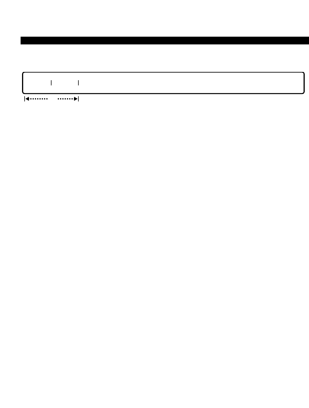
PERCEPTION 4000 COMMANDS
DISPLAY
This operation displays the assigned DTMF receivers. Loops are allowed in both fields. If a <TAB> is entered in
the "SHELF #" field, all of the DTMF receivers display. If a <TAB> is entered in the "CARD #" field, then all of the
receivers on the specified shelf number display.
PARAMETERS
Each field parameter is described in this section. Any variations for a particular operation are noted separately.
FIELD: SHELF # (Shelf Number of DTMF Receiver)
TYPE: Decimal
FORMAT: 1 or 2 digits
VALUE: 1 to 10
LOOP: DISPLAY operation only
This field specifies the shelf number for the DTMF receiver.
FIELD: CARD # (Card Number of DTMF Receiver)
TYPE: Decimal
FORMAT: 1 or 2 digits
VALUE: 1 to 11, 13
LOOP: DISPLAY operation only
This field specifies the card number for the DTMF receiver.
NOTE: Cards 11 and 12 are installed together; an entry of 11 represents both.
Cards 13 and 14 are installed together; an entry of 13 represents both.
SYSTEM ERROR MESSAGES
The following error messages are unique to this command.
C41600 - Device has already been installed
C41601 - Device not found
C41602 - Cards 11 and 12 are installed together; input only 11
C41603 - Cards 13 and 14 are installed together; input only 13
C41604 - Not a DTMF receiver card type
C41605 - A maximum of N DTMF cards can be installed
SHELF # CARD #
opt
ISS 2, SECTION 4000-014-000
DTMF RECEIVER ASSIGNMENT (CMD 416)
3-177

PERCEPTION 4000 COMMANDS
ISS 2, SECTION 4000-014-000
EMERGENCY CALL DESTINATION ASSIGNMENT (CMD 345)
EMERGENCY CALL DESTINATION ASSIGNMENT (CMD 345)
The PERCEPTION 4000 system provides four distinct emergency calling levels, each accessed by its own
access code. Emergency calls are allowed routing to attendants, attendant groups, or off-premises destinations.
Command Keyword: EMERGENCY_CALL
Category Name: Station
PREREQUISITE COMMANDS
Attendant Group Assignment (CMD 372)
Attendant Position Assignment (CMD 370)
OPERATIONS
Available operations: MODIFY
DISPLAY
The function and required data fields for each operation are described in this section.
MODIFY
This operation changes an emergency access code, its destination number, and/or its display message for the
specified emergency level (EMR LEVEL). Ranges are not permitted. For Emergency levels 1 and 2, a destination
number does need not to be specified.
DISPLAY
This operation displays emergency calling levels and information pertaining to each level. Looping is allowed in
the “EMR LEVEL” field.
EMR LEVEL EMR CODE DESTINATION NUMBER EMERGENCY DISPLAY MESSAGE
opt
EMR LEVEL EMR CODE DESTINATION NUMBER EMERGENCY DISPLAY MESSAGE
optreq
3-178

PERCEPTION 4000 COMMANDS
PARAMETERS
Each field parameter is described in this section. Any variations for a particular operation are noted separately.
FIELD: EMR LEVEL (Emergency Level)
TYPE: Decimal
FORMAT: 1 digit
VALUE: 1 to 4
LOOP: Allowed in a DISPLAY operation only
The emergency level numbers represent relative priority for emergency calls. 1has the highest
priority and 4has the lowest. Priority 1 and 2 calls receive next-call-in-queue treatment at the
attendant or attendant group destination.
High volume ringing is offered the attendant (or attendants) if the emergency ringing flag is
enabled (see Attendant Position Assignment command, CMD 370) regardless of the console's
local ringing level setting. In addition, an emergency message displays on the attendant's (or
attendants') display unit(s). Priority levels 3 and 4 may be prioritized relative to other call
categories for the attendant console or group as defined in the Attendant Incoming Call Priority
Assignment command, CMD 373.
FIELD: EMR CODE (Emergency Access Code)
TYPE: Dialing Digits
FORMAT: 1 to 5 digits
VALUE: 0 to 99999
RANGE: Allowed in a DISPLAY operation only
Entries in this field must not conflict with other directory numbers or access codes defined in the
system numbering plan.
FIELD: DESTINATION NUMBER
TYPE: DN Type
FORMAT: 1 to 5 digits
VALUE: 0 to 99999
Valid destinations for emergency calling are attendants and attendant groups. In the MODIFY
operation, the destination number for Emergency levels 1 and 2 need not be specified. However,
a destination number must be entered for Emergency levels 3 and 4.
FIELD: EMERGENCY DISPLAY MESSAGE
TYPE: Text
FORMAT: 0 to 30 ASCII characters
This field defines the text message that displays on the attendant console when a corresponding
emergency call is made.
ISS 2, SECTION 4000-014-000
EMERGENCY CALL DESTINATION ASSIGNMENT (CMD 345)
3-179

PERCEPTION 4000 COMMANDS
ISS 2, SECTION 4000-014-000
EMERGENCY CALL DESTINATION ASSIGNMENT (CMD 345)
SYSTEM ERROR MESSAGES
The following error messages are unique to this command.
C34500 - Access code is already in use
C34501 - Access code not found
C34502 - No space in code table
C34503 - Input parameter error
C34504 - Illegal emergency access code
C34505 - Cannot assign this code as an emergency access code
C34506 - Illegal emergency level
C34507 - Not an attendant dialing digit type
C34508 - Destination number is out of range
C34509 - Invalid entry; must input data in fields 2 and 3
C34510 - Destination number entry is not needed for Emergency levels 1 and 2
I345510 - Warning: Undefined destination number
C34511 - Emergency code is already used by another emergency level
C34512 - Invalid entry; must input data in field 3
C34513 - Invalid entry; must input data in field 2
I34514 - Warning: Undefined data in field 3
RELATED COMMAND
Attendant Incoming Call Priority Assignment (CMD 373)
3-180

PERCEPTION 4000 COMMANDS
EXCEPTION RESTRICTION TABLES (CMD 340)
Exception Restriction Tables provide a means for assigning absolute denial and/or allowance to certain numbers
or groups of numbers. The command is flexible in its design, allowing you to make small or vast changes, from
changing the options on a single subscriber number to more widespread changes such as implementing control
over an office code regardless of area code (such as 976 numbers), or control operator access, 10XXX codes, as
well as standard telephone numbers.
Command Keyword: EXCEPT_RESTRICT
Category Name: Restrict
PREREQUISITE COMMANDS
There are no prerequisites for this command.
OPERATIONS
Available operations: ADD
DELETE
DISPLAY
The function and required data fields for each operation are described in this section.
ADD
This operation adds destination numbers to the allowance/denial exception list of one or more trunk restriction
groups. Each allowance/denial list can contain a maximum of 32 exception numbers.
DELETE
This operation deletes destination numbers from the allowance/denial exception list of one or more trunk
restriction groups. If ALL is entered in the “EXCEPTION NUMBER” field, all exception numbers for the specified
"TRGN" and "DRL" are deleted.
TYPE TRGN DRL EXCEPTION NUMBER
req
TYPE TRGN DRL EXCEPTION NUMBER
req
ISS 2, SECTION 4000-014-000
EXCEPTION RESTRICTION TABLES (CMD 340)
3-181

PERCEPTION 4000 COMMANDS
ISS 2, SECTION 4000-014-000
EXCEPTION RESTRICTION TABLES (CMD 340)
DISPLAY
This operation displays the allowance/denial exception list of one or more trunk restriction groups. The first field is
required. If no data is entered in the remaining fields, all of the lists of allowance/denial exception numbers for the
specified type display. Ranges are permitted in the “TRGN”, “DRL” and “INDEX” fields.
PARAMETERS
Each field parameter is described in this section. Any variations for a particular operation are noted separately.
FIELD: TYPE (Type of List)
TYPE: Keyword
FORMAT: Predefined ASCII characters
Keywords: ALW - Exceptional Allowance List Type
DNY - Exceptional Denial List Type
ALL - Display Both Types (used in a DISPLAY operation only)
This field specifies whether the list is an allowance or denial list. In a DISPLAY operation, both
types may be displayed with entry of the ALL option.
FIELD: TRGN (Trunk Restriction Group Number)
TYPE: Decimal
FORMAT: 1 digit
VALUE : 2 to 8 (or to the maximum system configuration)
RANGE: Allowed in all operations
There are seven trunk restriction groups which can be defined in the system. Refer to the Trunk
Group Assignment command (CMD 310) for assigned trunk group restriction numbers.
FIELD: DRL (Destination Restriction Level)
TYPE: Decimal
FORMAT: 1 or 2 digits
VALUE: 2 to 16 (or to the maximum system configuration)
RANGE: Allowed in all operations
The Destination Restriction Level determines the restrictions on the outgoing calling pattern. The
DRL table is set up with the Destination Restriction Level Assignment command (CMD 337).
FIELD: EXCEPTION NUMBER
TYPE: Dialing Digits, plus X, Y, N, and T (Explained below) / Keywords
FORMAT: 1 to 24 digits / Predefined ASCII characters
RANGE: Not allowed
Keyword: ALL
TYPE TRGN DRL INDEX EXCEPTION NUMBER
optreq
3-182

PERCEPTION 4000 COMMANDS
Valid digits and characters include the following:
0 to 9 - Dialed digits
X - Represents any digit 0-9
Y - Represents a 1 or 0
N - Represents any digit 2-9
T - Followed by one or more digits, last digit identified by a timeout
When the keyword ALL is entered in a DELETE operation, all exception numbers for the
specified "TRGN" and "DRL" are deleted. Examples of exception numbers are as follows:
411 - Restricts local information
1XXX976XXXX - Restricts all non-local 976 numbers
976XXXX - Restricts local 976 numbers
10XXX1900XXXXXXX - Restricts all 900 area code numbers via equal access dialing
0T - Restricts 0+ dialing
011T - Restricts international direct distance dialing
0 - Restricts straight 'Dial 0' calls
FIELD: INDEX (List Index Number)
TYPE: Decimal
FORMAT: 1 or 2 digits
VALUE: 1 to 32
RANGE: Allowed in a DISPLAY operation
This field, which appears in a DISPLAY operation only, acts as a counter by totalling the number
of entries in the exception lists, and is generated automatically by the system. Its value does not
set any priority for data entered in the command.
SYSTEM ERROR MESSAGES
The following error messages are unique to this command.
C34000 - Exception destination restriction list is full
C34001 - Exception destination restriction number does not exist
C34002 - Exception destination restriction number already exists
C34003 - Check trunk restriction group number range
C34004 - This key is not used for this operation
C34005 - Illegal input
COMMENTS
A total of 32 exceptions are allowed for each TRGN/DRL combination. This is the maximum for the combined
number of entries in the allowance and denial exception lists. For example, if 25 denial exceptions exist for a
certain TRGN/DRL combination, then the maximum allowable exceptions for that same combination is 7.
RELATED COMMANDS
Destination Restriction Level (DRL) Assignment (CMD 337)
Trunk Group Assignment (CMD 310)
ISS 2, SECTION 4000-014-000
EXCEPTION RESTRICTION TABLES (CMD 340)
3-183

PERCEPTION 4000 COMMANDS
ISS 2, SECTION 4000-014-000
FACILITY RESTRICTION LEVEL PROFILE ASSIGNMENT (CMD 387)
FACILITY RESTRICTION LEVEL PROFILE ASSIGNMENT (CMD 387)
This command provides the definition of the relationship between the originator's Facility Restriction Level Profile
(FRLP) number and the Facility Restriction Levels (FRLs) assigned to various routes within each Least Cost
Routing route table. There are 32 FRLPs in the system.
FRL/FRLP relationships are used to 1) control calling party access to higher cost routes, 2) perform outgoing call
restrictions, and 3) provide grade of service operations for shared tenant or resale of service applications.
Command Keyword: FRLP_ASSIGN
Category Name: Restrict
PREREQUISITE COMMANDS
There are no prerequisites for this command.
OPERATIONS
Available operations: MODIFY
DISPLAY
The function and required data fields for each operation are described in this section.
MODIFY
This operation modifies an FRLP number. Ranges are not permitted.
DISPLAY
This operation displays FRLP numbers. Looping is permitted in the “FRLP” field. If no data is entered, all FRLPs
are displayed.
opt
FRLP F1 F2 F3 F4 F5 F6 F7 F8 F9 F10 F11 F12 F13 F14 F15 F16
opt
FRLP F1 F2 F3 F4 F5 F6 F7 F8 F9 F10 F11 F12 F13 F14 F15 F16
req
3-184

PERCEPTION 4000 COMMANDS
PARAMETERS
Each field parameter is described in this section. Any variations for a particular operation are noted separately.
FIELD: FRLP (Facility Restriction Level Profile Number)
TYPE: Decimal
FORMAT: 1 or 2 digits
VALUE: 1 to 32 (or to the maximum system configuration)
LOOP: Allowed in a DISPLAY operation
For each FRLP number used in the system, the administrator assigns all desired FRLs. When a
caller with a given FRLP makes a call through Least Cost Routing, each route in the route table is
checked for its respective FRL.
Routes which have an FRL defined for the caller's FRLP number allow the outgoing call. Any
routes having an FRL not defined in the caller's FRLP deny the call.
FIELD: F1 to F16 (Facility Restriction Levels 1 to 16)
TYPE: Keyword
FORMAT: X (A marker)
When the keyword Xis entered, it marks which FRL is legal. To delete an FRL field, enter a
<CONTROL-D>.
SYSTEM ERROR MESSAGES
The following error messages are unique to this command.
C38700 - FRL already exists in field N
C38701 - FRL does not exist in field N
RELATED COMMANDS
Attendant Position Assignment (CMD 370)
Authorization Code Assignment (CMD 349)
Data Station Assignment (CMD 360)
LCR Routing Table Assignment (CMD 383)
ISS 2, SECTION 4000-014-000
FACILITY RESTRICTION LEVEL PROFILE ASSIGNMENT (CMD 387)
3-185
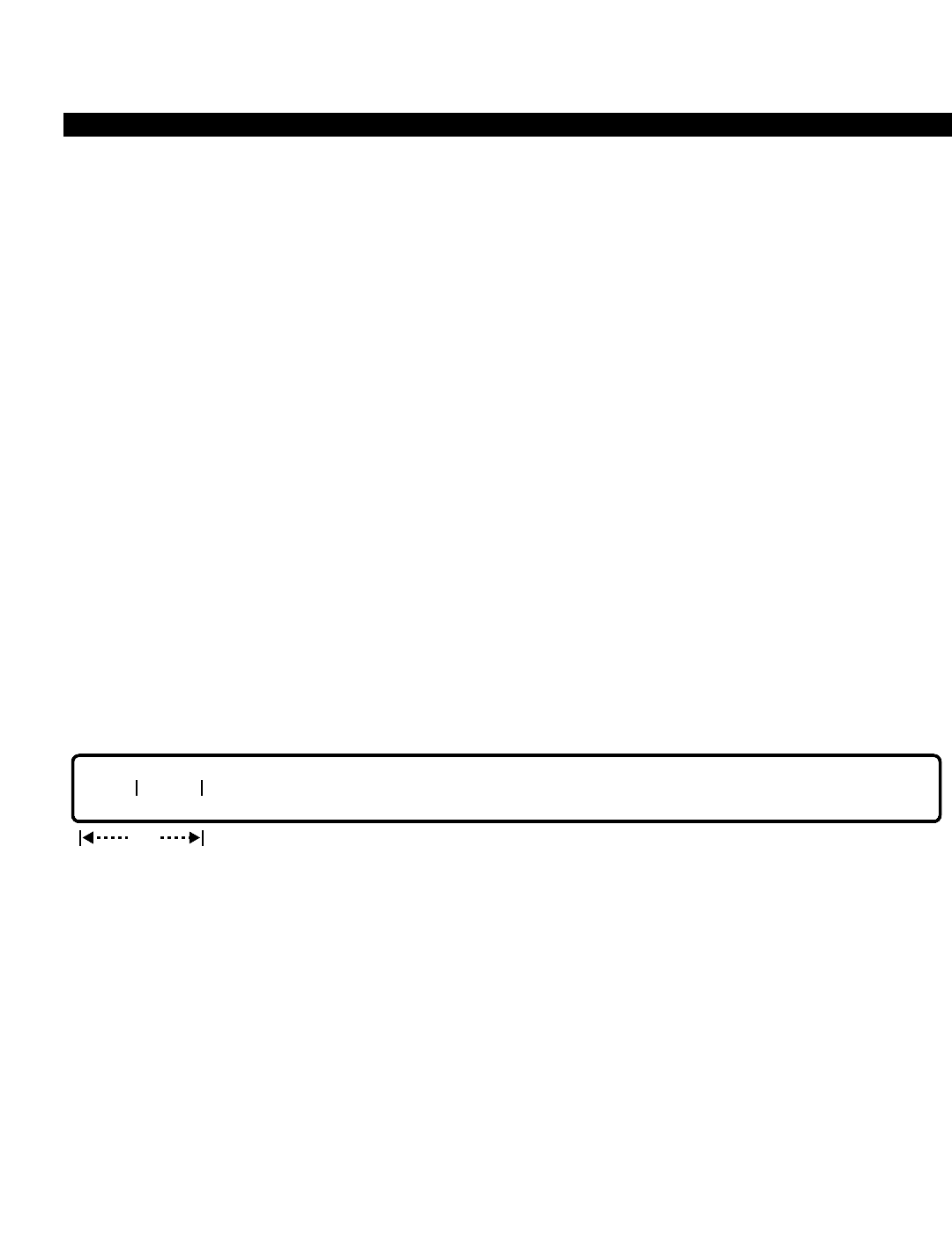
PERCEPTION 4000 COMMANDS
ISS 2, SECTION 4000-014-000
FILE CONSOLIDATION (CMD 153)
FILE CONSOLIDATION (CMD 153)
The File Consolidation command writes program and/or data files to the hard disk. Any changes or additions
performed on the system are consolidated into the system files with this command. Additionally, a logout
command or a full change log buffer on the MCPU automatically updates the files on the hard disk. This
command is used on both the active and standby sides. Note that if a system switchover occurs, or the system is
turned off, all files not consolidated are saved in the change log.
Command Keyword: FILE_CONSOLIDATION
Category Name: Maintenance
PREREQUISITE COMMAND
Memory Test (CMD 144)
OPERATIONS
Available operations: ENABLE
The function and required data fields for each operation are described in this section.
ENABLE
This operation executes the command. If the hard disk is busy or out of service, the system outputs an error
message.
PARAMETERS
Each field parameter is described in this section. Any variations for a particular operation are noted separately.
FIELD: SIDE
TYPE: Keyword
FORMAT: Predefined ASCII characters
Keywords: ACT - Active Side
SBY - Standby Side
BOTH - Both Sides
This field selects the side(s) on which the file consolidation will take place.
req
SIDE TYPE
3-186

PERCEPTION 4000 COMMANDS
FIELD: TYPE (Data Type)
TYPE: Keyword
FORMAT: Predefined ASCII characters
Keywords: ALL - Program and Data
DATA - Data/Database Only
PROG - Program Only
NON - Abort Request
This field designates the data-type files to be consolidated. To abort the command, enter NON in
this field.
SYSTEM ERROR MESSAGES
C15300 - Timeout in Command 153
C15301 - Stand-by side is not installed
C15302 - Timeout in stand-by side
C15303 - Hard disk is in use; please try later
ISS 2, SECTION 4000-014-000
FILE CONSOLIDATION (CMD 153)
3-187
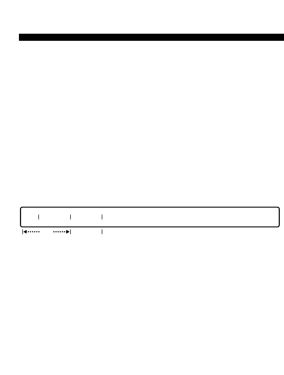
PERCEPTION 4000 COMMANDS
ISS 2, SECTION 4000-014-000
FILE DUMP (CMD 151)
FILE DUMP (CMD 151)
The File Dump command “dumps” the contents of a file from a hard disk or floppy disk to an M&A console and/or
printer.
Command Keyword: FILE_DUMP
Category Name: Fault
PREREQUISITE COMMANDS
There are no prerequisites for this command.
OPERATIONS
Available operations: DISPLAY
The function and required data fields for each operation are described in this section.
DISPLAY
This operation displays the contents of a file on the specified hard disk or floppy disk. Output is in both binary and
ASCII format.
PARAMETERS
Each field parameter is described in this section. Any variations for a particular operation are noted separately.
FIELD: DEV (Disk Drive)
TYPE: Keyword
FORMAT: Predefined ASCII characters
Keywords: HDA - Hard Disk Drive of Side A
HDB - Hard Disk Drive of Side B
FDA - Floppy Disk Drive of Side A
FDB - Floppy Disk Drive of Side B
The “DEV” field contains the logical name of a disk drive.
req
DEV FILENAME ADDRESS
opt
3-188

PERCEPTION 4000 COMMANDS
FIELD: FILENAME
TYPE: Text
FORMAT: Up to 12 ASCII characters
The “FILENAME” identifies the file to be displayed and/or printed. To display a directory of the
files on the specified “DEV”, use the Disk File Manipulation command (CMD 152).
FIELD: ADDRESS
TYPE: Hexadecimal
FORMAT: 1 to 6 hexadecimal digits
VALUE: 0 to FFFFFF
This optional field specifies where to begin the display within the file (i.e., the starting address of
the specified file).
SYSTEM ERROR MESSAGES
C15100 - Failed to send transaction to FMS
C15101 - Failed to mount disk
C15102 - Failed to unmount disk
C15103 - Failed to open file
C15104 - Failed to close file
C15105 - Failed to read file
C15106 - Invalid address
C15107 - Device is out of service
C15108 - Display of files from standby side is not supported
ISS 2, SECTION 4000-014-000
FILE DUMP (CMD 151)
3-189
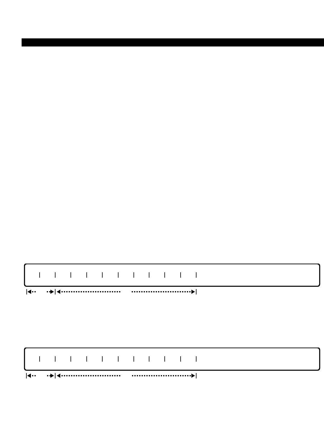
PERCEPTION 4000 COMMANDS
ISS 2, SECTION 4000-014-000
FORCED ACCOUNT CODE TOLL-FREE TABLES (CMD 352)
FORCED ACCOUNT CODE TOLL-FREE TABLES (CMD 352)
When the forced account code flag is set for a station user for toll calls only (as defined in the Station-Level
Parameter Assignment command, CMD 329), the system must screen the call against a toll-free definition. The
Forced Account Code Toll-free Tables provide this definition. Multiple tables may be defined for the system. Each
table defines office codes that are toll-free in a particular area code.
Command Keyword: FAC_TF_TABLE
Category Name: Dialing
PREREQUISITE COMMANDS
There are no prerequisites for this command.
OPERATIONS
Available operations: ADD
DELETE
DISPLAY
The function and required data fields for each operation are described in this section.
ADD
This operation adds office codes to the tables. The "AC" field and first "OC" field are required for an ADD
operation. Scopes are permitted in all of the “OC” fields except the last one.
DELETE
This operation deletes office codes from the tables. The "AC" field and first "OC" field are required. To delete the
whole table, enter ALL in the first “OC” field or use scope fields. Scopes are permitted in all of the “OC” fields
except the last one.
req
AC OC OC OC OC OC OC OC OC OC OC
opt
req
AC OC OC OC OC OC OC OC OC OC OC
opt
3-190

PERCEPTION 4000 COMMANDS
DISPLAY
This operation displays all Forced Account Code Toll-Free table(s) that meet the conditions established for each
field. All of the fields are optional. The “AC” field is a loop field, and the “OC” fields accept range input.
PARAMETERS
Each field parameter is described in this section. Any variations for a particular operation are noted separately.
FIELD: AC (Area Code)
TYPE: Decimal with fixed length
FORMAT: 3 digits in the form N Y X (where N = 2 to 9, Y = 0 or 1, and X = 0 to 9)
VALUE: 200 to 919
LOOP: Primary loop in a DISPLAY operation only
RANGE: Not allowed
This field contains the area code for the table. Note that only one table per area code is allowed.
FIELD: OC (Office Code)
TYPE: Decimal with fixed length / Keyword
FORMAT: 3 digits in the form NXX (where N = 2 to 9, and X = 0 to 9) / Predefined ASCII characters
VALUE: 200 to 999
LOOP: Not allowed
RANGE: Allowed in a DISPLAY operation
SCOPE: Allowed for ADD and DELETE operations
Keyword: ALL (Allowed in a DELETE operation only)
In ADD and DELETE operations, the first "OC" field is required while the remaining ones are
optional. Scopes are permitted in ADD and DELETE operations. To delete a group of office
codes, enter ALL in the first “OC” field or use a scope entry.
SYSTEM ERROR MESSAGES
The following error messages are unique to this command.
C35200 - Scope field needs a high value
C35201 - Scope field needs a low value
C35202 - Scope fields need low and high values
C35203 - Scope is not allowed in the last office code field
C35204 - No more space to add more
C35205 - Area code does not exist
AC OC OC OC OC OC OC OC OC OC OC
opt
ISS 2, SECTION 4000-014-000
FORCED ACCOUNT CODE TOLL-FREE TABLES (CMD 352)
3-191

PERCEPTION 4000 COMMANDS
ISS 2, SECTION 4000-014-000
FORCED ACCOUNT CODE TOLL-FREE TABLES (CMD 352)
RELATED COMMAND
Station-Level Parameter Assignment (CMD 329)
3-192

PERCEPTION 4000 COMMANDS
GROUP SPEED CALLING LIST ASSIGNMENT (CMD 351)
The PERCEPTION 4000 system allows each speed calling group a list of up to ten destination numbers which
may be accessed by all members belonging to that group. Each destination number may be up to 24 digits in
length. Internal numbers are allowed, but feature access codes are not.
Command Keyword: GROUP_SC_LIST
Category Name: Station
PREREQUISITE COMMANDS
There are no prerequisites for this command.
OPERATIONS
Available operations: MODIFY
DISPLAY
The function and required data fields for each operation are described in this section.
MODIFY
This operation modifies a destination number in the group speed calling list. All of the fields are required. The
destination number can be deleted if a <CONTROL-D> is entered in that field. Loops are allowed in the “GRP#”
and “GSCC” fields.
DISPLAY
This operation displays destination numbers of group speed calling lists. Loops are allowed in the “GRP#” and
“GSCC” fields. If no data is entered in any of these fields, all group speed calling lists in the system are displayed.
GRP# GSCC DESTINATION NUMBER
opt
GRP# GSCC DESTINATION NUMBER
req
ISS 2, SECTION 4000-014-000
GROUP SPEED CALLING LIST ASSIGNMENT (CMD 351)
3-193

PERCEPTION 4000 COMMANDS
ISS 2, SECTION 4000-014-000
GROUP SPEED CALLING LIST ASSIGNMENT (CMD 351)
PARAMETERS
Each field parameter is described in this section. Any variations for a particular operation are noted separately.
FIELD: GRP# (Group Speed Calling Group Number)
TYPE: Decimal
FORMAT: 1 to 3 digits
VALUE: 1 to 255
LOOP: Allowed in MODIFY and DISPLAY operations
This field selects the group number that is to be assigned a Group Speed Calling Code (GSCC).
FIELD: GSCC (Group Speed Calling Code)
TYPE: Decimal
FORMAT: 1 digit
VALUE: 0 to 9
LOOP: Allowed in MODIFY and DISPLAY operations
This field assigns a group speed calling code to the designated group. The code represents the
digits entered in the next field (DESTINATION NUMBER). Upon access to the Group Speed
Calling feature, the user enters this code (the "GSCC" code) and the system automatically
outpulses the "DESTINATION NUMBER" digits.
FIELD: DESTINATION NUMBER
TYPE: Dialing Digits plus * and #
FORMAT: 1 to 24 digits (including * and #)
VALUE: 0 to 9, * and #
RANGE: Not allowed
Destination numbers must include a trunk group access code or the Least Cost Routing access
code if an external number is required. Dial tone detection (**) and timed pauses (*n, where n = 1
to 9 seconds) are also allowed and, though composed of two characters, represent one digit of
the 24 allowable.
SYSTEM ERROR MESSAGES
C35100 - Check input format
C35101 - Destination number is not defined
C35102 - Speed dialing feature activation number cannot be a destination number
C35103 - Group speed call code does not exist
RELATED COMMAND
Group Speed Calling Membership Assignment (CMD 350)
3-194

PERCEPTION 4000 COMMANDS
GROUP SPEED CALLING MEMBERSHIP ASSIGNMENT (CMD 350)
The PERCEPTION 4000 system supports up to 255 Group Speed Calling groups which may have as many as 32
members per group. Members include voice stations and data stations only. Both voice and data terminal
directory numbers cannot be in the same group. The Group Speed Calling Membership Assignment command
assigns members to a group.
Command Keyword: GROUP_SC_MEMBERS
Category Name: Station
PREREQUISITE COMMAND
Station Assignment (CMD 330)
OPERATIONS
Available operations: ADD
DELETE
DISPLAY
The function and required data fields for each operation are described in this section.
ADD
This operation adds a member’s directory number(s) to a Group Speed Calling group. Loops are allowed in the
“GRP#” and “INDEX” fields.
DELETE
This operation deletes a member’s directory number(s) from a Group Speed Calling group. Ranges are not
allowed.
GRP# MEM DN
req
GRP# INDEX MEM DN
req
ISS 2, SECTION 4000-014-000
GROUP SPEED CALLING MEMBERSHIP ASSIGNMENT (CMD 350)
3-195

PERCEPTION 4000 COMMANDS
ISS 2, SECTION 4000-014-000
GROUP SPEED CALLING MEMBERSHIP ASSIGNMENT (CMD 350)
DISPLAY
This operation displays members and their directory numbers of Group Speed Calling group(s). Looping is
allowed in the “GRP#" field. Range input is permitted in the “MEM DN” field.
PARAMETERS
Each field parameter is described in this section. Any variations for a particular operation are noted separately.
FIELD: GRP# (Speed Calling Group Number)
TYPE: Decimal
FORMAT: 1 to 3 digits
VALUE: 1 to 255
LOOP: Allowed in ADD, DELETE, and DISPLAY operations
This field selects the group number that is to be assigned a member directory number (MEM
DN).
FIELD: INDEX (Speed Calling Group Member Index)
TYPE: Decimal (Output only)
FORMAT: 1 or 2 digits
VALUE: 1 to 32
The "INDEX" number is used as a counter in an ADD operation. Its value does not indicate an
actual position or set any priority for data entered in this command. This is an output only field in
a DISPLAY operation.
FIELD: MEM DN (Member Prime/Data Directory Number)
TYPE: DN Type
FORMAT: 1 to 5 digits
VALUE: 0 to 99999
RANGE: Allowed in a DISPLAY operation
The "MEM DN" must be a prime DN or data DN, and can only belong to one Group Speed
Calling group.
SYSTEM ERROR MESSAGES
The following error messages are unique to this command.
C35000 - Directory number not found
C35001 - Not a station directory number
GRP# INDEX MEM DN
output
only
opt opt
3-196

PERCEPTION 4000 COMMANDS
C35002 - Table is full
C35003 - Directory number is already in another group
C35004 - Check input format in field 3
C35005 - Group number is already used by voice DN
C35006 - Group number is already used by data DN
RELATED COMMANDS
Group Speed Calling List Assignment (CMD 351)
Trunk Group Assignment (CMD 310)
ISS 2, SECTION 4000-014-000
GROUP SPEED CALLING MEMBERSHIP ASSIGNMENT (CMD 350)
3-197

PERCEPTION 4000 COMMANDS
ISS 2, SECTION 4000-014-000
HIGH USAGE DATA DESTINATION ASSIGNMENT (CMD 368)
HIGH USAGE DATA DESTINATION ASSIGNMENT (CMD 368)
Up to 64 high usage data numbers which automatically select a modem for an outbound call are supported by the
system. The High Usage Data Destination Assignment command sets up a table and assigns a modem pool
number to each entry in the table. When a data call is made, the system looks at the digits dialed and searches
the table for a match. If one is found, the system proceeds with the data call using the assigned modem pool
group number.
Command Keyword: HIGH_USAGE_DATA
Category Name: Data
PREREQUISITE COMMAND
Modem Pool Assignment (CMD 347)
OPERATIONS
Available operations: MODIFY
DISPLAY
The function and required data fields for each operation are described in this section.
MODIFY
This operation modifies the High Usage Data Destination Table. The “INDEX” field requires data input.
DISPLAY
This operation displays the High Usage Data Destination numbers that meet the conditions established for each
field. Looping is permitted in the “INDEX” field only.
opt
INDEX MODEM ID DESTINATION NUMBER
opt
INDEX MODEM ID DESTINATION NUMBER
req
3-198

PERCEPTION 4000 COMMANDS
PARAMETERS
Each field parameter is described in this section. Any variations for a particular operation are noted separately.
FIELD: INDEX
TYPE: Decimal
FORMAT: 1 or 2 digits
VALUE: 1 to 64
LOOP: Allowed in a DISPLAY operation only
"INDEX" is an entry number in the High Usage Data Destination table, and is provided for the
administrator's convenience. This number corresponds to the number entered in the
"DESTINATION NUMBER" field. When modifying or displaying an entry in the table, this number
may be entered instead of the destination number.
FIELD: MODEM ID (Modem Pool Number)
TYPE: Decimal
FORMAT: 1 or 2 digits
VALUE: 1 to 32
LOOP: Not allowed
This field selects the modem pool number that is to be assigned to the destination number
entered in the next field. The "MODEM ID" is first defined with the Modem Pool Assignment
command (CMD 347). In a MODIFY operation, a <CONTROL-D> may be entered to delete the
current value.
FIELD: DESTINATION NUMBER
TYPE: DN Type
FORMAT: 1 to 24 digits (including * and #)
VALUE: 0 to 9
LOOP: Not allowed
This field defines the frequently dialed data destination number, such as a network access
number. The destination number should be in the NDP (North American Dialing Plan) format. In a
MODIFY operation, a <CONTROL-D> may be entered to delete the current value.
SYSTEM ERROR MESSAGES
The following error messages are unique to this command.
C36800 - The high usage data destination number is already defined
C36801 - The high usage data destination number is not defined
C36802 - Illegal high usage data destination number
RELATED COMMANDS
Name Dialing Assignment (CMD 367)
Numbering Plan Assignment (CMD 300)
ISS 2, SECTION 4000-014-000
HIGH USAGE DATA DESTINATION ASSIGNMENT (CMD 368)
3-199

PERCEPTION 4000 COMMANDS
ISS 2, SECTION 4000-014-000
I/O PORT ASSIGNMENT (CMD 415)
I/O PORT ASSIGNMENT (CMD 415)
The I/O Port Assignment command allows each I/O port to be defined as a standard TTY port or as an
applications processor port. Additionally, if the I/O port is configured as a TTY port, multiple applications can
interface with one physical circuit.
Command Keyword: I/O_PORT_ASSIGN
Category Name: System
PREREQUISITE COMMANDS
There are no prerequisites for this command.
OPERATIONS
Available operations: ADD
DELETE
DISPLAY
The function and required data fields for each operation are described in this section.
ADD
This operation adds new applications to the specified I/O port.
DELETE
This operation deletes applications from the specified I/O port.
IOP# TYPE APPL APPL APPL APPL APPL APPL APPL APPL APPL APPL APPL APPL
optreq
IOP# TYPE APPL APPL APPL APPL APPL APPL APPL APPL APPL APPL APPL APPL
optreq
3-200
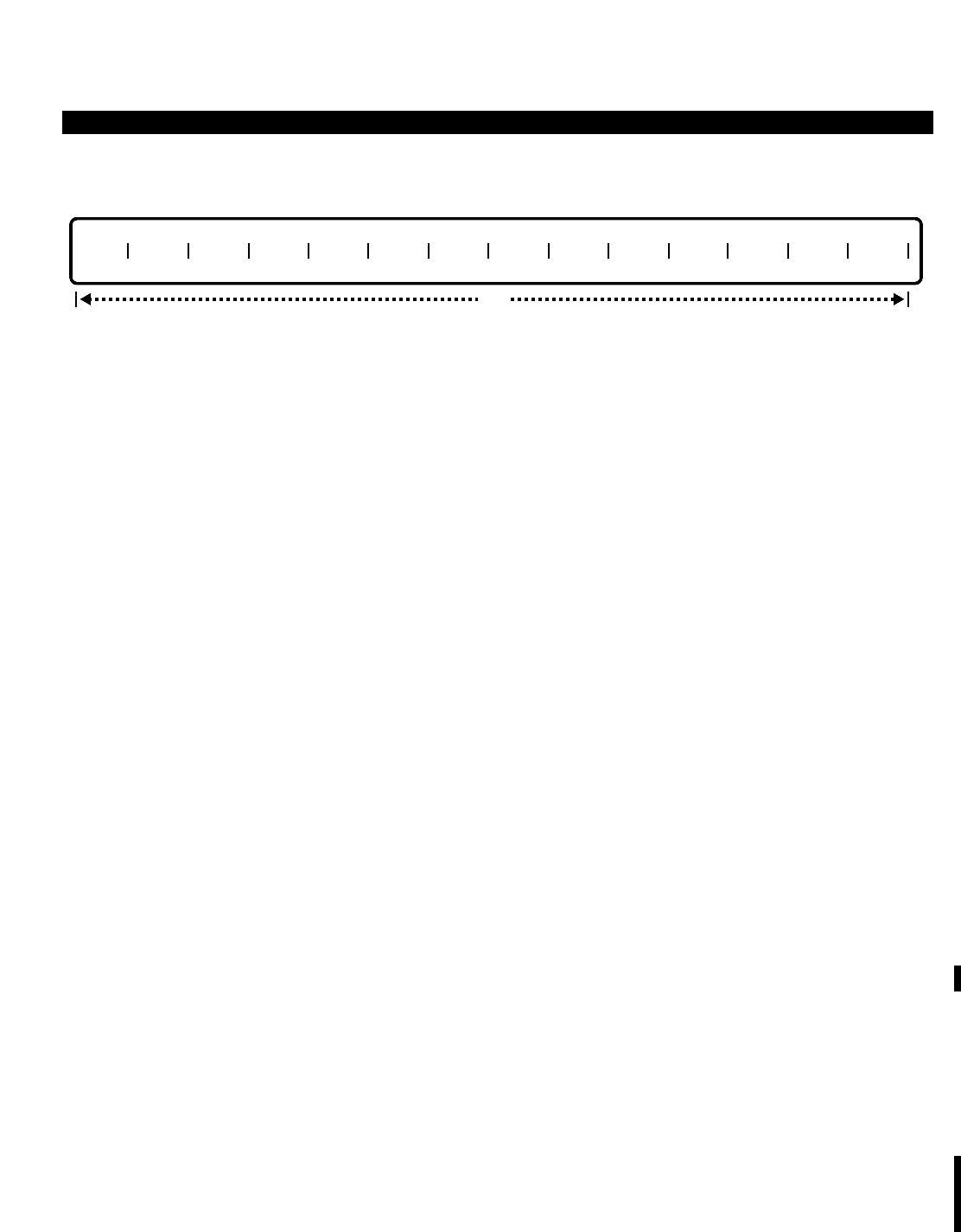
PERCEPTION 4000 COMMANDS
DISPLAY
This operation displays the I/O port applications.
PARAMETERS
Each field parameter is described in this section. Any variations for a particular operation are noted separately.
FIELD: IOP# (I/O Port Number)
TYPE: Decimal
FORMAT: 1 digit
VALUE: 1 to 4
This field selects an I/O port on the MISC card. Data input is optional in a DISPLAY operation,
but required in ADD and DELETE operations.
FIELD: TYPE (I/O Port Type)
TYPE: Keyword
FORMAT: Predefined ASCII characters
Keywords: TTY - Maintenance and Administration Console
AP - Application Processor
The I/O port is assigned as either a TTY or AP type port. System defaults define ports one
through three as TTY ports and port four as an AP port.
FIELD: APPL (Application Usage)
TYPE: Keyword
FORMAT: Predefined ASCII characters
Keywords: TTY type usage:
MA - Maintenance Console
SSR - System Status Report
EFR - Error or Fault Report
TFR - Traffic Report
SMDR - Station Message Detail Report
AP type usage:
ACD - Automatic Call Distribution
VMS1 - Voice Message Status Type 1
VMS2 - Voice Message Status Type 2
VMS3 - Voice Message Status Type 3
IOP# TYPE APPL APPL APPL APPL APPL APPL APPL APPL APPL APPL APPL APPL
opt
ISS 2, SECTION 4000-014-000
I/O PORT ASSIGNMENT (CMD 415)
3-201

PERCEPTION 4000 COMMANDS
ISS 2, SECTION 4000-014-000
I/O PORT ASSIGNMENT (CMD 415)
Both TTY and AP port types (not applicable in an ADD operation):
ALL - DELETE/DISPLAY all of the applications assigned to the designated
port.
For TTY-type I/O ports, the application usage field may define various combinations of MA, SSR,
EFR, TFR or/and SMDR.
For AP-type I/O ports, the application usage field must be either ACD or VMS. Both of these
applications require a dedicated I/O port and may not share that port with other devices or
subsystems.
In a DISPLAY operation, this field is optional. While in ADD and DELETE operations, at least one
application must be specified.
SYSTEM ERROR MESSAGES
The following error messages are unique to this command.
C41500 - Mismatch I/O port type
C41501 - Mismatch port type and application
C41502 - <ALL> is not allowed in ADD operation
C41503 - Mismatch I/O port number and console application
C41504 - Not allowed when deleting main console
C41505 - Each port can have one and only one assigned AP application
C41506 - Application already exists
C41507 - There is no application assigned
C41508 - SMDI is not supported; only VMS1 is available
RELATED COMMAND
I/O Port Configuration Assignment (CMD 414)
3-202

PERCEPTION 4000 COMMANDS
I/O PORT CONFIGURATION ASSIGNMENT (CMD 414)
The I/O Port Configuration Assignment command defines the protocols, timers, and controls necessary for the I/O
port to communicate successfully with the outboard device.
Command Keyword: I/O_PORT_CONFIG
Category Name: System
PREREQUISITE COMMANDS
There are no prerequisites for this command.
OPERATIONS
Available operations: MODIFY
DISPLAY
The function and required data fields for each operation are described in this section.
MODIFY
This operation modifies the I/O port attributes of the MISC card. The "IOP#" field is required for all MODIFY
operations that change port dependent data. If port number 1 (IOP# = 1) is selected, the "DATA BIT", "STOP",
"PRTY", and "SPEED" fields are locked, and dip switches on the MISC card must be updated. The "IOP#" field is
not required when modifying only the "FCT" or the "MCT" field.
The “MC CODE” field contains the motor control codes (the ASCII code for turning the motor ON and OFF). This
field is meaningful only when “MC” is set to YES. Looping is permitted in the "IOP#" field only.
DISPLAY
This operation displays all I/O port attributes of the MISC card that meet the conditions established for each field.
Looping is permitted in the “IOP#” field only.
FCT MCT IOP# TYPE MC MC CODE LOT DATA BIT STOP PRTY SPEED
opt
FCT MCT IOP# TYPE MC MC CODE LOT DATA BIT STOP PRTY SPEED
opt
ISS 2, SECTION 4000-014-000
I/O PORT CONFIGURATION ASSIGNMENT (CMD 414)
3-203

PERCEPTION 4000 COMMANDS
ISS 2, SECTION 4000-014-000
I/O PORT CONFIGURATION ASSIGNMENT (CMD 414)
PARAMETERS
Each field parameter is described in this section. Any variations for a particular operation are noted separately.
FIELD: FCT (Flow Control Timer)
TYPE: Decimal
FORMAT: 1 to 3 digits
VALUE: 1 to 600
LOOP: Not allowed
RANGE: Not allowed
DEFAULT: 60 seconds (1 minute)
The flow control timer periodically checks the status of the TTY port to verify that it is functioning
correctly. The timer is based on seconds.
FIELD: MCT (Motor Control Timer)
TYPE: Decimal
FORMAT: 1 to 4 digits
VALUE: 1 to 1800
LOOP: Not allowed
RANGE: Not allowed
DEFAULT: 600 seconds (10 minutes)
The motor control timer checks a device (usually a printer) to see if it has been idle for a specified
period of time. When the idle time goes beyond the option set in this field, a signal is sent to the
control program and the device is automatically turned OFF. The timer is based on seconds.
FIELD: IOP# (I/O Port Number)
TYPE: Decimal
FORMAT: 1 digit
VALUE: 1 to 4
LOOP: Allowed
RANGE: Not allowed
This field defines the I/O port number on the MISC card, and is required in a MODIFY operation
for changing port dependent attributes. If port number 1is selected, the "DATA BIT", "STOP",
"PRTY", and "SPEED" fields are locked, and dip switches on the MISC card must be updated.
FIELD: TYPE (Flow Control Type)
TYPE: Keyword
FORMAT: Predefined ASCII characters
Keywords: RCFC - RTS/CTS control method based on the Request-to-Send and Clear-to-
Send signals at the hardware interface
DC13 - DC1/DC3 control method (i.e. XON/XOFF)
BOTH - Use both handshake methods listed above
NON - Use no flow control
This field specifies which flow control mechanism the system uses on the specified terminal port.
3-204

PERCEPTION 4000 COMMANDS
FIELD: MC (Motor Control Setting)
TYPE: Keyword
FORMAT: Predefined ASCII characters
Keywords: YES - Motor Control feature enabled
NO - Motor Control feature disabled
This field enables or disables the motor control feature. If this field is set to YES, the following
field (MC CODE) is required. If set to NO, the following field is ignored.
FIELD: MC CODE (Motor Control Codes)
TYPE: Hexadecimal
FORMAT: 4 digits
VALUE: 0000 to 7F7F
LOOP: Not allowed
RANGE: Not allowed
DEFAULT: 0000
The motor ON/OFF codes are defined with this field. The first two digits represent the ASCII code
for the motor ON command, and the second two represent the ASCII code for the motor OFF.
This field is meaningful only when the preceding field (MC) is set to YES.
FIELD: LOT (Logout Timer Value)
TYPE: Decimal
FORMAT: 1 to 4 digits
VALUE: 1 to 1800
LOOP: Not allowed
RANGE: Not allowed
DEFAULT: 600 seconds (10 minutes)
The logout timer tells the system how long inactivity may exist on the terminal before forcing a
logout. The timer is based on seconds.
FIELD: DATA BIT (Number of Data Bits)
TYPE: Keyword
FORMAT: Predefined ASCII characters
Keywords: 7BIT - Specifies 7 data bits
8BIT - Specifies 8 data bits
This field defines how many data bits are transmitted through the communications framing. If the
"IOP#" field is set to port number 1, the "DATA BIT" field becomes a locked field.
FIELD: STOP (Number of Stop Bits)
TYPE: Keyword
FORMAT: Predefined ASCII characters
Keywords: 1BIT - Specifies 1 stop bit
2BIT - Specifies 2 stop bits
ISS 2, SECTION 4000-014-000
I/O PORT CONFIGURATION ASSIGNMENT (CMD 414)
3-205

PERCEPTION 4000 COMMANDS
ISS 2, SECTION 4000-014-000
I/O PORT CONFIGURATION ASSIGNMENT (CMD 414)
This field defines the number of stop bits in the communications framing. If the "IOP#" field is set
to port number 1, the "STOP" field becomes a locked field.
FIELD: PRTY (Parity Setting)
TYPE: Keyword
FORMAT: Predefined ASCII characters
Keywords: ODD - Odd parity
EVEN - Even parity
NON - No parity checking (no parity bit)
The type of parity used by the I/O port is defined with this command. If 8BIT is selected in the
"DATA BIT" field, this field must be set to NON. If the "IOP#" field is set to port number 1, the
"PRTY" field becomes a locked field.
FIELD: SPEED (Baud Rate Selection)
TYPE: Keyword
FORMAT: Predefined ASCII characters
Keywords: 300 - 300 bits per second (bps)
1200 - 1200 bps
9600 - 9600 bps
19200 - 19200 bps
Speed selection for the I/O port is defined with this command. If the "IOP#" field is set to port
number 1, the "SPEED" field becomes a locked field.
SYSTEM ERROR MESSAGES
The following error messages are unique to this command.
C41400 - I/O port number is required
C41401 - Motor Control Setting field is NO
C41402 - Motor control code is out of range
C41403 - Fields 8 to 11 for IOP# 1 cannot be modified; use dip switches on MISC card
COMMENTS
The flow control and motor control timers affect all of the ports. They are independent of the I/O port number. In a
MODIFY operation, changes to either timer do not require that the "IOP#" be specified.
All port dependent fields (TYPE ~ SPEED) require that the I/O port number be specified in the “IOP#” field.
3-206

PERCEPTION 4000 COMMANDS
INITIATE SWITCHOVER (CMD 102)
The Initiate Switchover command provides the capability to manually swap sides (ACTIVE to STAND-BY) on a
redundant system.
Command Keyword: SWITCHOVER
Category Name: Maintenance
PREREQUISITE COMMANDS
There are no prerequisites for this command.
OPERATIONS
Available operations: ENABLE
The function and required data fields for each operation are described in this section.
ENABLE
This operation initiates the switch-over process and logs a message into the history file. If the printer option is
turned ON, the message outputs to the printer.
PARAMETERS
Each field parameter is described in this section. Any variations for a particular operation are noted separately.
FIELD: SWITCHOVER (Switch-over from Active to Stand-by Side)
TYPE: Keyword
FORMAT: Predefined ASCII characters
Keywords: YES - Activate switch-over process
NO - Abort request
The "SWITCH OVER" field allows you to activate the process, or to abort the request.
SWITCHOVER
req
ISS 2, SECTION 4000-014-000
INITIATE SWITCHOVER (CMD 102)
3-207

PERCEPTION 4000 COMMANDS
ISS 2, SECTION 4000-014-000
INITIATE SWITCHOVER (CMD 102)
SYSTEM ERROR MESSAGES
The following error messages are unique to this command.
C10200 - Stand-by is out of service
C10201 - Switch-over failed
C10202 - Set timer error
C10203 - Switch-over time out
COMMENTS
The switch-over process may be set to either automatic or manual operation.
Automatic Switch-over
A periodic switch-over operation is handled by the Time Activated Command Programming command (CMD 110).
With this command, the start time and the periodical report interval is set.
Manual Switch-over
The Initiate Switchover command activates a manual switch-over on a redundant system. The system's manual
override switch must be in the Auto Select position in order to perform the operation.
RELATED COMMAND
Time Activated Command Programming (CMD 110)
3-208

PERCEPTION 4000 COMMANDS
INTERCHANGEABLE OFFICE CODE TABLE (CMD 318)
This command builds a table of interchangeable office codes. These codes resemble area codes in that they
follow the area code format (NYX), where:
N = 2 to 9
Y = 0 or 1
X = 0 to 9
Interchangeable office codes must not have an area code counterpart. For example, 917 may be an office code
that follows the format for area codes and yet is not an existing area code.
Office code information can be obtained from the serving central offices for all central office and foreign exchange
trunks. This information should be reviewed at least every six months to ensure codes entered into the table
remain unique, and to ensure no new area codes have come into existence which may nullify the uniqueness of
an interchangeable office code previously defined in the table.
Command Keyword: IOC_TABLE
Category Name: Station
PREREQUISITE COMMANDS
There are no prerequisites for this command.
OPERATIONS
Available operations: ADD
DELETE
DISPLAY
The function and required data fields for each operation are described in this section.
ADD
This operation adds Interchangeable Office Codes (IOCs) to the table. The first "IOC" field is required for an ADD
operation. Scopes are permitted in all of the fields.
IOC IOC IOC IOC IOC IOC IOC IOC IOC IOC IOC IOC
optreq
ISS 2, SECTION 4000-014-000
INTERCHANGEABLE OFFICE CODE TABLE (CMD 318)
3-209
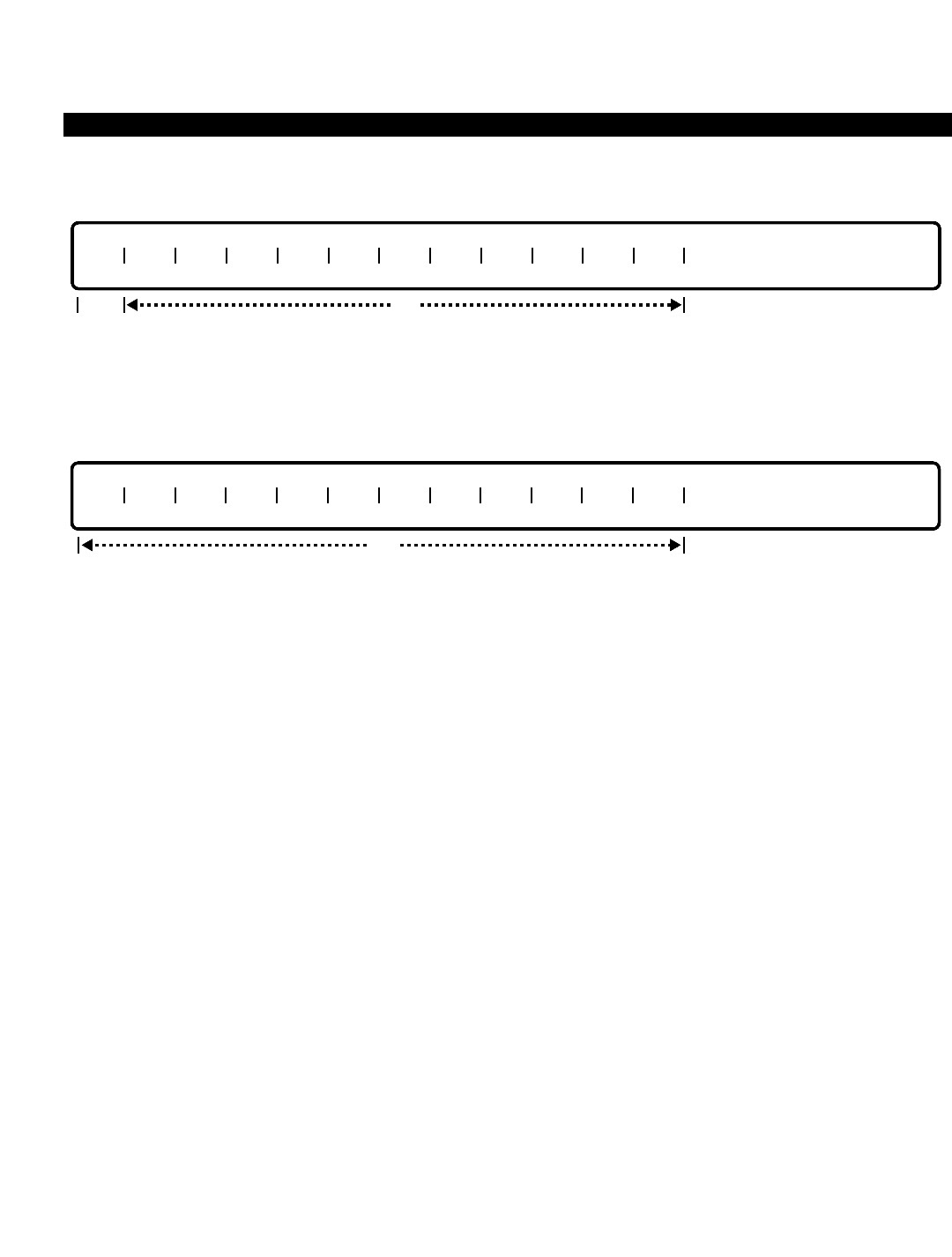
PERCEPTION 4000 COMMANDS
ISS 2, SECTION 4000-014-000
INTERCHANGEABLE OFFICE CODE TABLE (CMD 318)
DELETE
This operation deletes Interchangeable Office Codes from the table. The first "IOC" field is required for a DELETE
operation. Scopes are permitted in all of the fields.
DISPLAY
This operation displays the Interchangeable Office Codes in the table. All of the fields are optional. If a tab is
entered in the first field, all of the interchangeable office codes are displayed. Ranges are permitted for this
operation. If consecutive office codes exist, scope fields are output. For example, “213-218”.
PARAMETERS
Each field parameter is described in this section. Any variations for a particular operation are noted separately.
FIELD: IOC (Interchangeable Office Code)
TYPE: Decimal with fixed length
FORMAT: 3 digits in the form N Y X (where N = 2 to 9, Y = 0 or 1, and X = 0 to 9)
VALUE: 200 to 919
LOOP: Not allowed
RANGE: Allowed in a DISPLAY operation
In ADD and DELETE operations, the first "IOC" field is required, while the remaining fields are
optional. Values are from 200 to 919: the first digit is from 2 to 9, the second must be a 1 or 0,
and the last digit can be 0 to 9. Scopes are permitted in ADD and DELETE operations.
SYSTEM ERROR MESSAGES
The following error messages are unique to this command.
C31800 - IOC table has no space
C31801 - IOC not found
C31802 - IOC is already assigned
C31803 - Check format
C31804 - Missing data in scope type field in field N
C31805 - Dash in last scope field N
IOC IOC IOC IOC IOC IOC IOC IOC IOC IOC IOC IOC
opt
IOC IOC IOC IOC IOC IOC IOC IOC IOC IOC IOC IOC
optreq
3-210

PERCEPTION 4000 COMMANDS
RELATED COMMAND
Dialing Definition (CMD 317)
ISS 2, SECTION 4000-014-000
INTERCHANGEABLE OFFICE CODE TABLE (CMD 318)
3-211
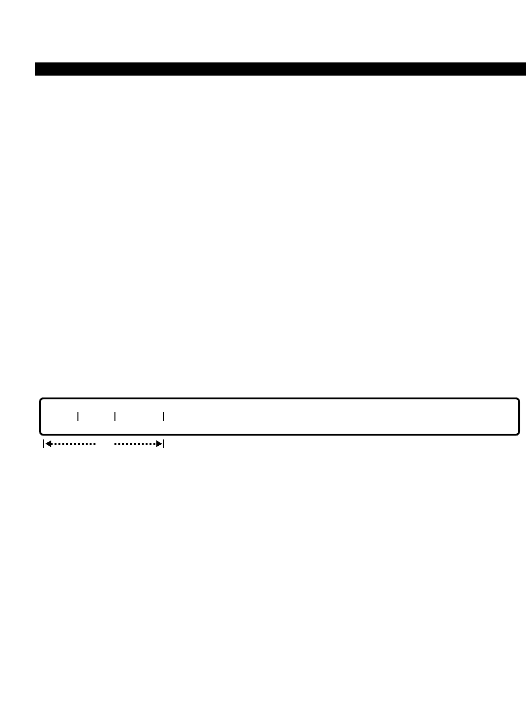
PERCEPTION 4000 COMMANDS
ISS 2, SECTION 4000-014-000
INTERCOM GROUP MEMBER DISPLAY (CMD 333)
INTERCOM GROUP MEMBER DISPLAY (CMD 333)
The Intercom Group Member Display command displays intercom group membership(s). Intercom groups are
designed to provide PERCEPTION 4000 digital telephone users with an abbreviated method of calling people
within a department or designated group.
Command Keyword: INTERCOM_DISPLAY
Category Name: Station
PREREQUISITE COMMANDS
Station Feature Key Assignment (CMD 331)
OPERATIONS
Available operations: DISPLAY
The function and required data fields for each operation are described in this section.
DISPLAY
This operation displays all intercom groups and their members that meet the conditions established for each field.
If a <TAB> and <RETURN> are input, then all intercom groups and their members are displayed. To halt the
display, press <CONTROL-S>, or to abort it, press <ESC> (<SHIFT-2>). If only the intercom group number is
input, than all members of the group are displayed. Loops are permitted in the group number (GRP#) and
intercom member number (ICM #) fields. A range is allowed only in the prime directory number (PRM DN) field.
PARAMETERS
Each field parameter is described in this section. Any variations for a particular operation are noted separately.
FIELD: GRP# (Intercom Group #)
TYPE: Decimal
FORMAT: 1 to 3 digits
VALUE: 1 to 256
LOOP: Allowed
The system is restricted to having at most 128 groups with 20 members per group, or 256
intercom groups with 10 members per group. The number of groups and their size can be mixed
or matched in any way as long as the restriction mentioned is not violated.
opt
GRP# ICM # PRM DN
3-212

PERCEPTION 4000 COMMANDS
FIELD: ICM # (Intercom Group’s Member #)
TYPE: Decimal
FORMAT: 2 digits for 20 members, 1 digit for 10 members
VALUE: 01 to 20, or 0 to 9
LOOP: Allowed
This number is used to address a station belonging to an intercom group. The intercom group’s
size is defined individually. That is, an intercom group can either have 10 members or 20
members depending on the particular needs of the group.
FIELD: PRM DN (Member’s Prime Directory Number)
TYPE: DN Type
FORMAT: 1 to 5 digits
VALUE: 0 to 99999
RANGES: Allowed in a DISPLAY operation only
LOOP: Not allowed
This parameter identifies the members of a multiline telephone intercom group. Only prime
directory numbers are accepted as members of an intercom group.
SYSTEM ERROR MESSAGES
The following error messages are unique to this command.
C33301 - Invalid DN-LDN relationship
C33302 - Check input in field 2
COMMENTS
The PERCEPTION 4000 system can have a maximum of either 128 intercom groups with 20 members per group,
or 256 intercom groups with ten members per group. Groups can be mixed and matched, as long as the system
maximum of 2,560 members is not exceeded.
Only prime lines can be specified as intercom group members.
A station can be a member of more than one intercom group.
RELATED COMMAND
Station Feature Key Assignment (CMD 331)
ISS 2, SECTION 4000-014-000
INTERCOM GROUP MEMBER DISPLAY (CMD 333)
3-213

PERCEPTION 4000 COMMANDS
ISS 2, SECTION 4000-014-000
INTERNAL CALL ALTERNATE ROUTING ASSIGNMENT (CMD 374)
INTERNAL CALL ALTERNATE ROUTING ASSIGNMENT (CMD 374)
The Internal Call Alternate Routing command assigns, changes, and displays the alternate answering point for
internal callers to attendants and/or attendant groups that are in the position busy mode. An alternate answering
position may be assigned for each of four time zones.
Command Keyword: INT_CALL_ALT_ROUTING
Category Name: Attendant
PREREQUISITE COMMANDS
Attendant Group Assignment (CMD 372)
Attendant Position Assignment (CMD 370)
At least one of the following commands is required before entering a value in an "AR TZ n" field:
ACD Group Assignment (CMD 355)
Announcement Pattern Assignment (CMD 353)
Miscellaneous Device Assignment (CMD 400)
Night Bell Assignment (CMD 405)
Station Assignment (CMD 330)
Station Hunting Assignment (CMD 342)
UCD Group Assignment (CMD 354)
OPERATIONS
Available operations: MODIFY
DISPLAY
The function and required data fields for each operation are described in this section.
MODIFY
This operation modifies the alternate route of each time zone for the specified attendant or attendant group when
it is busy. The attendant DN or attendant group DN is used as the key to perform the modifications and must be
entered. If no data is entered in any of the time zone fields (AR TZ n), no modification is performed.
opt
ATT DN/GRP DN AR TZ 1 AR TZ 2 AR TZ 3 AR TZ 4
req
3-214
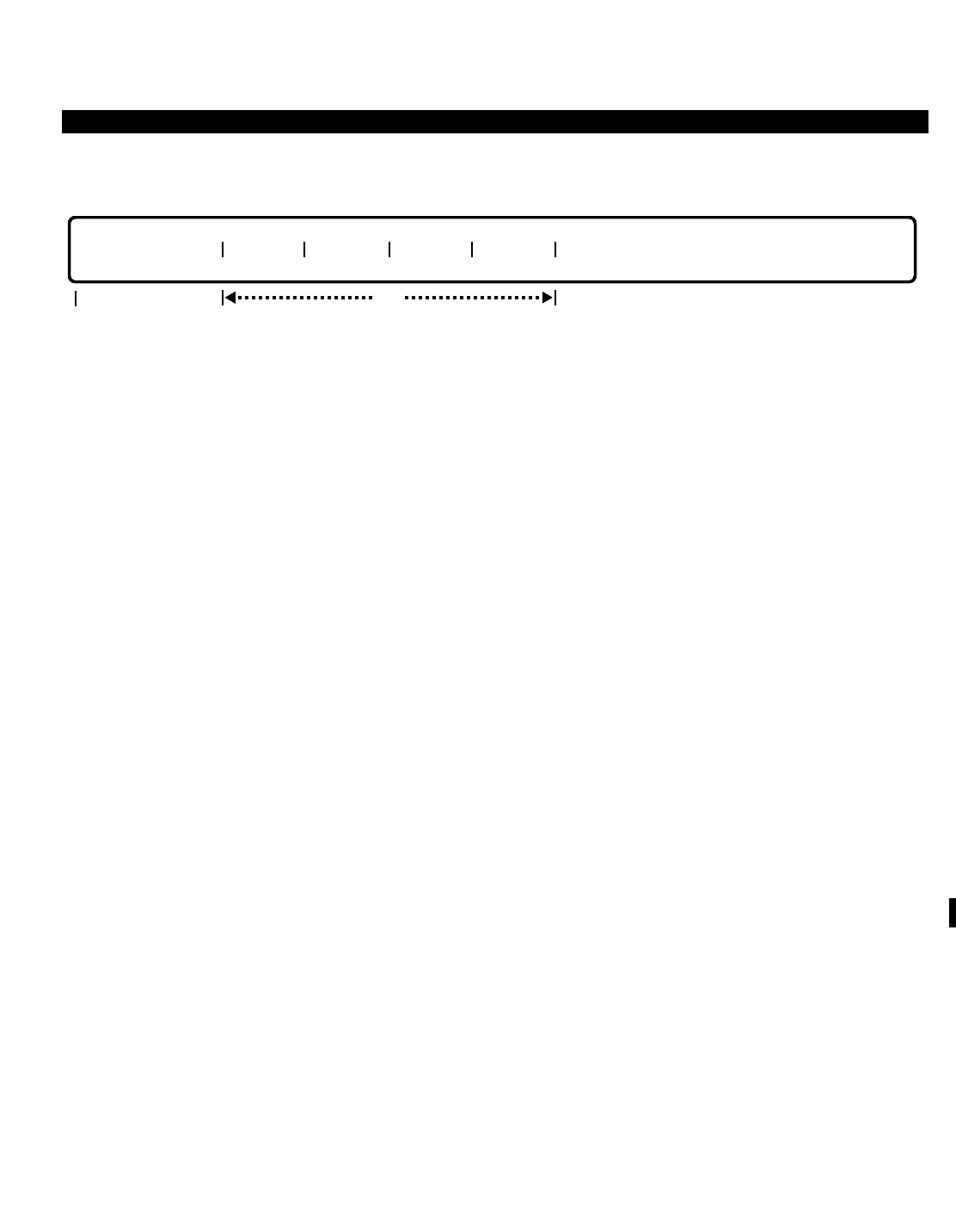
PERCEPTION 4000 COMMANDS
DISPLAY
This operation displays the alternate route of each time zone for the specified attendant or attendant group when
it is busy. The attendant DN or attendant group DN is used as the key to perform the modifications and must be
entered. All other fields are optional.
PARAMETERS
Each field parameter is described in this section. Any variations for a particular operation are noted separately.
FIELD: ATT DN/GRP DN (Attendant or Attendant Group Directory Number)
TYPE: DN Type
FORMAT: 1 to 5 digits
VALUE: 0 to 99999
RANGE: Not allowed
LOOP: Not allowed
The attendant or attendant group directory number is assigned through the Attendant Group
Assignment command (CMD 372). This is a required field in both DISPLAY and MODIFY
operations.
FIELD: AR TZ n (Alternate Route for Time Zone 1, 2, 3, or 4)
TYPE: DN Type or Keyword
FORMAT: 1 to 5 digits for DN Type / Predefined ASCII characters for Keywords
VALUE: 0 to 99999 Station directory number, Hunt group pilot number,
UCD group pilot number, or ACD group pilot number
RANGE: Not allowed
LOOP: Not allowed
Keywords: AP01 - AP50 Announcement Pattern Number (1 ~ 50)
BL01 - BL64 Night Bell Device Number (1 ~ 64)
NON No Alternate Route Defined
This field defines an alternate answering position for internal calls according to the designated
time zone.
opt
ATT DN/GRP DN AR TZ 1 AR TZ 2 AR TZ 3 AR TZ 4
req
ISS 2, SECTION 4000-014-000
INTERNAL CALL ALTERNATE ROUTING ASSIGNMENT (CMD 374)
3-215

PERCEPTION 4000 COMMANDS
ISS 2, SECTION 4000-014-000
INTERNAL CALL ALTERNATE ROUTING ASSIGNMENT (CMD 374)
SYSTEM ERROR MESSAGES
The following error messages are unique to this command.
C37400 - Directory number does not exist
C37401 - Invalid alternate directory number
C37402 - Invalid announcement device
C37403 - Invalid night bell device
I37404 - Warning: Undefined data in field AR TZ #n
3-216
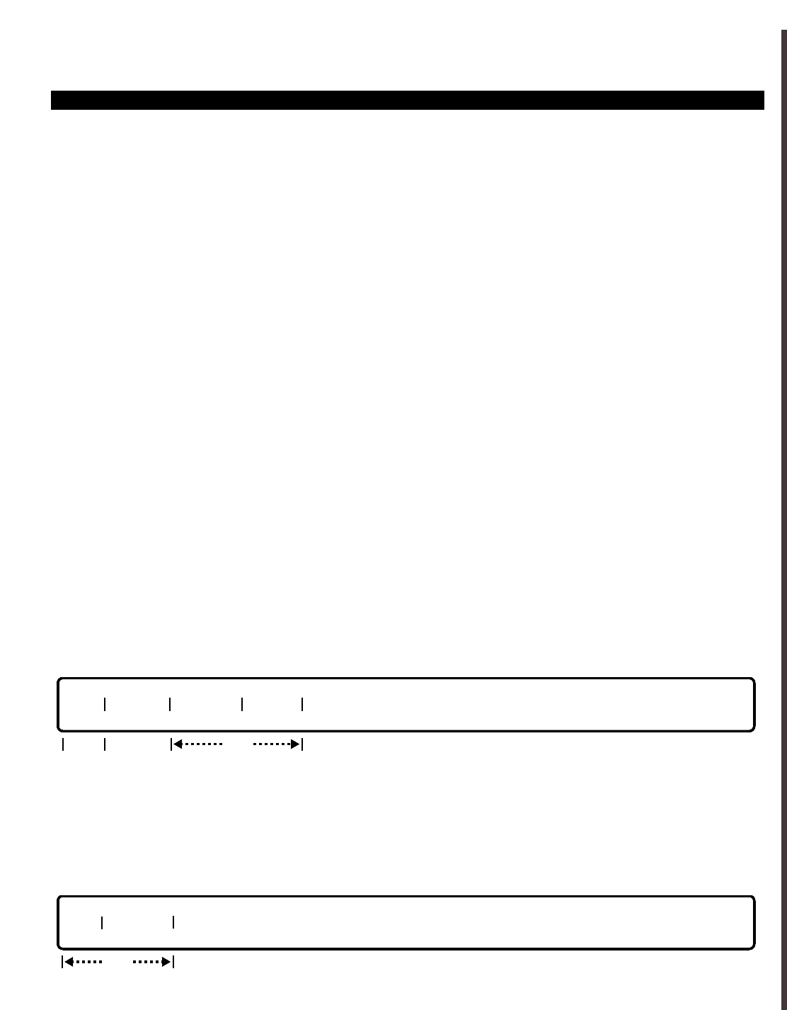
PERCEPTION 4000 COMMANDS
ISDN CHANNEL GROUP ASSIGNMENT (CMD 423)
The ISDN Channel Group Assignment command is used to add, delete, display, or modify one or more channel
groups, as well as to adjust each channel group's related time zone class, equipment number, and channel
structure.
Command Keyword: CGN_ASSIGN
Category Name: ISDN
PREREQUISITE COMMANDS
ISDN IPRC and IPRI Card Assignment (CMD 422)
Time Zone Assignment (CMD 336)
OPERATIONS
Available operations:
ADD
DELETE
MODIFY
DISPLAY
The function and required data fields for each operation are described as follows:
ADD
This operation is used to add one or more channel groups and their related data. Each channel group must have
an assigned time zone class ("TZ CLS"). If no data is entered for "TZ CLS," then the "TZ CLS" entry defaults to 1.
Looping is permitted in the "EQUIP #" field.
DELETE
ThIs operation is used to delete one or more existing channel groups. Looping is permitted in the 'EQUIP #" field.
req
CGN EQUIP #
CGN TZ CLS EQUIP # B STR
req
req opt
ISS 2, SECTION 4000-014-000
ISDN CHANNEL GROUP ASSIGNMENT (CMD 423)
3-217
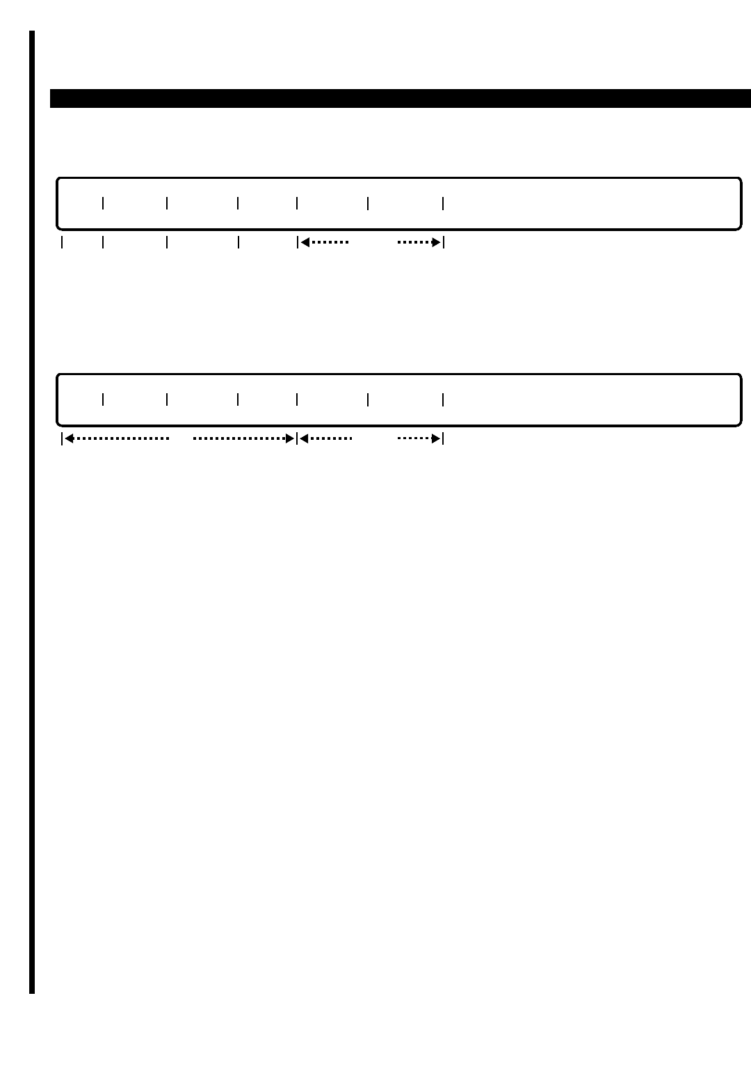
PERCEPTION 4000 COMMANDS
ISS 2, SECTION 4000-014-000
ISDN CHANNEL GROUP ASSIGNMENT (CMD 423)
MODIFY
This operation is used to modify the equipment position and channel structure of a channel group. If data is
entered in the "B STR" field, then "EQUIP #" data must be entered.
DISPLAY
ThIs operation is used to display one or more existing channel groups. Looping is permited in the "CGN" and
"EQUIP #" fields.
PARAMETERS
This section defines input permitted for each field. Any variations for a particular operation are noted separately.
FIELD: CGN (Channel Group Number)
TYPE: Decimal
FORMAT: 1 to 2 digits
VALUE: 1 to 32 (or maximum system trunk configuration)
RANGE: Allowed in DISPLAY operation only
LOOP: Not allowed
The "CGN" entry is required in the ADD, DELETE, and MODIFY operations. In the DISPLAY
operation, this is an optional field. If no entry is made, then the attributes of all assigned channel
groups in the PERCEPTION 4000 system will be displayed.
More than one CGN can be assigned to an IPRC card. For example, CGN 1 can have channels
from 20801 to 20810 on IPRI card 208, and CGN 2 can have channels 20811 to 20823.
The same CGN cannot be assigned to channels controlled by two different IPRC cards. For
example, if CGN 1 has channels on IPRI card 208, then the channels on IPRI card 408 cannot be
assigned to CGN 1. For the same reason, a CGN cannot be assigned to channels that are
controlled by two different LCPUs.
FIELD: TZ CLS (Time Zone Class)
TYPE: Keyword
FORMAT: Predefined ASCII characters
CGN TZ CLS EQUIP # B STR H0 STR H11 STR
opt locked
CGN TZ CLS EQUIP # B STR H0 STR H11 STR
opt
req locked
req opt
3-218

PERCEPTION 4000 COMMANDS
Keyword: IS01 - ISDN time zone class 1
IS02 - ISDN time zone class 2
IS03 - ISDN time zone class 3
IS04 - ISDN time zone class 4
The "TZ CLS" entry is used to assign a channel group to a time zone class. Each class is a type
of allocation plan, in which up to four different time zones can be assigned. (Time zones are
assigned to classes in CMD 336). The "TZ CLS" entry applies to the entire channel group;
therefore, if the channel group is used for more than one type of ISDN service, the specified time
zone class will apply to all services in that channel group.
FIELD: EQUIP # (Equipment Number)
TYPE: Decimal
FORMAT: 10101 to 101424
RANGE: Not allowed
LOOP: Allowed in ADD, DELETE, and DISPLAY operations
The entered equipment number applies to the equipment number of the channel group's
associated trunk group. The first one or two digits of the entry represent the number of the shelf
containing the trunk circuit card. The second two digits represent the card number; and the last
two digits represent the circuit number.
FIELD: B STR (B Channel Structure)
TYPE: Keyword
FORMAT: Preassigned ASCII characters
RANGE: Not allowed
LOOP: Not Allowed
Keyword: YES - The channel can be used for calls requiring a B channel
NO - The channel cannot be used for calls requiring a B channel
This field should be entered "YES" to enable calls requiring a B channel. The "NO" option is for
future use.
FIELD: H0 STR (H0 Channel Structure)
TYPE: Keyword
FORMAT: Preassigned ASCII characters
Keyword: YES - The channel can be used for calls requiring an H0 channel
NO - The channel cannot be used for calls requiring an H0 channel
This field is locked in all operations and is reserved for future use.
FIELD: H11 STR (H11 Channel Structure)
TYPE: Keyword
FORMAT: Preassigned ASCII characters
Keyword: YES - The channel can be used for calls requiring an H11 channel
NO - The channel cannot be used for calls requiring an H11 channel
This field is locked in all operations and is reserved for future use.
ISS 2, SECTION 4000-014-000
ISDN CHANNEL GROUP ASSIGNMENT (CMD 423)
3-219

PERCEPTION 4000 COMMANDS
ISS 2, SECTION 4000-014-000
ISDN CHANNEL GROUP ASSIGNMENT (CMD 423)
SYSTEM MESSAGES
The following error messages are unique to this command.
C42300 - Card or equipment number is already assigned to other devices
C42301 - Invalid equipment number
C42302 - Equipment number has already been assigned
C42303 - Circuit number must be 1 for H11 and 1,7, 13, or 19 for H0
C42304 - Total number of MIN AVCs exceed total channels for given CGN
C42305 - Not allowed to delete; H0 or H11 must be set to NO
C42306 - Invalid input; data does not match
C42307 - Trunk group number has already been assigned
C42308 - Channel group number is out of range
C42309 - Data has already been assigned in database
C42310 - Data is not assigned in database
D42311 - B-channel is out of range
D42312 - Channel group number is not registered
D42313 - LDN is not available
D42314 - LDN is not registered for this channel group number
D42315 - LDN pool cannot support request
D42316 - LDN status is busy
D42317 - Channel group number is in use
D42318 - Channel group number is not used
D42319 - ISDN time zone class is undefined
D42320 - Channel group number change table database is full
D42321 - LCPU number is out of range
3-220
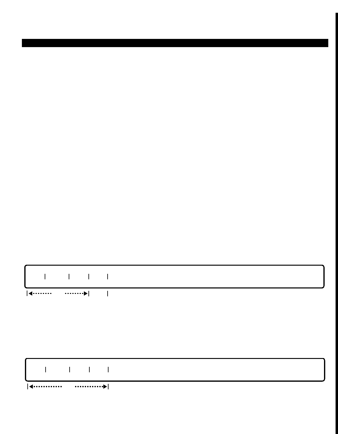
PERCEPTION 4000 COMMANDS
ISDN CHANNEL GROUP HUNTING ASSIGNMENT (CMD 424)
The ISDN Channel Group Hunting Assignment command is used to modify or display the channel group hunting
sequence between two IPRI cards. The selection of which IPRI card is searched first determines which channel
groups will be searched first for an available channel. This command is also used to modify the hunting direction
between channel groups/channels (from channel 1 to channel 24, or from channel 24 to channel 1).
Command Keyword: CGN_HUNTING
Category Name: ISDN
PREREQUISITE COMMANDS
ISDN IPRC and IPRI Card Assignment (CMD 422)
OPERATIONS
Available operations:
MODIFY
DISPLAY
The function and required data fields for each operation are described as follows:
MODIFY
This operation is used to modify the hunting sequence between two IPRI cards, thereby affecting available
channel group selection. If data is not entered in the "SEQ#" field, then data must be entered in the "IPRI" and
"DIR" fields. Range and loop procedures are not permitted in the MODIFY operation.
DISPLAY
This operation is used to display the hunting sequence of two IPRI cards, and therefore their assigned trunk
groups/channel groups. Ranges are permitted in the "CGN" and "SEQ#" fields.
CGN SEQ# IPRI DIR
opt
CGN SEQ# IPRI DIR
req opt
ISS 2, SECTION 4000-014-000
ISDN CHANNEL GROUP HUNTING ASSIGNMENT (CMD 424)
3-221

PERCEPTION 4000 COMMANDS
ISS 2, SECTION 4000-014-000
ISDN CHANNEL GROUP HUNTING ASSIGNMENT (CMD 424)
PARAMETERS
This section defines input permitted for each field. Any variations for a particular operation are
noted separately.
FIELD: CGN (Channel Group Number)
TYPE: Decimal
FORMAT: 1 to 2 digits
VALUE: 1 to 32 (or maximum system trunk configuration)
RANGE: Not allowed
LOOP: Allowed in DISPLAY operation only
The "CGN" entry is required in the MODIFY operation. In the DISPLAY operation, this is an
optional field; if no entry is made, then the attributes of all assigned channel groups in the
PERCEPTION 4000 system will be displayed.
FIELD: SEQ# (Sequence Number)
TYPE: Decimal
FORMAT: 1 digit
VALUE: 1 or 2
RANGE: Not allowed
LOOP: Not allowed
The "SEQ#" field is used to assign a sequence number to the channel group. The specification of
1 or 2 actually refers to the IPRI card associated with the channel group. For example, if the
channel group specified in the "CGN" field is assigned to a trunk group supported by IPRI card
"1," then an entry of 1 in the "SEQ#" field indicates that this trunk group/CGN will have hunting
priority over those trunk groups/CGNs supported by IPRI card "2." The default "SEQ#" value is
the reverse of IPRI card installation order. For example, if IPRI card "1" was installed before IPRI
card "2," then IPRI card "2" will have a "SEQ#" of 1.
FIELD: IPRI (Related IPRI Card Position)
TYPE: Decimal
FORMAT: 3 to 4 digits
VALUE: 101 to 1012
RANGE: Allowed in DISPLAY operation only
LOOP: Not allowed
The "IPRI" field entry indicates the equipment number of the IPRI card associated with the
channel group. The first one or two digits represent the number of the shelf in which the IPRI card
is installed. The last two digits represent the card slot number.
FIELD: DIR (Hunting Direction)
TYPE: Keyword
FORMAT: Preassigned ASCII characters
Keyword: FRWD - Forward (from channel 1 to channel 24)
BACK - Backward (from channel 24 to channel 1)
This field indicates the direction used for hunting among the channel groups/channels supported
by an IPRI card. The default value is Backward. Note that each IPRI card supports up to 24
channels; however a channel on one of the IPRI cards must be used as a D-channel rather than
as a bearer channel. This single D-channel can support the 47 bearer channels on the two IPRI
cards.
3-222

PERCEPTION 4000 COMMANDS
SYSTEM MESSAGES
The following error messages are unique to this command.
C42400 - Channel group number does not exist
C42401 - Sequence number does not exist
C42402 - Invalid hunting direction
C42403 - Invalid IPRI number
C42404 - Sequence number is required
C42405 - Check sequence number
ISS 2, SECTION 4000-014-000
ISDN CHANNEL GROUP HUNTING ASSIGNMENT (CMD 424)
3-223
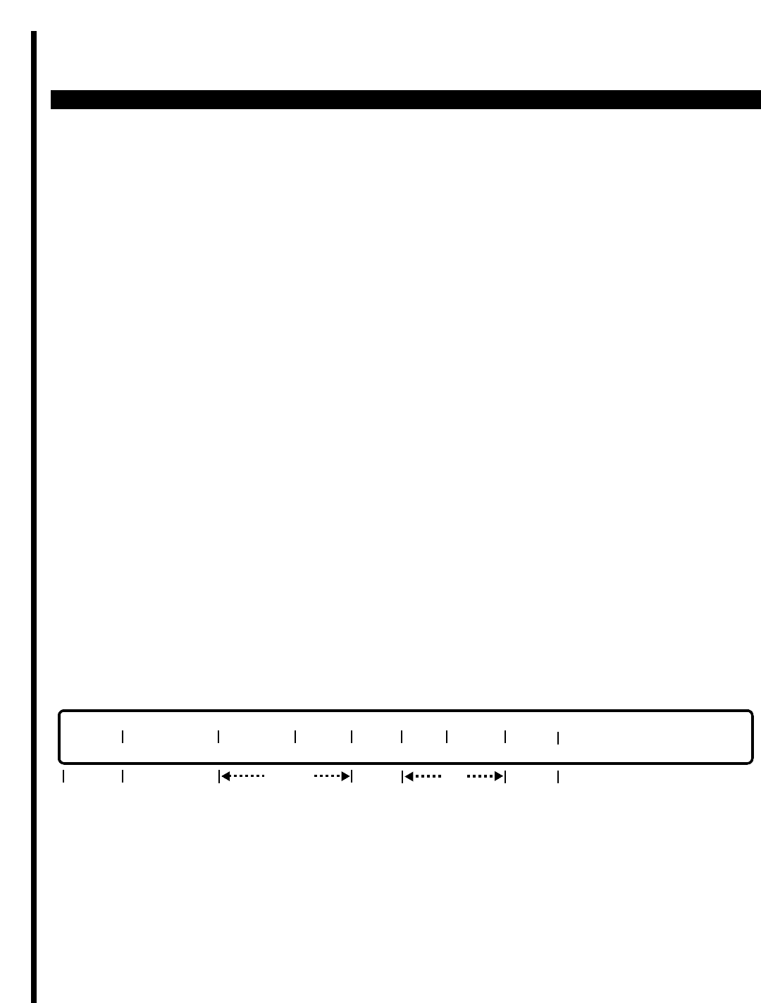
PERCEPTION 4000 COMMANDS
ISS 2, SECTION 4000-014-000
ISDN IPRC AND IPRI CARD ASSIGNMENT (CMD 422)
ISDN IPRC AND IPRI CARD ASSIGNMENT (CMD 422)
The ISDN IPRC and IPRI Card Assignment command is used to assign the ISDN Primary Rate Controller (IPRC)
and ISDN Primary Rate Interface (IPRI) circuit cards. The IPRI card is responsible for the layer 1 ISDN/PRI
software and hardware interface, while the IPRC card is responsible for layers 2 and 3. In addition to general card
assignment or removal, this command is also used to add, delete, modify, or display the following: IPRC protocol
type; layer 2 mode; HDLC inversion flag; D-channel card position; IPRI interface identifier; IPRI D4/ESF framing
and line code scheme.
Command Keyword: IPRC_IPRI_ASSIGN
Category Name: ISDN
PREREQUISITE COMMANDS
There are no prerequisites for this command.
OPERATIONS
Available operations:
ADD
DELETE
MODIFY
DISPLAY
The function and required data fields for each operation are described as follows:
ADD
This operation is used to add an IPRC card and assign it to one or two IPRI cards, and to assign each card's
associated data. Required fields are the "CARD", "IPRI", and "INF ID" fields. The "PROTOCOL", "T303", and "D
CH" fields are all optional when adding a second IPRI card for use with the assigned IPRC card. Both "L2MODE"
and "HDLC" are locked fields.
CARD# PROTOCOL L2MODE HDLC T303 IPRI INF ID D CH
locked
req opt optopt req
3-224
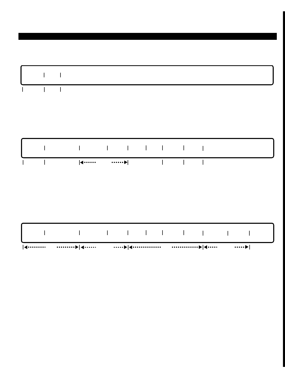
PERCEPTION 4000 COMMANDS
DELETE
ThIs operation is used to delete an IPRC card. Before deleting the IPRC card, the related IPRI card(s) must be
deleted from the system.
MODIFY
This operation is used to change any of the following: IPRC protocol; the ISDN Layer 3 timer; IPRI card position;
and the interface identifier. To change the data in the "INF ID" (IPRI Interface ID) field, the IPRI number must be
specified. Locked fields in the MODIFY operation are Layer 2 mode, the HDLC inversion flag, and the D-channel
card position.
DISPLAY
This operation is used to display IPRC protocol, layer 2 mode, HDLC inversion flag, D-channel and IPRI card
position, and related IPRI card data. Ranges are permitted in the "IPRI," "INF ID," and D CH" fields.
PARAMETERS
This section defines input permitted for each field. Any variations for a particular operation are noted separately.
FIELD: CARD# (IPRC Card Number)
TYPE: Decimal
FORMAT: 3 to 4 digits
VALUE: 101 to 1014
RANGE: Not allowed
LOOP: Allowed in DISPLAY operation only
The entered value indicates the equipment number of the IPRC card. The first one or two digits
represent the number of the shelf containing the card (1 to 10) and the last one or two digits
represent the number of the utilized card slot (01 to 14).
CARD# PROTOCOL L2MODE HDLC T303 IPRI INF ID D CH FRAME CODE
opt locked opt locked
CARD# PROTOCOL L2MODE HDLC T303 IPRI INF ID D CH
req lockedreq
locked
opt opt
req
CARD# IPRI
opt
ISS 2, SECTION 4000-014-000
ISDN IPRC AND IPRI CARD ASSIGNMENT (CMD 422)
3-225

PERCEPTION 4000 COMMANDS
ISS 2, SECTION 4000-014-000
ISDN IPRC AND IPRI CARD ASSIGNMENT (CMD 422)
FIELD: PROTOCOL (Protocol Type)
TYPE: Keyword
FORMAT: Preassigned ASCII characters
Keyword: 4ESS - AT&T User Protocol
5ESS - AT&T User Protocol
TPVT - Toshiba Private Protocol (future use)
This field indicates the protocol that is used by the ISDN Primary Rate Controller (IPRC) card.
FIELD: L2MODE (Layer 2 Mode)
TYPE: KEYWORD
FORMAT: Predefined ASCII characters
Keyword: NEW - Network Mode
USER - User Mode
This field remains locked in all operations. The field indicates the mode that is used for the ISDN
Layer 2. Layer 2 is supported by the IPRC card.
FIELD: HDLC (HDLC Inversion Flag))
TYPE: Keyword
FORMAT: Predefined ASCII characters
Keyword: NO - Without HDLC inversion (Default)
YES - With HDLC inversion
This field is locked as NO in all operations. This coincides with the locked "CODE" field entry of
B8ZS.
FIELD: T303 (Layer 3 Timer)
TYPE: Decimal
FORMAT: 1 to 3 decimal digits
VALUE: 2 to 255
RANGE: Allowed in DISPLAY operation only
LOOP: Not allowed
This field specifies the timer that is used for ISDN Layer 3. The default value is 4 seconds. The
ISDN Layer 3 is supported by the IPRC card.
FIELD: IPRI (Related IPRI Card Position)
TYPE: Decimal
FORMAT: 3 to 4 digits
VALUE: 101 to 1012
RANGE: Allowed in DISPLAY operation only
LOOP: Not allowed
This field indicates the equipment number of each IPRI card that is associated with the IPRC
card. Up to two IPRI cards can be related to a single IPRC card. The value entry represents the
number of the shelf (1 to 10) and the card slot (02, 04, 06, 08, 10, or 12) where the IPRI card is
installed.
3-226

PERCEPTION 4000 COMMANDS
FIELD: INF ID (Interface Identifier)
TYPE: Decimal
FORMAT: 1 digit
VALUE: 0 or 1
RANGE: Allowed in DISPLAY operation only
LOOP: Not allowed
The entered interface ID must be unique for each IPRC. If a D-channel IPRI card is used, the
interface ID must be set at 0.
FIELD: D CH (D-Channel Card Position)
TYPE: Keyword
FORMAT: Predefined ASCII characters
Keyword: YES - IPRI card has D-channel
NO - IPRI card does not have D-channel
This field is locked in the MODIFY operation. The default value is NO. However, when the IPRC
card and the first IPRI card are assigned, YES must be entered, indicating that the D-channel
exists on the IPRI. If a second IPRI card is assigned to the IPRC, then a NO entry is allowed. At
least one of the IPRI cards assigned to the IPRC card must contain the D-channel.
FIELD: FRAME (IPRI Card Framing)
TYPE: Keyword
FORMAT: Predefined ASCII characters
Keyword: D4 -
ESF - Default
This field appears only in the DISPLAY operation and is a locked field.
FIELD: CODE (Line Code Scheme)
TYPE: Keyword
FORMAT: Predefined ASCII characters
RANGE: Not allowed
LOOP: Not allowed
Keyword: B8ZS - Default
ZCS -
This field appears only in the DISPLAY operation and is a locked field.
ISS 2, SECTION 4000-014-000
ISDN IPRC AND IPRI CARD ASSIGNMENT (CMD 422)
3-227

PERCEPTION 4000 COMMANDS
ISS 2, SECTION 4000-014-000
ISDN IPRC AND IPRI CARD ASSIGNMENT (CMD 422)
SYSTEM MESSAGES
The following error messages are unique to this command.
C42200 - IPRC card does not exist
C42201 - Interface identifier must be unique for each IPRI card
C42202 - IPRI card has already been assigned
C42203 - Invalid entry; IPRC and IPRI cards have different IFG
C42204 - Invalid entry; IPRC and IPRI cards are on different LCPUs
C42205 - Number of IPRI cards for a given CARD# has reached maximum
C42206 - Cannot delete D-channel IPRI; must delete non D-channel IPRI(s) first
C42207 - Cannot delete IPRC card; must delete assigned IPRI(s) first
C42208 - IPRC card and D-channel do not exist
C42209 - IPRC and IPRI cards do not exist
C42210 - Invalid IPRC card number in field 1
C42211 - Invalid IPRI card number; IPRI port must be an even number, 02 to 12
C42212 - Cannot have the same IPRC and IPRI card numbers
C42213 - D-channel structure still exists
C42214 - Number of IPRC cards has reached the system maximum
C42215 - Clock provider has reached maximum
C42216 - Providable IPRI card cannot be deleted
C42217 - D-channel has already been assigned for a specific CARD#
C42218 - Equipment number in CARD# field is not an IPRC card
C42219 - Equipment number in IPRI field is not an IPRI card
C42220 - Check input in field T303; mismatch with original value
C42221 - Interface identifier is required
C42222 - Check input in field PROTOCOL; mismatch with original value
C42223 - IPRC protocol is required
C42224 - Must assign D CH field for the first IPRI card
C42225 - Check input in D CH field; mismatch with original value
C42226 - IPRI card number is required
C42227 - Must enter data in order to modify
C42228 - D-channel IPRI card must have interface identifier equal to 0
3-228

PERCEPTION 4000 COMMANDS
ISDN SERVICE MIN/MAX ASSIGNMENT (CMD 425)
The ISDN Service Min/Max Assignment command is used to modify or display an ISDN trunk group's bearer
capability class (BCC), as well as to modify/display the minimum and maximum limits that are used for both Call-
by-Call Service Selection and dedicated ISDN service.
With Call-by-Call Service Selection (that is, with non-dedicated ISDN service), the assigned minimum and
maximum limits indicate how many channels in a channel group can be used for a specific ISDN service. Since a
channel group can contain more than one trunk group (and thus can be used for more than one ISDN service),
the setting of minimum and maximum limits provides control over channel usage. For example, within a single
channel group, one trunk may be assigned to Software Defined Network while another is assigned to MEGACOM
service. The careful assignment of upper and lower usage levels (MIN/MAX limits) enables automatic channel
selection to be in line with actual usage of ISDN services. A higher usage of one service over another would
require higher MIN/MAX levels.
With dedicated ISDN service, all channels within a dedicated service channel group are assigned to the same
ISDN service. In this case, minimum and maximum limits can be set to limit user access to channels during
certain time periods. For example, a maximum level of channel groups can be set at zero to prevent any channels
from being accessed.
Command Keyword: SERVICE_MIN/MAX
Category Name: ISDN
PREREQUISITE COMMANDS
ISDN Channel Group Assignment (CMD 424)
Time Zone Assignment (CMD 336)
Trunk Group Assignment (CMD 310)
OPERATIONS
Available operations:
MODIFY
DISPLAY
The function and required data fields for each operation are described as follows:
ISS 2, SECTION 4000-014-000
ISDN SERVICE MIN/MAX ASSIGNMENT (CMD 425)
3-229
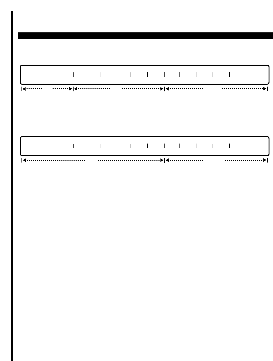
PERCEPTION 4000 COMMANDS
ISS 2, SECTION 4000-014-000
ISDN SERVICE MIN/MAX ASSIGNMENT (CMD 425)
MODIFY
This operation is used to modify the trunk group's ISDN bearer capability class, as well as the minimum and
maximum limits for channel allocation. Range and loop operations are not permitted.
DISPLAY
This operation is used to display the bearer capability class and the minimum/maximum limits for one or more
ISDN trunk groups. Range and loop entries are permitted.
PARAMETERS
This section defines input permitted for each field. Any variations for a particular operation are noted separately.
FIELD: TGN (Trunk Group Number)
TYPE: Decimal
FORMAT: 1 to 3 digits
VALUE: 1 to 256 (or maximum system trunk configuration)
RANGE: Allowed in DISPLAY operation only
LOOP: Allowed in DISPLAY operation only
The "TGN" entry is required in the MODIFY operation. In the DISPLAY operation, this is an
optional field; if no entry is made, then the attributes of all assigned ISDN trunk groups in the
PERCEPTION 4000 system will be displayed.
FIELD: TIME ZONE # (ISDN Time Zone Class Number)
TYPE: Decimal
FORMAT: 1digit
VALUE: 1 to 4 (or maximum system configuration)
RANGE: Allowed in DISPLAY operation only
LOOP: Not allowed
The "TIME ZONE #" is used to specify the time period in which the assigned minimum/maximum
limits will apply. The actual day/hour time periods are defined in the Time Zone Assignment
command (CMD 336). Time periods are assigned to ISDN time zone classes in the ISDN
Channel Group Assignment command (CMD 424).
TGN TIME ZONE # MIN SVC MAX SVC VOC 31K 64U 64R H0U H0R H11U H11R
opt locked
TGN TIME ZONE # MIN SVC MAX SVC VOC 31K 64U 64R H0U H0R H11U H11R
opt locked
req
3-230

PERCEPTION 4000 COMMANDS
1 = IS01 (ISDN time zone class 1)
2 = IS02 (ISDN time zone class 2)
3 = IS03 (ISDN time zone class 3)
4 = IS04 (ISDN time zone class 4)
FIELD: MIN SVC (Minimum Number of Channels Reserved)
TYPE: Decimal
FORMAT: 1 to 3 digits
VALUE: 0 to 47
RANGE: Allowed in DISPLAY operation only
LOOP: Not allowed
The "MIN SVC" field entry indicates the number of channels within the trunk group's associated
channel group, which will always be available for the trunk group's assigned ISDN service. As a
general rule, the most commonly used services should have the higher minimum limit values.
Note that the assigned minimum limit cannot exceed the total number of channels in the ISDN
trunk group's associated channel group. Therefore, the deletion of a channel, as performed via
the ISDN Channel Group Assignment command (CMD 424), should be reflected in the assigned
"MIN SVC" value.
FIELD: MAX SVC (Maximum Number of Channels Allowed)
TYPE: Decimal
FORMAT: 1 to 3 digits or Keyword
VALUE: 0 TO 47
RANGE: Allowed in DISPLAY operation only
LOOP: Not allowed
Keyword: MAXV - The maximum limit is equal to the total number of channels in
the channel group
The "MAX SVC" field entry indicates the maximum number of channels within the trunk group's
associated channel group, which can ever be used for the trunk group's assigned ISDN service.
The entry of the keyword MAXV sets the maximum limit equal to the total number of channels
available in the channel group. With the keyword entry, the PERCEPTION 4000 automatically
adjusts the actual maximum value to correspond with any channel additions or deletions to/from
the channel group. Channels are added or deleted to/from a channel group via the ISDN Channel
Group Assignment command (CMD 424).
FIELD: VOC (Bearer Capability—Voice or Voice-grade Data)
TYPE: Keyword
FORMAT: Preassigned ASCII characters
Keyword: YES - Bearer capability supports speech of 3.1 Khz
NO - Bearer capability does not support speech of 3.1 Khz
The "VOC" field specifies whether speech of 3.1 Khz can be transmitted over the ISDN trunk
group's associated channels. If the trunk group is to be used for voice transmission, then the field
entry should be YES. If the trunk group is to be used for data transmission only, the entry should
be NO.
ISS 2, SECTION 4000-014-000
ISDN SERVICE MIN/MAX ASSIGNMENT (CMD 425)
3-231

PERCEPTION 4000 COMMANDS
ISS 2, SECTION 4000-014-000
ISDN SERVICE MIN/MAX ASSIGNMENT (CMD 425)
FIELD: 31K (3.1 KHz Audio)
TYPE: Keyword
FORMAT: Preassigned ASCII characters
Keyword: YES - Bearer capability provides audio of 3.1 Khz
NO - Bearer capability does not provide audio of 3.1 Khz
The "31K" field specifies whether audio of 3.1 Khz is to be provided over the ISDN trunk group's
associated channels. If the trunk group is to be used for data transmission, then the field entry
should be YES, to enable the transmission of modem data tones. If the trunk group is to be used
for voice transmission only, the entry should be NO.
FIELD: 64U (64K Unrestricted Digital)
TYPE: Keyword
FORMAT: Preassigned ASCII characters
Keyword: YES - Bearer capability supports modem-less data traffic
NO - Bearer capability does not support modem-less data traffic
The "64U" field specifies whether or not modem-less data traffic is to be supported over the ISDN
trunk group. This is a locked field and is reserved for future use.
FIELD: 64R (64K Restricted Digital)
TYPE: Keyword
FORMAT: Preassigned ASCII characters
Keyword: YES - Bearer capability supports modem-less data traffic
NO - Bearer capability does not support modem-less data traffic
The "64R" field is a locked field and is reserved for future use. The "64R" field specifies whether
or not modem-less data traffic is to be supported over the ISDN trunk group. Restricted 64K
bearer capability allocates 8 bits for signaling; thereby providing 56 bits for transmission.
FIELD: H0U (H0 - 384K, Unrestricted Digital)
TYPE: Keyword
FORMAT: Preassigned ASCII characters
Keyword: YES - Bearer capability supports H0 clear channel traffic
NO - Bearer capability does not support H0 clear channel traffic
The "H0U" field is used for H0 clear channel traffic. This field is locked in all operations and is
reserved for future use.
FIELD: H0R (H0 - 384K, Restricted Digital)
TYPE: Keyword
FORMAT: Preassigned ASCII characters
Keyword: YES - Bearer capability supports H0 restricted channel traffic
NO - Bearer capability does not support H0 restricted channel traffic
The "H0R" field is used for H0 restricted traffic. This field is locked in all operations and is
reserved for future use.
3-232

PERCEPTION 4000 COMMANDS
FIELD: H11U (H11 - 1536K, Unrestricted Digital)
TYPE: Keyword
FORMAT: Preassigned ASCII characters
Keyword: YES - Bearer capability supports H11 clear channel traffic
NO - Bearer capability does not support H11 clear channel traffic
The "H11U" field field is used for H11 clear channel traffic. This field is locked in all operations
and is reserved for future use.
FIELD: H11R (H11 - 1536K, Restricted Digital)
TYPE: Keyword
FORMAT: Preassigned ASCII characters
Keyword: YES - Bearer capability supports H11 restricted channel traffic
NO - Bearer capability does not support H11 restricted channel traffic
The "H11R" field is used for H11 restricted traffic. This field is locked in all operations and is
reserved for future use.
SYSTEM MESSAGES
The following error messages are unique to this command.
C42500 - Undefined trunk group number
C42501 - Total number of MIN SVC exceeds total number of channels in TGN's channel group
C42502 - Check trunk group number range
C42503 - Undefined channel group number
C42504 - Check time zone range
C42505 - Total number of MAX SVC exceeds total number of channels in TGN's channel group
C42506 - Check trunk group type
C42507 - The total MAX SVC cannot be less than MIN SVC
ISS 2, SECTION 4000-014-000
ISDN SERVICE MIN/MAX ASSIGNMENT (CMD 425)
3-233
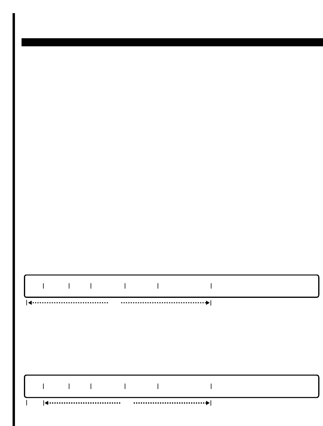
PERCEPTION 4000 COMMANDS
ISS 2, SECTION 4000-014-000
ISDN TRUNK GROUP PARAMETER ASSIGNMENT (CMD 421)
ISDN TRUNK GROUP PARAMETER ASSIGNMENT (CMD 421)
The ISDN Trunk Group Parameter Assignment command allows the attributes of one or more ISDN trunk groups
to be displayed or modified. ISDN trunk group attributes include: inward mode; outgoing call number presentation
flag; trunk group number's listed directory number for call number presentation; display option for incoming call;
and the trunk group name. Note that the total number of ISDN trunks with DNIS/DDI inward routing mode, plus
the total number of non-ISDN DID/DNIS/CCSA trunks cannot exceed 16.
Command Keyword: ISDN_TRK_GRP_PARA
Category Name: ISDN
PREREQUISITE COMMANDS
Trunk Group Assignment (CMD 310)
OPERATIONS
Available operations:
DISPLAY
MODIFY
The function and required data fields for each operation are described as follows:
DISPLAY
This operation is used to display the trunk attributes of one or more existing ISDN trunk groups. If no data is input
in this operation, then the attributes of all trunk groups in the PERCEPTION 4000 system will be displayed.
Information relating only to specific trunk groups is provided by entering each trunk group's corresponding trunk
group number. Range entries are permitted in selected fields, including the Trunk Group Number ("TGN") field.
MODIFY
TGN MODE DISP OUT CPN CPN LDN TRK GRP NAME
opt
req
TGN MODE DISP OUT CPN CPN LDN TRK GRP NAME
opt
3-234

PERCEPTION 4000 COMMANDS
ThIs operation is used to modify the attributes of one or more existing ISDN trunk groups. The required data input
field in this operation is the Trunk Group Number ("TGN") field. Range entries are permitted in the "TGN" field.
PARAMETERS
This section defines input permitted for each field. Any variations for a particular operation are noted separately.
FIELD: TGN (ISDN Trunk Group Number)
TYPE: Decimal
FORMAT: 1 to 3 digits
VALUE: 1 to 256 (or maximum system trunk configuration)
RANGE: Allowed in DISPLAY operation only
LOOP: Allowed in all operations
The "TGN" entry is required in the MODIFY operation. In the DISPLAY operation, this is an
optional field. If no entry is made, then the attributes of all trunk groups in the PERCEPTION
4000 system will be displayed.
FIELD: MODE (Inward Routing Mode)
TYPE: Keyword
FORMAT: Preassigned ASCII characters
Keyword: DIT - Direct Inward Termination Mode—inward routing destination is
based on the termination point assigned to the utilized channel
group for the current time zone (set in CMD 307)
DDI - Direct Dial-in Mode—inward routing destination is based on the
Called Party Number (CPN), as defined in the SETUP message
DNIS - Dialed Number Identification Service—inward routing destination
is based on the current time zone, as with DIT; however, unlike
DIT, DNIS involves no type of digit translation
This field indicates the inward routing procedure that will be applied to the ISDN trunk group.
Calls that arrive to the trunk group will be routed according to the assigned routing procedure.
FIELD: DISP (Display Option for Incoming Calls)
TYPE: Keyword
FORMAT: Preassigned ASCII characters
Keyword: NAME - Trunk Group Number's name
CDPN - Called Party Number
CGPN - Calling Party Number
DNIS - DNIS Name (Requires DNIS as the "MODE" field setting)
CGDN - Calling Party Number, plus the first three characters of the DNIS
name (Requires DNIS as the "MODE" field setting)
This field defines the type of information that will appear on display telephones or display screens
when calls arrive over the ISDN trunk. The selected option should provide the most helpful type
of information to the called party, to enable easy call identifcation and appropriate call answering.
ISS 2, SECTION 4000-014-000
ISDN TRUNK GROUP PARAMETER ASSIGNMENT (CMD 421)
3-235

PERCEPTION 4000 COMMANDS
ISS 2, SECTION 4000-014-000
ISDN TRUNK GROUP PARAMETER ASSIGNMENT (CMD 421)
FIELD: OUT CPN (Outgoing Call Number Presentation Flag)
TYPE: Keyword
FORMAT: Preassigned ASCII characters
Keyword: ALW - Outgoing Call Number Presentation is allowed
DNY - Outgoing Call Number Presentation is restricted
BAR - Outgoing Call Number Presentation is barred
This field indicates whether or not the calling party's number will be presented at the distant end.
The ALW entry allows outgoing numbers to always be presented. The DNY entry restricts
presentation of the calling party's number by requiring the calling station user to enter a specific
access code. The BAR entry is used to eliminate the presentation of the calling party's number at
all times.
FIELD: CPN LDN (ISDN TGN's Listed Directory Number for Called Party Number Presentation)
TYPE: Decimal
FORMAT: 1 to 15 digits
VALUE: 0 to 9; *, and # (Delete symbol, D, is allowed in MODIFY operation)
RANGE: Not allowed
LOOP: Not allowed
This field indicates the directory number (Called Directory Number) that will be displayed at
receiving display telephones whenever calls arrive over the ISDN trunk group.
FIELD: TRK GRP NAME (Trunk Group Name)
TYPE: Text
FORMAT: 0 to 14 ASCII characters
This field indicates the name (Trunk Group Name) that will be displayed at receiving display
telephones whenever calls arrive over the ISDN trunk group. The Delete symbol (D) can be used
in the MODIFY operation to delete the text entry.
SYSTEM MESSAGES
The following error messages are unique to this command.
C42100 - Undefined trunk group number
C42101 - Check trunk group number range
C42102 - Non-ISDN trunk group number
C42103 - Total DID, DNIS, CCSA type plus DDI, DNIS inward mode cannot exceed 16
C42104 - CGDN/DNIS display option can only have DNIS/DDI as inward routing mode
3-236
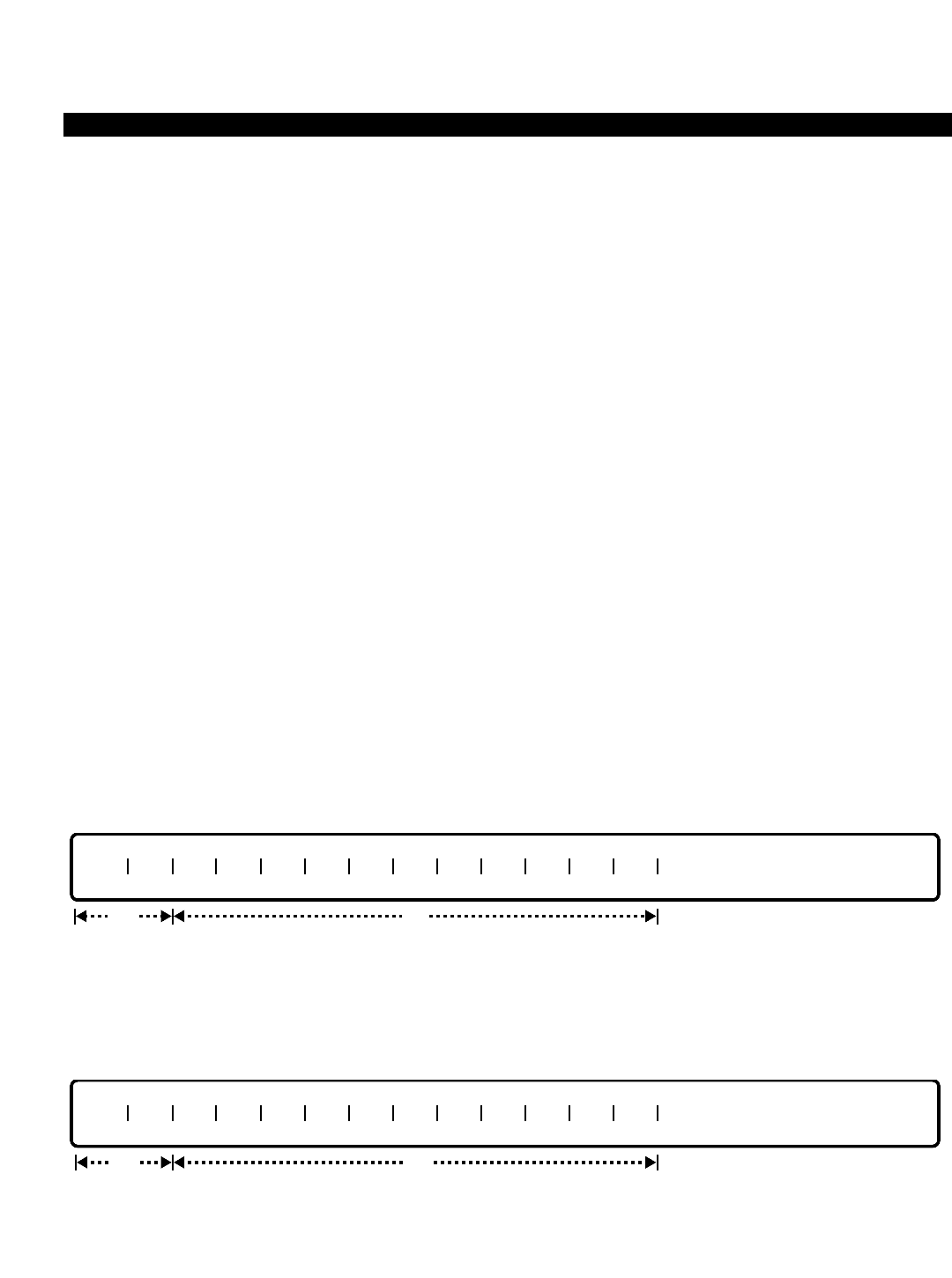
PERCEPTION 4000 COMMANDS
LCR AREA CODE ROUTING ASSIGNMENT (CMD 381)
In order to perform routing over the least costly facility for long distance direct dialing, the system analyzes the
dialed number and examines the Least Cost Routing Area/Office Code tables. If an AC/OC table is not found for
the number, the system then examines the Least Cost Routing Area Code tables to determine the route pattern
to be used to ultimately determine the routing for the call.
The LCR Area Code Routing Assignment command adds, deletes and displays area codes for the selected
Route Pattern Number (RPN).
Command Keyword: AC_ROUTING
Category Name: LCR
PREREQUISITE COMMAND
LCR Routing Table Assignment (CMD 383)
OPERATIONS
Available operations: ADD
DELETE
DISPLAY
The function and required data fields for each operation are described in this section.
ADD
This operation adds one or more area codes to the specified LCR Area Code table. The route pattern number
(RPN) and at least one area code (AC) are required.
DELETE
This operation deletes one or more area codes from the specified LCR Area Code table. The "RPN" and at least
one "AC" are required.
RPN AC AC AC AC AC AC AC AC AC AC AC AC
optreq
RPN AC AC AC AC AC AC AC AC AC AC AC AC
optreq
ISS 2, SECTION 4000-014-000
LCR AREA CODE ROUTING ASSIGNMENT (CMD 381)
3-237

PERCEPTION 4000 COMMANDS
ISS 2, SECTION 4000-014-000
LCR AREA CODE ROUTING ASSIGNMENT (CMD 381)
DISPLAY
This operation displays one or more LCR area code table(s). If no data is entered in any of the fields, all of the
area code tables in the system display.
PARAMETERS
Each field parameter is described in this section. Any variations for a particular operation are noted separately.
FIELD: RPN (Route Pattern Number)
TYPE: Decimal
FORMAT: 1 to 3 digits
VALUE: 1 to 100 (or to the maximum system configuration)
RANGE: Allowed in a DISPLAY operation only
A route pattern number is assigned to the table which represents which least cost routing table to
use based on the time zone in effect. Routing patterns are defined with the LCR Routing Table
Assignment command, CMD 383.
FIELD: AC (Area Code)
TYPE: Decimal with fixed length
FORMAT: 3 digits in the form N Y X (where N = 2 to 9, Y = 0 or 1, and X = 0 to 9)
VALUE: 200 to 919
RANGE: Allowed in a DISPLAY operation
The valid area code format is in the form of NYX, where N is 2 to 9, Y is either 0 or 1, and X is 0
to 9. Ranges are permitted for DISPLAY operations; and scopes are allowed in ADD and
DELETE operations. The first AC field is required for ADD and DELETE operations.
SYSTEM ERROR MESSAGES
The following error messages are unique to this command.
C38100 - Area code is not defined for this route pattern
C38101 - Area code is already defined for another route pattern
C38102 - Data is needed following scope in field N
RELATED COMMANDS
LCR Special Routing Assignment (CMD 384)
LCR/Authorization TZ Change Assignment (CMD 343)
Time Zone Assignment (CMD 336)
RPN AC AC AC AC AC AC AC AC AC AC AC AC
opt
3-238
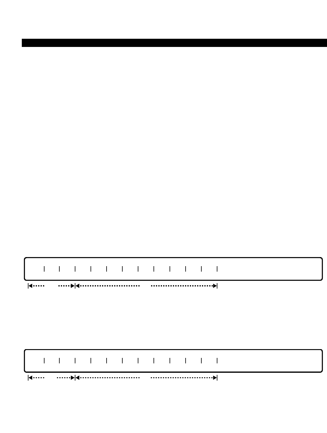
PERCEPTION 4000 COMMANDS
LCR AREA/OFFICE CODE ROUTING ASSIGNMENT (CMD 382)
The LCR Area/Office Code Table command displays, adds or deletes office codes from the area code for a
specified route pattern number. Multiple area/office code tables may be defined, each using a different routing
pattern.
Command Keyword: AC/OC_ROUTING
Category Name: LCR
PREREQUISITE COMMAND
LCR Routing Table Assignment (CMD 383)
OPERATIONS
Available operations: ADD
DELETE
DISPLAY
The function and required data fields for each operation are described in this section.
ADD
This operation adds office codes to the table by specifying the route pattern number (RPN) and area code (AC).
These two fields are required and must be input. The first office code is also required for an ADD operation.
Scopes are permitted in all of the "OC" fields but the last.
DELETE
This operation deletes office codes from the table by specifying the Area Code and Route Pattern number. "RPN"
and "AC" are required fields and must be input. The first "OC" is required for the DELETE operation. Scopes are
permitted in all of the "OC" fields but the last.
RPN AC OC OC OC OC OC OC OC OC OC OC
optreq
RPN AC OC OC OC OC OC OC OC OC OC OC
optreq
ISS 2, SECTION 4000-014-000
LCR AREA/OFFICE CODE ROUTING ASSIGNMENT (CMD 382)
3-239

PERCEPTION 4000 COMMANDS
ISS 2, SECTION 4000-014-000
LCR AREA/OFFICE CODE ROUTING ASSIGNMENT (CMD 382)
DISPLAY
This operation displays office codes for the specified Area Code and Route Pattern number. All of the fields are
optional. "RPN" and "AC" are loop fields. Ranges may be entered in any of the "OC" fields. If a <TAB> and
<RETURN> are entered in the "RPN" field, the complete table displays.
PARAMETERS
Each field parameter is described in this section. Any variations for a particular operation are noted separately.
FIELD: RPN (Route Pattern Number)
TYPE: Decimal
FORMAT: 1 to 3 digits
VALUE: 1 to 100 (or to the maximum system configuration)
LOOP: Primary loop for a DISPLAY operation only
RANGE: Not allowed
The routing pattern (defined with the LCR Routing Table Assignment command, CMD 383)
represents which least cost routing table to use based on the time zone in effect. The "RPN" field
is required for both the ADD and DELETE operations.
FIELD: AC (Area Code)
TYPE: Decimal with fixed length
FORMAT: 3 digits in the form N Y X (where N = 2 to 9, Y = 0 or 1, and X = 0 to 9)
VALUE: 200 to 919
LOOP: Secondary loop for a DISPLAY operation only
RANGE: Not allowed
The "AC" field is required for both the ADD and DELETE operations. Values from 200 to 919 are
defined as follows: the first digit ranges from 2 to 9, the second digit must be a 1 or 0, and the
last digit can be 0 to 9. In a DISPLAY operation, "AC" is the secondary loop field. If a <TAB> is
entered, all of the area codes for the specified Route Pattern Number display.
FIELD: OC (Office code)
TYPE: Decimal with fixed length
FORMAT: 3 digits in the form NXX (where N = 2 to 9, and X = 0 to 9)
VALUE: 200 to 999
SCOPE: Allowed in ADD and DELETE operations
LOOP: Not allowed
RANGE: Allowed in a DISPLAY operation
In ADD and DELETE operations, the first "OC" field is required, while the remaining fields are
optional. Scopes are permitted in these fields to add or delete a group of office codes. In a
DISPLAY operation, "OC" is optional. If a <TAB> is entered, all office codes for the specified area
RPN AC OC OC OC OC OC OC OC OC OC OC
opt
3-240

PERCEPTION 4000 COMMANDS
code display. When ranges are used for this operation, scope fields are output. This means that if
there is more than one consecutive office code for an area code, the output contains a “-”. For
example, an output of “223-288” includes all office codes from 223 to 288.
SYSTEM ERROR MESSAGES
The following error messages are unique to this command.
C38200 - Route pattern table is not defined for area code
C38201 - Office code already exists for another route pattern/AC table
C38202 - Route pattern is the default pattern for this area code
C38203 - Office code tables are at system maximum; cannot add more
C38204 - Data is needed following scope in field N
COMMENTS
Multiple AC/OC routing tables per area code are allowed, however unique office codes cannot be in more than
one AC/OC table per area code.
RELATED COMMANDS
LCR/Authorization TZ Change Assignment (CMD 343)
Time Zone Assignment (CMD 336)
ISS 2, SECTION 4000-014-000
LCR AREA/OFFICE CODE ROUTING ASSIGNMENT (CMD 382)
3-241

PERCEPTION 4000 COMMANDS
ISS 2, SECTION 4000-014-000
LCR COUNTRY CODE ROUTING ASSIGNMENT (CMD 380)
LCR COUNTRY CODE ROUTING ASSIGNMENT (CMD 380)
The LCR Country Code Routing Assignment command adds, deletes, and displays country codes (CC) for a
specified route pattern number (RPN). Each route pattern number has a list of country codes assigned to it, and
is required for all country codes not intended for default routing.
Command Keyword: CC_ROUTING
Category Name: LCR
PREREQUISITE COMMANDS
Country Code Assignment (CMD 335)
LCR Routing Table Assignment (CMD 383)
OPERATIONS
Available operations: ADD
DELETE
DISPLAY
The function and required data fields for each operation are described in this section.
ADD
This operation adds country codes to the table by specifying the "RPN" and the "CC". The "RPN" and the first
"CC" are required fields. Scopes are permitted in all of the country code fields except the last one.
DELETE
This operation deletes country codes from the table by specifying the "RPN" and "CC". The "RPN" and the first
"CC" are required fields. Scopes are permitted in all of the country code fields except the last one.
RPN CC CC CC CC CC CC CC CC CC CC CC CC
optreq
RPN CC CC CC CC CC CC CC CC CC CC CC CC
optreq
3-242

PERCEPTION 4000 COMMANDS
DISPLAY
This operation displays country codes for the specified "RPN". All of the fields are optional, and "RPN" is a loop
field. Ranges may be entered in any of the country code fields. If a <TAB> and a <RETURN> are entered in the
"RPN" field, the complete table is displayed.
PARAMETERS
Each field parameter is described in this section. Any variations for a particular operation are noted separately.
FIELD: RPN (Route Pattern Number)
TYPE: Decimal
FORMAT: 1 to 3 digits
VALUE: 1 to 100 (or to the maximum system configuration)
LOOP: Primary loop for a DISPLAY operation only
RANGE: Not allowed
SCOPE: Not allowed
A route pattern number is assigned to the country code table which represents which least cost
routing table to use based on the time zone in effect. Routing patterns are defined with the LCR
Routing Table Assignment command, CMD 383.
FIELD: CC (Country Code)
TYPE: Decimal
FORMAT: 1 to 3 digits
VALUE: 1 to 999
LOOP: Not allowed
RANGE: Allowed in a DISPLAY operation only
SCOPE: Allowed in ADD and DELETE operations
Country codes using the routing pattern specified in the "RPN" field are entered in the "CC"
fields. The country codes must be predefined with the Country Code Assignment command
(CMD 335). Multiple country code tables may be defined, each using a different routing pattern. A
country code may not exist in more than one LCR country code table.
SYSTEM ERROR MESSAGES
The following error messages are unique to this command.
C38000 - The last field cannot be a scope field
C38001 - Check scope data
RPN CC CC CC CC CC CC CC CC CC CC CC CC
opt
ISS 2, SECTION 4000-014-000
LCR COUNTRY CODE ROUTING ASSIGNMENT (CMD 380)
3-243

PERCEPTION 4000 COMMANDS
ISS 2, SECTION 4000-014-000
LCR COUNTRY CODE ROUTING ASSIGNMENT (CMD 380)
C38002 - Country code is defined for another route pattern number
C38003 - Country code(s) are not found or are invalid
C38004 - Country code(s) already exist or are invalid
C38005 - Number of defined country codes has reached system maximum
C38006 - Missing data in scope type field in field N
RELATED COMMANDS
LCR Special Routing Assignment (CMD 384)
3-244

PERCEPTION 4000 COMMANDS
LCR DIGIT TRANSLATION PROFILE ASSIGNMENT (CMD 386)
This command modifies and displays the attributes of a Least Cost Routing (LCR) Digit Translation Profile.
Profiles manipulate a dialed digit string by adding or deleting area codes or toll prefixes, or by defining new prefix
and suffix strings. For example, a profile may be used for deleting an area code when a ten digit call is dialed that
is to be routed over a foreign exchange line to the dialed area. Or, a profile may be defined to add a toll prefix
when a ten digit number is dialed.
Command Keyword: LCR_DIGIT_PROFILES
Category Name: LCR
PREREQUISITE COMMANDS
There are no prerequisites for this command.
OPERATIONS
Available operations: MODIFY
DISPLAY
The function and required data fields for each operation are described in this section.
MODIFY
This operation creates/modifies the attributes of an LCR Digit Translation Profile. The "PFL#" field is required. The
remaining fields are optional and can be modified by tabbing over to the field and entering new data.The "PREFIX
STRING" and "SUFFIX STRING" fields are delete fields; predefined data in these fields can be deleted by
entering a <CONTROL-D>.
DISPLAY
This operation displays the LCR Digit Translation Profiles and their attributes. If no data is entered in the "PFL#"
field, all of the LCR Digit Translation Profiles in the system display (to a total of 32).
PFL# DDN DUNP TPTMT OPFX DEAC ACTMT PREFIX STRING SUFFIX STRING
opt
PFL# DDN DUNP TPTMT OPFX DEAC ACTMT PREFIX STRING SUFFIX STRING
optreq
ISS 2, SECTION 4000-014-000
LCR DIGIT TRANSLATION PROFILE ASSIGNMENT (CMD 386)
3-245

PERCEPTION 4000 COMMANDS
ISS 2, SECTION 4000-014-000
LCR DIGIT TRANSLATION PROFILE ASSIGNMENT (CMD 386)
PARAMETERS
Each field parameter is described in this section. Any variations for a particular operation are noted separately.
FIELD: PFL# (Digit Translation Profile Number)
TYPE: Decimal
FORMAT: 1 or 2 digits
VALUE: 1 to 32 (or to the maximum number of time zones)
LOOP: Allowed in a DISPLAY operation
This field identifies the translation instruction which follows and is used to reference the
instruction for the LCR Routing Table Assignment command (CMD 383). A maximum of 32
profiles may be created.
FIELD: DDN (Delete Dialed Number)
TYPE: Keyword
FORMAT: Predefined ASCII characters
Keywords: ALL - Delete all dialed numbers
D01 - Delete the first dialed digit
D02 - Delete the first 2 dialed digits
:
D24 - Delete the first 24 dialed digits
K01 - Keep the last dialed digit
K02 - Keep the last 2 dialed digits
:
K24 - Keep the last 24 dialed digits
NON - No deletion (Default)
This field instructs the system to delete, keep or leave dialed digits as they are. For example,
dialing certain area codes may be screened by rerouting those calls to the corporate operator.
FIELD: DUNP (Delete UNP Location Code)
TYPE: Keyword
FORMAT: Predefined ASCII characters
Keywords: DEL - Delete UNP Location Code
NON - Do not delete UNP Location Code (Default)
This field instructs the system to delete or not to delete the dialed Uniform Numbering Plan (UNP)
location code. The UNP code is set up through the Uniform Numbering Plan Assignment
command (CMD 301) and the UNP Routing Assignment command (CMD 302).
FIELD: TPTMT (Toll Prefix Treatment)
TYPE: DN Type / Keyword
FORMAT: 1 to 3 digits / Predefined ASCII characters
VALUE: 0 to 999
Keywords: ADD - Add Toll Prefix
DEL - Delete Toll Prefix (Default value for ISDN trunks)
3-246

PERCEPTION 4000 COMMANDS
A10TP - Add Toll Prefix for 10 digit DDD call
D7TP - Delete 7 digits' Toll Prefix
D7A10 - Delete 7 digits' Toll Prefix and add Toll Prefix for 10-digit DDD calls
NON - Leave Toll Prefix unchanged (Default value for non-ISDN trunks)
This field adds, deletes, changes or leaves the toll prefix as is. If "ADD" is selected, the value from
the "TP" field in the Dialing Definition command (CMD 317) is automatically added as the toll
prefix. Entry of a DN-type value in the "TPTMT" field automatically replaces the existing toll
prefix.
FIELD: OPFX (Operator Prefix)
TYPE: Keyword
FORMAT: Predefined ASCII characters
Keywords: DEL - Delete Operator Prefix (Default value for non-ISDN trunks)
NON - Leave Operator Prefix unchanged (Default value for ISDN trunks)
This field instructs the system to delete or not to delete the operator prefix, which is defined with
the Dialing Definition command (CMD 317).
FIELD: DEAC (Delete Equal Access Code)
TYPE: Keyword
FORMAT: Predefined ASCII characters
Keywords: DEL - Delete 10XXX Equal Access Code (Default value for non-ISDN trunks)
NON - Leave Equal Access Code unchanged (Default value for ISDN trunks)
This field instructs the system to delete or not to delete the Equal Access Code (10XXX), which is
defined with the Common Carrier Assignment command (CMD 344).
FIELD: ACTMT (Area Code Treatment)
TYPE: Keyword
FORMAT: Predefined ASCII characters
Keywords: ADD - Add Area Code
DEL - Delete Area Code
NON - Leave Area Code unchanged (Default)
This field adds the home area code, deletes the area code, or leaves the existing area code as is.
FIELD: PREFIX STRING
TYPE: Dialing Digits plus * and #
FORMAT: Up to 20 digits
VALUE: 0-9, #, *
A string of digits is defined with this field. Up to 20 digits are prefixed to a dialed number with this
field. Entry of a <CONTROL-D> in a MODIFY operation deletes data from this field. The default
value is a NULL string.
ISS 2, SECTION 4000-014-000
LCR DIGIT TRANSLATION PROFILE ASSIGNMENT (CMD 386)
3-247

PERCEPTION 4000 COMMANDS
ISS 2, SECTION 4000-014-000
LCR DIGIT TRANSLATION PROFILE ASSIGNMENT (CMD 386)
FIELD: SUFFIX STRING
TYPE: Dialing Digits plus * and #
FORMAT: Up to 20 digits
VALUE: 0-9, #, *
A string of digits is defined with this field. Up to 20 digits are appended to a dialed number with
this field. Entry of a <CONTROL-D> in a MODIFY operation deletes data from this field. The
default value is a NULL string.
SYSTEM ERROR MESSAGES
The following error messages are unique to this command.
C38600 - Check Digit Translation Profile Number
C38601 - Check Delete Dialed Number
C38602 - Check Delete UNP Location Code
C38603 - Check Toll Prefix Treatment
C38604 - Check Operator Prefix
C38605 - Check Delete Eqal Acce Code
C38606 - Check Area Code Treatment
C38607 - Check Toll Prefix Digits
C38608 - Check Toll Prefix Treatment Length
RELATED COMMANDS
Common Carrier Assignment (CMD 344)
Dialing Definition (CMD 317)
LCR Area Code Routing Assignment (CMD 381)
LCR Area/Office Code Routing Assignment (CMD 382)
LCR Country Code Routing Assignment (CMD 380)
LCR Routing Table Assignment (CMD 383)
LCR Special Routing Assignment (CMD 384)
UNP Routing Assignment (CMD 302)
Uniform Numbering Plan Assignment (CMD 301)
3-248
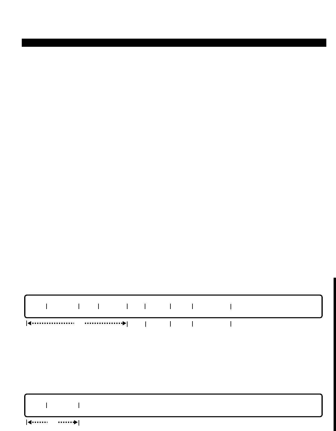
PERCEPTION 4000 COMMANDS
LCR ROUTING TABLE ASSIGNMENT (CMD 383)
The LCR Routing Table Assignment command defines up to 100 routing tables. Each table contains up to eight
routes that are examined for an available trunk circuit to place the call. Trunks within each table are generally
placed in order from least costly to most expensive. In addition, a warning tone flag may be inserted in the routing
table to advise the caller that a more costly route has been accessed.
Command Keyword: LCR_ROUTE_ASSIGN
Category Name: LCR
PREREQUISITE COMMANDS
Common Carrier Assignment (CMD 344)
Facility Restriction Level Profile Assignment (CMD 387)
LCR Digit Translation Profile Assignment (CMD 386)
Trunk Group Assignment (CMD 310)
OPERATIONS
Available operations: ADD
DELETE
MODIFY
DISPLAY
The function and required data fields for each operation are described in this section.
ADD
This operation creates routing table(s) and specifies the order of search, or adds route(s) to an existing routing
table. When adding a new route, the "TGN", "FRL", and "PFL#" must be entered, and the "ROUTE #" is
resequenced. If no data is entered in the “WARN” field, the warning tone flag is not set. The first route choice
cannot be assigned a warning tone. If a <TAB> is entered in the "CARR #" field, the carrier number defaults to
"Not Defined".
DELETE
TBL# ROUTE #
req
TBL# ROUTE # TGN CARR # FRL WARN PFL# CALL TYPE
req opt reqreq opt
ISS 2, SECTION 4000-014-000
LCR ROUTING TABLE ASSIGNMENT (CMD 383)
3-249
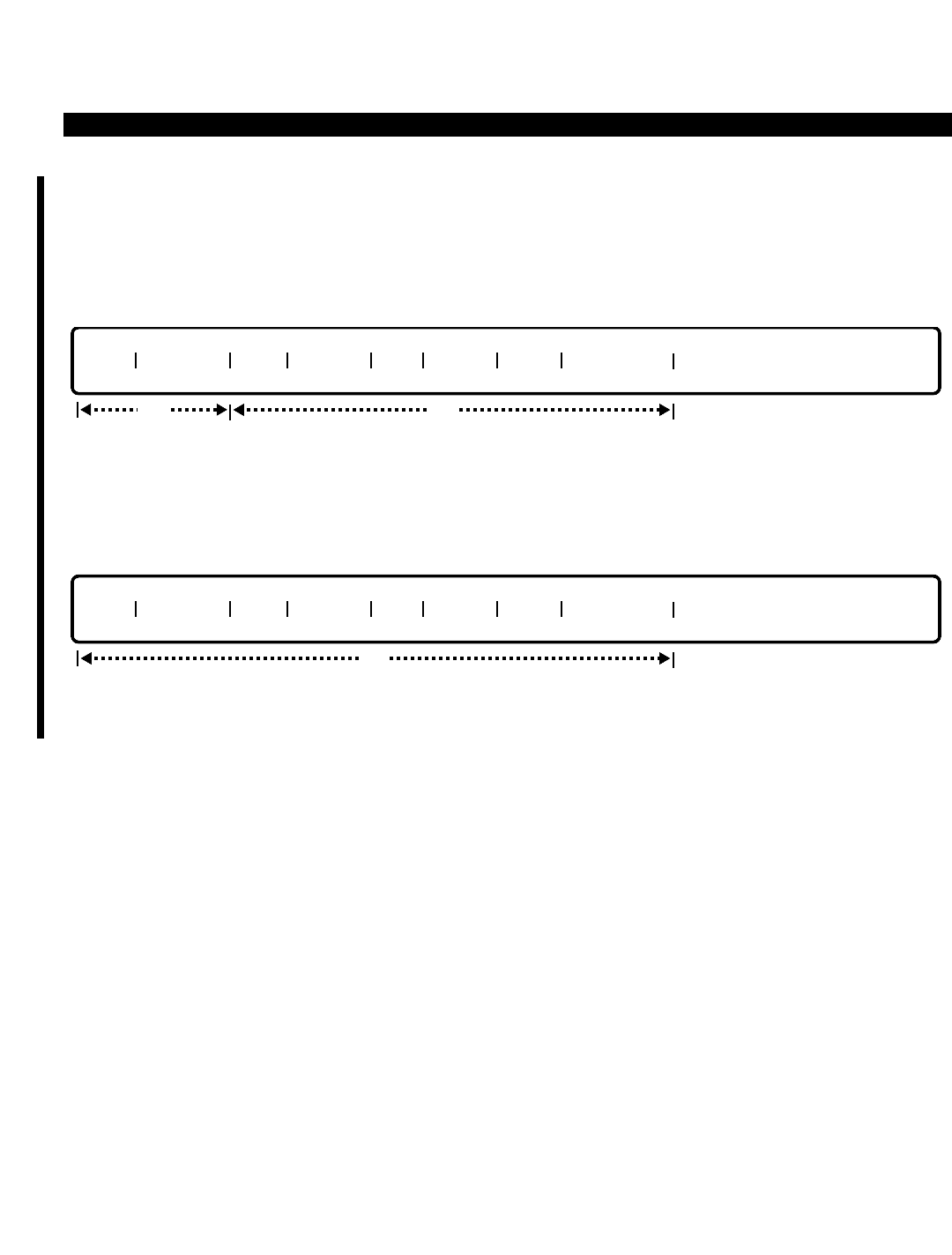
PERCEPTION 4000 COMMANDS
ISS 2, SECTION 4000-014-000
LCR ROUTING TABLE ASSIGNMENT (CMD 383)
The DELETE operation deletes route(s) from an existing routing table. When deleting a specific route, the
remaining routing index is resequenced. For example, after deleting route #2, the current route #3 becomes route
#2.
MODIFY
This operation modifies the definition of a route in an existing routing table. If a <CONTROL-D> is entered in the
"CARR #" field, the carrier number is deleted.
DISPLAY
This operation displays LCR routing tables and their related definitions of routes. If no data is entered in the
“TBL#” field, all LCR routing tables in the system are displayed.
PARAMETERS
Each field parameter is described in this section. Any variations for a particular operation are noted separately.
FIELD: TBL# (LCR Routing Table Number)
TYPE: Decimal
FORMAT: 1 to 3 digits
VALUE: 1 to 100 (or to the maximum system configuration)
LOOP: Allowed in all operations
The "TBL#" field contains the index number referenced by the routing pattern. Up to 100 route
tables may be defined in the system, depending on the system configuration. This field is
required for all operations except a DISPLAY operation.
FIELD: ROUTE # (Route Number)
TYPE: Decimal / Keyword
FORMAT: 1 digit / Predefined ASCII characters
VALUE: 1 to 8
LOOP: Allowed in ADD and DISPLAY operations
Keyword: ALL
TBL# ROUTE # TGN CARR # FRL WARN PFL# CALL TYPE
opt
TBL# ROUTE # TGN CARR # FRL WARN PFL# CALL TYPE
req req
3-250

PERCEPTION 4000 COMMANDS
The system examines available routes for outgoing calls, starting from the lowest numbered route
to the highest. Therefore, ordering is important; the lowest numbered route should be the least
costly and, as the route number rises, the routes should become more expensive.
The keyword ALL is used for deleting all routes in the same routing table.
FIELD: TGN (Trunk Group Number)
TYPE: Decimal
FORMAT: 1 to 3 digits
VALUE: 1 to 256 (or to the maximum system configuration)
RANGE: Allowed in a DISPLAY operation
The "TGN" field specifies the trunk group to be used to place the outgoing call. The trunk group
must be a bothway or outgoing only trunk group and must be for network access (that is, not for
paging, dictation machines, etc.). The Trunk Group number cannot be duplicated among routes
within one routing table. This field is required for an ADD operation.
FIELD: CARR # (Carrier Number)
TYPE: Decimal
FORMAT: 1 or 2 digits
VALUE: 1 to 10
LOOP: Allowed in a DISPLAY operation
The Carrier Number field calls up the indicated equal access number when a call is placed over a
long distance carrier other than the facility's primary carrier. If a carrier number is defined, the
system gets the appropriate 10XXX code from the Common Carrier table (CMD 344, Common
Carrier Assignment) and outpulses it to the central office prior to outpulsing the destination
number.
FIELD: FRL (Facility Restriction Level)
TYPE: Decimal
FORMAT: 1 or 2 digits
VALUE: 1 to 16
RANGE: Allowed in a DISPLAY operation
The Facility Restriction Level (FRL) number controls caller access to certain routes in the route
table while allowing access to others. This is accomplished through the relationship defined
between a caller's Facility Restriction Level Profile (FRLP) and the route's FRL. This relationship
is established in the FRLP command (CMD 387). The "FRL" field is required for an ADD
operation.
FIELD: WARN (Warning Tone Flag)
TYPE: Keyword
FORMAT: Predefined ASCII characters
Keywords: YES - Warning Tone Flag is ON
NO - Warning Tone Flag is OFF
The Warning Tone field provides a warning tone to users when a route about to be examined is
considered a high cost route. Any route may be flagged, with the exception of the first route
ISS 2, SECTION 4000-014-000
LCR ROUTING TABLE ASSIGNMENT (CMD 383)
3-251

PERCEPTION 4000 COMMANDS
ISS 2, SECTION 4000-014-000
LCR ROUTING TABLE ASSIGNMENT (CMD 383)
choice, which is always considered least costly. Any number of routes may be flagged in a given
route table, however, only one warning tone is issued to a caller regardless of how many high
cost routes are examined. The caller's queue priority level (QPL) is flagged to allow/deny the
caller to receive a warning tone when one is encountered. (Refer to the LCR Special Routing
Assignment command, CMD 384.)
FIELD: PFL# (Translation Profile Number)
TYPE: Decimal / Keyword
FORMAT: 1 or 2 digits; predefined ASCII characters
VALUE: 1 to 32; Keyword NONE
LOOP: Allowed in a DISPLAY operation
The "PFL#" field defines which digit translation profile should be used for manipulation of a dialed
number. These profiles add or delete area codes and toll prefixes, or define new prefix and suffix
strings. Entering the keyword NONE for non-ISDN trunks indicates no digit translation. For ISDN
trunks, an entry of NONE indicates no digit translation except the deletion of operator prefix, toll
prefix, international toll prefix, and equal access code. Refer to the LCR Digit Translation Profile
Assignment command (CMD 386). The "PFL#" field is required for an ADD operation.
FIELD: CALL TYPE (Call Type)
TYPE: Keyword
FORMAT: Predefined ASCII characters
LOOP: Not allowed
Keywords: NAT - National
INT - International
SUB - Subscriber
UNK - Unknown
The "Call Type" field is required for ISDN trunks and refers to the type of ISDN service being
used. If a <Control D> is entered in this field, the call type will be deleted. For non-ISDN trunks,
skip this field.
SYSTEM ERROR MESSAGES
The following error messages are unique to this command.
C38300 - Check warning flag
C38301 - Check trunk group number
C38302 - Check range of table number, route number, or trunk group number
C38303 - Check range of carrier number
C38304 - Routing tables are full
C38305 - Route not found
C38306 - Check range of translation profile number
C38307 - Trunk group number is not defined
C38308 - Check next route warning flag
C38309 - Incoming trunk groups are not allowed
C38310 - Private line trunk groups are not allowed
C38311 - Non-ISDN trunks do on require call type
C38312 - ISDN trunks require call type
3-252

PERCEPTION 4000 COMMANDS
RELATED COMMANDS
LCR Area Code Routing Assignment (CMD 381)
LCR Area/Office Code Routing Assignment (CMD 382)
LCR/Authorization TZ Change Assignment (CMD 343)
LCR Country Code Routing Assignment (CMD 380)
LCR Special Routing Assignment (CMD 384)
ISS 2, SECTION 4000-014-000
LCR ROUTING TABLE ASSIGNMENT (CMD 383)
3-253
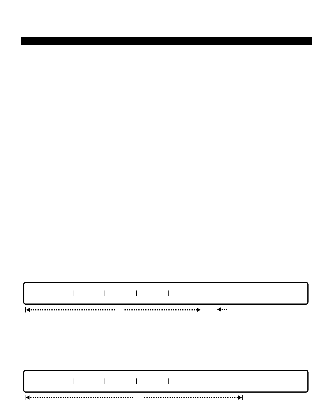
PERCEPTION 4000 COMMANDS
ISS 2, SECTION 4000-014-000
LCR SPECIAL ROUTING ASSIGNMENT (CMD 384)
LCR SPECIAL ROUTING ASSIGNMENT (CMD 384)
The LCR Special Routing Assignment command provides the system with a dialing definition to reference
whenever a call is placed via LCR. For seven digit dialing it defines one home area code for all calls placed
through LCR so that the proper area/office or area code table may be screened for call routing.
In addition, this table provides default routing for numbers dialed which are not found in LCR code tables. It
defines a route pattern for special numbers such as operators and N11 numbers. For private networks using a
Uniform Numbering Plan (UNP), this command provides default routing for network calls not found in the UNP
Routing Assignment (CMD 302). Finally, the command defines the relationship between queueing priority levels
and warning tone presentation.
Command Keyword: LCR_SPECIAL_ROUTING
Category Name: LCR
PREREQUISITE COMMANDS
There are no prerequisites for this command.
OPERATIONS
Available operations: MODIFY
DISPLAY
The function and required data fields for each operation are described in this section.
MODIFY
This operation modifies related information of the LCR dial plan number. If the warning tone flag of the queue
priority level is to be changed, data must also be entered in the "QPL" field, otherwise the default or existing value
of the warning tone is used.
DISPLAY
LCR DIAL PLAN LCR HAC DEF RPN SPC RPN UNP RPN QPL WARN
opt
LCR DIAL PLAN LCR HAC DEF RPN SPC RPN UNP RPN QPL WARN
optopt
opt
3-254

PERCEPTION 4000 COMMANDS
This operation displays information about LCR routing.
PARAMETERS
Each field parameter is described in this section. Any variations for a particular operation are noted separately.
FIELD: LCR DIAL PLAN (LCR Dial Plan Number)
TYPE: Decimal
FORMAT: 1 digit
VALUE: 2, 3, or 4
LOOP: Not allowed
RANGE: Not allowed
The LCR dialing plan field selects one of the defined dialing definitions for all LCR calls. The
value entered must be 2, 3, or 4 since dialing definition 1 is undefined and is used for TIE lines.
FIELD: LCR HAC (LCR Home Area Code)
TYPE: Decimal with fixed length
FORMAT: 3 digits in the form N Y X (where N = 2 to 9, Y = 0 or 1, and X = 0 to 9)
VALUE: 200 to 919
LOOP: Not allowed
RANGE: Not allowed
This field identifies the area code where the switch is located, and is needed so seven digit calls
may be analyzed by the area/office and/or area code tables for proper route selection.
FIELD: DEF RPN (Default Route Pattern Number)
TYPE: Decimal
FORMAT: 1 to 3 digits
VALUE: 1 to 100 (or to the maximum system configuration)
LOOP: Not allowed
RANGE: Not allowed
This field defines which route pattern will be used for all international, 10 and 1+10 digit, and 7
and 1+7 digit calls that are not found in any of their respective LCR code tables.
FIELD: SPC RPN (Special Default Route Pattern Number)
TYPE: Decimal
FORMAT: 1 to 3 digits
VALUE: 1 to 100
LOOP: Not allowed
RANGE: Not allowed
The "SPC RPN" field defines what route pattern is used for 0, 0+, 00+, 01+, and N11 call routing.
FIELD: UNP RPN (UNP Default Route Pattern Number)
TYPE: Decimal
FORMAT: 1 to 3 digits
VALUE: 1 to 100 (or to the maximum system configuration)
ISS 2, SECTION 4000-014-000
LCR SPECIAL ROUTING ASSIGNMENT (CMD 384)
3-255

PERCEPTION 4000 COMMANDS
ISS 2, SECTION 4000-014-000
LCR SPECIAL ROUTING ASSIGNMENT (CMD 384)
LOOP: Not allowed
RANGE: Not allowed
This field routes UNP calls that have no match in the UNP routing tables.
FIELD: QPL (Queue Priority Level)
TYPE: Decimal
FORMAT: 1 digit
VALUE: 1 to 8
LOOP: Allowed
RANGE: Not allowed
This field and the "WARN" field are interrelated. If a "QPL" value is entered, then a keyword must
be entered in the "WARN" field. Together, these fields define whether a warning tone is heard by
a caller when a more costly route is accessed if the least costly route is unavailable.
FIELD: WARN (Warning Tone Flag)
TYPE: Keyword
FORMAT: Predefined ASCII characters
Keywords: YES - Warning Tone Enabled
NO - Warning Tone Disabled
If the keyword YES is entered, the warning tone is enabled. The warning tone route is defined in
the LCR Routing Table Assignment command, CMD 383.
SYSTEM ERROR MESSAGES
The following error messages are unique to this command.
C38400 - Routing pattern number is not within range
C38401 - QPL entry is required
C38402 - Invalid request type
RELATED COMMANDS
Dialing Definition (CMD 317)
LCR Routing Table Assignment (CMD 383)
Station Assignment (CMD 330)
Trunk Group Assignment (CMD 310)
UNP Routing Assignment (CMD 302)
3-256

PERCEPTION 4000 COMMANDS
LCR/AUTHORIZATION TZ CHANGE ASSIGNMENT (CMD 343)
The LCR/Authorization TZ Change Assignment command sets up tables that allow you to change the COS, DRL,
FRLP, and QPL based on the current time zone. Additionally, this command defines for each route pattern the
LCR route tables which are to be used in each time zone.
Command Keyword: LCR/AUTH_TZ
Category Name: Administration
PREREQUISITE COMMANDS
There are no prerequisites for this command.
OPERATIONS
Available operations: MODIFY
DISPLAY
The function and required data fields for each operation are described in this section.
MODIFY
This operation modifies the attributes of one of the tables mentioned above. "TYPE" and "ORG DEF/RPN" are
required fields, while the remaining fields are optional.
DISPLAY
This operation displays all or part of one of the five tables. "TYPE" is a required field, while the remaining fields
are optional. If a <TAB> is entered in the "ORG DEF/RPN" field, the complete table for the specified table type is
displayed. Loops are permitted in the "ORG DEF/RPN" field.
opt
TYPE ORG DEF/
RPN TZ1
NEW DEF/TBL TZ2
NEW DEF/TBL TZ3
NEW DEF/TBL TZ4
NEW DEF/TBL
req
opt
TYPE ORG DEF/
RPN TZ1
NEW DEF/TBL TZ2
NEW DEF/TBL TZ3
NEW DEF/TBL TZ4
NEW DEF/TBL
req
ISS 2, SECTION 4000-014-000
LCR/AUTHORIZATION TZ CHANGE ASSIGNMENT (CMD 343)
3-257

PERCEPTION 4000 COMMANDS
ISS 2, SECTION 4000-014-000
LCR/AUTHORIZATION TZ CHANGE ASSIGNMENT (CMD 343)
PARAMETERS
Each field parameter is described in this section. Any variations for a particular operation are noted separately.
FIELD: TYPE (Type of Table)
TYPE: Keyword
FORMAT: Predefined ASCII characters
Keywords: COS - Class of Service Table
DRL - Destination Restriction Level Table
FRLP - Facility Restriction Level Profile Table
QPL - Queue Priority Level Table
LCR - Least Cost Routing
This field specifies the table to be modified or displayed.
FIELD: ORG DEF/RPN (Original Definition for COS, DRL, FRLP, and QPL/LCR Route Pattern Number)
TYPE: Decimal
FORMAT: 1 to 3 digits
VALUE: 1 to 100 (Dependent on Table Type)
RANGE: Allowed
LOOP: Allowed
This field selects the current definition or pattern number that is to be changed. Valid entries for
this field depend on the "TYPE" field, and are:
COS - 1 to 64 QPL - 1 to 8
DRL - 1 to 16 RPN - 1 to 100 (LCR Route Pattern Number)
FRLP - 1 to 32
FIELD: TZ1, 2, 3, 4 NEW DEF/TBL (Time Zones 1 to 4: New Definition for COS, DRL, FRLP, and
TYPE: Decimal QPL/LCR Route Table Number)
FORMAT: 1 to 3 digits
VALUE: 1 to 100 (Dependent on Table Type)
RANGE: Not allowed
LOOP: Not allowed
These fields assign new values to the four time zones for the selected table type. Valid entries
depend on the "TYPE" field:
COS - 1 to 64 QPL - 1 to 8
DRL - 1 to 16 RPN - 1 to 100 (LCR Route Table Number) *
FRLP - 1 to 32
* The RPN option in this field defines the LCR route table number for each route pattern defined.
Entry of a <CONTROL-D> erases the current value. For the COS, DRL, FRLP, and QPL tables,
the value defaults to the original definition number. For the RPN table, the value defaults to
undefined.
3-258

PERCEPTION 4000 COMMANDS
SYSTEM ERROR MESSAGES
The following error message is unique to this command.
D34300 - N - Invalid data at TZ1, TZ2, TZ3, or TZ4
RELATED COMMANDS
Class of Service Assignment (CMD 334)
Destination Restriction Level Assignment (CMD 337)
Facility Restriction Level Profile Assignment (CMD 387)
LCR Routing Table Assignment (CMD 383)
LCR Special Routing Assignment (CMD 384)
Time Zone Assignment (CMD 336)
UNP Routing Assignment (CMD 302)
ISS 2, SECTION 4000-014-000
LCR/AUTHORIZATION TZ CHANGE ASSIGNMENT (CMD 343)
3-259

PERCEPTION 4000 COMMANDS
ISS 2, SECTION 4000-014-000
LABEL PRINT (CMD 312)
LABEL PRINT (CMD 312)
Key label(s) for the flexible keys on PERCEPTION 4000 digital telephones are printed with this command.
Command Keyword: LABEL_PRINT
Category Name: Utility
PREREQUISITE COMMANDS
Station Assignment (CMD 330)
Station Feature Key Assignment (CMD 331)
OPERATIONS
Available operations: DISPLAY
The function and required data fields for each operation are described in this section.
DISPLAY
This operation prints a digital telephone flexible key label for the specified prime directory number. Each label
sheet contains three labels. In a loop function, the labels print in consecutive order, filling each sheet to the end of
the loop. Each new line of input causes a form feed and begins printing labels on the first label of the next sheet.
Looping is allowed in the “PRM DN” field.
PARAMETERS
Each field parameter is described in this section. Any variations for a particular operation are noted separately.
FIELD: TYPE (Digital Telephone Type)
TYPE: Keyword
FORMAT: Predefined ASCII characters
Keywords: 2010 - PERCEPTION 4000 10-key digital telephone
ID10 - PERCEPTION 4000 10-key digital telephone with DIU
2020 - PERCEPTION 4000 20-key digital telephone
ID20 - PERCEPTION 4000 20-key digital telephone with DIU
This field defines the format for the label.
req
TYPE | PRM DN | PRINTER | OPTION |
opt
3-260

PERCEPTION 4000 COMMANDS
FIELD: PRM DN (Prime Directory Number)
TYPE: DN Type
FORMAT: 1 to 5 digits
VALUE: 0 to 99999
LOOP: Allowed
This optional field selects the telephone(s) for which the labels are to be printed.
FIELD: PRINTER (Type of Printer)
TYPE: Keyword
FORMAT: Predefined ASCII characters
Keywords: IBM - IBM Proprinter Model XL24 emulation for Toshiba ExpressWriter printer
with Alternative Graphic mode (AGM mode) (Default)
TOSH - Toshiba emulation for Toshiba Model P351 or PS321 printers
The "PRINTER" field selects the appropriate printer.
FIELD: OPTION (Key Position Option)
TYPE: Keyword
FORMAT: Predefined ASCII characters
Keywords: MLIN - Print the multiple directory numbers for multi-line hunt key positions
PRM - Print the prime directory number for multi-line hunt key positions (Default)
The "OPTION" field provides the option of printing either the prime directory number (DN) or
unique multiple DNs for every multi-line hunt key position. For example, if there are three multiple
lines on a given station, then selecting PRM as the print option will print the prime DN for all three
multi-line hunt key positions. On the other hand, selecting MLIN as the print option will print each
key's unique multiple DN. A station's flexible keys can be assigned as multi-line hunt keys via the
Station Feature Key Assignment command (CMD 331).
If a directory number contained within a multi-line hunt group has a secondary appearance at
another station, then that line's unique multiple DN will always be printed on the other station's
corresponding key, regardless of what is entered (PRM, MLIN, or a <TAB>) in the OPTION field.
SYSTEM ERROR MESSAGES
The following error messages are unique to this command.
C31200 - Not a 2010/2020 telephone prime DN
C31201 - Timeout during print request
ISS 2, SECTION 4000-014-000
LABEL PRINT (CMD 312)
3-261

PERCEPTION 4000 COMMANDS
ISS 2, SECTION 4000-014-000
LOGICAL LINE CALL FORWARD ASSIGNMENT (CMD 322)
LOGICAL LINE CALL FORWARD ASSIGNMENT (CMD 322)
The Logical Line Call Forward Assignment command allows the system administrator to assign, remove, or
display a call-forward activation of the specified logical line directory number.
Command Keyword: LLINE_CALL_FORWARD
Category Name: Station
PREREQUISITE COMMANDS
Coordinated Numbering Plan Assignment (CMD 303)
Numbering Plan Assignment (CMD 300)
Station Assignment (CMD 330)
Station Feature Key Assignment (CMD 331)
Trunk Assignment (CMD 313)
Trunk Group Assignment (CMD 310)
Uniform Numbering Plan Assignment (CMD 301)
OPERATIONS
Available operations: MODIFY
DISPLAY
The function and required data fields for each operation are described in this section.
MODIFY
This operation changes the current Call Forward type of the specified logical line directory number. If a
<CONTROL-D> is entered in the "TYPE" field, the Call Forward type for the "DN" will be deleted.
DISPLAY
This operation displays the current Call Forward destination of the specified logical line directory number.
DN TYPE DESTINATION
req locked
DN TYPE DESTINATION
req opt
3-262

PERCEPTION 4000 COMMANDS
PARAMETERS
Each field parameter is described in this section. Any variations for a particular operation are noted separately.
FIELD: DN (Logical Line Directory Number)
TYPE: DN Type
FORMAT: 1 to 5 digits
VALUE: 1 to 99999
LOOP: Not allowed
The "DN" field, which is required in both the MODIFY and DISPLAY operations, specifies the
registered logical line directory number.
FIELD: TYPE (Call Forward Type)
TYPE: Keyword
FORMAT: Predefined ASCII characters
Keywords: CFAC - Call Forward All Calls
CFBN - Call Forward Busy No Answer
CFNA - Call Forward No Answer
The "TYPE" identifies the type of call forwarding programmed on the specified logical line
directory number. A <CONTROL-D> entered in this field in a MODIFY operation deletes the
current setting.
FIELD: DESTINATION (Call Forwarding Destination)
TYPE: Dialing Digits
FORMAT: 1 to 24 digits
VALUE: 0 to 9
RANGE: Not allowed
This field specifies the Call Forwarding destination for the specified "DN." Valid destinations
include an internal attendant or station directory number, and an external directory number which
includes the appropriate outgoing access code, such as for Least Cost Routing, Direct Trunk
Access, and private networking. The "DESTINATION" is optional in a MODIFY operation, and
locked in a DISPLAY operation.
SYSTEM ERROR MESSAGES
The following error messages are unique to this command.
C32200 - Directory number is not a logical line directory number
C32201 - Directory number does not exist
C32202 - Destination is not required to de-activate call forwarding
C32203 - Destination is required
C32204 - Destination does not exist
ISS 2, SECTION 4000-014-000
LOGICAL LINE CALL FORWARD ASSIGNMENT (CMD 322)
3-263
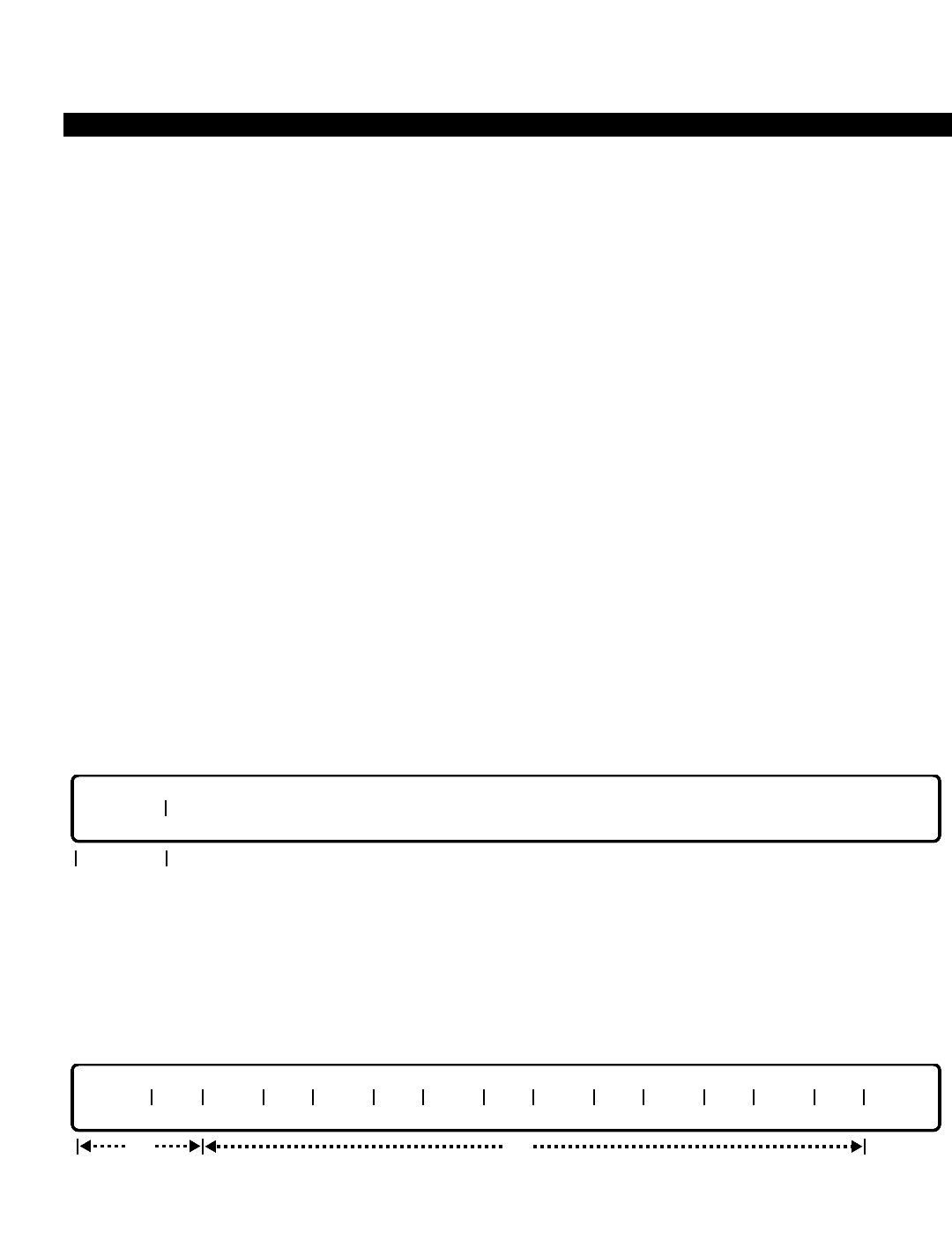
PERCEPTION 4000 COMMANDS
ISS 2, SECTION 4000-014-000
M&A SECURITY LEVEL AND ACCESS ASSIGNMENT (CMD 403)
M&A SECURITY LEVEL AND ACCESS ASSIGNMENT (CMD 403)
The M&A Security Level and Access Assignment command sets up or modifies login security passwords within
the administrator's jurisdiction. The administrator may also review his/her own security setup, and change the
security setup for commands and/or operations of a lower privileged level. Note that reviewing or changing
security setups that are on the same or higher privilege levels is not permitted.
Command Keyword: M/A_SECURITY_ASSIGN
Category Name: Administration
PREREQUISITE COMMANDS
There are no prerequisites for this command.
OPERATIONS
Available operations: PASSWORD
MODIFY
DISPLAY
The function and required data fields for each operation are described in this section.
PASSWORD (PWD)
This operation assigns or re-assigns a security password for a lower hierarchical level or for the administrator.
The "SEC LVL" field is required. Prompts requesting entry of a security password and verification of the new
password assist in this operation. The password may be up to 15 characters, beginning with either an alpha or
numeric character.
MODIFY
This operation modifies access to commands and/or operations for specific commands. The administrator may
only modify those commands and/or operations assigned to a hierarchical level below his/her level, and may not
modify his/her own capabilities. The "SEC LVL" and "CMD" fields are required.
opt
SEC LVL CMD OPER ALW OPER ALW OPER ALW OPER ALW OPER ALW OPER ALW
req
req
SEC LVL
3-264

PERCEPTION 4000 COMMANDS
DISPLAY
This operation displays the commands and/or operations allowed for the specified security level. The
administrator may examine his/her own privileges or those of a lower hierarchical level. “SEC LVL” is a required
field. Looping is permitted in the “CMD” field.
PARAMETERS
Each field parameter is described in this section. Any variations for a particular operation are noted separately.
FIELD: SEC LVL (Security Level)
TYPE: Keyword
FORMAT: Predefined ASCII characters
Keywords: MFG - Manufacturer
DIST - Distributor
USER - User
TN1 to TN32 - Tenant 1 to Tenant 32
The "SEC LVL" is the primary key for this command and is required in all operations. A maximum
of 35 levels may be defined. The 'Manufacturer' level is the most privileged, followed by the
'Distributor' level. The lowest privileged levels are the 32 tenant levels. Each "SEC LVL" is
assigned a security password, a list of commands that it can access, and the degree of access
for each command.
FIELD: CMD (Command ID)
TYPE: Decimal with fixed length
FORMAT: 3 digits
VALUE: 000 to 999
LOOP: Allowed in a DISPLAY operation only
This field defines commands which are available for the selected "SEC LVL". Looping is allowed
in this field to display several commands at once. The administrator may display only those
commands at his/her own security level or any lower level(s), and modify only those commands
at lower levels.
FIELD: OPER (Operation Keyword)
TYPE: Keyword
FORMAT: Predefined ASCII characters
Keywords: ADD - Add INI - Initialize
ALM - Alarm Operation INL - Install
BKP - Backup Operation INS - In-Service
CHG - Change MKB - Make Busy
opt
SEC LVL CMD OPER OPER OPER OPER OPER OPER OPER OPER OPER OPER OPER OPER
req
ISS 2, SECTION 4000-014-000
M&A SECURITY LEVEL AND ACCESS ASSIGNMENT (CMD 403)
3-265

PERCEPTION 4000 COMMANDS
ISS 2, SECTION 4000-014-000
M&A SECURITY LEVEL AND ACCESS ASSIGNMENT (CMD 403)
CMP - Compare MOD - Modify
CNT - Count Operation OOS - Out of Serivce
CPY - Copy PSWD - Password
CRT - Create Operation RES - Restore
DEL - Delete RMV - Remove
DIR - Display Directory RST - Reset
DIS - Disable SET - Set
DSP - Display SHW - Show
ENB - Enable SUP - Setup Operation
FMT - Format SWO - Switchover
FRE - Free SWP - Swap
IDL - Idle ALL - Allow/disallow the command
This field selects or displays operations which are available for the specified command ID. Only
those operations that the administrator is permitted to use may be modified. ALL is used to
specify whether all the operations within the command are allowed or denied.
FIELD: ALW (Allowance)
TYPE: Keyword
FORMAT: Predefined ASCII characters
Keywords: YES - Sets the preceding attribute to Allow
NO - Sets the preceding attribute to Deny
This field sets the allowance/denial attribute of a command or operation for the selected "SEC
LVL." Each "ALW" field sets the attribute of the preceding operation.
SYSTEM ERROR MESSAGES
The following error messages are unique to this command.
C40300 - Check security level
C40301 - Check security password
C40302 - Password unchanged; auto logout
C40303 - Check command ID
C40304 - Check operation ID
C40305 - Check command allowance
C40306 - Check operation allowance
C40307 - Input line overflowed
COMMENTS
The security level affects the capabilities of the user to access commands in the Maintenance and Administration
subsystem. It is also used to define accessibility within each command, i.e., whether the user may only display
reports or is permitted to modify data controlled by the command.
Access levels must be set for each command. MMI uses this information to control the extent of user operations.
3-266

PERCEPTION 4000 COMMANDS
MEMORY TEST (CMD 144)
When enabled, the Memory Test command reads all program and data bytes in the MCPU's and LCPUs'
memory. The test checks to see if any intermediate errors are present in the memory. This command should be
enabled prior to performing a file consolidation (CMD 153) to help ensure that the file consolidation procedure is
not interrupted by an error detection. If a memory error is detected during the Memory Test procedure, then the
system will perform a restart (or will perform a switchover if redundant components are used). After system
operation resumes, a system error message will be sent to an on-line printer/terminal. If a restart or switchover
occurs after performing the Memory Test procedure, contact Toshiba Technical Support at (800) 777-4873 for
further instructions regarding error isolation and correction.
Command Keyword: MEMORY_TEST
Category Name: Maintenance
PREREQUISITE COMMANDS
There are no prerequisites for this command.
OPERATIONS
Available operation: ENABLE
The function and required data fields for each operation are described in this section.
ENABLE
The ENABLE operation activates the memory test for the selected side(s) (either active, standby, or both sides).
Note that the test takes about seven or eight minutes to complete.
PARAMETERS
Each field parameter is described in this section. Any variations for a particular operation are noted separately.
FIELD: SIDE
TYPE: Keyword
FORMAT: Predefined ASCII characters
req
SIDE
ISS 2, SECTION 4000-014-000
MEMORY TEST (CMD 144)
3-267

PERCEPTION 4000 COMMANDS
ISS 2, SECTION 4000-014-000
MEMORY TEST (CMD 144)
Keywords: ACT - Active Side
SBY - Standby Side
BOTH - Both Sides
This field selects the system side(s) on which the memory test will take place.
SYSTEM ERROR MESSAGES
The following error messages are unique to this command.
C14400 - Map table has an error
C14401 - Number of files exceeds the defined value
C14402 - An error occurred when checking LCPU memory or a timeout
C14403 - Standby is not in service
RELATED COMMAND
File Consolidation (CMD 153)
3-268

PERCEPTION 4000 COMMANDS
MISCELLANEOUS DEVICE ASSIGNMENT (CMD 400)
This command sets up the Announcement Machine/Music-on-Hold table. The table defines the equipment
number and usage for each announcement machine and Music-on-Hold device. Up to 64 announcement
machines and four external Music-on-Hold sources are supported in the system.
Command Keyword: MISC_DEVICE_ASSIGN
Category Name: System
PREREQUISITE COMMANDS
There are no prerequisites for this command.
OPERATIONS
Available operations: ADD
DELETE
DISPLAY
The function and required data fields for each operation are described in this section.
ADD
This operation adds an announcement machine or Music-on-Hold device to the table. The "DEV" and "EQUIP #"
fields are required. The "USAGE" field defaults to GEN (General Intercept) for an announcement machine.
DELETE
This operation deletes an announcement machine or Music-on-Hold device from the table. The "DEV" field is
required.
req
DEV
req
DEV EQUIP # USAGE
opt
ISS 2, SECTION 4000-014-000
MISCELLANEOUS DEVICE ASSIGNMENT (CMD 400)
3-269

PERCEPTION 4000 COMMANDS
ISS 2, SECTION 4000-014-000
MISCELLANEOUS DEVICE ASSIGNMENT (CMD 400)
DISPLAY
This operation displays all announcement machines and Music-on-Hold devices that meet the conditions
established for each field. All of the fields are optional.
PARAMETERS
Each field parameter is described in this section. Any variations for a particular operation are noted separately.
FIELD: DEV (Device Number)
TYPE: Keyword
FORMAT: Predefined ASCII characters
Keywords: AM01 - Announcement Machine #1
AM02 - Announcement Machine #2
::
AM64 - Announcement Machine #64
MS01 - Music-on-Hold Device #1
MS02 - Music-on-Hold Device #2
::
MS04 - Music-on-Hold Device #4
The device number field provides device type and number identification.
FIELD: EQUIP # (Equipment Number)
TYPE: EQ Type
FORMAT: 5 or 6 digits
VALUE: (0)10101 to 101408 *
RANGE: Not allowed
LOOP: Not allowed
* Use the following chart to determine valid ranges for various types of equipment.
For Music-on-Hold (MOH) BSTI equipment cards, the following ranges apply:
Digits Range Hardware
First digit(s) (0)1~10 Shelf no.
Second two digits 01~11, 13 Card slot no.
Last two digits 01~16 Circuit no.
For Music-on-Hold (MOH) XSTI and announcement machine (ANN) EM1I cards, the following
are valid ranges:
opt
DEV EQUIP # USAGE
3-270

PERCEPTION 4000 COMMANDS
Digits Range Hardware
First digit(s) (0)1~10 Shelf no.
Second two digits 01~14 Card slot no.
Last two digits 01~08 Circuit no.
For an announcement machine (ANN) EM2I card, the following ranges apply:
Digits Range Hardware
First digit(s) (0)1~10 Shelf no.
Second two digits 01~14 Card slot no.
Last two digits 01~06 Circuit no.
This field defines the equipment number for the announcement machine or Music-on-Hold
device. The equipment number is unique in the system, and must be associated with an EM1I,
EM2I, or BSTI card. The first digit(s) represent the shelf number, the next two digits represent the
card slot number, and finally, the last two digits represent the circuit number.
FIELD: USAGE (Announcement Machine Usage)
TYPE: Keyword
FORMAT: Predefined ASCII characters
Keywords: ACD - Automatic Call Distribution Announcement
UCD - Uniform Call Distribution Announcement
DID - Direct Inward Dialing Announcement
GEN - General Intercept
AUX - Other (Auxiliary)
This field contains information about the usage of each announcement machine. The default
usage is GEN.
SYSTEM ERROR MESSAGES
The following error messages are unique to this command.
C40000 - Announcement machine is already in use
C40001 - Announcement machine is not defined
C40002 - Music-on-Hold device is already in use
C40003 - Music-on-Hold device is not defined
C40004 - Invalid usage
C40005 - Equipment number is already in use
C40006 - Invalid equipment number for BSTI card
C40007 - Invalid equipment number for SRTI card
C40008 - Remove system music by using Command 408
C40009 - Announcement used in announcement pattern; remove by using Command 353
RELATED COMMAND
Announcement Pattern Assignment (CMD 353)
ISS 2, SECTION 4000-014-000
MISCELLANEOUS DEVICE ASSIGNMENT (CMD 400)
3-271

PERCEPTION 4000 COMMANDS
ISS 2, SECTION 4000-014-000
MODEM POOL ASSIGNMENT (CMD 347)
MODEM POOL ASSIGNMENT (CMD 347)
The Modem Pool Assignment command adds, removes, modifies, and displays modem pools which may be used
for incoming, outgoing, or bothway calling. The system supports up to 32 groups of 64 modems per group.
Command Keyword: MODEM_POOL_ASSIGN
Category Name: Data
PREREQUISITE COMMANDS
There are no prerequisites for this command.
OPERATIONS
Available operations: ADD
DELETE
MODIFY
DISPLAY
The function and required data fields for each operation are described in this section.
ADD
This operation adds modem pool group(s) or member(s) to the modem pool database. When adding a new group,
the “GRP#”, “TYPE”, "MODEM EN", and "DIU EN" fields are required. When adding a new member to an
existing group, the “GRP#”, “MODEM EN”, and “DIU EN” fields are required. Loops are permitted in the “GRP#”
and “INDEX” fields.
DELETE
This operation removes existing modem pool group(s) or member(s) from the modem pool database. The “GRP#”
and either the "MODEM EN" or "DIU EN" fields are required. The keyword ALL may be used for deletion of all of
the modems or DIUs assigned to the specified group number.
req/opt
GRP# MODEM EN DIU EN
req
req
GRP# NAME TYPE INDEX MODEM EN DIU EN
optreq/opt
opt
req
3-272

PERCEPTION 4000 COMMANDS
MODIFY
This operation modifies the modem pool group’s name or type of modem pool. The “GRP#” and either the
"NAME" or "TYPE" fields are required.
DISPLAY
This operation displays modem pool group(s) and their member(s) that meet the conditions established for each
field. Loops are permitted in the “GRP#” and “INDEX” fields for display purpose only.
PARAMETERS
Each field parameter is described in this section. Any variations for a particular operation are noted separately.
FIELD: GRP# (Group Number)
TYPE: Decimal
FORMAT: 1 or 2 digits
VALUE: 1 to 32 (or to the maximum system configuration)
LOOP: Allowed in ADD and DISPLAY operations
This field, the primary key for the command, assigns a number to a modem group. The system
supports up to 32 groups of modems.
FIELD: NAME
TYPE: Text
FORMAT: 0 to 9 ASCII characters
This field defines the modem pool group’s name with a maximum of 9 characters/numbers
including punctuation and spaces. Looping is not allowed in any operations.
FIELD: TYPE (Type of Call Usage)
TYPE: Keywords
FORMAT: Predefined ASCII characters
Keywords: INC - Incoming Call Usage
OUT - Outgoing Call Usage
BWY - Bothway Call Usage
opt
GRP# NAME TYPE INDEX MODEM EN DIU EN
req/opt
GRP# NAME TYPE
req
ISS 2, SECTION 4000-014-000
MODEM POOL ASSIGNMENT (CMD 347)
3-273

PERCEPTION 4000 COMMANDS
ISS 2, SECTION 4000-014-000
MODEM POOL ASSIGNMENT (CMD 347)
This field defines the modem pool group type as being either incoming only, outgoing only, or
bothway calling.
FIELD: INDEX
TYPE: Decimal
FORMAT: 1 or 2 digits
VALUE: 1 to 64
LOOP: Allowed in a DISPLAY operation only
Modem pools use distributed hunting, thereby allowing more even usage of system and
peripheral resources. The order of hunting is defined by the "INDEX", going from the lowest to
the highest number, then wrapping around to the lowest number again.
FIELD: MODEM EN (Modem Equipment Number)
TYPE: EQ Type / Keyword
FORMAT: 5 or 6 digits / Predefined ASCII characters
VALUE: (0)10101 to 101408 *
LOOP: Not allowed
Keyword: ALL
* Use the following chart to determine valid ranges for various types of equipment.
For BSTI equipment cards, the following ranges apply:
Digits Range Hardware
First digit(s) (0)1~10 Shelf no.
Second two digits 01~11, 13 Card slot no.
Last two digits 01~16 Circuit no.
For XSTI equipment cards, the following are valid ranges:
Digits Range Hardware
First digit(s) (0)1~10 Shelf no.
Second two digits 01~14 Card slot no.
Last two digits 01~08 Circuit no.
This field defines the modem equipment number for the designated modem pool group number.
The modem and DIU equipment numbers (DIU EN) must belong to the same LCPU. The first
digit(s) represents the shelf number of the BSTI or XSTI card, the next two digits represent the
card slot number, and finally, the last two digits represent the circuit number. Only modem
equipment numbers which are analog ports can be assigned to modem pool group(s). The
keyword ALL may be used for deletion of all of the modems assigned to the specified group
number.
FIELD: DIU EN (DIU Equipment Number)
TYPE: EQ Type / Keyword
FORMAT: 5 or 6 digits / Predefined ASCII characters
VALUE: (0)10101 to 101316 *
LOOP: Not allowed
3-274

PERCEPTION 4000 COMMANDS
Keyword: ALL
* Use the following chart to determine valid ranges for a DIU equipment number.
For DSTI equipment cards, the following ranges apply:
Digits Range Hardware
First digit(s) (0)1~10 Shelf no.
Second two digits 01~11, 13 Card slot no.
Last two digits 01~16 Circuit no.
NOTE: Slot 13 is unavailable if the card is a 2B type.
This field defines the data interface unit equipment number for the modem pool group member.
The "DIU EN" and the "MODEM EN" must belong to the same LCPU. Only DIU equipment
numbers which are digital ports can be assigned to modem pool group(s). The keyword ALL may
be used for deletion of all of the DIUs assigned to the specified group number.
NOTES:
1. DIUs may be installed on DSTI cards configured for 1B or 2B operation. When installed on a
DSTI card configured for 2B operation, a '2B' device must already be assigned to the card.
2. If installed on a DSTI card configured for 2B operation, the circuit's voice channel is ignored
by the system.
SYSTEM ERROR MESSAGES
The following error messages are unique to this command.
C34700 - This modem equipment number is already allocated in the system
C34701 - This DIU equipment number is already allocated in the system
C34702 - Modem pool member is not defined
C34703 - Invalid modem pool index
C34704 - Illegal pool group name
C34705 - DIU/Modem pair must be in the same LCPU
C34706 - Data must be entered in input fields
C34707 - Inconsistent pool name
C34708 - Inconsistent pool type
C34709 - Inconsistent card type
C34710 - No more space to add modem
C34711 - Must enter either modem or DIU equipment number
C34712 - Name cannot exceed nine characters
C34713 - Must enter either name or type
COMMENTS
A modem or DIU equipment number cannot be defined in more than one modem pool group.
All modem-DIU pairs, and all pairs within a given group must reside in the same LCPU.
ISS 2, SECTION 4000-014-000
MODEM POOL ASSIGNMENT (CMD 347)
3-275

PERCEPTION 4000 COMMANDS
ISS 2, SECTION 4000-014-000
MODEM POOL ASSIGNMENT (CMD 347)
RELATED COMMANDS
Data Interface Parameter Assignment (CMD 361)
Data Station Assignment (CMD 360)
Data Station Parameter Assignment (CMD 362)
High Usage Data Destination Assignment (CMD 368)
3-276

PERCEPTION 4000 COMMANDS
NAME DIALING ASSIGNMENT (CMD 367)
The Name Dialing Assignment command adds, deletes, or displays up to 128 name strings which may be used
via keyboard dialing to address internal or external data destinations.
Command Keyword: NAME_DIALING
Category Name: Data
PREREQUISITE COMMANDS
Data Hunting Assignment (CMD 366)
Data Station Assignment (CMD 360)
OPERATIONS
Available operations: ADD
DELETE
DISPLAY
The function and required data fields for each operation are described in this section.
ADD
This operation adds the character string (name) and its translated destination number (an individual data station
number or a data hunt group) to the Name Dialing table.
DELETE
This operation deletes the character string (name) and its translated destination number (an individual data
station number or a data hunt group) from the Name Dialing table. The first "NAME" field is required, while the
remaining fields are optional.
opt
NAME NAME NAME NAME NAME NAME NAME
req
req
NAME DESTINATION NUMBER
ISS 2, SECTION 4000-014-000
NAME DIALING ASSIGNMENT (CMD 367)
3-277

PERCEPTION 4000 COMMANDS
ISS 2, SECTION 4000-014-000
NAME DIALING ASSIGNMENT (CMD 367)
DISPLAY
This operation displays the names and destination numbers in the Name Dialing table. If a <TAB> and a
<RETURN> are entered in the "INDEX" field, all entries in the table display.
PARAMETERS
Each field parameter is described in this section. Any variations for a particular operation are noted separately.
FIELD: NAME (Character String or Name)
TYPE: Text (Alphanumeric)
FORMAT: 1 to 9 characters
LOOP: Not allowed
SCOPE: Not allowed
The first character of a name string must be an alpha character; all others may be alpha or
numeric. Embedded spaces are not allowed in the construction of a name string. A maximum of
128 names (entries) are allowed in the table. The "NAME" field is required in an ADD operation.
In a DELETE operation, the first “NAME” field is required, while the rest are optional.
FIELD: DESTINATION NUMBER
TYPE: Dialing Digits plus * and #
FORMAT: 1 to 24 digits (including * and #)
VALUE: 0 to 9, *, #
LOOP: Not allowed
RANGE: Not allowed
An internal or external destination number is assigned to each name string. External numbers
must begin with a direct trunk group access code or the Least Cost Routing access code. Pauses
and dial tone detection are not recognized in this field. Feature access codes are not allowed,
however, system speed call numbers are. This field is required in an ADD operation.
FIELD: INDEX (Index Number)
TYPE: Decimal
FORMAT: 1 to 3 digits
VALUE: 1 to 128
LOOP: Allowed
RANGE: Not allowed
This number is provided by the system during a DISPLAY operation for the administrator's
convenience. The number indicates how many entries are in the Name Dialing table.
opt
INDEX NAME DESTINATION NUMBER
3-278

PERCEPTION 4000 COMMANDS
SYSTEM ERROR MESSAGES
The following error messages are unique to this command.
C36700 - Name string is already defined
C36701 - No space to add more
C36702 - Not found in field N
C36703 - Check format of name string
C36704 - Invalid destination number
C36705 - Undefined destination number
C36706 - This is not a DIU DN
ISS 2, SECTION 4000-014-000
NAME DIALING ASSIGNMENT (CMD 367)
3-279

PERCEPTION 4000 COMMANDS
ISS 2, SECTION 4000-014-000
NIGHT BELL ASSIGNMENT (CMD 405)
NIGHT BELL ASSIGNMENT (CMD 405)
The Night Bell Assignment command assigns night bells or chimes to analog line circuits (BSTI or XSTI cards).
These bells are used as Universal Night Answer devices as well as attendant overflow and alternate call
termination points.
Command Keyword: NIGHT_BELL_ASSIGN
Category Name: System
PREREQUISITE COMMANDS
There are no prerequisites for this command.
OPERATIONS
Available operations: ADD
DELETE
DISPLAY
The function and required data fields for each operation are described in this section.
ADD
This operation adds a night bell device to the system. Both fields are required. The night bell can only be
connected to a BSTI or XSTI card.
DELETE
This operation deletes a night bell from the system.
UNA BELL #
req
UNA BELL # EQUIP #
req
3-280
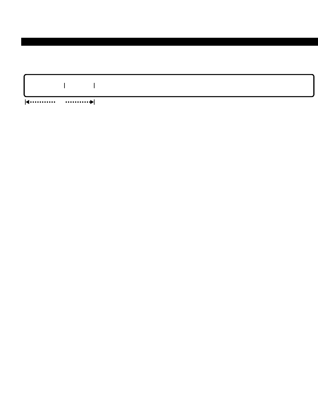
PERCEPTION 4000 COMMANDS
DISPLAY
This operation displays all night bells that meet the conditions established for each field.
PARAMETERS
Each field parameter is described in this section. Any variations for a particular operation are noted separately.
FIELD: UNA BELL # (Universal Night Answer Bell Number)
TYPE: Keyword
FORMAT: Predefined ASCII characters
Keywords: BL01 ~ BL64
This field assigns the night bell device designator.
FIELD: EQUIP # (Equipment Number)
TYPE: EQ Type
FORMAT: 5 or 6 digits
VALUE: (0)10101 to 101408 *
RANGE: Not allowed
* Use the following chart to determine valid ranges for various types of equipment.
For BSTI equipment cards, the following ranges apply:
Digits Range Hardware
First digit(s) (0)1~10 Shelf no.
Second two digits 01~11, 13 Card slot no.
Last two digits 01~16 Circuit no.
For XSTI equipment cards, the following are valid ranges:
Digits Range Hardware
First digit(s) (0)1~10 Shelf no.
Second two digits 01~14 Card slot no.
Last two digits 01~08 Circuit no.
This field contains the equipment number for the night bell. The first digit(s) represent the shelf
number, the next two digits represent the card slot number, and finally, the last two digits
represent the circuit number.
UNA BELL # EQUIP #
opt
ISS 2, SECTION 4000-014-000
NIGHT BELL ASSIGNMENT (CMD 405)
3-281

PERCEPTION 4000 COMMANDS
ISS 2, SECTION 4000-014-000
NIGHT BELL ASSIGNMENT (CMD 405)
SYSTEM ERROR MESSAGES
The following error messages are unique to this command.
C40500 - UNA night bell is already in use
C40501 - UNA night bell is not defined
C40502 - Invalid equipment number for this card type
C40503 - Equipment number is already in use
C40504 - Equipment number and card type mismatch
RELATED COMMANDS
Attendant Group Assignment (CMD 372)
DID/CCSA/DNIS LDN Assignment (CMD 316)
DID/CCSA/DNIS Trunk Group Assignment (CMD 314)
Internal Call Alternate Routing Assignment (CMD 374)
Trunk Group Routing Assignment (CMD 307)
Trunk Routing Assignment (CMD 308)
3-282

PERCEPTION 4000 COMMANDS
NUMBERING PLAN ASSIGNMENT (CMD 300)
The Numbering Plan Assignment command assigns system feature access codes and facility access codes
(trunk groups, LCR access, and networking). The command also specifies the length of the post dialing digits for
certain features. In addition, the command modifies an access code for a feature number and displays access
codes for one or more feature numbers.
Note that ambiguity may not exist within the system's numbering plan, including station numbers and steering
digits. Ambiguity is defined where any one number is equal to the prefix of another. For example, the following
numbers may not co-exist: 72 and 723 or 678 and 67820.
Command Keyword: NUMBERING_PLAN
Category Name: Dialing
PREREQUISITE COMMANDS
There are no prerequisites for this command.
OPERATIONS
Available operations: MODIFY
DELETE
DISPLAY
The function and required data fields for each operation are described in this section.
MODIFY
This operation changes an access code and/or post dialing digits for the specified feature. Ranges are not
permitted. A trunk group access code can be deleted with this operation by entering blanks (i.e., spaces) in the
“ACC” field.
DELETE
This operation deletes the access code of a feature. Ranges are not permitted.
req
FNO ACC
opt
opt
FNO ACC LEN PD1 LEN PD2
req
ISS 2, SECTION 4000-014-000
NUMBERING PLAN ASSIGNMENT (CMD 300)
3-283
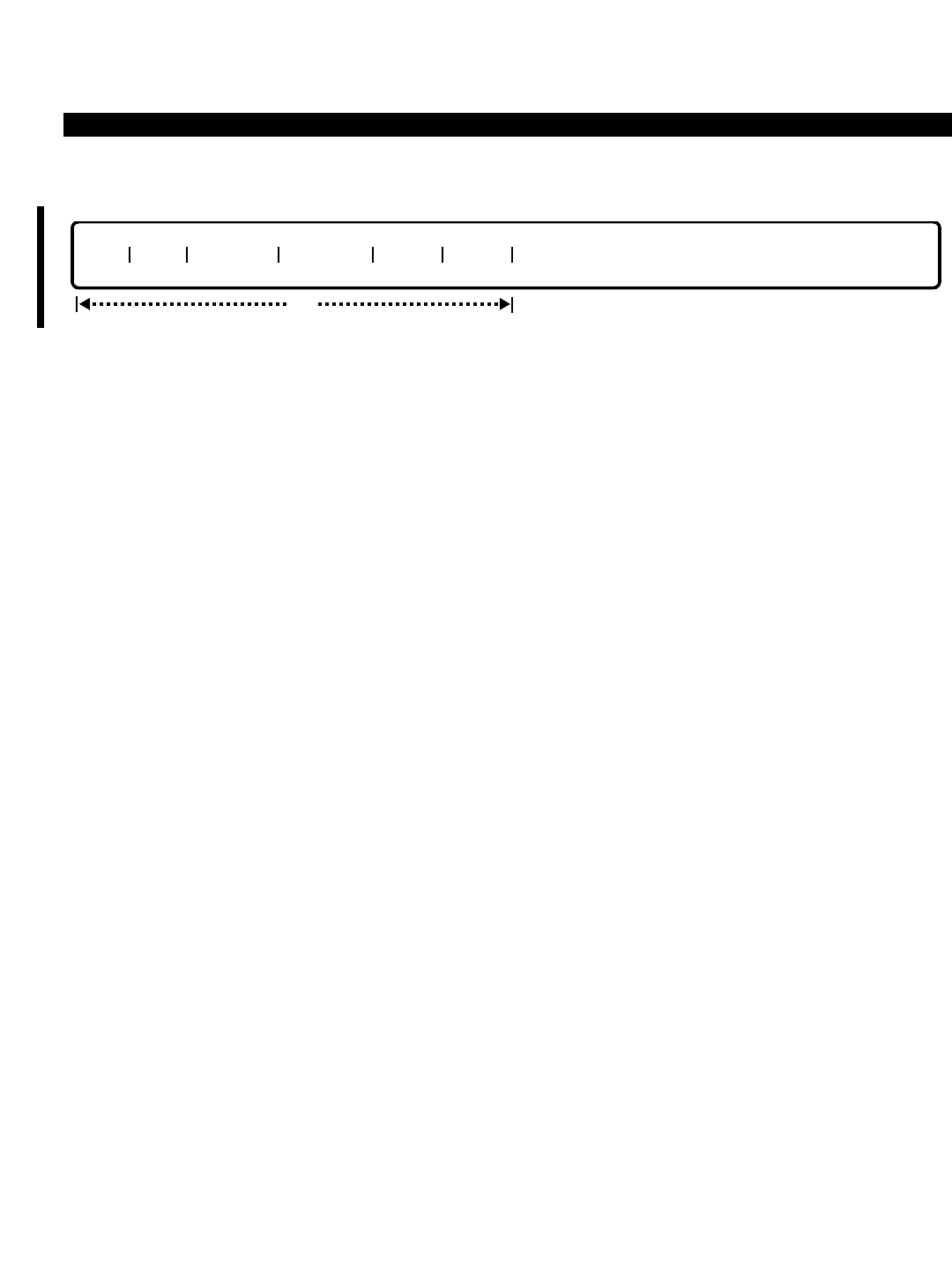
PERCEPTION 4000 COMMANDS
ISS 2, SECTION 4000-014-000
NUMBERING PLAN ASSIGNMENT (CMD 300)
DISPLAY
This operation displays access codes and the lengths of the post dialing digits of one or more features. All of the
fields are optional. If no data is entered in any of the fields, all feature access codes, their post dialing digit
lengths, and feature names will be displayed.
PARAMETERS
Each field parameter is described in this section. Any variations for a particular operation are noted separately.
FIELD: FNO (Feature Number)
TYPE: Decimal with fixed length
FORMAT: 3 digits
VALUE: 001 to 333
RANGE: Allowed in a DISPLAY operation
LOOP: Allowed in DELETE and MODIFY operations
FNO Feature Name Abbreviation
001 Direct Trunk Access - Trunk Group 1 TG001
nnn Direct Trunk Access - Trunk Group nnn (1<nnn<256) TGnnn
256 Direct Trunk Access - Trunk Group 256 TG256
258 Code Calling Access CC
259 Voice Paging Access - Zone VP_Z
260 Voice Paging Access - System VP_S
261 Voice Paging Access - Emergency VP_E
262 Call Pickup - Group GPU
263 Dictation Machine Access - Group DC_G
264 Dictation Machine Access - Individual DC_I
265 Voice Paging Retrieval - Zone VPMM
266 Voice Paging Retrieval - System PR_S
267 Code Calling Retrieval CCMM
269 Night Answer Access UNA
282 Modem Pooling Access MPAC
283 Last Number Redial LND
284 Call Pickup - Directed DPU
285 Call Pickup - Directed Group DGPU
286 Camp-on Callback Cancellation CBCL
287 Swap SWAP
288 Do Not Disturb Registration DNDR
289 Do Not Disturb Cancellation DNDC
290 Speed Calling - System SYSD
291 Speed Calling - Group SC_G
292 Attendant Access - Universal OPER
294 Least Cost Routing Access LCR
opt
FNO ACC LEN PD1 LEN PD2 NAME ABBR
3-284

PERCEPTION 4000 COMMANDS
295 Call Fwd - All Calls Register ACFR
296 Call Fwd - Busy/No Ans Register BNFR
297 Call Fwd - No Answer Register NAFR
298 Call Fwd - Cancellation CFCL
299 Authorization Code AUTH
300 Call Hold - Analog AHLD
301 Call Park - Local Access/Retrieval CP_L
302 Call Park - Remote Access/Retrieval CP_R
303 Data Access by Code Dialing DAD
304 Message Waiting Registration MW_R
305 Message Waiting Retrieval MW_B
306 Message Waiting Cancellation MW_C
307 Account Code ACCT
308 Uniform Numbering Plan UNP
310 UCD Available UCDA
311 UCD Unavailable UCDU
312 Data Privacy DPVY
313 Eight Party Conference Access 8WY
314 Eight Party Conference Release 8WYR
315 ACD Login LOGI
316 ACD Logout LOGO
318 ACD Available ACD
319 ACD Unavailable ACDU
321 ACD Work Mode Cancellation CANC
322 ACD Work Unit WRKU
323 ACD Intra-Group Call Pickup ACDP
324 ACD Assistance ASST
333 Attendant Parked Page Retrieval PR_A
334 Trunk Verification from Station TRKV
341 LCD Remote Logout Agent RLOG
342 ISDN CPN Presentation Allowed CPNA
343 ISDN CPN Presentation Restricted CPNR
345 Attendent End-to-End Signaling AEE
The "FNO" is an index used by the system to identify the feature or facility being defined. Values
001 to 256 specify trunk groups 1 to 256 respectively, however, trunk groups 129 to 256 are
reserved for systems configured above the standard default of 128. Values 257 to 333 are used
for other features. These values are predefined by Toshiba and may not be modified.
FIELD: ACC (Access Code)
TYPE: Dialing Digits plus * and #
Blank (for deleting a trunk group access code)
FORMAT: 1 to 3 dialing pad characters
VALUE: 0 to 9
RANGE: Allowed in a DISPLAY operation
Access codes listed in the numbering plan must not conflict with the station numbering plan; and
each code must be unique. Any combination of digits can be an access number. The *and #
characters can be used in an access code, but must be the first character of the dialed digit
string.
ISS 2, SECTION 4000-014-000
NUMBERING PLAN ASSIGNMENT (CMD 300)
3-285

PERCEPTION 4000 COMMANDS
ISS 2, SECTION 4000-014-000
NUMBERING PLAN ASSIGNMENT (CMD 300)
FIELD: LEN PD1 (Length of First Post Dialing Digits)
TYPE: Decimal
FORMAT: 1 or 2 digits
VALUE: 0 to 99
RANGE: Allowed in a DISPLAY operation only
This field defines the length of the first set of post dialing digits (if required for the specified
feature). For example, the Zone Voice Paging Access Code, FNO 259, requires the zone number
in addition to the feature access code. In this case, "LEN PD1" is the length of the zone number.
If the zone number is three digits, then a 3is entered in this field.
FIELD: LEN PD2 (Length of Second Post Dialing Digits)
TYPE: Decimal
FORMAT: 1 or 2 digits
VALUE: 0 to 99
RANGE: Allowed in a DISPLAY operation only
The "LEN PD2" field defines the length of the second set of post dialing digits (if required for the
specified feature). For example, Code Call Dialing requires the zone number and ID code in
addition to the access code. In this case, "LEN PD1" is the length of the zone number and "LEN
PD2" is the length of the ID Code.
FIELD: NAME (Feature Name)
TYPE: Text
FORMAT: A text string of up to 30 characters
Feature Name FNO Abbreviation
Account Code 307 ACCT
ACD Login 315 LOGI
ACD Logout 316 LOGO
ACD Available 318 ACD
ACD Unavailable 319 ACDU
ACD Assistance 324 ASST
ACD Call Pickup 323 ACDP
ACD Work Unit 322 WRKU
ACD Work Mode Cancellation 321 CANC
Attendant Parked Page Retrieval 333 PR_A
Attendant Access - Universal 292 OPER
Authorization Code 299 AUTH
Call Fwd - All Calls Register 295 ACFR
Call Fwd - Busy/No Ans Register 296 BNFR
Call Fwd - No Answer Register 297 NAFR
Call Fwd - Cancellation 298 CFCL
Call Hold - Analog 300 AHLD
Call Park - Local Access/Retrieval 301 CP_L
Call Park - Remote Access/Retrieval 302 CP_R
Call Pickup - Directed 284 DPU
Call Pickup - Directed Group 285 DGPU
Call Pickup - Group 262 GPU
3-286

PERCEPTION 4000 COMMANDS
Camp-on Callback Cancellation 286 CBCL
Code Calling Access 258 CC
Code Calling Retrieval 267 CCMM
Data Access by Code Dialing 303 DAD
Data Privacy 312 DPVY
Dictation Access - Individual 264 DC_I
Dictation Access - Group 263 DC_G
Direct Trunk Access - Trunk Group 1 001 TG001
Direct Trunk Access - Trunk Group nnn (1<nnn<256) nnn TGnnn
Direct Trunk Access - Trunk Group 256 256 TG256
Do Not Disturb Registration 288 DNDR
Do Not Disturb Cancellation 289 DNDC
Eight Party Conference Access 313 8WY
Eight Party Conference Release 314 8WYR
ISDN CPN Presentation Allowed 342 CPNA
ISDN CPN Presentation Restricted 343 CPNR
Last Number Redial 283 LND
Least Cost Routing Access 294 LCR
Message Waiting Callback 305 MW_B
Message Waiting Cancellation 306 MW_C
Message Waiting Registration 304 MR_R
Modem Pooling Access 282 MPAC
Night Answer Access 269 UNA
Speed Calling - Group 291 SC_G
Speed Calling - System 290 SYSD
Swap 287 SWAP
Trunk Verification from Station 334 TRKV
UCD Available 310 UCDA
UCD Unavailable 311 UCDU
Uniform Numbering Plan 308 UNP
Voice Paging Access - Emergency 261 VP_E
Voice Paging Access - System 260 VP_S
Voice Paging Access - Zone 259 VP_Z
Voice Paging Retrieval - System 266 PR_S
Voice Paging Retrieval - Zone 265 VPMM
This field, which appears in a DISPLAY operation only, contains the predefined feature name for
the corresponding feature number. A wild card may be entered in this field to display feature
names that are similar. For example, by entering MESSAGE in this field, all names beginning
with "Message" display, such as Message Waiting Callback, Message Waiting Cancellation, etc.
FIELD: ABBR (Feature Name Abbreviation)
TYPE: Predefined ASCII characters
FORMAT: 1 to 6 characters
This field appears only in the DISPLAY operation, and indicates the ASCII character abbreviation
for each feature name.
ISS 2, SECTION 4000-014-000
NUMBERING PLAN ASSIGNMENT (CMD 300)
3-287

PERCEPTION 4000 COMMANDS
ISS 2, SECTION 4000-014-000
NUMBERING PLAN ASSIGNMENT (CMD 300)
SYSTEM ERROR MESSAGES
The following error messages are unique to this command.
C30000 - Invalid feature number
C30001 - No such access code exists
C30002 - Access code is already used by another feature
C30003 - Input access code is out of range
C30004 - Failed to read PD1 & PD2 from database
C30005 - Failed to write PD1 & PD2 to database
C30006 - Failed to remove the access code from database
C30007 - This feature does not yet have an access code
C30008 - Failed to recover the PD1 & PD2 from database
C30009 - Failed to recover the access code from database
C30010 - Feature does not need an access code
C30011 - Input PD1 is out of range
C30012 - Input PD2 is out of range
C30013 - Cannot assign access code to an out of range trunk group number
C30014 - Database for this feature is not empty
C30015 - The verified account code length is longer than PD1
C30016 - PD1 failed to match with Zone Number assigned in CMD319
I30017 - PD1 has been modified, please change zone paging digit length in CMD 371
COMMENTS
Other numbering plans, such as the station number, ACD/UCD group pilot numbers, etc., are added and modified
by other M&A commands.
Dialing digits that are not literally interpreted by the numbering plan are:
Authorization Codes
Account Codes
ACD Agent ID Codes
External Call Destination Digits (DDD, Public Data Network, etc.)
Device Control Codes (i.e., Paging Devices)
Hardware Test Codes (for telset or attendant testing)
Speed Calling Codes
Intercom Codes
Features that are accessed by a hookflash and then an access code may not have the same dialing digits as
those features accessed by access codes only.
If a feature access code is changed with this command, all users in the system must be alerted to the change so
they may adjust their programmed keys (i.e., Autodial keys). In addition, individual attendant console features
must be updated (i.e., attendant overflow destinations).
RELATED COMMANDS
Numerous commands are related to the Numbering Plan Assignment command, and rather than list all of them
here, the relationship is stated under the individual command.
3-288

PERCEPTION 4000 COMMANDS
PATCH REPORT (CMD 143)
The Patch Report command displays a list of integrated patches in the system. This feature provides Toshiba
personnel with current software status information.
Command Keyword: PATCH_REPORT
Category Name: Utility
PREREQUISITE COMMANDS
There are no prerequisites for this command.
OPERATIONS
Available operations: DISPLAY
The function and required data fields for each operation are described in this section.
DISPLAY
This operation displays all of the integrated patches in the system. Parameter input is optional. During a DISPLAY
operation, pressing <CONTROL-S> halts the display, pressing <CONTROL-Q> resumes it, and pressing <SHIFT-
2> aborts the operation.
PARAMETERS
Each field parameter is described in this section. Any variations for a particular operation are noted separately.
FIELD: VERSION# (Release Version Number)
TYPE: Decimal with fixed length
FORMAT: 3 digits
VALUE: (See below)
RANGE: Not allowed
LOOP: Not allowed
This field displays the system's current software version number. If a value is entered, it must
match the software version number exactly, i.e., 673. If the value is not known, press the <TAB>
key and the value is inserted automatically.
VERSION# PATCH ID#
opt
ISS 2, SECTION 4000-014-000
PATCH REPORT (CMD 143)
3-289

PERCEPTION 4000 COMMANDS
ISS 2, SECTION 4000-014-000
PATCH REPORT (CMD 143)
FIELD: PATCH ID# (Patch Identification Number)
TYPE: Decimal
FORMAT: Up to 3 digits
VALUE: 1 to 255
RANGE: Allowed in a DISPLAY operation only
LOOP: Not allowed
The "PATCH ID#" field provides a list of all patches applied to the system's software.
SYSTEM ERROR MESSAGES
The following error messages are unique to this command.
C14300 - Check the release version, input is out of range
C14301 - Check release version
3-290
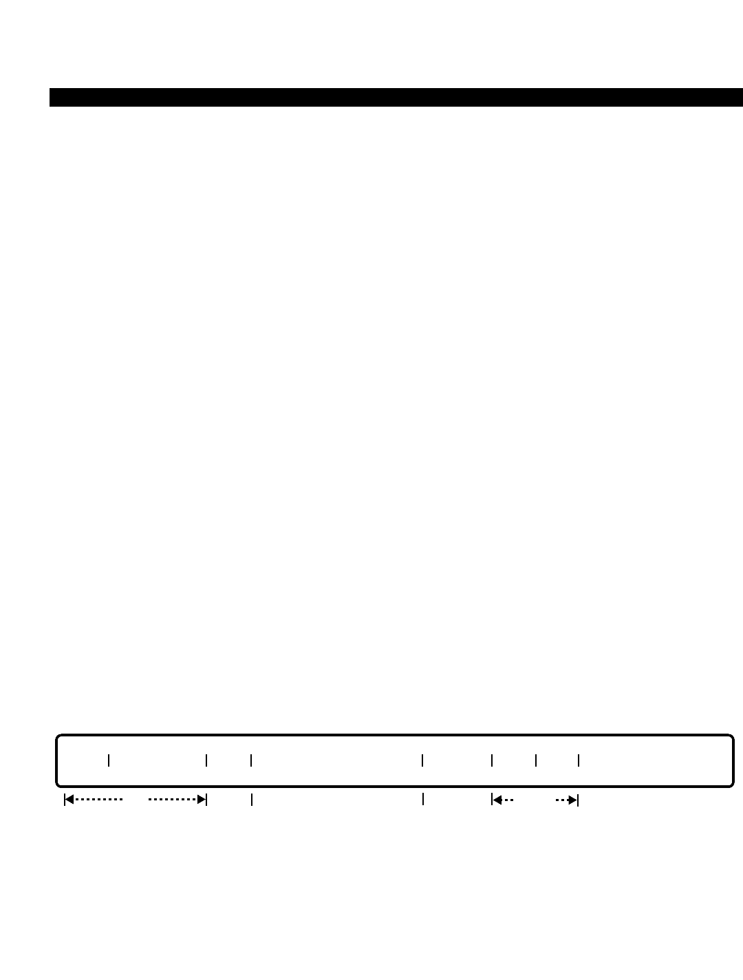
PERCEPTION 4000 COMMANDS
PRIVATE/HOTLINE ASSIGNMENTS (CMD 332)
The Private/Hotline Assignments command assigns a trunk access code and optional destination number for a
private line or hot line. Once assigned, when the private line key is pressed, the system automatically seizes a
trunk which is reserved for this private line and outpulses to the optional destination if programmed. When the
hotline key is pressed, the system automatically dials a predefined destination.
Command Keyword: PVT/HOT_ASSIGN
Category Name: Station
PREREQUISITE COMMANDS
Station Assignment (CMD 330)
Station Feature Key Assignment (CMD 331)
For Private Line Assignments:
Numbering Plan Assignment (CMD 300)
Trunk Assignment (CMD 313)
Trunk Group Assignment (CMD 310)
Trunk Hunting Assignment (CMD 309)
OPERATIONS
Available operations: MODIFY
DELETE
DISPLAY
The function and required data fields for each operation are described in this section.
MODIFY
* The "TGN" field is required for modification of a private line only. If data is entered in this field for a hotline,
an error message displays.
** The "DESTINATION NUMBER" field is required for hotlines, but optional for private lines.
This operation modifies the destination number of the private line or hotline key.
req
TYPE HOT/PVT DN TGN DESTINATION NUMBER PRM DN DEV POS
req* opt output
only
req**
ISS 2, SECTION 4000-014-000
PRIVATE/HOTLINE ASSIGNMENTS (CMD 332)
3-291
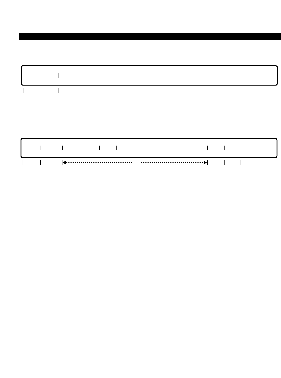
PERCEPTION 4000 COMMANDS
ISS 2, SECTION 4000-014-000
PRIVATE/HOTLINE ASSIGNMENTS (CMD 332)
DELETE
This operation deletes the hot line feature on an analog telephone only. To delete a hotline or a private line on a
digital telephone, use the Station Feature Key Assignment command (CMD 331).
DISPLAY
This operation displays all telephone keys that meet the conditions established for each field.
PARAMETERS
Each field parameter is described in this section. Any variations for a particular operation are noted separately.
FIELD: TYPE (Key Type)
TYPE: Keyword
FORMAT: Predefined ASCII characters
Keywords: PVT - Private Line
HOT - Hot Line
This field selects the line type, which is originally defined in the Station Feature Key Assignment
command (CMD 331). If PVT is entered in this field in a MODIFY operation, the "TGN" field
requires data input. Note that the keyword PVT includes both the primary and secondary private
lines (PVT and SPVT) as programmed in CMD 331.
FIELD: INDEX (Index Number)
TYPE: Decimal (Output only)
FORMAT: 1 to 3 digits
VALUE: 1 to 256
This field is used internally as a counter for the Private/Hotline table. Its value does not indicate
an actual position or set any priority for data entered in this command.
TYPE INDEX HOT/PVT DN TGN DESTINATION NUMBER PRM DN DEV POS
output
only optreq opt
output
only
HOT/PVT DN
req
3-292

PERCEPTION 4000 COMMANDS
FIELD: HOT/PVT DN (Directory Number for HOT/PVT Line)
TYPE: DN Type
FORMAT: 1 to 5 digits
VALUE: 0 to 99999
RANGE: Allowed in a DISPLAY operation
This field defines the directory number of the private/hotline. The number must be the directory
number assigned to the key with the Station Feature Key Assignment command (CMD 331), or it
must be the prime directory number if a single-line telephone is being configured for ringdown.
The number assigned to a private line is not accessible to station direct dialing within the system.
Only the attendant may direct calls to this number. Prime lines may not be used as hotlines on
multiline telephones.
FIELD: TGN (Trunk Group Number)
TYPE: Decimal
FORMAT: 1 to 3 digits
VALUE: 1 to 256 (or to the maximum system configuration)
This field is valid for private line types only. Values from 1 to 256 designate the trunk group
numbers which were predefined as private line trunk groups in the Trunk Group Assignment
command (CMD 310).
FIELD: DESTINATION NUMBER
TYPE: Dialing Digits plus * and #
FORMAT: 24 digits
VALUE: 0 to 9, *, #
The destination number field is required for hotlines and only used for private lines if an off-
premises ringdown circuit is desired. Internal destination numbers are legal entries for hotlines,
but not for private lines. Off-premises numbers are legal for both types; however, a trunk or LCR
access code is required for hotline off-premises numbers but should not be included in private
line destinations. Normally a destination is not defined for a private line.
FIELD: PRM DN (Prime Directory Number)
TYPE: DN Type
FORMAT: 1 to 5 digits
VALUE: 0 to 99999
RANGE: Allowed in a DISPLAY operation
The "PRM DN" field is the prime directory number of the device with the key being assigned. For
single line telephones, this number must be the same DN as defined in the "HOT/PVT DN" field
and must be entered.
FIELD: DEV (Telephone Device Type)
TYPE: Keyword
FORMAT: Predefined ASCII characters
Keywords: 4000 - PERCEPTION 4000 digital telephone
AD1 - Add-on module
EKT - Electronic telephone
ISS 2, SECTION 4000-014-000
PRIVATE/HOTLINE ASSIGNMENTS (CMD 332)
3-293

PERCEPTION 4000 COMMANDS
ISS 2, SECTION 4000-014-000
PRIVATE/HOTLINE ASSIGNMENTS (CMD 332)
STD - Standard telephone
DKT - DKT digital telephone
The "DEV" field is an output only field that identifies the type of device the private line or hotline
resides on.
FIELD: POS (Key Assignment Position Number)
TYPE: Decimal
FORMAT: 1 or 2 digits
VALUE: 1 to 60
This is an output only field in a MODIFY operation and an optional field in a DISPLAY operation.
The "POS" is assigned with the Station Feature Key Assignment command (CMD 331).
SYSTEM ERROR MESSAGES
The following error messages are unique to this command.
C33200 - Invalid directory number
C33201 - Directory number is not consistent with the numbering plan
C33202 - The selected trunk has been used as another private line
C33203 - Invalid trunk access code
C33204 - Invalid digits in the destination number
C33205 - Prime directory number is missing
C33206 - Invalid trunk access code
C33207 - Invalid private trunk feature number
C33208 - Invalid trunk group type
C33209 - DA registration failed
C33210 - No such hotline is assigned to this station
C33211 - No such hotline is assigned in the system
C33212 - No such private line exists in the system
C33213 - No such phone device exists in the system
C33214 - Cannot delete; need to be modified by command 331
C33215 - This analog phone is not a hotline
C33216 - In MODIFY operation; PRM DN field for private line is for output only
C33217 - Must indicate trunk group number for private line
C33218 - Destination field is required
C33219 - TGN field is not required for hotline
C33220 - Not a private trunk group
C33221 - Timeout in XXX
C33222 - Trunk group number should be non-ISDN type
RELATED COMMANDS
Trunk Group Routing Assignment (CMD 307)
Trunk Routing Assignment (CMD 308)
3-294

PERCEPTION 4000 COMMANDS
REDUNDANCY SELECTION ASSIGNMENT (CMD 410)
In a redundant system, each Line/Trunk (L/T) shelf contains two power units. The Redundancy Selection
Assignment command changes or displays the L/T shelf power unit redundancy selections and the number of L/T
shelves in the system. Note that a system may have some redundant L/T shelf power units and some non-
redundant.
Command Keyword: REDUNDANCY_ASSIGN
Category Name: System
PREREQUISITE COMMANDS
There are no prerequisites for this command.
OPERATIONS
Available operations: MODIFY
DISPLAY
The function and required data fields for each operation are described in this section.
MODIFY
This operation modifies the redundancy of L/T shelf power units, and the number of L/T shelves in the system.
Looping is not permitted in either of the optional fields.
DISPLAY
This operation displays the redundancy selections and the number of L/T shelves in the system. Both fields are
output only. To display information, press <TAB> and <RETURN>.
output only
REDUNDANCY # L/T SHELF
opt
REDUNDANCY # L/T SHELF
ISS 2, SECTION 4000-014-000
REDUNDANCY SELECTION ASSINGMENT (CMD 410)
3-295

PERCEPTION 4000 COMMANDS
ISS 2, SECTION 4000-014-000
REDUNDANCY SELECTION ASSINGMENT (CMD 410)
PARAMETERS
Each field parameter is described in this section. Any variations for a particular operation are noted separately.
FIELD: REDUNDANCY (Redundancy Selections)
TYPE: Keyword
FORMAT: Predefined ASCII characters
Keywords: YES - Redundant L/T Shelf Power
NO - Non-redundant L/T Shelf Power
This field selects the redundancy options for the L/T shelf power units. The default is NO.
FIELD: # L/T SHELF (Number of Line/Trunk Shelves)
TYPE: Decimal
FORMAT: 1 or 2 digits
VALUE: 1 to 10
LOOP: Not allowed
RANGE: Not allowed
This field specifies the number of L/T shelves in the system. The default is 1.
SYSTEM ERROR MESSAGES
The following error message is unique to this command.
C41001 - Number of L/T Shelves is out of range
3-296

PERCEPTION 4000 COMMANDS
SMDR CONFIGURATION ASSIGNMENT (CMD 409)
The SMDR Configuration Assignment command defines whether the Station Message Detailed Recording logs
internal and/or external calls. External calls may further have all calls or only toll calls recorded. SMDR
information can be selected on a system level or on specific trunk groups.
Command Keyword: SMDR_ASSIGN
Category Name: Application Processor
PREREQUISITE COMMAND
Trunk Group Assignment (CMD 310) This command is required if an entry is made in the
"TGN" field.
OPERATIONS
Available operations: MODIFY
DISPLAY
The function and required data fields for each operation are described in this section.
MODIFY
This operation modifies SMDR configuration. The "TGN" field is required if any of the three fields following it are
to be modified.
DISPLAY
This operation displays the SMDR selection on the system level as well as trunk groups.
PARAMETERS
Each field parameter is described in this section. Any variations for a particular operation are noted separately.
opt
TIMER SMDR INC SMDR OUT TGN INC CALLS OUT CALLS TOLL CALLS ONLY
opt
TIMER SMDR INC SMDR OUT TGN INC CALLS OUT CALLS TOLL CALLS ONLY
opt
ISS 2, SECTION 4000-014-000
SMDR CONFIGURATION ASSIGNMENT (CMD 409)
3-297

PERCEPTION 4000 COMMANDS
ISS 2, SECTION 4000-014-000
SMDR CONFIGURATION ASSIGNMENT (CMD 409)
FIELD: TIMER (SMDR Threshold Timer)
TYPE: Decimal
FORMAT: 1 or 2 digits
VALUE: 0 to 40 seconds
DEFAULT: 20 seconds
The "TIMER" field defines the value of the SMDR threshold timer, which determines how long an
outgoing trunk call must exist before the call is recorded. The timer is used in the absence of
answer supervision by the Central Office.
FIELD: SMDR INC (Incoming SMDR Recording)
TYPE: Keyword
FORMAT: Predefined ASCII characters
DEFAULT: NO
Keywords: YES - Enable incoming SMDR recording
NO - Disable incoming SMDR recording
This field enables/disables incoming SMDR recording.
FIELD: SMDR OUT (Outgoing SMDR Recording)
TYPE: Keyword
FORMAT: Predefined ASCII characters
DEFAULT: NO
Keywords: YES - Enable outgoing SMDR recording
NO - Disable outgoing SMDR recording
This field enables/disables outgoing SMDR recording.
FIELD: TGN (Trunk Group Number)
TYPE: Decimal
FORMAT: 1 to 3 digits
VALUE: 1 to 256 (or to the maximum system configuration)
This field defines the trunk groups to be monitored. Ranges are allowed in both DISPLAY and
MODIFY operations. The maximum trunk group number is based on the system's configuration.
In a MODIFY operation, this field is required if any of the following three fields need to be
changed.
FIELD: INC CALLS (Screen Incoming Calls)
TYPE: Keyword
FORMAT: Predefined ASCII characters
DEFAULT: NO
Keywords: YES - Screen incoming calls
NO - Do not screen incoming calls
This field enables/disables incoming SMDR recording for the specified trunk group number.
3-298

PERCEPTION 4000 COMMANDS
FIELD: OUT CALLS (Screen Outgoing Calls)
TYPE: Keyword
FORMAT: Predefined ASCII characters
DEFAULT: NO
Keywords: YES - Screen outgoing calls
NO - Do not screen outgoing calls
This field enables/disables outgoing SMDR recording for the specified trunk group number. If this
field is set to YES (On), outgoing calls will be recorded. If set to NO (Off), the following field
selection (for TOLL CALLS ONLY) has no effect.
NOTE: The "TOLL CALLS ONLY" field is a subset of the "OUT CALLS" field. To record all
outgoing calls, set "OUT CALLS" to YES and "TOLL CALLS ONLY" to NO. To record toll calls
only, set both "OUT CALLS" and "TOLL CALLS ONLY" to YES.
FIELD: TOLL CALLS ONLY
TYPE: Keyword
FORMAT: Predefined ASCII characters
DEFAULT: NO
Keywords: YES - Limit SMDR recording to toll calls only
NO - Do not limit SMDR recording
This field can be used to limit SMDR recording of toll calls. If this field is set to YES, the Forced
Account Code Toll-free Tables (programmed in CMD 352) must be defined.
SYSTEM ERROR MESSAGES
The following error messages are unique to this command.
C40901 - Missing input after trunk group number fields
C40902 - Missing trunk group number input
C40903 - Missing input data
RELATED COMMANDS
Forced Account Code Toll-free Tables (CMD 352)
ISS 2, SECTION 4000-014-000
SMDR CONFIGURATION ASSIGNMENT (CMD 409)
3-299

PERCEPTION 4000 COMMANDS
ISS 2, SECTION 4000-014-000
SECONDARY LINE APPEARANCES DISPLAY (CMD 327)
SECONDARY LINE APPEARANCES DISPLAY (CMD 327)
The Secondary Line Appearances Display command displays the equipment number, prime directory number,
telephone device name, key position, and type of multiple appearances of a line for a specified directory number.
Command Keyword: SECONDARY_LINE_DISP
Category Name: Station
PREREQUISITE COMMANDS
Feature Key Assignment (CMD 331)
Station Assignment (CMD 330)
OPERATIONS
Available operations: DISPLAY
The function and required data fields for each operation are described in this section.
DISPLAY
This operation displays information for a specified directory number that has secondary line appearances.
PARAMETERS
Each field parameter is described in this section. Any variations for a particular operation are noted separately.
FIELD: DN (Directory Number)
TYPE: DN Type
FORMAT: 1 to 5 digits
VALUE: 1 to 99999
RANGE: Not allowed
LOOP: Not allowed
The "DN" is the primary key for this command and required for the DISPLAY operation. This field
uniquely identifies the voice line which is assigned by the Station Assignment command (CMD
330), the data line assigned by the Data Station Assignment command (CMD 360), and a private,
hotline, secondary line, or logical line which is assigned by the Feature Key Assignment
command (CMD 331).
output only
DN EQUIP # PRM DN DEV POS TYPE
req
3-300

PERCEPTION 4000 COMMANDS
FIELD: EQUIP # (Equipment Number)
TYPE: EQ Type (Output only)
FORMAT: 5 or 6 digits
VALUE: (0)10101 to 101408
RANGE: Not allowed
LOOP: Not allowed
This is an output only field and displays the equipment number of the prime directory number
listed in the next field (PRM DN).
FIELD: PRM DN (Prime Directory Number)
TYPE: DN Type (Output only)
FORMAT: 1 to 5 digits
VALUE: 1 to 99999
RANGE: Not allowed
LOOP: Not allowed
This is an output only field and displays the prime directory number where the line (DN in Field 1)
is located.
FIELD: DEV (Telephone Device Name)
TYPE: Keyword (Output only)
FORMAT: Predefined ASCII characters
Keywords: 4000 - PERCEPTION 4000 telephone
AD1 - Add-on module one
AD2 - Add-on module two
AD3 - Add-on module three
EKT - Electronic telephone
STD - Standard telephone
DKT - DKT digital telephone
This is an output only field and displays the device type on which the line (DN in Field 1) is
located. Device names are assigned with the Station Feature Key Assignment command (CMD
331).
FIELD: POS (Key Position Number)
TYPE: Decimal (Output only)
FORMAT: 1 or 2 digits
VALUE: 1 to 10 (10-key digital telephone)
1 to 20 (20-key digital and electronic telephones, and 20-key add-on modules)
1 to 60 (60-key add-on module [three 20-key modules])
RANGE : Not allowed
LOOP: Not allowed
This is an output only field and displays the key position on the secondary telephone or add-on
module for the specified "DN".
FIELD: TYPE (Key Assignment Type)
ISS 1, SECTION 4000-014-000
SECONDARY LINE APPEARANCES DISPLAY (CMD 327)
3-301

PERCEPTION 4000 COMMANDS
ISS 1, SECTION 4000-014-000
SECONDARY LINE APPEARANCES DISPLAY (CMD 327)
TYPE: Keyword (Output only)
FORMAT: Predefined ASCII characters
Keywords: DDN - Data Line (Integrated DIU)
HOT - Hotline
LINE - Line Key
LLIN - Logical Line (Not used)
MLIN - Multiple Line
PRM - Prime Line
PVT - Private Trunk Line
SDDN- Data Line (Logical Pair)
SPVT - Secondary Private Line
This is an output only field and displays the line type for the key appearing in the "POS" field.
SYSTEM ERROR MESSAGES
The following error message is unique to this command.
C32700 - Invalid directory number
C32701 - Directory number not consistent with numbering plan
C32702 - Timeout in 1, 2, or 3
COMMENTS
In the DISPLAY operation, a secondary line on an add-on module may have a key position value greater than
118. To determine the key position on the add-on module, subtract 118 from the displayed key position number.
The type of add-on module is assigned in the Station Feature Key Assignment command (CMD 331).
3-302

3-303
PERCEPTION 4000 COMMANDS
STATION ASSIGNMENT (CMD 330)
The Station Assignment command is the primary command in assigning stations to the system. This command
defines the station's prime directory number, establishes linkage to a hardware circuit, instructs the system on
what type of station this is (digital, electronic, analog single-line) and defines terminal-level and prime-line
attributes. The Station-Level Parameter Assignment command (CMD 329) is also required to complete
fundamental station information. Multi-line devices also require the Station Feature Key Assignment command
(CMD 331) for further assignment.
NOTES:
1. If the station's "TYPE" field is an ID10 or ID20 (digital telephone with an integrated Data Interface Unit [DIU]),
the station must be assigned to a DSTI card configured for 2B operation, thereby allowing for simultaneous
voice and data communications.
2. If the station's "TYPE" field is a 2010 or 2020 (digital telephone without DIU), the station may be assigned to
a DSTI card configured for 1B or 2B operation. When installed on a DSTI card configured for 2B operation, a
'2B' device (ID10 or ID20) must already be assigned to the card.
3. A digital telephone with an integrated DIU (ID10 or ID20) must have the data channel programmed through
the Data Station Assignment command (CMD 360).
4. If a 10-key or 20-key digital telephone is selected in the "TYPE" field (2010 or 2020) and installed on a DSTI
card configured for 2B operation, the circuit's data channel is ignored by the system.
5. In a MODIFY operation, a '2B' device may not be changed to a '1B' device.
Additional information is listed under the COMMENTS section at the end of this command.
Command Keyword: STA_ASSIGNMENT
Category Name: Station
PREREQUISITE COMMANDS
Attendant Group Assignment (CMD 372) If "ANSPOS" is set to an attendant directory
Attendant Position Assignment (CMD 370) number, CMDs 372 and 370 are required.
Station Feature Key Pattern Assignment (CMD 320) If a feature key pattern other than "1" is entered,
CMD 320 is required.
OPERATIONS
Available operations: ADD
DELETE
MODIFY
DISPLAY
The function and required data fields for each operation are described in this section.
ISS 2, SECTION 4000-014-000
STATION ASSIGNMENT (CMD 330)
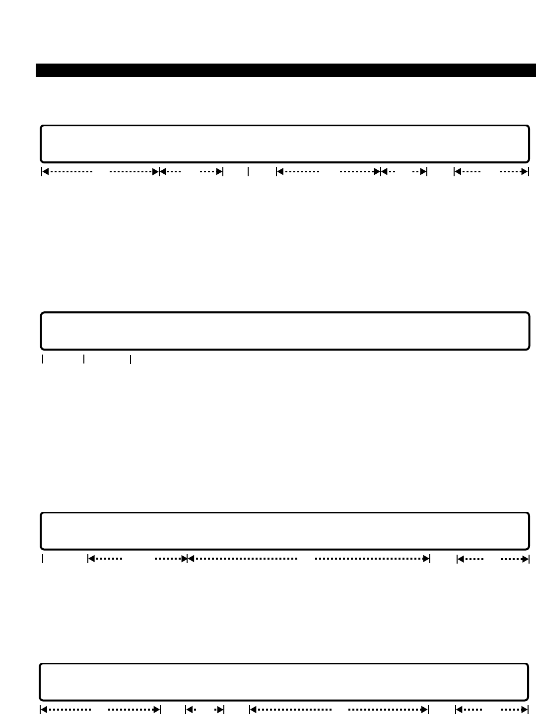
PERCEPTION 4000 COMMANDS
ISS 2, SECTION 4000-014-000
STATION ASSIGNMENT (CMD 330)
ADD
This operation assigns a station port to a spare equipment port location. The minimum set of data that defines a
station port is required. The directory number selected must meet the constraints established for prime directory
numbers. Loops are permitted to expedite the establishment of large numbers of station ports. Once the station is
installed, other attributes which are not covered by this command are assigned with default values automatically.
Refer to the COMMENTS section later in this command for a listing of these attributes. The optional "PAT" field
defaults to the basic key position template, Pattern #1, if a <TAB> is entered in this field.
DELETE
This operation changes a station port to a spare equipment port. The equipment number is required. Looping is
allowed in the “EQUIP #” field to expedite the deletion of large numbers of ports. If the station has secondary
directory numbers assigned to its line(s) or key(s), all of the secondary directory numbers must be removed
through the Station Feature Key Assignment command (CMD 331) prior to performing this operation. The station
must also be removed from group associations such as hunting, speed calling, ACD, etc. If the station's "TYPE" is
an ID10 or ID20 (digital telephone with integrated DIU), the data station must be deleted first. Refer to the
COMMENTS section later in this command for additional DELETE operation information.
MODIFY
This operation modifies the attributes of the station equipment. The "EQUIP #" field is the only required field. The
"PRM DN," "TYPE," "PAT," and "SRG" fields are locked fields and cannot be modified. Before changing attributes
of a station, review the NOTES at the beginning of this command and the COMMENTS at the end.
DISPLAY
opt locked opt optlocked
EQUIP # | PRM DN | TYPE | PAT | A1 | A2 | EXT | RNG | COS | DRL | FRL | QPL | ANSPOS | SRG | NAME | DEPT
locked opt
optreq locked locked opt
EQUIP # | PRM DN | TYPE | PAT | A1 | A2 | EXT | RNG | COS | DRL | FRL | QPL | ANSPOS | SRG | NAME | DEPT
EQUIP # | PRM DN |
opt
req
req
EQUIP # | PRM DN | TYPE | PAT | A1 | A2 | EXT | RNG | COS | DRL | FRL | QPL | ANSPOS | SRG | NAME | DEPT
req optopt locked opt locked opt
3-304

PERCEPTION 4000 COMMANDS
This operation displays all station equipment ports that meet the conditions established for each field. Ranges are
permitted in any field that accepts numeric input, (i.e., COS, DRL, FRL, etc.). The “EQUIP #” field is the only loop
field for this operation.
PARAMETERS
Each field parameter is described in this section. Any variations for a particular operation are noted separately.
FIELD: EQUIP # (Equipment Location)
TYPE: EQ Type
FORMAT: 5 or 6 digits
VALUE: (0)10101 to 101408 *
RANGE: Not allowed
LOOP: Allowed in DISPLAY, ADD, and DELETE operations
* Use the following chart to determine valid ranges for various types of equipment.
For BSTI and 1B-Channel DSTI equipment cards, the following ranges apply:
Digits Range Hardware
First digit(s) (0)1~10 Shelf no.
Second two digits 01~11, 13 Card slot no.
Last two digits 01~16 Circuit no.
For a 2B-Channel DSTI equipment card, the following ranges apply:
Digits Range Hardware
First digit(s) (0)1~10 Shelf no.
Second two digits 01, 03, 05, 07, 09, 11 Card slot no.
Last two digits 01~16 Circuit no.
For an EKTI, DKTI, or XSTI card, the following are valid ranges:
Digits Range Hardware
First digit(s) (0)1~10 Shelf no.
Second two digits 01~14 Card slot no.
Last two digits 01~08 Circuit no.
Each station is assigned to a circuit on a line card. The "EQUIP #" field defines the location of the
connection. The first digit(s) represents the shelf number, the next two digits represent the card
slot number, and the last two digits represent the circuit number. This field is required for all
operations except DISPLAY. Review the NOTES at the beginning of this command before adding
stations to the system.
If a station is going to serve as an ACD agent position, then it is important to note the relationship
between the agent’s assigned equipment number, its controlling LCPU, and its assigned agent
group number. LCPU support is allocated among the PERCEPTION 4000 System’s Modular
Line/Trunk Units (Shelves) as follows:
ISS 2, SECTION 4000-014-000
STATION ASSIGNMENT (CMD 330)
3-305
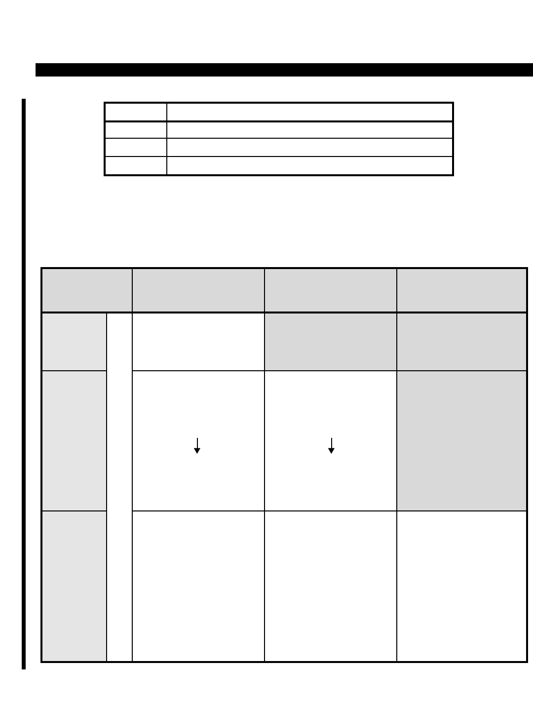
PERCEPTION 4000 COMMANDS
ISS 2, SECTION 4000-014-000
STATION ASSIGNMENT (CMD 330)
When assigning agent stations in a system with redundant processing, those stations which are
to be in the same ACD group need to be assigned to equipment locations that will be supported
by the same LCPU. This is because different LCPUs support different ACD groups, as noted in
the following table. Programming agent stations in accordance with this table will help ensure that
calls are not interrupted if a system switchover occurs.
3-306
LCPU(X) Modular Line/Trunk Units (Shelves) Controlled by LCPU(X)
1 1 ~ 4
2 5 ~ 8
3 9 ~ 10
System
Size LCPU1
Shelves Supported:
1 ~ 4
LCPU2
Shelves Supported:
5 ~ 8
LCPU3
Shelves Supported:
9 ~ 10
1 LCPU
System
ACD Groups Supported:
1 ~ 32
(All groups supported
by LCPU1)
ACD Groups Supported:
1
3
5
7
31
(All odd-numbered
groups are supported
by LCPU2)
ACD Groups Supported:
1
4
7
10
13
16
19
22
25
28
31
ACD Groups Supported:
2
4
6
8
32
(All even-numbered
groups are supported
by LCPU2)
ACD Groups Supported:
2
5
8
11
14
17
20
23
26
29
32
ACD Groups Supported:
3
6
9
12
15
18
21
24
27
30
2 LCPU
System
3 LCPU
System
ACD AGENT GROUP SUPPORT ALLOCATION

PERCEPTION 4000 COMMANDS
FIELD: PRM DN (Prime Directory Number)
TYPE: DN Type
FORMAT: 1 to 5 digits
VALUE: 0 to 99999
RANGE: Allowed in a DISPLAY operation only
The directory number must not conflict with any other directory number, steering digit, or
feature/facility access codes defined in the system's numbering plan. Ranges are allowed in a
DISPLAY operation. Note that the "PRM DN" cannot be modified.
FIELD: TYPE (Station Type)
TYPE: Keyword
FORMAT: Predefined ASCII characters
Keywords: 2010 - PERCEPTION 4000 10-key digital telephone
2020 - PERCEPTION 4000 20-key digital telephone
ID10 - PERCEPTION 4000 10-key digital telephone / Data Interface Unit (DIU)
ID20 - PERCEPTION 4000 20-key digital telephone / Data Interface Unit (DIU)
ANLG - Analog telephone
ANMW - Analog telephone with Message Waiting
AVMS - Analog port assigned to Voice Messaging System
OPS - Off-premises analog station
EK01 - Electronic telephone with 1 line key and 3 fixed keys
EK10 - Electronic telephone with 10 flexible keys and 4 fixed keys
EK20 - Electronic telephone with 20 flexible keys and 4 fixed keys
EK2D - Electronic telephone with 20 flexible keys, 4 fixed keys, and display
DK10 - DKT digital telephone with 10 flexible keys
DK1D - DKT digital telephone with 10 flexible keys and display
DK20 - DKT digital telephone with 20 flexible keys
DK2D - DKT digital telephone with 20 flexible keys and display
This field defines the station type—digital, analog, electronic, etc. An analog telephone that lacks
a Message Waiting lamp may be set up as an ANMW to receive a stuttered dial tone (which
indicates that a message(s) is waiting). If the station is a digital telephone with or without an
integrated data interface unit, then the next two fields (A1 and A2) may be defined. Review the
NOTES at the beginning of this command before assigning a station type.
FIELD: PAT (Pattern Number of Template for Position of Feature Keys)
TYPE: Decimal
FORMAT: 1 digit
VALUE: 1 to 4
RANGE: Not allowed
LOOP: Not allowed
This field selects the feature key pattern to be assigned to the station. "PAT" is a locked field in
the MODIFY and DISPLAY operations. The field defaults to the basic key position template,
Pattern #1, if a <TAB> is entered. Patterns are programmed with the Station Feature Key Pattern
Assignment command (CMD 320).
ISS 2, SECTION 4000-014-000
STATION ASSIGNMENT (CMD 330)
3-307

PERCEPTION 4000 COMMANDS
ISS 2, SECTION 4000-014-000
STATION ASSIGNMENT (CMD 330)
FIELD: A1 (First Add-on Module Type)
TYPE: Keyword
FORMAT: Predefined ASCII characters
Keywords: M1 - 20-key Add-on Module
M2 - 60-key Add-on Module (three 20-key modules)
NO - No Add-on Module
This field applies to digital telephones only, and specifies whether the station has a 20-key, 60-
key, or no add-on module. A maximum of 60 keys may be added to a station, therefore, a station
may be assigned one or two 20-key add-ons, or one 60-key add-on. A 60-key add-on module
consists of three 20-key modules. All keys assigned to an add-on module must be deleted
through the Station Feature Key Assignment command (CMD 331) before the "A1" or "A2" fields
can be modified.
FIELD: A2 (Second Add-on Module Type)
TYPE: Keyword
FORMAT: Predefined ASCII characters
Keywords: M1 - 20-key Add-on Module
M2 - 60-key Add-on Module (Reserved for future use.)
NO - No Add-on Module
This field applies to digital telephones only, and specifies whether the station has a second 20-
key add-on module. See "A1" for additional information on add-on modules.
FIELD: EXT (Analog Extension - Used for analog telephones only) (Reserved for future use)
TYPE: Keyword
FORMAT: Predefined ASCII characters
Keywords: EXT - Digital Telephone Extension
NON - Non-extension
This field is reserved for future use.
FIELD: RNG (Ringing Option)
TYPE: Keyword
FORMAT: Predefined ASCII characters
Keywords: RNG - Ring
NRG - No Ring
The ringing option field defines whether or not an analog station is rung for incoming calls. If set
to NRG, the telephone rings for camp-on callbacks and recalls only. All devices default to RNG
when added to the system. To modify a digital or electronic telephone, use the Station Feature
Key Assignment command (CMD 331) "DEF 2" field.
3-308

PERCEPTION 4000 COMMANDS
FIELD: COS (Class Of Service)
TYPE: Decimal
FORMAT: 1 or 2 digits
VALUE: 1 to 64
RANGE: Allowed in a DISPLAY operation only
This field, along with the next four fields, provides feature and facility access and dialing control
definitions. Class of Service tables are defined with the Class of Service Assignment command
(CMD 334).
FIELD: DRL (Destination Restriction Level)
TYPE: Decimal
FORMAT: 1 or 2 digits
VALUE: 1 to 16 (or to the maximum system configuration)
RANGE: Allowed in a DISPLAY operation only
Destination restriction levels control outgoing calls via direct trunk group access. Restriction
levels are defined with the Destination Restriction Level Assignment command (CMD 337).
FIELD: FRL (Facility Restriction Level Profile)
TYPE: Decimal
FORMAT: 1 or 2 digits
VALUE: 1 to 32 (or to the maximum system configuration)
RANGE: Allowed in a DISPLAY operation only
The "FRL" field defines restrictions assigned to various routes within each least cost routing route
table. Facility Restriction Level Profile relationships are defined with the Facility Restriction Level
Profile Assignment command (CMD 387).
FIELD: QPL (LCR Queue Priority Level)
TYPE: Decimal
FORMAT: 1 digit
VALUE: 1 to 8
RANGE: Allowed in a DISPLAY operation only
This field sets queuing priority for outgoing calls and is defined with the LCR Special Routing
Assignment command (CMD 384).
FIELD: ANSPOS (Answer Position)
TYPE: DN Type / Keyword
FORMAT: 1 to 5 digits / Predefined ASCII characters
VALUE: 0 to 99999
RANGE: Allowed in a DISPLAY operation only
Keyword: NON
This optional field defines the directory number where calls made through the universal attendant
access code are directed. The answer position is defined as an attendant group number, an
attendant number, a station number, or a pilot number such as for hunt groups, UCD, etc. The
keyword NON indicates that no answer position is selected and is the default value.
ISS 2, SECTION 4000-014-000
STATION ASSIGNMENT (CMD 330)
3-309

PERCEPTION 4000 COMMANDS
ISS 2, SECTION 4000-014-000
STATION ASSIGNMENT (CMD 330)
FIELD: SRG (Station Restriction Group Number) (Reserved for future use)
TYPE: Decimal
FORMAT: 1 or 2 digits
VALUE: 1 to 16
RANGE: Allowed in a DISPLAY operation only
This field is reserved for future use.
FIELD: NAME (Station Name)
TYPE: Text
FORMAT: 0 to 9 ASCII characters
This optional field allows you to enter a station name of up to nine ASCII characters. Embedded
spaces are allowed. The name entered here appears on display-equipped devices when calls are
directed to these devices.
FIELD: DEPT (Department Name)
TYPE: Text
FORMAT: 0 to 4 ASCII characters
This optional field identifies the department to which the device belongs. For example, ACCT
would identify the Accounting Department and PUR would identify the Purchasing Department.
SYSTEM ERROR MESSAGES
The following error messages are unique to this command.
C33000 - Specified equipment number is not available in the system
C33001 - Specified equipment number is already being used
C33002 - Prime directory number already exists
C33003 - Unable to add a new directory number to database
C33004 - Prime directory number conflicts with existing number or access code
C33005 - Directory number is a group member
C33006 - Add operation; DN-LDN relation failed
C33007 - Add operation; SSC LDN MPT failed
C33008 - Cannot delete; station is not the last member
C33009 - Failed to remove this directory number from database
C33010 - Failed to remove DN-LDN relationship
C33011 - Failed to release the deleted LDN
C33012 - Failed to release the deleted LTN
C33013 - Failed to add new LTN to HDT database
C33014 - Unmatched prime directory number
C33015 - Failed to recover DA in all LCPUs
C33016 - Failed to remove KSU member
C33017 - Failed to remove KSU-LDN relationship
C33018 - EXT is not yet supported; input TAB is required
C33019 - Cannot delete; station is not last line
C33020 - Cannot delete; read line count failed
3-310

PERCEPTION 4000 COMMANDS
C33021 - Equipment number is already used by another device
C33022 - No such station exists in the system
C33023 - No matched card type
C33024 - Cannot add card to this card slot
C33025 - 10-key telephone line count exceeds system configuration limit
C33026 - 20-key telephone line count exceeds system configuration limit
C33027 - Failed to allocate memory for CbList/LCD Buffer
C33028 - Station type is not changeable
C33029 - Not allowed to install DSTI/BSTI/PBRC to slot 12/14
C33030 - Not allowed to install DSTI-2B to an even card slot
C33031 - Not allowed to install DSTI-2B to card slot 12-14
C33032 - Not allowed to install T-1 to an odd card slot
C33033 - Not allowed to install T-1 to card slot 14
C33034 - DIU database has not been removed
C33035 - Dial 0 destination DN does not exist
C33036 - Failed to read ANSPOS
C33037 - Failed to read authorization attribute
C33038 - Failed to read phone attribute
C33039 - Failed to read prime line attribute
C33040 - There is no available key for adding DDN key
C33041 - Failed to update authorization attribute
C33042 - Failed to update phone attribute
C33043 - Failed to update station dial 0 destination
C33044 - Failed to update line attribute flag byte
C33045 - Cannot change to integrated DIU; next slot is in use
C33046 - Cannot change to integrated DIU; DSTI-2B cannot be in an even slot
C33047 - Cannot change to integrated DIU; DSTI-2B not allowed in slot 12-14
C33048 - Modify field EXT is not allowed; input TAB is required
C33049 - Modify field RNG is not allowed; input TAB is required
C33050 - Add-on module is applicable to P-4000 phone only
C33051 - RNG is not allowed; input TAB is required
C33052 - Add-on module #1 is required for P-4000 phone
C33053 - Add-on module #2 is required for P-4000 phone
C33054 - Delete all keys assigned in add-on module #2 before removing
C33055 - Cannot read add-on key table
C33056 - Delete all keys assigned in add-on module #1 before removing
C33057 - Delete all keys assigned in add-on module #1 before modifying
C33058 - Delete all keys assigned in add-on module #2 before modifying
C33059 - Cannot allocate memory to add new add-on module
C33060 - Cannot add VMS LDN to table
C33061 - Cannot remove VMS LDN from table
C33062 - Cannot add prime line attribute for this station
C33063 - Cannot add KSU member to this station
C33064 - Failed to read LDN from database
C33065 - Database does not have any free available LTNs
C33066 - Database does not have any free available LDNs
C33067 - Failed to delete LTN from database
C33068 - Wait for ACD agent to logout before removing
C33069 - Failed to read message waiting queue
C33070 - Failed to add to message waiting queue
C33071 - Failed to remove from message waiting queue
C33072 - Exceeds maximum message waiting allowed in the system
ISS 2, SECTION 4000-014-000
STATION ASSIGNMENT (CMD 330)
3-311

PERCEPTION 4000 COMMANDS
ISS 2, SECTION 4000-014-000
STATION ASSIGNMENT (CMD 330)
C33073 - Exceeds maximum voice mail port allowed in the system
I33074 - Warning: Undefined data in field #13
C33075 - Total directory numbers have reached maximum system configured
C33076 - Cannot use pattern number; prime position is not assigned
C33077 - Cannot use pattern number; data position is not assigned
C33078 - Cannot use pattern number; too many autodial keys
C33079 - Cannot use pattern number; too many preregistered call forward keys
I33080 - Warning: Pattern number will be disregarded for single key station
C33081 - Total number of keys on add-on module #1 and #2 cannot exceed 60
C33082 - No more LDNs are available
COMMENTS
1. When a digital or electronic telephone is installed, other attributes not covered by this command are
automatically assigned with default values. These attributes, listed below, are changed and/or displayed via
the Station Feature Key Assignment command (CMD 331).
Prime Line Key Position Receive Voice Announce on Prime Line
Message Key Position (for multiline electronic telephones) Receive Voice Announce via Intercom
Release Key Position Automatic Answerback to Voice Announce
Line Preference Ring Over Busy
Additionally, the PRM DN and Data DN (if it exists) are assigned default key positions automatically with
the Station Assignment command (CMD 330).
2. To delete a station, the prime directory number as well as all of the secondary directory numbers assigned
to the line(s)/key(s) on that station are checked. If the directory numbers can be removed from the station,
the station is then deleted. Otherwise, an error message is given and no deletion is performed.
All appearances of a station's prime directory number on other stations must be deleted prior to the station's
removal. The Secondary Line Appearances Display command (CMD 327) may be used to display all
appearances of the prime directory number.
Deletion of a directory number from a station is inhibited if the directory number is the last appearance of
that number in the system, and is a member of any of the following groups:
ACD Group UCD Group Hotline Station Private Line
Hunt Group Pickup Group Intercom Group Secondary Line
An error message appears indicating which of the above conditions exist causing the operation to be
aborted. To break the group-member relationships, use the appropriate M&A commands first and then
delete the directory number from the station.
3. Station removal is not allowed unless associated data station removal is performed first. Refer to the Data
Station Assignment command (CMD 360) for information on deleting a data station.
4. Station removal must be confirmed if any of the following features are actively registered by or to the station:
Call In Progress Calls on Hold
3-312

PERCEPTION 4000 COMMANDS
If one of these conditions occurs, select one of the following options:
Cancel,
Remove when it becomes idle (wait),
Force removal
RELATED COMMANDS
Call Pickup Group Assignment (CMD 346)
Class of Service Assignment (CMD 334)
Data Station Assignment (CMD 360)
Destination Restriction Level Assignment (CMD 337)
Facility Restriction Level Profile Assignment (CMD 387)
Group Speed Calling Member Assignment (CMD 350)
Intercom Group Member Display (CMD 333)
Internal Call Alternate Routing Assignment (CMD 374)
LCR Special Routing Assignment (CMD 384)
Private/Hotline Assignment (CMD 332)
Station Feature Key Assignment (CMD 331)
Station Hunting Assignment (CMD 342)
Station-Level Parameter Assignment (CMD 329)
Terminal Maintenance (CMD 206)
UCD Group Assignment (CMD 354)
ISS 2, SECTION 4000-014-000
STATION ASSIGNMENT (CMD 330)
3-313
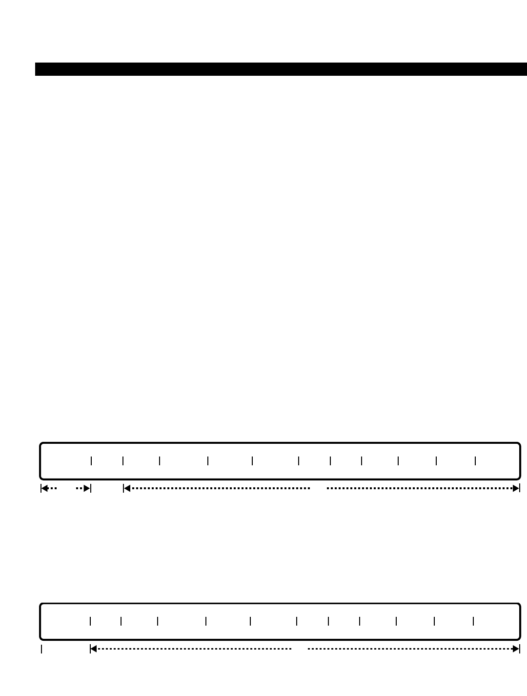
PERCEPTION 4000 COMMANDS
ISS 2, SECTION 4000-014-000
STATION FEATURE KEY ASSIGNMENT (CMD 331)
STATION FEATURE KEY ASSIGNMENT (CMD 331)
The Station Feature Key Assignment command defines digital and electronic telephone attributes and feature key
usage for these telephone types as well as for the PERCEPTION 4000 add-on module. Before this command can
be implemented, the Station Assignment command (CMD 330) must be programmed.
Command Keyword: STA_KEY_ASSIGN
Category Name: Station
PREREQUISITE COMMANDS
Data Station Assignment (CMD 360) Command 360 is required if a data key is specified in
the "TYPE" field.
Station Assignment (CMD 330)
OPERATIONS
Available operations: MODIFY
DISPLAY
SWAP
The function and required data fields for each operation are described as follows:
MODIFY
This operation modifies the attributes of station equipment. The Device Category (DEV) field is optional if
modifications are made to phone attributes (fields "PREF" to "ROB"). If modifications are made to key attributes
(fields "POS" and "TYPE," "DEF1," "DEF2," and/or "DEF3," the "DEV" field is required. Ranges are permitted in
the Feature Key Position (POS) field only.
DISPLAY
This operation displays attributes that meet the conditions established in each field for the specified prime
directory number.
PRM DN DEV PREF PRM VA ICM VA AUT VA ROB POS TYPE DEF 1 DEF 2 DEF 3
req opt
PRM DN DEV PREF PRM VA ICM VA AUT VA ROB POS TYPE DEF 1 DEF 2 DEF 3
optreq req/opt
3-314
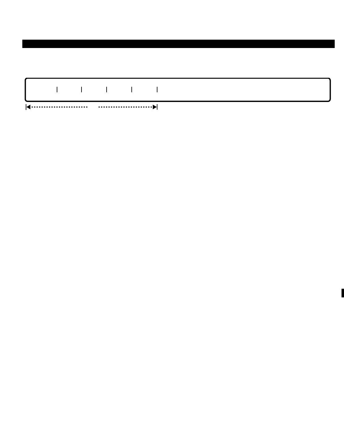
PERCEPTION 4000 COMMANDS
SWAP
This operation exchanges the attributes of two keys. The "DEV n" fields identify the device on which each key is
located. Ranges are not permitted.
PARAMETERS
Each field parameter is described in this section. Any variations for a particular operation are noted separately.
FIELD: PRM DN (Prime Directory Number)
TYPE: DN Type
FORMAT: 1 to 5 digits
VALUE: 0 to 99999
This field, which is required in all operations, selects the prime directory number to be modified or
displayed. The prime directory number uniquely identifies each station and is originally assigned
through the Station Assignment command, CMD 330.
FIELD: DEV, DEV 1, DEV 2 (Device Category)
TYPE: Keyword
FORMAT: Predefined ASCII characters
Keywords: 4000 - PERCEPTION 4000 digital telephone
EKT - Electronic telephone
DKT - DKT digital telephone
AD1 - Add-on module 1
AD2 - Add-on module 2
This field identifies the device as being a digital or electronic telephone, or an add-on unit.
FIELD: PREF (Line Preference)
TYPE: Keyword
FORMAT: Predefined ASCII characters
Keywords: PRM - Prime Line
IDL - Idle
PIDL - Prime & Idle
PRNG - Prime & Ringing
RNG - Longest Ringing
RIDL - Ringing & Idle
ALL - All
NON - No Preference
req
PRM DN DEV 1 POS 1 DEV 2 POS 2
ISS 2, SECTION 4000-014-000
STATION FEATURE KEY ASSIGNMENT (CMD 331)
3-315

PERCEPTION 4000 COMMANDS
ISS 2, SECTION 4000-014-000
STATION FEATURE KEY ASSIGNMENT (CMD 331)
This field defines the automatic line selection capability of the telephone based on various states.
Refer to Appendix D for matrices which show how this field handles automatic line selection.
FIELD: PRM VA (Receive Voice Announce on Prime Line)
TYPE: Keyword
FORMAT: Predefined ASCII characters
Keywords: ALW - Voice Announce on Prime Line allowed
DNY - Voice Announce on Prime Line denied
This field defines whether or not a station receives voice announcements over the prime line.
FIELD: ICM VA (Receive Voice Announce via Intercom Line)
TYPE: Keyword
FORMAT: Predefined ASCII characters
Keywords: ALW - Voice Announce via Intercom Line allowed
DNY - Voice Announce via Intercom Line denied
This field defines whether or not a station receives voice announcements over the intercom line.
FIELD: AUT VA (Automatic Answerback to Voice Announcement)
TYPE: Keyword
FORMAT: Predefined ASCII characters
Keywords: ALW - Automatic Answerback to Voice Announcement allowed
DNY - Automatic Answerback to Voice Announcement denied
This field determines if the station's microphone automatically activates for automatic answerback
to voice announcements when they take place. (This field should not be confused with the
Automatic Answer feature.)
FIELD: ROB (Ring Over Busy)
TYPE: Keyword
FORMAT: Predefined ASCII characters
Keywords: YES - Ring Over Busy enabled
NO - Ring Over Busy disabled
This field defines whether the station user receives a ring over busy indication when a call arrives
on another line while the station user is presently engaged in a call. Ring over busy is a muted
ring generated through the station's speaker and occurs only when the user is in handset mode
on a line other than the one receiving the new call. In order to receive the ring over busy signal,
the line being rung must be set to allow audible ringing.
The above parameters pertain to digital and electronic telephone configurations, with the exception of
the device fields. The following fields pertain to multi-line stations as well as add-on modules.
3-316
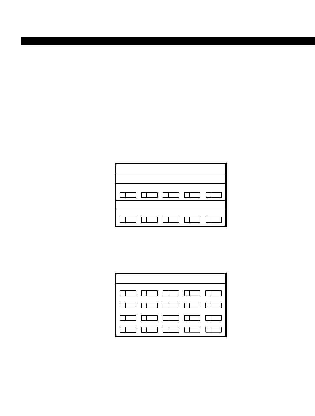
PERCEPTION 4000 COMMANDS
FIELD: POS, POS 1, POS 2 (Key Assignment Position Number)
TYPE: Decimal
FORMAT: 1 or 2 digits
VALUE: 1 to 10 (10-key digital and electronic telephone)
1 to 20 (20-key digital and electronic telephones, 20-key add-on modules)
1 to 60 (60-key add-on module [three 20-key modules])
RANGE : Allowed in a DISPLAY operation
LOOP: Allowed in a MODIFY operation
The "POS" field assigns secondary keys on multi-line stations. Data entered in this field
determines the “TYPE” field, which determines whether data is entered in the "DEF 1," “DEF 2,”
and/or “DEF 3” fields. Ranges and auto-increments are allowed in the "POS" fields for all
operations. Refer to the following figures for key positions on the various devices.
Figure 3-3
Key Positions - PERCEPTION 4000 Digital Telephones
10
5
9
4
8
3
7
2
6
1
NOTES:
# 5
# 6
# 10
DDN
PRM DN
RLS
=
=
=
Data Directory Number, if data is used (Default)
Prime Directory Number (Default)
Release Key (Non-definable)
20
NOTES:
# 5
# 16
# 20
DDN
PRM DN
RLS
=
=
=
Data Directory Number, if data is used (Default)
Prime Directory Number (Default)
Release Key (Non-definable)
15
10
5
19
14
9
4
18
13
8
3
17
12
7
2
16
11
6
1
10-KEY
20-KEY
ISS 2, SECTION 4000-014-000
STATION FEATURE KEY ASSIGNMENT (CMD 331)
3-317
PERCEPTION 4000 COMMANDS
ISS 2, SECTION 4000-014-000
STATION FEATURE KEY ASSIGNMENT (CMD 331)
Figure 3-4
Key Positions - Electronic and DKT Digital Telephones
9
10
7
8
5
6
3
4
2
NOTES:
For Electronic Telephones:
For DKT Digital Telephones:
# 1
# 9
# 10
PRM DN
RLS
MSG
=
=
=
Prime Directory Number (Default)
Release Key (Default)
Message Waiting (Default)
1
19
20
17
18
15
16
14
13
12
11
9
10
7
8
5
6
4
3
2
1
NOTES:
For Electronic Telephones:
For DKT Digital Telephones:
# 1
# 19
# 20
PRM DN
RLS
MSG
=
=
=
Prime Directory Number (Default)
Release Key (Default)
Message Waiting (Default)
10-KEY
20-KEY
# 1
# 10
PRM DN
RLS
=
=Prime Directory Number (Default)
Release Key (Default)
# 1
# 19 PRM DN
RLS
=
=Prime Directory Number (Default)
Release Key (Default)
3-318
PERCEPTION 4000 COMMANDS
Figure 3-5
Key Positions - AD1, AD2 Devices
FIELD: TYPE (Key Assignment Type)
TYPE: Keyword
FORMAT: Predefined ASCII characters
Keywords: FEA - Feature Key
LINE - Secondary Appearance Line Key
PRM - Prime Line
LLIN - Logical Line
AGE - ACD Line - Agent
SUP - ACD Line - Supervisor
DDN - Integrated Data DN Key
SDDN - Secondary Data DN Key
MLIN - Multiple Line
PVT - Private Trunk Line
SPVT - Secondary Private Trunk Line
HOT - Hotline
ICM - Intercom Group
SLU - Switch Loop Unit (Reserved for future use)
UND - Undefined
32
31
34
33
36
35
37
38
39
40
22
21
24
23
26
25
27
28
29
30
52
51
54
53
56
55
57
58
59
60
42
41
44
43
46
45
47
48
49
50
12
11
14
13
16
15
17
18
19
20
2
1
4
3
6
5
7
8
9
10
20-KEY
12
11
14
13
16
15
17
18
19
20
2
1
4
3
6
5
7
8
9
10
60-KEY
ISS 2, SECTION 4000-014-000
STATION FEATURE KEY ASSIGNMENT (CMD 331)
3-319

PERCEPTION 4000 COMMANDS
ISS 2, SECTION 4000-014-000
STATION FEATURE KEY ASSIGNMENT (CMD 331)
The "TYPE" field defines the key type for the location selected in the “POS” field. Key types
include feature keys, line keys, and intercom keys. Values in the “DEF 1”, “DEF 2”, and “DEF 3”
fields are determined by the key type. If the key type is a private line or a hotline, additional
information must be entered in the Private/Hotline Assignment command (CMD 332).
FIELD: DEF 1 (Key Assignment Definition One)
TYPE: DN Type / Decimal / Keyword
FORMAT: 1 to 5 digits / Predefined ASCII characters
VALUE: 0 to 99999 (for LINE/HOT/PVT/SPVT/LLIN/PRM/DDN/MLIN)
1 to 256 (for ICM GROUP #)
Empty (for UND/AGE/SUP)
Keywords: For FEA (Feature Keys) Valid input for feature keys is in the form of a predefined
number or keyword.
Feature Name Number Keyword
ACD Alarm Key 326 ALRM
ACD Assistance 324 ASST
ACD Inter-Group Call Pickup 336 INTP
ACD Inter-Group Tap Key 337 INTM
ACD Intra-Group Call Pickup 323 ACDP
ACD Intra-Group Tap Key 325 TAP
ACD Log Key 317 LOG
ACD Status Key 320 STAT
ACD Work Mode Cancellation 321 CANC
ACD Work Unit 322 WRKU
Account Code 307 ACCT
Attendant Parked Page Retrieval 333 PR_A
Authorization Code 299 AUTH
Autodial Key 278 ADL
Automatic Answer Key 279 AUTO
Call Forward - All Calls Key 271 CFAC
Call Forward - Busy/No Answer Key 272 CFBN
Call Forward - No Answer Key 273 CFNA
Call Forward - Preregistered 275 PRCF
Call Park - Local Access/Retrieval 301 CP_L
Call Park - Remote Access/Retrieval 302 CP_R
Call Pickup - Directed 284 DPU
Call Pickup - Directed Group 285 DGPU
Call Pickup - Group 262 GPU
Camp-on Key 281 CAMP
Code Calling Access 258 CC
Code Calling Retrieval 267 CCMM
Data Privacy 312 DPVY
Dictation Machine Access - Direct 264 DC_I
Dictation Machine Access - Group 263 DC_G
Do Not Disturb Key 270 DND
Headset Control Key 339 HSC
Headset Mode Key 338 HSM
LCD Contrast Control Key 340 LCDC
3-320

PERCEPTION 4000 COMMANDS
Night Answer Access 269 UNA
Privacy Release 268 PRLS
Program Mode Key 274 PRGM
Save and Repeat Key 277 S&R
Speed Calling - Group 291 SC_G
Speed Calling - System 290 SYSD
Swap 287 SWAP
UCD Available/Unavailable Key 309 UCD
Voice Calling Key 276 VC
Voice Paging Access - Emergency 261 VP_E
Voice Paging Access - System 260 VP_S
Voice Paging Access - Zone 259 VP_Z
Voice Paging Retrieval - System 266 PR_S
Voice Paging Retrieval - Zone 265 VPMM
The "DEF 1" field is defined based upon the key type selected in the “TYPE” field. If the key type
is a line key (LINE), the "DEF 1" field may be required to enter a directory number, such as for a
regular line, hotline, private line, logical line, or logical paired data key. If ICM is entered in the
"TYPE" field, "DEF1" represents the intercom group number.
If the key type is a feature key (FEA), the "DEF 1" field is required to enter the abbreviated
feature name or the feature number. Certain features can only be assigned once for the same
station, such as Do Not Disturb, Call Forward, Conference, etc.
FIELD: DEF 2 (Key Assignment Definition Two)
TYPE: Keyword
FORMAT: Predefined ASCII characters
Keywords: RNG - Ring
NRG - No Ring
The "DEF 2" field is defined only when the "TYPE" is a line key and the "DEF 1" field is defined
as a directory number. A ringing condition cannot be assigned to an ACD line ("AGE" and "SUP"
fields). This setting does not affect Camp-on callbacks and recalls.
FIELD: DEF 3 (Key Assignment Definition Three)
TYPE: Decimal with fixed lengths
VALUE: 0 to 9 (for ICM group of 10 members)
01 to 20 (for ICM group of 20 members)
1 to 7 (for Multiple Line (MLIN) Index)
"DEF 3" is used when the key type is an intercom line or a multiple line key. For intercom lines,
the member number is assigned to the key using this field. For multiple lines, this field is optional.
If a <TAB> is entered in a MODIFY operation, then the default value will be the next multiple line
index number. If there are three multiple line members, and an index number greater than "4" is
entered, the command will reject input and display an error message.
ISS 2, SECTION 4000-014-000
STATION FEATURE KEY ASSIGNMENT (CMD 331)
3-321

PERCEPTION 4000 COMMANDS
ISS 2, SECTION 4000-014-000
STATION FEATURE KEY ASSIGNMENT (CMD 331)
SYSTEM ERROR MESSAGES
The following error messages are unique to this command.
C33100 - There must be only one prime DN key
C33101 - Input was mistyped in DEF 1, DEF 2, or DEF 3 field
C33102 - Unable to delete activated feature
C33103 - Key position is out of range
C33104 - Feature number is out of range
C33105 - Directory number already exists for this station
C33106 - Feature number already exists for this station
C33107 - This key is reserved for the Release key
C33108 - Number of intercom groups exceeds system configuration limit
C33109 - Inconsistency between intercom group number and intercom number
C33110 - Number of intercom members per group exceeds system configuration limit
C33111 - Directory number in field ten has been used
C33112 - Number of intercom total members exceeds system config. limit
C33113 - A logically-paired data station is not allowed
C33114 - SDDN key is already installed on this station
C33115 - This is not an integrated data station
C33116 - Original DDN key has to be deleted by Command 360
C33117 - No DDN key exists for this station
C33118 - This station does not exist
C33119 - There should be only one ACD line key
C33120 - Intercom index exists in this intercom group
C33121 - Key position is out of range in this phone unit
C33122 - Phone device is required when modifying the key attributes
C33123 - Other appearances of this logical/multiple DN still exist
C33124 - Reserved DDN key
C33125 - Missing data
C33126 - Inconsistent prime DN in DEF 1 field
C33127 - Too many autodial keys
C33128 - Too many preregistered call forward keys
C33129 - Too many hotlines
C33130 - Too many private lines
C33131 - Directory number in DEF 2 field has been used for private line
C33132 - 10-key telephone line count exceeds system configuration limit
C33133 - 20-key telephone line count exceeds system configuration limit
C33134 - Hotline count exceeds system configuration limit
C33135 - Private line count exceeds system configuration limit
C33136 - Autodial line count exceeds system configuration limit
C33137 - Preregistered call forward count exceeds system config. limit
C33138 - Key system unit line count exceeds system configuration limit
C33139 - Key system unit line appearance exceeds system configuration limit
C33140 - Exceeds MCPU system configuration limit
C33141 - There are still secondary appearances of this private line
C33142 - This key is reserved for the message key
C33143 - Key system unit line appearance exceeds a maximum of 16 members
C33144 - Key system unit member list is inconsistent with SSC
C33145 - Device field is inconsistent with phone type
3-322

PERCEPTION 4000 COMMANDS
C33146 - Headset mode is not supported by electronic or digital key phones
C33147 - Not enough HDT memory space for adding new line
C33148 - Not enough KSU memory space for adding new line
C33149 - Not enough ICM memory space for adding new line
C33150 - No more LDNs are available
C33151 - The DN in field 9 is a VMS DN
C33152 - Total directory numbers have reached maximum system configuration
C33153 - LCD contrast control is only supported by 2020 phones
C33154 - Directory number in DEF1 is a group member
C33155 - Last number redial is only supported by electronic telephones
C33156 - Multiple line index in DEF3 is out of range
C33157 - Number of multiple lines assigned to prime DN has reached maximum
C33158 - Total line appearances on station have reached a maximum of 80
C33159 - Directory number in DEF 1 is out of range
COMMENTS
Directory number removal is inhibited if any of the following features are actively registered at the selected key:
Calls on Hold
Call in Progress
If a private line (PVT) is assigned to a primary directory number (PRM DN), the private line must be given a new
directory number. However, if a hotline is assigned, it may or may not be given a new directory number.
Command 330, the Station Assignment Command, automatically assigns default settings to the “PREF,” “PRM
VA," “ICM VA,” “AUT VA,” and "ROB” fields when first setting up new stations.
RELATED COMMANDS
Intercom Group Member Display (CMD 333)
Private/Hotline Assignment (CMD 332)
Station-Level Parameter Assignment (CMD 329)
ISS 2, SECTION 4000-014-000
STATION FEATURE KEY ASSIGNMENT (CMD 331)
3-323

PERCEPTION 4000 COMMANDS
ISS 2, SECTION 4000-014-000
STATION FEATURE KEY PATTERN ASSIGNMENT (CMD 320)
STATION FEATURE KEY PATTERN ASSIGNMENT (CMD 320)
The Station Feature Key Pattern Assignment command allows the system administrator to set up a template of
preprogrammed key patterns for PERCEPTION 4000 multi-line telephones. For example, the default pattern
(Pattern #1) determines the positions of all prime directory number, data directory number, and release keys. For
electronic telephones (EKTs), the Message Waiting key is also preprogrammed with Pattern #1. Patterns 2
through 4 can be modified and programmed with additional features, such as Call Forwarding keys, ACD keys,
and Autodial keys.
Command Keyword: STA_KEY_PATTERN
Category Name: Station
PREREQUISITE COMMANDS
There are no prerequisites for this command.
OPERATIONS
Available operations: ADD
DELETE
MODIFY
DISPLAY
The function and required data fields for each operation are described in this section.
ADD
The ADD operation programs Patterns 2 through 4 (PAT) for each type of telephone (DEV). The "PRM POS" field
is required for the first-time addition of a given pattern number. Also, the "DDN POS" is required for the first-time
addition of a given pattern number if the "DEV" is an ID10 or ID20. For other devices, a <TAB> must be entered in
the "DDN POS" field. The "FEA POS" is a loop field and is required when a feature key is to be assigned to the
specified device.
DEV | PAT | PRM POS | DDN POS | FEA POS | FEA ID |
optreq req
3-324
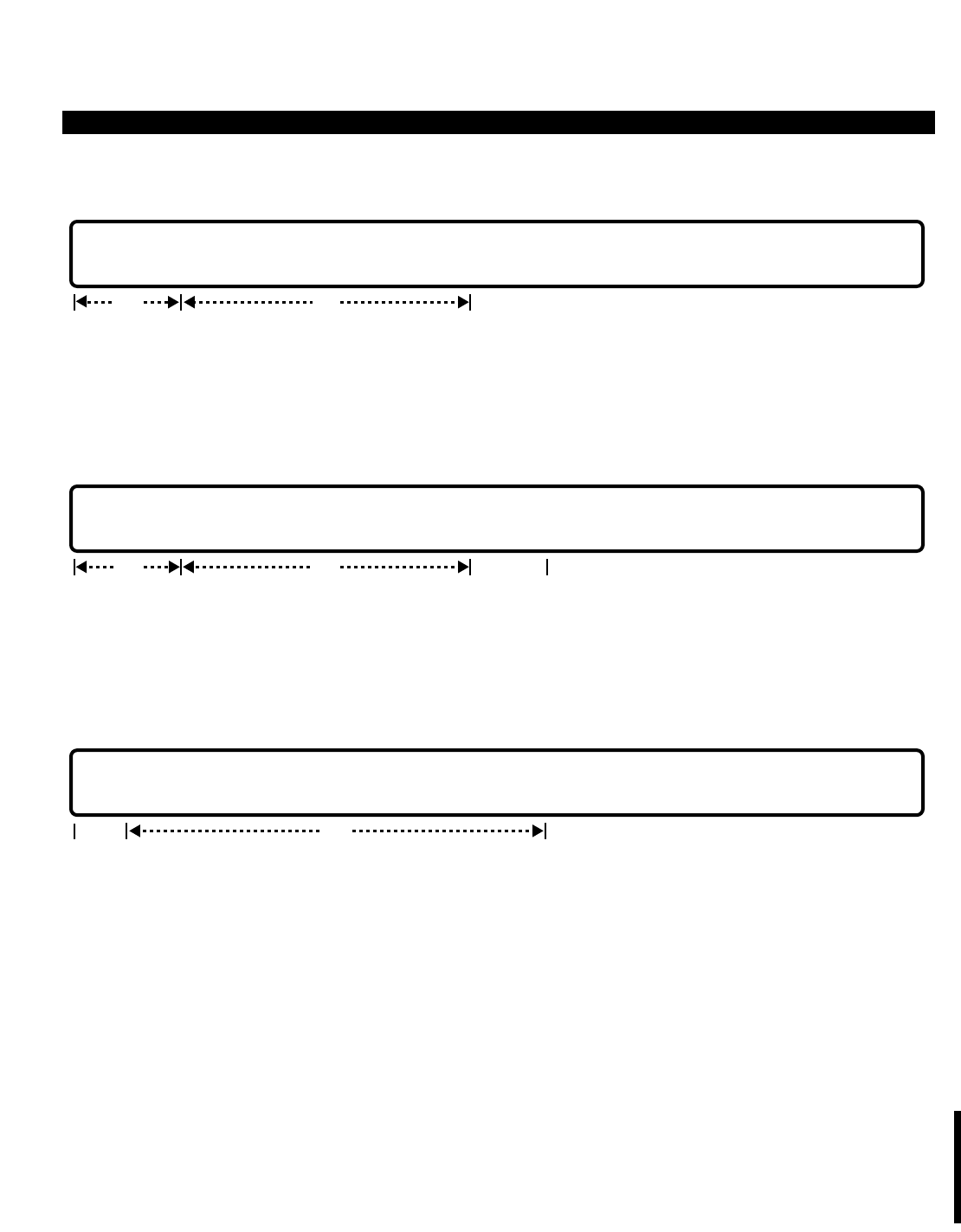
PERCEPTION 4000 COMMANDS
DELETE
This operation deletes a pattern (Pattern #2, 3, or 4) or a key position from a pattern for the specified device. The
"PRM POS" may be deleted only after the "DDN POS" and all "FEA POS" key positions are deleted. The "FEA
POS" is a loop field.
MODIFY
Key positions for Patterns 2 through 4 are modified with this operation. If a pattern is modified after telephones
have been programmed using that pattern, the modification does not affect those telephones, it affects only those
telephones added after the modification.
DISPLAY
Key patterns are displayed on the maintenance console for the specified device (DEV). "PAT" and "FEA POS" are
loop fields.
PARAMETERS
Each field parameter is described in this section. Any variations for a particular operation are noted separately.
FIELD: DEV (Telephone Device Type)
TYPE: Keyword
FORMAT: Predefined ASCII characters
Keywords: 2010 - PERCEPTION 4000 10-key digital telephone
2020 - PERCEPTION 4000 20-key digital telephone
EKT1 - Electronic telephone with 10 flexible keys
EKT2 - Electronic telephone with 20 flexible keys, with or without display
DKT1 - DKT digital telephone with 10 keys, with or without display
DEV | PAT | PRM POS | DDN POS | FEA POS | FEA ID |
optreq
DEV | PAT | PRM POS | DDN POS | FEA POS | FEA ID |
optreq req
DEV | PAT | PRM POS | DDN POS | FEA POS |
optreq
ISS 2, SECTION 4000-014-000
STATION FEATURE KEY PATTERN ASSIGNMENT (CMD 320)
3-325

PERCEPTION 4000 COMMANDS
ISS 2, SECTION 4000-014-000
STATION FEATURE KEY PATTERN ASSIGNMENT (CMD 320)
DKT2 - DKT with 20 keys, with or without display
ID10 - PERCEPTION 4000 10-key digital telephone with DIU-I
ID20 - PERCEPTION 4000 20-key digital telephone with DIU-I
The "DEV" field identifies the type of telephone to be programmed with a template, and is
required in all operations.
FIELD: PAT (Pattern Number of Template for Position of Feature Keys)
TYPE: Decimal
FORMAT: 1 digit
VALUE: 1 to 4 (in a DISPLAY operation)
2 to 4 (in an ADD, DELETE, or MODIFY operation)
RANGE: Not allowed
LOOP: Allowed in a DISPLAY operation only
This field selects the pattern to be programmed. Note that Pattern #1 may not be modified in any
way. The DISPLAY operation is the only operation allowed for this pattern.
FIELD: PRM POS (Prime Directory Number Key Position)
TYPE: Decimal
FORMAT: 1 or 2 digits
VALUE: 1 to 10 (for PERCEPTION 4000 10-key digital telephones, 10-key DKTs, and 10-key electronic
telephones)
1 to 20 (for PERCEPTION 4000 20-key digital telephones, 20-key DKTs, and 20-key electronic
telephones)
RANGE: Not allowed
LOOP: Not allowed
This field defines the location of the prime directory number key on the selected device, and is
required for the first-time addition for a given pattern number. Pattern #1 default values are as
follows:
"DEV" Field "PRM POS" Field
2010 6
2020 16
ID10 6
ID20 16
EKT1 1
EKT2 1
DKT1 1
DKT2 1
FIELD: DDN POS (Data Directory Number Key Position)
TYPE: Decimal
FORMAT: 1 or 2 digits
VALUE: 1 to 10 (for 10-key PERCEPTION 4000 digital telephones with DIU-Is).
For illustrations of key positions, refer to the Station Feature Key Assignment command (CMD 331).
3-326

PERCEPTION 4000 COMMANDS
1 to 20 (for 20-key PERCEPTION 4000digital telephones with DIU-Is).
RANGE: Not allowed
LOOP: Not allowed
This field defines the location of the data directory number key on the selected device, and is
required for the first-time addition for a given pattern number. Pattern #1 default values are as
follows:
"DEV" Field "DDN POS" Field
ID10 5
ID20 5
FIELD: FEA POS (Feature Key Position)
TYPE: Decimal
FORMAT: 1 or 2 digits
VALUE: 1 to 10 (for PERCEPTION 4000 10-key digital telephones, 10-key DKTs, and 10-key electronic
telephones)
1 to 20 (for PERCEPTION 4000 20-key digital telephones, 20-key DKTs, and 20-key electronic
telephones)
RANGE: Not allowed
LOOP: Allowed in ADD, DELETE, and DISPLAY operations
This field is required if a feature key ("FEA ID" field) is to be assigned to the selected device.
Certain feature key positions are set up with specific feature IDs that cannot be modified or
deleted for all patterns. These include the following key positions:
DEVICE FEATURE POSITION FEATURE ID
2010 10 RLS
2020 20 RLS
ID10 10 RLS
ID20 20 RLS
EKT1 9 RLS
10 MSW
EKT2 19 RLS
20 MSW
DKT1 10 RLS
DKT2 20 RLS
FIELD: FEA ID (Feature ID Number or Abbreviation)
TYPE: Decimal / Keyword
FORMAT: 1 to 4 digits / Predefined ASCII characters
VALUE: 0 to 9999 (Feature ID Number)
RANGE: Not allowed
LOOP: Not allowed
ISS 2, SECTION 4000-014-000
STATION FEATURE KEY PATTERN ASSIGNMENT (CMD 320)
3-327

PERCEPTION 4000 COMMANDS
ISS 2, SECTION 4000-014-000
STATION FEATURE KEY PATTERN ASSIGNMENT (CMD 320)
Keywords: Feature Name Number Abbreviation
ACD Alarm Key 326 ALRM
ACD Assistance 324 ASST
ACD Inter-Group Call Pickup 336 INTP
ACD Inter-Group Tap Key 337 INTM
ACD Intra-Group Call Pickup 323 ACDP
ACD Intra-Group Tap Key 325 TAP
ACD Log Key 317 LOG
ACD Status Key 320 STAT
ACD Work Mode Cancellation 321 CANC
ACD Work Unit 322 WRKU
Account Code 307 ACCT
Attendant Parked Page Retrieval 333 PR_A
Authorization Code 299 AUTH
Autodial Key 278 ADL
Automatic Answer Key 279 AUTO
Call Forward - All Calls Key 271 CFAC
Call Forward - Busy/No Answer Key 272 CFBN
Call Forward - No Answer Key 273 CFNA
Call Forward - Preregistered 275 PRCF
Call Park - Local Access/Retrieval 301 CP_L
Call Park - Remote Access/Retrieval 302 CP_R
Call Pickup - Directed 284 DPU
Call Pickup - Directed Group 285 DGPU
Call Pickup - Group 262 GPU
Camp-on Key 281 CAMP
Code Calling Access 258 CC
Code Calling Retrieval 267 CCMM
Data Privacy 312 DPVY
Dictation Machine Access - Direct 264 DC_I
Dictation Machine Access - Group 263 DC_G
Do Not Disturb Key 270 DND
Headset Control Key 339 HSC
Headset Mode Key 338 HSM
LCD Contrast Control Key 340 LCDC
LCD Remote Logout Agent 341 RLOG
Night Answer Access 269 UNA
Privacy Release 268 PRLS
Program Mode Key 274 PRGM
Save and Repeat Key 277 S&R
Speed Calling - Group 291 SC_G
Speed Calling - System 290 SYSD
Swap 287 SWAP
UCD Available/Unavailable Key 309 UCD
Voice Calling Key 276 VC
Voice Paging Access - Emergency 261 VP_E
Voice Paging Access - System 260 VP_S
Voice Paging Access - Zone 259 VP_Z
Voice Paging Retrieval - System 266 PR_S
Voice Paging Retrieval - Zone 265 VPMM
3-328

PERCEPTION 4000 COMMANDS
This field is required when programming a feature key. Data entry for this field is in the form of a
feature "Number" or "Abbreviation." Note that certain features can only be assigned once for the
same station, such as Do Not Disturb, Call Forward, Conference, etc.
SYSTEM ERROR MESSAGES
The following error messages are unique to this command.
C32000 - Pattern 1 cannot be added, modified, or deleted
C32001 - DDN key assignment is only allowed for ID10 or ID20 devices
C32002 - FEA ID is a required field for FEA POS
C32003 - FEA POS is a required field for FEA ID
C32004 - Key position is out of range in field(s) X
C32005 - Duplicate key position in field(s) X
C32006 - PRM POS is required in Field 3
C32007 - DDN POS is required in Field 4
C32008 - There must be only one PRM POS assigned
C32009 - There must be only one DDN POS assigned
C32010 - Delete all FEA POS's before deleting the PRM POS
C32011 - Delete all FEA POS's before deleting the DDN POS
C32012 - Delete the DDN POS before deleting the PRM POS
C32013 - Feature key position Z is a reserved key
C32014 - Invalid key position in field X
C32015 - Feature number is out of range
C32016 - Feature key position has already been assigned
C32017 - Feature ID already exists for this pattern
C32018 - LCD contrast control is only supported by 2020 and ID20 telephones
C32019 - Key position Z does not exist
C32020 - Key position Z has already been used
C32021 - Headset mode is not supported by electronic or digital key telephones
C32022 - The deletion of PRM POS or DDN POS in setup mode is not allowed
C32023 - Last number redial is only supported by electronic/DKT telephones
C32024 - Missing data in field 3, 4, or 5
NOTE: "X" = 3, 4, or 5
"Z" = 1 through 20
RELATED COMMANDS
Station Assignment (CMD 330)
Station Feature Key Assignment (CMD 331)
ISS 2, SECTION 4000-014-000
STATION FEATURE KEY PATTERN ASSIGNMENT (CMD 320)
3-329
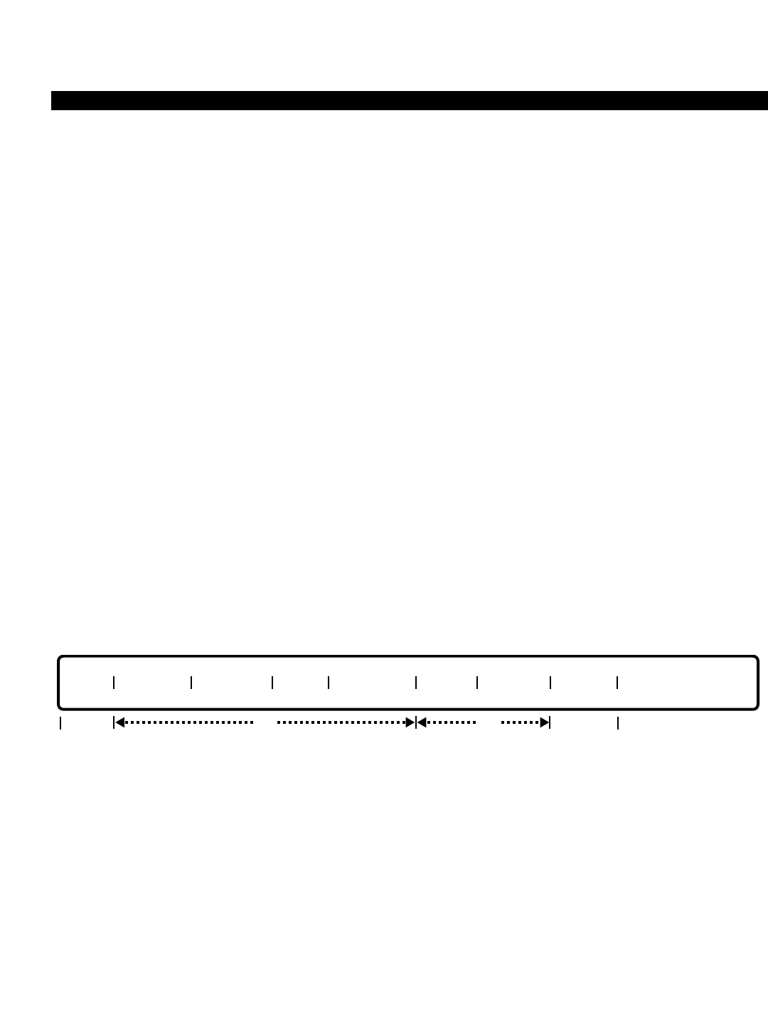
PERCEPTION 4000 COMMANDS
ISS 2, SECTION 4000-014-000
STATION HUNTING ASSIGNMENT (CMD 342)
STATION HUNTING ASSIGNMENT (CMD 342)
The Station Hunting Assignment command defines and modifies voice hunt groups in the system. This type of
hunt group performs a serial or circular search of the members from the entry point to the end of the list. Up to
200 groups with a maximum of 16 members in each group may be defined. Note that the system allows for a
maximum of 800 members. Data hunt groups are assigned via the Data Hunting Assignment command
(CMD 366).
Command Keyword: STA_HUNTING
Category Name: Station
PREREQUISITE COMMAND
Station Assignment (CMD 330)
OPERATIONS
Available operations: ADD
DELETE
MODIFY
DISPLAY
The function and required data fields for each operation are described in this section.
ADD
This operation inserts a membership directory number or pilot directory number into a station hunting group. The
Hunt Group Number, Member Number, and Member Directory Number are required. The Member Directory
Number is limited to being a member of only one hunt group. If the "METHOD" is specified as SER, the Entry
Point is required. If the "METHOD" is CIR, the Entry Point defaults to YES. Looping is allowed in the "MEM #"
field. Note that the addition of a specified member number moves all of the following members one step backward
accordingly.
req
GRP# METHOD PILOT DN NAME OVF DEST MEM # MEM DN ENT PT
opt opt
req
3-330
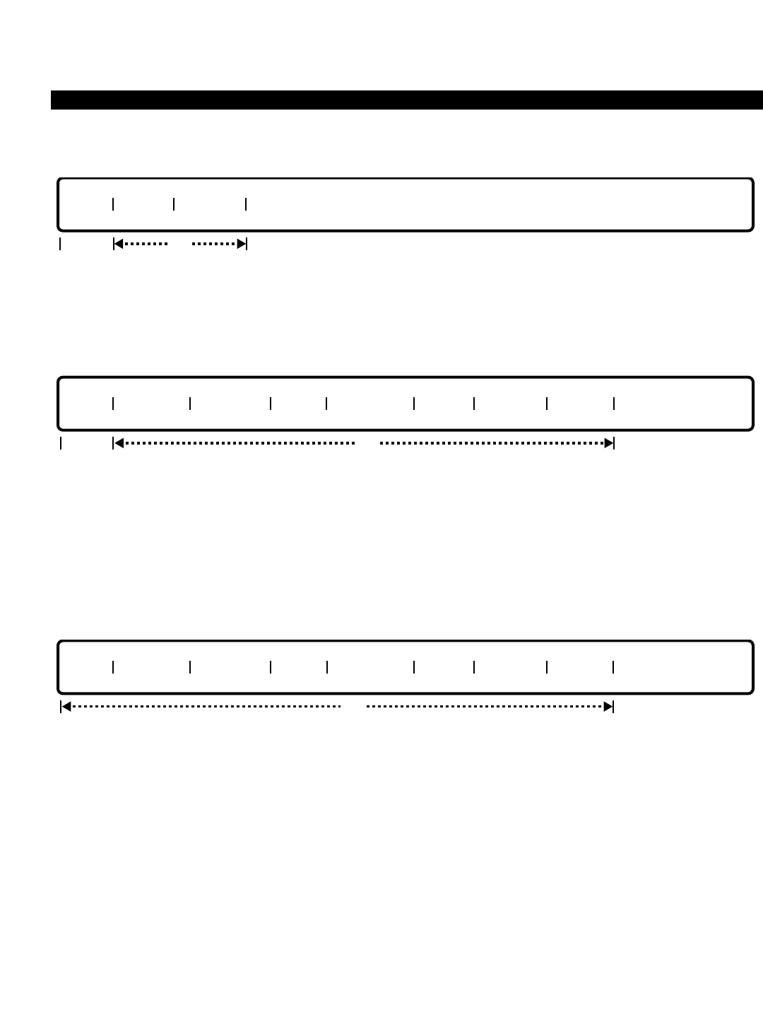
PERCEPTION 4000 COMMANDS
DELETE
This operation removes a membership directory number. The Hunt Group Number is required. To delete all
members from a Hunt Group Number, enter the keyword ALL in the "MEM #" field. Looping is allowed in the
"MEM #" field.
MODIFY
This operation changes the hunt method, hunt group pilot directory number, group name, overflow destination,
member directory number, or entry point attributes for a hunt group. If the method is changed from serial to
circular, all of the entry points are changed to YES automatically, and the pilot directory number is automatically
deleted. If the method is changed from circular to serial, the pilot directory number is allowed. If the member
directory number or the entry point is modified, the member number must be entered. To modify group attributes,
the last three fields should not be specified.
DISPLAY
This operation displays all station hunt groups and their members that meet the conditions established in each
field. Loops are permitted in the "GRP#" and "MEM #" fields. Ranges are permitted in the "MEM DN" field only.
PARAMETERS
Each field parameter is described in this section. Any variations for a particular operation are noted separately.
FIELD: GRP# (Hunt Group Number)
TYPE: Decimal
FORMAT: 1 to 3 digits
VALUE: 1 to 200
LOOP: Allowed in a DISPLAY operation only
The system may define up to 200 station hunt groups for both the circular and serial hunt group
types for voice hunting. The combined total of both hunt group types may not exceed 200 groups.
FIELD: METHOD (Hunt Method)
GRP# METHOD PILOT DN NAME OVF DEST MEM # MEM DN ENT PT
opt
req
GRP# METHOD PILOT DN NAME OVF DEST MEM # MEM DN ENT PT
opt
req
GRP# MEM # MEM DN
opt
ISS 2, SECTION 4000-014-000
STATION HUNTING ASSIGNMENT (CMD 342)
3-331

PERCEPTION 4000 COMMANDS
ISS 2, SECTION 4000-014-000
STATION HUNTING ASSIGNMENT (CMD 342)
TYPE: Keyword
FORMAT: Predefined ASCII characters
Keywords: SER - Serial Hunt Method
CIR - Circular Hunt Method
This field establishes whether the hunt group is circular or serial. For a circular hunt group, dialing
any member directory number which is busy or in Do not Disturb (but not forwarded) results in a
search for an available member in the order established with this command. The search 'wraps
around' and continues searching until the called member is reached. In a circular hunt, all
members are entry points.
For a serial hunt, entry into the group is generally by the pilot number. The hunt begins at the top
of the list and ceases at the bottom. Various members may also be flagged as entry points.
Dialing any member directory number marked as an entry point which is busy or in Do not
Disturb (but not forwarded) results in a search for an available member in the order established in
this command, starting at the busy member and proceeding to the end of the list. 'Wrapping'
does not occur in a serial hunt.
FIELD: PILOT DN (Pilot Directory Number)
TYPE: DN Type
FORMAT: 1 to 5 digits
VALUE: 0 to 99999
This field, valid for serial hunt groups only, marks an entry point into a serial hunt group table
using a virtual directory number. The number cannot be assigned to a physical equipment
location, and must meet the numbering plan restrictions. The directory number cannot appear in
more than one hunt group. The "PILOT DN" field can be deleted by pressing <CONTROL-D> in a
MODIFY operation.
FIELD: NAME (Group Name)
TYPE: Text
FORMAT: 0 to 9 ASCII characters
The group name is provided for the benefit of users with display equipped telephones and the
attendant. When the pilot number is dialed or a legal entry point is used into a serial hunt group,
this information displays. For example, the group name "I SALES" would indicate this hunt group
is made up of inside sales personnel. The "NAME" field can be deleted by pressing <CONTROL-
D> in a MODIFY operation.
FIELD: OVF DEST (Overflow Destination)
TYPE: DN Type
FORMAT: 1 to 5 digits
- Individual attendant console directory number
- Station number
- Hunt group pilot number
- UCD group pilot number
- ACD group pilot number
- Attendant group directory number
VALUE: 0 to 99999 (Termination DN)
3-332

PERCEPTION 4000 COMMANDS
FORMAT: 4 to 6 digits
VALUE: 1 to 3 digits, plus 3 digit speed call access and code
The overflow directory number establishes a secondary hunt or call termination point. Only one
level of hunt overflow is allowed. If the destination is another hunt group which also has an
overflow defined, the second group's overflow is not used. Off-premises routing is available via
system speed call number entry. The "OVF DEST" field can be deleted by pressing <CONTROL-
D> in a MODIFY operation.
FIELD: MEM # (Membership Index Number)
TYPE: Decimal / Keyword
FORMAT: 1 or 2 digits / Predefined ASCII characters
VALUE: 1 to 16 / ALL
LOOP: Allowed in DISPLAY, ADD, and DELETE operations
The index number shows the order of search from the lowest to the highest number when the
hunt group pilot directory number is dialed. The keyword ALL may be entered in this field in a
DELETE operation to remove all members from a specified hunt group.
FIELD: MEM DN (Member Directory Number)
TYPE: DN Type
FORMAT: 1 to 5 digits
VALUE: 0 to 99999
RANGE: Allowed in a DISPLAY operation only
Member directory numbers are assigned in the sequence desired. Only voice stations are legal
members of a voice hunt group. Each directory number can be set up to be an entry point, and
can be a member of only one hunt group.
FIELD: ENT PT (Entry Point to Serial Hunt Group List)
TYPE: Keyword
FORMAT: Predefined ASCII characters
Keywords: YES - Allow MEM DN to be entry point to serial hunt group
NO - Do not allow MEM DN to be entry point to serial hunt group
This field determines whether or not a member directory number can be used as an entry point
into the serial hunt group list. The search starts at that directory number’s position and continues
down the list until the first idle directory number is found, or until the remaining members have
been exhausted. For circular hunt groups, only YES may be entered.
SYSTEM ERROR MESSAGES
The following error messages are unique to this command.
C34200 - Input member directory number or entry point
C34201 - Group is already full
C34202 - Hunt Method field is required
C34203 - Circular group; pilot directory number is not needed
C34204 - Circular group; entry point must be YES
C34205 - Member directory number is not defined in the system
ISS 2, SECTION 4000-014-000
STATION HUNTING ASSIGNMENT (CMD 342)
3-333

PERCEPTION 4000 COMMANDS
ISS 2, SECTION 4000-014-000
STATION HUNTING ASSIGNMENT (CMD 342)
C34206 - Entry point should be input
C34207 - Not allowed; the second member's entry point is NO
C34208 - Hunt Method mismatch
C34209 - Pilot directory number mismatch
C34210 - Group name mismatch
C34211 - Overflow termination mismatch
C34212 - Group is empty
C34213 - Member number is not in group
C34214 - Member directory number is not in group
C34215 - Inconsistent member number/directory pair
C34216 - Pilot directory number is already in use
C34217 - Overflow termination is not defined
C34218 - Member number is required
C34219 - Entry point of the first member must be YES
C34220 - Member number is not continuous in group
C34221 - Member directory number is in another hunt group
C34222 - Cannot use this directory number
C34223 - The input overflow termination is already used for a group
C34224 - Pilot directory number is used as overflow in another group
C34225 - Input pilot or member directory number is the same as overflow
C34226 - Group name is too long
C34227 - This hunt group is for VMS; directory number must be a VMS DN
C34228 - This directory number is for VMS; cannot be used for this group
C34229 - No more space left to add
C34230 - A private line directory number cannot be used to hunt
C34231 - Serial group; pilot directory number is required
I34232 - Warning: Undefined data in field 5
C34233 - Origination only station cannot be used to hunt
COMMENTS
When adding a new group, if the method is specified as SER, the virtual pilot directory number field must be
entered. Otherwise, if the method is specified as CIR, the virtual pilot directory number field must be left empty.
When adding a member to an 'SER' hunt group, the entry point must be input. When the addition is to a 'CIR'
hunt group, the entry point may be left empty or set to YES.
RELATED COMMANDS
ACD Group Assignment (CMD 355)
Attendant Group Assignment (CMD 372)
Attendant Position Assignment (CMD 370)
Authorization Code Assignment (CMD 349)
Internal Call Alternate Routing Assignment (CMD 374)
Numbering Plan Assignment (CMD 300)
Station Feature Key Assignment (CMD 331)
System Speed Calling Assignment (CMD 402)
UCD Group Assignment (CMD 354)
3-334
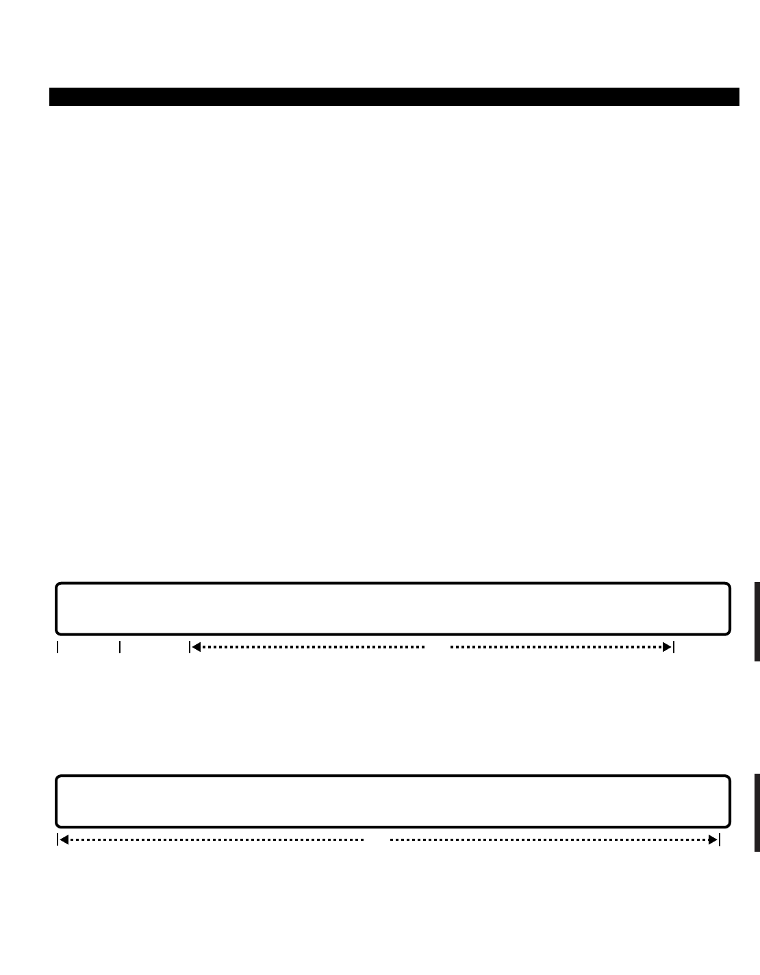
PERCEPTION 4000 COMMANDS
STATION-LEVEL PARAMETER ASSIGNMENT (CMD 329)
The Station-Level Parameter Assignment command modifies and displays station parameters including the prime
directory number, voice mail retrieval destination, forced account code types, originate-/terminate-only station
designation, privacy, attendant supervision, timeout routing destination index, data security, and the voice mail
port number for analog telephones.
Command Keyword: STA_PARAMETERS
Category Name: Station
PREREQUISITE COMMAND
Station Assignment (CMD 330)
OPERATIONS
Available operations: MODIFY
DISPLAY
The function and required data fields for each operation are described in this section.
MODIFY
This operation modifies several station parameters. The "EQUIP #" field is required; and looping is allowed in this
field. The prime directory number (PRM DN) field cannot be modified.
DISPLAY
This operation displays the station equipment ports which meet the conditions established for each field. Looping
is allowed in the “EQUIP #” field.
EQUIP # | PRM DN | VM DEST | TYPE | ORG/TER | PVT | ASD | TOR# | DID# | DISP | SEC | VMS# |
opt
EQUIP # | PRM DN | VM DEST | TYPE | ORG/TER | PVT | ASD | TOR# | DID# | DISP | SEC |
optreq locked
ISS 2, SECTION 4000-014-000
STATION-LEVEL PARAMETER ASSIGNMENT (CMD 329)
3-335

PERCEPTION 4000 COMMANDS
ISS 2, SECTION 4000-014-000
STATION-LEVEL PARAMETER ASSIGNMENT (CMD 329)
PARAMETERS
Each field parameter is described in this section. Any variations for a particular operation are noted separately.
FIELD: EQUIP # (Equipment Number)
TYPE: EQ Type
FORMAT: 5 or 6 digits
VALUE: (0)10101 to 101408
LOOP: Allowed in both the MODIFY and DISPLAY operations
The equipment number is assigned with the Station Assignment command (CMD 330). This field
selects the appropriate station to be modified or displayed.
FIELD: PRM DN (Prime Directory Number)
TYPE: Dialing Digits
FORMAT: 1 to 5 digits
VALUE: 0 to 99999
LOOP: Not allowed
RANGE: Allowed in a DISPLAY operation only
This field specifies the prime directory number assigned to the "EQUIP #" defined in the previous
field. The "PRM DN" field is locked in a MODIFY operation.
FIELD: VM DEST (Voice Mail Retrieval Destination)
TYPE: Dialing Digits
FORMAT: 1 to 5 digits
VALUE: 0 to 99999
LOOP: Not allowed
The voice mail retrieval destination number defines a voice mail port or hunt group pilot used for
accessing the voice mail system.
FIELD: TYPE (Forced Account Code Type)
TYPE: Keyword
FORMAT: Predefined ASCII characters
DEFAULT: NON
Keywords: ALL - All calls
TOLL - Toll calls only
NON - None
This field defines whether calls made by the user require forced account code entry or not and, if
so, the type of forced account. A forced account code can be required for all outgoing calls or for
toll calls only. Note that the definition of non-toll dialing for the Forced Account Code feature is
defined with the Forced Account Code Toll-free Tables command (CMD 352). This feature affects
all lines on the specified station, not only the prime line.
3-336

PERCEPTION 4000 COMMANDS
FIELD: ORG/TER (Originate- or Terminate-only Station)
TYPE: Keyword
FORMAT: Predefined ASCII characters
Keywords: ORG - Origination allowed and termination denied
TER - Origination denied and termination allowed
BOTH - Both origination and termination allowed (Default)
A station may be configured as allowed to receive calls only or make calls only with this field.
Calls with originate-only status may still receive camp-on callbacks and recalls. Terminate-only
stations may not perform a consultation hold. The "ORG/TER" field affects all voice line
appearances for the defined station.
FIELD: PVT (Privacy)
TYPE: Keyword
FORMAT: Predefined ASCII characters
Keywords: YES - Privacy enabled
NO - Privacy disabled (Default)
When set to YES, the Privacy feature prevents the attendant from breaking into an existing
conversation.
FIELD: ASD (Attendant Supervision Disable)
TYPE: Keyword
FORMAT: Predefined ASCII characters
Keywords: YES - Disable attendant supervision
NO - Enable attendant supervision (Default)
When set to YES, the supervisor is prevented from performing supervision (locked loop
operation) of any call the station is handling.
FIELD: TOR# (Timeout Routing Index)
TYPE: Decimal
FORMAT: 1 or 2 digits
VALUE: 1 to 32
LOOP: Not allowed
RANGE: Allowed in MODIFY operation
The "TOR#" field selects a destination number from the Timeout Routing Assignment Table (refer
to the Timeout Routing Destination Assignment command, CMD 323). When the station user
goes off-hook and fails to dial, or fails to dial enough digits for a valid number, the station is
routed to the predefined timeout destination number.
FIELD: DID# (DID Index Number)
TYPE: Decimal
FORMAT: 1 or 2 digits
VALUE: 1 to 16
LOOP: Not allowed
RANGE: Allowed in DISPLAY operation only
ISS 2, SECTION 4000-014-000
STATION-LEVEL PARAMETER ASSIGNMENT (CMD 329)
3-337

PERCEPTION 4000 COMMANDS
ISS 2, SECTION 4000-014-000
STATION-LEVEL PARAMETER ASSIGNMENT (CMD 329)
The "DID#" field is used to specify the DID index number that applies to the telephone. This index
number refers to the prefix number assigned in the System Option Flag Assignment command
(CMD 408). Each prefix (index) number represents the digits that will prefix the telephone's DID
number to represent an entire telephone number. This telephone number will appear at called
display stations. For example, if prefix (index) number 1 is "583" and a station's DID number is
"3700," then an entry of "1" in the "DID#" field, will produce a displayed number of "5833700."
FIELD: DISP (Outgoing Call Display Flag)
TYPE: Keyword
FORMAT: Predefined ASCII characters
Keywords: NAME - Trunk name
DLDN - Dialed number (Default)
This field is used to assign the type of call identification information that will appear at the station
when placing either ISDN or non-ISDN outgoing calls. When dialing a number from a station, the
dialed digits initially appear on the station's own display. After the outgoing call is recognized by
the PERCEPTION 4000 system and a trunk is selected, these digits can either remain displayed
or be replaced by the name of the utilized trunk/trunk group. By entering the keyword DLDN, the
displayed digits will be maintained. By entering NAME, the digits will be replaced by the name of
the utilized trunk/trunk group.
FIELD: SEC (Data Security)
TYPE: Keyword
FORMAT: Predefined ASCII characters
Keywords: YES - Data security enabled
NO - Data security disabled (Default)
The security field specifies whether or not the station has data security on the prime line. If set to
YES, break-ins or other types of monitoring are not allowed on this line. This secures the line
from any interruption that could corrupt data transmission, including Call Waiting tones. This flag
is normally set for analog stations which frequently connect to a modem for analog data
transmission.
FIELD: VMS# (Voice Messaging System Port Number)
TYPE: Decimal
FORMAT: 1 or 2 digits
VALUE: 1 to 32
LOOP: Not allowed
RANGE: Allowed in a DISPLAY operation
The "VMS#" field identifies a voice messaging system port number for an analog telephone. The
port number table is established by the Station Assignment command (CMD 330), "TYPE" field,
AVMS option.
3-338

PERCEPTION 4000 COMMANDS
SYSTEM ERROR MESSAGES
The following error messages are unique to this command.
C32900 - Specified equipment number is not available in the system
C32901 - Check terminate or originate-only station
C32902 - Check privacy
C32903 - Check attendant supervision disable
C32904 - Check timeout routing index
C32905 - ORG/TER field cannot be modified; ACD agent is remotely logged in
C32906 - Failed to read prime line attributes
C32907 - Hunting member station cannot be assigned as originating only
C32908 - Equipment number is assigned to another device
RELATED COMMAND
Forced Account Code Toll-free Tables (CMD 352)
Timeout Routing Destination Assignment (CMD 323)
ISS 2, SECTION 4000-014-000
STATION-LEVEL PARAMETER ASSIGNMENT (CMD 329)
3-339
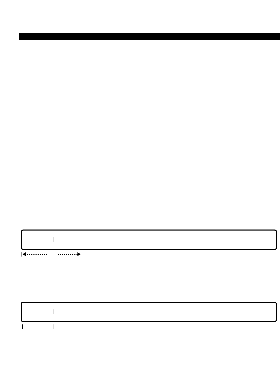
PERCEPTION 4000 COMMANDS
ISS 2, SECTION 4000-014-000
SYSTEM DISA SECURITY CODE ASSIGNMENT (CMD 321)
SYSTEM DISA SECURITY CODE ASSIGNMENT (CMD 321)
Security codes for the Direct Inward System Access (DISA) feature are defined with this command if DISA
requires security code entry (as established in the System Option Flag Assignment command, CMD 408). In
addition, SMDR ID codes are assigned to defined DISA security codes.
Command Keyword: DISA_CODES
Category Name: System
PREREQUISITE COMMANDS
There are no prerequisites for this command.
OPERATIONS
Available operations: ADD
DELETE
MODIFY
DISPLAY
The function and required data fields for each operation are described in this section.
ADD
This operation defines the DISA security code and SMDR ID code. The default length of the security code is six
digits.
DELETE
This operation deletes security codes. If the keyword ALL is entered, all of the codes in the DISA security code
table are deleted.
SEC CODE
req
SEC CODE SMDR ID
req
3-340
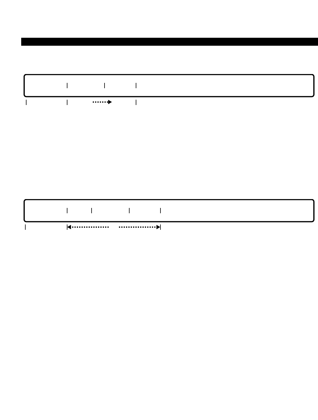
PERCEPTION 4000 COMMANDS
MODIFY
This operation modifies the length of the DISA security codes, and/or changes the SMDR ID for the specified
security code. If data is entered in the “SEC CODE” field, data must be entered in the “SMDR ID” field. A
MODIFY operation may not be performed if a specified security code is not in the database (i.e., a security code
and SMDR ID must be added before they can be modified).
All security codes must be of the same length. To change the "SEC LENGTH" field, delete all of the security
codes, use a MODIFY operation to change the length to a new value, and add new security codes and SMDR
IDs into the system.
DISPLAY
This operation displays the DISA security code table. Looping is allowed in the “INDEX” field. If a <TAB> is
entered in the “SEC LENGTH” and “INDEX” fields and no data is entered in the other fields, the complete DISA
security code table displays. The "SEC LENGTH" field is an output only field in a DISPLAY operation.
PARAMETERS
Each field parameter is described in this section. Any variations for a particular operation are noted separately.
FIELD: SEC LENGTH (Security Code Length)
TYPE: Decimal
FORMAT: 1 digit
VALUE: 3 to 6
DEFAULT: 6
This field sets the number of digits required for security codes. When modifying the length of the
security codes, all security codes must first be deleted. In a DISPLAY operation, this is an output
only field.
FIELD: INDEX (Security Code Index Number)
TYPE: Decimal
FORMAT: 1 or 2 digits
VALUE: 1 to 64
LOOP: Allowed in a DISPLAY operation
SEC LENGTH INDEX SEC CODE SMDR ID
optoutput only
SEC LENGTH SEC CODE SMDR ID
optopt opt
ISS 2, SECTION 4000-014-000
SYSTEM DISA SECURITY CODE ASSIGNMENT (CMD 321)
3-341

PERCEPTION 4000 COMMANDS
ISS 2, SECTION 4000-014-000
SYSTEM DISA SECURITY CODE ASSIGNMENT (CMD 321)
This field is used internally as a counter for the DISA security code table. Its value does not
indicate an actual position or set any priority for data entered in this command.
FIELD: SEC CODE (Security Code)
TYPE: Dialing Digits / Keyword
FORMAT: 3, 4, 5, or 6 digits (depending on the SEC LENGTH field) / ASCII characters
VALUE: 0 to 9 / ALL
RANGE: Allowed in a DISPLAY operation to match a partial string
Up to 64 DISA security codes may be defined. All codes must be the same length, as specified in
the "SEC LENGTH" field. The keyword ALL is used in a DELETE operation when deleting all of
the security codes in the table.
FIELD: SMDR ID (SMDR ID Code)
TYPE: Decimal with fixed length
FORMAT: 3 to 5 digits
VALUE: 001 to 99999
Each security code may be assigned a unique SMDR identification code. This code is 3 to 5
digits in length; it does not have to be the same length as the security code. The SMDR ID code
is printed out on the SMDR call record when DISA access has been successful, and can be used
to identify the calling party for accounting purposes.
SYSTEM ERROR MESSAGES
The following error messages are unique to this command.
C32100 - Security code must be of length N
C32101 - Table entries exceed 64
C32102 - # or * are not accepted as security code digits
C32103 - Security code has been used
C32104 - SMDR ID code has been used
C32105 - Security code is not found
C32106 - Check input in field(s) Ni..Nj
C32107 - To modify security code length, enter <TAB> in fields 2 and 3
C32108 - To modify security code length, delete all security codes first
RELATED COMMANDS
System Option Flag Assignment (CMD 408)
Trunk Group Assignment (CMD 310)
3-342

PERCEPTION 4000 COMMANDS
SYSTEM HOLIDAY ASSIGNMENT (CMD 404)
This command adds/deletes/displays holidays in the System Holiday table and also changes the holiday in the
table. Up to 16 holidays may be defined. If the System Administrator wants to specify specific time zones for
some holidays, then it is necessary to set the appropriate time zone in the Time Zone Assignment command
(CMD 336).
Command Keyword: HOLIDAY_ASSIGN
Category Name: System
PREREQUISITE COMMANDS
There are no prerequisites for this command.
OPERATIONS
Available operations: ADD
DELETE
MODIFY
DISPLAY
The function and required data fields for each operation are described in this section.
ADD
This operation adds holidays to the System Holiday table. Addition of a specific entry re-sequences all entries
following it. Looping is allowed in the “INDEX” field.
DELETE
This operation deletes holidays from the System Holiday table. Deletion of an entry re-sequences all entries
following it. When ALL is entered in the “INDEX” field, all of the entries in the System Holiday table are deleted.
INDEX DATE
optreq reqopt
req
INDEX DATE
ISS 2, SECTION 4000-014-000
SYSTEM HOLIDAY ASSIGNMENT (CMD 404)
3-343

PERCEPTION 4000 COMMANDS
ISS 2, SECTION 4000-014-000
SYSTEM HOLIDAY ASSIGNMENT (CMD 404)
MODIFY
This operation changes a holiday in the System Holiday table.
DISPLAY
This operation displays the System Holiday table. If no data is entered, the complete table displays.
PARAMETERS
This section defines inputs permitted for each field. Any variations for a particular operation are noted separately.
FIELD: INDEX (Index Number)
TYPE: Decimal
FORMAT: 1 or 2 digits
VALUE: 1 to 16
LOOP: Allowed in ADD and DISPLAY operations
Keyword: ALL
The index number provides a counter for the convenience of the administrator. Its value does not
indicate an actual position or set any priority for data entered in this field. The holiday list is
sorted according to date regardless of the order entered.
The keyword ALL is only used in a DELETE operation when deleting all of the entries in the
system holiday table.
FIELD: DATE (Holiday)
TYPE: Decimal with fixed length
FORMAT: 4 digits
VALUE: 0101-1231
RANGE: Allowed in a DISPLAY operation
Each date is defined using four digits in the format: MMDD
MM (Month) = 01 to 12
DD (Day) = 01 to 31
opt
INDEX DATE
req
INDEX DATE
3-344

PERCEPTION 4000 COMMANDS
The correct date and time must be set on the system's real time clock for these dates to be
invoked correctly.
SYSTEM ERROR MESSAGES
The following error messages are unique to this command.
C40400 - Duplicate holiday dates
C40401 - Table entries exceed 16
C40402 - Index number is already defined in the table
C40403 - Invalid input data
C40404 - Index number is not defined in the table
C40405 - Input holiday date is not found in the table
C40406 - Holiday date value is out of range
RELATED COMMAND
Time Zone Assignment (CMD 336)
ISS 2, SECTION 4000-014-000
SYSTEM HOLIDAY ASSIGNMENT (CMD 404)
3-345
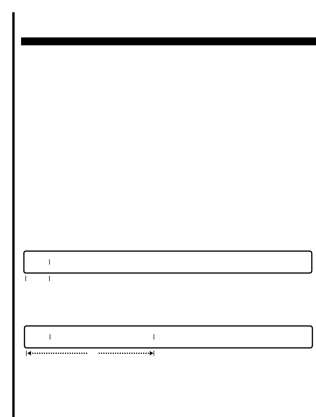
PERCEPTION 4000 COMMANDS
ISS 2, SECTION 4000-014-000
SYSTEM INVENTORY (CMD 210)
SYSTEM INVENTORY (CMD 210)
The System Inventory command enables an M&A user to display a summary report of a PERCEPTION 4000
system's hardware and software configuration. This report is very helpful in troubleshooting situations, since it
provides in-service/out-of-service indications of various system components. The numerical output from this
command can provide precise indications of any system fault activity.
Command Keyword: SYS_INVENTORY
Category Name: Utility
PREREQUISITE COMMANDS
There are no prerequisites for this command.
OPERATIONS
Available operations: DISPLAY
MODIFY
The function and required data fields for each operation are described in this section.
DISPLAY
This operation is used to display the system inventory report.
MODIFY
This operation is used to modify system supplementary information.
req
TYPE SUPPLEMENTARY INFORMATION
TYPE
req
3-346

PERCEPTION 4000 COMMANDS
PARAMETERS
This section defines inputs permitted for each field. Any variations for a particular operation are noted separately.
FIELD: TYPE (System Inventory Report Type)
TYPE: Keyword
FORMAT: Preassigned ASCII characters
Keywords: HW - System Hardware Inventory Report
SW - System Software Inventory Report (Future Use)
SUP - System Supplementary Information Report
CONF - System Configuration Strings for PC
ALL - System Hardware, Software, Supplementary Information,
and Configuration Strings for PC Reports
This entry is necessary in the DISPLAY operation only. Items listed in the Hardware Inventory
Report include the common control shelves (both active and standby sides); interface shelves
(both active and standby); interface circuits; terminals (including telephones, add-on modules;
attendant consoles, trunks, DIUs, DTMF receivers, announcement machines, music-on-hold
devices, UNA night bells, and modem pools), and input/output port assignments (assigned to
M&A devices or application processors). System operating sides are noted in the Hardware
Inventory Report as A or B. Component status is noted as either INS (in service) or OOS (out of
service).
The Software Inventory Report indicates item, trunk, attendant, and feature key assignments to
particular LCPUs (future use). The System Supplementary Information Report reports
information that has been assigned to describe a particular PERCEPTION 4000 system. For
example, this report indicates assigned system identification information such as customer name;
customer address/location; customer telephone number; the utilized ACD and/or voice mail
system configuration; the system's power supply/battery backup configuration; and paging
device/modem usage.
The System Configuration Strings for PC option provides digit strings that are used for system
remote maintenance. There are four different groups of system configuration strings that can be
requested: Interface Circuits with Critical Conditions; General Line/Trunk Configuration and State;
General Common Control Configuration; and ACD and VMS I/O Port Assignment and State.
Displayed digit strings are encoded to represent card type, port status, etc. The different digit
string formats are each explained below:
I. Interface Circuits with Critical Conditions
Format = SSPPCC MM N0 N1 N2 N3 N4
where SSPPCC = the equipment number which ranges from 010101 to 101408
MM = a two digit decimal number representing the interface circuit card type as follows:
00 - BSTI card type
01 - COGI card type
02 - DIDI card type
03 - DKTI card type
04 - 1-B channel DSTI card type
ISS 2, SECTION 4000-014-000
SYSTEM INVENTORY (CMD 210)
3-347

PERCEPTION 4000 COMMANDS
ISS 2, SECTION 4000-014-000
SYSTEM INVENTORY (CMD 210)
05 - 2-B channel DSTI card type
06 - EKTI card type
07 - DM1I card type
08 - EM2I card type
09 - IPRC card type
10 - IPRI card type
11 - PBRC card type
12 - TTRI card type
13 - XSTI card type
14 - No card
15 - Undefined
16 - Reserved
N0 = the physical status of a terminal as follows:
00 - Terminal idle
01 - No port processor
02 - No answer
03 - No match
04 - In down line load process
05 - Down line load fault
06 - Start check (trunk)
07 - Made busy
08 - Made busy; no port processor
09 - Made busy; no answer
10 - Made busy; no match
11 - Made busy; in down line load process
12 - Made busy; down line load fault
13 - Made busy; start check (trunk)
14 - Miscellaneous
15 - No answer; no port processor
16 - In down line load; no port processor
99 - No database is assigned
N1 = the port state as follows:
0 - Equipment is made idle
1 - Equipment is made busy
2 - Equipment is made force made busy
3 - Equipment is pre-blocking
N2 = the port make busy/idle status as follows:
0 - Made idle
1 - Made busy
2 - Make busy requested
3 - Made idle requested
4 - Pre-blocked
3-348

PERCEPTION 4000 COMMANDS
N3 = the card in service/out of service status as follows:
0 - Card is out of service
1 - Card is in service
N4 = the card status as follows:
0 - Hardware and database match
1 - No card installed and no database installed
2 - Hardware and database do not match
3 - Card is not installed, but database is installed
NOTE: The SSPPCC MM N0 N1 N2 N3 N4 string will be prompted only if the equipment is in a
critical state. For example, if N0=N1=N2=0, then the string will not be displayed since the
equipment is considered idle.
II. General Line/Trunk Configuration and State
Format = LMM NNA NNA NNA NNA NNA NNA NNA NNA NNA NNA NNA NNA NNA
NNA BBBBB BBBBB
where LMM = a two digit decimal number representing the line/trunk shelf L01 through
L10.
NN = a two digit decimal number representing the interface circuit card type as follows:
00 - BSTI card type
01 - COGI card type
02 - DIDI card type
03 - DKTI card type
04 - 1-B channel DSTI card type
05 - 2-B channel DSTI card type
06 - EKTI card type
07 - EM1I card type
08 - EM2I card type
09 - IPRC card type
10 - IPRI card type
11 - PBRC card type
12 - TTRI card type
13 - XSTI card type
14 - No card
15 - Undefined
16 - Reserved
A = a single character representing the general state of the card as follows:
N - Not applicable
X - Database is assigned, but no card exists
G - Card is in good condition
F - Card is in a fault condition
P - Card is in a prefault condition
ISS 2, SECTION 4000-014-000
SYSTEM INVENTORY (CMD 210)
3-349

PERCEPTION 4000 COMMANDS
ISS 2, SECTION 4000-014-000
SYSTEM INVENTORY (CMD 210)
NOTE: A card is considered to be in a fault condition when all of its circuits are in a critical condition. A card is in
a pre-fault condition when at least one of its circuits is in a critical condition. A card is in good condition if all of its
circuits are in good condition.
BBBBB = a five character digit string representing the line/trunk power state as follows:
ILPWU - Line/trunk power supply unit is in service
OLPWU - Line/trunk power supply unit is out of service
XLPWU - No line/trunk power supply unit is installed
III. General Common Control Configuration
Format = CX NNA NNA NNA NNA NNA NNA NNA NNA NNA NNA NNA NNA M
where CX = the common control shelf as follows:
CA - Side A Common Control Shelf
CB - Side B Common Control Shelf
NN = a two digit decimal number representing the common control card type as follows:
00 - Miscellaneous card
01 - Main clock
02 - Hard disk drive
03 - Floppy disk drive
04 - Main CPU and memory
05 - Disk drive controller
06 - Local CPU and memory one
07 - Local CPU and memory two
08 - Local CPU and memory three
09 - Basic time division switching card
10 - Extended time division switching card
11 - Main power unit
12 - No card
A = a single character representing the general state of the card as follows:
X - Card is not installed
I - Card is in service
O - Card is out of service
M = the active/standby common control shelf as follows:
A - Active side
S - Standby side
U - Neither active nor standby
IV. ACD and VMS Input/Output Port Assignment and State
Format = XXXX N S
3-350

PERCEPTION 4000 COMMANDS
where XXXX = the application usage on the input/output port as follows:
ACD - Automatic Call Distribution
VMS1 - Voice Messaging System (BTI)
VMS2 - Voice Messaging System (SMDI)
VMS3 - Voice Messaging System (SMDIP)
N = a value from 1 to 4 representing the input/output port number
S = the status of the input/output port as follows:
U - Link up
D - Link down
FIELD: INDEX (Supplementary Index Number)
TYPE: Decimal
FORMAT: 1 or 2 digits
VALUE: 1 to 25
RANGE: Not allowed
LOOP: Not allowed
The index represents the line number in the supplementary information listing. For example, line
1 (index number 1) is typically used for customer name and Line 2 (index number 2) is typically
used for customer address/location. The provision of 25 different supplementary lines enables an
M&A user to program a variety of system identification information.
FIELD: SUPPLEMENTARY INFORMATION (Supplementary Information Text)
TYPE: Text
FORMAT: ASCII characters
RANGE: Not allowed
LOOP: Not allowed
Each line of text can be used to enter a different type of information. For example, on line 1
(index number 1), enter the customer name; on line 2, enter the customer's address/location; on
line 3, enter the customer's telephone number, etc. Additional information that may be desirable
to add in the Supplementary Information field is the type of utilized ACD or voice mail system; the
model/type of utilized power supply/battery backup equipment; and pager/modem information.
ISS 2, SECTION 4000-014-000
SYSTEM INVENTORY (CMD 210)
3-351
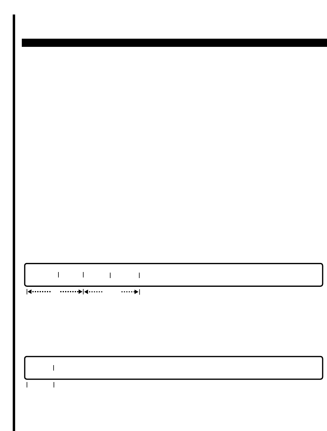
PERCEPTION 4000 COMMANDS
ISS 2, SECTION 4000-014-000
SYSTEM NUMBER SUMMARY (CMD 326)
SYSTEM NUMBER SUMMARY (CMD 326)
The System Number Summary command enables an M&A user to request a summary of number usage within
the Perception 4000 system.
Command Keyword: SYS_NUM_PLAN
Category Name: System
PREREQUISITE COMMANDS
There are no prerequisites for this command.
OPERATIONS
Available operations:
DISPLAY
SHOW
The function and required data fields for each operation are described as follows:
DISPLAY
This operation displays system numbering plan data based on input field information. The Display operation will
list all numbers, their use, and other important data such as the equipment numbers that correspond to assigned
prime directory numbers.
SHOW
The Show operation is used to display either all used numbers or all available numbers in the System Numbering
Plan.
USAGE
req
opt
NUMBER TYPE DEF 1 NAME
locked
3-352
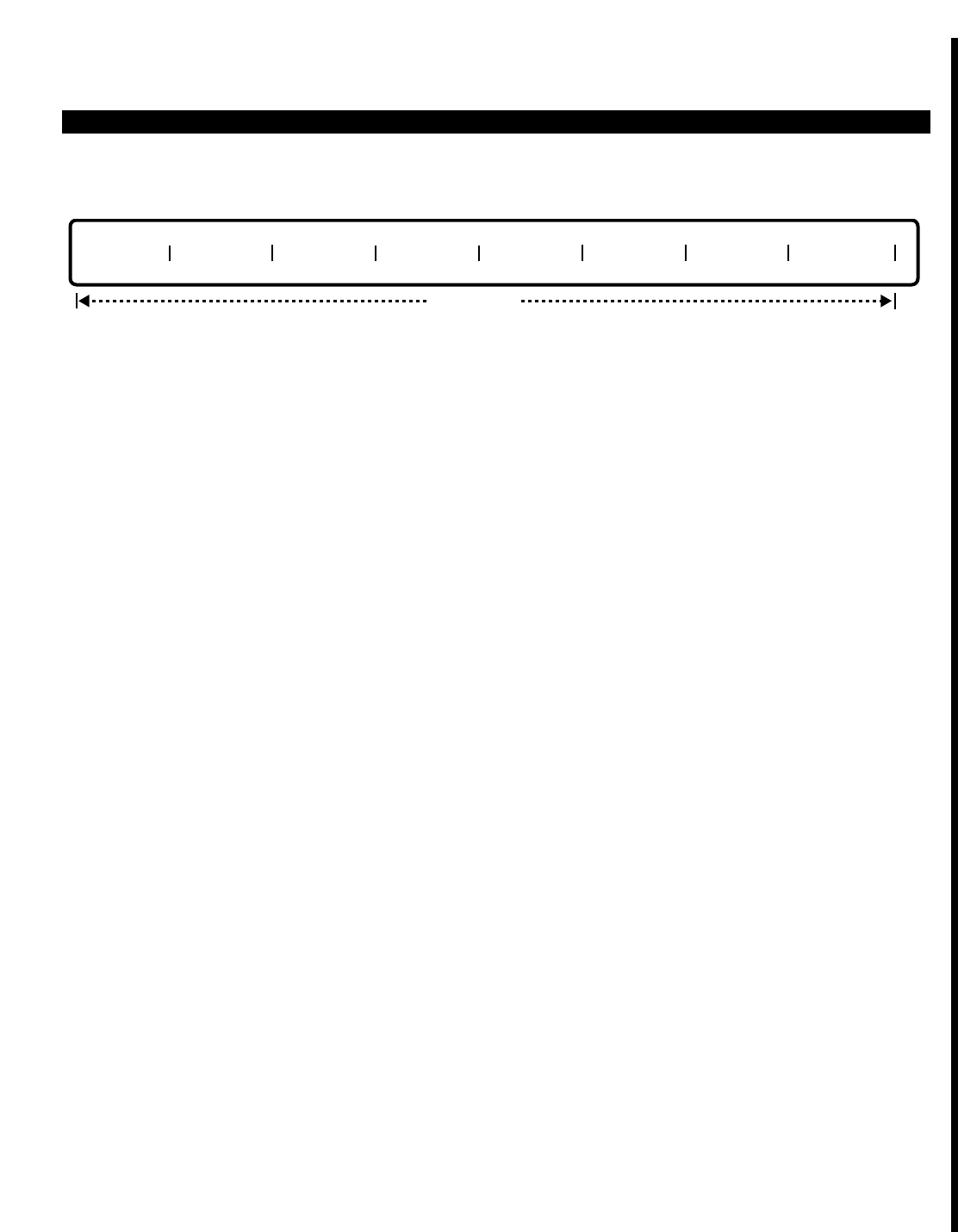
PERCEPTION 4000 COMMANDS
After selecting a "USAGE" option, the form of the SHOW operation will be:
PARAMETERS
This section defines input permitted for each field. Any variations for a particular operation are noted separately.
FIELD: NUMBER
TYPE: Digits 0 - 9; #; *
FORMAT: 1 - 5 digits
VALUE: # - 99999
RANGE: Not allowed
This field is used to specify the numbers to be displayed. If a <TAB> is entered, then all numbers in the System
Numbering Plan will be displayed. Specific groups of numbers can be specified by entering prefix digits. For
example, to display all numbers in the System Numbering Plan that begin with the numbers "42," simply enter
"42" in this field. When entering a particular category in the "TYPE" field of this command, enter the appropriate
digits (0 - 9, #, *) to indicate the numbers to be displayed.
FIELD: TYPE
TYPE: Keyword
FORMAT: Preassigned ASCII characters
Keywords: ACD - ACD pilot number
ATG - Attendant group directory number
ATT - Attendant console directory number
DDN - Data directory number
DHG - Data hunt group pilot number
EMR - Emergency access code
FEA - Feature access code
HOT - Hotline directory number
LCR - LCR access code
LLIN - Logical directory number
PRM - Prime directory number
PVT - Private line directory number
STD - Steering digit
TAC - Trunk group access code
UCD - UCD pilot number
UNP - UNP access code
VHG - Voice hunt group pilot number
DN - All system directory numbers
NDN - All system non-directory numbers
NUMBER NUMBER NUMBER NUMBER NUMBER NUMBER NUMBER NUMBER
output only
ISS 2, SECTION 4000-014-000
SYSTEM NUMBER SUMMARY (CMD 326)
3-353

PERCEPTION 4000 COMMANDS
ISS 2, SECTION 4000-014-000
SYSTEM NUMBER SUMMARY (CMD 326)
This field is used to specify the category of numbers to be displayed. If the keyword DN is entered, then all
categories based on directory numbers will be displayed (all categories except FEA, LCR, STD, TAC, and UNP).
If the keyword NDN is entered, then only non-directory number categories will be displayed (FEA, LCR, STD,
TAC, and UNP).
FIELD: DEF 1 (Definition 1)
TYPE: Decimal
FORMAT: 1 to 3 decimal digits
VALUE: When "TYPE" is:
ACD 1 - 32, representing the ACD group number
ATG 1 - 32, representing the attendant group number
ATT 1 - 32, representing the attendant group to which the attendant belongs
DDN 5 or 6 digits, representing the equipment number
DHG 1 - 32, representing the data hunt group number
EMR Not used
FEA 258 to maximum feature number
HOT 1 - 5 decimal digits, representing the hotline directory number
LCR Feature number
LLIN 1 - 5 decimal digits, representing the prime directory number to which the
logical line belongs
PRM 5 or 6 digits, representing the equipment number
PVT 1- 128, representing the trunk group number
STD 1 - 128, representing the trunk group number
TAC 1 - 128, representing the trunk group number
UCD 1 - 8, representing the UCD group number
UNP Feature number
VHG 1 to maximum number of voice hunt groups
Keywords: Not allowed
The "DEF 1" field specifies the category type of numbers to be displayed.
FIELD: NAME
TYPE: Text
FORMAT: For output only
The "NAME" field is a display-only field which indicates the name that has been previously assigned to a number.
For example, this field will indicate the name assigned to a prime directory number or the name assigned to a
trunk group.
FIELD: USAGE
TYPE: Keyword
FORMAT: Preassigned ASCII characters
Keywords: AVAIL - Print the available (unused) numbers in the system
USED - Print the used numbers in the system
The "USAGE" field specifies whether available or already-used numbers in the System Numbering Plan will be
displayed.
3-354

PERCEPTION 4000 COMMANDS
SYSTEM MESSAGES
The following error message is unique to this command. This error message will usually appear if relationships
within the system have not been adequately resolved prior to modifying an entity.
C32600 - No match
ISS 2, SECTION 4000-014-000
SYSTEM NUMBER SUMMARY (CMD 326)
3-355

PERCEPTION 4000 COMMANDS
ISS 2, SECTION 4000-014-000
SYSTEM OPTION FLAG ASSIGNMENT (CMD 408)
SYSTEM OPTION FLAG ASSIGNMENT (CMD 408)
The System Option Flag Assignment command defines various options allowed in the system.
Command Keyword: SYS_OPTION_ASSIGN
Category Name: System
PREREQUISITE COMMANDS
There are no prerequisites for this command.
OPERATIONS
Available operations: MODIFY
DISPLAY
The function and required data fields for each operation are described in this section.
MODIFY
This operation modifies system options. The first “OPTION” and “VALUE” fields are required, while the remaining
fields are optional. If data is entered in an “OPTION” field, data in the following “VALUE” field must also be
entered.
DISPLAY
This operation displays system options. If a <TAB> or the keyword ALL is entered in the first “OPTION” field, all
of the system options are displayed.
PARAMETERS
Each field parameter is described in this section. Any variations for a particular operation are noted separately.
opt
OPTION VALUE OPTION VALUE OPTION VALUE OPTION VALUE OPTION VALUE
req
OPTION VALUE OPTION VALUE OPTION VALUE OPTION VALUE OPTION VALUE
opt opt opt opt opt opt opt opt
3-356

PERCEPTION 4000 COMMANDS
FIELD: OPTION (System Option)
TYPE: Keyword
FORMAT: Predefined ASCII characters
Keywords: ACD - Automatic Call Distribution
ALL - Used when displaying all System Option Flags
CAMP - DID Camp-on Flag
CAMQ - Camp-on Queue Preemption. If the Trunk Queuing Method (QUE) is
set to FIFO (First In/First Out), this option (CAMQ) allows a call to
preempt the last call in the camp-on queue if the queue is full. If
"QUE" is set to PRI (Priority Queuing), the preemption is allowed if
the call has a higher priority than the last call in the queue.
DISA - DISA Security Code Required
FACL - Forced Account Code length to be validated
IQP1 - First incoming ACD call queuing priority
IQP2 - Second incoming ACD call queuing priority
ISMDR - Internal Call SMDR Flag
LCR - LCR Call Restriction Method
MUSC - Music-on-Hold Tone
MXCM - Maximum Number of Camp-on Calls
NCFA - No COS Feature Access Code Intercept Treatment Method (i.e.,
treatment caused by dialing a feature access code which is not
allowed by the user's COS)
NCTA - No COS Trunk Access Code Intercept Treatment Method (i.e.,
treatment caused by dialing a trunk access code which has no user
COS)
PX1 - PX16- Station Identification (SID) Prefix 1 to 16
QUE - Trunk Queuing Method
RDRL - Restrict DRL Intercept Treatment Method (i.e., treatment caused by
dialing an outside number which is restricted by DRL)
VACC - Verified option flag of account code
VDNI - Vacant DN Intercept Treatment Method (i.e., treatment caused by
dialing a number which is not in the system numbering plan)
WARN - Attendant/ACD Monitor Warning Tone
This field selects the system option to be modified or displayed. Each keyword has its own value,
as entered in the "VALUE" field.
FIELD: VALUE (Value of System Option)
TYPE: Decimal or Keyword, depending on the option
VALUE: Depends on the option (listed below)
RANGE: Not allowed
For ACD (Automatic Call Distribution)
Keywords: NAF - Next Available Agent First (Default)
MIF - Most Idle Agent First
All ACD agents must be logged out before modifying this flag.
ISS 2, SECTION 4000-014-000
SYSTEM OPTION FLAG ASSIGNMENT (CMD 408)
3-357

PERCEPTION 4000 COMMANDS
ISS 2, SECTION 4000-014-000
SYSTEM OPTION FLAG ASSIGNMENT (CMD 408)
For CAMP (DID Camp-on Flag)
Keywords: YES - Allow DID call to camp-on to busy station (Default)
NO - Do not allow DID call to camp-on to busy station
For CAMQ (Camp-on Queue Preemption)
Keywords: YES - Allow preemption of camp-on queuing (Default)
NO - Do not allow preemption
For DISA (DISA Security Code Required)
Keywords: YES - DISA Security Code required (Default)
NO - DISA Security Code not required
For FACL (Forced Account Code Length to be Validated)
Keywords: DIG0 to DIG15 - Length in 0 to 15 digits
DIG0 - Default
For IQP1 (First Incoming ACD Call Queuing Priority)
Decimal: Value of 1 to 16
16 - Default
For IQP2 (Second Incoming ACD Call Queuing Priority)
Decimal: Value of 1 to 16 (cannot be greater than IQP1 value)
Keyword: NONE - DISA security code required (Default)
For ISMDR (Internal Call SMDR Flag)
Keywords: YES - Enable internal call SMDR recording
NO - Disable internal call SMDR recording (Default)
For LCR (LCR Call Restriction Method)
Keywords: FRLP - Facility Restriction Level Profile only (Default)
BOTH - Destination Restriction Level (DRL) and Facility Restriction Level
(FRL)
For MUSC (Music-on-Hold Tone)
Keywords: IMT - Internal Music Tone (Default)
MS01 - External Music Tone 1
MS02 - External Music Tone 2
MS03 - External Music Tone 3
MS04 - External Music Tone 4
QT - Quiet Tone
3-358

PERCEPTION 4000 COMMANDS
For MXCM (Maximum Number of Camp-on Calls allowed per Station)
Decimal Value: 1 - 256 (Default = 4)
For NCFA (No COS Feature Access Code Intercept Treatment Method)
Keywords: AP01 to AP50 - Announcement Pattern 1 to 50
ROT - Reorder Tone (Default)
For NCTA (No COS Trunk Access Code Intercept Treatment Method)
An attendant or attendant group directory number
or
Keywords: AP01 to AP50 - Announcement Pattern 1 to 50
ROT - Reorder Tone (Default)
For PX1 to PX16 (Station Identification Prefix 1 to 16)
Decimal: Maximum number of defined digits for each PX (1 through 16) is 12
For QUE (Trunk Queuing Method)
Keywords: FIFO - First-in/First-out Queuing
PRI - Priority Queuing (Default)
For RDRL (Restrict DRL Intercept Treatment Method)
An attendant or attendant group directory number
or
Keywords: AP01 to AP50 - Announcement Pattern 1 to 50
ROT - Reorder Tone (Default)
For VACC (Verified Option Flag for Account Code)
Keywords: YES - Account code will be verified (Default)
NO - Account code will not be verified
For VDNI (Vacant Directory Number Intercept Treatment Method)
An attendant or attendant group directory number
or
Keywords: AP01 to AN50 - Announcement Pattern 1 to 50
ROT - Reorder Tone (Default)
For WARN (Attendant/ACD Monitor Warning Tone)
Keywords: YES - A warning tone is sent
NO - No warning tone is sent (Default)
This field defines the value for the option listed in the previous "OPTION" field.
ISS 2, SECTION 4000-014-000
SYSTEM OPTION FLAG ASSIGNMENT (CMD 408)
3-359

PERCEPTION 4000 COMMANDS
ISS 2, SECTION 4000-014-000
SYSTEM OPTION FLAG ASSIGNMENT (CMD 408)
SYSTEM ERROR MESSAGES
The following error messages are unique to this command.
C40800 - Option value is out of range
C40801 - Directory number is not an attendant DN
C40802 - Attendant group or directory number can only be used for VDNI, RDRL, or NCTA
C40803 - External music tone does not exist
C40804 - Option field required
C40805 - Value field required
C40806 - Option field is duplicated
C40807 - Force Account code length must be defined first
C40808 - The device for this option is not defined
C40809 - ACD group is still on shift
C40810 - ACD agent is still logged in
C40814 - Maximum Camp-on value is out of range
C40815 - FACL value is over the PDD1 length defined in CMD 300
C40816 - Check input in value field n
3-360

PERCEPTION 4000 COMMANDS
SYSTEM SPEED CALLING ASSIGNMENT (CMD 402)
The System Speed Calling Assignment command defines the destination for each system speed calling number.
Up to 1000 system speed calling numbers are allowed. They may be used to address internal destinations or
external public/private network destinations.
Command Keyword: SYS_SC_ASSIGN
Category Name: System
PREREQUISITE COMMAND
Numbering Plan Assignment (CMD 300)
OPERATIONS
Available operations: ADD
DELETE
MODIFY
DISPLAY
The function and required data fields for each operation are described in this section.
ADD
This operation assigns a destination number to a system speed calling code. Looping is permitted in the "INX"
field during this operation.
DELETE
This operation removes existing speed calling assignments. Looping is permitted in the "INX" field to expedite the
deletion of blocks of speed calling numbers. When a loop is used, the system requests confirmation of the delete
operation.
opt
INDX DESTINATION NUMBER
req
req
INDX DESTINATION NUMBER
ISS 2, SECTION 4000-014-000
SYSTEM SPEED CALLING ASSIGNMENT (CMD 402)
3-361
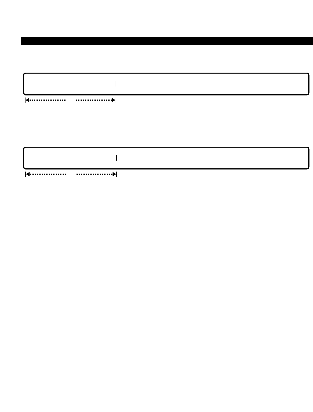
PERCEPTION 4000 COMMANDS
ISS 2, SECTION 4000-014-000
SYSTEM SPEED CALLING ASSIGNMENT (CMD 402)
MODIFY
This operation modifies a system speed calling code and/or destination number. Both fields are required.
DISPLAY
This operation displays all of the system speed calling numbers that meet the conditions established in each field.
Looping is permitted in the "INDX" field only.
PARAMETERS
Each field parameter is described in this section. Any variations for a particular operation are noted separately.
FIELD: INDX (System Speed Calling Code)
TYPE: Decimal with Fixed Length
FORMAT: 3 digits
VALUE: 000 to 999
LOOP: Allowed in ADD, DELETE, and DISPLAY operations
This field assigns a system speed calling code. The code represents the digits entered in the
following field (DESTINATION NUMBER). Upon access to the system speed calling feature, this
3-digit code is entered. The system then automatically outpulses the "DESTINATION NUMBER".
FIELD: DESTINATION NUMBER
TYPE: Dialing Digits plus * and #
FORMAT: 1 to 24 digits
VALUE: 0 to 9, *, **, and #
RANGE: Not allowed
The destination number may be external or internal. External destinations must include a direct
trunk group access code, the least cost routing feature access code, or the PERCEPTION 4000
Networking feature access code. Internal numbers may be any legal directory number including
hunt, ACD, and UCD pilot numbers.
Up to 24 digits/functions (including a feature access code, except for a speed calling number)
may be used to define the destination number. Speed calling functions include timed pauses
(programmable period) and dial tone detection. For private network numbers and numbers that
opt
INDX DESTINATION NUMBER
req
INDX DESTINATION NUMBER
3-362

PERCEPTION 4000 COMMANDS
are unconventional in their arrangement (such as international calls) the pound sign (#) may be
used to signal end of dialing to the system. Ranges are not permitted.
Functional designators are counted as one place in the 24 possible entries, even if it takes two
places to define:
** - Dial Tone Detect
* - Pause, this key requires an additional digit (n) to follow which indicates how may
seconds to delay execution of the remaining destination number. (n = 0 to 9)
# - Indicates beginning of a feature access code or termination of the dialing digit.
Timed pauses of greater than 9 seconds can be achieved via back-to-back definitions. For
example, a pause of 13 seconds could be achieved by entering *9*4. This would count as two of
the possible 24 digits/functions.
SYSTEM ERROR MESSAGES
The following error messages are unique to this command.
C40200 - The speed dialing index is already defined
C40201 - Check input format
C40202 - Destination number is not defined
C40203 - Speed dialing feature activation cannot be destination number
COMMENTS
The Trunk/LCR access codes must be defined in the system's numbering plan prior to entering them in the
"DESTINATION NUMBER" field.
Speed calling access codes (group and system) cannot be used in the "DESTINATION NUMBER" field.
The destination number entered can be a pilot to any type of group or a directory number for a station, attendant,
or data station.
RELATED COMMANDS
ACD Agent Assignment (CMD 356)
Attendant Group Assignment (CMD 372)
Attendant Position Assignment (CMD 370)
Data Station Assignment (CMD 360)
Station Assignment (CMD 330)
Station Feature Key Assignment (CMD 331)
Station Hunting Assignment (CMD 342)
Trunk Assignment (CMD 313)
Trunk Group Assignment (CMD 310)
UCD Group Assignment (CMD 354)
ISS 2, SECTION 4000-014-000
SYSTEM SPEED CALLING ASSIGNMENT (CMD 402)
3-363
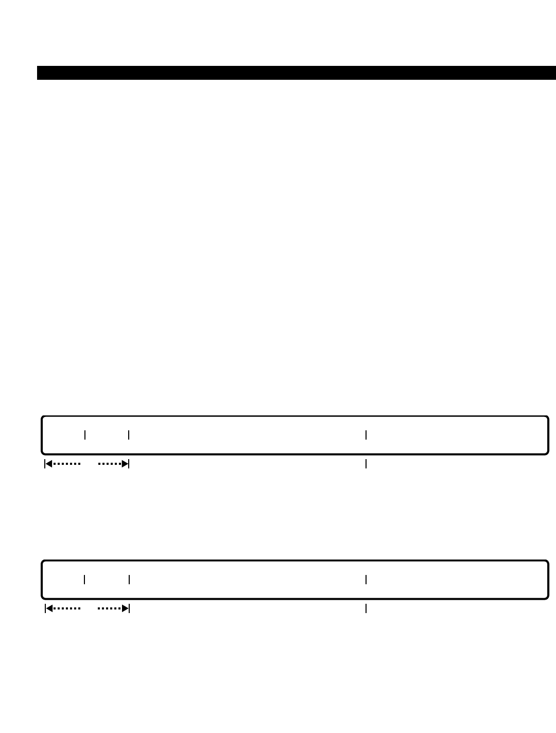
PERCEPTION 4000 COMMANDS
ISS 2, SECTION 4000-014-000
SYSTEM TIMER ASSIGNMENT (CMD 407)
SYSTEM TIMER ASSIGNMENT (CMD 407)
Several features within the system require a timer, such as for recalls and tone duration. This command modifies
the system's timers and displays the System Timer Table.
Command Keyword: SYS_TIMER_ASSIGN
Category Name: System
PREREQUISITE COMMANDS
There are no prerequisites for this command.
OPERATIONS
Available operations: MODIFY
DISPLAY
The function and required data fields for each operation are described in this section.
MODIFY
This operation modifies a timer(s) in the System Timer Table. The "NAME" is defined by Toshiba and displayed
during confirmation of an entry.
DISPLAY
This operation displays a system timer(s). Looping is permitted in the “INDEX” field. If no data is entered, the
complete System Timer Table displays.
opt
INDEX TIMER NAME
output only
req
INDEX TIMER NAME
Output only when prompting for confirmation
3-364

PERCEPTION 4000 COMMANDS
PARAMETERS
Each field parameter is described in this section. Any variations for a particular operation are noted separately.
FIELD: INDEX (Timer Table Index Number)
TYPE: Decimal
FORMAT: 1 or 2 digits
VALUE: 1 to 99
LOOP: Allowed in a DISPLAY operation
The index number identifies a specific timer. This number corresponds to the Index # listed in the
"TIMER" field description. A DISPLAY operation also lists the current Timer Table index numbers.
FIELD: TIMER (Timer Value)
TYPE: Decimal
FORMAT: 1 to 5 digits
VALUE: 1 to 99999 in seconds (or to the maximum value; see the list below)
RANGE: Not allowed
Each timer has a range of values. Following are the timer index numbers, their names, ranges,
defaults, and a brief description of each timer. Note that the maximum entry allowed for timer
values far exceeds current needs. These values are provided to allow users flexibility in
customizing their systems.
Index Name Value Default Description
#
1 Camp-on Timer 1 - 3600 10 The amount of time busy tone rings
before off-hook Camp-on occurs
2 Callback Timer 1 - 72000 8000 The amount of time a Camp-on will
exist without a callback before being
automatically cancelled by the system
3 Success Tone Duration 1 - 3600 5 The length of time success tone is
heard
4 LCR Warning Tone 1 - 3600 5 The length of time expensive route
Duration warning tone is heard
5 Station Callback Ring 1 - 3600 15 The amount of time a Camp-on callback
Duration will ring a station before cancelling the
station Camp-on
6 Trunk Callback Ring 1 - 3600 15 The amount of time a Camp-on callback
Duration will ring a station before ceasing to wait
for the next attempt or before cancelling
the trunk Camp-on
ISS 2, SECTION 4000-014-000
SYSTEM TIMER ASSIGNMENT (CMD 407)
3-365

PERCEPTION 4000 COMMANDS
ISS 2, SECTION 4000-014-000
SYSTEM TIMER ASSIGNMENT (CMD 407)
Index Name Value Default Description
#
7 Trunk Callback Interval 1 - 14400 300 The amount of time between Camp-on
Timer callbacks due to no-answer conditions
at the station being rung
8 Long Hold Recall 1 - 3600 120 The length of time a call will sit on hard
hold before recalling to the station
9 Reorder Tone Timer 1 - 3600 20 The amount of time reorder tone will be
given before station lockout or off-hook
idle occurs
10 UNA Bell No Answer 1 - 3600 300 The amount of time a call rings at the
Timer night bell before being dropped
11 Unscreened RBT Timer 1 - 3600 60 The maximum amount of time that an
unscreened transfer will go unanswered
before recalling to the initiating party
12 Call Forward - No 1 - 3600 30 The amount of time that a call rings at a
Answer Timer station before forwarding - applicable to
Call Forward No Answer and Call
Forward Busy/No Answer features
13 Recall No Answer Timer 1 - 3600 30 The amount of time that a trunk recall
will ring at a station before recalling to
the attendant
14 Park Recall Timer 1 - 3600 120 The amount of time that a call may
remain parked before recalling to the
park originator
15 Overflow Timer 1 - 3600 120 The time a call will remain in the
attendant queue before overflowing to a
secondary location
16 Analog Hold Timer 1 - 3600 5 The length of time a call will sit on hard
hold before recalling to the station
17 Camp-on RBT Timer 1 - 3600 180 The maximum amount of time that a
Camp-on transfer will go unanswered
before recalling to the initiating party
30 Detect Dial Tone Timer 1 - 3600 15 The amount of time a CO trunk detects
dial tone
3-366

PERCEPTION 4000 COMMANDS
Index Name Value Default Description
#
31 Interchangeable Office 1 - 3600 4 The amount of time the system waits for
Code Timer additional digits after receiving seven
digits. If the timer expires before
receiving more digits, the first three
digits are treated as an office code. If
more digits are received before the
timer expires, then the first three digits
are treated as an area code.
33 Voice Page Recall Timer 1 - 3600 120 The amount of time a parked call due to
a meet-me paging attempt will remain
parked before recalling to the initiator
34 Code Call Recall Timer 1 - 3600 120 The amount of time a parked call due to
a meet-me code-call attempt will remain
parked before recalling to the initiator
35 LED Error Flashing 1 - 3600 5 The length of time the red LED flashes
Duration when an error occurs while
programming a feature or a key
36 Supervisor Warning 1 - 3600 1 The amount of time that a warning tone
Tone Timer sounds during an attendant break-in
function
37 Announcement Release 1 - 3600 180 The amount of time that incoming trunk
Timer calls that have no routing and are
intercepted by an announcement
machine are held before the call is
disconnected
38 Attendant BLF Timer 1 - 3600 5 Interval of time between scans of the
system to update the Busy Lamp Field
on the attendant console to the current
state
39 Attendant Forced PB 1 - 3600 30 The amount of time allowed for the
Timer attendant to answer incoming calls. If an
incoming call is not answered before
this timer expires, the attendant console
goes to the position busy state.
40 Break-in Warning Tone 1 - 3600 1 The amount of time that a warning tone
Timer sounds during an attendant break-in
function (Use #36 when modifying the
warning tone.)
ISS 2, SECTION 4000-014-000
SYSTEM TIMER ASSIGNMENT (CMD 407)
3-367

PERCEPTION 4000 COMMANDS
ISS 2, SECTION 4000-014-000
SYSTEM TIMER ASSIGNMENT (CMD 407)
Index Name Value Default Description
#
41 ACD Call Ring No 0 - 3600 20 The amount of time that a call rings at
Answer Timer an ACD station before the system
redirects the call to another ACD agent.
If none is available, the call rings again
at the original ACD agent's station. If
the timer expires before the agent
answers, that station is placed into the
Unavailable mode and the call is
disconnected.
42 Station/Attendant ACD 0 - 9999 0 The amount of time that a caller to a
Queue Priority Advance station or attendant console must wait
Timer in the ACD queue before the caller's
priority level is increased.
43 Station/Attendant ACD 0 - 9999 0 The amount of time that a caller to a
Overflow Timer station or attendant console must wait
in the ACD queue before overflow to
another groups will be attempted.
FIELD: NAME (Timer Name)
TYPE: Text
LENGTH: Up to 60 ASCII characters
The "NAME" field is an output only field, which is coded into the database and not changeable.
Refer to the "TIMER" field for a list of current timer names.
SYSTEM ERROR MESSAGES
The following error messages are unique to this command.
C40700 - Timer value is out of range
C40701 - Specified timer is not defined
C40702 - ACD advance timer should be less than overflow timer
3-368

PERCEPTION 4000 COMMANDS
T-1 CLOCK PROVIDER SELECTION ASSIGNMENT (CMD 412)
The T-1 Clock Provider command allows you to manually switch the clock provider to the primary or other
reference, depending on where it currently resides. This feature must be enabled with the Digital Carrier Channel
Assignment command (CMD 413) before the command can be executed.
Command Keyword: T1_CLOCK_ASSIGN
Category Name: Trunk
PREREQUISITE COMMAND
Digital Carrier Channel Assignment (CMD 413)
OPERATIONS
Available operations: SWITCH
The function and required data fields for each operation are described in this section.
SWITCH
This operation manually switches the clock provider to the primary reference (1) if the current clock provider is a
lower priority reference (2 to 60), or switches to another reference if the current clock provider is the primary
reference.
PARAMETERS
Each field parameter is described in this section. Any variations for a particular operation are noted separately.
FIELD: CLK PROVIDER (T-1 Clock Provider)
TYPE: Keyword
FORMAT: Predefined ASCII characters
Keywords: PRIMARY - Primary Reference
OTHER - Other Reference
This field manually switches the T-1 clock provider between the primary reference (1) and other
references (2 to 60). The T-1 clock provider feature must be enabled with the Digital Carrier
Channel Assignment command (CMD 413) before this command can be executed.
req
CLK PROVIDER
ISS 2, SECTION 4000-014-000
T-1 CLOCK PROVIDER SELECTION ASSIGNMENT (CMD 412)
3-369

PERCEPTION 4000 COMMANDS
ISS 2, SECTION 4000-014-000
T-1 CLOCK PROVIDER SELECTION ASSIGNMENT (CMD 412)
SYSTEM ERROR MESSAGES
The following error messages are unique to this command.
C41200 - Check Clock Provider
I41201 - Warning: Please try later, database is reserved
3-370

PERCEPTION 4000 COMMANDS
TERMINAL MAINTENANCE (CMD 206)
The Terminal Maintenance command is used to make equipment or terminal ports busy or idle, and to display the
state of these ports.
Command Keyword: TERMINAL_MAINT
Category Name: Maintenance
PREREQUISITE COMMANDS
There are no prerequisites for this command.
OPERATIONS
Available operations: BUSY
IDLE
DISPLAY
SHOW
The function and required data fields for each operation are described in this section.
BUSY
This operation sets a terminal to the busy state. Looping is permitted.
IDLE
This operation sets a terminal to the idle state. When the equipment number and a carriage return are entered,
the system displays a prompt confirming the 'make idle' request. Looping is permitted.
req
EQUIP #
req
EQUIP #
ISS 2, SECTION 4000-014-000
TERMINAL MAINTENANCE (CMD 206)
3-371
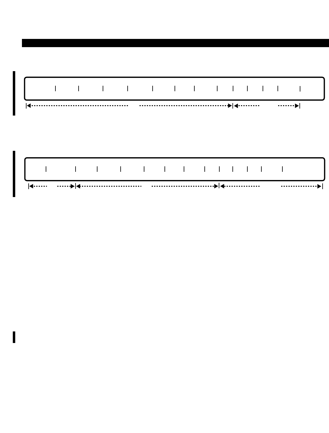
PERCEPTION 4000 COMMANDS
ISS 2, SECTION 4000-014-000
TERMINAL MAINTENANCE (CMD 206)
DISPLAY
This operation displays terminal status information. Loops are permitted in the “EQUIP #” and "POS" fields.
SHOW
The SHOW operation displays 'snapshots' of the current status of the selected equipment number over a
specified period of time, or for a specified number of times. For example, the status of "EQUIP #" 011101 can be
displayed continually for a quarter of an hour; or it can display up to 999 snapshots. Any equipment status
changes are shown on the display screen as they occur. Note that if the system is congested, the SHOW
operation runs slowly, producing fewer snapshots.
PARAMETERS
Each field parameter is described in this section. Any variations for a particular operation are noted separately.
FIELD: EQUIP # (Equipment Number)
TYPE: EQ Type
FORMAT: 5 or 6 digits
VALUE: (0)10101 to 101408 *
LOOP: Allowed in BUSY, IDLE, and DISPLAY operations
* Use the following chart to determine valid ranges for various types of equipment.
For BSTI, PBRC, DKTI, and 1B-DSTI equipment cards, the following ranges apply:
Digits Range Hardware
First digit(s) (0)1~10 Shelf no.
Second two digits 01~11, 13 Card slot no.
Last two digits 01~16 Circuit no.
REP# EQUIP # TRML PHY S PRT S PBI S POS TYPE DN TS GS SS AT&T TIME STAMP
opt lockedreq
EQUIP # CARD TRML PHY S PRT S PBI S POS TYPE DN TS GS SS AT&T
opt locked
3-372

PERCEPTION 4000 COMMANDS
For a 2B-DSTI equipment card, the following ranges apply:
Digits Range Hardware
First digit(s) (0)1~10 Shelf no.
Second two digits 01, 03, 05, 07, 09, 11 Card slot no.
Last two digits 01~16 Circuit no.
For an EKTI, DKTI, DIDI, XSTI, EM1I, and COGI card, the following are valid ranges:
Digits Range Hardware
First digit(s) (0)1~10 Shelf no.
Second two digits 01~14 Card slot no.
Last two digits 01~08 Circuit no.
For an EM2I card, the following are valid ranges:
Digits Range Hardware
First digit(s) (0)1~10 Shelf no.
Second two digits 01~14 Card slot no.
Last two digits 01~06 Circuit no.
For a TTRI or IPRI card, the following ranges are valid:
Digits Range Hardware
First digit(s) (0)1~10 Shelf no.
Second two digits 02, 04, 06, 08, 10, 12 Card slot no.
Last two digits 01~24 Circuit no.
For an IPRC card, the following ranges are valid:
Digits Range Hardware
First digit(s) (0)1~10 Shelf no.
Second two digits 01~11, 13 Card slot no.
Last two digits 01 Circuit no.
This field designates an equipment number. The first digit(s) represents the shelf number, the
next two digits represent the card slot number, and the last two digits represent the circuit
number.
FIELD: CARD (Equipment Card Type)
TYPE: Keyword
FORMAT: Predefined ASCII characters
Keywords: 1DSTI - 1-B channel DSTI card
2DSTI - 2-B channel DSTI card
BSTI - BSTI card
COGI - COGI card
ISS 2, SECTION 4000-014-000
TERMINAL MAINTENANCE (CMD 206)
3-373

PERCEPTION 4000 COMMANDS
ISS 2, SECTION 4000-014-000
TERMINAL MAINTENANCE (CMD 206)
DIDI - DIDI card
DKTI - DKTI card
EKTI - EKTI card
EM1I - EM1I card
EM2I - EM2I card
IPRC - IPRC card
IPRI - IPRI card
PBRC - PBRC (DTMF) card
TTRI - TTRI card
XSTI - XSTI card
NOCARD - No card
UND - Undefined
RSVD - Reserved card, circuit cannot be used
This field displays what type of card the equipment is assigned to.
FIELD: TRML (Terminal Type)
TYPE: Keyword
FORMAT: Predefined ASCII characters
Keywords: 2010 - 10-key PERCEPTION 4000 digital telephone
2020 - 20-key PERCEPTION 4000 digital telephone
AD1 - Add-on Module #1
AD2 - Add-on Module #2
AM - Announcement Machine
ANLG - Analog Telephone
ANMW - Analog Telephone with Message Waiting
ATT - Attendant
AVMS - Analog VMS Port
B_CH - ISDN B-channel terminal
BL - UNA Night Bell
D_CH - ISDN D-channel terminal
DID - Direct Inward Dialing Trunk
DIU - Data Station
DK10 - DKT with 10 keys and no display
DK1D - DKT with 10 keys and display
DK20 - DKT with 20 keys and no display
DK2D - DKT with 20 keys and display
DM - Dictation Machine
DTMF - DTMF Receiver
EK01 - Electronic telephone with 1 line key and 3 fixed keys
EK10 - Electronic telephone with 10 flexible keys and 4 fixed keys
EK20 - Electronic telephone with 20 flexible keys and 4 fixed keys
EK2D - Electronic telephone with 20 flexible keys, 4 fixed keys, and a display
EM1 - EM Type 1 Trunk
EM2 - EM Type 2 Trunk
GND - Ground Start Trunk
ID10 - 10-key PERCEPTION 4000 Digital Telephone with DIU
ID20 - 20-key PERCEPTION 4000 Digital Telephone with DIU
LP - Loop Start Trunk
3-374

PERCEPTION 4000 COMMANDS
LTIE - Loop Start TIE Trunk
MDM - Modem Pool
MPD - Modem Pool DIU
MS - Music-on-Hold Device
OPS - Off-premises Station
T1 - T1 Trunk
The "TERMINAL" field defines the type of terminal that is associated with the equipment number.
FIELD: PHY S (Physical Status of the Equipment)
TYPE: Keyword
FORMAT: Predefined ASCII characters
Keywords: DLLF - Down Line Load Fault
DLNP - In Down Line Load; No Port Processor
INDL - In Down Line Load Process
MBDF - Made Busy; Down Line Load Fault
MBDL - Made Busy; In Down Line Load Process
MBNA - Made Busy; No Answer
MBNM - Made Busy; No Match
MBNP - Made Busy; No Port Processor
MBST - Made Busy; Start Check (Trunk)
MBSY - Made Busy
MISC - Miscellaneous
NANP - No Answer; No Port Processor
NANS - No Answer
NMCH - No Match
NOPP - No Port Processor
STCH - Start Check (Trunk)
TIDL - Terminal Idle
This field specifies the hardware (or physical) state of the equipment.
FIELD: PRT S (Status of the Equipment Port)
TYPE: Keyword
FORMAT: Predefined ASCII characters
Keywords: FMKB - Equipment was forced into a make busy state
IDL - Equipment was made idle
MKB - Equipment was made busy
NODB - Equipment has either no software database, or has a
mixed hardware and software status
PRBK - Equipment is pre-blocking
This field specifies the software status of the equipment.
FIELD: PBI S (Port Make Busy/Idle Status)
TYPE: Keyword
FORMAT: Predefined ASCII characters
ISS 2, SECTION 4000-014-000
TERMINAL MAINTENANCE (CMD 206)
3-375

PERCEPTION 4000 COMMANDS
ISS 2, SECTION 4000-014-000
TERMINAL MAINTENANCE (CMD 206)
Keywords: IDL - Made Idle
IREQ - Make Idle Requested
MKB - Made Busy
MREQ - Make Busy Requested
PRBK - Pre-blocked
This field displays the Make Busy/Idle status of the equipment port. The IREQ and MREQ
keywords indicate that a request to Make Idle/Make Busy has been sent, but a response has not
been received back. The IDL and MKB options indicate that the request has been carried out.
PRBK signifies that a Make Busy request has been sent to a port that is in the talking state, and
that port will go into a Make Busy state when the call is terminated.
FIELD: POS (Key Assignment Position Number)
TYPE: Decimal
FORMAT: 1 or 2 digits
VALUE: 1 to 10 (For 10-key PERCEPTION 4000 digital telephones, 10-key DKT telephones, and 10-key
electronic telephones)
1 to 20 (For 20-key PERCEPTION 4000 digital telephones, 20-key DKT telephones, 20-key
electronic telephones, and 20-key add-on modules)
1 to 60 (For 60-key add-on module [three 20-key modules])
LOOP: Allowed in a DISPLAY operation only
This field specifies a station's key position, as defined in the Station Feature Key Assignment
command (CMD 331), and applies to digital and electronic telephones, add-on modules, and
digital telephones with DIUs.
FIELD: TYPE (Key Assignment Type)
TYPE: Keyword
FORMAT: Predefined ASCII characters
Keywords: AGE - ACD Line, Agent
DDN - Data Line (Integrated DIU)
HOT - Hotline
ICM - Intercom Group
LINE - Secondary Line Appearance
LLIN - Logical Line
MLIN - Multiple Line
PRM - Prime Line
PVT - Private Trunk Line
SPVT - Secondary Private Trunk Line
SUP - ACD Line, Supervisor
The "TYPE" field defines the key type for the location listed in the "POS" field. Key types are
assigned with the Station Feature Key Assignment command (CMD 331).
FIELD: DN (Directory Number)
TYPE: DN Type
FORMAT: 1 to 5 digits
VALUE: 0 to 99999
RANGE: Not allowed
LOOP: Not allowed
3-376

PERCEPTION 4000 COMMANDS
This field displays the directory number assigned to a given station key position, as defined in the
Station Feature Key Assignment command (CMD 331).
FIELD: TS (Terminal Layer's State)
TYPE: Decimal
FORMAT: 1 to 3 digits
VALUE: 0 to 999
RANGE: Not allowed
LOOP: Not allowed
The "TS" field is an output only field used by Toshiba personnel for diagnosing software status.
For attendant consoles, this field represents the state of ATC virtual machines. For trunks, this
field represents the state of TTC virtual machines. For stations, this field represents the state of
HDT virtual machines. For ISDN terminals, this field represents the state of ITTC virtual
machines.
FIELD: GS (Group Layer's State)
TYPE: Decimal
FORMAT: 1 to 3 digits
VALUE: 0 to 999
RANGE: Not allowed
LOOP: Not allowed
The "GS" field is an output only field used by Toshiba personnel for diagnosing software status.
For attendant consoles, this field represents the state of AGC virtual machines. For stations, this
field represents the state of KSU virtual machines. For ISDN trunks, this field represents each
channel's made busy/made idle state in ITTC virtual machines.
FIELD: SS (Server Layer's State)
TYPE: Decimal
FORMAT: 1 to 3 digits
VALUE: 0 to 999
RANGE: Not allowed
LOOP: Not allowed
The "SS" field is an output only field used by Toshiba personnel for diagnosing software status.
For attendant consoles, this field represents the state of ASC virtual machines. For trunks, this
field represents the state of TSC virtual machines. For stations, this field represents the state of
SSC virtual machines.
FIELD: AT&T (AT&T Maintenance Mode)
TYPE: Decimal
FORMAT: 1 to 3 digits
VALUE: 0 to 999
RANGE: Not allowed
LOOP: Not allowed
The "AT&T" field is an output only field used by Toshiba personnel for diagnosing software status.
ISS 2, SECTION 4000-014-000
TERMINAL MAINTENANCE (CMD 206)
3-377

PERCEPTION 4000 COMMANDS
ISS 2, SECTION 4000-014-000
TERMINAL MAINTENANCE (CMD 206)
FIELD: TIME STAMP (Time Stamp)
TYPE: Decimal
FORMAT: hh:mm:ss where: hh indicates the hour - 00 to 23
mm indicates the minutes - 00 to 59
ss indicates the seconds - 00 to 59
VALUE: 00:00:00 to 23:59:59
RANGE: Not allowed
LOOP: Not allowed
This is an output only field and displays the current time in military format.
FIELD: REP# (Number of Repetitions)
TYPE: Decimal / Keyword
FORMAT: 1 to 3 digits / Predefined ASCII characters
VALUE: 1 to 999
RANGE: Not allowed
LOOP: Not allowed
Keywords: Q1 - Repeat for 1 quarter of an hour
Q2 - Repeat for 2 quarter hour periods
Q3 - Repeat for 3 quarter hour periods
Q4 - Repeat for 4 quarter hour periods (1 hour)
Q5 - Repeat for 5 quarter hour periods
Q6 - Repeat for 6 quarter hour periods
Q7 - Repeat for 7 quarter hour periods
Q8 - Repeat for 8 quarter hour periods (2 hours)
This field selects the number of repetitions or the period of time in which to display the ongoing
status of the selected equipment. The equipment can be monitored for up to 999 times or up to a
full two hours. Any equipment status changes are shown on the display screen as they occur.
SYSTEM ERROR MESSAGES
The following error messages are unique to this command.
C20600 - Equipment is already busy
C20601 - Equipment is already idle
C20602 - No database exists for this equipment
C20603 - Equipment number is out of range
C20604 - BUSY and IDLE operations are not applicable to night bell equipment
3-378
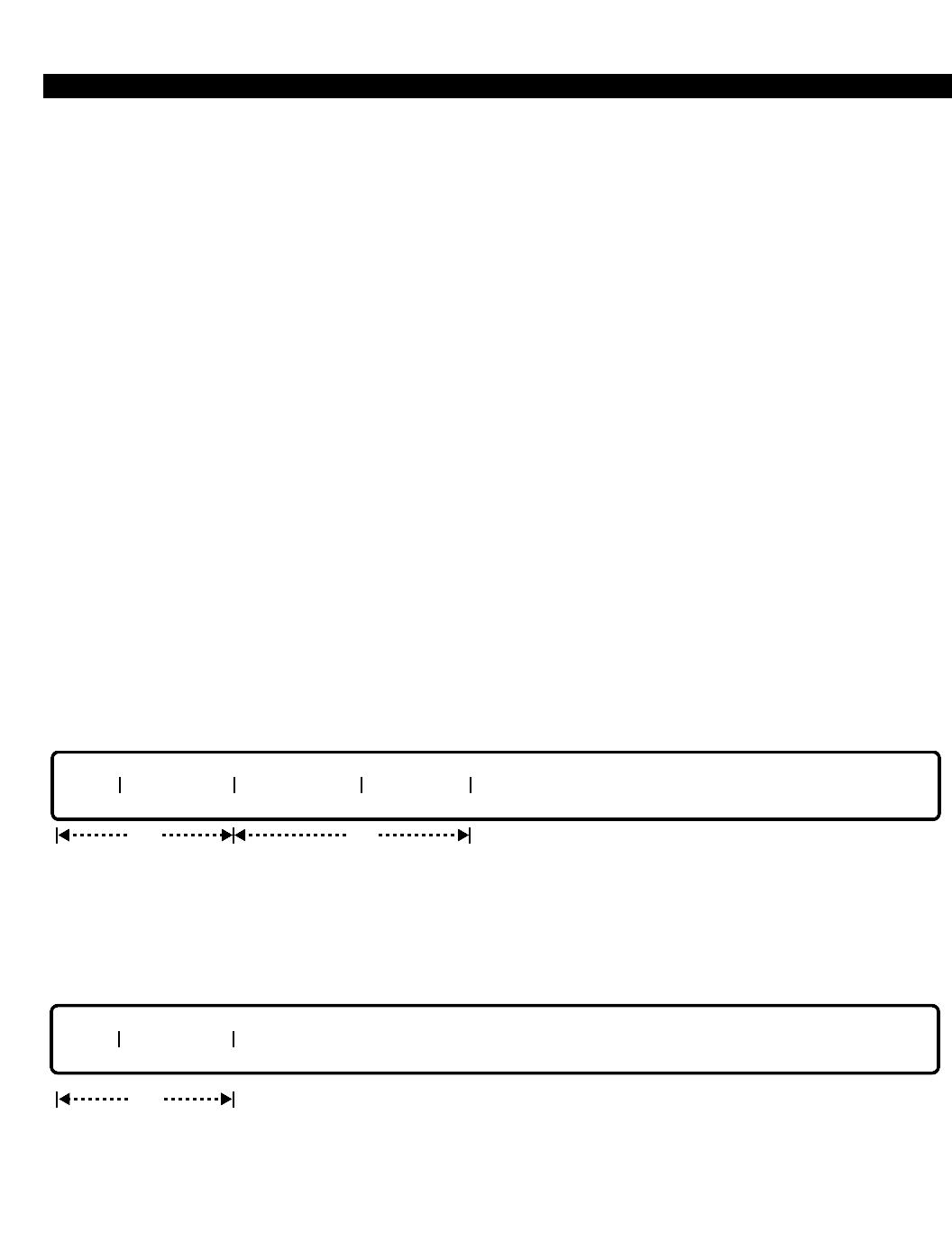
PERCEPTION 4000 COMMANDS
TIME ACTIVATED COMMAND PROGRAMMING (CMD 110)
The Time Activated Command Programming command sets timers for automatic activation or deactivation of
maintenance and/or diagnostic functions. The command also displays the current time activation set-up status of
each function. Pre-determined maintenance functions are activated at the specified date and time. Audit functions
are activated based on their specified relative interval time.
Command Keyword: TIME_ACT_COM
Category Name: Diagnostic
PREREQUISITE COMMANDS
There are no prerequisites for this command.
OPERATIONS
Available operations: ENABLE
DISABLE
DISPLAY
The function and required data fields for each operation are described in this section.
ENABLE
This operation programs the automatic activation of the specified maintenance or diagnostic function. Once this
operation is executed, the specified functions are activated at the desired time.
DISABLE
This operation cancels automatic activation of functions set by the ENABLE operation by removing activation
timer(s) from the operating system's timer queue. The function type and name are required.
req
TYPE FNC NAME
TYPE FNC NAME START TIME INTERVAL
req opt
ISS 2, SECTION 4000-014-000
TIME ACTIVATED COMMAND PROGRAMMING (CMD 110)
3-379
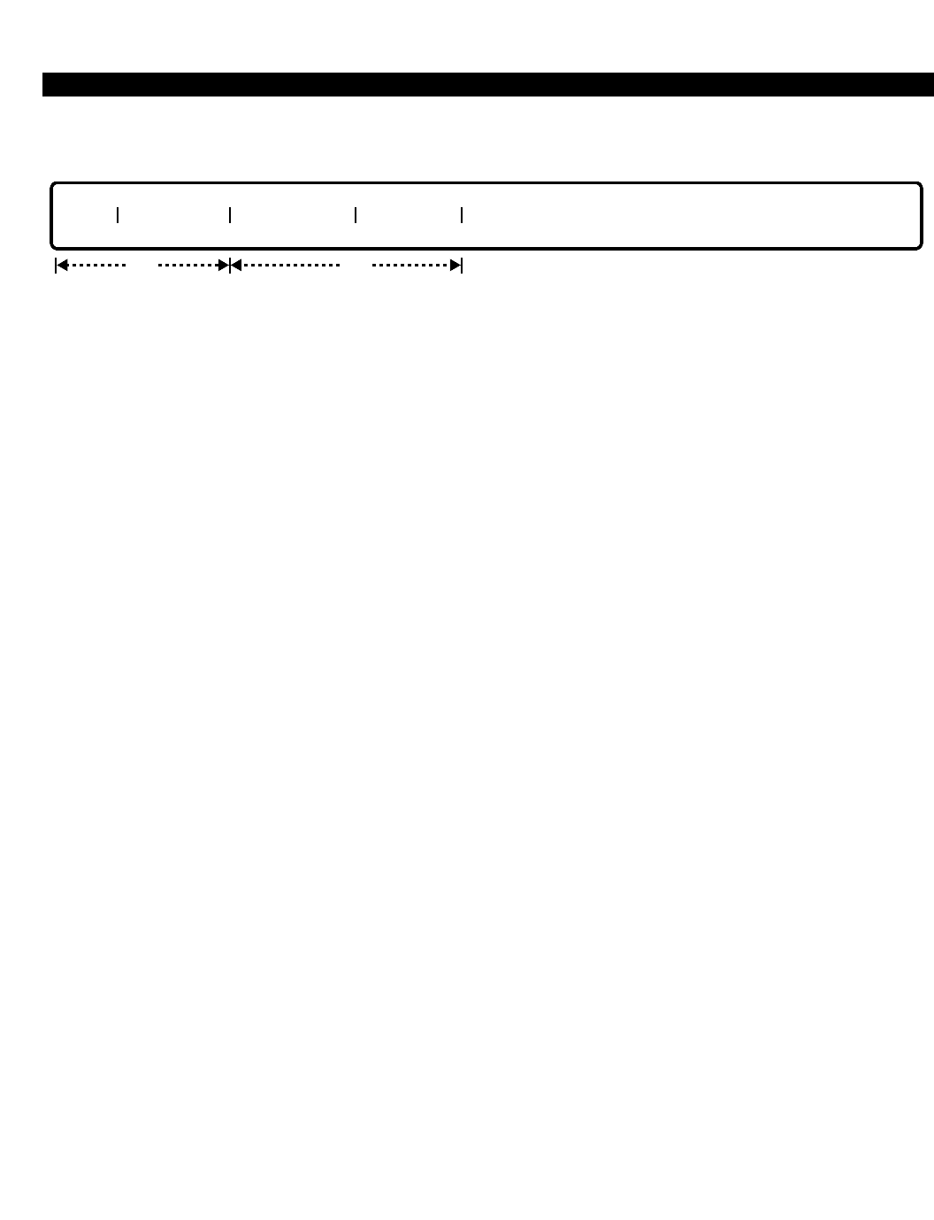
PERCEPTION 4000 COMMANDS
ISS 2, SECTION 4000-014-000
TIME ACTIVATED COMMAND PROGRAMMING (CMD 110)
DISPLAY
This operation displays the time activation set up for the specified function. The function type and name are
required.
PARAMETERS
Each field parameter is described in this section. Any variations for a particular operation are noted separately.
FIELD: TYPE (Type of Function)
TYPE: Keyword
FORMAT: Predefined ASCII characters
Keywords: MAIN - Maintenance Function
DIAG - Diagnostic Function
BOTH - Both Maintenance and Diagnostic Functions (Allowed in a DISPLAY
operation only)
This field indicates the type of function to be enabled, disabled, or displayed.
FIELD: FNC NAME (Function Name)
TYPE: Keyword
FORMAT: Predefined ASCII characters
Keywords - Maintenance Functions:
CMCK - Compares the contents in memory to the contents of the corresponding
file on the hard disk. If there is a mismatch, the system prints out an error
message.
FBKP - Performs a program/data file consolidation. A consolidation is performed
on both sides if the system is redundant.
SWO - Initiates a system switch-over.
ALL - All of the above (Allowed in a DISPLAY operation only)
Keywords - Diagnostic Functions:
LPWR - Checks the power on the line/trunk shelves.
MISC - Checks communications between the MISC card and the MCPU and
LCPU.
MPWR - Checks the operational status of the stand-by side in a redundant
system.
PPWR - Audits status of the port processor cards and terminals.
TEMP - Checks the system's operating temperature.
ALL - All of the above (Allowed in a DISPLAY operation only)
TYPE FNC NAME START TIME INTERVAL
req opt
3-380

PERCEPTION 4000 COMMANDS
The entry in this field must correspond to the type of function entered in the "TYPE" field. The
keyword ALL is available only in a DISPLAY operation. Before entering LPWR, adjust the
parameters of the Redundancy Selection Assignment command (CMD 409) to fit the
configuration of the PERCEPTION 4000 system being worked on.
FIELD: START TIME (Activation Start Time)
TYPE: Decimal with fixed length
FORMAT: 4 digits in the form HHMM (HH=hour, MM=minutes)
VALUE: 0000 to 2359 (Maintenance functions only)
DEFAULT: Maintenance Function: Current Programmed Time
Diagnostic Function: Current Time
RANGE: Allowed in a DISPLAY operation only
LOOP: Not allowed
A <TAB> key entry indicates the default time is to be used as input data. However, data entered
in this field is treated differently based on the specified "TYPE" and operation. For maintenance
functions, a <TAB> key entry defaults to the current setup time, otherwise,data entered in this
field replaces the current setup time. For diagnostic functions, any input in this field other than a
<TAB> is ignored; the default current clock is used and the following message displays: “DATA
INPUT to START TIME FIELD IS IGNORED.”
FIELD: INTERVAL (Interval Time)
TYPE: Decimal
FORMAT: 1 to 4 digits
VALUE: Maintenance Function: 1 to 31 Days
Diagnostic Function: 0030 to 3600 Seconds
DEFAULT: Maintenance Function: 1 day
Diagnostic Functions
MPWR: 0005 seconds
All others: 0030 seconds
RANGE: Allowed in a DISPLAY operation only
LOOP: Not allowed
For maintenance functions, a <TAB> key entry defaults to a one (1) day interval between function
activation, otherwise, data entered replaces the current setup. For diagnostic functions, a <TAB>
key entry sets a 30 second interval between operations, otherwise, data entered replaces the
current setup.
SYSTEM ERROR MESSAGES
The following error messages are unique to this command.
C11000 - Keyword combination error
C11001 - Set timer error
I11002 - Warning: Data entered in Activation Start Time field is ignored
C11003 - Interval time is out of range
C11004 - This item is not registered
C11005 - Input activation start time is out of range
C11006 - Start time conflicts with switch-over start time
ISS 2, SECTION 4000-014-000
TIME ACTIVATED COMMAND PROGRAMMING (CMD 110)
3-381

PERCEPTION 4000 COMMANDS
ISS 2, SECTION 4000-014-000
TIME ACTIVATED COMMAND PROGRAMMING (CMD 110)
RELATED COMMANDS
Clock Reset (CMD 121)
Disk File Manipulation (CMD 152)
Initiate Switchover (CMD 102)
3-382
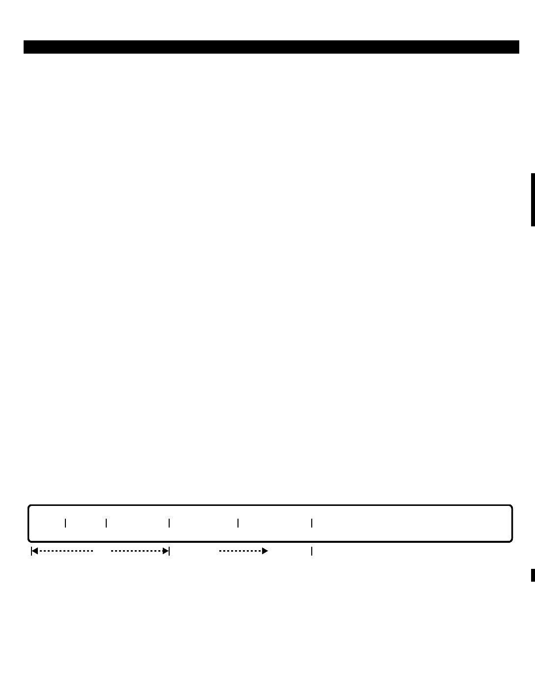
PERCEPTION 4000 COMMANDS
ISS 2, SECTION 4000-014-000
TIME ZONE ASSIGNMENT (CMD 336)
3-383
TIME ZONE ASSIGNMENT (CMD 336)
The Time Zone Assignment command defines different time zones (1 to 4) for each day of the week and holidays.
This information is used by the following tables for all outbound and inbound calls:
1. LCR Time Zone Table
2. Inward Routing Time Zone Table
3. COS/DRL/FRL/Queue Priority Time Zone Table
4. ISDN Time Zone Class 1 Table
5. ISDN Time Zone Class 2 Table
6. ISDN Time Zone Class 3 Table
7. ISDN Time Zone Class 4 Table
These tables change LCR routing of calls, inward routing of calls, and the COS, DRL, FRL, and Queue Priority
Level of configured stations, based on the day of the week and time of day.
Command Keyword: TZ_ASSIGN
Category Name: Administration
PREREQUISITE COMMANDS
There are no prerequisites for this command.
OPERATIONS
Available operations: MODIFY
DISPLAY
The function and required data fields for each operation are described in this section.
MODIFY
This operation modifies the attributes of the seven prementioned tables. The first three fields are required, while
the remaining fields are optional. If, however, an entry or deletion (<CONTROL-D>) is made in the "START TIME"
field, an entry or deletion must also be made in the "TIME ZONE #" field. A time zone may be deleted only if it is
the last one of the day. All start times for each day must be in ascending order.
req
TYPE INDEX WEEK DAY START TIME TIME ZONE #
opt opt
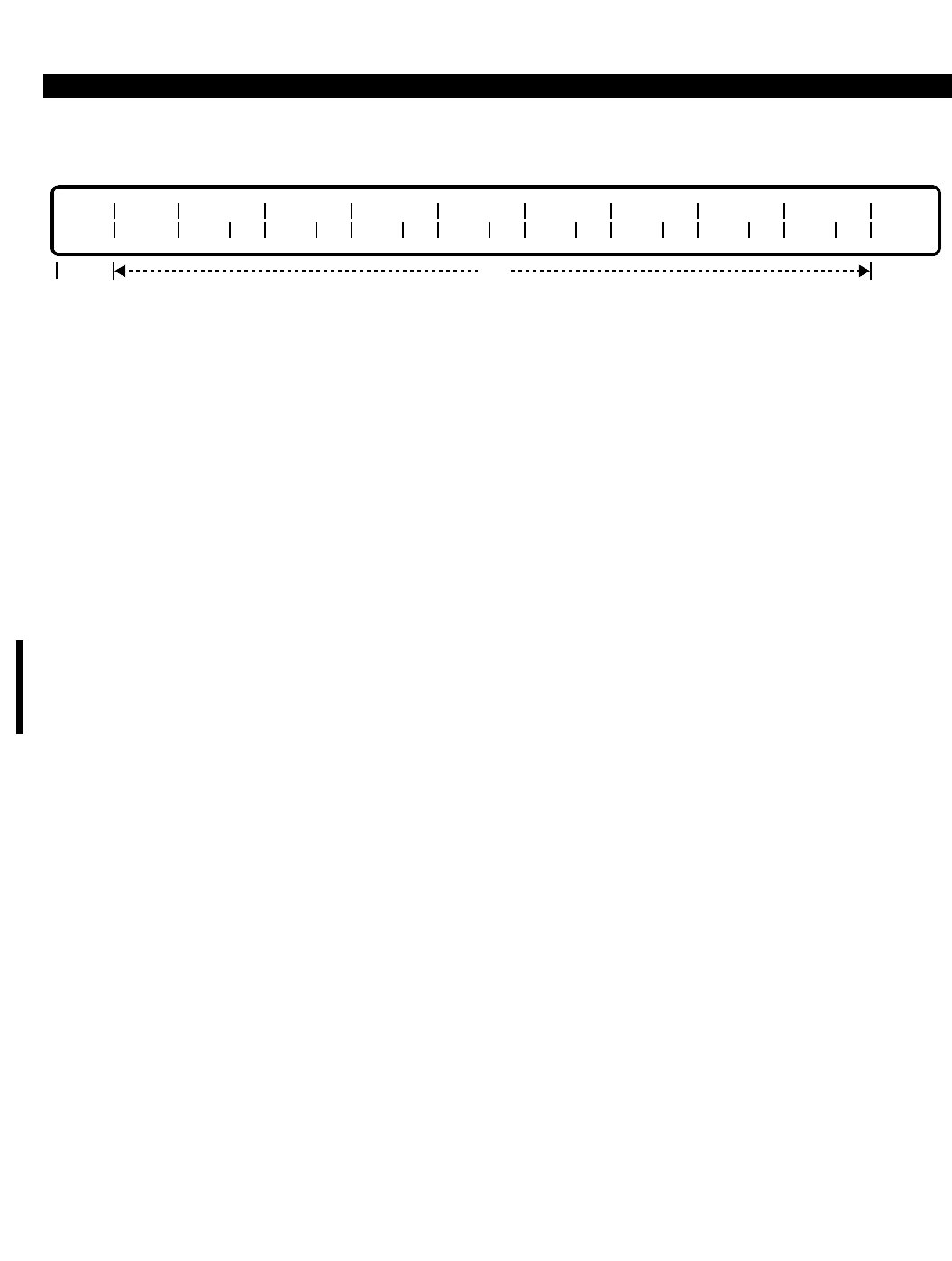
PERCEPTION 4000 COMMANDS
ISS 2, SECTION 4000-014-000
TIME ZONE ASSIGNMENT (CMD 336)
DISPLAY
This operation displays various time zone table information based on the specified input data. The “TYPE” field is
required, while the remaining fields are optional. Looping is permitted in the “INDEX” field. The "S TZ" field is the
start time which is in the form HHMM (HH is the hour, MM is the minute).
PARAMETERS
Each field parameter is described in this section. Any variations for a particular operation are noted separately.
FIELD: TYPE (Type of Table)
TYPE: Keyword
FORMAT: Predefined ASCII characters
Keywords: COS - COS/DRL/FRLP/QPL Time Zone Table
INW - Inward Routing Time Zone Table
LCR - LCR Time Zone Table
IS01 - ISDN Time/Day Change Definition Table (Class 1)
IS02 - ISDN Time/Day Change Definition Table (Class 2)
IS03 - ISDN Time/Day Change Definition Table (Class 3)
IS04 - ISDN Time/Day Change Definition Table (Class 4)
This field specifies the table to be modified or displayed.
FIELD: INDEX (Index Number)
TYPE: Decimal
FORMAT: 1 digit
VALUE: 1 to 4 (or to the maximum number of time zones)
LOOP: Allowed in DISPLAY operation
RANGE: Not allowed
This field is an index number used for the convenience of the administrator. The value varies
according to the maximum number of time zones configured.
FIELD: WEEK DAY (Day of Week or Holiday)
TYPE: Keyword
FORMAT: Predefined ASCII characters
opt
TYPE INDEX SUN
S TZ TZ
req
MON
S TZ TZ TUE
S TZ TZ WED
S TZ TZ THU
S TZ TZ FRI
S TZ TZ SAT
S TZ TZ HOL
S TZ TZ
3-384

PERCEPTION 4000 COMMANDS
Keywords: SUN - Sunday
MON - Monday
TUE - Tuesday
WED - Wednesday
THU - Thursday
FRI - Friday
SAT - Saturday
HOL - Holiday
This field selects the day of the week (or a holiday) that is to be modified. In a DISPLAY
operation, each day/holiday displays in the header with subfields.
FIELD: START TIME and S TZ (Start Time for each Time Zone)
TYPE: Decimal with fixed length
FORMAT: 4 digits in the form HHMM (where HH = hour and MM = minutes)
VALUE: 00 to 23 (HH = 24 hours/day in military time)
00 to 59 (MM = 60 minutes/hour)
LOOP: Not allowed
RANGE: Not allowed
The "START TIME" and "S TZ" fields indicate the starting time for the specified time zone. The first two digits
represent the hour of the day in military time (00 to 23), and the last two digits represent the minute (00 to 59). All
start times for each day must be in ascending order. The ending time is the minute before the next starting time. If
no further starting time is entered for the day, the last time zone is carried over to the next day.
FIELD: TIME ZONE # and TZ (Time Zone Number)
TYPE: Decimal
FORMAT: 1 digit
VALUE: 1 to 4
LOOP: Not allowed
RANGE: Not allowed
This field assigns a time zone number for the starting time entered in the previous field (START
TIME or S TZ). In a MODIFY operation, if an entry or deletion (<CONTROL-D>) is made in the
"START TIME" field, an entry or deletion must also be made in the "TIME ZONE #" field.
If the time zone for ISDN is not specified, then this parameter will default to Zone 1, which will
apply for all 24 hours for all ISDN tables (ISO1 ~ ISO4).
SYSTEM ERROR MESSAGES
The following error messages are unique to this command.
C33600 - Check time for time change
C33601 - Time zone number must be input
C33602 - Start time must be input
C33603 - Check time change number
C33604 - Entry into this time change number cannot be done; check previous
C33605 - Deletion of this time change cannot be done; check next
C33606 - Must delete both start time and zone number for the time change
ISS 2, SECTION 4000-014-000
TIME ZONE ASSIGNMENT (CMD 336)
3-385

PERCEPTION 4000 COMMANDS
ISS 2, SECTION 4000-014-000
TIME ZONE ASSIGNMENT (CMD 336)
COMMENTS
The following is an example of a Time Zone Table.
As shown, time zones may overlap from one day to the next (Zone 3).
RELATED COMMANDS
Class of Service Assignment (CMD 334)
Destination Restriction Level Assignment (CMD 337)
Facility Restriction Level Profile Assignment (CMD 387)
LCR/Authorization TZ Change Assignment (CMD 343)
LCR Routing Table Assignment (CMD 383)
System Holiday Assignment (CMD 404)
1
2
3
Index# Monday Time Time Zone Duration
0800
1700
2300
1
2
3
8:00 AM to 4:59 PM
5:00 PM to 10:59 PM
11:00 PM to 7:59 AM Tuesday
1
2
3
Index# Tuesday Time
0800
1700
2300
Zone
1
2
3
Zone Time Zone Duration
8:00 AM to 4:59 PM
5:00 PM to 10:59 PM
11:00 PM to ...
3-386

PERCEPTION 4000 COMMANDS
TIMEOUT ROUTING DESTINATION ASSIGNMENT (CMD 323)
The Timeout Routing feature allows a call to be routed to a preselected location if the user times out while dialing.
This feature is activated if the user fails to dial or fails to dial enough digits for a valid number. Up to 32 destination
locations can be selected in the system. Each station can be programmed to route to one of these 32 locations in
a time-out condition. If the destination location is undefined or deleted, the caller will receive Reorder Tone when
the time-out occurs.
This command allows you to modify the destination location, which can be an internal station number, a logical
line, an attendant or attendant group, or a hunt group pilot DN.
Command Keyword: TIMEOUT_ROUTING
Category Name: Administration
PREREQUISITE COMMANDS
Attendant Group Assignment (CMD 372) (The prerequisite commands depend upon the
Attendant Position Assignment (CMD 370) destination number.)
Station Assignment (CMD 330)
Station Hunting Assignment (CMD 342)
OPERATIONS
Available operations: MODIFY
DISPLAY
The function and required data fields for each operation are described in this section.
MODIFY
The MODIFY operation allows you to change a destination number in the Timeout Routing Assignment Table.
Both the "INDEX" and the "DESTINATION NUMBER" fields are required. The destination number can be deleted
if a <CONTROL-D> is entered in that field. Loops are not allowed in either field.
INDEX | DESTINATION NUMBER |
req
ISS 2, SECTION 4000-014-000
TIMEOUT ROUTING DESTINATION ASSIGNMENT (CMD 323)
3-387

PERCEPTION 4000 COMMANDS
ISS 2, SECTION 4000-014-000
TIMEOUT ROUTING DESTINATION ASSIGNMENT (CMD 323)
DISPLAY
This operation displays the destination numbers assigned to the Timeout Routing Assignment Table. Parameter
input is optional. Looping is allowed in the "INDEX" field, however, if no data is entered in this field, all assigned
index options are displayed.
PARAMETERS
Each field parameter is described in this section. Any variations for a particular operation are noted separately.
FIELD: INDEX (Timeout Routing Index Number)
TYPE: Decimal
FORMAT: 1 or 2 digits
VALUE: 1 to 32
LOOP: Allowed in a DISPLAY operation
This field specifies the Timeout Routing Index Number assigned to a station, and corresponds to
the "TIMEOUT INDEX" field in the Station-Level Parameter Assignment command (CMD 329).
Valid entries are from 1 to 32.
FIELD: DESTINATION NUMBER (Destination Directory Number)
TYPE: Dialing Digits
FORMAT: 1 to 5 digits
VALUE: 0 to 99999
RANGE: Allowed in a DISPLAY operation
LOOP: Not allowed
This field identifies a specific destination for its associated "INDEX" number. Valid destinations
include an internal station, a logical line, an attendant/attendant group, a hunt group pilot
directory number, or an emergency access code. During a MODIFY operation, if a <CONTROL-
D> is entered, the destination number will be deleted.
SYSTEM ERROR MESSAGES
The following error messages are unique to this command.
C32301 - DN must be an ATT/ATT GRP, Station, Hunt Group Pilot DN, or Emergency Access Code
C32302 - No DN is found for the given INDEX
RELATED COMMANDS
Station-Level Parameter Assignment (CMD 329)
INDEX | DESTINATION NUMBER |
opt
3-388
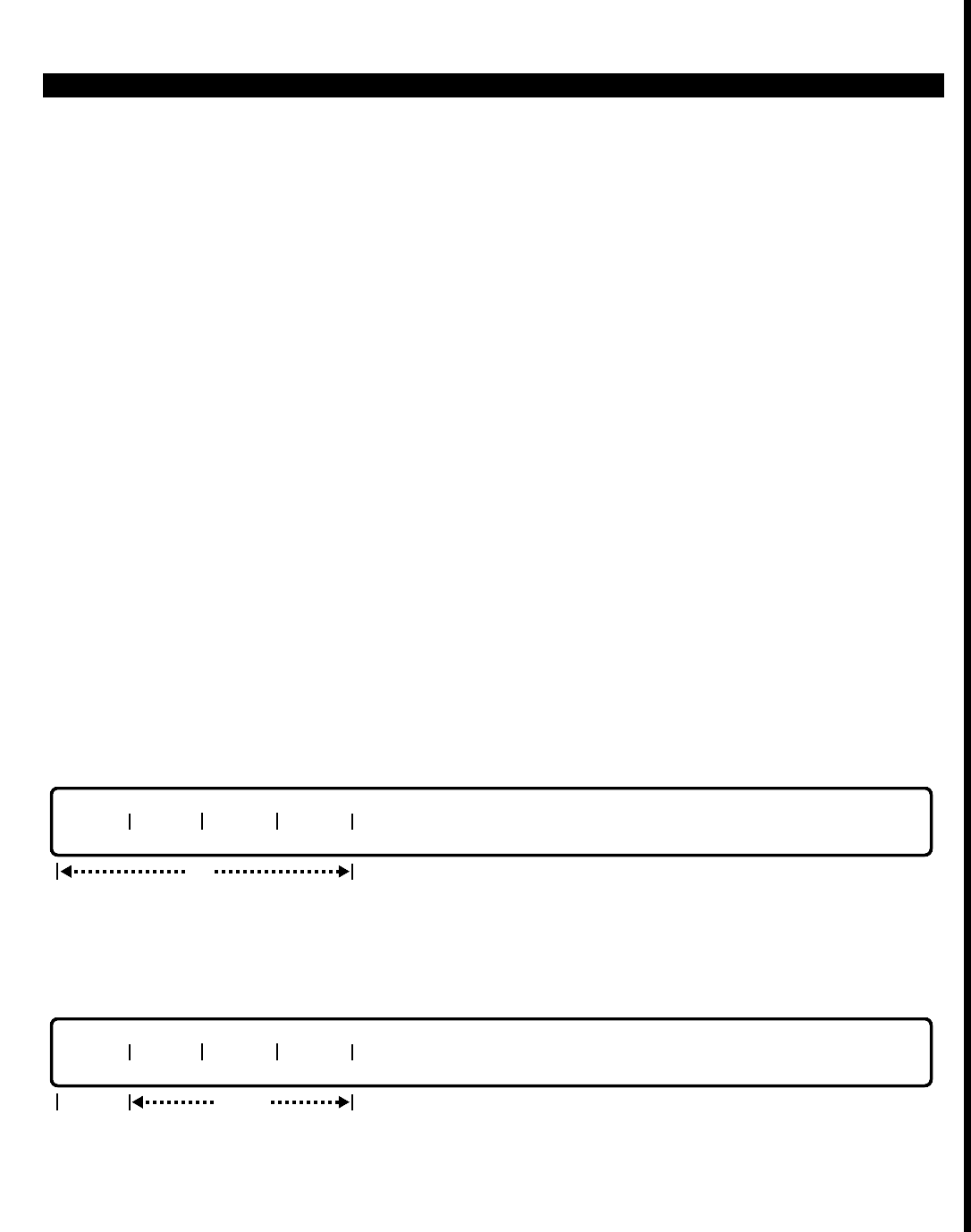
PERCEPTION 4000 COMMANDS
TRACE SETUP (CMD 168)
The Trace Setup command is used to enable a historical output regarding a virtual machine within the
PERCEPTION 4000 system. Once enabled, the PERCEPTION 4000 system will begin to collect virtual machine
operating information in a designated system buffer. Collected information can be displayed via the Crash Dump
Display command (CMD 164). A key on the PERCEPTION 4000 attendant console can be assigned to initiate the
data collection procedure. When this key is pressed, the system will begin collecting information on the virtual
machine that has been specified via the ENABLE operation. Termination of the data collection procedure requires
programming input (the attendant console key does not toggle on/off operation).
Command Keyword: TRACE_SETUP
Category Name: MAINT
OPERATIONS
Available operations:
ENABLE
DISPLAY
SETUP
SHOW
The function and required data fields for each operation are described as follows:
ENABLE
This operation is used to specify the virtual machine about which historical information is desired.
DISPLAY
This operation displays the virtual machine that was selected through the ENABLE operation. Note that actual
historical information about this virtual machine is provided via the Crash Dump Display command (CMD 164).
locked
MCPU LPU1 LPU2 LPU3
tab
opt
MCPU LPU1 LPU2 LPU3
ISS 2, SECTION 4000-014-000
TRACE SETUP (CMD 168)
3-389
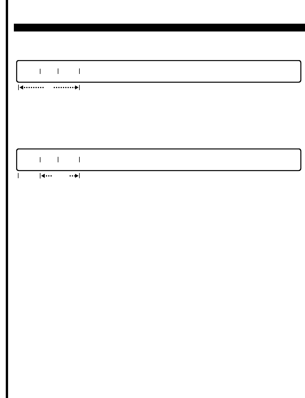
PERCEPTION 4000 COMMANDS
ISS 2, SECTION 4000-014-000
TRACE SETUP (CMD 168)
SETUP
This operation is used to assign a key on the PERCEPTION 4000 attendant console for the manufacturer
(Toshiba) to start the virtual machine data collection procedure. Note that this key is not also used to end the data
collection procedure; to end the procedure, an entry of NON in the "SHOW" field is required.
SHOW
This operation is used to display the attendant console directory number and the key position that were setup to
begin the virtual machine history collection procedure.
PARAMETERS
This section defines input permitted for each field. Any variations for a particular operation are noted separately.
FIELD: MCPU (Main Central Processing Unit)
TYPE: Keyword
FORMAT: 3 ASCII characters
Keywords: APH - Application handler
CFM - Command file management
IOC - Input/output control
MDL - MCPU download to cards
MFS - MCPU fault supervisor
MSC - MCPU system control
MSM - MCPU system management
MTF - MCPU traffic measurement
NON - No setting
The keyword entry in the "MCPU" field specifies the MCPU virtual machine that will be monitored for historical
data.
FIELD: LPU1 (Local Processing Unit 1)
TYPE: Keyword
FORMAT: 3 ASCII characters
locked
TYPE DN POS
tab
req
TYPE DN POS
3-390

PERCEPTION 4000 COMMANDS
Keywords: DTF - Data traffic measurement
LDL - LCPU download to cards
LFS - LCPU fault supervisor
LSC - LCPU system control
LSM - LCPU system management
LPC - Logic pair control
LTF - LCPU traffic measurement
NON - No setting
The "LPU1" field entry specifies the virtual machine related to Local Central Processing Unit 1, which will be
monitored for historical data.
FIELD: LPU2 (Local Processing Unit 2)
TYPE: Keyword
FORMAT: 3 ASCII characters
Keywords: DTF - Data traffic measurement
LDL - LCPU download to cards
LFS - LCPU fault supervisor
LSC - LCPU system control
LSM - LCPU system management
LPC - Logic pair control
LTF - LCPU traffic measurement
NON - No setting
The "LPU2" field entry specifies the virtual machine related to Local Central Processing Unit 2, which will be
monitored for historical data.
FIELD: LPU3 (Local Processing Unit 3)
TYPE: Keyword
FORMAT: 3 ASCII characters
Keywords: DTF - Data traffic measurement
LDL - LCPU download to cards
LFS - LCPU fault supervisor
LSC - LCPU system control
LSM - LCPU system management
LPC - Logic pair control
LTF - LCPU traffic measurement
NON - No setting
The "LPU3" field entry specifies the virtual machine related to Local Central Processing Unit 3, which will be
monitored for historical data.
FIELD: TYPE (Device Type)
TYPE: Keyword
FORMAT: 3 ASCII characters
Keywords: ATT - Attendant console
STA - Station (option not available—future use)
ISS 2, SECTION 4000-014-000
TRACE SETUP (CMD 168)
3-391

PERCEPTION 4000 COMMANDS
ISS 2, SECTION 4000-014-000
TRACE SETUP (CMD 168)
The "TYPE" field entry should be ATT. The STA option is for future use. The specified device is that which is to
contain the key that starts the data collection procedure.
FIELD: DN (Directory Number of Device Type)
TYPE: Decimal
FORMAT: 1 to 5 digits
VALUE: 1 to 99999
Enter the directory number of the device (attendant console) that is to contain the key that starts the data
collection procedure.
FIELD: POS (Key Position Number)
TYPE: Decimal or Keyword
FORMAT: 1 to 2 digits
VALUE: 1 to 24
Keywords: NON - Disable key operation
When programming an attendant console key for data collection initiation, specify the position number of the
desired key on the console. To disable key operation or to disable the data collection procedure, enter the
keyword NON.
SYSTEM MESSAGES
The following error messages are unique to this command.
C16800 - Attendant directory number already exists
C16801 - Not an individual attendant directory number
C16802 - Attendant directory number does not exist
RELATED COMMANDS
Crash Dump Display (CMD 164)
3-392
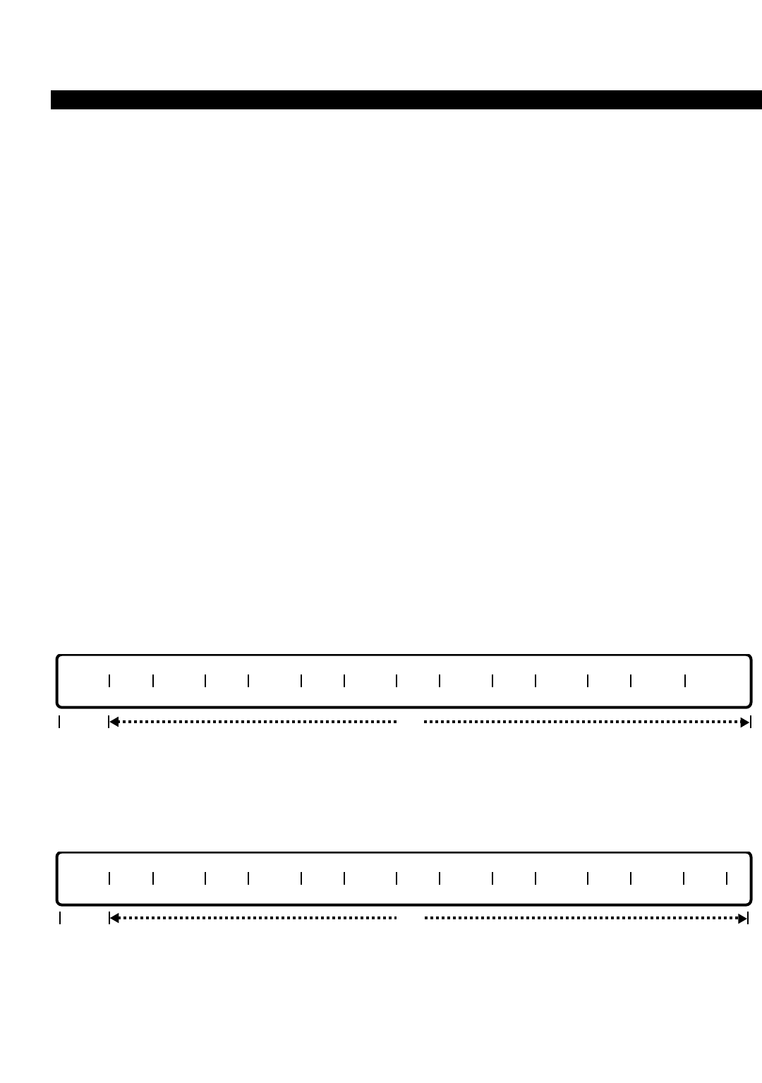
PERCEPTION 4000 COMMANDS
TRAFFIC MEASUREMENT OBJECT ASSIGNMENT (CMD 902)
The Traffic Measurement Object Assignment command defines the types of objects to be tracked (attendant
groups/trunk groups), and specifies the attendant group/trunk group numbers to be measured. In addition, traffic
measurement can be set up to track all trunk groups. Up to 32 objects can be assigned for traffic measurement.
Command Keyword: TRAFFIC_OBJECT
Category Name: Application Processor
PREREQUISITE COMMANDS
Attendant Group Assignment (CMD 372) (Prerequisite commands depend upon the "TYPE"
Trunk Assignment (CMD 313) selections.)
Trunk Group Assignment (CMD 310)
OPERATIONS
Available operations: ADD
DELETE
DISPLAY
INIT
The function and required data fields for each operation are described in this section.
ADD
This operation adds new objects to the Traffic Measurement Object Table, up to a total of 32 objects. To add a
new object, its “TYPE” must be specified. The "OBJ" may or may not be required based on the “TYPE."
DELETE
This operation deletes an object from the table. The “TYPE” must be specified, while the “OBJ” may or may not
be required based on the “TYPE."
TYPE OBJ TYPE OBJ TYPE OBJ TYPE OBJ TYPE OBJ TYPE OBJ TYPE OBJ
req opt
TYPE OBJ TYPE OBJ TYPE OBJ TYPE OBJ TYPE OBJ TYPE OBJ TYPE OBJ
req opt
ISS 2, SECTION 4000-014-000
TRAFFIC MEASUREMENT OBJECT ASSIGNMENT (CMD 902)
3-393
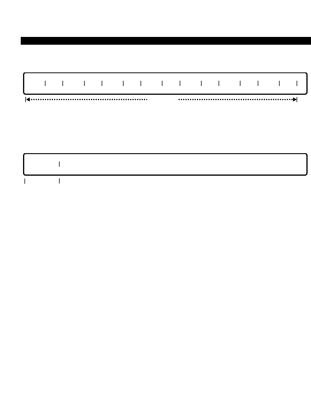
PERCEPTION 4000 COMMANDS
ISS 2, SECTION 4000-014-000
TRAFFIC MEASUREMENT OBJECT ASSIGNMENT (CMD 902)
DISPLAY
This operation displays the Traffic/Feature Measurement Object Table. The table displays automatically after
entering a <TAB> and a <CARRIAGE RETURN>.
INIT
This operation initializes the object table. Before erasing the table, the system requests confirmation of the
operation. Once executed, a message displays confirming initialization.
PARAMETERS
Each field parameter is described in this section. Any variations for a particular operation are noted separately.
FIELD: TYPE (Type of Traffic)
TYPE: Keyword
FORMAT: Predefined ASCII characters
Keywords: ATG - Attendant Group
TGN - Trunk Group
TRTL - Total for All Trunks
This field specifies the types of objects for which traffic measurement is to be performed. The
ATG and TGN fields require an "OBJ," while the TRTL option does not. The TRTL option
provides a total for all trunk groups that are defined in the system.
FIELD: OBJ (Traffic Object - Group)
TYPE: Decimal
FORMAT: 1 to 3 digits
VALUE: 1 to 30 for Attendant Groups (or to the maximum system configuration)
1 to 256 for Trunk Groups (or to the maximum system configuration)
The "OBJ" field specifies which group selected in the "TYPE" field is to be tracked. The TRTL
option does not require an "OBJ" field entry.
FIELD: INITIALIZE (Initialize Traffic Measurement Table)
TYPE: Keyword
FORMAT: Predefined ASCII characters
req
INITIALIZE
output only
TYPE OBJ TYPE OBJ TYPE OBJ TYPE OBJ TYPE OBJ TYPE OBJ TYPE OBJ
3-394

PERCEPTION 4000 COMMANDS
Keywords: YES - Perform Initialization
NO - Cancel Initialization Request
This field initializes, or erases, all of the Traffic/Feature Measurement Object Tables. The system
requests confirmation before performing the operation. Once a YES is entered, a message
displays confirming initialization.
SYSTEM ERROR MESSAGES
The following error messages are unique to this command.
C90200 - Check Objects: M, M
C90201 - N objects too many; input not accepted
C90204 - Initialization complete
C90205 - Maximum A:X
C90206 - Minimum value for A:X
C90207 - Object not found
C90208 - Not allowed to enter data in OBJ field for TRTL type
NOTE: M = 1 to 14.
N = 1 to 7.
A is a keyword (TGN or ATG).
X is the maximum value of the system configuration for the keyword, i.e., if the system has a
total of 5 attendant groups, any value above 5 is rejected in the OBJ field for attendant groups.
RELATED COMMANDS
Traffic Measurement Setup Assignment (CMD 900)
Traffic Measurement Time Zone Assignment (CMD 901)
ISS 2, SECTION 4000-014-000
TRAFFIC MEASUREMENT OBJECT ASSIGNMENT (CMD 902)
3-395
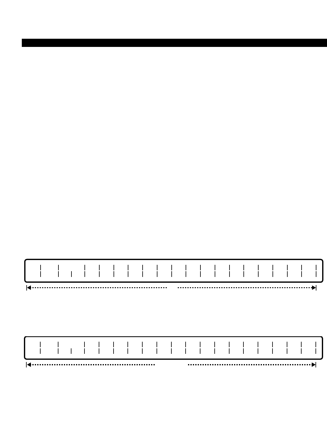
PERCEPTION 4000 COMMANDS
ISS 2, SECTION 4000-014-000
TRAFFIC MEASUREMENT SETUP ASSIGNMENT (CMD 900)
TRAFFIC MEASUREMENT SETUP ASSIGNMENT (CMD 900)
The Traffic Measurement Setup Assignment command activates/deactivates the traffic measurement system
feature. In addition, the command selects the output device for system reports. This command is used in
conjunction with the Traffic Measurement Time Zone Assignment command (CMD 901) and the Traffic
Measurement Object Assignment command (CMD 902).
Command Keyword: TRAFFIC_SETUP
Category Name: Application Processor
PREREQUISITE COMMANDS
There are no prerequisites for this command.
OPERATIONS
Available operations: MODIFY
DISPLAY
The function and required data fields for each operation are described in this section.
MODIFY
This operation modifies the attributes of the Traffic Measurement Setup Table. All of the fields are optional.
DISPLAY
This operation displays a Traffic Measurement Setup Table. The table displays automatically after entering a
<TAB> and a <CARRIAGE RETURN>.
output only
A/D DEV DISP
SZ EZ Z01
A R Z02
A R Z03
A R Z04
A R Z05
A R Z06
A R Z07
A R Z08
A R Z09
A R Z10
A R Z11
A R Z12
A R Z13
A R Z14
A R Z15
A R Z16
A R
opt
A/D DEV DISP
SZ EZ Z01
A R Z02
A R Z03
A R Z04
A R Z05
A R Z06
A R Z07
A R Z08
A R Z09
A R Z10
A R Z11
A R Z12
A R Z13
A R Z14
A R Z15
A R Z16
A R
3-396

PERCEPTION 4000 COMMANDS
PARAMETERS
Each field parameter is described in this section. Any variations for a particular operation are noted separately.
FIELD: A/D (Activate/Deactivate)
TYPE: Keyword
FORMAT: Predefined ASCII characters
Keywords: ON - Traffic Measurement is turned ON
OFF - Traffic Measurement is turned OFF
This field sets a "master flag" to activate/deactivate the traffic measurement feature. When set to
OFF, the feature is turned OFF for all 16 time zones, even if a Yis entered in a "Znn A R" field to
turn traffic measurement ON. When "A/D" is set to ON, each time zone may be activated/
deactivated on an individual basis.
FIELD: DEV (Output Device)
TYPE: Keyword
FORMAT: Predefined ASCII characters
Keywords: TTY - Report format is in TTY printer format for serial I/O port
AP - Report format is in AP format for AP interface
This field selects the format and output device for the reports. The output device may be either a
printer (TTY) or an onscreen display (AP).
FIELD: DISP SZ (Starting Time Zone for Real Time Display)
TYPE: Decimal
FORMAT: 1 or 2 digits
VALUE: 1 to 16
A traffic report may be displayed at any time. This field specifies the beginning time zone for the
report.
FIELD: DISP EZ (Ending Time Zone for Real Time Display)
TYPE: Decimal
FORMAT: 1 or 2 digits
VALUE: 1 to 16
This field specifies the ending time zone for on demand display.
FIELD: Znn A R (Activation Flag & Reporting Flag for a specific Time Zone)
TYPE: Keyword
FORMAT: Predefined ASCII characters
Keywords: Y Y - Turn ON Traffic Measurement & Report
N N - Turn OFF Traffic Measurement & Report
Y N - Turn ON Traffic Measurement & Turn OFF Report
N Y - Turn OFF Traffic Measurement & Turn ON Report (Release 2.0 supported)
ISS 2, SECTION 4000-014-000
TRAFFIC MEASUREMENT SETUP ASSIGNMENT (CMD 900)
3-397

PERCEPTION 4000 COMMANDS
ISS 2, SECTION 4000-014-000
TRAFFIC MEASUREMENT SETUP ASSIGNMENT (CMD 900)
Up to sixteen time zones (Z01 to Z16) may be defined for traffic measurement each day (see the
Traffic Measurement Time Zone Assignment command, CMD 901). Traffic measurement may be
turned ON for a specified time zone during the day with/without report output, or turned OFF
completely.
SYSTEM ERROR MESSAGES
The following error messages are unique to this command.
C90000 - Check input
D90001 Failed to send transaction to TF
RELATED COMMANDS
Traffic Measurement Object Assignment (CMD 902)
Traffic Measurement Time Zone Assignment (CMD 901)
3-398

PERCEPTION 4000 COMMANDS
TRAFFIC MEASUREMENT TIME ZONE ASSIGNMENT (CMD 901)
The Traffic Measurement Time Zone Assignment command modifies and displays the Traffic Measurement Daily
Time Zone Table. The table may have a maximum of 16 time zones.
Command Keyword: TRAFFIC_TIME_ZONE
Category Name: Application Processor
PREREQUISITE COMMANDS
There are no prerequisites for this command.
OPERATIONS
Available operations: MODIFY
DISPLAY
The function and required data fields for each operation are described in this section.
MODIFY
This operation changes the starting time of the traffic measurement (TM) time zone(s).
DISPLAY
This operation displays the current Traffic Measurement Daily Time Zone Table. The table displays automatically
after entering a <TAB> and a <CARRIAGE RETURN>.
output only
TZ1 TZ2 TZ3 TZ4 TZ5 TZ6 TZ7 TZ8 TZ9 TZ10 TZ11 TZ12 TZ13 TZ14 TZ15 TZ16
opt
TZ1 TZ2 TZ3 TZ4 TZ5 TZ6 TZ7 TZ8 TZ9 TZ10 TZ11 TZ12 TZ13 TZ14 TZ15 TZ16
ISS 2, SECTION 4000-014-000
TRAFFIC MEASUREMENT TIME ZONE ASSIGNMENT (CMD 901)
3-399

PERCEPTION 4000 COMMANDS
ISS 2, SECTION 4000-014-000
TRAFFIC MEASUREMENT TIME ZONE ASSIGNMENT (CMD 901)
PARAMETERS
Each field parameter is described in this section. Any variations for a particular operation are noted separately.
FIELD: TZ1 to TZ16 (Traffic Measurement Time Zones 1 to 16)
TYPE: Decimal / Keyword
FORMAT: 3 or 4 digits (H(H)MM, where H(H) = hour and MM = minutes)
Predefined ASCII characters
VALUE: 0 to 23 (H(H) = 24 hours/day in military time)
00, 15, 30, or 45 (MM = minutes in quarter hour increments)
LOOP: Not allowed
RANGE: Not allowed
Keyword: AUTO - Automatic generation of starting times for time zones
This field modifies or displays the starting time for individual time zones. For decimal entries, the
first digit(s) represents the hour of the day in military time (0 to 23), and the last two digits
represent the minute in quarter hour increments (00, 15, 30, and 45). All start times must be in
ascending order from "TZ1" to "TZ16." Note that it is not necessary to define all time zones.
In a MODIFY operation, if a <CONTROL-D> is entered, the stored value is deleted and the field
is treated as an empty field.
The keyword AUTO may be entered in any time zone (TZ) field. When entered, it automatically
adds one hour, based on the previous time zone, to all following empty fields. If all the preceding
TZs are empty, the field in which AUTO is entered defaults to 000.
If AUTO is entered in the "TZ1" field and the other TZ fields are empty, the start time in "TZ1"
becomes 000 (the default value), and all subsequent TZ fields increment by one hour. For
example, "TZ2" = 100, "TZ3" = 200, ... TZ16 = 1500.
If AUTO is entered in "TZi" (2 ≥i ≤16), the start time in the "TZi" field is based on the start time
TZ (i-1). If the time in TZ(i-1) is empty, it is based on the time in TZ(i-2), and so on. For example,
if all time zone fields have no values entered, except "TZ7" which had a start time of 10:45, then,
by entering the keyword AUTO in field parameters "TZ2" and "TZ10," the following table would be
established:
TZ1 | TZ2 | TZ3 | TZ4 | TZ5 | TZ6 | TZ7 | TZ8 | TZ9 | TZ10 | TZ11 | TZ12 | TZ13 | TZ14 | TZ15 | TZ16 |
000 100 200 300 400 1045 1145 1245 1345 1445 1545 1645 1745
Another example would be to set the first time zone, then to select AUTO to set the balance.
TZ1 | TZ2 | TZ3 | TZ4 | TZ5 | TZ6 | TZ7 | TZ8 | TZ9 | TZ10 | TZ11 | TZ12 | TZ13 | TZ14 | TZ15 | TZ16 |
600 AUTO 800 900 1000 1100 1200 1300 1400 1500 1600 1700 1800 1900 2000 2100
3-400

PERCEPTION 4000 COMMANDS
SYSTEM ERROR MESSAGES
The following error messages are unique to this command.
C90100 - Times zones are overlapped
C90101 - Times zones are not in ascending order
C90102 - Format of minute should be 00, 15, 30, or 45
C90103 - Check start time format; it would make last time zone exceed 2400
C90104 - Failed to send transaction to TF
RELATED COMMANDS
902 Traffic Measurement Object Assignment (CMD 902)
900 Traffic Measurement Setup Assignment (CMD 900)
ISS 2, SECTION 4000-014-000
TRAFFIC MEASUREMENT TIME ZONE ASSIGNMENT (CMD 901)
3-401

PERCEPTION 4000 COMMANDS
ISS 2, SECTION 4000-014-000
TRUNK ASSIGNMENT (CMD 313)
TRUNK ASSIGNMENT (CMD 313)
The Trunk Assignment command installs or removes trunks from the PERCEPTION 4000 system. It also displays
or changes the attributes of these facilities. Trunk attributes related to this command include the associated
equipment number, trunk group number, dialing mode, signaling, CO supervision type, start method, DISA trunk
flag, trunk termination method, and trunk name display.
Command Keyword: TK_ASSIGN
Category Name: Trunk
PREREQUISITE COMMAND
Trunk Group Assignment (CMD 310)
OPERATIONS
Available operations: ADD
DELETE
MODIFY
DISPLAY
The function and required data fields for each operation are described in this section.
ADD
This operation installs one or more trunks to the PERCEPTION 4000 system. Ranges are permitted when
installing a number of trunks in the same trunk group with identical parameters.
DELETE
This operation deletes one or more trunks from the PERCEPTION 4000 system. Ranges are permitted when
deleting a number of trunks. However, before deleting a trunk, the trunk must be removed from its trunk hunting
group (Trunk Hunting Assignment command, CMD 309). A warning is sent by the system when deleting the last
trunk from a trunk group.
req
EQUIP #
req
EQUIP # TGN ORG TERM SIG CO SUP TYPE ST DT DISA TRK NAME
opt
3-402
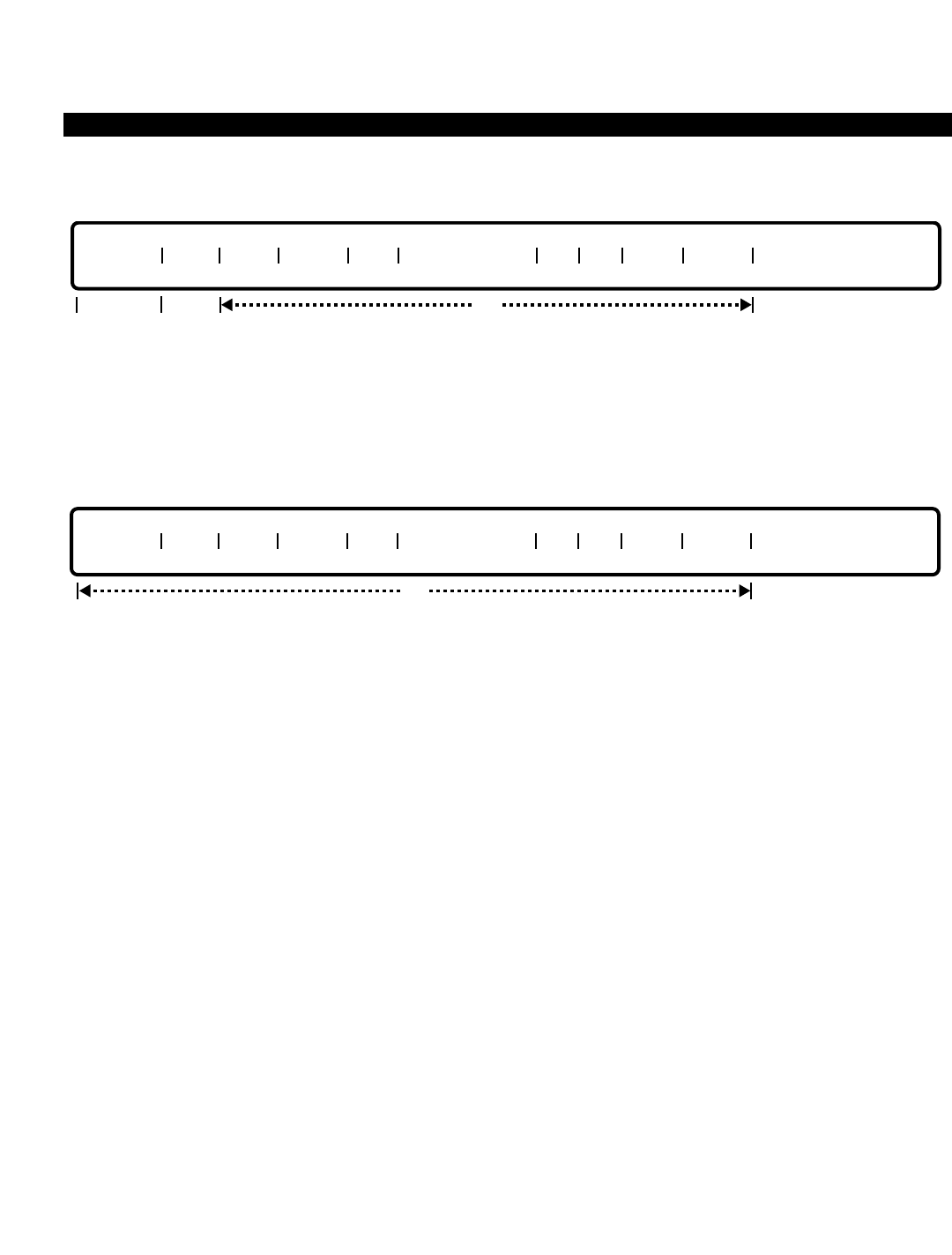
PERCEPTION 4000 COMMANDS
MODIFY
This operation modifies attributes of one or more existing trunks in the system. The "TGN" field cannot be
modified. To relocate a "TGN" to another trunk group, a DELETE and ADD operation must be performed. Ranges
are permitted in the "EQUIP #" field when changing attributes for a number of trunks.
DISPLAY
This operation displays trunk attributes of one or more existing trunks. All of the fields are optional. If no data is
entered in any of these fields, the attributes of all the trunks in the system display. Ranges are permitted in any
field that accepts numeric input, such as the "EQUIP #" and "TGN" fields.
PARAMETERS
Each field parameter is described in this section. Any variations for a particular operation are noted separately.
FIELD: EQUIP # (Equipment Number)
TYPE: EQ Type
FORMAT: 5 or 6 digits
VALUE: (0)10101 to 101408 *
LOOP: Primary loop field, and allowed for all operations
* Use the following chart to determine valid ranges for various types of equipment.
For COGI, DIDI, and EM1I cards, the following are valid ranges:
Digits Range Hardware
First digit(s) (0)1~10 Shelf no.
Second two digits 01~14 Card slot no.
Last two digits 01~08 Circuit no.
For an EM2I card, the circuit number cannot be greater than 6:
Digits Range Hardware
First digit(s) (0)1~10 Shelf no.
Second two digits 01~14 Card slot no.
Last two digits 01~06 Circuit no.
EQUIP # TGN ORG TERM SIG CO SUP TYPE ST DT DISA NAME
opt
opt
EQUIP # TGN ORG TERM SIG CO SUP TYPE ST DT DISA NAME
req output
only
ISS 2, SECTION 4000-014-000
TRUNK ASSIGNMENT (CMD 313)
3-403

PERCEPTION 4000 COMMANDS
ISS 2, SECTION 4000-014-000
TRUNK ASSIGNMENT (CMD 313)
The "EQUIP #" field defines the location of the connection to the trunk card. The first digit(s)
represent the shelf number, the next two digits represent the card slot number, and finally, the last
two digits represent the circuit number.
FIELD: TGN (Trunk Group Number)
TYPE: Decimal
FORMAT: 1 to 3 digits
VALUE: 1 to 256 (or to the maximum system configuration)
RANGE: Allowed in a DISPLAY operation only
This field assigns a trunk group to the equipment port designated in the "EQUIP #" field. The
trunk group number, which is defined with the Trunk Group Assignment command (CMD 310),
cannot be modified.
FIELD: ORG (Originating Dial Mode)
TYPE: Keyword
FORMAT: Predefined ASCII characters
Keywords: DTMF - Dual-tone Multi-frequency
DP10 - Dial Pulse / 10 pulses per second
DP20 - Dial Pulse / 20 pulses per second
The originating dial mode is used for all outgoing and bothway trunk groups, and defines whether
DTMF or dialpulse sending is used over the circuit.
FIELD: TERM (Terminating Dial Mode)
TYPE: Keyword
FORMAT: Predefined ASCII characters
Keywords: DTMF - Dual-tone Multi-frequency
DP10 - Dial Pulse / 10 pulses per second
DP20 - Dial Pulse / 20 pulses per second
NA - Not Applicable
The terminating dial mode is primarily for DID, CCSA, and incoming TIE trunk calls, and defines
what type of sending the PERCEPTION 4000 system can expect to receive from the distant end.
This field is not applicable for outgoing only trunk groups.
FIELD: SIG (Signaling)
TYPE: Keyword
FORMAT: Predefined ASCII characters
Keywords: DID - Direct Inward Dialing
EM1 - E&M Type 1
EM2 - E&M Type 2
GND - Ground Start
LP - Loop Start
LTIE - Loop TIE Start
3-404

PERCEPTION 4000 COMMANDS
The signaling field defines the type of signaling to be used by the trunk circuit. This signaling
must be consistent with the type of trunk interface card installed, which in turn must be
compatible with the signaling used by the serving central office.
FIELD: CO SUP TYPE (Central Office Supervision Type)
TYPE: Keyword
FORMAT: Predefined ASCII characters
Keywords: CLD - Called Party Disconnect
CLG - Calling Party Disconnect
EPD - Either Party Disconnect (also called First Party Disconnect)
NON - No Supervision
This field determines the type of release supervision provided by the central office for a given
trunk circuit. The release supervision is considered by the system whenever a Trunk-to-Trunk
connection is requested in order to prevent trunk lockups. Refer to the Trunk-to-Trunk Connection
Assignment command (CMD 305) for further information on trunk connections.
If the "DISA" field is set to YES, this field must be set to CLG or EPD.
All peripheral equipment interfacing to trunk circuits should have this field set to NON, indicating
there is no release supervision.
FIELD: ST (Start Method)
TYPE: Keyword
FORMAT: Predefined ASCII characters
Keywords: DLY - Delay Dial
DT - Dial Tone
IMM - Immediate Start
TIM - Timing Start
WNK - Wink Start
The start method field is used for TIE trunks connecting different systems. The use of this field
requires a knowledge of the other systems' signaling scheme, therefore coordination between
administrators is important. If this field is set to IMM, the originating and terminating dial mode
types must not be DTMF. TIM is required for loop start trunks.
FIELD: DT (Dial Tone)
TYPE: Keyword
FORMAT: Predefined ASCII characters
Keywords: DT - Dial Tone Returned
STR - Silent Tone Returned
The dial tone field is used in private network applications and determines whether the
PERCEPTION 4000 system returns dial tone or silence to the calling end before the distant end
begins to send digits.
ISS 2, SECTION 4000-014-000
TRUNK ASSIGNMENT (CMD 313)
3-405

PERCEPTION 4000 COMMANDS
ISS 2, SECTION 4000-014-000
TRUNK ASSIGNMENT (CMD 313)
FIELD: DISA (Direct Inward System Access Flag)
TYPE: Keyword
FORMAT: Predefined ASCII characters
Keywords: YES - The trunk allows DISA
NO - The trunk does not allow DISA
The Direct Inward System Access flag determines whether incoming or bothway trunks allow
access to the DISA feature. Outgoing only trunks cannot be designated for DISA usage.
FIELD: TRK NAME (Trunk Name)
TYPE: Text
LENGTH: 0 to 14 ASCII characters
Each trunk circuit may optionally be assigned a name which may be up to 14 ASCII characters in
length. This name appears on display-equipped stations and attendant consoles when connected
to this trunk.
SYSTEM ERROR MESSAGES
The following error messages are unique to this command.
C31300 - Trunk is not found in system
C31301 - Trunk is already installed
C31302 - Start method not compatible
C31303 - DISA is not for TIE, private lines, or outgoing trunks
C31304 - Undefined trunk group number
C31305 - Card or equipment number is already assigned to other devices
C31306 - No DISA flag for given trunk group number
C31307 - Exceeds maximum trunks allowed in trunk group
D31308 - Trunk group cannot be modified
C31309 - Check data in TERM field
C31310 - Signaling is not compatible
D31311 - Download PP data failed
C31312 - Silence tone returned only for TIE
C31313 - Private feature key still exists
C31314 - IMM start cannot have DTMF dial mode
C31315 - DISA must have EPD or CLG release supervision
C31316 - Removed hunting sequence before deleting trunk
C31317 - Trunk name is up to 9 characters
I31318 - Warning: N is the last trunk to be removed from trunk group M
C31319 - Failed to read LCPU database
C31320 - Trunks exceed the limit for LCPU-n (n = 1, 2, or 3)
C31321 - Trunk group number should be a non-ISDN type
C31322 - Trunk cannot be assigned to a dictation machine trunk group
C31323 - Remove voice paging zones related to this trunk before deletion
3-406

PERCEPTION 4000 COMMANDS
COMMENTS
When installing a trunk in the database, if the physical circuit does not exist, the trunk should be marked as
'MADE BUSY' by using the Terminal Maintenance command (CMD 206).
A trunk can belong to one and only one trunk group.
Prior to removing a trunk, the trunk must first be removed from its trunk group.
User confirmation is required when deleting a number of trunks.
RELATED COMMANDS
Numbering Plan Assignment (CMD 300)
Private/Hotline Assignment (CMD 332)
Trunk Hunting Assignment (CMD 309)
Trunk PP Parameter Change (CMD 364)
Trunk Routing Assignment (CMD 308)
Trunk-to-Trunk Connection Assignment (CMD 305)
ISS 2, SECTION 4000-014-000
TRUNK ASSIGNMENT (CMD 313)
3-407
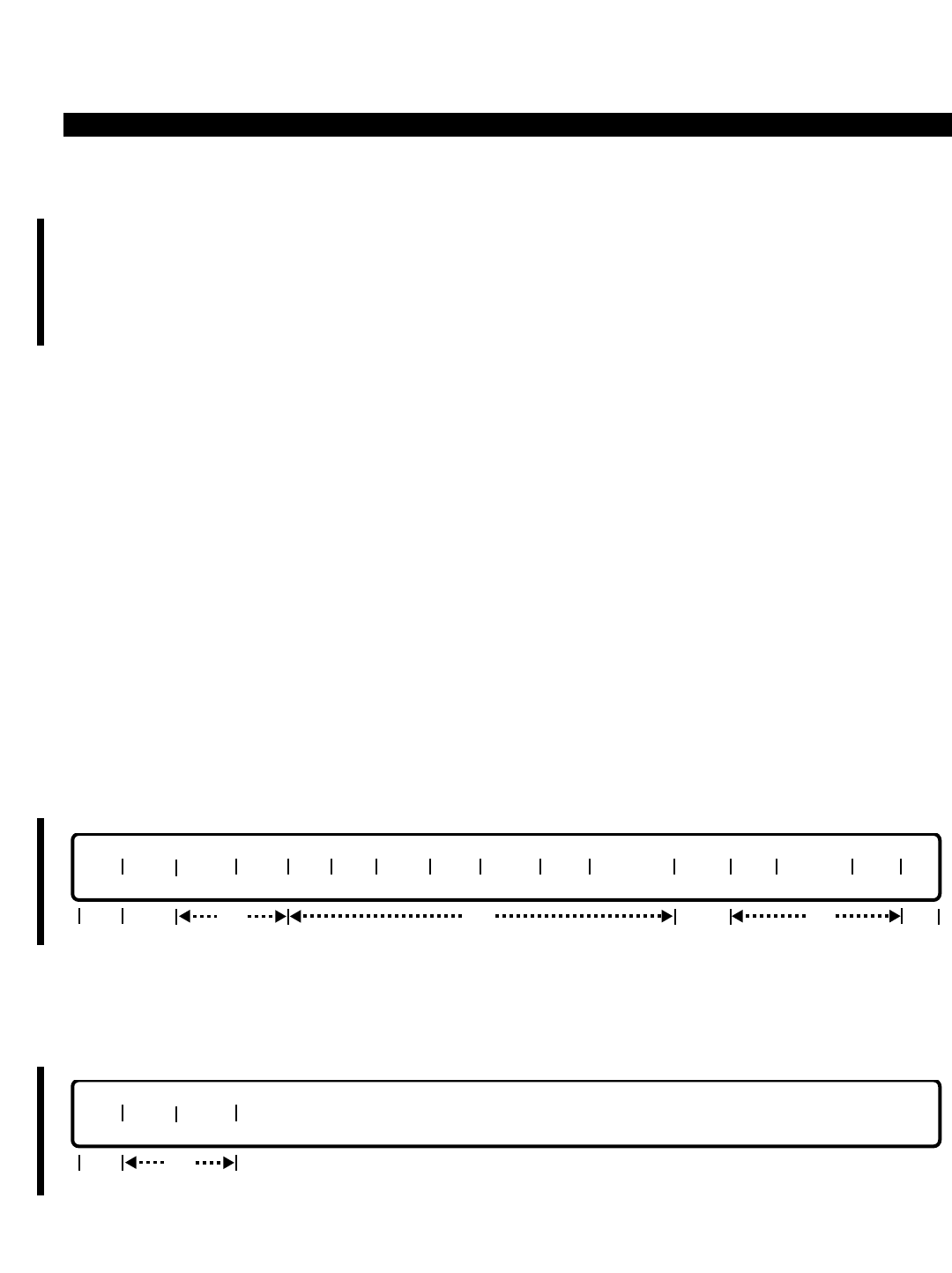
PERCEPTION 4000 COMMANDS
ISS 2, SECTION 4000-014-000
TRUNK GROUP ASSIGNMENT (CMD 310)
TRUNK GROUP ASSIGNMENT (CMD 310)
The Trunk Group Assignment command creates or deletes trunk groups in the PERCEPTION 4000 system. This
command also modifies or displays general attributes of one or more trunk groups, including the channel group
(for ISDN trunks), trunk type, restriction group number, dialing definition group number, Class of Service,
Destination Restriction Level, Facility Restriction Level Profile, Queuing Priority Level, answer position, trunk
group home area code, answer supervision, and recall destination.
Command Keyword: TG_ASSIGN
Category Name: Trunk
PREREQUISITE COMMANDS
If data is entered in the "ANSPOS" field, then an appropriate command may be required for assignment
of the attendant DN, attendant group DN, station DN, hunt group pilot, UCD pilot, or ACD pilot.
OPERATIONS
Available operations: ADD
DELETE
MODIFY
DISPLAY
The function and required data fields for each operation are described in this section.
ADD
This operation creates one or more trunk groups in the system. Ranges are permitted when adding a number of
trunk groups with the same type and attributes. Note that the "S RG" and "GF" fields are locked fields.
DELETE
This operation deletes one or more trunk groups from the system. The "TGN" field is required. Ranges are
permitted when deleting a number of trunk groups, however, confirmation is requested by the system before
deleting a group. Note that all trunks in a trunk group must be deleted before deleting the group.
req
TGN CGN TYPE
opt
req
TGN CGN TYPE USE RG DG COS DRL FRLP QPL ANS POS S RG SUP RCL DN HAC GF
opt locked opt
opt req locked
3-408
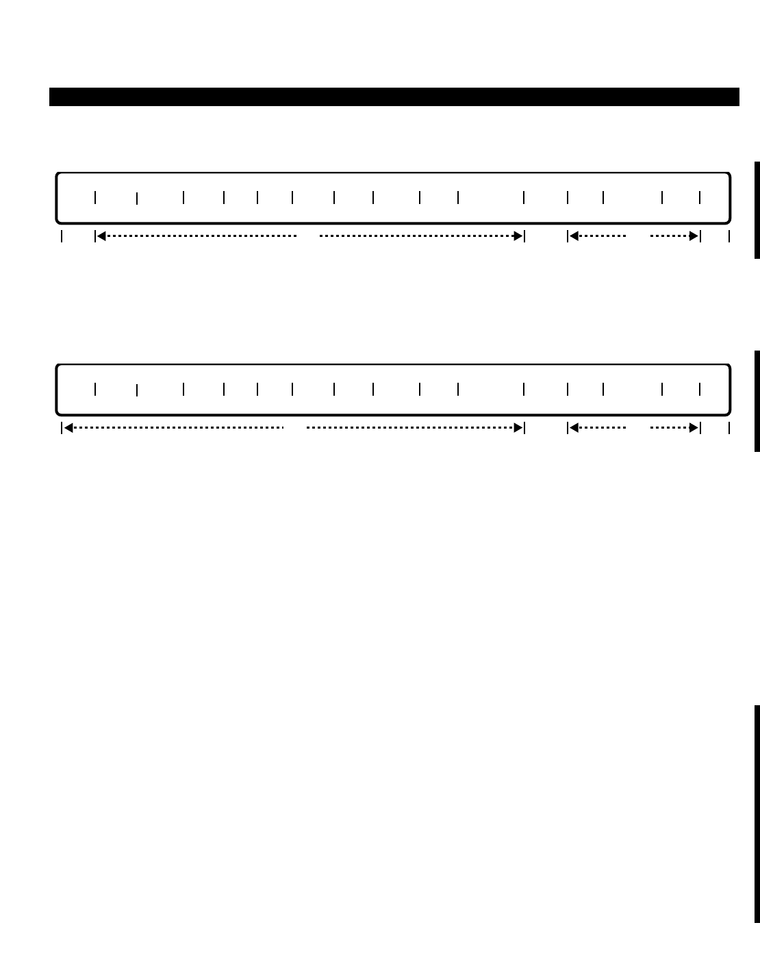
PERCEPTION 4000 COMMANDS
MODIFY
This operation changes the attributes of one or more existing trunk groups. Ranges are permitted in the "TRG"
field when modifying a number of trunk groups with the same attributes.
DISPLAY
This operation displays the attributes of one or more trunk groups. Ranges are permitted in any field that accepts
numeric input, such as the “TGN” and “RG” fields. If no data is entered in any of the fields, the attributes of all of
the trunk groups in the system display.
PARAMETERS
Each field parameter is described in this section. Any variations for a particular operation are noted separately.
FIELD: TGN (Trunk Group Number)
TYPE: Decimal
FORMAT: 1 to 3 digits
VALUE: 1 to 256 (or to the maximum system configuration)
RANGE: Allowed in a DISPLAY operation only
LOOP: Primary loop field, and allowed in all operations
This field assigns a number to each non-ISDN/ISDN trunk group. This number is unique and may
not be duplicated among tenants.
FIELD: CGN (ISDN PRI Channel Group Number)
TYPE: Decimal
FORMAT: 1 to 2 digits
VALUE: 1 to 32 (or to the maximum system configuration)
RANGE: Allowed in a DISPLAY operation only
LOOP: Not allowed
This field must be entered when assigning ISDN trunk types to trunk groups. Individual trunks are
assigned to channel groups via the ISDN Channel Group Assignment command (CMD 423).
TGN CGN TYPE USE RG DG COS DRL FRLP QPL ANS POS S RG SUP RCL DN HAC GF
opt locked opt locked
req
TGN CGN TYPE USE RG DG COS DRL FRLP QPL ANS POS S RG SUP RCL DN HAC GF
opt locked opt locked
ISS 2, SECTION 4000-014-000
TRUNK GROUP ASSIGNMENT (CMD 310)
3-409

PERCEPTION 4000 COMMANDS
ISS 2, SECTION 4000-014-000
TRUNK GROUP ASSIGNMENT (CMD 310)
FIELD: TYPE (Trunk Type)
TYPE: Keyword
FORMAT: Predefined ASCII characters
For Non-ISDN Trunks:
Keywords: AUX - Auxiliary Use
CC - Code Call
CCSA - Common Channel Signaling Arrangement
CO - Central Office
DID - Direct Inward Dialing
DM01 to
DM16 - Dictation Machine groups 1 to 16.
DNIS - Dialed Number Identification Service
FX - Foreign Exchange
PVT - Private Line or Trunk
TIE - TIE Line
VPG - Voice Paging
WATS - Wide Area Telecommunication Service
For ISDN Trunks:
Keywords: ACCU - ACCUNET Switched Digital Services
ATAT - AT&T Long Distance Service—A shared use, two-way, premise-to-
premise service that uses the public switched network to transmit and
receive voice and data
IMC8 - International AT&T MEGACOM 800 service
INCW - INWATS—Provides OUTWATS-like pricing and services for incoming
calls
MAXW - MAXWATS—A WATS-like offering; with MAXWATS, user's calls are billed
at the highest WATS band subscribed to by the user
MC - AT&T MEGACOM—An AT&T service that provides unbanded long
distance services using special access from an AT&T node
MC8 - AT&T MEGACOM 800—An AT&T service that provides unbanded 800
service using special access from an AT&T node
MQST - Multiquest—900 service
OUTW - OUTWATS—A voice-grade service that provides both voice and low-
speed data transmission capabilities from the user's location to defined
service areas commonly referred to as bands
POTS - Plain Old Telephone Service—Supports 3/7/10 international calls and
equal access operator-related calls
PSDN - Private Software Defined Network
SDN - Public/Global Software Defined Network
The "TYPE" field identifies non-ISDN and ISDN trunk group usage. With non-ISDN trunk groups,
trunk use can be specified as CCSA, CO, DID, DNIS, FX, TIE, WATS, or other auxiliary uses. An
AUX entry can be used for any standard loop start or ground start trunk interface and is used to
support out board equipment. The CO, FX, and WATS types are interchangeable. For ISDN trunk
groups, the specified trunk use is the supported ISDN service—MEGACOM 800, Long Distance
Service, etc.
3-410

PERCEPTION 4000 COMMANDS
FIELD: USE (Trunk Use)
TYPE: Keyword
FORMAT: Predefined ASCII characters
Keywords: INC - Incoming
OUT - Outgoing
BWY - Bothway
Each non-ISDN and ISDN trunk group is defined as an incoming, outgoing, or a bothway trunk
group. DID, MC8, IMC8, and MQST trunks are incoming only.
FIELD: RG (Restriction Group Number)
TYPE: Decimal
FORMAT: 1 digit
VALUE: 1 to 8 (or to the maximum system configuration)
RANGE: Allowed in a DISPLAY operation only
This field applies to both non-ISDN and ISDN bothway or outgoing trunk groups. DID, MC8,
IMC8, and MQST trunks; dictation devices; announcement devices; and auxiliary trunk groups do
not require trunk restriction.
Trunk restriction groups represent a set of trunk groups which have similar dialing restrictions
placed on them due to cost factors and sensible dialing practices. For example, an FX line
terminating in Dallas from Los Angeles would be prohibited from placing local calls in Los
Angeles. The FX trunk groups to the Dallas area should be bundled together in one restriction
group, while regular CO lines terminating to the serving central office in Los Angeles might be
grouped together in another. Trunk restriction groups 2 through 8 may be used for this bundling
purpose.
Restriction group 1 is reserved for use by TIE trunks and interfaces to peripheral equipment
where unconventional dialing patterns are used and where absolute unrestricted dialing for all
parties is required.
FIELD: DG (Dialing Definition Group Number)
TYPE: Decimal
FORMAT: 1 digit
VALUE: 1 to 4
RANGE: Allowed in a DISPLAY operation only
This field applies to both non-ISDN and ISDN trunk groups. Dialing groups define characteristics
for similar central offices. These definitions include various operator and toll prefixes, as well as
N11 numbers and interchangeable office code recognition. Dialing definitions are defined with the
Dialing Definition command (CMD 317). Group 1 is undefined and recommended for TIE trunk
groups and trunk groups where no digit analysis or restriction is necessary.
ISS 2, SECTION 4000-014-000
TRUNK GROUP ASSIGNMENT (CMD 310)
3-411

PERCEPTION 4000 COMMANDS
ISS 2, SECTION 4000-014-000
TRUNK GROUP ASSIGNMENT (CMD 310)
FIELD: COS (Class of Service)
TYPE: Decimal
FORMAT: 1 or 2 digits
VALUE: 1 to 64
RANGE: Allowed in DISPLAY operation only
This field, along with the next three fields, is required for non-ISDN/ISDN TIE trunks and DISA
trunks. Together, the three fields provide feature and facility access and dialing control definitions
for the specified trunk. Class of Service tables are defined with the Class of Service Assignment
command (CMD 334).
FIELD: DRL (Destination Restriction Level)
TYPE: Decimal
FORMAT: 1 or 2 digits
VALUE: 1 to 16 (or to the maximum system configuration)
RANGE: Allowed in DISPLAY operation only
This field, required for TIE and DISA trunks, controls outgoing calls via direct trunk group access.
When DRL is 1, all calls are allowed regardless of what Restriction Group number (RG) is in use.
Restriction levels are defined with the Destination Restriction Level Assignment command (CMD
337).
FIELD: FRLP (Facility Restriction Level Profile)
TYPE: Decimal
FORMAT: 1 or 2 digits
VALUE: 1 to 32 (or to the maximum system configuration)
RANGE: Allowed in DISPLAY operation only
This field, required for TIE and DISA trunks, defines restrictions assigned to various routes within
each least cost routing route table. Restriction levels are defined with the Facility Restriction
Level Profile Assignment command (CMD 387).
FIELD: QPL (Queue Priority Level)
TYPE: Decimal
FORMAT: 1 digit
VALUE: 1 to 8
RANGE: Allowed in a DISPLAY operation only
This field, required for TIE and DISA trunks, sets queuing priority for outgoing calls and is defined
with the LCR Special Routing Assignment command (CMD 384).
FIELD: ANSPOS (Answer Position)
TYPE: DN Type
FORMAT: 1 to 5 digits
VALUE: 0 to 99999
RANGE: Not allowed
This field is used by both non-ISDN and ISDN trunk groups. The answer position field defines the
directory number to which calls made via the universal attendant access code are directed.
These are normally 'Dial 0' internal calls. '0' may be redefined as any legal directory number in
the system numbering plan (Numbering Plan Assignment command, CMD 300).
3-412

PERCEPTION 4000 COMMANDS
The destination can be an attendant DN, attendant group DN, station DN, hunt group pilot, UCD
pilot, or ACD pilot. This field is required for TIE trunks and DISA supporting trunk groups.
FIELD: S RG (Station Restriction Group Number) (Reserved for future use)
TYPE: Decimal
FORMAT: 1 or 2 digits
VALUE: 1 to 16
RANGE: Allowed in a DISPLAY operation only
This field defines internal station-to-station calling capabilities. This is a locked field and reserved
for future use.
FIELD: SUP (Answer Supervision)
TYPE: Keyword
FORMAT: Predefined ASCII characters
Keywords: YES - Answer supervision is enabled
NO - Answer supervision is disabled
The Answer Supervision field applies to both non-ISDN and ISDN trunk groups. The field entry
tells the PERCEPTION 4000 system whether or not answer supervision is supplied to the system
from the network after a call is answered. This field is useful for Station Message Detail Report
(SMDR) records to know when to start billing the call. Otherwise the call is charged when the
SMDR threshold timer expires, regardless of whether the call was answered immediately or
never answered.
For ISDN trunks, Answer Supervision should be entered as YES. If a <TAB> is entered when
assigning an ISDN trunk group via the ADD operation, then Answer Supervision will default to
YES.
FIELD: RCL DN (Recall Destination Directory Number)
TYPE: Dialing Digits (i.e., 001 is not the same as 01 or 1)
FORMAT: 1 to 5 digits
VALUE: 0 to 99999
RANGE: Allowed in a DISPLAY operation only
This field applies to both non-ISDN and ISDN trunk groups. The CO/FX/WATS/DID/CCSA trunks
must have a recall destination directory number. This number can be either an attendant DN, an
attendant group DN, or a station DN. If a <CONTROL-D> is entered in this field, the RCL
directory number is deleted.
FIELD: HAC (Trunk Group’s Home Area Code)
TYPE: Dialing Digits (i.e., 001 is not the same as 01 or 1)
FORMAT: 3 digits in the form N Y X (where N = 2 to 9, Y = 0 or 1, and X = 0 to 9)
VALUE: 200 to 919
RANGE: Allowed in a DISPLAY operation only
This field applies to both non-ISDN and ISDN trunk groups. The trunk group has a home area
code assigned to it which is used by the outgoing call restriction process for seven digit calls over
a desired facility. The area/office and exceptional restriction tables are checked to see if the call is
ISS 2, SECTION 4000-014-000
TRUNK GROUP ASSIGNMENT (CMD 310)
3-413

PERCEPTION 4000 COMMANDS
ISS 2, SECTION 4000-014-000
TRUNK GROUP ASSIGNMENT (CMD 310)
allowed or denied based on the trunk restriction group and calling entity's destination restriction
level.
TIE trunks do not require an HAC entry. If a <CONTROL-D> is entered in this field, the HAC is
deleted.
FIELD: GF (Global Net Flag)
TYPE: Keyword
FORMAT: Predefined ASCII characters
DEFAULT: N
Keywords: Y = Enable global network access
N = Disable global network access
The "GF" field activates/deactivates access to the Global Network system, and is used only with
the Toshiba Proprietary Global Network. This field applies only to non-ISDN trunks and is a
locked field.
SYSTEM ERROR MESSAGES
The following error messages are unique to this command.
C31000 - Undefined trunk group number
C31001 - Trunk group number is already defined
C31002 - Check trunk group number range
C31003 - HAC entry is required for outgoing and bothway trunks
C31004 - Remove all trunks in trunk group first
C31005 - Need RG, DG, HAC, and TF#
C31006 - DID/INCW/MC8/IMC8/MQST trunks are incoming only
C31007 - TIE needs COS, DRL, FRLP, QPL, and ANSPOS
C31008 - Check answer position DN
C31009 - No HAC or TF# needed for TIE
C31010 - Only CO, FX, and WATS type can be interchanged
C31011 - Remove all trunks and trunk-to-trunk connections first
I31012 - Warning: TIE needs answer position
C31013 - Recall DN must be an attendant group DN
I31014 - Warning: CO/FX/WATS/CCSA/DID need RCL destination
C31015 - Dictation machine should be bothway or outgoing type
I31016 - Warning: LCR routes still exist in table
I31017 - Warning: Steering digits still exist
C31018 - Remove LCR routes before adding private trunks
C31019 - Remove steering digits before adding private trunks
C31020 - Remove trunks before modifying USE
C31021 - Private trunk can only be bothway or outgoing
C31022 - CGN field is required for ISDN trunk groups
C31023 - CGN field should not be entered for non-ISDN trunk groups
C31024 - Not allowed to modify trunk group type in field 3
C31025 - Cannot delete trunk group number; CGN mismatch
C31026 - Total DID, DNIS, CCSA type, plus DDI, DNIS inward mode cannot exceed 16
C21027 - ISDN channel group number is not assigned
C21028 - Duplicate trunk group type for the assigned channel group number
3-414

PERCEPTION 4000 COMMANDS
C31029 - Incompatible trunk group type for the assigned channel group number
I31030 - Warning: Undefined data in field #N
C31031 - Not allowed to modify ISDN trunk group usage in field 4
C31032 - OUTW/MAXW/MC trunks are outgoing only
C31033 - HAC is needed for CO/FX/PVT/WATS/ISDN outgoing/bothway trunks
COMMENTS
All of the trunks contained within a trunk group must be individually deleted before the trunk group can be
deleted.
When the last trunk of a trunk group is removed, the status of the trunk group must be changed accordingly.
Status may be indicated by a flag that denotes the empty trunk group.
The total number of DID, DNIS, and CCSA non-ISDN trunk groups, plus the total number of DDI/DNIS trunk
groups must be less than or equal to 16.
For outgoing trunks, bothway trunks, and dictation machine groups to operate correctly, trunks belonging to these
groups must have trunk hunting sequences defined using the Trunk Hunting Assignment command (CMD 309).
This applies even if the trunk group has only one trunk, as in the case of private line trunk groups.
RELATED COMMANDS
Class of Service Assignment (CMD 334)
Destination Restriction Level Assignment (CMD 337)
Dialing Definition (CMD 317)
Dictation Group/Machine Assignment (CMD 401)
DID/CCSA DISA LDN Assignment (CMD 315)
DID/CCSA LDN Assignment (CMD 316)
DID/CCSA Trunk Group Assignment (CMD 314)
Facility Restriction Level Profile Assignment (CMD 387)
ISDN Trunk Group Parameter Assignment (CMD 421)
LCR Routing Table Assignment (CMD383)
Numbering Plan Assignment (CMD 300)
Private/Hotline Assignment (CMD 332)
SMDR Configuration Assignment (CMD 409)
Traffic Measurement Object Assignment (CMD 902)
Trunk Assignment (CMD 313)
Trunk Group Parameter Assignment (CMD 420)
Trunk Group Routing Assignment (CMD 307)
Trunk Hunting Assignment (CMD 309)
Trunk PP Parameter Change (CMD 364)
Trunk-to-Trunk Connection Assignment (CMD 305)
Voice Paging/Code-Call Assignment (CMD 319)
ISS 2, SECTION 4000-014-000
TRUNK GROUP ASSIGNMENT (CMD 310)
3-415
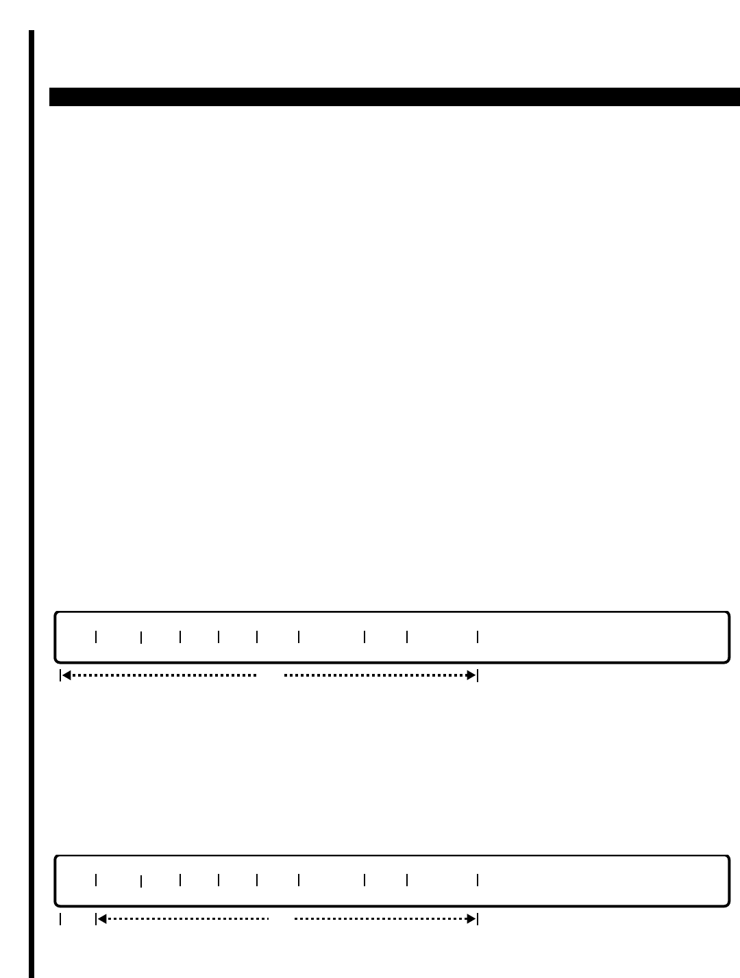
PERCEPTION 4000 COMMANDS
ISS 2, SECTION 4000-014-000
TRUNK GROUP PARAMETER ASSIGNMENT (CMD 420)
TRUNK GROUP PARAMETER ASSIGNMENT (CMD 420)
The Trunk Group Parameter Assignment command allows the attributes of one or more non-ISDN or ISDN trunk
groups to be displayed or modified. Trunk group attributes include: translation profile number; toll-free table
number; incoming call ACD queue priority level; incoming call ACD queue priority timer; next incoming call ACD
queue priority level; and ACD overflow destination.
Command Keyword: TG_PARAMETER
Category Name: Trunk
PREREQUISITE COMMANDS
Trunk Group Assignment (CMD 310)
OPERATIONS
Available operations:
DISPLAY
MODIFY
The function and required data fields for each operation are described as follows:
DISPLAY
This operation is used to display the trunk attributes of one or more existing trunk groups. If no data is input in this
operation, then the attributes of all trunk groups in the PERCEPTION 4000 system will be displayed. Information
relating only to specific trunk groups is provided by entering each trunk group's corresponding trunk group
number. Range entries are permitted in selected fields, including Trunk Group Number and Translation Profile
Number.
MODIFY
req
TGN PLF# TF# TF# TF# IQP1 IQP TMR IQP2 OVF TMR
opt
TGN PLF# TF# TF# TF# IQP1 IQP TMR IQP2 OVF TMR
opt
3-416

PERCEPTION 4000 COMMANDS
ThIs operation is used to modify the attributes of one or more existing trunk groups. Data input is required only in
the "TGN" field; other fields are optional. Range entries are permitted in the "TGN" field.
Form:
PARAMETERS
This section defines input permitted for each field. Any variations for a particular operation are noted separately.
FIELD: TGN (Trunk Group Number)
TYPE: Decimal
FORMAT: 1 to 3 digits
VALUE: 1 to 256 (or maximum system trunk configuration)
RANGE: Allowed in DISPLAY operation only
LOOP: Allowed in all operations
The "TGN" entry is required in the MODIFY operation. In the DISPLAY operation, this is an
optional field. If no entry is made, then the attributes of all trunk groups in the PERCEPTION
4000 system will be displayed.
FIELD: PFL# (Profile Number)
TYPE: Decimal or Keyword
FORMAT: 1 to 2 digits; preassigned ASCII characters
VALUE: 1 to 32
RANGE: Allowed in DISPLAY operation only
LOOP: Not allowed
Keyword: NON - No translation profile number is assigned
This field is used to assign a translation profile number to each trunk group. This field applies to
both non-ISDN and ISDN trunk groups. The default value for this field is NON.
FIELD: TF# (Toll-free Table Number)
TYPE: Decimal
FORMAT: 1 to 2 digits
VALUE: 1 to 16 (or maximum system configuration)
RANGE: Allowed in DISPLAY operation only
LOOP: Not allowed
This field applies to both non-ISDN and ISDN trunk groups. Up to three defined toll-free
area/office code tables can be assigned to a trunk group. A table number can be entered in each
of the provided "TF#" programming fields. If <Control> D is entered, the entered "TF#" value will
be deleted. The toll-free area/office code tables are defined by using CMD 311.
FIELD: IQP1 (Incoming ACD Call Queing Priority
TYPE: Decimal
FORMAT: 1 to 2 digits
VALUE: 1 to 16 (1 is the highest priority; 16 is the lowest priority)
RANGE: Allowed in DISPLAY operation only
LOOP: Not Allowed
ISS 2, SECTION 4000-014-000
TRUNK GROUP PARAMETER ASSIGNMENT (CMD 420)
3-417

PERCEPTION 4000 COMMANDS
ISS 2, SECTION 4000-014-000
TRUNK GROUP PARAMETER ASSIGNMENT (CMD 420)
This field applies to both non-ISDN and ISDN trunk groups. The positioning of an ACD call into
the ACD queue depends on the assigned priority level of the trunk used to route the call. ACD
calls routed over high-priority trunks (such as 1) will be positioned at the front of the ACD queue
and will be the first calls to be sent to available ACD agents. Conversely, ACD calls routed over
low priority trunks (such as 16) will be positioned at the end of the ACD queue and will be sent to
available ACD agents only after all ACD calls with higher priorities are handled.
When a trunk group is first assigned via the Trunk Group Assignment command (CMD 310), the
"IQP1" value defaults to 1. Alterations to this value are made via the "IQP1" field in CMD 420. An
"IQP1" value cannot be deleted by using the Delete symbol; it must be a valid value of 1 to 16.
FIELD: IQP TMR (Incoming ACD Call Queing Priority Timer)
TYPE: Decimal
FORMAT: 1 to 4 digits
VALUE: 1 to 9999, in seconds
RANGE: Allowed in DISPLAY operation only
LOOP: Not allowed
This field applies to both non-ISDN and ISDN trunk groups. The "IQP TMR" field defines the time
(in seconds) that an incoming ACD call can wait in the ACD queue for an available ACD agent.
Once this timer expires, the ACD call will be repositioned in the ACD queue as determined by its
assigned "IQP2" priority level. This field should be defined if an "IQP2" value is assigned. If
<Control> D is entered, then both the "IQP TMR" and "IQP2" values will be deleted.
FIELD: IQP2 (Second Incoming ACD Call Queing Priority
TYPE: Decimal
FORMAT: 1 to 2 digits
VALUE: 1 to 16 (1 is the highest priority; 16 is the lowest priority)
RANGE: Allowed in DISPLAY operation only
LOOP: Not allowed
This field applies to both non-ISDN and ISDN trunk groups. The "IQP2" priority level is the new
priority level assigned to an incoming ACD call that has waited in the QCD queue longer than
allowed by the incoming ACD call queuing priority timer ("IQP TMR"). Once this timer expires, the
waiting ACD call is repositioned in the ACD queue depending on its new priority level. Note that
the "IQP2" priority level must be greater than the "IQP1" priority level (i.e., the numeric value of
"IQP2" must be less than "IQP1"). If the "IQP2" field is assigned a value, then both the "IQP1"
and "IQP TMR" fields must also be assigned. If <Control> D is entered in the "IQP2" field, then
both the "IQP2" and "IQP TMR" values will be deleted.
FIELD: OVF TMR (ACD Overflow Timer)
TYPE: Decimal
FORMAT: 1 to 4 digits
VALUE: 1 to 9999, in seconds
RANGE: Allowed in DISPLAY operation only
LOOP: Not allowed
This field applies to both non-ISDN and ISDN trunk groups. The OVF TMR value represents the
overall time (in seconds) that an incoming ACD call can wait in the ACD queue. This assignment
is independent of the trunk group's assigned priority value(s) and the ACD call queing priority
3-418

PERCEPTION 4000 COMMANDS
timer ("IQP TMR"). Once the ACD overflow timer ("OVF TMR") expires, the waiting ACD call will
be routed to a preassigned overflow destination, as assigned via the ACD Group Parameter
Assignment command (CMD 357). Note that the "OVF TMR" value must be greater than that of
the "IQP TMR."
SYSTEM MESSAGES
The following error messages are unique to this command.
C42000 - Undefined trunk group number
C42001 - Check trunk group number range
C42002 - Incoming trunks cannot be toll-free
C42003 - Check toll-free number
C42004 - Toll-free is not required for TIE trunks
C42005 - Duplicated TF# table
C42006 - Toll-free table overflow; cannot add more
C42007 - IQP2 should be less than IQP1
C42008 - IQP1 timer and IQP2 should be entered together
C42009 - ACD overflow timer should be greater than IQP TMR
RELATED COMMANDS
DID/CCSA/DNIS DISA LDN Assignment (CMD 315)
DID/CCSA/DNIS LDN Assignment (CMD 316)
DID/CCSA/DNIS Trunk Group Assignment (CMD 314)
LCR Routing Table Assignment (CMD 383)
Private Line/Hotline Assignment (CMD 332)
SMDR Configuration Assignment (CMD 409)
Trunk Assignment (CMD 313)
Traffic Measurement Object Assignment (CMD 902)
Trunk Group Routing Assignment (CMD 307)
Trunk Hunting Assignment (CMD 309)
Trunk-to-Trunk Connection Assignment (CMD 305)
Voice Paging/Code Call Assignment (CMD 319)
ISS 2, SECTION 4000-014-000
TRUNK GROUP PARAMETER ASSIGNMENT (CMD 420)
3-419

PERCEPTION 4000 COMMANDS
ISS 2, SECTION 4000-014-000
TRUNK GROUP ROUTING ASSIGNMENT (CMD 307)
TRUNK GROUP ROUTING ASSIGNMENT (CMD 307)
The Trunk Group Routing Assignment command provides a means of routing incoming trunk calls, with the
exception of DID, CCSA, DISA, and inbound TIE trunks. When a call arrives on a trunk, the Trunk Routing Table
is checked to see if unique routing is defined for the trunk in the active time zone. If not, the Trunk Group Routing
Table is examined for routing instructions for that trunk group as defined for the time zone that is active. If no
definition exists at either the trunk or trunk group level for the time zone used, the caller receives CO ringback
indefinitely.
This command provides up to three routing destinations at the trunk group level for the given time zone.
Command Keyword: TG_ROUTING
Category Name: Trunk
PREREQUISITE COMMANDS
Time Zone Assignment (CMD 336)
Trunk Assignment (CMD 313)
Trunk Group Assignment (CMD 310)
Depending on the route choices, appropriate commands from the following list may be required for
assignment.
ACD Group Assignment (CMD 355)
Announcement Pattern Assignment (CMD 353)
Attendant Group Assignment (CMD 372)
Attendant Position Assignment (CMD 370)
Miscellaneous Device Assignment (CMD 400)
Night Bell Assignment (CMD 405)
Station Assignment (CMD 330)
Station Hunting Assignment (CMD 342)
System Speed Calling Assignment (CMD 402)
UCD Group Assignment (CMD 354)
OPERATIONS
Available operations: MODIFY
DISPLAY
The function and required data fields for each operation are described in this section.
3-420
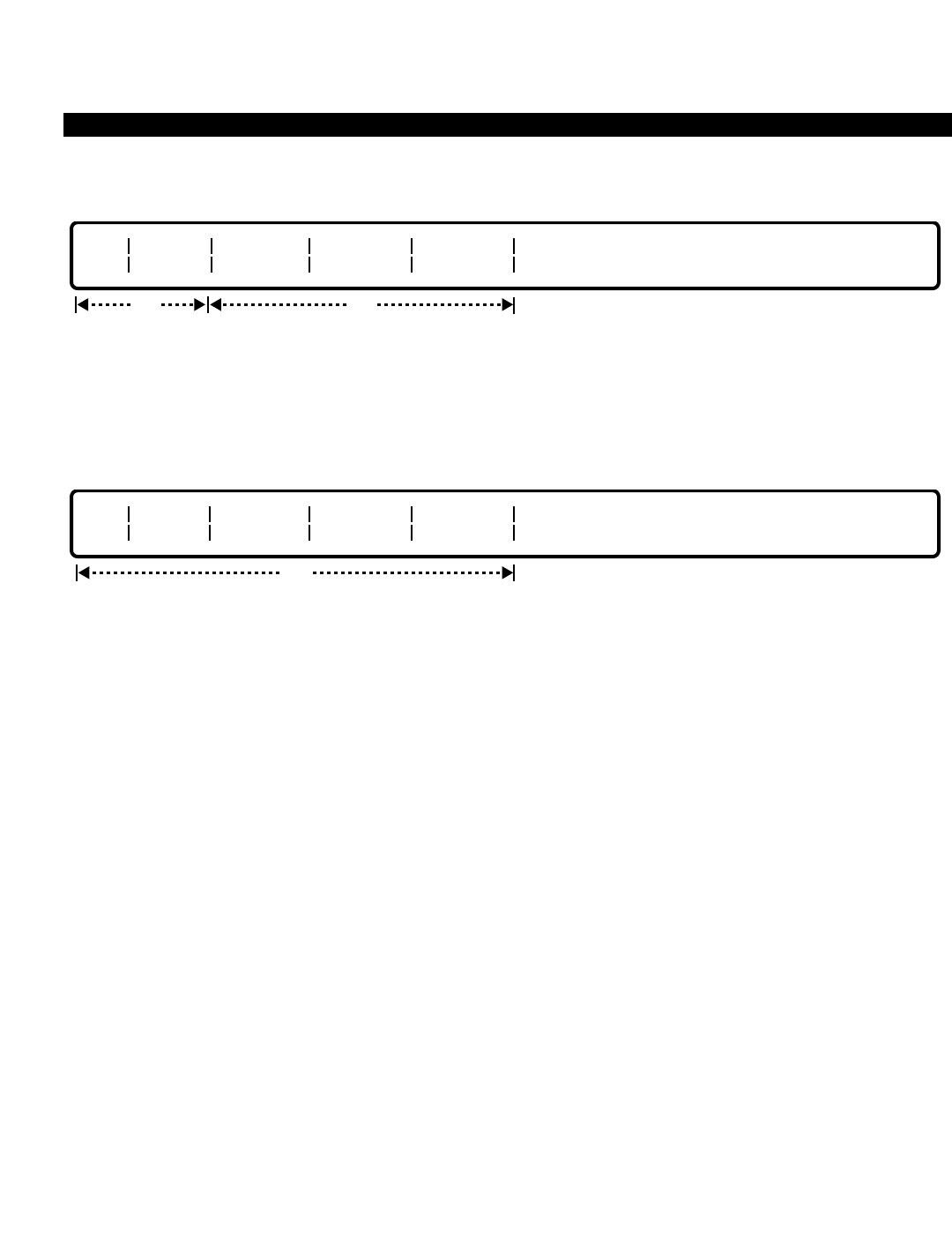
PERCEPTION 4000 COMMANDS
MODIFY
This operation changes the routing destinations of one or more trunk groups. The "TGN" and "TIME ZONE #"
fields are required, while the route choice fields are optional. Ranges are permitted in the "TGN" field when
modifying a number of trunk groups with the same routing destinations. All calls "ON HOLD" or "IN PROGRESS"
must be completed before a MODIFY operation may be performed.
DISPLAY
This operation displays routing destinations of one or more trunk groups. All of the fields are optional. If no data is
entered in any of these fields, the routing destinations of all the trunk groups in the system display. Ranges are
permitted in all fields.
PARAMETERS
Each field parameter is described in this section. Any variations for a particular operation are noted separately.
FIELD: TGN (Trunk Group Number)
TYPE: Decimal
FORMAT: 1 to 3 digits
VALUE: 1 to 256 (or to the maximum system configuration)
LOOP: Primary loop field, and allowed in all operations
This field specifies the trunk group number to be defined. The number is previously assigned with
the Trunk Group Assignment command (CMD 310).
FIELD: TIME ZONE #
TYPE: Decimal
FORMAT: 1 digit
VALUE: 1 to 4
LOOP: Allowed in all operations
Inbound routing destinations can be varied from time zone to time zone. This field specifies the
time zone to be defined.
FIELD: ROUTE CHOICE 1/2/3
TYPE: Dialing Digits / Keyword
FORMAT: 1 to 5 digits / 4 to 6 digits
opt
TGN TIME
ZONE # ROUTE
CHOICE 1 ROUTE
CHOICE 2 ROUTE
CHOICE 3
opt
TGN TIME
ZONE # ROUTE
CHOICE 1 ROUTE
CHOICE 2 ROUTE
CHOICE 3
req
ISS 2, SECTION 4000-014-000
TRUNK GROUP ROUTING ASSIGNMENT (CMD 307)
3-421

PERCEPTION 4000 COMMANDS
ISS 2, SECTION 4000-014-000
TRUNK GROUP ROUTING ASSIGNMENT (CMD 307)
VALUE: 0 to 99999 / Speed Access Code + Index
Keywords: AP01 ~ AP50 Announcement Pattern Number
BL01 ~ BL64 Night Bell
NON No Routing
"ROUTE CHOICE 1" can be one of the following:
a) Individual attendant console directory number
b) Attendant group directory number
c) Station number
d) Announcement pattern number
e) Hunt group pilot number
f) UCD group pilot number
g) ACD group pilot number
h) Speed calling codes (System speed calling access code plus system speed calling index
number)
i) Night bell
j) No routing (May be used for Route Choice 1 only)
"ROUTE CHOICE 2" has the same options as "ROUTE CHOICE 1." However, to define "ROUTE
CHOICE 2," ROUTE CHOICE 1" must be defined as an attendant or an attendant group which is
found to be unavailable (in the Position Busy mode).
"ROUTE CHOICE 3" has the same options as "ROUTE CHOICE 1," with the exception of the
attendant and attendant group options. To define "ROUTE CHOICE 3," both "ROUTE CHOICE
1" and "2" must be defined as an attendant or attendant group or mix thereof, with both route
choices "1" and "2" unavailable due to console or attendant group Position Busy mode.
In cases where the attendant or attendant group is in the Position Busy mode, the call is routed to
the second choice. If the second choice is an attendant or attendant group in the Position Busy
mode, the call is routed to the third choice. Depending on what Route 3 is defined as, other call
processing may be performed by hunting, UCD, ACD, or call forwarding.
SYSTEM ERROR MESSAGES
The following error messages are unique to this command.
C30700 - Undefined trunk group number
C30701 - Check trunk group number range
C30702 - Undefined night bell
C30703 - Undefined announcement machine
C30704 - Check time zone number range
C30705 - Check directory number
C30706 - Check combination of routing destinations
C30707 - Check trunk use
C30708 - Check trunk type
C30709 - Check announcement machine usage
3-422

PERCEPTION 4000 COMMANDS
C30710 - NON is allowed for Route Choice 1 only
I30711 - Warning, Undefined data in Route Choice #n
RELATED COMMANDS
Time Zone Assignment (CMD 336)
Trunk Routing Assignment (CMD 308)
ISS 2, SECTION 4000-014-000
TRUNK GROUP ROUTING ASSIGNMENT (CMD 307)
3-423

PERCEPTION 4000 COMMANDS
ISS 2, SECTION 4000-014-000
TRUNK GROUP TOLL-FREE TABLES (CMD 311)
TRUNK GROUP TOLL-FREE TABLES (CMD 311)
Up to 16 toll-free area/office code tables may be defined for the system's trunk groups. These tables define the
toll-free zone around a serving central office. Up to three tables may be assigned to any given trunk group. These
tables are used by the outgoing call restriction process for a given trunk restriction group and calling device
destination restriction level.
The Trunk Group Toll-free tables are optional for outgoing call management, but provide a convenient shorthand
method for allowing only toll-free calls over certain facilities by certain calling entities.
Command Keyword: TG_TF_TABLES
Category Name: Trunk
PREREQUISITE COMMANDS
There are no prerequisites for this command.
OPERATIONS
Available operations: ADD
DELETE
DISPLAY
The function and required data fields for each operation are described in this section.
ADD
This operation defines new area/office code toll-free tables and adds entries to them. Since it is possible for one
or more tables to have the same area code, the table number is required to uniquely identify it. Ranges are
permitted in the "TBL#" field. The office code fields allow scope entries.
DELETE
opt
TBL# AC OC OC OC OC OC OC OC OC OC OC
req
opt
TBL# AC OC OC OC OC OC OC OC OC OC OC
req
3-424

PERCEPTION 4000 COMMANDS
This operation deletes entries in the area/office code toll-free tables. When all entries within a table are deleted,
the table automatically becomes free. Since it is possible for one or more tables to have the same area code, the
table number is required to uniquely identify it. Ranges are permitted in the "TBL#" and "AC" fields. The office
code fields allow scope entries.
DISPLAY
This operation displays all area/office code toll-free table(s), or entries within the table(s), that meet the conditions
established for each field. Ranges are allowed in all fields.
PARAMETERS
This section defines inputs permitted for each field. Any variations for a particular operation are noted separately.
FIELD: TBL# (Table Number)
TYPE: Decimal
FORMAT: 1 or 2 digits
VALUE: 1 to 32 (or maximum configuration number)
LOOP: Allowed in all operations
This field represents the Trunk Group Toll-free Table number.
FIELD: AC (Area Code)
TYPE: Decimal with fixed length
FORMAT: 3 digits in the form N Y X (where N = 2 to 9, Y = 0 or 1, and X = 0 to 9)
VALUE: 200 to 919
LOOP: Allowed in DISPLAY and DELETE operations
This field represents the area code.
FIELD: OC (Office Code)
TYPE: Decimal with fixed length
FORMAT: 3 digits in the form NXX (N = 2 to 9, X = 0 to 9)
VALUE: 200 to 999 inclusive
RANGE: Allowed in a DISPLAY operation
SCOPE: Allowed in ADD and DELETE operations
This field represents the office code. All office codes listed in these tables are toll-free. The first
"OC" field is required in ADD and DELETE operations.
opt
TBL# AC OC OC OC OC OC OC OC OC OC OC
ISS 2, SECTION 4000-014-000
TRUNK GROUP TOLL-FREE TABLES (CMD 311)
3-425

PERCEPTION 4000 COMMANDS
ISS 2, SECTION 4000-014-000
TRUNK GROUP TOLL-FREE TABLES (CMD 311)
SYSTEM ERROR MESSAGES
The following error message are unique to this command.
C31100 - The table is not in use
C31101 - Invalid table number
C31102 - Invalid office code high bound
C31103 - Invalid office code low bound
C31104 - Invalid office code range
C31105 - Area code does not match table number
C31106 - Scope data must have low and high bounds in fields
C31107 - Scope data must have high bound in field
C31108 - Scope data must have low bound in field
C31109 - Scope data is not allowed in the last field
C31110 - Database update failed; software error
C31111 - Area code is needed when first creating table
RELATED COMMANDS
Trunk Group Assignment (CMD 310)—The Trunk Group Assignment command assigns the toll-free
AC/OC tables defined here to each trunk group created.
3-426

PERCEPTION 4000 COMMANDS
TRUNK HUNTING ASSIGNMENT (CMD 309)
Trunk hunting determines the type and order of hunting that is performed by the system when a trunk group is
selected to make an outbound call. This command adds/modifies the hunting method, adds/deletes hunting
sequence numbers of trunks in a trunk group, and displays the hunting method and hunting sequence numbers.
This command must be performed for all outgoing and bothway trunk groups as well as dictation machine and
private line trunk group members.
Command Keyword: TRUNK_HUNTING
Category Name: Trunk
PREREQUISITE COMMANDS
Dictation Group/Machine Assignment (CMD 401) Command 401 is required if a Dictation Machine
group trunk type is selected in the "TGN" field.
Trunk Assignment (CMD 313)
Trunk Group Assignment (CMD 310)
OPERATIONS
Available operations: ADD
DELETE
MODIFY
DISPLAY
The function and required data fields for each operation are described in this section.
ADD
This operation adds a hunting method or sets a hunting sequence for trunks in a trunk group. Loops are allowed
in the “TGN” and “SEQ#” fields. When adding a specific sequence number for an equipment circuit, all following
equipment numbers are re-sequenced automatically.
DELETE
opt
TGN TYPE SEQ# EQUIP #
reqoptreq
TGN TYPE SEQ# EQUIP #
reqoptreq
ISS 2, SECTION 4000-014-000
TRUNK HUNTING ASSIGNMENT (CMD 309)
3-427
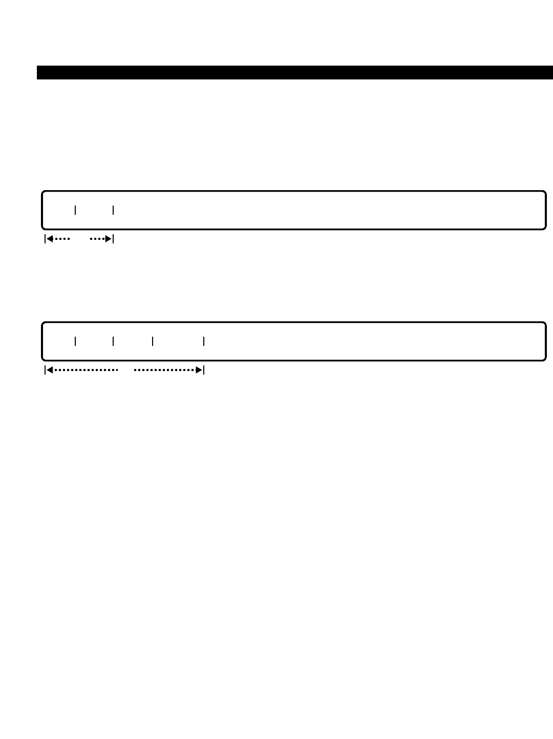
PERCEPTION 4000 COMMANDS
ISS 2, SECTION 4000-014-000
TRUNK HUNTING ASSIGNMENT (CMD 309)
This operation deletes a trunk from the trunk hunting group. When deleting a specific sequence number, all of the
following trunks are re-sequenced automatically. If the keyword ALL is entered in the “SEQ#” field, all the trunks
in the trunk hunting group are deleted.
MODIFY
This operation modifies the hunting method for trunk groups. Ranges are permitted in the “TGN” field.
DISPLAY
This operation displays the hunting method and sequence of trunks in a trunk hunting group(s). Ranges are
permitted in the “TGN” and “SEQ#” fields. If no data is entered in the “SEQ#” field, all equipment numbers for the
given trunk group display.
PARAMETERS
Each field parameter is described in this section. Any variations for a particular operation are noted separately.
FIELD: TGN (Trunk Group Number)
TYPE: Decimal
VALUE: 1 to 256 (or to the maximum system configuration)
LOOP: Allowed in all operations except DELETE
This field specifies the trunk group number to be defined. The number is previously assigned with
the Trunk Group Assignment command (CMD 310).
NOTE: Incoming only trunk groups are not allowed PBX-side trunk hunting assignment.
FIELD: TYPE (Hunting Method)
TYPE: Keyword
FORMAT: Predefined ASCII characters
Keywords: DIST - Distributed method
TERM- Terminal method
Distributed and terminal hunting methods are available on the PERCEPTION 4000 system. The
distributed hunting method attempts to seize a trunk from the trunk group by remembering which
circuit was last used for an outgoing call, and then connecting the user to the next idle trunk in
opt
TGN TYPE SEQ# EQUIP #
TGN TYPE
req
3-428

PERCEPTION 4000 COMMANDS
sequence. This method has the primary advantage of distributing traffic evenly to all circuits,
thereby prolonging hardware equipment life.
Terminal hunting is used in situations where glare (sometimes referred to as collision) may be a
problem. Glare occurs usually on loop-start trunks when an inbound call simultaneously seizes
the same trunk being used to perform an outbound call. Thus two parties are connected with
each other accidentally. When setting up terminal hunting, inbound traffic ordering should be from
the 'top down', while outbound traffic ordering should be from the 'bottom up'. This eliminates the
chance of glare.
NOTE: Dictation machine groups only support the terminal hunting method.
FIELD: SEQ# (Hunting Sequence Number)
TYPE: Decimal
VALUE: 1 to 64
KEYWORD: ALL (Used in DELETE operation only)
LOOP: Allowed in ADD/DISPLAY operation
This field defines the sequence in which the system hunts through the trunks for outgoing calls
for the specified trunk group. Sequence numbers are reordered automatically when a trunk is
added to or deleted from the trunk group.
FIELD: EQUIP # (Trunk Equipment Number)
TYPE: EQ Type
FORMAT: 5 or 6 digits
VALUE: (0)10101 to 101408
RANGE: Allowed in a DISPLAY operation
The equipment number is assigned with the Trunk Assignment command (CMD 313). This field
selects the appropriate trunk to be added, deleted, or displayed in the trunk hunting feature.
SYSTEM ERROR MESSAGES
The following error messages are unique to this command.
C30900 - Trunk group number not found
C30901 - Undefined trunk group number
C30902 - Trunk group number is out of range
C30903 - Sequence number already exists
C30904 - Hunting method mismatch
C30905 - Check trunk use (incoming trunk)
C30906 - Check type of trunk
C30907 - Invalid input
C30908 - Undefined sequence number
C30909 - Unsuitable sequence number
C30910 - Equipment number mismatch
C30911 - No sequence number is defined
C30912 - Hunting method required
C30913 - Equipment is not installed
C30914 - Equipment number can only have a maximum of eight circuits
C30915 - Dictation machine can only use terminal hunt
ISS 2, SECTION 4000-014-000
TRUNK HUNTING ASSIGNMENT (CMD 309)
3-429

PERCEPTION 4000 COMMANDS
ISS 2, SECTION 4000-014-000
TRUNK PP PARAMETER CHANGE (CMD 364)
TRUNK PP PARAMETER CHANGE (CMD 364)
The Trunk PP Parameter Change command is used to modify or display the settings that are assigned to each
trunk. Such parameters include start check error time, interdigit timers, dial width, dial time, dial tone width, busy
tone width, and disconnect timers.
Command Keyword: TRUNK_PARAMETER_CHANGE
Category Name: Trunk
PREREQUISITE COMMANDS
Trunk Group Assignment (CMD 310)
Trunk Assignment (CMD 313)
OPERATIONS
Available operations:
MODIFY
DISPLAY
The function and required data fields for each operation are described as follows:
MODIFY
This operation modifies the parameters of a specified trunk. "EQUIP NUM" is a required field and must be input.
All remaining fields are optional. If any of the "PARA" fields are entered, the corresponding value field must also
be entered. The first "PARA" and "VALUE" fields are required for this operation.
DISPLAY
This operation displays trunk parameter values. EQUIP NUM is a loop field. All fields for this operation are
optional and may not be input. The following header text is displayed while in the DISPLAY operation.
EQUIP PARA VALUE PARA VALUE PARA VALUE PARA VALUE PARA VALUE
opt
EQUIP PARA VALUE PARA VALUE PARA VALUE PARA VALUE PARA VALUE
req opt opt opt opt
3-430

PERCEPTION 4000 COMMANDS
PARAMETERS
This section defines input permitted for each field. Any variations for a particular operation are noted separately.
FIELD: EQUIP (Equipment number)
TYPE: Decimal
FORMAT: 6 digits
VALUE: 010101 to 121416
LOOP: Allowed in both MODIFY and DISPLAY operations
This field indicates the equipment number of the trunk that is to be changed or displayed. The first two digits
represent the number of the shelf containing the trunk circuit card; the next two digits represent the card slot
number; and the last two digits represent the circuit number.
FIELD: PARA (Parameter to be changed)
TYPE: Keyword
FORMAT: Preassigned ASCII characters
KEYWORDS:
CKERR - Number of start check errors
CKTIM - Start check error time
1TIME - First interdigit timer
2TIME - Second interdigit timer
DLWDT - Dial width
DLTIM - Dial time
GDTIM - Guard time
DTONW - Dial tone on width
DTOFW - Dial tone off width
SDTON - Secondary dial tone on width
SDTOF - Secondary dial tone off width
BTONW - Busy tone on width
BTOFW - Busy tone off width
DISHC - Disconnect time for E&M line or HIC open time for loop line
FIELD: VALUE (Value of the parameter)
TYPE: Decimal
FORMAT: 1 to 5 digits
VALUE: 0 to 10200
RANGE: Not allowed
LOOP: Not allowed
The values in this field depend on the parameter input. The values are as follows:
CKERR - 1 - 100 seconds
CKTIM - 1000 - 10000 milliseconds
1TIME - 2 - 40 seconds
2TIME - 2 - 40 seconds
DLWDT - 80 - 600 milliseconds
DLTIM - 80 - 600 milliseconds
GDTIM - 440 - 10200 milliseconds
ISS 2, SECTION 4000-014-000
TRUNK PP PARAMETER CHANGE (CMD 364)
3-431

PERCEPTION 4000 COMMANDS
ISS 2, SECTION 4000-014-000
TRUNK PP PARAMETER CHANGE (CMD 364)
DTONW - 40 - 10200 milliseconds
DTOFW - 40 - 10200 milliseconds
SDTON - 40 - 10200 milliseconds
SDTOF - 40 - 10200 milliseconds
BTONW - 40 - 10200 milliseconds
BTOFW - 40 - 10200 milliseconds
DISHC - 160 - 10200 milliseconds
SYSTEM MESSAGES
The following error messages are unique to this command.
C36400 - Check start check error range
C36401 - Check start check error time range
C36402 - Check first interdigit timer range
C36403 - Check second interdigit timer range
C36404 - Check dial width range
C36405 - Check dial time range
C36406 - Check guard time range
C36407 - Check dial tone on width
C36408 - Check dial tone off width
C36409 - Check secondary tone on width
C36410 - Check secondary tone off width
C36411 - Check busy tone on width
C36412 - Check busy tone off width
C36413 - Check disconnect time/HIC open time
C36414 - Equipment is not a trunk
C36415 - Invalid keyword entered
C36416 - Must input the parameter value
C36417 - Must input the parameter number
C36419 - All millisecond input must be in multiples of 40
C36420 - Equipment number can only have a maximum of eight circuits
COMMENTS
Guard time must be greater than the disconnect time for E&M trunk or HIC open time for LOOP trunk.
RELATED COMMANDS
Trunk Assignment (CMD 313)
Trunk Group Assignment (CMD 310)
3-432

PERCEPTION 4000 COMMANDS
TRUNK ROUTING ASSIGNMENT (CMD 308)
The Trunk Routing Assignment command provides a means of routing incoming trunk calls, with the exception of
DID, CCSA, DISA, and inbound TIE trunks. When a call arrives on a trunk, the Trunk Routing Table (CMD 308) is
checked to see if unique routing is defined for the trunk in the active time zone. If not, the Trunk Group Routing
Table (CMD 307) is examined for routing instructions for that trunk group as defined for the time zone that is
active. If no definition exists at either the trunk or trunk group level for the time zone used, the caller receives CO
ringback indefinitely.
This command provides up to three routing destinations for the given time zone.
Command Keyword: TRUNK_ROUTING
Category Name: Trunk
PREREQUISITE COMMANDS
Trunk Assignment (CMD 313)
Trunk Group Assignment (CMD 310)
Time Zone Assignment (CMD 336)
Depending on the route choices, appropriate commands from the following list may be required for
assignment.
ACD Group Assignment (CMD 355)
Attendant Group Assignment (CMD 372)
Attendant Position Assignment (CMD 370)
Announcement Pattern Assignment (CMD 353)
Miscellaneous Device Assignment (CMD 400)
Night Bell Assignment (CMD 405)
Station Assignment (CMD 330)
System Speed Calling Assignment (CMD 402)
UCD Group Assignment (CMD 354)
OPERATIONS
Available operations: MODIFY
DISPLAY
The function and required data fields for each operation are described in this section.
MODIFY
opt
EQUIP # TIME
ZONE # ROUTE
CHOICE 1 ROUTE
CHOICE 2 ROUTE
CHOICE 3
req
ISS 2, SECTION 4000-014-000
TRUNK ROUTING ASSIGNMENT (CMD 308)
3-433
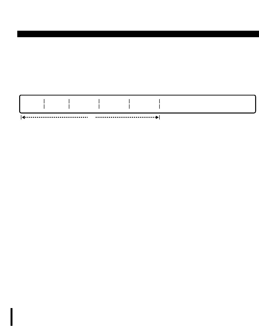
PERCEPTION 4000 COMMANDS
ISS 2, SECTION 4000-014-000
TRUNK ROUTING ASSIGNMENT (CMD 308)
This operation changes the routing destinations of one or more trunks. The "EQUIP #" and "TIME ZONE #" fields
are required, while the route choice fields are optional. Ranges are permitted in the "EQUIP #" field when
modifying a number of trunks with the same routing destinations. When performing a MODIFY operation, the
specified trunk may not have any calls "ON HOLD" or "IN PROGRESS".
DISPLAY
This operation displays the routing destinations of one or more trunks. All of the fields are optional. If no data is
entered in any of these fields, the routing destinations of all the trunks in the system display. Ranges are
permitted in all fields.
PARAMETERS
Each field parameter is described in this section. Any variations for a particular operation are noted separately.
FIELD: EQUIP # (Equipment Number)
TYPE: EQ Type
FORMAT: 5 or 6 digits
VALUE: (0)10101 to 101408
LOOP: Primary loop field, and allowed in all operations.
The equipment number is assigned with the Trunk Assignment command (CMD 313). This field
selects the appropriate trunk to be modified or displayed.
FIELD: TIME ZONE #
TYPE: Decimal
FORMAT: 1 digit
VALUE: 1 to 4
LOOP: Allowed in a DISPLAY operation only
Inbound routing destinations can be varied from time zone to time zone. This field specifies the
time zone to be defined.
FIELD: ROUTE CHOICE 1/2/3
TYPE: Dialing Digits / Keyword
FORMAT: 1 to 5 digits / 4 to 6 digits
VALUE: 0 to 99999 / Speed Access Code + Index
Keywords: AP01 ~ AP50 Announcement Pattern Number
BL01 ~ BL64 Night Bell
NON No Routing
opt
EQUIP # TIME
ZONE # ROUTE
CHOICE 1 ROUTE
CHOICE 2 ROUTE
CHOICE 3
3-434

PERCEPTION 4000 COMMANDS
"ROUTE CHOICE 1" can be one of the following:
a) Individual attendant console directory number
b) Attendant group directory number
c) Station number
d) Announcement call treatment pattern number
e) Hunt group pilot number
f) UCD group pilot number
g) ACD group pilot number
h) Speed call codes (System speed calling access code plus system speed calling index
number)
i) Night bell
j) No routing (may be used for Route Choice 1 only)
"ROUTE CHOICE 2" has the same options as "ROUTE CHOICE 1". However, to define "ROUTE
CHOICE 2", "ROUTE CHOICE 1" must be defined as an attendant or an attendant group which
is found to be unavailable (in the Position Busy mode).
"ROUTE CHOICE 3" has the same options as "ROUTE CHOICE 1", with the exception of the
attendant and attendant group options. To define "ROUTE CHOICE 3", both "ROUTE CHOICE
1" and "2" must be defined as an attendant or attendant group or mix thereof, with both route
choices "1" and "2" unavailable due to console or attendant group Position Busy mode.
In cases where the attendant or attendant group is in the Position Busy mode, the call is routed to
the second choice. If the second choice is an attendant or attendant group in the Position Busy
mode, the call is routed to the third choice. Depending on what Route 3 is defined as, other call
processing may be performed by hunting, UCD, ACD, or call forwarding.
SYSTEM ERROR MESSAGES
The following error message are unique to this command.
C30800 - Specified trunk is not in the system
C30801 - Specified equipment number is not a trunk device
C30802 - Undefined night bell
C30803 - Undefined announcement machine
C30804 - Check time zone number range
C30805 - Check directory number
C30806 - Check combination of routing destinations
C30807 - Outgoing trunk group does not have routing
C30808 - Check trunk type
C30809 - NON is allowed for Route Choice 1 only
C30810 - Check announcement machine usage
C30811 - Only display operation is allowed for private trunk
C30812 - Equipment number can only have a maximum of eight circuits
I30813 - Warning: Undefined data in ROUTE CHOICE n field
RELATED COMMAND
Station Hunting Assignment (CMD 342)
ISS 2, SECTION 4000-014-000
TRUNK ROUTING ASSIGNMENT (CMD 308)
3-435
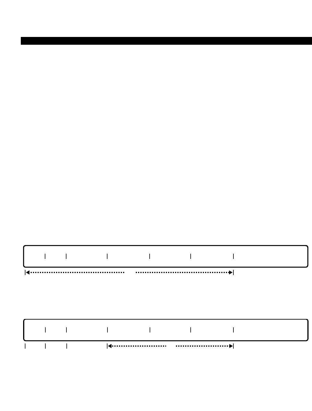
PERCEPTION 4000 COMMANDS
ISS 2, SECTION 4000-014-000
TRUNK-TO-TRUNK CONNECTION ASSIGNMENT (CMD 305)
TRUNK-TO-TRUNK CONNECTION ASSIGNMENT (CMD 305)
The Trunk-to-Trunk Connection Assignment command contains two tables which allow or deny trunk connections
between incoming, outgoing, and bothway trunks. These tables are the Attendant Capability Table and the Station
Connectivity Table.
Command Keyword: TRUNK_CONNECTIONS
Category Name: Trunk
PREREQUISITE COMMAND
Trunk Group Assignment (CMD 310)
OPERATIONS
Available operations: ADD
DELETE
DISPLAY
The function and required data fields for each operation are described in this section.
ADD
This operation adds one or more entries into the Trunk-to-Trunk connection tables. Input is required in all fields.
DELETE
This operation deletes one or all entries from the Trunk-to-Trunk connection tables. If the keyword ALL is entered
in the “TGN/TYPE A” field, all the Trunk-to-Trunk connections are deleted. A confirmation is requested by the
system before a deletion occurs.
opt
APPL TYPE TGN/TYPE A ORG DIRECT TGN/TYPE B ORG DIRECT
reqoptreq
req
APPL TYPE TGN/TYPE A ORG DIRECT TGN/TYPE B ORG DIRECT
3-436

PERCEPTION 4000 COMMANDS
DISPLAY
This operation displays the Trunk-to-Trunk connection tables. If no input is entered in the “INDEX” field,
depending on the data in the “APPL” field, the Station's Connectivity Table or the Attendant's Capability Table
displays. Ranges are allowed in any field that accepts numeric input.
PARAMETERS
Each field parameter is described in this section. Any variations for a particular operation are noted separately.
FIELD: APPL (Application Usage)
TYPE: Keyword
FORMAT: Predefined ASCII characters
Keywords: ATT - Attendant’s Capability Table
STA - Station’s Connectivity Table
The table to be added to, deleted, or displayed is selected with this field.
FIELD: TYPE (Table Type)
TYPE: Keyword
FORMAT: Predefined ASCII characters
Keywords: ALW - Trunk-to-trunk connection allowed
DNY - Trunk-to-trunk connection denied
Trunks are defined by setting the table definition as an allow or deny table, whichever will require
the shorter definition. For example, you may wish to deny only those calls which are incoming
800 calls connected to all other outbound or bothway trunk groups. It would be simpler to build a
deny table than to build an allow table for all other possibilities.
Once the "TYPE" field is selected as an allow or deny table, then all assignments of new Trunk-
to-Trunk connections must be of the same type.
FIELD: INDEX (Index Number)
TYPE: Decimal
FORMAT: 1 to 3 digits
VALUE: 1 to 160 (or to the maximum system configuration)
LOOP: Allowed in a DISPLAY operation only
This field acts as a counter in a DISPLAY operation. Its value does not set any priority for data
entered in this command.
FIELD: TGN/TYPE A or B (Trunk Group or Type of Trunk)
TYPE: Decimal / Keyword
opt
APPL TYPE INDEX TGN/TYPE A ORG DIRECT TGN/TYPE B ORG DIRECT
req
ISS 2, SECTION 4000-014-000
TRUNK-TO-TRUNK CONNECTION ASSIGNMENT (CMD 305)
3-437

PERCEPTION 4000 COMMANDS
ISS 2, SECTION 4000-014-000
TRUNK-TO-TRUNK CONNECTION ASSIGNMENT (CMD 305)
FORMAT: 1 to 3 digits / Predefined ASCII characters
VALUE: 1 to 256 trunk groups (or to the maximum system configuration)
RANGE: Allowed in a DISPLAY operation
Keywords - Trunk Types:
AUX - Auxiliary
CC - Code Call
CCSA - Common Control Switching Arrangement
CO - Central Office
DIC - Dictation Machine
DID - Direct Inward Dialing
FX - Foreign Exchange
PVT - Private Line or Trunk
RPG - Radio Page
TIE - Inter-PBX Communication
VPG - Voice Paging
WATS - Wide Area Telecommunication Service
ALL
Each Trunk-to-Trunk connection may be defined by either trunk group numbers, trunk group
types, or a combination of both. Decimal values 1 to 256 represent the trunk group numbers, and
the keywords represent the trunk group types. Trunk groups 129 to 256 are reserved for systems
configured above the standard default of 128. Note that trunk groups are subsets of trunk types.
When the keyword ALL is entered in a DELETE operation, all entries in the denial/allowance
table are deleted.
FIELD: ORG DIRECT (Direction of Origination)
TYPE: Keyword
FORMAT: Predefined ASCII characters
Keywords: INC - Incoming
OUT - Outgoing
BWY - Both Incoming and Outgoing
Each facility specified may be defined as pertaining to incoming only, outgoing only, or bothway
call types.
SYSTEM ERROR MESSAGES
The following error messages are unique to this command.
C30500 - Redundant entry: connection is already defined
C30501 - Number of trunk groups of this type exceeds available entries
C30502 - Undefined trunk type
C30503 - Undefined trunk group
C30504 - Check trunk group number range
C30505 - Parameter is out of range
C30506 - This connection is not registered
C30507 - The attendant table type is different
3-438

PERCEPTION 4000 COMMANDS
C30508 - The station table type is different
C30509 - Field input error
COMMENTS
A denial to perform a Trunk-to-Trunk connection in one's Class of Service definition absolutely prevents the
connection. Also, if release supervision does not allow the connection, it is denied. Attendants may, however,
place the call on a locked loop automatically, thus allowing manual supervision of the call and preventing potential
trunk lockups.
Removal of a trunk group/type from the system must be preceded by the removal of the corresponding entry in
these tables.
For stations, connections between pairs of trunk types/groups not inhibited by their denial tables are still subject
to the supervisory requirement. For instance, if neither party involved in a Trunk-to-Trunk connection has release
supervision, the connection will not be made.
RELATED COMMANDS
Attendant Group Assignment (CMD 372)
Attendant Position Assignment (CMD 370)
Trunk Assignment (CMD 313)
ISS 2, SECTION 4000-014-000
TRUNK-TO-TRUNK CONNECTION ASSIGNMENT (CMD 305)
3-439
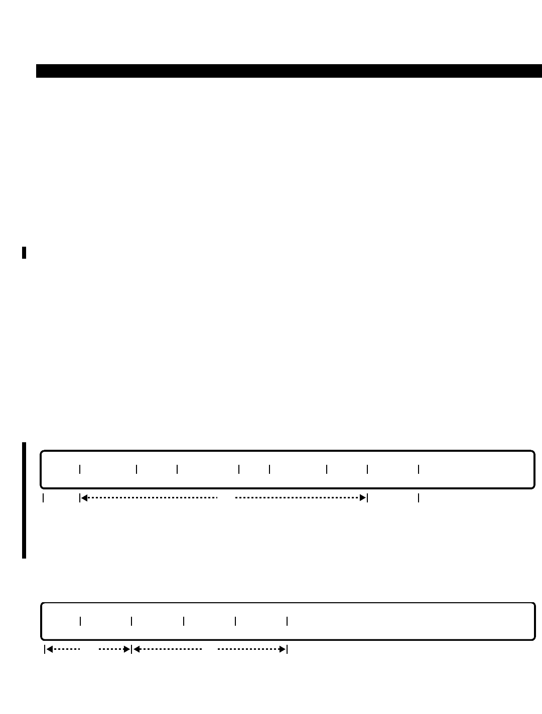
PERCEPTION 4000 COMMANDS
ISS 2, SECTION 4000-014-000
UCD GROUP ASSIGNMENT (CMD 354)
UCD GROUP ASSIGNMENT (CMD 354)
The PERCEPTION 4000 system may be configured with up to eight Uniform Call Distribution (UCD) groups. This
command defines UCD group members and provides information pertinent to group operation.
Command Keyword: UCD_GROUP_ASSIGN
Category Name: Station
PREREQUISITE COMMANDS
Announcement Pattern Assignment (CMD 353)
Miscellaneous Device Assignment (CMD 400)
Station Assignment (CMD 330)
OPERATIONS
Available operations: ADD
DELETE
MODIFY
DISPLAY
The function and required data fields for each operation are described in this section.
ADD
This operation adds member directory numbers to the specified UCD group number. If the group is being defined
for the first time, the “PILOT DN” and “AP#” fields are required; otherwise, these fields are optional. The “INDEX”
field is a counter for the convenience of the administrator.
DELETE
This operation removes member directory numbers from the specified UCD group. The keyword ALL may be
entered in the first “MEM DN” field to delete the entire UCD group.
opt
GRP# MEM DN MEM DN MEM DN MEM DN
req
opt
GRP# PILOT DN NAME OVF DEST AP# OVF TMR INDEX MEM DN
req req
3-440
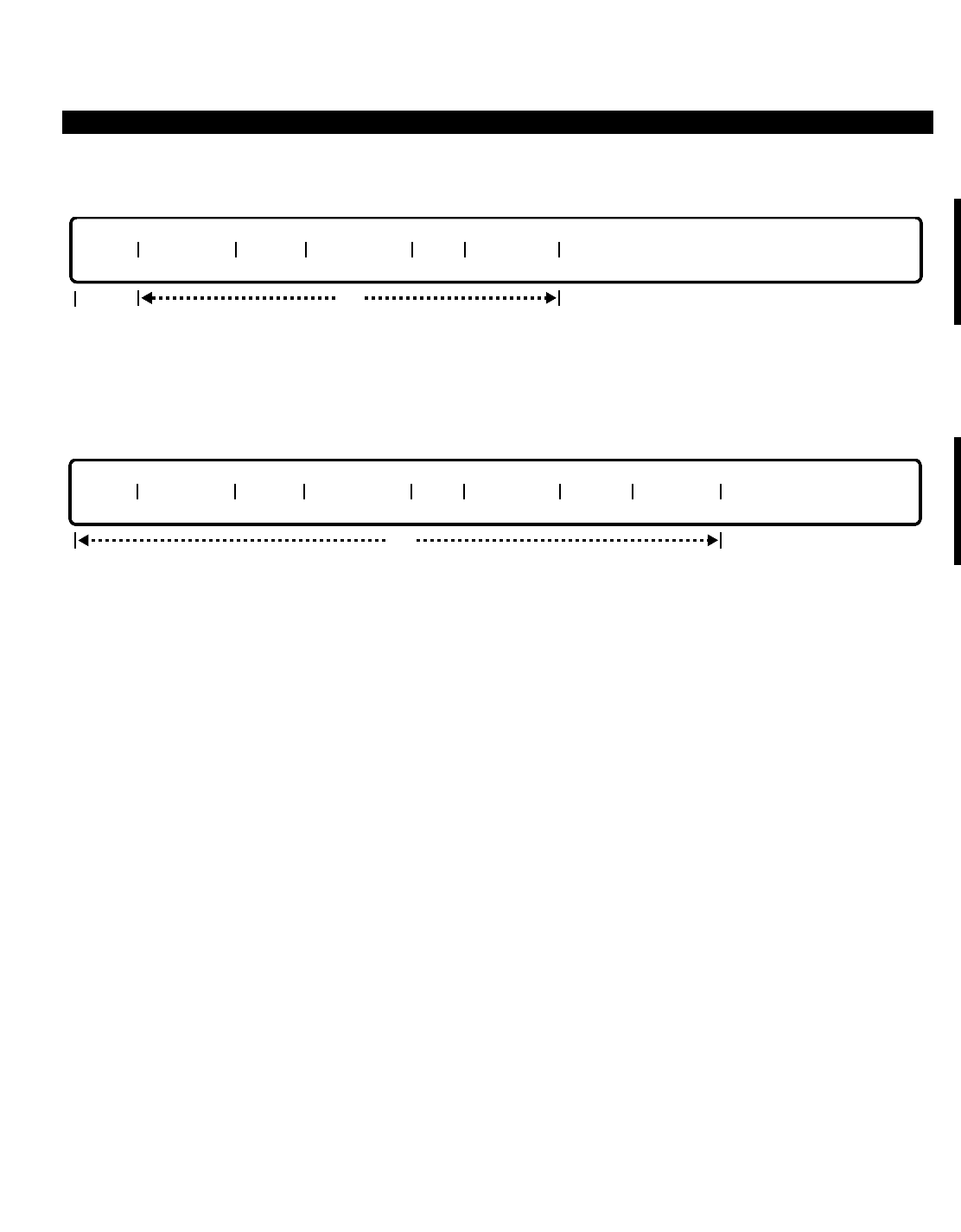
PERCEPTION 4000 COMMANDS
MODIFY
This operation modifies the attributes of the specified UCD group. “GRP #” is a required field, while the remaining
fields are optional.
DISPLAY
This operation displays the attributes of the specified UCD group. All fields are optional.
PARAMETERS
Each field parameter is described in this section. Any variations for a particular operation are noted separately.
FIELD: GRP# (UCD Group Number)
TYPE: Decimal
FORMAT: 1 digit
VALUE: 1 to 8
RANGE: Not allowed
LOOP: Allowed in a DISPLAY operation only
This field assigns a UCD group number, and is required in all operations. In a DISPLAY
operation, “GRP#” is a loop field. If a <TAB> and <RETURN> are entered, all eight groups
display.
FIELD: PILOT DN (Pilot Directory Number)
TYPE: DN Type
FORMAT: 1 to 5 digits
VALUE: 0 to 99999
RANGE: Not allowed
LOOP: Not allowed
The UCD group pilot number is defined with this field. This is the only entry point into the UCD
group. The number must not conflict with other numbers and access codes in the system's
numbering plan, and must not have a physical device counterpart.
FIELD: NAME
TYPE: Text
opt
GRP# PILOT DN NAME OVF DEST AP# OVF TMR INDEX MEM DN
opt
GRP# PILOT DN NAME OVF DEST AP# OVF TMR
req
ISS 2, SECTION 4000-014-000
UCD GROUP ASSIGNMENT (CMD 354)
3-441

PERCEPTION 4000 COMMANDS
ISS 2, SECTION 4000-014-000
UCD GROUP ASSIGNMENT (CMD 354)
FORMAT: 0 to 9 ASCII characters
The UCD group may optionally be assigned a group name which is displayed on calling party
terminals or the attendant console. Embedded spaces are allowed. In a MODIFY operation, if a
<CONTROL-D> is entered, this field is removed from the group.
FIELD: OVF DEST (Overflow Destination)
TYPE: DN Type
FORMAT: 1 to 5 digits
VALUE: 0 to 99999
RANGE: Not allowed
LOOP: Not allowed
The overflow destination may be defined as another UCD group. Only one overflow is allowed per
call, even if the overflow group has another overflow specified. In a MODIFY operation, if a
<CONTROL-D> is entered, this field is removed from the group. Note that this field is optional in
all operations.
FIELD: AP# (Announcement Pattern Number)
TYPE: Decimal
FORMAT: 1 or 2 digits
VALUE: 1 to 50
RANGE: Not allowed
LOOP: Not allowed
This field selects one of the 50 announcement pattern numbers defined in the system. (Refer to
the Announcement Pattern Assignment command, CMD 353.) The pattern number describes
how the call is treated while waiting in queue (announcements, music, etc.).
FIELD: OVF TMR (Overflow Timer)
TYPE: Decimal
FORMAT: 1 to 4 digits
VALUE: 0 to 1000
RANGE: Not allowed
LOOP: Not allowed
This field sets the time in seconds which a call must wait in queue before overflowing to the
overflow destination.
FIELD: INDEX
TYPE: Decimal
FORMAT: 1 or 2 digits
VALUE: 1 to 16
LOOP: Allowed in ADD and DELETE operations
This field is used as a counter in ADD and DISPLAY operations. Its value does not indicate an
actual position in a UCD group or set any priority for data entered in this command.
FIELD: MEM DN (UCD Member Directory Number)
TYPE: DN Type / Keyword
3-442

PERCEPTION 4000 COMMANDS
FORMAT: 1 to 5 digits / Predefined ASCII characters
VALUE: 0 to 99999
RANGE: Allowed in a DISPLAY operation only
LOOP: Not allowed
Keyword: ALL
This field assigns members to the UCD group. The directory number entered must be a prime
directory number of a voice station, and may only appear in one UCD group. Logical line DNs are
not allowed. In a DELETE operation, the keyword ALL deletes an entire UCD group.
SYSTEM ERROR MESSAGES
The following error messages are unique to this command.
C35400 - Pilot directory number mismatch
C35401 - Group name mismatch
C35402 - Overflow destination mismatch
C35403 - Group maximum number has been reached
C35404 - UCD member directory number does not exist
C35405 - UCD member directory number is not a station directory number
C35406 - Pilot directory number must be input
C35407 - Pilot directory number is already in use
C35408 - Cannot use this overflow directory number
C35409 - No UCD members exist for this group
C35410 - Member directory number is not in this UCD group
C35411 - Station belongs to another UCD group
C35412 - Announcement pattern number must be input
C35413 - Announcement pattern number is not defined
C35414 - Announcement pattern number mismatch
C35415 - Announcement pattern number is not for UCD use
C35416 - Group name length is a maximum of 9 characters
C35417 - Pilot and overflow directory numbers cannot be the same
C35418 - Overflow timer mismatch
C35419 - Private line directory number may not be used in UCD
C35420 - Hotline directory number may not be used in UCD
C35421 - Logical/Multiple line directory number may not be used in UCD
C35422 - Total number of UCD memory blocks have reached their limit
C35423 - Total number of UCD members have reached their limit
I35424 - Warning: Unidentified data in field #4
RELATED COMMANDS
ACD Group Assignment (CMD 355)
Authorization Code Assignment (CMD 349)
Internal Call Alternate Routing Assignment (CMD 374)
Station Hunting Assignment (CMD 342)
Trunk Group Routing Assignment (CMD 307)
Trunk Routing Assignment (CMD 308)
ISS 2, SECTION 4000-014-000
UCD GROUP ASSIGNMENT (CMD 354)
3-443

PERCEPTION 4000 COMMANDS
ISS 2, SECTION 4000-014-000
UNP ROUTING ASSIGNMENT (CMD 302)
UNP ROUTING ASSIGNMENT (CMD 302)
The UNP Routing Assignment command specifies a Route Pattern Number (RPN) for the location codes defined
for the network in the Uniform Numbering Plan Assignment command (CMD 301). The RPN is then used by the
LCR/Authorization TZ Change Assignment command (CMD 343) to direct the call over the proper facility.
Command Keyword: UNP_ROUTING
Category Name: Network
PREREQUISITE COMMAND
Uniform Numbering Plan Assignment (CMD 301)
OPERATIONS
Available operations: ADD
DELETE
DISPLAY
The function and required data fields for each operation are described in this section.
ADD
This operation adds UNP location codes (RNXs) to the specified Route Pattern Number (RPN) Table.
DELETE
This operation deletes UNP location codes (RNXs) from the specified Route Pattern Number (RPN) Table.
RPN RNX RNX RNX RNX RNX RNX RNX RNX RNX RNX RNX RNX
optreq
RPN RNX RNX RNX RNX RNX RNX RNX RNX RNX RNX RNX RNX
optreq
3-444

PERCEPTION 4000 COMMANDS
DISPLAY
This operation displays UNP location codes (RNXs) of the specified Route Pattern Number (RPN) Table. All fields
are optional; and the "RPN" field is a loop field.
PARAMETERS
Each field parameter is described in this section. Any variations for a particular operation are noted separately.
FIELD: RPN (Route Pattern Number)
TYPE: Decimal
FORMAT: 1 to 3 digits
VALUE: 1 to 100 (or to the maximum system configuration)
LOOP: Primary loop for a DISPLAY operation only
RANGE: Not allowed
The "RPN" field defines a pattern number used by the LCR/Authorization TZ Change Assignment
command (CMD 343) to direct a call to the proper LCR routing table. Up to 16 UNP Routing
Assignment Tables may be defined in the system. A routing pattern number is required for all
RNXs not intended for default routing. If a <TAB> is entered in this field in a DISPLAY operation,
all RPN tables of RNXs display.
FIELD: RNX (Location Code for PBX Systems in the Network)
TYPE: Dialing Digits / Keyword
FORMAT: 1 to 3 digits / Predefined ASCII characters
VALUE: 0 to 999
LOOP: Not allowed
RANGE: Not allowed
Keyword: ALL
This field assigns location codes of other PBX systems in the Network to the specified route
pattern number. In a DELETE operation, the keyword ALL may be entered in the first "RNX" field
to delete all location codes from the table.
SYSTEM ERROR MESSAGES
The following error messages are unique to this command.
C30200 - Check RNX input format
C30201 - RNX already defined
C30202 - No space to add more
C30203 - RNX not found
opt
RPN RNX RNX RNX RNX RNX RNX RNX RNX RNX RNX RNX RNX
ISS 2, SECTION 4000-014-000
UNP ROUTING ASSIGNMENT (CMD 302)
3-445

PERCEPTION 4000 COMMANDS
ISS 2, SECTION 4000-014-000
UNP ROUTING ASSIGNMENT (CMD 302)
C30204 - Route pattern number is out of range
C30205 - UNP location code not found in setup table
C30206 - RNX should be 1 - 3 digits
C30207 - RNX is not in the corresponding RPN table
RELATED COMMAND
LCR/Authorization TZ Change Assignment (CMD 343)
3-446

PERCEPTION 4000 COMMANDS
UNIFORM NUMBERING PLAN ASSIGNMENT (CMD 301)
The Uniform Numbering Plan (UNP) is one of two methods used by the system for private networking. This
command instructs the system on the length of on-net calls, provides an identifying location code for this PBX in
the network, and defines all other RNX (location) codes used in the network.
Command Keyword: UNP_ASSIGN
Category Name: Network
PREREQUISITE COMMANDS
There are no prerequisites for this command.
OPERATIONS
Available operations: ADD
DELETE
MODIFY
DISPLAY
The function and required data fields for each operation are described in this section.
ADD
This operation adds PBX location codes to the PERCEPTION 4000 Network.
DELETE
This operation deletes PBX location codes from the Network. The keyword ALL may be entered in the first "RNX"
field to delete all location codes from the table.
opt
RNX RNX RNX RNX RNX RNX RNX RNX RNX RNX RNX RNX RNX
req
opt
RNX RNX RNX RNX RNX RNX RNX RNX RNX RNX RNX RNX RNX
req
ISS 2, SECTION 4000-014-000
UNIFORM NUMBERING PLAN ASSIGNMENT (CMD 301)
3-447
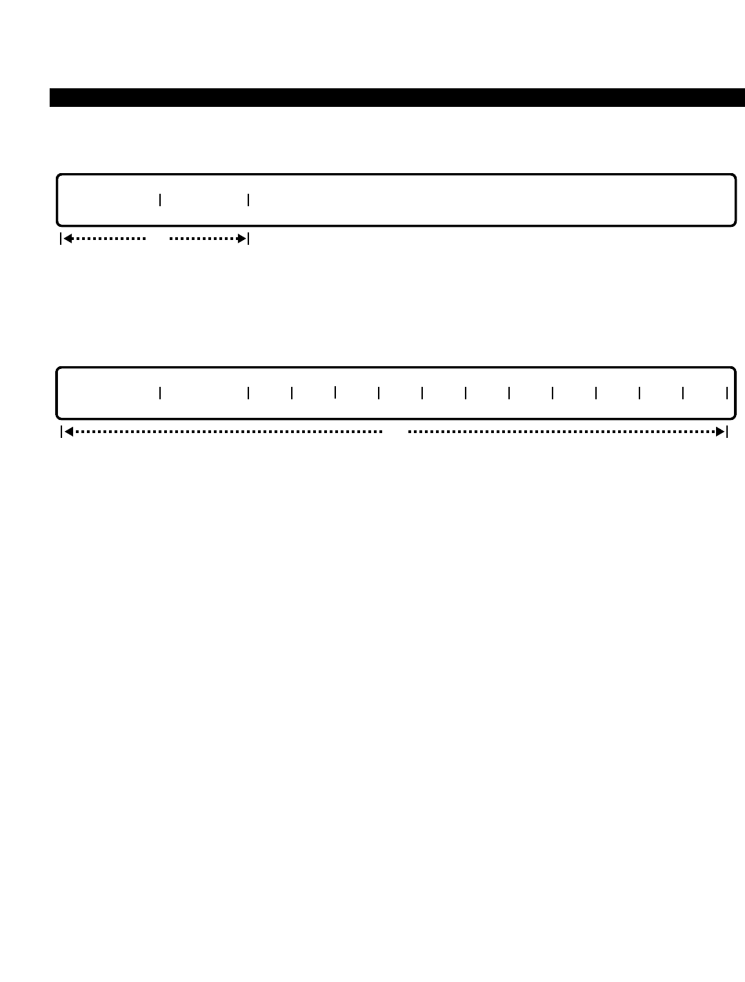
PERCEPTION 4000 COMMANDS
ISS 2, SECTION 4000-014-000
UNIFORM NUMBERING PLAN ASSIGNMENT (CMD 301)
MODIFY
This operation modifies the format for the length of the location code and station numbers of the network, and the
home PBX location code.
DISPLAY
This operation displays the UNP length, the Home UNP location code, and other UNP location code(s) in the
Network.
PARAMETERS
Each field parameter is described in this section. Any variations for a particular operation are noted separately.
FIELD: UNP LENGTH (Length of Location Code of PBX with Station Numbers)
TYPE: Decimal
FORMAT: 1 digit
VALUE: 4 to 8
LOOP: Not allowed
RANGE: Not allowed
Each station in the network has a home PBX location code and a station number assigned to it.
This field sets the length of the combined location code and station number. For example, the
home PBX location code may be a three-digit number (734), and the station may be a four-digit
number (3229). Therefore, this field would be set to 7.
FIELD: HOME RNX (Location Code for Home PBX)
TYPE: Dialing Digits
FORMAT: 1 to 3 digits
VALUE: 0 to 999
LOOP: Not allowed
RANGE: Not allowed
Each PBX in the system is assigned a location code from 1 to 3 digits. This field assigns the
location code for the home PBX.
opt
UNP LENGTH HOME RNX RNX RNX RNX RNX RNX RNX RNX RNX RNX RNX RNX
opt
UNP LENGTH HOME RNX
3-448

PERCEPTION 4000 COMMANDS
FIELD: RNX (Location Code for Other PBX Systems in the Network)
TYPE: Dialing Digits / Keyword
FORMAT: 1 to 3 digits / Predefined ASCII characters
VALUE: 0 to 999
LOOP: Not allowed
RANGE: Not allowed
Keyword: ALL
This field assigns location codes for other PBX systems in the PERCEPTION 4000 Network. In a
DELETE operation, the keyword ALL may be entered in the first "RNX" field to delete all location
codes from the table.
SYSTEM ERROR MESSAGES
The following error codes are unique to this command.
C30100 - RNX is defined as home location code
C30101 - One of the RNX(s) is already defined
C30102 - No space to add more
C30103 - One of the RNX(s) was not found
C30104 - Check length of UNP
C30105 - Check RNX input format
C30106 - RNX should be 1 - 3 digits
C30107 - Remove RPN from Command 302 table before deleting
C30108 - Remove all RPNs from Command 302 table before deleting ALL
RELATED COMMANDS
Coordinated Numbering Plan Assignment (CMD 303)
UNP Routing Assignment (CMD 302)
ISS 2, SECTION 4000-014-000
UNIFORM NUMBERING PLAN ASSIGNMENT (CMD 301)
3-449

PERCEPTION 4000 COMMANDS
ISS 2, SECTION 4000-014-000
VOICE PAGING/CODE-CALL ASSIGNMENT (CMD 319)
VOICE PAGING/CODE-CALL ASSIGNMENT (CMD 319)
The Voice Paging/Code-Call Assignment command creates the linkage between various types of paging and the
trunk group used for the hardware interface. Additionally, the command provides the translation from
PERCEPTION 4000 system paging types and/or zones to control code information which is sent to out board
paging equipment for zone and usage selection. The control codes are sent via in-band DTMF signaling prior to
the system cutting through the paging party to the paging equipment. This action is transparent to the user.
Command Keyword: VP/CC_ASSIGN
Category Name: Dialing
PREREQUISITE COMMANDS
Numbering Plan Assignment (CMD 300)
Trunk Group Assignment (CMD 310)
OPERATIONS
Available operations: ADD
DELETE
MODIFY
DISPLAY
The function and required data fields for each operation are described in this section.
ADD
This operation adds the defined attribute of the specified feature to its definition table. The "CONTROL CODE #"
field is not used for the Code-Call feature. Values 1 to 128 are used as input for the Zone Paging feature. ZERO is
the default value for the Emergency Paging and System Paging features.
DELETE
This operation removes the attribute of the specified feature from its definition table. The "ZONE #" field is
applicable for the Code Call and Zone Paging features only.
opt
TYPE ZONE #
req
opt
TYPE ZONE # TGN CONTROL CODE #
optreq req
3-450
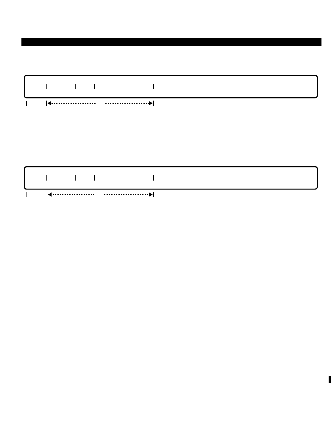
PERCEPTION 4000 COMMANDS
MODIFY
This operation modifies existing attributes of the specified feature. The “TYPE” field is required for all features.
The “ZONE #” field is required by the Code Call and Zone Paging features, while the remaining fields are
optional. The “CONTROL CODE #” field defaults to zero for all features except for Zone Paging.
DISPLAY
This operation displays the attributes of one or all related features where the condition is established in the
“TYPE” and “ZONE #” fields. If ALL is entered in the “TYPE” field, the system displays all the related tables.
PARAMETERS
Each field parameter is described in this section. Any variations for a particular operation are noted separately.
FIELD: TYPE (Type of Feature)
TYPE: Keyword
FORMAT: Predefined ASCII characters
Keywords: CC - Code Call Feature
EPAG - Emergency Paging Feature
SPAG - System Paging Feature
ZPAG - Zone Paging Feature
ALL - All of the above features
This field selects one of the Code Call or paging features of the system. The keyword ALL is
available for a DISPLAY operation only, and is used to indicate all the related features that are to
be displayed.
FIELD: ZONE # (Trunk Port Code)
TYPE: Decimal
FORMAT: 1 to 2 digits
VALUE: The value depends on the "LEN PD1" field entries in the Numbering Plan Assignment command
(CMD 300) for Feature Numbers (FNOs) 258 and 259 (Code Calling Access and Voice Paging
Access - Zone respectively). (Note that maximum values depend on the system configuration,
i.e., if there are 10 code calling devices and 10 zone paging devices, any value above 10 is
invalid.)
opt
TYPE ZONE # TGN CONTROL CODE #
req
opt
TYPE ZONE # TGN CONTROL CODE #
req
ISS 2, SECTION 4000-014-000
VOICE PAGING/CODE-CALL ASSIGNMENT (CMD 319)
3-451

PERCEPTION 4000 COMMANDS
ISS 2, SECTION 4000-014-000
VOICE PAGING/CODE-CALL ASSIGNMENT (CMD 319)
If "LEN PD1" = 1 The "ZONE #" value range is 1 to 9
If "LEN PD1" = 2 The maximum "ZONE #" value is 32 for CC (Code Calling) and 99 for
ZPAG (Zone Paging)
RANGE: Not allowed
This field represents the System Paging Zone Number or the Code Calling Access Code that is
dialed following the Paging Access Code. The number of digits must correspond to the "LEN
PD1" field entry following the appropriate paging type in the Numbering Plan Assignment
command (CMD 300). This field is not used by the System Paging or Emergency Paging
features.
FIELD: TGN (Trunk Group Number)
TYPE: Decimal
FORMAT: 1 to 3 digits
VALUE: 1 to 256 (or to the maximum system configuration)
RANGE: Not allowed
The trunk group number represents the trunk group to which the paging trunk circuit is assigned.
There may only be one circuit per supporting trunk group. The "TGN" must be defined for the
same use in the Trunk Group Assignment command (CMD 310). This field is required for Voice
Zone Paging and Code Calls.
FIELD: CONTROL CODE # (Device Code Number)
TYPE: Decimal / Keyword
FORMAT: 1 digit / Predefined ASCII characters
VALUE: 0 to 9 / NON
RANGE: Not allowed
This field specifies the voice zone paging device to be accessed (values 0 to 9). NON is used
with paging devices that do not support control codes. For the Emergency Paging and System
Paging features, a default value of zero is required. The Code Calling feature does not use this
field.
SYSTEM ERROR MESSAGES
The following error messages are unique to this command.
C31900 - Invalid feature number
C31901 - Invalid trunk group number
C31902 - Zone number is out of range
C31903 - <TAB> is required for zone number field
C31904 - Missing input for zone number field
C31905 - Missing input for Control Code Number field
C31906 - <TAB> is required for Control Code Number field
C31907 - Trunk group number is out of range
C31908 - No space to add zone number
C31909 - Zone number is already in use
C31910 - Zone number is not in the table
C31911 - This entry is already defined in the table
C31912 - This entry is not defined in the table
3-452

PERCEPTION 4000 COMMANDS
C31913 - Trunk must be assigned to a trunk group number before update
C31914 - Zone post digits have NOT been set, please define in CMD 300
C31915 - Control code is out of range; should be 0 - 9 or NON
RELATED COMMANDS
Attendant Feature Key Assignment (CMD 371)
Station Feature Key Assignment (CMD 331)
ISS 2, SECTION 4000-014-000
VOICE PAGING/CODE-CALL ASSIGNMENT (CMD 319)
3-453

Chapter 4
PERCEPTION 4000 ERROR AND INFORMATION MESSAGES
Error and information messages appear on the output device alerting the user of certain conditions occurring
within the system. These messages include indications of incorrect input, informational matter, and system
messages. This chapter contains a description of the format used to display these messages along with a
complete listing of all messages.
MESSAGE FORMAT
Each message contains a message ID and text.The ID consists of a leading character followed by five digits.
<Character><digit><digit><digit><digit><digit> - Text
Leading Character
“C” represents a special message from a particular command.
“D” represents messages for debugging usage.
“G” represents messages from MMI and messages common to every command.
“I” represents FYI (For your information only) messages.
“S” represents a system message.
Five-digit Numbers (tttnn)
ttt - The first three digits represent an MMI internal module ID (000 to 013) for common error messages,
or the command ID (100 to 999).
Module IDs
000 - Message Dispatcher
001 - Command Operation
002 - Data Entry and Parsers
003 - Setup Control
004 - Program Control
005 - Training Control
007 - Overlay Control
008 - Messages common to all commands
009 - Post Command Processor
011 - Change Replay
012 - Change Log Control
013 - Change Write Control
nn - The last two digits represent the message number.
Text - Up to 71 ASCII characters display error or information messages.
COMMON ERROR MESSAGES
C00123 - Failed to mount FD
C00124 - Failed to open script file on FD
C00125 - Failed to read script sub-header
C00126 - Failed to read script file
ISS 2, SECTION 4000-014-000
4-1

PERCEPTION 4000 ERROR AND INFORMATION MESSAGES
ISS 2, SECTION 4000-014-000
C00127 - Failed to close FD
C00130 - DISPLAY/SHOW operation not allowed during FD input
D00107 - Command operation substate is out of range
D00128 - Incorrect record/block count in sub-header
D00217 - DE_CTL substate is out of range
D00218 - Internal data structures corrupted; around field N
D00219 - Aborted while in MKB
D00220 - Timeout while in MKB for equipment number SSPPCC
D00302 - SE_CTL substate is out of range
D00402 - Unknown error in IDLE_PR state
D00403 - PR_CTL substate is out of range
D00404 - Header ruler format error
D00701 - Cannot open command
D00702 - Cannot read command
D00703 - Cannot close command
D00704 - Cannot load command
D00705 - LCPU command loading failed
D00706 - Version mismatch
D00808 - Software error
D00809 - Please see PBX administrator
D00810 - MCPU database Read error
D00811 - MCPU database Write error
D00812 - LCPU database Read error
D00813 - LCPU database Write error
D00814 - Failed to send message to LCPU
D00815 - Failed to send message to Traffic virtual machine
D00816 - Timeout while waiting for transaction from LCPU 1, 2, or 3
D00817 - Loop failed in LCPU 1, 2, or 3
D00818 - Invalid equipment number during conversion
D00819 - Invalid device number during conversion
D00820 - LCPU number is out of range
D00821 - Invalid trunk device number during conversion
D00822 - Memory dump to hard disk failed
D00823 - Hard disk drive is no good
D00824 - Cannot access hard disk file
D00825 - Mount hard disk drive failed
D00826 - Open change log header failed
D00827 - Open patch log header failed
D00828 - Open file from hard disk failed
D00829 - Write file to hard disk failed
D00831 - Close file from hard disk failed
D00832 - Clear change log header failed
D00833 - Clear patch or change log header failed
D00834 - Found unmatched line; Nth byte in the compare buffer
D00900 - MKI failed
D00901 - Timeout in MKI
D00902 - Entering CPP from CHG_CTL with TRAPTR
D00903 - Entering CPP from cmd with TRAPTR
D00904 - Command load in standby failed
D00905 - Sync. timeout; need to put SBY OUS & use ^Y
4-2

PERCEPTION 4000 ERROR AND INFORMATION MESSAGES
D00906 - Command sync failed; need to put SBY OUS & use ^Y
D00907 - Disk drive is out of service
D01100 - Cannot create change log
D01101 - Get header failed
D01103 - Replay command failed
D01104 - Replay MKB failed
D01105 - Failed to manipulate patch log file
D01106 - Failed to manipulate change log file
D01107 - Synchronization change log timeout
D01108 - Auto file consolidation cannot be performed
D01109 - PAM switch-over/command check in process; wait then login again
D01110 - Auto file consolidation in process; wait then login again
D01208 - Change log sync timeout; need to put SBY OUS & use ^Y
D01209 - Failed to manipulate patch log file
D01300 - Timeout when writing log file
D01301 - Failed to write to hard disk
G00102 - Login failed
G00103 - Privileged command
G00104 - Check command name/ID?
G00105 - Privileged operation
G00106 - Check operation name/ID?
G00108 - No such command
G00109 - No such operation
G00131 - Aborting from FD input
G00202 - Must enter <tab> after data in field N
G00203 - Only 0 - 9 (decimal) can be entered in field N
G00204 - Only 0 - 9, #, * (dial digit) can be entered in field N
G00205 - Check equipment number format (ssppcc) in field N
G00206 - Only 0 - 9, A - F (hexadecimal) can be entered in field N
G00207 - Only 0 - 7 (octal) can be entered in field N
G00208 - Check AC format (N-0/1-X) in field N
G00209 - Check OC format (NXX) in field N
G00210 - Check time format (hhmm) in field N
G00211 - Check date Format (mmddyy) in field N
G00212 - Check input
G00213 - Check input scope in field N
G00214 - Check input format in field N
G00215 - Program mode is not available
G00216 - Loop is not available in field N
G00221 - Check LCR; class of service is not configurable
G00222 - Check INW; values are 1 - 100
G00301 - Check range or increment in field N
G00303 - Increments are not permitted in non loop fields
G00304 - Range is not permitted in field N
G00305 - Ranges are no longer permitted
G00306 - Ranges and increments are no longer permitted
G00307 - Increment is not permitted in range field
G00400 - Already in program mode
G00401 - Operation aborted
G00801 - LCPU is not in service - LCPU 1, 2, or 3
ISS 2, SECTION 4000-014-000
4-3

PERCEPTION 4000 ERROR AND INFORMATION MESSAGES
ISS 2, SECTION 4000-014-000
G00802 - All LCPUs are not in service
G00803 - Check COS; values are 1 - 64
G00804 - Check DRL; class of service is not configurable
G00805 - Check FRL; class of service is not configurable
G00806 - Check QPL; values are 1 - 8
G00807 - Type mismatch
I00100 - No activity, auto/force-logout; wait a while before login
I00101 - Logout completed
I00110 - Please logout and login to synchronize standby side
I00129 - Zero record/block count in sub-header
I00131 - Command/operation not allowed during congestion
I00200 - No match
I00201 - Input line aborted
I00300 - Already in setup mode
I00500 - Training console logged-in
I00501 - Training console logged-out
I00700 - Command loading in process
I00800 - User aborted
I00830 - Successful memory dump to hard disk
I01200 - Change log file is 80% full
I01201 - Change log file is full
I01202 - Change log file is 85% full
I01203 - Change log file is 90% full
I01204 - Patch log file is 80% full
I01205 - Patch log file is full
I01206 - CHGLOG queue is full
I01207 - PATCH LOG queue is full
INDIVIDUAL COMMAND ERROR MESSAGES
CMD 102 - Initiate Switch-Over
C10200 - Standby is out of service
C10201 - Switch-over failed
C10202 - Set timer error
C10203 - Switch-over timeout
CMD 110 - Time Activated Command Programming
C11000 - Keyword combination error
C11001 - Set timer error
I11002 - Warning: Data entered in Activation Start Time field is ignored
C11003 - Interval time is out of range
C11004 - This item is not registered
C11005 - Input activation start time is out of range
C11006 - Start time conflicts with switch-over start time
CMD 121 - Clock Reset
C12100 - Clock set error
4-4

PERCEPTION 4000 ERROR AND INFORMATION MESSAGES
CMD 143 - Patch Report
C14300 - Check the release version, input is out of range
C14301 - Check release version
CMD 144 - Memory Test
C14400 - Map table has an error
C14401 - Number of files exceeds the defined value
C14402 - An error occurred when checking LCPU memory or a timeout
C14403 - Standby is not in service
CMD 151 - File Dump
C15100 - Failed to send transaction to FMS
C15101 - Failed to mount disk
C15102 - Failed to unmount disk
C15103 - Failed to open file
C15104 - Failed to close file
C15105 - Failed to read file
C15106 - Invalid address
C15107 - Device is out of service
C15108 - Display of files from standby side is not supported
CMD 152 - Disk File Manipulation
C15200 - Disk drive is out of service
C15201 - File already exists
C15202 - A wrong combination of drive 1 and drive 2
C15203 - Format operation cannot be performed; the drive is in service
C15204 - Parameter error; enter the drive field
C15205 - Failed file consolidation while copying changelog or patchlog
C15206 - Failed to open changelog file
C15207 - Failed to open patchlog file
C15208 - Failed to read changelog file
C15209 - Failed to read patchlog file
C15210 - File type does not match; please check floppy disk
C15211 - Failed to mount floppy driver
C15212 - Timer timeout
C15218 - Display or comparison of files from standby side is not supported
D15219 - Failed to reserve hard disk drive
C15220 - Hard disk drive is in use; try later
C15221 - Some files are still open; try later
C15222 - Floppy disk drive is out of service
C15223 - Hard disk drive is out of service
C15224 - Not enough space left on floppy disk for file copy
C15225 - Standby hard disk drive is out of service
C15226 - Invalid input; to restore this disk enter (Y/N)
ISS 2, SECTION 4000-014-000
4-5

PERCEPTION 4000 ERROR AND INFORMATION MESSAGES
ISS 2, SECTION 4000-014-000
CMD 153 - File Consolidation
C15300 - Timeout in Command 153
C15301 - Standby side is not installed
C15302 - Timeout in standby side
C15303 - Hard disk is in use; please try later
CMD 160 - Alarm/Fault Display and Reset
C16000 - Database recovered
C16001 - Alarm display request failed
C16002 - Alarm reset request failed
C16003 - Alarm reset timeout
CMD 164 - Crash Dump Display
C16400 - Invalid parameter for object input
C16401 - MCPU database read error
C16402 - LCPU database read error
C16403 - LCPU is out of service
C16404 - Standby side is not installed
C16405 - Standby side read failed
CMD 167 - Data Structure Display
C16700 - Prime directory number does not exist
C16701 - MCPU database Read error (LDN attributes)
C16702 - MCPU database Read error (LPU number)
C16703 - MCPU database Read error (SSC state number)
C16704 - MCPU database Read error (LDN record address)
C16705 - MCPU database Read error (SLSB record address)
C16706 - MCPU database Read error (OFHCAMP record address)
C16707 - MCPU database Read error (ONHCAMP record address)
C16708 - HDT data not available for pilot directory numbers
C16709 - Data does not exist for virtual pilot directory numbers
C16710 - Check input in PARA 1 field
C16711 - Check input in PARA 2 field
C16712 - ACD group is not defined
CMD 168 - Trace Setup
C16800 - Attendant directory number already exists
C16801 - Not an individual attendant directory number
C16802 - Attendant directory number does not exist
CMD 169 - Data Structure Display 2
C16900 - Attendant directory number has not been defined
C16901 - Attendant group directory number has not been defined
C16902 - Convert equipment error
4-6

PERCEPTION 4000 ERROR AND INFORMATION MESSAGES
C16903 - Read LCPU data timeout
C16904 - LCPU number does not match with the one in transaction
C16905 - Address error (address 0xNNNNNNNNN)
C16906 - Read MCPU error
C16907 - Invalid LDN
CMD 206 - Terminal Maintenance
C20600 - Equipment is already busy
C20601 - Equipment is already idle
C20602 - No database exists for this equipment
C20603 - BUSY and IDLE operations are not applicable to night bell equipment
C20604 - Equipment number is out of range
CMD 208 - Device Service Status
C20800 - Device has already been installed
C20801 - Device has already been removed
C20802 - Device is already in service
C20803 - Device is already out of service
C20804 - Cannot register device
C20805 - Does not match system configuration
C20806 - Program/data transfer
C20807 - No response
C20808 - Failed to send message to SYC
C20809 - Failed to set timer
C20810 - Stand-by side no response
C20811 - Regulated by SYM
C20812 - Failed to receive message from SYC
C20813 - BOTH is not an allowed keyword in this operation
C20814 - Standby side setup timeout
C20815 - Standby side is out of service
CMD 300 - Numbering Plan Assignment
C30000 - Invalid feature number
C30001 - No such access code exists
C30002 - Access code is already used by another feature
C30003 - Input access code is out of range
C30004 - Failed to read PD1 & PD2 from database
C30005 - Failed to write PD1 & PD2 to database
C30006 - Failed to remove the access code from database
C30007 - This feature does not yet have an access code
C30008 - Failed to recover the PD1 & PD2 from database
C30009 - Failed to recover the access code from database
C30010 - Feature does not need an access code
C30011 - Input PD1 is out of range
C30012 - Input PD2 is out of range
C30013 - Cannot assign access code to an out of range trunk group number
C30014 - Database for this feature is not empty
ISS 2, SECTION 4000-014-000
4-7

PERCEPTION 4000 ERROR AND INFORMATION MESSAGES
ISS 2, SECTION 4000-014-000
C30015 - The verified account code length is longer than PD1
C30016 - PD1 failed to match with Zone Number assigned in CMD 319
I30017 - PD1 has been modified; please change zone paging digit length in CMD 371
CMD 301 - Uniform Numbering Plan Assignment
C30100 - RNX is defined as home location code
C30101 - One of the RNX(s) is already defined
C30102 - No space to add more
C30103 - One of the RNX(s) was not found
C30104 - Check length of UNP
C30105 - Check RNX input format
C30106 - RNX should be 1 - 3 digits
C30107 - Remove RPN from Command 302 table before deleting
C30108 - Remove all RPNs from Command 302 table before deleting ALL
CMD 302 - UNP Routing Assignment
C30200 - Check RNX input format
C30201 - RNX already defined
C30202 - No space to add more
C30203 - RNX not found
C30204 - Route pattern number is out of range
C30205 - UNP location code not found in setup table
C30206 - RNX should be 1 - 3 digits
C30207 - RNX is not in the corresponding RPN table
CMD 303 - Coordinated Numbering Plan Assignment
C30300 - STDGTs in fields Ni..Nj are already used
C30301 - No space to add steering digits from field N
C30302 - STDGTs in fields Ni..Nj are not found
C30303 - Trunk group number is not a TIE type
C30304 - Trunk group number is not defined
C30305 - Trunk group number is defined as incoming (INC) type
C30306 - Same STDGTs in fields Ni..Nj
CMD 305 - Trunk-to-Trunk Connection Assignment
C30500 - Redundant entry: connection is already defined
C30501 - Number of trunk groups of this type exceeds available entries
C30502 - Undefined trunk type
C30503 - Undefined trunk group
C30504 - Check trunk group number range
C30505 - Parameter is out of range
C30506 - This connection is not registered
C30507 - The attendant table type is different
C30508 - The station table type is different
C30509 - Field input error
4-8

PERCEPTION 4000 ERROR AND INFORMATION MESSAGES
CMD 307 - Trunk Group Routing Assignment
C30700 - Undefined trunk group number
C30701 - Check trunk group number range
C30702 - Undefined night bell
C30703 - Undefined announcement machine
C30704 - Check time zone number range
C30705 - Check directory number
C30706 - Check combination of routing destinations
C30707 - Check trunk use
C30708 - Check trunk type
C30709 - Check announcement machine usage
C30710 - NON is allowed for Route Choice 1 only
I30711 - Warning: Undefined data in Route Choice #n
CMD 308 - Trunk Routing Assignment
C30800 - Specified trunk is not in the system
C30801 - Specified equipment number is not a trunk device
C30802 - Undefined night bell
C30803 - Undefined announcement machine
C30804 - Check time zone number range
C30805 - Check directory number
C30806 - Check combination of routing destinations
C30807 - Outgoing trunk group does not have routing
C30808 - Check trunk type
C30809 - NON is allowed for Route Choice 1 only
C30810 - Check announcement machine usage
C30811 - Only display operation is allowed for private trunk
C30812 - Equipment number can only have a maximum of eight circuits
I30813 - Warning: Undefined data in ROUTE CHOICE n field
CMD 309 - Trunk Hunting Assignment
C30900 - Trunk group number not found
C30901 - Undefined trunk group number
C30902 - Trunk group number is out of range
C30903 - Sequence number already exists
C30904 - Hunting method mismatch
C30905 - Check trunk use (incoming trunk)
C30906 - Check type of trunk
C30907 - Invalid input
C30908 - Undefined sequence number
C30909 - Unsuitable sequence number
C30910 - Equipment number mismatch
C30911 - No sequence number is defined
C30912 - Hunting method required
C30913 - Equipment is not installed
C30914 - Equipment number can only have a maximum of eight circuits
C30915 - Dictation machine can only use terminal hunt
ISS 2, SECTION 4000-014-000
4-9

PERCEPTION 4000 ERROR AND INFORMATION MESSAGES
ISS 2, SECTION 4000-014-000
CMD 310 - Trunk Group Assignment
C31000 - Undefined trunk group number
C31001 - Trunk group number is already defined
C31002 - Check trunk group number range
C31003 - HAC entry is required for outgoing and bothway trunks
C31004 - Remove all trunks in trunk group first
C31005 - Need RG, DG, HAC, and TF#
C31006 - DID/INCW/MC8/IMC8/MQST trunks are incoming only
C31007 - TIE needs COS, DRL, FRLP, QPL, and ANSPOS
C31008 - Check answer position DN
C31009 - No HAC or TF# needed for TIE
C31010 - Only CO, FX, and WATS type can be interchanged
C31011 - Remove all trunks and trunk-to-trunk connections first
I31012 - Warning: TIE needs answer position
C31013 - Recall DN must be an attendant group DN
I31014 - Warning: CO/FX/WATS/CCSA/DID need RCL destination
C31015 - Dictation machine can be bothway and outgoing type
I31016 - Warning: LCR routes still exist in table
I31017 - Warning: Steering digits still exist
C31018 - Remove LCR routes before adding private trunks
C31019 - Remove steering digits before adding private trunks
C31020 - Remove trunks before modifying USE
C31021 - Private trunk can only be bothway or outgoing
C31022 - CGN field is required for ISDN trunk groups
C31023 - CGN field should not be entered for non-ISDN trunk groups
C31024 - Not allowed to modify trunk group type in field 3
C31025 - Cannot delete trunk group number; CGN mismatch
C31027 - ISDN channel group number is not assigned
C21028 - Duplicate trunk group type for the assigned channel group number
C31029 - Incompatible trunk group type for the assigned channel group number
I31030 - Warning: Undefined data in field #N
C31031 - Not allowed to modify ISDN trunk group usage in field 4
C31032 - OUTW/MAXW/MC trunks are outgoing only
C31033 - HAC is needed for CO/FX/PVT/WATS/ISDN outgoing/bothway trunks
CMD 311 - Trunk Group Toll-free Tables
C31100 - The table is not in use
C31101 - Invalid table number
C31102 - Invalid office code high bound
C31103 - Invalid office code low bound
C31104 - Invalid office code range
C31105 - Area code does not match table number
C31106 - Scope data must have low and high bounds in fields
C31107 - Scope data must have high bound in field
C31108 - Scope data must have low bound in field
C31109 - Scope data is not allowed in the last field
C31110 - Database update failed; software error
C31111 - Area code is needed when first creating table
4-10

PERCEPTION 4000 ERROR AND INFORMATION MESSAGES
CMD 312 - Label Print
C31200 - Not a 4010/4020 telephone prime DN
C31201 - Timeout during print request
CMD 313 - Trunk Assignment
C31300 - Trunk is not found in system
C31301 - Trunk is already installed
C31302 - Start method not compatible
C31303 - DISA is not for TIE, private lines, or outgoing trunks
C31304 - Undefined trunk group number
C31305 - Card or equipment number is already assigned to other devices
C31306 - No DISA flag for given trunk group number
C31307 - Exceeds maximum trunks allowed in trunk group
D31308 - Trunk group cannot be modified
C31309 - Check data in TERM field
C31310 - Signaling is not compatible
D31311 - Download PP data failed
C31312 - Silence tone returned only for TIE
C31313 - Private feature key still exists
C31314 - IMM start cannot have DTMF dial mode
C31315 - DISA must have EPD or CLG release supervision
C31316 - Removed hunting sequence before deleting trunk
C31317 - Trunk name is up to 9 characters
I31318 - Warning: N is the last trunk to be removed from trunk group M
C31319 - Failed to read LCPU database
C31320 - Trunks exceed the limit for LCPU-n (n = 1, 2, or 3)
C31321 - Trunk group number should be a non-ISDN type
C31322 - Trunk cannot be assigned to a dictation machine trunk group
C31323 - Remove voice paging zones related to this trunk before deletion
CMD 314 - DID/CCSA/DNIS Trunk Group Assignment
C31400 - Trunk group number is not a DID/CCSA type
C31401 - Directory number listed as intercept type is not an attendant or attendant group DN
C31402 - Announcement pattern number listed as intercept type is not available for DID treatment
C31403 - Night bell listed as intercept alternate is not available
C31404 - This trunk group number is already assigned
C31405 - This trunk group number is not yet assigned
C31406 - Remove DISA LDN member before changing CO sending digits
C31407 - Number of deleted digits cannot exceed CO sending digits
C31408 - Added digit string overflow
C31409 - Original/new/kept/added digits do not apply to DNIS trunk groups
C31410 - Original digits are not unique for this trunk group
C31411 - Delete intercept alternate before modifying intercept treatment type
C31412 - Number of kept digits cannot exceed the number of CO sending digits
C31413 - Added and kept digits do not apply to DNIS trunk groups
C31414 - CO digits are not required for an ISDN trunk group
C31415 - Intercept treatment type must be specified
ISS 2, SECTION 4000-014-000
4-11

PERCEPTION 4000 ERROR AND INFORMATION MESSAGES
ISS 2, SECTION 4000-014-000
C31416 - Original / new digit combinations are invalid
C31417 - Original / new digits are not found
C31418 - No space exists for original / new digits to be added for this trunk group
C31419 - Only decimal digits (0, 1, ...9) are allowed as original / new digits
C31420 - Kept digits may be needed
C31421 - Check trunk group's night bell number
C31422 - CO digits are required for non-ISDN trunk groups
CMD 315 - DID/CCSA/DNIS DISA LDN Assignment
C31500 - Check input format in field N
C31501 - Group is not defined as DID/CCSA
C31502 - Length of LDN in field N does not match length sent from CO
C31503 - Not enough space to add LDN(s)
C31504 - Input LDN in field N is already in group
C31505 - Input LDN in field N is not in group
C31506 - The same LDNs exist in fields Ni...Nj
(where N is from 2 to 9.)
C31507 - Trunk group should be a non-ISDN type
C31508 - LDN has been defined in Command 316 already
CMD 316 - DID/CCSA/DNIS LDN Assignment
C31600 - Group is not defined as DID/CCSA
C31601 - Group is full
C31602 - Group is empty
C31603 - Check input format in field N
C31604 - Length of input LDN is not correct
C31605 - Input LDN is already in group
C31606 - Input LDN is not in group
C31607 - Input announcement pattern is undefined
C31608 - Input night bell is undefined
C31609 - Invalid announcement pattern
C31610 - Invalid directory number
C31611 - Check combination of routing destinations
C31612 - Input any route choice
C31613 - Input LDN time zone is already in group
C31614 - Input LDN time zone is not found in group
C31615 - Undefined trunk group number
C31616 - DID/CCSA/DNIS/DDI trunk group attributes are not assigned
I31617 - Warning: Undefined data in Route Choice
C31618 - LDN has been defined in Command 315 already
CMD 317 - Dialing Definition
C31700 - Check dialing group number range
C31701 - Same value exists in two or more fields
4-12

PERCEPTION 4000 ERROR AND INFORMATION MESSAGES
CMD 318 - Interchangeable Office Code Table
C31800 - IOC table has no space
C31801 - IOC not found
C31802 - IOC is already assigned
C31803 - Check format
C31804 - Missing data in scope type field in field N
C31805 - Dash in last scope field N
CMD 319 - Voice Paging/Code Call Assignment
C31900 - Invalid feature number
C31901 - Invalid trunk group number
C31902 - Zone number is out of range
C31903 - <TAB> is required for zone number field
C31904 - Missing input for zone number field
C31905 - Missing input for Control Code Number field
C31906 - <TAB> is required for Control Code Number field
C31907 - Trunk group number is out of range
C31908 - No space to add zone number
C31909 - Zone number is already in use
C31910 - Zone number is not in the table
C31911 - This entry is already defined in the table
C31912 - This entry is not defined in the table
C31913 - Trunk must be assigned to a trunk number before update
C31914 - Zone post digits have NOT been set, please define in CMD 300
C31915 - Control code is out of range; should be 0-9 or NON
CMD 320 - Station Feature Key Pattern Assignment
C32000 - Pattern 1 cannot be added, modified, or deleted
C32001 - DDN key assignment is only allowed for ID10 or ID20 devices
C32002 - FEA ID is a required field for FEA POS
C32003 - FEA POS is a required field for FEA ID
C32004 - Key position is out of range in field(s) X
C32005 - Duplicate key position in field(s) X
C32006 - PRM POS is required in Field 3
C32007 - DDN POS is required in Field 4
C32008 - There must be only one PRM POS assigned
C32009 - There must be only one DDN POS assigned
C32010 - Delete all FEA POS's before deleting the PRM POS
C32011 - Delete all FEA POS's before deleting the DDN POS
C32012 - Delete the DDN POS before deleting the PRM POS
C32013 - Feature key position Z is a reserved key
C32014 - Invalid key position in field X
C32015 - Feature number is out of range
C32016 - Feature key position has already been assigned
C32017 - Feature ID already exists for this pattern
C32018 - LCD contrast control is only supported by 2020 and ID20 telephones
C32019 - Key position Z does not exist
C32020 - Key position Z has already been used
ISS 2, SECTION 4000-014-000
4-13

PERCEPTION 4000 ERROR AND INFORMATION MESSAGES
ISS 2, SECTION 4000-014-000
C32021 - Headset mode is not supported by electronic telephones
C32022 - The deletion of PRM POS or DDN POS in setup mode is not allowed
C32023 - Last number redial is only supported by electronic/DKT telephones
C32024 - Missing data in field 3, 4, or 5
CMD 321 - System DISA Security Code Assignment
C32100 - Security code must be of length N
C32101 - Table entries exceed 64
C32102 - # or * are not accepted as security code digits
C32103 - Security code has been used
C32104 - SMDR ID code has been used
C32105 - Security code is not found
C32106 - Check input in field(s) Ni..Nj
C32107 - To modify security code length, enter <tab> in fields 2 and 3
C32108 - To modify security code length, delete all security codes first
CMD 322 - Logical Line Call Forward Assignment
C32200 - Directory number is not a logical line directory number
C32201 - Directory number does not exist
C32202 - Destination is not required to deactivate call forwarding
C32203 - Destination is required
C32204 - Destination does not exist
CMD 323 - Timeout Routing Destination Assignment
C32301 - DN must be an ATT/ATT GRP, Station, Hunt Group Pilot DN, or Emergency Access Code
C32302 - No DN is found for the given INDEX
CMD 324 - Autodial Number Display
C32400 - Terminal does not exist in LCPU
C32401 - Directory number does not exist
C32402 - Specified key number in not an Autodial key
C32403 - Specified key number is out of range
C32404 - Device type does not match with terminal type
C32405 - Specified line selection is not a line key
C32406 - Secondary line key position is required
C32407 - Not an Autodial destination
C32408 - Line selection device does not match with terminal type
CMD 325 - Call Forwarding Destination Display
C32500 - Terminal does not exist in LCPU
C32501 - Directory number does not exist
C32502 - Specified key number is not a preregistered Call Forward key
C32503 - Key number is out of range
C32504 - Device type does not match with terminal type
C32505 - There is no call forward activation
4-14

PERCEPTION 4000 ERROR AND INFORMATION MESSAGES
C32506 - Device is not required; enter a <TAB> in this field
C32607 - Position number is not required; enter a <TAB> in this field
C32508 - Device is required for PCF selection
C32509 - Position number is required for PCF selection
C32510 - Destination is not required; enter a <TAB> in this field
C32511 - Destination is required
C32512 - Not allowed to delete preregistered call forwarding
C32513 - Destination does not exist
C32514 - Directory number is a multiple line number
C32515 - Directory number is an originate-only station
C32516 - Terminal is in feature registration mode; please try again
CMD 326 - System Number Summary
C32600 - No match
CMD 327 - Secondary Line Appearances Display
C32700 - Invalid directory number
C32701 - Directory number not consistent with numbering plan
C32702 - Timeout in 1, 2, or 3
CMD 328 - Canned Text/Advisory Message Creation
C32800 - Invalid message length
C32801 - Index is out of range
CMD 329 - Station-Level Parameter Assignment
C32900 - Specified equipment number is not available in the system
C32901 - Check terminate or originate-only station
C32902 - Check privacy
C32903 - Check attendant supervision disable
C32904 - Check timeout routing index
C32905 - ORG/TER field cannot be modified; ACD agent is remotely logged in
C32906 - Failed to read prime line attributes
C32907 - Hunting member station cannot be assigned as originating only
C32908 - Equipment number is assigned to another device
CMD 330 - Station Assignment
C33000 - Specified equipment number is not available in the system
C33001 - Specified equipment number is already being used
C33002 - Prime directory number already exists
C33003 - Unable to add a new directory number to database
C33004 - Prime directory number in field 2 is already being used
C33005 - Directory number is a group member
C33006 - Add operation; DN-LDN relation failed
C33007 - Add operation; SSC LDN MPT failed
C33008 - Cannot delete; station is not the last member
C33009 - Failed to remove this directory number from database
ISS 2, SECTION 4000-014-000
4-15

PERCEPTION 4000 ERROR AND INFORMATION MESSAGES
ISS 2, SECTION 4000-014-000
C33010 - Failed to remove DN-LDN relationship
C33011 - Failed to release the deleted LDN
C33012 - Failed to release the deleted LTN
C33013 - Failed to add new LTN to HDT database
C33014 - Unmatched prime directory number
C33015 - Failed to recover DA in all LCPUs
C33016 - Failed to remove KSU member
C33017 - Failed to remove KSU-LDN relationship
C33018 - EXT is not yet supported; input TAB is required
C33019 - Cannot delete; station is not last line
C33020 - Cannot delete; read line count failed
C33021 - Equipment number is already used by another device
C33022 - No such station exists in the system
C33023 - No matched card type
C33024 - Cannot add card to this card slot
C33025 - 10-key telephone line count is now up to system configuration limit
C33026 - 20-key telephone line count is now up to system configuration limit
C33027 - Failed to allocate memory for CbList/LCD Buffer
C33028 - Station type is not changeable
C33029 - Not allowed to install DSTI/BSTI/PBRC to slot 12/14
C33030 - Not allowed to install DSTI-2B to an even card slot
C33031 - Not allowed to install DSTI-2B to card slot 11-14
C33032 - Not allowed to install T1 to an odd card slot
C33033 - Not allowed to install T1 to card slot 14
C33034 - DIU database has not been removed
C33035 - Dial 0 destination DN does not exist
C33036 - Failed to read ANSPOS
C33037 - Failed to read authorization attribute
C33038 - Failed to read phone attribute
C33039 - Failed to read prime line attribute
C33040 - There is no available key for adding DDN key
C33041 - Failed to update authorization attribute
C33042 - Failed to update phone attribute
C33043 - Failed to update station dial 0 destination
C33044 - Failed to update line attribute flag byte
C33045 - Cannot change to integrated DIU; next slot is in use
C33046 - Cannot change to integrated DIU; DSTI-2B cannot be in an even slot
C33047 - Cannot change to integrated DIU; DSTI-2B not allowed in slot 12-14
C33048 - Modify field EXT is not allowed; input TAB is required
C33049 - Modify field RNG is not allowed; input TAB is required
C33050 - Add-on module is applicable to P-4000 phone only
C33051 - RNG is not allowed; input TAB is required
C33052 - Add-on module #1 is required for P-4000 phone
C33053 - Add-on module #2 is required for P-4000 phone
C33054 - Delete all keys assigned in add-on module #2 before removing
C33055 - Cannot read add-on key table
C33056 - Delete all keys assigned in add-on module #1 before removing
C33057 - Delete all keys assigned in add-on module #1 before modifying
C33058 - Delete all keys assigned in add-on module #2 before modifying
C33059 - Cannot allocate memory to add new add-on module
4-16

PERCEPTION 4000 ERROR AND INFORMATION MESSAGES
C33060 - Cannot add VMS LDN to table
C33061 - Cannot remove VMS LDN from table
C33062 - Cannot add prime line attribute for this station
C33063 - Cannot add KSU member to this station
C33064 - Failed to read LDN from database
C33065 - Database does not have any free available LTNs
C33066 - Database does not have any free available LDNs
C33067 - Failed to delete LTN from database
C33068 - Wait for ACD agent logout before removing
C33069 - Failed to read message waiting queue
C33070 - Failed to add message waiting queue
C33071 - Failed to remove from message waiting queue
C33072 - Exceeds maximum message waiting allowed in the system
C33073 - Exceeds maximum voice mail port allowed in the system
I33074 - Warning: Undefined data in field #13
C33075 - Total directory numbers have reached maximum system configured
C33076 - Cannot use pattern number; prime position is not assigned
C33077 - Cannot use pattern number; data position is not assigned
C33078 - Cannot use pattern number; too many autodial keys
C33079 - Cannot use pattern number; too many preregistered call forward keys
I33080 - Warning: Pattern number will be disregarded for single key station
C33081 - Total number of keys on add-on module #1 and #2 cannot exceed 60
C33082 - No more LDNs are available
CMD 331 - Station Feature Key Assignment
C33100 - There must be only one prime DN key
C33101 - Input was mistyped in DEF 1, DEF 2, or DEF 3 field
C33102 - Unable to delete activated feature
C33103 - Key position is out of range
C33104 - Feature number is out of range
C33105 - Directory number already exists for this station
C33106 - Feature number already exists for this station
C33107 - This key is reserved for Release key
C33108 - Number of intercom groups exceeds system configuration limit
C33109 - Inconsistency between intercom group number and intercom number
C33110 - Number of intercom members per group exceeds system configuration limit
C33111 - Directory number in field ten has been used
C33112 - Number of intercom total members exceeds system config. limit
C33113 - A logically-paired data station is not allowed
C33114 - SDDN key is already installed on this station
C33115 - This is not an integrated data station
C33116 - Original DDN key has to be deleted in Command 360
C33117 - No DDN key exists for this station
C33118 - This station does not exist
C33119 - There should be one and only one ACD line key
C33120 - Intercom index exists in this intercom group
C33121 - Key position is out of range for this phone unit
C33122 - Phone device is required when modifying the key attributes
C33123 - Other appearances of this logical directory number still exist
ISS 2, SECTION 4000-014-000
4-17

PERCEPTION 4000 ERROR AND INFORMATION MESSAGES
ISS 2, SECTION 4000-014-000
C33124 - Reserved DDN key
C33125 - Missing data
C33126 - Inconsistent prime DN in DEF 1 field
C33127 - Too many autodial keys
C33128 - Too many preregistered call forward keys
C33129 - Too many hotlines
C33130 - Too many private lines
C33131 - Directory number in DEF 2 field has been used for private line
C33132 - 10-key telephone line count exceeds system configuration limit
C33133 - 20-key telephone line count exceeds system configuration limit
C33134 - Hotline count exceeds system configuration limit
C33135 - Private line count exceeds system configuration limit
C33136 - Autodial line count exceeds system configuration limit
C33137 - Preregistered call forward count exceeds system config. limit
C33138 - Key system unit line count exceeds system configuration limit
C33139 - Key system unit line appearance exceeds system configuration limit
C33140 - Exceeds MCPU system configuration limit
C33141 - There are still secondary appearances of this private line
C33142 - This key is reserved for message key
C33143 - Key system unit line appearance exceeds a maximum of 16 members
C33144 - Key system unit member list is inconsistent with SSC
C33145 - Device field is inconsistent with phone type
C33146 - Headset mode is not supported by electronic or digital key telephones
C33147 - Not enough HDT memory space for adding new line
C33148 - Not enough KSU memory space for adding new line
C33149 - Not enough ICM memory space for adding new line
C33150 - No more LDNs are available
C33151 - The DN in field 9 is a VMS DN
C33152 - Total directory numbers have reached maximum system configuration
C33153 - LCD contrast control is only supported by 2020 phones
C33154 - Directory number in DEF1 is a group member
C33155 - Last number redial is only supported by electronic telephones
C33156 - Multiple line index in DEF3 is out of range
C33157 - Number of multiple lines assigned to prime DN has reached maximum
C33158 - Total line appearances on station have reached a maximum of 80
C33159 - Directory number in DEF 1 is out of range
CMD 332 - Private/Hotline Assignment
C33200 - Invalid directory number
C33201 - Directory number is not consistent with numbering plan
C33202 - The selected trunk has been used as another private line
C33203 - Invalid trunk access code
C33204 - Invalid digits in destination number
C33205 - Prime directory number is missing
C33206 - Invalid trunk access code
C33207 - Invalid private trunk feature number
C33208 - Invalid trunk group type
C33209 - DA registration failed
C33210 - No such hotline is assigned to this station
4-18

PERCEPTION 4000 ERROR AND INFORMATION MESSAGES
C33211 - No such hotline is assigned in the system
C33212 - No such private line exists in the system
C33213 - No such phone device exists in the system
C33214 - Cannot delete; needs to be modified by command 331
C33215 - This analog phone is not a hotline
C33216 - In MODIFY operation; PRM DN field for private line is for output only
C33217 - Must indicate trunk group number for private line
C33218 - Destination field is required
C33219 - TGN field is not required for hotline
C33220 - Not a private trunk group
C33221 - Timeout in XXX
C33222 - Trunk group number should be non-ISDN type
CMD 333 - Intercom Group Member Display
C33300 - Invalid DN-LDN relationship
C33301 - Check input in field 2
CMD 334 - Class of Service Assignment
C33400 - Check for a valid feature number
C33401 - Invalid tenant number
C33402 - Invalid Class of Service number
C33403 - Feature number is out of range
C33404 - Missing data in scope type field in field N
CMD 335 - Country Code Assignment
C33500 - Country code(s) already exist or are invalid
C33501 - Table full; cannot add more country code(s) at NNN
C33502 - Country code not found
C33503 - Check field format
C33504 - Country code conflicts with the table
CMD 336 - Time Zone Assignment
C33600 - Check time for time change
C33601 - Time zone number must be input
C33602 - Start time must be input
C33603 - Check time change number
C33604 - Entry into this time change number cannot be done; check previous
C33605 - Deletion of this time change cannot be done; check next
C33606 - Must delete both start time and zone number for the time change
CMD 337 - Destination Restriction Level Assignment
C33700 - Check trunk restriction group number range
ISS 2, SECTION 4000-014-000
4-19

PERCEPTION 4000 ERROR AND INFORMATION MESSAGES
ISS 2, SECTION 4000-014-000
CMD 338 - Country Code Restriction Tables
C33800 - Table type does not match the table type defined originally
C33801 - Country code(s) already exist in restricted country code table
C33802 - Table full; cannot add more country code(s) at NNN
C33803 - Country code is not in system country code definition table
C33804 - Invalid trunk restriction group number
C33805 - Invalid destination restriction level
C33806 - Invalid country code
CMD 339 - Area/Office Code Restriction Tables
C33900 - Check trunk restriction group number range
C33901 - Area code/office code table undefined
C33902 - Office code NNN is incorrect
I33903 - Area code/office code table is full
C33904 - Dash should not be used in last scope field N
C33905 - Missing data in scope type field of field N
CMD 340 - Exception Restriction Tables
C34000 - Exception destination restriction list is full
C34001 - Exception destination restriction number does not exist
C34002 - Exception destination restriction number already exists
C34003 - Check trunk restriction group number range
C34004 - This key is not used for this operation
C34005 - Illegal input
CMD 341 - Area Code Restriction Tables
C34100 - Check trunk restriction group number range
C34101 - Area code(s), Ni..Nj are already in table
C34102 - Area code(s), Ni..Nj are not in table
CMD 342 - Station Hunting Assignment
C34200 - Input member directory number or entry point
C34201 - Group is already full
C34202 - Hunt Method field is required
C34203 - Circular group; pilot directory number is not needed
C34204 - Circular group; entry point must be YES
C34205 - Member directory number is not defined in the system
C34206 - Entry point should be input
C34207 - Not allowed; the second member’s entry point is NO
C34208 - Hunt Method mismatch
C34209 - Pilot directory number mismatch
C34210 - Group name mismatch
C34211 - Overflow termination mismatch
C34212 - Group is empty
C34213 - Member number is not in group
4-20

PERCEPTION 4000 ERROR AND INFORMATION MESSAGES
C34214 - Member directory number is not in group
C34215 - Inconsistent member number/directory pair
C34216 - Pilot directory number is already in use
C34217 - Overflow termination is not defined
C34218 - Member number is required
C34219 - Entry point of the first member must be YES
C34220 - Member number is not continuous in group
C34221 - Member directory number is in another hunt group
C34222 - Cannot use this directory number
C34223 - The input overflow termination is already used for a group
C34224 - Pilot directory number is used as overflow in another group
C34225 - Input pilot or member directory number is the same as overflow
C34226 - Group name is too long
C34227 - This hunt group is for VMS; directory number must be a VMS DN
C34228 - This directory number is for VMS; cannot be used for this group
C34229 - No more space left to add
C34230 - A private line directory number cannot be used to hunt
C34231 - Serial group; pilot directory number is required
I34232 - Warning: Undefined data in field 5
C34233 - Origination only station cannot be used to hunt
CMD 343 - LCR/Authorization TZ Change Assignment
D34300 - N - Invalid data at TZ1, TZ2, TZ3, or TZ4
CMD 344 - Common Carrier Assignment
C34400 - Carrier code input already exists in database
CMD 345 - Emergency Call Destination Assignment
C34500 - Access code is already in use
C34501 - Access code not found
C34502 - No space in code table
C34503 - Input parameter error
C34504 - Illegal emergency access code
C34505 - Cannot assign this code as an emergency access code
C34506 - Illegal emergency level
C34507 - Not an attendant dialing digit type
C34508 - Destination number is out of range
C34509 - Invalid entry; must input data in fields 2 and 3
C34510 - Destination number entry is not needed for Emergency levels 1 and 2
I34510 - Warning: Undefined destination number
C34511 - Emergency code is already used by another emergency level
C34512 - Invalid entry; must input data in field 3
C34513 - Invalid entry; must input data in field 2
I34514 - Warning: Undefined data in field 3
ISS 2, SECTION 4000-014-000
4-21

PERCEPTION 4000 ERROR AND INFORMATION MESSAGES
ISS 2, SECTION 4000-014-000
CMD 346 - Call Pickup Group Assignment
C34600 - Not a station directory number
C34601 - Table is full
C34602 - Directory number is already in another pickup group
C34603 - Directory number not found
C34604 - Directory number is already in the pickup group
C34605 - Directory number is a private line
C34606 - Directory number is not a prime DN
C34607 - No space left to add new members
CMD 347 - Modem Pool Assignment
C34700 - This modem equipment number is already allocated in the system
C34701 - This DIU equipment number is already allocated in the system
C34702 - Modem pool member is not defined
C34703 - Invalid modem pool index
C34704 - Illegal pool group name
C34705 - DIU/Modem pair must be in the same LCPU
C34706 - Data must be entered in input fields
C34707 - Inconsistent pool name
C34708 - Inconsistent pool type
C34709 - Inconsistent card type
C34710 - No more space to add modem
C34711 - Must enter either modem or DIU equipment number
C34712 - Name cannot exceed nine characters
C34713 - Must enter either name or type
CMD 348 - Account Code Assignment
C34800 - No match
C34801 - Account code already defined
C34802 - Account code not found
C34803 - No space
C34804 - Account code's length does not agree with preassigned length (CMD 300)
C34805 - Invalid account code
I34806 - Accessing and sorting
CMD 349 - Authorization Code Assignment
C34900 - Invalid dial 0 destination
C34901 - Invalid authorization code
C34902 - Authorization code already exists
C34903 - Authorization code does not exist
C34904 - Invalid authorization code length
C34905 - SMDR identification code maximum is 5 characters
C34906 - Number of authorization codes has reached system maximum
4-22

PERCEPTION 4000 ERROR AND INFORMATION MESSAGES
CMD 350 - Group Speed Calling Membership Assignment
C35000 - Directory number not found
C35001 - Not a station directory number
C35002 - Table is full
C35003 - Directory number is already in another group
C35004 - Check input format in field 3
C35005 - Group number is already used by voice DN
C35006 - Group number is already used by data DN
CMD 351 - Group Speed Calling List Assignment
C35100 - Check input format
C35101 - Destination number is not defined
C35102 - Speed dialing feature activation number cannot be a destination number
C35103 - Group speed call code does not exist
CMD 352 - Forced Account Code Toll-free Tables
C35200 - Scope field needs a high value
C35201 - Scope field needs a low value
C35202 - Scope fields need low and high values
C35203 - Scope is not allowed in the last office code field
C35204 - No more space to add more
C35205 - Area code does not exist
CMD 353 - Announcement Pattern Assignment
C35300 - Pattern already exists
C35301 - Pattern is not defined
C35302 - Input announcement 2
C35303 - Input announcement 3
C35304 - Enter both announcements
C35305 - Deletion of announcement 2 is not allowed
C35306 - Deletion of announcement 3 is not allowed
C35307 - Delete all information regarding announcement 2
C35308 - Delete all information regarding announcement 3
C35309 - Announcement number is not defined
C35310 - Memory for patterns is at system maximum
C35311 - Number of announcement machines exceeds system maximum
CMD 354 - UCD Group Assignment
C35400 - Pilot directory number mismatch
C35401 - Group name mismatch
C35402 - Overflow destination mismatch
C35403 - Group maximum number has been reached
C35404 - UCD member directory number does not exist
C35405 - UCD member directory number is not a station directory number
C35406 - Pilot directory number must be input
ISS 2, SECTION 4000-014-000
4-23

PERCEPTION 4000 ERROR AND INFORMATION MESSAGES
ISS 2, SECTION 4000-014-000
C35407 - Pilot directory number is already in use
C35408 - Cannot use this overflow directory number
C35409 - No UCD members exist for this group
C35410 - Member directory number is not in this UCD group
C35411 - Station belongs to another UCD group
C35412 - Announcement pattern number must be input
C35413 - Announcement pattern number is not defined
C35414 - Announcement pattern number mismatch
C35415 - Announcement pattern number is not for UCD use
C35416 - Group name length is a maximum of 9 characters
C35417 - Pilot and overflow directory numbers cannot be the same
C35418 - Overflow timer mismatch
C35419 - Private line directory number may not be used in UCD
C35420 - Hotline directory number may not be used in UCD
C35421 - Logical line directory number may not be used in UCD
C35422 - Total number of UCD memory blocks have reached their limit
C35423 - Total number of UCD members have reached their limit
I35424 - Warning: Unidentified data in field #4
CMD 355 - ACD Group Assignment
C35500 - ACD Group is already defined
C35501 - ACD Group is not defined
C35502 - Pilot directory number conflicts with another DN or access code
C35503 - Check value of maximum calls
C35504 - Not enough free LDNs
C35505 - Number of active calls exceeds allowable maximum
C35506 - Some agents are still active/login; wait and try again later
C35507 - Agent(s) are login but in unavailable mode; try again later
C35508 - Supervisor password digits can only be 0 - 9
C35509 - Check input in fields 2 through 7
D35510 - Add customer group DB failed in LCPU
D35511 - Change password failed in LCPU
D35512 - Change monitor flag failed in LCPU
D35513 - Change maximum terminal failed in LCPU
D35514 - Add group/supervisor LDN failed in LCPU
D35515 - Add agent LDNs failed in LCPU
D35516 - Write pilot DN failed in LCPU
D35517 - Write group to LCPU mapping failed in LCPU
D35518 - Remove agent LDN failed in LCPU
D35519 - Remove pilot DN failed in LCPU
C35520 - Supervisor is still active/logged in
C35521 - Supervisor/Agents are still active/logged in
CMD 356 - ACD Agent Assignment
C35600 - Agent identification code is already assigned
C35601 - Agent identification code is not found
C35602 - Number of agents exceeds the configured allowance
C35603 - Group number’s LCPU number is not defined
4-24

PERCEPTION 4000 ERROR AND INFORMATION MESSAGES
C35604 - Group number is not defined
C35605 - No agent identification code was assigned in ACD group
C35606 - Agent identification code is still login
C35607 - Cannot delete group; member(s) are still login
CMD 357 - ACD Group Parameter Assignment
C35700 - Check ACD group number
C35701 - Check day time overflow destination
C35702 - Check night time overflow destination
C35703 - Alarm-on Q-size exceeds the allowable maximum
C35704 - Alarm-off Q-size exceeds the allowable maximum
C35705 - Alarm-on value should be greater than Alarm-off value
C35706 - Announcement pattern number is not defined
C35707 - Announcement pattern is not for ACD use
CMD 358 - ACD Status Display and Remote Logout
C35801 - Group number is not defined
C35802 - Agent identification number is not found
C35803 - Agent has logged out
C35804 - Supervisor is not found
C35805 - Failed to read prime directory number
C35806 - Failed to read device number
C35807 - Failed to read supervisor LDN
C35808 - Failed to read supervisor STN
C35809 - Agent is not logged in
CMD 359 - DID/CCSA/DNIS ACD Parameter Assignment
C35900 - Undefined trunk group number
C35901 - Check trunk group number range
C35902 - The specified LDN does not exist
C35903 - IQP2 must be smaller than IQP1
C35904 - Trunk type is not DID, CCSA, or DNIS
C35905 - ISDN trunk group with DNIS/DDI inward mode is not allowed
C35906 - Overflow timer must be greater than Queuing Priority Timer
C35907 - IQP2 field has been defined; IQP TMR should also be defined
C35908 - IQP TMR has been defined; IQP2 field should also be defined
C35911 - Deletion not allowed; check IQP2 and IQP TMR entries
CMD 360 - Data Station Assignment
C36000 - Directory number conflicts with existing number or access code
C36001 - Specified equipment number is a group member
C36002 - No LTN is available
C36003 - No LDN is available
D36004 - Add DN-LDN relation failed
D36005 - Failed to remove this DN from DA tree
D36006 - Add DN-LDN relation failed
D36007 - Failed to remove DN-LDN Relationship
ISS 2, SECTION 4000-014-000
4-25

PERCEPTION 4000 ERROR AND INFORMATION MESSAGES
ISS 2, SECTION 4000-014-000
D36008 - Failed to release the deletion LDN
D36009 - Failed to release the deletion LTN
C36010 - DIU directory number does not match
D36011 - Failed to add KSU-LDN relationship
D36012 - Failed to add KSU member
D36013 - Failed to remove KSU Member
D36014 - Failed to remove KSU-LDN relationship
C36015 - Card type does not match
C36016 - Cannot add card to this card slot
C36017 - Number of DIUs is up to system maximum
C36018 - Cannot install DSTI/BSTI/PBRC in slot 12 or 14
C36019 - Cannot install DSTI-2B in an even card slot
C36020 - Cannot install DSTI-2B in card slots 11 - 14
C36021 - Cannot install T1 in an odd card slot
C36022 - Cannot install T1 in card slot 14
C36023 - Check associate directory number input
C36024 - DIU directory number already exists
C36025 - Check existence of modem pool identification
C36026 - Missing operation specified
D36027 - LDN-to-LTN conversion failed
C36028 - Check specified DIU directory number
C36029 - Check specified DIU type
C36030 - Specified data station does not exist
C36031 - Specified equipment number is already in use
D36032 - DIU logic pairing failed
D36033 - Addition of LDN to KSU failed
D36034 - Removal of LDN from KSU failed
C36035 - Must remove SDDN key
C36036 - Substate is not valid
C36037 - Specified DIU does not exist
C36038 - Data directory number already exists
C36039 - Must assign data directory number
D36040 - Addition of data line failed
D36041 - Read phone attributes failed
C36042 - Logic pair already exists
C36043 - DDN key does not exist
D36044 - Removal of data line failed
D36045 - Removal of logic pair failed
D36046 - Addition of DIU attributes failed
D36047 - Modification of DIU attributes failed
D36048 - Addition of DIU failed
C36049 - Check specified equipment number
D36050 - Removal of DIU failed
D36051 - Directory number registration failed
C36052 - Database has recovered
C36053 - Recovering database
C36054 - Equipment number has been used or reserved
C36055 - Permanent connection exists
C36056 - Write authorization attributes failed
4-26

PERCEPTION 4000 ERROR AND INFORMATION MESSAGES
CMD 361 - Data Interface Parameter Assignment
C36100 - Check equipment or modem pool number
C36101 - Check parity bit
C36102 - Empty modem pool
C36103 - Check DTE/DCE field in EMU mode
C36104 - Check input in SPEED field
C36105 - Cannot modify; EMU is in DTE mode
C36106 - Cannot modify; EMU is on DCE mode
C36107 - Check DTR field
C36108 - DIU-DCE is in permanent connection; no modification is allowed
C36109 - The equipment number is assigned for another device or is invalid
CMD 362 - Data Station Parameter Assignment
C36200 - Check equipment or modem pool number
C36201 - Value in Backspace, Cancel, Display Character fields cannot be 0
C36202 - <CR> or ^P (Control P) are reserved
C36203 - Duplicated value in two or more fields
C36204 - Value in local echo selection has to be NON
C36205 - Value in local editing selection has to be DIS
C36206 - Value in Backspace, Cancel, Display Character fields has to be 0
C36207 - Value in Dial Up UCI field has to be OFF
C36208 - Check local edit selection
C36209 - Check local echo selection
C36210 - Empty modem pool
C36211 - Check input in Backspace Character field
C36212 - Check input in Cancel Character field
C36213 - Check input in Display Character field
C36214 - Check input in UCI field
C36215 - Check input in Dial Up UCI field
C36216 - Check AUTO DC field
C36217 - D UCI field conflicts with DTR setting in command 361
C36218 - D UCI field conflicts with AUTO DC and.or UCI setting
C36219 - DIU-DCE is in permanent connection; no modification is allowed
CMD 364 - Trunk PP Parameter Change
C36400 - Check start check error range
C36401 - Check start check error time range
C36402 - Check first interdigit timer range
C36403 - Check second interdigit timer range
C36404 - Check dial width range
C36405 - Check dial time range
C36406 - Check guard time range
C36407 - Check dial tone on width
C36408 - Check dial tone off width
C36409 - Check secondary tone on width
C36410 - Check secondary tone off width
C36411 - Check busy tone on width
C36412 - Check busy tone off width
ISS 2, SECTION 4000-014-000
4-27

PERCEPTION 4000 ERROR AND INFORMATION MESSAGES
ISS 2, SECTION 4000-014-000
C36413 - Check disconnect time/HIC open time
C36414 - Equipment is not a trunk
C36415 - Invalid keyword entered
C36416 - Must input the parameter value
C36417 - Must input the parameter number
C36419 - All millisecond input must be in multiples of 40
C36420 - Equipment number can only have a maximum of eight circuits
CMD 366 - Data Hunting Assignment
C36600 - Input member directory number
C36601 - Group is already full
C36602 - Member directory number is not defined in the system
C36603 - Pilot directory number mismatch
C36604 - Group name mismatch
C36605 - Group is empty
C36606 - Member number is not in group
C36607 - Member directory number is not in group
C36608 - Inconsistent member number/directory number pair
C36609 - Pilot directory number is already in use
C36610 - Member number is required
C36611 - Member number is not continuous in group
C36612 - Member directory number is already in another data hunt group
C36613 - Cannot use this directory number
C36614 - Input pilot directory number
C36615 - Group name is too long
C36616 - The data hunting member cannot be in permanent connection
C36617 - Failed to convert LDN to LTN
C36618 - Failed to send a transaction to LPU side
CMD 367 - Name Dialing Assignment
C36700 - Name string is already defined
C36701 - No space to add more
C36702 - Not found
C36703 - Check format of name string
C36704 - Invalid destination number
C36705 - Undefined destination number
C36707 - This is not a DIU DN
CMD 368 - High-Usage Data Destination Assignment
C36800 - The high usage data destination number is already defined
C36801 - The high usage data destination number is not defined
C36802 - Illegal high usage data destination number
CMD 370 - Attendant Position Assignment
C37000 - Equipment number is already assigned to another device
C37001 - Attendant directory number has already been defined
4-28

PERCEPTION 4000 ERROR AND INFORMATION MESSAGES
C37002 - Invalid attendant directory number
C37003 - Attendant group directory number has not been defined
C37004 - Input exceeds the number of possible attendants in the system
C37005 - The specified attendant does not exist
C37006 - Equipment number and directory number do not match
C37007 - Equipment number or attendant directory number is required
C37008 - Not a DSTI card type
I37010 - Are you sure you want to remove last attendant from attendant group?
I37011 - Remove this attendant?
C37012 - Cannot assign more attendants to attendant groups
C37013 - Cannot assign more attendants to shelves
C37014 - Cannot modify attendant group directory number
C37015 - Cannot modify attendant directory number
C37016 - Attendant call queue has L calls; try again when it is M or less (L and M are values between 1
and 320)
C37017 - Attendant call queue has N calls; try again when it is empty (N is a value between 1 and 32).
CMD 371 - Attendant Feature Key Assignment
C37100 - Invalid attendant directory number
C37101 - An access code is required in DEF 2 field
C37102 - Invalid incoming call number
C37103 - Attendant directory number has not been defined
C37104 - Invalid zone number
C37105 - DEF 1 and DEF 2 exceed the allowable maximum
C37106 - DEF 1 and DEF 2 have already been defined
C37107 - The specified incoming call key does not exist
C37108 - DEF 1 and DEF 2 do not match
C37109 - Autodial keys exceed the allowable maximum
C37110 - An ICI category number is required in DEF 2 field
CMD 372 - Attendant Group Assignment
C37200 - Attendant group DN has not been defined
C37201 - Attendant group DN is required
C37202 - Attendant group DN has not been defined
C37203 - Attendant group DN has already been defined
C37204 - Attendant group DN is required
C37205 - Invalid Attendant group DN
C37206 - Invalid group name
C37207 - Overflow timer is required
C37208 - Invalid overflow timer
C37209 - Overflow destination is out of range
C37210 - Overflow destination is required
C37211 - Invalid overflow destination
C37212 - Incoming key number is required
C37213 - Incoming call category has already been defined
C37214 - Incoming call category is required
C37215 - Invalid incoming call category
C37216 - Attendant group number or DN is required
C37217 - Attendant has already been defined
ISS 2, SECTION 4000-014-000
4-29

PERCEPTION 4000 ERROR AND INFORMATION MESSAGES
ISS 2, SECTION 4000-014-000
C37218 - Attendant group has already been defined
C37219 - Cannot reassign a new value in field 8
I37220 - Warning: Undefined night bell in field #5
C37221 - Cannot modify attendant group directory number
CMD 373 - Attendant Incoming Call Priority Assignment
C37300 - Attendant group DN has not been defined
C37301 - NNN is not defined for priority
C37302 - Category has already been defined
C37303 - Too many categories
C37304 - Trunk group number has not been defined
C37305 - At least one category must be entered
CMD 374 - Internal Call Alternate Routing Assignment
C37400 - Directory number does not exist
C37401 - Invalid alternate directory number
C37402 - Invalid announcement device
C37403 - Invalid night bell device
I37404 - Warning: Undefined data in field AR TZ #n
CMD 375 - Attendant Password Assignment
C37500 - Index number is out of range
C37501 - Index number has not been defined
C37502 - Index number has already been defined
C37503 - Attendant password has already been defined
C37504 - Attendant password is required
C37505 - SMDR ID has already been defined
C37506 - SMDR ID is required
C37507 - Attendant password or SMDR ID is required
C37508 - Invalid attendant password
CMD 380 - LCR Country Code Routing Assignment
C38000 - The last field cannot be a scope field
C38001 - Check scope data
C38002 - Country code is defined for another route pattern number
C38003 - Country code(s) are not found or are invalid
C38004 - Country code(s) already exist or are invalid
C38005 - Number of defined country codes has reached system maximum
C38006 - Missing data in scope type field in field N
CMD 381 - LCR Area Code Routing Assignment
C38100 - Area code is not defined for this route pattern
C38101 - Area code is already defined for another route pattern
C38102 - Data is needed following scope in field N
4-30

PERCEPTION 4000 ERROR AND INFORMATION MESSAGES
CMD 382 - LCR Area/Office Code Routing Assignment
C38200 - Route pattern table is not defined for area code
C38201 - Office code already exists for another route pattern/AC table
C38202 - Route pattern is the default pattern for this area code
C38203 - Office code tables are at system maximum; cannot add more
C38204 - Data is needed following scope in field N
CMD 383 - LCR Routing Table Assignment
C38300 - Check warning flag
C38301 - Check trunk group number
C38302 - Check range of table number, route number, or trunk group number
C38303 - Check range of carrier number
C38304 - Routing tables are full
C38305 - Route not found
C38306 - Check range of translation profile number
C38307 - Trunk group number is not defined
C38308 - Check next route warning flag
C38309 - Incoming trunk groups are not allowed
C38310 - Private line trunk groups are not allowed
C38311 - Non-ISDN trunks do not require call type
C38312 - ISDN trunks require call type
CMD 384 - LCR Special Routing Assignment
C38400 - Routing pattern number is not within range
C38401 - QPL entry is required
C38402 - Invalid request type
CMD 386 - LCR Digit Translation Profile Assignment
C38600 - Check Digit Translation Profile Number
C38601 - Check Delete Dialed Number
C38602 - Check Delete UNP Location Code
C38603 - Check Toll Prefix Treatment
C38604 - Check Operator Prefix
C38605 - Check Delete Equal Access Code
C38606 - Check Area Code Treatment
C38607 - Check Toll Prefix Digits
C38608 - Check Toll Prefix Treatment Length
CMD 387 - Facility Restriction Level Profile Assignment
C38700 - FRL already exists in field N
C38701 - FRL does not exist in field N
CMD 400 - Miscellaneous Device Assignment
C40000 - Announcement machine is already in use
ISS 2, SECTION 4000-014-000
4-31

PERCEPTION 4000 ERROR AND INFORMATION MESSAGES
ISS 2, SECTION 4000-014-000
C40001 - Announcement machine is not defined
C40002 - Music-on-hold device is already in use
C40003 - Music-on-hold device is not defined
C40004 - Invalid usage
C40005 - Equipment number is already in use
C40006 - Invalid equipment number for BSTI card
C40007 - Invalid equipment number for SRTI card
C40008 - Remove system music by using Command 408
C40009 - Announcement used in announcement pattern; remove by using Command 353
CMD 401 - Dictation Group/Machine Assignment
C40100 - Check dictation machine group number range
C40101 - Check device number range
C40102 - Device has already been installed
C40103 - Device not found
C40104 - Dictation machine group is not defined
C40105 - Card or equipment number is assigned to another device
C40106 - Equipment number is not a dictation machine card type
C40107 - Dictation machine's device name exceeds 14 characters
C40108 - Remove hunting sequence before deleting dictation machine
CMD 402 - System Speed Calling Assignment
C40200 - The speed dialing index is already defined
C40201 - Check input format
C40202 - Destination number is not defined
C40203 - Speed dialing feature activation cannot be dest. number
CMD 403 - M&A Security Level and Access Assignment
C40300 - Check security level
C40301 - Check security password
C40302 - Password unchanged; auto logout
C40303 - Check command ID
C40304 - Check operation ID
C40305 - Check command allowance
C40306 - Check operation allowance
C40307 - Input line overflowed
CMD 404 - System Holiday Assignment
C40400 - Duplicate holiday dates
C40401 - Table entries exceed 16
C40402 - Index number is already defined in the table
C40403 - Invalid input data
C40404 - Index number is not defined in the table
C40405 - Input holiday date is not found in the table
C40406 - Holiday date value is out of range
4-32

PERCEPTION 4000 ERROR AND INFORMATION MESSAGES
CMD 405 - Night Bell Assignment
C40500 - UNA night bell is already in use
C40501 - UNA night bell is not defined
C40502 - Invalid equipment number for this card type
C40503 - Equipment number is already in use
C40504 - Equipment number and card type mismatch
CMD 407 - System Timer Assignment
C40700 - Timer value is out of range
C40701 - Specified timer is not defined
C40702 - ACD advance timer should be smaller than overflow timer
CMD 408 - System Option Flag Assignment
C40800 - Option value is out of range
C40801 - Directory number is not an attendant DN
C40802 - Attendant group or directory number can only be used for VDNI, RDRL, or NCTA
C40803 - External music tone does not exist
C40804 - Option field required
C40805 - Value field required
C40806 - Option field is duplicated
C40807 - Force Account code length must be defined first
C40808 - The device for this option is not defined
C40809 - ACD group is still on shift
C40810 - ACD agent is still logged in
C40814 - Maximum Camp-on value is out of range
C40815 - FACL value is over the PDD1 length defined in CMD 300
C40816 - Check input in value field n
CMD 409 - SMDR Configuration Assignment
C40901 - Missing input after trunk group number fields
C40902 - Missing trunk group number input
C40903 - Missing input data
CMD 410 - Redundancy Selection Assignment
C41000 - Number of L/T Shelves is out of range
CMD 412 - T-1 Clock Provider Selection Assignment
C41200 - Check clock provider
I41201 - Warning: Please try later, database is reserved
CMD 413 - Digital Carrier Channel Assignment
C41300 - Card type or equipment number is already in use
C41301 - Undefined trunk group number
C41302 - Number of trunks in trunk group number exceeds maximum
ISS 2, SECTION 4000-014-000
4-33

PERCEPTION 4000 ERROR AND INFORMATION MESSAGES
ISS 2, SECTION 4000-014-000
C41303 - Trunk group number cannot be modified
C41304 - Signaling is not compatible
C41305 - Start method is not compatible
C41306 - Check start method for outgoing call
C41307 - Check dial tone
C41308 - Check the dial mode
C41309 - DISA must have EPD or CLG release supervision
C41310 - DISA is for incoming and bothway
C41311 - No DISA flag for given trunk group number
C41312 - Channel name exceeds 9 alpha-numeric characters
C41313 - Download PP data failed
C41314 - Check input format in field 4 or 5
C41315 - Check input format in field 8 or 9
C41316 - Channel has already been installed
C41317 - Undefined equipment number
C41318 - Number of T1 cards exceeds system maximum
I41319 - Warning: This is the last trunk to be removed from trunk group
C41320 - Clock provider cannot be modified
I41320 - Warning: Equipment number is the last channel removed from T1 card
C41321 - Remove hunting sequence before deleting trunks
C41322 - Private feature key still exists
I41322 - Warning: Please try later; database is reserved
C41323 - Failed to read LCPU database
C41324 - Trunk group number should be non-ISDN type
I41324 - Warning: Equipment number is the last channel removed from T1 card
C41325 - Trunk cannot be assigned to a dictation machine trunk group
C41326 - Clock provider cannot be deleted
C41327 - Clock database is full
I41328 - Warning: Please try later; database is reserved
CMD 414 - I/O Port Configuration Assignment
C41400 - I/O port number is required
C41401 - Motor Control Setting field is NO
C41402 - Motor control code is out of range
C41403 - Fields 8 to 11 for IOP# 1 cannot be modified; use dip switches on MISC card
CMD 415 - I/O Port Assignment
C41500 - Mismatch I/O port type
C41501 - Mismatch port type and application
C41502 - <ALL> is not allowed in ADD operation
C41503 - Mismatch I/O port number and console application
C41504 - Not allowed when deleting main console
C41505 - Each port can have one and only one assigned AP application
C41506 - Application already exists
C41507 - There is no application assigned
C41508 - SMDI is not supported; only VMS1 is available
4-34

PERCEPTION 4000 ERROR AND INFORMATION MESSAGES
CMD 416 - DTMF Receiver Assignment
C41600 - Device has already been installed
C41601 - Device not found
C41602 - Cards 11 and 12 are installed together; input only 11
C41603 - Cards 13 and 14 are installed together; input only 13
C41604 - Not a DTMF receiver card type
C41605 - A maximum of N DTMF cards can be installed
CMD 417 - Clock Provider Assignment
I41700 - Warning: Please try later; database is reserved
C41701 - This card is the clock provider
C41702 - Check card number
C41703 - Check priority level
C41704 - TTRI/IPRC card is not installed
C41705 - No ccd data (update ccd by using CMD 422)
C41706 - To search NOT PROVIDER card, enter <TAB>
CMD 420 - Trunk Group Parameter Assignment
C42000 - Undefined trunk group number
C42001 - Check trunk group number range
C42002 - Incoming trunks cannot be toll-free
C42003 - Check toll-free number
C42004 - Toll-free is not required for TIE trunks
C42005 - Duplicated TF# table
C42006 - Toll-free table overflow; cannot add more
C42007 - IQP2 should be less than IQP1
C42008 - IQP1 timer and IQP2 should be entered together
C42009 - ACD overflow timer should be greater than IQP TMR
CMD 421 - ISDN Trunk Group Parameter Assignment
C42100 - Undefined trunk group number
C42101 - Check trunk group number range
C42102 - Non-ISDN trunk group number
C42103 - Total DID, DNIS, CCSA type plus DDI, DNIS inward mode cannot exceed 16
C42104 - CGDN/DNIS display option can only have DNIS/DDI as inward routing mode
CMD 422 - ISDN IPRC and IPRI Card Assignment
C42200 - IPRC card does not exist
C42201 - Interface identifier must be unique for each IPRI card
C42202 - IPRI card has already been assigned
C42203 - Invalid entry; IPRC and IPRI cards have different IFG
C42204 - Invalid entry; IPRC and IPRI cards are on different LCPUs
C42205 - Number of IPRI cards for a given CARD# has reached maximum
C42206 - Cannot delete D-channel IPRI; must delete non D-channel IPRI(s) first
C42207 - Cannot delete IPRC card; must delete assigned IPRI(s) first
C42208 - IPRC card and D-channel do not exist
ISS 2, SECTION 4000-014-000
4-35

PERCEPTION 4000 ERROR AND INFORMATION MESSAGES
ISS 2, SECTION 4000-014-000
C42209 - IPRC and IPRI cards do not exist
C42210 - Invalid IPRC card number in field 1
C42211 - Invalid IPRI card number; IPRI port must be an even number, 02 to 12
C42212 - Cannot have the same IPRC and IPRI card numbers
C42213 - D-channel structure still exists
C42214 - Number of IPRC cards has reached the system maximum
C42215 - Clock provider has reached maximum
C42216 - Providable IPRI card cannot be deleted
C42217 - D-channel has already been assigned for a specific CARD#
C42218 - Equipment number in CARD# field is not an IPRC card
C42219 - Equipment number in IPRI field is not an IPRI card
C42220 - Check input in field T303; mismatch with original value
C42221 - Interface identifier is required
C42222 - Check input in field PROTOCOL; mismatch with original value
C42223 - IPRC protocol is required
C42224 - Must assign D CH field for the first IPRI card
C42225 - Check input in D CH field; mismatch with original value
C42226 - IPRI card number is required
C42227 - Must enter data in order to modify
C42228 - D-channel IPRI card must have interface identifier equal to 0
CMD 423 - ISDN Channel Group Assignment
C42300 - Card or equipment number is already assigned to other devices
C42301 - Invalid equipment number
C42302 - Equipment number has already been assigned
C42303 - Circuit number must be 1 for H11 and 1, 7, 13, or 19 for H0
C42304 - Total number of MIN AVCs exceed total channels for given CGN
C42305 - Not allowed to delete; H0 or H11 must be set to NO
C42307 - Trunk group number has already been assigned
C42308 - Channel group number is out of range
C42309 - Data has already been assigned in database
D42310 - Data is not assigned in database
D42311 - B-channel is out or range
D42312 - Channel group number is not registered
D42313 - LDN is not available
D42314 - LDN is not registered for this channel group number
D42315 - LDN pool cannot support request
D42316 - LDN status is busy
D42317 - Channel group number is in use
D42318 - Channel group number is not used
D42319 - ISDN time zone class is undefined
D42320 - Channel group number change table database is full
D42321 - LCPU number is out of range
CMD 424 - ISDN Channel Group Hunting Assignment
C42400 - Channel group number does not exist
C42401 - Sequence number does not exist
C42402 - Invalid hunting direction
C42403 - Invalid IPRI number
4-36

PERCEPTION 4000 ERROR AND INFORMATION MESSAGES
C42404 - Sequence number is required
C42405 - Check sequence number
CMD 425 - ISDN Service Min/Max Assignment
C42500 - Undefined trunk group number
C42501 - Total number of MIN SVC exceeds total number of channels in TGN's channel group
C42502 - Check trunk group number range
C42503 - Undefined channel group number
C42504 - Check time zone range
C42505 - Total number of MAX SVC exceeds total number of channels in TGN's channel group
C42506 - Check trunk group type
C42507 - The total MAX SVC cannot be less than MIN SVC
CMD 900 - Traffic Measurement Setup Assignment
C90000 - Check input
D90001 - Failed to send transaction to TF
CMD 901 - Traffic Measurement Time Zone Assignment
C90100 - Times zones are overlapped
C90101 - Times zones are not in ascending order
C90102 - Format of minute should be 00, 15, 30, or 45
C90103 - Check start time format; it would make last time zone exceed 2400
C90104 - Failed to send transaction to TF
CMD 902 - Traffic Measurement Object Assignment
C90200 - Check object in fields Mi...Mj
C90201 - N objects too many; input not accepted
C90204 - Initialization complete
C90205 - Maximum A:X
C90206 - Minimum value for A:X
C90207 - Object not found
C90208 - Not allowed to enter data in OBJ field for TRTL type
ISS 2, SECTION 4000-014-000
4-37


Appendix A
PERCEPTION 4000 APPENDIX A
FIELD PARAMETER INPUT CHARACTERS
Valid field parameter input for the Maintenance & Administration commands on the PERCEPTION 4000 are listed
in this section. The "^" character denotes pressing the <CONTROL> key along with the specified key.
ASCII Character Description
TAB Skip field/no input is entered.
C/R Carriage Return/Line Feed; indicates end of data input.
^F Duplicate value used for field in previous input line.
^P Enter Setup Mode.
^Q Resume output that was halted with a ^S.
^R Duplicate values used in the previous input line for the remaining fields.
^S Halt display of data on the output device.
^W Refresh the display screen.
SPACE Input/output character
" Input/output character
# Input/output character
% Input/output character
' Input/output character
( Input/output character
) Input/output character
* Input/output character
, Auto-increment indicator
- Scope indicator, used to separate the lower and upper values.
. Input/output character; undefined data for field.
/ Input/output character
0 Input/output character
1 Input/output character
2 Input/output character
3 Input/output character
4 Input/output character
5 Input/output character
ISS 2, SECTION 4000-014-000
Appendix A-1

PERCEPTION 4000 APPENDIX A
ISS 2, SECTION 4000-014-000
6 Input/output character
7 Input/output character
8 Input/output character
9 Input/output character
: Range indicator, used to separate the lower and upper range values.
= Output display only, used by the system to indicate that input is expected.
? Immediate Help indicator
@ Escape operation (SHIFT-2) (abort current input line, abort display of output,
move up the hierarchy level)
A Input/output character
B Input/output character
C Input/output character
D Input/output character
E Input/output character
F Input/output character
G Input/output character
H Input/output character
I Input/output character
J Input/output character
K Input/output character
L Input/output character
M Input/output character
N Input/output character
O Input/output character
P Input/output character
Q Input/output character
R Input/output character
S Input/output character
T Input/output character
U Input/output character
V Input/output character
W Input/output character
Appendix A-2

PERCEPTION 4000 APPENDIX A
X Input/output character
Y Input/output character
Z Input/output character
[ Input/output character
\ Used internally to set up a keyword list
] Input/output character
_ Input/output character
a Input/output character
b Input/output character
c Input/output character
d Input/output character
e Input/output character
f Input/output character
g Input/output character
h Input/output character
i Input/output character
j Input/output character
k Input/output character
l Input/output character
m Input/output character
n Input/output character
o Input/output character
p Input/output character
q Input/output character
r Input/output character
s Input/output character
t Input/output character
u Input/output character
v Input/output character
w Input/output character
x Input/output character
y Input/output character
z Input/output character
ISS 2, SECTION 4000-014-000
Appendix A-3


Appendix B
PERCEPTION 4000 APPENDIX B
MAINTENANCE & ADMINISTRATION COMMANDS
Numeric Command Name Command Keyword
ID
102 Initiate Switchover SWITCHOVER
110 Time Activated Command Programming TIME_ACT_COM
121 Clock Reset CLOCK_RESET
143 Patch Report PATCH_REPORT
144 Memory Test MEMORY_TEST
151 File Dump FILE_DUMP
152 Disk File Manipulation FILE_MANIPULATION
153 File Consolidation FILE_CONSOLIDATION
160 Alarm/Fault Display and Reset ALM/FAULT_DISP/RESET
164 Crash Dump Display CRASH_DUMP_DISP
167 Data Structure Display DATA_STRUCTURE_DISP
168 Trace Setup TRACE_SETUP
169 Data Structure Display 2 DATA STRUCTURE DISP2
206 Terminal Maintenance TERMINAL_MAINT
208 Device Service Status DEVICE_STATUS
210 System Inventory SYS_INVENTORY
300 Numbering Plan Assignment NUMBERING_PLAN
301 Uniform Numbering Plan Assignment UNP_ASSIGN
302 UNP Routing Assignment UNP_ROUTING
303 Coordinated Numbering Plan Assignment CNP_ASSIGN
305 Trunk-to-Trunk Connection Assignment TRUNK_CONNECTIONS
307 Trunk Group Routing Assignment TG_ROUTING
308 Trunk Routing Assignment TRUNK_ROUTING
309 Trunk Hunting Assignment TRUNK_HUNTING
310 Trunk Group Assignment TG_ASSIGN
311 Trunk Group Toll-free Tables TG_TF_TABLES
312 Label Print LABEL_PRINT
313 Trunk Assignment TK_ASSIGN
314 DID/CCSA/DNIS Trunk Group Assignment DID/CCSA_TG_ASSIGN
315 DID/CCSA/DNIS DISA LDN Assignment DID/CCSA_DISA
316 DID/CCSA/DNIS LDN Assignment DID/CCSA_LDN
317 Dialing Definition DIALING_DEFINITION
318 Interchangeable Office Code Table IOC_TABLE
319 Voice Paging/Code Call Assignment VP/CC_ASSIGN
320 Station Feature Key Pattern Assignment STA_KEY_PATTERN
321 System DISA Security Code Assignment DISA_CODES
322 Logical Line Call Forward Assignment LLINE_CALL_FORWARD
323 Timeout Routing Destination Assignment TIMEOUT_ROUTING
324 Autodial Number Display AUTO_DIAL_DISP
325 Call Forwarding Destination Display CALL_FORWARD_DISP
326 System Number Summary SYS_NUM_PLAN
327 Secondary Line Appearances Display SECONDARY_LINE_DISP
328 Canned Text/Advisory Message Creation MESSAGE_ASSIGN
329 Station-Level Parameter Assignment STA_PARAMETERS
330 Station Assignment STA_ASSIGN
331 Station Feature Key Assignment STA_KEY_ASSIGN
ISS 2, SECTION 4000-014-000
Appendix B-1

PERCEPTION 4000 APPENDIX B
ISS 2, SECTION 4000-014-000
332 Private/Hotline Assignment PVT/HOT_ASSIGN
333 Intercom Group Member Display INTERCOM_DISPLAY
334 Class of Service Assignment CLASS_OF_SERVICE
335 Country Code Assignment CC_ASSIGN
336 Time Zone Assignment TZ_ASSIGN
337 Destination Restriction Level Assignment DRL_ASSIGN
338 Country Code Restriction Tables CC_RESTRICT
339 Area/Office Code Restriction Tables AC/OC_RESTRICT_TBL
340 Exception Restriction Tables EXCEPT_RESTRICT
341 Area Code Restriction Tables AC_RESTRICT
342 Station Hunting Assignment STA_HUNTING
343 LCR/Authorization TZ Change Assignment LCR/AUTH_TZ
344 Common Carrier Assignment COMMON_CARRIERS
345 Emergency Call Destination Assignment EMERGENCY_CALL
346 Call Pickup Group Assignment CALL_PICKUP
347 Modem Pool Assignment MODEM_POOL_ASSIGN
348 Account Code Assignment ACCOUNT_CODE_ASSIGN
349 Authorization Code Assignment AUTHORIZATION_CODES
350 Group Speed Calling Member Assignment GROUP_SC_MEMBERS
351 Group Speed Calling List Assignment GROUP_SC_LIST
352 Forced Account Code Toll-free Tables FAC_TF_TABLE
353 Announcement Pattern Assignment ANNOUNCEMENT_PAT
354 UCD Group Assignment UCD_GROUP_ASSIGN
355 ACD Group Assignment ACD_GROUP
356 ACD Agent Assignment ACD_AGENT_ASSIGN
357 ACD Group Parameter Assignment ACD_PARAMETERS
358 ACD Status Display and Remote Logout ACD_DISP_LOGOUT
359 DID/CCSA/DNIS ACD Parameter Assignment DID/CCSA/DNIS_ACD
360 Data Station Assignment DATA_ASSIGN
361 Data Interface Parameter Assignment DATA_INT_PARAMETERS
362 Data Station Parameter Assignment DATA_STA_PARAMETERS
364 Trunk PP Parameter Change TRUNK_PARAMETER CHANGE
366 Data Hunting Assignment DATA_HUNTING
367 Name Dialing Assignment NAME_DIALING
368 High Usage Data Destination Assignment HIGH_USAGE_DATA
370 Attendant Position Assignment ATT_CONSOLE_ASSIGN
371 Attendant Feature Key Assignment ATT_KEY_ASSIGN
372 Attendant Group Assignment ATT_GROUP_ASSIGN
373 Attendant Incoming Call Priority Assignment CALL_PRIORITY_ASSIGN
374 Internal Call Alternate Routing Assignment INT_CALL_ALT_ROUTING
375 Attendant Password Assignment ATT_PASSWORDS
380 LCR Country Code Routing Assignment CC_ROUTING
381 LCR Area Code Routing Assignment AC_ROUTING
382 LCR Area/Office Code Routing Assignment AC/OC_ROUTING
383 LCR Routing Table Assignment LCR_ROUTE_ASSIGN
384 LCR Special Routing Assignment LCR_SPECIAL_ROUTING
386 LCR Digit Translation Profile Assignment LCR_DIGIT_PROFILES
387 Facility Restriction Level Profile Assignment FRLP_ASSIGN
400 Miscellaneous Device Assignment MISC_DEVICE_ASSIGN
401 Dictation Group/Machine Assignment DICTATION_ASSIGN
402 System Speed Calling Assignment SYS_SC_ASSIGN
Appendix B-2

PERCEPTION 4000 APPENDIX B
403 M&A Security Level and Access Assignment M/A_SECURITY_ASSIGN
404 System Holiday Assignment HOLIDAY_ASSIGN
405 Night Bell Assignment NIGHT_BELL_ASSIGN
407 System Timer Assignment SYS_TIMER_ASSIGN
408 System Option Flag Assignment SYS_OPTION_ASSIGN
409 SMDR Configuration Assignment SMDR_ASSIGN
410 Redundancy Selection Assignment REDUNDANCY_ASSIGN
412 T-1 Clock Provider Selection Assignment T1_CLOCK_ASSIGN
413 Digital Carrier Channel Assignment DIGITAL_CARRIER
414 I/O Port Configuration Assignment I/O_PORT_CONFIG
415 I/O Port Assignment I/O_PORT_ASSIGN
416 DTMF Receiver Assignment DTMF_RECEIVER_ASSIGN
417 Clock Provider Assignment CLOCK_PROVIDER
420 Trunk Group Parameter Assignment TG_PARAMETER
421 ISDN Trunk Group Parameter Assignment ISDN_TRK_GRP_PARA
422 ISDN IPRC and IPRI Card Assignment IPRC_IPRI_ASSIGN
423 ISDN Channel Group Assignment CGN_ASSIGN
424 ISDN Channel Group Hunting CGN_HUNTING
425 ISDN Service Min/Max Assignment SERVICE MIN/MAX
900 Traffic Measurement Setup Assignment TRAFFIC_SETUP
901 Traffic Measurement Time Zone Assignment TRAFFIC_TIME_ZONE
902 Traffic Measurement Object Assignment TRAFFIC_OBJECT
ISS 2, SECTION 4000-014-000
Appendix B-3


Appendix C
PERCEPTION 4000 APPENDIX C
MAINTENANCE & ADMINISTRATION FEATURES
Features for the PERCEPTION 4000 are listed below with their feature numbers (FNOs) and key label
abbreviations. Values from 1 to 256 are reserved for trunk group numbers, and values from 257 to 339 identify
feature access codes and/or feature keys.
FNO Feature Name ABBREV
1 Direct Trunk Access - Trunk Group 1 TG001
nnn Direct Trunk Access - Trunk Group nnn (1<nnn<256) TGnnn
256 Direct Trunk Access - Trunk Group 256 TG256
257 Trunk-to-Trunk Connection TKTK
258 Code Calling Access CC
259 Voice Paging Access - Zone VP_Z
260 Voice Paging Access - System VP_S
261 Voice Paging Access - Emergency VP_E
262 Call Pickup - Group GPU
263 Dictation Machine Access - Group DC_G
264 Dictation Machine Access - Direct DC_I
265 Voice Paging Retrieval - Zone VPMM
266 Voice Paging Retrieval - System PR_S
267 Code Calling Retrieval CCMM
268 Privacy Release PRLS
269 Night Answer Access UNA
270 Do Not Disturb Key DND
271 Call Forward - All Calls Key CFAC
272 Call Forward - Busy/No Answer Key CFBN
273 Call Forward - No Answer Key CFNA
274 Program Mode Key PRGM
275 Call Forward - Preregistered PRCF
276 Voice Calling Key VC
277 Save and Repeat Key S&R
278 Autodial Key ADL
279 Automatic Answer Key AUTO
280 Eight Party Conference Key CONF
281 Camp-on Key CAMP
282 Modem Pooling Access MPAC
283 Last Number Redial LND
284 Call Pickup - Directed DPU
285 Call Pickup - Directed Group DGPU
286 Camp-on Callback Cancellation CBCL
287 Swap SWAP
288 Do Not Disturb Registration DNDR
289 Do Not Disturb Cancellation DNDC
290 Speed Calling - System SYSD
291 Speed Calling - Group SC_G
292 Attendant Access - Universal OPER
293 Station Dialing STDL
ISS 2, SECTION 4000-014-000
Appendix C-1

PERCEPTION 4000 APPENDIX C
ISS 2, SECTION 4000-014-000
294 Least Cost Routing Access LCR
295 Call Fwd - All Calls Register ACFR
296 Call Fwd - Busy/No Ans Register BNFR
297 Call Fwd - No Answer Register NAFR
298 Call Fwd - Cancellation CFCL
299 Authorization Code AUTH
300 Call Hold - Analog AHLD
301 Call Park - Local Access/Retrieval CP_L
302 Call Park - Remote Access/Retrieval CP_R
303 Data Access by Code Dialing DAD
304 Message Waiting Registration MW_R
305 Message Waiting Retrieval MW_B
306 Message Waiting Cancellation MW_C
307 Account Code ACCT
308 Uniform Numbering Plan UNP
309 UCD Available/Unavailable Key UCD
310 UCD Available UCDA
311 UCD Unavailable UCDU
312 Data Privacy DPVY
313 Eight Party Conference Access 8WY
314 Eight Party Conference Release 8WYR
315 ACD Login LOGI
316 ACD Logout LOGO
317 ACD Log Key LOG
318 ACD Available ACD
319 ACD Unavailable ACDU
320 ACD Status Key STAT
321 ACD Work Mode Cancellation CANC
322 ACD Work Unit WRKU
323 ACD Intra-Group Call Pickup ACDP
324 ACD Assistance ASST
325 ACD Intra-Group Tap Key TAP
326 ACD Alarm Key ALRM
327 Attendant Overflow Control Key OVF
328 ICI Key ICI
329 SPLIT Key SPLT
330 SUPERVISE Key SPVS
331 BLF Control Key BLF
332 Attendant Break-in BRK
333 Attendant Parked Page Retrieval PR_A
334 Trunk Verification from Station TRKV
335 HELP HELP
336 ACD Inter-Group Call Pick-up INTP
337 ACD Inter-Group Tap Key INTM
338 Headset Mode Key HSM
339 Headset Control Key HSC
340 LCD Contrast Control Key LCDC
341 LCD Remote Logout Agent RLOG
342 ISDN CPN Presentation Allowed CPNA
343 ISDN CPN Presentation Restricted CPNR
345 Attendent End-to-End Signaling AEE
Appendix C-2

Appendix D
PERCEPTION 4000 APPENDIX D
LINE PREFERENCE FIELD (PREF)
Station Feature Key Assignment (CMD 331)
The Station Feature Key Assignment command (CMD 331) defines attributes for PERCEPTION 4000 digital and
electronic telephones. Within this command, the Line Preference (PREF) field defines the way the system
performs automatic line selection. The selection is based on the current state of the telephone, such as ringing on
the prime line, ringing on all lines, or all lines are in the idle state.
The following matrices illustrate line selection with respect to the "PREF" setting and the station's status at the
time of automatic selection. If you go off-hook or press the SPEAKER key while the station is on-hook idle,
automatic line selection conforms to Table D-1. If you attempt direct dialing via keypad or feature keys (e.g. last
number redial, autodial, etc.) while the station is on-hook idle, Table D-2 is consulted for automatic line selection.
MATRIX 1
ISS 2, SECTION 4000-014-000
Appendix D-1
PRIME LINE
PREFERENCE
RINGING LINE
PREFERENCE
IDLE LINE
PREFERENCE
PRIME PLUS
RINGING
PREFERENCE
PRIME PLUS
IDLE
PREFERENCE
RINGING PLUS
IDLE
PREFERENCE
ALL TYPES OF
PREFERENCE
IDLE,
ALL LINES RINGING ON
PRIME LINE
RINGING ON
NON-PRIME LINES,
PRIME LINE IDLE
RINGING ON
NON-PRIME LINES,
PRIME LINE BUSY RINGING ON
ALL LINES NO RING,
PRIME BUSY
STATUS
PRIME
LINE PRIME LINE
NO PREFERENCE QUIET TONE QUIET TONE QUIET TONE QUIET TONE QUIET TONE
QUIET
TONE
PRIME LINE
ANY
IDLE LINE
PRIME LINE
PRIME LINE
PRIME LINE
PRIME LINE
PRIME LINE
LONGEST
RINGING LINE
PRIME LINE
LONGEST
RINGING LINE
PRIME LINE
LONGEST
RINGING LINE
LONGEST
RINGING LINE
QUIET TONE
LONGEST
RINGING LINE
ANY
IDLE LINE
LONGEST
RINGING LINE
LONGEST
RINGING LINE
LONGEST
RINGING LINE
ANY
IDLE LINE
PRIME LINE
LONGEST
RINGING LINE
QUIET TONE
PRIME LINE
LONGEST
RINGING LINE
PRIME LINE
PRIME LINE
QUIET TONE
QUIET TONE
QUIET TONE
ANY
IDLE LINE
ANY
IDLE LINE
ANY
IDLE LINE
ANY
IDLE LINE
QUIET
TONE
PRIME
LINE
PRIME
LINE
PRIME
LINE
PRIME
LINE
PRIME
LINE
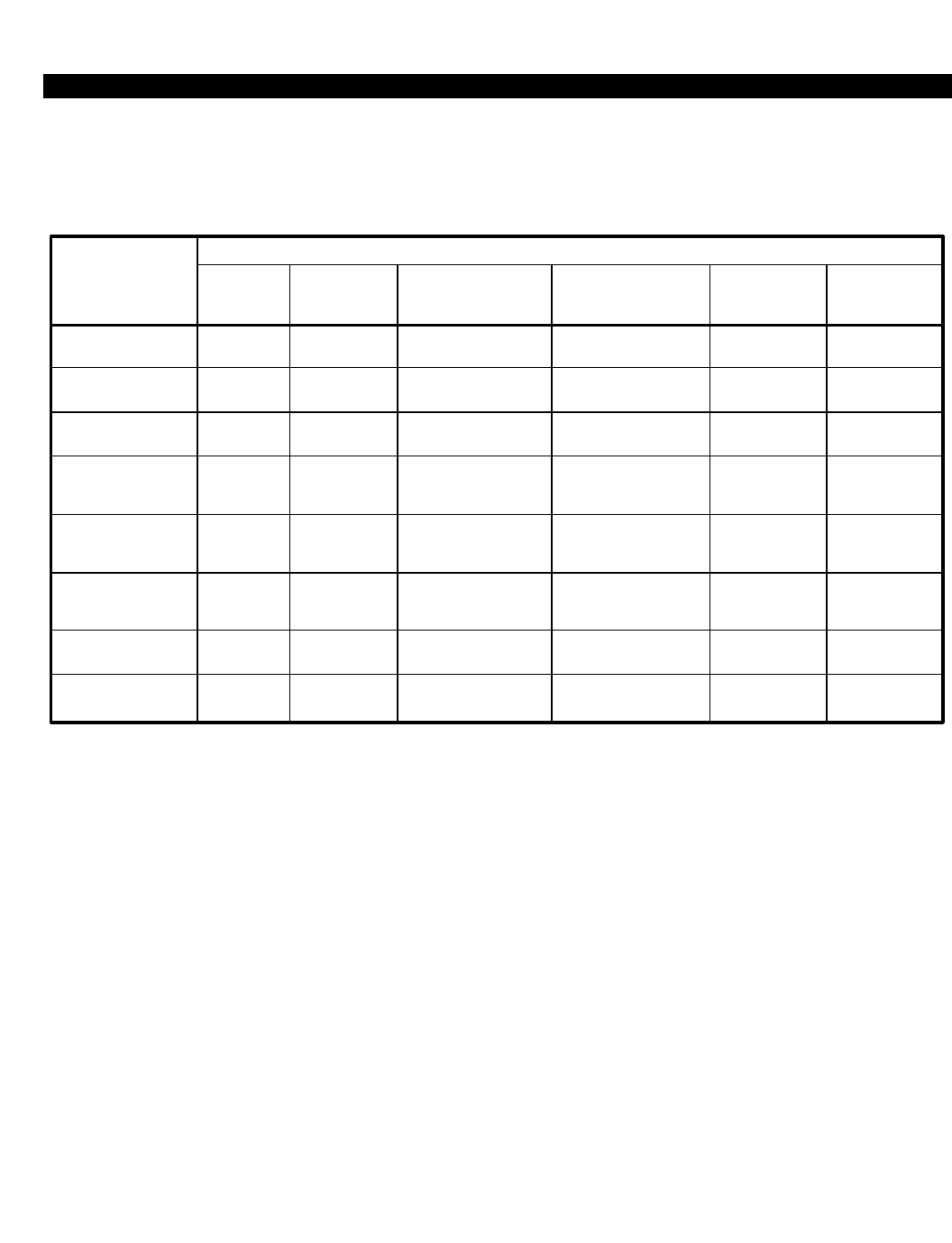
PERCEPTION 4000 APPENDIX D
ISS 2, SECTION 4000-014-000
MATRIX 2
Appendix D-2
PRIME LINE
PREFERENCE
RINGING LINE
PREFERENCE
IDLE LINE
PREFERENCE
PRIME PLUS
RINGING
PREFERENCE
PRIME PLUS
IDLE
PREFERENCE
RINGING PLUS
IDLE
PREFERENCE
ALL TYPES OF
PREFERENCE
IDLE,
ALL LINES RINGING ON
PRIME LINE
RINGING ON
NON-PRIME LINES,
PRIME LINE IDLE
RINGING ON
NON-PRIME LINES,
PRIME LINE BUSY RINGING ON
ALL LINES NO RING,
PRIME BUSY
STATUS
PRIME
LINE IGNORE KEY
NO PREFERENCE IGNORE KEY IGNORE KEY IGNORE KEY IGNORE KEY
IGNORE
KEY
IGNORE KEY
ANY
IDLE LINE
IGNORE KEY
PRIME LINE
PRIME LINE
IGNORE KEY
ANY
IDLE LINE
IGNORE KEY
IGNORE KEY
IGNORE KEY
IGNORE
KEY
PRIME
LINE
PRIME
LINE
PRIME
LINE
PRIME
LINE
PRIME
LINE
ANY
IDLE LINE
ANY
IDLE LINE
ANY
IDLE LINE
IGNORE KEY
PRIME LINE
PRIME LINE
PRIME LINE
PRIME LINE
IGNORE KEY
ANY
IDLE LINE
ANY
IDLE LINE
ANY
IDLE LINE
IGNORE KEY
IGNORE KEY
IGNORE KEY
IGNORE KEY
IGNORE KEY
IGNORE KEY
IGNORE KEY
IGNORE KEY
ANY
IDLE LINE
IGNORE KEY
ANY
IDLE LINE
ANY
IDLE LINE
ANY
IDLE LINE

Glossary
PERCEPTION 4000 GLOSSARY
Area Code Restriction - The ability of the switching equipment to selectively identify 3-digit area codes, and
either allow or deny passage of long distance calls to those specific area codes.
Area/Office Code Restriction - The ability of the switching system to selectively identify 6-digit area and office
codes, and either allow or deny passage of long distance calls to those specific 6-digit codes.
ASCII - American Standard Code for Information Interchange.
asynchronous transmission - A method of transmission that allows data to be sent at irregular intervals by
preceding each character with a "start bit" and following it with a "stop bit."
attribute - A field in the row/field level of operation that assigns a quality to the primary key field. For example, in
the Station Assignment Command (CMD 330) all fields following the first field (EQUIP #) assign
characteristics to the equipment number such as data security, Class of Service, Destination Restriction
Level, etc.
Automatic Call Distribution - A PBX feature designed to evenly distribute a large number of incoming calls to an
answering pool of agents.
CCSA - Common Control Switching Arrangement: a private switched service network (utilizing telephone
company Central Office facilities) providing direct station-to-station network inward and outward dialing
plus other features similar to those normally found in the public telephone network.
CCSA access - The compatibility of a PBX system for connection, via trunk access circuits, to private CCSA
networks.
circular hunting - An arrangement allowing the hunting (for an available nonbusy station) to start with the called
station line and then proceed in a prearranged order to test all lines in the group, completing the incoming
call to the first idle station line.
Class of Service - A set of facility and feature access capabilities assigned to groups of common users which
logically fit together in terms of telephone needs and privilege levels.
clear line - The state in which no automatic increments or conditions have been set by the system. You have a
clean slate on which to enter data to meet the requirements of the system prompt. A 'clear line' occurs
after each hierarchical prompt: "COMMAND=", "OPERATION=", and "SECURITY CODE=". In addition, a
'clear line' exists when the cursor is at the far left field in Data Entry and Setup modes.
common carrier - A company which furnishes public long distance services, such as AT&T.
COS - Class of Service.
Data Interface Unit - A device used to convert data signals of a transmitting data device/terminal to the internal
digital format of the switching system and vice versa. The PERCEPTION 4000 accommodates both
stand-alone and integrated DIUs.
Destination Restriction Level - Dialing restrictions which control outgoing calls made via direct trunk group
access and optionally via LCR access.
DID - Direct Inward Dialing.
ISS 2, SECTION 4000-014-000
Glossary-1

PERCEPTION 4000 GLOSSARY
ISS 2, SECTION 4000-014-000
Direct Inward Dialing - A feature allowing incoming calls to bypass the attendant and directly ring a station or
ACD pilot number.
Direct Inward System Access - A service which allows an outside caller the ability to dial directly into a PBX
system, without attendant intervention, to gain complete access to PBX system facilities and outgoing
trunk circuits (such as WATS access lines and TIE line circuits).
DISA - Direct Inward System Access.
DIU - Data Interface Unit.
DNIS - Dialed Number Identification Service.
DRL - Destination Restriction Level.
DTMF - Dual Tone Multi-Frequency signaling.
entity - An object that has meaning for a particular application. In this manual, an entity is a key parameter in the
row/field level of operation, such as an "EQUIP #" or "TGN" field.
Facility Restriction Level Profile - Restriction levels which determine which LCR routes a specific station user
has access to.
FRLP - Facility Restriction Level Profile.
full duplex operation - The simultaneous, independent transmission of data in both directions over a
communications link.
half duplex operation - The transmission of data in either direction, but only one way at a time.
ISDN - Integrated Services Digital Network
keyword - A word predefined by the system as valid data input in the row/field level of operation. The field must
be of fixed form, and may be designated as a decimal field, but not as a loop field.
LCR - Least Cost Routing.
LDN - Listed Directory Number.
Least Cost Routing - A feature which selects the most economical trunk facility to use for outgoing calls initiated
by a station.
Listed Directory Number - A feature allowing incoming directory number calls on DID and CCSA trunks, that
have been registered in the system, to be intercepted and routed to the attendant or designated
answering position.
loop field - A primary field used to identify the beginning point of a set of attributes (fields) that occur more than
once for an entity. The system may repeatedly execute data entry in these fields as controlled by the loop
field. The ability to enter additional attributes, with the loop field incrementing automatically provides a
useful tool when performing large sets of modifications. If the operation contains more than one loop field,
the innermost loop is completed first, and works outward to the outer loop.
Glossary-2

PERCEPTION 4000 GLOSSARY
M&A - Maintenance and Administration.
M&A console - A terminal or data entry device used to change the system database (such as activation of new
station lines, changes in station numbers, changes in restrictions and feature assignments, etc.), as well
as perform diagnostic and other maintenance functions.
Man-Machine Interface - The means by which the user interacts with the PERCEPTION 4000 system through
the M&A console.
MMI - Man-Machine Interface.
primary field - The first field of an operation, usually a decimal-type loop field. The value entered identifies the
entity being selected for modification or display.
QPL - Queue Priority Level.
Queue Priority Level - A feature used by Least Cost Routing that determines the station placement in queue for
busy trunk groups. Also defines whether a caller will receive expensive route warning tone if a route is
designated as such.
redundant system - A second set of common control equipment which, should the main processor fail, provides
automatic switchover to prevent interruption to call processing.
serial hunting - An arrangement setting up a pilot number as the first number in a hunt group. The hunting
arrangement activates as a result of dialing the pilot number and begins at the top of the list and ceases
at the bottom. Various members may also be flagged as entry points. Dialing any member directory
number marked as an entry point which is busy or in Do-Not-Disturb (but not forwarded) results in a
search for an available member in the order established in this command, starting at the busy member
and proceeding to the end of the list. 'Wrapping' does not occur in a serial hunt.
synchronous transmission - A method of data transmission in which the bits are transmitted at a fixed rate. The
transmitter and receiver both use the same clock signals for synchronization.
TIE lines - Special trunk circuits which provide voice and data communication between PBX systems.
UCD - Uniform Call Distribution.
Uniform Call Distribution - A feature by which calls are evenly distributed among group members. If a member
is not presently available to take a call, the call waits in a queue and receives announcement and/or
music treatment. Calls not handled in a timely manner can be routed to another location.
Uniform Numbering Plan - A method used by the system indicating that all station users in the network must
dial the same number of digits to reach any location (end-point) in the network.
UNP - Uniform Numbering Plan.
ISS 2, SECTION 4000-014-000
Glossary-3


Index
PERCEPTION 4000 INDEX
ISS 2, SECTION 4000-014-000
A
access codes 3-283
account codes 3-5, 3-190
ACD (see Automatic Call Distribution)
Active side 3-135, 3-186, 3-207
ADD operation 1-20, 2-7, 3-265
add-on module 3-308, 3-315
advisory message creation 3-82
alarms 3-25
announcements 3-19, 3-32, 3-156, 3-161, 3-359,
3-367, 3-422, 3-434, 3-442
machine 3-269
area codes 3-38, 3-41, 3-132
LCR 3-237, 3-239
attendant
console
feature key assignment 3-44
position assignment 3-61
groups 3-48
incoming call priority assignment 3-55
internal call alternate routing 3-214
password assignment 3-58
authorization codes 3-68, 3-257
Autodial 3-72
Automatic Call Distribution 3-7, 3-11, 3-17, 3-21,
3-32, 3-147
automatic line selection 3-316, D-1
B
BACKUP operation 3-169, 3-265
C
call forwarding 3-76, 3-262
call pickup groups 3-79
canned text creation 3-82
CCSA (see Common Control Switching Arrangement)
change log 1-1
Class of Service 3-85, 3-258, 3-357, 3-383
'clear line' 1-5, 1-7, 1-14
clock 3-89, 3-91, 3-139, 3-164
clock provider 3-89, 3-164
CNP (see Coordinated Numbering Plan)
Code Call 3-450
command categories 1-2, 1-26, 2-23
command format 3-1
command notations 3-2
common carrier 3-95
Common Control Switching Arrangement 3-147, 3-
150, 3-153, 3-158
COMPARE operation 3-170, 3-266
control key operation
CONTROL-D 1-8
CONTROL-F 1-9
CONTROL-P 1-8, 1-14, 1-17
CONTROL-Q 1-8
CONTROL-R 1-9
CONTROL-S 1-8
CONTROL-W 1-9, 1-16, 2-22
Coordinated Numbering Plan 3-97
COPY operation 3-170, 3-266
COS (see Class of Service)
country codes 3-99, 3-101
LCR 3-242
crash dump 3-104
CREATE operation 3-170, 3-266
D
data
files 3-169, 3-186
group speed calling 3-195
high usage data numbers 3-198
hunt groups 3-106
key assignment 3-314
station 3-115, 3-122
Data Entry mode 1-7, 1-15, 1-16, 2-8, 2-11, 2-13
Data Interface Units 3-109, 3-115, 3-122, 3-274,
3-307
Data Structure 3-127, 3-130
DELETE operation 1-21, 2-10, 3-171, 3-266
Destination Restriction Level 3-132, 3-257, 3-383
diagnostic commands
Alarm/Fault Display & Reset command 3-25
Device Service Status command 3-135
File Dump 3-188
Patch Report 3-289
Time Activated Command Programming command
3-379
Dialed Number Identification Service 3-147, 3-150,
3-153, 3-158
dialing groups 3-140
dictation machine 3-144, 3-410, 3-427, 3-438
DID (see Direct Inward Dialing)
Digital Carrier Channel 3-163
Direct Inward Dialing 3-147, 3-150, 3-153, 3-158
Direct Inward System Access 3-150, 3-167, 3-340,
3-357, 3-402, 3-406
DISA (see Direct Inward System Access)
disk files 3-169
DISPLAY operation 1-24, 2-15, 3-171, 3-266
DNIS (see Dialed Number Identification Service)
Index-1

PERCEPTION 4000 INDEX
ISS 2, SECTION 4000-014-000
DIU (see Data Interface Units)
DRL (see Destination Restriction Level)
DTMF 3-176, 3-404
E
emergency
calls 3-65, 3-142, 3-178
paging 3-287, 3-451
Error Messages 4-1
<ESC> key 1-5, 1-14, 2-19
Exception Restriction Tables 3-181
F
Facility Restriction Level Profile 3-184, 3-257, 3-383
faults 3-25
feature numbers 3-85, 3-283, 3-320, C-1
Field Parameter Input Characters 1-9, A-1
file consolidation 3-186
file dump 1-188
fixed values 1-18
floppy diskette 3-137, 3-169
FORMAT operation 3-171, 3-266
formatting keys 1-4
FREE operation 3-171, 3-266
FRLP (see Facility Restriction Level Profile)
H
hard disk 3-137, 3-169, 3-186
HELP operation 1-2, 1-8, 1-24, 2-22
command selection level 1-25, 2-22
operation selection level 1-26, 2-25
parameter selection level 1-27, 2-30
holiday assignment 3-343, 3-383
home area code 3-247, 3-254, 3-408
hotline 3-291, 3-302, 3-319
hunt group
data 3-106
voice 3-330
voice mail 3-335
I
I/O port 3-200, 3-203
Interactive mode 1-19
intercom 3-212
internal call alternate routing 3-214
ISDN
channel groups 3-217, 3-221
IPRC and IPRI cards 3-224
ISDN service min/max levels 3-229
ISDN trunk groups 3-234
K
key assignments
attendant console 3-44
station 3-314
key parameters 1-14
keyword 1-3, 1-9, 3-2
L
labels 3-260
LCR (see Least Cost Routing)
LDN (see Listed Directory Number)
Least Cost Routing 3-237, 3-239, 3-242, 3-245,
3-249, 3-254, 3-257, 3-357, 3-383
Listed Directory Number 3-150, 3-153
login 1-1, 3-264
logout 1-28
loop operation 1-6, 1-20
M
M&A commands
examples 2-1
listed alphabetically 3-2
listed by numeric ID, Index 3
listed by numeric ID and keyword B-1
maintenance commands
Alarm/Fault Display & Reset command 3-25
Clock Reset command 3-91
Crash Dump DIsplay command 3-104
Data Structure Display command 3-127
Data Structure Display 2 command 3-130
Device Service Status command 3-135
Disk File Manipulation command 3-169
File Consolidation command 3-186
Initiate Switchover command 3-207
Memory Test command 3-267
System Inventory command 3-346
System Number Summary command 3-352
Terminal Maintenance command 3-371
Time Activated Command Programming command
3-379
Trace Setup command 3-389
modem pool 3-115, 3-198, 3-272
MODIFY operation 1-22, 2-13, 3-264
Music-on-Hold 3-32, 3-269, 3-356
N
name dialing 3-277
network 3-97, 3-254, 3-283, 3-361, 3-444, 3-447
night bell 3-48, 3-153, 3-158, 3-214, 3-280, 3-420,
3-433
numbering plan 3-97, 3-283, 3-447
Index-2

PERCEPTION 4000 INDEX
ISS 2, SECTION 4000-014-000
O
office codes 3-41, 3-132, 3-209
interchangeable 3-209
LCR 3-239
P
paging 3-45, 3-321, 3-450
passwords 1-1, 3-58, 3-264, 3-340
patch report 3-289
predefined keys 1-4
private line 3-291, 3-408, 3-436, 3-438
Q
QPL (see Queue Priority Level)
Queue Priority Level 3-61, 3-68, 3-115, 3-254,
3-257, 3-303, 3-383, 3-408
R
ranges 1-11, 1-17
redundant system 3-207, 3-295
RESTORE operation 3-170, 3-266
S
scopes 1-12
secondary line appearances 3-300, 3-319
security code 1-1, 1-14, 3-264, 3-340
security levels 1-1, 3-264
Setup mode 1-7, 1-15, 1-17, 2-8, 2-12, 2-14, 2-15
Severity Level Table 3-29
SMDR 3-58, 3-68, 3-201, 3-297, 3-340, 3-357
speed calling
group 3-193, 3-195
system 3-361
Standby side 3-135, 3-186, 3-207
station
assignment 3-303
feature key assignment 3-314
feature key pattern assignment 3-324
hunt groups 3-330
parameter assignments 3-335
switchover 3-207, 3-266, 3-380
system
clock 3-28, 3-91, 3-139
inventory 3-346
number summary 3-352
option flags 3-356
speed calling 3-361
timer 3-364
T
T-1 clock provider 3-163, 3-369
terminal maintenance 3-371
terminating with an M&A session 1-28
Time Activated Command Programming 3-379
timeout routing 3-387
time zones 3-158, 3-257, 3-383, 3-396
toll-free
calls 3-132
tables 3-408, 3-424
toll prefix 3-140, 3-245
trace setup 3-389
traffic measurement 3-393, 3-396, 3-399
trunk
assignment 3-402
dialing groups 3-140
group
assignment 3-158, 3-234, 3-408
parameters 3-416
routing 3-420
toll-free tables 3-424
hunting 3-427
private line 3-291
restriction groups 3-38, 3-41
routing 3-153, 3-158, 3-249, 3-433
shelf 3-224
Trunk-to-Trunk Connection tables 3-436
U
UCD (see Uniform Call Distribution)
Uniform Call Distribution 3-17, 3-32, 3-440
Uniform Numbering Plan 3-254, 3-444, 3-447
UNP (see Uniform Numbering Plan)
V
voice hunt groups 3-330
voice mail 3-335
voice paging 3-46, 3-87, 3-321, 3-410, 3-438, 3-450
COMMANDS
102 Initiate Switchover 3-207
110 Time Activated Command Programming 3-379
121 Clock Reset 3-91
143 Patch Report 3-289
144 Memory Test 3-267
151 File Dump 3-188
Index-3

PERCEPTION 4000 INDEX
ISS 2, SECTION 4000-014-000
152 Disk File Manipulation 3-169
153 File Consolidation 3-186
160 Alarm/Fault Display and Reset 3-25
164 Crash Dump Display 3-104
167 Data Structure Display 3-127
168 Trace Setup 3-389
169 Data Structure Display 2 3-130
206 Terminal Maintenance 3-371
208 Device Service Status 3-135
210 System Inventory 3-346
300 Numbering Plan Assignment 3-283
301 Uniform Numbering Plan Assignment 3-447
302 UNP Routing Assignment 3-444
303 Coordinated Numbering Plan Assignment 3-97
305 Trunk-to-Trunk Connection Assignment 3-436
307 Trunk Group Routing Assignment 3-420
308 Trunk Routing Assignment 3-433
309 Trunk Hunting Assignment 3-427
310 Trunk Group Assignment 3-408
311 Trunk Group Toll-free Tables 3-424
312 Label Print 3-260
313 Trunk Assignment 3-402
314 DID/CCSA/DNIS Trunk Group Asnmt 3-158
315 DID/CCSA/DNIS DISA LDN Assignment 3-150
316 DID/CCSA/DNIS LDN Assignment 3-153
317 Dialing Definition 3-140
318 Interchangeable Office Code Table 3-209
319 Voice Paging/Code Call Assignment 3-450
320 Station Feature Key Pattern Asnmnt 3-324
321 System DISA Security Code Asnmnt 3-340
322 Logical Line Call Forward Assignment 3-262
323 Timeout Routing Destination Asnmnt 3-387
324 Autodial Number Display 3-72
325 Call Forwarding Destination Display 3-76
326 System Number Summary 3-352
327 Secondary Line Appearances Display 3-300
328 Canned Text/Advisory Message Creation 3-82
329 Station-Level Parameter Assignment 3-335
330 Station Assignment 3-303
331 Station Feature Key Assignment 3-314
332 Private/Hotline Assignment 3-291
333 Intercom Group Member Display 3-212
334 Class of Service Assignment 3-85
335 Country Code Assignment 3-99
336 Time Zone Assignment 3-383
337 Destination Restriction Level Asnmnt 3-132
338 Country Code Restriction Tables 3-101
339 Area/Office Code Restriction Tables 3-41
340 Exception Restriction Tables 3-181
341 Area Code Restriction Tables 3-38
342 Station Hunting Assignment 3-330
343 LCR/Authorization TZ Change Asnmnt 3-257
344 Common Carrier Assignment 3-95
345 Emergency Call Destination Assignment 3-178
346 Call Pickup Group Assignment 3-79
347 Modem Pool Assignment 3-272
348 Account Code Assignment 3-5
349 Authorization Code Assignment 3-68
350 Group Speed Calling Member Asnmnt 3-195
351 Group Speed Calling List Assignment 3-193
352 Forced Account Code Toll-free Tables 3-190
353 Announcement Pattern Assignment 3-32
354 UCD Group Assignment 3-440
355 ACD Group Assignment 3-11
356 ACD Agent Assignment 3-7
357 ACD Group Parameter Assignment 3-17
358 ACD Status Display and Remote Logout 3-21
359 DID/CCSA/DNIS ACD Parameter Assignment
3-147
360 Data Station Assignment 3-115
361 Data Interface Parameter Assignment 3-109
362 Data Station Parameter Assignment 3-122
364 Trunk PP Parameter Change 3-430
366 Data Hunting Assignment 3-106
367 Name Dialing Assignment 3-277
368 High Usage Data Destination Asnmnt 3-198
370 Attendant Position Assignment 3-61
371 Attendant Feature Key Assignment 3-44
372 Attendant Group Assignment 3-48
373 Attendant Incoming Call Priority Asnmnt 3-55
374 Internal Call Alternate Routing Asnmnt 3-214
375 Attendant Password Assignment 3-58
380 LCR Country Code Routing Assignment 3-242
381 LCR Area Code Routing Assignment 3-237
382 LCR Area/Office Code Routing Asnmnt 3-239
383 LCR Routing Table Assignment 3-249
384 LCR Special Routing Assignment 3-254
386 LCR Digit Translation Profile Asnmnt 3-245
387 Facility Restriction Level Profile Asnmnt 3-184
400 Miscellaneous Device Assignment 3-269
401 Dictation Group/Machine Assignment 3-144
402 System Speed Calling Assignment 3-361
403 M&A Security Level and Access Asnmnt 3-264
404 System Holiday Assignment 3-343
405 Night Bell Assignment 3-280
407 System Timer Assignment 3-364
408 System Option Flag Assignment 3-356
409 SMDR Configuration Assignment 3-297
410 Redundancy Selection Assignment 3-295
412 T-1 Clock Provider Selection Asnmnt 3-369
413 Digital Carrier Channel Assignment 3-163
414 I/O Port Configuration Assignment 3-203
Index-4

PERCEPTION 4000 INDEX
ISS 1, SECTION 4000-014-000
415 I/O Port Assignment 3-200
416 DTMF Receiver Assignment 3-176
417 Clock Provider Assignment 3-89
420 Trunk Group Parameter Assignment 3-416
421 ISDN Trunk Group Parameter Assignment
3-234
422 ISDN IPRC and IPRI Card Assignment 3-224
423 ISDN Channel Group Assignment 3-217
424 ISDN Channel Group Hunting Asnmnt 3-221
425 ISDN Service Min/Max Assignment 3-229
900 Traffic Measurement Setup Assignment 3-396
901 Traffic Measurement Time Zone Asnmnt 3-399
902 Traffic Measurement Object Assignment 3-393
Index-5
