PETRO METER TCS 3000 Register Operations Manual
User Manual: manual pdf -FilePursuit
Open the PDF directly: View PDF ![]() .
.
Page Count: 41
Catalog Title
Catalog Subtle
Setup & Operaon Manual
TCS 3000
REGISTER

2
Table of Contents
W&M Settings 17
Products 17
Product Test Run 17
Recalibrate Product 17
Modify Parameters 18
Product Name 18
Comp. Table 18
Comp. Table Param. 18
Mass Density 19
Pump Control 19
Valve Type 19
Maximum Flow 20
Pulser Type 20
Pulse Estimate 20
Product Units 20
Product Units (Cont.) 20
Hose Volume 20
Begin Recalibration 21
Edit Calibration 21
Add New Product 21
Remove Product 22
System Metrics 22
Temp Probe 22
Meter Information 22
Prover Ticket 23
Reset Totalizers 23
Enable Remote Config 23
Product Settings 24
Product Prices 24
Product Prices (Continued) 24
Activate Product 26
Deactivate Product 26
Preset Timing 26
Preset Timing 26
Air Eliminator Hold 26
Hose Volume 26
Product Lists 26
Advanced Functions 27
System Shutdown 27
System Update 27
Start Up “Must Knows” 28
Inventory How To 29
Daisy Chain 30
Daisy Chain (Continued) 31
Temperature Probe Calibration 32
Trouble Shooting 33
Trouble Shooting (Continued) 34
Trouble Shooting (Continued) 35
Trouble Shooting (Continued) 36
Notes 37
Notes 37
Warranty 39
Table of Contents 2
Receipt & Inspection 3
Notice 3
Introduction 4
System Specifications 4
TCS 3000 Start Up 5
Navigation 5
Navigation (Continued) 6
Display Icons 6
Select Functions 7
Start Delivery 7
Show Last Delivery 8
Begin or End Shift 8
Duplicate Shift Ticket 9
Re-Print Tickets 9
System Menu 9
Reports 10
Show Prover Status 10
Prover Ticket 10
Meter Info 10
Version Info 10
Memory Status 10
Display Settings 10
Display Settings 11
Printer Settings 11
Enable / Disable Printer 12
Select Printer 12
Enable / Disable Host 12
Clients Address Range 12
Regional Settings 12
Delivery Settings 12
Configure Ticket 12
Configure Ticket (Continued) 13
Accounting 14
Presets 14
Multiple Deliveries 14
Customer ID 14
Display Precision 14
Zero-Flow Timeout 15
Auxiliary Devices 15
External Display 15
External Display (Continued) 15
Air Elimination 15
Additive Injection 15
Pulse Output 16
Connectivity 16
Misc. Settings 16

3
Receipt & Inspection
Upon receipt of register shipment, be sure to inspect the packaging and the register assembly for any damage be-
fore signing the receipt of the shipment. Notify the delivery company about possible damage and refuse receipt of
the shipment.
Registers are individually boxed and are protected with static resistant packing material. Each package is identified
with the register assembly part number, description, serial number. Verify the register model is the correct model,
size, and configuration as ordered. Contact your distributor if there is any discrepancy or question.
Register assemblies should be handled with appropriate methods for the size and weight involved. Appropriate
clothing and shoes need to be utilized. Transport the register package to the installation site with appropriate trans-
portation methods, careful not to damage the register.
Be careful of any loose or protruding staples from the packaging, as they can be very sharp and may potentially
cause injury.
If foam has been used to protect register, carefully remove top foam layer before attempting to remove register as-
sembly from box. Foam packaging maybe formed around the register assembly making it difficult to remove. Do
not lift the register assembly by wires or anything other than the metal body of the register. Do not insert objects or
cables into the register unless stated. Removing register assembly from packaging without adhering these warn-
ings may cause serious injury to you and/or the register.
Appropriate precautions should be taken regarding any personal, environmental and material compatibility with the
end use system.
Notice
Total Control Systems (TCS) shall not be liable for technical or editorial errors in this manual or omissions from this manual.
TCS makes no warranes, express or implied, including the implied warranes of merchantability and tness for a parcular
purpose with respect to this manual and, in no event, shall TCS be liable for special or consequenal damages including, but
not limited to, loss of producon, loss of prots, etc.
The contents of this publication are presented for informational purposes only, and while every effort has been
made to ensure their accuracy, they are not to be construed as warranties or guarantees, expressed or implied,
regarding the products or services described herein or their use or applicability. We reserve the right to modify or
improve the designs or specifications of such products at any time.
TCS does not assume responsibility for the selection, use or maintenance of any product. Responsibility for proper
selection, use and maintenance of any TCS product remains solely with the purchaser and end-user.
All rights reserved. No part of this work may be reproduced or copied in any form or by any means –
graphic, electronic or mechanical – without first receiving the written permission of Total Control Systems,
Fort Wayne, Indiana USA.

4
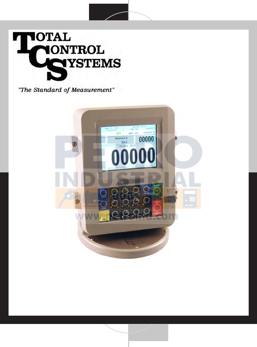
Introduction
The TCS 3000 register is a fully integrated custody transfer flow computer that will control all vehicle delivery operations.
The Open Software Architecture provides the option of a simple “Pump & Print” delivery or a custom measurement solu-
tion. The TCS 3000 features a 4.5”x 3.5” full color VGA display screen, multiple delivery screens and a flexible mounting
with backlit alpha-numeric keypad for the user interface. Available in flexible mounting configurations of 75 or 90 degree
displays for meter mounting, and a remote mounting.
As an flow computer with open software architecture, there will always be a need to add features to the register as the
industry applications evolve. Therefore please be reminded to contact the factory for periodic updates.
The TCS 3000 electronic register is a fully integrated flow computer that will control all delivery operations. The modular
design and open software architecture provide you with a tailored system that is expandable for future needs. The TCS
3000 features a large easy view VGA screen, alpha-numeric keypad and open printer interface for simple “Pump and
Print” deliveries. Software features offer complete flexibility of delivery screen information and view, preset, price/tax,
ticket format and password protection.
Optional GPS, Bluetooth, Wi-Fi and Cellular capability enables the TCS 3000 to improve your product security and ease
access to your delivery data to reduce your operation costs. Many additional features are available (multiple product
delivery, additive injection, density/temperature correction, multiple valve & pump control, etc.) to enhance your measure-
ment solution.
TCS 3000 - This manual will help guide you with the setup confirmation and calibration of the register. Additional infor-
mation will be provided for wiring instruction and auxiliary devices to integrate into the register.
ELECTRICAL
Power: 12—24V, 4A DC INPUT
A fuse shall be provided in the field to limit the 12VDC power source to 4 amps max.
Current: 1.4 Amp
Solid State Relays: 12/24 Vdc; Passive Solid State
INTERNAL PULSER
Pulse Ratio 400:1 PPR; Quadrature
Power 5 Vdc
Hertz 0 — 5000 Hz
EXTERNAL PULSE INPUT
Type Single or Dual Channel (Quadrature)
Power 5 Vdc
ENCLOSURE
Aluminum die cast with epoxy powder coat
Built to Ingress Protection 66 and Nema 4 ratings
Temperature Range: -40 F to 158 F (-40 C to 70 C)
Ports: Ten 1/2” NPT UL, cUL threaded connection ports, ATEX
Backlit LED Keypad
Calibration optical switch, password and mechanical seal
UL/cUL Rating Class 1, Division 2, Group C + D
The USB0 and USB1 connectors are for maintenance only. To access these connectors, power to the unit is to be
Disconnected or the area known to be free of ignitable gas or equivalent.
COMMUNICATION
Four RS 485 output, 2-wire half duplex, custom protocol; 9600 baud, 8 bit, no parity, 1 stop bit
One RS 232 output, 9600 baud; 8 bit, no parity, 1 stop bit
System Specifications
5
TCS 3000 Register Start Up:
Before placing this register into service you will receive a warning when you turn on the register
to calibrate the device before using. It will read as follows:
Caution
Before Placing this product into service, make sure that the register
has been properly calibrated and setup for the type of fluid being
measured. This includes calibration factor, compensation type,
compensation parameter, product type, valve settings, no flow
timeout and others. Refer to the operation manual supplied with the
register for instructions. Failure to properly calibrate and setup the
register can result in unexpected operation, inaccurate measure-
ments and damage to equipment or property.
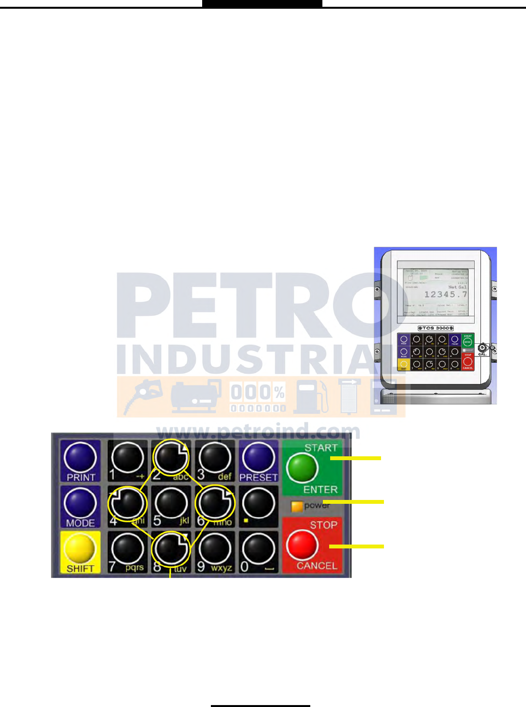
Navigation Keyboard Functions
Start/Enter Key
Stop/Cancel Key
Arrow Keys
Power Light
Power Light Allows you to see that there is power to the electronic register.
Start/Enter Key Allows you to enter register functions and start deliveries.
Stop/Cancel Key Allows you to stop a delivery and cancel an operation.
Arrow Keys Allow you to move to different fields on the Register.
WARNINGS:
SUITABLE FOR USE IN CLASS 1, DIVISION 2, GROUPS C AND D HAZARDOUS LOCATIONS, OR UNCLASSIFIED
LOCATIONS.
WARNING– EXPLOSION HAZARD– DO NOT DISCONNECT EQUIPMENT WHILE THE CIRCUIT IS LIVE OR UN-
LESS THE AREA IS KNOWN TO BE FREE OF IGNITABLE CONCENTRATIONS
WARNING– EXPLOSION HAZARD– SUBSTITUTION OF ANY COMPONENT MAY IMPAIR SUITABILITY FOR CLASS
1, DIVISION 2.
6
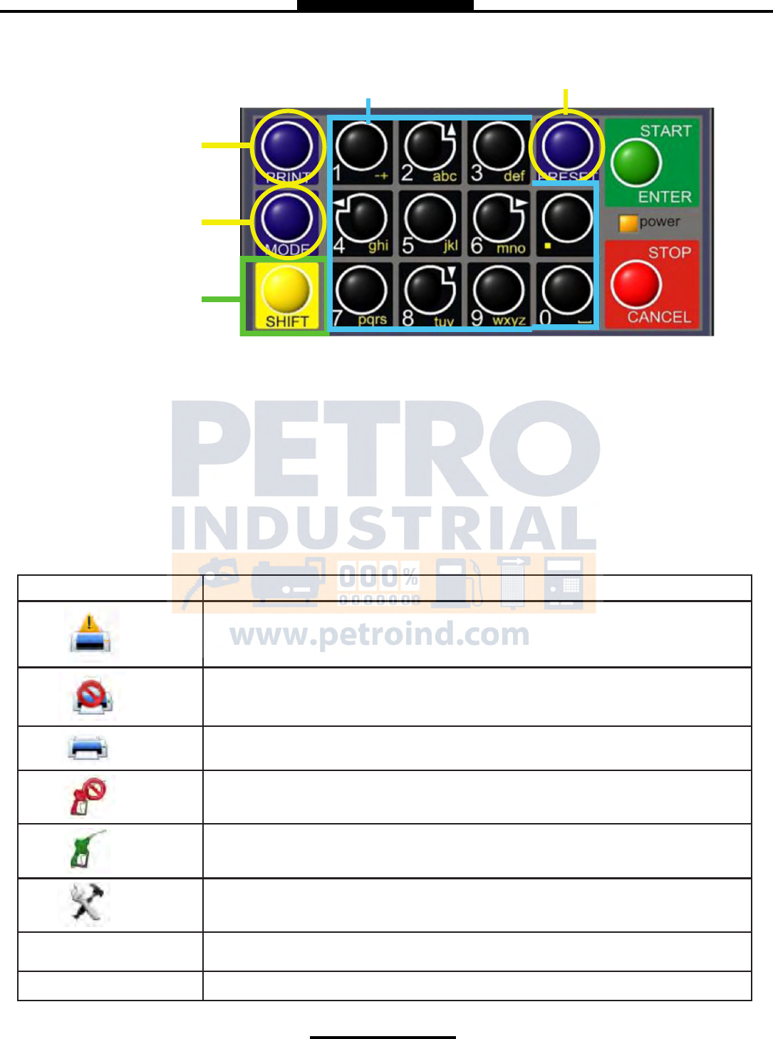
Shi Key
Preset Key Alpha, Numeric, and Symbol Keys
Print Key
Mode Key
Preset Key Allows you to PRESET the Price and Tax as well as Gallons into the Register.
Alpha/Numeric Keys Allow you to enter different prices, products, etc. into the Register.
Mode Key MODE allows you to select different screens on the Register.
Print Key Allows you to print. You can print the delivery with or without selecting the STOP key.
Shift Key Allows you to select the Alpha Keys on the Alpha/Numeric Keys. Selecting Shift allows
you to use anything on the Key Pad in yellow.
Shift & Mode Allows you to get into the main Menu screen.
Navigation Keyboard Functions (Continued)
Display Icons
ICON DESCRIPTION
Printer with no ticket.
No printer connection
Printer ready with Ticket
Valve not open
Valve(s) open
System Settings
Weights & Measures
AIR Air/Vapor Exhaust
7
Select Function
SELECT FUNCTION MENU (Quick Guide)
Start Delivery Begins delivery transaction.
Show Last Delivery Shows the last delivery on the TCS 3000 screen.
Begin or End Shift Beginning Shift will take a record of Delivery information at the start
through the end of the user shift.
Duplicate Shift Ticket Duplicate Shift Ticket will print a duplicate of the Begin or End Shift.
Re-Print Tickets Will reprint past delivery transactions
Non-Printed Delivery Prints the last 75 transactions that have not printed.
Already Printed Delivery Reprints the last ### of transactions already printed
Shift Tickets Reprints the last ### of shift tickets.
System Menu Setup and Configuration MENU’S for TCS 3000
Reports Calibration Log / Identification and Software Version
System Settings Configuration of System Parameters, Printer and Auxiliary Devices
W&M Settings Product Setup and Calibration
Product Settings Product Activation, Price Settings and Device Time Settings
Advanced Functions System Software Update
SELECT FUNCTION — Start Delivery
1) START DELIVERY. Press START to begin delivery transaction. This will reset the register causing the
delivery screen to read 0.0. Start your delivery.
2) If a Preset or Customer ID Field is Enabled, the delivery process will begin with prompts requesting data input.
See Page 14 for Preset Settings and / or for Customer ID Field to Enable/Disable.
3) If a Multiple Tank Delivery is Enabled, the Operating Driver must Hold the Shift Key down while pressing the
START key. When the Multiple Tank Delivery begins, a multiple tank icon will be
displayed during delivery. See Page14 for Multiple Tank Delivery to Enable/Disable.
4) Finish the delivery. Press STOP once to PAUSE and twice to STOP. If the Printer is Enabled, the
ticket will be printed automatically. If the printer is not Enabled, it will be stored in memory
to be retrieved at a later date.
8
Select Function
—Show Last
SHOW LAST Press START/ENTER to see the last delivery transaction
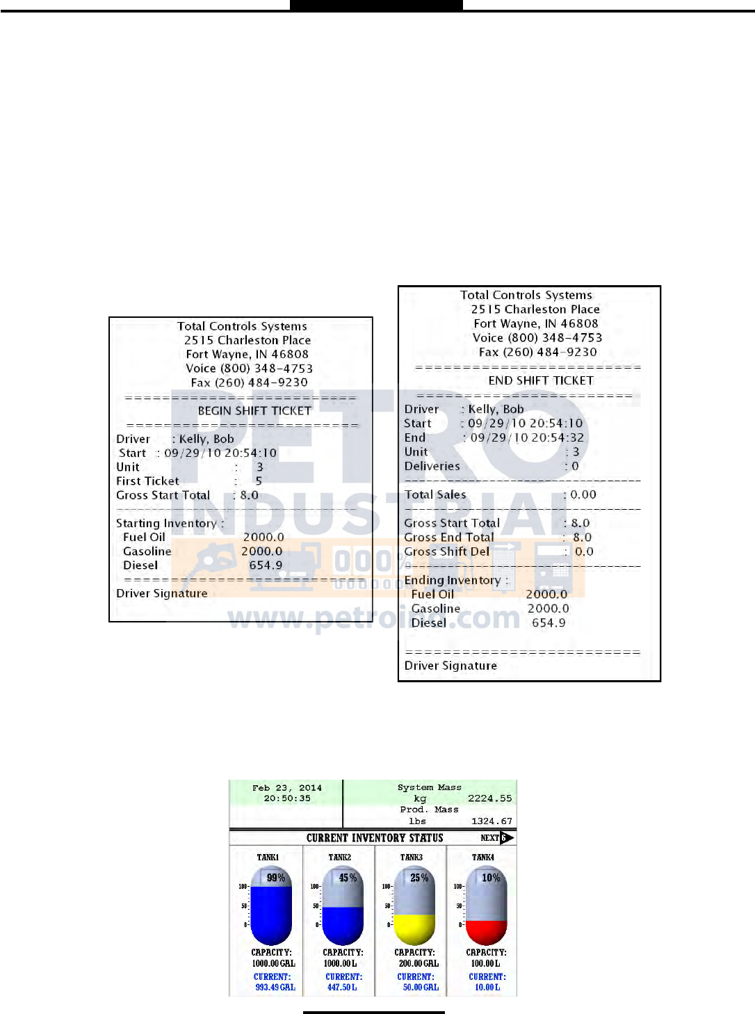
—Begin Shift/End Shift
The Shift function records the Time/Date, Meter Identification and the Delivery Data from the beginning of the shift to the
end of the shift. NOTE: This function is only accurate as the driver operators that utilize this feature.
1) BEGIN SHIFT Press and hold the SHIFT key, then press the MODE key.
2) END SHIFT Press and hold the SHIFT key, then press the MODE key.
3) After or before each Shift, the display will read Saving and Printing BEGIN or END Shift Ticket.
Sample Begin and End Shift Tickets
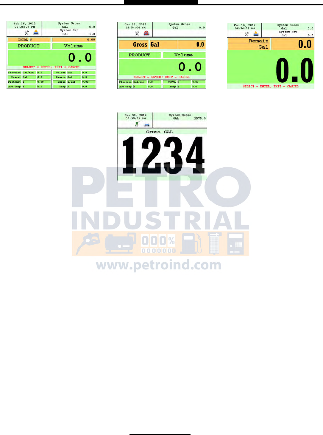
View Inventory
View Inventory allows you to select and view the inventory of product in the tank.
INVENTORY DISPLAY Displays the inventory and tank size.

9
Select Function
SELECT INVENTORY Allows you to use the arrow keys to select the product in order to view the Inventory
Details.
PRINT INVENTORY REPORT Generates a ticket of the Inventory Report
—Duplicate Shift Ticket
To print a Duplicate Shift Ticket, navigate down to select the function and press ENTER.
—Re-Print Tickets
To locate and reprint a past delivery ticket, navigate down to select the function and press ENTER
1) NON PRINTED DELIVERY Will ask how many of the last sequential tickets (that have NOT printed) do you
wish to print. Enter quantity and press ENTER.
2) ALREADY PRINTED DELIVERY Will ask how many of the last sequential tickets do you wish to re-print. Enter
quantity and press ENTER.
3) SHIFT TICKETS Will ask how many of the last sequential tickets do you wish to re-print. Enter
quantity and press ENTER.
System Menu (Quick Guide)
Report View and print calibration, meter information and software
Show Prover Status Weights & Measures access, calibration and configuration log
Prover Ticket Print calibration proving ticket
Meter Info Meter identification
Version Info Operating Firmware and Software
System Settings Configuration of system functions
Display Settings Configure display screens and fields
Printer Settings Select printer, host ,remote or none
Regional Settings Date and Time settings
Delivery Settings Configure delivery functions like tickets, presets, ID fields, etc.
Auxiliary Devices Select and configure auxiliary devices and pulse output
Connectivity Configure register and printer addresses for network data sharing
Misc. Settings Password settings
W&M Settings Weights & Measures product setup and calibration
Products Product settings and calibration
System Metrics Unit of measure precision
Temp Probe Temperature probe calibration
Meter Information Register, Meter and Truck Identification
Prover Ticket Print calibration proving ticket
Reset Totalizers Reset system and product totalizers
Enable Remote Config Remote interface configuration
Product Settings Product identification for shifts and price/tax
Product Prices Product pricing and taxation
Activate Product Activating onboard products within Shifts
Deactivate Product Deactivating onboard products outside of Shifts
Product Timing Product preset and auxiliary device timing
Product Lists Listing of active, inactive and uncalibrated products
Advanced Functions Administrative Configuration
System Shutdown Rebooting of system
System Update Software update

10
System Menu
—Reports
1) SHOW PROVER STATUS
Selecting Show Prover Status allows you to view the last date and time of the last calibration.
2) PROVER TICKET
Selecting Prover Ticket allows you to print the prover information from the register.
3) METER INFO
Selecting Meter Information allows you to view the Meter Data, such as The Truck ID, Register ID, Meter Make, Meter
Model, Meter Version, and the Meter Serial Number. Information must be input within the Weights & Measures menu.
4) VERSION INFO
Selecting Version Info allows you to view the Version of Software and Firmware running on the TCS 3000.
5) MEMORY STATUS
Selecting Memory Status allows you to view the number and type of tickets printed by the TCS3000.
—System Settings
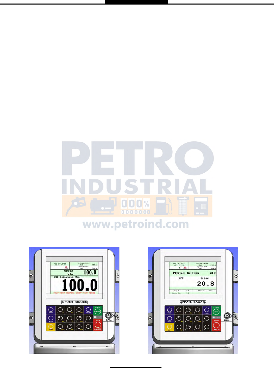
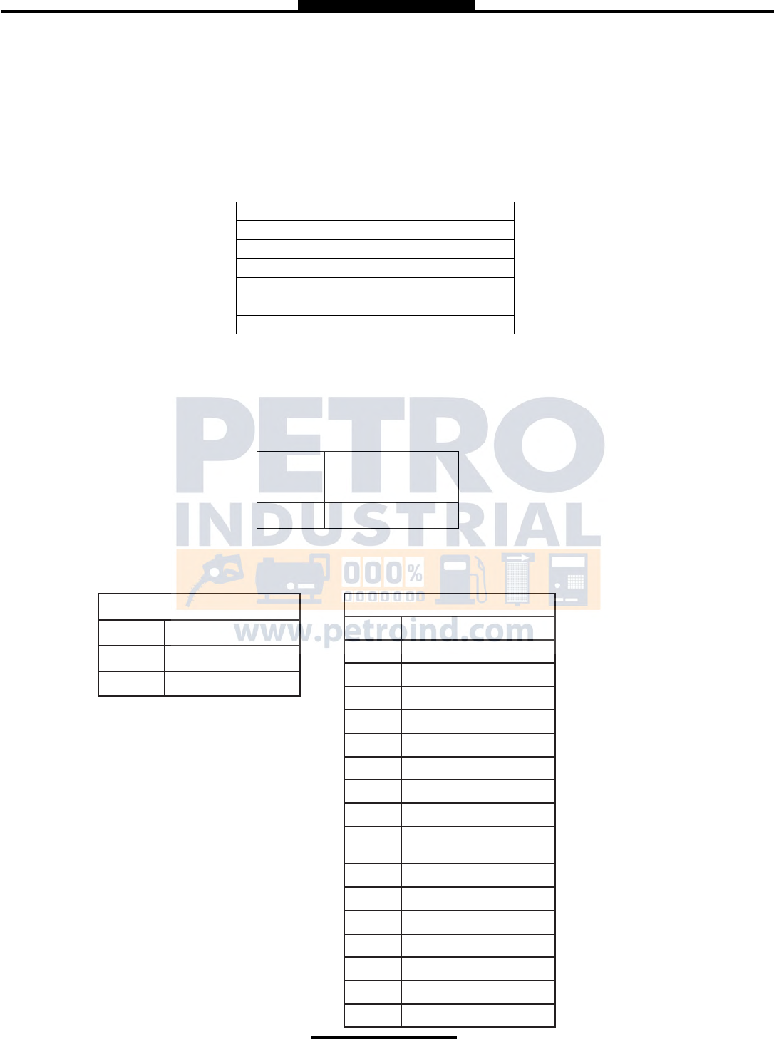
1) DISPLAY SETTINGS
DELIVERY SCREENS
Select Active Type Active Type allows you to set your DEFAULT display screen. Highlight the type
(type 1, 2, or 3) of screen you would like to view during delivery and start-up.
Configure Type 1 Using the arrow keys to move around the screen, highlight the field you would like
to change and select ENTER. The field options are in Table 1 below.
Configure Type 2 Using the arrow keys to move around the screen, highlight the field you would like
to change and select ENTER. The field options are in Table 1 below.
Configure Type 3 Using the arrow keys to move around the screen, highlight the field you would like
to change and select ENTER. The field options are in Table 1 below.
Empty No Data
Product Name (LPG, Diesel, Av Gas, Etc.)
Delivery Gross Non-Compensated Delivery Total
Delivery Net Compensated Delivery Total
Delivery Volume Amount of Delivery
Delivery Total Total Delivered
Flowrate Amount Delivered through Per Minute
AVG Temperature Average Temperature of Product
Temperature Temperature of Product
Mass Mass of the Product (e.g. Pounds per Gallon, etc.)
Preset Remain Remaining Preset (What is left of the Preset Total)
Preset Volume Preset Volume Amount for Delivery
Preset Amount Preset Currency Amount for Delivery
Density Density of the Product
TABLE 1
11
System Menu
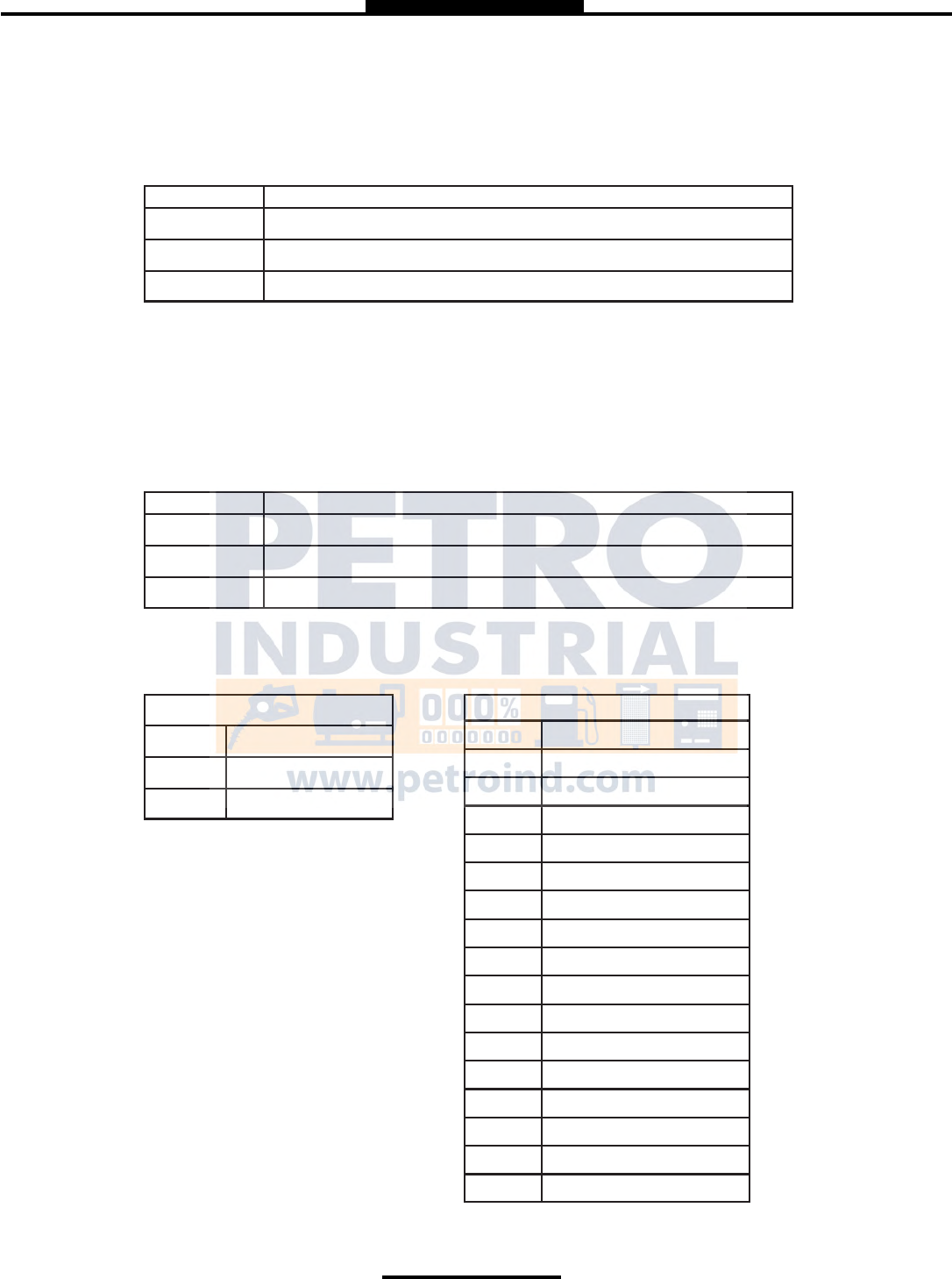
TYPE 1 TYPE 2 TYPE 3
TYPE 4
* TYPE 4 Only displays delivered volume.
CALIBRATION SCREEN
Temperature Calibration screen will show volume/mass and Temperature
Flowrate Calibration screen will show volume/mass and Flowrate
Empty Calibration screen will show volume/mass and nothing else
BRIGHTNESS Brightness allows you to set the brightness of the display screen from 100 to 30 percent
(brightest to dimmest) settings.
NET TOTALIZER Net Totalizer allows you to set whether the Net Totalizer is visible on the display screen.
Always Net Totalizer is always visible
Auto Net Totalizer is visible only when a product has Automatic Temperature Correction
(ATC) enabled on a Product
Never net Totalizer is never visible
GROSS TOTALIZER Gross Totalizer allows you to set whether the Gross or Volume Totalizer is visible on the
display screen.
Volume Totalizer Volume Totalizer is always visible
Mass Totalizer Mass Totalizer is always visible
2) PRINTER SETTINGS
ENABLE/DISABLE PRINTER
Enable Allows the printer to operate. Highlight Enable and select ENTER. When
the printer is Enabled, a printer icon will appear in the top left portion of the screen.
Disable Will not allow the printer to operate. Highlight Disable and select ENTER. When
the printer is Disabled, the little printer will disappear in the top left portion of the
screen.

12
Weights & Measures
CUSTOM1 Allows you to customize the ticket
MAXIMUM Allows the maximum amount of space on the ticket.
MINIMUM Allows the minimum amount of space to be used on the ticket.
ONELINER Uses one line on the ticket.
SELECT PRINTER
Epson TMU 220/295 Epson slip or roll printer driver installed
Citizen CMP30 Citizen printer driver installed
Printek Printek printer driver installed
Blaster Blaster printer driver installed
Remote Selecting Remote will allow you to use a printer remotely when connected to the
register through a daisy chain RS485 serial communication.
None Selecting None will remove the communication for printing
PRINTER HOST
Printer Host is used when you plan to daisy chain multiple TCS 3000 registers together for
a single printer. Host is the primary meter and the Clients are all registers following the
Host.
Enable/Disable Host To Enable or Disable the Printer Host, highlight Enable or Disable and select
ENTER
- Enable will allow you to use Printer Host
- Disable will not allow you to use Printer Host
3) REGIONAL SETTINGS
DATE & TIME
Date Format MMMM DD, yyyy
MM/dd/yyyy
yy/MM/dd
dd/mm/yyyy
dd/mm/yy
Time Format 24 Hour Clock
12 Hour Clock AM/PM
Set Date Year — Format YYYY
Month — Select Month
Date — Select Date
Set Time Format time as Hours (input from 24 hr. clock) . Minutes . Seconds (HH.MM.SS)
NOTE: a period must be used as your divider
DECIMAL SYMBOL Select a ‘.’ period or a ‘,’ comma and press ENTER
4) DELIVERY SETTINGS
CONFIGURE TICKETS
Select Ticket Type Sets the DEFAULT for the delivery ticket. Choose from the following:
CUSTOMIZE TICKET
Customize Ticket allows you to customize the preconfigured information printed
on the delivery ticket. Choose from the following:

13
System Menu
TCS 3000 Menu Example Prints
Header 1 Total Control Systems
Header 2 TCS 3000
Header 3 Delivery Ticket
Header 4 (888) 888-8888
Header 5 Programmable Field
Thick Separator ———————————————-
Start Time Start Jun 04, 2012 09:42:09 AM
End Time End Jun 04, 2012 09:53:42 AM
Truck ID 3842 Meter 2
Ticket Number ########
Product Name Gasoline (Product setup in Prover)
ProdNet Total Begin ########
ProdNet Totalizer ########
ProdGrs Total Begin ########
ProdGrs Totalizer ########
SysNet Total Begin ########
SysNet Totalizer ########
SysGrs Total. Begin ########
SysGrs Totalizer ########
Delivery Secon —— Delivery ——
Customer ID 1 Programmable Field
Customer ID 2 Programmable Field
Customer ID 3 Programmable Field
Customer ID 4 Programmable Field
Line
Delivery Gross Begin ########
Delivery Gross End ########
Delivery Net Begin ########
Delivery Net End ########
TempComp Line Volume Corrected to 60F (15C)
Tempcomp Table Table —— i.e. Table 24
Average Temp AVG Temp. F
Gross Delivered Gross Gal. Delivered
Net Delivered Net Gal. Delivered
Line
Unit Price Unit Price —- i.e. 1.86
Sale Amount ########
Tax 1 Tax 1 —— i.e. Road Tax
Tax 2 Tax 2 —— i.e. Sales Tax
Tax Amount Tax Amount
Star Line ***********
Amount Due Amount Due ———— ##.##
Empty Line ########
Thick Separator ————-
System Line 1 ** Duplicate Invoice **
System Line 2 *** Power Loss ***
Footer 1 Programmable Field
Footer 2 Programmable Field
Footer 3 Programmable Field
Footer 4 Programmable Field
Footer 5 Programmable Field

14
System Menu
Add Ticket Type Create a NEW Customized Ticket, then press ENTER to name it.
Copy from an Existing Ticket, then press ENTER to name it.
NOTE: Any new ticket name must be 3 or more characters long
Remove Ticket Type Select ticket to be removed from the system and press ENTER
Header Defaults There are FIVE programmable fields for contact information or messages
Footer Defaults There are FIVE programmable fields for contact information or messages
Shift Ticket Headers There are FOUR programmable fields for contact information or messages
Inventory Tickets Header There are FOUR programmable fields for contact information or messages
PRESET SETTINGS
Enable Preset Utilizing the preset will request a preset amount before a delivery begins. After selection,
press ENTER to complete setting.
Enable Preset Enable or disable preset
Preset By Price Enable or disable preset by Price
Gross Preset Enable or disable preset in GROSS VOLUME
Net Preset Enable or disable preset in NET CORRECTED VOLUME
Retain Preset Enable or disable preset for repeat BATCH presets
MULTIPLE DELIVERIES
Allows for the user to fill multiple tanks on one (1) single ticket transaction.
Simply press and hold the SHIFT key down while pressing the START key
to begin the multiple deliveries.
If preset is enabled, each tank delivery will prompt the preset amount.
CUSTOMER ID OPTIONS
The Customer ID Option will provide four (4) separate fields for the user to input prior to
the delivery. The Customer Identification is normally used for Tank, Truck, Airplane Tail
No., Locomotive, Driver, Customer, etc. Manual entry of data will be required through the
alpha-numeric keypad. After selection, press ENTER to complete setting.
Customer ID# (1-4)
Customer ID# Text
Field programmable for identification
Request ID#
Field requires user to enter an ID
Enforce ID#
Field requires user to enter an ID in order to operate the system
Validate ID#
Field validates the ID to ensure the ID is in the database, if invalid
the system will be inoperable
DISPLAY PRECISION
The unit precision can be displayed as a whole, tenth, hundredth or thousands measure
ment. After selection, press ENTER to complete setting.
1 Whole Unit
1.1 Tenth Unit
1.11 Hundredth Unit
1.111 Thousands Unit

15
Select Function
ZERO FLOW TIMEOUT
Feature will complete a delivery transaction if the user does not press the STOP key.
Enter whole numbers in Seconds for the timeout setting and press ENTER.
NOTE: Factory setting is 180 seconds, 3 minutes after the last pulse transmission to the TCS 3000 regis-
ter. This feature CANNOT be disabled. For desired extended periods, utilizer a large number to have the
Timeout ignored.
PAUSE OPTIONS
Pause controls how pump control is used.
Allow Pause Allow Pause Pauses the pump during the delivery
Pause Pump Pause Pump stops the delivery completely during delivery.
5) AUXILIARY DEVICES
EXTERNAL DISPLAY
The External Display setting is for the specific manufacturers of large LED displays. This
setting is for serial communication to an ancillary display that will read the same data that is
displayed on the TCS 3000 register.
Enable/Disable Enable or disable and press ENTER
Configure Select Type: Red Lion LD is currently the only external display available today
Address: Display Address from 1 to 99 and press ENTER
Display Data Choose the information to display on External Display and press
ENTER
- Delivery Gross
- Delivery Net
- Delivery Volume
- Delivery Total (Currency)
- Flow Rate
- Mass
Test This is a test sequence of numbers to exhibit on external display
AIR ELIMINATOR
The Air Eliminator is for the electronic actuation of a solenoid exhaust vent and a down
stream valve, when a level sensor switches.
AE Enable/Disable Enable or disable for operation
AE Detection Select Normally Open or Closed for level sensor detection
AE Relay Enable or disable exhaust vent solenoid valve actuation
ADDITIVE INJECTOR
This feature is not currently enabled

16
Select Function
PULSE OUTPUT
The solid state pulse frequency transmission of a scalable pulse factor
Enable/Disable Enable or disable operation
Configure Sets the DEFAULT for pulse transmission output data
Delivery Total (Currency)
Gross Volume
1 (1 pulse per unit)
1.1 (10 pulses per unit)
1.11 (100 pulses per unit)
1.111 (1000 pulses per unit)
Net/Auto Volume
1 (1 pulse per unit)
1.1 (10 pulses per unit)
1.11 (100 pulses per unit)
1.111 (1000 pulses per unit)
Pulse Repeater repeats the incoming pulse value
Startup Reset Enable or disable and press ENTER
RFID READER
RFID is for fixed location or fleet refueling
External External is used for remote readers
ThinkMagic ThinkMagic is for fixed locations
CONNECTIVITY
Connectivity is used for accessory communication settings
Network Settings
Interface Interface is for handheld communication. An interface is required for this setting.
Address Device Address will assign the TCS 3000 the unique address within the Daisy
Chain communication sequence. Primary Host will always be number one (1) and
the Client Address range will be two (2) through eight (8).
Printer Settings
Enable/Disable Enable or Disable for operation
Select Printer Select desired printer to be used with the system
Printer Host Enable or Disable a printer host
Clients Address Range Displays the range between Client and Host in a daisy chain.
MISC SETTINGS
L1 Password Level one (1) password protection for System Settings.
Procedure to set L1 Password is as follows:
1. Highlight L1 Password and press ENTER.
2. Highlight Set Password and press ENTER.
3. Input alphanumeric password and press ENTER.
4. Confirm password entry by resubmitting password, and press ENTER.
NOTE: Alphanumeric password must be at least three (3) characters long.

17
Select Function
L2 Password Level two (2) password protection for System Settings.
Procedure to set L2 Password is as follows:
1. Highlight L2 Password and press ENTER.
2. Highlight Set Password and press ENTER.
3. Input alphanumeric password and press ENTER.
4. Confirm password entry by resubmitting password, and press ENTER.
NOTE: Alphanumeric password must be at least three (3) characters long.
Access Key
Access Key is used to lock or unlock the register keyboard when a Computer or
Handheld device is in use.
System Mode
System Mode is used for databases
Default Used for standard register mode
MR1 Used for database
User DB Update
Used to update the database.
Weights & Measures Settings
NOTE: The Calibration bolt must be removed in order to enter calibration mode. To remove the bolt, unscrew the bolt
with a 3mm Hex drive. Place calibration plate and screw in a safe location where it will not be lost. Under the calibration
plate you will find a screw. Using the 3mm Hex drive, loosen the calibration screw. You do not need to remove this
screw all the way.
*If you lose the calibration screw, you will not be able to operate the register.*
DO NOT LOSE THE SCREW
BEFORE YOU CALIBRATE THE REGISTER YOU MUST ENTER A PRODUCT
To Calibrate begin in section ADD NEW on Page 20.
*NOTE: ALL PRODUCTS MUST BE CALIBRATED INDIVIDUALLY *
PRODUCTS
PRODUCT TEST RUN This allows you to run the product after you’ve calibrated in order to verify repeatability.
Available Products Highlight the product you are calibrating and select ENTER.
START automatically begins the product test run until you press STOP to
finish.
RECALIBRATE PRODUCT
Available Products Highlight the product you want to re-calibrate and select ENTER.
*If you need to modify the settings you originally selected for the calibration of a product select MODIFY PARAMETERS,
if the settings were correct and you do not need to change them select BEGIN RECALIBRATION.*

18
Weights & Measures
A) Modify Parameters
Product Name Using the keypad type in the name of the product you are calibrating. If
the product listed is correct select ENTER. To change the product name
press Enter and input name as desired.
Compensation Table Choose the correct Volume Temperature Compensation Table and press
ENTER. See TABLE 2 for reference.
Comp. Table Param. Input the correct Compensation Table Parameter and press ENTER. See
TABLE 2 for reference. NOTE: this list references most common products,
not an exhaustive list of every volume correction
Product Name API Table Coefficient Value Range Mean Temp.
Fuel Oil 6B
Gasoline 6B
Diesel 6B
Kerosene 6B
Jet A 6B
Jet A-1 6B
Av Gas 6B
Refined Fuels 6B Specific Gravity 0 — 85 F
Liquefied Propane Gas (LPG) 24 Specific Gravity 0.500 — 0.550 0.510 F
Gasoline 54B Density KG/m3 640 — 780 730 C
Diesel Oil 54B Density KG/m3 780 — 1074 840 C
Fuel Oil 54B Density KG/m3 830 — 900 840 C
Kerosene / Jet Fuel 54B Density KG/m3 780 — 840 800 C
Stoddard Solvent 54B Density KG/m3 780 — 800 790 C
Lubricating Oils 54B Density KG/m3 850 — 905 880 C
TABLE 2

19
Weights & Measures
Mass Density To provide a calculated Mass value, determine the value to input Mass
Density and press ENTER.
Mass = Density X Volume
Pump Control & Timing Enable/Disable Pump Control and select ENTER.
- Pump is an Optional Output Control
- Enabled means that the pump control will energize whatever element of
the truck you’ve connected to.
- Disabled means that the pump control is not active and will not energize.
Pump Starter to enter the Start Duration time in seconds, then press
ENTER.
Pump Starter Advance to enter Starter Advance time in Seconds, then
press ENTER.
Pump Stabilization is used to enter how long you wish the Pump Starter
stays powered. Enter value in Seconds and press ENTER.
Valve Type
Select whether you are using a Single or Dual Stage Valve and press
ENTER
- A Single Stage valve will energize valve with Solenoid 1.
- A Dual Stage valve will energize valve with Solenoids 1 and 2.
DUAL
-1101
Both S1 and S2 energize at the beginning of delivery and near the end of the delivery
S1 shuts off and S2 is still operating.
-1001
At the beginning of the delivery the S1 valve opens energizes while the S2 remains
closed until near the end of the delivery, then S1 closes and S2 opens.
Unit of Measure
Gram/cm3 Gram/Cubic Centimeter
Gram/m3 Gram/Cubic Meter
Kilogram/m3 Kilogram/Cubic Meter
Milligram/m3 Milligram/Cubic Meter
Pound/ft3 Pound/Cubic Foot
Pound/in3 Pound/Cubic Inch
Ton/yard3 Ton/Cubic Yard
20
Weights & Measures
Maximum Flowrate Input the maximum rated flow of flow meter and press ENTER.
NOTE: this value is critical to the Valve actuation!
Pulser Type Select the pulse input type (Single or Dual Channel) and press ENTER.
Pulser Estimate Manual entry of the Meter Pulse Estimate (Meter Factor). Input pulse
value and press ENTER.
Product Units Select TCS 3000 register units of measure and press ENTER.
Volume: Highlight Volume Unit and press ENTER.
NOTE: Selecting Product Unit does not change the Totalizer unit of
measure. See Page 21 for changing Totalizer unit of measure.
Temperature: Highlight Temperature Unit and press ENTER
Currency: Select the Currency Symbol or Abbreviation and press ENTER.
F Fahrenheit
C Celsius
K Kelvin
SYMBOL
$ Dollar
£ Pound
¥ Euro
ABBREVIATION
USD US Dollar
EUR Euro
GBP British Pound Sterling
CAD Canadian Dollar
MXN Mexican Peso
CLP Chilean Peso
JPY Japanese Yen
BGN Bulgarian Lev
CHF Swiss Franc
CZK Czech Republic Ko-
runa
DKK Danish Krone
HUF Hungarian Forint
LVL Latvian Lats
LTL Lithuanian Litas
PLN Polish Zloty
RON Romanian Leu
SEK Swedish Krona
GAL USA Gallons
L Liters
UKG UK Gallons
daL Dekaliter
mL Milliliter
m3 Cubic Meter
bbl Barrel

21
Weights & Measures
lbs Pounds
oz Ounce
t Ton
kg Kilogram
g Gram
Mass: Highlight the Mass unit and press ENTER.
Hose Volume: Enter unit value for “packing” hose downstream of meter and press
ENTER. Value will not display prior to setting and there will be no lost liquid.
B) Begin Recalibration
*NOTE: ALL PRODUCTS MUST BE CALIBRATED INDIVIDUALLY *
Select Begin Recalibration to change the Meter Calibration Value. Press ENTER
to begin calibration run. The display will prompt you to press START to begin
automatic calibration of the flow meter. Press STOP when finished with a certified
Weights & Measures volumetric or gravimetric proving system. Input Prover Value
and press ENTER.
When finished, a Calibration Summary screen will appear with the Gross Amount,
Net Amount, Average Temperature, Compensation Table, Pulse/Second and
Pulse/Volume (Meter Calibration Value). Press STOP to continue.
Display menu will prompt you to continue with a Test Run? or to finish the
calibration. Push SHIFT + START to begin Test Run to validate the Meter
Calibration Value. Press STOP to finish.
C) Edit Prod. Calibration
Allows a manual calibration modification. A “WARNING” screen will then be
displayed, press ENTER to continue to change Meter Calibration Value.
- Select Product to manually change Meter Calibration Value. Adjust the current
Meter Calibration Value by multiplying by the equation below.
- Input value and press ENTER, which will display a “MODIFICATION” screen.
Press any key to continue.
D) Add New
Before you can calibrate the register, you must enter a product. Select Add New
and use the keypad to enter a product (e.g. LPG, Fuel Oil, Aviation Gasoline, etc.).
Once you’ve entered your product, press ENTER.
- All parameters for a New Product MUST be entered for the product to be
accepted by the TCS 3000. Follow pages 17 through 19, under Modify Parame
ters to complete the Add New product setup. Once the new product parameters
have been entered, you will be required to calibrate the product. NOTE: A new
product MUST be calibrated for it to be available as an Active product. Without
calibration, the new product will only be seen in Product Settings LIST.
% ERROR = Volume on Prover — Volume on Meter Display X 100
Volume on Meter Display

22
Weights & Measures
E) Remove Product
To remove an unwanted product from the TCS 3000, select and press ENTER.
To confirm product removal, press MODE. NOTE: You must first End Shift and
then Deactivate the product under Product Settings.
2) ACCOUNTING
Select Accounting to set the Ticket Number.
SYSTEM METRICS
PRECISION The unit precision can be displayed as a whole, tenth, hundredth or thousands measurement.
After selection, press ENTER to complete setting.
1 Whole Unit
1.1 Tenth Unit
1.11 Hundredth Unit
1.111 Thousands Unit
SYSTEM TOTALIZERS
This function will allow the System Totalizers to be changed to zero (0). Press ENTER to
proceed with change.
Volume Unit Once the Totalizer has been changed, the display will prompt you to
change the Unit of Measure for the Totalizer. Highlight the Unit of Measure and press
ENTER.
4) TEMP PROBE This function is used to change the reference temperature of the meter system RTD
temperature probe. Highlight Offset Calibration and press ENTER.
Highlight Reference Temperature Unit of Measure and press ENTER.
Enter the correct temperature to recalibrate the Reference Temperature and press ENTER.
5) METER INFORMATION
Selecting Meter Information allows you to enter the information off of your meter and
register. This information is required for the Report Menu on page 10, as well as the
Prover Tickets from Meter Calibration.
GAL USA Gallons
L Liters
UKG UK Gallons
daL Dekaliter
mL Milliliter
m3 Cubic Meter
bbl Barrel
F Fahrenheit
C Celsius
K Kelvin

23
Weights & Measures
REGISTER # Highlight Register # and input the TCS 3000 serial number located on the unit. Press
ENTER when complete.
TRUCK ID Highlight Truck ID to input the truck or tank number. Press ENTER when complete.
NOTE: if there are multiple meters daisy chained together, the Truck ID and Meter
sequence number should be input here.
METER VERSION Highlight Meter Version and enter the manufacture. Press ENTER when complete.
METER MAKE Highlight Meter Make and enter the meter manufacturer’s name and Press ENTER
when complete.
METER MODEL Highlight Meter Model and enter the assembly model number. Press ENTER when
complete.
METER SERIAL # Highlight Meter Serial # and input the meter serial number of the unit. Press ENTER when
complete.
SYSTEM ID Highlight System ID and input the system identification. Press ENTER when complete.
6) PROVER TICKET
Selecting Prover Ticket allows you to Print the existing Prover Data from the TCS 3000.
Select PRINT to print the Prover Ticket.
7) TICKETS CLEANUP
Enabling Tickets Cleanup will allow the system to delete the oldest 500 non-printed tickets
when there are more than 5000 non-printed tickets stored.
*This Might Not Be Legal in Some Countries or States
8) RESET TOTALISERS
System and Product Totalizers record the amount of all liquid that has passed
through the meter by product.
* Please Note *
Resetting the Totalizers will reset the TCS 3000 Totalizers to zero. There is no way to recover totalizers once
deleted.
SYSTEM TOTALIZER
System Totalizers record the amount of all liquid that has been measured.
End Shift before resetting the System Totalizer. Highlight the System Totalizer and press
ENTER. A “WARNING” will appear on the screen that you are about to reset the
Totalizers. Press MODE to confirm the Totalizer reset.
PRODUCT TOTALIZER
Product Totalizers record the amount of liquid for a specific product that has been measured.
You must End Shift and Deactivate Product in Product Settings (page 22) before resetting
the Product Totalizer. Without doing so, the error “No Active Products” will be displayed.
Highlight Product Totalizer and press ENTER.
9) ENABLE REMOTE CONFIG
Allows you to connect the TCS 3000 to a F-RAMS handheld device to remotely
control the Calibration of the register.
- To Enable Remote Config make sure your F-Rams handheld is connected to the TCS
3000 register with the TCS 300859 quick disconnect cable kit).
- Highlight Remote Config and select ENTER. This will enable the Remote Config setting
and you will be able to calibrate your system.
- When finished calibrating, press any key to exit.

24
Select Function
—Product Settings
1) INVENTORY
Inventory monitors how much product is in a tank.
ADD INVENTORY
Creates an Inventory “Tank” to be monitored. Here you will Name your Inventory “Tank” Enter in the Tank
Capacity and Enter the Current Tank Level
**Must be outside of a Shift to do this step**
ASSIGN INVENTORY
Allows you to Pair an Active Product to the Inventory Tank Created to be Monitored.
**This must be done to track inventory levels**
**Can be done during a Shift**
UPDATE INVENTORY
Allows you to correct the Inventory levels by manual entering the proper inventory level.
Add to Inventory allows you to add to the current inventory when you are loading “X” amount of product to the tank
Set Inventory Value allows you to change the inventory level to a specific amount
Filling up the inventory to 100% Tank Capacity
Emptying the Inventory to 0%.
**Can be done during a Shift**
VIEW INVENTORY
Allows you to see your total inventory levels of numerous tanks on one display, See Individual inventory
details, or print an Inventory Report
**Can be done during a Shift**
REMOVE INVENTORY
Removes the Inventory Tank from being Monitored
**Must be outside of a Shift to do this step**
Shortcut to Inventory options from Delivery Screen
Pressing Shift + Print will allow you to Update, Fill, or Empty Inventory Levels Quickly during a Shift
After Adjusting the inventory you will be prompted to provide a Bill of Lading Number
2) PRODUCT PRICES
Product Prices allows the price to be set for a specific product. For multiple products,
pricing must also be changed. To set pricing, highlight the desired product and press
ENTER. NOTE: if you have not changed the Product name, the factory default “DEMO” will
be displayed.
25
Select Function
None No tax will be entered.
Percent Tax amount value is calculated as a percent (%).
Per unit Tax is calculated per unit of measure.
TaxTax Tax is calculated on a tax.
None No tax will be entered.
Percent Tax amount value is calculated as a percent (%).
Per unit Tax is calculated per unit of measure.
TaxTax Tax is calculated on a tax.
UNIT PRICE Highlight Unit Price and press ENTER. Input the price value and press ENTER.
TAX 1 NAME Highlight Tax 1 Name and press ENTER. Input tax name and press ENTER.
TAX 1 TYPE Highlight Tax 1 Type and press ENTER. Use the navigation arrows to select Tax 1 Type
and press ENTER.
TAX 1 VALUE Highlight Tax 1 Value and press ENTER. Input tax value and press ENTER.
TAX 2 NAME Highlight Tax 2 Name and press ENTER. Input tax name and press ENTER.
TAX 2 TYPE Highlight Tax 2 Type and press ENTER. Use the navigation arrows to select Tax 2 Type
and press ENTER.
TAX 2 VALUE Highlight Tax 2 Value and press ENTER. Input tax value and press ENTER.
CURRENCY Select the Currency Symbol or Abbreviation and press ENTER
SYMBOL
$ Dollar
£ Pound
¥ Euro
ABBREVIATION
USD US Dollar
EUR Euro
GBP British Pound Sterling
CAD Canadian Dollar
MXN Mexican Peso
CLP Chilean Peso
JPY Japanese Yen
BGN Bulgarian Lev
CHF Swiss Franc
CZK Czech Republic Koruna
DKK Danish Krone
HUF Hungarian Forint
LVL Latvian Lats
LTL Lithuanian Litas
PLN Polish Zloty
RON Romanian Leu
SEK Swedish Krona

26
Select Function
PREVIEW PRICING
Preview Pricing will show the Product price and taxes.
3) ACTIVATE PRODUCT
Activate Product allows you to activate a product for a specific Shift. When liquid in your
tank changes, you can change the product and calibration to match.
- To Activate a product, highlight the product and press ENTER.
4) DEACTIVATE PRODUCT
Deactivate Product allows you to deactivate an active Shift product. When liquid in
your tank changes, you can also change the product.
5) PRODUCT TIMING
Product Timing allows auxiliary device settings to be changed to suite the needs of the
application. Currently set up for Preset Valve, Air Eliminator Hold and Hose Volume.
Product Timing is product specific, adjusting the actuation or closure type.
PRESET TIMING
Preset Timing adjusts the valve closure type for preset or security valves.
Highlight the Preset Timing function desired and press ENTER. This will be chosen as your
default setting for the specific Product.
Full-Auto Full Automatic tune preset shutoff for Solenoid S1 (fast) and S2 (slow) flow valves.
Semi-Auto Semi-Automatic tune preset shutoff for Solenoid S2 (slow) flow valve. Highlight Semi Auto
and press ENTER. Input Solenoid S1 (fast) flow valve closure and press ENTER.
Next Fix Next Fix is an automatic tune shutoff, however it will allow the preset to overrun batch
amount. Designed to automatically correct the shutoff on the next preset delivery. Highlight
Next Fix and press ENTER. Input Solenoid S1 (fast) flow valve closure and press ENTER.
Static Static settings for the Solenoid S1 (fast) and S2 (slow) flow valves. There is no automatic
correction for zero point shutoff. Highlight Static and press ENTER. Input Solenoid S1
(fast) flow valve closure and Solenoid S2 (slow) flow valve and press ENTER.
AIR ELIMINATOR HOLD
When the TCS 3000 senses air, it will actuate the Solenoid S1 and S2 to shut off and
open the Auxiliary Relay for the exhaust port to remove air from the system. Highlight Air
Eliminator Hold and press Enter. The HOLD (s) is the adjustable setting for the Auxiliary
Relay closure in Seconds. Input value in Seconds and press ENTER.
STARTUP VOLUME
6) PROUCT LISTS
Displays a list of Active, Inactive and Un-Calibrated products on the TCS 3000. To view
these Products, highlight the selection and press ENTER.
27
Select Function
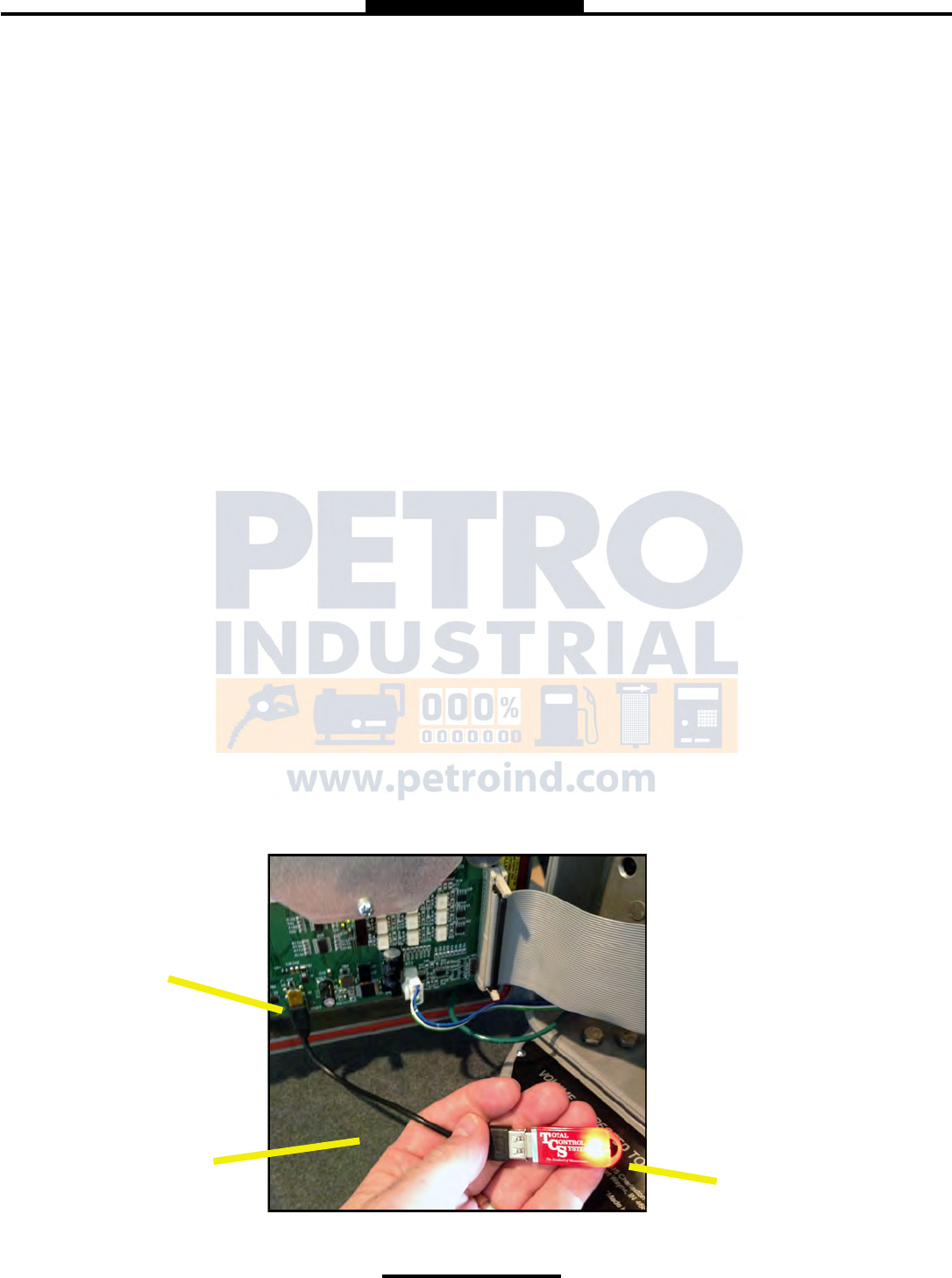
USB Thumb Drive with
communication LED
Mini USB Port
Male Mini USB to
Female USB
—Advanced Functions
LOCK THE SYSTEM
SYSTEM SHUTDOWN
System Shutdown Shuts the TCS3000 down. You must cut power to the TCS 3000 and
reboot to turn the unit back on.
SYSTEM UPDATE
System Update allows you to upgrade the TCS 3000 Software. NOTE: Update process
does NOT change Weights & Measures settings or parameters.
Procedure to upload new software is as follows:
1) Load new software upgrade to a USB thumb drive (dongle).
NOTE: The new software upgrade should be the ONLY file on the drive.
2) Open the TCS 3000 register. On the front cover of the register, there are 2 mini-USB
connections.. Using a factory supplied USB cable, attach the thumb drive to the USB
port closest to the inside of the register. This port is the highest on the circuit board of the two.
See Figure 1.
3) Plug the USB cable into the USB port, and then insert the USB thumb drive into the mating cable
(see Figure 1).
4) Under Advanced Functions, locate System Update and press ENTER.
5) The screen will display System Update, press MODE to continue with the update.
6) If the thumb drive is not recognized or there is a faulty cable, the display will respond with NO
UPDATE DATA error message.
7) Once the file is recognized, the operating system will begin the update process. This should
take approximately 4 minutes.
NOTE: Do not power down or pull USB thumb drive until the TCS3000 tells you to do so.
8) You may remove the USB cable and close the TCS 3000 register once the Update is Complete.
FIGURE 1
28
“Must Know” & How To
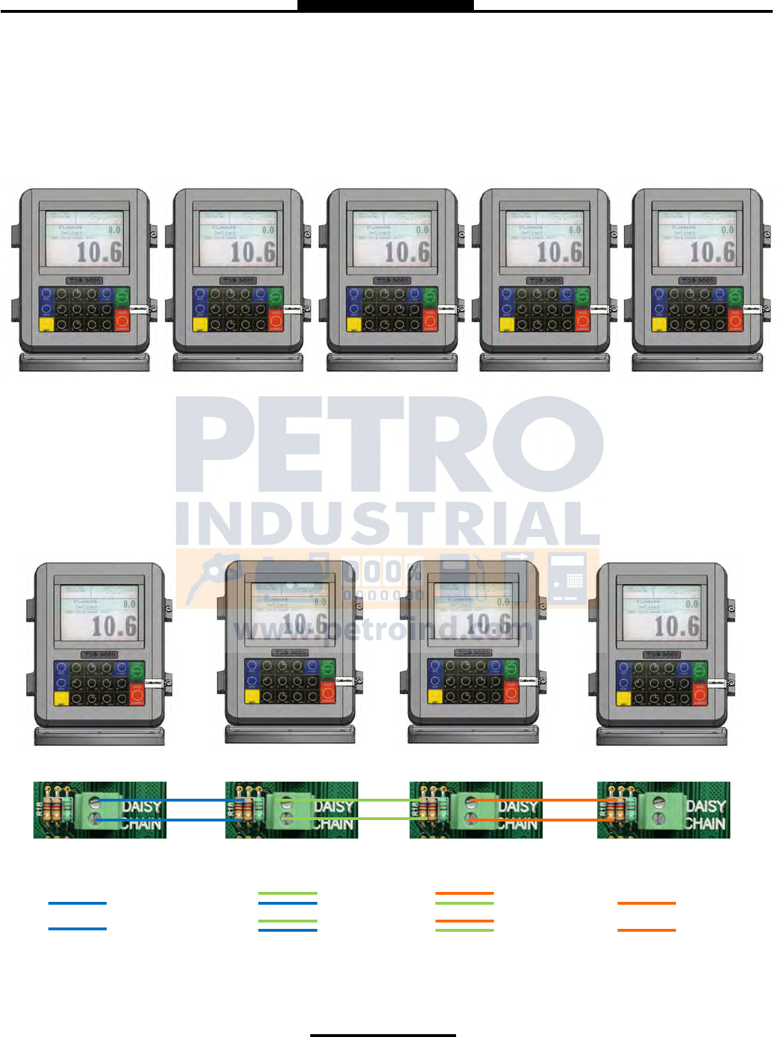
Daisy Chain:
Daisy Chain is used for linking mulple registers together to use one printer or to link mulple registers to the data-
base.
To Daisy Chain the Registers use a two wire 22 gauge shielded cable. Nominate one Register to be the Host.
Once you’ve chosen which Register will be the Host the other Registers will be considered the clients. Strip a small
amount of wire and run the wire from slot A and B of DAISY CHAIN on the Host Unit to slot A and B of DAISY CHAIN on
the Client Unit.
To e the Client to the next Client unit on the Daisy Chain, strip a small amount of wire and run the wire from slot A
and B of DAISY CHAIN to slot A and B of the next client’s DAISY CHAIN.
B
A
B
A
B
A
B
A
Host Client 2 Client 3 Client 4
Client 2 will have 4 wires.
B
A
Client 3 will have 4 wires.
B
A
The Last Client will have 2 wires.
B
A
The Host will have 2 wires.
B
A
Connue to Daisy Chain unl you have ed the chain together, alternang slots on the Daisy Chain unl you’ve
reached the end of the chain. The Host and the last Client on the chain will be the only two registers on the chain to
have a one wire connecon.
Installaon Procedure—Daisy Chain

29
“Must Know” & How To
Daisy Chain for the Printer
Connect the Printer to the Host Register. To set the Host :
Enable the Printer:
SYSTEM MENU → SYSTEM SETTINGS → PRINTER SETTINGS → ENABLE/DISABLE PRINTER → ENABLE PRINTER
Select the Printer:
PRINTER SETTINGS → SELECT PRINTER → [SELECTED PRINTER] → ENABLE
Selecng the Host Register
Select Register as Host:
PRINTER SETTINGS → DISABLE/ENABLE HOST → ENABLE
Select the Client Range:
PRINTER SETTINGS → PRINTER HOST → CLIENTS ADDRESS RANGE → CLIENTS RANGE START ADDRESS [ Enter 2 and
Select] →
CLIENTS RANGE END ADDRESS [ Enter the number of Registers on the Chain and Select]
*Please Note the Host is always # 1. The Client always starts at #2*
Selecng the Client Register
*If you are not using the Daisy Chain for the Printer Please Disregard the Enabling and Selecng the Printer Steps.
Enable the Printer:*
PRINTER SETTINGS → ENABLE/DISABLE PRINTER → ENABLE PRINTER
Select the Printer:*
PRINTER SETTINGS → SELECT PRINTER → [REMOTE] → ENABLE
SYSTEM SETTINGS → CONNECTIVITY SETTINGS → NETWORK SETTINGS → ADDRESS → DEVICE ADDRESS [Select the
number of the unit you are using ex. 2 if it is the second register on the chain or 3 if it’s the third register on the chain.]
To Connect to the Chain:
SYSTEM SETTINGS → CONNECTIVITY SETTINGS → NETWORK SETTINGS → INTERFACE BRIDGE [Only used when there
are 2 Registers ed in the chain] → TRANSFER DATA BETWEEN RS232 <-> RS485 INTERFACES ENABLED
Connue the Selecng Client Register steps for every Client on the Chain.
You may only use the Daisy Chain on ve devices at a me. You may not Chain more than ve devices together.
30
“Must Know” & How To
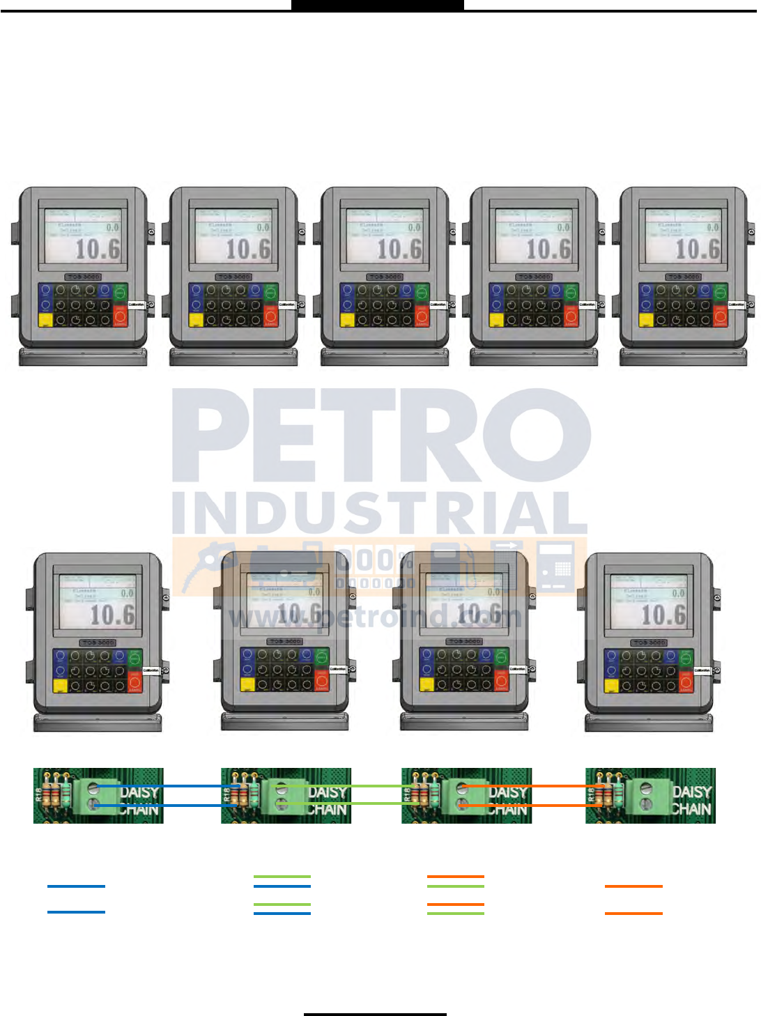
Daisy Chain:
Daisy Chain is used for linking mulple registers together to use one printer or to link mulple registers to the data-
base.
To Daisy Chain the Registers use a two wire 22 gauge shielded cable. Nominate one Register to be the Host.
Once you’ve chosen which Register will be the Host the other Registers will be considered the clients. Strip a small
amount of wire and run the wire from slot A and B of DAISY CHAIN on the Host Unit to slot A and B of DAISY CHAIN on
the Client Unit.
To e the Client to the next Client unit on the Daisy Chain, strip a small amount of wire and run the wire from slot A
and B of DAISY CHAIN to slot A and B of the next client’s DAISY CHAIN.
B
A
B
A
B
A
B
A
Host Client 2 Client 3 Client 4
Client 2 will have 4 wires.
B
A
Client 3 will have 4 wires.
B
A
The Last Client will have 2 wires.
B
A
The Host will have 2 wires.
B
A
Connue to Daisy Chain unl you have ed the chain together, alternang slots on the Daisy Chain unl you’ve
reached the end of the chain. The Host and the last Client on the chain will be the only two registers on the chain to
have a one wire connecon.
Installaon Procedure—Daisy Chain Modem

31
Selecng the Host Register
Select Register as Host:
PRINTER SETTINGS → DISABLE/ENABLE HOST → ENABLE
Select the Client Range:
PRINTER SETTINGS → PRINTER HOST → CLIENTS ADDRESS RANGE → CLIENTS RANGE START ADDRESS [ Enter 2 and
Select] →
CLIENTS RANGE END ADDRESS [ Enter the number of Registers on the Chain and Select]
*Please Note the Host is always # 1. The Client always starts at #2*
Selecng the Client Register
Enable the Printer:*
PRINTER SETTINGS → ENABLE/DISABLE PRINTER → ENABLE PRINTER
Select the Printer:*
PRINTER SETTINGS → SELECT PRINTER → [REMOTE] → ENABLE
SYSTEM SETTINGS → CONNECTIVITY SETTINGS → NETWORK SETTINGS → ADDRESS → DEVICE ADDRESS [Select the
number of the unit you are using ex. 2 if it is the second register on the chain or 3 if it’s the third register on the chain.]
To Connect to the Chain:
SYSTEM SETTINGS → CONNECTIVITY SETTINGS → NETWORK SETTINGS → INTERFACE BRIDGE [Only used when there
are 2 Registers ed in the chain] → TRANSFER DATA BETWEEN RS232 <-> RS485 INTERFACES ENABLED
Connue the Selecng Client Register steps for every Client on the Chain.
You may only use the Daisy Chain on ve devices at a me. You may not Chain more than ve devices together.

32
Real Time Inventory How To Manual Inventory How To
Real Time Inventory is for Automac Tank Levels Only
Add Inventory:
While holding Shi select Mode → System Menu → Product
Sengs → Inventory → Add Inventory →GIVE INVENTORY
NAME (Use the Keypad to assign a name, ex. Av Gas, Gasoline,
Tank 1, Tank 2, etc.) → Select Unit Volume (Gallons, Liters) →
ENTER CAPACITY (Tank Size) → ENTER INVENTORY (Actual
Known Inventory) → Press Any Key to Connue
Assign Inventory:
Assign Inventory → Select an Acve Product → Assign the
Acve Product to an Inventory List → Press Any Key to Connue
*Please Note You can apply mulple inventories to one meter.*
Update Inventory:
Update Inventory → Level Meter → Select CH# (Ex. If Product
1 is ed to CH2, then you select LVL2) →
Inventory Update Message → Press Any Key to Connue
*Please Note: Use CH2-6*
*Also Note: Level Meter will only update when there is no
movement.*
To Check the Changes:
Update Inventory → Level Meter →The LVL# you selected
should be highlighted.
*If you enter into this screen and None is highlighted, then the
unit does not see the circuit board or the Madison Gauge.
A cket will generate if a printer is set up.
Remove Inventory:
Remove Inventory → Select Inventory → Press Mode to Con-
rm
Print Inventory Report:
View Inventory → Print Inventory Report
Bill of Lading:
Once you have nished in Inventory, select STOP/CANCEL →
ENTER BILL Nr. → START/ENTER
Add Inventory:
While holding Shi select Mode → System Menu → Product
Sengs → Inventory → Add Inventory →GIVE INVENTORY
NAME (Use the Keypad to assign a name, ex. Av Gas, Gasoline,
etc.) → Select Unit Volume (Gallons, Liters) → ENTER CAPACITY
(Tank Size) → ENTER INVENTORY (Actual Known Inventory) →
Press Any Key to Connue
Assign Inventory:
Assign Inventory → Select an Acve Product → Assign the Ac-
ve Product to an Inventory List → Press Any Key to Connue
*Please Note You can apply mulple inventories to one meter.*
Update Inventory:
Update Inventory → ADD To Inventory → ENTER AMOUNT
(Amount added to tank)
Set Inventory Value → ENTER CURRENT VALUE (Current
amount of product in the tank)
Fill Up Inventory → Press Any Key to Connue (Resets
Inventory to full capacity)
Empty Inventory → Press Any Key to Connue (Zero’s out tank
amount)
Remove Inventory:
Remove Inventory → Select Inventory → Press Mode to Con-
rm
Print Inventory Report:
View Inventory → Print Inventory Report
Bill of Lading:
Once you have nished in Inventory, select STOP/CANCEL →
ENTER BILL Nr. → START/ENTER
Inventory Short Cut
In the Delivery Screen:
Hold down SHIFT and select PRINT (while holding Shi)
You can enter inventory through the short cut only aer you’ve
set up and assigned inventory.
*Please note, you must End Shi before you may Add or Remove Inventory*
Color Guide: Blue: Operang Volume Yellow: 25% Cauonary Volume Red: 10% Low Volume
33
“Must Know” & How To
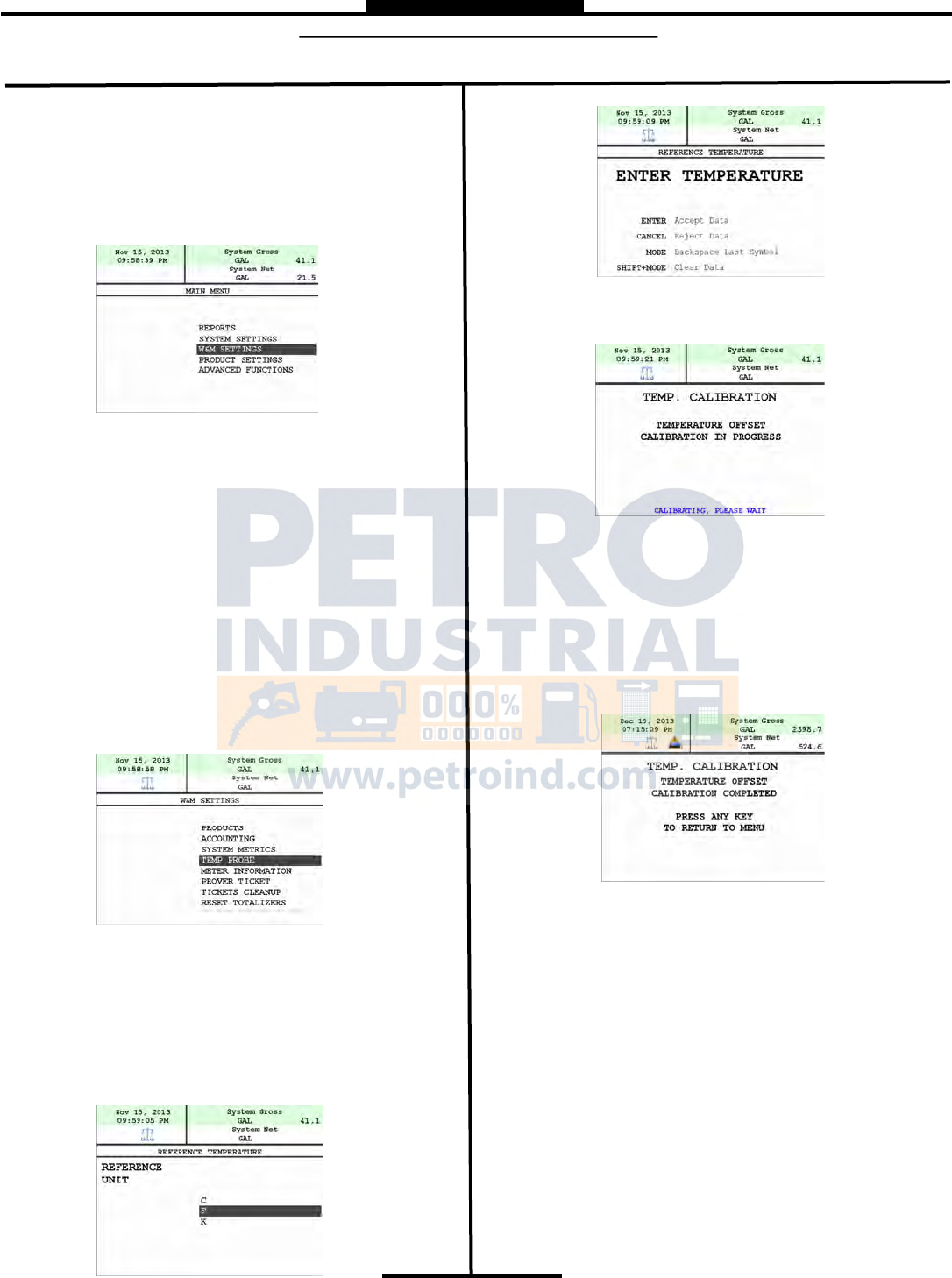
TEMPERATURE PROBE CALIBRATION HOW TO
* The following is based on product(s) you have calibrated. You must select the compensaon table and the temperature unit for
the product when Calibrang your product in order to Calibrate Temperature.*
Press Shi and Mode to enter the Select Funcon
Screen.
Use the arrow keys to highlight SYSTEM MENU and
Select START/ENTER.
*Remove the Calibraon Bolt and set in a safe locaon.*
Use the arrow keys to highlight W&M SETTING.
Select START/ENTER.
Use the arrow keys to highlight your product. Select
START/ENTER.
Use the arrow keys to highlight PRODUCT TEST RUN.
Select START/ENTER.
Use the arrow keys to highlight your product. Select
START/ENTER.
Use the arrow keys to highlight TEMP PROBE select
START/ENTER.
Selecng TEMP PROBE will take you to Oset Calibraon
Press START/ENTER
(You are now calibrang the TCS3000 Register Temperature
Probe to the Weights and Measures Temperature Probe)
Use the arrow keys to highlight the Reference Temperature
select START/ENTER.
*Note: You will want to take 3 temperature readings during a
run to get the average temperature.
Enter the Average Temperature Select START/ENTER
*Note: The register will display that it is calibrang and is apply-
ing the correcons. It will take a minute to calibrate the RTD
Probe to the Weights & Measures Probe.
When Calibraon is done the Register will display the following
message:
Repeat the steps if necessary.

34
Trouble Shooting
NOTICE DANGER
It may be necessary to break Weights & Measure seals to
perform certain troubleshooting steps in this guide. Con-
tact your supervisor or local Weights & Measures authori-
ties for information before breaking any seals.
Serious Injury or Death may Result – Fire, Explosion, and
Electrical Shock Hazard.
Only trained and authorized personnel should perform
troubleshooting. Use extreme caution when troubleshoot-
ing and taking all electrical measurements. Be sure that
equipment is in a well ventilated area and that hazardous
or flammable vapors are not and will not be present dur-
ing testing. If equipment is located in a hazardous envi-
ronment, it may be necessary to remove the equipment
and perform troubleshooting in a safe area.
Trouble Shooting
To comply with Weights & Measures requirements, it is necessary to start and stop each delivery with a fully packed
hose. Normally, this will be the case. However, there are times where the hose is not fully packed (e.g. after a preset
delivery). As such, the hose must be packed and the register zeroed prior to making the next deliver.
NOTE: This procedure will not work for an empty or dry hose. If more than 1 gallon or 5
Liters of liquid is required to pack the hose, a delivery ticket must be printed.
To pack the hose at the start of a delivery:
Press the Start Button, this energizes the solenoids. Allow the pump to pack the hose.
TCS 3000 Trouble Shooting Guide
The TCS3000 troubleshooting guide covers most common problem situations. Call your Total Controls Service Center
for any problems that are not covered in this guide.
Trouble Shooting Guidelines:
1) Before attempting to troubleshoot the TCS 3000 system, become familiar with the operation and set-up of the specific
installation.
2) Make sure all electrical connections are secure and tight.
3) Make sure all terminal blocks are firmly connected.
4) ALWAYS use a good digital multimeter. Voltage levels are critical to proper system operation. Use an accurate,
reliable multimeter to test for proper voltages at the start of any service procedure. Voltage requirements are listed
under each component.
NOTE: Check for proper operating voltages before changing the circuit board. If the circuit board needs to be
changed, be sure to remove all power to the TCS 3000.
5) If an error occurs during a delivery, the message will appear on the Display and print on the delivery ticket. The
delivery ticket will print an error message that can be useful in troubleshooting. This ticket will automatically print.
Examine the prover ticket to make sure all set-up fields are accurate, e.g. pulses per unit volume, temperature
coefficient, and base temperature.
6) NEVER remove a terminal block or jumper with the power on.
7) NEVER install a terminal block or jumper with the power on.

35
Trouble Shooting
8) NEVER force a terminal block into its location.
9) NEVER exchange or reposition terminal blocks on the circuit board.
10) In case of a major problem such as a burned or water-damaged circuit board, evaluate possible causes before
replacing it and turn the power back on.
11) Isolate the problem before changing the circuit board.
12) Return faulty circuit boards with the proper forms, concisely completed.
There may be several probable causes for a system malfunction. Listed on the next 3 pages are several probable caus-
es to aid in returning the system to operation as quickly as possible. The list is not all-inclusive and should only be used
as a guide.
PROBLEM PROBABLE CAUSE SOLUTION
Unit will not
power up or
there is no
display
Inadequate supply
voltage. +9 to 28
VDC is required for
operation
1. With the key in the accessory position, check the battery voltage to the circuit
board. Use the negative terminal as DC ground. While the TCS 3000 will
power-up at +9VDC, it is recommended that the input be at least +12.6VDC.
2. Check the 7.5A, in-line fuse for continuity. It is located in the accessory power
line. Replace if necessary.
3. If the green light blinks fast it is doing what it is supposed to, but then it will go
to a slow blink. If you see red, then you do not have enough power on the
register. It must see a minimum of 9vdc.
4. If the red light comes on and the unit doesn’t power-up. Check the voltage if
the voltage is OK but the temperature is -20 this will indicate that the heater is
warming the display to prevent any damage to the VGA display and should
come-up shortly
Unit blow
7.5A Fuse
+12 VDC battery line
is shorted to ground
1. For safety reasons, remove the 7.5A, in-line fuse from the accessory power
cable.
2. Unscrew the 3 pin power connector. Inspect for stray wire strands and
visible shorts.
3. Inspect the full length of the power cable. Look for damaged insulation, which
may cause shorting between the cable and ground potential (e.g. truck frame
or chassis). If the power cable is damaged, it must be replaced.
4. Replace the 7.5A fuse and re-install the wires into the terminal connector.
5. If the 7.5A blows again, then replace the power cable.
6. If the 7.5A fuse blows after replacing the power cable, then replace the TCS
3000 terminal circuit board.

36
Trouble Shooting
PROBLEM PROBABLE CAUSE SOLUTION
Power Fail-
ure appears
on the deliv-
ery ticket
Power to the TCS
3000 interrupted dur-
ing delivery.
Static Discharge
1. Check accessory power cable for damage. Ensure that the power, common
and ground wires on power connector are secure. Located on the right hand
corner of the terminal board
2. Turn on all truck accessories (headlamps, 2 way radio, heater, etc.). Engage
the hose reel and monitor the DV voltage at ## using terminal ## as positive
and terminal ## as ground. If the voltage drops below +10VDC, the truck
electrical system may not be adequate to handle the current load for the TCS
3000. It may be necessary to upgrade the electrical system to accommodate
the 3-amp TCS 3000 current requirements.
3. Verify proper grounding of the TCS 3000. Refer to the TCS 3000 Installation
Manual for proper grounding procedures.
Epson printer
release light
flashes
Low voltage to the
Epson Printer
1. Check the battery voltage for a minimum of +12.6VDC.
2. Under extreme cold conditions, the printer may not operate. Warm up the cab
of the vehicle.
3. If the release light continues to flash, replace the Epson 295 Printer.
No power
indicator
lights to the
Epson Print-
er
No power to the Ep-
son printer
1. Verify that the power switch is in the ON position. This switch is located on
the left-hand side of the Epson 295 Printer.
2. Check the printer power cable to ensure that it is seated properly. If the prob-
lem persists, replace the power cable followed by the Epson printer.
“Temperatur
e Error” ap-
pears on the
TCS 3000
display
Open or shorted cir-
cuit between RTD
probe and the TCS
3000
1. Check the RTD Probe and terminal block for continuity.
2. Remove terminal block Temp Probe from the circuit board. On the terminal
block, measure and record the resistance between the following pins:
PIN READING
Red to White 100 Ω ±20?
3. If the readings are not within the above tolerances, replace the RTD
probe.
Product flow
does not reg-
ister on TCS
3000
Pulser shaft is not
turning with product
flow. Pulse Failure
1. Manually spin the pulser shaft and monitor the TCS 3000 display.
2. If the TCS 3000 displays counter increments, this may indicate a mechanical
problem. Contact your TCS 3000 Service Center for assistance.
3. If the TCS 3000 display counter does not increment, see Pulser Failure.
Pulser Fail-
ure, register
is not reading
gallons or
liters
Missing pulse
counts.
Excessive reversals
Note: Pulser faults
generally occur in a
high vibration envi-
ronment. TCS is not
responsible for puls-
er failures caused by
excessive vibration.
1. Check the pulser output.
2. Open the TCS 3000 cover by loosening the two bolts that hold the cover
closed. Using a reliable multimeter, measure the following DC voltages on
terminal block is connected to the circuit board. Use terminal as ground refer-
ence.
3. TERMINAL PULSER VOLTAGE
+0 VDC
+5 VDC
+3.74 TO 0 VDC TAHA1 WHILE SPININING
+0 TO 3.74 VDC TAHB1 WHILE SPINNING
4 If the following voltages are observed, check for loose pulser wiring connec-
tions. If no loose connections are found, replace the encoder.
5 Insert a ticket into the Epson printer. Begin a delivery. With product flowing
through the meter, measure the following DC voltages on the terminal block.
6 TERMINAL PULSER VOLTAGE
+0 VDC
+5 VDC
+3.74 to 0 VDC TAHA1 WHILE SPINNING
+0 to 3.74 VDC TAHB1 WHILE SPINNING
37
Trouble Shooting
PROBLEM PROBABLE CAUSE SOLUTION
Valve will not
open
Solenoids are inac-
tive or inoperative.
Foreign debris in sys-
tem
1. Insert a delivery ticket into the Epson printer and start a delivery.
2. Start a delivery and listen for the audible clicking sound from the solenoids.
3. If there is NO audible click form the solenoid, check the voltage to Pin +
and 0 V of terminal block Solenoid 1. While the TCS 3000 is still in deliv-
ery, use a reliable multimeter to measure the following DC voltages on the
circuit board. Use 0 pin as a ground or frame ground.
4. If there is an audible click from the solenoid (but still no flow), this may be
an indication of a mechanical problem with the main valve or its associate
components. Contact your TCS3000 Service Center.
TERMINAL SOLENOID 1 for 2 VOLTAGE
9.0 VDC with plug remove VDC
2..0 VDC with solenoid connect
12.0 VDC with the solenoid energized
5. If the above voltages are correct, this may be an indication of a problem
with the valve or its associated components. Contact you TCS 3000 Ser-
vice Center for assistance.
6. If the above voltage are NOT correct, replace the following components
with known working units until the problem is resolved: Solenoids
7. TCS 3000 Circuit Boards
Product has
wrong Name
The Register was
never calibrated or
had the name
changed in W&M
Settings.
Go into prover and calibrate the product or change the Name.
Valve doesn’t
shut off
Valve was never set
up or calibrated
Select the product and calibrated the valve for zero shutoff.
Display is read-
ing in reverse
Channel A and B are
wired backwards
Switch wiring between Channel A and B
Daisy chain
communication
is not working
Network Address of
registers are not in
proper sequence
Host and Client Ad-
dresses are not in
proper sequence
1. Check the RX and TX wiring between registers.
2. Make sure the printer is wired to the primary HOST register.
3. Check the Device Addresses of each register, with the primary HOST as 1
and CLIENTS from 2 to 8.
4. Make sure the primary HOST register has the Client Address Range set to
communicate with all the TCS 3000 registers in the daisy chain.
Totalizers are
incorrect
Product vs. System
Totalizer
Ticket is configured
to show Product To-
talizer instead of Sys-
tem Totalizer
Net vs. Gross
Totalizer
1. The Product Totalizer was not reset when the System Totalizer was reset
to zero.
2. The ticket is configured to print the Product Totalizer instead of the System
Totalizer, or visa-versa.
3. The ticket is configured to print the Net Compensated Totalizer instead of
the Gross Uncompensated Totalizer, or visa-versa.
Cant begin a
delivery be-
cause the
screen reads
“Delivery Not
Completed”
Last delivery had the
printer enabled, but
the ticket had not
printed.
The delivery ticket must be printed when the printer is communicating with the
TCS 3000. To move on without the printer, either disable the printer or have
the Select Printer changed to None under Printer Settings. You will be able to
Re-print Tickets under the Select Function.

38
“Must Know” & How To
Start Up “Must Knows” for Setup Configuration & Calibration
1) Each Product must be thoroughly configured and calibrated in W&M Settings. There are many parameters that need
to be configured to ensure your system operates properly. Failure to complete the Product Configuration may result
in the TCS3000 to not function correctly.
2) Products that have been calibrated may appear either as an Active or Inactive Product. The TCS 3000 must have at
least 1 Active Product in order to Begin a Shift and Start a Delivery. Products may only be Activated or Deactivated
after a Shift has Ended.
3) The Calibration Screw must be threaded completely into the Calibration setting, or you will not be able to begin a
shift or start a delivery.

39
Warranty Information
—Warranty Information
WARRANTY
New 3000 electronic registers, equipment or components manufactured by Total Control Systems, a division
of Murray Equipment, Inc. (TCS) with which this warranty is enclosed, are warranted by TCS to the original
purchaser only for a period of TWELVE (12) months from installation or eighteen (18) months from the date of
shipment, to be free, under normal use and service, from defects in material and workmanship.
Defects occurring within the stated warranty period, TCS will repair or replace, at TCS’s option; provided that
part or parts are returned to TCS transportation charges prepaid, and TCS’s examination discloses the parts
or workmanship to have been defective upon delivery to the purchaser.
EXCLUSIONS
Warranty does not cover any parts and equipment not manufactured by TCS, but these items may be covered
by separate warranties of their respective manufacturers. This warranty does not extend to any equipment
that has been subjected to misuse, negligence or accident or if operated in any manner other than in accord-
ance with TCS’s operating instructions and specifications.
CLAIM PROCEDURES
In order to obtain performance by TCS of its obligations under this warranty, the original purchaser must ob-
tain a Return Goods Authorization (RGA) number from TCS’s customer service department within 30 days of
discovery of a purported breach of warranty, but not later than the expiration of the warranty period. Once
authorization is received, return the defective meter, piece of equipment, or component covered by this war-
ranty, with transportation charges prepaid, to TCS at the address shown below together with a written state-
ment setting forth the nature of the defect and RGA number.
LIMITATIONS
THERE ARE NO OTHER WARRANTIES OF ANY KIND, EXPRESS OR IMPLIED. TCS SPECIFICALLY DIS-
CLAIMS ANY WARRANTY OF MERCHANTABILITY OR OF FITNESS FOR ANY PARTICULAR PURPOSE.
TCS will determine if all parts or meter defect falls within the warranty guidelines and will repair or replace
within a reasonable time span. TCS is not responsible for any in or out bound freight. TCS's sole obligation
that shall represent the buyer's sole and exclusive remedy shall be to repair or at TCS's option to replace any
product or part determined to be defective. In no event shall TCS be liable for any special, direct, indirect, inci-
dent, consequential or other damages of similar nature, including without limitation, loss of profits, products,
production time, or loss of expenses of any nature incurred by the buyer or any third party. TCS has not au-
thorized on its behalf any representation or warranties to be made, nor any liability to be assumed except as
expressly provided herein; there is no other express or implied warranty.
DESIGN AND EQUIPMENT CHANGES
Any changes in design or improvements added shall not create any obligation to install same on equipment
previously sold or ordered.

2515 Charleston Place
Fort Wayne, IN 46808
Toll Free: (800) 348-4753
Phone: (260) 484-0382
Fax: (260) 484-9230
Email: sales@tcsmeters.com
Website: www.tcsmeters.com
TCS900040 REV. 7
2/24/15

PETRO Contact Information
AFRICA
South Africa
Factory 1 - 16 Bentonite Street
Alrode, Alberton, Johannesburg
South Africa
P: +27 (0)11 864 7758
F: +27 (0) 11 864 1649
E: sales@petroindustrial.co.za
AUSTRALIA
Eastern Australia
Factory 2, 106 Potassium Street
PO Box 407
Narangba QLD 4504
P: 07 3204 9558
F: 07 3293 4852
E: sales@petroindustrial.com.au
Western Australia
2 Competition Way
Wangara WA 6065
P: 08 6305 0855
F: 08 6305 0319
E: saleswa@petroindustrial.com.au
CANADA
Alberta
Bay A, 233175 Range Road 283
Rocky View, AB T1X 0J9
PO Box 75148
Calgary Alberta T3H 3M1 Canada
P: +1 403 998 7190
TOLL FREE: 1855 44 PETRO
F: +1 403 770 8065
E: sales@petroind.ca
UAE
Dubai
Oce LB17330, Lobby Building 17
Jebel Ali Free Zone
PO Box 18602
Dubai, United Arab Emirates
P: +971 488 76688
F: +971 488 76932
E: salesuae@petroind.com
P
E
T
R
O
petroind.com
