1 Page Soundstream Picasso PCA Class D Series Amp Manual
User Manual: Soundstream Picasso PCA Class D Series Amp Manual Troubleshoot Soundstream Picasso PCA Class D Series Amp |
Open the PDF directly: View PDF ![]() .
.
Page Count: 15
- 10 page [Converted].pdf
- 11 page [Converted] copy.pdf
- 12 page [Converted] copy.pdf
- 13 page [Converted] copy.pdf
- 14 page [Converted] copy.pdf
- 15 page [Converted].pdf
- 2 page [Converted].pdf
- 3 page [Converted].pdf
- 4 page [Converted].pdf
- 5 page [Converted].pdf
- 6 page [Converted].pdf
- 7 page [Converted] copy.pdf
- 8 page [Converted] copy.pdf
- 9 page [Converted].pdf
- cover page1 [Converted].pdf

PCA1000D / 1500D / 2000D / 3500D
OWNER'S MANUAL

TROUBLE SHOOTING 14
ADJUSTING & TUNING 13
PLANNING & MOUNTING YOUR SYSTEM 10
WIRING DIAGRAM 11 ~12
CONTROLS & FUNCTIONS
FEATURES & SPECIFICATIONS
TABLE OF CONTENTS
INTRODUCTION 2
3
4 ~ 9
TABLE OF CONTENTS
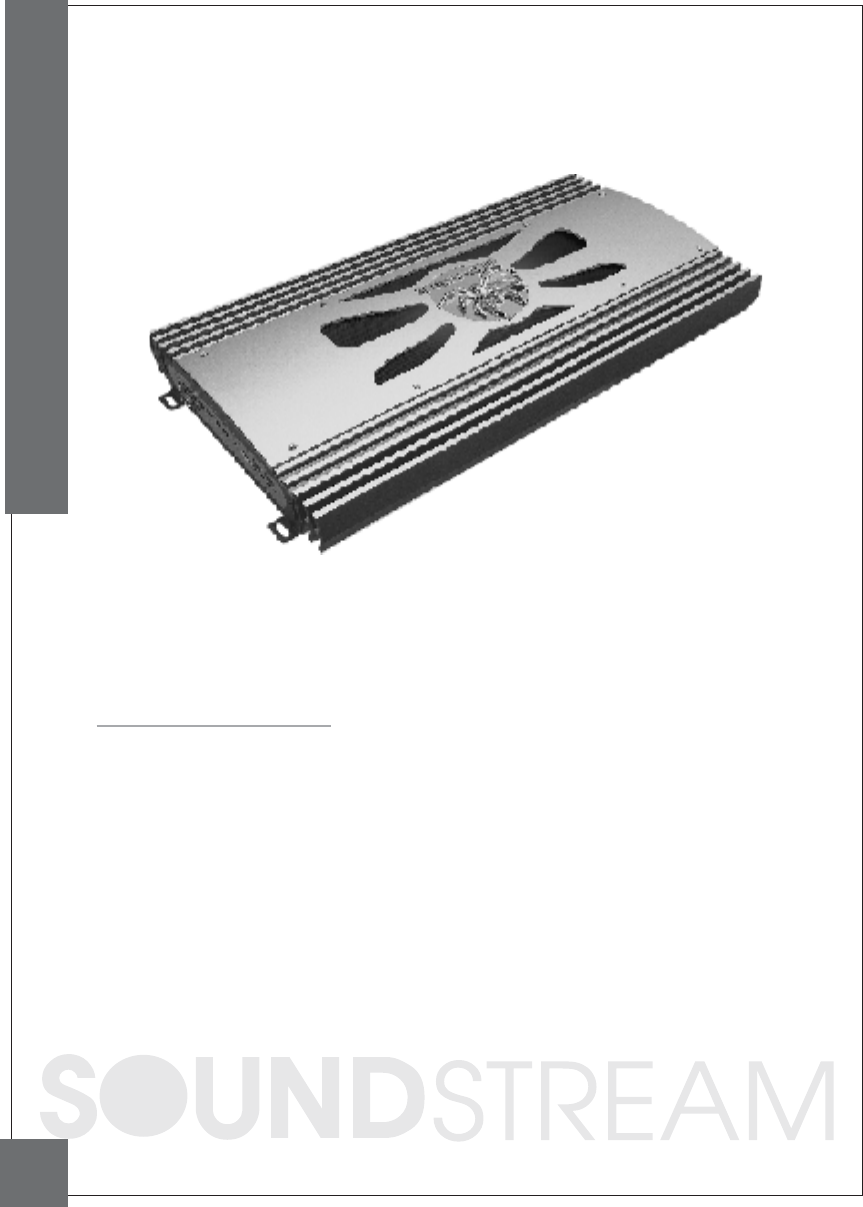
INTRODUCTION
Amplifie r's provide hig h-p e rforma nc e sound re info rc e me nt for you'r
mobile a ud io e quip me nt. The Multi-Mode brid g ing c a pa bilitie s a llow
fle xibility in hosting se ve ra l d iffe re nt spe a ke r c onfig ura tions.
To a c hieve optimum pe rforma nc e, it is highly rec ommende d tha t you re a d
this Owners Ma nua l before beginning insta lla tion.
2
INTRODUCTION
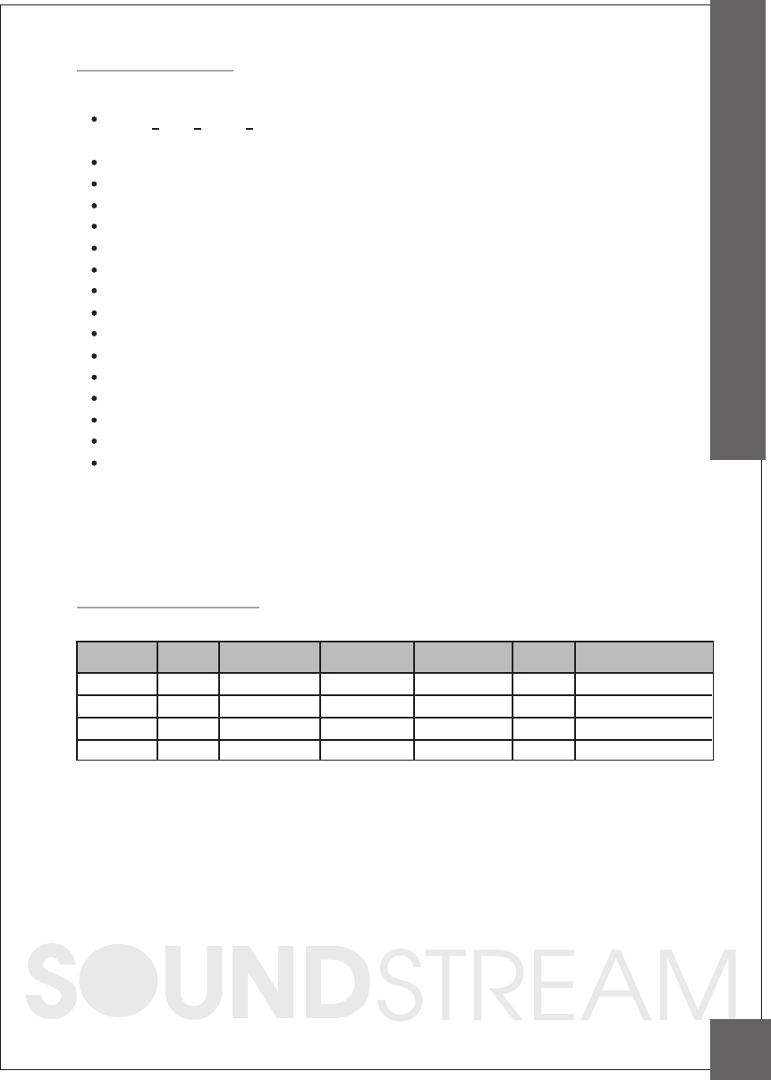
FEATURES
Specifications
TST (Twin Sta c k Te c hnolo g y)2 a mp lifie r's to d rive
o ne vo ic e c o il, e ffe c tive ly d o ub ling the p o we r.
C la ss D c irc uitry
1 O hm sta b le
Hig h q ua lity FR-4 c irc uit b oa rd
C o ntinuo usly va ria b le lo w-p a ss filte r : 5 0 Hz to 1 5 0 Hz (2 4 d B slo p e s)
C o ntinuo usly va ria b le sub so nic filte r : 15 Hz to 4 0 Hz (2 4 d B slo pe s)
Sub wo o fe r e q ua lize r c o ntro l : 0 ~ + 1 8 d B
Va ria b le p ha se shift c o ntro l : 0 ~ 18 0 d e g re e
Fre q ue nc y re sp onse : 15Hz-1 5 0 Hz
Pla tinum RC A inp uts a nd o utp uts
Inp ut se nsitivity : 2 0 0mV-8 V
O EM floa ting g ro und inp ut
Pla tinum 4 -g a ug e p owe r c o nne c to rs
S/N Ra tio : 1 0 0d B
0 . 3 0% THD
Inc lud e s PC A-RM re mo te b a ss c o ntro l
™
MODEL
CHANNEL
RMS @ 4 OHM
@ 2 OHM @ 1 OHM FUSES DIMENSIONS
PCA1000D
1500D
00D
PCA3500D
PCA
PCA20
1
1
1
1
500W x 1
800W x 1
1100W x 1
2500W
Ch
Ch
Ch
x 1Ch
800W x 1
1100W x 1
1500W x 1
300
Ch
Ch
Ch
0W x 1Ch
1000W x 1Ch
1500W x 1
2000W x 1
350
Ch
Ch
0W x 1Ch
30A x 3
30A x 4
None
11" x 2.6" x 12.6"
11 x 15"
11 x 17.7"
11.1
" x 2.6"
" x 2.6"
" x 2.8" x 20.9"
None
3
FEATURES & SPECIFICATIONS
Controls & Functions
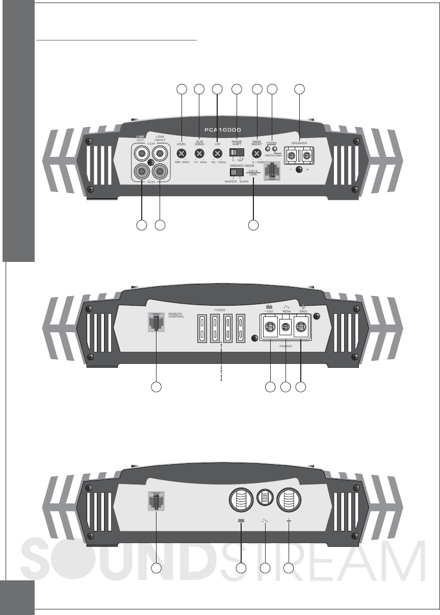
PCA1000D / 1500D / 2000D FRONT
PCA1000D / 1500D REAR
14 10 11 12
PCA1000D: 30A X 3
PCA1500D: 30A X 4
4
CONTROLS & FUNCTIONS
7 68
1 5 2 4 39 13
PCA2000D REAR
REMOTE
CONTROL
POWER
REM GND+12v
14 10 11 12
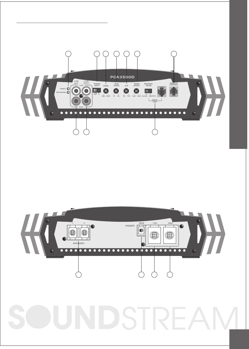
Controls & Functions
PCA3500D REAR
13 1011 12
CONTROLS & FUNCTIONS
5
PCA3500D FRONT
76
8
1 5 24 39 14
L E VE L
M IN M A X
1. Input Level Adjustment
This c ontrol a djusts the a mplifie r's input sensitivity. Input se nsitivity is va ria ble from
200 Millivolts to 8 volts. C loc kwise inc rea se s sensitivity. C ounte rc loc kwise dec re a ses
sensitivity. The a mplifier c a n be driven to full power with a wide ra nge of signa l leve ls.
A lower signa l leve l will re quire inc rea sed sensitivity for full power. A higher signa l leve l
will require de c re a se d se nsitivity. Avoid setting se nsitivity lower tha n ne c essa ry a s this
would introduc e unwa nted distortion.
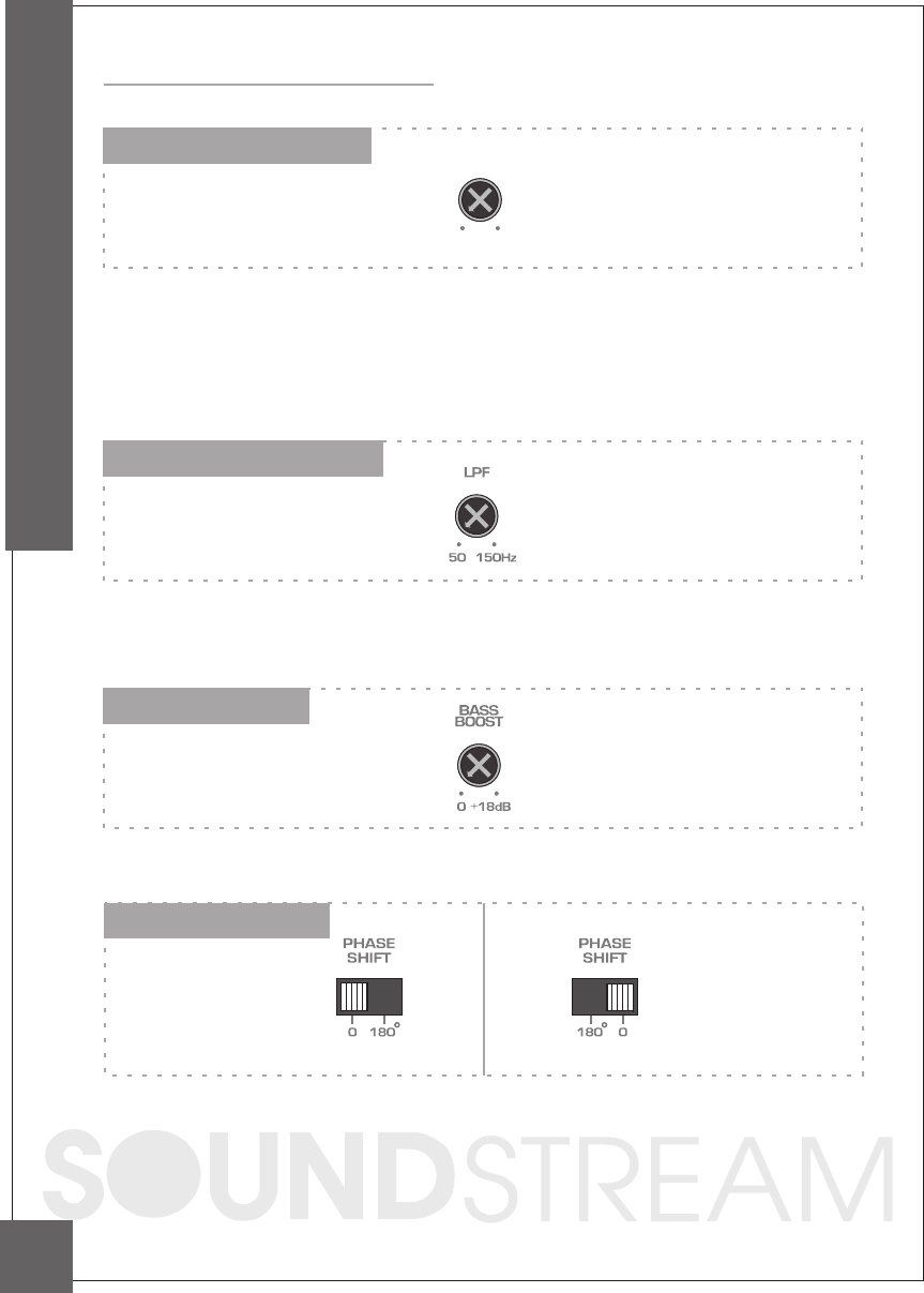
2. Low Pass Filter Control
This c ontrol is used to set the desired low pa ss fre quenc y (50 ~ 150HZ).
The filter a c ts to c ut-off fre quenc ies a bove the set-point. In ge nera l, the selec ted
frequenc y should c losely ma tc h the resona nt frequenc y of the spe a ker box.
Controls & Functions
3. Bass Boost Control
By using the bass boost function, bass notes at 35Hz - 80Hz are emphasized as much
as 18dB.
4. Phase Shift Control
PHASE SHIFT SWITC H (0 AND 180 DEG REES):
Allows you to c ha ng e the pha se of your subwoofe r from 0 to 180 de g re e s to he lp
c ompe nsa te for timing d iffe re nc e s be twe e n d rive rs.
6
6
CONTROLS & FUNCTIONS
PCA1000D/1500D/2000D PCA3500D
Controls & Functions
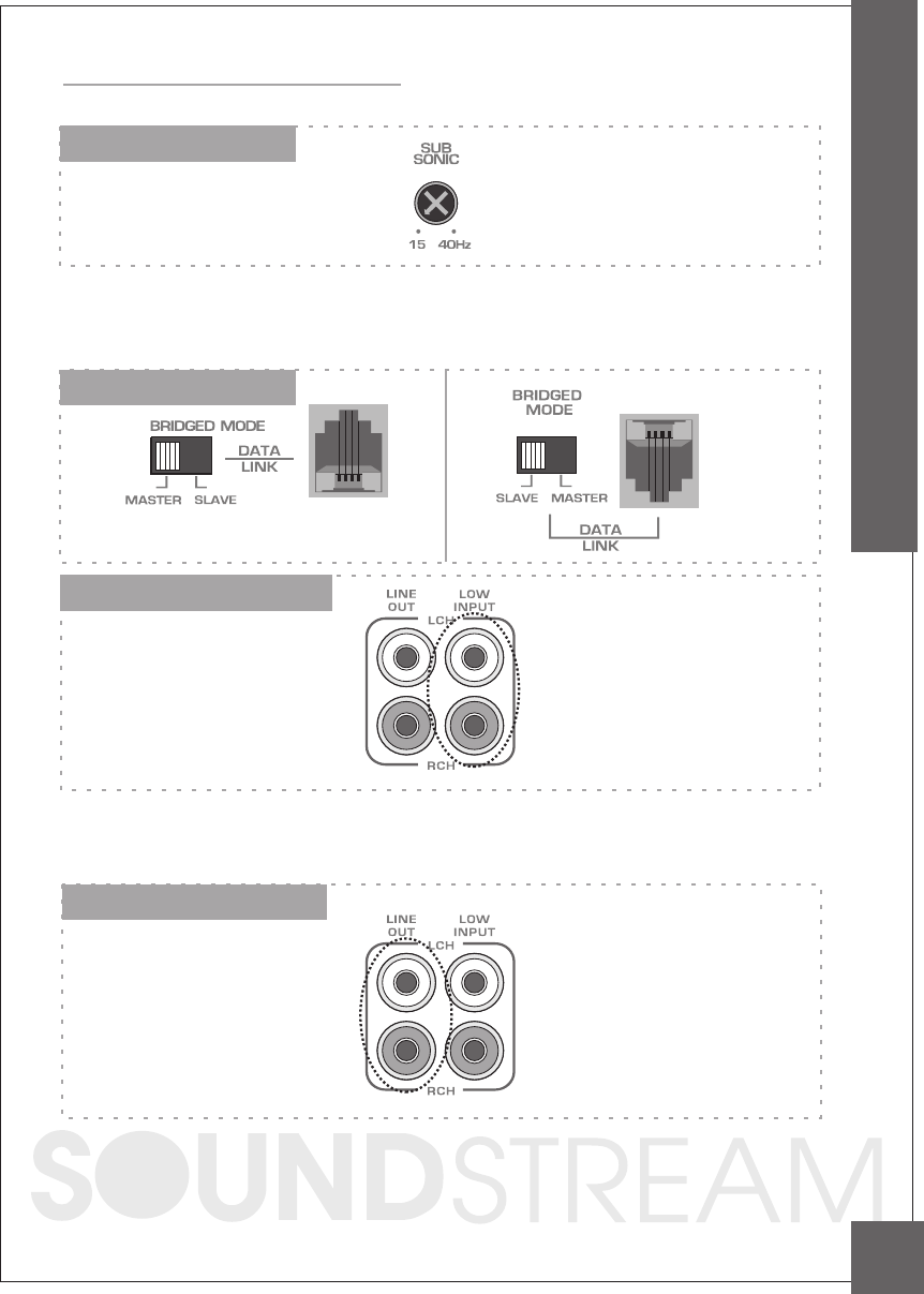
5. Subsonic Filter Control
Variable Subsonic Filter (15Hz - 40Hz) :
The Subsonic filter will roll off all of the unwanted frequencies below 15Hz - 40Hz.
This will allow the amplifier to use that wasted power on the audible bandwidth.
6. Bridged Mode Switch
7. Low Level Input RCA jacks
These inputs a re for signa l c a bles from the sourc e. Alwa ys use high qua lity shielded
RC A c a bles.
8. Low Level OUT RCA jacks
The LINE OUT a llows you to build multiple a mplifier syste ms without ha ving to use splitter
c ords to distribute the signa l. Now it is simply a ma tter of bringing one set of RC AS into
the first a mplifier, then using the line out RC A ja c ks a s the feed to the next a mplifier.
7
CONTROLS & FUNCTIONS
7
PCA1000D/1500D/2000D PCA3500D
Controls & Functions
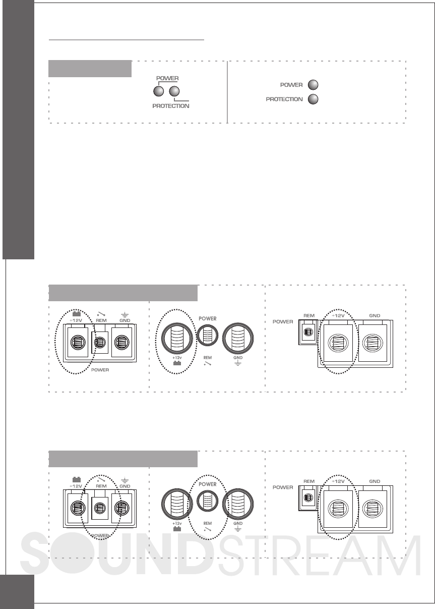
10. B+ Terminal (Battery positive)
Due to the power requireme nts of the Amplifie r, this c onnec tion should be ma de
direc tly to the positive (+ ) te rmina l of ba tte ry. For sa fety me a sure, insta ll a n in-line
fuse Holde r (not inc lud e d) a s c lose to the ba tte ry positive (+ ) te rmina l a s possible with
a n a mpe re ra ting ; not to e xc eed tota l va lue of fuse s in Amp.
9. LED Indicator
PWR(Powe r): This G REEN LED will illumina te whe n the a mp lifie r is turne d "O N". If it fa ils
to illumina te , c he c k the p owe r c onne c tions to the Amp lifie r a nd fuse s.
PROT(Protec tion): The a mplifier protec tion c irc uitry will disa ble the a mplifier if input overloa d,
short c irc uit or e xtremely high tempera ture c onditions a re detec ted. When the protec tion
mode is in ope ra tion, the LED indic a tor on the side pa nel will be illumina ted, indica ting the
a mplifier ha s gone into a self-preserva tion mode.
If you observe tha t the Protec tion LED is lit, plea se c hec k the system c a refully to determine
wha t ha s c a used the protec tion c irc uit to enga ge. The a mplifier c a n be reset by turning the
remote power off a nd then on a ga in. If the a mplifier shut down due to a therma l overloa d
c ondition, plea se a llow it to c ool down before resta rting. If the a mplifier shut down bec a use
of a n input overloa d or short c irc uit, be sure to repa ir these c onditions before a ttempting to
power up the a mplifier a ga in.
11. Remote Power On
8
CONTROLS & FUNCTIONS
PCA1000D/1500D PCA3500D
PCA2000D
PCA1000D/1500D PCA3500D
PCA2000D
PCA1000D/1500D/2000D PCA3500D
REMOTE
CONTROL
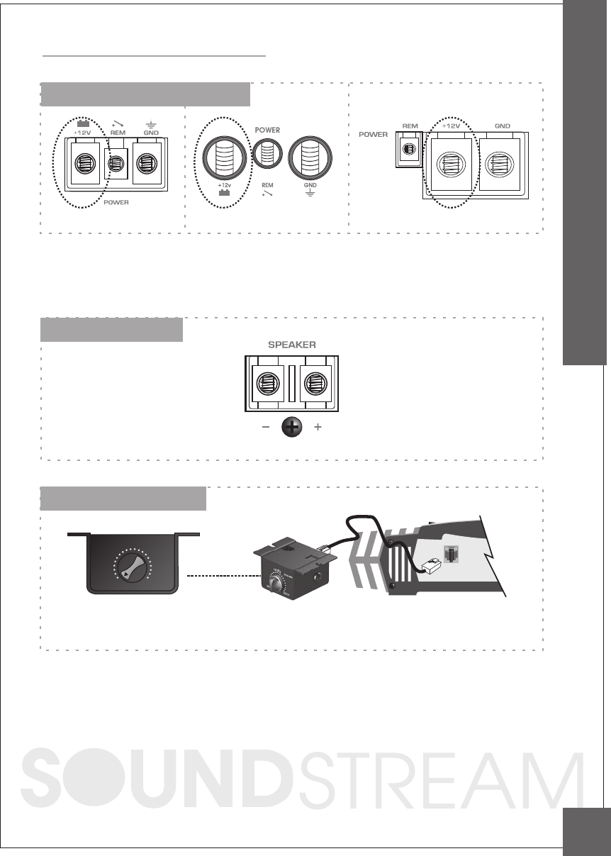
To a void unwa nted ig nition noise c a use d by ground loops, it is e sse ntia l tha t the
Amplifie r b e g round e d to a c le a n, b a re, me ta l surfa c e of the ve hic les c ha ssis.
Note : G RO UND WIRE SHO ULD NO T BE EXTENDED M O RE THAN 3 FT (1 METER).
13. Speaker terminals
Controls & Functions
14. Remote Control Input
LEVEL
MAXMIN
Remote Bass Boost Control : PCA-RM
Remote Bass Boost Control : This control adjusts the Bass Boost gain for the amplifier's
speaker output (0 ~+18dB)
PCA-RM
PCA-RM
12. B- Terminal (Chassis ground)
CONTROLS & FUNCTIONS
9
PCA1000D/1500D PCA3500D
PCA2000D

Planning and Mounting Your System
The mounting position of your Amplifier will ha ve a grea t effec t on its a bility to
dissipa te the he a t genera ted during norma l ope ra tion.
Unde r norma l c onditions, the hea tsink will dissipa te suffic ient he a t to a void the rma l
shutdown. However plea se do not insta ll the a mplifie r in a wooden box or simila r
de vic e a s this will preve nt hea t dissipa tion into the a tmosphe re.
Te mp e ra ture s in c a r trunks ha ve be e n me a sure d a s hig h a s (155'F) in the summe r
time . sinc e the the rma l shut-d o wn p oint fo r the a mp lifie r is (1 5 8 'F) it is e a sy to
se e tha t it must b e mo unte d fo r ma ximum c ooling c a pa b ility. To a c hie ve
ma ximum a d va nta g e of c onve c tio n a ir flow in a n e nc lo se d trunk, mount the
a mp lifie r in a horizonta l position.
Cooling requirements are considerably relaxed when mounting inside the passenger
compartment since the driver will not often allow temperatures to reach a critical
point. Floor mounting under the seat is usually satisfactory as long as there is at least
1 inch of clearance (2.54 cm) above the Amplifier's fins for ventilation.
A. Select a suitable location that is convenient for mounting, is accessible for wiring.
And has ample room for air circulation and cooling.
B. Use the amplifier as a template to mark the mounting holes. Remove the Amplifier
and drill holes. Use extreme caution, inspect underneath surface before drilling!
C. Secure the Amplifier using the screws provided.
10
PLANNING & MOUNTING YOUR SYSTEM
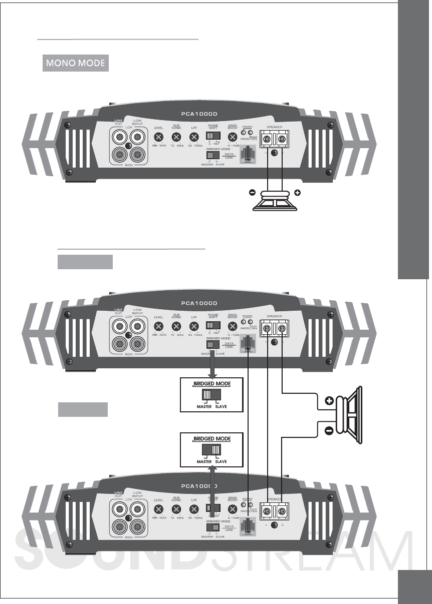
PCA1000D / 1500D / 2000D
SUB WOOFER
1 OHM
Bridging Two Amplifier's
SPEAKER
IMPEDANCE
2 OHMS
MASTER AMP
SLAVE AMP
BRIDGED SWITCH : MASTER POSITION
BRIDGED SWITCH : SLAVE POSITION
11
WIRING DIAGRAM
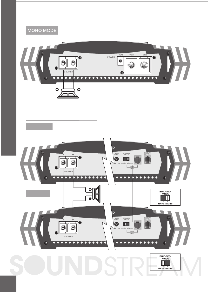
PCA3500D
Bridging Two Amplifier's
MASTER AMP
SUB WOOFER
1 OHM
12
WIRING DIAGRAM
SLAVE AM P SPEAKER
IMPEDANCE
2 OHMS
REAR FRONT
REAR FRONT
Tuning on the Amplifier
Adjusting The Audio Level
The a mplifier a utoma tic a lly turns on a few sec onds a fte r you turn your vehic le's ignition
switc h to AC C or ON or turn on your a uto sound syste m, depending on how you wired
the system. The POWER indic a tor on the top of the a mplifier lights when the a mplifier is on.
Important : Your amplifier requires 30 amps or more of power from your vehicle's
battery during operation. To protect your battery from discharging,
do not operate the amplifier unless your vehicle is running.
FREQUENCY (Hz)
10
-30dB
-20dB
-10dB
0dB
+10dB
+20dB
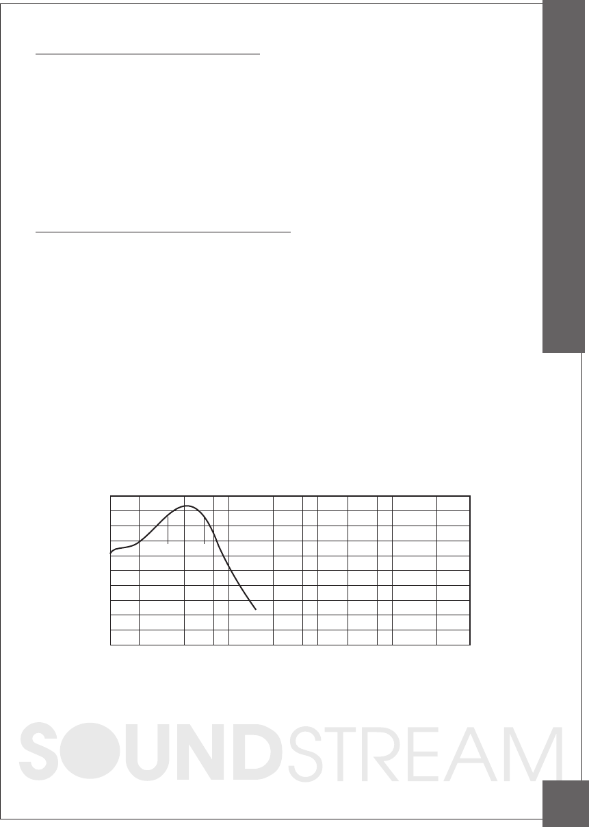
FREQUENCY RESPONSE
RESPONSE (dB)
BASS BOOST ON
45
35 80
100 500 1K 5K 20K 50K
NOTE: Ra ising the Ba ss freque nc y a llows higher frequenc ies to rea c h the ba ss spea kers
while bloc king lower frequenc ies from midra nge spea kers. Lowering the Ba ss
freque nc ies a llows lower frequenc ies to rea c h the midra nge spe a kers while
bloc king highe r freque nc ies from ba ss spea kers.
For the be st pe rforma nc e , you must se t G AIN (MIN / MAX) on the side of the
a mplifier to a djust the leve l of the a ud io signa ls tha t e nter the a mplifier.
1. Use a screwdriver to turn GAIN (MIN / MAX) fully counterclockwise to MIN.
2. Turn the auto sound system's volume control to about one-third of its full range.
3. Adjust GAIN (MIN / MAX) to a comfortable listening level.
4. Turn up the auto sound system's volume control until the sound begins to distort.
Then immediately turn the volume down to a point just before where the
distortion began.
Caution : Never turn up the auto sound system's volume control more than needed
to adjust the audio level, more than two thirds of its maximum volume.
5. Adjust GAIN (MIN / MAX) until the sound is at the maximum level you want the
amplifier to produce.
6. Adjust the auto sound system's volume control to a comfortable listening level.
13
ADJUSTING & TUNING
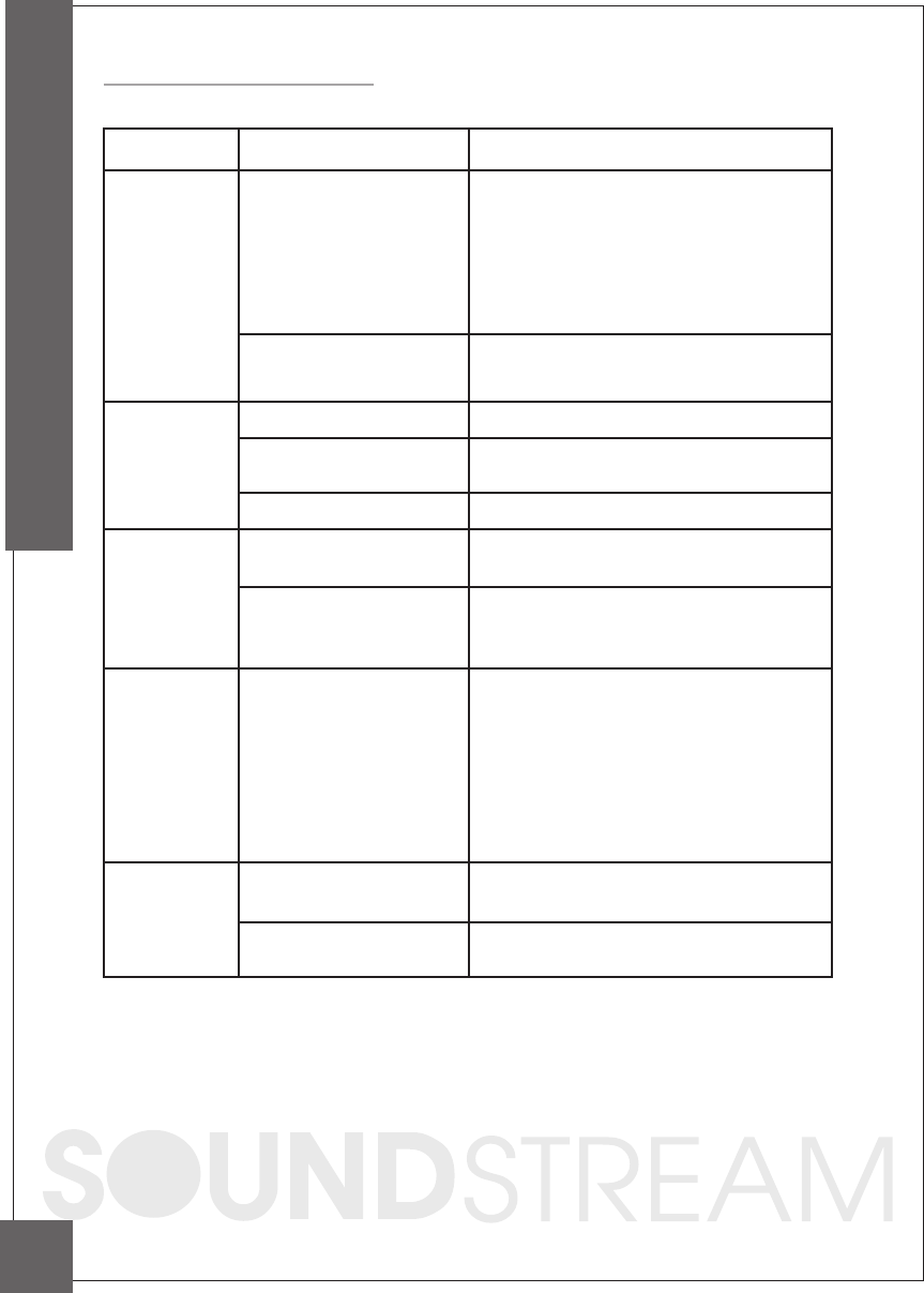
Trouble Shooting
SYMPTOMS
NO SOUND
AMP NOT
SWITCHING
ON
NO SOUND
IN ONE
CHANNEL
AMP TURNING
OFF
MEDIUM /
HIGH
VOLUME
PROTECTION
LAMP ON
Is the power
Is the Diagnostic
LED illuminated? (YES)
No power to power wire Repair power wire or connections.
No power to remote
wire with receiver on
Check connections to radio.
Burnt or broken fuse
Check Speaker Leads Inspect for short circuit or an
open connection.
Reverse Left and Right RCA inputs
to determine if the problem is
occurring before the amp.
Be sure proper speaker load
impedance recommendations
are observed.
(If you use an ohmmeter to check
speaker resistance, please
remember that DC resistance and
AC impedance may not be the same.)
Check Audio Leads
Check Speaker load
impedance
Shut down Turn radio down
Wait for AMP to cool
Speaker wires shorted Separate speaker wires and
insulate
Check for speaker short or
amplifier overheating.
Check all fuses to amplifier.
Be sure Turn-on lead is connected
check signal leads.
Check gain control.
Check Tuner/Deck volume level.
Clean contacts on fuse holders.
LED illuminated?
(NO)
CHECK REMEDY
Replace fuse
TROUBLE SHOOTING
14
