The Autograph Monitor Screens Contain Most Common Information For Operator PTM LOADGARD Series Manual Rev5.9
User Manual: PTM LOADGARD Series Manual Rev5.9
Open the PDF directly: View PDF ![]() .
.
Page Count: 80

1
HELM INSTRUMENT CO., INC.
PTM - LOADGARD
Series
USER MANUAL
Rev. 5.9
Aug 20 2015

i
LIMITED WARRANTY
Helm Instrument Co., Inc. (”HELM”) hereby warrants that the instruments and sensors
(collectively the ”Product”) manufactured by it and sold to customer, are free from
defects in material and/or workmanship under normal use subject to the following
conditions. This warranty shall not apply to any Product which has been subjected to
improper installation, misuse, negligence, accident, alteration, where service has been
performed by other than an authorized Helm serviceman, or where the serial number
has been defaced or altered. This warranty shall extend for the one (1) year period from
date of shipment from our factory or authorized dealer, provided that the product is
returned, freight prepaid, to Helm within the one (1) year warranty period within specific
written authorization to perform repairs. Helm’s obligations and the exclusive remedy of
customer under this warranty are limited to repairing or replacing any defective Product
at no additional charge and returning Product to customer freight paid. Repair parts and
replacement Products shall be furnished on an exchange basis and shall be either new
or reconditioned. All replaced parts and Products shall become the property of Helm.
EXCEPT AS SPECIFICALLY STATED HEREIN, HELM MAKES NO WARRANTIES
EXPRESSED OF IMPLIED, OF THIS PRODUCT INCLUDING BUT NO LIMITED TO
WARRANTIES OF MERCHANTABILITY OR FITNESS FOR A PARTICULAR
PURPOSE, OR AS TO THE QUALITY, UTILITY OR PERFORMANCE, ALL QF WHICH
ARE HEREBY EXPRESSLY EXCLUDED. IN NO EVENT SHALL THE LIABILITY OF
HELM EXCEED THE PURCHASE PRICE OF THIS PRODUCT. NOR SHALL HELM BE
LIABLE FOR ANY DAMAGES WHATSOEVER, INCLUDING BUT NOT LIMITED TO
SPECIAL, INDIRECT, INCIDENTAL OR CONSEQUENTIAL CHARGES, EXPENSE OR
DAMAGES, ARISING OUT OF THE USE OR INABILITY TO USE THIS PRODUCT OR
FOR ANY CLAIM BY ANY OTHER PARTY.
Should you have any questions concerning this Warranty, you may contact Helm by
writing or calling:
HELM INSTRUMENT COMPANY, INC.
CUSTOMER SERVICE
361 WEST DUSSEL DRIVE
MAUMEE, OHIO 43537
(419) 893-4356

PTM LOADGARD Series Operators Manual
ii
EXPLANATION OF SYMBOLS
~ Alternating Current
Earth (ground) TERMINAL
On (Supply)
Off (Supply)
Caution, risk of electric shock
Caution (refer to accompanying documents)
1
EXPLANATION OF SYMBOLS ................................................................................................................................. ii
Introduction................................................................................................................................................................. 5
ABOUT PTM LOADGARD SERIES ........................................................................................................................... 5
Benefit ........................................................................................................................................................................ 5
PTM (Peak Tonnage Module) .................................................................................................................................... 5
Main Features ............................................................................................................................................................ 6
OPERATING MODES ................................................................................................................................... 6
LOOK WINDOW TIME (ms) - Only applicable to none Resolver Model ..................................................... 6
SAMPLING (also referred to as “Learning” or “Trending” cycles) ................................................................ 6
ALARMS ....................................................................................................................................................... 6
Other Features ........................................................................................................................................................... 7
TOUCH SCREEN INTERFACE ................................................................................................................................. 8
MAIN MENU ............................................................................................................................................................... 8
PRESS MONITOR ..................................................................................................................................................... 9
Tonnage Display Screen ............................................................................................................................................ 9
MAIN PEAK LOAD SCREEN ........................................................................................................................ 9
CURRENT JOB DISPLAY .......................................................................................................................... 12
ALARM INDICATOR & HISTORY .............................................................................................................. 12
ALARM HISTORY ....................................................................................................................................... 12
TOTAL PEAK DISAPLY FOR FRAME ....................................................................................................... 12
PEAK TONNAGE DISPLAY FOR FRAME (Ch1 – 4) ................................................................................. 12
TREND LED ................................................................................................................................................ 13
ALARM INDICATOR LED FOR FRAME CHANNEL .................................................................................. 13
PEAK DISPLAY FOR IN-DIE & ALARM INDICATOR (In-Die Screen Only) .............................................. 13
VIEWING CURRENT ALARM SETTINGS (In-Die Screen Only) ............................................................... 14
ALARM RESET ........................................................................................................................................... 14
ALARM SETUP ........................................................................................................................................... 14
OPERATING MODE ................................................................................................................................... 14
COPYING SAMPLE TO TARGET .............................................................................................................. 15
VIEW PEAK HISTORY ............................................................................................................................... 15
Peak History & SPC(Statistical Process Control) Charts ......................................................................................... 16
ZOOMED MODE ......................................................................................................................................... 16
CHANNEL SELECT BUTTONS .................................................................................................................. 16
CONFIG ...................................................................................................................................................... 16
CHANGE GRAPH RESOLUTION .............................................................................................................. 17
SCROLL ...................................................................................................................................................... 17
UNZOOM .................................................................................................................................................... 17
GRID ........................................................................................................................................................... 17
BOLD........................................................................................................................................................... 17
LEGEND ..................................................................................................................................................... 17
SPC ............................................................................................................................................................. 17
Current Alarm Setting ............................................................................................................................................... 18
Group Select ............................................................................................................................................... 19
HIGH CAPACITY ........................................................................................................................................ 19
LOW CAPACITY ......................................................................................................................................... 19
TARGET ...................................................................................................................................................... 19
+ TOL .......................................................................................................................................................... 19
- TOL ........................................................................................................................................................... 19
EXPAND FACTOR ...................................................................................................................................... 19
LEARNING CYCLE ..................................................................................................................................... 21
ADAPTIVE LEARNING ENABLE/DISABLE ............................................................................................... 21
DELTA TRACK EX ...................................................................................................................................... 20
PTM LOADGARD Series Operators Manual
2
ALARM WINDOW (ms) ............................................................................................................................... 21
(LOOK) WINDOW TIME (ms) - Only applicable to none Resolver Model .................................................. 21
ENABLING EDIT ......................................................................................................................................... 21
DOWNLOAD ............................................................................................................................................... 22
JOB RECIPE ............................................................................................................................................... 22
SAVING TO RECIPE DATABASE .............................................................................................................. 22
MAIN MENU ................................................................................................................................................ 22
Press Curve Alarm ................................................................................................................................................... 23
PTM Loadgard Press Curve Setup Procedure ........................................................................................................ 23
JOB ............................................................................................................................................................. 25
PEAK ........................................................................................................................................................... 25
HIGH CAP ................................................................................................................................................... 25
LOW CAP .................................................................................................................................................... 25
TARGET ...................................................................................................................................................... 25
SAMPLE ...................................................................................................................................................... 25
HIGH TOL ................................................................................................................................................... 25
LOW TOL .................................................................................................................................................... 25
WAVE VIEWING WINDOW ........................................................................................................................ 26
READ TONNAGE AT ANGLE .................................................................................................................... 26
ZOOM IN ..................................................................................................................................................... 27
RESET ZOOM ............................................................................................................................................ 27
TREND TYPE ............................................................................................................................................. 27
TREND ........................................................................................................................................................ 27
GRID ........................................................................................................................................................... 28
BOLD........................................................................................................................................................... 28
LEGEND ..................................................................................................................................................... 28
CHANNEL SELECT .................................................................................................................................... 28
OVERLAY ................................................................................................................................................... 28
Overlay Screens ....................................................................................................................................................... 28
SIGNATURE OVERLAY SCREEN ............................................................................................................. 29
SIGNATURE OVERLAY SCREEN ............................................................................................................. 29
PEAK BARS SCREEN ................................................................................................................................ 29
RECIPE MANAGER ................................................................................................................................................. 30
Recipe Main Screen ................................................................................................................................................. 30
JOB SUMMARY DISPLAY.......................................................................................................................... 30
NAVIGATION BAR ...................................................................................................................................... 30
EDIT ON ...................................................................................................................................................... 30
REMOVE ..................................................................................................................................................... 31
EDIT ............................................................................................................................................................ 31
ADD ............................................................................................................................................................. 31
COPY .......................................................................................................................................................... 31
DOWNLOAD ............................................................................................................................................... 31
MAIN MENU ................................................................................................................................................ 31
Job Setup Screen ..................................................................................................................................................... 32
JOB NAME .................................................................................................................................................. 32
HIGH CAPACITY ........................................................................................................................................ 32
LOW CAPACITY ......................................................................................................................................... 32
TARGET ...................................................................................................................................................... 32
+ TOL .......................................................................................................................................................... 33
- TOL ........................................................................................................................................................... 33
EXPAND FACTOR ...................................................................................................................................... 33
LEARNING CYCLE ..................................................................................................................................... 33
ADAPTIVE LEARNING ENABLE/DISABLE ............................................................................................... 33
ALARM WINDOW (ms) ............................................................................................................................... 34
(LOOK) WINDOW TIME (ms) - Only applicable to none Resolver Model .................................................. 34
PTM LOADGARD Series Operators Manual
3
PASTE......................................................................................................................................................... 34
CANCEL ...................................................................................................................................................... 34
SAVE ........................................................................................................................................................... 34
PASSWORD CHANGE ............................................................................................................................................ 35
MASTER PASSWORD ............................................................................................................................... 35
ADMINISTRATOR PASSWORD ................................................................................................................ 35
OPERATOR PASSWORD .......................................................................................................................... 35
INITIAL PASSWORD .................................................................................................................................. 35
ADTSERVER SETUP SCREEN .............................................................................................................................. 36
Monitor Screen ......................................................................................................................................................... 36
OPERATING STATUS INDICATOR ........................................................................................................... 36
OPERATING MODE INDICATOR .............................................................................................................. 36
Sensor Calibration Screen ....................................................................................................................................... 37
System Setup Screen .............................................................................................................................................. 38
WINDOW TIME (ms) - Only applicable to none Resolver Model ............................................................... 38
PEAK WINDOW (Enable/Disable) - Only applicable to none Resolver Model ........................................... 38
SCALE SET ................................................................................................................................................ 38
TREND ALARM .......................................................................................................................................... 38
System Setup Screen for PTM-5600P/6700P ............................................................................................ 39
SCALE SET ................................................................................................................................................ 39
System Setup Screen for PTM-4500TSM/6700TSM/6700i-TSM ............................................................................ 40
TREND WARNING OUTPUT LEVEL ......................................................................................................... 40
SAVE ........................................................................................................................................................... 40
CANCEL ...................................................................................................................................................... 40
LOOK WINDOWS ....................................................................................................................................... 40
PTM LOADGARD ADC SETUP for TSM model .................................................................................................... 41
Go To ADC Manager .......................................................................................................................... 41
ADC Manager Setup ........................................................................................................................... 41
ADC RS232 CABLE CONNECTION .................................................................................................. 43
GETTING READY FOR CALIBRATION .................................................................................................................. 44
SYSTEM SPECIFICATIONS ................................................................................................................................... 46
BYPASS OPTION FOR PTM-4500TSM Model ....................................................................................................... 47
To enable the Bypass option, please contact Helm Instrument for further instruction. ADC ASCII PROTOCOL ... 47
ADC ASCII PROTOCOL .......................................................................................................................................... 48
APPENDIX A ( PTM-4500L2 ) - 4Ch Frame with 2 Linear Transducer ................................................................. 50
APPENDIX B ( PTM-2300L ) – 2Ch Frame/Indie with 1 Linear Transducer Input ................................................ 51
APPENDIX C ( PTM-6700i ) – 6Ch In-Die Applcation ........................................................................................... 52
APPENDIX D ( PTM-5600F ) – 3Ch In-die + 2Ch Frame application .................................................................... 53
APPENDIX E ( PTM-6700TSM ) 4Ch Frame + 2Ch Indea with Resolver Input ................................................... 54
APPENDIX F ( PTM-4400i ) 4Ch In-die application ............................................................................................... 55
APPENDIX G ( PTM-4500TSM )- 4Ch Frame with Resolver Input ...................................................................... 56
APPENDIX H ( PTM-4500TSM-ASA )- 4Ch Frame + Auto Shutheight Adjust w/ Resolver Input ........................ 57
PTM LOADGARD Series Operators Manual
4
APPENDIX I ( PTM-5600P) - 5Ch Piezo Sensor Input .......................................................................................... 58
APPENDIX J ( PTM-4500) - 4Ch Frame with CAM input ...................................................................................... 59
APPENDIX K ( PTM-4500-ADC) - 4Ch Frame with Automatic Die Change Option .............................................. 60
APPENDIX L LINE SUPERVISOR WITH RLG CONENCTION ........................................................................... 61
APPENDIX M ( PTM-6100-SS) - 4Ch Frame, 1Ch In-Die, 1Ch Laser Sensor ....................................................... 62
APPENDIX N ( PTM-6700i-TSM) - 6Ch In-Die With Trend Warning Output .......................................................... 63
APPENDIX O PTM LOADGARD DIMEMSION (Standard Mount) ......................................................................... 64
APPENDIX P PTM LOADGARD DIMEMSION (FLANGE MOUNT)....................................................................... 65
APPENDIX P-1 PTM LOADGARD PANEL PC CONNECTIONS LAYOUT ........................................................... 66
APPENDIX Q (PTM-884TSM-SS) 4Ch Frame, 4Ch In-Die Sensors...................................................................... 67
APPENDIX R (PTM-844TSM-SS) Connection Drawing ......................................................................................... 68
APPENDIX R (PTM-844TSM-SS) Connection Drawing ......................................................................................... 68
APPENDIX S (PTM-1248TSM-SS) 4Ch Frame, 8Ch In-Die Sensors .................................................................... 69
APPENDIX S (PTM-1248TSM-SS) 4Ch Frame, 8Ch In-Die Sensors .................................................................... 69
APPENDIX T (PTM-1248TSM-SS) Connection Drawing ....................................................................................... 70
APPENDIX U RLG Line Supervisor Connection .................................................................................................... 71
APPENDIX V PTM-102L Connections .................................................................................................................... 72
APPENDIX W PTM-4500TSM New I/O Board Connections .................................................................................. 73
APPENDIX X PTM-6600TSM for Doule Action Connections ................................................................................ 74
APPENDIX Y PTM-8800TSM for Doule Action Connections ................................................................................. 75
PTM LOADGARD Series Operators Manual
5
INTRODUCTION
HELM INSTRUMENT CO., INC. manufactures a complete line of load monitoring control systems
for use on metal stamping, forging, compaction and assembly presses; cold forming, cold
heading, injection molding and die cast machines. Standard or custom transducers and load cells
are available for in-die monitoring and transfer or progressive tooling. At HELM, quality is
inherent not only in the design of our products but in the attitudes of our employees as well.
We're working together to give you the best. After all, that's what our business is all about -
providing innovative instrumentation to help make your manufacturing process more productive
and your operation more effective.
ABOUT PTM LOADGARD SERIES
PTM LOADGARD series is one of the most advanced load monitoring systems Helm can offer.
Sophisticated features such as smart sampling, adaptive learning, SPC(Statistical Process
Control) Charts, etc. help monitoring the operation of your machine and protect them from faulty
operation.
BENEFIT
Press Protection – protect press components, including dies, from costly damage
Parts Quality Control – ensure parts are being made (stamped) as specified
Variations in the mechanical press and the part making process have the costly potential of press
damage, waste of material, and downtime. The PTM LOADGARD uses force monitoring for both
press protection and parts quality control. If an excessive force that could potentially damage the
press machine or a variation in force occurs during the part making process are detected, the
PTM LOADGARD triggers an “alarm” and stops the press. This allows the press operator to
correct the potential problem ahead.
PTM (PEAK TONNAGE MODULE)
PTM is a single channel strain gage sensor input module to process the signal of the strain
gage to analog output.
PTM provides Auto-Zero® feature (patented by Helm Instrument Co., Inc.). The Auto-Zero®
feature automatically keeps the zero balance of the load signal between every load cycles to
compensate the tonnage variation affected by any environmental conditions changes such as
temperature.
PTM LOADGARD Series Operators Manual
6
MAIN FEATURES
OPERATING MODES
PTM LOADGARD Series has three function modes controlled by an operator.
Setup Mode – Used for system setup, Job setup or new job download.
Capacity alarms are active. Trend Alarms are active if the Trend Alarm in
Setup option is enabled from Server Setup screen. Target value is used
for monitoring the Trend alarm conditions as a reference point.
Learn Mode – Learns new sample value.
Capacity alarms are active. Trend alarms are active if the Trend Alarm in
Setup option is enabled from Server Setup screen. Target value is used
for monitoring the Trend alarm conditions as a reference point.
Monitor Mode – Adaptive learning can be active in this mode.
Capacity alarms are active. Trend alarms are active. Sample value is
used for monitoring the Trend alarm conditions as a reference point.
LOOK WINDOW TIME (ms) - Only applicable to none Resolver Model
PTM LOADGARD monitors tonnages between the “critical” time of the press stroke called the
look window. 224 points (tonnage readings) per channel are recorded during the look window
time from the look window start trigger point. These points are displayed as a “wave” or
“signature” in the Signature Analysis screen.
SAMPLING (also referred to as “Learning” or “Trending” cycles)
Samples for pre-determined number of press strokes, defined as sample counts in Alarm Setup
screen.
When the sampling is completed, PTM LOADGARD takes an average peak tonnage and / or
tonnage signature per channel (while sampling), and stores as a Sample peak value and/or
Sample Signature per channel and uses it as a reference point for Trend / Tracking Alarm
conditions.
Sample – Sample is the value learned automatically from Learn mode or Monitor mode
by adaptive learn feature. The Sample value is used to calculate the Trend and Tracking
Alarm condition in Monitor mode.
Target – When you create a new job, Target values need to be entered manually. These
values can be copied from the Sample values when Leaning process is completed for the
job. The Target is used during Setup or Learn mode to monitor the Trend Alarm
conditions before new Sample values are available.
ALARMS
In normal operation, the Alarm relay is closed for fail safe. When the tonnage alarm(s)
condition is detected, the system opens the TOP STOP relay
High/Low Capacity – Normally set at machine capacity. This provides the protection for
the Machine. This alarm is active in all modes.
High/Low Trend – creates high and low tolerance for peak load based on Target or
Sample tonnage. The tolerance values are the allowable tonnage deviation above and
below Sample or Target tonnage. This provides the means to maintain the quality of the
part making. Trend alarms are available in all modes. There is an option to disable the
Trend alarm during Setup or Learn mode.
PTM LOADGARD Series Operators Manual
7
High/Low Tacking – creates high and low tolerance bands around the sample tonnage
signature for monitoring the alarm condition through out the stroke. Tracking alarm is only
available in Monitor mode
Press Curve (only available for Resolver based model) – Since a press may have
different force capacities at different angles, the press manufacture may provide a
“through the stroke press-curve and motion curve” set of data points. This alarm is valid
in both setup and Monitor mode.
OTHER FEATURES
Signature Analysis – Displays the forming force signature for each channel. You can
zoom, read the tonnage value at angle, overlay multiple channels, view multiple peak
tonnage value in bar graph, and more to help you analyzing the force signature.
Alarm History – You can view last 500 alarm messages with time stamped.
Peaks History – You can view a peak tonnage history graph of last 10000 strokes.
SPC (Statistical Process Control) – You can view statistical charts of peak tonnage
variation from selected peak history. Avail SPC charts are Individual & Moving Range,
*Average & Range, *Median & Range, *Average & Std. Deviation, and Histogram
Jobs Recipe – You create alarm settings per job base and store to Job Recipe for later
quick download to setup the system.
Adaptive learning – While the system is in Monitor mode, you can enable an Adaptive
Learning option to continuously learn new sample tonnage while monitoring. This will
allow the system to adapt any small gradual variances of the tonnage through time when
requires
Multi-Level Password Protection – you can restrict certain functions or screens of the
system from being accessed by unauthorized personnel or prevent from unauthorized
changes of the system settings. Different level of passwords gives more secure and
effective protection for the system.
PTM LOADGARD Series Operators Manual
8
TOUCH SCREEN INTERFACE
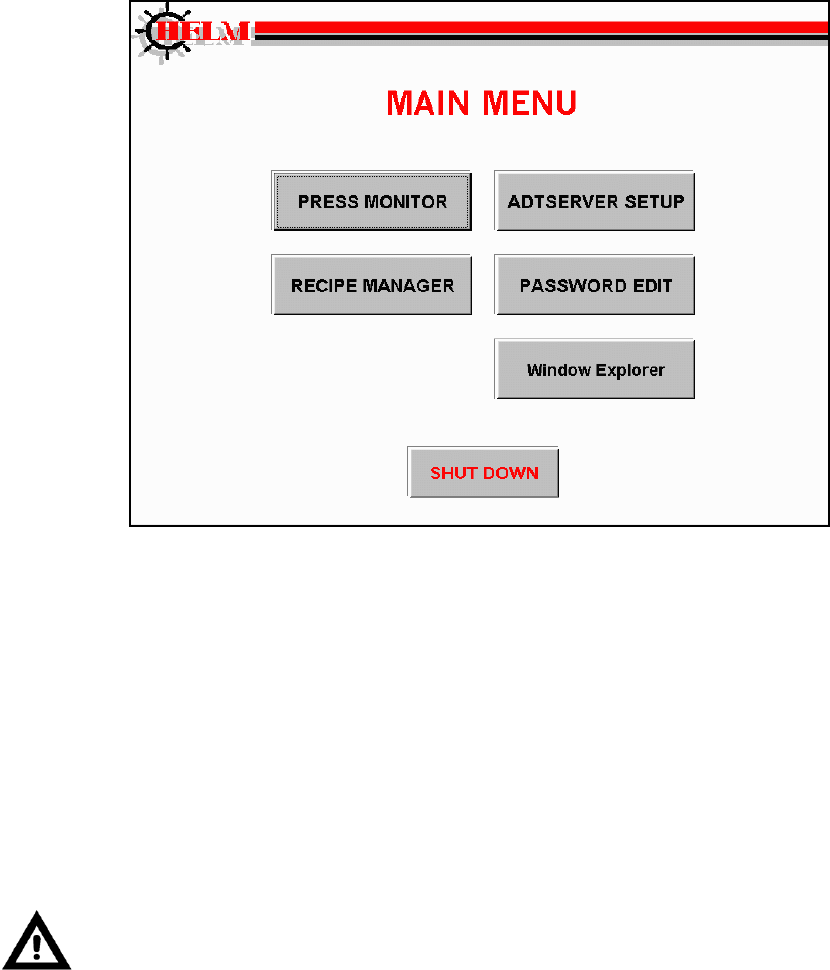
MAIN MENU
Main menu allows you to access different area of the system. The PTM LOADGARD™
features a touch screen display for easy navigation and operation of the system. Click or
touch on the button you wish to access.
PRESS MONITOR – This is where you can monitor the peak tonnage values, tonnage
signatures, change Alarms setting, view Alarm Messages, SPC and more.
RECIPE MANAGER – You can create a new job, edit or delete existing jobs, and download a
job settings to the system.
PASSWORD EDIT – set or change the passwords.
ADTSERVER – helps to diagnose the system status for the trouble shooting purposes. Initial
and system setup is done here.
SHUTDOWN – prepares the system to be powered down safely. This is protected by
operator password. Use “4356123” as password to exit out to Windows Desktop screen
without shutting down the system.
Warning: We recommend to use SHUTDOWN button before powering down the system.
Improper shutting down of the system may cause an abnormal system operation.
PTM LOADGARD Series Operators Manual
9
PRESS MONITOR
TONNAGE DISPLAY SCREEN
PRESS MONITOR provides the screens to view peak tonnage load, Tonnage signatures, ,peak
tonnage history, and SPC charts, You can change Alarm settings and view Alarm Messages as
well.
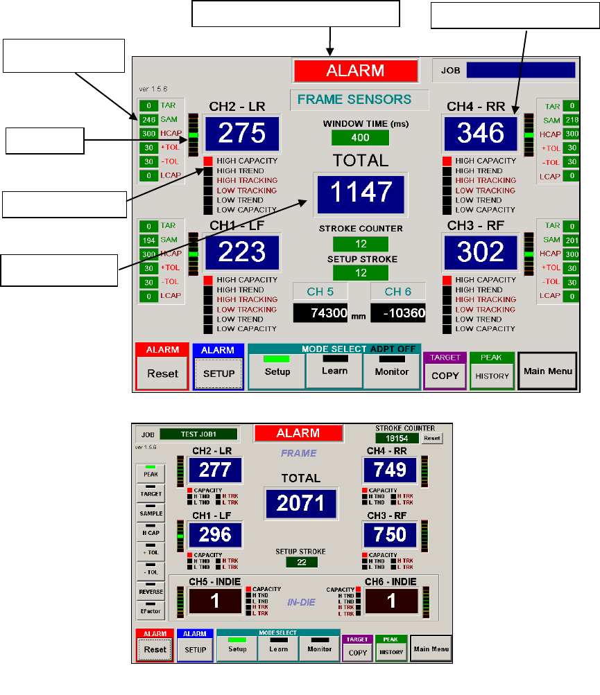
MAIN PEAK LOAD SCREEN FOR VARIATY PTM MODELS
This screen displays peak tonnage values, alarm settings, and alarm indicators for all channels.
Alarm Setting
Display
Trend LED
Alarm Indicator LED
Peak Tonnage Display
Alarm Indicator & Alarm History
Total Peak Display
Main Tonnage screen from PTM-6700TSM
Main Tonnage screen from PTM-4500L2
PTM LOADGARD Series Operators Manual
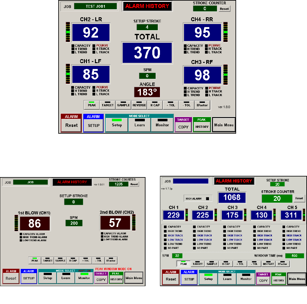
10
Main Tonnage screen from PTM-4500TSM
Main Tonnage screen from PTM-5600P
Main Tonnage screen from PTM-2300PG
PTM LOADGARD Series Operators Manual
11
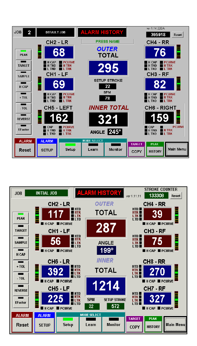
Main Tonnage screen from PTM-6600TSM-DA
Main Tonnage screen from PTM-8800TSM-DA
FOR DOUBLE ACTION PRESS MACHINES
PTM LOADGARD Series Operators Manual
12
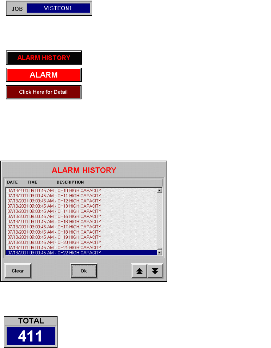
CURRENT JOB DISPLAY
ALARM INDICATOR & HISTORY
ALARM HISTORY
Click on ALARM WARNING DISPLAY button to view ALARM HISTORY.
TOTAL PEAK DISAPLY FOR FRAME
PEAK TONNAGE DISPLAY FOR FRAME (Ch1 – 4)
This peak display shows the peak tonnage load of each channel within the look window from
each cycle of the press.
Shows current Job name. Job name can be edited from
RECIPE MANAGER screen
This ALARM INDICATOR button has two functions, It indicates
any alarms tonnage condition and lets you view alarm history.
When the machine is running within normal parameter, the
message on the button shows ALARM HISTORY. The message
ALARM with red color background indicates there is an alarm
condition(s). In this case, it will flash the message “Click Here
for Detail”. To view the detail message of the alarm, click on the
display to open ALARM HISTORY screen. You can click on this
display to view previous alarm messages at anytime.
You can view up to last 500 alarm
messages that have date and
time stamp. Use the scroll bar on
the right side of the list box or
arrow buttons on the bottom to
scroll up and down the history list.
Use Clear button to empty all
messages.
Note: you need administrator or
higher level of password to clear
the alarm history.
TOTAL displays the summation of the four corner peak tonnages .
This value is the actual peak tonnage load that the press is taking in
each cycle.
PTM LOADGARD Series Operators Manual
13
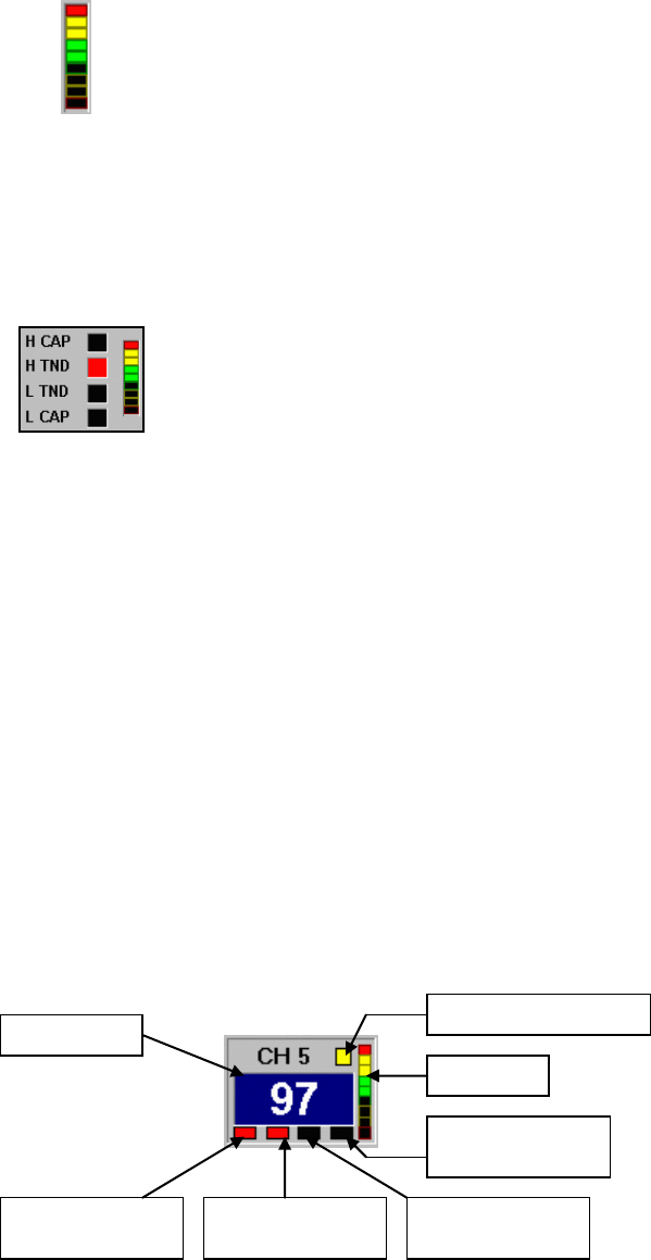
TREND LED
ALARM INDICATOR LED FOR FRAME CHANNEL
H TND (HIGH TREND ALARM)
When the peak tonnage of an individual channel reaches the high limit of the setting for Trend
Alarm, the black rectangle next to the description will turn red to indicate that a High Trend alarm
is triggered. Refer to ALARM SETUP SCREEN for details.
L TND (LOW TREND ALARM)
When the peak tonnage of an individual channel reaches the low limit of the setting for Trend
Alarm, the black rectangle next to the description will turn red to indicate that a Low Trend alarm
is triggered. Refer to ALARM SETUP SCREEN for details.
L CAP (LOW CAPACITY ALARM)
When the peak tonnage of an individual channel reaches the low limit of the setting for Capacity
alarm, the black rectangle next to the description will turn red to indicate that a Low Capacity
alarm is triggered. Refer to ALARM SETUP SCREEN for details.
PEAK DISPLAY FOR IN-DIE & ALARM INDICATOR (In-Die Screen Only)
When alarm(s) occurred, ALARM INDICATOR LED displays the cause of the
alarm.
H CAP (HIGH CAPACITY ALARM)
When the peak tonnage of an individual channel reaches the high limit of the
setting for Capacity alarm, the black rectangle next to the description will turn
red to indicate that High Capacity alarm is triggered. Refer to ALARM SETUP
SCREEN for details.
The vertical bar meter next to the peak display box is a Trend Display bar. It
shows the visual reference of a peak tonnage variation comparing to TARGET or
SAMPLE tonnage for Trend Alarm. The center green light indicates 0% variance
within the tolerance of the Trend Alarm. The green light, one above the center,
indicates 25% variance. Toward to the red light on the top, the yellow light shows
50% and 75%. Once the tonnage reaches 100% of the tolerance or beyond, all
the bars from the center to top light up and it indicates the High Trend Alarm
condition. This applies to Low Trend Alarm as well. Only difference is the
negative percentage (-25%, -50%, -75% and –100%) and opposite instead.
Gag Tool Input Indicator
Trend LED
High Capacity
Alarm Indicator
High Trend Alarm
Indicator
Low Trend Alarm
Indicator
Low Capacity
Alarm Indicator
Peak Display
PTM LOADGARD Series Operators Manual
14
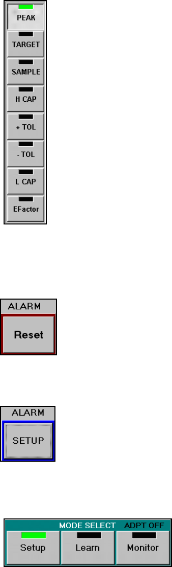
VIEWING CURRENT ALARM SETTINGS (In-Die Screen Only)
ALARM RESET
ALARM SETUP
OPERATING MODE
Setup Mode – Used for system setup, Job setup or job download.
Capacity alarms and Trend alarms are available. The tolerance band for Trend alarm is
calculated by Target value + ( ±TOL x Expand Factor ). You can enable or disable the Trend
Alarm from System Setup screen.
Once the Alarm output relay is disengaged by an alarm condition(s), click on
the RESET button to clear all alarm indication and alarm relay output.
Operating mode can be switched by clicking one of the
CURRENT MODE buttons. While in LEARN mode, the
mode always changes to MONITOR mode
automatically after LEARN cycle is completed.
Click on one of the buttons to view current alarm setting values. The values will
be displayed in the Peak tonnage display boxes for 20 seconds and change back
to PEAK automatically.
The TOTAL PEAK display box shows the viewing mode currently selected.
PEAK Current peak tonnage value.
TARGET (TARG) Target tonnage value.
SAMPLE (SAMP) Sample tonnage value.
HIGH CAP (HCAP) High Capacity tonnage limit
+TOL (+TOL) High tolerance tonnage limit above the Sample or Target
value.
-TOL (-TOL) Low tolerance tonnage limit below Sample or Target
value
LOW CAP (LOW) Low capacity tonnage limit
EFACTOR (EFAC) Expanded Factor which is tolerance multiplier to
increase the tolerance band in Setup & Learn Mode
Click on ALARM SETUP button to bring up CURRENT ALARM SETTING screen
where you can set or change the current alarm settings and download the new
settings to the system to take effect. You can also stores any change you made
in this screen to Recipe database easily. Refer to CURRENT ALARM SETTING
for details.

PTM LOADGARD Series Operators Manual
15
Learn Mode – In LEARN mode, system averages the peak values for each channel during the
predefined learning cycle. Once the learning cycle is completed, the each average value is stored
as sample value for each channel and the operating mode automatically switches to Monitor
mode. Capacity alarms and Trend alarms are available during Learn mode. The tolerance band
for Trend alarms is calculated by Target value + ( ±TOL x Expand Factor ). You can enable or
disable the Trend Alarm from System Setup screen.
Note: you can define the number of Learn Cycle and store it as a part of job recipe item in Job
Setup screen.
Monitor Mode – In Monitor mode, you have the option to enable or disable the Adaptive
Learning feature which is part of job recipe item. When the Adaptive Learning is active, the
system continuously re-learns sample values while monitoring for any alarm condition. You can
change the number of Adaptive Learning cycle by changing the Learning Cycle from Alarm
Setup screen.
ADPT ON/OFF - This indicates whether Adaptive Learning feature is turned on or off.
Once the Adaptive Learn is active, you should see that the green LED on the mode select button
flashes.
COPYING SAMPLE TO TARGET
VIEW PEAK HISTORY
Use COPY button to replace the TARGET value with the SAMPLE value. It is
useful when you have to arbitrary set the Target value for a new job for the first
time. After the Learning procedure is completed for a new job, click on the COPY
button to update the Target values with the Sample values. When making a copy,
it prompts with a message to give you the option to update the new TARGET
values to the Recipe database for a current job.
Click this button to open PEAK TONNAGE HISTORY screen where you can view
a recorded peak tonnage graph up to previous 1000 hits in one screen. Also, you
can select the range of the peak history to display SPC (Statistical Processor
Control) charts. Refer PEAK HISTORY & SPC for details.
PTM LOADGARD Series Operators Manual
16
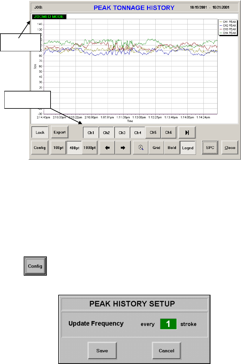
PEAK HISTORY & SPC(STATISTICAL PROCESS CONTROL) CHARTS
ZOOMED MODE
This indicates that the current history graph has been zoomed. To zoom the graph, point to the
area on the screen where you want to start zooming and drag the point down right to create a
zoom rectangle. Once the inside of the zoom rectangle covers the area where you want to zoom
in, release the point from the screen. You can repeat this to continue zooming within the area.
CHANNEL SELECT BUTTONS
Toggle the buttons to add or remove the peak graph of the channel from the history graph.
CONFIG
Channel Select
Buttons
Zoom Mode
Indicator
You can define how often the peak values need to be recorded into the
peak history. Set the Update Frequency value and click Save to take
effect the new setting.

PTM LOADGARD Series Operators Manual
17
CHANGE GRAPH RESOLUTION
SCROLL
UNZOOM
GRID
BOLD
LEGEND
SPC
Click this toggle button to make the width of the peak graph line bold.
Click this button to show or hide the legend of the graphs displayed on the screen.
Click this button to reset the zoomed graph and return to original size.
The Peak history records up to 10,000 previous peak values. You can
change the number of viewable peak points on a graph by choosing
one of the options
100pt – to display 100 peak points at a time
500pt – to display 500 peak points at a time
1000pt – to display 1000 peak points at a time
Click this button to show or hide vertical and horizontal grid lines on Peak Graph
screen.
These buttons let you scroll left or right to view rest of the peak points outside
the graph. Click left arrow button to scroll left, right arrow button to scroll right.
Click this button to generate SPC charts within the peak data displayed on the history
graph. Use Zoom or Scroll to select the range of the peak history to generate SPC
chart you want to see.
If more than one channel is displayed in the history graph, SPC averages them to
generate the charts.

PTM LOADGARD Series Operators Manual
18
CURRENT ALARM SETTING
In CURRENT ALARM SETTING, you can view / edit the current alarm settings and also save the
change to current job database and download the change to ADTServer.
Resolver TSM model: PTM 2300/4500/6600DA/6700TSM
None Resolver model: PTM-4500
PTM LOADGARD Series Operators Manual
19
Group Select
Select Group Select option if you want all channels to have same settings.
HIGH CAPACITY
HIGH CAPACITY is the limit for the maximum peak tonnage allowed to operate the machine.
Normally the value is set at or below the scale value which is the capacity of the machine
divided by the number of frame sensor channels. HIGH CAPACITY alarm is available in all
modes.
Note: You need to enable the Edit mode by using Administrator or higher level of password in
order to make any changes from this screen.
LOW CAPACITY
LOW CAPACITY is the limit of the minimum peak tonnage allowed to operate the machine.
Normally the value is set for 0 (disabled) unless there is a special need. LOW CAPACITY
alarm is available in all modes.
TARGET
The concept of TARGET is to provide a Trend alarm protection for SETUP and LEARN
modes. Normally, Trend Alarm requires a sample tonnage to compare the current peak
tonnage to monitor the alarm condition. However, the Sample value is only available when
the system has completed its Learning cycle and the operating mode has been changed to
Monitor mode. In typical load monitoring system, the Trend alarm is not available during
Setup and Learn mode. In this system, the TARGET feature is to gives you the full protection
of Trend Alarm by letting you manually enter the expected tonnage value for the job before
running the press. Once the machine has started and acquired new Sample values by
Learning procedure, you can update the Target values with them by clicking the Target
COPY button in the main Tonnage screen. In case that you try to run a new job and are not
sure where the Targets need to be set at, you can set each Target value to zero. This will
disable the Trend Alarm on a channel by channel basis. After system learns the new sample
values, you can use the Target Copy command to update the Target values.
Note: While the system is in Setup or Learn mode, adjust Expand Factor to increase the
tolerance band to avoid unnecessary Trend alarm warning. Refer to Expand Factor for
details.
+ TOL
This is the upper tolerance tonnage limit for a High Trend alarm of each channel. This limit
prevents the current peak tonnage load from exceeding the +TOL tonnage setting above the
Target (In Setup or Learn mode) or Sample (In Monitor mode) value.
Note: Depending on EXPAND FACTOR value, actual tolerance may differ from the value that
was set while the system is in Setup or Learn mode. Refer to EXPAND FACTOR for detail.
- TOL
This is the lower tolerance tonnage limit for a Low Trend alarm of each channel. This limit
prevents the current peak tonnage from exceeding the -TOL tonnage setting below the
Target (In Setup or Learn mode) or Sample (In Monitor mode) value.
Note: Depending on EXPAND FACTOR value, actual tolerance may differ from the value that
was set while the system is in Setup or Learn mode. Refer to EXPAND FACTOR for detail.
EXPAND FACTOR
These are the multipliers for the + and -TOL values to increase the range of the tolerance
bands so that the system has less chance to fire Trend alarms while the press is running in
SETUP or LEARN mode. Once the system is in Monitor mode, This EXPAND FACTOR does
not affect the tolerance for Trend and Tracking alarm band in PLM model. However, in TSM
PTM LOADGARD Series Operators Manual
20
model(with Resolver), this expand factor still applies to the Tolerance setting for Trend alarm,
but not Tracking alarm.
Example: Target = 60 , Sample = 64, +Tol = 10, -Tol =15, Exp Factor = 2.0
In Setup or Learn mode
Actual High Trend limit = 60 + (10 * 2.0) = 80
Actual Low Trend limit = 60 - (15 * 2.0) = 30
In Monitor mode
Actual High Trend limit = 60 + 10 = 70
Actual Low Trend limit = 60 - 15 = 45
DELTA TRACK EX
Delta Track feature pertains to the filtering of tracking alarms, and help avoid “nuisance” type
alarms. The filtering occurs during sudden force change through the press stroke. Delta
Track filtering can be seen in the signature screen, where high slopes area of the sample
signature (along with the tracking bands) are filtered out during relatively small portion of the
stroke.
Filter level can be adjusted. Enter a value between 1 and 99 to determine how much of the
slope rate area to be filtered. 99 filter the least and 1 will filter the most out of the slope area.
Enter ‘0’ to disable Delta Track filtering.
Enter “100” to enable Perpendicular Tolerance(PT) tracking bands.
PT Tracking generates the tracking bands that envelop around the sample signatures evenly
throughout the alarm window area. This Tacking gives you the ability to monitor tracking
alarm in very tight tolerance setting without cause “nuisance” alarm by any minimal horizontal
shiftiness of the force signature.
Standard Tracking at 15% Tolerance
Delta Track Enabled & set at 80
P.T. Tracking at 3% Tolerance
PTM LOADGARD Series Operators Manual
21
LEARNING CYCLE
Enter the number of cycles to take to learn new Sample values in LEARN mode. In
MONITOR mode, Adaptive Learning feature uses this cycle to learn new Samples when it is
enabled. In TSM Model, enter 0 to use Target values as Sample for Trend alarm in Monitor
mode without going through learning process for new sample. Note that Learn Cycle set to
“0” disables Tracking alarm.
ADAPTIVE LEARNING ENABLE/DISABLE
You can enable or disable Adaptive Learning feature in MONITOR mode. By enabling the
Adaptive Learning, the system continuously learns new sample values while it is in Monitor
mode and applies the new Sample values to monitor Trend alarm conditions as soon as
available. This will allow the system to adapt any small gradual variances of the tonnage
load through the time which are caused by environmental change such as temperature. If
any tonnage load that causes an alarm, the reading is excluded from Adaptive Learning
process.
ALARM WINDOW (ms)
Set alarm window to adjust the area of the force signature to monitor for tracking alarm. If
PEAK WINDOW is enabled, this ALARM WINDOW determined the area of the signature to
capture the peak tonnage instead of from entire signature. Enter start and stop Alarm
Window times in msec within Window Time.
Note: In Resolver model, enter the range of the angle value instead of time.
(LOOK) WINDOW TIME (ms) - Only applicable to none Resolver Model
Look Window Time is the duration of time when the force signature and peak tonnage is
captured. The WINDOW TIME need to be adjusted based on the speed of the machine to
capture optimal force signature.
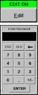
ENABLING EDIT
Before you are able to make any changes on the settings in this screen, you
have to enable Edit mode first. To do so, click on Edit button and enter a
password to enable the Edit mode. Depending on the password clearance
level, restrictions will apply.
Default Password:
Operator password = “123”
Administrator Password = “123456”
Master Password = “1968”
PTM LOADGARD Series Operators Manual
22
Here is the table for editable contents based on the password type.
Functions
Operator
Password
Administrator
Password
Master
Password
Scale Value change
X
X
O
High/Low Capacity Setting
X
X
O
Window Time Setting
X
O
O
Tracking Threshold Set
X
X
O
High/Low Tolerance Setting
O
O
O
Target/ EXP Factor
O
O
O
Tracking On/Off
O
O
O
Learn Cycle Count
O
O
O
Alarm Window Setting
O
O
O
RECIPE Job Download
O
O
O
RECIPE Job Add/Edit/Delete
X
O
O
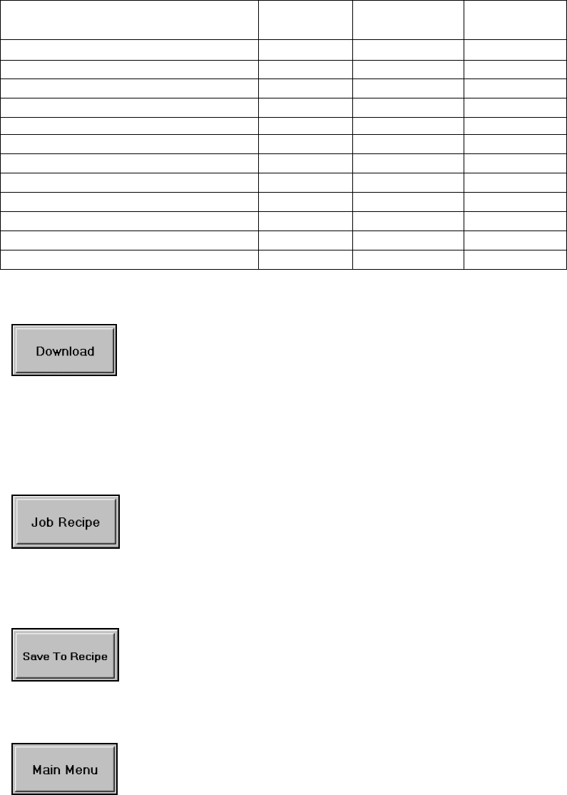
DOWNLOAD
JOB RECIPE
SAVING TO RECIPE DATABASE
MAIN MENU
Click this button to download new alarm settings to system. Downloading
is only allowed in Setup mode. If the system is currently in LEARN or
AUTOMATIC mode, it will prompt with a message that will ask if you want
to switch back to SETUP mode.
Note: Any change of settings you make in this screen will take effect after
Download is completed.
Click this button to go to RECIPE MANAGER screen.
Click this button to update current job stored in Recipe database with the
new settings made from this screen.
Click this button to return to main tonnage screen
PTM LOADGARD Series Operators Manual
23
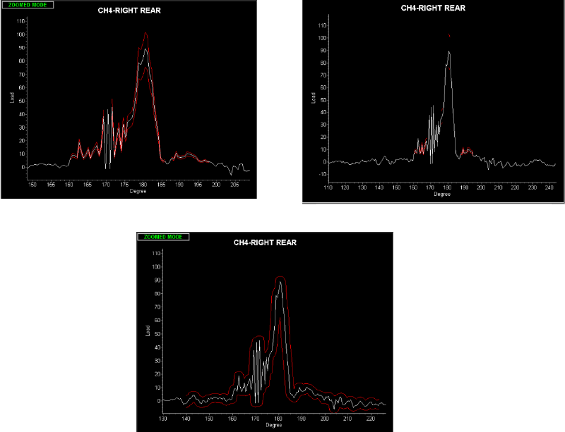
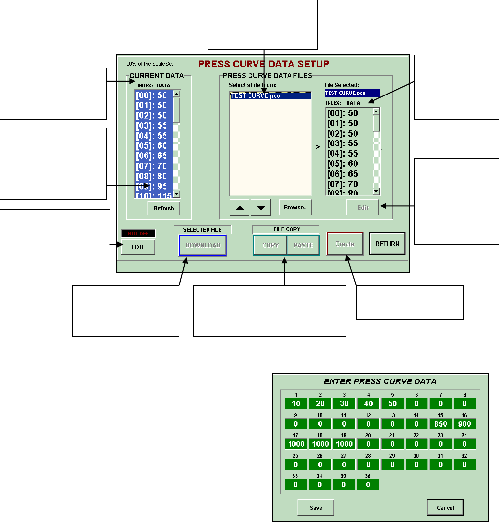
PRESS CURVE ALARM
The resolver based PTM Loadgard system allows the operator to enter the specified 36
press curve points in the Press Curve Data Setup screen for Press Curve Alarm.
Multiple press curve data can be saved. Select a press curve data file and click download to
active it.
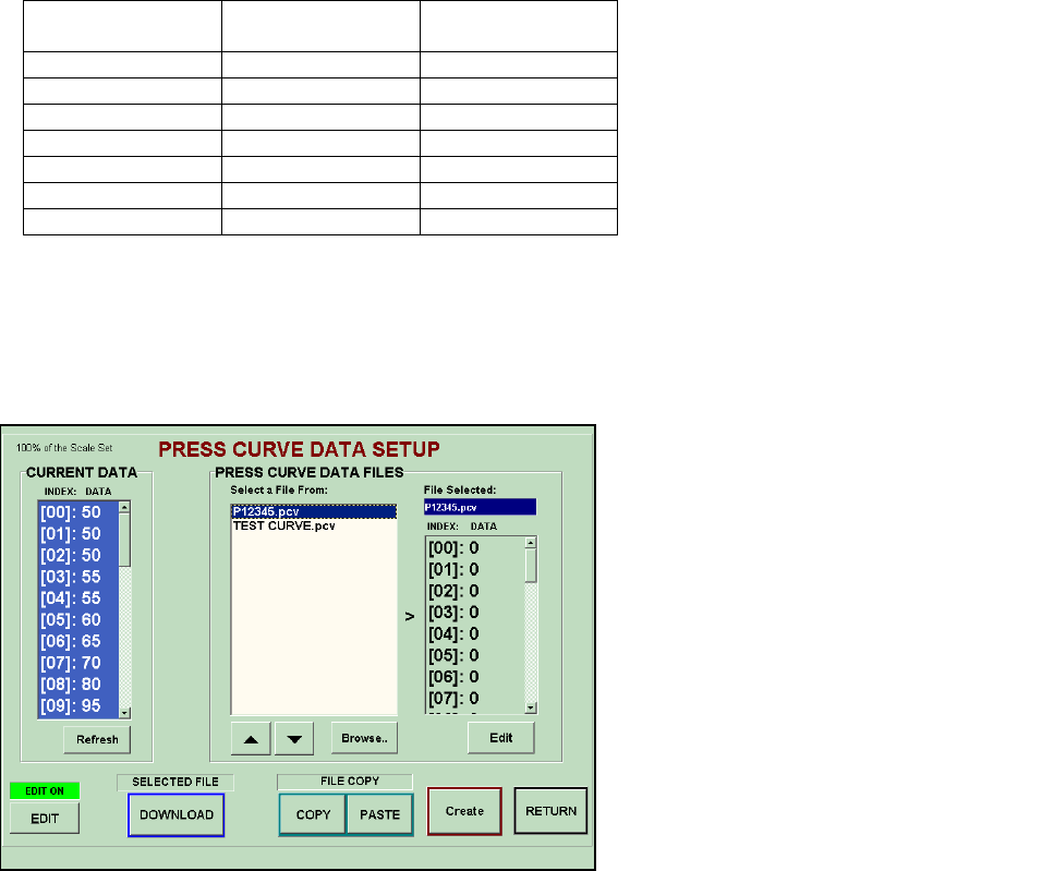
PTM LOADGARD PRESS CURVE SETUP PROCEDURE
A. How to edit existing Press Curve data file
1. Select the file you created from the list then click
Edit button to enter date points
2. Edit the value in 36 points to match Press Curve
data. starting 0 degree in degree, enter data every
10 degree. The data is a percent value x 10 of total
capacity of the machine.
3. For example, if the press capacity is 500t and the
press is rated as 250t at 90 degree crank angle
according to the press curve chart, then enter 500
(50% x 10 = 500) for 9th data entry point. The
formula is:
Press Curve Data Value = (Capacity @ angle / Press Capacity) * 1000
( 250 / 500 ) x 1000 = 500
Active Press Curve
data in the Loadgard
System.
Turn Edit On to make
changes
When new data has
been downloaded,
click Refresh to
update the screen
with new data
Press Curve data
files stored in
memory
Data from the
selected file
stored in
memory.
To edit the data
in the selected
file. This will
lead to PRESS
CURVE DATA
entry screen
To create a new
press curve data file.
Download a selected
Press Curve data file
to be active data
PRESS CURVE DATA ENTRY
SCREEN
Copy all data points from a
selected file and paste the
same data into a different file
selected
PTM LOADGARD Series Operators Manual
24
B. How to Create a new Press Curve data file.
1. First you need 36 data points from Angle vs. Tonnage capacity graph.
2. Turn Edit On.
3. Click Create button and name your data file using the pop-up keyboard.
4. Select the file you created from the list then click Edit button to enter date points
5. Enter 36 points for Press Curve date. starting 10th degree, enter data every 10 degree.
The data is a percent value x 10 of total capacity of the machine.
Please refer to the table below for example how to calculate the data points for each degree.
Press Capacity: 500t
Crank Angle
(Degree)
Capacity@Angle
(t)
Press Curve Data
(% x 10)
10
100
200
20
110
220
30
120
240
40
140
280
50
180
360
60
200
400
70
225
450
Press Curve Data Value = (Capacity @ angle / Press Capacity) * 1000
For example, if the press capacity is 500t and the press is rated as 250t at 90 degree crank angle
according to the press curve chart, then enter 500 (50% x 10 = 500) for 9th data entry point.
( 250 / 500 ) x 1000 = 500
C. How to Download A Press Curve Data File to be Active .
1. Select a Press Curve data file
created in PRESS CURVE DATA
FILES list and click DOWNLOAD
button.
2. Click Refresh button to update the
CURRENT DATA list screen with
the recently downloaded data.
3. Click Return to go back to Alarm
Setup screen and enable Press
Curve feature for each Channel.
PTM LOADGARD Series Operators Manual
25
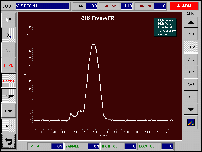
Signature (Wave) Display Screen
The Signature Display screen displays real-time force signatures for individual channels. The
overlaying with other signatures or graphs help you to monitor the operating status of the
machine or verify the alarm conditions easier.
JOB
This is the current job name downloaded from RECIPE MANAGER.
PEAK
Current peak tonnage value for the channel currently displayed.
HIGH CAP
High Capacity Alarm setting value in tons for the channel currently displayed.
LOW CAP
Low Capacity Alarm setting value in tons for the channel currently displayed.
TARGET
TARGET setting value in tons for the channel currently displayed.
SAMPLE
SAMPLE value in tons for the channel currently displayed.
HIGH TOL
+ TOLERANCE setting value in tons for the channel currently displayed.
LOW TOL
- TOLERANCE setting value in tons for the channel currently displayed.
PTM LOADGARD Series Operators Manual
26
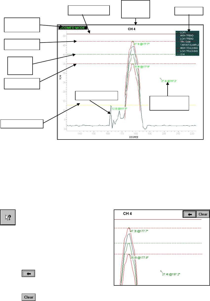
WAVE VIEWING WINDOW
ZOOM INDICATOR: This message indicates that the graph is currently zoomed.
HIGH CAPACITY: High Capacity limit
HIGH TREND: Upper limit of trend alarm band
LOW TREND: Lower limit of trend alarm band
SAMPLE/TARGET: In SETUP and LEARN mode, it displays the Target line.
In AUTOMATIC mode, it displays the Sample line.
LOW CAPACITY: Low Capacity limit
CURRENT WAVE: Current tonnage signature read from sensor.
READ TONNAGE AT ANGLE
To delete last reading on the
screen
Click on this button to enable the Read
Tonnage at Angle feature. To view the
tonnage at angle, click on the
coordination you want to read from the
signature screen. You can view up to
20 readings on a screen
simultaneously. Use Back or Clear
button at the top-right corner to delete
unwanted readings.
HIGH CAPACITY
CURRENT
CHANNEL
NUMBER
LEGEND
HIGH TREND
LOW TREND
SAMPLE/
TARGET
LOW CAPACITY
CURRENT WAVE
To clear all readings on the
screen
ZOOM
INDICATOR
READ TONNAGE
@ ANGLE
PTM LOADGARD Series Operators Manual
27
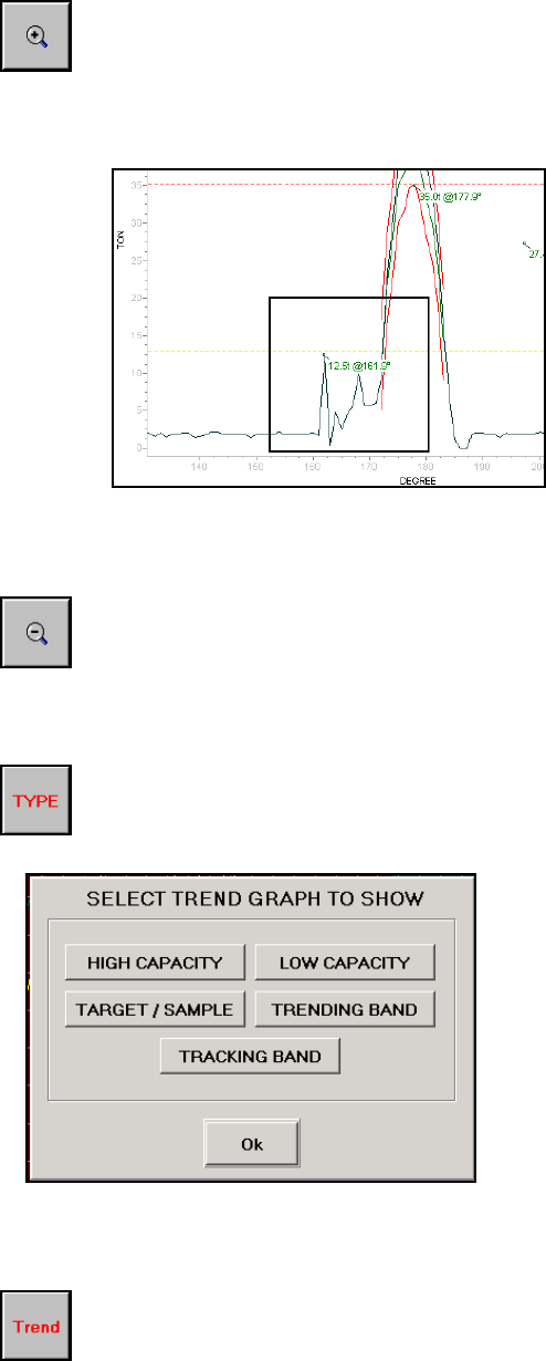
ZOOM IN
RESET ZOOM
TREND TYPE
TREND
The Zoom feature allows the user to “zoom in” on a selected area of the signature
for analysis at a higher resolution. Click this button to put the signature screen in
zoom mode.
Note: Once the wave is zoomed, a message “ZOOMED” shows up on the top-left
corner of the Signature View Window to indicate that signature is currently in
zoomed mode.
To select an area to zoom in: Press
touch screen (and keep pressed) at
top left area of desired part of wave
to zoom in, and drag finger at a
diagonal down and to the right. A box
will be drawn and finger followed as
the touch screen is pressed. Release
touch screen to draw zoomed-in part
of the wave.
Repeat Zooming is permitted to
continuously zoom in on a particular
area of a signature.
Click this button to return full view(unzoom)
Click this button to open the SELECT TREND GRAPH TO SHOW screen where you
can
select which Trend graphs to be displayed when TREND button is activeted.
You can add/remove different types of
trend graphs you desire to overlay on the
signature screen. To add, click on the
button you want to view. When the button
is pushed in, the option for the graph is
added. Click again to remove it.
Note: This option only works with TREND
button.
Toggle this button to show or hide the trend graphs selected from TREND TYPE
option. This will give the visual references of the alarm settings and forming force
related to the Sample.
PTM LOADGARD Series Operators Manual
28
Thru
GRID
BOLD
LEGEND
CHANNEL SELECT
OVERLAY
OVERLAY SCREENS
Click this button to show or hide vertical and horizontal grid lines on the wave
screen.
Click this toggle button to make the current signature graph line bold.
Click this button to show or hide the legend of the graphs displayed on the screen.
Select a button to display the corresponding channel signature on
the screen.
Click this button to view the overlay of multiple channels of current signatures. Also,
you can select the option to view multi-channel peak bar graph from here. Refer to
OVERLAY SCREEN for details
Note: You cannot view Trend graphs while Overlay screen is on. All other features are
still available.
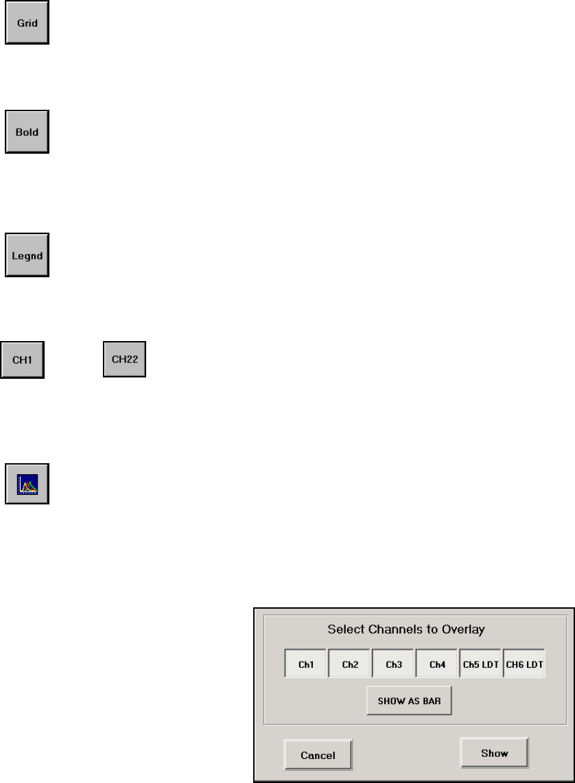
You can add/remove multiple channels
of signatures to overlay on one screen
by clicking the channel buttons from
Select Channels To Overlay screen.
Choose the channel(s) you wish to
view and click Show button to view
Signature Overlay.
Select SHOW AS BAR to view Peak
Bars instead.

PTM LOADGARD Series Operators Manual
29
SIGNATURE OVERLAY SCREEN
PEAK BARS SCREEN
High Capacity limit
Peak Tonnage
reading
Color coded Alarm
Indication
Trend alarm
Tolerance range
bar
Peak Tonnage Bar
PTM LOADGARD Series Operators Manual
30
RECIPE MANAGER
RECIPE MAIN SCREEN
Recipe Manager is where you can create and store new jobs, edit or delete existing jobs, and
download the job you want to set the system for. You can store virtually unlimited number of
jobs.
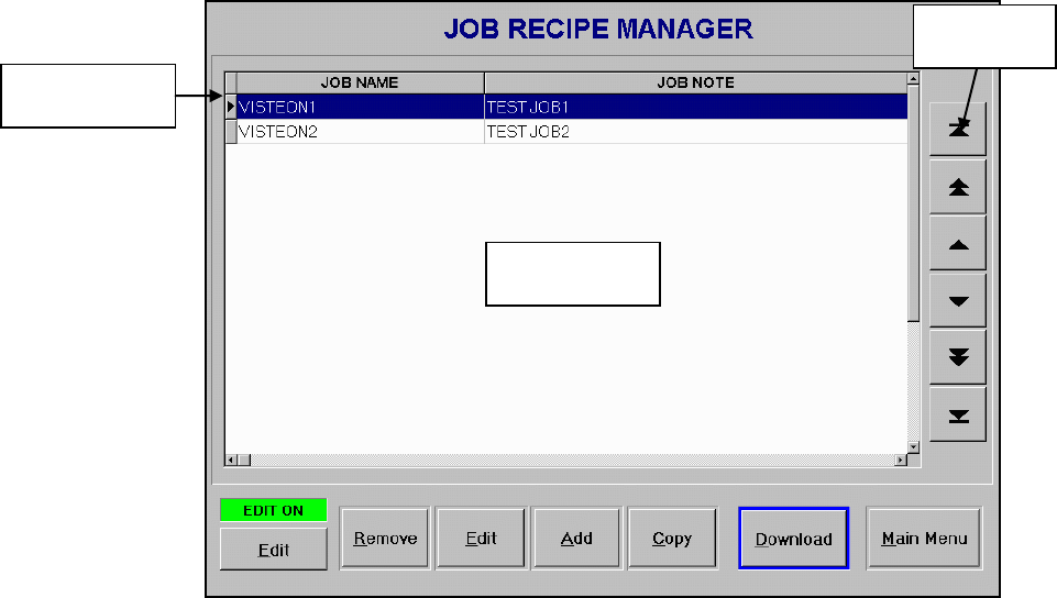
JOB SUMMARY DISPLAY
Job Summary Display shows a list of all stored jobs that have been created and saved into a
job database. Each job is listed with job name and note. By clicking on one of the jobs from
the list, it will highlight the job and make it as an active job. The active job can only be
Edited, Removed or Downloaded. You can use navigation bar on the right side of the list box
to change the active job.
NAVIGATION BAR
You can select an active job by using navigation buttons. It will help you to navigate through
the Job Summary Display to select the job you want by using touch of buttons instead of
dragging small scroll bar.
EDIT ON
In order to Add, Edit, Delete, or Download an active job, The Edit button on the bottom-left of
the screen must be turned on. This enables Edit, Add, Remove, and/or Download buttons
depending on which level of password is entered. Download requires either the Operator
level or higher password. Edit, Add and Remove require Administrator level or higher
password.
JOB SUMMARY
DISPLAY
NAVIGATION
BAR
CURRENT
ACTIVE JOB

PTM LOADGARD Series Operators Manual
31
REMOVE
EDIT
ADD
COPY
DOWNLOAD
MAIN MENU
.
REMOVE button deletes a current active job from the Job Summary Display.
Select the job you wish to delete and click on REMOVE button.
EDIT button will lead you to JOB SETUP screen where you can make changes
of current active job settings such as Job name, alarm settings, etc. In order to
edit a job, select the job you wish to edit from Job Summary Display and click
on EDIT button.
Click Add button to bring up JOB SETUP screen. All parameters for alarm
settings will be blank except the High Capacity alarm. The High Capacity alarm
is predefined by previous job.
When you create a new job, you can also copy the settings from an existing job
from the Job Summary List and paste them into a new job or the existing job.
To copy a job, select the job you want to copy and click on COPY button. Once
you go to JOB SETUP screen to add or edit a job, you will see that PASTE
button is enabled. Click on the PASTE button to paste the settings, you copied,
into the alarm settings for the job.
Click DOWNLOAD button to download the current active job to ADTServer to
take effect of the new settings. The operation mode has to be in SETUP mode to
download the job.
Click this button to return to Main menu.
PTM LOADGARD Series Operators Manual
32
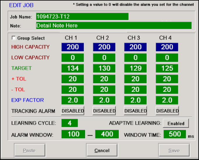
JOB SETUP SCREEN
This is where you can edit or enter new settings for the job you created.
JOB NAME
Enter a job name for the job you created. This will identify each job in the Job database. You
can enter any character up to 20 characters.
HIGH CAPACITY
HIGH CAPACITY is the limit for the maximum peak tonnage allowed to operate the machine.
Normally the value is set at or below the scale value which is the capacity of the machine
divided by the number of frame sensor channels. HIGH CAPACITY alarm is available in all
modes.
Note: You need to enable the Edit mode by using Administrator or higher level of password in
order to make any changes from this screen.
LOW CAPACITY
LOW CAPACITY is the limit of the minimum peak tonnage allowed to operate the machine.
Normally the value is set for 0 (disabled) unless there is a special need. LOW CAPACITY
alarm is available in all modes.
TARGET
The concept of TARGET is to provide a Trend alarm protection for SETUP and LEARN
modes. Normally, Trend Alarm requires a sample tonnage to compare the current peak
tonnage to monitor the alarm condition. However, the Sample value is only available when
the system has completed its Learning cycle and the operating mode has been changed to
Monitor mode. In typical load monitoring system, the Trend alarm is not available during
Setup and Learn mode. In this system, the TARGET feature is to gives you the full protection
of Trend Alarm by letting you manually enter the expected tonnage value for the job before
running the press. Once the machine has started and acquired new Sample values by
Learning procedure, you can update the Target values with them by clicking the Target
COPY button in the main Tonnage screen. In case that you try to run a new job and are not
sure where the Targets need to be set at, you can set each Target value to zero. This will
PTM LOADGARD Series Operators Manual
33
disable the Trend Alarm on a channel by channel basis. After system learns the new sample
values, you can use the Target Copy command to update the Target values.
Note: While the system is in Setup or Learn mode, adjust Expand Factor to increase the
tolerance band to avoid unnecessary Trend alarm warning. Refer to Expand Factor for
details.
+ TOL
This is the upper tolerance tonnage limit for a High Trend alarm of each channel. This limit
prevents the current peak tonnage load from exceeding the +TOL tonnage setting above the
Target (In Setup or Learn mode) or Sample (In Monitor mode) value.
Note: Depending on EXPAND FACTOR value, actual tolerance may differ from the value that
was set while the system is in Setup or Learn mode. Refer to EXPAND FACTOR for detail.
- TOL
This is the lower tolerance tonnage limit for a Low Trend alarm of each channel. This limit
prevents the current peak tonnage from exceeding the -TOL tonnage setting below the
Target (In Setup or Learn mode) or Sample (In Monitor mode) value.
Note: Depending on EXPAND FACTOR value, actual tolerance may differ from the value that
was set while the system is in Setup or Learn mode. Refer to EXPAND FACTOR for detail.
EXPAND FACTOR
These are the multipliers for the + and -TOL values to increase the range of the tolerance
bands so that the system has less chance to fire Trend alarms while the press is running in
SETUP or LEARN mode. Once the system is in Monitor mode, This EXPAND FACTOR does
not affect the tolerance.
Example: Target = 60 , Sample = 64, +Tol = 10, -Tol =15, Exp Factor = 2.0
In Setup or Learn mode
Actual High Trend limit = 60 + (10 * 2.0) = 80
Actual Low Trend limit = 60 - (15 * 2.0) = 30
In Monitor mode
Actual High Trend limit = 60 + 10 = 70
Actual Low Trend limit = 60 - 15 = 45
LEARNING CYCLE
Enter the number of cycles to take to learn new Sample values in LEARN mode. In
MONITOR mode, Adaptive Learning feature uses this cycle to learn new Samples when it is
enabled.
ADAPTIVE LEARNING ENABLE/DISABLE
You can enable or disable Adaptive Learning feature in MONITOR mode. By enabling the
Adaptive Learning, the system continuously learns new sample values while it is in Monitor
mode and applies the new Sample values to monitor Trend alarm conditions as soon as
available. This will allow the system to adapt any small gradual variances of the tonnage
load through the time which are caused by environmental change such as temperature. If
any tonnage load that causes an alarm, the reading is excluded from Adaptive Learning
process.

PTM LOADGARD Series Operators Manual
34
ALARM WINDOW (ms)
Set alarm window to adjust the area of the force signature to monitor for tracking alarm. If
PEAK WINDOW is enabled, this ALARM WINDOW determined the area of the signature to
capture the peak tonnage instead of from entire signature. Enter start and stop Alarm
Window times in msec within Window Time.
Note: In Resolver Model, enter Angle instead of time.
(LOOK) WINDOW TIME (ms) - Only applicable to none Resolver Model
Look Window Time is the duration of time when the force signature and peak tonnage is
captured. The WINDOW TIME need to be adjusted based on the speed of the machine to
capture optimal force signature.
PASTE
CANCEL
SAVE
Click PASTE button to overwrite the current settings in this screen with the
settings you copy from RECIPE MAIN SCREEN. It is very useful when you
create a new job by duplicating existing job and making some adjustment from
there.
Click CANCEL to cancel any changes you made on this screen and return back
to RECIPE main screen. If you are creating a new job, Clicking CANCEL button
will terminate the creating the job and delete it from the Job Summary Display.
Click SAVE button to save the changes you made in this screen. If you are
creating a new job, it will save all settings you entered and add to Job Summary
Display as a new job.
PTM LOADGARD Series Operators Manual
35
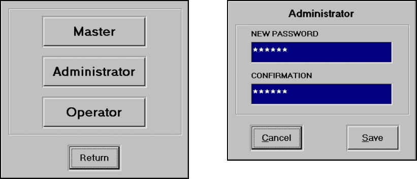
PASSWORD CHANGE
In PASSWORD CHANGE screen, you can set and change the different level of the
passwords.
MASTER PASSWORD
A master level of password can access any password-protected areas. It overrides the
ADMINISTRATOR and OPERATOR level of the passwords and allows you to change their
passwords from this screen. Click MASTER button to change the Master password. This
requires Master level of password.
ADMINISTRATOR PASSWORD
Administrator level of password can access most of the password-protected areas except for
SYSTEM SETUP change in ADTServer. It overrides the OPERATOR level of password and
allows you to change it from this screen. Click ADMINISTRATOR button to change the
Administrator password. This requires Administrator or higher level of password.
OPERATOR PASSWORD
Operator level of password has limited access areas. With Operator level password, you can
change current alarm settings and download the change. However, you cannot alter any
existing jobs in the JOB RECIPE database or create a new job. It only allows you to
download existing job from RECIPE MANAGER screen. Click OPERATOR button to change
the Operator password. This requires Operator or higher level of password.
INITIAL PASSWORD
Master: 1968
Administrator: 123456
Operator: 123
Note: If you forget your passwords, contact HELM INSTRUMENT CO., Inc. at (419) 893-4356

PTM LOADGARD Series Operators Manual
36
ADTSERVER SETUP SCREEN
ADTServer is the core of the engine for the software of this system. ADTServer receives
tonnage signal from SCM module, processes the data, monitors the alarm conditions, and
handles I/Os. When the system is installed in a machine for the first time, ADTSERVER
requires several initial setups from SYSTEM SETUP screen. Any change of the settings in
ADTSERVER is protected by the Master level of password.
MONITOR SCREEN
Here, you can monitor the current operating status of the ADTSERVER for system trouble
shooting purpose.
OPERATING STATUS INDICATOR
OPERATING MODE INDICATOR
OPERATING MODE INDICATOR indicates the system’s current operating mode. Green
background color shows the currently active mode.
Note: Auto means Monitor mode.
FREQUENCY
Sampling speed rate in Hz per Channel
POINTS
Number of sampled points per cycle.
BUFFER CURRENT INDEX
Total number of data stored in buffer per
a cycle.
RESET INPUT
Reset Input Indicator. Turn to red color
when there is reset input.
STROKE COUNT
Displays stroke count after the system is
powered on.
WINDOW TIME (Only applicable to
none Resolver Model)
Displays current Window Time setting.
IDLE
This indicates that press slide position is out of look window and
ADTSERVER is in idle.
READING
This indicates that press slide position is within look window and
ADTSERVER is sampling data.
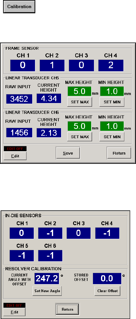
PTM LOADGARD Series Operators Manual
37
SENSOR CALIBRATION SCREEN
CALIBRATION SCREEN FOR PTM4500TSM/6700TSM
FRAME SEMSOR screen is to help
calibrating a PTM-1 module to get a proper
reading from the load sensors connected.
Each number is a percentage of the voltage
from PTM-1 track out signals for each
channel. 100 means 2.67V which is ideal
voltage to be set as max scale tonnage for a
press. It displays sensor balance numbers
if PTM module’s function switch is in AZ-OFF
position and Cal numbers if the switch is in
CAL position.
For details about PTM function switches,
Please refer to PTM-1 manual.
Click Calibration button to view a Sensor Calibration screen.
Note: To make any changes of the settings, Master level of password is
required to turn on the Edit Enable Mode.
LINEAR TRANSDUCER screen is to help
calibrating optional Linear Transducer inputs
connected to channel 5 and 6. It is 2 points
calibration. Move slide to maximum position
and enter the measured height to MAX
HEIGHT then Click SET MAX button. Then,
move slide to minimum position and enter
the measured height to MIN HEIGHT then
Click SET MIN button.
RESOLVER CALIBRATION
Current ANGLE WITH OFFSET displays the
current position of the resolver with stored
offset applied.
If the current resolver angle read out does
not match with actual machine slide position,
Click Clear Offset to clear any stored Offset
value, click Set New Angle, then enter the
actual angle position of the machine.
This will store new OFFSET value .
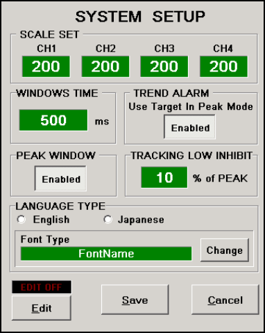
PTM LOADGARD Series Operators Manual
38
SYSTEM SETUP SCREEN
The SETUP screen is where you can configure the initial settings for the system. To make
any changes of the settings, Master level of password is required to turn on the Edit Enable
Mode.
TRACKING LOW INHIBIT(%)
This is to ignore the tracking alarm from monitoring the area of the load signature below the set
percentage of the current peak tonnage. For example, the Tracking Low Inhibit is set to 10%
and the current peak load is 90ton, then through out the load signature, any tonnages below 9
ton will not be monitored by tracking alarm.
WINDOW TIME (ms) - Only applicable to none Resolver Model
Look Window Time is the duration of time in msec when the force signature and peak
tonnage is captured. The WINDOW TIME needs to be adjusted based on the speed of the
machine to capture optimal force signature.
PEAK WINDOW (Enable/Disable) - Only applicable to none Resolver Model
If you are interested in monitoring certain part of the signature to capture the peak tonnage
instead of the entire signature, enable PEAK WINDOW option.
When PEAK WINDOW is enabled, you can adjust the monitoring area by using ALARM
WINDOW. The Trend alarm and Tracking alarm will only apply to the PEAK WINDOW area.
However, High Capacity alarm still looks for the actual peak tonnage of entire signature.
SCALE SET
Scale value is usually set for capacity of the press
divide by number of channel of the frame sensors
TREND ALARM
Use Target In Setup Mode Enable/Disable
This enables or disables the Trend Alarm
feature in Setup and Learn modes.
When enabled, Trend Alarm feature is active in
all modes. In Setup and Learn modes, Trend
Alarm uses Target value as a reference point to
trigger alarm while Sample value is used as the
reference point in Monitor mode. When
disabled, the Target is no longer used and
Trend Alarm feature is only active in Monitor
mode after learning cycle is completed.

PTM LOADGARD Series Operators Manual
39
System Setup Screen for PTM-5600P/6700P
SCALE SET
Default Scale values for Piezo series are set to 267. We recommend using this value as your
scale set. This will scale the peak load output value to match with the sensor voltage output. For
example, if Ch1 peak shows 157, it means the sensor peak output from PTM Piezo module is
1.57V.
DIVERTER DURATION
Enter a time in msec to adjust the duration how long the Diverter output stays on. When Trend/
tracking/ capacity alarm condition happen, the diverter output turns on for given duration.
You can choose the Diverter output type to be either Normally Open(N.O.) or Normally Closed
(N.C.)
The diverter works for every trend/tracking alarm condition regardless the Fault Delay counter
setting.
CONSECUTIVE FAULT DELAY COUNTER
Enter a number of consecutive fault stroke that required to stop the machine.
When Trend and Tracking alarm condition happens, alarm output does not drop out until the
alarm condition persists consecutively for the number of set cycle.
For example, if the "Consecutive Fault delay counter " is set to 3, When Trend/tracking alarm
condition occurs for 2 continuous strokes and no trend alarm condition in 3rd stroke, the delay
counter reset to 0. Therefore, another 3 continuous trend/tracking alarm conditions have to
happen to trigger Alarm Stop replay or it will run without stopping machine.
* In case of Capacity alarm, system will drop the Alarm Stop relay right away regardless the
Consecutive Fault delay counter setting and turn on diverter for given duration as well.
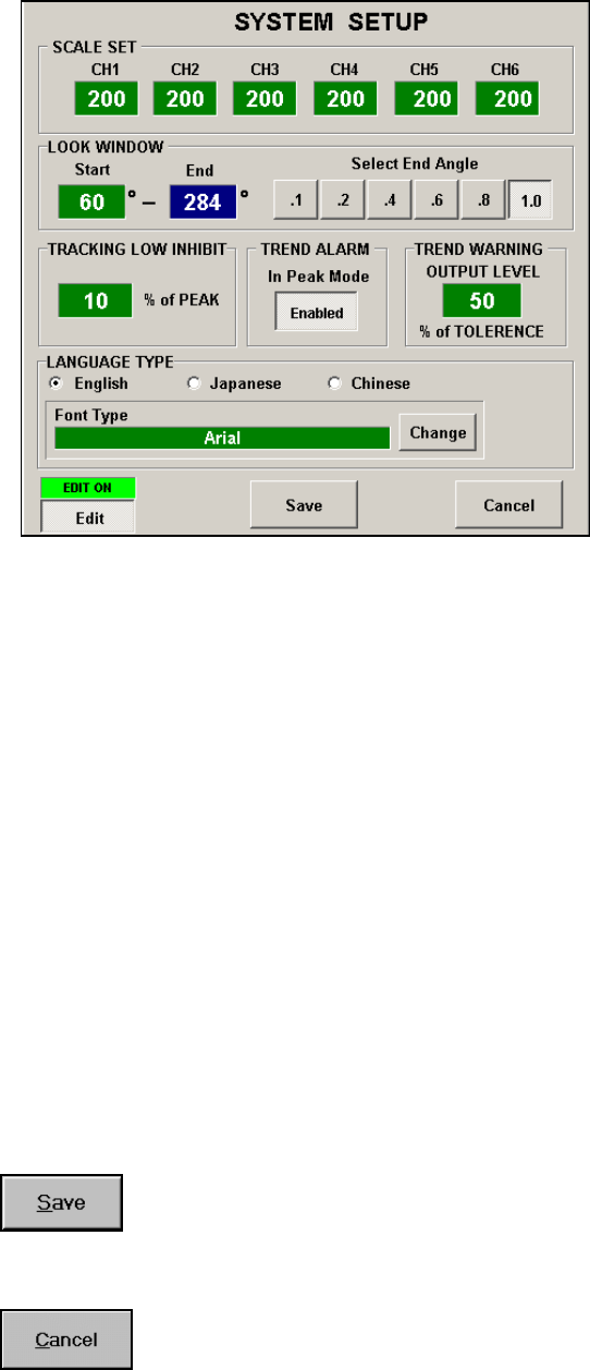
PTM LOADGARD Series Operators Manual
40
SYSTEM SETUP SCREEN FOR PTM-4500TSM/6700TSM/6700I-TSM
TREND WARNING OUTPUT LEVEL
Set a percentage of the Tolerance set value where you want to monitor for tonnage
warning condition. When current tonnage reaches or exceeds warning level, the
Tonnage Warning output relay unlatches. When the tonnage returns to normal, the
output relay latches back automatically. For Example, if High Tol is set at 20%, and
Trend Warning Level is set at 50% of Tolerance, when current peak tonnage reaches
or exceeds 50% of Trend indicator (10% from sample peak tonnage), Loadgard
triggers Tonnage Warning output. This gives the way to warn the machine control
prior to tonnage Trend alarm without stopping machine’s operation.
SAVE
CANCEL
LOOK WINDOWS
Look Window is the area of the slide position where the force signature and peak
tonnage is captured. The LOOK WINDOW needs to be adjusted to capture optimal
force signature of the machine.
Enter a start angle(degree) where you want to start to monitor the force. By choosing
a multiplier button, it will display the calculated end look window angle automatically.
Click SAVE button to save any configuration changes on this screen for
ADTSERVER to take effect.
Click on CANCEL button to cancel any configuration changes on this screen
and return to previous screen.
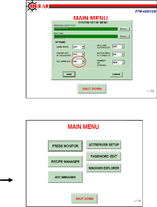
PTM LOADGARD Series Operators Manual
41
PTM LOADGARD ADC SETUP FOR TSM MODEL
Go To ADC Manager
From Main Menu screen, if you do not see ADC MANAGER menu button, then click on
the hidden button located at the left bottom area of the screen to go to SYSTEM SETUP
MENU. Use 6534 for password
Turn ADC MANAGER option ON and click Save then restart the system.
ADC Manager Setup
a. To enter into the ADC Manager
screen, use master password
(Default mater password “1968”)
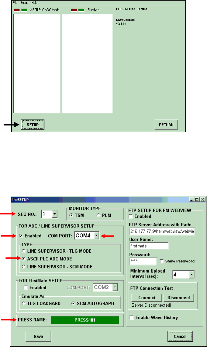
PTM LOADGARD Series Operators Manual
42
b. Click SETUP button to go to ADC Setup screen.
c. In ADC Setup screen, select a SEQ number to 1, select a COMPORT number where the
ADC communication cable is plugged in, and select ASCII PLC ADC MODE option.
d. You can also enter a press name as optional
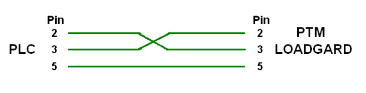
PTM LOADGARD Series Operators Manual
43
ADC RS232 CABLE CONNECTION
Direct RS-232 connection is possible with PLC as long as the able length is less than
50feet.
RS-232 Cable connection
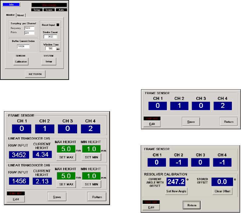
PTM LOADGARD Series Operators Manual
44
GETTING READY FOR CALIBRATION
1. Make sure proper Look window timing Input is connected to CAM Input of PTM Loadgard.
Please refer to the drawing from the Appendix in the manual for connection details. For TSM
model, Make sure the Resolver is connected properly instead of CAM input
2. Check sensor balance and gain values from the PTM LoadGard,
a. From main menu screen, go to “ADTSERVER SETUP”
b. Click on Monitor tab, and click on Sensor CALIBRATION button.
In this screen, you can verify the current balance and the gain
values of the sensors connected to PTM modules by switching
the 3 position toggle switch on the PTM module inside. OFF
position displays sensor balance, CAL position displays gain
value of the sensor. Please refer to the PTM-1 Module manual
for detail.
Depending on the PTM LOADGARD model, you can calibrate
Resolver angle position or position of Linear input devices in this
screen as well.
c. For TSM model, you need to calibrate Resolver angle in this screen as well. If the current
resolver angle read out does not match with actual machine slide position, turn Edit option
On by entering master level of password (default: 1968), click Clear Offset to clear any
stored Offset value, click Set New Angle, then enter the actual angle position of the
machine. This will store new OFFSET value.
PTM-4500-L2 Model
PTM-4500 Model
PTM-4500-TSM Model
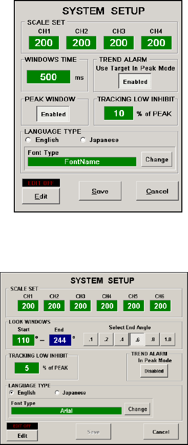
PTM LOADGARD Series Operators Manual
45
3. Entering Scale values for each Channel.
Next thing before the calibration, you need to enter proper scale value for each channel.
Scale value is the tonnage that each sensor will measure at full capacity of the machine. For
example, if a machine is rated at 800ton as maximum capacity and has total 4 sensors mounted
on columns of the machine, then the scale value would be 200 ( 800 / 4 = 200) per channel.
To Enter the scale value for each channel,
a. go to “ADTSERVER SETUP”
b. Click on Monitor tab, and click on Setup button
c. Enable Edit by entering master level of password
(default: 1968)
d. Enter scale value to each channel on SCALE SET
section and click Save.
4. For CAM input model , you need to enter initial Window
Time for calibration.
Look Window Time is the duration of time in
millisecond when the force signature and peak tonnage
is captured. The WINDOW TIME needs to be adjusted
based on the speed of the machine to capture optimal
force signature. For that reason the WINDOW TIME is
one of the job recipe items that can be programmed
for each job.
For initial window time during calibration, set to 500ms
and check the load signature after the first hit on load
cell.
If the load signatures loading duration is less than 25% of the total look window time, then
reduce the Look Window Time.
For TSM model, you need to select Look Window
Angle. Look Window Angle is the area of the stroke in
angle where the force signature and peak tonnage is
monitored and captured.
Unlikely the Look Window Time, the Look Window
Angle does not need to be adjusted per job.
Enter a Look Window Start angle value then select one
of the multiplier (.1, .2, .4, .8. 1.0) to determine the End
angle.
Click Save button to save the changes.
Now the PTM LoadGard is ready to be calibrated. For more details of the features and functions,
please read the PTM LOADGARD User Manual and PTM-1 User Manual.

PTM LOADGARD Series Operators Manual
46
SYSTEM SPECIFICATIONS
1. 90-240 VAC input power source @ 3.125 Amp.
2. Automatic Zero Balance (Auto-Zero)
3. 2/4/6 channel load-strain gauge input utilizes 175 - 700 ohm nominal bridge resistance.
4. *24VDC-Cam/Prox/PLC input
5. Hi/Lo Gain Range (1 meg/140K)
6. 24VDC I/O
2 inputs : 10-30 VDC
2 outputs : 10-30 VDC
7. Communication Ports
ADC(Automatic Die Change) (RS-422) - Optional
Line Supervisor (ASCII) (RS-422) - Optional
FirstMate (RS-422) - Optional
8.
9. A/D resolution: 16Bit
10. **Resolver Input: Sine/Cosine 12 bit 0.1-degree resolution
11. Speed Range: **3 - 200SPM , *3 - 1000SPM
12. 1 Ethernet port.
13. Interface Display
10.4” TFT LCD Display with 640x480 Resolution w/ Touch Screen.
Windows XP Embedded with Read-Only Filter Enabled to protect OS files
Duel Memory: 4GByte + 2GByte
________________________________________________________________
** : Resolver Input model only
* : CAM Input model only
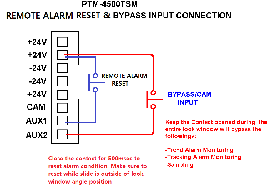
PTM LOADGARD Series Operators Manual
47
BYPASS &REMOTE ALARM RESET
OPTION FOR PTM-4500TSM MODEL
PTM-4500TSM model has Remote Alarm reset and Bypass option to bypass Low Trend
and Low Tracking alarm feature while running. This feature is useful for initial setup
procedure after job change while the parts are being fed through a press line.
While bypass is activated during the stroke, Trend alarm, Tracking alarm, and sampling are
disabled. However, Capacity Press Curve alarms are still active to monitor any overload
condition.
TO ENABLE THE BYPASS OPTION
Open “D:\PTM4500TSM\TMONITOR.INI” file using Windows Explorer, set bypass option to
1 as below. Save the file, then restart the system.
[PTM6700i:SYSTEM]
…..
BYPASS OPTION=1
When bypass option is ON, every stroke will be bypassed until BYPASS input is closed
while the silde position is entering Look window start angle set.

PTM LOADGARD Series Operators Manual
48
ADC ASCII PROTOCOL
This protocol is to communication with the ADC port of the PTM LOADGARD
directly with optional RS422 serial interface for ADC feature.
Communication Port Setting
BAUD rate: 9600
PARITY: None
Data Bits: 8
Stop Bits: 1
How to Send Command ASCII DATA
There are 2 types of data protocol. COMMAND DATA and COMFIMATION DATA
1. Send 9 byte of COMMAND DATA
2. SCM Autograph will send back 9 byte of data you sent. Wait for the echo data.
3. Compare the 9 bytes of original data with echoed data for verification.
4. If both data matches, send COMFIRMATION DATA to complete the command
ASCII Data Format - COMMAND DATA
BYTE#
BYTE DESCRIPTION
1
ID Byte ( 96 + SCM sequence Number set by DIP switch on the board)
2
0 (MSByte of Remaining Data Byte to Send)
3
6 (LSByte of Remaining Data Byte to Send)
4
218
5
192
6
76
7
203
8
65
9
ADC Mode
0 – 250 = Download Job Number
251 = Change to Setup Mode
252 = Change to Monitor Part Mode
253 = Change to Monitor Part Mode
254 = Reset Alarm
255 = No Action
ASCII Data Format - CONFIRMATION DATA
BYTE#
BYTE DESCRIPTION
1
ID Byte ( 64 + SCM sequence Number set by DIP switch on the board)
2
0 (MSByte of Remaining Data Byte to Send)
3
5 (LSByte of Remaining Data Byte to Send)
4
218
5
192
6
76
7
203
8
85
PTM LOADGARD Series Operators Manual
49
Example)
To change the mode to Setup mode for SCM module which is set as Seq#1,
1. Send 9 bye of data below
97, 0, 6,218, 192, 76, 203, 65, 251
2. Wait for response data (9byte) from SCM Autograph
3. compare the data received and the data you sent to see if all matches.
4. If both data matches, send COMFIRMATION DATA to complete the command as below
65, 0, 5, 218, 192, 76, 203, 85
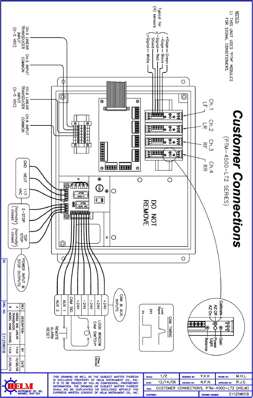
PTM LOADGARD Series Operators Manual
50
APPENDIX A ( PTM-4500L2 ) - 4CH FRAME WITH 2 LINEAR TRANSDUCER
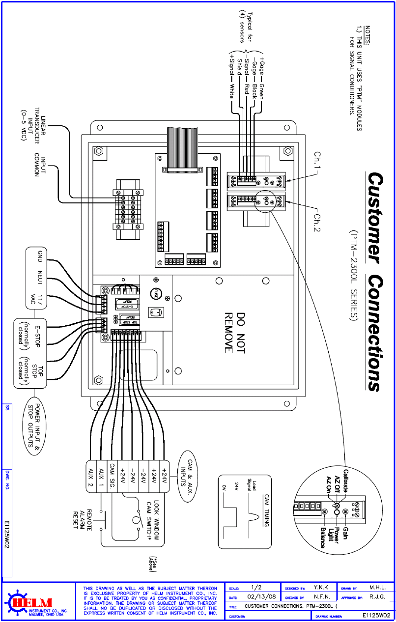
PTM LOADGARD Series Operators Manual
51
APPENDIX B ( PTM-2300L ) – 2CH FRAME/INDIE WITH 1 LINEAR TRANSDUCER INPUT
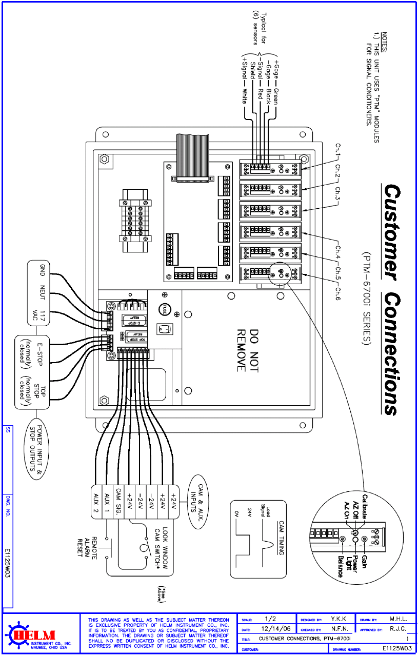
PTM LOADGARD Series Operators Manual
52
APPENDIX C ( PTM-6700I ) – 6CH IN-DIE APPLCATION
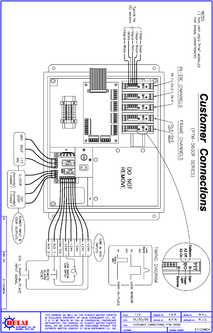
PTM LOADGARD Series Operators Manual
53
APPENDIX D ( PTM-5600F ) – 3CH IN-DIE + 2CH FRAME APPLICATION

PTM LOADGARD Series Operators Manual
54
APPENDIX E ( PTM-6700TSM ) 4CH FRAME + 2CH INDEA WITH RESOLVER INPUT
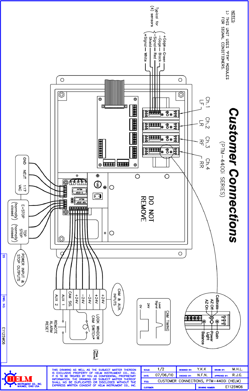
PTM LOADGARD Series Operators Manual
55
APPENDIX F ( PTM-4400I ) 4CH IN-DIE APPLICATION
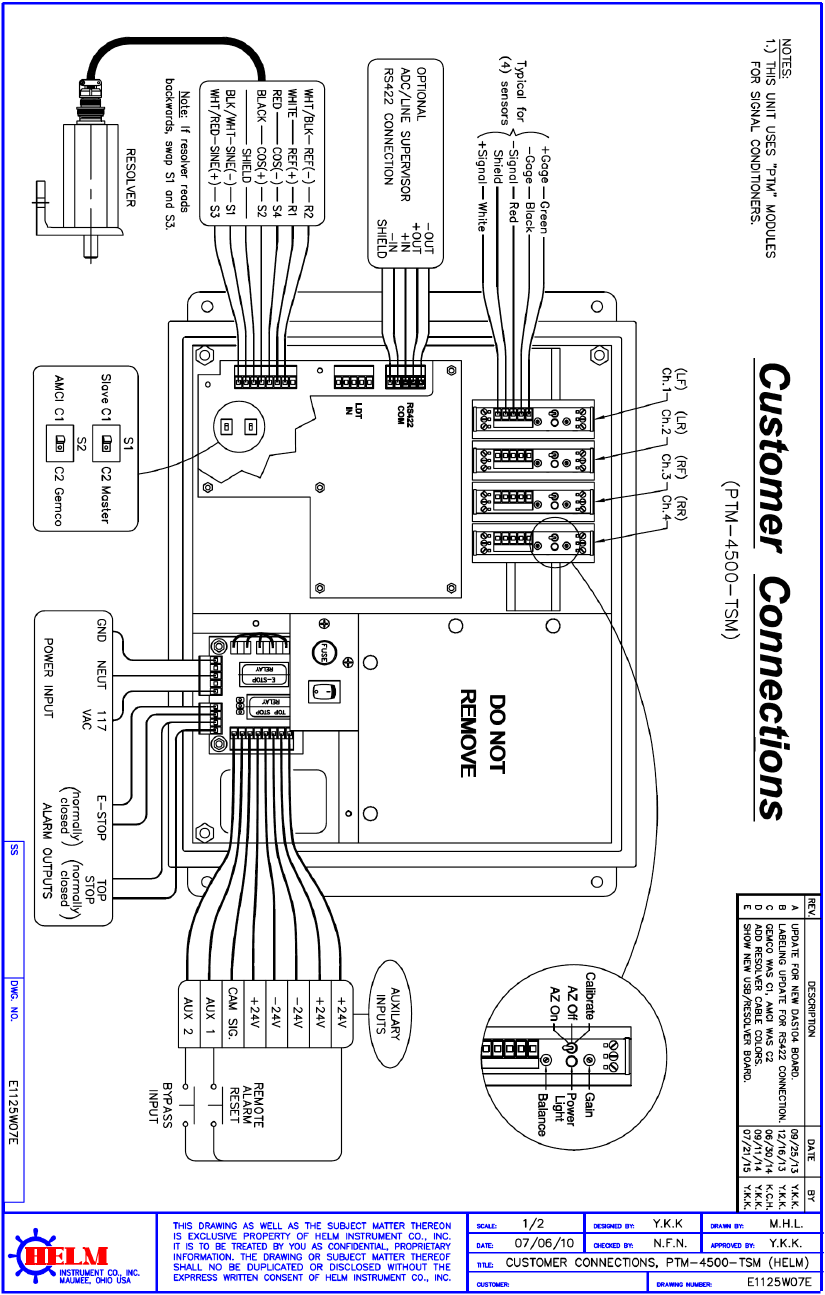
PTM LOADGARD Series Operators Manual
56
APPENDIX G ( PTM-4500TSM )- 4CH FRAME WITH RESOLVER INPUT
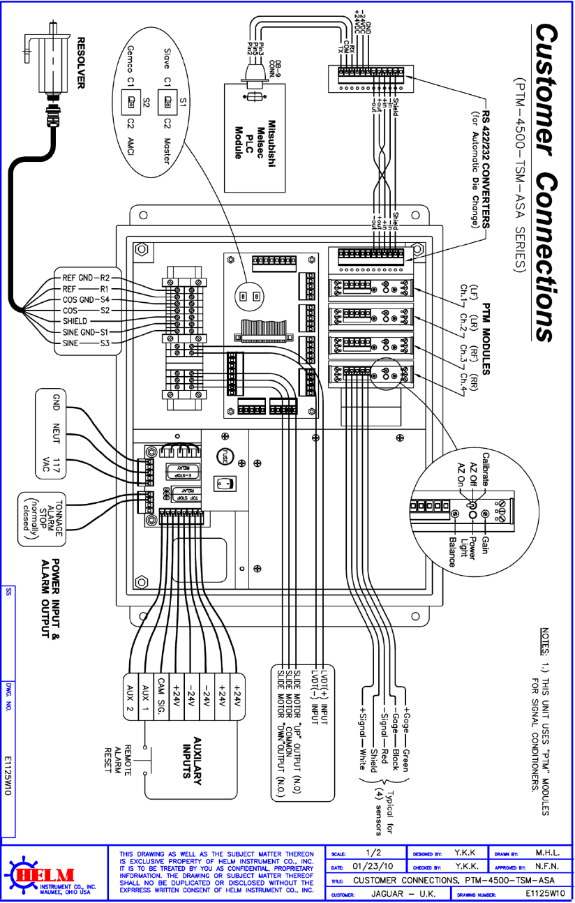
PTM LOADGARD Series Operators Manual
57
APPENDIX H ( PTM-4500TSM-ASA )- 4CH FRAME + AUTO SHUTHEIGHT ADJUST W/ RESOLVER
INPUT
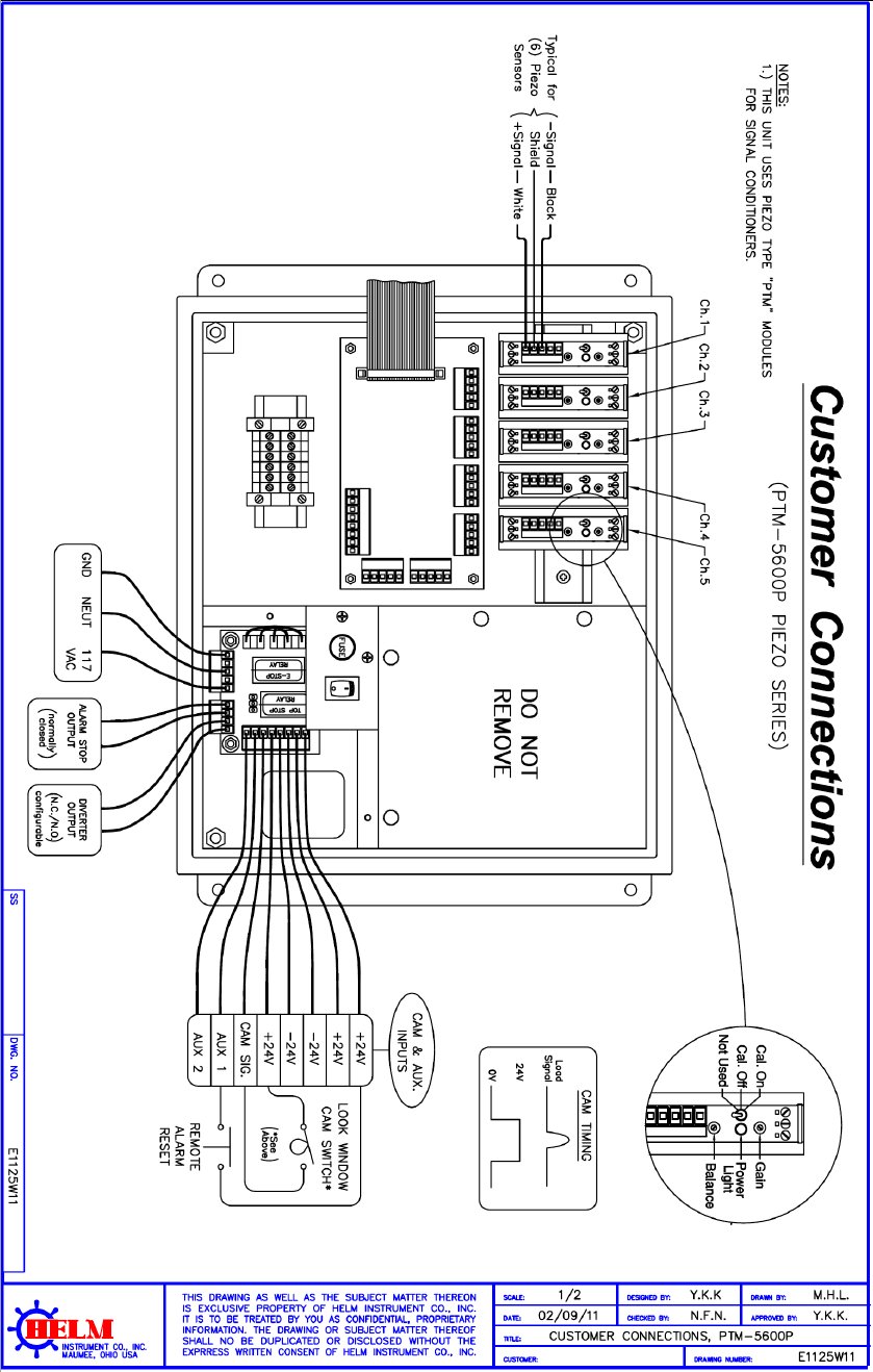
PTM LOADGARD Series Operators Manual
58
APPENDIX I ( PTM-5600P) - 5CH PIEZO SENSOR INPUT
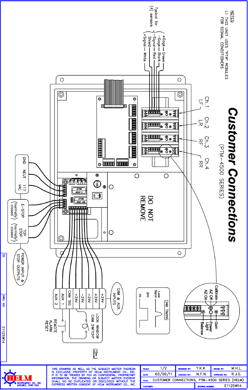
PTM LOADGARD Series Operators Manual
59
APPENDIX J ( PTM-4500) - 4CH FRAME WITH CAM INPUT
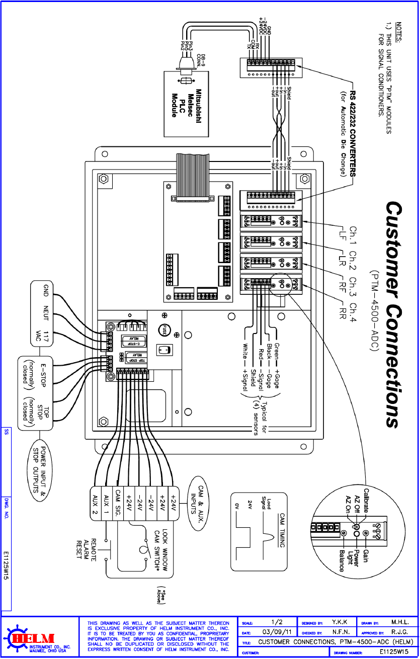
PTM LOADGARD Series Operators Manual
60
APPENDIX K ( PTM-4500-ADC) - 4CH FRAME WITH AUTOMATIC DIE CHANGE OPTION
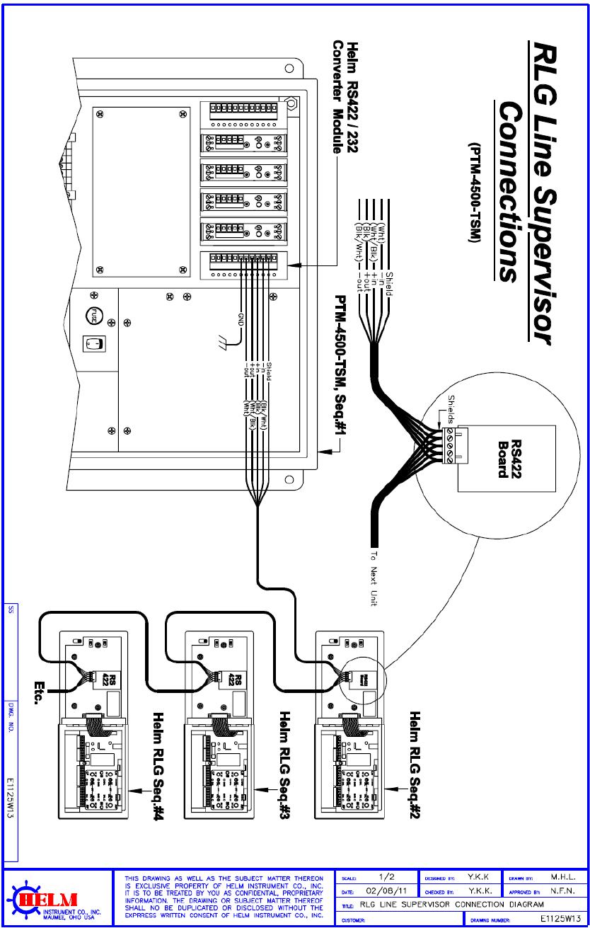
PTM LOADGARD Series Operators Manual
61
APPENDIX L LINE SUPERVISOR WITH RLG CONENCTION
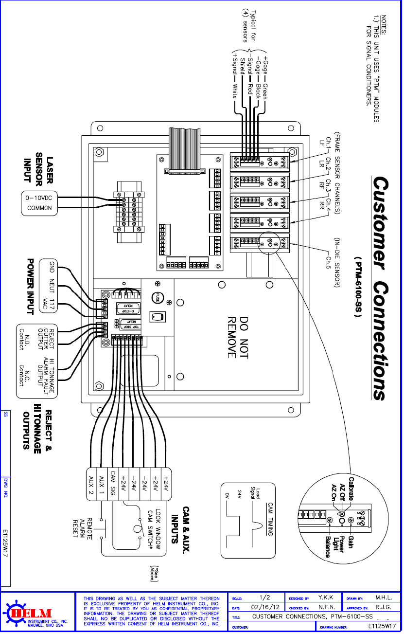
PTM LOADGARD Series Operators Manual
62
APPENDIX M ( PTM-6100-SS) - 4CH FRAME, 1CH IN-DIE, 1CH LASER SENSOR
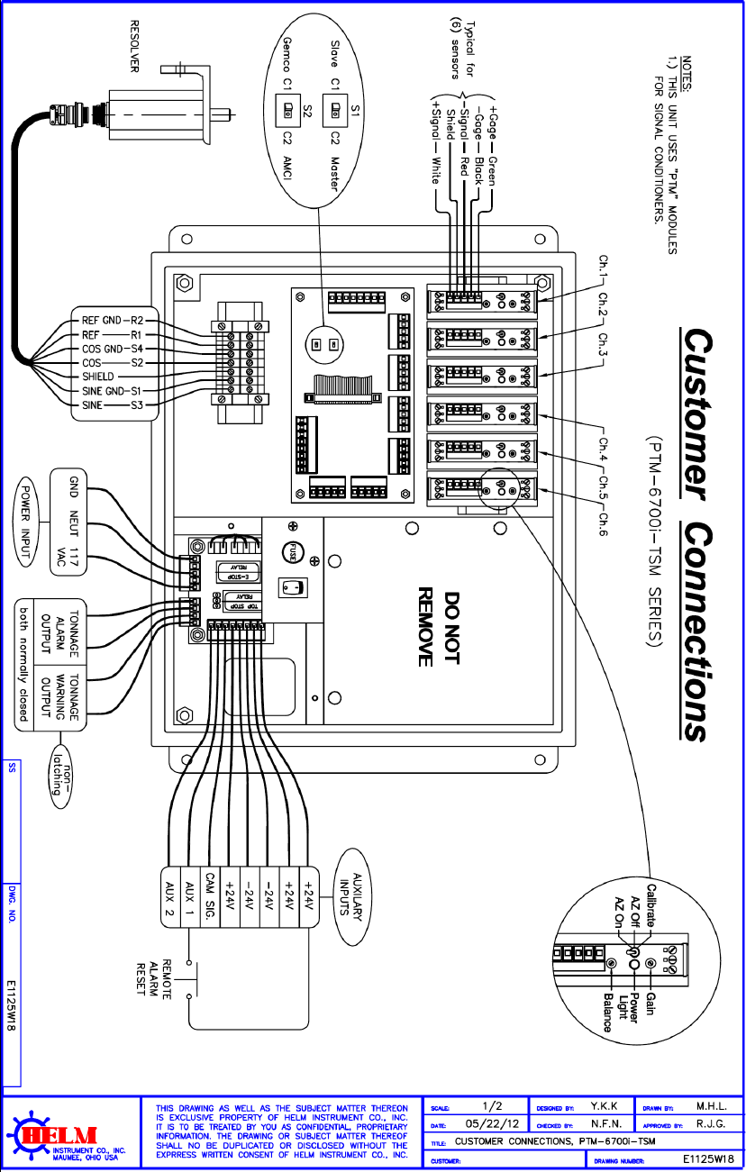
PTM LOADGARD Series Operators Manual
63
APPENDIX N ( PTM-6700I-TSM) - 6CH IN-DIE WITH TREND WARNING OUTPUT
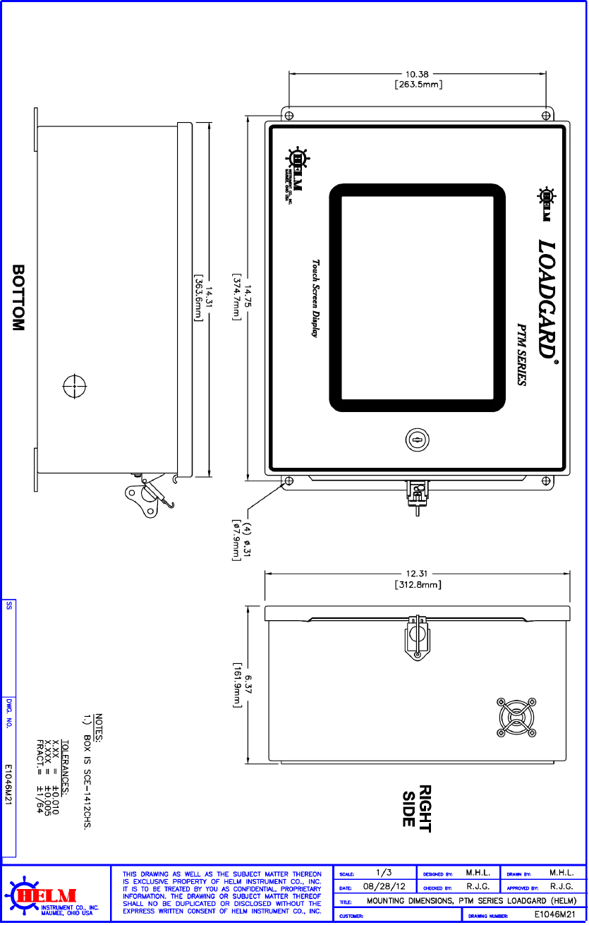
PTM LOADGARD Series Operators Manual
64
APPENDIX O PTM LOADGARD DIMEMSION (STANDARD MOUNT)
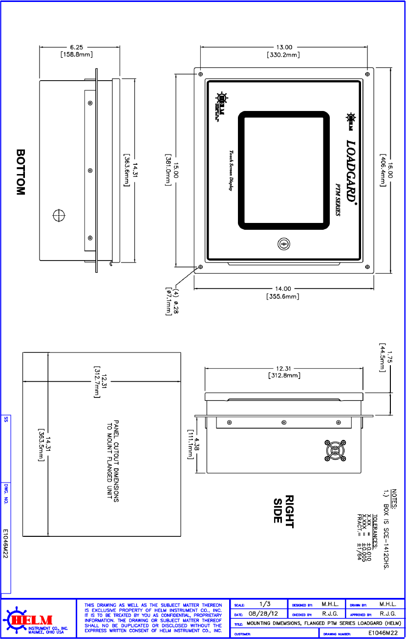
PTM LOADGARD Series Operators Manual
65
APPENDIX P PTM LOADGARD DIMEMSION (FLANGE MOUNT)
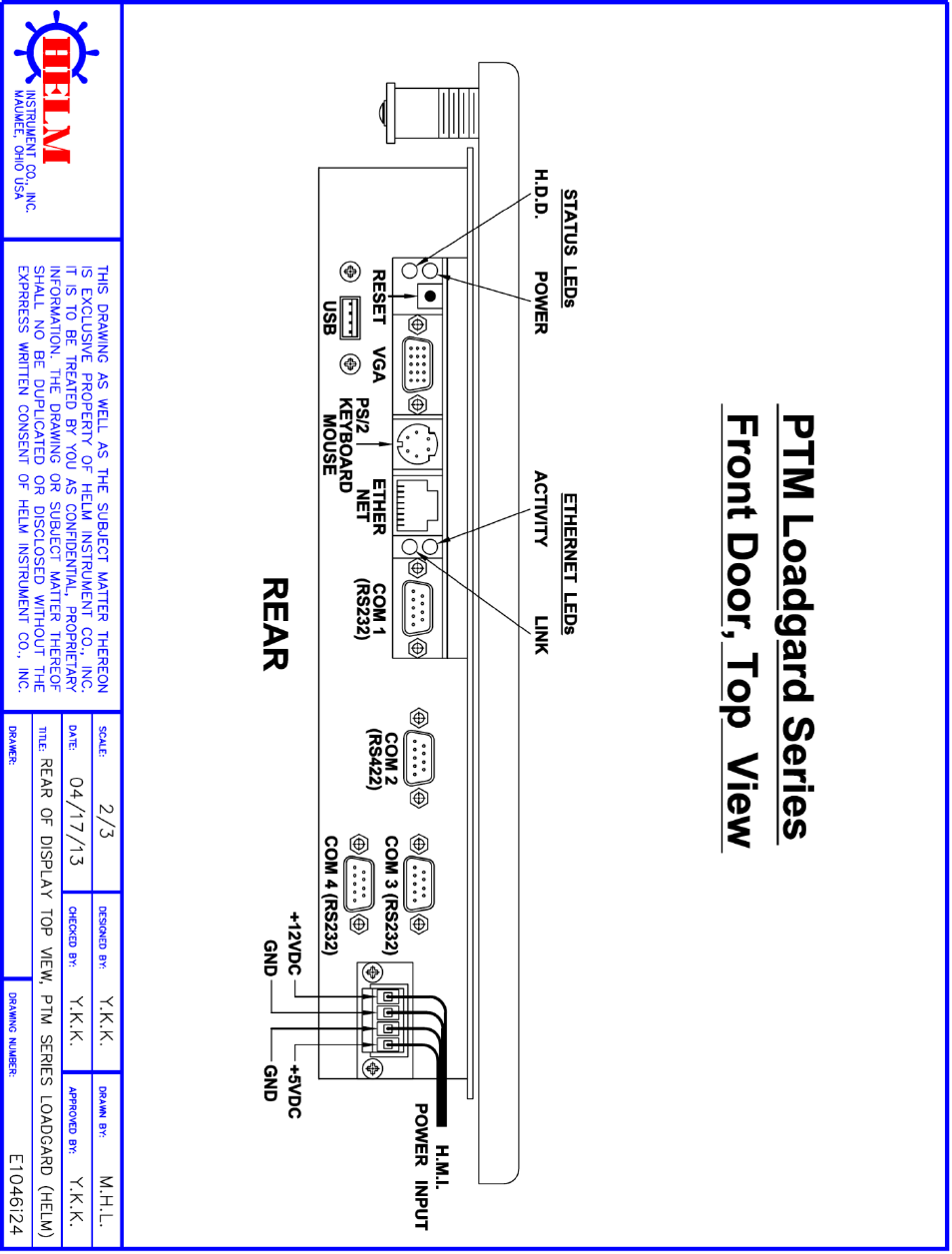
PTM LOADGARD Series Operators Manual
66
APPENDIX P-1 PTM LOADGARD PANEL PC CONNECTIONS LAYOUT
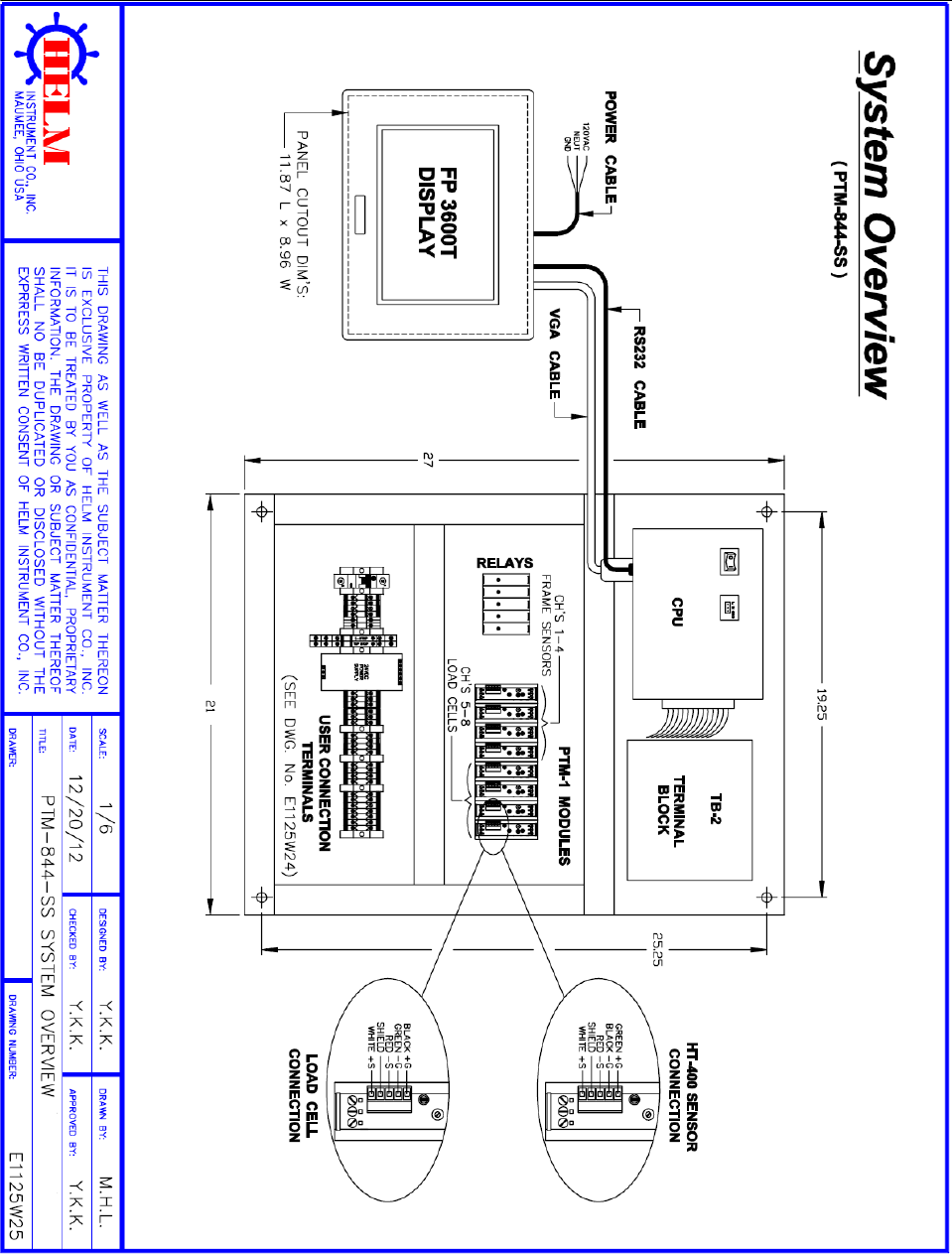
PTM LOADGARD Series Operators Manual
67
APPENDIX Q (PTM-884TSM-SS) 4CH FRAME, 4CH IN-DIE SENSORS

PTM LOADGARD Series Operators Manual
68
APPENDIX R (PTM-844TSM-SS) CONNECTION DRAWING
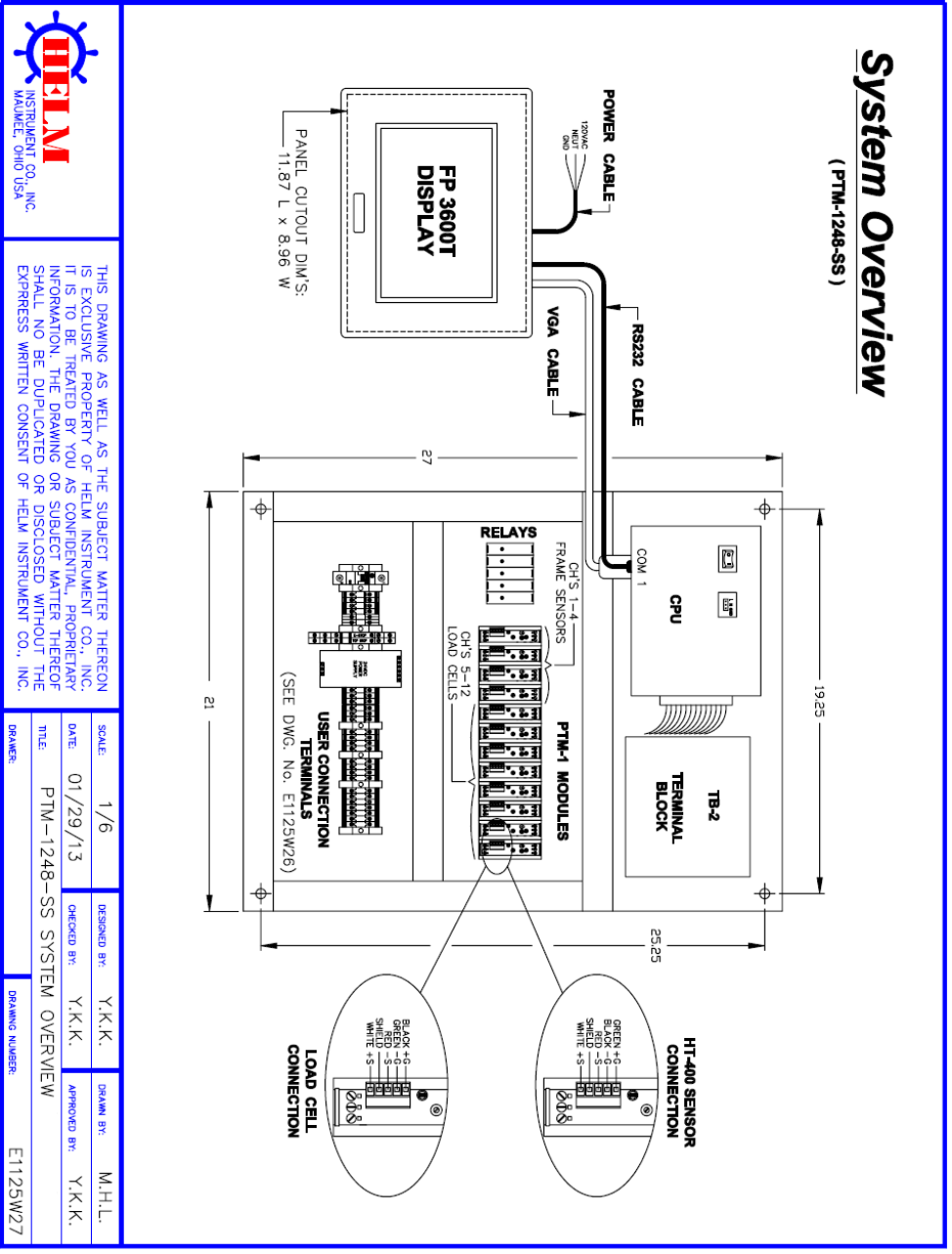
PTM LOADGARD Series Operators Manual
69
APPENDIX S (PTM-1248TSM-SS) 4CH FRAME, 8CH IN-DIE SENSORS
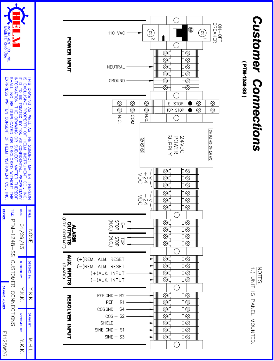
PTM LOADGARD Series Operators Manual
70
APPENDIX T (PTM-1248TSM-SS) CONNECTION DRAWING
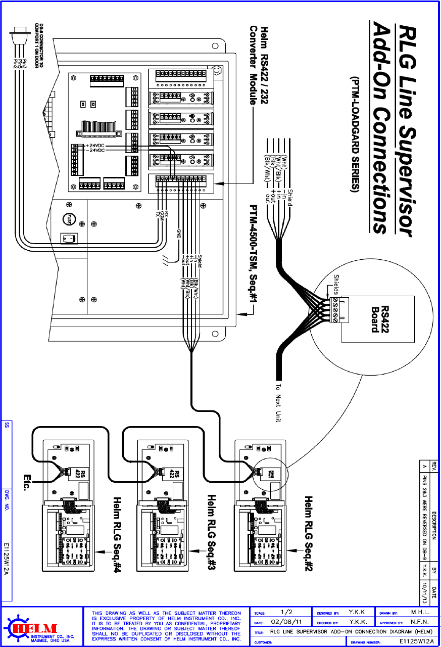
PTM LOADGARD Series Operators Manual
71
APPENDIX U RLG LINE SUPERVISOR CONNECTION
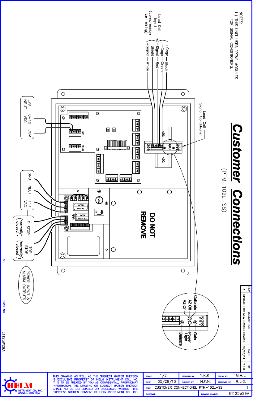
PTM LOADGARD Series Operators Manual
72
APPENDIX V PTM-102L CONNECTIONS
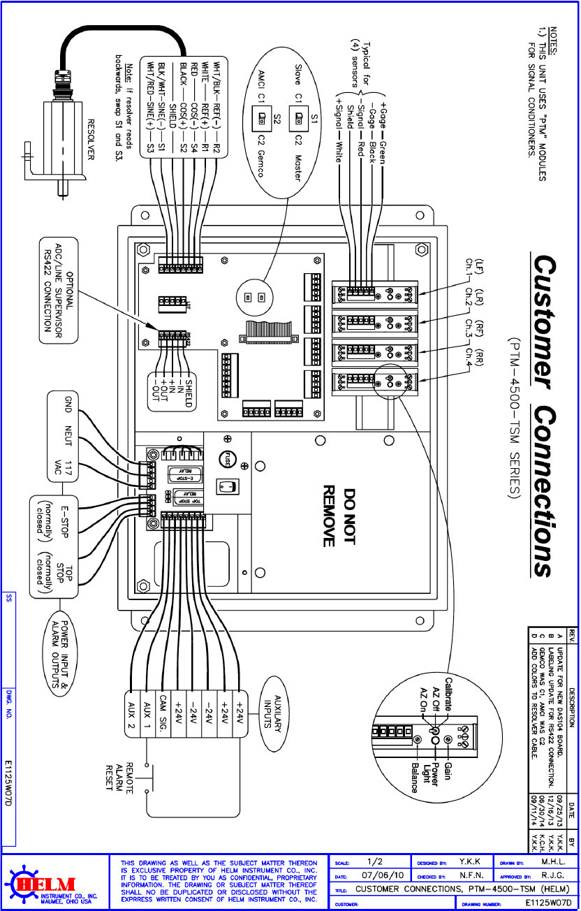
PTM LOADGARD Series Operators Manual
73
APPENDIX W PTM-4500TSM NEW I/O BOARD CONNECTIONS
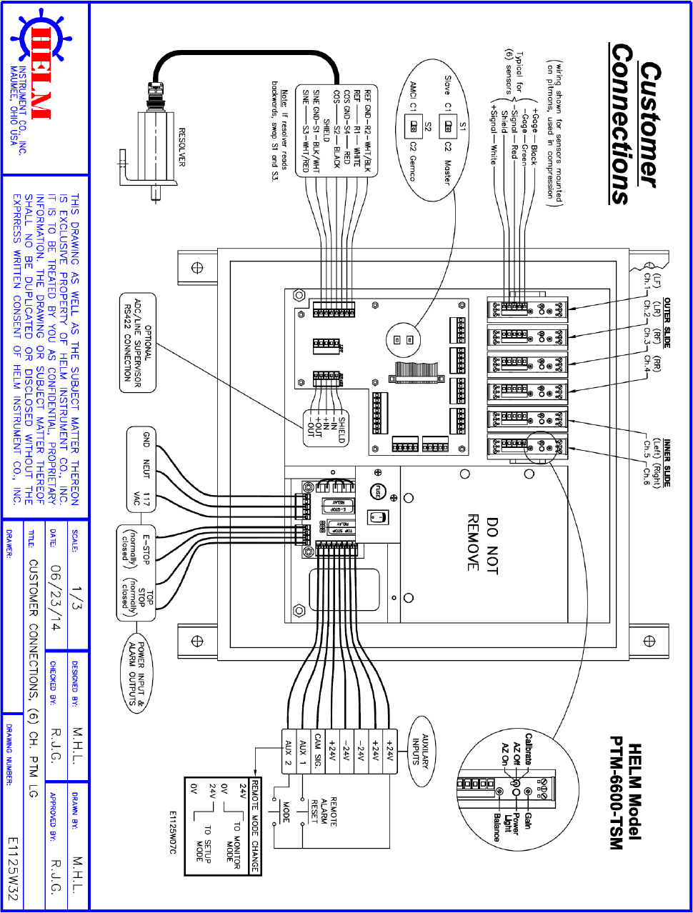
PTM LOADGARD Series Operators Manual
74
APPENDIX X PTM-6600TSM FOR DOULE ACTION CONNECTIONS
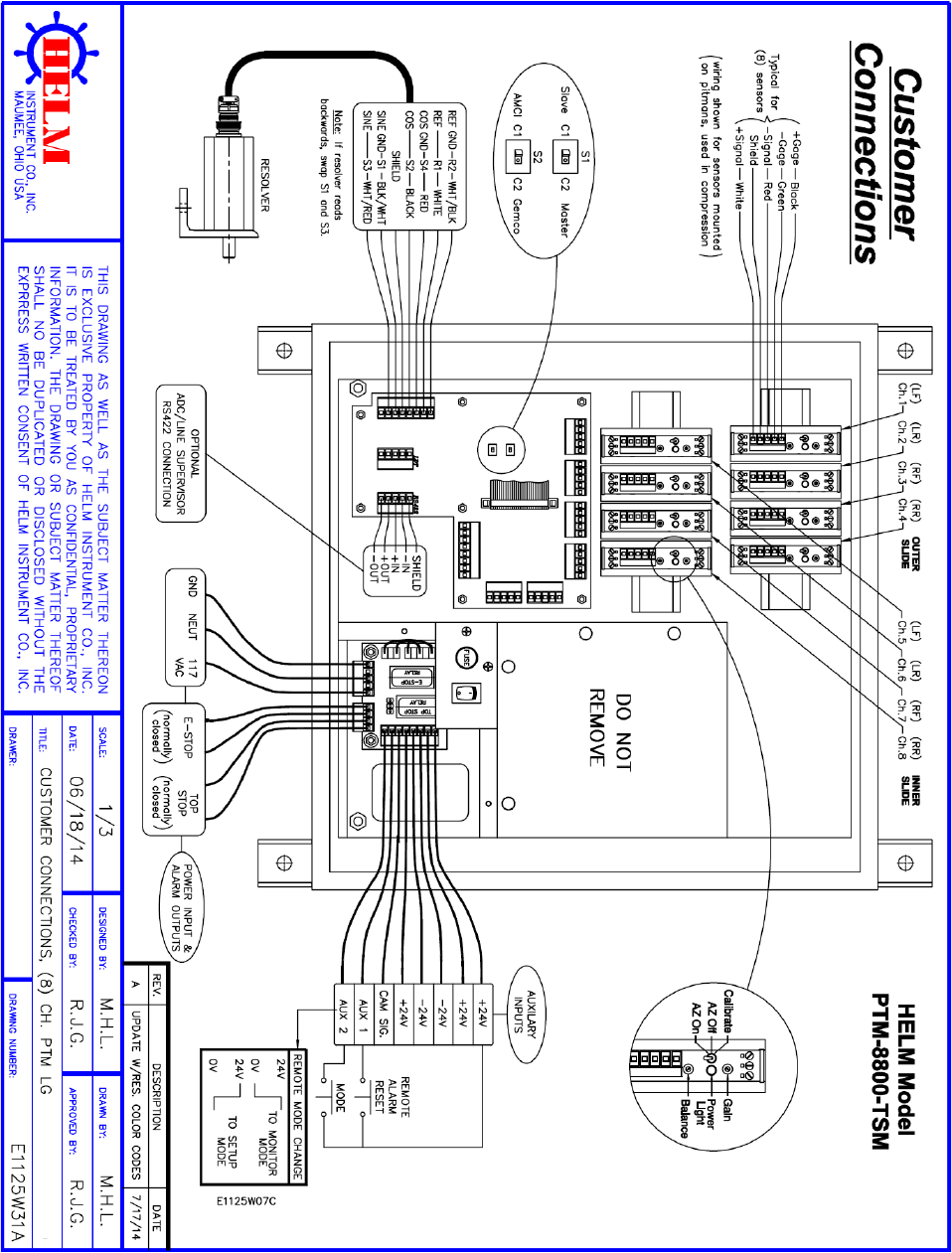
PTM LOADGARD Series Operators Manual
75
APPENDIX Y PTM-8800TSM FOR DOULE ACTION CONNECTIONS
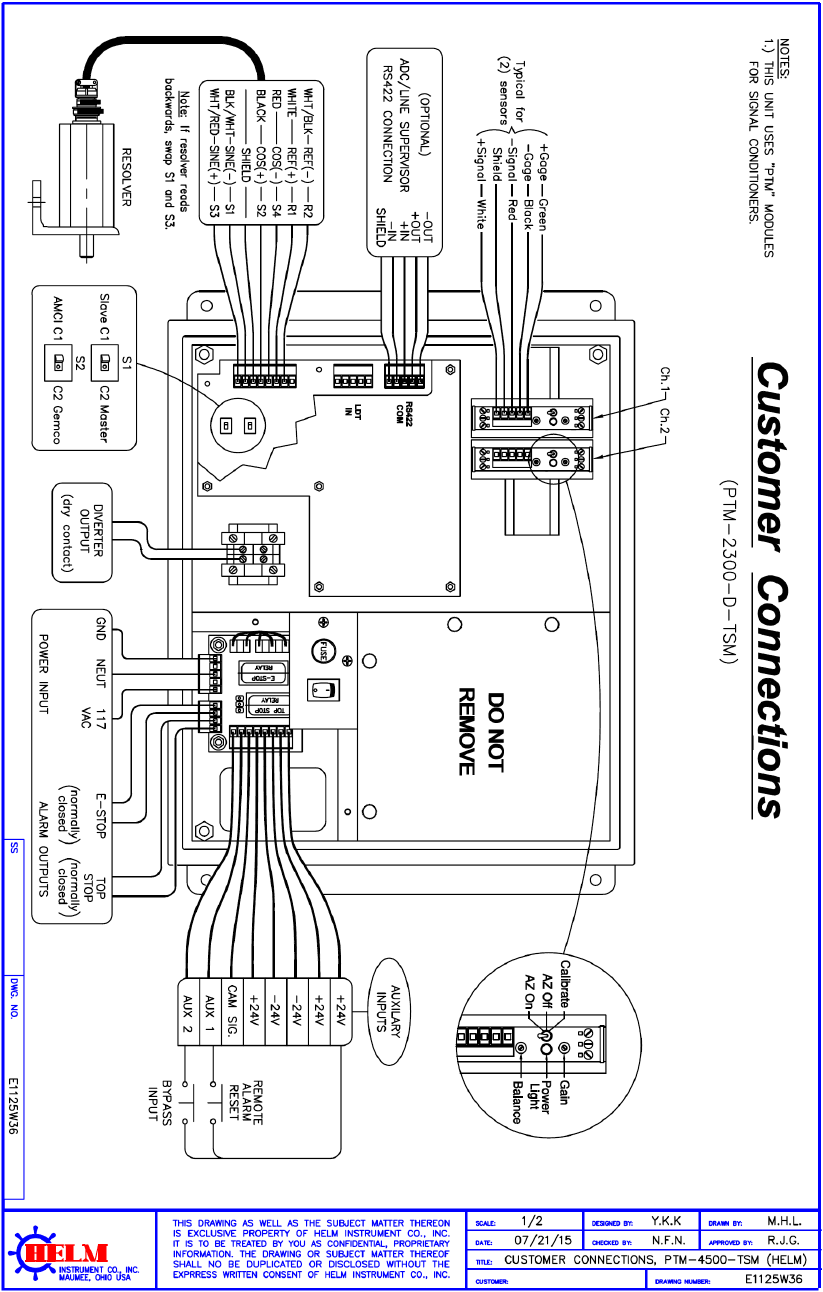
PTM LOADGARD Series Operators Manual
76
APPENDIX Z PTM-2300D-TSM WITH DIVERTER OUTPUT
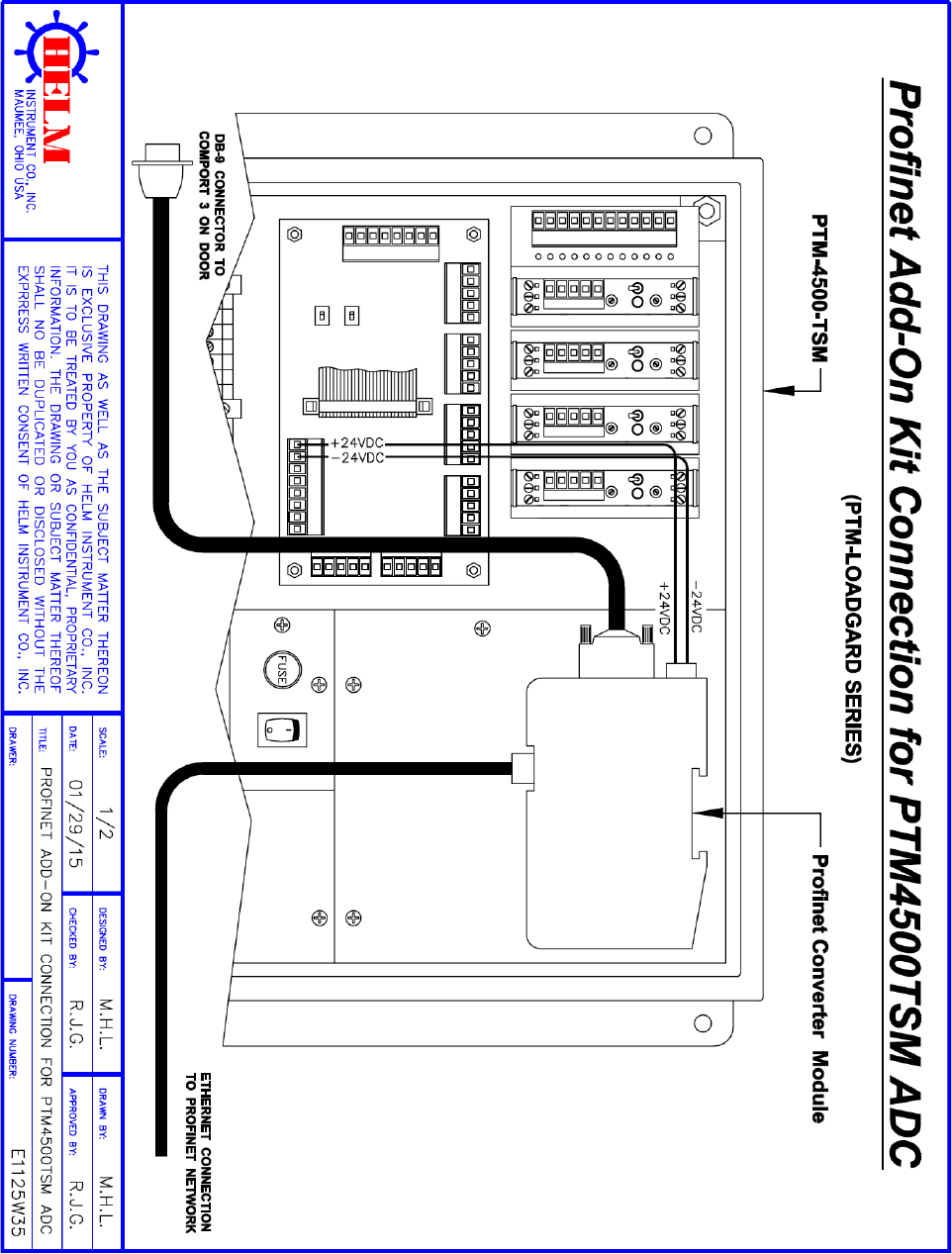
PTM LOADGARD Series Operators Manual
77
APPENDIX Z1 PROFINET ADD-ON KIT CONNECTION
