Pfeiffer, Dual Gauge TPG 262 Channel Control Unit, For Compact Gauges Pfeiffer TPG262 Operating Instructions
User Manual:
Open the PDF directly: View PDF ![]() .
.
Page Count: 106 [warning: Documents this large are best viewed by clicking the View PDF Link!]
2BG 805 196 BE / B (2004-08) TPG262.oi
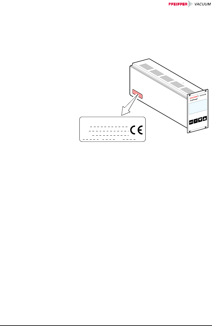
In all communications with Pfeiffer Vacuum, please
specify the information on the product nameplate. For
convenient reference copy that information into the
space provided below.
Typ:
No:
F-No:
V Hz VA
Pfeiffer Vacuum, D-35614 Asslar
This document applies to products with part number
PTG28280.
The part number (No.) can be taken from the product
nameplate.
This manual is based on firmware version 302-510-A.
If your unit does not work as described in this document,
please check that it is equipped with the above firmware
version (→ 60).
We reserve the right to make technical changes without
prior notice.
All dimensions are indicated in mm.
Product Identification
Validity

BG 805 196 BE / B (2004-08) TPG262.oi 3
The TPG 262 is used together with Pfeiffer Vacuum
Compact Gauges (in this document referred to as
gauges) for total pressure measurement. All products
must be operated in accordance with their respective
Operating Instructions.
The scope of delivery consists of following parts:
1 TPG 262 Dual-Channel Measurement and Control
Unit
1 Power cord
1 Connector for control connection
4 Collar screws and plastic sleeves
2 Rubber feet
1 Rubber bar
1 Operating Instructions (this document)
1 Betriebsanleitung
DualGauge™ INFICON AG
FullRange™ INFICON GmbH
Intended Use
Scope of Delivery
Trademarks

4BG 805 196 BE / B (2004-08) TPG262.oi
Contents
Product Identification 2
Validity 2
Intended Use 3
Scope of Delivery 3
Trademarks 3
1 Safety 6
1.1 Symbols Used 6
1.2 Personnel Qualifications 7
1.3 General Safety Instructions 7
1.4 Liability and Warranty 8
2 Technical Data 9
3 Installation 14
3.1 Personnel 14
3.2 Installation, Setup 14
3.2.1 Rack Installation 14
3.2.2 Installation in a Control Panel 17
3.2.3 Use as Desk-Top Unit 18
3.3 Mains Power Connector 19
3.4 Gauge Connectors sensor 1, sensor 2 20
3.5 control Connector 21
3.6 relay Connector 22
3.7 Interface Connector RS232 23
4 Operation 24
4.1 Front Panel 24
4.2 Turning the TPG 262 On and Off 25
4.3 Operating Modes 26
4.4 Measurement mode 27
4.5 Parameter Mode 31
4.5.1 Switching Function Parameters 33
4.5.2 Gauge Parameters 38
4.5.3 Gauge Control 47
4.5.4 General Parameters 54
4.5.5 Test Parameters 58

BG 805 196 BE / B (2004-08) TPG262.oi 5
5 Communication (Serial Interface) 68
5.1 RS232C Interface 68
5.1.1 Data Transmission 68
5.1.2 Communication Protocol 70
5.2 Mnemonics 72
5.2.1 Measurement Mode 73
5.2.2 Parameter Mode 79
5.2.2.1 Switching Function Parameters 79
5.2.2.2 Gauge Parameters 80
5.2.2.3 Gauge Control 84
5.2.2.4 General Parameters 85
5.2.2.5 Test Parameters 86
5.2.3 Example 92
6 Maintenance 93
7 Troubleshooting 94
8 Repair 95
9 Storage 96
10 Disposal 96
Appendix 97
A: Conversion Tables 97
B: Default Parameter Settings 98
C: Firmware Update 99
D: Literature 102
E: Index 104
Declaration of Conformity 106
For cross-references within this document, the symbol
(→ XY) is used, for cross-references to further docu-
ments, listed under "Literature", the symbol (→ [Z]).
6BG 805 196 BE / B (2004-08) TPG262.oi
1 Safety
DANGER
Information on preventing any kind of physical injury.
WARNING
Information on preventing extensive equipment and
environmental damage.
Caution
Information on correct handling or use. Disregard can
lead to malfunctions or minor equipment damage.
The lamp/display is lit.
The lamp/display flashes.
The lamp/display is dark.
Press the key (example: PARA key).
Do not press any key.
1.1 Symbols Used
Symbols for residual
risks
Further symbols
BG 805 196 BE / B (2004-08) TPG262.oi 7
Skilled personnel
All work described in this document may only be car-
ried out by persons who have suitable technical train-
ing and the necessary experience or who have been
instructed by the end-user of the product.
Adhere to the applicable regulations and take the nec-
essary precautions for all work you are going to do and
consider the safety instructions in this document.
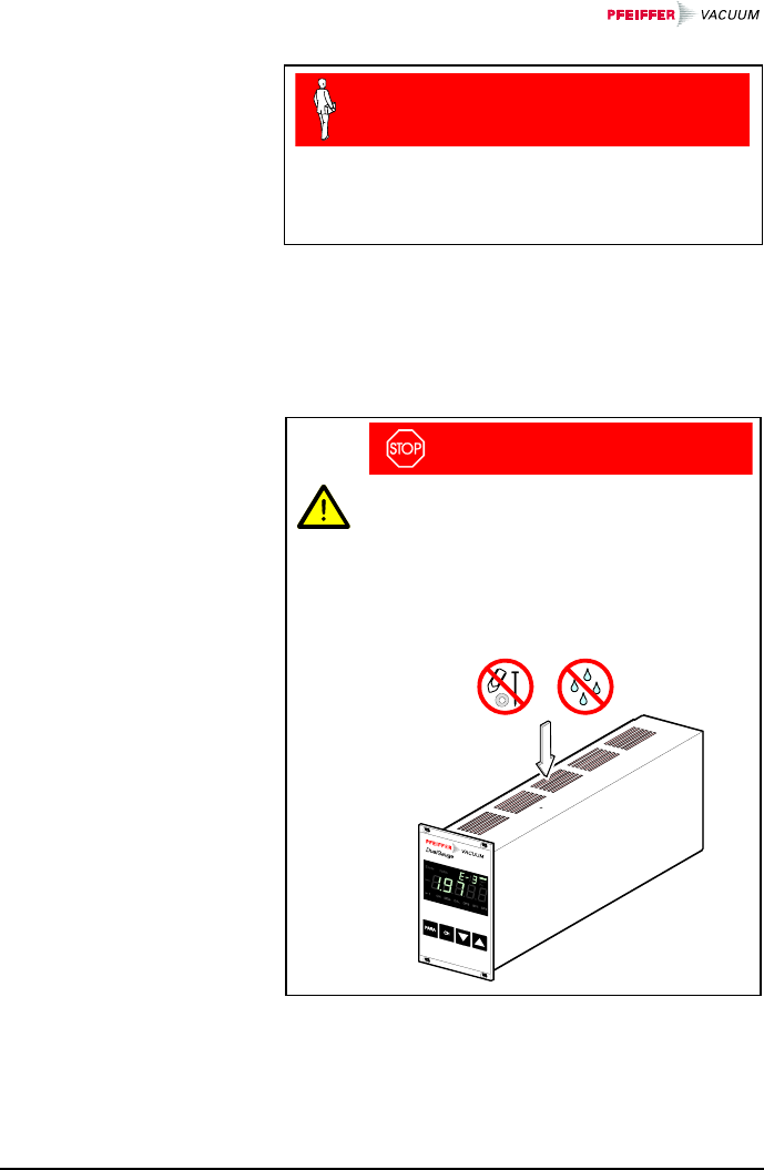
DANGER
Caution: mains voltage
Contact with live parts is extremely hazardous
when any objects are introduced or any liq-
uids penetrate into the unit.
Make sure no objects enter through the lou-
vers and no liquids penetrate into the equip-
ment.
Communicate the safety instructions to all other users.
1.2 Personnel
Qualifications
1.3 General Safety
Instructions

8BG 805 196 BE / B (2004-08) TPG262.oi
Pfeiffer Vacuum assumes no liability and the warranty
becomes null and void if the end-user or third parties
• disregard the information in this document
• use the product in a non-conforming manner
• make any kind of interventions (modifications, altera-
tions etc.) on the product
• use the product with accessories not listed in the cor-
responding product documentation.
1.4 Liability and
Warranty

BG 805 196 BE / B (2004-08) TPG262.oi 9
2 Technical Data
Voltage 90 … 250 VAC
Frequency 50 … 60 Hz
Power consumption ≤45 W
Overvoltage category II
Protection class 1
Connection European appliance connec-
tor IEC 320 C14
Temperature
storage
operation –20 … +65 °C
+ 5 … +50 °C
Relative humidity ≤80% up to +31 °C,
decreasing to 50% at +40 °C
Use indoors only
max. altitude 2000 m NN
Pollution degree II
Protection type IP30
Number 2
Compatible
Compact Gauges
Pirani
Pirani Capacitance
Cold Cathode
FullRange™ CC
Process Ion
FullRange™ BA
Capacitance
Piezo
TPR 261, TPR 265, TPR 280,
TPR 281
PCR 260
IKR 251, IKR 261, IKR 270
PKR 251, PKR 261
IMR 265
PBR 260
CMR 261 … CMR 275
APR 250 … APR 267
Number 2 (1 per channel)
sensor connector Amphenol C91B appliance
connector, female, 6-pole
(pin assignment → 20)
Mains specifications
Ambiance
Compatible gauges
Gauge connections

10 BG 805 196 BE / B (2004-08) TPG262.oi
Voltage +24 VDC ±5%
Current 750 mA
Power 18 W
Fuse protection 900 mA with PTC element,
self-resetting after turning the
TPG 262 off or disconnecting
the gauge. The supply con-
forms to the requirements of a
grounded protective extra low
voltage (SELV-E according to
EN 61010).
Front panel
Remote control via 4 keys
via RS232C interface
Measurement ranges depending on gauges
(→ [1] … [14])
Measurement error
gain error
offset error
≤0.01% F.S.
≤0.01% F.S.
Measurement rate 50 / s
Display rate 10 / s
Filter time constant
slow
normal (nor)
fast
1.2 s (fg = 0.13 Hz)
400 ms (fg = 0.4 Hz)
20 ms (fg = 8 Hz)
Measurement units mbar, Pa, Torr
Offset correction for linear gauges
–5 … 110% F.S.
Calibration factor for logarithmic gauges
0.10 … 9.99
for linear gauges
0.500 … 2.000
A/D converter resolution 0.001% F.S.
Gauge supply
Operation
Measurement values

BG 805 196 BE / B (2004-08) TPG262.oi 11
Number 4 (user-assignable)
Reaction delay ≤20 ms if switching threshold
close to measurement value
(for larger differences con-
sider filter time constant).
Adjustment range depending on gauge
(→ [1] … [14])
Hysteresis ≥1% F.S. for linear gauges,
≥10% of measurement value
for logarithmic gauges
Contact type floating changeover contact
Load max. 30 VAC, 30 W (ohmic)
60 VDC, 1 A, 30 W (ohmic)
Service life
mechanic
electric 5×10⁷ cycles
1×10⁵ cycles (at max. load)
Contact positions → 22
Relay connector D-Sub appliance connector,
female, 15-pole
(pin assignment → 22)
Number 1
Reaction time ≤20 ms
Contact type floating normally open contact
Load max. 30 VAC, 30 W (ohmic)
60 VDC, 1 A, 30 W (ohmic)
Service life
mechanic
electric 5×10⁷ cycles
1×10⁵ cycles (at max. load)
Contact positions → 21
Control connector Amphenol C91B appliance
connector, female, 7-pole
(pin assignment → 21)
Switching functions
Switching function relays
Error signal
Error signal relay

12 BG 805 196 BE / B (2004-08) TPG262.oi
Automatic
ON setpoint
OFF setpoint adjustable (→ 50)
adjustable (→ 52)
Manual
via keys
activation/deactivation (→ 28, 49, 51)
External
via control connector
ON condition
OFF condition signal ≤ +0.8 VDC
signal +2.0 … 5 VDC or input
open
Hotstart
when mains power on (→ 50)
Self control
deactivation when
pressure is rising
OFF threshold adjustable (→ 52)
Control connector Amphenol C91B appliance
connector, female, 7-pole
(pin assignment → 21)
Number 2 (1 per channel)
Voltage range 0 … +10 VDC
Internal resistance 660 Ω
Measuring signal vs.
pressure depending on gauge
(→ [1] … [14])
Control connector Amphenol C91B appliance
connector, female, 7-pole
(pin assignment → 21)
Standard RS232C
Protocol ACK/NAK, ASCII with
3-character mnemonics,
bi-directional data flow,
8 data bits, no parity bit,
1 stop bit
RS232C only TXD and RXD used
Transmission rate 9600, 19200, 38400 baud
RS232 connector D-Sub appliance connector,
male, 9-pole
(pin assignment → 23)
Gauge control
Analog outputs
Interface
BG 805 196 BE / B (2004-08) TPG262.oi 13
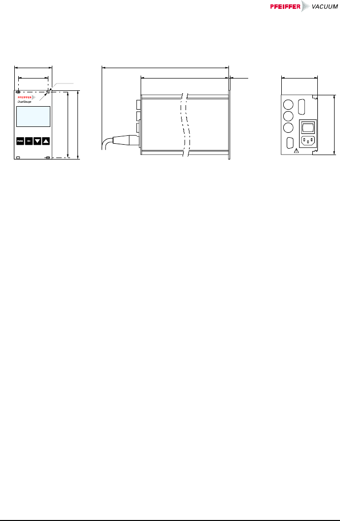
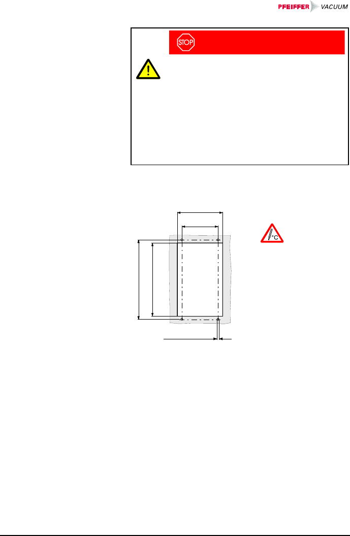
228.5 2.5
≈310
VACUUM
ø3.5
55.9
70.8
122.5
128.5
111.6
68.1
For incorporation into a rack or control panel or as desk-
top unit.
1.06 kg
Dimensions [mm]
Use
Weight
14 BG 805 196 BE / B (2004-08) TPG262.oi
3 Installation
Skilled personnel
The unit may only be installed by persons
who have suitable technical training and the
necessary experience.
The TPG 262 is suited for incorporation into a 19" rack
or a control panel or for use as desk-top unit.
DANGER
Caution: damaged product
Putting a damaged product into operation can
be extremely hazardous.
In case of visible damages, make sure the
product is not put into operation.
The TPG 262 is designed for installation into a 19" rack
chassis adapter according to DIN 41 494. For this pur-
pose, four collar screws and plastic sleeves are supplied
with it.
DANGER
Caution: protection class of the rack
If the product is installed in a rack, it is likely
to lower the protection class of the rack
(protection against foreign bodies and water)
e.g. according to the EN 60204-1 regulations
for switching cabinets.
Take appropriate measures for the rack to
meet the specifications of the protection
class.
3.1 Personnel
3.2 Installation, Setup
3.2.1 Rack Installation
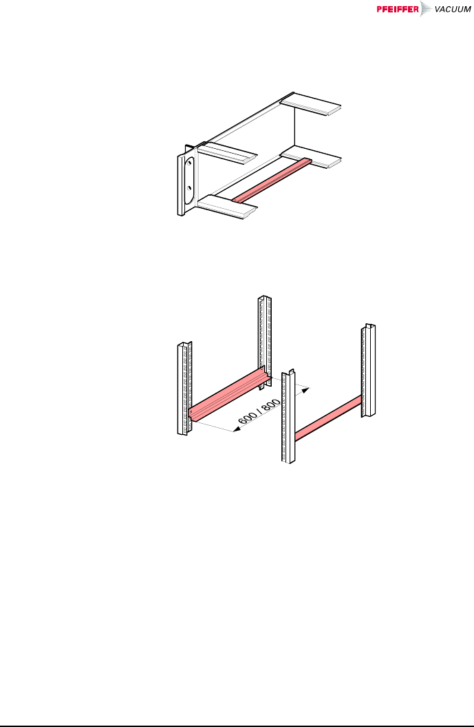
BG 805 196 BE / B (2004-08) TPG262.oi 15
In order to reduce the mechanical strain on the front
panel of the TPG 262, preferably equip the rack chassis
adapter with a guide rail.
For safe and easy installation of heavy rack chassis
adapters, preferably equip the rack frame with slide rails.
Guide rail
Slide rails
16 BG 805 196 BE / B (2004-08) TPG262.oi
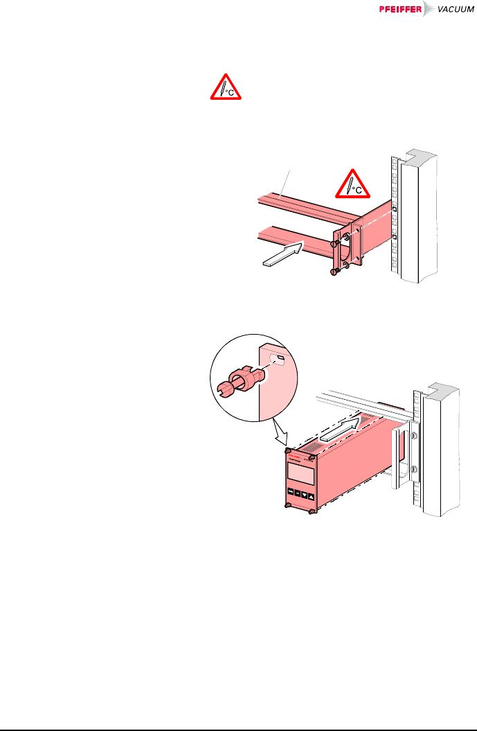
nSecure the rack adapter in the rack frame.
The admissible maximum ambient tem-
perature (→ 9) must not be exceeded
neither the air circulation obstructed.
Rack chassis adapter
Height 3 U
oSlide the TPG 262 into the rack chassis adapter …
… and fasten the adapter panel to the rack chas-
sis adapter using the screws supplied with the
TPG 262.
Height 3 U rack
chassis adapter
BG 805 196 BE / B (2004-08) TPG262.oi 17
DANGER
Caution: protection class of the control panel
If the product is installed in a control panel, it
is likely to lower the protection class of the
control panel (protection against foreign
bodies and water) e.g. according to the
EN 60204-1 regulations for switching cabi-
nets.
Take appropriate measures for the control
panel to meet the specifications of the pro-
tection class.
For mounting the TPG 262 into a control panel, the fol-
lowing cut-out is required:
M3 or ø 3.5
122.5
113
70
55.9
The admissible maxi-
mum ambient tem-
perature (→ 9) must
not be exceeded nei-
ther the air circulation
obstructed.
For reducing the mechanical strain on the front panel,
preferably support the unit.
3.2.2 Installation in a
Control Panel
18 BG 805 196 BE / B (2004-08) TPG262.oi
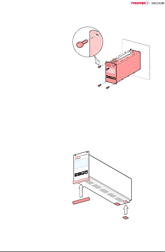
nSlide the TPG 262 into the cut-out of the control
panel …
… and secure it with four M3 or equivalent screws.
The TPG 262 is also suited for use as desk-top unit. For
this purpose, two self-adhesive rubber feet as well as a
slip-on rubber bar are supplied with it.
nStick the two supplied rubber feet to the rear part
of the bottom plate …
… and slip the supplied rubber bar onto the bot-
tom edge of the front panel.
3.2.3 Use as Desk-Top
Unit
BG 805 196 BE / B (2004-08) TPG262.oi 19
Select a location where the admissible maxi-
mum ambient temperature (→ 9) is not ex-
ceeded (e.g. due to sun irradiation).
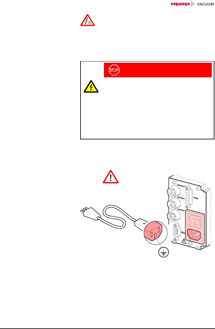
DANGER
Caution: line voltage
Incorrectly grounded products can be ex-
tremely hazardous in the event of a fault.
Use only a 3-conductor power cable with
protective ground. The power connector may
only be plugged into a socket with a protec-
tive ground. The protection must not be nulli-
fied by an extension cable without protective
ground.
The unit is supplied with a power cord. If the mains con-
nector is not compatible with your system, use your own,
suitable cable with protective ground (3×1.5 mm3).
The socket must be
fuse-protected with
10 Amax
If the unit is installed in a switching cabinet, the mains
voltage should be supplied and turned on via a central
distributor.
3.3 Mains Power
Connector
20 BG 805 196 BE / B (2004-08) TPG262.oi
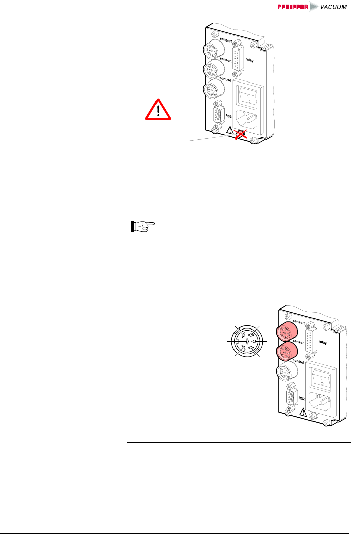
Do not unfasten
this screw
(internal ground
protection)
For each measurement channel, there is a female appli-
ance connector on the rear of the unit.
Connect the gauge to the sensor connector via
a sensor cable set available from us (→ sales
literature) or your own, screened (electromag-
netic compatibility) sensor cable. Use com-
patible gauges only (→ 9).
Pin assignment of
the two female
6-pole Amphenol
C91B appliance
connectors:
1
2
3
4
56
12
54
63
Pin Signal
1
6
2
3
4
5
Identification
Supply +24 VDC
Supply common GND
Signal input (measuring signal+)
Signal common (measuring signal–)
Screening
3.4 Gauge Connectors
sensor 1, sensor 2
Pin assignment
sensor 1, sensor 2
BG 805 196 BE / B (2004-08) TPG262.oi 21
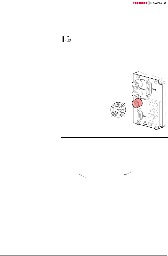
This connector allows to read the measuring signal, to
evaluate the state of the floating contacts of the error
relay, and to activate or deactivate the gauges (→ 47).
Connect the peripheral components to the
control connector on the rear of the unit using
your own, screened (electromagnetic compati-
bility) cable.
Pin assignment of
the female 7-pole
Amphenol C91B ap-
pliance connector:
1
3
2
54
67 8
64
75
82
1
3
Pin Signal
2
1
5
4
6
Analog output gauge 1 0 … 10 VDC
Analog output gauge 2 0 … 10 VDC
Screening GND
Gauge 1 on signal ≤+0.8 VDC
off signal +2.0 … 5 VDC or input open
Gauge 2 on signal ≤+0.8 VDC
off signal +2.0 … 5 VDC or input open
3
7 No error Error or power
supply turned off
A suitable connector is supplied with the TPG 262.
3.5 control Connector
Pin assignment
Contact positions
control
22 BG 805 196 BE / B (2004-08) TPG262.oi
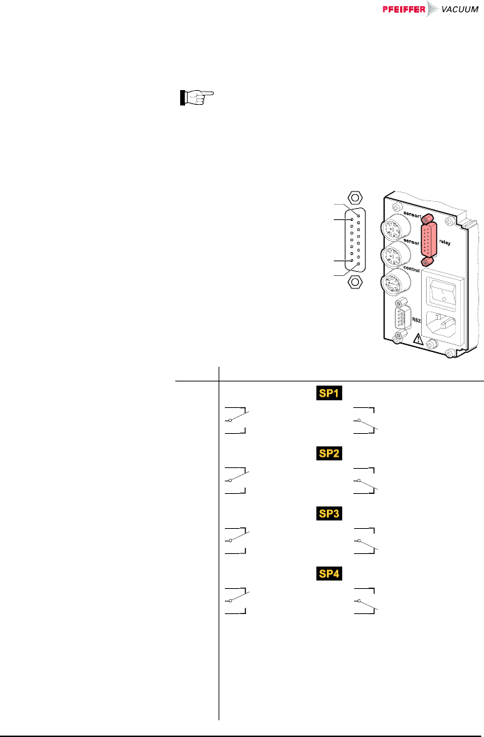
This connector allows to use the floating switching con-
tacts for an external control system.
Connect the peripheral components to the relay
connector on the rear of the unit using your
own, screened (electromagnetic compatibility)
cable.
Pin assignment of
the female 15-pole
D-Sub appliance
connector:
15
9
8
1
Pin Signal
Switching function 1
4
3
2
Pressure below
threshold
Pressure above
threshold or power
supply turned off
Switching function 2
7
6
5
Pressure below
threshold
Pressure above
threshold or power
supply turned off
Switching function 3
11
10
9
Pressure below
threshold
Pressure above
threshold or power
supply turned off
Switching function 4
14
13
12
Pressure below
threshold
Pressure above
threshold or power
supply turned off
Supply for relays with higher switching power
15
1
8
+24 VDC, 200 mA
GND
GND
Fuse-protected at 300 mA with PTC
element, self-resetting after power
off or pulling the relay connector.
Meets the requirements of a
grounded protective extra low volt-
age (SELV-E according to
EN 61010).
3.6 relay Connector
Pin assignment
Contact positions
relay
BG 805 196 BE / B (2004-08) TPG262.oi 23
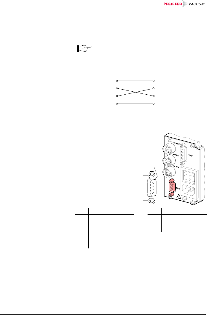
The RS232C interface allows for operating the TPG 262
via a HOST or terminal (→ 68). It can also be used for
updating the firmware (→ 99).
Connect the serial interface to the RS232 con-
nector on the rear of the unit using your own,
screened (electromagnetic compatibility) cable.
e.g. PC TPG 262
Chassis
2 RXD
RXD
3 TXD
TXD
5 GND
Chassis
GND
(Minimum configuration)
Pin assignment of
the male 9-pole
D-Sub appliance
connector:
5
1
9
6
Screening
Pin Signal Pin Signal
2
3
5
RXD
TXD
GND
1
6
9
not connected
not connected
not connected
4
7
8
DTR
RTS
CTS
Casing = screening
3.7 Interface Connector
RS232
Pin assignnment
RS232
24 BG 805 196 BE / B (2004-08) TPG262.oi
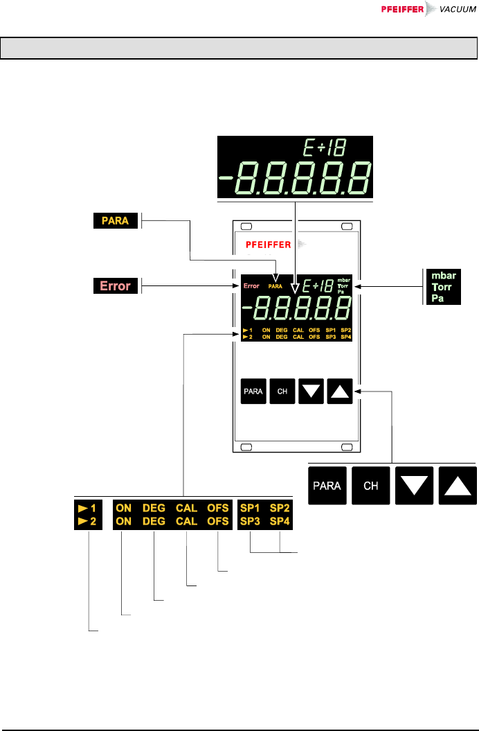
4 Operation
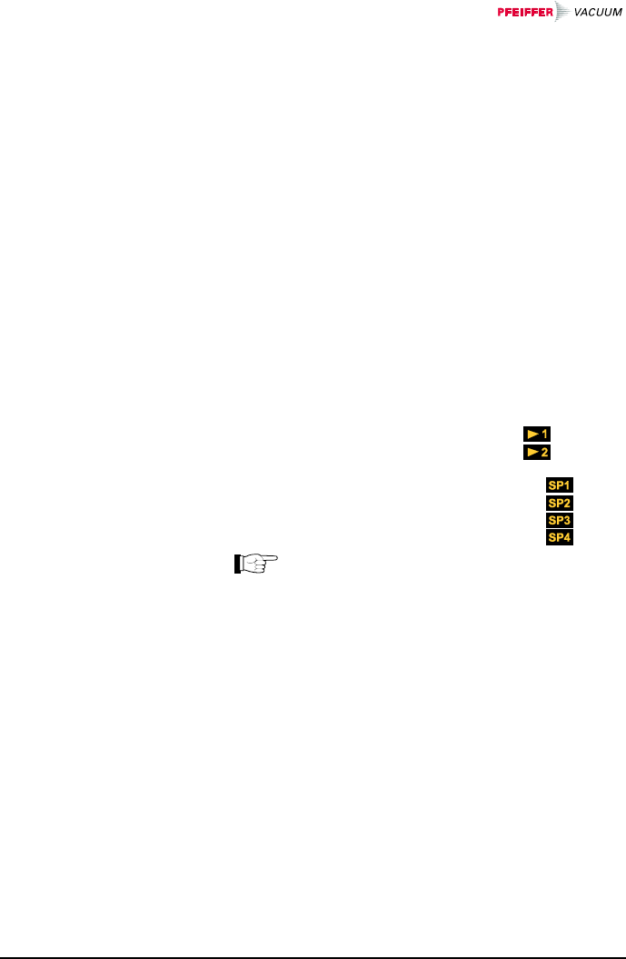
VACUUM
Correction factor ≠ 1
Offset value ≠ 0
Degas activated
Gauge activated
Active measurement channel
Measurement
unit
Measurement value in floating point
or exponential format or status messages
Operator keys
Switching function status
Parameter mode
activated
Warning/error
(flashing)
4.1 Front Panel
BG 805 196 BE / B (2004-08) TPG262.oi 25
Make sure the TPG 262 is correctly installed and the
specifications in the Technical Data are met.
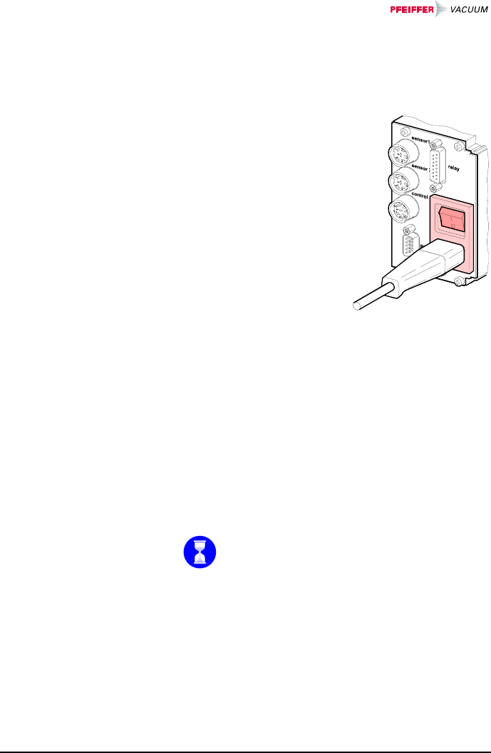
The power switch is on the
rear of the unit.
Turn the TPG 262 on with
the power switch (or cen-
trally, via a switched power
distributor, if the unit is in-
corporated in a rack).
After power on, the TPG 262 …
• automatically performs a self-test
• identifies the connected gauge
• activates the parameters that were in effect before
the last power off
• switches to the Measurement mode
• adapts the parameters if required (if another gauge
was previously connected).
Turn the TPG 262 off with the power switch (or centrally,
via a switched power distributor, if the unit is incorpo-
rated in a rack).
Wait at least 10 s before turning the TPG 262
on again in order for it to correctly initialize it-
self.
4.2 Turning the
TPG 262 On and Off
Turning the TPG 262
on
Turning the TPG 262
off

26 BG 805 196 BE / B (2004-08) TPG262.oi
The TPG 262 works in the following operating modes:
• Measurement mode
for displaying measurement values or statuses
(→ 27)
• Parameter mode
for displaying or editing parameters (→ 31)
− Switching function parameter group
for entering or displaying thresholds (→ 33)
− Gauge parameter group
for entering or displaying gauge parameters
(→ 38)
− Gauge control group
for entering or displaying gauge control parame-
ters (→ 47)
− General parameter group
for entering or displaying general parameters
(→ 54)
− Test program group
for running internal test programs (→ 58)
• Program transfer mode
for updating the firmware (→ 99)
4.3 Operating Modes
BG 805 196 BE / B (2004-08) TPG262.oi 27
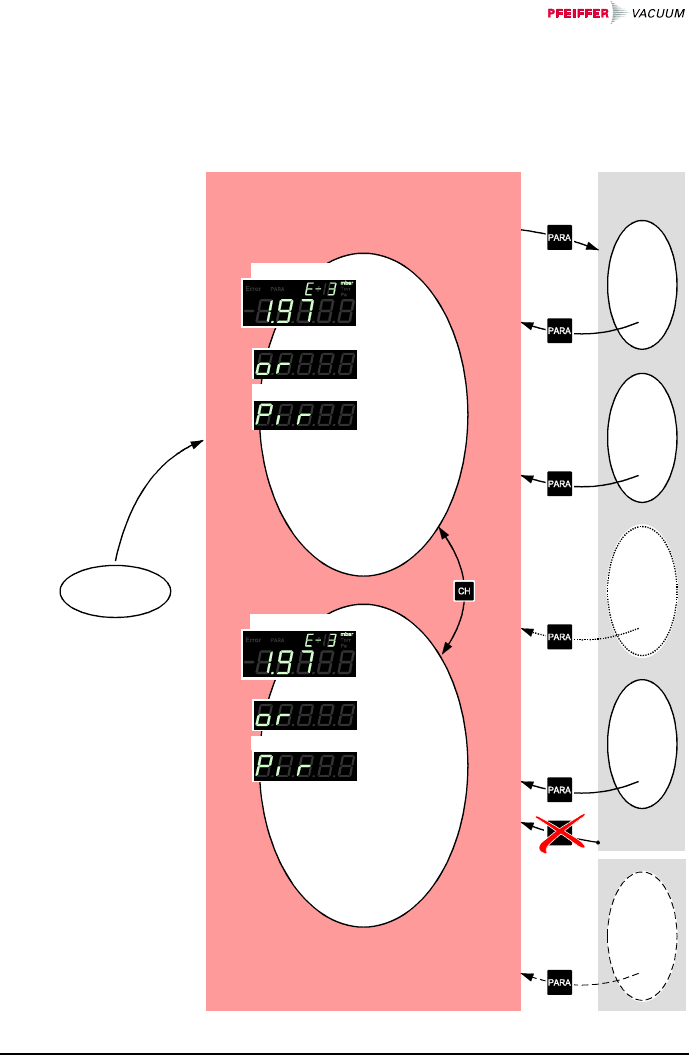
The Measurement mode is the standard operating mode
of the TPG 262. Measurement values and statuses as
well as the gauge identification are displayed in this
mode.
Power on
Parameter
mode
depending
on history
>10 s
Measurement mode
Gauge identification
Status
Measurement value
Gauge identification
Status
Measurement value
4.4 Measurement mode
28 BG 805 196 BE / B (2004-08) TPG262.oi
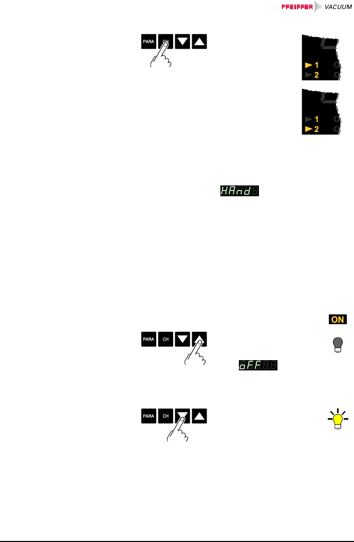
ÖChannel 1
is activated
ÖChannel 2
is activated
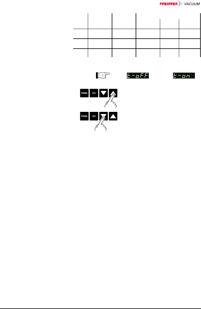
Certain gauges can be turned on and off manually, if the
gauge control is set to (→ 51).
Available for:
Pirani Gauge (TPR)
Pirani Capacitance Gauge (PCR)
;Cold Cathode Gauge (IKR)
;FullRange™ CC Gauge (PKR)
;Process Ion Gauge (IMR)
;FullRange™ BA Gauge (PBR)
Capacitance Gauge (CMR)
Piezo Gauge (APR)
ÖPress key >1 s:
The gauge is
turned off.
is dis-
played instead of
the measurement
value.
ÖPress key >1 s:
The gauge is
turned on. A status
message may be
displayed instead
of the measure-
ment value.
Selecting a measure-
ment channel
Turning a gauge on
and off
BG 805 196 BE / B (2004-08) TPG262.oi 29
Pressure p
Measurement
range
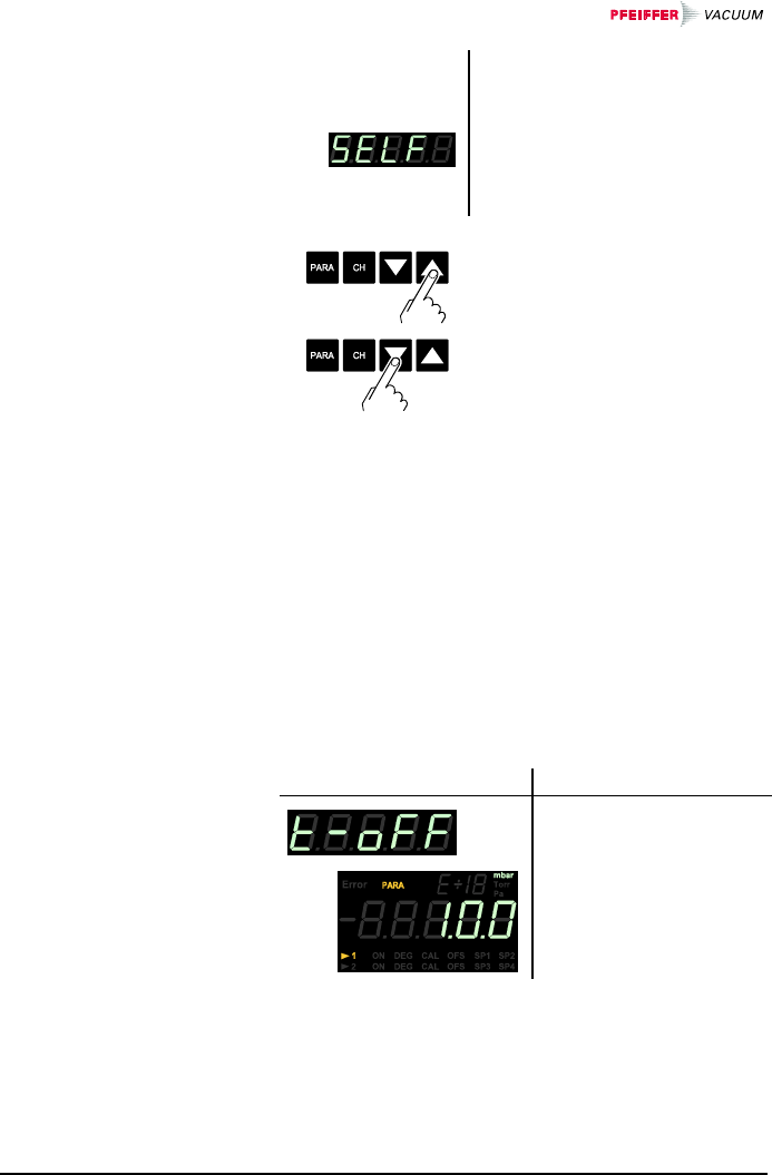
30 BG 805 196 BE / B (2004-08) TPG262.oi
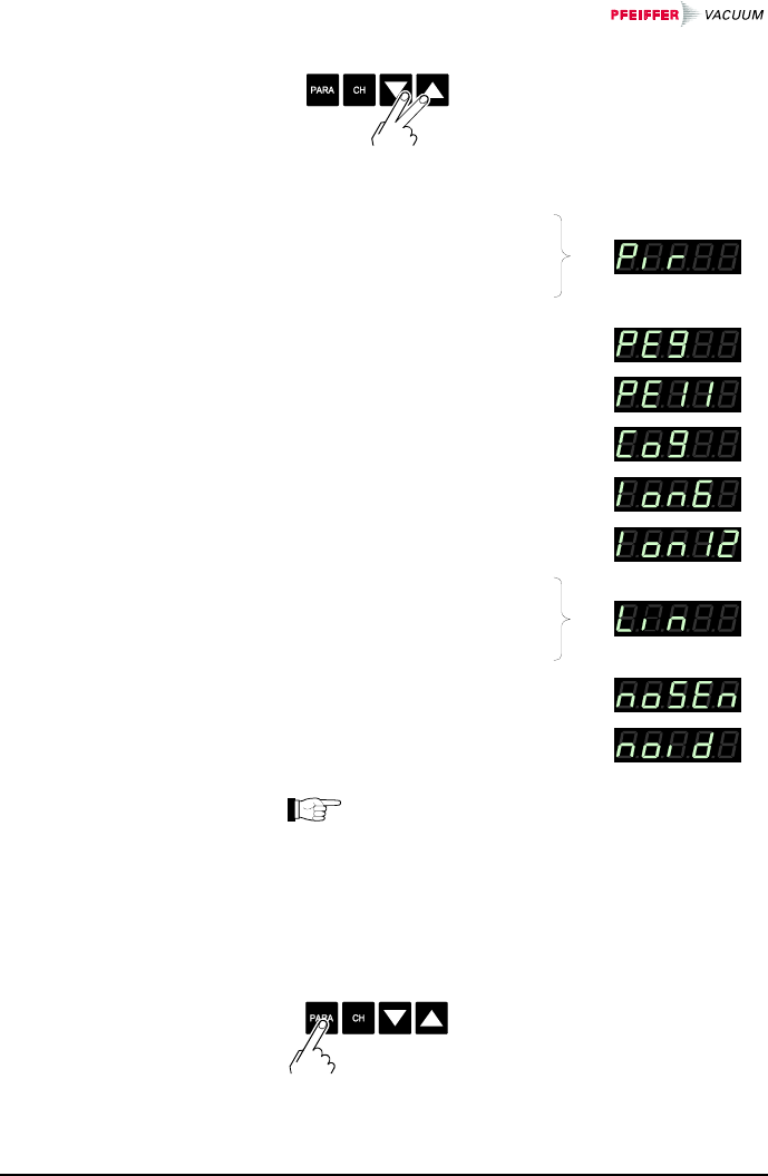
ÖPress keys >0.5 s:
The type of the connected
gauges is automatically iden-
tified and displayed for 4 s
(2 s per channel):
Pirani Gauge
(TPR 261, TPR 265, TPR 280,
TPR 281)
Pirani Capacitance Gauge 1)
(PCR 260)
Cold Cathode Gauge
(IKR251, IKR261)
Cold Cathode Gauge
(IKR270)
FullRange™ CC Gauge
(PKR251, PKR261)
Process Ion Gauge
(IMR265)
FullRange™ BA Gauge
(PBR260)
Capacitance Gauge
(CMR261 … CMR275)
Piezo Gauge
(APR250 … APR267)
No gauge connected
(no Sensor)
Connected gauge cannot be
identified (no Identifier)
1) TPR and PCR have identical identifiers. In
the TPG 262, there is no distinction made on
the display and in data evaluation, since pres-
sure ranges of these gauges are approximately
the same.
→ 31
Displaying the gauge
identification
Getting to the
Parameter mode
BG 805 196 BE / B (2004-08) TPG262.oi 31
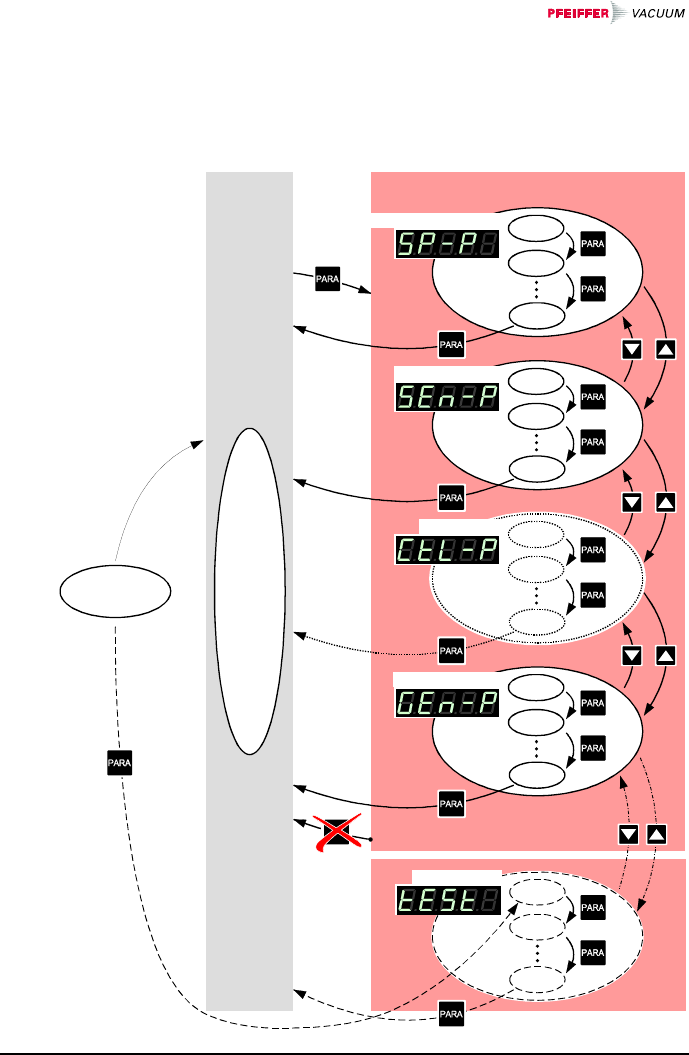
The Parameter mode is used for displaying, editing and
entering parameter values as well as for testing the
TPG 262. For ease of operation, the parameters are di-
vided into groups.
Power on
Parameter mode
depending
on history
Switching function parameters
Gauge parameters
Gauge control
General parameters
Test parameters
>10 s
Measurement
mode
4.5 Parameter Mode

32 BG 805 196 BE / B (2004-08) TPG262.oi
ÖSwitching function parame-
ters → 33
Gauge parameters → 38
Gauge control → 47
General parameters
→ 54
Test parameters
→ 58
Modifications of parameters come into effect immedi-
ately and are stored automatically. Exceptions are men-
tioned under the corresponding parameters.
Selecting a parameter
group
Selecting a parameter
in a parameter group
Editing a parameter in
a parameters group
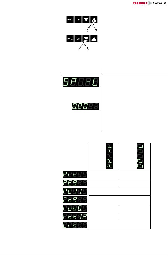
BG 805 196 BE / B (2004-08) TPG262.oi 33
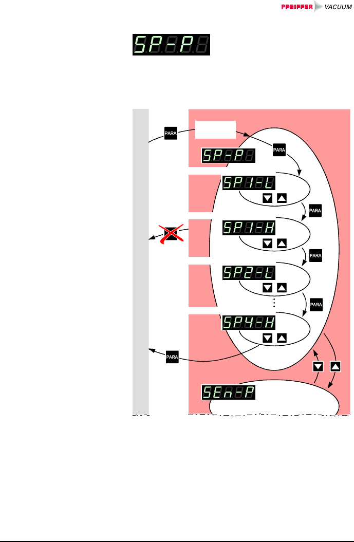
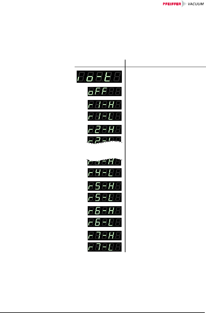
The switching function parameter
group (setpoint parameters) is
used for displaying, entering and
editing threshold values and as-
signing the four switching func-
tions to a measurement channel.
Measurement mode
Parameter mode
depending
on history
Switching function 1 lower threshold
Switching function 1 upper threshold
Switching function 2 lower threshold
Swiching function 4 upper threshold
>10 s
4.5.1 Switching
Function
Parameters
34 BG 805 196 BE / B (2004-08) TPG262.oi
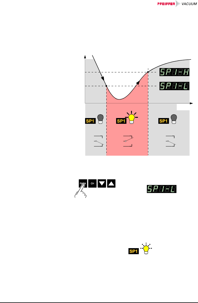
The TPG 262 has four switching functions with two ad-
justable thresholds each. The status of the switching
function is displayed on the front panel (→ 24, 21) and
can be evaluated via the floating contacts at the Control
connector.
Pressure p
Switching
function
On Off
Time t
Off
2
3
4
2
3
4
2
3
4
Display
M
e
a
s
u
r
e
m
e
n
t
v
a
l
u
e
ÖThe name of the parameter,
e.g.: Switching function 1
lower setpoint
is displayed as long as the
key is pressed or at least for
1.5 s.
Afterwards, the currently
valid threshold value is dis-
played.
Selecting a parameter
BG 805 196 BE / B (2004-08) TPG262.oi 35
ÖPress key <1 s:
The value is increased/
decreased by 1 increment.
Press key >1 s:
The value is increased/
decreased continuously.
Value
The lower switching threshold
(Setpoint low) defines the pres-
sure at which the switching func-
tion is activated when the pres-
sure is dropping.
e.g.:
Ögauge dependent
(→ table).
If another gauge type is con-
nected, the TPG 262 auto-
matically adjusts the switching
threshold if required.
lower
threshold
limit
upper
threshold
limit
1×10⁻²
1000
5×10⁻⁴
1×10⁻⁹
1×10⁻⁶
10005×10-10
all values in mbar, CAL=1
1×10⁻²
1×10-11
10001×10-9
1500
F.S. / 1000 F.S.
Editing the threshold
value
Limits of the lower
switching thresholds
36 BG 805 196 BE / B (2004-08) TPG262.oi
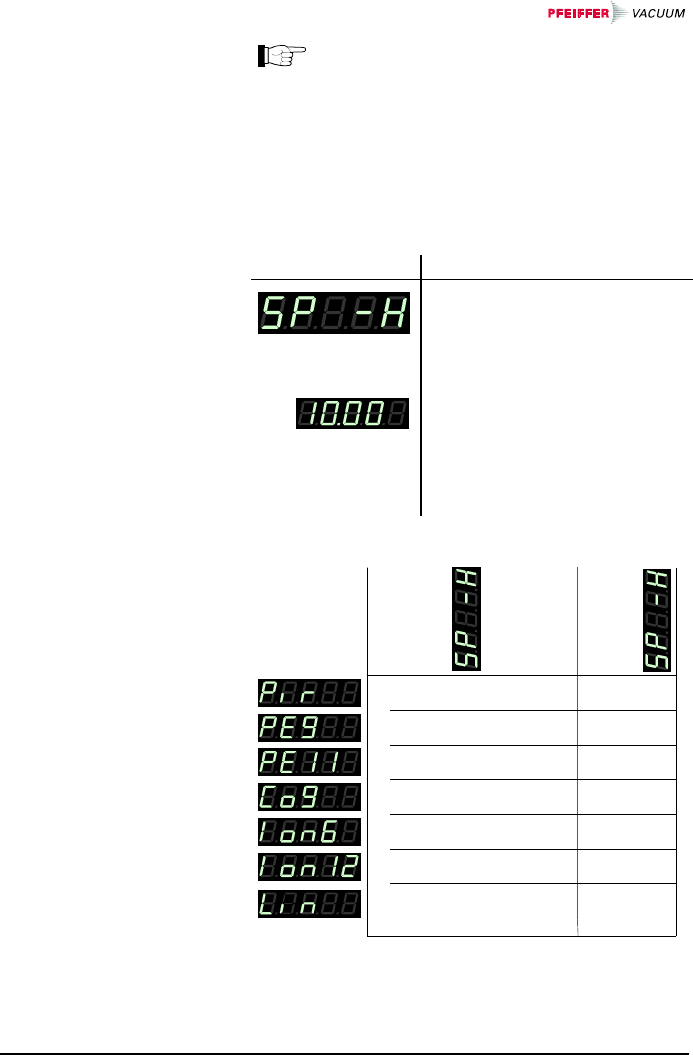
The minimum hysteresis between the upper
and lower switching threshold is at least 10% of
the lower threshold or 1% of the set full scale
value. If the value of the minimum hysteresis
drops below these values, the upper threshold
is automatically adjusted to a minimum hystere-
sis. This prevents unstable states.
Value
The upper switching threshold
(Setpoint high) defines the pres-
sure at which the switching func-
tion is deactivated when the pres-
sure is rising.
e.g.:
ÖGauge dependent
(→ table).
If another gauge type is con-
nected, the TPG 262 automa-
tically adjusts the threshold if
required.
+10% lower threshold
lower threshold
1500
1×10⁻²
1000
+10% lower threshold
+10% lower threshold
+10% lower threshold
1000
all values in mbar, CAL=1
upper
thershold
limit
lower
threshold
limit
1×10⁻²
+10% lower threshold
1000+10% lower threshold
F.S.
+1% measurement
range (F.S.)
Limits of the upper
switching thresholds
BG 805 196 BE / B (2004-08) TPG262.oi 37
The minimum hysteresis between the upper
and lower switching threshold is at least 10% of
the lower threshold or 1% of the set full scale
value. If the value of the minimum hysteresis
drops below these values, the upper threshold
is automatically adjusted to a minimum hystere-
sis. This prevents unstable states.
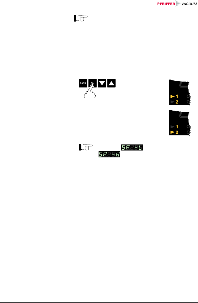
ÖSwitching
function is
assigned to
channel 1.
ÖSwitching
function is
assigned to
channel 2.
The lower and the upper
switching threshold of a switching
function are always assigned to the same
channel. The last assignment is valid for both
thresholds.
Assigning a switching
function
38 BG 805 196 BE / B (2004-08) TPG262.oi
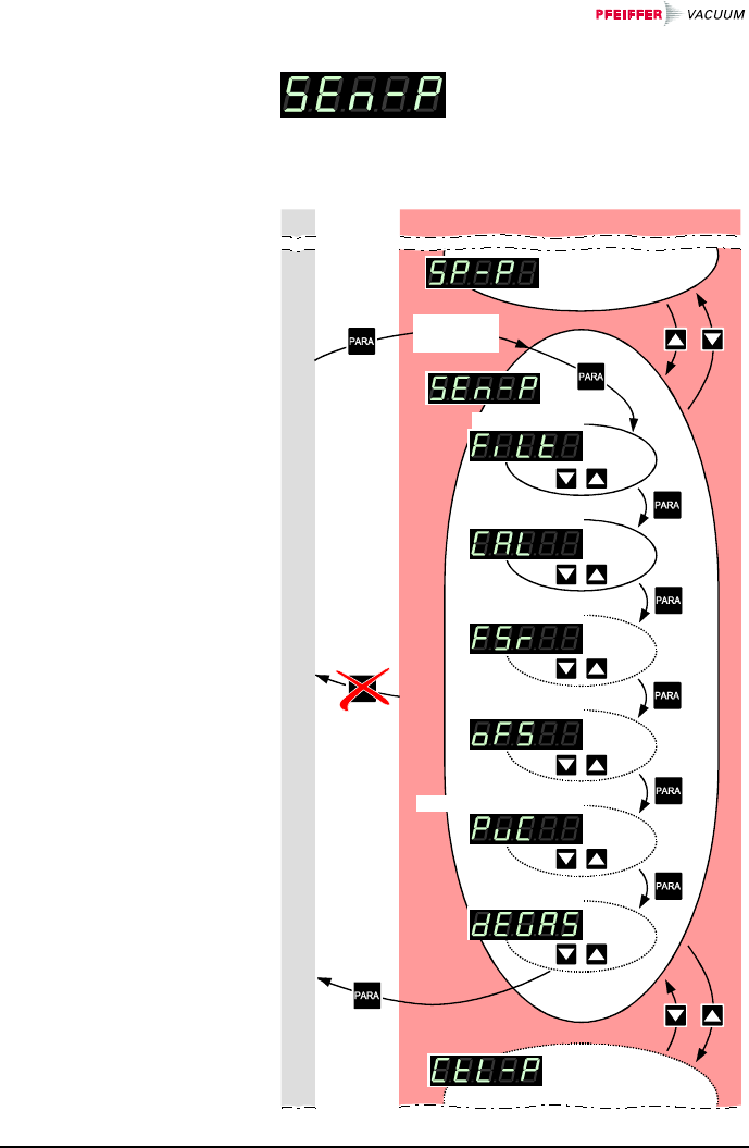
The Gauge parameter group
(sensor parameters) is used for
displaying, entering and editing
parameters of the connected
gauges.
Measurement mode
depending
on history
Filter time constant
Calibration factor
Measurement range
Offset
Penning Underrange Control
Degas
Parameter mode
>10 s
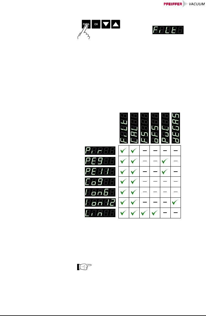
4.5.2 Gauge Parameters
BG 805 196 BE / B (2004-08) TPG262.oi 39
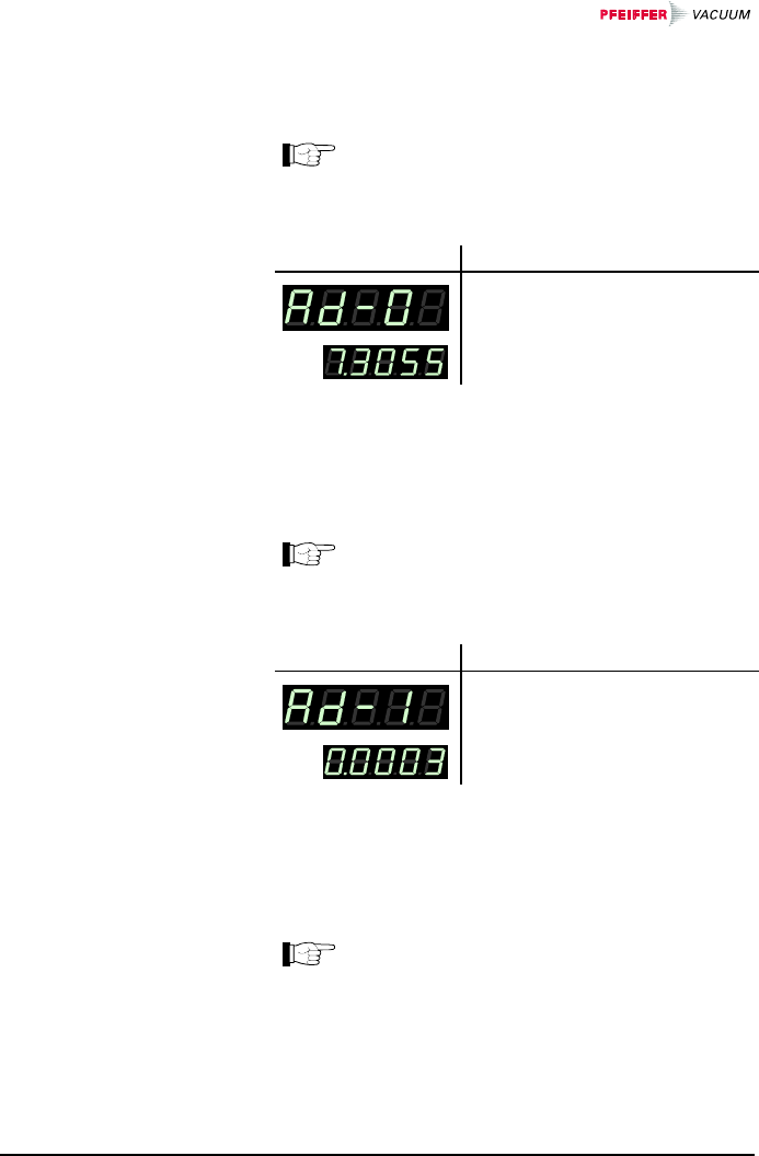
ÖThe name of the parameter,
e.g.: Filter time constant
is displayed as long as the
key is pressed or at least for
1.5 s.
Afterwards, the currently
valid threshold value is dis-
played.
Some parameters are not available for all gauges and
thus not always displayed.
→ 39 41 42 43 44 46
*) depending on pressure
*)
*)
Available for
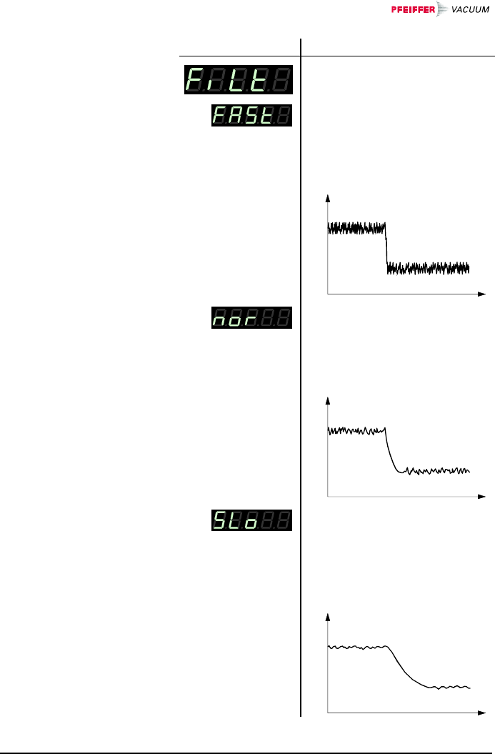
The measurement value filter permits a better evaluation
of unstable or disturbed measuring signals.
The measurement value filter does not affect
the analog output (→ 21).
Selecting a parameter
Measurement value
filter
40 BG 805 196 BE / B (2004-08) TPG262.oi
Value
ÖFast:
The TPG 262 responds quickly
to fluctuations of the measure-
ment value. As a result, it will
respond faster to interference
in the measured values.
Pressure p
Time t
ÖNormal:
Good relationship between re-
sponse and sensitivity of the
display and the switching func-
tion to changes in the meas-
ured values.
Pressure p
Time t
ÖSlow:
The TPG 262 does not re-
spond to small changes in
measured values. As a result,
it will respond more slowly to
changes in the measured
values.
Pressure p
Time t
BG 805 196 BE / B (2004-08) TPG262.oi 41
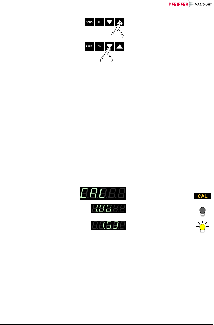
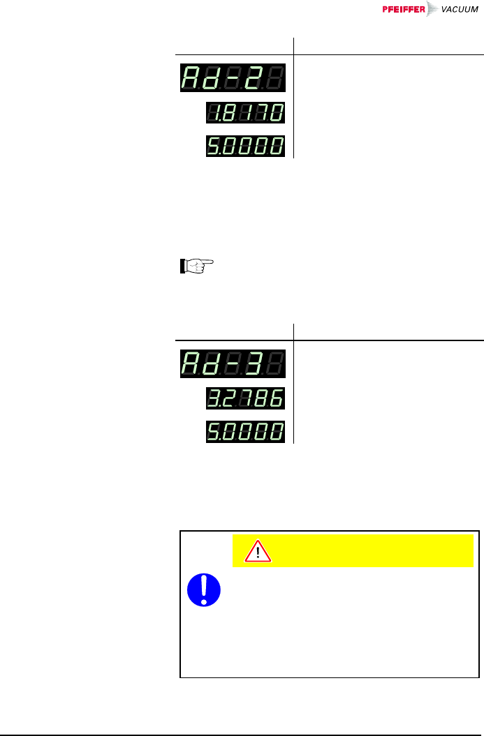
ÖThe value is increased/
decreased by the defined in-
crements.
The calibration factor allows the measured value to be
calibrated for other gases than N2 (→ characteristic
curves in [1] … [12]).
Available for:
;Pirani Gauge (TPR)
;Pirani Capacitance Gauge (PCR)
;Cold Cathode Gauge (IKR)
;FullRange™ CC Gauge (PKR)
;Process Ion Gauge *) (IMR)
;FullRange™ BA Gauge **) (PBR)
;Capacitance Gauge (CMR)
;Piezo Gauge (APR)
*) only for pressures <1×10⁻² mbar.
**) only for pressures <1×10⁻¹ mbar.
Value
e.g.:
ÖNo correction
e.g.:
ÖMeasurement value
corrected by a factor
of 0.10 … 9.99
(logarithmic gauges).
Measurement value
corrected by a factor
of 0.500 … 2.000
(linear gauges).
Calibration factor
42 BG 805 196 BE / B (2004-08) TPG262.oi
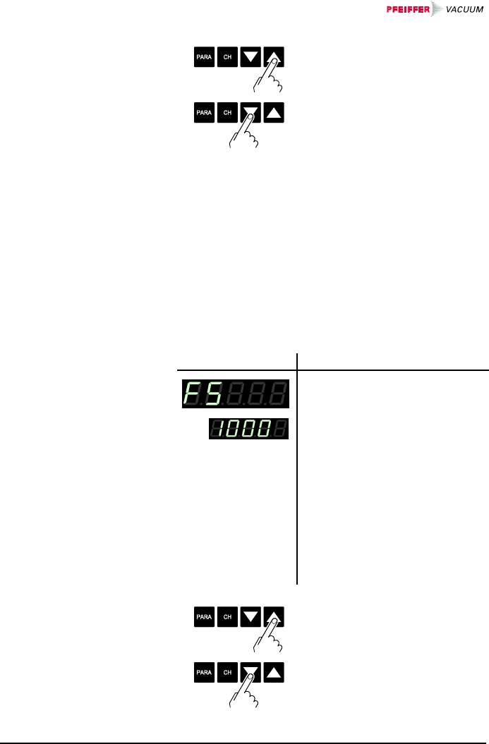
ÖPress key <1 s:
The value is increased/
decreased by 1 increment.
Press key >1 s:
The value is increased/
decreased continuously.
For linear gauges, the full scale (F.S.) value has to be
defined according to the connected gauge type. For
logarithmic gauges it is automatically recognized.
Available for:
Pirani Gauge (TPR)
Pirani Capacitance Gauge (PCR)
Cold Cathode Gauge (IKR)
FullRange™ CC Gauge (PKR)
Process Ion Gauge (IMR)
FullRange™ BA Gauge (PBR)
;Capacitance Gauge (CMR)
;Piezo Gauge (APR)
Value
e.g.:
Ö0.01 mbar
0.1 mbar
1 mbar
10 mbar
100 mbar
1000 mbar
2 bar
5 bar
10 bar
50 bar
Conversion table
→ Appendix 97
ÖThe value is increased/
decreased by the defined in-
crements.
Measurement range
(F.S.) of linear
gauges
BG 805 196 BE / B (2004-08) TPG262.oi 43
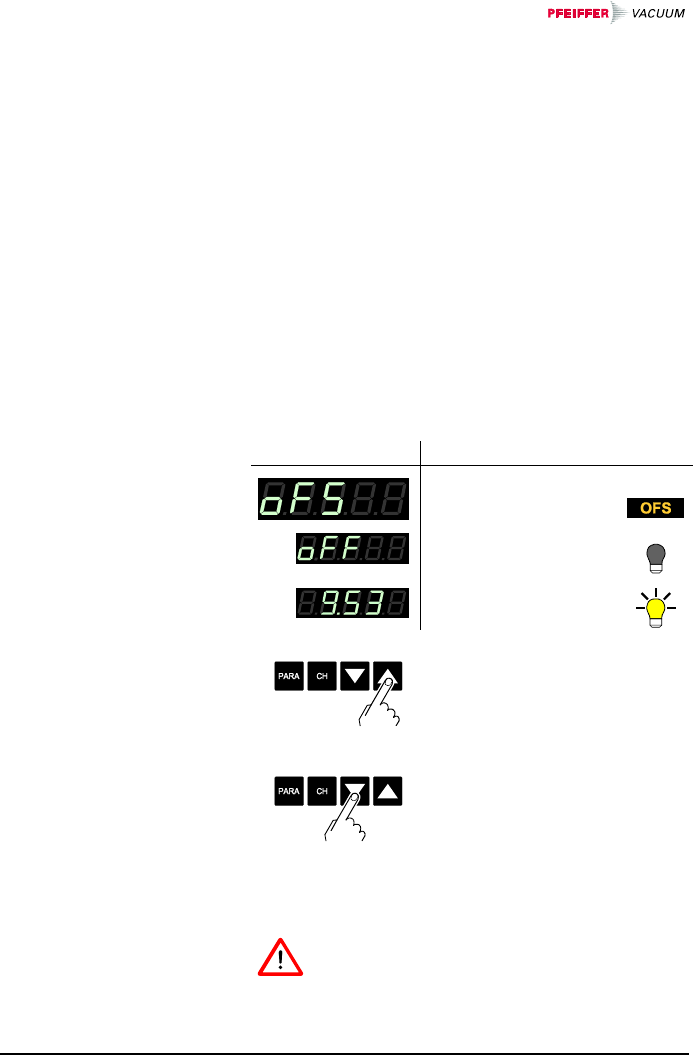
The offset value is displayed and readjusted according
to the actual measurement value (in the range of
-5 … +110% of the set full scale value).
Available for:
Pirani Gauge (TPR)
Pirani Capacitance Gauge (PCR)
Cold Cathode Gauge (IKR)
FullRange™ CC Gauge (PKR)
Process Ion Gauge (IMR)
FullRange™ BA Gauge (PBR)
;Capacitance Gauge (CMR)
;Piezo Gauge (APR)
The offset correction affects:
;the displayed measurement value
the displayed threshold value of the switching
functions
the analog outputs at the control connector (→ 21)
Value
ÖOffset correction
deactivated
e.g.:
ÖOffset correction
activated
ÖPress key >1.5 s:
The offset value is read-
justed. The actual measure-
ment value is accepted as
new offset value.
ÖReset the offset value.
When the offset correction is activated, the saved offset
value is subtracted from the actual measurement value.
This allows measuring relative to a reference pressure.
When the zero of the gauge is readjusted, the
offset correction must be deactivated.
Offset correction
44 BG 805 196 BE / B (2004-08) TPG262.oi
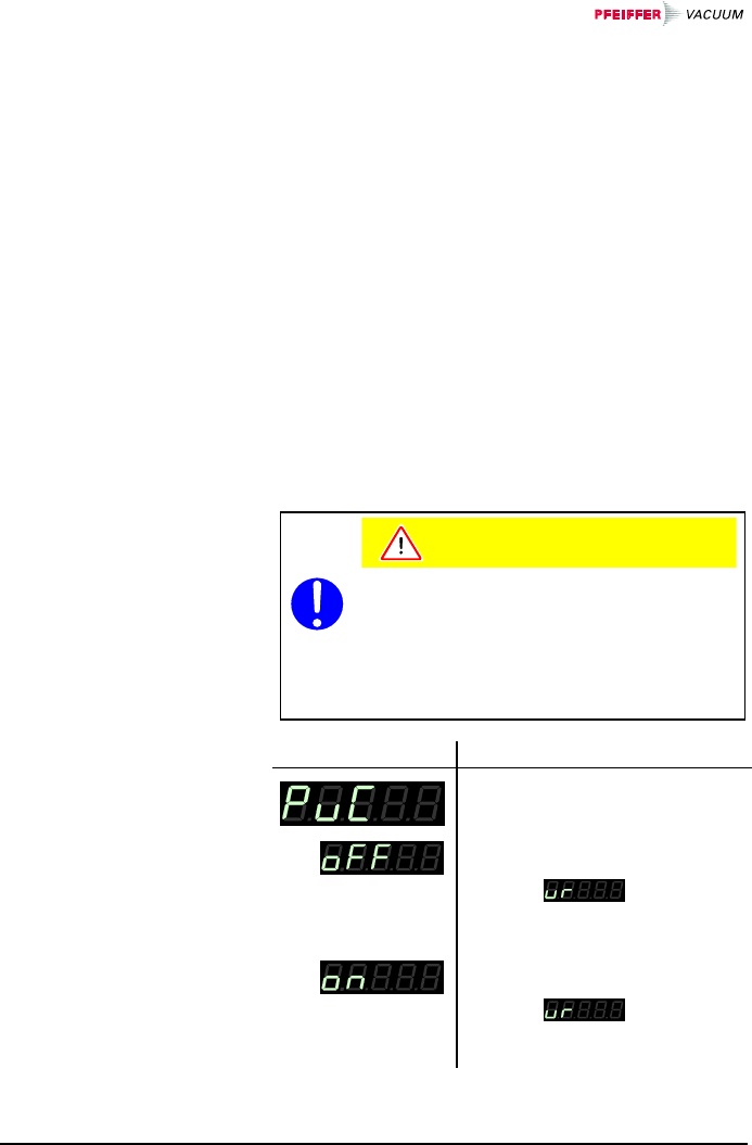
Behavior in the event of an underrange with Cold Cath-
ode Gauges (Penning underrange control).
Available for:
Pirani Gauge (TPR)
Pirani Capacitance Gauge (PCR)
;Cold Cathode Gauge (IKR)
FullRange™ CC Gauge (PKR)
Process Ion Gauge (IMR)
FullRange™ BA Gauge (PBR)
Capacitance Gauge (CMR)
Piezo Gauge (APR)
There is a number of possible causes of an underrange:
• the pressure in the vacuum system is lower than the
measurement range
• the measurement element has not ignited (yet)
• the discharge has failed
• a defect has occurred
Caution
Caution: relay is switching
An underrange can lead to unintended re-
actions of the connected control system.
Prevent false control signals and messages
by disconnecting the sensor and control ca-
bles.
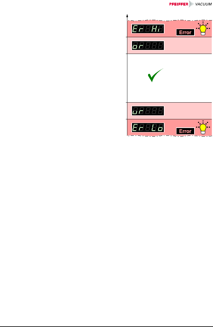
Value
ÖUnderrange state is interpreted
as admissible measurement
value. is displayed.
The switching function remains
ON.
ÖUnderrange state is interpreted
as inadmissible measurement
value. is displayed.
The switching function
changes to OFF.
Underrange control

BG 805 196 BE / B (2004-08) TPG262.oi 45
ÖActivate/deactivate the
underrange control.
If chances are that the pressure in the vacuum
system drops below the measurement range of
the gauge, it is advisable to select .
If is selected, the evaluation of the
switching function is suppressed for approx.
10 seconds when the gauge is turned on and
each time after an underrange has occurred.
During this time, the switching function remains
OFF.
46 BG 805 196 BE / B (2004-08) TPG262.oi
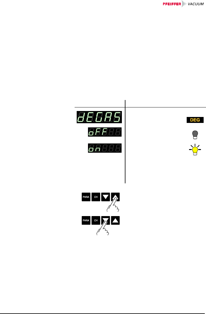
Contamination deposits on the electrode system of hot
cathode gauges may cause instabilities of the measure-
ment values. The Degas function allows to clean the
electrode system.
Available for:
Pirani Gauge (TPR)
Pirani Capacitance Gauge (PCR)
Cold Cathode Gauge (IKR)
FullRange™ CC Gauge (PKR)
Process Ion Gauge (IMR)
;FullRange™ BA Gauge (PBR )
Capacitance Gauge (CMR)
Piezo Gauge (APR)
Value
ÖNormal operation.
ÖDegas: The electron
collection grid is
heated to ≈700 °C by
electron bombard-
ment and the elec-
trode system is thus
cleaned.
ÖStart Degas.
Duration of the Degas func-
tion 3 min. (can be aborted).
ÖAbort Degas.
Degas
BG 805 196 BE / B (2004-08) TPG262.oi 47
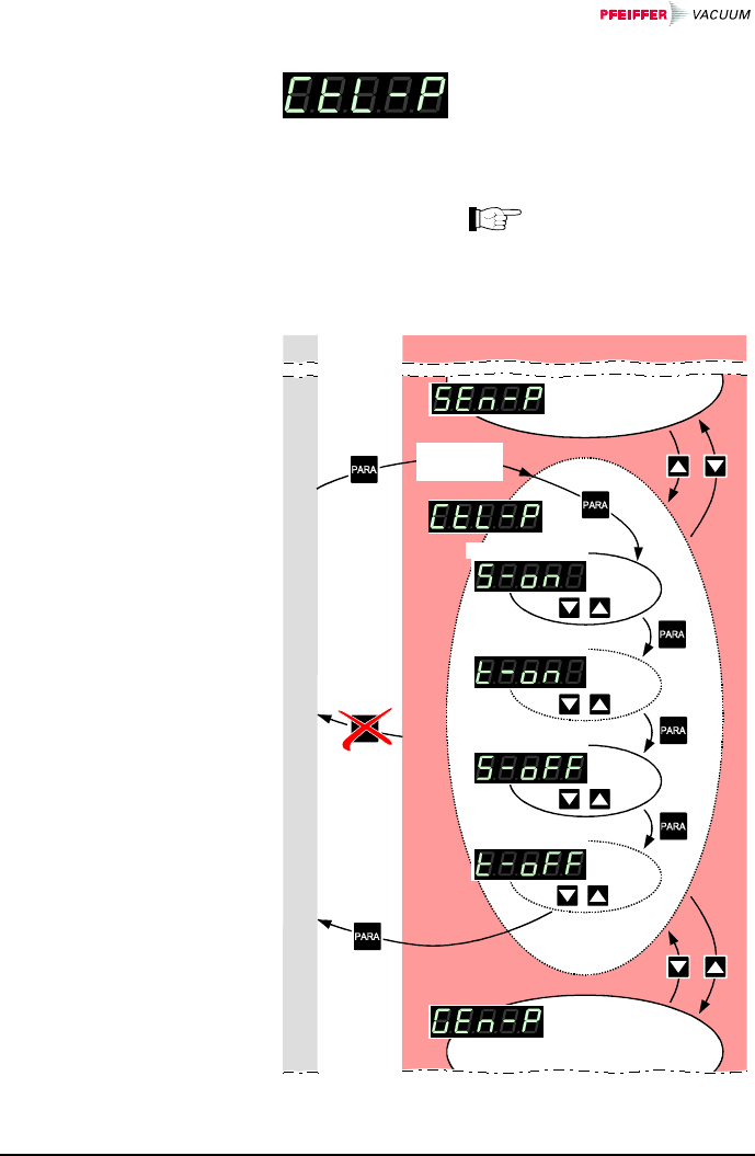
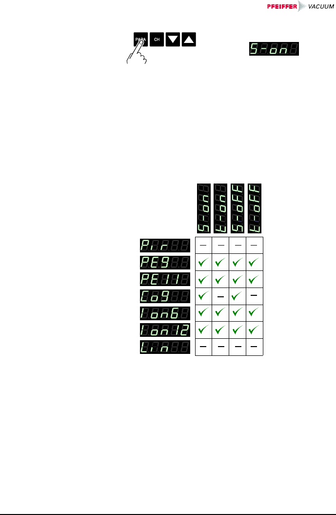
The Gauge control group (control
parameters) is used for display-
ing, entering and editing parame-
ters which define how the con-
nected gauges are activated/ de-
activated.
If the connected gauges
cannot be controlled
(→ 49), this group is
not available.
Measurement mode
depending
on history
Gauge activation
Gauge deactivation
ON threshold
OFF threshold
Parameter mode
>10 s
4.5.3 Gauge Control
48 BG 805 196 BE / B (2004-08) TPG262.oi
ÖThe name of the parameter,
e.g.: Gauge activation
is displayed as long as the
key is pressed or at least for
1.5 s.
Afterwards, the currently
valid threshold value is dis-
played.
Some parameters are not available for all gauges and
thus not always displayed.
→ 49 50 51 52
Available for
Selecting a parameter
BG 805 196 BE / B (2004-08) TPG262.oi 49
Certain gauges can be activated by different means.
The following gauges can be controlled:
Pirani Gauge (TPR)
Pirani Capacitance Gauge (PCR)
;Cold Cathode Gauge (IKR)
;FullRange™ CC Gauge *) (PKR)
;Process Ion Gauge (IMR)
;FullRange™ BA Gauge (PBR)
Capacitance Gauge (CMR)
Piezo Gauge (APR)
*) except by a gauge connected to the other measurement
channel
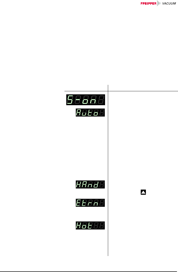
Value
ÖAutomatic activation:
The gauge is activated by one
of the following gauges con-
nected to the other measure-
ment channel.
;Pirani Gauge (TPR)
;Pirani Capacitance Gauge (PCR)
Cold Cathode Gauge (IKR)
;FullRange™ CC Gauge (PKR)
;Process Ion Gauge (IMR)
;FullRange™ BA Gauge (PBR)
;Capacitance Gauge *) (CMR)
;Piezo Gauge *) (APR)
*) only gauges with F.S.
1, 10 or 100 mbar
ÖManual activation:
The gauge is activated by
pressing the key.
ÖExternal activation:
The gauge is activated by an
input signal fed via the control
connector (→ 21).
ÖHot start:
The gauge is automatically ac-
tivated when the TPG 262 is
turned on. Measurement is
thus automatically resumed
after a power failure. Gauge
deactivation → 51.
Gauge activation
50 BG 805 196 BE / B (2004-08) TPG262.oi
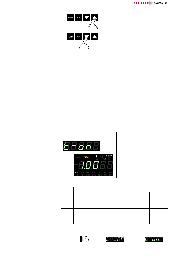
ÖIncrease/decrease the value
by the defined increments.
Definition of the ON threshold for the gauge to be acti-
vated by a gauge connected to the other measurement
channel.
Available for:
Pirani Gauge (TPR)
Pirani Capacitance Gauge (PCR)
;Cold Cathode Gauge (IKR)
FullRange™ CC Gauge (PKR)
;Process Ion Gauge (IMR)
;FullRange™ BA Gauge (PBR)
Capacitance Gauge (CMR)
Piezo Gauge (APR)
Adjustment range
e.g.:
→ table below
PKR CMR, APR
TPR
PCR IMR
PBR F.S.=1 F.S.=10 F.S.=100
IKR 10-3…10-2 10-5…10-2 10-3…10-2 ——
IMR 10-3…1 10-5…1 10-3…1 10-2…1 10-1…1
PBR 10-3…1 10-5…1 10-3…1 10-2…1 10-1…1
all values in mbar, CAL=1
Value must be ≥ .
ON threshold
BG 805 196 BE / B (2004-08) TPG262.oi 51
ÖPress key <1 s:
The value is increased/
decreased by 1 increment.
Press key >1 s:
The value is increased/
decreased continuously.
Certain gauges can be deactivated by different means.
The following gauges can be controlled:
Pirani Gauge (TPR)
Pirani Capacitance Gauge (PCR)
;Cold Cathode Gauge (IKR)
;FullRange™ CC Gauge *, **) (PKRx)
;Process Ion Gauge *) (IMR)
;FullRange™ BA Gauge *) (PBR)
Capacitance Gauge (CMRx)
Piezo Gauge (APR)
*) except for self control
**) except by a gauge connected to the other measurement
channel
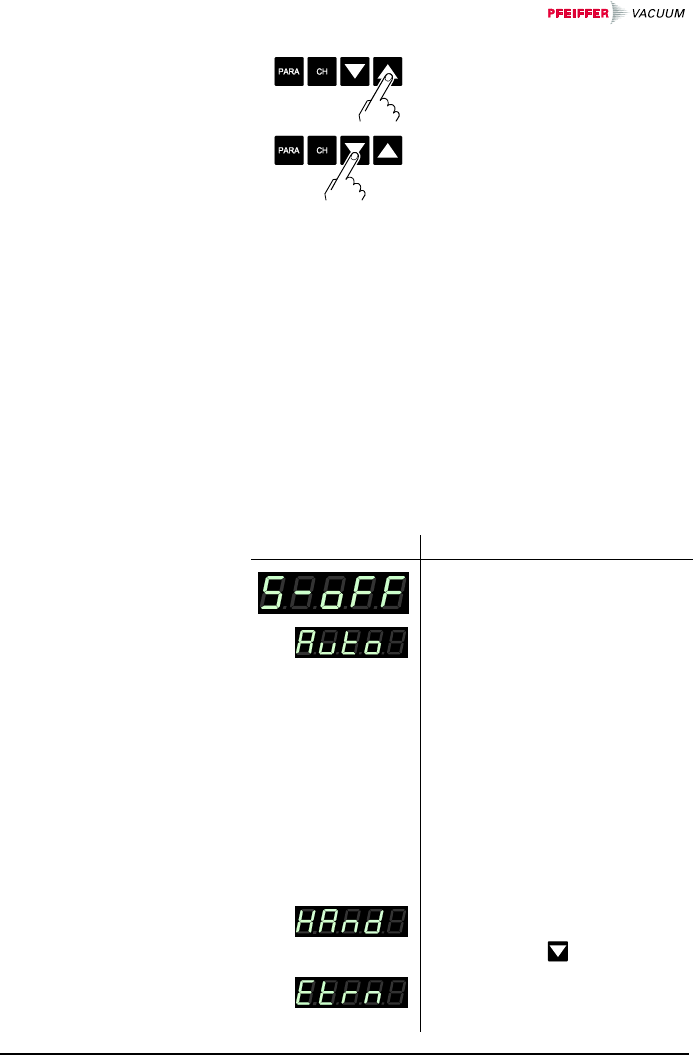
Value
ÖAutomatic deactivation:
The gauge is deactivated by
one of the following gauges
connected to the other meas-
urement channel.
;Pirani Gauge (TPR)
;Pirani Capacitance Gauge (PCR)
Cold Cathode Gauge (IKR)
;FullRange™ CC Gauge (PKR)
;Process Ion Gauge (IMR)
;FullRange™ BA Gauge (PBR)
;Capacitance Gauge *) (CMR)
;Piezo Gauge *) (APR)
*) only for gauges with F.S. 1, 10, or
100 mbar
ÖManual deactivation:
The gauge is deactivated by
pressing the key.
ÖExternal deactivation:
The gauge is deactivated by
an input signal via the control
Gauge deactivation
52 BG 805 196 BE / B (2004-08) TPG262.oi
connector (→ 21).
Additionally for Cold
Cathode Gauge:
ÖSelf control:
The gauge deactivates itself
when the pressure rises
(→ 52).
ÖIncrease/decrease the value
by the defined increments.
Definition of the OFF threshold for the gauge to be de-
activated by a gauge connected to the other measure-
ment channel or by itself.
Available for:
Pirani Gauge (TPR)
Pirani Capacitance Gauge (PCR)
;Cold Cathode Gauge (IKRx)
FullRange™ CC Gauge (PKR)
;Process Ion Gauge (IMR)
;FullRange™ BA Gauge (PBR)
Capacitance Gauge (CMR)
Piezo Gauge (APR)
Adjustment range
e.g.:
→ table below
OFF threshold
BG 805 196 BE / B (2004-08) TPG262.oi 53
PKR CMR, APR
TPR
PCR IMR
PBR F.S.=1 F.S.=10 F.S.=100
IKR 10-3…10-2 10-5…10-2 10-3…10-2 ——
IMR 10-3…1 10-5…1 10-3…1 10-2…1 10-1…1
PBR 10-3…1 10-5…1 10-3…1 10-2…1 10-1…1
all values in mbar, CAL=1
Value must be ≥ .
ÖPress key <1 s:
The value is increased/
decreased by 1 increment.
Press key >1 s:
The value is increased/
decreased continuously.
54 BG 805 196 BE / B (2004-08) TPG262.oi
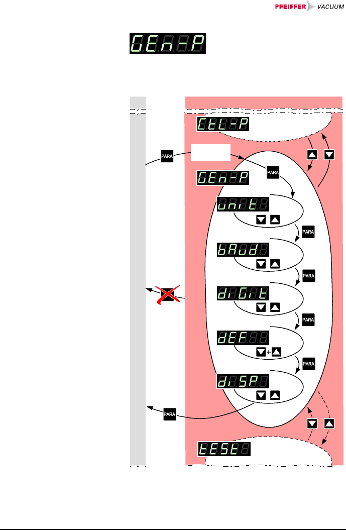
The General parameters group
(general parameters) is used for
displaying, entering and editing
generally applicable system para-
meters.
Measurement mode
depending
on history
Measurement unit
Transmission rate
Display resolution
Default settings
Display changeover
Parameter mode
>10 s
4.5.4 General
Parameters
BG 805 196 BE / B (2004-08) TPG262.oi 55
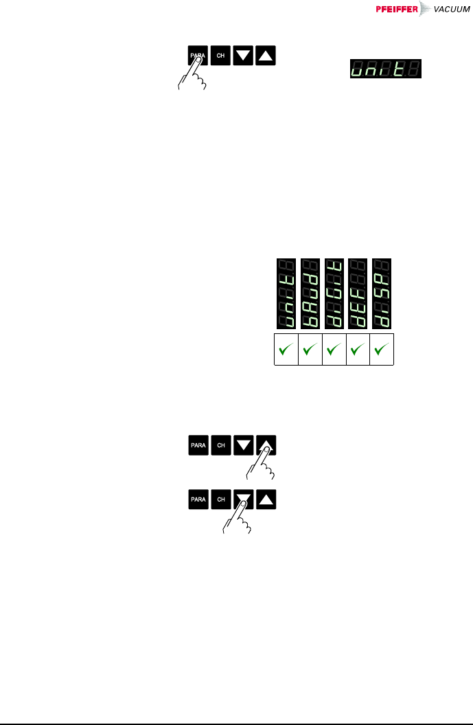
ÖThe name of the parameter,
e.g.: Measurement unit
is displayed as long as the
key is pressed or at least for
1.5 s.
Afterwards, the currently
valid threshold value is dis-
played.
The parameters are available for all gauge types and
thus always displayed.
→ 56 56 56 57 57
Available for
all gauges
ÖIncrease/decrease the value
by the defined increments.
Selecting a parameter
Editing a parameter
56 BG 805 196 BE / B (2004-08) TPG262.oi
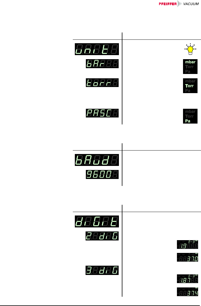
Unit of measured values, thresholds etc. See Appendix
(→ 97) for conversion.
Value
Ömbar/bar
ÖTorr (only available if
Torr lock is not activated
i.e. Torr is not sup-
pressed → 63)
ÖPascal
Transmission rate of the RS232C interface.
Value
e.g.:
Ö 9600 baud
19200 baud
38400 baud
Display resolution of measured values.
Value
ÖDisplay
• rounded to one
decimal digit
• or two integrals
ÖDisplay
• rounded to two
decimal digits
• or three inte-
grals
Measurement unit
Transmission rate
Display resolution
(digits)
BG 805 196 BE / B (2004-08) TPG262.oi 57
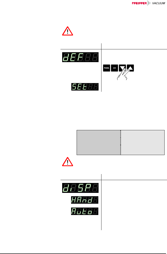
All user parameter settings are replaced by the factory
settings.
Loading of the default parameter settings is ir-
reversible.
Value
ÖThe default values are loaded
(→ 98).
Definition of the measurement display behavior when a
Pirani gauge or a Pirani Capacitance Gauge is com-
bined with a linear gauge with F.S. 1000 mbar.
5×10⁻⁴ mbar 10 mbar 1000 mbar
Pirani gauge
or
Pirani Capacitance
Gauge
Linear gauge
Automatic display changeover is available for
this gauge combination only.
Value
ÖManual change of measure-
ment value display
ÖAutomatic change of measure-
ment value display when the
measured value of the linear
gauge drops below or rises
above 10 mbar
Default values
Display changeover
58 BG 805 196 BE / B (2004-08) TPG262.oi
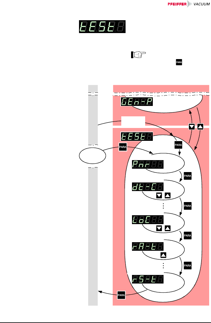
The Test parameter group is used
for displaying the firmware ver-
sion, entering and editing special
parameter values, and for running
test programs.
This group is only avail-
able if the key was
pressed while the
TPG 262 was turned on.
Measurement mode
Firmware version
Watchdog control
Keylock
RAM test program
RS232C test program
Parameter mode
Power
on
depending
on history
4.5.5 Test Parameters
BG 805 196 BE / B (2004-08) TPG262.oi 59
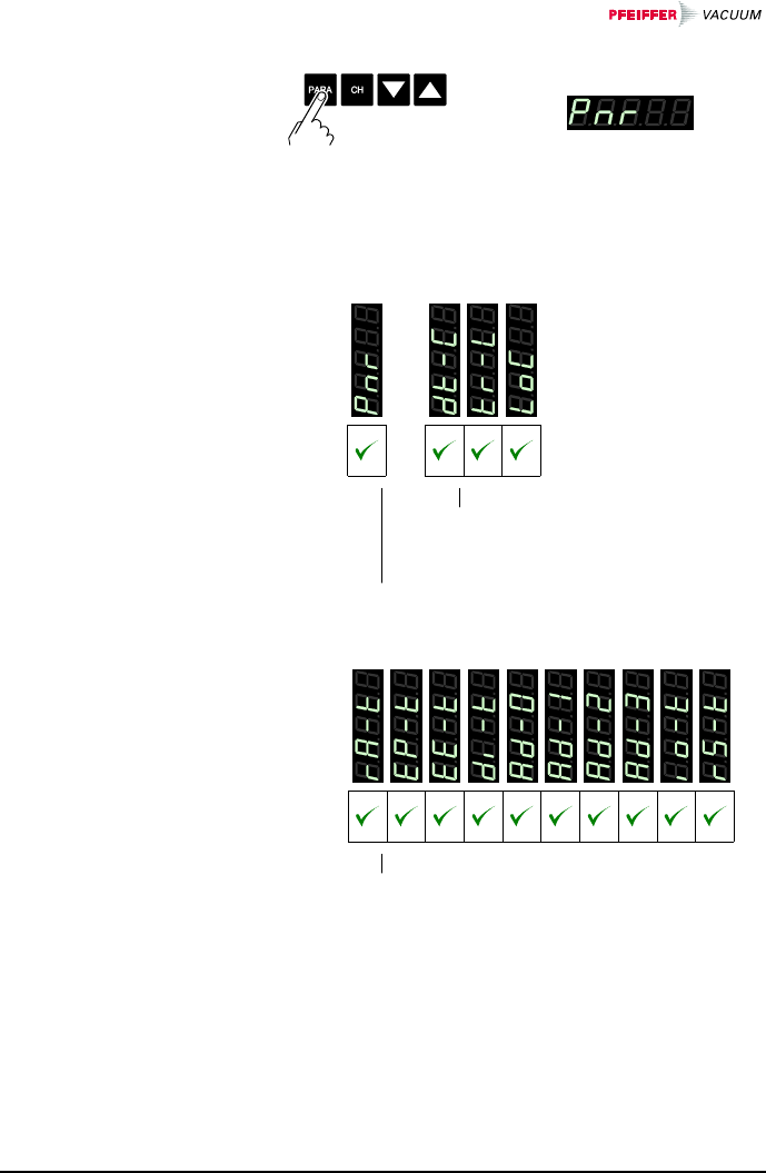
ÖThe name of the parameter,
e.g.: Firmware version
is displayed.
The parameters are available for all gauge types and
thus always displayed.
→ 60 61 61 61
Available for
all gauges
The name of the parameter is dis-
played as long as the key is pressed
or at least for 1.5 s.
The firmware version is continuously displayed.
→ 62 62 63 63 64 64 64 65 65 67
Available for
all gauges
The name of the test program is displayed until
it is started.
Selecting a parameter
60 BG 805 196 BE / B (2004-08) TPG262.oi
ÖIncrease/decrease the value
by the defined increments.
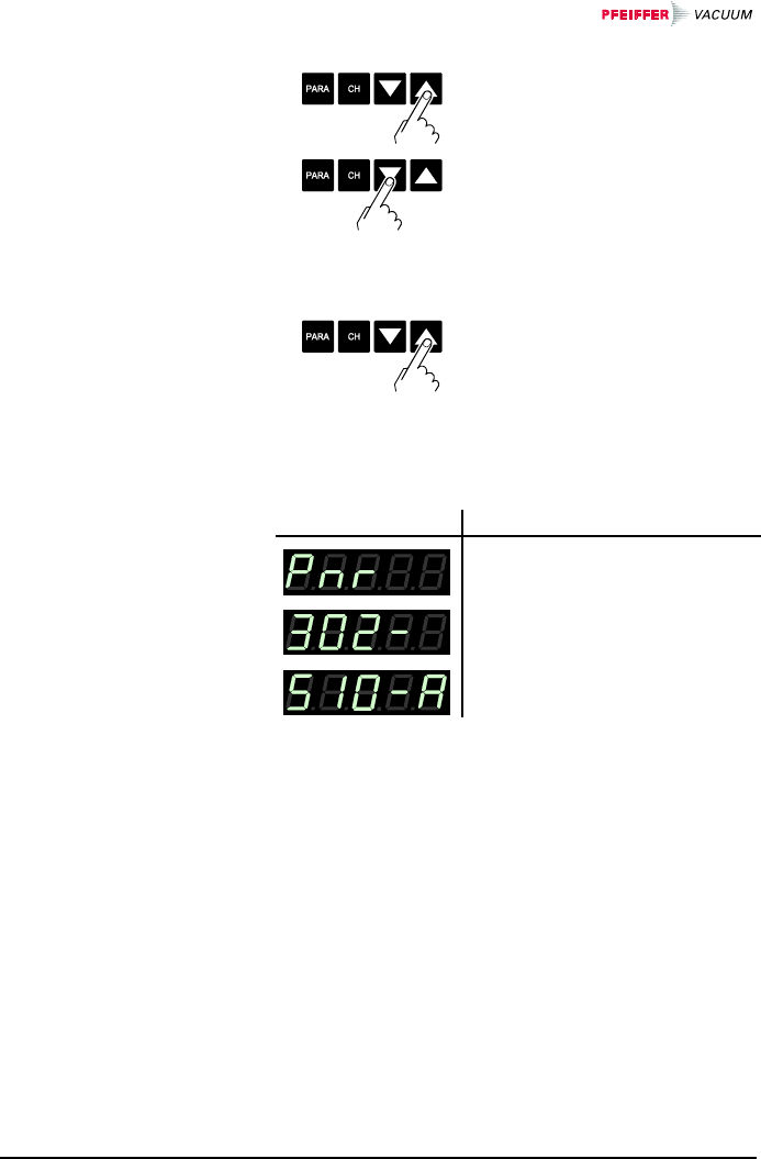
ÖStart test program.
The firmware version (program version) is displayed.
Version
ÖThe two parts of the firmware
number are displayed alter-
nately.
The last character indicates the modifi-
cation index (-, A … Z). Please mention
this index when contacting
Pfeiffer Vacuum in the event of a prob-
lem.
Editing a parameter
Starting the test
program
Firmware version
BG 805 196 BE / B (2004-08) TPG262.oi 61
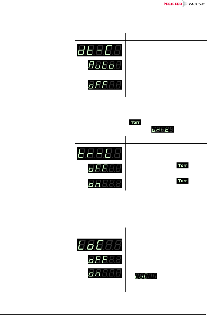
Behavior of the system control (watchdog) in the event
of an error.
Setting
ÖThe system automatically ac-
knowledges error messages of
the watchdog after 2 s.
ÖError messages of the watch-
dog have to be acknowledged
by the operator.
The measurement unit can be suppressed in the
corresponding parameter setting (→ 56).
Setting
ÖMeasurement unit
available.
ÖMeasurement unit not
available.
The keylock function prevents inadvertent entries in the
Parameter mode and thus malfunctions.
Setting
ÖKeylock function disabled.
ÖKeylock function enabled.
is displayed when
the user attempts to edit a set-
ting in the Parameter mode.
Watchdog control
Torr lock
Keylock
62 BG 805 196 BE / B (2004-08) TPG262.oi
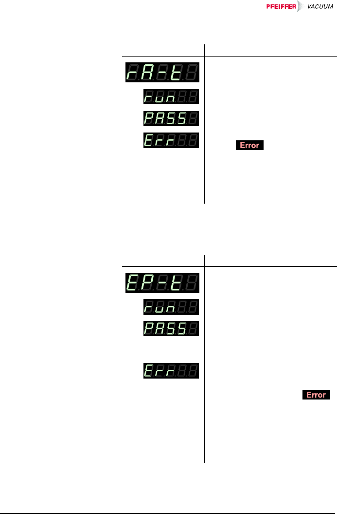
Test of the main memory.
Test sequence
The test runs automatically one
time:
ÖTest in process (very briefly).
ÖTest finished, no error found.
ÖTest finished, error(s) found.
The lamp flashes.
If the error message persists
after several test sequences
have been run, please contact
your local Pfeiffer Vacuum
service center.
Test of the program memory.
Test sequence
The test runs automatically one
time:
ÖTest in process
ÖTest finished, no error found.
After the test, a four-digit
checksum (hexadecimal for-
mat) is displayed.
ÖTest finished, error(s) found.
After the test, a four-digit
checksum (hexadecimal for-
mat) is displayed. The
lamp flashes.
If the error message persists
after several test sequences
have been run, please contact
your local Pfeiffer Vacuum
service center.
RAM test
EPROM test
BG 805 196 BE / B (2004-08) TPG262.oi 63
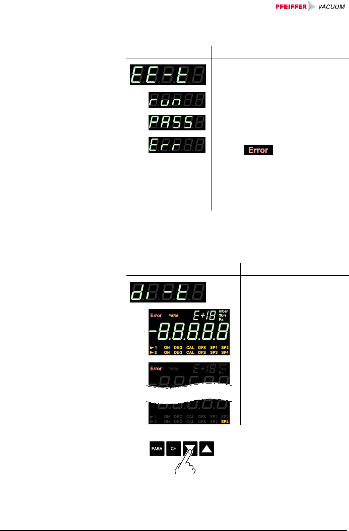
Test of the parameter memory.
Test sequence
The test runs automatically one
time:
ÖTest in process (very briefly).
ÖTest finished, no error found.
ÖTest finished, error(s) found.
The lamp flashes.
If the error message persists
after several test sequences
have been run, please contact
your local Pfeiffer Vacuum
service center.
Test of the display.
Test sequence
The test runs automati-
cally one time*):
ÖFirst, all display ele-
ments are lit at the
same time, ...
:
Ö... and then, each ele-
ment is lit individually.
*) ÖStop the test sequence
and activate one element
after another by pressing
the key once per element.
EEPROM test
Display test
64 BG 805 196 BE / B (2004-08) TPG262.oi
Test of channel 0 of the analog/digital converter (with a
reference voltage at the signal input of the sensor con-
nector (→ 20)).
If the signal input is open, the TPG 262 dis-
plays a default value that may easily fluctuate
because of the high sensitivity of the open
measurement circuit.
Test sequence
e.g.:
ÖMeasuring signal CH1 in Volt.
Test of channel 1 of the analog/digital converter (with a
reference voltage at the signal input of the sensor con-
nector (→ 20)).
If the signal input is open, the TPG 262 dis-
plays a default value that may easily fluctuate
because of the high sensitivity of the open
measurement circuit.
Test sequence
e.g.:
ÖMeasuring signal CH2 in Volt.
Test of channel 2 of the analog/digital converter (with a
reference voltage at the identification input of the sensor
connector (→ 20).
If the signal input is open, the TPG 262 dis-
plays a default value that may easily fluctuate
because of the high sensitivity of the open
measurement circuit.
A/D converter test 0
A/D converter test 1
A/D converter test 2
BG 805 196 BE / B (2004-08) TPG262.oi 65
Test sequence
e.g.:
ÖGauge identification voltage
CH1
ÖNo gauge connected
Test of channel 3 of the analog/digital converter (with a
reference voltage at the identification input of the sensor
connector (→ 20)).
If the signal input is open, the TPG 262 dis-
plays a default value that may easily fluctuate
because of the high sensitivity of the open
measurement circuit.
Test sequence
e.g.:
ÖGauge identification voltage
CH2
ÖNo gauge connected
Test of the relays of the TPG 262. The program tests
their switching function.
Caution
Caution: The relays switch irrespective of the
pressure
Starting a test program may cause unwanted
effects in connected control systems.
Disconnect all sensor cables and control
system lines to ensure that no control com-
mands or messages are triggered by mistake.
A/D converter test 3
I/O test
66 BG 805 196 BE / B (2004-08) TPG262.oi
The relays switch on and off cyclically. The switching
operations are indicated optically and can be heard.
The contacts of switching functions 1 … 4 are connected
to the relay connector (→ 22), the contacts of the error
relay to the control connector (→ 21) on the rear of the
housing. Check their function with an ohmmeter.
Test sequence
The test runs automatically one
time:
ÖAll relays deactivated
ÖSwitching function relay 1
ÖSwitching function relay 2
:
ÖSwitching function relay 4
ÖGauge relay CH1
ÖGauge relay CH2
ÖError relay

BG 805 196 BE / B (2004-08) TPG262.oi 67
Test of the RS232C interface. The TPG 262 repeats
each sign transmitted by the communicating HOST.
The data transferred from/to the TPG 262 can
be displayed by the computer only (→ 68).
Test sequence
The test runs automatically.
RS232C test

68 BG 805 196 BE / B (2004-08) TPG262.oi
5 Communication (Serial Interface)
The serial interface is used for communication between
the TPG 26x 1) and a computer. A terminal can be con-
nected for test purposes.
When the TPG 26x is put into operation, it starts trans-
mitting measured values in intervals of 1 s. As soon as
the first character is transferred to the TPG 26x, the
automatic transmission of measured values stops. After
the necessary inquiries or parameter modifications have
been made, the transmission of measured values can be
started again with the COM command (→ 75).
Pin assignment of the 9-pole D-Sub connector and
RS232 interface cable → 23.
The data transmission is bi-directional, i.e. data and
control commands can be transmitted in either direction.
1 start bit
8 data bits
No parity bit
1 stop bit
No hardware handshake
1) Communication structure and procedures are identi-
cal for both controllers TPG 261 and TPG 262.
Therefore the term TPG 26x is used in this chapter.
5.1 RS232C Interface
Connection diagram
connection cable
5.1.1 Data Transmission
Data format

BG 805 196 BE / B (2004-08) TPG262.oi 69
The following abbreviations and symbols are used:
Symbol Meaning
HOST Computer or terminal
[...] Optional elements
ASCII American Standard Code for Information
Interchange
Dec. Hex.
<ETX> END OF TEXT (CTRL C)
Reset the interface 3 03
<CR> CARRIAGE RETURN
Go to beginning of line 13 0D
<LF> LINE FEED
Advance by one line 10 0A
<ENQ
>ENQUIRY
Request for data transmission 5 05
<ACK> ACKNOWLEDGE
Positive report signal 6 06
<NAK> NEGATIVE ACKNOWLEDGE
Negative report signal 21 15
"Transmit": Data transfer from HOST to TPG 26x
"Receive": Data transfer from TPG 26x to HOST
After each ASCII string, the HOST must wait for a report
signal (<ACK><CR><LF> or <NAK> <CR><LF>).
The input buffer of the HOST must have a capacity of at
least 32 bytes.
Definitions
Flow Control

70 BG 805 196 BE / B (2004-08) TPG262.oi
Messages are transmitted to the TPG 26x as ASCII
strings in the form of mnemonic operating codes and
parameters. All mnemonics comprise three ASCII char-
acters.
Spaces are ignored. <ETX> (CTRL C) clears the input
buffer in the TPG 26x.
HOST TPG 26x Explanation
Mnemonics
[and parameters] >
<CR>[<LF>] >
Receives message
with "end of mes-
sage"
< <ACK><CR><LF> Positive acknowledg-
ment of a received
message
When requested with a mnemonic instruction, the
TPG 26x transmits the measurement data or parameters
as ASCII strings to the HOST.
<ENQ> must be transmitted to request the transmission
of an ASCII string. Additional strings, according to the
last selected mnemonic, are read out by repetitive
transmission of <ENQ>.
If <ENQ> is received without a valid request, the
ERROR word is transmitted.
5.1.2 Communication
Protocol
Transmission format
Transmission
protocol
Reception format

BG 805 196 BE / B (2004-08) TPG262.oi 71
HOST TPG 26x Explanation
Mnemonics
[and parameters] >
<CR>[<LF>] >
Receives message
with "end of mes-
sage"
< <ACK><CR><LF> Positive acknowledg-
ment of a received
message
<ENQ> > Requests to transmit
data
< Measurement values
or parameters
< <CR><LF>
Transmits data with
"end of message"
::
<ENQ>> Requests to transmit
data
< Measurement values
or parameters
< <CR><LF>
Transmits data with
"end of message"
The strings received are verified in the TPG 26x. If an
error is detected, a negative acknowledgment <NAK> is
output.
HOST TPG 26x Explanation
Mnemonics
[and parameters] >
<CR>[<LF>] >
Receives message
with "end of mes-
sage"
***** Transmission or programming error *****
< <NAK><CR><LF> Negative acknowl-
edgment of a re-
ceived message
Mnemonics
[and parameters] >
<CR>[<LF>] >
Receives message
with "end of mes-
sage"
< <ACK><CR><LF> Positive acknowl-
edgment of a re-
ceived message
Reception protocol
Error processing
Error recognition
protocol

72 BG 805 196 BE / B (2004-08) TPG262.oi
→
ADC A/D converter test 89
BAU Baud rate (transmission rate) 85
COM Continuous mode 75
CAL Calibration factor 81
DCD Display control digits (display resolution) 85
DGS Degas 83
DIC Display control (display changeover) 86
DIS Display test 88
EEP EEPROM test 88
EPR EPROM test 88
ERR Error status 77
FIL Filter time constant (measurement value filter) 80
FSR Full scale range (measurement range of linear gauges) 81
IOT I/O test 90
LOC Keylock 87
OFC Offset correction (linear gauges) 82
OFD Offset display (linear gauges) 82
PNR Program number (firmware version) 86
PR1 Pressure measurement (measurement data) gauge 1 73
PR2 Pressure measurement (measurement data) gauge 2 73
PRX Pressure measurement (measurement data) gauge 1 and 2 74
PUC Penning underrange control (underrange control) 83
RAM RAM test 88
RES Reset 78
RST RS232 test 91
SAV Save parameters to EEPROM 86
SC1 Sensor control 1 (gauge control 1) 84
SC2 Sensor control 2 (gauge control 2) 84
SCT Sensor channel change (measurement channel change) 77
SEN Sensors on/off 76
SP1 Setpoint 1 (switching function 1) 79
SP2 Setpoint 2 (switching function 2) 79
SP3 Setpoint 3 (switching function 3) 79
SP4 Setpoint 4 (switching function 4) 79
SPS Setpoint status (switching function status) 80
TID Transmitter identification (gauge identification) 76
TKB Keyboard test (operator key test) 91
TLC Torr lock 87
UNI Pressure unit 85
WDT Watchdog control 87
5.2 Mnemonics

BG 805 196 BE / B (2004-08) TPG262.oi 73
Transmit: PRx <CR>[<LF>]
Measurement value x = 1 –> Gauge 1
2 –> Gauge 2
Receive: <ACK><CR><LF>
Transmit: <ENQ>
Receive: x,sx.xxxxEsxx <CR><LF>
Measurement value 1)
[in current pressure unit]
Status, x =
0 –> Measurement data okay
1 –> Underrange
2 –> Overrange
3 –> Sensor error
4 –> Sensor off (IKR, PKR, IMR, PBR)
5 –> No sensor
(output: 5,2.0000E-2 [mbar])
6 –> Identification error
1) Values always in exponential format.
For logarithmic gauges, the 3rd and 4th decimal
are always 0.
5.2.1 Measurement
Mode
Measurement data
gauge 1 or 2

74 BG 805 196 BE / B (2004-08) TPG262.oi
Transmit: PRX <CR>[<LF>]
Receive: <ACK><CR><LF>
Transmit: <ENQ>
Receive: x,sx.xxxxEsxx,y,sy.yyyyEsyy <CR><LF>
Measurement
value gauge 2 1)
[in current
pressure unit]
Status gauge 2
Measurement value gauge 1 1)
[in current pressure unit]
Status gauge 1, x =
0 –> Measurement data okay
1 –> Underrange
2 –> Overrange
3 –> Sensor error
4 –> Sensor off (IKR, PKR, IMR, PBR)
5 –> No sensor
(output: 5,2.0000E-2 [mbar])
6 –> Identification error
1) Values always in exponential format.
For logarithmic gauges, the 3rd and 4th decimal
are always 0.
Measurement data
gauges 1 and 2

BG 805 196 BE / B (2004-08) TPG262.oi 75
Transmit: COM [,x] <CR>[<LF>]
Mode x = 0 –> 100 ms
1 –> 1 s (default)
2 –> 1 min.
Receive: <ACK><CR><LF>
<ACK> is immediately followed by the con-
tinuous output of the measurement value in
the desired interval.
Receive: x,sx.xxxxEsxx,y,sy.yyyyEsyy <CR><LF>
Measurement
value gauge 2 1)
[in current
pressure unit]
Status gauge 2
Measurement value gauge 1 1)
[in current pressure unit]
Status gauge 1, x =
0 –> Measurement data okay
1 –> Underrange
2 –> Overrange
3 –> Sensor error
4 –> Sensor off (IKR, PKR, IMR, PBR)
5 –> No sensor
(output: 5,2.0000E-2 [mbar])
6 –> Identification error
1) Values always in exponential format.
For logarithmic gauges, the 3rd and 4th decimal
are always 0.
Continuous output of
measurement values
(RS232)

76 BG 805 196 BE / B (2004-08) TPG262.oi
Transmit: SEN [,x,x] <CR>[<LF>]
Gauge 2, x =
0 –> No status change
1 –> Turn gauge off
2 –> Turn gauge on
Gauge 1
Receive: <ACK><CR><LF>
Transmit: <ENQ>
Receive: x,x <CR><LF>
Status gauge 2, x =
0 –> Gauge cannot be turned on/off
1 –> Gauge turned off
2 –> Gauge turned on
Status gauge 1
Transmit: TID <CR>[<LF>]
Receive: <ACK><CR><LF>
Transmit: <ENQ>
Receive: x,x <CR><LF>
Identification gauge 2, x =
TPR (Pirani Gauge or
Pirani Capacitive gauge 1))
IKR9 (Cold Cathode Gauge 10-9)
IKR11 (Cold Cathode Gauge 10-11)
PKR (FullRange CC Gauge)
PBR (FullRange BA Gauge)
IMR (Pirani / High Pressure Gauge)
CMR (Linear gauge)
noSEn (no SEnsor)
noid (no identifier)
Identification gauge 1
1) TPR and PCR have identical identifiers.
There is no distinction made in communication
and in data evaluation, since pressure ranges
of these gauges are approximately the same.
Turning a gauge
on/off
Gauge identification

BG 805 196 BE / B (2004-08) TPG262.oi 77
Transmit: SCT [,x] <CR>[<LF>]
Display channel, x =
0 –> Gauge 1
1 –> Gauge 2
Receive: <ACK><CR><LF>
Transmit: <ENQ>
Receive: x <CR><LF>
Display channel
Transmit: ERR <CR>[<LF>]
Receive: <ACK><CR><LF>
Transmit: <ENQ>
Receive: xxxx <CR><LF>
xxxx =
0000 –> No error
1000 –> Error Controller error
(See display
on front panel)
0100 –> NO HWR No hardware
0010 –> PAR Inadmissible
parameter
0001 –> SYN Syntax error
The ERROR word is cancelled when read out.
If the error persists, it is immediately set again.
Measurement
channel change
Error status

78 BG 805 196 BE / B (2004-08) TPG262.oi
Transmit: RES [,x] <CR>[<LF>]
x = 1 –> Cancels currently active
error and returns to
measurement mode
Receive: <ACK><CR><LF>
Transmit: <ENQ>
Receive: [x]x,[x]x,... <CR><LF>
List of all present error messages,
xx =
0 –> No error
1 –> Watchdog has responded
2 –> Task fail error
3 –> EPROM error
4 –> RAM error
5 –> EEPROM error
6 –> DISPLAY error
7 –> A/D converter error
9 –> Gauge 1 error (e.g. filament
rupture, no supply)
10 –> Gauge 1 identification error
11 –> Gauge 2 error (e.g. filament
rupture, no supply)
12 –> Gauge 2 identification error
Reset
BG 805 196 BE / B (2004-08) TPG262.oi 79
Transmit: SPx [,y,x.xxxxEsxx,x.xxxxEsxx] <CR>[<LF>]
Upper threshold 1)
[in current
pressure unit]
(default =
depending on
gauge)
Lower threshold 1)
[in current pressure unit]
(default = depending on
gauge)
Switching function assignment, y =
0 –> Meas. channel 1
1 –> Meas. channel 2
1 –> Switching function 1
2 –> Switching function 2
3 –> Switching function 3
4 –> Switching function 4
1) Values can be entered in any format. They
are internally converted into the floating point
format.
Receive: <ACK><CR><LF>
Transmit: <ENQ>
Receive: y,x.xxxxEsxx,x.xxxxEsxx <CR><LF>
Upper threshold
[in current
pressure unit]
Lower threshold
[in current pressure unit]
Switching function assignment
5.2.2 Parameter Mode
5.2.2.1 Switching
Function
Parameters
Threshold value
setting, allocation

80 BG 805 196 BE / B (2004-08) TPG262.oi
Transmit: SPS <CR>[<LF>]
Receive: <ACK><CR><LF>
Transmit: <ENQ>
Receive: x,x,x,x <CR><LF>
Status switching function 4 1)
Status switching function 3 1)
Status switching function 2 1)
Status switching function 1 1)
1) x = 0 –> off
1 –> on
Transmit: FIL [,x,x] <CR>[<LF>]
Gauge 2 x = 0 –> fast
1 –> medium
(default)
2 –> slow
Gauge 1
Receive: <ACK><CR><LF>
Transmit: <ENQ>
Receive: x,x <CR><LF>
Filter time constant gauge 2
Filter time constant gauge 1
Switching function
status
5.2.2.2 Gauge Parameters
Measurement value
filter

BG 805 196 BE / B (2004-08) TPG262.oi 81
Transmit: CAL [,x.xxx,x.xxx] <CR>[<LF>] ( )
Gauge 2
log. 0.100 ... 9.990
(default = 1.000)
lin. 0.500 ... 2.000
(default = 1.000)
Gauge 1
Receive: <ACK><CR><LF>
Transmit: <ENQ>
Receive: x.xxx,x.xxx <CR><LF>
Calibration factor gauge 2
Calibration factor gauge 1
The full scale value of the measurement range
(Full Scale) of linear gauges has to be defined
by the user; the full scale value of logarithmic
gauges is automatically recognized.
Transmit: FSR [,x,x] <CR>[<LF>]
Gauge 2, x =
0 –> 0.01 mbar
1 –> 0.1 mbar
2 –> 1 mbar
3 –> 10 mbar
4 –> 100 mbar
5 –> 1000 mbar (default)
6 –> 2 bar
7 –> 5 bar
8 –> 10 bar
9 –> 50 bar
Gauge 1
Receive: <ACK><CR><LF>
Transmit: <ENQ>
Receive: x,x <CR><LF>
Measurement range gauge 2
Measurement range gauge 1
Calibration factor
Measurement range
(F.S.) of
linear gauges

82 BG 805 196 BE / B (2004-08) TPG262.oi
Transmit: OFC [,x,x] <CR>[<LF>] ( )
Gauge 2, x =
0 –> off (default)
1 –> on
2 –> auto (offset measurement)
Gauge 1
Receive: <ACK><CR><LF>
Transmit: <ENQ>
Receive: x,x <CR><LF>
Gauge 2
Gauge 1
Transmit: OFD [,sx.xxxxEsxx,sx.xxxxEsxx] <CR>[<LF>]
Gauge 2 Offset 1)
[in current
pressure unit]
(default = 0.0000)
Gauge 1
1) Values can be entered in any format. They
areinternally converted into the floating point
format.
Receive: <ACK><CR><LF>
Transmit: <ENQ>
Receive: sx.xxxxEsxx,sx.xxxxEsxx <CR><LF>
Gauge 2
Gauge 1
Offset correction
(linear gauges)
Offset display
(linear gauges)

BG 805 196 BE / B (2004-08) TPG262.oi 83
Transmit: PUC [,x,x] <CR>[<LF>]
Gauge 2, x = 0 –> off (default)
1 –> on
Gauge 1
Receive: <ACK><CR><LF>
Transmit: <ENQ>
Receive: x,x <CR><LF>
Gauge 2
Gauge 1
Transmit: DGS [,x,x] <CR>[<LF>] ( .)
Gauge 2, x =
0 –> Degas off (default)
1 –> Degas on (3 min.)
Gauge 1
Receive: <ACK><CR><LF>
Transmit: <ENQ>
Receive: x,x <CR><LF>
Degas status gauge 2
Degas status gauge 1
Underrange control
Degas

84 BG 805 196 BE / B (2004-08) TPG262.oi
Transmit: SCx [,x,y,x.xxEsxx,y.yyEsyy] <CR>[<LF>]
OFF threshold
ON threshold
Controlling source for gauge
deactivation, x =
0 –> no control
1 –> automatic deactivation
2 –> manual deactivation
(default)
3 –> external deactivation
4 –> self control
Controlling source for gauge
activation, x =
0 –> no control
1 –> automatic activation
2 –> manual activation (default)
3 –> external activation
4 –> hot start
Controlled gauge, x =
1 –> Gauge 1
2 –> Gauge 2
Receive: <ACK><CR><LF>
Transmit: <ENQ>
Receive: x,y,x.xxEsxx,y.yyEsyy <CR><LF>
OFF threshold
ON threshold
Controlling source for
deactivating the gauge
Controlling source for activating the
gauge
5.2.2.3 Gauge Control
Gauge control

BG 805 196 BE / B (2004-08) TPG262.oi 85
Transmit: UNI [,x] <CR>[<LF>]
Pressure unit, x =
0 –> mbar/bar (default)
1 –> Torr
2 –> Pascal
Receive: <ACK><CR><LF>
Transmit: <ENQ>
Receive: x <CR><LF>
Pressure unit
Transmit: BAU [,x] <CR>[<LF>]
Transmission rate, x =
0 –> 9600 baud (default)
1 –> 19200 baud
2 –> 38400 baud
As soon as the new baud rate has been en-
tered, the report signal is transmitted at the new
transmission rate.
Receive: <ACK><CR><LF>
Transmit: <ENQ>
Receive: x <CR><LF>
Transmission rate
Transmit: DCD [,x] <CR>[<LF>]
Resolution, x =
2 –> Display x.x (2 digits)
(default)
3 –> Display x.xx (3 digits)
Receive: <ACK><CR><LF>
Transmit: <ENQ>
Receive: x <CR><LF>
Resolution
5.2.2.4 General
Parameters
Pressure unit
Transmission rate
Display resolution

86 BG 805 196 BE / B (2004-08) TPG262.oi
Transmit: SAV [,x] <CR>[<LF>]
x = 0 –> Save default
parameters
1 –> Save user parameters
Receive: <ACK><CR><LF>
Transmit: DIC [,x] <CR>[<LF>]
Measurement display behavior
when a Pirani gauge or a Pirani
Capacitance gauge is combined
with a linear gauge with
1000 mbar F.S., x =
0 –>manual (default)
1 –>automatic
Receive: <ACK><CR><LF>
Transmit: <ENQ>
Receive: x <CR><LF>
Measurement display behavior
(For service personnel)
Transmit: PNR <CR>[<LF>]
Receive: <ACK><CR><LF>
Transmit: <ENQ>
Receive: 302-510-x <CR><LF>
-x = Modification index
(-- = original version)
Firmware number
Save parameters to
EEPROM
Display changeover
5.2.2.5 Test Parameters
Firmware version

BG 805 196 BE / B (2004-08) TPG262.oi 87
Transmit: WDT [,x] <CR>[<LF>]
x = 0 –> Manual error
acknowledgement
1 –> Automatic error
acknowledgement 1)
(default)
1) If the watchdog has responded, the error is
automatically acknowledged and cancelled af-
ter 2 s.
Receive: <ACK><CR><LF>
Transmit: <ENQ>
Receive: x <CR><LF>
Watchdog control
Transmit: TLC [,x] <CR>[<LF>]
x = 0 –> off (default)
1 –> on
Receive: <ACK><CR><LF>
Transmit: <ENQ>
Receive: x <CR><LF>
Torr lock status
Transmit: LOC [,x] <CR>[<LF>]
x = 0 –> off (default)
1 –> on
Receive: <ACK><CR><LF>
Transmit: <ENQ>
Receive: x <CR><LF>
Keylock status
Watchdog control
Torr lock
Keylock

88 BG 805 196 BE / B (2004-08) TPG262.oi
Transmit: RAM <CR>[<LF>]
Receive: <ACK><CR><LF>
Transmit: <ENQ> Starts the test (duration <1 s)
Receive: xxxx <CR><LF>
ERROR word
Transmit: EPR <CR>[<LF>]
Receive: <ACK><CR><LF>
Transmit: <ENQ> Starts the test (duration ≈5 s)
Receive: xxxx,yyyy <CR><LF>
Check sum (hex)
ERROR word
Transmit: EEP <CR>[<LF>]
Receive: <ACK><CR><LF>
Transmit: <ENQ> Starts the test (duration <1 s)
Do not keep repeating the test (EEPROM life).
Receive: xxxx <CR><LF>
ERROR word
Transmit: DIS [,x] <CR>[<LF>]
x = 0 –> Stops the test – display
according to current
operating mode (default)
1 –> Starts the test –
all LEDs on
Receive: <ACK><CR><LF>
Transmit: <ENQ>
Receive: x <CR><LF>
Display test status
RAM test
EPROM test
EEPROM test
Display test

BG 805 196 BE / B (2004-08) TPG262.oi 89
Transmit: ADC <CR>[<LF>]
Receive: <ACK><CR><LF>
Transmit: <ENQ>
Receive: [x]x.xxxx,[x]x.xxxx,x.xxxx,x.xxxx <CR><LF>
ADC channel 4
identification
Gauge 2
[0.0000 ...
5.0000 V]
ADC channel 3
Gauge 1 identification
[0.0000 ... 5.0000 V]
ADC channel 2
Measurement signal
gauge 2
[0.0000 ... 11.0000 V]
ADC channel 1
Measurement signal gauge 1
[0.0000 ... 11.0000 V]
ADC test

90 BG 805 196 BE / B (2004-08) TPG262.oi
Caution
Caution: The relays switch irrespective of the
pressure.
Starting a test program may cause unwanted
effects in connected control systems.
Disconnect all sensor cables and control
system lines to ensure that no control com-
mands or messages are triggered by mistake.
Transmit: IOT [,x,yy] <CR>[<LF>]
Relay status (in hex format), yy =
00 –> All relays deactivated
01 –> Switching function relay 1
activated
02 –> Switching function relay 2
activated
04 –> Switching function relay 3
activated
08 –> Switching function relay 4
activated
10 –> Gauge relay CH1 activated
20 –> Gauge relay CH2 activated
40 –> Error relay activated
7F –> All relays activated
x = 0 –> Test stopped
1 –> Test runs
Receive: <ACK><CR><LF>
Transmit: <ENQ>
Receive: x,yy <CR><LF>
Relay status
I/O test status
I/O test

BG 805 196 BE / B (2004-08) TPG262.oi 91
Transmit: TKB <CR>[<LF>]
Receive: <ACK><CR><LF>
Transmit: <ENQ>
Receive: xxxx <CR><LF>
Key 4 x = 0 –> Not pushed
1 –> Pushed
Key 3
Key 2
Key 1
Transmit: RST <CR>[<LF>]
Receive: <ACK><CR><LF>
Transmit: <ENQ> Starts the test (repeats each
character, test is interrupted
with <CTRL> C)
Operator key test
RS232 test

92 BG 805 196 BE / B (2004-08) TPG262.oi
"Transmit (T)" and "Receive (R)" are related to Host.
S: TID <CR> [<LF>]
E: <ACK> <CR> <LF>
S: <ENQ>
E: TPR,CMR <CR> <LF>
Request for gauge identification
Positive acknowledgement
Request for data transmission
Gauge identifications
S: SEN <CR> [<LF>]
E: <ACK> <CR> <LF>
S: <ENQ>
E: 0,0 <CR> <LF>
Request for gauge statuses
Positive acknowledgement
Request for data transmission
Gauge statuses
S: SP1 <CR> [<LF>]
E: <ACK> <CR> <LF>
S: <ENQ>
E: 0,1.0000E-09,9.0000E-07 <CR> <LF>
Request for parameters of
switching function 1 (setpoint 1)
Positive acknowledgement
Request for data transmission
Thresholds
S: SP1,1,6.80E-3,9.80E-3 <CR> [<LF>]
E: <ACK> <CR> <LF>
Modification of parameters of
switching function 1 (setpoint 1)
Positive acknowledgement
S: FOL,1,2 <CR> [<LF>]
E: <NAK> <CR> <LF>
S: <ENQ>
E: 0001 <CR> <LF>
S: FIL,1,2 <CR> [<LF>]
E: <ACK> <CR> <LF>
S: <ENQ>
E: 1,2 <CR> <LF>
Modification of filter time constant
(syntax error)
Negative acknowledgement
Request for data transmission
ERROR word
Modification of filter time constant
Positive acknowledgement
Request for data transmission
Filter time constants
5.2.3 Example
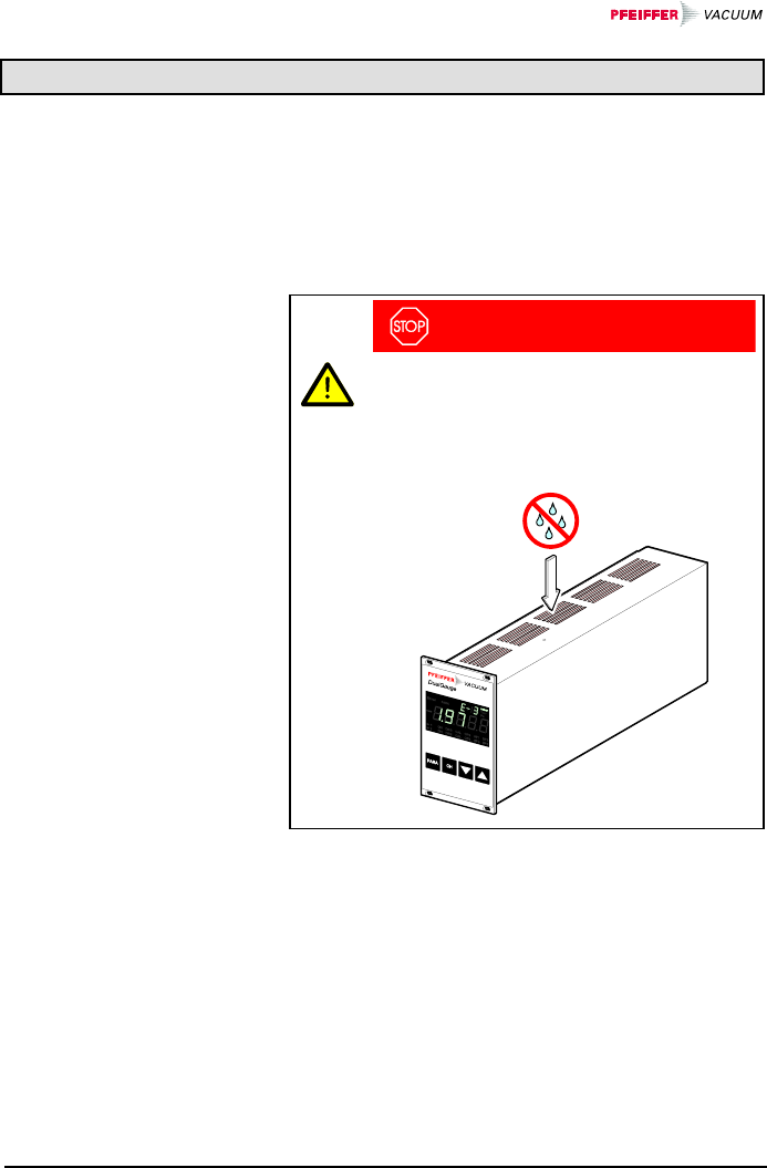
BG 805 196 BE / B (2004-08) TPG262.oi 93
6 Maintenance
The product requires no maintenance.
For cleaning the outside of the TPG 262, a slightly moist
cloth will usually do. Do not use any aggressive or scour-
ing cleaning agents.
DANGER
Caution: mains voltage
Contact with live parts is extremely hazardous
when liquids penetrate into the unit.
Make sure no liquids penetrate into the equip-
ment.
Cleaning the TPG 262
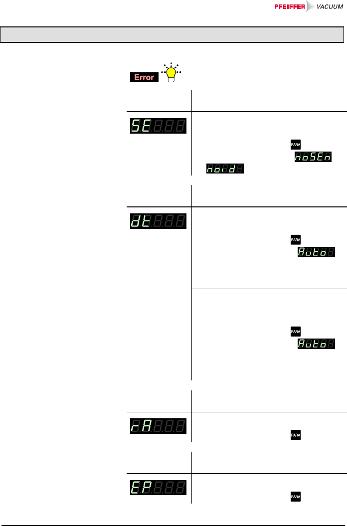
94 BG 805 196 BE / B (2004-08) TPG262.oi
7 Troubleshooting
and the error relay opens (→ 21).
Possible cause and remedy/
acknowledgement
Interruption or instability in sensor line
or connector (Sensor error).
ÖAcknowledge with the . key
If the problem persists, or
is displayed.
Possible cause and remedy/
acknowledgement
The TPG 262 has been turned on too
fast after power off.
ÖAcknowledge with the key.
If the watchdog is set to ,
the TPG 262 acknowledges the
message automatically after 2 s
(→ 61).
The watchdog has tripped because of
a severe electric disturbance or an op-
erating system error.
ÖAcknowledge with the key.
If the watchdog is set to ,
the TPG 262 acknowledges the
message automatically after 2 s
(→ 61).
Possible cause and remedy/
acknowledgement
Main memory (RAM) error.
ÖAcknowledge with the key.
Possible cause and remedy/
acknowledgement
Program memory (EPROM) error.
ÖAcknowledge with the key.
Signalization of errors
Error messages
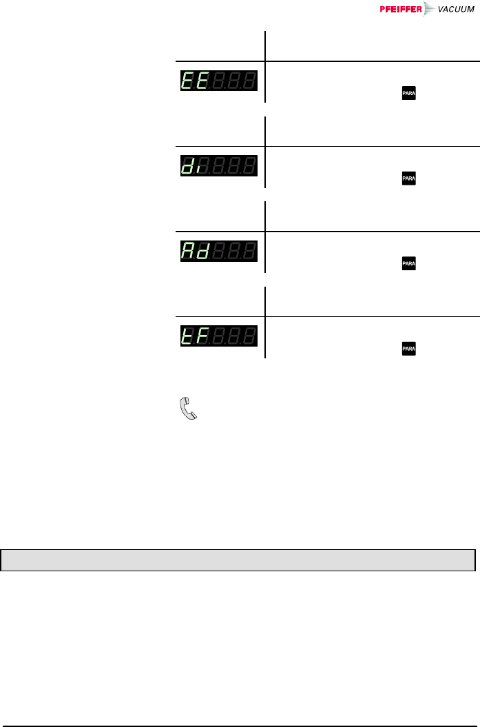
BG 805 196 BE / B (2004-08) TPG262.oi 95
Possible cause and remedy/
acknowledgement
Parameter memory (EEPROM) error.
ÖAcknowledge with the key.
Possible cause and remedy/
acknowledgement
Display driver error.
ÖAcknowledge with the key.
Possible cause and remedy/
acknowledgement
A/D converter error.
ÖAcknowledge with the key.
Possible cause and remedy/
acknowledgement
Operating system (Task Fail) error.
ÖAcknowledge with the key.
If the problem persists after the message has been
acknowledged for several times and/or the gauge
has been exchanged, please contact you local
Pfeiffer Vacuum service center.
8 Repair
Return defective products to your nearest
Pfeiffer Vacuum service center for repair.
Pfeiffer Vacuum assumes no liability and the warranty
becomes null and void if repair work is carried out by the
end-user or third parties.
Technical support
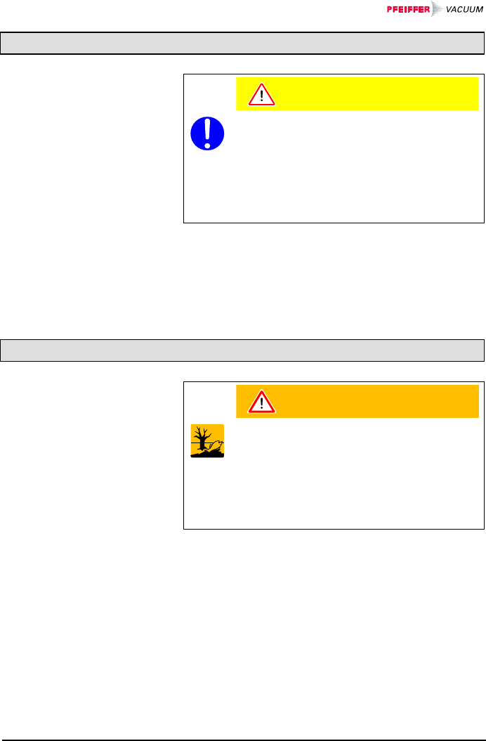
96 BG 805 196 BE / B (2004-08) TPG262.oi
9 Storage
Caution
Caution: electronic component
Inappropriate storage (static electricity, hu-
midity etc.) can damage electronic compo-
nents.
Store the product in an antistatic bag or con-
tainer. Observe the corresponding specifica-
tions in the technical data (→ 9).
10 Disposal
N
WARNING
Caution: substances detrimental to the envi-
ronment
Products or parts thereof (mechanical and
electric components, operating fluids etc.)
can be detrimental to the environment.
Dispose of such substances in accordance
with the relevant local regulations.
After disassembling the product, separate its compo-
nents according to the following criteria:
Such components must be separated according to their
materials and recycled.
Such components must be separated according to their
materials and recycled.
Separating the
components
Non-electronic
components
Electronic
components

BG 805 196 BE / B (2004-08) TPG262.oi 97
Appendix
kg lb slug oz
kg 1 2.205 68.522×10⁻³ 35.274
lb 0.454 1 31.081×10⁻³ 16
slug 14.594 32.174 1 514.785
oz 28.349×10⁻³ 62.5×10⁻³ 1.943×10⁻³ 1
N/m2, Pa bar mbar Torr at
N/m2, Pa 1 10×10-6 10×10-3 7.5×10⁻³ 9.869×10⁻⁶
bar 100×1031 103750.062 0.987
mbar 100 10-3 1 750.062×10⁻³ 0.987×10⁻³
Torr 133.322 1.333×10⁻³ 1.333 1 1.316×10⁻³
at 101.325×1031.013 1.013×103760 1
mbar Pascal Torr mmWs psi
mbar 1 100 750.062×10⁻³ 10.2 14.504×10⁻³
Pascal 10×10-3 1 7.5×10⁻³ 0.102 0.145×10⁻³
Torr 1.333 133.322 1 13.595 19.337×10⁻³
mmWs 9.81×10⁻² 9.81 7.356×10⁻² 1 1.422×10⁻³
psi 68.948 6.895×10351.715 703 1
mm m inch ft
mm 1 10-3 39.37×10⁻³ 3.281×10⁻³
m1031 39.37 3.281
inch 25.4 25.4×10⁻³ 1 8.333×10⁻²
ft 304.8 0.305 12 1
Kelvin Celsius Fahrenheit
Kelvin 1 °C+273.15 (°F+459.67)×5/9
Celsius K-273.15 1 5/9×°F-17.778
Fahrenheit 9/5×K-459.67 9/5×(°C+17.778) 1
A: Conversion Tables
Weights
Pressures
Pressure units used in
the vacuum technology
Linear measures
Temperature
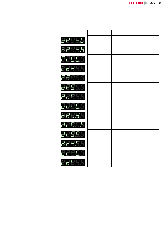
98 BG 805 196 BE / B (2004-08) TPG262.oi
The following values are activated when the default pa-
rameter settings are loaded (→ 57):
1000 mbar
1.00 (log)
1.000 (lin)
normal
off
0×10-2 mbar
1×10-11 mbar
Default
off
mbar
9600
2 Digit
User
off
off
Auto
Hand
9×10-11 mbar
B: Default Parameter
Settings
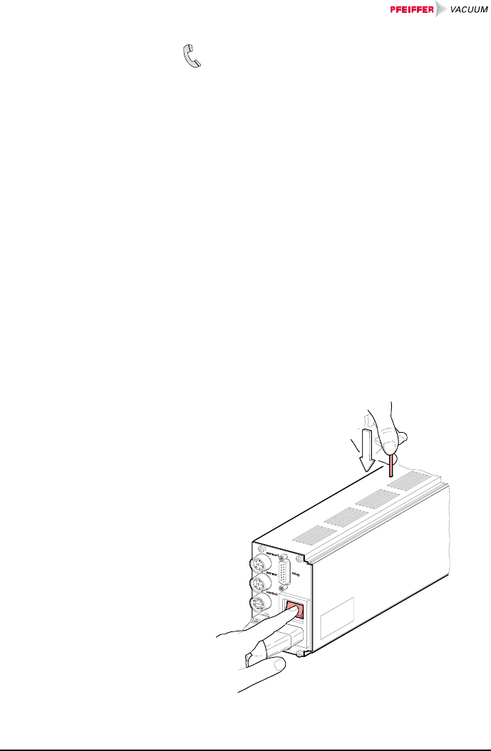
BG 805 196 BE / B (2004-08) TPG262.oi 99
If your TPG 262 firmware needs updating, e.g. for
implementing a new gauge type, please contact
your local Pfeiffer Vacuum service center.
Most of the settings you may have defined in the Pa-
rameter and Test mode will not be affected by a firm-
ware update. To be sure, note your parameter settings
before upgrading the firmware (→ 98).
nTurn the TPG 262 off.
oConnect the TPG 262 with the serial COM1
(COM2) interface of your PC via a 9-pole D-Sub
extension cable (→ 23) (the firmware of the
TPG 262 cannot be loaded from a Mac).
pWith a pin (ø<2 mm) depress the switch on the top
of the unit, under the housing, and turn the
TPG 262 on.
After power on, the display remains dark.
C: Firmware Update
User parameters
Preparing the TPG 262
for a program transfer
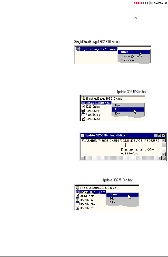
100 BG 805 196 BE / B (2004-08) TPG262.oi
In the following instructions, the index is used instead
of the actual index.
nUnpack the self extracting file
.
oIf you have not connected the TPG 262 to the
COM1 interface:
• Open the batch file …
• … edit the interface …
• … and save the new setting.
pStart batch file .
ÖThe new firmware is transmitted to the TPG 262.
Program transfer
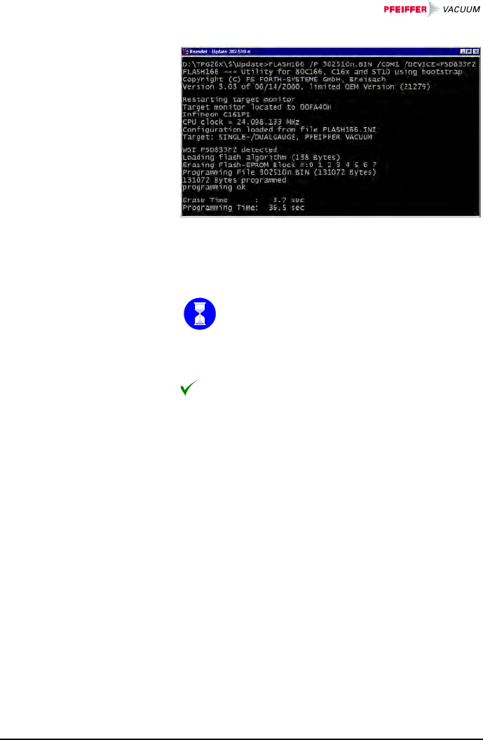
BG 805 196 BE / B (2004-08) TPG262.oi 101
If the program transfer was successful, quit the Update
mode by turning the TPG 262 off.
Wait at least 10 s before turning the TPG 262
on again in order for it to correctly initialize it-
self.
The TPG 262 is now ready for operation. To be
sure, check that the current parameter settings are
identical with the previously defined settings
(→ 98).
Starting the TPG 262
with the updated firm-
ware

102 BG 805 196 BE / B (2004-08) TPG262.oi
[1] www.pfeiffer-vacuum.de
Instruction Sheet
Compact Pirani Gauge TPR 261
BG 805 105 BE
Pfeiffer Vacuum GmbH, D–35614 Asslar,
Deutschland
[2] www.pfeiffer-vacuum.de
Operating Instructions
Compact Pirani Gauge TPR 265
BG 805 177 BE
Pfeiffer Vacuum GmbH, D–35614 Asslar,
Deutschland
[3] www.pfeiffer-vacuum.de
Operating Instructions
Pirani-Messröhre TPR 280
BG 805 178 BE
Pfeiffer Vacuum GmbH, D–35614 Asslar,
Deutschland
[4] www.pfeiffer-vacuum.de
Operating Instructions
Pirani-Messröhre TPR 281
BG 5179 BE
Pfeiffer Vacuum GmbH, D–35614 Asslar,
Deutschland
[5] www.pfeiffer-vacuum.de
Operating Instructions
Compact Pirani Capacitance Gauge PCR 260
BG 805 180 BE
Pfeiffer Vacuum GmbH, D–35614 Asslar,
Deutschland
[6] www.pfeiffer-vacuum.de
Instruction Sheet
Compact Cold Cathode Gauge IKR 251
BG 805 110 BN
Pfeiffer Vacuum GmbH, D–35614 Asslar,
Deutschland
[7] www.pfeiffer-vacuum.de
Instruction Sheet
Compact Cold Cathode Gauge IKR 261
BG 805 113 BN
Pfeiffer Vacuum GmbH, D–35614 Asslar,
Deutschland
D: Literature

BG 805 196 BE / B (2004-08) TPG262.oi 103
[8] www.pfeiffer-vacuum.de
Instruction Sheet
Compact Cold Cathode Gauge IKR 270
BG 805 115 BE / A
Pfeiffer Vacuum GmbH, D–35614 Asslar,
Deutschland
[9] www.pfeiffer-vacuum.de
Instruction Sheet
Compact FullRange™ Gauge PKR 251
BG 805 119 BN
Pfeiffer Vacuum GmbH, D–35614 Asslar,
Deutschland
[10] www.pfeiffer-vacuum.de
Instruction Sheet
Compact FullRange™ Gauge PKR 261
BG 805 122 BN
Pfeiffer Vacuum GmbH, D–35614 Asslar,
Deutschland
[11] www.pfeiffer-vacuum.de
Instruction Sheet
Compact Process Ion Gauge IMR 265
BG 805 132 BE
Pfeiffer Vacuum GmbH, D–35614 Asslar,
Deutschland
[12] www.pfeiffer-vacuum.de
Instruction Sheet
Compact FullRange™ BA Gauge PBR 260
BG 805 131 BE
Pfeiffer Vacuum GmbH, D–35614 Asslar,
Deutschland
[13] www.pfeiffer-vacuum.de
Instruction Sheet
Compact Capacitance Gauge
CMR 261 … CMR275
BG 805 133 BE
Pfeiffer Vacuum GmbH, D–35614 Asslar,
Deutschland
[14] www.pfeiffer-vacuum.de
Instruction Sheet
Compact Piezo Gauge APR 250 … APR 267
BG 805 127 BN
Pfeiffer Vacuum GmbH, D–35614 Asslar,
Deutschland

104 BG 805 196 BE / B (2004-08) TPG262.oi
– A –
A/D converter test 64
– B –
Baud rate 56
– C –
Calibration factor 41
Cleaning 93
Communication 68
interface 68
Connectors
control 21
mains power 19
relay 22
RS232 23
sensor 20
Contact positions
control 21
relay 22
Contents 4
control connector 21
Conversion 97
– D –
Default values 57; 98
Degas 46
Display
changeover 57
resolution 56
test 63
Disposal 96
– E –
EEPROM test 63
EPROM test 62
Error messages 94
Example 92
– F –
Factory settings 57; 98
Filter 39
Firmware
update 99
version 2; 60
– G –
Gauge connector 20
Gauge control 12; 47
gauge activation 49
gauge deactivation 51
OFF threshold 52
ON threshold 50
Gauge identification 30
Gauge parameters 38
calibration factor 41
measurement value filter 39
General parameters 54
default values 57
display changeover 57
display resolution 56
measurement unit 56
transmission rate 56
– I –
I/O test 65
Identification of gauges 30
Intended use 3
Interface
connector 23
test 67
– K –
Keylock 61
– L –
Liability 8
Literature 102
– M –
Mains power connector 19
Maintenance 93
Measurement mode 27; 73
gauge identification 30
selecting a measurement
channel 28
status messages 28
turning a gauge on and off 28
Measurement range 42
Measurement units
conversion 97
selection 56
Measurement value filter 39
Mnemonics 72
E: Index

BG 805 196 BE / B (2004-08) TPG262.oi 105
– O –
OFF threshold 52
Offset 43
ON threshold 50
Operating modes
Measurement mode 27
overview 26
Parameter mode 31
Program transfer mode 99
Operation
power off 25
power on 25
– P –
Parameter mode 79
gauge control 47
gauge parameters 38
general parameters 54
measurement value filter 39
switching function
parameters 33
switching thresholds 35; 36
test parameters 58
Parameters
Degas 46
measurement range 42
Offset 43
underrange control 44
Pin assignment
control 21
relay 22
RS232 23
sensor 20
Power connector 19
Power off 25
Power on 25
Pressure units
conversion 97
selection 56
Program
update 99
version 2; 60
– R –
RAM test 62
relay connector 22
Repair 95
RS232 connector 23
RS232C test 67
– S –
Safety 6
Scope of delivery 3
sensor connector 20
Serial interface
connector 23
test 67
Status messages 28
Storage 96
Switching function
parameters 33
Switching functions 11; 22
thresholds 35; 36
Symbols 6
– T –
Test parameters 58
Test program 58
A/D converter test 64
display test 63
EEPROM test 63
EPROM test 62
firmware version 60
I/O test 65
keylock 61
RAM test 62
RS232C test 67
Torr lock 61
watchdog 61
Thresholds 35; 36
OFF 52
ON 50
Torr lock 61
Transmission rate 56
Troubleshooting 94
– U –
Underrange control 44
Units
conversion 97
selection 56
Update 99
– V –
Validity 2
– W –
Warranty 8
Watchdog 61

Berliner Strasse 43
D–35614 Asslar
Deutschland
Tel +49 (0) 6441 802-0
Fax +49 (0) 6441 802-202
Original: German BG 805 196 BD / B (2004-08) info@pfeiffer-vacuum.de
bg805196be/ b www.pfeiffer-vacuum.de
