Piranha_Tooling Attachments Piranha Tooling
User Manual: Piranha_ToolingAttachments
Open the PDF directly: View PDF ![]() .
.
Page Count: 24

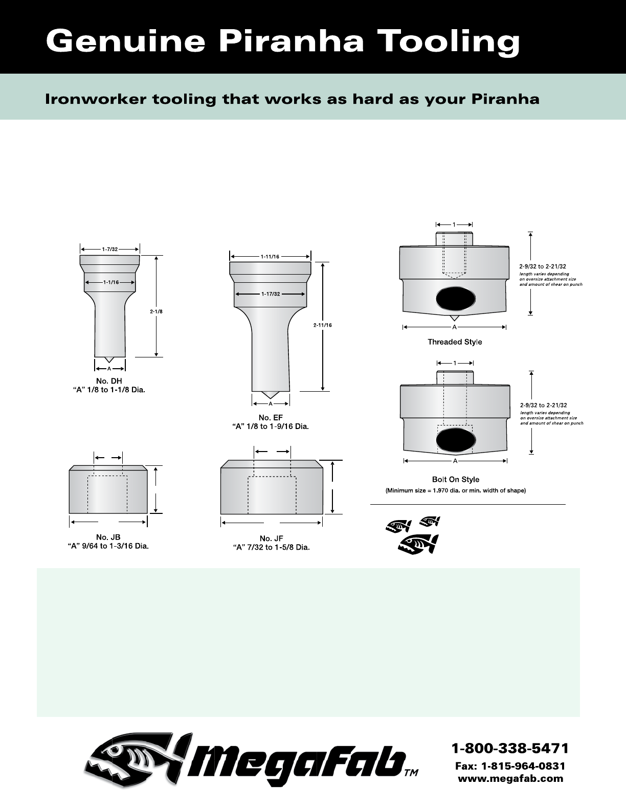
No. HC
“A” 9/64 to 3/4 Dia.
No. HH
“A” 9/64 to 1-1/8 Dia.
No. JB
“A” 9/64 to 1-3/16 Dia.
No. JF
“A” 7/32 to 1-5/8 Dia.
No. JC
“A” 9/64 to 1-3/8 Dia.
No. JG
“A” 3/4 to 1-5/8 Dia.
No. JK
“A” 3/4 to 1-11/16 Dia.
A
3/4
1
A
A
A
A
A
1-1/2
1-13/16
2-3/8
2
2-1/2 2-7/8
1
1-1/8
1-1/4
1
1-1/4 1-1/4
A
No. HC
“A” 9/64 to 3/4 Dia.
No. HH
“A” 9/64 to 1-1/8 Dia.
No. JB
“A” 9/64 to 1-3/16 Dia.
No. JF
“A” 7/32 to 1-5/8 Dia.
No. JC
“A” 9/64 to 1-3/8 Dia.
No. JG
“A” 3/4 to 1-5/8 Dia.
No. JK
“A” 3/4 to 1-11/16 Dia.
A
3/4
1
AA
A
A
A
1-1/2 1-13/16
2-3/8
2
2-1/2 2-7/8
11-1/8
1-1/4
1
1-1/4 1-1/4
A
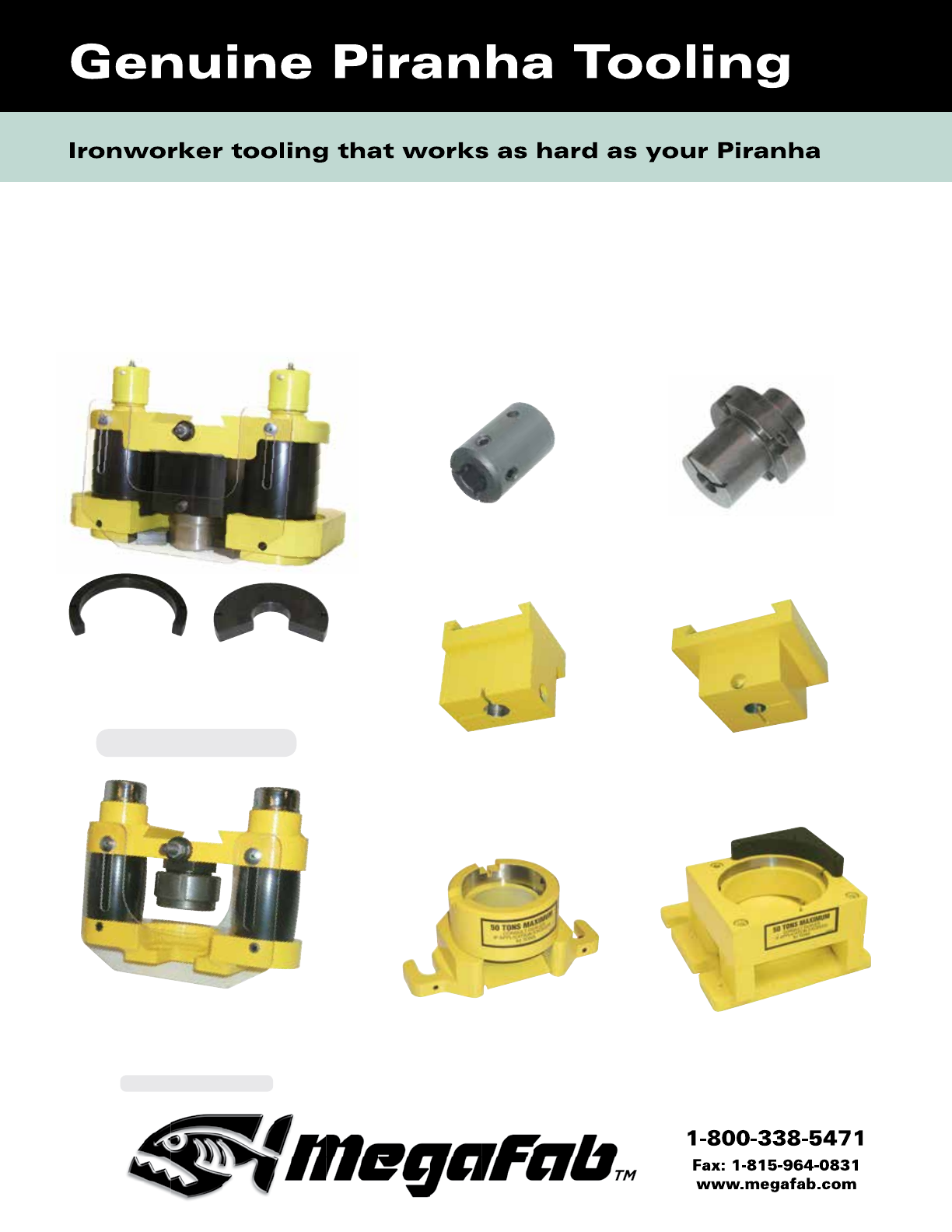
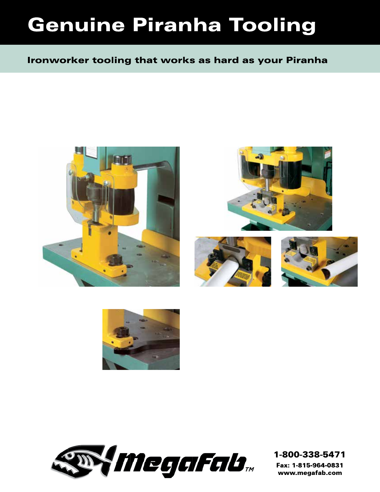
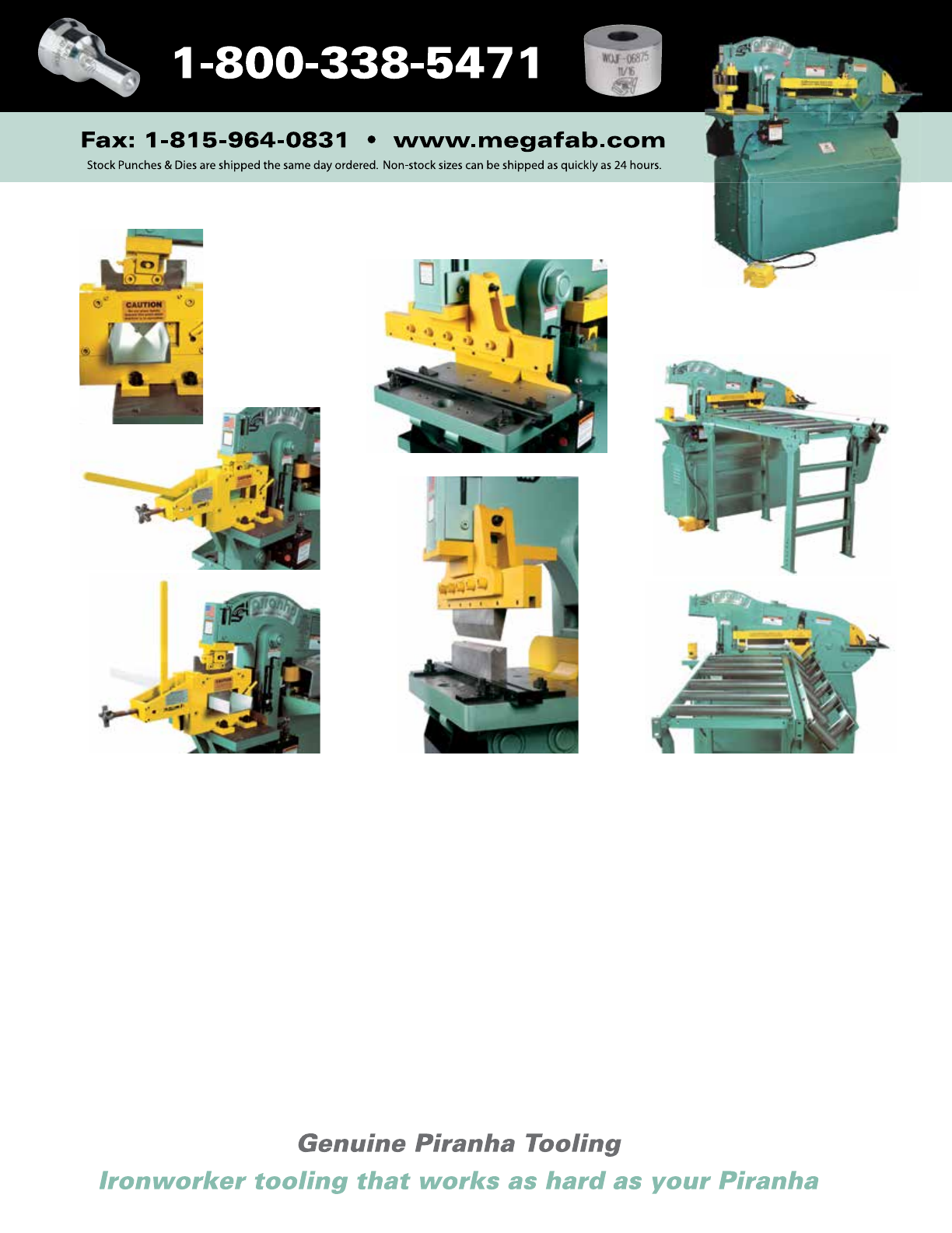
Genuine Piranha Tooling
Get the most from your Piranha ironworker by using
genuine Piranha ironworker tooling and replacement
parts. All tooling available in inch and metric.
Place your order today. Call 1-800-338-5471.
For fastest order processing, have your Piranha model
number, material thicknesses and hole size(s) ready.
Convenient payment via Visa, MasterCard, American
Express.
Policies and Terms
Terms—All prices are net, f.o.b. factory. Minimum
order is $50. Net 30 days.
Returns—Prior to returning goods, approval must
be received from the Tooling Service Department,
1-800-338-5471. Tools authorized for return are to
be shipped pre-paid. Credit will not be allowed on
damaged or used tooling.
Specials—Non-standard punches and dies are
non-cancellable and non-returnable.
2
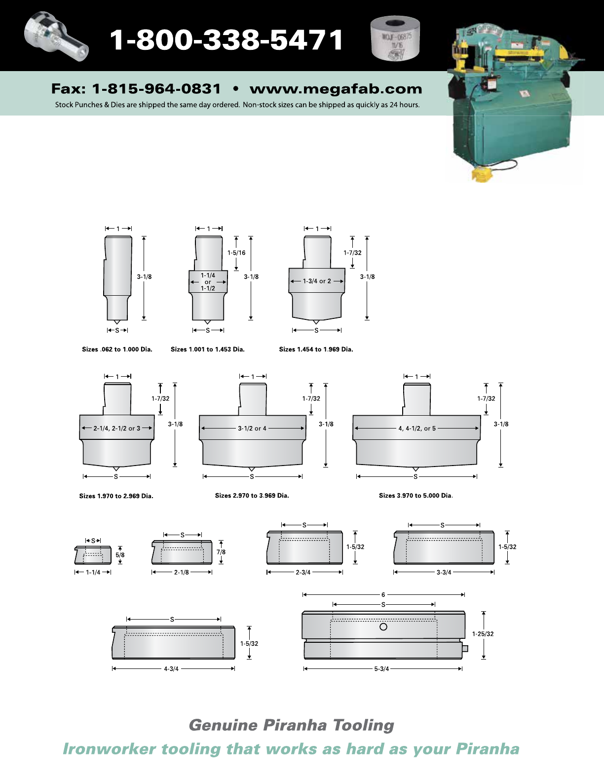
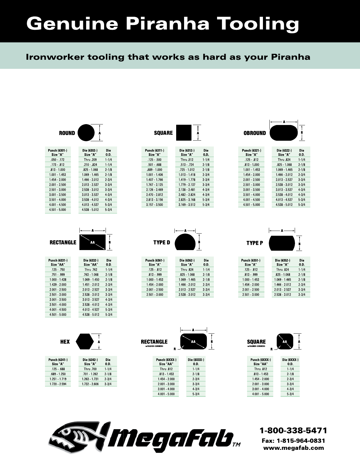
Piranha Standard Punches & Dies
Dimensions & Specifications
Heavy Duty Punches
Standard for P2, P-36, P-40, P-50, P65
Existing P-36 and P-50 machines will
require a larger coupling nut to accept
1-1/16" to 1-1/8" diameter tooling.
Standard for P-70, P-90, P-110,
P-120, P-140 & PII-65/88/110/140
Piranha Tool School Tip
Attachments are available
for optional punch sizes
(see page 14).
59 STYLE
OVER 50 TONS
64 STYLE
OVER 50 TONS
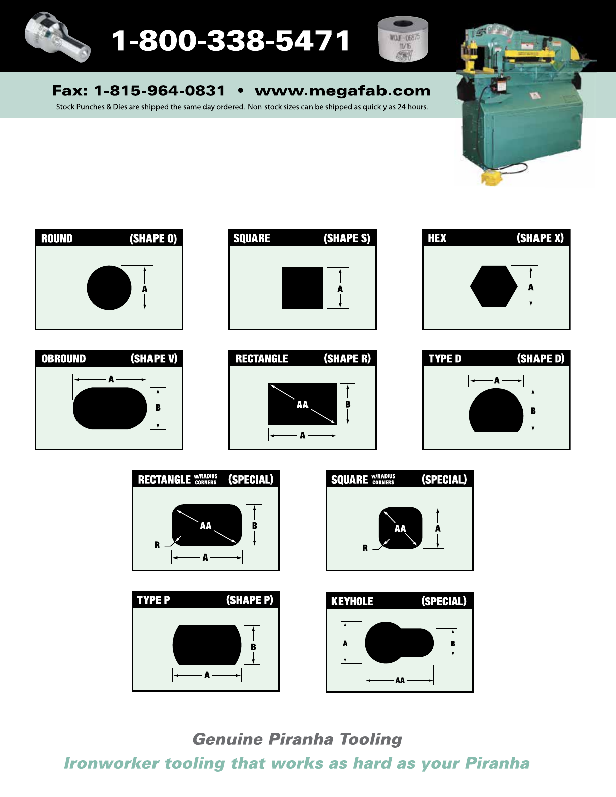
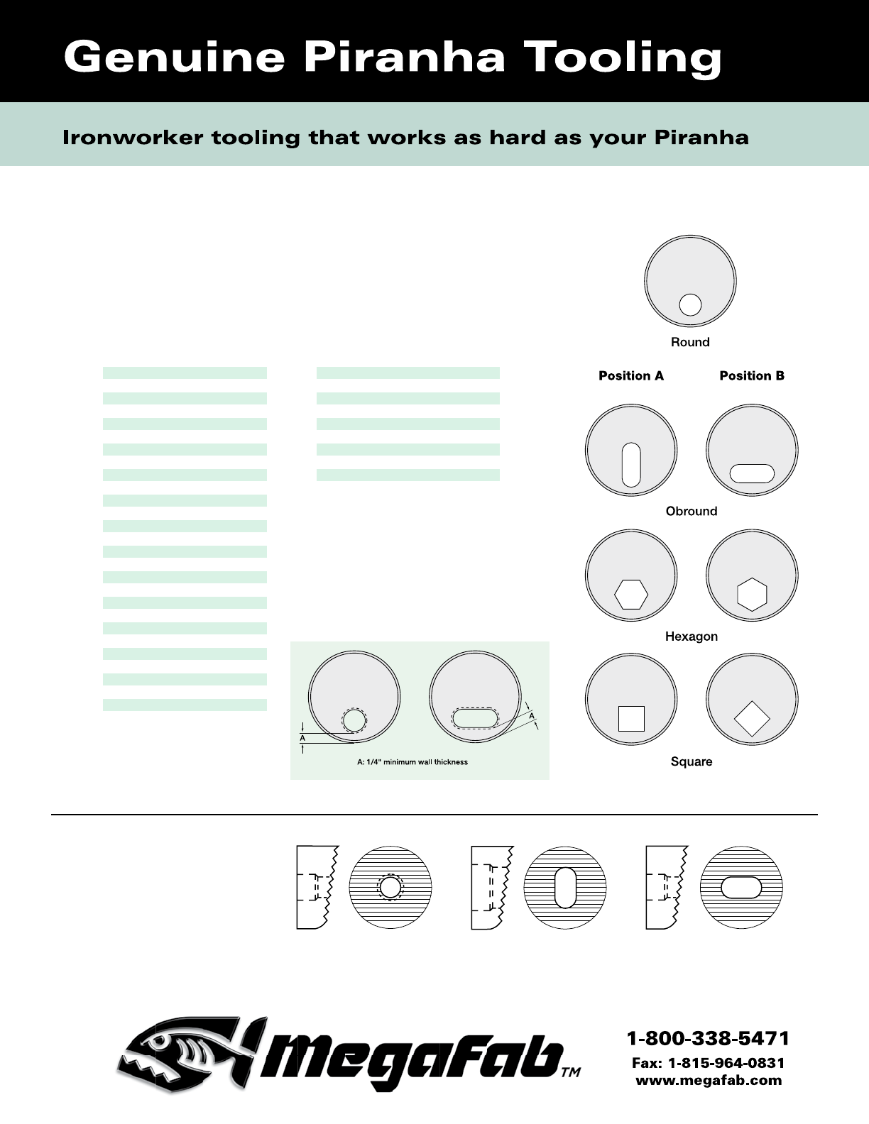
All punches in this catalog can be made in any shape.
Shown below are a few of the most commonly used shapes.
Please call or fax your inquiries to us.
3
STOCK
ROUND PUNCHES
Size JB JF
5/32 •
3/16 • •
7/32 • •
1/4 • •
9/32 • •
5/16 • •
11/32 • •
3/8 • •
13/32 • •
7/16 • •
15/32 • •
1/2 • •
17/32 • •
9/16 • •
19/32 • •
5/8 • •
21/32 • •
11/16 • •
23/32 • •
3/4 • •
25/32 • •
13/16 • •
27/32 • •
7/8 • •
29/32 • •
15/16 • •
31/32 • •
1 • •
1-1/32 • •
1-1/16 • •
1-3/32 • •
1-1/8 • •
1-5/32 • •
1-3/16 • •
1-7/32 •
1-1/4 •
1-9/32 •
1-5/16 •
1-11/32 •
1-3/8 •
1-13/32 •
1-7/16 •
1-15/32 •
1-1/2 •
1-17/32 •
1-9/16 •
1-19/32 •
1-5/8 •
STOCK
ROUND DIES
WARNING
The user is responsible for set-up
and use of the machinery and tooling
in accordance with all OSHA laws
and ANSI B11.5 standards. Extreme
pressures can be generated in metal
punching. Approved guards and safety
glasses should be used at all times.
Operators should be trained on set-up
and machine operation and safety pro-
cedures should be enforced.
Material Thickness Clearance
16 ga. thru 5/32" 1/64"
3/16" thru 5/16" 1/32"
11/32" thru 1/2" 1/16"
17/32" thru 3/4" 3/32"
Clearance Chart
For A-36 and Mild Steel Plate:
Piranha Round Tooling
Size DH EF
1/8 •
5/32 • •
3/16 • •
7/32 • •
1/4 • •
9/32 • •
5/16 • •
11/32 • •
3/8 • •
13/32 • •
7/16 • •
15/32 • •
1/2 • •
17/32 • •
9/16 • •
19/32 • •
5/8 • •
21/32 • •
11/16 • •
23/32 • •
3/4 • •
25/32 • •
13/16 • •
27/32 • •
7/8 • •
29/32 • •
15/16 • •
31/32 • •
1 • •
1-1/32 • •
1-1/16 • •
1-3/32 •
1-1/8 • •
1-5/32 •
1-3/16 •
1-7/32 •
1-1/4 •
1-9/32 •
1-5/16 •
1-11/32 •
1-3/8 •
1-13/32 •
1-7/16 •
1-15/32 •
1-1/2 •
1-17/32 •
1-9/16 •
4
• Same-Day Shipment Sizes
Note: Hexagon punch and
die sizes are measured
from flat to flat.
5
STOCK SQUARE
PUNCHES DIES
Piranha Square
& Hexagon Tooling
Size DH EF JB JF
7/32 •
1/4 • •
9/32 • •
5/16 • • •
11/32 • • • •
3/8 • • • •
13/32 • • • •
7/16 • • • •
15/32 • • • •
1/2 • • • •
17/32 • • • •
9/16 • • • •
19/32 • • • •
5/8 • • • •
21/32 • • • •
11/16 • • • •
23/32 • • • •
3/4 • • • •
25/32 • • • •
13/16 • • • •
27/32 • • •
7/8 • • •
29/32 • •
15/16 • •
31/32 • •
1 • •
1-1/32 • •
1-1/16 • •
1-3/32 •
1-1/8 •
STOCK HEXAGON
PUNCHES DIES
Size DH EF JB JF
11/32 • •
3/8 • • • •
13/32 • • • •
7/16 • • • •
15/32 • • • •
1/2 • • • •
17/32 • • • •
9/16 • • • •
19/32 • • • •
5/8 • • • •
21/32 • • • •
11/16 • • • •
23/32 • • • •
3/4 • • • •
25/32 • • • •
13/16 • • • •
27/32 • • •
7/8 • • •
29/32 • •
15/16 • •
31/32 • •
1 • •
1-1/32 • •
1-1/16 • •
1-3/32 • •
1-1/8 • •
1-5/32 • •
1-3/16 • •
1-7/32 • •
1-1/4 • •
1-9/32 •
1-5/16 •
• Same-Day Shipment Sizes
• Same-Day Shipment Sizes
6
Size DH EF
3/16 x 3/4 •
3/16 x 1 • •
7/32 x 7/16 • •
7/32 x 1 • •
1/4 x 1/2 • •
1/4 x 3/4 • •
1/4 x 1 • •
9/32 x 9/16 • •
9/32 x 3/4 • •
9/32 x 1 • •
5/16 x 1/2 • •
5/16 x 5/8 • •
5/16 x 3/4 • •
5/16 x 1 • •
5/16 x 1-1/16 • •
5/16 x 1-1/4 •
5/16 x 1-1/2 •
11/32 x 11/16 • •
11/32 x 1 • •
3/8 x 1/2 • •
3/8 x 3/4 • •
3/8 x 1 • •
3/8 x 1-1/4 •
3/8 x 1-1/2 •
13/32 x 13/16 • •
13/32 x 1 • •
13/32 x 1-1/4 •
Size DH EF
7/16 x 9/16 •
7/16 x 3/4 • •
7/16 x 7/8 • •
7/16 x 1 • •
7/16 x 1-1/16 • •
7/16 x 1-1/4 •
7/16 x 1-1/2 •
15/32 x 1 • •
1/2 x 3/4 • •
1/2 x 1 • •
1/2 x 1-1/16 • •
1/2 x 1-1/4 •
1/2 x 1-1/2 •
17/32 x 1 • •
17/32 x 1-1/4 •
17/32 x 1-1/2 •
9/16 x 3/4 • •
9/16 x 1 • •
9/16 x 1-1/16 • •
9/16 x 1-1/8 • •
9/16 x 1-1/4 •
9/16 x 1-1/2 •
5/8 x 1 • •
5/8 x 1-1/4 •
5/8 x 1-1/2 •
11/16 x 1 • •
11/16 x 1-1/16 • •
Size DH EF
11/16 x 1-1/8 •
11/16 x 1-1/4 •
11/16 x 1-1/2 •
3/4 x 1 • •
3/4 x 1-1/4 •
3/4 x 1-1/2 •
13/16 x 1 • •
13/16 x 1-1/16 • •
13/16 x 1-1/8 • •
13/16 x 1-1/4 •
13/16 x 1-1/2 •
7/8 x 1-1/4 •
7/8 x 1-1/2 •
15/16 x 1-1/16 • •
15/16 x 1-1/8 • •
15/16 x 1-1/4 •
15/16 x 1-1/2 •
15/16 x 1-9/16 •
1 x 1-1/4 •
1 x 1-1/2 •
1 x 1-9/16 •
1-1/16 x 1-1/4 •
1-1/16 x 1-5/16 •
1-1/16 x 1-1/2 •
1-1/16 x 1-9/16 •
1-1/8 x 1-1/2 •
Piranha Obround Tooling
• Same-Day Shipment Sizes
Please note:
Obround punches are stocked without v-groove in the head.
V-groove is available upon request.
Obround dies are stocked without locators, but are available
upon request.
STOCK OBROUND PUNCHES
Size JB JF
7/32 x 25/32 •
7/32 x 1-1/32 • •
15/64 x 29/64 •
1/4 x 15/32 •
1/4 x 1-1/32 • •
9/32 x 17/32 • •
9/32 x 25/32 • •
9/32 x 1-1/32 • •
5/16 x 19/32 • •
5/16 x 25/32 • •
5/16 x 1-1/32 • •
11/32 x 17/32 • •
11/32 x 21/32 • •
11/32 x 25/32 • •
11/32 x 1-1/32 • •
11/32 x 1-3/32 • •
11/32 x 1-9/32 •
11/32 x 1-17/32 •
3/8 x 23/32 • •
3/8 x 1-1/32 • •
3/8 x 1-5/16 •
13/32 x 17/32 • •
13/32 x 25/32 • •
13/32 x 1-1/32 • •
13/32 x 1-9/32 •
13/32 x 1-17/32 •
7/16 x 27/32 • •
7/16 x 1-1/32 • •
7/16 x 1-9/32 •
7/16 x 1-5/16 •
15/32 x 19/32 • •
15/32 x 25/32 • •
15/32 x 29/32 • •
15/32 x 1-1/32 • •
15/32 x 1-3/32 • •
15/32 x 1-9/32 •
15/32 x 1-17/32 •
1/2 x 1-1/32 • •
1/2 x 1-1/16 • •
1/2 x 1-5/16 •
17/32 x 25/32 • •
17/32 x 1-1/32 • •
17/32 x 1-3/32 •
Size JB JF
17/32 x 1-9/32 •
17/32 x 1-17/32 •
9/16 x 13/16 • •
9/16 x 1-1/32 • •
9/16 x 1-1/16 • •
9/16 x 1-1/8 • •
9/16 x 1-3/16 • •
9/16 x 1-9/32 •
9/16 x 1-5/16 •
9/16 x 1-17/32 •
9/16 x 1-9/16 •
19/32 x 25/32 • •
19/32 x 1-1/32 • •
19/32 x 1-3/32 • •
19/32 x 1-5/32 • •
19/32 x 1-9/32 •
19/32 x 1-17/32 •
5/8 x 13/16 • •
5/8 x 1-1/16 • •
5/8 x 1-1/8 • •
5/8 x 1-3/16 • •
5/8 x 1-5/16 •
5/8 x 1-9/16 •
21/32 x 1-1/32 • •
21/32 x 1-9/32 •
21/32 x 1-17/32 •
11/16 x 1-1/16 • •
11/16 x 1-5/16 •
11/16 x 1-9/16 •
23/32 x 1-1/32 • •
23/32 x 1-3/32 • •
23/32 x 1-5/32 • •
23/32 x 1-9/32 •
23/32 x 1-17/32 •
3/4 x 1-1/16 • •
3/4 x 1-1/8 • •
3/4 x 1-3/16 • •
3/4 x 1-5/16 •
3/4 x 1-9/16 •
25/32 x 1-1/32 • •
25/32 x 1-9/32 •
25/32 x 1-17/32
13/16 x 1-1/16 • •
Size JB JF
13/16 x 1-5/16 •
13/16 x 1-9/16 •
27/32 x 1-1/32 • •
27/32 x 1-3/32 • •
27/32 x 1-5/32 • •
27/32 x 1-9/32 •
27/32 x 1-17/32 •
7/8 x 1-1/16 • •
7/8 x 1-1/8 • •
7/8 x 1-3/16 • •
7/8 x 1-5/16 •
7/8 x 1-9/16 •
29/32 x 1-9/32 •
29/32 x 1-17/32 •
15/16 x 1-5/16 •
15/16 x 1-9/16 •
31/32 x 1-3/32 • •
31/32 x 1-5/32 • •
31/32 x 1-9/32 •
31/32 x 1-17/32 •
1 x 1-1/8 • •
1 x 1-3/16 • •
1 x 1-5/16 •
1 x 1-9/16 •
1 x 1-5/8 •
1-1/32 x 1-9/32 •
1-1/32 x 1-17/32 •
1-1/32 x 1-19/32 •
1-1/16 x 1-5/16 •
1-1/16 x 1-9/16 •
1-1/16 x 1-5/8 •
1-3/32 x 1-9/32 •
1-3/32 x 1-11/32 •
1-3/32 x 1-17/32 •
1-1/8 x 1-5/16 •
1-1/8 x 1-3/8 •
1-1/8 x 1-9/16 •
1-1/8 x 1-5/8 •
1-5/32 x 1-17/32 •
1-3/16 x 1-9/16 •
7
• Same-Day Shipment Sizes
STOCK OBROUND DIES
Size JB JF
9/32 • •
5/16 • •
11/32 • •
3/8 • •
13/32 • •
7/16 • •
15/32 • •
1/2 • •
17/32 • •
9/16 • •
19/32 • •
5/8 • •
21/32 • •
11/16 • •
23/32 • •
3/4 • •
25/32 • •
13/16 • •
27/32 • •
7/8 • •
29/32 • •
15/16 • •
31/32 • •
1 • •
1-1/32 • •
1-1/16 •
1-3/32 •
1-1/8 •
STOCK ROUND
OFFSET DIES
STOCK OBROUND
OFFSET DIES
Size JB JF
13/32 x 25/32 • •
13/32 x 1-1/32 • •
15/32 x 25/32 • •
15/32 x 1-1/32 • •
17/32 x 1-1/32 • •
19/32 x 25/32 • •
19/32 x 1-1/32 • •
23/32 x 1-1/32 • •
27/32 x 1-1/32 • •
Piranha Eccentric Dies
Bevel Serrated Dies
Bevel serrated dies are
available on request.
Please specify die style,
shape, orientation of shape
to bevel and size. Parallel
to Bevel
Perpendicular
to Bevel
8
Eccentric Dies
Offset dies are made with at least
a 1/4" wall thickness.
Please specify location of whistle
notch if required. Stock dies do
not have whistle notch.
• Same-Day
Shipment Sizes
9
Piranha 28XX Tooling
Dimensions & Specifications
28XX round and shaped punches and dies for Piranha Ironworker oversize attachments.
28XX Punches are available up to
5.000" in diameter.
All round punches through 1.453"
diameter (or equivalent size shape)
are flat-faced, with a center point on
the punch face. Larger punches are
standard with 1/8" housetop shear
and center point. Other shear types are
available at customer request.
Please specify the size of the oversize attachment when ordering.
28XX Punches & Dies
—
Standard Shapes
10
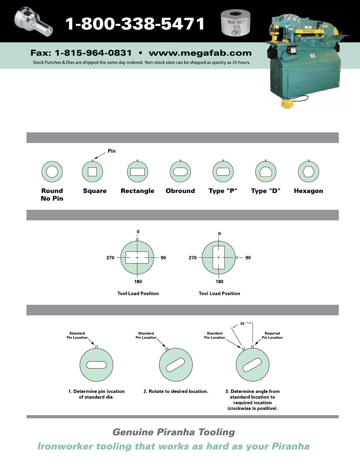
Orientations and Pin Locations
All shaped 28XX punches and dies are pinned for 0° and 90° positioning. Pin locations are shown for
standard shapes. Other pin locations may be specified, at additional cost, when ordering. Use the three
step procedure shown here to determine the proper degree of location for a custom pin location.
Pin Locations for Standard Shapes
Standard Shaped Dies—Orientations in Machine
Determining Custom Pin Location
View from top of die.
View from top of die.
View from top of die.
11
HOLE DIA 20 GA 18 GA 16 GA 14 GA 12 GA 11 GA 10 GA 3/16 1/4 5/16 3/8 1/2 5/8 3/4 7/8 1
(INCHES) .0359 0.0478 0.0598 0.0747 0.1046 0.1196 0.1345 0.1875 0.2500 0.3125 0.3750 0.5000 0.6250 0.7500 0.8750 1.0000
1/8 0.35 0.47 0.59 0.73 1.0 1.2
3/16 0.53 0.70 0.88 1.1 1.5 1.8 2.0 2.8
1/4 0.70 0.94 1.2 1.5 2.1 2.3 2.6 3.7 4.9
5/16 0.88 1.2 1.5 1.8 2.6 2.9 3.3 4.6 6.1 7.7
3/8 1.06 1.4 1.8 2.2 3.1 3.5 4.0 5.5 7.4 9.2 11.0
7/16 1.23 1.6 2.1 2.6 3.6 4.1 4.6 6.4 8.6 10.7 12.9 17.2
1/2 1.41 1.9 2.3 2.9 4.1 4.7 5.3 7.4 9.8 12.3 14.7 19.6
9/16 1.59 2.1 2.6 3.3 4.6 5.3 5.9 8.3 11.0 13.8 16.6 22.1 27.6
5/8 1.76 2.3 2.9 3.7 5.1 5.9 6.6 9.2 12.3 15.3 18.4 24.5 30.7
11/16 1.94 2.6 3.2 4.0 5.6 6.5 7.3 10.1 13.5 16.9 20.2 27.0 33.7 40.5
3/4 2.11 2.8 3.5 4.4 6.2 7.0 7.9 11.0 14.7 18.4 22.1 29.5 36.8 44.2
13/16 2.29 3.1 3.8 4.8 6.7 7.6 8.6 12.0 16.0 19.9 23.9 31.9 39.9 47.9 55.8
7/8 2.47 3.3 4.1 5.1 7.2 8.2 9.2 12.9 17.2 21.5 25.8 34.4 43.0 51.5 60.1 68.7
15/16 2.64 3.5 4.4 5.5 7.7 8.8 9.9 13.8 18.4 23.0 27.6 36.8 46.0 55.2 64.4 73.6
1.00 2.82 3.8 4.7 5.9 8.2 9.4 10.6 14.7 19.6 24.5 29.5 39.3 49.1 58.9 68.7 78.5
1.50 4.23 5.6 7.0 8.8 12.3 14.1 15.8 22.1 29.5 36.8 44.2 58.9 73.6 88.4 103 118
2.00 5.64 7.5 9.4 11.7 16.4 18.8 21.1 29.5 39.3 49.1 58.9 78.5 98.2 118 137 157
2.50 7.05 9.4 11.7 14.7 20.5 23.5 26.4 36.8 49.1 61.4 73.6 98.2 123 147 172 196
3.00 8.46 11.3 14.1 17.6 24.6 28.2 31.7 44.2 58.9 73.6 88.4 118 147 177 206 236
3.50 9.87 13.1 16.4 20.5 28.8 32.9 37.0 51.5 68.7 85.9 103 137 172 206 241 275
4.00 11.28 15.0 18.8 23.5 32.9 37.6 42.3 58.9 78.5 98.2 118 157 196 236 275 314
4.50 12.69 16.9 21.1 26.4 37.0 42.3 47.5 66.3 88.4 110 133 177 221 265 309 353
5.00 14.10 18.8 23.5 29.3 41.1 47.0 52.8 73.6 98.2 123 147 196 245 295 344 393
Calculating Punching Force Requirements
Single Hole Punching—When using a press for single round hole punching, refer to the chart above to determine the amount of force required
to punch a given hole. This chart is based on punching mild steel—50,000 PSI shear strength using flat face punches only.
Example: To punch a 15/16" diameter hole through 10 gauge mild steel, the required punching force is 9.9 tons.
To determine the punching force needed to punch a single hole
with a flat faced punch:
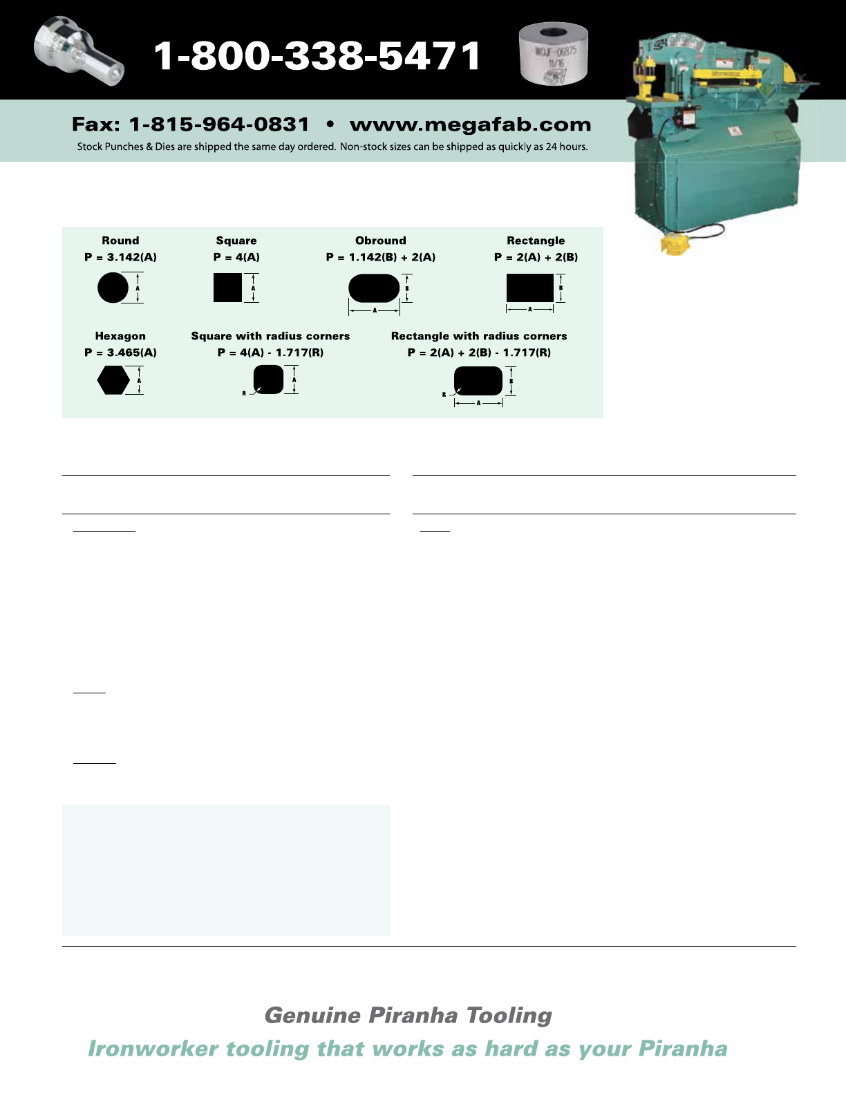
• Calculate the Hole Perimeter using the formulas on page 13.
• Find the Material Shear Strength on the table on page 13.
• Then use the following equation:
Flat Face Punching Force (lbs) = Punch Perimeter (inches) x Material
Thickness (inches) x Material Shear Strength (lbs/in2)
To change from pounds of punching force to tons of punching
force use the following equation: tons = lbs/2000
Example: To punch a 1/4" square hole in 3/16" stainless steel:
4(1/4") x 3/16" x 70,000 lbs/in2 = 13,125 lbs (6.56 tons) of
punching force.
Punching Force Requirements for Round Holes in Mild Steel
12
Thickness 1/8" Shear
Factor
.135" (3.4 mm) .55
.187" (5.0 mm) .64
.250" (6.0 mm) .74
.313" (8.0 mm) .84
.375" (10.0 mm) .95
.500" (12.0 mm) 1.00
.625" (16.0 mm) 1.00
.750" (18.0 mm) 1.00
.875" (22 0 mm) 1.00
1.00" (25.0 mm) 1.00
Note: The required force to punch a hole
is reduced when the punch has shear.
To find actual punching force needed
(for round holes only) find the shear
factor and use the following formula:
Actual Punching Force with Shear
(lbs or tons) = Flat Face Punching
Force (lbs or tons) x Shear Factor
28XX™ punches up thru 1.453"
diameter have no shear; 1.454" thru
5.000" diameter have 1/8" housetop
shear.*
*Other shear sizes and types are available.
Material Shear Strength Chart
(PSI) Multiplier
Aluminum
1100-0 9,500 .19
1100-H14 11,000 .22
3003-H14 14,000 .28
2024-T4 44,000 .88
5005-H18 19,000 .38
6063-T5 18,000 .36
6061-T4 24,000 .48
6061-T6 29,000 .58
7075-T6 54,000 1.08
Brass
Rolled Sheet (Soft) 42,000 .84
1/2 Hard 56,000 1.12
Hard 68,000 1.36
Copper
1/4 Hard 29,000 .58
Hard 43,000 .86
Material Shear Strength Chart
(PSI) Multiplier
Steel
Mild Steel 50,000 1.00
Boiler Plate 55,000 1.10
Cold Drawn 60,000 1.20
40-50 Carbon 74,000 1.48
Structural A-36 60,000 1.20
Structural EX-TEN
(ASTM-A572) – Grade 42 50,000 1.00
Grade 45 50,000 1.00
Grade 50 55,000 1.10
Grade 55 60,000 1.20
Grade 60 65,000 1.30
Grade 65 70,000 1.40
Structural COR-TEN
(ASTM-A242) 60,000 1.20
Cold Rolled C-1018 60,000 1.20
Hot Rolled C-1050 125,000 2.50
Hot Rolled C-1095 125,000 2.50
Hot Rolled C-1095 Annealed 90,000 1.80
Stainless 302 Annealed 70,000 1.40
Stainless 304 Cold Rolled 70,000 1.40
Stainless 316 Cold Rolled 70,000 1.40
Steel, Abrasion Resisting 110,000 2.20
ASTM A656 – Grade 80 85,000 1.70
These are average values only. Actual shear strength can be higher depending on actual tensile and yield strengths of material batch.
Consult Piranha engineers with any punching problems.
Average Shear Strength of Materials (pounds per square inch)
Chart Multiplier
For piercing materials with a different shear strength than
50,000 psi it is necessary to use a multiplier for calculating
the proper amount of force required to punch the hole.
Example: To pierce a 15/16" diameter hole through 10 gage
stainless steel (70,000 psi shear strength) the force required
(from the table on page 22) is 9.9 tons. The multiplier is
1.4—therefore, 9.9 tons x 1.4 = 13.9 tons actual force.
Formulas for Calculating the Perimeter of Standard Shapes
13
Calculate your
own tonnage
requirements
or call a
Piranha Service
Representative.
Piranha Oversize Attachments
Please Note: Standard 28XX punch holders have a 50 ton maximum punching capacity. Heavy duty punches must
be used when punching applications exceed 50 tons. 28XX punch attachments are furnished without strippers. Con-
tact Piranha’s engineering department for heavy duty part numbers.
PII-65/88 28XX
Punch Holder
P-50/65/70/90/110/120/140
28XX Oversized Heavy Duty
Stripping Attachment
28XX
Punch Holder
PII-110/140 28XX
Punch Holder
28XX
Punch Holder
28XX 3-3/4"
Die Holder
28XX 5-3/4"
Die Holder
P2/40/50/65
1-1/2" Oversize Attachment
Note: Spanner wrench required.
14
Max. punch diameter on P-50 is 3".
Max. punch diameter on P-70/90/120 is 5".
Max. punch diameter is 1-1/2".
Piranha Parts
Model No.
Urethane Stripper • • • • • • • • • • • N/A N/A N/A N/A N/A N/A N/A N/A N/A N/A
Punch Stem • • • • • • • • • • • • • • • • • • • • •
Die Holder • • • • • • • • • • • • • • • • • • • •
Coupling Nut • • • • • • • • • • • • • • • • • • • • •
Filter Element • • • • • • • • • • • • • • • • • • • • •
P2
P-36
P-40
P-50 (P-3)
RP-50
P-65
P-70
P-90
P-110
P-120
P-140
PII-35
PII-65
PII-88
PII-110
PII-140
SEPP-35
SEPP-65
SEPP-88
SEP-120
SEPP-140
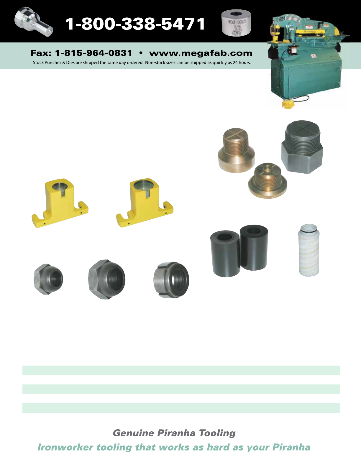
Piranha Punch Stems, Coupling Nuts
and Miscellaneous Parts
The table below lists our stock Piranha punch stems, coupling
nuts, die holders, urethane strippers and filter elements. Please
provide the model and serial number when ordering replace-
ment parts. If the part required is not listed, please provide a
part number, sketch or drawing.
Urethane
Strippers
Coupling Nut
Filter
Element
Coupling Nut
Oversize Attachment
Coupling Nut
Die Holder Die Holder
15
Punch
Stems
• Same-Day Shipment Items
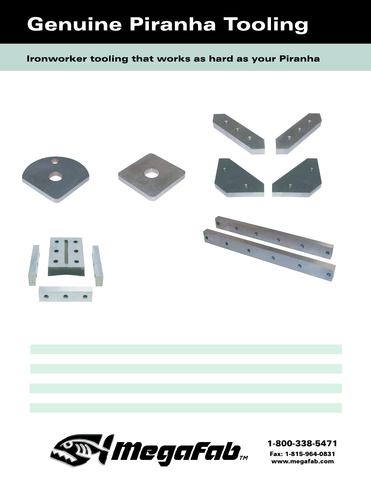
Piranha Blades
Shear Blade
(2 Required)
Long and short available
Upper
Angle Blade
Lower Coper—Side
(2 Required)
Upper Coper
Lower Coper—Front
Lower
Angle Blade
(2 Required)
16
The table below lists our stock Piranha shear blades, angle
blades and copers. Please provide the model and serial number
when ordering replacement blades. If the blade required is not
listed, please provide a part number, sketch or drawing.
• Same-Day Shipment Items * Prior to serial # 3000
Model No.
Short Shear Blade (2 Required) • • • • • • • • • • • • • • • •
Long Shear Blade (2 Required) • • • • N/A N/A N/A •* • • • • • • N/A •
Upper Angle • • • • • • • • • • • • • • • •
Lower Angle (2 Required) • • • • • • • • • • • • • • • •
Upper Coper • • • • • • • • • • • • • • • •
Lower Coper—Front • • • • • • • • • • • • • • • •
Lower Coper—Side (2 Required) • • • • • • • • • • • • • • • •
P2
P-36
P-40
P-50 (P-3)
RP-50
P-65
P-70
P-90
P-110
P-120
P-140
PII-35
PII-65
PII-88
PII-110
PII-140
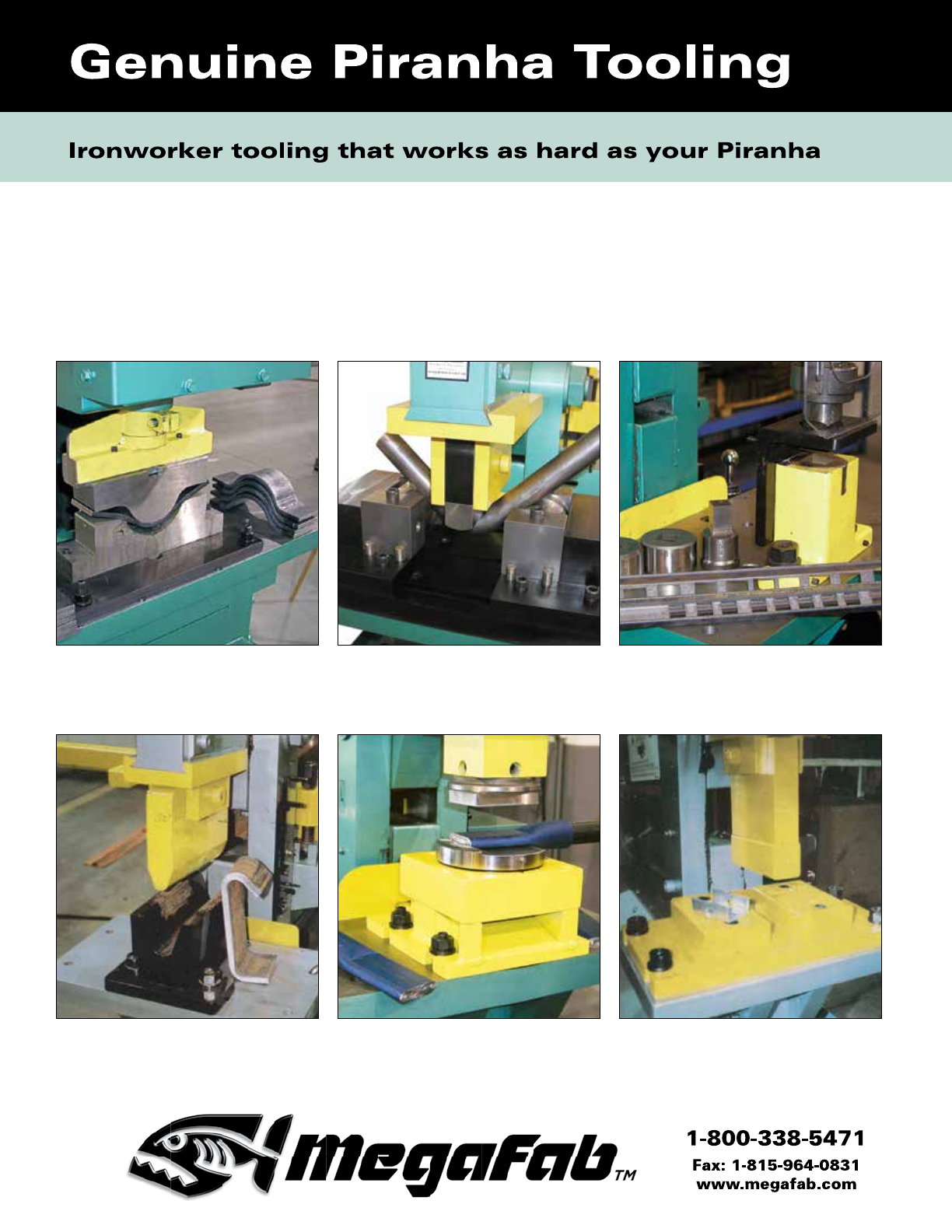
Piranha Special Tooling
Expand Your Metal Fabricating Capabilities
Get greater productivity from your Piranha through the use of special tooling. Our design engineering
department has a thorough understanding of your machine’s capabilities for special parts fabrication.
We can assist you with tooling to precisely fit your Piranha machine and maximize its capabilities.
17
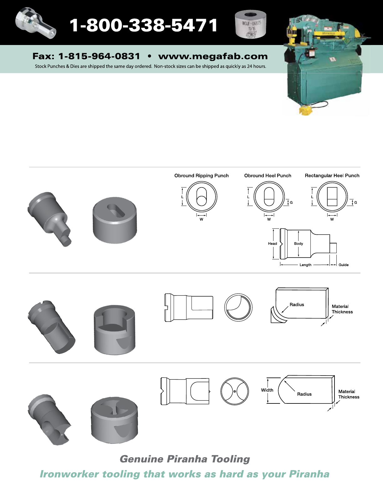
Ripping and Heel Punches
Corner Rounding Punch & Die
When ordering, please provide shape, material thickness and the dimensions shown.
Guide should be 1/8" to 1/4" greater than material thickness.
When ordering, please provide corner radius and material thickness.
Minimum radius is 1/8". Maximum material thickness is 3/8".
Trim and Part tooling produces end radii on flat bar stock. When ordering
please provide radius, material thickness and width.
Maximum material thickness is 3/8".
Trim & Part (Lattice Bar)
Punch & Die
Piranha Special Tooling
Explore Your Metal Fabricating Possibilities
Bending attachment for acute angle
bending of flat bar.
Channel punch
Strap bending
Tube crimper Convertible “U” bracket bending attachment.
Capable of bending different “U” widths
using the same base.
18
Adjustable bending attachment for solid round
bar. Used for non-scuff bending of anchor bolts.
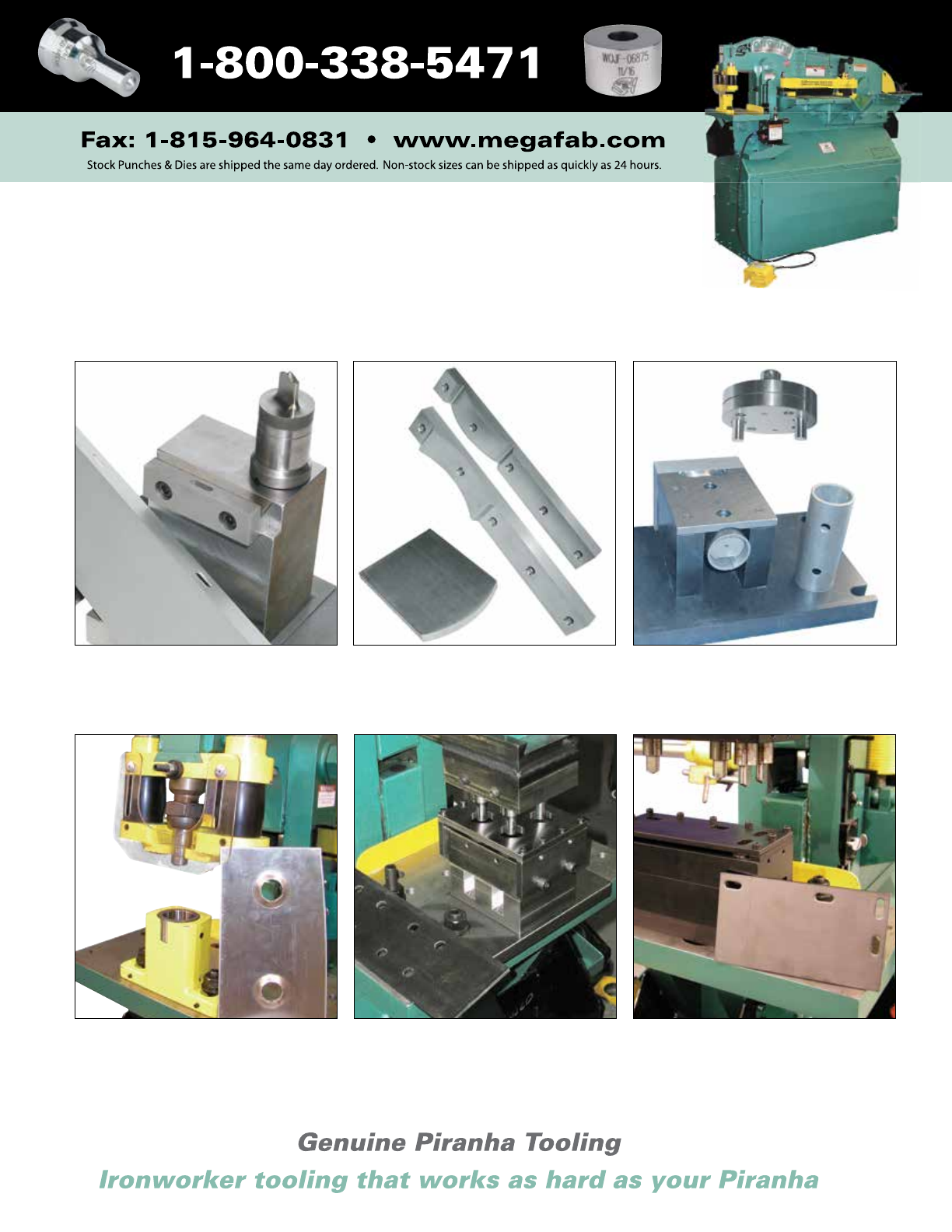
One-hit tread plate tooling punch & form
Piranha Special Tooling
Extend Your Metal Fabricating Potential
Custom shear knives Tube punch
19
Aluminum extrusion channel flange punch
Multiple hole punch Multiple hole punch. Equal force applied
though each punch.
20
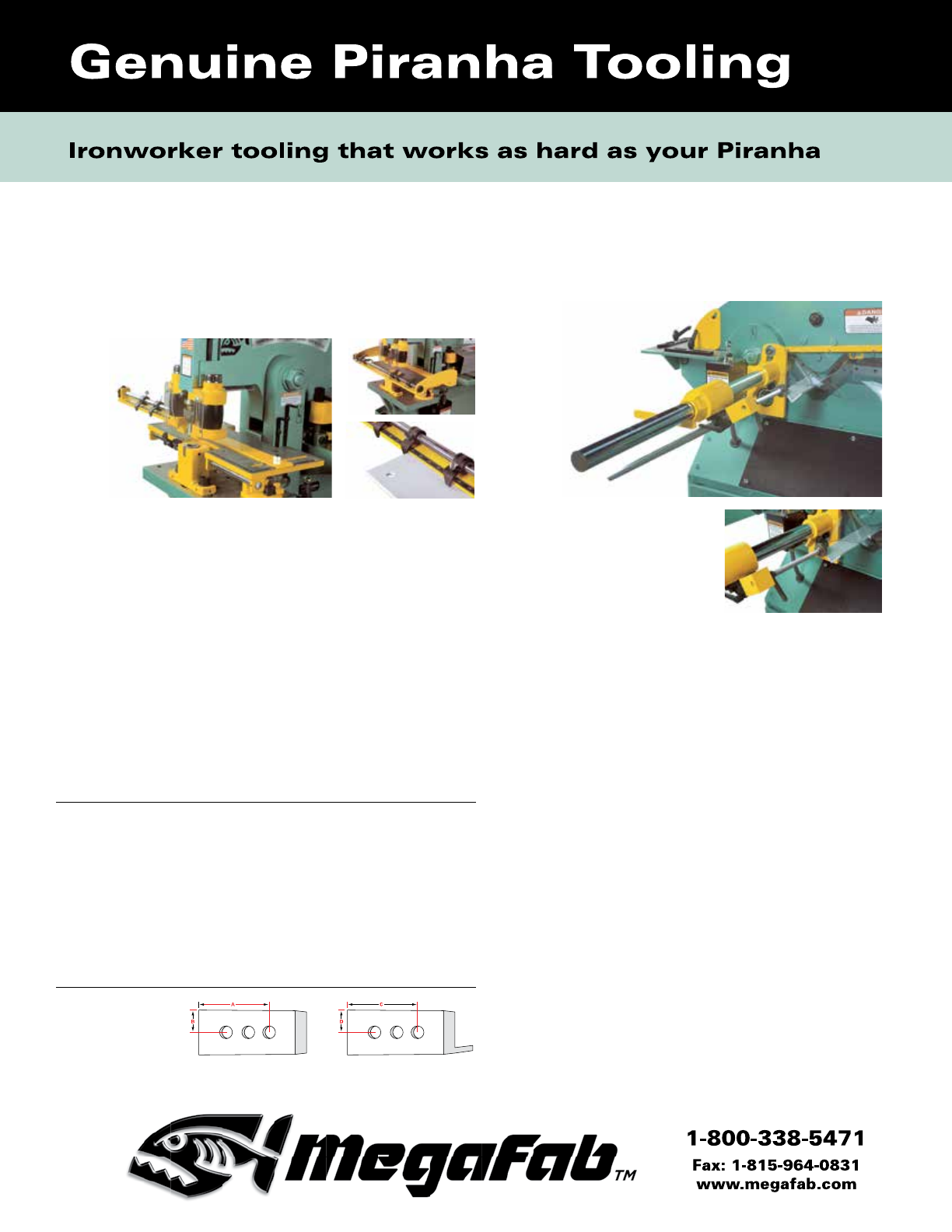
Optional Tooling to Enhance
Your Piranha’s Versatility
Quickset Gauging Tables
• Unit includes both plate- and angle-gauging guide bars.
• Chrome-plated guide bar rods are made from 3/4" 1050 round
bar, induction hardened to RC 63-65.
• Gauging table mounts on machine platen table without remov-
ing punch attachment or die block.
• Table and both guide bars have measuring rules.
• Table has recessed scale.
• All models include two left-hand stops on the table and six stops
(three left hand and three right hand) on the angle guide bar.
• Table extensions are available in 5’ and 10’ lengths for the left
and right sides.
Plate Guide Bar
Model A B C D # Flip Stops
PII-35 24" 5" 12" 4-1/2" 3
P2/36/40/50* 24" 3" 12" 6" 3
P-50/65 24" 6" 12" 6" 3
P-70/90** 36" 8" 18" 5-3/4" 4
P-90/110 36" 10" 18" 6" 4
P-120/140 36" 10" 18" 9" 4
PII-65/88 36" 7" 18" 5-1/2" 4
PII-110/140 48" 18" 18" 9" 6
SEPP-35 24" 5" 12" 4-1/2" 3
SEPP-65/88 36" 7" 18" 5-1/2" 4
SEPP-140 48" 18" 18" 9" 6
SEP-120 48" 18" 18" 9" 6
* See specifications for number of plate guide bar stops. Additional stops can be ordered.
Mechanical
Backgauge
• Bolts on with no machine
modifications.
• Easy access of sheared
material.
• Backgauge material stop allows for infinite length adjustment.
• Backgauge carriage utilizes a compression sleeve for
positive locking and no marring of the gauge bar.
• Chromed, 2" diameter, solid gauge bar allows easy gauge
adjustment, provides rigidity and resists corrosion.
• Accommodates angle, plate and round bar shear
sections.
Electrical Backgauge
• Incorporates all features of the mechanical backgauge.
• May be purchased with new machine or as an option for
field installation on existing machines.*
• Utilizes existing limit switches for stroke control.
• Dedicated power switch and run light standard.
Specifications
• Mechanical backgauges are avaiable for all Piranha iron-
worker models.
• Electrical backgauges are available for models P2, P-40,
P-50, P-65, P-70, P-90, P-110, P-120, P-140, PII-65, PII-88,
PII-110 and PII-140.
• Backgauge lengths are available in 3-, 6-, 9- and 12-foot
lengths.
• 9- and 12-foot lengths include leg support.
A - Minimum 1-1/2"
B - Minimum 1/2"
From either end
of the material
Plate Bar Angle Bar
* Field installation requires minor modifications to electrical components.
* Above serial number 13,001 on P-50 ** Above serial number 3001 on P-90
21
28XX Punch Attachment
• Mounts in place of the standard punch holder and die
block.
• Punch holder can accommodate all standard 28XX punches.
The size is limited to the capacity of the machine.
Specifications
Four die blocks are available:
Die Maximum
Outside Punch
Diameter Diameter
2-3/4" 2"
3-3/4" 3"*
4-3/4" 4"*
5-3/4" 5"*
Channel Punch Die Block
• Each model uses standard punch holder and material stripper.
• Channel die block mounts in place of the standard die block.
Specifications
• Channel die block uses figure JB dies.
• Die is flush with front of channel die block.
• Standard channel die block is designed to punch a hole in
the leg of a 3" through 6" standard weight channel.
• 50-ton punching capacity for all models.
• Standard channel die block is designed to punch a hole in
the web of 4" through 6" standard weight channel.
Notes: A material stripper is NOT furnished with these attachments.
Standard 28XX tooling is for 50-ton and lighter applications. For applications greater
than 50 tons, a heavy-duty punch is required. Contact factory for information.
* Adapter rings are available
to utilize smaller O.D. dies. Note: The machine stroke control must be used with this option.
22
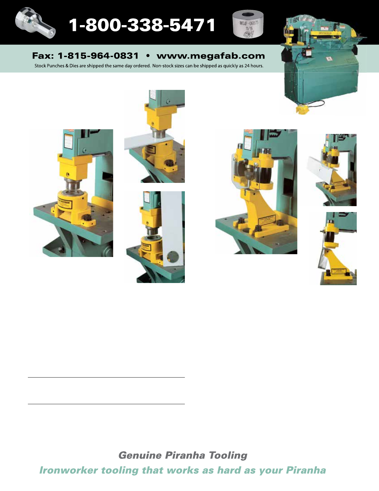
Optional Tooling to Enhance
Your Piranha’s Versatility
Notes: A striker (mounted in the standard punch attachment) will be required to actuate
this attachment. Contact the factory for any special notching applications.
Note: This punch holder with automatic urethane stripper action is available as an
option on models PII-65, PII-88, SEPP-65 and SEPP-88.
1-1/2" Oversize Punch Attachment
• Mounts in place of stan-
dard punch holder and die
block.
• Use same stripper action
as standard punch attach-
ment.
Specifications
• Use figure EF punches and
figure JF dies.
• Allows punching up to a 1-9/16" hole within the capacity
limits of the machine.
• Available in P2, P-36, P-40, P-50, P-65, PII-35 and SEPP-35
models
Pipe/Tube Notching Attachment
• Mounts easily to platen.
• Spring-loaded return.
• Standard base die accommodates several die sizes.
• Perfect for hand-rail fabrication.
Specifications
• Pipe: 3/4" through 2" diameter for schedule 40 wall thickness.
• For larger sizes, tubing and other schedules of pipe, please
contact the factory for information.
23
Press Brake Tooling
Holders
• Available for models P-50*, P-65,
P-70, P-90, P-110, P-120, P-140,
PII-65, PII-88, PII-110, PII-140, SEPP-65,
SEPP-88, SEPP-140 up to 24" length.
• Punch holder will accept a 1/2" wide
by 5/8" tall tang.
Roller Feed Tables
• Roller feed tables accommodate
the bar, plate and angle shearing
sections of the machine, making
material feeding fast and easy.
• Roller feed table assemblies are
available in 5’ increments and are
adjustable to allow for variances in
floor height and machine type.
• Can be bolted together to make up
longer lengths.
Please note that the roller feed table can be
positioned away from the machine for better
work space accessibilty.
Note: The machine stroke control must be used with
this option.
Note: Tooling sold separately.
* Prior to serial number 13,001 on P-50
Channel Shear
• Channel shear bolts to worktable
and attaches to dovetail slide or
punch ram in place of standard
punch holder.
• This channel shear is a sectional
shear for standard weight channel,
and removes a 1/2" slug during cut.
Slug must be removed after each
cut on all models.
• Adjustment for channel size is
accomplished by using a pinned
block and adjustment knob. Material
is secured by quick release locking
handle.
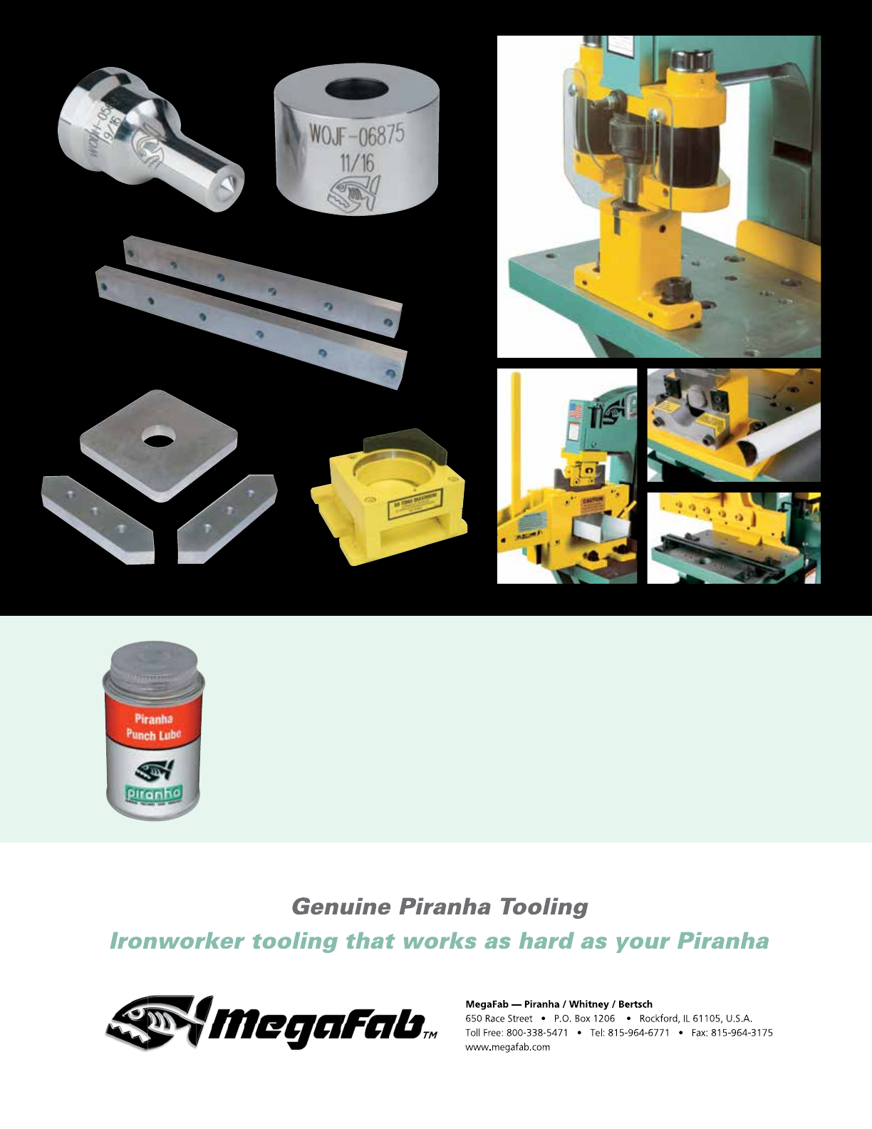
Piranha Punch Lube
Piranha Punch Lube is an extreme pressure, heavy-duty lubricant
for metal bending, shaping, and punching. It effectively prevents
scoring and galling problems by reducing the heat produced from
the punching and stripping process.
© 2013 MegaFab All Rights Reserved
