09_IVP Configuration Plexus IVP Book
User Manual: Plexus IVP Configuration Book
Open the PDF directly: View PDF ![]() .
.
Page Count: 140 [warning: Documents this large are best viewed by clicking the View PDF Link!]
page 9-1 System Overview - Section 9.1
,93&RQILJXUDWLRQ
6\VWHP2YHUYLHZ
The Plexus Digital Telephone System offers fully integrated Voice Mail
and Automated Attendant functionality with the addition of the
optional Integrated Voice Processor (IVP) peripheral card. This chapter
separates the components and features of the cards into the following
sections:
• “The Integrated Voice Processor (IVP) Peripheral Card”
• “The Automated Attendant”
• “The Voice Mailboxes”
• “The System Parameters”
• “The Voice Mail System Manager”
• “Setting up Hold Queue Intercepts”
• “Multi-Language Option”
The IVP card is the physical device inserted into the system cabinet to
provide the necessary functionality for the voice mail system (e.g., hard
drive to store voice messages and prompts). In the case of some models
of the Micro system, the Integrated Voice Processor is incorporated on
the system motherboard.
The IVP card, like any other peripheral card, can be configured through
either the Plexus Administrator Windows application or through a
Plexus key telephone with a display panel.
Section 9.1- System Overview page 9-2
IVP Configuration
The Automated Attendant (a.k.a. auto-attendant) is the system component that
routes calls to various Plexus system (e.g., users and user groups) and voice mail
(e.g., voice mailboxes) resources. The auto-attendant tree developed by the Voice
Mail System Manager determines how the auto-attendant operates. The
architecture of the Plexus voice mail system is such that the auto-attendant is
extremely flexible in meeting the unique call routing needs at each Plexus
installation.
Note
The auto-attendant tree may be modified and maintained via the Plexus
Administrator Windows application or through any DTMF-capable telephone
handset (see “Voice Mail System Manager” - section 9.6).
Voice mailboxes are the system components that provide storage for voice
messages. Voice mailboxes may also perform such advanced functions as
notifying pagers and remote telephone numbers when new messages have
arrived. Mailboxes are typically created by the Voice Mail System Manager for
each user on the system, but they may also be created for user groups,
telecommuting employees, overflow, and other specialized applications.
Note
The voice mailboxes may be created and maintained via the Plexus
Administrator Windows application or through any DTMF-capable telephone
handset (see “Voice Mail System Manager” - section 9.6).
System Parameters are IVP settings that affect the system. They include the
Voice Mail System Manager passwords, the Silence Detect Threshold among
others. These two settings can be set by the VPS Attribute Editor. The others
must be modified through the Voice Mail System Manager.
The Voice Mail System Manager is the individual or group of individuals trained
to administer the voice mail system. Administration functions include the
development and maintenance of the auto-attendant tree and the creation and
maintenance of voice mailboxes.
page 9-3 System Overview - Section 9.1
IVP Configuration
The IVP can be defined as the Intercept Pilot ID for user and user group Hold
Queues. The intercept will periodically reassure the user that they are on hold
and the call will be answered. The IVP card offers a default system message to
be played or a custom message to be created for this Intercept.
The Multi-Language Option allows incoming callers to select a language in
which the menu options will be announced. Mailbox owners may select the
language in which their mailbox options are read.
Section 9.2- The Integrated Voice Processor (IVP) Peripheral Card page 9-4
IVP Configuration
7KH,QWHJUDWHG9RLFH3URFHVVRU,933HULSKHUDO&DUG
The IVP card is inserted into the system cabinet like any other peripheral card
Refer to chapter 4, "Installation."
When adding an IVP card to an established Plexus system, modifications need to
be made to the Plexus configuration file to account for the addition of the new
peripheral card.
To modify the existing configuration:
1 Launch Plexus Administrator.
2 From the File menu, select Open.
3 Select the appropriate configuration file. Plexus configuration files have an
extension of .zdb.
4 Modify the configuration according to the instructions below for creating and
configuring Voice IDs.
5 After completing the configuration changes, upload the modified
configuration file according to the instructions in the Software
Configuration section of the Plexus Product Manual.
When incorporating an IVP card at the time of original install and configuration,
follow the instructions below in conjunction with the instructions for the other
system components and peripheral cards found in chapter 6, "Software
Configuration."
Note
Refer to “Inserting Peripheral Cards” - section 4.3 for instructions on card
layout. An image of the IVP card must appear in the proper slot before the
following configuration instructions can be carried out.
1 Click on the System tab within Plexus Administrator to display an image of
the system cabinet and the available peripheral cards.
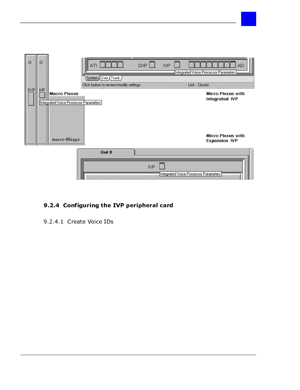
page 9-5 The Integrated Voice Processor (IVP) Peripheral Card - Section 9.2
IVP Configuration
2 Click on the button on the image of the Integrated Voice Processor (IVP)
card to configure the voice processor.
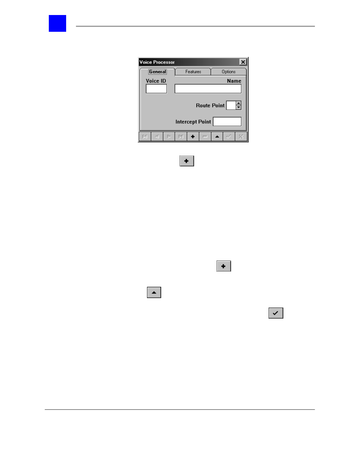
1 Click on the button on the image of the IVP card, as shown above.
Section 9.2- The Integrated Voice Processor (IVP) Peripheral Card page 9-6
IVP Configuration
2 The following dialog window will be displayed.
3 To create a Voice ID, click on and enter a Voice ID Sequence. The Voice
ID sequence is the start number of the range of logical IDs assigned to
voice mail system resources.
• The Voice ID sequence may begin with any number based on the Dial-Number
Range system parameter. Refer to the Dial Plan tab under System Parameters in
your Plexus System Manual for more information.
• Note that the voice mail system, unlike the Plexus system, only supports a Dial-
Number Range width of 2-4.
• The default settings call for a range from 1 to 4 with a width of 3. Therefore, the
Voice ID sequence may be any number between 100 and 499.
4 After entering a Voice ID Sequence, additional voice mail resources (i.e.,
Voice IDs) may be created by clicking on .
5 Existing Auto-Attendant IDs may be edited from this dialog box by selecting
the Edit button: .
6 After editing an Auto-Attendant ID, the Post Edit button ( ) must be
selected to record the changes. See “Navigating in Voice Processor
Properties” on page 7 for more information about the Edit and Post Edit
buttons.
page 9-7 The Integrated Voice Processor (IVP) Peripheral Card - Section 9.2
IVP Configuration
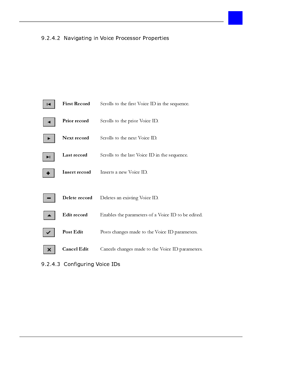
The 9 buttons at the bottom of each Voice Processor tab scroll between existing
Voice IDs, create additional Voice IDs according to the established sequence,
delete existing Voice IDs, and prevent configuration errors from being posted to
the system. The Edit record button must be selected prior to making any
changes on a tab.
The buttons and their functions are as follows:
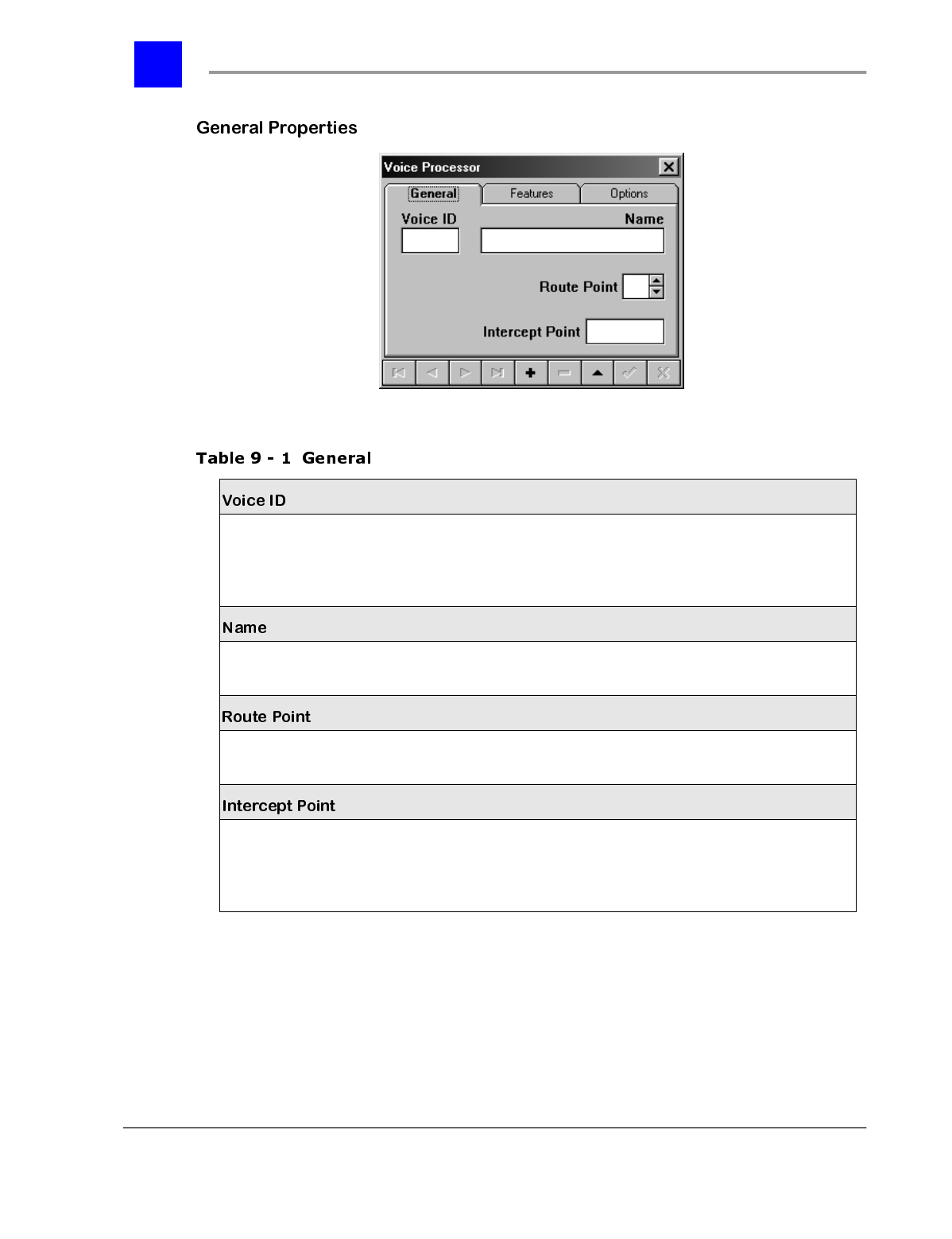
Scroll to the desired Voice ID and make appropriate entries and selections on
each of the tabs presented below.
Section 9.2- The Integrated Voice Processor (IVP) Peripheral Card page 9-8
IVP Configuration
* = default settings
Logical identifier for the voice mail resource.
Note
: The ID is automatically assigned based on the
Voice ID Sequence entered when the first Voice ID
was created.
Numeric
2 to 4 digits,
(depending on the dial plan)
Informal identifier for the voice mail resource.
E.g., Day Message Alphanumeric
Up to 20 characters
The Route Point for the auto-attendant tree with which
this Voice ID will be associated. 0-9 0 *
The main dial node that the Intercept is off of. For
example, an Intercept may be created for a user or
user group. See “Setting up Hold Queue Intercepts” -
section 9.7.
Numeric
page 9-9 The Integrated Voice Processor (IVP) Peripheral Card - Section 9.2
IVP Configuration
* = default settings
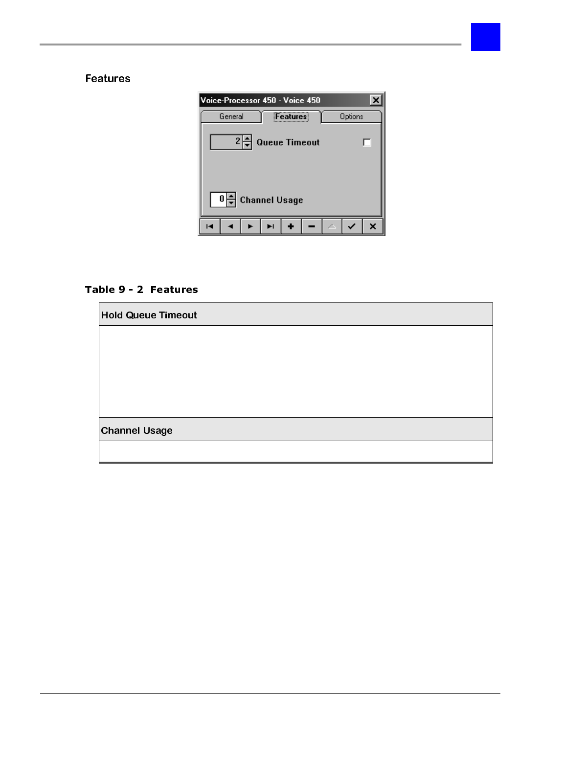
The Hold Queue Timeout refers to the period of time that
a call may remain in queue, waiting for an available
channel, before going to the Busy Cover-Pilot.
Note
: The checkbox enables the Hold Queue. If the Hold
Queue is not enabled (i.e., checked), calls will go straight
to the Busy Cover Pilot in cases where there are no
available channels.
0-255 minutes
Enable/Disable* 2 minutes *
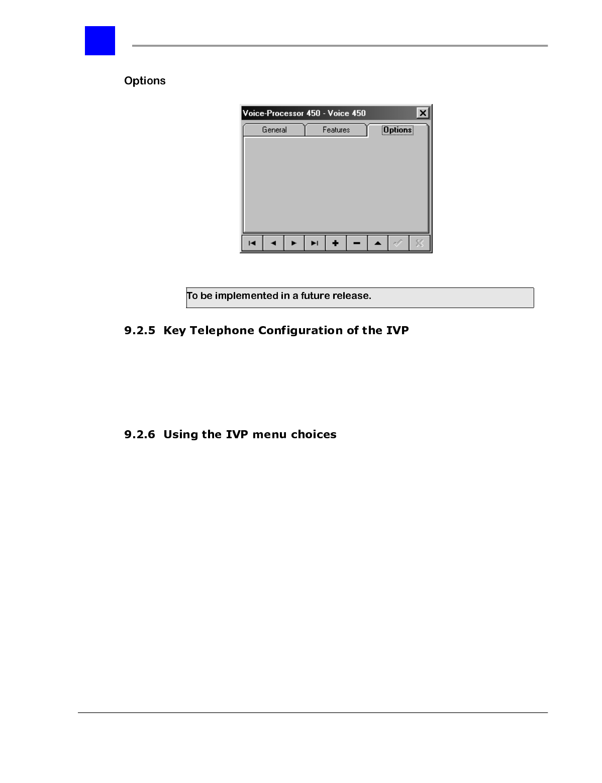
To be implemented in a future release.
Section 9.2- The Integrated Voice Processor (IVP) Peripheral Card page 9-10
IVP Configuration
Refer to Chapter 7, "Administration by Keyphone" for instructions on entering
programming mode and utilizing the Key Telephone Configuration template.
The IVP card must be physically inserted into the system cabinet before key
telephone configuration can be carried out.
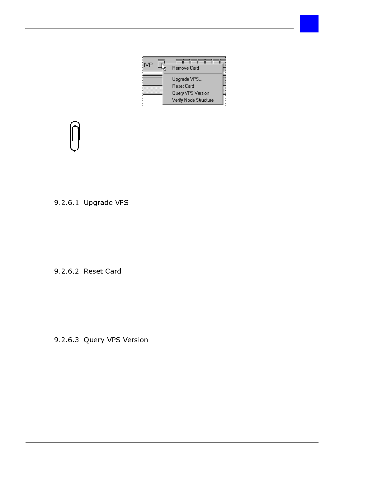
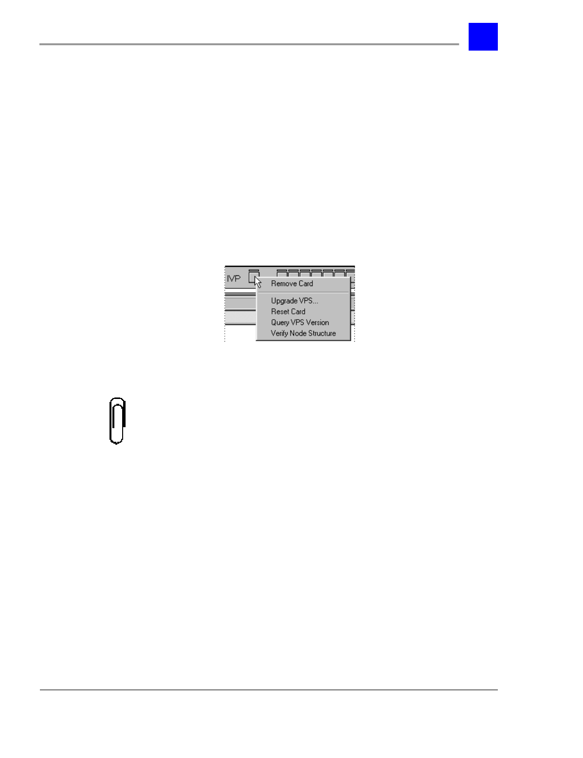
There are four menu choices when right-clicking on the IVP card in an open
configuration file. To access these menus, proceed as follows:
1 Launch Plexus Administrator.
2 From the File menu, select Open.
3 Select the appropriate configuration file. Plexus configuration files have an
extension of .zdb.
4 From the Link menu, select Open.
5 The link indicator at the bottom of the screen should indicate Link:
Opened and the LED image should appear green. (See “Establishing a
link” - section 6.27 for more information).
page 9-11 The Integrated Voice Processor (IVP) Peripheral Card - Section 9.2
IVP Configuration
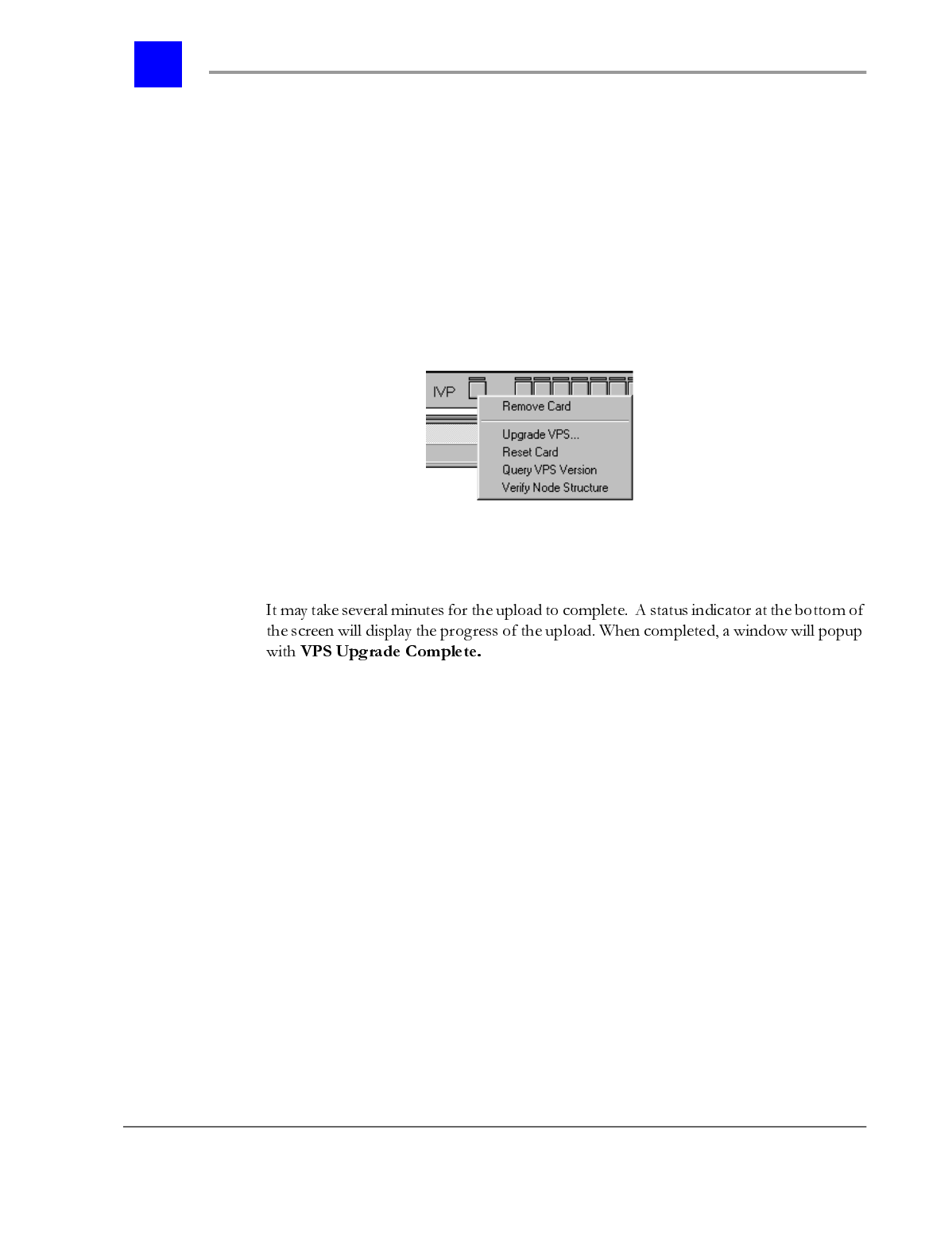
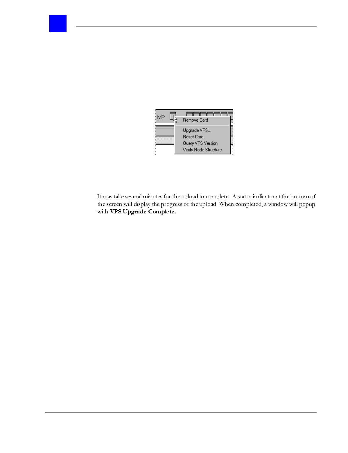
6 Right click on the IVP port of the IVP Card.
Note
The menu choices will not be available without an active link.
7 Point to the menu choice desired and left click once.
There are four IVP menu choices available. Each provides a tool for IVP
configuration or maintenance.
Upgrade VPS is used to upgrade Node configurations, Mailbox configurations,
IVP operating software, or System parameter changes. Refer to “The Automated
Attendant” - section 9.3, “Voice Mailboxes” - section 9.4, “Updating IVP
operating software” - section 9.2.7, or “System Parameters” - section 9.5 for
more information.
Reset card is used to reset the IVP card without power cycling or resetting the
entire system. An IVP card would have to be reset if the digit width of Voice
Mailboxes has been changed or after updating the IVP operating software. Refer
to “Voice Mailboxes” - section 9.4 or “Updating IVP operating software” - section
9.2.7 for more information.
Query VPS Version queries the current version of the IVP operating software.
This would be done if the system is changing Plexus Administrator software
versions or if directed to by BBS Telecom Technical Support.
Section 9.2- The Integrated Voice Processor (IVP) Peripheral Card page 9-12
IVP Configuration
Verify Node structure reads the node configuration description from the IVP
card. This can be very helpful if the original node configuration has been lost or
is not available. Once the Plexus Administrator has read the node configuration,
it will save the file as Vps-node.ndb in the saved file of the Plexus
Administrator folder. You will have to open this node configuration to view it
(see “Modifying an existing node structure” - section 9.3.7 for details). The node
configuration will only have the node descriptions and properties. No
recordings will be downloaded from the IVP card, only the node descriptions
and properties.
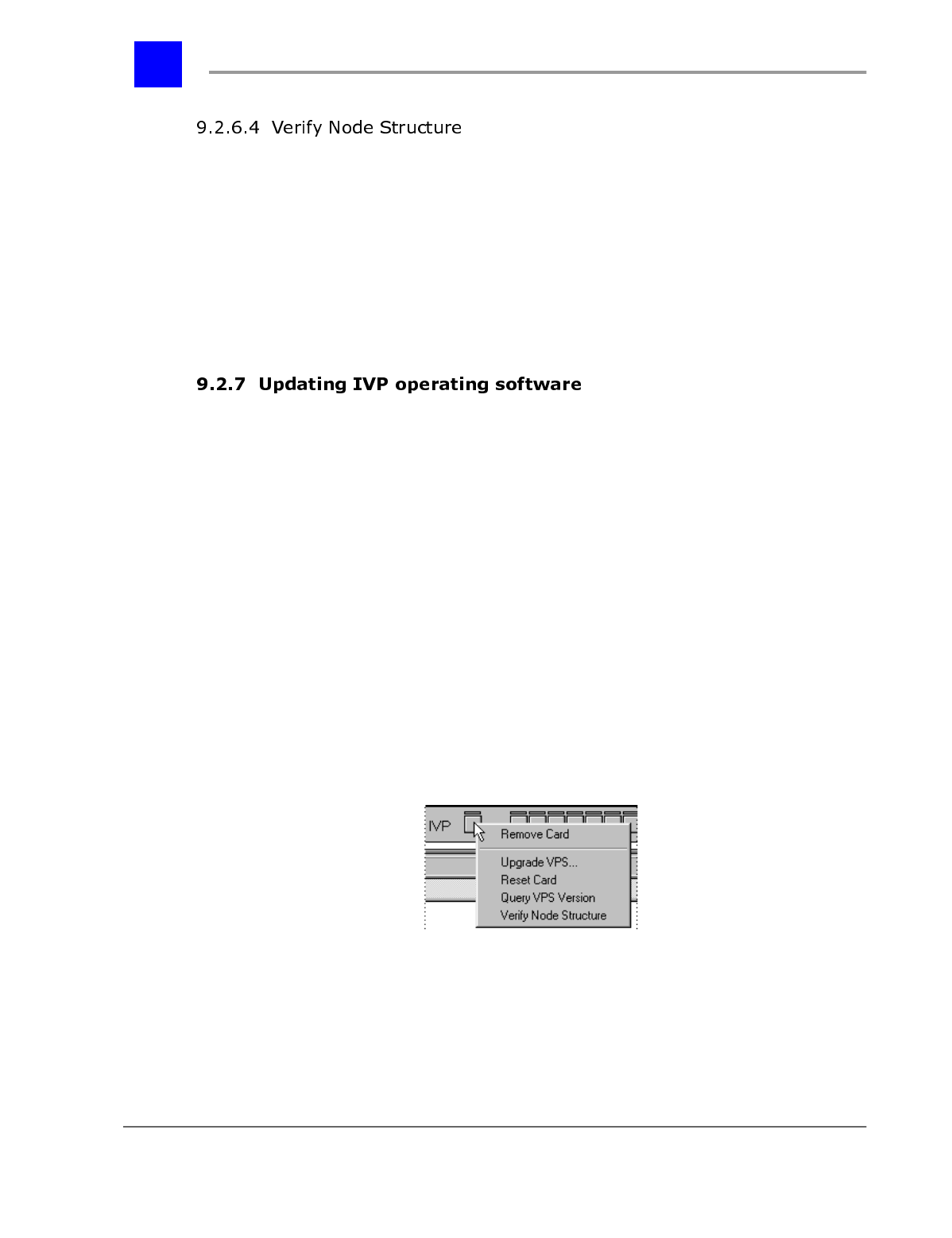
On occasion, it may be necessary to upgrade the IVP’s operating software. This
is usually done when upgrading to newer versions of the Plexus Administrator
software or when directed to upgrade by BBS Telecom Technical Support. To
upgrade the IVP operating software, proceed as follows:
1 Launch the Plexus Administrator Windows application.
2 Open the system’s configuration file (.zdb file)
3 From the Link menu, select Open.
4 The link indicator at the bottom of the screen should indicate Link:
Opened and the LED image should appear green. (See “Establishing a
link” - section 6.27 for more information).
5 Right click on the IVP card.
6 From the pop-up menu, select “Upgrade VPS”.
page 9-13 The Integrated Voice Processor (IVP) Peripheral Card - Section 9.2
IVP Configuration
7 Locate the updated IVP operating software. You can get this from BBS
Telecom Technical Support or from the BBS Telecom web site at
www.bbstelecom.com. The file will be named something very similar to
orc3xx.vps with the xx being the most recent version (e.g., orc352.vps).
8 Click on OK.
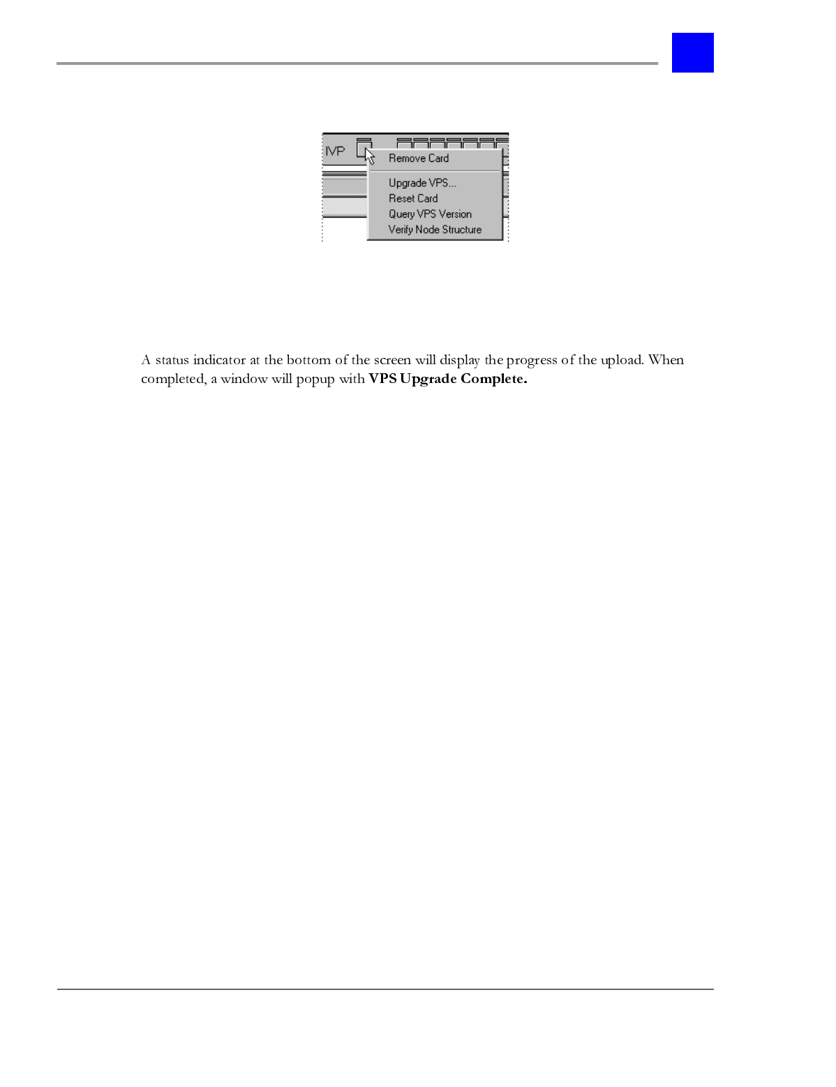
9 A status indicator at the bottom of the screen will display the progress of the
upload. When completed, a window will popup with VPS Upgrade
Complete. Click on OK.
10 Right click on the IVP card.
11 From the pop-up menu, select “Reset Card.”
12 The card will take between 10-30 seconds to reset. IVP resources will not
be available during this time.
Note
Upgrading the IVP operating system will not delete or reset existing node
configurations or mailbox configurations already stored on the card.

Section 9.2- The Integrated Voice Processor (IVP) Peripheral Card page 9-14
IVP Configuration
page 9-15 The Automated Attendant - Section 9.3
IVP Configuration
7KH$XWRPDWHG$WWHQGDQW
The Integrated Voice Processor utilizes an Automated Attendant (a.k.a. auto-
attendant) to route calls to various system (e.g., users and user groups) and
voice mail (e.g., mailboxes) resources. The structure of the auto-attendant,
referred to as the auto-attendant tree, is customized to meet the call routing
needs at each Plexus installation. An auto-attendant tree is developed by
creating and linking nodes. Each node performs a different function (e.g.,
present a menu of choices, dial an extension, access a voice mailbox, etc.).
A Menu Node plays a recorded message for callers and directs calls to
subsequent nodes based on the digits (i.e., DTMF tone) entered by the callers.
Also see “Menu Node Properties” - section 9.3.15.1.
Menu Nodes allow the digits 0-9 to be entered by the caller. The * and # keys are
also defined within a menu node. By default, entering the * key followed by a
mailbox number logs the caller into a mailbox (e.g., to check messages). By
default, entering the # key followed by a mailbox number plays the associated
mailbox greeting and allows the caller to leave a message in the mailbox.
The * and # keys can also be set to restart the auto-attendant or be ignored when
pressed as an alternative to the default actions discussed above.
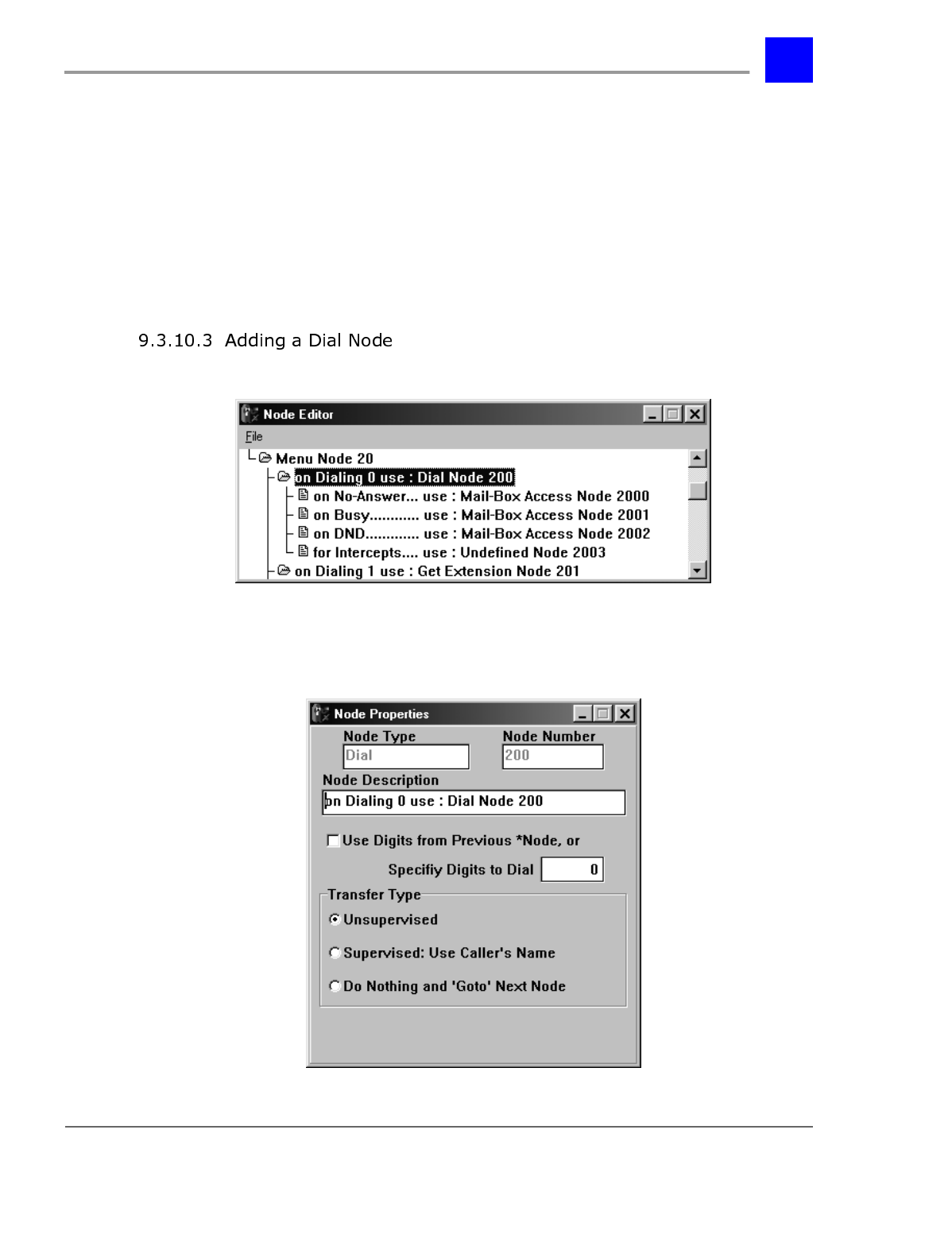
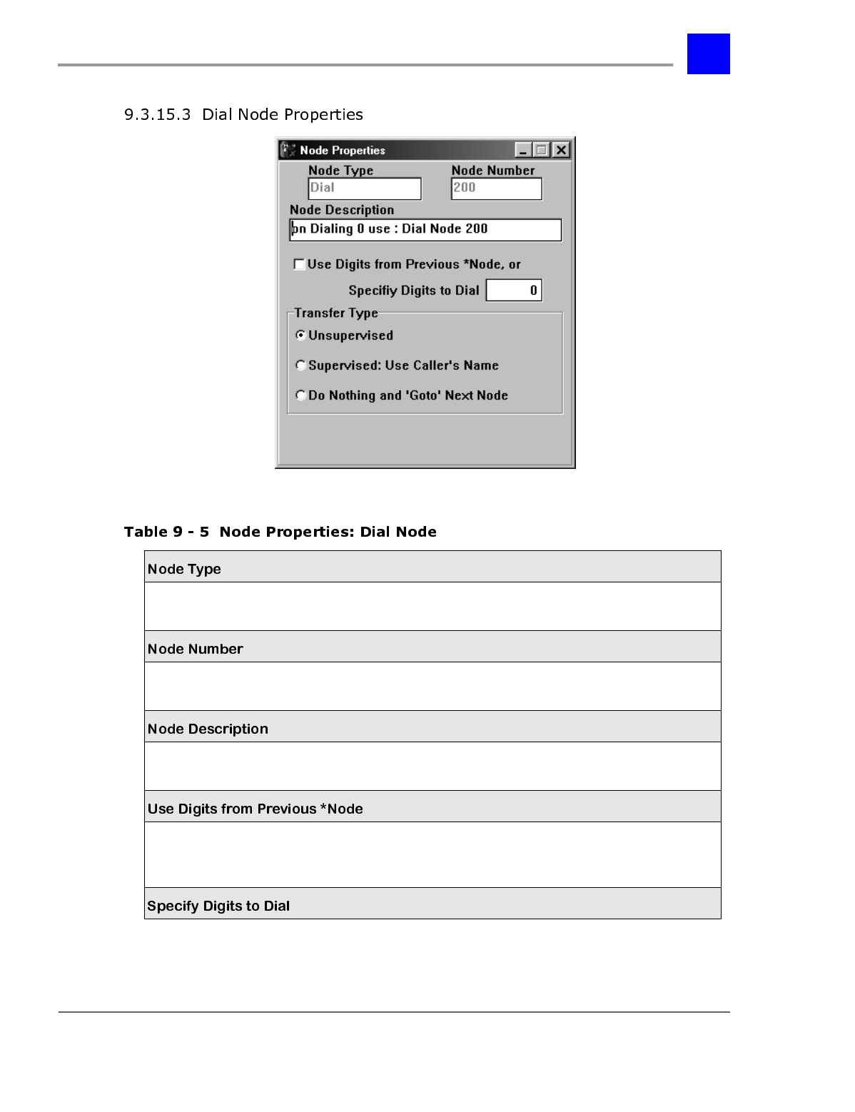
A Dial Node instructs the auto-attendant to dial a specific system entity (e.g., a
user or user group) and route the call to that entity. Also see “Dial Node
Properties” - section 9.3.15.3.
Section 9.3- The Automated Attendant page 9-16
IVP Configuration
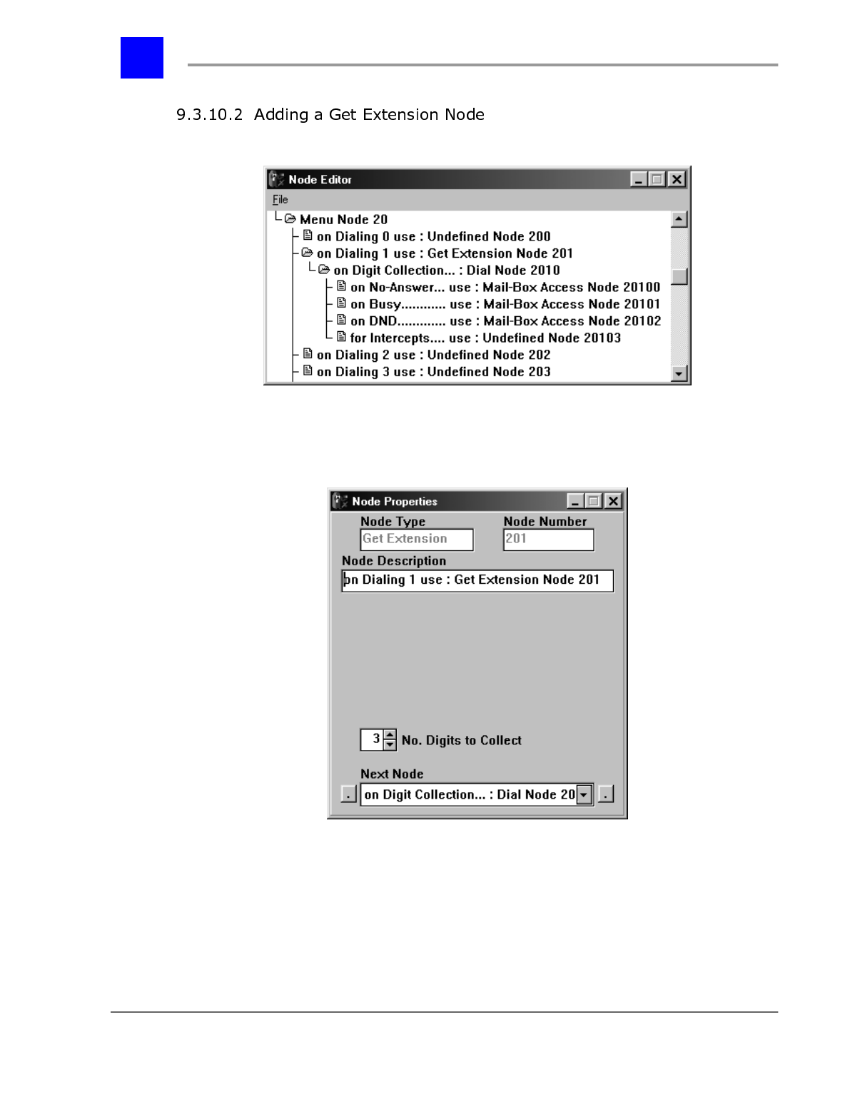
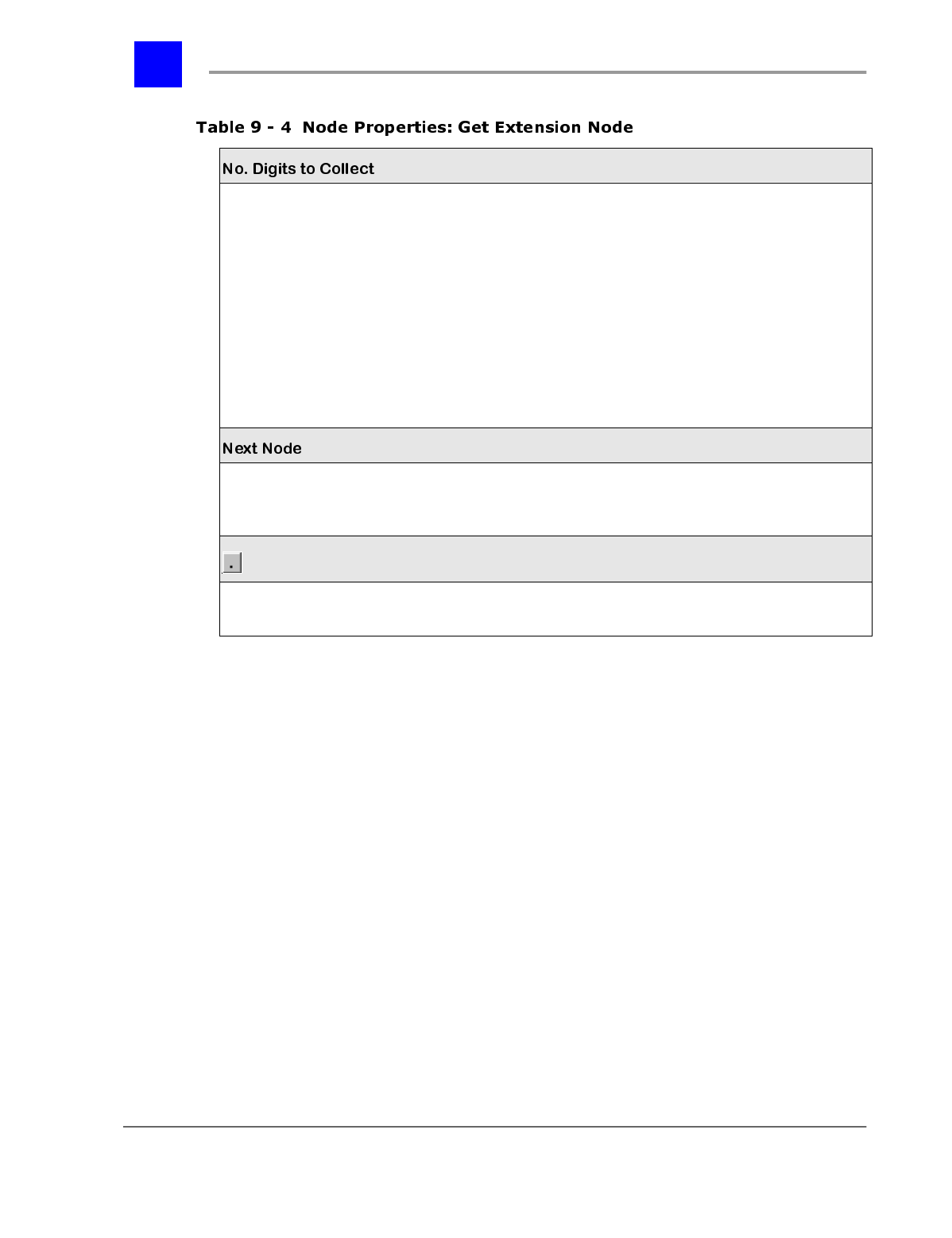
A Get Extension Node records DTMF tones entered by a caller. The tones
recorded may then be passed on to a Dial Node to dial a specific system entity
(e.g., user or user group). Typically, the main auto-attendant greeting includes
the option to dial a party’s extension. Also see “Get Extension Node Properties” -
section 9.3.15.2
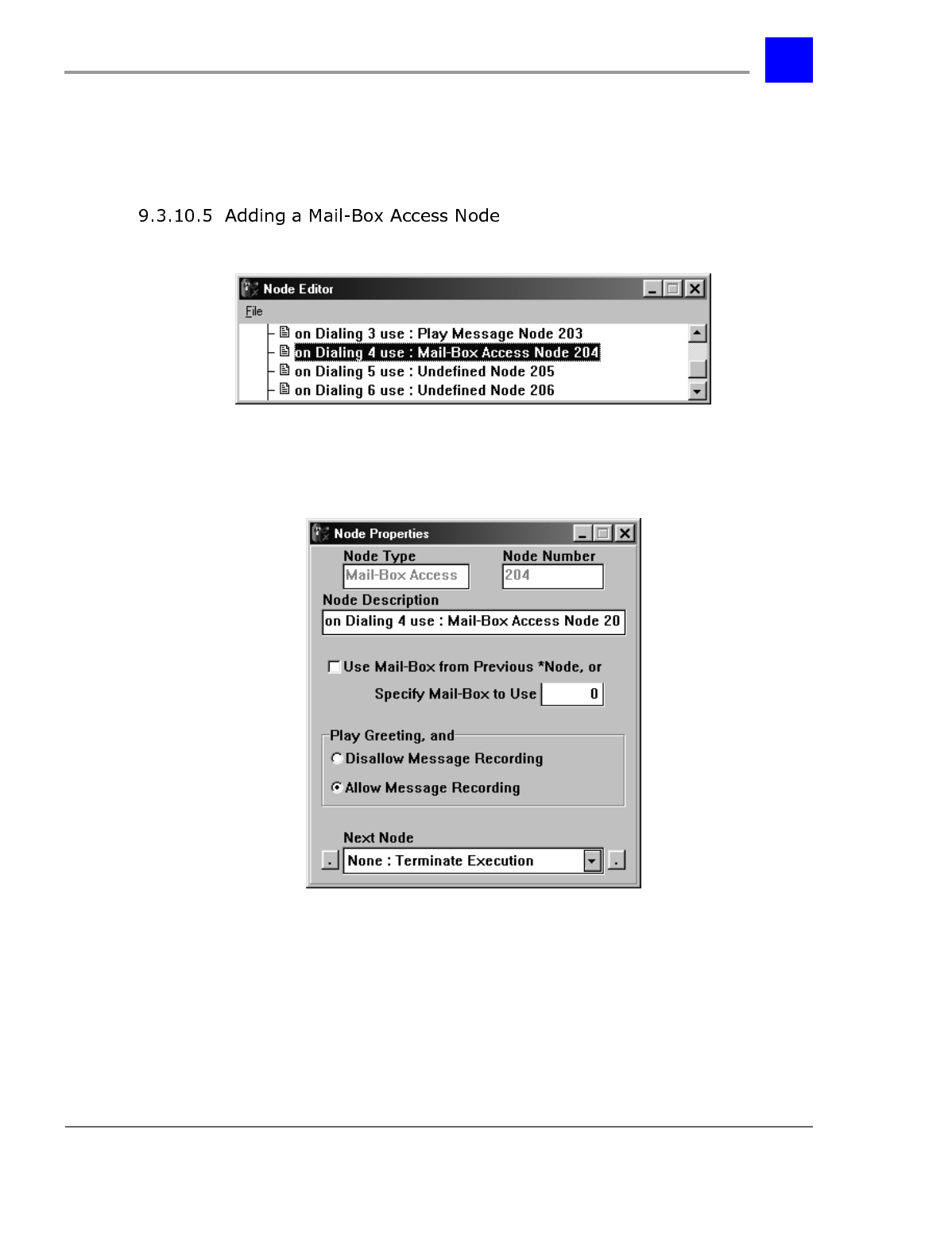
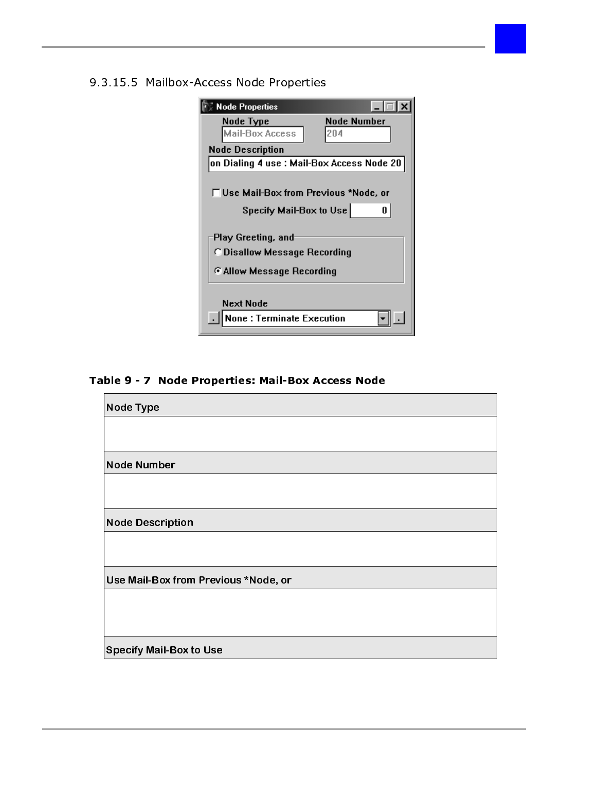
A Mailbox-Access Node directs a call into a mailbox and plays the mailbox
greeting. Mailbox-Access Nodes may be configured to allow the caller to leave a
message or to simply play the greeting and then exit. Also see “Mailbox-Access
Node Properties” - section 9.3.15.5.
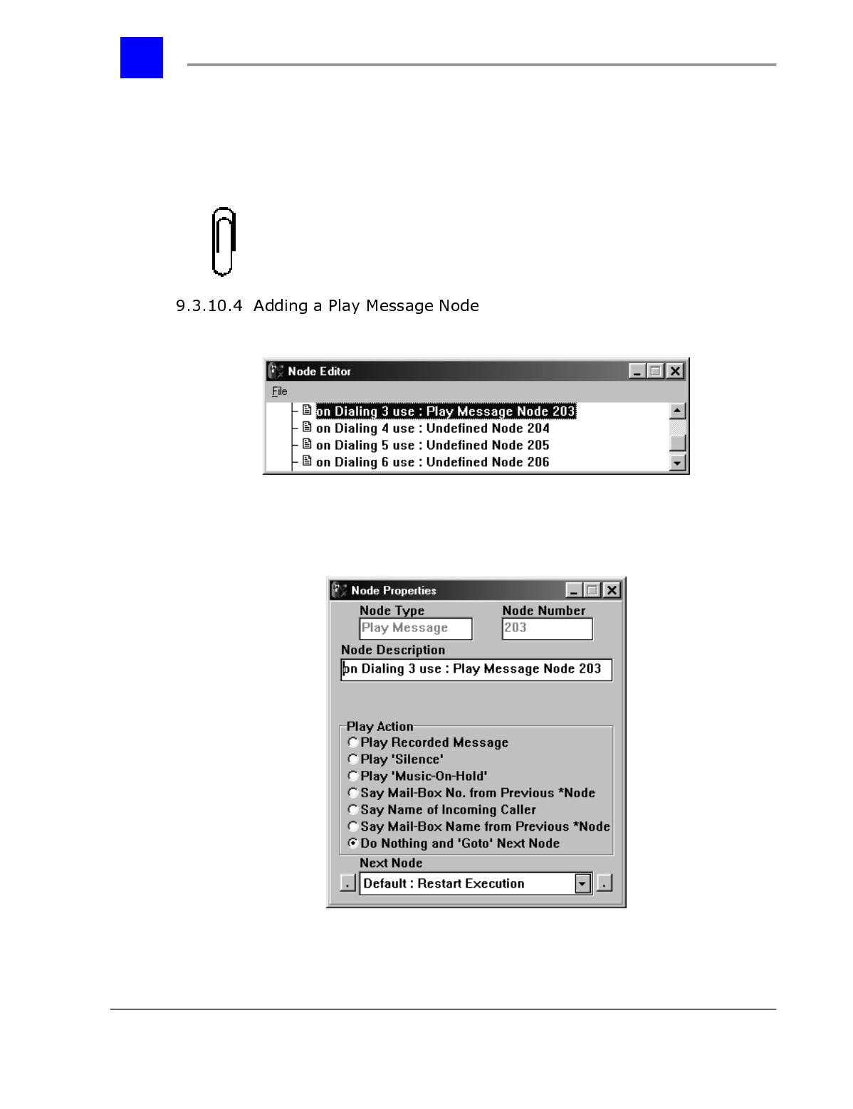
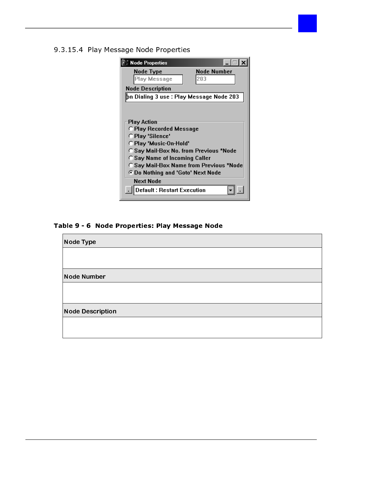
The Play Message Node is a multi-purpose node. Play Message Nodes are
primarily used to play informational messages to callers, but they also may be
used for the following functions:
• To record your own message.
• To play the User ID (extension) entered in a previous Get Extension Node or
Directory Node.
• To direct a call to a different sub-tree of the auto-attendant.
• To play the name of the incoming caller.
• To play silence for a specified period of time.
• To play Music-On-Hold for a specified period of time.
• To play the name of the owner of the mailbox specified by the caller in a
previous Get Extension Node or Directory Node.
Play Message Nodes may be utilized almost anywhere in an auto-attendant tree.
They are most useful when a recorded message needs to be played to the caller,
but no DTMF digits need to be collected. Also see “Play Message Node
Properties” - section 9.3.15.4.
page 9-17 The Automated Attendant - Section 9.3
IVP Configuration
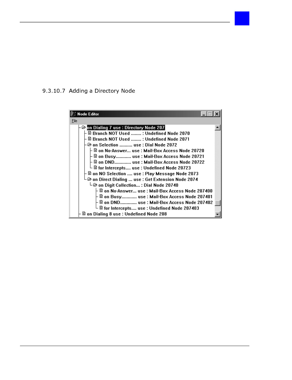
A Directory Node announces the names and mailbox numbers (optional) of each
user on the voice mail system. While the voice mail system is playing the users’
names, the caller can press the "#" key to make a selection. The voice mail
system can then attempt to dial the corresponding user. Also see “Directory
Node Properties” - section 9.3.15.7.
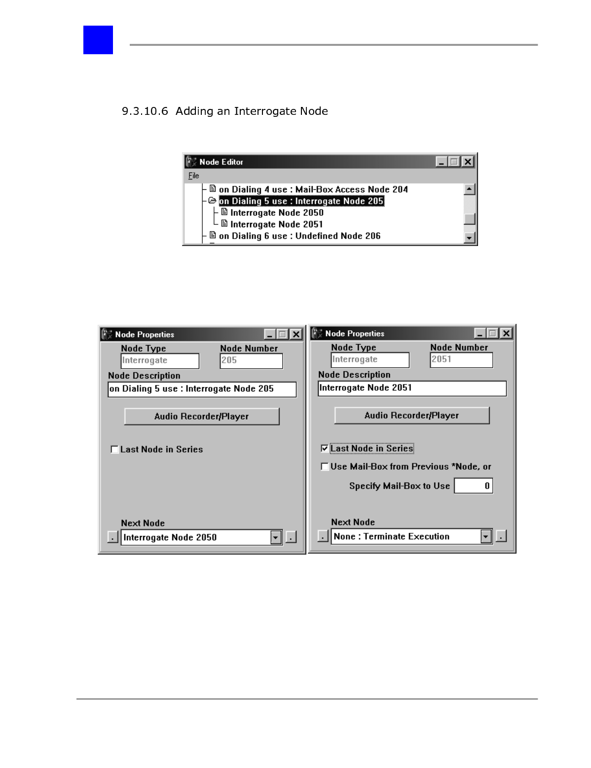
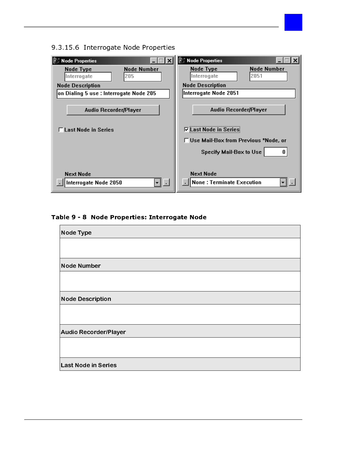
Interrogate Nodes are used to present a caller with a series of messages (e.g.,
questions), each requiring a verbal response from the caller. The voice mail
system can deposit the series of responses in a mailbox as a single message. The
Interrogate Node is useful for asking a caller a series of short questions such as
name, address, and phone number. Also see “Interrogate Node Properties” -
section 9.3.15.6.
The first (left-most) digit in a node number is the Route Point. The Plexus voice
mail system supports up to 10 (i.e., 0-9) Route Points. Each Route Point
provides a unique location for a call to enter the voice mail system. The Route
Points allow the system to route incoming calls differently based on parameters
such as the time of day or the trunk (CO line) on which the call was received.
The use of different Route Points facilitates the following example applications:
• Specify different auto-attendant sequences for day and night operation. Day
calls could enter at Route Point 0 while night calls could enter at Route
Point 1.
• Specify different auto-attendant sequences to service multiple businesses
using the same Plexus system. Incoming calls on one group of trunks (CO
lines) would enter at one Route Point corresponding to Company A.
Incoming calls on another group of trunks would enter at a different Route
Point corresponding to Company B.
Section 9.3- The Automated Attendant page 9-18
IVP Configuration
The second digit in a node number is the route point starting point. For each
route point, there are 10 route point starting points (i.e., 0-9). This allows
multiple auto-attendant trees to be defined for each Route Point. Only one route
point starting point can be active for each route point at any given time.
However, the Voice Mail System Manager can easily change the active route
point starting point when logged into System Manager Mailbox #001 (see “Voice
Mail System Manager” - section 9.6) or by dialing F95, voice ID, and the new
route point starting point (e.g., dialing F95 + 450 + 1 would change the starting
point of the route point associated with voice ID 450).
Since there are 10 starting points, it is possible to have up to 10 independent
auto-attendant trees defined in memory for each route point and to switch
between the trees depending on current needs.
The use of different starting points facilitates the following example
applications:
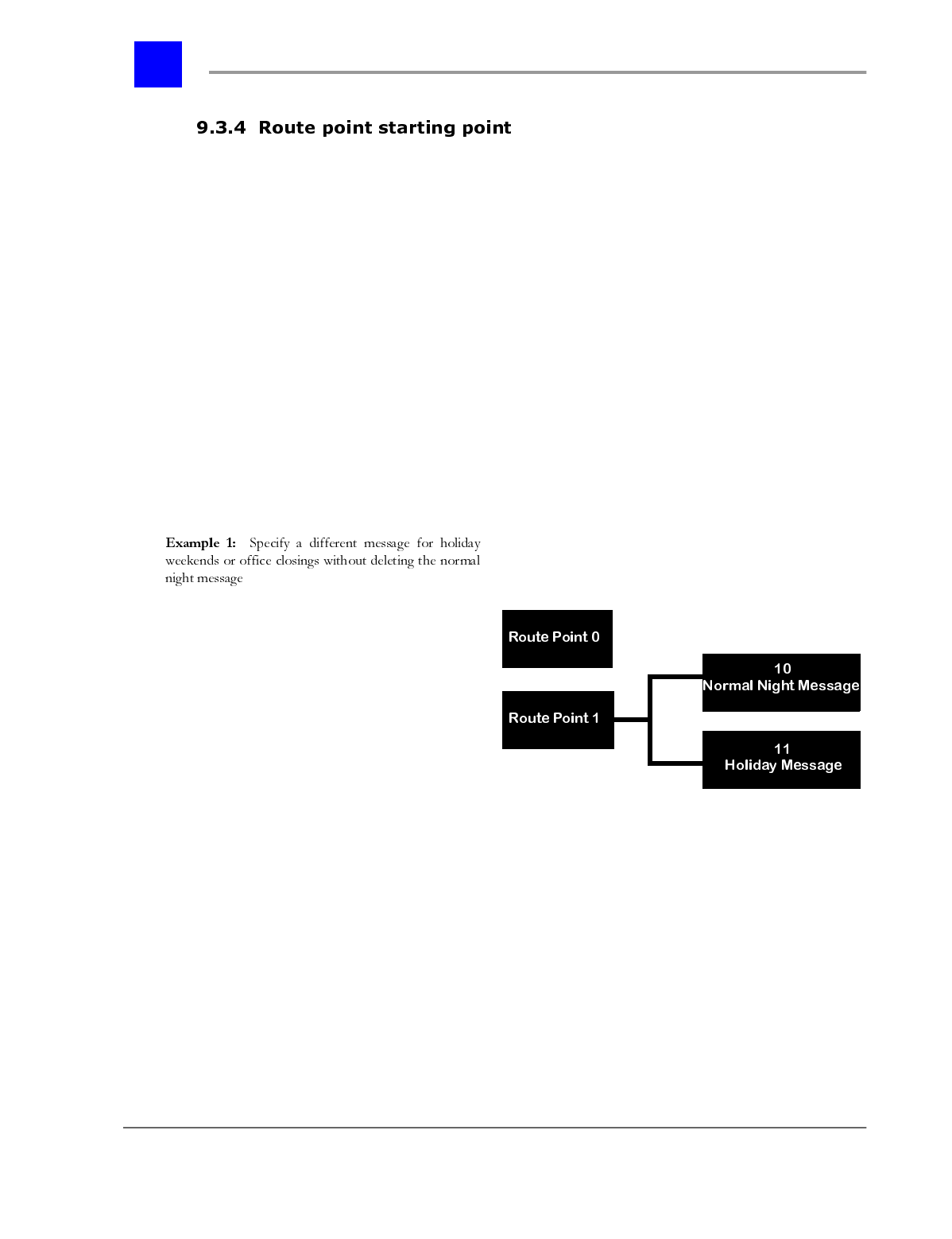
Route Point 0 is used for calls during business
hours.
Route Point 1 is used for after hours call.
Route Point 1 has two associated Route Point
starting points. One is for regular night calls
(node 10). One is for holidays (node 11).
Each starting point (node 10 and node 11) can
have a different auto-attendant tree. Alter-
nately, they can both link to the same tree, but
provide different main greetings.
page 9-19 The Automated Attendant - Section 9.3
IVP Configuration
Route Point Starting Point Summary
• Only one Route Point Starting Point can be active at any given time. Any
calls entering Route Point 1 will route to the active auto-attendant tree.
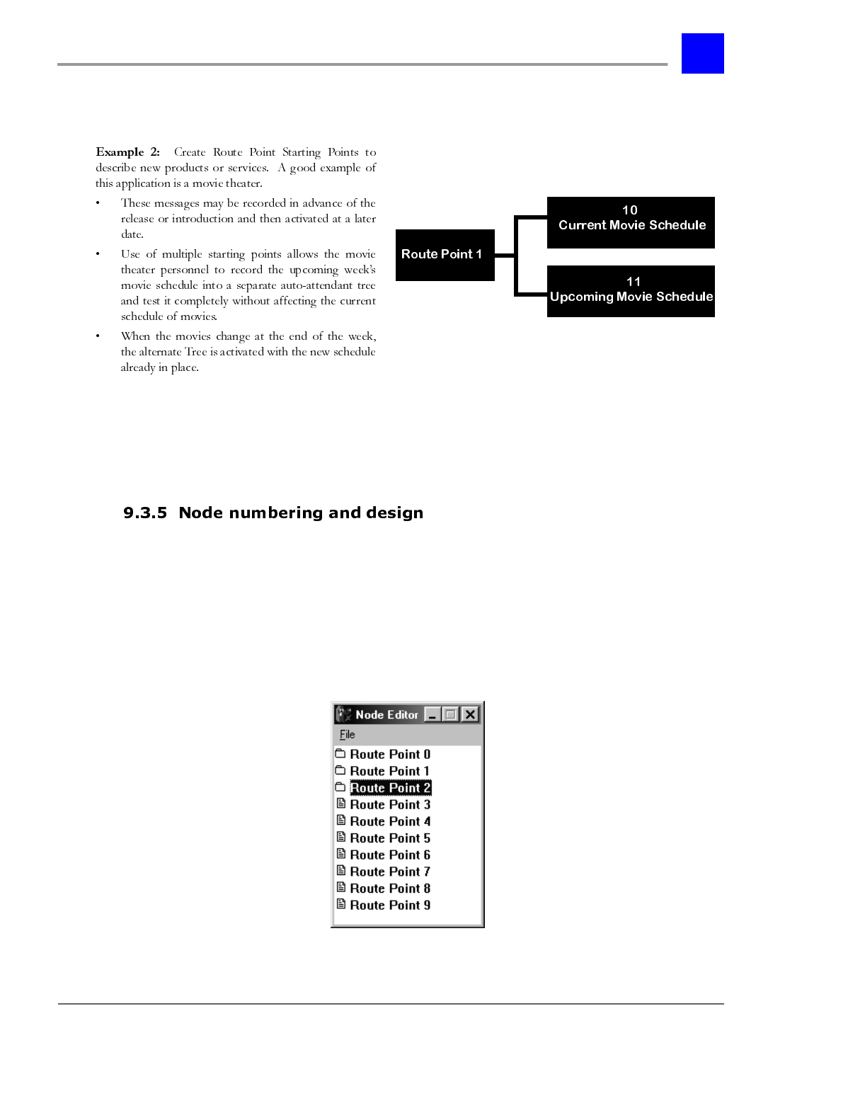
A node number is a place holder the auto attendant structure. Each node has a
unique 2 - 8 digit node number, using 0 to 9 with 0 always being accessed before
1, 1 before 2, etc. The node number defines the specific place the node falls in the
auto attendant.
The first digit of any node signifies the Route Point that the node falls under.
There are 10 available route points, 0 to 9:
Section 9.3- The Automated Attendant page 9-20
IVP Configuration
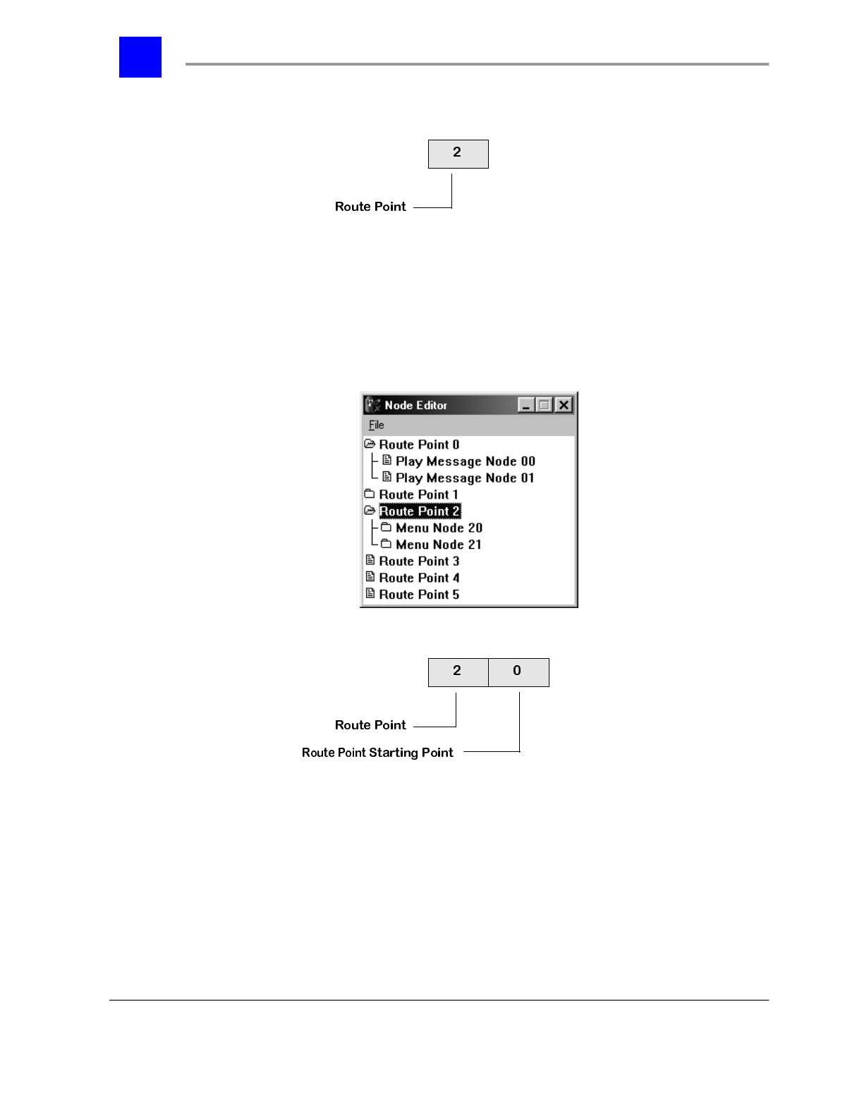
The next digit in the node represents the Route Point Starting Point. By default,
the route point starts at 0. This starting point can be changed through the
System Manager (see “Set the Node Starting Points (Route Point Starting
Point)” - section 9.6.5.6) or by dialing F95, voice ID, and the new route point
starting point (e.g., dialing F95 450 1 would change the starting point of the
route point associated with voice ID 450).
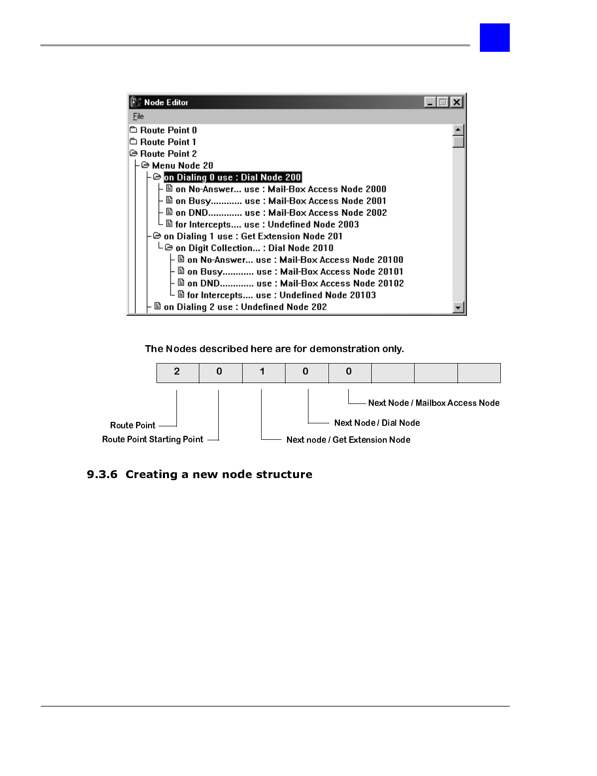
The third through seventh digit (all digits except the last) represent the various
node sub-trees that the node falls under.
page 9-21 The Automated Attendant - Section 9.3
IVP Configuration
The auto-attendant tree is created using the VPS Node Editor feature of Plexus
Administrator software.
To use the VPS Node Editor:
1 Launch Plexus Administrator. Refer to the Software Configuration
section of the Plexus Product Manual for instructions on launching Plexus
Administrator.
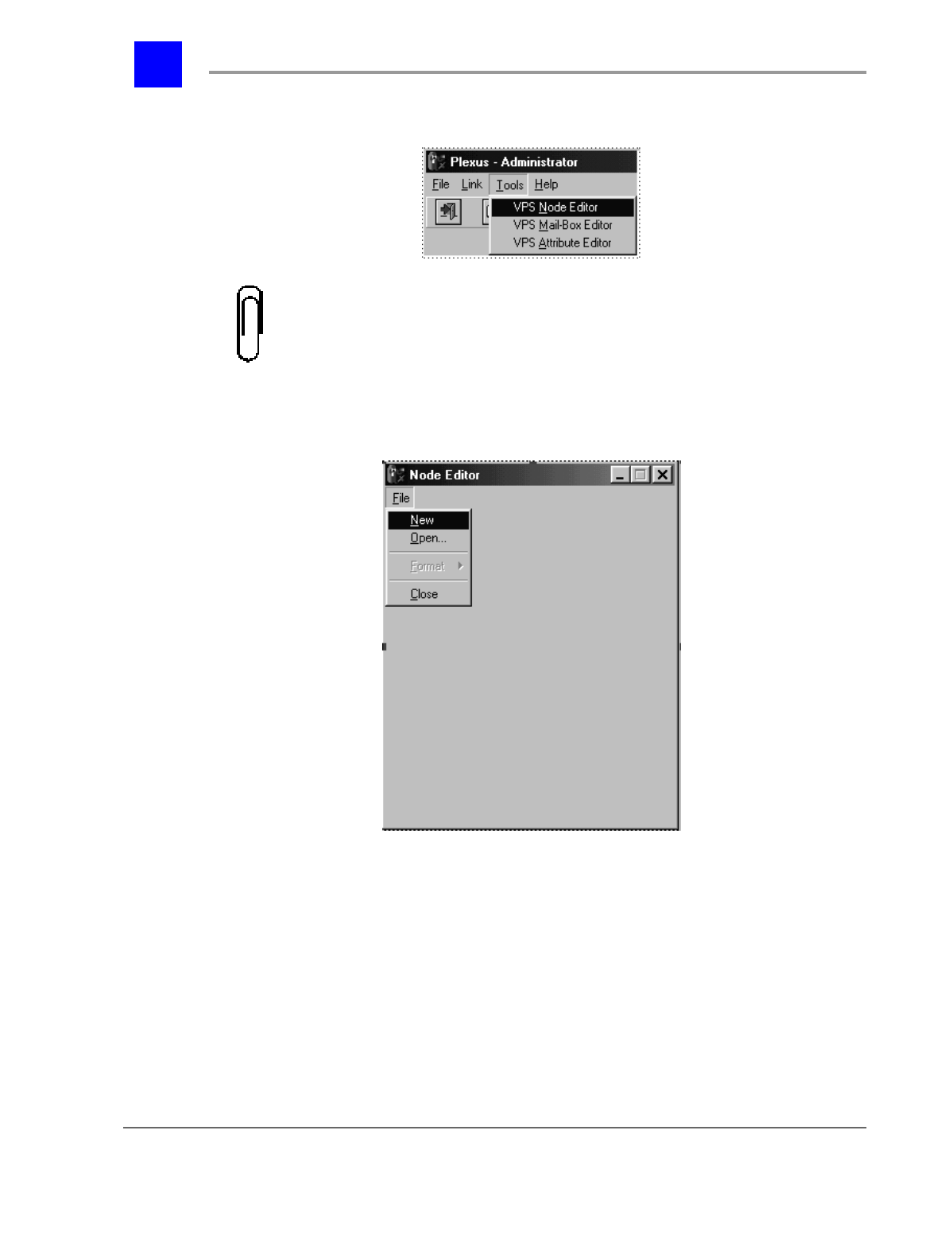
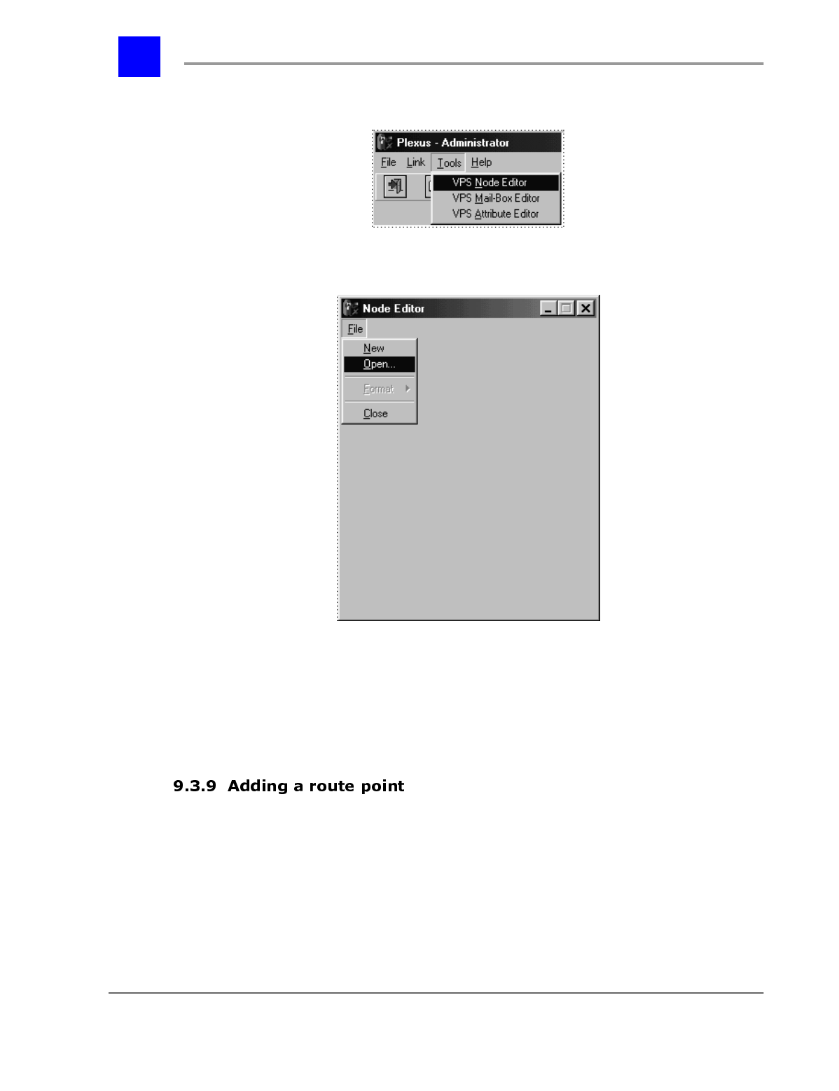
2 From the Tools menu, select VPS Node Editor.
Section 9.3- The Automated Attendant page 9-22
IVP Configuration
Note
The Tools menu will only be available if there is not a .zdb configuration open.
If there is a configuration open in the Plexus Administrator window, close the
configuration before accessing the Tools menu.
3 The Node Editor window will be displayed.
4 Select New from the File Menu.
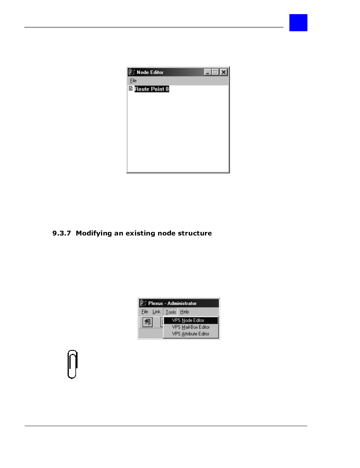
5 The Node Editor dialog window will then display an initial Route Point, "0."
page 9-23 The Automated Attendant - Section 9.3
IVP Configuration
6 Nodes are added to the route point to create the node structure. To continue
building the node structure, skip to “Adding a node” - section 9.3.10.
1 Launch Plexus Administrator. Refer to the Software Configuration
section of the Plexus Product Manual for instructions on launching Plexus
Administrator.
2 From the Tools menu, select VPS Node Editor.
Note
The Tools menu will only be available if there is not a .zdb configuration open.
If there is a configuration open in the Plexus Administrator window, close the
configuration before accessing the Tools menu.
Section 9.3- The Automated Attendant page 9-24
IVP Configuration
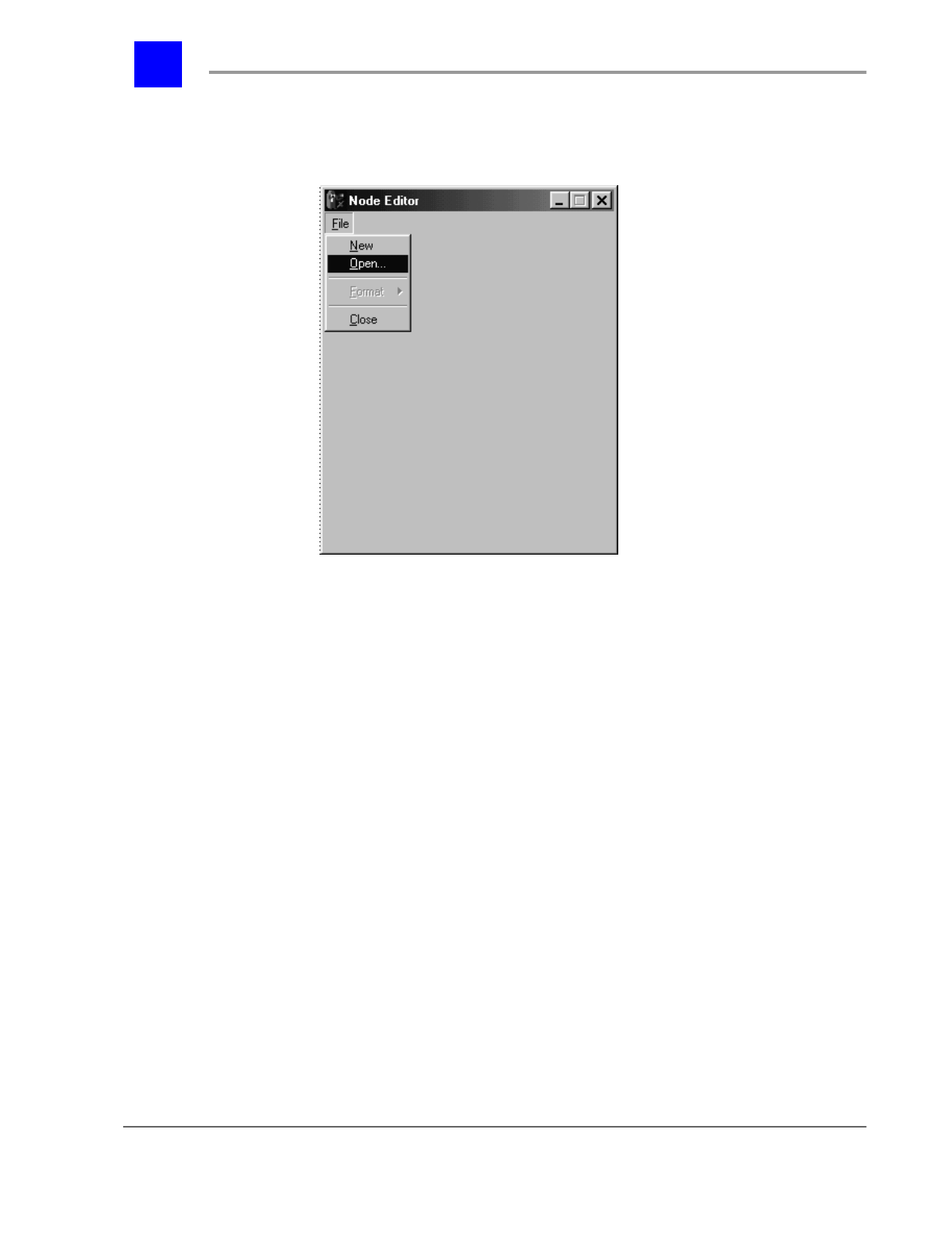
3 The Node Editor window will be displayed.
4 Select Open from the File Menu.
5 Select the desired auto-attendant configuration file. Plexus Administrator
auto-attendant files will have the extension .ndb (e.g., wiz-node.ndb). Be
sure to open the correct file in the correct saved folder.
6 To modify the node structure, skip to “Adding a node” - section 9.3.10.
page 9-25 The Automated Attendant - Section 9.3
IVP Configuration
1 Launch Plexus Administrator. Refer to the Software Configuration
section of the Plexus Product Manual for instructions on launching Plexus
Administrator.
2 From the Tools menu, select VPS Node Editor.
The node structure
wiz-node.ndb will be
created each time the
Wizard creates a new
configuration for a
Plexus system
Section 9.3- The Automated Attendant page 9-26
IVP Configuration
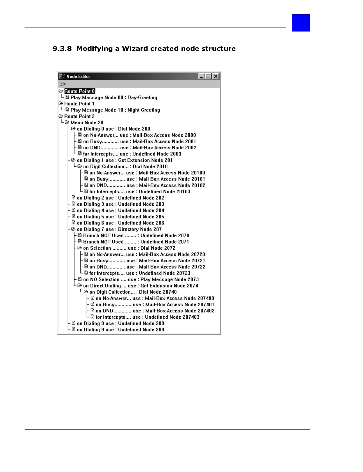
3 The Node Editor window will be displayed.
4 Select Open from the File Menu.
5 Select the desired auto-attendant configuration file. Plexus Administrator
Wizard auto-attendant files will have the name wiz-node.ndb. Be sure to
open the correct file in the correct saved folder.
6 To modify the node structure, skip to “Adding a node” - section 9.3.10.
To add a Route Point to an auto-attendant tree, proceed as follows:
1 Right mouse-click anywhere in the Node Editor dialog window.
page 9-27 The Automated Attendant - Section 9.3
IVP Configuration
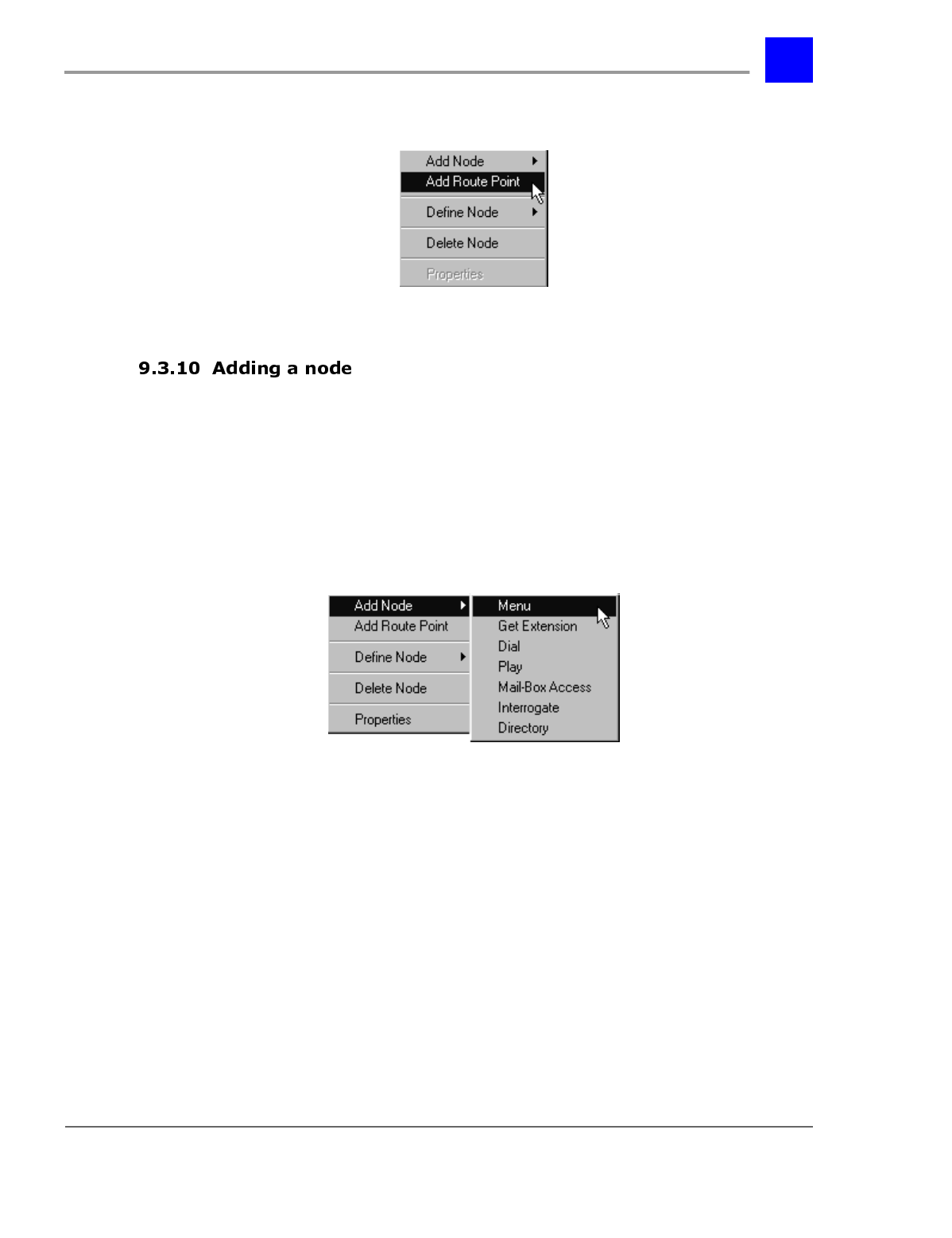
2 The following pull-down menu will be displayed.
3 Point to Add Route Point and click once.
To add a node to an auto-attendant tree, proceed as follows:
1 Click once on the existing Route Point or node to which the new node should
be appended.
2 The selected Route Point or node will become highlighted.
3 Right mouse-click.
4 The following pull-down menu will be displayed.
5 Point to Add Node.
6 Point to the desired node type on the node type pull-down menu and click
once.
The addition of certain node types will automatically create other required
nodes. For example, the addition of a Menu Node automatically creates an
undefined node for each digit that may be dialed by a caller while in the menu
node. The required nodes should be defined accordingly.
If you wish to add a node but there is already a different type node in the new
nodes place, you must delete the existing node before adding the new node. To
delete an existing node and the sub-nodes under that node, proceed as follows:
Section 9.3- The Automated Attendant page 9-28
IVP Configuration
1 Click once on the existing Route Point or node to be deleted.
2 The selected Route Point or node will become highlighted.
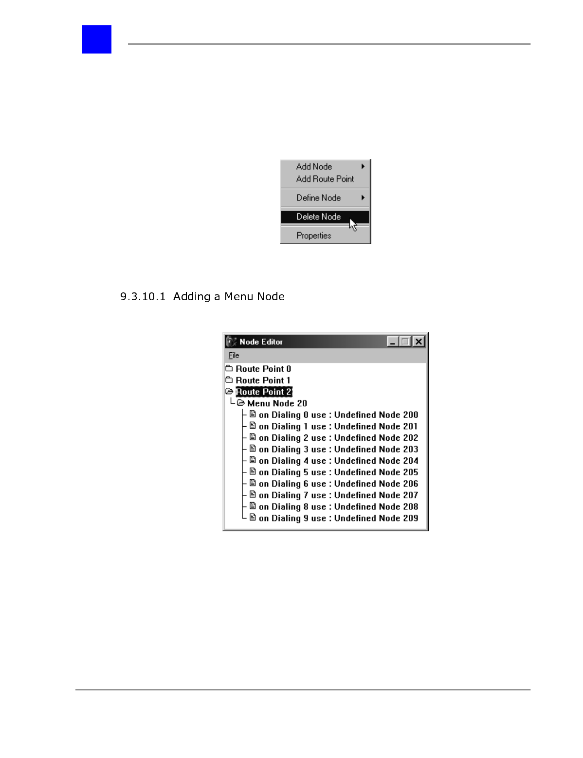
3 Right mouse-click.
4 The following pull-down menu will be displayed.
5 Point to Delete Node and click once.
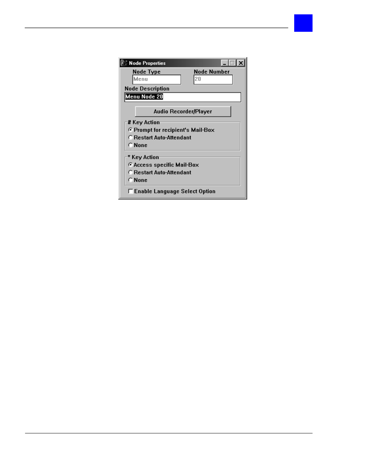
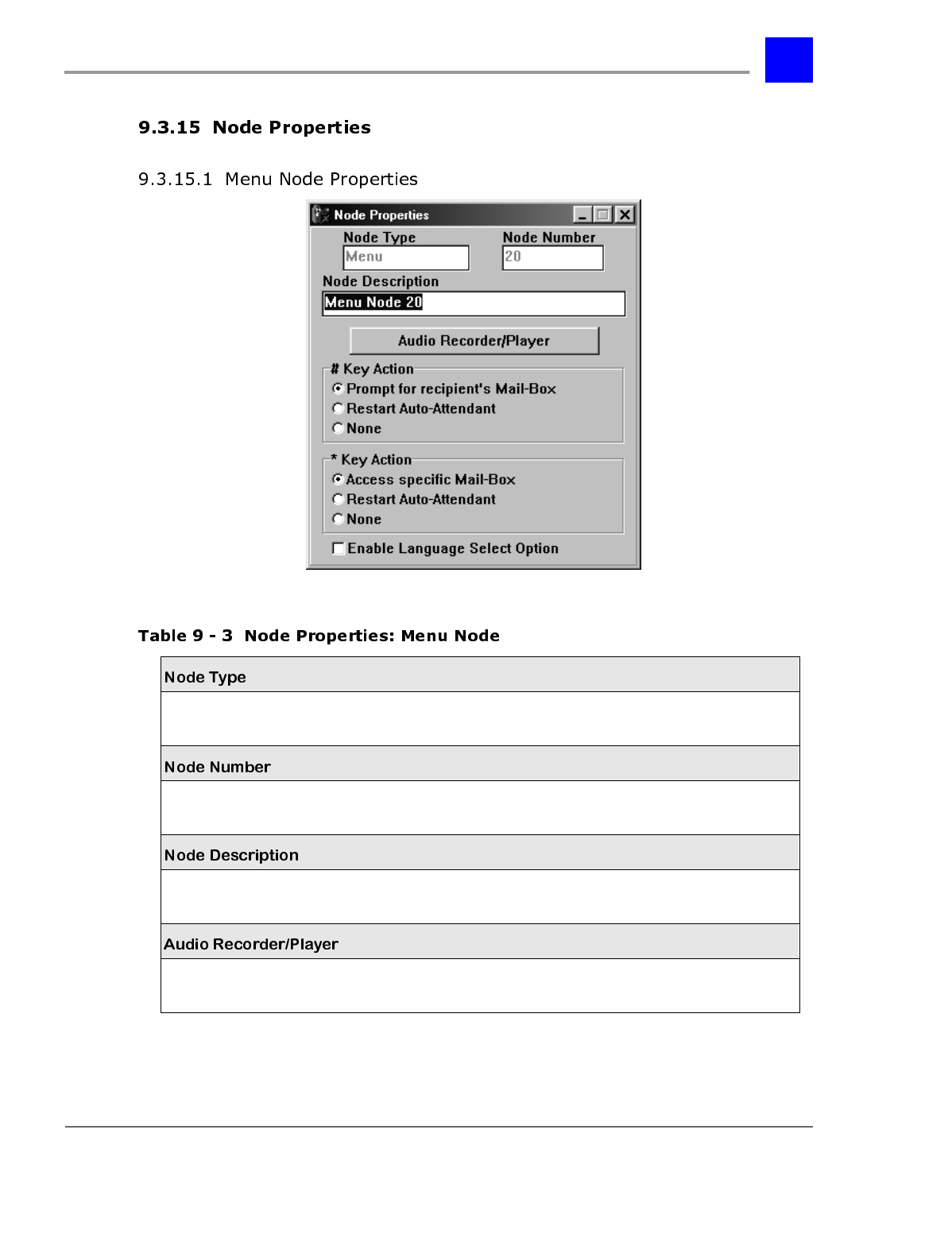
The Menu Node requires the following parameters to be set under Node
Properties (see “Node Properties” - section 9.3.15):
page 9-29 The Automated Attendant - Section 9.3
IVP Configuration
1 Audio Recorder/Player
2 # Key Action
3 * Key Action
4 Enable Language Select Option
When a Menu Node is added, the Node Editor will automatically place nodes
after the Menu Node. These nodes are preset to route the call based on the
dialing of 0-9 by the caller during the Menu Node Message. Each of these nodes
will be undefined for Node Type. Each node will have to be defined to properly
route calls.
"On Dialing 0 use :" serves two purposes under a Menu Node:
1 It defines the call routing for when the caller dials 0.
2 It defines the call routing if no digit is dialed. This provides a successful call
routing for callers from rotary phones or other phones where digit dialing
is unavailable.
page 9-31 The Automated Attendant - Section 9.3
IVP Configuration
When a Get Extension Node is created, five additional nodes are created by the
Node Editor:
A Dial Node is created that routes the calls using the digits captured by the Get
Extension Node. Mail-Box Access Nodes and a Intercept Default Node are
created for call routing in cases of unavailable (no answer, busy, DND)
extensions.
These additional nodes will need no modifications
The Dial Node requires the following parameters to be set under Node
Properties (see “Node Properties” - section 9.3.15):
Section 9.3- The Automated Attendant page 9-32
IVP Configuration
1 Use Digits from Previous *Node, or
2 Specify Digits to Dial
3 Transfer Type
Note
"Use Digits from Previous *Node" should only be used by Dial Nodes and Mail-
Box Access Nodes when they are used as routing under a Get Extension
Node or a Directory Node.
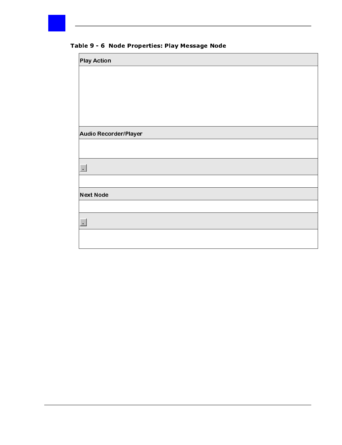
The Play Message Node requires the following parameters to be set under Node
Properties (see “Node Properties” - section 9.3.15):
page 9-33 The Automated Attendant - Section 9.3
IVP Configuration
1 Play Action
2 Next Node
The Mail-Box Access Node requires the following parameters to be set under
Node Properties (see “Node Properties” - section 9.3.15):
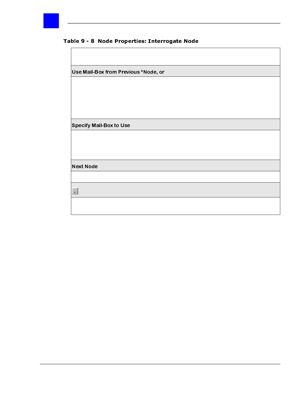
1 Use Digits from Previous *Node, or
2 Specify Mail-Box to Use
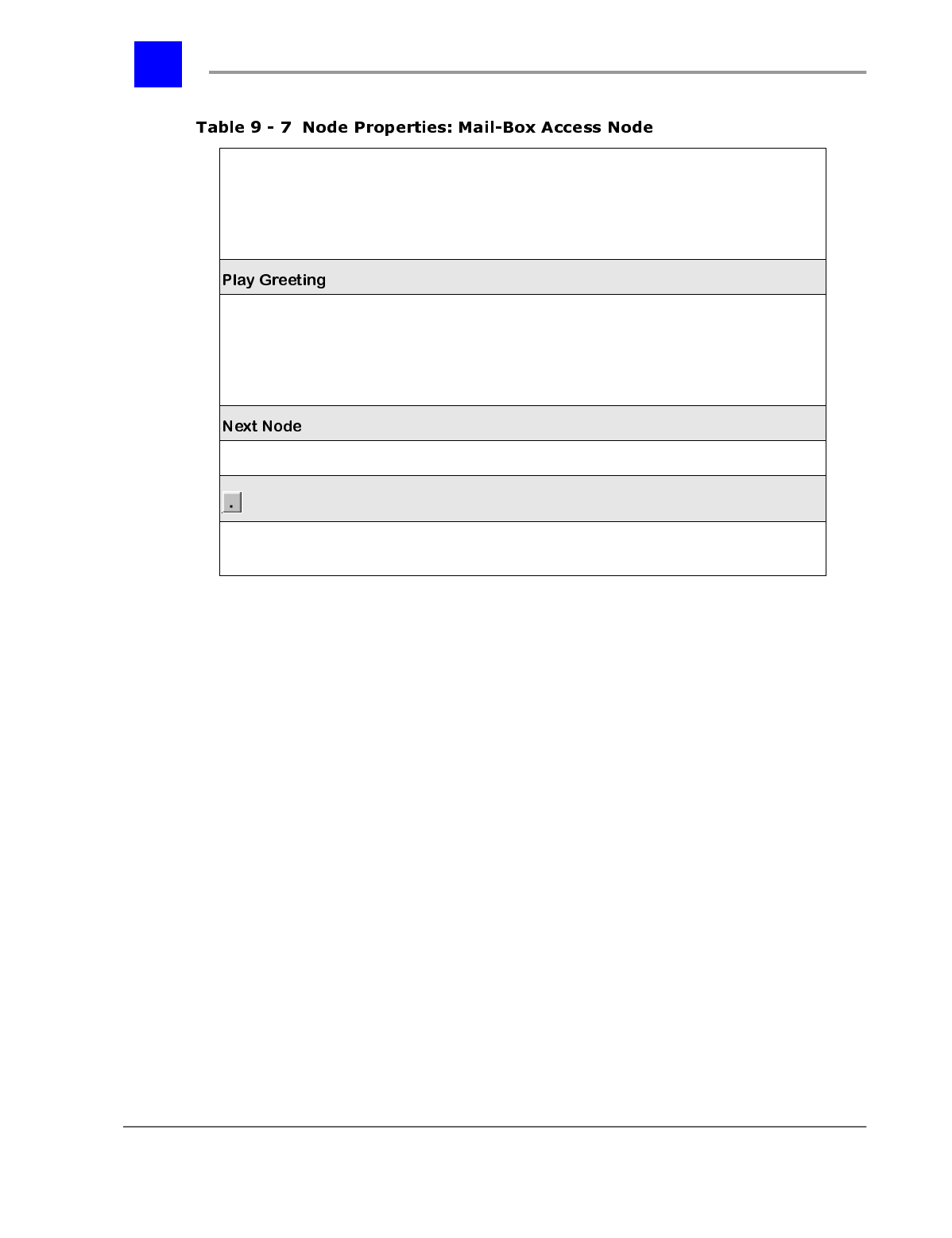
3 Play Greeting, and
page 9-35 The Automated Attendant - Section 9.3
IVP Configuration
4 Specify Mail-Box to Use
5 Next Node
Interrogate Nodes usually are used in a series to ask several questions of a
caller. The last node in the series will require information as to which mailbox
should receive the caller’s recorded answers.
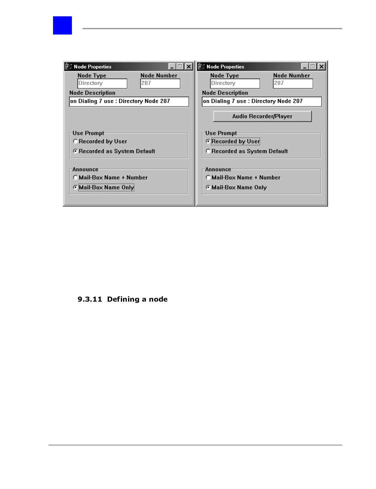
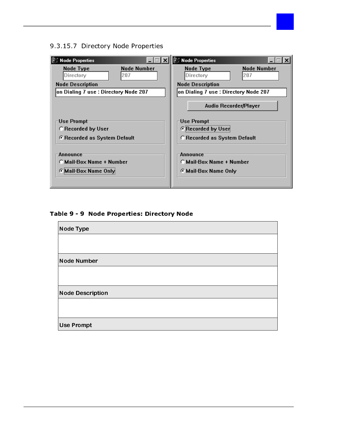
The Directory Node requires the following parameters to be set under Node
Properties (see “Node Properties” - section 9.3.15):
Section 9.3- The Automated Attendant page 9-36
IVP Configuration
1 Audio Recorder/Player (if Use Prompt is "Recorded by User")
2 Use Prompt
3 Announce
When a Directory Node is created, fourteen additional nodes are created by the
Node Editor. The Node Editor will configure these additional nodes
automatically, no additional configuration is required or recommended.
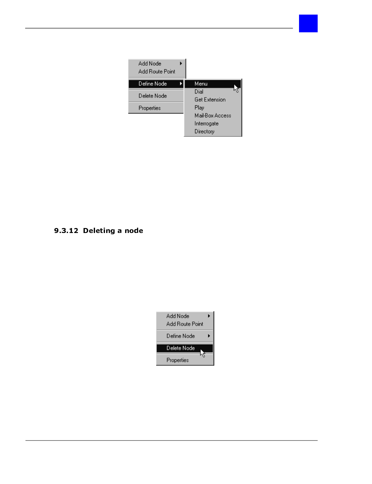
To define an existing undefined node proceed as follows:
1 Click once on the existing node.
2 The selected node will become highlighted.
3 Right mouse-click.
page 9-37 The Automated Attendant - Section 9.3
IVP Configuration
4 The following pull-down menu will be displayed.
5 Point to Define Node.
6 Point to the desired node type on the node type pull-down menu and click
once.
The definition of a node as a certain node type will automatically create other
required nodes. For example, the addition of a menu node will automatically
create an undefined node for each digit that may be dialed by a caller while in
the menu node. The required nodes should be defined accordingly.
To delete an existing node, proceed as follows:
1 Click once on the existing Route Point or node to be deleted.
2 The selected Route Point or node will become highlighted.
3 Right mouse-click.
4 The following pull-down menu will be displayed.
5 Point to Delete Node and click once.
Section 9.3- The Automated Attendant page 9-38
IVP Configuration
To redefine an existing node, it must be deleted and re-created. After deleting
the node, make sure the beginning of the node tree is highlighted before adding
the new node.
To redefine an existing node, proceed as follows:
1 Click once on the existing Route Point or node to be deleted.
2 Delete the node according to the directions in “Deleting a node” - section
9.3.12.
3 After deleting the node, make sure the beginning of the node tree is
highlighted before adding the new node.
4 Add the new node according to the directions in “Adding a node” - section
9.3.10
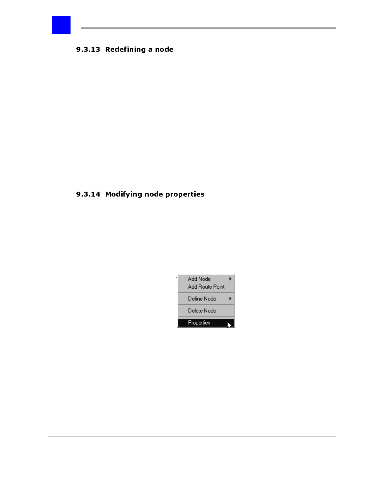
To set up the properties for an existing node, proceed as follows:
1 Click once on the existing node.
2 The selected node will become highlighted.
3 Right mouse-click.
4 The following pull-down menu will be displayed.
5 Point to Properties and click once.
6 The corresponding Node Properties dialog window will be displayed. Make
appropriate changes on the Node Properties dialog for each node.
page 9-39 The Automated Attendant - Section 9.3
IVP Configuration
The node type of the currently selected node.
E.g., Menu Automatically Identified
Logical identifier for the node.
Note: Refer to Node Numbering & Design. Automatically Assigned
Informal identifier for the node.
E.g., Main Greeting. Alphanumeric
Up to 30 characters
Launches the Plexus audio utility for recording the menu
greeting.
Section 9.3- The Automated Attendant page 9-40
IVP Configuration
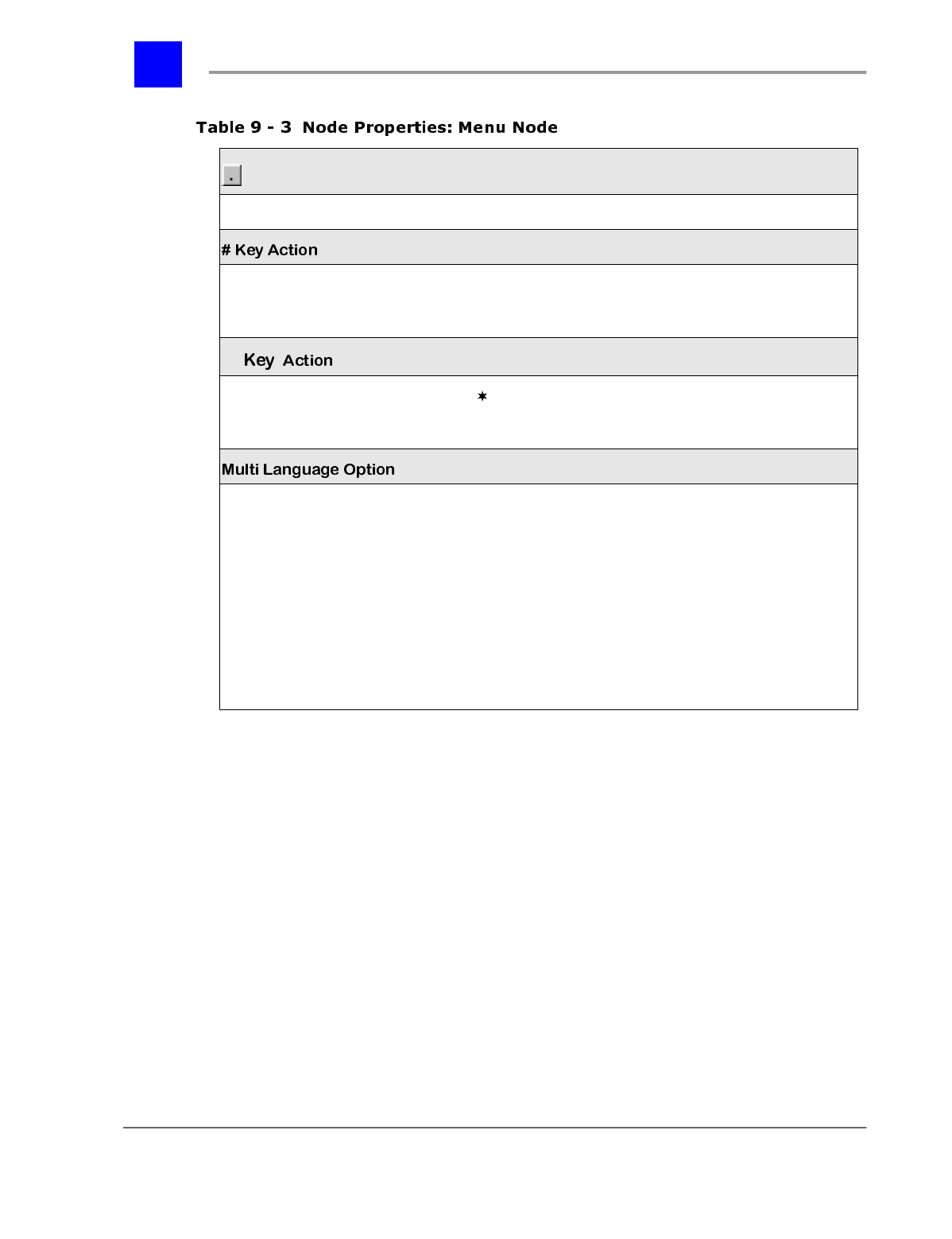
* =default settings
Clears the associated audio recording
Action taken when a caller presses ‘#’ while in the Menu
Node. Prompt for a Mail-Box*
Restart Auto-Attendant
None
Action taken when a caller presses ’ ’ while in the Menu
Node. Access Mail-Box*
Restart Auto-Attendant
None
Enables caller to select a language from the menu. The Multi
Language selection only works from the primary menu and
must be directed to sub menus.
Possible actions include:
Press ‘1’ for the primary language
Press ‘2’ for the secondary language
Press ‘3’ for the tertiary language
The 1,2, and 3 should be directed to a corresponding
submenu.
Note: Use of this option requires the optional Multi-Language
Voice Mail upgrade.
page 9-41 The Automated Attendant - Section 9.3
IVP Configuration
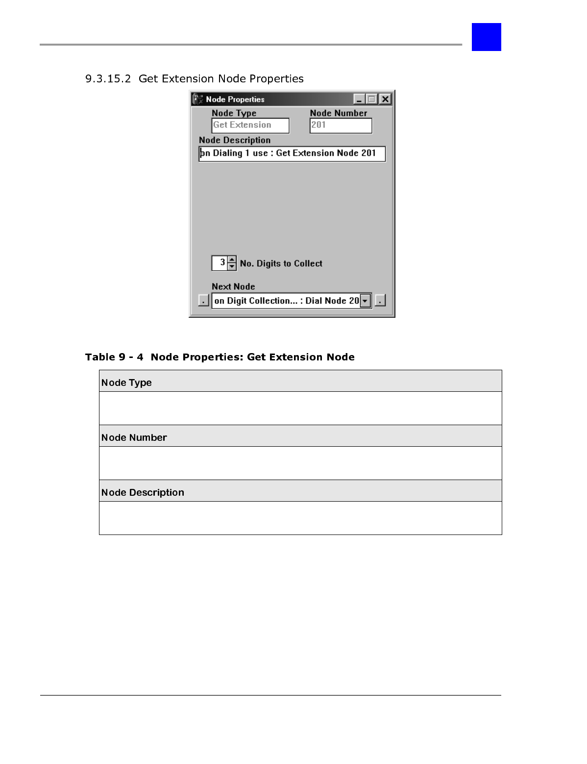
The node type of the currently selected node.
E.g., Get Extension Automatically Identified
Logical identifier for the node.
Note: Refer to Node Numbering & Design. Automatically Assigned
Informal identifier for the node.
E.g., Collect User ID. Alphanumeric
Up to 30 characters
Section 9.3- The Automated Attendant page 9-42
IVP Configuration
* =default settings
Indicates the number of DTMF digits that the Get
Extension Node should collect.
When using a Get Extension Node to collect digits to dial
a user or user group, this value should correspond to the
width of the Dial-Number Range. Refer to the “Software
Configuration” chapter of the Plexus System Manual
(specifically, the Dial Plan tab under System Parameters).
If the width of numbers changes from its default of 3 to
either 2 or 4, the Plexus system must be powered down
completely, and turned back on with the IVP card
inserted. Refer to the Plexus System Manual for more
information.
0-4 3*
The node number of the next node to be accessed.
Note
: The next node will typically be a Dial Node, and will
be pre-defined.
predefined by Node Editor*
left button = None: Terminate Execution
right button = Default: Restart Execution
page 9-43 The Automated Attendant - Section 9.3
IVP Configuration
The node type of the currently selected node.
E.g., Dial Automatically Identified
Logical identifier for the node.
Note: Refer to Node Numbering & Design. Automatically Assigned
Informal identifier for the node.
E.g., Dial user or user group. Alphanumeric
Up to 30 characters
When selected, this parameter instructs the auto-
attendant to dial the digits from a previous Get
Extension or Directory Node.
Select/Deselect
Section 9.3- The Automated Attendant page 9-44
IVP Configuration
* = default settings
If Use Digits from Previous *Node is not selected, digits
(e.g., User/User Group ID) are entered here.
Note: This field is used in cases where the Dial Node
will always connect to the same user or user group.
Up to 4 digits 0*
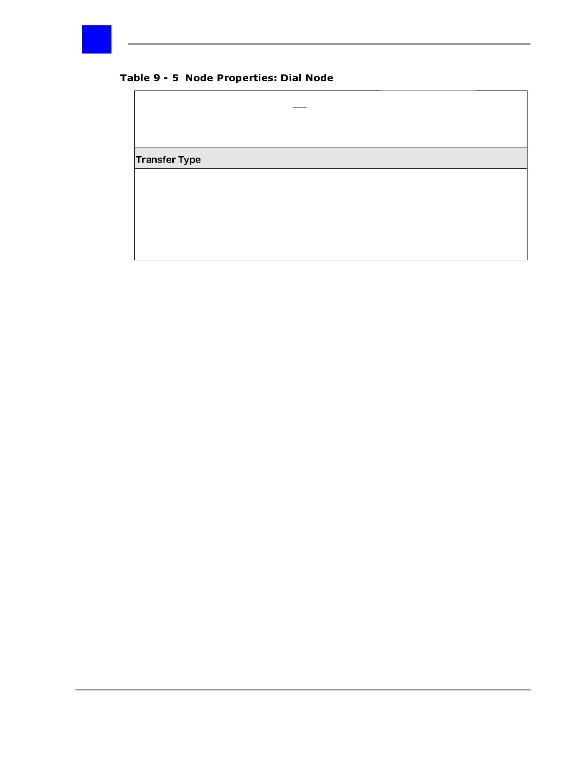
The type of transfer that will be implemented in
attempting to connect to the dialed system entity (e.g.,
user/user group).
Note
: If Unsupervised is selected and the user or user
group is unavailable, the call will be routed according to
the user’s/user group’s coverage. Refer to chapter 6,
"Software Configuration"
Unsupervised (Blind)*
Supervised (Transfer with
Screening)
Do Nothing and ‘Goto’ Next
Node (for future release)
page 9-45 The Automated Attendant - Section 9.3
IVP Configuration
The node type of the currently selected node.
E.g., Play Message Automatically Identified
Logical identifier for the node.
Note: Refer to Node Numbering & Design. Automatically Assigned
Informal identifier for the node.
E.g., Play Silence. Alphanumeric
Up to 30 characters
Section 9.3- The Automated Attendant page 9-46
IVP Configuration
* = default settings
The action that the Play Message Node will carry
out.
Note
: If Play Recorded Message is selected, the
Audio Recorder/Player button will appear.
If either Play ‘Silence’ or Play ‘Music-On-Hold’ is
selected, an additional parameter, representing the
duration (in seconds) of the silence or the Music-
On-Hold, will appear.
Play Recorded Message
Play ‘Silence’
Play ‘Music-On-Hold’
Say Mail-Box No. from *Previous Node
Say Name of Incoming Caller
Say Mail-Box Name from *Previous
Node
Do Nothing and ‘Goto’ Next Node*
Launches the Plexus audio utility for recording
messages.
Clears audio recording associated with that node.
The node number of the next node to be accessed. Default: Restart Execution*
left button = None: Terminate Execution
right button = Default: Restart Execution
page 9-47 The Automated Attendant - Section 9.3
IVP Configuration
The node type of the currently selected node.
E.g., Mailbox-Access Automatically Identified
Logical identifier for the node.
Note: Refer to Node Numbering & Design. Automatically Assigned
Informal identifier for the node.
E.g., Access the selected mailbox. Alphanumeric
Up to 30 characters
When selected, this parameter instructs the auto-
attendant to dial the digits from a previous Get
Extension or Directory Node.
Select/Deselect
Section 9.3- The Automated Attendant page 9-48
IVP Configuration
* = default settings
If Use Mail-Box from Previous *Node is not selected,
the mailbox number is entered here.
Note: This field is used in cases where the Mailbox-
Access Node will always connect to the same
mailbox.
Up to 4
digits 0*
Establishes whether the caller, upon accessing the
mailbox, will be able to leave a message.
Note
: If Disallow Message Recording is selected the
mailbox greeting will be played, but the caller will be
unable to leave a message in the mailbox.
Disallow Message Recording
Allow Message Recording*
The node number of the next node to be accessed. None: Terminate Execution*
left button = None: Terminate Execution
right button = Default Restart Execution
page 9-49 The Automated Attendant - Section 9.3
IVP Configuration
The node type of the currently selected node.
E.g., Interrogate Automatically Identified
Logical identifier for the node.
Note: Refer to Node Numbering & Design. Automatically Assigned
Informal identifier for the node.
E.g., Intro and First Question. Alphanumeric
Up to 30 characters
Launches the Plexus audio utility for recording messages
or questions.
Section 9.3- The Automated Attendant page 9-50
IVP Configuration
* = default settings
Indicates that the Interrogate Node is the last node in a
series of Interrogate Nodes. Select/Deselect
When selected, this parameter instructs the auto-
attendant to place the interrogate responses in the
mailbox indicated in a previous Get Extension or Directory
Node.
Note: This parameter is available only if the Interrogate
Node is the last in the series.
Select/Deselect
If Use Mail-Box from Previous *Node is not selected, the
mailbox number is entered here.
Note: This field is used in cases where the interrogate
responses will always be placed in the same mailbox.
Up to 4 digits 0*
The node number of the next node to be accessed. None: Terminate Execution*
left button = None: Terminate Execution
right button = Default Restart Execution
page 9-51 The Automated Attendant - Section 9.3
IVP Configuration
The node type of the currently selected node.
E.g., Directory Automatically Identified
Logical identifier for the node.
Note: Refer to Node Numbering & Design. Automatically Assigned
Informal identifier for the node.
E.g., Company Directory. Alphanumeric
Up to 30 characters
Section 9.3- The Automated Attendant page 9-52
IVP Configuration
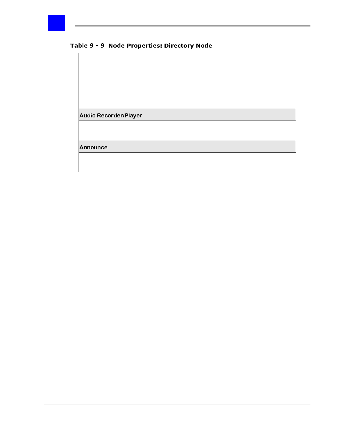
* = default settings
Establishes whether a prompt will be recorded or if
the System Default prompt will be accepted for the
Directory Node.
Refer to the Directory Node section for a transcript of
the System Default prompt.
Note
: If Recorded by User is selected, the Audio
Recorder/Player button will appear.
Recorded by User
Recorded as System Default*
Launches the Plexus audio utility for recording the
prompt.
Establishes what is announced to a caller in a
Directory Node. Mail-Box Name + Number
Mail-Box Name Only*
page 9-53 The Automated Attendant - Section 9.3
IVP Configuration
Several node types require an audio recording (e.g., the greeting in a Menu
Node). Prerecorded .wav files may be incorporated into the node properties and
utilized by the voice mail system. Alternately, recordings may be made using
the Plexus Administrator audio utility.
In order to use the integrated audio utility, the PC must have the following
components properly configured for use within Windows:
• sound card
• speakers
• microphone
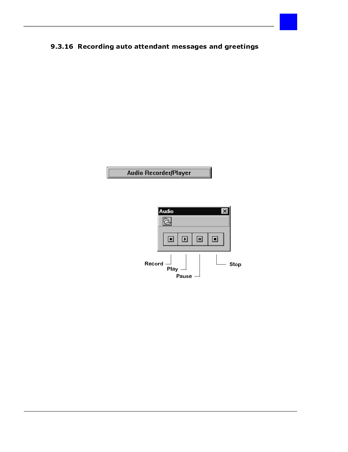
To make a recording using the integrated audio utility, proceed as follows:
1 Click on in the Node Properties
dialog window to launch the audio utility.
2 The following window will open.
3 Click on the Record button.
4 Speak into the microphone.
5 Click again on Record or click on Stop when complete.
6 The sound recording will be automatically saved and indexed as part of the
auto-attendant configuration file.
The integrated audio utility produces PCM 8KHz 16 Bit Mono .wav files.
Prerecorded .wav files must be converted to this format in order to be utilized in
the voice mail system.
Section 9.3- The Automated Attendant page 9-54
IVP Configuration
To incorporate a previously recorded .wav file, proceed as follows:
1 Click on in the Audio dialog window.
2 Select the desired .wav file.
3 Click on OK.
To save an auto-attendant tree developed using the Plexus Administrator VPS
Node Editor:
1 From the File menu, select Save As.
2 Name the file.
1 From the File menu, select Save.
Note
Auto-attendant trees are saved as auto-attendant configuration files. Plexus
Administrator auto-attendant configuration files have an extension of .ndb.
Before a completed auto-attendant tree can be uploaded to the Plexus system,
the auto-attendant configuration file must be converted to .vps file format. This
is accomplished via the Format menu option.
Note
The Node Editor and the Mail-Box editor both format files using .vps file
format. If you format your auto attendant structure and your mailbox structure
with the same name, one file will overwrite the other. Be sure to give unique
names to each .vps file.
page 9-55 The Automated Attendant - Section 9.3
IVP Configuration
The Format menu option may be used to format either an entire auto-attendant
tree or only certain portions of an auto-attendant tree. For example, it may be
used to format a sub-tree or a node. This feature enables quick changes to be
made to an already established auto-attendant tree.
Note
Formatting a single node or a node sub tree will only affect those formatted
nodes. Other nodes already uploaded to the Plexus system will not be
affected.
To format either an entire auto-attendant tree or a portion thereof, proceed as
follows:
1 Save the auto-attendant tree or open an existing auto-attendant
configuration file.
2 If only a sub-tree or a node will be formatted, select the desired portion by
clicking once on the sub-tree folder or node.
3 The selected portion will become highlighted.
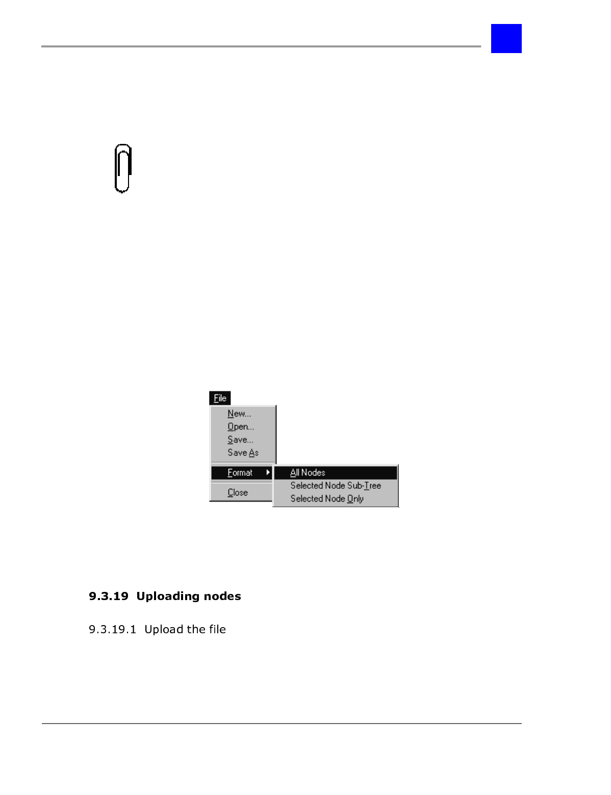
4 From the File menu, select Format.
5 The following pull-down menu will be displayed.
6 Point to All Nodes, Selected Node Sub-Tree, or Selected Node Only
and click once.
7 Enter a name for the new .vps file and click on OK.
1 Launch the Plexus Administrator Windows application.
Section 9.3- The Automated Attendant page 9-56
IVP Configuration
2 Open the system’s configuration file (.zdb file)
3 From the Link menu, select Open.
4 The link indicator at the bottom of the screen should indicate Link:
Opened and the LED image should appear green. (See “Establishing a
link” - section 6.27 for more information).
5 Right click on the IVP card.
6 From the pop-up menu, select “Upgrade VPS”.
7 Locate the auto attendant .vps file.
8 Click on OK.
9
Click on OK.
page 9-57 Voice Mailboxes - Section 9.4
IVP Configuration
9RLFH0DLOER[HV
Plexus voice mailboxes serve as repositories for voice messages and other
recordings and perform such advanced features as notifying pagers and remote
telephone numbers when new messages have arrived. The Plexus voice mail
system supports up to 511 voice mailboxes. Mailboxes are typically assigned to
users, user groups, and off-site employees.
Each mailbox can store up to 128 messages and each message may be up to 6.5
minutes in length. Standard IVP peripheral cards provide over 40 hours of voice
mail system storage capacity.
The mailbox number is the logical ID for the mailbox. It can be 2-4 digits in
length, but it must correspond to the width of the established system Dial-
Number Range (see chapter 6, “Software Configuration” for more information).
The mailbox number is determined at the time the mailbox is created and it may
not be subsequently modified. Typically, mailbox numbers are set to the same
value as the user’s User ID or the user group’s User Group ID. Refer to
“Importing Mailbox Users” - section 9.4.5 for more information.
Note
If the width of the mailbox numbers is changed from the default of 3 to either 2
or 4, the Plexus system must be shut down and turned back on (i.e., power-
cycled) with the IVP card inserted.
An ordinary mailbox is the standard single user mailbox (as opposed to a group
delivery mailbox). The user has full access to the features allowed for this
mailbox in the set-up. Ordinary mailboxes are generally used for users, virtual
users, or play message mailboxes that do not allow for the recording of
messages.
Section 9.4- Voice Mailboxes page 9-58
IVP Configuration
There are two types of group delivery mailboxes. The first type of group delivery
mailbox is a dispatch mailbox and performs a “dispatch” function. A message
left in a single mailbox is copied into a group of mailboxes, but only the first
mailbox owner that listens to the message retains it. Other copies of the
message are then removed from the other mailboxes.
Mailboxes associated with a dispatch mailbox can be notified in groups with a
time delay between delivery to each group. The configuration of these dispatch
groups may accomplished in two ways:
• To configure through Plexus Administrator VPS Mailbox Editor, refer to
“Create a new mailbox” - section 9.4.8.
• To configure by logging into the user side of the dispatch mailbox and going
to Group Settings refer to the Voice Mail User’s Guide.
Dispatch group 0 is notified immediately. Dispatch groups 1 through 9 are then
notified according to the specified time delay.
The second type of group delivery mailbox is a broadcast mailbox and copies a
message left in a single mailbox into a group of other mailboxes. All mailboxes
then have their own personal copy of the message and can treat the message as
an ordinary message.
Simple mailboxes are limited feature, individual mailboxes. Users only have
access to listen to, save, and delete voice messages. Users have no access to any
other mailbox features. Simple mailboxes are ideal for use with Hotel & Motel
applications (see chapter 18, "Hotel / Motel Package").
Overflow mailboxes are ordinary or group delivery mailboxes that provide a
backup system to record messages if a user’s mailbox becomes full. The overflow
mailboxes can be ordinary or group delivery mailboxes. The overflow mailbox
must be mailbox number 999. Additional overflow mailboxes may be created in
case the first mailbox becomes full. These additional overflow mailboxes must be
descending sequential from 999 (998, 997, 996, ...).
page 9-59 Voice Mailboxes - Section 9.4
IVP Configuration
If any or several mailbox(es) become full of messages (i.e., reach maximum
capacity), the voice mail system will check to see if mailbox 999 exists. If it does
exist, any new messages to full mailboxes will be stored in mailbox 999. If
mailbox 999 does not exist, messages for full mailboxes will not be recorded.
Note
Overflow mailboxes must be created by the Voice Mail System Manager
before any overflow messages will be recorded.
Note
No notification will be given of messages in the overflow mailboxes unless the
mailbox is set as a group delivery mailbox. If the mailbox is to be an ordinary
mailbox, it is recommended that a user be tasked to check for new messages
on a regular basis.
This parameter specifies whether an extension (i.e., user) is associated with a
mailbox. An extension is associated with a mailbox by default.
Note
Mailboxes which belong to off-site employees will not have an associated
extension if the employee does not have a User ID.
All mailboxes assigned to users or user groups on the system should have an
associated extension (i.e., user or user group). Associating an extension with a
mailbox assures that the voice mail system can correctly dial the user or user
group (e.g., from a Dial Node).
If a Dial Node attempts to dial ‘100’ in a case where both a user #100 and a
mailbox #100 exist, but are not associated, the call will go directly to mailbox
#100.
If a mailbox is configured to be private, information about the mailbox will not
be presented in a Directory Node.
Mailboxes are not private by default.
Section 9.4- Voice Mailboxes page 9-60
IVP Configuration
This feature enables a mailbox to play a summary of all the new messages left in
all the existing mailboxes on the system. Note that the message content
remains confidential; the summary only indicates which mailboxes have new
messages and how many.
The summary of new messages feature is disabled by default.
This feature enables a mailbox to notify a digital pager each time a new message
is received. The mailbox owner specifies the pager number to be dialed. Refer to
the Voice Mail User’s Guide for more information.
The digital pager notification feature is disabled by default.
Note
A mailbox may only have Digital Pager Notification or Remote Telephone
Notification active at the same time. If both features are active at the same
time, they will cancel each other out and no notification will be sent.
This feature enables a mailbox to notify a user at a remote telephone number
each time a new message is received. Upon reaching the user, the voice mail
system indicates that the user has messages and allows them to log into their
mailbox to retrieve the messages. The mailbox owner specifies the remote
telephone number to be dialed. Refer to the Voice Mail User’s Guide for more
information.
The remote telephone notification feature is disabled by default.
Note
A mailbox may only have Digital Pager Notification or Remote Telephone
Notification active at the same time. If both features are active at the same
time, they will cancel each other out and no notification will be sent.
When configuring a mailbox, the Voice Mail System Manager can record the
mailbox owner’s name. This recording may be utilized by both Directory and
Play Message Nodes. The mailbox owner can change this recording through
user settings when they log into their mailbox [Refer to the Voice Mail User’s
Guide].
page 9-61 Voice Mailboxes - Section 9.4
IVP Configuration
When using telephone configuration to configure a mailbox, the Voice Mail
System Manager will need to enter the three numeric digits associated with the
first three letters of the mailbox owner’s name. This entry is used to identify the
user in a Directory Node.
Software configuration automatically assigns these digits based on the name
entered or imported into the Mail-Box Name field. Refer to “Modifying system
level mailbox settings” - section 9.4.9.
This parameter determines the number of days that a message may remain in a
mailbox before it is automatically deleted.
Note
There is also a system-wide value for message age that may be configured
through the telephone configuration system parameters option (option ‘3’
under the System Manager Main Menu). The system value serves only as the
initial value for mailboxes. Modifications made at the mailbox level override
the system value.
Each mailbox has a password of up to four digits in length, that must be used by
the owner in order to retrieve messages. The default password for every mailbox
is no password. The mailbox password may be modified by the mailbox owner
through user settings (refer to the User’s Guide). The Voice Mail System
Manager can reset the password to the default (e.g., in cases where a user
changed the password from the default and then forgot his/her password).
To use the VPS Mailbox Editor:
1 Launch Plexus Administrator. Refer to chapter 6, "Software Configuration"
for instructions on launching Plexus Administrator.
2 From the Tools menu, select VPS Mail-Box Editor.
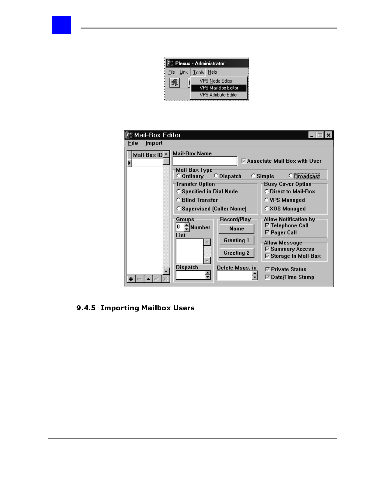
Section 9.4- Voice Mailboxes page 9-62
IVP Configuration
3 The Mail-Box Editor dialog window will be displayed with default settings
and no listed Mail-Box IDs.
The quickest way to develop mailboxes for all users on a Plexus system is to
import the user information from a Plexus configuration file (.zdb). When the
import option is utilized, all users on the system are imported into the mailbox
configuration and a mailbox is set up with the default parameters for each user.
To import mailbox users from a Plexus configuration file:
1 Open the VPS Mail Editor (see above for assistance).
2 From the Import menu, select Mail-Box Users
page 9-63 Voice Mailboxes - Section 9.4
IVP Configuration
3 Select the desired Plexus configuration file. Plexus configuration files have
an extension of .zdb.
To edit an existing mailbox configuration:
1 Open the VPS Mail Editor (see above for assistance).
2 From the File menu, select Open.
Plexus Administrator
Note
To modify a mailbox configuration created by the Configuration Wizard, open
the file wiz-mail.xdb under the folder created for the system you are
modifying.
Section 9.4- Voice Mailboxes page 9-64
IVP Configuration
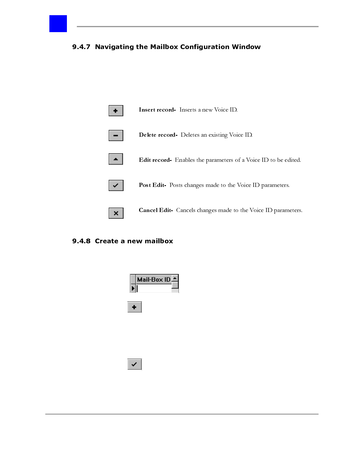
The 5 buttons at the bottom of the Mail-Box Editor dialog window enable the
creation, deletion, and editing of mailbox records. The Edit record button must
be selected prior to making any changes to a mailbox. The buttons and their
function are as follows:
To create a mailbox, proceed as follows.
1 Place the cursor in the Mail-Box ID list.
2 Click on .
3 Enter a mailbox ID (i.e., mailbox number).
4 The ‘}’ in the Mail-Box ID list will change to a ‘*’ to indicate that a new ID
may be inserted.
5 Click on .
page 9-65 Voice Mailboxes - Section 9.4
IVP Configuration
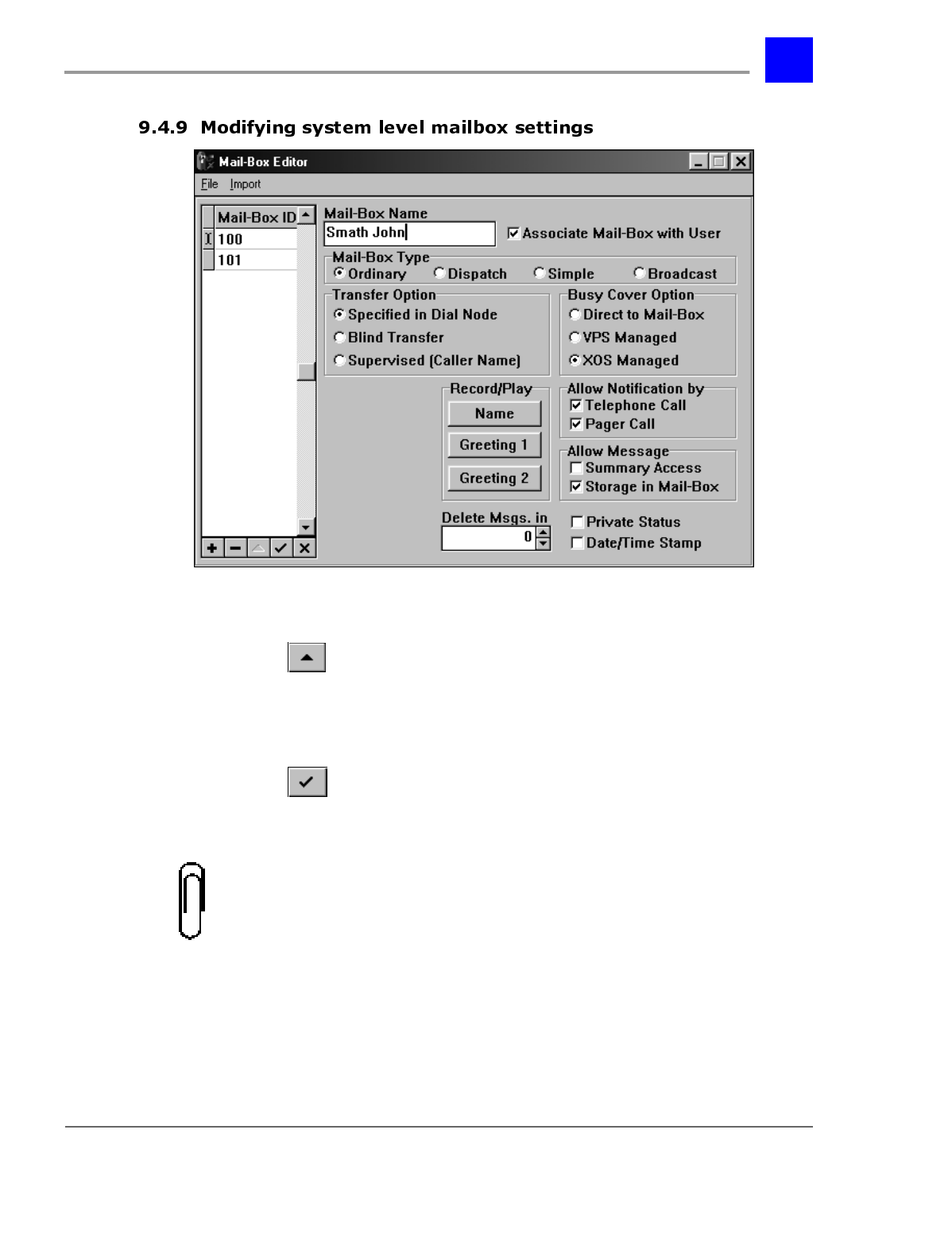
To configure the parameters of a mailbox, proceed as follows:
1 Click on .
2 Make the desired changes to the various default parameters. Each
parameter is listed in the table below.
3 Click on .
Note
To alleviate the repetitive tasks associated with configuring multiple mailboxes,
right-click on a setting and select Replicate All or Replicate Selected
[Replicate Selected is only available if mailboxes have been selected]. The
Replicate options automatically assign a setting to all or selected mailboxes.
Section 9.4- Voice Mailboxes page 9-66
IVP Configuration
Note
<Ctrl> and <Shift> may be used to select multiple mailboxes. Click on the
first mailbox so that it becomes highlighted. Hold down <Ctrl> and select
additional mailboxes. Hold down <Shift> and use <Ç> and <È> to select a
consecutive list of mailboxes.
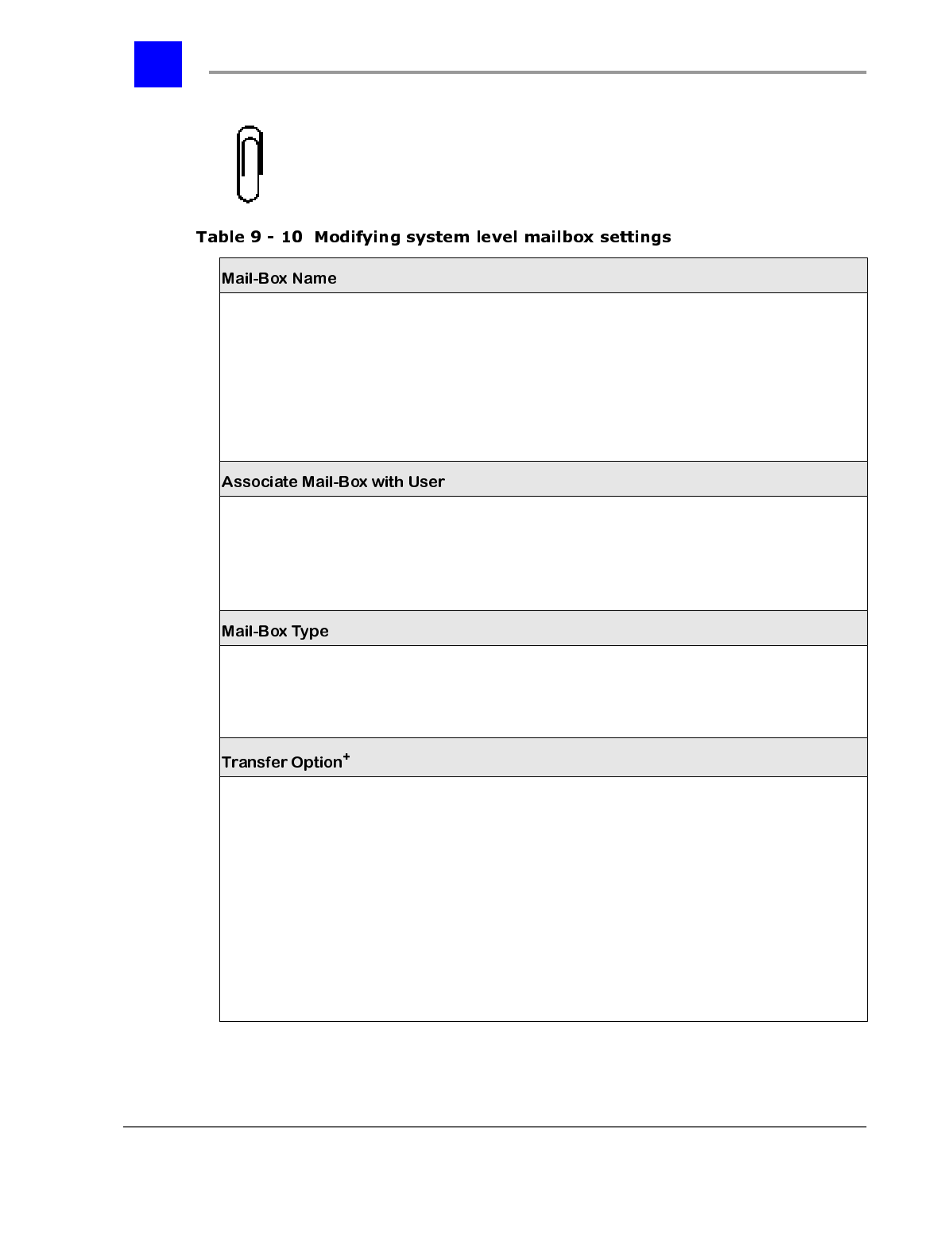
Mailbox owner’s name.
Note: If the mailbox users are imported [See Import Mailbox
Users], the information from the Name field on the General
tab under User will automatically be entered here.
NOTE:
Numbers corresponding to the first 3 letters in this
field will be used to identify this mailbox in a Directory
Node.
e.g., ABC=2, DEF=3, etc.
Alphanumeric
Up to 20 characters
Associates this mailbox with a user or user group (i.e.,
extension) on the Plexus system.
Note:
In order to associate a mailbox with a user or user group,
the Mailbox ID (i.e., mailbox number) and the User or User
Group ID must be the same value.
Yes*/No
Determines the mailbox type for the mailbox. Each mailbox
type performs different functions.
Note: Dispatch and Broadcast are the two different types of
Group Delivery mailbox.
Ordinary*
Dispatch
Broadcast
Simple
Accepts or modifies the transfer method defined by the Voice
Mail System Manager in the auto-attendant tree (e.g., Dial
Nodes).
Dial Node Specified: Accept the transfer method defined in the
Dial Node.
Blind Transfer: Always utilize blind transfers when transferring
calls to the user.
Supervised (Caller Name): Instructs the system to always ask
for and record the caller’s name. The caller’s name will then be
played for the user and the user will have the option to accept
the call, send the call to his/her mailbox, or place the call on
hold.
Dial Node Specified*
Blind Transfer
Supervised (Caller
Name)
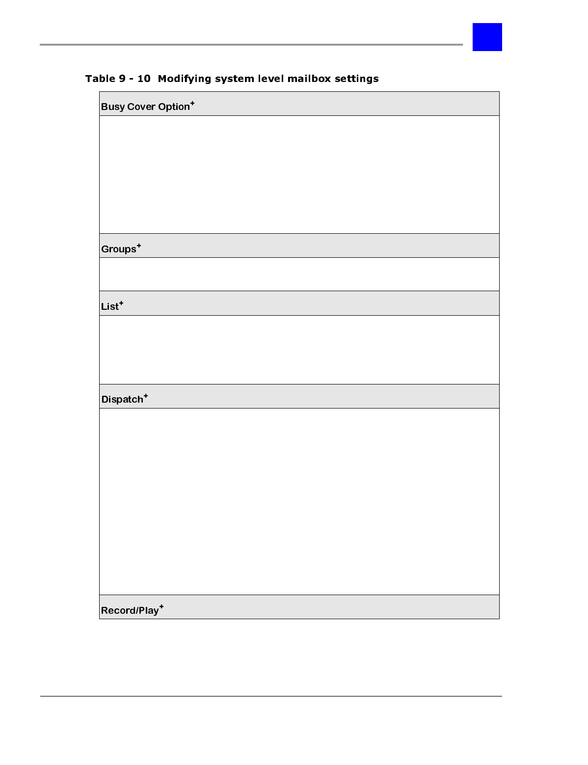
page 9-67 Voice Mailboxes - Section 9.4
IVP Configuration
Determines how a call is handled when the user or user group
is busy.
Direct to Mail-Box: Immediately forces callers into the mailbox
owner’s mailbox when the user or user group is busy.
VPS Managed: Allows custom messages to be played to a
caller while the call is on hold.
XOS Managed: Gives control of the held call to the Plexus
system and follows the established call coverage options [Refer
to the Coverage tab under User and User Group].
Direct to Mail-Box
VPS Managed
XOS Managed*
Up to ten groups (0-9) may be set up for purposes of Group Delivery if this mailbox is a
Dispatch mailbox.
The members of a Group Delivery group may be defined by entering the Mailbox IDs here.
Scroll to the desired group number (See Groups above) by clicking on 5and 6.
Enter the Mailbox ID (i.e., mailbox number) in the List box.
Press <Enter>.
Note: Repeat steps 2 and 3 to add additional Mailbox IDs.
In the case of Dispatch Group Delivery mailboxes, there is a time delay between delivery to
each defined group. Group 0 is sent the message immediately. The remaining groups are
sent the message according to a defined schedule.
Scroll to group 1 by clicking on 5and 6.
Enter the desired time delay (in seconds).
Note
: Scroll to each subsequent group and repeat steps 1 and 2. No delay time is
necessary for group 0.
E.g., If group 1 is set up for a 10-second time delay and group 2 is set up for a 20-second
time delay, group 1 will get dispatch messages 10 seconds after group 0 and group 2 will
get dispatch messages 30 seconds after group 0.
Note:
Placing a user in more than one dispatch group will cause the user to receive
multiple notifications of a new message and receive inaccurate notification of the number
of new messages. Once a dispatch group has received notification of a new message, the
members of the group will retain the message notification even if additional dispatch
groups are notified.
Section 9.4- Voice Mailboxes page 9-68
IVP Configuration
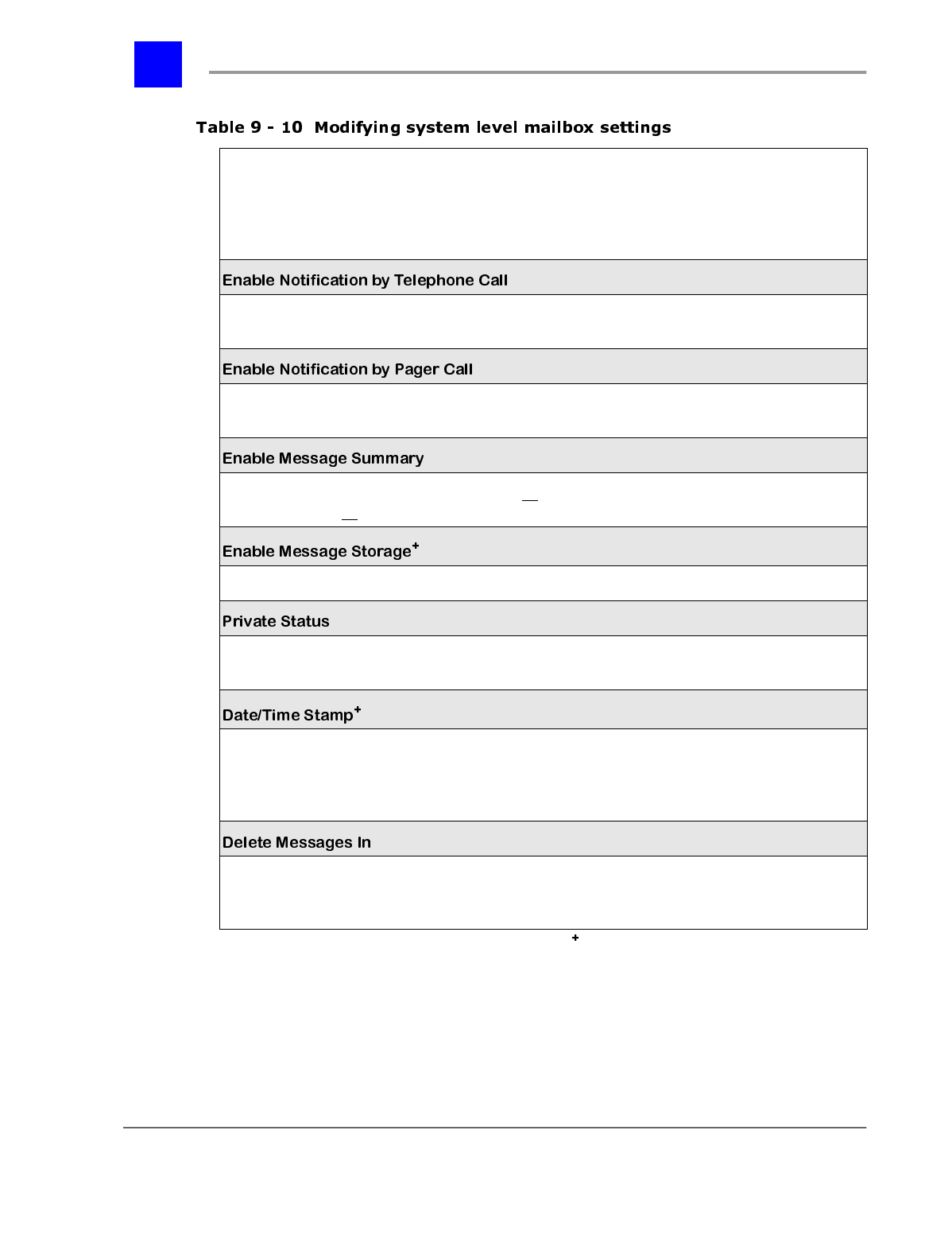
= May be modified by the mailbox owner.
* =default settings
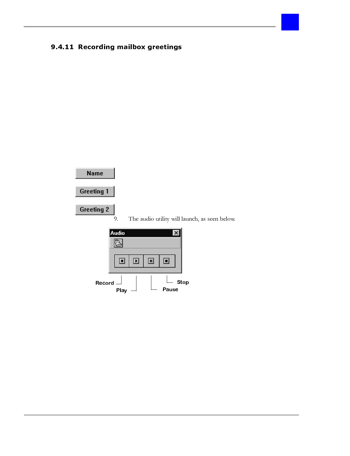
The mailbox owner’s name and the two available greetings are recorded by clicking on the
corresponding buttons [See Recording Mailbox Greetings].
Note:
The mailbox owner may change such default recordings. However, mailbox owner
changes will be overwritten with subsequent mailbox configuration uploads [See
Formatting a Mailbox Configuration File].
Enables the mailbox to notify a user at a remote telephone
number each time a new message is received. Enable/Disable*
Enables the mailbox to notify a digital pager each time a new
message is received. Enable/Disable*
Enables the mailbox to play a summary of all the new
messages left in all the existing mailboxes on the system. Enable/Disable*
Enables callers to leave messages in the mailbox. Enable*/Disable
Designates the mailbox as a private mailbox for purposes of
directory nodes. Select/Deselect*
Instructs the mailbox to play the date and time stamp when
playing messages.
Note: The date and time stamp indicates the date and time that
a message was received.
Select/Deselect*
Designates the number of days a message may be saved in
the mailbox before it is deleted.
Note:
0 days = never
# days
0*
page 9-69 Voice Mailboxes - Section 9.4
IVP Configuration
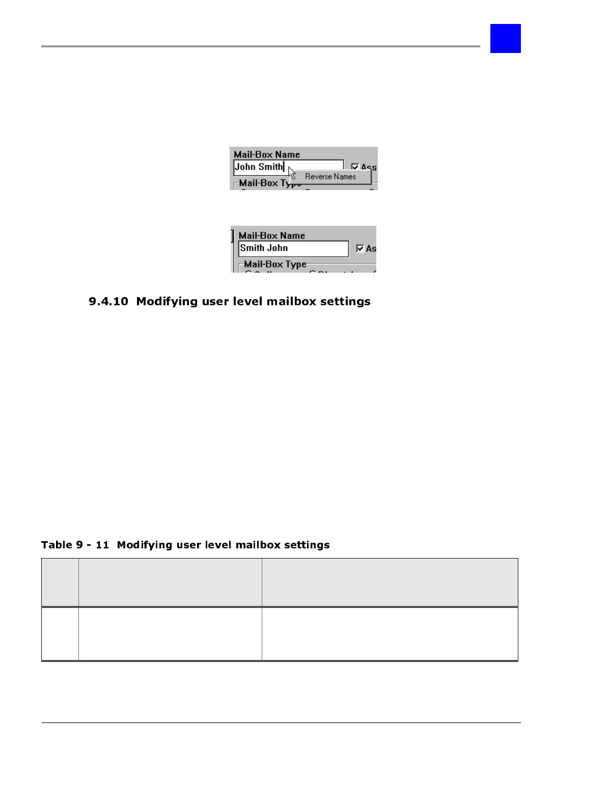
If a directory node is going to be created with a custom message asking for the
first three letters of the persons first name, the names in the Mail-box Name
field can be reversed by
All mailboxes will have the names reversed.
Several setting can only be modified from the user level or can be overridden by
the user. These setting are accessed by logging into a mailbox and pressing 3 to
"to make changes to your mailbox settings".
To make changes to user level mailbox settings:
1 Press MSG key
2 Enter * + Mailbox ID to make changes to
3 Enter the mailbox password (if applicable, default is no password)
4 Press 3
5 Press 8 the number of times indicated below to access each menu item listed.
Press ’8"
X times
to skip to
this
option Option Parameters
0 Language Selection English
Spanish
Korean
French
Portuguese

Section 9.4- Voice Mailboxes page 9-70
IVP Configuration
1Change Password Enter new password or Press the * key for no password
2 Select Greeting to use Greeting #1 (default)
Greeting #2
3Record Greeting #1 Record greeting and press # when finished
4 Record Greeting #2 Record greeting and press # when finished
5Record your name Record your name and press # when finished (this is the recording
played by a directory in the Auto Attendant)
6 Date And Time Stamp On/Off On
Off (default)
7Set whether callers can leave a message 1 Allow messages to be left (default)
2 Disallow messages to be left
8 Modify Distribution Group Settings Select group number to modify:
1 Add user to group
2 Hear list of users in group
3 Remove all users from group
9Select Transfer Type 1 Defined by Auto Attendant (default)
2 Blind Transfer
3 Screen Caller
10 Set Busy Options,
Intercept MSG
1 Sends caller directly to mailbox
2 Play custom message
3 Play default intercept message (default)
11 Set options for remote Call Forwarding 1 Immediate
2 If no answer
3 Disabled (default)
12 Select the phone number for Remote Call
Forwarding
Select a phone number to be used. Enter a Number from 1 - 4. This
number will be from the Remote Call Forwarding and Remote Call
Notification phone number list. 1 (default)
13 Set Options for Remote Call Notification 1 Notify phone of new messages
2 Disable (default)
14 Select the Phone Number for Remote Call
Notification
Select a phone number to be used. Enter a Number from 1 - 4. This
number will be from the Remote Call Forwarding and Remote Call
Notification phone number list. 1 (default)
15 Set Options for Digital Pager Notification 1 Notify page of new messages
2 Disable (default)
16 Enter the Remote Call Forwarding and Remote
Call Notification Phone Number
Remote Call Forwarding and Remote Call Notification List 1 - 4
Four separate telephone numbers may be entered to be used with
Remote Call Forwarding and Remote Call Notification. Only one
number may be used at a time.
17 Enter Digital Pager Phone Number To Send a 2 Second Pause Press *1
To Send a * Press **
To Send a number Press * followed by the number
18 Specify the number of times the system will
attempt to call a Digital Pager or Remote Call
Notification Phone Number
1 - 9 attempts or select 0 for infinite number of attempts
5 attempts (default)
19 Specify the number of minutes between retry
attempts for Digital Pager or Remote Call
Notification
1 - 99 minutes
15 minutes (default)
Press ’8"
X times
to skip to
this
option Option Parameters
page 9-71 Voice Mailboxes - Section 9.4
IVP Configuration
Prerecorded .wav files may be incorporated into the mailbox parameters or
recordings may be made using the Plexus Administrator audio utility. In order
to use the integrated audio utility the PC must have the following components
properly configured for use within Windows:
• sound card
• speakers
• microphone
To make a recording using the integrated audio utility, proceed as follows:
1 Click on one of the following buttons on the Mail-Box Editor dialog window
to launch the audio utility:
•
•
•
2 Click on the Record button.
3 Speak into the microphone.
4 Click again on Record (or click on Stop) when complete.
5 The sound recording will be automatically saved and indexed as part of the
mailbox configuration file.
Section 9.4- Voice Mailboxes page 9-72
IVP Configuration
Note
The integrated audio utility produces PCM 8KHz 16 Bit Mono .wav files.
Prerecorded .wav files must be converted to the above format in order to be
utilized in the voice mail system.
To incorporate a previously recorded .wav file, proceed as follows:
1 Click on in the Audio dialog window.
2 Select the desired .wav file.
3 Click on OK.
To save a mailbox configuration developed using the Plexus Administrator VPS
Mail Editor, select Save As from the File menu and name the file.
Note
Plexus Administrator mailbox configuration files have an extension of .xdb.
E.g., The Configuration Wizard creates the mailbox configuration file wiz-
mail.xdb
The mailbox configuration file need only be given a name the first time it is
saved. Subsequent saves may be accomplished simply by selecting Save under
the File menu.
Before a completed mailbox configuration can be uploaded to the Plexus system,
the mailbox configuration must be converted to .vps file format. This is
accomplished via the Format menu option.
The Format menu option may be used to format either an entire mailbox
configuration or selected mailboxes only. This feature enables quick and easy
mailbox additions and modifications.
To format either an entire mailbox configuration or selected mailboxes, proceed
as follows:
1 Save the mailbox configuration or open an existing mailbox configuration
file.
2 If only selected mailboxes will be formatted, select the desired mailboxes by
clicking once on the corresponding Mail-Box ID.
page 9-73 Voice Mailboxes - Section 9.4
IVP Configuration
3 The selected mailboxes will become highlighted.
Note
Formatting a single mailbox or selected mailboxes will only affect those
formatted mailboxes. Other mailboxes already uploaded to the Plexus system
will not be affected.
Note
<Ctrl> and <Shift> may be used to select multiple mailboxes. Click on the
first mailbox so that it becomes highlighted. Hold down <Ctrl> and select
additional mailboxes. Hold down <Shift> and use <Ç> and <È> to select a
consecutive list of mailboxes.
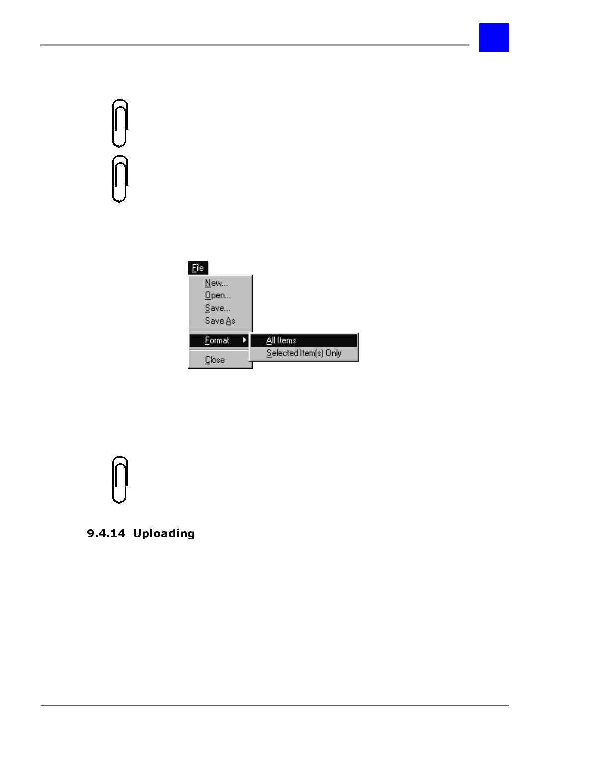
4 From the File menu, select Format.
5 The following pull-down menu will be displayed.
6 Point to All Items or Selected Item(s) Only and click once.
7 Enter a name for the new .vps file.
8 Click on OK.
Note
The Node Editor and the Mail-Box editor both format files using .vps file
format. If you format your auto attendant structure and your mailbox structure
with the same name, one file will overwrite the other. Be sure to give unique
names to each .vps file.
1 Launch the Plexus Administrator Windows application.
2 Open the system’s configuration file (.zdb file)
3 From the Link menu, select Open.
Section 9.4- Voice Mailboxes page 9-74
IVP Configuration
4 The link indicator at the bottom of the screen should indicate Link:
Opened and the LED image should appear green. (See Software
Configuration - "Setting up a link" for more information).
5 Right click on the IVP card.
6 From the pop-up menu, select “Upgrade VPS”.
7 Locate the voice mailbox .vps file.
8 Click on OK.
9
Click on OK.
page 9-75 System Parameters - Section 9.5
IVP Configuration
6\VWHP3DUDPHWHUV
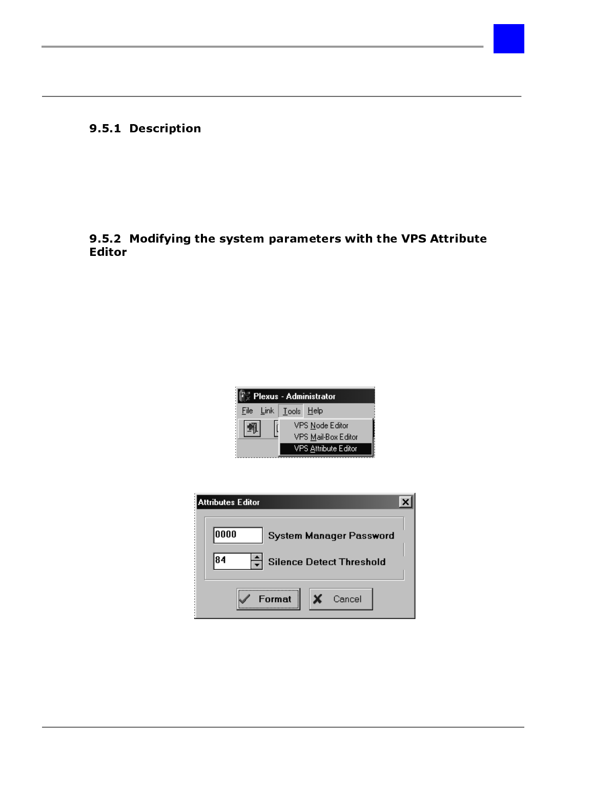
System Parameters are IVP settings that affect the system. They include the
Voice Mail System Manager password, the Silence Detect Threshold among
others. These two settings can be set by the VPS Attribute Editor. The others
must be modified through the Voice Mail System Manager (see “Change system
parameters” - section 9.6.7).
To use the VPS Attribute Editor:
1 Launch Plexus Administrator. Refer to the Software Configuration
section of the Plexus Product Manual for instructions on launching Plexus
Administrator.
2 From the Tools menu, select VPS Attribute Editor.
3 The Attribute Editor dialog window will be displayed with default settings.
4 After modifying the settings, press Format. A file named system.vps will
be automatically created in the Plexus\saved\ folder.
Section 9.5- System Parameters page 9-76
IVP Configuration
Modifying the system manager password will only change the password to
mailbox 001.
Note
Only the Voice Mail System Manager logged into Voice Mail System Manager
Mailbox #001 can change the passwords for all five of the System Manager
Mailboxes.
The default password for all System Manager Mailboxes is 0000.
Be sure to keep a record of any changes made to the System Manager Mailbox
passwords. Without the proper password, access to the mailboxes is prohibited.
While recording a message, the voice mail system will detect when the caller has
been silent for a certain period of time. This parameter sets the voice level
which is presumed to be silence. A lower number means that the incoming
caller must be quieter for silence to be detected. A higher number may be used
when there is a greater amount of background noise on the incoming lines and
silence is never detected. This parameter will accept values between 1 to 999.
The default value is 84.
1 Launch the Plexus Administrator Windows application.
2 Open the system’s configuration file (.zdb file)
3 From the Link menu, select Open.
4 The link indicator at the bottom of the screen should indicate Link:
Opened and the LED image should appear green. (See Software
Configuration - "Setting up a link" for more information).
5 Right click on the IVP card.
6 From the pop-up menu, select “Upgrade VPS”.
page 9-77 System Parameters - Section 9.5
IVP Configuration
7 Locate the system.vps file. It will be in the saved folder in the folder which
the Plexus Administrator was installed in.
8 Click on OK.
Click on OK.

Section 9.5- System Parameters page 9-78
IVP Configuration
page 9-79 Voice Mail System Manager - Section 9.6
IVP Configuration
9RLFH0DLO6\VWHP0DQDJHU
Plexus
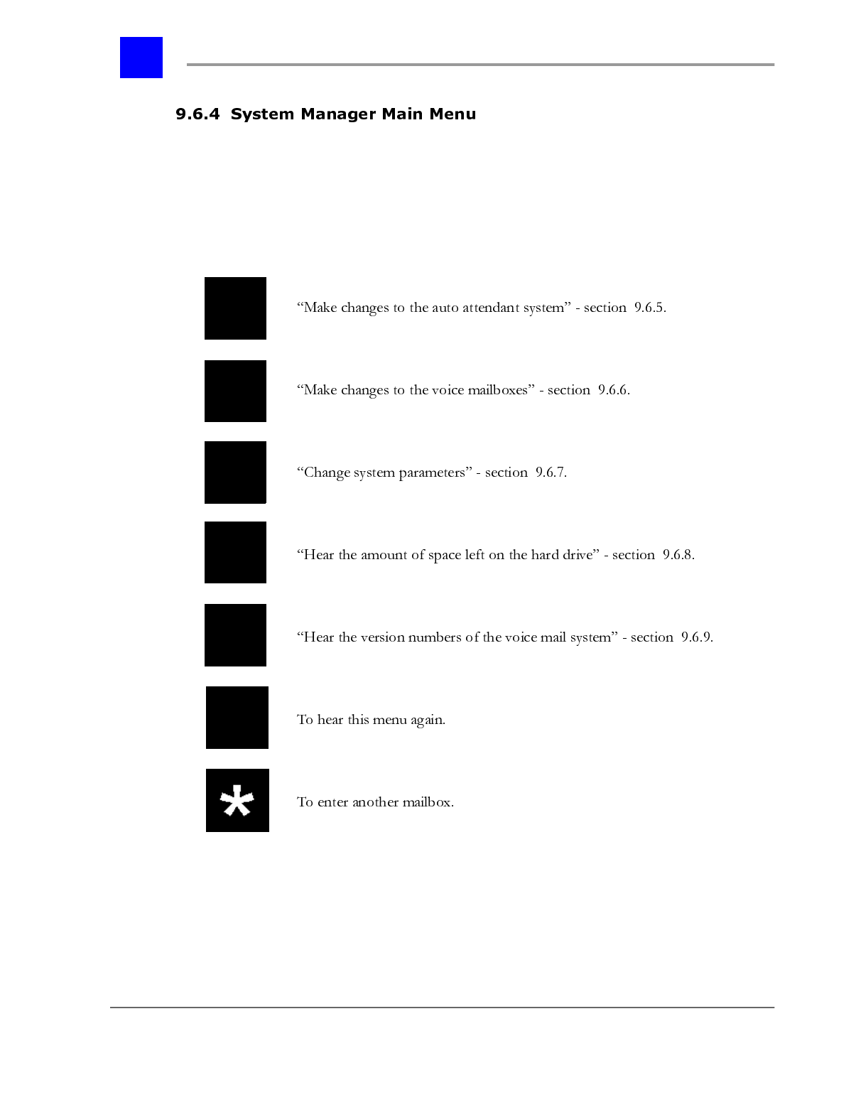
“Make changes to the auto attendant system” - section 9.6.5
“Make changes to the voice mailboxes” - section 9.6.6
“Change system parameters” - section 9.6.7
“Hear the amount of space left on the hard drive” - section 9.6.8
“Hear the version numbers of the voice mail system” - section 9.6.9
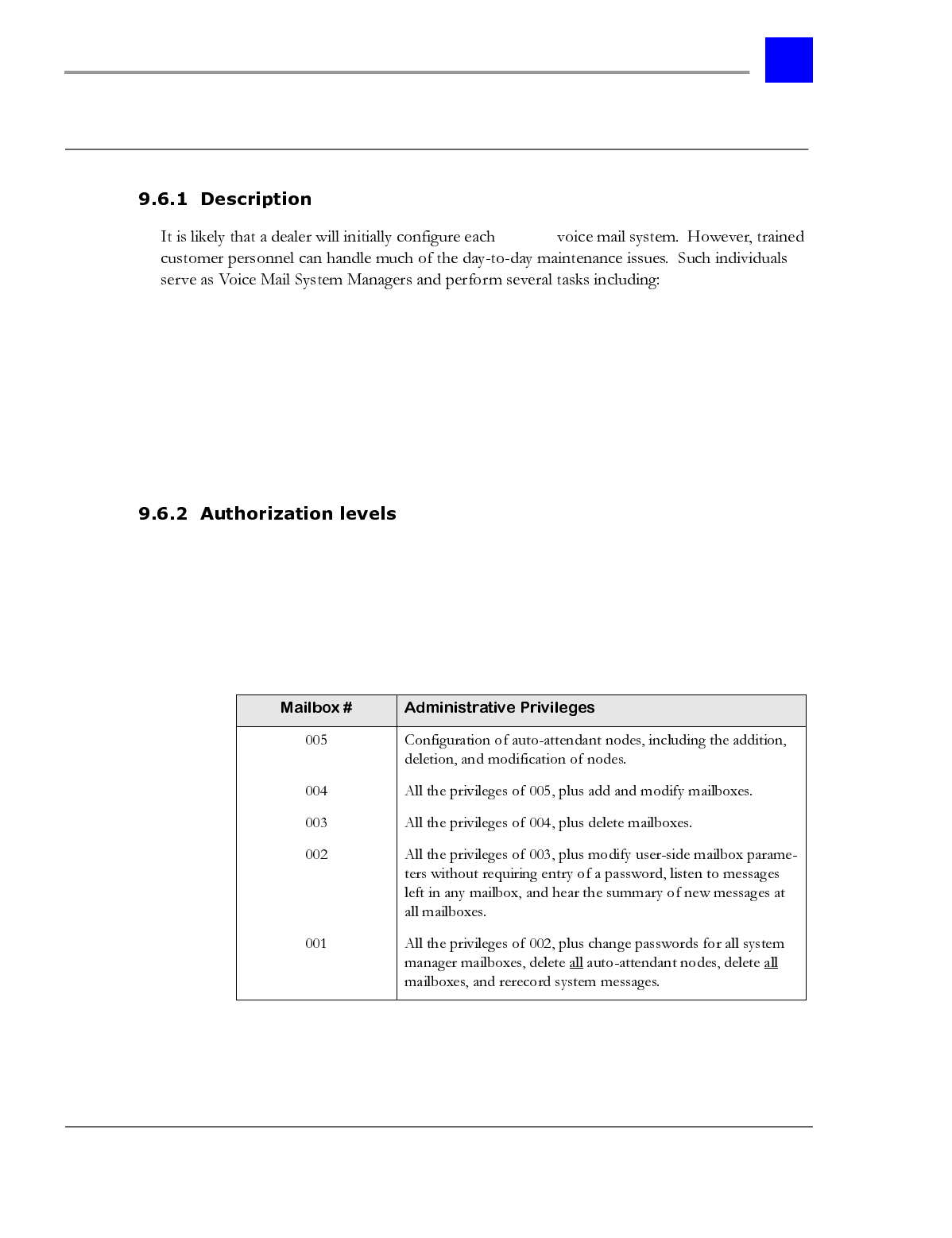
Before an individual can configure any part of the voice mail system via a
DTMF-capable telephone, they must log in to one of the System Manager
Mailboxes. There are five System Manager Mailboxes, each with its own unique
password and privileges. The different mailboxes allow the Voice Mail System
Manager to give restricted administrative privileges to other personnel. The
System Manager Mailboxes and the associated privileges are as follows:
Section 9.6- Voice Mail System Manager page 9-80
IVP Configuration
Note
The default password for all System Manager Mailboxes is 0000. If trained
customer personnel will be given access to these mailboxes, it is strongly
suggested that the personnel receive only the mailbox # access needed to
complete the required tasks and that all System manager mailboxes receive
new passwords. See “System Parameters” - section 9.5.
Access to the Voice Mail System Manager can be done locally (on a phone
attached to the system) or remotely (calling into the system from an external
location).
A. Accessing From a Plexus Key Telephone
To access the voicemail system from a Plexus Key Telephone, proceed as follows.
1 From a Key Telephone, press MSG.
2 The voice mail system will prompt you to log into a mailbox or enter your
mailbox password.
3 Press ‘*’ followed by the appropriate mailbox (001-005).
4 When prompted for a password, enter the appropriate password.
5 After completing these steps, the extension (i.e., user) is logged into a
System Manager Mailbox.
B. Accessing From an Ordinary Telephone
Alternately, you may access the voicemail system from an ordinary telephone.
1 At system dial tone, enter <F52>.
2 The voice mail system will prompt you to log into a mailbox or enter your
mailbox password.
3 Press ‘*’ followed by the appropriate mailbox (001-005).
4 When prompted for a password, enter the appropriate password.
5 After completing these steps, the extension (i.e., user) is logged into a
System Manager Mailbox.
page 9-81 Voice Mail System Manager - Section 9.6
IVP Configuration
1 Dial into the system as a regular caller.
2 If a user answers, request to be connected to an Auto Attendant or to be
transferred into somebody’s mailbox.
3 When the Auto Attendant answers or you receive a mailbox greeting, press
‘*’ followed by the appropriate mailbox (001-005).
4 When prompted for a password, enter the appropriate password.
5 After completing these steps the caller is logged into a System Manager
Mailbox.
Section 9.6- Voice Mail System Manager page 9-82
IVP Configuration
Once you have logged into a System Manager Mailbox, you will receive the
System Manager Main Menu. Complete access to this menu and sub menus is
only available when logged into System Manager Mailbox #001. If you try to
access a menu choice not available in your mailbox privileges, a message will be
played advising that this access is not permitted.
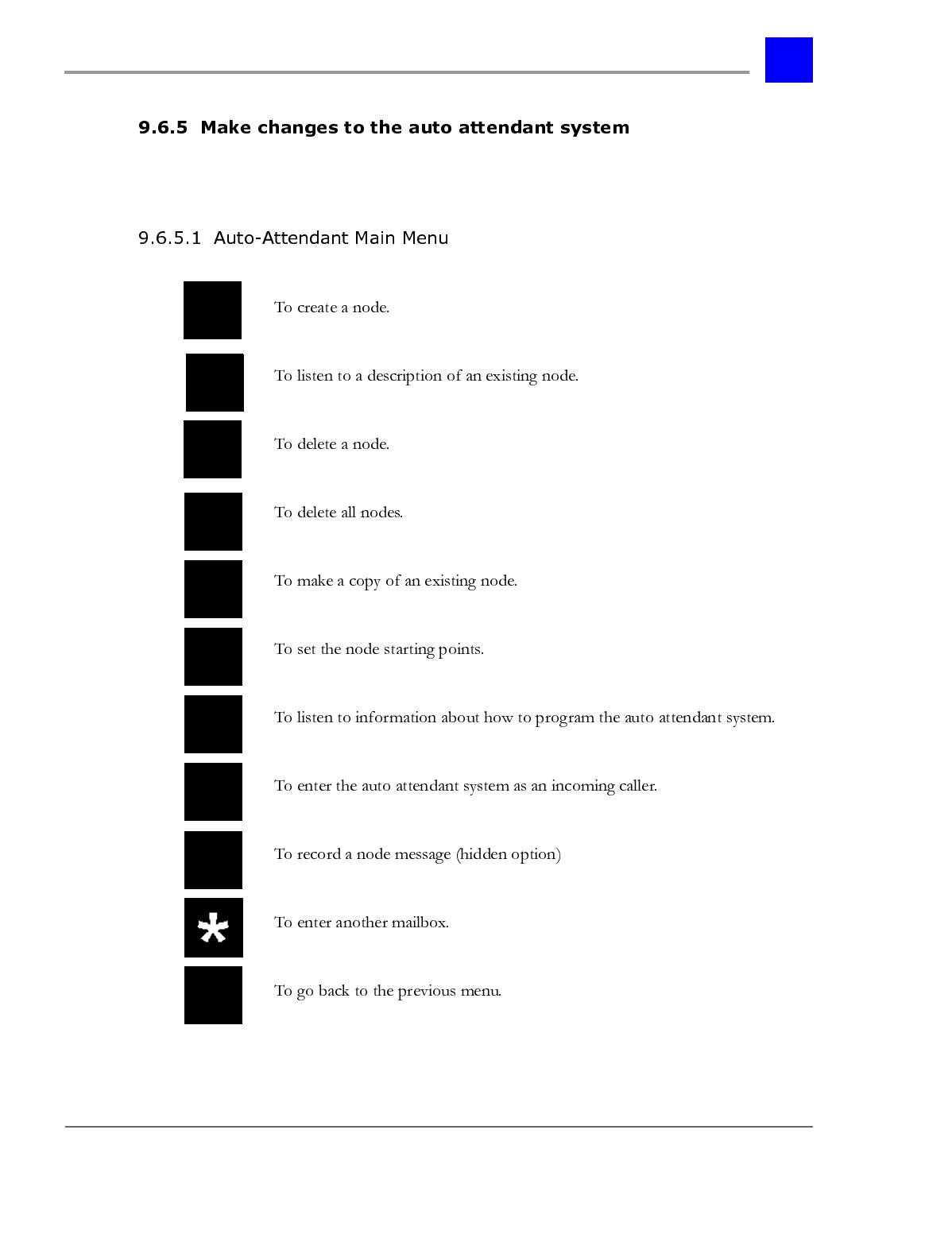
page 9-83 Voice Mail System Manager - Section 9.6
IVP Configuration
Upon reaching the System Manager Main Menu, select ’1’ to hear the Auto
Attendant Main Menu
Section 9.6- Voice Mail System Manager page 9-84
IVP Configuration
This feature is accessible to All System Manager Mailboxes.
To create a node, proceed as follows:
1 Select ‘1’ from the Auto-Attendant Main Menu.
2 Enter a node number. If the node number is less than eight digits, press the
‘#’key to end the entry.
3 Press the digit corresponding to the desired type of node.
Note
For information on setting up the parameters for each node type created, see
“Node Templates” - section 9.6.5.10
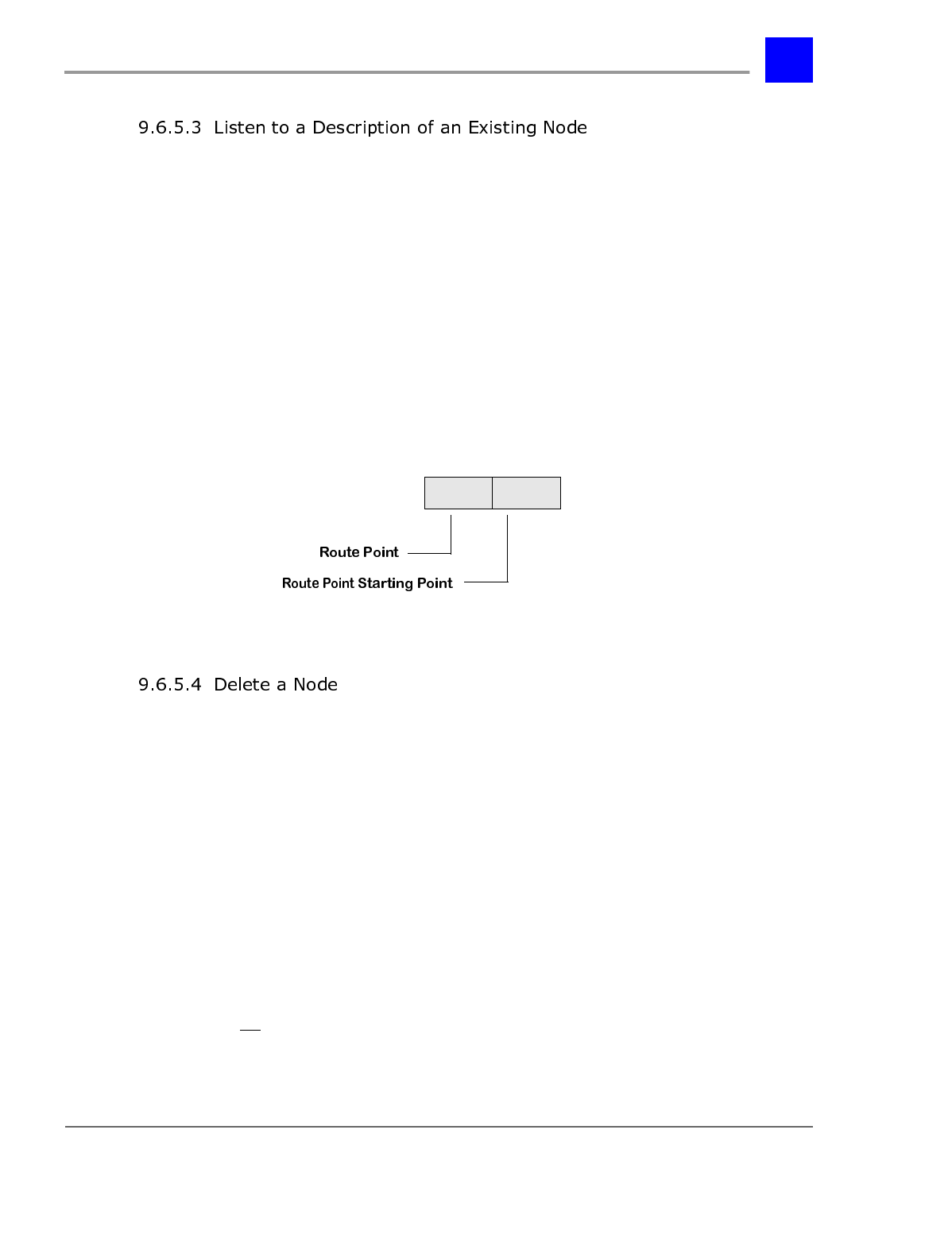
page 9-85 Voice Mail System Manager - Section 9.6
IVP Configuration
This feature is accessible from all System Manager Mailboxes.
To hear a description of any existing node, proceed as follows:
1 Select ‘2’ from the Auto-Attendant Main Menu.
2 Enter a node number. If the node number is less than eight digits, press the
‘#’ key to end the entry.
3 To hear a listing of all nodes press ‘*’.
4 While reviewing the list of all nodes, press ‘1’ to skip to the next node in the
list.
5 To hear a listing of all nodes beginning at a certain starting point, enter the
two digit starting point followed by ‘*’.
6 To exit this menu, press ‘#’.
This feature is accessible from all System Manager Mailboxes.
To delete a node, proceed as follows:
1 Select ‘3’ from the Auto-Attendant Main Menu.
2 Enter a node number. If the node number is less than eight digits, press the
‘#’ key to end the entry.
3 To confirm deletion of this node, press ‘1’. To return to the Auto-Attendant
Main Menu, press any other key.
Delete All Nodes
This feature is accessible from System Manager Mailbox 001.
To delete all nodes, proceed as follows:
Section 9.6- Voice Mail System Manager page 9-86
IVP Configuration
1 Select ‘4’ from the Auto-Attendant Main Menu.
2 The voice mail system will announce “This will cause all nodes in the auto-
attendant system to be deleted.”
3 If you want to proceed with this operation, press ‘1’. To return to the main
menu, press any other key.
This feature is accessible from all System Manager Mailboxes.
To make a copy of an existing node, proceed as follows:
1 Select ‘5’ from the Auto-Attendant Main Menu.
2 Enter the node number of the existing node which you would like to copy.
3 If the node number is less than eight digits, press the ‘#’ key to end the
entry. Or, to return to the main menu, press the ‘*’ key.
4 Enter the node number of the node you want to create.
5 If the node number is less than eight digits, press the ‘#’ key to end the
entry. Or, to return to the main menu, press the ‘*’ key.
This feature is accessible from all System Manager Mailboxes.
To set the node starting points (i.e., Voice Mail Starting Point), proceed as
follows. To exit at any time, press the ‘#’ key.
1 Select ‘6’ from the Auto-Attendant Main Menu.
2 Enter the PBX designated starting point (i.e., Route Point) for which you
wish to set the Voice Mail Starting Point.
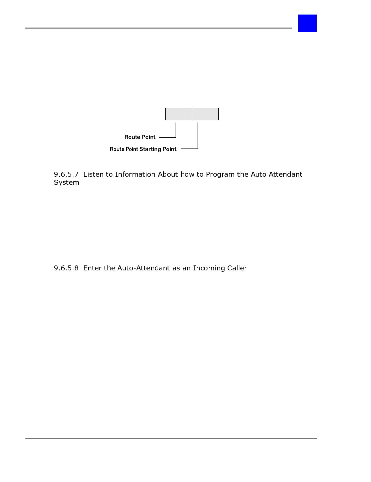
page 9-87 Voice Mail System Manager - Section 9.6
IVP Configuration
3 The voice mail system will announce “The current setting for PBX starting
point ___ (i.e., Route point) is ___ (i.e., Voice Mail Starting Point). This
means that an incoming call with this PBX starting point will start at
node ___.”
4 Enter the new Voice Mail Starting Point to be used with this PBX starting
point (route point). Or, to cancel this command, press the ‘#’ key.
This feature is accessible from all System Manager Mailboxes.
To access this feature, proceed as follows:
1 Select ‘7’ from the Auto-Attendant Main Menu.
2 Listen to prompts for general information about programming the auto
attendant system.
This feature is accessible from all System Manager Mailboxes.
To enter the auto-attendant system as an incoming caller, proceed as follows:
1 Select ‘8’ from the Auto-Attendant Main Menu.
2 The voice mail system will announce “This option allows you to listen to a
programmed auto-attendant sequence before it is enabled for public use.”
3 Enter the two digit starting node.
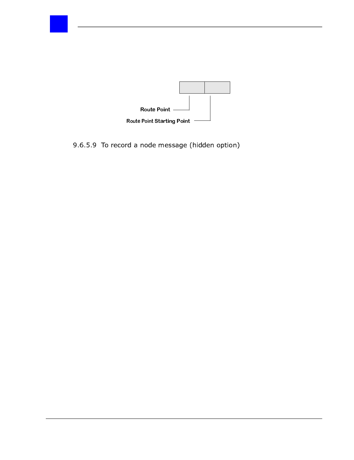
Section 9.6- Voice Mail System Manager page 9-88
IVP Configuration
4 Once the two digit starting node is entered, the auto-attendant system is
launched as it would be for an incoming caller. All keys apply as they
would for the defined nodes. Or, to return to the Auto-Attendant Main
Menu, press the ‘#’ key.
This feature is accessible from all System Manager Mailboxes.
To access this feature, proceed as follows:
1 Select ‘9’ from the Auto-Attendant Main Menu.
2 Enter the node number for which you wish to make a recording. Only Menu
Nodes, Play Message Nodes, Directory Nodes (with custom message), and
Interrogate Nodes have message recordings. If the node number is less
than eight digits, press the ‘#’ key to end the entry.
3 Record the message. Speak clearly in a normal to soft voice. A loud recording
or a recording with shrill, high notes can interfere with the Plexus
system’s DTMF recognition.
4 Press ‘#’ when finished recording.
5 To rerecord the message, repeat these steps.
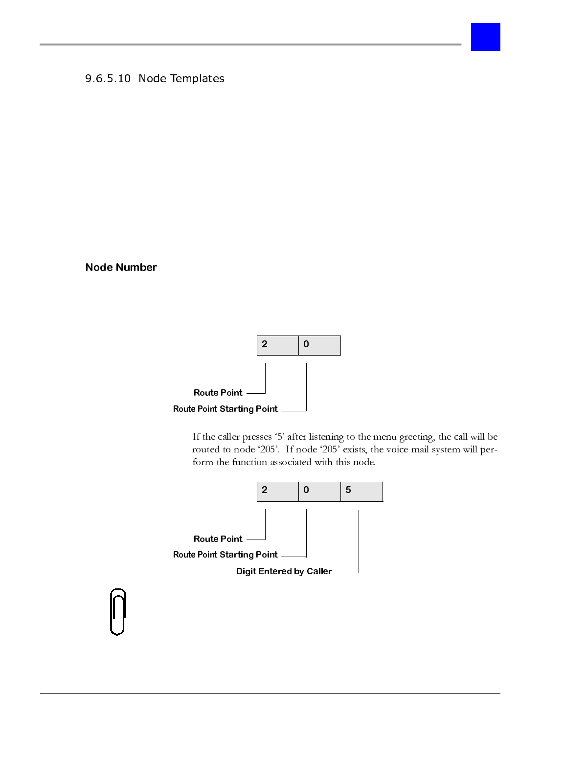
page 9-89 Voice Mail System Manager - Section 9.6
IVP Configuration
A. Menu Node Template
This section provides a template for creating and configuring the Menu Node
from a Plexus key telephone. Each of the steps is described more fully below.
1 Enter the Node Number.
2 Select the action to be taken when the incoming caller presses the ‘*’ key.*
3 Define the action to be taken when the incoming caller presses the ‘#’ key.
4 Record your message after the following tone. Press the ‘#’ key when
finished recording.
The voice mail system will route a call from a Menu Node to a subsequent node
based on the digit entered by the caller. For example, the node number for a
Menu Node with a Route Point of ‘2’ and a Voice Mail Starting Point of ‘0’ is ‘20’.
Note
If node ‘205’ does not exist a short error message (i.e., “The digit you dialed is
not a valid choice”) is played, and the Menu Node is restarted.
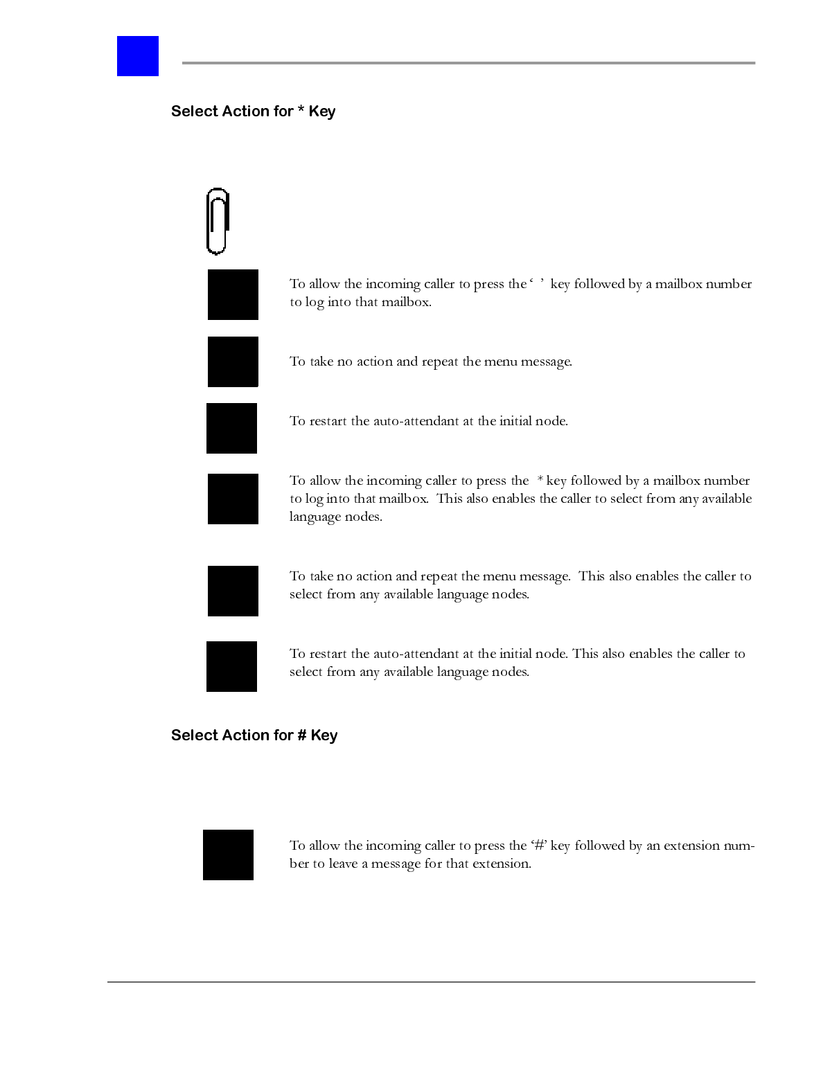
Section 9.6- Voice Mail System Manager page 9-90
IVP Configuration
For the Menu Node, you can select the action to be taken when the incoming
caller presses the ‘*’ key.
Note
Options 4, 5, and 6 are only available if the voicemail has been equipped with
the Multiple Languages feature.
*
You can define the action to be taken when the incoming caller presses the ‘#’
key.
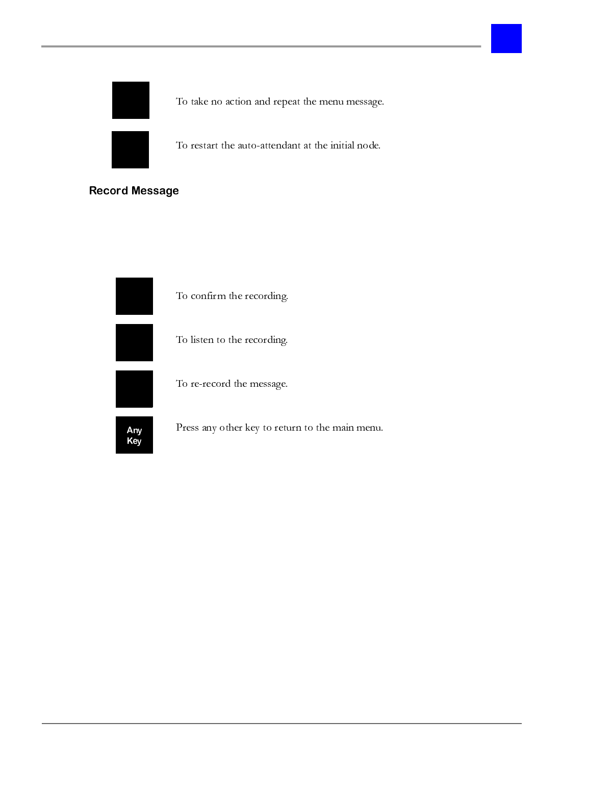
page 9-91 Voice Mail System Manager - Section 9.6
IVP Configuration
Record your message after the following tone. Press the ‘#’ key when finished
recording.
After recording your message, press one of the following keys:
B. Dial Node Template
This section provides a template for creating and configuring the Dial Node from
a Plexus key telephone. Each of the steps is described more fully below.
1 Enter the Node Number.
2 For the Dial Node, you can specify the extension number or the PBX group
number to which you want the call to be transferred.
3 Define the transfer type.
4 If transfer type 4 is selected, enter the node number that will be accessed
after this node. If the node number is less than eight digits, press the ‘#’
key after entry.
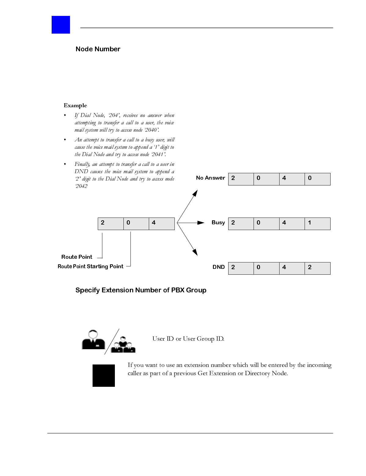
Section 9.6- Voice Mail System Manager page 9-92
IVP Configuration
When a Dial Node attempts a supervised transfer to an unavailable user, or
attempts a blind transfer with voicemail as the coverage, the voice mail system
will route the call to a subsequent node based on the unavailable state (no
answer, busy, DND) of the user.
For the Dial Node, you can specify the extension number or the PBX group
number to which you want the call to be transferred.
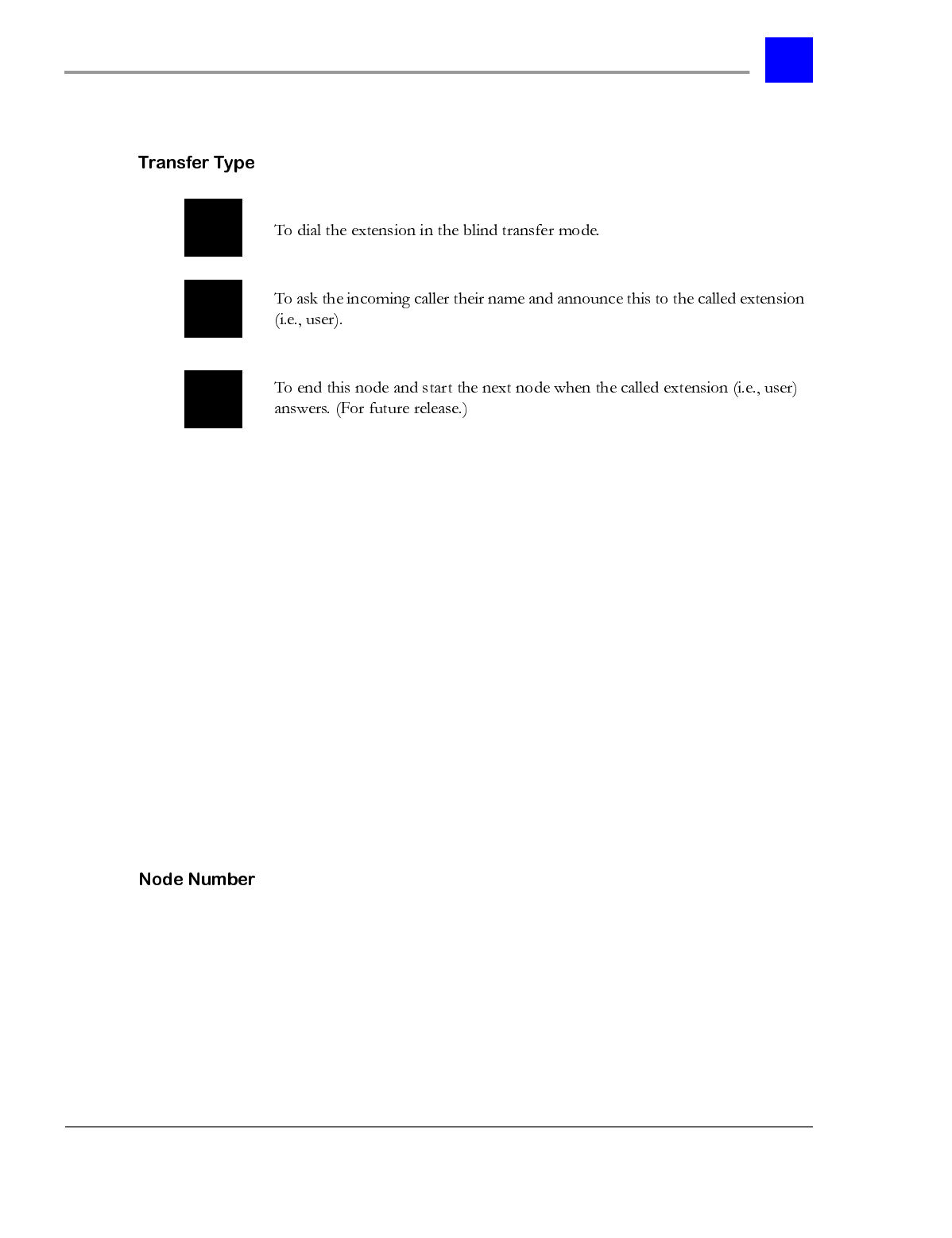
page 9-93 Voice Mail System Manager - Section 9.6
IVP Configuration
C. Play Message Node Template
This section provides a template for creating and configuring the Play Message
Node from a Plexus key telephone. Each of the steps is described more fully
below.
1 Enter the Node Number.
2 Enter the node number that will be accessed after this node. If the node
number is less than eight digits, press the ‘#’ key to end the entry.
3 Set the Play Message Node parameters.
4 Record your message.
5 Enter the number of seconds for this operation.
6 Complete the message recording.
Enter the Node Number
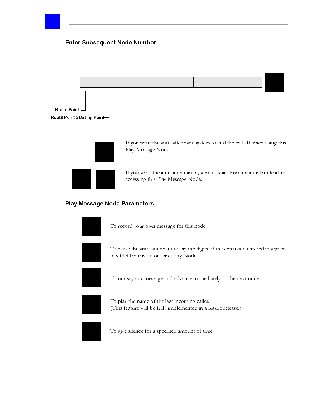
Section 9.6- Voice Mail System Manager page 9-94
IVP Configuration
Enter the node number that will be accessed after this node. If the node number
is less than eight digits, press the ‘#’ key to end the entry.
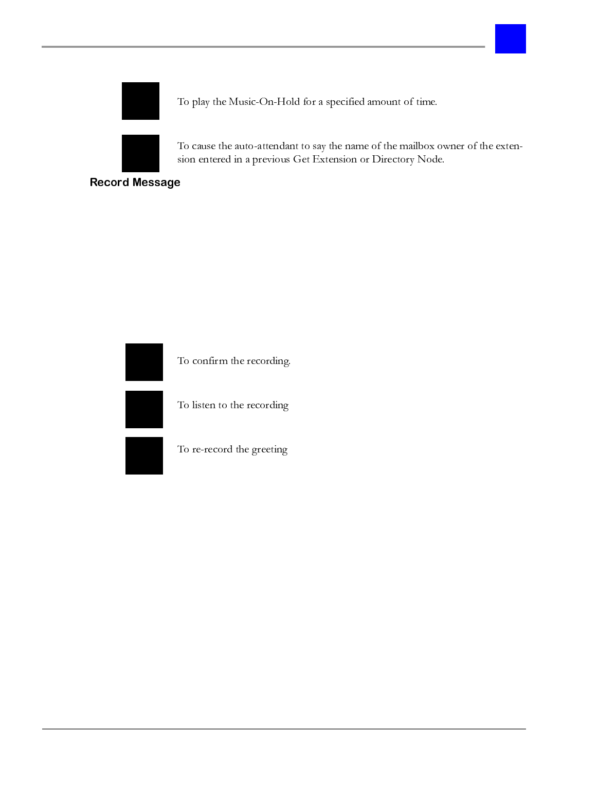
page 9-95 Voice Mail System Manager - Section 9.6
IVP Configuration
1 If 1 is selected above, record your message after the following tone.
2 If 5 is selected above, enter the number of seconds for this operation. You
may enter any number from ‘1’ to ‘999’, followed by the ‘#’ key. To exit,
press the ‘*’ key.
3 Press the ‘#’ key when finished recording.
4 After recording your message, press one of the following options, or press
any key to go to the main menu.
D. Get Extension Node Template
This section provides a template for creating and configuring the Get Extension
Node from a Plexus key telephone. Each of the steps is described more fully
below.
1 Enter the Node Number.
2 Enter the node number that will be accessed after this node. If the node
number is less than eight digits, press the ‘#’ key to end the entry.
3 Get Extension Node parameters. Enter the number of digits which are to be
entered by the incoming caller as part of this node.
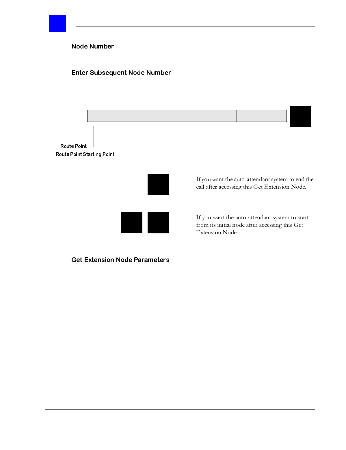
Section 9.6- Voice Mail System Manager page 9-96
IVP Configuration
Enter the node number
Enter the node number that will be accessed after this node. If the node number
is less than eight digits, press the ‘#’ key to end the entry.
Enter the number of digits which are to be entered by the incoming caller as part
of this node.
E. Mailbox Access Node Template
This section provides a template for creating and configuring the Mailbox Access
Node from a Plexus key telephone. Each of the steps is described more fully
below.
1 Enter the Node Number.
2 Enter the node number that will be accessed after this node. If the node
number is less than eight digits, press the ‘#’ key to end the entry.
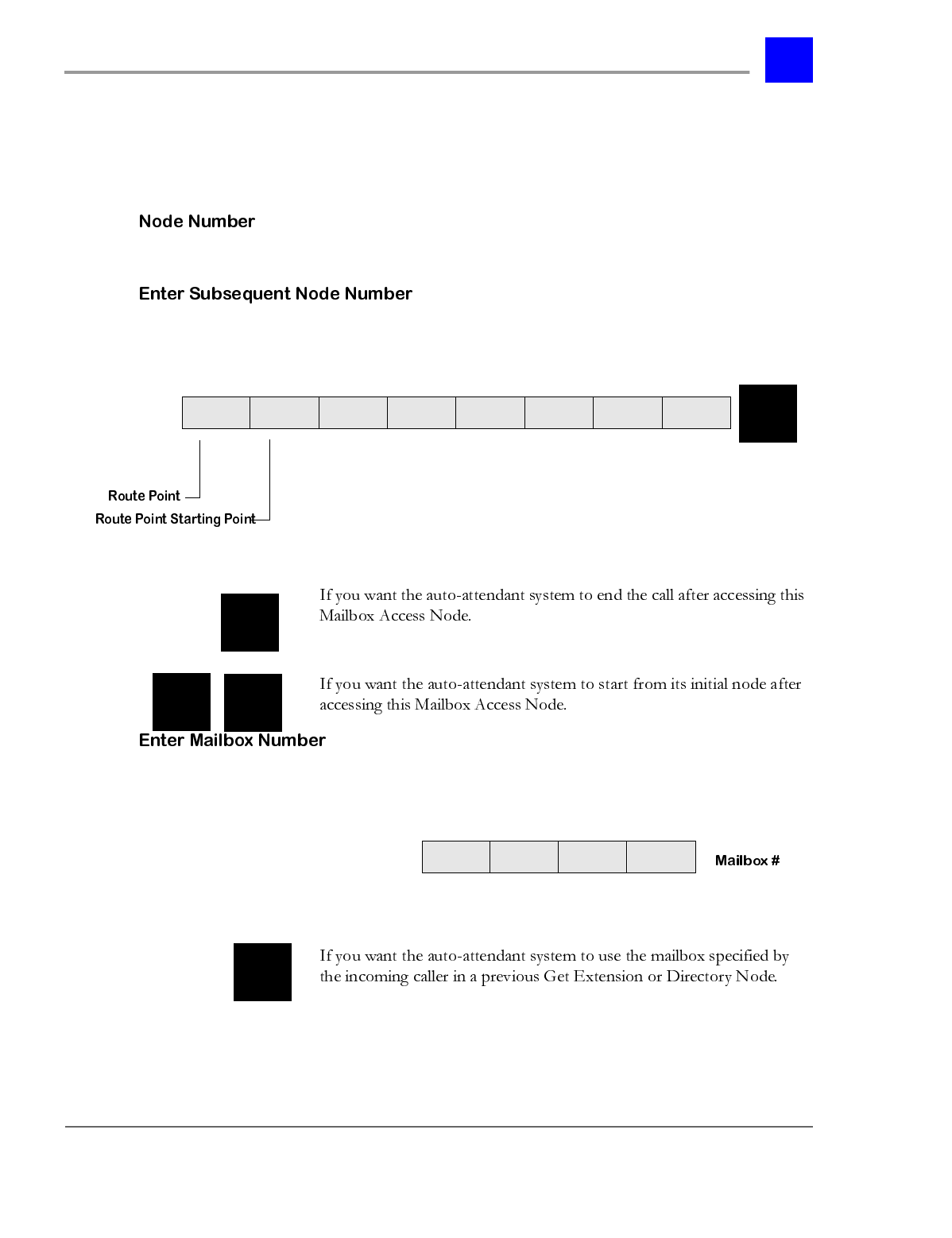
page 9-97 Voice Mail System Manager - Section 9.6
IVP Configuration
3 For the Mailbox Access Node, enter the mailbox number which is to be
accessed by this node.
4 Allow a message to be left, or simply play a greeting.
Enter the node number
Enter the node number that will be accessed after this node. If the node number
is less than eight digits, press the ‘#’ key to end the entry.
For the Mailbox-Access Node, enter the mailbox number which is to be accessed
by this node.
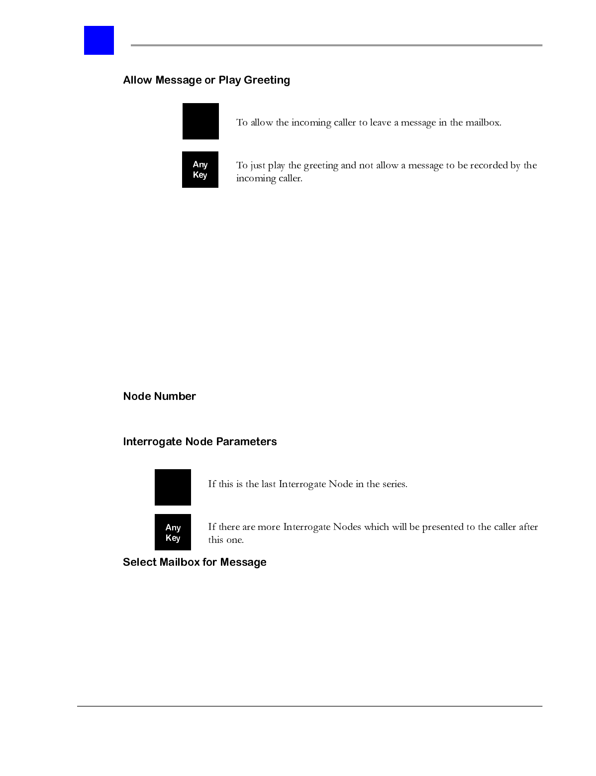
Section 9.6- Voice Mail System Manager page 9-98
IVP Configuration
F. Interrogate Node Template
This section provides a template for creating and configuring the Interrogate
Node from a Plexus key telephone. Each of the steps is described more fully
below.
1 Enter the Node Number.
2 Enter the mailbox number where the Interrogate Node will leave the
message
3 Enter the node number that will be accessed after this node. If the node
number is less than eight digits, press the ‘#’ key to end the entry
4 Record Message.
Enter the node number.
If 1 is selected above, enter the mailbox number where the Interrogate Node will
leave the message.
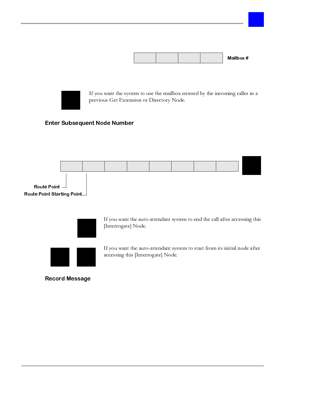
page 9-99 Voice Mail System Manager - Section 9.6
IVP Configuration
Enter the node number that will be accessed after this node. If the node number
is less than eight digits, press the ‘#’ key to end the entry.
1 Record your message after the following tone.
2 Press the ‘#’ key when finished recording.
3 When you are finished recording, select from the following options, or press
any key to return to the main menu.
Section 9.6- Voice Mail System Manager page 9-100
IVP Configuration
G. Directory Node Template
This section provides a template for creating and configuring the Directory Node
from a Plexus key telephone. Each of the steps is described more fully below.
1 Enter the Node Number.
2 Set Directory Node parameters.
3 If you do not want to use the default message, record a new prompt for your
Directory node.
Enter the node number.
The Directory Node will prompt the incoming caller to enter the first three
letters of the desired party’s last name and the Directory Node will say only
those mailboxes.
page 9-101 Voice Mail System Manager - Section 9.6
IVP Configuration
1 If 2 is selected above, record your message after the following tone.
2 Press the ‘#’ key when finished recording.
3 When you are finished recording, select from the following options, or press
any other key to return to the main menu.
Section 9.6- Voice Mail System Manager page 9-102
IVP Configuration
Upon reaching the System Manager Main Menu, select ‘2’ to hear the System
Manager Mailbox Menu.
This feature may be performed by System Managers.
To create a new mailbox, proceed as follows:
1 Select ‘1’ from the System Manager Mailbox Menu.
2 To create a single mailbox, enter the mailbox number. This number may be
2-4 digits depending on the configuration.
3 To create a range of mailboxes, press ‘#’.
4 To return to the main menu, press ‘*’.
5 If ‘#’ was selected above, enter the starting mailbox number. Or, to return to
the main menu, press ‘#’.
6 Enter the ending mailbox number.
page 9-103 Voice Mail System Manager - Section 9.6
IVP Configuration
7 If there are mailboxes which already exist in this range, they will not be
modified.
Note
For information on setting up the parameters for each mailbox created, see
“Mailbox Templates” - section 9.6.6.7. If a range is created, each mailbox must
be configured by selecting option ‘2’, modify an existing mailbox, under the
System Manager Mailbox Menu.
This feature may be accessed by System Managers.
To modify an existing mailbox, proceed as follows:
1 Select ‘2’ from the System Manager Mailbox Menu.
2 Enter the mailbox number.
3 At this point the voice mail system will proceed with the configuration of the
mailbox [Refer to the “Mailbox Templates” - section 9.6.6.7].
This feature may be accessed by System Managers.
To delete a mailbox, proceed as follows:
1 Select ‘3’ from the System Manager Mailbox Menu.
2 Enter the mailbox number.
3 To delete this mailbox, press ‘1’. Or, to retain this mailbox, press any
other key.
This feature may be accessed by System Managers.
To delete all mailboxes, proceed as follows:
1 Select ‘4’ from the System Manager Mailbox Menu.
2 The voice mail system will announce “This will cause all mailboxes to be
deleted and all mailbox messages will be lost.”

Section 9.6- Voice Mail System Manager page 9-104
IVP Configuration
3 If you want to proceed with this operation, press ‘1’. Or, to return to the
main menu, press any other key.
To hear a listing of all mailboxes, proceed as follows:
1 Select ‘5’ from the System Manager Mailbox Menu.
2 The voice mail system will announce the list of mailboxes as follows:
“Mailbox number _ _ _ _ + name of owner (if recorded)”
“Mailbox number _ _ _ _ + name of owner (if recorded)”
etc.
3 While listening to the listing, press ‘1’ to skip to the next mailbox in the list.
OR, to return to the main menu, press any other key.
The templates on the following pages were developed to assist with configuring
mailboxes. Utilize the templates to identify the parameters that must be set up
for each mailbox.
page 9-105 Voice Mail System Manager - Section 9.6
IVP Configuration
Section 9.6- Voice Mail System Manager page 9-106
IVP Configuration
After selecting option 1, you will be able to select whether this is to be an
ordinary mailbox or a Group Delivery mailbox.
page 9-107 Voice Mail System Manager - Section 9.6
IVP Configuration
Section 9.6- Voice Mail System Manager page 9-108
IVP Configuration
Associating an extension with the mailbox allows the Dial node to request a
transfer to that extension.
page 9-109 Voice Mail System Manager - Section 9.6
IVP Configuration
Section 9.6- Voice Mail System Manager page 9-110
IVP Configuration
A mailbox specified as private will not be announced to the incoming caller
during a Directory node.
page 9-111 Voice Mail System Manager - Section 9.6
IVP Configuration
Section 9.6- Voice Mail System Manager page 9-112
IVP Configuration
After selecting option 1 above, you will be able to select from the following
options:
page 9-113 Voice Mail System Manager - Section 9.6
IVP Configuration
Section 9.6- Voice Mail System Manager page 9-114
IVP Configuration
After selecting option 1 above, you will be able to select from the following
options:
page 9-115 Voice Mail System Manager - Section 9.6
IVP Configuration
Section 9.6- Voice Mail System Manager page 9-116
IVP Configuration
After selecting option 1 above, you will be able to select from the following
options:
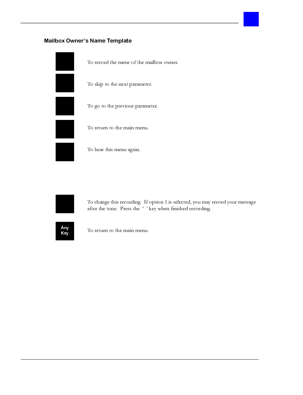
page 9-117 Voice Mail System Manager - Section 9.6
IVP Configuration
After selecting option 1 above, you will hear the current recording. You may
then select to change the recording, or return to the main menu.
#
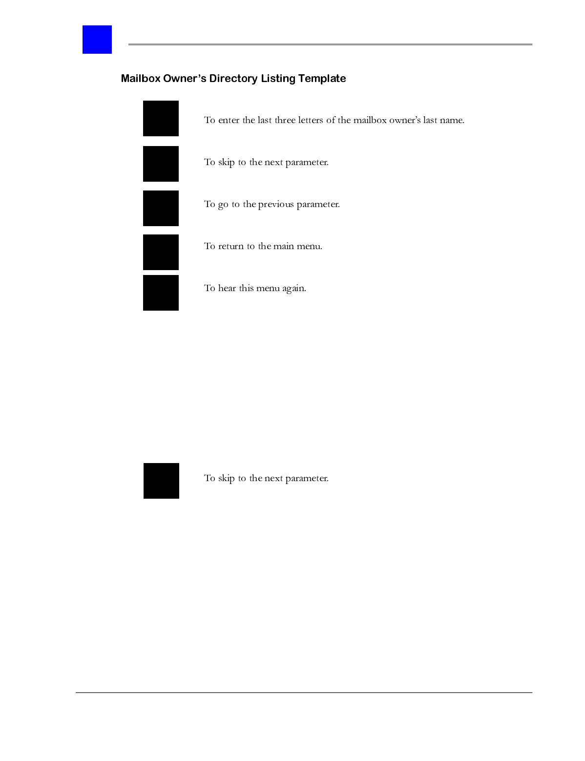
Section 9.6- Voice Mail System Manager page 9-118
IVP Configuration
After selecting option 1 above, you will hear the current settings. You may then
select to change the settings, or return to the main menu.
Using the letters associated with the numbers on your telephone, enter 3 digits
representing the first 3 digits of the person’s last name. You must enter three
digits. For example, the last name “Smith” would be entered by dialing ‘S’, ‘M’,
‘I’, or ‘7’, ‘6’, ‘4’. For last names having fewer than 3 letters, use the zero key at
the end of the name to fill the entry. To enter the letter ‘Q’, use the 7 key. To
enter the letter ‘Z’, use the 9 key.
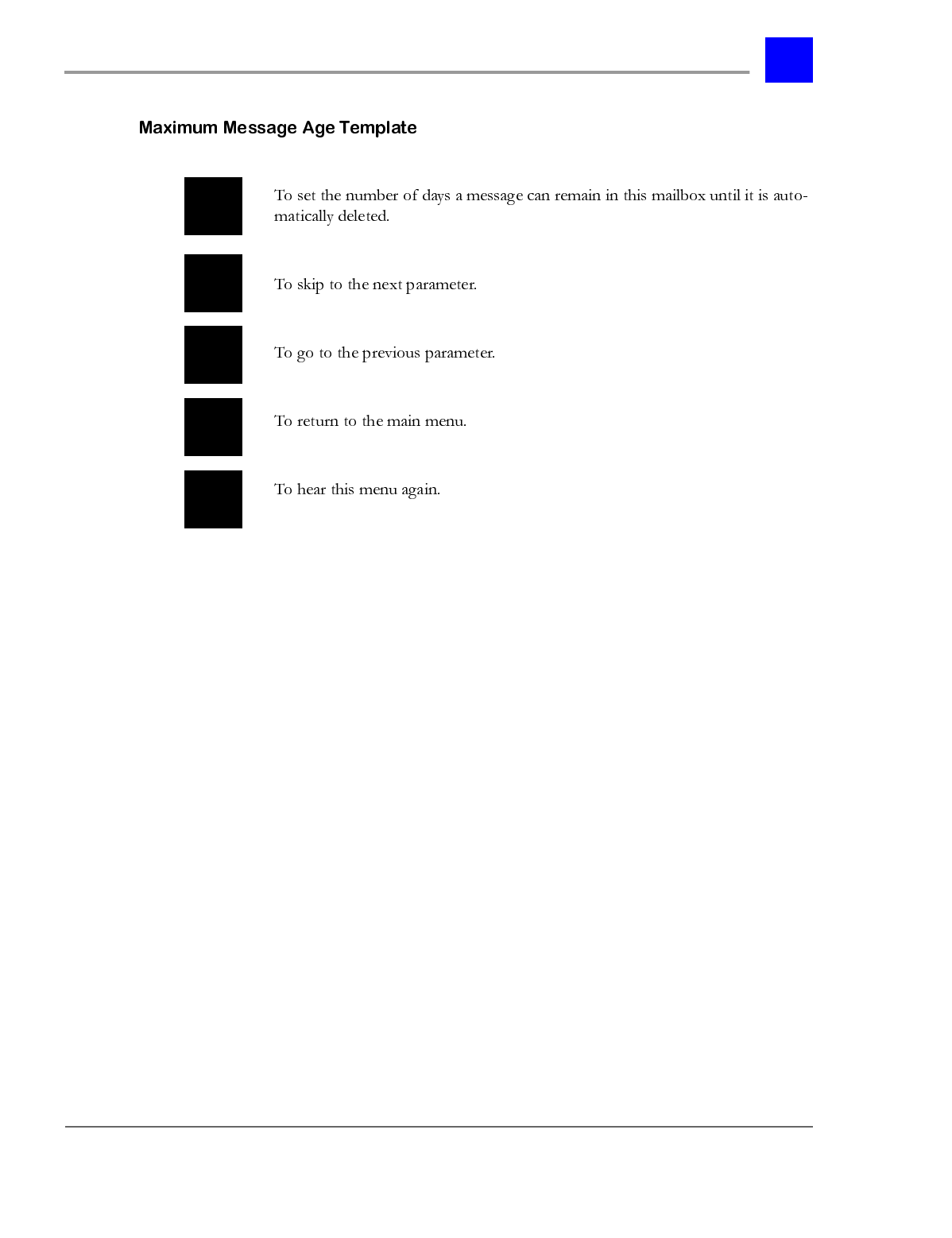
page 9-119 Voice Mail System Manager - Section 9.6
IVP Configuration
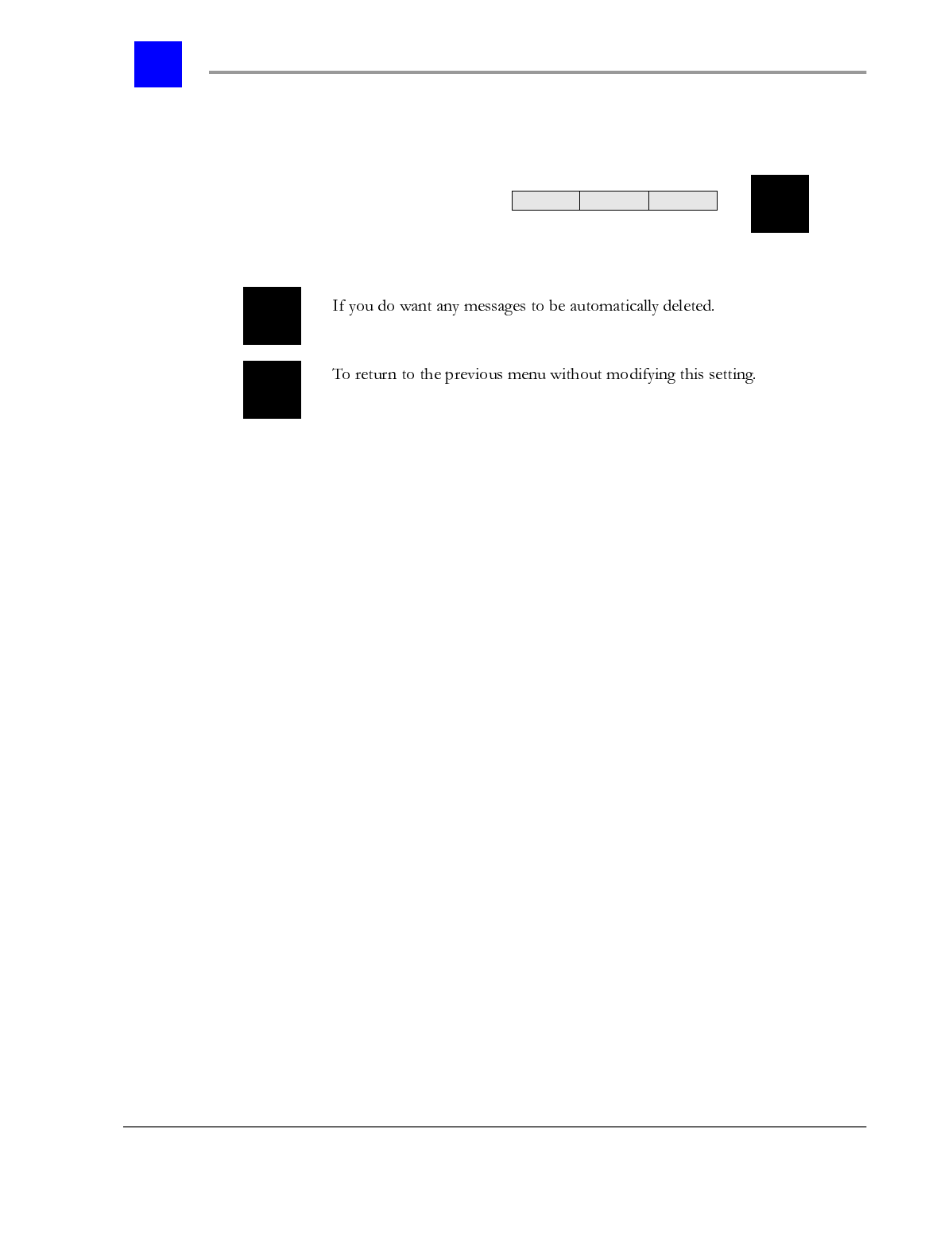
Section 9.6- Voice Mail System Manager page 9-120
IVP Configuration
After selecting option 1 above, you will hear the current setting. To change this
setting, you may enter any number from 1 to 365 days followed by the ‘#’ key.
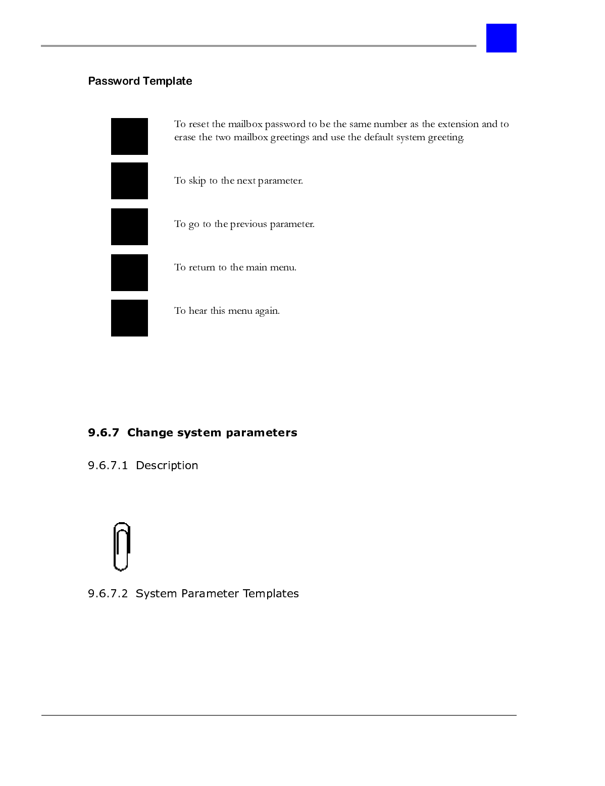
page 9-121 Voice Mail System Manager - Section 9.6
IVP Configuration
Your entry has been saved. There are no more options to be
programmed.
Upon reaching the System Manager Main Menu, select ‘3’ to hear the System
Parameter menu.
Note
The System Parameter menu can only be accessed from mailbox 001.
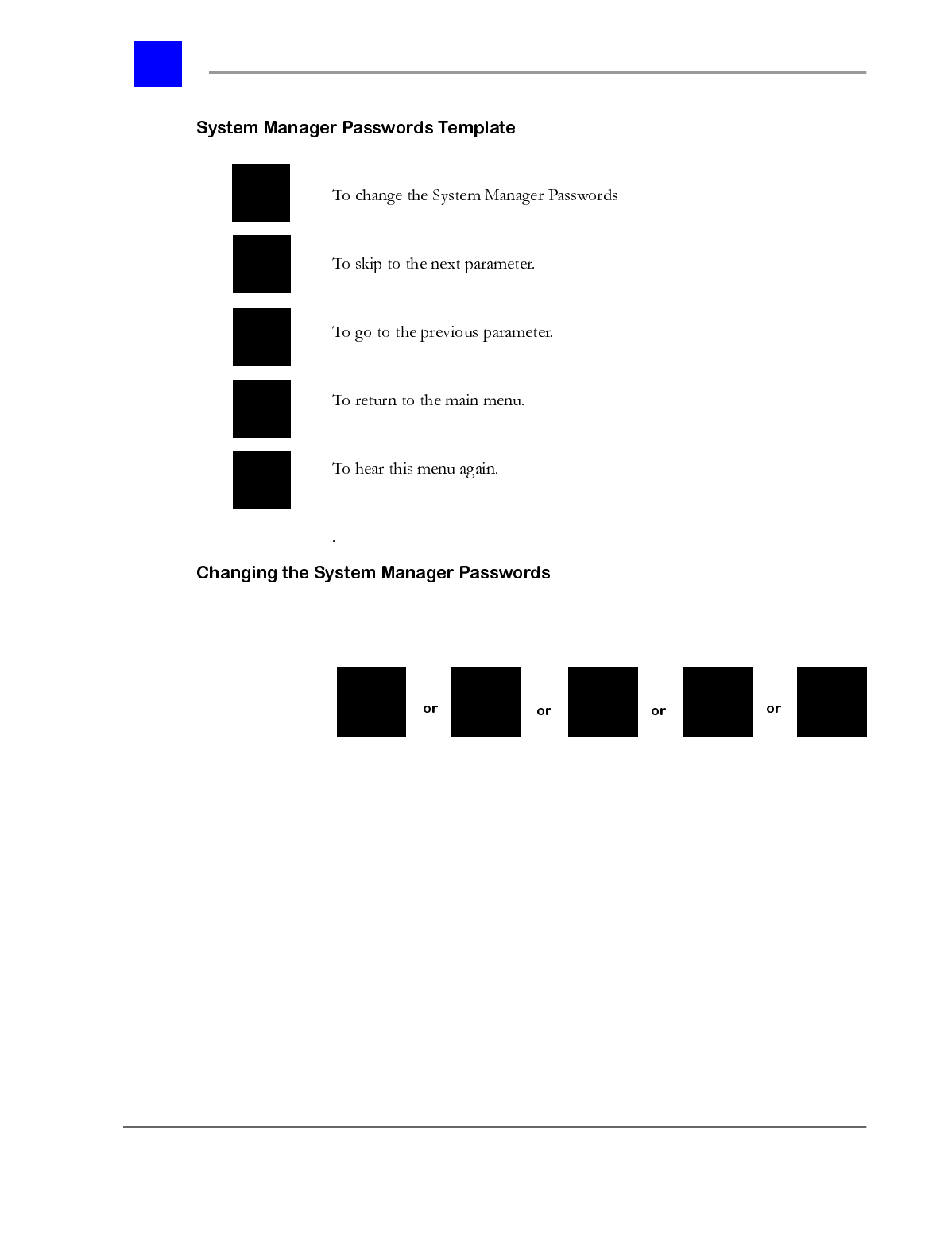
Section 9.6- Voice Mail System Manager page 9-122
IVP Configuration
1 Enter the System Manager level password you would like to change. There
are 5 levels, 1 being the highest and 5 being the lowest.
2 Enter your new four-digit password. Or, if you do not want to use a
password, press the ‘#’ key.
3 You have entered _ _ _ _.
4 To accept this as your new password, press 1.
5 To return to the main menu, press any key.
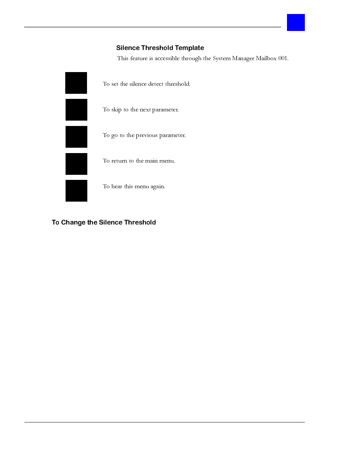
page 9-123 Voice Mail System Manager - Section 9.6
IVP Configuration
1 Press 1. The system will announce the current setting:
2 The current setting is _____ (84default).
3 You may enter any number from ‘1’ to ‘999’, followed by the ‘#’ key. A
smaller number makes the system more sensitive and may delay the
detection of silence. A larger number makes the system less sensitive and
may end the recording prematurely if a caller is speaking too softly.
4 To return to the previous menu without changing this parameter, press the
‘*’ key.
The recommended value for this field is 84.
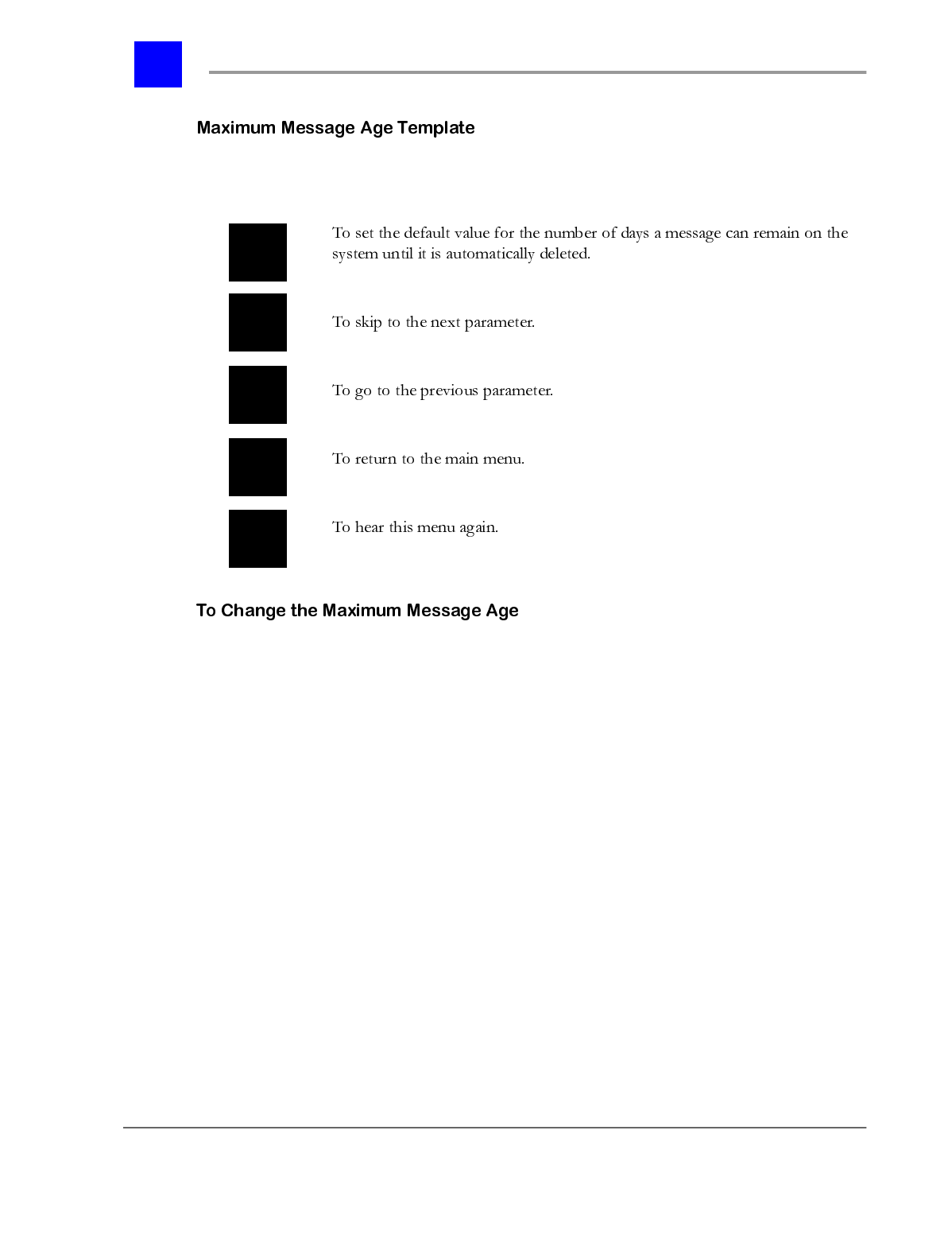
Section 9.6- Voice Mail System Manager page 9-124
IVP Configuration
This feature is accessible through the System Manager Mailbox 001.
1 After selecting ‘1’ from the menu above, you will hear the current setting.
By default, messages are not automatically deleted.
2 The current setting is _____.
3 You may enter any number from ‘1’ to ‘365’ days, followed by the ‘#’ key.
4 Press ‘#’ If you do not want any messages to be automatically deleted.
5 Press ‘*’ to return to the previous menu.
page 9-125 Voice Mail System Manager - Section 9.6
IVP Configuration
This feature is accessible through the System Manager Mailbox 001.
1 Select ‘1’ from the menu above.
2 Enter the three digit message number.
3 The message will be played.
4 To return to the previous menu, press ‘#’.
5 If you record your own message over the existing message, you will not be
able to restore the original system message.
Section 9.6- Voice Mail System Manager page 9-126
IVP Configuration
This feature is accessible through the System Manager Mailbox 001.
page 9-127 Voice Mail System Manager - Section 9.6
IVP Configuration
1 After pressing ‘1’ from the menu above, you will hear the following message:
“The current setting is x digits per mailbox.” (3default)
2 Enter the new value for this parameter. You may specify that 2, 3, or 4
digits are required to specify a mailbox number.
3 Then, select from the following options.
Upon reaching the System Manager Main Menu, select ‘4’ to hear the amount of
space available for message recording on the IVP hard drive. The following
information will be played:
There is approximately ______ hour(s) and ______ minutes of storage space left
on the hard disk.
The system reports the number of hours and minutes of recording time
remaining on the hard disk. When the amount of space on the hard disk slips
below 1 hour of recording time, a warning is presented to all users upon logging
into their mailboxes. If the available recording time drops below 15 minutes, the
system does not allow any recording to take place and instead plays an error
message indicating that the disk is full.
Section 9.6- Voice Mail System Manager page 9-128
IVP Configuration
Deleting messages from the hard drive may not immediately free up space. The
system recalculates the hard disk status approximately every 6 hours. However,
it is possible to force a recalculation of disk space by accessing the Maximum
Message Age system parameter menu. When this menu is invoked, the system
automatically recalculates the space on the hard disk. Refer to “Modify an
Existing Mailbox” - section 9.6.6.3 for more information.
This feature is accessible through all System Manager Mailboxes. Upon
reaching the System Manager Main Menu, select ‘5’.
A string of numbers indicating the voice mail system operating system and
various serial numbers will be played. The number immediately following the
first “The current setting is” prompt is the current voice mail operating system.
Note
This version number should periodically be compared to the latest available
version and upgraded when necessary.
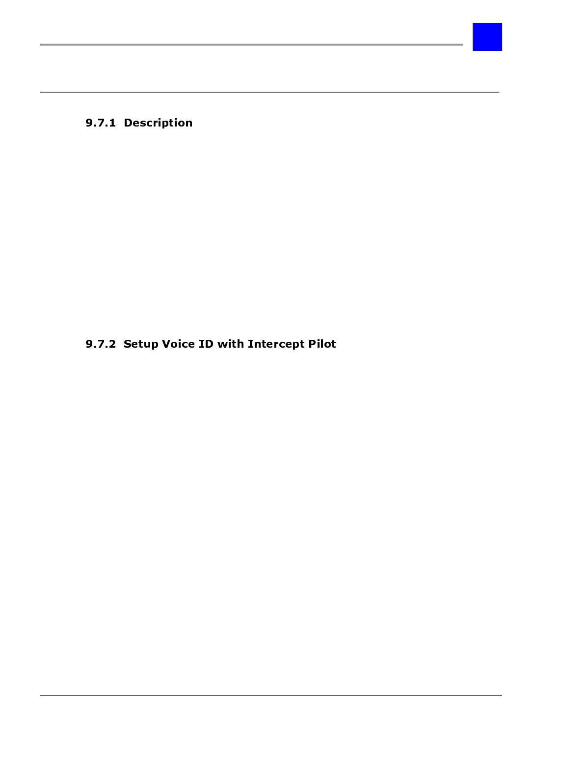
page 9-129 Setting up Hold Queue Intercepts - Section 9.7
IVP Configuration
6HWWLQJXS+ROG4XHXH,QWHUFHSWV
Busy Queuing for a user or user group can be set up such that the queue is
intercepted periodically with a default system message, a custom message, or a
connection to another user on the system. The default system message provides
a point-in-queue indication so that the caller knows how many calls are ahead of
them. While custom messages cannot take advantage of the point-in-queue
indication, they should provide reassurance to callers, letting them know that
the system is aware that they are still holding. If the intercept is directed to
another user on the system, that user can update the caller on the availability of
the targeted user. Busy Queuing occurs when a call is Camped-On or Parked for
the busy user; it is not available to calls placed on hold.
This section covers the configuration of intercepts that provide a default system
message or a custom recorded message. Both these options use the IVP to play
messages for the holding caller.
For Intercept Messages to work, Intercept Pilots for users and user groups must
be defined as a voice ID. This voice ID must have a Intercept Point defined. This
Intercept Point must be a Dial Node. When the system accesses this Intercept
Point, it will access the placeholder for Intercept Messages under the Dial Node.
This node can be an Undefined Node for system default messages or a Play
Message Node or Menu Node for custom messages (see “Custom messages” -
section 9.7.5 for information on additional parameters that must be defined).
The placeholder is defined by adding a 3 to the defined Dial Node (e.g., dial node
2010 has a Intercept message placeholder of node 20103). For system default
messages only, the Intercept Point Dial Node must be a Dial Node under a Get
Extension Node for proper operation.
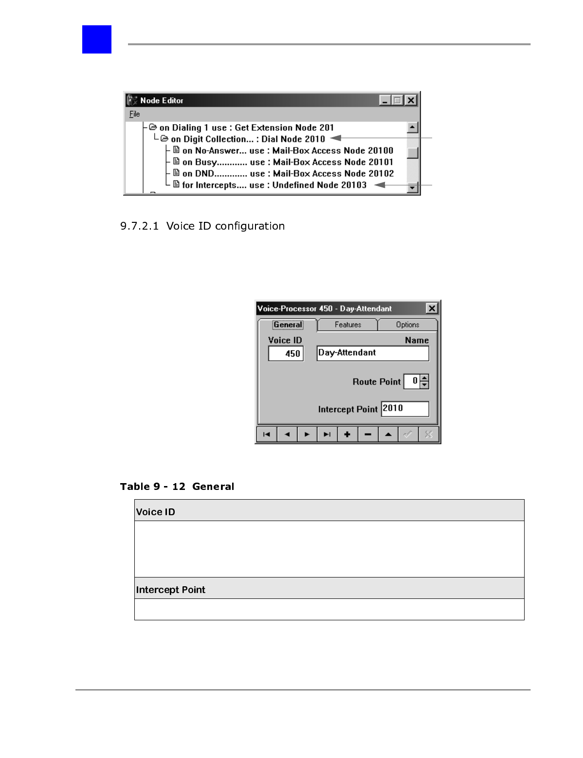
Section 9.7- Setting up Hold Queue Intercepts page 9-130
IVP Configuration
Scroll to the desired Voice ID and make appropriate entries and selections on
each of the tabs presented below.
Logical identifier for the voice mail resource.
Note
: The ID is automatically assigned based on the
Voice ID Sequence entered when the first Voice ID
was created.
Numeric
2 to 4 digits,
(depending on the dial plan)
The main dial node over the intercept node. Numeric
Intercept Message
Placeholder
Dial Node
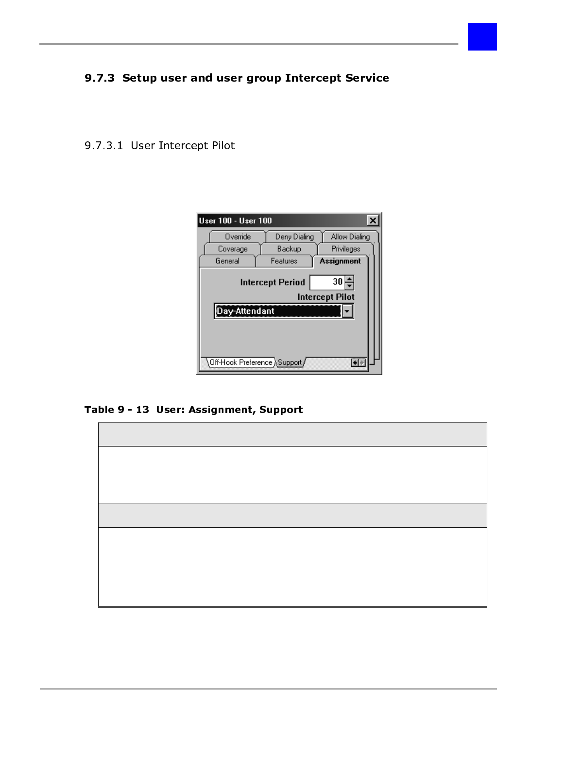
page 9-131 Setting up Hold Queue Intercepts - Section 9.7
IVP Configuration
To set up intercept service for a user or user group, enable and assign an
intercept pilot.
The settings to set up intercept service for a user are found in User: Assignment,
Support (see “User: Assignment, Support” - section 6.22.11).
* = default settings
Intercept Period
The period of time between connections to the
intercept pilot while a caller is waiting in a user’s
exclusive hold queue.
Note:
See “Intercept Service” - section 8.84.
0-255 seconds 30 seconds*
Intercept Pilot
Intercept connect to for calls in queue for the user. None *
User ID
User Group ID
Auto Attendant
ID
Voice ID
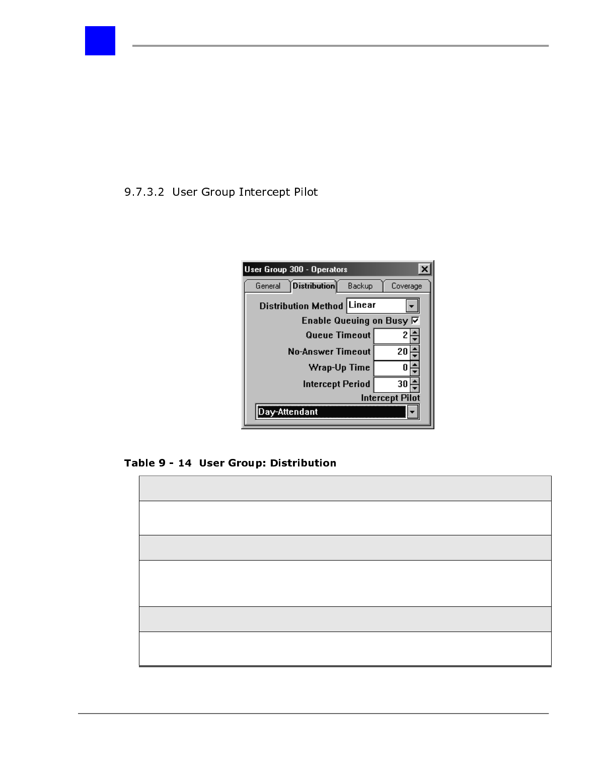
Section 9.7- Setting up Hold Queue Intercepts page 9-132
IVP Configuration
The Intercept Pilot should be set to a voice ID of the IVP card. This voice ID will
have an intercept point defined (see “Setup Voice ID with Intercept Pilot” -
section 9.7.2).
Users enable Busy Queuing on an individual basis. See “Busy Queuing - User” -
section 8.21 for detailed instructions for enabling the busy Busy Queuing with
an Intercept Message.
The settings to set up intercept service for a user group are found in User Group:
Distribution (see “User Group: Distribution” - section 6.23.2).
Enable Queuing on Busy
Whether Busy Queuing is enabled for calls to this group.
Note:
See “Busy Queuing - User Group” - section 8.22. Enable /
disable*
Queue Timeout
The period of time that a call may remain in queue waiting for
an available user before routing to backup and/or coverage.
Note:
See “Busy Queuing - User Group” - section 8.22.
0-255 minutes 2
minutes*
Intercept Period
Refers to the period of time between reassurance messages
while a caller is waiting in the busy queue. 0-255 seconds 30
seconds*
page 9-133 Setting up Hold Queue Intercepts - Section 9.7
IVP Configuration
* = default settings
The Intercept Pilot should be set to a voice ID of the IVP card. This voice ID will
have an intercept point defined (see “Setup Voice ID with Intercept Pilot” -
section 9.7.2).
The system default message is a prerecorded system message for callers in the
Hold Queue. The message played is, "All agents are currently busy. There are x
calls ahead of you. To continue waiting, please stay on the line. To leave a
message for this extension, press the 'pound' key." The x represents the caller’s
point in queue or the number of queued calls ahead of the caller.
Callers are able to stay on the line, hang up, or press # to leave a message. The
message will repeat itself at the time interval defined in the user or user group
Intercept Period.
Note
For system default messages only, the Intercept Point Dial Node
must
be a
Dial Node under a Get Extension Node for proper operation of the "press #"
feature.
While custom messages cannot take advantage of the point-in-queue indication,
they should provide reassurance to callers, letting them know that the system is
aware that they are still holding.
For a custom message to be played, the Intercept Message Placeholder must be
redefined and the user or user groups mailbox must be configured to allow for
custom messages to be played for queued calls to the user or user group.
Intercept Pilot ID
System entity providing the audio prompts for calls holding in
the queue. None *
User ID
User Group ID
AutoAttendant
ID
Voice ID
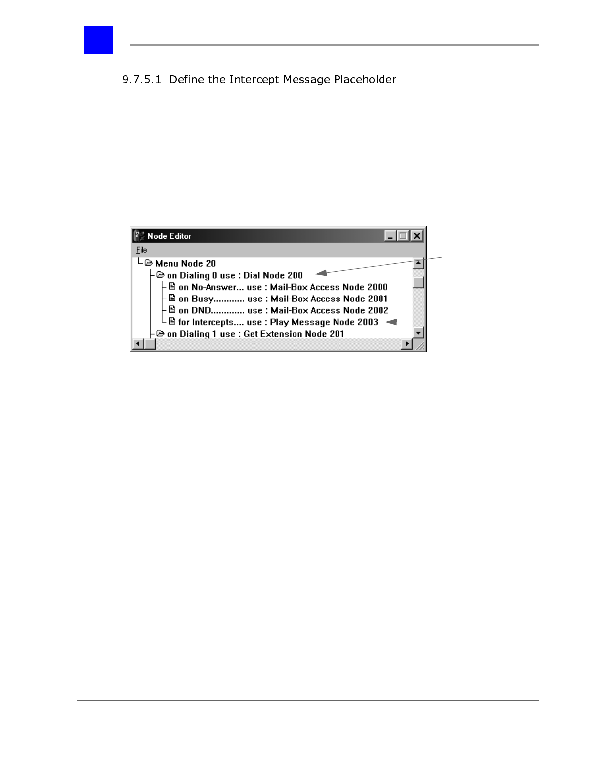
Section 9.7- Setting up Hold Queue Intercepts page 9-134
IVP Configuration
A Play Message Node or a Menu Node must be defined in the Intercept Message
Placeholder under the Intercept Point’s defined Dial Node.
A. Play Message Node
A Play Message Node will play the recording associated with the node for the
caller. The Play Message Node will ignore any digits dialed by the caller and
return the call to the held state once the message is through playing.
To properly configure the Play Message Node, the Play action for the node
should be set to Play Recorded Message and a message should be recorded for
the node. The node will ignore the setting Next Node and return the call to a
held state after the message has played. For the steps to modify the Play
Message Node properties, see “Modifying node properties” - section 9.3.14.
Dial Node
Intercept Message
Placeholder
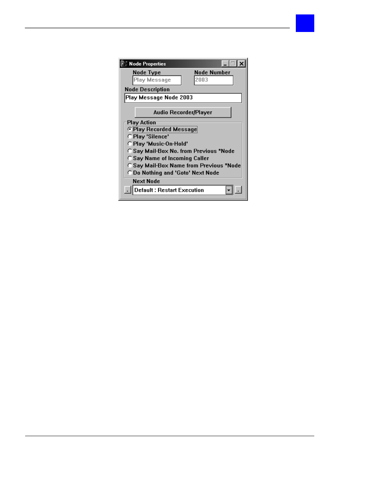
page 9-135 Setting up Hold Queue Intercepts - Section 9.7
IVP Configuration
B. Menu Node
A Menu Node will play the recording associated with the node for the caller. The
caller will have the option to press digits that have been mapped under the
Menu Node to hear prerecorded messages or stay on the line to continue holding
for the user or user group. The nodes defined under a Menu Node can only be
Play Message Nodes and More Menu Nodes. All other types of nodes will not
operate in an Intercept. See “Adding a Menu Node” - section 9.3.10.1.
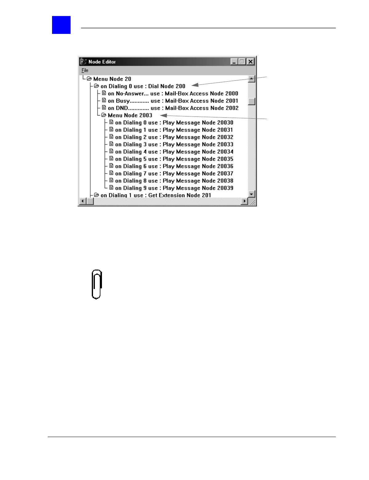
Section 9.7- Setting up Hold Queue Intercepts page 9-136
IVP Configuration
To properly configure the Menu Node, The choices for the caller entering a * or #
must be defined. Any menu choices under the Menu Node must also be defined.
See “Adding a Menu Node” - section 9.3.10.1 and “Menu Node Properties” -
section 9.3.15.1.
Note
All nodes defined under a Menu Node in an Intercept must be Play Message
Nodes or Menu Nodes, other types of nodes will not operate properly in an
Intercept.
Dial Node
Intercept Message
Placeholder
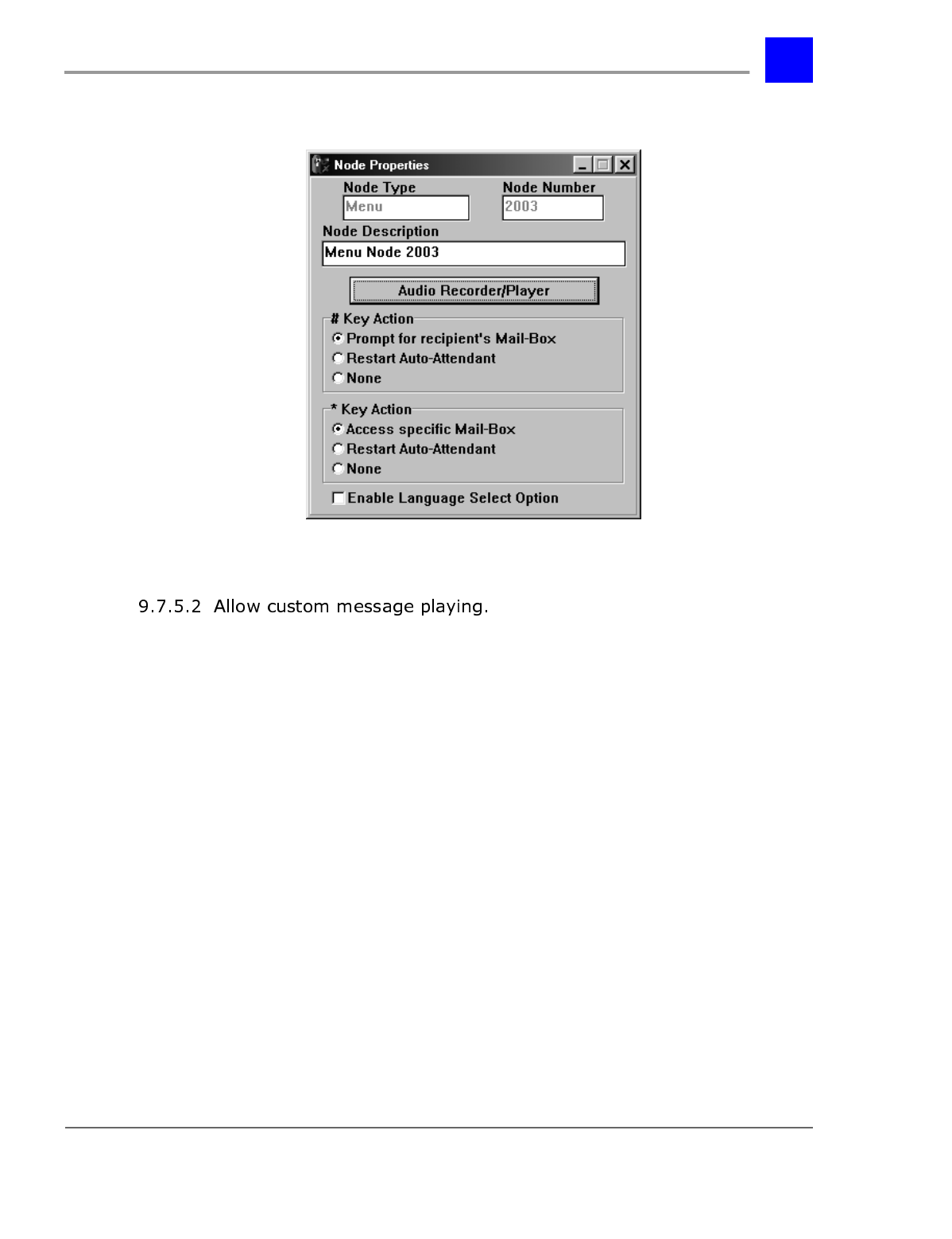
page 9-137 Setting up Hold Queue Intercepts - Section 9.7
IVP Configuration
For the system to play a custom messages, the user or user groups mailbox must
be configured to allow for custom messages to be played for queued calls to the
user or user group. To modify the mailbox for the user or user group that is
being set up to have custom messages played for queued calls, follow the
following steps:
1 Log in to the user or user group mailbox. This can be done by accessing any
mailbox to leave a message and dialing * and the desired mailbox to
configure.
2 Enter the mailbox password (if applicable, default is no password).
3 Press ’3’ to modify mailbox parameters.
4 Press ’8’ ten times to forward to parameter "set busy options".
5 Press ’1’ to modify this parameter.
6 Press ’2’ to allow for custom intercept messages to be played.
7 When the system states "Your entry has been saved", hang up.

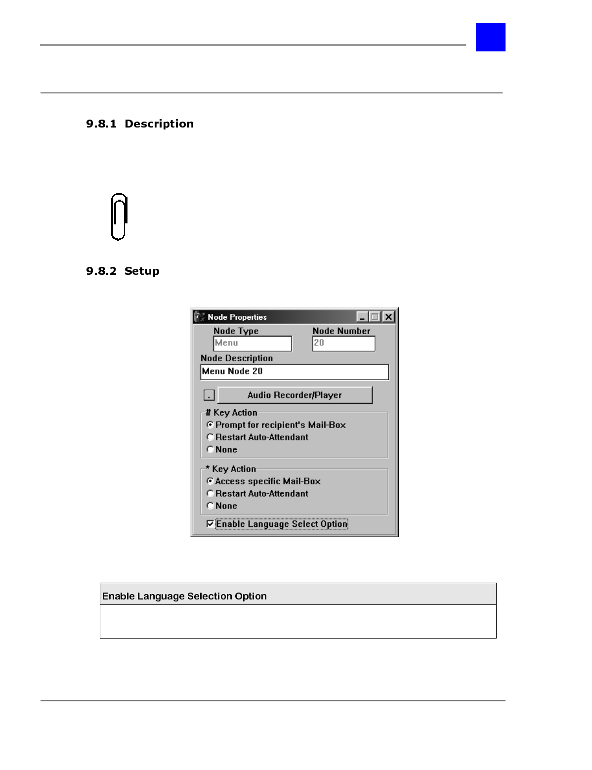
page 9-139 Multi-Language Option - Section 9.8
IVP Configuration
0XOWL/DQJXDJH2SWLRQ
The Multi-Language Option allows incoming callers to select a language in
which the menu options will be announced. Mailbox owners may select the
language in which their mailbox options are read.
Note
You must have a multi-language enabled Integrated Voice Processor (IVP)
Interface card for this option to be implemented.
* = default setting
Enables language selection option Enable /
disable*

Section 9.8- Multi-Language Option page 9-140
IVP Configuration
