ProPak6_User_Manual Pro Pak6 Manual
User Manual:
Open the PDF directly: View PDF ![]() .
.
Page Count: 130 [warning: Documents this large are best viewed by clicking the View PDF Link!]
- Notices
- Customer Support
- Introduction
- Installation
- 2.1 Additional Equipment Required
- 2.2 ProPak6 Hardware
- 2.3 Communication with the ProPak6
- 2.4 Standard Configuration Installation
- 2.5 Dual Antenna Configuration and Installation
- 2.6 Cellular Antenna Installation
- 2.7 ProPak6 Alternative Power Source
- 2.8 Installing NovAtel Connect PC Utilities
- 2.9 ProPak6 Security
- 2.10 Next Steps
- Operation
- 3.1 Communications with the Receiver
- 3.1.1 Communicating Using a Remote Terminal
- 3.1.2 Communicating Using a Computer
- 3.1.3 Status Indicators
- 3.1.4 COM Ports LEDs
- 3.1.5 Bluetooth LED
- 3.1.6 Wi-Fi LED
- 3.1.7 INS and ALIGN LEDs
- 3.1.8 Satellite Tracking and Positioning LEDs
- 3.1.9 Cell Port and LED
- 3.1.10 Universal Serial Bus (USB) Port and LEDs
- 3.1.11 Ethernet Port
- 3.1.12 ICOM Ports
- 3.1.13 Serial Ports
- 3.1.14 I/O Port
- 3.1.15 Expansion Port
- 3.1.16 Antenna LNA Port
- 3.1.17 External Oscillator Port (model dependent)
- 3.2 Getting Started
- 3.3 Establishing a Receiver COM Connection
- 3.4 Transmitting and Receiving Corrections
- 3.5 External ALIGN Master or Rover Configuration Only
- 3.6 STEADYLINE®
- 3.7 Logging and Retrieving Data Overview
- 3.8 ProPak6 Web User Interface (UI)
- 3.1 Communications with the Receiver
- Ethernet Configuration
- Radio Configuration and Activation
- NTRIP Configuration
- NovAtel Firmware and Software
- OEM6 Firmware and Software
- NovAtel Connect PC Utilities Software Bundle
- Firmware and Software included
- 7.1 Firmware Updates and Model Upgrades
- 7.2 Authorization Code
- 7.3 Updating or Upgrading Using the WinLoad Utility
- 7.4 Updating Using SoftLoad Commands
- 7.5 Upgrading Using the AUTH Command
- Built-In Status Tests
- Technical Specifications
- Replacement Parts
- Frequently Asked Questions
ProPak6™
Installation & Operation
User Manual
OM-20000148 Rev 5 July 2017

2 ProPak6 Installation and Operation User Manual Rev Rev 5
ProPak6 Installation and Operation User Manual
Publication Number: OM-20000148
Revision Level: Rev 5
Revision Date: July 2017
To download the latest firmware and/or software visit: www.novatel.com/support/firmware-downloads
This manual reflects firmware version 6.606 / OEM060606RN000
Warranty
NovAtel® Inc. warrants that its GNSS products are free from defects in materials and workmanship,
subject to the conditions set forth on our web site: www.novatel.com/products/warranty/.
ProPak6 One (1) Year
GPS Antenna Series One (1) Year
Cables and Accessories Ninety (90) Days
Software Warranty One (1) Year
Return Instructions
To return products, refer to the instructions found under the Return Policy Tab on the warranty page:
www.novatel.com/products/warranty/.
Proprietary Notice
Information in this document is subject to change without notice and does not represent a commitment
on the part of NovAtel Inc. The software described in this document is furnished under a licence
agreement or non-disclosure agreement. The software may be used or copied only in accordance with
the terms of the agreement. It is against the law to copy the software on any medium except as
specifically allowed in the license or non-disclosure agreement.
The information contained within this manual is believed to be true and correct at the time of publication.
STEADYLINE, ALIGN, OEM6, NovAtel and SPAN are registered trademarks of NovAtel Inc.
NovAtel Connect, ProPak6 and GLIDE are trademarks of NovAtel Inc.
All other brand names are trademarks of their respective holders.
Manufactured and protected under U.S. patents.
© Copyright 2016 NovAtel Inc. All rights reserved.
Unpublished rights reserved under International copyright laws.
#5,101,416 #6,184,822 B1
#5,390,207 #6,243,409 B1
#5,414,729 #6,445,354 B1
#5,495,499 #6,608,998 B1
#5,736,961 #6,664,923 B1
#5,809,064 #7,738,536

ProPak6 Installation and Operation User Manual Rev 5 3
Table of Contents
Notices 8
Customer Support 15
1 Introduction 16
1.1 Introduction ........................................................................................................................... 16
1.2 System Components............................................................................................................. 16
1.3 Models and Features ............................................................................................................ 16
1.4 Overview—ProPak6 Hardware ............................................................................................. 17
2 Installation 21
2.1 Additional Equipment Required ............................................................................................ 21
2.2 ProPak6 Hardware................................................................................................................ 22
2.2.1 ProPak6 Cables........................................................................................................... 22
2.2.2 Selecting a GNSS Antenna ......................................................................................... 22
2.2.3 Choosing a Coaxial Cable ........................................................................................... 22
2.3 Communication with the ProPak6 ......................................................................................... 23
2.3.1 Power Supply Requirements ....................................................................................... 23
2.3.2 COM1 and COM2 Peripheral Power ........................................................................... 23
2.4 Standard Configuration Installation....................................................................................... 24
2.5 Dual Antenna Configuration and Installation......................................................................... 26
2.6 Cellular Antenna Installation ................................................................................................. 28
2.6.1 Mounting the GNSS Antenna ...................................................................................... 30
2.7 ProPak6 Alternative Power Source....................................................................................... 30
2.7.1 Battery Backup ............................................................................................................31
2.7.2 Connect the Additional Communication Ports on a ProPak6 ...................................... 32
2.7.3 Connect the CAN Bus ................................................................................................. 33
2.7.4 Mounting the ProPak6 ................................................................................................. 33
2.8 Installing NovAtel Connect PC Utilities ................................................................................. 33
2.9 ProPak6 Security .................................................................................................................. 34
2.9.1 Administration Password ............................................................................................. 34
2.9.2 FTP Server and ICOM Ports ....................................................................................... 34
2.10 Next Steps .......................................................................................................................... 34
3 Operation 35
3.1 Communications with the Receiver....................................................................................... 35
3.1.1 Communicating Using a Remote Terminal.................................................................. 35
3.1.2 Communicating Using a Computer.............................................................................. 35
3.1.3 Status Indicators.......................................................................................................... 35
3.1.4 COM Ports LEDs ......................................................................................................... 36
3.1.5 Bluetooth LED .............................................................................................................37
3.1.6 Wi-Fi LED .................................................................................................................... 37
3.1.7 INS and ALIGN LEDs .................................................................................................. 37
3.1.8 Satellite Tracking and Positioning LEDs...................................................................... 38
3.1.9 Cell Port and LED........................................................................................................ 40
3.1.10 Universal Serial Bus (USB) Port and LEDs ............................................................... 40
3.1.11 Ethernet Port ............................................................................................................. 41
3.1.12 ICOM Ports................................................................................................................ 42
3.1.13 Serial Ports ................................................................................................................ 42
3.1.14 I/O Port ...................................................................................................................... 43
3.1.15 Expansion Port ..........................................................................................................43
3.1.16 Antenna LNA Port...................................................................................................... 44
3.1.17 External Oscillator Port (model dependent)............................................................... 44

4 ProPak6 Installation and Operation User Manual Rev 5
Table of Contents
3.2 Getting Started ..................................................................................................................... 44
3.2.1 Applying Power to the Receiver.................................................................................. 44
3.3 Establishing a Receiver COM Connection ........................................................................... 45
3.3.1 Communicating with the Receiver Using NovAtel Connect ........................................ 46
3.4 Transmitting and Receiving Corrections............................................................................... 47
3.4.1 Defining Antenna and Base Antenna.......................................................................... 48
3.4.2 Base Station Configuration ......................................................................................... 48
3.4.3 Rover Station Configuration........................................................................................ 50
3.5 External ALIGN Master or Rover Configuration Only ........................................................... 50
3.5.1 PDP and GLIDE™ Configurations ............................................................................... 51
3.6 STEADYLINE®.................................................................................................................................................................... 51
3.6.1 Maintain ...................................................................................................................... 52
3.6.2 Transition .................................................................................................................... 52
3.6.3 Prefer Accuracy .......................................................................................................... 53
3.6.4 UAL ............................................................................................................................. 53
3.6.5 Configuration Notes .................................................................................................... 55
3.6.6 Enabling SBAS Positioning......................................................................................... 55
3.6.7 Enabling L-Band ......................................................................................................... 56
3.7 Logging and Retrieving Data Overview ................................................................................ 58
3.7.1 Onboard Data Storage ................................................................................................ 59
3.7.2 Reading Data and Post-Processing............................................................................ 61
3.7.3 Pass-Through Logging................................................................................................ 62
3.8 ProPak6 Web User Interface (UI)......................................................................................... 62
3.8.1 Setup Up Network IP .................................................................................................. 62
3.8.2 Device Menu ...............................................................................................................65
3.8.3 Dashboard .................................................................................................................. 66
3.8.4 Terminal ...................................................................................................................... 71
4 Ethernet Configuration 74
4.1 Required Hardware .............................................................................................................. 74
4.2 Static IP Address Configuration............................................................................................ 74
4.2.1 Static IP Address Configuration—Receiver ................................................................ 75
4.2.2 Static IP Address Configuration—Windows XP with SP3........................................... 76
4.2.3 Static IP Address Configuration—Windows 7............................................................. 76
4.2.4 Confirming Ethernet Setup.......................................................................................... 77
4.3 Dynamic IP Address Configuration....................................................................................... 78
4.4 Base/Rover Configuration through Ethernet Connectivity .................................................... 79
5 Radio Configuration and Activation 82
5.1 Bluetooth® Configuration ...................................................................................................... 82
5.1.1 Enable Bluetooth on the ProPak6 Receiver................................................................ 82
5.2 Wi-Fi Network Configuration.................................................................................................84
5.2.1 Configure Wi-Fi as the Network Default...................................................................... 84
5.2.2 Wi-Fi AP Configuration ............................................................................................... 85
5.2.3 Wi-Fi Client Configuration ........................................................................................... 87
5.2.4 Wi-Fi Scanning............................................................................................................88
5.3 Cellular Activation GSM/GPRS/HSDPA ............................................................................... 90
5.3.1 Configure Cellular as the Network Default .................................................................. 90
5.3.2 Cellular Network Activation and Configuration............................................................ 90
5.3.3 Eject a SIM Card......................................................................................................... 92
5.4 Airplane Mode ...................................................................................................................... 92
6 NTRIP Configuration 93
7 NovAtel Firmware and Software 95
7.1 Firmware Updates and Model Upgrades.............................................................................. 95

Table of Contents
ProPak6 Installation and Operation User Manual Rev 5 5
7.1.1 Firmware Updates ....................................................................................................... 95
7.1.2 Model Upgrades .......................................................................................................... 96
7.2 Authorization Code ............................................................................................................... 96
7.3 Updating or Upgrading Using the WinLoad Utility................................................................. 97
7.3.1 Transferring Firmware Files......................................................................................... 97
7.3.2 Using the WinLoad Utility ............................................................................................ 98
7.4 Updating Using SoftLoad Commands................................................................................... 99
7.4.1 SoftLoad Commands and Logs ................................................................................... 99
7.4.2 Working With S-Records ............................................................................................. 100
7.4.3 Sending Firmware Data............................................................................................... 101
7.4.4 SoftLoad Update Method............................................................................................. 102
7.4.5 Firmware Update Using FTP or USB Mass Storage Device ....................................... 104
7.4.6 SoftLoad Direct Commands and Logs......................................................................... 104
7.4.7 SoftLoad Direct Update Method .................................................................................. 104
7.4.8 SoftLoad Errors ...........................................................................................................105
7.5 Upgrading Using the AUTH Command ................................................................................. 105
7.5.1 Upgrade Procedure ..................................................................................................... 105
8 Built-In Status Tests 106
8.1 Overview ............................................................................................................................... 106
8.2 Receiver Status Word ........................................................................................................... 106
8.3 Error Strobe Signal ............................................................................................................... 107
8.4 RXSTATUSEVENT Log........................................................................................................ 107
8.5 RXSTATUS Log.................................................................................................................... 107
8.5.1 Overview...................................................................................................................... 107
8.5.2 Error Word ................................................................................................................... 108
8.5.3 Status Code Arrays ..................................................................................................... 108
8.5.4 Receiver Status Code.................................................................................................. 109
8.5.5 Auxiliary Status Codes ................................................................................................ 109
8.5.6 Set and Clear Mask for all Status Code Arrays ........................................................... 109
A Technical Specifications 110
A.1 OEM638 Receiver Card Performance for ProPak6 ............................................................. 110
A.2 ProPak6 Specifications ........................................................................................................ 111
A.3 Dimension Drawings ............................................................................................................ 113
A.4 OEM615 Receiver Card Performance for ProPak6 (model dependent) ........................... 118
A.5 Cables ................................................................................................................................. 119
B Replacement Parts 125
B.1 ProPak6 ............................................................................................................................... 125
B.2 Accessories ......................................................................................................................... 125
B.3 Manufacturer’s Part Number ............................................................................................... 126
C Frequently Asked Questions 127

6 ProPak6 Installation and Operation User Manual Rev 5
Figures
1 Primary and Secondary Lightning Protection ...................................................................... 13
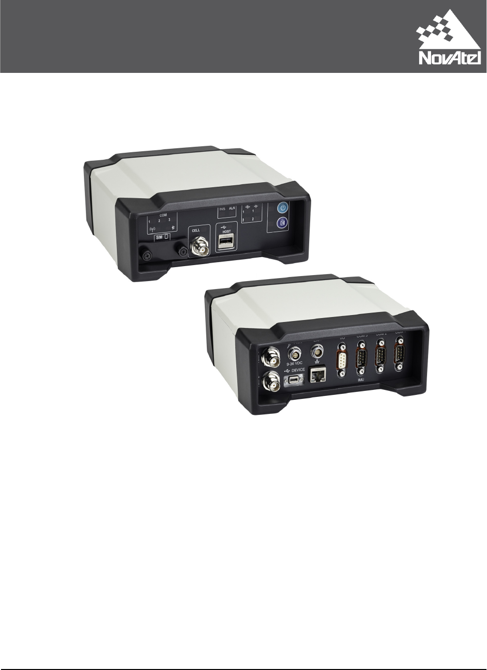
2 ProPak6—Back Connectors ............................................................................................... 17
3 ProPak6—Front Communication Ports, Buttons and Connectors ...................................... 18
4 Typical Standard Installation with External Oscillator ......................................................... 24
5 Antenna and External Oscillator Ports ................................................................................ 25
6 Power Port .......................................................................................................................... 25
7 Ethernet, COM or USB Device Ports .................................................................................. 25
8 Expansion and I/O Ports ..................................................................................................... 26
9 Typical Dual Antenna Installation ........................................................................................ 27
10 GNSS Antenna Ports .......................................................................................................... 27
11 Cellular Network Setup .......................................................................................................28
12 Additional COM ports on the ProPak6 ................................................................................ 32
13 CAN Bus ports on the ProPak6 ........................................................................................... 33
14 Power Button ....................................................................................................................... 44
15 Basic Differential Setup ....................................................................................................... 47
16 Positioning Change Without STEADYLINE ........................................................................ 51
17 STEADYLINE Maintain ....................................................................................................... 52
18 STEADYLINE Transition ..................................................................................................... 52
19 STEADYLINE Prefer Accuracy ........................................................................................... 53
20 STEADYLINE UAL- Warning Limit Example ....................................................................... 54
21 STEADYLINE UAL - Out of Bounds Example ..................................................................... 54
22 Product Information (Info) ...................................................................................................64
23 Status Display Top Panel .................................................................................................... 64
24 Cross-Over Ethernet Cable Configuration—ProPak6 ......................................................... 75
25 ProPak6 Ethernet Hardware Setup ..................................................................................... 78
26 Base/Rover Ethernet Setup—ProPak6 ............................................................................... 80
27 Wi-Fi Configuration Overview ............................................................................................. 84
28 SIM Card Installation ........................................................................................................... 91
29 NTRIP System .................................................................................................................... 93
30 WinLoad’s Open Window .................................................................................................... 98
31 Open File in WinLoad .......................................................................................................... 98
32 COM Port Setup .................................................................................................................. 98
33 Searching for Card .............................................................................................................. 99
34 Authorization Code Window ................................................................................................ 99
35 Upgrade Process Complete ................................................................................................ 99
36 Location of Receiver Status Word ....................................................................................... 107
37 Reading the Bits in the Receiver Status Word .................................................................... 107
38 Location of Receiver Error Word ......................................................................................... 108
39 Reading the Bits in the Receiver Error Word ...................................................................... 108
40 ProPak6 Dimensions ...........................................................................................................113
41 Bluetooth/Wi-Fi Antenna Keep-out Area and Antenna Location ......................................... 114

ProPak6 Installation and Operation User Manual Rev 5 7
Tables
1 ProPak6 Model Features......................................................................................................16
2 ProPak6 - Back Connector Definitions .................................................................................17
3 ProPak6 - Front Label Definitions......................................................................................... 19
4 ProPak6 Cables....................................................................................................................22
5 Enclosure Power Requirements ...........................................................................................30
6 Fuse/Holder Recommendations ........................................................................................... 31
7 INS LED States ....................................................................................................................37
8 ALN (ALIGN) LED States ..................................................................................................... 38
9 Satellite Tracking LEDs States (GPS and/or GNSS)............................................................ 38
10 Satellite Position LEDs States ..............................................................................................39
11 CELL LED States .................................................................................................................40
12 Data Communication Port Defaults ......................................................................................42
13 Status Drop Menu Examples................................................................................................ 65
14 COM1 and COM2 Port Pin-Out Descriptions ....................................................................... 115
15 COM3/IMU Port Pin-Out Description .................................................................................... 115
16 I/O Port Pin-Out Descriptions ............................................................................................... 116
17 Expansion Port Pin-Out Description .....................................................................................116
18 ProPak6 Strobe Electrical Specifications ............................................................................. 117
19 Wiring Table: ........................................................................................................................120
20 I/O Cable Wiring (01018519) ................................................................................................122
21 Twisted Pair I/O Cable Wiring Table (01019148) .................................................................122
22 ProPak6 Expansion Cable Pin-Out Descriptions.................................................................. 123
23 P2 Connector Pin-Out Descriptions...................................................................................... 124

ProPak6 Installation and Operation User Manual Rev 5 8
Notices
The following notices apply to the ProPak6 device.
FCC
This device complies with part 15 of the FCC Rules. Operation is subject to the following two conditions:
(1) this device may not cause harmful interference, and (2) this device must accept any interference
received, including interference that may cause undesired operation.
ProPak6 has been tested and found to comply with the radiated and conducted emission limits for a
Class B digital device. The Class B limits are designed to provide reasonable protection against harmful
interference in a residential installation.
The equipment listed generates, uses and can radiate radio frequency energy and, if not installed and
used in accordance with the instructions, may cause harmful interference to radio communications.
However, there is no guarantee that interference will not occur in a particular installation. If this
equipment does cause harmful interference to radio or television reception, which can be determined by
turning the equipment off and on, the user is encouraged to try to correct the interference by one or more
of the following measures:
• Re-orient or relocate the ProPak6
• Increase the separation between the equipment and the ProPak6
• Connect the equipment to an outlet on a circuit different from that to which the ProPak6 is
connected
• Consult the dealer or an experienced radio/TV technician for help
Innovation, Science and Economic Development (ISED) Canada
ProPak6 Class B digital device complies with Canadian ICES-003.
ProPak6 appareil numérique de la classe B est conforme à la norme NMB-003 du Canada.
This device complies with ISED license-exempt RSS-GEN and RSS-210. Operation is subject to the
following two conditions: (1) this device may not cause interference and (2) this device must accept any
interference, including interference that may cause undesired operation of the device.
Changes or modifications to this equipment, not expressly approved by NovAtel Inc., could
void the user’s authority to operate this equipment.
To maintain compliance with the limits of a Class B digital device, you must use properly
shielded interface cables (such as Belden #9539 or equivalent) when using the serial data
ports, and double-shielded cables (such as Belden #9945 or equivalent) when using the I/O
strobe port.

Notices
ProPak6 Installation and Operation User Manual Rev 5 9
Bluetooth®
The ProPak6 contains Bluetooth wireless technology (Bluetooth 2.1 SPP - Serial Port Profile).
The Bluetooth word mark and logos are registered trademarks owned by Bluetooth SIG, Inc. and any use
of such marks by NovAtel Inc., is under license. Other trademarks and trade names are those of their
respective owners.
Propak6 contains a Bluetooth radio with the following modular approvals:
• FCC ID: TFB-TIWI1-01
• IC: 5969A-TIWI101
Wi-Fi
The ProPak6 contains Wi-Fi wireless technology (802.11b/g/n). See the caution in Cell Port and LED on
page 40 and the Wi-Fi antenna keep-out information in Figure 41, Bluetooth/Wi-Fi Antenna Keep-out
Area and Antenna Location on page 114.
Propak6 contains a Wi-Fi radio with the following modular approvals:
• FCC ID: TFB-TIWI1-01
• IC: 5969A-TIWI101
Cellular
Some Propak6 models contain cellular radio technology.
Propak6 contains a cellular radio with the following modular approvals:
• FCC ID: RI7HE910
• IC: 5131A-HE910
FCC Radiation Exposure Statement
The radiated output power of this device is below the FCC radio frequency exposure limits.
Nevertheless, this device should be used in such a manner that the potential for human
contact during normal operation is minimized.
This device has been evaluated for and shown compliant with the FCC RF Exposure limits
under mobile exposure conditions. At least 20cm of separation distance between the
ProPak6 device (and from its cellular antenna) to the user's body must be maintained at all
times.
To comply with FCC and Industry Canada regulations limiting both maximum RF output
power and human exposure to RF radiation, the maximum system gain (antenna gain
minus system loss) must not exceed 1.4 dBi in the U.S. Cellular band and 3.0 dBi in the
PCS band for the GSM/GPRS/HSDPA variant. System loss is the total of external cable and
connector losses and ProPak6 internal losses. For reference and system gain calculation
purposes, the ProPak6 has internal losses of 0.6 dB for the 800 MHz Cellular band and 1.8
dB for the 1900 MHz PCS band.

10 ProPak6 Installation and Operation User Manual Rev 5
Notices
European Union (EU)
ProPak6 BT/Wi-Fi
NovAtel Inc. declares that the ProPak6 BT/Wi-Fi transceiver is in compliance with Directive 2014/53/EU
(Radio Equipment).
The full text of the EU Declaration of Conformity may be obtained from the NovAtel web site at:
www.novatel.com/products/compliance/eu-declaration-of-conformity
Radio Information
Description of Service: Wi-Fi (802.11b/g/n)
Operational Frequency: 2400 MHz to 2480 MHz
Modulation: OFDM
Rated Power: 18.6 dBm e.i.r.p
Description of Service: Bluetooth
Operational Frequency: 2400 MHz to 2480 MHz
Modulation: GFSK
Rated Power: 13.9 dBm e.i.r.p
ProPak6 BT/Wi-Fi/Cellular
NovAtel Inc. declares that the ProPak6 BT/Wi-Fi/Cellular transceiver is in compliance with Directive
2014/53/EU (Radio Equipment).
The full text of the EU Declaration of Conformity may be obtained from the NovAtel web site at:
www.novatel.com/products/compliance/eu-declaration-of-conformity
Radio Information
Description of Service: UMTS 900 MHz Band VIII
Transmit Frequency: 880 MHz to 915 MHz
Receive Frequency: 925 MHz to 960 MHz
Modulation: QPSK, 16 QAM
Power Class: Class 3
Rated Power: 24 dBm, conducted
Description of Service: UMTS 2100 MHz Band I
Transmit Frequency: 1920 MHz to 1980 MHz
Receive Frequency: 2110 MHz to 2170 MHz
Modulation: QPSK, 16 QAM
Power Class: Class 3
Rated Power: 24 dBm, conducted
Notices
ProPak6 Installation and Operation User Manual Rev 5 11
Instructions for Safe Operation of Equipment
The ProPak6 is capable of operation at ambient temperatures up to 65°C. In such cases the metallic
surface temperature of the ProPak6 may exceed 70°C. Therefore, under these conditions the equipment
needs to be installed in a RESTRICTED ACCESS LOCATION.
If the ProPak6 is operating in a lower temperature environment where the ambient temperature is less
than 60°C, installation in a RESTRICTED ACCESS LOCATION is not required.
Ethernet Port
WEEE Notice
If you purchased your ProPak6 product in Europe, please return it to your dealer or supplier at the end of
its life. The objectives of the European Community's environment policy are, in particular, to preserve,
protect and improve the quality of the environment, protect human health and utilise natural resources
prudently and rationally. Sustainable development advocates the reduction of wasteful consumption of
natural resources and the prevention of pollution. Waste electrical and electronic equipment (WEEE) is a
regulated area. Where the generation of waste cannot be avoided, it should be reused or recovered for
its material or energy. WEEE products may be recognized by their wheeled bin label ( ).
See www.novatel.com/products/compliance/environmental-compliance for more information.
RoHS
The ProPak6 is in conformity with Directive 2011/65/EU of the European Parliament and of the council of
8 June 2011 on the restriction of the use of certain hazardous substances in electrical and electronic
equipment.
REACH
The ProPak is compliant with Regulation (EC) No. 1907/2006 of the European Parliament and the
Council of 18 December 2006 concerning the Registration, Evaluation, Authorization and Restriction of
Chemicals (REACH). The candidate list of Substances of Very High Concern (SVHC) published by the
European Chemical Agency (ECHA) is available at:
https://echa.europa.eu/candidate-list-table
The Ethernet ports are safety extra-low voltage (SELV) circuits only and are suitable for
connection within a building only. Do not connect them to telephone-network voltage (TNV)
circuits.
Cables may contain DEHP (CAS Number 117-81-7) in concentrations above 0.1% w/w.

12 ProPak6 Installation and Operation User Manual Rev 5
Notices
Lightning Protection Installation and Grounding Procedures
What is the hazard?
A lightning strike into the ground causes an increase in the earth's potential which results in a high
voltage potential between the center conductor and shield of the coaxial cable. This high voltage
develops because the voltage surge induced onto the center conductor lags in time behind the voltage
surge induced onto the shield.
Hazard Impact
A lightning strike causes the ground potential in the area to rise to dangerous levels resulting in harm to
personnel or destruction of electronic equipment in an unprotected environment. It also conducts a
portion of the strike energy down the inner conductor of the coax cable to the connected equipment.
Actions to Mitigate Lightning Hazards
1. Do not install antennas or antenna coaxial cables outside the building during a lightning storm.
2. It is not possible to avoid over-voltages caused by lightning, but a lightning protection device may be
used to shunt a large portion of the transient energy to the building ground reducing the over-voltage
condition as quickly as possible.
3. Primary lightning protection must be provided by the operator/customer according to local building
codes as part of the extra-building installation.
4. To ensure compliance with clause 7 "Connection to Cable Distribution Systems" of EN 60950-1,
Safety for Information Technology Equipment, a secondary lightning protection device must be used
for in-building equipment installations with external antennas. The following device has been
approved by NovAtel Inc.:
Polyphaser - Surge Arrestor DGXZ+24NFNF-B
If this device is not chosen as the primary lightning protection device, the device chosen must meet
the following requirements:
• UL listed, or equivalent, in country of installation (for example, TUV, VDE and so on) for lightning
surge protection
• The primary device must be capable of limiting an incoming surge of 10 kV
5. The shield of the coaxial cable entering the building should be connected at a grounding plate at the
building's entrance. The lightning protection devices should have their chassis grounded to the same
ground near to the building's entrance.
6. The primary and secondary lightning protections should be as close to the building's entrance as
possible. Where feasible they should be mounted onto the grounding plate itself. See Figure 1,
Primary and Secondary Lightning Protection on page 13.
Only qualified personnel, electricians as mandated by the governing body in the country of
installation, may install lightning protection devices.
Notices
ProPak6 Installation and Operation User Manual Rev 5 13
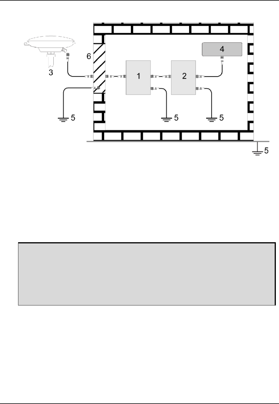
Figure 1: Primary and Secondary Lightning Protection
These installation instructions are the minimum requirements for receiver and antenna installations.
Where applicable, follow the electrical codes for the country of installation. Examples of country codes
include:
• USA National Electrical Code (NFPA 70)
• Canada Canadian Electrical Code (CSA C22)
• UK British Standards Institute (BSI 7671)
Ref # Description
1 Primary lightning protection device
2 Secondary lightning protection device
3 External antenna
4 GNSS Receiver
5 To ground
6 Grounding plate or grounding point at the building’s entrance
Acceptable choices for Earth Grounds, for central buildings, are:
• Grounded interior metal cold water pipe within five feet (1.5 m) of the point where it
enters the building
• Grounded metallic service raceway
• Grounded electrical service equipment enclosure
• Eight-foot grounding rod driven into the ground (only if bonded to the central
building ground by #6, or heavier, bonding wire)

14 ProPak6 Installation and Operation User Manual Rev 5
Notices
Manual Scope
This manual contains information about the installation and operation of the ProPak6 system. It is beyond
the scope of this manual to provide details on service or repair. Contact your local NovAtel dealer for any
customer-service related inquiries, refer to Customer Support on page 15.
A ProPak6 system requires the addition of accessories, an antenna and a power supply.
ProPak6 output is compatible with post-processing software from NovAtel's Waypoint® Products Group.
Visit our Web site at www.novatel.com for details.
Global Navigation Satellite System (GNSS) positioning observes range measurements from orbiting
GNSS satellites. From these observations, the receiver can compute position and velocity with high
accuracy. NovAtel GNSS positioning systems are highly accurate positioning tools. GNSS positioning
requires line of sight view to at least four satellites simultaneously and differential GNSS positioning can
be accurate to within a few centimeters. For a detailed discussion of GNSS, refer to NovAtel’s book
Introduction to GNSS available from our web site.
Conventions
The following conventions are used in this manual:
Information that supplements or clarifies text.
A caution that actions, operation or configuration may lead to incorrect or improper use of
the hardware.
A warning that actions, operation or configuration may result in regulatory noncompliance,
safety issues or equipment damage.

15 ProPak6 Installation and Operation User Manual Rev 5
Customer Support
NovAtel Knowledge Base
If a technical issue i s encountered, browse the NovAtel Web site: www.novatel.com/support/search. Use
the support pages to search for general information about GNSS and other technologies, information
about NovAtel hardware and software and installation and operation issues.
Before Contacting Customer Support
Before contacting NovAtel Customer Support about a software problem, perform the following steps:
1. Log the following data to a file a computer for 15 minutes:
RXSTATUSB ONCHANGED
RAWEPHEMB ONCHANGED
RANGECMPB ONTIME 1
BESTPOSB ONTIME 1
RXCONFIGA ONCE
VERSIONA ONCE
2. If using one of the ProPak6 network interfaces, also log the following as necessary:
WIFICONFIG ONCE
WIFIAPSTATUS ONCHANGED
WIFICLISTATUS ONCHANGED
BLUETOOTHSTATUS ONCHANGED
CELLULARSTATUS ONCHANGED
LOGFILESTATUS ONCE
3. Send the data file to NovAtel Customer Support, using either the NovAtel FTP site at ftp://
ftp.novatel.ca/ or through the support@novatel.com e-mail address.
4. You can also issue a FRESET command to the receiver to clear any unknown settings.
If you are having a hardware problem, send a list of the troubleshooting steps taken and results.
Contact Information
Log a support request with NovAtel Customer Support using one of the following methods:
Log a Case and Search Knowledge:
Website: www.novatel.com/support
Log a Case, Search Knowledge and View Your Case History: (login access required)
Web Portal: https://novatelsupport.force.com/community/login
E-mail:
support@novatel.com
Telephone:
U.S. and Canada: 1-800-NOVATEL (1-800-668-2835)
International: +1-403-295-4900
The FRESET command will erase all user settings. You should know your configuration and
be able to reconfigure the receiver before you send the FRESET command.

16 ProPak6 Installation and Operation User Manual Rev 5
Chapter 1 Introduction
1.1 Introduction
The ProPak6 is a high performance Global Navigation Satellite System (GNSS) receiver capable of
receiving and tracking different combinations of GNSS signal and integrated L-Band on 240 channels.
GPS, GLONASS, Galileo, BeiDou, QZSS and SBAS support are standard and the ProPak6 adaptability
offers multi-system, frequency and size configurations for any application requirement. ProPak6 models
have a NovAtel OEM638 receiver card; some models also include a NovAtel OEM615 receiver card for
additional functionality. Excellent acquisition and re-acquisition times allow this receiver to operate in
environments where very high dynamics and frequent interruption of signals can be expected. The
ProPak6 options include integrated radio and dual input heading options to provide a tightly integrated
and rugged solution for any application.
1.2 System Components
The ProPak6 system includes the following components:
• OEM638 receiver with built in Wi-Fi, Bluetooth, USB 2.0 and 4 GB of onboard memory
• 12 VDC power adapter (CLA) with slow blow fuse
• Null modem cable
• DB9 male extension cable
• I/O DB9 male interface cable
• Mounting bracket and hardware
Refer to Section 2.2.1, ProPak6 Cables on page 22, Section 2.6.1, Mounting the GNSS Antenna on
page 30 and Appendix A, Technical Specifications on page 110 for details on cables and mounting the
ProPak6.
Refer to Section 2.1, Additional Equipment Required on page 21 for a equipment not included with the
ProPak6.
1.3 Models and Features
The ProPak6 is available in several different firmware models whose configurations may include other
additional features.
Table 1: ProPak6 Model Features
Model Configuration
Firmware Features
External
Oscillator
Dual
Antenna
Cellular/
HSPA
OEM638
Card
OEM615
Card
ProPak6 Dual/Cellular ■■■■
ProPak6 Dual ■■■
PP6 Single/Cellular ■■■
PP6 Single ■■

Introduction Chapter 1
ProPak6 Installation and Operation User Manual Rev 5 17
1.4 Overview—ProPak6 Hardware
The ProPak6 has a series of ports on the back of the unit for connecting specific cables. In the front, the
ProPak6 is outfitted with a number of LEDs to indicate receiver status, buttons to initiate functionality and
access to onboard storage (model dependent).
Figure 2: ProPak6—Back Connectors
Ethernet, Wi-Fi, Bluetooth, high speed USB 2.0 and 4 GB onboard memory available
on all models. Refer to Appendix A, Technical Specifications on page 110, Section
NovAtel Part Numbers for model details.
Table 2: ProPak6 - Back Connector Definitions
Connector Type Connector Label Description
GNSS Antenna
External Oscillator
ANT 1
ANT 2
or
ANT1
OSC
GNSS GPS1 and GPS2 antennas (TNC) (model dependent)
or
GNSS GPS1 antenna (TNC) and external oscillator (BNC) (model
dependent)
Refer to Figure 5, Antenna and External Oscillator Ports on
page 25 for details
Power PWR
4-pin LEMO power connector
Refer to Figure 6, Power Port on page 25 for details
Expansion EXP.
9-pin LEMO expansion port for CAN1, CAN2 and an additional USB
host port
Refer to Figure 8, Expansion and I/O Ports on page 26 for details
USB DEVICE
USB Device (Type micro B) connector
Refer to Figure 7, Ethernet, COM or USB Device Ports on page 25
for details
Ethernet
Ethernet RJ45 connector
Refer to Figure 7, Ethernet, COM or USB Device Ports on page 25
for details
I/O
I/O
Event Input/output (DB9 female connector)
I/O port is configurable
Refer to Figure 8, Expansion and I/O Ports on page 26 for details
Serial
Communication Port
COM1
COM2
COM3/IMU
COM1, COM2, COM3/IMU DB9 male communications port
RS-232 and RS-422 selectable via software
Refer to Figure 7, Ethernet, COM or USB Device Ports on page 25
for details
ANT2 indicates Dual Antenna model
OSC indicates External Oscillator model

18 ProPak6 Installation and Operation User Manual Rev 5
Chapter 1 Introduction
Figure 3: ProPak6—Front Communication Ports, Buttons and Connectors
Also refer to Appendix A, Technical Specifications on page 110 for connector details.
The Bluetooth/Wi-Fi antennas are located on the front of the ProPak6 (not visible).
Refer to Figure 41, Bluetooth/Wi-Fi Antenna Keep-out Area and Antenna Location on
page 114 for exact location and keep-out dimensions for this antenna.
INS ALN
HOST
CELL
INS ALN
HOST
Cellular Model
Non-cellular Model
Bluetooth/Wi-Fi
antenna location
Introduction Chapter 1
ProPak6 Installation and Operation User Manual Rev 5 19
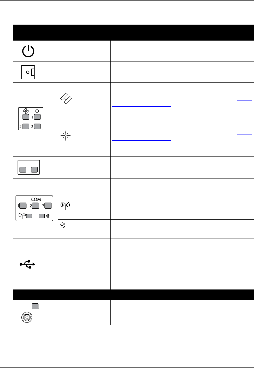
Table 3: ProPak6 - Front Label Definitions
Button/Connector/
LED Type Label LED Description
N/A Yes
Power button and status LED
Refer to Section 3.2.1, Applying Power to the Receiver on page 44
for details
N/A Yes
Logging button with user configurable status LED
Refer to Section 3.7, Logging and Retrieving Data Overview on
page 58 for details
Tracking
Yes
Indicates number of satellites being tracked by the corresponding
receiver
User configurable (refer to the LEDCONFIG command in the OEM6
Firmware Reference Manual - OM-20000129)
Refer to Section 3.1.8, Satellite Tracking and Positioning LEDs on
page 38 for details
Position
Yes
Indicates satellite position status for the corresponding receiver
User configurable (refer to the LEDCONFIG command in the OEM6
Firmware Reference Manual - OM-20000129)
Refer to Section 3.1.8, Satellite Tracking and Positioning LEDs on
page 38 for details
INS
ALN Yes
INS status indication (SPAN configuration only)
ALIGN heading status indication (Dual antenna configuration only)
Refer to Section 3.1.7, INS and ALIGN LEDs on page 37 for details
COM 1, 2 and 3 Yes
Transmit/Receive indication (COM 1, 2 and/or 3)
Refer to Section 3.1.13.1, Configure COM 1, 2 and 3 on page 43 and
Section 3.1.4, COM Ports LEDs on page 36 for details
Wi-Fi
Yes Wi-Fi radio status LED
Refer to Section 3.1.6, Wi-Fi LED on page 37 for details
Bluetooth
Yes Bluetooth radio status LED
Refer to Section 3.1.5, Bluetooth LED on page 37 for details
HOST Yes
USB Host (Type A) connector - ProPak6 built in USB host with status
LED
Memory stick port for automatic downloading of logged data (refer to
Section 3.7, Logging and Retrieving Data Overview on page 58) and
updating firmware (refer to Section 7.4, Updating Using SoftLoad
Commands on page 99)
Refer to Section 3.1.10, Universal Serial Bus (USB) Port and LEDs
on page 40 for details
CELLULAR - OPTIONAL (refer to 5.3, Cellular Activation GSM/GPRS/HSDPA on page 90)
CELL Yes
Fully integrated TNC, cellular modem antenna connector (GPRS/
HSPA) and status LED
Refer to Section 3.1.9, Cell Port and LED on page 40 for details
INS ALN

20 ProPak6 Installation and Operation User Manual Rev 5
Chapter 1 Introduction
Mini-SIM only
(25 mm x 15 mm)
SIM No
Push-push style SIM card holder
Remove SIM card holder cover to insert card; replace cover to avoid
damaging card
Table 3: ProPak6 - Front Label Definitions
Button/Connector/
LED Type Label LED Description
Open Covered

21 ProPak6 Installation and Operation User Manual Rev 5
Chapter 2 Installation
This chapter contains instructions and tips to install the ProPak6 and create a GNSS receiver system.
2.1 Additional Equipment Required
Refer to Chapter 1, Introduction on page 16 for a list of components included with the Propak6. In order
for the receiver to perform optimally, the following additional equipment is required:
• At least one GNSS antenna and antenna cable with a TNC male connector at the receiver end. For
example, a quality, dual-frequency GNSS antenna such as NovAtel’s GPS-702-GG or ANT-A72GA-
TW-N for airborne/high speed applications. See the NovAtel website www.novatel.com/products/
gnss-antennas) for information on a variety of quality antennas available to meet your form factor
and performance needs.
User Supplied Additional Equipment (as required)
• A quality coaxial cable and interconnect adapter cable as necessary (user-supplied)
• A Windows based computer
• A means of communicating between the ProPak6 and computer or other external devices:
• Ethernet cable
• USB micro-B cable
• RS-232 serial cable
• RS-422 serial cable
• A cellular link
• A cell antenna such as PCTEL Inc., MLPV800 (12023303) and magnetic mount such as PCTEL Inc.,
GMHFML195C (12023300)cellular radio antenna cable
•Bluetooth link
•Wi-Fi network
• Real-time data collection, status monitoring and receiver configuration is possible through the
NovAtel Connect™ PC Utilities software is available from our web site: www.novatel.com/support/
info/documents/809.
Use a serial COM or USB connection to communicate with the receiver first. This
provides the ability to configure the computer and ProPak6 before Wi-Fi, Ethernet,
Bluetooth or cellular are configured and used.
When the ProPak6 is installed in a permanent location, such as in a building, it should
be protected by a lightning protection device according to local building codes. See
Lightning Protection Installation and Grounding Procedures on page 12.

22 ProPak6 Installation and Operation User Manual Rev 5
Chapter 2 Installation
2.2 ProPak6 Hardware
2.2.1 ProPak6 Cables
To prevent damage to both the receiver and the cables, each connector can be inserted in only one way.
Furthermore, the connectors used to mate the cables to the receiver require careful insertion and
removal. Observe the following when handling cables.
• To insert a cable, make certain to use the appropriate cable for the port
• Insert the connector until it is on straight and secure
• To remove a cable, grasp it by the connector
Table 4: ProPak6 Cables
For more information about the cables used with ProPak6, refer to Section A.5, Cables on page 119.
2.2.2 Selecting a GNSS Antenna
An active antenna is required because its Low Noise Amplifier (LNA) boosts the power of the incoming
signal to compensate for the line loss between the antenna and the receiver.
NovAtel offers a variety of single and dual-frequency GNSS antenna models. All include band pass
filtering and an LNA. The GNSS antenna chosen depends on the particular application. Each model
offers exceptional phase-center stability as well as a significant measure of immunity against multipath
interference. Each one has an environmentally-sealed radome.
2.2.3 Choosing a Coaxial Cable
An appropriate 50 ohm coaxial cable whose line loss does not exceed 10.0 dB. If the limit is exceeded,
excessive signal degradation may occur and the receiver may not be able to meet its performance
specifications. NovAtel offers a variety of coaxial cables to meet GNSS antenna interconnection
requirements, including:
• 5, 15, or 30 m antenna cables with TNC male connectors on both ends (NovAtel part numbers C006,
C016 and C032 respectively)
A local NovAtel dealer can offer advise about specific configuration requirements. If an application
requires the use of cables longer than 30 m, refer to the application note APN-003 RF Equipment
Selection and Installation on our website or obtain it directly by contacting NovAtel (refer to Contact
Information on page 15).
High quality coaxial cables should be used.
Do not pull directly on a cable.
NovAtel Part # Port Labeled Purpose
01017658 COM1
COM2
COM3/IMU
Null modem cable, 6 foot DB9 female/female
Provides connections for:
COM1
COM2
COM3/IMU
01017663 PWR Power cable assembly, 4-Pin LEMO - 6 amp cigarette lighter
01018520 COM1 Extension cable 6 feet DB9 male/female ITE (straight through)
01018519 I/O 6 foot DB9 male/single ended ITE cable (DB9 to wire leads)
01019154 EXP Expansion cable for access to COM7, 8, 9 and 10 as well as CAN1
and CAN2

Installation Chapter 2
ProPak6 Installation and Operation User Manual Rev 5 23
2.3 Communication with the ProPak6
The ProPak6 can communicate with a computer or computer network in a number of ways:
• Communicate via the serial COM ports using either RS-232 or RS-422 (refer to Section 3.1.13.1,
Configure COM 1, 2 and 3 on page 43)
• Communicate via the USB Device port from a computer containing necessary drivers (refer to
Section 3.1.10, Universal Serial Bus (USB) Port and LEDs on page 40)
• Remove logged data files using the USB Host port (refer to Section 3.1.10, Universal Serial Bus
(USB) Port and LEDs on page 40)
• Communicate via the Ethernet port to connect to an existing network (refer to Section 3.1.11,
Ethernet Port on page 41)
• Communicate using built in Bluetooth wireless device communications (refer to Section 5.1,
Bluetooth® Configuration on page 82)
• Communicate using built in Wi-Fi to create or join a wireless network (refer to 5.2, Wi-Fi Network
Configuration on page 84)
• Communicate using an optional cellular radio (refer to Section 5.3, Cellular Activation GSM/GPRS/
HSDPA on page 90)
2.3.1 Power Supply Requirements
This section contains information on the requirements for the input power to the receiver (refer to
Figure 6, Power Port on page 25 for port location). See Appendix A, Technical Specifications on
page 110 for more power supply specifications.
The ProPak6 is supplied with a 12 V power adapter with a built-in 6 A slow blow fuse for use with a
standard 12 VDC power outlet. When valid voltage is present at the power supply input, the ProPak6
power LED briefly flashes red and then turns solid green (operational mode). The power button only
needs to be pressed to turn off the ProPak6. Refer to Section 3.2.1, Applying Power to the Receiver on
page 44 for details on powering the ProPak6 and Section 3.2.1.1, Power Down and Reset the ProPak6
on page 45 for instructions on powering down the ProPak6.
2.3.2 COM1 and COM2 Peripheral Power
The peripheral power from COM1 and COM2 can be controlled using the COMVOUT command. The
peripheral power is directly supplied from the enclosure input voltage (the 4-pin LEMO) and can be
output to pin-4 of both COM1 and COM2 (refer to Figure 7, Ethernet, COM or USB Device Ports on
page 25 for port location).
If the voltage supplied is below the minimum specification, the receiver suspends
operation. If the voltage supplied is above the maximum specification, the receiver may
be permanently damaged, voiding the warranty. The supply must be capable of
providing enough current to operate the ProPak6, including the initial inrush transient.
The supply must also be current limited to 6 A with an external fuse.
For alternate power supply and battery backup details, refer to Section 2.7, ProPak6
Alternative Power Source on page 30 and/or 2.7.1, Battery Backup on page 31.
To avoid damaging the ProPak6 or the connected device, the physical connection must
be capable of handling up to 36 V before the COMVOUT command is issued.
24 ProPak6 Installation and Operation User Manual Rev 5
Chapter 2 Installation
The available power for both COM ports are shared (maximum 1.5 A total in any combination between
the ports). If only one COM port is used, the entire 1.5 A is available to that port. The total peripheral
power current is limited to 1.5 A. Transient currents greater than 1.5 A are clamped by the ProPak6.
Refer to A.2, ProPak6 Specifications on page 111 for baud rates. Refer to the OEM6 Firmware
Reference Manual (OM-20000129) for COMVOUT command details.
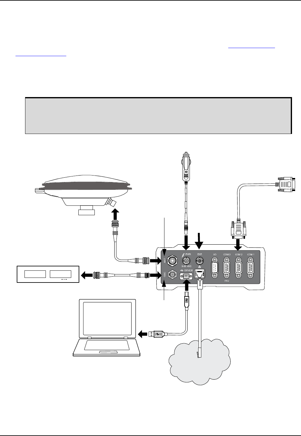
2.4 Standard Configuration Installation
Complete the steps below to connect and power a standard ProPak6 configuration.
Figure 4: Typical Standard Installation with External Oscillator
1. Mount a GNSS antenna (user supplied) on a secure, stable structure with an unobstructed view of
the sky from horizon to horizon. Refer also to Section 2.6.1, Mounting the GNSS Antenna on
page 30.
If using the ProPak6 in a low vibration installation, attach the included mounting
brackets to the ProPak6 prior to cabling. Complete mounting instructions are contained
in the Quick Start Guide included with the ProPak6. Refer to Section 2.7.4, Mounting
the ProPak6 on page 33 for direct mounting instructions.
Network
Marked ANT
Marked OSC
Installation Chapter 2
ProPak6 Installation and Operation User Manual Rev 5 25
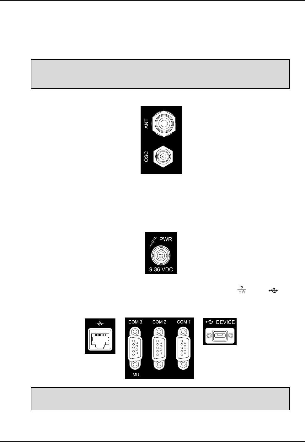
2. Use a coaxial cable (user supplied) to connect an antenna to the TNC ANT port on the back face of
the ProPak6 (Figure 5). Refer also to Section 3.1.16, Antenna LNA Port on page 44.
3. Use a coaxial cable (user supplied) to connect an external oscillator to the BNC OSC port on the
back face of the ProPak6 (Figure 5). Refer also to Section 3.1.17, External Oscillator Port (model
dependent) on page 44.
Figure 5: Antenna and External Oscillator Ports
Refer to the Input/Output Connectors section of A.2, ProPak6 Specifications on page 111.
4. The power cable connector (included) is keyed to the PWR 9-36 VDC connector (Figure 6) on the
back of the ProPak6. Line up the red dot on the cable with the red line on the connector port and
insert. Refer also to Section 3.2.1, Applying Power to the Receiver on page 44.
Figure 6: Power Port
5. Use the appropriate cable to connect a computer to the COM port, Ethernet port or DEVICE
port on the back of the ProPak6 (Figure 7).
Figure 7: Ethernet, COM or USB Device Ports
The external oscillator is an optional model. If the dual-antenna model is used, refer
to Section 2.5, Dual Antenna Configuration and Installation on page 26 for
installation instructions.
COM ports are configurable to RS-232 or RS-422. Refer to Section 3.1.13.1,
Configure COM 1, 2 and 3 on page 43 for configuration instructions.
26 ProPak6 Installation and Operation User Manual Rev 5
Chapter 2 Installation
Refer to the Input/Output Connectors section of A.2, ProPak6 Specifications on page 111. Also refer to
Table 14, COM1 and COM2 Port Pin-Out Descriptions on page 115 and Table 15, COM3/IMU Port Pin-
Out Description on page 115.
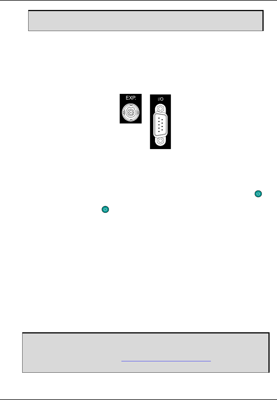
6. Connect the I/O signals (optional) and/or expansion (EXP.) devices (optional) on the back of the
ProPak6 using the appropriate cables (Figure 8). Refer also to Section 3.1.14, I/O Port on page 43
and/or Section 3.1.15, Expansion Port on page 43.
Figure 8: Expansion and I/O Ports
Refer to the Input/Output Connectors section of A.2, ProPak6 Specifications on page 111. Also refer to
Table 16, I/O Port Pin-Out Descriptions on page 116 and Table 17, Expansion Port Pin-Out Description
on page 116.
7. Connect the ProPak6 to a power source. Once power is detected or activity detected on COM1,
COM2 or COM3, the ProPak6 automatically enters Operational mode. The LED beside the
button on the front of the ProPak6 briefly turns red and then turns solid green. The ProPak6 is now in
Operational mode. The power button is only pressed to turn off the ProPak6. Refer to
Section 3.2.1, Applying Power to the Receiver on page 44 for instructions on turning on the ProPak6.
2.5 Dual Antenna Configuration and Installation
NovAtel's ALIGN® heading technology generates distance and bearing information between a “master”
and one or more “rover” receivers. This information can be used by SPAN® to update the inertial error
estimates and improve attitude accuracy. This is particularly useful in applications with reduced motion.
ProPak6 Dual Antenna provides the hardware necessary to run an ALIGN baseline with a second
receiver.
With ProPak6, the ALIGN GNSS baseline can be used to assist the initial alignment of the SPAN
solution. In addition, the ALIGN baseline solution aids the heading solution from the receiver if the
heading drifts due to slow or constant dynamics.
ALIGN is capable of a 10 Hz heading output rate when integrated with the ProPak6 receiver.
Complete the steps below to connect and power a dual antenna ProPak6 configuration.
The Ethernet port must be configured prior to first use. Refer to Chapter 4, Ethernet
Configuration on page 74 for configuration instructions.
The ProPak6 may contain an OEM615 receiver used as a dual antenna. The
DUALANTENNAPOWER command controls the LNA power to that receiver, independent of
the OEM638's LNA. The dual antenna power feature is on, by default, for dual antenna
ProPak6 models. Refer to the OEM6 Firmware Reference Manual (OM-20000129) for
command details.
Installation Chapter 2
ProPak6 Installation and Operation User Manual Rev 5 27
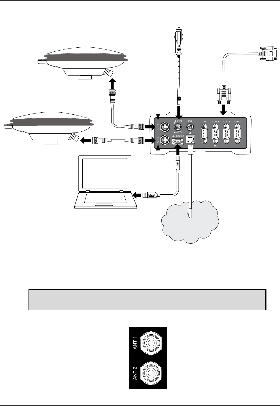
Figure 9: Typical Dual Antenna Installation
1. Mount GNSS antennas (user supplied) on a secure, stable structure with an unobstructed view of the
sky from horizon to horizon. Refer also to Section 2.6.1, Mounting the GNSS Antenna on page 30.
2. Use a coaxial cable (user supplied) to connect an antenna to the TNC ANT1 port and connect a
second antenna to the other TNC ANT2 port on the back face of the ProPak6 (Figure 10).
Figure 10: GNSS Antenna Ports
Network
Marked ANT2
Marked ANT1
Install the ProPak6 and the two antennas in the vehicle such that the relative
distance between them is fixed.
28 ProPak6 Installation and Operation User Manual Rev 5
Chapter 2 Installation
3. Insert the power cable connector into the PWR 9-36 V connector (Figure 6) on the back of the
ProPak6. Refer to Section 3.2.1, Applying Power to the Receiver on page 44 for details on applying
power and power modes.
4. Use the appropriate cables to make any additional connections for communications as required and
as described in the steps for Standard Configuration Installation on page 24 beginning at step 5.
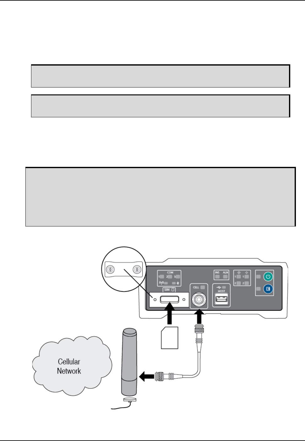
2.6 Cellular Antenna Installation
The ProPak6 has a cellular antenna port to facilitate the connection of an external cellular antenna. An
external antenna must be connected to this port in order to use the integrated cellular radio.
Figure 11: Cellular Network Setup
1. Remove the SIM card holder cover.
For instructions on setting up heading, refer to 3.5, External ALIGN Master or
Rover Configuration Only on page 50.
The Ethernet port must be configured prior to first use. Refer to Chapter 4, Ethernet
Configuration on page 74 for configuration instructions.
To comply with FCC regulations limiting both maximum RF output power and human
exposure to RF radiation, the maximum system gain (antenna gain minus system loss)
must not exceed 1.4 dBi in the U.S. Cellular band and 3.0 dBi in the PCS band for the
GSM/GPRS/HSDPA variant. System loss is the total of external cable and connector
losses and ProPak6 internal losses. For reference and system gain calculation
purposes, the ProPak6 has internal losses of 0.6 dB for the 800 MHz Cellular band and
1.8 dB for the 1900 MHz PCS band.

Installation Chapter 2
ProPak6 Installation and Operation User Manual Rev 5 29
2. Insert the SIM card and replace the card holder cover.
3. Use a coaxial cable to connect an antenna to the CELL port on the front face of the ProPak6. Specific
antenna types are available from NovAtel for the GSM/GPRS/HSDPA version of the ProPak6.
Secure the RF connector to the ProPak6 ensuring a “hand tight” connection.
Refer to Section 5.3, Cellular Activation GSM/GPRS/HSDPA on page 90 for details on activating a
cellular network. Refer to Section 3.1.9, Cell Port and LED on page 40 for details on cell status
information. Also refer to the section Mobile/Cellular Antenna Port, A.2, ProPak6 Specifications on
page 111.
Once the SIM card is correctly installed, secure the SIM cover to the base using a
screwdriver. Screws should be torqued to 4-6 inch-pound. Failure to properly
secure SIM cover will violate ProPak6 IP67 ingress rating.
Ensure the cellular antenna is installed at least 30 cm away from the ProPak6 or
GNSS positioning accuracy may be degraded. Refer to Figure 41, Bluetooth/Wi-Fi
Antenna Keep-out Area and Antenna Location on page 114 for details.
• Antennas must be installed on a “ground plane”. A vehicle with a metal roof is
inherently a ground plane. For vehicles with a non-metallic roof a metal ground
plane (available from NovAtel) must be used.
• When installing the antenna on a metallic roof, it is recommended that the
antenna be installed no closer than 10 cm, (4 inches) from the edge of the
rooftop, to avoid adversely affecting the antenna performance due to distortion
of the antenna pattern.
• The NovAtel ground plane accessory for use on non-metallic vehicle cab roofs
is designed to provide a sufficient symmetrical ground plane around the
antenna to guarantee optimal antenna performance.
• Do not shorten the cable lengths provided with any particular antenna type as
this creates a safety hazard.
• Do not use pliers or other tool types to over tighten the RF connector as
damage to the connector will occur.
• Ensure the RF connectors (male and female) are clean and dry before mating.
Low pressure compressed air can be used to clean the connectors (that is,
compressed air available in aerosol can format). Do not use a high pressure
compressed air as moisture seals in the connector can be damaged. If the
ProPak6 is moved between multiple vehicles each with its own cellular
antenna, some means of sealing the unmated RF connectors should be used.
Cellular radio frequencies are much higher than older forms of radio
communications; the effects of moisture and/or dust will have a greater effect
on performance.

30 ProPak6 Installation and Operation User Manual Rev 5
Chapter 2 Installation
2.6.1 Mounting the GNSS Antenna
The ProPak6 has been designed to operate with any of the NovAtel single-frequency or dual-frequency
GNSS antenna models.
When installing the antenna system:
• Choose an antenna location with a clear view of the sky so that each satellite above the horizon can
be tracked without obstruction (refer to Multipath in NovAtel’s book Introduction to GNSS available
from our web site).
• Mount the antenna on a secure, stable structure capable of safe operation in the specific
environment.
2.7 ProPak6 Alternative Power Source
If a different supply is desired, the table below provides the input range and type of connector required to
mate with the enclosure’s power connector. The supply should be capable of 14 W.
If the 12 V car adapter is not convenient, it can be cut off from the power cable. The exposed wires can
then be tied to a 9-36 VDC power supply capable of at least 14 W through a user supplied 6 Amp fuse.
For an alternative power source:
1. Cut the 12 V car adapter from the power cable.
2. Install a user supplied 6 A slow blow fuse at the power source to protect the power supply wiring and
the warranty.
3. Tie the exposed wires to a 9-36 VDC supply capable of at least 14 W. Be sure to connect the red and
orange or green wires to the positive side of the power supply and connect the black and brown or
white wires to the negative side of the power supply.
4. Plug in the adapter and/or turn on the power supply. The power LED briefly turns red when power is
detected and then turns green and enters operational mode.
Table 5: Enclosure Power Requirements
Enclosure Power Cable Connector Required Power Input Range
ProPak6 4-pin LEMO socket connector a labeled PWR
a. See Appendix B, Replacement Parts on page 125 for connector part numbers.
+9 to +36 V DC
The supplied 12 V power adapter cannot be used for 24 V or above systems.
Since the 12 V car adapter on the supplied adapter cable incorporates a 6 A fuse, a
user supplied 6 A slow blow fuse in a suitable holder must be used at the alternate
power source to protect both the power supply and the warranty.
The ProPak6 provides an output voltage on pin 4 of COM1 and COM2 (POUT).
This output voltage is at the same level as the power source used to power the
ProPak6.
Installation Chapter 2
ProPak6 Installation and Operation User Manual Rev 5 31
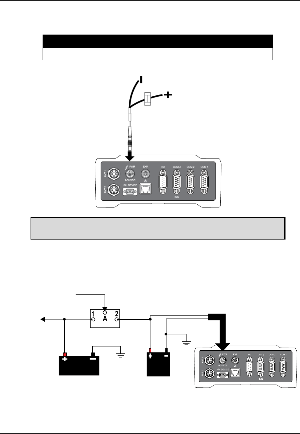
For a 12 V System the following are recommended:
2.7.1 Battery Backup
If installed in a vehicle so as to avoid loss of lock when tracking L-Band, it is recommended a back-up
battery be placed between the receiver and the voltage supply as a power buffer. When a vehicle engine
is started, power can dip to below minimum operating voltage or cut-out to ancillary equipment causing
the receiver to lose lock and calibration settings.
Table 6: Fuse/Holder Recommendations
Fuse Holder
BK/MDA-6-R Fuse (or equivalent) BK/HFA-R-R Fuse (or equivalent)
The fuse and holder are made by Cooper/Bussmann; available from Digikey.
6 A Fuse
Vehicle Main Auxiliary
Battery Isolator
from Vehicle
Alternator
to Vehicle Electrical
System
Battery
Battery
32 ProPak6 Installation and Operation User Manual Rev 5
Chapter 2 Installation
2.7.1.1 Seamless Battery Swap
Two batteries can be connected at the same time. Lemo connectors positive wires (2 and 3) should be
split. The two positives are combined on the ProPak6 via diodes so no current can flow from one battery
to the other. The battery with the highest voltage supplies power to the ProPak6. The negative wires
should not be split. Be sure that both supplies share a common ground and are connected to the ground
of the ProPak6. If a battery requires charging, it can be removed without experiencing any power
interruption (battery A or B).
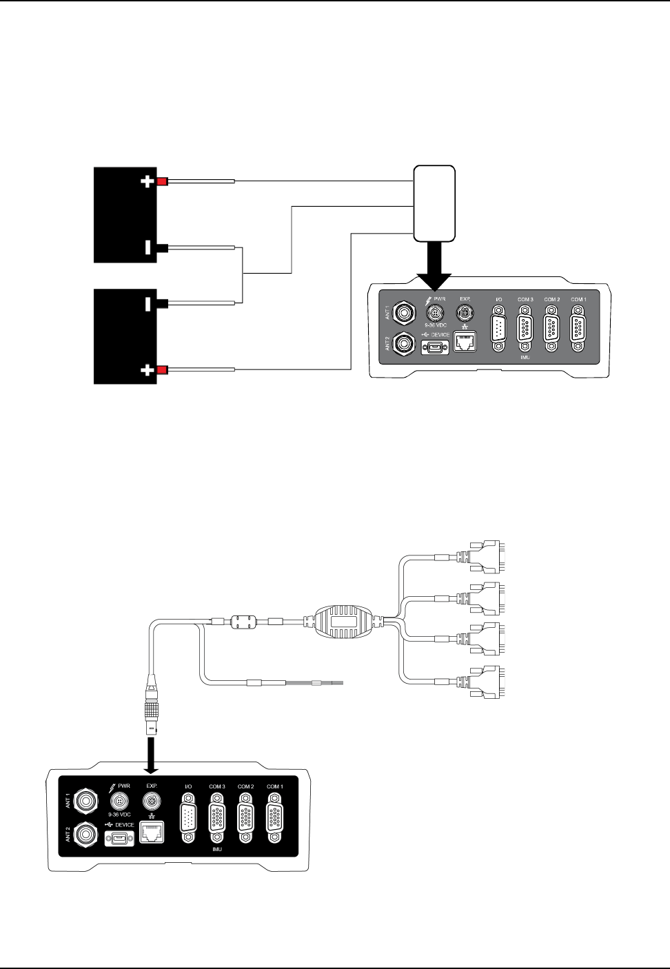
2.7.2 Connect the Additional Communication Ports on a ProPak6
In addition to the three COM ports (COM1, COM2 and COM3/IMU) on the back of the ProPak6, there are
four additional COM ports available from the EXP port. To access these ports, connect the ProPak6
Expansion Cable (01019154) to the EXP port. For more information about this cable, see Section A.5.5,
ProPak6 Expansion Cable (NovAtel part number 01019154) on page 123.
Figure 12: Additional COM ports on the ProPak6
Refer to A.5.5, ProPak6 Expansion Cable (NovAtel part number 01019154) on page 123 and Table 22,
ProPak6 Expansion Cable Pin-Out Descriptions on page 123 for pin out details.
L
E
M
O
P
O
W
E
R
P
O
W
E
R
Negative A
Negative B
Positive B
Positive A
Black
Brown
or
White
Orange
or
Green
Red Pin 2
Pin 1, 4
Pin 3
COM7
COM8
COM9
COM10
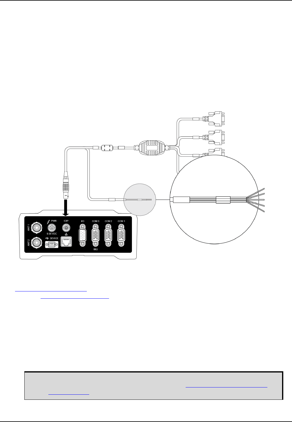
Installation Chapter 2
ProPak6 Installation and Operation User Manual Rev 5 33
2.7.3 Connect the CAN Bus
OEM6 family receivers incorporate a CAN Bus controller that supports physical layer signals and low
level messages specified in the appropriate sections of the J1939 and ISO11783 standards.
Manufacturers can also create messages specific to their application without violating these standards.
To facilitate manufacturer messages, NovAtel provides an Application Program Interface (API). To obtain
information about this API, contact NovAtel Customer Support.
The ProPak6 receiver has two CAN Bus ports, CAN1 and CAN2, which are available on the EXP port. To
access these signals, use the ProPak6 Expansion Cable (see Figure 13, CAN Bus ports on the
ProPak6). For information about the ProPak6 Expansion Cable, see Section A.5.5, ProPak6 Expansion
Cable (NovAtel part number 01019154) on page 123. For information about the EXP port, refer to
Section 3.1.15, Expansion Port on page 43 of this manual.
Figure 13: CAN Bus ports on the ProPak6
2.7.4 Mounting the ProPak6
For general applications, the supplied mounting brackets may be used to install the receiver, refer to the
ProPak6 Quick Start Guide (GM-14915125) provided with the receiver or download the guide from our
web site: www.novatel.com/support.
For high vibration installations, NovAtel recommends mounting the ProPak6 directly using 1/4” 20-UNC
threaded screws (4 locations). Vibration dampeners or isolators (user supplied) for additional vibration
reduction may be used. Refer to Figure 40, ProPak6 Dimensions on page 113 for mounting hole
locations.
2.8 Installing NovAtel Connect PC Utilities
The NovAtel Connect PC Utilities contain a number of utilities that can be used with the ProPak6 along
with complete instructions for installation and use of the NovAtel PC utilities.
CAN1+
CAN1-
CAN2+
CAN2-
DGND
Download the latest PC Utilities software including NovAtel Connect™ PC Utilities
along with the necessary user documentation from: www.novatel.com/support/info/
documents/809.
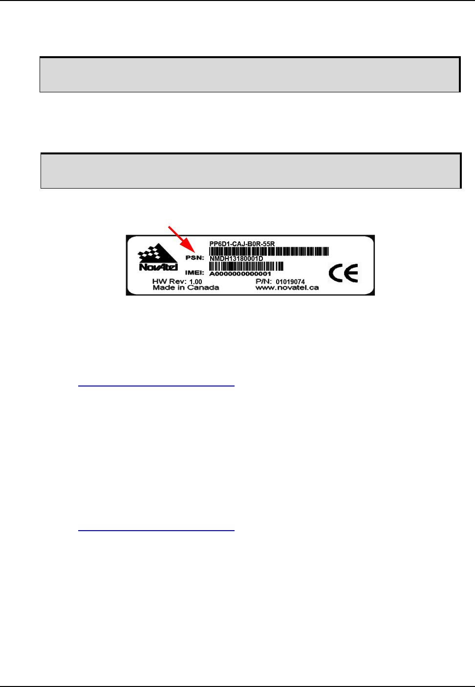
34 ProPak6 Installation and Operation User Manual Rev 5
Chapter 2 Installation
NovAtel Connect is a windows based GUI used to access the receiver's many features without the need
for communications protocol or other special software. The Convert utility is a windows based utility used
to convert between file formats and strips unwanted records for data file compilation.
2.9 ProPak6 Security
2.9.1 Administration Password
An Administrator password is available to secure FTP and ICOM ports. The default Administrator
password is the Product Serial Number (PSN) of the receiver and the predefined user name is “admin”.
An Administrator has read/write access and the ability to change passwords, issue commands, upload
files to the FTP server or upload new firmware.
A password can be up to a maximum of 28 characters/digits. The “admin” user name cannot be changed.
Use the SETADMINPASSWORD command to change the default password.
Refer to the OEM6 Firmware Reference Manual - OM-20000129 for command details.
2.9.2 FTP Server and ICOM Ports
The FTP server is disabled by default. The IPSERVICE FTP_SERVER command is issued to enable or
disable the FTP server port. Refer to Section 3.7.1.5, Remote Retrieval of Logged Data on page 60 for
instructions on enabling the FTP port.
For security purposes, the IPSERVICE SECURE_ICOM command can also be used to enable password
security on the ICOM ports. When security is enabled, the port refuses incoming commands until a valid
User Name and Password are entered using the LOGIN command. Once logged in to an ICOM port, use
the LOGOUT command to sign out of the connection and resecure the port. Refer to Section 3.1.13.1,
Configure COM 1, 2 and 3 on page 43 for further details.
Refer to the OEM6 Firmware Reference Manual - OM-20000129 for details on the IPSERVICE
command.
2.10 Next Steps
Once the physical installation is complete and power is applied, various ports and radios need to be
enabled and/or configured. Refer to the upcoming chapters for operation and configuration details.
If using Ethernet, the port needs to be configured prior to use. Refer to Chapter 4,
Ethernet Configuration on page 74 for configuration instructions.
The Administrator password should be changed prior to using the FTP server or ICOM
ports.
Example:
Label is located on the bottom of the ProPak6

35 ProPak6 Installation and Operation User Manual Rev 5
Chapter 3 Operation
Before operating the receiver for the first time, please ensure the installation instructions in Chapter 2,
Installation starting on page 21 were followed.
3.1 Communications with the Receiver
Communication with the receiver typically consists of issuing commands through the communication
ports from an external serial communications device. This could be either a terminal or a computer
connected directly to the receiver serial port using a null-modem cable. If using an RTK radio, connect to
the receiver’s COM port by means of the radio serial cable. Familiarity with the commands and logs
detailed in the OEM6 Firmware Reference Manual - OM-20000129 will ensure maximum utilization of the
ProPak6 capabilities.
3.1.1 Communicating Using a Remote Terminal
One method of communicating with the receiver is through a remote terminal. The receiver is wired to
allow proper RS-232 interface with the data terminal by default. It is possible to configure RS-422
communication (refer to Section 3.1.13.1, Configure COM 1, 2 and 3 on page 43 for details). To
communicate with the terminal, the receiver only requires the RX, TX and GND lines to be used.
Handshaking is an option and is not required. Ensure the terminal’s communications setup matches the
receiver’s RS-232 protocol. Bluetooth, Wi-Fi and Ethernet are also available. Refer to Section 3.1.13,
Serial Ports on page 42 for additional information.
Refer to Section 3.1.13, Serial Ports on page 42 for details.
3.1.2 Communicating Using a Computer
A computer can be set up to emulate a remote terminal as well as provide the added flexibility of creating
multiple command batch files and data logging storage files. Any standard communications software
package that emulates a terminal can be used to establish bidirectional communications with the
receiver, for example, HyperTerminal or NovAtel’s graphic user interface (GUI) program, NovAtel
Connect. All data is sent as raw 8-bit binary or ASCII characters.
Refer to Section 3.3, Establishing a Receiver COM Connection on page 45 for details.
3.1.3 Status Indicators
LED indicators on the front of the ProPak6 provide the status of the receiver. Some LEDs are user
configurable and some are fixed.
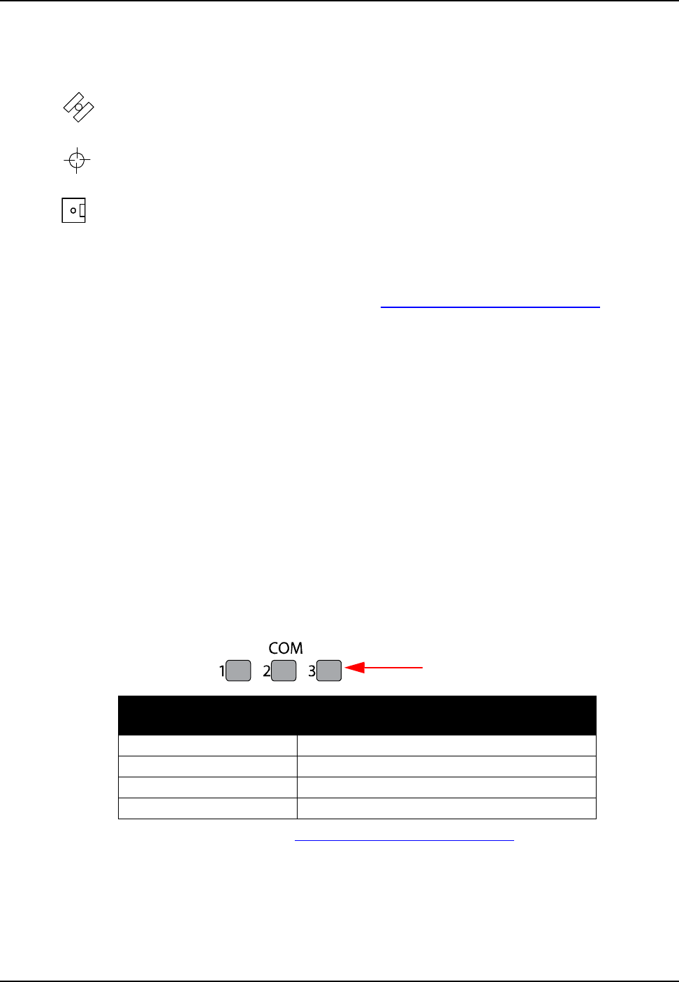
36 ProPak6 Installation and Operation User Manual Rev 5
Chapter 3 Operation
3.1.3.1 User Configurable Status Indicators
Some of the LEDs on the ProPak6 front panel have configurable threshold settings that determine when
the LED changes color and states. The user configurable LEDs are:
• Satellite Tracking 1 and 2 (refer to Section 3.1.8, Satellite Tracking and Positioning LEDs on
page 38 for LED status states)
• GNSS Positioning 1 and 2 (refer to Section 3.1.8, Satellite Tracking and Positioning LEDs on
page 38 for LED status states)
• Data Logging (refer to Section 3.7, Logging and Retrieving Data Overview on page 58 for LED
status states)
The LEDCONFIG command is used to configure a specific indicator LED. All configuration settings,
except the two GNSS positioning LEDs, take two parameters: one value determines when the LED turns
red and the other value determines when it turns amber (with the default setting outside the value range
being green). Refer to the LEDCONFIG command in the OEM6 Firmware Reference Manual -
OM-20000129 for details.
3.1.3.2 Fixed Status Indicators
The fixed LEDs are:
• Power (refer to Section 3.2.1, Applying Power to the Receiver on page 44 for LED states)
• INS (refer to Section 3.1.7, INS and ALIGN LEDs on page 37 for LED states)
• ALN (ALIGN/Heading) (refer to Section 3.1.7, INS and ALIGN LEDs on page 37 for LED states)
• COM 1, 2 and 3 (refer to Section 3.1.4, COM Ports LEDs on page 36 for LED states)
• Wi-Fi (refer to Section 3.1.6, Wi-Fi LED on page 37 for LED states)
• Bluetooth (refer to Section 3.1.5, Bluetooth LED on page 37 for LED states)
• USB Host (refer to Section 3.1.10, Universal Serial Bus (USB) Port and LEDs on page 40 for LED
states)
• Cell (refer to Section 3.1.9, Cell Port and LED on page 40 for LED states)
3.1.4 COM Ports LEDs
The COM LEDs for COM1, 2 and 3 are on the front of the ProPak6. The LEDs indicates if data is in the
process of being transmitted or received.
Refer to the LEDCONFIG command in the OEM6 Firmware Reference Manual - OM-20000129 for
additional details.
LED State
COM1, COM2, COM3 Description
Off no activity
Green (blinking) RS-232 Transmitting data (Tx)
Red (blinking) RS-232 Receiving data (Rx)
Green (solid) RS-422 all states
Status LED
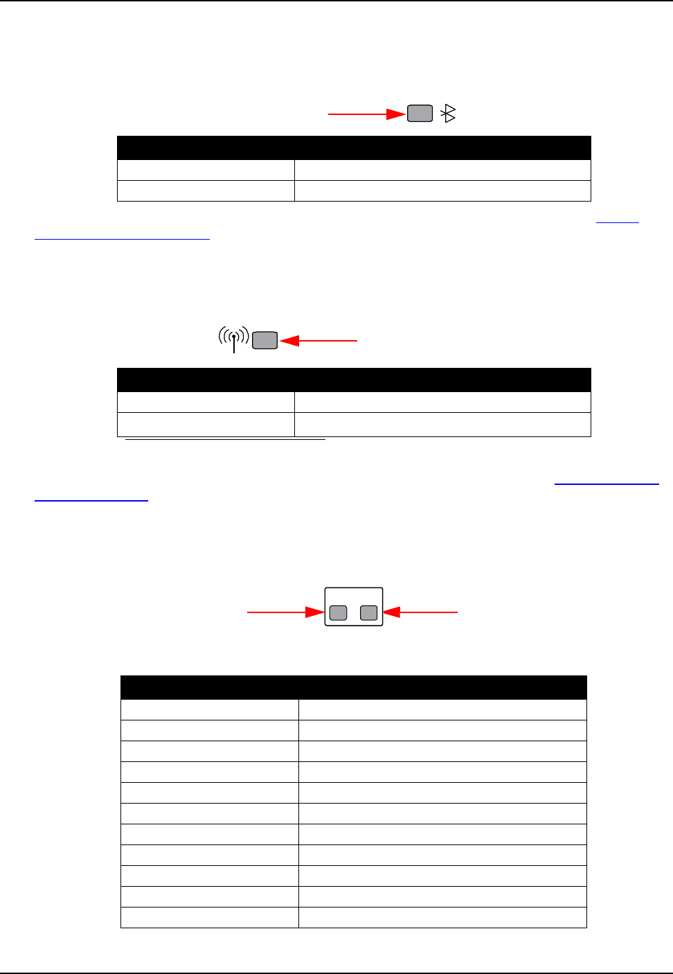
Operation Chapter 3
ProPak6 Installation and Operation User Manual Rev 5 37
3.1.5 Bluetooth LED
The Bluetooth LED lights blue when the ProPak6 is enabled and powered. Refer to Section 5.1,
Bluetooth® Configuration on page 82 for Bluetooth details.
Use the BLUETOOTHCONFIG command to power the radio on or off (default off). Refer to the OEM6
Firmware Reference Manual - OM-20000129 for command details.
3.1.6 Wi-Fi LED
The Wi-Fi LED lights blue when the ProPak6 is enabled and powered. Refer to Section 5.2, Wi-Fi
Network Configuration on page 84 for Wi-Fi details.
Use the WIFICONFIG command to power the radio on or off (default off). Refer to the OEM6 Firmware
Reference Manual - OM-20000129 for command details.
3.1.7 INS and ALIGN LEDs
The INS LED indicates the status of the Inertial Navigation System (INS); the ALN LED indicates the
ALIGN heading status.
Table 7: INS LED States
LED State Description
Off Bluetooth radio is not powered
Blue (solid) Bluetooth radio is powered
Status LED
LED State Description
Off Wi-Fi radio is not powered
Blue (solid)a
a. By default the radio is on and powered in AP mode.
Wi-Fi radio is powered
Status LED
LED State Description
Off INS disabled (GNSS only)
Off INS enabled-no IMU detected
Red (solid) INS inactive (IMU detected, no error)
Red (blinking) IMU error (INS state not applicable)
Red/Amber (alternating) INS determining orientation (IMU good)
Red/Amber (alternating) INS waiting initial position
Green/Amber (alternating) INS solution free
Amber (solid) INS is aligning
Amber (blinking) INS high variance
Green (solid) INS solution good
Green (blinking) INS alignment complete
Status LED
Status LED
INS ALN
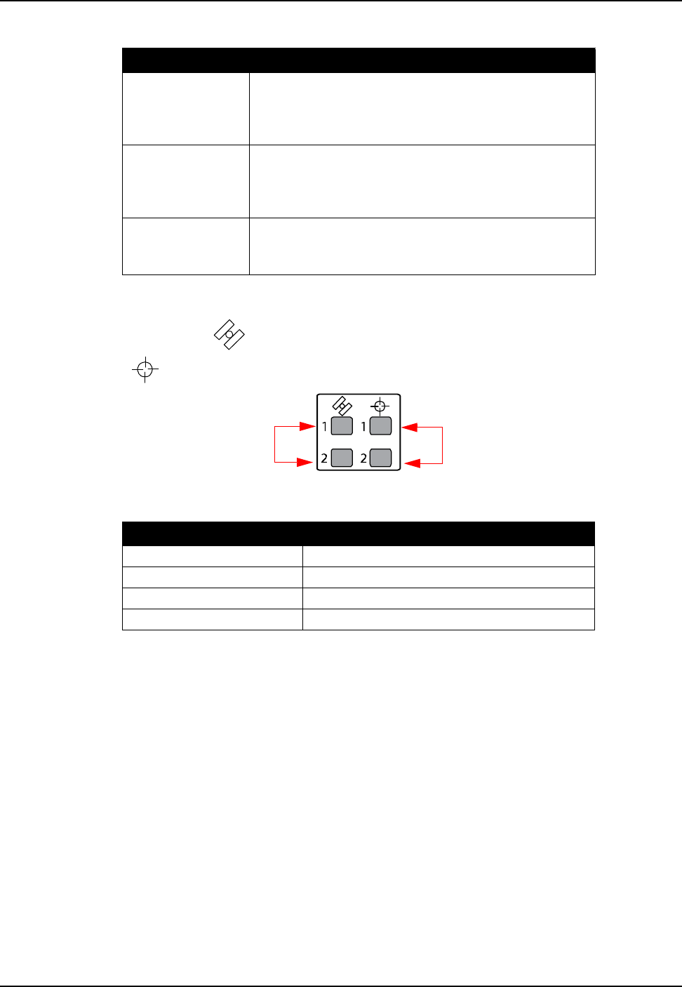
38 ProPak6 Installation and Operation User Manual Rev 5
Chapter 3 Operation
Table 8: ALN (ALIGN) LED States
3.1.8 Satellite Tracking and Positioning LEDs
The Satellite tracking LEDs ( ) indicate the number of satellites being tracked (1 and 2); the Satellite
position LEDs ( ) indicate the position of satellites (1 and 2).
Table 9: Satellite Tracking LEDs States (GPS and/or GNSS)
LED State Description
Off
ALIGN is not operational
- Dual card is disabled or unavailable
- Tracking <4 satellites
- Heading log not received/updated in 30 seconds
Amber (solid)
ALIGN has FLOAT solution
- SOLTYPE_L1_FLOAT
- SOLTYPE_NARROW_FLOAT or
- SOLTYPE_WIDE_FLOAT
Green (solid)
ALIGN has fixed solution
- SOLTYPE_L1_INT
- SOLTYPE_NARROW_INT
LED State Description
Off Tracking 0 satellites
Red (solid) Tracking 1 to 3 satellites
Amber (solid) Tracking 4 to 5 satellites
Green (solid) Tracking more than 5 satellites
Status LEDs
Status LEDs Position
Tracking

Operation Chapter 3
ProPak6 Installation and Operation User Manual Rev 5 39
Table 10: Satellite Position LEDs States
Both the Satellite Tracking and Satellite Positioning LEDs are user configurable. Refer to the LEDCONFIG
command in the OEM6 Firmware Reference Manual (OM-20000129) for details.
LED State Description Included Position Types
Off No fix - SOLTYPE_NONE
Amber (blinking)a
a. When a OEM615 is used in a dual antenna configuration, the LED for GNSS2 only shows as off
or amber.
Single point - SOLTYPE_SINGLE
- SOLTYPE_INS_PSRSP
Amber (solid) Converging accuracy - SOLTYPE_L1_FLOAT
- SOLTYPE_IONOFREE_FLOAT
- SOLTYPE_NARROW_FLOAT
- SOLTYPE_L1L2_FLOAT
- SOLTYPE_INS_RTKFLOAT
- SOLTYPE_INS_OMNISTAR - Unconverged
- SOLTYPE_INS_OMNISTAR_HP - Unconverged
- SOLTYPE_INS_OMNISTAR_XP - Unconverged
- SOLTYPE_OMNISTAR_HP - Unconverged
- SOLTYPE_OMNISTAR_XP – Unconverged
- SOLTYPE_PROPAGATED
- SOLTYPE_PPP_CONVERGING
- SOLTYPE_INS_PPP_CONVERGING
Green (solid) Converged accuracy - SOLTYPE_INS_OMNISTAR - Converged
- SOLTYPE_INS_OMNISTAR_HP - Converged
- SOLTYPE_INS_OMNISTAR_XP - Converged
- SOLTYPE_OMNISTAR_HP - Converged
- SOLTYPE_OMNISTAR_XP – Converged
- SOLTYPE_L1L2_INT
- SOLTYPE_L1L2_INT_VERIFIED
- SOLTYPE_L1_INT
- SOLTYPE_WIDE_INT
- SOLTYPE_NARROW_INT
- SOLTYPE_RTK_DIRECT_INS
- SOLTYPE_INS_RTKFIXED
- SOLTYPE_PPP
- SOLTYPE_INS_PPP
- SOLTYPE_EXT_CONSTRAINED
- SOLTYPE_FIXEDPOS
Green (blinking) PSR/PDP using
corrections
- SOLTYPE_PSR_DIFF
- SOLTYPE_OMNISTAR
- SOLTYPE_INS_SBAS
- SOLTYPE_INS_PSRDIFF
- SOLTYPE_CDGPS
- SOLTYPE_FIXEDHEIGHT
- SOLTYPE_FIXEDVEL
- SOLTYPE_DOPPLER_VELOCITY
- SOLTYPE_WAAS
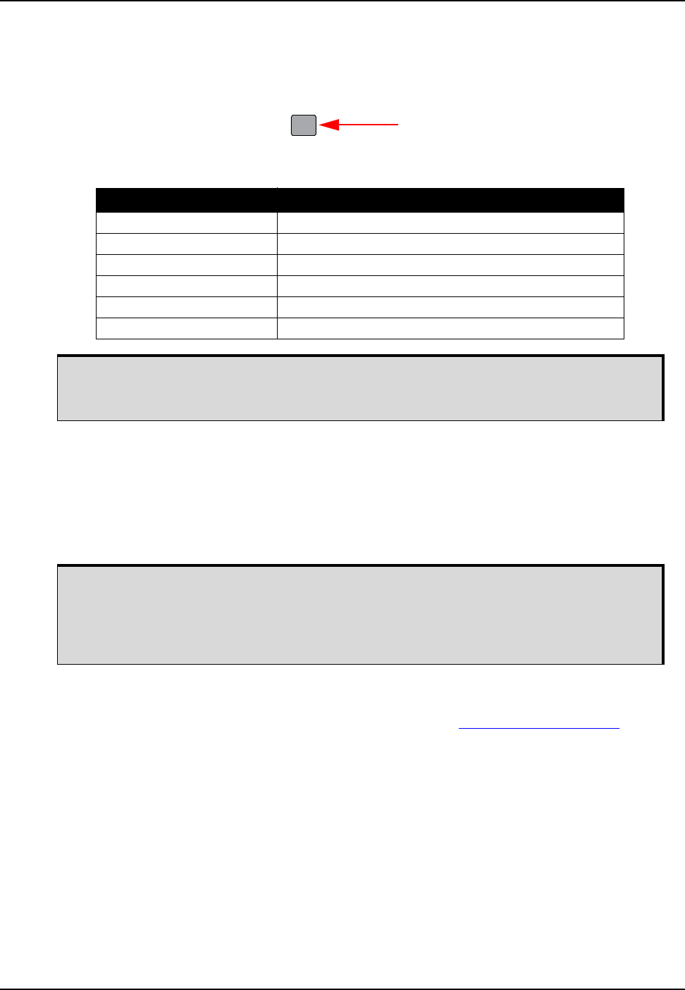
40 ProPak6 Installation and Operation User Manual Rev 5
Chapter 3 Operation
3.1.9 Cell Port and LED
The ProPak6 has a cellular antenna port to connect an external cellular antenna (TNC). An external
antenna must be connected to this port in order to use the integrated cellular modem. Refer to
Section 5.3, Cellular Activation GSM/GPRS/HSDPA on page 90 for activation and command instructions.
Table 11: CELL LED States
3.1.10 Universal Serial Bus (USB) Port and LEDs
NovAtel USB drivers are available for Microsoft Windows 2000, Windows XP, Windows Vista and
Windows 7 to provide three virtual serial ports over a single USB 2.0 connection using the ProPak6’s
USB Device port. The USB drivers are digitally signed and officially supported on Microsoft Windows XP,
Windows Vista and Windows 7. They can also be installed on Microsoft Windows 2000 and Windows
Server 2003 but are not WHQL signed in those applications.
The NovAtel USB Configuration Utility, installed with the NovAtel USB drivers, is used to change the
COM port numbers assigned to the virtual serial ports. Refer to the NovAtel PC Utilities manual for
instructions or check for updates to the drivers and release notes at www.novatel.com/support.
LED State Description
Off Cellular not available
Red (solid) No cellular signal
Red (blinking) Error
Amber Cellular network available-IP connectivity not available
Green (blinking) Cellular activity (transmitting or receiving)
Green (solid) Idle PDP context activated but not transmitting/receiving
Ensure the cellular antenna is installed at least 30 cm away from the ProPak6 antenna
or GNSS positioning accuracy may be degraded. Refer to Figure 41, Bluetooth/Wi-Fi
Antenna Keep-out Area and Antenna Location on page 114 for details.
CELL
Status LED
A computer may have several USB ports. The assignment of COM port numbers is tied
to a USB port on the computer. This allows receivers to be switched without Microsoft
Windows assigning new COM ports. However, if the receiver is connected to a different
physical USB port, Windows detects the receiver's presence and assigns three new
COM port numbers by default.
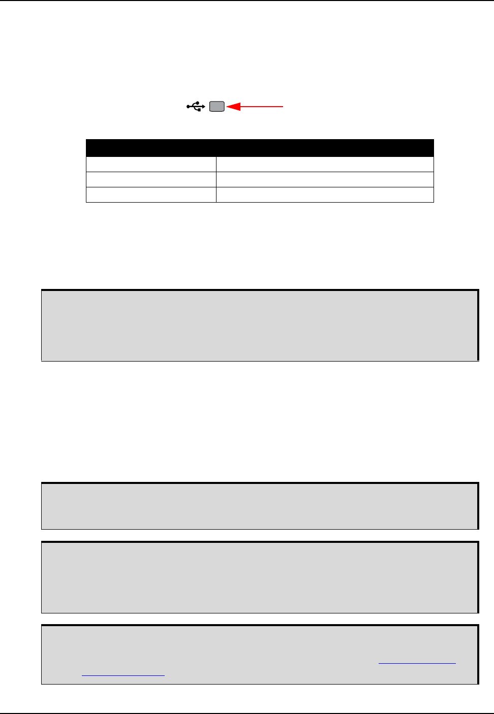
Operation Chapter 3
ProPak6 Installation and Operation User Manual Rev 5 41
3.1.10.1 USB Host LED
The ProPak6 can be configured to manually (default) or automatically download stored data when a
memory stick is inserted into the USB Host port (Type A). Refer to Section 3.7.1.3, Manual Retrieval of
Logged Data on page 60 for details on configuring the USB Host.
Once USB Host is connected, the LED changes to indicate the state.
Refer to Section 3.7.1.3, Manual Retrieval of Logged Data on page 60 for details on configuring the USB
Host.
3.1.10.2 USB Device
The USB Device port (Type micro-B) functions as three virtual serial ports.
3.1.11 Ethernet Port
The ProPak6 receiver is equipped with a 10-Base-T/100-Base-TX or 10/100 Mbps Ethernet port that
supports IPv4 Internet layer, TCP/IP transport and telnet. Users can conduct remote debugging, accept
MRTCA (modified RTCA) data and download firmware. The ProPak6 receiver is also equipped with
NTRIP Version 2.0 (Networked Transport of RTCM via Internet Protocol) client and server capability.
The Ethernet port must be configured before using. Refer to Chapter 4, Ethernet Configuration on
page 74 for configuration details.
LED State Description
Off No devices connected or an error has occurred
Red (solid) Device is idle
Red (blinking) Device is busy (active)
HOST
Status LED
A computer may have several USB ports. The assignment of COM port numbers is tied
to a USB port on the computer. This allows receivers to be switched without Microsoft
Windows assigning new COM ports. However, if the receiver is connected to a different
physical USB port, Windows detects the receiver's presence and assigns three new
COM port numbers.
The Ethernet ports are Safety Extra-Low Voltage (SELV) circuits only and are suitable
for connection within a building only. Do not connect them to Telephone Network
Voltage (TNV) circuits.
Issue the SAVEETHERNETDATA ETHA command to ensure port settings are retained
after a reset and automatically used at boot time. The SAVEETHERNETDATA ETHA
command is not applicable to the ICOMCONFIG and NTRIPCONFIG command
settings. The SAVEETHERNETDATA ETHA command takes precedence over the
SAVECONFIG command configuration.
The Ethernet port is the default port setting for internet access. If at any time the default
is changed to Wi-Fi or Cellular, the SETPREFERREDNETIF ETHA command must be
issued to return to using Ethernet for internet access. Refer to the OEM6 Firmware
Reference Manual (OM-20000129) for command details.

42 ProPak6 Installation and Operation User Manual Rev 5
Chapter 3 Operation
3.1.12 ICOM Ports
ICOM ports are virtual ports. The ProPak6 has three shared ICOM ports for Ethernet, Wi-Fi and Cellular.
The transport/application layer of the ICOM ports can be configured using Transmission Control Protocol
(TCP) for internet IP or User Datagram Protocol (UDP) a slower and less reliable IP protocol. If using
TCP, only one connection at a time is supported.
Although each port can be configured independently, the system only uses one DNS server at a time.
Refer to DNSCONFIG command for Ethernet DNS and the WIFICLICONFIG command for configuring
DNS for a static Wi-Fi network. (If using DHCP, DNS is automatically set.)
The following are the default ICOM configurations:
• ICOMCONFIG ICOM1 TCP :3001
• ICOMCONFIG ICOM2 TCP :3002
• ICOMCONFIG ICOM3 TCP :3003
Each ICOM port can act as a server (waiting for an external connection to be made) or as a client
(actively establishing a connection to a specific port).
Refer to the OEM6 Firmware Reference Manual (OM-20000129) for details on the ICOM port commands
DNSCONFIG, IPCONFIG, ICOMCONFIG, the ETHCONFIG command and the Wi-Fi WIFICLICONFIG
command.
In this manual, refer to Section 2.9.2, FTP Server and ICOM Ports on page 34 for details on securing
ICOM ports.
3.1.13 Serial Ports
The receiver communicates with the computer or terminal via a serial port. For communication to occur,
both the receiver and the operator interface must be properly configured. The ProPak6’s COM1, COM2
and COM3 default port settings are as follows:
• 9600 bps, no parity, 8 data bits, 1 stop bit, no handshaking, echo off
Table 12: Data Communication Port Defaults
The data transfer rate determines how fast information is transmitted. Take for example a log whose
message byte count is 96. The default port settings allows 10 bits/byte (8 data bits + 1 stop bit + 1
framing bit). It therefore takes 960 bits per message. To get 10 messages per second then requires 9600
bps. Please also remember that even if you set the bps to 9600 the actual data transfer rate is lower and
depends on the number of satellites being tracked, data filters in use, and idle time. It is therefore
suggested that you leave yourself a margin when choosing a data rate (115200 is recommended for most
applications).
Connection Name COM1 COM2 COM3
Connector location Rear panel-COM1 Rear panel-COM2 Rear panel-COM3/IMU
Default configuration RS-232 RS-232 RS-232
Alternate configuration RS-422 RS-422 RS-422
Although the receiver can operate at data transfer rates as low as 300 bps, this is not
desirable. For example, if several data logs are active (that is, a significant amount of
information needs to be transmitted every second) but the bit rate is set too low, data
overflows the serial port buffers, causing an error condition in the receiver status that
results in lost data.

Operation Chapter 3
ProPak6 Installation and Operation User Manual Rev 5 43
3.1.13.1 Configure COM 1, 2 and 3
COM1, COM2 and COM3/IMU can communicate using the RS-422 protocol in addition to the standard
RS-232 protocol. On the ProPak6, the IMUCOM port is equivalent to COM3.
There are 2 ways to select between RS-232 and RS-422 protocol for the various ports (default is
RS-232).
1. A Configuration Code obtained from NovAtel Customer Support can be installed in the receiver to
select the protocol for COM1 and COM3/IMU independently.
2. The SERIALPROTOCOL command can be used to select RS-232 or RS-422 for any of the 3 COM
ports. This method overrides the protocol set using the previous method.
The configuration code will configure the ports at boot time so the receiver may be loaded over the
configured protocol.
For the SERIALPROTOCOL command method, commands are executed after the receiver has completed
booting and so the communication lines are configured as RS-232 during boot. For automatic
configuration, the SERIALPROTOCOL command can be saved using the SAVECONFIG command.
Refer to the OEM6 Firmware Reference Manual (OM-20000129) for command details.
3.1.14 I/O Port
3.1.14.1 Strobes
ProPak6 has configurable inputs and outputs, referred to as strobes, that provide status and
synchronization signals. Refer to Table 16, I/O Port Pin-Out Descriptions on page 116 for details
Also refer to the Chapter 4, Ethernet Configuration on page 74 for details and to the IOCONFIG,
EVENTINCONTROL and EVENTOUTCONTROL commands in the OEM6 Family Firmware Reference
Manual (OM-20000129) for configuration and command details.
3.1.15 Expansion Port
The ProPak6 Expansion port supplies two CAN ports and a USB Host port which is reserved for future
use. Refer to Table 17, Expansion Port Pin-Out Description on page 116 for details.
•CAN1
•CAN2
• USB Host (reserved for future use)
3.1.15.1 CAN Bus
The ProPak6 CAN Bus controller supports physical layer signals and low level messages specified in the
appropriate sections of the J1939 and ISO11783 standards. Manufacturers can also create messages
specific to their application without violating these standards. To facilitate manufacturer messages,
NovAtel provides an Application Program Interface (API). To obtain information about the NovAtel API,
contact www.novatel.com/support.
The ProPak6 has two CAN ports: CAN1 and CAN2. Both CAN ports are brought out to the expansion
port. CAN1 and CAN2 both support applications up to 1 Mbps.
CAN interfaces are accessed using NovAtel’s API, but shared signals must be disabled to avoid conflicts.
Refer to Appendix A, Technical Specifications on page 110 for further details.
Proper bus termination is required.
The SERIALCONFIG command is used to configure certain protocol settings when
using either RS-232 or RS-422.
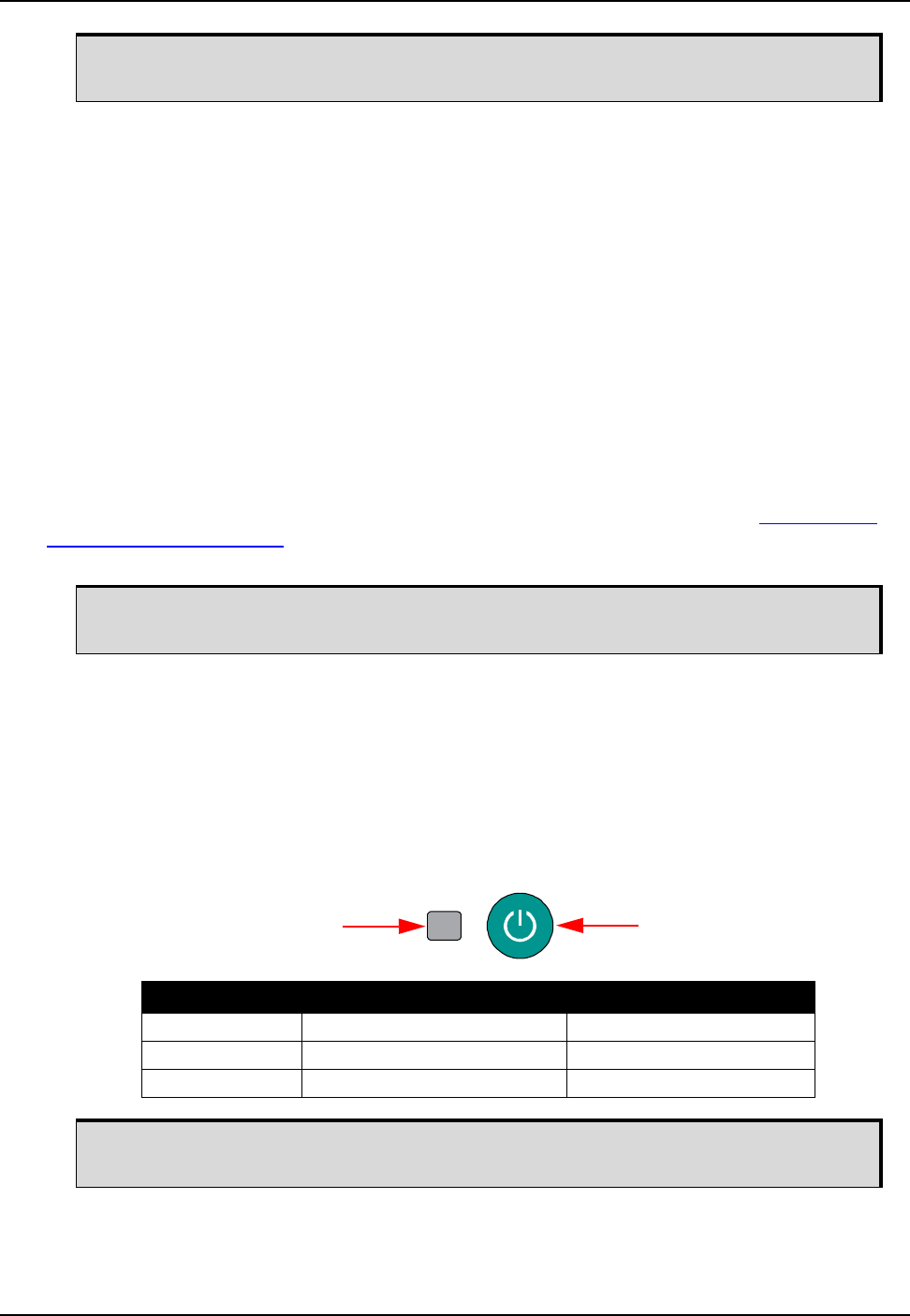
44 ProPak6 Installation and Operation User Manual Rev 5
Chapter 3 Operation
3.1.16 Antenna LNA Port
NovAtel antennas and coaxial cables meet receiver RF input gain requirements. NovAtel antennas are
equipped with built-in LNAs that provide 26 dB of gain to the satellite signal received. The power to the
antenna LNA is provided through the receiver’s RF port center conductor. To achieve the required input
gain to the receiver, NovAtel coaxial cables are designed to introduce no more than 10 dB loss. Antenna
supply over current protection limits the LNA power. The ProPak6 provides +5 VDC ±5% at a maximum
of 200 mA to the antenna connected to the ANT1 connector. If the ProPak6 is equipped with an ANT2
connector, the second antenna is provided with 5 VDC ±5% at a maximum current of 100 mA.
3.1.17 External Oscillator Port (model dependent)
For applications requiring greater precision than what is possible using the on-board Voltage Controlled,
Temperature Compensated Crystal Oscillator (VCTCXO), the ProPak6 may be connected to an external,
high stability oscillator, at 5 MHz or 10 MHz.
Connect a cable from the external oscillator to the receiver’s external oscillator input connector (OSC).
The receiver does not have to be powered down during this operation. The input impedance is 50 ohms.
When using the external oscillator, use the EXTERNALCLOCK command (refer to the OEM6 Family
Firmware Reference Manual-OM-20000129 for details) to set the clock type (e.g: cesium, rubidium or
ovenized crystal) and frequency.
3.2 Getting Started
3.2.1 Applying Power to the Receiver
Connect the power supply to the power port. Once valid power is detected, the ProPak6 power LED
briefly flashes red and then turns green as the ProPak6 enters Operational mode. Press the Power
button or issue the SOFTPOWER command to power down the ProPak6.
Figure 14: Power Button
CAN Bus functionality is controlled through NovAtel’s optional API software. The API
header file includes documentation on using the CAN bus.
An external oscillator is not available for systems with the Heading functionality. On
systems with the Heading feature, the port is used for the second GNSS antenna.
LED State Description Mode
Off (not lit) No power connected
Red (solid) Power connected brief pre-Operational mode
Green (solid) Power on Operational
The ProPak6 also automatically enters Operational mode if valid power is connected or
if activity is detected on COM1, COM2 or COM3.
Status LED Button
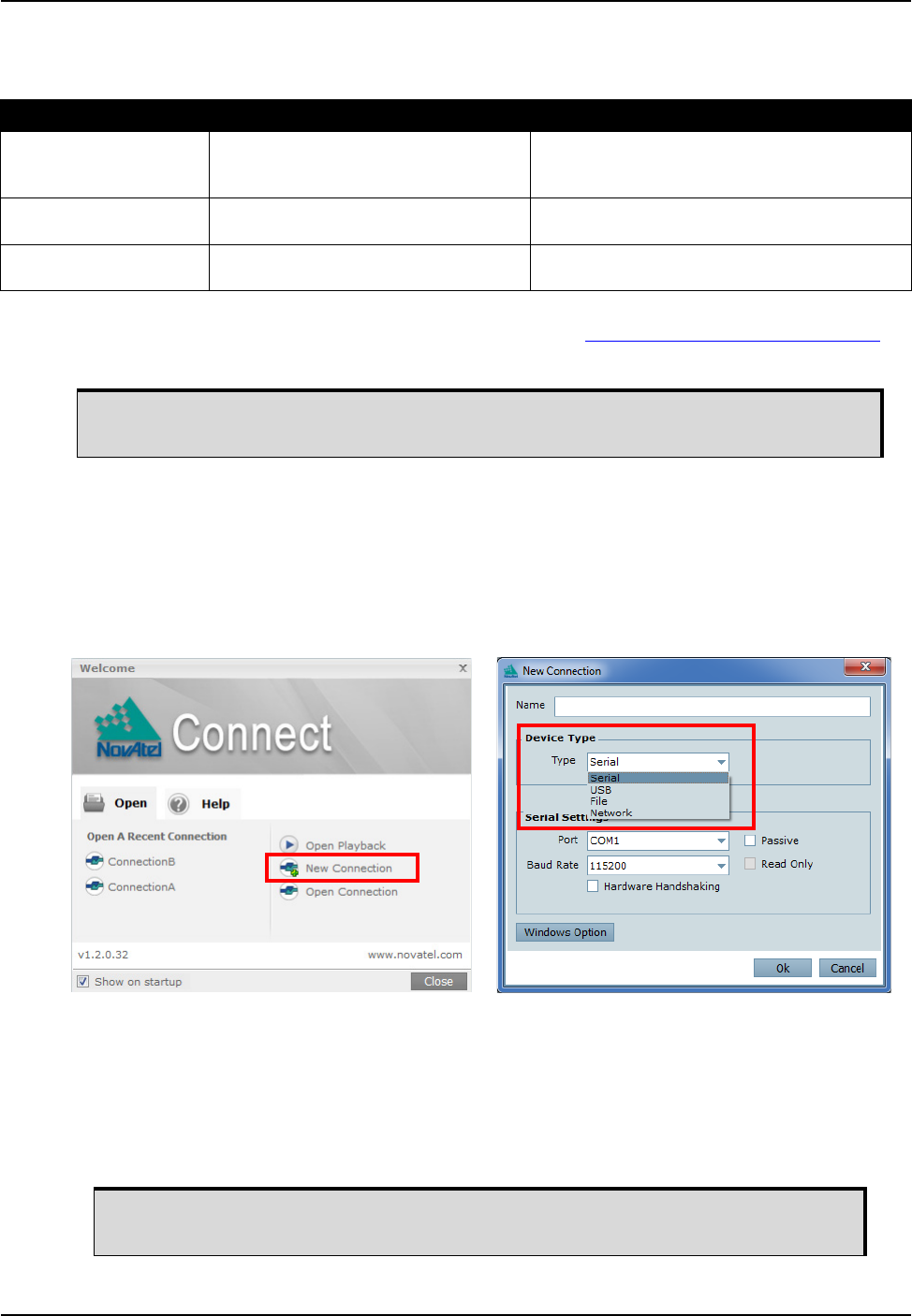
Operation Chapter 3
ProPak6 Installation and Operation User Manual Rev 5 45
3.2.1.1 Power Down and Reset the ProPak6
If the ProPak6 button is pressed and held for period of time, the receiver shuts down or resets.
The ProPak6 can also be powered down by issuing the SOFTPOWER command which unmounts the
internal flash storage to minimize the risk of losing data. Refer to OEM6 Firmware Reference Manual
(OM-20000129) for details.
3.3 Establishing a Receiver COM Connection
To establish a new connection to the receiver, complete the following:
1. Launch Connect from the Start menu folder specified during the installation process. The default
location is Start | All Programs | NovAtel PC Software | NovAtel Connect.
2. Select New Connection from the Welcome window.
3. Enter a name for the connection.
4. Select Device Type to use to communicate from the drop list:
• Serial - choose a COM port
• USB - choose a COM port
• Network - choose a receiver and define network settings
5. Click the OK button to save the new connection.
Button Press Time Result LEDs
Press and hold minimum
3 s and maximum 10 s
Power to the ProPak6 is turned off After 3 s, Satellite tracking and GNSS positioning
(1 and 2) LEDs = Amber (solid)
When the button is released, these LEDs turn off.
Press and hold minimum
10 s and maximum 20 s
A FRESET (factory reset) of the ProPak6
is performed
Satellite tracking and GNSS positioning (1 and
2), IMU and ALN LEDs = Red (solid)
Press over 20 s Button press aborted-ProPak6 returns to
normal operation
Ignored
Ensure the ProPak6 is properly powered down before removing the power cord.
Detailed instructions for using NovAtel Connect are available from within the utility
Help.
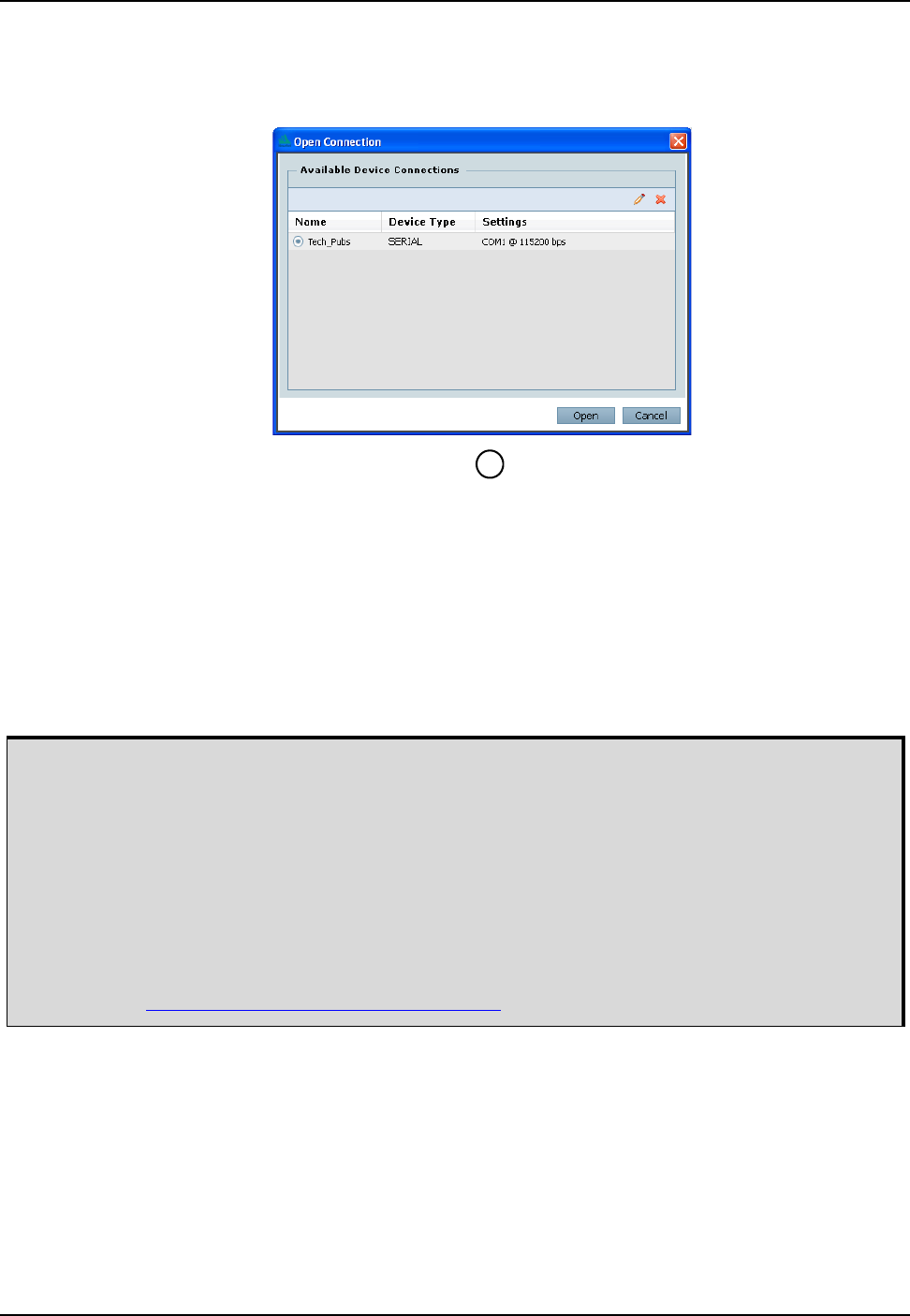
46 ProPak6 Installation and Operation User Manual Rev 5
Chapter 3 Operation
3.3.1 Communicating with the Receiver Using NovAtel Connect
Open the NovAtel Connect program and select Device | Open Connection from the main menu. The
Open Connection window appears. Open an existing connection or a create a New connection.
Refer to NovAtel Connect’s Help (press F1, click on icon or select the NovAtel button | Help). Ensure
the Console and ASCII Messages windows are displayed (select from the View menu if necessary).
When the receiver is first turned on, no data is transmitted from the COM ports except for the port
prompt. The Console window displays a port name:
[COM1] if connected to com1 port
[COM2] if connected to com2 port
or
[COM3] if connected to com3 port
Any of the COM port prompts indicate that the receiver is ready and waiting for command input. The
screen may display other port names for other port types (e.g., USB1, USB2, USB3 or AUX).
An example of a response to an input FIX POSITION command:
[COM2] FIX POSITION 51.11635 -114.0383 1048.2 [carriage return]
<OK
In this example, [COM2] is the port prompt.
This example illustrates command input to the base receiver’s COM2 port that sets the position of the
base station receiver for differential operation.
If the command was accepted, the receiver responds with:
<OK
?
1. Output from receiver self-tests may take some time. On startup, the ProPak6 receiver is set to
log the RXSTATUSEVENTA log ONNEW on all ports. See Section 8.4 RXSTATUSEVENT Log
on page 107 for more details.
2. If NovAtel Connect is unable to locate the ProPak6 receiver, use a different COM port to com-
municate with the receiver. When communication has been established, issue a FRESET
STANDARD command. The original communications port should be ready for use.
3. XCOM1, XCOM2 and XCOM3 virtual ports can be generated by the receiver. However, they
are unlikely to appear as a port prompt as you cannot connect to these types of ports using
NovAtel Connect. Also, the XCOM ports are not available with the SERIALCONFIG com-
mand but may be used with other commands, such as INTERFACEMODE and LOG. Refer to
the OEM6 Family Firmware Reference Manual (OM-20000129) for details on the virtual ports.
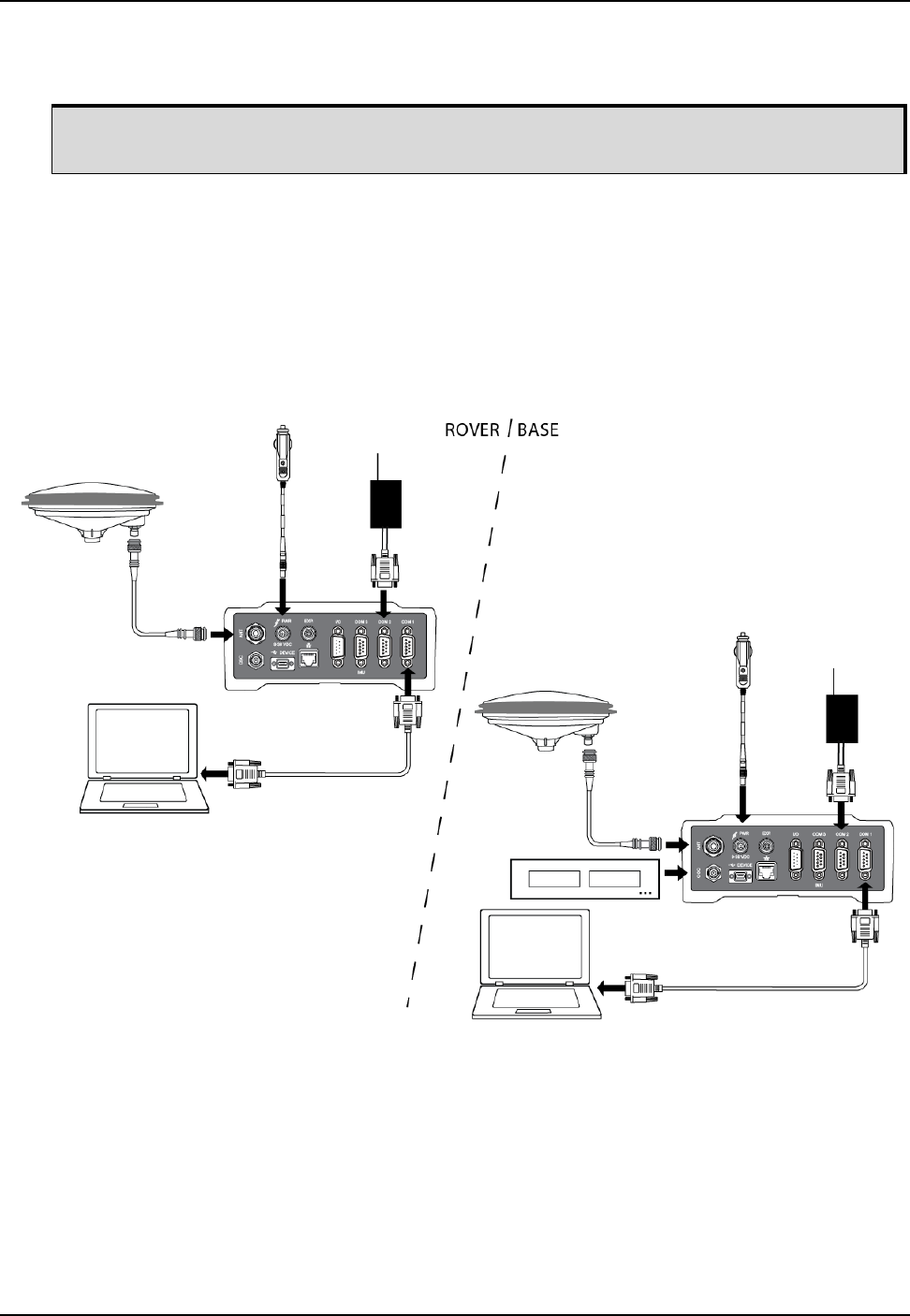
Operation Chapter 3
ProPak6 Installation and Operation User Manual Rev 5 47
If a command is entered incorrectly, the receiver responds with:
<ERROR:Invalid Message ID (or a more detailed message)
3.4 Transmitting and Receiving Corrections
Corrections can be transmitted from a base station to a rover station to improve position accuracy. The
base station is the GNSS receiver that acts as the stationary reference. The stationary reference has a
known position and transmits correction messages to the rover station. The rover station is the GNSS
receiver that does not know its exact position and requires correction messages from a base station to
calculate differential GNSS positions.
Figure 15: Basic Differential Setup
Ensure the computer does not sleep or hibernate during a logging session or data will be lost.
Use a ProPak6 receiver for the Rover Station Use a ProPak6 receiver for the Base Station
1. Connection a GNSS antenna 1. Connection a GNSS antenna
2. Connect a computer to COM1 2. Connect a computer to COM1 for setup and monitoring
3. Connect a power supply 3. Connect a power supply
4. Connect a user supplied radio device to COM2 4. Connect a user supplied radio device to COM2
5. Connect an external oscillator (optional) to the OSC port.

48 ProPak6 Installation and Operation User Manual Rev 5
Chapter 3 Operation
For information on positioning errors and the application of corrections for them, refer to the application
note APN-051 Positioning Modes of Operation, available at www.novatel.com/support/search/. To
receive corrections with a base/rover setup, a data link between the base station and the rover station is
required. The base and rover stations can both be NovAtel receivers, however NovAtel receivers will
work with some other brands. Contact Customer Support for further details (refer to Customer Support on
page 15 for details).
The data link should support a rate of at least 19200 bits per second, but a rate of 115200 bits per
second, with less than 4.0 s latency, is recommended. Unlike the base/rover concept, SBAS and L-Band
corrections can be applied directly to a single receiver.
When your base and rover are set up, configure them as shown in the configuration examples in
Sections 3.5 and 3.5.1.
3.4.1 Defining Antenna and Base Antenna
The type of the antenna and/or the remote base receiving the corrections can be defined using the
THISANTENNATYPE and BASEANTENNATYPE commands respectively.
The Phase Center Variation (PCV) and the Phase Center Offset (PCO) for each can also be specified
using the THISANTENNAPCV and THISANTENNAPCO or the BASEANTENNAPCV or BASEANTENNAPCO
commands.
Refer to the OEM6 Firmware Reference Manual (OM-20000129) for command details.
3.4.2 Base Station Configuration
At the base station, enter the following commands:
interfacemode port rx_type tx_type [responses]
fix position latitude longitude height (enter your own lat, long and hgt values)
log port message [trigger [period]] (port = COM2 / refer to Figure 15 above)
saveconfig (optional)
For example:
RTK Automated Correction Generation
fix position lat lon hgt (enter your own lat, lon, hgt)
generatertkcorrections rtcm3 com2
RTCA
interfacemode com2 none rtca off
fix position lat lon hgt (enter your own lat, lon, hgt)
log com2 rtcaobs2 ontime 1 (works with both GPS and GPS + GLONASS models)
log com2 rtcaref ontime 10
log com2 rtca1 ontime 5 (optional, enable code-DGPS coverage)
log com2 rtcaephem ontime 10 1 (optional)
saveconfig (optional)
RTCM V2.3
interfacemode com2 none rtcm off
fix position lat lon hgt (enter your own lat, lon, hgt)
log com2 rtcm3 ontime 10
log com2 rtcm22 ontime 10 1
log com2 rtcm1819 ontime 1
log com2 rtcm1 ontime 5 (optional)
savconfig (optional)
For ProPak6 Dual model configurations being used as a base station, issue
DUALCARDCONFIG DISABLE to stop dual card functionality and increase RTK accuracy.
Issue DUALCARDCONFIG ENABLE to return the ProPak6 to dual card functionality.

Operation Chapter 3
ProPak6 Installation and Operation User Manual Rev 5 49
RTCM V2.3 with GLONASS
interfacemode com2 none rtcm off
fix position lat lon hgt (enter your own lat, lon, hgt)
log com2 rtcm1 ontime 5 (optional, GPS PSRDIFF)
log com2 rtcm3 ontime 10
log com2 rtcm22 ontime 10 1
log com2 rtcm31 ontime 5 1 (optional, GLONASS PSRDIFF)
log com2 rtcm32 ontime 10 2
log com2 rtcm1819 ontime 1
saveconfig (optional)
RTCM V3
interfacemode com2 none rtcmv3 off
fix position lat lon hgt (enter your own lat, lon, hgt)
log com2 rtcm1002 ontime 1 (for L1 only models)
log com2 rtcm1004 ontime 1 (for L1/L2 models)
log com2 rtcm1006 ontime 10
log com2 rtcm1019 ontime 120
saveconfig (optional)
RTCM V3 with GLONASS
interfacemode com2 none rtcmv3 off
fix position lat lon hgt (enter your own lat, lon, hgt)
log com2 rtcm1002 ontime 1 (for L1 only models)
log com2 rtcm1004 ontime 1 (for L1/L2 models)
log com2 rtcm1010 ontime 1 (for L1 only models)
log com2 rtcm1012 ontime 1 (for L1/L2 models)
log com2 rtcm1006 ontime 10
log com2 rtcm1033 ontime 10
log com2 rtcm1019 ontime 120
log com2 rtcm1020 ontime 120
saveconfig (optional)
CMRPLUS (CMR+)
interfacemode com2 none cmr off
fix position lat lon hgt (enter your own lat, lon, hgt)
log com2 cmrobs ontime 1
log com2 cmrgloobs ontime 1
log com2 cmrplus ontime 1 (important to use ontime 1 with cmrplus)
saveconfig (optional)
CMR
interfacemode com2 none cmr off
fix position lat lon hgt (enter your own lat, lon, hgt)
log com2 cmrobs ontime 1
log com2 cmrgloobs ontime 1
log com2 cmrref ontime 10
log com2 cmrdesc ontime 10 1 (optional)
saveconfig (optional)
NOVATELX
interfacemode com2 none novatelx off
fix position lat lon hgt (enter your own lat, lon, hgt)
log com2 novatelxobs ontime 1
saveconfig (optional)

50 ProPak6 Installation and Operation User Manual Rev 5
Chapter 3 Operation
3.4.3 Rover Station Configuration
At the rover station, enter the following commands:
interfacemode port rx_type tx_type [responses]
For example, if COM2 was connected to the correction source:
RTK Automated Correction Detection
interfacemode com2 auto none off
RTCA
interfacemode com2 rtca none off
RTCAOBS2
interfacemode com2 rtca none off
RTCM V2.3
interfacemode com2 rtcm none off
RTCM V3
interfacemode com2 rtcmv3 none off
RTCM V3 with GLONASS
interfacemode com2 rtcmv3 none off
CMR+
interfacemode com2 cmr none off
CMR
interfacemode com2 cmr none off (same as CMR+)
NOVATELX
interfacemode com2 NOVATELX none off
3.5 External ALIGN Master or Rover Configuration Only
This section provides instructions for setting up an external master station with additional ALIGN capable
rover receivers for applications requiring heading output. Refer to APN-048 ALIGN Overview and Setup,
at www.novatel.com/support/search/.
Automatic Set Up for Direct-Wire Connection between Master and Rover via COM2
alignautomation enable
or
alignautomation enable com2 230400 10 on
The ProPak6 product is a dual card enclosure that can provide an ALIGN solution
without additional receivers.
This section is for applications that require additional rover receivers.

Operation Chapter 3
ProPak6 Installation and Operation User Manual Rev 5 51
Manual Set Up via COM2
Master:
interfacemode com2 novatel novatelx off
movingbasestation enable
log com2 novatelxobs ontime 1
log com2 novatelxref ontime 1
log headinga onnew
log gphdt onnew
Rover:
interfacemode com2 novatelx novatel off
log com2 headingext2b onnew
log headinga onnew
log gphdt onnew
hdtoutthreshold 1.0
3.5.1 PDP and GLIDE™ Configurations
Pseudorange/Delta-Phase (PDP) and GLIDE position filters can be used for single-frequency single
point, WAAS or DGPS positioning. Refer to the PDPFILTER and PDPMODE commands in the OEM6
Family Firmware Reference Manual (OM-20000129).
To reset the PDP or GLIDE filter:
pdpfilter reset
To enable the PDP filter:
pdpfilter enable
Ensure the PDPFILTER command is used before the PDPMODE command. Set the PDP type and
kinematic type according to the application. For most kinematic applications:
pdpmode relative dynamic or pdpmode relative auto
The rest of the setup is position type and log dependent according to the application. For example,
details of the RTKSOURCE, PSRDIFFSOURCE, INTERFACEMODE, SERIALCONFIG and other
configuration commands are outlined in the OEM6 Family Firmware Reference Manual (OM-20000129).
Also refer to the NovAtel application note APN-038 Pseudorange/Delta-Phase (PDP) and GLIDE
available from www.novatel.com/support/search/.
3.6 STEADYLINE®
The STEADYLINE functionality helps mitigate the discontinuities that often occur when a GNSS receiver
changes positioning modes. The effect is especially evident when a receiver transitions from an RTK
position mode solution to a lower accuracy “fall back” solution, such as NovAtel CORRECT PPP, DGPS,
WAAS+GLIDE or even autonomous GLIDE (see Figure 16, Positioning Change Without STEADYLINE).
Smooth transitions are particularly important for agricultural steering applications where sudden jumps
are problematic.
Figure 16: Positioning Change Without STEADYLINE
The STEADYLINE feature internally monitors the position offsets between all the positioning modes
present in the receiver. When the current positioning mode becomes unavailable, the receiver transitions
to the next most accurate positioning mode.
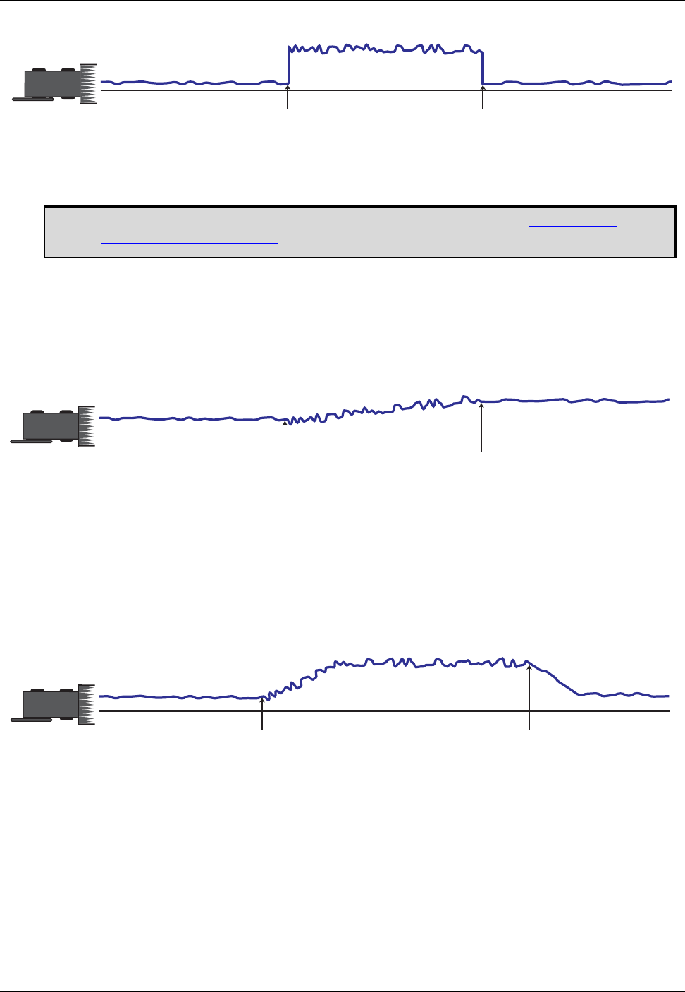
52 ProPak6 Installation and Operation User Manual Rev 5
Chapter 3 Operation
The setting in the STEADYLINE command determines how the receiver transitions to the next positioning
mode. The following sections describe the STEADYLINE modes.
3.6.1 Maintain
When the receiver transitions to a different positioning mode, it maintains the position offset calculated to
limit a potential real position jump. The receiver continues to apply the position offset to all positions
calculated in the new positioning mode.
Figure 17: STEADYLINE Maintain
3.6.2 Transition
When the receiver transitions to a different positioning mode, the position offset is applied to the
calculated position to limit a potential real position jump. The position then slowly transitions to the new
reference position type over a specified period of time. This time period is specified by the Transition time
parameter in the STEADYLINE command.
Figure 18: STEADYLINE Transition
Position
Intended Path
change to
lower accuracy
solution
change to
higher accuracy
solution
For more information about the STEADYLINE command, refer to the OEM6 Family
Firmware Reference Manual (OM-20000129).
Position
Intended Path
change to
lower accuracy
solution
change to
higher accuracy
solution
Position
Intended Path
change to
lower accuracy
solution
change to
higher accuracy
solution
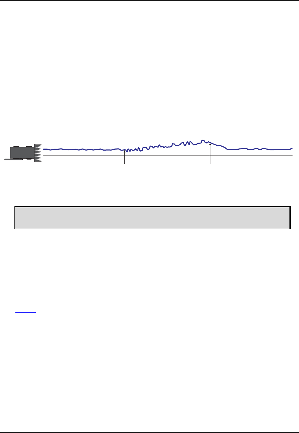
Operation Chapter 3
ProPak6 Installation and Operation User Manual Rev 5 53
3.6.3 Prefer Accuracy
The positioning mode change depends on the accuracy level of the positioning modes.
When the position mode is changing from a more accurate mode to a less accurate mode (e.g., changing
from RTK to GLIDE), the receiver uses the Maintain option.
When the position mode is changing from a less accurate mode to a more accurate mode (e.g., GLIDE to
RTK), the receiver uses the Transition option.
For example, a receiver is configured to do both RTK and GLIDE. If this receiver has a fixed RTK position
and experiences a loss of correction data causing the loss of the RTK solution it will immediately apply
the offset between the two position modes and uses the GLIDE position stability to maintain the previous
trajectory. Over time the GLIDE (or non-RTK) position will experience some drift. Once the RTK position
is achieved again the receiver will start using the RTK positions for position stability and will slowly
transition back to the RTK positions at a default rate of 0.005 m/s or the time specified in the
STEADYLINE command.
Figure 19: STEADYLINE Prefer Accuracy
3.6.4 UAL
The STEADYLINE mode used depends on the BESTPOS and GPGGA solution types.
When the solution type is OPERATIONAL, the receiver uses the Maintain option.
When the solution type is WARNING, the receiver uses the Prefer option. When the receiver changes
from WARNING to OPERATIONAL, it will continue to use the Prefer option until any existing offset is
gone.
When the solution type is OUT_OF_BOUNDS, the STEADYLINE feature is disabled.
The thresholds used to determine the solution type (OPERATIONAL, WARNING or OUT_OF_BOUNDS),
can be specified using the UALCONTROL command. Refer to the OEM6 Family Firmware Reference
Manual (OM-20000129) for more information.
Figure 20, STEADYLINE UAL- Warning Limit Example on page 54 and Figure 21, STEADYLINE UAL -
Out of Bounds Example on page 54 show an examples of STEADYLINE using the UAL mode.
UAL mode will not function unless UALCONTROL is enabled using the UALCONTROL
command.
Position
Intended Path
change to
lower accuracy
solution
change to
higher accuracy
solution
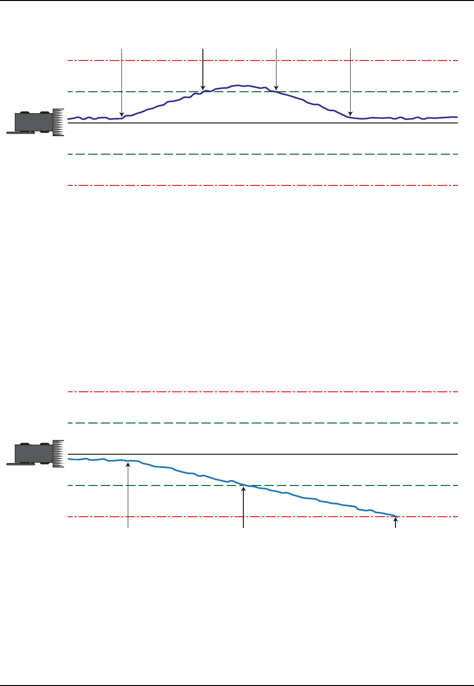
54 ProPak6 Installation and Operation User Manual Rev 5
Chapter 3 Operation
Figure 20: STEADYLINE UAL- Warning Limit Example
Figure 21: STEADYLINE UAL - Out of Bounds Example
APosition type is OPERATIONAL.
Higher accuracy corrections are lost. The receiver changes to a lower accuracy solution.
STEADYLINE operates in Maintain mode while the solution accuracy remains within the Operational
limit.
BThe solution accuracy exceeds the operational limit. The position type changes to WARNING.
The STEADYLINE mode changes from Maintain to Prefer.
CThe solution accuracy moves back within the operational limit. The position type changes to
OPERATIONAL.
The STEADYLINE mode remains in Prefer mode.
DThe solution offset is removed.
The STEADYLINE mode changes from Prefer to Maintain.
Operational
Limit
Warning
Limit
Operational
Limit
Warning
Limit
ABCD
AThe position type is OPERATIONAL.
Higher accuracy corrections are lost. The receiver changes to a lower accuracy solution.
STEADYLINE operates in Maintain mode while solution accuracy remains within the Operational
limit.
BThe solution accuracy exceeds the operational limit. The position type changes to WARNING.
The STEADYLINE mode changes from Maintain to Prefer.
CThe solution accuracy exceeds the warning limit. The position type changes to OUT_OF_BOUNDS.
STEADYLINE is disabled.
Operational
Limit
Warning
Limit
Operational
Limit
Warning
Limit
AB C

Operation Chapter 3
ProPak6 Installation and Operation User Manual Rev 5 55
3.6.5 Configuration Notes
For compatibility with other GNSS receivers and to minimize message size, use the standard form of
RTCA, RTCM, RTCMV3, CMR+ or CMR corrections shown in the base and rover examples above. This
requires using the INTERFACEMODE command to dedicate one direction of a serial port to one
message type only. When the INTERFACEMODE command is used to change the mode from the
NOVATEL default, the NovAtel format messages can no longer be used.
To mix NovAtel format messages and RTCA, RTCM, RTCMV3 or CMR messages on the same port,
leave the interface mode set to NOVATEL and log out variants of the standard correction messages with
a NovAtel header. ASCII or binary variants can be requested by appending an A or B to the standard
message name. For example, on the base station:
interfacemode com2 novatel novatel
fix position 51.11358042 -114.04358013 1059.4105
log com2 rtcaobs2b ontime 2
At the rover, leave the interface mode default settings (interfacemode com2 novatel novatel). The rover
recognizes the default and uses the corrections it receives with a NovAtel header.
The PSRDIFFSOURCE and RTKSOURCE commands set the station ID values that identify the base
stations to accept pseudorange or RTK corrections from. They are useful commands when the rover
station is receiving corrections from multiple base stations.
At the base station, log the contents of the standard corrections in a form that is easier to read. These
larger variants have the correction fields broken out into standard types in the log, rather than
compressed into bit fields. This can be useful to modify the format of the corrections for a non-standard
application or to look at the corrections for system debugging purposes. These variants have DATA in
their names (e.g., RTCADATA1, RTCMDATA1, CMRDATAOBS). Refer to the OEM6 Family Firmware
Reference Manual (OM-20000129) for more information.
3.6.6 Enabling SBAS Positioning
The ProPak6 is capable of SBAS positioning. This positioning mode is enabled using the
SBASCONTROL command:
sbascontrol enable auto
When the command is entered, the ProPak6 automatically tracks the SBAS that is operating in the region
(e.g., WAAS or EGNOS) and applies the corrections from the service. On a simulator, leave the test
mode parameter off or specify NONE explicitly. For more on SBAS, refer to the NovAtel application note
APN-051 Positioning Modes of Operation available from our website www.novatel.com/support/search/.
1. Interface mode must be set to NOVATEL for the receiver to issue logs with an A or
B suffix.
2. Using the receiver in NOVATEL mode consumes more CPU bandwidth than using
the native differential messages as shown in Section 3.4.1, Defining Antenna and
Base Antenna on Page 48.
3. To find information on how to send multiple commands and log requests using DOS
or Windows, search our knowledge database at www.novatel.com/support/search/.

56 ProPak6 Installation and Operation User Manual Rev 5
Chapter 3 Operation
3.6.7 Enabling L-Band
L-Band equipped receivers can achieve sub-metre position accuracy using correction data received from
geostationary satellites. To use the L-Band corrections, an L-Band-capable receiver model and antenna
are required (refer to our web site www.novatel.com/products/gnss-antennas for information on NovAtel
L-Band-capable antennas).
For more information on L-Band positioning, refer to:
• NovAtel Application Notes: APN-061 NovAtel CORRECT with TerraStar, APN-062
NovAtel CORRECT with Veripos (service dependent) or APN-051 Positioning Modes of
Operation available from www.novatel.com/support/search/items/Application%20Note
•the OEM6 Family Firmware Reference Manual (OM-20000129) for log/command details
and/or
• visit www.novatel.com/support
• visit www.novatel.com/products/novatel-correct
TerraStar Subscriptions
A subscription is required to use the TerraStar service for land, airborne and near shore applications.
Near shore applications are defined as vessels operating within 10 km of shore. To obtain a subscription,
contact your local NovAtel sales representative or visit www.novatel.com/products/terrastar-gnss-
corrections. The receiver’s TerraStar Product Activation Code (PAC) or the NovAtel product serial
number (PSN) is needed to obtain a subscription. To obtain the receiver-specific PAC, enter the following
command:
log terrastarinfo
This log displays the PAC in the first field following the log header and also displays the status of your
subscription.
To activate a subscription, the receiver must be powered and tracking an L-Band TerraStar satellite prior
to the planned activation time. Use the ASSIGNLBANDBEAM command to configure the receiver to track
the TerraStar satellite.
To confirm tracking of an L-Band signal, log the L-Band tracking status information by entering the
following command:
log lbandtrackstata
If receiving TerraStar service, the sixth field following the header (tracking status word) of the
LBANDTRACKSTAT log will be 00c2, as shown in the following example:
#lbandtrackstata,com1,0,73.5,finesteering,1769,328196.000,00000000,29fd,12602:
1,"98w",1539902500,1200,974c 00c2,0, 316.186,43.842,4.3840,61.920,1088,2,2,
138176,79,0.0001*3e43cb7d
OEM615, OEM617, OEM617D and FlexPak6D are not L-Band capable.
The latest services and coverage can be obtained from www.terrastar.net. For additional
information on TerraStar activation, contact NovAtel Customer Service at www.novatel.com/
support or download the APN-061 NovAtel CORRECT with TerraStar from:
www.novatel.com/support/search/items/Application%20Note

Operation Chapter 3
ProPak6 Installation and Operation User Manual Rev 5 57
Veripos Subscriptions
A subscription is required to use the Veripos services for offshore marine applications. Contact Veripos
sales at www.veripos.com/support.html to obtain a Service Access License (SAL) number. To activate
the service, contact the Veripos Help Desk at +44 (0) 1224 527 104 or visit www.veripos.com/
support.html. Provide the SAL number and the receiver's Veripos Serial Number (VSN).To obtain the
receiver-specific VSN, enter the following command:
log veriposinfo
The log displays the VSN in the first field following the log header and also displays the status of your
subscription.
To activate a subscription, the receiver must be powered and tracking an L-Band Veripos satellite prior to
the planned activation time. Use the ASSIGNLBANDBEAM command to configure the receiver to track
the Veripos satellite.
OmniSTAR®
A subscription is required to use the OmniSTAR service. To obtain a subscription, contact OmniSTAR at
1-888-883-8476 or 713-785-5850. Provide the receiver’s OmniSTAR serial number (which is different
from the NovAtel serial number). To obtain the OmniSTAR serial number, enter the following command:
log lbandinfo
The log displays the L-Band serial number in the fifth field following the log header. The log also provides
the status of your subscription. Refer to the LBANDINFO log in the OEM6 Family Firmware Reference
Manual (OM-20000129) for more information.
To activate the subscription, the receiver must be powered and tracking an L-Band satellite. When
advised by OmniSTAR of the appropriate satellite frequency and data link rate for your location, use the
ASSIGNLBAND command to configure your receiver.
Example:
assignlband omnistar 1557855 1200
To confirm tracking of an L-Band signal, log the L-Band status information by entering the following
command:
Subscriptions to the Veripos Apex and Apex2 marine services must be obtained directly
from Veripos. A unit with a marine subscription can not be switched to a land subscription
and vice versa.
The latest services and coverage can be obtained from www.veripos.com. For additional
information on Veripos activation, contact NovAtel Customer Service at www.novatel.com/
support or download the APN-062 NovAtel CORRECT with Veripos from:
www.novatel.com/support/search/items/Application%20Note
OmniSTAR service is not supported for OEM6 products sold after October 24, 2013. If
unsure whether the receiver is OmniSTAR capable, contact NovAtel Sales at
www.novatel.com/where-to-buy/sales-offices, NovAtel Customer Support at
www.novatel.com/support or visit www.novatel.com/products/novatel-correct.
The latest frequencies can be obtained from: www.omnistar.com.

58 ProPak6 Installation and Operation User Manual Rev 5
Chapter 3 Operation
log lbandstat
If receiving OmniSTAR HP, the fifth field of the LBANDSTAT log should be 00c2, as shown in the
following example:
lbandstat com1 0 81.0 finesteering 1596 235136.000 00000000 d1c2 5968
<1557854678 48.98 1098.9 0.00 00c2 0000 153860 545 0 0000 0201 154019
68000000 00000000
Refer to the NovAtel application note APN-051 Positioning Modes of Operation for OmniSTAR specifics.
3.7 Logging and Retrieving Data Overview
Data can be collected for post-processing and stored directly on the internal flash memory of the
ProPak6 (4 GB total). Data logging can be initiated manually from the ProPak6 or remotely from a
computer using a variety of communication protocols.
Data can be retrieved from the ProPak6 onboard memory for post-processing manually at the ProPak6
or remotely using a variety of methods.
The following are the main steps used to perform logging tasks.
• Determine the data to log
• Set the trigger and data rate of each in the LOG command
• Specify a port after LOG but prior to the specific message to log data to the specified port
(if no port specified, data is output to the console or ascii message windows)
• Stop logging in two ways:
UNLOG [PORT] [LOGNAME]
UNLOGALL (stops all logging activity)
Refer to the following sections for detailed instructions on performing logging tasks.
Naming Log Files
File names for logs saved to onboard storage can be specified manually or the ProPak6 can be set to
automatically name files.
Manual Log File Naming
Use NovAtel Connect or HyperTerminal to name logged files. If the file name entered already exists, the
command returns an error. Use the LOGFILESTATUS log to view errors, determine if a log file is open or
closed or if the internal storage device is busy.
Manual Logging Initiation Remote Logging Initiation
- Press the Log button on the ProPak6
(refer to Section 3.7.1.1, Manual
Logging Initiation on page 59)
-ICOM port via either Ethernet or Wi-Fi
-COM1/COM2/COM3/USB1/USB2/USB3
(refer to Section 3.7.1.2, Remote Logging Initiation on
page 60)
Manual Retrieval of Logged Data Remote Retrieval of Logged Data
- USB Host (memory stick)
(refer to Section 3.7.1.3, Manual
Retrieval of Logged Data on page 60)
- FTP via either Ethernet or Wi-Fi
(refer to Section 3.7.1.5, Remote Retrieval of Logged Data on
page 60)
If ICOM port security is enabled (using the IPSERVICE command), commands are refused
until the LOGIN command is issued. Refer to Section 2.9, ProPak6 Security on page 34 and
the OEM6 Family Firmware Reference Manual (OM-20000129) for command details.
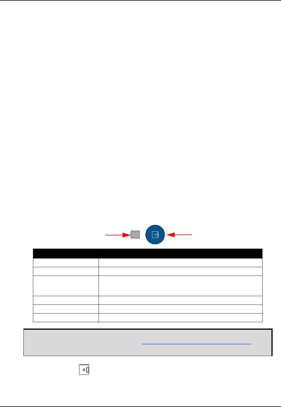
Operation Chapter 3
ProPak6 Installation and Operation User Manual Rev 5 59
Automatic Log File Naming
If a name is not supplied for a logged file, one is automatically generated based on the PSN of receiver
and an automatically incrementing number beginning at one. If a log in the sequence number is deleted,
the number is recycled for use in order.
3.7.1 Onboard Data Storage
The ProPak6 contains 4 GB of memory for onboard data storage. Data can be logged to internal memory
and downloaded for post-processing in a variety of ways.
To begin logging:
•Issue the LOGFILE OPEN command or press the Logging button
• A log file must be open for logs to be recorded
• Only one logging file can be open at a time
• Logs collected onchanged are not output until there is a change to the content
• Use the Status LED or the LOGFILESTATUS log to monitor logging status
• The DIRENT log contains a list of the file contents currently in the onboard memory
3.7.1.1 Manual Logging Initiation
Required log requests must be saved to the NVM prior to logging start.
Example:
LOG FILE VERSIONA
LOG FILE RANGEB ONTIME1
LOG FILE BESTPOSB ONTIME1
SAVECONFIG
Logging can be initiated by pressing the Logging button. Logged data is stored in the ProPak6 onboard,
internal flash memory.
Pressing the Log button ( ) automatically issues the LOGFILE OPEN or LOGFILE CLOSE commands
(the open/close log status toggles between the two states).
LED State (default) Description
Green (solid) Internal memory capacity >40% to within ±0.5%
Amber (solid) Internal memory capacity between 20 and 40% to within ±0.5%
Red (solid) Internal memory capacity >20% to within ±0.5%
Also, when downloading files via the USB Host when connected on
the front of the ProPak6
Green (blink) Logging as 1 Hz and file is currently open
Green/Amber alternate System busy (internal setup)
Off No activity-button not pressed
The capacity indication level for the Logging LED can be configured using the
LEDCONFIG command. Refer to the OEM6 Family Firmware Reference Manual
(OM-20000129) for command details.
Status LED Button

60 ProPak6 Installation and Operation User Manual Rev 5
Chapter 3 Operation
3.7.1.2 Remote Logging Initiation
Once a Wi-Fi or Ethernet connection is established, send the LOGFILE OPEN command and specify
FILE as the output port when issuing LOG commands to begin logging data. To stop saving data to the
file, issue the LOGFILE CLOSE command.
Example to log data to onboard storage:
LOGFILE OPEN SAMPLE_DATA.LOG
LOG FILE VERSION
LOG FILE RANGEB ONTIME 1
LOG FILE BESTPOSB ONTIME 1
3.7.1.3 Manual Retrieval of Logged Data
By default, files can be copied from the ProPak6 USB Host port (Type A) to a USB stick using DOSCMD
COPY command. Example:
DOSCMD COPY MYFILE.LOG
A check is performed before each file is copied to ensure there is enough space on the USB stick. If there
is not enough room, the file is skipped and copying continues with the next file. This is considered an
error for all copy options except SKIP (refer to OEM6 Family Firmware Reference Manual for the SKIP
option description) but will continue copying the rest of the files (if space is available). The USB Host LED
blinks red during the copy process.
At the end of the copy, if there is an error the USB Host LED turns off. The USB Host LED is solid red
indicating the USB stick is inserted and idle. Refer to Section 3.1.10.1, USB Host LED on page 41 for
LED details.
3.7.1.4 Automatic Retrieval of Logged Data
The SETFILECOPYMODE command configures how the receiver copies files from internal memory to a
USB stick. The SETFILECOPYMODE command must be issued prior to inserting the USB stick to trigger
auto-copy. When auto copying files, there must be enough space available on the USB stick to hold the
files. Files that won’t fit are skipped and therefore are not copied to the USB stick.
Example: SETFILECOPYMODE AUTO_ALL
3.7.1.5 Remote Retrieval of Logged Data
The FTP server on the ProPak6 allow access to the internal flash memory. There is a limitation of one
connection at any given time. This not only means that only one user can access the FTP server at a
time but the FTP Client software must be set to only use one connection (refer to Section 5.2.3, Wi-Fi
Client Configuration on page 87 for Client setup details). The FTP server can be accessed via Ethernet
or Wi-Fi.
A maximum of 256 files can be stored (depending on individual file sizes). For further
details about file system limitations, consult the FAT32 standards from MicroSoft.
To avoid corrupting files, press the Log button or issue the LOGFILE CLOSE command
before powering down the receiver or extracting data.
The ProPak6 only supports FAT12/16/32 file systems. Other file systems, in particular
NTFS, are not supported.
Refer to OEM6 Family Firmware Reference Manual (OM-20000129) for command
details.

Operation Chapter 3
ProPak6 Installation and Operation User Manual Rev 5 61
Setting FTP Transfer Mode to Binary
1. Using standard terminal software, open an FTP connection to the receiver.
2. To change to binary mode, enter: BIN
3. To transfer a file, enter: get <FILENAME.DAT>
3.7.1.6 Stop Logging
Press the Log button ( ) to stop logging (open/close toggles based on the last state) or issue the
LOGFILE CLOSE command.
3.7.2 Reading Data and Post-Processing
Logs can be directed to any of the ProPak6 communication ports and can be automatically generated
when new or changed data becomes available or at regular intervals.
Example:
LOG BESTPOSA ONTIME 1
Data can be collected through NovAtel Connect using the Logging Control Window.
Refer NovAtel Connect within the Help or the .chm file bundled with the software for further logging
details.
When transferring binary data files, ensure FTP transfer mode is set to binary. If left in
ASCII mode, files will not successfully download will become corrupted.
If the FTP connection is lost during the downloading of files, reconnect and begin the
file transfer again. The data files are not removed from internal storage until manually
deleted. If the Propak6 lost power and commands to configure the Ethernet (Chapter 4,
Ethernet Configuration on page 74), Wi-Fi (Section 5.2, Wi-Fi Network Configuration on
page 84), and FTP Server (Section 2.9.2, FTP Server and ICOM Ports on page 34)
were not saved to NVM using the SAVECONFIG command, they must be reconfigured.
Otherwise, the receiver is ready for a connection from client software running on a PC
or other device. When the transfer is successful, files can be deleted issuing the
DOSCMD DEL command or by using the 'del' command from within the FTP client.
Logging automatically stops when the ProPak6 internal memory is full (4 GB). To avoid
filling internal memory, ensure transferred or no longer needed logs are regularly
deleted.

62 ProPak6 Installation and Operation User Manual Rev 5
Chapter 3 Operation
3.7.3 Pass-Through Logging
The pass-through logging feature enables the GNSS receiver to redirect any ASCII or binary data that is
input at a specified COM port or USB port, to any specified receiver COM or USB port. This capability, in
conjunction with the SEND command, allows the receiver to perform bidirectional communications with
other devices such as a modem, terminal or another receiver.
There are several pass-through logs: PASSCOM1, PASSCOM2, PASSCOM3, PASSXCOM1,
PASSXCOM2, PASSXCOM3, PASSUSB1, PASSUSB2, PASSUSB3, PASSICOMX, PASSNCOM and
PASSAUX are available on OEM6 family receivers for logging through serial ports. Refer to the
PASSCOM logs in the OEM6 Family Firmware Reference Manual (OM-20000129) for details.
3.8 ProPak6 Web User Interface (UI)
The ProPak6 is able to perform basic monitoring, configuration and updating tasks over a selected
Ethernet/Wi-Fi network. The feature/functionality available for the ProPak6 web UI is:
• Advanced Tracking
• DOP Status
• Onboard Storage Status
• Port Configuration
• Position Mode Configuration
• Logging Profile Manager
• Rx Health Status
• Solution Status
If the necessary feature/functionality required is not available in the Web UI, use NovAtel Connect to
perform comprehensive monitoring, configuration and updating tasks using various connections. Refer to
Section 2.8, Installing NovAtel Connect PC Utilities on page 33 for details regarding NovAtel Connect.
The following browsers are supported:
• IE11, Google Chrome (33.0.1750.154 m) and Mozilla Firefox (27.0.1)
3.8.1 Setup Up Network IP
After installing and powering up the ProPak6 (follow the steps in Section 2.4, Standard Configuration
Installation on page 24 or Section 2.5, Dual Antenna Configuration and Installation on page 26) perform
the following steps to setup the ProPak6 Web UI.
1. Ethernet DHCP is the default network setup for Internet access for the ProPak6. If a Static IP is
required, refer to Section 4.2, Static IP Address Configuration on page 74. Refer to Section 5.2, Wi-Fi
Network Configuration on page 84 or Section 5.3, Cellular Activation GSM/GPRS/HSDPA on
page 90 for additional network configuration details.
2. On a wireless device, locate the list of detected Access Points. By default, the ProPak6 detected is
named using the Product Serial Number (PSN). Example: ProPak-6 NMCMxxxxxxxxx
3. Select the ProPak6 from the list to connect.
4. Open a supported internet browser, for example, Internet Explorer®.

Operation Chapter 3
ProPak6 Installation and Operation User Manual Rev 5 63
5. Enter the receiver IP address in the browser address bar and press Enter. The Login page displays:
6. Click in the Username field and enter the default user name: admin
7. Click in the Password field and enter the default password: the ProPak6 receiver Product Serial
Number (PSN) is the default password (located bottom of receiver).
8. Press the Log In button.
The default Product Information home page displays, This page contains information about the
connected ProPak6 receiver. Note, it may take a few moments to load all information into the fields.
When entering any information into the Web UI, check for auto corrections or
turn auto correct off.
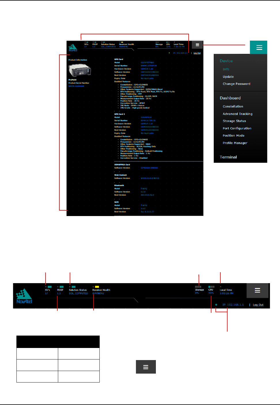
64 ProPak6 Installation and Operation User Manual Rev 5
Chapter 3 Operation
Figure 22: Product Information (Info)
Figure 23: Status Display Top Panel
Status Information
(refer to Figure 23)
Click to open.
Current
information
regarding
connected
ProPak6
Click + to display
information for Satellite
Vehicles in use
Click + to display
information for
Dilution of Precision
Shows percent
of CPU in use
Click to display a local
time for the satellites
being tracked
Shows percent of
onboard storage used
Click + to display information
and configure Position Mode
Click + to display
current receiver health
information
Color Status
Red Error
Green Good
Yellow Warning
Shows IP status
The blinking light
indicates receiver
connection alive status
Press the button, in the upper right corner, to display
additional information and configuration options.
Hover the mouse over the Solution or Receiver Health
status to display detailed information on the status
message and display troubleshooting suggestions to
assist in resolving any error conditions
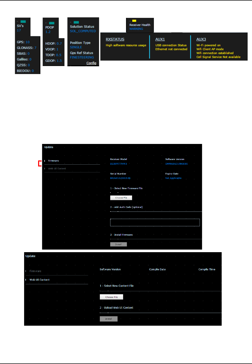
Operation Chapter 3
ProPak6 Installation and Operation User Manual Rev 5 65
Table 13: Status Drop Menu Examples
3.8.2 Device Menu
The Device menu contains the Info Page (default home page), Update and Change Password options.
3.8.2.1 Info
Refer to Figure 22, Product Information (Info) on Page 64 for location.
3.8.2.2 Update
Use to update either the firmware on the ProPak6 or the Web UI interface.
Click to move
between
options
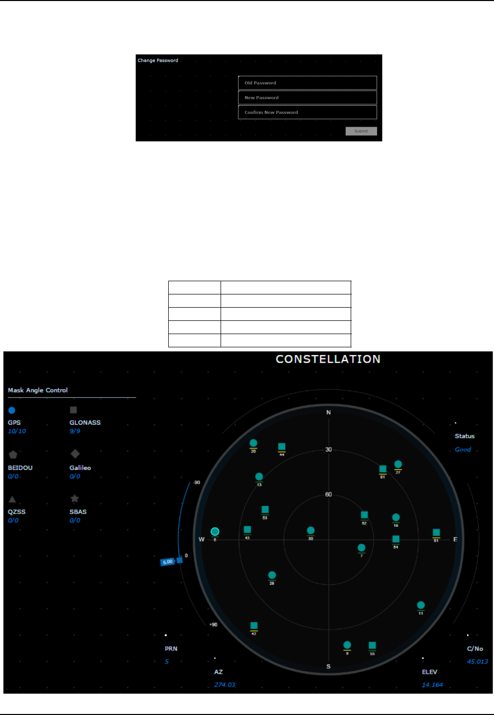
66 ProPak6 Installation and Operation User Manual Rev 5
Chapter 3 Operation
3.8.2.3 Change Password
Use this page to change the password.
3.8.3 Dashboard
The Dashboard contains the Constellation, Advanced Tracking, Storage Status, Port Configuration,
Position Mode and Profile Manager.
3.8.3.1 Constellation
Use to monitor the satellites currently being tracked. Each satellite type displays as a different shape.
The color indicates the status of the channel; the colored line below the shape indicates the signal
strength. Each shape also displays the PRN of that satellite. Click a shape, within the Constellation circle,
to display SV information.
Red No signal match
Blue No ephemeris
Yellow No ambiguity
Teal All other health status
Orange N/A
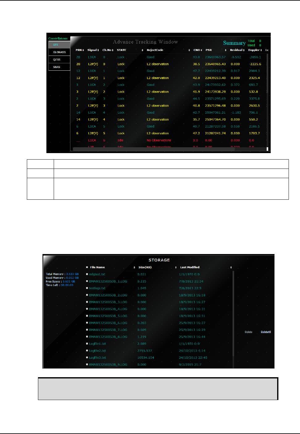
Operation Chapter 3
ProPak6 Installation and Operation User Manual Rev 5 67
3.8.3.2 Advanced Tracking
The page displays receiver channel status information.
3.8.3.3 Storage Status
Displays the amount of memory available, amount used, available space and time left along with a list for
files including size and date modified on the ProPak6. Click on one or multiple check boxes and press the
delete button to delete selected files. Click on the up/down arrows at the top of each column to customize
the sort order.
Green Good
Red Bad Health, Misclosure, No Ephemeris, Unknown, Not Used, NA, Bad Integrity, Lossoflock
Yellow OldEphemeris, Elevationerror, Nodiffcorr,Invalidiode, Lockedout, Lowpower, OBSL2,
Noionocolor, OBSL1,OBSE1,OBSL5, OBSE5,OBSB2,OBSB1, NoSignalmatch,
Supplementary, Noambiguity
The ProPak6 contains 4 GB of onboard data storage. Refer to Section 3.7.1,
Onboard Data Storage on page 59 for details.
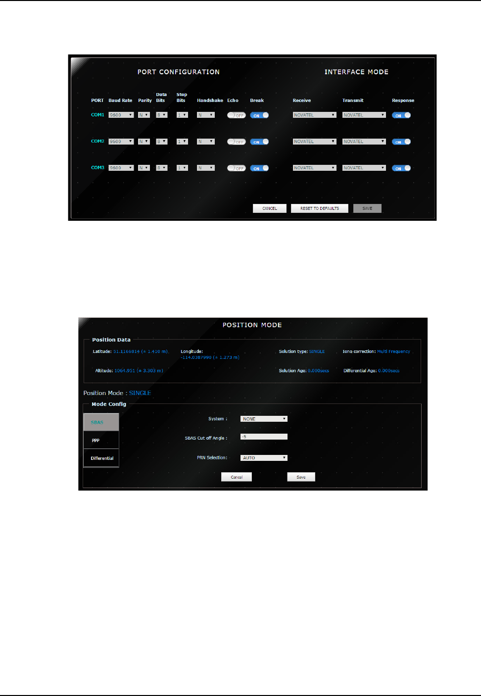
68 ProPak6 Installation and Operation User Manual Rev 5
Chapter 3 Operation
3.8.3.4 Port Configuration
Use to configure ports and set the interface mode.
3.8.3.5 Position Mode
Displays the current position mode currently used by the receiver. Is also used to configure the receiver
for SBAS, PPP and Differential operation.
Use the SBAS page to select the SBAS system to use in the receiver solution, let the receiver determine
the best system or do not use SBAS system satellites.
Once set, use save button to configure the receiver with the selected position mode settings. Set system
to NONE to reset to previous position mode.
Use the PPP Tab to configure a position mode for Precise Point Positioning if your receiver is enabled
with a TerraStar Subscription. A message at the bottom of the screen indicate the current subscription
status.If there is an active subscription, click the 'Enable L-Band' button to automatically select the
appropriate L-Band Beam and the system will begin converging a PPP solution. Note that this can take
approximately 15-20 minutes to complete. Clicking another beam from the beam table and clicking
'Assign L-Band Beam' will manually assign the beam selected.
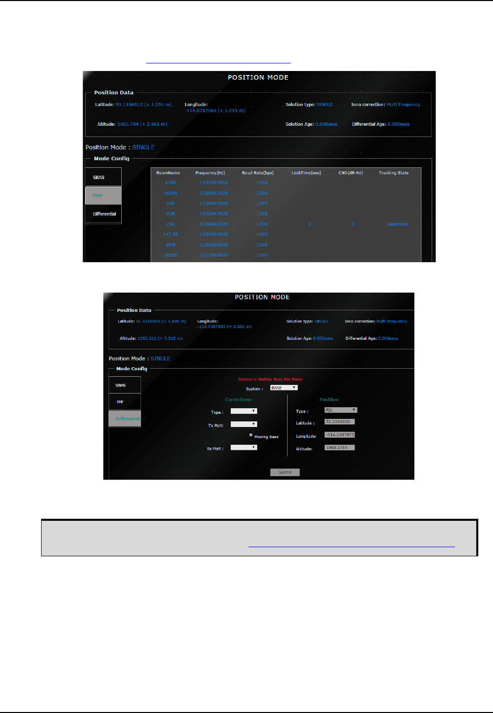
Operation Chapter 3
ProPak6 Installation and Operation User Manual Rev 5 69
If there is no TerraStar subscription available on the receiver, the button text displays 'Track L-Band'
beams, and will only allow the user view the available beams and not select one. Contact NovAtel
Customer Support (support@novatel.com) to inquire about TerraStar subscription activation. For beam
coverage information, visit www.terrastar.net/coverage.html.
Use the Differential page to configure the receiver for Base/Rover operations.
The NovAtel Connect PC Utilities contain a number of additional utilities that can be used to access more
advanced features of the ProPak6.
Download the latest PC Utilities that include NovAtel Connect™ along with the
necessary user documentation from: www.novatel.com/support/info/documents/809.
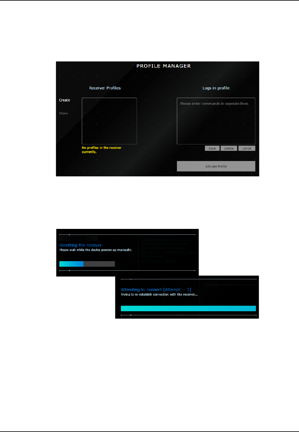
70 ProPak6 Installation and Operation User Manual Rev 5
Chapter 3 Operation
3.8.3.6 Profile Manager
Use the Profile Manager to group sequences of receiver configuration commands under a common
profile and to create and store multiple profiles on to a receiver. Use saved profiles to easily configure the
receiver for a variety of applications by simply selecting the appropriate profile which after being
activated, will being logging automatically whenever the receiver is powered on, until the profile is
manually deactivated. Up to 9 profiles can be stored on the ProPak6 and 20 commands per profile.
Profile restrictions are each command in a profile cannot exceed 200 characters and a maximum of 1500
characters for all commands in one profile.
Press the Activate Profile to load the selected ProPak6 receiver profile. Activating a profile causes the
receiver to reset.

Operation Chapter 3
ProPak6 Installation and Operation User Manual Rev 5 71
3.8.4 Terminal
Commands can be sent to the receiver using the command line at the bottom of the Terminal page.
Load Button
Create a text file containing a list of commands to be executed in sequence. Name and save the file to
the connected computer/device (not the ProPak6). Use the Load button to find and select one of these
files.
Only ASCII log responses are allowed. No responses and no recording for binary log
requests. If abbreviated ASCII log requests are sent, ASCII responses are shown/recorded.

72 ProPak6 Installation and Operation User Manual Rev 5
Chapter 3 Operation
Save Button
Press the Save button to name and create a file of any logged data. Logged data files are listed under the
Storage menu. Use the Cancel button to return to the Terminal page without saving.
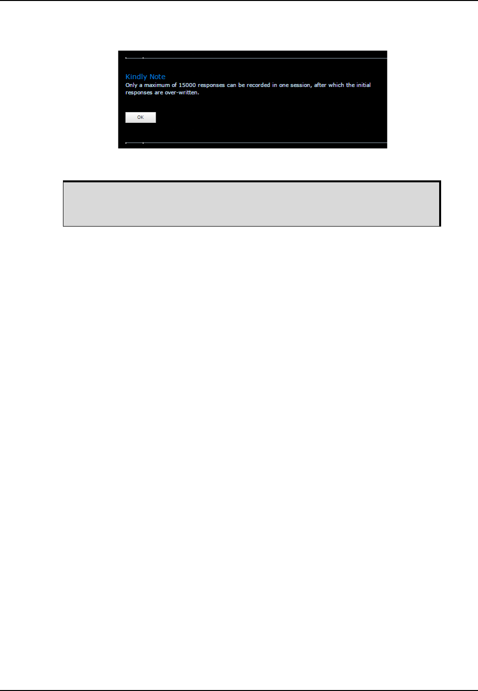
Operation Chapter 3
ProPak6 Installation and Operation User Manual Rev 5 73
Rec Button
Press the Rec button to record the output results of logged data.
The Rec button flashes during recording. To stop recording, press the Rec button again.
A maximum of 15000 responses can be recorded in one session using the
Rec feature. Refer to Section 3.8.3.6, Profile Manager on page 70 if
intending to log data over a long period of time.

74 ProPak6 Installation and Operation User Manual 5
Chapter 4 Ethernet Configuration
An Ethernet connection can be used to send commands to and obtain logs from an Ethernet capable
ProPak6 receiver. An Ethernet connection can also be used to connect two receivers in a base/rover
configuration.
This chapter describes how to configure the Ethernet port on an ProPak6 receiver. It provides the step-
by-step process for connecting to the ProPak6 receiver through the Ethernet interface, setting up a base/
rover configuration through Ethernet connectivity and utilizing the NTRIP interface. The Ethernet port
connections for a computer connected to the receiver are also described for both Windows XP (with SP3)
and Windows 7 operating systems.
4.1 Required Hardware
The following hardware is required to set up an Ethernet interface to an ProPak6 receiver:
• a user supplied computer with an available Ethernet and serial or USB port or Wi-Fi or Bluetooth link
• a ProPak6 receiver
• an RS-232 null modem cable or USB cable
• a cross-over CAT5 Ethernet cable or a user supplied Ethernet network hub or wired router (optional)
and CAT 5 Ethernet cable
4.2 Static IP Address Configuration
For a static IP address configuration, unique IP addresses are assigned to both the ProPak6 receiver
and the computer. TCP/IP is used for the connection in this simple network. This configuration can also
be used in a bench test environment to confirm Ethernet functionality. By default, the ProPak6 is set to
Ethernet DHCP Dynamic IP address.
Ethernet (ETHA) is the default network for internet access for the ProPak6. The default
network can be changed to Wi-Fi or Cellular or changed back to Ethernet using the
SETPREFERREDNETIF ETHA command. Refer to the Section 5.2.1, Configure Wi-Fi as
the Network Default on page 84 or Section 5.3.1, Configure Cellular as the Network
Default on page 90 for details.
Refer to Section 3.1.11, Ethernet Port on page 41 for details on the physical parameters
of the Ethernet Port.
The ProPak6 default is Ethernet DHCP Dynamic IP address.
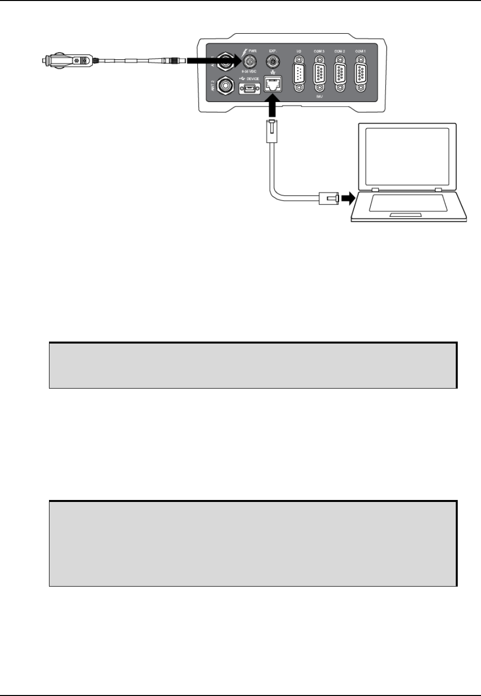
Ethernet Configuration Chapter 4
ProPak6 Installation and Operation User Manual 5 75
Figure 24: Cross-Over Ethernet Cable Configuration—ProPak6
4.2.1 Static IP Address Configuration—Receiver
Follow these steps to set up a static IP address on the ProPak6 receiver:
1. Connect a computer to the ProPak6 receiver using a null modem serial cable or USB cable or use
Bluetooth or Wi-Fi.
2. Establish a connection to the receiver using either NovAtel Connect or another terminal program
such as HyperTerminal. This connection is used to send the commands in this procedure to the
receiver.
3. Enable the Ethernet port on the receiver by entering:
ethconfig etha auto auto auto auto
4. Assign the TCP/IP port number used for the connection by entering:
icomconfig icom1 tcp :2000
5. Assign the receiver IP address, subnet mask and default gateway by entering:
ipconfig etha static 192.168.74.10 255.255.255.0 192.168.74.1
6. Save the new Ethernet settings by entering:
saveconfig
7. Log the IPCONFIG command and confirm the TCP/IP configuration by entering:
log ipconfig once
Ethernet Cable
ProPak6
Computer
Power Cable
For information about establishing a connection using NovAtel Connect, refer to the
Quick Start Guide for the product or NovAtel Connect Help included with NovAtel
Connect PC Utilities available from our web site.
The command above assign the following values to the ProPak6 receiver:
ip address = 192.168.74.10
subnet mask = 255.255.255.0
gateway = 192.168.74.1
These settings are examples only. The settings appropriate to the network may be
different.

76 ProPak6 Installation and Operation User Manual 5
Chapter 4 Ethernet Configuration
8. Configure your computer with a static IP address.
For a computer using Windows XP Service Pack 3,refer to Section 4.2.2 Static IP Address Configu-
ration—Windows XP with SP3 on page 76.
For a computer using Windows 7, refer to Section 4.2.3 Static IP Address Configuration—Windows 7
on page 76.
4.2.2 Static IP Address Configuration—Windows XP with SP3
Follow these steps to set up a static IP address on your computer:
1. Click START | Settings | Network Connections.
The Network Connections window appears.
2. Right click on Local Area Connection and select Properties.
The Local Area Connection Properties window appears.
3. Click Internet Protocol (TCP/IP) and then click the Properties button.
The Internet Protocol (TCP/IP) Properties window appears.
4. Select the Use the following IP address radio button.
5. Enter the IP address, Subnet mask and Default gateway for the Ethernet port on the computer.
6. Click the OK button.
The Local Area Connection Properties window appears.
7. Click the Close button.
8. Proceed to Section 4.2.4, Confirming Ethernet Setup on page 77.
4.2.3 Static IP Address Configuration—Windows 7
Follow these steps to set up a static IP address on a computer:
1. Click Start | Control Panel.
2. Click View Network Status and Tasks under Network and Internet.
3. Click the Local Area Connection link.
The Local Area Connection Status window appears.
4. Click the Properties button.
The Local Area Connection Properties window appears.
5. Select Internet Protocol Version 4 (TCP/IPv4) and then click the Properties button.
The Internet Protocol Version 4 (TCP/IPv4) Properties window appears.
Issue the SAVEETHERNETDATA ETHA command to ensure port settings are
retained after a reset and automatically used at boot time. The
SAVEETHERNETDATA ETHA command is not applicable to the ICOMCONFIG and
NTRIPCONFIG settings. The SAVEETHERNETDATA ETHA command overrides the
SAVECONFIG command configuration settings.
Ensure the Ethernet settings used for the computer are compatible with the Ethernet
settings on the ProPak6 receiver.
For example, the following settings are compatible with the ProPak6 receiver settings
used in Section 4.2.1 Static IP Address Configuration—Receiver on page 75:
ip address = 192.168.74.11
subnet mask = 255.255.255.0
gateway = 192.168.74.1
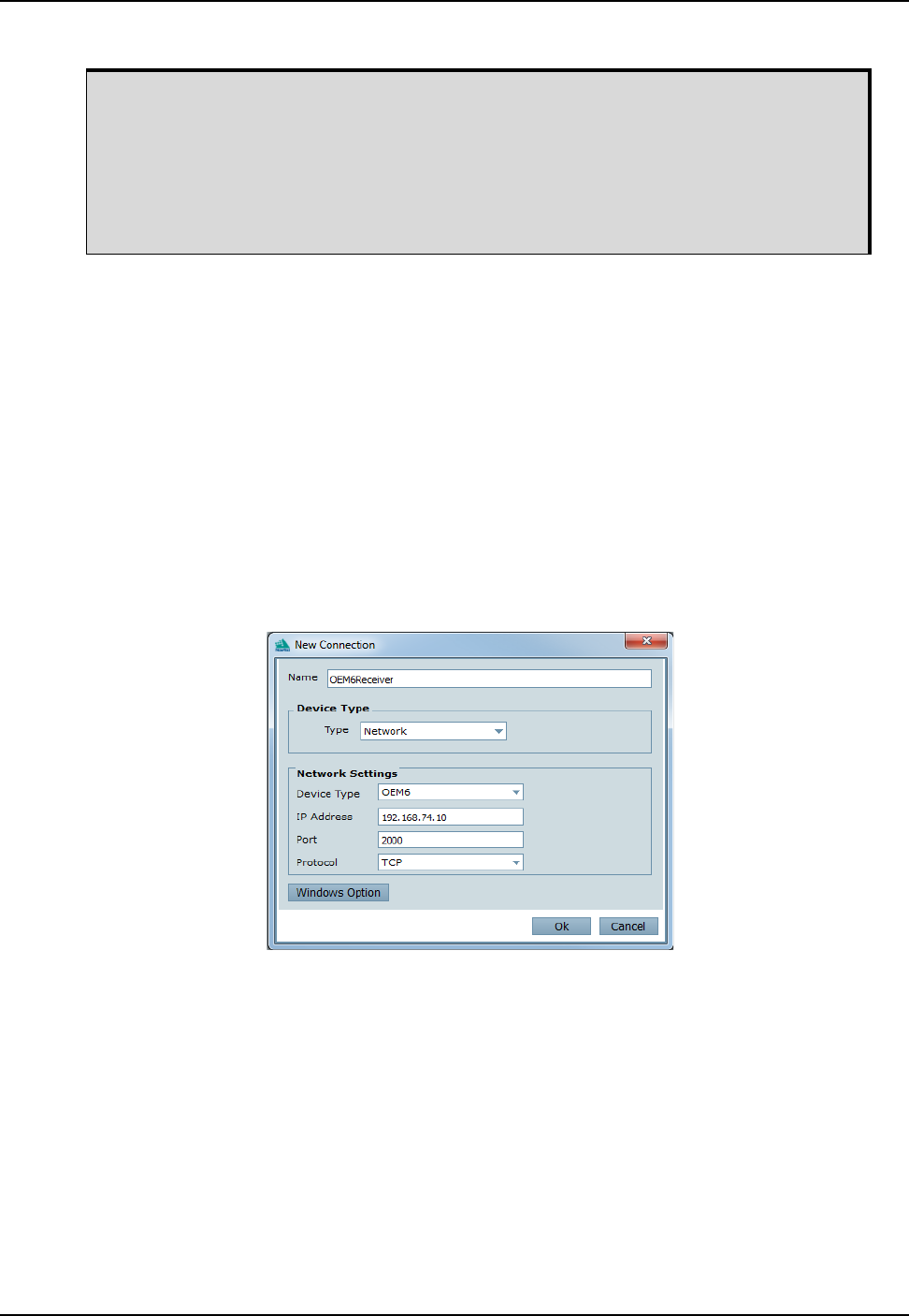
Ethernet Configuration Chapter 4
ProPak6 Installation and Operation User Manual 5 77
6. Enter the IP address, Subnet mask and Default gateway for the Ethernet port on the computer.
7. Click the OK button.
The Local Area Connection Properties window appears.
8. Click the Close button.
The Local Area Connection Status window appears.
9. Click the Close button.
10. Proceed to Section 4.2.4, Confirming Ethernet Setup on page 77.
4.2.4 Confirming Ethernet Setup
1. Connect the computer to the ProPak6 receiver using an Ethernet cross-over cable.
2. Connect to the receiver using NovAtel Connect or any third party terminal program that supports
TCP/IP connections. Use the static IP address and port number assigned to the ProPak6 receiver in
Section 4.2.1 Static IP Address Configuration—Receiver on page 75.
The figure below shows the New Connection window in NovAtel Connect with the example Ethernet
settings used in Section 4.2.1.
Ensure the Ethernet settings used for the computer are compatible with the Ethernet
settings on the ProPak6 receiver.
For example, the following settings are compatible with the ProPak6 receiver settings
used in Section 4.2.1 Static IP Address Configuration—Receiver on page 75:
ip address = 192.168.74.11
subnet mask = 255.255.255.0
gateway = 192.168.74.1

78 ProPak6 Installation and Operation User Manual 5
Chapter 4 Ethernet Configuration
Figure 25: ProPak6 Ethernet Hardware Setup
4.3 Dynamic IP Address Configuration
For this configuration, a direct connection is made from the ProPak6 receiver to a Dynamic Host
Communication Protocol (DHCP) network and into a computer. The DHCP server automatically assigns
an IP addresses to the OEM6 receiver, based on its predetermined available IP addresses.
To set up a dynamic IP address configuration, follow these steps:
1. For first time configuration, connect a computer to the ProPak6 receiver using a null modem serial
cable or USB cable.
2. Establish a connection to the receiver using either NovAtel Connect or another terminal program
such as Windows HyperTerminal. This connection is used to send the commands in this procedure to
the receiver.
3. Enable the Ethernet port by entering:
ethconfig etha auto auto auto auto
For information about establishing a connection using NovAtel Connect, refer to the
Quick Start Guide for the product or NovAtel Connect Help included with NovAtel
Connect PC Utilities.
ProPak6
Computer
Ethernet
Cable
Network Hub
Power Cable
The ProPak6 default is Ethernet DHCP Dynamic IP address.
For information about establishing a connection using NovAtel Connect, refer to the
Quick Start Guide for the product or NovAtel Connect Help.
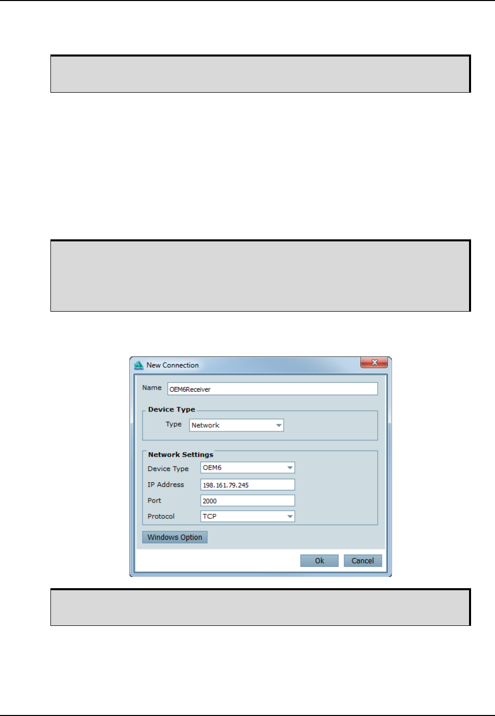
Ethernet Configuration Chapter 4
ProPak6 Installation and Operation User Manual 5 79
4. Obtain the IP address assigned to the ProPak6 receiver by the DHCP server.
log ipstatus once
5. Confirm that DHCP is enabled. by entering:
log ipconfig once
6. Assign the TCP/IP port number by entering:
icomconfig icom1 tcp :2000
7. Confirm the port number assigned to ICOM1 by entering:
log icomconfig once
8. Save settings the settings by entering:
saveconfig
9. Use the IP address obtained from the IPSTATUS log and the assigned port number. Confirm new
settings (refer to the figure below)..
4.4 Base/Rover Configuration through Ethernet Connectivity
You can use an Ethernet connection to provide communication between a base and rover receiver.
Make a note of the IP address returned with this log. This value is used later in this
procedure.
Issue the SAVEETHERNETDATA ETHA command to ensure port settings are
retained after a reset and automatically used at boot time. The
SAVEETHERNETDATA ETHA command is not applicable to the ICOMCONFIG and
NTRIPCONFIG settings. The SAVEETHERNETDATA ETHA command overrides the
SAVECONFIG command configuration settings.
For information about establishing a connection using NovAtel Connect, refer to the
Quick Start Guide for the product or NovAtel Connect Help.
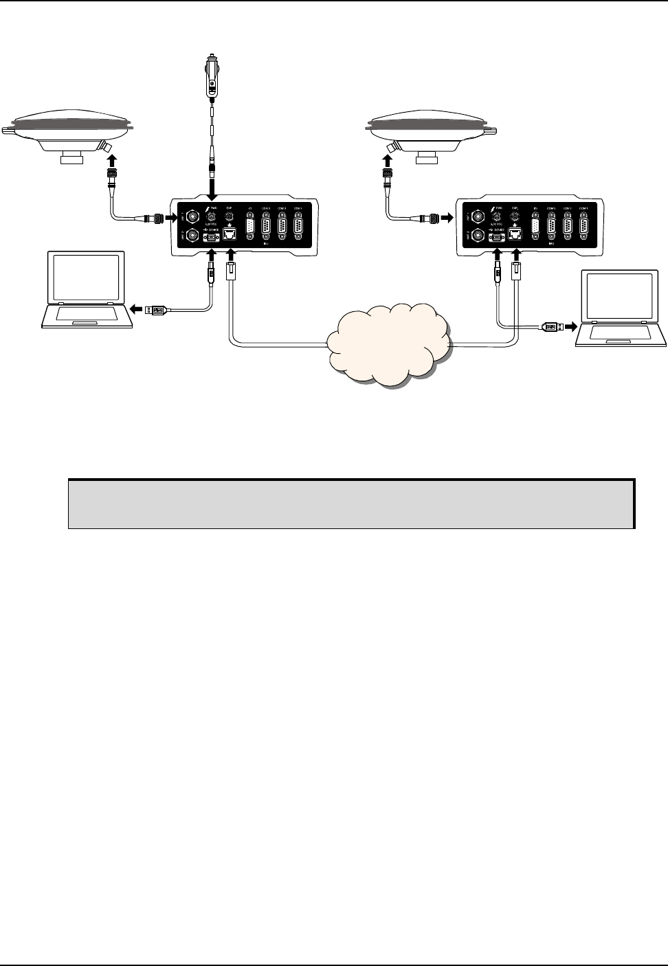
80 ProPak6 Installation and Operation User Manual 5
Chapter 4 Ethernet Configuration
Figure 26: Base/Rover Ethernet Setup—ProPak6
1. Connect your computer to both ProPak6 receivers using null modem serial cables or USB cables.
2. Establish a connection to the receiver using either NovAtel Connect or another terminal program
such as Windows HyperTerminal. This connection is used to send the commands in this procedure to
the receivers.
3. Connect the power cables to both of the ProPak6 receivers and apply power to the receivers.
4. Connect the Ethernet cables to the Ethernet ports on both ProPak6 receivers.
5. Establish an Ethernet connection, either static or dynamic configurations. Refer to Section 4.2 Static
IP Address Configuration on page 74 or Section 4.3 Dynamic IP Address Configuration on page 78
for more information.
6. Send the following commands to each receiver either through serial or USB ports:
Base:
fix position <lat> <long> <height>
interfacemode icom1 none rtca off
log icom1 rtcaobs2 ontime 1
log icom1 rtcaref ontime 10
log icom1 rtca1 ontime 5
saveconfig
Rover:
icomconfig icom1 tcp <base ip address>:<base port #>
interfacemode icom1 rtca none off
log bestposa ontime 1 (optional)
saveconfig
Use the BESTPOS log to confirm that the ProPak6 rover is in RTK mode.
ProPak6
ProPak6
Computer
Computer
Antenna Antenna
Antenna
Cable
Antenna
Cable
Ethernet
Cable Ethernet
Cable
Network
Power Cable
USB Cable
USB Cable
For information about establishing a connection using NovAtel Connect, refer to the
Quick Start Guide for the product or NovAtel Connect Help.

Ethernet Configuration Chapter 4
ProPak6 Installation and Operation User Manual 5 81
Issue the SAVEETHERNETDATA ETHA command to ensure port settings are
retained after a reset and automatically used at boot time. The
SAVEETHERNETDATA ETHA command is not applicable to the ICOMCONFIG and
NTRIPCONFIG settings. The SAVEETHERNETDATA ETHA command overrides the
SAVECONFIG command configuration settings.
The FRESET command does not clear Ethernet setting; FRESET INTERNET must
be issued.

ProPak6 Installation and Operation User Manual Rev 5 82
Chapter 5 Radio Configuration and Activation
This chapter discusses the methods for configuring the ProPak6 radios and activating network services
for Bluetooth®, Wi-Fi and Cellular radios (model dependent, refer to Table 1, ProPak6 Model Features on
page 16).
5.1 Bluetooth® Configuration
Bluetooth is a wireless radio communication standard designed for use over short ranges (within 10 m).
Before a Bluetooth enabled device can communicate with the ProPak6, it must be configured to
recognize and communicate with the ProPak6 (paired). Only one incoming Bluetooth connection is
supported at a time by the ProPak6. A maximum of 16 devices can be paired with the ProPak6.
Refer to Section 3.1.5, Bluetooth LED on page 37 for status LED information.
5.1.1 Enable Bluetooth on the ProPak6 Receiver
By default, the Bluetooth radio is turned off.
1. Connect the ProPak6 to a computer using one of the communication ports and turn power on.
2. To turn on the Bluetooth radio, issue
BLUETOOTHCONFIG POWER ON command
The Bluetooth LED on the front of the ProPak6 lights blue .
3. Enter LOG BLUETOOTHSTATUS ONCHANGED to display the Bluetooth radio status.
4. Issue the SAVECONFIG command to save the configuration to Non-Volatile Memory (NVM).
5.1.1.1 Pairing Bluetooth Devices
5. To allow Bluetooth devices to locate and pair with other Bluetooth devices, found within 10 m of the
ProPak6, issue:
BLUETOOTHDISCOVERABILITY ON
6. If prompted, enter the PIN confirmation (ProPak6 default pin number 0000).
7. Accept or LOG BLUETOOTHSTATUS to verify pass code.
8. To turn off Bluetooth discovery once pairing is complete, issue:
BLUETOOTHDISCOVERABILITY OFF
The FRESET command can be used to reset any of the Bluetooth, Wi-Fi or Cellular
ProPak6 radios.
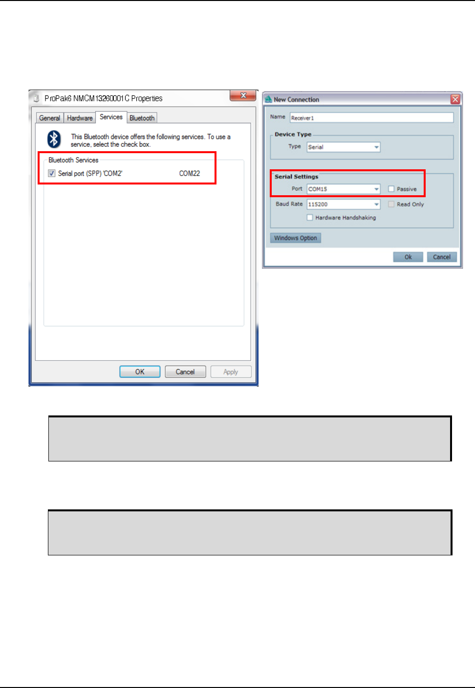
Radio Configuration and Activation Chapter 5
ProPak6 Installation and Operation User Manual Rev 5 83
5.1.1.2 Connecting Bluetooth Devices
9. Determine the serial port assigned to Bluetooth for the connected computer (COM port X). This
information is found in different locations depending on the type of the device and/or operating
system. The New Connection window of NovAtel Connect can also be used. Once the COM port is
determined, connect to the device over this port.
10. To turn off and disconnect devices, issue:
BLUETOOTHCONFIG POWER OFF
Instructions for configuring Bluetooth devices vary depending on the type of device
and/or operating system. Consult the instructions provided with the Bluetooth
device for detailed setup instructions.
Bluetooth discovery may minimally restrict Wi-Fi performance. NovAtel
recommends performing any Bluetooth discovery prior to joining a Wi-Fi network
and always turning off Bluetooth discoverability when pairing is complete.
Example: Windows® 7
Example: NovAtel Connect
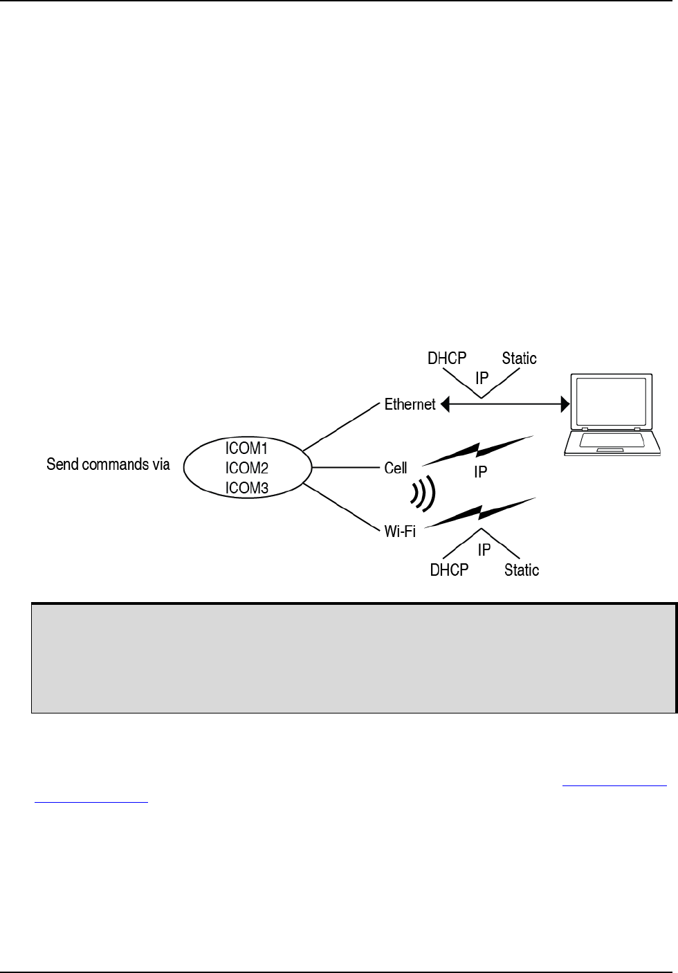
84 ProPak6 Installation and Operation User Manual Rev 5
Chapter 5 Radio Configuration and Activation
5.2 Wi-Fi Network Configuration
Wi-Fi is a Wireless Local Area Network (WLAN) used to exchange data wirelessly over a computer
network. When the ProPak6 Wi-Fi radio is enabled, it can be configured to act as a Access Point (AP) or
Client. By default, the ProPak6 is configured with Wi-Fi on and as an AP.
When configured as either a Client or AP, users can access the ProPak6 using FTP, ICOM ports, telnet,
NTRIP, etc. The mode of operation to use is dependent on how the Local Area Network (LAN) is
configured.
To have the ProPak6 accessible on a LAN like other common devices (printer, computer, etc.), configure
the ProPak6 as a Client. An existing Wi-Fi access point on the LAN must be available for the ProPak6 to
connect to. While in Client mode, the ProPak6 IP address can support both static and dynamic IP
address assignment.
If the ProPak6 is not to be accessible to a LAN or is located in a remote location that does not have an
AP nearby, configure the ProPak6 as the AP. When configured as the AP, the ProPak6 must use a static
IP address, although any devices connecting to the ProPak6 (mobile phone, laptop, etc.) can use either
static or dynamic IP address assignment.
Figure 27: Wi-Fi Configuration Overview
5.2.1 Configure Wi-Fi as the Network Default
Ethernet (ETHA) is the default network for Internet access for the ProPak6. The default network can be
changed to Wi-Fi by issuing the SETPREFERREDNETIF WIFI command. Refer to the OEM6 Firmware
Reference Manual (OM-20000129) for additional command details.
The following commands are used for Wi-Fi Network configuration:
•WIFICONFIG - sets the state (enable/disable) and the mode (AP/Client) of the ProPak6
•WIFIAPCONFIG - sets AP network parameter values when in AP mode
•WIFICLICONFIG -sets Client network parameter values when in Client mode
•WIFICLICONTROL - scans for network access points
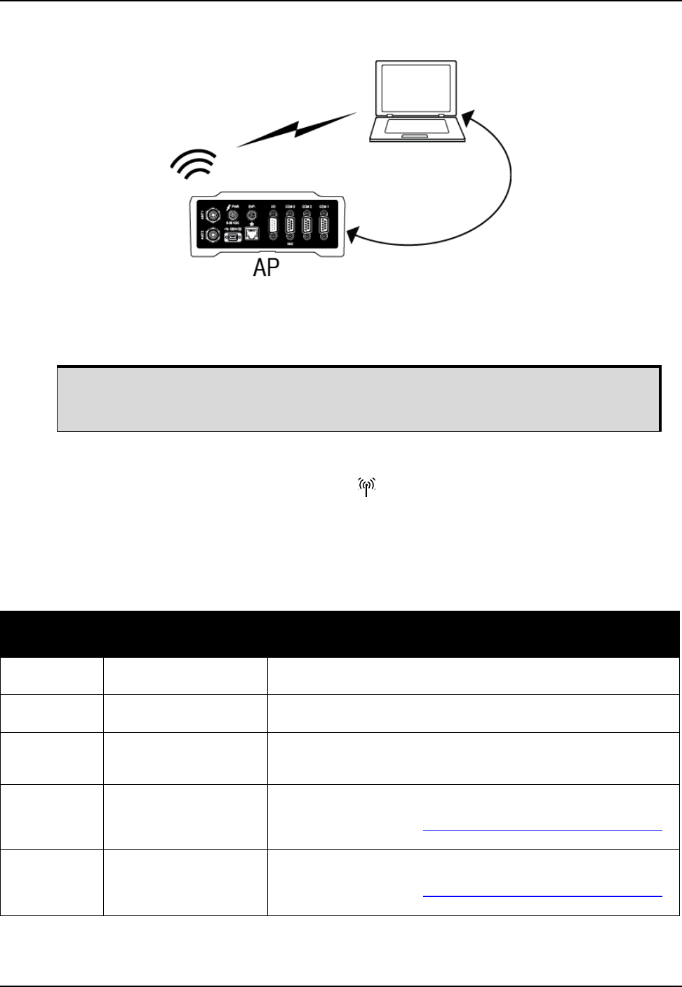
Radio Configuration and Activation Chapter 5
ProPak6 Installation and Operation User Manual Rev 5 85
5.2.2 Wi-Fi AP Configuration
By default, the ProPak6 Wi-Fi radio is configured as an AP and is enabled.
1. Connect the ProPak6 to a computer using one of the communication ports and turn power on.
2. The LED on the front of the ProPak6 lights blue (it may take up to 10 seconds for the AP to
become available). (If the radio is off, issue the WIFICONFIG STATE ENABLED command to turn on
the Wi-Fi radio.)
3. Enter LOG WIFIAPSTATUS ONCHANGED to monitor connection status.
4. Configure the AP by issuing the WIFIAPCONFIG command and the required network values.
Example: WIFIAPCONFIG X AUTHENTICATION OPEN (where X is the AP mode number (1-4))
If a ProPak6 is changed from the default AP to a Client configuration and later needs to
return to an AP configuration, the WIFIAPCONFIG MODE AP command is issued and
the Wi-Fi module power cycled (see step 9 below).
WIFIAP
Configuration
Parameter
Value Description
SSID String
(PSN default)
The Service Set Identifier (network name) of the Wi-Fi AP.
IsHidden TRUE
FALSE (default)
When this parameter set to TRUE, the Wi-Fi AP does not broadcast the
SSID.
Channel 802.11 Channel
(default 6)
The 802.11 Channel to use for this Wi-FI AP.
The valid range of Channels depends on 802.11 regulatory domain. In
North America the valid range is: 1-11
Authentication OPEN
WPA_PSK (default)
WPA2_PSK
WPA/WPA2_PSK
The authentication type used for the Wi-Fi AP.
The value for Authentication is dependent on the values for Encryption
and Protocol. Refer to the OEM6 Family Firmware Reference Manual
(OM-20000129) for details.
Encryption NONE
TKIP
AES_CCMP (default)
TKIP AES_CCMP
The encryption protocol used for the Wi-Fi AP.
The value for Encryption is dependent on the values for Authentication
and Protocol. Refer to the OEM6 Family Firmware Reference Manual
(OM-20000129) for details.

86 ProPak6 Installation and Operation User Manual Rev 5
Chapter 5 Radio Configuration and Activation
5. Configure the ICOM ports to be used (refer to Section 3.1.12, ICOM Ports on page 42 for details).
6. If required, configure port security (refer to Section 2.9.2, FTP Server and ICOM Ports on page 34 for
details).
7. If using, configure NTRIP (refer to Chapter 6, NTRIP Configuration on page 93 for details).
8. Issue the SAVECONFIG command to save the configuration to Non-Volatile Memory (NVM).
9. If any changes were made to the default WIFIAPCONFIG settings, a power cycle to the Wi-Fi module
is required for the changes to take affect. Issue:
WIFICONFIG STATE OFF
WIFICONFIG STATE ENABLED
10. On a Wi-Fi Client, scan for a ProPak6 AP and connect to it.
11. If prompted, enter a password. (The default password is the Product Serial Number (PSN) located on
the bottom of the ProPak6.)
12. Configure network properties on the connected Client computer to use a static IP address. Consult
the Network Administrator to obtain the necessary network parameters.
• The first three numbers of the IP should match the receiver
• To avoid IP conflicts between the static IP address of the Client and the IP of the ProPak6, set the
static IP address of the client to 192.168.1.5 or above
• The subnet should be the same as the ProPak6
• The gateway is the same as the ProPak6 IP address
13. Open the port to the receiver from a computer or mobile device.
• The IP address should be the IP address of the ProPak6
• The port number is the port number assigned to the ICOM port being connected to (default ICOM
configurations: ICOMCONFIG ICOM1 TCP :3001, ICOMCONFIG ICOM2 TCP :3002 and
ICOMCONFIG ICOM3 TCP :3003
Passphrase String
(PSN default)
WPA/WPA2 passphrase (8 to 63 ASCII characters)
or
Hex key (32 bytes - 64 ASCII characters)
IPAddr ddd.ddd.ddd.ddd
(192.168.1.1 default)
The IP address of the Wi-Fi AP.
This must be a static IP address.
Netmask ddd.ddd.ddd.ddd
(255.255.255.0 default)
The netmask for Wi-Fi AP IP address.
Gateway ddd.ddd.ddd.ddd The IP address of the gateway.
Protocol b
g
bg
bgn (default)
The 802.11 standard protocol used for the Wi-Fi AP.
The value for Protocol is dependent on the values for Authentication and
Encryption. Refer to the OEM6 Family Firmware Reference Manual
(OM-20000129) for details.
Client_Timeout 1 to 3600 seconds
(300 s default)
Time in seconds for the Wi-Fi AP to detect a lost client connection.
WIFIAP
Configuration
Parameter
Value Description
Refer to the OEM6 Family Firmware Reference Manual (OM-20000129) for log and
command details.
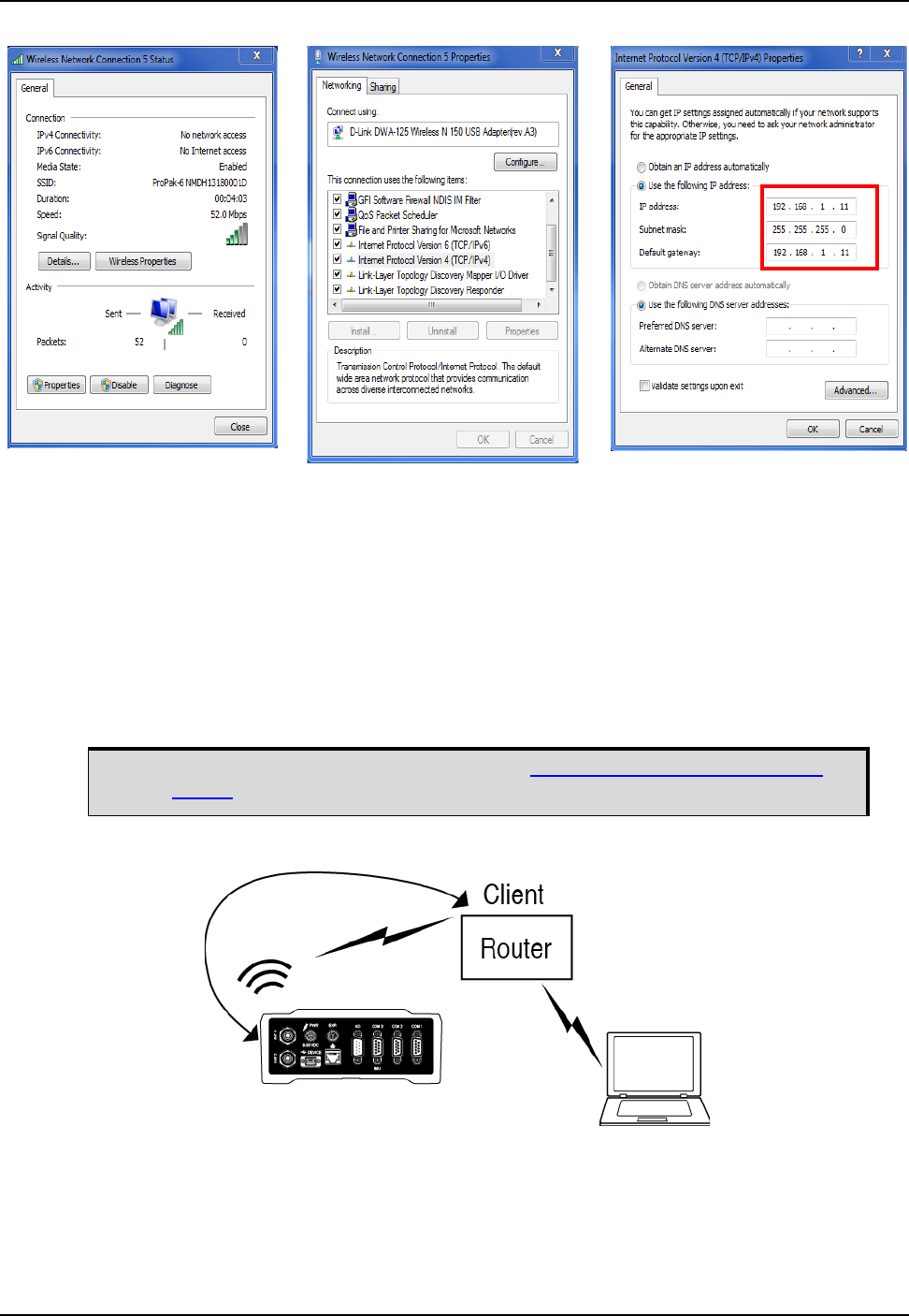
Radio Configuration and Activation Chapter 5
ProPak6 Installation and Operation User Manual Rev 5 87
5.2.2.1 Multiple AP Configurations
Up to four APs can be configured on the ProPak6. Each AP supports up to 5 Client associations at one
time. The default mode is AP1. Default value settings for AP2, AP3 and AP4 are blank.
1. Follow the first three steps in Section 5.2.2, Wi-Fi AP Configuration on page 85.
2. Issue the WIFICONFIG MODE AP X command, X being 2, 3 or 4 for the additional AP
configurations.
3. Continue following the steps in Section 5.2.2, Wi-Fi AP Configuration on page 85.
4. Repeat as required for a maximum of 4 APs.
5.2.3 Wi-Fi Client Configuration
The ProPak6 can store configurations for a maximum of 16 APs on each Client.
Refer to the WIFICONFIG command in the OEM6 Family Firmware Reference
Manual (OM-20000129) for command details.

88 ProPak6 Installation and Operation User Manual Rev 5
Chapter 5 Radio Configuration and Activation
1. Before Client configuration, consult the Network Administrator and obtain the necessary configura-
tion values required to connect to the wireless network.
2. Connect the ProPak6 to a computer using one of the communication ports and turn power on.
5.2.4 Wi-Fi Scanning
Wi-Fi scanning is performed before connecting to either an Open/Encrypted, DHCP/Static network.
3. Enter LOG WIFICLISCANRESULTS ONCHANGED to display a list of the scan results.
4. Enter LOG WIFICLISTATUS ONCHANGED to monitor the connection status.
5. Issue the following commands:
WIFICONFIG MODE CLIENT defines receivers as Client
WIFICONFIG STATE ENABLED enables Client receiver
WIFICLICONTROL SCAN initiates scanning for AP
6. Review the WIFICLISCANRESULTS log for any detected APs and manually configure the required
network settings. Refer to Step 1 above.
WIFIClient
Network
Configuration
Value Description
SSID String
(default blank)
Service Set Identifier of the Wi-Fi AP being connected to
This value must be entered in ASCII characters only (no binary).
BSSID aa::bb::cc::ee::ff Basic Service Set ID. The client will connect only to this BSSID.
Enabled TRUE, FALSE When set to TRUE, the Wi-Fi client network is included as a potential connection
when the client interface is enabled and the system is searching for Access Points
it knows.
When set to FALSE, the Wi-Fi client network is kept for reference but is not
automatically used.
Priority Int Instructs the client to always attempt connecting to this network, regardless of
availability of other networks, signal strength, etc
Authentication OPEN (default)
WPA_PSK
WPA2_PSK
The authentication method for the AP being connected to.
Encryption NONE (default)
TKIP
AES_CCMP
The encryption method for the AP being connected to.
Passphrase String, 64 WPA, WPA2 passphrase (8-63 ascii chars), or key (64 hex digits)
DHCP TRUE (default)
FALSE
When set to TRUE, DHCP is used to acquire the network configuration from the AP.
When set to FALSE the static configuration values (shown below) are used to
connect to the AP.
Note that unless this value is specifically set to FALSE, DHCP is enabled regardless
of any network parameters that may be set (IP, Netmask, Gateway, DNS)
IPAddr ddd.ddd.ddd.ddd
(for example:
10.0.0.2)
The IP address to be used by the receiver. (If not using DHCP.)
Netmask ddd.ddd.ddd.ddd
(for example:
255.255.255.0)
The netmask to be used by the receiver. (If not using DHCP.)
Gateway ddd.ddd.ddd.ddd
(for example:
10.0.0.1)
The IP address of the default gateway. (If not using DHCP.)
DNS1 ddd.ddd.ddd.ddd
(for example:
10.0.0.3)
The IP address of the primary DNS server. (If not using DHCP.)

Radio Configuration and Activation Chapter 5
ProPak6 Installation and Operation User Manual Rev 5 89
5.2.4.1 Connecting to an Open AP Network
7. Consult the Network Administrator for network parameters and values.
Issue the following commands depending on the type of network being used
WIFICLICONFIG 1 SSID XXXX, where XXXX is the open AP to connect to
WIFICLICONFIG 1 AUTHENTICATION OPEN
WIFICLICONFIG 1 ENCRYPTION NONE
WIFICLICONFIG 1 ENABLED TRUE
5.2.4.2 Connecting to an Encrypted AP Network
8. Consult the Network Administrator for network parameters and values.
Issue the following commands depending on the type of network being used
WIFICLICONFIG 1 SSID XXXX, where XXXX is the protected AP to connect to
WIFICLICONFIG 1 AUTHENTICATION XXXX, where XXXX is the authentication setting of the AP
(WPA_PSK, WPA2)
WIFICLICONFIG 1 ENCRYPTION XXXX, where XXXX is the encryption setting of the AP (TKIP,
AES_CCMP)
WIFICLICONFIG 1 PASSPHRASE XXXX, where XXXX is the passphrase (password) of the AP
WIFIWLICONFIG 1 ENABLED TRUE
9. Configure the ICOM ports to be used (refer to Section 3.1.12, ICOM Ports on page 42 for details).
10. If required, configure port security (refer to Section 2.9.2, FTP Server and ICOM Ports on page 34 for
details).
11. If using, configure NTRIP (refer to Chapter 6, NTRIP Configuration on page 93 for details).
12. Issue the SAVECONFIG command to save the configuration to Non-Volatile Memory (NVM).
13. Issue the WIFICLICONTROL APPLYCONFIG command to save settings.
Once Wi-Fi is connected, the ProPak6 Client is accessible on the LAN.
Scan results are not used to configure the Client Wi-Fi connection.
To use Wi-Fi as the primary internet access point, issue the SETPREFERREDNETIF WIFI
command. Refer to the OEM6 Family Firmware Reference Manual- (OM-20000129),
various Wi-Fi commands for details.
If Wi-Fi performance is slow, Bluetooth discoverability may be on. NovAtel recommends
performing any Bluetooth discovery prior to joining a Wi-Fi network.
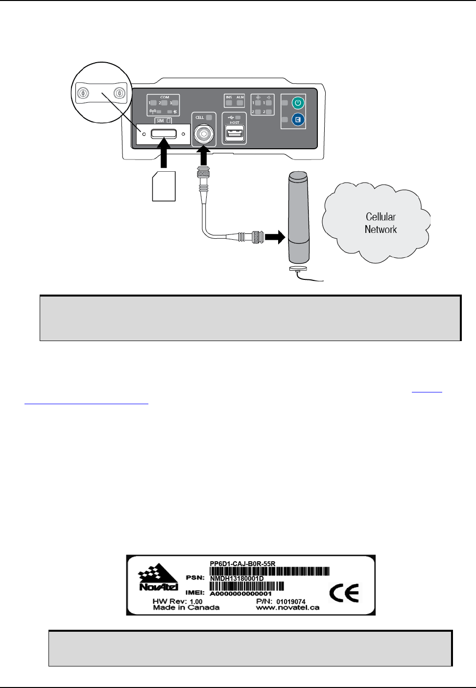
90 ProPak6 Installation and Operation User Manual Rev 5
Chapter 5 Radio Configuration and Activation
5.3 Cellular Activation GSM/GPRS/HSDPA
By default, the cellular radio is disabled.
5.3.1 Configure Cellular as the Network Default
Ethernet (ETHA) is the default network for internet access for the ProPak6. The default network can be
changed to Cellular by issuing the SETPREFERREDNETIF CELL command. Refer to the OEM6
Firmware Reference Manual (OM-20000129) for additional command details.
5.3.2 Cellular Network Activation and Configuration
The GSM/GPRS/HSDPA modem is not “locked” to any particular carrier. To activate a ProPak6 on a
GSM/GPRS/HSDPA network, follow these steps:
1. Obtain an active account and SIM card providing GSM/GPRS/HSDPA data services (recommended
data plans for Network RTK are 5GB/Month Rate Plans). The Service Provider may require the fol-
lowing information to setup an active account.
a. Product Name: ProPak6 GSM/GPRS/HSDPA
b. Modem Serial Number (IMEI): Modem serial number from ProPak6 product label
Refer Section 2.6, Cellular Antenna Installation on page 28 for instructions on installing
a cellular radio antenna. Refer to Section 3.1.9, Cell Port and LED on page 40 for
status LED information.
The cellular provider may require additional activation steps. Refer to any
instructions provided with the SIM card.
Example:
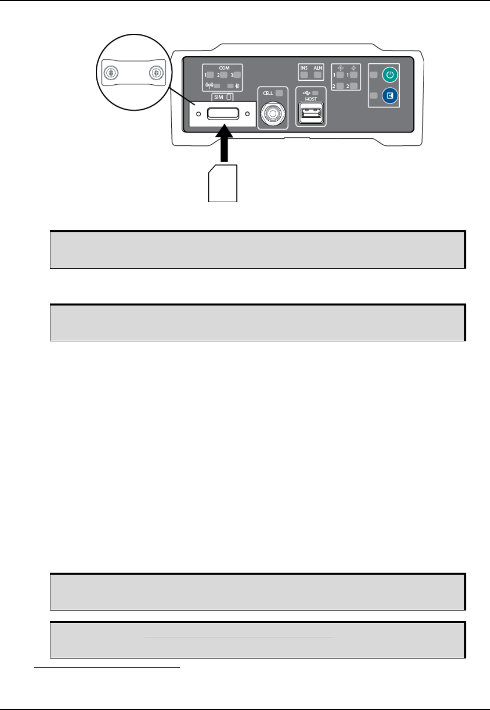
Radio Configuration and Activation Chapter 5
ProPak6 Installation and Operation User Manual Rev 5 91
Figure 28: SIM Card Installation
2. Remove the SIM card cover and insert the SIM card.
3. Once the SIM card is correctly installed, secure the SIM cover to the base using a screwdriver.
Screws should be torqued to 4-6 inch-pound.
4. Ensure a cellular antenna is connected to the ProPak6 and turn the ProPak6 power on.
5. LOG CELLULARSTATUS ONCHANGED to display the modem and cellular connection status.
6. LOG CELLULARINFO ONCE to display modem and network information.
7. The CELLULARCONFIG command is issued to configure cellular parameters. Issue the following
commands:
CELLULARCONFIG POWER ON enables the radio
CELLULARCONFIG APN <APN> sets AP name1
CELLULARCONFIG USERNAME <USERNAME> sets user name1
CELLULARCONFIG PASSWORD <PASSWORD> sets APN password1
CELLULARCONFIG DATA ON enables/disables data connectivity on the configured APN
CELLULARCONFIG DATAROAM ON enables/disables data connectivity when roaming
8. If internet access is required over this interface, issue the SETPREFERREDNETIF CELL command.
9. Issue the SAVECONFIG command to save the configuration to Non-Volatile Memory (NVM).
Only use a mini-SIM card (25 mm x 15 mm). ProPak6 does not support micro-SIM
or nano-SIM cards.
Failure to properly secure SIM cover will violate ProPak6 IP67 ingress rating.
1.Optional—consult the cellular data provider to determine if required.
Cellular data consumption and service charges are dependent on the configuration
of the ProPak6 receiver and data logging rates.
Refer to the OEM6 Family Firmware Reference Manual (OM-20000129) for log and
command details.

92 ProPak6 Installation and Operation User Manual Rev 5
Chapter 5 Radio Configuration and Activation
5.3.3 Eject a SIM Card
Issue the CELLULARCONFIG POWER OFF command to power down the cellular radio before removing a
SIM card.
To remove the SIM card, push it slightly in. It should then partially eject from the SIM card holder. The
modem does not work if the SIM is in the partially ejected “ready for removal” position. Replace the SIM
Card holder cover and ensure the cover is properly aligned and secured.
Issue the CELLULARCONFIG POWER ON command to turn the cellular radio on.
5.4 Airplane Mode
Enabling Airplane Mode turns off any Wi-Fi, Bluetooth or cellular radios in the ProPak6. Airplane Mode is
disabled by default (radios on). If Airplane mode is enabled and then disabled, all radios automatically
return to their last state (on or off) however, any connections made before airplane mode was enabled
are not restored. Refer to the AIRPLANEMODE command and log in the OEM6 Firmware Reference
Manual (OM-20000129) for command details.
To turn all three radios off, issue the following commands:
AIRPLANEMODE ENABLE
AIRPLANEMODE DISABLE
LOG AIRPLANEMODE (to view radio status)
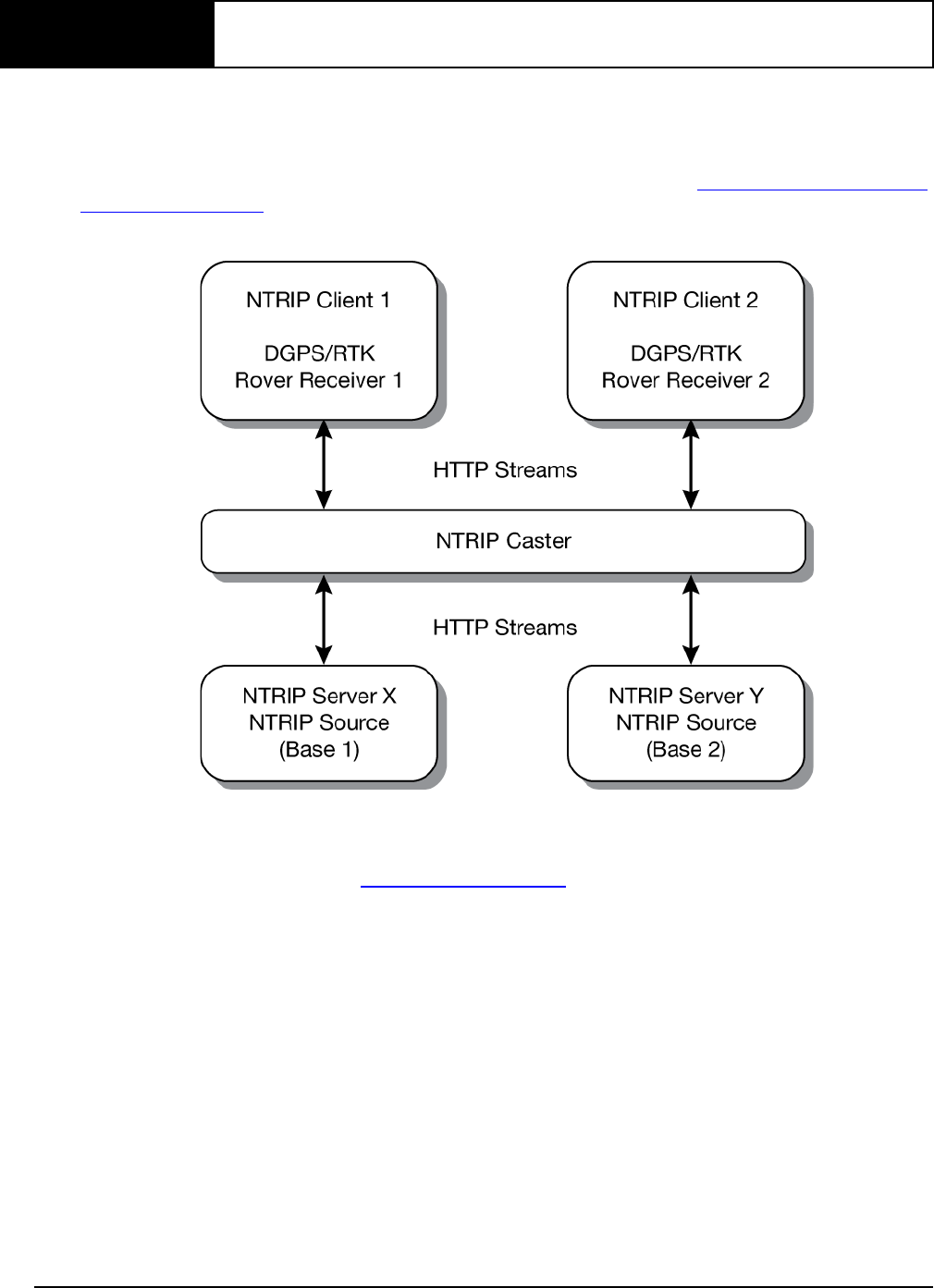
93 ProPak6 Installation and Operation User Manual Rev 5
Chapter 6 NTRIP Configuration
Network Transport of RTCM via Internet Protocol (NTRIP) is an application protocol used to stream
GNSS differential correction data over the Internet.
Configure an ProPak6 receiver as either an NTRIP server or an NTRIP client. For more information
about NovAtel’s NTRIP, refer to our NTRIP Product Sheet on our website at www.novatel.com/products/
firmware-options/ntrip/.
Figure 29: NTRIP System
The NTRIP caster is an HTTP internet service that acts as a communication medium between NTRIP
servers and NTRIP clients. The NTRIP caster is provided by third party sources. For a full list of NTRIP
casters, refer to the following link: www.rtcm-ntrip.org/home.
The following procedure describes how to configure a NovAtel base and a NovAtel rover through a third
party NTRIP caster. This configuration is recommended for optimal RTK performance.
1. Establish a connection to the receiver using Ethernet, Wi-Fi or Cellular. Refer to Chapter 4, Ethernet
Configuration on page 74 or the sections Section 5.2, Wi-Fi Network Configuration on page 84 or
Section 5.3, Cellular Activation GSM/GPRS/HSDPA on page 90 for details.
2. Use the following commands to enable the base receiver as an NTRIP Server:
NTRIPCONFIG NCOM1 SERVER V2 <endpoint> <mountpoint> <username>
<password> etha
INTERFACEMODE NCOM1 NONE RTCA OFF
FIX POSITION <lat> <long> <height>
LOG NCOM1 RTCAOBS2 ONTIME 1
LOG NCOM1 RTCAREF ONTIME 10
LOG NCOM1 RTCA1 ONTIME 1
SETPREFERREDNETIF <WIFI> or <CELL> or <ETHA>
SAVECONFIG

94 ProPak6 Installation and Operation User Manual Rev 5
Chapter 6 NTRIP Configuration
3. Use the following commands to enable the rover receiver as an NTRIP Client:
NTRIPCONFIG NCOM1 CLIENT V1 <endpoint> <mountpoint> <username>
<password > etha
The following is an NTRIP Client configuration example without the use of a Network RTK system:
INTERFACEMODE NCOM1 RTCA NONE OFF
RTKSOURCE AUTO ANY
PSRDIFFSOURCE AUTO ANY
LOG BESTPOS ONTIME 1 (optional)
SETPREFERREDNETIF <WIFI> or <CELL> or <ETHA>
SAVECONFIG
If using a specific Network RTK system, certain National Marine Electronics
Association (NMEA) strings are required to be sent from the rover back to the RTK
network. For example, if connected to the VRS mount point, the rover is required to
send its position to the network in a standard NMEA GGA message. This is
achieved by issuing the following commands: LOG NCOMx GPGGA ONTIME 5,
until data is received by the caster. For more information about Network RTK
options and properties, refer to the application note APN-041 Network RTK for
OEMV Receivers found on our website at www.novatel.com/support/search/.

ProPak6 Installation and Operation User Manual Rev 5 95
Chapter 7 NovAtel Firmware and Software
Download the most recent versions of the NovAtel firmware and receiver software from the Downloads
section of www.novatel.com/support/search/.
OEM6 Firmware and Software
NovAtel Connect PC Utilities Software Bundle
Bundled PC Utilities software includes:
• NovAtel Connect (a GUI interface)
• Connection Import (imports connection profiles)
• Convert (converts receiver data logs into different formats)
• USB Drivers and Window Signing
Firmware and Software included
• Firmware *.shex file
• WinLoad software utility
7.1 Firmware Updates and Model Upgrades
A local NovAtel dealer can provide all the information needed to upgrade or update a receiver. Refer to
www.novatel.com/where-to-buy for contact information or contact sales@novatel.com or
support@novatel.com directly.
7.1.1 Firmware Updates
Firmware updates are firmware releases that include fixes and enhancements to the receiver
functionality. Firmware updates are released occasionally on the NovAtel web site as they become
available. Firmware upgrades can be performed using the WinLoad utility, SoftLoad commands or with a
custom loader application. Contact NovAtel Customer Support (support@novatel.com) for details on
custom loader requirements.
Refer to 7.3.1, Transferring Firmware Files on page 97 for descriptions of
the Update and OEM versions.
The NovAtel Connect PC Utilities bundle can be download from the
Downloads section of www.novatel.com/support/search/.
WinLoad and SoftLoad instructions follow.
ProPak6 Installation and Operation User Manual Rev 5 96
Chapter 7 NovAtel Firmware and Software
7.1.2 Model Upgrades
Model upgrades enable purchased receiver features.
Contact a local NovAtel dealer to assist in selecting the upgrade options that best suit your GNSS needs
at www.novatel.com/where-to-buy. Contact NovAtel Customer Support www.novatel.com/support or
NovAtel Sales to request a temporary upgrade authorization code for trial purposes.
Model upgrades can be applied to the receiver with an authorization code and the AUTH command
without returning the receiver to the dealer.
7.2 Authorization Code
An authorization code, commonly known as an auth-code, is required to upgrade an OEM6 family
receiver. Auth-codes are obtained by contacting NovAtel Customer Support. Upon contact, NovAtel
Customer Support requires:
• the receiver model number
• the receiver serial number
• the receiver firmware version
Enter the LOG VERSION command to determine the receiver model, serial number and firmware
version.
Example:
After determining the appropriate model and firmware version the authorization code (auth-code) is
issued. The auth-code is required to unlock the features on the new model type.
To upgrade to a new model with the same firmware version, use the AUTH command with the issued
auth-code, as outlined in Upgrading Using the AUTH Command.
To upgrade to a new model with a new firmware version, the new firmware needs to be loaded into the
OEM6 receiver. Refer to 7.3, Updating or Upgrading Using the WinLoad Utility on page 97 for use
instructions or to 7.4, Updating Using SoftLoad Commands on page 99.
There are two types of auth-codes:
• Standard auth-codes, which are tied to a model, serial number and firmware version
• Signature auth-codes, which are tied only to a model and serial number
When upgrading to a new version of firmware, the Standard auth-code for the old version of firmware will
not work with the new version of firmware. Therefore, a new auth-code is required for each receiver that
is upgraded.
However, Signature auth-codes work with any signed firmware image. Therefore, if a receiver has a
Signature auth-code for the old version of firmware, that same auth-code will work for the new version of
firmware, provided both images are digitally signed by NovAtel.
Signature auth-codes require firmware version OEM060200RN0000 (6.200) or later and boot code
version OEM060100RB0000 (6.100) or later.
Signed firmware images are distributed in *.shex files, while unsigned firmware images are distributed in
*.hex files.
GPSCARD “D2LR0RTTRA” “BFN11230026” “OEM628-1.00” “OEM060300RN0000”
PRODUCT
FIRMWARE
RELEASE
INDICATOR
FAMILY
NUMBER
SERIALMODEL
NUMBER NUMBER
FIRMWARE
VERSION
ENTER

NovAtel Firmware and Software Chapter 7
97 ProPak6 Installation and Operation User Manual Rev 5
Temporary auth-codes may be provided by NovAtel for evaluation purposes. Once the trial period has
expired, a new auth-code will need to be obtained from NovAtel Customer Support
(support@novatel.com).
The new download package includes a signed firmware file type that uses an extension designated as
“.shex” (example OEM060200RN0000.shex), as well as the latest WinLoad utility and What’s New file
containing firmware update change details.
7.3 Updating or Upgrading Using the WinLoad Utility
WinLoad is the simplest and most common way to update or upgrade an OEM6 receiver.
7.3.1 Transferring Firmware Files
To proceed with an update or possibly an upgrade, obtain the latest version of firmware by downloading
the (OEM Version) for your product from www.novatel.com/support/firmware-downloads/.
Format of Firmware Files
All of the firmware available on the downloads website are packaged in .zip files with the following
names:
• OEMXXXRN0000.zip for firmware to be installed on OEM615, OEM617, OEM617D,
FlexPak6 or OEM628 receivers
• OMPXXXRN0000.zip for firmware to be installed on OEM638 receiver
NovAtel Customer Service may generate and provide the required authorization code. Authorization
codes are obtained by contacting support@novatel.com or at www.novatel.com/Support/.
For convenience, unzip the update file to a GNSS sub-directory (for example, C:\GNSS\LOADER). If the
firmware update file is password protected, NovAtel Customer Support provides the required password.
The zip archive includes the following files:
winload.exe WinLoad utility program
howto.txt Instructions on how to use the WinLoad utility
whatsnew.rtf Information on the changes made in the firmware since the last revision
x..x.shex Firmware version upgrade file, where x..x defines the product name and release
(e.g., OEM060400RN0000.shex)
NovAtel Software License Agreement.rtf License agreement for the firmware.
The files are extracted to unzip/program files/NovAtel Inc/x.xxx Full Update Disk, where x.xxx is the
firmware version.
Prior to firmware version OEM060200RN0000, authorization codes depended on the
software model, the firmware version and the serial number of the receiver. The
authorization code changed if any of the three items changed. This is no longer the case,
they are now no longer dependent on firmware version.
NovAtel has an online video tutorial that explains firmware uploading at:
www.novatel.com/support/videos.
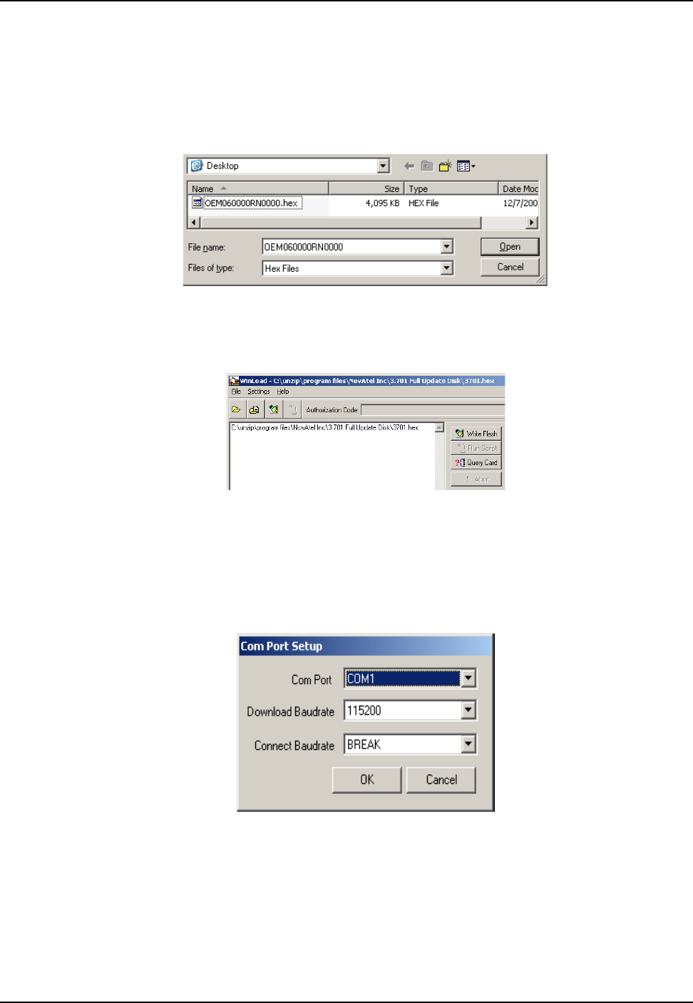
ProPak6 Installation and Operation User Manual Rev 5 98
Chapter 7 NovAtel Firmware and Software
7.3.2 Using the WinLoad Utility
If opening WinLoad for the first time, ensure the file and communications settings are correct.
Open a File to Download
Select File |Open. Navigate to the file to open (Figure 30).
Figure 30: WinLoad’s Open Window
When a file is selected, the filename appears in the main WinLoad display area and in the title bar
(Figure 31).
Figure 31: Open File in WinLoad
Communications Settings
To set the communications port and baud rate, select Settings | COM Settings. Choose the computer port
to use from the Com Port drop down list and the baud rate from the Download Baudrate drop down list.
Set the baud rate as high as possible (the default of 115200 is preferred if a higher baud rate is not
available).
Figure 32: COM Port Setup
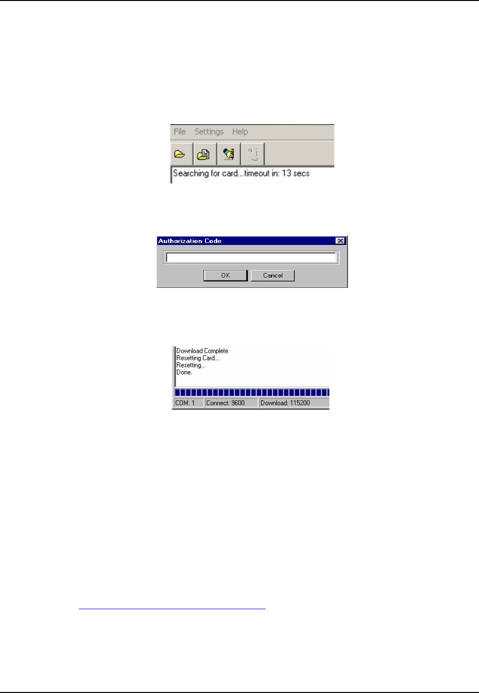
NovAtel Firmware and Software Chapter 7
99 ProPak6 Installation and Operation User Manual Rev 5
Downloading Firmware
1. Select the file to download according to Open a File to Download on Page 98.
2. Ensure the file path and name are displayed in main display area (see Figure 31, Open File in Win-
Load on Page 98).
3. Click Write Flash to download the firmware.
4. When Searching for card appears in the main display, power cycle the receiver.
Figure 33: Searching for Card
5. If the Authorization Code window appears, enter the auth-code and click OK. See Section 7.2 Autho-
rization Code on page 96 for further information about the Authorization Code.
Figure 34: Authorization Code Window
6. The receiver finishes the download and then resets. The process is complete when Done appears in
the main display area.
Figure 35: Upgrade Process Complete
7. Close WinLoad.
7.4 Updating Using SoftLoad Commands
Firmware can be updated on a running receiver using a process called SoftLoad. Any available
communication ports on the receiver (COM, USB, ICOM, XCOM, etc.) can be used. The SoftLoad
process is made up of a set of commands and logs that are used to send new firmware data to a receiver
and check the progress of the update. Use SoftLoad if automated loading is desired or if a connection is
only possible through USB or Ethernet.
The receiver stops tracking GNSS satellites during the SoftLoad process. Do not attempt to SoftLoad
when GNSS satellite tracking on the unit is required. If the unit is connected to the NovAtel Connect
utility, only the Console and ASCII Message windows may remain open in the Connect Utility.
7.4.1 SoftLoad Commands and Logs
Refer to the OEM6 Family Firmware Reference Manual (OM-20000129) for further log and command
information.

ProPak6 Installation and Operation User Manual Rev 5 100
Chapter 7 NovAtel Firmware and Software
Each command and log can be used in abbreviated ASCII, ASCII or binary format, with the exception of
SOFTLOADDATA, which should only be used in binary format.
File Types
Firmware data is stored in *.hex and *.shex files as ASCII data in the form of S-Records, based on the
Motorola S-Record format. The *.shex file is the same as the *.hex file but includes a digital signature for
the firmware.
7.4.2 Working With S-Records
Each S-Record has a header indicating the type of information contained in the record.
Records beginning with S0, S5 and S7 contain metadata about the firmware image, such as version
information and which card types are supported by the firmware image.
Example S0 Record
S0~V~OEM060400RN0000
Example S5 Records
S50000
S503D9FE25
S5033158D5A
Example S7 Records
S70000
S70500000000FA
Records beginning with S3 contain the actual firmware image data. Aside from the header, each pair of
characters forms the ASCII representation of a binary byte. The format is as follows:
Command Description
SOFTLOADRESET Initiate a new SoftLoad process
SOFTLOADSREC Send an S-Record to the receiver for the SoftLoad process
SOFTLOADDATA Send firmware image data to the receiver for the SoftLoad process
SOFTLOADCOMMIT Complete the SoftLoad process
SOFTLOADSETUP Send configuration information to the receiver for the SoftLoad process. This
command is not required when working with a *.hex or *.shex file
Log Description
SOFTLOADSTATUS Provides status updates for the ongoing SoftLoad process
S3 LL AAAAAAAA DDDDDDDD...DDDDDDDD CC
Check Sum.
Little Endian Data. These bytes are copied into the "data" field of the
SOFTLOADDATA command
4 - Byte Address. Set this as the value of "offset" in the SOFTLOADDATA command
Length.This is the hexadecimal number of character pairs to follow in the record. This value
minus 4 bytes for the address and 1 byte for the check sum is copied into the "data length" field
of the SOFTLOADDATA command
Header

NovAtel Firmware and Software Chapter 7
101 ProPak6 Installation and Operation User Manual Rev 5
7.4.3 Sending Firmware Data
C++ source code is available to provide example code of processing S-Records and converting them to
NovAtel format commands, as well as providing help with the SoftLoad process. Contact NovAtel
Customer Support and ask about the srec2softload utility.
The SOFTLOADSREC and SOFTLOADDATA commands can be used to send firmware data from *.hex
or *.shex files to the receiver.
S0, S5 and S7 S-Records should be sent directly to the receiver using the SOFTLOADSREC command,
by enclosing the S-Record in quotation marks and issuing the command to the receiver, as follows:
SOFTLOADSREC "<S-RECORD>"
S3 records can be sent individually to the receiver using the SOFTLOADSREC command. Alternatively,
the data from an S3 record can be parsed and packaged together with data from other S3 records into a
binary SOFTLOADDATA command. Packaging data parsed from multiple S3 records into a binary
SOFTLOADDATA command can result in improved firmware update times as each S3 record contains
only a small number of bytes of firmware data. A single SOFTLOADDATA command can package up to
4096 bytes of firmware data from multiple S3 records, whereas a single SOFTLOADSREC command
contains a maximum of 28 bytes of firmware data from a single S3 record.
Multiple S3 records can be packaged into a single SOFTLOADDATA command as long as the data from
one S3 record follows immediately after the previous record.That is, the address from the current S3
record must equal the address from the previous S3 record plus the data length of the previous S3
record. If the data is not consecutive then the SOFTLOADDATA command can be sent with the amount
of data it has packaged up to that point. Subsequent data can be packaged in a new SOFTLOADDATA
command. Within the SOFTLOADDATA command, the "offset" field remains the address of the first S3
record and the "data" and "data length" are updated to include the new data. Refer to the OEM6 Family
Firmware Reference Manual (OM-20000129) for more information regarding the SOFTLOADDATA
command.
The *.hex and *.shex file data may contain many gaps and jumps. For example, in many NovAtel *.hex
and *.shex files, data for address 0x000_00000 is stored near the very end of the file.
Example Packaging Multiple S3 Records In A SOFTLOADDATA Command
Start a new SOFTLOADDATA command
S32100407AD48FCA63034B80F5CE0C36507DE3D8DCC0C6C0C00515D74BCACF2F2949E1
Address: 0x00407AD4 Num Data Bytes: 0x21 – 0x01 – 0x04 = 0x1C
S32100407AF04CCA4985F0F7B081E41D9B7D806C26989AE2D4E4CCBCB47C10FBFD3E43
Previous Address + Previous Num Bytes = 0x00407AD4 + 0x1C = 0x00407AF0
Address: 0x00407AF0 Num Data Bytes: 0x1C
Add data to existing SOFTLOADDATA command
S30D00407B0CDE0400A6374D5BFFC5
Previous Address + Previous Num Bytes = 0x00407AF0 + 0x1C = 0x00407B0C
Address: 0x00407B0C Num Data Bytes: 0x0D – 0x01 – 0x04 = 0x08
Add data to existing SOFTLOADDATA command
S3210000000007F0A7F1F4060000147B4000F49217813C7BB00014493F005C00000009
Previous Address + Previous Num Bytes = 0x00407B0C + 0x08 = 0x00407B14
Address: 0x00000000 Num Data Bytes: 0x1C

ProPak6 Installation and Operation User Manual Rev 5 102
Chapter 7 NovAtel Firmware and Software
Requires new SOFTLOADDATA command because address does not match previous address +
previous number of data bytes
Send existing SOFTLOADDATA command, and start a new SOFTLOADDATA command
S3210000001C80040000E001000030000000082B0100D8060000E4060000C806000063
Address: 0x0000001C Num Data Bytes: 0x1C
Previous Address + Previous Num Bytes = 0x00000000 + 0x1C = 0x0000001C
Add data to existing SOFTLOADDATA command
The SOFTLOADDATA command must be sent as a NovAtel binary format command.
7.4.4 SoftLoad Update Method
This section describes the sequence of commands that are issued to the receiver when updating using a
*.hex or *.shex file.
1. Open a connection to any port on the receiver (COM, USB, ICOM or XCOM) with the input and out-
put INTERFACEMODE set to NOVATEL.
2. Request the SOFTLOADSTATUS log using the following command:
LOG SOFTLOADSTATUSA ONCHANGED
3. Initialize SoftLoad with a SOFTLOADRESET command. This command stops all tracking on the
receiver to ensure sufficient memory is available for the loading process. An RXSTATUSEVENTA log
reports a SoftLoad In Progress status.
4. Open the *.hex or *.shex firmware file.
5. Read each line of the *.hex or *.shex firmware file.
A. Send S0, S5 and S7 S-Records directly to the receiver using the SOFTLOADSREC command. The
S-Record must be enclosed in quotation marks:
SOFTLOADSREC "<S-RECORD>"
Data within S0 records can also be sent to the receiver by converting them to SOFTLOADSETUP
commands. Refer to the OEM6 Family Firmware Reference Manual (OM-20000129) for details
on how to convert from S0 S-Records to SOFTLOADSETUP commands.
B. S3 S-Records should be parsed and packaged into a SOFTLOADDATA command.
6. Send the SOFTLOADCOMMIT command after all data from the *.hex or *.shex file has been trans-
ferred to the receiver. The SOFTLOADSTATUS log reports the status of the loading process. Wait for
a SOFTLOADSTATUS log to indicate the status is COMPLETE. The COMPLETE status or an error
is guaranteed to be output from the receiver within 300 seconds from the time the SOFTLOADCOM-
MIT command was received by the receiver.
7. Send the auth code for the newly downloaded image using the AUTH command. This is only required
if there is not already a signature auth code on the receiver as signature auth codes are maintained
through a SoftLoad update. See Section 7.2 on page 96 for details on Auth Codes.
AUTH ADD_DOWNLOAD <AUTH CODE>
8. Reset the receiver using any of the following methods:
A. Enter the RESET command
B. Enter the FRESET command
The response for each command must be processed before sending the next
command so as to determine if the command was accepted or rejected, and to wait
for the receiver to complete the operation. Responses to SoftLoad commands are
guaranteed to be output from the receiver within a specific time, which varies by
command. Refer to the OEM6 Family Firmware Reference Manual (OM-20000129)
for more information on responses, and the timeout values for SoftLoad commands.
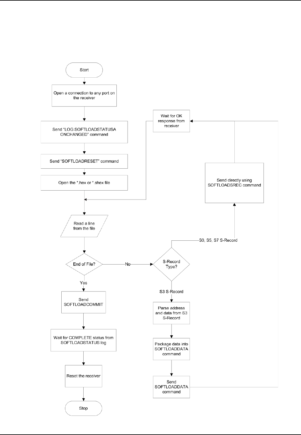
NovAtel Firmware and Software Chapter 7
103 ProPak6 Installation and Operation User Manual Rev 5
C. Power-cycle the receiver
Once the receiver resets, the new version of firmware is active.
The SoftLoad process can be safely canceled at any time using the SOFTLOADRESET command or by
otherwise resetting the receiver. Once the COMPLETE status is reported by SOFTLOADSTATUS, the
new firmware image will be run after the receiver is reset.

ProPak6 Installation and Operation User Manual Rev 5 104
Chapter 7 NovAtel Firmware and Software
7.4.5 Firmware Update Using FTP or USB Mass Storage Device
Select OEM receivers support upload of firmware files via FTP or USB. The SOFTLOADFILE command
can be used to update the receiver firmware if *.hex or *.shex files have been uploaded via FTP or are
available on an attached USB mass storage device. This method is called SoftLoad Direct.
The FTP server in the receiver can be accessed using Ethernet or Wi-Fi. Refer to the IPSERVICE
command in the OEM6 Family Firmware Reference Manual (OM-20000129) for details. The FTP server
allows uploads to the internal flash of the receiver, however the firmware file in internal flash must be
copied to the receiver’s boot flash device using the SOFTFLOADFILE command before it becomes the
active firmware running on the receiver.
This method of updating firmware is referred to as the SoftLoad Direct method.
7.4.6 SoftLoad Direct Commands and Logs
Refer to the OEM6 Family Firmware Reference Manual (OM-20000129) for further log and command
information.
Each command and log can be used in abbreviated ASCII, ASCII or binary format.
7.4.7 SoftLoad Direct Update Method
1. Open a connection to any port on the receiver (COM, USB, ICOM or XCOM) with the input and out-
put INTERFACEMODE set to NOVATEL.
2. Request the SOFTLOADSTATUSA log using the following command:
LOG SOFTLOADSTATUSA ONCHANGED
3. Initiate the firmware update using one of the following commands where <<firmwarefilename.hex>>
is the name of the *.hex or *.shex file:
A. If using internal flash use this command: SOFTLOADFILE INTERNAL_FLASH firmwarefile-
name.hex
B. If using a USB mass storage device: SOFTLOADFILE USBSTICK firmwarefilename.hex
4. During the loading process, SOFTLOADSTATUS logs report the load status. Wait for the SOFT-
LOADSTATUS to indicate the status is COMPLETE.
5. Send the auth code for the newly downloaded image using the AUTH command. This is only required
if there is not already a signature auth code on the receiver as signature auth codes are maintained
through a SoftLoad update. See Section 7.2 on page 96 for details on Auth Codes
AUTH ADD_DOWNLOAD <AUTH CODE>
6. Reset the receiver using any of the following methods:
A. Enter the RESET command
B. Enter the FRESET command
C. Power-cycle the receiver
7. Once the receiver resets, the new version of firmware is active.
Command Description
SOFTLOADFILE Allows updating using a *.hex or *.shex file that has been uploaded to the receiver via
FTP or USB on platforms supporting those interfaces
Log Description
SOFTLOADSTATUS Provides status updates for the ongoing SoftLoad process

NovAtel Firmware and Software Chapter 7
105 ProPak6 Installation and Operation User Manual Rev 5
7.4.8 SoftLoad Errors
It is possible for errors to occur during the SoftLoad update. All command responses should be checked
to verify all issued commands were accepted. The SoftLoad status should also be monitored in the
SOFTLOADSTATUS log. Any status enum value greater than the ERROR status indicates an error has
occurred during the SoftLoad update. In the event of an error, the SoftLoad update should be restarted by
issuing a SOFTLOADRESET command or normal operation can be restored by resetting the receiver.
In rare cases after a SoftLoad error, the boot code may not be able to determine which is the latest
firmware to be executed. To protect against this, SoftLoad does not erase the previous valid firmware
image from flash on the receiver. In such cases, the boot code will execute the old image and raise the
"Safe Mode" error (see RXSTATUS log). If that error is detected, simply restart the SoftLoad process to
reload the new firmware image and the error will be resolved.
7.5 Upgrading Using the AUTH Command
The AUTH command is used to upgrade to a new OEM6 family model with an authorization code that
enables (unlocks) model features. This command only functions with a valid auth-code assigned by
NovAtel Customer Support.
The upgrade can be performed directly through the NovAtel Connect command line or from any other
communications program.
7.5.1 Upgrade Procedure
1. Power up the OEM6 family receiver and establish communications (refer to the Quick Start Guide
included with the product for instructions).
2. Issue the LOG VERSION command to verify the current model, firmware version and serial number
(refer to 7.2, Authorization Code on page 96 for instructions on obtaining).
3. Issue the AUTH command, followed by the auth-code and model type (refer to Section 7.2 Authori-
zation Code on page 96 for details on obtaining any auth-code). The syntax is as follows:
auth <your auth-code here>
where auth is a command that enables model upgrades and auth-code is the upgrade authorization
code, expressed as follows:
XXXXXX,XXXXXX,XXXXXX,XXXXXX,XXXXXX,MODEL,EXPDATE
where:
1. Each X character is a case-insensitive ASCII character.
2. The MODEL string is a maximum of 15 characters long and represents the model enabled by the
auth-code.
3. The EXPDATE string is the auth-code’s expiry date, in YYMMDD format
Example:
auth 7WBMBK,887CB6,K5J3FH,5DF5P2,42PW8G,D1SB0GTT0,121211
When the AUTH command is executed, the OEM6 family receiver reboots. Issuing the LOG VERSION
command confirms the new upgrade model type and firmware version number.
If communicating using NovAtel Connect, the communication path must be closed and reopened using
the Device menu.
Refer to the Format of Firmware Files section on Page 97 for details on
updating versus upgrading.

106 ProPak6 Installation and Operation User Manual Rev 5
Chapter 8 Built-In Status Tests
8.1 Overview
The Built-In Status Test monitors system performance and status to ensure the receiver is operating
within specifications. The test detects an exceptional condition and informs the user through one or more
indicators. The receiver status system is used to configure and monitor the indicators:
1. Receiver status word (included in the header of every message)
2. ERROR strobe signal (see 3.1.14.1, Strobes on page 43)
3. RXSTATUSEVENT log
4. RXSTATUS log
In normal operation, the error strobe is driven low. When an unusual and non-fatal event occurs (for
example, there is no valid position solution), a bit is set in the receiver status word. Receiver operation
continues normally, the error strobe remains off. When the event ends (for example, when there is a valid
position solution), the bit in the receiver status word is cleared.
When a fatal event occurs (for example, a receiver hardware failure), a bit is set in the receiver error
word, part of the RXSTATUS log, to indicate the cause of the problem. Bit 0 is set in the receiver status
word to show that an error occurred, the error strobe is driven high. An RXSTATUSEVENT log is
generated on all ports to show the cause of the error. Receiver tracking is disabled but command and log
processing continues to allow error diagnosis. Even if the source of the error is corrected, the receiver
must be reset to resume normal operation.
Two scenarios describe factory default behavior. These behaviors can be customized to better suit an
individual application. RXSTATUSEVENT logs can be disabled completely with the UNLOG command.
RXSTATUSEVENT logs can be generated when a receiver status bit is set or cleared with the
STATUSCONFIG SET and STATUSCONFIG CLEAR commands. Bits in the receiver status word can also
be promoted to act like error bits with the STATUSCONFIG PRIORITY command.
8.2 Receiver Status Word
The receiver status word indicates the current status of the receiver. This word is found in the header of
all logs and in the RXSTATUS log. In addition, the receiver status word is configurable.
The importance of the status bits with priority masks can be determined. For receiver status, setting a bit
in the priority mask causes the condition to trigger an error. The error causes the receiver to idle all
channels, turn off the antenna and disable the RF hardware, just like it would if a bit in the receiver error
word is set. Setting a bit in an Auxiliary Status priority mask causes the condition to set the bit in the
receiver status that corresponds to the auxiliary status.
Use the STATUSCONFIG command to configure the various status mask fields in the RXSTATUS log.
Use the masks to specify whether various status fields generate errors or event messages when set or
cleared.
Refer to the RXSTATUS log, RXSTATUSEVENT log and STATUSCONFIG command in the OEM6 Family
Firmware Reference Manual for more detailed descriptions of these messages.

Built-In Status Tests Chapter 8
ProPak6 Installation and Operation User Manual Rev 5 107
8.3 Error Strobe Signal
The error strobe signal is one of the I/O strobes. The strobe signal is driven low when the receiver is
operating normally. When the receiver is in the error state and tracking is disabled, the error strobe is
driven high. This can be caused by a fatal error or by an unusual receiver status indication that the user
has promoted to be treated like a fatal error. Once on, the error status remains high until the cause of the
error is corrected and the receiver is reset. See also Section 3.1.14.1 Strobes on page 43.
8.4 RXSTATUSEVENT Log
The RXSTATUSEVENT log is used to output event messages, as indicated in the RXSTATUS log.
On start up, the OEM6 family receiver is set to log the RXSTATUSEVENTA log ONNEW on all ports.
Remove this message using the UNLOG command.
Refer to the RXSTATUSEVENT log in the OEM6 Family Firmware Reference Manual for a more detailed
description of this log.
8.5 RXSTATUS Log
8.5.1 Overview
The Receiver Status log (RXSTATUS) provides system status and configuration information in a series of
hexadecimal words.
The status word is the third field after the header, as shown in the example in Figure 36.
Figure 36: Location of Receiver Status Word
Each bit in the status word indicates the status of a specific receiver condition or function. If the status
word is 00000000, the receiver is operating normally. The numbering of the bits is shown in Figure 37.
Figure 37: Reading the Bits in the Receiver Status Word
If the receiver status word indicates a problem, see Resolving an Error in the Receiver Status Word table
in the troubleshooting section of the OEM6 Family Installation and Operation User Manual
(OM-20000128).
<RXSTATUS COM1 0 92.0 UNKNOWN 0 154.604 005c0020 643c 1899
< 00000000 4
< 005c0020 00000000 00000000 00000000
< 00000087 00000008 00000000 00000000
< 00000000 00000000 00000000 00000000
< 00000000 00000000 00000000 00000000
Receiver
Status
Word
0 0 0 4 0 0 2 8
0000 0000 0000 0100 0000 0000 0010 1000
Bit 0
Bit 31
108 ProPak6 Installation and Operation User Manual Rev 5
Chapter 8 Built-In Status Tests
8.5.2 Error Word
The error field contains a 32-bit word. Each bit in the word is used to indicate an error condition. Error
conditions may result in damage to the hardware or erroneous data, so the receiver is put into an error
state. If any bit in the error word is set, the receiver sets the error strobe line, flashes the error code on
the status LED, broadcasts the RXSTATUSEVENT log on all ports (unless the user has unlogged it),
idles all channels, turns the antenna off and disables the RF hardware. To override the error state, reset
the receiver.
The receiver can be configured to generate event messages triggered by status conditions. Receiver
Error words automatically generate event messages. These event messages are output in
RXSTATUSEVENT logs (see also Section 8.5.6, Set and Clear Mask for all Status Code Arrays on page
109).
The error word is the first field after the log header in the RXSTATUS log, as shown in the example in
Figure 38.
Figure 38: Location of Receiver Error Word
Figure 39 shows an example of a receiver error word.
Figure 39: Reading the Bits in the Receiver Error Word
Refer to the RXSTATUS and the RXSTATUSEVENT logs in the OEM6 Family Firmware Reference
Manual (OM-20000129) for more detailed log descriptions. If the receiver error word indicates an error,
refer to Resolving an Error in the Receiver Error Word table in the troubleshooting section of the OEM6
Family Installation and Operation User Manual (OM-20000128).
8.5.3 Status Code Arrays
There are currently 4 status code arrays:
• receiver status word
• auxiliary 1 status
• auxiliary 2 status
• auxiliary 3 status
Each status code array consists of four 32-bit words (the status word, a priority mask, a set mask and a
clear mask). The status word is similar to the error word, with each of the 32 bits indicating a condition.
The mask words are used to modify the behavior caused by a change in one of the bits in the associated
status words. Each bit, in any mask, operates on the bit in the same position in the status word. For
example, setting bit 3 in the priority mask changes the priority of bit 3 in the status word.
<RXSTATUS COM1 0 92.0 UNKNOWN 0 154.604 005c0020 643c 1899
< 00000000 4
< 005c0020 00000000 00000000 00000000
< 00000087 00000008 00000000 00000000
< 00000000 00000000 00000000 00000000
< 00000000 00000000 00000000 00000000
Receiver
Error
Word
0 0 0 0 0 0 2 2
0000 0000 0000 0000 0000 0000 0010 0010
Bit 0
Bit 15

Built-In Status Tests Chapter 8
ProPak6 Installation and Operation User Manual Rev 5 109
8.5.4 Receiver Status Code
The receiver status word is included in the header of all logs. It has 32 bits that indicate certain receiver
conditions. If any of these conditions occur, a bit in the status word is set. Unlike the error word bits, the
receiver continues to operate, unless the priority mask for the bit has been set. The priority mask bit
changes the receiver status word into an error bit. Anything that results from an error bit becoming active
also occurs if a receiver status and its associated priority mask bits are set.
8.5.5 Auxiliary Status Codes
The auxiliary status codes are only in the RXSTATUS log. The three arrays that represent the auxiliary
status codes indicates the receiver state for information purposes only. The events represented by these
bits typically do not cause receiver performance degradation. The priority mask for the auxiliary codes
does not put the receiver into an error state. Setting a bit in the auxiliary priority mask results in the
corresponding bit in the receiver status code to be set if any masked auxiliary bit is set. Bit 31 of the
receiver status word indicates the condition of all masked bits in the auxiliary 1 status word. Likewise, bit
30 of the receiver status word corresponds to the auxiliary 2 status word and bit 29 to the auxiliary 3
status word.
Refer also to the RXSTATUS log in the OEM6 Family Firmware Reference Manual (OM-20000129) for a
more detailed description.
8.5.6 Set and Clear Mask for all Status Code Arrays
The other two mask words in the status code arrays operate on the associated status word in the same
way. These mask words are used to configure the bits in the status word that result in a
RXSTATUSEVENT log broadcast. The set mask is used to turn logging on temporarily while the bit
changes from the 0 to 1 state. The clear mask is used to turn logging on temporarily while the bit changes
from a 1 to a 0 state. Note the error word does not have any associated mask words. Any bit set in the
error word results in a RXSTATUSEVENT log broadcast (unless unlogged).
Refer also to the RXSTATUS log in the OEM6 Family Firmware Reference Manual (OM-20000129) for a
more detailed description.

110 ProPak6 Installation and Operation User Manual Rev 5
Appendix A Technical Specifications
A.1 OEM638 Receiver Card Performance for ProPak6
PERFORMANCE (SUBJECT TO GPS SYSTEM CHARACTERISTICS)
Position Accuracya
a. Typical values. All position and velocity RMS values are based on Horizontal position accuracy. Performance
specifications are subject to GPS system characteristics, U.S. DOD operational degradation, ionospheric and
tropospheric conditions, satellite geometry, baseline length and multipath effects.
Standalone:
L1 only 1.5 m RMS
L1/L2 1.2 m RMS
NovAtel CORRECT
SBASb60 cm RMS
DGPS 40 cm RMS
PPPbc
TerraStar-L
TerraStar-C
b. Requires a TerraStar subscription which is available direct from NovAtel www.novatel.com/products/novatel-
correct-ppp.
c. Performance dependent on local observing conditions.
40 cm RMS
4 cm RMS
RTK 1 cm + 1 ppm
Time to First Fix Hot: 35 s (Almanac and recent ephemeris saved and approximate position and
time entered)
Cold: <50 s (No almanac or ephemeris and no approximate position or time)
Reacquisition 0.5 s L1 (typical)
1.0 s L2 (typical)
1.0 s L5 (typical)
Data Rates Measurements
Position
100 Hz
100 Hz
Time Accuracyad
d. Time accuracy does not include biases due to RF or antenna delay.
20 ns RMS
Velocity Accuracya0.03 m/s RMS
Measurement Precision GPS GLO
Code Carrier Code Carrier
L1 C/A 4 cm 0.5 mm 8 cm 1.0 mm
L2 P(Y)e
e. L2 P for GLONASS
8 cm 1.0 mm 8 cm 1.0 mm
L2 Cf
f. L2 C/A for GLONASS
8 cm 0.5 mm 8 cm 1.0 mm
L5 3 cm 0.5 mm - -
Dynamics Velocity 515 m/sg
g. In accordance with export licensing.

ProPak6 Installation and Operation User Manual Rev 5 111
A.2 ProPak6 Specifications
NOVATEL PART NUMBERS
ProPak6 BT/Wi-Fi
ProPak6 BT/Wi-Fi/Cellular
ProPak6 BT/Wi-Fi/Heading
ProPak6 BT/Wi-Fi/Heading/Cellular
01019026
01019027
01019028
01018943
ProPak6 High Vibration BT/Wi-Fi
ProPak6 High Vibration BT/Wi-Fi/Cellular
ProPak6 High Vibration BT/Wi-Fi/Heading
ProPak6 High Vibration BT/Wi-Fi/Heading/
Cellular
01019073
01019071
01019075
01019069
PHYSICAL
Size (all models) 190 x 184.9 x 75 mm
Weight (including high vibe) 1.94 kg Bluetooth/Wi-Fi/Heading/HSPA
1.89 kg Bluetooth/Wi-Fi/HSPA
1.79 kg Bluetooth/Wi-Fi
1.84 kg Bluetooth/Wi-Fi/Heading
ENVIRONMENTAL
Operating Temperature -40C to +75C
-40C to +65C (heading)
-40C to +65C (cellular)
Storage Temperature -45C to +95C
Humidity Not to exceed 95% non-condensing
Dust IEC 60529 IP6X
Waterproof IEC 60529 IPX7
Vibrationa
a. See also the Notice section of this manual starting on page 8.
Random MIL-STD-810 514.6 Category 24, 20-2000Hz/
7.7 Grms, 1hr/axis
Sinusoidal IEC 68-2-6 10-2000 Hz, 5 g
Shock MIL-STD-810G, 516.6, Procedure 1,
40 g 11 ms terminal sawtooth
Acceleration MIL-STD-810G, Method 513.6, Procedure II (operational) 16 g

112 ProPak6 Installation and Operation User Manual Rev 5
POWER REQUIREMENTS
Input Voltage 9-36 VDC (external 6 A fuse required, refer to Fuse/Holder
Recommendations on page 31 for fuse details)
Power ConsumptionaMinimum 3.5 W
Typical 6.5 W
Maximum 15.5 W
Inrush Current 8 A for less than 120 µs
INPUT/OUTPUT CONNECTORS
Antenna Input
GPS1 and GPS2 (if equipped)
TNC female jack, 50 nominal impedance
+4.75 to +5.10 VDC, 100 mA max
(output from ProPak6 to antenna/LNA)
200 mA - GPS1
100 mA - GPS2
(Refer to Figure 10, GNSS Antenna Ports on page 27)
External Oscillator (if equipped) BNC (Refer to Figure 10, GNSS Antenna Ports on page 27)
Power 4-pin LEMO connector (LEMO Part Number: HMG.0B.304.CLNP)
(Refer to Figure 6, Power Port on page 25)
Expansion port 9-pin LEMO connector (LEMO Part Number: HMA.0B.309.CLNP)
(Refer to Figure 8, Expansion and I/O Ports on page 26)
USB 2.0 Device USB type micro-B connector (Refer to Figure 7, Ethernet, COM or USB
Device Ports on page 25)
USB 2.0 Host USB type A connector (Refer to Section 3.1.10.1, USB Host LED on page 41)
Ethernet RJ45 connector
10/100 base T Ethernet support
(Refer to Figure 7, Ethernet, COM or USB Device Ports on page 25)
I/O DB9 female connector (Refer to Figure 8, Expansion and I/O Ports on
page 26)
COM1
COM2
COM3/IMU
DB9 male connector
DB9 male connector
DB9 male connector
Baud rates: 300, 600, 900, 1200, 2400, 4800, 9600, 19200, 38400, 57600,
115200, 230400, 460800, 921600 (921600 not available on COM 2)
(Refer to Figure 7, Ethernet, COM or USB Device Ports on page 25)
SIM Card Slot Push-push (Refer to Figure 11, Cellular Network Setup on page 28)
MOBILE/CELLULAR ANTENNA PORT
Frequency Range 850 to 1900 MHz
Depending by frequency band(s) provided by the network operator. Use the
most suitable antenna for the band(s). NovAtel recommends the accessory
ANT GSM/HSPA LP 3 / 4 dBi NMO MTG antenna – P/N 12023303
Bandwidth 70 MHz in GSM850, 80 MHz in GSM900, 170 MHz in DCS and 140 MHz PCS
band
Connector Type/Impedance TNC Female, 50
VSWR Absolute Maximum <= 10:1
Recommended <= 2:1
Sensitivity -107 dBm (typical)
Output Power Class 4 (2 W) @ 850/900 MHz
Class 1 (1 W) @ 1800/1900 MHz
a. Power consumption varies based on the receiver and enclosure configuration.
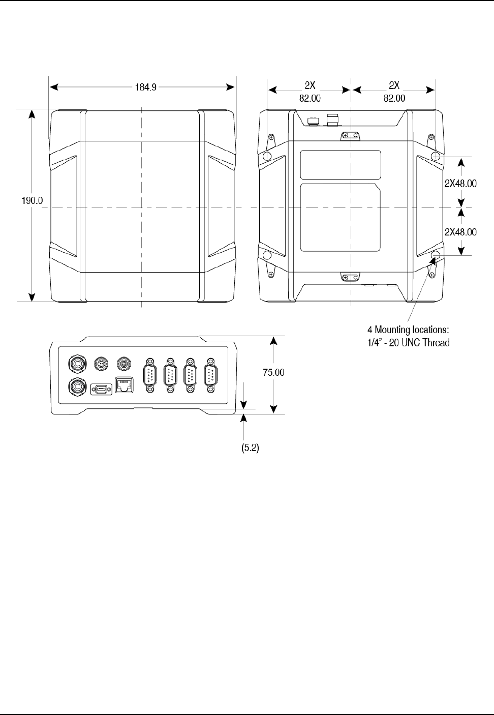
ProPak6 Installation and Operation User Manual Rev 5 113
A.3 Dimension Drawings
Figure 40: ProPak6 Dimensions
Dimensions are in millimeters
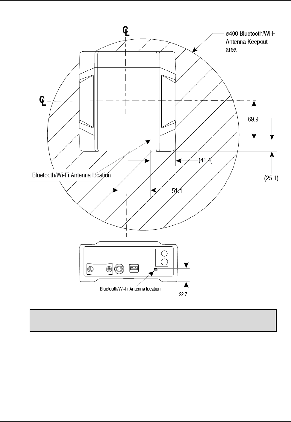
114 ProPak6 Installation and Operation User Manual Rev 5
Figure 41: Bluetooth/Wi-Fi Antenna Keep-out Area and Antenna Location
Keep-out 20 cm from Bluetooth/Wi-Fi antenna.
Dimensions are in millimeters

ProPak6 Installation and Operation User Manual Rev 5 115
A.3.1 ProPak6 Port Pin-Outs
Table 14: COM1 and COM2 Port Pin-Out Descriptions
Refer to Figure 7, Ethernet, COM or USB Device Ports on page 25.
Table 15: COM3/IMU Port Pin-Out Description
Refer to Figure 7, Ethernet, COM or USB Device Ports on page 25.
Connector Pin No. RS-232 Mode RS-422 Mode
1N/CN/C
2RXDRX(+)
3TXDTX(+)
4Vouta
a. Can be turned on or off using the COMVOUT command. Refer to
the OEM6 Family Firmware Reference Manual (OM-20000129)
for more information.
Vouta
5GNDGND
6N/CN/C
7RTSTX(-)
8 CTS RX(-)
9N/CN/C
Connector Pin No. RS-232 Mode RS-422 Mode
1a
a. The IMU_EVENT_OUT(SYNC)1 signal can be disabled.
IMU_EVENT_OUT(SYNC)1 IMU_EVENT_OUT(SYNC)1
2RXD RX(+)
3TXD TX(+)
4N/C N/C
5GND GND
6N/C N/C
7 RTS TX(-)
8CTS RX(-)
9 reserved reserved

116 ProPak6 Installation and Operation User Manual Rev 5
Table 16: I/O Port Pin-Out Descriptions
Refer to Figure 8, Expansion and I/O Ports on page 26.
Table 17: Expansion Port Pin-Out Description
Refer to Figure 8, Expansion and I/O Ports on page 26.
Connector Pin
No.
Default
Configuration
Optional
Configuration Description
1 EVENT_OUT 1 VARF Output Event1 / Variable Frequency
(VARF) output
2 PPS PPS 1 Pulse Per Second (PPS) output
3 EVENT_OUT 2 MSR Output Event2 / Measured output for
Event 2
4 EVENT_IN 1 EVENT1 Input Event1
5 EVENT_OUT 3 PV Output Event3 / Position valid output
6 EVENT_IN 2 EVENT2 Input Event2
7 EVENT_IN 3 _RESETOUT Input Event3 / active low reset out
8 EVENT_IN 4 ERROR Input Event4 / error indicator out
9GND GND
Connector Pin No. Signal
1CAN1+
2CAN1-
3CAN2+
4CAN2-
5DGND
6 VBUS
7 USB (D-)
8 USB (D+)
9DGND
Shell DGND

ProPak6 Installation and Operation User Manual Rev 5 117
Table 18: ProPak6 Strobe Electrical Specifications
Strobe Sym Min (V) Max (V) Current (mA) Conditions
Event_In1
(Mark 1)
Event_In2
(Mark2)
Event_In3
(Mark3)
Event_In4
(Mark4)
VIL 0.8 VCC = 3.3 V; 85C
VIH 2.0 VCC = 3.3 V; 85C
PPS
VOL 0.4
8 VCC = 3.3 V; 85C
VOH 2.4
PV
VARF
VOL 0.4 24 VCC = 3.3 V; 85C
VOH 3.0 24 VCC = 3.3 V; 85C
RESETIN VIL 0.8 VCC = 3.3 V; 85C
VIH 2.3 VCC = 3.3 V; 85C

118 ProPak6 Installation and Operation User Manual Rev 5
A.4 OEM615 Receiver Card Performance for ProPak6 (model dependent)
PERFORMANCE (Subject to GPS System Characteristics
Position Accuracya
a. Typical values. All position and velocity RMS values are based on Horizontal position accuracy. Performance
specifications are subject to GPS system characteristics, U.S. DOD operational degradation, ionospheric and
tropospheric conditions, satellite geometry, baseline length and multipath effects.
Standalone:
L1 only 1.5 m RMS
L1/L2 1.2 m RMS
SBASb
b. GPS-only.
0.6 m RMS
DGPS 0.4 m RMS
RTK 1 cm + 1 ppm RMS
Time to First Fix Hot: 35 s (Almanac and recent ephemeris saved and approximate position and
time entered)
Cold: 50 s (No almanac or ephemeris and no approximate position or time)
Reacquisition 0.5 s L1 (typical)
1.0 s L2 (typical)
Data Rates Measurements up to 20 Hz
Position up to 20 Hz
Time Accuracyac
c. Time accuracy does not include biases due to RF or antenna delay.
20 ns RMS
Velocity Accuracya0.03 m/s RMS
Measurement Precision GPS GLO
Code Carrier Code Carrier
L1 C/A 4 cm 0.5 mm 8 cm 1.0 mm
L2 P(Y)d
d. L2 P for GLONASS
8 cm 1.0 mm 8 cm 1.0 mm
L2 Ce
e. L2 C/A for GLONASS
8 cm 0.5 mm 8 cm 1.0 mm
Dynamics Velocity 515 m/sf
f. In accordance with export licensing.
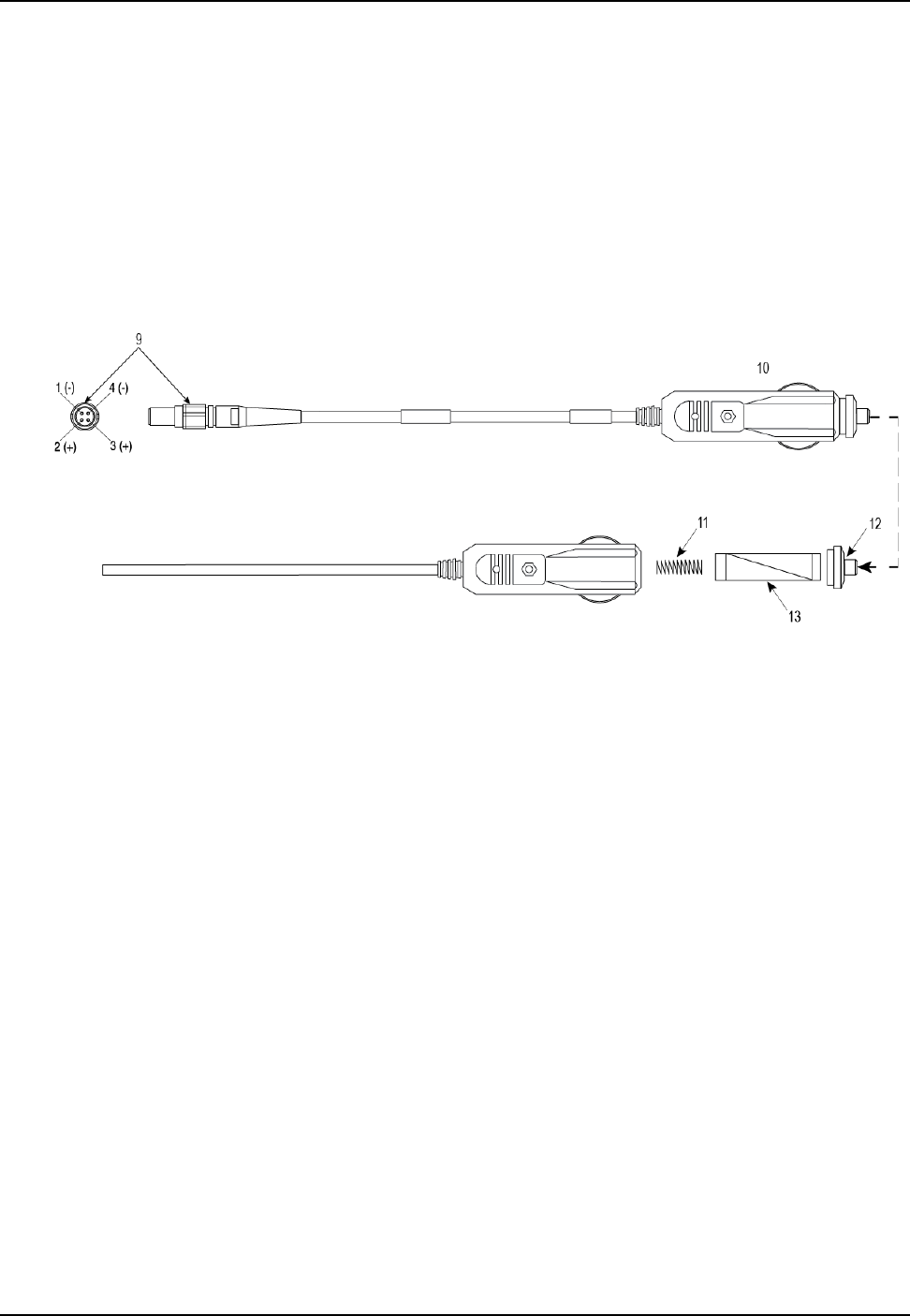
ProPak6 Installation and Operation User Manual Rev 5 119
A.5 Cables
A.5.1 12 V Power Adapter Cable (NovAtel part number 01017663)
The power adapter cable supplied with the ProPak6, provides a convenient means for supplying +12 V
DC while operating in the field.
Input is provided through the standard 12V power outlet. The output from the power adapter utilizes a 4-
pin LEMO connector (LEMO part number FGG.0B.304.CLAD52Z) and plugs directly into the PWR input
located on the back panel of the ProPak6.
This cable is RoHS compliant.
For alternate power sources, see Section 2.8, Installing NovAtel Connect PC Utilities on page 33.
Reference Description Reference Description
1 Black 1 Ground
2Red 212 V
3 Orange or Green 3 12 V
4 Brown or White 4 Ground
9 Connector key marking 12 Universal tip
10 12 V adapter 13 6 Amp slow-blow fuse
11 Spring
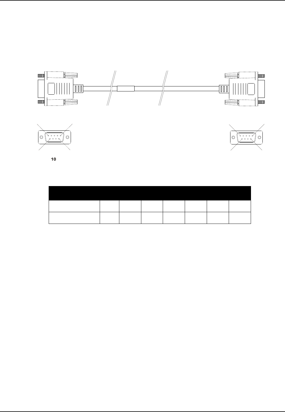
120 ProPak6 Installation and Operation User Manual Rev 5
A.5.2 Null-modem Cable (NovAtel part number 01017658)
This cable supplied with the ProPak6, provides an easy means of communications with a PC/laptop. The
cable is equipped with a 9-pin connector at the receiver end which can be plugged into the COM1,
COM2, or AUX port. At the PC/laptop end, a 9-pin connector is provided to accommodate a computer
serial (RS-232) communication port.
This cable is RoHS compliant.
Table 19: Wiring Table:
Note: Cables may contain DEHP.
Connector Pin Number
To DB9S (10)2387451 & 6
To DB9S (11) 3 2 7 8 1 & 6 5 4
5
11
5
6
99
6
11
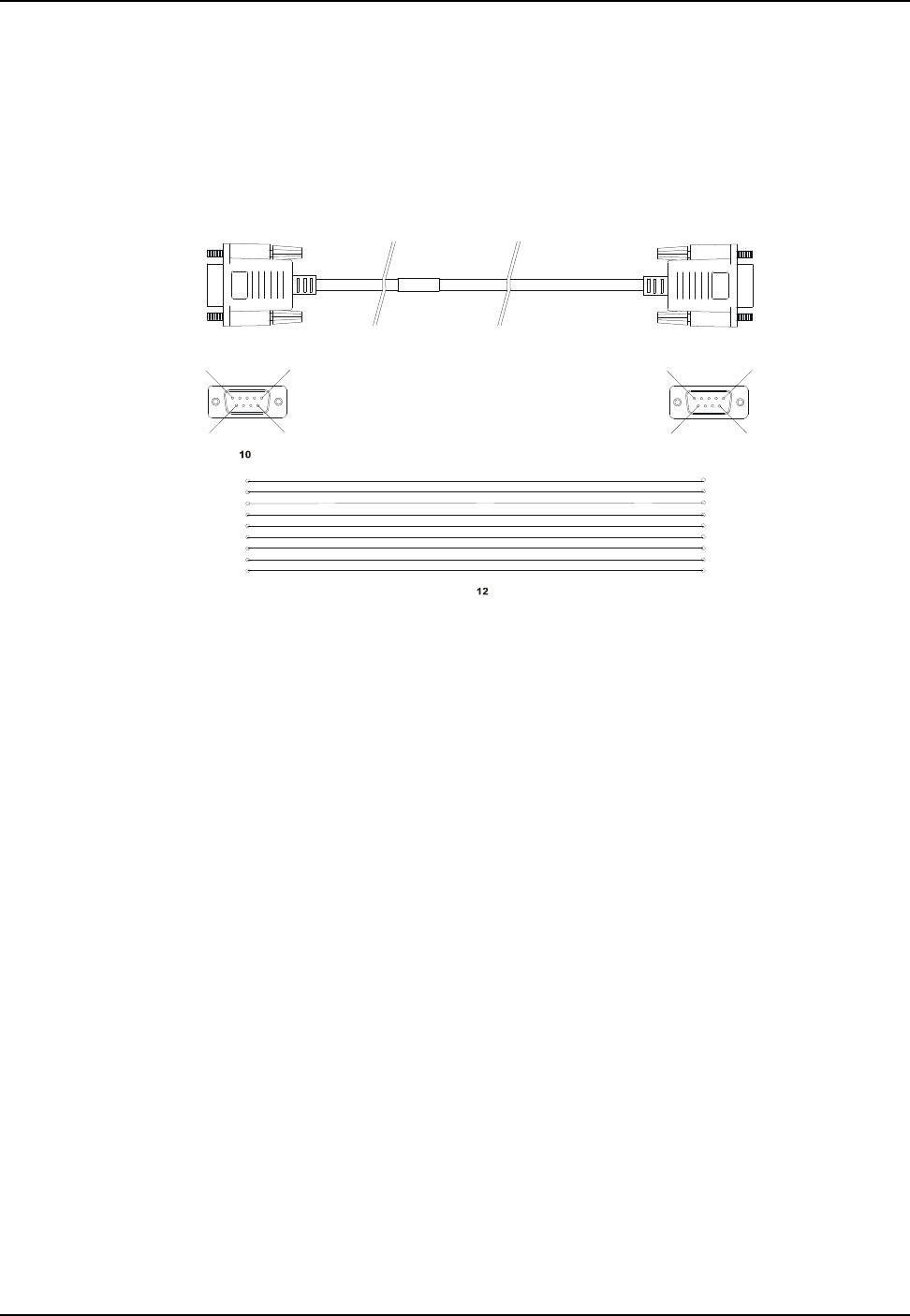
ProPak6 Installation and Operation User Manual Rev 5 121
A.5.3 Straight Through Serial Cable (NovAtel part number 01018520)
This cable can be used to connect the ProPak6 to a modem or radio transmitter to propagate differential
corrections. The cable is equipped with a female DB9 connector at the receiver end. The male DB9
connector at the other end is provided to plug into your user-supplied equipment (please refer to your
modem or radio transmitter user guide for more information on its connectors). The cable is
approximately 2 m in length.
This cable is RoHS compliant.
5
11
5
6
99
6
11
1
2
3
4
5
6
1
2
3
4
5
6
7
8
9
9
7
8
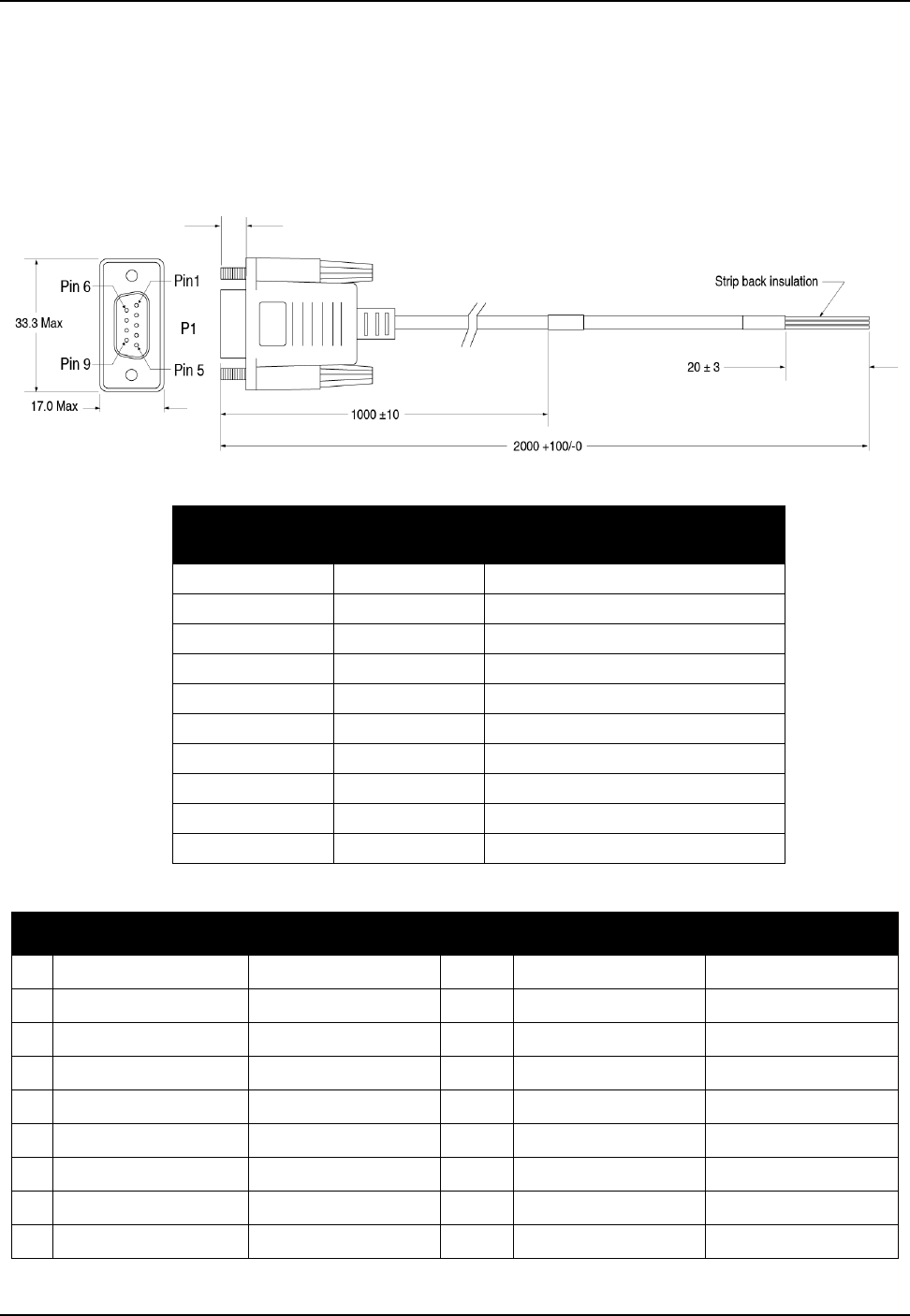
122 ProPak6 Installation and Operation User Manual Rev 5
A.5.4 I/O Cable (NovAtel part number 01018519, 01019148)
These cables can be used to connect the ProPak6 I/O port. The cables are 2 metres in length, with a
DB9 male connector at one end and tinned and tagged conductors at the other.
The 01019148 cable is similar in function to the 0108519 cable, however each signal is in a twisted pair
with a ground wire to reduce cross talk and improve signal integrity. The 01019148 cable is
recommended when using multiple event lines simultaneously in order to prevent false triggers.
Table 20: I/O Cable Wiring (01018519)
Table 21: Twisted Pair I/O Cable Wiring Table (01019148)
DB9 Male to
Receiver Color Code Pin Function
P1 Black VARF/EVENT_OUT1
P2 Brown PPS
P3 Red MSR/EVENT_OUT2
P4 Orange EVENT_IN1
P5 Yellow PV/EVENT_OUT3
P6 Green EVENT_IN2
P7 Blue nRESETOUT/EVENT_IN3
P8 Violet ERROR/EVENT_IN4
P9 White/Grey Signal Ground
Shell Shield Chassis
P1 Color Code Tag Name P1 Color Code Tag Name
1 Black VAR/EVT O1 5 Yellow PV/EVT O3
9 White (of black pair) VAR/EVT O1 GND 9 White (of yellow pair) PV/EVT O3 GND
2 Brown PPS 6 Green EVT I2
9 White (of brown pair) PPS GND 9 White (of green pair) EVT I2 GND
3 Red MSR/EVT O2 7 Blue RST O/EVT I3
9 White (of red pair) MSR/EVT O2 GND 9 White (of blue pair) RST O/EVT I3 GND
4 Orange EVT I1 8 Violet ERR O/EVT I4
9 White (of orange pair) EVT I1 GND 9 White (of violet pair) ERR/EVT I4 GND
Shell Shield
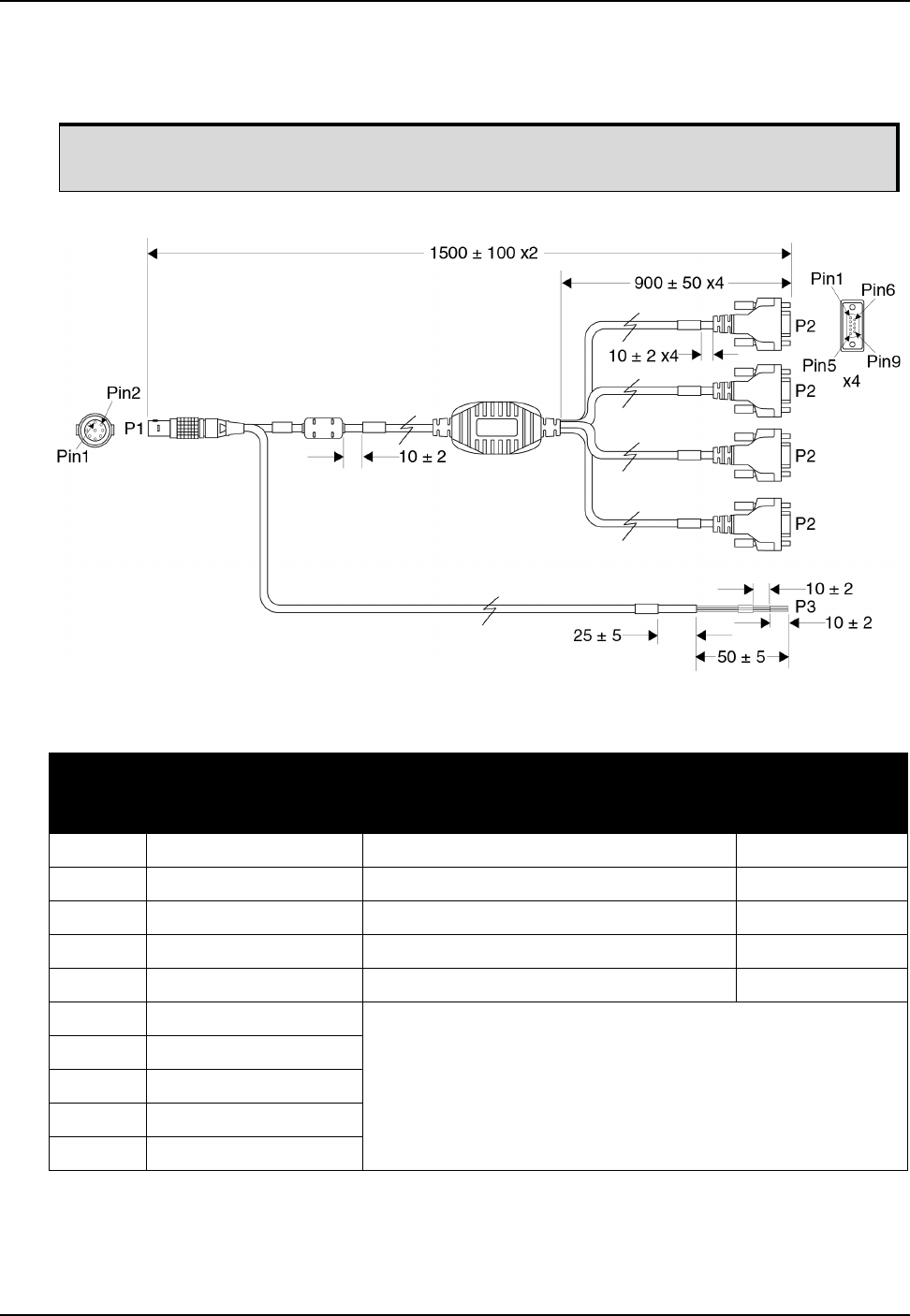
ProPak6 Installation and Operation User Manual Rev 5 123
A.5.5 ProPak6 Expansion Cable (NovAtel part number 01019154)
The optional cable 01019154 provides access to the COM7, COM8, COM9, COM10, CAN1 and CAN2
ports.
COM4, COM5 and COM6 are used internally on the ProPak6.
Table 22: ProPak6 Expansion Cable Pin-Out Descriptions
P1 (EXP)
Pin # Function P2
DB9 Connectors
P3
Wire Bundle
Label
1 CAN Bus 1+ CAN1+
2 CAN Bus 1- CAN1-
3 CAN Bus 2+ CAN2+
4 CAN Bus 2- CAN2-
5 Digital Ground DGND
6VBUS
The ProPak6 Expansion Cable multiplexes four serial COM ports
(COM7, COM8, COM9 and COM10) onto a single USB port.
See Table 23, P2 Connector Pin-Out Descriptions on page 124
for the pin-out of the four P2 connectors.
7 USB D-
8 USB D+
9 Digital Ground
Shell Braid Shield
Dimensions are in millimetres.
COM7
COM8
COM9
COM10

124 ProPak6 Installation and Operation User Manual Rev 5
Table 23: P2 Connector Pin-Out Descriptions
Pin Description
1 No connect
2 Transmit Data (TXD)
3 Receive Data (RXD)
4 No connect
5 Ground (GND)
6 No connect
7 Clear To Send (CTS)
8 Request To Send (RTS)
9 No connect
Shell Ground (GND)

125 ProPak6 Installation and Operation User Manual Rev 5
Appendix B Replacement Parts
The following are a list of the replacement parts available for your NovAtel ProPak6 receiver. Should you
require assistance, or need to order additional components, please contact your local NovAtel dealer or
Customer Service representative.
B.1 ProPak6
B.2 Accessories
Part Description NovAtel Part
Extension cable DB9 Male/Female ITE 6 ft 01018520
Null-modem serial data cable DB9 6 ft 01017658
Power cable assembly, 4-pin LEMO 6 AMP CIG LGH 01017663
I/O cable 6 ft DB9 male/single ended 01018519, 01019148
Part Description NovAtel Part
GSM/HSPA antenna base, NMO magnetic mount to TNC, 3.65 m cable 12023300
GSM/HSPA antenna, 3/4 dBi, 806-960 MHz/1710-2500 MHz, NMO 12023303
Ethernet PATCH CABLE - 7FT BLACK W/ SR HOOD 60723118
CABLE USB A TO USB MICRO B 2 METER 60723119
30 W AC to DC power adapter (LEMO to wall socket)
Operating temperature range: 0 to 40°C (indoor use only)
01018931
Optional NovAtel Antennas:
Model 702 (L1/L2) GPS-702
Model 701 (L1-only) GPS-701
Model 702L (L1/L2/L-Band, B1 BeiDou) GPS-702L
Model 702GG (L1/L2/GLONASS) GPS-702-GG
Model 701GG (L1/GLONASS) GPS-701-GG
Model 703GGG (L1/L2/L5 GPS, L1/L2/L3 GLONASS,
B1/B2 BeiDou, E1/E5a-b Galileo)
GPS-703-GGG
Model GPS-704 (GPS L1/L2/L5, Galileo E1/E5a/E5b/E6
and GLONASS L1/L2, TNC connector), B1/B2/B3 BeiDou
GPS-704-X
Model 702GGL (L1/L2/GLONASS/L-Band, B1 BeiDou) GPS-702-GGL
Model 701GGL (L1/GLONASS/L-Band,B1 BeiDou) GPS-701-GGL
Model 35C50P1GLA (L1/GLONASS/L-Band) ANT-35C50P1GLA-TW-N
Model 26C1GA (L1) ANT-26C1GA-TBW-N
Model 42G1215A (L1/L2/L-Band) 42G1215A-XT-1-2 and
42G1215A-XT-1-3
Model C2GA (L1/L2) ANT-C2GA-TW-N

126 ProPak6 Installation and Operation User Manual Rev 5
B.3 Manufacturer’s Part Number
The following original manufacturer’s part number is provided for information only and is not available
from NovAtel as a separate part:
Model 42G1215A (L1/L2) 42G1215A-XT-1
Optional RF Antenna Cable: 5 meters GPS-C006
15 meters GPS-C016
30 meters GPS-C032
Part Description NovAtel Part
Product Part Description Company Part Number
ProPak6 Power Cable
connector
4-pin socket connector LEMO FGG.0B.304.CLAD52Z
ProPak6 Expansion Port
connector
9-pin socked connector LEMO FGA.OB.309.CLAZ

127 ProPak6 Installation and Operation User Manual Rev 5
Appendix C Frequently Asked Questions
The ProPak6 Bluetooth and Cellular radios are off by default, why?
They are off by default in order to minimize power consumption as well as EMI (Electromagnetic
Interference). Each component has its own setup instructions contained in this manual as well as the
Quick Start Guide provided with the product. Instructions include specific commands that allow the
configuration of settings associated with each component. These peripherals include Wi-Fi (both client
and access point) and Bluetooth. By default, the Wi-Fi radio is on.
Refer to Chapter 5, Radio Configuration and Activation on page 82 for details.
How are RTK corrections sent over Ethernet?
In order to utilize Ethernet for correction services, first configure the port settings of the receiver. The
ProPak6 Ethernet and Wi-Fi share the same set of ICOM ports. When a connection is established, a
specific ICOM port is assigned individually (unlike previous models, which would assign 3 virtual ports
when establishing Ethernet connection). Information on Ethernet configuration can be found in the
Chapter 4, Ethernet Configuration on page 74 or by following the steps laid out in the NovAtel application
note APN-57 – OEM628 Ethernet Configuration. Once established, differential corrections can be sent in
all standard NovAtel supported message formats (RTCA, RTCM v2.3, RTCM V3.0, CMR). Specific
messages, logs, commands and responses are detailed in the OEM6 Firmware Reference Guide
(OM-20000129) under each message format, while sample configurations of each can be found in this
manual in Section 3.4, Transmitting and Receiving Corrections on page 47.
Are there any Bluetooth connectivity issues while using Wi-Fi?
The ProPak6 uses a common Bluetooth and Wi-Fi antenna. Only when discovering Bluetooth devices
(pairing) is Wi-Fi performance impacted. Simply ensure Bluetooth discoverability is turned off before
connecting to a Wi-Fi network (refer to Section 5.1.1.2, Connecting Bluetooth Devices on page 83 for
details).
The Bluetooth connection may also be lost when switching a Propak6 between AP and Client modes.
When issuing LOG IPCONFIG, the ProPak6 does not have a default IP address,
why?
The ProPak6 can be configured as both a Access Point (AP) or a Client. So by default, the unit is not
assigned an IP address. However, once an IP address is assigned to the receiver, it is preserved through
issuing the SAVECONFIG command so the IP address is retained if the ProPak6 is powered down (refer
to theWi-Fi Network Configuration on page 84 for details). This is especially important in the preservation
of remote Ethernet connectivity.
Is it possible to save logs directly onto the receiver?
Yes. The ProPak6 is able to log directly onto the OEM638’s onboard 4 GB of memory by replacing the
usual port number with FILE. During internal logging, the ProPak6 automatically names files stored onto
the internal memory. It is also possible to manually set file names through the use of the LOGFILE
command. This command also opens or closes log files. Below are examples of using this feature:
1. Save RANGE logs to an automatically generated file:
LOGFILE OPEN (opens an automatically generated file for logging)
LOG FILE RANGE ONTIME 1 (saves RANGE logs once a second to file)
LOGFILE CLOSE (issue once sufficient data has been collected to close off file)
2. Log BESTPOS observations to a special file named TESTDATA.DAT:
LOGFILE OPEN TESTDATA.DAT (creates TESTDATA.DAT on internal memory)

128 ProPak6 Installation and Operation User Manual Rev 5
LOG FILE BESTPOS ONTIME 0.5 (saves BESTPOS logs, twice a second, to named file)
LOGFILE CLOSE
Refer to the Section 3.7, Logging and Retrieving Data Overview on page 58 for logging details.
How is SBAS enabled on the ProPak6?
SBAS is enabled or disabled by issuing the SBASCONTROL command. This command is also used to set
the augmentation system, specific PRN, as well as configure test mode acceptance. The following
example enables WAAS:
SBASCONTROL ENABLE WAAS
Refer to Section 3.6.6, Enabling SBAS Positioning on page 55 for additional information and the detailed
field breakout of SBASCONTROL command available in the OEM6 Firmware Reference Guide
(OM-20000129) from our web site.
How is L-Band enabled on the ProPak6?
Refer to Section 3.6.7, Enabling L-Band on page 56 in this manual for details.
Does Bluetooth discoverability have to be manually turned off?
Yes. The ProPak6 remains discoverable until this option is turned off or an exclusive connection is
established over Bluetooth port. Simply pairing a device does not take the receiver out of discoverability
mode. A direct communications connection must be established, such as use of a terminal program in
order to lock out other devices. Otherwise, Bluetooth discoverability can be manually disabled by issuing
the command:
BLUETOOTHDISCOVERABILTY OFF
When the discoverability is disabled, no new device may pair with the ProPak6, however previously
paired devices are recognized. The only way to fully disable Bluetooth is by issuing the follow command
BLUETOOTHCONFIG POWER OFF which completely powers down the ProPak6.
Why is data not being received on the ICOM Ports?
The ProPak6 ICOM ports can be locked and password protection assigned. If enabled, the LOGIN
command must be issued and a password entered to enable the port to receive data. Refer to
Section 2.9.2, FTP Server and ICOM Ports on page 34 for detailed instructions.
Wi-Fi AP settings are not retained, why?
Once the WIFIAPCONFIG command is used to modify AP settings, the ProPak6 requires a power cycle
to the radio for the changes to take affect. Once satisfied with AP settings, issue the WIFICONFIG
STATE OFF command and then issue the WIFICONFIG STATE ENABLED command.
My network keeps defaulting to Wi-Fi, why?
Ethernet is the ProPak6 default network primarily used for internet access. It can be changed to either
Wi-Fi or Cellular as needed by issuing:
SETPREFERREDNETIF <ETHA>, <CELL> or <WIFI>
Refer to the SETPREFERREDNETIF command in the OEM6 Firmware Reference Guide (OM-20000129)
for command details.
While performing logging, data gaps are experienced, why?
Data gaps indicate a throughput issue. When performing high data rate Ethernet logging using TCP/IP,
disable Windows Delayed Ack Algorithm (DAA) for complete data logging. If DAA is not disabled, data
gaps appear due to the Windows Ethernet buffer.

ProPak6 Installation and Operation User Manual Rev 5 129
If done incorrectly, changing the Windows Registry may impair the operation of the computer. Editing the
Windows Registry is for advanced Microsoft Windows users only. NovAtel Inc. is not able to provide any
technical support for any actions taken regarding information found in Microsoft’s Knowledge Base.
Windows XP (SP3) and Windows Server 2003:
http://support.microsoft.com/kb/328890
http://support.microsoft.com/kb/815230
Refer to the Chapter Customer Support on page 15 for details on contacting NovAtel Customer Support.
The HWMONITOR log reports Reading Type 6 is under the lower error limit (a
voltage reading of 2.7V and status 602). Is this an error?
This is not an error. The ProPak6 supplies 3.3V directly to the OEM638 within the unit and a back voltage
may be present at the point where the "supply voltage" is sampled. As long as Reading Type 3 is
showing approximately 3.3V and the status is 300, the power supplies are functioning correctly

OM-20000148 Rev 5 July 2017
