ProcessorSDKRadar_UserGuide Processor SDKRadar User Guide
User Manual:
Open the PDF directly: View PDF ![]() .
.
Page Count: 31
- TABLE OF CONTENTS
- 1 Introduction
- 2 System Requirements
- 3 Build and Run
- 3.1 Overview of application in release
- 3.2 Building the application
- 3.3 Console Output
- 3.4 Boot Modes
- 3.5 Load using QSPI
- 3.6 Load using QSPI and SD boot
- 3.7 Load using SD Card
- 3.8 Load using CCS
- 3.9 Run the demo
- 3.9.1 Usecase Specific Steps to run
- 3.9.1.1 Radar (Single AWR1243) Capture + Null (TDA3xx Only)
- 3.9.1.2 Radar (Single AR1243) Capture + Radar Object Detect (EVE1) + Display (TDA3xx Only)
- 3.9.1.3 Radar (Single AWR1243) Capture + Radar FFT (EVE1) + DSP (FFT Heat Map) + Null (TDA3xx Only)
- 3.9.1.4 Null Source (SD/Network) Input + Radar FFT (EVE1) + Null (SD/Network)
- 3.9.1.5 Satellite Radar (Single AWR1243) Capture + Radar FFT (EVE1) + DSP (FFT Heat Map) + Display (TDA3xx Only)
- 3.9.1 Usecase Specific Steps to run
- 4 Frequently Asked Questions
- 5 Revision History
Copyright © 2016-2018 Texas Instruments Incorporated. All rights reserved.
Information in this document is subject to change without notice. Texas Instruments may
have pending patent applications, trademarks, copyrights, or other intellectual property
rights covering matter in this document. The furnishing of this documents is given for
usage with Texas Instruments products only and does not give you any license to the
intellectual property that might be contained within this document. Texas Instruments
makes no implied or expressed warranties in this document and is not responsible for the
products based from this document.
Page 1 of 31
Processor SDK – Radar
(v03.03)
User Guide
Page 2 of 31
IMPORTANT NOTICE
Texas Instruments and its subsidiaries (TI) reserve the right to make changes to their products
or to discontinue any product or service without notice, and advise customers to obtain the
latest version of relevant information to verify, before placing orders, that information being
relied on is current and complete. All products are sold subject to the terms and conditions of
sale supplied at the time of order acknowledgment, including those pertaining to warranty,
patent infringement, and limitation of liability.
TI warrants performance of its products to the specifications applicable at the time of sale in
accordance with TI’s standard warranty. Testing and other quality control techniques are utilized
to the extent TI deems necessary to support this warranty. Specific testing of all parameters of
each device is not necessarily performed, except those mandated by government requirements.
Customers are responsible for their applications using TI components.
In order to minimize risks associated with the customer’s applications, adequate design and
operating safeguards ought to be provided by the customer so as to minimize inherent or
procedural hazards.
TI assumes no liability for applications assistance or customer product design. TI does not
warrant or represent that any license, either express or implied, is granted under any patent
right, copyright, mask work right, or other intellectual property right of TI covering or relating to
any combination, machine, or process in which such products or services might be or are used.
TI’s publication of information regarding any third party’s products or services does not
constitute TI’s approval, license, warranty or endorsement thereof.
Reproduction of information in TI data books or data sheets is permissible only if reproduction is
without alteration and is accompanied by all associated warranties, conditions, limitations and
notices. Representation or reproduction of this information with alteration voids all warranties
provided for an associated TI product or service, is an unfair and deceptive business practice,
and TI is neither responsible nor liable for any such use.
Resale of TI’s products or services with statements different from or beyond the parameters
stated by TI for that product or service voids all express and any implied warranties for the
associated TI product or service, is an unfair and deceptive business practice, and TI is not
responsible nor liable for any such use.
Also see: Standard Terms and Conditions of Sale for Semiconductor Products.
www.ti.com/sc/docs/stdterms.htm
Mailing Address:
Texas Instruments
Post Office Box 655303
Dallas, Texas 75265
Copyright © 2016-2018, Texas Instruments Incorporated

Page 3 of 31
TABLE OF CONTENTS
1 Introduction ................................................................................................. 4
1.1 References ...................................................................................................... 4
1.2 Directory Structure ........................................................................................... 5
2 System Requirements .................................................................................. 7
2.1 Windows Installation......................................................................................... 7
2.2 Linux Installation ................................................................................................. 7
2.3 Hardware Requirements .................................................................................... 9
2.4 Software Installation ...................................................................................... 15
3 Build and Run ............................................................................................. 17
3.1 Overview of application in release .................................................................... 17
3.2 Building the application ................................................................................... 17
3.3 Console Output .............................................................................................. 19
3.4 Boot Modes ................................................................................................... 20
3.5 Load using QSPI ............................................................................................. 20
3.6 Load using QSPI and SD boot .......................................................................... 20
3.7 Load using SD Card ........................................................................................ 21
3.8 Load using CCS .............................................................................................. 21
3.9 Run the demo ................................................................................................ 22
4 Frequently Asked Questions ....................................................................... 29
5 Revision History ......................................................................................... 31
Page 4 of 31
1 Introduction
Processor SDK Radar is a multi-processor software development package for TI’s
family of ADAS SoCs. The software framework allows users to create different Radar
application data flows involving integration of FMCW transceiver, radar signal
processing, and visualization on a display device. The framework has sample Radar
processing data flows which exercises different CPUs and HW accelerators in the
ADAS SoC and demonstrates how to effectively use different sub-systems within the
SoC. Frame work is generic enough to plug in application specific algorithms in the
system.
This document explains the HW/SW setup for TDA based Radar Platform.
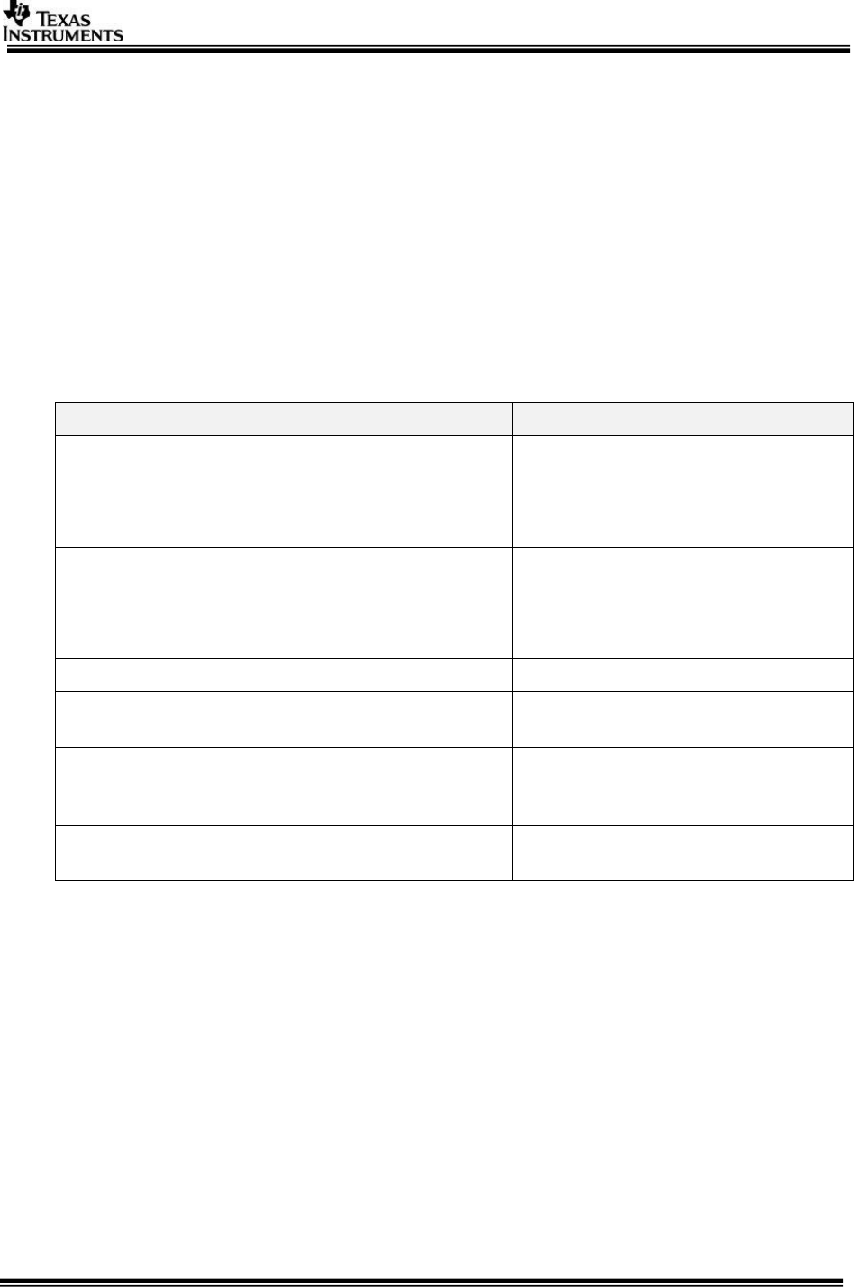
1.1 References
Refer the below additional documents for more information about Processor SDK
Radar
Document
Description
ProcessorSDKRadar_ReleaseNotes.pdf
Release specific information
VisionSDK_UserGuide_TDA3xx.pdf
This document contains install,
build, execution information for
TDA3xx ADAS SoC
VisionSDK_UserGuide_TDA2xx.pdf
This document contains install,
build and execution information on
the TDA2xx ADAS SoC.
VisionSDK_ApiGuide.CHM
User API interface details
VisionSDK_SW_Architecture.pdf
Overview of software architecture
VisionSDK_DevelopmentGuide.pdf
Details how to create data flow (s)
& add new functionality
ProcessorSDKRadar_DevelopmentGuide.pdf
Details how to create data flow (s)
& add new functionality specific to
Radar data processing.
ProcessorSDKRadar_Datasheet.pdf
Performance and benchmark
information for Radar Usecases.

Page 5 of 31
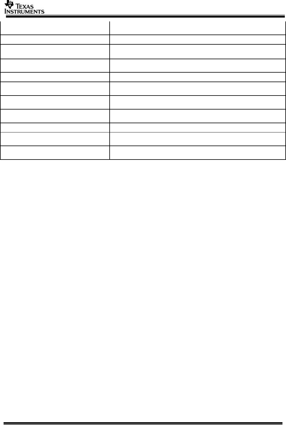
1.2 Directory Structure
Once Processor SDK Radar is installed, two main directories are created namely vision_sdk
and ti_components.
Directory
Description
vision_sdk
Root directory of Processor SDK Radar
vision_sdk/build
Support files for building entire release package
vision_sdk/build/rtos/makerules
Make rules for components and cores for RTOS applications
vision_sdk/build/rtos/tda3xx
Rules specifically for TDA3xx device
vision_sdk/build/rtos/tda2xx
Rules specifically for TDA3xx device
vision_sdk/apps/configs
Build configuration option folders and configuration files
vision_sdk/docs
Documentation for Processor SDK Radar. Use the Index.html
file to navigate through all the documentation.
vision_sdk/sample_app
Sample Use case to get started
vision_sdk/apps
Applications and Usecase Examples, Use case for TDA2xxx
and TDA3xx device
vision_sdk/apps/include
Include files needed for use case support infrastructure
vision_sdk/apps/src
Source files needed for use case support infrastructure
vision_sdk/apps/src/rtos/radar/
include
All include files related to radar framework
vision_sdk/apps/src/rtos/radar/
src
All the source files for the radar framework
vision_sdk/apps/src/rtos/radar/
src/alg_plugins
All the source files for the radar algorithm plugin
vision_sdk/apps/src/rtos/radar/
src/alg_plugins/alg_fxns
All the source files for the radar algorithm functions
vision_sdk/apps/src/rtos/radar/
src/usecase
Usecase folders for different Radar Data Processing
flows.
vision_sdk/links_fw/include
All the include files for the framework
vision_sdk/links_fw/include/link_api
Interface files for all the links
vision_sdk/links_fw/src
All the source files for the framework
vision_sdk/links_fw/src/links_commo
n
Files which are for common across all links
vision_sdk/links_fw/src/links_dsp
Source files for individual links present on DSP
vision_sdk/links_fw/src/links_eve
Source files for individual links present on EVE
vision_sdk/links_fw/src/links_ipu
Source files for individual links present on IPU
vision_sdk/links_fw/src/main_app
Folder for main() functionality
vision_sdk/links_fw/src/utils_commo
n
Common utilities used in framework
ti_components
Root directory of tools accompanying vision SDK
ti_components/algorithms/eve_sw_x
x_xx_xx_xx
EVE Kernels Library
ti_components/cg_tools
All the code gen tools
ti_components/cg_tools/windows/ar
m_x_x_x
Tools needed for ARM CPU cores
ti_components/cg_tools/windows/arp
32_x_x_x
Tools needed for ARP32 core
Page 6 of 31
ti_components/cg_tools/windows/c60
00_x.x.x
Tools needed for C66x DSP
ti_components/drivers
All the drivers used in Vision SDK
ti_components/drivers/pdk_xx_xx_xx
_xx
Driver components for all the peripherals along with Lowest
level SW interface for programming HW registers
ti_components/drivers/edma3_lld_xx
_xx_xx_xx
Driver for system DMA usage
ti_components/networking
Networking related tools
ti_components/networking/ndk_x_xx
_xx_xx
Network Development Kit
ti_components/networking/nsp_vayu
_x_xx_xx_xx
Network Development Kit Support Package
ti_components/radar/mmwave_
dfp_xx_xx_xx_xx
mmWave device firmware package
ti_components/os_tools
Operating System related tools
ti_components/os_tools/bios_x_xx_x
x_xx
BIOS operating sytem used in Vision SDK
ti_components/os_tools/windows/xdc
tools_x_xx_xx_xx
XDC tools related files
Page 7 of 31
2 System Requirements
This chapter provides a brief description of the system requirements (hardware and
software) and instructions for installing Processor SDK Radar.
2.1 Windows Installation
2.1.1 PC Requirements
Installation of this release needs a windows machine with about 8GB of free disk
space. Building of the SDK is supported on windows environment.
2.1.2 Software Requirements
All software packages required to build and run the Processor SDK Radar are
included as part of the SDK release package.
2.1.3 A15 Compiler, Linker
The windows installer for the linaro tools should be downloaded from below link
https://launchpad.net/gcc-arm-embedded/+milestone/4.9-2015-q3-update
The tools need to be installed in “<install dir>/ti_components/cg_tools/windows/gcc-
arm-none-eabi-4_9-2015q3” location.
IMPORTANT NOTE: A15 Compiler and linker MUST be installed before
proceeding else compile will fail. Also make sure the compiler is installed at
the exact path mentioned above
2.1.4 Code Composer Studio
CCS is needed to load, run and debug the software. CCS can be downloaded from
the below link. CCS version CCS version 6.0.1.00040 or higher should be installed.
http://processors.wiki.ti.com/index.php/Download_CCS
2.2 Linux Installation
2.2.1 PC Requirements
Installation of this release needs a Linux Ubuntu 14.04 machine.
IMPORTANT NOTE: If you are installing Ubuntu on a virtual machine, ensure it is a
64 bit Ubuntu.
2.2.2 Software Requirements
All software packages required to build and run the Vision SDK are included as part
of the SDK release package except for the ones mentioned below
2.2.2.1 A15 Compiler, Linker
The Linux installer should be downloaded from below link
https://launchpad.net/gcc-arm-embedded/+milestone/4.9-2015-q3-update
The tools need to be installed in $INSTALL_DIR/ti_components/os_tools/linux/
location.
IMPORTANT NOTE: A15 Compiler and linker MUST be installed before initiating the
build else compilation will fail. Also make sure the compiler is installed at the exact
path mentioned above after installation of vision sdk.
Use following steps to install the toolchain
Page 8 of 31
2.2.3 Other software packages for build depending upon OS baseline
Ensure these packages/tools are installed on the installation machine
uname, sed, mkimage, dos2unix, dtrx, mono-complete, git, lib32z1
lib32ncurses5 lib32bz2-1.0 libc6:i386 libc6-i386 libstdc++6:i386
libncurses5:i386 libz1:i386 libc6-dev-i386 device-tree-compiler mono-
complete
To install
$>sudo apt-get install <package_name>
Page 9 of 31
2.3 Hardware Requirements
Hardware setup for different use-cases is described in this section
2.3.1 AWR12 Sensor Setup with TDA3xx EVM
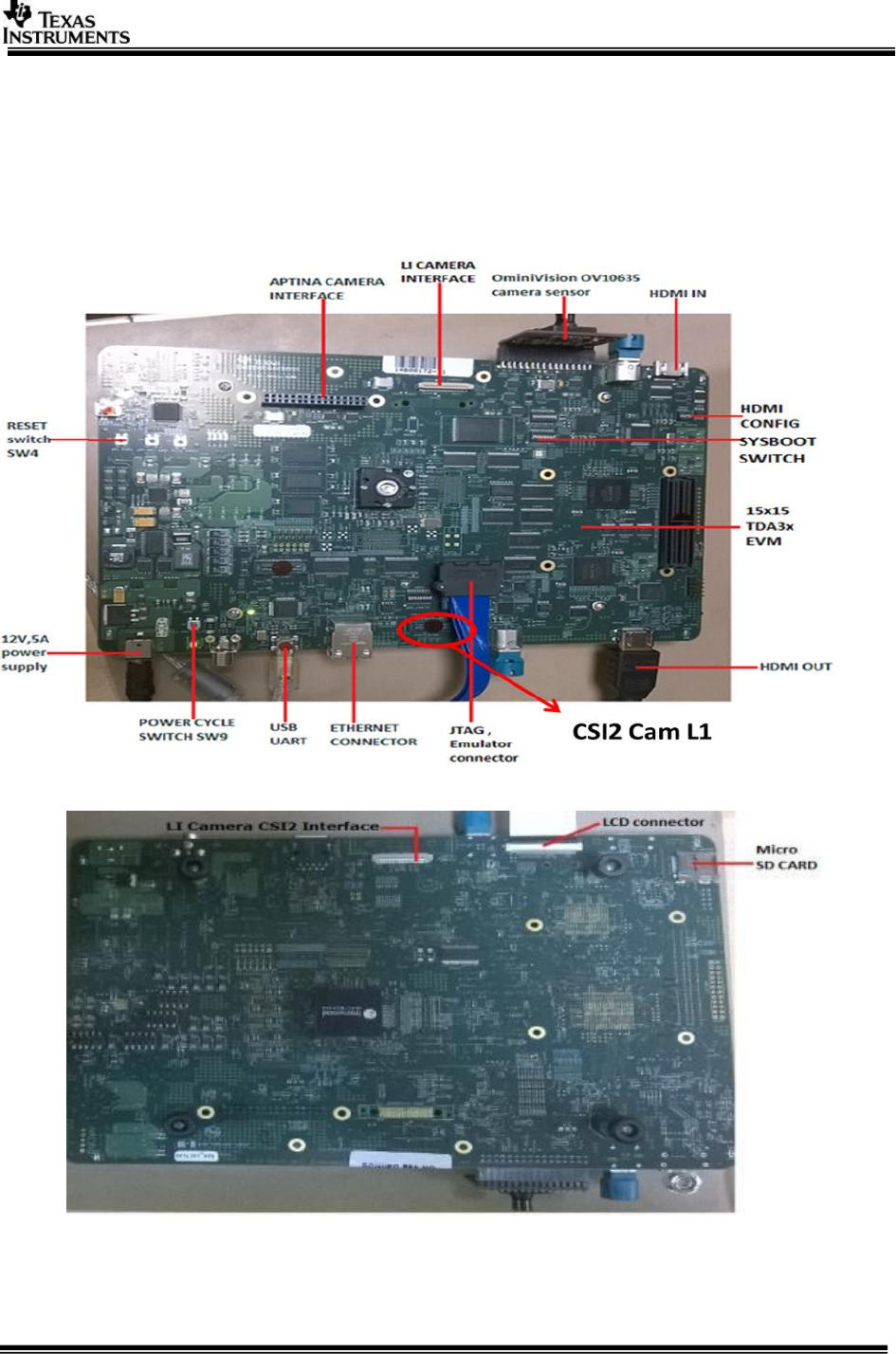
The TDA3xx EVM and DIB, VAB & Booster Pack add-on boards are shown in the
following figures:
Figure 2.1 15x15 TDA3x EVM (FRONT SIDE)
Figure 2.2 15x15 TDA3x EVM (BACK SIDE)
Page 10 of 31
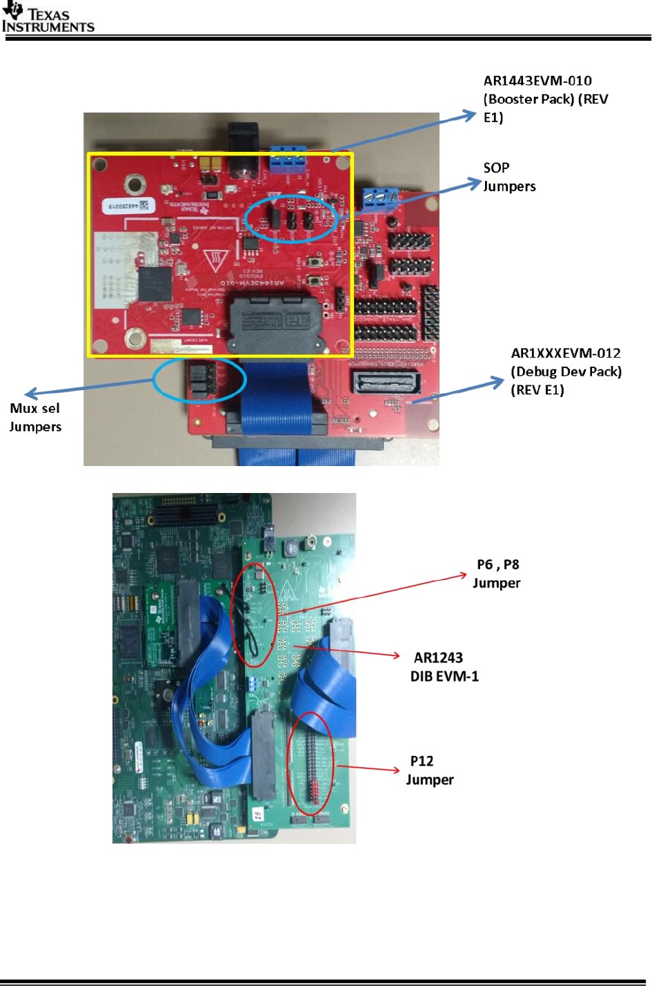
Figure 2.3 AWR12 Booster Pack & Debug DEV Pack
Figure 2.4 AWR1243 DIB & VAB EVM 1 board mounted on TDA3xx EVM
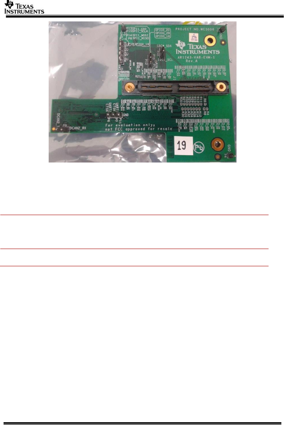
Page 11 of 31
Figure 2.5 AWR1243 VAB EVM-1 board
2.3.1.1 Required H/W modification / Configurations
2.3.1.1.1 TDA3XX EVM Modifications for Radar Usecase
Hardware Modifications on TDA3xx EVM are as below:
Resistor
TDA3xx
EVM Change
Done
TDA3x Signal
AWR12xx Signal
TDA3xx
EVM
R9057
Removed
H_RGMII0_TXC/GPIO3_19
NRESET
J28
R9067
Removed
H_RGMII0_RXD1/GPIO3_29
SPI_HOST_INTR_1
J28
2.3.1.1.2 AWR1XX EVM Jumper settings for TDA3xx setup
The following jumper settings are required for AWR1xx EVM to work with Processor SDK for
tda3xx
AR1443EVM-010 (Booster Pack) (REV E1)
With reference to Figure 2.3, Sense on Power (SOP) Settings in the Functional Mode
are:
SOP0 – Closed
SOP1 – Open
SOP2 – Open
AWR1XXXEVM-012 (Debug Dev Pack) (REV E1)
With reference to Figure 2.3, Jumpers settings to select digital signal MUX between FTDI
chip and 120pin connector on Mux_Sel_Jumpers are:
Page 12 of 31
JP1 -> PIN 1-2 connected (jumpers towards the FTDI marking).
JP2 -> PIN 1-2 connected (jumpers towards the FTDI marking).
JP3 -> PIN 1-2 connected (jumpers towards the FTDI marking).
JP4 -> PIN 1-2 connected (jumpers towards the FTDI marking).
AWR1243 DIB EVM-1 P12 Jumper Settings
With reference to the Figure 2.4 the Jumper settings for the DIB board to connect AWR12
and TDA3 signals are:
Center pin to WARM_RESET
Center pin to SPI_MISO_1
Center pin to SPI_HOST_INTR_1
Center pin to SPI_CS_1
Center pin to SPI_MOSI_1
Center pin to SPI_CLK_1
Center pin to NRESET
NOTE: For the reset line to propagate connect a blue wire from P8 (TDA3X_3V3) Supply to
P6 (VDDIO_IN). 3.3V Supply Voltage of tda3xx is at P8 is to be connected to P6 VDDIO_IN.
2.3.1.2 Power Supply Information
The TDA3xx EVM requires a 12 V power supply provided as a part of the TDA3xx EVM Kit.
The AR1443EVM-010 (Booster Pack) requires a 5 V power supply provided as part of the kit.
The AWR1XXXEVM-012 (Debug Dev Pack) requires the micro USB connection to the PC for
its power supply.
2.3.1.3 Erasing the AWR12x Booster Pack onboard serial flash
Before you load your own code to the serial flash or connect the board to Radar Studio it’s
recommended to completely erase the on board serial flash.
This can be done using the FlashProgrammer utility that’s present as part of the Radar
studio tool. Following the following steps to erase the flash:
1. Install Flash programmer from http://www.ti.com/tool/mmwave-dfp. The Flash
programmer is part of the folder
mmwave_dfp_<Version>\rf_eval\radarstudio\FlashProgrammer
2. Provide the 5V supply to the BoosterPack and connect the micro USB cable to the PC.
3. Keep the following SOP jumper configuration to enter flash mode P3 (SOP2) : closed
, P2(SOP1): Open , P1(SOP 0): closed to put the device in SOP mode 5.
4. Press the NRST switch SW2.
5. Create a file (if not already present) AR1X_Package.txt with the following contents:
FORMAT,SFLASH
6. Open a windows command prompt and type
cd mmwave_dfp_<Version>\rf_eval\radarstudio\FlashProgrammer
mmwaveprog_cmdline.exe -c -p [COM#] -b AR1X_Package.txt
The [COM#] is the COM port that comes up as the XDS110 Class Application/User
UART in the device manager.
Page 13 of 31
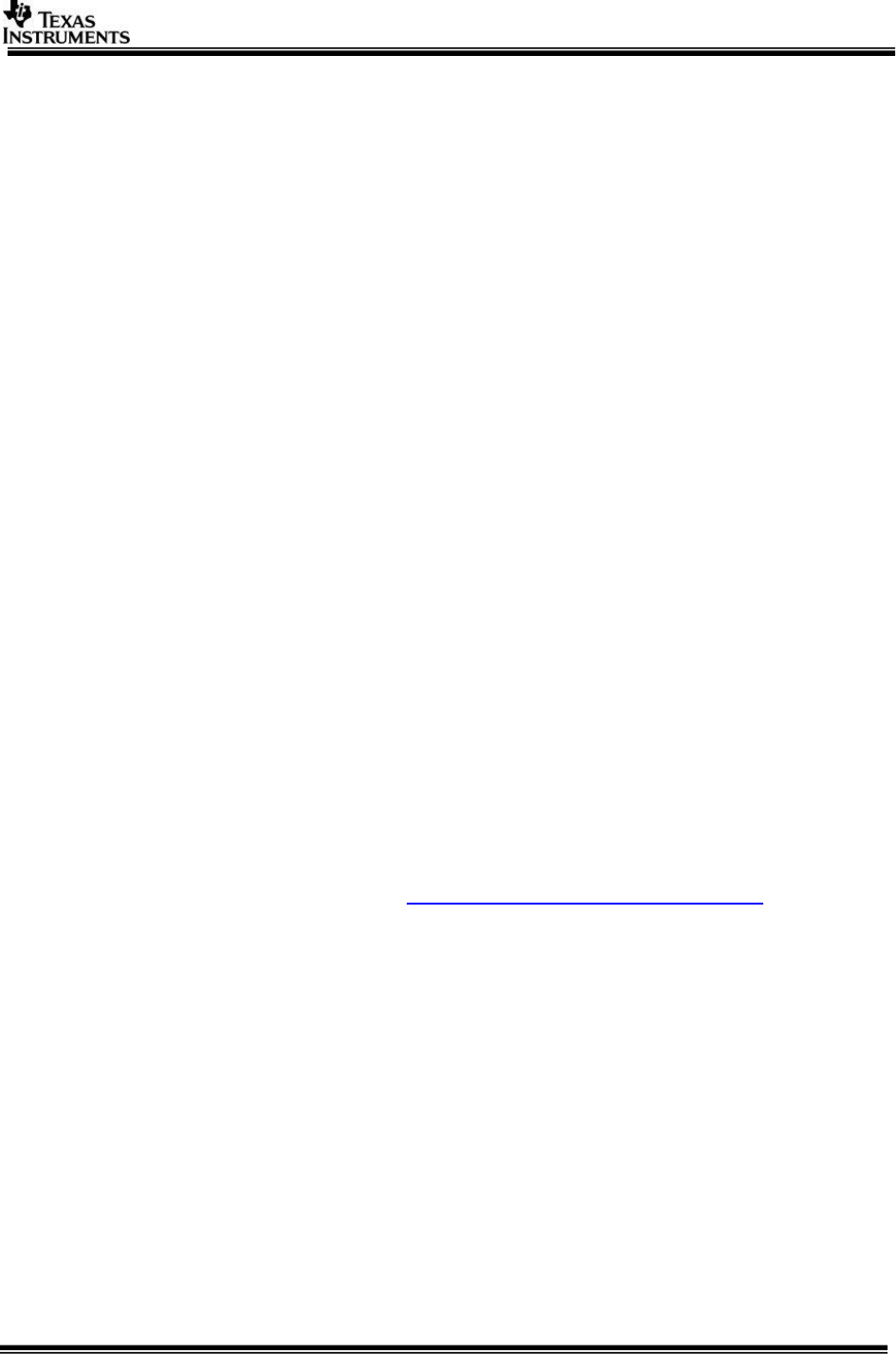
2.3.2 TDA3xx ALPS Board
The TDA3xx ALPS Board is a compact hardware which houses the AWR12 sensor
mounted on the TDA3xx board. It takes a 5-6V input supply. The image of the board
is as below:
Figure 2.6 AWR12 + TDA3xx ALPS Board setup
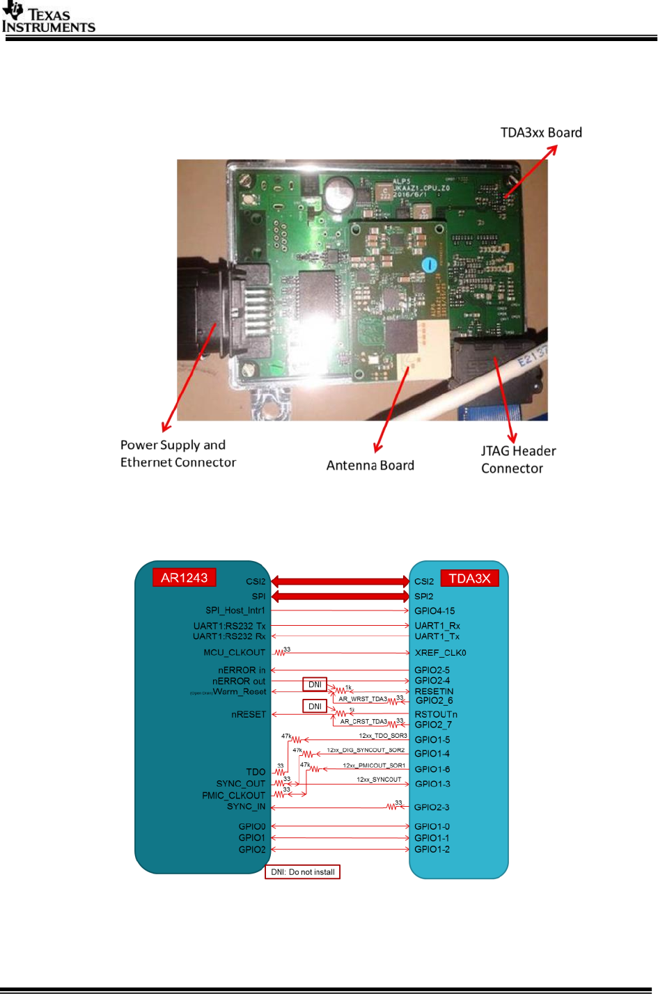
The connection between the TDA3xx and the AWR12xx on the ALPS board is as shown
below:
Figure 2.7 AWR12 + TDA3xx Connection on the ALPS Board setup
NOTE: This board does not have a UART or Display Connection from TDA3xx.
Page 14 of 31
NOTE: Users should use either CCS logs or Network Console to be able to
see the console logs. Kindly have a look at the run instructions in Section
3.9.
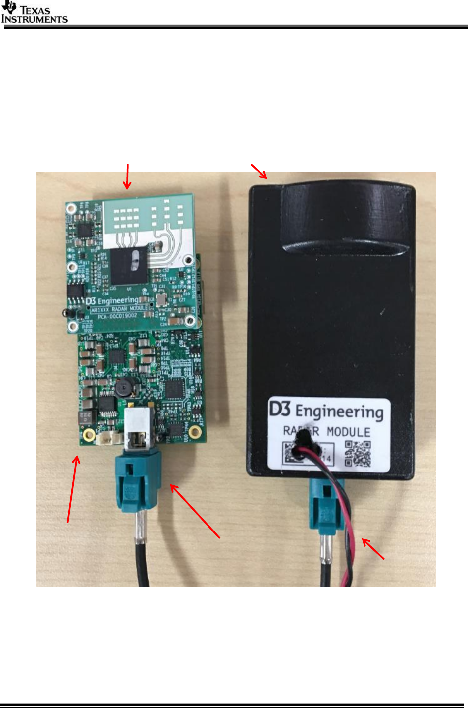
2.3.3 AWR1243 Satellite Radar Module + RVP-TDA3x via FPD-Link III
Satellite Radar use case is developed with the evaluation platform from D3
Engineering. The full platform includes the following components:
AWR1243 Satellite Radar Module (with Serializer UB953)
Figure 2.8 AWR1243 Satellite Radar Module
AWR1243
Module
UB953 Serializer
Daughter Card
FPD-Link III
With Enclosure
Power Supply
Page 15 of 31
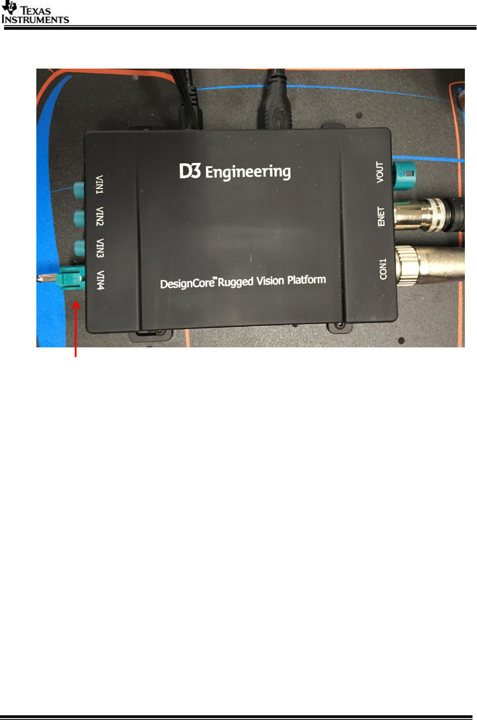
RVP-TDA3x (with Deserializer Hub UB960)
Figure 2.9 RVP-TDA3x
NOTE: Satellite Radar module should be connected to VIN4 on RVP-TDA3x
as shown in Fig 2.9.
2.4 Software Installation
PROCESSOR_SDK_RADAR_xx_xx_xx_xx_setupwin.exe is the SDK package installer.
Copy the installer to the path of your choice.
NOTE: For windows command prompt build install preferably at C: or D: top
level folders to keep the overall path length small.
Double click the installer to begin the installation.
Follow the self-guided installer for installation.
IMPORTANT NOTE: On some computers running as administrator is needed.
Right click on the installer and select option of “Run as administrator”. If
this is not done then you may see a message like “This program might not
have installed correctly
On completion of installation a folder by name PROCESSOR_SDK_RADAR would have
been created in the installation path.
Satellite Radar Input

Page 16 of 31
2.4.1 Uninstall Procedure
To uninstall, double click on uninstall.exe created during installation in the folder
PROCESSOR_SDK_RADAR.
At the end of uninstall, PROCESSOR_SDK_RADAR folder still remains. It is just an
empty folder. It can be deleted manually.
Page 17 of 31
3 Build and Run
This chapter provides a brief overview of the sample applications or use cases
present in the SDK and procedure to build and run it.
3.1 Overview of application in release
The Processor SDK Radar supports the following use-cases
RADAR Usecases
---------------
ALPS Board:
1: AWR12 Firmware Flash (ALPS board Only)
2: Radar (Single AR1243) Capture + Null (TDA3xx Only)
4: Radar (Single AR1243) Capture + Radar Object Detect (EVE1) + Null (TDA3xx Only)
5: Radar (Single AR1243) Capture + Radar Frame Copy (DSP1) + Null (TDA3xx Only)
TDA3xx EVM + DIB + VAB + AWR12 Booster Pack:
2: Radar (Single AR1243) Capture + Null (TDA3xx Only)
3: Radar (Single AR1243) Capture + Radar Object Detect (EVE1) + Display (TDA3xx Only)
4: Radar (Single AR1243) Capture + Radar Object Detect (EVE1) + Null (TDA3xx Only)
5: Radar (Single AR1243) Capture + Radar Frame Copy (DSP1) + Null (TDA3xx Only)
TDA3xx EVM (no AWR12) or TDA2xx EVM (no AWR12):
6: Null Source (SD/Network) Input + Radar FFT (EVE1) + Null (SD/Network)
TDA3xx RVP
3: Radar (Single AR1243) Capture + Radar Object Detect (EVE1) + Display (TDA3xx Only)
7: Multi Radar (AR1243) Capture + Radar FFT (EVE1) + Display (TDA3xx Only)
Use option "s" on the main menu in UART to view PRCM Statistics and Bandwidth
usage
3.2 Building the application
1. On windows command prompt, go inside the directory
PROCESSOR_SDK_RADAR/vision_sdk/build.
2. Open file /vision_sdk/build/Rules.make and set
MAKEAPPNAME=apps
For TDA3xx EVM + VIB + DAB: MAKECONFIG=tda3xx_evm_bios_radar
For TDA3xx RVP: MAKECONFIG=tda3xx_rvp_bios_radar
For ALPS: MAKECONFIG= tda3xx_alps_bios_radar
For TDA2xx EVM (no AWR12): MAKECONFIG= tda2xx_evm_bios_radar
For TDA2px EVM (no AWR12): MAKECONFIG= tda2px_evm_bios_radar
For TDA3xx EVM (no AWR12): MAKECONFIG=tda3xx_evm_bios_radar
and modify configs/tda3xx_evm_bios_radar/cfg.mk with
RADAR_BOARD=none (perform a clean build if already built for TDA3xx +
DIB + VAB)
Page 18 of 31
3. Build is done by executing gmake. “gmake” is present inside XDC package.
For “gmake” to be available in windows command prompt, the XDC path must
be set in the windows system path.
IMPORTANT NOTE: xdc path is needed to be set in environment
variables. If not, then set it using the set PATH =
<Install_dir>/ti_components/os_tools/windows/xdctools_x_xx_xx_
xx;%PATH% in command prompt
IMPORTANT NOTE: If on Windows you are facing build issues, try by
first setting the path to only the following:
set
Path=C:\PROCESSOR_SDK_RADAR_<version>\ti_components\os_tools\wind
ows\xdctools_<version>_core;C:\windows\system32;C:\windows;C:\window
s\System32\Wbem;C:\windows\System32\WindowsPowerShell\v1.0\
IMPORTANT NOTE: If the installation folder depth is high then
windows cmd prompt fails with error that it cannot find a file, even in
file is present in mentioned path, this is because Windows has a
limitation of 8191 characters for the commands that can execute. In
such a situation as a workaround either restrict the folder depth to
d:/ or if it cannot be restricted use git bash to build. Refer
https://support.microsoft.com/en-in/kb/830473 for more details.
(Always point to xdc path gmake only)
4. Under vision_sdk directory
a. When building first time run the below sequence of commands
> gmake –s –j depend
> gmake –s –j
b. When building after the first time or incremental build, run the below
command
> gmake –s –j
Executing “gmake –s –j depend” will build all the necessary components (PDK
drivers, EDMA drivers) and “gmake –s –j” will build the SDK framework and
examples.
IMPORTANT NOTE: For incremental build, make sure to do "gmake -s –j depend"
before "gmake –s -j” when below variables specified in
/vision_sdk/apps/configs/$(MAKECONFIG)/*cfg.mk are changed
when PROC_$(CPU)_INCLUDE is changed
when DDR_MEM is changed
when PROFILE is changed
when ALG plugin or usecase is enabled or disabled in
/vision_sdk/apps/configs/$(MAKECONFIG) /*_cfg.mk
when any .h or .c file in TI component is installed in ti_components is changed
when any new TI component is installed in ti_components
Page 19 of 31
If "gmake -s –j depend" not done in these cases then build and/or execution may
fail.
IMPORTANT NOTE: When options (other than those specified above) are changed
in /vision_sdk/apps/configs/$(MAKECONFIG)/cfg.mk a clean build is recommended
for the updated settings to take effect.
5. On a successful build completion, the executables will be generated in the
below path
/vision_sdk/binaries/apps/$(MAKECONFIG)/vision_sdk/bin/tda3xx-evm
6. The build config that is selected in config file can be confirmed by doing below
> gmake –s showconfig
7. Cleaning the build can be done by following command
> gmake –s clean
Alternatively, below folder can be deleted to delete all generated files
> make –j –s clean
> rm –rf binaries
3.3 Console Output
IMPORTANT NOTE:
TDA3xx EVM Setup uses UART 2 and SBL uses UART 3. SDK logs
appear on UART 2.
TDA2xx EVM Setup uses UART 1.
TDA3xx ALPS Board does not have UART. Refer
docs/FeatureSpecificUserGuides/VisionSDK_UserGuide_NetworkTools.pdf
Section 5. Network CONS Tool should be used to see the Logs on a network
console.
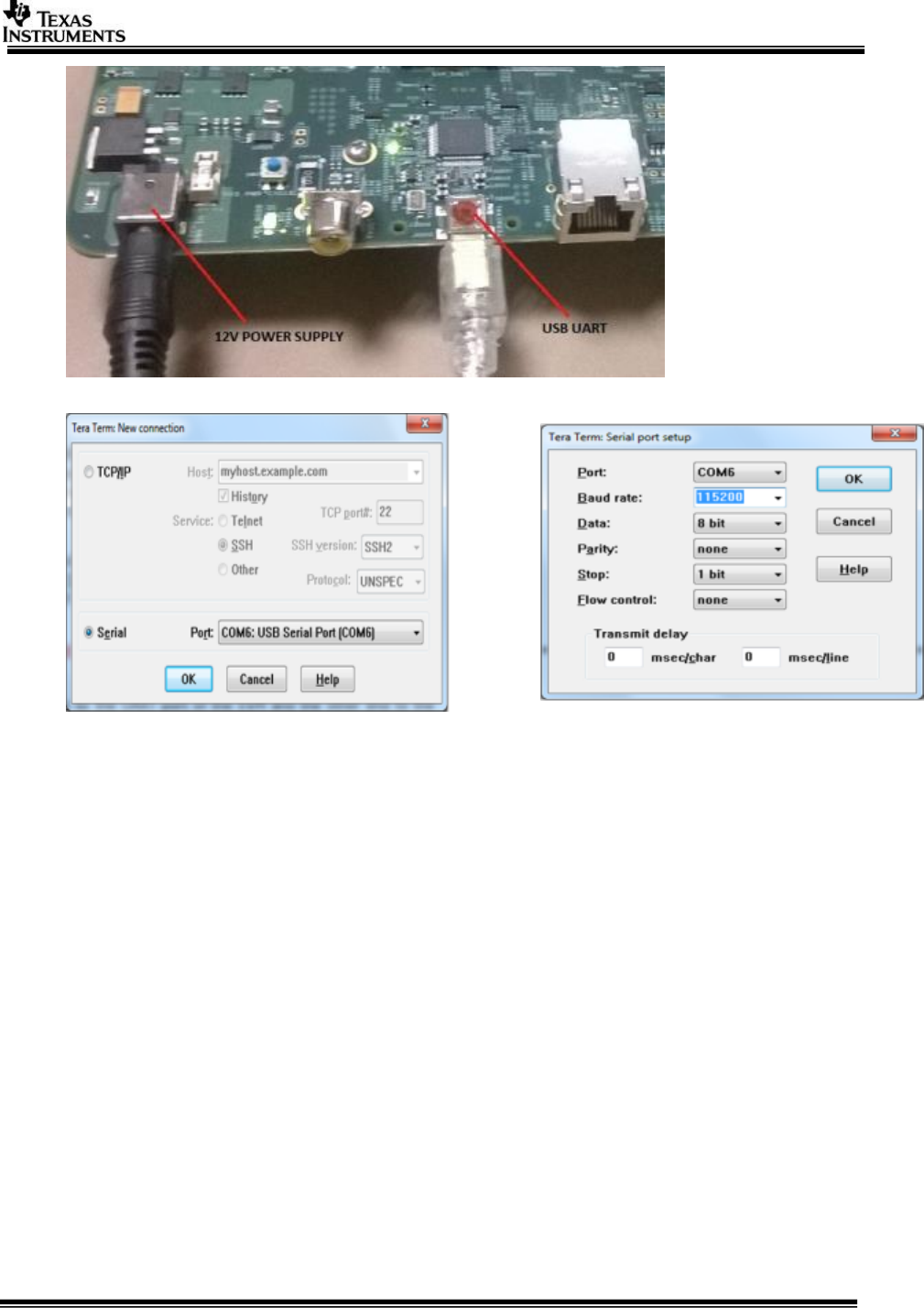
Connect a serial cable to the UART port of the EVM and the other end to the serial
port of the PC (configure the HyperTerminal at 115200 baud rate) to obtain logs and
select demo. EVM it detects 4 UART ports, you need to select the 2nd one.
IMPORTANT NOTE: On some EVMs we were observing that UART terminal
does not work. Updating the USB to UART driver on PC made UART work on
the failings PCs. You can download the drivers from the below links.
http://www.ftdichip.com/Drivers/VCP.htm
http://www.ftdichip.com/Drivers/CDM/CDM%20v2.10.00%20WHQL%20Certified.exe
Page 20 of 31
For RVP-TDA3x refer 3.3 UART settings in VisionSDK_UserGuide_TDA3xx_RVP.pdf
3.4 Boot Modes
For TDA3xx refer 3.4 Boot Modes in VisionSDK_UserGuide_TDA3xx.pdf
NOTE: With AWR12 setup and TDA3x board modification QSPI_SD boot
mechanism will not be functional
NOTE: On the ALPS board the Boot Mode is always set to QSPI.
NOTE: On the RVP-TDA3x board the Boot Mode is always set to QSPI_SD.
For TDA2xx refer 3.4 Boot Modes in VisionSDK_UserGuide_TDA2xx.pdf
3.5 Load using QSPI
For TDA3xx refer 3.5 Load using QSPI in VisionSDK_UserGuide_TDA3xx.pdf
For TDA2xx refer 3.6 Load using QSPI in VisionSDK_UserGuide_TDA2xx.pdf
3.6 Load using QSPI and SD boot
[Applicable only to TDA3xx]
Refer 3.6 Load using QSPI and SD boot in VisionSDK_UserGuide_TDA3xx.pdf
NOTE: With AWR12 setup and TDA3x board modification this boot mode will
not be functional
Page 21 of 31
For RVP-TDA3x refer 3.4 Load using QSPI and SD boot in
VisionSDK_UserGuide_TDA3xx_RVP.pdf
3.7 Load using SD Card
[Applicable only to TDA2xx]
Refer 3.5 Load using SD card in VisionSDK_UserGuide_TDA2xx.pdf
3.8 Load using CCS
For TDA3xx refer 3.7 Load using CCS in VisionSDK_UserGuide_TDA3xx.pdf
For TDA2xx refer 3.8 Load using CCS in VisionSDK_UserGuide_TDA2xx.pdf
For TDA3xx refer 3.5 Load using CCS in VisionSDK_UserGuide_TDA3xx_RVP.pdf

Page 22 of 31
3.9 Run the demo
1. Power-on the Board after loading binaries by (SD, QSPI or CCS) and follow UART
settings to setup the console for logs and selecting demo.
a. For the ALPS board first find the IP address of the board and then run the
network console tool to get the logs on a network console. Refer Section 5.
Network CONS Tool in
docs/FeatureSpecificUserGuides/VisionSDK_UserGuide_NetworkTools.pdf
Select demo required from the menu by keying in corresponding option from uart
menu.
3.9.1 Usecase Specific Steps to run
3.9.1.1 Radar (Single AWR1243) Capture + Null (TDA3xx Only)
This usecase is used to capture from AWR12 hardware and Null.
User can dump the data from Null using CCS and feed the data to Radar Studio or any other
PC tool for analysis.
Connect the AWR12xx hardware as per the guide (EVM User’s Guide V0.1 August 9, 2016)
provided along with hardware.
Change the hardware jumper settings as mentioned in Required H/W modification /
Configurations. (Section 2.3.1.1)
Select the usecase 1 (RADAR Use cases) and ‘2’ (Capture Null) in usecase menu.
[IPU1-0] 87.683279 s:
[IPU1-0] 87.683370 s: CHAINS: Init AR12xx ...
[IPU1-0] 87.683614 s: UTILS_MCSPI: McSPI is configured in interrupt
mode!!
[IPU1-0] 89.040627 s: AWR12XX: ES1.0 Device detected!!
[IPU1-0] 89.042670 s: AWR12XX: Version Master : X.X.X.X
[IPU1-0] 89.042762 s: AWR12XX: Version RF:X.X.X.X
[IPU1-0] 89.042823 s: CHAINS: Config AR12xx ...
[IPU1-0] 89.042884 s:
[IPU1-0]
[IPU1-0] ===========================
[IPU1-0] Select Frame Configuration
[IPU1-0] ===========================
[IPU1-0]
[IPU1-0] 1: Normal Frame
[IPU1-0] 2: Advanced Frame
[IPU1-0]
[IPU1-0] Enter Choice:
Select ‘1’ for normal frame configuration. This will allow you to first check if the board is
operational with the normal frame capture.
To ensure demo functional
Print Performance Statistics and verify the capture fps is 15+
[IPU1-0] [ ISSCAPTURE ] Link Statistics,
[IPU1-0] ******************************
[IPU1-0]
[IPU1-0] Elapsed time = 11243 msec
Page 23 of 31
[IPU1-0]
[IPU1-0] Get Full Buf Cb = 15.15 fps
[IPU1-0] Put Empty Buf Cb = 15.15 fps
[IPU1-0] Driver/Notify Cb = 15.15 fps
[IPU1-0]
[IPU1-0] Input Statistics,
[IPU1-0]
[IPU1-0] CH | In Recv | In Drop | In User Drop | In Process
[IPU1-0] | FPS | FPS | FPS | FPS
[IPU1-0] --------------------------------------------------
[IPU1-0] 0 | 15.15 0. 0 0. 0 15.15
[IPU1-0]
[IPU1-0] Output Statistics,
[IPU1-0]
[IPU1-0] CH | Out | Out | Out Drop | Out User Drop
[IPU1-0] | ID | FPS | FPS | FPS
[IPU1-0] ---------------------------------------------
[IPU1-0] 0 | 0 15.15 0. 0 0. 0
If you are able to see 15 FPS capture for the normal frame configuration, you
can confirm this demo is working correctly.
In order to save the data from CCS, you can follow the steps:
1. Place a break point at NullLink_drvDumpFrames in IPU1_0.
2. Once you hit the breakpoint, place the expression in CCS Expressions
window – “((System_VideoFrameBuffer *)pBuf->payload)->bufAddr[0]”.
This contains the address of the buffer where the captured data is shown.
3.9.1.2 Radar (Single AR1243) Capture + Radar Object Detect (EVE1) + Display
(TDA3xx Only)
This usecase is used to capture from AWR12 hardware Radar FFT Algo + Peak detection +
Beam Forming on EVE, Radar Draw Objects on DSP and Display.
Connect the AWR12xx hardware as per the guide (EVM User’s Guide V0.1 August 9, 2016)
provided along with hardware.
Change the hardware jumper settings as mentioned in Required H/W modification /
Configurations (Section 2.3.1.1)
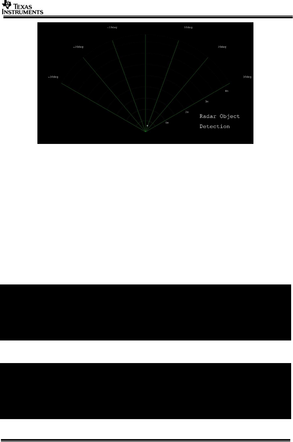
Select the usecase 3 (RADAR Use cases) in usecase menu
Output is as shown similar to below based on the objects placed in-front of the radar and
the current radar parameters. The maximum range and velocity vary based on the radar
parameters. The latest SDK supports maximum range of 4 m for in room demonstrations
and ultra-short range radar.
Page 24 of 31
3.9.1.3 Radar (Single AWR1243) Capture + Radar FFT (EVE1) + DSP (FFT Heat
Map) + Null (TDA3xx Only)
This usecase is used to capture from AWR12 hardware Radar FFT + Peak Detection + Beam
Forming Algo on EVE, Radar Object Draw on DSP and Send out the data using Ethernet.
Connect the ALPS module to a 12 V power supply and the Ethernet cable to the network
router. Once the application has booted up you should see the IP address in the CCS
console. If you are using QSPI boot, modify the application before building for static IP to
not have to connect to CCS and read the IP address.
Once you have got the board IP address, open the command prompt in the PC and type:
>> network_cons.exe --ipaddr <Board IP address>
Ensure the AWR12 firmware is flashed by selecting ‘1’ (Radar Usecases), ‘1’ AWR12
Firmware Flash, ‘2’ Flash AWR12xx Firmware. Note this is one time operation and need not
be done unless you plan to upgrade to a different AWR12 firmware.
[IPU1-0] AWR12XX Flash Programming Menu
[IPU1-0] -----------------------------
[IPU1-0]
[IPU1-0] 1: Erase AWR12xx Flash.
[IPU1-0]
[IPU1-0] 2: Flash AWR12xx Firmware.
[IPU1-0]
[IPU1-0] x: Exit
Wait for the flashing to complete. This may take over 2-3 mins:
[IPU1-0] 34.812755 s:
[IPU1-0] 34.812785 s: CHAINS: Started erasing the AWR12 flash memory....
[IPU1-0] 36.139083 s: AWR12XX: ES1.0 Device detected!!
[IPU1-0] 49.296895 s: CHAINS: Erasing AWR12 flash memory completed.
[IPU1-0] 49.296986 s: CHAINS: Started flashing the AWR12 firmware....
[IPU1-0] 49.297078 s: AWR12XX: Flashing BSS...
[IPU1-0] 95.136033 s: AWR12XX: Flashing BSS finished.
[IPU1-0] 95.136125 s: AWR12XX: Flashing MSS...

Page 25 of 31
[IPU1-0] 117.495180 s: AWR12XX: Flashing MSS finished.
[IPU1-0] 117.495272 s: AWR12XX: Flashing Config...
[IPU1-0] 117.933660 s: AWR12XX: Flashing Config finished.
[IPU1-0] 117.933752 s: CHAINS: Finished flashing the AWR12 firmware.
[IPU1-0] 117.933813 s:
Exit out of the flashing menu and Select Usecase ‘4’ for the usecase.
You would see the print below:
[IPU1-0] 87.683279 s:
[IPU1-0] 87.683370 s: CHAINS: Init AWR12xx ...
[IPU1-0] 87.683614 s: UTILS_MCSPI: McSPI is configured in interrupt
mode!!
[IPU1-0] 89.040627 s: AWR12XX: ES1.0 Device detected!!
[IPU1-0] 89.042670 s: AWR12XX: Version Master : X.X.X.X
[IPU1-0] 89.042762 s: AWR12XX: Version RF:X.X.X.X
[IPU1-0] 89.042823 s: CHAINS: Config AWR12xx ...
[IPU1-0] 89.042884 s:
[IPU1-0]
[IPU1-0] ===========================
[IPU1-0] Select Frame Configuration
[IPU1-0] ===========================
[IPU1-0]
[IPU1-0] 1: Normal Frame
[IPU1-0] 2: Advanced Frame
Select ‘1’ for normal frame configuration or ‘2’ for the advanced frame.
[IPU1-0] Select Network Mode,
[IPU1-0] --------------------
[IPU1-0] 1: TFDTP
[IPU1-0] 2: TCP/IP
[IPU1-0]
[IPU1-0] Enter Choice:
Select TFDTP or TCP/IP for the network transmit of the Object Detection output.
Once the usecase starts running you can use the following menu options to interact with the
usecase:
[IPU1-0] ====================
[IPU1-0] Chains Run-time Menu
[IPU1-0] ====================
[IPU1-0]
[IPU1-0] 0: Stop Chain
[IPU1-0]
[IPU1-0] c: Read-back and Check AR params
[IPU1-0]
[IPU1-0] Change display:
[IPU1-0] 1: Profile 0
[IPU1-0] 2: Profile 1
[IPU1-0] 3: Profile 2
[IPU1-0] 4: Profile 3
[IPU1-0]
[IPU1-0] d: Dynamically change slope
[IPU1-0]
[IPU1-0] p: Print Performance Statistics

Page 26 of 31
First use ‘p’ to check the capture FPS is as expected (15 FPS for normal frame), (15 FPS for
advanced frame).
Use ‘c’ to check if the AWR12 parameters are applied as expected. Note this works only for
AWR12 ES2.0 samples.
[IPU1-0] 116194.933233 s: CHAINS: Parameters have matched with programmed!!
Use ‘d’ to dynamically change the Profile parameter slope:
[IPU1-0]
[IPU1-0] 115768.469438 s: CHAINS: AWR12xx Stopping Radar Sensor ...
[IPU1-0] 115768.471542 s: CHAINS: AWR12xx Radar Stopped ...
[IPU1-0] 115768.503965 s: CHAINS: Reconfiguring Parameters ...
[IPU1-0] 115768.508113 s: CHAINS: Reconfigured Parameters ...
[IPU1-0] 115768.508296 s: CHAINS: AWR12xx Re-starting Radar Sensor ...
[IPU1-0] 115768.512017 s: CHAINS: AWR12xx Radar Started ...
[IPU1-0] 115768.512078 s:
In order to see the output from the network, in the PC command prompt type:
For TFDTP : network_rx --host_ip <PC ipaddr> --target_ip <Board ipaddr> --
usetfdtp --files <file>
For TCP/IP : network_rx --host_ip <PC ipaddr> --target_ip <Board ipaddr> --files
<file>
This will save an RGB 565 image each of size 1920x1080. You can use an RGB viewer to
visualize the output.
3.9.1.4 Null Source (SD/Network) Input + Radar FFT (EVE1) + Null
(SD/Network)
Note: This usecase doesn’t require AWR12xx Hardware and any board Modification
When using SD card, the card needs to be in FAT32 file system
Input Clips can be found at
vision_sdk/apps/src/rtos/radar/src/usecases/radar_read_fft_write/Input_512x128_4Rx_1Tx
_1TS_10Frm.bin
Details regarding this input file are captured in
vision_sdk/apps/src/rtos/radar/src/usecases/radar_read_fft_write/Input_512x128_4Rx_1Tx
_1TS_10Frm_cfg.txt
This usecase does file read and write from either network or SD Card.
The user can select the mode of operation at run time using the following Menu option:
Note: On TDA3x EVM Network and FATFS cannot be enabled at the same time. At
compile time you can select one of the two. Ensure your choice is consistent with
the build time option. On TDA2xx EVM there is no compile time restriction. You can
choose the option at run time.
Select Data Read/Write Mode,
----------------------------
1: SD CARD
2: NETWORK

Page 27 of 31
Enter Choice:
Once the mode has been selected, based on the selection the source and destination of the
FFT processing would be derived either from network or SD card.
3.9.1.4.1 SD Card
If SD Card is selected, ensure that the file Input_512x128_4Rx_1Tx_1TS_10Frm.bin is
present on the SD Card.
The following Menu option is then displayed.
[IPU1-0] ====================
[IPU1-0] Chains Run-time Menu
[IPU1-0] ====================
[IPU1-0] 0: Stop Chain
[IPU1-0] p: Print Performance Statistics
[IPU1-0] f: File IO Menu
[IPU1-0] Enter Choice:
For further SD File read and write options Enter ‘f’:
[IPU1-0] ====================
[IPU1-0] FILE IO Run-time Menu
[IPU1-0] ====================
[IPU1-0]
[IPU1-0] a: Write Start
[IPU1-0] b: Write Pause
[IPU1-0] c: Write Resume
[IPU1-0] d: Write Stop
[IPU1-0] e: Write One Frame
Select the desired write option.
File write will create a file in sd card.
3.9.1.4.2 Network
If the network option is selected, based on the compile options if the NSP_TFDTP_INCLUDE
= yes, the following menu is displayed.
Select Network Mode,
--------------------
1: TFDTP
2: TCP/IP
Enter Choice:
Enter the choice of TFDTP or TCP/IP.
On the PC side run the following applications for TCP/IP:
CONSOLE 1:
vision_sdk/apps/tools/network_tools/bin>
network_rx.exe --target_ip <BOARD_IP> --host_ip <PC_IP> --files
../output_file.bin

Page 28 of 31
CONSOLE 2:
vision_sdk/apps/tools/network_tools/bin>
network_rx.exe --target_ip <BOARD_IP> --host_ip <PC_IP> --files <Install
Path>/
vision_sdk/apps/src/rtos/radar/src/usecases/radar_read_fft_write/Input_512x12
8_4Rx_1Tx_1TS_10Frm.bin
On the PC side run the following applications for TFDFTP:
CONSOLE 1:
vision_sdk/apps/tools/network_tools/bin >
network_rx.exe --target_ip <BOARD_IP> --host_ip <PC_IP> --usetfdtp --files
../output_file.bin
CONSOLE 2:
vision_sdk/apps/tools/network_tools/bin >
network_rx.exe --target_ip <BOARD_IP> --host_ip <PC_IP> --usetfdtp --files
<Install Path>/
vision_sdk/apps/src/rtos/radar/src/usecases/radar_read_fft_write/Input_512x12
8_4Rx_1Tx_1TS_10Frm.bin
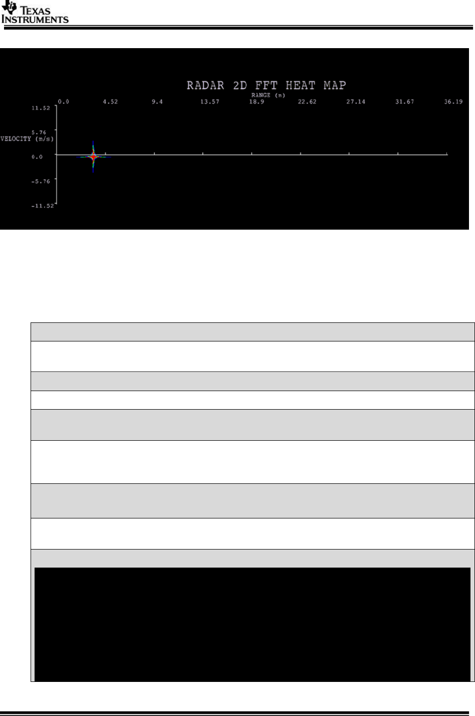
For both SD Card and network, the display shows the output on FFT Heat Map layout for the
input.
3.9.1.5 Satellite Radar (Single AWR1243) Capture + Radar FFT (EVE1) + DSP
(FFT Heat Map) + Display (TDA3xx Only)
This usecase is used to capture from AWR12 hardware Radar FFT Algo on EVE, Radar
DrawFFTHeatMap on DSP and Display.
Connect the AWR1243 satellite radar module to RVP-TDA3x VIN4 as per Chapter 2.3.3 in
this guide.
Select the usecase 7 (RADAR Use cases) in usecase menu
Output is as shown similar to below based on the objects placed in-front of the radar and
the current radar parameters. The maximum range and velocity vary based on the radar
parameters.
Page 29 of 31
Note: Intensity of detected object may vary depending on draw parameters and actual
object reflection (Maximum Range and velocity and resolution subject to change)
4 Frequently Asked Questions
Q. Always see the error as sd card read error please retry
SD card must be in FAT32 format and SD card is not accessible if HW modification
done for radar setup.
Q. While building SBL, path not found errors appear….. will this be an issue ?
This can be ignored as the following are not used for SBL build
Q. While building we find error as file not present, when checked the file is present at
the location is there something to be set?
If the folder depth increases then windows cmd prompt fails with error cannot find
file even in file is present in mentioned path, this is because of windows 8191 char
limitation. Refer https://support.microsoft.com/en-in/kb/830473
Q. We see build error as
Interrupt/Exception caught (code = xxxxxxxx, addr = xxxxxxxxx)
This is because the gmake/make path is wrong. Set xpc_path as mentioned above
and retry
Q. I get the following warnings while building:
vision_sdk/apps/configs/autorules_footer_cfg.mk:78: ipc_PATH does not
exist! ()
vision_sdk/apps/configs/autorules_footer_cfg.mk:78: avbtp_PATH does not
exist! (ti_components/networking/avbtp_0_10_00_00)
vision_sdk/apps/configs/autorules_footer_cfg.mk:78: hdvicplib_PATH does
not exist!
(ti_components/codecs/ivahd_hdvicp20api_01_00_00_23_production)
vision_sdk/apps/configs/autorules_footer_cfg.mk:78: jpegvdec_PATH does
not exist! (ti_components/codecs/ivahd_jpegvdec_01_00_13_01_production)
vision_sdk/apps/configs/autorules_footer_cfg.mk:78: jpegvenc_PATH does
Page 30 of 31
not exist! (ti_components/codecs/ivahd_jpegvenc_01_00_16_01_production)
vision_sdk/apps/configs/autorules_footer_cfg.mk:78: vlib_PATH does not
exist! (ti_components/algorithms/vlib_c66x_3_3_0_3)
vision_sdk/apps/configs/autorules_footer_cfg.mk:78: fc_PATH does not
exist! (ti_components/codecs/framework_components_3_40_02_07)
This is harmless. These are optional components which are not used by Processor
SDK Radar.
Also refer VisionSDK_FAQs.pdf
Page 31 of 31
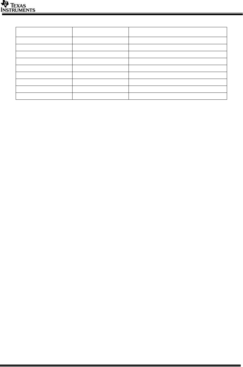
5 Revision History
Version
Date
Revision History
1.0
29th Sept 2016
Initial Version
1.1
30th Sept 2016
Addressed Review comments
1.2
26th Oct 2016
Updates for Release 2.11
1.3
30th Jan 2017
Updates for Release 2.12
1.4
26th June 2017
Updates for Release 3.00
1.5
28th June 2017
Updated linux installation steps
1.6
14th Oct 2017
Updates for Release 3.01
1.7
20th Dec 2017
Updates for Release 3.02
1.8
4th April 2018
Updates for Release 3.03
««« § »»»
