RAM Megafunction User Guide
User Manual:
Open the PDF directly: View PDF ![]() .
.
Page Count: 118 [warning: Documents this large are best viewed by clicking the View PDF Link!]
- RAM Megafunction
- Contents
- About this User Guide
- 1. About this Megafunction
- 2. Getting Started
- Software and System Requirements
- MegaWizard Plug-In Manager Customization
- Using the MegaWizard Plug-In Manager
- Instantiating Megafunctions in HDL Code
- Identifying a Megafunction after Compilation
- Simulation
- In-System Updating of Memory and Constants
- Design Examples for the RAM Megafunctions
- Conclusion
- 3. Specifications


Copyright © 2007 Altera Corporation. All rights reserved. Altera, The Programmable Solutions Company, the stylized Altera logo, specific device des-
ignations, and all other words and logos that are identified as trademarks and/or service marks are, unless noted otherwise, the trademarks and
service marks of Altera Corporation in the U.S. and other countries. All other product or service names are the property of their respective holders. Al-
tera products are protected under numerous U.S. and foreign patents and pending applications, maskwork rights, and copyrights. Altera warrants
performance of its semiconductor products to current specifications in accordance with Altera's standard warranty, but reserves the right to make
changes to any products and services at any time without notice. Altera assumes no responsibility or liability arising out of the ap-
plication or use of any information, product, or service described herein except as expressly agreed to in writing by Altera
Corporation. Altera customers are advised to obtain the latest version of device specifications before relying on any published in-
formation and before placing orders for products or services.
ii Altera Corporation
RAM Megafunction User Guide Preliminary March 2007
UG-MF9404-2.0

Altera Corporation iii
Contents
Chapter 1. About this Megafunction
Device Family Support ......................................................................................................................... 1–1
Introduction ............................................................................................................................................ 1–2
Features of RAM: 1-PORT MegaWizard Plug-In Manager ............................................................. 1–3
General Description of RAM: 1-PORT MegaWizard Plug-In Manager ................................... 1–4
Resource Utilization and Performance of Single-Port RAM ...................................................... 1–6
Features of RAM: 2-PORT MegaWizard Plug-In Manger ............................................................... 1–7
General Description of RAM: 2-PORT MegaWizard Plug-In Manager ................................... 1–7
Resource Utilization and Performance of Dual-Port RAM ........................................................ 1–9
Features of RAM: 3-PORT MegaWizard Plug-In Manager ........................................................... 1–10
General Description of the RAM: 3-PORT MegaWizard Plug-In Manager .......................... 1–10
Resource Utilization and Performance of the Tri-Port RAM ................................................... 1–11
Chapter 2. Getting Started
Software and System Requirements ................................................................................................... 2–1
MegaWizard Plug-In Manager Customization ................................................................................. 2–1
Using the MegaWizard Plug-In Manager .......................................................................................... 2–2
The RAM: 1-PORT MegaWizard Plug-In Manager Page Descriptions ................................... 2–3
The RAM: 2-PORT MegaWizard Plug-In Manager Page Descriptions ................................. 2–11
The RAM: 3-PORT MegaWizard Plug-In Manager Page Descriptions ................................. 2–22
Inferring Megafunctions from HDL Code .................................................................................. 2–28
Instantiating Megafunctions in HDL Code ..................................................................................... 2–28
Identifying a Megafunction after Compilation ............................................................................... 2–28
Simulation ............................................................................................................................................. 2–29
Quartus II Software Simulation ................................................................................................... 2–29
EDA Simulation .............................................................................................................................. 2–29
In-System Updating of Memory and Constants ............................................................................. 2–30
Design Examples for the RAM Megafunctions ............................................................................... 2–31
Design Files ..................................................................................................................................... 2–31
Example for RAM: 1-PORT ........................................................................................................... 2–31
Generate the Single-Port RAM ................................................................................................ 2–31
Implement Single-Port RAM ................................................................................................... 2–38
Functional Results—Simulate the Single-Port RAM in the Quartus II Software ............ 2–40
Understanding the Simulation Results .................................................................................. 2–42
Functional Results—Simulate the Single-Port RAM in the ModelSim-Altera Software 2–44
Example for RAM: 2-PORT ........................................................................................................... 2–45
Generate the Dual-Port RAM .................................................................................................. 2–45
Implement Dual-Port RAM ..................................................................................................... 2–55
Functional Results—Simulate the Dual-Port RAM in Quartus II Software ..................... 2–56
Understanding the Simulation Results .................................................................................. 2–58
Functional Results—Simulate the Dual-Port RAM in the ModelSim-Altera Software .. 2–61

iv Altera Corporation
RAM Megafunction User Guide
Contents
Example for RAM: 3-PORT ........................................................................................................... 2–63
Generate the Tri-Port RAM ..................................................................................................... 2–63
Implement the Tri-Port RAM .................................................................................................. 2–68
Functional Results—Simulate the Tri-Port RAM in the Quartus II Software .................. 2–68
Understanding the Simulation Results .................................................................................. 2–71
Functional Results—Simulate the Tri-Port RAM in the ModelSim-Altera Software ..... 2–73
Conclusion ............................................................................................................................................ 2–75
Chapter 3. Specifications
Introduction ............................................................................................................................................ 3–1
Ports and Parameters for the lpm_ram_dq Megafunction .............................................................. 3–1
Ports and Parameters for the altdpram Megafunction .................................................................... 3–6
Ports and Parameters for the altsyncram Megafunction ............................................................... 3–11
Ports and Parameters for the alt3pram Megafunction ................................................................... 3–20
Altera Corporation v
March 2007 RAM Megafunction User Guide
About this User Guide
Revision History The table below displays the revision history for this user guide.
How to Contact
Altera
For the most up-to-date information about Altera® products, go to the
Altera world-wide web site at www.altera.com. For technical support for
this product, go to www.altera.com/mysupport. For additional
information about Altera products, consult the following sources.
Date Document
Version Changes Made
March 2007 2.0 ●Complete re-write of the Guide.
September 2004 1.0 ●Initial Release.
Information Type Contact
Technical support www.altera.com/mysupport/
Product literature www.altera.com (1)
Altera literature services literature@altera.com
FTP site ftp.altera.com
Note to table:
(1) You can also contact your local Altera sales office or sales representative.

2–vi Altera Corporation
RAM Megafunction User Guide March 2007
Typographic Conventions
Typographic
Conventions
This document uses the following typographic conventions.
Visual Cue Meaning
Bold Type with Initial
Capital Letters
Command names, dialog box titles, checkbox options, and dialog box options are
shown in bold, initial capital letters. Example: Save As dialog box.
bold type External timing parameters, directory names, project names, disk drive names,
filenames, filename extensions, and software utility names are shown in bold
type. Examples: fMAX, \qdesigns directory, d: drive, chiptrip.gdf file.
Italic Type with Initial Capital
Letters
Document titles are shown in italic type with initial capital letters. Example:
AN 75: High-Speed Board Design.
Italic type Internal timing parameters and variables are shown in italic type.
Examples: tPIA, n + 1.
Variable names are enclosed in angle brackets (< >) and shown in italic type.
Example: <file name>, <project name>.pof file.
Initial Capital Letters Keyboard keys and menu names are shown with initial capital letters. Examples:
Delete key, the Options menu.
“Subheading Title” References to sections within a document and titles of on-line help topics are
shown in quotation marks. Example: “Typographic Conventions.”
Courier type Signal and port names are shown in lowercase Courier type. Examples: data1,
tdi, input. Active-low signals are denoted by suffix n, e.g., resetn.
Anything that must be typed exactly as it appears is shown in Courier type. For
example: c:\qdesigns\tutorial\chiptrip.gdf. Also, sections of an
actual file, such as a Report File, references to parts of files (e.g., the AHDL
keyword SUBDESIGN), as well as logic function names (e.g., TRI) are shown in
Courier.
1., 2., 3., and
a., b., c., etc.
Numbered steps are used in a list of items when the sequence of the items is
important, such as the steps listed in a procedure.
■●• Bullets are used in a list of items when the sequence of the items is not important.
v The checkmark indicates a procedure that consists of one step only.
1 The hand points to information that requires special attention.
cA caution calls attention to a condition or possible situation that can damage or
destroy the product or the user's work.
wA warning calls attention to a condition or possible situation that can cause injury
to the user.
r The angled arrow indicates you should press the Enter key.
f The feet direct you to more information on a particular topic.

Altera Corporation 1–1
March 2007 RAM Megafunction User Guide
1. About this Megafunction
Device Family
Support
The RAM megafunction supports the following target Altera® device
families:
■Stratix®III
■Stratix II
■Stratix II GX
■Stratix
■Stratix GX
■Cyclone®III
■Cyclone II
■Cyclone
■HardCopy®II
■HardCopy Stratix
■MAX®II
■MAX 3000A
■MAX 7000AE
■MAX 7000B
■MAX 7000S
■ACEX 1K®
■APEX™ II
■APEX 20KC
■APEX 20KE
■FLEX 10K®
■FLEX® 10KA
■FLEX 10KE
■FLEX 6000

1–2 Altera Corporation
RAM Megafunction User Guide March 2007
Introduction
Introduction As design complexities increase, the use of vendor-specific intellectual
property (IP) blocks has become a common design methodology. Altera
provides parameterizable megafunctions that are optimized for Altera
device architectures. Using megafunctions instead of coding your own
logic saves valuable design time. The Altera-provided functions offer
more efficient logic synthesis and device implementation. You can scale
the size of the megafunction by setting various parameters.
The Quartus®II software provides three MegaWizard® Plug-In
Managers that support single-port, dual-port, and tri-port RAM
functionality.
■RAM:1-PORT
■RAM: 2-PORT
■RAM: 3-PORT
These plug-in managers are user view wizards and not the actual
megafunctions.
Table 1–1 shows the RAM megafunctions used when configuring
through the RAM MegaWizard Plug-In Managers for different Altera
device families.
Table 1–1. RAM Megafunctions Used for Different Device Families (Part 1
of 2)
Device RAM: 1-Port RAM: 2-Port RAM: 3-Port
Stratix III
Stratix II GX
Stratix II
Stratix
Stratix GX
Cyclone III
Cyclone II
Cyclone
HardCopy®II
HardCopy Stratix
altsyncram(1) altsyncram(2) alt3pram

Altera Corporation 1–3
March 2007 RAM Megafunction User Guide
About this Megafunction
The MegaWizard Plug-In Manager chooses the right megafunction based
on the selections you make in the wizard. This chapter describes the
features, descriptions, and resource usage of the RAM MegaWizard
Plug-In Managers.
Features of
RAM: 1-PORT
MegaWizard
Plug-In Manager
The RAM: 1-PORT MegaWizard Plug-In Manager implements a
single-port RAM function and offers many additional features, which
include:
■Configurable RAM block type
■Single clock or dual clock (input/output) modes
■Synchronous or asynchronous single-port RAM
■Additional port for Stratix III and Cyclone III devices that provides
extra RAM features
■Read-During-Write option for Stratix III and Cyclone III devices
fFor more information about new features supported by Stratix III
devices, refer to the TriMatrix Embedded Memory Blocks in Stratix III
Devices chapter of the Stratix III Device Handbook.
MAX II
MAX 3000A
MAX 7000AE
MAX 7000B
MAX 7000S
ACEX®1K
APEX®II
APEX 20KE
APEX 20KC
FLEX®10K
FLEX 10KA
FLEX 10KE
FLEX 6000
lpm_ram_dq altdpram alt3pram
Notes to Table 1– 1 :
(1) If the RAM block type is LC, the device uses the lpm_ram_dq megafunction.
(2) If the RAM block type is LC or if the RAM block type is MLAB with unregistered
read input, the Stratix III device uses the altdpram megafunction.
Table 1–1. RAM Megafunctions Used for Different Device Families (Part 2
of 2)
Device RAM: 1-Port RAM: 2-Port RAM: 3-Port

1–4 Altera Corporation
RAM Megafunction User Guide March 2007
Features of RAM: 1-PORT MegaWizard Plug-In Manager
General Description of RAM: 1-PORT MegaWizard Plug-In
Manager
The RAM: 1-PORT MegaWizard Plug-In Manager is an easy-to-use GUI
for configuring a single-port RAM.
It provides different RAM block types for selection depending on the
device you select. Refer to “Resource Utilization and Performance of
Single-Port RAM” on page 1–6 for more details.
The RAM: 1-PORT MegaWizard Plug-In Manager allows you to specify
either of two clocking modes: a single clock mode or a dual clock
(input/output) mode.
In single clock mode, the read and write operations are synchronous with
the same clock. In the Stratix and Cyclone series of devices, a single clock
with a clock enable controls all registers of the memory block.
Dual clock (input/output) mode operates with two independent clocks:
inclock (input clock for write operation) and outclock (output clock
for read operation). The input clock controls all registers related to the
data input to the memory block, including data, address, byte enables,
read enables, and write enables. The output clock controls the data output
registers.
When you select either of the the Stratix and Cyclone series of devices,
you can either select single clock or dual clock (input/output) mode for
your single-port RAM. For other devices, you can only use dual clock
mode for your single-port RAM. Regardless of device type you select,
you must use dual clock mode if you select logic cells (LCs) as your RAM
block type. Also, regardless of the clock mode used, asynchronous clears
are available on output latches and output registers only if you use
Stratix III or Cyclone III devices.
For the Stratix and Cyclone series of devices, only synchronous RAM is
supported. For other devices, you can use synchronous or asynchronous
single-port RAM.
Synchronous write operations into the memory block use the address[]
and data[] ports, which are triggered by the rising edge of the inclock
while the we (write enable) port is enabled. For asynchronous operation,
the address[] and data[]signals must be valid at both edges of the
write enable signal. Ideally, the values on the data and address lines
should not be changed while the we port is active.

Altera Corporation 1–5
March 2007 RAM Megafunction User Guide
About this Megafunction
For devices other than the Stratix and Cyclone series, you cannot access
the clock enable ports, byte enable port or asynchronous clear port. These
ports are only accessible for the Stratix and Cyclone series of devices,
provided that LC is not selected. All types of memory blocks (except
M512 and LCs) support byte enables that mask the input data, to ensure
that only specific bytes of data are written. The unwritten bytes retain
their previous written values.
fFor more information about byte enable supported by Stratix III devices,
refer to the TriMatrix Embedded Memory Blocks in Stratix III Devices
chapter of the Stratix III Devices Handbook.
In addition to these ports, Stratix III and Cyclone III devices support the
read enable port (rden) for single-port RAM. This port is supported by
Stratix III and Cyclone III devices only, for all types of RAM block except
for MLAB and LCs. Refer to Figure 1–1.
The RAM: 1-PORT MegaWizard Plug-In Manager also provides an
additional feature, the Read-During-Write option, if you select either a
Stratix III or Cyclone III device. This feature is not supported by Stratix III
or Cyclone III devices when the LCs type of memory block is selected.
When you select this option, you can determine whether the read value is
Don't Care, New Data, or Old Data when reading during a simultaneous
write to the same memory location. The data options vary depending on
the RAM block type you selected.
1–6 Altera Corporation
RAM Megafunction User Guide March 2007
Features of RAM: 1-PORT MegaWizard Plug-In Manager
Figure 1–1. Typical Single-Port RAM Block Diagram for Stratix III Devices
Note (1)
Note to Figure 1–1:
(1) This image shows only the common input ports for a typical single-port RAM for
Stratix III devices when the altsyncram megafunction is used. Refer to “Ports and
Parameters for the altsyncram Megafunction” on page 3–11 for all the input and
output ports.
Resource Utilization and Performance of Single-Port RAM
The RAM: 1-PORT MegaWizard Plug-In Manager uses either the
altsyncram megafunction or the lpm_ram_dq megafunction to
implement single-port RAM. The single-port RAM uses the following
device resources:
■MLAB, M9K, or M144K in Stratix III devices
■M512, M4K, or M-RAM in Stratix series of devices (except Stratix III
devices)
■M9K in Cyclone III devices
■M4K in Cyclone and Cyclone II devices
■Embedded System Blocks (ESB) in APEX II, and APEX 20KC devices
■DFFE primitives or latch arrays in FLEX 6000, MAX II, MAX 3000A,
MAX 7000AE, MAX 7000B, and MAX 7000S devices
■Embedded Array Blocks (EAB) in ACEX 1K, FLEX 10K, FLEX 10KA,
and FLEX 10KE devices
data[ ]
wren
address[ ]
byteena[ ]
aclr
rden
inclock
inclocken
outclock
outclocken
Single-Port
RAM Array
q[ ]

Altera Corporation 1–7
March 2007 RAM Megafunction User Guide
About this Megafunction
Features of
RAM: 2-PORT
MegaWizard
Plug-In Manger
The RAM: 2-PORT MegaWizard Plug-In Manager implements a
dual-port RAM function and offers many additional features, which
include:
■Simultaneous read and write access to memory cells
■Configurable RAM block type
■Different clock modes
■Error checking and correction feature for Stratix III devices
■Read-during-Write option for Stratix III and Cyclone III devices for
each output port independently
General Description of RAM: 2-PORT MegaWizard Plug-In
Manager
The RAM: 2-PORT MegaWizard Plug-In Manager is an easy-to-use GUI
for configuring a dual-port RAM.
The wizard allows you to specify either of two dual-port modes, a simple
dual-port mode (one read port (rdaddress) and one write port
(wraddress)) or a true dual-port mode (two read/write port
(address_a and address_b)). The Stratix and Cyclone series of devices
support both modes for the dual-port RAM. Other devices support only
the simple dual-port mode for the dual-port RAM. If you select simple
dual-port mode, its dual-addressing feature supports simultaneous read
and write operations in the same clock cycle.
The RAM: 2-PORT MegaWizard Plug-In Manager allows you to specify
different RAM block types depending on the device you select. Refer to
“Resource Utilization and Performance of Dual-Port RAM” on page 1–9
for more details.
Through the RAM: 2-PORT MegaWizard Plug-In Manager, you can
configure different clock modes for your dual-port RAM: single clock
mode, independent clock mode, input/output clock mode, read/write
clock mode, and asynchronous mode. The availability of the clocking
modes varies depending on the device you select.
In single clock mode, the read and write operations are synchronous with
the same clock. In independent clock mode, a separate clock is available
for each port (A and B). Clock A controls all registers on the port A side,
and clock B controls all registers on the port B side. In input/output clock
mode, an input clock controls all registers data input to the memory block
and the output clock controls the data output registers.

1–8 Altera Corporation
RAM Megafunction User Guide March 2007
Features of RAM: 2-PORT MegaWizard Plug-In Manger
In read/write clock mode, a write clock controls the following write
signals:
■Data-input
■Byte enable
■Write-address
■Write-enable registers
Similarly, a read clock controls the following read signals:
■Data-output
■Read-address
■Read-enable registers
While in asynchronous mode, no clock is required. In this clocking mode,
the write operation depends only on the wren (write enable) signal. The
read operation depends on the rden (read enable) signal. If an rden
signal is not present, the rden port is connected to VCC by default. These
clocking options are available for your selection depending on the device
you target. The Stratix and Cyclone series of devices do not support
asynchronous mode.
fFor more information about clocking modes supported by Stratix III
devices, refer to the TriMatrix Embedded Memory Blocks in Stratix III
Devices chapter of the Stratix III Device Handbook.
Stratix III supports error checking and correcting features to check and
correct single bit errors and detect double bit errors. The Error Correction
Code (ECC) is supported for dual-port RAM in simple dual-port mode
(one read/one write mode) with M144K RAM block type only.
fFor more information about ECC support, refer to the TriMa tr ix
Embedded Memory Blocks in Stratix III Devices chapter of the Stratix III
Device Handbook.
For dual-port RAM, a read enable feature is supported by all Altera
devices for all types of RAM block except MRAM and MLAB. Read
enable is not supported for the Stratix and Cyclone series of devices
(except Stratix III and Cyclone III devices) with true dual-port mode.
If you select a Stratix III or Cyclone III device in true dual-port mode, the
RAM: 2-PORT MegaWizard Plug-In Manager provides an additional
option: Read-during-Write options for port A and port B. When you
select this option, you determine whether the read value during a
simultaneous write operation to the same memory location is New Data
or Old Data. See Figure 1–2.
Altera Corporation 1–9
March 2007 RAM Megafunction User Guide
About this Megafunction
Figure 1–2. Typical True Dual-port Ram Block Diagram for Stratix III Devices
Note (1)
Note to Figure 1–2:
(1) This image shows only the common input ports for a typical true dual-port RAM
for Stratix III devices. Refer to “Ports and Parameters for the altsyncram
Megafunction” on page 3–11 for all the input and output ports.
Resource Utilization and Performance of Dual-Port RAM
The RAM: 2-PORT MegaWizard Plug-In Manager uses either the
altsyncram megafunction or the altdpram megafunction to implement
dual-port RAM. The dual-port RAM uses the following device resources:
■MLAB, M9K or M144K in Stratix III devices
■M512, M4K or M-RAM in Stratix series of devices (except Stratix III
devices)
■M9K in Cyclone III devices
■M4K in Cyclone and Cyclone II devices
■DFFE primitives or latch arrays in FLEX 6000, MAX II, MAX 3000A,
MAX 7000AE, MAX 7000B, and MAX 7000S devices
■Embedded System Blocks (ESB) in APEX II, and APEX 20KC devices
■Embedded Array Blocks (EAB) in ACEX 1K, FLEX 10K, FLEX 10KA,
and FLEX 10KE devices
data_a[ ]
data_b[ ]
address_a[ ]
address_b[ ]
clock_a
clock_b
rden_a
rden_b
wren_a
wren_b
Dual-Port
RAM Array
q_a[ ]
q_b[ ]

1–10 Altera Corporation
RAM Megafunction User Guide March 2007
Features of RAM: 3-PORT MegaWizard Plug-In Manager
Features of
RAM: 3-PORT
MegaWizard
Plug-In Manager
The RAM: 3-PORT MegaWizard Plug-In Manager implements a tri-port
RAM function and offers many additional features, which include:
■Tri-addressing with one write port and two read ports
■Simultaneous read and write access to memory cells
■Configurable RAM block type
■Different clock modes
General Description of the RAM: 3-PORT MegaWizard Plug-In
Manager
The RAM: 3-PORT MegaWizard Plug-In Manager is an easy-to-use GUI
for configuring a tri-port RAM.
This Plug-In Manager allows you to specify a tri-port RAM with one
write port and two read ports. This tri-addressing feature supports
simultaneous read and write access to a memory cell in which you can
write to and read from different memory locations in the same clock cycle
using a tri-port RAM.
The RAM: 3-PORT MegaWizard Plug-In Manager also allows you to
specify different RAM block types, depending on your device. Refer to
“Resource Utilization and Performance of the Tri-Port RAM” on
page 1–11 for more details.
Through the RAM: 3-Port MegaWizard Plug-In Manager, you can
configure different clock modes for your tri-port RAM, such as single
clock, dual clock, and asynchronous modes. In single clock mode, the
read and write operations are synchronous with the same clock.
In dual clock mode, you can either use separate clocks for read and write
operation or use separate clocks for input and output. The tri-port RAM
supports applications that require parallel data transfer in which two
independent clock ports use different access rates for read and write
operations. Refer to Figure 1–3.
While in asynchronous mode, no clock is required. The write operation
depends only on the wren (write enable) signal. The read operation
depends on the rden (read enable) signal. If an rden signal is not
present, the rden port is connected to VCC by default.
The Stratix and Cyclone series of devices support all clock modes except
asynchronous mode.
Altera Corporation 1–11
March 2007 RAM Megafunction User Guide
About this Megafunction
Figure 1–3. Typical Tri-Port RAM Block Diagram for Stratix III Devices Note (1)
Note for Figure 1–3:
(1) This image shows only the common input ports for a typical tri-port RAM for
Stratix III devices. Refer to “Ports and Parameters for the alt3pram Megafunction”
on page 3–20 for all input and output ports.
Resource Utilization and Performance of the Tri-Port RAM
The RAM: 3-PORT MegaWizard Plug-In Manager uses the alt3pram
megafunction to implement tri-port RAM. The tri-port RAM uses the
following device resources:
■MLAB, M9K or M144K in Stratix III devices
■M512, M4K or M-RAM in Stratix series of families (except Stratix III
devices)
■M9K in Cyclone III devices
■M4K in Cyclone and Cyclone II devices
■DFFE primitives or latch arrays in FLEX 6000, MAX II, MAX 3000A,
MAX 7000AE, MAX 7000B, and MAX 7000S devices
■Embedded System Blocks (ESB) in APEX II, and APEX 20KC devices
■Embedded Array Blocks (EAB) in ACEX 1K, FLEX 10K, FLEX 10KA,
and FLEX 10KE devices
data[ ]
wraddress[ ]
wren[ ]
rdaddress_a[ ]
rdaddress_b[ ]
wrclock
rdclock
rden_a
rden_b
aclr
Tr i - Po r t
RAM Array
qa[ ]
qb[ ]

1–12 Altera Corporation
RAM Megafunction User Guide March 2007
Features of RAM: 3-PORT MegaWizard Plug-In Manager

Altera Corporation 2–1
March 2007 RAM Megafunction User Guide
2. Getting Started
Software and
System
Requirements
The instructions in this section require the following hardware and
software:
■For Operating System support information, refer to the software
support page of the Altera® website (www.altera.com).
■The Quartus®II software version 7.0 or higher.
MegaWizard
Plug-In Manager
Customization
The MegaWizard® Plug-In Manager creates or modifies design files that
contain custom megafunction variations which can then be instantiated
in a design file. The MegaWizard Plug-In Manager provides a wizard that
allows you to specify options for single-port RAM, dual-port RAM, and
tri-port RAM depending on the RAM MegaWizard Plug-In Manager you
select.
You can use the wizard to set the features of the RAM megafunctions in
the design. Start the MegaWizard Plug-In Manager using one of the
following methods:
■On the Tools menu, click MegaWizard Plug-In Manager.
■When working in the Block Editor, in the Symbol window, click
MegaWizard Plug-In Manager.
■Start the stand-alone version of the MegaWizard Plug-In Manager by
typing the following command at the command prompt:
qmegawizr
2–2 Altera Corporation
RAM Megafunction User Guide March 2007
Using the MegaWizard Plug-In Manager
Using the
MegaWizard
Plug-In Manager
This section provides descriptions of the options available on the
individual pages of the RAM: 1-PORT, RAM: 2-PORT, and
RAM: 3-PORT MegaWizard Plug-In Managers.
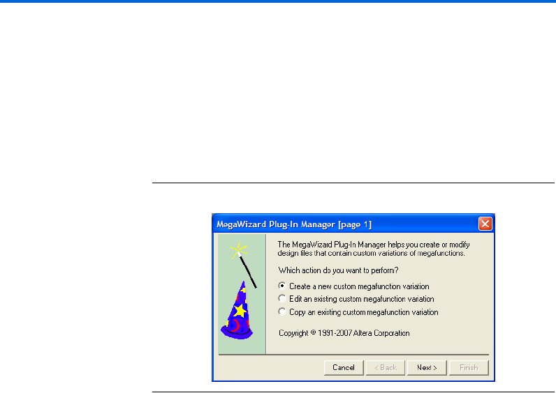
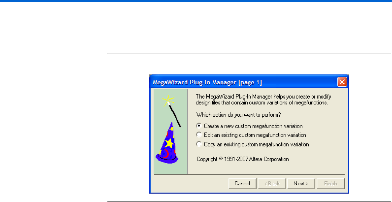
On page 1 of a MegaWizard Plug-In Manager, select Create a new
custom megafunction variation, Edit an existing custom megafunction
variation, or Copy an existing custom megafunction variation. This
page identifies what you would like to do using the wizard. Figure 2–1
shows page 1 of a MegaWizard Plug-In Manager.
Figure 2–1. MegaWizard Plug-In Manager [Page 1]
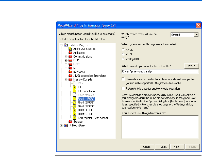
Page 2a is where you specify which MegaWizard you want to use. The
RAM: 1-PORT, RAM: 2-PORT, and RAM: 3-PORT MegaWizard Plug-In
Managers are all located under Memory Compiler.
You can also specify the family of device to use, the type of output file to
create, and the name of the output file from the page. You can choose
AHDL (.tdf), VHDL (.vhd), or Verilog HDL (.v) as the output file type.
Also, you can check the Generate clear box netlist file instead of a
default wrapper file (for use with supported EDA synthesis tools only)
to generate a clear-box netlist if this option is available. This option is not
shown if the MegaWizard Plug-In Manager does not support this feature.
Figure 2–2 shows page 2a of a MegaWizard Plug-In Manager.

Altera Corporation 2–3
March 2007 RAM Megafunction User Guide
Getting Started
Figure 2–2. MegaWizard Plug-In Manager [Page 2a]
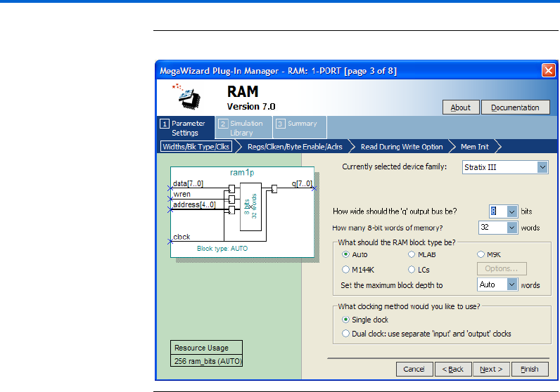
The RAM: 1-PORT MegaWizard Plug-In Manager Page
Descriptions
Page 2a of the MegaWizard Plug-In Manager under Memory Compiler
is where you select RAM: 1-PORT MegaWizard Plug-In Manager
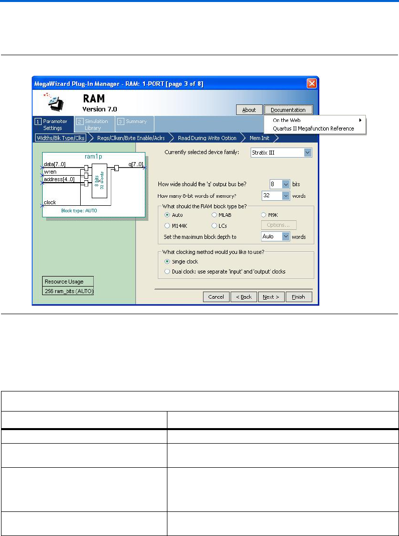
Page 3 of the wizard is where you specify the device family, set the width
of the data input/output bus, set the number of words of memory, select
the RAM block type, and select the clock mode.
1Beginning with page 3, from the Documentation button, you
can launch the Quartus II Help for the single-port RAM,
dual-port RAM, or tri-port RAM by selecting the Quartus II
Megafunction Reference option. For some of the configurations
you set, an option to generate a sample simulation waveform is
available under the Documentation button.
2–4 Altera Corporation
RAM Megafunction User Guide March 2007
Using the MegaWizard Plug-In Manager
Figure 2–3 shows page 3 of the RAM: 1-PORT MegaWizard Plug-In
Manager.
Figure 2–3. MegaWizard Plug-In Manager – RAM: 1-PORT [Page 3]
Table 2–1 shows the features and settings of the RAM: 1-PORT
MegaWizard Plug-In Manager page 3 options.
Table 2–1. RAM: 1-PORT MegaWizard Plug-In Manager Page 3 Options
Function Description
Currently selected device family: Specify which Altera device family to use.
How wide should the 'q' output bus be? Specify the width of the output data bus. Note that you can
manually enter a number that is not in the drop-down list.
How many 8-bit words of memory? Specify the number of 8-bit words in the memory. 8-bit
represents the width of the 'q' output bus that you set. You can
set different widths of output data bus. Note that you can
manually enter a number that is not in the drop-down list.
What should the RAM block type be? Specify the RAM block type. The options available vary
depending on the device you select. (1)
Altera Corporation 2–5
March 2007 RAM Megafunction User Guide
Getting Started
Page 4 of the RAM: 1-PORT MegaWizard Plug-In Manager is where you
specify input and output ports for registration, create a clock enable
signal for each clock signal, a byte enable port, an asynchronous clear for
the registered ports, and a read enable signal. Figure 2–4 shows page 4 of
the RAM: 1-PORT MegaWizard Plug-In Manager.
Figure 2–4. MegaWizard Plug-In Manager – RAM: 1-PORT [Page 4]
What clocking method would you like to use? Specify the clocking mode: single clock or dual clock. (2)
Notes to Table 2– 1 :
(1) Available RAM Block Type Options
Auto/MLAB/M9K/M144K/LCs
Auto/M512/M4K/M-RAM/LCs
Auto/M9K/LCs
Auto/M4K/LCs
Auto/LCs
Associated Device or Devices
Stratix III
Stratix series (except Stratix III)
Cyclone III
Cyclone series (except Cyclone III)
Other devices
(2) You must use dual clock mode for devices other than the Stratix and Cyclone series, or when you select LCs as your
memory block type. Single- or dual-clock modes are only available for the Stratix and Cyclone series of devices.
Table 2–1. RAM: 1-PORT MegaWizard Plug-In Manager Page 3 Options
Function Description

2–6 Altera Corporation
RAM Megafunction User Guide March 2007
Using the MegaWizard Plug-In Manager
Table 2–2 shows the features and settings of the RAM: 1-PORT
MegaWizard Plug-In Manager page 4 options.
Table 2–2. RAM: 1-PORT MegaWizard Plug-In Manager Page 4 Options
Function Description
Which ports should be registered? The ports available for registration are data and wren
input ports, address input port, and q output port.
wren is only available for registration for the Stratix and
Cyclone series of devices. You can use asynchronous
mode by unregistering all of the ports under this section,
but this feature is only supported by devices other than
the Stratix and Cyclone series of devices. For the Stratix
and Cyclone series of devices, you can only use
synchronous mode because the input ports are forced to
be registered.
Create one clock enable signal for each clock signal.
All registered ports are controlled by the enable
signal or signals.
When turned on, a clock enable signal is created for each
clock signal.
This option is only available for the Stratix and Cyclone
series of devices, with all RAM block types except LCs.
Create a byte enable port When turned on, a byte enable port is created.
This option is only available for the Stratix and Cyclone
series of devices, with all RAM block types except M512
and LCs. Supported data widths for the byte enable port
are 5, 8, 9, and 10. 5 and 10 are the natively supported
widths in MLAB and are only supported in the MLAB RAM
block type.
Create an 'aclr' asynchronous clear for the
registered ports
Asynchronously clear the input and/or output ports.
This option is only available for the Stratix and Cyclone
series of device. Asynchronous clears are available on
output latches and output registers only for Stratix III or
Cyclone III devices. This feature has no effect on input
registers for the Stratix III, Stratix II, Cyclone III,
Cyclone II, Hardcopy II, and Stratix II GX devices. This
feature does, however, affect the input register when you
select Cyclone, Stratix, Stratix GX, or Hardcopy Stratix
devices.
Create a 'rden' read enable signal Create a read enable signal to control read operation.
This option is available only for Stratix III and Cyclone III
devices with all RAM block types except MLAB and LCs.
Altera Corporation 2–7
March 2007 RAM Megafunction User Guide
Getting Started
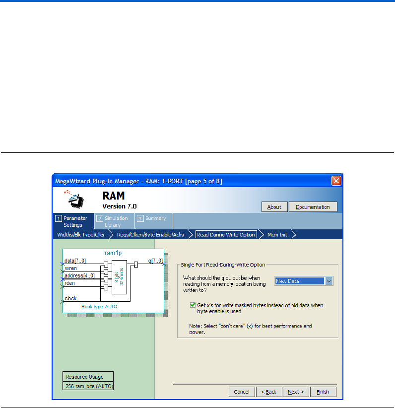
Page 5 of the RAM: 1-PORT MegaWizard Plug-In Manager provides you
the options to select the type of the q output data either as Old Data, New
Data, or Don't Care when reading from memory during a simultaneous
write to the same memory location.
This feature is supported only by Stratix III and Cyclone III devices. This
option allows you to determine the read data type when write and read
operations occur simultaneously at the same memory address.
Figure 2–5 shows page 5 of the RAM: 1-PORT MegaWizard Plug-In
Manager.
Figure 2–5. MegaWizard Plug-In Manager – RAM: 1-PORT [Page 5]
2–8 Altera Corporation
RAM Megafunction User Guide March 2007
Using the MegaWizard Plug-In Manager
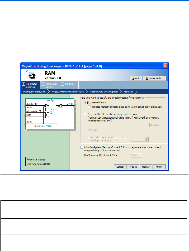
Page 6 of the RAM: 1-PORT MegaWizard Plug-In Manager is where you
specify the initial content of memory, and select whether you want the
In-System Memory Content Editor to capture and update content
independently of the system clock.
Figure 2–6 shows page 6 of the RAM: 1-PORT MegaWizard Plug-In
Manager.
Figure 2–6. MegaWizard Plug-In Manager – RAM: 1-PORT [Page 6]
Table 2–3 shows the features and settings of the RAM: 1-PORT
MegaWizard Plug-In Manager page 6 options.
Table 2–3. RAM: 1-PORT MegaWizard Plug-In Manager Page 6 Options
Function Description
Do you want to specify the initial content
of the memory?
Specify the initial content of the memory, leave it blank, or use
Hexadecimal File (.hex) or a Memory Initialization File (.mif) for the
memory content data.
Allow In-System Memory Content Editor
to capture and update content
independently of the system clock
Turn on to enable In-System Memory Content.
This option is not available for dual clock mode, M512, MLAB, and
LCs RAM block types.
Altera Corporation 2–9
March 2007 RAM Megafunction User Guide
Getting Started
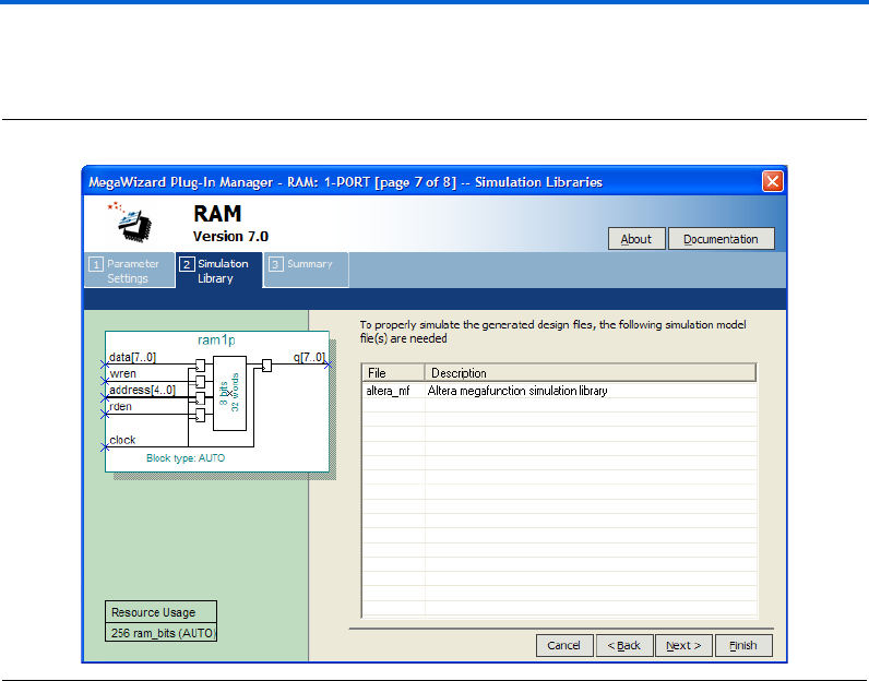
Page 7 shows the simulation libraries to properly simulate the generated
design files. No input is required for this page.
Figure 2–7. MegaWizard Plug-In Manager – RAM: 1-PORT [page 7]
2–10 Altera Corporation
RAM Megafunction User Guide March 2007
Using the MegaWizard Plug-In Manager
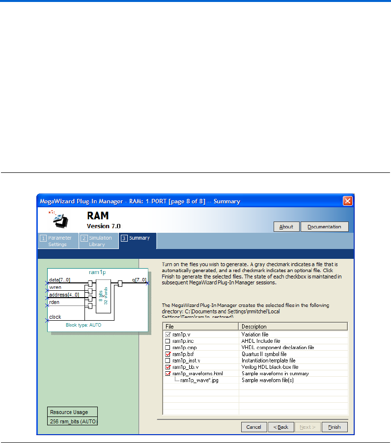
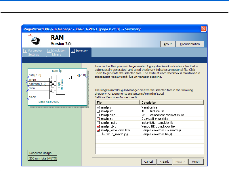
On page 8 of the RAM: 1-PORT MegaWizard Plug-In Manager, specify
the types of files to be generated. Choose from the HDL wrapper file,
<function name>.v, <function name>.inc, <function name>.cmp, <function
name>.bsf, <function name>_inst.v, or <function name>_bb.v. The gray
checkmark indicates a file that is automatically generated, and a red
checkmark indicates an optional file.
For most devices, you can check the <function name>_waveforms.html to
generate a sample waveform summary based on the configuration you
set through the wizard.
Figure 2–8 shows page 8 of the RAM: 1-PORT MegaWizard Plug-In
Manager.
Figure 2–8. MegaWizard Plug-In Manager – RAM: 1-PORT [page 8]
Altera Corporation 2–11
March 2007 RAM Megafunction User Guide
Getting Started
The RAM: 2-PORT MegaWizard Plug-In Manager Page
Descriptions
On page 2a of the MegaWizard Plug-In Manager, under Memory
Compiler, you can select RAM: 2-PORT MegaWizard Plug-In Manager.
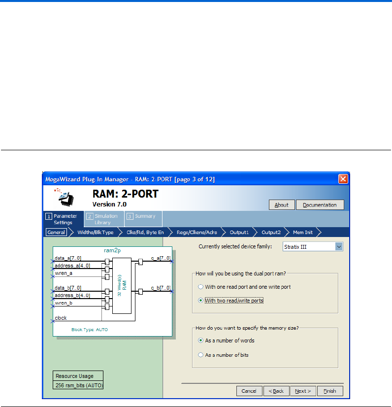
Page 3 of the RAM: 2-PORT MegaWizard Plug-In Manager is where you
specify the device family, determine how the dual-port RAM is used, and
specify the memory size as a number of words or as a number of bits.
Figure 2–9 shows page 3 of the RAM: 2-PORT MegaWizard Plug-In
Manager.
Figure 2–9. MegaWizard Plug-In Manager – RAM: 2-PORT [Page 3]
2–12 Altera Corporation
RAM Megafunction User Guide March 2007
Using the MegaWizard Plug-In Manager
Table 2–4 shows the features and settings of the RAM: 2-PORT
MegaWizard Plug-In Manager page 3 options.
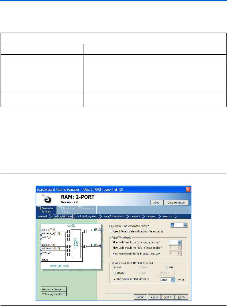
Page 4 of the RAM: 2-PORT MegaWizard Plug-In Manager is where you
specify the memory capacity, set the width of read/write ports, and set
the RAM block type. Figure 2–10 shows page 4 of the RAM: 2-PORT
MegaWizard Plug-In Manager.
Figure 2–10. MegaWizard Plug-In Manager – RAM: 2-PORT [Page 4]
Table 2–4. RAM: 2-PORT MegaWizard Plug-In Manager Page 3 Options
Function Description
Currently selected device family: Specify which Altera device family to use.
How will you be using the dual port ram? Specify whether the dual-port RAM has one read port and one write
port (simple dual-port mode), or two read/write ports (true dual-port
mode).
If you want to allow simultaneous read and write operations, specify
simple dual-port mode. (1)
How do you want to specify the memory
size?
Specify the memory size as a number of words, or as a number of bits.
Note to Table 2–4 :
(1) For the Stratix and Cyclone series of devices, both simple and true-dual port modes are supported. For other
devices, the RAM only supports simple dual-port mode. Simple dual-port mode supports simultaneous read and
write operations because it has dedicated read address and write address ports for read and write operations

Altera Corporation 2–13
March 2007 RAM Megafunction User Guide
Getting Started
Table 2–5 shows the features and settings of the RAM: 2-PORT
MegaWizard Plug-In Manager page 4 options.
Table 2–5. RAM: 2-PORT MegaWizard Plug-In Manager Page 4 Options
Function Description
How many 8-bit words of memory? Specify the number of 8-bit words in the memory. 8-bit
represents the width of the output q data bus. Note that
you can manually enter a number that is not in the
drop-down list.
Use different data widths on different ports Toggle the ability to specify different widths for the data
input and output busses.
Read/Write Ports Specify the width of the data input and output busses.
Note that you can manually enter a number that is not
in the drop-down list.
What should the RAM block type be? Specify the RAM block type. The options available
depend on the targeted device. (1)
Notes to Table 2– 5 :
(1) Available RAM Block Type Options
Auto/MLAB/M9K/M144K/LCs
Auto/M512/M4K/M-RAM/LCs
Auto/M9K/LCs
Auto/M4K/LCs
Auto/LCs
Device or Devices
Stratix III
Stratix series (except Stratix III)
Cyclone III
Cyclone series (except Cyclone III)
Other devices
In true dual-port mode, LCs/M512/MLAB are not available for selection.
2–14 Altera Corporation
RAM Megafunction User Guide March 2007
Using the MegaWizard Plug-In Manager
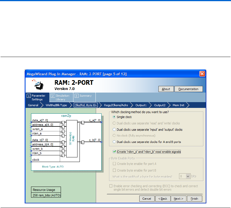
Page 5 of the RAM: 2-PORT MegaWizard Plug-In Manager is where you
specify the clocking method, create read enable ports, create byte enable
ports, and enable error checking and correcting features.
Figure 2–11 shows page 5 of the RAM: 2-PORT MegaWizard Plug-In
Manager
Figure 2–11. MegaWizard Plug-In Manager – RAM: 2-PORT [Page 5]

Altera Corporation 2–15
March 2007 RAM Megafunction User Guide
Getting Started
Table 2–6 shows the features and settings of the RAM: 2-PORT
MegaWizard Plug-In Manager page 5 options.
Table 2–6. RAM: 2-PORT MegaWizard Plug-In Manager Page 5 Options
Function Description
Which clocking method do you
want to use?
Three clocking mode are available: single clock, dual clock, and
asynchronous mode.
In single clock mode, the read and write operations are synchronous with
the same clock. There are three dual clock modes: independent clock mode,
input/output clock mode, and read/write clock mode. While in asynchronous
mode, no clock is required. Only devices other than the Stratix and Cyclone
series of device support asynchronous clocking mode.
Create an 'rden' read enable
signal
Create read enable signal to control read operation.
This option is not supported when using the Stratix and Cyclone series of
devices (except Stratix III and Cyclone III devices) in true dual-port mode, or
with MRAM memory block type. Also, it is not supported by Stratix III
devices specifically, when you use the MLAB memory block type.
Byte Enable Ports Create byte enable port for port A and or port B.
This option is only available for the Stratix and Cyclone series of devices
(unless the RAM block type is LCs). Supported widths for the byte enable
port are 5, 8, 9, and 10. 5 and 10 are the natively supported widths in MLAB
and are only supported in the MLAB RAM block type.
Enable error checking and
correcting (ECC) to check and
correct single bit errors and detect
double bit errors
Turn on to enable ECC on single-bit error correction and double-bit error
detection.
This feature is only supported by Stratix III devices in simple dual-port mode
with the M144K RAM block type.
2–16 Altera Corporation
RAM Megafunction User Guide March 2007
Using the MegaWizard Plug-In Manager
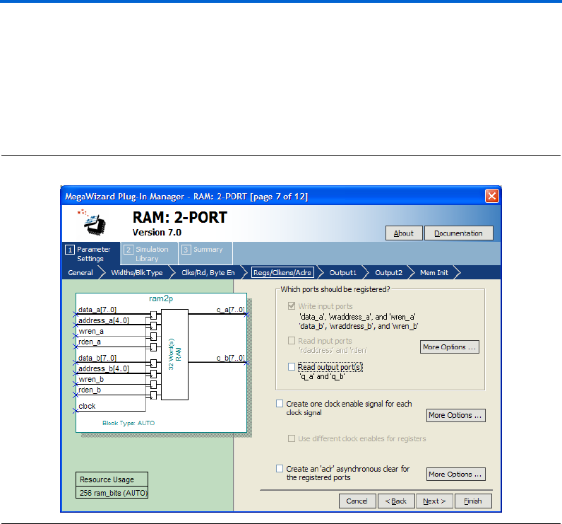
Page 7 of the RAM: 2-PORT MegaWizard Plug-In Manager is where you
specify input and output ports for registration, create a clock enable
signal for each clock signal, and create an asynchronous clear for the
registered ports.
Figure 2–12 shows page 7 of the RAM: 2-PORT MegaWizard Plug-In
Manager.
Figure 2–12. MegaWizard Plug-In Manager – RAM: 2-PORT [Page 7]

Altera Corporation 2–17
March 2007 RAM Megafunction User Guide
Getting Started
Table 2–7 shows the features and settings of the RAM: 2-PORT
MegaWizard Plug-In Manager page 7 options.
Page 8 of the RAM: 2-PORT MegaWizard Plug-In Manager is where you
specify the behavior of the q output when reading a memory location that
is being written from the other port. You can set the q to retain the old
memory content or “don’t care” if it is not important to your design. This
page is only available for the Stratix and Cyclone series of devices.
Figure 2–13 shows page 8 of the RAM: 2-PORT MegaWizard Plug-In
Manager.
Table 2–7. RAM: 2-PORT MegaWizard Plug-In Manager Page 7 Options
Function Description
Which ports should be registered? The ports available for registration are write input ports,
read input ports, and read output ports.
You can use asynchronous mode by unregistering all of
the ports under this section, but this feature is only
supported by devices other than the Stratix and Cyclone
series of device. For the Stratix and Cyclone series of
devices, you can only use synchronous mode because
the input ports are forced to be registered.
Create one clock enable signal for each clock signal When checked, clock enable signal is created for each
clock signal. All register ports are controlled by the enable
signal.
Create an 'aclr' asynchronous clear for the
registered ports
Asynchronously clear the input and/or output ports.
Under More Options..., you can check available ports to
set which port is to be clear when aclr is active.

2–18 Altera Corporation
RAM Megafunction User Guide March 2007
Using the MegaWizard Plug-In Manager
Figure 2–13. MegaWizard Plug-In Manager – RAM: 2-PORT [Page 8]
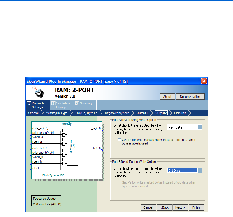
Page 9 of the RAM: 2-PORT MegaWizard Plug-In Manager is where you
specify the type of the q output for different ports when reading during
a simultaneous write to the same memory location. This option is
dedicated to each input port A and port B. You can select Old Data or
New Data for each port.
1The option on page 8 of the wizard defines the data type of the
output when input port A writes data and output port B reads
data from the same memory location simultaneously. It also
applied for the case when input port B writes data and output
port A reads data from the same memory location
simultaneously.
On page 9 of the wizard, it defines the data type of the output when input
port A writes data and output port A reads data from the same memory
location simultaneously. The same case applied for input and output
ports B. Only Stratix III and Cyclone III devices support this feature and
is only available if you configure the RAM as a true dual-port RAM.
Altera Corporation 2–19
March 2007 RAM Megafunction User Guide
Getting Started
Also, if you activate the byte enable feature to mask certain bytes (from
page 5 of the wizard, Figure 2–11 on page 2–14), you can set the masked
bytes to have value of “x”, instead of old data using the option provided
on page 9 of the wizard.
Figure 2–14 shows page 9 of the RAM: 2-PORT MegaWizard Plug-In
Manager.
Figure 2–14. MegaWizard Plug-In Manager – RAM: 2-PORT [Page 9]
2–20 Altera Corporation
RAM Megafunction User Guide March 2007
Using the MegaWizard Plug-In Manager
Page 10 of the RAM: 2-PORT MegaWizard Plug-In Manager is where you
specify the initial content of memory. You can leave it blank, or use
Hexadecimal File (.hex) or a Memory Initialization File (.mif) for the
memory content data.
Figure 2–15 shows page 10 of the RAM: 2-PORT MegaWizard Plug-In
Manager.
Figure 2–15. MegaWizard Plug-In Manager – RAM: 2-PORT [Page 10]
Altera Corporation 2–21
March 2007 RAM Megafunction User Guide
Getting Started
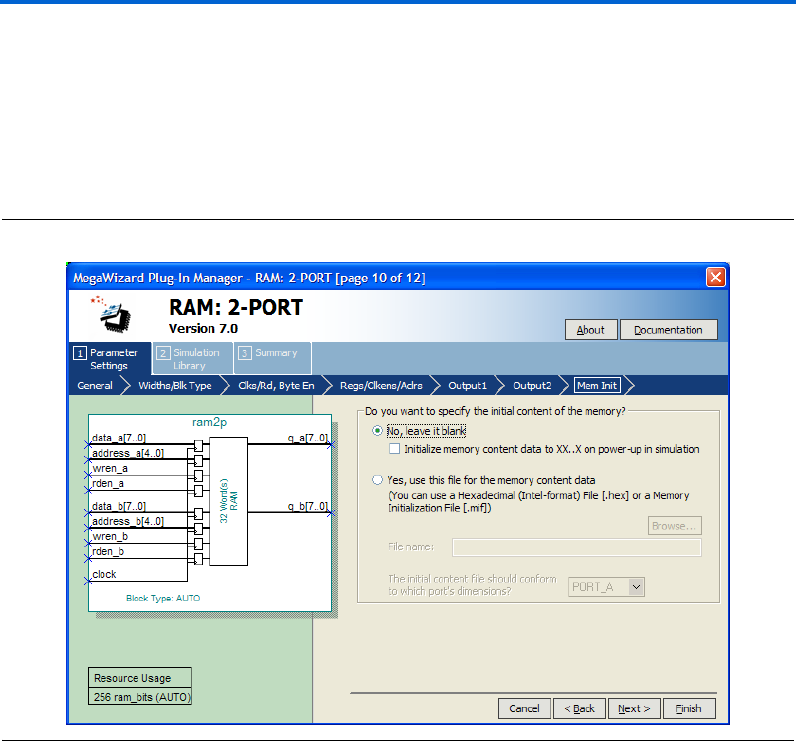
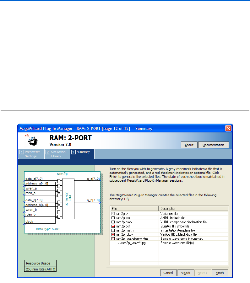
On page 12 of the RAM: 2-PORT MegaWizard Plug-In Manager, specify
the types of files to be generated. Choose from the HDL wrapper file,
<function name>.v, <function name>.inc, <function name> .cmp, <function
name>.bsf, <function name>_inst.v, or <function name>_bb.v. The gray
checkmark indicates a file that is automatically generated, and a red
checkmark indicates an optional file.
For most devices, you can check the <function name>_waveforms.html to
generate a sample waveforms summary based on the configuration you
set through the wizard.
Figure 2–16 shows page 12 of the RAM: 2-PORT MegaWizard Plug-In
Manager.
Figure 2–16. MegaWizard Plug-In Manager – RAM: 2-PORT [Page 12]
2–22 Altera Corporation
RAM Megafunction User Guide March 2007
Using the MegaWizard Plug-In Manager
The RAM: 3-PORT MegaWizard Plug-In Manager Page
Descriptions
On page 2a of the MegaWizard Plug-In Manager, under Memory
Compiler, you can select RAM: 3-PORT MegaWizard Plug-In Manager.
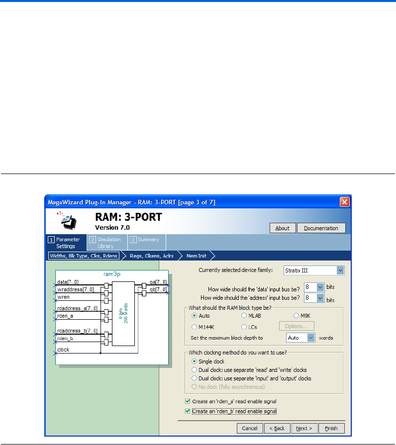
Page 3 of the RAM: 3-PORT MegaWizard Plug-In Manager is where you
specify the device family, set the width of the data input/output bus,
select the RAM block type, select the clock mode, and create read enable
signals.
Figure 2–17 shows page 3 of the RAM: 3-PORT MegaWizard Plug-In
Manager.
Figure 2–17. MegaWizard Plug-In Manager – RAM: 3-PORT [Page 3]

Altera Corporation 2–23
March 2007 RAM Megafunction User Guide
Getting Started
Table 2–8 shows the features and settings of the RAM: 3-PORT
MegaWizard Plug-In Manager page 3 options.
Table 2–8. RAM: 3-PORT MegaWizard Plug-In Manager Page 3 Options
Function Description
Currently selected device family: Specify which Altera device family to use.
How wide should the 'data' input bus be? Specify the width of input/output data bus. Note that you can
manually enter a number that is not in the drop-down list.
How wide should the 'address' input bus
be?
Specify the width of the input address bus. Note that you can
manually enter a number that is not in the drop-down list.
What should the RAM block type be? Specify the RAM block type. The options available vary depending
on your device selection. (1)
Which clocking method do you want to
use?
Three clocking modes are available: single clock, dual clock, and
asynchronous mode.
In single clock mode, the read and write operations are synchronous
with the same clock. There are two dual clock modes: separate
clocks for read and write operations, and separate clocks for input
and output. While in asynchronous mode, no clock is required. Only
older devices support asynchronous clocking mode.
Create an 'rden_a' read enable signal Create a read enable signal to control read operation for port A. (2)
Create an 'rden_b read enable signal Create a read enable signal to control read operation for port B. (2)
Notes to Table 2– 8 :
(1) Available RAM Block Type Options
Auto/MLAB/M9K/M144K/LCs
Auto/M512/M4K/M-RAM/LCs
Auto/M9K/LCs
Auto/M4K/LCs
Auto/LCs
Device or Devices
Stratix III
Stratix series (except Stratix III)
Cyclone III
Cyclone series (except Cyclone III)
Other devices
(2) This feature is not available if the RAM block type is M-RAM.
2–24 Altera Corporation
RAM Megafunction User Guide March 2007
Using the MegaWizard Plug-In Manager
Page 4 of the RAM: 3-PORT MegaWizard Plug-In Manager is where you
specify input and output ports for registration, create a clock enable
signal for each clock signal, and create an asynchronous clear for the
registered ports.
Figure 2–18 shows page 4 of the RAM: 3-PORT MegaWizard Plug-In
Manager.
Figure 2–18. MegaWizard Plug-In Manager – RAM: 3-PORT [Page 4]

Altera Corporation 2–25
March 2007 RAM Megafunction User Guide
Getting Started
Table 2–9 shows the features and settings of the RAM: 3-PORT
MegaWizard Plug-In Manager page 4 options.
Page 5 of the RAM: 3-PORT MegaWizard Plug-In Manager is where you
specify the initial contents of memory. You can leave it blank, or use
Hexadecimal File (.hex) or a Memory Initialization File (.mif) for the
memory content data.
Figure 2–19 shows page 5 of the RAM: 3-PORT MegaWizard Plug-In
Manager.
Table 2–9. RAM: 3-PORT MegaWizard Plug-In Manager Page 4 Options
Function Description
Which ports should be registered? The ports available for registration are write input ports,
two read input ports, and two read output ports.
You can use asynchronous mode by unregistering all the
ports under this section, but this feature is supported by
devices other than the Stratix and Cyclone series of
devices only.
Create one clock enable signal for each clock signal When turned on, a clock enable signal is created for each
clock signal. All register ports are controlled by the enable
signal.
Create an 'aclr' asynchronous clear for the
registered ports
Asynchronously clear the input and output ports.
Under More Options..., you can check available ports to
set which port is to be clear when aclr is active.

2–26 Altera Corporation
RAM Megafunction User Guide March 2007
Using the MegaWizard Plug-In Manager
Figure 2–19. MegaWizard Plug-In Manager – RAM: 3-PORT [Page 5]
On page 7 of the RAM: 3-PORT MegaWizard Plug-In Manager, specify
the types of files to be generated. Choose from the HDL wrapper file,
<function name>.v, <function name>.inc, <function name>.cmp, <function
name>.bsf, <function name>_inst.v, or <function name>_bb.v. The gray
checkmark indicates a file that is automatically generated, and a red
checkmark indicates an optional file.
Figure 2–20 shows page 7 of the RAM: 3-PORT MegaWizard Plug-In
Manager.


2–28 Altera Corporation
RAM Megafunction User Guide March 2007
Instantiating Megafunctions in HDL Code
Inferring Megafunctions from HDL Code
Synthesis tools, including Quartus II integrated synthesis, recognize
certain types of HDL code and automatically infer the appropriate
megafunction when a megafunction can provide optimal results. The
Quartus II software uses the Altera megafunction code when compiling
your design, even though you may not have specifically instantiated a
megafunction. The Quartus II software infers megafunctions because
they are optimized for Altera devices, so their area usage, performance,
or both may be better than those of generic HDL code. Additionally, you
must use megafunctions to access certain Altera architecture-specific
features, including memory, DSP blocks, and shift registers. These
features provide improved performance when compared to basic logic
elements.
fRefer to the Recommended HDL Coding Styles chapter in volume 1 of the
Quartus II Handbook for specific information about your particular
megafunction.
Instantiating
Megafunctions
in HDL Code
When you use the MegaWizard Plug-In Manager to set up and
parameterize a megafunction, it creates either a VHDL or Verilog HDL
wrapper file that instantiates the megafunction (a black-box
methodology). For some megafunctions, you can generate a fully
synthesizable netlist for improved results with EDA synthesis tools, such
as Synplify and Precision RTL Synthesis (a clear-box methodology).
fFor more information about clear- and black-box methodologies, refer to
the third-party synthesis support chapters in the Synthesis section of
volume 1 of the Quartus II Handbook.
Identifying a
Megafunction
after
Compilation
During compilation with the Quartus II software, analysis and
elaboration is performed to build the structure of you design. You can
locate your megafunction in the Project Navigator window by expanding
the compilation hierarchy and locating the megafunction by its name.
Similarly, to search for node names within the megafunction using the
Node Finder, in the Look in box, click Browse (...) and select the
megafunction from the Hierarchy box.

Altera Corporation 2–29
March 2007 RAM Megafunction User Guide
Getting Started
Simulation The Quartus II Simulator provides an easy-to-use, integrated solution for
performing simulations. The following sections describe the simulation
options.
Quartus II Software Simulation
With the Quartus II Simulator, you can perform two types of simulations:
functional and timing. A functional simulation enables you to verify the
logical operation of your design without taking into consideration the
timing delays in the FPGA. This simulation is performed using only your
RTL code. When performing a functional simulation, add only signals
that exist before synthesis. You can find these signals with the Registers,
Pre-Synthesis, Design Entry, or Pin filters in the Node Finder. The
top-level ports of megafunctions are found using these three filters.
In contrast, the timing simulation in the Quartus II software verifies the
operation of your design with annotated timing information. This
simulation is performed using the post place-and-route netlist. When
performing a timing simulation, add only signals that exist after
place-and-route. These signals are found with the post-compilation filter
of the Node Finder. During synthesis and place-and-route, the names of
RTL signals change. Finding signals from your megafunction
instantiation in the post-compilation filter therefore may be difficult.
To preserve the names of your signals during the synthesis and
place-and-route stages, use the synthesis attributes keep or preserve.
These are Verilog and VHDL synthesis attributes that direct analysis and
synthesis to keep a particular wire, register, or node intact. Use these
synthesis attributes to keep a combinational logic node so you can
observe the node during simulation.
fFor more information about these attributes, refer to the Quartus II
Integrated Synthesis chapter in volume 1 of the Quartus II Handbook.
EDA Simulation
For more information about EDA simulation, refer to the appropriate
chapter (based on the tool you use) in the Simulation section in volume 3
of the Quartus II Handbook. The Quartus II Handbook chapters describe
how to perform functional and gate-level timing simulations that include
the megafunctions, with details about the files that are needed and the
directories where the files are located.

2–30 Altera Corporation
RAM Megafunction User Guide March 2007
SignalTap II Embedded Logic Analyzer
SignalTap II
Embedded Logic
Analyzer
The SignalTap®II embedded logic analyzer provides a non-intrusive
method of debugging the Altera megafunctions within your design. With
the SignalTap II embedded logic analyzer, you can capture and analyze
data samples for the top-level ports of Altera megafunctions while your
system is running at full speed.
To monitor signals from Altera megafunctions, configure the SignalTap II
embedded logic analyzer in the Quartus II software, and include the
analyzer as part of your Quartus II project. The Quartus II software then
embeds the analyzer in your design in the selected device seamlessly.
fFor more information about using the SignalTap II embedded logic
analyzer, refer to the Design Debugging Using the SignalTap II Embedded
Logic Analyzer chapter in volume 3 of the Quartus II Handbook.
In-System
Updating of
Memory and
Constants
FPGA designs are growing larger in density and are becoming more
complex. Designers and verification engineers require more access to the
design that is programmed in the device to identify, test, and resolve
issues quickly and accurately. The In-System Updating of Memory and
Constants capability of the Quartus II software provides you with a
non-intrusive method of accessing your RAM within the Altera FPGA.
With the In-System Memory Content Editor, you can capture, analyze,
and update RAM data while your system is running at full speed.
To gain access to your RAM megafunction, enable the In-System
Updating of Memory and Constants feature within the MegaWizard
Plug-In Manager. The Quartus II software will then modify your RAM
(in the background) so you have access to it while the FPGA is processing.
You can read, write, or update the contents of your RAM multiple times
without having to reconfigure your FPGA. This In-System Updating of
Memory and Constants feature is not available for certain configuration
through the MegaWizard. For example, this feature is not available when
you select LCs as your RAM block type.
fFor more information about viewing and modifying internal memories
and constants, refer to the In-System Updating of Memory and Constants
chapter in volume 3 of the Quartus II Handbook.

Altera Corporation 2–31
March 2007 RAM Megafunction User Guide
Getting Started
Design
Examples for the
RAM
Megafunctions
This section presents three design examples that use RAM: 1-PORT,
RAM: 2-PORT, and RAM: 3-PORT MegaWizard Plug-In Managers to
generate single-port RAM, dual-port RAM, and tri-port RAM
respectively. As you go through the wizard, each page is described in
detail. When you are finished with the examples, you can incorporate
them into your overall project.
Design Files
The example design files are available in the Quartus II Project section on
the Design Examples page in the Quartus II support page of the Altera
website (www.altera.com).
Select the Examples for RAM Megafunction User Guide link from the
examples page to download the design file.
Example for RAM: 1-PORT
The objective of the examples is to implement and instantiate a
single-port RAM using the RAM: 1-PORT MegaWizard Plug-In
Manager. The RAM: 1-PORT example illustrates single clock with
registered output mode.
This example also shows the new features supported by Stratix III for
RAM: 1-PORT MegaWizard Plug-In Manager, such as the read enable
signal to control read operation, and a special feature to allow you to set
the behavior of the q output when reading during a simultaneous write
to the same memory location. Verify the results you obtained at the end
of this example with the expected simulation results provided.
In this example, you perform the following activities:
■Generate a single-port RAM using the RAM: 1-PORT MegaWizard
Plug-In Manager
■Implement the single-port RAM by assigning the Stratix III device to
the project and compiling the project
■Simulate the single-port RAM design
Generate the Single-Port RAM
To generate the single-port RAM, follow these steps:
1. Open ram1p_DesignExample_ex1.zip and extract ram1p.qar to any
working directory.
2. In the Quartus II software, open ram1p.qar and restore the archive
file into your working directory.
2–32 Altera Corporation
RAM Megafunction User Guide March 2007
Design Examples for the RAM Megafunctions
3. On the Tools menu, click MegaWizard Plug-In Manager. Page 1 of
the MegaWizard Plug-In Manager appears (Figure 2–21).
Figure 2–21. MegaWizard Plug-In Manager [Page 1]
4. Select Create a new custom megafunction variation, and click
Next. Page 2a appears.
5. On page 2a of the MegaWizard Plug-In Manager, make the
following selections:
a. In the Which device family will you be using? list, select
Stratix III.
b. Under Which type of output file do you want to create?, select
Verilog HDL.
c. Expand the Memory Compiler and select RAM: 1-PORT.
d. For the name of the output file, type ram1p, or click Browse (...)
to select the file from the project folder.
Figure 2–22 shows page 2a after you have made these selections.
2–34 Altera Corporation
RAM Megafunction User Guide March 2007
Design Examples for the RAM Megafunctions
Figure 2–23. MegaWizard Plug-In Manager—RAM: 1-PORT [Page 3]
8. Click Next. Page 4 appears.
9. Check the boxes for 'q' output port, and Create an 'rden' read
enable signal. Leave the other options as the default.
Figure 2–24 shows page 4 after you have made these selections.
Altera Corporation 2–35
March 2007 RAM Megafunction User Guide
Getting Started
Figure 2–24. MegaWizard Plug-In Manager—RAM: 1-PORT [Page 4]
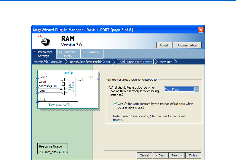
10. Click Next. Page 5 appears.
11. In the What should the q output be when reading from a memory
location being written to? list, select New Data.
This is another feature supported only by Stratix III and Cyclone III
devices. This feature allows you to set the behavior of the output q
when reading during a simultaneous write to the same memory
location.
Figure 2–25 shows page 5 after you have made these selections.
Altera Corporation 2–37
March 2007 RAM Megafunction User Guide
Getting Started
Figure 2–26. MegaWizard Plug-In Manager—RAM: 1-PORT [Page 6]
14. Click Finish. Page 8 appears.
15. On page 8 of the wizard, you can turn on any additional output files
you want so they can be created for the project. The gray checkmark
indicates files automatically generated; the red checkmark indicates
those files you can select as you wish, as shown in Figure 2–27.
2–38 Altera Corporation
RAM Megafunction User Guide March 2007
Design Examples for the RAM Megafunctions
Figure 2–27. MegaWizard Plug-In Manager—RAM: 1-PORT [Page 8]
16. Click Finish.
The ram1p module is now built.
Implement Single-Port RAM
Next, assign the EP3SE50F484C2 device to the project and compile the
project.
1. On the Assignments menu, click Settings. The Settings dialog box
appears.
2. Under Category, select Device.
3. In the Family field, select Stratix III.
4. Under Target Dev i c e, ensure that Specific device selected in
'Available devices' list is selected.
5. In the Available devices: list, select EP3SE50F484C2.
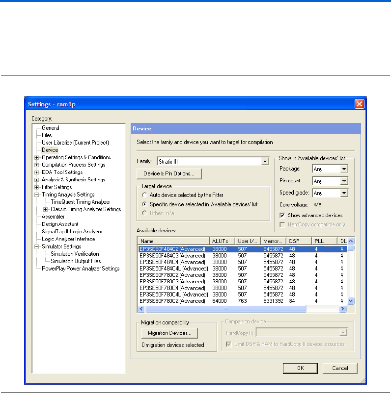
Altera Corporation 2–39
March 2007 RAM Megafunction User Guide
Getting Started
6. Leave all other variables as the default.
Figure 2–28 shows the Settings dialog box after you have made these
selections.
Figure 2–28. Device Settings Dialog Box
7. Click OK.
8. To compile the design, on the Processing menu, click Start
Compilation, or, on the toolbar, click Start Compilation.
9. When the Full Compilation was successful message box appears,
click OK.

2–40 Altera Corporation
RAM Megafunction User Guide March 2007
Design Examples for the RAM Megafunctions
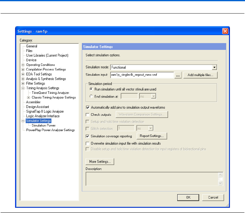
Functional Results—Simulate the Single-Port RAM in the Quartus II
Software
Finally, simulate the design to verify the results. Set up the Quartus II
Simulator by performing the following steps:
1. On the Processing menu, click Generate Functional Simulation
Netlist.
2. When the Functional Simulation Netlist Generation was
successful message box appears, click OK.
3. On the Assignments menu, click Settings. The Settings dialog box
appears.
4. Under Category, select Simulator Settings.
5. In the Simulation mode: drop-down list, select Functional.
6. In the Simulation input: box, type
ram1p_singleclk_regout_new.vwf, or Browse (...) to select
the file from the project folder.
7. Select Run simulation until all vector stimuli are used.
8. Make sure that the Automatically add pins to simulation output
waveforms and Simulation coverage reporting options are turned
on.
9. Make sure that the Overwrite simulation input file with
simulation results option is off.
Figure 2–29 shows the Simulation Settings Dialog Box after you have
made these selections.
Altera Corporation 2–41
March 2007 RAM Megafunction User Guide
Getting Started
Figure 2–29. Simulator Settings Dialog Box
10. Click OK.
11. To run the simulation, on the Processing menu, click Start
Simulation, or, on the toolbar, click the Start Simulation button.
12. When the Simulation was successful message box appears, click
OK.
13. In the Simulation Report window, view the simulation waveforms
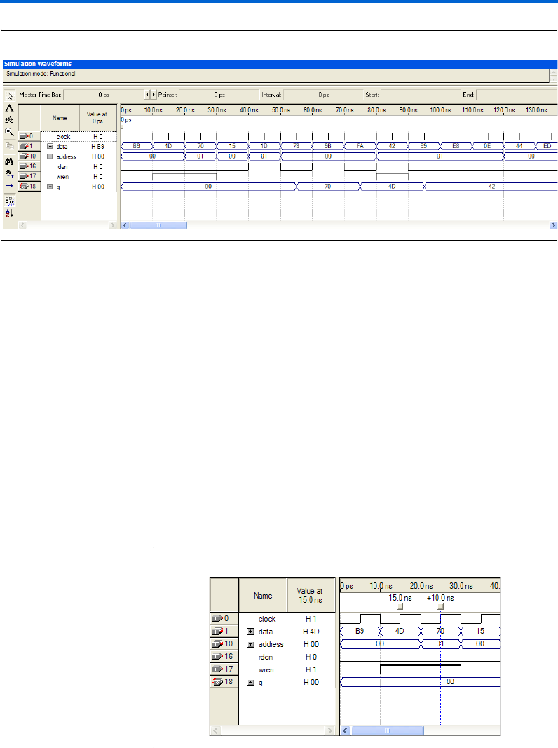
to verify the results. Figure 2–30 shows the expected simulation
results.
2–42 Altera Corporation
RAM Megafunction User Guide March 2007
Design Examples for the RAM Megafunctions
Figure 2–30. Functional Waveform for Single Clock Mode with Registered Output for Single-Port RAM
Understanding the Simulation Results
In this example, you configured the RAM: 1-PORT to have the following
properties:
■Single clock
■Registered output q
■read enable signal that is only supported by Stratix III and
Cyclone III devices
■Output q holds New Data when reading during a simultaneous
write to the same memory location
The following section explains the simulation results corresponding to
the configuration you set with the RAM: 1-PORT MegaWizard Plug-In
Manager.
Figure 2–31 shows the first two write operations to the single-port RAM.
Figure 2–31. Write Operations
Altera Corporation 2–43
March 2007 RAM Megafunction User Guide
Getting Started
The first data 4D and second data 70 are written into memory address 00
and 01 at 15 ns and 25 ns respectively, at the rising edge of the clock when
wren is high. No data is read since rden is low.
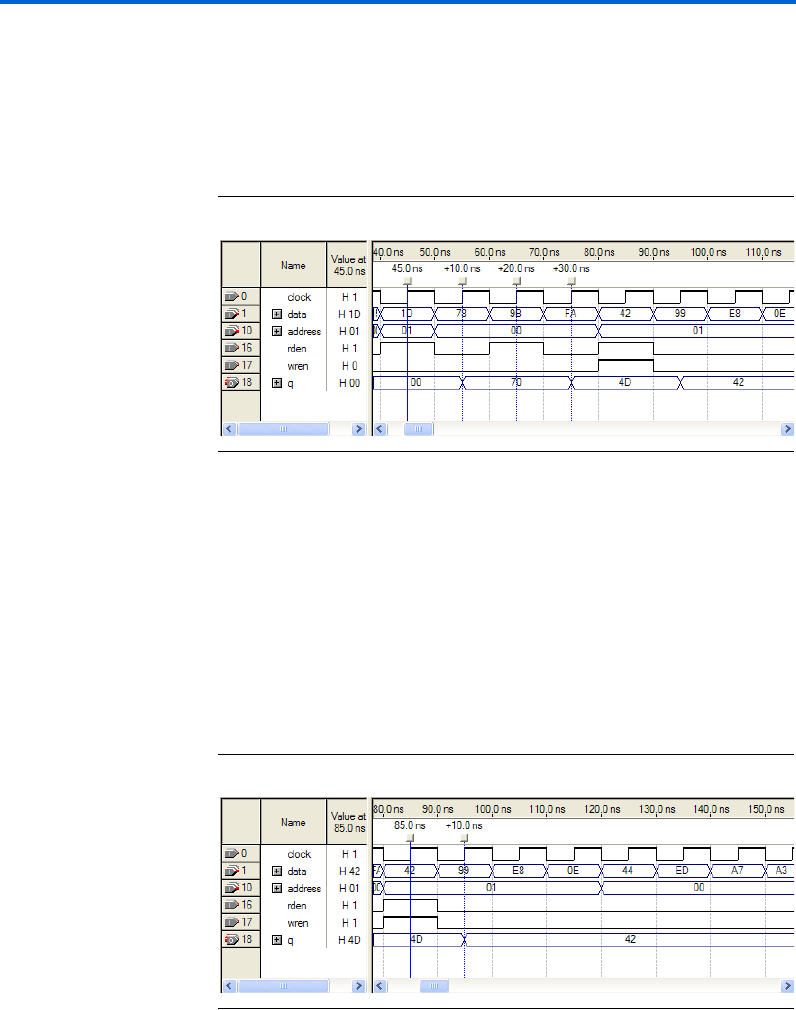
Figure 2–32 shows the read operations occurred after the write
operations.
Figure 2–32. Read Operations
The first read operation occurs at 45 ns from memory address 01 (storing
data 70) when rden is high, but the data appears on the output only at
the next rising edge of the clock at 55 ns.
Similarly, the second read operation occurs at 65 ns, but the data appears
on the output one cycle later, at 75 ns. This delay is due to registered q
output set with the wizard. If you want to override the delay, use
unregistered q output.
Figure 2–33 shows the read and write operations occurring at the same
time.
Figure 2–33. Read and Write Operations Occurring at the Same Time

2–44 Altera Corporation
RAM Megafunction User Guide March 2007
Design Examples for the RAM Megafunctions
The read and write operations occur simultaneously at 85 ns, at
memory address 01. As shown in Figure 2–31, the data value 70 was
previously written to memory address 01, but this data is replaced by
data value 42, when the write operation occurred at 85 ns, as shown in
Figure 2–33.
Because the read operation occurs at the same time as the write to
memory location, either new data 42 or old data 70 may appear on the
output. When using Stratix III or Cyclone III devices, you can configure
the output behavior through the wizard to either output the old data or
the new data in this case. Because you selected New Data from the wizard
for this example, the new data 42 is read out at 95 ns.
Functional Results—Simulate the Single-Port RAM in the
ModelSim-Altera Software
Simulate the design in ModelSim to compare the results of both
simulators. This User Guide assumes that you are familiar with using
ModelSim-Altera before trying out the design example. If you are
unfamiliar with ModelSim-Altera, refer to the support page of the
software products page of the Altera website (www.altera.com). On the
support page for ModelSim-Altera on the Altera website, there are
various links to topics such as installation, usage, and troubleshooting.
Set up the ModelSim-Altera simulator by performing the following steps:
1. Unzip the ram1p_ex1_msim.zip file to any working directory on
your PC.
2. Open the ram1p_msim.do file. Ensure that the Stratix III device
library is located at the correct path in your PC; for example,
C:/altera/70/modelsim_ae/altera/verilog/stratixiii. Change it to
correct path if it is not.
3. Start ModelSim-Altera.
4. On the File menu, click Change Directory.
5. Select the folder in which you unzipped the files. Click OK.
6. On the Tools menu, click Execute Macro.
7. Select the ram1p_msim.do file and click Open. This is a script file
for ModelSim that automates all necessary settings for the
simulation.
8. Verify the results shown in the Waveform Viewer window.
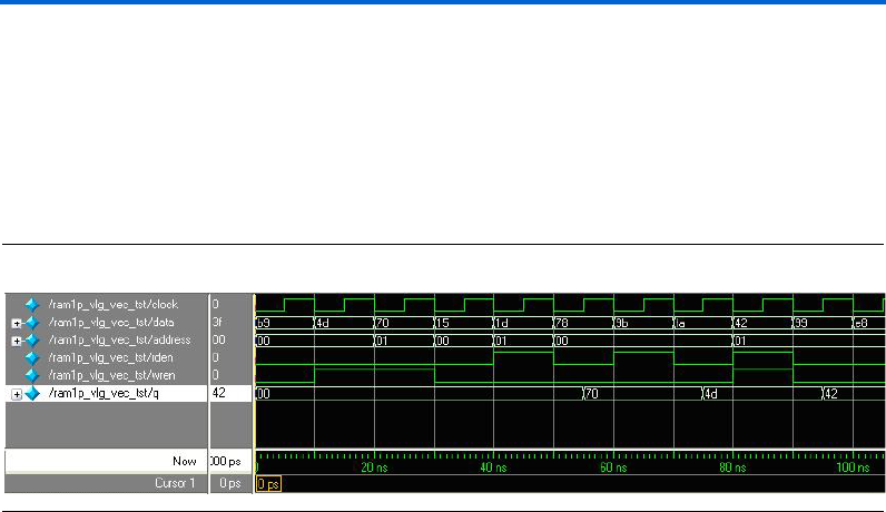
Altera Corporation 2–45
March 2007 RAM Megafunction User Guide
Getting Started
You can rearrange signals, remove signals, add signals, and change the
radix by modifying the script in ram1p_msim.do accordingly to match
the order of the results in the Quartus II Simulator.
Figure 2–34 shows the expected simulation results when running the
design example in ModelSim-Altera. Compare the results obtained using
the Quartus II simulator from Figure 2–30 on page 2–42.
Figure 2–34. ModelSim Simulation Waveform for Single-Port RAM
Example for RAM: 2-PORT
The objective of the examples is to implement and instantiate a dual-port
RAM using the RAM: 2-PORT MegaWizard Plug-In Manager. The
RAM: 2-PORT example illustrates a two read/write ports RAM (true
dual-port mode) with single clock and unregistered outputs.
This example also shows one of the features supported by Stratix III and
Cyclone III devices for the RAM: 2-PORT MegaWizard Plug-In Manager.
This feature allows you to set the Read-During-Write behavior of the q_a
and q_b outputs independently. Verify the results you obtain at the end
of this example with the expected simulation results provided.
In this example, you perform the following activities:
■Generate a dual-port RAM using the RAM: 2-PORT MegaWizard
Plug-In Manager
■Implement the dual-port RAM by assigning the Stratix III device to
the project and compiling the project
■Simulate the dual-port RAM design
Generate the Dual-Port RAM
To generate the dual-port RAM, perform the following steps:
1. Open ram2p_DesignExample_ex2.zip and extract ram2p.qar.
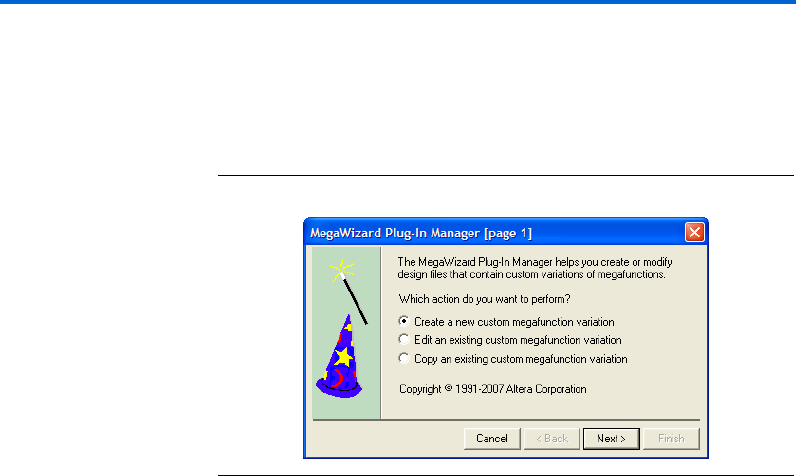
2–46 Altera Corporation
RAM Megafunction User Guide March 2007
Design Examples for the RAM Megafunctions
2. In the Quartus II software, open ram2p.qar and restore the archive
file into your working directory.
3. On the Tools menu, click MegaWizard Plug-In Manager. Page 1 of
the MegaWizard Plug-In Manager appears (Figure 2–35).
Figure 2–35. MegaWizard Plug-In Manager [Page 1]
4. Select Create a new custom megafunction variation, and click
Next. Page 2a appears.
5. On page 2a of the MegaWizard Plug-In Manager, make the
following selections:
a. In the Which device family will you be using? list, select
Stratix III.
b. Under Which type of output file do you want to create?, select
Verilog HDL.
c. Expand the Memory Compiler and select RAM: 2-PORT.
d. For the name of the output file, type ram2p, or click Browse (...)
to select the file from the project folder.
e. Leave everything else as the default.
Figure 2–36 shows page 2a after you have made these selections.
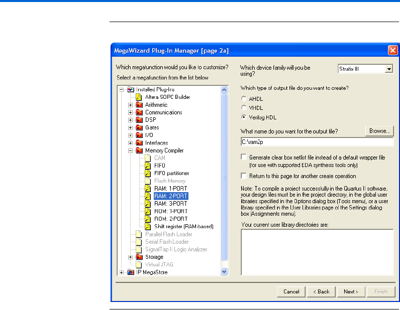
Altera Corporation 2–47
March 2007 RAM Megafunction User Guide
Getting Started
Figure 2–36. MegaWizard Plug-In Manager—RAM: 2-PORT [Page 2a]
6. Click Next. Page 3 appears.
7. Under How will you be using the dual port ram?, select With two
read/write ports.
8. Under How do you want to specify the memory size?, keep the
default setting, As a number of words.
Figure 2–37 shows page 3 after you have made these selections.
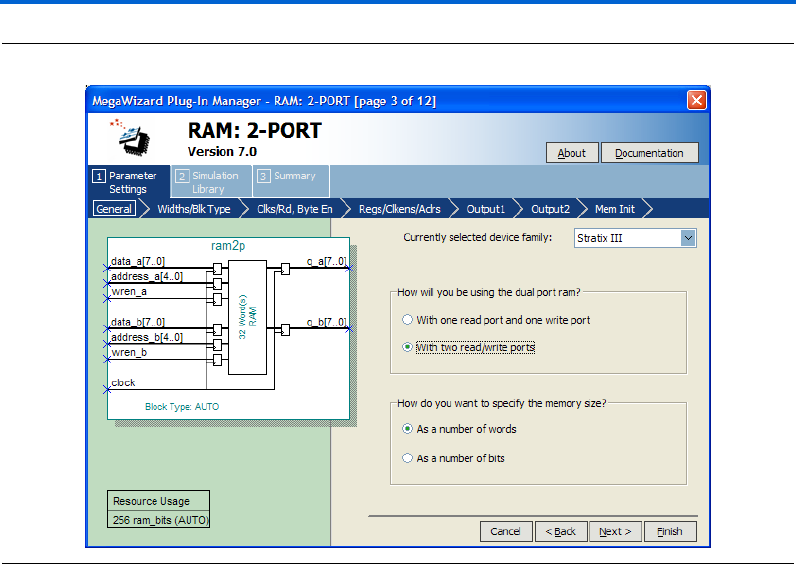
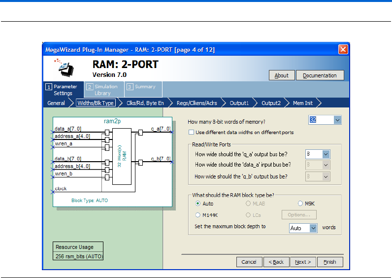
Altera Corporation 2–49
March 2007 RAM Megafunction User Guide
Getting Started
Figure 2–38. MegaWizard Plug-In Manager—RAM: 2-PORT [Page 4]
11. Click Next. Page 5 appears.
12. Under Which clocking method do you want to use?, select Single
Clock.
13. Check the box for Create an 'rden' read enable signal.
Figure 2–39 shows page 5 after you have made these selections.

2–50 Altera Corporation
RAM Megafunction User Guide March 2007
Design Examples for the RAM Megafunctions
Figure 2–39. MegaWizard Plug-In Manager—RAM: 2-PORT [Page 5]
14. Click Next. Page 7 appears.
15. Uncheck the Read output port(s) 'q_a' and 'q_b'
16. Keep the other settings as the default.
Figure 2–40 shows page 7 after you have made these selections.

Altera Corporation 2–51
March 2007 RAM Megafunction User Guide
Getting Started
Figure 2–40. MegaWizard Plug-In Manager—RAM: 2-PORT [Page 7]
17. Click Next. Page 8 appears.
18. Under How should the q_a and q_b outputs behave when reading
a memory location that is being written from the other port?, select
I don't care.
Figure 2–41 shows page 8 after you have made this selection.
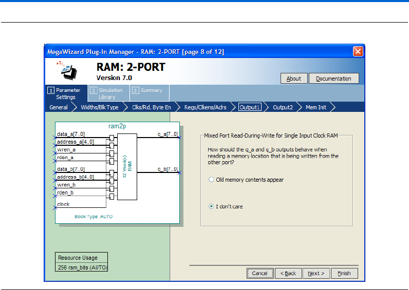
2–52 Altera Corporation
RAM Megafunction User Guide March 2007
Design Examples for the RAM Megafunctions
Figure 2–41. MegaWizard Plug-In Manager – RAM: 2-PORT [Page 8]
19. Click Next. Page 9 appears.
20. Under Port A Read-During-Write Option, in the What should the
q_a output be when reading from a memory location being
written to? section, select New Data. Be sure that the option to Get
x’s for write masked bytes instead of old data when byte enable is
used remains unchecked.
21. Under Port B Read-During-Write Option, select Old Data.
This is a new feature supported only by Stratix III and Cyclone III
devices where you can set the Read-During-Write behavior of the
outputs independently.
Figure 2–42 shows page 9 after you have made these selections.
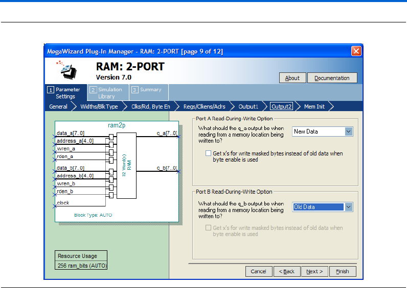
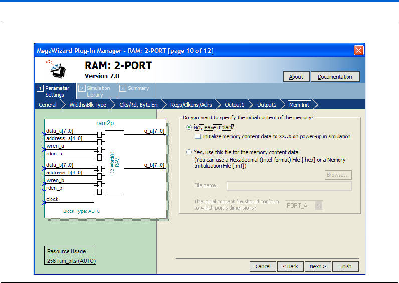
2–54 Altera Corporation
RAM Megafunction User Guide March 2007
Design Examples for the RAM Megafunctions
Figure 2–43. MegaWizard Plug-In Manager—RAM: 2-PORT [Page 10]
24. Click Finish. Page 12 appears.
25. On page 12 of the wizard (Figure 2–44), you can turn on any
additional output files you want so they can be created for the
project. Otherwise, keep the default settings.
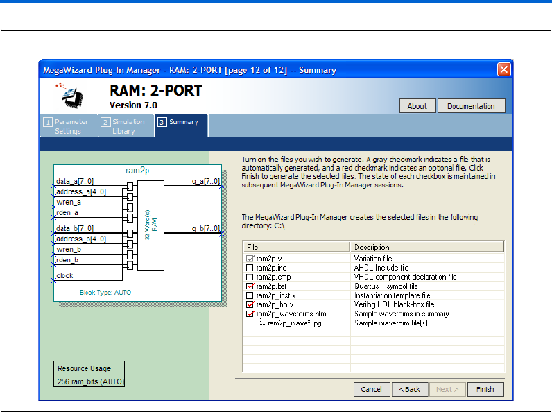
Altera Corporation 2–55
March 2007 RAM Megafunction User Guide
Getting Started
Figure 2–44. MegaWizard Plug-In Manager—RAM: 2-PORT [Page 12]
26. Click Finish.
The ram2p module is built.
Implement Dual-Port RAM
Implement the dual-port RAM in the same way you implemented the
single-port RAM in the “Example for RAM: 1-PORT” on page 2–31.
Refer to “Implement Single-Port RAM” on page 2–38 for instructions on
how to assign settings for the design. These steps (assigning settings for
the design) must be carried out before you generate the functional netlist.

2–56 Altera Corporation
RAM Megafunction User Guide March 2007
Design Examples for the RAM Megafunctions
Functional Results—Simulate the Dual-Port RAM in Quartus II
Software
Finally, simulate the design to verify the results. Set up the Quartus II
Simulator by performing the following steps:
1. On the Processing menu, click Generate Functional Simulation
Netlist.
2. When the Functional Simulation Netlist Generation was
successful message box appears, click OK.
3. On the Assignments menu, click Settings. The Settings dialog box
appears.
4. Under Category, select Simulator Settings.
5. In the Simulation mode: list, select Functional.
6. In the Simulation input: box, type
ram2p_singleclk_unregout_AnewBold.vwf or Browse (...) to
select the file from the project folder.
7. Select Run simulation until all vector stimuli are used.
8. Make sure that the Automatically add pins to simulation output
waveforms and Simulation coverage reporting options are turned
on.
9. Make sure that the Check outputs and Overwrite simulation input
file with simulation results options are off.
Figure 2–45 shows the Settings dialog box after you have made these
selections.
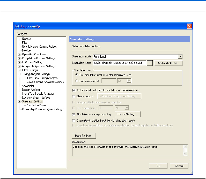
Altera Corporation 2–57
March 2007 RAM Megafunction User Guide
Getting Started
Figure 2–45. Simulator Settings Dialog Box
10. Click OK.
11. To run the simulation, on the Processing menu, click Start
Simulation.
12. When the Simulation was successful message box appears, click
OK.
13. In the Simulation Report window, view the simulation waveforms
to verify the results.
Figure 2–46 shows the expected simulation results.
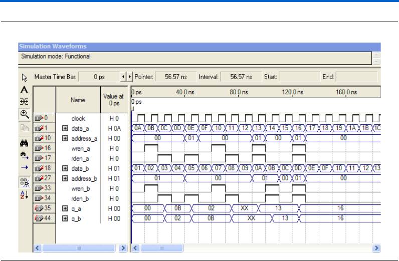
2–58 Altera Corporation
RAM Megafunction User Guide March 2007
Design Examples for the RAM Megafunctions
Figure 2–46. Functional Waveform for Single Clock Mode with Unregistered Output for Dual-Port RAM
Understanding the Simulation Results
In this example, you configured the RAM: 2-PORT to have the following
properties:
■Single clock
■Unregistered q_a and q_b outputs
■The q_a and q_b outputs to have New Data and Old Data
respectively when reading from a memory location that is
simultaneously being written
The following section explains how the simulation results correspond to
the configuration you set with the RAM: 2-PORT MegaWizard Plug-In
Manager.
Figure 2–47 shows the write operation and read operation for each port
in the dual-port RAM.
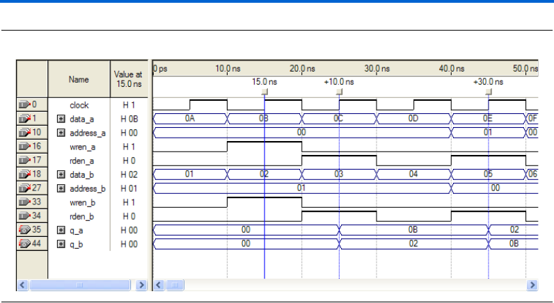
Altera Corporation 2–59
March 2007 RAM Megafunction User Guide
Getting Started
Figure 2–47. Write and Read Operations for Port A and Port B
At 15 ns, data values 0B and 02 are written to memory addresses 00 and
01, respectively. Because you configured the RAM to have unregistered
output in the design example, the data occurs on the output at the first
rising edge of the clock after both rden_a and rden_b become high. The
rden signals rise at 20 ns, and the following rising edge of the clock
occurs at 25 ns. At 40 ns, q_a and q_b swap their target memory
locations, and, as a result, at 45 ns their values become read data values
02 and 0B respectively.
Figure 2–48 shows two simultaneous write operations with different data
(on data_a and data_b) to the same memory address.
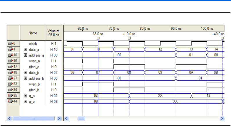
2–60 Altera Corporation
RAM Megafunction User Guide March 2007
Design Examples for the RAM Megafunctions
Figure 2–48. Different Data from data_a and data_b Written to the Same Memory Address
At 65 ns, data values from data_a and data_b are both written to the
memory address 00. Because two different data were written to the same
memory location, the output data read from that memory address
displays value XX at 75 ns. Unknown data was being written to that
memory location, because conflict resolution circuitry is not built into the
memory blocks. To avoid address conflicts, you must implement conflict
resolution logic outside of the memory block.
Figure 2–49 shows the waveforms when simultaneous read and write
operations target the same memory address.
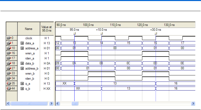
Altera Corporation 2–61
March 2007 RAM Megafunction User Guide
Getting Started
Figure 2–49. Read and Write Operations Occur at the Same Time Targeting Same Memory Address
Read and write operations occur simultaneously at 95 ns for port A.
Because you set the behavior of port A was to get new data, the new
data 13 previously written to memory address 01 is read out on q_a.
For port B, read and write operations occur simultaneously at 105 ns.
Unlike port A, port B reads out the old data 13 from memory address 01,
even though the new data 0B is written to that memory location.
Stratix III and Cyclone III devices support this feature, which allows you
to specify the Read-During-Write behavior of different ports
independently.
Functional Results—Simulate the Dual-Port RAM in the
ModelSim-Altera Software
Simulate the design in ModelSim to compare the results of both
simulators. This User Guide assumes that you are familiar with using
ModelSim-Altera before trying out the design example. If you are
unfamiliar with ModelSim-Altera, refer to the support page of the
software products page of the Altera website, (www.altera.com). On the
support page for ModelSim-Altera, there are various links to topics such
as installation, usage, and troubleshooting.
Set up the ModelSim-Altera simulator by performing the following steps:
1. Unzip the ram2p_ex2_msim.zip file to any working directory on
your PC.
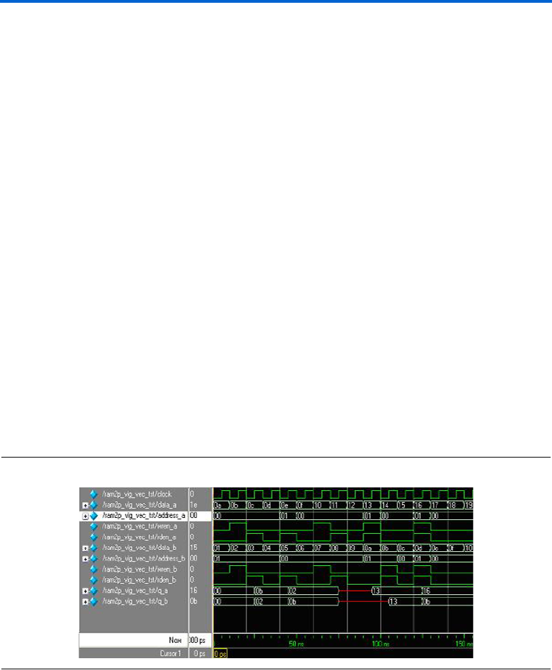
2–62 Altera Corporation
RAM Megafunction User Guide March 2007
Design Examples for the RAM Megafunctions
2. Open the ram2p_msim.do file. Ensure that the Stratix III device
library is located at the correct path in your PC; for example,
C:/altera/70/modelsim_ae/altera/verilog/stratixiii. Change it to
correct path if it is not.
3. Start ModelSim-Altera.
4. On the File menu, click Change Directory.
5. Select the folder in which you unzipped the files. Click OK.
6. On the Tools menu, click Execute Macro.
7. Select the ram2p_msim.do file and click Open. This is a script file
for ModelSim that automates all necessary settings for the
simulation.
8. Verify the results shown in the Waveform Viewer window.
You can rearrange signals, remove signals, add signals, and change the
radix by modifying the script in ram2p_msim.do accordingly to match
the order of the results in the Quartus II Simulator
Figure 2–50 shows the expected simulation results when running the
design example in ModelSim-Altera. Compare the results obtained using
the Quartus II simulator from Figure 2–46 on page 2–58. Refer to
“Understanding the Simulation Results” on page 2–58 for more details.
Figure 2–50. ModelSim Simulation Waveform for Dual-Port RAM
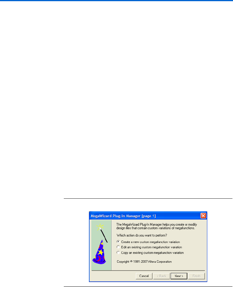
Altera Corporation 2–63
March 2007 RAM Megafunction User Guide
Getting Started
Example for RAM: 3-PORT
The objective of the examples is to implement and instantiate a tri-port
RAM using the RAM: 3-PORT MegaWizard Plug-In Manager. The
RAM: 3-PORT example illustrates tri-addressing mode (one write
address and two read addresses), and single clock with unregistered
output mode. Verify the results you obtained at the end of this example
with the expected simulation results provided.
In this example, you perform the following activities:
■Generate a tri-port RAM using the RAM: 3-PORT MegaWizard
Plug-In Manager
■Implement the tri-port RAM by assigning the Stratix III device to the
project and compiling the project
■Simulate the tri-port RAM design
Generate the Tri-Port RAM
To generate the tri-port RAM, perform the following steps:
1. Open ram3p_DesignExample_ex3.zip and extract ram3p.qar.
2. In the Quartus II software, open ram3p.qar and restore the archive
file into your working directory.
3. On the Tools menu, click MegaWizard Plug-In Manager. Page 1 of
the MegaWizard Plug-In Manager appears (Figure 2–51).
Figure 2–51. MegaWizard Plug-In Manager [Page 1]
4. Select Create a new custom megafunction variation, and click
Next. Page 2a appears.
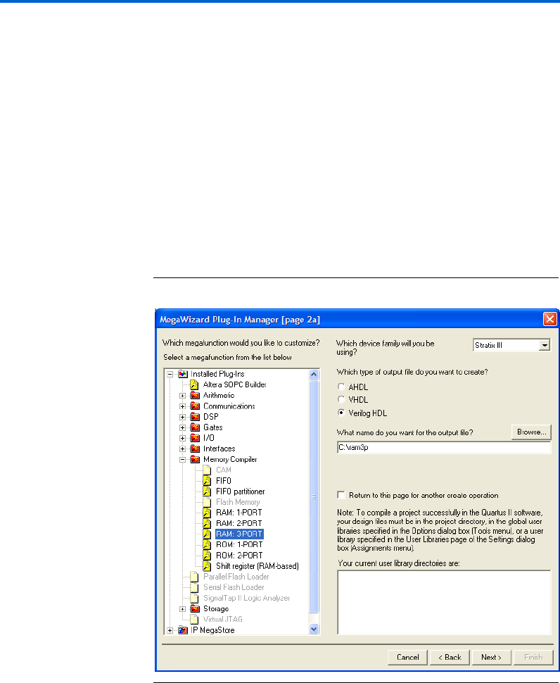
2–64 Altera Corporation
RAM Megafunction User Guide March 2007
Design Examples for the RAM Megafunctions
5. On page 2a of the MegaWizard Plug-In Manager, make the
following selections:
a. In the Which device family will you be using? list, select
Stratix III.
b. Under Which type of output file do you want to create?, select
Verilog HDL.
c. Expand the Memory Compiler and select RAM: 3-PORT.
d. For the name of the output file, type ram3p, or click Browse to
select the file from the project folder.
Figure 2–52 shows page 2a after you have made these selections.
Figure 2–52. MegaWizard Plug-In Manager – RAM: 3-PORT [Page 2a]
e. Click Next. Page 3 appears.
6. On page 3 of the wizard, make the following selections:
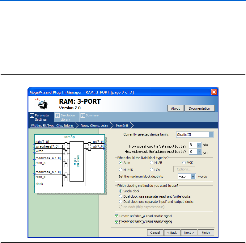
Altera Corporation 2–65
March 2007 RAM Megafunction User Guide
Getting Started
a. Under Which clocking method do you want to use?, select
Single clock.
b. Check the box to turn on Create an 'rden_a' read enable signal.
c. Check the box to turn on Create an 'rden_b' read enable signal.
d. Keep all other settings as the default, as shown in Figure 2–53.
Figure 2–53. MegaWizard Plug-In Manager – RAM: 3-PORT [Page 3]
e. Click Next. Page 4 appears.
7. Under Which ports should be registered?, uncheck the boxes for
Read output port 'qA' and Read output port 'qB', as shown in
Figure 2–54.
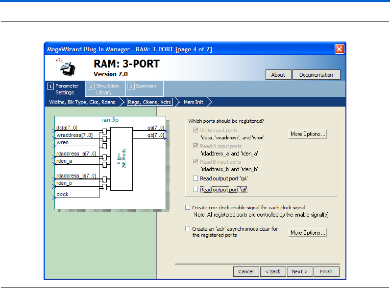
2–66 Altera Corporation
RAM Megafunction User Guide March 2007
Design Examples for the RAM Megafunctions
Figure 2–54. MegaWizard Plug-In Manager – RAM: 3-PORT [Page 4]
Click Next. Page 5 appears.
8. For Do you want to specify the initial content of the memory?,
keep the default setting of No, leave it blank, as shown in
(Figure 2–55).
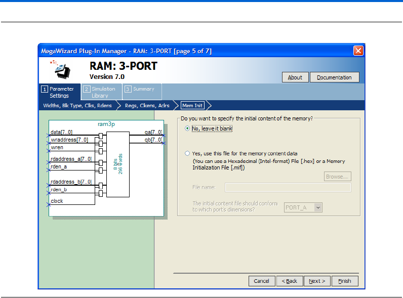
Altera Corporation 2–67
March 2007 RAM Megafunction User Guide
Getting Started
Figure 2–55. MegaWizard Plug-In Manager —RAM: 3-PORT [Page 5]
Click Finish. Page 7 appears.
9. On page 7 of the wizard (Figure 2–56), you can turn on any
additional output files you want so they can be created for the
project. Otherwise, keep the default settings and click Finish.
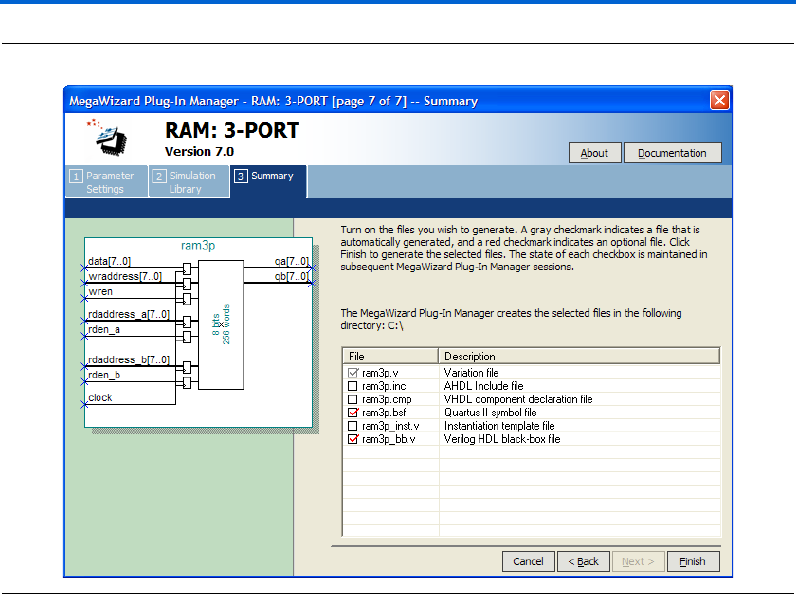
2–68 Altera Corporation
RAM Megafunction User Guide March 2007
Design Examples for the RAM Megafunctions
Figure 2–56. MegaWizard Plug-In Manager – RAM: 3-PORT [Page 7]
The ram3p module is built.
Implement the Tri-Port RAM
Implement the dual-port RAM in the same way you implemented the
single-port RAM in the “Example for RAM: 1-PORT” on page 2–31.
Refer to “Implement Single-Port RAM” on page 2–38 for instructions on
how to assign settings for the design. These steps (assigning settings for
the design) must to be carried out before you generate the functional
netlist.
Functional Results—Simulate the Tri-Port RAM in the Quartus II
Software
Finally, simulate the design to verify the results. Set up the Quartus II
Simulator by performing the following steps:
1. On the Processing menu, click Generate Functional Simulation
Netlist.

Altera Corporation 2–69
March 2007 RAM Megafunction User Guide
Getting Started
2. When the Functional Simulation Netlist Generation was
successful message box appears, click OK.
3. On the Assignments menu, click Settings. The Settings dialog box
appears.
4. Under Category, select Simulator Settings.
5. In the Simulation mode: list, select Functional.
6. In the Simulation input: box, type
ram3p_singleclk_unregout.vwf, or Browse (...) to select the
file from the project folder.
7. Select Run simulation until all vector stimuli are used.
8. Make sure that the Automatically add pins to simulation output
waveforms and Simulation coverage reporting options are turned
on.
9. Make sure that the Check outputs and Overwrite simulation input
file with simulation results options are off.
Figure 2–57 shows the Simulation Settings Dialog Box after you have
made these selections.

2–70 Altera Corporation
RAM Megafunction User Guide March 2007
Design Examples for the RAM Megafunctions
Figure 2–57. Simulator Settings Dialog Box
10. Click OK.
11. To run the simulation, on the Processing menu, click Start
Simulation.
12. When the Simulation was successful message box appears, click
OK.
13. In the Simulation Report window, view the simulation waveforms
to verify the results. Figure 2–58 shows the expected simulation
results.
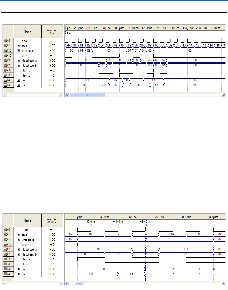
Altera Corporation 2–71
March 2007 RAM Megafunction User Guide
Getting Started
Figure 2–58. Functional Waveform for Single Clock Mode with Unregistered Output for Tri-Port RAM
Understanding the Simulation Results
In this example, you configured the RAM: 3-PORT to have the following
properties:
■Single clock
■Unregistered outputs qa and qb
The following section explains how the simulation results correspond to
the configuration you set with the RAM: 3-PORT MegaWizard Plug-In
Manager.
Figure 2–59 shows simultaneous read operations for port A and port B.
Figure 2–59. Simultaneous Read Operations for Port A and Port B
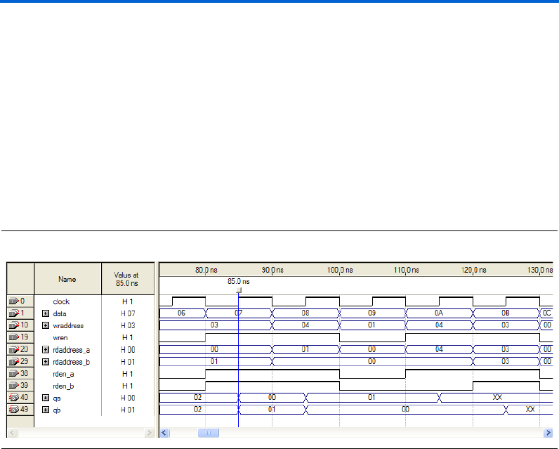
2–72 Altera Corporation
RAM Megafunction User Guide March 2007
Design Examples for the RAM Megafunctions
Data 00, 01, and 02 are written to memory addresses 00, 01, and 02 at
15 ns, 25 ns, and 35 ns respectively when wren is HIGH. At 45 ns, data
value 00 is read from memory address 00 via port A, and appears on qa.
At 55 ns, data value 01 is read from memory address 01 via port B, and
appears on qb.
At 65 ns, qa and qb simultaneously read data value 02 from the memory
address 02.
The tri-port RAM also supports simultaneous read and write operations.
Figure 2–60 shows read and write operations that occur simultaneously
and target different memory addresses.
Figure 2–60. Simultaneous Read and Write Operations Targeting Different Memory Addresses
Read and write operations occur simultaneously at 85 ns, targeting
different memory addresses. During the write operation, data value 07 is
written to memory address 03. In the read operations, qa and qb read
data values 00 and 01 from memory addresses 00 and 01, respectively.
read addresses and the write address are all different.
Figure 2–61 shows read and write operations that occur simultaneously
and target the same memory address.
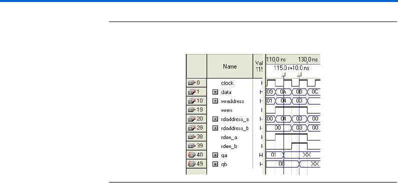
Altera Corporation 2–73
March 2007 RAM Megafunction User Guide
Getting Started
Figure 2–61. Simultaneous Read and Write Operations Targeting the Same
Memory Address
At 115 ns, a port A read operation and a write operation both target
memory address 04. The previous value at this memory location is 08.
The write operation writes data value 0A. Because the tri-port RAM
(unlike the RAM:1-PORT and RAM_2-PORT in Stratix III and Cyclone III
devices) does not support the Read-During-Write feature, the qa output
now displays the XX value.
At 125 ns, a port B read operation and a write operation both target
memory address 03. The previous value at this memory location is 07.
The write operation writes data value 0B. Because the tri-port RAM does
not support the Read-During-Write feature, the qb output now displays
the XX value.
To avoid the undefined data values that result from address conflicts, you
must implement conflict resolution logic outside the memory block.
Functional Results—Simulate the Tri-Port RAM in the
ModelSim-Altera Software
Simulate the design in ModelSim to compare the results of both
simulators. This User Guide assumes that you are familiar with using
ModelSim-Altera before trying out the design example. If you are
unfamiliar with ModelSim-Altera, refer to the support page of the
software products page of the Altera website, (www.altera.com). On the
support page for ModelSim-Altera, there are various links to topics such
as installation, usage, and troubleshooting.
Set up the ModelSim-Altera simulator by performing the following steps:
1. Unzip the ram3p_ex3_msim.zip file to any working directory on
your PC.
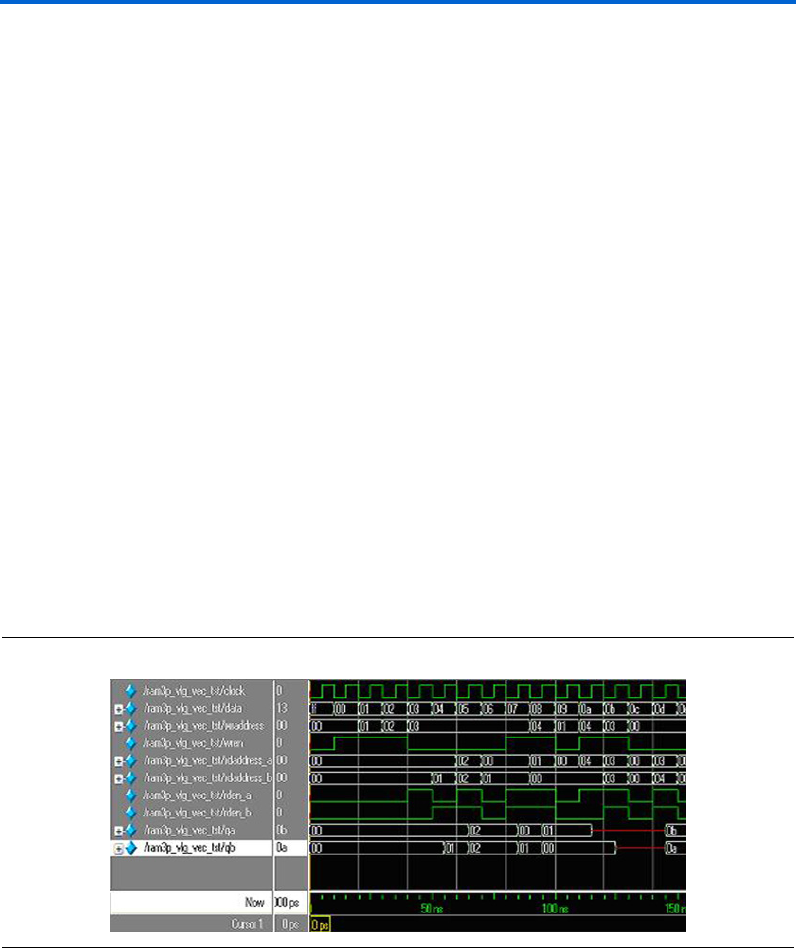
2–74 Altera Corporation
RAM Megafunction User Guide March 2007
Design Examples for the RAM Megafunctions
2. Open the ram3p_msim.do file. Ensure that the Stratix III device
library is located at the correct path in your PC; for example,
C:/altera/70/modelsim_ae/altera/verilog/stratixiii. Change it to
correct path if it is not.
3. Start ModelSim-Altera.
4. On the File menu, click Change Directory.
5. Select the folder in which you unzipped the files. Click OK.
6. On the Tools menu, click Execute Macro.
7. Select the ram3p_msim.do file and click Open. This is a script file
for ModelSim that automates all necessary settings for the
simulation.
8. Verify the results shown in the Waveform Viewer window.
You can rearrange signals, remove signals, add signals, and change the
radix by modifying the script in ram3p_msim.do accordingly to match
the order of the results in the Quartus II Simulator.
Figure 2–62 shows the expected simulation results when running the
design example in ModelSim-Altera. Compare the results obtained using
the Quartus II simulator from Figure 2–58 on page 2–71.
Figure 2–62. ModelSim Simulation Waveform for Single-Port RAM

Altera Corporation 2–75
March 2007 RAM Megafunction User Guide
Getting Started
Conclusion The Quartus II software provides parameterizable RAM megafunctions
through RAM:1-PORT, RAM:2-PORT, and RAM:3-PORT MegaWizard
Plug-In Manager. With these megafunctions, you can easily configure
your RAM design with other support features, such as different clocking
modes, read enable, byte enable, clock enable, asynchronous clear,
read-during-write, and others feature. These megafunctions are
performance-optimized for Altera devices and therefore, provide more
efficient logic synthesis and device implementation, because they
automate the coding process and save valuable design time. In addition,
it is easy to re-configure the characteristics of your RAM design through
the easy-to-use GUI. Altera recommends using these functions during
design implementation so you can consistently meet your design goals.

2–76 Altera Corporation
RAM Megafunction User Guide March 2007
Conclusion

Altera Corporation 3–1
March 2007 RAM Megafunction User Guide
3. Specifications
Introduction The Quartus®II software provides four megafunctions that support
single-port, dual-port, and tri-port RAM functionality: lpm_ram_dq,
altdpram, altsyncram, and alt3pram.
One of the megafunctions implements your RAM, depending on your
targeted device and the configurations you set with the MegaWizard®
Plug-In Manager. Refer to Table 1–1 on page 1–2 for more details about
the wizard.
The parameter details are only relevant for users who bypass the
MegaWizard Plug-In Manager interface and use the megafunction as a
directly parameterized instantiation in their design. The details of these
parameters are hidden from MegaWizard Plug-In Manager interface
users.
fRefer to the latest version of the Quartus II software Help for the most
current information about the ports and parameters for these
megafunctions.
Ports and
Parameters for
the lpm_ram_dq
Megafunction
Table 3–1 shows the input ports, Table 3–2 on page 3–2 shows the output
ports, and Table 3–3 on page 3–2 shows the lpm_ram_dq megafunction
parameters.
Table 3–1. lpm_ram_dq Megafunction Input Ports
Port Name
Required?
Description
data[] vData input to the memory. Input port LPM_WIDTH wide.
address[] vAddress input to the memory. Input port LPM_WIDTHAD wide.

3–2 Altera Corporation
RAM Megafunction User Guide March 2007
Ports and Parameters for the lpm_ram_dq Megafunction
we vWrite enable input. Enables write operations to the memory when high.
Required if inclock is not present. If only the we port is used, the data on the address[]
port should not change while we is high. If the data on the address[] port changes
while the we port is high, all memory locations that are addressed are overwritten with
data[].
inclock — Synchronizes memory loading.
If the inclock port is used, the we port acts as an enable for write operations
synchronized to the rising edge of the inclock signal. If the inclock port is not used, the
we port acts as an enable for asynchronous write operations. In addition, if the inclock
port is not used, the LPM_INDATA and LPM_ADDRESS_CONTROL parameters should
be set to UNREGISTERED.
outclock — Synchronizes q outputs from memory.
The addressed memory content-to-q[] response is synchronous when the outclock
port is connected, and asynchronous when it is not connected. In addition, if the
outclock port is not used, the LPM_OUTDATA parameter should be set to
UNREGISTERED.
Table 3–2. lpm_ram_dq Megafunction Output Ports
Port Name Required? Description
q[] vData output from the memory. Output port LPM_WIDTH wide.
Table 3–3. lpm_ram_dq Megafunction Parameters (Part 1 of 4)
Parameter Type
Required?
Description
LPM_WIDTH Integer vWidth of data[] and q[] ports.
LPM_WIDTHAD Integer vWidth of the address port. LPM_WIDTHAD should be (but is not
required to be) equal to log2(LPM_NUMWORDS). If LPM_WIDTHAD
is too small, some memory locations will not be addressable. If it is
too large, the addresses that are too high will return undefined (X)
logic levels.
Table 3–1. lpm_ram_dq Megafunction Input Ports
Port Name
Required?
Description

Altera Corporation 3–3
March 2007 RAM Megafunction User Guide
Specifications
LPM_NUMWORDS Integer — Number of words stored in memory. In general, this value should be
(but is not required to be) 2 ^ LPM_WIDTHAD-1 <
LPM_NUMWORDS <= 2 ^ LPM_WIDTHAD. If omitted, the default
is 2 ^ LPM_WIDTHAD.
LPM_FILE String — Name of the Memory Initialization File (.mif) or Hexadecimal (Intel-
Format) Output File (.hex) containing ROM initialization data (“<file
name>”), or UNUSED. If omitted, contents default to all zeros. The we
port must be registered to support memory initialization.
LPM_INDATA String — Values are REGISTERED, UNREGISTERED, and UNUSED.
Controls whether the data port is registered. If omitted, the default is
REGISTERED. If the inclock port is not used, the LPM_INDATA and
LPM_ADDRESS_CONTROL parameters should be set to
UNREGISTERED.
LPM_ADDRESS_CONTROL String — Values are REGISTERED, UNREGISTERED, and UNUSED.
Controls whether the address port is registered. If omitted, the
default is REGISTERED.
If LPM_ADDRESS_CONTROL is UNREGISTERED, the we port is
level-sensitive, so that when the we port is high, the address[]
port must be stable to prevent other memory locations from being
overwritten. If the inclock port is not used, the LPM_INDATA and
LPM_ADDRESS_CONTROL parameters should be set to
UNREGISTERED.
LPM_OUTDATA String — Values are REGISTERED, UNREGISTERED, and UNUSED.
Controls whether the q and internal eq ports are registered. If
omitted, the default is REGISTERED. If the outclock port is not
used, the LPM_OUTDATA parameter should be set to
UNREGISTERED.
LPM_HINT String — Allows you to assign Altera-specific parameters in VHDL Design
Files (.vhd). These parameter are used for synthesis purposes only.
If omitted, the default is UNUSED.
When you instantiate a library of parameterized modules (LPM)
function in a VHDL Design File (.vhd), you must use the LPM_HINT
parameter to specify an Altera-specific parameter.
For example:
LPM_HINT = "CHAIN_SIZE = 8,
ONE_INPUT_IS_CONSTANT = YES"
Table 3–3. lpm_ram_dq Megafunction Parameters (Part 2 of 4)
Parameter Type
Required?
Description

3–4 Altera Corporation
RAM Megafunction User Guide March 2007
Ports and Parameters for the lpm_ram_dq Megafunction
LPM_TYPE String — Identifies the library of parameterized modules (LPM) entity name in
VHDL Design Files.
ENABLE_RUNTIME_MOD String — Altera-specific parameter. You must use the LPM_HINT parameter
to specify the ENABLE_RUNTIME_MOD parameter in VHDL Design
Files.
Values are YES or NO.
The ENABLE_RUNTIME_MOD allows you to use the lpm_ram_dq
megafunction with the In-System Memory Content Editor. When
the ENABLE_RUNTIME_MOD parameter is specified to YES, the
INSTANCE_NAME must be specified. If omitted, the default is
NONE.
Table 3–3. lpm_ram_dq Megafunction Parameters (Part 3 of 4)
Parameter Type
Required?
Description

Altera Corporation 3–5
March 2007 RAM Megafunction User Guide
Specifications
INSTANCE_NAME String — Altera-specific parameter. You must use the LPM_HINT parameter
to specify the INSTANCE_NAME parameter in VHDL Design Files.
String values must be a maximum of 4 characters long.
To specify a string value for the INSTANCE_NAME parameter in
VHDL Design Files, you must use the LPM_HINT parameter. The
INSTANCE_NAME parameter is used to identify the instance used
with the In-System Memory Content Editor. The value of the
INSTANCE_NAME parameter appears in the Instance ID column of
the In-System Memory Content Editor.
USE_EAB String — Altera-specific parameter. You must use the LPM_HINT parameter
to specify the USE_EAB parameter in VHDL Design Files.
Values are ON, OFF, and UNUSED.
Setting the USE_EAB parameter to OFF prevents the Quartus II
software from using Embedded System Blocks (ESBs) to implement
the logic in APEX 20K, APEX II, and Mercury devices, or Embedded
Array Blocks (EABs) in ACEX 1K and FLEX 10KE devices; it can
only use registers or latches. (The ON setting is not useful in memory
functions: the Quartus II software automatically implements
memory functions in ESBs or EABs by default.)
This parameter is not available for simulation with other EDA
simulators and for FLEX 6000, MAX 3000, and MAX 7000 devices.
If you wish to use this parameter when you instantiate the function
in a Block Design File (.bdf), you must specify it by entering the
parameter name and value manually with the Parameters tab in the
Symbol Properties dialog box or in the Block Properties dialog
box. You can also use this parameter name in a Text Design File
(.tdf) or a Verilog Design File (.v).
Table 3–3. lpm_ram_dq Megafunction Parameters (Part 4 of 4)
Parameter Type
Required?
Description

3–6 Altera Corporation
RAM Megafunction User Guide March 2007
Ports and Parameters for the altdpram Megafunction
Ports and
Parameters for
the altdpram
Megafunction
Table 3–4 shows the input ports, Table 3–5 on page 3–7 shows the output
ports, and Table 3–6 on page 3–7 shows the altdpram megafunction
parameters.
Table 3–4. altdpram Megafunction Input Ports (Part 1 of 2)
Port Name
Required?
Description
data[] vData input to the memory. Input port WIDTH wide.
rdaddress[] vRead address input to the memory. Input port WIDTHAD wide.
rdaddressstall[] — Read address stall input port. The rdaddress port must be registered.
For Stratix III devices, the USE_EAB parameter value must be ON and the
RAM_BLOCK_TYPE parameter value must be MLAB. For other device families,
the value must be GND.
wraddress[] vWrite address input to the memory. Input port WIDTHAD wide.
wraddressstall[] —Write address stall input port. The wraddress port must be registered.
For Stratix III devices, the USE_EAB parameter value must be ON and the
RAM_BLOCK_TYPE parameter value must be set to MLAB. For other device
families, the value must be GND.
byteena — Byte enable input port.
Input port [WIDTH_BYTEENA - 1..0] wide.
For Stratix III devices, the USE_EAB parameter value must be ON, the
RAM_BLOCK_TYPE parameter value must be set to MLAB, and the WIDTH
parameter must be a non-unary multiple of the BYTE_SIZE parameter. For other
device families, the value must be VCC.
wren vWrite enable input port.
inclock — Positive-edge-triggered input clock port.
Used for registered write ports; for example, data, wraddress, and wren.
Can also be used for registered read ports; for example, rdaddress and rden.
inclocken —Clock enable port for inclock.
Altera Corporation 3–7
March 2007 RAM Megafunction User Guide
Specifications
1When the altdpram megafunction is used with the APEX 20K
device family, and both the WRADDRESS_REG and
WRCONTROL_REG parameters are set to INCLOCK, the value of
the WRADDRESS_ACLR and WRCONTROL_ACLR parameters must
be the same.
rden —Read enable input. Disables reading when low (0).
In ACEX 1K, APEX 20K, APEX 20KE, APEX II, FLEX 6000, FLEX 10KE, and
Mercury devices, the rden port controls a latch that remembers the value last
read while the rden port was high. In APEX 20K devices, the rden port
becomes a power-down signal.
outclock — Positive-edge-triggered input clock port.
Used for the registered q[] port. Can also be used for registered read ports; for
example, rdaddress and rden.
outclocken — Clock enable port for outclock.
aclr — Asynchronous clear input. Affects registered inputs and outputs.
Table 3–5. altdpram Megafunction Output Ports
Port Name Required? Description Comments
q[] vData output from the memory. Output port WIDTH wide.
Table 3–4. altdpram Megafunction Input Ports (Part 2 of 2)
Port Name
Required?
Description
Table 3–6. altdpram Megafunction Parameters
Parameter Type
Required?
Description
WIDTH Integer vWidth of data[] and q[] ports.
WIDTHAD Integer vWidth of the rdaddress[] and wraddress[] ports.
BYTE_SIZE Integer — Specifies the byte size for the byte-enable mode.
For Stratix III devices, values are 5, 8, 9, and 10. Values 5 and
10 are supported widths, values 8 and 9 are available for
backward compatibility with Stratix II device M512 blocks.
For all other families, values are 8 and 9.

3–8 Altera Corporation
RAM Megafunction User Guide March 2007
Ports and Parameters for the altdpram Megafunction
WIDTH_BYTEENA Integer — Specifies the width of the byteena input port.
The WIDTH_BYTEENA parameter value must be equal to
WIDTH_B / BYTE_SIZE for Stratix III devices. For all other
devices families, the default value is 1.
RAM_BLOCK_TYPE String — Values are AUTO, M-RAM(MEGARAM), M4K, M512, M9K,
M144K, and MLAB.
When USE_EAB parameter value is ON, the result is a
block-ram implementation, and the RAM_BLOCK_TYPE is set
to MLAB. When USE_EAB parameter value is OFF, the result is
a logic cell implementation.
NUMWORDS Integer — Number of words stored in memory.
This value must be within the range 2 ^ WIDTHAD-1 <
NUMWORDS <= 2 ^ WIDTHAD. If omitted, the default is 2 ^
WIDTHAD.
LPM_FILE String — Name of the Memory Initialization File (.mif) or Hexadecimal
(Intel-Format) Output File (.hex) containing RAM initialization
data (“<file name>”), or UNUSED.
The default is UNUSED. If omitted, default for all contents is 0.
The wren port must be registered to support memory
initialization.
READ_DURING_WRITE_MOD
E_MIXED_PORTS
String — Read during write mode behavior. Values are DONT_CARE,
OLD_DATA, and NEW_DATA. If omitted, the default is
DONT_CARE.
Values of OLD_DATA and NEW_DATA are supported only if the
rdaddress input port and the q[] output port are registered
by the write clock. If omitted, the default is NEW_DATA.
WRADDRESS_REG String — Determines the clock used by the wraddress[] port.
Values are UNREGISTERED and INCLOCK. The default is
INCLOCK.
WRADDRESS_ACLR String — Defines whether aclr affects the wraddress[] port register.
Values are ON and OFF. The default is ON. Legal values for
Stratix III devices is OFF
Table 3–6. altdpram Megafunction Parameters
Parameter Type
Required?
Description

Altera Corporation 3–9
March 2007 RAM Megafunction User Guide
Specifications
WRCONTROL_REG String — Determines the clock used by the wren port.
Values are UNREGISTERED and INCLOCK. The default is
INCLOCK and is the only legal value for Stratix III devices.
WRCONTROL_ACLR String — Defines whether aclr affects the wren port register.
Values are ON and OFF. The default is ON.
RDADDRESS_REG String — Determines the clock used by the rdaddress[] port.
Values are UNREGISTERED, INCLOCK, and OUTCLOCK. The
default is OUTCLOCK.
RDADDRESS_ACLR String — Defines whether aclr affects the rdaddress[] port.
Values are ON and OFF. The default is ON. The legal value for
Stratix III devices is OFF.
RDCONTROL_REG String — Determines the clock used by the rden port.
Values are UNREGISTERED, INCLOCK, and OUTCLOCK. The
default is OUTCLOCK.
RDCONTROL_ACLR String — Defines whether aclr affects the rden port register.
Values are ON and OFF. The default is ON.
INDATA_REG String — Determines the clock used by the data port.
Values are UNREGISTERED and INCLOCK. The default is
INCLOCK.
INDATA_ACLR String — Defines whether aclr affects the data[] port register.
Values are ON and OFF. The default is ON. Legal value for
Stratix III devices is OFF only.
OUTDATA_REG String — Determines the clock used by the q[] port.
Legal values for Stratix III devices are UNREGISTERED,
INCLOCK, and OUTCLOCK. The default is UNREGISTERED.
INCLOCK is legal value for Stratix III MLAB mode only to
provide support for
read_during_write_mode_mixed_ports.
Table 3–6. altdpram Megafunction Parameters
Parameter Type
Required?
Description

3–10 Altera Corporation
RAM Megafunction User Guide March 2007
Ports and Parameters for the altdpram Megafunction
OUTDATA_ACLR String — Defines whether aclr affects the q[] port register.
Values are ON and OFF. The default is ON.
LPM_HINT String — Allows you to specify Altera-specific parameters in VHDL
Design Files (.vhd). The default is UNUSED.
LPM_TYPE String — Identifies the library of parameterized modules (LPM) entity
name in VHDL Design Files.
INTENDED_DEVICE_
FAMILY
String — This parameter is used for modeling and behavioral simulation
purposes. Create the altdpram megafunction with the
MegaWizard Plug-in Manager to calculate the value for this
parameter.
MAXIMUM_DEPTH Integer — Specifies the slicing depth of the RAM slices.
USE_EAB String — Altera-specific parameter. You must use the LPM_HINT
parameter to specify the USE_EAB parameter in VHDL Design
Files.
Values for Stratix III are ON and OFF. Values for all other
devices are ON, OFF, and UNUSED.
Setting the USE_EAB parameter to OFF prevents the Quartus II
software from using Embedded System Blocks (ESB)s to
implement the logic in APEX 20K, APEX II, and Mercury
devices, or Embedded Array Blocks (EABs) in ACEX 1K and
FLEX 10KE devices; it can only use registers or latches.
The ON setting is not useful in memory functions: the Quartus II
software automatically implements memory functions in ESBs
or EABs by default.
This parameter is not available for simulation with other EDA
simulators and for FLEX 6000, MAX 3000, and MAX 7000.
Table 3–6. altdpram Megafunction Parameters
Parameter Type
Required?
Description

Altera Corporation 3–11
March 2007 RAM Megafunction User Guide
Specifications
Ports and
Parameters for
the altsyncram
Megafunction
Table 3–7 shows the input ports, Table 3–8 on page 3–13 shows the
output ports, and Table 3–9 on page 3–13 shows the altsyncram
megafunction parameters.
Table 3–7. altsyncram Megafunction Input Ports
Port Name
Required?
Description
wren_a — Write enable input.
The wren_a port is not available when the OPERATION_MODE parameter is set to
ROM mode.
rden_a — Read enable input port.
This port is available for Stratix III and Cyclone III devices only. Not available in
MLAB mode.
wren_b — Write enable input.
The wren_b input port is available only when the OPERATION_MODE parameter is
set to BIDIR_DUAL_PORT.
rden_b — Read enable input port.
The rden_b input port is available only when the OPERATION_MODE parameter is
set to DUAL_PORT and when the RAM_BLOCK_TYPE parameter is not set to
M-RAM.
For Stratix III devices, a value of BIDIR_DUAL_PORT is also available, but it is not
supported in MLAB mode.
data_a[] — Data input port to the memory for port A.
Input port [WIDTH_A - 1..0] wide.
data_b[] — Data input port to the memory for port B.
Input port [WIDTH_B - 1..0] wide.
address_a[] vAddress input to the memory for port A.
Input port [WIDTHAD_A - 1..0] wide.
address_b[] vAddress input to the memory for port B.
Input port [WIDTHAD_B - 1..0] wide.
clock0 vClock input port for the RAM.

3–12 Altera Corporation
RAM Megafunction User Guide March 2007
Ports and Parameters for the altsyncram Megafunction
clock1 — Clock input port for the RAM.
clocken0 —Clock enable for clock0.
clocken1 —Clock enable for clock1.
clocken2 —Clock enable for clock1.
This port is available for Stratix III devices only.
clocken3 —Additional clock enable for clock1. Defaults to VCC.
This port is available for Stratix III devices only.
aclr0 — The first asynchronous clear input.
aclr1 — The second asynchronous clear input.
byteena_a[] — Byte enable input port.
Input port WIDTH_BYTEENA_A-1..0 wide. The byteena_a enable input port
can be used only when the data_a port is at least 2 bytes wide.
byteena_b[] — Byte enable input port.
Input port WIDTH_BYTEENA_B-1..0 wide. The byteena_b enable input port
can be used only when the data_b port is at least 2 bytes wide.
addressstall_a — Address stall input for port A.
This port is available for supported device (Cyclone II, Cyclone III, HardCopy II,
Stratix II, Stratix II GX, and Stratix III) families.
addressstall_b — Address stall input for port B.
This port is available for supported device (Cyclone II, Cyclone III, HardCopy II,
Stratix II, Stratix II GX, and Stratix III) families.
Table 3–7. altsyncram Megafunction Input Ports
Port Name
Required?
Description

Altera Corporation 3–13
March 2007 RAM Megafunction User Guide
Specifications
Table 3–8. altsyncram Megafunction Output Ports
Port Name
Required?
Description
q_a[] vData output port from the memory.
Output port [WIDTH_A - 1..0] wide. The q_a[] port is legal only when the
OPERATION_MODE parameter is set to SINGLE_PORT, BIDIR_DUAL_PORT, or ROM.
q_b[] vData output port from the memory.
Output port [WIDTH_B - 1..0] wide. The q_b[] port is legal only when the
OPERATION_MODE parameter is set to DUAL_PORT or BIDIR_DUAL_PORT.
eccstatus[] — Status output for the memory core clock enable (ECC).
Output port [2..0] wide. This port is available only for Stratix III devices. The following
conditions must be met to use this port:
●The value of operation_mode must be DUAL_PORT
●The value of WIDTH_A must be the same as the value of WIDTH_B
●The value of RAM_BLOCK_TYPE must be M144K
Table 3–9. altsyncram Megafunction Parameters (Part 1 of 8)
Parameter Type
Required?
Description
OPERATION_MODE String vSpecifies the operation of the RAM.
Values are SINGLE_PORT, DUAL_PORT,
BIDIR_DUAL_PORT, or ROM. If omitted, the default is
BIDIR_DUAL_PORT.
WIDTH_A Integer vSpecifies the width of the data_a[] input port. If omitted, the
default is 1.
WIDTHAD_A Integer vSpecifies the width of the address_a[] input port. If omitted,
the default is 1.
NUMWORDS_A Integer — Number of words stored in memory. If omitted, the default is 2
^ WIDTHAD_A.
OUTDATA_REG_A String — Specifies the clock for the q_a[] output port.
Values are CLOCK0, CLOCK1, UNREGISTERED, or UNUSED. If
omitted, the default is UNREGISTERED.

3–14 Altera Corporation
RAM Megafunction User Guide March 2007
Ports and Parameters for the altsyncram Megafunction
ADDRESS_ACLR_A String — Specifies the asynchronous clear for the address_a[] port.
Values are CLEAR0 and NONE. If omitted, the default is NONE.
For Cyclone II, Cyclone III, Stratix II, and Stratix III devices, the
value must be set to NONE.
OUTDATA_ACLR_A String — Specifies the asynchronous clear for the q_a[] output port.
Values are CLEAR0, CLEAR1, or NONE. If omitted, the default
is NONE.
Specifies the asynchronous clear parameter for the output latch
in Stratix III and Cyclone III devices when the
OUTDATA_REG_A parameter is set to UNREGISTERED,
except in MLAB mode.
INDATA_ACLR_A String — Specifies the asynchronous clear for the data_a[] input port.
Values are CLEAR0, NONE, or UNUSED. If omitted, the default
is NONE.
For Stratix III and Cyclone III devices, the value must be set to
NONE.
WRCONTROL_ACLR_A String — Specifies the asynchronous clear for the wren_ainput port.
Values are CLEAR0, NONE, or UNUSED. If omitted, the default
is NONE. For Stratix III and Cyclone III devices, the value must
be set to NONE.
If the value of the RAM_BLOCK_TYPE parameter is M512 in
SINGLE_PORT mode, the value must be set to NONE.
BYTEENA_ACLR_A String — Specifies the asynchronous clear for the byteena_a[] input
port.
Value is NONE. For Cyclone and Stratix devices, a value of
CLEAR0 is also allowed. For Stratix III and Cyclone III devices,
the value must be set to NONE.
WIDTH_BYTEENA_A Integer — Specifies the width of the byteena_a[] input port.
The WIDTH_BYTEENA_A parameter value must be equal to
WIDTH_A / BYTE_SIZE. Default of 1 is allowed when
byte-enable is not used.
Table 3–9. altsyncram Megafunction Parameters (Part 2 of 8)
Parameter Type
Required?
Description

Altera Corporation 3–15
March 2007 RAM Megafunction User Guide
Specifications
WIDTH_B Integer — Specifies the width of the data_b[] input port.
When the OPERATION_MODE parameter is set to DUAL_PORT
mode, the WIDTH_B parameter is required. If omitted, the
default is 1.
WIDTHAD_B Integer — Specifies the width of the address_b[] input port. If omitted,
the default is 1.
NUMWORDS_B Integer — Number of words stored in memory. If omitted, the default is
2 ^ WIDTHAD_B.
RDCONTROL_REG_B String — Specifies the clock for the rden_b port during read mode.
Values are CLOCK0 and CLOCK1. If omitted, the default is
CLOCK1.
INDATA_REG_B String — Specifies the clock for the data_b[] port.
Values are CLOCK0 and CLOCK1. If omitted, the default is
CLOCK1.
WRCONTROL_WRADDRESS_R
EG_B
String — Specifies the clock for the wren_b and address_b[] port
during write mode.
Values are CLOCK0 and CLOCK1. If omitted, the default is
CLOCK1.
BYTEENA_REG_B String — Specifies the clock for the byteena_b[] port.
Values are CLOCK0 and CLOCK1. If omitted, the default is
CLOCK1.
OUTDATA_REG_B String — Specifies the clock for the q_b[] port.
Values are CLOCK0, CLOCK1, and UNREGISTERED. If
omitted, the default is UNREGISTERED.
OUTDATA_ACLR_B String — Specifies the asynchronous clear for the q_b[] output port.
Values are CLEAR0, CLEAR1, and NONE. If omitted, the default
is NONE.
Specifies the asynchronous clear parameter for the output latch
in Stratix III and Cyclone III devices when the
OUTDATA_REG_B parameter is set to UNREGISTERED except
in MLAB.
Table 3–9. altsyncram Megafunction Parameters (Part 3 of 8)
Parameter Type
Required?
Description

3–16 Altera Corporation
RAM Megafunction User Guide March 2007
Ports and Parameters for the altsyncram Megafunction
RDCONTROL_ACLR_B String — Specifies the asynchronous clear for the rden_b input port.
Values are CLEAR0, CLEAR1, NONE, or UNUSED. The default
value is NONE.
For Cyclone II, Cyclone III, Stratix II, and Stratix III devices, the
value must be set to NONE.
If the value of the RAM_BLOCK_TYPE parameter is M512 in
DUAL_PORT mode, the value must be set to NONE.
INDATA_ACLR_B String — Specifies the asynchronous clear for the data_b[] input port.
Values are CLEAR0, NONE, or UNUSED. If omitted, the default
is NONE.
For Stratix III and Cyclone III devices, the value must be set to
NONE.
WRCONTROL_ACLR_B String — Specifies the asynchronous clear for the wren_binput port.
Values are CLEAR0, NONE, or UNUSED. If omitted, the default
is NONE.
For Stratix III and Cyclone III devices, the value must be set to
NONE.
ADDRESS_ACLR_B String — Specifies the asynchronous clear for the address_b[] port.
Values are CLEAR0 and NONE. If omitted, the default is NONE.
For Cyclone II and Stratix II devices, the value must be set to
NONE. For Stratix III and Cyclone III devices in
BIDIR_DUAL_PORT mode, the value must be to NONE.
BYTEENA_ACLR_B String — Specifies asynchronous clear for the byteena_b[] input port.
Values are CLEAR0, CLEAR1, NONE, or UNUSED. If omitted,
the default is NONE.
For Stratix III and Cyclone III devices, the value must be set to
NONE.
WIDTH_BYTEENA_B Integer — Specifies the width of the byteena_b input port. The
WIDTH_BYTEENA_B parameter value must be equal to
WIDTH_B / BYTE_SIZE.
Table 3–9. altsyncram Megafunction Parameters (Part 4 of 8)
Parameter Type
Required?
Description

Altera Corporation 3–17
March 2007 RAM Megafunction User Guide
Specifications
BYTE_SIZE Integer — Specifies the byte size for the byte-enable mode.
Values are:
Device Family Byte Size
Stratix III (MLAB) 5, 8, 9, 10
Stratix II (Others) 8, 9
Cyclone II, Stratix II, and Stratix II GX 1, 2, 4, 8, 9
Cyclone, Stratix, and Stratix GX 8, 9
READ_DURING_WRITE_
MODE_MIXED_PORTS
String — Specifies the behavior when the read and write operations
occur at different ports on the same RAM address. Values are
OLD_DATA, NEW_DATA, and DONT_CARE. The default value is
DONT_CARE. Values of NEW_DATA and OLD_DATA are
supported only if read address and output data use write clock
in MLAB mode.
Compatible parameter values:
READ_DURING_WRITE_
MODE_ MIXED_PORTS RAM_BLOCK_TYPE
OLD_DATA M512, M4K, M9K, M144K
DONT_CARE M-RAM, M9K, M144K
Automatically selected AUTO
RAM_BLOCK_TYPE String — Specifies the RAM block type.
Values are device family-dependent. Values are M-RAM, M4K,
M512K, M9K, M144K, MLAB, and AUTO. If omitted, the default
is AUTO.
INIT_FILE String — Name of the Memory Initialization File (.mif) or Hexadecimal
(Intel-Format) Output File (.hex) containing RAM initialization
data (“<file name>”), or UNUSED. The default is UNUSED.
The INIT_FILE parameter is unavailable when the
RAM_BLOCK_TYPE parameter is set to M-RAM. When the
OPERATION_MODE parameter is set to DUAL_PORT, the
Compiler uses only the WIDTH_B parameters to read the
initialization file.
For M512 and M4K memory blocks in Stratix and Stratix II
devices, you can use the INIT_FILE parameter to specify
Memory Initialization Files. For HardCopy Stratix devices, all of
the blocks do not support an initialization file. In Stratix III device
designs, you can specify the INIT_FILE parameter for all
block types.
Table 3–9. altsyncram Megafunction Parameters (Part 5 of 8)
Parameter Type
Required?
Description

3–18 Altera Corporation
RAM Megafunction User Guide March 2007
Ports and Parameters for the altsyncram Megafunction
INIT_FILE_LAYOUT String — Specifies the layout port used with the initialization file.
Values are PORT_A, PORT_B, and UNUSED. If omitted, the
default is UNUSED.
If the OPERATION_MODE is set to DUAL_PORT mode, the
default value is PORT_B. If the OPERATION_MODE is set to
other modes, the default value is PORT_A.
MAXIMUM_DEPTH Integer — Specifies the maximum segmented value of the RAM.
The MAXIMUM_DEPTH parameter value depends on the
RAM_BLOCK_TYPE parameter. If omitted, the default is 0.
CLOCK_ENABLE_INPUT_A String — Specifies the clock enable for all port A inputs.
This parameter is available for HardCopy II, Cyclone II,
Cyclone III, Stratix II, and Stratix III devices only.
For Stratix II devices, values are NORMAL and BYPASS. For
Stratix III devices, values are NORMAL, BYPASS, and
ALTERNATE. If omitted, the default is NORMAL.
CLOCK_ENABLE_OUTPUT_A String — Specifies the clock enable for the q_a[] output port.
Values are NORMAL and BYPASS.
This parameter is available for HardCopy II, Cyclone II,
Cyclone III, Stratix II, and Stratix III devices only.
CLOCK_ENABLE_CORE_A String — Specifies the clock enable for the core of port A.
Values are NORMAL, and BYPASS. If omitted, the default is the
value of USE_INPUT_CLKEN.
This parameter is available for Stratix III devices only.
READ_DURING_WRITE_
MODE_PORT_A
String — Specifies the read during write mode for port A.
Values are NEW_DATA_NO_NBE_READ,
NEW_DATA_WITH_NBE_READ and OLD_DATA. If omitted, the
default is NEW_DATA_NO_NBE_READ.
For older devices, the available value is
NEW_DATA_WITH_NBE_READ only. In MLAB mode, the value
is DONT_CARE.
Table 3–9. altsyncram Megafunction Parameters (Part 6 of 8)
Parameter Type
Required?
Description

Altera Corporation 3–19
March 2007 RAM Megafunction User Guide
Specifications
CLOCK_ENABLE_INPUT_B String — Specifies the clock enable for all port B inputs.
Values are NORMAL, BYPASS, or ALTERNATE.
This parameter is available for HardCopy II, Cyclone II,
Cyclone III, Stratix II, and Stratix III devices only. For Stratix II
devices, if omitted, the default is NORMAL. For Stratix III
devices, the value is ALTERNATE.
CLOCK_ENABLE_OUTPUT_B String — Specifies the clock enable for the q_b[] output port.
Values are NORMAL and BYPASS.
This parameter is available for HardCopy II, Cyclone II,
Cyclone III, Stratix II, and Stratix III devices only.
CLOCK_ENABLE_CORE_B String — Specifies the clock enable for the core of port B.
Values are NORMAL, BYPASS, and ALTERNATE. If omitted, the
default is NORMAL.
This parameter is available for Stratix III devices only.
READ_DURING_WRITE_
MODE_PORT_B
String — Specifies the read during write mode for port B.
Values are NEW_DATA_NO_NBE_READ,
NEW_DATA_WITH_NBE_READ and OLD_DATA. If omitted, the
default is NEW_DATA_NO_NBE_READ.
For older devices, the only available value is
NEW_DATA_WITH_NBE_READ.
ENABLE_ECC String — Specifies whether the error correction code (ECC) feature is on
or off.
Values are TRUE and FALSE. The TRUE value is only available
for Stratix III devices where the OPERATION_MODE parameter
is set to a simple DUAL_PORT mode.
If omitted, the default is FALSE. For the ENABLE_ECC value to
be TRUE, the value of RAM_BLOCK_TYPE must be M144K.
LPM_HINT String — Allows you to assign Altera-specific parameters in VHDL
Design Files (.vhd). If omitted, the default is UNUSED.
Table 3–9. altsyncram Megafunction Parameters (Part 7 of 8)
Parameter Type
Required?
Description
3–20 Altera Corporation
RAM Megafunction User Guide March 2007
Ports and Parameters for the alt3pram Megafunction
Ports and
Parameters for
the alt3pram
Megafunction
Table 3–10 shows the input ports, Table 3–11 on page 3–21 shows the
output ports, and Table 3–12 on page 3–21 shows the alt3pram
megafunction Parameters.
LPM_TYPE String — Identifies the library of parameterized modules (LPM) entity
name in VHDL Design Files.
INTENDED_DEVICE_
FAMILY
String — This parameter is used for modeling and behavioral simulation
purposes. Create the altsyncram megafunction with the
MegaWizard Plug-in Manager to calculate the value for this
parameter.
Table 3–9. altsyncram Megafunction Parameters (Part 8 of 8)
Parameter Type
Required?
Description
Table 3–10. alt3pram Megafunction Input Ports
Port Name
Required?
Description
data[] vData input to the memory. Input port WIDTH wide.
rdaddress_a[] vRead address input to the memory. Input port WIDTHAD wide.
rdaddress_b[] vRead address input to the memory.
wraddress[] vWrite address input to the memory. Input port WIDTHAD wide.
wren vWrite enable input.
inclock — Positive-edge-triggered clock.
Used for registered write ports; for example, data, wraddress[], and wren. Can
also be used for registered read ports; for example, rdaddress_a[],
rdaddress_b[], rden_a, and rden_b.
inclocken — Clock enable for inclock.
rden_a vRead enable input. Disables reading when low (0).
In ACEX 1K, APEX 20K,APEX II, FLEX 6000, FLEX 10KE, and Mercury devices, the
rden_a port controls a latch that remembers the value last read while the rden_a
port was high. In APEX 20K devices, the port becomes a power-down signal.

Altera Corporation 3–21
March 2007 RAM Megafunction User Guide
Specifications
rden_b vRead enable input. Disables reading when low (0).
In ACEX 1K, APEX 20K, APEX II, FLEX 6000, FLEX 10KE, and Mercury devices, the
rden_b port controls a latch that remembers the value last read while the rden_b
port was high. In APEX 20K devices, the rden_b port becomes a power down signal.
outclock — Positive-edge-triggered clock.
Used for the registered q_a[] or q_b[] port. Can also be used for registered read
ports; for example, rdaddress_a[], rdaddress_b[], rden_a, and rden_b.
outclocken — Clock enable for outclock.
aclr vAsynchronous clear input. Affects registered inputs and outputs.
Table 3–11. alt3pram Megafunction Output Ports
Port Name Required? Description
qa[] vData output from the memory. Output port WIDTH wide.
qb[] vData output from the memory. Output port WIDTH wide.
Table 3–12. alt3pram Megafunction Parameters
Parameter Type
Required?
Description
WIDTH Integer vWidth of data[], q[]_a, and q[]_b ports.
WIDTHAD Integer vWidth of the rdaddress_a[], rdaddress_b[], and
wraddress[] ports.
NUMWORDS Integer — Number of words stored in memory. This value must be within the range
2 ^ WIDTHAD-1 < NUMWORDS <= 2 ^ WIDTHAD. If omitted, the
default is 2 ^ WIDTHAD.
LPM_FILE String — Name of the Memory Initialization File (.mif) or Hexadecimal (Intel-
Format) Output File (.hex) containing RAM initialization data (“<file
name>”), or UNUSED. The default is UNUSED.
If omitted, contents default to all 0s. The wren port must be registered to
support memory initialization.
Table 3–10. alt3pram Megafunction Input Ports
Port Name
Required?
Description

3–22 Altera Corporation
RAM Megafunction User Guide March 2007
Ports and Parameters for the alt3pram Megafunction
WRITE_REG String — Determines the clock used by the wraddress[] and wren ports.
Values are UNREGISTERED and INCLOCK. If omitted, the default is
INCLOCK.
WRITE_ACLR String — Defines whether aclr affects the wraddress[] port register.
Values are ON and OFF. If omitted, the default is ON.
RDADDRESS_REG_A String — Determines the clock used by the rdaddress_a[] port.
Values are UNREGISTERED, INCLOCK, and OUTCLOCK. If omitted, the
default is INCLOCK.
RDADDRESS_REG_B String — Determines the clock used by the rdaddress_b[] port.
Values are UNREGISTERED, INCLOCK, and OUTCLOCK. If omitted, the
default is INCLOCK.
RDADDRESS_ACLR_A String — Defines whether aclr affects the rdaddress_a[] port.
Values are ON and OFF. If omitted, the default is ON.
RDADDRESS_ACLR_B String — Defines whether aclr affects the rdaddress_b[] port.
Values are ON and OFF. If omitted, the default is ON.
RDCONTROL_REG_A String — Determines the clock used by the rden_a port.
Values are UNREGISTERED, INCLOCK, and OUTCLOCK. If omitted, the
default is INCLOCK.
RDCONTROL_REG_B String — Determines the clock used by the rden_b port.
Values are UNREGISTERED, INCLOCK, and OUTCLOCK. If omitted, the
default is INCLOCK.
RDCONTROL_ACLR_A String — Specifies whether aclr affects the rden_a port register.
Values are ON and OFF. If omitted, the default is ON.
RDCONTROL_ACLR_B String — Specifies whether aclr affects the rden_b port register.
Values are ON and OFF. If omitted, the default is ON.
INDATA_REG String — Determines the clock used by the data[] port.
Values are UNREGISTERED and INCLOCK. If omitted, the default is
INCLOCK.
Table 3–12. alt3pram Megafunction Parameters
Parameter Type
Required?
Description

Altera Corporation 3–23
March 2007 RAM Megafunction User Guide
Specifications
INDATA_ACLR String — Defines whether aclr affects the data[] port register.
Values are ON and OFF. If omitted, the default is ON.
OUTDATA_REG_A String — Determines the clock used by the q_a[] port.
Values are UNREGISTERED and OUTCLOCK. If omitted, the default is
OUTCLOCK.
OUTDATA_REG_B String — Determines the clock used by the q_b[] port.
Values are UNREGISTERED and OUTCLOCK. If omitted, the default is
OUTCLOCK.
OUTDATA_ACLR_A String — Defines whether aclr affects the q_a[] port register.
Values are ON and OFF. If omitted, the default is ON.
OUTDATA_ACLR_B String — Defines whether aclr affects the q_b[] port register.
Values are ON and OFF. If omitted, the default is ON.
INTENDED_DEVICE_
FAMILY
String — This parameter is used for modeling and behavioral simulation
purposes. Create the alt3pram megafunction with the MegaWizard
Plug-in Manager to calculate the value for this parameter.
LPM_HINT String — Allows you to assign Altera-specific parameters in VHDL Design Files
(.vhd). If omitted, the default is UNUSED.
LPM_TYPE String — Identifies the library of parameterized modules (LPM) entity name in
VHDL Design Files.
USE_EAB String — Altera-specific parameter. You must use the LPM_HINT parameter to
specify the USE_EAB parameter in VHDL Design Files.
Values are ON, OFF, and UNUSED. Setting the USE_EAB parameter to
OFF prevents the Quartus II software from using Embedded System
Blocks (ESBs) to implement the logic in APEX 20K, APEX II, and
Mercury devices, or Embedded Array Blocks (EABs) in ACEX 1K and
FLEX 10KE devices; it can only use registers or latches.
The ON setting is not useful in memory functions; the Quartus II software
automatically implements memory functions in ESBs or EABs by default.
This parameter is not available for simulation with other EDA simulators
and for FLEX 6000, MAX 3000, and MAX 7000 devices.
Table 3–12. alt3pram Megafunction Parameters
Parameter Type
Required?
Description

3–24 Altera Corporation
RAM Megafunction User Guide March 2007
Ports and Parameters for the alt3pram Megafunction
