R&S/R&S Z11, Z21 OPS R&S
User Manual: R&S/R&S Z11, Z21 OPS
Open the PDF directly: View PDF ![]() .
.
Page Count: 118 [warning: Documents this large are best viewed by clicking the View PDF Link!]
- Title Page
- Supplement V02.00
- Tabbed Divider Overview
- Safety Instructions
- Certificate of quality
- EC Certificate of Conformity
- Support Center
- R&S Addresses
- Putting into Operation
- Virtual Power Meter
- Manual Operation
- Remote Control – Fundamentals
- Remote Control – Commands
- Notation
- Commands as per IEEE 488.2
- SCPI Commands
- CALibration
- SENSe (Sensor Configuration)
- SENSe:AVERage:COUNt[?]€€€1€to€65536
- SENSe:AVERage:COUNt:AUTO[?]€€€OFF€|€ON€|€ONCE
- SENSe:AVERage:COUNt:AUTO:MTIMe[?]€€€1.0€to€999.99
- SENSe:AVERage:COUNt:AUTO:NSRatio[?]€€€0.0001€to€1.0
- SENSe:AVERage:COUNt:AUTO:RESolution[?]€€€1€to€4
- SENSe:AVERage:COUNt:AUTO:SLOT[?]€€€1€to€<SENSe:POWer:TSLot:AVG:COUNt>
- SENSe:AVERage:COUNt:AUTO:TYPE[?]€€€RESolution€|€NSRatio
- SENSe:AVERage:RESet
- SENSe:AVERage:STATe[?]€€€OFF€|€ON
- SENSe:AVERage:TCONtrol[?]€€€MOVing€|€REPeat
- SENSe:CORRection:DCYCle[?]€€€0.001€to€99.999
- SENSe:CORRection:DCYCle:STATe[?]€€€OFF€|€ON
- SENSe:CORRection:OFFSet[?]€€€–200.0€to€200.0
- SENSe:CORRection:OFFSet:STATe[?]€€€OFF€|€ON
- SENSe:CORRection:SPDev:STATe[?]€€€OFF€|€ON
- SENSe:FREQuency[?]€€€10.0e6€to€8.0e9 (NRP-Z11) or 18.0e9 (NRP-Z21)
- SENSe:FUNCtion[?]€€€<sensor_function>
- SENSe:POWer:AVG:APERture[?]€€€0.0001€to€0.3
- SENSe:POWer:AVG:BUFFer:SIZE[?]€€€1€to€1024
- SENSe:POWer:AVG:BUFFer:STATe[?]€€€OFF€|€ON
- SENSe:POWer:AVG:SMOothing:STATe[?]€€€OFF€|€ON
- SENSe:POWer:BURSt:DTOLerance[?]€€€0.0€to€0.003
- SENSe:POWer:TSLot:AVG:COUNt[?]€€€1€to€128
- SENSe:POWer:TSLot:AVG:WIDTh[?]€€€0.0001€to€0.1
- SENSe:RANGe[?]€€€0€to€2
- SENSe:RANGe:AUTO[?]€€€OFF€|€ON
- SENSe:RANGe:AUTO:CLEVel[?]€€€–20.0€to€0.0
- SENSe:SAMPling[?]€€€FREQ1€|€FREQ2
- SENSe:SGAMma:CORRection:STATe[?]€€€OFF€|€ON
- SENSe:SGAMma:MAGNitude[?]€€€0.0€to€1.0
- SENSe:SGAMma:PHASe[?]€€€–360.0€to€360.0
- SENSe:TRACe:AVERage:COUNt[?]€€€1€to€65536
- SENSe:TRACe:AVERage:COUNt:AUTO[?]€€€OFF€|€ON€|€ONCE
- SENSe:TRACe:AVERage:COUNt:AUTO:MTIMe[?]€€€1.0€to€999.99
- SENSe:TRACe:AVERage:COUNt:AUTO:NSRatio[?]€€€0.0001€to€1.0
- SENSe:TRACe:AVERage:COUNt:AUTO:RESolution[?]€€€1€to€4
- SENSe:TRACe:AVERage:COUNt:AUTO:POINt[?]€€€1€to€<SENSe:TRACe:POINts>
- SENSe:TRACe:AVERage:COUNt:AUTO:TYPE[?]€€€RESolution€|€NSRatio
- SENSe:TRACe:AVERage:STATe[?]€€€OFF€|€ON
- SENSe:TRACe:AVERage:TCONtrol[?]€€€MOVing€|€REPeat
- SENSe:TRACe:MPWidth?
- SENSe:TRACe:OFFSet:TIME[?]€€€–€(<TRIGger:DELay>€+€0.005)€to€100.0
- SENSe:TRACe:POINts[?]€€€1€to€1024
- SENSe:TRACe:REALtime[?]€€€OFF€|€ON
- SENSe:TRACe:TIME[?]€€€0.0001€to€0.3
- SENSe:TIMing:EXCLude:STARt[?]€€€0.0€to€0.1
- SENSe:TIMing:EXCLude:STOP[?]€€€0.0€to€0.003
- SYSTem
- TEST
- TRIGger
- ABORt
- INITiate:CONTinuous[?]€€€OFF€|€ON
- INITiate:IMMediate
- TRIGger:ATRigger:STATe[?]€€€OFF€|€ON
- TRIGger:COUNt[?]€€€1€to€2€?€109
- TRIGger:DELay[?]€€€x€to€100.0
- TRIGger:DELay:AUTO[?]€€€OFF€|€ON
- TRIGger:HOLDoff[?]€€€0.0€to€10.0
- TRIGger:HYSTeresis[?]€€€0.0€to€10.0
- TRIGger:IMMediate
- TRIGger:LEVel[?]€€€x€to€y
- TRIGger:SLOPe[?]€€€POSitive€|€NEGative
- TRIGger:SOURce[?]€€€BUS€|€EXTernal€|€HOLD€|€IMMediate€|€INTernal
- List of Remote-Control Commands
- Service Instructions

1137.7406.32-02- 1
Test and Measurement
Division
Manual
Average Power Sensor
R&S NRP-Z11
10 MHz to 8 GHz / 200 pW to 200 mW
1138.3004.02
R&S NRP-Z21
10 MHz to 18 GHz / 200 pW to 200 mW
1137.6000.02
Printed in the Federal
Republic of Germany
1137.7406.32-02- 2
Dear Customer,
R&S® is a registered trademark of Rohde & Schwarz GmbH & Co. KG.
Trade names are trademarks of the owners.

R&S NRP-Z11/-Z21 Supplement
1137.7406.32-01- Supplement 1 E-1
Operation of Power Sensor R&S NRP-Z11
from R&S NRP base unit
The power sensor shipped with this manual has firmware revision 02.00 or higher. For operation from
an R&S NRP base unit, all software components within the base unit must also be of revision 02.00 or
higher.
Revision numbers for the software components installed in the base unit can be displayed under menu
item ’System Info’, lines ’Main Program’, ’Bootloader’ and ’Keybd. Ctrl.’. The ’System Info’ can be found
in the ’File’ menu for revision numbers lower than 02.00 and in the ’System’ menu otherwise.

R&S NRP-Z11/-Z21 Tabbed Divider Overview
1137.7406.32 RE E-1
Tabbed Divider Overview
Data Sheet
Safety Instructions
Certificate of Quality
EU Certificate of Conformity
List of R&S Representatives
Tabbed Divider
1 Chapter 1: Putting into Operation
2 Chapter 2: Virtual Power Meter
3 Chapter 3: Operation
4 Chapter 4: for future extensions
5 Chapter 5: Remote Control – Basics
6 Chapter 6: Remote Control – Commands
7 Chapter 7: for future extensions
8 Service Instructions
1171.0000.42-02.00 Sheet 1
Before putting the product into operation for
the first time, make sure to read the following
Safety Instructions
Rohde & Schwarz makes every effort to keep the safety standard of its products up to date and to offer
its customers the highest possible degree of safety. Our products and the auxiliary equipment required
for them are designed and tested in accordance with the relevant safety standards. Compliance with
these standards is continuously monitored by our quality assurance system. This product has been
designed and tested in accordance with the EC Certificate of Conformity and has left the manufacturer’s
plant in a condition fully complying with safety standards. To maintain this condition and to ensure safe
operation, observe all instructions and warnings provided in this manual. If you have any questions
regarding these safety instructions, Rohde & Schwarz will be happy to answer them.
Furthermore, it is your responsibility to use the product in an appropriate manner. This product is
designed for use solely in industrial and laboratory environments or in the field and must not be used in
any way that may cause personal injury or property damage. You are responsible if the product is used
for an intention other than its designated purpose or in disregard of the manufacturer's instructions. The
manufacturer shall assume no responsibility for such use of the product.
The product is used for its designated purpose if it is used in accordance with its operating manual and
within its performance limits (see data sheet, documentation, the following safety instructions). Using
the products requires technical skills and knowledge of English. It is therefore essential that the
products be used exclusively by skilled and specialized staff or thoroughly trained personnel with the
required skills. If personal safety gear is required for using Rohde & Schwarz products, this will be
indicated at the appropriate place in the product documentation.
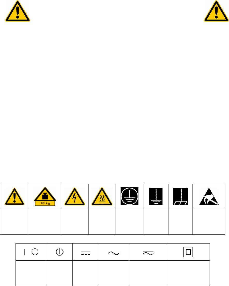
Symbols and safety labels
Observe
operating
instructions
Weight
indication for
units >18 kg
Danger of
electric
shock
Warning!
Hot
surface
PE terminal Ground Ground
terminal
Attention!
Electrostatic
sensitive
devices
Supply
voltage
ON/OFF
Standby
indication
Direct
current
(DC)
Alternating
current (AC)
Direct/alternating
current (DC/AC)
Device fully
protected by
double/reinforced
insulation
Safety Instructions
1171.0000.42-02.00 Sheet 2
Observing the safety instructions will help prevent personal injury or damage of any kind caused by
dangerous situations. Therefore, carefully read through and adhere to the following safety instructions
before putting the product into operation. It is also absolutely essential to observe the additional safety
instructions on personal safety that appear in other parts of the documentation. In these safety
instructions, the word "product" refers to all merchandise sold and distributed by Rohde & Schwarz,
including instruments, systems and all accessories.
Tags and their meaning
DANGER This tag indicates a safety hazard with a high potential of risk for the
user that can result in death or serious injuries.
WARNING This tag indicates a safety hazard with a medium potential of risk for the
user that can result in death or serious injuries.
CAUTION This tag indicates a safety hazard with a low potential of risk for the user
that can result in slight or minor injuries.
ATTENTION This tag indicates the possibility of incorrect use that can cause damage
to the product.
NOTE This tag indicates a situation where the user should pay special attention
to operating the product but which does not lead to damage.
These tags are in accordance with the standard definition for civil applications in the European
Economic Area. Definitions that deviate from the standard definition may also exist. It is therefore
essential to make sure that the tags described here are always used only in connection with the
associated documentation and the associated product. The use of tags in connection with unassociated
products or unassociated documentation can result in misinterpretations and thus contribute to personal
injury or material damage.
Basic safety instructions
1. The product may be operated only under
the operating conditions and in the
positions specified by the manufacturer. Its
ventilation must not be obstructed during
operation. Unless otherwise specified, the
following requirements apply to
Rohde & Schwarz products:
prescribed operating position is always with
the housing floor facing down, IP protection
2X, pollution severity 2, overvoltage
category 2, use only in enclosed spaces,
max. operation altitude max. 2000 m.
Unless specified otherwise in the data
sheet, a tolerance of ±10% shall apply to
the nominal voltage and of ±5% to the
nominal frequency.
2. Applicable local or national safety
regulations and rules for the prevention of
accidents must be observed in all work
performed. The product may be opened
only by authorized, specially trained
personnel. Prior to performing any work on
the product or opening the product, the
product must be disconnected from the
supply network. Any adjustments,
replacements of parts, maintenance or
repair must be carried out only by technical
personnel authorized by Rohde & Schwarz.
Only original parts may be used for
replacing parts relevant to safety (e.g.
power switches, power transformers,
fuses). A safety test must always be
performed after parts relevant to safety
have been replaced (visual inspection, PE
conductor test, insulation resistance
measurement, leakage current
measurement, functional test).
3. As with all industrially manufactured goods,
the use of substances that induce an
allergic reaction (allergens, e.g. nickel)
such as aluminum cannot be generally
excluded. If you develop an allergic
reaction (such as a skin rash, frequent
sneezing, red eyes or respiratory
difficulties), consult a physician immediately
to determine the cause.
Safety Instructions
1171.0000.42-02.00 Sheet 3
4. If products/components are mechanically
and/or thermically processed in a manner
that goes beyond their intended use,
hazardous substances (heavy-metal dust
such as lead, beryllium, nickel) may be
released. For this reason, the product may
only be disassembled, e.g. for disposal
purposes, by specially trained personnel.
Improper disassembly may be hazardous to
your health. National waste disposal
regulations must be observed.
5. If handling the product yields hazardous
substances or fuels that must be disposed
of in a special way, e.g. coolants or engine
oils that must be replenished regularly, the
safety instructions of the manufacturer of
the hazardous substances or fuels and the
applicable regional waste disposal
regulations must be observed. Also
observe the relevant safety instructions in
the product documentation.
6. Depending on the function, certain products
such as RF radio equipment can produce
an elevated level of electromagnetic
radiation. Considering that unborn life
requires increased protection, pregnant
women should be protected by appropriate
measures. Persons with pacemakers may
also be endangered by electromagnetic
radiation. The employer is required to
assess workplaces where there is a special
risk of exposure to radiation and, if
necessary, take measures to avert the
danger.
7. Operating the products requires special
training and intense concentration. Make
certain that persons who use the products
are physically, mentally and emotionally fit
enough to handle operating the products;
otherwise injuries or material damage may
occur. It is the responsibility of the
employer to select suitable personnel for
operating the products.
8. Prior to switching on the product, it must be
ensured that the nominal voltage setting on
the product matches the nominal voltage of
the AC supply network. If a different voltage
is to be set, the power fuse of the product
may have to be changed accordingly.
9. In the case of products of safety class I with
movable power cord and connector,
operation is permitted only on sockets with
earthing contact and protective earth
connection.
10. Intentionally breaking the protective earth
connection either in the feed line or in the
product itself is not permitted. Doing so can
result in the danger of an electric shock
from the product. If extension cords or
connector strips are implemented, they
must be checked on a regular basis to
ensure that they are safe to use.
11. If the product has no power switch for
disconnection from the AC supply, the plug
of the connecting cable is regarded as the
disconnecting device. In such cases, it
must be ensured that the power plug is
easily reachable and accessible at all times
(length of connecting cable approx. 2 m).
Functional or electronic switches are not
suitable for providing disconnection from
the AC supply. If products without power
switches are integrated in racks or systems,
a disconnecting device must be provided at
the system level.
12. Never use the product if the power cable is
damaged. By taking appropriate safety
measures and carefully laying the power
cable, ensure that the cable cannot be
damaged and that no one can be hurt by
e.g. tripping over the cable or suffering an
electric shock.
13. The product may be operated only from
TN/TT supply networks fused with max.
16 A.
14. Do not insert the plug into sockets that are
dusty or dirty. Insert the plug firmly and all
the way into the socket. Otherwise this can
result in sparks, fire and/or injuries.
15. Do not overload any sockets, extension
cords or connector strips; doing so can
cause fire or electric shocks.
16. For measurements in circuits with voltages
Vrms > 30 V, suitable measures (e.g.
appropriate measuring equipment, fusing,
current limiting, electrical separation,
insulation) should be taken to avoid any
hazards.
17. Ensure that the connections with
information technology equipment comply
with IEC 950/EN 60950.
18. Never remove the cover or part of the
housing while you are operating the
product. This will expose circuits and
components and can lead to injuries, fire or
damage to the product.
Safety Instructions
1171.0000.42-02.00 Sheet 4
19. If a product is to be permanently installed,
the connection between the PE terminal on
site and the product's PE conductor must
be made first before any other connection
is made. The product may be installed and
connected only by a skilled electrician.
20. For permanently installed equipment
without built-in fuses, circuit breakers or
similar protective devices, the supply circuit
must be fused in such a way that suitable
protection is provided for users and
products.
21. Do not insert any objects into the openings
in the housing that are not designed for this
purpose. Never pour any liquids onto or into
the housing. This can cause short circuits
inside the product and/or electric shocks,
fire or injuries.
22. Use suitable overvoltage protection to
ensure that no overvoltage (such as that
caused by a thunderstorm) can reach the
product. Otherwise the operating personnel
will be endangered by electric shocks.
23. Rohde & Schwarz products are not
protected against penetration of water,
unless otherwise specified (see also safety
instruction 1.). If this is not taken into
account, there exists the danger of electric
shock or damage to the product, which can
also lead to personal injury.
24. Never use the product under conditions in
which condensation has formed or can form
in or on the product, e.g. if the product was
moved from a cold to a warm environment.
25. Do not close any slots or openings on the
product, since they are necessary for
ventilation and prevent the product from
overheating. Do not place the product on
soft surfaces such as sofas or rugs or
inside a closed housing, unless this is well
ventilated.
26. Do not place the product on heat-
generating devices such as radiators or fan
heaters. The temperature of the
environment must not exceed the maximum
temperature specified in the data sheet.
27. Batteries and storage batteries must not be
exposed to high temperatures or fire. Keep
batteries and storage batteries away from
children. If batteries or storage batteries are
improperly replaced, this can cause an
explosion (warning: lithium cells). Replace
the battery or storage battery only with the
matching Rohde & Schwarz type (see
spare parts list). Batteries and storage
batteries are hazardous waste. Dispose of
them only in specially marked containers.
Observe local regulations regarding waste
disposal. Do not short-circuit batteries or
storage batteries.
28. Please be aware that in the event of a fire,
toxic substances (gases, liquids etc.) that
may be hazardous to your health may
escape from the product.
29. Please be aware of the weight of the
product. Be careful when moving it;
otherwise you may injure your back or other
parts of your body.
30. Do not place the product on surfaces,
vehicles, cabinets or tables that for reasons
of weight or stability are unsuitable for this
purpose. Always follow the manufacturer's
installation instructions when installing the
product and fastening it to objects or
structures (e.g. walls and shelves).
31. Handles on the products are designed
exclusively for personnel to hold or carry
the product. It is therefore not permissible
to use handles for fastening the product to
or on means of transport such as cranes,
fork lifts, wagons, etc. The user is
responsible for securely fastening the
products to or on the means of transport
and for observing the safety regulations of
the manufacturer of the means of transport.
Noncompliance can result in personal injury
or material damage.
32. If you use the product in a vehicle, it is the
sole responsibility of the driver to drive the
vehicle safely. Adequately secure the
product in the vehicle to prevent injuries or
other damage in the event of an accident.
Never use the product in a moving vehicle if
doing so could distract the driver of the
vehicle. The driver is always responsible for
the safety of the vehicle; the manufacturer
assumes no responsibility for accidents or
collisions.
33. If a laser product (e.g. a CD/DVD drive) is
integrated in a Rohde & Schwarz product,
do not use any other settings or functions
than those described in the documentation.
Otherwise this may be hazardous to your
health, since the laser beam can cause
irreversible damage to your eyes. Never try
to take such products apart, and never look
into the laser beam.
1171.0000.42-02.00 página 1
Por favor lea imprescindiblemente antes de
la primera puesta en funcionamiento las
siguientes informaciones de seguridad
Informaciones de seguridad
Es el principio de Rohde & Schwarz de tener a sus productos siempre al día con los estandards de
seguridad y de ofrecer a sus clientes el máximo grado de seguridad. Nuestros productos y todos los
equipos adicionales son siempre fabricados y examinados según las normas de seguridad vigentes.
Nuestra sección de gestión de la seguridad de calidad controla constantemente que sean cumplidas
estas normas. Este producto ha sido fabricado y examinado según el comprobante de conformidad
adjunto según las normas de la CE y ha salido de nuestra planta en estado impecable según los
estandards técnicos de seguridad. Para poder preservar este estado y garantizar un funcionamiento
libre de peligros, deberá el usuario atenerse a todas las informaciones, informaciones de seguridad y
notas de alerta. Rohde&Schwarz está siempre a su disposición en caso de que tengan preguntas
referentes a estas informaciones de seguridad.
Además queda en la responsabilidad del usuario utilizar el producto en la forma debida. Este producto
solamente fue elaborado para ser utilizado en la indústria y el laboratorio o para fines de campo y de
ninguna manera deberá ser utilizado de modo que alguna persona/cosa pueda ser dañada. El uso del
producto fuera de sus fines definidos o despreciando las informaciones de seguridad del fabricante
queda en la responsabilidad del usuario. El fabricante no se hace en ninguna forma responsable de
consecuencias a causa del maluso del producto.
Se parte del uso correcto del producto para los fines definidos si el producto es utilizado dentro de las
instrucciones del correspondiente manual del uso y dentro del margen de rendimiento definido (ver
hoja de datos, documentación, informaciones de seguridad que siguen). El uso de los productos hace
necesarios conocimientos profundos y el conocimiento del idioma inglés. Por eso se deberá tener en
cuenta de exclusivamente autorizar para el uso de los productos a personas péritas o debidamente
minuciosamente instruidas con los conocimientos citados. Si fuera necesaria indumentaria de
seguridad para el uso de productos de R&S, encontrará la información debida en la documentación del
producto en el capítulo correspondiente.
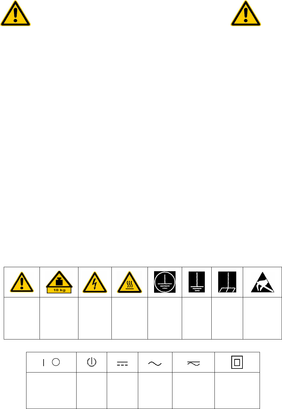
Símbolos y definiciones de seguridad
Ver manual
de
instrucciones
del uso
Informaciones
para
maquinaria
con uns peso
de > 18kg
Peligro de
golpe de
corriente
¡Advertencia!
Superficie
caliente
Conexión a
conductor
protector
Conexión
a tierra
Conexión
a masa
conductora
¡Cuidado!
Elementos de
construción
con peligro de
carga
electroestática
potencia EN
MARCHA/PARADA
Indicación
Stand-by
Corriente
continua
DC
Corriente
alterna AC
Corriente
continua/alterna
DC/AC
El aparato está
protegido en su
totalidad por un
aislamiento de
doble refuerzo
Informaciones de seguridad
1171.0000.42-02.00 página 2
Tener en cuenta las informaciones de seguridad sirve para tratar de evitar daños y peligros de toda
clase. Es necesario de que se lean las siguientes informaciones de seguridad concienzudamente y se
tengan en cuenta debidamente antes de la puesta en funcionamiento del producto. También deberán
ser tenidas en cuenta las informaciones para la protección de personas que encontrarán en otro
capítulo de esta documentación y que también son obligatorias de seguir. En las informaciones de
seguridad actuales hemos juntado todos los objetos vendidos por Rohde&Schwarz bajo la
denominación de „producto“, entre ellos también aparatos, instalaciones así como toda clase de
accesorios.
Palabras de señal y su significado
PELIGRO Indica un punto de peligro con gran potencial de riesgo para el
ususario.Punto de peligro que puede llevar hasta la muerte o graves
heridas.
ADVERTENCIA Indica un punto de peligro con un protencial de riesgo mediano para el
usuario. Punto de peligro que puede llevar hasta la muerte o graves
heridas .
ATENCIÓN Indica un punto de peligro con un protencial de riesgo pequeño para el
usuario. Punto de peligro que puede llevar hasta heridas leves o
pequeñas
CUIDADO Indica la posibilidad de utilizar mal el producto y a consecuencia
dañarlo.
INFORMACIÓN Indica una situación en la que deberían seguirse las instrucciones en el
uso del producto, pero que no consecuentemente deben de llevar a un
daño del mismo.
Las palabras de señal corresponden a la definición habitual para aplicaciones civiles en el ámbito de la
comunidad económica europea. Pueden existir definiciones diferentes a esta definición. Por eso se
debera tener en cuenta que las palabras de señal aquí descritas sean utilizadas siempre solamente en
combinación con la correspondiente documentación y solamente en combinación con el producto
correspondiente. La utilización de las palabras de señal en combinación con productos o
documentaciones que no les correspondan puede llevar a malinterpretaciones y tener por
consecuencia daños en personas u objetos.
Informaciones de seguridad elementales
1. El producto solamente debe ser utilizado
según lo indicado por el fabricante referente
a la situación y posición de funcionamiento
sin que se obstruya la ventilación. Si no se
convino de otra manera, es para los
productos R&S válido lo que sigue:
como posición de funcionamiento se define
principialmente la posición con el suelo de la
caja para abajo , modo de protección IP 2X,
grado de suciedad 2, categoría de
sobrecarga eléctrica 2, utilizar solamente en
estancias interiores, utilización hasta 2000 m
sobre el nivel del mar.
A menos que se especifique otra cosa en la
hoja de datos, se aplicará una tolerancia de
±10% sobre el voltaje nominal y de ±5%
sobre la frecuencia nominal.
2. En todos los trabajos deberán ser tenidas en
cuenta las normas locales de seguridad de
trabajo y de prevención de accidentes. El
producto solamente debe de ser abierto por
personal périto autorizado. Antes de efectuar
trabajos en el producto o abrirlo deberá este
ser desconectado de la corriente. El ajuste,
el cambio de partes, la manutención y la
reparación deberán ser solamente
efectuadas por electricistas autorizados por
R&S. Si se reponen partes con importancia
para los aspectos de seguridad (por ejemplo
el enchufe, los transformadores o los
fusibles), solamente podrán ser sustituidos
por partes originales. Despues de cada
recambio de partes elementales para la
seguridad deberá ser efectuado un control de
Informaciones de seguridad
1171.0000.42-02.00 página 3
seguridad (control a primera vista, control de
conductor protector, medición de resistencia
de aislamiento, medición de medición de la
corriente conductora, control de
funcionamiento).
3. Como en todo producto de fabricación
industrial no puede ser excluido en general
de que se produzcan al usarlo elementos
que puedan generar alergias, los llamados
elementos alergénicos (por ejemplo el
níquel). Si se producieran en el trato con
productos R&S reacciones alérgicas, como
por ejemplo urticaria, estornudos frecuentes,
irritación de la conjuntiva o dificultades al
respirar, se deberá consultar inmediatamente
a un médico para averigurar los motivos de
estas reacciones.
4. Si productos / elementos de construcción son
tratados fuera del funcionamiento definido de
forma mecánica o térmica, pueden generarse
elementos peligrosos (polvos de sustancia
de metales pesados como por ejemplo
plomo, berilio, níquel). La partición elemental
del producto, como por ejemplo sucede en el
tratamiento de materias residuales, debe de
ser efectuada solamente por personal
especializado para estos tratamientos. La
partición elemental efectuada
inadecuadamente puede generar daños para
la salud. Se deben tener en cuenta las
directivas nacionales referentes al
tratamiento de materias residuales.
5. En el caso de que se produjeran agentes de
peligro o combustibles en la aplicación del
producto que debieran de ser transferidos a
un tratamiento de materias residuales, como
por ejemplo agentes refrigerantes que deben
ser repuestos en periodos definidos, o
aceites para motores, deberan ser tenidas en
cuenta las prescripciones de seguridad del
fabricante de estos agentes de peligro o
combustibles y las regulaciones regionales
para el tratamiento de materias residuales.
Cuiden también de tener en cuenta en caso
dado las prescripciones de seguridad
especiales en la descripción del producto.
6. Ciertos productos, como por ejemplo las
instalaciones de radiación HF, pueden a
causa de su función natural, emitir una
radiación electromagnética aumentada. En
vista a la protección de la vida en desarrollo
deberían ser protegidas personas
embarazadas debidamente. También las
personas con un bypass pueden correr
peligro a causa de la radiación
electromagnética. El empresario está
comprometido a valorar y señalar areas de
trabajo en las que se corra un riesgo de
exposición a radiaciones aumentadas de
riesgo aumentado para evitar riesgos.
7. La utilización de los productos requiere
instrucciones especiales y una alta
concentración en el manejo. Debe de
ponerse por seguro de que las personas que
manejen los productos estén a la altura de
los requerimientos necesarios referente a
sus aptitudes físicas, psíquicas y
emocionales, ya que de otra manera no se
pueden excluir lesiones o daños de objetos.
El empresario lleva la responsabilidad de
seleccionar el personal usuario apto para el
manejo de los productos.
8. Antes de la puesta en marcha del producto
se deberá tener por seguro de que la tensión
preseleccionada en el producto equivalga a
la del la red de distribución. Si es necesario
cambiar la preselección de la tensión
también se deberán en caso dabo cambiar
los fusibles correspondientes del prodcuto.
9. Productos de la clase de seguridad I con
alimentación móvil y enchufe individual de
producto solamente deberán ser conectados
para el funcionamiento a tomas de corriente
de contacto de seguridad y con conductor
protector conectado.
10. Queda prohibida toda clase de interrupción
intencionada del conductor protector, tanto
en la toma de corriente como en el mismo
producto ya que puede tener como
consecuencia el peligro de golpe de corriente
por el producto. Si se utilizaran cables o
enchufes de extensión se deberá poner al
seguro, que es controlado su estado técnico
de seguridad.
11. Si el producto no está equipado con un
interruptor para desconectarlo de la red, se
deberá considerar el enchufe del cable de
distribución como interruptor. En estos casos
deberá asegurar de que el enchufe sea de
fácil acceso y nabejo (medida del cable de
distribución aproximadamente 2 m). Los
interruptores de función o electrónicos no
son aptos para el corte de la red eléctrica. Si
los productos sin interruptor están integrados
en construciones o instalaciones, se deberá
instalar el interruptor al nivel de la
instalación.
Informaciones de seguridad
1171.0000.42-02.00 página 4
12. No utilice nunca el producto si está dañado el
cable eléctrico. Asegure a través de las
medidas de protección y de instalación
adecuadas de que el cable de eléctrico no
pueda ser dañado o de que nadie pueda ser
dañado por él, por ejemplo al tropezar o por
un golpe de corriente.
13. Solamente está permitido el funcionamiento
en redes de distribución TN/TT aseguradas
con fusibles de como máximo 16 A.
14. Nunca conecte el enchufe en tomas de
corriente sucias o llenas de polvo. Introduzca
el enchufe por completo y fuertemente en la
toma de corriente. Si no tiene en
consideración estas indicaciones se arriesga
a que se originen chispas, fuego y/o heridas.
15. No sobrecargue las tomas de corriente, los
cables de extensión o los enchufes de
extensión ya que esto pudiera causar fuego
o golpes de corriente.
16. En las mediciones en circuitos de corriente
con una tensión de entrada de Ueff > 30 V se
deberá tomar las precauciones debidas para
impedir cualquier peligro (por ejemplo
medios de medición adecuados, seguros,
limitación de tensión, corte protector,
aislamiento etc.).
17. En caso de conexión con aparatos de la
técnica informática se deberá tener en
cuenta que estos cumplan los requisitos de
la EC950/EN60950.
18. Nunca abra la tapa o parte de ella si el
producto está en funcionamiento. Esto pone
a descubierto los cables y componentes
eléctricos y puede causar heridas, fuego o
daños en el producto.
19. Si un producto es instalado fijamente en un
lugar, se deberá primero conectar el
conductor protector fijo con el conductor
protector del aparato antes de hacer
cualquier otra conexión. La instalación y la
conexión deberán ser efecutadas por un
electricista especializado.
20. En caso de que los productos que son
instalados fijamente en un lugar sean sin
protector implementado, autointerruptor o
similares objetos de protección, deberá la
toma de corriente estar protegida de manera
que los productos o los usuarios estén
suficientemente protegidos.
21. Por favor, no introduzca ningún objeto que
no esté destinado a ello en los orificios de la
caja del aparato. No vierta nunca ninguna
clase de líquidos sobre o en la caja. Esto
puede producir corto circuitos en el producto
y/o puede causar golpes de corriente, fuego
o heridas.
22. Asegúrese con la protección adecuada de
que no pueda originarse en el producto una
sobrecarga por ejemplo a causa de una
tormenta. Si no se verá el personal que lo
utilice expuesto al peligro de un golpe de
corriente.
23. Los productos R&S no están protegidos
contra el agua si no es que exista otra
indicación, ver también punto 1. Si no se
tiene en cuenta esto se arriesga el peligro de
golpe de corriente o de daños en el producto
lo cual también puede llevar al peligro de
personas.
24. No utilice el producto bajo condiciones en las
que pueda producirse y se hayan producido
líquidos de condensación en o dentro del
producto como por ejemplo cuando se
desplaza el producto de un lugar frío a un
lugar caliente.
25. Por favor no cierre ninguna ranura u orificio
del producto, ya que estas son necesarias
para la ventilación e impiden que el producto
se caliente demasiado. No pongan el
producto encima de materiales blandos como
por ejemplo sofás o alfombras o dentro de
una caja cerrada, si esta no está
suficientemente ventilada.
26. No ponga el producto sobre aparatos que
produzcan calor, como por ejemplo
radiadores o calentadores. La temperatura
ambiental no debe superar la temperatura
máxima especificada en la hoja de datos.
Informaciones de seguridad
1171.0000.42-02.00 página 5
27. Baterías y acumuladores no deben de ser
expuestos a temperaturas altas o al fuego.
Guardar baterías y acumuladores fuera del
alcance de los niños. Si las baterías o los
acumuladores no son cambiados con la
debida atención existirá peligro de explosión
(atención celulas de Litio). Cambiar las
baterías o los acumuladores solamente por
los del tipo R&S correspondiente (ver lista de
piezas de recambio). Baterías y
acumuladores son deshechos problemáticos.
Por favor tirenlos en los recipientes
especiales para este fín. Por favor tengan en
cuenta las prescripciones nacionales de cada
país referente al tratamiento de deshechos.
Nunca sometan las baterías o acumuladores
a un corto circuito.
28. Tengan en consideración de que en caso de
un incendio pueden escaparse gases tóxicos
del producto, que pueden causar daños a la
salud.
29. Por favor tengan en cuenta que en caso de
un incendio pueden desprenderse del
producto agentes venenosos (gases, líquidos
etc.) que pueden generar daños a la salud.
30. No sitúe el producto encima de superficies,
vehículos, estantes o mesas, que por sus
características de peso o de estabilidad no
sean aptas para él. Siga siempre las
instrucciones de instalación del fabricante
cuando instale y asegure el producto en
objetos o estructuras (por ejemplo paredes y
estantes).
31. Las asas instaladas en los productos sirven
solamente de ayuda para el manejo que
solamente está previsto para personas. Por
eso no está permitido utilizar las asas para la
sujecion en o sobre medios de transporte
como por ejemplo grúas, carretillas
elevadoras de horquilla, carros etc. El
usuario es responsable de que los productos
sean sujetados de forma segura a los medios
de transporte y de que las prescripciones de
seguridad del fabricante de los medios de
transporte sean tenidas en cuenta. En caso
de que no se tengan en cuenta pueden
causarse daños en personas y objetos.
32. Si llega a utilizar el producto dentro de un
vehículo, queda en la responsabilidad
absoluta del conductor que conducir el
vehículo de manera segura. Asegure el
producto dentro del vehículo debidamente
para evitar en caso de un accidente las
lesiones u otra clase de daños. No utilice
nunca el producto dentro de un vehículo en
movimiento si esto pudiera distraer al
conductor. Siempre queda en la
responsabilidad absoluta del conductor la
seguridad del vehículo y el fabricante no
asumirá ninguna clase de responsabilidad
por accidentes o colisiones.
33. Dado el caso de que esté integrado un
producto de laser en un producto R&S (por
ejemplo CD/DVD-ROM) no utilice otras
instalaciones o funciones que las descritas
en la documentación. De otra manera pondrá
en peligro su salud, ya que el rayo laser
puede dañar irreversiblemente sus ojos.
Nunca trate de descomponer estos
productos. Nunca mire dentro del rayo laser.

Qualitätszertifikat
Sehr geehrter Kunde,
Sie haben sich für den Kauf eines Rohde &
Schwarz-Produktes entschieden. Hiermit
erhalten Sie ein nach modernsten Ferti-
gungsmethoden hergestelltes Produkt. Es
wurde nach den Regeln unseres Qualitäts-
managementsystems entwickelt, gefer-
tigt und geprüft. Das Rohde & Schwarz-
Qualitätsmanagementsystem ist u.a. nach
ISO 9001 und ISO14001 zertifiziert.
Certificate of quality
Dear Customer,
You have decided to buy a Rohde &
Schwarz product. You are thus assured of
receiving a product that is manufactured
using the most modern methods available.
This product was developed, manufac-
tured and tested in compliance with our
quality management system standards.
The Rohde & Schwarz quality manage-
ment system is certified according to stan-
dards such as ISO9001 and ISO14001.
Certificat de qualité
Cher client,
Vous avez choisi d'acheter un produit
Rohde & Schwarz. Vous disposez donc
d'un produit fabriqué d'après les métho-
des les plus avancées. Le développement,
la fabrication et les tests respectent nos
normes de gestion qualité. Le système de
gestion qualité de Rohde & Schwarz a été
homologué, entre autres, conformément
aux normes ISO 9001 et ISO14001.
Certified Quality System
ISO 9001
Certified Environmental System
ISO 14001
DQS REG. NO 1954 QM
DQS REG. NO 1954 UM

1143.8500.02 CE E-1
EC Certificate of Conformity
Certificate No.: 2002-36
This is to certify that:
Equipment type Stock No. Designation
NRP 1143.8500.02 Power Meter
NRP-B1 1146.9008.02 Sensor Check Source
NRP-B2 1146.8801.02 Second Sensor Input
NRP-B5 1146.9608.02 3rd und 4th Sensor
NRP-B6 1146.9908.02 Rear-Panel Sensor
NRP-Z3 1146.7005.02 USB Adapter
NRP-Z4 1146.8001.02 USB Adapter
NRP-Z11 1138.3004.02 Average Power Sensor
NRP-Z21 1137.6000.02 Average Power Sensor
complies with the provisions of the Directive of the Council of the European Union on the
approximation of the laws of the Member States
- relating to electrical equipment for use within defined voltage limits
(73/23/EEC revised by 93/68/EEC)
- relating to electromagnetic compatibility
(89/336/EEC revised by 91/263/EEC, 92/31/EEC, 93/68/EEC)
Conformity is proven by compliance with the following standards:
EN61010-1 : 1993 + A2 : 1995
EN55011 : 1998 + A1 : 1999
EN61326 : 1997 + A1 : 1998 + A2 : 2001
For the assessment of electromagnetic compatibility, the limits of radio interference for Class
B equipment as well as the immunity to interference for operation in industry have been used
as a basis.
Affixing the EC conformity mark as from 2002
ROHDE & SCHWARZ GmbH & Co. KG
Mühldorfstr. 15, D-81671 München
Munich, 2002-06-27 Central Quality Management FS-QZ / Becker

1007.8684.14-02.00
Support Center
Telefon / Telephone: +49 (0)180 512 42 42
Fax: +49 89 41 29 137 77
E-mail: CustomerSupport@rohde-schwarz.com
Für technische Fragen zu diesem Rohde & Schwarz-Gerät steht Ihnen
die Hotline der Rohde & Schwarz Vertriebs-GmbH, Support Center, zur
Verfügung.
Unser Team bespricht mit Ihnen Ihre Fragen und sucht Lösungen für Ihre
Probleme.
Die Hotline ist Montag bis Freitag von 8.00 bis 17.00 Uhr MEZ besetzt.
Bei Anfragen außerhalb der Geschäftszeiten hinterlassen Sie bitte eine
Nachricht oder senden Sie eine Notiz per Fax oder E-Mail. Wir setzen
uns dann baldmöglichst mit Ihnen in Verbindung.
Um Ihr Gerät stets auf dem neuesten Stand zu halten,
abonnieren Sie bitte Ihren persönlichen Newsletter unter
http://www.rohde-schwarz.com/www/response.nsf/newsletterpreselection.
Sie erhalten dann regelmäßig Informationen über Rohde &
Schwarz-Produkte Ihrer Wahl, über Firmware-Erweiterungen,
neue Teiber und Applikationsschriften.
Should you have any technical questions concerning this Rohde &
Schwarz product, please contact the hotline of Rohde & Schwarz
Vertriebs-GmbH, Support Center.
Our hotline team will answer your questions and find solutions to your
problems.
You can reach the hotline Monday through Friday from 8:00 until 17:00
CET.
If you need assistance outside office hours, please leave a message or
send us a fax or e-mail. We will contact you as soon as possible.
To keep your instrument always up to date, please subscribe
to your personal newsletter at
http://www.rohde-schwarz.com/www/response.nsf/newsletterpreselection.
As a subscriber, you will receive information about your
selection of Rohde & Schwarz products, about firmware
extensions, new drivers and application notes on a regular
basis.

Adressen/Addresses
FIRMENSITZ/HEADQUARTERS
Phone
Fax
E-mail
Rohde & Schwarz GmbH & Co. KG
Mühldorfstraße 15 · D-81671 München
Postfach 80 14 69 · D-81614 München
+49 (89) 41 29-0
+49 89 4129-121 64
-
WERKE/PLANTS
Rohde & Schwarz Messgerätebau GmbH
Riedbachstraße 58 · D-87700 Memmingen
Postfach 1652 · D-87686 Memmingen
+49 (8331) 108-0
+49 (8331) 108-11 24
-
Rohde & Schwarz GmbH & Co. KG
Werk Teisnach
Kaikenrieder Straße 27 · D-94244 Teisnach
Postfach 1149 · D-94240 Teisnach
+49 (9923) 857-0
+49 (9923) 857-11 74
-
Rohde & Schwarz GmbH & Co. KG
Dienstleistungszentrum Köln
Graf-Zeppelin-Straße 18 · D-51147 Köln
Postfach 98 02 60 · D-51130 Köln
+49 (2203) 49-0
+49 (2203) 49 51-308
info@rsdc.rohde-schwarz.com
service@rsdc.rohde-schwarz.com
TOCHTERUNTERNEHMEN/SUBSIDIARIES
Rohde & Schwarz Vertriebs-GmbH
Mühldorfstraße 15 · D-81671 München
Postfach 80 14 69 · D-81614 München
+49 (89) 41 29-137 74
+49 (89) 41 29-137 77
-
Rohde & Schwarz International GmbH
Mühldorfstraße 15 · D-81671 München
Postfach 80 14 60 · D-81614 München
+49 (89) 41 29-129 84
+49 (89) 41 29-120 50
-
Rohde & Schwarz Engineering and Sales
GmbH
Mühldorfstraße 15 · D-81671 München
Postfach 80 14 29 · D-81614 München
+49 (89) 41 29-137 11
+49 (89) 41 29-137 23
-
R&S BICK Mobilfunk GmbH
Fritz-Hahne-Str. 7 · D-31848 Bad Münder
Postfach 2062 · D-31844 Bad Münder
+49 (5042) 998-0
+49 (5042) 998-105
-
Rohde & Schwarz FTK GmbH
Wendenschlossstraße 168, Haus 28
D-12557 Berlin
+49 (30) 658 91-122
+49 (30) 655 50-221
-
Rohde & Schwarz SIT GmbH
Agastraße 3
D-12489 Berlin
+49 (30) 658 84-0
+49 (30) 658 84-183
ADRESSEN DEUTSCHLAND/ADDRESSES GERMANY
Rohde & Schwarz Vertriebs-GmbH
Mühldorfstraße 15 · D-81671 München
Postfach 80 14 69 · D-81614 München
+49 89 4129-133 74
+4989 4129-133 77
-
Zweigniederlassungen der Rohde &
Schwarz Vertriebs-GmbH/Branch offices of
Rohde & Schwarz Vertriebs-GmbH
Zweigniederlassung Nord, Geschäftsstelle
Berlin
Ernst-Reuter-Platz 10 · D-10587 Berlin
Postfach 100620 · D-10566 Berlin
+49 (30) 34 79 48-0
+49 (30) 34 79 48 48
-
Zweigniederlassung Büro Bonn
Josef-Wirmer-Straße 1-3 · D-53123 Bonn
Postfach 140264 · D-53057 Bonn
+49 (228) 918 90-0
+49 (228) 25 50 87
-
Zweigniederlassung Nord, Geschäftsstelle
Hamburg
Steilshooper Alle 47 · D-22309 Hamburg
Postfach 60 22 40 · D-22232 Hamburg
+49 (40) 63 29 00-0
+49 (40) 630 78 70
-
Zweigniederlassung Mitte, Geschäftsstelle
Köln
Niederkasseler Straße 33 · D-51147 Köln
Postfach 900 149 · D-51111 Köln
+49 (2203) 807-0
+49 (2203) 807-650
-
Zweigniederlassung Süd, Geschäftsstelle
München
Mühldorfstraße 15 · D-81671 München
Postfach 80 14 69 · D-81614 München
+49 (89) 41 86 95-0
+49 (89) 40 47 64
-
Zweigniederlassung Süd, Geschäftsstelle
Nürnberg
Donaustraße 36
D-90451 Nürnberg
+49 (911) 642 03-0
+49 (911) 642 03-33
-
Zweigniederlassung Mitte, Geschäftsstelle
Neu-Isenburg
Siemensstraße 20
D-63263 Neu-Isenburg
+49 (6102) 20 07-0
+49 (6102) 20 07 12
-
ADRESSEN WELTWEIT/ADDRESSES WORLDWIDE
siehe / see AustriaAlbania
ROHDE & SCHWARZ
Bureau d'Alger
5B Place de Laperrine
16035 Hydra-Alger
+213 (21) 48 20 18
+213 (21) 69 46 08
Algeria
PRECISION ELECTRONICA S.R.L.
Av. Pde Julio A. Roca 710 - 6° Piso
(C1067ABP) Buenos Aires
+541 (14) 331 41 99
+541 (14) 334 51 11
alberto_lombardi@prec-elec.com.ar
Argentina
ROHDE & SCHWARZ (AUSTRALIA) Pty. Ltd.
Sales Support
Unit 6
2-8 South Street
Rydalmere, N.S.W. 2116
+61 (2) 88 45 41 00
+61 (2) 96 38 39 88
lyndell.james@rsaus.rohde-
schwarz.com
Australia
ROHDE & SCHWARZ-ÖSTERREICH
Ges.m.b.H.
Sonnleithnergasse 20
1100 Wien
+43 (1) 602 61 41-0
+43 (1) 602 61 41-14
office@rsoe.rohde-schwarz.com
Austria
ROHDE & SCHWARZ Azerbaijan
Liaison Office Baku
ISR Plaza
340 Nizami Str.
370000 Baku
+994 (12) 93 31 38
+994 (12) 93 03 14
RS-Azerbaijan@RUS.Rohde-
Schwarz.com
Azerbaijan
siehe / see DenmarkBaltic
Countries
BIL Consortium Ltd.
Corporation Office
House No: 95/A, Block - 'F'
Road No. 4, Banani
Dhaka-1213
+880 (2) 881 06 53
+880 (2) 882 82 91
Bangladesh
ROHDE & SCHWARZ BELGIUM N.V.
Excelsiorlaan 31 Bus 1
1930 Zaventem
+32 (2) 721 50 02
+32 (2) 725 09 36
info@rsb.rohde-schwarz.com
Belgium
ROHDE & SCHWARZ DO BRASIL LTDA.
Av. Alfredo Egidio de Souza Aranha n° 177,
1° andar - Santo Amaro
04726-170 Sao Paulo - SP
+55 (11) 56 44 86 11 (general)
+55 (11) 56 44 86 25 (sales)
+55 (11) 56 44 86 36
sales-brazil@rsdb.rohde-
schwarz.com
Brasil
GKL Equipment PTE. Ltd.
Jurong Point Post Office
P.O.Box 141
Singapore 916405
+65 (6) 276 06 26
+65 (6) 276 06 29
gkleqpt@singnet.com.sg
Brunei
ROHDE & SCHWARZ ÖSTERREICH
Representation Office Bulgaria
39, Fridtjof Nansen Blvd.
1000 Sofia
+359 (2) 963 43 34
+359 (2) 963 21 97
rohdebg@rsoe.rohde-schwarz.com
Bulgaria
siehe / see SloveniaBosnia-
Herzegovina

Adressen/Addresses
ROHDE & SCHWARZ CANADA Inc.
555 March Rd.
Kanata, Ontario K2K 2M5
+1 (613) 592 80 00
+1 (613) 592 80 09
cgirwarnauth@rscanada.ca
Canada
TEKTRONIX CANADA Inc.
Test and Measurement
4929 Place Olivia
Saint-Laurent, Pq
Montreal H4R 2V6
+1 (514) 331 43 34
+1 (514) 331 59 91
Canada
DYMEQ Ltda.
Av. Larrain 6666
Santiago
+56 (2) 339 20 00
+56 (2) 339 20 10
dnussbaum@dymeq.com
Chile
ROHDE & SCHWARZ China Ltd.
Representative Office Shanghai
Central Plaza
227 Huangpi North Road
RM 807/809
Shanghai 200003
+86 (21) 63 75 00 18
+86 (21) 63 75 91 70
China
ROHDE & SCHWARZ China Ltd.
Representative Office Beijing
Room 602, Parkview Center
2 Jiangtai Road
Chao Yang District
Beijing 100016
+86 (10) 64 31 28 28
+86 (10) 64 37 98 88
info.rschina@rsbp.rohde-
schwarz.com
China
ROHDE & SCHWARZ China Ltd.
Representative Office Guangzhou
Room 2903, Metro Plaza
183 Tianhe North Road
Guangzhou 510075
+86 (20) 87 55 47 58
+86 (20) 87 55 47 59
China
ROHDE & SCHWARZ China Ltd.
Representative Office Chengdu
Unit G, 28/F, First City Plaza
308 Shuncheng Avenue
Chengdu 610017
+86 (28) 86 52 76 05 to 09
+86 (28) 86 52 76 10
rsbpc@mail.sc.cninfo.net
China
ROHDE & SCHWARZ China Ltd.
Unit 3115
31/F Entertainment Building
30 Queen's Road Central
Hongkong
+85 (2) 21 68 06 70
+85 (2) 21 68 08 99
China
ROHDE & SCHWARZ China Ltd.
Representative Office Xi'an
Room 10125, Jianguo Hotel Xi'an
No. 2, Huzhu Road
Xi'an 710048
+86 (29) 321 82 33
+86 (29) 329 60 15
sherry.yu@rsbp.rohde-schwarz.com
China
Shanghai ROHDE & SCHWARZ
Communication Technology Co.Ltd.
Central Plaza, Unit 809
227 Huangpi North Road
Shanghai 200003
China
Beijing ROHDE & SCHWARZ Communication
Technology Co.Ltd.
Room 106, Parkview Centre
No. 2, Jiangtai Road
Chao Yang District
Beijing 100016
+86 (10) 64 38 80 80
+86 (10) 64 38 97 06
China
siehe / see SloveniaCroatia
HINIS TELECAST LTD.
Agiou Thoma 18
Kiti
Larnaca 7550
+357 (24) 42 51 78
+357 (24) 42 46 21
hinis@logos.cy.net
Cyprus
ROHDE & SCHWARZ - Praha s.r.o.
Hadovka Office Park
Evropská 33c
16000 Praha 6
+420 (2) 24 31 12 32
+420 (2) 24 31 70 43
office@rscz.rohde-schwarz.com
Czech Republic
ROHDE & SCHWARZ DANMARK A/S
Ejby Industrivej 40
2600 Glostrup
+45 (43) 43 66 99
+45 (43) 43 77 44
Denmark
REPRESENTACIONES MANFRED
WEINZIERL
Vía Láctea No. 4 y Via Sta. Inés
P.O.Box 17-22-20309
1722 Cumbayá-Quito
+593 (22) 89 65 97
+593 (22) 89 65 97
mweinzierl@accessinter.net
Ecuador
U.A.S. Universal Advanced Systems
31 Manshiet El-Bakry Street
Heliopolis
11341 Cairo
+20 (2) 455 67 44
+20 (2) 256 17 40
an_uas@intouch.com
Egypt
siehe / see Mexico
El Salvador
ROHDE & SCHWARZ DANMARK A/S
Estonian Branch Office
Narva mnt. 13
10151 Tallinn
+372 (6) 14 31 23
+372 (6) 14 31 21
margo.fingling@rsdk.rohde-
schwarz.com
Estonia
Orbis Oy
P.O.Box 15
00421 Helsinski 42
+358 (9) 47 88 30
+358 (9) 53 16 04
info@orbis.fi
Finland
ROHDE & SCHWARZ FRANCE
Immeuble "Le Newton"
9-11, rue Jeanne Braconnier
92366 Meudon La Forêt Cédex
+33 (1) 41 36 10 00
+33 (1) 41 36 11 73
France
Niederlassung/Subsidiary Rennes
37 Rue du Bignon
Bât. A
F-35510 Cesson Sevigne
+33 (0) 299 51 97 00
+33 (0) 299 51 98 77
-
France
Niederlassung/Subsidiary Toulouse
Technoparc 3
B.P. 501
F-31674 Labège Cédex
+33 (0) 561 39 10 69
+33 (0) 561 39 99 10
-
France
Aix-en-Provence +33 (0) 494 07 39 94
+33 (0) 494 07 55 11
-
France
Office Lyon +33 (0) 478 29 88 10
+33 (0) 478 79 18 57
France
Office Nancy +33 (0) 383 54 51 29
+33 (0) 383 54 82 09
France
KOP Engineering Ltd.
P.O. Box 11012
3rd Floor Akai House, Osu
Accra North
+233 (21) 77 89 13
+233 (21) 701 06 20
Ghana
MERCURY S.A.
6, Loukianou Str.
10675 Athens
+302 (10) 722 92 13
+302 (10) 721 51 98
mercury@hol.gr
Greece
siehe / see Mexico Guatemala
siehe / see Mexico Honduras
Electronic Scientific Engineering
36/F Dorset House, Taikoo Place
979 King's Road
Quarry Bay
Hong Kong
+852 (25) 07 03 33
+852 (25) 07 09 25
stephenchau@ese.com.hk
Hongkong
ROHDE & SCHWARZ
Budapesti Iroda
Váci út 169
1138 Budapest
+36 (1) 412 44 60
+36 (1) 412 44 61
rohdehu@rsoe.rohde-schwarz.com
Hungary
siehe / see DenmarkIceland

Adressen/Addresses
ROHDE & SCHWARZ India Pvt. Ltd.
Bangalore Office
No. 24, Service Road, Domlur
2nd Stage Extension
Bangalore - 560 071
+91 (80) 535 23 62
+91 (80) 535 03 61
rsindiab@rsnl.net
India
ROHDE & SCHWARZ India Pvt. Ltd.
Hyderabad Office
302 & 303, Millenium Centre
6-3-1099/1100, Somajiguda
Hyderabad - 500 016
+91 (40) 23 32 24 16
+91 (40) 23 32 27 32
rsindiah@nd2.dot.net.in
India
ROHDE & SCHWARZ India Pvt. Ltd.
244, Okhla Industrial Estate, Phase-III
New Delhi 110020
+91 (11) 26 32 63 81
+91 (11) 26 32 63 73
sales@rsindia.rohde-schwarz
services@rsindia.rohde-schwarz.com
India
ROHDE & SCHWARZ India Pvt. Ltd.
RS India Mumbai Office
B-603, Remi Bizcourt, Shah Industrial
Estate, Off Veera Desai Road
Mumbai - 400 058
+91 (22) 26 30 18 10
+91 (22) 26 32 63 73
rsindiam@rsnl.net
India
PT ROHDE & SCHWARZ Indonesia
Graha Paramita 5th Floor
Jln. Denpasar Raya Blok D-2
Jakarta 12940
+62 (21) 252 36 08
+62 (21) 252 36 07
sales@rsbj.rohde-schwarz.com
services@rsbj.rohde-schwarz.com
Indonesia
ROHDE & SCHWARZ IRAN
Groundfloor No. 1, 14th Street
Khaled Eslamboli (Vozara) Ave.
15117 Tehran
+98 (21) 872 42 96
+98 (21) 871 90 12
rs-tehran@neda.net
Iran
siehe / see United KingdomIreland
EASTRONICS LTD.
Messtechnik / T&M Equipment
11 Rozanis St.
P.O.Box 39300
Tel Aviv 61392
+972 (3) 645 87 77
+972 (3) 645 86 66
david_hasky@easx.co.il
Israel
J.M. Moss (Engineering) Ltd.
Kommunikationstechnik/ Communications
Equipment
9 Oded Street
P.O.Box 967
52109 Ramat Gan
+972 (3) 631 20 57
+972 (3) 631 40 58
jmmoss@zahav.net.il
Israel
ROHDE & SCHWARZ ITALIA S.p.a.
Centro Direzionale Lombardo
Via Roma 108
20060 Cassina de Pecchi (MI)
+39 (02) 95 70 42 03
+39 (02) 95 30 27 72
ornella.crippa@rsi.rohde-
schwarz.com
Italy
ROHDE & SCHWARZ ITALIA S.p.a.
Via Tiburtina 1182
00156 Roma
+39 (06) 41 59 82 18
+39 (06) 41 59 82 70
Italy
ADVANTEST Corporation
RS Sales Department
1-32-1, Asahi-cho
Nerima-ku
Tokyo 179-0071
+81 (3) 39 30 41 90
+81 (3) 39 30 41 86
RSSales@advantest.co.jp
Japan
Jordan Crown Engineering & Trading Co.
Jabal Amman, Second Circle
Youssef Ezzideen Street
P.O.Box 830414
Amman, 11183
+962 (6) 462 17 29
+962 (6) 465 96 72
jocrown@go.com.jo
Jordan
ROHDE & SCHWARZ Kazakhstan
Representative Office Almaty
Pl. Respubliki 15
480013 Almaty
+7 (32) 72 63 55 55
+7 (32) 72 63 46 33
RS-Kazakhstan@RUS-Rohde-
Schwarz.com
Kazakhstan
Excel Enterprises Ltd
Dunga Road
P.O.Box 42 788
Nairobi
+254 (2) 55 80 88
+254 (2) 54 46 79
Kenya
ROHDE & SCHWARZ Korea Ltd.
83-29 Nonhyun-Dong, Kangnam-Ku
Seoul 135-010
+82 (2) 514 45 46
+82 (2) 514 45 49
sales@rskor.rohde-schwarz.com
service@rskor.rohde-schwarz.com
Korea
Group Five Trading & Contracting Co.
Mezanine Floor
Al-Bana Towers
Ahmad Al Jaber Street
Sharq
+965 (244) 91 72/73/74
+965 (244) 95 28
jk_agarwal@yahoo.com
Kuwait
ROHDE & SCHWARZ DANMARK A/S
Latvian Branch Office
Merkela iela 21-301
1050 Riga
+371 (7) 50 23 55
+371 (7) 50 23 60
rsdk@rsdk.rohde-schwarz.com
Latvia
ROHDE & SCHWARZ Liaison Office
c/o Haji Abdullah Alireza Co. Ltd.
P.O.Box 361
Riyadh 11411
+966 (1) 465 64 28 Ext. 303
+966 (1) 465 64 28 Ext. 229
chris.porzky@rsd.rohde-schwarz.com
Lebanon
siehe / see SwitzerlandLiechtenstein
ROHDE & SCHWARZ DANMARK A/S
Lithuanian Office
Lukiskiu 5-228
2600 Vilnius
+370 (5) 239 50 10
+370 (5) 239 50 11
Lithuania
siehe / see BelgiumLuxembourg
siehe / see SloveniaMacedonia
DAGANG TEKNIK SDN. BHD.
No. 9, Jalan SS 4D/2
Selangor Darul Ehsan
47301 Petaling Jaya
+60 (3) 27 03 55 68
+60 (3) 27 03 34 39
mey.nara@danik.com.my
Malaysia
ITEC International Technology Ltd
B'Kara Road
San Gwann SGN 08
+356 (21) 37 43 00 or 37 43 29
+356 (21) 37 43 53
sales@itec.com.mt
Malta
Rohde & Schwarz de Mexico (RSMX)
S. de R.L. de C.V.
German Centre Oficina 4-2-2
Av. Santa Fé 170
Col. Lomas de Santa Fé
01210 Mexico D.F.
+52 (55) 85 03 99 13
+52 (55) 85 03 99 16
latinoamerica@rsd.rohde-
schwarz.com
Mexico
Rohde & Schwarz de Mexico (RSMX)
Av. Prol. Americas No. 1600, 2° Piso
Col. Country Club
Guadalajara, Jal.
Mexico CP, 44610
+52 (33) 36 78 91 70
+52 (33) 36 78 92 00
Mexico
siehe / see RomaniaMoldavia
ROHDE & SCHWARZ NEDERLAND B.V.
Perkinsbaan 1
3439 ND Nieuwegein
+31 (30) 600 17 00
+31 (30) 600 17 99
info@rsn.rohde-schwarz.com
Netherlands
Nichecom
1 Lincoln Ave.
Tawa, Wellington
+64 (4) 232 32 33
+64 (4) 232 32 30
rob@nichecom.co.nz
New Zealand
siehe / see MexicoNicaragua
Ferrostaal (NIGERIA) Ltd.
P.O. Box 72021
27/29 Adeyamo Alkaija Street
Victoria Island
Lagos
+234 (1) 262 00 60
+234 (1) 262 00 64
fs-nig@linkserve.com.ng
Nigeria

Adressen/Addresses
ROHDE & SCHWARZ NORGE AS
Enebakkveien 302 B
1188 Oslo
+47 (23) 38 66 00
+47 (23) 38 66 01
Norway
Mustafa Sultan
Science & Industry Co. LLC.
P.O.Box 3340
Postal Code 112
Ruwi
+968 63 60 00
+968 60 70 66
m-aziz@mustafasultan.com
Oman
Siemens Pakistan
23, West Jinnah Avenue
Islamabad
+92 (51) 227 22 00
+92 (51) 227 54 98
reza.bokhary@siemens.com.pk
Pakistan
siehe / see Mexico Panama
siehe / see AustraliaPapua-New
Guinea
MARCOM INDUSTRIAL EQUIPMENT, Inc.
6-L Vernida I Condominium
120 Amorsolo St.
Legaspi Village
Makati City/ Philippines 1229
+63 (2) 813 29 31
+63 (2) 810 58 07
marcom@i-next.net
Philippines
ROHDE & SCHWARZ Österreich SP.z o.o.
Przedstawicielstwo w Polsce
ul. Stawki 2, Pietro 28
00-193 Warszawa
+48 (22) 860 64 94
+48 (22) 860 64 99
rohdepl@rsoe.rohde-schwarz.com
Poland
Rohde & Schwarz Portugal, Lda.
Alameda Antonio Sergio, n° 7
R/C, Sala A
2795-023 Linda-a-Velha
+351 (21) 415 57 00
+351 (21) 415 57 10
telerus@mail.telepac.pt
Portugal
ROHDE & SCHWARZ
Representation Office Bucharest
Str. Uranus 98
Sc. 2, Et. 5, Ap. 36
76102 Bucuresti, Sector 5
+40 (21) 410 68 46
+40 (21) 411 20 13
rohdero@rsoe.rohde-schwarz.com
Romania
ROHDE & SCHWARZ
Representative Office Moscow
119180, Yakimanskaya nab., 2
Moscow
+7 (095) 745 88 50 to 53
+7 (095) 745 88 50 to 53
rohderus@rsoe.rohde-schwarz.com
Russian
Federation
Mr. Chris Porzky
ROHDE & SCHWARZ International GmbH
c/o Haji Abdullah Alireza Co. Ltd.
P.O.Box 361
Riyadh 11411
+966 (1) 465 64 28 Ext. 303
+966 (1) 465 6428 Ext. 229
chris.porzky@rsd.rohde-schwarz.com
Saudi Arabia
Representative Office Belgrade
Tose Jovanovica 7
11030 Beograd
+381 (11) 305 50 25
+381 (11) 305 50 24
Serbia-
Montenegro
Specialne systemy a software, a.s.
Svrcia ul.
841 04 Bratislava
+421 (2) 65 42 24 88
+421 (2) 65 42 07 68
stefan.lozek@special.sk
Slovak
Republic
ROHDE & SCHWARZ
Representation Ljubljana
Tbilisijska 89
1000 Ljubljana
+386 (1) 423 46 51
+386 (1) 423 46 11
rohdesi@rsoe.rohde-schwarz.com
Slovenia
Protea Data Systems (Pty.) Ltd.
Communications and Measurement Division
Private Bag X19
Bramley 2018
+27 (11) 719 57 00
+27 (11) 786 58 91
unicm@protea.co.za
South Africa
Protea Data Systems (Pty.) Ltd.
Cape Town Branch
Unit G9, Centurion Business Park
Bosmandam Road
Milnerton
Cape Town, 7441
+27 (21) 555 36 32
+27 (21) 555 42 67
unicm@protea.co.za
South Africa
ROHDE & SCHWARZ ESPANA S.A.
Salcedo, 11
28034 Madrid
+34 (91) 334 10 70
+34 (91) 329 05 06
rses@rses-rohde-schwarz.com
Spain
LANKA AVIONICS
658/1/1, Negombo Road
Mattumagala
Ragama
+94 (1) 95 66 78
+94 (1) 95 83 11
lankavio@sltnet.lk
Sri Lanka
SolarMan Co. Ltd.
P.O.Box 11 545
North of Fraouq Cementry 6/7/9 Bldg. 16
Karthoum
+249 (11) 47 31 08
+249 (11) 47 31 38
solarman29@hotmail.com
Sudan
ROHDE & SCHWARZ SVERIGE AB
Marketing Div.
Flygfältsgatan 15
128 30 Skarpnäck
+46 (8) 605 19 00
+46 (8) 605 19 80
info@rss.se
Sweden
Roschi Rohde & Schwarz AG
Mühlestr. 7
3063 Ittigen
+41 (31) 922 15 22
+41 (31) 921 81 01
sales@roschi.rohde-schwarz.com
Switzerland
Electro Scientific Office
Baghdad Street
Dawara Clinical Lab. Bldg
P.O.Box 8162
Damascus
+963 (11) 231 59 74
+963 (11) 231 88 75
memo@hamshointl.com
Syria
Lancer Communication Co. Ltd.
for Div. 1 and 7
16F, No. 30, Pei-Ping East Road
Taipei
+886 (2) 23 91 10 02
+886 (2) 23 95 82 82
info@lancercomm.com.tw
Taiwan
System Communication Co. Ltd.
for Div. 2 and 8
16F, No. 30, Pei-Ping East Road
Taipei
+886 (2) 23 91 10 02
+886 (2) 23 95 82 82
info@lancercomm.com.tw
Taiwan
SSTL Group
P.O. Box 7512
Dunga Street Plot 343/345
Dar es Salaam
+255 (22) 276 00 37
+255 (22) 276 02 93
sstl@twiga.com
Tanzania
Schmidt Electronics (Thailand) Ltd.
63 Government Housing Bank Bldg.
Tower II, 19th floor, Rama 9 Rd.
Huaykwang, Bangkapi
Bangkok 10320
+66 (2) 643 13 30 to 39
+66 (2) 643 13 40
kamthoninthuyot@schmidtthailand.c
om
Thailand
TPP Operation Co., Ltd.
41/5 Mooban Tarinee
Boromrajchonnee Road
Talingchan, Bangkok 10170
+66 (2) 880 93 47
+66 (2) 880 93 47
thipsukon@tpp-operation.com
Thailand
siehe / see Mexico
Trinidad
&Tobago
ROHDE & SCHWARZ International GmbH
Liaison Office Istanbul
Bagdad Cad. 191/3, Arda Apt. B-Blok
81030 Selamicesme-Istanbul
+90 (216) 385 19 17
+90 (216) 385 19 18
rsturk@superonline.com
Turkey
ROHDE & SCHWARZ
Representative Office Kiev
4, Patris Loumoumba ul
01042 Kiev
+38 (044) 268 60 55
+38 (044) 268 83 64
rohdeukr@rsoe.rohde-schwarz.com
Ukraine
ROHDE & SCHWARZ International GmbH
Liaison Office Abu Dhabi
P.O. Box 31156
Abu Dhabi
+971 (2) 633 56 70
+971 (2) 633 56 71
michael.rogler@rsd.rohde-
schwarz.com
United Arab
Emirates
ROHDE & SCHWARZ Bick Mobile
Communication
P.O.Box 17466
Dubai
+971 (4) 883 71 35
+971 (4) 883 71 36
www.rsbick.de
United Arab
Emirates

Adressen/Addresses
ROHDE & SCHWARZ Emirates L.L.C.
P.O.Box 31156
Abu Dhabi
+971 (2) 631 20 40
+971 (2) 631 30 40
rsuaeam@emirates.net.ae
United Arab
Emirates
ROHDE & SCHWARZ UK Ltd.
Ancells Business Park
Fleet
Hampshire
GU 51 2UZ England
+44 (1252) 81 88 88 (sales)
+44 (1252) 81 88 18 (service)
+44 (1252) 81 14 47
sales@rsuk.rohde-schwarz.com
United
Kingdom
AEROMARINE S.A.
Cerro Largo 1497
11200 Montevideo
+598 (2) 400 39 62
+598 (2) 401 85 97
mjn@aeromarine.com.uy
Uruguay
ROHDE & SCHWARZ, Inc.
Broadcast & Comm. Equipment
(US Headquarters)
7150-K Riverwood Drive
Columbia, MD 21046
+1 (410) 910 78 00
+1 (410) 910 78 01
rsatv@rsa.rohde-schwarz.com
rsacomms@rsa.rohde-schwarz.com
USA
Rohde & Schwarz Inc.
Marketing & Support Center / T&M
Equipment
2540 SW Alan Blumlein Way
M/S 58-925
Beaverton, OR 97077-0001
+1 (503) 627 26 84
+1 (503) 627 25 65
info@rsa.rohde-schwarz.com
USA
Rohde & Schwarz Inc.
Systems & EMI Products
8080 Tristar Drive
Suite 120
Irving, Texas 75063
+1 (469) 713 53 00
+1 (469) 713 53 01
info@rsa.rohde-schwarz.com
USA
EQUILAB TELECOM C.A.
Centro Seguros La Paz
Piso 6, Local E-61
Ava. Francisco de Miranda
Boleita, Caracas 1070
+58 (2) 12 34 46 26
+58 (2) 122 39 52 05
r_ramirez@equilabtelecom.com
Venezuela
REPRESENTACIONES BOPIC S.A.
Calle C-4
Qta. San Jose
Urb. Caurimare
Caracas 1061
+58 (2) 129 85 21 29
+58 (2) 129 85 39 94
incotr@cantv.net
Venezuela
Schmidt Vietnam Co., (H.K.) Ltd.,
Representative Office in Hanoi
Intern. Technology Centre
8/F, HITC Building
239 Xuan Thuy Road
Cau Giay, Tu Liem
Hanoi
+84 (4) 834 61 86
+84 (4) 834 61 88
svnhn@schmidtgroup.com
Vietnam
siehe / see Mexico
West Indies

R&S NRP-Z11/-Z21 Table of Contents Chapter 1
1137.7406.12 I-1.1 E-2
Table of Contents
1 Putting into Operation ..................................................................................................... 1.1
Unpacking the sensor ..................................................................................................................... 1.1
Connecting the sensor.................................................................................................................... 1.1
Operation with the R&S NRP basic unit..................................................................................... 1.2
Connecting the sensor to the R&S NRP basic unit........................................................ 1.2
Connecting the sensor to the DUT................................................................................. 1.2
PC control................................................................................................................................... 1.2
Hardware and software requirements............................................................................ 1.2
Operation via the Active USB Adapter R&S NRP-Z3 .................................................... 1.4
Operation via the Passive USB Adapter R&S NRP-Z4.................................................. 1.5
Connecting the sensor to the DUT................................................................................. 1.5

Figs. Chapter 1 R&S NRP-Z11/-Z21
1137.7406.12 I-1.2 E-2
Figs.
Fig. 1-1 Displaying the total available power of a USB port .......................................................... 1.3
Fig. 1-2 Configuration with Active USB Adapter R&S NRP-Z3 ..................................................... 1.4
Fig. 1-3 Changing the primary adapter.......................................................................................... 1.4
Fig. 1-4 Configuration with Passive USB Adapter R&S NRP-Z4 .................................................. 1.5
R&S NRP-Z11/-Z21 Unpacking the sensor
1137.7406.12 1.1 E-2
1 Putting into Operation
Follow the instructions below precisely to prevent damage to the sensor – particularly
when you are putting it into operation for the first time.
Unpacking the sensor
Remove the sensor from its packing and check that nothing is missing. Inspect all items for damage. If
you discover any damage, inform the carrier responsible immediately and keep the packing to support
any claims for compensation.
It is also best to use the original packing if the sensor is to be shipped or transported at a later date..
The sensor contains components which can be destroyed by electrostatic discharges. To
prevent this happening, never touch the inner conductor of the RF connector and never
open the sensor.
Connecting the sensor
To prevent EMI, the sensor must never be operated with its enclosure wholly or partially
removed. Only use shielded cables that meet the relevant EMC standards.
Never exceed the maximum RF power limit. Even brief overloads can destroy the sensor.
In many cases, the RF connector only requires manual tightening. However, for maximal
measurement accuracy, the RF connector must be tightened using a torque wrench with a
nominal torque of 1.36 Nm (12" lbs.).

Connecting the sensor R&S NRP-Z11/-Z21
1137.7406.12 1.2 E-2
Operation with the R&S NRP basic unit
Connecting the sensor to the R&S NRP basic unit
The sensor can be connected to the R&S NRP basic unit when it is in operation. The interface
connector must be inserted, red marking upwards, into one of the R&S NRP basic unit’s sensor
connectors. When the sensor is connected, it is detected by the R&S NRP basic unit and initialized.
Connecting the sensor to the DUT
The Sensor R&S NRP-Z11/-Z21 has a male N connector and so can be connected to any standard
female N connector. Using light pressure, and keeping the male N connector perpendicular, insert it into
the female N connector and tighten the N connector locking nut (right-hand thread).
PC control
Hardware and software requirements
The following requirements must be met if the sensor is to be controlled by a PC via an interface
adapter:
• The PC must have a USB port.
• The PC’s operating system must support the USB port. This is the case with Windows™ 98,
Windows™ ME, Windows™ 2000, Windows™ XP and more recent versions of the Windows™
operating system.
• The USB device drivers in the supplied NRP Toolkit software package must be installed.
If these requirements are met, the sensor can be controlled using a suitable application program such
as the NrpFlashup program contained in the NRP Toolkit (includes the modules Power Viewer, USB
Terminal, Firmware Update and Update S-Parameters).
When you insert the CD-ROM supplied with the R&S NRP, the NRP Toolkit is automatically installed on
your PC. The rest of the procedure is self-explanatory.
The sensor can be powered in two ways:
• Self-powered from a separate power supply via the Active USB Adapter R&S NRP-Z3.
• Bus-powered from the PC or a USB hub with its own power supply (self-powered hub) via the
Active USB Adapter R&S NRP-Z3 or via the Passive USB Adapter R&S NRP-Z4.
As the sensor is a high-power device, there is no guarantee that it can be powered from all types of
laptop or notebook in the bus-powered mode. To be sure, you should determine the current at the USB
connectors beforehand:
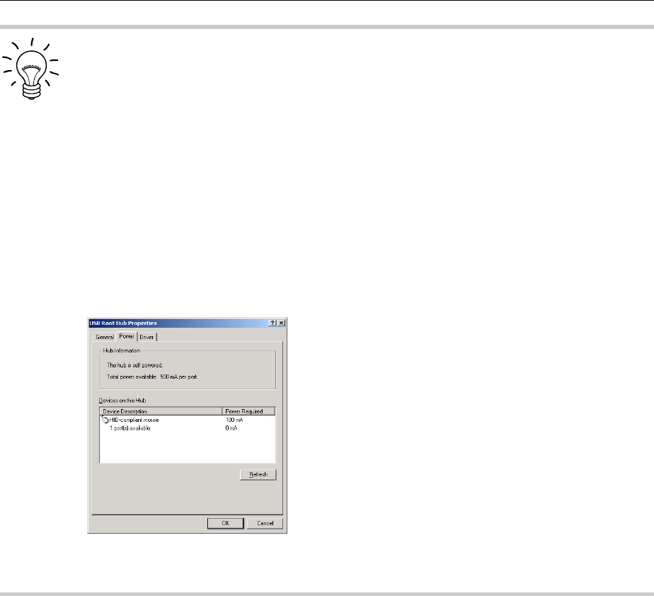
R&S NRP-Z11/-Z21 Connecting the sensor
1137.7406.12 1.3 E-2
• In the Windows™ start menu, select Settings – Control Panel
• Select the System icon
• Select the Hardware tab
• By clicking on the button with that name, start the Device Manager
• Open USB Controller (all USB controllers, hubs and USB devices are listed here)
• Double-click on USB Root Hub or select Properties in the context menu (use the
right-hand mouse button)
• Select the Power tab (Fig. 1-1). If the hub is self-powered and the total power
available is, as indicated by Hub Information, 500 mA per port, high-power devices
can be connected.
Fig. 1-1 Displaying the total available power of a USB port
If you have any doubts, ask the manufacturer if the USB port on your laptop or notebook can handle
high-power devices.
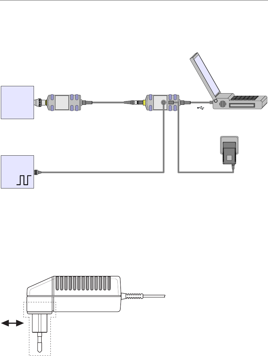
Connecting the sensor R&S NRP-Z11/-Z21
1137.7406.12 1.4 E-2
Operation via the Active USB Adapter R&S NRP-Z3
Figure 1-2 shows the configuration with the Active USB Adapter R&S NRP-Z3, which also makes it
possible to feed in a trigger signal for the Timeslot and Scope modes. The order in which the cables are
connected is not critical.
NR
P
−
Z
3
NR
P
−
Z
11
/
−
Z
21
P
C
w
i
t
h
U
SB
ho
s
t
i
n
t
e
r
f
a
c
e
U
SB
P
l
ug
−
i
n
po
w
e
r
s
upp
l
y
(
op
t
i
ona
l
,
s
upp
li
ed
w
i
t
h
NR
P
−
Z
3
)
A
C
s
upp
l
y
c
onne
c
t
i
on
G
~
S
i
gna
l
s
ou
r
c
e
T
r
i
gge
r
s
ou
r
c
e
(
op
t
i
ona
l
)
G
TT
L
/
C
M
O
S
B
NC
c
ab
l
e
(
no
t
s
upp
li
ed
w
i
t
h
NR
P
−
Z
3
)
Fig. 1-2 Configuration with Active USB Adapter R&S NRP-Z3
The plug-in power supply for the R&S NRP-Z3 can be powered from a single-phase AC source with a
nominal voltage range of 100 V to 240 V and a nominal frequency between 50 Hz and 60 Hz. The plug-
in power supply autosets to the applied AC voltage. No manual voltage selection is required.
The plug-in power supply comes with four primary adapters for Europe, the UK, the USA and Australia.
No tools of any kind are required to change the primary adapter. The adapter is pulled out manually and
another adapter inserted until it locks (Fig. 1-3).
Fig. 1-3 Changing the primary adapter
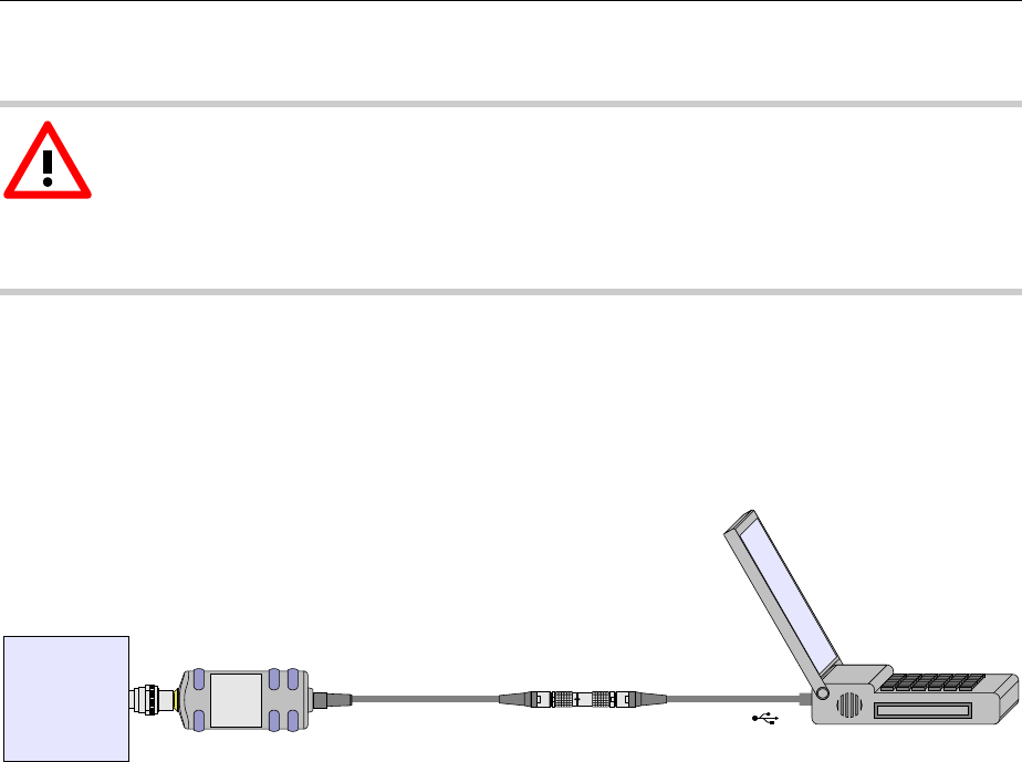
R&S NRP-Z11/-Z21 Connecting the sensor
1137.7406.12 1.5 E-2
The plug-in power supply is short-circuit-proof and has an internal fuse. It is not possible to replace this
fuse or open the plug-in power supply.
The plug-in power supply is not intended for outdoor use.
Keep within the temperature range of 0°C to 50°C.
If there is any condensation on the plug-in power supply, dry it off before connecting it to
the AC supply.
Operation via the Passive USB Adapter R&S NRP-Z4
Fig. 1-4 is a schematic of the measurement setup. The order in which the cables are connected is not
critical.
P
C
w
i
t
h
U
SB
ho
s
t
I
n
t
e
r
f
a
c
e
U
SB
G
~
S
i
gna
l
S
ou
r
c
e
NR
P
−
Z
11
/
−
Z
21
NR
P
−
Z
4
Fig. 1-4 Configuration with Passive USB Adapter R&S NRP-Z4
Connecting the sensor to the DUT
See the section “Operation with the R&S NRP basic unit” for information on how to connect the sensor
to the DUT.

R&S NRP-Z11/-Z21 Table of Contents Chapter 2
1137.7406.12 I-2.1 E-2
Table of Contents
2 Virtual Power Meter........................................................................................................... 2.1
Overview........................................................................................................................................... 2.1
Menus......................................................................................................................................... 2.3

List of Figs. and Tables Chapter 2 R&S NRP-Z11/-Z21
1137.7406.12 I-2.2 E-2
Figs.
Fig. 2-1 Power Viewer virtual power meter .................................................................................. 2.1
Tables
Table 2-1 Virtual power meter keys.................................................................................................. 2.2
Table 2-2 Virtual power meter entry fields........................................................................................ 2.2
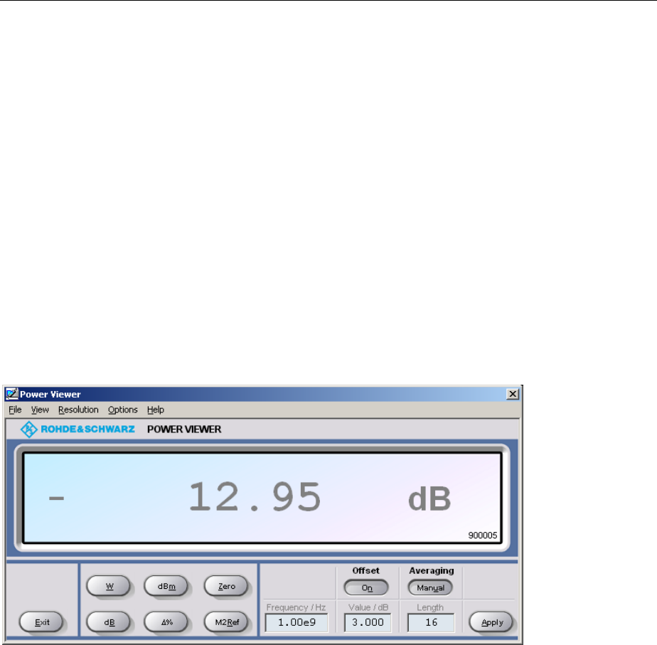
R&S NRP-Z11/-Z21 Overview
1137.7406.12 2.1 E-2
2 Virtual Power Meter
You will find the NrpFlashup program for controlling sensors with a PC under Windows™ on the
CD-ROM that accompanies the sensor. The program comprises several modules which can be started
centrally via the Windows™ start-menu entry NRP Toolkit.
This section describes the Power Viewer program module. This is a virtual power meter which only
uses a cut-down set of the sensor’s functions. This means that after an extremely brief familiarization
period, the user can measure the average power of modulated signals.
The other modules in NrpFlashup are described in Chapter 3 of the operating manual (Terminal and
Update S-Parameters modules) or in the service manual (Firmware Update module).
Overview
Start the virtual power meter using the NRP Toolkit – Power Viewer start-menu entry. The Power
Viewer program window is displayed (Fig. 2-1).
Fig. 2-1 Power Viewer – virtual power meter
The result display occupies most of the program window. The result, unit and additional sensor status
information are displayed. The serial number of the sensor is displayed in the bottom right. The program
window also contains animated buttons and entry fields (see Table 2-1 and Table 2-2).

Overview R&S NRP-Z11/-Z21
1137.7406.12 2.2 E-2
Table 2-1 Virtual power meter keys
Button Function Key combination
Exit Terminates the program. The current settings are saved and recalled the
next time the program is started. Alt + E
W Selects Watt as the display unit. Alt + W
dBm Selects dBm as the display unit. Alt + M
Zero Zeroes the sensor. Alt + Z
dB Selects dB as the display unit. This is the log of the ratio of the measured
value to the reference value. Alt + B
Selects % as the display unit. The difference between the measured value
and the reference value is expressed as a percentage. Alt + %
M2Ref Makes the current measured value the reference value for the relative
display units dB and %. Alt + R
Offset
On/Off Turns the offset correction for the sensor on or off. If the offset correction is
Off, the Offset/dB entry field has a grey background. Alt + N
Averaging
Man/Auto Turns auto-averaging on or off. When auto-averaging is on, the Length entry
field has a grey background; the current averaging factor is displayed. Alt + T
Apply Accepts edited numerical values in the Frequency/Hz, Value/dB and
Length entry fields and transfers them to the sensor. Alt + A
or Enter key
Table 2-2 Virtual power meter entry fields
Entry field Function
Frequency/Hz Frequency of the RF carrier in Hertz.
Value/dB Attenuation in dB of the twoport connected to the sensor. The valid range is –100 to 100. The offset
correction must be activated beforehand with the Offset On/Off button if this entry field is to be edited.
Length Length of the averaging filter (= averaging factor). The valid range is 1 to 65536. Averaging must be set
to manual with the Averaging Man/Auto button if this entry field is to be edited.
Scientific notation can also be used for the entry fields. If an invalid entry is made, an error message is
output. An edited numerical value will not be transferred to the sensor unless you use the Apply button
or the Enter key to terminate the entry.
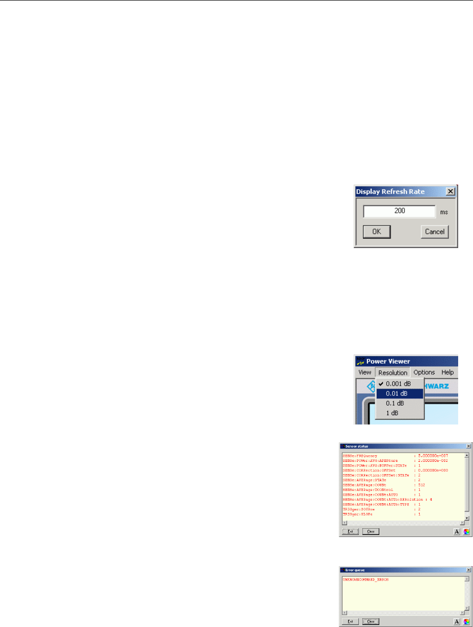
R&S NRP-Z11/-Z21 Overview
1137.7406.12 2.3 E-2
Menus
The menu bar can be used to call less frequently used functions.
File Start Log ... Opens a file-selection dialog to specify the path and name
of the log file. Clicking the Save button starts the
recording. All displayed values are written line-by-line to
the log file with the date (format: YY/MM/DD) and time
(format: hh:mm:ss.ms). Example:
-22.51 dBm (03/02/25 15:37:25.310)
Stop Log Ends the log-file recording.
View Display Refresh Rate Opens a dialog box to
adjust the display refresh
rate. The time in
milliseconds between two
refresh operations is
entered. The default
setting is 200 ms.
Colours
Result
Unit
Edit
Button
Opens a dialog box to select the background colour for
• the result,
• the unit,
• the text in the number fields or
• the key labelling.
Resolution For setting the result
resolution. If auto-
averaging has been
selected, a higher
resolution leads to a
greater averaging factor,
which means a longer
result settling time.
Options Read Sensor Status …Reads the current sensor
status. A parameter list is
output.
Read Error Queue …Reads the error queue. All
the error messages that
have been issued since
the last call are read line-
by-line. A tick before this
menu entry indicates that
an error has occurred.
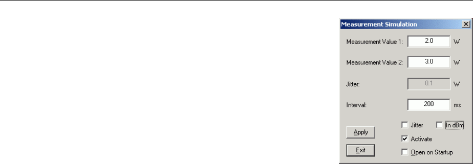
Overview R&S NRP-Z11/-Z21
1137.7406.12 2.4 E-2
Simulation …For trying out the functions
of the virtual power meter
without actually connecting
a sensor. The display
alternates between
Measurement Value 1 &
Measurement Value 2
with a period given by
Interval. Simulation can
be activated immediately
with the Activate check
box.
Reset Sensor Initializes the sensor. Any previous zeroing remains valid.
Help Contents Opens the table of contents for the online-help facility.
About Displays information about the program version used, etc.

R&S NRP-Z11/-Z21 Table of Contents Chapter 3
1137.7406.12 I-3.1 E-2
Table of Contents
3 Manual Operation............................................................................................................... 3.1
Program module "Terminal"........................................................................................................... 3.1
Main control elements................................................................................................................ 3.1
Menus......................................................................................................................................... 3.3
Program module "Firmware Update" ............................................................................................ 3.6
Program module "Update S-Parameters" ..................................................................................... 3.6
Fundamentals ............................................................................................................................ 3.6
Procedure................................................................................................................................... 3.9

List of Figs. and Tables Chapter 3 R&S NRP-Z11/-Z21
1137.7406.12 I-3.2 E-2
Figs.
Fig. 3-1 Sending commands using the Input field................................................................................. 3.1
Fig. 3-2 Sending commands using command files................................................................................ 3.2
Fig. 3-3 Dialog window for loading an s-parameter table...................................................................... 3.9
Fig. 3-4 Dialog window for loading the backup file of a calibration data set........................................ 3.10
Tables
Table 3-1 Buttons assigned to the Input field....................................................................................... 3.2
Table 3-2 Buttons assigned to the Command File field....................................................................... 3.2
Table 3-3 Buttons assigned to the Output field.................................................................................... 3.3
Table 3-4 Uncertainties of the s-parameter test system (example)...................................................... 3.7
Table 3-5 Interpolated uncertainties of measurement frequencies for s-parameters (example).......... 3.7
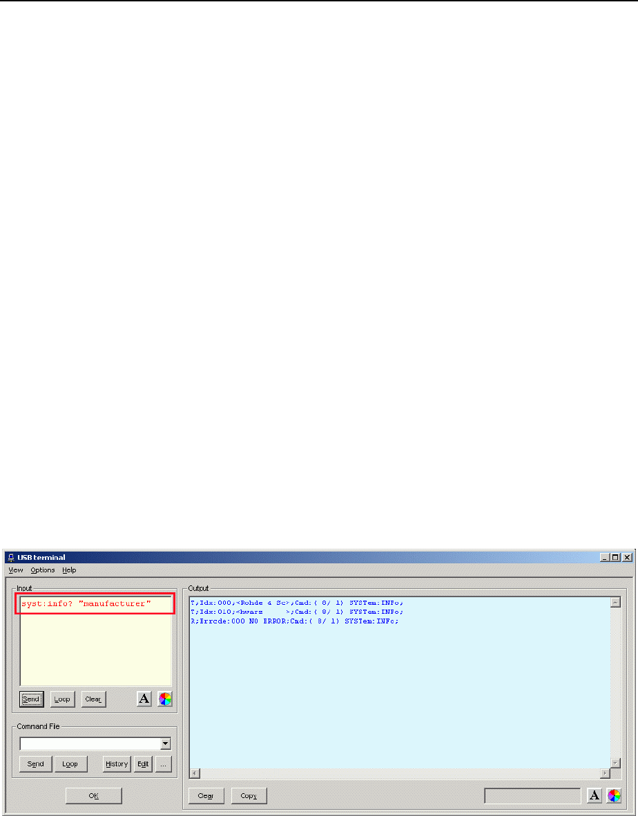
R&S NRP-Z11/-Z21 Program module "Terminal"
1137.7406.12 3.1 E-2
3 Manual Operation
The previous section describes the Power Viewer program module supplied with the instrument. This
module simplifies the most frequently used function of a power meter – measuring the average power of
an RF signal of almost any modulation. Other program modules are also part of the supplied equipment
and can be selected in the Start menu:
• Power Viewer: A detailed description of this virtual power meter module is provided in section 2.
• Terminal: Program module for sending commands and command sequences to the sensor and for
displaying measurement results, status information and other data from the sensor
• Firmware Update: Program module for updating the sensor firmware
• Update S-Parameters: Program module for loading an s-parameter table into the sensor
Program module "Terminal"
Main control elements
With the USB terminal, commands and command sequences can be sent to the sensor in two different
ways:
• Commands are entered in the Input field (Fig. 3-1). Consecutive commands can be entered as
separate lines, one below the other. The buttons associated with the Input field are described in
Table 3-1.
• Commands or command sequences are stored in command files. Command files are created with a
text editor, for instance, and then stored. They can be called as often as required (Fig. 3-2). The
buttons of the Command File field are described in Table 3-2.
Fig. 3-1 Sending commands using the Input field
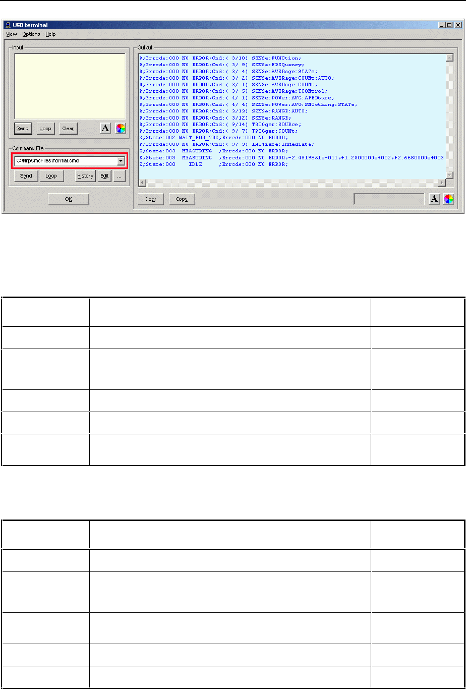
Program module "Terminal" R&S NRP-Z11/-Z21
1137.7406.12 3.2 E-2
Fig. 3-2 Sending commands using command files
Table 3-1 Buttons assigned to the Input field
Button Function Key combination
Send Sends the content of the Input entry field to the sensor. Alt + S
Loop With Loop the command or command sequence is cyclically sent. Pressing
the button again terminates the cyclic transmission. The repetition rate is set
in a dialog window that can be opened with View - Loop...
Alt + L
Clear Clears the content of the Input field. Alt + R
Font key Opens a dialog window where the font for the Input field can be selected.
Colour key Opens a dialog window where the background colour of the Input field can
be selected.
Table 3-2 Buttons assigned to the Command File field
Button Function Key combination
Send Sends the content of the command file to the sensor. Alt + E
Loop With Loop the command or command sequence is cyclically sent. Pressing
the button again terminates the cyclic transmission. The repetition rate is set
in a dialog window that can be opened with View - Loop...
Alt + O
History Opens a window for editing the command file name in the Command File
field. Alt + H
Edit Opens the selected command file in the Windows™ text editor. Alt + D
…Opens a file opening dialog for selecting the command file.
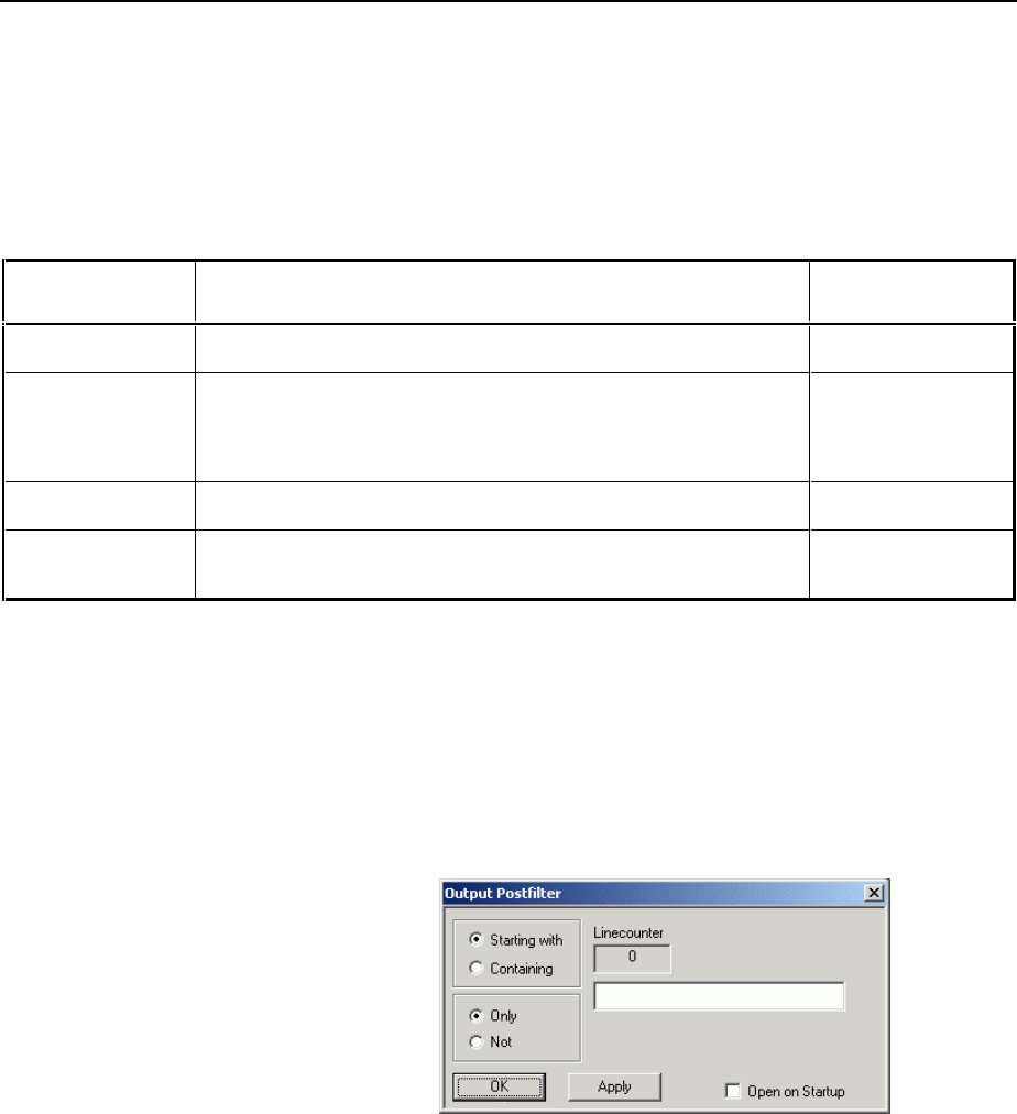
R&S NRP-Z11/-Z21 Program module "Terminal"
1137.7406.12 3.3 E-2
A command line starting with a tab, a blank or a special character is considered a comment and not
forwarded to the sensor.
Measurement results, parameters and status information returned by the sensor are displayed in the
Output field.
Table 3-3 Buttons assigned to the Output field
Button Function Key combination
Clear Clears the content of the Output field Alt + A
Copy Copies the content of the Output field to the clipboard. (Another possiblity:
mark the desired information in the output window with the mouse cursor,
press the right mouse key or Ctrl+C and then copy the selected text to the
clipboard using the menu item Copy in the opened context menu.)
Alt + Y
Font button Opens a dialog window where the font for the Output field can be selected.
Colour button Opens a dialog window where the background colour of the Output field can
be selected.
Close the USB terminal with OK.
Menus
View Post Filter … Opens the Output Postfilter dialog window where the lines stored in
the input buffer can be filtered according to different criteria.
Filter criteria:
Only + Starting with: Only lines starting with the entered character
string are displayed.
Not + Starting with: Only lines not starting with the entered character
string are displayed.
Only + Containing: Only lines containing the entered character string
are displayed.
Not + Containing: Only lines not containing the entered character
string are displayed.
Lines not matching the specific filter criterion are blanked but not
cleared.
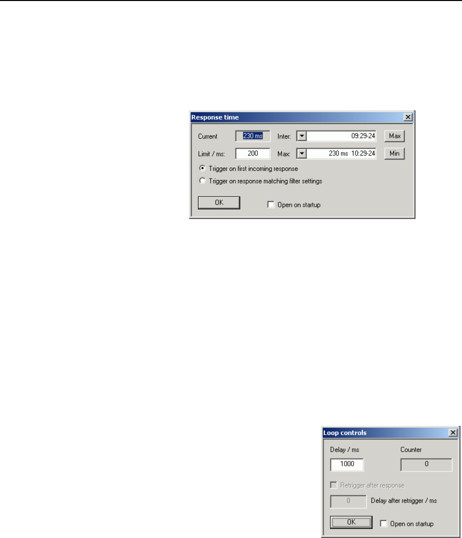
Program module "Terminal" R&S NRP-Z11/-Z21
1137.7406.12 3.4 E-2
Filtering is started with Apply. The number of lines matching the filter
criterion is displayed in the Linecounter field. If Open on startup is
active, the Output Postfilter dialog is automatically opened when the
terminal is started. The dialog window is closed with OK.
.
Response
Time …Opens the Response time dialog window where the response time of
the sensor can be set.
Current indicates the time elapsed between dispatch of the last
command and receipt of an acknowledgement from the sensor.
When the Max button is clicked, the response times exceeding the
value in the limit / ms field are recorded. When the Min button is
clicked, the response times within the value in the limit / ms field are
recorded.
If Trigger on first incoming response is active, the time
measurement is terminated as soon as the first response arrives after a
command is sent. If Trigger on response matching filter settings is
active, the time measurement is terminated as soon as the first
response matching the filter criterion in the
Output Postfilter
dialog
window is received.
If Open on startup is active, the Response Time dialog is
automatically displayed when the Terminal module is started. The
dialog window is closed with OK.
Loop …Opens the Loop controls dialog
window where the cyclic transfer of
commands and command sequences
can be controlled.
In the Delay / ms field, the time
interval for the cyclic transfer is
specified in milliseconds.
The number of completed transfer
cycles is displayed in the Counter
field. If Open on startup is active, the
Response time dialog is
automatically opened when the
Terminal module is started. The
dialog window is closed with OK.
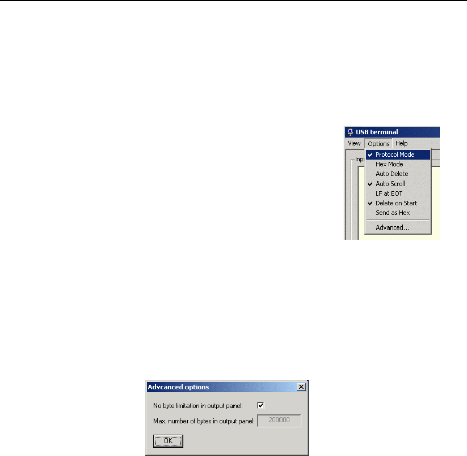
R&S NRP-Z11/-Z21 Program module "Terminal"
1137.7406.12 3.5 E-2
Options Protocol Mode In this mode, a time stamp is added to
each response block.
Hex Mode In this mode, the response blocks
from the sensor are displayed in
hexadecimal format.
Auto Delete With this option active, the Output
field is automatically cleared when the
Send button is pressed.
Auto Scroll With this option active, older items in
the Output field are automatically
shifted upward and off the display if
space is required for new values.
LF at EOT With this option active, a line feed is
appended to each response block
from the sensor.
Delete on Start With this option active, the Output
field is automatically cleared when the
Terminal module is started.
Send as Hex With this option active, the text in the
Input field is interpreted as a
hexadecimal character sequence.
Advanced …Opens a dialog window where the buffer size for the Output field can
be set.
Help Contents Opens the table of contents for the online help.
About Displays information about the program version, etc.

Program module "Firmware Update" R&S NRP-Z11/-Z21
1137.7406.12 3.6 E-2
Program module "Firmware Update"
A detailed description of the program module for firmware updates is provided in the Service Manual.
Program module "Update S-Parameters"
Fundamentals
With the Sensor R&S NRP-Z11/-Z21 the influence of any twoport connected to the input on the
measurement result can be corrected by way of calculation. A precondition is that a complete set of s-
parameters of the twoport is available in the frequency range in question. The set of calibration data in
the R&S NRP-Z11/-Z21 therefore includes an s-parameter table with up to 1000 measurement
frequencies. The real and the imaginary part of each frequency as well as the uncertainty of
s-parameters 11
s, 12
s, 21
s and 22
s can be stored. Since the measurement frequencies in the
s-parameter table are independent of the calibration frequencies, they can be set so that the twoport
frequency range of interest is optimally covered. The real and the imaginary parts between these
measurement frequencies are linearly interpolated, while the more substantial measurement uncertainty
at the two neighbouring frequency points is used for calculating the uncertainty of the measurement
result. Below the first and above the last measurement frequency, the values of the first and the last
measurement frequency are used, respectively.
The NrpFlashup program (menu item Update S-Parameters) is used for loading an s-parameter table.
To ensure compatibility with a great number of network analyzers, NrpFlashup can process
measurement data files in S2P format. All standard frequency units (Hz, kHz, MHz, GHz) and display
formats (real and imaginary part, linear magnitude and phase, magnitude in dB and phase) are
supported. The only restriction is that a reference impedance of 50 Ω must be used for the
s-parameters. Other noise parameters in the measurement data file are not evaluated.
Structure of the S2P measurement data file:
1. The option line has the following format:
# [<frequency unit>] [<parameter>] [<format>] [<R n>]
# identifies the option line.
The <frequency unit> may be Hz, kHz, MHz or GHz. If a frequency unit is not specified, GHz is
implicitly assumed.
If a parameter is specified, S must be used in <parameter> for s-parameter files. If a parameter
is not specified, S is implicitly assumed.
The <format> may be MA (linear magnitude and phase in degree), DB (magnitude in dB, phase
in degree) or RI (real and imaginary part). If a format is not specified, MA is implicitly assumed.
R is optional and followed by the reference impedance in Ω. If an entry is made for R, R50 must
be specified. If no entry is made, R50 is implicitly assumed.
The option line should therefore read:
# [HZ | KHZ | MHZ | GHZ] [S] [MA | DB | RI] [R 50]
2. The measurement frequencies in ascending order are specified as follows:
() () () ()
iiiii fsfsfsfsf 22122111 ,
where
()
ijk fs is the specified display format for the option line.
() ()
ijkijk fsfs arg (display format for linear magnitude and phase in degree) or
() ()
ijkijk fsfs arg lg20⋅(display format for magnitude in dB and phase in degree)
()
[
]
()
[
]
ijkijk fsfs Im Re (display format for real and imaginary part)
R&S NRP-Z11/-Z21 Program module "Update S-Parameters"
1137.7406.12 3.7 E-2
3. Comments: Any line starting with an exclamation mark (!) is interpreted as a comment line.
To characterize the measurement uncertainty of the s-parameter test system, another data file can
optionally be created. Without this file, the measurement uncertainty cannot be correctly calculated in
the sensor. The syntax of the uncertainty data file is similar to that of the S2P data file but U is specified
as <Parameter> in the option line so that the option line reads # Hz U for frequencies in Hz.
The measurement frequencies must not be identical to those of the S2P measurement data files. In
most cases a few entries will be sufficient to characterize the measurement uncertainty of the s-
parameter test system. An s-parameter uncertainty as high as that of the neighbouring measurement
frequencies of the uncertainty data file is then selected. If different values are available, the higher one
is chosen. This is illustrated in the example below:
Table 3-4 Uncertainties of the s-parameter test system (example)
f in GHz unc [sik(f)]
0.1 0.01
1.0 0.01
1.1 0.005
10.0 0.005
10.1 0.01
40.0 0.01
Table 3-5 Interpolated uncertainties of measurement frequencies for s-parameters (example)
f in GHz unc [sik(f)]
0.9 0.01
0.95 0.01
1.0 0.01
1.05 0.01
1.1 0.005
1.15 0.005
1.2 0.005
At 1.05 GHz, the higher uncertainty of the two adjacent 1.0 GHz and 1.1 GHz measurement
frequencies is entered in the s-parameter table. If an uncertainty of 0.005 is desired for all frequencies
above 1.0 GHz, the first measurement frequency in the uncertainty data file must above 1.0 GHz, e.g.
1.000001 GHz.
Program module "Update S-Parameters" R&S NRP-Z11/-Z21
1137.7406.12 3.8 E-2
Structure of the uncertainty data file:
1. The option line has the following format:
# [<frequency unit>] <parameter> [<format>] [<R n>]
# identifies the option line.
The <frequency unit> may be Hz, kHz, MHz or GHz. If a frequency unit is not specified, GHz is
implicitly assumed.
U must be specified for <parameter> in uncertainty data files. If a parameter is not specified, S
is implicitly assumed and as a result an error message is triggered.
<format> is ignored in uncertainty measurement files; the entry is therefore irrelevant.
R is optional and followed by the reference impedance in Ω. If an entry is made for R, R50 must
be specified. If no entry is made, R50 is implicitly assumed.
The option line should therefore read:
# [HZ | KHZ | MHZ | GHZ] U [MA | DB | RI] [R 50]
2. Measurement frequencies in ascending order are specified in the following form:
()
[]
()
[]
()
[]
()
[]
iiiii fsfsfsfsf 22122111 unc unc unc unc .
The s-parameters uncertainties are forwarded as follows:
• as extended absolute uncertainties ( 2=k) for the magnitude of reflection parameters 11
s
and 22
s, for instance 0.015,
• as extended uncertainties ( 2=k) in dB for the magnitude of transmission parameters 21
s
and 12
s, for instance 0.015.
3. Comments: Any line starting with an exclamation mark (!) is interpreted as a comment line.
Two additional values must be specified when the s-parameters are loaded: the lower and the upper
nominal measurement limit of the sensor-twoport combination. If s-parameter correction is active, these
values are transferred by the sensor in response to SYSTem:INFO? The values cannot always be
derived from the lower or upper measurement limit of the sensor alone and from the loss or gain of the
preconnected twoport. The upper measurement limit of the sensor-twoport combination may also be
limited by the twoport’s maximum power-handling capacity. Furthermore, the lower measurement limit
may be raised not only by the loss but also by the inherent noise of the twoport. For this reason,
NrpFlashup allows these values to be entered.
The upper nominal measurement limit of the sensor-twoport combination entered when
loading the s-parameters should be carefully specified, as automatic test systems may
evaluate it and an incorrect value may cause the sensor and/or the twoport to be
overloaded.
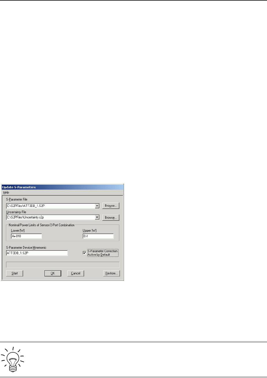
R&S NRP-Z11/-Z21 Program module "Update S-Parameters"
1137.7406.12 3.9 E-2
Procedure
To load an s-parameter table into the calibration set of the sensor, proceed as follows:
1. Connect the sensor to the USB port of the PC and start NrpFlashup.
2. Activate Update S-Parameters in the menu. The corresponding dialog window is opened (Fig.
3-3).
3. Under S-Parameter File enter the search path and the name of the S2P file containing the
parameters. Press the Browse... button to open a file-opening dialog where the S2P measurement
data file can be easily selected.
4. Under Uncertainty File enter the search path and the name of the measurement uncertainty file
containing the measurement uncertainty of the s-parameter test system. Press the Browse...
button to open a file-opening dialog where the measurement uncertainty file can be easily selected.
5. Enter the upper and lower nominal measurement limit of the sensor-twoport combination in the
Lower Power Limit and Upper Power Limit fields.
6. Enter a name for the loaded s-parameter set in the S-Parameter Device Mnemonic field. This
name can later be queried with SYSTem:INFO? "SPD Mnemonic" and is displayed on the NRP
basic unit when s-parameter correction is switched on.
7. Activate S-Parameter Correction on by Default if the SENSe:CORRection:TRANsmission switch
should be automatically set to ON when the sensor is put into operation.
8. Press Start for loading. (The dialog is closed with OK and the set parameters are retained. When
the dialog is exited with Cancel, all parameter modifications are ignored.)
Fig. 3-3 Dialog window for loading an s-parameter table
During loading, the current calibration data set of the sensor is overwritten. To be on the safe side, a
backup copy of the current calibration data set is therefore automatically stored before s-parameters are
loaded. The names of the backup files have the structure <batch number>_<date><time>.bak, where
<batch number> is the batch number of the sensor, <date> the date of the s-parameter update in
yymmdd format and <time> the time of the s-parameter update in the format hhmmss.
Store the automatically created backup files on a separate data medium (e.g. diskette,
CD-ROM or network drive) and, if required, assign an meaningful name to them to
simplify reloading. With the aid of these files, a previously used calibration data set of the
sensor can be restored.
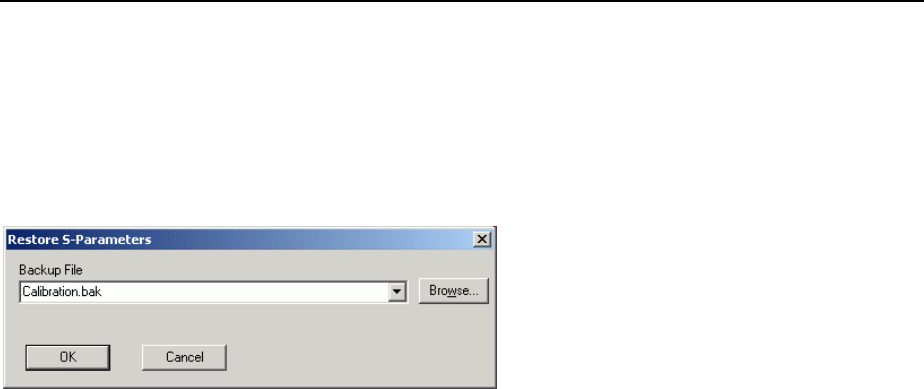
Program module "Update S-Parameters" R&S NRP-Z11/-Z21
1137.7406.12 3.10 E-2
To reload the backup file of a calibration data set into the sensor, proceed as follows:
• Press the Restore... button. The Restore S-Parameters window is opened (Fig. 3-4).
• Enter the search path and the name of the backup file in the Backup File field. Press the Browse...
button to open a dialog where the backup file can be easily selected.
• Press OK to start the restore procedure. (With Cancel the dialog window is exited without data
being restored).
Fig. 3-4 Dialog window for loading the backup file of a calibration data set

R&S NRP-Z11/-Z21 Table of Contents Chapter 5
1137.7406.12 I-5.1 E-3
Table of Contents
5 Remote Control – Fundamentals ................................................................................ 5.1

R&S NRP-Z11/-Z21 Remote Control – Fundamentals
1137.7406.12 5.1 E-3
5 Remote Control – Fundamentals
Rohde & Schwarz recommends to utilize the VXI Plug & Play Driver for the remote control of R&S NRP
power sensors. This driver can be found on the CD-ROM supplied with the sensor or downloaded in its
most recent version via the internet (http://rohde-schwarz.com/).
The old remote control interface provided by the Dynamic Link Library NrpControl.dll is not developed
further, but remains on the CD-ROM and can be downloaded via the internet.

R&S NRP-Z11/-Z21 Table of Contents Chapter 6
1137.7406.12 I-6.1 E-2
Table of Contents
6 Remote Control – Commands...................................................................................... 6.1
Notation ............................................................................................................................................ 6.1
Commands as per IEEE 488.2 ........................................................................................................ 6.2
*IDN? – IDentification Query ...................................................................................................... 6.2
*RST – Reset ............................................................................................................................. 6.2
*TRG – Trigger ........................................................................................................................... 6.2
*TST? – Self Test Query ............................................................................................................ 6.2
SCPI Commands.............................................................................................................................. 6.3
CALibration................................................................................................................................. 6.3
CALibration:DATA[?] <calibration data set as definite length block> .......................... 6.3
CALibration:DATA:LENGth? .......................................................................................... 6.3
CALibration:ZERO:AUTO[?] OFF | ON | ONCE .......................................................... 6.4
SENSe (Sensor Configuration) .................................................................................................. 6.5
SENSe:AVERage:COUNt[?] 1 to 65536...................................................................... 6.7
SENSe:AVERage:COUNt:AUTO[?] OFF | ON | ONCE............................................... 6.7
SENSe:AVERage:COUNt:AUTO:MTIMe[?] 1.0 to 999.99........................................... 6.8
SENSe:AVERage:COUNt:AUTO:NSRatio[?] 0.0001 to 1.0 ........................................ 6.8
SENSe:AVERage:COUNt:AUTO:RESolution[?] 1 to 4................................................ 6.8
SENSe:AVERage:COUNt:AUTO:SLOT[?] 1 to <SENSe:POWer:TSLot:AVG:COUNt>..... 6.8
SENSe:AVERage:COUNt:AUTO:TYPE[?] RESolution | NSRatio............................... 6.9
SENSe:AVERage:RESet ............................................................................................... 6.9
SENSe:AVERage:STATe[?] OFF | ON........................................................................ 6.9
SENSe:AVERage:TCONtrol[?] MOVing | REPeat....................................................... 6.9
SENSe:CORRection:DCYCle[?] 0.001 to 99.999...................................................... 6.10
SENSe:CORRection:DCYCle:STATe[?] OFF | ON ................................................... 6.10
SENSe:CORRection:OFFSet[?] –200.0 to 200.0 ...................................................... 6.10
SENSe:CORRection:OFFSet:STATe[?] OFF | ON.................................................... 6.10
SENSe:CORRection:SPDev:STATe[?] OFF | ON ..................................................... 6.11
SENSe:FREQuency[?] 10.0e6 to 8.0e9 (NRP-Z11) or 18.0e9 (NRP-Z21) ............... 6.11
SENSe:FUNCtion[?] <sensor_function>.................................................................... 6.12
SENSe:POWer:AVG:APERture[?] 0.0001 to 0.3....................................................... 6.13
SENSe:POWer:AVG:BUFFer:SIZE[?] 1 to 1024 ....................................................... 6.13
SENSe:POWer:AVG:BUFFer:STATe[?] OFF | ON.................................................... 6.14
SENSe:POWer:AVG:SMOothing:STATe[?] OFF | ON .............................................. 6.14
SENSe:POWer:BURSt:DTOLerance[?] 0.0 to 0.003................................................. 6.14
SENSe:POWer:TSLot:AVG:COUNt[?] 1 to 128......................................................... 6.15
SENSe:POWer:TSLot:AVG:WIDTh[?] 0.0001 to 0.1................................................. 6.15
SENSe:RANGe[?] 0 to 2 ............................................................................................ 6.15
SENSe:RANGe:AUTO[?] OFF | ON .......................................................................... 6.16
SENSe:RANGe:AUTO:CLEVel[?] –20.0 to 0.0.......................................................... 6.16
SENSe:SAMPling[?] FREQ1 | FREQ2....................................................................... 6.16
SENSe:SGAMma:CORRection:STATe[?] OFF | ON................................................. 6.16
SENSe:SGAMma:MAGNitude[?] 0.0 to 1.0 ............................................................... 6.17

Table of Contents Chapter 6 R&S NRP-Z11/-Z21
1137.7406.12 I-6.2 E-2
SENSe:SGAMma:PHASe[?] –360.0 to 360.0............................................................ 6.17
SENSe:TRACe:AVERage:COUNt[?] 1 to 65536 ....................................................... 6.17
SENSe:TRACe:AVERage:COUNt:AUTO[?] OFF | ON | ONCE................................ 6.17
SENSe:TRACe:AVERage:COUNt:AUTO:MTIMe[?] 1.0 to 999.99............................ 6.18
SENSe:TRACe:AVERage:COUNt:AUTO:NSRatio[?] 0.0001 to 1.0 ......................... 6.18
SENSe:TRACe:AVERage:COUNt:AUTO:RESolution[?] 1 to 4 ................................. 6.18
SENSe:TRACe:AVERage:COUNt:AUTO:POINt[?] 1 to <SENSe:TRACe:POINts>.. 6.18
SENSe:TRACe:AVERage:COUNt:AUTO:TYPE[?] RESolution | NSRatio................ 6.19
SENSe:TRACe:AVERage:STATe[?] OFF | ON......................................................... 6.19
SENSe:TRACe:AVERage:TCONtrol[?] MOVing | REPeat........................................ 6.19
SENSe:TRACe:MPWidth? ........................................................................................... 6.19
SENSe:TRACe:OFFSet:TIME[?] – (<TRIGger:DELay> + 0.005) to 100.0................ 6.20
SENSe:TRACe:POINts[?] 1 to 1024.......................................................................... 6.20
SENSe:TRACe:REALtime[?] OFF | ON..................................................................... 6.20
SENSe:TRACe:TIME[?] 0.0001 to 0.3....................................................................... 6.20
SENSe:TIMing:EXCLude:STARt[?] 0.0 to 0.1 ........................................................... 6.20
SENSe:TIMing:EXCLude:STOP[?] 0.0 to 0.003........................................................ 6.21
SYSTem................................................................................................................................... 6.22
SYSTem:INFO? [Item] ................................................................................................. 6.22
SYSTem:INITialize....................................................................................................... 6.23
SYSTem:MINPower? ................................................................................................... 6.24
SYSTem:TRANsaction:BEGin ..................................................................................... 6.24
SYSTem:TRANsaction:END ........................................................................................ 6.24
TEST ........................................................................................................................................ 6.25
TEST:SENSor? ............................................................................................................ 6.25
TRIGger ................................................................................................................................... 6.26
ABORt .......................................................................................................................... 6.26
INITiate:CONTinuous[?] OFF | ON ............................................................................ 6.26
INITiate:IMMediate....................................................................................................... 6.27
TRIGger:ATRigger:STATe[?] OFF | ON .................................................................... 6.27
TRIGger:COUNt[?] 1 to 2 × 10⁹.................................................................................. 6.27
TRIGger:DELay[?] x to 100.0..................................................................................... 6.28
TRIGger:DELay:AUTO[?] OFF | ON .......................................................................... 6.28
TRIGger:HOLDoff[?] 0.0 to 10.0 ................................................................................ 6.28
TRIGger:HYSTeresis[?] 0.0 to 10.0 ........................................................................... 6.28
TRIGger:IMMediate...................................................................................................... 6.28
TRIGger:LEVel[?] x to y ............................................................................................. 6.29
TRIGger:SLOPe[?] POSitive | NEGative ................................................................... 6.29
TRIGger:SOURce[?] BUS | EXTernal | HOLD | IMMediate | INTernal...................... 6.29
List of Remote-Control Commands ............................................................................................. 6.30

Figures and List of Tables Chapter 6 R&S NRP-Z11/-Z21
1137.7406.12 I-6.3 E-2
Figs.
Fig. 6-1 Effect of SENSe:POWer:BURSt:DTOLerance............................................................... 6.15
Fig. 6-2 Effect of SENSe:TIMing:EXCLude:STARt and :END in the Burst Average mode......... 6.21
Fig. 6-3 Effect of SENSe:TIMing:EXCLude:STARt and :END in the Timeslot mode.................. 6.21
Tables
Table 6-1 Commands of the CALibration system............................................................................. 6.3
Table 6-2 Commands of the SENSe system.................................................................................... 6.5
Table 6-3 Measurement modes......................................................................................................6.12
Table 6-4 Optimum selection of the sampling window size (N = 1, 2, 3, …).................................. 6.13
Table 6-5 Commands of the SYSTem system ............................................................................... 6.22
Table 6-6 Meaning of Item in the SYSTem:INFO? command........................................................ 6.22
Table 6-7 Commands of the TEST system .................................................................................... 6.25
Table 6-8 Commands of the TRIGger system................................................................................ 6.26
Table 6-9 List of remote-control commands................................................................................... 6.30

R&S NRP-Z11/-Z21 Remote Control - Commands
1137.7406.12 6.1 E-2
6 Remote Control – Commands
Notation
In the following sections, all commands implemented in the sensor are first listed in a table according to
command systems and are then described in detail. The notation is largely in line with the SCPI
standard.
Command tables For a quick overview of available commands, the commands are listed in a table
before they are described. These tables contain the following four columns:
Command: Commands and their tree structure.
Parameters: Possible parameters.
Unit: The basic unit of the physical parameters (must not be sent with
parameters).
Remarks: Identification of all commands
• that have no query form
• that are available as query only
Indentations The various levels of the SCPI command hierarchy are shown in the table by
indentations to the right. The lower the level, the greater the indentation to the right.
It should be noted that the complete notation of the command includes the higher
levels too.
Example:
SENSe:AVERage:COUNt is represented in the table as follows:
SENSe first level
:AVERage second level
:COUNt third level
In the individual description, the command is shown in full length. An example of the
command is given at the end of the description.
[?]
?A question mark in square brackets at the end of a command indicates that this
command can either be used as a setting command (without question mark) or as a
query (with question mark). If the question mark is not in square brackets, the
command is a query only.
Example:
SENSe:POWer:AVG:APERture[?]
SENSe:POWer:AVG:APERture 1e-3 sets the length of the sampling window to
1 ms.
SENSe:POWer:AVG:APERture? Returns the currently set length as a response.
*IDN? Queries the sensor identification string that of course cannot be changed. For
this reason, this command is only available as a query.
Special
characters | for
parameters
A vertical bar between parameters is used to separate alternative options (OR link).
Example:
NITiate:CONTinuous OFF | ON
The parameter OFF or ON can be entered.
{numeric
expression} A numeric expression in braces means that it has been rounded to the nearest
integral value.
<parameter>
<variable> A parameter or a variable in triangular brackets expresses its current value.

Remote Control - Commands R&S NRP-Z11/-Z21
1137.7406.12 6.2 E-2
Commands as per IEEE 488.2
The sensor supports a subset of the possible setting commands and queries (Common Commands and
Queries) in line with IEEE 488.2.
*IDN? – IDentification Query
*IDN? returns a string with information on the sensor’s identity (device identification code). In addition,
the version number of the installed firmware is indicated. The string for a sensor of type R&S NRP-Z21
has the following structure:
ROHDE&SCHWARZ,NRP-Z21,<serial number>,<firmware version>
<serial number>: Serial number in ASCII
<firmware version>: Firmware version number in ASCII
*RST – Reset
*RST sets the sensor to the default state, i.e. the default settings for all test parameters are loaded.
*TRG – Trigger
*TRG triggers a measurement. For this purpose, the sensor is in the WAIT_FOR_TRIGGER state and
the source for the trigger event is set to BUS (TRIGger:SOURce BUS).
*TST? – Self Test Query
*TST? starts a selftest and returns 0 (no error found) or 1 (an error has occurred). The selftest
comprises the following functions:
• RAM test
• Operating voltages
• Temperature measurement
• Calibration data set
• Noise
• Zero-point offsets.

R&S NRP-Z11/-Z21 Remote Control - Commands
1137.7406.12 6.3 E-2
SCPI Commands
The sensors R&S NRP-Z11/-Z21 are controlled via the groups of commands
• CALibration (zeroing)
• SENSe (measurement configurations)
• SYSTem
• TRIGger
• SERVice.
CALibration
Table 6-1 Commands of the CALibration system
Command Parameter Unit Remarks
CALibration
:DATA[?] <calibration data set as definite length block>
:LENGth? Bytes Query only
:ZERO
:AUTO[?] OFF | ON | ONCE
CALibration:DATA[?] <calibration data set as definite length block>
CALibration:DATA is used for writing a calibration data set in the flash memory of the sensor.
The query yields the calibration data set currently stored in the flash memory as a definite length block.
CALibration:DATA:LENGth?
CALibration:DATA:LENGth? yields the length in bytes of the calibration data set currently stored in the
flash memory. Programs that read out the calibration data set can use this information to determine the
capacity of the buffer memory required.

Remote Control - Commands R&S NRP-Z11/-Z21
1137.7406.12 6.4 E-2
CALibration:ZERO:AUTO[?] OFF | ON | ONCE
The commands CALibration:ZERO:AUTO ON and CALibration:ZERO:AUTO ONCE zeroes the three
measurement paths of the sensor. For this purpose, the test signal must be deactivated or the sensor
disconnected from the signal source. The sensor automatically detects the presence of any significant
power to be measured. This causes zeroing to be aborted and error message NRPERROR_CALZERO
to be output. The CALibration:ZERO:AUTO OFF is ignored. Zeroing takes four seconds at a minimum,
but at least as long as the selected averaging filter needs for settling (only fixed-filter mode).
Repeat zeroing
• during warm-up after switching on or connecting the instrument
• after a substantial variation of the ambient temperature
• after fastening the sensor to an RF connector at high temperature
• after several hours of operation
• when very low-power signals are to be measured, e.g. less than 10 dB above the
lower measurement limit.
For zeroing switch off the test signal and do not remove the sensor from the signal source.
Apart from keeping the thermal balance, this has the advantage that the noise
superimposed on the test signal (e.g. from a broadband amplifier) can be detected on
zeroing and does not impair the measurement result.
The query always yields 1 (= OFF).
Default setting
After a power-on reset, the zero offsets determined during the last calibration are used until the first
zeroing. Therefore, very slight zero offsets are to be expected with a warmed up sensor. Initialization by
means of *RST or SYSTem:INITialize has no influence on the current zero offsets.

R&S NRP-Z11/-Z21 Remote Control - Commands
1137.7406.12 6.5 E-2
SENSe (Sensor Configuration)
The sensor is configured by means of the commands of the groups SENSe and TRIGger.
Table 6-2 Commands of the SENSe system
Command Parameter Unit Remarks
SENSe
:AVERage
:RESet No query
:STATe[?] OFF | ON
:TCONtrol[?] MOVing | REPeat
:COUNt[?] 1 to 65536
:AUTO[?] OFF | ON | ONCE
:TYPE[?] RESolution | NSRatio
:MTIMe[?] 1.0 to 999.99 s
:NSRatio[?] 0.0001 to 1.0 dB
:RESolution[?] 1 to 4
:SLOT[?] 1 to <SENSe:POWer:TSLot:AVG:COUNt>
:CORRection
:OFFSet[?] -200.0 to 200.0 dB
:STATe[?] OFF to ON
:DCYCle[?] 0.001 to 99.999 %
:STATe[?] OFF to ON
:SPDevice:STATe[?] OFF to ON
:FREQuency[?] 10.0e6 to 8.0e9 (NRP-Z11) or 18.0e9 (NRP-Z21) Hz
:FUNCtion[?] “POWer:AVG“ | “POWer:TSLot:AVG“ |
“POWer:BURSt:AVG“ | “XTIME:POWer“
:POWer
:AVG
:APERture[?] 1.0e-6 to 0.3 s
:BUFFer
:STATe[?] OFF | ON
:SIZE[?] 1 to 1024

Remote Control - Commands R&S NRP-Z11/-Z21
1137.7406.12 6.6 E-2
Command Parameter Unit Remarks
:SMOothing:STATe[?] OFF | ON
:BURSt:DTOLerance[?] 0.0 to 3.0e-3 s
:TSLot:AVG
:COUNt[?] 1 to 128
:WIDTh[?] 10e-6 to 100e-3 s
:RANGe [?] 0 to 2
:AUTO[?] OFF | ON
:CLEVel[?] 0.0 to 20.0 dB
:SAMPling[?] FREQ1 | FREQ2
:SGAMma
:CORRection:STATe[?] OFF | ON
:MAGNitude[?] 0.0 to 1.0
:PHASe[?] -360.0 to 360.0 degree
:TRACe
:AVERage
:STATe[?] OFF | ON
:TCONtrol[?] MOVing | REPeat
:COUNt[?] 1 to 65536
:AUTO[?] OFF | ON | ONCE
TYPE[?] RESolution | NSRatio
:MTIMe[?] 1.0 to 999.99 s
:NSRatio[?] 0.0001 to 1.0 dB
:RESolution[?] 1 to 4
:POINt[?] 1 to <SENSe:TRACe:POINts>
:MPWidth? s Query only
:OFFSet:TIME[?] – (<TRIGger:DELay> + 0.005) to 100.0 s
:POINts[?] 1 to 1024
:REALtime[?] OFF | ON
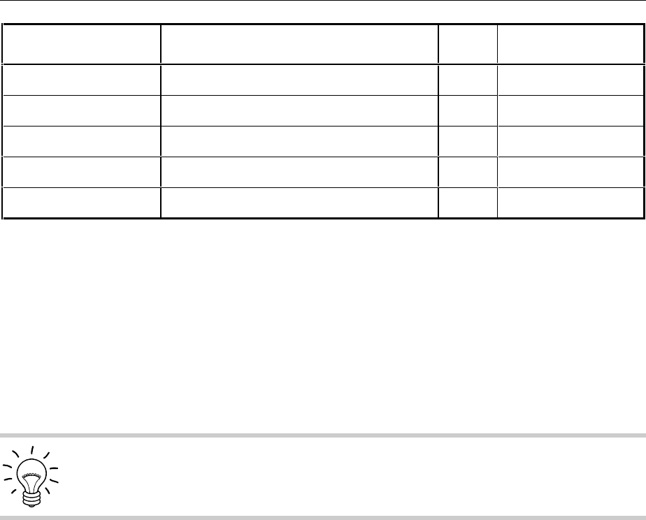
R&S NRP-Z11/-Z21 Remote Control - Commands
1137.7406.12 6.7 E-2
Command Parameter Unit Remarks
:TIME[?] 0.0001 to 0.3
:TIMing
:EXCLude
:STARt[?] 0.0 to 3.0e-3 s
:STOP[?] 0.0 to 3.0e-3 s
SENSe:AVERage:COUNt[?] 1 to 65536
SENSe:AVERage:COUNt sets the number of measured values that have to be averaged for forming
the measurement result in the modes Continuous Average, Burst Average and Timeslot. The higher this
averaging factor, the less the measured values fluctuate and the longer the measurement time lasts.
The parameter is rounded off to the nearest power-of-two number.
The query yields the averaging factor used in the modes Continuous Average, Burst Average and
Timeslot.
The averaging function must be activated with SENSe:AVERage:STATe ON so that the
set averaging factor becomes effective.
Default setting: 4
SENSe:AVERage:COUNt:AUTO[?] OFF | ON | ONCE
SENSe:AVERage:COUNt:AUTO activates (auto-averaging) or deactivates (fixed-filter mode) automatic
determination of the averaging factor in the modes Continuous Average, Burst Average and Timeslot. If
auto-averaging is activated, the averaging factor is continuously determined and set depending on the
level of power and other parameters.
SENSe:AVERage:COUNt:AUTO ON activates auto-averaging and SENSe:AVERage:COUNt
:AUTO OFF deactivates it. On deactivation, the previous, automatically determined averaging factor is
used in the fixed-filter mode. The SENSe:AVERage:COUNt:AUTO ONCE command ensures that a new
averaging factor is determined by the filter automatic function under the current measurement
conditions and used in the fixed-filter mode.
The query yields
• 1 for OFF,
• 2 for ON.
Default setting: OFF

Remote Control - Commands R&S NRP-Z11/-Z21
1137.7406.12 6.8 E-2
SENSe:AVERage:COUNt:AUTO:MTIMe[?] 1.0 to 999.99
SENSe:AVERage:COUNt:AUTO:MTIMe sets the settling time upper limit of the averaging filter in the
auto-averaging mode for the Continuous Average, Burst Average and Timeslot modes and limits the
length of the filter.
The query yields the current settling time upper limit of the averaging filter in the auto-averaging mode
for the Continuous Average, Burst Average and Timeslot modes.
Default setting: 30.0 [s]
SENSe:AVERage:COUNt:AUTO:NSRatio[?] 0.0001 to 1.0
SENSe:AVERage:COUNt:AUTO:NSRatio determines the relative noise component in the measurement
result for the Continuous Average, Burst Average and Timeslot modes if auto-averaging is operated in
the corresponding mode (SENSe:AVERage:COUNt:AUTO:TYPE NSRatio). The noise component is
defined as the magnitude of the level variation in dB caused by the inherent noise of the sensor (two
standard deviations).
The query yields the relative noise component in the result for the Continuous Average, Burst Average
or Timeslot modes.
Default setting: 0.01 [dB]
SENSe:AVERage:COUNt:AUTO:RESolution[?] 1 to 4
SENSe:AVERage:COUNt:AUTO:RESolution sets the resolution index for the automatic averaging filter
in the Continuous Average, Burst Average and Timeslot modes if it is operated in the RESolution mode.
The resolution index equals the number of decimal places that have to be taken into account for the
further processing of the measurement result in dBm, dBµV or dB. The normal mode is designed in a
similar manner as for the predecessors R&S NRVS and R&S NRVD or other commercial power meters.
The higher the selected index, the better the measurement result is filtered without the last significant
place (0.01 dB with an index of 3) actually being set. The NSRatio setting is recommended instead.
The query yields the resolution index for the Continuous Average, Burst Average and Timeslot modes.
Default setting: 3
SENSe:AVERage:COUNt:AUTO:SLOT[?] 1 to <SENSe:POWer:TSLot:AVG:COUNt>
SENSe:AVERage:COUNt:AUTO:SLOT defines the timeslot, whose power is referenced by
auto-averaging in the Timeslot mode. The timeslot is addressed via its number, the counting beginning
with 1. The timeslot number must not exceed the number of the currently set timeslots. If a valid
timeslot number is initially set and then the number of timeslots reduced to a value that is smaller than
the initial timeslot number, the initial value is automatically set to the new timeslot number, i.e.
auto-averaging references the most recent timeslot.
The query yields the number of the current timeslot, whose power is referenced by auto-averaging in
the Timeslot mode.
Default setting: 1

R&S NRP-Z11/-Z21 Remote Control - Commands
1137.7406.12 6.9 E-2
SENSe:AVERage:COUNt:AUTO:TYPE[?] RESolution | NSRatio
SENSe:AVERage:COUNt:AUTO:TYPE defines the automatic averaging filter mode in the Continuous
Average, Burst Average and Timeslot modes. The RESolution parameter sets the mode usual for
power meters; NSRatio predefines the compliance to an exactly defined noise component.
The query yields
• 1 for RESolution,
• 2 for NSRatio.
Default setting: RESolution
SENSe:AVERage:RESet
SENSe:AVERage:RESet initializes the averaging filter for the Continuous Average, Burst Average or
Timeslot modes. This is useful if a high averaging factor is set in the SENSe:AVERage
:TCONtrol MOVing filter mode and if the power to be measured has significantly decreased since the
previous measurement, e.g. by several powers of ten. In this case, previous measurement results still
contained in the averaging filter strongly affect the settling of the display; as a result, the advantage of
the SENSe:AVERage:TCONtrol MOVing filter mode, i.e. the ability to detect trends in the measurement
result while the measurement is still in progress, is lost. The SENSe:AVERage:RESet command solves
this problem by deleting all previous measurement results that the averaging filter contains. After
initialization, the filter length gradually increases from 1 to its nominal value SENSe:AVERage:COUNt,
so that trends in the measurement result become quickly apparent. However, this procedure does not
shorten the measurement time required in order for the averaging filter to settle completely.
SENSe:AVERage:STATe[?] OFF | ON
SENSe:AVERage:STATe switches on or off the averaging filter for the Continuous Average, Burst
Average and Timeslot modes.
The query yields
• 1 for OFF,
• 2 for ON.
Default setting: ON
SENSe:AVERage:TCONtrol[?] MOVing | REPeat
SENSe:AVERage:TCONtrol (terminal control) defines the behaviour of the averaging filter in the
Continuous Average, Burst Average and Timeslot modes. As soon as a new measured value is shifted
to the FIR filter, a new average value is available at the filter output, which is obtained from the new
measured value and the other values stored in the filter.
The MOVing parameter defines that each new average value is output as a measurement result. This
allows tendencies in the result to be recognized during the measurement procedure.
The REPeat parameter defines that a new result is output after the FIR filter has been filled with new
measured values. This ensures that no redundant information is output.
The query yields
• 1 for MOVing,
• 2 for REPeat.
Default setting: MOVing

Remote Control - Commands R&S NRP-Z11/-Z21
1137.7406.12 6.10 E-2
SENSe:CORRection:DCYCle[?] 0.001 to 99.999
SENSe:CORRection:DCYCle sets the duty cycle to a percent value for the correction of pulse-
modulated signals. With the correction activated, the sensor calculates the signal pulse power from this
value and the mean power. Since the duty cycle is only useful in the Continuous Average mode and the
normal mode, it is evaluated only there.
The query yields the current duty cycle in percent.
Default setting: 1.0 [%]
SENSe:CORRection:DCYCle:STATe[?] OFF | ON
SENSe:CORRection:DCYCle:STATe ON activates the duty cycle correction and thus the pulse-power
measurement whereas SENSe:CORRection:DCYCle:STATe OFF deactivates it.
The query yields
• 1 for OFF,
• 2 for ON.
Default setting: OFF
SENSe:CORRection:OFFSet[?] –200.0 to 200.0
SENSe:CORRection:OFFSet defines a fixed offset in dB, which is used to correct the measured value.
(When a log scale is used, the offset is added to the measured value; this is the reason why the
command has this name.)
The attenuation of an attenuator located ahead of the sensor or the coupling attenuation of a directional
coupler is taken into account with a positive offset, i.e. the sensor calculates the power at the input of
the attenuator or directional coupler. A negative offset can be used to correct the influence of a gain
connected ahead.
The query yields the set offset in dB.
Default setting: 0.0 [dB]
SENSe:CORRection:OFFSet:STATe[?] OFF | ON
SENSe:CORRection:OFFSet:STATe ON activates the offset correction and
SENSe:CORRection:OFFSet:STATe OFF deactivates it.
The query yields
• 1 for OFF,
• 2 for ON.
Default setting: OFF

R&S NRP-Z11/-Z21 Remote Control - Commands
1137.7406.12 6.11 E-2
SENSe:CORRection:SPDev:STATe[?] OFF | ON
SENSe:CORRection:SPDevice:STATe ON activates the s-parameter data set for a component
(attenuator, directional coupler) connected ahead of the sensor. Parameter OFF deactivates it.
The use of s-parameters instead of a fixed offset
(see group of commands SENSe:CORRection:OFFSet)
allows more precise measurements, since the interactions between the sensor, the source and
components connected between them can be taken into account. (For detailed information on loading
s-parameter data sets, refer to section 3.) The sensor has no factory-set s-parameter data set. In this
state, the SENSe:CORRection:SPDevice:STATe ON command generates an error message.
The query yields
• 1 for OFF,
• 2 for ON.
Default setting:
The factory-set default setting of the sensor is OFF. On loading an s-parameter table, the default setting
can be redefined (see section 3).
SENSe:FREQuency[?] 10.0e6 to 8.0e9 (NRP-Z11) or 18.0e9 (NRP-Z21)
SENSe:FREQuency transfers the carrier frequency of the RF signal to be measured; this frequency is
used for the frequency-response correction of the measurement result. The center frequency is set for
broadband signals (spread-spectrum signals, multicarrier signals).
The query yields the set carrier frequency in Hz.
Default setting: 50.0e6 [Hz]

Remote Control - Commands R&S NRP-Z11/-Z21
1137.7406.12 6.12 E-2
SENSe:FUNCtion[?] <sensor_function>
SENSe:FUNCtion <sensor_function> sets the sensor to one of the following measurement modes:
Table 6-3 Measurement modes
<sensor_function> Description of the measurement mode
"POWer:AVG" Continuous Average
After occurrence of the trigger event, the mean power is measured in a time interval (sampling
window) whose width is defined with SENSe:POWer:AVG:APERture.
The single measurements are performed in pairs to obtain a more accurate measurement result by
differentiation. With the averaging function activated, this operation is repeated the number of times
specified by the averaging factor. With the averaging function activated, the actual measurement time
is thus
2 × <SENSe:AVERage:COUNt> × <SENSe:POWer:AVG:APERture>
and with deactivated averaging function
2 × <SENSe:POWer:AVG:APERture>.
Trigger events start one or several measurements in the Continuous Average mode (depending on the
TRIGger:COUNt parameter).
"POWer:TSLot:AVG" Timeslot
The power is measured in a defined number of consecutive timeslots. Up to 128 timeslots have the
same width, which is defined by SENSe:POWer:TSLot :WIDTh. Their quantity is defined by
SENSe:POWer:TSLot:COUNt. The measurement result is an array, which contains as many elements
as timeslots. Each element represents the average power in one of the timeslots. After each
occurrence of the trigger event, a measurement is performed in all timeslots. The single
measurements are also performed in pairs in this mode to obtain a more accurate measurement result
by differentiation. With the averaging function activated, this operation is repeated the number of times
specified by the averaging factor. With the averaging function activated, the actual measurement time
is thus
2 × <SENSe:AVERage:COUNt> × <SENSe:POWer:TSLot:AVG:WIDTh>
and with deactivated averaging function
2 × <SENSe:POWer:TSLot:AVG:WIDTh>.
Note that a corresponding number of trigger events must be available.
"POWer:BURSt:AVG" Burst Average
This mode is used for the measurement of the average power of repetitive single bursts, for example.
The time interval (integration time) in which the average power is measured is not predefined. Instead,
a special algorithm detects the beginning and end of the burst and ensures the synchronization of the
sampling window. However, the user must define the dropout tolerance, a time criterion for detecting
the pulse or burst end, using SENSe:POWer:BURSt:DTOLerance.
In the Burst Average mode, external trigger events (irrespective of the setting of the TRIGger:SOURce
parameter) and the TRIGger:DELay parameter are ignored.
"XTIMe:POWer" Scope
The Scope mode is similar to the Timeslot mode. Since, however, up to 1024 consecutive timeslots
(called "points" here) are possible, the maximum averaging factor is limited to 8192 due to the storage
capacity. In the Scope mode, other limits than in the Timeslot mode apply to the timeslot width.
SENSe:TRACe:REALtime ON optimizes the time resolution. The differentiation and averaging filter are
ignored.
R&S NRP-Z11/-Z21 Remote Control - Commands
1137.7406.12 6.13 E-2
Time intervals that are excluded from the measurement can be set at the beginning and the end of the
sampling window or timeslot in the measurement modes Burst Average and Timeslot.
(SENSe:TIMing:EXCLude:STARt and -:STOP).
The query yields
• 1 for "POWer:AVG",
• 2 for "POWer:TSLot:AVG",
• 4 for "POWer:BURSt:AVG",
• 8 for "XTIMe:POWer".
Default setting: "POWer:AVG"
SENSe:POWer:AVG:APERture[?] 0.0001 to 0.3
SENSe:POWer:AVG:APERture defines the time interval (sampling window) for the Continuous Average
mode; measured values are continuously recorded in this interval. In manual operation, the default
setting of 20 ms in conjunction with the activated smoothing (see
SENSe:POWer:AVG:SMOothing:STATe) is sufficient in most cases. Another value, which is normally
higher, is required when the measurement result shows variations due to modulation. Especially with
low-frequency modulation, it is useful to adapt the size of the sampling window exactly to the
modulation period, which yields an optimum stable display.
Table 6-4 Optimum selection of the sampling window size (N = 1, 2, 3, …)
Smoothing Optimum sampling window size
OFF N × modulation period / 2
ON N × modulation period × 2
The theoretically shortest measurement time can then be obtained only with smoothing deactivated. As
the number of modulation periods that fit into a sampling window increases, the issue of whether N is
an integer becomes more critical. With smoothing activated, approx. 5 periods are sufficient to reduce
variations due to modulation to an acceptable extent; variations are no longer perceptible with more
than 9 periods. With smoothing deactivated, the situation is significantly unfavourable. In this case, 5
instead of 300 periods are required and the variations completely disappear as of 3000 periods.
The query yields the currently set width of the sampling window in seconds.
Default setting: 0.02 [s]
SENSe:POWer:AVG:BUFFer:SIZE[?] 1 to 1024
SENSe:POWer:AVG:BUFFer:SIZE sets the buffer size for the buffered Continuous Average mode.
The query yields the current buffer size for the buffered Continuous Average mode.
Default setting: 1

Remote Control - Commands R&S NRP-Z11/-Z21
1137.7406.12 6.14 E-2
SENSe:POWer:AVG:BUFFer:STATe[?] OFF | ON
The buffered Continuous Average mode is activated with ON and deactivated with OFF. In this mode,
the results generated by trigger events are collected in the sensor until the buffer is filled. All results are
then transferred as block data. The measurement rate obtained is thus higher than in the non-buffered
Continuous Average mode. The maximum measurement rate is obtained by combining the buffered
mode with multiple triggering (see parameter TRIGger:COUNt). The size of the result buffer is set with
the SENSe:POWer:AVG:BUFFer:SIZe command.
The query yields
• 1 for OFF,
• 2 for ON.
Default setting: OFF
SENSe:POWer:AVG:SMOothing:STATe[?] OFF | ON
The ON parameter activates a smoothing filter for modulated signals in the Continuous Average mode
and OFF deactivates it. The smoothing filter is a steep-edge digital lowpass filter used to suppress
variations of results caused by low-frequency modulation. This parameter should be activated to reduce
variations in results due to modulation when the size of the sampling window cannot or should not be
exactly adapted to the modulation period. If the selected sampling window is 5 to 9 times larger than a
modulation period, the variations in display are normally sufficiently reduced. With smoothing
deactivated, 300 to 3000 periods are required to obtain the same effect.
With smoothing deactivated, the sampling values are considered equivalent and averaged in a
sampling window, which yields an integrating behaviour of the measuring instrument. As described
above, optimum suppression of variations in the result is thus obtained when the size of the sampling
window is exactly adapted to the modulation period. Otherwise, the modulation can have a
considerable influence, even if the sampling window is much larger than the modulation period. The
behaviour can be considerably improved by subjecting sampling values to weighting (raised-von-Hann
window), which corresponds to video filtering. This is exactly what happens with activated smoothing.
Since the smoothing filter increases the inherent noise of the sensor by approx. 20%, it should remain
deactivated if it is not required.
The query yields
• 1 for OFF,
• 2 for ON.
Default setting: ON
SENSe:POWer:BURSt:DTOLerance[?] 0.0 to 0.003
SENSe:POWer:BURSt:DTOLerance defines the dropout tolerance, a parameter for reliably detecting
the burst end in the Burst Average mode with modulated signals (e. g. with digital standards NADC,
PDC, PHS, etc.). The dropout tolerance should be selected larger than the longest amplitude drop and
smaller than the gap between two consecutive bursts. The default value is sufficient for all usual digital
communication standards.
The query yields the dropout tolerance for the Burst Average mode.
Default setting: 0.0001 [s]
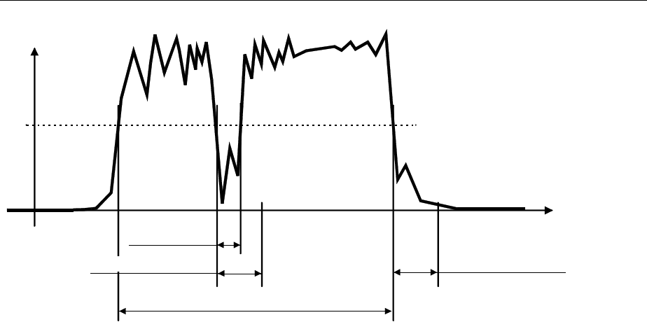
R&S NRP-Z11/-Z21 Remote Control - Commands
1137.7406.12 6.15 E-2
Dropout time
Trigger
level
Power
Time
BURSt:DTOLerance
Pulse duration
BURSt:DTOLerance
Fig. 6-1 Effect of SENSe:POWer:BURSt:DTOLerance
SENSe:POWer:TSLot:AVG:COUNt[?] 1 to 128
For the Timeslot mode, SENSe:POWer:TSLot:AVG:COUNt sets the number of consecutive timeslots
that are to be processed after each trigger event.
The query yields the number of consecutive timeslots.
Default setting: 1
SENSe:POWer:TSLot:AVG:WIDTh[?] 0.0001 to 0.1
SENSe:POWer:TSLot:AVG:WIDTh sets the length of a timeslot in seconds for the Timeslot mode.
The query yields the length of a timeslot in seconds for the Timeslot mode.
Default setting: 0.001 [s]
SENSe:RANGe[?] 0 to 2
SENSe:RANGe selects the measurement path of the sensor. The sensor has three separate
measurement paths. Path 1 is the most sensitive, path 2 medium and path 3 the least sensitive.
SENSe:RANGe 0 selects path 1, SENSe:RANGe 1 path 2 and SENSe:RANGe 2 path 3.
The dynamic ranges of these measurement paths depend on temperature and are model-specific.
Reference values are 40 µW(–14 dBm) for the most sensitive measurement path, 4 mW (6 dBm) for the
medium one and 400 mW (26 dBm) for the least sensitive.
The query yields
• 0 for path 1,
• 1 for path 2,
• 2 for path 3.
If the measurement path is selected manually (SENSe:RANGe:AUTO OFF), the currently selected
measurement path is output. With automatic selection, the last path that was set manually is output. It is
therefore immediately reset after deactivating the automatic function.
Default setting: 2 (least sensitive path)

Remote Control - Commands R&S NRP-Z11/-Z21
1137.7406.12 6.16 E-2
SENSe:RANGe:AUTO[?] OFF | ON
SENSe:RANGe:AUTO ON activates the automatic selection of the measurement path and
SENSe:RANGe:AUTO OFF deactivates it.
The query yields
• 1 for OFF,
• 2 for ON.
Default setting: ON
SENSe:RANGe:AUTO:CLEVel[?] –20.0 to 0.0
SENSe:RANGe:AUTO:CLEVel is used to reduce the transition range between measurement paths 1
and 2 or 2 and 3 by the indicated value (in dB). This can improve the measurement accuracy for
signals with a high peak-to-average ratio, since the headroom for modulation peaks becomes larger.
The disadvantage is that the S/N ratio is reduced at the lower limits of the transition ranges.
The query yields the offset of transition ranges between measurement channels 1 and 2 or 2 and 3.
Default setting: 0.0 [dB]
SENSe:SAMPling[?] FREQ1 | FREQ2
SENSe:SAMPling is used to vary the sampling frequency of the analog-digital converter in the sensor.
With parameter specification FREQ1 the sampling frequency is 133.400 kHz, and 119.467 kHz with
parameter FREQ2. This is provided to suppress interfering low-frequency mixture products from signal
components and the sampling frequency.
The query yields
• 1 for FREQ1,
• 2 for FREQ2.
Default setting: FREQ1
SENSe:SGAMma:CORRection:STATe[?] OFF | ON
SENSe:SGAMma:CORRection:STATe ON initiates the use of the complex reflection coefficient of the
source defined with SENSe:SGAMma:MAGNitude and SENSe:SGAMma:PHASe for the correction of
interactions between the sensor, the source and the components connected between them (see
SENSe:CORRection:SPDevice:STATe). This compensates for the source mismatch, which often
largely contributes to measurement uncertainty.
The query yields
• 1 for OFF,
• 2 for ON.
Default setting: OFF

R&S NRP-Z11/-Z21 Remote Control - Commands
1137.7406.12 6.17 E-2
SENSe:SGAMma:MAGNitude[?] 0.0 to 1.0
SENSe:SGAMma:MAGNitude defines the magnitude of the complex reflection coefficient of the source.
A value of 0.0 corresponds to an ideal matched source and a value of 1.0 to total reflection.
The query yields the set magnitude.
Default setting: 0.0
SENSe:SGAMma:PHASe[?] –360.0 to 360.0
SENSe:SGAMma:MAGNitude defines the phase angle (in degrees) of the complex reflection coefficient
of the source.
The query yields the set phase angle.
Default setting: 0.0 [°]
SENSe:TRACe:AVERage:COUNt[?] 1 to 65536
SENSe:TRACe:AVERage:COUNt is used to set the number of measured values to be averaged in the
Scope mode for the formation of the measurement result. The higher this averaging factor, the lesser
the fluctuation the measured values and the longer the measurement time. The parameter is rounded
off to the next power-of-two number.
The query yields the averaging factor used in the Scope mode.
The averaging function must be activated with SENSe:TRACe:AVERage:STATe ON so
that the set averaging factor becomes effective.
Default setting: 4
SENSe:TRACe:AVERage:COUNt:AUTO[?] OFF | ON | ONCE
SENSe:SWep:AVERage:COUNt:AUTO activates (auto-averaging) or deactivates (fixed-filter mode) the
automatic determination of the averaging factor in the Scope mode. If auto-averaging is activated, the
averaging factor is continuously determined and set depending on the level of power and other
parameters.
SENSe:TRACe:AVERage:COUNt:AUTO ON activates auto-averaging and SENSe:TRACe
:AVERage:COUNt:AUTO OFF deactivates it. When deactivation occurs, the previous, automatically
determined averaging factor is used in the fixed-filter mode. The SENSe:TRACe:AVERage
:COUNt:AUTO ONCE command ensures that a new averaging factor is determined by the filter
automatic function under the current measurement conditions and that this factor is used in the fixed-
filter mode.
The query yields
• 1 for OFF,
• 2 for ON.
Default setting: OFF

Remote Control - Commands R&S NRP-Z11/-Z21
1137.7406.12 6.18 E-2
SENSe:TRACe:AVERage:COUNt:AUTO:MTIMe[?] 1.0 to 999.99
SENSe:TRACe:AVERage:COUNt:AUTO:MTIMe sets the settling time upper limit of the averaging filter
in the auto-averaging mode for the Scope mode and limits the length of the filter.
The query yields the current settling time upper limit of the averaging filter in the auto-averaging mode
for the Scope mode.
Default setting: 30.0 [s]
SENSe:TRACe:AVERage:COUNt:AUTO:NSRatio[?] 0.0001 to 1.0
SENSe:TRACe:AVERage:COUNt:AUTO:NSRatio determines the relative noise component in the
measurement result for the Scope mode if auto-averaging is operated in the corresponding mode
(SENSe:TRACe:AVERage:COUNt:AUTO:TYPE NSRatio). The noise component is defined as the
magnitude of the level variation in dB caused by the inherent noise of the sensor (two standard
deviations).
The query yields the relative noise component in the measurement result in the Scope mode.
Default setting: 0.01 [dB]
SENSe:TRACe:AVERage:COUNt:AUTO:RESolution[?] 1 to 4
SENSe:TRACe:AVERage:COUNt:AUTO:RESolution sets the resolution index for the automatic
averaging filter in the Scope mode when it is operated in the RESolution mode. The resolution index is
equal to the number of decimal places that have to be taken into account for the further processing of
the measurement result in dBm, dBµV or dB. Thus, the design of the normal mode is similar to that for
the predecessors R&S NRVS and R&S NRVD or other commercial power meters. The higher the
selected index, the better the measurement result is filtered without the last significant place (0.01 dB
with an index of 3) being actually set. The NSRatio setting is recommended instead.
The query yields the resolution index for the Scope mode.
Default setting: 3
SENSe:TRACe:AVERage:COUNt:AUTO:POINt[?] 1 to <SENSe:TRACe:POINts>
SENSe:TRACe:AVERage:COUNt:AUTO:SLOT defines the "point" whose power is referenced by
auto-averaging in the Scope mode. The "point" is addressed via its number, the counting beginning
with 1. The "point" number must not exceed the number of the currently set "points". If a valid "point"
number is initially set and then the number of "points" reduced to a value that is smaller than the initial
"point" number, the initial value is automatically set to the new "point" number, i.e. auto-averaging
references the most recent "point".
The query yields the number of the current "point" whose power is referenced by auto-averaging in the
Scope mode.
Default setting: 1

R&S NRP-Z11/-Z21 Remote Control - Commands
1137.7406.12 6.19 E-2
SENSe:TRACe:AVERage:COUNt:AUTO:TYPE[?] RESolution | NSRatio
SENSe:TRACe:AVERage:COUNt:AUTO:TYPE defines the mode of the automatic averaging filter in the
Scope mode. The RESolution parameter sets the mode usual for power meters; NSRatio predefines the
compliance to an exactly defined noise component.
The query yields
• 1 for RESolution,
• 2 for NSRatio.
Default setting: RESolution
SENSe:TRACe:AVERage:STATe[?] OFF | ON
SENSe:TRACe:AVERage:STATe switches the averaging filter on or off for the Scope mode.
The query yields
• 1 for OFF,
• 2 for ON.
Default setting: ON
SENSe:TRACe:AVERage:TCONtrol[?] MOVing | REPeat
SENSe:TRACe:AVERage:TCONtrol (terminal control) defines the behaviour of the averaging filter in
the Scope mode. As soon as a new measured value is shifted to the FIR filter, a new mean is available
at the filter output, which is obtained from the new measured value and the other values stored in the
filter.
The MOVing parameter defines that each new average value is output as a measurement result. This
allows trends in the result to be recognized during the measurement procedure.
The REPeat parameter defines that a new result is output after the FIR filter has been filled with new
measured values. This ensures that no redundant information is output.
The query yields
• 1 for MOVing,
• 2 for REPeat.
Default setting: MOVing
SENSe:TRACe:MPWidth?
SENSe:TRACe:MPWidth? provides the minimum point width for the Scope mode, i.e. time resolution in
seconds is determined as a function of the TRIGger:SOURce parameter while taking into consideration
how the sensor operates. The display may be incorrect if
<SENSe:TRACe:POINts> × <SENSe:TRACe:MPWidth> < SENSe:TRACE:TIME>
One way to prevent this is to decrease the number of points of the Scope measurement sequence.

Remote Control - Commands R&S NRP-Z11/-Z21
1137.7406.12 6.20 E-2
SENSe:TRACe:OFFSet:TIME[?] – (<TRIGger:DELay> + 0.005) to 100.0
This command is used to shift the timeslot for measured-data acquisition along the time axis in the
Scope mode without modifying the value of TRIGger:DELay. Positive values yield an additional delay
and negative values a correspondingly earlier measured-data acquisition.
The query yields the set time in seconds.
Default setting: 0.0 [s]
SENSe:TRACe:POINts[?] 1 to 1024
This command defines the time resolution of the measurement result. Each "point" represents a time
interval whose duration is obtained from the length of the timeslot (command SENSe:TRACe:TIME)
divided by the number of "points". The measurement result for a "point" equals the average power over
the associated time interval.
The query yields the number of set "points".
Default setting: 100
SENSe:TRACe:REALtime[?] OFF | ON
SENSe:TRACe:REALtime ON suppresses the measured-value acquisition in pairs so that single
operations can be recorded in this setting. Since the averaging filter of the sensor is not used,
SENSe:AVERage:STATe is ignored, but is not affected.
The query yields
• 1 for OFF,
• 2 for ON.
Default setting: OFF
SENSe:TRACe:TIME[?] 0.0001 to 0.3
SENSe:TRACe:TIME sets the duration of the timeslot in the Scope mode. This timeslot is divided into a
number of equal intervals, in which the average power is determined. The number of intervals equals
the number of test points, which is set with the command SENSe:TRACe:POINts.
The query yields the duration of the timeslot in the Scope mode (in s).
Default setting: 0.01 [s]
SENSe:TIMing:EXCLude:STARt[?] 0.0 to 0.1
SENSe:TIMing:EXClude:STARt defines the exclusion time at the beginning of the measurement
window in the Burst Average (Fig. 6-2) and Timeslot (Fig. 6-3) modes.
The query yields the exclusion time at the beginning of the measurement window.
Default setting: 0.0 [s]
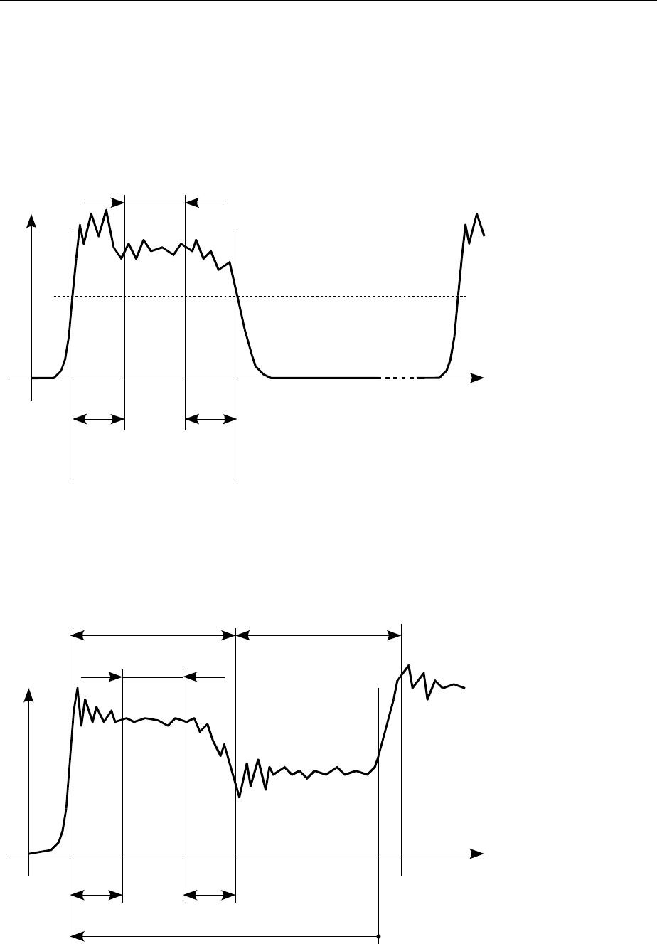
R&S NRP-Z11/-Z21 Remote Control - Commands
1137.7406.12 6.21 E-2
SENSe:TIMing:EXCLude:STOP[?] 0.0 to 0.003
SENSe:TIMing:EXClude:STOP defines the exclusion time at the end of the measurement window in the
Burst Average (Fig. 6-2) and Timeslot (Fig. 6-3) modes.
The query yields the exclusion time at the end of the measurement window.
Default setting: 0.0 [s]
TSTART TSTOP Time
Power
Trigger level
Triggering
(Start) Triggering
(Stop)
Measurement
window
Fig. 6-2 Effect of SENSe:TIMing:EXCLude:STARt and :END in the Burst Average mode
TSTART TSTOP Time
Power
Nominal Width Nominal Width
Trigger Delay (< 0) Triggering
(Start)
Measurement
window
Fig. 6-3 Effect of SENSe:TIMing:EXCLude:STARt and :END in the Timeslot mode

Remote Control - Commands R&S NRP-Z11/-Z21
1137.7406.12 6.22 E-2
SYSTem
With the aid of the SYSTem system, administrative device settings can be defined and queried. This
includes detailed information on the sensor and its initialization and the transfer of available commands
and their parameter limits.
Table 6-5 Commands of the SYSTem system
Command Parameter Unit Remarks
SYSTem
:INFO? [Item] Query only
:INITialize No query
MINPower? WQuery only
:TRANsaction
:BEGIN: No query
:END No query
SYSTem:INFO? [Item]
SYSTem:INFO? yields a string containing information that is more detailed than the identification string
delivered by the sensor as a response to *IDN?. If no Item is specified, the response string is a
sequence of entries in the form Item:Information-String separated by CR and LF (in C notation: \r\n).
With the Item optionally appended to the command, the entry for the required Item can be queried. The
response string is zero-terminated, i.e. its end identification is a zero byte (in C notation: \0).
Table 6-6 Meaning of Item in the SYSTem:INFO? command
Item Information string Remarks
"MANUFACTURER" "Rohde & Schwarz GmbH & Co. KG" Manufacturer
"TYPE" "NRP-Z11" or "NRP-Z21" Type designation
"STOCK NUMBER" "1138.3004.02" or "1137.6000.02" Material number
"SERIAL" "<serial number>" 6-digit serial number
"HWVERSION" "000000000" Hardware version (standard)
"HWVARIANT" "000000000" Hardware model (standard)
"SW BUILD" "<build number>" Version number of sensor firmware
"TECHNOLOGY" "3 Path Diode" Detector technology used
"FUNCTION" "Power Terminating" The R&S NRP-Z11/-Z21 is a termination power sensor.

R&S NRP-Z11/-Z21 Remote Control - Commands
1137.7406.12 6.23 E-2
Item Information string Remarks
"MINPOWER" "<nominal lower test limit in W>" The nominal lower test limit of the R&S NRP-Z11/-Z21 is
200 pW, i.e. with s-parameter correction deactivated, the
sensor returns the information string "2e-10" as a response to
"SYSTem:INFo? "MINPOWER". With s-parameter correction
activated, the information string depends on the nominal lower
limit of the sensor/twoport combination.
"MAXPOWER" "<nominal upper test limit in W>" The nominal upper test limit of the R&S NRP-Z11/-Z21 is
200 mW, i.e. with s-parameter correction deactivated, the
sensor returns the information string "0.2" as a response to
"SYSTem:INFo? "MAXPOWER". With s-parameter correction
activated, the information string depends on the nominal upper
limit of the sensor/twoport combination.
"MINFREQ" "1e+07" The minimum measuring frequency of the R&S NRP-Z11/-Z21
is 10 MHz.
"MAXFREQ" "8e+09" or "1.8e+10" The maximum measuring frequency is 8 GHz for the R&S NRP-
Z11 and 18 GHz for the R&S NRP-Z21.
"RESOLUTION" “2.5µs Ext, 10µs Int”The maximum time resolution that can be reached in the Scope
mode is 2.5 µs for internal triggering and 10 µs for external
triggering.
"IMPEDANCE" "50" The R&S NRP-Z11/-Z21 RF input has a nominal input
impedance of 50 Ω.
"COUPLING" "AC/DC" The RF input of the R&S NRP-Z11/-Z21 is DC-coupled, but DC
voltages superimposed on the RF signal are suppressed by the
measurement amplifier.
"CAL. ABS." "<date>" Date of absolute calibration in the format YYYY-MM-DD. "Invalid
Calibration Date" is returned with an invalid date entry.
"CAL. REFL." "<date>" Date of reflection-coefficient calibration in the format YYYY-MM-
DD. "Invalid Calibration Date" is returned with an invalid date
entry.
"CAL. S PARA." "<date>" Date of s-parameter calibration in the format YYYY-MM-DD. If
no S parameter set is loaded, the sensor returns the string "not
applicable". "Invalid Calibration Date" is returned with an invalid
date entry.
"CAL. MISC." "<date>" Date of the calibration of other parameters in the format YYYY-
MM-DD. "Invalid Calibration Date" is returned with an invalid
date entry.
"SPD MNEMONIC" "<mnemonic string>" Clear-text designation of the components connected ahead of
the sensor.
SYSTem:INITialize
SYSTem:INITialize sets the sensor to the standard state, i.e. the default settings for all test parameters
are loaded in the same way as with *RST. The sensor then outputs a complete list of all supported
commands and parameters. With the command, the remote-control software can automatically adapt to
the features of different types of sensors with different functionality.

Remote Control - Commands R&S NRP-Z11/-Z21
1137.7406.12 6.24 E-2
SYSTem:MINPower?
SYSTem:MINPower? yields the lower test limit of the sensor or the combination comprising the sensor
and components connected ahead of it, if the SENSe:CORRection:SPDevice parameter has the ON
value. This query can be used to determine a useful resolution for the result display near the lower test
limit.
SYSTem:TRANsaction:BEGin
SYSTEM:TRANsaction:BEGin marks the beginning of a sequence of setting commands between which
the parameter limits must not be checked. This prevents the display of error messages when a setting
command causes a conflict that is resolved by a subsequent setting command. See
SYSTEM:TRANsaction:END.
SYSTem:TRANsaction:END
SYSTEM:TRANsaction:END marks the end of a sequence of setting commands between which the
parameter limits must not be checked. After this command, the parameter limits are checked.

R&S NRP-Z11/-Z21 Remote Control - Commands
1137.7406.12 6.25 E-2
TEST
Table 6-7 Commands of the TEST system
Command Parameter Unit Remarks
TEST:SENSor? Query only
TEST:SENSor?
TEST:SENSor? triggers a selftest of the sensor. In contrast to *TST, this command yields detailed
information, which is useful for troubleshooting.

Remote Control - Commands R&S NRP-Z11/-Z21
1137.7406.12 6.26 E-2
TRIGger
Table 6-8 Commands of the TRIGger system
Command Parameter Unit Remarks
ABORt No query
INITiate
:CONTinuous[?] OFF | ON
:IMMediate No query
TRIGger
:ATRigger:STATe[?] OFF | ON
:COUNt[?] 1 to 2×10⁹
:DELay[?] x to 100.0 s
:AUTO[?] OFF | ON
:HOLDoff[?] 0.0 to 10.0 s
:HYSTeresis[?] 0.0 to 3.0 dB
:IMMediate No query
:LEVel[?] x to y W
:SLOPe[?] POSitive | NEGative
:SOURce[?] BUS | EXTernal | HOLD | IMMediate | INTernal
ABORt
ABORt interrupts the current measurement and sets the sensor to the IDLE state (normal case).
However, if the sensor is in the continuous measurement mode (setting INITiate:CONTinuous ON), the
IDLE state is immediately exited and the sensor enters the WAIT_FOR_TRIGGER state.
INITiate:CONTinuous[?] OFF | ON
INITiate:CONTinuous ON activates the continuous measurement mode. In this mode, a new
measurement is automatically started when a measurement is terminated. The sensor first enters the
WAIT_FOR_TRIGGER state and begins with the measurement as soon as the trigger condition is
fulfilled. Once the measurement is completed, the sensor again enters the WAIT_FOR_TRIGGER
state. The sensor will measure continuously assuming continuous trigger events.
In contrast, each measurement cycle must be explicitly started with the INITiate:IMMediate command
after the INITiate:CONTinuous OFF command has been sent. After triggering and completion of the
measurement, the sensor enters the IDLE status and remains in this status until a new measurement is
started with the INITiate:IMMediate command.

R&S NRP-Z11/-Z21 Remote Control - Commands
1137.7406.12 6.27 E-2
The query yields
• 1 for OFF,
• 2 for ON.
Default setting: OFF
INITiate:IMMediate
INITiate:IMMediate starts a single measurement cycle. The sensor first changes from the IDLE state to
the WAIT_FOR_TRIGGER state and begins with the measurement as soon as the trigger condition is
fulfilled. Once the measurement is completed, the sensor again enters the IDLE state. Since the
command is ignored during measurement, it normally has no effect in the continuous mode (setting
INITiate:CONTinuous ON).
TRIGger:ATRigger:STATe[?] OFF | ON
TRIGger:ATRigger:STATe ON causes an artificial trigger event to be triggered if no trigger is recorded
more than 10 s after the measurement has been started (only in the Scope mode).
TRIGger:ATRigger:STATe OFF deactivates the trigger automatic function.
The query yields
• 1 for OFF,
• 2 for ON.
Default setting: OFF
TRIGger:COUNt[?] 1 to 2 × 10⁹
This setting is designed for applications in which several consecutive measurements have to be
performed by sending the INITiate:IMMediate command only once, e.g. to obtain a higher measurement
speed. The gap between a single measurement and the continuous measurement mode is thus closed.
The number of measurements is defined with the parameter associated with the TRIGger:COUNt
command. This number equals the number of results yielded by the sensor at the end of the
measurement.
The TRIGger:COUNt command does not define the number of trigger events required for
performing the entire measurement task. The number may vary depending on the
measurement mode.
A further increase in the measurement speed can be obtained by combining the mode
used with the buffered mode. The results are not made available immediately but as a
block at the end of the measurement sequence (see group commands
SENSe:POWer:AVG:BUFFer).
The query yields the number of measurements performed with the INIT:IMMediate command after a
measurement start.
Default setting: 1

Remote Control - Commands R&S NRP-Z11/-Z21
1137.7406.12 6.28 E-2
TRIGger:DELay[?] x to 100.0
TRIGger:DELay defines the delay (in seconds) between the occurrence of the trigger event and the
beginning of the measurement itself for the Timeslot and Scope modes. This parameter is ignored in
the Burst Average mode. Pretriggering is obtained by means of negative values; with bus-triggered
measurements (see TRIGger:SOURce), the parameter must be set to positive values or zero to avoid
measurement errors.
The query yields the set trigger delay for the Timeslot and Scope modes (in seconds).
Lower limit x of the parameter
Modes Continuous Average, Burst Average and Timeslot: x = –0.005
Mode Scope: x = – (<SENSe:TRACe:OFFSet:TIME> + 0.005)
Default setting: 0.0 [s]
TRIGger:DELay:AUTO[?] OFF | ON
TRIGger:DELay:AUTO ON ensures by means of an automatically determined delay that a
measurement is only started after the sensor has settled. This is important when thermal sensors are
used. The automatically determined delay is ignored if a longer period was set with TRIGger:DELay.
This does not overwrite the value of TRIGger:DELay. TRIGger:DELay:AUTO OFF deactivates this
function.
The query yields
• 1 for OFF,
• 2 for ON.
Default setting: ON
TRIGger:HOLDoff[?] 0.0 to 10.0
TRIGger:HOLDoff suppresses trigger events within the set holdoff time (in s), starting from the time of
the last successful triggering.
The query yields the set holdoff time (in s).
Default setting: 0.0 [s]
TRIGger:HYSTeresis[?] 0.0 to 10.0
TRIGger:HYSTeresis sets the hysteresis of the internal trigger threshold (parameter TRIGger:LEVel).
Hysteresis is the magnitude (in dB) by which the trigger signal level falls below the trigger threshold
(with positive trigger edge) to enable triggering again. The case is exactly the opposite with a negative
trigger edge. The trigger hysteresis setting is only relevant to the INTernal trigger source.
The query yields the trigger hysteresis in dB.
Default setting: 0.0 [dB]
TRIGger:IMMediate
TRIGger:IMMediate triggers a generic trigger event that causes the sensor to exit immediately the
WAIT_FOR_TRIGGER state irrespective of the trigger source and the trigger delay and begin with the
measurement. The command is the only means of starting a measurement when the trigger source is
set to HOLD.

R&S NRP-Z11/-Z21 Remote Control - Commands
1137.7406.12 6.29 E-2
TRIGger:LEVel[?] x to y
TRIGger:LEVel sets the trigger threshold for internal triggering derived from the test signal (in W). This
setting is irrelevant to all other trigger sources.
The query yields the trigger threshold in W.
Lower limit x and upper limit y of parameter
SENSe:CORRection:OFFSet:STATe OFF: x = 500 × <lower test limit>
y = <upper test limit >
SENSe:CORRection:OFFSet:STATe ON: x = 500 × < lower test limit > ×
10^(<SENSe:CORRection:OFFSet> / 10)
y = < upper test limit > ×
10^(<SENSe:CORRection:OFFSet> / 10)
< lower test limit >: 200.0e-12 (with SENSe:CORRection:SPDevice:STATe OFF) or
entered lower test limit of sensor/twoport combination
(with SENSe:CORRection:SPDevice:STATe ON)
< upper test limit >: 0.2 (with SENSe:CORRection:SPDevice:STATe OFF) or entered
upper test limit of sensor/twoport combination
(with SENSe:CORRection:SPDevice:STATe ON)
Default setting: 10 × x
TRIGger:SLOPe[?] POSitive | NEGative
TRIGger:SLOPe defines the edge of the trigger event with internal and external triggering in the
Timeslot and Scope modes. In this connection, positive means increasing envelope power (with internal
triggering) or increasing voltage (with external triggering). As in the Burst Average mode, this command
has no effect in conjunction with trigger sources BUS, HOLD and IMMediate.
The query yields
• 1 for POSitive,
• 2 for NEGative.
Default setting: POSitive
TRIGger:SOURce[?] BUS | EXTernal | HOLD | IMMediate | INTernal
TRIGger:SOURce sets the trigger source.
• BUS: Triggering with command *TRG or TRIGger:IMMediate.
• EXTernal: Triggering via USB Adapter R&S NRP-Z3. Relevant trigger parameters:
TRIGger:DELay and TRIGger:SLOPe.
• HOLD: Triggering only with command TRIGger:IMMediate.
• IMMediate: Automatic triggering without explicit event.
• INTernal: Triggering by the measurement signal. Relevant trigger parameters:
TRIGger:LEVel, TRIGger:DELay and TRIGger:SLOPe (not in the Burst Average mode).
The query yields
• 1 for BUS,
• 2 for EXTernal,
• 4 for HOLD,
• 8 for IMMediate,
• 16 for INTernal.
Default setting: IMMediate

Remote Control - Commands R&S NRP-Z11/-Z21
1137.7406.12 6.30 E-2
List of Remote-Control Commands
The remote-control commands of the R&S NRP-Z11/-Z21 have a syntax based on standard SCPI
1999.0, but they comply with it only to a limited extent.
Table 6-9 List of remote-control commands
Command Parameter Unit Default setting Page
* Commands
*IDN? 6.2
*RST 6.2
*TRG 6.2
*TST? 6.2
CALibration Commands
CALibration:DATA[?] <calibration data set as definite length
block> 6.3
CALibration:DATA:LENGth? Bytes 6.3
CALibration:ZERO:AUTO[?] OFF | ON | ONCE OFF (fixed) 6.4
SENSe Commands
SENSe:AVERage:COUNt[?] 1 to 65536 4 6.7
SENSe:AVERage:COUNt:AUTO[?] OFF | ON | ONCE ON 6.7
SENSe:AVERage:COUNt:AUTO:MTIMe[?] 1.0 to 999.99 s 30.0 6.8
SENSe:AVERage:COUNt:AUTO:NSRatio[?] 0.0001 to 1.0 dB 0.01 6.8
SENSe:AVERage:COUNt:AUTO:RESolution[?] 1 to 4 3 6.8
SENSe:AVERage:COUNt:AUTO:SLOT[?] 1 to <SENSe:POWer:TSLot:AVG
:COUNt> 16.8
SENSe:AVERage:COUNt:AUTO:TYPE[?] RESolution | NSRatio RESolution 6.9
SENSe:AVERage:RESet 6.9
SENSe:AVERage:STATe[?] OFF | ON ON 6.9
SENSe:AVERage:TCONtrol[?] MOVing | REPeat REPeat 6.9
SENSe:CORRection:DCYCle[?] 0.001 to 99.999 % 1.0 6.10
SENSe:CORRection:DCYCle:STATe[?] OFF | ON OFF 6.10
SENSe:CORRection:OFFSet[?] -200.0 to 200.0 dB 0.0 6.10

R&S NRP-Z11/-Z21 Remote Control - Commands
1137.7406.12 6.31 E-2
Command Parameter Unit Default setting Page
SENSe:CORRection:OFFSet:STATe[?] OFF | ON OFF 6.10
SENSe:CORRection:SPDev:STATe[?] OFF | ON OFF (can be
modified by the user) 6.11
SENSe:FREQuency[?] 10.0e6 to 8.0e9 (NRP-Z11) or 18.0e9
(NRP-Z21) Hz 50.0e6 6.11
SENSe:FUNCtion[?] "POWer:AVG" |
"POWer:TSLot:AVG" |
"POWer:BURSt:AVG" |
"XTIMe:POWer"
"POWer:AVG" 6.12
SENSe:POWer:AVG:APERture[?] 0.0001 to 0.3 s 0.02 6.13
SENSe:POWer:AVG:BUFFer:SIZE[?] 1 to 1024 1 6.13
SENSe:POWer:AVG:BUFFer:STATe[?] OFF | ON OFF 6.14
SENSe:POWer:AVG:SMOothing:STATe[?] OFF | ON ON 6.14
SENSe:POWer:BURSt:DTOLerance[?] 0.0 to 0.003 s 0.0001 6.14
SENSe:POWer:TSLot:AVG:COUNt[?] 1 to 128 8 6.15
SENSe:POWer:TSLot:AVG:WIDTh[?] 0.0001 to 0.1 s 0.001 6.15
SENSe:RANGe[?] 0 to 2 2 6.15
SENSe:RANGe:AUTO[?] OFF | ON ON 6.16
SENSe:RANGe:AUTO:CLEVel[?] –20.0 to 0.0 dB 0.0 6.16
SENSe:SAMPLING[?] FREQ1 | FREQ2 FREQ1 6.16
SENSe:SGAMma:CORRection:STATe[?] OFF | ON OFF 6.16
SENSe:SGAMma:MAGNitude[?] 0.0 to 1.0 0.0 6.17
SENSe:SGAMma:PHASe[?] –360.0 to 360.0 degree 0.0 6.17
SENSe:TRACe:AVERage:COUNt[?] 1 to 65536 4 6.17
SENSe:TRACe:AVERage:COUNt:AUTO[?] OFF | ON | ONCE ON 6.17
SENSe:TRACe:AVERage:COUNt:AUTO
:MTIMe[?] 1.0 to 999.99 s 30.0 6.18
SENSe:TRACe:AVERage:COUNt:AUTO
:NSRatio[?] 0.0001 to 1.0 dB 0.01 6.18
SENSe:TRACe:AVERage:COUNt:AUTO
:POINt[?] 1 to <SENSe:TRACe:POINts> 1 6.18
SENSe:TRACe:AVERage:COUNt:AUTO
:RESolution[?] 1 to 4 3 6.18
SENSe:TRACe:AVERage:COUNt:AUTO
:TYPE[?] RESolution | NSRatio RESolution 6.19

Remote Control - Commands R&S NRP-Z11/-Z21
1137.7406.12 6.32 E-2
Command Parameter Unit Default setting Page
SENSe:TRACe:AVERage:STATe[?] OFF | ON ON 6.19
SENSe:TRACe:AVERage:TCONtrol[?] MOVing | REPeat REPeat 6.19
SENSe:TRACe:MPWidth? s 6.19
SENSe:TRACe:OFFSet:TIME[?] – (<TRIGger:DELay> + 0.005) to
100.0 s 0.0 6.19
SENSe:TRACe:POINts[?] 1 to 1024 100 6.20
SENSe:TRACe:REALtime[?] OFF | ON OFF 6.20
SENSe:TRACe:TIME[?] 0.0001 to 0.3 s 0.01 6.20
SENSe:TIMing:EXCLude:STARt[?] 0.0 to 0.003 s 0.0 6.20
SENSe:TIMing:EXCLude:STOP[?] 0.0 to 0.003 s 0.0 6.20
SYSTem Commands
SYSTem:INFO? [Item] 6.22
SYSTem:INITialize 6.23
SYSTem:MINPower? W6.24
SYSTem:TRANsaction:BEGin 6.23
SYSTem:TRANsaction:END 6.24
Test Commands
TEST:SENSor? 6.25
Triggersystem Commands
ABORt 6.26
INITiate:CONTinuous[?] OFF | ON OFF 6.26
INITiate:IMMediate 6.27
TRIGger:ATRigger:STATe[?] OFF | ON OFF 6.27
TRIGger:COUNt[?] 1 to 2×10916.27
TRIGger:DELay[?] x to 100.0 s0.0 6.28
TRIGger:DELay:AUTO[?] OFF | ON OFF 6.28
TRIGger:HOLDoff[?] 0.0 to 10.0 s0.0 6.28
TRIGger:HYSTeresis[?] 0.0 to 10.0 dB 0.0 6.28

R&S NRP-Z11/-Z21 Remote Control - Commands
1137.7406.12 6.33 E-2
Command Parameter Unit Default setting Page
TRIGger:IMMediate 6.28
TRIGger:LEVel[?] x to y W1.0e-6 6.29
TRIGger:SLOPe[?] POSitive | NEGative POSitive 6.29
TRIGger:SOURce[?] BUS | EXTernal | HOLD | IMMediate |
INTernal IMMediate 6.29
SERVice Commands
SERVice:CALibration:DITHer ONCE OFF
SERVice:CALibration:DITHer:DATA? 0
SERVice:CALibration:TEMP ONCE OFF
SERVice:CALibration:TEMP:DATA? K0.0
SERVice:CALibration:TEST[?] -1
SERVice:CALibration:ZERO:NEG0? 1
SERVice:CALibration:ZERO:POS0? 2
SERVice:CALibration:ZERO:NEG1? 3
SERVice:CALibration:ZERO:POS1? 4
SERVice:CALibration:ZERO:NEG2? 5
SERVice:CALibration:ZERO:POS2? 6
SERVice:DITHer OFF | ON ON
SERVice:MVCorrection[?] 0 to 63 63
SERVice:PARameter:RTEMp[?] <float value> K0.0
SERVice:PARameter:RNULL0[?] <float value> Ω0.0
SERVice:PARameter:RNULL1[?] <float value> Ω0.0
SERVice:PARameter:RNULL2[?] <float value> Ω0.0
SERVice:PARameter:RBAHN[?] <float value> Ω0.0
SERVice:PARameter:NREF[?] <float value> 0.0
SERVice:PARameter:ATHERM[?] <float value> K-1 0.0
SERVice:PARameter:BTHERM[?] <float value> K0.0
SERVice:PARameter:CTHERM[?] <float value> K-1 0.0
SERVice:PARameter:DTHERM[?] <float value> K-1 0.0

Remote Control - Commands R&S NRP-Z11/-Z21
1137.7406.12 6.34 E-2
Command Parameter Unit Default setting Page
SERVice:PARameter:CJUNC[?] <float value> F0.0
SERVice:RCount[?] 1 to 32767 0
SERVice:RESult[?] 0.0 to 1.0e6 W0.0
SERVice:SAMPle[?] 0 to 99999999 1000
SERVice:TDEScriptor?
SERVice:TDEScriptor:LENGth? Bytes
SERVice:UNLock 1234

1137.7406.82
Test and Measurement
Division
Service Instructions

R&S NRP-Z11/-Z21 Contents
1137.7406.82 I-1 E-1
Contents
1 Performance Test............................................................................................................... 1.1
Preliminary Remarks ....................................................................................................................... 1.1
Test Instructions.............................................................................................................................. 1.1
Measuring Equipment and Accessories ....................................................................................... 1.1
Performance Test ............................................................................................................................ 1.2
with Calibration Kit NRVC and Calibration Software Recal ........................................................ 1.2
Performance Test with Other Measuring Equipment................................................................... 1.2
Checking Absolute Measuring Accuracy ................................................................................... 1.2
Checking the Linearity................................................................................................................ 1.3
Checking Matching..................................................................................................................... 1.4
Quick Test......................................................................................................................................... 1.5
Test Instructions......................................................................................................................... 1.5
Measuring Equipment and Accessories Required for the Quick Test ....................................... 1.6
Checking Zeroing....................................................................................................................... 1.6
Checking the Absolute Measuring Accuracy ............................................................................. 1.7
Checking the Linearity................................................................................................................ 1.7
Checking Input Resistance ........................................................................................................ 1.8
Test Report ................................................................................................................................ 1.9
2Adjustment............................................................................................................................ 2.1
Preliminary Remarks ....................................................................................................................... 2.1
3 Repair of Sensors R&S NRP-Z11/-Z21 ...................................................................... 3.1
Design and Circuit Description ...................................................................................................... 3.1
Block Diagram............................................................................................................................ 3.1
Description of Block Diagram..................................................................................................... 3.2
Microwave Detector........................................................................................................ 3.2
Analog Board.................................................................................................................. 3.3
Digital Board...................................................................................................................3.3

Contents R&S NRP-Z11/-Z21
1137.7406.82 I-2 E-1
Module Replacement....................................................................................................................... 3.4
Tools Required............................................................................................................... 3.4
List of Modules ........................................................................................................................... 3.6
Opening and Reassembly (Exchange of Plastic Shell Halves) ..................................... 3.7
Replacement of Sensor Cable W1............................................................................................. 3.9
Removing the Sensor Cable .......................................................................................... 3.9
Installing the Sensor Cable ............................................................................................ 3.9
Troubleshooting ............................................................................................................................ 3.10
Overview of Errors, Causes and Corrective Steps .................................................................. 3.11
4 Firmware Update/Installation of Options................................................................. 4.1
Installation of New R&S NRP-Z11/-Z21 Software.......................................................................... 4.1
Hardware and software requirements........................................................................................ 4.1
Preparation................................................................................................................................. 4.2
Updating the application firmware.............................................................................................. 4.3
Updating the boot loader............................................................................................................ 4.4
5 Documents............................................................................................................................ 5.1
Shipping of Instrument and Ordering of Spare Parts .................................................................. 5.1
Shipping of Instrument ............................................................................................................... 5.1
Ordering Spare Parts ................................................................................................................. 5.1
Ordering Replacement Sensors................................................................................................. 5.2
Spare Parts....................................................................................................................................... 5.3

List of figures and tables R&S NRP-Z11/-Z21
1137.7406.82 I-3 E-1
Figures
Fig. 1-1 Connection of DUT for measuring the input resistance ................................................... 1.8
Fig. 3-1 Block diagram of Sensors R&S NRP-Z11 and R&S NRP-Z21 ........................................ 3.1
Fig. 3-2 Membrane cables............................................................................................................. 3.5
Fig. 3-3 Opening the sensor .......................................................................................................... 3.7
Fig. 3-4 Replacement of sensor cable........................................................................................... 3.9
Tables
Table 1-1 Calibration powers............................................................................................................ 1.2
Table 1-2 Expanded calibration uncertainties of Sensors R&S NRP-Z11/-Z21 (in dB) ................... 1.2
Table 1-3 Max. measurement error (in dB) between meas. paths 1 and 2
at –20 dBm (10 µW) ......................................................................................................... 1.3
Table 1-4 Expanded linearity uncertainties of Sensors R&S NRP-Z11 and
R&S NRP-Z21 at 50 MHz (in dB, with reference to 0 dBm)............................................. 1.3
Table 1-5 Max. SWR of Sensors R&S NRP-Z11 and R&S NRP-Z21.............................................. 1.4
Table 2-1 Uncertainty of power calibration system at 0 dBm (in dB, including mismatch) .............. 2.1
Table 3-1 Assignment of flexstrip connector W3.............................................................................. 3.2
Table 3-2 List of modules/spare parts for R&S NRP-Z11 and R&S NRP-Z21................................. 3.6

R&S NRP-Z11/-Z21 Preliminary Remarks
1137.7406.82 1.1 E-1
1 Performance Test
Preliminary Remarks
Verifying the data sheet specifications for the Power Sensors R&S NRP-Z11 and R&S NRP-Z21
requires a considerable amount of equipment and care. Rohde & Schwarz therefore recommends using
the Power Calibration System R&S NRVC or corresponding equipment that yields the same accuracy.
The tests are to be carried out directly at the manufacturer, its representatives or subsidiaries or at
calibration sites that are equipped accordingly.
A quick test (see page 1.5) is recommended for checking the sensor with simple means.
Test Instructions
• The tests are to be performed at an ambient temperature of 20°C to 25°C. The DUT should be
connected to the (activated) R&S NRP base unit for at least 30 minutes before the tests are
performed.
• The test limits used in the following sections are based on the data sheet for the sensors
R&S NRP-Z11 and R&S NRP-Z21. The test limits are valid only on the conditions defined in the
corresponding test step. They are therefore not legally binding as accuracy specifications; only data
sheet specifications are legally binding.
Measuring Equipment and Accessories
Item Type of unit Recommended characteristics Recommended
units R&S order
number Application
1 Power calibration
system 10 MHz to 18 GHz
Calibration level 0 dBm
R&S NRVC
R&S NRVC-B1
R&S SMP02
R&S NRVD
1109.0500.02
1109.1007.02
1035.5005.02
0857.8008.02
Absolute measuring
accuracy
2 Linearity
calibration system -30 dBm to +23 dBm
Test frequency 50 MHz
R&S NRVC-B2
R&S SMGL
1109.1207.02
1020.2005.52
Linearity
3 Network analyzer 10 MHz to 18 GHz
Test port: N connector
R&S ZVM 1127.8500.60 Matching
4 Controller 1 PC with IEC/IEEE-bus card (NI) In connection with
R&S NRVC and
R&S NRVC-B2
5 Power meter To connect the DUT R&S NRP 1143.8500.02 Absolute measuring
accuracy
1 For program-controlled calibration in connection with Calibration Kit R&S NRVC and Calibration Software Recal.
Performance Test R&S NRP-Z11/-Z21
1137.7406.82 1.2 E-1
Performance Test
with Calibration Kit NRVC and Calibration Software Recal
For detailed information about the performance test, refer to the operating manual for Calibration Kit
R&S NRVC.
SWR measurement has to be carried out on a separate network analyzer. Evaluation is performed by
Calibration Software Recal.
Performance Test with Other Measuring Equipment
Checking Absolute Measuring Accuracy
The sensor contains three measurement paths. Individual calibration factors are stored for these
measurement paths in the sensor. The measurement paths therefore have to be checked separately.
(Table 1-1 and Table 1-2). The maximum permissible error depends on the calibration uncertainties of
the sensor (Table 1-2) and the uncertainties of the calibration system. It is recommended to combine
both uncertainties according to the RSS method (square root based on the sum of squares) and to use
the expanded combined uncertainty as the test limit.
To calibrate measurement path 1, the measurement result of measurement path 2 can be used if the
calibration system does not provide a calibration power of 10 µW or if its uncertainty is too high. In this
case, only the displayed difference between the two measurement paths will be checked (Table 1-3).
Table 1-1 Calibration powers
Measurement path Power measurement range Calibration power
1 200 pW to 50 µW (-67 dBm to -13 dBm) 10 µW
2 20 nW to 5 mW (-47 dBm to +7 dBm) 1 mW
3 2 µW to 200 mW (-27 dBm to +23 dBm) 1 mW
Table 1-2 Expanded calibration uncertainties of Sensors R&S NRP-Z11/-Z21 (in dB)
Frequency
10 MHz to
<20 MHz 20 MHz to
<100 MHz 100 MHz to
4 GHz >4 GHz to
8 GHz >8 GHz to
12.4 GHz >12.4 GHz to
18 GHz
Measurement path Only R&S NRP-Z21
1 0.056 0.056 0.066 0.083 0.094 0.123
2 0.047 0.047 0.057 0.071 0.076 0.099
3 0.048 0.047 0.057 0.072 0.076 0.099
Calibration frequencies: 10 MHz, 15 MHz, 20 MHz, 30 MHz, 50 MHz, 100 MHz;
from 250 MHz to 18 GHz in 250 MHz steps.
R&S NRP-Z11/-Z21 Performance Test with Other Measuring Equipment
1137.7406.82 1.3 E-1
Table 1-3 Max. measurement error (in dB) between meas. paths 1 and 2 at –20 dBm (10 µW)
Frequency 10 MHz to
<20 MHz 20 MHz to
<100 MHz 100 MHz to
4 GHz >4 GHz to
8 GHz >8 GHz to
12.4 GHz >12.4 GHz to
18 GHz
Only R&S NRP-Z21
Measurement error 0.045 0.044 0.048 0.054 0.063 0.079
Procedure:
• Perform zeroing (without power applied).
• Set measurement path in Sensor – Range menu on the R&S NRP.
• Set calibration frequency in Frequency menu on the R&S NRP.
• Read power on the R&S NRP and compare with power value of calibration system. At least three
measurements are recommended, with the sensor set to a different position with respect to the
output connector of the calibration system each time.
Checking the Linearity
The linearity check is performed at 50 MHz with autoranging activated. The reference power is 1 mW
(0 dBm). The maximum permissible linearity error depends on the linearity uncertainty of the sensor
(Table 1-4) and the linearity uncertainty of the calibration system. It is recommended to combine both
uncertainties according to the RSS method (square root based on the sum of squares) and to use the
expanded combined uncertainty as the test limit.
Table 1-4 Expanded linearity uncertainties of Sensors R&S NRP-Z11 and R&S NRP-Z21 at
50 MHz (in dB, with reference to 0 dBm)
Test level -30 dBm to -13 dBm -13 dBm to +1 dBm +1 dBm to +23 dBm
Uncertainty 0.044 0.022 0.044
Calibration levels: -30 dBm, -25 dBm, -20 dBm, -15 dBm, -10 dBm, -5 dBm, 0 dBm,
+5 dBm, +10 dBm, +15 dBm, +20 dBm, +23 dBm
Procedure:
• Perform zeroing (without power applied).
• Set autoranging in Sensor – Range menu on the R&S NRP.
• Set 50 MHz in Frequency menu on the R&S NRP.
• Apply level of 0 dBm and activate Relative On in the Measurement menu on the R&S NRP. Use
the current measurement value as the reference value (Reset). Set unit to dB.
• Set the calibration level and compare the relative level measured by the R&S NRP with that of the
calibration system.
Performance Test with Other Measuring Equipment R&S NRP-Z11/-Z21
1137.7406.82 1.4 E-1
Checking Matching
For these measurements, the sensor can be operated with or without the R&S NRP base unit. The
measurement procedure depends on the network analyzer used.
Table 1-5 Max. SWR of Sensors R&S NRP-Z11 and R&S NRP-Z21
Frequency 10 MHz to
<30 MHz 30 MHz to
2.4 GHz >2.4 GHz to
8 GHz >8 GHz to
12.4 GHz >12.4 GHz to
18 GHz
Only R&S NRP-Z21
Max. SWR 1.13 1.11 1.18 1.23 1.23

R&S NRP-Z11/-Z21 Quick Test
1137.7406.82 1.5 E-1
Quick Test
The following tests are used to check the R&S NRP-Z11 and R&S NRP-Z21 with simple means. If the
tests are passed, compliance of the sensors with the specifications within the complete frequency and
power range is largely ensured.
The test consists of:
• Zeroing.
• Absolute measuring accuracy at 0 dBm (50 MHz).
• Linearity when changing the measurement path (50 MHz).
• Input resistance (for DC voltage/current).
Test Instructions
• The tests are to be performed at an ambient temperature of 15°C to 35°C. The DUT should be
connected to the (activated) R&S NRP base unit for at least 30 minutes before the tests are
performed.
• The test limits used in the following sections are based on the data sheet but are valid only on the
conditions defined for the corresponding test step. They are therefore not binding as far as accuracy
is concerned but are strictly data sheet information.
• The entries made on the Power Meter R&S NRP are abbreviated as follows:
[<KEY>] Press front-panel key, e.g. [FREQ].
[<SOFTKEY>] Press softkey, e.g. [Range].
[<nn unit>] Enter value and confirm with unit, e.g. [3 GHz].
Successive entries are separated by [:], e.g. [ FREQ : 3 GHz ].

Quick Test R&S NRP-Z11/-Z21
1137.7406.82 1.6 E-1
Measuring Equipment and Accessories Required for the Quick Test
Item Type of unit Recommended characteristics Recommended
units R&S order
number Application
1 Power meter For connecting the DUT
with power reference 1 mW / 50 MHz
Expanded uncertainty <1.2 %
R&S NRP
R&S NRP-B1 1143.8500.02
1146.9008.02 Absolute measuring
accuracy
Linearity
2 Signal
generator 50 MHz
Output level -20 dBm ... 0 dBm R&S SML01 1090.3000.11 Linearity
3 System
voltmeter 4-wire resistance measurement at
50 Ω
Expanded measurement uncertainty
<0.2 Ω
Input resistance
4 Adapter BNC (plug) to 4-mm sockets (2-pin). 0017.6742.00 Input resistance
5 Adapter BNC (socket) to N (socket). Input resistance
Checking Zeroing
Test setup - Sensor (DUT) is connected to power reference output of power
meter (1).
- Power reference is switched off.
Settings on R&S NRP - [ (PRE)SET: (PRE)SET ]
- [ ZERO/CAL: ZERO/CAL ]
Test - Message "Zeroing A(B) successful".
- Display value is within limits of test report.

R&S NRP-Z11/-Z21 Quick Test
1137.7406.82 1.7 E-1
Checking the Absolute Measuring Accuracy
Test setup - Sensor (DUT) is connected to power reference output.
- Power reference is switched off.
Setting on R&S NRP - [ (PRE)SET: (PRE)SET: System: Power Ref On ]
Test - Display value is within the limits of test report.
Checking the Linearity
Test setup - Sensor is connected to signal generator output
Setting on signal generator - Frequency 50 MHz, output level -20 dBm, unmodulated.
Setting on R&S NRP - [ (PRE)SET: (PRE)SET: Sensor: Range: Auto : Path 1]
Measurement - On R&S NRP, approx. -20 dBm must be displayed.
Setting on R&S NRP - [ Measurement: Relative On: Reset]
Measurement - On R&S NRP, 0.00 dB must be displayed.
Setting on R&S NRP - [ Sensor: Range: Auto : Path 2]
Test - Displayed value is within limits of Performance Test Report.
Setting on signal generator - Frequency 50 MHz, output level 0 dBm, unmodulated.
Setting on R&S NRP - [ Sensor: Range: Auto : Path 2]
Measurement - On R&S NRP, approx. 0 dBm must be displayed.
Setting on R&S NRP - [ Measurement: Relative On: Reset]
Measurement - On R&S NRP, 0.00 dB must be displayed.
Setting on R&S NRP - [ Sensor: Range: Auto : Path 3]
Test - Displayed value is within limits of Performance Test Report.
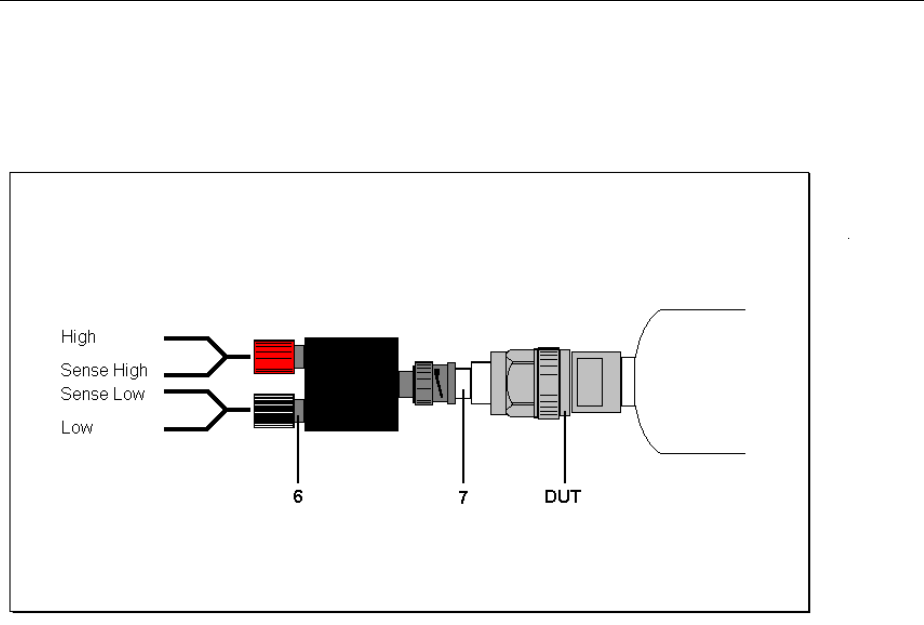
Quick Test R&S NRP-Z11/-Z21
1137.7406.82 1.8 E-1
Checking Input Resistance
Test setup - System voltmeter is set to 4-wire impedance measurement and
is connected to DUT according to figure.
Fig. 1-1 Connection of DUT for measuring the input resistance
Test - Check input resistance of sensor for compliance with limits of
test report.

R&S NRP-Z11/-Z21 Quick Test
1137.7406.82 1.9 E-1
Test Report
Quick test
Power Sensor R&S NRP-Z11
Stock number: 1138.3004.02 Name: ............................
Serial number: ...................... Date: ............................
Item
no. Characteristic Min. value Actual value Max. value Unit
1 Zeroing ------- -67.0 dBm
2 Absolute measuring accur.
at 0 dBm / 50 MHz
-0.10 +0.10 dBm
3 Linear. of meas. path 1 → 2 -0.10 +0.10 dB
4 Linear. of meas. path 2 → 3 -0.10 +0.10 dB
5 Input resistance 50.2 51.8 Ω
Quick test
Power Sensor R&S NRP-Z21
Stock number: 1137.6000.02 Name: ............................
Serial number: ...................... Date: ............................
Item
no. Characteristic Min. value Actual value Max. value Unit
6 Zeroing ------- -67.0 dBm
7 Absolute measuring accur.
at 0 dBm / 50 MHz
-0.10 +0.10 dBm
8 Linear. of meas. path 1 → 2 -0.10 +0.10 dB
9 Linear. of meas. path 2 → 3 -0.10 +0.10 dB
10 Input resistance 50.2 51.8 Ω

R&S NRP-Z11/-Z21 Preliminary Remarks
1137.7406.82 2.1 E-1
2 Adjustment
Preliminary Remarks
The Sensors R&S NRP-Z11 and R&S NRP-Z21 cannot be adjusted manually but have to be adjusted
by updating the calibration data in the memory. Calibration Software Recal, which is part of the
equipment supplied with the Calibration Kit R&S NRVC, is therefore required. The measurement results
for the absolute calibration of the three measurement paths which can be obtained during a
performance test (see Section 1) form the basis of the adjustment. The Calibration Kit R&S NRVC is
recommended but is not mandatory.
To ensure that the measuring accuracy corresponds to the data sheet values after the adjustment, the
calibration system must not have any inaccuracies that are higher than those given in the table below.
Table 2-1 Uncertainty of power calibration system at 0 dBm (in dB, including mismatch)
Frequency 10 MHz to
<20 MHz 20 MHz to
<100 MHz 100 MHz to
4 GHz >4 GHz to
8 GHz >8 GHz to
12.4 GHz >12.4 GHz to
18 GHz
Only R&S NRP-Z21
0.04 0.04 0.05 0.065 0.07 0.09
For further details, refer to the operating manual for the Calibration Kit R&S NRVC or the online help for
the Recal program.
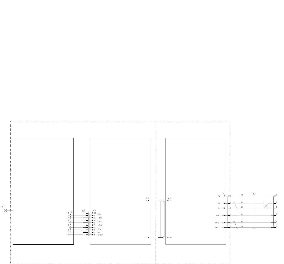
R&S NRP-Z11/-Z21 Design and Circuit Description
1137.7406.82 3.1 E-1
3 Repair of Sensors R&S NRP-Z11/-Z21
This section describes the design and simple measures for repairing and determining faults as well as
the replacement of modules.
The firmware update is explained in section 4 of this service manual.
Design and Circuit Description
Block Diagram
NRP-Z11
8 GHZ DETEKTOR
1138.3085.02
NRP-Z21
18 GKZ DETEKTOR
1137.6080.02
A3 A2
ANALOG BOARD
1137.6900.02
A1
DIGITAL BOARD
1137.6800.02
Fig. 3-1 Block diagram of Sensors R&S NRP-Z11 and R&S NRP-Z21

Design and Circuit Description R&S NRP-Z11/-Z21
1137.7406.82 3.2 E-1
Description of Block Diagram
The Sensors R&S NRP-Z11 and R&S NRP-Z21 can determine the average power of almost any
modulated RF signal over a large dynamic range. They include all modules required for analog and
digital signal processing and provide fully corrected measured values. Communication with the
R&S NRP base unit is handled via a USB interface.
Three detectors are used to obtain the large dynamic range of 90 dB (–67 dBm to +23 dBm); the input
signal is fed unattenuated to path 1, attenuated by 20 dB to path 2 and attenuated by 40 dB to path 3.
Sensitivity is highest on path 1, medium on path 2 and lowest on path 3.
Depending on the RF input signal level, one or two test paths are driven at such a level that these paths
can be evaluated. A channel is always either driven at a very low level or overdriven. The output
voltages of the three detectors are amplified and digitized independently of each other to obtain a
continuous transition between the test paths. The digital values provided by the A/D converters undergo
various corrections (zero offset, temperature, linearity). A weighting algorithm then decides which path
or – in transition ranges – which two paths are to be evaluated, and forms a weighted measured value.
Integration values that represent the average power of the RF signal in a predefined integration period
are derived by averaging all sampling values within the integration period.
The final measured values are the averaged result from several integration values.
Microwave Detector
The microwave detector A3 is a hybrid circuit. It contains the three test paths and a thermistor for
temperature measurement. The detector has an RF signal input and a flexstrip connector for output
signals, control signals and operating voltages with the following assignment:
Table 3-1 Assignment of flexstrip connector W3
Connector Signal name Description
W3:1 CHOP Logic signal for controlling the choppers
W3:2 NTC Thermistor connector (the other connector of the thermistor is connected to ground)
W3:3
W3:4 CH3 Output of the most insensitive test path
W3:5 –5VA Negative operating voltage for the choppers
W3:6
W3:7 CH2 Output of the medium test path
W3:8 +5VA Positive operating voltage for the choppers
W3:9
W3:10 CH1 Output of the most sensitive test path
The casing of the detector is at ground potential.

R&S NRP-Z11/-Z21 Design and Circuit Description
1137.7406.82 3.3 E-1
Analog Board
The analog board A2 contains three test channels of the same design, each consisting of an
instrumentation amplifier, a buffer amplifier and a 14-bit A/D converter. The instrumentation amplifiers
amplify the output difference voltage of the detectors and convert it into a ground-referenced voltage.
The buffer amplifiers are quickly settling operational amplifiers with negative current feedback; they
isolate the instrumentation amplifiers from the current peaks occurring at the A/D converter inputs. The
A/D converters operate on the successive approximation principle. They have serial outputs.
The serial output data streams of the A/D converters are subjected to serial-parallel conversion in a
CPLD and stored in three addressable registers. The digital board consecutively addresses and reads
out these registers.
The analog board also comprises an 8-bit D/A converter for generating a noise-line large-scale dither
signal that is controlled by the digital board with a sequence of pseudo-random digital values.
The analog board contains a four-channel 12-bit A/D converter for measuring the substrate temperature
of the detector as well as for monitoring the operating voltages ±5 V and +1.75 V. The 12-bit A/D
converter is supplied by the 3.3 V operating voltage of the digital board and is thus operational even if
the voltage supply of the analog board is defective. It is connected to the synchronous serial interface of
the digital board and utilizes the MICROWIRE™ protocol.
The +5 V operating voltage of the analog board is generated from +3.3 V by a charge pump doubler
with subsequent linear regulator. The 5 V operating voltage is generated by a switching regulator with a
very low output ripple voltage.
Digital Board
The digital board A1 mainly consists of a controller based on a microcontroller Intel StrongARM
SA1110, two SRAMs (together 1 Mbyte) as random access memory and two flash PROMs (together
2 Mbyte).
The interface to the R&S NRP base unit is formed by connector X1 on the digital board. Besides the
four lines for the USB interface, the sensor cable contains two signal lines for applying a differential
trigger signal.
The connection to the analog board is established by press-in connector X2.
The digital board contains two DC/DC converters that generate the voltages +3.3 V and +1.75 V (for the
microcontroller core) from the +5 V operating voltage.
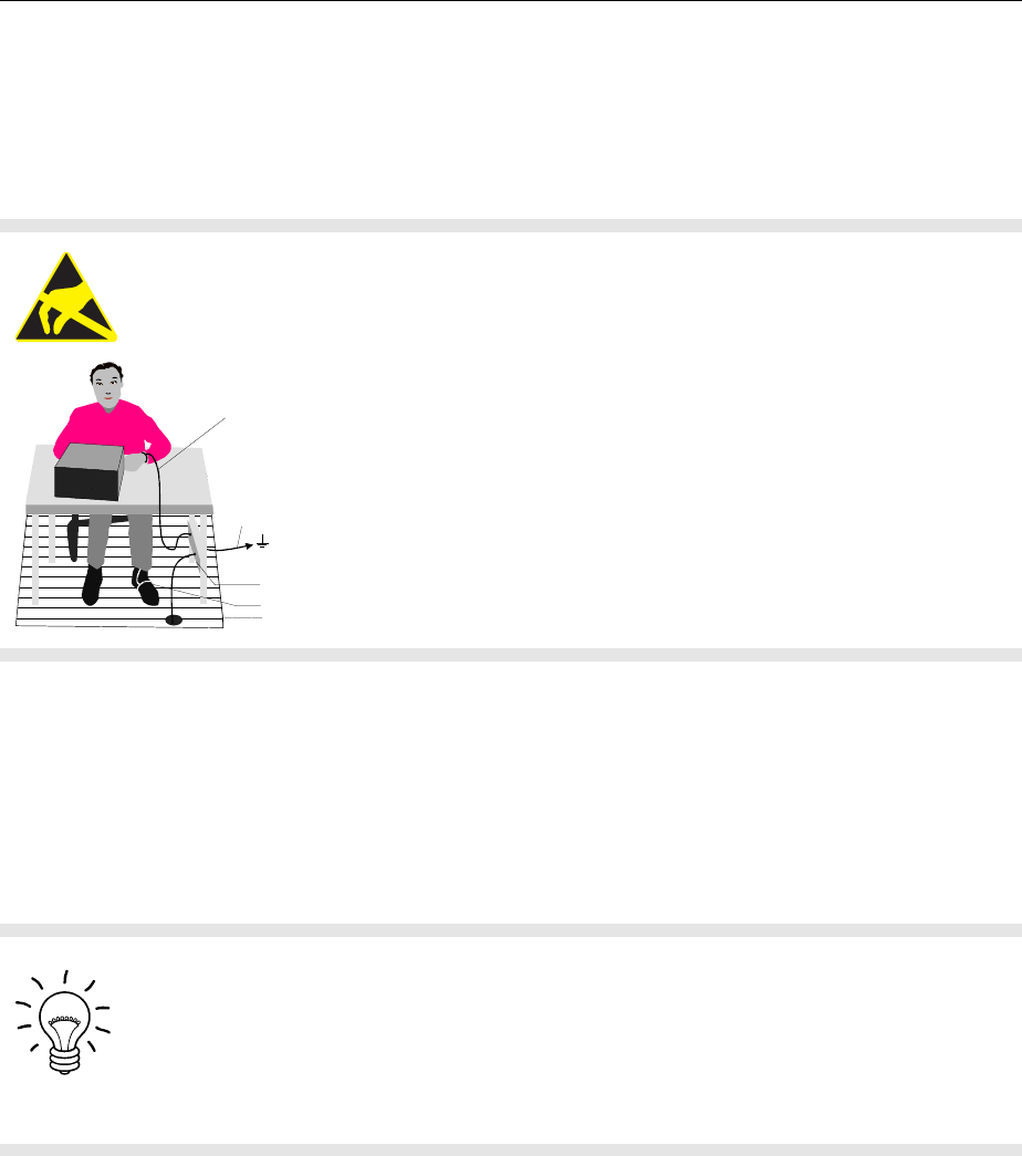
Module Replacement R&S NRP-Z11/-Z21
1137.7406.82 3.4 E-1
Module Replacement
The following section describes how to exchange the plastic shell halves and how to replace the
connecting cable. If one of the electronic modules (microwave detector, analog board or digital board) is
defective, the sensor has to be sent to Rohde & Schwarz Central Service for repair.
Wrist strap with cord
Building ground
Floor mat
Ground connection
of operational site
Heel strap
• Observe the safety instructions at the beginning of this manual.
• To avoid damaging electronic components, the instrument
should only be opened on a workplace protected against
electrostatic discharges.
The following methods can be used separately or combined to
ensure protection against electrostatic discharges:
• Anti-static wrist strap with grounding cable.
• Conductive flooring with foot strap.
Tools Required
Torx screwdriver Size T8
Thread M 2.5
Note:
The numeric values in brackets refer to the item in the list of mechanical parts and
spare parts in section 5.
These items are identical to the item numbers in the drawings illustrating the module
replacement.
Caution!
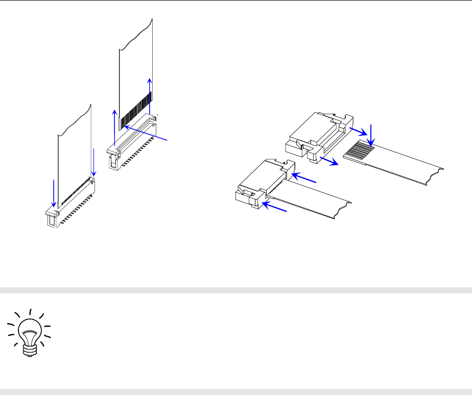
R&S NRP-Z11/-Z21 Module Replacement
1137.7406.82 3.5 E-1
Lock
Unlock
Contact side
Contact side
Lock
Unlock
Fig. 3-2 Membrane cables
Note:
Remove membrane cables:
Membrane cables can be removed after unlocking the female connector.
Connect membrane cables:
Observe the contact side and lock the female connector.

Module Replacement R&S NRP-Z11/-Z21
1137.7406.82 3.6 E-1
List of Modules
Table 3-2 List of modules/spare parts for R&S NRP-Z11 and R&S NRP-Z21
Item No. Designation Electrical
identification Stock No.
20 ANALOG BOARD A2 **)
40 POWER SENSOR CABLE W1 1137.7141.02
60 SCREW 7985/ISR-M2X8-A4 FOR POWER SENSOR CABLE W1 1148.2600.00 *)
80 DIGITAL BOARD A1 **)
90 SCREW 7985/ISR-M2X10-A4 FOR DIGITAL BOARD A1 1148.2917.00 *)
100 18 GHZ DETECTOR (NRP-Z21) A3 **)
101 8 GHZ DETECTOR (NRP-Z11) A3 **)
150 SHIELDING 1137.6068.00 *)
160 SENSOR HOUSING 1137.6022.00
170 SCREW 7985/ISR-M2X8-A4 FOR OUTER CASING 1148.2600.00 *)
180 LABEL 1 R&S NRP-Z11 1138.3033.00
190 LABEL 2 R&S NRP-Z11 1138.3040.00
200 LABEL 1 R&S NRP-Z21 1137.6039.00
210 LABEL 2 R&S NRP-Z21 1137.6045.00
*) Available but not maintained in spare parts stock, i.e. delivery time may be longer.
**) Spare part not available; to be replaced only by Rohde & Schwarz Central Service.
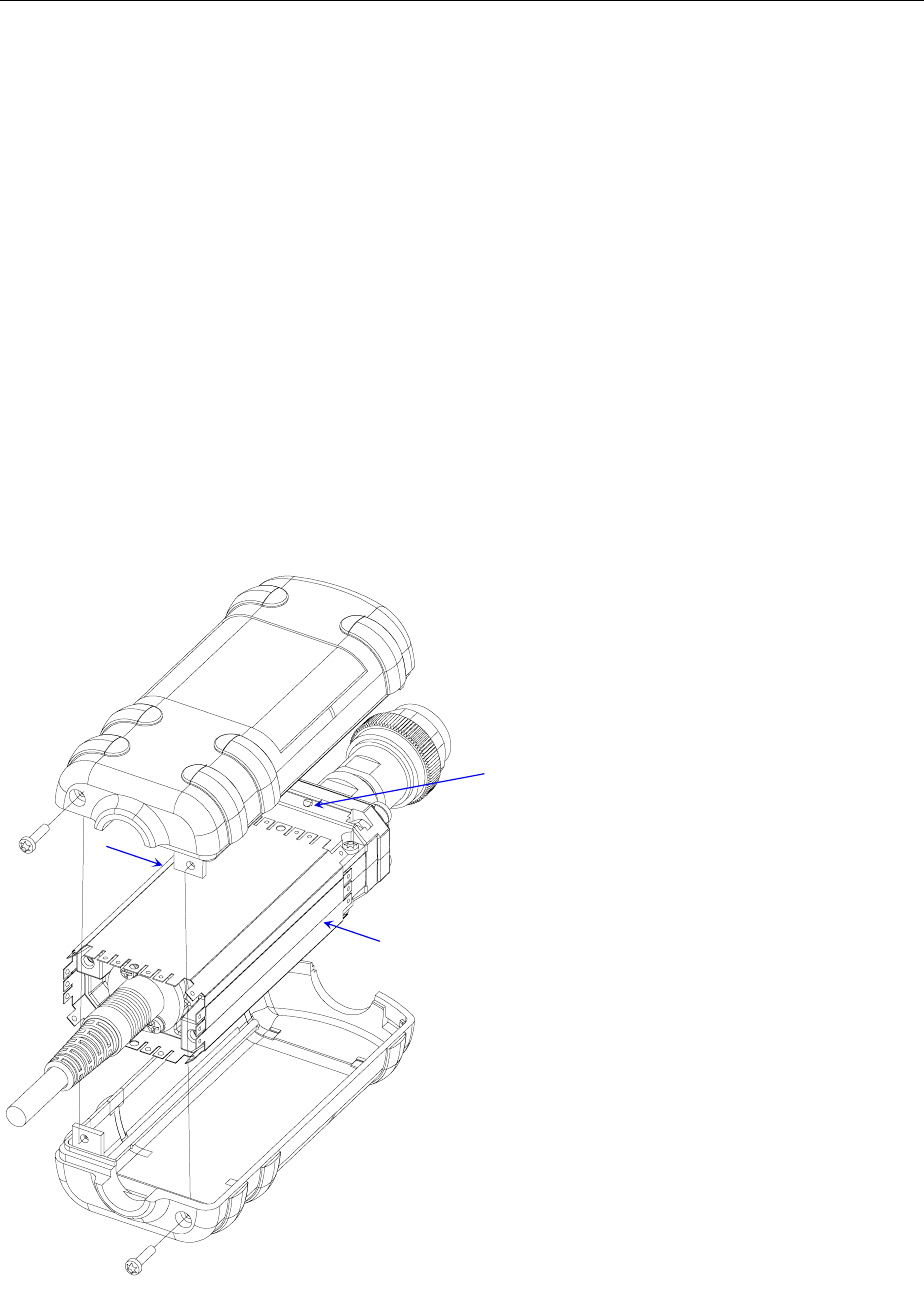
R&S NRP-Z11/-Z21 Module Replacement
1137.7406.82 3.7 E-1
Opening and Reassembly (Exchange of Plastic Shell Halves)
Opening
½ Undo two screws (170) on the two sides of the cable connector.
½ First pull off the plastic shell halves of the cable connector and take them apart by twisting them at
the RF connector.
½ The shielding is attached by a catch of the body on the RF connector side. Slightly bend and unlock
the shielding by firmly pressing on the two slim sides and pull it off in the cable direction.
Reassembly
½ Push the shielding and lock it into the catch of the body.
½ Insert the sensor into one of the shell halves and lock the second shell half on the RF connector side
and close at the cable connector.
½ Attach the shell halves to the body using two screws (170).
Catch for locking the
shielding
170
170
Press
Press
Fig. 3-3 Opening the sensor

Module Replacement R&S NRP-Z11/-Z21
1137.7406.82 3.8 E-1
Caution:
Observe a torque of 29 Ncm for all screws.
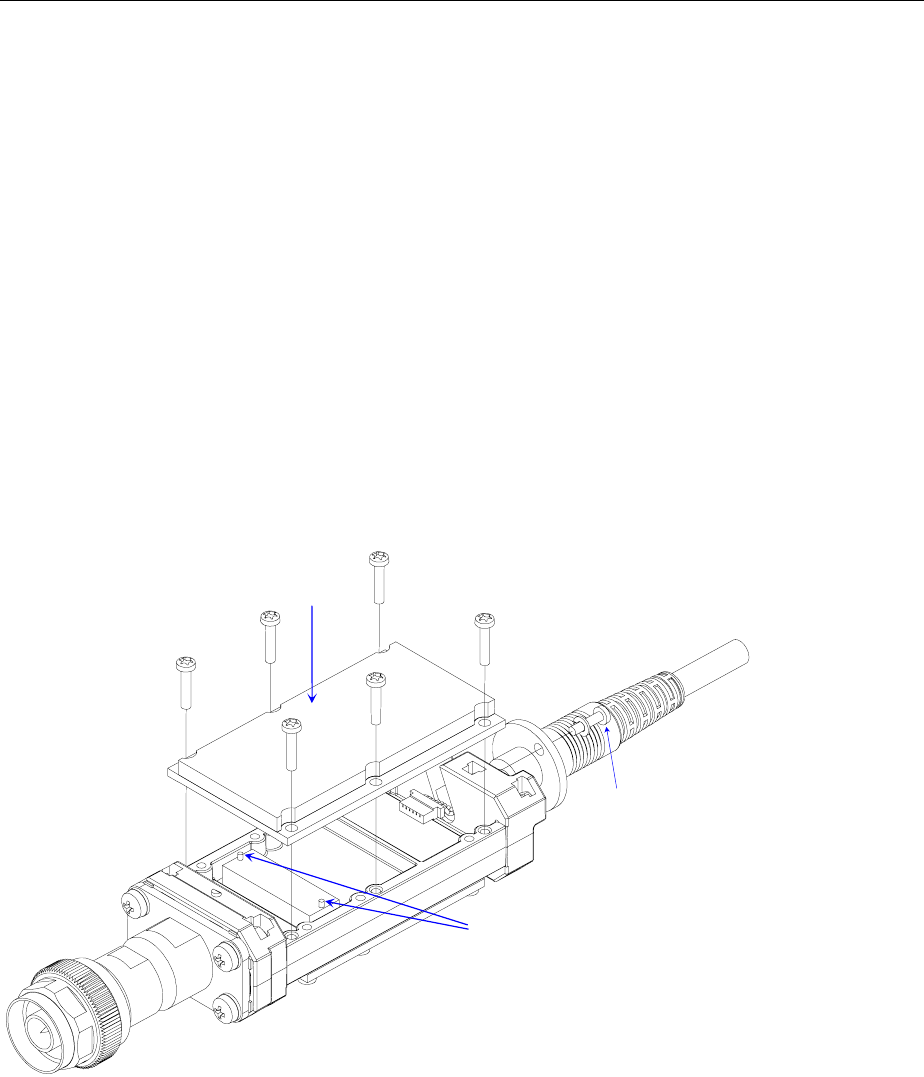
R&S NRP-Z11/-Z21 Module Replacement
1137.7406.82 3.9 E-1
Replacement of Sensor Cable W1
Removing the Sensor Cable
½ Opening the sensor (see page 3.7).
½ Undo 6 screws (90).
½ Carefully remove digital board A1 from the body.
½ Unplug sensor cable W1 from digital board.
½ For removing sensor cable W1, undo two screws (60) and remove the cable from the body.
Installing the Sensor Cable
½ Install in the reverse order.
½ Ensure that the guide pins of press-in connector X2 lock into the corresponding boreholes of the
digital board.
Digital board A1 90 (6x)
X2
W1
Guide pins
60 (2x)
W1
Fig. 3-4 Replacement of sensor cable

Troubleshooting R&S NRP-Z11/-Z21
1137.7406.82 3.10 E-1
Troubleshooting
Malfunctions may sometimes be due to simple reasons but may also result from defective components.
These troubleshooting instructions permit malfunctions or errors to be traced down to module level.
Module replacement and further diagnosis of errors or malfunctions should be carried out by our
customer service. It is therefore recommended to send the unit to the nearest service center (see list of
addresses at the beginning of this manual).
Caution:
Prior to opening sensor and replacing modules, disconnect sensor from base unit
(R&S NRP) or USB adapters (R&S NRP-Z3 or R&S NRP-Z4).

R&S NRP-Z11/-Z21 Troubleshooting
1137.7406.82 3.11 E-1
Overview of Errors, Causes and Corrective Steps
This section provides an overview of possible errors, their causes and corrective steps.
Problems when plugging in the sensor or switching on the R&S NRP base unit
• Error: The power sensor is not found (neither measured values nor error messages are
displayed on the R&S NRP base unit).
Troubleshooting instruction Potential error source and further corrective
steps
Unplug sensor from base unit and check male and
female connector for damage. Defective connection.
Replace the sensor cable and/or the connector in
the R&S NRP.
⇓
Check whether the error also occurs on another
base unit or in another channel. Error source within base unit.
Refer to chapter 3 of the R&S NRP service manual
for detailed troubleshooting.
Error source within sensor.
Open sensor and check connection of sensor
cable W1 with digital board.
Exchange sensor cable.
Send sensor in for repair (digital board possibly
defective).
• Error: The R&S NRP base unit has detected an error (pop-up window contains error
message, e.g. Sensor communication error).
Troubleshooting instruction Potential error source and further corrective
steps
Base unit and sensor cannot communicate with
each other. The firmware versions may not be
compatible.
⇓
Load current firmware into sensor and base unit
according to section 4. If updated firmware does not correct problem,
perform the same measures as described above
(sensor is not found).

Troubleshooting R&S NRP-Z11/-Z21
1137.7406.82 3.12 E-1
• Error: The power sensor has detected an error (HW Error displayed at extreme right of title
bar).
Troubleshooting instruction Potential error source and further corrective
steps
The sensor detected an error during selfttest or
during communication (hardware defect or
defective voltage supply).
⇓
Check whether error also occurs on a different
base unit. Error source within base unit.
Refer to chapter 3 of the R&S NRP service manual
for detailed troubleshooting.
Error source within sensor.
Send sensor in for repair (analog board or digital
board is defective).
Problems during measurement
• Error: Measured power readings are erroneous.
Troubleshooting instruction Potential error source and further corrective
steps
Perform performance test or selftest according to
section 1. Sensor was overloaded: indicated by very poor
matching and/or errors in measurement path 1.
Send sensor in for repair (microwave detector is
defective).
Other parts of sensor hardware are defective.
Send sensor in for repair (microwave detector or
analog board is defective).
Sensor hardware is probably ok since test limits
are only slightly exceeded.
Perform update of calibration factors in data
memory of sensor according to section 2.

R&S NRP-Z11/-Z21 Installation of New R&S NRP-Z11/-Z21 Software
1137.7406.82 4.1 E-1
4 Firmware Update/Installation of Options
Chapter 4 provides information on the software update and the installation of options. Descriptions
enclosed with the software update or options can be filed here.
Installation of New R&S NRP-Z11/-Z21 Software
Use the Firmware Update program module to load new firmware for the Power Sensors R&S NRP-Z11
and NRP-Z21. The module is part of the R&S NRP Toolkit that is supplied on a CD-ROM together with
the power sensors and enables you to update the boot loader and the application firmware.
The current firmware versions can be downloaded from the R&S homepage on the Internet, since the
CD-ROM accompanying the power sensors contains the firmware status at the time of delivery.
Hardware and software requirements
The system requirements for a firmware update are the same as for the operation of the power sensor
on a PC (an update via the power meter is not possible):
• PC with free USB port.
• USB Interface Adapter R&S NRP-Z3 or R&S NRP-Z4.
• Operating system Windows™ 98, Windows™ ME, Windows™ 2000, or Windows™ XP.
• The R&S NRP Toolkit software must already be installed on your PC.
• One of the following files must be selected (depending on the software component to be updated):
• <Type>_Sensor<Version Number>.nrp Application
• Bootloader_<Version Number>.nrp, Boot loader
The files are available in the \software\firmware\sensors directory of the CD-ROM.

Installation of New R&S NRP-Z11/-Z21 Software R&S NRP-Z11/-Z21
1137.7406.82 4.2 E-1
Preparation
½ Connect the R&S NRP power sensor to the PC using one of the two USB interface adapters.
½ If a second R&S NRP-Z power sensor or an R&S NRP is connected to the PC, unplug these devices
from the PC.
½ Shortly afterwards, the PC should have identified the new USB hardware and assigned the
appropriate driver from the R&S NRP Toolkit to the power sensor (brief message in a small
window).
If you forgot to install the R&S NRP Toolkit beforehand, Windows will try in vain to
find a USB driver for the power sensor. If this happens, the R&S NRP-Zxx is
highlighted by a yellow exclamation mark in the Windows device manager. In this
case, proceed as follows:
½ Abort the dialog for driver installation.
½ Install the R&S NRP Toolkit from the CD-ROM.
Then manually assign the USB driver from the toolkit to the power sensor.
½ Go to Control Panel – Add/Remove Hardware and start the hardware assistant to
search for new components.
½ Mark the R&S NRP-Zxx in the list of hardware components and complete the driver
installation.
½ Unplug the power sensor and reconnect it.
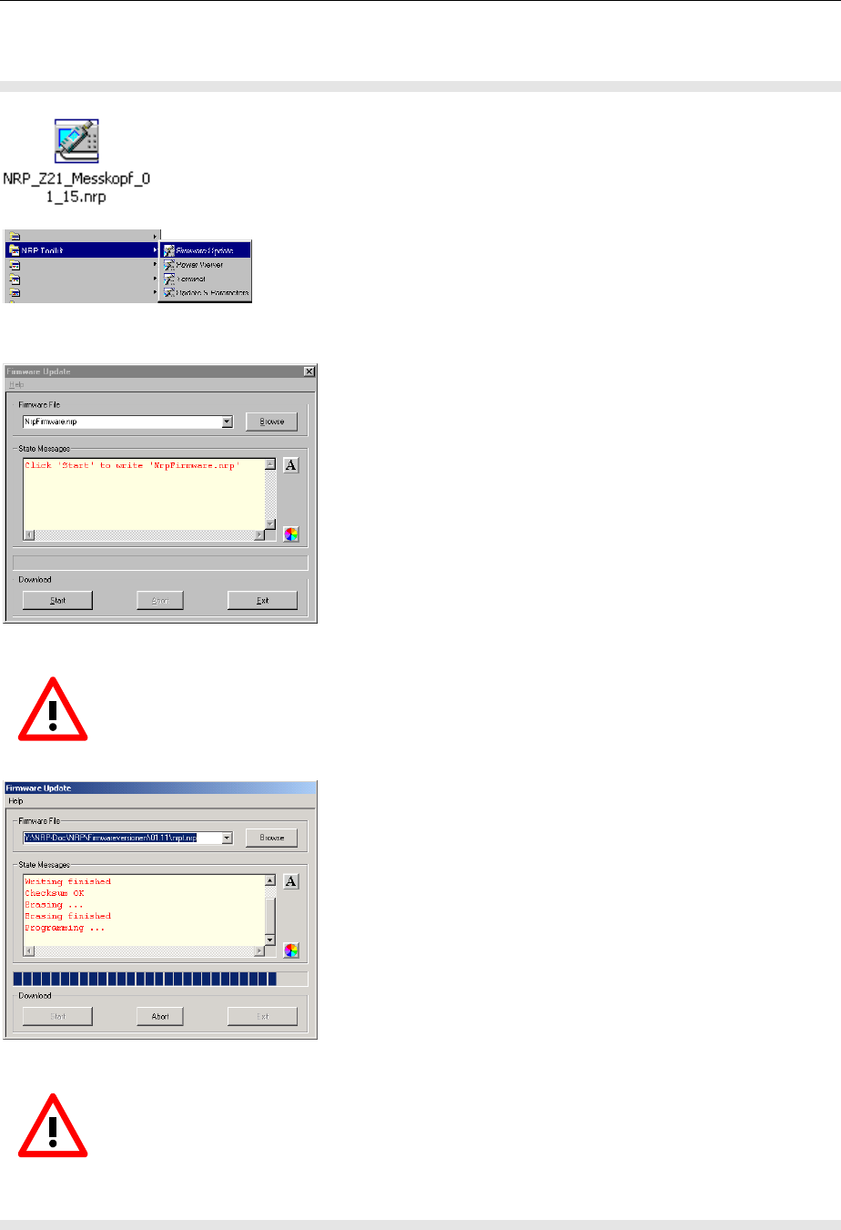
R&S NRP-Z11/-Z21 Installation of New R&S NRP-Z11/-Z21 Software
1137.7406.82 4.3 E-1
Updating the application firmware
The update can be started as follows:
½ Either double-click the icon of the update file named
<Type>_Messkopf_<Version Number>.nrp
½ Or start NRP Toolkit – Firmware Update from the
Windows Start menu.
The dialog box on the left is displayed next.
½ If the update was started via the Windows Start menu,
enter the file name of the application firmware in the
Firmware File box (or search for the name by using the
Browse button).
½ Click the Start button to start the file transfer, which is
performed automatically.
½ Observe the following:
• Do not disconnect the power sensor from the PC.
• Neither connect nor disconnect the power supply for the
R&S NRP-Z3 adapter.
• Exit the Firmware Update program only after it has been
completely executed.
½ During the update, the State Messages box informs you
of the progress. The update has been completed
successfully if the message ’Device <Type
Designation><Serial Number> is active’
appears.
½ You can then use the power sensor for measuring.
Potential problems
- Error in the compatibility and consistency checks.
In this case, the update is aborted and an error message
is output.
½ Unplug the power sensor, reconnect it and start the
update again.
Installation of New R&S NRP-Z11/-Z21 Software R&S NRP-Z11/-Z21
1137.7406.82 4.4 E-1
Updating the boot loader
The boot loader update is similar to the update of the
application firmware (see above).
½ Instead of the application, however, you must load the
new boot loader named
Bootloader_<Version Number>.nrp
Strictly observe the warnings under "Updating the
application firmware", since the destruction of the boot
loader will generally require a repair of the power sensor.
Potential problems
- The power sensor cannot be accessed after the update
(error message).
½ Exit the Firmware Update program, unplug the power
sensor from the PC and reconnect it. The power sensor is
now ready for operation.

R&S NRP-Z11/-Z21 Shipping of Instrument and Ordering of Spare Parts
1137.7406.82 5.1 E-1
5 Documents
This section provides information for ordering spare parts and contains the relevant documents for the
Rohde & Schwarz Power Sensors R&S NRP-Z11 and R&S NRP-Z21.
Shipping of Instrument and Ordering of Spare Parts
Please contact your Rohde & Schwarz support center or our spare parts express service if you need to
request service, repair your equipment, or order spare parts and modules.
The list of Rohde & Schwarz representatives and the address of our spare parts express service are
provided in the front section of this service manual.
You will need to provide the following information in order for us to respond to your inquiries quickly and
accurately and to determine whether the warranty for your instrument is still valid:
• Instrument model
• Serial number
• Detailed error description in case of repair
• Contact partner for checkbacks
Shipping of Instrument
When shipping the instrument, be sure to provide sufficient mechanical and anti-static protection:
½ Repack the instrument as it was originally packed. The antistatic packing foil prevents unintentional
electrostatic charging from occurring.
½ If you do not use the original packaging, include sufficient padding to prevent the instrument from
slipping inside the package. Wrap antistatic packing foil around the instrument to protect it from
electrostatic charging.
Ordering Spare Parts
To deliver replacement parts promptly and correctly, we need the following information:
• R&S stock number (refer to the spare part lists in this section)
• Designation
• Number of units
• Instrument type for the replacement part
• Contact person for possible questions
The R&S stock number to be used when ordering replacement parts and modules as well as power
cables can be found further below.

Shipping of Instrument and Ordering of Spare Parts R&S NRP-Z11/-Z21
1137.7406.82 5.2 E-1
Ordering Replacement Sensors
Rohde & Schwarz maintains a replacement program for a number of power sensors. Within this
program, it is possible to provide a fully operational power sensor to replace a defective one at short
notice and at a fixed price. Please note that replacement sensors are used equipment but are always
tested. They are therefore equivalent to new sensors even though they may exhibit slight signs of use.
If required, the delivery of replacement sensors can include a new calibration. If interested, please
contact your nearest Rohde & Schwarz office.

R&S NRP-Z11/-Z21 Spare Parts
1137.7406.82 5.3 E-1
Spare Parts
The R&S stock numbers necessary for ordering replacement parts and modules can be found in the
spare part lists provided below.
List of R&S NRP-Z11/-Z21 Spare Parts
The following table lists available spare parts together with their R&S stock numbers.
Item No. Designation Electrical
identification Stock No.
20 ANALOG BOARD A2 **)
40 POWER SENSOR CABLE W1 1137.7141.02
60 SCREW 7985/ISR-M2X8-A4 FOR POWER SENSOR CABLE W1 1148.2600.00 *)
80 DIGITAL BOARD A1 **)
90 SCREW 7985/ISR-M2X10-A4 FOR DIGITAL BOARD A1 1148.2917.00 *)
100 18 GHZ DETECTOR (NRP-Z21) A3 **)
101 8 GHZ DETECTOR (NRP-Z11) A3 **)
150 SHIELDING 1137.6068.00 *)
160 SENSOR HOUSING 1137.6022.00
170 SCREW 7985/ISR-M2X8-A4 FOR OUTER CASING 1148.2600.00 *)
180 LABEL 1 R&S NRP-Z11 1138.3033.00
190 LABEL 2 R&S NRP-Z11 1138.3040.00
200 LABEL 1 R&S NRP-Z21 1137.6039.00
210 LABEL 2 R&S NRP-Z21 1137.6045.00
Note: The reference can be found in the drawings 3-3 and 3-4 in Section 3.
*) Available but not maintained in spare parts stock, i.e. delivery time may be longer.
**) Spare part not available; to be replaced only by Rohde & Schwarz Central Service.
