200102 Raad
User Manual: 200102
Open the PDF directly: View PDF ![]() .
.
Page Count: 41
- Book 2.pdf
- Book 1.pdf
- Book 3.pdf
- Book 4.pdf
- Book 5.pdf
- Book 6.pdf
- Book 7.pdf
- Book 8.pdf
- Book 9.pdf
- Book 10.pdf
- Book 11.pdf
- Book 12.pdf
- Book 13.pdf
- Book 14.pdf
- Book 15.pdf
- Book 16.pdf
- Book 17.pdf
- Book 18.pdf
- Book 19.pdf
- Book 20.pdf
- Book 21.pdf
- Book 22.pdf
- Book 23.pdf
- Book 24.pdf
- Book 25.pdf
- Book 26.pdf
- Book 27.pdf
- Book 28.pdf
- Book 29.pdf
- Book 30.pdf
- Book 31.pdf
- Book 32.pdf
- Book 33.pdf
- Book 34.pdf
- Book 35.pdf
- Book 36.pdf
- Book 37.pdf
- Book 38.pdf
- Book 39.pdf
- Book 40.pdf
- Book 41.pdf

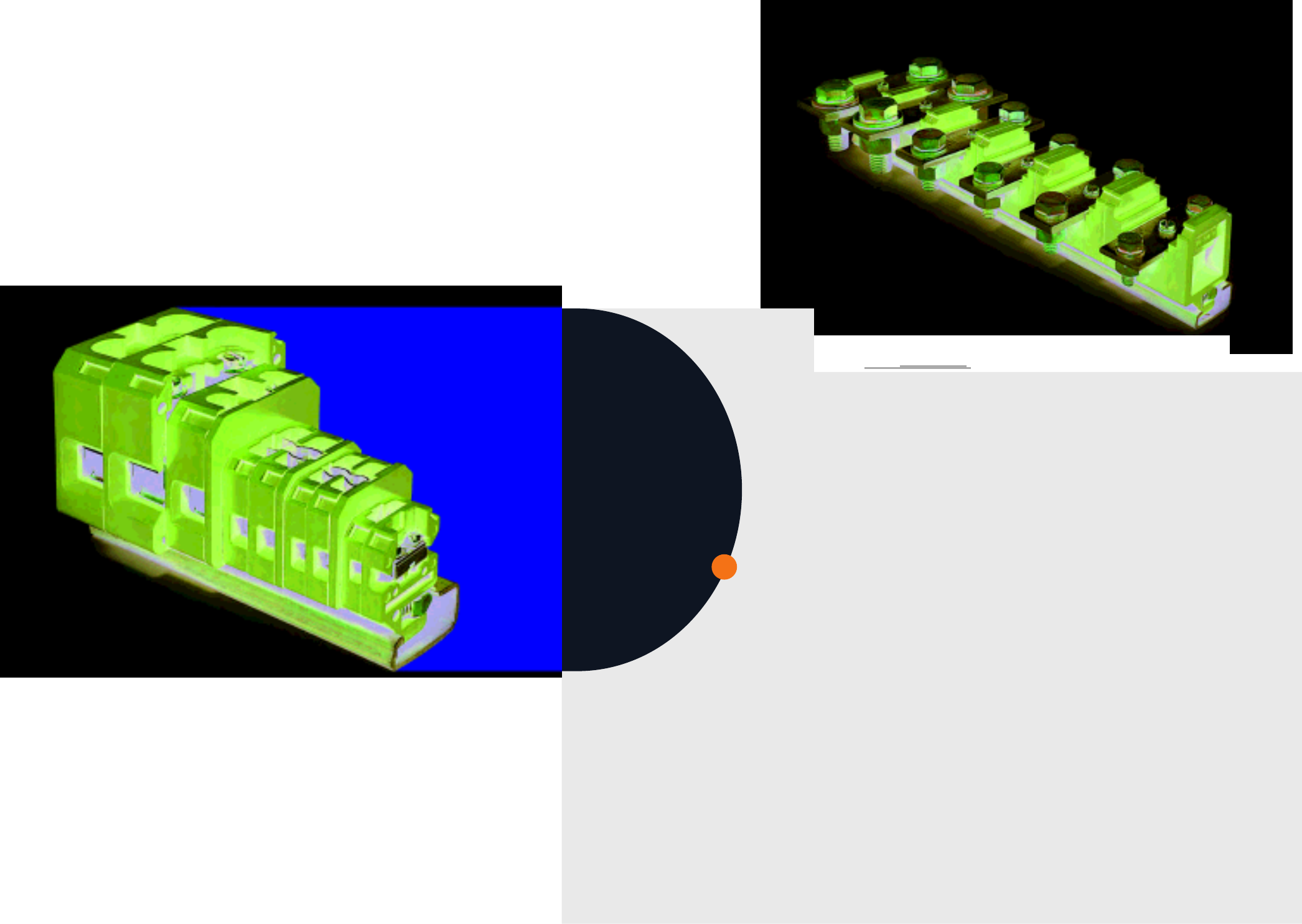
MODULAR
TERMINAL BLOCKSTERMINAL BLOCKS
RAAD
In The Name of God
2005 Products Catalog
Confidenc in Connection
Photo & Design: Gilar +9821 8830988

Raad Manufacturing Company was founded in 1988 as a designer and producer of different kinds
of molds. In 1992, the company expanded its activities and continued as an OEM in modular
terminal block industry.
Since the beginning of its operation, Raad has maintained and improved close cooperative
relation with its customers and taken benefit of their views and feedbacks. Key strategies such as
enhancing customers satisfaction, applying highly productive technological processes and using
the best quality materials and parts, are all the company's policies which define its approach to
development and open the doors into new discoveries in the field.
Today, thanks to several approvals obtained world-wide by its products, having had comprehensive
range of products, Raad is, honorably, the leading manufacturer of terminal blocks in Middle East.
The company’s headquarter and sales division is located in Tehran and the manufacturing site is
practicing in a rural area of Isfahan, employing over 200 well-trained and skilled personnel.
Raad Manufacturing Co. reserves the right to make changes to any
information given in this catalog regarding technical progresses.
Please contact us for update technical information and new prices.
The Company
Headquarter and sales division
North 3rd floor, 28, 2nd St.
Shahnazari St., Madar Sq., Mirdamad Blv.
Tehran - Iran
Tel. +98 21 227 8455 - 6
Fax +98 21 227 8457
salse@raad-co.com
www.raad-co.com
Factory
20th St., Azadegan freeway
Isfahan - Iran
PO Box 81395/111
Tel. +98 311 3802026
Fax +98 311 3802013
info@raad-co.com
Contents
Product overview
RTP series terminal blocks
Protective conductor terminal blocks
Double level terminal blocks
Test disconnect terminal blocks
Fuse terminal blocks
Coloured terminal blocks
RTM series terminal blocks
RCT series terminal blocks
Accessories
General technical information
4
9
15
19
27
33
39
41
47
55
67
4
MODULAR TERMINAL BLOCKS / 2005
5
Product Overview
RTP 2.5 / Page 10
RTP 16 / Page 12
RTP 95 / Page 14
RET 6 / Page 17
DRTP4 / Page 20
RTP 4/ Page 10
RTP 25 / Page 12
RET 10 / Page 17
DRTP4-D1 / Page 21
RTP 6 / Page 11
RTP 35 / Page 13
RET 2.5 / Page 16
RET 16 / Page 18
DRTP4-D2 / Page 22
RTP 10 / Page 11
RTP 50 / Page13
RET 4 / Page 16
RET 35 / Page 18
DRTP4-D3 / Page 22
DRTP4-D4 / Page 23
DRTP4-DR2 / Page 25
RCT-LU2 / Page 28
RDT4-TS / Page 30
RCTF10-LD / Page 35
DRTP4-D5 / Page 23
DRTP4-LD / Page 26
RST6 / Page 29
STC6 / Page 31
RFT5 / Page 36
DRTP4-D6 / Page 24
DRTP4-NL / Page 26
RTT6 / Page 29
RCTF10 / Page 34
RFT5-NL / Page 36
DRTP4-DR1 / Page 25
RCT-L2 / Page 28
RDT4 / Page 30
RCTF10-NL / Page 34
RFTS-LD / Page 37
Protective Conductor
Terminal Blocks
Double Level
Terminal Blocks
Test Disconnect
Terminal Blocks
Fuse
Terminal Blocks
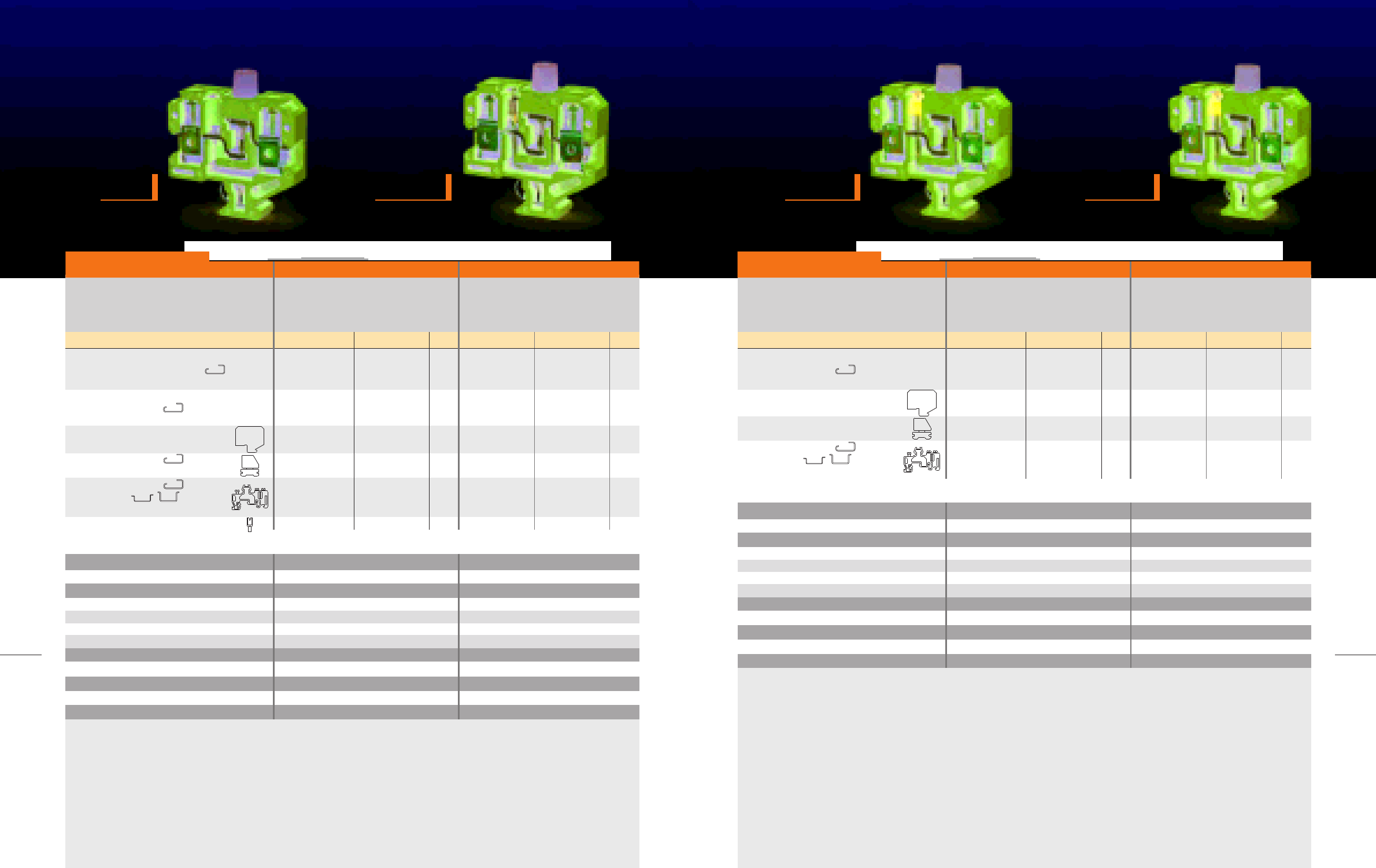
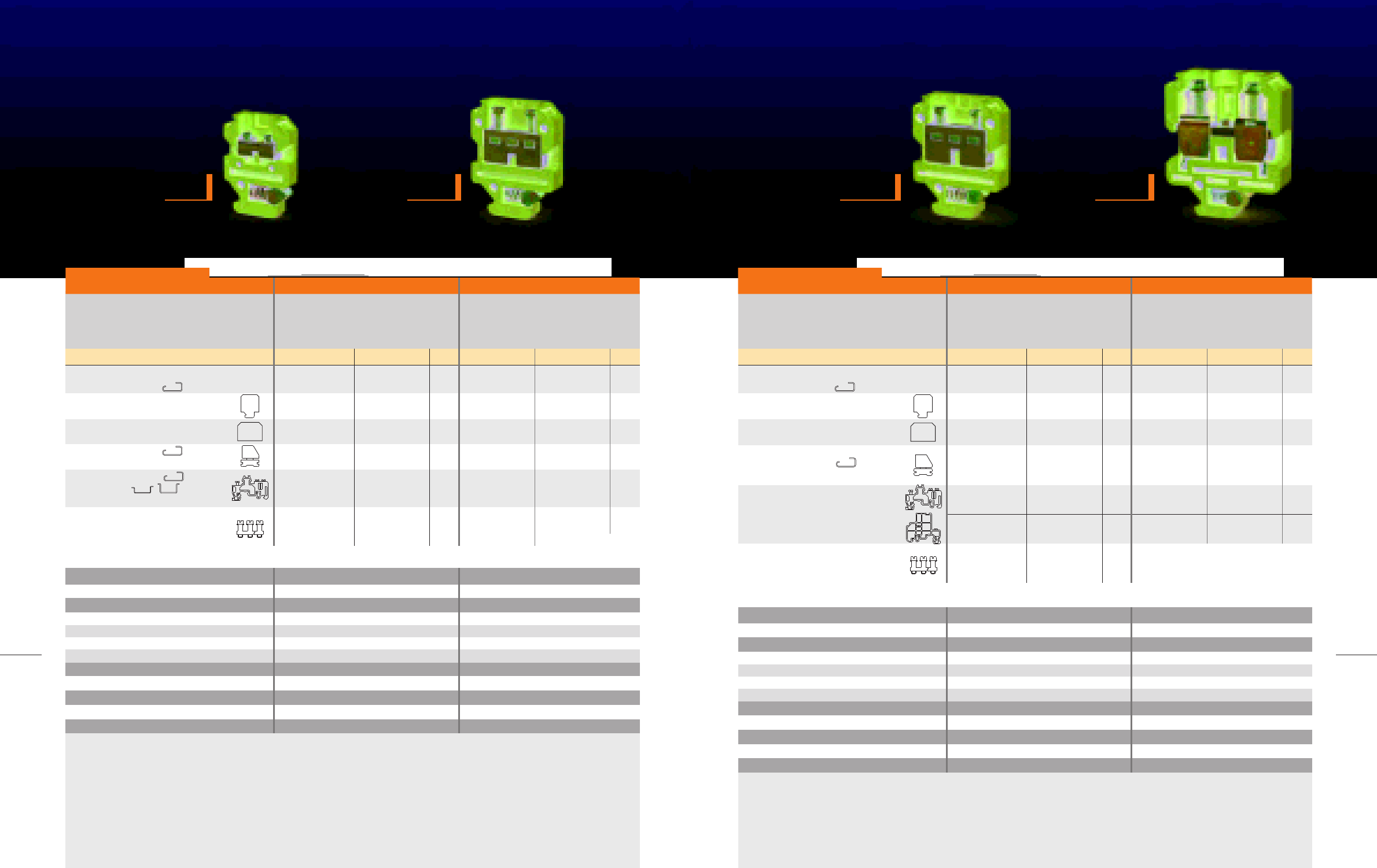
RTP Series
Terminal Blocks
6
MODULAR TERMINAL BLOCKS / 2005
7
Product Overview
RTM2.5 / Page 42
RTM16 / Page 44
RCT4 / Page 48
RCT50 / Page 50
RCT150 / Page 52
RTM4 / Page 42
RTM25 / Page 44
RCT6 / Page 48
RCT70 / Page 51
RCT185 / Page 53
RTM6 / Page 43
RTM35 / Page 45
RCT16 / Page 49
RCT95 / Page 51
RTM10 / Page 43
RTM50 / Page 45
RCT35 / Page 49
RCT120 / Page 52
RCT240 / Page 53
NS6 / Page 56
LB/1 / Page 57
Cross-Connection / Page 62
MOUNTING RAILS
ACCESSORIES / Page 66
NS6.4 / Page 56
LB/2 / Page 57
TEST SOCKET / Page 64
EB/1 / Page 66
NS8 / Page 56
End Plates & Partition / Page 60
MOVEABLE LINK / Page 64
EB/2 / Page 66
COVER / Page 60
MOUNTING
RAILS / Page 65
EB32 / Page 66
RTM Series
Terminal Blocks
RCT Series
Terminal Blocks
Accessories

Raad offers the
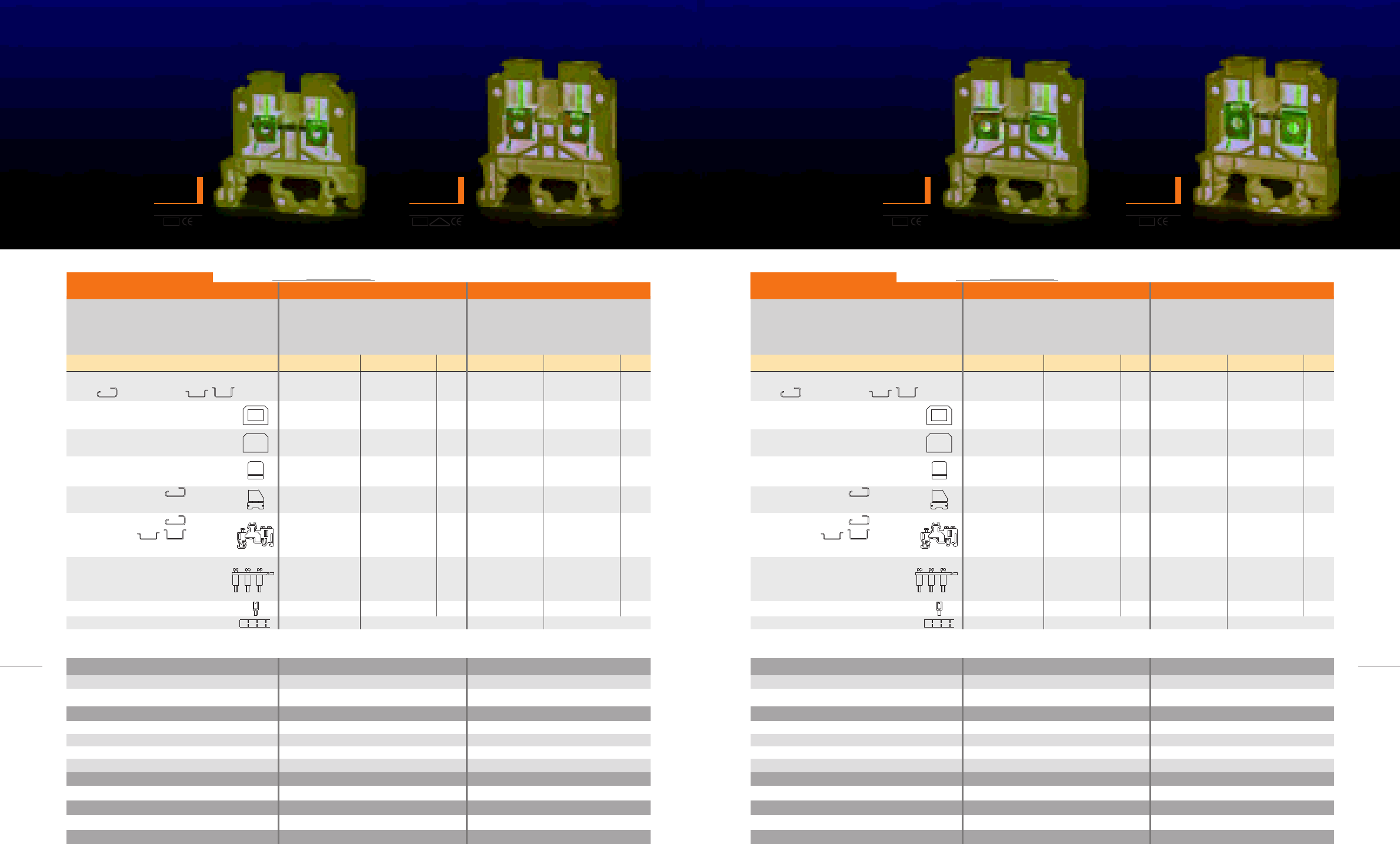
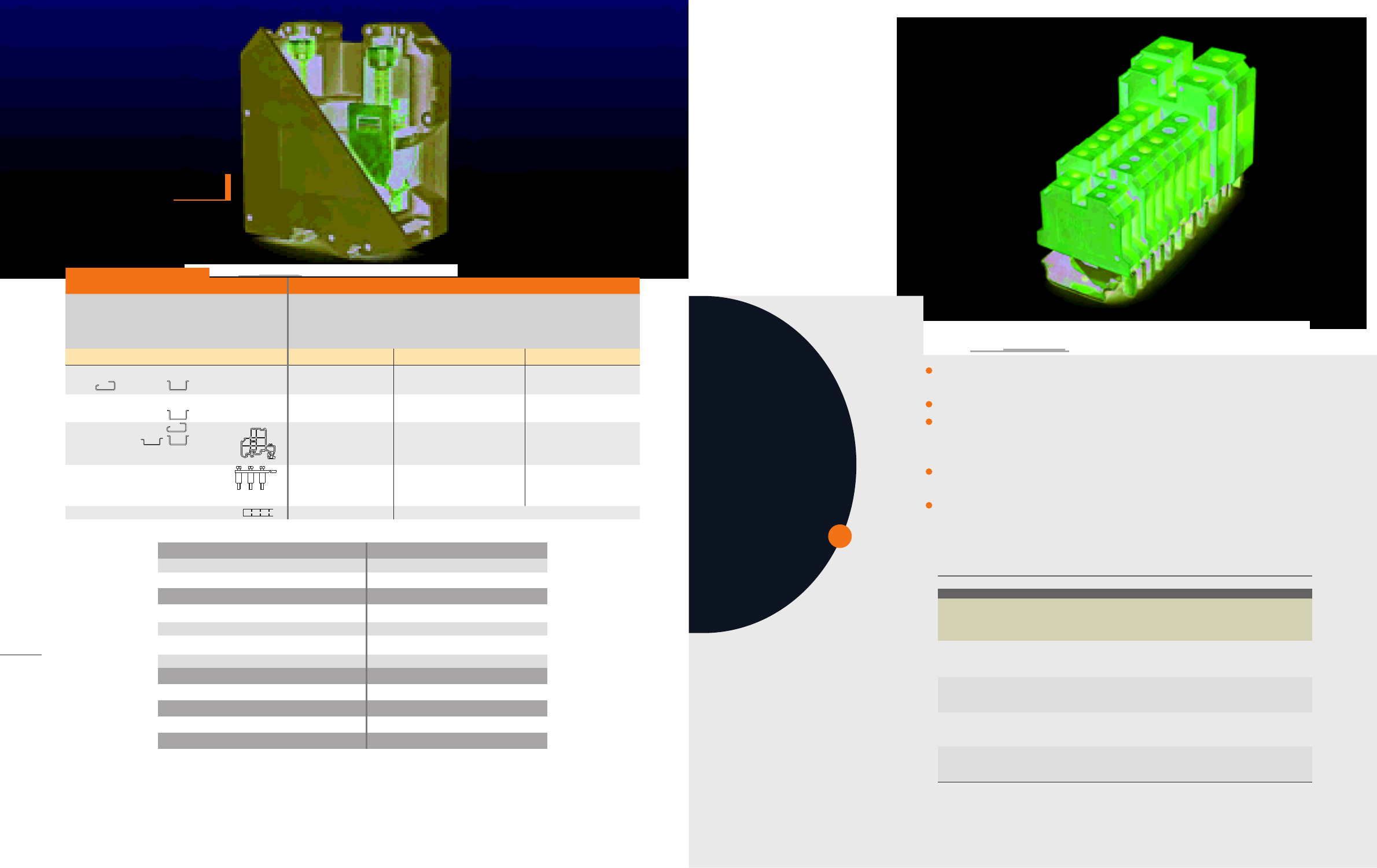
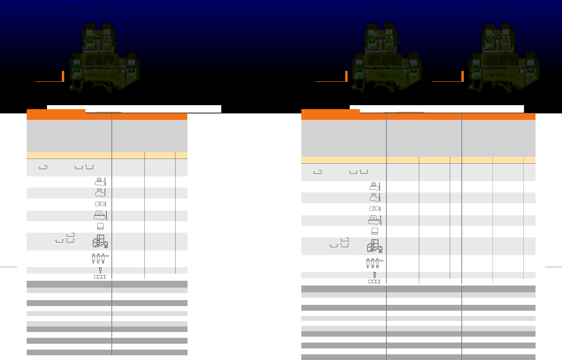
RTP series with the following advantages:
Combination foot for both TH35 and G32 mounting rails
Terminal insulation body polyamide 6.6
Easy to tighten due to screwdriver guide
Closed cable entry for preventing from wire splitting
Best connection of the conductor, needing no special cable
preparation
Appropriate for different cross-sections, rigid or flexible
Similar end plates and patition for several types
Preassembled and divisible cross-connection system and easy
removable unwanted cross-connection
Offering protective conductor terminals, suitable for various sizes of
terminals
Having 10 marker strips simultaneously mountable on some sizes of
the terminal
Certified by notorious national institutes
RTP SERIES
TERMINAL BLOCKS
10
MODULAR TERMINAL BLOCKS / 2005
11
RTP SERIES
RTP2.5
width 6 mm
RTP4
width 6.4 mm
RTP6
width 8 mm
RTP10
width 10 mm
KEMA
EUR VDE
KEMA
EUR
IEC 60947-7-1 rated data
Voltage(V)/Impulse voltage (kV)
Pollution degre/Voltage category/Material group
Current (A)
Cross - section (mm2)
500/6
3/III/I
24
2.5
500/6
3/III/I
32
4
RTP2.5 RTP4
Reg.-No. 130597
Terminal block, for mounting on
G 32 ,TH 35-7.5, 15
End plate
width (mm)
Partition
width (mm)
Small partition
no loss of pitch
End bracket, for G 32
width (mm) Raad recommended
End bracket, for G 32
TH 35- 7.5, 15
width (mm) Raad recommended
Cross-connection
max. current (A)
Test socket
Marking
Description Type Ordering No. Qty. Type Ordering No. Qty.
RTP2.5
EP-RTP2.5
1.5
P-RTP2.5
1.5
SP-2.5-10
EB32
8
EB/1
9.5
CC10-2.5 10-pos.
CC3-2.5 3-pos.
CC2-2.5 2-pos.
20
TS3/6/2.3
NS6
101001
201001
201005
201007
200101
200102
201020
201021
201022
200540
100
100
100
100
50
50
10
50
50
50
RTP4
EP-RTP4,6,10
1.5
P-RTP4,6,10
1.5
SP-2.5-10
EB32
9.5
EB/1
9.5
CC10-4 10-pos.
CC3-4 3-pos.
CC2-4 2-pos.
32
TS3/6/2.3
NS6.4
101003
201003
201008
201007
200101
200102
201023
201024
201025
200540
100
50
50
100
50
50
10
50
50
50
IEC 60947-7-1 rated data
Voltage(V)/Impulse voltage (kV)
Pollution degre/Voltage category/Material group
Current (A)
Cross - section (mm2)
800/8
3/III/I
41
6
800/8
3/III/I
57
10
RTP6 RTP10
Terminal block, for mounting on
G 32 ,TH 35-7.5, 15
End plate
width (mm)
Partition
width (mm)
Small partition
no loss of pitch
End bracket, for G 32
width (mm) Raad recommended
End bracket, for G 32
TH 35- 7.5, 15
width (mm) Raad recommended
Cross-connection
max. current (A)
Test socket
Marking
Description Type Ordering No. Qty. Type Ordering No. Qty.
RTP6
EP-RTP4,6,10
1.5
P-RTP4,6,10
1.5
SP-2.5-10
EB32
8
EB/1
9.5
CC10-6 10-pos.
CC3-6 3-pos.
CC2-6 2-pos.
47
TS3/8/4
NS8
101005
201003
201008
201007
200101
200102
201026
201027
201028
200541
50
50
50
100
50
50
10
50
50
50
RTP10
EP-RTP4,6,10
1.5
P-RTP4,6,10
1.5
SP-2.5-10
EB32
8
EB/1
9.5
CC10-10 10-pos.
CC3-10 3-pos.
CC2-10 2-pos.
47
TS3/8/4
NS8
101007
201003
201008
201007
200101
200102
201029
201030
201031
200541
50
50
50
100
50
50
10
50
50
50
KEMA
EUR KEMA
EUR
Raad recommended
For details see Accessories For details see Accessories For details see Accessories For details see Accessories
0.5-4
0.5-4
0.5-2.5
20-12
A3
10
M2.5
0.4
PA 6.6
Connection capacity
Solid (mm2)
Multi stranded (mm2)
Flexible (mm2)
American Wire Gauge (AWG)
IEC test gauge
Stripping Iength (mm)
Clamping screw
Tightening torque (N.m)
Insulation material
0.5-4
0.5-4
0.5-4
20-12
A4
12
M3
0.5
PA 6.6
Dimensions (mm)
Width/Length
Hight, G32/TH 35-7.5/TH 35-15
6.4/45.6
51.3/47.4/54.9
6/45.5
45.7/41.5/49
0.5-10
0.5-10
0.5-6
20-8
A5
12
M3.5
1.2
PA 6.6
Connection capacity
Solid (mm2)
Multi stranded (mm2)
Flexible (mm2)
American Wire Gauge (AWG)
IEC test gauge
Stripping Iength (mm)
Clamping screw
Tightening torque (N.m)
Insulation material
0.5-16
0.5-16
0.5-10
20-6
B6
12
M4
1.5
PA 6.6
Dimensions (mm)
Width/Length
Hight, G32/TH 35-7.5/TH 35-15
10/45.6
51.3/47.4/54.9
8/45.6
51.3/47.4/54.9
1 2 3
1 2 3
1.5-16
1.5-35
1.5-35
14-1
B9
14.9
M6
3.5
PA 6.6
Connection capacity
Solid (mm2)
Multi stranded (mm2)
Flexible (mm2)
American Wire Gauge (AWG)
IEC test gauge
Stripping Iength (mm)
Clamping screw
Tightening torque (N.m)
Insulation material
6-16
6-50
10-50
8-0
B10
19
M8
4.5
PA 6.6-V0 on request
Dimensions (mm)
Width/Length
Hight, G32/TH 35-7.5/TH 35-15
20.1/67.8
73.5/69.5/77
16.5/51.4
67.6/63.5/71
12
MODULAR TERMINAL BLOCKS / 2005
13
RTP SERIES
RTP16
width 12.5 mm
RTP25
width 13.6 mm
RTP35
width 16.5 mm
RTP50
width 20.1 mm
KEMA
EUR
IEC 60947-7-1 rated data
Voltage(V)/Impulse voltage (kV)
Pollution degre/Voltage category/Material group
Current (A)
Cross - section (mm2)
800/8
3/III/I
76
16
800/8
3/III/I
101
25
RTP16 RTP25
Terminal block, for mounting on
G 32 ,TH 35-7.5, 15
Partition
width (mm)
Small Partition
no loss of pitch
End bracket, for G 32
TH 35- 7.5, 15
width (mm) Raad recommended
Cross-connection
max. current (A)
Test socket
Marking
Description Type Ordering No. Qty. Type Ordering No. Qty.
RTP16
GP
3
EB/1
9.5
CC10-16 10-pos.
CC3-16 3-pos.
CC2-16 2-pos.
47
TS3.5/8/4
NS8
50
20
50
50
50
KEMA
EUR KEMA
EUR
KEMA
EUR
SP-16-35
EB/2
10
Raad recommended
101009
201103
200102
201120
201121
201122
200542
201101
200103
10
20
20
50
For details see Accessories
RTP25
GP
3
EB/1
9.5
CC10-25 10-pos.
CC3-25 3-pos.
CC2-25 2-pos.
65
TS4/8/4
NS8
SP-16-35
EB/2
10
Raad recommended
101011
201103
200102
201123
201124
201125
200543
201101
200103
For details see Accessories
50
20
50
50
50
10
20
20
50
IEC 60947-7-1 rated data
Voltage(V)/Impulse voltage (kV)
Pollution degre/Voltage category/Material group
Current (A)
Cross - section (mm2)
800/8
3/III/I
125
35
1000/8
3/III/I
150
50
RTP35 RTP50
Terminal block, for mounting on
G 32 ,TH 35-7.5, 15
Partition
width (mm)
Small partition
no loss of pitch
End bracket, for G 32
TH 35- 7.5, 15
width (mm) Raad recommended
Cross-connection
max. current (A)
Test socket
Marking
Description Type Ordering No. Qty. Type Ordering No. Qty.
RTP35
GP
3
EB/1
9.5
CC10-35 10-pos.
CC3-35 3-pos.
CC2-35 2-pos.
65
TS4/8/4
NS8
20
20
50
50
50
SP-16-35
EB/2
10
Raad recommended
101013
201103
200102
201126
201127
201128
200543
201101
200103
10
20
20
50
For details see Accessories
RTP50
GP
3
CC3-50 3-pos.
CC2-50 2-pos.
180
NS8
SP-50
EB/2
10
Raad recommended
101015
201103
201129
201130
201102
200103
For details see Accessories
20
20
50
50
10
10
CP50 201180 50Protection cover
0.5-16
0.5-16
0.5-16
20-4
B7
12.3
M5
2.5
PA 6.6
Connection capacity
Solid (mm2)
Multi stranded (mm2)
Flexible (mm2)
American Wire Gauge (AWG)
IEC test gauge
Stripping Iength (mm)
Clamping screw
Tightening torque (N.m)
Insulation material
0.5-16
0.5-25
0.5-25
20-3
B8
12.3
M5
2.5
PA 6.6
Dimensions (mm)
Width/Length
Hight, G32/TH 35-7.5/TH 35-15
13.6/49.8
65/61/68.5
12.5/49.8
65/61/68.5
1 2 3
1 2 3
6-95
6-95
10-95
8-4/0
B12
24.5
M8
12-14
PA 6.6 - V0 on request
Connection capacity
Solid (mm2)
Multi stranded (mm2)
Flexible (mm2)
American Wire Gauge (AWG)
IEC test gauge
Stripping Iength (mm)
Clamping screw
Tightening torque (N.m)
Insulation material
Dimensions (mm)
Width/Length
Hight, G32/TH 35-15
25/90.2
97.3/101
Moutable on both TH35 and G32 mounting rails, beside other types
of terminals
Having green - yellow, partially insulated, cases made of polyamide 6.6
Designed to provide proper electrical and mechanical connection
with its mounting rail, so that it can be used as a protective conductor
busbar
Protective conductor terminal blocks share the same space-saving
characteristic and design specifications as the RTP series
Used for connecting PE and PEN conductors, regarding the rated
cross - section to be more than 10 mm for PEN function, as specified
in the below table
14
MODULAR TERMINAL BLOCKS / 2005
RTP95
width 25 mm
IEC 60947-7-1 rated data
Voltage(V)/Impulse voltage (kV)
Pollution degre/Voltage category/Material group
Current (A)
Cross - section (mm2)
1000/8
3/III/I
232
95
RTP95
Terminal block, for mounting on
G 32 ,TH 35-15
Terminal block, for mounting on
TH 35 -15, 2.3 thickness
End bracket, for G 32
TH 35- 7.5, 15
width (mm) Raad recommended
Cross-connection
max. current (A)
Marking
Description Type Ordering No. Qty.
RTP95
RTP95
CC3-95 3-pos.
CC2-95 2-pos.
232
NS8
EB/2
10
Raad recommended
102018
102019
200103
201218
201219
For details see Accessories
5
5
50
10
10
PROTECTIVE CONDUCTOR
TERMINAL BLOCKS
Table A.1 - Maximum short - time withstand currents allocated to the rail profile
and thermal rated current of a PEN busbar
Copper or aluminium alloys selected by the manufacturer of terminal block assembly to achieve
the values in the table.
Steel protective conductor busbars are not allowed to be used as a PEN conductor.
Rail profile Equivalent
E-Cu
cross-section
mm2
Short-time
withstand current
1 s
kA
Thermal rated
current of a PEN
busbar
A
Material
10
25
16
35
120
70
16
50
35
50
150
95
Steel **
Copper *
Aluminium *
Steel **
Copper *
Aluminium *
Steel **
Copper *
Aluminium *
Steel **
Copper *
Aluminium *
“Top hat” rail
IEC 607 15/TH 15-5.5
G-type rail
IEC 607 15/G32
“Top hat” rail
IEC 607 15/TH 35-7.5
“Top hat” rail
IEC 607 15/TH 35-15
1.2
3
1.92
4.2
14.4
8.4
1.92
6
4.2
6
18
11.4
-
101
76
-
269
192
-
150
125
-
309
232
IEC 60947-7-2
*
**
1 2 3

16
MODULAR TERMINAL BLOCKS / 2005
17
PROTECTIVE CONDUCTOR TERMINAL BLOCKS
RET2.5
width 6 mm
RET4
width 6.4 mm
RET6
width 8 mm
RET10
width 10 mm
IEC 60947-7-2 rated data
Impulse voltage (kV)
Pollution degre/Voltage category/Material group
Current (A)
Cross - section (mm2)
6
3/III/I
-
2.5
6
3/III/I
-
4
RET2.5 RET4
Terminal block, for mounting on
G 32 ,TH 35-7.5, 15
Marking
Description Type Ordering No. Qty. Type Ordering No. Qty.
RET 2.5
NS6
50101201
For details see Accessories
RET 4
NS6.4
101202
For details see Accessories
50
0.5-4
0.5-4
0.5-2.5
20-12
A3
10
M2.5/0.4
M3/0.5
PA 6.6
Connection capacity
Solid (mm2)
Multi stranded (mm2)
Flexible (mm2)
American Wire Gauge (AWG)
IEC test gauge
Stripping Iength (mm)
Clamping screw/Tightening torque (N.m)
Center screw/Tightening torque (N.m)
Insulation material
0.5-4
0.5-4
0.5-4
20-12
A4
12
M3/0.5
M3/0.5
PA 6.6
Dimensions (mm)
Width/Length
Hight, G32/TH 35-7.5/TH 35-15
6.4/45.6
51.3/47.4/54.9
6/45.5
45.7/41.5/49
IEC 60947-7-2 rated data
Impulse voltage (kV)
Pollution degre/Voltage category/Material group
Current (A)
Cross - section (mm2)
8
3/III/I
-
6
8
3/III/I
57
10
RET6 RET10
Terminal block, for mounting on
G 32 ,TH 35-7.5, 15
Marking
Description Type Ordering No. Qty. Type Ordering No. Qty.
RET 6
NS8
25101203
For details see Accessories
RET 10
NS8
101204
For details see Accessories
25
0.5-10
0.5-10
0.5-6
20-8
A5
12
M3.5/1.2
M4/1.2
PA 6.6
Connection capacity
Solid (mm2)
Multi stranded (mm2)
Flexible (mm2)
American Wire Gauge (AWG)
IEC test gauge
Stripping Iength (mm)
Clamping screw/Tightening torque (N.m)
Center screw/Tightening torque (N.m)
Insulation material
0.5-16
0.5-16
0.5-10
20-6
B6
12
M4/1.5
M4/1.2
PA 6.6
Dimensions (mm)
Width/Length
Hight, G32/TH 35-7.5/TH 35-15
10/45.6
51.3/47.4/54.9
8/45.6
51.3/47.4/54.9
Raad recommended
1 2 31 2 3
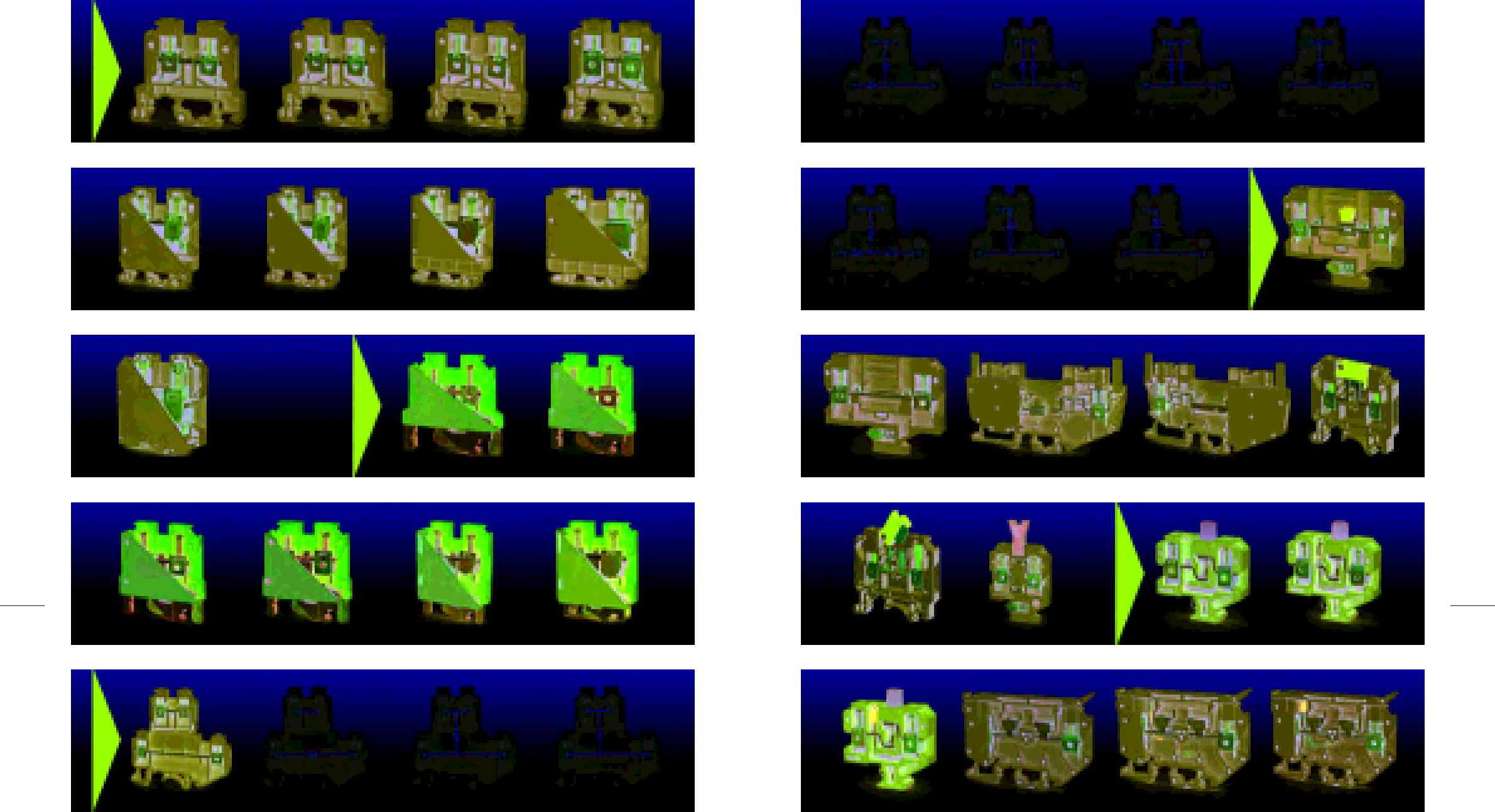
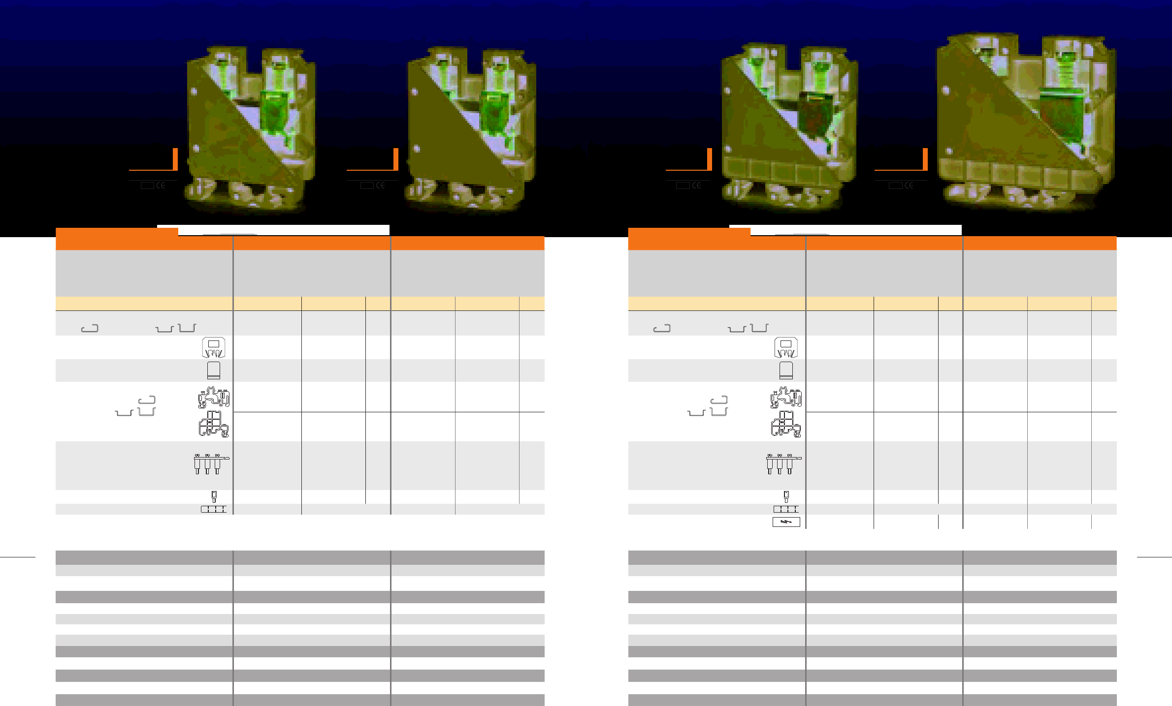
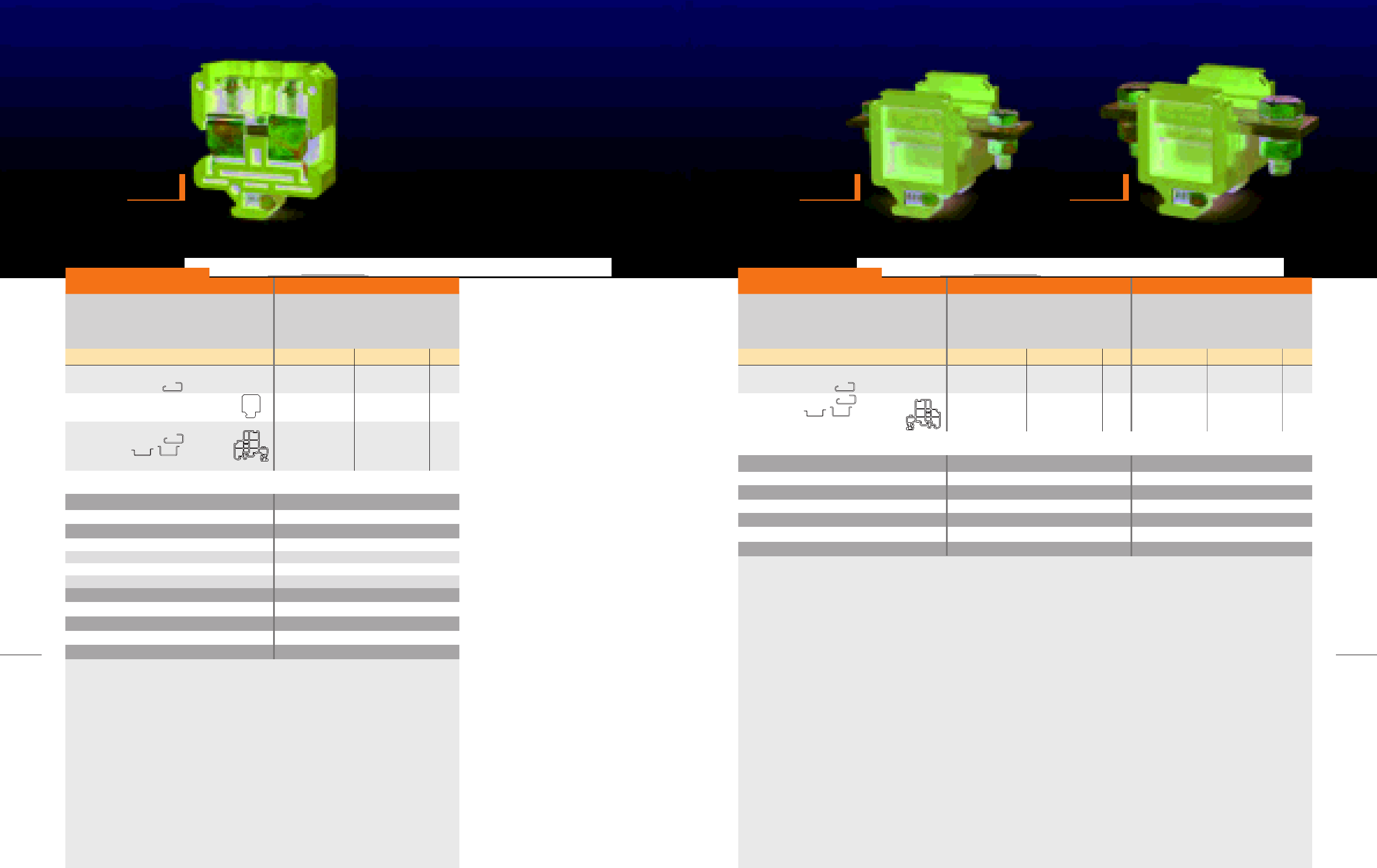
Raad double level terminal blocks enjoy the spase-saving
advantage. It is remarkable in this type of terminal that the upper
level is offset laterally by half of the terminal block width. The
following advantages are met, due to the double wiring density:
Accessibility of the lower level screw is more effective with a screw
driver and
Lower labels and entry points can be viewed better
The EP3 end plate and the EP2 end plate compensates for the level
offset at the beginning and the end of the terminal strips, so that
standard terminal blocks can be directly aligned.
As for foot connection, they can be mounted on either of the TH 35
or G 32 mounting rails.
DOUBLE LEVEL
TERMINAL BLOCKS
18
MODULAR TERMINAL BLOCKS / 2005
RET16
width 12.5 mm
RET35
width 16.5 mm
IEC 60947-7-2 rated data
Impulse voltage (kV)
Pollution degre/Voltage category/Material group
Current (A)
Cross - section (mm2)
8
3/III/I
76
16
8
3/III/I
125
35
RET16 RET35
Terminal block, for mounting on
G 32 ,TH 35-7.5, 15
Marking
Description Type Ordering No. Qty. Type Ordering No. Qty.
RET 16
NS8
20101205
For details see Accessories
RET 35
NS8
101206
For details see Accessories
20
0.5-16
0.5-16
0.5-16
20-4
B7
12.3
M5/2.5
M4/1.2
PA 6.6
Connection capacity
Solid (mm2)
Multi stranded (mm2)
Flexible (mm2)
American Wire Gauge (AWG)
IEC test gauge
Stripping Iength (mm)
Clamping screw/Tightening torque (N.m)
Center screw/Tightening torque (N.m)
Insulation material
1.5-35
1.5-35
1.5-35
14-1
B9
14.9
M6/3.5
M5/2
PA 6.6
Dimensions (mm)
Width/Length
Hight, G32/TH 35-7.5/TH 35-15
16.5/51.4
67.6/68.5/71
12.2/49.8
65/61/68.5
Raad recommended Raad recommended
1 2 3
20
MODULAR TERMINAL BLOCKS / 2005
21
DOUBLE LEVEL TERMINAL BLOCKS
DRTP4
width 6.4 mm
IEC 60947-7-1 rated data
Voltage(V)/Impulse voltage (kV)
Pollution degre/Voltage category/Material group
Current (A)
Cross - section (mm2)
500/6
3/III/I
32
4
DRTP4
Terminal block, for mounting on
G 32 ,TH 35-7.5, 15
End plate 1
width (mm)
End plate 2
width (mm)
End plate 3
width (mm)
Partition
width (mm)
Small partition
no loss of pitch
End bracket, for G 32
TH 35- 7.5, 15
width (mm) Raad recommended
Cross-connection
max. current (A)
Test socket
Marking
Description Type Ordering No. Qty.
0.5-4
0.5-4
0.5-4
20-12
A4
9
M2.5
0.4
PA 6.6
Connection capacity
Solid (mm2)
Multi stranded (mm2)
Flexible (mm2)
American Wire Gauge (AWG)
IEC test gauge
Stripping Iength (mm)
Clamping screw
Tightening torque (N.m)
Insulation material
Dimensions (mm)
Width/Length
Hight, G32/TH 35-7.5/TH 35-15
6.4/68.4
71.5/67.5/75
DRTP4-D1
width 6.4 mm
IEC 60947-7-1 rated data
Voltage (VAC)
Diode reverse voltage (V)
Current (A)
Diode current (A)
Diode
Cross - section (mm2)
400
1000
32
1
1N4007
4
DRTP4-D1
Terminal block, for mounting on
G 32 ,TH 35-7.5, 15
End plate 1
width (mm)
End plate 2
width (mm)
End plate 3
width (mm)
Partition
width (mm)
Small partition
no loss of pitch
End bracket, for G 32
TH 35- 7.5, 15
width (mm) Raad recommended
Cross-connection
max. current (A)
Test socket
Marking
Description Type Ordering No. Qty.
0.5-4
0.5-4
0.5-4
20-12
A4
9
M2.5
0.4
PA 6.6
Connection capacity
Solid (mm2)
Multi stranded (mm2)
Flexible (mm2)
American Wire Gauge (AWG)
IEC test gauge
Stripping Iength (mm)
Clamping screw
Tightening torque (N.m)
Insulation material
Dimensions (mm)
Width/Length
Hight, G32/TH 35-7.5/TH 35-15
6.4/68.4
71.5/67.5/75
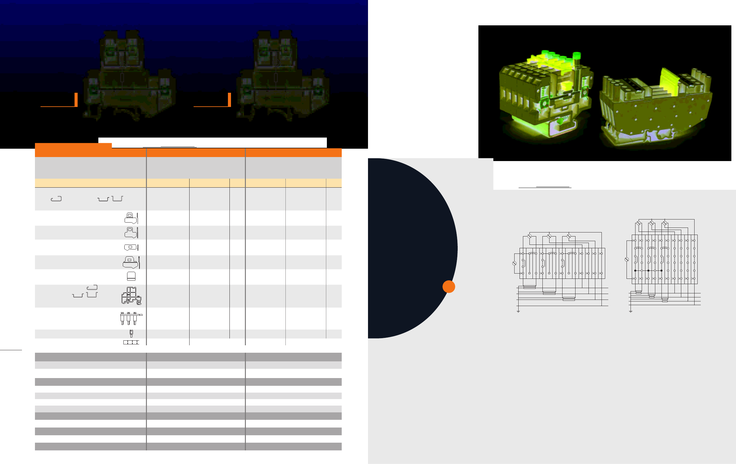
In designing DRTP4, Special capabilities
are offered for installing electronic
elements.
Raad double level terminal blocks are
used for voltage rectifying, monitoring,
fine switching, and test circuits.
Furthermore, a number of circuits, in
which the terminal are applied, are
offered. Any other type of circuit is
offered on request.
Example for rectifying purposes
Example for displying protection status
Example for fine switching a DC load
Example for lamp test circuit
101302
201302
201303
201304
200302
200103
For details see Accessories
201007
201310
201311
201312
200540
50
20
20
20
20
100
50
10
50
50
DRTP4
EP1-DRTP4
EP2-DRTP4
EP3-DRTP4
P-DRTP4
CC10-D4 10-pos.
CC3-D4 3-pos.
CC2-D4 2-pos.
32
TS3/6/2.3
NS6.4
SP-2.5-10
EB/2
10
101310
201302
201303
201304
200302
200103
201007
201310
201311
201312
200540
50
20
20
20
20
100
50
10
50
50
DRTP4-D1
EP1-DRTP4
EP2-DRTP4
EP3-DRTP4
P-DRTP4
CC10-D4 10-pos.
CC3-D4 3-pos.
CC2-D4 2-pos.
32
TS3/6/2.3
NS6.4
SP-2.5-10
EB/2
10
For details see Accessories
1 2 3
+
-
~
-
+
+ -
TEST
0 V
24 V
1 2 3
DRTP4-D2 DRTP4-D3
width 6.4 mm
DRTP4-D4
width 6.4 mm
DRTP4-D5
width 6.4 mm
22
MODULAR TERMINAL BLOCKS / 2005
23
DOUBLE LEVEL TERMINAL BLOCKS
IEC 60947-7-1 rated data
Voltage (VAC)
Diode reverse voltage (V)
Current (A)
Diode current (A)
Diode
Cross - section (mm2)
400
1000
-
1
1N4007
4
400
1000
-
1
1N4007
4
DRTP4-D4 DRTP4-D5
Terminal block, for mounting on
G 32 ,TH 35-7.5, 15
for lamp test circuit
End plate 1
width (mm)
End plate 2
width (mm)
End plate 3
width (mm)
Partition
width (mm)
Small partition
no loss of pitch
End bracket, for G 32
TH 35- 7.5, 15
width (mm) Raad recommended
Cross-connection
max. current (A)
Test socket
Marking
Description Type Ordering No. Qty. Type Ordering No. Qty.
DRTP4-D4
EP1-DRTP4
EP3-DRTP4
EB/2
10
CC10-D4 10-pos.
CC3-D4 3-pos.
CC2-D4 2-pos.
32
TS3/6/2.3
NS6.4 For details see Accessories
EP2-DRTP4
SP-2.5-10
P-DRTP4
101313
201302
201304
200103
201310
201311
201312
200540
201303
201007
200302
50
20
20
50
10
50
50
50
20
100
20
DRTP4-D5
EP1-DRTP4
EP3-DRTP4
EB/2
10
CC10-D4 10-pos.
CC3-D4 3-pos.
CC2-D4 2-pos.
32
TS3/6/2.3
NS6.4
EP2-DRTP4
SP-2.5-10
P-DRTP4
101314
201302
201304
200103
201310
201311
201312
200540
201303
201007
200302
50
20
20
50
10
50
50
50
20
100
20
For details see Accessories
0.5-4
0.5-4
0.5-4
20-12
A4
9
M2.5
0.4
PA 6.6
Connection capacity
Solid (mm2)
Multi stranded (mm2)
Flexible (mm2)
American Wire Gauge (AWG)
IEC test gauge
Stripping Iength (mm)
Clamping screw
Tightening torque (N.m)
Insulation material
0.5-4
0.5-4
0.5-4
20-12
A4
9
M2.5
0.4
PA 6.6
Dimensions (mm)
Width/Length
Hight, G32/TH 35-7.5/TH 35-15
6.4/68.4
71.5/67.5/75
6.4/68.4
71.5/67.5/75
IEC 60947-7-1 rated data
Voltage (VAC)
Diode reverse voltage (V)
Current (A)
Diode current (A)
Diode
Cross - section (mm2)
400
1000
-
1
1N4007
4
400
1000
-
1
1N4007
4
DRTP4-D2 DRTP4-D3
Terminal block, for mounting on
G 32 ,TH 35-7.5, 15
Freewheeling diode for DC loads
End plate 1
width (mm)
End plate 2
width (mm)
End plate 3
width (mm)
Partition
width (mm)
Small partition
no loss of pitch
End bracket, for G 32
TH 35- 7.5, 15
width (mm) Raad recommended
Cross-connection
max. current (A)
Test socket
Marking
Description Type Ordering No. Qty. Type Ordering No. Qty.
DRTP4-D2
EP1-DRTP4
EP3-DRTP4
EB/2
10
CC10-D4 10-pos.
CC3-D4 3-pos.
CC2-D4 2-pos.
32
TS3/6/2.3
NS6.4 For details see Accessories
EP2-DRTP4
SP-2.5-10
P-DRTP4
101311
201302
201304
200103
201310
201311
201312
200540
201303
201007
200302
50
20
20
50
10
50
50
50
20
100
20
DRTP4-D3
EP1-DRTP4
EP3-DRTP4
EB/2
10
CC10-D4 10-pos.
CC3-D4 3-pos.
CC2-D4 2-pos.
32
TS3/6/2.3
NS6.4
EP2-DRTP4
SP-2.5-10
P-DRTP4
101312
201302
201304
200103
201310
201311
201312
200540
201303
201007
200302
50
20
20
50
10
50
50
50
20
100
20
For details see Accessories
0.5-4
0.5-4
0.5-4
20-12
A4
9
M2.5
0.4
PA 6.6
Connection capacity
Solid (mm2)
Multi stranded (mm2)
Flexible (mm2)
American Wire Gauge (AWG)
IEC test gauge
Stripping Iength (mm)
Clamping screw
Tightening torque (N.m)
Insulation material
0.5-4
0.5-4
0.5-4
20-12
A4
9
M2.5
0.4
PA 6.6
Dimensions (mm)
Width/Length
Hight, G32/TH 35-7.5/TH 35-15
6.4/68.4
71.5/67.5/75
6.4/68.4
71.5/67.5/75
width 6.4 mm
1 2 31 2 3
24
MODULAR TERMINAL BLOCKS / 2005
25
DOUBLE LEVEL TERMINAL BLOCKS
DRTP4-DR1
width 6.4 mm
DRTP4-DR2
width 6.4 mm
IEC 60947-7-1 rated data
Voltage (VDC)
Diode reverse voltage (V)
Current (A)
Diode current (A)
Diode
Resistor
Cross - section (mm2)
24
1000
-
1
1N4007
1.5kΩ
4
24
1000
-
1
1N4007
1.5kΩ
4
DRTP4-DR1 DRTP4-DR2
Terminal block, for mounting on
G 32 ,TH 35-7.5, 15
for lamp test circuit with resistor
End plate 1
width (mm)
End plate 2
width (mm)
End plate 3
width (mm)
Partition
width (mm)
Small partition
no loss of pitch
End bracket, for G 32
TH 35- 7.5, 15
width (mm) Raad recommended
Cross-connection
max. current (A)
Test socket
Marking
Description Type Ordering No. Qty. Type Ordering No. Qty.
DRTP4-DR1
EP1-DRTP4
EP3-DRTP4
EB/2
10
CC10-D4 10-pos.
CC3-D4 3-pos.
CC2-D4 2-pos.
32
TS3/6/2.3
NS6.4 For details see Accessories
EP2-DRTP4
SP-2.5-10
P-DRTP4
101316
201302
201304
200103
201310
201311
201312
200540
201303
201007
200302
50
20
20
50
10
50
50
50
20
100
20
DRTP4-DR2
EP1-DRTP4
EP3-DRTP4
EB/2
10
CC10-D4 10-pos.
CC3-D4 3-pos.
CC2-D4 2-pos.
32
TS3/6/2.3
NS6.4
EP2-DRTP4
SP-2.5-10
P-DRTP4
101317
201302
201304
200103
201310
201311
201312
200540
201303
201007
200302
50
20
20
50
10
50
50
50
20
100
20
For details see Accessories
0.5-4
0.5-4
0.5-4
20-12
A4
9
M2.5
0.4
PA 6.6
Connection capacity
Solid (mm2)
Multi stranded (mm2)
Flexible (mm2)
American Wire Gauge (AWG)
IEC test gauge
Stripping Iength (mm)
Clamping screw
Tightening torque (N.m)
Insulation material
0.5-4
0.5-4
0.5-4
20-12
A4
9
M2.5
0.4
PA 6.6
Dimensions (mm)
Width/Length
Hight, G32/TH 35-7.5/TH 35-15
6.4/68.4
71.5/67.5/75
6.4/68.4
71.5/67.5/75
DRTP4-D6
width 6.4 mm
IEC 60947-7-1 rated data
Voltage (VAC)
Diode reverse voltage (V)
Current (A)
Diode current (A)
Diode
Cross - section (mm2)
400
1000
-
1
1N4007
4
DRTP4-D6
Terminal block, for mounting on
G 32 ,TH 35-7.5, 15
for lamp test circuit
End plate 1
width (mm)
End plate 2
width (mm)
End plate 3
width (mm)
Partition
width (mm)
Small partition
no loss of pitch
End bracket, for G 32
TH 35- 7.5, 15
width (mm) Raad recommended
Cross-connection
max. current (A)
Test socket
Marking
Description Type Ordering No. Qty.
DRTP4-D6
EP1-DRTP4
EP3-DRTP4
EB/2
10
CC10-D4 10-pos.
CC3-D4 3-pos.
CC2-D4 2-pos.
32
TS3/6/2.3
NS6.4 For details see Accessories
EP2-DRTP4
SP-2.5-10
P-DRTP4
101315
201302
201304
200103
201310
201311
201312
200540
201303
201007
200302
50
20
20
50
10
50
50
50
20
100
20
0.5-4
0.5-4
0.5-4
20-12
A4
9
M2.5
0.4
PA 6.6
Connection capacity
Solid (mm2)
Multi stranded (mm2)
Flexible (mm2)
American Wire Gauge (AWG)
IEC test gauge
Stripping Iength (mm)
Clamping screw
Tightening torque (N.m)
Insulation material
Dimensions (mm)
Width/Length
Hight, G32/TH 35-7.5/TH 35-15
6.4/68.4
71.5/67.5/75
1 2 3
1 2 3
DRTP4-LD
width 6.4 mm
DRTP4-NL
width 6.4 mm
IEC 60947-7-1 rated data
Voltage
LED or Neon lamp current
Cross - section (mm2)
24VDC
<5mA
4
115-230VAC
<5mA
4
DRTP4-LD DRTP4-NL
Terminal block, for mounting on
G 32 ,TH 35-7.5, 15
DC and AC voltage indicator
End plate 1
width (mm)
End plate 2
width (mm)
End plate 3
width (mm)
Partition
width (mm)
Small partition
no loss of pitch
End bracket, for G 32
TH 35- 7.5, 15
width (mm) Raad recommended
Cross-connection
max. current (A)
Test socket
Marking
Description Type Ordering No. Qty. Type Ordering No. Qty.
DRTP4-LD
DC voltage indicator
EP1-DRTP4
EP3-DRTP4
EB/2
10
CC10-D4 10-pos.
CC3-D4 3-pos.
CC2-D4 2-pos.
32
TS3/6/2.3
NS6.4 For details see Accessories
EP2-DRTP4
SP-2.5-10
P-DRTP4
101318
201302
201304
200103
201310
201311
201312
200540
201303
201007
200302
50
20
20
50
10
50
50
50
20
100
20
DRTP4-NL
AC voltage indicator
EP1-DRTP4
EP3-DRTP4
EB/2
10
CC10-D4 10-pos.
CC3-D4 3-pos.
CC2-D4 2-pos.
32
TS3/6/2.3
NS6.4
EP2-DRTP4
SP-2.5-10
P-DRTP4
101319
201301
201304
200103
201310
201311
201312
200540
201303
201007
200302
50
20
20
50
10
50
50
50
20
100
20
For details see Accessories
0.5-4
0.5-4
0.5-4
20-12
A4
9
M2.5
0.4
PA 6.6
Connection capacity
Solid (mm2)
Multi stranded (mm2)
Flexible (mm2)
American Wire Gauge (AWG)
IEC test gauge
Stripping Iength (mm)
Clamping screw
Tightening torque (N.m)
Insulation material
0.5-4
0.5-4
0.5-4
20-12
A4
9
M2.5
0.4
PA 6.6
Dimensions (mm)
Width/Length
Hight, G32/TH 35-7.5/TH 35-15
6.4/68.4
71.5/67.5/75
6.4/68.4
71.5/67.5/75
26
MODULAR TERMINAL BLOCKS / 2005
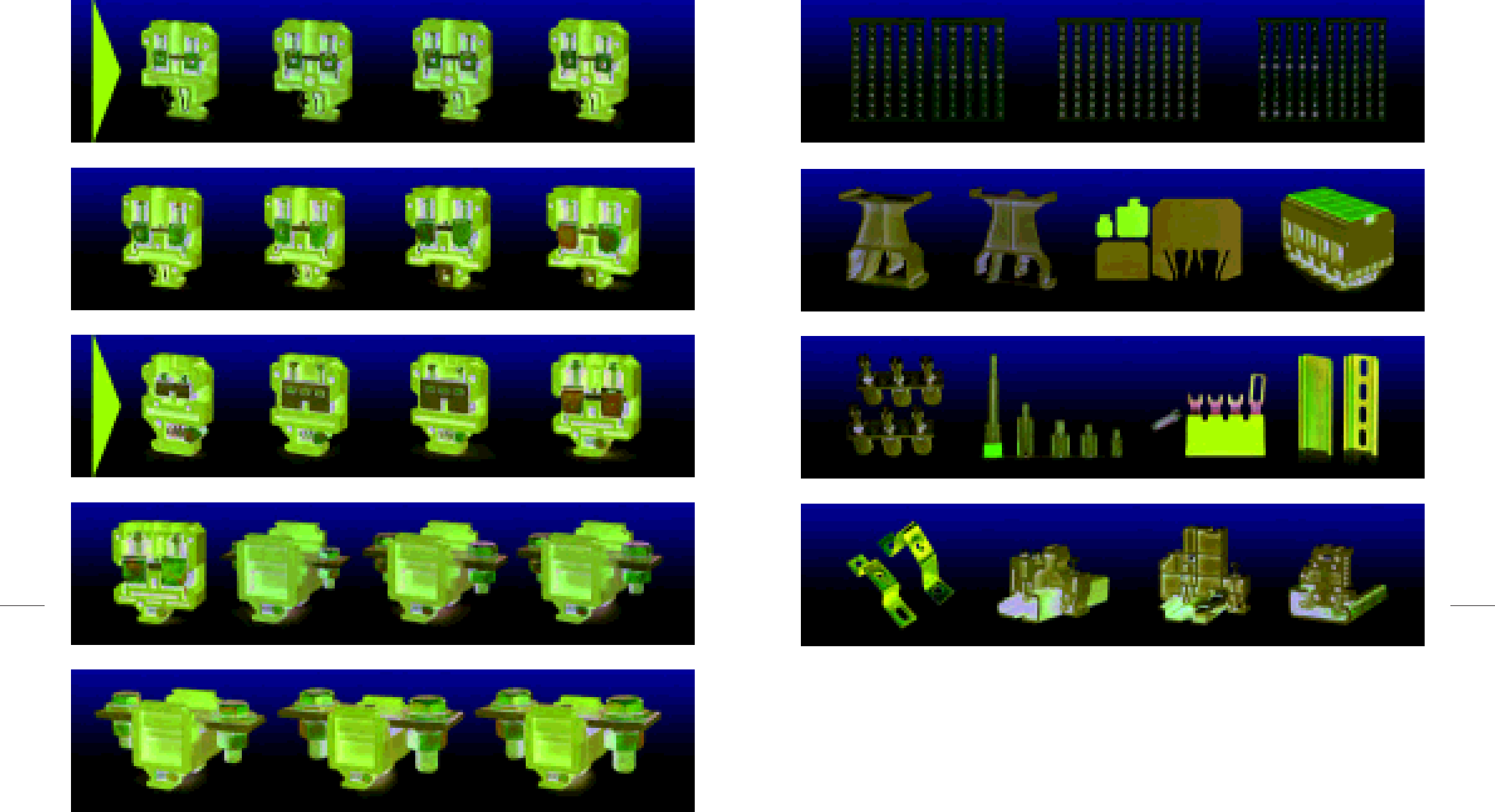
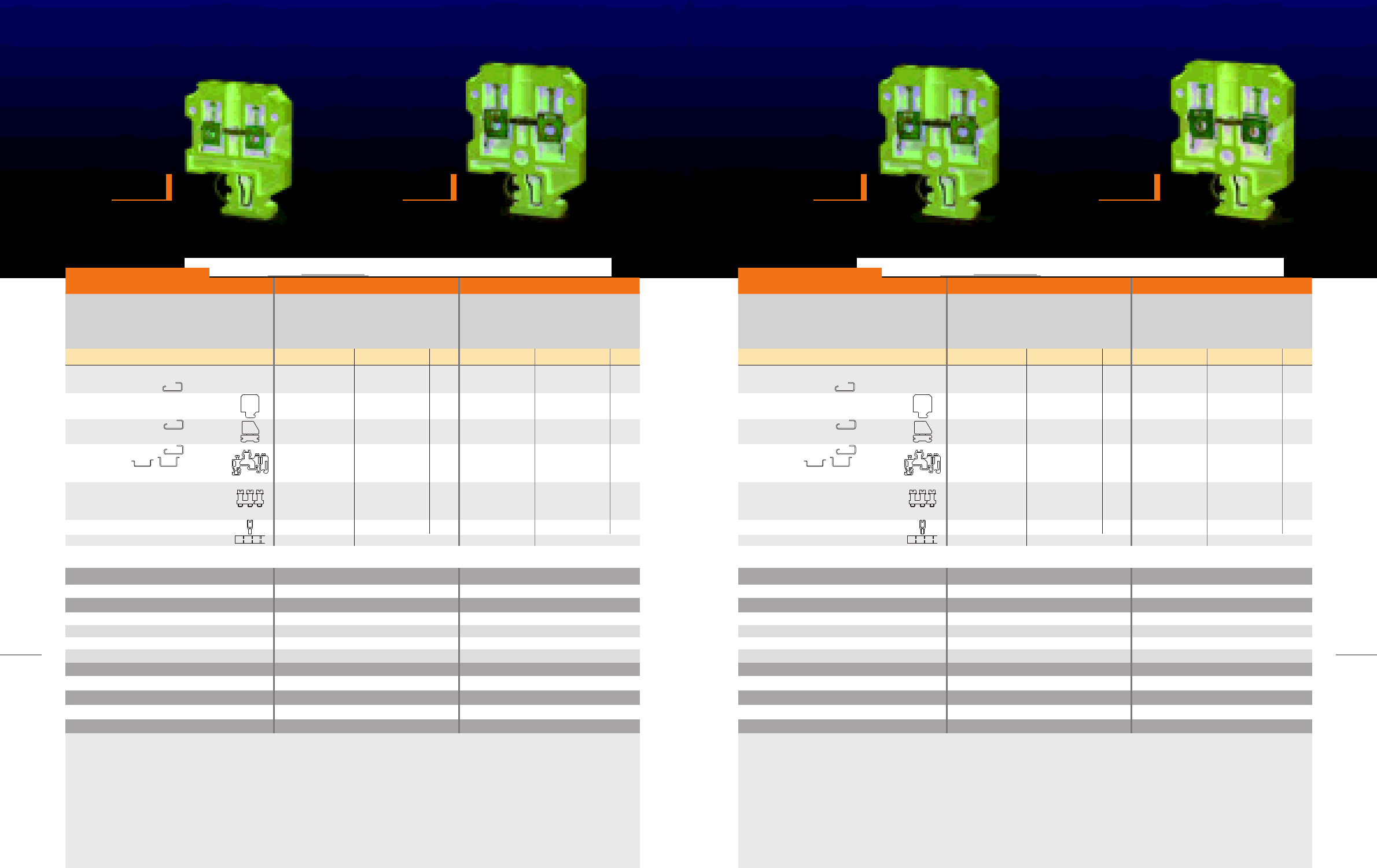
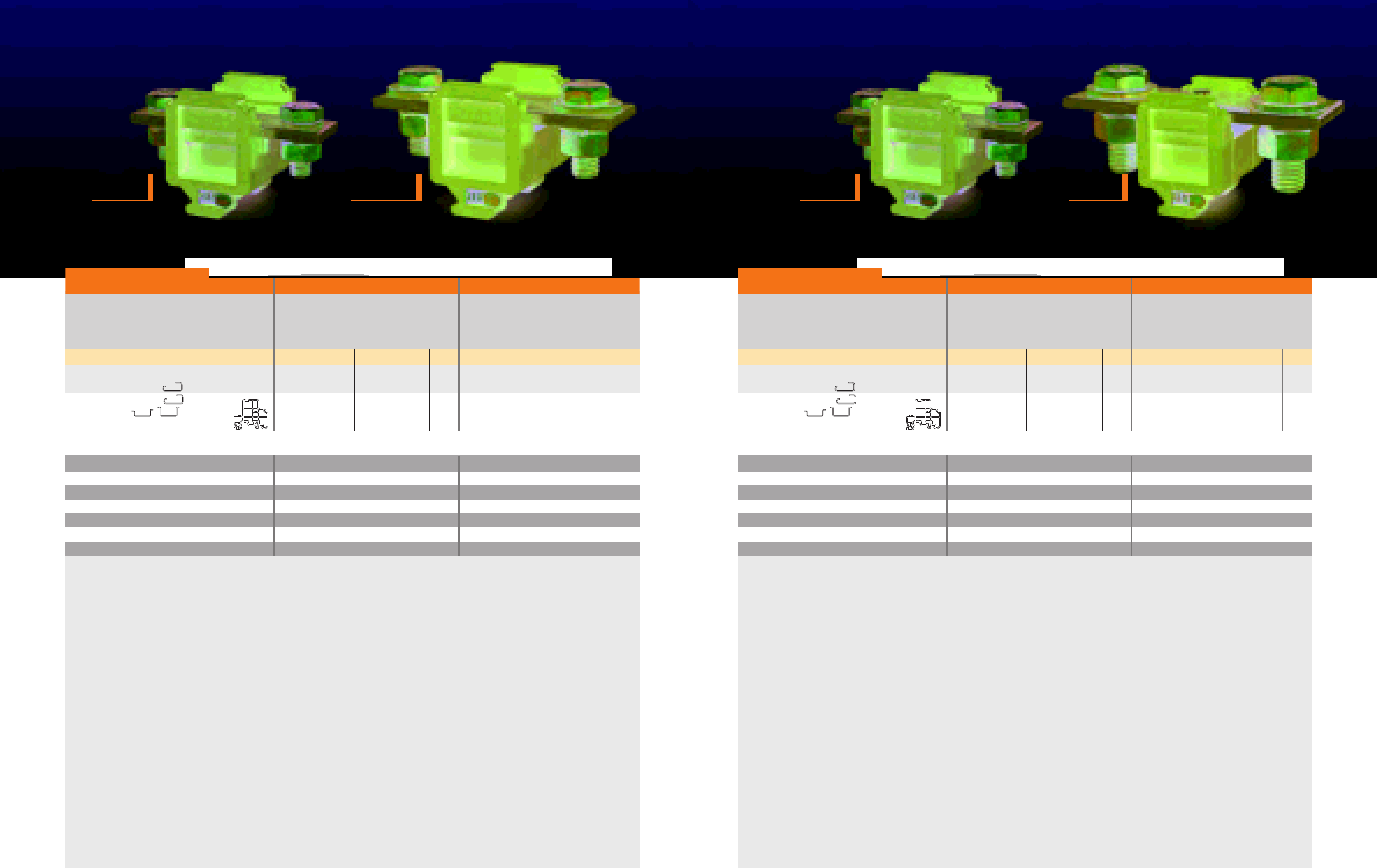
In measuring, control and remote - controlled systems test and
disconnect terminals are often installed.
A typical circuit can be considered for each of the above
mentioned items.RCTL2, RCTLU2, STC6, and new types such as
RST6, RTT6, RDT4, accompanied by their relating accessories,
can be mounted in all types of circuits specified in this field,
including secondary circuits for current transformers.
TEST DISCONNECT
TERMINAL BLOCKS
Wattmeter test circuit, designed with 10
RST6 and RTT6
Wattmeter test circuit, designed with 13
RCT-L2 and RCT-LU2
N
L3
L2
L1
12 13
L3 N
10 11
L1 L2
5 63 4
lK
21 87 9
lK lK
1 2
K l K
43
K
65
L2L1
87
NL3
109
L1
L2
L3
N
l l
1 2 3
0.5-10
0.5-10
0.5-6
20-8
A5
12
M3.5/1.2
M3/0.5
PA 6.6
Connection capacity
Solid (mm2)
Multi stranded (mm2)
Flexible (mm2)
American Wire Gauge (AWG)
IEC test gauge
Stripping Iength (mm)
Clamping screw/Tightening torque (N.m)
Center screw/Tightening torque (N.m)
Insulation material
0.5-10
0.5-10
0.5-6
20-8
A5
12
M3.5/1.2
-
PA 6.6
Dimensions (mm)
Width/Length
Hight, G32/TH 35-7.5/TH 35-15
8/107
65/61.5/69
8/107
65/61.5/69
28
MODULAR TERMINAL BLOCKS / 2005
29
TEST DISCONNECT TERMINAL BLOCKS
RCT-L2
width 8 mm
RCT-LU2
width 8 mm
RST6
width 8 mm
RTT6
width 8 mm
KEMA
EUR
IEC 60947-7-1 rated data
Voltage (V) / Impulse voltage (kV)
Pollution degree/Voltage category/Material group
Current (A)
Cross - section (mm2)
400/6
3/III/I
32
6
400/6
3/III/I
32
6
RST6 RTT6
Test disconnect terminal, for
mounting on G 32
TH 35-7.5,15
Moveable cross-connection, for 2
terminal blocks, with
2 screws
max. current (A)
Moveable cross-connection, for
3 terminal blocks, with
3 screws
max. current (A)
Moveable cross-connection, for
4 terminal blocks, with
4 screws
max. current (A)
Cross-connection
max. current (A)
End bracket, for G 32
TH 35- 7.5, 15
width (mm) Raad recommended
Marking
Description Ordering No. Qty. Type Ordering No. Qty.
100912 20
For details see Accessories
RST6
ML2N
32
ML4N
32
ML3N
32
NS8
200708
200709
200712
50
50
25
50
IEC 60947-7-1 rated data
Voltage (V) / Impulse voltage (kV)
Pollution degree/Voltage category/Material group
Current (A)
Cross - section (mm2)
400/6
3/III/I
32
6
400/6
3/III/I
32
6
RCT-L2 RCT-LU2
Test disconnect terminal, for
mounting on G 32
End plate
width (mm)
End bracket, for G 32
width (mm) Raad recommended
End bracket, for G 32
TH 35- 7.5, 15
width (mm) Raad recommended
Moveable cross-connection, for 2
terminal blocks, with 2 test socket
screws and 2 sleeves
max. current (A)
Moveable cross-connection, for
4 terminal blocks, with 4 test socket
screws and 4 sleeves
max. current (A)
Moveable cross-connection, for
2 terminal blocks, with 2 screws and
2 sleeves
max. current (A)
Moveable cross-connection, for 4
terminal blocks, with 4 screws
and 4 sleeves
max. current (A)
Test socket
Marking
Description Type Ordering No. Qty. Type Ordering No. Qty.
100902 50
For details see Accessories For details see Accessories
RCT-L2
EP-L2,LU2
2
EB/1
9.5
ML2A
24
EB32
8
ML4A
24
ML2B
24
ML4B
24
TS3/14/4
NS6
200710
200101
200102
200706
200707
200701
200702
200703
50
50
50
100
50
100
50
50
100901 50RCT-LU2
EP-L2,LU2
2
EB/1
9.5
ML2A
24
EB32
8
ML4A
24
ML2B
24
ML4B
24
TS3/14/4
200710
200101
200102
200706
200707
200701
200702
200703
50
50
50
100
50
100
50
50
NS6
0.5-10
0.5-10
0.5-6
20-8
A5
12
M3.5/1.2
M3/0.5
PA 6.6
Connection capacity
Solid (mm2)
Multi stranded (mm2)
Flexible (mm2)
American Wire Gauge (AWG)
IEC test gauge
Stripping Iength (mm)
Clamping screw/Tightening torque (N.m)
Center screw/Tightening torque (N.m)
Insulation material
0.5-10
0.5-10
0.5-6
20-8
A5
12
M3.5/1.1
-
PA 6.6
Dimensions (mm)
Width/Length/Hight, G32 8/64/52.58/64/52.5
CC10-6 10-pos.
CC3-6 3-pos.
CC2-6 2-pos.
47
EB/1
9.5
Type
201026
201027
201028
200102
10
50
50
For details see Accessories
RTT6
ML2N
32
ML4N
32
ML3N
32
NS8
CC10-6 10-pos.
CC3-6 3-pos.
CC2-6 2-pos.
47
EB/1
9.5
100913
200708
200709
200712
201026
201027
201028
200102
20
50
50
25
50
10
50
50
1 2 3
1 2 3
30
MODULAR TERMINAL BLOCKS / 2005
31
TEST DISCONNECT TERMINAL BLOCKS
RDT4
width 6.4 mm
RDT4-TS
width 6.4 mm
STC6
width 6.4 mm
0.5-4
0.5-4
0.5-4
20-12
A4
12
M3
0.5
PA 6.6
Connection capacity
Solid (mm2)
Multi stranded (mm2)
Flexible (mm2)
American Wire Gauge (AWG)
IEC test gauge
Stripping Iength (mm)
Clamping screw
Tightening torque (N.m)
Insulation material
0.5-4
0.5-4
0.5-4
20-12
A4
12
M3
0.5
PA 6.6
Dimensions (mm)
Width/Length
Hight, G32/TH 35-7.5/TH 35-15
6.4/49
51.3/47.4/54.9
6.4/49
51.3/47.4/54.9
IEC 60947-7-1 rated data
Voltage (V) / Impulse voltage (kV)
Pollution degree/Voltage category/Material group
Current (A)
Cross - section (mm2)
500/6
3/III/I
17.5
4
500/6
3/III/I
17.5
4
RDT4 RDT4-TS
Test disconnect terminal, for
mounting on G 32
TH 35-7.5,15
End plate
width (mm)
End bracket, for G 32
width (mm) Raad recommended
End bracket, for G 32
TH 35- 7.5, 15
width (mm) Raad recommended
Bridge-comb
max. current (A)
Marking
Description Ordering No. Qty. Type Ordering No. Qty.
50
For details see Accessories
RDT4
EP-RDT4
EB/1
9.5
EB32
8
100
50
10
Type
BC10-4 10-pos.
12
NS6.4
101401
200404
200102
200101
201410
50
50
For details see Accessories
100
50
10
101401
200404
200102
200101
201410
50
RDT4-TS
with socket screw
EP-RDT4
EB/1
9.5
EB32
8
BC10-4
12
NS6.4
IEC 60947-7-1 rated data
Voltage (V) / Impulse voltage (kV)
Pollution degree/Voltage category/Material group
Current (A)
Cross - section (mm2)
500/6
3/III/I
24
4
STC6
Disconnect terminal, for
mounting on G 32
End plate
width (mm)
End bracket, for G 32
width (mm) Raad recommended
End bracket, for G 32
TH 35- 7.5, 15
width (mm) Raad recommended
Marking
Description Ordering No. Qty.
100
For details see Accessories
STC6
EP-STC6
1.5
EB/1
9.5
EB32
8
100
50
Type
NS6
100701
200401
200101
200102 50
0.5-4
0.5-4
0.5-4
20-12
A4
12
M3
0.5
PA 6.6
Connection capacity
Solid (mm2)
Multi stranded (mm2)
Flexible (mm2)
American Wire Gauge (AWG)
IEC test gauge
Stripping Iength (mm)
Clamping screw
Tightening torque (N.m)
Insulation material
Dimensions (mm)
Width/Length/Hight, G32 6.4/39.5/66
1 2 3
1 2 3

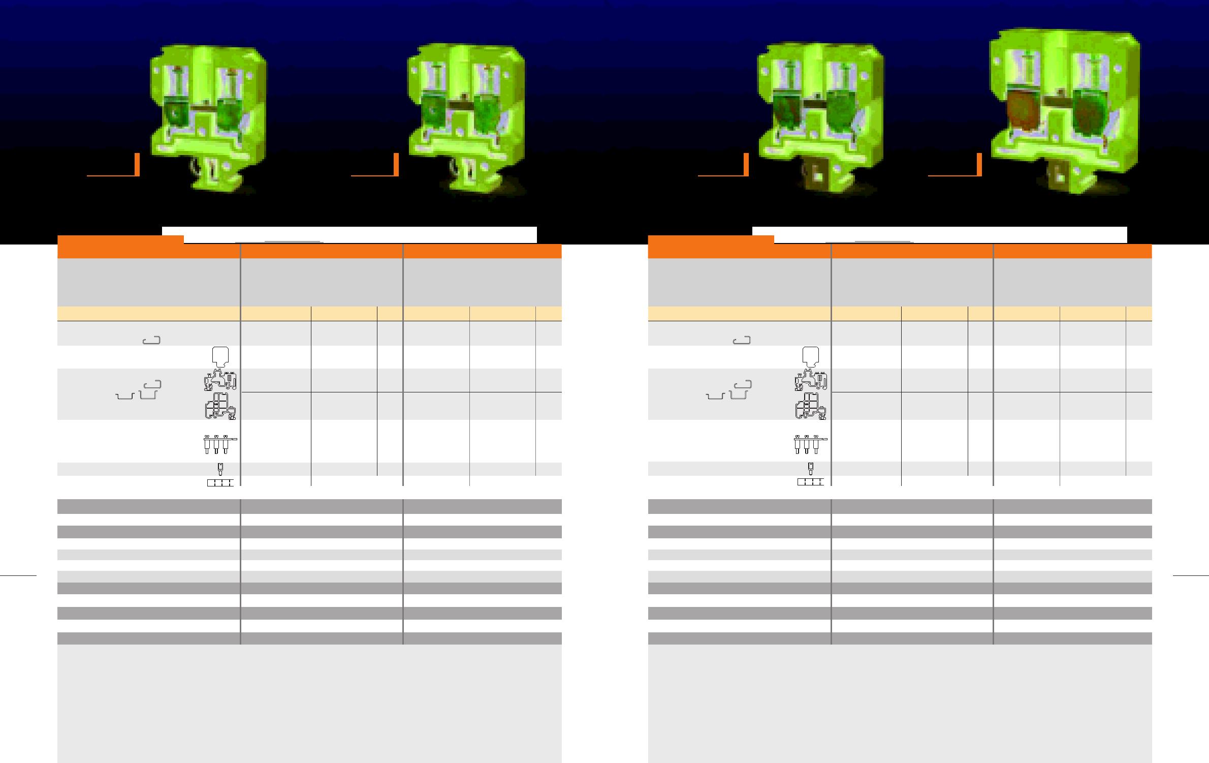
In accordance with the electrical standards, all electrical equipment
control systems and machines must be protected with fuse cartridges,
thus fuse terminal blocks have been developed to meet these standards
and requirements.
The technical data of the fuse terminal blocks, for the protection of
electrical devices, is bound to the application and the use of products.
In RCTF type, the fuse cartridge is inserted in terminal block together
with the screw cap. The terminal block is furnished with a light indicator
which signalizes when the fuse blows.
The RFT type holds different segments: The base terminal block and
the upper hinged-type fuse carrier.
The RFT type is equipped with indicator light, RCTF type alike,
functioning similarly. Another advantage of the RFT type which
distinguishes it from other types is its bonus to carry a spare fuse
cartridge inside the terminal cartridge.
FUSE
TERMINAL BLOCKS
FUSE TERMINAL BLOCKS
34
MODULAR TERMINAL BLOCKS / 2005
35
FUSE TERMINAL BLOCKS
RCTF10
width 13 mm
RCTF10-NL
width 13 mm
RCTF10-LD
width 13 mm
RCTF10-LD
width 13 mm
IEC 60947-7-1 rated data
Voltage (V) / Impulse voltage (kV)
Pollution degree/Voltage category/Material group
Current (A)
Cross - section (mm2)
400/6
3/III/I
6.3
10
-
3/III/I
6.3
10
RCTF10 RCTF10-NL
Fuse terminal block, without
indicator, for mounting on G 32 ,
for fuse cartridge 5*20 and 5*25mm
Fuse terminal block, with neon lamp,
for mounting on G 32 , for fuse
cartridge 5*20 and 5*25mm
End plate
width (mm)
End bracket, for G 32
width (mm) Raad recommended
End bracket, for G 32
TH 35- 7.5, 15
width (mm) Raad recommended
Test socket
Description Type Ordering No. Qty. Type Ordering No. Qty.
100801 20RCTF10
EP-RCTF10
3
EB/1
9.5
TS3/8/4
EB32
8
200901
200101
200102
200541
20
50
50
50
0.5-16
0.5-16
0.5-10
20-6
B6
12
M4
1.5
MF 150
Connection capacity
Solid (mm2)
Multi stranded (mm2)
Flexible (mm2)
American Wire Gauge (AWG)
IEC test gauge
Stripping Iength (mm)
Clamping screw
Tightening torque (N.m)
Insulation material
0.5-16
0.5-16
0.5-10
20-6
B6
12
M4
1.5
MF 150
Dimensions (mm)
Width/Length/Hight, G32 13/53.6/51.113/53.6/51.1
100802 20
RCTF10-NL
110-250VAC
EP-RCTF10
3
EB/1
9.5
EB32
8
200901
200101
200102
20
50
50
IEC 60947-7-1 rated data
Voltage (V) / Impulse voltage (kV)
Pollution degree/Voltage category/Material group
Current (A)
Cross - section (mm2)
-
3/III/I
6.3
10
-
3/III/I
6.3
10
RCTF10-LD RCTF10-LD
Fuse terminal block, with LED,
for mounting on G 32 , for fuse
cartridge 5*20 and 5*25mm
End plate
width (mm)
End bracket, for G 32
width (mm) Raad recommended
End bracket, for G 32
TH 35- 7.5, 15
width (mm) Raad recommended
Description Type Ordering No. Qty. Type Ordering No. Qty.
100803 20
RCTF10-LD
24VDC,48VAC
EB32
8
EB/1
9.5
200901
200101
200102
20
50
50
0.5-16
0.5-16
0.5-10
20-6
B6
12
M4
1.5
MF 150
Connection capacity
Solid (mm2)
Multi stranded (mm2)
Flexible (mm2)
American Wire Gauge (AWG)
IEC test gauge
Stripping Iength (mm)
Clamping screw
Tightening torque (N.m)
Insulation material
0.5-16
0.5-16
0.5-10
20-6
B6
12
M4
1.5
MF 150
Dimensions (mm)
Width/Length/Hight, G32 13/53.6/59.513/53.6/59.5
EP-RCTF10
3
100804 20
RCTF10-LD
40-60VDC,
80-120VAC
EB32
8
EB/1
9.5
200901
200101
200102
20
50
50
EP-RCTF10
3
* Other voltages available upon request
36
MODULAR TERMINAL BLOCKS / 2005
37
FUSE TERMINAL BLOCKS
RFT5
width 8 mm
RFT5-NL
width 8 mm
IEC 60947-7-1 rated data
Voltage (V) / Impulse voltage (kV)
Pollution degree/Voltage category/Material group
Current (A)
Cross - section (mm2)
800/8
3/III/I
6.3
6
-
3/III/I
6.3
6
RFT5 RFT5-NL
Fuse terminal block, without
indicator, for mounting on G 32 ,
TH 35- 7.5, 15
for fuse cartridge 5*20 and 5*25mm
Fuse terminal block, with neon lamp,
for mounting on G 32 ,
TH 35- 7.5, 15
for fuse cartridge 5*20 and 5*25mm
End bracket, for G 32
width (mm) Raad recommended
End bracket, for G 32
TH 35- 7.5, 15
width (mm) Raad recommended
Marking
Description Type Ordering No. Qty. Type Ordering No. Qty.
For details see Accessories
RFT5
EB/1
9.5
NS8
EB32
8
100805
200101
200102
20
50
50
RFT5-NL
110-250VAC
EB/1
9.5
NS8
EB32
8
100807
200101
200102
20
50
50
For details see Accessories
0.5-10
0.5-10
0.5-6
20-8
A5
12
M3.5
1.2
PA 6.6
Connection capacity
Solid (mm2)
Multi stranded (mm2)
Flexible (mm2)
American Wire Gauge (AWG)
IEC test gauge
Stripping Iength (mm)
Clamping screw
Tightening torque (N.m)
Insulation material
0.5-10
0.5-10
0.5-6
20-8
A5
12
M3.5
1.2
PA 6.6
Dimensions (mm)
Width/Length
Hight, G32/TH 35-7.5/TH 35-15
8/72.5
59.4/55.6/63.1
8/72.5
59.4/55.6/63.1
20
RFT5-LD
width 8 mm
IEC 60947-7-1 rated data
Voltage (V) / Impulse voltage (kV)
Pollution degree/Voltage category/Material group
Current (A)
Cross - section (mm2)
-
3/III/I
6.3
6
RFT5-LD
Fuse terminal block, with LED,
for mounting on G 32 ,
TH 35- 7.5, 15
for fuse cartridge 5*20 and 5*25mm
End bracket, for G 32
width (mm) Raad recommended
End bracket, for G 32
TH 35- 7.5, 15
width (mm) Raad recommended
Marking
Description Type Ordering No. Qty.
100806 20
RFT5-LD
12-24VDC
24-48VAC
EB32
8
EB/1
9.5
200101
200102
50
50
NS8
0.5-10
0.5-10
0.5-6
20-8
A5
12
M3.5
1.2
PA 6.6
Connection capacity
Solid (mm2)
Multi stranded (mm2)
Flexible (mm2)
American Wire Gauge (AWG)
IEC test gauge
Stripping Iength (mm)
Clamping screw
Tightening torque (N.m)
Insulation material
Dimensions (mm)
Width/Length
Hight, G32/TH 35-7.5/TH 35-15
8/72.5
59.4/55.6/63.1
For details see Accessories
* Other voltages available upon request
1 2 3
1 2 3

Raad Manufacturing Company initiated manufacturing RTP series in
two colour varieties, gray and blue, and has, honorably, succeed to
turn the series in eleven colours in order to meet its customer’s demands
and provide them other opportunities to handle through 11-coloured
terminal blocks as the followings:
COLOURED
TERMINAL BLOCKS
Grey
Blue
Light cream
Black
Brown
Red
Orange
Yellow
Green
Violet
White

40
RTP TERMINAL BLOCKS
Melamine moulded products are specialized to resist any deformation
effect and enjoy a very high tracking resistance .This resin has excellent
non-hygroscopic behavior with low humidity absorption, compared
to PA 6.6., having a higher continuous service temperature. Raad
melamine terminals are technically produced and best for working
sites which level of dryness and humidity is in variable conditions.
One disadvantage of melamine terminal blocks in comparison to the
PA 6.6 type is their low flexibility and their lack of disposable feature.
Raad melamine terminal blocks in RCT and RTM series are G32 mounting
rails mountable designed.
RTM SERIES
TERMINAL BLOCKS
42
MODULAR TERMINAL BLOCKS / 2005
43
RTM SERIES
RTM2.5
width 6.2 mm
RTM4
width 6.6 mm
RTM6
width 8 mm
IEC 60947-7-1 rated data
Voltage (V) / Impulse voltage (kV)
Pollution degree/Voltage category/Material group
Current (A)
Cross - section (mm2)
500/6
3/III/I
24
2.5
500/6
3/III/I
32
4
RTM2.5 RTM4
Terminal block,
for mounting on G 32
End Plate
width (mm)
End bracket, for G 32
width (mm) Raad recommended
End bracket, for G 32
TH 35- 7.5, 15
width (mm) Raad recommended
Cross-connection
max. current (A)
Test socket
Marking
Description Type Ordering No. Qty. Type Ordering No. Qty.
For details see Accessories
RTM2.5
EB/1
9.5
NS6
EP-RTM2.5
3
100201
200520
200521
200540
100
10
50
For details see Accessories
EB32
8
CCM10-2.5 10-pos.
CCM4-2.5 4-pos.
16
TS3/6/2.3
200501
200101
200102
100
50
50
50
RTM4
EB/1
9.5
NS6.4
EP-RTM4,6,10
3
200522
200523
200540
50
10
50
EB32
8
CCM10-4 10-pos.
CCM4-4 4-pos.
16
TS3/6/2.3
200101
200102
100
50
50
50
100202
200502
0.5-4
0.5-4
0.5-2.5
20-12
A3
10
M2.5
0.4
MF 150
Connection capacity
Solid (mm2)
Multi stranded (mm2)
Flexible (mm2)
American Wire Gauge (AWG)
IEC test gauge
Stripping Iength (mm)
Clamping screw
Tightening torque (N.m)
Insulation material
Dimensions (mm)
Width/Length/Hight, G32 6.2/36.2/46.2
0.5-4
0.5-4
0.5-4
20-12
A4
12
M3
0.5
MF 150
6.6/39.8/51.5
RTM10
width 10 mm
IEC 60947-7-1 rated data
Voltage (V) / Impulse voltage (kV)
Pollution degree/Voltage category/Material group
Current (A)
Cross - section (mm2)
500/6
3/III/I
41
6
500/6
3/III/I
57
10
RTM6 RTM10
Terminal block,
for mounting on G 32
End Plate
width (mm)
End bracket, for G 32
width (mm) Raad recommended
End bracket, for G 32
TH 35- 7.5, 15
width (mm) Raad recommended
Cross-connection
max. current (A)
Test socket
Marking
Description Type Ordering No. Qty. Type Ordering No. Qty.
For details see Accessories
RTM6
EB/1
9.5
NS6.4
EP-RTM4,6,10
3
100203
200524
200525
200541
50
10
50
For details see Accessories
EB32
8
CCM10-6 10-pos.
CCM4-6 4-pos.
24
TS3/8/4
200502
200101
200102
100
50
50
50
0.5-10
0.5-10
0.5-6
20-8
A5
12
M3.5
1.2
MF 150
Connection capacity
Solid (mm2)
Multi stranded (mm2)
Flexible (mm2)
American Wire Gauge (AWG)
IEC test gauge
Stripping Iength (mm)
Clamping screw
Tightening torque (N.m)
Insulation material
Dimensions (mm)
Width/Length/Hight, G32 8/39.8/51.5
0.5-16
0.5-16
0.5-10
20-6
B6
12
M4
1.5
MF 150
8/39.8/51.5
RTM10
EB/1
9.5
NS6.4
EP-RTM4,6,10
3
100204
200526
200527
200541
50
10
50
EB32
8
CCM10-10 10-pos.
CCM4-10 4-pos.
30
TS3/8/4
200502
200101
200102
100
50
50
50
1 2 31 2 3
45
RTM SERIES
44
MODULAR TERMINAL BLOCKS / 2005
RTM16
width 13 mm
RTM25
width 14 mm
IEC 60947-7-1 rated data
Voltage (V) / Impulse voltage (kV)
Pollution degree/Voltage category/Material group
Current (A)
Cross - section (mm2)
1000/8
3/III/I
76
16
1000/8
3/III/I
101
25
RTM16 RTM25
Terminal block,
for mounting on G 32
End Plate
width (mm)
End bracket, for G 32
TH 35- 7.5, 15
width (mm) Raad recommended
Cross-connection
max. current (A)
Test socket
Marking
Description Type Ordering No. Qty. Type Ordering No. Qty.
For details see Accessories
RTM16
EB/2
10
NS8
EP-RTM16,25
3
100205
200528
200542
50
10
For details see Accessories
EB/1
9.5
CCM10-16 10-pos.
47
TS3.5/8/4
200503
200102
200103
50
50
50
50
0.5-16
0.5-16
0.5-16
20-4
B7
12.3
M5
2.5
MF 150
Connection capacity
Solid (mm2)
Multi stranded (mm2)
Flexible (mm2)
American Wire Gauge (AWG)
IEC test gauge
Stripping Iength (mm)
Clamping screw
Tightening torque (N.m)
Insulation material
Dimensions (mm)
Width/Length/Hight, G32 13/46.4/61.2
0.5-16
0.5-25
0.5-25
20-3
B7
12.3
M5
2.5
MF 150
13/46.4/61.2
RTM25
EB/2
10
NS8
EP-RTM16,25
3
100206
200529
200543
50
10
EB/1
9.5
CCM10-25 10-pos.
65
TS4/8/4
200503
200102
200103
50
50
50
50
RTM35
width 17.5 mm
RTM50
width 20 mm
IEC 60947-7-1 rated data
Voltage (V) / Impulse voltage (kV)
Pollution degree/Voltage category/Material group
Current (A)
Cross - section (mm2)
1000/8
3/III/I
125
35
1000/8
3/III/I
150
50
RTM35 RTM50
Terminal block,
for mounting on G 32
End Plate
width (mm)
End bracket, for G 32
TH 35- 7.5, 15
width (mm) Raad recommended
Cross-connection
max. current (A)
Test socket
Marking
Description Type Ordering No. Qty. Type Ordering No. Qty.
For details see Accessories
RTM35
EB/2
10
NS8
EP-RTM35
3
100207
200530
200543
20
10
For details see Accessories
EB/1
9.5
CCM10-35 10-pos.
65
TS4/8/4
200504
200102
200103
20
50
50
50
1.5-16
1.5-35
1.5-35
14-1
B9
14.9
M6
3.5
MF 150
Connection capacity
Solid (mm2)
Multi stranded (mm2)
Flexible (mm2)
American Wire Gauge (AWG)
IEC test gauge
Stripping Iength (mm)
Clamping screw
Tightening torque (N.m)
Insulation material
Dimensions (mm)
Width/Length/Hight, G32 17.5/54/67.1
6-16
6-50
10-50
8-0
B10
19
M8
4.5
MF 150
20/68/77.1
RTM50
EB/2
10
NS8
EP-RTM50
3
100208
200531
20
10CCM3-50 3-pos.
180
200506
200103
20
50
1 2 31 2 3
42
RTP TERMINAL BLOCKS
40
RTP TERMINAL BLOCKS
RCT SERIES
TERMINAL BLOCKS
RCT4
width 7 mm
RCT6
width 8 mm
IEC 60947-7-1 rated data
Voltage (V) / Impulse voltage (kV)
Pollution degree/Voltage category/Material group
Current (A)
Cross - section (mm2)
250/4
3/III/I
24
2.5
320/4
3/III/I
41
4
RCT4 RCT6
Terminal block,
for mounting on G 32
End Plate
width (mm)
Partition
width (mm)
End bracket, for G 32
width (mm)
End bracket, for G 32
TH 35- 7.5, 15
width (mm)
Cross-connection
max. current (A)
Description Type Ordering No. Qty. Type Ordering No. Qty.
RCT4
EB32
8
EP-RCT4
3
100101
200220
200221
100
10
50
P-RCT4
3
200201
200210
200101
100
100
50
1-4
1-4
1-2.5
16-12
A3
8
M3
0.5
MF 150
Connection capacity
Solid (mm2)
Multi stranded (mm2)
Flexible (mm2)
American Wire Gauge (AWG)
IEC test gauge
Stripping Iength (mm)
Clamping screw
Tightening torque (N.m)
Insulation material
Dimensions (mm)
Width/Length/Hight, G32 7/28/41
1.5-6
1.5-6
1.5-4
14-10
A4
10
M4
1.2
MF 150
8/34.8/48
RCT6
EB32
8
EP-RCT6
3
100102
200222
200223
50
10
50
P-RCT6
3
CCT10-6 10-pos.
CCT4-6 4-pos.
16
200202
200211
200101
100
100
50
200102EB/1
9.5
50
48
MODULAR TERMINAL BLOCKS / 2005
49
RCT SERIES
RCT16
width 10.2 mm
RCT35
width 16.5 mm
IEC 60947-7-1 rated data
Voltage (V) / Impulse voltage (kV)
Pollution degree/Voltage category/Material group
Current (A)
Cross - section (mm2)
320/4
3/III/I
57
10
500/6
3/III/I
125
25
RCT16 RTM35
Terminal block,
for mounting on G 32
End Plate
width (mm)
Partition
width (mm)
End bracket, for G 32
width (mm) Raad recommended
End bracket, for G 32
TH 35- 7.5, 15
width (mm) Raad recommended
Cross-connection
max. current (A)
Description Type Ordering No. Qty. Type Ordering No. Qty.
RCT16
EB32
8
EP-RCT16
3
100103
200102
50
50
P-RCT16
3
CCT10-16 10-pos.
CCT4-16 4-pos.
24
200203
200212
200101
100
100
50
10
50
EB/1
9.5
200224
200225
RCT35
EB/1
9.5
EP-RCT35
3
100104
200102
20
50
200204 20
EB/2
10 200103 50
2.5-16
2.5-16
2.5-10
12-6
B6
12
M4
1.2
MF 150
Connection capacity
Solid (mm2)
Multi stranded (mm2)
Flexible (mm2)
American Wire Gauge (AWG)
IEC test gauge
Stripping Iength (mm)
Clamping screw
Tightening torque (N.m)
Insulation material
Dimensions (mm)
Width/Length/Hight, G32 10.2/36.8/50
6-16
6-35
10-25
8-2
B8
16
M6
2.5
MF 150
16.5/49.8/62.7
CCT10-4 10-pos.
CCT4-4 4-pos.
16
50
MODULAR TERMINAL BLOCKS / 2005
51
RCT SERIES
RCT50
width 22.5 mm
IEC 60947-7-1 rated data
Voltage (V) / Impulse voltage (kV)
Pollution degree/Voltage category/Material group
Current (A)
Cross - section (mm2)
800/6
3/III/I
150
35
RCT50
Terminal block,
for mounting on G 32
End Plate
width (mm)
End bracket, for G 32
TH 35- 7.5, 15
width (mm) Raad recommended
Description Type Ordering No. Qty.
10-16
10-50
16-35
6-1
B9
18
M8
3.5
MF 150
Connection capacity
Solid (mm2)
Multi stranded (mm2)
Flexible (mm2)
American Wire Gauge (AWG)
IEC test gauge
Stripping Iength (mm)
Clamping screw
Tightening torque (N.m)
Insulation material
Dimensions (mm)
Width/Length/Hight, G32 22.5/59.5/70.7
RCT50
EP-RCT50
3
100105 20
EB/2
10
200205
200103
20
50
RCT70
width 54 mm
RCT95
width 54 mm
IEC 60947-7-1 rated data
Voltage (V) / Impulse voltage (kV)
Pollution degree/Voltage category/Material group
Current (A)
Cross - section (mm2)
1000/8
3/III/I
192
70
1000/8
3/III/I
232
95
RCT70 RCT95
Terminal block,
for mounting on G 32
End bracket, for G 32
TH 35- 7.5, 15
width (mm)Raad recommended
Description Type Ordering No. Qty. Type Ordering No. Qty.
RCT70
EB/2
10
100106 5
200103 50
RCT95
EB/2
10
100107 5
200103 50
16-70
M8
6
MF 150
Connection capacity
Cable lugs DIN 46235
Clamping screw
Tightening torque (N.m)
Insulation material
Dimensions (mm)
Width/Length/Hight, G32 54/80/57
16-95
M10
10
MF 150
54/91/57
52
MODULAR TERMINAL BLOCKS / 2005
53
RCT SERIES
RCT120
width 54 mm
RCT150
width 54 mm
IEC 60947-7-1 rated data
Voltage (V) / Impulse voltage (kV)
Pollution degree/Voltage category/Material group
Current (A)
Cross - section (mm2)
1000/8
3/III/I
269
120
1000/8
3/III/I
309
150
RCT120RCT150
Terminal block,
for mounting on G 32
End bracket, for G 32
TH 35- 7.5, 15
width (mm)Raad recommended
Description Type Ordering No. Qty. Type Ordering No. Qty.
RCT120
EB/2
10
100108 5
200103 50
RCT150
EB/2
10
100109 5
200103 50
16-120
M10
10
MF 150
Connection capacity
Cable lugs DIN 46235
Clamping screw
Tightening torque (N.m)
Insulation material
Dimensions (mm)
Width/Length/Hight, G32 54/91/57
25-150
M12
14
MF 150
54/107/57
RCT185
width 54 mm
RCT240
width 54 mm
IEC 60947-7-1 rated data
Voltage (V) / Impulse voltage (kV)
Pollution degree/Voltage category/Material group
Current (A)
Cross - section (mm2)
1000/8
3/III/I
353
185
1000/8
3/III/I
415
240
RCT185 RCT240
Terminal block,
for mounting on G 32
End bracket, for G 32
TH 35- 7.5, 15
width (mm)Raad recommended
Description Type Ordering No. Qty. Type Ordering No. Qty.
RCT185
EB/2
10
100111 5
200103 50
RCT240
EB/2
10
100110 5
200103 50
50-185
M16
25
MF 150
Connection capacity
Cable lugs DIN 46235
Clamping screw
Tightening torque (N.m)
Insulation material
Dimensions (mm)
Width/Length/Hight, G32 54/122/57
50-240
M16
25
MF 150
54/122/57
40
RTP TERMINAL BLOCKS
Marking
End Plates and Partitions
Cross-Connections
Test Accessories
Mouting Rails and End Brackets
ACCESSORIES
LB/1 LB/2
The NS Quick Marking System
This type of labeling meets the advantage of easy handling. The NS sheets
consist of white polyamide with black printings.
The sheets are labeled horizontally with maximum 3 characters, easy to
read and high-contrast.The hot impressed black printings are absolutely
wiping resistant. One NS sheet consists of 5 strips, includes 10 single tags
that can be simply pushed into the label slots of the terminal blocks. The NS
sheets can be divided at any point and can be manually labeled with ease.
Size
The push-on tags of NS marking system can be requested
in any of the following sizes with or without printed
characters.
1) NS6, used for terminal block width 6 mm or more.
2) NS6.4, used for terminal block width 6.4 mm or more.
3) NS 8, used for terminal block width 8 mm or more.
Packing
The NS sheets are delivered in plastic bags of 10
sheets=50 strips=500 single tags.
NS Special printings
Special printings can be offered on request.
56
MODULAR TERMINAL BLOCKS / 2005
57
Accessories
Marking
Type Size Ord. No. Qty.
(111...)
(222...)
(333...)
(444...)
(555...)
(666...)
(777...)
(888...)
NS6
NS6.4
NS8
NS6
NS6.4
NS8
NS6
NS6.4
NS8
NS6
NS6.4
NS8
NS6
NS6.4
NS8
NS6
NS6.4
NS8
NS6
NS6.4
NS8
NS6
NS6.4
NS8
202001
203001
204001
202005
203005
204005
202009
203009
204009
202013
203013
204013
202017
203017
204017
202021
203021
204021
202025
203025
204025
202029
203029
204029
10
10
10
10
10
10
10
10
10
10
10
10
10
10
10
10
10
10
10
10
10
10
10
10
Type Size Ord. No. Qty.
(999...)
(1010...)
(0...9)
(1...10)
(11...15)
(11...20)
(16...20)
(21...25)
NS6
NS6.4
NS8
NS6
NS6.4
NS8
NS6
NS6.4
NS8
NS6
NS6.4
NS8
NS6
NS6.4
NS8
NS6
NS6.4
NS8
NS6
NS6.4
NS8
NS6
NS6.4
NS8
202033
203033
204033
202037
203037
204037
202035
203034
204034
202041
203041
204053
202042
203042
204042
202077
203045
204077
202043
203043
204043
202047
203047
204047
10
10
10
10
10
10
10
10
10
10
10
10
10
10
10
10
10
10
10
10
10
10
10
10
Group marker carrier, for mounting on G32
TH 35- 7.5, 15
width (mm)
Group marker carrier, for mounting on G32
TH 35- 7.5, 15
width (mm)
Description Type Ordering No. Qty. Material
LB/1
19.5
LB/2
9.5
50
50
PA6.6
PA6.6
200104
200105
Marker carrier for groups of terminal blocks
NS6 Terminal width >6
NS6.4 Terminal width >6.4
NS8 Terminal width >8
58
MODULAR TERMINAL BLOCKS / 2005
59
Accessories
Type Size Ord. No. Qty.
(51...100)
(26...30)
(1...50)
(101...150)
(31...35)
(10...500)
(36...40)
(41...45)
(46...50)
(51...55)
(56...60)
(61...65)
(21...30)
(66...70)
(71...75)
(76...80)
NS6
NS6.4
NS8
NS6
NS6.4
NS8
NS6
NS6.4
NS8
NS6
NS6.4
NS8
NS6
NS6.4
NS8
NS6
NS6.4
NS8
NS6
NS6.4
NS8
NS6
NS6.4
NS8
NS6
NS6.4
NS8
NS6
NS6.4
NS8
NS6
NS6.4
NS8
NS6
NS6.4
NS8
NS6
NS6.4
NS8
NS6
NS6.4
NS8
NS6
NS6.4
NS8
NS6
NS6.4
NS8
202049
203109
204049
202051
203051
204051
202053
203053
204041
202057
203141
204141
202059
203159
204059
202073
203173
204073
202074
203074
204074
202075
203075
204075
202076
203076
204076
202078
203078
204078
202079
203079
204079
202080
203080
204080
202081
203081
204081
202082
203082
204082
202083
203083
204083
202084
203084
204084
10
10
10
10
10
10
10
10
10
10
10
10
10
10
10
10
10
10
10
10
10
10
10
10
10
10
10
10
10
10
10
10
10
10
10
10
10
10
10
10
10
10
10
10
10
10
10
10
Type Size Ord. No. Qty.
(31...40)
(81...50)
(86...90)
(91...95)
(41...50)
(96...100)
(151...200)
(51...66)
(91...100)
(131...140)
(141...150)
(301...350)
(351...400)
(71...80)
(51...60)
(61...70)
NS6
NS6.4
NS8
NS6
NS6.4
NS8
NS6
NS6.4
NS8
NS6
NS6.4
NS8
NS6
NS6.4
NS8
NS6
NS6.4
NS8
NS6
NS6.4
NS8
NS6
NS6.4
NS8
NS6
NS6.4
NS8
NS6
NS6.4
NS8
NS6
NS6.4
NS8
NS6
NS6.4
NS8
NS6
NS6.4
NS8
NS6
NS6.4
NS8
NS6
NS6.4
NS8
NS6
NS6.4
NS8
202085
203085
204085
202086
203086
204086
202087
203087
204087
202088
203088
204088
202089
203057
204089
202090
23090
204090
202129
203111
204142
202134
203124
204134
202099
203059
204165
202094
203063
204063
202104
203064
204064
202116
203116
204016
202107
203117
204107
202157
203056
204157
202149
203054
204149
202153
203055
204153
10
10
10
10
10
10
10
10
10
10
10
10
10
10
10
10
10
10
10
10
10
10
10
10
10
10
10
10
10
10
10
10
10
10
10
10
10
10
10
10
10
10
10
10
10
10
10
10
Type Size Ord. No. Qty.
(251...300)
(201...250)
(111...120)
(121...130)
(101...110)
(100...150)
(401...450)
(451...500)
(81...90)
(LPE...)
(AB...Z)
(UVWN...)
UNPRINTED
(UVW...)
(RSTN...)
(R...)
NS6
NS6.4
NS8
NS6
NS6.4
NS8
NS6
NS6.4
NS8
NS6
NS6.4
NS8
NS6
NS6.4
NS8
NS6
NS6.4
NS8
NS6
NS6.4
NS8
NS6
NS6.4
NS8
NS6
NS6.4
NS8
NS6
NS6.4
NS8
NS6
NS6.4
NS8
NS6
NS6.4
NS8
NS6
NS6.4
NS8
NS6
NS6.4
NS8
NS6
NS6.4
NS8
NS6
NS6.4
NS8
202115
203115
204035
202114
203114
204114
202091
203061
204061
202092
203062
204062
202120
203060
204060
202110
203110
204130
202108
203118
204108
202119
203119
204159
202161
203058
204161
202121
203121
204121
202065
203129
204145
202069
203069
204069
202000
203000
204000
202123
203133
204115
202045
203113
204113
202189
203189
204139
10
10
10
10
10
10
10
10
10
10
10
10
10
10
10
10
10
10
10
10
10
10
10
10
10
10
10
10
10
10
10
10
10
10
10
10
10
10
10
10
10
10
10
10
10
10
10
10
Type Size Ord. No. Qty.
(N...)
(Y...)
(L...)
(1V...)
(2V...)
(3V...)
(BB...)
(UVW...MP)
(1W...)
(2W...)
(3W...)
(---...)
(+++...)
(1U...)
(2U...)
(3U...)
NS6
NS6.4
NS8
NS6
NS6.4
NS8
NS6
NS6.4
NS8
NS6
NS6.4
NS8
NS6
NS6.4
NS8
NS6
NS6.4
NS8
NS6
NS6.4
NS8
NS6
NS6.4
NS8
NS6
NS6.4
NS8
NS6
NS6.4
NS8
NS6
NS6.4
NS8
NS6
NS6.4
NS8
NS6
NS6.4
NS8
NS6
NS6.4
NS8
NS6
NS6.4
NS8
NS6
NS6.4
NS8
202186
203186
204186
202188
203188
204188
202185
203185
204185
202145
203135
204135
202183
203183
204183
202187
203187
204187
202136
203136
204136
202096
203016
204116
202148
203138
204138
202159
203139
204169
202182
203182
204182
202097
203097
204097
202093
203073
204093
202130
203130
204030
202141
203131
204131
202184
203184
204184
10
10
10
10
10
10
10
10
10
10
10
10
10
10
10
10
10
10
10
10
10
10
10
10
10
10
10
10
10
10
10
10
10
10
10
10
10
10
10
10
10
10
10
10
10
10
10
10
End Plate
The last terminal in a row must, in most cases, be covered with
an end plate. Within one terminal strip, composed of various terminal
sizes, end plates should also be interposed. The end plate external
dimensions correspond to the core dimensions of the attendant
terminal. The end plates are held by an end bracket.
Partition
Depending upon the operating voltage, a partition must be fitted
next to cross-connection groups, so that the necessary
clearance and creepage distance can be maintained.
Small Partition
Space-saving partitions can be post-fitted between cross-
connections for terminal blocks.
General Partition
These types of partitions serve for RTP16-50.
60
MODULAR TERMINAL BLOCKS / 2005
61
Accessories
End Plates and Partitions
Cover
Several safety regulations, namely as the accident prevention regulation, require that the
live elements of electrical operating components must be protected against direct contact.
This type is provided only for RTP 50 terminal series.
Type Ord. No. Qty.
200210
200211
200212
201005
201008
201007
201101
201102
201103
200201
200202
200203
200204
200205
200403
200404
201180
200501
200502
200503
200504
200506
200710
200901
201001
201003
RCT4
RCT6
RCT16
RTP2.5
RTP4. 6, 10
RTP2.5-10
RTP16-35
RTP50
-
RCT4
RCT6
RCT16
RCT35
RCT50
STC6
RDT4
RTP50
RTM2.5
RTM4, 6, 10
RTM16,25
RTM35
RTM50
RCTL2,RCTLU2
RCTF10
RTP2.5
RTP4, 6, 10
100
100
100
100
50
100
50
50
20
100
100
100
20
20
100
100
50
100
100
50
20
20
50
20
100
50
Application Material
P-RCT4
P-RCT6
P-RCT16
P-RTP2.5
P-RTP4. 6, 10
SP-RTP2.5-10
SP-16-35
SP-50
GP
EP-RCT4
EP-RCT6
EP-RCT16
EP-RCT35
EP-RCT50
EP-STC6
EP-RDT4
CP-50
EP-RTM2.5
EP-RTM4, 6, 10
EP-RTM16,25
EP-RTM35
EP-RTM50
EP-L2, LU2
EP-RCTF10
EP-RTP2.5
EP-RTP4, 6, 10
MF150
MF150
MF150
PA6.6
PA6.6
PA6.6
PA6.6
PA6.6
PA6.6
MF150
MF150
MF150
MF150
MF150
PA6.6
PA6.6
PA6.6
MF150
MF150
MF150
MF150
MF150
PA6.6
MF150
PA6.6
PA6.6
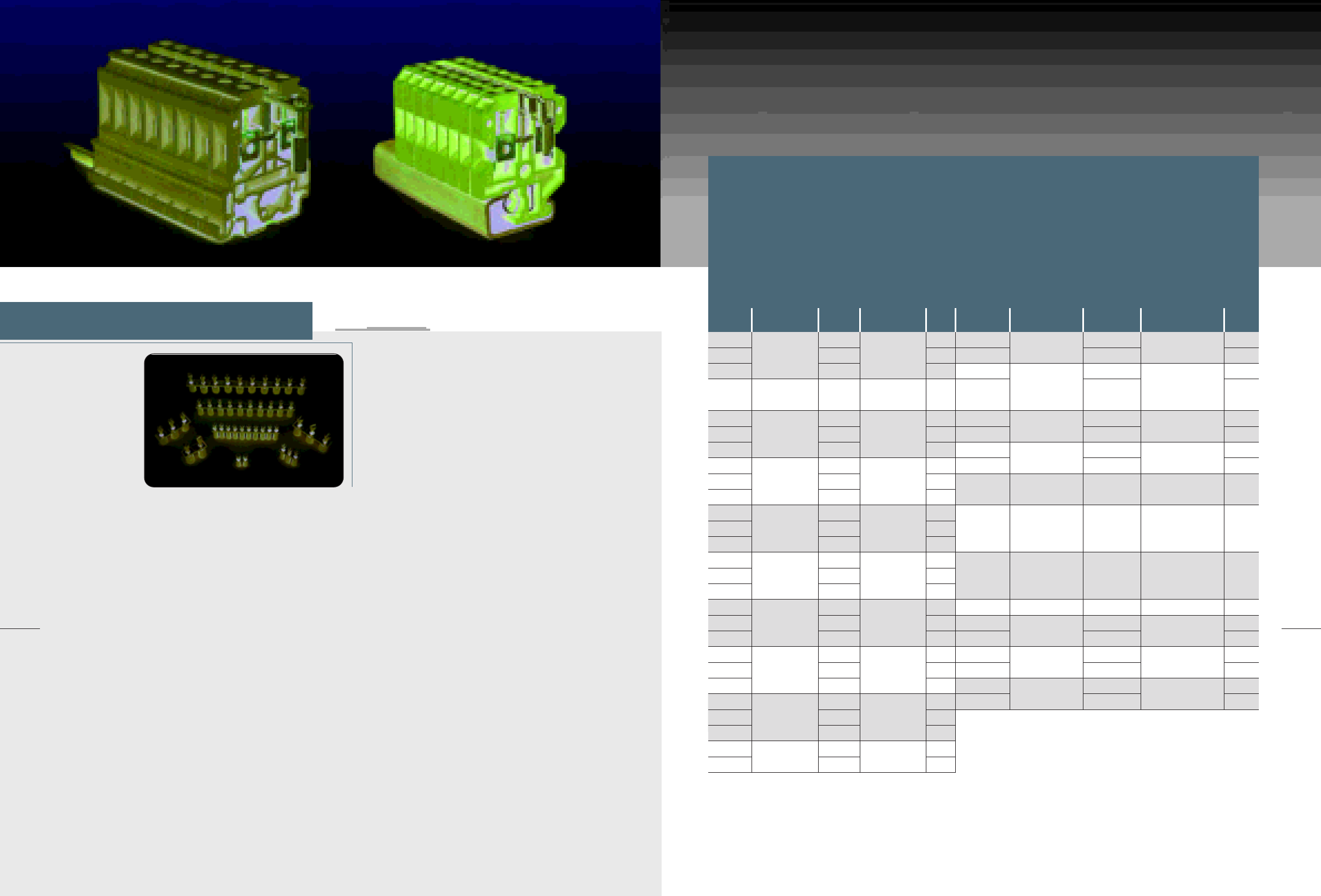
62
MODULAR TERMINAL BLOCKS / 2005
For cross-connection bar, connection sleeves and screws
are already captively mounted with the corresponding
number of poles. The cross-connection then only requires
inserting in the individual terminal row when fitting.
The cross-connection unit is supplied in 2, 3 and 10 poles.
Cross-Connection Bar
To handle cross-connection of several terminal blocks,
with the same potential, copper cross-connection bars
are used. These cross-connection bars supplied in 2, 3
and 10 pole lengths are equal to the individual terminal
widths. The cross-connection bar is electrically joined
through a connection sleeve to the terminal block bus
bar.
Connection Sleeve and Screw
The length of the brass connection sleeve is matched
to the individual terminal. In order to be able to connect
the cross-connection bar and the connection sleeve to
a terminal block bus bar, a brass screw is applied. The
cross-connections are designed so that where a terminal
does not need any cross-connection; it is possible to
remove the screw and its sleeve, thus no cross-connection
occurs in the terminal.
Cross-Connection
63
Accessories
Type Ord.
No. Qty.
201020
201021
201022
201014
201023
201024
201025
201310
201311
201312
201026
201027
201028
201029
201030
201031
201120
201121
201122
201123
201124
201125
201126
201127
201128
201129
201130
RTP2.5
RTP4, RDTU4
DRTP4, STC6
RTP4
DRTP4
RTP6, RST6, RTT6
RTP10
RTP16
RTP25
RTP35
RTP50
10
50
50
10
10
50
50
10
50
50
10
50
50
10
50
50
10
20
20
10
20
20
10
20
20
10
10
Application
CC10-2.5
CC3-2.5
CC2-2.5
BC10-4
CC10-4
CC3-4
CC2-4
CC10-D4
CC3-D4
CC2-D4
CC10-6
CC3-6
CC2-6
CC10-10
CC3-10
CC2-10
CC10-16
CC3-16
CC2-16
CC10-25
CC3-25
CC2-25
CC10-35
CC3-35
CC2-35
CC3-50
CC2-50
CCM10-2.5
CCM4-2.5
CCM10-4
CCM4-4
CCM10-6
CCM4-6
CCM10-10
CCM4-10
CCM10-16
CCM10-25
CCM10-35
CCM3-50
CCT10-4
CCT4-4
CCT10-6
CCT4-6
CCT10-16
CCT4-16
16 200520
200521
200522
200523
200524
200525
200526
200527
200528
200529
200530
200531
200220
200221
200222
200223
200224
200225
10
50
10
50
10
50
10
50
10
10
10
10
10
50
10
50
10
50
Type Max
Current (A) Ord.
No. Application Qty.
20
24
30
47
65
65
180
16
20
24
RTM2.5
RTM4
RTM6
RTM10
RTM16
RTM25
RTM35
RTM50
RCT4
RCT6
RCT16
20
Max
Current (A)
12
32
32
47
47
47
65
65
180
64
MODULAR TERMINAL BLOCKS / 2005
Test socket
This type of test accessory, made of brass, is tightened in the middle of terminal block busbar.
Test Accessories
65
Accessories
Moveable link
Moveable link, which is half in plastic (PA 6.6) and half in brass, permits the current
branching for the terminal block, functioning as a cross-connection, which makes a connection,
and though installed can also disconnect. It is also used in test disconnect terminal blocks.
TS3/6/2.3
TS3/8/4
TS3.5/8/4
TS4/8/4
TS3/14/4
TSS3/26/4
a
a
a
a
a
b
200540
200541
200542
200543
200703
200705
6
8
8
8
14
26
3.5
3.5
5
5
5
9
2.3
4
4
4
4
4
4
6
7
7
6
5.7
3
3
3.5
4
3
3
RTP2.5,4
RTP6,10,RTM6,10,RCTF10
RTP16,RTM16
RTP25,35,RTM25,35
RCTL2,RCTLU2
RCTL2,RCTLU2
50
50
50
50
50
50
Type Drawing Ord No. L L1 d D M Application QTY.
Type Ord No. Application QTY.
ML2A
ML4A
ML2B
ML4B
ML2N
ML3N
ML4N
200706
200707
200701
200702
200708
200709
200712
RCTL2,RCTLU2
RCTL2,RCTLU2
RCTL2,RCTLU2
RCTL2,RCTLU2
RST6,RTT6
RST6,RTT6
RST6,RTT6
100
50
100
50
50
50
50
Mounting Rails and End Brackets
IEC 60715 mounting rails form the basis for the
mounting of modular terminal blocks, as well as for rail
mountable electro technical and electric components.
Active and passive components are installed on
mounting rails. In control cabinet design, the TH 35-
15, TH 35-7.5 and G32 rails stand out with their high
degree of dimensional accuracy and surface tempering.
All steel versions are electroplated and additionally
passivised with a yellow chromate coating; comply
with the IEC 60715 standard. Raad supplies components
which are totally co-ordinated in their functionality.
The mounting rails can also be used as a protective
busbar. Raad protective conductor terminals meet the
requirements specified in IEC 60947-7-2.
The rails are both produced in slotted and unslotted
form for easier application by the users.
Type Ord No. QTY.Description
Mounting Rail
In accordance with IEC 60715, yellow chromated,
length 2m, Slotted
Mounting Rail
In accordance with IEC 60715, yellow chromated,
length 2m, Unslotted
Mounting Rail
In accordance with IEC 60715, yellow chromated,
length 2m, Slotted
Mounting Rail
In accordance with IEC 60715, yellow chromated,
length 2m, Unslotted
Mounting Rail
In accordance with IEC 60715, yellow chromated,
length 2m , Slotted
Mounting Rail
In accordance with IEC 60715, yellow chromated,
length 2m, Unslotted
Material Steel, galvanized &yellow chromated
TH 35-7.5/S
TH 35-7.5
TH 35-15/S
TH 35-15
G 32/S
G 32
401102
401104
401106
401108
401002
401004
20
20
20
20
20
20
TH35-7.5
TH35-7.5/S
TH35-15
TH35-15/S
G32
G32/S
25
6.3
18
32
18
1.5
9
G 32
1.5
35
15
TH 35-15
25
18
6.3
35
7.5
TH 35-7.5
1
b)
D
LM
MM
a)
L1 L
D
d
66
MODULAR TERMINAL BLOCKS / 2005
ARS mounting rail supports allow for sloped attachment of mounting
rails at an angle of 35∞.Their designs are available with M6 threads.
The FRS mounting rail supports are similar to ARS rail supports,
but with flat surface.
Mounting Rails Accessories
Type Ord No. QTY.Description
Angled rail support
allow for sloped attachment of mounting rail at
an angle of 35, with M6 thread
Flat rail support
allow for flat attachment of mounting rail, with
M6 thread
Material Steel, galvanized &yellow chromated
ARS/M6
FRS/M6
401202
401204
10
10
General Technical
Information
UL
R
Type Ord No. QTY.Description
End bracket
For mounting on G32, adjustable with terminal NS marking
Width(mm)
End bracket
For mounting on G32 and TH35, adjustable with terminal NS marking
Width(mm)
End bracket
For mounting on G32 and TH35, adjustable with terminal NS marking
Width(mm)
Material Polyamide 6.6
EB32
8
EB/1
9.5
200101
200102
50
50
End Brackets
EB/2
10 200103 50
84
18 1.8
48
35
M6
84
18
M6
1.8
20

68
MODULAR TERMINAL BLOCKS / 2005
Achieving a uniform quality on production in
mass productuion is impossible unless through
establishment of quality management system.
Having the certificate of quality management
system in accordance with ISO 9000-2000 issued
by authorized and well-known standard
institutions, Raad manufacturing company is
seeking to assure its customers for the existence
of such system.
Furthermore, Raad products quality is proven
by outstanding institutions, being well-known
in electric field all around the world, offered
various types of certificates.
Both, the certificates of products quality and
quality management system indicate reliable
products, manufactured by the company. The
development plan to gain other certificates on
products quality and quality management system
is still alive and continuing.
Raad, Quality in Action
69
GENERAL TECHNICAL INFORMATION
Confidence in Connection
RAAD products use parts and materials conform to standards in electrical industry
and are subject to quality control system.
Metals
All metal parts in RAAD products are electro-plated using the latest state of
engineering.
The surface protection conforms to technical standards. Steel parts at the beginning
are zinc-plated and then a yellow chromate layer coats over the zinc, providing
the best possible passivation.
Copper and brass parts are tin-plated. Tin plating provides excellent protection
against corrosion and has good electrical conduction.
Insulating Material
RAAD terminal blocks use two kinds of insulating materials, thermoplastics and
thermosetting plastics.
Thermoplastics are processed using economical and environmentally healthy
injection molding processes, and have good recycling properties and can be
reused. Polyamide 6.6 is a thermoplastic, used in the insulation body of RAAD
products. This modern semi-crystalline material has excellent electrical, mechanical,
chemical and other characteristics even at 100 C for continues operating.
The short-time peak temperatures are permissible up to about 200 C and the
melting point is around 260 C.
Polyamide 6.6 absorbs moisture from its surroundings, on average 2.8 %. This
makes the PA 6.6 more flexible and resistant to breakage, even at -40 C. Today PA
6.6 is approved for use by the approval authorities such as CSA, NEMKO, KEMA,
PTB, SEV, UL, VDE, etc.
Thermosetting materials have high dimensional stability, negligible water absorption
and are tropic and termite resistant. Thermosetting plastic used by RAAD is a
melamine formaldehyde molding compound type MF 150, mainly organically filled
and is specified and tested in accordance with ISO, DIN, ASTM, JIS and BS. MF
150 has high continuous operating temperature, excellent inflammability and very
good tracking resistance.
Material
Standard Unit PA 6.6Properties
Max. application temperature
Flammability class
Comprative tracking index
Electrical strength (1 mm thickness)
Surface resistivety
Volume resistivety
Tropical and termite resistance
IEC60216-1
UL94
IEC60112
IEC60243-1
IEC60093
IEC60093
-
MF 150
0C,<50h
0C, <20.000h
-
CTI
CTIM
kV/mm
Ω
cm
-
160
135
V0
600
600
30
1011
1012
good
125
105
V2
600
575(475)
31
>1015
1015
good
70
MODULAR TERMINAL BLOCKS / 2005
71
GENERAL TECHNICAL INFORMATION
This is the most popular of all known methods of
connection. No other connection method allows such
high contact forces to be produced in such a small space
as a screw. RAAD terminal block screw connection is easy
to operate with a standard screwdriver, suitable for all
types of conductors without special preparation,
absolutely gas tight and vibrationproof.
Reliable clamping
Most RAAD products use a clamping unit system which
has been proven millions of times, world-wide. The
clamping units as well as clamping screws are produced
from hardened steel. When the clamping screw is
tightened, the resultant force causes the upper thread
overlap to spring open, thus causing a locking action to
be exerted on the screw and an excellent resistance
against vibration is achieved.
Screw Connection
Standards and Regulations
Following are some of the important standards and regulations taken into
consideration during the development and the production of our products,
insofar as they apply.
IEC 60947-7-1 (2002)
Low- voltage switchgear and controlgrear
Part 7: Ancillary equipment
Section 1: Terminal blocks for copper conductors
IEC 60947-7-2 (2002)
Low - voltage switchgear and controlgear
Part 7: Ancillary equipment
Section 2: Protective conductor terminal blocks for copper conductors
IEC 60947-7-3 (2002)
Low-voltage switchgear and controlgear
Part 7: Ancillary equipment
Section 3: Safety equipment for fuse terminal blocks
IEC 60947-1 (2004)
Low - voltage switchgear and controlgear
Patr 1: General rules
IEC 60998-2-1 (2002)
Connecting devices for low voltage circuits for household and similar
purposes
Part 2-1: Particular requirements for connecting devices as separate
entities with screw - type clamping units
IEC 60998-1 (2002)
Connecting devices for low voltage circuits for household and similar
purposes
Part 1: General requirements
IEC 60664-1 (2002)
Insulation coordination for equipment within low voltage systems
Part 1: Principles, requirements and tests
IEC 60715 (1981)
Dimensions of low - voltage switchgear and controlgear standardized
mounting on rails for mechanical support of electrical devices in switchgear
and controlgear installations
IEC 60127-1 (2003)
Miniature fuses
Part 1: Difinitions of miniature fuses and general requirements for miniature fuse - links
IEC 60127-2 (2003)
Miniature fuses
Part 2: Cartridge fuse - links
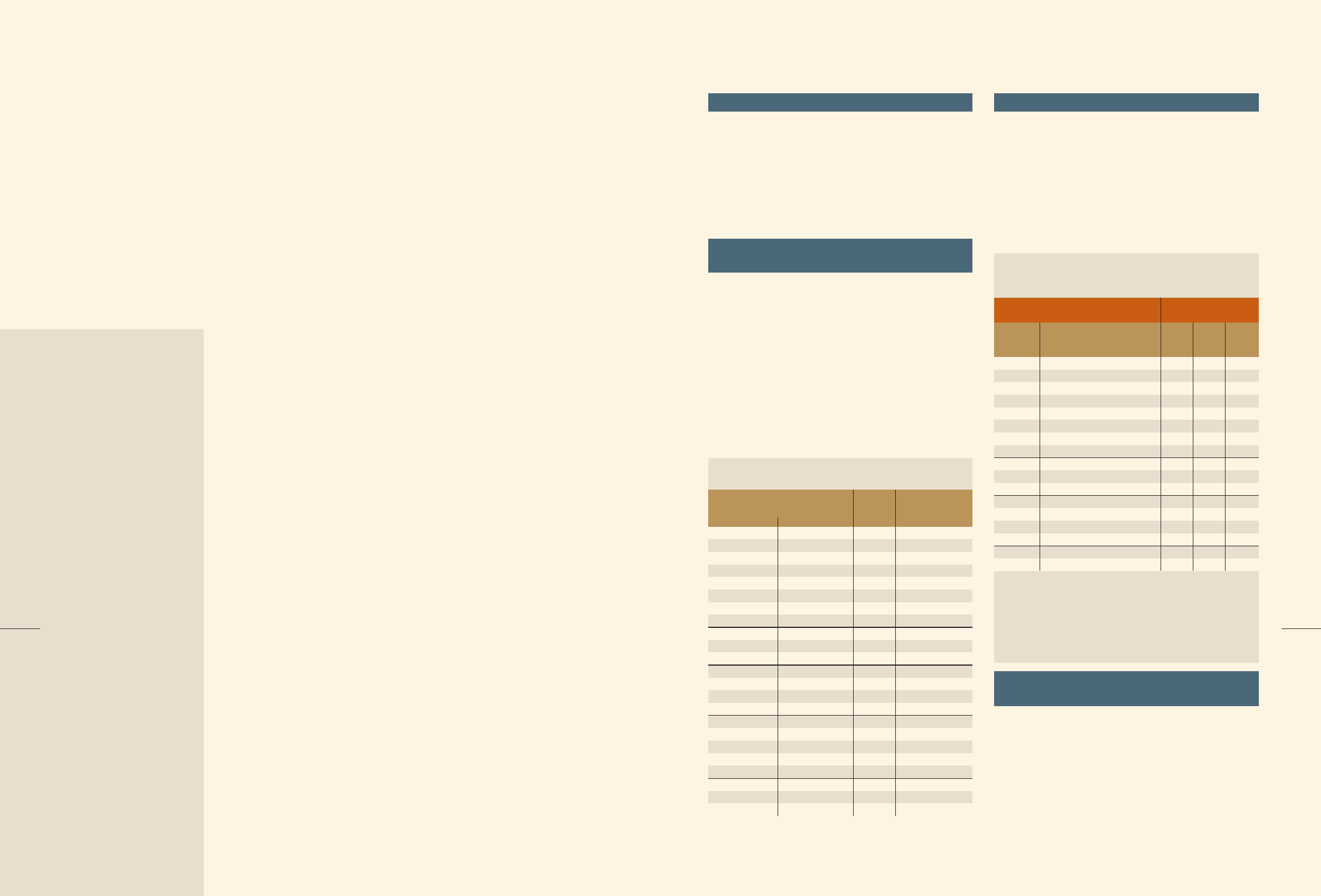
72
MODULAR TERMINAL BLOCKS / 2005
73
GENERAL TECHNICAL INFORMATION
IEC 60529 (2001)
Classification of degrees of protection provided by enclosures (IP code)
IEC 60112 (2003)
Methods for determining the comparative and the proof tracking indices of
solid insulating materials under moist conditions.
IEC 60243-1 (1988)
Methods of test for electric strength of solid insulating materials
Part 1: Tests at power frequencies
IEC 60093 (1980)
Methods of testing of electrical insulating materials specific contact resistance
and specific surface resistance of solid, electrically insulating materials
IEC 60216-1 (2001)
Electrical insulating materials
Properties of thermal endurance
Part 1: Ageing procedures and evaluation of test results
IEC 60695-2-10 (2000)
Fire Hazard testing
Part 2-10: Glowing/hot-wire based test methods
GLow-wire apparatus and common test procedure
IEC 60695-2-11 (2000)
Fire Hazard testing
Part 2-11: Glowing/hot-wire based test methods
GLow-wire apparatus and common test procedure
UL 94 (1991)
Test for flammability of plastic materials for parts in devices and appliances
IEC 60079-0 (2004)
Electrical apparatus for explosive gas atmospheres
Part 0: General requirements
IEC 60079-7 (2001)
Electrical apparatus for explosive gas atmospheres
Part 7: Increased safety ‘e’
IEC 60079-11 (1999)
Electrical apparatus for explosive gas atmospheres
Part 7: Intrinsic safety ‘i’
UL 1059 (2001)
Standard for Terminal Blocks
CSA CC 22.2 No.158 (1999)
Terminal Blocks
Terminal blocks tests
IEC 60947-7-1 is the main standard which meets all types
of Raad terminal blocks. All Raad products are designed,
manufactured and tested in accordance with the standard,
which along with IEC 60947-1 determines the tests to be
conducted on terminal blocks, each as a type test.
Testsí details are specified in the standards. Below is an
abstract of the forgoing tests.
To assure the stability of the terminal block to its mounting
rail, with standard shape and dimension values, a relevant
test is conducted by inserting a 150 mm long steel pin
with a diameter specified in table 3 of IEC 60947-7-1. It
is connected to each clamping unit and a tightening torque
must be applied, as given in table 4 of IEC 60947-1. Force
must be applied to the pin with regular intensity and without
tears; the corresponding value must be taken from table 3
of IEC 60947-7-1. The distance between the application
point of the force and the centre of clamping unit must be
equal to 100 mm. During the test, no terminal block must
disengage from its mounting rail or suffer any damage.
Attachment of the terminal block to
its mounting rail
Rated cross-section of terminal
block
mm2AWG/kcmil N mm
Force Diameter of
pin
IEC 60947-7-1
Attachment test parameters
0.2
0.34
0.5
0.75
1.0
1.5
2.5
4
6
10
16
25
35
50
70
95
-
120
150
185
240
300
24
22
20
18
-
16
14
12
10
8
6
4
2
0
00
000
0000
250
300
350
500
600
kcmil
kcmil
kcmil
kcmil
kcmil
1
5
10
15
20
1.0
2.8
5.7
12.8
20.5
Mechanical strength of terminals
To handle this test on screw-clamp terminal blocks, the
conductors must be used, which have the maximum cross-
section. The conductors must be connected and
disconnected five times depending on the screw clamping,
as determined in table 4 of IEC 60947-1. Where a screw
is loosened, a new conductor must be applied. During
the test, clamping units shall not work loose and there
shall be no damage that will impair the further use of the
screwed connections.
Table 3
Damage and accidental loosening of
conductors-flexion test
Specifically, this test is applied on terminal blocks suited
for the connection of unprepared round copper
conductors. It is a must to test both rigid and flexible
conductors with Min and Max cross-sections; optionally,
connections of multiple conductors to a single clamping
unit. A particular test apparatus is considered to aid the
test performance. During the test, neither must the
conductor slip out of the clamping unit, nor does breakage
occur near the clamping unit. Soon after the flexion test,
Diameter of thread
mm
Metric
standard
values Range of diameter I
Tightening
torque
IEC 60947-1
Tightening torques for the verification of the
mechanical strength of screw-type terminals
1.6
2.0
2.5
3.0
-
3.5
4.0
4.5
5
6
8
10
12
14
16
20
24
up to and including
up to and including
up to and including
up to and including
up to and including
up to and including
up to and including
up to and including
up to and including
up to and including
up to and including
up to and including
up to and including
up to and including
up to and including
0.05
0.1
0.2
0.25
0.3
0.4
0.7
0.8
0.8
1.2
2.5
-
-
-
-
-
-
0.1
0.2
0.4
0.5
0.6
0.8
1.2
1.8
2.0
3.0
6.0
10.0
14.0
19.0
25.0
36.0
50.0
Table 4
II III
0.1
0.2
0.4
0.5
0.6
0.8
1.2
1.8
2.0
2.5
3.5
4.0
-
-
-
-
-
2.0
2.8
3.0
3.2
3.6
4.1
4.7
5.3
6.0
8.0
10.0
12
15
20
24
≤
1.6
>1.6
>2.0
>2.8
>3.0
>3.2
>3.6
>4.1
>4.7
>5.3
>6.0
>8.0
>10
>12
>15
>20
>24
Applies to screws without heads which, when tightened,
do not protrude from the hole, and to other screws which
cannot be tightened by means of a screwdriver with a blade
wider than the root diameter of screw.
Column I
Applies to nuts and screws which are tightened by means
of a screwdriver.
Applies to nuts and screws which can be tightened by
means other than a screwdriver.
Column II
Column III
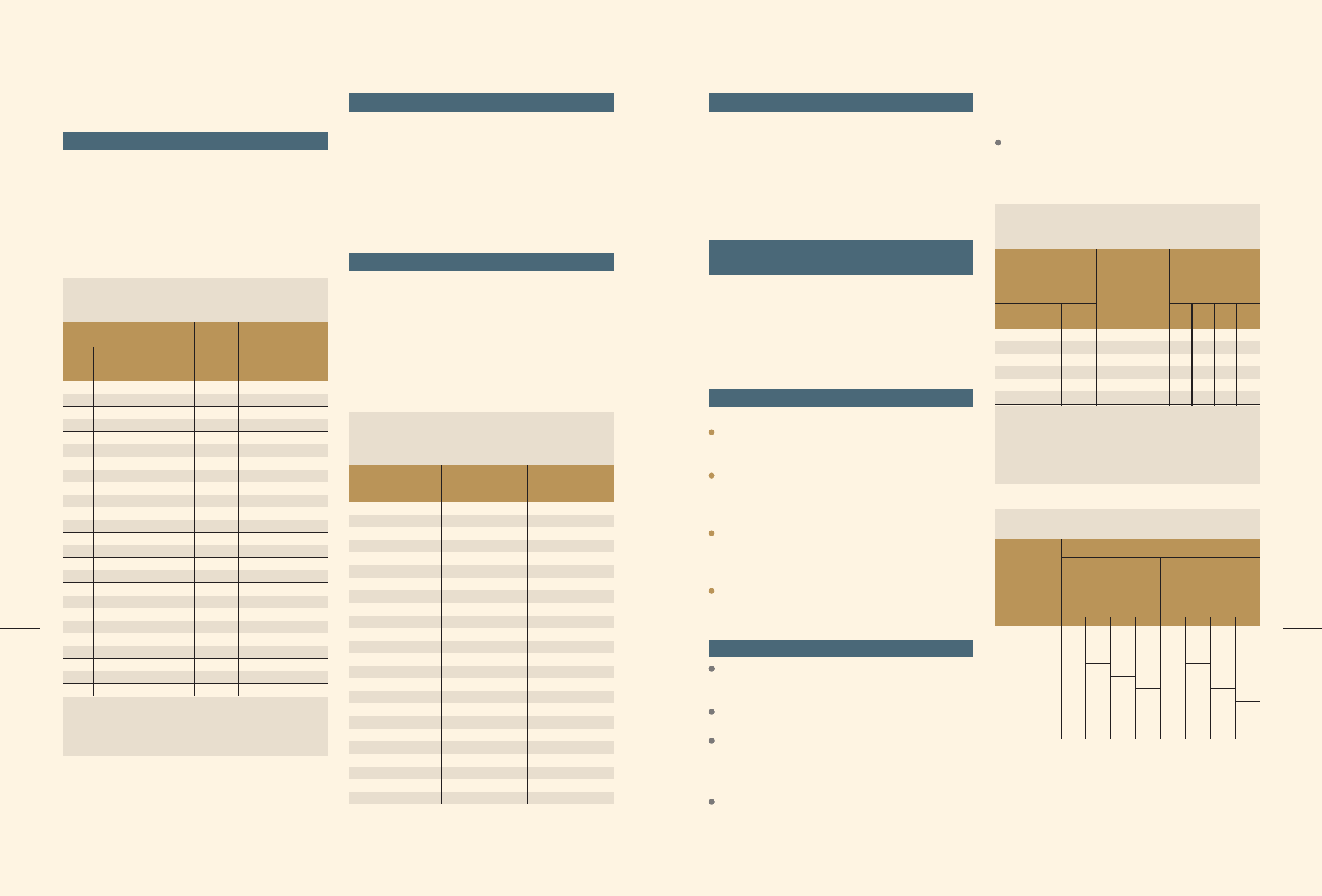
74
MODULAR TERMINAL BLOCKS / 2005
75
GENERAL TECHNICAL INFORMATION
a pull-out test must occur without restoring the initial
tightening torque.
Pull-out test
After the flexion test was conducted, a pull-out is carried-
out by force, the value of which is presented in table 5
of IEC 60947-1 to the conductor attached to the clamping
unit; this force must be applied regularly and without tears,
for 1 minute; for screw-clamp terminal blocks, the tightening
screws must not be newly tightened. During the test,
neither must the conductor slip out of the clamping unit,
nor does breakage occur near the clamping unit.
Rated cross-section
It is the value of max connectable conductor cross-
section. The rated cross-section shall be selected from
the standard cross-sections presented in table 1, IEC
60947-1. Where a ferrule is applied on a flexible conductor,
then a terminal block of one step higher rated cross-section
must be used, for example, a 2.5mm≤ flexible conductor
covered with the relating ferrule must be inserted to a one
step higher cross-section, i.e. terminal block with rated
cross-section 4mm.
Rated connection capacity
It is the value of max connectable conductor cross-
section. The rated cross-section shall be selected from
the standard cross-sections presented in table 1, IEC
60947-1. Where a ferrule is applied on a flexible conductor,
then a terminal block of one step higher rated cross-section
must be used, for example, a 2.5mm≤ flexible conductor
covered with the relating ferrule must be inserted to a one
step higher cross-section, i.e. terminal block with rated
cross-section 4mm.
NOTE:
Rated cross-section
mm2
AWG/kcmil size
mm2
Equivalent metric
arra
IEC 60947-7-1
Standard cross-sections of round copper conductors
and approximate relationship between mm2 and
AWG/kcmil sizes
0,2
0,34
0,5
0,75
1
1,5
2,5
4
6
10
16
25
35
-
50
70
95
-
120
150
185
-
240
300
24
22
20
18
-
16
14
12
10
8
6
4
2
1
0
00
000
0000
250
300l
350l
400
500
600
kcmil
kcmil
kcmil
kcmil
kcmil
kcmil
0,205
0,324
0,519
0,82
-
1,3
2,1
3,3
5,3
8,4
13,3
21,2
33,6
42,4
53,5
67,4
85,0
107,2
127
152
177
203
253
304
The dash, when it appears, counts as a size when
considering connecting capacity (see 7.1.7.2).
Rated connection capacity
It is the range of cross-sections and the number of
connectable conductors based on which the terminal
blocks are designed. The IEC 947-7-1 determines the
relation between the rated cross-section and rating
connecting capacity of terminal blocks. Practically, terminal
blocks up to 35mm2, must be possible to connect a
conductor of cross-section equal to the nominal cross-
section and lower up to two cross-sections.
Insulation coordination for equipment
within low voltage systems
IEC 60664-1 deals with insulation coordination for
equipment within low voltage systems. It specifies the
requirements for clearances, creepage distances and solid
insulation for equipment based upon the performance
criteria. Terminal blocks standard, IEC 60947-7-1, has the
rules for coordination of insulation in accordance with IEC
60664-1.
Clearances
Degrees of pollution in the micro-environment
Pollution degree 1
No pollution or only dry, non-conductive pollution occurs.
The pollution has no influence.
Pollution degree 2
Only non- conductive pollution occurs except that
occasionally a temporary conductivity caused by
condensation is to be expected.
Pollution degree 3
Conductive pollution occurs or dry non-conductive
pollution occurs which becomes conductive due to
condensation which is to be expected.
Pollution degree 4
The pollution generates persistent conductivity caused
by conductive dust, rain or snow.
Overvoltage categories
Equipment of overvoltage category I is equipment for
connection to circuits in which measures are taken to limit
transient overvoltages to an appropriately low level.
Examples for such devices are protected electronic
circuits.
Equipment of overvoltage category II is energy-
consuming equipment to be supplied from the fixed
installation. Examples of such equipment are appliances,
portable tools and other household and similar loads.
Equipment of over voltage category III is equipment in
fixed installations and for cases where the reliability and
the availability of the equipment are subject to special
requirements. Examples of such equipment are switches
in fixed installation and equipment for industrial use with
permanent connection to the fixed installation.
Equipment of overvoltage category IV is for use at the
origin of the installation. Examples of such equipment are
electricity meters and primary over-current protection
equipment
Conductor
cross-section
mm2
Pulling
force
0.2
0.2
0.3
0.4
0.4
0.4
0.7
0.9
1.4
2.0
2.9
4.5
5.9
6.8
8.6
9.5
10.4
14
14
14
15
16.8
16.8
20
22.7
10
15
20
30
35
40
50
60
80
90
100
135
156
190
236
236
285
351
427
427
427
503
503
578
578
MassHeight
H 1)
Diameter
of bushing
hole 1) 2)
AWG/kcmil mm mm kg n
260
260
260
260
260
260
280
280
280
280
300
300
320
320
343
343
368
368
368
406
406
432
432
464
464
6.5
6.5
6.5
6.5
6.5
6.5
9.5
9.5
9.5
9.5
13.0
13.0
14.5
14.5
15.9
15.9
19.1
19.1
19.1
22.2
22.2
25.4
25.4
28.6
28.6
24
22
20
18
-
16
14
12
10
8
6
4
3
2
1
0
00
000
0000
250
300
350
400
500
600
kcmil
kcmil
kcmil
kcmil
kcmil
kcmil
0.2
0.34
0.5
0.75
1.0
1.5
2.5
4.0
6.0
10
16
25
-
35
-
50
70
95
-
120
150
185
-
240
300
IEC 60947-1
Test values for flexion and pull-out tests for round
copper conductors
Table 5
1) Tolerances: for heigh H ± 15 mm, for diameter of the bushing
hole ± 2 mm.
2) If the bushing hole diameter is not large enough to accommodate
the conductor without binding, a bushing having the next larger
hole size may be used.
Table 1
Nominal voltage of the
supply system based
on IEC 38 2)
VOver voltage category
230
500
800
1500
2500
4000
Voltage line to
neutral derived
from normal
voltages a.c. or
d.c. up to and
including
V
Single
phase I
50
100
150
300
600
1000
230/400 277/480
4009690
1000
IEC 60664-1
Rated impulse voltage for equipment energized
directly form the low-voltage mains
Table 1
1) Equipment with these rated impulse voltages can be used in
installation in accordance with IEC364-4-443.
2) The / mark indicates a four-wire three-phase distribution system.
The lower value is the voltage line -to- netural, while the higher
value is the voltage line-to-line. Where only one value is indicated,
it refers to three-wire, three-phase systems and specifies value
line-to-line.
Three phase
120-240
500
800
1500
2500
4000
6000
II
800
1500
2500
4000
6000
8000
III
1500
2500
4000
6000
8000
12000
IV
Rated impulse voltage 1)
V
Rated impulse
withstand
voltage
Uimp
0.01
0.04
0.1
0.3
0.6
1.2
2
3
4.5
Case A
Pollution degree
0.33
0.5
0.8
1.5
2.5
4.0
6.0
8.0
12
IEC 60947-1
Minimum clearance inair
Table 13
NOTE The values of minimum clearance in air are based on 1,2/50
µ
s
impulse voltage, for barometric pressure of 80 kPa, equipment
to normal atmospheric pressure at 2 000 m above sea level.
0.2
0.3
0.6
1.2
2
3
4.5
0.8
1.2
2
3
4.5
1.6
2
3
4.5
Case B
Homogeneeous field
ideal conditions
(see 2.5.62)
kV
Inhomogeneeous field
conditions
(see 2.5.63)
Minimum clearances
mm
Pollution degree
1 2 3 4
0.01
0.04
0.1
0.5
1.5
3
5.5
8
14
0.2
0.5
1.5
3
5.5
8
14
0.8
1.5
3
5.5
8
14
1.6
3
5.5
8
14
1 2 3 4
76
MODULAR TERMINAL BLOCKS / 2005
77
GENERAL TECHNICAL INFORMATION
Creepage distances
The creepage distance is based on the rated voltage which
is derived from the working voltage or nominal voltage of
the supply system. The minimum creepage distances are
allocated to the rated voltage according to the pollution
degree and material group in table 15, IEC 60947-1.
In this catalog the products must be measured in
compliance with IEC 60664-1 for overvoltage category III,
pollution degree 3 and material group I, other wise the
product information would include additional details.
Material groups
According to the range of values of the comparative
tracing index (CTI), material groups are classified as follows:
Material Group 600
≤
CTI
Material Group II 400
≤
CTI <600
Material Group IIIa 175
≤
CTI<400
Material Group IIIb 100
≤
CTI<175
The CTI values refer to values obtained in accordance
with IEC 60112, method A, for the insulating material used.
IEC 60947-1
Minimum creepage distances
Creepage distances for equipment subject to long term stress
mm
Pollution degree Pollution degree
2
Pollution degree
3
Pollution degree
4
1 5) 2 5) 1
Material group Material group Material group Material group
1) 2) 1) I II IIIa IIIIb I II IIIa IIIIb I II IIIa IIIIb
Rated insulation
voltage of
equipment or
working voltage
a.c. r.m.s
or d.c. 4)
V
10
12.5
16
20
25
32
40
50
63
80
100
125
160
200
250
320
400
500
630
800
1 000
1 250
1 600
2 000
2 500
3 200
4 000
5 000
6 300
8 000
10 000
0.025
0.025
0.025
0.025
0.025
0.025
0.025
0.025
0.04
0.063
0.1
0.16
0.25
0.4
0.56
0.75
1
1.3
1.8
2.4
3.2
0.04
0.04
0.04
0.04
0.04
0.04
0.04
0.04
0.063
0.1
0.16
0.25
0.4
0.63
1
1.6
2
2.5
3.2
4
5
0.08
0.09
0.1
0.11
0.125
0.14
0.16
0.18
0.2
0.22
0.25
0.28
0.32
0.42
0.56
0.75
1
1.3
1.8
2.4
3.2
4.2
5.6
7.5
10
12.5
16
20
25
32
40
0.4
0.42
0.45
0.48
0.5
0.53
0.56
0.6
0.63
0.67
0.71
0.75
0.8
1
1.25
1.6
2
2.5
3.2
4
5
6.3
8
10
12.5
16
20
25
32
40
50
0.4
0.42
0.45
0.48
0.5
0.53
0.8
0.85
0.9
0.95
1
1.05
1.1
1.4
1.8
2.2
2.8
3.6
4.5
5.6
7.1
9
11
14
18
22
28
36
45
56
71
0.4
0.42
0.45
0.48
0.5
0.53
1.1
1.2
1.25
1.3
1.4
1.5
1.6
2
2.5
3.2
4
5
6.3
8
10
12.5
16
20
25
32
40
50
63
80
100
1
1.05
1.1
1.2
1.25
1.3
1.4
1.5
1.6
1.7
1.8
1.9
2
2.5
3.2
4
5
6.3
8
10
12.5
16
20
25
32
40
50
63
80
100
125
1
1.05
1.1
1.2
1.25
1.3
1.6
1.7
1.8
1.9
2
2.1
2.2
2.8
3.6
4.5
5.6
7.1
9
11
14
18
22
28
36
45
56
71
90
110
140
1
1.05
1.1
1.2
1.25
1.3
1.8
1.9
2
2.1
2.2
2.4
2.5
3.2
4
5
6.3
8
10
12.5
16
20
25
32
40
50
63
80
100
125
160
3)
1.6
1.6
1.6
1.6
1.7
1.8
1.9
2
2.1
2.2
2.4
2.5
3.2
4
5
6.3
8
10
12.5
16
20
25
32
40
50
63
80
100
125
160
200
1.6
1.6
1.6
1.6
1.7
1.8
2.4
2.5
2.6
2.8
3
3.2
4
5
6.3
8
10
12.5
16
20
25
32
40
50
63
80
100
125
160
200
250
1.6
1.6
1.6
1.6
1.7
1.8
3
3.2
3.4
3.6
3.8
4
5
6.3
8
10
12.5
16
20
25
32
40
50
63
80
100
125
160
200
250
320
3)
1) Material groups I, II, IIIa, IIIb.
2) Material groups I, II, IIIa.
3) Values of creepage distances in this area have not been established. Material groups
IIIb is in general not recommended for application in pollution degree 3 above 630
V and in pollution degree 4.
4) As an exception, for rated insulation voltages 127 V, 208 V, 415/440 V, 660/690 V
and 830 V, creepage distances corresponding to the lower values 125 V, 200 V, 400
V, 630 V and 800 V respectively may be used.
5) The values given in these two columns apply to creepage distances of printing
NOTE 1 It is appreciated that tracking or erosion will not occur on insulation subjected
to working voltages of 32 V and below. However, the possibility of electrolytic
corrosion has to be considered and for this reason minimum creepage distances have
been specified.
NOTE 2 Voltage values are selected in accordance with the R10 series.
circuit materials.
6) The values of creepage distances stated for 250 V can be used for 230 V (±10 %)
normal voltage.
Table 15
Dielectric test
The test is conducted on 5 adjacent terminal blocks,
mounted on a metallic mounting rail and connected with
rated cross-section conductors.
Test voltage must have a sinusoidal waveform with a
frequency between 45 and 62 Hz.
The values applied, for 5 seconds, are those specified
in the table 12A, IEC 60947-1. Irrespective of glow
discharges without drop of voltage, no disruptive
discharges shall occur during the test.
Rated insulation
voltage
Ui
V V V
DC test voltage2), 3)
IEC 60947-1
Dielectric test voltage corresponding to the rated
insulation voltage
Ui ≤ 60
60 < Ui ≤ 300
300 < Ui ≤ 690
690 < Ui ≤ 800
800 < Ui ≤ 1 000
1 000 < Ui ≤ 1 5001)
1 000
1 500
1 890
2 000
2 200
-
1 415
2 120
2 670
2 830
3 110
3 820
Table 12A
AC test voltage
(r.m.s.)
For d.c. only.
Test voltages based on 4.1.2.3.1, third paragraph of IEC 60664-1.
A direct current test voltage may be used only if an alternating test
voltage cannot be applied. See also 3) b) ii) of 8.3.3.4.1.
1)
2)
3)
Short-time withstand current
The standard IEC 947-7-1 obliges terminal blocks to
withstand a current equal to 120A per each square mm
of rated cross-section for 1 second.
Temperature-rise test
The current in a terminal block causes overheating due
to continuous operation. The overheating level shall not
overcome a specified value, thus a temperature-rise test
is applied to verify this performance requirement. The test
is conducted by means of temperature-rise test on 5
neighboring terminal blocks connected at a test current
as specified in table 4, IEC 60947-7-1. The temperature-
rise of any part of the centrally located terminal block shall
not exceed 45 K.
Rated cross-section
mm2
IEC 60947-7-1
Values of test current for temperature-rise
test, ageing test and voltage drop test for
metric wire sizes
Table 4
Test
current
A
Rated cross-section Test
current
Amm2
4
6
9
13.5
17.5
24
32
41
57
76
25
35
50
70
95
120
150
185
240
300
0.2
0.5
0.75
1
1.5
2.5
4
6
10
16
101
125
150
192
232
269
309
353
415
520
Voltage drop
Voltage drop at the terminal indicates an index of contact
resistance against the follow of current. The voltage drop
test is conducted before and after mechanical strength,
short-time withstand current and temperature-rise tests.
IEC 60947-7-1 states that the voltage drop, measured on
a new terminal block, must be lower than 3.2 mV and
after the tests lower than 150 % of the value measured
before the tests.


North 3rd floor, 28, 2nd St.
Shahnazari St., Madar Sq.
Mirdamad Blv.
Tehran - Iran
Tel. +98 21 227 8455 - 6
Fax +98 21 227 8457
salse@raad-co.com
www.raad-co.com
