INST AP 127 B040910 (APC Remote Accessory Wiring Diagram).qxp Duct Smoke Detector Accessories Installation Sheet
User Manual: Duct Smoke Detector
Open the PDF directly: View PDF ![]() .
.
Page Count: 2
AIR PRODUCTS AND CONTROLS INC.
INSTALLATION INSTRUCTIONS FOR DUCT SMOKE DETECTOR
REMOTE ACCESSORIES
1749 East Highwood • Pontiac, MI 48340 USA • US Toll Free 888.332.2241 • Phone 248.332.3900 • Fax 248.332.8807 • www.ap-c.com
*NOTE:For proper installation, testing, operation and maintenance of a duct smoke detector, please refer to the detector installation guide. The
following wiring diagrams are applicable only to compatible, current limited, UL Listed remote accessories from Air Products and Controls. Use of
any other devices may result in damage to the duct smoke detector, potential injury, and will void any applicable warranties.
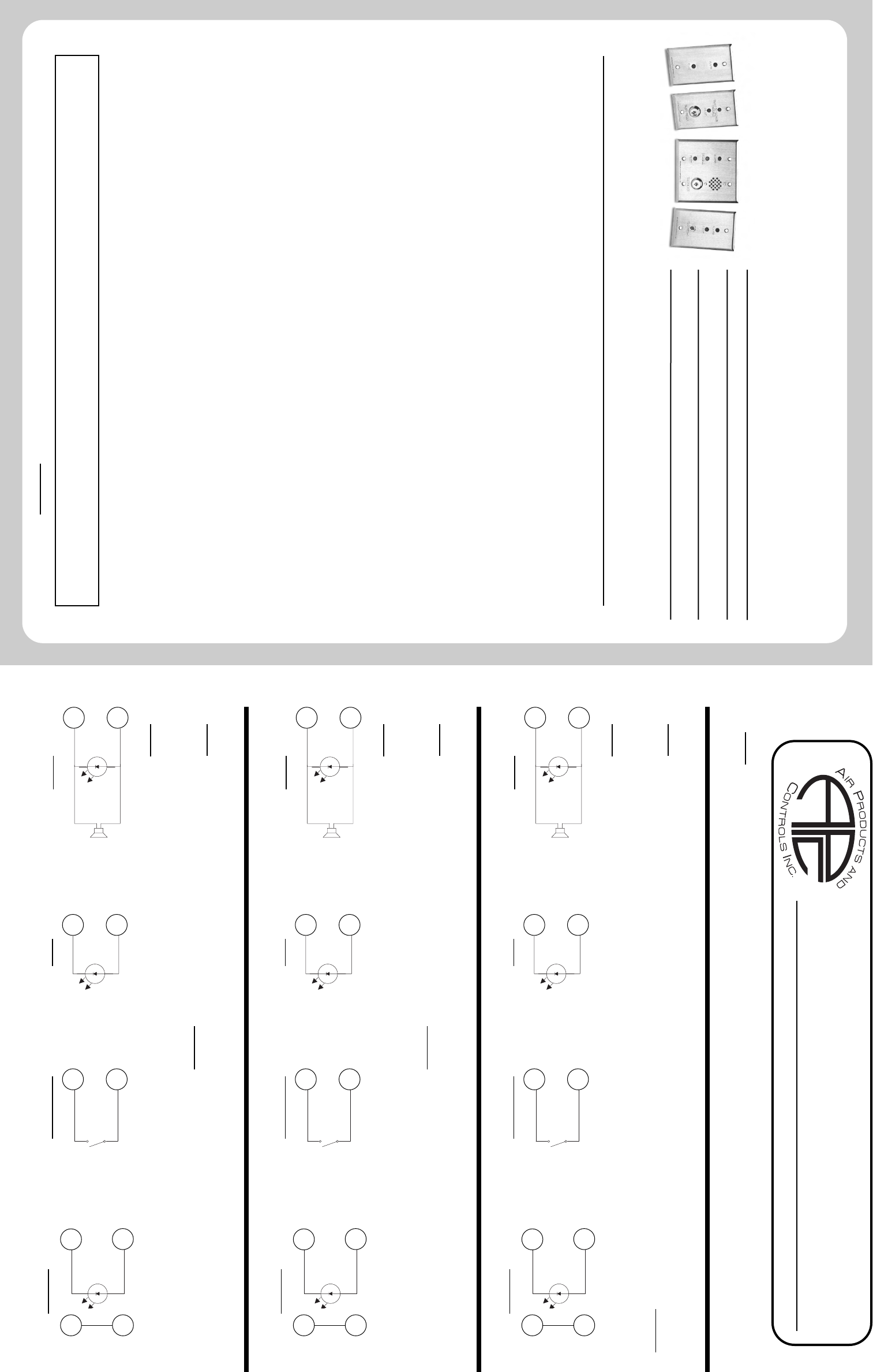
SL-2000 Series Duct Smoke Detectors
*NOTE:For remote accessories with a Trouble LED (yellow), a jumper wire must be placed between Terminals 20 and 15. The Trouble LED will
illuminate when the detector cover is removed, or if the smoke detector head is removed and the cover replaced. Trouble contacts CANNOT be
connected to a Fire Alarm Control Panel when using this option without the use of a slave relay.
*NOTE:If duct smoke detectors are interconnected for common functions, please refer to unit installation guide for proper connection of remote
alarm functions.
RED
ALARM
LED
RED
BLACK
STROBE
AND/OR
HORN
12
19
ALARM
GREEN
PILOT
LED
BLACK
RED
2
19
PILOT
BLACK
BLACK
KEY OR
PUSH BUTTON
“TEST / RESET”
SWITCH
1
20
TEST / RESET TROUBLE
RED
BLACK
YELLOW
TROUBLE
LED
4
19
20
15
JUMPER
SM-501 Series Duct Smoke Detectors
*NOTE:For remote accessories with a Trouble LED (yellow), a jumper wire must be placed between Terminals 14 and 18. The Trouble LED will
illuminate when the smoke detector head is removed. Trouble contacts CANNOT be connected to a Fire Alarm Control Panel when using this option
without the use of a slave relay.
*NOTE:If duct smoke detectors are interconnected for common functions, please refer to unit installation guide for proper connection of remote
alarm functions.
RED
ALARM
LED
RED
BLACK
STROBE
AND/OR
HORN
17
19
ALARM
GREEN
PILOT
LED
BLACK
RED
21
19
PILOT
BLACK
BLACK
KEY OR
PUSH BUTTON
“TEST / RESET”
SWITCH
21
20
TEST / RESET TROUBLE
RED
BLACK
YELLOW
TROUBLE
LED
13
19
14
18
JUMPER
2650-560APC and 2650-561APC Duct Smoke Detectors
*NOTE:For remote accessories with a Trouble LED (yellow), a jumper wire must be placed between Terminals 20 and 13. The Trouble LED will
illuminate when the smoke detector head is removed. Trouble contacts CANNOT be connected to a Fire Alarm Control Panel when using this option
without the use of a slave relay.
*NOTE:If duct smoke detectors are interconnected for common functions, please refer to unit installation guide for proper connection of remote
alarm functions.
RED
ALARM
LED
RED
BLACK
STROBE
AND/OR
HORN
16
17
ALARM
GREEN
PILOT
LED
BLACK
RED
19
20
PILOT
BLACK
BLACK
KEY OR
PUSH BUTTON
“TEST / RESET”
SWITCH
18
19
TEST / RESET TROUBLE
RED
BLACK
YELLOW
TROUBLE
LED
16
14
20
13
JUMPER
INST AP-127 B040913
A COPY OF THESE INSTRUCTIONS SHOULD BE LEFT WITH THE EQUIPMENT UNTIL INSTALLATION BY ALL TRADES IS FULLY COMPLETE.
FOLLOWING FINAL INSPECTION, A COPY SHOULD BE LEFT WITH THE OWNER/USER.
AVAILABLE ACCESSORIES FOR USE WITH
AIR PRODUCTS DUCT SMOKE DETECTORS
REMOTE ACCESSORIES
MS-RA Remote Alarm
MS-RA/R Remote Alarm, push button Test/Reset Switch
MS-RA/P/R Remote Alarm, Pilot, push-button Test/Reset Switch
MS-KA/R Remote Alarm, key-operated Test/Switch
MS-KA/P/R Remote Alarm, Pilot, key-operated Test/Reset Switch
MS-RA/P Remote Alarm, Pilot
MS-RH Remote Alarm Horn
MS-RH/KA/P/R Remote Alarm, Pilot, Horn, key-operated Test/Reset Switch
MS-RH/P/A Remote Alarm, Pilot, Horn
MS-RH/KA/P/A/T Remote Alarm, Trouble, Pilot, Horn, key-operated Test/Reset Switch
MS-RA/P/T Remote Pilot, Trouble
MS-RA/FT/P Remote Pilot, Trouble, push-button Test/Reset Switch
MS-KA/P/R/T Remote Pilot, Trouble, key-operated Test/Reset Switch
MS-RD Remote Alarm
MS-F/T Remote Trouble
SHP24-1575R Horn/Strobe, red housing, clear cover
SHP24-1575O Horn/Strobe, white housing, opaque cover
SHP24-1575W Horn/Strobe, white housing, clear cover
SMOKE TEST GAS
TG-1000 Solo Aerosol Test Gas with Spray Nozzle
TG-2000 Solo Aerosol Test Gas with Nozzle for SL- Series Test Port
SAMPLING TUBES (RW- AND SM- SERIES) NOTCHED SAMPLING TUBES (SL- SERIES)
STS-1.0 For duct widths of 6” TO 1.0’ STN-1.0 For duct widths of 6” TO 1.0’
STS-2.5 For duct widths of 1.0’ TO 2.5’ STN-2.5 For duct widths of 1.0’ TO 2.5’
STS-5.0 For duct widths of 2.5’ TO 5.0’ STN-5.0 For duct widths of 2.5’ TO 5.0’
STS-10.0 For duct widths of 5.0’ TO 10.0’ STN-10.0 For duct widths of 5.0’ TO 10.0’
WEATHERPROOF ENCLOSURES
WP-1 Weatherproof Enclosure for RW- and SM- Series Detectors
WP-2000 Weatherproof Enclosure for SL- Series Detectors
POWER SUPPLIES
T-PB 202-1 24VAC @ 4.0A Class I Power Supply
T-PB 202-0 24VAC @ 4.0A Class I Power Supply
T-PB 303-1 24VAC @ 3.0A Class II Power Supply
T-PB 303-0 24VAC @ 3.0A Class II Power Supply
NOTICE: The information contained in this document is the most current available at the time of shipment of accompanying product, and is subject to change without notice. Future references should always be made
to the most current revision of this document. The information contained in all this document should be considered before installing or using the product. Any example applications shown are subject to the most cur-
rent enforced local/national codes, standards, approvals, certifications, and/or the authority having jurisdiction. All of these resources, as well as the specific manufacturer of any shown or mentioned related equipment,
should be consulted prior to any implementation. For further information or assistance concerning this product, contact Air Products and Controls Inc. Air Products and Controls Inc. reserves the right to change any and
all documentation without notice. © Air Products and Controls Inc. 2004
MS SERIES REMOTE ACCESSORIES
Power Requirements: Alarm LED 15mA @ 24VDC
Trouble LED 15mA @ 24VDC
Pilot LED 15mA @ 24VDC
Alarm Horn 20mA @ 24VDC
Sound Pressure: 78db @ 10 ft
Dimensions: Single Gang 4½” (114.3mm)H x 2¾” (69.85mm)W
Double Gang 4½” (114.3mm)H x 4½” (114.3mm)W
Wiring: LEDs/Horn 6” 24AWG Pigtails
Switches 6” 22AWG Pigtails
Approvals: UL Listed for use with Air Products and Controls duct smoke
detectors including all RW- Series, SM- Series and SL- Series
duct smoke detectors
UL URRQ.S7425
CSFM 7300-1004:107
MEA 73-92-E Vol.25
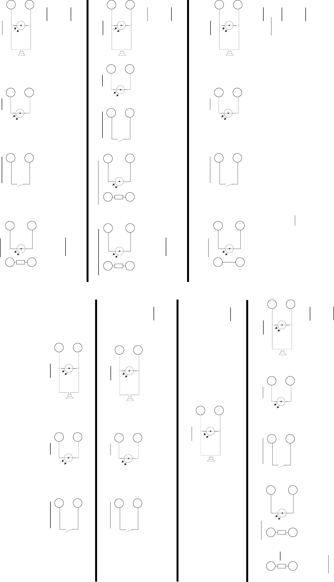
RWJ Series Duct Smoke Detectors
RWF Series Duct Smoke Detectors
RWX Series Duct Smoke Detectors
RWL Series Duct Smoke Detectors
RWH Series Duct Smoke Detectors
*NOTE:For RWJ Series duct smoke detectors, no jumper is required for remote accessory Trouble conenctions. A Trouble LED (yellow) con-
nected to Terminals 13 and 20 will illuminate when the smoke detector is removed. If the trouble contacts of the RWJ Series detector are being used
for other switching applications, or for connection to a Fire Alarm Control Panel, the on-board RWJ option jumper must be removed (cut). Failure to
remove the RWJ option jumper could result in damage to the Fire Alarm Control Panel or other connected equipment.
*NOTE:For connection of remote accessories with a Trouble LED (yellow) to the RWF Series, RWX Series, RWL Series and RWH Series, a
jumper wire must be placed between Terminals 14 and 19. The Trouble LED will illuminate when the smoke detector head is removed. Trouble
contacts CANNOT be connected to a Fire Alarm Control Panel when using this option without the use of a slave relay.
*NOTE:If duct smoke detectors are interconnected for common functions, please refer to unit installation guide for proper connection of remote
alarm functions.
RED
ALARM
LED
RED
BLACK
STROBE
AND/OR
HORN
19
18
ALARM
GREEN
PILOT
LED
BLACK
RED
16
20
PILOT
BLACK
BLACK
KEY OR
PUSH BUTTON
“TEST / RESET”
SWITCH
16
17
TEST / RESET TROUBLE
RED
BLACK
YELLOW
TROUBLE
LED
13
20
14
19
JUMPER*
RW-UNI Series Duct Smoke Detectors
*NOTE:For remote accessories with a Trouble LED (yellow), an SKD-115 jumper (available from Air Products and Controls Inc.) must be placed
between Terminals 3 and 12. The Trouble LED will illuminate when the smoke detector head is removed. Trouble contacts CANNOT be connect-
ed to a Fire Alarm Control Panel when using this option without the use of a slave relay.
*NOTE:If duct smoke detectors are interconnected for common functions, please refer to unit installation guide for proper connection of remote
alarm functions.
RED
ALARM
LED
RED
BLACK
STROBE
AND/OR
HORN
16
17
ALARM
GREEN
PILOT
LED
BLACK
RED
19
20
PILOT
BLACK
BLACK
KEY OR
PUSH BUTTON
“TEST / RESET”
SWITCH
16
18
TEST / RESET
INST AP-127 B040913
*Jumper not required for RWJ
Series Duct Smoke Detectors
RW-024 Series Duct Smoke Detectors
*NOTE:For remote accessories with a Trouble LED (yellow), an SKD-24 jumper (available from Air Products and Controls Inc.) must be placed
between Terminals 5 and 12. The Trouble LED will illuminate when the smoke detector head is removed. Trouble contacts CANNOT be connect-
ed to a Fire Alarm Control Panel when using this option without the use of a slave relay.
*NOTE:If duct smoke detectors are interconnected for common functions, please refer to unit installation guide for proper connection of remote
alarm functions.
RED
ALARM
LED
RED
BLACK
STROBE
AND/OR
HORN
16
17
ALARM
GREEN
PILOT
LED
BLACK
RED
19
20
PILOT
BLACK
BLACK
KEY OR
PUSH BUTTON
“TEST / RESET”
SWITCH
16
18
TEST / RESET TROUBLE
RED
BLACK
YELLOW
TROUBLE
LED
13
20
5
12
SKD-24
RED
WHITE
2INST AP-127 B040913
RW-230/24 Series Duct Smoke Detectors
*NOTE:For remote accessories with a Trouble LED (yellow), an SKD-115 or SKD-24 jumper (available from Air Products and Controls Inc.) must
be placed between Terminals 5 and 12. The Trouble LED will illuminate when the smoke detector head is removed. Trouble contacts CANNOT be
connected to a Fire Alarm Control Panel when using this option without the use of a slave relay.
*NOTE:If duct smoke detectors are interconnected for common functions, please refer to unit installation guide for proper connection of remote
alarm functions.
RED
ALARM
LED
RED
BLACK
STROBE
AND/OR
HORN
16
17
ALARM
GREEN
PILOT
LED
BLACK
RED
19
20
PILOT
BLACK
BLACK
KEY OR
PUSH BUTTON
“TEST / RESET”
SWITCH
16
18
TEST / RESET TROUBLE
RED
BLACK
YELLOW
TROUBLE
LED
13
20
5
12
SKD-24
RED
WHITE
3
3
12
SKD-115
BLACK
WHITE
OR
RW-AA Series Duct Smoke Detectors
*NOTE:When alarm horn is connected, the sound pressure is weaker than usual. A strobe cannot be used directly with this detector.
RED
ALARM
LED
RED
BLACK
STROBE
AND/OR
HORN
4
3
ALARM
HORN
RW-AR Series Duct Smoke Detectors
RW-ARL Series Duct Smoke Detectors
*NOTE:Remote accessory terminals 4, 5 and 6 are not supervised, and the output voltage (24VDC) will be present when the duct detector is in
the appropriate monitored condition.
RED
ALARM
LED
RED
BLACK
STROBE
AND/OR
HORN
5
6
ALARM
GREEN
PILOT
LED
BLACK
RED
5
4
PILOT
BLACK
BLACK
KEY OR
PUSH BUTTON
“TEST / RESET”
SWITCH
4
6
TEST / RESET
RW-DC Series Duct Smoke Detectors
GREEN
PILOT
LED
BLACK
RED
2
3
PILOT
@ 24VAC/DC @ 230VAC
RED
ALARM
LED
RED
BLACK
STROBE
AND/OR
HORN
2
5
ALARM
BLACK
BLACK
KEY OR
PUSH BUTTON
“TEST / RESET”
SWITCH
2
4
TEST / RESET
TROUBLE @ 24VAC/DC
RED
BLACK
YELLOW
TROUBLE
LED
13
20
5
12
SKD-24
RED
WHITE
3
12
SKD-115
BLACK
WHITE
TROUBLE @ 115VAC/DC
RED
BLACK
YELLOW
TROUBLE
LED
13
2
