653B Resistivity Meter 653
User Manual: 653B
Open the PDF directly: View PDF ![]() .
.
Page Count: 16
Model 653B Resistivity Meter
Instruction Manual
Manual No. 101418648, Revision E
Instrument No. 101582036

101418648 Revision E, January 2014 2
Model 653B Resistivity Meter Instruction Manual
©2014 Fann Instrument Company
Houston, Texas, USA
All rights reserved. No part of this work covered by the copyright hereon may be reproduced or
copied in any form or by any means (graphic, electronic, or mechanical) without first receiving the
written permission of Fann Instrument Company, Houston, Texas, USA.
Printed in USA.
The information contained in this document includes concepts, methods, and apparatus which may be
covered by U.S. Patents. Fann Instrument Company reserves the right to make improvements in
design, construction, and appearance of our products without prior notice.
FANN® and the FANN logo are registered trademarks of Fann Instrument Company in the United
States and/or other countries. All other trademarks mentioned in the operating instructions are the
exclusive property of the respective manufacturers.
Contact FANN
Phone
TELEPHONE: 281-871-4482
TOLL FREE: 800-347-0450
FAX: 281-871-4358
Mail
Fann Instrument Company
P.O. Box 4350
Houston, Texas, 77210 USA
Location
Fann Instrument Company
14851 Milner Road, Gate 5
Houston, Texas, 77032, USA
Online
www.fann.com
fannmail@fann.com

Model 653B Instruction Manual
101418648 Revision E, January 2014 3
Table of Contents
1 Introduction ............................................................................................................... 4
1.1 Document Conventions .................................................................................... 4
2 Safety ....................................................................................................................... 6
2.1 Battery Safety ................................................................................................... 6
3 Features and Specifications ...................................................................................... 7
4 Operation .................................................................................................................. 9
4.1 Fluid Samples ................................................................................................... 9
4.2 Semisolid Samples ......................................................................................... 10
5 Troubleshooting and Maintenance .......................................................................... 13
5.1 Calibration ...................................................................................................... 13
5.2 Battery Replacement ...................................................................................... 13
5.3 Cleaning ......................................................................................................... 14
6 Parts List................................................................................................................. 15
7 Warranty and Returns ............................................................................................. 16
7.1 Warranty ......................................................................................................... 16
7.2 Returns ........................................................................................................... 16
List of Figures
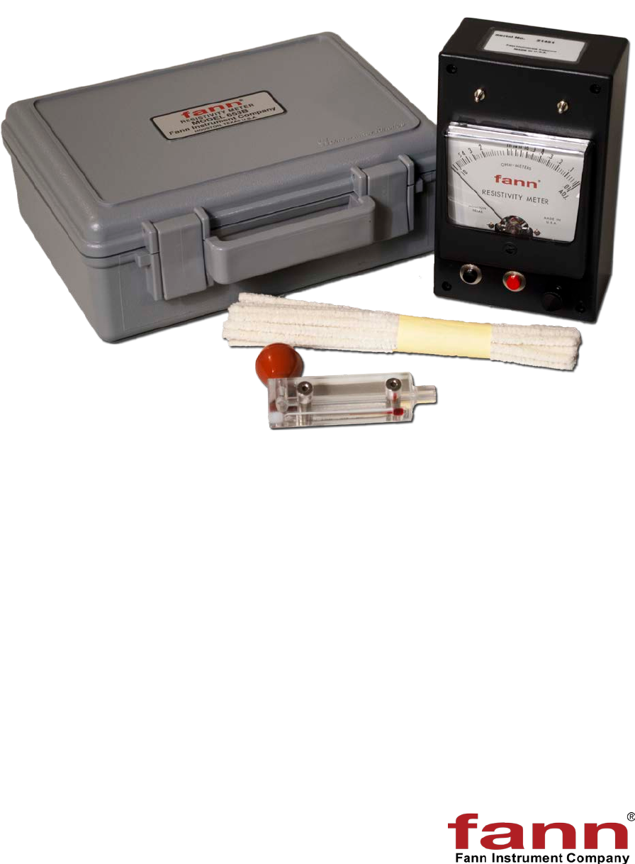
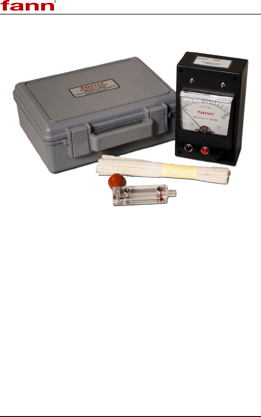
Figure 3-1 Resistivity Meter, Model 653B ........................................................................ 8
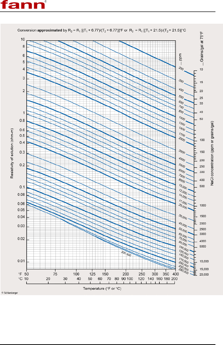
Figure 4-1 Resistivity Chart for NaCl Solutions .............................................................. 12
List of Tables
Table 3-1 Resistivity Meter, Model 653B Specifications .................................................. 7
Table 3-2 Range of Environmental Conditions ................................................................ 7
Table 6-1 Model 653B Resistivity Meter Included Parts, P/N 101582036 ..................... 15
Table 6-2 Optional Equipment ....................................................................................... 15
Model 653B Instruction Manual
101418648 Revision E, January 2014 4
1 Introduction
The Model 653B Resistivity Meter is a portable electronic meter that measures the
resistivity of fluids, slurries, and semisolids according to API Recommended
Practice 13B-1. The resistivity range for this meter is 0.01 to 10 ohm meters. This
ohm-meter reading can be converted to ppm sodium chloride by using the sodium
chloride resistivity chart provided in this instruction manual. Field and laboratory
personnel rely on this instrument to evaluate formation characteristics from electric
logs. Resistivity is the ability of a material to resist conduction; conductivity is the
reciprocal of resistivity.
1.1 Document Conventions
The following icons are used as necessary in this instruction manual.
NOTE. Notes emphasize additional information that may be
useful to the reader.
CAUTION. Describes a situation or practice that requires operator
awareness or action in order to avoid undesirable consequences.
MANDATORY ACTION. Gives directions that, if not observed,
could result in loss of data or in damage to equipment.
WARNING! Describes an unsafe condition or practice that if not
corrected, could result in personal injury or threat to health.
Model 653B Instruction Manual
101418648 Revision E, January 2014 5
ELECTRICITY WARNING! Alerts the operator that there is risk of
electric shock.
HOT SURFACE! Alerts the operator that there is a hot surface and
that there is risk of getting burned if the surface is touched.
EXPLOSION RISK! Alerts the operator that there is risk of
explosion.
Model 653B Instruction Manual
101418648 Revision E, January 2014 6
2 Safety
Safe laboratory practices and procedures should be observed while operating and
maintaining the Model 653B.
2.1 Battery Safety
On nine volt batteries, the positive and negative terminals are on
the same end, next to each other. If these terminals touch
anything metal, such as steel wool, coins, or a paper clip, a short
circuit could occur, creating heat, sparks, a fire, or an explosion.
Nine volt batteries can explode if they are stored in a hot location,
charged improperly, or if the terminals contact metal, creating a
short circuit.
Some batteries contain toxic or corrosive material, which can leak
if the battery is damaged.
• Store unused 9-volt batteries in their original packaging, a sealed plastic container,
or securely cover both terminals to prevent short circuits.
• Do not charge rechargeable batteries before storing them.
• Store batteries at or below 70oF (21oC).

Model 653B Instruction Manual
101418648 Revision E, January 2014 7
3 Features and Specifications
The Model 653B can measure resistivity from 0.01 to 10 ohm-meters. The ohm-
meter reading can be converted into parts per million sodium chloride (or
equivalent calcium chloride, potassium chloride or other carbonate or hydroxyl
salts) using the resistivity chart (Figure 4-1). This instrument can be operated by its
9V battery. Refer to Figure 3-1.
The Model 653B has these features:
• Direct reading in ohm-meters
• Built-in temperature probe
• Push Button for calibration (black)
Table 3-1 Resistivity Meter, Model 653B Specifications
Category Specification
Meter Range 0.01 to 10 ohm-meters
Meter Dimensions
(Height x Width x Length)
3.1 x 3.7 x 6.2 inches
8.0 x 9.5 x 15.8 centimeters
Carrying Case Dimensions
(Height x Width x Length)
9 x 3.5 x 7.9 inches
22.9 x 8.9 x 20.1 centimeters
Weight 3.25 lb (1.5 kg)
Power Supply 9V alkaline battery
Table 3-2 Range of Environmental Conditions
Maximum Altitude
6562 ft (2000 m)
Temperature Range
41oF to 104oF (5oC to 40oC)
Maximum Relative Humidity (RH)
80% RH at 87.8oF (31oC) or less
50% RH at 104
o
F (40
o
C)
Model 653B Instruction Manual
101418648 Revision E, January 2014 8
Figure 3-1 Resistivity Meter, Model 653B

Model 653B Instruction Manual
101418648 Revision E, January 2014 9
4 Operation
This resistivity meter can measure resistivity of fluid samples and semisolid
samples (e.g., filter cakes or mud solids). Procedures for both types of samples are
listed here.
The resistivity chart (Figure 4-1) is used to determine the quantity of sodium
chloride (in combination with distilled water or other salt-free aqueous medium)
that is required to produce a solution with the same resistivity as the sample. The
concentration for carbonate salts, calcium salts, and hydroxyl salts can be found in
conductance tables for aqueous solutions.
4.1 Fluid Samples
This procedure explains how to measure resistivity of liquids, filtrates, and drilling
fluids. Refer to Figure 3-1.
1. Remove the sample cell and fill it with the sample. Fill and discharge the
sample cell several times before the final fill. To fill use the suction ball to pull
sample into the Lucite cell.
Make sure there are no bubbles in the sample.
2. Reattach the sample cell onto the pins on the meter.
Be sure the sample fills the area between the two metal posts in
the cell. If the sample is not at room temperature, wait for the
temperatures of the sample and the sell to reach equilibrium.
3. Press black switch to calibrate the meter. Use the ADJ control to set the meter
to the ADJ position.
4. Press both the black and red switches at the same time. Then read the resistivity
directly from the meter in ohm-meters.
Model 653B Instruction Manual
101418648 Revision E, January 2014 10
5. Read the temperature of the sample as shown on the thermometer in the cell
wall.
6. Remove the sample cell and clean it with distilled water. If necessary, use a
pipe cleaner and mild soap to clean the cell bore.
Do not use solvents to clean the cell.
7. Using the resistivity chart (Figure 4-1), convert the resistivity in ohm-meters to
concentration of chlorides.
4.2 Semisolid Samples
This procedure explains how to measure resistivity of semisolid samples, such as
filter cakes and mud solids. Refer to Figure 3-1.
1. Prepare samples of uniform moisture content.
2. Remove the sample cell from the resistivity meter.
3. Completely fill the slot on the outer surface of the cell with semisolid sample.
4. Reattach the sample cell onto the pins on the meter.
Be sure the sample fills the area between the two metal posts in
the cell. If the sample is not at room temperature, wait for the
temperatures of the sample and the sell to reach equilibrium.
5. Press black switch to calibrate the meter. Use the ADJ control to set the meter
to the ADJ position.
6. Press both the black and red switches at the same time. Then read the resistivity
directly from the meter in ohm-meters.
7. Read the temperature of the sample as shown on the thermometer in the cell
wall.
8. Remove the sample cell and clean it with distilled water. If necessary, use a
pipe cleaner and mild soap to clean the slot.

Model 653B Instruction Manual
101418648 Revision E, January 2014 11
Do not use solvents to clean the cell.
9. Using the resistivity chart (Figure 4-1), convert the resistivity in ohm-meters to
concentration of chlorides.
Model 653B Instruction Manual
101418648 Revision E, January 2014 12
Figure 4-1 Resistivity Chart for NaCl Solutions
Model 653B Instruction Manual
101418648 Revision E, January 2014 13
5 Troubleshooting and Maintenance
Calibration and regular maintenance procedures are described in this section. If
more extensive maintenance or service of the instrument is required, please contact
Fann Instrument Company.
5.1 Calibration
Press black switch to calibrate the meter. Use the ADJ control to set the meter to
the ADJ position.
A thorough calibration requires a calibration kit.
A calibration kit (P/N 210179) is available as a separate
purchase. See the parts list for details.
5.2 Battery Replacement
When the meter cannot be calibrated with the zero control, replace the 9 Volt
battery (P/N 205643).
Observe the polarity marking on the printed circuit board.
If the battery is inserted incorrectly, it will become damaged.
Model 653B Instruction Manual
101418648 Revision E, January 2014 14
5.3 Cleaning
Always clean the cell immediately after making a measurement.
Do not use solvents to clean the cell.
Avoid scratching the surface of the cell.
1. Purge the cell with distilled water until it is clean.
2. If additional cleaning is necessary, use a pipe cleaner and mild soap.
3. After extensive use, follow these steps to thoroughly clean the cell.
a. Soak the cell bore in cleaning solution (P/N 210181) for 2 to 3 hours.
b. Scrub it with a pipe cleaner.
c. Rinse with distilled water.
d. Dry the cell with a clean pipe cleaner.
Model 653B Instruction Manual
101418648 Revision E, January 2014 15
6 Parts List
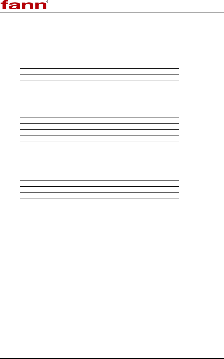
Table 6-1 Model 653B Resistivity Meter Included Parts, P/N 101582036
Part No.
Description
205643
BATTERY, 9 VOLT
208758
CARRYING CASE
210174
CELL (COMPLETE)
210170
CIRCUIT BOARD ASSEMBLY
210168
ELECTRODE CONTACT (2 REQUIRED)
204330
KNOB
101418648
INSTRUCTION MANUAL
205764
METER, 0 TO 50 MICRO AMPS
210441
PIPE CLEANERS, 20/PKG
205119
BLACK PUSHBUTTON SWITCH
205120
RED PUSHBUTTON SWITCH
210071
RUBBER BULB
206043
THERMOMETER
Table 6-2 Optional Equipment
Part No.
Description
210179
RESISTIVITY CALIBRATION KIT*
210181
CLEANING SOLUTION, 4 OZ.
210182
STANDARD RESISTIVITY SOLUTION, 4 0Z.
*Calibration Kit includes pipe cleaners, cleaning solution, and standard resistance solution.

Model 653B Instruction Manual
101418648 Revision E, January 2014 16
7 Warranty and Returns
7.1 Warranty
Fann Instrument Company warrants only title to the equipment, products and
materials supplied and that the same are free from defects in workmanship and
materials for one year from date of delivery. THERE ARE NO WARRANTIES,
EXPRESS OR IMPLIED OF MERCHANTABILITY, FITNESS OR
OTHERWISE BEYOND THOSE STATED IN THE IMMEDIATELY
PRECEDING SENTENCE. Fann's sole liability and Customer's exclusive remedy
in any cause of action (whether in contract, tort, breach of warranty or otherwise)
arising out of the sale, lease or use of any equipment, products or materials is
expressly limited to the replacement of such on their return to Fann, or at Fann's
option, to the allowance to Customer of credit for the cost of such items. In no
event shall Fann be liable for special, incidental, indirect, consequential or punitive
damages. Notwithstanding any specification or description in its catalogs,
literature or brochures of materials used in the manufacture of its products, Fann
reserves the right to substitute other materials without notice. Fann does not
warrant in any way equipment, products, and material not manufactured by Fann,
and such will be sold only with the warranties, if any, that are given by the
manufacturer thereof. Fann will only pass through to Customer the warranty
granted to it by the manufacturer of such items.
7.2 Returns
For your protection, items being returned must be carefully packed to prevent
damage in shipment and insured against possible damage or loss. Fann will not be
responsible for damage resulting from careless or insufficient packing.
Before returning items for any reason, authorization must be obtained from Fann
Instrument Company. When applying for authorization, please include information
regarding the reason the items are to be returned.
Our correspondence address:
Fann Instrument Company
P.O. Box 4350
Houston, Texas USA 77210
Telephone: 281-871-4482
Toll Free: 800-347-0450
FAX: 281-871-4446
Email fannmail@fann.com
Our shipping address:
Fann Instrument Company
14851 Milner Road, Gate 5
Houston, Texas USA 77032
