PDF Rohde&Schwarz EK895 HF Reciever Datasheet
Rohde&Schwarz_EK895 HF reciever_Datasheet Rohde&Schwarz_EK895 HF reciever_Datasheet
Rohde%26Schwarz_EK895 HF reciever_Datasheet The Eye | File Listing
User Manual: PDF T E X T F I L E S
Open the PDF directly: View PDF ![]() .
.
Page Count: 12
Version
04.00
June
2003
For all shortwave applications from 10 kHz to 30 MHz
◆Compact DSP-based receivers for the
following applications:
– Radiomonitoring and radio
detection
– Radiocommunications
– Search operation, DF systems
– Frontend for HF intelligence tasks
◆Digital signal processing (DSP) for
convenient and versatile operation
◆Two models:
– Half-rack receiver R&S EK895
– Search receiver R&S EK896
◆Realtime remote control or
master-slave mode
◆Tried and tested system concept
◆Excellent price/performance ratio
◆Extremely reliable operation under
harsh environmental and EMC
conditions
Digital VLF-HF Receivers R&S® EK895/R&S® EK896
2 Digital VLF-HF Receivers R&S® EK895/R&S® EK896
Digital VLF-HF Receivers R&S® EK895/R&S® EK896
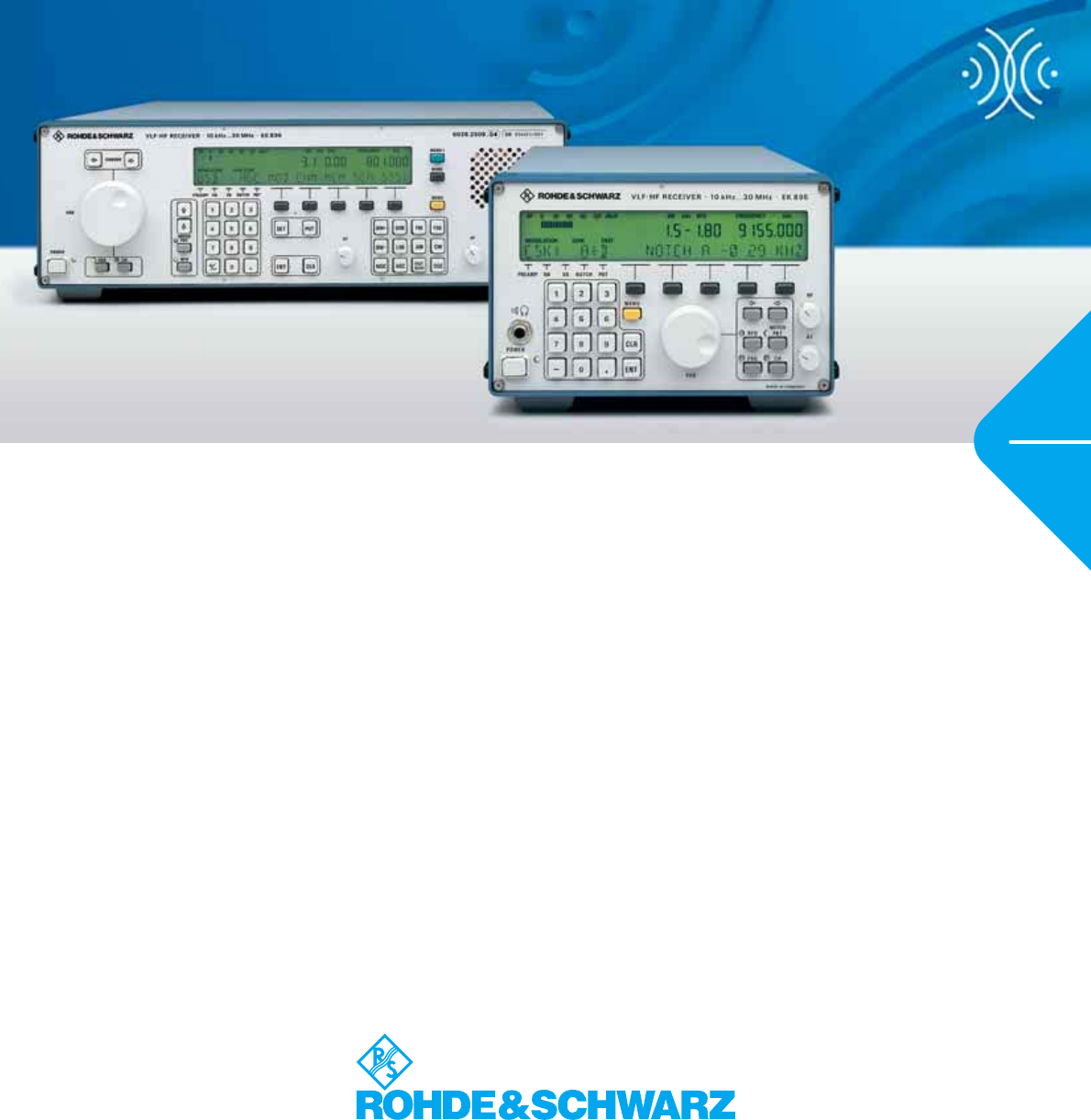
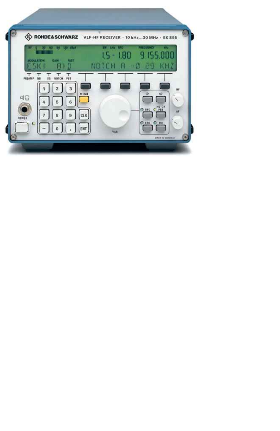
VLF-HF Receiver R&S EK895
with control panel
Special features
◆Excellent large-signal behaviour, very
good intercept points
◆High resolution of tuning frequency
down to 1 Hz
◆Fast and low-noise synthesizer
◆Demodulators for AM, CW, LSB, USB,
ISB, FM, FSK, AFSK and FAX included
in basic configuration
◆13 bandwidths from 150 Hz to 8 kHz
(quasi-continuous on request)
◆RF preamplifier, switchable (noise
figure 8kT0)
◆Double notch filter
◆Noise blanker
◆DATA LINK reception (option)
◆Passband tuning
◆Syllabic squelch
◆Special RTTY (FSK/AFSK) mark and
space filters, matched to the selected
shift
◆Digital data output
◆Maximum input voltage protection up
to 100 V EMF
◆Control interface fully complying with
international standards
◆Low power consumption <25 VA
(basic model R&S EK895), therefore
little self-heating
◆Powerful microprocessor for bus inter-
facing, menus and user programs
◆Dual receiver as 19“ desktop or rack
models
◆Free slots for retrofitting of options
◆Integrated self-test down to module
level with plain-text result display
◆Available with operator front panel or
remote-control-only front panel
◆Highly compact; width 1/
219"
(R&S EK895) or 19" (R&S EK896)
Operational features
◆Easy to operate via terminal,
computer or front panel
◆High rejection of strong interfering
signals
◆1000 programmable channel memory
locations
◆Scan mode for programmable
frequency ranges and any desired
channel sequences
◆Remote control of all settings – over
any distance when using modems
◆Ideal handoff receivers in stationary,
mobile and remote receiving systems
◆High availability owing to long MTBF
and short MTTR
◆Easy to adapt to special requirements
by means of optional plug-in modules
and standardized interfaces
Digital VLF-HF Receivers R&S® EK895/R&S® EK896 3
Overview
General characteristics of the
R&S EK895
With the R&S EK890 family, Rohde&
Schwarz is presenting a powerful genera-
tion of VLF-HF receivers which are top-
end products benefiting from many years
of experience in this field. All members of
this family are based on the R&S EK890
basic model. Due to the advantages of
digital signal processing, embedded in
the improved receiver versions R&S
EK895/R&SEK 896 a number of addi-
tional features and operational conve-
nience have been added. Straightfor-
ward, menu-guided selection and pro-
gramming of the receiving settings
ensure excellent processing and handling
of the received signal content. The com-
pact design is due to the use of large-
scale-integration SMDs. Featuring full
system compatibility, the receivers pro-
vide the basis for extremely economical
customer-specific solutions.
With its excellent RF characteristics and
clearcut, full remote-control capability via
standardized data interfaces, the R&S
EK890 family is suitable for all civil,
administrative and military shortwave
applications. These receivers are an ideal
choice for receiving systems that have to
fulfill extremely high reliability require-
ments, in particular under harsh environ-
mental and EMC conditions.
Operation is possible via an ASCII termi-
nal, a computer (PC) or via the front panel.
Using line drivers, a master receiver can
control up to 99 remote receivers in mas-
ter-slave operation. On the R&S EK895/
R&S EK896, two wired and bus-integrated
slots for plug-in modules are provided for
extensions, e.g. BCD interface or input fil-
ters.
Uses
The comprehensive sequence control can
be used for all demanding shortwave
reception tasks. Due to flexible program-
ming of the processor, the following oper-
ating modes are possible:
◆Manual operation
◆Remote control or master-slave
operation
◆Channel scanning, sequential and
programmable
◆Frequency scan
◆Channel reception
◆Password-protected channel
reception
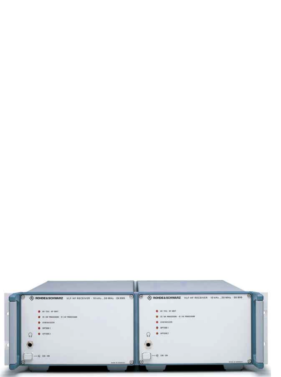
Two independent Receivers R&S EK895 with remote-control panel in a 19“ rackmount adapter
The R&S EK890 family thus fulfills the
requirements for versatile use in voice
receiving and any kind of data communi-
cation system as well as for all radio-
monitoring, radio detection and radio
intelligence (COMINT) applications. For
application in DF systems, an R&S EK895
is used as the master (controlling synthe-
sizer), its LOs being brought out for exter-
nal amplification, distribution and phase-
locked application to all other receivers.
The built-in memory has capacity for non-
volatile storage of 1000 complete channel
settings so that channel management
and control by an external computer are
not required but are nevertheless addi-
tionally possible. Due to their excellent
characteristics regarding dynamic range,
low synthesizer noise and gain control
range, the receivers are ideal high-perfor-
mance frontends for subsequent signal
processing.
4 Digital VLF-HF Receivers R&S® EK895/R&S® EK896
Search Receiver R&S EK896
The R&S EK896 has especially been
designed for complex tasks of radio
detection and search reception, its oper-
ating principle and configuration per-
fectly matching the relevant require-
ments. Basically it is fitted with panel
controls and LCD displays for local and
remote-control operation.
High-speed and reliable radiomonitoring
is supported by temporary storage of a
complete receiver setup and its transfer
to or readout from the connected slave.
The R&S EK896 is the optimal operator’s
position in modern radiomonitoring sys-
tems. In the usual master-slave mode, a
master receiver can control up to 99 slave
receivers via additional line drivers to
handle simultaneous radiomonitoring or
specific radio detection tasks. Due to its
outstanding characteristics, the R&S
EK896 is ideal for use as a standalone
receiver. All R&S EK895 options can be
fitted.
Design
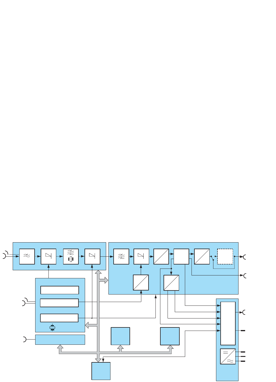
RF unit
The antenna signal is routed via a low-
pass filter, which is provided for rejecting
image frequencies and suppressing oscil-
lator reradiation, and applied to the input
mixer where it is converted to the first IF
of 41.44 MHz by means of an oscillator
variable in 1 Hz steps. The crystal filter
that follows determines the maximum
receiving bandwidth of 10 kHz and rejects
the second image frequency. A fixed fre-
quency of 40 MHz is used for conversion
to the second IF of 1.44 MHz.
The high-performance mixer at the
receiver input ensures excellent large-
signal behaviour. The intercept points are
typically +70 dBm (IP2) and +35 dBm
(IP3); the crossmodulation transfer is 10%
for an interfering signal of +21 dBm. In
most cases, additional filters such as sub-
octave filters are therefore not required.
IF/AF processor (DSP)
The second IF is converted to the third IF
of 25 kHz using a 5.66 MHz fixed fre-
quency. After digitization of the third IF in
a 16-bit A/D converter, the processor
assumes all signal generation and pro-
cessing tasks (DSP) including the follow-
ing:
◆Automatic, remote or manual control
(AGC, DGC, MGC)
◆Measurement of received levels
◆Filtering with 13 fixed or quasi-contin-
uously adjustable bandwidths
◆Demodulation, passband tuning,
double notch filter
◆Noise blanker, syllabic squelch
◆Generation of BFO frequency as
analog IF from 0 to 40 kHz, digital IF
as serial data and I/Q data stream
Synthesizer
The synthesizer supplies all the conver-
sion frequencies required for the RF and
the IF demodulator units. Due to direct
digital frequency synthesis, the first con-
version oscillator can be varied in 1 Hz
steps. The settling time of the oscillator is
5 ms for any frequency variation. Two
phase-locked loops (PLLs) produce the
40 MHz and 5.66 MHz fixed frequencies.
The operation of the total of four PLLs in
the synthesizer is continuously moni-
tored.
In the basic version, all the frequencies
are derived from a temperature-compen-
sated crystal oscillator. Higher accuracy
requirements can be fulfilled by including
a heated crystal oscillator (optional
OCXO) or using an external frequency
standard (1 MHz, 5 MHz or 10 MHz).
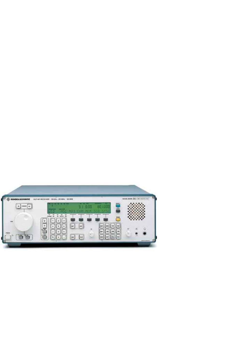
Search Receiver R&S EK896 with front panel for local/remote control
Digital VLF-HF Receivers R&S® EK895/R&S® EK896 5
Antenna
41.45 MHz to 71.44 MHz
5.66 MHz
External
frequency
standard
40 MHz EMC
filter
Headphones Option 1 Option 2
AC supply
Output
RS-232-C/
RS-485
interface
Processor
Control unit
RS-232-C/RS-485
Power
supply
TTY
AF 1
AF 2
I/Q
RF unit
Synthesizer
IF = 41.44 MHz
TCXO
OCXO (option)
A
DDSP
D
A
1
4
A
D
Option
IF
converter
455 kHz
IF/AF processor
IF = 25 kHz
IF = 1.44 MHz
IF 0 to 40 kHz
or
IF 455 kHz
Digital IF (data,
clock, frame)
Control functions
Processor and software
The 16-bit microprocessor using power-
saving CMOS technology is what makes
the high-performance, compact, reliable
and user-friendly concept of the R&S
EK895 possible. The microprocessor is
not only responsible for setting and man-
aging the module functions, it also com-
municates with the outside world via the
panel controls and the data interface,
executes the internal programs and
ensures the high operational reliability
through various routines:
◆Nonvolatile storage of all settings
◆Continuous testing of CPU, RAM and
PROM functions
◆Continuous monitoring (CM) of
synthesizer
◆BIT (built-in test) for module testing
The simple and logical ASCII command
syntax for controlling the receiver via the
serial interface includes control com-
mands for the following:
Basic settings
◆Frequency
◆BFO
◆Bandwidth
◆Demodulation modes
◆Gain control mode
◆Digital threshold
◆Passband tuning
Search operations
◆Frequency scanning
◆Channel scanning
◆Hold time
◆Dwell time
◆Stop criterion
Test operations
◆Read CM status
◆BIT start
◆BIT readout
System operations
Readout of
◆Software version
◆Options
◆Error messages
◆Signal level
◆Deviation
Channel operations
◆Channel manipulations
◆Store channel
◆Erase channel
◆Select channel
◆Readout channel
Special operations
◆Master-slave operation
◆Complete erasure of channel memory
In addition, the following functions can
be selected on the front panel:
◆Display of interface configuration
◆Fast channel storage
◆Channel buffer storage
◆Default settings on/off
◆Password for channel service
◆Local/remote mode
◆Knob increments
Block diagram of the Digital VLF-HF Receivers R&S EK895/R&S EK896
6 Digital VLF-HF Receivers R&S® EK895/R&S® EK896
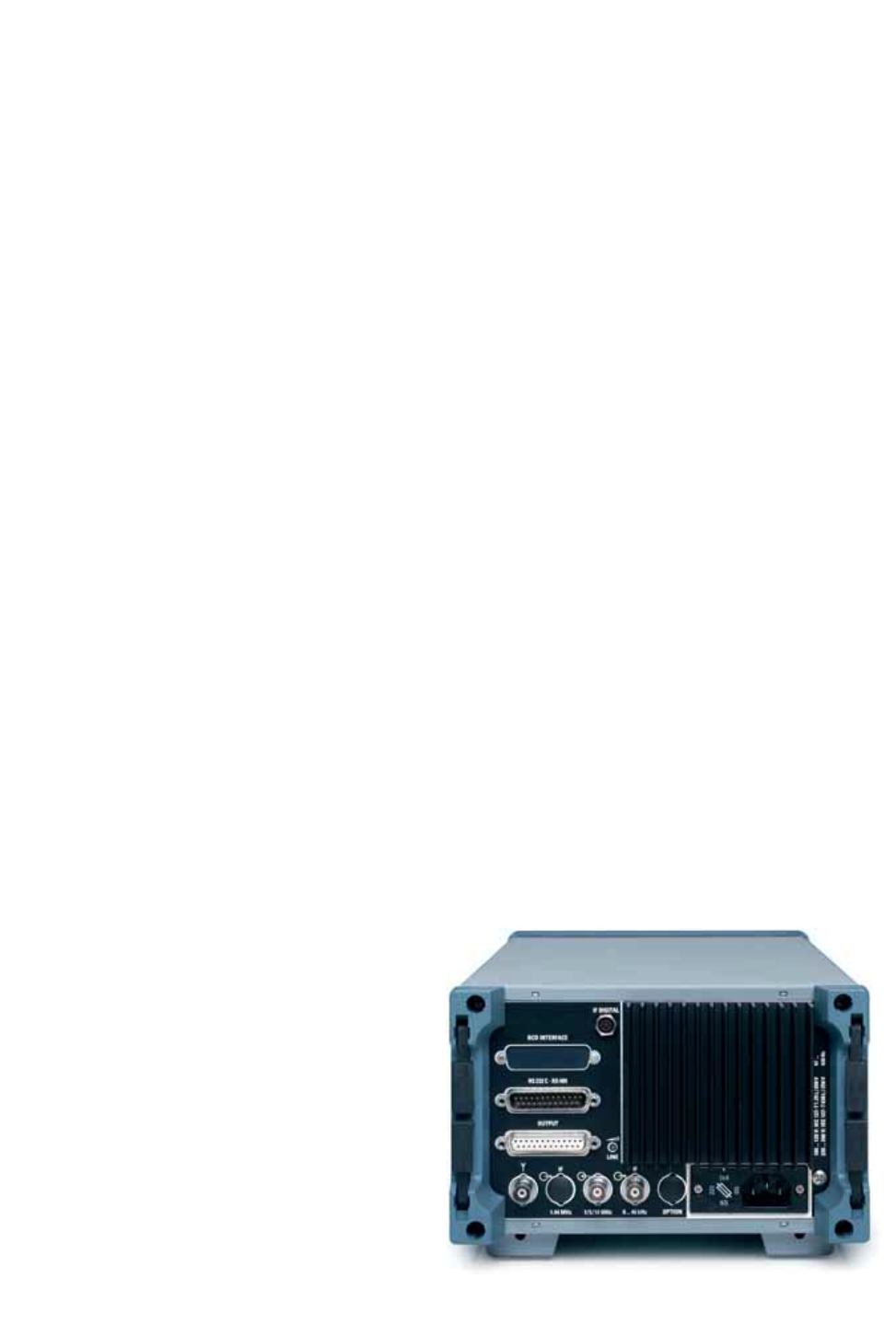
Rear view of the
R&S EK895
Various configurations
Receivers with control panel
In the standard version, the R&S EK895
receiver is available with an operator
front panel, which can also be retrofitted.
This front panel also permits manual con-
trol and display of all functions while full
remote-control capability is maintained.
This version is particularly suitable for use
as a master receiver in receiving systems
or as a standalone unit (standard with
R&S EK896).
The operator interface allows for a combi-
nation of hardkey and softkey entries.
Parameters that are frequently handled,
i.e. receive frequency, channel, BFO fre-
quency and passband tuning (PBT), can
be entered directly via a separate keypad.
All current receiver settings are continu-
ously displayed in large high-contrast
characters on a backlit LCD. An additional
bargraph indicator allows display of
either the receive level (0 to 120 dBµV, in
5 dB steps), the DGC or MGC settings or
the frequency offset (as a tuning aid and
deviation indication).
Receivers with remote-control panel
Optionally, the receivers are remote-
controlled by ASCII command sequences
via a multistandard interface (RS-232-C,
RS-485, RS-422/423, 2-/4-wire). In the
simplest case, a terminal can be used as
the control unit. For more convenience, a
computer can be used to handle complex
tasks and to create special user inter-
faces. A demo program for generating a
virtual front panel is available if desired.
The features newly incorporated into the
R&S EK895/R&SEK 896, such as pream-
plifier (PREAMP), noise blanker (NB),
squelch (SQ), notch filter (NOTCH) and
passband tuning (PBT), are selected in
submenus using softkeys. If one of these
features is active, a bargraph appears on
the display above the relevant inscription
(PREAMP, NB, SQ, NOTCH, PBT).
Remote Control Unit R&S GB899
(model 03)
This option is an R&S EK895 reduced to
control functions plus a Control Panel
R&S GB890. It is used for realtime remote
control of handoff receiving equipment,
over long distances preferably via addi-
tional modems.
IF bandwidth configuration
The R&S EK895/R&S EK896 features 13
bandwidths from 150 Hz to 8 kHz. Quasi-
continuous tuning in 128 steps is avail-
able as an option.
Input Filter Unit R&S FK890H1
(option)
The input filter module comprises a low-
pass filter, a bandpass filter and eight
suboctave filters which are automatically
selected with the receive frequency.
BCD Interface R&S GC890 (option)
A plug-in BCD interface is available for
controlling frequency-dependent add-on
units with parallel interfaces, e.g. a selec-
tive antenna.
TTY Line Current Source R&S GH890
(option)
For the operation of older teletype units
that require line current (single/double
current), a TTY line current source requir-
ing no extra slot can be accommodated.
IF Converter R&S UX895 (option)
The IF Converter R&S UX895 can be sup-
plied as a submodule for incorporation
into the IF/AF processor. Instead of the
analog IF output signal of 0 to 40 kHz, it
linearly converts the set receive parame-
ters to the IF of 455 kHz.
Digital Selection R&S FK896D
(option for R&S EK896 only)
This option considerably improves the
input selectivity of the receiver. Two ver-
sions are available for 20 dB or 40 dB
stopband attenuation. The automatically
tracking selection circuit includes the fol-
lowing functions:
◆7-circuit lowpass (0 to 30 MHz)
◆5-circuit lowpass (0 to 1.5 MHz) for
rejection of strong shortwave interfer-
ing signals
◆Tracking single-circuit filter (1.5 MHz
to 30 MHz) with a stopband attenua-
tion of >20 dB (40 dB) at 10% spacing
from the center frequency
◆Switch on/off by remote control
◆
Input voltage protection of
≥
200 V EMF
The Digital Selection R&S FK896D is rec-
ommended for use in environments with
strong RF interference (collocation prob-
lems). It improves input selection by auto-
matically tracking the receive frequency
and, at the same time, considerably
increases input-voltage protection
(overload protection).

Digital VLF-HF Receivers R&S® EK895/R&S® EK896 7
Broadband IF Output R&S GM893
(option)
The optional broadband output (plug-in
module) supplies a 1 MHz output signal at
the first IF of 41.44 MHz (relative to a
receive frequency of ±500 kHz). To pre-
vent impairment of the receiver sensitiv-
ity of the main channel (message chan-
nel), the path to the broadband channel is
decoupled by approx. 10 dB. For broad-
band spectrum analysis, a spectrum
display can be connected to this broad-
band output.
Digital data output (option)
For further digital signal processing of the
received signal, a separate digital IF inter-
face (connector X 69 at rear) is available,
delivering the digital DATA, CLOCK
FRAME outputs (0 to 40 kHz, sampling
rate 100 ksps).
DATA LINK option
If DATA LINK operation (MIL-STD-188-
203-1A) is required, special receiver ver-
sions are available.
1.44 MHz IF output, unregulated
(option)
For connecting and operating an external
IF spectrum display, e.g. the Digital
Spectrum Display R&S EP090, an
unregulated IF output at 1.44 MHz is
available. This option uses the HF unit
(model 03) and has to be ordered along
with the basic receiver.
Setting possibilities of R&S EK895 down to second menu level
Operating concept
The R&S EK890 family has a suitable oper-
ating mode for every application (see also
page 8). The remote-control interface is
configured to the RS-485 standard and is
bus-compatible for system operation.
Users who want to control their radiomon-
itoring system from the receiver front
panel rather than from a computer can use
the receivers of the R&S EK890 family as a
master receiver or install the Remote
Control Unit R&S GB899.
The softkey-menu operator interface pro-
vides the ergonomical advantage of clean
front panel layout as well as access to a
large number of setting parameters. When
you insert extension modules, they are
automatically detected and incorporated
in the software BIT and the menu system.
The clearcut operating concept of the R&S
EK890 family has five menu levels which
allow 50 logically structured operating rou-
tines to be called up by softkeys. In spite of
the multitude of functions, operation is
higly convenient, e.g. each type of modula-
tion is assigned a default setting with all
relevant parameters, which can also be
individually programmed.
The table to the left shows all possible set-
tings down to the second menu level.
For fast access to the setting parameters,
the R&S EK896 has 12 additional hard-
keys, e.g. for standard types of modula-
tion, bandwidth variation, etc.
Main menu: MOD GAIN BW SCA MORE
↓Second menu level
MOD Demodulation modes
MORE: for further modes
AM CW LSB USB MORE
GAIN Control modes
Auto, manual, auto+manual, auto+digital
MORE: fast or slow control
AGC MGC A+M A+D MORE
BW Bandwidth BW ↓ BW ↑
SCA Scan mode
Frequency sweep, channel sweep (any sequence),
channel sweep (incremental), stop or continue
sweep, program sweep
FRQ CHP CHS S/C PRO
MORE: M/S SYS SPEC CHM MEM
↓
M/S Master-slave operation
Address slave (indicate slave address, e.g. 62), read
out or vary slave settings
ADR62 GET PUT
SYS System status
Read out firmware version, built-in options, error
messages; start self-test; MORE: total reset
VERS OPT CM BIT MORE
SPEC Special functions
Rotary knob: step size on/off;
level setting for threshold-controlled external
switching signal; show serial interface setting;
switch to remote control; default settings on/off
KNOB LEV SER REM DEF
CHM Channel memory parameters
Channel memory indication and channel-specific
parameter variation without interrupting reception
MOD GAIN BW THLD
MEM Channel memory operations
Clear all memory, clear certain memory,
store to certain memory, use next free memory
CLA CLCH STCH STO
8 Digital VLF-HF Receivers R&S® EK895/R&S® EK896
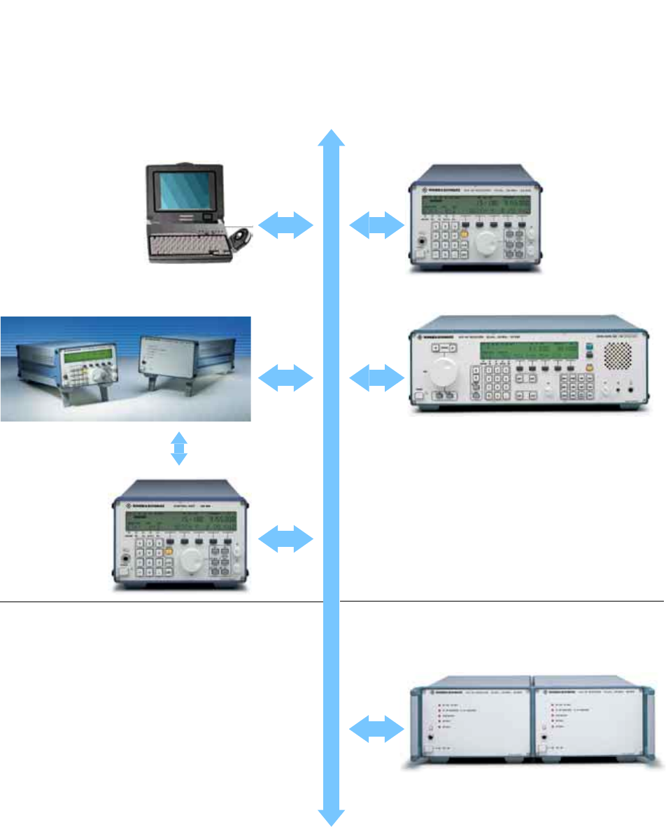
Control concepts of the Digital VLF-HF Receivers R&S EK895/R&S EK896
RS-485 bus
Remote control
R&S EK895 with control
panel as a standalone unit
or as a master receiver in
systems
Local control
Search Receiver R&S EK896
Slave receivers, max. 99 addressable
R
&S EK895 with front
p
anel for remote control
… via PC or ASCII
terminal
Master-slave operation
RS-485 bus
…
via the Remote Control
Unit R&S GB899,
model 03

Digital VLF-HF Receivers R&S® EK895/R&S® EK896 9
Specifications
Frequency range 10 kHz to 30 MHz
Resolution 1 Hz
Frequency drift
Frequency standard
Oven-controlled frequency standard
–10 to +45°C aging/year
5 x 10⁻⁷ 1 x 10⁻⁶
1 x 10⁻⁷ 1 x 10⁻⁷
External frequency standard 1/5/10 MHz, 0.2 V to 1 V rms
Antenna input BNC connector, 50 Ω
VSWR
<
1.5 typ. with preamp on for f
>
250 kHz
<3
typ. w/o preamp for f
>
5MHz
otherwise <4
typ.
Max. input voltage (≤30 MHz) 100 V EMF
Oscillator reradiation into 50 Ω
termination ≤10 µV
Demodulation modes CW/MCW (A1A, A1B, A2A, A2B)
FAX1 (F1C)
AM/AME (A3E, H2A, H2B, H2E) USB/
LSB (R2A, R3E, J2A, J3E) ISB (B8E)
FSK/AFSK (F1A, F1B), F6 (F7B)
FAX2 (F3C), FM (F3E)
DATA LINK acc. to
MIL-STD-188-203-1A
(on request)
IF bandwidth
(standard values)
3 dB 60 dB
±75 Hz ±150 Hz
±150 Hz ±225 Hz
±300 Hz ±430 Hz
±500 Hz ±770 Hz
±750 Hz ±990 Hz
±1050 Hz ±1600 Hz
±1200 Hz ±1760 Hz
±1350 Hz ±1900 Hz
±1550 Hz ±2100 Hz
±2000 Hz ±3400 Hz
±2400 Hz ±3700 Hz
±3000 Hz ±4200 Hz
±4000 Hz ±5200 Hz
Quasi-continuous bandwidth
(option for R&S EK895) 128 steps, 100 Hz to 9 kHz
Sensitivity
For S/N=10 dB, f=0.1 MHz to 30 MHz
A1A (CW)
J3E (SSB), J7B
H3E (AME), 1 kHz, m=60%
0.4 µV EMF (−121 dBm), BW=300 Hz
1.0 µV EMF (−113 dBm), BW=2.7 kHz
2.7 µV EMF (−104 dBm), BW=6 kHz
With preamplifier, f=0.2 MHz to
30 MHz
A1A (CW)
J3E (SSB), J7B
H3E (AME), 1 kHz, m=60%
0.2 µV EMF (−127 dBm), BW=300 Hz
0.4 µV EMF (−121 dBm), BW=2.7 kHz
1.0 µV EMF (−113 dBm), BW=6 kHz
Immunity to interference,
non-linarities
Intermodulation (1.5 MHz to 30 MHz;
∆f ≥30 kHz; interfering signal 0 dBm)
IP2
IP3
>60 dBm (70 dBm typ.)
>30 dBm (35 dBm typ.)
Crossmodulation (0.1 MHz to 30 MHz,
interfering signal 5 V EMF (+21 dBm);
∆f ≥30 kHz; m=0.3; f=1 kHz; signal
level 10 mV EMF (−33 dBm)) ≤10% modulation transfer
Blocking (0.1 MHz to 30 MHz; interfer-
ing signal 6.3 V EMF (+23 dBm);
∆f≥30 kHz; signal level 1 mV EMF
(−53 dBm); m=0.3; f=1 kHz) ≤1 dB signal attenuation
Desensitization (interfering signal
300 mV EMF; ∆f ≥30 kHz; signal level
30 µV EMF; bandwidth 3.1 kHz) ≥20 dB SINAD
Inherent spurious signals (f >100 kHz) <−113 dBm (nominal −124 dBm)
Image frequency rejection >90 dB
IF rejection >90 dB
Weighted S/N ratio for 1 mV EMF >46 dB SINAD
Gain control automatic (AGC), manual (MGC) or
remote (DGC)
AGC error ≤3 dB typ. (1 µV to 1 V EMF)
Time response constants
Attack time
Decay time
<15 ms
25/150/500 ms, 1 s, 3 s
DGC range 0 to 120 dBµV EMF in 1 dB steps
BFO −5.00 kHz to +5.00 kHz
Resolution 10 Hz
AFSK/FSK demodulator transfer rate (50 baud to 600 baud)
and deviation range (±42.5 Hz to
±425 Hz) adjustable; V.28 interface
and audible tone circuit
Diplex telegraphy demodulator (F7B) 2 x V.28 interface
Channel memory for 1000 channels, nonvolatile, stor-
age of complete receiver setup for
each channel
Data interface RS-232-C, RS-485 (bus-compatible)
Transfer rate 50 baud to 38400 baud
Outputs
AF output 1, AF (I)
Settling range
0.3 kHz to 3.4 kHz; floating;
Zout =600 Ω
−10 dBm to +10 dBm
AF (Q)
FAX1 (F1C)
FAX2 (F3C)
FM (F3E)
480 mV rms, Zout ≈ 100 Ω
1.9 kHz ± 150 Hz in VLF range
(f<500 kHz) 1.9 kHz ±400 Hz in HF
range (f≥500 kHz)
1.9 kHz modulated
NBFM (3 dB bandwidth:
±
4 kHz)
AF output 2 (LSB in ISB mode)
Settling range
0.3 kHz to 3.4 kHz, floating,
Zout =600 Ω
−10 dBm to +10 dBm
Monitoring output 500 mV, Zout =332 Ω
FM video output 1 V/kHz, Zout =1 kΩ
IF (1.44 MHz) output (unregulated)
BW (–3 dB): ≥10 kHz;
gain: (18 ±2) dB, 50 Ω
IF output (analog) 0 to 40 kHz in 100 Hz steps,
0 dBm into 600 Ω or 455 kHz,
0 dBm into 50 Ω (optional)
IF output (digital) serial data (clock, data, frame),
100 ksps
I/Q output (digital) baseband signal, multiplexed,
5 V CMOS

10 Digital VLF-HF Receivers R&S® EK895/R&S® EK896
Options
Control Panel R&S GB890
(model 03)
with controls and indicators for com-
plete receiver setup; connector for
loudspeaker or headphones
(max. 1 W into 8 Ω )
Remote Control Unit R&S GB899
(model 03, on request)
Control Panel R&S GB890 plus R&S
EK895 reduced to control functions,
using RS-232-C with a transfer rate of
50 baud to 19200 baud; modem oper-
ation is recommended for distances
beyond about 100 m
Input Filter Unit R&S FK890H1 lowpass filter 0 to 0.5 MHz
bandpass filter 0.5 MHz to 1.5 MHz
8 suboctave filters 1.5 MHz to 30 MHz
BCD Interface R&S GC890 frequency information, 22 bit parallel
(CMOS, 5 V)
TTY Line Current Source R&S GH890 single current: 40 mA/60 V
double current: ±20 mA/±30 V
IF Converter R&S UX895
(on request)
455 kHz, 0 dBm into 50 Ω,
BNC female
Digital Selection R&S FK896D
(R&S EK896 only)
Frequency range 0 to 30 MHz, at f <1.5 MHz as LPF
Stopband attenuation ≥20 dB (>40 dB: R&S FK896D, model
04) at 10% spacing from center fre-
quency
(f = 1.5 MHz to 30 MHz)
Gain 0 to +2 dB
Tuning time <10 ms
Inband IP3≥34 dBm (≥30 dBm: R&S FK896D,
model 04)
Noise figure 13 dB typ.
RF input voltage protection
Response threshold
≥200 V EMF (Zin =50 Ω)
>10 V EMF or >4 A
General data
Broadband IF Output R&S GM893
(model 03)
Output frequency 41.44 MHz
3 dB bandwidth >1 MHz
Attenuation <10 dB relative to antenna input
Impedance 50 Ω
Oven-controlled frequency standard aging/day ≤1 x 10⁻⁹ (OCXO)
Environmental conditions
Operating temperature range
Permissible temperature range
Storage temperature range
Humidity (non-condensing)
to MIL-STD-810 D
−10°C to +45°C
−25°C to +55°C
−40°C to +80 °C
max. 95 % at +40°C
Vibration test 10 to 55 Hz; 0.4 mm double amplitude
Shock test 30 g, 11 ms
EMC to MIL-STD-461/462
MTBF >14 000 h
Power supply 100/120/220/240 V −15/+10%,
47 Hz to 420 Hz (approx. 25 VA to
75 VA, depending on model)
Dimensions (W x H x D), weight
R&S EK895
R&S EK896
211 mm x 132 mm x 460 mm,
approx. 8 kg
426 mm x 132 mm x 460 mm,
approx. 11 kg

Digital VLF-HF Receivers R&S® EK895/R&S® EK896 11
Ordering information
Digital VLF-HF Receiver R&S EK895
Remote control via serial interface 6057.8996.02
With control panel; for local and remote control 6057.8996.12
With control panel; for local and remote control; with built-in OCXO 6057.8996.14
With control panel; for local and remote control; with built-in OCXO;
LINK11 reception 6057.8996.17
With control panel; for local and remote control; with built-in OCXO;
LINK11 reception; for use with external frequency standard 6057.8996.37
With control panel; for local and remote control; with 1.44 MHz IF output 6057.8996.63
Digital VLF-HF Search Receiver R&S EK896
Control panel with speaker; for local and remote control 6038.2509.12
Control panel with speaker; for local and remote control; with built-in OCXO 6038.2509.14
With control panel; for local and remote control; with built-in OCXO;
LINK11 reception 6038.2509.17
With control panel; for local and remote control; with built-in OCXO;
LINK11 reception; for use with external frequency standard 6038.2509.37
Plug-in modules (R&S EK895, R&S EK896)
Preselection Unit R&S FK890H1 6007.7750.02
Digitally Tuned RF Selection
Stopband attenuation 20 dB; for R&S EK896 only R&S FK896D 6077.3019.02
Digitally Tuned RF Selection
Stopband attenuation 40 dB; for R&S EK896 only R&S FK896D 6077.3019.04
BCD Interface R&S GC890 6007.7809.02
Broadband IF Output R&S GM893 6051.8494.03
Recommended extras (R&S EK895, R&S EK896)
Transfer Software Package R&S EK890S3 6015.4492.02
Quasi-Continuous IF Bandwidth Control R&S EK895S7 6077.0510.02
Loudspeaker Unit R&S GA890L1 6041.6199.02
Remote Control Unit R&S GB899 6037.3501.03
TTY Line Current Source R&S GH890 6007.6054.02
Service Kit R&S KA890C1 6030.9004.02
19" Assembling Kit for two R&S EK895
Desktop model R&S KA890L1 6041.6699.02
19" Assembling Kit for two R&S EK895
For rack installation R&S KA890L1 6041.6699.03
High-precision Oven-controlled Master Quartz Oscillator 6007.3255.03
IF Conversion to 455 kHz R&S UX895 6077.0261.02
19" Adapter Kit
For one R&S EK895 and one blank panel R&S ZZA-98 0827.4533.00

Rohde& Schwarz GmbH & Co. KG ⋅ Mühldorfstraße 15 ⋅ 81671 München ⋅ Germany
P.O.B. 8014 69 ⋅ 81614 München, Germany ⋅ Telephone +49 89 4129-0 ⋅ Fax +49 89 4129-13663 ⋅ www.rohde-schwarz.com
Printed in Germany (Pe bb)
R&S® is a registered trademark of Rohde&Schwarz GmbH&Co. KG · Trade names are trademarks of the owners
PD 0758.0251.32 ⋅ Digital VLF-HF Receivers R&S® EK895/R&S® EK896 ⋅ Version 04.00 ⋅ June 2003 ⋅ Data without tolerance limits are not binding ⋅ Subject to change
