S3394 (2015 08) Honeywell Water Pump DC3
User Manual: Honeywell Water Pump DC3
Open the PDF directly: View PDF ![]() .
.
Page Count: 5
Form No. S3394-815
Supersedes S3394-114
Page 1 of 5
The DC3002 is a 2-unit HVAC lead/lag controller, and
the DC3003 is designed to control 3-units. For DC3003,
the #3 HVAC unit is always last to operate, while the #1
and #2 units will switch for lead/lag operation. They
will work with units with and without economizers, and
are designed with the additional feature to control an
auxiliary DC Fan system supplied by others. These
controllers have an independent pilot duty control relay
for purpose of controlling the load control relay (supplied
by others) for the DC Fan package, and the user has
a choice of designating the DC Fan to be used for
emergency ventilation only, for free cooling only, or both.
There is also a purge cycle option available that permits
the DC Fan package to function periodically to purge
the building. The purge length can be from 1 to 10
minutes long in 1-minute increments, and the interval
between purge cycles can by from 1 to 24 hours in
1-hour increments — both user selectable.
Both DC3002 and DC3003 have a full-featured alarm
board with Form C (SPDT) dry contact alarm relays
used, offering both NC and NO switching to meet the
user’s specific alarm protocol, providing complete
flexibility to meets any user’s requirements. All alarm
actuations are individually indicated on the controller
front panel, along with active stages of cooling or
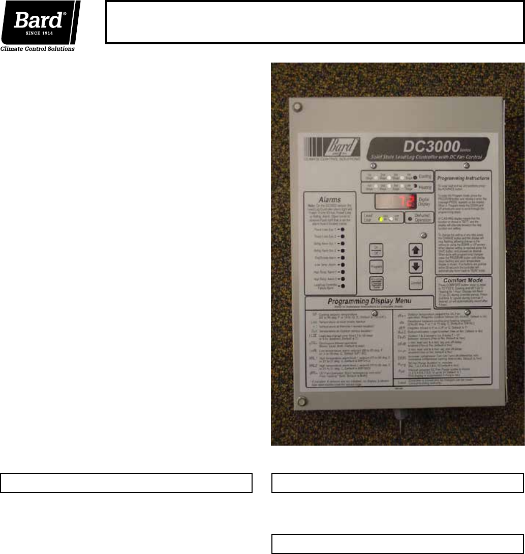
heating, and which unit is currently “lead”. A digital
display indicates building temperature and is also used
for all of the programming functions.
Refer to DC3002 and DC3003 Installation Instruction
#2100-484 (latest revision) for complete operation details.
Controller:
• Electronic (non-mercury) design
• Programmable
• Works with or without economizers
• Dehumidification control option
• Auxiliary DC fan control
Alarm Boards:
• Alarm circuits can be NO or NC logic
Ease of Installation:
• Powered by 24V from A/C units
• Phasing of 24V from units is not required
• Durable metal enclosure adequately sized
for ease of conduit and wire installation
Certifications:
• Tested for FCC and CE requirements
• EN50082-2 Standard for Immunity
• EN55011 Standard for Emissions
8612-023A 35-foot sensor, used for both remote
indoor and outdoor sensor.
Note: 1 of the 8612-023A sensors is
required as outdoor sensor for non-
economizer units if auxiliary DC Fan is
to be used for free cooling.
DC3002 Complete controller system for 2-units
DC3003 Complete controller system for 3-units
DC3000 Series
Solid State Lead/Lag Controller with DC Fan Control
Key Design Features Controller Models Available
Remote Sensors – Optional
Form No. S3394-815
Supersedes S3394-114
Page 2 of 5
Feature Selection Guide DC3002 DC3003
Number of HVAC units controlled 2 3
2-unit lead/lag control (DC3003, Unit #3 is always last) Yes Yes
Cooling stages (See Note 3) 4 5
Heating stages (configured for A/C with electric heat) 2 3
Temperature control type Electronic Electronic
Display (4 character .375" high LCD) Digital Digital
Stage “On” LED for Cooling and Heating Yes Yes
Lead unit LED Yes Yes
Advance (switch) lead unit feature Yes Yes
One button comfort (72F for 1-hour) feature Yes Yes
Local sensor (standard with controller) Yes Yes
Remote indoor sensor option (See Notes 1 and 2) Yes Yes
Remote outdoor sensor option (See Note 4) Yes Yes
Controller locking feature (prevents unauthorized changes) Yes Yes
Smoke/fire lockout circuit (shutdown of controller & A/C) Yes Yes
Generator run feature (inhibits lag A/C unit operation) Yes Yes
Humidity control feature (requires optional humidity controller input) Yes Yes
Selectable continuous fan control, lead-both-none (See Note 5) Yes Yes
Both fans On @ 5F delta T between 2 sensors (selectable) Yes Yes
Control strategy to limit excessive compressor cycling Yes Yes
-24V or -48V backup power connection for emergency alarms Yes Yes
Power loss alarm relay and LED for all units Yes Yes
HP/LP refrigerant lockout alarm relay and LED for all units Yes Yes
Smoke/fire alarm relay and LED Yes Yes
Low temperature alarm relay and LED Yes Yes
High temperature #1 alarm relay and LED Yes Yes
High temperature #2 alarm relay and LED Yes Yes
2nd stage cooling alarm relay Yes Yes
Controller failure alarm relay and LED Yes Yes
Economizer relay (emergency vent strategy) for all units Yes Yes
Auxiliary DC Fan pilot duty control relay (load control relay by others) Yes Yes
Option to use Auxiliary DC Fan for emergency ventilation Yes Yes
Option to use Auxiliary DC Fan for free cooling Yes Yes
Option to use Auxiliary DC Fan for purge cycle Yes Yes
Note 1: Optional remote 35-foot space temperature sensors available, Bard PN 8612-023A. Controller automatically detects any connected sensors.
Note 2: Multiple Sensor Control Strategy:
A. If only the standard local sensor is used, it will govern space temperature control along with low and high temperature alarm monitoring.
B. If 1 remote sensor is installed and connected, the temperature readout display and the building temperature are controlled to an average of connected sensors.
If there is more than 10F difference between the two sensors, the actual control will be governed by the hottest sensor for cooling and the coldest sensor for heating.
Note 3: Also for use with A/C units that have either 2-stage compressors or units with 2 compressors.
Note 4: Required for non-economizer application if DC Fan is to be used for free cooling.
Note 5: For DC3003, the HVAC #3 blower operates on demand only.
Form No. S3394-815
Supersedes S3394-114
Page 3 of 5
Specifications/Features for Basic Controller
DC3000 Basic Controller
• Input power: 18 to 32VAC, 60/50Hz, power is supplied from A/C #1 and/or A/C #2 (or A/C #3 for DC3003)
• Isolation circuitry: no line or low voltage phasing required
• Backup power: connection for -24VDC or -48VDC (-20 to -56V) allows DC Fan Control and maintains microprocessor
operation, front panel indication, and alarm relay operation during commercial power outages
• Digital display: 4-character LCD
• Temperature display: F or C
• HVAC outputs: Form A (NO) relays (1A @ 24VAC)
• Cooling control stages: 2 for each A/C unit (4 total), DC3003 has 5 stages total with Unit 3 located on DC3003 alarm board
• Heating control stages: 1 for each A/C unit
• Dehumidification circuit: requires optional humidity controller as input signal
• Locking feature, allows controller to be “locked” so no unauthorized changes to programming can be made
• Operating temperature range: 0 to 120F (-18 to 49C)
• Storage temperature range: -20 to 140F (-29 to 60C)
• Temperature accuracy: +/- 1F from 60-85F (16-30C) +/- 1% outside 60-85F
• Lead/lag changeover time: 0 to 30 days
• Timing accuracy: +/- 1%
• Inter-stage time delay: 10 seconds between stages
• Inter-stage differential: 2F (1C) for all modes
• On-Off differential: 2F (1C) is standard, 4F (3C) when “excessive cycling” mode is enabled
• Cooling set point range: 65 to 90F (18 to 32C)
• Comfort setting-Cooling 72F, Heating 68F, for 1 hour
• Dead band (difference between cooling and heating set points): 2F to 20F (1C to 10C)
• Fire/smoke interface: standard NC circuit jumper, remove for connection to building system control, shuts down both A/C units
• Generator run feature, inhibits lag A/C unit from operating if generator is operating (to limit amperage)
• Memory: EEPROM for set point and changeable parameters (maintains settings on power loss)
• Indoor space temperature sensors: 1 local is standard, will accept 1 optional 25-foot remote sensors. When two sensors are
used temperatures are averaged for basic control
• Outdoor space temperature sensors: required only in non-economizer application and desire to use Auxiliary DC Fan for free cooling
• LEDs for basic controller: Lead unit, Active Cooling stages, Active Heating stages, Dehumidification operation
• Six (6) Push-button controls: On/Off switch-Change lead unit-Increase and Decrease set points-Program/Save-Comfort
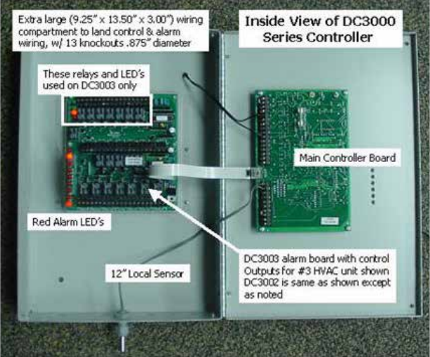
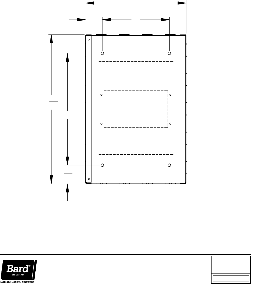
• Controller Enclosure: 20-gauge pre-painted steel, 9.25"W x 13.50"H x 3.00"D, hinged cover, thirteen (13) .875" diameter
electrical knockouts
Specifications/Features for Alarm Boards
DC3002 Alarm Board (Inputs/Outputs)
• Refrigerant alarm from A/C #1, input
• Refrigerant alarm from A/C #2, input
• Cooling operation signal from A/C #1, input
• Cooling operation signal from A/C #2, input
• Power loss alarm A/C #1, Form C (SPDT) output
• Power loss alarm A/C #2, Form C (SPDT) output
• Smoke/fire alarm, Form C (SPDT) output
• Low temperature alarm, Form C (SPDT) output
• 1st stage (H1) high temperature alarm, Form C (SPDT) output
• 2nd stage (H2) high temperature alarm, Form C (SPDT) output
• Refrigerant system lockout A/C #1, Form C (SPDT) output
• Refrigerant system lockout A/C #2, Form C (SPDT) output
• 2nd stage cooling alarm, Form C (SPDT) output
• Controller system failure alarm, Form C (SPDT) output
• Emergency ventilation economizer outputs, Form A (SPNO) for both A/C #1 and A/C #2
o Emergency ventilation option for either air conditioner with refrigerant alarm @ H1 high temp alarm set point
o Emergency ventilation option for both air conditioners @ H2 high temp alarm set point
• Auxiliary DC Fan control relay, Form C (SPDT) output
DC3003 Alarm Board (Inputs/Outputs)
• All alarm inputs/outputs same as base version above, plus:
• HVAC outputs for HVAC #3, Form A (NO) relays (1A @ 24VAC)
• Refrigerant alarm from A/C #3, input
• Power loss alarm A/C #3, Form C (SPDT) output
• Refrigerant system lockout A/C #3, Form C (SPDT) output
• Emergency ventilation economizer output A/C #3
o Same sequence as for DC3002
• Also located on DC3003 alarm board are LED’s for A/C #3, 1st and 2nd stage cooling, power loss and refrigerant lockout
Note: All alarm/output relays are dry contacts rated
1A @ 24VAC, 1A @ 30VDC, 0.5A @ 150VDC
Alarm relays can be wired for NO (close on alarm) or
NC (open on alarm) strategy.
Alarm relays can be used individually if there are
enough available building alarm points, or can be
arranged into smaller groups or even a single group so
that all alarm capabilities can be utilized.
When multiple alarms are grouped together and
issued as a single alarm, there will be no off-site
indication of which specific problem may have
occurred, only that one of the alarms in the group has
been triggered. The individual alarm problem will be
displayed on the LED display on face of the controller.
Form No. S3394-815
Supersedes S3394-114
Page 4 of 5
Controller Programmable Features and Default Settings
Feature Description Range/Choice Default
Cooling Set Point 65F to 90F (18C to 32C) 75F (24C)
Dead Band (difference between Cooling and Heating Set Points) 2F to 20F (1C to 10C) 10F (5C)
Lead/Lag Changeover Time 0 to 30 Days 7
Humidistat Logic Enable (Requires optional humidity controller) Yes/No No
Continuous Blower Operation None/Lead/Both Lead
Continuous Blower (Both Units) on 5F Delta T (Requires 1 remote sensor) Yes/No Yes
Minimum Compressor Off-Delay (3-minutes Lead, 4-minutes Lag) Yes/No No
Minimum Compressor Runtime Option (3-minutes) Yes/No No
Change Compressor Turn On/Turn Off w/ Excessive Cycling Rate Yes/No Yes
Standard On/Off differential is 2F (1C), When Excessive Cycling is Yes the differential is 4F (3C)
Low Temperature Alarm Set Point 28F to 65F (-2C to 18C) 50F (10C)
High Temperature Alarm #1 Set Point 70F to 120F (21C to 49C) 85F (29C)
High Temperature Alarm #2 Set Point 70F to 120F (21C to 49C) 90F (32C)
Also DC Fan Set Point for Emergency Ventilation
DC Fan Operation (Emergency Vent only, Free Cool only, both) EdcF, Free, Both Both
DC Fan On Set Point for Non-Economizer Units (• Requires Outdoor Sensor) 50-55-60 55
DC Fan Used for Building Purge Cycle (Minutes) No,1,2,3,4,5,6,7,8,9,10 No
DC Fan Purge Cycle, Interval between Cycles (Hours) 1,2,3,4,5 Up to 24 1
General Programming Overview
DC3000 Controller Buttons and Function
On/Off Button
1. Press and release the On/Off button to turn On
controller, 4-character display will illuminate and
Lead unit LED will light.
2. Press and release the On/Off button to turn Off
controller. Controller will go dark and A/C units
will stop.
Comfort Button
1. Press and release the Comfort button to change
the Cooling Set Point to 72F and the Heating Set
Point to 68F for a period of 1 hour.
2. Set Points will return to the programmed settings
automatically after 1 hour.
3. Pressing the Comfort button during the 1 hour
period will deactivate the Set Point change.
4. The temperature display will flash the current
temperature while in override mode.
Program Button
1. Press the Program button and release it when
the message “Prog” appears on the display.
2. Refer to Programming Instructions and follow
these commands to change from Default
settings.
Advance/Change/Save Button
1. Press and release the Advance button to swap lead and lag unit positions.
2. When in Program mode the Down and Up buttons are used to scroll through the programming steps.
3. A flashing display means that the particular function of that programming step is “set”, and the display will alternate between the
step function and the setting.
4. To change the setting press the Change button and the display will stop flashing, allowing change to the setting.
5. Use Down or Up arrows to change setting as desired, and press the Save button and proceed as desired.
6. When done with programming changes press the Program button until display stops flashing and room temperature is shown.
Up and Down Buttons
These buttons are used to change the settings in conjunction with the Advance/Change/Save button when in programming mode.
Form No. S3394-815
Supersedes S3394-114
Page 5 of 5
"
21
1
13
10"
11
32
"
9"
"
32
1 1
26"
MIS-3760
Form No.
S3394
August, 2015
Supersedes: S3394-114
Bard Manufacturing Company, Inc.
Bryan, Ohio 43506
www.bardhvac.com
Due to our continuous product improvement policy, all
specifications subject to change without notice.
Before purchasing this appliance, read important energy
cost and efficiency information available from your retailer.
Mounting Hole Layout
