SA32 User Manual
SA32_user_manual
User Manual:
Open the PDF directly: View PDF ![]() .
.
Page Count: 6

Security at Fingertips
www.esslsecurity.com
User Manual
Single Door RFID Based Access Control
SA32-E
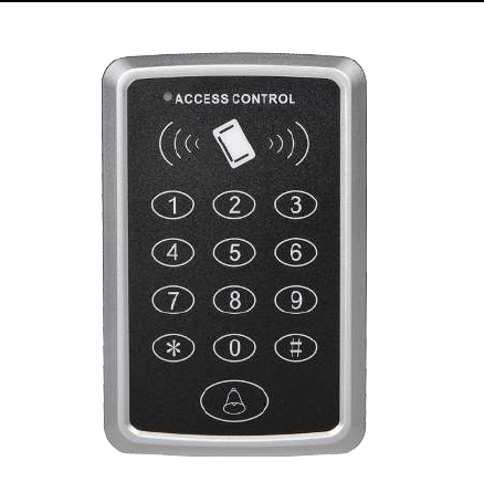
Product Overview
SA32-E is an Access Control Standalone Device with contact-less
smart card and password verifications, which enables 3 verification modes
(Card only, PIN only, and Card & PIN) to ensure maximum safety and
flexibility. With 1 Relay output (optional) and 1 PUSH (low) output,
1 door button Port and 1 doorbell Port, SA32 is simple but effective to use,
its convenience and adaptability allow it to be well deployed in residential
housing, offices and any other public facilities.
SA32-E
Single Door RFID Based Access Control
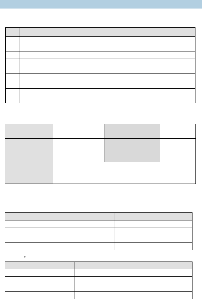
1. Specifications:
1.1Technical parameters:
NO Item Value
1
Operating voltage
DC 12V±10%
2
Operating current
< 100mA
3
Dimensions
120mm×78mm×22mm
4
Weight
110g
5
Ambient temperature
0
—60
6
Relative humidity
20%—80%
7
Storage
1000users
8
Card type (alternative)
EM(ID) card(IC card for options)
9
Card reading distance
1
-
15CM
1.2 Factory Default:
1.3 Light and Sound indicates:
Light: red and green
Light Description
Access control status
Red light flash every 1 sec
(
Slow flash
)
Holding state
Red light is always ON
Programming state
Green light is always ON within Open time
Unlocking state
Green light flash every 0.5sec (Fast flash)
Pending further action
Sound :buzz
Description
I ndicates
1 short buzz
Valid input
3 short buzz
Invalid input
1 long buzz
Program success
Continuous long buzz
Restoring factory programming passwords
Programming
Password
123456 Common Access
Password
None
Backlight Auto (for options) Relay Unlock
output 5 Seconds
W26 port Input (for options) Security mode OFF
Open mode
Card or Access Password
Access Password include Private Access Password (PIN) and
Common Access Password
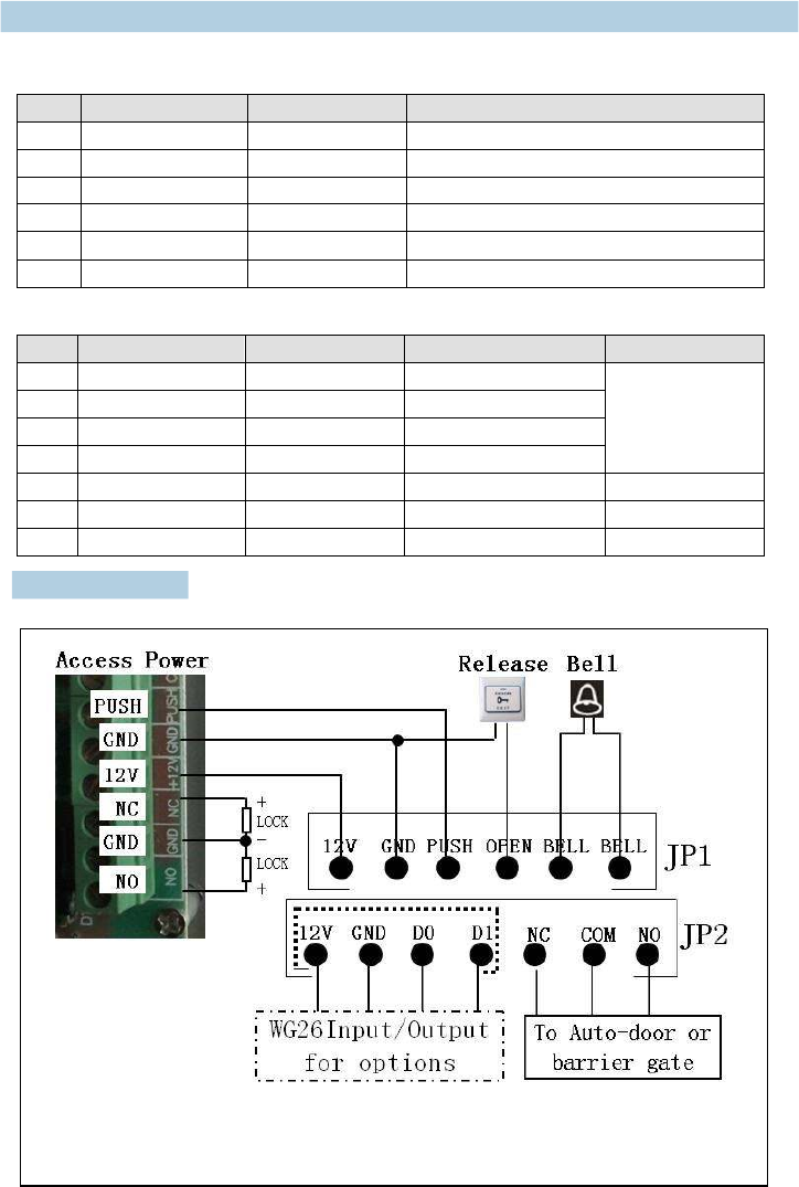
2. Installations Guide
JP1 terminal:
JP2 terminal:
NO
Mark
Color
Function
Remark
1
+12V
Red
Power+
For options
2
GND
Black
Power-
3
DATA0
Green
WG DATA0
4
DATA1
White
WG DATA1
5
NC
Brown
Relay NC output
6
COM
Blue
Relay Com output
7
NO
Purple
Relay NO output
NO
Mark
Color
Function
1
+12V
Red
Power+
2
GND
Black
Power-
3
PUSH
BLUE
Low level output
4
OPEN
Yellow
Door Release
5
BELL
Grey
BELL
6
BELL
White
BELL
R
emark:
If
let relay drive electric -
“-” poles.
lock, please connect a reverse diode with the lock’s “+” and
Wiring diagram:
3.2 To reset to Factory Programming Password (123456)
Step1、Turn off power and connect bin 2&3 of RST(S1)。
Step2、Turn on power and buzzer gives 3 long buzz with green light flash fast。
If need to set Manager Card, now read two empty cards first one as Manager Add Card and
Second one as Manager Delete Card with red light flashing and continuous short buzz .
Step3、Turn off power, disconnect bin2&3 and connect bin 1&2 of RST。
Step4、Turn on power again.
3.3 How to use Manager Card - MAC & MDC
To add a card user in standby mode: read MAC read new cards read MAC
To delete a card user in standby mode: read MDC read registered cards read MDC
To delete all users in standby mode: read MDC read MAC read MDC
Remark: User cards can be added or deleted continuously.
3.4 User ID No. explain
User ID is auto-generating 4-digit number started at 0001. The number increases with adding
user one by one and ignores deleting user. Common Access Password has no ID.
3.5 How to change PIN (When open mode: card+ PIN)
After reading card and input corresponding PIN to open the door, within 5 seconds, long press #
until the green lights flash fast. and then input new PIN # new PIN # , new PIN
changed successfully with a long buzz.
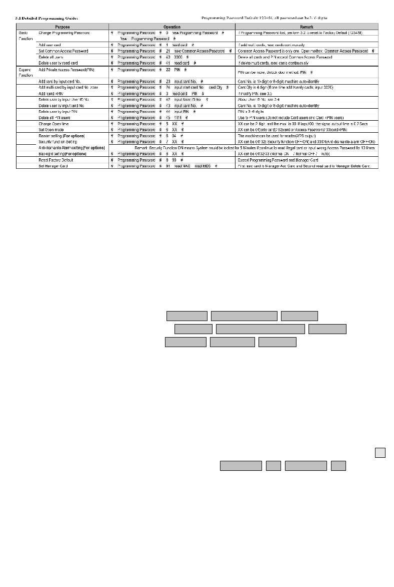
3. Programming Guide

#24,Shambavi Building, 23rd Main, Marenahalli,
JP Nagar 2nd Phase, Bangalore - 560078
Phone: 91-8026090500 | Email : sales@esslindia.com
www.esslsecurity.com
