SARA R4 / N4 AT Commands Manual
User Manual:
Open the PDF directly: View PDF ![]() .
.
Page Count: 307 [warning: Documents this large are best viewed by clicking the View PDF Link!]
- Preface
- Contents
- 1 AT command settings
- 2 General operation
- 3 IPC - Inter Processor Communication
- 4 General
- 4.1 Manufacturer identification +CGMI
- 4.2 Manufacturer identification +GMI
- 4.3 Model identification +CGMM
- 4.4 Model identification +GMM
- 4.5 Firmware version identification +CGMR
- 4.6 Firmware version identification +GMR
- 4.7 IMEI identification +CGSN
- 4.8 IMEI identification +GSN
- 4.9 Identification information I
- 4.10 TE character set configuration +CSCS
- 4.11 International mobile subscriber identification +CIMI
- 4.12 Card identification +CCID
- 4.13 Repeat last command A/
- 5 Mobile equipment control and status
- 6 Call control
- 7 Network service
- 7.1 Subscriber number +CNUM
- 7.2 Signal quality +CSQ
- 7.3 Extended signal quality +CESQ
- 7.4 Operator selection +COPS
- 7.5 Radio Access Technology (RAT) selection +URAT
- 7.6 Network registration status +CREG
- 7.7 Network selection control +PACSP
- 7.8 Channel and network environment description +UCGED
- 7.9 Edit Verizon wireless APN table +VZWAPNE
- 7.10 Read RSRP values +VZWRSRP
- 7.11 Read RSRQ values +VZWRSRQ
- 7.12 eDRX setting +CEDRXS
- 7.13 eDRX read dynamic parameters +CEDRXRDP
- 7.14 Set MNO profile +UMNOPROF
- 7.15 Band selection bitmask +UBANDMASK
- 8 Security
- 9 Short Messages Service
- 9.1 Introduction
- 9.2 Select message service +CSMS
- 9.3 Preferred message storage +CPMS
- 9.4 Preferred message format +CMGF
- 9.5 Save settings +CSAS
- 9.6 Restore settings +CRES
- 9.7 New message indication +CNMI
- 9.8 Read message +CMGR
- 9.9 New message acknowledgement to MT +CNMA
- 9.10 List message +CMGL
- 9.11 Send message +CMGS
- 9.12 Write message to memory +CMGW
- 9.13 Send message from storage +CMSS
- 9.14 Set text mode parameters +CSMP
- 9.15 Delete message +CMGD
- 9.16 Service center address +CSCA
- 9.17 Read concatenated message +UCMGR
- 9.18 List concatenated message +UCMGL
- 9.19 Send concatenated message +UCMGS
- 9.20 Write concatenated message to memory +UCMGW
- 9.21 More messages to send +CMMS
- 9.22 Sending of originating data via the control plane +CSODCP
- 9.23 Terminating data reporting via control plane +CRTDCP
- 10 V24 control and V25ter
- 10.1 Introduction
- 10.2 Circuit 109 behavior &C
- 10.3 Circuit 108/2 behavior &D
- 10.4 DSR override &S
- 10.5 Flow control &K
- 10.6 DTE-DCE character framing +ICF
- 10.7 DTE-DCE local flow control +IFC
- 10.8 Set flow control \Q
- 10.9 UART data rate configuration +IPR
- 10.10 Return to on-line data state O
- 10.11 Escape character S2
- 10.12 Command line termination character S3
- 10.13 Response formatting character S4
- 10.14 Command line editing character S5
- 10.15 Pause before blind dialling S6
- 10.16 Connection completion timeout S7
- 10.17 Command dial modifier time S8
- 10.18 Automatic disconnect delay S10
- 10.19 Escape prompt delay (EPD) S12
- 10.20 Command echo E
- 10.21 Result code suppression Q
- 10.22 DCE response format V
- 10.23 Result code selection and call progress monitoring control X
- 10.24 Reset to default configuration Z
- 10.25 Set to factory defined configuration &F
- 10.26 Display current configuration &V
- 11 SIM management
- 12 SIM toolkit
- 13 Packet switched data services
- 13.1 PDP contexts and parameter definition
- 13.2 PPP LCP handshake behaviour
- 13.3 PDP context definition +CGDCONT
- 13.4 Packet switched data configuration +UPSD
- 13.5 GPRS attach or detach +CGATT
- 13.6 PDP context activate or deactivate +CGACT
- 13.7 Enter PPP state/GPRS dial-up D*
- 13.8 Show PDP address +CGPADDR
- 13.9 GPRS event reporting +CGEREP
- 13.10 GPRS network registration status +CGREG
- 13.11 Manual deactivation of a PDP context H
- 13.12 UE modes of operation for EPS +CEMODE
- 13.13 EPS network registration status +CEREG
- 13.14 Delete non-active PDP contexts +CGDEL
- 13.15 Configure the authentication parameters of a PDP/EPS bearer +UAUTHREQ
- 13.16 PDP IP configuration when roaming +UDCONF=75
- 13.17 Enable/Disable data when roaming +UDCONF=76
- 14 System features
- 14.1 Firmware installation +UFWINSTALL
- 14.2 Firmware update Over AT (FOAT) +UFWUPD
- 14.3 Antenna detection +UANTR
- 14.4 Power saving control (Power SaVing) +UPSV
- 14.5 End user test +UTEST
- 14.6 Internal temperature monitor +UTEMP
- 14.7 Power Saving Mode Setting +CPSMS
- 14.8 Power Saving Mode Assigned Values +UCPSMS
- 14.9 Set LWM2M FOTA URCs +ULWM2MSTAT
- 14.10 Cancel LWM2M FOTA Download +ULWM2M=0
- 14.11 LWM2M configuration +UFOTACONF
- 14.12 Last gasp configuration +ULGASP
- 15 GPIO
- 15.1 Introduction
- 15.1.1 GPIO functions
- 15.1.2 GPIO mapping
- 15.1.3 Network status indication
- 15.1.3.1 No service (no network coverage or not registered)
- 15.1.3.2 Registered home network 2G
- 15.1.3.3 Registered home network 3G
- 15.1.3.4 Registered home network Cat NB1
- 15.1.3.5 Registered roaming 2G
- 15.1.3.6 Registered roaming 3G
- 15.1.3.7 Registered roaming Cat NB1
- 15.1.3.8 Data transmission
- 15.1.3.9 Data transmission roaming
- 15.2 GPIO select configuration command +UGPIOC
- 15.3 GPIO read command +UGPIOR
- 15.4 GPIO set command +UGPIOW
- 15.1 Introduction
- 16 File System
- 17 DNS
- 18 Internet protocol transport layer
- 18.1 Introduction
- 18.2 IPv4/IPv6 addressing
- 18.3 Create Socket +USOCR
- 18.4 SSL/TLS mode configuration on TCP socket +USOSEC
- 18.5 Set socket option +USOSO
- 18.6 Get Socket Option +USOGO
- 18.7 Close Socket +USOCL
- 18.8 Get Socket Error +USOER
- 18.9 Connect Socket +USOCO
- 18.10 Write socket data +USOWR
- 18.11 SendTo command (UDP only) +USOST
- 18.12 Read Socket Data +USORD
- 18.13 Receive From command (UDP only) +USORF
- 18.14 Set Listening Socket +USOLI
- 18.15 HEX mode configuration +UDCONF=1
- 18.16 Set socket in Direct Link mode +USODL
- 18.17 UDP Direct Link Packet Size configuration +UDCONF=2
- 18.18 UDP Direct Link Sending timer configuration +UDCONF=3
- 18.19 Timer Trigger configuration for Direct Link +UDCONF=5
- 18.20 Data Length Trigger configuration for Direct Link +UDCONF=6
- 18.21 Character trigger configuration for Direct Link +UDCONF=7
- 18.22 Congestion timer configuration for Direct Link +UDCONF=8
- 18.23 Socket control +USOCTL
- 18.24 Configure Dormant Close Socket Behavior +USOCLCFG
- 19 SSL/TLS
- 20 FTP
- 21 HTTP
- 22 GNSS
- 22.1 NMEA
- 22.2 GNSS power management +UGPS
- 22.3 Assisted GNSS unsolicited indication +UGIND
- 22.4 GNSS profile configuration +UGPRF
- 22.5 Aiding server configuration +UGSRV
- 22.6 GNSS aiding request command +UGAOS
- 22.7 Send of UBX string +UGUBX
- 22.8 GNSS indications timer +UGTMR
- 22.9 Get GNSS time and date +UGZDA
- 22.10 Get GNSS fix data +UGGGA
- 22.11 Get geographic position +UGGLL
- 22.12 Get number of GNSS satellites in view +UGGSV
- 22.13 Get recommended minimum GNSS data +UGRMC
- 22.14 Get course over ground and ground speed +UGVTG
- 22.15 Get satellite information +UGGSA
- 22.16 Ask for localization information +ULOC
- 22.17 Localization information request status unsolicited indication +ULOCIND
- 22.18 GNSS sensor configuration +ULOCGNSS
- 23 I2C
- 24 MQTT
- A Appendix: Error result codes
- B Appendix: AT Commands List
- C Appendix: UDP Direct Link workflow
- D Appendix: Glossary
- Related documents
- Revision history
- Contact

SARA-R4/N4 series
Size-optimized LTE Cat M1 / NB1 / GPRS modules
AT Commands Manual
Abstract
Description of standard and proprietary AT commands used with u-blox
cellular modules.
www.u-blox.com
UBX-17003787 - R09
SARA-R4/N4 series-AT Commands Manual
UBX-17003787 - R09
Page 2 of 307
Document Information
Title SARA-R4/N4 series
Subtitle Size-optimized LTE Cat M1 / NB1 / GPRS modules
Document type AT Commands Manual
Document number UBX-17003787
Revision and date R09 15-Jun-2018
Disclosure restriction
u-blox reserves all rights to this document and the information contained herein. Products, names, logos and designs
described herein may in whole or in part be subject to intellectual property rights. Reproduction, use, modification or
disclosure to third parties of this document or any part thereof without the express permission of u-blox is strictly
prohibited.
The information contained herein is provided “as is” and u-blox assumes no liability for the use of the information. No
warranty, either express or implied, is given, including but not limited, with respect to the accuracy, correctness, reliability
and fitness for a particular purpose of the information. This document may be revised by u-blox at any time. For most
recent documents, visit www.u-blox.com.
Copyright © 2018, u-blox AG
u-blox is a registered trademark of u-blox Holding AG in the EU and other countries.
SARA-R4/N4 series-AT Commands Manual
UBX-17003787 - R09
Preface
Page 3 of 307
Preface
Applicable products
This document applies to the following products:
Name Type number Modem version Application version PCN reference
SARA-R404M SARA-R404M-00B-00 K0.0.00.00.07.06 N.A. UBX-17047084
SARA-R410M SARA-R410M-01B-00
SARA-R410M-02B-00
SARA-R410M-52B-00
L0.0.00.00.02.03
L0.0.00.00.05.06
L0.0.00.00.06.04
N.A.
A02.00
A02.05
UBX-17051617
UBX-18010263
UBX-18020937
SARA-R412M SARA-R412M-02B-00 M0.04.01 A01.04 UBX-18019641
SARA-N410 SARA-N410-02B-00 L0.0.00.00.07.04 A02.05 UBX-18020938
How to use this Manual
The u-blox Cellular Modules AT Commands Manual provides the necessary information to successfully design
in and configure the applicable u-blox cellular modules.
This manual has a modular structure. It is not necessary to read it from the beginning to the end.
The following symbols are used to highlight important information within the manual:
An index finger points out key information pertaining to module integration and performance.
A warning symbol indicates actions that could negatively impact or damage the module.
Summary table
The summary table on the top of each command section is a quick reference for the user.
command_name
TOBY-L2 MPCI-L2
LISA-U110 LISA-U120 LISA-U130 LISA-U2
Modules
LEON-G1 SARA-G3
Syntax PIN required Settings saved Can be aborted Response time Error referenceAttributes
full No No No - -
It is composed of two sections:
•Modules: lists all the modules that support the command. The modules are grouped in rows by cellular
standard (i.e. L for LTE high data rate (Cat 3 and above), R for LTE low data rate (Cat 1 and below), U for
UMTS/HSPA, G for GSM/GPRS). In each row the modules are grouped by: form factor (i.e. SARA, LISA),
platform technology (e.g. SARA-G), platform generation (e.g. SARA-G3), product name (e.g. SARA-G350)
and ordering code (e.g. SARA-G350-00S). In example: if 'LISA-U2' is reported, the command applies to all
the modules having LISA form factor, second chipset version provided with any release of firmware.
•Attributes
oSyntax
-full: the command syntax is fully compatible among all the products listed in the "Modules" section
-partial: the products support different syntaxes (usually backward compatible with respect to
previous cellular standards)
oPIN required
-Yes: it is necessary to insert the PIN before the set and/or read command execution
-No: the PIN insertion is not needed to execute the command
oSettings saved
-Profile: the command setting can be saved in a personal profile as specified in Chapter 1.2
-NVM: the command setting is saved in the non-volatile memory as specified in Chapter 1.2
-No: the current command setting is volatile and cannot be saved
oCan be aborted

SARA-R4/N4 series-AT Commands Manual
UBX-17003787 - R09
Preface
Page 4 of 307
-Yes: the command execution can be aborted if a character is sent to the DCE during the command
execution
-No: the command cannot be aborted during the command execution
oResponse time: estimated maximum time to get the final result code for the AT command execution.
More precisely, the command response time measures the time from the complete acquisition of the
command line to the issuing of the command result code. This kind of response time is generally lower
than the time measured by the application on the DTE, because the issuing of the command on the
DTE is influenced by the AT interface characteristics (e.g. the synchronous/asynchronous transfer type,
the selected baudrate, etc.), by power saving and flow control, which introduce a variable latency in the
command acquisition by the DCE.
For example, the maximum expected response time shall be extended if the communication with the
module is carried out on a MUX virtual port, because in this case the command line and the result code
are transferred via a specific protocol running on the physical port, that might introduce additional
communication delay due to framing and retransmissions.
Similarly, the maximum expected response time of AT commands accessing the SIM shall be extended
if the module is using a remote SIM card via SAP instead of the local SIM card.
If the response time for a command is left blank (actually "-"), it is an "immediate" response. It means
that the command is executed without asynchronous requests to the protocol stack or the internal
applications, which usually require time to be answered: the command execution is synchronous
(implying that no long blocking processing is done) and lasts a negligible time (the command response
is issued by the module in typically less than 10 ms, and in any case less than 1 s).
The response time shall be extended if the issued AT command triggers a service that cannot be served
immediately due to concurrent access to the same service or resource via AT commands issued on a
different communication port or from internal applications; typical examples are registration commands
and SIM access, that can be also autonomously triggered by the module (e.g. auto-COPS) and can
therefore postpone the execution of the AT commands issued by the user.
oError reference: reference to the error result codes listed in the Appendix A
u-blox Technical Documentation
As part of our commitment to customer support, u-blox maintains an extensive volume of technical
documentation for our products. In addition to our product-specific technical data sheets, the following
manuals are available to assist u-blox customers in product design and development.
AT Commands Manual: This document provides the description of the AT commands supported by u-blox
cellular modules.
System Integration Manual: This document describes u-blox cellular modules from the hardware and the
software point of view. It provides hardware design guidelines for the optimal integration of the cellular module
in the application device and it provides information on how to set up production and final product tests on
application devices integrating the cellular module.
Application Notes: These documents provide guidelines and information on specific u-blox cellular module
hardware or software topics. See Related documents for application notes related to your cellular module.
Questions
If you have any questions about u-blox Cellular Hardware Integration, please:
• Read this manual carefully
• Contact our information service on our homepage www.u-blox.com
• Read the questions and answers on our FAQ database
Technical Support
Worldwide Web
Our website (www.u-blox.com) is a rich pool of information. Product information, technical documents and
helpful FAQ can be accessed 24h a day.

SARA-R4/N4 series-AT Commands Manual
UBX-17003787 - R09
Preface
Page 5 of 307
By E-mail
If you have technical problems or cannot find the required information in the provided documents, contact
the nearest of the Technical Support offices by email. Use our service pool email addresses rather than any
personal email address of our staff. This makes sure that your request is processed as soon as possible. You
will find the contact details at the end of the document.
Helpful Information when Contacting Technical Support
When contacting Technical Support please have the following information ready:
• Module type (e.g. SARA-G350-00S-00) and firmware version (e.g. 08.49)
• Module configuration
• Clear description of your question or the problem
• A short description of the application
• Your complete contact details

SARA-R4/N4 series-AT Commands Manual
UBX-17003787 - R09
Contents
Page 6 of 307
Contents
1AT command settings......................................................................................................11
1.1 Definitions..........................................................................................................................................................11
1.2Storing of AT commands setting................................................................................................................ 14
1.3S-parameters....................................................................................................................................................14
2General operation.............................................................................................................16
2.1Start up and initialization.............................................................................................................................. 16
2.2AT commands types...................................................................................................................................... 16
3IPC - Inter Processor Communication........................................................................19
3.1Multiplexing mode +CMUX............................................................................................................................ 19
4General.................................................................................................................................21
4.1Manufacturer identification +CGMI.............................................................................................................21
4.2Manufacturer identification +GMI...............................................................................................................21
4.3Model identification +CGMM.......................................................................................................................22
4.4Model identification +GMM..........................................................................................................................22
4.5Firmware version identification +CGMR................................................................................................... 22
4.6Firmware version identification +GMR......................................................................................................23
4.7IMEI identification +CGSN............................................................................................................................23
4.8IMEI identification +GSN.............................................................................................................................. 24
4.9Identification information I.......................................................................................................................... 24
4.10TE character set configuration +CSCS................................................................................................... 25
4.11International mobile subscriber identification +CIMI.............................................................................26
4.12Card identification +CCID........................................................................................................................... 26
4.13Repeat last command A/............................................................................................................................ 27
5Mobile equipment control and status.......................................................................28
5.1Module switch off +CPWROFF.................................................................................................................... 28
5.2Set module functionality +CFUN................................................................................................................28
5.3Indicator control +CIND................................................................................................................................ 30
5.4Configuration of indicator control +UCIND............................................................................................... 31
5.5Mobile termination event reporting +CMER............................................................................................ 32
5.6Clock +CCLK....................................................................................................................................................34
5.7Set greeting text +CSGT.............................................................................................................................. 34
5.8Automatic time zone update +CTZU........................................................................................................ 35
5.9Report mobile termination error +CMEE.................................................................................................. 36
6Call control.........................................................................................................................37
6.1Dial command D.............................................................................................................................................. 37
6.2Call answer A.................................................................................................................................................. 38
6.3Hook control H................................................................................................................................................ 38
6.4Automatic answer S0................................................................................................................................... 38
7Network service............................................................................................................... 40
7.1Subscriber number +CNUM..........................................................................................................................40
7.2Signal quality +CSQ....................................................................................................................................... 40
7.3Extended signal quality +CESQ...................................................................................................................42
7.4Operator selection +COPS............................................................................................................................43
7.5Radio Access Technology (RAT) selection +URAT..................................................................................45
7.6Network registration status +CREG.......................................................................................................... 46
7.7Network selection control +PACSP............................................................................................................ 49
7.8Channel and network environment description +UCGED......................................................................49
7.9Edit Verizon wireless APN table +VZWAPNE.......................................................................................... 54
7.10Read RSRP values +VZWRSRP................................................................................................................. 56

SARA-R4/N4 series-AT Commands Manual
UBX-17003787 - R09
Contents
Page 7 of 307
7.11Read RSRQ values +VZWRSRQ................................................................................................................. 56
7.12eDRX setting +CEDRXS...............................................................................................................................57
7.13eDRX read dynamic parameters +CEDRXRDP....................................................................................... 58
7.14Set MNO profile +UMNOPROF.................................................................................................................. 59
7.15Band selection bitmask +UBANDMASK.................................................................................................. 60
8Security.............................................................................................................................. 62
8.1Enter PIN +CPIN..............................................................................................................................................62
8.2Facility lock +CLCK........................................................................................................................................63
8.3Change password +CPWD........................................................................................................................... 64
9Short Messages Service............................................................................................... 66
9.1Introduction......................................................................................................................................................66
9.2Select message service +CSMS................................................................................................................. 66
9.3Preferred message storage +CPMS...........................................................................................................67
9.4Preferred message format +CMGF............................................................................................................68
9.5Save settings +CSAS.................................................................................................................................... 69
9.6Restore settings +CRES...............................................................................................................................69
9.7New message indication +CNMI................................................................................................................. 70
9.8Read message +CMGR................................................................................................................................. 73
9.9New message acknowledgement to MT +CNMA....................................................................................75
9.10List message +CMGL.................................................................................................................................. 76
9.11Send message +CMGS.................................................................................................................................79
9.12Write message to memory +CMGW........................................................................................................ 80
9.13Send message from storage +CMSS....................................................................................................... 81
9.14Set text mode parameters +CSMP...........................................................................................................81
9.15Delete message +CMGD............................................................................................................................. 82
9.16Service center address +CSCA..................................................................................................................83
9.17Read concatenated message +UCMGR...................................................................................................84
9.18List concatenated message +UCMGL.....................................................................................................86
9.19Send concatenated message +UCMGS...................................................................................................89
9.20Write concatenated message to memory +UCMGW...........................................................................90
9.21More messages to send +CMMS...............................................................................................................91
9.22Sending of originating data via the control plane +CSODCP.............................................................. 91
9.23Terminating data reporting via control plane +CRTDCP.....................................................................92
10V24 control and V25ter............................................................................................... 94
10.1Introduction.................................................................................................................................................... 94
10.2Circuit 109 behavior &C............................................................................................................................... 94
10.3Circuit 108/2 behavior &D........................................................................................................................... 94
10.4DSR override &S........................................................................................................................................... 96
10.5Flow control &K.............................................................................................................................................96
10.6DTE-DCE character framing +ICF.............................................................................................................98
10.7DTE-DCE local flow control +IFC............................................................................................................... 99
10.8Set flow control \Q..................................................................................................................................... 100
10.9UART data rate configuration +IPR.........................................................................................................101
10.10Return to on-line data state O............................................................................................................... 102
10.11Escape character S2................................................................................................................................. 102
10.12Command line termination character S3.............................................................................................103
10.13Response formatting character S4.......................................................................................................104
10.14Command line editing character S5......................................................................................................104
10.15Pause before blind dialling S6................................................................................................................ 105
10.16Connection completion timeout S7.......................................................................................................105
10.17Command dial modifier time S8............................................................................................................ 106
10.18Automatic disconnect delay S10............................................................................................................106
10.19Escape prompt delay (EPD) S12............................................................................................................. 107
10.20Command echo E......................................................................................................................................107
10.21Result code suppression Q..................................................................................................................... 108
10.22DCE response format V.......................................................................................................................... 108
10.23Result code selection and call progress monitoring control X........................................................ 109
10.24Reset to default configuration Z...........................................................................................................109

SARA-R4/N4 series-AT Commands Manual
UBX-17003787 - R09
Contents
Page 8 of 307
10.25Set to factory defined configuration &F.............................................................................................. 110
10.26Display current configuration &V...........................................................................................................110
11SIM management.......................................................................................................... 112
11.1Generic SIM access +CSIM......................................................................................................................... 112
11.2Read the SIM language +CLAN................................................................................................................. 112
11.3SIM states reporting +USIMSTAT............................................................................................................113
12SIM toolkit...................................................................................................................... 115
12.1Introduction....................................................................................................................................................115
12.2Bearer Independent Protocol status indication +UBIP.........................................................................115
12.3Read the USAT profile +CUSATR.............................................................................................................116
12.4Write the USAT profile +CUSATW...........................................................................................................117
12.5Enable USAT terminal URCs +UCUSATA...............................................................................................117
13Packet switched data services.................................................................................119
13.1PDP contexts and parameter definition.................................................................................................. 119
13.2PPP LCP handshake behaviour.................................................................................................................121
13.3PDP context definition +CGDCONT......................................................................................................... 121
13.4Packet switched data configuration +UPSD.........................................................................................123
13.5GPRS attach or detach +CGATT............................................................................................................. 128
13.6PDP context activate or deactivate +CGACT........................................................................................129
13.7Enter PPP state/GPRS dial-up D*............................................................................................................. 131
13.8Show PDP address +CGPADDR............................................................................................................... 133
13.9GPRS event reporting +CGEREP............................................................................................................. 133
13.10GPRS network registration status +CGREG........................................................................................135
13.11Manual deactivation of a PDP context H...............................................................................................137
13.12UE modes of operation for EPS +CEMODE..........................................................................................137
13.13EPS network registration status +CEREG...........................................................................................138
13.14Delete non-active PDP contexts +CGDEL............................................................................................ 140
13.15Configure the authentication parameters of a PDP/EPS bearer +UAUTHREQ............................. 141
13.16PDP IP configuration when roaming +UDCONF=75........................................................................... 142
13.17Enable/Disable data when roaming +UDCONF=76.............................................................................142
14System features...........................................................................................................144
14.1Firmware installation +UFWINSTALL..................................................................................................... 144
14.2Firmware update Over AT (FOAT) +UFWUPD...................................................................................... 145
14.3Antenna detection +UANTR.....................................................................................................................146
14.4Power saving control (Power SaVing) +UPSV.......................................................................................146
14.5End user test +UTEST............................................................................................................................... 147
14.6Internal temperature monitor +UTEMP.................................................................................................155
14.7Power Saving Mode Setting +CPSMS.................................................................................................... 156
14.8Power Saving Mode Assigned Values +UCPSMS................................................................................ 158
14.9Set LWM2M FOTA URCs +ULWM2MSTAT..........................................................................................159
14.10Cancel LWM2M FOTA Download +ULWM2M=0................................................................................ 159
14.11LWM2M configuration +UFOTACONF.................................................................................................. 160
14.12Last gasp configuration +ULGASP........................................................................................................ 161
15GPIO..................................................................................................................................163
15.1Introduction...................................................................................................................................................163
15.2GPIO select configuration command +UGPIOC.................................................................................... 167
15.3GPIO read command +UGPIOR................................................................................................................ 169
15.4GPIO set command +UGPIOW................................................................................................................. 169
16File System..................................................................................................................... 171
16.1File tags.......................................................................................................................................................... 171
16.2Download file +UDWNFILE........................................................................................................................ 172
16.3List files information +ULSTFILE............................................................................................................ 173
16.4Read file +URDFILE.....................................................................................................................................174
16.5Partial read file +URDBLOCK....................................................................................................................175
16.6Delete file +UDELFILE................................................................................................................................ 175
16.7Partial download file +UDWNBLOCK.......................................................................................................176

SARA-R4/N4 series-AT Commands Manual
UBX-17003787 - R09
Contents
Page 9 of 307
16.8File system limits........................................................................................................................................ 177
17DNS................................................................................................................................... 178
17.1Resolve name / IP number through DNS +UDNSRN.............................................................................178
18Internet protocol transport layer............................................................................180
18.1Introduction...................................................................................................................................................180
18.2IPv4/IPv6 addressing..................................................................................................................................180
18.3Create Socket +USOCR..............................................................................................................................181
18.4SSL/TLS mode configuration on TCP socket +USOSEC....................................................................182
18.5Set socket option +USOSO...................................................................................................................... 183
18.6Get Socket Option +USOGO.....................................................................................................................184
18.7Close Socket +USOCL................................................................................................................................186
18.8Get Socket Error +USOER........................................................................................................................ 186
18.9Connect Socket +USOCO..........................................................................................................................187
18.10Write socket data +USOWR................................................................................................................... 188
18.11SendTo command (UDP only) +USOST.................................................................................................190
18.12Read Socket Data +USORD..................................................................................................................... 191
18.13Receive From command (UDP only) +USORF......................................................................................192
18.14Set Listening Socket +USOLI.................................................................................................................194
18.15HEX mode configuration +UDCONF=1.................................................................................................. 195
18.16Set socket in Direct Link mode +USODL............................................................................................. 195
18.17UDP Direct Link Packet Size configuration +UDCONF=2..................................................................197
18.18UDP Direct Link Sending timer configuration +UDCONF=3............................................................. 197
18.19Timer Trigger configuration for Direct Link +UDCONF=5................................................................ 198
18.20Data Length Trigger configuration for Direct Link +UDCONF=6....................................................199
18.21Character trigger configuration for Direct Link +UDCONF=7.......................................................... 199
18.22Congestion timer configuration for Direct Link +UDCONF=8........................................................ 200
18.23Socket control +USOCTL.......................................................................................................................200
18.24Configure Dormant Close Socket Behavior +USOCLCFG................................................................202
19 SSL/TLS......................................................................................................................... 203
19.1Introduction..................................................................................................................................................203
19.2SSL/TLS certificates and private keys manager +USECMNG..........................................................203
19.3SSL/TLS security layer profile manager +USECPRF..........................................................................206
19.4AT+USECMNG command example........................................................................................................ 209
19.5Notes..............................................................................................................................................................210
20FTP....................................................................................................................................211
20.1FTP service configuration +UFTP............................................................................................................ 211
20.2FTP command +UFTPC............................................................................................................................ 213
20.3FTP error +UFTPER................................................................................................................................... 216
21HTTP.................................................................................................................................217
21.1HTTP control +UHTTP................................................................................................................................ 217
21.2HTTP advanced control+UHTTPAC....................................................................................................... 220
21.3HTTP command +UHTTPC....................................................................................................................... 221
21.4HTTP protocol error +UHTTPER............................................................................................................. 223
22GNSS...............................................................................................................................224
22.1NMEA............................................................................................................................................................ 224
22.2GNSS power management +UGPS........................................................................................................ 224
22.3Assisted GNSS unsolicited indication +UGIND................................................................................... 226
22.4GNSS profile configuration +UGPRF..................................................................................................... 227
22.5Aiding server configuration +UGSRV.................................................................................................... 229
22.6GNSS aiding request command +UGAOS............................................................................................230
22.7Send of UBX string +UGUBX....................................................................................................................231
22.8GNSS indications timer +UGTMR.......................................................................................................... 232
22.9Get GNSS time and date +UGZDA........................................................................................................ 232
22.10Get GNSS fix data +UGGGA.................................................................................................................. 233
22.11Get geographic position +UGGLL..........................................................................................................234
22.12Get number of GNSS satellites in view +UGGSV...............................................................................234

SARA-R4/N4 series-AT Commands Manual
UBX-17003787 - R09
Contents
Page 10 of 307
22.13Get recommended minimum GNSS data +UGRMC..........................................................................235
22.14Get course over ground and ground speed +UGVTG........................................................................236
22.15Get satellite information +UGGSA........................................................................................................237
22.16Ask for localization information +ULOC..............................................................................................237
22.17Localization information request status unsolicited indication +ULOCIND................................ 240
22.18GNSS sensor configuration +ULOCGNSS........................................................................................... 241
23I2C.................................................................................................................................... 243
23.1Introduction................................................................................................................................................. 243
23.2I2C open logical channel +UI2CO............................................................................................................ 243
23.3I2C write to peripheral +UI2CW...............................................................................................................244
23.4I2C read from peripheral +UI2CR............................................................................................................245
23.5I2C read from peripheral register +UI2CREGR.....................................................................................245
23.6I2C close logical channel +UI2CC............................................................................................................246
24MQTT.............................................................................................................................. 247
24.1MQTT profile configuration +UMQTT.................................................................................................... 247
24.2MQTT Will Topic configuration +UMQTTWTOPIC............................................................................. 250
24.3MQTT Will Message configuration +UMQTTWMSG.......................................................................... 251
24.4Save/Restore MQTT profile from NVM +UMQTTNV..........................................................................252
24.5MQTT command +UMQTTC................................................................................................................... 252
24.6MQTT error +UMQTTER.......................................................................................................................... 255
AAppendix: Error result codes.....................................................................................256
A.1Mobile termination error result codes +CME ERROR...........................................................................256
A.2Message service error result codes +CMS ERROR.............................................................................. 260
A.3Firmware install final result codes.......................................................................................................... 264
A.4FOAT error result codes.............................................................................................................................264
A.5Internal TCP/UDP/IP stack class error codes........................................................................................ 264
A.6Internet suite error classes....................................................................................................................... 266
A.7MQTT error codes........................................................................................................................................270
BAppendix: AT Commands List...................................................................................275
B.1Parameters stored in profiles....................................................................................................................292
B.2Parameters stored in non volatile memory............................................................................................293
B.3Saving AT commands configuration.......................................................................................................294
B.4Estimated command response time....................................................................................................... 294
B.5Multiple AT command interfaces............................................................................................................ 295
CAppendix: UDP Direct Link workflow...................................................................... 297
C.1Data from the IP network to the external port.......................................................................................297
C.2Data from the external port to the IP network......................................................................................297
DAppendix: Glossary.......................................................................................................299
Related documents..............................................................................................................302
Revision history.................................................................................................................... 306
Contact.................................................................................................................................... 307

SARA-R4/N4 series-AT Commands Manual
UBX-17003787 - R09
1AT command settings
Page 11 of 307
1AT command settings
u-blox cellular modules provide at least one physical serial interface that is compliant to V.24 [26]. When the
module is powered on, it enters the command mode. For more details on command mode, see Chapter 1.1.
For module and hyper terminal connection and settings see the corresponding evaluation kit user guide.
1.1 Definitions
In this document the following naming conventions are used:
• MT (Mobile Terminal) or DCE (Data Communications Equipment): u-blox cellular module
• TE (Terminal Equipment) or DTE (Data Terminal Equipment): terminal that issues the command to the
module
• TA (Terminal Adaptor): the function, integrated in the MT, of supporting AT command interface according
to the applicable standards
• ME (Mobile Equipment): equivalent to MT, it is used to refer to the device itself regardless of the inserted
SIM card
The terms DCE and DTE are used in the serial interface context.
SARA-R4 / SARA-N4
u-blox cellular modules can implement more than one interface between the DTE and the DCE, either
virtual interfaces (multiplexer channels) or physical interfaces (UART, USB, SPI, etc., when available). Each
interface works as specified by the followings definitions. If not differently stated, all the subsequent
descriptions are applicable to each interface. Appendix
B.5 describes the different behaviour among the interfaces in reference to the AT command interface.
See the corresponding module data sheet for the list of available AT command interfaces.
The DCE/MT interface can operate in these modes:
•Command mode: the DCE waits for AT command instructions. The DCE interprets all the characters
received as commands to execute. The DCE may send responses back to the DTE indicating the outcome
of the command or further information without having received any commands by the DTE (e.g. unsolicited
response code - URC). Any communication in the command mode (in both directions) is terminated by the
command line termination character.
•Data mode: the DCE transfers data after having sent the "CONNECT" string; all the characters sent to the
DCE are intended to be transmitted to the remote party. Any further characters received over the serial link
are deemed to be from the remote party, and any characters sent are transmitted to the remote party. The
DCE enters data mode immediately after it makes a Circuit Switched Data (CSD) or Packet Switched Data
(PSD) connection.
•Online command mode: the DCE has a data connection established with a remote party, but treats signals
from the DTE as command lines and sends back responses and unsolicited indications to the DTE.
1.1.1Switch from data mode to online command mode
It is possible to switch from data mode to online command mode (when a data connection is established) in
the following ways:
• with the escape sequence: for more details see the S2 command description
• via a DTR transition: during data mode, the current DTR state is not important, but only its transition.
Furthermore, only the DTR transition from ON to OFF is detected; it can be used to control the switch to
online command mode, or to command mode (the data connection is released). For more details see the
Table 6 and the Table 7
To switch back to data mode from online command mode the O command is used. For more details see also
the &D command.
1.1.2Command description
The AT commands configure and enable the cellular module functionalities according to 3GPP normative and
u-blox specifications. The AT commands are issued to the module via a hyper terminal through a command
line and are described in the following sections. A general description of each command is provided including
the functionalities, the correct syntax to be provided by the TE/DTE, the allowed responses and an example.
SARA-R4/N4 series-AT Commands Manual
UBX-17003787 - R09
1AT command settings
Page 12 of 307
The command description defines each named parameter with its type, its range (valid / acceptable values),
the default value (when available) and the factory-programmed value (when applicable).
For default value it is intended the value automatically set if the parameter is omitted and at the module
power-on (if the command setting is not stored in NVM/profile). For factory-programmed value it is intended
the value set at the module power-on when the setting is not modified respect with the manufacturer setting;
it is valid for the commands that store the setting in NVM/profile.
The summary table on the top of each command section and the Appendix B lists all the u-blox cellular modules
that support that command.
The example provided in the command description refers only to the handling provided by the command.
It may be not valid for all the products which the document is applied to. The list of allowed values for a
specific product is provided in the corresponding "Defined values" section.
In this document <CR><LF> are intentionally omitted in the command syntax.
If a parameter is omitted, no value will be inserted between the two commas indicating the interested
parameter in the command line sent by the DTE.
1.1.3Default values
If the command parameters are optional, they can be left out in the command line. If not otherwise specified,
the default values are assumed as follows:
• For parameters of type Number, the default value is 0
• For parameters of type String, the default value is an empty string
1.1.4Command line
The AT commands are typically issued to the cellular modules using a command line with the following generic
syntax:
"AT"<command_name><string><S3_character>
Where:
• "AT": prefix to be set at the beginning of each command line
• <command_name>: command name string; it can have a "+" character as prefix
• <string>: string consisting of the parameters value following the syntax provided in this manual
The following rules are used when describing the command syntax:
o <...>: the name in angle brackets is a parameter. The brackets themselves do not appear in the command
line
o [...]: the square brackets represent the optional parameters of a command or an optional part of the DCE
information text response. Brackets themselves do not appear in the command line. When a parameter
is not given, the value will be set to the default value provided in the command description
Parameter types:
o Number: positive and negative counting numbers, as well as zero {..., -2, -1, 0, 1, 2,...}.
o String: sequence of characters enclosed within quotation marks (" ").
• <S3_character>: command line termination character; the factory-programmed termination character is
<CR>
The maximum length of the command line is the maximum number of characters which can be accepted
on a single command line (including the command line termination character).
The command line is not case sensitive unless autobauding is enabled; in this case the prefix "AT" must
be typed either as "AT" or "at"; other combinations ("aT" or "Ta") are not allowed.
When writing or sending an SMS, Ctrl-Z or ESC terminates the command; <CR> is used between the two
parts of the SMS (address and text).
The serial interface driver generally does not allow a new command until the previous one has been terminated
by "OK" final result code or by an error result code. In specific cases (see the abortability attribute), the
command execution may be aborted if a character is sent to DCE before the command has ended.
SARA-R4/N4 series-AT Commands Manual
UBX-17003787 - R09
1AT command settings
Page 13 of 307
1.1.4.1Concatenation of AT commands
More than one AT command can be entered on the same command line. The "AT" prefix must be provided only
at the beginning of the command line. Each command must be separated by using a semicolon as delimiter
only if the command has a "+" character as prefix.
Example: ATI;+CGATT?;+COPS?<CR>
If a command in the command line causes an error, or is not recognized as a valid command, then the execution
is terminated, the remaining commands in the command line are ignored and an error result code is returned.
If all the commands are correctly executed, only the "OK" final result code of the last command is returned.
SARA-R4 / SARA-N4
Not all the commands can be entered with other commands on the same command line: +CMGW, +CMGS,
+USOWR, +USOST, +UDWNFILE must be used by themselves.
1.1.5Notes
SARA-R4 / SARA-N4
• The maximum length of the command line is 1024 characters.
• String parameter type limitations - The following characters are not allowed in the parameter string:
o 0x00 (NUL)
o 0x0D (CR)
o 0x15 (NAK)
o 0x22 (")
o 0x2C (,)
1.1.6Information text responses and result codes
The AT command response comprises an optional information text string and a final result code that can
assume the format as follows:
•Verbose format:
Information text response(s): <S3_character><S4_character><text><S3_character><S4_character>
Final result code: <S3_character><S4_character><verbose code><S3_character><S4_character>
•Numerical format:
Information text response(s): <text><S3_character><S4_character>
Final result code: <numerical_code><S3_character>
where
• <S3_character> is the command line termination character
• <S4_character> is the linefeed character
SARA-R4 / SARA-N4
The V AT command configures the result code in numeric or verbose format.
The command line termination character can be set with S3 AT command.
The linefeed character can be set with S4 AT command.
Table 1 lists the allowed result codes.
Verbose Numeric Result code type Description
OK 0 Final Command line successfully processed and the command is
correctly executed
CONNECT 1 Intermediate Data connection established
RING 2 Unsolicited Incoming call signal from the network
NO CARRIER 3 Final Connection terminated from the remote part or attempt to
establish a connection failed
ERROR 4 Final General failure. The AT+CMEE command configures the error result
format
NO DIALTONE 6 Final No dialtone detected
BUSY 7 Final Engaged signal detected (the called number is busy)
NO ANSWER 8 Final No hang up detected after a fixed network timeout
CONNECT<data rate> 9 Intermediate Same as CONNECT including also the data rate (data call).
SARA-R4/N4 series-AT Commands Manual
UBX-17003787 - R09
1AT command settings
Page 14 of 307
Verbose Numeric Result code type Description
In case of data/fax call, see Circuit 108/2, +++ behaviour for the
different &D: summarizing table to return in command mode
and disconnect the call.
Command aborted 3000 Final Command execution aborted issuing a character to the DCE
Table 1: Allowed result codes
SARA-R4 / SARA-N4
The AT commands can not be aborted, except if explicitly stated in the corresponding AT command
description.
Intermediate outputs as well as descriptive outputs of a command are formatted as information text
responses; if more than one string has to be printed out (see for example the +CGDCONT command
description), additional command line termination and linefeed characters may be inserted for sake of
readability.
If the command is not accepted by the MT an error result code will be displayed. The AT+CMEE command
configures the error result code format as follows:
• "+CMS ERROR: <err>" for SMS-related AT commands
• "+CME ERROR: <err>" for any other AT commands
where <err> represents the verbose or numeric error result code depending on the +CMEE AT command
setting.
The most typical error result codes are the following:
• If the command is not supported or unknown, either "+CME ERROR: unknown" or "+CME ERROR: operation
not supported" is sent
• If the command syntax is wrong, "+CME ERROR: operation not supported" is sent ("+CMS ERROR: operation
not supported" for SMS related commands)
The list of all the possible error result codes is available in Appendix A.1 and Appendix A.2. For some commands
only the "ERROR" final result code is displayed and is documented in the command description.
The proprietary AT commands supporting the following features implement a different error
management and provide different error result codes:
• Firmware update Over AT command and over the air: see the Appendix A.3 and Appendix A.4
• TCP and UDP connections, FTP and HTTP: see the Appendix A.5, Appendix A.6, Appendix A.6.1,
Appendix A.6.2
The corresponding sections provide more details for retrieving the error result codes for these operations.
1.2Storing of AT commands setting
Several user settings may be stored in the cellular module's memory. Some are directly stored in the non volatile
memory (NVM), while the others are organized into two personal profiles. The first profile is the default profile,
whose data is by default loaded during the module's power on.
Appendix B.2 lists the complete settings that can be directly stored in NVM and the corresponding commands.
Appendix B.1 lists the complete settings stored in the profiles and the corresponding commands.
SARA-R4 / SARA-N4
The module does not store the AT commands setting in the profiles.
1.3S-parameters
The S-parameters, as specified in ITU-T recommendation V250 [20], constitute a group of commands that
begin with the string "ATS". They are generally indicated as S registers and are used to configure the way the
module operates. Their syntax is:
ATS<parameter_number>?
ATS<parameter_number>=<value>
The number following the "ATS" is the referenced S parameter.
u-blox cellular modules support the following set of S-parameters (<parameter_number>):
SARA-R4/N4 series-AT Commands Manual
UBX-17003787 - R09
1AT command settings
Page 15 of 307
AT command S Number Description
S0 0 Automatic answer setting
S2 2 Escape character setting
S3 3 Command line termination character setting
S4 4 Response formatting character setting
S5 5 Command line editing character setting
S6 6 Pause before blind dialling setting
S7 7 Connection completion timeout setting
S8 8 Command dial modifier time setting
S10 10 Automatic disconnect delay setting
S12 12 Escape prompt delay setting
If a <parameter_number> other than those listed above is introduced, the S command returns an error
result code (+CME ERROR: operation not supported).

SARA-R4/N4 series-AT Commands Manual
UBX-17003787 - R09
2General operation
Page 16 of 307
2General operation
2.1Start up and initialization
The characteristics of the boot of the cellular device vary from module to module and are described in the
corresponding System Integration Manual; during this phase the module might be not responsive on the AT
interface until all necessary SW modules have been installed (e.g. USB drivers); monitoring of the greeting text,
where supported, can help in detecting the successful end of the boot phase.
A complete start up to be able to operate on the cellular network can take place only with a SIM card.
If the SIM card has enabled the PIN check, some commands answer with "+CME ERROR: SIM PIN required"
and most cellular functionalities are not started. After entering the required PIN via the +CPIN command, or
if booting with a SIM with disabled PIN check, SIM initialization is carried out and a lot of SIM files are read:
it is possible that some commands (e.g. phonebook AT commands) are affected by this preliminary phase,
resulting in a temporary error response.
2.1.1Auto-registration
If the +COPS <mode> parameter in the profiles or in NVM is left to its factory-programmed value 0 or set to 1,
after SIM initialization, all u-blox modules will automatically perform PLMN selection and registration for circuit
switched/non EPS services as well as packet switched/EPS services. Auto-registration (sometimes called also
"auto-COPS", not to be confused with automatic <mode>=0) will be triggered also at SIM insertion, for modules
supporting SIM hot insertion, or at SIM driver recovery, occurring when the communication with the SIM card
is re-established by the module after an unrecoverable error, caused e.g. by mechanical vibrations or electrical
interference. If no SIM is inserted in the module, the module will anyway select a cell of the cellular network and
try to maintain synchronization with it in limited service.
The radio access technology selected by the module at start up is defined by the <PreferredAct> parameter of
the +URAT command; afterwards the module will reselect the RAT based on the requirements of the cellular
standards it complies with and it is not possible to force it to remain in a given RAT unless it is locked on it via
+URAT or on a specific cell via +UCELLLOCK (if supported).
The user can retrieve the result of the auto-registration by polling the registration status commands (e.g.
+CREG/+CGREG/+CEREG/+CIREG) or enabling their unsolicited notifications. If auto-COPS is running, at boot
time or at SIM insertion, network service commands issued by the user might have a longer response time than
expected; this is particularly visible when the module is switched on in a jammed condition, or with a roaming
SIM card that shall perform several registration attempts before gaining access to a VPLMN. In case of failures
of the automatic registration whose cause cannot be retrieved via +CEER, it is suggested to disable auto-COPS
starting the module in +COPS:2 or in airplane mode +CFUN:4 and trigger registration with AT commands.
2.1.2Operational restrictions
Operational restrictions may derive from several settings: PIN required, SIM lock, invalidation of the IMEI
or SIM credentials by the Mobile Network Operator (MNO) during the registration procedure, FDN enabled.
Restrictions to access the network are also applied by the module in any one of these conditions:
• In eCall only state (for all modules supporting the eCall feature)
• In minimum functionality power modes (+CFUN: 0, +CFUN: 4, +CFUN: 19, +CFUN: 127), and even if the
module is restarted in +CFUN: 4 or +CFUN: 19 modes, because they are persistent
In case the module is in operational restricted state, it may reject all or specific service requests (e.g. operator
selection, connection establishment).
2.2AT commands types
2.2.1Action command
An action command forces the DCE to print information text or execute a specific action for the command.
A typical example of this command type is the provision of the factory-programmed settings of the DCE like
manufacturer name, firmware version, etc.

SARA-R4/N4 series-AT Commands Manual
UBX-17003787 - R09
2General operation
Page 17 of 307
2.2.2Set command
A set command configures the preferred settings for the specified command. The set command is the only
way to set the preferred settings in the DCE. For some commands it is possible to store the current settings
in the profile or in the non volatile memory and retrieve them in another connection.
2.2.3Read command
A read command provides the current setting of the command parameters. It is used to find out the current
command configuration.
2.2.4Test command
A test command provides the list of the values allowed by each parameter of the command.
2.2.5Unsolicited Result Code (URC)
An unsolicited result code is a string message (provided by the DCE) that is not triggered as a information
text response to a previous AT command and can be output, when enabled, at any time to inform the DTE of
a specific event or status change.
The URC can have the same name of the command that enables it (e.g. +CREG) or can be enabled by another
command (e.g. the +CMTI URC must be enabled by AT+CNMI AT command).
2.2.5.1URCs presentation deferring
Since the URCs are text responses issued by the DCE without being requested by the DTE, their occurrence
is completely uncorrelated to an AT command execution. Therefore, a collision between a URC and an AT
command response might occur and it may lead the DTE to misunderstand the URC as part of the AT
command's text response or viceversa.
The module avoids this collision by delaying the URCs presentation in case the AT command interface is busy.
The AT command interface can be busy in the following cases:
• During a data call (data mode)
• During the execution of an AT command in command or online command mode
The command execution starts when the command line is completed by the command line termination
character and the AT interpreter in the module accepts it; the command execution ends when the final result
code for the command is sent out. Inside this period, the module is not allowed to send the not buffered URCs.
For most of the messages, the DCE needs to be configured whether or not to send a URC. After enabling, for
most of the URCs, if the AT command interface is busy, the pending URCs are buffered and their sending to
the DCE is deferred. The RING indication is always generated as an unsolicited result code. The NO CARRIER
indication is generated as an unsolicited result code when it has not to be considered the final response for
the executing command (e.g.: ATH); in case it is handled as an unsolicited result code, it follows the rule of the
other URCs.
Generally, the buffered URCs are sent to the terminal as soon as the terminal exits the data mode or the
command execution is terminated. An exception to this behavior is implemented for the following URCs
classes:
Class AT command to configure the class
Reception of a new SMS related URCs AT+CNMI AT command
+CIEV URCs AT+CMER AT command
For the above classes, it is possible to select the presentation strategy in case of AT interface busy according
the 3GPP TS 27.007 [2]; the buffering or discarding are the two possible choices (URCs are lost in the latter
case). This is done by means of the corresponding AT command (see the AT command listed in the table above).
If the URCs are enabled or for the three described classes of URCs, the buffered URCs are sent out only when
the AT interface is in idle again; this occurs as soon as:
• The data mode is released (the data call is disconnected)
• The final result code for an AT command is issued
The DTE should wait some time (the recommended value is at least 20 ms) after the reception of an AT
command final result code or URC before issuing a new AT command to give the DCE the opportunity to

SARA-R4/N4 series-AT Commands Manual
UBX-17003787 - R09
2General operation
Page 18 of 307
transmit the buffered URCs. Otherwise the collision of the URCs with the subsequent AT command is
still possible.
In case multiple AT interfaces are available, it should be advisable to use one of the different AT interfaces
to manage all the user enabled URCs, while use the others ones to send AT commands and receive their
responses.
Anyway URCs related to external causes (e.g. RING) are issued on all interfaces.
2.2.6Intermediate Result Code (IRC)
An intermediate result code is a string message (provided by the DCE) which provides to the DTE some
information about the processing status of the pending AT command.
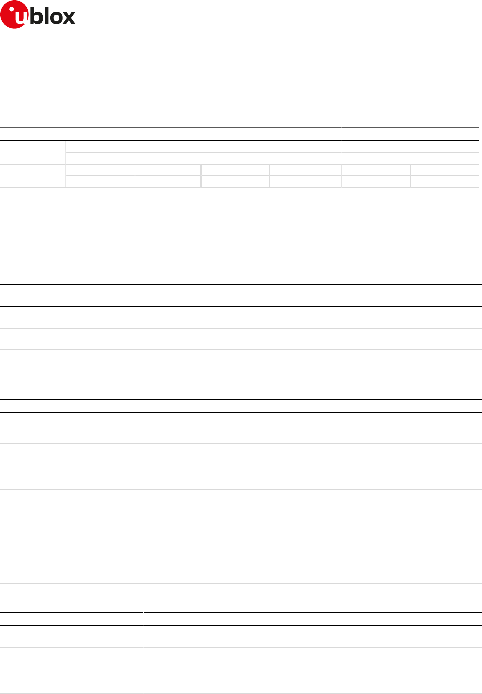
SARA-R4/N4 series-AT Commands Manual
UBX-17003787 - R09
3IPC - Inter Processor Communication
Page 19 of 307
3IPC - Inter Processor Communication
3.1Multiplexing mode +CMUX
+CMUX
SARA-R404M SARA-R410M-01B SARA-R410M-02B SARA-R410M-52B SARA-R412MModules
SARA-N4
Syntax PIN required Settings saved Can be aborted Response time Error referenceAttributes
partial No No No - +CME Error
3.1.1Description
Enables the multiplexing protocol control channel as defined in 3GPP TS 27.010 [46]. The command sets the
parameters for the control channel. The result code is returned using the old interface speed. The parameters
become active only after sending the OK result code.
The usage of +CMUX command during the multiplexing is not allowed.
The multiplexer configuration is as follows:
Channel Control channel AT commands / data
connection
GNSS tunneling SAP (SIM Access
Profile)
SARA-R404M-00B / SARA-R410
M-01B
Channel 0 Channel 1 - 3
SARA-R410M-02B / SARA-R410M-
52B / SARA-N4
Channel 0 Channel 1 - 2 Channel 3
Table 2: Multiplexer configuration
3.1.2Syntax
Type Syntax Response Example
Set AT+CMUX=<mode>[,<subset>[,
<port_speed>[,<N1>[,<T1>[,<N2>[,
<T2>[,<T3>[,<k>]]]]]]]
OK AT+CMUX=0,0,,1500,50,3,90
OK
Read AT+CMUX? +CMUX: <mode>,[<subset>],<port_
speed>,<N1>,<T1>,<N2>,<T2>,
<T3>[,<k>]
OK
+CMUX: 0,0,0,1500,253,3,254,0,0
OK
Test AT+CMUX=? +CMUX: (list of supported
<mode>s),(list of supported
<subset>s),(list of supported <port_
speed>s),(list of supported <N1>s),
(list of supported <T1>s),(list of
supported <N2>s),(list of supported
<T2>s),(list of supported <T3>s),
(list of supported <k>s)
OK
+CMUX: (0),(0),,(1-1509),(1-255),(0-
5),(2-255),,
OK
3.1.3Defined values
Parameter Type Description
<mode> Number Multiplexer transparency mechanism:
• 0: basic option
<subset> Number The way in which the multiplexer control channel is set up:
• 0 (default value): UIH frames used only
• 1: UI frames used only
See Notes for the parameter applicability.
<port_speed> Number Transmission rate. The allowed range is 0-7.
SARA-R4/N4 series-AT Commands Manual
UBX-17003787 - R09
3IPC - Inter Processor Communication
Page 20 of 307
Parameter Type Description
This parameter is ignored and the value 0 is always displayed in case of read
command.
<N1> Number Maximum frame size:
• Allowed range is 1-1509.
• The default value is 31.
<T1> Number Acknowledgement timer in units of ten milliseconds. The allowed range is 1-255.
This parameter is ignored and the value 253 is always set.
<N2> Number Maximum number of re-transmissions:
• Allowed range is 0-5.
• The default value is 3.
<T2> Number Response timer for the multiplexer control channel in units of ten milliseconds. The
allowed range is 2-255.
This parameter is ignored and the value 254 is always set.
<T3> Number Wake up response timer. The allowed range is 0-255.
This parameter is ignored and the value 0 is always displayed in case of the read
command.
<k> Number Window size, for advanced operation with Error Recovery options. The allowed range
is 0-255.
This parameter is ignored and the value 0 is always displayed in case of the read
command.
3.1.4Notes
• If the multiplexer protocol is not started (the +CMUX set command has not been issued or returned an
error result code) and AT+CMEE is set to 2, the +CMUX read command returns the following error result
code: +CME ERROR: operation not allowed.
• For complete compatibility between u-blox products, leave the unsupported/unused parameters blank
(which are reported as blank by the +CMUX test command).
• <T1> must be lower than or equal to <T2>.
SARA-R4 / SARA-N4
• <subset> can only assume the value 0.
• <T1>, <T2>, <N2> values are ignored, since the related timers are not implemented.
• The command is only supported on the UART interface. It cannot be used on the USB port.

SARA-R4/N4 series-AT Commands Manual
UBX-17003787 - R09
4General
Page 21 of 307
4General
4.1Manufacturer identification +CGMI
+CGMI
SARA-R404M SARA-R410M-01B SARA-R410M-02B SARA-R410M-52B SARA-R412MModules
SARA-N4
Syntax PIN required Settings saved Can be aborted Response time Error referenceAttributes
full No No No - +CME Error
4.1.1Description
Text string identifying the manufacturer.
4.1.2Syntax
Type Syntax Response Example
Action AT+CGMI <manufacturer>
OK
u-blox
OK
Test AT+CGMI=? OK
4.1.3Defined values
Parameter Type Description
<manufacturer> String Manufacturer name
4.2Manufacturer identification +GMI
+GMI
SARA-R404M SARA-R410M-01B SARA-R410M-02B SARA-R410M-52B SARA-R412MModules
SARA-N4
Syntax PIN required Settings saved Can be aborted Response time Error referenceAttributes
full No No No - +CME Error
4.2.1Description
Text string identifying the manufacturer.
4.2.2Syntax
Type Syntax Response Example
Action AT+GMI <manufacturer>
OK
u-blox
OK
4.2.3Defined values
Parameter Type Description
<manufacturer> String Manufacturer name

SARA-R4/N4 series-AT Commands Manual
UBX-17003787 - R09
4General
Page 22 of 307
4.3Model identification +CGMM
+CGMM
SARA-R404M SARA-R410M-01B SARA-R410M-02B SARA-R410M-52B SARA-R412MModules
SARA-N4
Syntax PIN required Settings saved Can be aborted Response time Error referenceAttributes
full No No No - +CME Error
4.3.1Description
Text string identifying the model identification.
4.3.2Syntax
Type Syntax Response Example
Action AT+CGMM <model>
OK
LISA-U200
OK
Test AT+CGMM=? OK
4.3.3Defined values
Parameter Type Description
<model> String Name of model
4.4Model identification +GMM
+GMM
SARA-R404M SARA-R410M-01B SARA-R410M-02B SARA-R410M-52B SARA-R412MModules
SARA-N4
Syntax PIN required Settings saved Can be aborted Response time Error referenceAttributes
full No No No - +CME Error
4.4.1Description
Text string identifying the model identification.
4.4.2Syntax
Type Syntax Response Example
Action AT+GMM <model>
OK
LISA-U120
OK
4.4.3Defined values
Parameter Type Description
<model> String Name of model
4.5Firmware version identification +CGMR
+CGMR
SARA-R404M SARA-R410M-01B SARA-R410M-02B SARA-R410M-52B SARA-R412MModules
SARA-N4
Syntax PIN required Settings saved Can be aborted Response time Error referenceAttributes
full No No No - +CME Error
4.5.1Description
Returns the firmware version of the module.
SARA-R4/N4 series-AT Commands Manual
UBX-17003787 - R09
4General
Page 23 of 307
4.5.2Syntax
Type Syntax Response Example
Action AT+CGMR <version>
OK
11.40
OK
Test AT+CGMR=? OK
4.5.3Defined values
Parameter Type Description
<version> String Firmware version
4.6Firmware version identification +GMR
+GMR
SARA-R404M SARA-R410M-01B SARA-R410M-02B SARA-R410M-52B SARA-R412MModules
SARA-N4
Syntax PIN required Settings saved Can be aborted Response time Error referenceAttributes
full No No No - +CME Error
4.6.1Description
Returns the firmware version of the module.
4.6.2Syntax
Type Syntax Response Example
Action AT+GMR <version>
OK
11.40
OK
4.6.3Defined values
Parameter Type Description
<version> String Firmware version
4.7IMEI identification +CGSN
+CGSN
SARA-R404M SARA-R410M-01B SARA-R410M-02B SARA-R410M-52B SARA-R412MModules
SARA-N4
Syntax PIN required Settings saved Can be aborted Response time Error referenceAttributes
partial No No No - +CME Error
4.7.1Description
Returns the product serial number, the International Mobile Equipment Identity (IMEI) of the MT.
4.7.2Syntax
Type Syntax Response Example
Action AT+CGSN[=<snt>] <sn>
OK
004999010640000
OK
Test AT+CGSN=? +CGSN: (list of supported <snt>s)
OK
+CGSN: (0-3,255)
OK
4.7.3Defined values
Parameter Type Description
<sn> String Serial number, by default the IMEI
SARA-R4/N4 series-AT Commands Manual
UBX-17003787 - R09
4General
Page 24 of 307
Parameter Type Description
<snt> Number It indicates the requested serial number type. Depending on <snt> value, the <sn>
parameter in the information text response provides different information:
• 0 (default value): International Mobile station Equipment Identity (IMEI)
• 1: International Mobile station Equipment Identity (IMEI)
• 2: International Mobile station Equipment Identity and Software Version number
(IMEISV)
• 3: Software Version Number (SVN)
• 255: IMEI (not including the spare digit), the check digit and the SVN
4.7.4Notes
SARA-R4 / SARA-N4
• The <snt> parameter is not supported.
• The response to the test command does not provide the information text response.
4.8IMEI identification +GSN
+GSN
SARA-R404M SARA-R410M-01B SARA-R410M-02B SARA-R410M-52B SARA-R412MModules
SARA-N4
Syntax PIN required Settings saved Can be aborted Response time Error referenceAttributes
full No No No - +CME Error
4.8.1Description
The commands handling is the same of +CGSN.
4.8.2Syntax
Type Syntax Response Example
Action AT+GSN[=<snt>] <sn>
OK
004999010640000
OK
Test AT+GSN=? OK
4.8.3Defined values
See +CGSN AT command.
4.9Identification information I
I
SARA-R404M SARA-R410M-01B SARA-R410M-02B SARA-R410M-52B SARA-R412MModules
SARA-N4
Syntax PIN required Settings saved Can be aborted Response time Error referenceAttributes
partial No No No - +CME Error
4.9.1Description
Returns some module information as the module type number and some details about the firmware version.
The information text response of ATI9 contains the modem version and the application version of the
module where applicable; it returns "Undefined" where not applicable.
4.9.2Syntax
Type Syntax Response Example
Action Ordering code request
ATI[0]
<type_number>
OK
ATI0
SARA-G350-00S-00
OK
SARA-R4/N4 series-AT Commands Manual
UBX-17003787 - R09
4General
Page 25 of 307
Type Syntax Response Example
Modem and application version
request
ATI9
<modem_version>,<applications_
version>
OK
ATI9
29.90,A01.00
OK
4.9.3Defined values
Parameter Type Description
<type_number> String Product type number
<modem_version> String Module modem version
<applications_
version>
String Module application version. Where not applicable the module provides "Undefined"
4.10TE character set configuration +CSCS
+CSCS
SARA-R404M SARA-R410M-01B SARA-R410M-02B SARA-R410M-52B SARA-R412MModules
SARA-N4
Syntax PIN required Settings saved Can be aborted Response time Error referenceAttributes
full No No No - +CME Error
4.10.1Description
Selects the TE character set.
The selected character set is actually used for encoding/decoding of only the AT commands' string type
parameters whose description explicitly references the +CSCS setting itself.
4.10.2Syntax
Type Syntax Response Example
Set AT+CSCS=<chset> OK AT+CSCS="IRA"
OK
Read AT+CSCS? +CSCS: <chset>
OK
+CSCS: "IRA"
OK
Test AT+CSCS=? +CSCS: (list of supported <chset>'s)
OK
+CSCS: ("IRA","GSM","PCCP437",
"8859-1","UCS2","HEX")
OK
4.10.3Defined values
Parameter Type Description
<chset> String • "IRA" (factory-programmed value): International Reference Alphabet (ITU-T T.50)
• "GSM": GSM default alphabet (3GPP TS 23.038)
• "PCCP437": PC character set Code Page 437
• "8859-1": ISO 8859 Latin 1 character set
• "UCS2": 16-bit universal multiple-octet coded character set (USO/IEC10646); UCS2
character strings are converted to hexadecimal numbers from 0000 to FFFF; e.g.
"004100620063" equals three 16-bit characters with decimal values 65, 98 and 99
• "HEX": character strings consist only of hexadecimal numbers from 00 to FF; e.g.
"032FE6" equals three 8-bit characters with decimal values 3, 47 and 230; no
conversions to the original MT character set shall be done
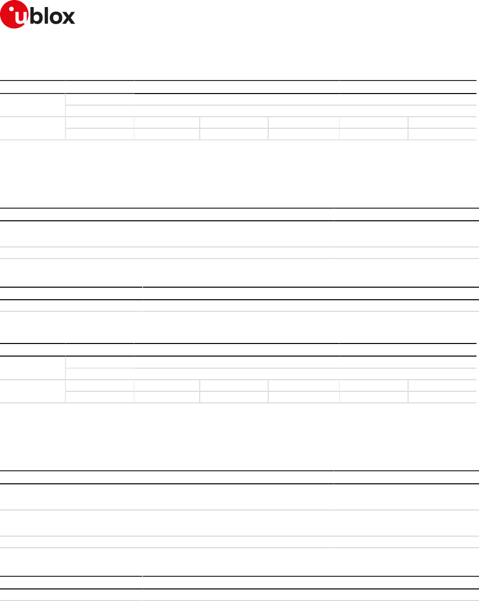
SARA-R4/N4 series-AT Commands Manual
UBX-17003787 - R09
4General
Page 26 of 307
4.11International mobile subscriber identification +CIMI
+CIMI
SARA-R404M SARA-R410M-01B SARA-R410M-02B SARA-R410M-52B SARA-R412MModules
SARA-N4
Syntax PIN required Settings saved Can be aborted Response time Error referenceAttributes
full Yes No No - +CME Error
4.11.1Description
Request the IMSI (International Mobile Subscriber Identity).
4.11.2Syntax
Type Syntax Response Example
Action AT+CIMI <IMSI>
OK
222107701772423
OK
Test AT+CIMI=? OK
4.11.3Defined values
Parameter Type Description
<IMSI> Number International Mobile Subscriber Identity
4.12Card identification +CCID
+CCID
SARA-R404M SARA-R410M-01B SARA-R410M-02B SARA-R410M-52B SARA-R412MModules
SARA-N4
Syntax PIN required Settings saved Can be aborted Response time Error referenceAttributes
full No No No - +CME Error
4.12.1Description
Returns the ICCID (Integrated Circuit Card ID) of the SIM-card. ICCID is a serial number identifying the SIM.
4.12.2Syntax
Type Syntax Response Example
Action AT+CCID +CCID: <ICCID>
OK
+CCID: 8939107800023416395
OK
Read AT+CCID? +CCID: <ICCID>
OK
+CCID: 8939107900010087330
OK
Test AT+CCID=? OK
4.12.3Defined values
Parameter Type Description
<ICCID> String ICCID of the SIM card
4.12.4Notes
• The command needs of the SIM to correctly work.
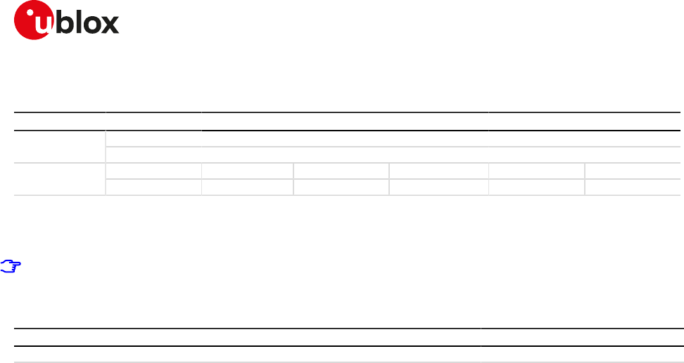
SARA-R4/N4 series-AT Commands Manual
UBX-17003787 - R09
4General
Page 27 of 307
4.13Repeat last command A/
A/
SARA-R404M SARA-R410M-01B SARA-R410M-02B SARA-R410M-52B SARA-R412MModules
SARA-N4
Syntax PIN required Settings saved Can be aborted Response time Error referenceAttributes
full No No No - +CME Error
4.13.1Description
Repeats the previously executed command again. Only the A/ command cannot be repeated.
If autobauding is active, the MT is not able to recognize the command and the command A/ cannot be
used.
4.13.2Syntax
Type Syntax Response Example
Action A/
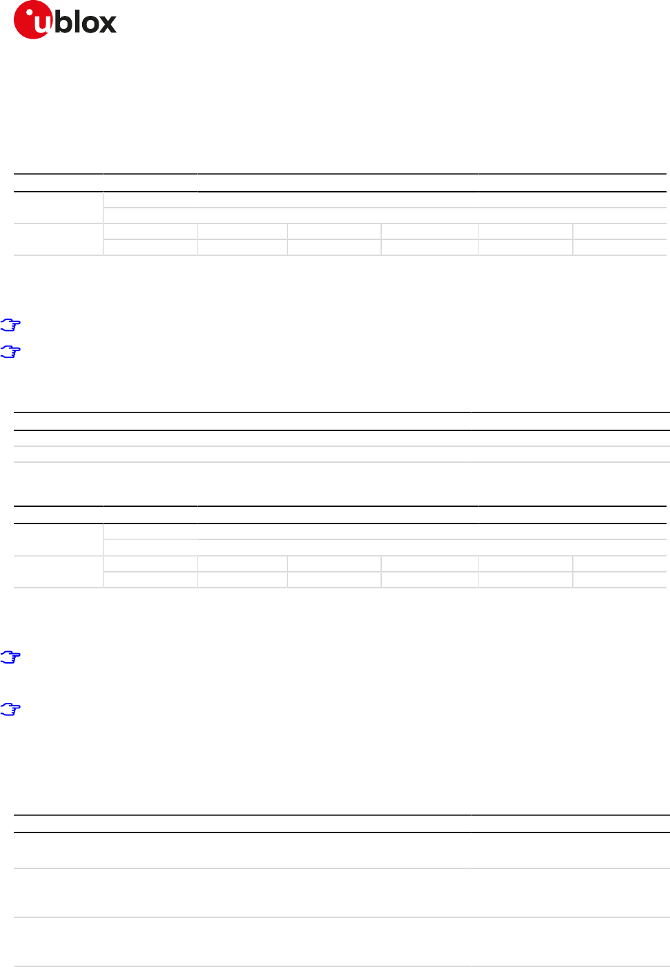
SARA-R4/N4 series-AT Commands Manual
UBX-17003787 - R09
5Mobile equipment control and status
Page 28 of 307
5Mobile equipment control and status
5.1Module switch off +CPWROFF
+CPWROFF
SARA-R404M SARA-R410M-01B SARA-R410M-02B SARA-R410M-52B SARA-R412MModules
SARA-N4
Syntax PIN required Settings saved Can be aborted Response time Error referenceAttributes
full No No No < 40 s +CME Error
5.1.1Description
Switches off the MT. During shut-down current settings are saved in module's non-volatile memory.
Using this command can result in the following command line being ignored.
See the corresponding System Integration Manual for the timing and the electrical details of the module
power-off sequence via the +CPWROFF command.
5.1.2Syntax
Type Syntax Response Example
Action AT+CPWROFF OK
Test AT+CPWROFF=? OK
5.2Set module functionality +CFUN
+CFUN
SARA-R404M SARA-R410M-01B SARA-R410M-02B SARA-R410M-52B SARA-R412MModules
SARA-N4
Syntax PIN required Settings saved Can be aborted Response time Error referenceAttributes
partial No No No Up to 3 min +CME Error
5.2.1Description
Selects the level of functionality <fun> in the MT.
SARA-R4 / SARA-N4
If the syntax +CFUN=15 or +CFUN=16 (resets) or +CFUN=127 is used, the rest of the command line, placed
after that will be ignored.
SARA-R4 / SARA-N4
A SW reset via AT+CFUN=1,1 triggers signalling attempts whose number is internally counted by the SW
and limited based on mobile network operators' thresholds. The AT&T RPM feature (see also the +URPM
AT command) limits the number of SW resets per hour, and might cause the AT command to return an
error result code.
5.2.2Syntax
Type Syntax Response Example
Set AT+CFUN=<fun>[,<rst>] OK AT+CFUN=1
OK
Read AT+CFUN? +CFUN: <power_mode>,<STK_
mode>
OK
+CFUN: 1,0
OK
Test AT+CFUN=? +CFUN: (list of supported <fun>'s),
(list of supported <rst>'s)
OK
+CFUN: (0,1,4,6,7,8,15,16),(0-1)
OK
SARA-R4/N4 series-AT Commands Manual
UBX-17003787 - R09
5Mobile equipment control and status
Page 29 of 307
5.2.3Defined values
Parameter Type Description
<fun> Number Selected functionality:
• 0: sets the MT to minimum functionality (disable both transmit and receive RF
circuits by deactivating both CS and PS services)
• 1 (factory-programmed value): sets the MT to full functionality, e.g. from airplane
mode or minimum functionality
• 4: disables both transmit and receive RF circuits by deactivating both CS and PS
services and sets the MT into airplane mode. Airplane mode is persistent between
power cycles triggered by +CFUN=16 or +CPWROFF (where supported)
• 6: enables the SIM-toolkit interface in dedicated mode and fetching of proactive
commands by SIM-APPL from the SIM-card
• 7 or 8: disables the SIM-toolkit interface and fetching of proactive commands by
SIM-APPL from the SIM-card
• 9: enables the SIM-toolkit interface in raw mode and fetching of proactive
commands by SIM-APPL from the SIM-card
• 15: MT silent reset (with detach from network and saving of NVM parameters),
without reset of the SIM card
• 16: MT silent reset (with detach from network and saving of NVM parameters), with
reset of the SIM card
• 19: sets the MT to minimum functionality by deactivating CS and PS services and
the SIM card
• 127: sets the MT in a deep low power state "HALT" (with detach from the network
and saving of the NVM parameters); the only way to wake up the module is a power
cycle or a module reset
<rst> Number Reset mode. This parameter can be used only when <fun> is 1, 4 or 19.
• 0 (default value): do not reset the MT before setting it to the selected <fun>
• 1: performs a MT silent reset (with detach from network and saving of NVM
parameters) with reset of the SIM card before setting it to the selected <fun>
<power_mode> Number • 0: MT is switched on with minimum functionality
• 1: MT is switched on
• 4: MT is in "airplane mode"
• 19: MT is in minimum functionality with SIM deactivated
<STK_mode> Number • 6: the SIM-toolkit interface in dedicated mode and fetching of proactive commands
by SIM-APPL from the SIM-card are enabled
• 0, 7 or 8: the SIM-toolkit interface is disabled; fetching of proactive commands by
SIM-APPL from the SIM-card is enabled
• 9: the SIM-toolkit interface in raw mode and fetching of proactive commands by
SIM-APPL from the SIM-card are enabled
5.2.4Notes
SARA-R4 / SARA-N4
• <fun>=16, 19 and 127 are not supported.
• <fun>=5 is returned in the information text response to the read command if the device is in Factory Test
Mode (FTM).
• <fun>=15 resets the SIM card.
• To reset the module issue the AT+CFUN=15 command.
SARA-R404M / SARA-R410M-01B
• <fun>=6, 7, 8 and 9 are not supported.
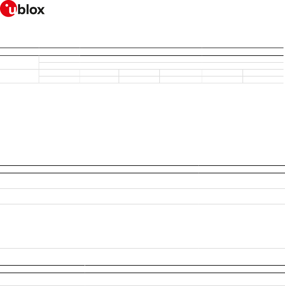
SARA-R4/N4 series-AT Commands Manual
UBX-17003787 - R09
5Mobile equipment control and status
Page 30 of 307
5.3Indicator control +CIND
+CIND
SARA-R404M SARA-R410M-01B SARA-R410M-02B SARA-R410M-52B SARA-R412MModules
SARA-N4
Syntax PIN required Settings saved Can be aborted Response time Error referenceAttributes
partial No No No - +CME Error
5.3.1Description
Provides indication states related to network status, battery information and so on.
The set command does not allow setting the values for those indications which are set according to module
state (see <descr> parameter).
The list of indications for set and read commands follows the indexes reported in the <descr> parameter, so
that the first <ind> corresponds to "battchg" and so on.
For more details see the 3GPP TS 27.007 [2].
5.3.2Syntax
Type Syntax Response Example
Set AT+CIND=[<ind>[,<ind>[,...]]] OK AT+CIND=
OK
Read AT+CIND? +CIND: <ind>[,<ind>[,...]]
OK
+CIND: 5,0,0,0,0,0,0,0,0,0,0,0
OK
Test AT+CIND=? +CIND: (list of <descr>s)
OK
+CIND: ("battchg",(0-5)),("signal",
(0-5)),("service",(0,1)),("sounder",
(0,1)),("message",(0,1)),("call",(0,1)),
("roam",(0,1)),("smsfull",(0,1)),("gprs",
(0-2)),("callsetup",(0-3)),("callheld",(0
,1)),("simind",(0-2))
OK
5.3.3Defined values
Parameter Type Description
<ind> Number Range of corresponding <descr> used to identify the service when an unsolicited
indication is provided
<descr> String Reserved by the norm and their <ind> ranges; it may have the values:
• "battchg": battery charge level (0-5)
• "signal": signal quality. See mapping in the note below
• "service": network service availability
o 0: not registered to any network
o 1: registered to the network
o 65535: indication not available
• "sounder": sounder activity, indicating when the module is generating a sound
o 0: no sound
o 1: sound is generated
• "message": unread message available in <mem1> storage
o 0: no messages
o 1: unread message available
• "call": call in progress
o 0: no call in progress
o 1: call in progress
• "roam": registration on a roaming network
o 0: not in roaming or not registered
o 1: roaming
o 65535: indication not available
SARA-R4/N4 series-AT Commands Manual
UBX-17003787 - R09
5Mobile equipment control and status
Page 31 of 307
Parameter Type Description
• "smsfull": indication that an SMS has been rejected with the cause of SMS storage
full
o 0: SMS storage not full
o 1: SMS storage full
• "gprs": PS indication status:
o 0: no PS available in the network
o 1: PS available in the network but not registered
o 2: registered to PS
o 65535: indication not available
• "callsetup": call set-up:
o 0: no call set-up
o 1: incoming call not accepted or rejected
o 2: outgoing call in dialling state
o 3: outgoing call in remote party alerting state
• "callheld": call on hold:
o 0: no calls on hold
o 1: at least one call on hold
• "simind": SIM detection
o 0: no SIM detected
o 1: SIM detected
o 2: not available
5.3.4Notes
• If the battery charging is not supported, "battchg" always returns 5 (full charge).
• The <descr> values cannot be changed with +CIND set.
• The following mapping of "signal" value to the power level exists:
"signal" value Power level
0 (< -105 dBm or unknown)
1 (< -93 dBm)
2 (< -81 dBm)
3 (< -69 dBm)
4 (< -57 dBm)
5 (>= -57 dBm)
5.4Configuration of indicator control +UCIND
+UCIND
SARA-R404M SARA-R410M-01B SARA-R410M-02B SARA-R410M-52B SARA-R412MModules
SARA-N4
Syntax PIN required Settings saved Can be aborted Response time Error referenceAttributes
full No No No - +CME Error
5.4.1Description
Allows the configuration of unsolicited results for indications with +CIEV.
5.4.2Syntax
Type Syntax Response Example
Set AT+UCIND=[<conf>] OK AT+UCIND=7
OK
Read AT+UCIND? +UCIND: <conf>
OK
+UCIND: 7
OK
Test AT+UCIND=? OK
SARA-R4/N4 series-AT Commands Manual
UBX-17003787 - R09
5Mobile equipment control and status
Page 32 of 307
5.4.3Defined values
Parameter Type Description
<conf> Number The unsigned integer (0 to 4095) is a bitmask representing the list of the indications
active for +CIEV URC reporting. The bit position corresponds to the indicator order
number (see the <descr> parameter of +CMER). The least significant bit is used for
the first indicator.
The bits corresponding to unused indicator order numbers (greater than 13) must be
set to 0 (setting a <conf> greater than 4095 causes an error). The default value is 40
95 (all the indications are enabled).
5.5Mobile termination event reporting +CMER
+CMER
SARA-R404M SARA-R410M-01B SARA-R410M-02B SARA-R410M-52B SARA-R412MModules
SARA-N4
Syntax PIN required Settings saved Can be aborted Response time Error referenceAttributes
partial No No No - +CME Error
5.5.1Description
Configures sending of URCs from MT to DTE for indications. The <mode> parameter controls the processing
of URCs specified within this command.
The URC is generated each time an indicator which is defined in +CIND command changes status. The code is
actually submitted to MT according to the +CMER settings.
The command +UCIND allows enabling or disabling indicators.
5.5.2Syntax
Type Syntax Response Example
Set AT+CMER=[<mode>[,<keyp>[,
<disp>[,<ind>[,<bfr>]]]]]
OK AT+CMER=1,0,0,2,1
OK
Read AT+CMER? +CMER: <mode>,<keyp>,<disp>,
<ind>,<bfr>
OK
+CMER: 1,0,0,0,1
OK
Test AT+CMER=? +CMER: (list of supported
<mode>'s),(list of supported
<keyp>'s),(list of supported
<disp>'s),(list of supported <ind>'s),
(list of supported <bfr>'s)
OK
+CMER: (0-3),(0),(0),(0-2),(0,1)
OK
URC +CIEV: <descr>,<value>
5.5.3Defined values
Parameter Type Description
<mode> Number • 0 (default value): buffer URCs in the MT
• 1: discard URCs when the V.24 interface is reserved for data; otherwise directly
display them on the DTE
• 2: buffer URCs in MT when the V.24 interface is reserved and flush them after
reservation; otherwise directly display them on the DTE
• 3: same as 1
<keyp> Number • 0: no keypad event reporting
<disp> Number • 0: no display event reporting
<ind> Number • 0: no indicator event reporting
• 1: indicator event reporting using the +CIEV URC. Only the indicator events which
are not caused by +CIND shall be indicated by the MT to the DTE.
• 2: indicator event reporting using the +CIEV URC. All the indicator events shall be
directed from MT to DTE.

SARA-R4/N4 series-AT Commands Manual
UBX-17003787 - R09
5Mobile equipment control and status
Page 33 of 307
Parameter Type Description
<bfr> Number • 0: MT buffer of URCs defined within this command is cleared when <mode> 1...3 is
entered
• 1: MT buffer of URCs defined within this command is flushed to the DTE when
<mode> 1...3 is entered (the OK final result code shall be given before flushing the
codes).
<descr> Number Indicates the indicator order number. The name in the brackets indicates the
corresponding <descr> parameter of +CIND; <value> is the new value of indicator:
• 1 ("battchg"): <value> provides the battery charge level (0-5)
• 2 ("signal"): <value> provides the signal quality
o 0: < -105 dBm
o 1: < -93 dBm
o 2: < -81 dBm
o 3: < -69 dBm
o 4: < - 57 dBm
o 5: >= -57 dBm
• 3 ("service"): <value> provides the network service availability:
o 0: not registered to the network
o 1: registered to the network
• 4 ("sounder"): <value> provides the sounder activity:
o 0: no sound
o 1: sound is generated
• 5 ("message"): <value> provides the unread message available in <mem1> storage:
o 0: no messages
o 1: unread message available
• 6 ("call"): <value> provides the call in progress:
o 0: no call in progress
o 1: call in progress
• 7 ("roam"): <value> provides the registration on a roaming network:
o 0: not in roaming
o 1: roaming
• 8 ("smsfull"): <value> provides the SMS storage status:
o 0: SMS storage not full
o 1: SMS Storage full (an SMS has been rejected with the cause of SMS storage
full)
• 9 ("gprs"): <value> provides the GPRS indication status:
o 0: no GPRS available in the network
o 1: GPRS available in the network but not registered
o 2: registered to GPRS
o 65535: PS service indication is not available
• 10 ("callsetup"): <value> provides the call set-up:
o 0: no call set-up
o 1: incoming call not accepted or rejected
o 2: outgoing call in dialing state
o 3: outgoing call in remote party alerting state
• 11 ("callheld"): <value> provides the call on hold:
o 0: no calls on hold
o 1: at least one call on hold
• 12 ("simind"): <value> provides the SIM detection:
o 0: no SIM detected
o 1: SIM detected
o 2: not available
SARA-R4/N4 series-AT Commands Manual
UBX-17003787 - R09
5Mobile equipment control and status
Page 34 of 307
5.6Clock +CCLK
+CCLK
SARA-R404M SARA-R410M-01B SARA-R410M-02B SARA-R410M-52B SARA-R412MModules
SARA-N4
Syntax PIN required Settings saved Can be aborted Response time Error referenceAttributes
partial No NVM No - +CME Error
5.6.1Description
Sets and reads the real-time clock of the MT.
5.6.2Syntax
Type Syntax Response Example
Set AT+CCLK=<time> OK AT+CCLK="14/07/01,15:00:00+01"
OK
Read AT+CCLK? +CCLK: <time>
OK
+CCLK: "14/07/01,15:00:00+01"
OK
Test AT+CCLK=? OK
5.6.3Defined values
Parameter Type Description
<time> String Format is "yy/MM/dd,hh:mm:ss+TZ". Characters indicate year, month, day, hours,
minutes, seconds, time zone. The factory-programmed value is "04/01/01,00:00:00+0
0". Values prior to the factory-programmed value are not allowed.
5.6.4Notes
• If the parameter value is out of range, then the "+CME ERROR: operation not supported" or "+CME ERROR:
4" will be provided (depending on the +CMEE AT command setting).
• "TZ": The Time Zone information is represented by two digits. The value is updated during the registration
procedure when the automatic time zone update is enabled (using +CTZU command) and the network
supports the time zone information.
• The Time Zone information is expressed in steps of 15 minutes and it can assume a value in the range
that goes from -96 to +96.
5.7Set greeting text +CSGT
+CSGT
SARA-R410M-52BModules
SARA-N4
Syntax PIN required Settings saved Can be aborted Response time Error referenceAttributes
partial No NVM No - +CME Error
5.7.1Description
Configures and activates/deactivates the greeting text. The greeting text configuration's change will be
applied at the subsequent boot. If active, the greeting text is shown at boot once, on any AT interface, the first
time the TE sets the DTR line to ON state.
Take care about restrictions related to the baud rate described in the Autobauding description.
5.7.2Syntax
Type Syntax Response Example
Set AT+CSGT=<mode>[,<text>] OK AT+CSGT=1,"Hello user"
OK
Read AT+CSGT? +CSGT: <text>,<mode> +CSGT: "Hello",0
SARA-R4/N4 series-AT Commands Manual
UBX-17003787 - R09
5Mobile equipment control and status
Page 35 of 307
Type Syntax Response Example
OK OK
Test AT+CSGT=? +CSGT: (list of supported <mode>s),
<ltext>
OK
+CSGT: (0-1),49
OK
5.7.3Defined values
Parameter Type Description
<text> String Greeting text. The factory-programmed value is the empty string.
<mode> Number • 0: turn off the greeting text
• 1: turn on the greeting text
<ltext> Number Maximum length of the <text> parameter.
5.8Automatic time zone update +CTZU
+CTZU
SARA-R404M SARA-R410M-01B SARA-R410M-02B SARA-R410M-52BModules
SARA-N4
Syntax PIN required Settings saved Can be aborted Response time Error referenceAttributes
full Yes NVM No - +CME Error
5.8.1Description
Configures the automatic time zone update via NITZ.
The Time Zone information is provided after the network registration (if the network supports the time
zone information).
5.8.2Syntax
Type Syntax Response Example
Set AT+CTZU=<on_off> OK AT+CTZU=1
OK
Read AT+CTZU? +CTZU: <on_off>
OK
+CTZU: 0
OK
Test AT+CTZU=? +CTZU: (list of supported <on_
off>s)
OK
+CTZU: (0-1)
OK
5.8.3Defined values
Parameter Type Description
<on_off> Number Allowed values (see Notes for the factory-programmed value):
• 0: automatic time zone via NITZ disabled
• 1: automatic time zone update via NITZ enabled; if the network supports the service,
the local time of the module is changed (not only time zone)
5.8.4Notes
SARA-R4 / SARA-N4
• The factory-programmed value of the <on_off> parameter is 0.
SARA-R4/N4 series-AT Commands Manual
UBX-17003787 - R09
5Mobile equipment control and status
Page 36 of 307
5.9Report mobile termination error +CMEE
+CMEE
SARA-R404M SARA-R410M-01B SARA-R410M-02B SARA-R410M-52B SARA-R412MModules
SARA-N4
Syntax PIN required Settings saved Can be aborted Response time Error referenceAttributes
full No No No - +CME Error
5.9.1Description
Configures the formatting of the result code +CME ERROR: <err> as an indication of an error relating to the
functionality of the MT. When enabled, MT related errors cause +CME ERROR: <err> final result code instead
of the regular ERROR final result code. The error result code is returned normally when an error is related to
syntax, invalid parameters or MT functionality.
5.9.2Syntax
Type Syntax Response Example
Set AT+CMEE=[<n>] OK AT+CMEE=2
OK
Read AT+CMEE? +CMEE: <n>
OK
+CMEE: 0
OK
Test AT+CMEE=? +CMEE: (list of supported <n>s)
OK
+CMEE: (0-2)
OK
5.9.3Defined values
Parameter Type Description
<n> Number • 0: +CME ERROR: <err> result code disabled and ERROR used
• 1: +CME ERROR: <err> result code enabled and numeric <err> values used
• 2: +CME ERROR: <err> result code enabled and verbose <err> values used
5.9.4Notes
• The following convention is valid:
Numeric error code Verbose error code Description
3 "operation not allowed" The MT is in a state which does not allow performing the
entered command.
4 "operation not supported" The error result code is related to a parameter not covered by
the GSM/ETSI or u-blox specification
SARA-R4/N4 series-AT Commands Manual
UBX-17003787 - R09
6Call control
Page 37 of 307
6Call control
6.1Dial command D
D
Modules SARA-R404M SARA-R410M-01B SARA-R410M-02B SARA-R410M-52B SARA-R412M
Syntax PIN required Settings saved Can be aborted Response time Error referenceAttributes
full Yes No Yes Up to 3 min +CME Error
6.1.1Description
Lists characters that may be used in a dialling string for making a call (voice, data or fax call) or controlling
supplementary services in accordance with 3GPP TS 22.030 [5] and initiates the indicated kind of call. No
further commands may follow in the command line in case of data or fax calls.
6.1.2Syntax
Type Syntax Response Example
Voice call
ATD123456;
OK
Data / fax call
ATD123456
CONNECT 9600
Action ATD<number>[<I>][<G>][;] See Result codes
Supplementary services
ATD*#43#
+CCWA: 0,1
+CCWA: 0,2
OK
6.1.3Defined values
Parameter Type Description
<number> Number Dial string; the allowed characters are: 1 2 3 4 5 6 7 8 9 0 * # + A B C D , T P ! W @ (see
the 3GPP TS 27.007 [2]). The following characters are ignored: , T ! W @.
The first occurrence of P is interpreted as pause and separator between the
dialling number and the DTMF string. The following occurrences are interpreted
only as pause. The use of P as pause has been introduced for AT&T certification.
<I> String Set the CLI status; the allowed values are:
• I (ASCII code 49 Hex): CLI presentation restricted
• i: CLI presentation allowed
The CLIR supplementary service subscription is overridden for this call.
<G> String Configures the CUG supplementary service for the specific call:
• G: CUG activated
• g: CUG deactivated
The index and the information parameters used during the call will be the same
previously set with +CCUG command.
6.1.4Notes
SARA-R404M / SARA-R410M-01B / SARA-R410M-02B / SARA-R410M-52B
• Voice calls are not supported.
SARA-R4/N4 series-AT Commands Manual
UBX-17003787 - R09
6Call control
Page 38 of 307
6.2Call answer A
A
Modules SARA-R404M SARA-R410M-01B SARA-R410M-02B SARA-R410M-52B SARA-R412M
Syntax PIN required Settings saved Can be aborted Response time Error referenceAttributes
full No No No < 20 s +CME Error
6.2.1Description
Instructs the DCE to immediately connect to the line and start the answer sequence as specified for the
underlying DCE. Any additional command that appears after A on the same command line is ignored. The
command is abortable.
SARA-R4
The user is informed that an incoming call is waiting, by the RING IRC.
6.2.2Syntax
Type Syntax Response Example
Action ATA RING
OK
6.3Hook control H
H
SARA-R404M SARA-R410M-01B SARA-R410M-02B SARA-R410M-52B SARA-R412MModules
SARA-N4
Syntax PIN required Settings saved Can be aborted Response time Error referenceAttributes
full No No No < 20 s -
6.3.1Description
Disconnects the remote user. In case of multiple calls, all the active calls and held calls are released while the
waiting calls are not.
In case of dual service calls, the command will switch the call from data (if different from fax) to voice.
If the module has a PDP context activated and is in On-Line Command Mode (OLCM), the command
deactivates the context. During the PSD OLCM an incoming CS call can be accepted with an ATA
command. Subsequent ATH command releases the current CS call while leaving the PDP context
activated. In this state a second ATH command also deactivates the PDP context.
6.3.2Syntax
Type Syntax Response Example
Action ATH OK
6.4Automatic answer S0
S0
Modules SARA-R404M SARA-R410M-01B SARA-R410M-02B SARA-R410M-52B SARA-R412M
Syntax PIN required Settings saved Can be aborted Response time Error referenceAttributes
partial No Profile No - +CME Error
6.4.1Description
Controls the automatic answering feature of the DCE. If set to 0, the automatic answering is disabled,
otherwise it causes the DCE to answer when the incoming call indication (RING) has occurred the number of
times indicated by the value.
For an incoming CSD call, if the autoanswering is enabled and the <value> parameter of &D command is
set to 2, the autoanswering only works if the DTR line of the AT interface with activated autoanswering
SARA-R4/N4 series-AT Commands Manual
UBX-17003787 - R09
6Call control
Page 39 of 307
is set to ON. Otherwise, if DTR is OFF, then the call is rejected. If the <value> parameter of &D command
is not set to 2, the DTR state has no impact on autoanswering.
6.4.2Syntax
Type Syntax Response Example
Set ATS0=<value> OK ATS0=2
OK
Read ATS0? <value>
OK
000
OK
6.4.3Defined values
Parameter Type Description
<value> Number Value in the range 0-255; the answer to the read command is in "xxx" format.
• 0 (factory-programmed value): disables automatic answer mode
• 1-255: enables automatic answering after specified number of rings
6.4.4Notes
SARA-R404M / SARA-R410M-01B / SARA-R410M-02B / SARA-R410M-52B
• The voice call autoanswering is not supported and the command is therefore not effective.
SARA-R4/N4 series-AT Commands Manual
UBX-17003787 - R09
7Network service
Page 40 of 307
7Network service
7.1Subscriber number +CNUM
+CNUM
SARA-R404M SARA-R410M-01B SARA-R410M-02B SARA-R410M-52B SARA-R412MModules
SARA-N4
Syntax PIN required Settings saved Can be aborted Response time Error referenceAttributes
full Yes No No < 10 s +CME Error
7.1.1Description
Returns the MSISDNs related to this subscriber. If the subscriber has different MSISDN for different services,
each MSISDN is returned in a separate line.
MSISDN is read from the SIM.
7.1.2Syntax
Type Syntax Response Example
Action AT+CNUM +CNUM: [<alpha1>],<number1>,
<type1>
[+CNUM: [<alpha2>],<number2>,
<type2>
[...]]
OK
or
OK
+CNUM: "Mario Rossi","+39320
821708",145
+CNUM: "ABCD . AAA","1234567890
12",129
OK
Test AT+CNUM=? OK
7.1.3Defined values
Parameter Type Description
<alphax> String Associated with <numberx>
<numberx> String Phone number of format specified by <typex>
<typex> Number Type of address, octet in Number format (145 when <numberx> string includes '+',
otherwise 129)
7.2Signal quality +CSQ
+CSQ
SARA-R404M SARA-R410M-01B SARA-R410M-02B SARA-R410M-52B SARA-R412MModules
SARA-N4
Syntax PIN required Settings saved Can be aborted Response time Error referenceAttributes
full No No No - +CME Error
7.2.1Description
Returns the Received Signal Strength Indication (RSSI) <rssi> and <qual> from the MT.
SARA-R4 / SARA-N4
The radio signal strength <rssi> will be also used to build and display the indicator "signal" i.e. signal quality
in the information text response of +CIND and in the +CIEV URC (see the +CMER command description).
In dedicated mode, during the radio channel reconfiguration (e.g. handover), invalid measurements may be
returned for a short transitory because the MT must compute them on the newly assigned channel.
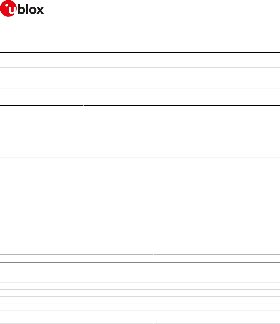
SARA-R4/N4 series-AT Commands Manual
UBX-17003787 - R09
7Network service
Page 41 of 307
7.2.2Syntax
Type Syntax Response Example
Action AT+CSQ +CSQ: <rssi>,<qual>
OK
+CSQ: 2,5
OK
Test AT+CSQ=? +CSQ: (list of supported <rssi>s),
(list of supported <qual>s)
OK
+CSQ: (0-31,99),(0-7,99)
OK
7.2.3Defined values
Parameter Type Description
<rssi> Number The allowed range is 0-31 and 99. Remapped indication of the following parameters:
• the Received Signal Strength Indication (RSSI) in GSM RAT
• the Received Signal Code Power (RSCP) in UMTS RAT
• the Reference Signal Received Power (RSRP) in LTE RAT
When the RF power level of the received signal is the highest possible, the value 31
is reported. When it is not known, not detectable or currently not available, 99 is
returned.
<qual> Number The allowed range is 0-7 and 99. The information provided depends on the selected
RAT:
• In 2G RAT CS dedicated and GPRS packet transfer mode indicates the Bit Error
Rate (BER) as specified in 3GPP TS 45.008 [148]
• In 2G RAT EGPRS packet transfer mode indicates the Mean Bit Error Probability
(BEP) of a radio block. 3GPP TS 45.008 [148] specifies the range 0-31 for the Mean
BEP which is mapped to the range 0-7 of <qual>
• In UMTS RAT indicates the Energy per Chip/Noise (ECN0) ratio in dB levels of
the current cell. 3GPP TS 25.133 [106] specifies the range 0-49 for EcN0 which is
mapped to the range 0-7 of <qual>
• In LTE RAT indicates the Reference Signal Received Quality (RSRQ). TS 36.133 [105]
specifies the range 0-34 for RSRQ which is mapped to the range 0-7 of <qual>
See Table 3 for the complete parameter mapping
7.2.4Notes
<qual> 2G RAT CS and GPRS 2G RAT EGPRS UMTS RAT LTE RAT
0 BER < 0.2% 28 <= MEAN_BEP <= 31 ECN0_LEV >= 44 RSRQ_LEV < 5
1 0.2% < BER < 0.4% 24 <= MEAN_BEP <= 27 38 <= ECNO_LEV < 44 5 <= RSRQ_LEV < 10
2 0.4% < BER < 0.8% 20 <= MEAN_BEP <= 23 32 <= ECNO_LEV < 38 10 <= RSRQ_LEV < 14
3 0.8% < BER < 1.6% 16 <= MEAN_BEP <= 19 26 <= ECNO_LEV < 32 14 <= RSRQ_LEV < 18
4 1.6% < BER < 3.2% 12 <= MEAN_BEP <= 15 20 <= ECNO_LEV < 26 18 <= RSRQ_LEV < 22
5 3.2% < BER < 6.4% 8 <= MEAN_BEP <= 11 14 <= ECNO_LEV < 20 22 <= RSRQ_LEV < 26
6 6.4% < BER < 12.8% 4 <= MEAN_BEP <= 7 8 <= ECNO_LEV < 14 26 <= RSRQ_LEV < 30
7 BER > 12.8% 0 <= MEAN_BEP <= 3 ECNO_LEV < 8 RSRQ _LEV >= 30
99 Not known or not detectable
Table 3: <qual> parameter mapping for each supported RAT
SARA-R404M / SARA-R410M / SARA-N4
• Only LTE RAT is supported.
• The <qual> parameter is not supported, and will be always set to 99.
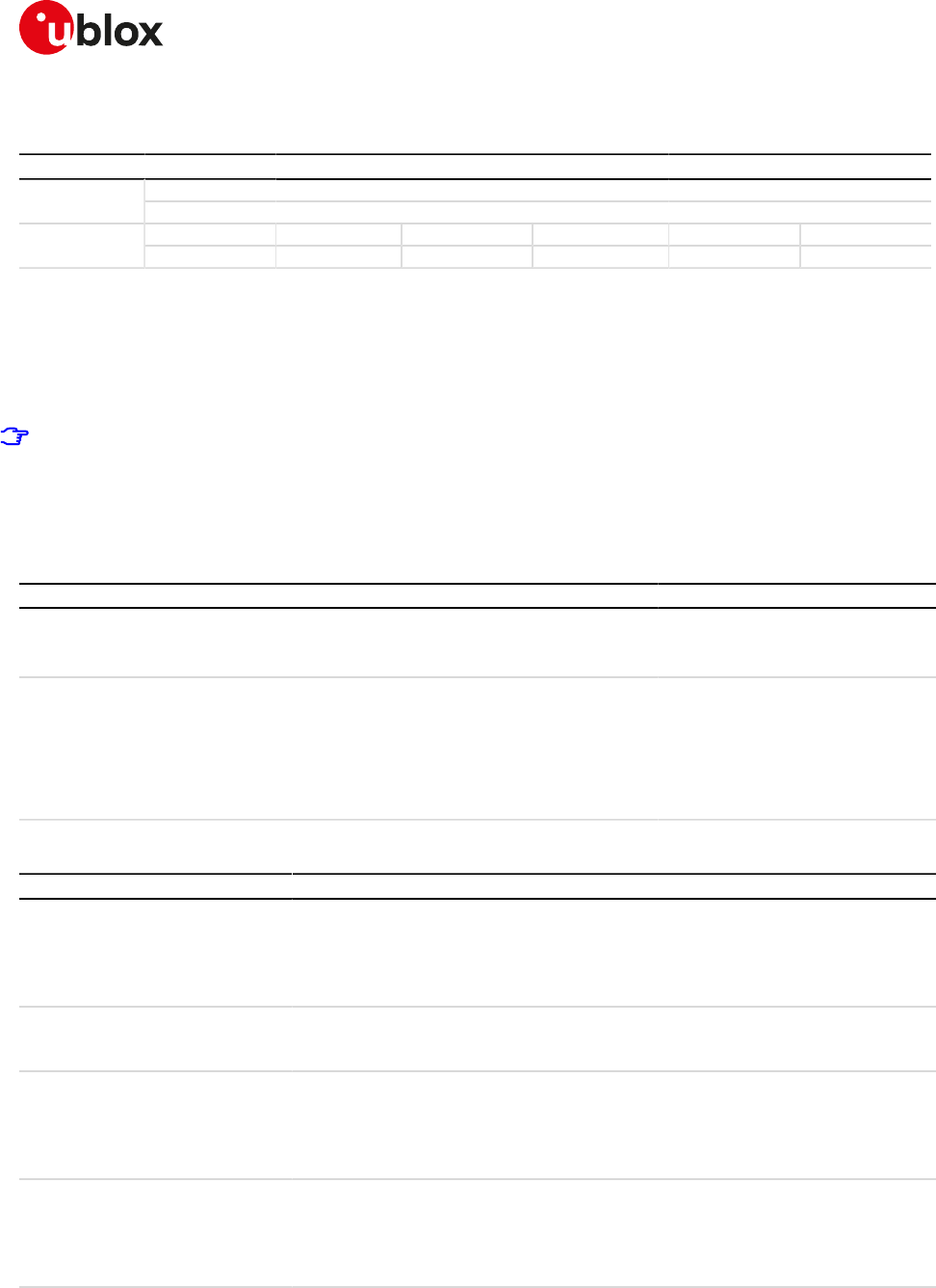
SARA-R4/N4 series-AT Commands Manual
UBX-17003787 - R09
7Network service
Page 42 of 307
7.3Extended signal quality +CESQ
+CESQ
SARA-R404M SARA-R410M-01B SARA-R410M-02B SARA-R410M-52B SARA-R412MModules
SARA-N4
Syntax PIN required Settings saved Can be aborted Response time Error referenceAttributes
full No No No - +CME Error
7.3.1Description
Returns the received signal quality and level:
• If the current serving cell is not a GERAN cell, the <rxlev> and <ber> parameters are set to value 99
• If the current serving cell is not a UTRA FDD cell, the <rscp> and the <ecn0> parameters are set to 255
• If the current serving cell is not an E-UTRA cell, the <rsrq> and <rsrp> parameters are set to 255.
The Reference Signal Received Power (RSRP) is a LTE specific measure that averages the power received
on the subcarriers carrying the reference signal. The RSRP measurement bandwidth is equivalent to a
single LTE subcarrier: its value is therefore much lower than the total received power usually referred
to as RSSI. In LTE the RSSI depends on the currently allocated bandwidth, which is not pre-determined.
Therefore the RSSI is not useful to describe the signal level in the cell.
7.3.2Syntax
Type Syntax Response Example
Action AT+CESQ +CESQ: <rxlev>,<ber>,<rscp>,<ecn0
>,<rsrq>,<rsrp>
OK
+CESQ: 99,99,255,255,20,80
OK
Test AT+CESQ=? +CESQ: (list of supported <rxlev>s),
(list of supported <ber>s),(list
of supported <rscp>s),(list
of supported <ecn0>s),(list
of supported <rsrq>s),(list of
supported <rsrp>s)
OK
+CESQ: (0-63,99),(0-7,99),(0-96,
255),(0-49,255),(0-34,255),(0-97,
255)
OK
7.3.3Defined values
Parameter Type Description
<rxlev> Number Received Signal Strength Indication (RSSI):
• 0: less than -110 dBm
• 1..62: from -110 to -49 dBm with 1 dBm steps
• 63: -48 dBm or greater
• 99: not known or not detectable
<ber> Number Bit Error Rate (BER):
• 0..7: as the RXQUAL values described in GSM TS 05.08 [28]
• 99: not known or not detectable
<rscp> Number Received Signal Code Power (RSCP):
• 0: -121 dBm or less
• 1..95: from -120 dBm to -24 dBm with 1 dBm steps
• 96: -25 dBm or greater
• 255: not known or not detectable
<ecn0> Number Ratio of received energy per PN chip to the total received power spectral density:
• 0: -24.5 dB or less
• 1..48: from -24 dB to -0.5 dBm with 0.5 dB steps
• 49: 0 dB or greater
• 255: not known or not detectable
<rsrq> Number Reference Signal Received Quality (RSRQ):
• 0: -19 dB or less
• 1..33: from -19.5 dB to -3.5 dB with 0.5 dB steps
• 34: -3 dB or greater
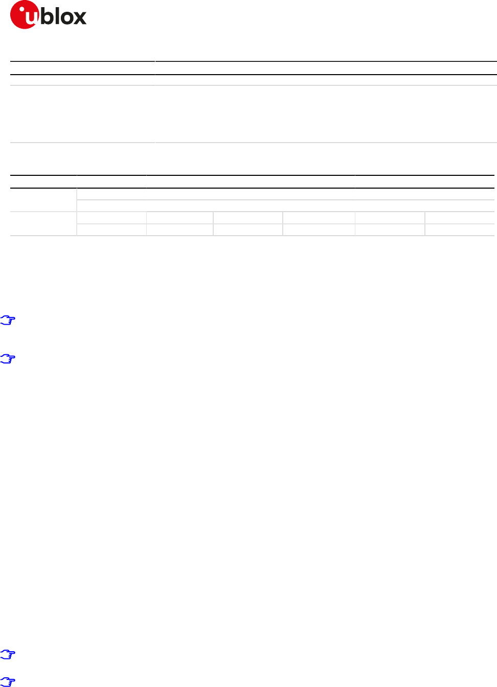
SARA-R4/N4 series-AT Commands Manual
UBX-17003787 - R09
7Network service
Page 43 of 307
Parameter Type Description
• 255: not known or not detectable
<rsrp> Number Reference Signal Received Power (RSRP):
• 0: -141 dBm or less
• 1..96: from -140 dBm to -45 dBm with 1 dBm steps
• 97: -44 dBm or greater
• 255: not known or not detectable
7.4Operator selection +COPS
+COPS
SARA-R404M SARA-R410M-01B SARA-R410M-02B SARA-R410M-52B SARA-R412MModules
SARA-N4
Syntax PIN required Settings saved Can be aborted Response time Error referenceAttributes
partial No Profile Yes Up to 3 min +CME Error
7.4.1Description
Forces an attempt to select and register with the GSM/LTE network operator, that can be chosen in the list of
network operators returned by the test command, that triggers a PLMN scan on all supported bands. Through
<mode> parameter the network selection can automatically be performed or forced by this command: the
access technology is indicated in <AcT> parameter (where supported).
In manual PLMN selection mode, if the optional <AcT> parameter is not specified, the modules will select
the default access technology with the following priority order: LTE and GSM (not supported technologies
will be ignored).
u-blox cellular modules are certified according to all the capabilities and options stated in the Protocol
Implementation Conformance Statement document (PICS) of the module. The PICS, according to 3GPP
TS 51.010-2 [84], 3GPP TS 34.121-2 [85], 3GPP TS 36.521-2 [115] and 3GPP TS 36.523-2 [116], is a statement
of the implemented and supported capabilities and options of a device. If the user changes the command
settings during the certification process, the PICS of the application device integrating a u-blox cellular
module must be changed accordingly.
To be able to exploit all command functionalities, the SIM card verification is required. The command is
accessible also without an inserted SIM. In this case the command AT+COPS=0 always returns an error result
code because the network registration cannot be performed without the SIM, while the configuration (i.e.
automatic registration) is correctly set. The set value can be checked with the command AT+COPS? or by
verifying the active profile with AT&V command if supported (parameter <format> is then also visible).
The set command handling depends on the <mode> parameter value:
•<mode>=0 and <mode>=1: the AT command setting is immediately stored in the current activated profile.
If the MT is set in automatic selection mode (<mode>= 0), only the mode will be saved. If the MT is set in
manual mode (<mode>= 1), also the format (<format>) and operator (<oper>) will be stored in the profile.
•<mode>=4: the module starts a manual selection of the specified operator; if this operation is not
successful, the module will start an automatic network selection and will remain in automatic mode.
If the set command with <mode>=0 is issued, a further set command with <mode>=0 is managed as a user
reselection (see the 3GPP TS 23.122 [70]), i.e. the module triggers a search for the HPLMN or a higher order
PLMN. This is useful when roaming in areas where the HPLMN or a higher order PLMN is available. If no HPLMN
or higher order PLMN is found, the module remains in the state it was in prior to the search (e.g. camped and/
or registered on the PLMN before the search).
The PLMN search cannot be performed in RRC connected state when the RAT is 3G or 4G, hence no PLMN list
will be returned at the end of the PLMN scan attempt.
The manual PLMN selection can fail due to the MNO control on the network selection procedure via EFCSP
setting; for further details see +PACSP.
The user should not enter colliding requests (e.g. AT+COPS=0 and AT+COPS=2) on different
communication ports, because this might cause interoperability issues in case overlapping registration
and deregistration requests are not handled by the network, and could result in an unpredictable
registration state. Similarly, when notified of a GPRS mobile terminated detach event (e.g. via +CGEV
SARA-R4/N4 series-AT Commands Manual
UBX-17003787 - R09
7Network service
Page 44 of 307
URC), it is recommended to wait a few seconds before entering AT+COPS=2 in order to let the pending
registration procedure (automatically triggered by the module in most cases) successfully end.
The user should not rely only on the set command "OK" final result code as a confirmation that the network
selection has been performed. To determine the current network registration status, +CEREG should be
also checked.
7.4.2Syntax
Type Syntax Response Example
Set AT+COPS=[<mode>[,
<format>[,<oper>[,
<AcT>]]]]
OK AT+COPS=0,0
OK
Read AT+COPS? +COPS: <mode>[,<format>,<oper>[,
<AcT>]]
OK
+COPS: 0,0,"vodafone IT"
OK
Test AT+COPS=? +COPS: [(<stat>, long <oper>, short
<oper>, numeric <oper>[,<AcT>])[,
(<stat>, long <oper>, short <oper>,
numeric <oper>[,<AcT>]),[...]]],(list of
supported <mode>s),(list of supported
<format>s)
OK
+COPS: (2,"vodafone IT","voda IT","22210
"),(1,"SI vodafone","vodafone SI","29340
"),(1,"I WIND","I WIND","22288"),(1,"I TIM",
"TIM","22201"),(1,"MOBITEL","MOBITEL",
"29341"),,(0-4),(0-2)
OK
7.4.3Defined values
Parameter Type Description
<mode> Number Is used to chose whether the network selection is automatically done by the MT or is
forced by this command to the operator <oper> given in the format <format>:
• 0 (default value and factory-programmed value): automatic (<oper> field is ignored)
• 1: manual
• 2: deregister from network
• 3: set only <format>
• 4: manual/automatic
<format> Number • 0 (factory-programmed value): long alphanumeric <oper>
• 1: short format alphanumeric <oper>
• 2: numeric <oper>
<oper> String Given in format <format> this field may be up to 24 characters long for long
alphanumeric format, up to 10 characters for short alphanumeric format and 5 or
6 characters long for numeric format (MCC/MNC codes). The factory-programmed
value is FFFF (undefined).
<stat> Number • 0: unknown
• 1: available
• 2: current
• 3: forbidden
<AcT> Number Indicates the radio access technology:
• 7: LTE
• 8: EC-GSM-IoT (A/Gb mode)
• 9: E-UTRAN (NB-S1 mode)
Allowed values:
• SARA-R404M - 7
• SARA-R410M-01B / SARA-R410M-02B - 8, 9
• SARA-R410M-52B - 7, 9
• SARA-N4 - 9
7.4.4Notes
SARA-R4 / SARA-N4
• <format> and <oper> parameters are optional only if the value of <mode> parameter is 0, 2 or 3.
• If the antenna is not connected, then the information text response to the test command is: +COPS: ,,
(0-4),(0-2)
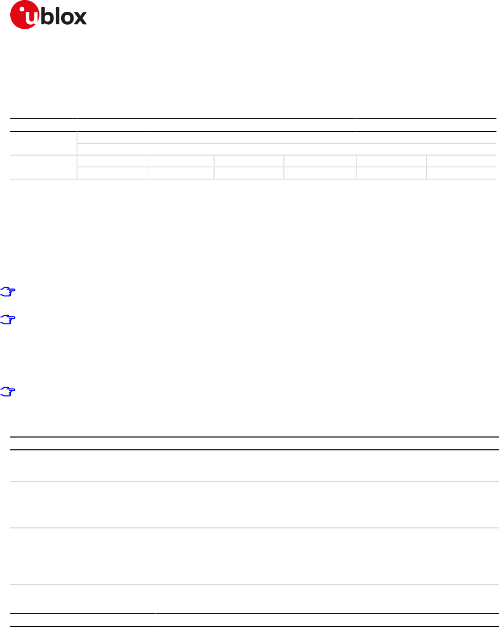
SARA-R4/N4 series-AT Commands Manual
UBX-17003787 - R09
7Network service
Page 45 of 307
SARA-R410M-01B / SARA-R410M-02B
• <AcT>=8 is used for LTE Cat M1.
7.5Radio Access Technology (RAT) selection +URAT
+URAT
SARA-R404M SARA-R410M-01B SARA-R410M-02B SARA-R410M-52B SARA-R412MModules
SARA-N4
Syntax PIN required Settings saved Can be aborted Response time Error referenceAttributes
partial No NVM No - +CME Error
7.5.1Description
Forces the selection of the Radio Access Technology (RAT) in the protocol stack. On the subsequent network
registration (+COPS, +CGATT) the selected RAT is used.
If dual or tri mode is selected, it is also possible to select the preferred RAT, which determines which RAT is
selected first (if available). If the preferred RAT is omitted, it will be set by default to the higher RAT available.
If tri mode is selected, it is also possible to select the second preferred RAT (if the preferred RAT was also
selected). This parameter determines which RAT is selected if the first preferred RAT is not available.
Any change in the RAT selection must be done in the detached state issuing the AT+COPS=2 AT
command.
u-blox cellular modules are certified according to all the capabilities and options stated in the Protocol
Implementation Conformance Statement document (PICS) of the module. The PICS, according to 3GPP
TS 51.010-2 [84], 3GPP TS 34.121-2 [85], 3GPP TS 36.521-2 [115] and 3GPP TS 36.523-2 [116], is a statement
of the implemented and supported capabilities and options of a device. If the user changes the command
settings during the certification process, the PICS of the application device integrating a u-blox cellular
module must be changed accordingly.
In dual mode and tri mode, all the requested Access Stratum protocols are active and Inter-RAT
measurements as well as Inter-RAT handovers may be performed (if ordered by the network).
7.5.2Syntax
Type Syntax Response Example
Set AT+URAT=<SelectedAcT>[,
<PreferredAct>[,
<2ndPreferredAct>]]
OK AT+URAT=1,0
OK
Read AT+URAT? +URAT: <SelectedAcT>[,
<PreferredAct>[,
<2ndPreferredAct>]]
OK
+URAT: 1,2
OK
Test AT+URAT=? +URAT: (list of the supported
<SelectedAcT>s),(list of the
supported <PreferredAct>s),(list of
the supported <2ndPreferredAct>s)
OK
+URAT: (0-6),(0,2,3),(0,2,3)
OK
7.5.3Defined values
Parameter Type Description
<SelectedAcT> Number Indicates the radio access technology and may be:
• 0: GSM (single mode)
• 1: GSM / UMTS (dual mode)
• 2: UMTS (single mode)
• 3: LTE (single mode)
• 4: GSM / UMTS / LTE (tri mode)
• 5: GSM / LTE (dual mode)
• 6: UMTS / LTE (dual mode)
• 7: LTE CAT-M1
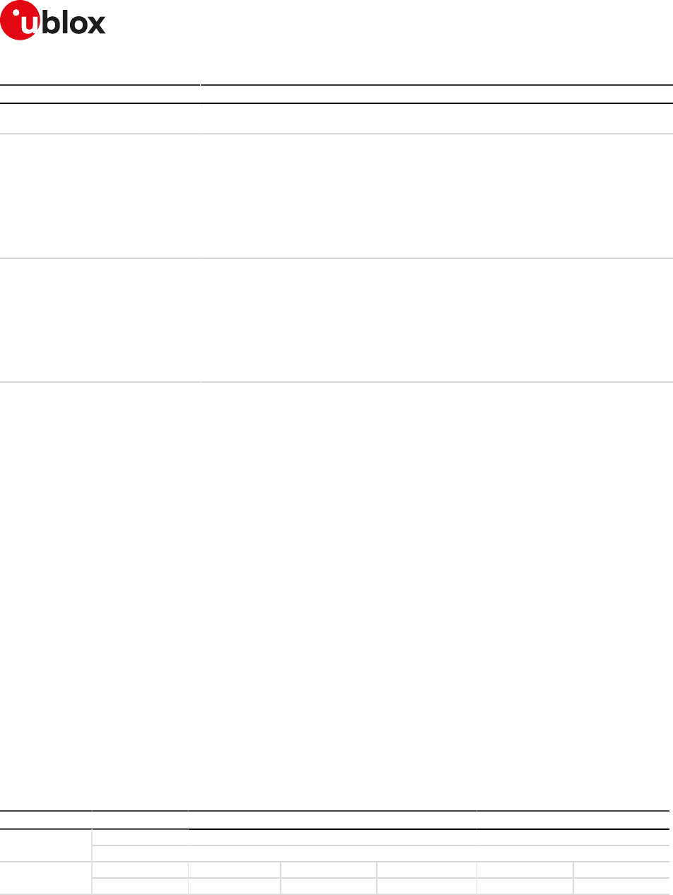
SARA-R4/N4 series-AT Commands Manual
UBX-17003787 - R09
7Network service
Page 46 of 307
Parameter Type Description
• 8: LTE CAT-NB1
• 9: eGPRS
<PreferredAct> Number Indicates the preferred access technology; it is ignored if dual mode or tri mode are
not selected.
• 0: GSM
• 2: UTRAN
• 3: LTE
• 7: LTE CAT-M1
• 8: LTE CAT-NB1
• 9: eGPRS
<2ndPreferredAct> Number Indicates the second preferred access technology; it is ignored if tri mode is not
selected.
• 0: GSM
• 2: UTRAN
• 3: LTE
• 7: LTE CAT-M1
• 8: LTE CAT-NB1
• 9: eGPRS
7.5.4Notes
• AT&T's EFRAT mode contains the RAT mode setting, the RAT mode setting is the mode that the module
shall be set to. Thus this setting may override +URAT's <SelectedAcT> and <PreferredAct> loaded at
boot time.
SARA-R404M / SARA-R410M-01B
• <SelectedAcT>=0, 1, 2, 4, 5, 6, 7, 8, 9 are not supported. The factory-programmed value of <SelectedAcT>
is 3.
SARA-R410M-02B / SARA-R410M-52B
• <SelectedAcT> is the first AcT the module will search. In the case a suitable cell can't be found on this
AcT, the module will search the <PreferredAct> if defined.
• <PreferredAct> is the next AcT the module will search if no suitable cell can be found on the
<SelectedAcT>. In the case a suitable cell can't be found on this AcT, the module will search the
<2ndPreferredAct> if defined.
• <SelectedAcT>=0, 1, 2, 3, 4, 5, 6, 9 are not supported. The factory-programmed value of <SelectedAcT>
is 7.
• <PreferredAct>=0, 2, 3, 9 are not supported. The factory-programmed value of <PreferredAct> is 8.
• <2ndPreferredAct>=0, 2, 3, 9 are not supported. The factory-programmed value of <PreferredAct> is
NULL.
SARA-N4
• <SelectedAcT>=0, 1, 2, 3, 4, 5, 6, 7, 8, 9 are not supported. The factory-programmed value of
<SelectedAcT> is 8.
7.6Network registration status +CREG
+CREG
SARA-R410M-02B SARA-R410M-52B SARA-R412MModules
SARA-N4
Syntax PIN required Settings saved Can be aborted Response time Error referenceAttributes
partial No No No - +CME Error
7.6.1Description
Configures the network registration information. Depending on the <n> parameter value, a URC can be issued:
• +CREG: <stat> if <n>=1 and there is a change in the MT's circuit switched mode network registration status
in GERAN/UTRAN/E-UTRAN
• +CREG: <stat>[,<lac>,<ci>[,<AcTStatus>]] if <n>=2 and there is a change of the network cell in GERAN/
UTRAN/E-UTRAN
SARA-R4/N4 series-AT Commands Manual
UBX-17003787 - R09
7Network service
Page 47 of 307
The parameters <AcTStatus>, <lac>, <ci> are provided only if available.
The read command provides the same information issued by the URC together with the current value of the
<n> parameter. The location information elements <lac>, <ci> and <AcTStatus>, if available, are returned only
when <n>=2 and the MT is registered with the network.
When <n>=2, in UMTS RAT, during dedicated connections, unsolicited location information may be
received if the network sends the UTRAN INFORMATION MOBILITY message. In GSM RAT, during a CS
connection, no unsolicited location information is received.
The DTE application should set a reasonable timer (10 s) when receiving the +CREG: 3 URC, since this
might be due to the fact that the LTE registration was rejected (SIM not enabled for LTE RAT, wrong APN
during the initial default bearer setup in the EPS attach procedure and other temporary reject causes).
If the MT also supports GPRS services and/or EPS services in E-UTRAN, the +CGREG / +CEREG set and
read command result codes apply to the registration status and location information for those services.
7.6.2Syntax
Type Syntax Response Example
Set AT+CREG=[<n>] OK AT+CREG=1
OK
Read AT+CREG? +CREG: <n>,<stat>[,<lac>,<ci>[,
<AcTStatus>]]
OK
+CREG: 0,0
OK
Test AT+CREG=? +CREG: (list of the supported <n>s)
OK
+CREG: (0-2)
OK
URC +CREG: <stat>[,<lac>,<ci>[,
<AcTStatus>]]
+CREG: 1,"4E54","44A5"
7.6.3Defined values
Parameter Type Description
<n> Number • 0 (default value and factory-programmed value): network registration URC disabled
• 1: network registration URC +CREG: <stat> enabled
• 2: network registration and location information URC +CREG: <stat>[,<lac>,<ci>[,
<AcTStatus>]] enabled
<stat> Number • 0: not registered, the MT is not currently searching a new operator to register to
• 1: registered, home network
• 2: not registered, but the MT is currently searching a new operator to register to
• 3: registration denied
• 4: unknown (e.g. out of GERAN/UTRAN/E-UTRAN coverage)
• 5: registered, roaming
• 6: registered for "SMS only", home network (applicable only when <AcTStatus>
indicates E-UTRAN)
• 7: registered for "SMS only", roaming (applicable only when <AcTStatus> indicates
E-UTRAN)
• 9: registered for "CSFB not preferred", home network (applicable only when
<AcTStatus> indicates E-UTRAN)
• 10: registered for "CSFB not preferred", roaming (applicable only when <AcTStatus>
indicates E-UTRAN)
<lac> String Two bytes location area code or tracking area code (if <AcTStatus>=7) in
hexadecimal format (e.g. "00C3"). The value FFFF means that the current <lac> value
is invalid.
<ci> String From 2 to 4 bytes cell ID in hexadecimal format (e.g. "A13F" or "129080B"). The value
FFFFFFFF means that the current <ci> value is invalid.
<AcTStatus> Number Indicates the radio access technology
• 0: GSM
• 1: GSM COMPACT
• 2: UTRAN
• 3: GSM with EDGE availability
• 4: UTRAN with HSDPA availability

SARA-R4/N4 series-AT Commands Manual
UBX-17003787 - R09
7Network service
Page 48 of 307
Parameter Type Description
• 5: UTRAN with HSUPA availability
• 6: UTRAN with HSDPA and HSUPA availability
• 7: E-UTRAN
• 255: the current <AcTStatus> value is invalid
7.6.4Notes
The following is an overview of the values assumed by the <stat> parameter:
• 0: a technical problem could have occurred, the user is requested to intervene. It is still possible to make
emergency calls if some network is available. Possible causes:
o PIN not entered
o Invalid HPLMN found on the SIM (SIM read error)
o SIM card not present
The registration is not started
• 1: the MT is registered for circuit-switched services on the HPLMN (or on one of the equivalent HPLMN's,
whose list is provided by the SIM)
• 2: the module is searching a network to register on. Possible causes:
o No network available
o Available networks have insufficient Rx level
o HPLMN or allowed PLMN are available but the registration is rejected, e.g. roaming is not allowed
in this Location Area
It is still possible to make emergency calls if network coverage is available
• 3: the CS registration failed after a Location Update Reject; possible causes are:
o Illegal MS
o Illegal ME
o IMSI unknown at HLR
o PLMN not allowed
o Location area not allowed
o Roaming not allowed in this location area
o Network failure
o Network congestion
It is still possible to make emergency calls if network coverage is available.
If the registration type is manual, then no further attempt is made to search for a new PLMN or register
with it. If the registration type is automatic, the MS may look for an allowed PLMN if the rejection cause
was roaming restriction. In case of illegal MS /ME, there could be possible problems with either the SIM
card or with the ME's identity (IMEI): user intervention may be required
• 4: this value, usually transitory, is returned if the registration state does not belong to any of the following:
o Normal
o Limited
o No service
o Service detached
o Service disabled
It may be issued after the failure of a registration procedure, before starting a PLMN search, when
<stat>=2.
• 5: the MT is registered for circuit-switched services on a VPLMN, in national or international roaming
• 6: in LTE, the MT is registered only for the SMS circuit-switched service on the HPLMN (ore on one of the
equivalent HPLMN's)
• 7: in LTE, the MT is registered only for the SMS circuit-switched service on a VPLMN, in national or
international roaming

SARA-R4/N4 series-AT Commands Manual
UBX-17003787 - R09
7Network service
Page 49 of 307
7.7Network selection control +PACSP
+PACSP
SARA-R410M-01B SARA-R410M-02B SARA-R410M-52B SARA-R412MModules
SARA-N4
Syntax PIN required Settings saved Can be aborted Response time Error referenceAttributes
full Yes No No - +CME Error
7.7.1Description
If the EFCSP (Customer Service Profile) is available the +PACSP URC is provided in the following cases:
• SARA-R4 / SARA-N4 - at the module registration
• SARA-R4 / SARA-N4 - whenever the SIM/USIM issues the REFRESH proactive command related to the
EFCSP
For further information, see the AT&T Device Requirements [61].
The EFCSP is available on SIM/USIM cards from AT&T mobile network operator.
7.7.2Syntax
Type Syntax Response Example
Read AT+PACSP? +PACSP<bit_value>
OK
+PACSP1
OK
URC +PACSP<bit_value> +PACSP0
7.7.3Defined values
Parameter Type Description
<bit_value> Number PLMN mode bit value:
• 0: automatic network selection is forced (see Notes)
• 1: network selection mode unchanged (see Notes)
7.7.4Notes
• If EFCSP is available, the PLMN mode bit forces the automatic network registration, according to the
+COPS <mode> value which is loaded at boot from the selected profile (see the Appendix B.1 and &V). The
following table explains the behavior:
Autoregistration <mode> PLMN mode bit <bit_value> Autoregistration behavior
0 0 Automatic network selection
1 0 Automatic network selection
2 0 Disabled
0 1 Automatic network selection
1 1 Manual network selection (search for the PLMN
stored in the selected profile)
2 1 Disabled
SARA-R4 / SARA-N4
• The read command is not supported.
7.8Channel and network environment description +UCGED
+UCGED
SARA-R410M-02B SARA-R410M-52B SARA-R412MModules
SARA-N4
Syntax PIN required Settings saved Can be aborted Response time Error referenceAttributes
partial No No No - +CME Error
7.8.1Description
Enables the protocol stack and network environment information collection.
SARA-R4/N4 series-AT Commands Manual
UBX-17003787 - R09
7Network service
Page 50 of 307
The information text response of the read command reports only the current RAT (if any) parameters,
determined by the <rat> parameter value.
Table 4 lists the supported <mode> parameter values:
Channel <mode>=0 <mode>=2 <mode>=3 <mode>=5
SARA-N4 * *
SARA-R4 * *
Table 4: <mode> parameter applicability
7.8.2Syntax
Type Syntax Response Example
AT+UCGED=2
OK
AT+UCGED=3
+UCGED: 0
65535,fff,fff,0000,ff,99
10588,1,222,88,1281d24,255,11,40
65535,255,255,255,fff,fff,ffff,0000
000,65535,255,255,255,255
OK
Set AT+UCGED=<mode> [+UCGED: <svc>
<arfcn>,<Gmcc>,<Gmnc>,<GcellId>,
<BSIC>,<rxlev>
<uarfcn>,<Wband>,<Wmcc>,
<Wmnc>,<WcellId>,<Wrrc>,<rssi>,
<ecn0_lev>
<earfcn>,<Lband>,<ul_BW>,<dl_
BW>,<Lmcc>,<Lmnc>,<tac>,
<LcellId>,<P-CID>,<rsrp>,<rsrq>,
<Lsinr>,<Lrrc>]
OK AT+UCGED=5
OK
<mode>= 0:
+UCGED: 0
OK
+UCGED: 0
OK
<mode>= 2, <rat>= 2:
+UCGED: 2
2,<svc>,<MCC>,<MNC>
<arfcn>,<band1900>,<GcellId>,
<BSIC>,<Glac>,<Grac>,<rxlev>,
<grr>,<t_adv>,<Gspeech_mode>
OK
+UCGED: 2
2,4,001,01
810,1,0000,01,0000,80,63,255,255,
255
OK
<mode>= 2, <rat>= 3:
+UCGED: 2
3,<svc>,<MCC>,<MNC>
<uarfcn>,<Wband>,<WcellId>,
<Wlac>,<Wrac>,<scrambling_
code>,<Wrrc>,<rssi>,<ecn0_lev>,
<Wspeech_mode>
OK
+UCGED: 2
3,4,001,01
4400,5,0000000,0000,80,9,4,62,42,
255
OK
Read AT+UCGED?
<mode>= 2, <rat>= 4:
+UCGED: 2
4,<svc>,<MCC>,<MNC>
<earfcn>,<Lband>,<ul_BW>,
<dl_BW>,<tac>,<LcellId>,<P-
CID>,<mTmsi>,<mmeGrId>,
<mmeCode>, <rsrp>,<rsrq>,
<Lsinr>,<Lrrc>,<RI>,<CQI>,
<avg_rsrp>,<totalPuschPwr>,
<avgPucchPwr>,<drx>, <l2w>,
<volte_mode>[,<meas_gap>,<tti_
bundling>]
+UCGED: 2
4,0,001,01
2525,5,25,50,2b67,69f6bc7,111,0000
0000,ffff,ff,67,19,0.00,255,255,255,
67,11,255,0,255,255,0,0
OK

SARA-R4/N4 series-AT Commands Manual
UBX-17003787 - R09
7Network service
Page 51 of 307
Type Syntax Response Example
OK
<mode>= 2, <rat>= 5:
+UCGED: 2
5,<svc>
OK
+UCGED: 2
5,1
OK
<mode>= 0:
+UCGED: MODE_5_DISABLED
OK
+UCGED: MODE_5_DISABLED
OK
<mode>= 5:
+RSRP: <P-CID>,<earfcn>,
"<RSRP>",
+RSRQ: <P-CID>,<earfcn>,
"<RSRQ>",
OK
+RSRP: 162,5110,"-075.00",
+RSRQ: 162,5110,"-14.20",
OK
Test AT+UCGED=? +UCGED: (list of supported
<mode>s)
OK
+UCGED: (0,2)
OK
7.8.3Defined values
Parameter Type Description
<mode> Number • 0: reporting disabled
• 2: short form reporting enabled
• 3: retrieve the short form text information report
• 5: RSRP and RSRQ reporting enabled
<rat> Number Current Radio Access Technology:
• 2: 2G
• 3: 3G
• 4: 4G
• 5: unknown. The parameter is set to a 5 until a network information update is not
successfully performed through +UCGED=2 or when the MT is set to minimum
functionality (+CFUN=4, +CFUN=19).
<svc> Number Current radio service state:
• 0: not known or not detectable
• 1: radio off
• 2: searching
• 3: no service
• 4: registered
The radio service state is updated at each change from a valid network service state
(2G, 3G or 4G) to another valid network service state (2G, 3G or 4G). To retrieve the
network registration status information refer to +CREG, +CGREG and +CEREG AT
commands.
<MCC> Number Mobile Country Code; the range is 0-999 (3 digits), FFF if not known or not detectable.
<MNC> Number Mobile Network Code; the range is 0-999 (1 to 3 digits), FFF if not known or not
detectable.
<arfcn> Number Absolute Radio Frequency Channel Number (ARFCN); the range is 0-1023, 65535 if
not known or not detectable.
<band1900> Number Indicates whether the given <arfcn> in the range 512-810 is part of band 1900 or not,
to avoid ambiguity between bands 1800 and 1900:
• 0: the given <arfcn> is not part of band 1900
• 1: the given <arfcn> is part of band 1900
<GcellId> Number GERAN Cell Identifier (CI) in hexadecimal format; the range is 0h-FFFFh (2 octets).
<BSIC> Number Base Station Identity Code (BSIC) of the GERAN cell in hexadecimal format; the range
is 0h-3Fh (6 bits), FF if not known or not detectable.
<Glac> Number Two bytes location area of the GERAN cell in hexadecimal format; FFFF if not known
or not detectable.

SARA-R4/N4 series-AT Commands Manual
UBX-17003787 - R09
7Network service
Page 52 of 307
Parameter Type Description
<Grac> Number One byte routing area of the GERAN cell in hexadecimal format; FF if not known or not
detectable.
<rxlev> Number GERAN cell Received Signal Strength Indicator (RSSI) index as defined in 3GPP TS
45.008 [28]:
• 0: less than -110 dBm
• 1..62: from -110 to -48 dBm with 1 dBm steps
• 63: -48 dBm or greater
• 255: not known or not detectable
<grr> Number Reserved for future use.
<t_adv> Number Reserved for future use.
<Gspeech_mode> Number Reports the latest obtained value of the GSM speech code. Allowed values:
• 0: GSM Enhanced Full Rate (12.2 kb/s)
• 1: GSM Full Rate (13.0 kb/s)
• 2: GSM Half Rate (5.6 kb/s)
• 3..10: AMR NB FR (from 4.75 kb/s to 12.2 kb/s) the value indicates the first codec
type chosen from the DUT; see the corresponding value of <Wspeech_mode>
parameter for the baud rate mapping
• 3..8: AMR NB HR (from 4.75 kb/s to 7.95 kb/s) the value indicates the first codec type
chosen from the DUT; see the corresponding value of <Wspeech_mode> parameter
for the baud rate mapping
• 11..13: AMR WB FR (from 6.60 kb/s to 12.65 kb/s) the value indicates the first
codec type chosen from the DUT; see the corresponding value of <Wspeech_mode>
parameter for the baud rate mapping
• 255: not known or not detectable
See 3GPP TS 26.201 [113] for more details on GSM codecs used during a voice call
In case a set of speech codecs is assigned by the network, then the parameter
reports the lowest one and this one is not necessary the one used.
<uarfcn> Number UTRAN Absolute Radio Frequency Channel Number (UARFCN); the range is 1537-10
838, 65535 if not known or not detectable.
<Wband> Number UTRAN band:
• 1: band 1 (2 GHz)
• 2: band 2 (1900 MHz)
• 4: band 4 (2100 MHz)
• 5: band 5 (800 MHz)
• 8: band 8 (900 MHz)
• 255: not known or not detectable
<WcellId> Number UTRAN CI (cell identifier) in hexadecimal format; the range is 0h-FFFFFFFh (28 bits),
0000000 if not known or not detectable.
<Wlac> Number Two bytes location area of the UTRAN cell in hexadecimal format; FFFF if not known
or not detectable.
<Wrac> Number One byte routing area of the GERAN cell in hexadecimal format; FF if not known or not
detectable.
<scrambling_code> Number Primary Scrambling Code; range 0-512, 0 if not known or not detectable.
<Wrrc> Number 3G RRC state:
• 0: idle
• 1: URA_PCH
• 2: CELL_PCH
• 3: CELL_FACH
• 4: CELL_DCH
• 255: not known or not detectable
<rssi> Number UTRAN cell Received Signal Strength Indicator as defined in 3GPP TS 25.133 [106]:
• 0: less than -100 dBm
• 1..75: from -100 to -25 dBm with 1 dBm steps
• 76: -25 dBm or greater
• 255: not known or not detectable
<ecn0_lev> Number UTRAN cell Ratio of received energy per PN chip to the total received power spectral
density as defined in 3GPP TS 25.133 [106]:
• 0: less than -24 dB
SARA-R4/N4 series-AT Commands Manual
UBX-17003787 - R09
7Network service
Page 53 of 307
Parameter Type Description
• 1..48: from -24 dB to 0 dB with 0.5 dB steps
• 49: 0 dB or greater
• 255: not known or not detectable
<Wspeech_mode> Number Reports the latest obtained value of the UMTS speech code. Allowed values:
• 3: AMR NB (4.75 kb/s)
• 4: AMR NB (5.15 kb/s)
• 5: AMR NB (5.90 kb/s)
• 6: AMR NB (6.70 kb/s)
• 7: AMR NB (7.40 kb/s)
• 8: AMR NB (7.95 kb/s)
• 9: AMR NB (10.2 kb/s)
• 10: AMR NB (12.2 kb/s)
• 11: AMR WB (6.60 kb/s)
• 12: AMR WB (8.85 kb/s)
• 13: AMR WB (12.65 kb/s)
• 14: AMR WB (14.25 kb/s)
• 15: AMR WB (15.85 kb/s)
• 16: AMR WB (18.25 kb/s)
• 17: AMR WB (19.85 kb/s)
• 18: AMR WB (23.05 kb/s)
• 19: AMR WB (23.85 kb/s)
• 255: not known or not detectable
See 3GPP TS 26.201 [113] for more details on UMTS codecs used during a voice call.
In case a set of speech codecs is assigned by the network, then the parameter
reports the lowest one and this one is not necessary the one used.
<earfcn> Number E-UTRAN Absolute radio frequency channel number; the range is 0-6449, 65535 if
not known or not detectable.
<Lband> Number E-UTRAN band (see 3GPP TS 36.101 Table 5.5-1 [99]); the range is 0-44, 255 if not
known or not detectable.
<ul_BW> Number Number of Uplink Resource Blocks (see 3GPP TS 36.101 Table 5.6-1 [99]), 255 if not
known or not detectable.
<dl_BW> Number Number of Downlink Resource Blocks (see 3GPP TS 36.101 Table 5.6-1 [99]), 255 if not
known or not detectable.
<tac> Number E-UTRAN cell Tracking area code in hexadecimal format; the range is 0h-FFFFh (2
octets), FFFF if not known or not detectable.
<LcellId> Number E-UTRAN CI (cell identifier) in hexadecimal format; the range is 0h-FFFFFFFh (28
bits), 0000000 if not known or not detectable.
<P-CID> Number E-UTRAN cell Physical Cell ID; the range is 0-503, 65535 if not known or not
detectable.
<mTmsi> Number 4 bytes MME Temporary Mobile Subscriber Identity in hexadecimal format; 0000000
0 if not known or not detectable.
<mmeGrId> Number 2 bytes MME Group Identifier in hexadecimal format; FFFF if not known or not
detectable.
<mmeCode> Number 1 byte MME Code in hexadecimal format; FF if not known or not detectable.
<rsrp> Number Reference Signal Received Power (RSRP) as defined in 3GPP TS 36.133 [105]:
• 0: less than -140 dBm
• 1..96: from -140 dBm to -44 dBm with 1 dBm steps
• 97: -44 dBm or greater
• 255: not known or not detectable
<rsrq> Number Reference Signal Received Quality (RSRQ) as defined in 3GPP TS 36.133 [105]:
• 0: less than -19.5 dB
• 1..33: from -19.5 dB to -3 dB with 0.5 dB steps
• 34: -3 dB or greater
• 255: not known or not detectable
<Lsinr> Number E-UTRAN Signal to Interference and Noise ratio in dB. The range goes from -15,88 to
15,88; 255 if not known or not detectable.
<Lrrc> Number 4G RRC state:
• 0: null
SARA-R4/N4 series-AT Commands Manual
UBX-17003787 - R09
7Network service
Page 54 of 307
Parameter Type Description
• 1: IDLE
• 2: ATTEMPT TO CONNECT
• 3: CONNECTED
• 4: LEAVING CONNECTED STATE
• 5: ATTEMPT LEAVING E-UTRA
• 6: ATTEMPT ENTERING E-UTRA
• 255: not known or not detectable
<RI> Number Rank Indicator value; 255 if not known or not detectable. It is updated every 480 ms
with the value which has been most often reported to the network in the previous 480
ms period. See 3GPP TS 36.213 [130] section 7.2 and 3GPP TS 36.212 [131] section
5.2.2.6 for more details.
<CQI> Number Channel Quality Indicator value; 255 if not known or not detectable. It is updated
every 480 ms with the value which has been most often reported to the network in
the previous 480 ms period. See 3GPP TS 36.213 [130] section 7.2 for more details.
<avg_rsrp> Number Average value of last 10th Reference Signal Received Power (RSRP).
<totalPuschPwr> Number Mobile output power for PUSCH transmission averaged over 480 ms in dBm; 255 if
not known or not detectable.
<avgPucchPwr> Number Mobile output power for PUCCH transmission averaged over 480 ms in dBm; 255 if
not known or not detectable.
<drx> Number Discontinuous Reception "drx-Inactivity-Timer" value in ms; 0 if not known or not
detectable.
<l2w> Number SIB3 LTE to WCDMA reselection criteria: (threshServingLow)x2 +(q-RxLevMin)x2;
255 if not known or not detectable.
<volte_mode> Number Reserved for future use.
<meas_gap> Number Measurement gap configuration:
• 0: disabled
• 40: 40 ms measurement gap repetition period corresponding to the measurement
gap pattern ID 0 (see Table 8.1.2.1-1 of 3GPP TS 36.133 [105])
• 80: 80 ms measurement gap repetition period corresponding to the measurement
gap pattern ID 1 (see Table 8.1.2.1-1 of 3GPP TS 36.133 [105])
<tti_bundling> Number TTi (Transmission Time interval) bundling status:
• 0: off
• 1: on
<RSRP> String Reference Signal Received Power (RSRP) as defined in 3GPP TS 36.133 [105]
expressed in dBm
<RSRQ> String Reference Signal Received Quality (RSRQ) as defined in 3GPP TS 36.133 [105]
expressed in dB
7.9Edit Verizon wireless APN table +VZWAPNE
+VZWAPNE
Modules SARA-R404M
Syntax PIN required Settings saved Can be aborted Response time Error referenceAttributes
partial No NVM No - +CME Error
7.9.1Description
Reads and writes the APN table stored in the NVM:
• The set command causes the APN table on the DUT to be overwritten. A set command must be issued for
each APN edit.
• The read command queries the APN table that is currently on the DUT, starting from the first entry to the
last; it returns each APN entry in a new line.
If the command fails, an error result code is returned. See the 3GPP TS 27.007 [2] subclause 9.2 for <err> values.
SARA-R4/N4 series-AT Commands Manual
UBX-17003787 - R09
7Network service
Page 55 of 307
7.9.2Syntax
Type Syntax Response Example
Set AT+VZWAPNE=<wapn>,<apncl>,
<apnni>,<apntype>,<apnb>,
<apned>,<apntime>
OK AT+VZWAPNE=1,1,"VZWIMS",
"IPv6","LTE","Enabled",0
OK
Read AT+VZWAPNE? [+VZWAPNE: <apncl>,<apnni>,
<apntype>,<apnb>,<apned>,
<apntime> [..]]
OK
+VZWAPNE: 1,"VZWIMS","IPv4v6",
"LTE","Enabled",0
+VZWAPNE: 2,"VZWADMIN",
"IPv4v6","LTE","Enabled",0
OK
Test AT+VZWAPNE=? +VZWAPNE: (list of supported
<wapn>s),(list of supported
<apncl>s),,(range of supported
<apntype>s),range of supported
<apnb>s),(list of supported
<apned>s),(list of supported
<apntime>s)
OK
+VZWAPNE: (0-4),(1-4),,("IPv6",
"IPv4v6"),("LTE"),("Enabled",
"Disabled"),(0-1023)
OK
7.9.3Defined values
Parameter Type Description
<wapn> Number APN list entry
<apncl> Number APN class
<apnni> String Network identifier:
• "VZWIMS": Verizon wireless IMS PDN
• "VZWADMIN": Verizon wireless administrative PDN
• "VZWINTERNET": Verizon Internet PDN
• "VZWAPP": Verizon wireless application PDN
The previous strings are predefined but others could be accepted.
<apntype> String • "IPv6": IPv6 type
• "IPv4v6" (factory-programmed value): IPv4 and IPv6 type
<apnb> String APN bearer:
• "LTE" (factory-programmed value): LTE bearer used
<apned> String Enable/disable the APN:
• "Enabled" (factory-programmed value): APN enabled
• "Disabled": APN disabled
<apntime> Number APN inactivity timer value in minutes. The range goes from 0 to 5. Value '0' (factory-
programmed value) sets the timer to infinity.
7.9.4Notes
APN class APN NI IP type APN bearer Enable flag WAIT_TIME Description
1 VZWIMS Ipv4v6 LTE Enabled 0 IMS
2 VZWADMIN Ipv4v6 LTE Enabled 0 Administrative
3 VZWINTERNET Ipv4v6 LTE Enabled 0 Internet
4 VZWAPP Ipv4v6 LTE Enabled 0 Application
Table 5: Factory-programmed APN table setting
SARA-R4/N4 series-AT Commands Manual
UBX-17003787 - R09
7Network service
Page 56 of 307
7.10Read RSRP values +VZWRSRP
+VZWRSRP
Modules SARA-R404M
Syntax PIN required Settings saved Can be aborted Response time Error referenceAttributes
full No No No - +CME Error
7.10.1Description
Returns the RSRP (Reference Signal Received Power) values for all LTE cells which the module is measuring.
7.10.2Syntax
Type Syntax Response Example
Read AT+VZWRSRP? +VZWRSRP:
[<cellID1>,<EARFCN1>,<RSRP1>[,
<cellID2>,<EARFCN2>,<RSRP2>[,
...]]]
OK
+VZWRSRP:
000,2175,"-61.00"
OK
7.10.3Defined values
Parameter Type Description
<cellIDn> Number nth cell physical cell identifier in "xxx" format. The range goes from 0 to 503.
<EARFCNn> Number nth cell EARFCN in decimal format. The range goes from 0 to 65535.
<RSRPn> String nth cell RSRP value in dBm/15 kHz where the format is "-XX.XX".
7.11Read RSRQ values +VZWRSRQ
+VZWRSRQ
Modules SARA-R404M
Syntax PIN required Settings saved Can be aborted Response time Error referenceAttributes
full No No No - +CME Error
7.11.1Description
Returns the RSRQ (Reference Signal Received Quality) values for all the LTE cells which the module is
measuring.
7.11.2Syntax
Type Syntax Response Example
Read AT+VZWRSRQ? +VZWRSRQ:
[<cellID1>,<EARFCN1>,<RSRQ1>[,
<cellID2>,<EARFCN2>,<RSRQ2>[,
...]]]
OK
+VZWRSRQ:
000,2175,"-11.00"
OK
7.11.3Defined values
Parameter Type Description
<cellID> Number nth cell physical cell identifier in "xxx" format. The range goes from 0 to 503.
<EARFCN> Number nth cell EARFCN in decimal format. The range goes from 0 to 65535.
<RSRP> String nth cell RSRP value in dBm/15 kHz where the format is "-XX.XX".
SARA-R4/N4 series-AT Commands Manual
UBX-17003787 - R09
7Network service
Page 57 of 307
7.12eDRX setting +CEDRXS
+CEDRXS
SARA-R410M-02B SARA-R410M-52BModules
SARA-N4
Syntax PIN required Settings saved Can be aborted Response time Error referenceAttributes
full No No No - +CME Error
7.12.1Description
Configures the UEs extended discontinuous reception (eDRX) parameters. The command controls whether the
UE wants to apply the eDRX or not, as well as the requested eDRX value for each specified type of radio access
technology. If the requested eDRX value is not provided in set command, then the UE will use the eDRX value
provided by the network.
The set command also enables the +CEDRXP URC, that is issued on any change in the eDRX parameters, when
enabled by the network.
The set command with <mode>=3, will disable the use of eDRX and reset all parameters to
factory-programmed values. Optional parameters are not provided in this form of command.
7.12.2Syntax
Type Syntax Response Example
Set AT+CEDRXS=<mode>[,<AcT_
type>[,<Requested_eDRX_value>]]
OK AT+CEDRXS=1,4,"0101"
OK
Read AT+CEDRXS? [+CEDRXS: <AcT_type>,
<Requested_eDRX_value>
[...]
[+CEDRXS: <AcT_type>,
<Requested_eDRX_value>]]
OK
+CEDRXS: 4,"0101"
OK
Test AT+CEDRXS=? +CEDRXS: (list of supported
<mode>s),(list of supported
<AcT_type>s),(list of supported
<Requested_eDRX_value>s)
OK
+CEDRXS: (0-3),(4-5),("0000"-"1111")
OK
URC +CEDRXP: <AcT_type>[,
<Requested_eDRX_value>[,<NW-
provided_eDRX_value>[,<Paging_
time_window>]]]
+CEDRXP: 4,"1010","1001","1101"
7.12.3Defined values
Parameter Type Description
<mode> Number Indication to disable or enable the use of eDRX in the UE. Allowed values:
• 0 (default value): use of eDRX disabled
• 1: use of eDRX enabled
• 2: enable the use of eDRX and enable the URC
• 3: disable the use of eDRX and reset all parameters for eDRX to factory-
programmed values
<AcT_type> Number Indicates the type of access technology. Allowed values:
• 4: E-UTRAN (WB-S1 mode)
• 5: E-UTRAN (NB-S1 mode)
<Requested_eDRX_
value>
String Requested extended DRX parameters information element, half a byte in a 4 bit
format. For the coding and the value range, see the extended DRX parameters
information element in Table 10.5.5.32 of 3GPP TS 24.008 [12].
<NW_provided_
eDRX_value>
String New provided extended DRX parameters information element, half a byte in a 4
bit format. For the coding and the value range, see the extended DRX parameters
information element in Table 10.5.5.32 of 3GPP TS 24.008 [12].
SARA-R4/N4 series-AT Commands Manual
UBX-17003787 - R09
7Network service
Page 58 of 307
Parameter Type Description
<Paging_time_
window>
String The paging time window refers to bit 8 to 5 of octet 3 of the extended DRX
parameters information element, half a byte in a 4 bit format. For the coding and
the value range, see the extended DRX parameters information element in Table 10
.5.5.32 of 3GPP TS 24.008 [12].
7.13eDRX read dynamic parameters +CEDRXRDP
+CEDRXRDP
SARA-R410M-02B SARA-R410M-52BModules
SARA-N4
Syntax PIN required Settings saved Can be aborted Response time Error referenceAttributes
full No No No - +CME Error
7.13.1Description
Returns the UEs extended discontinuous reception (eDRX) parameters (<AcT_type> and <Requested_eDRX_
value>, <NW_provided_eDRX_value> and <Paging_time_window>) if the eDRX is used for the cell which the MT
is currently registered to.
7.13.2Syntax
Type Syntax Response Example
Action AT+CEDRXRDP +CEDRXRDP: <AcT_type>,
<Requested_eDRX_value>,<NW_
provided_eDRX_value>,<Paging_
time_window>
OK
+CEDRXRDP: 5,"0010","1110","0101"
OK
Test AT+CEDRXRDP=? OK
7.13.3Defined values
Parameter Type Description
<AcT_type> Number Indicates the type of radio access technology. Allowed values:
• 0: do not use eDRX
• 1: EC-GSM-IoT (A/Gb mode)
• 2: GSM (A/Gb mode)
• 3: UTRAN (Iu mode)
• 4: E-UTRAN (WB-S1 mode)
• 5: E-UTRAN (NB-S1 mode)
<Requested_eDRX_
value>
String Requested extended DRX parameters information element, half a byte in a 4 bit
format. For the coding and the value range, see the extended DRX parameters
information element in Table 10.5.5.32 of 3GPP TS 24.008 [12].
<NW_provided_
eDRX_value>
String New provided extended DRX parameters information element, half a byte in a 4
bit format. For the coding and the value range, see the extended DRX parameters
information element in Table 10.5.5.32 of 3GPP TS 24.008 [12].
<Paging_time_
window>
String The paging time window refers to bit 8 to 5 of octet 3 of the extended DRX
parameters information element, half a byte in a 4 bit format. For the coding and
the value range, see the extended DRX parameters information element in Table 10
.5.5.32 of 3GPP TS 24.008 [12].
SARA-R4/N4 series-AT Commands Manual
UBX-17003787 - R09
7Network service
Page 59 of 307
7.14Set MNO profile +UMNOPROF
+UMNOPROF
SARA-R410M-02B SARA-R410M-52B SARA-R412MModules
SARA-N4
Syntax PIN required Settings saved Can be aborted Response time Error referenceAttributes
full Yes NVM No - +CME Error
7.14.1Description
Automatically configures the module to be compliant to the requirements of various Mobile Network
Operators.
Follow this procedure to properly set up the configuration:
• Deregister the module from the network (AT+COPS=2 or perform a AT+CFUN=0 cycle)
• Issue AT+UMNOPROF=<MNO>
• Reboot the module (AT+CFUN=15) in order to apply the new configuration
After setting a new configuration the module reconfigures the PDP context settings (e.g. APN of the initial
EPS bearer).
u-blox cellular modules are certified according to all the capabilities and options stated in the Protocol
Implementation Conformance Statement document (PICS) of the module. The PICS, according to 3GPP
TS 51.010-2 [84], 3GPP TS 34.121-2 [85], 3GPP TS 36.521-2 [115] and 3GPP TS 36.523-2 [116], is a statement
of the implemented and supported capabilities and options of a device. If the user changes the command
settings during the certification process, the PICS of the application device integrating a u-blox cellular
module must be changed accordingly.
7.14.2Syntax
Type Syntax Response Example
Set AT+UMNOPROF=<MNO> OK AT+UMNOPROF=1
OK
Read AT+UMNOPROF? +UMNOPROF: <MNO>
OK
+UMNOPROF: 3
OK
Test AT+UMNOPROF=? +UMNOPROF: (list of supported
<mode>s)
OK
+UMNOPROF:
0: SW default
1: SIM ICCID select
2: ATT
6: CT
4: Telstra
5: TMO
3: Verizon
OK
7.14.3Defined values
Parameter Type Description
<MNO> Number Mobile Network Operator (MNO) configuration:
• 0 (default value): SW default
• 1: SIM ICCID select
• 2: ATT
• 3: Verizon
• 4: Telstra
• 5: TMO
• 6: CT

SARA-R4/N4 series-AT Commands Manual
UBX-17003787 - R09
7Network service
Page 60 of 307
7.15Band selection bitmask +UBANDMASK
+UBANDMASK
SARA-R410M-02B SARA-R410M-52B SARA-R412MModules
SARA-N4
Syntax PIN required Settings saved Can be aborted Response time Error referenceAttributes
full Yes NVM No - +CME Error
7.15.1Description
Sets the supported 4G LTE bands for different Radio Access Technologies (RATs). The bands supported are
set by a bitmask where each bit in an 8 byte integer corresponds to a 4G LTE band.
Reboot the module (+CFUN=15) in order to make the setting effective.
u-blox cellular modules are certified according to all the capabilities and options stated in the Protocol
Implementation Conformance Statement document (PICS) of the module. The PICS, according to 3GPP
TS 51.010-2 [84], 3GPP TS 34.121-2 [85], 3GPP TS 36.521-2 [115] and 3GPP TS 36.523-2 [116], is a statement
of the implemented and supported capabilities and options of a device. If the user changes the command
settings during the certification process, the PICS of the application device integrating a u-blox cellular
module must be changed accordingly.
7.15.2Syntax
Type Syntax Response Example
Set AT+UBANDMASK=<RAT>,
<bitmask1>[,<bitmask2>]
OK AT+UBANDMASK=0,2074
OK
Read AT+UBANDMASK? +UBANDMASK: <RAT>,
<bitmask1>[,<bitmask2>][,<RAT>,
<bitmask1>[,<bitmask2>]]
OK
+UBANDMASK: 0,168761503,1,
168761503
OK
Test AT+UBANDMASK=? +UBANDMASK: (list of the
supported <RAT>s),<bitmask1>,
<bitmask2>
OK
+UBANDMASK: (0,1),0
xffffffffffffffff,0xffffffffffffffff
OK
7.15.3Defined values
Parameter Type Description
<RAT> Integer Indicates the Radio Access Technology (RAT):
• 0: LTE Cat M1
• 1: LTE Cat NB1
<bitmask1> Integer Indicated the bandmask for 4G LTE bands 1 through 64. Each bit enables/disables a
band.
• Bit 0: band 1
• Bit 1: band 2
• Bit 2: band 3
• Bit 3: band 4
• ..
• ..
• Bit 63: band 64
<bitmask2> Integer Indicated the bandmask for 4G LTE bands 65 through 128. Each bit enables/disables
a band.
• Bit 0: band 65
• Bit 1: band 66
• Bit 2: band 67
• Bit 3: band 68
• ..
• ..
• Bit 63: band 128

SARA-R4/N4 series-AT Commands Manual
UBX-17003787 - R09
7Network service
Page 61 of 307
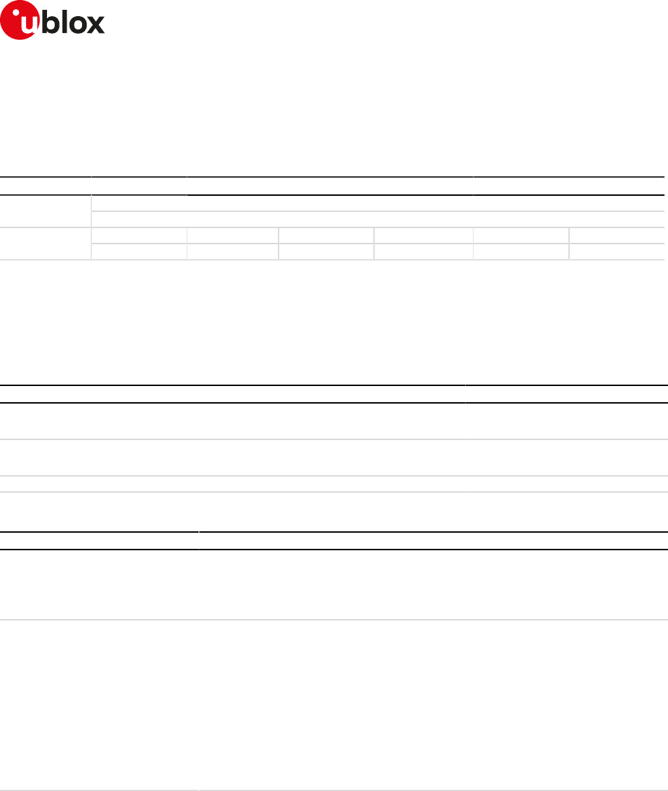
SARA-R4/N4 series-AT Commands Manual
UBX-17003787 - R09
8Security
Page 62 of 307
8Security
8.1Enter PIN +CPIN
+CPIN
SARA-R404M SARA-R410M-01B SARA-R410M-02B SARA-R410M-52B SARA-R412MModules
SARA-N4
Syntax PIN required Settings saved Can be aborted Response time Error referenceAttributes
full No No No < 10 s +CME Error
8.1.1Description
Enter PIN. If no PIN request is pending, the corresponding error code is returned. If a wrong PIN is given three
times, the PUK must be inserted in place of the PIN, followed by the <newpin> which replaces the old pin in
the SIM.
8.1.2Syntax
Type Syntax Response Example
Set AT+CPIN=<pin>[,<newpin>] OK AT+CPIN="0933"
OK
Read AT+CPIN? +CPIN: <code>
OK
+CPIN: SIM PIN
OK
Test AT+CPIN=? OK
8.1.3Defined values
Parameter Type Description
<pin>, <newpin> String 4-to-8 characters long string of decimal digits.
If only PIN is required, <newpin> is not to be entered.
If PUK is required, <pin> must be the PUK and <newpin>, the new PIN code, must be
entered as well.
<code> String • READY: MT is not pending for any password
• SIM PIN: MT is waiting SIM PIN to be given
• SIM PUK: MT is waiting SIM PUK to be given
• SIM PIN2: MT is waiting SIM PIN2 to be given
• SIM PUK2: MT is waiting SIM PUK2 to be given
• PH-NET PIN: MT is waiting network personalization password to be given
• PH-NETSUB PIN: MT is waiting network subset personalization password to be
given
• PH-SP PIN: MT is waiting service provider personalization password to be given
• PH-CORP PIN: MT is waiting corporate personalization password to be given
• PH-SIM PIN: MT is waiting phone to SIM/UICC card password to be given
8.1.4Notes
• The command needs the SIM module to work correctly
• If PIN is not inserted the following situation can occur:
AT+CMEE=2
OK
AT+COPS=0
+CME ERROR: SIM PIN required
AT+CMEE=0
OK
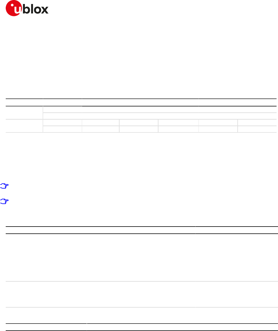
SARA-R4/N4 series-AT Commands Manual
UBX-17003787 - R09
8Security
Page 63 of 307
AT+COPS=0
ERROR
• To change the PIN the user must use the AT+CPWD="SC",<old_pin>,<new_pin> command (see Chapter
8.3 for details).
Example:
AT+CPWD="SC","1234","4321"
8.2Facility lock +CLCK
+CLCK
SARA-R404M SARA-R410M-01B SARA-R410M-02B SARA-R410M-52B SARA-R412MModules
SARA-N4
Syntax PIN required Settings saved Can be aborted Response time Error referenceAttributes
full Yes No Yes Up to 3 min +CME Error
8.2.1Description
Locks, unlocks or interrogates an MT or a network facility <fac>. A password is normally needed to do such
actions. When querying the status of a network service (<mode>=2) the information text response for "not
active" case (<status>=0) is returned only if the service is not active for any <class>. Instead when querying
the status of a network service (<mode>=2) asking for a specific <class>, the DUT sends a generic request.
The command can be aborted if network facilities are set or interrogated.
For <fac> "PN", "PU", "PP", "PC" and "PS" only <mode>=0 and <mode>=2 (unlock and query status) are
always supported.
For <fac> "PN", "PU", "PP", "PC" and "PS" <mode>=1 (lock status) is supported only if proper re-activation
characteristic is enabled during personalization.
8.2.2Syntax
Type Syntax Response Example
Set AT+CLCK=<fac>,<mode>[,
<passwd>[,<class>]]
OK
or
+CLCK: <status>[,<class1>]
[...]
[+CLCK: <status>[,<class1>]]
OK
AT+CLCK="SC",1,"0933"
OK
Test AT+CLCK=? +CLCK: (list of supported <fac>s)
OK
+CLCK: ("SC","PN","PU","PP","PC",
"PS","FD","AO","OI","OX","AI","IR",
"AB","AG","AC")
OK
8.2.3Defined values
Parameter Type Description
<fac> String Facility values:
• "SC": SIM (PIN enabled/disabled)
• "PN": Network Personalisation (see the 3GPP TS 22.022 [31])
• "PU": network sUbset Personalisation (see the 3GPP TS 22.022 [31])
• "PP": service Provider Personalisation (see the 3GPP TS 22.022 [31])
• "PC": Corporate Personalisation (see the 3GPP TS 22.022 [31])
• "PS": SIM/USIM Personalisation (see the 3GPP TS 22.022 [31])
• "FD": SIM fixed dialling phonebook feature
• "AO": BAR (Bar All Outgoing Calls)
• "OI": BOIC (Bar Outgoing International Calls)
• "OX": BOIC-exHC(Bar Outgoing International Calls except to Home Country)
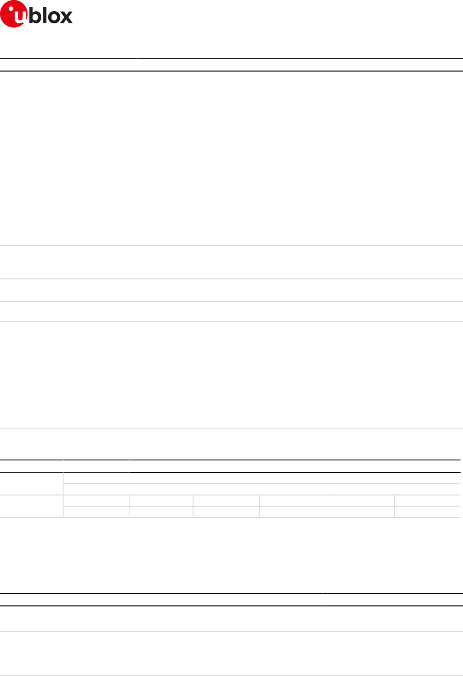
SARA-R4/N4 series-AT Commands Manual
UBX-17003787 - R09
8Security
Page 64 of 307
Parameter Type Description
• "AI": BAIC (Bar All Incoming Calls)
• "IR": BIC-Roam (Bar Incoming Calls when Roaming outside the home country)
• "AB": All Barring services (applicable only for <mode>=0)
• "AG": All outGoing barring services (applicable only for <mode>=0)
• "AC": All inComing barring services (applicable only for <mode>=0)
• "CS": CNTRL (lock CoNTRoL surface (e.g. phone keyboard)) (see the 3GPP TS 27.0
07 [2])
• "PF": Lock Phone to the very First inserted SIM/UICC card (see the 3GPP TS 27.00
7 [2])
• "NT": Barr incoming calls from numbers Not stored to TA memory (see the 3GPP
TS 27.007 [2])
• "NM": Barr incoming calls from numbers Not stored to MT memory (see 3GPP TS
27.007 [2])
• "NS": Barr incoming calls from numbers Not stored to SIM/UICC memory (see the
3GPP TS 27.007 [2])
• "NA": Barr incoming calls from numbers Not stored in any memory (see the 3GPP
TS 27.007 [2])
<mode> Number • 0: unlock
• 1: lock
• 2: query status
<status> Number • 0: not active
• 1: active
<passwd> String Shall be the same as password specified for the facility from the MT user interface or
with the +CPWD command
<class> Number Sum of numbers each representing a class of information. The default value is 7
(voice + data + fax):
• 1: voice
• 2: data
• 4: FAX
• 8: short message service
• 16: data circuit sync
• 32: data circuit async
• 64: dedicated packet access
• 128: dedicated PAD access
8.3Change password +CPWD
+CPWD
SARA-R404M SARA-R410M-01B SARA-R410M-02B SARA-R410M-52B SARA-R412MModules
SARA-N4
Syntax PIN required Settings saved Can be aborted Response time Error referenceAttributes
full Yes No Yes Up to 3 min +CME Error
8.3.1Description
Sets a new password for the facility lock function defined by command +CLCK. The command is abortable if a
character is sent to DCE during the command execution.
8.3.2Syntax
Type Syntax Response Example
Set AT+CPWD=<fac>,<oldpwd>,
<newpwd>
OK AT+CPWD="SC","0933","0934"
OK
Test AT+CPWD=? +CPWD: list of available (<fac>,
<pwdlength>s)
OK
+CPWD: ("SC",8),("P2",8),("AO",4),
("OI",4),("OX",4),("AI",4),("IR",4),("AB",
4),("AG",4),("AC",4)
OK
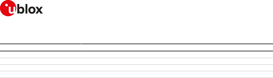
SARA-R4/N4 series-AT Commands Manual
UBX-17003787 - R09
8Security
Page 65 of 307
8.3.3Defined values
Parameter Type Description
<fac> String "P2" SIM PIN2; see the +CLCK command description for other values
<oldpwd> String Old password
<newpwd> String New password
<pwdlength> Number Length of password (digits)
8.3.4Notes
• If the PIN is blocked, an error result code will be provided when attempting to change the PIN code if the
PIN check is disabled through AT+CLCK command.

SARA-R4/N4 series-AT Commands Manual
UBX-17003787 - R09
9Short Messages Service
Page 66 of 307
9Short Messages Service
9.1Introduction
For a complete overview of SMS, see 3GPP TS 23.040 [8] and 3GPP TS 27.005 [16].
In case of errors all the SMS related AT commands return an error result code as defined in Appendix A.2.
9.1.1Class 0 SMS
The storing of a class 0 SMS depends on the module series:
• SARA-R4 / SARA-N4 - not stored.
9.1.2<index> parameter range
The <index> parameter range depends on the memory storage type:
ME (ME message), SM ((U)SIM message) MT (ME + SM):
• SARA-R4 / SARA-N4
o Values between 0 and 23: SMS stored in ME.
o Values between 0 and n: SMS stored in SIM (n depends on SIM card used).
BM (Broadcast Message):
• SARA-R4 / SARA-N4 - Broadcast Message storage is not supported.
SR (Status Report)
• SARA-R4 / SARA-N4 - Status Report storage is not supported.
9.1.3Limitations
The following limitations apply related to the SMS usage:
Single SMS
• 160 characters if <dcs>= "GSM 7 bit default alphabet data"
• 140 octets if <dcs>= "8-bit data"
• 70 UCS2 characters (2 bytes for each one) if <dcs>="16-bit uncompressed UCS2 data"
Concatenated SMS (where supported) - "8-bit reference number" type
• 153 characters if <dcs>= "GSM 7 bit default alphabet data"
• 134 octets if <dcs>= "8-bit data"
• 67 UCS2 characters (2 bytes for each one) if <dcs>="16-bit uncompressed UCS2 data"
Concatenated SMS (where supported) - "16-bit reference number" type
• The limits are the same as the "8-bit reference number" type, but are decreased by one unit.
A concatenated SMS can have as many as 255 parts.
9.2Select message service +CSMS
+CSMS
SARA-R404M SARA-R410M-01B SARA-R410M-02B SARA-R410M-52B SARA-R412MModules
SARA-N4
Syntax PIN required Settings saved Can be aborted Response time Error referenceAttributes
full Yes No No - +CMS Error
9.2.1Description
Selects the <service> message service. It returns the types of messages supported by the MT.
SARA-R4/N4 series-AT Commands Manual
UBX-17003787 - R09
9Short Messages Service
Page 67 of 307
9.2.2Syntax
Type Syntax Response Example
Set AT+CSMS=<service> +CSMS: <mt>,<mo>,<bm>
OK
AT+CSMS=1
+CSMS: 1,1,1
OK
Read AT+CSMS? +CSMS: <service>,<mt>,<mo>,
<bm>
OK
+CSMS: 0,1,1,1
OK
Test AT+CSMS=? +CSMS: (list of supported
<service>s)
OK
+CSMS: (0-1)
OK
9.2.3Defined values
Parameter Type Description
<service> Number • 0: see 3GPP TS 23.040 [8] and 3GPP TS 23.041 [9]; syntax of AT commands is
compatible with 3GPP TS 27.005 [16] phase 2; phase 2+ features may be supported
if no new command syntax is required
• 1: see 3GPP TS 23.040 [8] and 3GPP TS 23.041 [9]; syntax of AT commands is
compatible with 3GPP TS 27.005 [16] phase 2+
<mt> Number Mobile terminated messages:
• 0: not supported
• 1: supported
<mo> Number Mobile originated messages:
• 0: not supported
• 1: supported
<bm> Number Broadcast messages:
• 0: not supported
• 1: supported
9.2.4Notes
SARA-R4 / SARA-N4
• Set <service> to 1 to acknowledge an incoming message (either SMS or Status Report) with +CNMA AT
command.
• If <service> is changed from 1 to 0 and one or more parameters of the +CNMI command are in phase 2+,
switch the +CNMI parameters to phase 2 specific values before entering phase 2.
9.3Preferred message storage +CPMS
+CPMS
SARA-R404M SARA-R410M-01B SARA-R410M-02B SARA-R410M-52B SARA-R412MModules
SARA-N4
Syntax PIN required Settings saved Can be aborted Response time Error referenceAttributes
partial Yes NVM No Up to 3 min +CMS Error
9.3.1Description
Selects memory storages <mem1>, <mem2> and <mem3>. If the chosen storage is supported by the MT but
not suitable, the +CMS ERROR: <err> error result code should be returned.
See the test command for the supported memory types for each memory storage.
9.3.2Syntax
Type Syntax Response Example
Set AT+CPMS=<mem1>[,<mem2>[,
<mem3>]]
AT+CPMS: <used1>,<total1>,
<used2>,<total2>,<used3>,<total3>
OK
AT+CPMS="BM","SM","SM"
+CPMS: 0,5,0,50,0,50
SARA-R4/N4 series-AT Commands Manual
UBX-17003787 - R09
9Short Messages Service
Page 68 of 307
Type Syntax Response Example
OK
Read AT+CPMS? +CPMS: <mem1>,<used1>,<total1>,
<mem2>,<used2>,<total2>,
<mem3>,<used3>,<total3>
OK
+CPMS: "MT",4,350,"MT",4,350,
"MT",4,350
OK
Test AT+CPMS=? +CPMS: (list of supported
<mem1>s),(list of supported
<mem2>s),(list of supported
<mem3>s)
OK
+CPMS: ("MT","ME","SM","BM",
"SR"),("MT","ME","SM"),("MT","ME",
"SM")
OK
9.3.3Defined values
Parameter Type Description
<mem1> String Memory used to read and delete messages. The supported values may vary:
• "ME": ME message storage
• "SM": (U)SIM message storage
• "MT" (factory-programmed value): "ME"+"SM", "ME" preferred
• "BM": Broadcast Message storage
• "SR": Status Report storage
The default value is the currently set value.
<mem2> String Memory used to write and send SMS. The supported values may vary:
• "ME": ME message storage
• "SM": (U)SIM message storage
• "MT" (factory-programmed value): "ME"+"SM", "ME" preferred
The default value is the currently set value.
<mem3> String Memory preferred to store the received SMS. The supported values may vary:
• "ME": ME message storage
• "SM": (U)SIM message storage
• "MT" (factory-programmed value): "ME"+"SM", "ME" preferred
The default value is the currently set value.
<used1> Number Number of used message locations in <mem1>
<total1> Number Total number of message locations in <mem1>
<used2> Number Number of used message locations in <mem2>
<total2> Number Total number of message locations in <mem2>
<used3> Number Number of used message locations in <mem3>
<total3> Number Total number of message locations in <mem3>
9.4Preferred message format +CMGF
+CMGF
SARA-R404M SARA-R410M-01B SARA-R410M-02B SARA-R410M-52B SARA-R412MModules
SARA-N4
Syntax PIN required Settings saved Can be aborted Response time Error referenceAttributes
full Yes Profile No - +CMS Error
9.4.1Description
Indicates to the MT which input and output format of messages shall be used.
9.4.2Syntax
Type Syntax Response Example
Set AT+CMGF=[<mode>] OK AT+CMGF=1
OK
Read AT+CMGF? +CMGF: <mode>
OK
+CMGF: 1
OK
SARA-R4/N4 series-AT Commands Manual
UBX-17003787 - R09
9Short Messages Service
Page 69 of 307
Type Syntax Response Example
Test AT+CMGF=? +CMGF: (list of supported <mode>s)
OK
+CMGF: (0-1)
OK
9.4.3Defined values
Parameter Type Description
<mode> Number Indicates the format of messages used with send, list, read and write commands and
URCs resulting from receiving SMSes messages:
• 0 (default and factory-programmed value): PDU mode
• 1: text mode
9.5Save settings +CSAS
+CSAS
SARA-R404M SARA-R410M-01B SARA-R410M-02B SARA-R410M-52B SARA-R412MModules
SARA-N4
Syntax PIN required Settings saved Can be aborted Response time Error referenceAttributes
full No NVM No - +CMS Error
9.5.1Description
Saves active message service settings from the current active memory (RAM) to non-volatile memory (NVM).
The settings related to the +CSCA (the current SMSC address stored in RAM), +CSMP and +CSCB commands
are stored in a specific SMS profile (only one profile is available).
9.5.2Syntax
Type Syntax Response Example
Set AT+CSAS[=<profile>] OK AT+CSAS
OK
Test AT+CSAS=? +CSAS: (list of supported
<profile>s)
OK
+CSAS: (0)
OK
9.5.3Defined values
Parameter Type Description
<profile> Number Specific SMS profile index where to store the active message settings. The factory-
programmed value is 0.
9.6Restore settings +CRES
+CRES
SARA-R404M SARA-R410M-01B SARA-R410M-02B SARA-R410M-52B SARA-R412MModules
SARA-N4
Syntax PIN required Settings saved Can be aborted Response time Error referenceAttributes
full Yes No No < 10 s +CMS Error
9.6.1Description
Restores message service settings from a non-volatile memory (NVM) to the current active memory (RAM).
The settings related to the +CSCA (the SMSC address in the SIM card is also updated), +CSMP and +CSCB
commands are read from a specific SMS profile (only one profile is available).
9.6.2Syntax
Type Syntax Response Example
Set AT+CRES[=<profile>] OK AT+CRES=0

SARA-R4/N4 series-AT Commands Manual
UBX-17003787 - R09
9Short Messages Service
Page 70 of 307
Type Syntax Response Example
OK
Test AT+CRES=? +CRES: (list of supported <profile>s)
OK
+CRES: (0)
OK
9.6.3Defined values
Parameter Type Description
<profile> Number Specific SMS profile index from where to read the message service settings
9.7New message indication +CNMI
+CNMI
SARA-R404M SARA-R410M-01B SARA-R410M-02B SARA-R410M-52B SARA-R412MModules
SARA-N4
Syntax PIN required Settings saved Can be aborted Response time Error referenceAttributes
partial Yes Profile No - +CMS Error
9.7.1Description
Selects the procedure to indicate the reception of a new SMS in case of the MT is active (the DTR signal is ON).
If the MT is inactive (the DTR signal is OFF), the message reception should be done as specified in 3GPP TS
23.038 [7].
The +UCMT URC notifies the SMS-DELIVER status for 3GPP2 Mobile Terminated SMSes; it is equivalent to
+CMT but valid only for 3GPP2 SMS (i.e. 3GPP2 SMS over IMS received on Verizon MNO).
9.7.2Syntax
Type Syntax Response Example
Set AT+CNMI=[<mode>[,<mt>[,<bm>[,
<ds>[,<bfr>]]]]]
OK AT+CNMI=1,1
OK
Read AT+CNMI? +CNMI: <mode>,<mt>,<bm>,<ds>,
<bfr>
OK
+CNMI: 0,0,0,0,0
OK
Test AT+CNMI=? +CNMI: (list of supported <mode>s),
(list of supported <mt>s),(list of
supported <bm>s),(list of supported
<ds>s),(list of supported <bfr>s)
OK
+CNMI: (0-2),(0-3),(0-3),(0-2),(0-1)
OK
URC +CMTI: <mem>,<index> +CMTI: "SM",5
Text mode (+CMGF=1):
+CMT: <oa>,[<alpha>],
<scts>[,<tooa>,<fo>,<pid>,
<dcs>,<sca>,<tosca>,
<length>]<CR><LF><data>
+CMT: "+393475234652",,"14/11/21,
11:58:23+01"
Hello world
URC
PDU mode (+CMGF=0):
+CMT: ,<length><CR><LF><pdu>
Text mode (+CMGF=1):
+UCMT: <message_id>,
<oa>,<scts>,[<priority>],
[<privacy>],[<callback_number>],
<encoding>,[<status>],[<num_
sms>,<part>,<reference>],
<length><CR><LF><text>
+UCMT: 1,+1231241241,"18:02:28+0
8",,,,2,,,,,6
Hello!
URC
PDU mode (+CMGF=0):
+UCMT: <pdu_
length><CR><LF><pdu>
URC +CBMI: <mem>,<index> +CBMI: "BM",48
SARA-R4/N4 series-AT Commands Manual
UBX-17003787 - R09
9Short Messages Service
Page 71 of 307
Type Syntax Response Example
Text mode (+CMGF=1):
+CBM: <sn>,<mid>,<dcs>,<page>,
<pages><CR><LF><data>
+CBM: 271,1025,1,1,1
The quick brown fox jumps over the
lazy dog 0123456789
URC
PDU mode (+CMGF=0):
+CBM: <length><CR><LF><pdu>
URC +CDSI: <mem>,<index> +CDSI: "MT",2
Text mode (+CMGF=1):
+CDS: <fo>,<mr>,[<ra>],[<tora>],
<scts>,<dt>,<st>
+CDS: 6,202,"+393492323583",145,
"14/07/25,13:07:16+02","14/07/25,
16:35:44+02",0
URC
PDU mode (+CMGF=0):
+CDS: <length><CR><LF><pdu>
9.7.3Defined values
Parameter Type Description
<mode> Number Controls the processing of URCs specified within this command:
• 0 (default value): buffer URCs in the MT; if the MT buffer is full, the oldest indication
may be discarded and replaced with the new received indications (ring buffer)
• 1 (factory-programmed value): discard indication and reject new received message
URCs when MT-DTE link is reserved; otherwise forward them directly to the DTE
• 2: buffer URCs in the MT when the serial link is busy (e.g. data-transfer); otherwise
forward them directly to the DTE
• 3: forward URCs directly to the TE. TA-TE link specific inband technique used to
embed result codes and data when MT is in on-line data mode
<mt> Number Specifies the rules for managing the received SMS according the message's Data
Coding Scheme (DCS):
• 0 (default and factory-programmed value): No SMS-DELIVER indications are
routed to the TE
• 1: if SMS-DELIVER is stored in the MT, indication of the memory location is routed
to the DTE using the +CMTI URC
• 2: SMS-DELIVER (except class 2 SMS) are routed directly to the DTE (but not saved
in the module file system or SIM memory) using the +CMT URC. If MT has its own
display device then class 0 SMS and SMS in the message waiting indication group
(discard message) may be copied to both MT display and to DTE. In this case MT
shall send the acknowledgement to the network. Class 2 SMSs and messages in the
message waiting indication group (storage message) result in indication as defined
in <mt>=1
• 3: Class 3 SMS-DELIVERs are routed directly to DTE using URCs defined in <mt>=
2. Messages of other data coding schemes result in indication as defined in <mt>=1
<bm> Number Specifies the rules for managing the received Cell Broadcast messages (CBM):
• 0 (default and factory-programmed value): no CBM indications to the DTE
• 1: if the CBM is stored in the MT, an indication of the used memory location is routed
to DTE using the +CBMI URC
• 2: new CBMs are routed directly to the DTE using the +CBM URC
• 3: class 3 CBMs are routed directly to DTE using URCs defined in <bm>=2. If CBM
storage is supported, messages of other classes result in indication as defined in
<bm>=1
<ds> Number Specifies the rules for managing the Status Report messages:
• 0 (default and factory-programmed value): no SMS-STATUS-REPORTs are routed
to the DTE
• 1: SMS-STATUS-REPORTs are routed to the DTE using the +CDS URC
• 2: if SMS-STATUS-REPORT is stored in the MT, the indication of the memory
location is routed to the DTE using the +CDSI URC
<bfr> Number Controls the buffering of URCs:
• 0 (default and factory-programmed value): MT buffer of URCs defined within this
command is flushed to the DTE when <mode> 1...3 is entered (OK final result code
shall be given before flushing the codes).
• 1: MT buffer of URCs defined within this command is cleared when <mode> 1...3 is
entered

SARA-R4/N4 series-AT Commands Manual
UBX-17003787 - R09
9Short Messages Service
Page 72 of 307
Parameter Type Description
<mem> String Same as defined in +CPMS Defined Values
<index> Number Storage position
<length> Number Two meanings:
• in text mode: number of characters
• in PDU mode: PDU's length in octets without the Service Center's address. In
example: 039121430100038166F6000004E374F80D: this is a PDU with Service
Center's number +1234, that generates the address 03912143 (4 octets). Thus in
this case <length>=13.
<pdu> String Protocol data unit: each 8-bit octet is presented as two IRA character long
hexadecimal numbers, e.g. octet with integer value 42 is presented to TE as two
characters 2A (IRA 50 and 65)
<oa> String Originator address
<scts> String Service center time stamp in time-string format, see the <dt>
<data> String In the case of SMS: 3GPP TS 23.040 [8] TP-User-Data in text mode responses;
format:
• if <dcs> indicates that 3GPP TS 23.038 [7] GSM 7 bit default alphabet is used and
<fo> indicates that 3GPP TS 23.040 [8] TP-User-Data-Header-Indication is not set:
o if TE character set other than "HEX" (see the +CSCS command in 3GPP TS 27.0
07 [2]): ME/TA converts GSM alphabet into current TE character set according
to rules of Annex A
o if TE character set is "HEX": ME/TA converts each 7-bit character of GSM
7 bit default alphabet into two IRA character long hexadecimal number (e.g.
character Æ (GSM 7 bit default alphabet 28) is presented as 1C (IRA 49 and 67))
• if <dcs> indicates that 8-bit or UCS2 data coding scheme is used, or <fo> indicates
that 3GPP TS 23.040 [8] TP-User-Data-Header-Indication is set: ME/TA converts
each 8-bit octet into two IRA character long hexadecimal number (e.g. octet with
integer value 42 is presented to TE as two characters 2A (IRA 50 and 65))
In the case of CBS: 3GPP TS 23.041 [9] CBM Content of Message in text mode
responses; format:
• if <dcs> indicates that 3GPP TS 23.038 [7] GSM 7 bit default alphabet is used:
o if TE character set other than "HEX" (see the +CSCS in 3GPP TS 27.007 [2]): ME/
TA converts GSM alphabet into current TE character set according to rules of
Annex A
o if TE character set is "HEX": ME/TA converts each 7-bit character of the GSM 7
bit default alphabet into two IRA character long hexadecimal number
• if <dcs> indicates that 8-bit or UCS2 data coding scheme is used: ME/TA converts
each 8-bit octet into two IRA character long hexadecimal number
<sn> Number CBM serial number
<mid> Number CBM message identifier
<dcs> Number Data Coding Scheme
<page> Number CBM Page Parameter bits 4-7 in integer format as described in 3GPP TS 23.041 [9]
<pages> Number CBM Page Parameter bits 0-3 in integer format as described in 3GPP TS 23.041 [9]
<fo> Number First octet of the SMS TPDU (see 3GPP TS 23.040 [8])
<mr> Number Message reference
<ra> String Recipient address field
<tora> Number Type of address of <ra> - octet
<dt> String Discharge time in format "yy/MM/dd,hh:mm:ss+zz"; the time zone is expressed in
steps of 15 minutes. The range goes from -48 to +56
<st> Number Status of a SMS STATUS-REPORT
<message_id> Number Message-ID of the 3GPP2 SMS
<priority> Number 3GPP2 priority:
• 0: normal
• 1: interactive
• 2: urgent
• 3: emergency
<privacy> Number 3GPP2 privacy:
• 0: not restricted
• 1: restrictive
• 2: confidential
SARA-R4/N4 series-AT Commands Manual
UBX-17003787 - R09
9Short Messages Service
Page 73 of 307
Parameter Type Description
• 3: secret
<callback_number> String Callback number
<encoding> Number Text encoding:
• 2: ASCII7
• 3: IA5
• 4: UCS2
• 8: ISO 8859-1
• 9: GSM7
<num_sms> Number Total number of SMS
<part> Number Fragment part number
<reference> Number 3GPP2 reference ID
9.7.4Notes
• The incoming SMS/CBM URC indications will be displayed only on the AT interface where the last +CNMI
command was set. As a general rule, the command should be issued by the DTE:
o After start-up
o After using the Z and &F command (which reset the command configuration)
o Whenever the incoming SMS URCs indications are requested on a different AT interface
• <mode> = 3 is not supported.
9.8Read message +CMGR
+CMGR
SARA-R404M SARA-R410M-01B SARA-R410M-02B SARA-R410M-52B SARA-R412MModules
SARA-N4
Syntax PIN required Settings saved Can be aborted Response time Error referenceAttributes
full Yes No No <10 s +CMS Error
9.8.1Description
Returns the message with location value <index> from message storage <mem1> to the DTE.
The parameters <tooa>, <fo>, <pid>, <dcs>, <sca>, <tosca>, <length>, <cdata> shall be displayed only if
+CSDH=1 is set.
The syntax AT+CMGR=0 allows to display an SMS class 0 if it is signalized to MT, because no MMI is
available in the MT (see also the +CNMI AT command notes).
If the <index> value is out of range (it depends on AT+CPMS command setting) or it refers to an empty
position, then "+CMS ERROR: invalid memory index" error result code is returned.
9.8.2Syntax
Type Syntax Response Example
SMS-DELIVER
+CMGR: <stat>,<oa>,[<alpha>],
<scts>[,<tooa>,<fo>,<pid>,<dcs>,
<sca>,<tosca>,<length>]
<data>
OK
SMS-SUBMIT
+CMGR: <stat>,<da>,[<alpha>][,
<toda>,<fo>,<pid>,<dcs>,[<vp>],
<sca>,<tosca>,<length>]
<data>
OK
Set Text mode (+CMGF=1):
AT+CMGR=<index>
SMS-STATUS-report
+CMGR: <stat>,<fo>,<mr>,[<ra>],
[<tora>],<scts>,<dt>,<st>
AT+CMGR=303
+CMGR: "REC READ",
"+393488535999",,"07/04/05,18:0
2:28+08",145,4,0,0,"+393492000
466",145,93
You have a missed called. Free
information provided by your
operator.
OK
SARA-R4/N4 series-AT Commands Manual
UBX-17003787 - R09
9Short Messages Service
Page 74 of 307
Type Syntax Response Example
OK
SMS-COMMAND
+CMGR: <stat>,<fo>,<ct>[,<pid>,
[<mn>],[<da>],[<toda>],<length>
[<cdata>]]
OK
CBM storage
+CMGR: <stat>,<sn>,<mid>,<dcs>,
<page>,<pages>
<data>
OK
PDU mode (+CMGF=0):
AT+CMGR=<index>
+CMGR: <stat>,[<alpha>],<length>
<pdu>
OK
AT+CMGR=1
+CMGR: 1,,40
0791934329002000040
C9193230982661400008070
328045218018D4F29CFE0
6B5CBF379F87C4EBF41E4340
82E7FDBC3
OK
Test AT+CMGR=? OK
9.8.3Defined values
Parameter Type Description
<index> Number Storage position
<stat> Number • 0: in PDU mode or "REC UNREAD" in text mode: received unread SMS
• 1: in PDU mode or "REC READ" in text mode: received read SMS
• 2: in PDU mode or "STO UNSENT" in text mode: stored unsent SMS
• 3: in PDU mode or "STO SENT" in text mode: stored sent SMS
<oa> String Originator address
<alpha> String Alphanumeric representation of <da> or <oa> corresponding to the entry found in the
phonebook 3GPP TS 24.008 [12]. The parameter is not managed.
<scts> String Service center time stamp in time-string format, see <dt>
<tooa> Number Type of address of <oa> - octet
<fo> Number First octet of the SMS TPDU (see 3GPP TS 23.040 [8])
<pid> Number TP-Protocol-Identifier (default 0); see the 3GPP TS 23.040 [8]
<dcs> Number Data Coding Scheme
<sca> String Service center address field
<tosca> Number Type of address of <sca> - octet in Number format (for more details see the 3GPP TS
24.008 [12]); default 145 when string includes '+', otherwise default 129
<length> Number Two meanings:
• in text mode: number of characters
• in PDU mode: PDU's length in octets without the Service Center's address. In
example 039121430100038166F6000004E374F80D: this is a PDU with Service
Center's number +1234, that generates the address 03912143 (4 octets). Thus in
this case <length> = 13.
<data> String In the case of SMS: 3GPP TS 23.040 [8] TP-User-Data in text mode responses;
format:
• if <dcs> indicates that 3GPP TS 23.038 [7] GSM 7 bit default alphabet is used and
<fo> indicates that 3GPP TS 23.040 [8] TP-User-Data-Header-Indication is not set:
o if TE character set other than "HEX" (see +CSCS command description): ME/
TA converts GSM alphabet into current TE character set according to rules of
Annex A
o if TE character set is "HEX": ME/TA converts each 7-bit character of GSM
7 bit default alphabet into two IRA character long hexadecimal number (e.g.
character Æ (GSM 7 bit default alphabet 28) is presented as 1C (IRA 49 and 67))
• if <dcs> indicates that 8-bit or UCS2 data coding scheme is used, or <fo> indicates
that 3GPP TS 23.040 [8] TP-User-Data-Header-Indication is set: ME/TA converts
SARA-R4/N4 series-AT Commands Manual
UBX-17003787 - R09
9Short Messages Service
Page 75 of 307
Parameter Type Description
each 8-bit octet into two IRA character long hexadecimal number (e.g. octet with
integer value 42 is presented to TE as two characters 2A (IRA 50 and 65))
In the case of CBS: 3GPP TS 23.041 [9] CBM Content of Message in text mode
responses; format:
• if <dcs> indicates that 3GPP TS 23.038 [7] GSM 7 bit default alphabet is used:
o if TE character set other than "HEX" (see +CSCS command description): ME/
TA converts GSM alphabet into current TE character set according to rules of
Annex A
o if TE character set is "HEX": ME/TA converts each 7-bit character of the GSM 7
bit default alphabet into two IRA character long hexadecimal number
• if <dcs> indicates that 8-bit or UCS2 data coding scheme is used: ME/TA converts
each 8-bit octet into two IRA character long hexadecimal number
<da> String Destination address
<toda> Number Type of address of <da> - octet
<vp> Number Format depending of the <fo> setting:
• Relative format: validity period starting from when the SMS is received by the
SMSC, in range 0-255 (default value 167); for more details see the 3GPP TS 23.040
[8]
<vp> Validity period value
0 to 143 (TP-VP + 1) x 5 minutes (i.e. 5 minutes
intervals up to 12 hours)
144 to 167 12 hours + ((TP-VP -143) x 30 minutes)
168 to 196 (TP-VP - 166) x 1 day
197 to 255 (TP-VP - 192) x 1 week
• Absolute format: absolute time of the validity period termination in string format
("yy/MM/dd,hh:mm:ss+zz") (see the 3GPP TS 23.040 [8]); the time zone is
expressed in steps of 15 minutes. The range goes from -48 to +56
<mr> Number Message reference
<ra> String Recipient address field
<tora> Number Type of address of <ra> - octet
<dt> String Discharge time in format "yy/MM/dd,hh:mm:ss+zz"; the time zone is expressed in
steps of 15 minutes. The range goes from -48 to +56
<st> Number Status of an SMS STATUS-REPORT
<ct> Number TP-Command-Type (default 0)
<mn> Number See the 3GPP TS 23.040 [8] TP-Message-Number in integer format
<cdata> String TP-Command-Data in text mode responses
<sn> Number CBM serial number
<mid> Number CBM message identifier
<page> Number 3GPP TS 23.041 [9] CBM Page Parameter bits 4-7 in integer format
<pages> Number 3GPP TS 23.041 [9] CBM Page Parameter bits 0-3 in integer format
<pdu> String Protocol data unit: each 8-bit octet is presented as two IRA character long
hexadecimal numbers, e.g. octet with integer value 42 is presented to TE as two
characters 2A (IRA 50 and 65)
9.9New message acknowledgement to MT +CNMA
+CNMA
SARA-R404M SARA-R410M-01B SARA-R410M-02B SARA-R410M-52B SARA-R412MModules
SARA-N4
Syntax PIN required Settings saved Can be aborted Response time Error referenceAttributes
full Yes No No < 150 s +CMS Error
9.9.1Description
Confirms the reception of a new message (SMS-DELIVER or SMS-STATUS-REPORT) which is routed directly
to the TE (see the +CNMI command). This acknowledgement command shall be used when +CSMS parameter
<service> equals 1. The MT shall not send another +CMT or +CDS (see the +CNMI command) unsolicited result
codes to the TE before the previous one is acknowledged. If the MT does not get acknowledgement within
required time (network timeout), the MT should respond as specified in 3GPP TS 24.011 [13] to the network.
SARA-R4/N4 series-AT Commands Manual
UBX-17003787 - R09
9Short Messages Service
Page 76 of 307
The MT shall automatically disable routing to the TE by setting both <mt> and <ds> values of +CNMI to zero.
If the command is executed, but no acknowledgement is expected, or some other MT related error occurs, the
final result code +CMS ERROR: <err> is returned.
In PDU mode, it is possible to send either positive (RP-ACK) or negative (RP-ERROR) acknowledgement to the
network. The <n> parameter defines which one will be sent. Optionally (when <length> is greater than zero) an
acknowledgement TPDU (SMS-DELIVER-REPORT for RP-ACK or RP-ERROR) may be sent to the network. The
entering of PDU is done similarly as specified in +CMGS command, except that the format of <ackpdu> is used
instead of <pdu> (i.e. SMSC address field is not present). The PDU shall not be bounded by double quotes.
9.9.2Syntax
Type Syntax Response Example
Text mode (+CMGF=1):
AT+CNMA
OK AT+CNMA
OK
Set
PDU mode (+CMGF=0):
AT+CNMA[=<n>[,<length> [PDU is
given<Ctrl-Z>/<ESC>]]]
OK AT+CNMA=1,5
>0007000000 <Ctrl-Z>
OK
Text mode (+CMGF=1):
OK
OKTest AT+CNMA=?
PDU mode (+CMGF=0):
+CNMA: (list of supported <n>s)
OK
+CNMA: (0-2)
OK
9.9.3Defined values
Parameter Type Description
<n> Number • 0: the command operates similarly as defined for the text mode
• 1: sends RP-ACK (or buffered result code received correctly)
• 2: sends RP-ERROR (if PDU is not given, ME/TA shall send SMS-DELIVER-REPORT
with 3GPP TS 23.040 [8] TP-FCS value set to 'FF' (unspecified error cause))
<length> Number PDU's length in octets without the Service Center's address
9.10List message +CMGL
+CMGL
SARA-R404M SARA-R410M-01B SARA-R410M-02B SARA-R410M-52B SARA-R412MModules
SARA-N4
Syntax PIN required Settings saved Can be aborted Response time Error referenceAttributes
full Yes No No Up to 3 min (<1
s for prompt ">"
when present)
+CMS Error
9.10.1Description
Returns SMS messages with status value <stat> from message storage <mem1> to the DTE. If status of the
received message is "received unread", status in the storage changes to "received read".
9.10.2Syntax
Type Syntax Response Example
Set Text mode (+CMGF=1):
AT+CMGL[=<stat>]
Command successful and
SMS-DELIVERs:
+CMGL: <index>,<stat>,<oa>,
[<alpha>],[<scts>][,<tooa>,
<length>]
<data>
[+CMGL: <index>,<stat>,<oa>,
[<alpha>],[<scts>][,<tooa>,
<length>]<data>[...]]
AT+CMGL
+CMGL: 303,"REC READ","+39340
1234999",,"08/08/06,10:01:38+08"
You have a missed called. Free
information provided by your
operator.
OK

SARA-R4/N4 series-AT Commands Manual
UBX-17003787 - R09
9Short Messages Service
Page 77 of 307
Type Syntax Response Example
OK
Command successful and
SMS-SUBMITs:
+CMGL: <index>,<stat>,<da>,
[<alpha>],[<toda>, <length>]
<data>
[+CMGL: <index>,<stat>,
<da>,[<alpha>],[<toda>,
<length>]<data>[...]]
OK
Command successful and
SMS-STATUS-REPORTs:
+CMGL: <index>,<stat>,<fo>,<mr>,
[<ra>],[<tora>],<scts>,<dt>,<st>
[+CMGL: <index>,<stat>,<fo>,<mr>,
[<ra>],[<tora>],<scts>,<dt>,<st>
[...]]
OK
Command successful and
SMS-COMMANDs:
+CMGL: <index>,<stat>,<fo>,<ct>
[+CMGL: <index>,<stat>,<fo>,
<ct>[...]]
OK
Command successful and CBM
storage:
+CMGL: <index>,<stat>,<sn>,
<mid>,<page>,<pages><data>
[+CMGL: <index>,<stat>,<sn>,
<mid>,<page>,<pages>,<data>[...]]
OK
PDU mode (+CMGF=0):
AT+CMGL[=<stat>]
Command successful:
+CMGL: <index>,<stat>,[<alpha>],
<length>
<pdu>
[+CMGL: <index>,<stat>,[<alpha>],
<length>]
<pdu> [...]
AT+CMGL=1
+CMGL: 305,1,,57 079193432900
1185440ED0D637396C7EBBCB0
000909092708024802A050
003000303DEA0584CE60
205D974791994769BDF3A90
DB759687E9F534FD0DA2C9603419
OK
Test AT+CMGL=? +CMGL: (list of supported <stat>s)
OK
+CMGL: ("REC UNREAD","REC
READ","STO UNSENT","STO SENT",
"ALL")
OK
9.10.3Defined values
Parameter Type Description
<stat> Number or
String
Number type in PDU mode (default value: 4), or string type in text mode (default
value: "ALL"); indicates the status of message in memory:
• 0: in PDU mode or "REC UNREAD" in text mode: received unread SMS messages
• 1: in PDU mode or "REC READ" in text mode: received read SMS messages
• 2: in PDU mode or "STO UNSENT" in text mode: stored unsent SMS messages
• 3: in PDU mode or "STO SENT" in text mode: stored sent SMS messages
• 4: in PDU mode or "ALL" in text mode: all SMS messages
<index> Number Storage position
<oa> String Originator address

SARA-R4/N4 series-AT Commands Manual
UBX-17003787 - R09
9Short Messages Service
Page 78 of 307
Parameter Type Description
<alpha> String Alphanumeric representation of <da> or <oa> corresponding to the entry found in the
phonebook 3GPP TS 24.008 [12]. The parameter is not managed.
<scts> String Service center time stamp in time-string format; see the <dt> parameter
<tooa> Number Type of address of <oa> - octet
<length> Number Two meanings:
• in text mode: number of characters
• in PDU mode: PDU's length in octets without the Service Center's address. In
example 039121430100038166F6000004E374F80D: this is a PDU with Service
Center's number +1234, that generates the address 03912143 (4 octets). Thus in
this case <length> = 13.
<data> String This is the TP-User-Data in text mode; the decoding depends on the DCS (Data
Coding Scheme) and the FO (First Octect) of the SMS header 3GPP TS 23.040 [8];
format:
• if DCS indicates that 3GPP TS 23.038 [7] GSM 7 bit default alphabet is used and FO
indicates that 3GPP TS 23.040 [8] TP-User-Data-Header-Indication is not set:
o if TE character set other than "HEX" (see the +CSCS AT command description):
ME/TA converts GSM alphabet into current TE character set according to rules
of Annex A
o if TE character set is "HEX": ME/TA converts each 7-bit character of GSM
7 bit default alphabet into two IRA character long hexadecimal number (e.g.
character Æ (GSM 7 bit default alphabet 28) is presented as 1C (IRA 49 and 67))
• if DCS indicates that 8-bit or UCS2 data coding scheme is used, or FO indicates that
3GPP TS 23.040 [8] TP-User-Data-Header-Indication is set: ME/TA converts each
8-bit octet into two IRA character long hexadecimal number (e.g. octet with integer
value 42 is presented to TE as two characters 2A (IRA 50 and 65))
In the case of CBS: 3GPP TS 23.041 [9] CBM Content of Message in text mode
responses; format:
• if DCS indicates that 3GPP TS 23.038 [7] GSM 7 bit default alphabet is used:
o if TE character set other than "HEX" (see the +CSCS AT command description):
ME/TA converts GSM alphabet into current TE character set according to rules
of Annex A
o if TE character set is "HEX": ME/TA converts each 7-bit character of the GSM 7
bit default alphabet into two IRA character long hexadecimal number
if DCS indicates that 8-bit or UCS2 data coding scheme is used: ME/TA converts each
8-bit octet into two IRA character long hexadecimal number
<da> String Destination address
<toda> Number Type of address of <da> - octet
<fo> Number First octet of the SMS TPDU (see 3GPP TS 23.040 [8])
<mr> Number Message reference
<ra> String Recipient address field
<tora> Number Type of address of <ra> - octet
<dt> String Discharge time in format "yy/MM/dd,hh:mm:ss+zz"; the time zone is expressed in
steps of 15 minutes. The range goes from -48 to +56
<st> Number Status of an SMS STATUS-REPORT
<ct> Number TP-Command-Type (default 0)
<sn> Number CBM serial number
<mid> Number CBM message identifier
<page> Number 3GPP TS 23.041 [9] CBM Page Parameter bits 4-7 in integer format
<pages> Number 3GPP TS 23.041 [9] CBM Page Parameter bits 0-3 in integer format
<pdu> String Protocol data unit: each 8-bit octet is presented as two IRA character long
hexadecimal numbers, e.g. octet with integer value 42 is presented to TE as two
characters 2A (IRA 50 and 65)
<dcs> Number Data Coding Scheme

SARA-R4/N4 series-AT Commands Manual
UBX-17003787 - R09
9Short Messages Service
Page 79 of 307
9.11Send message +CMGS
+CMGS
SARA-R404M SARA-R410M-01B SARA-R410M-02B SARA-R410M-52B SARA-R412MModules
SARA-N4
Syntax PIN required Settings saved Can be aborted Response time Error referenceAttributes
full Yes No No Up to 3 min (<1
s for prompt ">"
when present)
+CMS Error
9.11.1Description
Sends a message from a DTE to the network (SMS-SUBMIT). The message reference value <mr> is returned to
the DTE for a successful message delivery. Optionally (when enabled by +CSMS AT command and the network
supports) <ackpdu> is returned. Values can be used to identify message upon unsolicited delivery status report
result code. <Ctrl-Z> indicates that the SMS shall be sent, while <ESC> indicates aborting of the edited SMS.
The entered text/PDU is preceded by a ">" (Greater-Than sign) character, and this indicates that the
interface is in "text/PDU enter" mode. The DCD signal shall be in ON state while the text/PDU is entered.
9.11.2Syntax
Type Syntax Response Example
Text mode (+CMGF=1):
AT+CMGS=<da>[,<toda>]<CR>
> text is entered<Ctrl-Z/ESC>
+CMGS: <mr>
OK
AT+CMGS="0171112233"<CR>
> This is the text<Ctrl-Z>
+CMGS: 2
OK
Set
PDU mode (+CMGF=0):
AT+CMGS=<length><CR>
> PDU is given<Ctrl-Z/ESC>
+CMGS: <mr>[,<ackpdu>]
OK
AT+CMGS=13<CR>
> 039121430100038166F600000
4E374F80D<Ctrl-Z>
+CMGS: 2
OK
Test AT+CMGS=? OK
9.11.3Defined values
Parameter Type Description
<da> String Destination address
<toda> Number Type of address of <da> - octet
<text> String SMS String
<mr> Number Message reference
<length> Number Two meanings:
• in text mode: number of characters
• in PDU mode: PDU's length in octets without the Service Center's address. In
example 039121430100038166F6000004E374F80D: is a PDU with Service Center's
number +1234, that generates the address 03912143 (4 octets). Thus in this case
<length>=13.
<PDU> String Protocol Data Unit: each 8-bit octet of the PDU must be written as two IRA character
long hexadecimal numbers, e.g. octet with integer value 42 must be written as two
characters 2A (IRA 50 and 65)
<ackpdu> String See the 3GPP TS 23.040 [8] RP-User-Data element of RP-ACK PDU; the format is
same as for <PDU> in case of SMS
9.11.4Notes
SARA-R4 / SARA-N4
• The <ackpdu> parameter is not supported.
SARA-R4/N4 series-AT Commands Manual
UBX-17003787 - R09
9Short Messages Service
Page 80 of 307
9.12Write message to memory +CMGW
+CMGW
SARA-R404M SARA-R410M-01B SARA-R410M-02B SARA-R410M-52B SARA-R412MModules
SARA-N4
Syntax PIN required Settings saved Can be aborted Response time Error referenceAttributes
full Yes No No <10 s +CMS Error
9.12.1Description
Stores a message (SMS-DELIVER or SMS-SUBMIT) to memory storage <mem2> and returns the memory
location <index> of the stored message. <Ctrl-Z> indicates that the SMS shall be stored, while <ESC> indicates
aborting of the edited SMS.
The entered text/PDU is preceded by a ">" (Greater-Than sign) character, and this indicates that the
interface is in "text/PDU enter" mode. The DCD signal shall be in ON state while the text/PDU is entered.
9.12.2Syntax
Type Syntax Response Example
Text mode (+CMGF=1):
AT+CMGW[=<oa/da>[,<tooa/toda>[,
<stat>]]]<CR>
text is entered<Ctrl-Z/ESC>
+CMGW: <index>
OK
AT+CMGW="091137880"<CR>
> This is the text<Ctrl-Z>
+CMGW: 303
OK
Set
PDU mode (+CMGF=0):
AT+CMGW=<length>[,<stat>]<CR>
PDU is given<Ctrl-Z/ESC>
+CMGW: <index>
OK
AT+CMGW=13<CR>
> 039121430100038166F600000
4E374F80D<Ctrl-Z>
+CMGW: 303
OK
Test AT+CMGW=? OK
9.12.3Defined values
Parameter Type Description
<da> String TP-Destination-Address Address-Value field (see the 3GPP TS 23.040 [8]); BCD
numbers (or GSM 7 bit default alphabet characters) are converted to characters
of the currently selected TE character set (see the +CSCS AT command); type of
address given by <toda>
<oa> String TP-Originating-Address Address-Value field (see the 3GPP TS 23.040 [8]); BCD
numbers (or GSM 7 bit default alphabet characters) are converted to characters
of the currently selected TE character set (see the +CSCS AT command); type of
address given by <tooa>
<tooa> Number TP-Originating-Address Type-of-Address octet (see the 3GPP TS 24.011 [13]); see the
<toda> parameter for the default value
<toda> Number TP-Destination-Address Type-of-Address octet (see the 3GPP TS 24.011 [13]); when
the first character of <da> is + (IRA 43) the default value is 145, otherwise it is 129)
<stat> Number or
String
Number type in PDU mode (default value: 2), or string type in text mode (default
value: "STO UNSENT"); it indicates the message status in memory:
• 0: in PDU mode or "REC UNREAD" in text mode: received unread SMS messages
• 1: in PDU mode or "REC READ" in text mode: received read SMS messages
• 2: in PDU mode or "STO UNSENT" in text mode: stored unsent SMS messages
• 3: in PDU mode or "STO SENT" in text mode: stored sent SMS messages
<text> String SMS string
<index> Number Storage position
<length> Number The parameter meaning depends on the message format:
• In text mode: number of characters
• In PDU mode: PDU's length in octets without the Service Center's address. In
example: 039121430100038166F6000004E374F80D is a PDU with Service Center's
SARA-R4/N4 series-AT Commands Manual
UBX-17003787 - R09
9Short Messages Service
Page 81 of 307
Parameter Type Description
number +1234, that generates the address 03912143 (4 octets). Thus in this case
<length>=13.
<PDU> String Protocol Data Unit: each 8-bit octet of the PDU must be written as two IRA character
long hexadecimal numbers, e.g. an octet with integer value 42 must be written as two
characters 2A (IRA 50 and 65)
9.13Send message from storage +CMSS
+CMSS
SARA-R404M SARA-R410M-01B SARA-R410M-02B SARA-R410M-52B SARA-R412MModules
SARA-N4
Syntax PIN required Settings saved Can be aborted Response time Error referenceAttributes
full Yes No No Up to 3 min +CMS Error
9.13.1Description
Sends message with location value <index> from the preferred message storage <mem2> to the network
(SMS-SUBMIT or SMS-COMMAND). If a new recipient address <da> is given for SMS-SUBMIT, it will be used
instead of the one stored with the message. Reference value <mr> is returned to the DTE on successful
message delivery.
9.13.2Syntax
Type Syntax Response Example
Text mode (+CMGF=1):
AT+CMSS=<index>[,<da>[,<toda>]]
+CMSS: <mr>
OK
AT+CMSS=302
+CMSS: 3
OK
Set
PDU mode (+CMGF=0):
AT+CMSS=<index>
+CMSS: <mr>
OK
AT+CMSS=302
+CMSS: 4
OK
Test AT+CMSS=? OK
9.13.3Defined values
Parameter Type Description
<index> Number Storage position
<da> String Destination address
<toda> Number Type of address of <da> - octet
<mr> Number Message reference
9.14Set text mode parameters +CSMP
+CSMP
SARA-R404M SARA-R410M-01B SARA-R410M-02B SARA-R410M-52B SARA-R412MModules
SARA-N4
Syntax PIN required Settings saved Can be aborted Response time Error referenceAttributes
full Yes No No < 10 s +CMS Error
9.14.1Description
Selects values for additional parameters needed when an SMS is sent to the network or placed in a storage
when text format message mode is selected. For more details see the 3GPP TS 23.038 [7] and the 3GPP TS
23.040 [8].
SARA-R4/N4 series-AT Commands Manual
UBX-17003787 - R09
9Short Messages Service
Page 82 of 307
9.14.2Syntax
Type Syntax Response Example
Set AT+CSMP=<fo>,<vp>[,<pid>[,
<dcs>]]
OK AT+CSMP=17,167,0,0
OK
Read AT+CSMP? +CSMP: <fo>,<vp>,<pid>,<dcs>
OK
+CSMP: 17,167,0,0
OK
Test AT+CSMP=? OK
9.14.3Defined values
Parameter Type Description
<fo> Number First octet of the SMS TPDU (see 3GPP TS 23.040 [8])
<vp> Number Format depending on the values of the bit3/bit4 of the <fo> (SMS-SUBMIT case):
bit 3 bit 4 Format
0 0 Validity period not present
0 1 Validity period present,
relative format
1 0 Reserved
1 1 Validity period present,
absolute format
• Relative format: validity period, counted from when the SMS-SUBMIT is received by
the SMSC, in range 0-255 (the default value is 167); for more details see the 3GPP
TS 23.040 [8]
<vp> Validity period value
0 to 143 (TP-VP + 1) x 5 minutes (i.e. 5 minutes
intervals up to 12 hours)
144 to 167 12 hours + ((TP-VP -143) x 30 minutes)
168 to 196 (TP-VP - 166) x 1 day
197 to 255 (TP-VP - 192) x 1 week
• Absolute format: absolute time of the validity period termination in string format
("yy/MM/dd,hh:mm:ss+zz") (see the 3GPP TS 23.040 [8]); the time zone is
expressed in steps of 15 minutes. The range goes from -48 to +56
<pid> Number TP-Protocol-Identifier (default value: 0); see the 3GPP TS 23.040 [8]
<dcs> Number Data Coding Scheme. The default value is 0
9.15Delete message +CMGD
+CMGD
SARA-R404M SARA-R410M-01B SARA-R410M-02B SARA-R410M-52B SARA-R412MModules
SARA-N4
Syntax PIN required Settings saved Can be aborted Response time Error referenceAttributes
partial Yes No No < 55 s +CMS Error
9.15.1Description
Deletes the message from the preferred message storage <mem1>, if <flag>= 0 or not present, in location
<index>. Otherwise the messages are deleted following the rules specified by <flag>.
When deleting a message from an empty location, the module returns the "OK" final result code.
If the <index> value is out of range (it depends on AT+CPMS command setting), then the "+CMS ERROR:
invalid memory index" error result code is returned.
9.15.2Syntax
Type Syntax Response Example
Set AT+CMGD=<index>[,<flag>] OK AT+CMGD=3
OK
SARA-R4/N4 series-AT Commands Manual
UBX-17003787 - R09
9Short Messages Service
Page 83 of 307
Type Syntax Response Example
Test AT+CMGD=? +CMGD: (list of supported
<index>s),(list of supported <flag>s)
OK
+CMGD: (1-350),(0-4)
OK
9.15.3Defined values
Parameter Type Description
<index> Number Storage position
<flag> Number Deletion flag. If present, and different from 0, the <index> parameter is ignored:
• 0 (default value): delete the message specified in <index>
• 1: delete all the read messages from the preferred message storage, leaving unread
messages and stored mobile originated messages (whether sent or not) untouched
• 2: delete all the read messages from the preferred message storage and
sent mobile originated messages, leaving unread messages and unsent mobile
originated messages untouched
• 3: delete all the read messages from the preferred message storage, sent and
unsent mobile originated messages leaving unread messages untouched
• 4: delete all the messages from the preferred message storage including unread
messages
9.16Service center address +CSCA
+CSCA
SARA-R404M SARA-R410M-01B SARA-R410M-02B SARA-R410M-52B SARA-R412MModules
SARA-N4
Syntax PIN required Settings saved Can be aborted Response time Error referenceAttributes
full Yes No No < 10 s +CMS Error
9.16.1Description
Updates the SMSC address, through which mobile originated SMSes are transmitted. In text mode the setting
is used by send and write commands. In PDU mode the setting is used by the same commands, but only when
the length of SMSC address coded into <pdu> parameter equals zero.
SARA-R4 / SARA-N4
This command sets the service center value both in the RAM (this value is actually the SMSC address
used) and in the SIM card. Through the read command the value of current service center stored in the
RAM is displayed. At the power on, the MT reads the SMSC address in the SIM card and the same value
is set in RAM.
9.16.2Syntax
Type Syntax Response Example
Set AT+CSCA=<sca>[,<tosca>] OK AT+CSCA="0170111000",129
OK
Read AT+CSCA? +CSCA: <sca>,<tosca>
OK
+CSCA: "",129
OK
Test AT+CSCA=? OK
9.16.3Defined values
Parameter Type Description
<sca> String Service center address
<tosca> String Type of address of <sca> (for more details refer to 3GPP TS 24.008 [12]); the default
is 145 when string includes '+', otherwise the default is 129
SARA-R4/N4 series-AT Commands Manual
UBX-17003787 - R09
9Short Messages Service
Page 84 of 307
9.17Read concatenated message +UCMGR
+UCMGR
SARA-R410M-02B SARA-R410M-52B SARA-R412MModules
SARA-N4
Syntax PIN required Settings saved Can be aborted Response time Error referenceAttributes
full Yes No No <10 s +CMS Error
9.17.1Description
Returns the message with location value <index> from message storage <mem1> to the DTE and shows
additional information when the message is a segment of a concatenated one:
• SMS-DELIVER: the parameters <tooa>, <fo>, <pid>, <dcs>, <sca>, <tosca>, <length> shall be displayed
only if +CSDH=1 is set.
• SMS-SUBMIT: the parameters <toda>, <fo>, <pid>, <dcs>, <vp>, <sca>, <tosca>, <length> shall be
displayed only if +CSDH=1 is set.
• SMS-COMMAND: <pid>, <mn>, <da>, <toda>, <length>, <cdata> shall be displayed only if +CSDH=1 is set.
The syntax AT+UCMGR=0 allows to display an SMS class 0 if it is signalized to MT, because no MMI is
available in the MT (see also the +CNMI AT command notes).
If the received message status is "received unread", the status in the storage changes to "received read".
The command is supported only for text mode (+CMGF=1).
If the <index> value is out of range (it depends on the preferred message storage, +CPMS command,
settings) or it refers to an empty position, then the "+CMS ERROR: invalid memory index" error result
code is returned.
9.17.2Syntax
Type Syntax Response Example
SMS-DELIVER
+UCMGR: <stat>,<oa>,[<alpha>],
<scts>[,<tooa>, <fo>,<pid>,<dcs>,
<sca>,<tosca>,<length>][,<seq>,
<max>,<iei>,<ref>]
<data>
OK
SMS-SUBMIT
+UCMGR: <stat>,<da>,[<alpha>]
[<toda>,<fo>,<pid>,<dcs>,[<vp>],
<sca>,<tosca>,<length>][,<seq>,
<max>,<iei>,<ref>]
<data>
OK
SMS-STATUS-report
+UCMGR:<stat>,<fo>,<mr>,[<ra>],
[<tora>]<scts><dt>,<st>
OK
SMS-COMMAND
+UCMGR: <stat>,<fo>,<ct>[,<pid>,
[<mn>],[<da>],[<toda>],<length>
[<cdata>]]
OK
Set AT+UCMGR=<index>
CBM storage
+UCMGR: <stat>,<sn>,<mid>,
<dcs>,<page>,<pages>
<data>
OK
AT+UCMGR=1
+UCMGR: "REC READ",
"+393488535999",,"07/04/05,18:0
2:28+08",145,4,0,0,"+393492000
466",145,153,1,2,0,127
u-blox reserves all rights to this
document and the information
contained herein. Reproduction, use
or disclosure to third parties without
express permis
OK

SARA-R4/N4 series-AT Commands Manual
UBX-17003787 - R09
9Short Messages Service
Page 85 of 307
Type Syntax Response Example
Test AT+UCMGR=? OK
9.17.3Defined values
Parameter Type Description
<index> Number Storage position
<stat> String Indicates the status of message in memory:
• "REC UNREAD": received unread SMS
• "REC READ": received read SMS
• "STO UNSENT": stored unsent SMS
• "STO SENT": stored sent SMS
<oa> String Originator address
<alpha> String Alphanumeric representation of <da> or <oa> corresponding to the entry found in the
phonebook 3GPP TS 24.008 [12]. The parameter is not managed.
<scts> String Service center time stamp in time-string format, refer to <dt>
<tooa> Number Type of address of <oa> - octet
<fo> Number First octet of the SMS TPDU (see 3GPP TS 23.040 [8])
<pid> Number TP-Protocol-Identifier (default 0); see 3GPP TS 23.040 [8]
<dcs> Number Data Coding Scheme
<sca> String Service center address field
<tosca> Number Type of address of <sca> - octet in Number format (for more details see 3GPP TS
24.008 [12]); default 145 when string includes '+', otherwise default 129
<length> Number Number of characters
<seq> Number Sequence number of the current short message (1-255)
<max> Number Maximum number of short messages in the concatenated short message (1-255)
<iei> Number Information Element Identifier, the possible values are the following:
• 0: Concatenated short messages, 8-bit reference number
• 8: Concatenated short messages, 16-bit reference number
<ref> Number Concatenated short message reference number:
• 0-255: concatenated short messages, 8-bit reference number case
• 0-65535: concatenated short messages, 16-bit reference number case
<data> String In the case of SMS: 3GPP TS 23.040 [8] TP-User-Data in text mode responses;
format:
• if <dcs> indicates that 3GPP TS 23.038 [7] GSM 7 bit default alphabet is used and
<fo> indicates that 3GPP TS 23.040 [8] TP-User-Data-Header-Indication is not set:
o if TE character set other than "HEX" (see the +CSCS AT command description):
ME/TA converts GSM alphabet into current TE character set according to rules
of 3GPP TS 27.005 [16] Annex A
o if TE character set is "HEX": ME/TA converts each 7-bit character of GSM
7 bit default alphabet into two IRA character long hexadecimal number (e.g.
character Æ (GSM 7 bit default alphabet 28) is presented as 1C (IRA 49 and 67))
• if <dcs> indicates that 8-bit or UCS2 data coding scheme is used, or <fo> indicates
that 3GPP TS 23.040 [8] TP-User-Data-Header-Indication is set: ME/TA converts
each 8-bit octet into two IRA character long hexadecimal number (e.g. octet with
integer value 42 is presented to TE as two characters 2A (IRA 50 and 65))
In the case of CBS: 3GPP TS 23.041 [9] CBM Content of Message in text mode
responses; format:
• if <dcs> indicates that 3GPP TS 23.038 [7] GSM 7 bit default alphabet is used:
o if TE character set other than "HEX" (see the +CSCS AT command description):
ME/TA converts GSM alphabet into current TE character set according to rules
of 3GPP TS 27.005 [16] Annex A
o if TE character set is "HEX": ME/TA converts each 7-bit character of the GSM 7
bit default alphabet into two IRA character long hexadecimal number
if <dcs> indicates that 8-bit or UCS2 data coding scheme is used: ME/TA converts
each 8-bit octet into two IRA character long hexadecimal number
<da> String Destination address
<toda> Number Type of address of <da> - octet
<vp> Number Format depending of the <fo> setting:
SARA-R4/N4 series-AT Commands Manual
UBX-17003787 - R09
9Short Messages Service
Page 86 of 307
Parameter Type Description
• Relative format: validity period starting from when the SMS is received by the
SMSC, in range 0-255 (default value 167); for more details see 3GPP TS 23.040 [8]
<vp> Validity period value
0 to 143 (TP-VP + 1) x 5 minutes (i.e. 5 minutes
intervals up to 12 hours)
144 to 167 12 hours + ((TP-VP -143) x 30 minutes)
168 to 196 (TP-VP - 166) x 1 day
197 to 255 (TP-VP - 192) x 1 week
• Absolute format: absolute time of the validity period termination in string format
("yy/MM/dd,hh:mm:ss+zz") (refer to 3GPP TS 23.040 [8]); the time zone is
expressed in steps of 15 minutes. The range goes from -48 to +56
<mr> Number Message reference
<ra> String Recipient address field
<tora> Number Type of address of <ra> - octet
<scts> String Service center time stamp in time-string format, refer to <dt>
<dt> String Discharge time in format "yy/MM/dd,hh:mm:ss+zz"; the time zone is expressed in
steps of 15 minutes. The range goes from -48 to +56
<st> Number Status of an SMS STATUS-REPORT
<ct> Number TP-Command-Type (default 0)
<mn> Number 3GPP TS 23.040 [8] TP-Message-Number in integer format
<mid> Number CBM message identifier
<cdata> String TP-Command-Data in text mode responses
<sn> Number CBM serial number
<page> Number 3GPP TS 23.041 [9] CBM page parameter bits 4-7 in integer format
<pages> Number 3GPP TS 23.041 [9] CBM page parameter bits 0-3 in integer format
9.18List concatenated message +UCMGL
+UCMGL
SARA-R410M-02B SARA-R410M-52B SARA-R412MModules
SARA-N4
Syntax PIN required Settings saved Can be aborted Response time Error referenceAttributes
full Yes No No Up to 3 min (<1
s for prompt ">"
when present)
+CMS Error
9.18.1Description
Returns SMS messages with status value <stat> from message storage <mem1> to the DTE and shows
additional information when the message is a segment of a concatenated one:
• SMS-DELIVER: the parameters <tooa>, <length> shall be displayed only if +CSDH=1 is set.
• SMS-SUBMIT: the parameters <toda>, <length> shall be displayed only if +CSDH=1 is set.
If status of the received message is "received unread", status in the storage changes to "received read".
The command is supported only for text mode (+CMGF=1).
9.18.2Syntax
Type Syntax Response Example
Set AT+UCMGL[=<stat>] SMS-DELIVERs:
+UCMGL: <index>,<stat>,<oa>,
[<alpha>],[<scts>][,<tooa>,
<length>][,<seq>,<max>,<iei>,
<ref>]
<data>
[+UCMGL: <index>,<stat>,<oa>,
[<alpha>],[<scts>][,<tooa>,
AT+UCMGL
+UCMGL: 304,"REC READ","+39340
1234999",,"08/08/06,10:01:38+08",
145,152,1,2,8,32767
u-blox reserves all rights to this
document and the information
contained herein. Reproduction, use
or disclosure to third parties without
express permi
SARA-R4/N4 series-AT Commands Manual
UBX-17003787 - R09
9Short Messages Service
Page 87 of 307
Type Syntax Response Example
<length>][,<seq>,<max>,<iei>,
<ref>]<data>[...]]
OK
+UCMGL: 305,"REC READ","+39340
1234999",,"08/08/06,10:01:40+08",
145,29,2,2,8,32767
ssion is strictly prohibited.
OK
SMS-SUBMITs:
+UCMGL: <index>,<stat>,<da>,
[<alpha>],[<toda>, <length>][,
<seq>,<max>,<iei>,<ref>]
<data>
[+UCMGL: <index>,<stat>,<da>,
[<alpha>],[<toda>,<length>][,<seq>,
<max>,<iei>,<ref>]<data>[...]]
OK
SMS-STATUS-REPORTs:
+UCMGL: <index>,<stat>,<fo>,
<mr>,[<ra>],[<tora>],<scts>,<dt>,
<st>
[+UCMGL: <index>,<stat>,<fo>,
<mr>,[<ra>],[<tora>],<scts>,<dt>,
<st> [...]]
OK
SMS-COMMANDs:
+UCMGL: <index>,<stat>,<fo>,<ct>
[+UCMGL: <index>,<stat>,<fo>,
<ct>[...]]
OK
CBM storage:
+UCMGL: <index>,<stat>,<sn>,
<mid>,<page>,<pages><data>
[+UCMGL: <index>,<stat>,<sn>,
<mid>,<page>,<pages>,<data>[...]]
OK
Test AT+UCMGL=? +UCMGL: (list of supported <stat>s)
OK
+UCMGL: ("REC UNREAD","REC
READ","STO UNSENT","STO SENT",
"ALL ")
OK
9.18.3Defined values
Parameter Type Description
<stat> String Indicates the status of message in memory:
• "REC UNREAD": received unread SMS messages
• "REC READ": received read SMS messages
• "STO UNSENT": stored unsent SMS messages
• "STO SENT": stored sent SMS messages
• "ALL": all SMS messages (default value)
<index> Number Storage position
<oa> String Originator address
<alpha> String Alphanumeric representation of <da> or <oa> corresponding to the entry found in the
phonebook 3GPP TS 24.008 [12]. The parameter is not managed.
<scts> String Service center time stamp in time-string format; refer to <dt>
<tooa> Number Type of address of <oa> - octet
<length> Number Number of characters
<seq> Number Sequence number of the current short message (1-255)
<max> Number Maximum number of short messages in the concatenated short message (1-255)

SARA-R4/N4 series-AT Commands Manual
UBX-17003787 - R09
9Short Messages Service
Page 88 of 307
Parameter Type Description
<iei> Number Information Element Identifier, the possible values are the following:
• 0: concatenated short messages, 8-bit reference number
• 8: concatenated short messages, 16-bit reference number
<ref> Number Concatenated short message reference number:
• 0-255: concatenated short messages, 8-bit reference number case
• 0-65535: concatenated short messages, 16-bit reference number case
<data> String In the case of SMS: 3GPP TS 23.040 [8] TP-User-Data in text mode responses;
format:
• if <dcs> indicates that 3GPP TS 23.038 [7] GSM 7 bit default alphabet is used and
<fo> indicates that 3GPP TS 23.040 [8] TP-User-Data-Header-Indication is not set:
o if TE character set other than "HEX" (see the +CSCS AT command description):
ME/TA converts GSM alphabet into current TE character set according to rules
of 3GPP TS 27.005 Annex A [16]
o if TE character set is "HEX": ME/TA converts each 7-bit character of GSM
7 bit default alphabet into two IRA character long hexadecimal number (e.g.
character Æ (GSM 7 bit default alphabet 28) is presented as 1C (IRA 49 and 67))
• if <dcs> indicates that 8-bit or UCS2 data coding scheme is used, or <fo> indicates
that 3GPP TS 23.040 [8] TP-User-Data-Header-Indication is set: ME/TA converts
each 8-bit octet into two IRA character long hexadecimal number (e.g. octet with
integer value 42 is presented to TE as two characters 2A (IRA 50 and 65))
In the case of CBS: 3GPP TS 23.041 [9] CBM Content of Message in text mode
responses; format:
• if <dcs> indicates that 3GPP TS 23.038 [7] GSM 7 bit default alphabet is used:
o if TE character set other than "HEX" (see the +CSCS AT command description):
ME/TA converts GSM alphabet into current TE character set according to rules
of 3GPP TS 27.005 [16] Annex A
• if TE character set is "HEX": ME/TA converts each 7-bit character of the GSM 7 bit
default alphabet into two IRA character long hexadecimal number
if <dcs> indicates that 8-bit or UCS2 data coding scheme is used: ME/TA converts
each 8-bit octet into two IRA character long hexadecimal number
<da> String Destination address
<toda> Number Type of address of <da> - octet
<fo> Number First octet of the SMS TPDU (see 3GPP TS 23.040 [8])
<mr> Number Message reference
<ra> String Recipient address field
<tora> Number Type of address of <ra> - octet
<dt> String Discharge time in format "yy/MM/dd,hh:mm:ss+zz"; the time zone is expressed in
steps of 15 minutes. The range goes from -48 to +56
<st> Number Status of an SMS STATUS-REPORT
<ct> Number TP-Command-Type (default 0)
<sn> Number CBM serial number
<mid> Number CBM message identifier
<page> Number 3GPP TS 23.041 [9] CBM Page Parameter bits 4-7 in integer format
<pages> Number 3GPP TS 23.041 [9] CBM Page Parameter bits 0-3 in integer format
<dcs> Number Data Coding Scheme
SARA-R4/N4 series-AT Commands Manual
UBX-17003787 - R09
9Short Messages Service
Page 89 of 307
9.19Send concatenated message +UCMGS
+UCMGS
SARA-R410M-02B SARA-R410M-52BModules
SARA-N4
Syntax PIN required Settings saved Can be aborted Response time Error referenceAttributes
full Yes No No Up to 3 min (<1
s for prompt ">"
when present)
+CMS Error
9.19.1Description
Sends one segment of a concatenated message from a DTE to the network (SMS-SUBMIT). The message
reference value <mr> is returned to the DTE for a successful message delivery. <Ctrl-Z> indicates that the
SMS shall be sent, while <ESC> indicates aborting of the edited SMS.
The command is supported only for text mode (+CMGF=1).
The entered text is preceded by a ">" (Greater-Than sign) character, and this indicates that the interface
is in "text enter" mode. The DCD signal shall be in ON state while the text is entered.
9.19.2Syntax
Type Syntax Response Example
Set AT+UCMGS=<da>,[<toda>],<seq>,
<max>,<iei>,<ref><CR>
text is entered<Ctrl-Z/ESC>
+UCMGS: <mr>
OK
AT+UCMGS="0171112233",,1,2,0,
127<CR>
> u-blox reserves all rights to this
document and the information
contained herein. Reproduction, use
or disclosure to third parties without
express permis<Ctrl-Z>
+UCMGS:2
OK
AT+UCMGS="0171112233",,2,2,0,
127<CR>
> sion is strictly prohibited.<Ctrl-Z>
+UCMGS:3
OK
Test AT+UCMGS=? OK
9.19.3Defined values
Parameter Type Description
<da> String Destination address
<toda> Number Type of address of <da> - octet
<seq> Number Sequence number of the current short message (1-255)
<max> Number Maximum number of short messages in the concatenated short message (1-255)
<iei> Number Information Element Identifier, the possible values are the following:
• 0: Concatenated short messages, 8-bit reference number
• 8: Concatenated short messages, 16-bit reference number
<ref> Number Concatenated short message reference number:
• 0-255: Concatenated short messages, 8-bit reference number case
• 0-65535: Concatenated short messages, 16-bit reference number case
<text> String SMS String
<mr> Number Message reference
SARA-R4/N4 series-AT Commands Manual
UBX-17003787 - R09
9Short Messages Service
Page 90 of 307
9.20Write concatenated message to memory +UCMGW
+UCMGW
SARA-R410M-02B SARA-R410M-52B SARA-R412MModules
SARA-N4
Syntax PIN required Settings saved Can be aborted Response time Error referenceAttributes
full Yes No No < 10 s +CMS Error
9.20.1Description
Stores one segment of a concatenated message (SMS-DELIVER or SMS-SUBMIT) to memory storage
<mem2> and returns the memory location <index> of the stored message. <Ctrl-Z> indicates that the SMS
shall be stored, while <ESC> indicates aborting of the edited SMS.
The command is supported only for text mode (+CMGF=1)
The entered text is preceded by a ">" (Greater-Than sign) character, and this indicates that the interface
is in "text enter" mode. The DCD signal shall be in ON state while the text is entered.
9.20.2Syntax
Type Syntax Response Example
Set AT+UCMGW=[<oa/da>],[<tooa/
toda>],[<stat>],<seq>,<max>,<iei>,
<ref><CR>
text is entered<Ctrl-Z/ESC>
+UCMGW: <index>
OK
AT+UCMGW="091137880",,,1,2,8,
32767<CR>
> u-blox reserves all rights to this
document and the information
contained herein. Reproduction, use
or disclosure to third parties without
express permi<Ctrl-Z>
+UCMGW:302
OK
AT+UCMGW="091137880",,,2,2,8,
32767<CR>
> ssion is strictly prohibited.<Ctrl-
Z>
+UCMGW:303
OK
Test AT+UCMGW=? OK
9.20.3Defined values
Parameter Type Description
<da> String 3GPP TS 23.040 [8] TP-Destination-Address Address-Value field in string format;
BCD numbers (or GSM 7 bit default alphabet characters) are converted to characters
of the currently selected TE character set (refer command +CSCS in 3GPP TS 27.007
[2]); type of address given by <toda>
<oa> String 3GPP TS 23.040 [8] TP-Originating-Address Address-Value field in string format;
BCD numbers (or GSM 7 bit default alphabet characters) are converted to characters
of the currently selected TE character set (refer command +CSCS chapter Chapter
4.10); type of address given by <tooa>
<tooa> Number 3GPP TS 24.011 [13] TP-Originating-Address Type-of-Address octet in integer format
(default refer <toda>)
<toda> Number 3GPP TS 24.011 [13] TP-Destination-Address Type-of-Address octet in integer format
(when first character of <da> is + (IRA 43) default is 145, otherwise default is 129)
<stat> String Indicates the status of message in memory:
• "REC UNREAD": received unread SMS messages
• "REC READ": received read SMS messages
• "STO UNSENT": stored unsent SMS messages
• "STO SENT": stored sent SMS messages (default value)
<seq> Number Sequence number of the current short message (1-255)
SARA-R4/N4 series-AT Commands Manual
UBX-17003787 - R09
9Short Messages Service
Page 91 of 307
Parameter Type Description
<max> Number Maximum number of short messages in the concatenated short message (1-255)
<iei> Number Information Element Identifier, the possible values are the following:
• 0: Concatenated short messages, 8-bit reference number
• 8: Concatenated short messages, 16-bit reference number
<ref> Number Concatenated short message reference number:
• 0-255: Concatenated short messages, 8-bit reference number case
• 0-65535: Concatenated short messages, 16-bit reference number case
<text> String SMS String
<index> Number Storage position
9.21More messages to send +CMMS
+CMMS
SARA-R404M SARA-R410M-01B SARA-R410M-02B SARA-R410M-52B SARA-R412MModules
SARA-N4
Syntax PIN required Settings saved Can be aborted Response time Error referenceAttributes
full Yes No No - +CMS Error
9.21.1Description
Controls the continuity of SMS relay protocol link. When enabled, multiple SMS messages can be sent much
faster as link is kept open.
9.21.2Syntax
Type Syntax Response Example
Set AT+CMMS=[<mode>] OK AT+CMMS=2
OK
Read AT+CMMS? +CMMS: <mode>
OK
+CMMS: 2
OK
Test AT+CMMS=? +CMMS: (list of supported
<mode>s)
OK
+CMMS: (0-2)
OK
9.21.3Defined values
Parameter Type Description
<mode> Number • 0 (default value): disabled
• 1: keep enabled until the time between the response of the latest message send
command (such as +CMGS) and the next send command exceeds 5 s, then close
the link and switch <mode> automatically back to 0
• 2: keep permanently enabled. The link is closed after each send sequence, but
<mode> is not switched back to 0
9.22Sending of originating data via the control plane
+CSODCP
+CSODCP
Modules SARA-N4
Syntax PIN required Settings saved Can be aborted Response time Error referenceAttributes
full No No No - +CME Error
9.22.1Description
Transmits data over control plane from a DTE to the network. Data is identified by the local context
identification parameter <cid>. This command causes transmission of an ESM DATA TRANSPORT message
(see the 3GPP TS 24.301 [88] subclause 9.9.4.25).
SARA-R4/N4 series-AT Commands Manual
UBX-17003787 - R09
9Short Messages Service
Page 92 of 307
It optionally indicates that the exchange of data will be completed with:
• Current uplink data transfer
• The next received downlink data
9.22.2Syntax
Type Syntax Response Example
Set AT+CSODCP=<cid>,<cpdata_
length>,<cpdata>[,<RAI>[,<type_of_
user_data>]]
OK AT+CSODCP=1,3,"AA11BB"
OK
Test AT+CSODCP=? +CSODCP: (range of supported
<cid>s),(maximum number of bytes
of the <cpdata_length>),(list of
supported <RAI>s),(list of supported
<type_of_user_data>s)
OK
+CSODCP: (0-10),(512),(0,1,2),(0,1)
OK
9.22.3Defined values
Parameter Type Description
<cid> Number See <cid>
<cpdata_length> Number Size of the received data. The maximum length is 512 bytes
<cpdata> String User data container content (see the 3GPP TS 24.301 [88] subclause 9.9.4.24)
<RAI> Number Indicates the value of the release assistance indication (see the 3GPP TS 24.301 [88]
subclause 9.9.4.25)
• 0 (default value): no information available
• 1: data exchange completed with the transmission of the ESM DATA TRANSPORT
message.
• 2: data exchange completed with the receipt of the ESM DATA TRANSPORT
message.
<type_of_user_data> Number Indicates the type of user data:
• 0 (default value): regular data
• 1: exception data
9.23Terminating data reporting via control plane +CRTDCP
+CRTDCP
Modules SARA-N4
Syntax PIN required Settings saved Can be aborted Response time Error referenceAttributes
full No No No - +CME Error
9.23.1Description
Configures the terminating data reporting from network to the DTE via the control plane. Data is identified by
the local context identification parameter <cid>. When enabled, the URC is sent from the MT upon reception
of data from network.
9.23.2Syntax
Type Syntax Response Example
Set AT+CRTDCP=<reporting> OK AT+CRTDCP=1
OK
Read AT+CRTDCP? +CRTDCP: <reporting>
OK
+CRTDCP: 1
OK
Test AT+CRTDCP=? +CRTDCP: (list of supported
<reporting>s),(range of supported
<cid>s),(maximum number of octets
of user data indicated by <cpdata_
length>)
OK
+CRTDCP: (0-1),(0-10),(512)
OK
SARA-R4/N4 series-AT Commands Manual
UBX-17003787 - R09
9Short Messages Service
Page 93 of 307
Type Syntax Response Example
URC +CRTDCP: <cid>,<cpdata_length>,
<cpdata>
+CRTDCP: 0,2,"ab"
9.23.3Defined values
Parameter Type Description
<reporting> Number • 0 (default value): reporting disabled
• 1: reporting enabled by means of the URC +CRTDCP
<cid> Number See <cid>
<cpdata_length> Number Size of the received data. The maximum length 512 bytes
<cpdata> String User data container content (see the 3GPP TS 24.301 [88] subclause 9.9.4.24)

SARA-R4/N4 series-AT Commands Manual
UBX-17003787 - R09
10V24 control and V25ter
Page 94 of 307
10V24 control and V25ter
10.1Introduction
These commands, unless specifically stated, do not implement set syntax using "=", read ("?"), or test ("=?").
If such commands are used, the "+CME ERROR: unknown" or "+CME ERROR: 100" error result code is provided
(depending on the +CMEE AT command setting).
10.2Circuit 109 behavior &C
&C
SARA-R404M SARA-R410M-01B SARA-R410M-02B SARA-R410M-52B SARA-R412MModules
SARA-N4
Syntax PIN required Settings saved Can be aborted Response time Error referenceAttributes
full No Profile No - +CME Error
10.2.1Description
Controls how the state of RS232 circuit 109 - Data Carrier Detect (DCD) - relates to the detection of received
line signal from the remote end.
10.2.2Syntax
Type Syntax Response Example
Action AT&C[<value>] OK
10.2.3Defined values
Parameter Type Description
<value> Number Indicates the behavior of circuit 109
• 0: DCE always presents ON condition on circuit 109
• 1 (default value and factory-programmed value): circuit 109 changes in accordance
with the Carrier detect status; ON if the Carrier is detected, OFF otherwise
10.2.4Notes
• See the corresponding module system integration manual for the DCD behavior during the initialization
phase of the module.
10.3Circuit 108/2 behavior &D
&D
SARA-R404M SARA-R410M-01B SARA-R410M-02B SARA-R410M-52B SARA-R412MModules
SARA-N4
Syntax PIN required Settings saved Can be aborted Response time Error referenceAttributes
full No Profile No - +CME Error
10.3.1Description
Controls how the state of RS232 circuit 108/2 - Data Terminal Ready (DTR) - relates to changes from ON to
OFF condition during on-line data state.
10.3.2Syntax
Type Syntax Response Example
Action AT&D[<value>] OK
SARA-R4/N4 series-AT Commands Manual
UBX-17003787 - R09
10V24 control and V25ter
Page 95 of 307
10.3.3Defined values
Parameter Type Description
<value> Number • 0: the DCE ignores circuit 108/2
• 1 (default value and factory-programmed value): upon an ON-to-OFF transition of
circuit 108/2, the DCE enters online command state and issues an OK result code
• 2: upon an ON-to-OFF transition of circuit 108/2, the DCE performs an orderly
cleardown of the call. The automatic answer is disabled while circuit 108/2 remains
OFF
10.3.4~+++ behavior in PSD &D
SARA-R4 / SARA-N4
The ~+++ behavior in PSD &D is not supported.
• A special meaning of the &D value is provided for the ~+++ sequence during a PSD data transfer with PPP
L2 protocol (this is outside the V25-ter specification scope). The ~+++ causes context deactivation during
a PSD data transfer session for the AT&D0 and AT&D2 value (the +++ return to on-line command mode is
provided for each &D value during a CSD data call)
• A different implementation for the ~+++ is done with the &D1 value: the PSD data transfer is escaped and
system returns in the on-line command state. The ATO command is used to resume the PSD data transfer
session
• During the on-line command mode different AT commands can be sent but data calls in PSD on-line
command mode cannot be granted (activate the AT+CRC=1 mode to identify the kind of call and reject data
incoming calls if PSD is in the on-line command mode)
For more details see the ITU-T Recommendation V250 [20], ITU-T V.25ter Recommendation [21] and
ITU-T V.32 Recommendation [22].
See the corresponding module system integration manual for the DTR behavior during the initialization
phase of the module.
10.3.5Circuit 108/2, +++ behavior for the different &D: summarizing tables
CSD data mode
Event DTE sends escape sequence (e.g. +++) DTR On to Off transition
&D0 DCE enters command mode No action
&D1 DCE enters command mode Switch to command mode
&D2 DCE enters command mode Cleardown call
Table 6: CSD data mode
PSD data mode (PPP L2 protocol case)
Event DTE sends ~+++ DTR On to Off transition
&D0 Context deactivation No action
&D1 DCE enters command mode DCE enters command mode
&D2 Context deactivation Context deactivation
Table 7: PSD data mode
10.3.6Notes
• The ON/OFF DTR transition in direct link forces the DCE into command mode. In case of AT&D0 the DTR
transition is ignored, also in direct link.
• The escape sequence for the PSD data mode with a L2 protocol different from the PPP is not ~+++, and
it could be not supported. See the #unique_383/unique_383_Connect_42_t1 for more information.
SARA-R4/N4 series-AT Commands Manual
UBX-17003787 - R09
10V24 control and V25ter
Page 96 of 307
10.4DSR override &S
&S
SARA-R404M SARA-R410M-01B SARA-R410M-02B SARA-R410M-52B SARA-R412MModules
SARA-N4
Syntax PIN required Settings saved Can be aborted Response time Error referenceAttributes
full No Profile No - +CME Error
10.4.1Description
Selects how the module will control RS232 circuit 107 - Data Set Ready (DSR).
10.4.2Syntax
Type Syntax Response Example
Action AT&S[<value>] OK
10.4.3Defined values
Parameter Type Description
<value> Number • 0: sets the DSR line to ON
• 1 (default value and factory-programmed value): sets the DSR line to ON in data
mode and to OFF in command mode
10.4.4Notes
• See the corresponding module system integration manual for the DSR behavior during the initialization
phase of the module.
10.5Flow control &K
&K
SARA-R404M SARA-R410M-01B SARA-R410M-02B SARA-R410M-52B SARA-R412MModules
SARA-N4
Syntax PIN required Settings saved Can be aborted Response time Error referenceAttributes
full No Profile No - +CME Error
10.5.1Description
Controls the flow control mechanism. The following settings are allowed:
• No flow control
• HW flow control also referred with RTS / CTS flow control
• SW flow control also referred with XON / XOFF flow control
10.5.2Syntax
Type Syntax Response Example
Action AT&K[<value>] OK
10.5.3Defined values
Parameter Type Description
<value> Number • 0: disable DTE flow control
• 3 (default and factory-programmed value): enable the RTS/CTS DTE flow control
• 4: enable the XON/XOFF DTE flow control
• 5: enable the XON/XOFF DTE flow control
• 6: enable the XON/XOFF DTE flow control
10.5.4Notes
• The command handling is the same for <value> parameter 4, 5 or 6.

SARA-R4/N4 series-AT Commands Manual
UBX-17003787 - R09
10V24 control and V25ter
Page 97 of 307
• Set the <value> parameter of AT&K command to 0 (flow control disabled) or 4, 5 or 6 (software flow
control) when the RTS and CTS lines are not physically connected.
• The software flow control (XON/XOFF) setting is not allowed on the USB interfaces, on the SPI interface
and on a multiplexer channel. See the Multiple AT command interfaces for all the behavior differences in
respect to the supported interfaces.
• The SW flow control (XON/XOFF) activation is only allowed in case of the text transmission: the binary
data cannot be transmitted because it may contain the special flow control characters (XON/XOFF).
• When the software flow control (XON/XOFF) is used, the DC1 (XON, 0x11) and DC3 (XOFF, 0x13) characters
are reserved and therefore filtered (e.g. in SMS text mode these two characters can not be input).
Since the DTE-DCE communication relies on the correct reception of DC1/DC3 characters, the UART
power saving should be disabled on the module when the SW flow control is used. If the UART power
saving is active, the DC1/DC3 characters could be used to wake up the module's UART, and therefore lost.
In case a DC3 character (XOFF) is correctly received by module's UART and some data is waiting to be
transmitted, the module is forced to stay awake until a subsequent DC1 character (XON) is received.
10.5.5SW flow control enhancement for PSD data transfer with PPP L2
protocol
The software flow control enhancement is only supported on the UART interface.
The standard implementation of the UART XON/XOFF flow control is limited to DTE-DCE communications
where the ASCII non-printable control characters are not transferred. This is an important limitation, since it is
not possible to use it in case of the generic binary data transfer. An extension to a PPP L2 protocol data transfer
has been done by exploiting the PPP octet stuffing procedure.
PPP Octet-stuffed framing and transparency
The PPP protocol implements an escape mechanism specified to allow control data such as XON/XOFF to be
transparently transmitted over the link, and to remove spurious control data which may be injected into the
link by intervening hardware and software.
The control escape octet is defined as binary 01111101 (hexadecimal 0x7d), most significant bit first. As a
minimum, sending implementations must escape the flag sequence and control escape octets.
After Frame Check Sequence (FCS) computation, the transmitter examines the entire frame between the
two flag sequences. Each flag sequence, control escape octet, and any octet which is flagged in the sending
Async-Control - Character-Map (ACCM), is replaced by a two octet sequence consisting of the control escape
octet followed by the original octet exclusive-or'd with hexadecimal 0x20.
The receiving implementations must correctly process all the control escape sequences. On the reception, prior
to FCS computation, each octet with value less than hexadecimal 0x20 is checked. If it is flagged in the receiving
ACCM, it is simply removed (it may have been inserted by intervening data communications equipment). Each
control escape octet is also removed, and the following octet is exclusive-or'd with hexadecimal 0x20, unless
it is the flag sequence (which aborts a frame).
ACCM negotiation for XON/XOFF chars during PPP LCP negotiation
The ACCM is negotiated in a LCP (Link Control Protocol, part of PPP protocol) configuration request. In
particular the LCP Option 02 is used.
This option is described in the RFC 1662 and has the following format.
| 02 | 06 | Async Control Character Map |
This configuration option provides a method to negotiate the use of control character transparency on
asynchronous links.
The module by default would start in any case requesting an ACCM sets to 0x00000000, which is incompatible
with XON/XOFF flow control.
To overcome this situation, the ACCM negotiation handler should combine the value received in a
Configure-Nak via a logical bitwise OR operation with the last configure-request value it sent. This result should
then be sent in the next Configure-Request message. If a configure-request is received whose bit mask includes
cleared bits for characters that the local implementation knows to be problematic (perhaps by way of an
administrative option or some kind of hardware information), then it should send a Configure-Nak with the
prior value modified to have these bits set.
SARA-R4/N4 series-AT Commands Manual
UBX-17003787 - R09
10V24 control and V25ter
Page 98 of 307
Application to XON/XOFF flow control implementation in the module
The flow control characters DC1 and DC3 appears at arbitrary locations in the data stream received by the
module. The module with software flow control active during a PPP session, discards these characters after
modifying the flow control state (stopping or starting its own transmit process) and does not include them in
any part of the received data or CRC calculation; in the transmitted data the module escapes the XON/XOFF
characters if they appear in the transmitted PPP frame. They are transmitted on the link as follows:
0x11 is encoded as 0x7d, 0x31. (XON)
0x13 is encoded as 0x7d, 0x33. (XOFF)
PPP ACCM negotiation in the module firmware is implemented in the following way:
• If the XON/XOFF flow control is active on the UART when the PPP is invoked, the requested ACCM is
0x000A0000
• If the XON/XOFF flow control is not active on the UART when the PPP is invoked, the requested ACCM is
0x00000000
As soon as the LCP configuration phase is completed, the IPCP protocol (the network control protocol for
establishing and configuring Internet Protocol over a Point-to-Point Protocol link) can start; from this point
forward the negotiated ACCM are applied.
If SW flow control is enabled on the module, but the DTE requests a wrong ACCM setting (ACCM differs than
0x0A0000) the SW flow control is anyway effective during the data mode, that is the 0x11 and 0x13 is detected
during data mode even if the ACCM is not properly set by the DTE during LCP configuration.
10.6DTE-DCE character framing +ICF
+ICF
SARA-R404M SARA-R410M-01B SARA-R410M-02B SARA-R410M-52B SARA-R412MModules
SARA-N4
Syntax PIN required Settings saved Can be aborted Response time Error referenceAttributes
partial No Profile No - +CME Error
10.6.1Description
Sets the local serial port start-stop (asynchronous) character framing which is used in information interchange
between DCE and DTE. Value 0 corresponds to the auto-detect case (if autobauding is supported).
The following restrictions must be reminded:
• If a data frame format refers to a frame without parity (ex. Format 3), the command is accepted, but
the parity value is ignored; it is returned by the AT+ICF read command (and displayed by AT&V) but
it has no meaning
• The command setting is ignored when the AT command interface runs on the USB or on the SPI
interface
10.6.2Syntax
Type Syntax Response Example
Set AT+ICF=[<format>[,<parity>]] OK AT+ICF=3,1
OK
Read AT+ICF? +ICF: <format>,<parity>
OK
+ICF: 3,1
OK
Test AT+ICF=? +ICF: (list of supported <format>s),
(list of supported <parity>s)
OK
+ICF: (0-3,5),(0-1)
OK
10.6.3Defined values
Parameter Type Description
<format> Number • 0: auto detect
• 1: 8 data 2 stop
SARA-R4/N4 series-AT Commands Manual
UBX-17003787 - R09
10V24 control and V25ter
Page 99 of 307
Parameter Type Description
• 2: 8 data 1 parity 1 stop
• 3: 8 data 1 stop
• 4: 7 data 2 stops
• 5: 7 bit, 1 parity, 1 stop
• 6: 7 bit, 1 stop
<parity> Number • 0: odd
• 1: even
10.6.4Notes
SARA-R4
• Automatic frame recognition is not supported (<format> cannot be set to 0).
• The only supported values are <format> = 3 and <parity> = 1.
10.7DTE-DCE local flow control +IFC
+IFC
SARA-R404M SARA-R410M-01B SARA-R410M-02B SARA-R410M-52B SARA-R412MModules
SARA-N4
Syntax PIN required Settings saved Can be aborted Response time Error referenceAttributes
full No Profile No - +CME Error
10.7.1Description
Controls the operation of the local flow control between DTE and DCE used when the data are sent or received.
The SW flow control (XON/XOFF) activation is only allowed in case of the text transmission: the binary data
cannot be transmitted because it may contain the special flow control characters (XON/XOFF). For the SW
flow control enhancement, allowing its usage during a PSD call with PPP L2 protocol, see SW flow control
enhancement for PSD data transfer with PPP L2 protocol in the AT&K command description.
When the software flow control (XON/XOFF) is used, the DC1 (XON, 0x11) and DC3 (XOFF, 0x13) characters are
reserved and therefore filtered (e.g. in SMS text mode these two characters can not be input).
Since the DTE-DCE communication relies on the correct reception of DC1/DC3 characters, the UART power
saving should be disabled on the module when SW flow control is used. If the UART power saving is active, the
DC1/DC3 characters could be used to wake up the module's UART, and therefore lost. In case a DC3 character
(XOFF) is correctly received by module's UART and some data is waiting to be transmitted, the module is forced
to stay awake until a subsequent DC1 character (XON) is received.
The software flow control (XON/XOFF) setting is not allowed on the USB interfaces, on the SPI interface
and on a multiplexer channel. See the Multiple AT command interfaces for all the behavior differences in
respect to the supported interfaces.
10.7.2Syntax
Type Syntax Response Example
Set AT+IFC=[<DCE_by_DTE>[,<DTE_by_
DCE>]]
OK AT+IFC=2,2
OK
Read AT+IFC? +IFC: <DCE_by_DTE>,<DTE_by_
DCE>
OK
+IFC: 2,2
OK
Test AT+IFC=? +IFC: (list of supported <DCE_by_
DTE>),(list of supported <DTE_by_
DCE>s)
OK
+IFC: (0-2),(0-2)
OK
SARA-R4/N4 series-AT Commands Manual
UBX-17003787 - R09
10V24 control and V25ter
Page 100 of 307
10.7.3Defined values
Parameter Type Description
<DCE_by_DTE> Number • 0: none
• 1: DC1/DC3 on circuit 103 (XON/XOFF)
• 2 (default and the factory-programmed value): circuit 105 (RTS)
<DTE_by_DCE> Number • 0: none
• 1: DC1/DC3 on circuit 104 (XON/XOFF)
• 2 (default and the factory-programmed value): circuit 106 (CTS)
10.7.4Notes
• <DCE_by_DTE> and <DTE_by_DCE> parameters must be provided with the same value in pairs (only (0,
0), (1,1) and (2,2) are allowed. The other combinations are not allowed and the "+CME ERROR: operation
not allowed" error result code is returned).
10.8Set flow control \Q
\Q
SARA-R404M SARA-R410M-01B SARA-R410M-02B SARA-R410M-52B SARA-R412MModules
SARA-N4
Syntax PIN required Settings saved Can be aborted Response time Error referenceAttributes
full No No No - +CME Error
10.8.1Description
Controls the operation of the local flow control between DTE and DCE. It is used when the data are sent or
received.
The SW flow control (XON/XOFF) activation is only allowed in case of the text transmission: the binary data
cannot be transmitted because it may contain the special flow control characters (XON/XOFF). For the SW
flow control enhancement, allowing its usage during a PSD call with PPP L2 protocol, see the SW flow control
enhancement for PSD data transfer with PPP L2 protocol in the AT&K command description.
When the software flow control (XON/XOFF) is used, the DC1 (XON, 0x11) and DC3 (XOFF, 0x13) characters are
reserved and therefore filtered (e.g. in SMS text mode these two characters can not be input).
Since the DTE-DCE communication relies on the correct reception of DC1/DC3 characters, the UART power
saving should be disabled on the module when SW flow control is used. If the UART power saving is active, the
DC1/DC3 characters could be used to wake up the module's UART, and therefore lost. In case a DC3 character
(XOFF) is correctly received by module's UART and some data is waiting to be transmitted, the module is forced
to stay awake until a subsequent DC1 character (XON) is received.
The software flow control (XON/XOFF) setting is not allowed on the USB interfaces, on the SPI interface
and on a multiplexer channel. See the Multiple AT command interfaces for all the behavior differences in
respect to the supported interfaces.
10.8.2Syntax
Type Syntax Response Example
Set AT\Q[<value>] OK AT\Q3
OK
10.8.3Defined values
Parameter Type Description
<value> Number • 0: no flow control
• 1: DC1/DC3 on circuit 103 and 104 (XON/XOFF)
• 3 (default value): DCE_by_DTE on circuit 105 (RTS) and DTE_by_DCE on circuit 10
6 (CTS)
SARA-R4/N4 series-AT Commands Manual
UBX-17003787 - R09
10V24 control and V25ter
Page 101 of 307
10.9UART data rate configuration +IPR
+IPR
SARA-R404M SARA-R410M-01B SARA-R410M-02B SARA-R410M-52B SARA-R412MModules
SARA-N4
Syntax PIN required Settings saved Can be aborted Response time Error referenceAttributes
partial No Profile No - +CME Error
10.9.1Description
Specifies the data rate at which the DCE accepts commands on the UART interface. The full range of data
rates depends on HW or other criteria.
When supported, the autobauding feature allows baud rate recognition by the DCE when it operates in
command mode.
The command settings are ignored when the AT command interface runs either on the USB or on the SPI
interface. The DCE sends the "OK" final result code but the command will have no effect.
10.9.2Syntax
Type Syntax Response Example
Set AT+IPR=[<rate>] OK AT+IPR=9600
OK
Read AT+IPR? +IPR: <rate>
OK
+IPR: 9600
OK
Test AT+IPR=? +IPR: (list of supported
autodetectable <rate> values)[,(list
of fixed only <rate> values)]
OK
+IPR: (0,2400,4800,9600,19200,
38400,57600,115200),()
OK
10.9.3Defined values
Parameter Type Description
<rate> Number Baud rate
• 0 (factory-programmed value): autobauding
• 1200, 2400, 4800, 9600, 19200, 38400, 57600, 115200 (default value), 230400, 460
800, 921600, 3000000, 3250000, 6000000, 6500000
10.9.4Notes
• On the UART AT interface, after the reception of the "OK" result code for the +IPR command, the DTE
shall wait for at least 100 ms before issuing a new AT command; this is to guarantee a proper baud rate
reconfiguration.
SARA-R4 / SARA-N4
• Automatic baud rate detection is not implemented (<rate>=0 is not supported).
• The factory-programmed value for <rate> is 115200.
• This command is not supported in the multiplexer mode. See the +CMUX AT command for more details.
SARA-R404M / SARA-R410M-01B / SARA-R410M-02B
• Valid baud rates <rate>= 9600, 19200, 38400, 57600, 115200.
SARA-R410M-52B / SARA-N4
• Valid baud rates <rate>= 9600, 19200, 38400, 57600, 115200, 230400, 460800.
SARA-R4/N4 series-AT Commands Manual
UBX-17003787 - R09
10V24 control and V25ter
Page 102 of 307
10.10Return to on-line data state O
O
SARA-R404M SARA-R410M-01B SARA-R410M-02B SARA-R410M-52B SARA-R412MModules
SARA-N4
Syntax PIN required Settings saved Can be aborted Response time Error referenceAttributes
full Yes No No - +CME Error
10.10.1Description
Causes the DCE to return to online data state and issue a CONNECT or CONNECT <text> (based on ATX
command) intermediate result code on DTE. It is the complementary command to the escape sequence, or to
the other actions (DTR ON to OFF transition, see table in Chapter 10.3.5) that cause the DCE to switch from
online data state to online command state.
ATO command is used to resume both circuit-switched and packet-switched data call. The resume is only
possible if the PPP L2 protocol is used.
10.10.2Syntax
Type Syntax Response Example
Action ATO <response> ATO
CONNECT
10.10.3Defined values
Parameter Type Description
<response> String • CONNECT
• NO CARRIER: the online data state cannot be resumed
10.10.4Notes
• The command provides an error result code ("+CME ERROR: operation not allowed" if +CMEE is set to 2)
in the following cases:
o The DCE is not in online command state
o It is issued on a DCE different from the one in online command state
• In case of PSD call, any data from the network (downlink data) received by the DCE during the on-line
command state is discarded. This means that after the O command and on-line data state resume, any
possible data loss has to be recovered by upper layer protocols (e.g. TCP).
10.11Escape character S2
S2
SARA-R404M SARA-R410M-01B SARA-R410M-02B SARA-R410M-52B SARA-R412MModules
SARA-N4
Syntax PIN required Settings saved Can be aborted Response time Error referenceAttributes
partial No Profile No - +CME Error
10.11.1Description
Controls the decimal value of the ASCII character used as the escape character. A value greater than 127
disables the escape process, i.e. no escape character will be recognized. The escape sequence contains three
escape characters e.g. "+++".
10.11.2Syntax
Type Syntax Response Example
Set ATS2=<value> OK ATS2=43
OK
Read ATS2? <value> 043
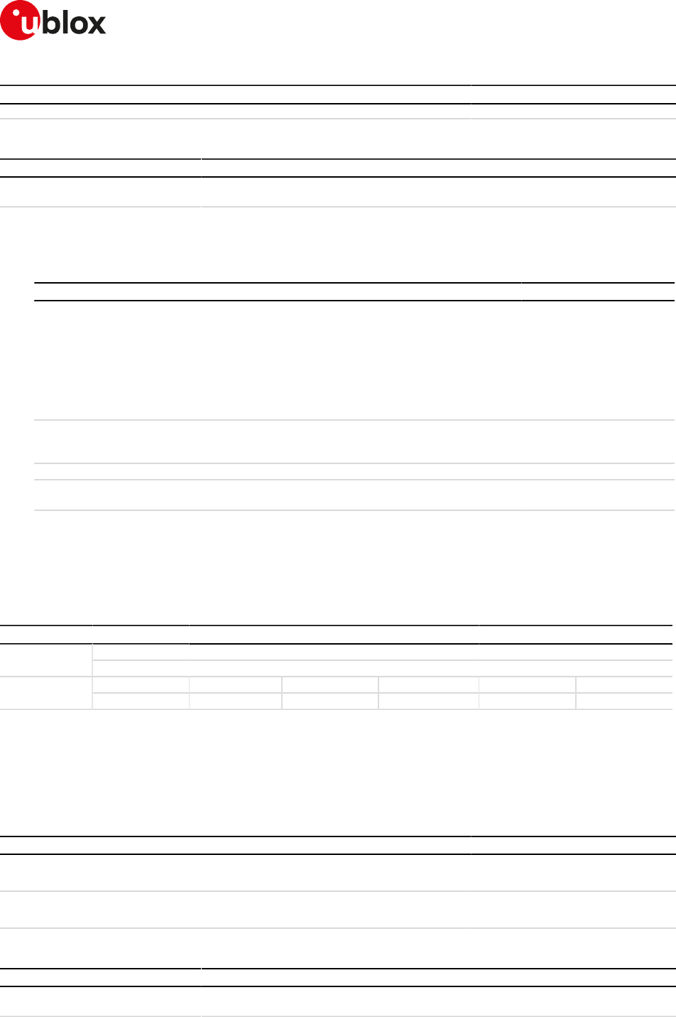
SARA-R4/N4 series-AT Commands Manual
UBX-17003787 - R09
10V24 control and V25ter
Page 103 of 307
Type Syntax Response Example
OK OK
10.11.3Defined values
Parameter Type Description
<value> Number Range 1 to 255. The answer to the read command is in "xxx" format. The default and
the factory-programmed value is 43 (ASCII '+').
10.11.4Notes
SARA-R4 / SARA-N4
• The following table shows how the ATS2 command works for different data call scenarios.
Data call command L2 protocol Description ATS2 behavior
ATD*99***1# PPP PSD call: dial up Escape sequence
detection is only done for ~
+++. ATS2 is not effective.
There is not a timing
constraint (see the S12 AT
command) for ~+++ (++
+ is incapsulated in a PPP
frame)
ATD1234 CSD call The command is effective
if issued in both command
and online command mode
AT+USODL=0 PSD call: Direct Link mode The command is effective
AT+USOWR=0,32 PSD call:AT socket (not transparent) Break detection is not
supported
Table 8: ATS2 handling for different data call scenarios
SARA-R4 / SARA-N4
• The command has no effect.
10.12Command line termination character S3
S3
SARA-R404M SARA-R410M-01B SARA-R410M-02B SARA-R410M-52B SARA-R412MModules
SARA-N4
Syntax PIN required Settings saved Can be aborted Response time Error referenceAttributes
partial No Profile No - +CME Error
10.12.1Description
Sets a value representing the decimal IRA5 value of the character recognized by the DCE from the DTE,
to terminate the incoming command line. It is also generated by the DCE as part of the header, trailer and
terminator for result codes and information text, along with the S4 setting.
10.12.2Syntax
Type Syntax Response Example
Set ATS3=<value> OK ATS3=13
OK
Read ATS3? <value>
OK
013
OK
10.12.3Defined values
Parameter Type Description
<value> Number Range 0 to 127. The answer to the read command is in "xxx" format. The default and
the factory-programmed value is 13 (ASCII carriage return (CR, IRA5 0/13)).
SARA-R4/N4 series-AT Commands Manual
UBX-17003787 - R09
10V24 control and V25ter
Page 104 of 307
10.13Response formatting character S4
S4
SARA-R404M SARA-R410M-01B SARA-R410M-02B SARA-R410M-52B SARA-R412MModules
SARA-N4
Syntax PIN required Settings saved Can be aborted Response time Error referenceAttributes
partial No Profile No - +CME Error
10.13.1Description
Sets a value representing the decimal IRA5 value of the character generated by the DCE as part of the header,
trailer and terminator for result codes and information text, along with the S3 setting.
10.13.2Syntax
Type Syntax Response Example
Set ATS4=<value> OK ATS4=10
OK
Read ATS4? <value>
OK
010
OK
10.13.3Defined values
Parameter Type Description
<value> Number Range 0 to 127. The answer to the read command is in "xxx" format. The default and
the factory-programmed value is 10 (line feed (LF, IRA5 0/10)).
10.14Command line editing character S5
S5
SARA-R404M SARA-R410M-01B SARA-R410M-02B SARA-R410M-52B SARA-R412MModules
SARA-N4
Syntax PIN required Settings saved Can be aborted Response time Error referenceAttributes
partial No Profile No - +CME Error
10.14.1Description
Sets a value representing the decimal IRA5 character recognized by the DCE as a request to delete from the
command line the immediately preceding character.
10.14.2Syntax
Type Syntax Response Example
Set ATS5=<value> OK ATS5=8
OK
Read ATS5? <value>
OK
008
OK
10.14.3Defined values
Parameter Type Description
<value> Number Range 0 to 127. The answer to the read command is in "xxx" format. The default and
the factory-programmed value is 8 (ASCII backspace (BS, IRA5 0/8)).

SARA-R4/N4 series-AT Commands Manual
UBX-17003787 - R09
10V24 control and V25ter
Page 105 of 307
10.15Pause before blind dialling S6
S6
SARA-R404M SARA-R410M-01B SARA-R410M-02B SARA-R410M-52B SARA-R412MModules
SARA-N4
Syntax PIN required Settings saved Can be aborted Response time Error referenceAttributes
partial No No No - +CME Error
10.15.1Description
Specifies the time in seconds that the DCE waits between connecting to the line and dialling, when the dial
tone is not implemented or enabled. The command is not applicable for signal based mobile phone software.
10.15.2Syntax
Type Syntax Response Example
Set ATS6=<value> OK ATS6=2
OK
Read ATS6? <value>
OK
002
OK
10.15.3Defined values
Parameter Type Description
<value> Number Range 2 - 10. The answer to the read command is in "xxx" format. The default value is
2 s.
10.16Connection completion timeout S7
S7
SARA-R404M SARA-R410M-01B SARA-R410M-02B SARA-R410M-52B SARA-R412MModules
SARA-N4
Syntax PIN required Settings saved Can be aborted Response time Error referenceAttributes
partial No Profile No - +CME Error
10.16.1Description
Specifies the time in seconds, that the DCE shall allow between either answering a call or completion of dialling
and establishment of a connection with a remote site.
10.16.2Syntax
Type Syntax Response Example
Set ATS7=<value> OK ATS7=30
OK
Read ATS7? <value>
OK
060
OK
10.16.3Defined values
Parameter Type Description
<value> Number Range 1 - 255. The answer to the read command is in "xxx" format. The default and
the factory-programmed value is 60 s.
SARA-R4/N4 series-AT Commands Manual
UBX-17003787 - R09
10V24 control and V25ter
Page 106 of 307
10.17Command dial modifier time S8
S8
SARA-R404M SARA-R410M-01B SARA-R410M-02B SARA-R410M-52B SARA-R412MModules
SARA-N4
Syntax PIN required Settings saved Can be aborted Response time Error referenceAttributes
partial No No No - +CME Error
10.17.1Description
Specifies the amount of time, in seconds, that the DCE shall pause during dialling, when a ',' (comma) dial
modifier is encountered in a dial string.
The command has no effect.
10.17.2Syntax
Type Syntax Response Example
Set ATS8=<value> OK ATS8=4
OK
Read ATS8? <value>
OK
002
OK
10.17.3Defined values
Parameter Type Description
<value> Number Range 0 - 255. The answer to the read command is in "xxx" format. The default value
is 2.
10.18Automatic disconnect delay S10
S10
SARA-R404M SARA-R410M-01B SARA-R410M-02B SARA-R410M-52B SARA-R412MModules
SARA-N4
Syntax PIN required Settings saved Can be aborted Response time Error referenceAttributes
partial No No No - +CME Error
10.18.1Description
Specifies the time in tenth of a second, that the DCE will remain connected to the line after the DCE has
indicated the absence of received line signal. Not supported for GSM but the OK response is returned.
10.18.2Syntax
Type Syntax Response Example
Set ATS10=<value> OK ATS10=30
OK
Read ATS10? <value>
OK
030
OK
10.18.3Defined values
Parameter Type Description
<value> Number Range 1 - 254. Default: 1
10.18.4Notes
SARA-R4 / SARA-N4
• The command has no effect.

SARA-R4/N4 series-AT Commands Manual
UBX-17003787 - R09
10V24 control and V25ter
Page 107 of 307
10.19Escape prompt delay (EPD) S12
S12
SARA-R404M SARA-R410M-01B SARA-R410M-02B SARA-R410M-52B SARA-R412MModules
SARA-N4
Syntax PIN required Settings saved Can be aborted Response time Error referenceAttributes
partial No No No - +CME Error
10.19.1Description
Defines the maximum period, in fiftieths of a second, allowed between the reception of the last character of
the sequence of three escape characters from the DTE and the sending of the OK result code to the DTE. If any
characters are detected during this time, the OK will not be sent.
Furthermore, the timeout is:
• The minimum period, before the first character reception of the three escape character sequence, during
which no other character must be detected to accept it as a valid first character
• The maximum period allowed between receipt of first, or second, character of the three escape character
sequence and receipt of the next
• The minimum period, after the last character reception of the three escape character sequence, during
which no other character must be detected to accept the escape sequence as a valid one
10.19.2Syntax
Type Syntax Response Example
Set ATS12=<value> OK ATS12=80
OK
Read ATS12? <value>
OK
050
OK
10.19.3Defined values
Parameter Type Description
<value> Number Range 0 - 255. The answer to the read command is in "xxx" format. The default value
is 50 (1 s)
10.20Command echo E
E
SARA-R404M SARA-R410M-01B SARA-R410M-02B SARA-R410M-52B SARA-R412MModules
SARA-N4
Syntax PIN required Settings saved Can be aborted Response time Error referenceAttributes
full No Profile No - +CME Error
10.20.1Description
Controls whether or not the MT echoes characters received from the DTE during command state.
10.20.2Syntax
Type Syntax Response Example
Set ATE[<value>] OK ATE1
OK
10.20.3Defined values
Parameter Type Description
<value> Number • 0: echo off
• 1 (default and the factory-programmed value): echo on
SARA-R4/N4 series-AT Commands Manual
UBX-17003787 - R09
10V24 control and V25ter
Page 108 of 307
10.21Result code suppression Q
Q
SARA-R404M SARA-R410M-01B SARA-R410M-02B SARA-R410M-52B SARA-R412MModules
SARA-N4
Syntax PIN required Settings saved Can be aborted Response time Error referenceAttributes
full No Profile No - +CME Error
10.21.1Description
Determines if DCE transmits result codes to the DTE or not. When result codes are being suppressed,
no portion of any intermediate, final or URC is transmitted. Information text transmitted in response to
commands is not affected by this setting.
10.21.2Syntax
Type Syntax Response Example
Set ATQ[<value>] OK ATQ1
OK
10.21.3Defined values
Parameter Type Description
<value> Number • 0 (default and the factory-programmed value): DCE transmits result codes
• 1: Result codes are suppressed and not transmitted
10.22DCE response format V
V
SARA-R404M SARA-R410M-01B SARA-R410M-02B SARA-R410M-52B SARA-R412MModules
SARA-N4
Syntax PIN required Settings saved Can be aborted Response time Error referenceAttributes
full No Profile No - +CME Error
10.22.1Description
Control the contents of the header and trailer transmitted with result codes and information text responses.
It also determines whether the result code is transmitted in a numeric form or an alphabetic (or verbose) form.
The information text response is not affected by this setting. See Information text responses and result codes
for description of the result code formats.
10.22.2Syntax
Type Syntax Response Example
Set ATV[<value>] OK ATV1
OK
10.22.3Defined values
Parameter Type Description
<value> Number • 0: DCE transmits limited headers, trailers and numeric text
• 1 (default and the factory-programmed value): DCE transmits full headers, trailers
and verbose response text
SARA-R4/N4 series-AT Commands Manual
UBX-17003787 - R09
10V24 control and V25ter
Page 109 of 307
10.23Result code selection and call progress monitoring
control X
X
SARA-R404M SARA-R410M-01B SARA-R410M-02B SARA-R410M-52B SARA-R412MModules
SARA-N4
Syntax PIN required Settings saved Can be aborted Response time Error referenceAttributes
full No Profile No - +CME Error
10.23.1Description
In a CS data call, determines how the DCE transmits to the DTE the CONNECT result code.
10.23.2Syntax
Type Syntax Response Example
Set ATX[<value>] OK ATX1
OK
10.23.3Defined values
Parameter Type Description
<value> Number • 0: CONNECT result code is given upon entering online data state;
• 1-4: CONNECT <speed> result code is given upon entering online data state; (4 is
the default and the factory-programmed value)
<speed> Number Transfer speed for CSD calls configured via the CBST command
10.24Reset to default configuration Z
Z
SARA-R404M SARA-R410M-01B SARA-R410M-02B SARA-R410M-52B SARA-R412MModules
SARA-N4
Syntax PIN required Settings saved Can be aborted Response time Error referenceAttributes
full No No No - +CME Error
10.24.1Description
Resets the DCE configuration into a known state; the reset includes the loading of the settings stored in the
profile identified by the <value> parameter, into the current profile, and the application of the settings.
When the command is issued, any CSD call in progress is released. In case of success, the result code is issued
using the format configuration (Q, V, S3, S4 commands) loaded from the requested profile. The other DCE
settings are applied after the result code has been sent.
For more details on the settings stored in the profiles, see the Appendix B.1.
10.24.2Syntax
Type Syntax Response Example
Action ATZ[<value>] OK
10.24.3Defined values
Parameter Type Description
<value> Number Profile index, possible values 0-1; optional parameter, the default value is 0
SARA-R4/N4 series-AT Commands Manual
UBX-17003787 - R09
10V24 control and V25ter
Page 110 of 307
10.25Set to factory defined configuration &F
&F
SARA-R404M SARA-R410M-01B SARA-R410M-02B SARA-R410M-52B SARA-R412MModules
SARA-N4
Syntax PIN required Settings saved Can be aborted Response time Error referenceAttributes
full No No No - +CME Error
10.25.1Description
Resets the current profile to factory-defined defaults. Other NVM settings, not included in the profiles, are not
affected.
In case of success, the response is issued using the configuration of the result codes format (Q, V, S3 and S4
AT commands) loaded from the factory default profile. The other DCE settings are applied after the response
has been sent.
For more details on the settings stored in the profiles, refer to Appendix B.1.
10.25.2Syntax
Type Syntax Response Example
Action AT&F[<value>] OK
10.25.3Defined values
Parameter Type Description
<value> Number Only 0 allowed
10.26Display current configuration &V
&V
SARA-R404M SARA-R410M-01B SARA-R410M-02B SARA-R410M-52B SARA-R412MModules
SARA-N4
Syntax PIN required Settings saved Can be aborted Response time Error referenceAttributes
full No No No - +CME Error
10.26.1Description
Reports a summary of the current configuration and of the stored user profiles.
Since not all configuration items are listed with this command, see the example below for the list of the
displayed configuration items. Appendix B.1 provides the complete list of the configuration items stored
in the profiles.
The command does not display audio parameters. Audio parameters can be displayed by the
corresponding read command (i.e. AT+UMGC?).
10.26.2Syntax
Type Syntax Response Example
Action AT&V ACTIVE PROFILE:
List of commands stored in the
active profile with the related values
STORED PROFILE 0:
List of commands stored in the
profile 0 with the related values
STORED PROFILE 1:
List of commands stored in the
profile 1 with the related values
OK
ACTIVE PROFILE: &C1, &D1, &S1,
&K3, E1, Q0, V1, X4, S00:000, S0
2:043, S03:013, S04:010, S05:00
8, S07:060, +CBST:007, 000, 001,
+CRLP:061, 061, 048, 006, +CR:0
00, +CRC:000, +IPR:0, +COPS:0,0,
FFFFF, +ICF:3,1, +UPSV: 0, +CMGF:0
, +CNMI:1,0,0,0,0, +USTS: 0
STORED PROFILE 0: &C1, &D1, &S1,
&K3, E1, Q0, V1, X4, S00:000, S0
2:043, S03:013, S04:010, S05:00
8, S07:060, +CBST:007, 000, 001,
+CRLP:061, 061, 048, 006, +CR:0

SARA-R4/N4 series-AT Commands Manual
UBX-17003787 - R09
10V24 control and V25ter
Page 111 of 307
Type Syntax Response Example
00, +CRC:000, +IPR:0, +COPS:0,0,
FFFFF, +ICF:3,1, +UPSV: 0, +CMGF:0
, +CNMI:1,0,0,0,0, +USTS: 0
STORED PROFILE 1: &C1, &D1, &S1,
&K3, E1, Q0, V1, X4, S00:000, S0
2:043, S03:013, S04:010, S05:00
8, S07:060, +CBST:007, 000, 001,
+CRLP:061, 061, 048, 006, +CR:0
00, +CRC:000, +IPR:0, +COPS:0,0,
FFFFF, +ICF:3,1, +UPSV: 0, +CMGF:0
, +CNMI:1,0,0,0,0, +USTS: 0
OK
10.26.3Notes
SARA-R4 / SARA-N4
• Only the ACTIVE PROFILE is available. The device does not support STORED PROFILE 0 or STORED
PROFILE 1
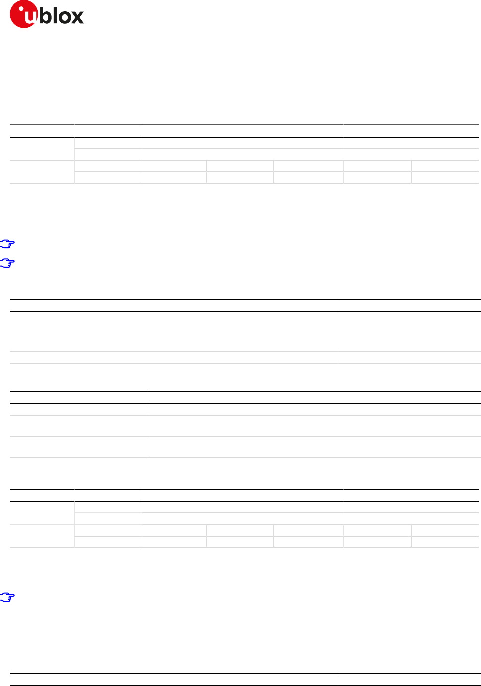
SARA-R4/N4 series-AT Commands Manual
UBX-17003787 - R09
11SIM management
Page 112 of 307
11SIM management
11.1Generic SIM access +CSIM
+CSIM
SARA-R410M-02B SARA-R410M-52B SARA-R412MModules
SARA-N4
Syntax PIN required Settings saved Can be aborted Response time Error referenceAttributes
full Yes No No - +CME Error
11.1.1Description
Allows direct control of the SIM by a distant application on the TE. This command transparently transmits the
<command> to the SIM via the MT. The <response> is returned in the same manner to the TE.
The command needs the SIM module to work correctly.
It is recommended to wait some seconds after boot (or reset) before using the command.
11.1.2Syntax
Type Syntax Response Example
Set AT+CSIM=<length>,<command> +CSIM: <length>,<response>
OK
AT+CSIM=14,"A0A40000027F20"
+CSIM: 4,"6E00"
OK
Test AT+CSIM=? OK OK
11.1.3Defined values
Parameter Type Description
<length> Number Length of the characters sent to the TE in <command> or <response> parameters
<command> String Command passed on by MT to SIM in hex format; see the 3GPP TS 51.011 [18] and
ETSI TS 102 221 [93]
<response> String Response to the command passed on by the SIM to the MT (3GPP TS 51.011 [18] and
ETSI TS 102 221 [93])
11.2Read the SIM language +CLAN
+CLAN
SARA-R410M-02B SARA-R410M-52B SARA-R412MModules
SARA-N4
Syntax PIN required Settings saved Can be aborted Response time Error referenceAttributes
full No No No - +CME Error
11.2.1Description
Reads the language from the SIM.
The read syntax will display the most preferred language from the preferred language list in EFELP (2F05)
file. If the EFELP file does not exist, the preferred language is read from EFLP (6F05) file. This file content
is decoded according to the CB (cell broadcast) data coding scheme (dcs), and the according language is
displayed in the response string. If this byte does not result in a valid language according to the CB dcs,
then it is printed in the response string in hexadecimal representation.
11.2.2Syntax
Type Syntax Response Example
Read AT+CLAN? +CLAN: <code> +CLAN: "en"
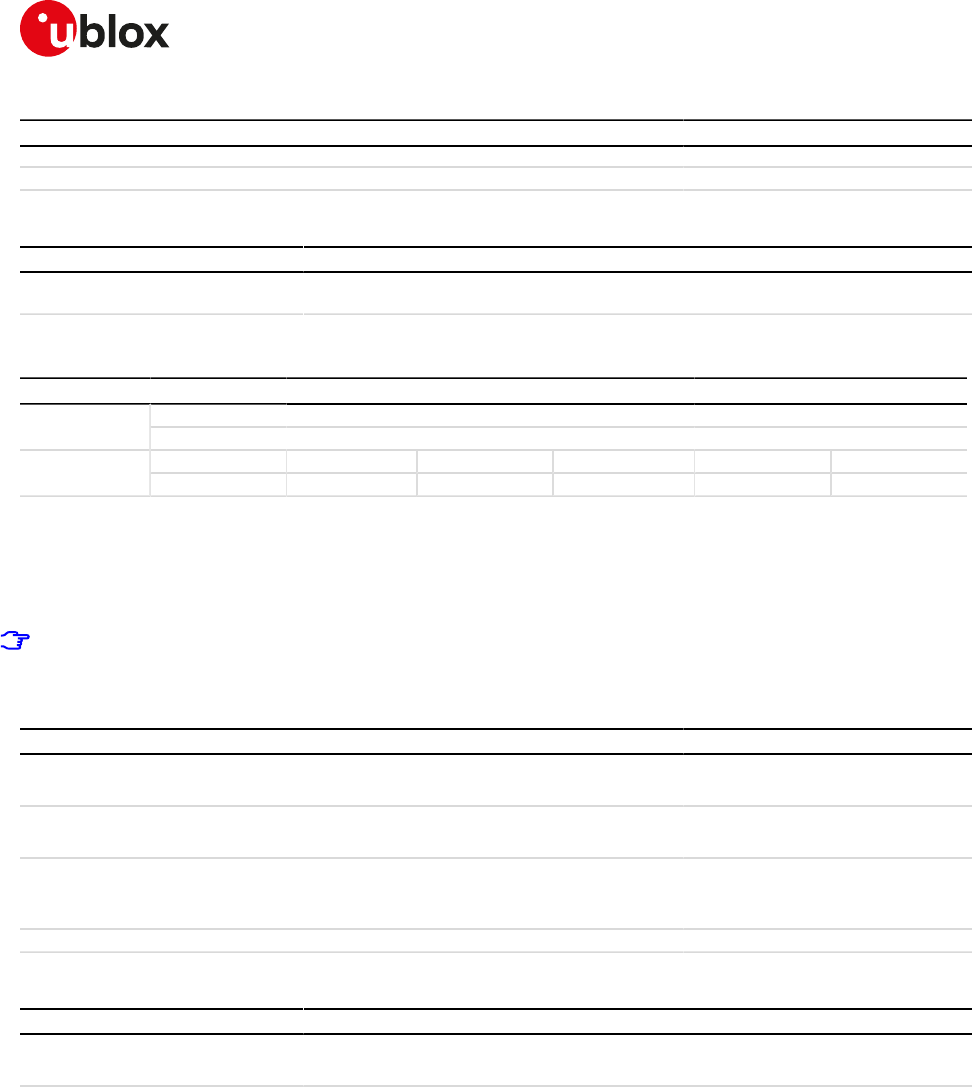
SARA-R4/N4 series-AT Commands Manual
UBX-17003787 - R09
11SIM management
Page 113 of 307
Type Syntax Response Example
OK OK
Test AT+CLAN=? OK
11.2.3Defined values
Parameter Type Description
<code> String It is a two-letter abbreviation of the language. The language codes, as defined in ISO
639, consists of two characters, e.g. "en", "it" etc
11.3SIM states reporting +USIMSTAT
+USIMSTAT
SARA-R410M-02B SARA-R410M-52B SARA-R412MModules
SARA-N4
Syntax PIN required Settings saved Can be aborted Response time Error referenceAttributes
partial No NVM No - +CME Error
11.3.1Description
Configures the +UUSIMSTAT URC presentation. Based on the configuration, the URC is able to report the SIM
card initialization status, the phonebook initialization status and the REFRESH proactive command execution
result.
If <state> 9 and 10 are reported, update all SIM card related parameters cached in the DTE's application
(e.g. the IMSI retrieved with +CIMI command).
11.3.2Syntax
Type Syntax Response Example
Set AT+USIMSTAT=<mode> OK AT+USIMSTAT=3
OK
Read AT+USIMSTAT? +USIMSTAT: <mode>
OK
+USIMSTAT: 3
OK
Test AT+USIMSTAT=? +USIMSTAT: (list of supported
<mode>s)
OK
+USIMSTAT: (0-7)
OK
URC +UUSIMSTAT: <state> +UUSIMSTAT: 8
11.3.3Defined values
Parameter Type Description
<mode> Number Bitmask representing which indications the +UUSIMSTAT URC is allowed to report.
See Table 9 for the meaning of each bit. The factory-programmed value is 0.
<state> Number • 0: SIM card not present
• 1: PIN needed
• 2: PIN blocked
• 3: PUK blocked
• 4: (U)SIM not operational
• 5: (U)SIM in restricted use (FDN or BDN active)
• 6: (U)SIM operational (registration may be initiated)
• 7: SIM phonebook ready to be used (when the SIM application is active)
• 8: USIM phonebook ready to be used (when the USIM application is active)
• 9: (U)SIM toolkit REFRESH proactive command successfully concluded
• 10: (U)SIM toolkit REFRESH proactive command unsuccessfully concluded
• 11: PPP connection active, (U)SIM toolkit REFRESH proactive command delayed till
PPP deactivation
• 12: voice call active, (U)SIM toolkit REFRESH proactive command delayed till call
release
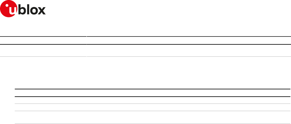
SARA-R4/N4 series-AT Commands Manual
UBX-17003787 - R09
11SIM management
Page 114 of 307
Parameter Type Description
• 13: CSD call active, (U)SIM toolkit REFRESH proactive command delayed till call
release
11.3.4Notes
• <state>=9 and 10 will not be reported when dedicated (+CFUN=6) or raw (+CFUN=9) mode is active.
•Table 9 provides the meaning of each bit with the corresponding state:
Bit States reported
0 Reports the (U)SIM initialization status (<state>'s from 0 to 6 may be reported)
1 Reports the (U)SIM phonebook initialization status (<state>'s from 7 to 8 may be reported)
2 Reports the (U)SIM toolkit REFRESH proactive command execution result (<state>'s from 9 to 13 may be
reported)
Table 9: <mode> bitmask meaning
SARA-R4/N4 series-AT Commands Manual
UBX-17003787 - R09
12SIM toolkit
Page 115 of 307
12SIM toolkit
12.1Introduction
SIM Application Toolkit (STK) is the 3GPP standard feature that allows the Subscriber Identity Module (SIM) to
handle the DCE, also by giving commands such as displaying menus and/or asking for user input, and control
its access to the network.
Once the SIM toolkit interface has been enabled via AT+CFUN command, the DTE is notified SIM toolkit
commands and events and can interact with the SIM through appropriate STK AT commands.
SIM toolkit processing supports two modes: dedicated and raw. In dedicated mode, the DTE is notified of STK
commands and events after decoding; in raw mode the DTE receives the raw data as received from the SIM.
Only one mode can be enabled and function at a time.
For more details on the command description and parameters, see 3GPP TS 51.014 [44].
The setup menu fetched from the SIM card may vary with the terminal profile supported by the MT, which
is affected by the capabilities of the module itself (e.g. speech): this implies that different u-blox modules
may display different setup menus with the same SIM card.
The commands in this section properly work only if the SIM toolkit interface has been activated by the
DTE. Otherwise the SIM toolkit processing will be blocked.
If an AT command related to the dedicated mode is used when the raw mode is enabled (and vice versa),
an error result code ("+CME ERROR: operation not allowed" if +CMEE is set to 2) is returned.
The STK commands related to the Bearer Independent Protocol, i.e. Open Channel, Close Channel, Receive
Data, Send Data, Get Channel Status and the events Data Available and Channel Status, are autonomously
managed by the device without the intervention from the TE, unless the dedicated mode is active and the Open
Channel command requires the user intervention (see ETSI TS 102 223 [51]).
12.2Bearer Independent Protocol status indication +UBIP
+UBIP
SARA-R410M-02B SARA-R410M-52B SARA-R412MModules
SARA-N4
Syntax PIN required Settings saved Can be aborted Response time Error referenceAttributes
full No NVM No - +CME Error
12.2.1Description
Configures the Bearer Independent Protocol status indication, i.e. the +UUBIP URC presentation.
12.2.2Syntax
Type Syntax Response Example
Set AT+UBIP=<mode> OK AT+UBIP=1
OK
Read AT+UBIP? +UBIP: <mode>
OK
+UBIP: 0
OK
Test AT+UBIP=? +UBIP: (list of supported <mode>'s)
OK
+UBIP: (0,1)
OK
URC +UUBIP: <ev_cmd>,<val> +UUBIP: 10,261
12.2.3Defined values
Parameter Type Description
<mode> Number Indicates whether the +UUBIP URC is enabled or not:
• 0 (factory-programmed value): BIP status indication disabled
• 1: BIP status indication enabled
SARA-R4/N4 series-AT Commands Manual
UBX-17003787 - R09
12SIM toolkit
Page 116 of 307
Parameter Type Description
• 2: OPEN CHANNEL, CLOSE CHANNEL and CHANNEL STATUS EVENT status
indications enabled
<ev_cmd> Number Indicates the event download's tag or proactive command's tag. Allowed values:
• 10: Channel status event
• 64: Open channel proactive command
• 65: Close channel proactive command
• 66: Receive data proactive command
• 67: Send data proactive command
<val> Number Indicates the channel status (in case of the event download channel status) or result
in case of a proactive command (see ETSI TS 102 223 [51])
12.3Read the USAT profile +CUSATR
+CUSATR
SARA-R410M-02B SARA-R410M-52B SARA-R412MModules
SARA-N4
Syntax PIN required Settings saved Can be aborted Response time Error referenceAttributes
full Yes No No - +CME Error
12.3.1Description
Reads the USAT terminal profile for the given profile storage. If the profile storage paramter is omitted in the
set command, the information text response will return the profile for all the supported profile storage values.
12.3.2Syntax
Type Syntax Response Example
Set AT+CUSATR[=<profile_storage>] +CUSATR: <profile_storage>,
<profile>
OK
AT+CUSATR=1
+CUSATR: 1,"F31FE84A119C00
878C00001FE060000043C000000
0004000400000000008"
OK
Test AT+CUSATR=? +CUSATR: (list of supported
<profile_storage>s)
OK
+CUSATR: (0-5)
OK
12.3.3Defined values
Parameter Type Description
<profile_storage> Number • 0: the TE profile that can be set with the +CUSATW AT command
• 1: the MT profile that can be set with the +CUSATW AT command
• 2: MT default profile that reflects the inherent, default supported facilities of the
MT
• 3: UICC profile that reflects the currently active UICC profile that was sent to the
UICC in the last TERMINAL PROFILE command
• 4: UICC EFUST. It represents the elementary file that indicates services available in
the USIM
• 5: list of MT only facilities (facilities that are not allowed to be assigned to the TE,
see 3GPP TS 31.111 [119])
<profile> String The profile in hexadecimal character format describing the supported facilities of the
referenced <profile_storage> as specified for the Terminal Profile in 3GPP TS 31.111
[119] or for the related EF in 3GPP TS 31.102 [19].
SARA-R4/N4 series-AT Commands Manual
UBX-17003787 - R09
12SIM toolkit
Page 117 of 307
12.4Write the USAT profile +CUSATW
+CUSATW
SARA-R410M-02B SARA-R410M-52B SARA-R412MModules
SARA-N4
Syntax PIN required Settings saved Can be aborted Response time Error referenceAttributes
full Yes NVM No - +CME Error
12.4.1Description
Writes a USAT terminal profile to the profile storage location. If the profile storage parameter is omitted in
the set command, it resets the profiles for all the supported profile storage values to factory-programmed
setting. If only the profile parameter is omitted, it will reset the given profile storage to factory-programmed
setting. Upon an attempt to store or reset a profile that conflicts with an already stored profile or the list of MT
only facilities, the operation fails and the profile referred to by command parameter <profile_storage> remains
unchanged. The MT will provide an error result code (+CME ERROR: 3 (Operation not allowed)).
12.4.2Syntax
Type Syntax Response Example
Set AT+CUSATW[=<profile_storage>[,
<profile>]]
OK AT+CUSATW=1,"F31FE84A119C00
878C00001FE060000043C000000
0004000400000000008"
OK
Test AT+CUSATW=? +CUSATW: (list of supported
<profile_storage>s)
OK
+CUSATR: (0,1)
OK
12.4.3Defined values
Parameter Type Description
<profile_storage> Number • 0: TE. It refers the profile storage for the facilities supported by the TE. The default
value is a blank profile with all bits set to zero. This value is applicable both in the
execution command and in the information text response.
• 1: MT. It refers the profile storage for the facilities to be supported by MT, which can
be a subset of the default MT facilities. The TE can choose to register a subset of
the MT default profile, typically omitting facilities also supported by the TE profile.
The default value is the MT default profile. This value is applicable both in the
execution command and in the information text response.
<profile> String The profile in hexadecimal character format describing the supported facilities of the
referenced <profile_storage> as specified for the Terminal Profile in 3GPP TS 31.111
[119] or for the related EF in 3GPP TS 31.102 [19].
12.5Enable USAT terminal URCs +UCUSATA
+UCUSATA
SARA-R410M-02B SARA-R410M-52B SARA-R412MModules
SARA-N4
12.5.1Description
Enables the USAT terminal URCs to the TE for USAT proactive commands sent from the UICC to the MT.
12.5.2Syntax
Type Syntax Response Example
Set AT+UCUSATA=<active_URC> OK AT+UCUSATA=0
OK
Read AT+UCUSATA? +UCUSATA: <active_URC>
OK
+UCUSATA: 0
OK
SARA-R4/N4 series-AT Commands Manual
UBX-17003787 - R09
12SIM toolkit
Page 118 of 307
Type Syntax Response Example
Test AT+UCUSATA=? +UCUSATA: (list of supported
<active_URC>s)
OK
+UCUSATA: (0-3)
OK
URC +CUSATP: <proactive_command>
URC +CUSATEND
12.5.3Defined values
Parameter Type Description
<active_URC> Number URC enabling/disabling. Allowed values:
• 0 (default value): disables all USAT URCs
• 1: enables the +CUSATEND URC
• 2: enables the +CUSATP URC
• 3: enables both USAT URCs
<proactive_
command>
String Command in hexadecimal character format. Proactive command as defined in 3GPP
TS 31.111 [119], consisting of the full BER-TLV data object.
12.5.4Notes
• The MT uses the unsolicited result code +CUSATP: <proactive_command> to forward to the TE proactive
commands issued by the UICC.
• The unsolicited result code +CUSATEND is issued by the MT when the UICC indicates that the proactive
command session is terminated.
• Terminal responses to the proactive commands can now be issued with +CUSATT and envelope
commands can be issued with +CUSATE
SARA-R4/N4 series-AT Commands Manual
UBX-17003787 - R09
13Packet switched data services
Page 119 of 307
13Packet switched data services
13.1PDP contexts and parameter definition
13.1.1Primary and secondary PDP contexts
A PDP context can be either primary or secondary. In LTE, PS data connections are referred to as EPS bearers:
EPS bearers are conceptually equivalent to the legacy PDP contexts, which are often referred to for sake of
simplicity. Similarly to a PDP context, the EPS bearer can be a default (primary) or dedicated (secondary) one.
The initial EPS bearer established during LTE attach procedure is actually a default EPS bearer. A secondary
PDP context uses the same IP address of a primary PDP context (the usual PDP context activated e.g. via
dial-up). The Traffic Flow Filters for such secondary contexts shall be specified according to 3GPP TS 23.060
[10].
The typical usage of the secondary PDP contexts is in VoIP calls, where RTP (speech) packets are conveyed on
one PDP context (e.g. the primary one) with a given QoS (e.g. low reliability) whereas SIP signalling is routed on
a different PDP context (e.g. the secondary one, with the same IP address but different port numbers) with a
more reliable QoS.
A Traffic Flow Template (i.e. a filter based on port number, specifying relative flow precedence) shall be
configured for the secondary context to instruct the GGSN to route down-link packets onto different QoS flows
towards the TE.
PDP context type Activation procedure
Primary Used to establish a logical connection through the network from the UE to the GGSN with a
specifically negotiated Quality of Service (QoS).
The UE initiates the PDP context activation: it changes the session management state to active,
creates the PDP context, obtains the IP address and reserves radio resources. After the activation,
the UE is able to send IP packets over the air interface.
Secondary Used to establish a second PDP context with the same IP address and the same APN as the
primary PDP context.
The two contexts may have different QoS profiles, which makes the feature useful for applications
that have different QoS requirements (e.g. IP multimedia); QoS is applied based on port number
addressing.
On all other modules, at most 2 secondary PDP contexts may be associated to a primary PDP context and
at most 2 secondary PDP contexts can be activated, since the maximum number of PDP contexts, both
normal and secondary, is always 3.
SARA-R4 / SARA-N4
The secondary PDP contexts are not supported.
13.1.2Multiple PDP contexts
Two PDP context types are defined:
• "external" PDP context: IP packets are built by the DTE, the MT's IP instance runs the IP relay function only;
• "internal" PDP context: the PDP context (relying on the MT's embedded TCP/IP stack) is configured,
established and handled via the data connection management AT commands.
Multiple PDP contexts are supported. The DTE can access these PDP contexts either alternatively through
the physical serial interface, or simultaneously through the virtual serial ports of the multiplexer (multiplexing
mode MUX), with the following constraints:
• Using the MT's embedded TCP/IP stack, only a internal PDP context is supported. This IP instance supports
up to 7 sockets;
• Using only external PDP contexts, it is possible to have at most 3 IP instances (with 3 different IP addresses)
simultaneously active. If in addition the internal PDP context is used, at most 2 external PDP contexts can
be activated.
SARA-R4 / SARA-N4
Multiple PDP contexts and internal PDP contexts are not supported.
SARA-R4/N4 series-AT Commands Manual
UBX-17003787 - R09
13Packet switched data services
Page 120 of 307
13.1.3Parameter definition
13.1.3.1<APN>
The Access Point Name (APN) is a string parameter, which is a logical name, valid in the current PLMN's
domain, used to select the GGSN (Gateway GPRS Support Node) or the external packet data network to be
connected to. The APN can be omitted: this is the so-called "blank APN" setting that may be suggested by
network operators (e.g. to roaming devices); in this case the APN string is not included in the message sent
to the network.
The maximum length of the parameter is 99 characters (the maximum length of coded APN is 100 octets, see
3GPP TS 23.003 [117], subclause 9.1).
SARA-R4 / SARA-N4
An optional special code placed at the beginning of <APN> indicates the type of authentication handling
between the module and the network and may be:
• CHAP: challenge handshake authentication protocol
• PAP: personal authentication protocol
• NOAUTH: authentication protocol not used
• code omitted: authentication protocol not used
An example for the usage of <APN> is:
AT+CGDCONT=1,"IP","CHAP:internet.t-d1.de"
The information text response to the +CGDCONT read command does not include the PAP: and CHAP:
prefixes in the APN string.
13.1.3.2<cid>
PDP context identifier. A numeric parameter specifying a particular PDP context definition. This parameter is
valid only locally on the interface DTE-MT.
The maximum number of definable and active PDP contexts depend(s) on the product version:1
Product Max number of
definable PDP contexts
Max number of active
PDP contexts
SARA-R4 / SARA-N4 8 8
13.1.3.3<PDP_addr>
String parameter identifying the MT in the IP-address space applicable to the PDP service. If the value is null or
omitted (dynamic IP addressing), then a value may be provided by the DTE during the PDP startup procedure
or, failing that, a dynamic address will be requested via DHCP. It can be read with the command AT+CGPADDR
or AT+CGDCONT read command.
To request a static IP address, a fixed IP address shall be specified for the <PDP_addr> paramater of the
+CGDCONT set command and the user shall not rely on PPP negotiation via IPCP CONFREQ option.
Depending on the IP-version, the <PDP_addr> consists of 4 octets (IPv4) or 16 octets (IPv6):
• IPv4: "ddd.ddd.ddd.ddd"
• IPv4v6: "ddd.ddd.ddd.ddd ddd.ddd.ddd.ddd.ddd.ddd.ddd.ddd.ddd.ddd.ddd.ddd.ddd.ddd.ddd.ddd"
• IPv6: "ddd.ddd.ddd.ddd.ddd.ddd.ddd.ddd.ddd.ddd.ddd.ddd.ddd.ddd.ddd.ddd"
13.1.3.4<PDP_type>
The Packet Data Protocol (PDP) type is a string parameter which specifies the type of packet data protocol:
• "IP" (default value): Internet Protocol (IETF STD 5)
• "NONIP": Non IP
• "IPV4V6": virtual <PDP_type> introduced to handle dual IP stack UE capability (see the 3GPP TS 24.301 [88])
• "IPV6": Internet Protocol, version 6 (see RFC 2460)
SARA-R404M / SARA-R410M-01B / SARA-R410M-02B
<PDP_type>="NONIP" is not supported.
1The maximum number of active PDP contexts may be limited by the MNO
SARA-R4/N4 series-AT Commands Manual
UBX-17003787 - R09
13Packet switched data services
Page 121 of 307
13.2PPP LCP handshake behaviour
When a data call is initiated by means of D* AT command, the module switches to PPP mode just after the
CONNECT intermediate result code. The first step of the PPP procedure is the LCP handshake, in this phase
the behaviour of 2G products differs from 3G products and 4G products.
Entering OnLine Command Mode (OLCM) during LCP handshake phase is strongly discouraged because
the handshake procedure could be broken and should be restarted from the beginning.
13.3PDP context definition +CGDCONT
+CGDCONT
SARA-R404M SARA-R410M-01B SARA-R410M-02B SARA-R410M-52B SARA-R412MModules
SARA-N4
Syntax PIN required Settings saved Can be aborted Response time Error referenceAttributes
partial Yes NVM No - +CME Error
13.3.1Description
Defines the connection parameters for a PDP context, identified by the local context identification parameter
<cid>. If the command is used only with parameter <cid>, the corresponding PDP context becomes undefined.
Each context is permanently stored so that its definition is persistent over power cycles.
The command is used to set up the PDP context parameters for an external context, i.e. a data connection
using the external IP stack (e.g. Windows dial up) and PPP link over the serial interface.
13.3.2Syntax
Type Syntax Response Example
IPv4 example
AT+CGDCONT=1,"IP","APN_name",
"1.2.3.4",0,0
OK
IPv4v6 example
AT+CGDCONT=1,"IPV4V6","APN","0
.0.0.0 0.0.0.0.0.0.0.0.0.0.0.0.0.0.0.0
",0,0
OK
Set AT+CGDCONT=[<cid>[,<PDP_
type>[,<APN>[,<PDP_addr>[,
<d_comp>[,<h_comp>[,
<IPv4AddrAlloc>[,<emergency_
indication>[,<P-CSCF_discovery>[,
<IM_CN_Signalling_Flag_Ind>[,
<NSLPI>]]]]]]]]]]]
OK
IPv6 example
AT+CGDCONT=1,"IPV6","APN","0.0.0
.0.0.0.0.0.0.0.0.0.0.0.0.0",0,0
OK
Read AT+CGDCONT? +CGDCONT: <cid>,<PDP_type>,
<APN>,<PDP_addr>,<d_comp>,
<h_comp>[,<IPv4AddrAlloc>,
<emergency_indication>,<P-CSCF_
discovery>,<IM_CN_Signalling_Flag_
Ind>[,<NSLPI>]]
OK
+CGDCONT: 1,"IP","web.omnitel.it",
"91.80.140.199",0,0
OK
Test AT+CGDCONT=? +CGDCONT: (list of supported
<cid>s),<PDP_type>,,,(list of
supported <d_comp>s),(list of
supported <h_comp>s)[,(list of
supported <IPv4AllocAddr>s),
(list of supported <emergency_
indication>s),(list of supported
<P-CSCF_discovery>s),(list of
supported <IM_CN_Signalling_
Flag_Ind>s)[,(list of supported
<NSLPI>s)]]
+CGDCONT: (1-3),"IP",,,(0-2),(0-4)
OK
SARA-R4/N4 series-AT Commands Manual
UBX-17003787 - R09
13Packet switched data services
Page 122 of 307
Type Syntax Response Example
OK
13.3.3Defined values
Parameter Type Description
<cid> Number See <cid>
<PDP_type> String See <PDP_type>
<APN> String See <APN>
<PDP_addr> Number See <PDP_addr>
<d_comp> Number PDP data compression; it can have the values:
• 0 (default value): off
• 1: on (predefined compression type i.e. V.42bis data compression)
• 2: V.42bis data compression
<h_comp> Number PDP header compression; it can have the values:
• 0 (default value): off
• 1: on (predefined compression type, i.e. RFC1144)
• 2: RFC1144
• 3: RFC2507
• 4: RFC3095
<h_comp>: the available head-compressions are dependent on configuration of
the stack (configured via features in the stack)
<IPv4AddrAlloc> Number Controls how the MT/TA requests to get the IPv4 address information:
• 0 (default value): IPv4 Address Allocation through NAS Signalling
• 1: IPv4 Address Allocated through DHCP
<emergency_
indication>
Number Indicates whether the PDP context is for emergency bearer services or not:
• 0 (default value): PDP context is not for emergency bearer services
• 1: PDP context is for emergency bearer services
<P-CSCF_discovery> Number Influences how the MT/TA requests to get the P-CSCF address, see 3GPP TS 24.229
[103] annex B and annex L:
• 0 (default value): preference of P-CSCF address discovery not influenced by
+CGDCONT
• 1: preference of P-CSCF address discovery through NAS Signalling
• 2: preference of P-CSCF address discovery through DHCP
<IM_CN_Signalling_
Flag_Ind>
Number Shows whether the PDP context is for IM CN subsystem-related signalling only or not:
• 0: PDP context is not for IM CN subsystem-related signalling only
• 1: PDP context is for IM CN subsystem-related signalling only
<NSLPI> Number Indicates the NAS signalling priority requested for the corresponding PDP context:
• 0 (default value): indicates that the PDP context has to be activated with the value
for the low priority indicator configured in the MT.
• 1: indicates that the PDP context has to be activated with the value for the low
priority indicator set to "MS is not configured for NAS signalling low priority".
The MT utilises the NSLPI information provided as specified in 3GPP TS 24.301 [88]
and 3GPP TS 24.008 [12].
13.3.4Notes
Additional examples:
Command Response Description
Configure the error result code
format by means of the +CMEE
AT command
AT+CGDCONT=? +CGDCONT: (1-3),"IP",,,(0),(0-1)
OK
Test command
AT+CGDCONT=4,"IP","internet" +CME ERROR: operation not allowed Define out of range PDP contexts
AT+CGDCONT=2,"IP","internet" OK Define allowed PDP contexts
AT+CGDCONT=1,"IP","STATREAL" OK Define allowed PDP contexts
AT+CGDCONT=3,"IP","PAP: tim.ibox.it" OK Define allowed PDP contexts
AT+CGDCONT=253,"IP","internet" +CME ERROR: operation not allowed Define out of range PDP contexts
SARA-R4/N4 series-AT Commands Manual
UBX-17003787 - R09
13Packet switched data services
Page 123 of 307
Command Response Description
AT+CGDCONT? +CGDCONT: 2,"IP","internet","0.0.0.0",0,0
+CGDCONT: 1,"IP","STATREAL","0.0.0.0",0
,0
+CGDCONT: 3,"IP","tim.ibox.it","0.0.0.0",0,0
OK
Read command
SARA-R4 / SARA-N4
• When registering in LTE, the initial default EPS bearer is mapped to <cid>= 1.
• If not specified by the set command, the following values are assumed:
o <cid>: 1
o <PDP_addr>: "0.0.0.0"
• <d_comp>=1, 2 are not supported.
• The command setting are stored in the NVM at the module switch off.
• The module automatically accepts Mobile Terminated PDP contexts/EPS bearers.
• The <NSLPI> parameter is not supported.
• <P-CSCF_discovery>=2 is not supported.
SARA-R4 / SARA-N4
• <h_comp>= 1, 2, 3 and 4 are not supported.
• If <PDP_addr> is not assigned or set to all zeros and <PDP_type>="IPV4V6", the read command will
only return the all zeros IPV6 address.
SARA-R404M
• The settings of the initial default EPS bearer mapped to <cid>= 1 must have a blank APN.
13.4Packet switched data configuration +UPSD
+UPSD
SARA-R404M SARA-R410M-01B SARA-R410M-02B SARA-R410M-52B SARA-R412MModules
SARA-N4
Syntax PIN required Settings saved Can be aborted Response time Error referenceAttributes
partial No NVM No - +CME Error
13.4.1Description
Sets or reads all the parameters in a specific packet switched data (PSD) profile. The command is used to set
up the PDP context parameters for an internal context, i.e. a data connection using the internal IP stack and
related AT commands for sockets.
To set all the parameters of the PSD profile a set command for each parameter needs to be issued.
In the read command, if only the first parameter is issued, the module returns all the parameters of the
given PSD profile, and lists them in separated lines.
13.4.2Syntax
Type Syntax Response Example
Set AT+UPSD=<profile_id>,<param_
tag>,<param_val>
OK AT+UPSD=0,1,"apn.provider.com"
OK
AT+UPSD=<profile_id>,<param_
tag>
+UPSD: <profile_id>,<param_tag>,
<param_val>
OK
AT+UPSD=0,1
+UPSD: 0,1,"apn.provider.com"
OK
Read
AT+UPSD=<profile_id> +UPSD: <profile_id>,0,<param_val0
>
+UPSD: <profile_id>,1,<param_
val1>...
+UPSD: <profile_id>,x,<param_valx>
AT+UPSD=0
+UPSD: 0,0,0
+UPSD: 0,1,"apn.provider.com"
+UPSD: 0,2,"username"
SARA-R4/N4 series-AT Commands Manual
UBX-17003787 - R09
13Packet switched data services
Page 124 of 307
Type Syntax Response Example
OK +UPSD: 0,4,"0.0.0.0"
...
+UPSD: 0,19,0
OK
13.4.3Defined values
Parameter Type Description
<profile_id> Number PSD profile identifier, in range 0-6
<param_tag> Number • 0: Protocol type; the allowed values of <param_val> parameter are
o 0 (factory-programmed value): IPv4
o 1: IPv6
o 2: IPv4v6 with IPv4 preferred for internal sockets
o 3: IPv4v6 with IPv6 preferred for internal sockets
• 1: APN - <param_val> defines the APN text string, e.g. "apn.provider.com"; the
maximum length is 99. The factory-programmed value is an empty string.
• 2: username - <param_val> is the user name text string for the authentication
phase. The factory-programmed value is an empty string.
• 3: password - <param_val> is the password text string for the authentication phase.
Note: the AT+UPSD read command with <param_tag> = 3 is not allowed and the
read all command does not display it
• 4: DNS1 - <param_val> is the text string of the primary DNS address. IPv4 DNS
addresses are specified in dotted decimal notation form (i.e. four numbers in
range 0-255 separated by periods, e.g. "xxx.yyy.zzz.www"). IPv6 DNS addresses
are specified in standard IPv6 notation form (2001:DB8:: address compression is
allowed). The factory-programmed value is "0.0.0.0".
• 5: DNS2 - <param_val> is the text string of the secondary DNS address. IPv4
DNS addresses are specified in dotted decimal notation form (i.e. four numbers
in range 0-255 separated by periods, e.g. "xxx.yyy.zzz.www"). IPv6 DNS addresses
are specified in standard IPv6 notation form (2001:DB8:: address compression is
allowed). The factory-programmed value is "0.0.0.0".
• 6: authentication - the <param_val> parameter selects the authentication type:
o 0 (factory-programmed value): none
o 1: PAP
o 2: CHAP
o 3: automatic selection of authentication type (none/CHAP/PAP)
• 7: IP address - <param_val> is the text string of the static IP address given by the
ISP in dotted decimal notation form (i.e. four numbers in range 0-255 separated by
periods, e.g. "xxx.yyy.zzz.www"). The factory-programmed value is "0.0.0.0". Note:
IP address set as "0.0.0.0" means dynamic IP address assigned during PDP context
activation
• 8: data compression - the <param_val> parameter refers to the default parameter
named <d_comp> and selects the data compression type:
o 0 (factory-programmed value): off
o 1: predefined, i.e. V.42bis
o 2: V.42bis
• 9: header compression - the <param_val> parameter refers to the default
parameter named <h_comp> and selects the header compression type:
o 0 (factory-programmed value): off
o 1: predefined, i.e. RFC1144
o 2: RFC1144
o 3: RFC2507
o 4: RFC3095
• 10: QoS precedence - the <param_val> parameter selects the precedence class:
o 0 (factory-programmed value): subscribed
o 1: high
o 2: normal
o 3: low
• 11: QoS delay - the <param_val> parameter selects the delay class:

SARA-R4/N4 series-AT Commands Manual
UBX-17003787 - R09
13Packet switched data services
Page 125 of 307
Parameter Type Description
o 0 (factory-programmed value): subscribed
o 1: class 1
o 2: class 2
o 3: class 3
o 4: best effort
• 12: QoS reliability - the <param_val> parameter selects the reliability class:
o 0 (factory-programmed value): subscribed
o 1: class 1 (Interpreted as class 2)
o 2: class 2 (GTP Unack, LLC Ack and Protected, RLC Ack)
o 3: class 3 (GTP Unack, LLC Unack and Protected, RLC Ack)
o 4: class 4 (GTP Unack, LLC Unack and Protected, RLC Unack)
o 5: class 5 (GTP Unack, LLC Unack and Unprotected, RLC Unack)
o 6: class 6 (Interpreted as class 3)
• 13: QoS peak rate - the <param_val> parameter selects the peak throughput in
range 0-9. The factory-programmed value is 0.
• 14: QoS mean rate - the <param_val> parameter selects the mean throughput in
range 0-18, 31. The factory-programmed value is 0.
• 15: minimum QoS precedence - the <param_val> parameter selects the acceptable
value for the precedence class:
o 0 (factory-programmed value): subscribed
o 1: high
o 2: normal
o 3: low
• 16: minimum QoS delay - the <param_val> parameter selects the acceptable value
for the delay class:
o 0 (factory-programmed value): subscribed
o 1: class 1
o 2: class 2
o 3: class 3
o 4: best effort
• 17: minimum QoS reliability - the <param_val> parameter selects the minimum
acceptable value for the reliability class:
o 0 (factory-programmed value): subscribed
o 1: class 1 (Interpreted as class 2)
o 2: class 2 (GTP Unack, LLC Ack and Protected, RLC Ack)
o 3: class 3 (GTP Unack, LLC Unack and Protected, RLC Ack)
o 4: class 4 (GTP Unack, LLC Unack and Protected, RLC Unack)
o 5: class 5 (GTP Unack, LLC Unack and Unprotected, RLC Unack)
o 6: class 6 (Interpreted as class 3)
• 18: minimum QoS peak rate - the <param_val> parameter selects the acceptable
value for the peak throughput in range 0-9. The factory-programmed value is 0.
• 19: minimum QoS mean rate - the <param_val> parameter selects the acceptable
value for the mean throughput in range 0-18, 31. The factory-programmed value is 0.
• 20: 3G QoS delivery order - the <param_val> parameter selects the acceptable value
for the delivery order:
o 0 (factory-programmed value): subscribed
o 1: enable
o 2: disable
• 21: 3G QoS erroneous SDU delivery - the <param_val> parameter selects the
acceptable value for the erroneous SDU delivery:
o 0 (factory-programmed value): subscribed
o 1: no detection
o 2: enable
o 3: disable
• 22: 3G QoS extended guaranteed downlink bit rate - <param_val> is the value for the
extended guaranteed downlink bit rate in kb/s. The factory-programmed value is 0.
• 23: 3G QoS extended maximum downlink bit rate - <param_val> is the value for the
extended maximum downlink bit rate in kb/s. The factory-programmed value is 0.

SARA-R4/N4 series-AT Commands Manual
UBX-17003787 - R09
13Packet switched data services
Page 126 of 307
Parameter Type Description
• 24: 3G QoS guaranteed downlink bit rate - <param_val> is the value for the
guaranteed downlink bit rate in kb/s. The factory-programmed value is 0.
• 25: 3G QoS guaranteed uplink bit rate - <param_val> is the value for the guaranteed
uplink bit rate in kb/s. The factory-programmed value is 0.
• 26: 3G QoS maximum downlink bit rate - <param_val> is the value for the maximum
downlink bit rate in kb/s. The factory-programmed value is 0.
• 27: 3G QoS maximum uplink bit rate - <param_val> is the value for the maximum
uplink bit rate in kb/s. The factory-programmed value is 0.
• 28: 3G QoS maximum SDU size - <param_val> is the value for the maximum SDU
size in octets. The factory-programmed value is 0.
• 29: 3G QoS residual bit error rate - <param_val> selects the acceptable value for the
residual bit error rate:
o 0 (factory-programmed value): subscribed
o 1: 5E2
o 2: 1E2
o 3: 5E3
o 4: 4E3
o 5: 1E3
o 6: 1E4
o 7: 1E5
o 8: 1E6
o 9: 6E8
• 30: 3G QoS SDU error ratio - <param_val> selects the acceptable value for the SDU
error ratio:
o 0 (factory-programmed value): subscribed
o 1: 1E2
o 2: 7E3
o 3: 1E3
o 4: 1E4
o 5: 1E5
o 6: 1E6
o 7: 1E1
• 31: 3G QoS signalling indicator - <param_val> selects the acceptable value for the
signalling indicator:
o 0 (factory-programmed value): subscribed
o 1: signalling indicator 1
• 32: 3G QoS source statistics descriptor - <param_val> selects the acceptable value
for the source statistics descriptor:
o 0 (factory-programmed value): subscribed
o 1: source statistics descriptor 1
• 33: 3G QoS traffic class - <param_val> selects the acceptable value for the traffic
class:
o 0 (factory-programmed value): subscribed
o 1: conversational
o 2: streaming
o 3: interactive
o 4: background
• 34: 3G QoS traffic priority - <param_val> selects the acceptable value for the traffic
priority:
o 0 (factory-programmed value): subscribed
o 1: priority 1
o 2: priority 2
o 3: priority 3
• 35: 3G QoS transfer delay - <param_val> is the value for the transfer delay in
milliseconds. The factory-programmed value is 0.
• 36: 3G minimum QoS delivery order - <param_val> selects the acceptable value for
the delivery order:
o 0 (factory-programmed value): subscribed
o 1: enable

SARA-R4/N4 series-AT Commands Manual
UBX-17003787 - R09
13Packet switched data services
Page 127 of 307
Parameter Type Description
o 2: disable
• 37: 3G minimum QoS erroneous SDU delivery - <param_val> selects the acceptable
value for the erroneous SDU delivery:
o 0 (factory-programmed value): subscribed
o 1: no detection
o 2: enable
o 3: disable
• 38: 3G minimum QoS extended guaranteed downlink bit rate - <param_val> is
the value for the extended guaranteed downlink bit rate in kb/s. The factory-
programmed value is 0.
• 39: 3G minimum QoS extended maximum downlink bit rate - <param_val> is the
value for the extended maximum downlink bit rate in kb/s. The factory-programmed
value is 0.
• 40: 3G minimum QoS guaranteed downlink bit rate - <param_val> is the value for
the guaranteed downlink bit rate in kb/s. The factory-programmed value is 0.
• 41: 3G minimum QoS guaranteed uplink bit rate - <param_val> is the value for the
guaranteed uplink bit rate in kb/s. The factory-programmed value is 0.
• 42: 3G minimum QoS maximum downlink bit rate - <param_val> is the value for the
maximum downlink bit rate in kb/s. The factory-programmed value is 0.
• 43: 3G minimum QoS maximum uplink bit rate - <param_val> is the value for the
maximum uplink bit rate in kb/s. The factory-programmed value is 0.
• 44: 3G minimum QoS maximum SDU size - <param_val> is the value for the
maximum SDU size in octets. The factory-programmed value is 0.
• 45: 3G minimum QoS residual bit error rate - <param_val> selects the acceptable
value for the residual bit error rate:
o 0 (factory-programmed value): subscribed
o 1: 5E2
o 2: 1E2
o 3: 5E3
o 4: 4E3
o 5: 1E3
o 6: 1E4
o 7: 1E5
o 8: 1E6
o 9: 6E8
• 46: 3G minimum QoS SDU error ratio - <param_val> selects the acceptable value
for the SDU error ratio:
o 0 (factory-programmed value): subscribed
o 1: 1E2
o 2: 7E3
o 3: 1E3
o 4: 1E4
o 5: 1E5
o 6: 1E6
o 7: 1E1
• 47: 3G minimum QoS signalling indicator - <param_val> selects the acceptable
value for the signalling indicator:
o 0 (factory-programmed value): subscribed
o 1: signalling indicator 1
• 48: 3G minimum QoS source statistics descriptor - <param_val> selects the
acceptable value for the source statistics descriptor:
o 0 (factory-programmed value): subscribed
o 1: source statistics descriptor 1
• 49: 3G minimum QoS traffic class - <param_val> selects the acceptable value for
the traffic class:
o 0 (factory-programmed value): subscribed
o 1: conversational
o 2: streaming
o 3: interactive
o 4: background
SARA-R4/N4 series-AT Commands Manual
UBX-17003787 - R09
13Packet switched data services
Page 128 of 307
Parameter Type Description
• 50: 3G minimum QoS traffic priority - <param_val> selects the acceptable value for
the traffic priority:
o 0 (factory-programmed value): subscribed
o 1: priority 1
o 2: priority 2
o 3: priority 3
• 51: 3G Minimum QoS transfer delay - <param_val> is the value for the transfer delay
in milliseconds. The factory-programmed value is 0.
• 100: map the +UPSD profile to the specified <cid> in the +CGDCONT table.
o 1: map the current profile to <cid> 1
o 2: map the current profile to <cid> 2
o 3: map the current profile to <cid> 3
o 4: map the current profile to <cid> 4
o 5: map the current profile to <cid> 5
o 6: map the current profile to <cid> 6
o 7: map the current profile to <cid> 7
o 8 (factory-programmed value): map the current profile to <cid> 8
13.4.4Notes
• For the description of the QoS parameters, see 3GPP TS 22.060 [50] and 3GPP TS 23.060 [10].
• The maximum length of <param_val> if <param_tag> is equal to 2 or 3 is 64.
SARA-R4 / SARA-N4
• The only supported <profile_id> is 0.
• The only supported <param_tag> is 0 (IP type).
13.5GPRS attach or detach +CGATT
+CGATT
SARA-R404M SARA-R410M-01B SARA-R410M-02B SARA-R410M-52B SARA-R412MModules
SARA-N4
Syntax PIN required Settings saved Can be aborted Response time Error referenceAttributes
full Yes No Yes Up to 3 min +CME Error
13.5.1Description
Register (attach) the MT to, or deregister (detach) the MT from the GPRS service. After this command the MT
remains in AT command mode. If the MT is already in the requested state (attached or detached), the command
is ignored and OK result code is returned. If the requested state cannot be reached, an error result code is
returned. The command can be aborted if a character is sent to the DCE during the command execution. Any
active PDP context will be automatically deactivated when the GPRS registration state changes to detached.
The user should not enter colliding requests (e.g. AT+CGATT=1 and AT+CGATT=0) on different
communication ports, because this might cause interoperability issues in case overlapping attach and
detach requests are not handled by the network, and could result in an unpredictable registration
state. Similarly, when notified of a mobile terminated GPRS detach event (e.g. via +CGEV URC), it is
recommended to wait a few seconds before entering AT+CGATT=0 in order to let the pending attach
procedure (automatically triggered by the module in most cases) successfully end.
SARA-R4
If MT is configured in class "B" (see the +CGCLASS AT command) and the GSM registration has not
yet been performed, AT+CGATT=1 triggers both GSM and GPRS registration. If the command is aborted
before the PS registration has ended, the CS registration is completed and the MT goes into class "CC".
The deregistration action is carried out even if the command is aborted.
13.5.2Syntax
Type Syntax Response Example
Set AT+CGATT=[<state>] OK AT+CGATT=1
SARA-R4/N4 series-AT Commands Manual
UBX-17003787 - R09
13Packet switched data services
Page 129 of 307
Type Syntax Response Example
OK
Read AT+CGATT? +CGATT: <state>
OK
+CGATT: 1
OK
Test AT+CGATT=? +CGATT: (list of supported
<state>s)
OK
+CGATT: (0-1)
OK
13.5.3Defined values
Parameter Type Description
<state> Number Indicates the state of GPRS attachment:
• 0: detached
• 1 (default value): attached
13.6PDP context activate or deactivate +CGACT
+CGACT
SARA-R404M SARA-R410M-01B SARA-R410M-02B SARA-R410M-52B SARA-R412MModules
SARA-N4
Syntax PIN required Settings saved Can be aborted Response time Error referenceAttributes
full Yes No Yes Up to 40-150 s
(see below)
+CME Error
13.6.1Description
Activates or deactivates the specified PDP context. After the command, the MT remains in AT command mode.
If any context is already in the requested state, the state for the context remains unchanged. If the required
action cannot succeed, an error result code is returned. If the MT is not GPRS attached when the activation of
a PDP context is required, the MT first performs a GPRS attach and then attempts to activate the specified
context.
The maximum expected response time is different whenever the activation or the deactivation of a PDP context
is performed (150 s and 40 s respectively).
The command can be aborted if a character is sent to the DCE during the command execution: if a PDP context
activation on a specific <cid> was requested, the PDP context deactivation is performed; if a multiple PDP
context activation was requested, it is aborted after the pending PDP context activation has finished.
The deactivation action is carried out even if the command is aborted.
13.6.2Syntax
Type Syntax Response Example
Set AT+CGACT=[<status>[,<cid>[,...]]] OK AT+CGACT=1,1
OK
Read AT+CGACT? [+CGACT: <cid>,<status>
[+CGACT: <cid>,<status>
[...]]]
OK
+CGACT: 1,1
OK
Test AT+CGACT=? +CGACT: (list of supported
<status>s)
OK
+CGACT: (0-1)
OK
13.6.3Defined values
Parameter Type Description
<status> Number Indicates the state of PDP context activation:
• 0: deactivated
• 1: activated
<cid> Number See <cid>.
SARA-R4/N4 series-AT Commands Manual
UBX-17003787 - R09
13Packet switched data services
Page 130 of 307
13.6.4Notes
SARA-R4 / SARA-N4
• If <cid> is not defined, the command activates or deactivates all the defined PDP contexts.
13.6.5Examples
Examples of usage of +CGDCONT, +CGACT, +CGPADDR command:
Command sent by the DTE DCE response Description
AT+CMEE=2 OK Set the verbose error result
codes
AT+COPS=0 OK
AT+COPS? +COPS: 0,0,"vodafone IT"
OK
AT+CGDCONT=1,"IP","web.omnitel.it" OK Define several PDP contexts
AT+CGDCONT=3,"IP","internet" OK
AT+CGDCONT=2,"IP",
"mms.vodafone.it"
OK
AT+CGDCONT? +CGDCONT: 1,"IP","web.omnitel.it","0.0.0.0",0,0
+CGDCONT: 3,"IP","internet","0.0.0.0",0,0
+CGDCONT: 2,"IP","mms.vodafone.it","0.0.0.0",0,0
OK
Read PDP contexts
AT+CGACT=1,1 OK Activate the PDP context 1
AT+CGPADDR=1 +CGPADDR: 1, "91.80.104.82"
OK
Show address of the PDP
context 1
AT+CGPADDR=2 +CGPADDR: 2, "0.0.0.0"
OK
Show the address of PDP
context 2
AT+CGPADDR=3 +CGPADDR: 3, "0.0.0.0"
OK
Show the address of PDP
context 3
AT+CGDCONT? +CGDCONT: 1,"IP","web.omnitel.it","91.80.104.82",0,0
+CGDCONT: 3,"IP","internet","0.0.0.0",0,0
+CGDCONT: 2,"IP","mms.vodafone.it","0.0.0.0",0,0
OK
AT+CGACT=0,1 OK Deactivate the PDP context
1
AT+CGDCONT? +CGDCONT: 1,"IP","web.omnitel.it","0.0.0.0",0,0
+CGDCONT: 3,"IP","internet","0.0.0.0",0,0
+CGDCONT: 2,"IP","mms.vodafone.it","0.0.0.0",0,0
OK
AT+CGACT=1 OK Activate all of defined PDP
contexts
AT+CGDCONT? +CGDCONT: 1,"IP","web.omnitel.it","91.80.101.207",0,0
+CGDCONT: 3,"IP","internet","83.225.114.136",0,0
+CGDCONT: 2,"IP","mms.vodafone.it","10.159.135.60",
0,0
OK
AT+CGPADDR=1 +CGPADDR: 1, "91.80.101.207"
OK
Show the address of PDP
context 1
AT+CGPADDR=2 +CGPADDR: 2, "10.159.135.60"
OK
Show the address of PDP
context 2
AT+CGACT=0 OK Deactivate all of defined
PDP contexts
AT+CGPADDR=2 +CGPADDR: 2, "0.0.0.0" Show the address of PDP
context 2
SARA-R4/N4 series-AT Commands Manual
UBX-17003787 - R09
13Packet switched data services
Page 131 of 307
Command sent by the DTE DCE response Description
OK
AT+CGPADDR=3 +CGPADDR: 3, "0.0.0.0"
OK
Show the address of PDP
context 3
AT+CGDCONT? +CGDCONT: 1,"IP","web.omnitel.it","0.0.0.0",0,0
+CGDCONT: 3,"IP","internet","0.0.0.0",0,0
+CGDCONT: 2,"IP","mms.vodafone.it","0.0.0.0",0,0
OK
AT+CGACT=1,2 OK Activate the PDP context 2
AT+CGDCONT? +CGDCONT: 1,"IP","web.omnitel.it","0.0.0.0",0,0
+CGDCONT: 3,"IP","internet","0.0.0.0",0,0
+CGDCONT: 2,"IP","mms.vodafone.it","10.153.123.229",
0,0
OK
AT+CGACT=1,3 OK Activate PDP context 3
AT+CGDCONT? +CGDCONT: 1,"IP","web.omnitel.it","0.0.0.0",0,0
+CGDCONT: 3,"IP","internet","83.225.171.77",0,0
+CGDCONT: 2,"IP","mms.vodafone.it","10.153.123.229",
0,0
OK
AT+CGACT=1,1 OK Activate the PDP context 1
AT+CGDCONT? +CGDCONT: 1,"IP","web.omnitel.it","91.80.175.163",0,0
+CGDCONT: 3,"IP","internet","83.225.171.77",0,0
+CGDCONT: 2,"IP","mms.vodafone.it","10.153.123.229",
0,0
OK
AT+CGACT=0 OK Deactivate all of defined
PDP contexts
AT+CGDCONT? +CGDCONT: 1,"IP","web.omnitel.it","0.0.0.0",0,0
+CGDCONT: 3,"IP","internet","0.0.0.0",0,0
+CGDCONT: 2,"IP","mms.vodafone.it","0.0.0.0",0,0
OK
13.7Enter PPP state/GPRS dial-up D*
D*
SARA-R404M SARA-R410M-01B SARA-R410M-02B SARA-R410M-52B SARA-R412MModules
SARA-N4
Syntax PIN required Settings saved Can be aborted Response time Error referenceAttributes
full Yes No No Up to 3 min +CME Error
13.7.1Description
The V.24 dial command "D", similar to the command with the syntax AT+CGDATA="PPP",<cid>, causes the
MT to perform the necessary actions to establish the communication between the DTE and the external PDP
network through the PPP protocol. This can include performing a PS attach and, if the PPP server on the
DTE side starts communication, PDP context activation on the specified PDP context identifier (if not already
requested by means of +CGATT and +CGACT commands).
If the command is accepted and the preliminary PS procedures have succeeded, the "CONNECT" intermediate
result code is returned, the MT enters the V.25ter online data state and the PPP L2 protocol between the MT
and the DTE is started.
The data session is terminated by one of the following events:
• sending ~+++.
SARA-R4/N4 series-AT Commands Manual
UBX-17003787 - R09
13Packet switched data services
Page 132 of 307
• via a DTR transition from ON to OFF.
• sending an LCP Terminate Request.
If used with <cid>= 100, this command can enable the local dial-up, that establishes a PPP communication
between the DTE and the module through a serial interface (UART, MUX, or CDC-ACM). In this case an active
PDP context is not needed since the DTE is assigned a private IP address.
13.7.2Local dial-up
The local dial-up feature is enabled by performing a dial-up on <cid>= 100. It establishes a PPP communication
between the DTE and the module through a serial interface (UART, MUX, or CDC-ACM). An IP link is created
by assigning private IP addresses to the endpoints. An active PDP context is not needed. The IP traffic is
automatically routed by the module, thus allowing the DTE to communicate with:
• the internet through an active PDP context (at least one PDP context/EPS bearer is needed for the IP
connectivity). By default, the first PDP context activated is used to convey the data;
• a device connected to the Virtual Ethernet over USB (RNDIS/CDC-ECM);
• devices (STA) connected to the Wi-Fi access point (AP) of the cellular module (see Wi-Fi section).
The feature has been studied to work in router mode.
In general no defined / no active context is required to use local dial-up. The local dial-up is in any case able to
communicate with the interfaces connected to the module IP stack, as for example RNDIS and Wi-Fi interfaces.
The local dial-up feature does not support the OnLine Command Mode (OLCM). Furthermore the DTR ON to
OFF transition and the ~+++ cannot be used to terminate the local dial-up (the procedure described in ~+++
behavior in PSD &D is not applicable).
The PIN insertion is not mandatory for the local dial-up feature.
13.7.3Syntax
Type Syntax Response Example
Set ATD[<dialing_type_char>]*<dialing_
number>[*[<address>][*[<L2P>]
[*[<cid>]]]]#
CONNECT
(data transfer starts)
ATD*99***1#
CONNECT
13.7.4Defined values
Parameter Type Description
<dialing_type_char> String Optional (legacy) "T" or "P" character indicating the tone dialing or pulse dialing
respectively
<dialing_number> Number List all the supported values
<address> - Ignored
<L2P> String Layer 2 protocol to be used between the DTE and MT; allowed values:
• "PPP" (default value)
• "M-HEX"
• "M-RAW_IP"
• "M-OPT-PPP"
The application on the remote side must support the selected protocol as well.
<cid> Number See <cid>
13.7.5Notes
• Dial up with PAP/CHAP authentication is not supported on an already active PDP context that was
activated without authentication.
• The context identifier <cid> is mapped to 1 if not specified.
• The GPRS dial-up command maps to AT+CGDATA="PPP",<cid>.
• If FDN is enabled and FDN check for PS data call is supported by the module, to perform a GPRS dial-up
one of the following entries must be stored in the FDN phonebook: *99#, *99*#, *99**# or *99***#.
SARA-R4 / SARA-N4
• The local dial-up feature is not supported.
SARA-R4/N4 series-AT Commands Manual
UBX-17003787 - R09
13Packet switched data services
Page 133 of 307
13.8Show PDP address +CGPADDR
+CGPADDR
SARA-R404M SARA-R410M-01B SARA-R410M-02B SARA-R410M-52B SARA-R412MModules
SARA-N4
Syntax PIN required Settings saved Can be aborted Response time Error referenceAttributes
full Yes No No - +CME Error
13.8.1Description
Returns a list of PDP addresses for the specified context identifiers. Only defined PDP contexts are displayed.
If the <cid> parameter is omitted, the addresses for all defined contexts are returned.
13.8.2Syntax
Type Syntax Response Example
Set AT+CGPADDR=[<cid>[,<cid> [,...]]] +CGPADDR: <cid>,<PDP_addr>
[+CGPADDR: <cid>,<PDP_addr>
[...]]
OK
AT+CGPADDR=1
+CGPADDR: 1,"1.2.3.4"
OK
Test AT+CGPADDR=? +CGPADDR: [(list of defined <cid>s)]
OK
+CGPADDR: 1,3
OK
13.8.3Defined values
Parameter Type Description
<cid> Number See <cid>
<PDP_addr> Number See <PDP_addr>
13.9GPRS event reporting +CGEREP
+CGEREP
SARA-R410M-02B SARA-R410M-52B SARA-R412MModules
SARA-N4
Syntax PIN required Settings saved Can be aborted Response time Error referenceAttributes
partial Yes No No - +CME Error
13.9.1Description
Configures sending of URCs from MT to the DTE, in case of certain events occurring during GPRS signalling
between the MT and the network.
13.9.2Syntax
Type Syntax Response Example
Set AT+CGEREP=[<mode>[,<bfr>]] OK AT+CGEREP=1,1
OK
Read AT+CGEREP? +CGEREP: <mode>,<bfr>
OK
+CGEREP: 0,0
OK
Test AT+CGEREP=? +CGEREP: (list of supported
<mode>s),(list of supported <bfr>s)
OK
+CGEREP: (0-2),(0-1)
OK
+CGEV: ME PDN ACT <cid>[,
<reason>[,<cid_other>]]
+CGEV: ME ACT <p_cid>,<cid>,
<event_type>
URC
+CGEV: ME PDN DEACT <cid>
+CGEV: NW CLASS "CC"
SARA-R4/N4 series-AT Commands Manual
UBX-17003787 - R09
13Packet switched data services
Page 134 of 307
Type Syntax Response Example
+CGEV: ME DEACT <PDP_type>,
<PDP_addr>,[<cid>]
+CGEV: ME DEACT,<p_cid>,<cid>,0
+CGEV: ME DEACT <p_cid>,<cid>,
<event_type>
+CGEV: ME MODIFY <cid>,
<change_reason>,<event_type>
+CGEV: ME DETACH
+CGEV: ME CLASS <class>
+CGEV: NW PDN ACT <cid>[,
<reason>]
+CGEV: NW ACT <p_cid>,<cid>,
<event_type>
+CGEV: NW PDN DEACT <cid>
+CGEV: NW DEACT,<p_cid>,<cid>,0
+CGEV: NW DEACT <p_cid>,<cid>,
<event_type>
+CGEV: NW DEACT <PDP_type>,
<PDP_addr>,[<cid>]
+CGEV: NW MODIFY <cid>,
<change_reason>,<event_type>
+CGEV: NW DETACH
+CGEV: NW CLASS <class>
+CGEV: VZW_SUBS_ACTION_
NORMAL (0) - No restriction to data
traffic
13.9.3Defined values
Parameter Type Description
<mode> Number Controls the processing of URCs specified within this command. Allowed values:
• 0 (default value): buffer URCs in the MT; if the buffer is full the oldest ones will be
discarded
• 1: discard URCs when V.24 link is reserved (online); otherwise forward them directly
to the DTE
• 2: buffer URCs in the MT when link reserved (online) and flush them to the DTE when
the link becomes available; otherwise forward them directly to the DTE
<bfr> Number Controls the effect on buffered codes when <mode> 1 or 2 is entered. Allowed values:
• 0 (default value): MT buffer of URCs defined within this command is cleared when
<mode> 1 or 2 is entered
• 1: MT buffer of URCs defined within this command is flushed to the DTE when
<mode> 1 or 2 is entered (OK is given before flushing the codes)
<cid> Number See <cid>
<reason> Number Indicates whether the reason why the context activation request for PDP type IPv4v6
was not granted:
• 0: IPv4 only allowed
• 1: IPv6 only allowed
• 2: single address bearers only allowed
• 3: single address bearers only allowed and MT initiated context activation for a
second address type bearer was not successful
<cid_other> Number Indicates whether the context identifier allocated by MT for an MT initiated context
of a second address type
<p_cid> Number Numeric parameter that identifies the particular PDP context definition, specified
using +CGDCONT, to which a secondary PDP context definition will be associated
using +CGDSCONT.
This parameter is only locally valid on the interface TE-MT.
<event_type> Number Indicates whether the event is informational or whether the TE has to acknowledge it:
• 0: informational event
• 1: information request: acknowledgement required
SARA-R4/N4 series-AT Commands Manual
UBX-17003787 - R09
13Packet switched data services
Page 135 of 307
Parameter Type Description
<change_reason> Number Indicates what kind of change occurred:
• 1: TFT only changed
• 2: QoS only changed
• 3: both TFT and QoS changed
<PDP_type> Number See <PDP_type>
<PDP_addr> Number See <PDP_addr>
<class> String GPRS mobile class. Allowed values:
• "A": class A mode of operation (A/Gb mode), or CS/PS mode of operation (Iu mode)
(highest mode of operation)
• "B": class B (circuit-switched and packet-switched data alternatively supported)
• "CG": class C (one service only) in GPRS mode
• "CC": class C (one service only) in circuit-switched (GSM) mode
13.9.4Explanation of URCs
URC Remarks
+CGEV: ME PDN ACT <cid>[,<reason>[,<cid_other>]] The MT has activated a primary context.
+CGEV: ME ACT <p_cid>,<cid>,<event_type> The network has responded to a MT initiated secondary
context activation.
+CGEV: ME PDN DEACT <cid> The MT has forced a primary context deactivation.
+CGEV: ME DEACT <PDP_type>,<PDP_addr>,[<cid>] The MT has forced a context deactivation.
+CGEV: ME DEACT,<p_cid>,<cid>,0 The UE has forced a secondary context deactivation.
+CGEV: ME DEACT <p_cid>,<cid>,<event_type> The MT has forced a secondary context deactivation.
+CGEV: ME MODIFY <cid>,<change_reason>,<event_
type>
The MT has forced a context modification.
+CGEV: ME DETACH The mobile station has forced a GPRS detach
+CGEV: ME CLASS <class> The mobile station has forced a change of MT class; the
highest available class is reported
+CGEV: NW PDN ACT <cid>[,<reason>] The network has activated a primary context.
+CGEV: NW ACT <p_cid>,<cid>,<event_type> The network has forced a secondary context deactivation.
+CGEV: NW PDN DEACT <cid> The network has forced a primary context deactivation.
+CGEV: NW DEACT,<p_cid>,<cid>,0 The network has forced a secondary context deactivation.
+CGEV: NW DEACT <p_cid>,<cid>,<event_type> The network has forced a secondary context deactivation.
+CGEV: NW DEACT <PDP_type>,<PDP_addr>,[<cid>] The network has forced a context deactivation.
+CGEV: NW MODIFY <cid>,<change_reason>,<event_
type>
The network has forced a context modification.
+CGEV: NW DETACH The network has forced a GPRS detach
+CGEV: NW CLASS <class> The network has forced a change of MT class (e.g. due to
service detach); the highest available class is reported
+CGEV: VZW_SUBS_ACTION_NORMAL (0) - No
restriction to data traffic
No restriction to data traffic. The URC is provided only on
Verizon network.
13.10GPRS network registration status +CGREG
+CGREG
SARA-R410M-02B SARA-R410M-52B SARA-R412MModules
SARA-N4
Syntax PIN required Settings saved Can be aborted Response time Error referenceAttributes
partial No No No - +CME Error
13.10.1Description
Configures the GPRS network registration information. Depending on the <n> parameter value, a URC can be
issued:
• +CGREG: <stat> if <n>=1 and there is a change in the GPRS network registration status in GERAN/UTRAN
• +CGREG: <stat>[,<lac>,<ci>[,<AcT>,<rac>]] if <n>=2 and there is a change of the network cell in GERAN/
UTRAN
SARA-R4/N4 series-AT Commands Manual
UBX-17003787 - R09
13Packet switched data services
Page 136 of 307
The parameters <lac>, <ci>, <AcT>, <rac> are provided only if available.
The read command provides the same information issued by the URC together with the current value of the
<n> parameter. The location information elements <lac>, <ci> and <AcT>, if available, are returned only when
<n>=2 and the MT is registered with the network.
When <n>=2, in UMTS RAT, unsolicited location information can be received if the network sends the
UTRAN INFORMATION MOBILITY message during dedicated connections. In contrast, in GSM RAT no
unsolicited location information is received during a CS connection.
If the GPRS MT also supports circuit mode services in GERAN/UTRAN and/or EPS services in E-UTRAN,
the +CREG / +CEREG commands return the registration status and location information for those
services.
13.10.2Syntax
Type Syntax Response Example
Set AT+CGREG=[<n>] OK AT+CGREG=1
OK
If <n>=0 or 1:
+CGREG: <n>,<stat>
OK
+CGREG: 0,4
OK
Read AT+CGREG?
If <n>=2:
+CGREG: <n>,<stat>[,<lac>,<ci>[,
<AcT>,<rac>]]
OK
+CGREG: 2,1,"61EF","7D58A3",2,"14"
OK
Test AT+CGREG=? +CGREG: (list of supported <n>s)
OK
+CGREG: (0-2)
OK
If <n>=1:
+CGREG: <stat>
+CGREG: 1URC
If <n>=2:
+CGREG: <stat>[,<lac>,<ci>[,<AcT>,
<rac>]]
+CGREG: 1,"4E54","44A5"
13.10.3Defined values
Parameter Type Description
<n> Number • 0 (default value and factory-programmed value): network registration URC disabled
• 1: network registration URC enabled
• 2: network registration and location information URC enabled
<stat> Number • 0: not registered, the MT is not currently searching an operator to register to
• 1: registered, home network
• 2: not registered, but MT is currently searching a new operator to register to
• 3: registration denied
• 4: unknown (e.g. out of GERAN/UTRAN coverage)
• 5: registered, roaming
• 8: attached for emergency bearer services only (see 3GPP TS 24.008 [12] and 3GPP
TS 24.301 [88] that specify the condition when the MS is considered as attached
for emergency bearer services) (applicable only when <AcT> indicates 2,4,5,6)
<lac> String Two bytes location area in hexadecimal format; it is optionally provided in the URC
and in the response to the read command if <n>=2. The value FFFF means that the
current <lac> value is invalid.
<ci> String From 2 to 4 bytes cell ID in hexadecimal format; it is optionally provided in the URC
and in the response to the read command if <n>=2. The value FFFFFFFF means that
the current <ci> value is invalid.
<AcT> Number Indicates the radio access technology:
• 0: GSM
• 1: GSM COMPACT
• 2: UTRAN
SARA-R4/N4 series-AT Commands Manual
UBX-17003787 - R09
13Packet switched data services
Page 137 of 307
Parameter Type Description
• 3: GSM with EDGE availability
• 4: UTRAN with HSDPA availability
• 5: UTRAN with HSUPA availability
• 6: UTRAN with HSDPA and HSUPA availability
• 255: the current <AcT> value is invalid
<rac> String One byte routing area in hexadecimal format
13.10.4Notes
• The DTE application should set a reasonable timer (10 s) when receiving the +CGREG: 3 URC, since this
might be due to the fact that the LTE registration was rejected (SIM not enabled for LTE RAT, wrong APN
during the initial default bearer set-up in the EPS attach procedure and other temporary reject causes).
13.11Manual deactivation of a PDP context H
H
SARA-R404M SARA-R410M-01B SARA-R410M-02B SARA-R410M-52B SARA-R412MModules
SARA-N4
Syntax PIN required Settings saved Can be aborted Response time Error referenceAttributes
full No No No < 20 s -
13.11.1Description
This command H (On-hook) deactivates a pending PDP context with PPP L2 protocol in online command mode.
The MT responds with OK. See Chapter 6.3 for a detailed description.
In GPRS online command mode, entered by typing the escape sequence "+++" or "~+++" (see Chapter
10.3.4), the ATH command is needed to terminate the connection. Alternatively, in data transfer mode,
DTE originated DTR toggling or PPP disconnection may be used.
13.11.2Syntax
Type Syntax Response Example
Action ATH OK
13.12UE modes of operation for EPS +CEMODE
+CEMODE
SARA-R410M-02B SARA-R410M-52B SARA-R412MModules
SARA-N4
Syntax PIN required Settings saved Can be aborted Response time Error referenceAttributes
full No NVM No - +CME Error
13.12.1Description
Sets the MT to operate according to the specified mode of operation for EPS, see 3GPP TS 24.301 [88]. If the
requested operation mode is not supported, an error result code is returned.
u-blox cellular modules are certified according to all the capabilities and options stated in the Protocol
Implementation Conformance Statement document (PICS) of the module. The PICS, according to 3GPP
TS 51.010-2 [84], 3GPP TS 34.121-2 [85], 3GPP TS 36.521-2 [115] and 3GPP TS 36.523-2 [116], is a statement
of the implemented and supported capabilities and options of a device. If the user changes the command
settings during the certification process, the PICS of the application device integrating a u-blox cellular
module must be changed accordingly.
13.12.2Syntax
Type Syntax Response Example
Set AT+CEMODE=[<mode>] OK AT+CEMODE=1
OK
SARA-R4/N4 series-AT Commands Manual
UBX-17003787 - R09
13Packet switched data services
Page 138 of 307
Type Syntax Response Example
Read AT+CEMODE? +CEMODE: <mode>
OK
+CEMODE: 1
OK
Test AT+CEMODE=? +CEMODE: (list of supported
<mode>'s)
OK
+CEMODE: (0-3)
OK
13.12.3Defined values
Parameter Type Description
<mode> Number Mode configuration:
• 0: PS mode 2 of operation. The UE registers only to EPS services, and the UE's usage
setting is "data centric"
• 1 (default and factory-programmed value for voice capable devices): CS/PS mode
1 of operation. The UE registers to both EPS and non-EPS services, and the UE's
usage setting is "voice centric"
• 2 (default and factory-programmed value for voice not-capable devices): CS/PS
mode 2 of operation. The UE registers to both EPS and non-EPS services, and the
UE's usage setting is "data centric"
• 3: PS mode 1 of operation. The UE registers only to EPS services, and the UE's usage
setting is "voice centric"
13.12.4Notes
• A UE set to "Data centric" does not disable the E-UTRAN capability if voice services cannot be obtained.
Upon receiving combined EPS/IMSI attach accept or combined TA/LA Update accept with "SMS-only"
indication, a data centric UE stays in the current RAT and is not allowed to use CSFB. Upon receiving
combined EPS/IMSI attach accept or combined TA/LA Update accept with "CSFB Not Preferred"
indication, a data centric UE stays in the current RAT and is allowed to use CSFB.
• A UE set to "Voice centric" shall always try to ensure that Voice service is possible. A CSFB and an IMS/
CS-voice capable UE set to "Voice centric" unable to obtain voice service in E-UTRAN (e.g. CSFB and IMS
voice are not supported or the configured preferences on how to handle voice services prevent usage of
any available voice services), shall disable the E-UTRAN capability, which results in re-selecting GERAN
or UTRAN. The E-UTRAN capability is re-enabled by the UE under the conditions described in 3GPP TS
24.301 [88].
• If +CEMODE is set to EPS-only (<mode>=0 or <mode>=3) the +CGCLASS command setting is
automatically updated to class "CG".
SARA-R4 / SARA-N4
• The set command is not supported. The operation mode for EPS is network operator specific and handled
via the +UMNOPROF command.
13.13EPS network registration status +CEREG
+CEREG
SARA-R404M SARA-R410M-01B SARA-R410M-02B SARA-R410M-52B SARA-R412MModules
SARA-N4
Syntax PIN required Settings saved Can be aborted Response time Error referenceAttributes
full No No No - +CME Error
13.13.1Description
Controls the presentation of the network registration URC. The URC assumes a different syntax depending on
the network and the <n> parameter:
• +CEREG: <stat> when <n>=1 and there is a change in the MT's EPS network registration status in E-UTRAN
• +CEREG: <stat>[,[<tac>],[<ci>],[<AcT>]] when <n>=2 and there is a change of the network cell in EUTRAN
• +CEREG: <stat>[,[<tac>],[<ci>],[<AcT>][,<cause_type>,<reject_cause>]] when <n>=3 and the value of
<stat> changes
• +CEREG: <stat>[,[<tac>],[<ci>],[<AcT>][,,[,[<Active_Time>],[<Periodic_TAU>]]]] when <n>=4 if there is a
change of the network cell in E-UTRAN
SARA-R4/N4 series-AT Commands Manual
UBX-17003787 - R09
13Packet switched data services
Page 139 of 307
• +CEREG: <stat>[,[<tac>],[<ci>],[<AcT>][,[<cause_type>],[<reject_cause>][,[<Active_Time>],[<Periodic_
TAU>]]]] when <n>=5 and the value of <stat> changes
The parameters <AcT>, <tac>, <ci>, <cause_type>, <reject_cause>, <Active-Time> and <Periodic-TAU> are
provided only if available.
The read command returns the status of result code presentation and an integer <stat> which shows whether
the network has currently indicated the registration of the MT. The location information elements <tac>,
<ci> and <AcT>, if available, are returned only when <n>=2 and the MT is registered with the network. The
parameters <cause_type>, <reject_cause>, if available, are returned when <n>=3.
SARA-R4 / SARA-N4
If the EPS MT in GERAN/UTRAN/E-UTRAN also supports circuit mode services and/or GPRS services,
the +CREG / +CGREG set and read command result codes apply to the registration status and location
information for those services.
13.13.2Syntax
Type Syntax Response Example
Set AT+CEREG=[<n>] OK AT+CEREG=1
OK
Read AT+CEREG? +CEREG: <n>,<stat>[,[<tac>],[<ci>],
[<AcT>[,<cause_type>,<reject_
cause>]]]
OK
+CEREG: 2,1,"3a9b","0000c33d",7
OK
Test AT+CEREG=? +CEREG: (list of supported <n>s)
OK
+CEREG: (0-3)
OK
URC +CEREG: <stat>[,[<tac>],[<ci>],
[<AcT>][,<cause_type>,<reject_
cause>[,[<Active-Time>],[<Periodic-
TAU>]]]]
+CEREG: 1,"3a9b","0000c33d",7
13.13.3Defined values
Parameter Type Description
<n> Number Mode configuration:
• 0 (default value): network registration URC disabled
• 1: network registration URC +CEREG: <stat> enabled
• 2: network registration and location information URC +CEREG: <stat>[,[<tac>],
[<ci>],[<AcT>]] enabled
• 3: network registration, location information and EMM cause value
information URC +CEREG: <stat>[,[<tac>],[<ci>],[<AcT>][,<cause_type>,<reject_
cause>]] enabled
• 4: PSM, network registration and location information information URC +CEREG:
<stat>[,[<tac>],[<ci>],[<AcT>][,,[,[<Active-Time>],[<Periodic-TAU>]]]] enabled
• 5: PSM, network registration, location information and EMM cause
value information URC +CEREG: <stat>[,[<tac>],[<ci>],[<AcT>][,[<cause_type>],
[<reject_cause>][,[<Active-Time>],[<Periodic-TAU>]]]] enabled
<stat> Number EPS registration status:
• 0: not registered, the MT is not currently searching an operator to register to
• 1: registered, home network
• 2: not registered, but the MT is currently trying to attach or searching an operator
to register to
• 3: registration denied
• 4: unknown (e.g. out of E-UTRAN coverage)
• 5: registered, roaming
• 8: attached for emergency bearer services only (see 3GPP TS 24.008 [12] and 3GPP
TS 24.301 [88] that specify the condition when the MS is considered as attached
for emergency bearer services)
<tac> String Two bytes tracking area code in hexadecimal format
<ci> String Four bytes E-UTRAN cell-id in hexadecimal format
<Act> Number Access technology of the serving cell:
SARA-R4/N4 series-AT Commands Manual
UBX-17003787 - R09
13Packet switched data services
Page 140 of 307
Parameter Type Description
• 7: E-UTRAN (see 3GPP TS 44.060 [89] that specifies the System Information
messages which give the information about whether the serving cell supports
EGPRS)
• 8: E-UTRAN EC-GSM-IoT (A/Gb mode)
• 9: E-UTRAN Cat NB1
<cause_type> Number <reject_cause> type:
• 0: indicates that <reject_cause> contains an EMM cause value, see 3GPP TS 24.30
1 [88] Annex A
• 1: indicates that <reject_cause> contains a manufacture-specific cause
<reject_cause> Number Cause of the failed registration. The value is of type as defined by <cause_type>
<Active_Time> String Indicates the Active Time value (T3324) to be allocated to the UE, one byte in an 8-bit
format. For the coding and the value range, see the GPRS Timer 2 IE in 3GPP TS 24.0
08 [12]
<Periodic_TAU> String Indicates the extended periodic TAU value (T3412) to be allocated to the UE in
EUTRAN, one byte in an 8-bit format. For the coding and the value range, see the
GPRS Timer 3 IE in 3GPP TS 24.008 [12]
13.13.4Notes
SARA-R4 / SARA-N4
• <tac>, <ci> and <AcT> should be ignored when the module is not registered.
SARA-R404M / SARA-R410M-01B / SARA-R410M-02B
• <n>= 4 and 5 are not supported.
SARA-R410M-01B / SARA-R410M-02B
• <AcT>=8 reports LTE Cat M1.
13.14Delete non-active PDP contexts +CGDEL
+CGDEL
SARA-R404M SARA-R410M-01B SARA-R410M-02B SARA-R410M-52B SARA-R412MModules
SARA-N4
Syntax PIN required Settings saved Can be aborted Response time Error referenceAttributes
full No No No - +CME Error
13.14.1Description
Removes the indicated PDP context and removes all the associated data related to the indicated PDP contexts
that are not activated. The AT command does not delete or remove the information for activated PDP contexts.
The removed PDP context is listed by the +CGDEL: <cid> IRC.
If the <cid> parameter points to a primary PDP context, the PDP context will be deleted together with all the
linked secondary PDP contexts if none of the PDP contexts are activated.
If the <cid> parameter points to a secondary PDP context, the PDP context will be deleted if it is not activated.
If the parameter <cid> is omitted, all the primary PDP contexts that are not activated or that have any
activated secondary PDP contexts will be removed and all secondary PDP contexts that are not activated
will be removed. The associated data of all the deleted PDP contexts will be removed, and the removed
PDP context are listed by the +CGDEL: <cid>[,<cid>,...]] IRC.
The command removes the associated PDP context data that can be set by the AT commands
+CGDCONT, +CGDSCONT, +CGTFT, +CGEQREQ, +CGEQMIN and +CGEQOS. For an attempt to delete
PDP context(s) which would violate these rules, an error result code is returned.
13.14.2Syntax
Type Syntax Response Example
Set AT+CGDEL=[<cid>] +CGDEL: <cid>[,<cid>[,...]]
OK
AT+CGDEL=2
+CGDEL: 2
OK
SARA-R4/N4 series-AT Commands Manual
UBX-17003787 - R09
13Packet switched data services
Page 141 of 307
Type Syntax Response Example
Test AT+CGDEL=? OK OK
13.14.3Defined values
Parameter Type Description
<cid> Number See <cid>
13.15Configure the authentication parameters of a PDP/EPS
bearer +UAUTHREQ
+UAUTHREQ
SARA-R410M-02B SARA-R410M-52B SARA-R412MModules
SARA-N4
Syntax PIN required Settings saved Can be aborted Response time Error referenceAttributes
partial Yes NVM No - +CME Error
13.15.1Description
Configures the authentication parameters of a defined PDP/EPS bearer. The authentication parameters will
be sent during the context activation phase as a protocol configuration options (PCO) information element.
When <auth_type>=3 is set, +CGACT=1,<cid> may trigger at most 3 PDP context activation requests for <cid>
to the protocol stack. The first request for <cid> is done with no authentication. If the PDP context activation
fails, a second attempt is triggered with PAP authentication. If the second PDP context activation fails, a
third attempt is triggered with CHAP authentication. These 3 PDP context activation requests are not to be
confused with the effective number of request PDP context activations sent to the network (see the 3GPP TS
24.008 [12]).
The command returns an error result code if the input <cid> is already active or not yet defined.
13.15.2Syntax
Type Syntax Response Example
Set AT+UAUTHREQ=<cid>,<auth_
type>,<username>,<password>
OK AT+UAUTHREQ=1,1,"user","pass"
OK
Test AT+UAUTHREQ=? +UAUTHREQ: (list of supported
<cid>s),(list of supported <auth_
type>s)[,,]
OK
+UAUTHREQ: (1-8),(0-2),,
OK
13.15.3Defined values
Parameter Type Description
<cid> Number See <cid>.
<auth_type> Number Configure the authentication. Allowed values:
• 0: no authentication
• 1: PAP
• 2: CHAP
• 3: automatic selection of authentication type (none/CHAP/PAP)
<username> String Username. The default value is an empty string:
• SARA-R4 / SARA-N4 - The maximum length is 64.
<password> String Password. The default value is an empty string:
• SARA-R4 / SARA-N4 - The maximum length is 64.
13.15.4Notes
• In a PPP dial-up scenario, the authentication parameters set by the +UAUTHREQ command are
overwritten whenever the host provides a new setting via the PPP authentication protocol (PAP or CHAP).
SARA-R4/N4 series-AT Commands Manual
UBX-17003787 - R09
13Packet switched data services
Page 142 of 307
• The <username> and <password> parameters must be set to an empty string if the authentication type
is not set (<auth_type>=0).
SARA-R4 / SARA-N4
• <auth_type>=3 is not supported.
13.16PDP IP configuration when roaming +UDCONF=75
+UDCONF=75
SARA-R410M-02B SARA-R410M-52B SARA-R412MModules
SARA-N4
Syntax PIN required Settings saved Can be aborted Response time Error referenceAttributes
full Yes NVM No - +CME Error
13.16.1Description
Configures the PDP IP when roaming. When set, the PDP IP can be limited to IPv4, IPv6, or IPv4v6 when roaming
on a network.
The configuration will be effective at the next power on.
Only one PDP profile can be set using this command.
13.16.2Syntax
Type Syntax Response Example
Set AT+UDCONF=75,<cid>,<PDP_IP_
conf>
OK AT+UDCONF=75,1,0
OK
Read AT+UDCONF=75 +UDCONF: 75,<cid>,<PDP_IP_conf>
OK
AT+UDCONF=75
+UDCONF: 75,1,0
OK
13.16.3Defined values
Parameter Type Description
<cid> Number See <cid>.
<PDP_IP_conf> Number PDP IP configuration when roaming:
• 0: IP
• 1: IPv6
• 2: IPv4v6
See <PDP_type>.
13.16.4Notes
SARA-R4 / SARA-N4
• Set the <PDP_IP_conf> parameter before to read it.
13.17Enable/Disable data when roaming +UDCONF=76
+UDCONF=76
SARA-R410M-02B SARA-R410M-52B SARA-R412MModules
SARA-N4
Syntax PIN required Settings saved Can be aborted Response time Error referenceAttributes
full Yes NVM No - +CME Error
13.17.1Description
Configures the PDP to enable or disable when roaming. When set to disabled, the PDP will not be able to send
data when roaming on a network.
SARA-R4/N4 series-AT Commands Manual
UBX-17003787 - R09
13Packet switched data services
Page 143 of 307
The configuration will be effective at the next power on.
Only one PDP profile can be set using this command.
13.17.2Syntax
Type Syntax Response Example
Set AT+UDCONF=76,<cid>,<Data_Flag> OK AT+UDCONF=76,1,0
OK
Read AT+UDCONF=76 +UDCONF: 76,<cid>,<Data_Flag>
OK
AT+UDCONF=76
+UDCONF: 76,1,0
OK
13.17.3Defined values
Parameter Type Description
<cid> Number See <cid>.
<Data_Flag> Number PDP data configuration when roaming:
• 0 (default value): data enabled when roaming
• 1: data disabled when roaming
13.17.4Notes
SARA-R4 / SARA-N4
• Set the <Data_Flag> parameter before to read it.
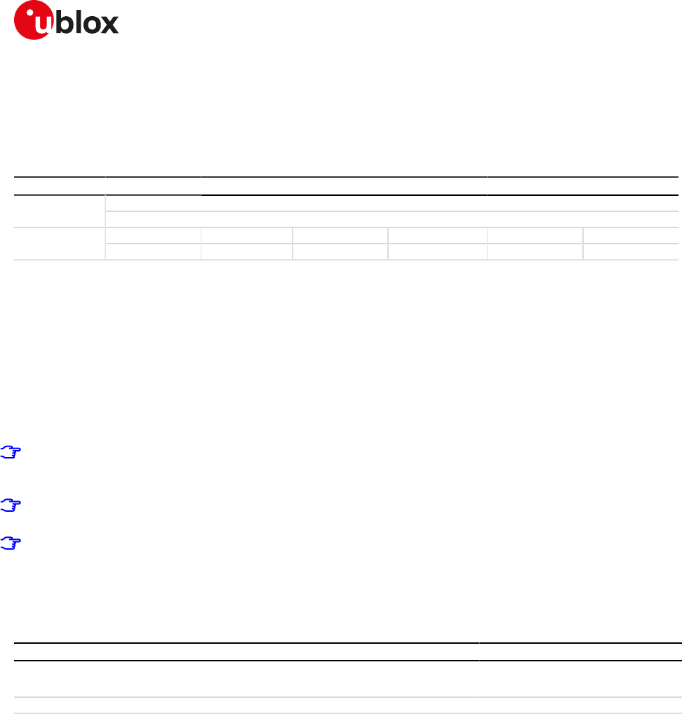
SARA-R4/N4 series-AT Commands Manual
UBX-17003787 - R09
14System features
Page 144 of 307
14System features
14.1Firmware installation +UFWINSTALL
+UFWINSTALL
SARA-R404M SARA-R410M-01B SARA-R410M-02B SARA-R410M-52B SARA-R412MModules
SARA-N4
Syntax PIN required Settings saved Can be aborted Response time Error referenceAttributes
full No No No - FW Install Error
14.1.1Description
Triggers the FW installation procedure, starting from the file (update binary file) stored in the module file
system. It could be used as a part of implementation of the FOTA procedure. The command causes a SW
system reset with network deregistration.
During the update process, the device cannot be used to make calls, even emergency calls. The update process
is fault tolerant, even if the battery is suddenly removed.
At the end of a successful installation, the main firmware software boots up, NVM and profiles data are set
to the factory-programmed values of the new firmware version and the SIM is reset (the PIN will be required
if enabled).
SARA-R4 / SARA-N4
Refer to the specific firmware update release notes for information concerning NVM after installing the
firmware.
Once the command has been sent correctly, the FW resets and at the next boot-up, the FW install will
start.
In case of power loss during the install phase, at the next module wake-up a fault is detected and the
module remains in Firmware Install Mode until the end of the procedure (install terminated).
The command syntax differs depending on the module: see the corresponding subsection for the correct
command handling.
14.1.2Syntax
Type Syntax Response Example
Set AT+UFWINSTALL OK AT+UFWINSTALL
OK
Test AT+UFWINSTALL=? OK OK
14.1.3Notes
SARA-R4 / SARA-N4
• After the command is issued, the module reboots and starts the install process which can take up to
20 minutes long. No result codes are issued on the terminal during this phase and both UART and USB
interfaces are unavailable for the communication. At the end of the update process the module reboots
again with the new firmware installed.
• Store the update file on the device; the procedure for storing is up to the user (+UFTPC, +UFWUPD or
+UDWNFILE).
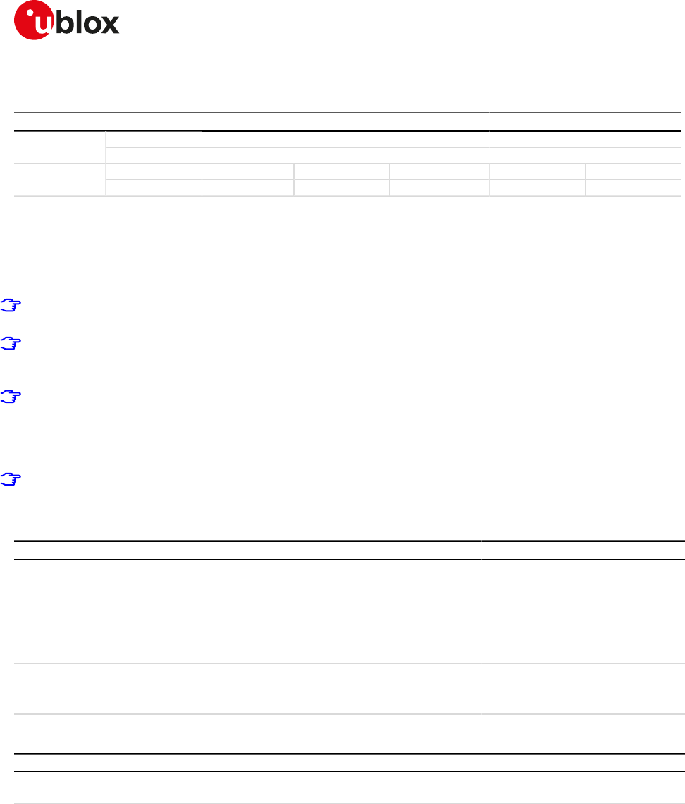
SARA-R4/N4 series-AT Commands Manual
UBX-17003787 - R09
14System features
Page 145 of 307
14.2Firmware update Over AT (FOAT) +UFWUPD
+UFWUPD
SARA-R404M SARA-R410M-01B SARA-R410M-02B SARA-R410M-52B SARA-R412MModules
SARA-N4
Syntax PIN required Settings saved Can be aborted Response time Error referenceAttributes
partial No No No - FOAT Error
14.2.1Description
Triggers the firmware update using the Xmodem or Xmodem-1k protocol.
The command syntax differs depending on the module series: see the corresponding subsection for the correct
command handling.
The errors (data corruption, data loss, etc.) during the Update phase are internally handled by the Xmodem
protocol itself; for more details about the error result codes, see FOAT error result codes.
If no data comes to the module after having issued the AT+UFWUPD command, up to ten NACK are sent
and then Firmware Update Mode is dropped out coming back to normal mode; the FW is unchanged and
still useable (ERROR1).
For more details, see the u-blox Firmware Update Application Note [86].
14.2.2Description
Making use of the file triggers the firmware download using the Xmodem or Xmodem-1k protocols.
In case of power loss during the download, at the next module wake-up the module remains in Firmware
Download Mode expecting that the download restarts from the beginning.
14.2.3Syntax
Type Syntax Response Example
Set AT+UFWUPD=<filetype> +UFWUPD: ONGOING
CCC<NACK><NACK><NACK>
<NACK><NACK><NACK><NACK>
<NACK><NACK><NACK>
OK
AT+UFWUPD=3
+UFWUPD: ONGOING
CCC<NACK><NACK><NACK>
<NACK><NACK><NACK><NACK>
<NACK><NACK><NACK>
OK
Test AT+UFWUPD=? +UFWUPD: (list of supported
<filetype>s)
OK
+UFWUPD: (3)
OK
14.2.4Defined values
Parameter Type Description
<filetype> Number Download type:
• 3: firmware image update
14.2.5Notes
SARA-R404M
• Status updates on the file transfer via CCC or <NACK><NACK><NACK> are not sent to the terminal.
SARA-R4/N4 series-AT Commands Manual
UBX-17003787 - R09
14System features
Page 146 of 307
14.3Antenna detection +UANTR
+UANTR
SARA-R404M SARA-R410M-01B SARA-R410M-02B SARA-R410M-52B SARA-R412MModules
SARA-N4
Syntax PIN required Settings saved Can be aborted Response time Error referenceAttributes
full No No No - +CME Error
14.3.1Description
Measures the DC component of load of the cellular antenna (the GPS antenna is RFU). The antenna load is
expressed in kOhm.
14.3.2Syntax
Type Syntax Response Example
Set AT+UANTR=[<antenna_id>] +UANTR: <antenna_id>,<antenna_
load>
OK
AT+UANTR=0
+UANTR: 0,10
OK
Test AT+UANTR=? +UANTR: (list of supported
<antenna_id>s)
OK
+UANTR: (0)
OK
14.3.3Defined values
Parameter Type Description
<antenna_id> Number Antenna identifier (optional parameter)
• 0 (default value): cellular antenna
• 1: GPS antenna (RFU)
<antenna_load> Number Measured value in kOhm of the antenna load with a resolution of 1 kOhm. The range
goes from -1 to 53 (only integer values can be assumed), where:
• -1: open circuit
• 0: short circuit
• 1: 1 kOhm (minimum limit of the measurement range)
...
• 53: 53 kOhm (maximum limit of the measurement range)
14.3.4Notes
• The load resistor values below the minimum limit of 1 kOhm are identified as short circuit (<antenna_
load>=0), while values above the maximum limit of 53 kOhm are identified as open circuit (<antenna_
load>=-1).
• The reported value could differ from the real resistance value of the diagnostic resistor mounted inside
the antenna assembly due to antenna cable length, antenna cable capacity and the measurement
method.
14.4Power saving control (Power SaVing) +UPSV
+UPSV
SARA-R410M-52BModules
SARA-N4
Syntax PIN required Settings saved Can be aborted Response time Error referenceAttributes
partial No Profile No - +CME Error
14.4.1Description
Sets the UART power saving configuration, but it has a global effect on the module power saving configuration:
• If the power saving is enabled (+UPSV: 4), the UART interface is disabled after 6 s of inactivity and the
module enters the idle mode automatically whenever possible
SARA-R4/N4 series-AT Commands Manual
UBX-17003787 - R09
14System features
Page 147 of 307
• If the power saving is disabled (+UPSV: 0), the UART interface is always enabled and the module does not
enter the idle mode
14.4.2Syntax
Type Syntax Response Example
Set AT+UPSV=<mode> OK AT+UPSV=4
OK
Read AT+UPSV? +UPSV: <mode>
OK
+UPSV: 0
OK
Test AT+UPSV=? +UPSV: (list of supported <mode>s)
OK
+UPSV: (0,4)
OK
14.4.3Defined values
Parameter Type Description
<mode> Number Power saving configuration. Allowed values:
• 0 (default and factory-programmed value): power saving disabled
• 4: power saving is controlled by the UART TX line activity
14.4.4Notes
• For a detailed explanation of modules' operating modes, modules and interfaces behavior in reference to
the +UPSV command setting, see the corresponding system integration manual.
14.5End user test +UTEST
+UTEST
SARA-R404M SARA-R410M-01B SARA-R410M-02B SARA-R410M-52B SARA-R412MModules
SARA-N4
Syntax PIN required Settings saved Can be aborted Response time Error referenceAttributes
full No No No - +CME Error
14.5.1Description
Enables the module testing on the RF parts and all the digital pins.
The usage of this command shall be restricted to controlled (shielded chamber/box) environments and
for test purposes only.
u blox assumes no responsibilities for the inappropriate use of this command.
14.5.2RF test description
Sets the module in non-signalling (or test) mode, or returns to the signalling (or normal) mode.
In test/non-signalling mode, the module switches off the protocol stack for performing single tests which could
not be performed during signalling mode.
Improper usage of this command on a real network could disturb other users and the network itself.
When entering the test mode, it is possible to sequentially trigger the following actions for testing purposes
(also depending on the RATs supported by the module):
• 2G transmission of a GSM burst sequence on the desired channel and power level (only one time slot
configuration is available)
• 2G transmission of an 8-PSK modulation burst sequence on the desired channel and power level (only one
time slot configuration is available)
• 3G transmission of a WCDMA signal on the desired channel and power level
• 4G transmission of an LTE SC-FDMA OFDM signal (5 MHz bandwidth) in the desired channel in the FDD
band and power level
SARA-R4/N4 series-AT Commands Manual
UBX-17003787 - R09
14System features
Page 148 of 307
• 4G transmission of LTE SC-FDMA OFDM signal (5 MHz bandwidth) in the desired channel in TDD band and
power level
• Receiving signal detection and RF level measurement on the desired 2G, 3G or 4G (LTE) channel
• Receiving signal detection at diversity or secondary antenna input and RF level measurement on the desired
2G, 3G or 4G (LTE) channel
The command only accepts the parameter set supported by the specific module version. When an
unsupported parameter is issued, an error result code will be provided ("+CME ERROR: operation not
supported" or "+CME ERROR: 4" depending on the +CMEE AT command setting).
The execution of these actions is performed in non-signalling mode. In non-signalling mode:
• The module only accepts +UTEST commands
SARA-R4 / SARA-N4
The module also accepts some non-signaling related commands. Although it is recommended that only
+UTEST commands are used.
In normal mode:
• The only allowed +UTEST command is the AT+UTEST=1 used to enable the testing interface
• All other +UTEST commands return an error result code ("+CME ERROR: operation not allowed" or "+CME
ERROR: 3" depending on the +CMEE AT command setting)
The module must not be registered with the network before entering the non-signalling mode, otherwise
an error result code ("+CME ERROR: operation not allowed" or "+CME ERROR: 3" depending on the +CMEE
AT command setting) is provided.
The +CMEE command can only be set in normal mode.
To return to the normal mode, perform one of these actions:
• A module reset
• Power off the module
• Send AT+UTEST=0
When the module returns the normal mode, the network registration status stored in the profile will be
restored.
See the End User Test Application Note [133] for further test command examples.
14.5.3Syntax
Type Syntax Response Example
If <mode>=0 or 1
OK
AT+UTEST=0
OK
Set AT+UTEST=<mode>,[<par1>],
[<par2>],[<par3>],[<par4>],[<par5>]
If <mode>=2 or 3
+UTEST: [<par1>,<par2>][,<par3>,
<par4>,<par5>][,<min>,<avg>,
<max>]
OK
AT+UTEST=2,124,250
+UTEST: 124,250,-80,-80,-80
OK
Read AT+UTEST? +UTEST: <mode>
OK
+UTEST: 1
OK
Test AT+UTEST=? +UTEST: (list of supported
<mode>s)
OK
+UTEST: (0-3)
OK
14.5.4Defined values
Parameter Type Description
<mode> Number Test mode setting:
• 0: the module returns to the module normal mode
• 1: the module enters non-signalling mode
• 2: RX test mode (measuring the antenna level estimation of the received RF signal)
• 3: TX test mode (GSMK/8-PSK burst or transmission in 3G bands)

SARA-R4/N4 series-AT Commands Manual
UBX-17003787 - R09
14System features
Page 149 of 307
Parameter Type Description
<par1>..<par5> Number Parameters needed for RX and TX test mode as reported in the table below.
14.5.5Notes
• Check the corresponding module data sheet for the list of supported bands and Radio Access
Technologies (RAT).
•RX mode setting (<mode>=2)
Parameter Description Range Default Notes
<par1> Channel 0 ÷ 165535 32 RX channel 2G RAT: for 850, 900, 1800 bands the value
corresponds to ARFCN while for 1900 band an offset of
32768 is added.
o [0-124]: GSM 900 MHz
o [128-251]: GSM 850 MHz
o [512-885]: DCS 1800 MHz
o [975-1023]: EGSM 900 MHz
o [33280-33578]: PCS 1900 MHz (corresponding to
ARFCN 512-810 range in band 1900)
RX channel 3G RAT: the value corresponds to UARFCN
except for band 19 where an offset of 20000 is added,
additional channels available in some 3G bands are not
supported.
o [1537-1738]: band 4 (1700 MHz)
o [2937-3088]: band 8 (900 MHz)
o [4357-4458]: band 5 (850 MHz)
o [4387-4413]: band 6 (800 MHz)
o [20712-20763]: band 19 (800 MHz)
o [9662-9938]: band 2 (1900 MHz)
o [10562-10838]: band 1 (2100 MHz)
o [10050-10125]: TD-SCDMA band 34 (2000 MHz)
o [9400-9600]: TD-SCDMA band 39 (1900 MHz)
RX channel 4G RAT: the value corresponds to EARFCN
with an offset of 100000.
<par1> range LTE band EARFCN range
[100000-100599] FDD 1 [0 - 599]
[100600-101199] FDD 2 [600 - 1199]
[101200-101949] FDD 3 [1200 - 1949]
[101950-102399] FDD 4 [1950 - 2399]
[102400-102649] FDD 5 [2400 - 2649]
[102650-102749] FDD 6 [2650 - 2749]
[102750-103449] FDD 7 [2750 - 3449]
[103450-103799] FDD 8 [3450 - 3799]
[103800-104149] FDD 9 [3800 - 4149]
[105010-105179] FDD 12 [5010 - 5179]
[105180-105279] FDD 13 [5180 - 5279]
[105730-105849] FDD 17 [5730 - 5849]
[106000-106149] FDD 19 [6000 - 6149]
[106150-106449] FDD 20 [6150 - 6449]
[108040 - 108689] FDD 25 [8040 - 8689]
[108690 - 109039] FDD 26 [8690 - 9039]
[109210-109659] FDD 28 [9210 - 9659]
[109660-109769] FDD 29 [9660 - 9769]
[136200-136349] TDD 34 [36200 - 36349]
[137750-138249] TDD 38 [37750 - 38249]
[138250-138649] TDD 39 [38250 - 38649]
[138650-139649] TDD 40 [38650 - 39649]
SARA-R4/N4 series-AT Commands Manual
UBX-17003787 - R09
14System features
Page 150 of 307
Parameter Description Range Default Notes
<par1> range LTE band EARFCN range
[139650-141589] TDD 41 [39650 - 41589]
Table 10: <par1> parameter range
The "+CME ERROR: operation not supported" or
"+CME ERROR: 4" error result code will be provided in
these cases (depending on the +CMEE AT command
setting):
o A value not belonging to the above ranges is
set
o The RX channel parameter value belongs to a
not supported RAT (2G or 3G or 4G RAT) or
band
<par2> Time 1 ÷ 600000 1000 Time interval for RX test expressed in ms
<par3> Antenna diversity 0 ÷ 1 0 Receiver path:
o 0: main / primary antenna
o 1: diversity / secondary antenna
The parameter is available only if supported, otherwise
an error result code will be provided ("+CME ERROR:
operation not supported" or "+CME ERROR: 4" depending
on the +CMEE AT command setting)
<min> Minimum antenna
RF level estimation
-100 ÷ -20 Expressed in dBm, for 2G RAT
SARA-R4 / SARA-N4
The range goes from -75 to -20.
<avg> Average antenna
RF level estimation
-100 ÷ -20 Expressed in dBm, for 2G RAT
SARA-R4 / SARA-N4
The range goes from -75 to -20.
<max> Maximum antenna
RF level estimation
-100 ÷ -20 Expressed in dBm, for 2G RAT
SARA-R4 / SARA-N4
The range goes from -75 to -20.
•TX mode setting (<mode>=3)
Parameter Description Range Default Notes
<par1> Tx channel 0 ÷ 165535 32 TX channel 2G RAT: for 850, 900, 1800 bands the value
corresponds to ARFCN while for 1900 band an offset of
32768 is added.
o [0-124]: GSM 900 MHz
o [128-251]: GSM 850 MHz
o [512-885]: DCS 1800 MHz
o [975-1023]: EGSM 900 MHz
o [33280-33578]: PCS 1900 MHz (corresponding to
ARFCN 512-810 range in band 1900)
TX channel 3G RAT: the value corresponds to UARFCN
except for the band 19 where an offset of 20000 is added,
additional channels available in some 3G bands are not
supported.
o [1312-1513]: band 4 (1700 MHz)
o [2712-2863]: band 8 (900 MHz)
o [4132-4233]: band 5 (850 MHz)
o [4162-4188]: band 6 (800 MHz)
o [20312-20363]: band 19 (800 MHz)
o [9262-9538]: band 2 (1900 MHz)
o [9612-9888]: band 1 (2100 MHz)
o [10050-10125]: TD-SCDMA band 34 (2000 MHz)
o [9400-9600]: TD-SCDMA band 39 (1900 MHz)
TX channel 4G RAT: the value corresponds to EARFCN
with an offset of 100000.
SARA-R4/N4 series-AT Commands Manual
UBX-17003787 - R09
14System features
Page 151 of 307
Parameter Description Range Default Notes
<par1> range LTE band EARFCN range
[118000-118599] FDD 1 [18000 - 18599]
[118600-119199] FDD 2 [18600 - 19199]
[119200-119949] FDD 3 [19200 - 19949]
[119950-120399] FDD 4 [19950 - 20399]
[120400-120649] FDD 5 [20400 - 20649]
[120650-120749] FDD 6 [20650 - 20749]
[120750-121449] FDD 7 [20750 - 21449]
[121450-121799] FDD 8 [21450 - 21799]
[121800-122149] FDD 9 [21800 - 22149]
[123010-123179] FDD 12 [23010 - 23179]
[123180-123279] FDD 13 [23180 - 23279]
[123730-123849] TDD 17 [23730 - 23849]
[124000-124149] FDD 19 [24000 - 24149]
[124150-124449] FDD 20 [24150 - 24449]
[126040 - 126689] FDD 25 [26040 - 26689]
[126690 - 127039] FDD 26 [26690 - 27039]
[127210-127659] FDD 28 [27210 - 27659]
[136200-136349] TDD 34 [36200 - 36349]
[137750-138249] TDD 38 [37750 - 38249]
[138250-138649] TDD 39 [38250 - 38649]
[138650-139649] TDD 40 [38650 - 39649]
[139650-141589] TDD 41 [39650 - 41589]
Table 11: <par1> parameter range
The "+CME ERROR: operation not supported" or
"+CME ERROR: 4" error result code will be provided in
these cases (depending on the +CMEE AT command
setting):
o A value not belonging to the above ranges is
set
o The TX channel parameter value belongs to a
not supported RAT (2G or 3G or 4G RAT) or
band
<par2> Power control level -56 ÷ 24 5 For 2G RAT: PCL (power control level). The allowed values
depend on the related <par1> value: lower numbers
means higher power level.
o [0-19]: GSM 850 and 900, if <par2> is less than 5 the
handling is the same for <par2>=5
o [0-15]: DCS 1800 and PCS 1900
In case <par4> is set to 2 (8-PSK modulation) the range
is as below. Other values are valid but behave as the
indicated level:
o [0-19]: GSM 850 and 900 if <par2> is less than 8 the
handling is the same for <par2>=8
o [0-15]: DCS 1800 and PCS 1900; if <par2> is less than
2 the handling is the same for <par2>=2
For 3G RAT: absolute output power [dBm]
o [-56 ÷ 24] for all the bands
For 4G RAT: absolute output power [dBm]
o [-40 ÷ 24] for all the bands
Only the values indicated in the above ranges are
valid, otherwise an error result code will be provided
("+CME ERROR: operation not supported" or "+CME
ERROR: 4" depending on the +CMEE AT command
setting).
SARA-R4/N4 series-AT Commands Manual
UBX-17003787 - R09
14System features
Page 152 of 307
Parameter Description Range Default Notes
<par3> Training sequence 0 ÷ 7 5 Training sequence to be used (to be changed only in case
of link with network simulator, else use default)
In 3G / 4G RAT the values is unused.
<par4> Modulation mode 1 ÷ 2 1 Modulation mode:
o 1: GMSK normal modulation including the training
sequence
o 2: 8-PSK normal modulation including the training
sequence
In 3G / 4G RAT the parameter is ignored.
LTE SC-FDMA OFDM modulation (5 MHz
bandwidth), FDD, is automatically set using for
<par1> an EARFCN value.
<par5> Time 0 ÷ 600000 1000 Time interval for TX test expressed in ms
o 0: burst sequence is continuously transmitted. In
this case the command will immediately return
the information text response. The command line
will be immediately available for any +UTEST
command. Provide AT+UTEST=1 command to
stop the burst sequence transmission, any other
+UTEST commands can be set and the current
sequence transmission is stopped.
14.5.6Examples
In RX mode test command examples the module provides the information text response after the timeout
issued in the set command.
Command Response Description
AT+UTEST=2 +UTEST: 32,1000,-89,-88,-87
OK
The module measures the antenna RX level at RX channel
32 band GSM 900 for 1 s interval.
In the example -89,-88,-87 are the antenna RF level
estimation: the numbers are just an example.
AT+UTEST=2,885,5000 +UTEST: 885,5000,-66,-65,-65
OK
The module measures the antenna RX level at RX channel
885 band DCS 1800 for 5 s interval.
AT+UTEST=2,10562,2000 +UTEST: 10562,2000,-60,-60,-
59
OK
The module measures the antenna RX level at RX channel
10562 band B1 for 2 s interval on the main antenna path.
AT+UTEST=2,10562 +UTEST: 10562,1000,0,-85,-85,
-85
OK
The module measures the antenna RX level at RX channel
10562 band B1 for 1 s interval on the main antenna path.
AT+UTEST=2,65,3000,0 +UTEST: 65,3000,0,-63,-62,-62
OK
The module measures the antenna RX level at RX channel
65 band GSM 900 for 3 s interval on the main antenna path.
AT+UTEST=2,4357,,1 +UTEST: 4357,1000,1,-51,-51,-51
OK
The module measures the antenna RX level at RX channel
4357 band B5 for 1 s interval on the diversity antenna path.
AT+UTEST=2,102174,500,0 +UTEST: 102174,500,0,-71,-70,-
70
OK
The module measures the antenna RX level at RX channel
2174 band FDD 4 for 0.5 s interval on the primary antenna
path.
AT+UTEST=2,105230,,1 +UTEST: 105230,1000,1,-72,-71,
-70
OK
The module measures the antenna RX level at RX channel
5230 band FDD 13 for 1 s interval on the secondary antenna
path.
Table 12: RX mode test command examples
Command Response Description
AT+UTEST=3,32,7,5 +UTEST: 32,7,5,1,1000
OK
The module will transmit for 1 s interval 1 slot burst
sequence at TX channel 32 GSM 900 at PCL 5 using
training sequence 5 and normal GMSK modulation.
SARA-R4/N4 series-AT Commands Manual
UBX-17003787 - R09
14System features
Page 153 of 307
Command Response Description
AT+UTEST=3,65,8,,2,5000 +UTEST: 65,8,5,2,5000
OK
The module will transmit for 5 s interval 1 slot burst
sequence at TX channel 65 GSM 900 at PCL 8 (gamma
6, 27 dBm) using training sequence 5 and normal 8-PSK
modulation.
AT+UTEST=3,660,,,,0 +UTEST: 660,5,5,1,0
OK
The module will transmit continuously 1 slot burst sequence
at TX channel 660 DCS 1800 at PCL 5 using training
sequence 5 and normal GMSK modulation.
AT+UTEST=3,9612,22,,,200
0
+UTEST: 9612,22,5,1,2000
OK
The module will transmit for 2 s interval at TX channel 9612
band B1 at 22 dBm power level using WCDMA modulation.
AT+UTEST=3,120399,15,,,
3000
+UTEST: 120399,15,5,1,3000
OK
The module transmits for 3 s interval at TX channel 20399
band FDD 4 at 15 dBm power level using SC-FDMA OFDM
modulation 5 MHz bandwidth.
AT+UTEST=3,123230,-10,,,0 +UTEST: 123230,-10,5,1,0
OK
The module continuously transmits at TX channel 23230
band FDD 13 at -10 dBm power level using SC-FDMA OFDM
modulation 5 MHz bandwidth.
Table 13: TX mode test command examples
14.5.7Digital pins testing description
Defines the commands to perform some verifications on all the digital pins of the u-blox cellular modules.
These pins can be considered as generic digital input / output pins; it is possible to configure one pin as a digital
output with "high" logic level and then verify the voltage level present. Conversely, it is possible set a pin as
a digital input, externally apply a "high" or "low" logic level and then check if the module is able to correctly
measure the voltage level applied.
After the execution of the AT+UTEST=10,5 command, it is possible to externally apply a voltage level to the
enabled input pins and / or measure the voltage level on the pins configured as digital input.
These commands are intended for production to check the correct digital pins behavior, detect possible
soldering or functional problems and can be executed only in non-signalling mode (otherwise the "+CME
ERROR: operation not allowed" or "+CME ERROR: 3" error result code - depending on the +CMEE AT
command setting - is issued without performing any operations).
Do not exceed the values reported in the Generic Digital Interface section of the module data sheet
when testing a pin as a digital input pin, since stressing the device above the listed ratings may cause a
permanent damage of the module.
SARA-R4 / SARA-N4
See the End User Test Application Note [133] and the corresponding module data sheet for the list of pins
available for testing and their levels characteristics and further test command examples.
14.5.8Syntax
Type Syntax Response Example
Digital pins testing generic syntax
Set AT+UTEST=10,<op_code>[,[<bit_
padding>]<pin_seq>]
OK AT+UTEST=10,3,"0000001000000
300"
OK
Original configuration restoring
Set AT+UTEST=10,0 OK AT+UTEST=10,0
OK
Pins set definition
Set AT+UTEST=10,2,[<bit_
padding>]<pin_seq>
OK AT+UTEST=10,2,"0000000C30000
0003000"
OK
Pins configuration
Set AT+UTEST=10,3,[<bit_
padding>]<pin_seq>
OK AT+UTEST=10,3,"0000000420000
0001000"
OK

SARA-R4/N4 series-AT Commands Manual
UBX-17003787 - R09
14System features
Page 154 of 307
Type Syntax Response Example
Output pins definition
Set AT+UTEST=10,4,[<bit_
padding>]<pin_seq>
OK AT+UTEST=10,4,"00000000100000
002000"
OK
Digital testing execution
Set AT+UTEST=10,5 OK AT+UTEST=10,5
OK
Digital value measurement
Set AT+UTEST=10,6 <bit_padding>]<pin_seq>
OK
AT+UTEST=10,6
00000004100000003000
OK
Read AT+UTEST? +UTEST: <mode>
OK
+UTEST: 1
OK
Test AT+UTEST=? +UTEST: (list of supported
<mode>s)
OK
+UTEST: (0-3)
OK
14.5.9Defined values
Parameter Type Description
<op_code> Number Test mode setting:
• 0: exits the test interface and restore the pins to the original configuration
• 2: defines a set of pins that will be tested and initialize these pins to be ready
for testing. The original pins configuration is kept for final restore. In the [<bit_
padding>]<pin_seq> parameter use this notation to represent each module pin
with its binary digit:
o 0: the pin will not be tested
o 1: the pin will be tested (as digital input or output)
• 3: configures the logical pins previously enabled for testing as output or input; the
command has effect only if AT+UTEST=10,2 has been previously issued.
In case a not enabled pin is set as digital input or output, the command does not
return an error and the setting is not applied. In the [<bit_padding>]<pin_seq>
parameter use this notation to represent each module pin with its binary digit:
o 0: the pin will be set as an output
o 1: the pin will be set as an input
• 4: configures the value of the output pins under testing; the command has
effect only if AT+UTEST=10,3 has been previously issued; The command is not
mandatory if there are not output pins to configure. In the [<bit_padding>]<pin_
seq> parameter use this notation to represent each module pin with its binary digit:
o 0: the pin will output a "low" logic level
o 1: the pin will output a "high" logic level
• 5: apply the setting change defined with <op_code>= 2 / 3 / 4 and triggers the
execution of the digital testing. Digital testing of the pins is possible only after the
execution of the AT+UTEST=10,5 command.
• 6: returns the logic value of pins under testing (both input and output); in the [<bit_
padding>]<pin_seq> parameter use this notation to represent each module pin
with its binary digit:
o 0: "low" logic digital level measured at the module pin
o 1: "high" logic digital level measured at the module pin
[<bit_
padding>]<pin_seq>
Number Sequence of hexadecimal digits containing the pin information and the action to
execute:
• SARA-R4 / SARA-N4 - See the Notes and End User Test Application Note [133] for
detailed number description
14.5.10Notes
• Consider these steps to construct the [<bit_padding>]<pin_seq> sequence:
o Consider the total number of the module's pins available
SARA-R4/N4 series-AT Commands Manual
UBX-17003787 - R09
14System features
Page 155 of 307
- SARA-R4 / SARA-N4 - 64 pins
o When a non-testable pin is selected, the command does not return an error result code but the value is
not considered and not applied.
o The status of the n-th pin will be represented by the corresponding n-th bit; see the <op_code>
description for the notation of each mode setting
o Convert each group of four binary digits into its hexadecimal representation
SARA-R4 / SARA-N4
See the End User Test Application Note [133] for the list of pins available for testing.
• An example of the AT commands sequence to test the digital pins is reported in Table 14.
Command Response Description
Configure the formatting of the error result code by
means of +CMEE AT command
AT+COPS=2 OK Deregister the module from the network
AT+UTEST=1 OK The module enters the test mode
AT+UTEST=10,2,"000007F400
C000D83F00"
OK The command puts the module in Interface initialised
state; the command saves the pins status to restore it
at the end of the test.
Pins enabled for testing: DSR, RI, DCD, DTR, RTS, CTS,
GPIO1, GPIO2, GPIO3, GPIO4, I2S1_RXD/GPIO6, I2S1_TXD/
GPIO7, GPIO5, I2S1_CLK/GPIO8, I2S1_WA/GPIO9, SPI_
SCLK/GPIO10, SPI_MOSI/GPIO11, SPI_MISO/GPIO12, SPI_
SRDY/GPIO13, SPI_MRDY/GPIO14
AT+UTEST=10,3,"0000049400
4000C01800"
OK Pins configuration:
o DTR, RTS, GPIO3, GPIO4, I2S1_RXD/GPIO6, GPIO5,
I2S1_CLK/GPIO8, SPI_MOSI/GPIO11, SPI_MRDY/
GPIO14 as input
o DSR, RI, DCD, CTS, GPIO1, GPIO2, I2S1_TXD/
GPIO7, I2S1_WA/GPIO9, SPI_SCLK/GPIO10, SPI_
MISO/GPIO12, SPI_SRDY/GPIO13 as output
AT+UTEST=10,4,"0000036000
8000182700"
OK Digital logic value of the output pins:
o DSR, RI, DCD, CTS, GPIO1, GPIO2, I2S1_TXD/
GPIO7, I2S1_WA/GPIO9, SPI_SCLK/GPIO10, SPI_
MISO/GPIO12, SPI_SRDY/GPIO13 set to "high".
AT+UTEST=10,5 OK Configurations made by AT+UTEST=10,2; AT+UTEST=
10,3 and AT+UTEST=10,4 are executed.
AT+UTEST=10,6 000007F400C000D83F00
OK
Logic digital value measured at modules pins:
o DSR, RI, DCD, DTR, RTS, CTS, GPIO1, GPIO2, GPIO3,
GPIO4, I2S1_RXD/GPIO6, I2S1_TXD/GPIO7, GPIO5,
I2S1_CLK/GPIO8, I2S1_WA/GPIO9, SPI_SCLK/GPIO10
, SPI_MOSI/GPIO11, SPI_MISO/GPIO12, SPI_SRDY/
GPIO13, SPI_MRDY/GPIO14: "high" level detected
AT+UTEST=0 OK Module exits from the test mode and normal pins
configurations is restored.
Table 14: Digital pins test command examples
The digital pins can be configured as many times as needed by the testing process; AT+UTEST=10,2
command is not needed any more as the DUT is already in Interface initialised state.
14.6Internal temperature monitor +UTEMP
+UTEMP
SARA-R410M-52BModules
SARA-N4
Syntax PIN required Settings saved Can be aborted Response time Error referenceAttributes
partial No No No - +CME Error
14.6.1Description
Returns the values of internal temperature sensors of the specified unit.
SARA-R4/N4 series-AT Commands Manual
UBX-17003787 - R09
14System features
Page 156 of 307
The command handling (sensors position and command syntax) depends on the module series:
• SARA-R4 / SARA-N4 - The AT command returns the value measured by the temperature sensor close to
the oscillator (XO).
14.6.2Syntax
Type Syntax Response Example
Set AT+UTEMP=<unit> +UTEMP: <pmic_temp>
OK
AT+UTEMP=0
+UTEMP: 310
OK
Test AT+UTEMP=? +UTEMP: (list of supported <unit>)
OK
+UTEMP: (0-1)
OK
14.6.3Defined values
Parameter Type Description
<unit> Number Select the measurement unit for value representation:
• 0: values in tenth of Celsius degrees returned
• 1: values in tenth of Fahrenheit degrees returned
<pmic_temp> Number Fetched value of XO temperature of the selected measurement unit; the allowed
range depends on the measurement unit:
• Celsius degrees: [-40; 140]
• Fahrenheit degrees: [-40; 284]
• 655355: no valid temperature measure is available
14.7Power Saving Mode Setting +CPSMS
+CPSMS
SARA-R404M SARA-R410M-01B SARA-R410M-02B SARA-R410M-52B SARA-R412MModules
SARA-N4
Syntax PIN required Settings saved Can be aborted Response time Error referenceAttributes
partial Yes NVM No < 10 s +CME Error
14.7.1Description
Enable the UEs power saving mode (PSM) and configures the corresponding parameters. The command
configures the PSM on the UE, as well as:
• the requested extended periodic RAU value in GERAN/UTRAN
• the requested GPRS READY timer value in GERAN/UTRAN
• the requested extended periodic TAU value in E-UTRAN
• the requested Active Time value
See the URCs provided by command +CEREG for the Active Time value and the extended periodic TAU value
that are allocated to the UE by the network in E-UTRAN.
Use the read command to get the assigned values from the network:
• If the power saving mode is enabled (+CPSMS: 1), everything on the device will power down except the
real-time clock (RTC) after the expiry of T3324 (Active Time). It will stay powered down until the expiry of
T3412 (Extended TAU Timer) or if the Power On line is toggled.
• If the power saving mode is disabled (+CPSMS: 0), the device will not enter Power Save Mode (PSM)
SARA-R4
The URCs provided by the +CEREG AT commands for the Active Time value and the extended periodic
TAU value are not supported.
SARA-R4
The read command will return the requested values. See the +UCPSMS AT command to get the values
assigned from the network.

SARA-R4/N4 series-AT Commands Manual
UBX-17003787 - R09
14System features
Page 157 of 307
14.7.2Syntax
Type Syntax Response Example
Set AT+CPSMS=[<mode>[,
<Requested_Periodic_RAU>[,
<Requested_GPRS_READY_timer>[,
<Requested_Periodic_TAU>[,
<Requested_Active_Time>]]]]]
OK AT+CPSMS=1,,,"01000011","010000
11"
OK
Read AT+CPSMS? +CPSMS: <mode>,[<Requested_
Periodic_RAU>],[<Requested_
GPRS_READY_timer>],
[<Requested_Periodic_TAU>],
[<Requested_Active_Time>]
OK
+CPSMS: 1,,,"01000011","01000011"
OK
Test AT+CPSMS=? +CPSMS: (list of supported
<mode>s),(list of supported
<Requested_Periodic_RAU>s),(list
of supported <Requested_GPRS_
READY_timer>s),(list of supported
<Requested_Periodic_TAU>s),(list
of supported <Requested_Active_
Time>s)
OK
+CPSMS: (0,1,2),,,("00000000"-
"11111111"),("00000000"-"11111111")
OK
14.7.3Defined values
Parameter Type Description
<mode> Number Indication to disable or enable the use of PSM in the UE. Allowed values:
• 0 (default and factory-programmed value): disable the use of PSM
• 1: enable the use of PSM
• 2: disable the use of PSM and reset all parameters for PSM to factory-programmed
values.
<Requested_
Periodic_RAU>
String Requested extended periodic RAU (T3312) value to be allocated to the GERAN/
UTRAN, one byte in an 8 bit format. For the coding and the value range, see the GPRS
Timer 3 IE in 3GPP TS 24.008 [12]
<Requested_GPRS_
READY_timer>
String Requested GPRS READY timer (T3314) value to be allocated to the UE in GERAN/
UTRAN, one byte in an 8 bit format. For the coding and the value range, see the GPRS
Timer 3 IE in 3GPP TS 24.008 [12]
<Requested_
Periodic_TAU>
String One byte in an 8 bit format. Requested extended periodic TAU value (T3412) to be
allocated to the device in E-UTRAN. The requested extended periodic TAU value is
coded as one byte (octet 3) of the GPRS Timer 3 information element coded as bit
format (e.g. "01000111" equals 70 hours). For the coding and the value range, see the
GPRS Timer 3 IE in 3GPP TS 24.008 Table 10.5.163a/3GPP TS 24.008 [12]. See also
3GPP TS 23.682 [153] and 3GPP TS 23.401 [154].
• SARA-R4 - The factory-programmed value is 150 s. The default value is "01100000".
<Requested_Active_
Time>
String One byte in an 8 bit format. Requested Active Time value (T3324) to be allocated to
the UE. The requested Active Time value is coded as one byte (octet 3) of the GPRS
Timer 2 information element coded as bit format (e.g. "00100100" equals 4 minutes).
For the coding and the value range, see the GPRS Timer 2 IE in 3GPP TS 24.008 Table
10.5.163/3GPP TS 24.008 [12]. See also 3GPP TS 23.682 [153], 3GPP TS 23.060 [10]
and 3GPP TS 23.401 [154].
• SARA-R4 - The factory-programmed value is 6 s. The default value is "00000000".
14.7.4Notes
• The <Requested_Periodic_RAU> and <Requested_GPRS_READY_timer> parameters are not supported.
SARA-R4
• <mode>= 2 is not supported.
• Reboot the module after enabling the Power Save Mode in order to enter the PSM state.
• The PSM mode cannot be enabled with a PIN enabled UICC card.
SARA-R4/N4 series-AT Commands Manual
UBX-17003787 - R09
14System features
Page 158 of 307
14.8Power Saving Mode Assigned Values +UCPSMS
+UCPSMS
SARA-R410M-01B SARA-R410M-02B SARA-R410M-52B SARA-R412MModules
SARA-N4
Syntax PIN required Settings saved Can be aborted Response time Error referenceAttributes
full Yes No No - +CME Error
14.8.1Description
Reads the UEs power saving mode (PSM) parameters assigned by the network. The command returns the
state of PSM on the UE, as well as:
• the requested extended periodic RAU value in GERAN/UTRAN
• the requested GPRS READY timer value in GERAN/UTRAN
• the requested extended periodic TAU value in E-UTRAN
• the requested Active Time value
To be noticed that
• Power saving mode enabled (+UCPSMS: 1): everything on the device is powered down except for the Real
Time Clock (RTC) after the expiry of T3324 (Active Time). It will stay powered down until the expiry of T3412
(Extended TAU Timer) or if the Power On line is toggled.
• Power saving mode disabled (+UCPSMS: 0): the device will not enter the Power Save Mode (PSM).
14.8.2Syntax
Type Syntax Response Example
Read AT+UCPSMS? +UCPSMS: <mode>,[<Assigned_
Periodic_RAU>],[<Assigned_GPRS_
READY_timer>],[<Assigned_
Periodic_TAU>],[<Assigned_Active_
Time>]
OK
+UCPSMS: 1,,,"01000011","01000011"
OK
14.8.3Defined values
Parameter Type Description
<mode> Number Indication to disable or enable the use of PSM in the UE. Allowed values:
• 0: use of PSM disabled
• 1: use of PSM enabled
<Assigned_Periodic_
RAU>
String Assigned extended periodic RAU (T3312) value allocated to the GERAN/UTRAN, one
byte in an 8 bit format. For the coding and the value range, see the GPRS Timer 3 IE in
3GPP TS 24.008 [12]
<Assigned_GPRS_
READY_timer>
String Assigned GPRS READY timer (T3314) value allocated to the UE in GERAN/UTRAN,
one byte in an 8 bit format. For the coding and the value range, see the GPRS Timer 3
IE in 3GPP TS 24.008 [12]
<Assigned_Periodic_
TAU>
String One byte in an 8 bit format. Assigned extended periodic TAU value (T3412) allocated
to the device in E-UTRAN. The Assigned extended periodic TAU value is coded as one
byte (octet 3) of the GPRS Timer 3 information element coded as bit format (e.g. "0
1000111" equals 70 hours). For the coding and the value range, see the GPRS Timer 3
IE in 3GPP TS 24.008 Table 10.5.163a/3GPP TS 24.008 [12]. See also 3GPP TS 23.682
[153] and 3GPP TS 23.401 [154].
<Assigned_Active_
Time>
String One byte in an 8 bit format. Assigned Active Time value (T3324) allocated to the UE.
The Assigned Active Time value is coded as one byte (octet 3) of the GPRS Timer
2 information element coded as bit format (e.g. "00100100" equals 4 minutes). For
the coding and the value range, see the GPRS Timer 2 IE in 3GPP TS 24.008 Table 10
.5.163/3GPP TS 24.008 [12]. See also 3GPP TS 23.682 [153], 3GPP TS 23.060 [10] and
3GPP TS 23.401 [154].
14.8.4Notes
SARA-R4 / SARA-N4
• <Assigned_Periodic_RAU> and <Assigned_GPRS_READY_timer> are not supported.
SARA-R4/N4 series-AT Commands Manual
UBX-17003787 - R09
14System features
Page 159 of 307
14.9Set LWM2M FOTA URCs +ULWM2MSTAT
+ULWM2MSTAT
SARA-R404M SARA-R410M-01B SARA-R410M-02B SARA-R410M-52B SARA-R412MModules
SARA-N4
Syntax PIN required Settings saved Can be aborted Response time Error referenceAttributes
full Yes NVM No - -
14.9.1Description
Allows enabling or disabling of LWM2M FOTA status URCs.
14.9.2Syntax
Type Syntax Response Example
Set AT+ULWM2MSTAT=<n> OK AT+ULWM2MSTAT=1
OK
Read AT+ULWM2MSTAT? +ULWM2MSTAT: <n>
OK
+ULWM2MSTAT: 1
OK
Test AT+ULWM2MSTAT=? +ULWM2MSTAT: (list of supported
<n>s)
OK
+ULWM2MSTAT: (0,1)
OK
URC +ULWM2MSTAT: <stat>,<percent> +ULWM2MSTAT: 1,99
14.9.3Defined values
Parameter Type Description
<n> Number Mode configuration:
• 0: LWM2M FOTA status URC disabled
• 1 (default value): LWM2M FOTA status +ULWM2MSTAT URC enabled
<stat> Number LWM2M FOTA status:
• 1: FOTA download in progress
• 2: FOTA download complete
<percent> Number Percentage of FOTA download completed
14.10Cancel LWM2M FOTA Download +ULWM2M=0
+ULWM2M=0
SARA-R404M SARA-R410M-01B SARA-R410M-02B SARA-R410M-52B SARA-R412MModules
SARA-N4
Syntax PIN required Settings saved Can be aborted Response time Error referenceAttributes
full Yes No No - -
14.10.1Description
When a LWM2M session is in progress and the firmware is being download to the device, the download can be
canceled by issuing this command. To make use of this command, URCs for LWM2M FOTA sessions must be
enabled. See +ULWM2MSTAT for details on enabling LWM2M URCs.
14.10.2Syntax
Type Syntax Response Example
Set AT+ULWM2M=0 OK AT+ULWM2M=0
OK
SARA-R4/N4 series-AT Commands Manual
UBX-17003787 - R09
14System features
Page 160 of 307
14.11LWM2M configuration +UFOTACONF
+UFOTACONF
SARA-R410M-52BModules
SARA-N4
Syntax PIN required Settings saved Can be aborted Response time Error referenceAttributes
full No NVM No - +CME Error
14.11.1Description
Configures the uFOTA registration and timer for periodic connections to the uFOTA server.
14.11.2Syntax
Type Syntax Response Example
Generic syntax
Set AT+UFOTACONF=<mode>,
<param>
OK AT+UFOTACONF=2,604800
OK
uFOTA registration
Set AT+UFOTACONF=1,<registration> OK AT+UFOTACONF=1,1
OK
uFOTA periodic connection
Set AT+UFOTACONF=2,<timer> OK AT+UFOTACONF=2,604800
OK
Read AT+UFOTACONF=<mode> +UFOTACONF: <mode>,<param>
OK
+UFOTACONF: 1,1
OK
Test AT+UFOTACONF=? +UFOTACONF: (list of supported
<mode>s),(list of supported
<param>s)
OK
+UFOTACONF: (1-2),(-1,1-
4294967295)
OK
14.11.3Defined values
Parameter Type Description
<mode> Number uFOTA parameter to be configured:
• 1: module registration to uFOTA server
• 2: timer for periodic connection to the uFOTA server
<registration> Number uFOTA registration:
• 0: module registration to uFOTA server disabled
• 1 (factory-programmed and default value): module registration to uFOTA server
enabled
<timer> Number Timer for periodic connection to the uFOTA server (in seconds); the factory-
programmed and default value is 604800 (7 days):
• -1: never periodically connected to the uFOTA server
• 1-4294967295: range in seconds for periodic connections
<param> Number /
String
Type and supported content depend on the related <op_code> parameter; details are
given above
SARA-R4/N4 series-AT Commands Manual
UBX-17003787 - R09
14System features
Page 161 of 307
14.12Last gasp configuration +ULGASP
+ULGASP
SARA-R410M-52BModules
SARA-N4
Syntax PIN required Settings saved Can be aborted Response time Error referenceAttributes
partial No NVM No < 10 s +CME Error
14.12.1Description
The command enables/disables and configures the last gasp feature. The application is automatically
triggered by a properly configured GPIO (see GPIO Introduction). The feature supports the sending of a
predefined last notification in case of power outage, just before the power goes off. It is assumed that the
cellular module is registered to the network when the alarm is triggered; however the command just configures
the feature so it is possible to issue it also if PIN is not inserted. It is possible to enable/disable the +UULGASP
URC in order to be notified about the operation result.
This AT command must be issued after a proper configuration of the GPIO has been performed via the
+UGPIOC command. Otherwise, if +UGPIOC is issued after +ULGASP, the Last Gasp will work only after
a reboot.
The parameters will be set to the values stored in the NVM in case they are omitted in the set command.
14.12.2Syntax
Type Syntax Response Example
Set AT+ULGASP=<GPIO_mode>,
<text>,<msg_format>,,<profile_id>,
<IP_protocol>,<IP_addr:PORT>[,
[<method>],,[<urc_enable>],[<nv_
upd_freq>],[<tx_count>]]
OK AT+ULGASP=0,"Power_loss",0,,1,17,
"192.168.100.20:8080"
OK
Read AT+ULGASP? +ULGASP: <GPIO_mode>,<text>,
<msg_format>,,<profile_ID>,
<IP_protocol>,<IP_addr:PORT>,
<method>,,<urc_enable>,<nv_upd_
freq>,<tx_count>
OK
+ULGASP: 0,"Power_loss",0,,1,17,
"192.168.100.20:8080",1,,1,0,1
OK
Test AT+ULGASP=? +ULGASP: (list of supported <GPIO_
mode>'s),,(list of supported <msg_
format>'s),,(list of supported
<profile_id>'s),(list of supported
<IP_protocol>'s),,(list of supported
<method>'s),,(list of supported <
urc_enable>'s),(list of supported
<nv_upd_freq>'s),(list of supported
<tx_count>'s)
OK
+ULGASP: (0-2),,(0-1),,(1),(17),,(1),,(0-
1),(0-3600),(1-10)
OK
URC +UULGASP: <result>,<bearer> +UULGASP: 0,1
14.12.3Defined values
Parameter Type Description
<GPIO_mode> Number Select the interrupt trigger. Allowed values:
• 0 (factory-programmed value): trigger disabled; the following arguments will be
ignored.
• 1: falling edge
• 2: rising edge
<text> String The string that will be sent upon GPIO movement. Text or binary format can be
selected with the <msg_format> parameter. When text format is selected, a
maximum of 256 ASCII chars is allowed. When the binary format is selected, a
maximum of 512 chars (0-9,A-F) is allowed. Every 8-bit octet of the message must be
written as two IRA character long hexadecimal numbers, e.g. an octet with integer
value 42 (i.e. 0x2A) must be written as a string of two characters "2A" (IRA 50 and 65).
SARA-R4/N4 series-AT Commands Manual
UBX-17003787 - R09
14System features
Page 162 of 307
Parameter Type Description
Factory-programmed value: empty string.
<msg_format> Number Format of the <text> parameter. Allowed values:
• 0 (factory-programmed value): text
• 1: binary
<profile_id> Number PSD profile identifier. Only the value 1 is allowed.
<IP_protocol> Number IP protocol used for socket connection. Allowed values:
• 17: UDP
<IP_addr:PORT> String IPv4 or IPv6 server address with the socket port.
Factory-programmed value: empty string.
<method> Number Notification method, it is the way the application send out the <text message>.
Allowed values:
• 1: use IP (TCP or UDP) connection
<urc_enable> Number Flag determining if the URC is to be issued or not. Allowed values:
• 0: disabled
• 1 (factory-programmed value): enabled
<result> Number Operation result. Allowed values:
• 0: success
• 1: generic fail
<bearer> Number Notification used bearer. Allowed values:
• 1: IP (TCP or UDP) connection
<nv_upd_freq> Number NVM update frequency in seconds. Valid range of 0-3600 seconds indicating how
frequently to flush the settings to NVM. A zero value indicates that settings should
never be saved to NVM, otherwise the following settings will be saved to NVM based
on the timer: <GPIO_mode>, <text>, <IP_addr:PORT>, <urc_enable>, <tx_count>.
Factory-programmed value: 60.
<tx_count> Number Indicates the number of times to transmit the last gasp message. Valid range is 1-10.
Factory-programmed value: 1.
14.12.4Notes
SARA-R410M-52B / SARA-N4
• The <urc_enable>,<nv_upd_freq>,<tx_count> parameters will return 0, 0 and 0 if read for the first time
before setting the mandatory last gasp parameters. Once the mandatory last gasp parameters are set,
these values take on the factory-programmed values.
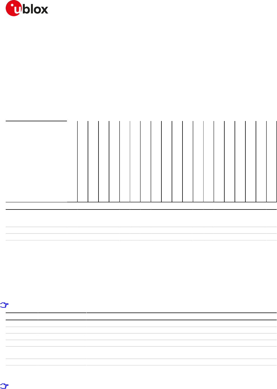
SARA-R4/N4 series-AT Commands Manual
UBX-17003787 - R09
15GPIO
Page 163 of 307
15GPIO
15.1Introduction
The section describes the AT commands used to configure the GPIO pins provided by u-blox cellular modules.
15.1.1GPIO functions
On u-blox cellular modules, GPIO pins can be opportunely configured as general purpose input or output.
Moreover GPIO pins of u-blox cellular modules can be configured to provide custom functions via +UGPIOC
AT command. The custom functions availability can vary depending on the u-blox cellular modules series and
version: see Table 15 for an overview of the custom functions supported by u-blox cellular modules.
<gpio_mode>
Output
Input
Network status indication
GNSS supply enable
GNSS data ready
GNSS RTC sharing
Jamming detection
SIM card detection
Headset detection
GSM Tx burst indication
Module operating status indication
Module functionality status indication
I2S digital audio interface
SPI serial interface
Master clock generation
UART (DSR, DTR, DCD and RI) interface
Wi-Fi enable
Ring indication
Last gasp enable
Pad disabled
0 1 2 3 4 5 6 7 8 9 10 11 12 13 14 15 16 18 19 255
SARA-R404M / SARA-
R412M / SARA-R410M-0
1B / SARA-R410M-02B
* * * * * *
SARA-R410M-52B * * * * * * *
SARA-N4 * * * * * * *
Table 15: GPIO custom functions overview
The configuration of the GPIO pins (i.e. the setting of the parameters of the +UGPIOC AT command) is saved
in the NVM and used at the next power-on.
15.1.2GPIO mapping
The number of available GPIO pins and their mapping can vary depending on the u-blox cellular modules series
and version. The GPIOs mapping for different u-blox cellular modules is reported in the following tables.
See the corresponding module system integration manual for the functions supported by each GPIO.
<gpio_id> Pin name Pin number Factory-programmed function Remarks
16 GPIO1 16 Pin disabled -
23 GPIO2 23 Pin disabled -
24 GPIO3 24 Pin disabled -
25 GPIO4 25 Pin disabled -
42 GPIO5 42 Pin disabled Only pin 42 can be configured for
SIM card detection functionality
19 GPIO6 19 Pin disabled -
Table 16: SARA-R4 / SARA-N4 series GPIO mapping
SARA-R4 / SARA-N4
When the SIM card detection functionality is enabled, the +CIND AT command reports the status.
When the SIM card detection functionality is enabled, the status can be read with the +UGPIOR AT
command.
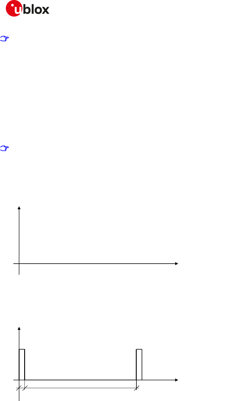
SARA-R4/N4 series-AT Commands Manual
UBX-17003787 - R09
15GPIO
Page 164 of 307
See the corresponding module system integration manual for the complete overview of all allowed
configurations.
15.1.3Network status indication
When a GPIO pin is configured to provide network status indication, its progress depends on the CS network
registration state (see +CREG) and on the module transmission state:
• No service: indicates no network coverage or not registered state
• Registered home network 2G: indicates registered state on home network in 2G RAT
• Registered home network 3G: indicates registered state on home network in 3G RAT
• Registered home network Cat NB1: indicates registered state on home network in Cat NB1
• Registered roaming 2G: indicates registered state with visitor 2G network (roaming in 2G RAT)
• Registered roaming 3G: indicates registered state with visitor 3G network (roaming in 3G RAT)
• Registered roaming Cat NB1: indicates registered state with visitor Cat NB1 network (roaming in Cat NB1)
• Data transmission: indicates voice or data call active either in 2G, 3G or 4G RAT
• Data transmission roaming: indicates voice or data call active either in 2G, 3G or 4G RAT with visitor network
SARA-R4 / SARA-N4
When registered on 4G (LTE) network, the GPIO pin progress is the same as for data transmission (Figure
8) because a PDP context/EPS bearer is available.
The following figures report the allowed progresses for GPIO pin set as network indication: VH and VL values
are provided in the corresponding module data sheet in the "Generic Digital Interfaces pins" section.
15.1.3.1No service (no network coverage or not registered)
• Continuous Output / Low
Time
Voltage
V
H
V
L
Figure 1: GPIO pin progress for no service
15.1.3.2Registered home network 2G
• Cyclic Output / High for 100 ms, Output / Low for 2 s
Time
Voltage
V
H
V
L
2 s
100
ms
Figure 2: GPIO pin progress for registered home network 2G
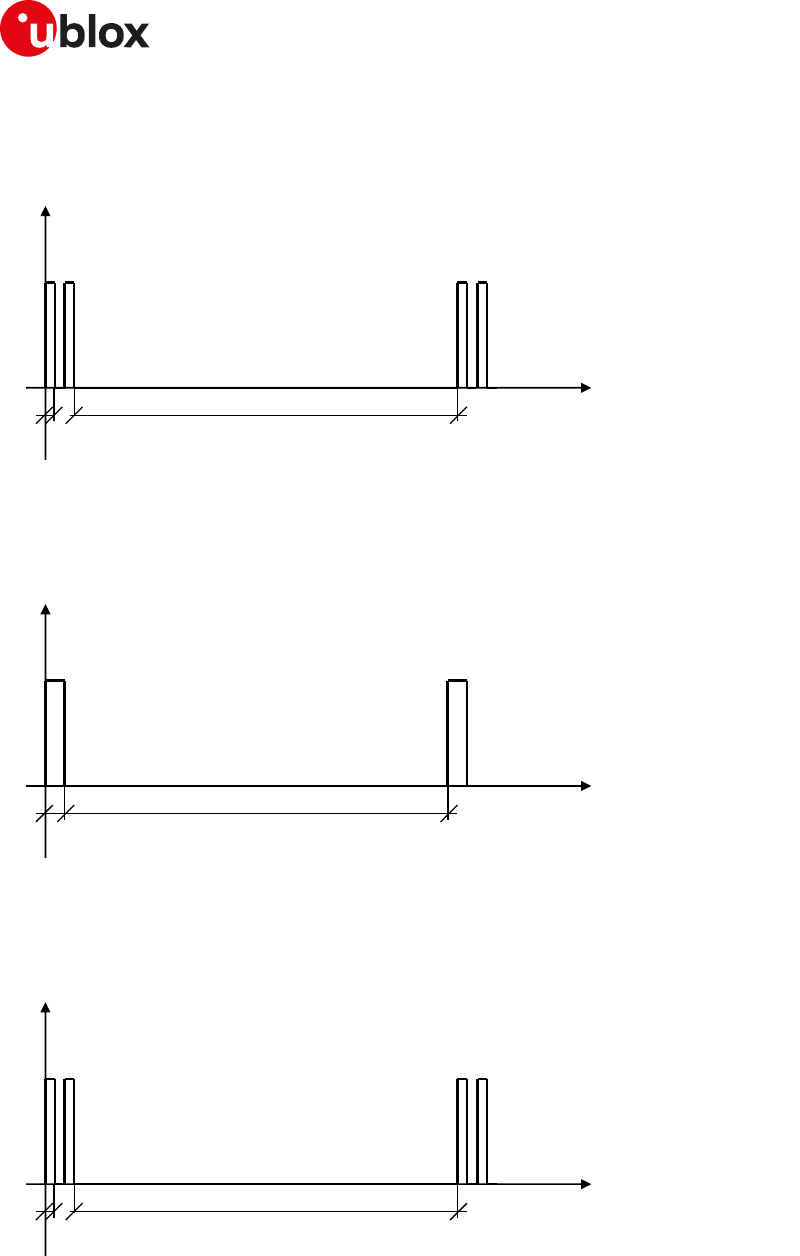
SARA-R4/N4 series-AT Commands Manual
UBX-17003787 - R09
15GPIO
Page 165 of 307
15.1.3.3Registered home network 3G
• Cyclic Output / High for 50 ms, Output / Low for 50 ms, Output / High for 50 ms, Output / Low for 2 s
Time
Voltage
V
H
V
L
2 s
50
ms
Figure 3: GPIO pin progress for registered home network 3G
15.1.3.4Registered home network Cat NB1
• Cyclic Output / High for 100 ms, Output / Low for 30 s
Time
Voltage
V
H
V
L
30 s
100
ms
Figure 4: GPIO pin progress for registered home network Cat NB1
15.1.3.5Registered roaming 2G
• Cyclic Output / High for 100 ms, Output / Low for 100 ms, Output / High for 100 ms, Output / Low for 2 s
Time
Voltage
V
H
V
L
2 s
100
ms
Figure 5: GPIO pin progress for registered roaming 2G
15.1.3.6Registered roaming 3G
• Cyclic Output / High for 50 ms, Output / Low for 50 ms, Output / High for 50 ms, Output / Low for 100 ms
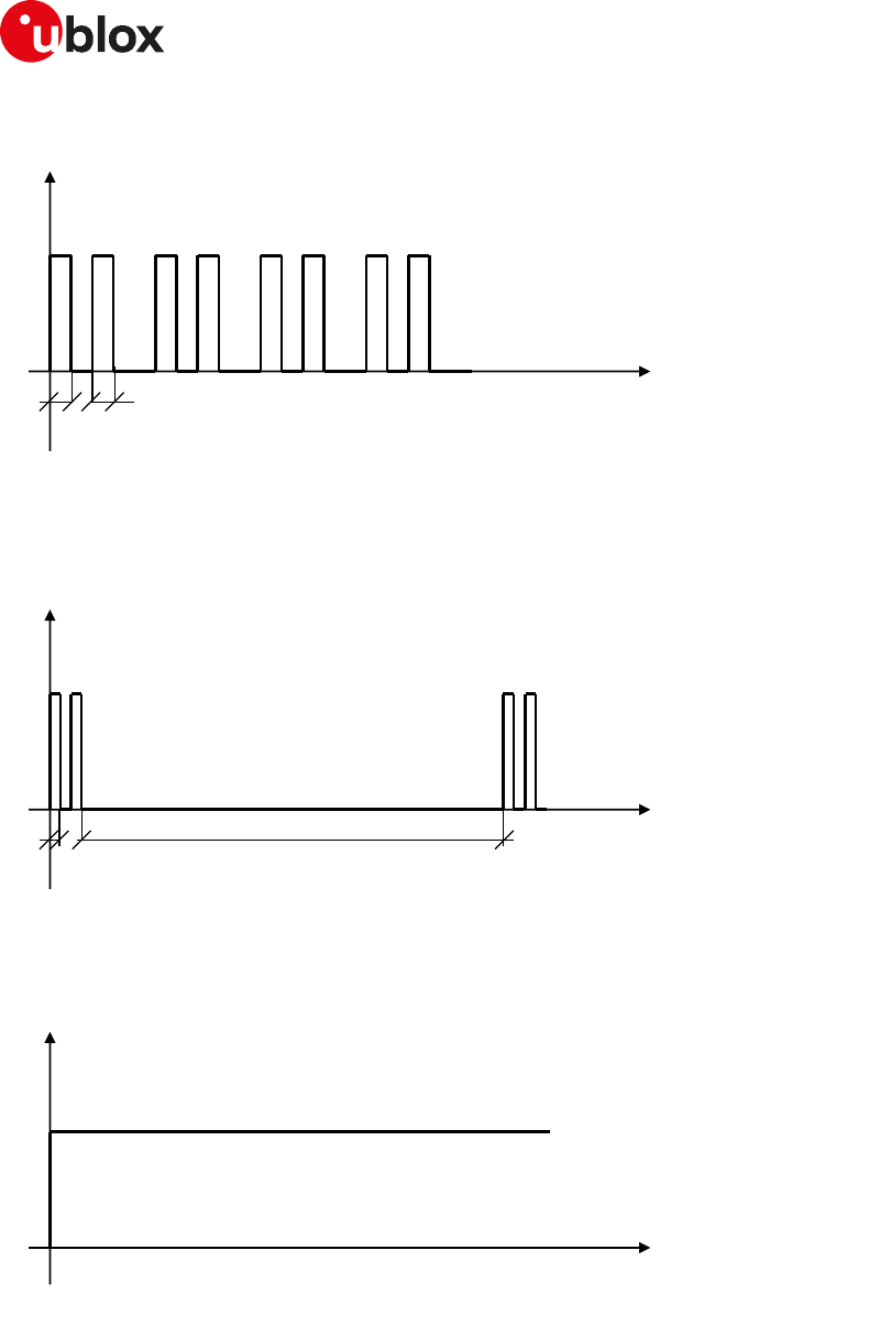
SARA-R4/N4 series-AT Commands Manual
UBX-17003787 - R09
15GPIO
Page 166 of 307
Time
Voltage
V
H
V
L
50
ms
50
ms
Figure 6: GPIO pin progress for registered roaming 3G
15.1.3.7Registered roaming Cat NB1
• Cyclic Output / High for 100 ms, Output / Low for 100 ms, Output / High for 100 ms, Output / Low for 30 s
Time
Voltage
V
H
V
L
30 s
100
ms
Figure 7: GPIO pin progress for registered roaming Cat NB1
15.1.3.8Data transmission
• Continuous Output / High
Time
Voltage
V
H
V
L
Figure 8: GPIO pin progress for data transmission
15.1.3.9Data transmission roaming
• Cyclic Output / High for 800 ms, Output / Low for 200 ms
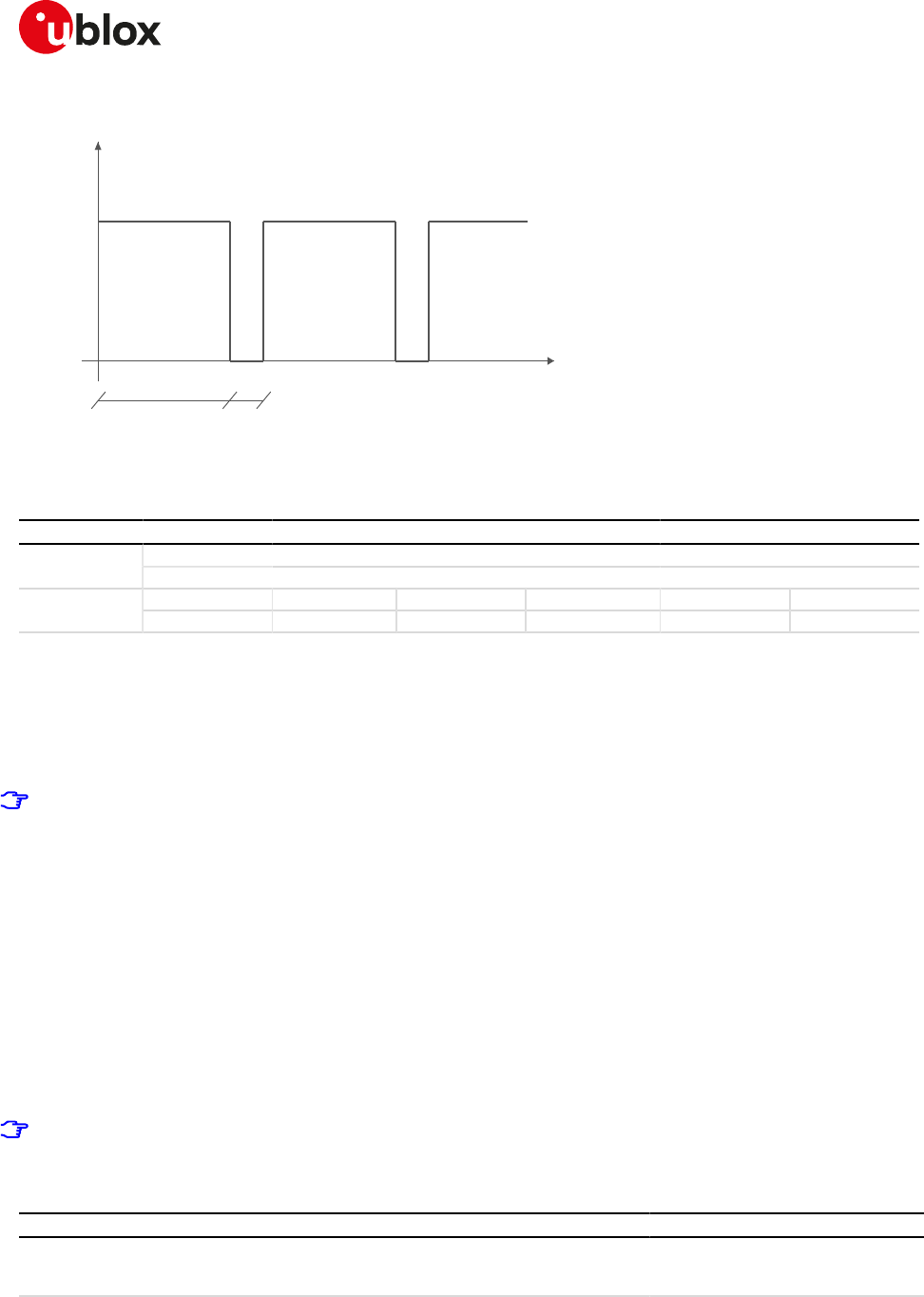
SARA-R4/N4 series-AT Commands Manual
UBX-17003787 - R09
15GPIO
Page 167 of 307
800 ms
200 ms
Time
Voltage
VH
VL
Figure 9: GPIO pin progress for data transmission roaming
15.2GPIO select configuration command +UGPIOC
+UGPIOC
SARA-R404M SARA-R410M-01B SARA-R410M-02B SARA-R410M-52B SARA-R412MModules
SARA-N4
Syntax PIN required Settings saved Can be aborted Response time Error referenceAttributes
partial No NVM No < 10 s +CME Error
15.2.1Description
Configures the GPIOs pins as input, output or to handle a custom function. When the GPIOs pins are configured
as output pin, it is possible to set the value.
The test command provides the list of the supported GPIOs, the supported functions and the status of all the
GPIOs.
Not all the GPIO functions can be assigned to each GPIO pin. If the configuration is not allowed, an error
result code will be returned (error result code 1502 - "+CME ERROR: Select GPIO mode error").
The following custom functions cannot be simultaneously configured on 2 GPIOs:
• Network status indication
• Ring indication
• GNSS supply enable
• GNSS data ready
• GNSS RTC sharing
• SIM card detection
• Headset detection
• GSM Tx burst indication
• Module operating status indication
• Module functionality status indication
• Last gasp trigger
For more details regarding the custom functions supported by the u-blox cellular modules and the
factory-programmed settings, see GPIO functions and GPIO mapping.
15.2.2Syntax
Type Syntax Response Example
Set AT+UGPIOC=<gpio_id>,<gpio_
mode>[,<gpio_out_val>\<gpio_in_
pull>]
OK AT+UGPIOC=20,0,1
OK
Read AT+UGPIOC? +UGPIOC:
<gpio_id>,<gpio_mode>
+UGPIOC:
20,0
SARA-R4/N4 series-AT Commands Manual
UBX-17003787 - R09
15GPIO
Page 168 of 307
Type Syntax Response Example
[<gpio_id>,<gpio_mode>
[....]]
OK
21,3
23,255
24,255
51,7
OK
Test AT+UGPIOC=? +UGPIOC: (list of supported <gpio_
id>),(list of supported <gpio_
mode>),(list of supported <gpio_
out_val>\<gpio_in_pull>)
[<gpio_id1>,<gpio_mode>
...
<gpio_idN>,<gpio_mode>]
OK
+UGPIOC: (20,21,23,24,51),(0-5,7,9,
255),(0-2)
OK
15.2.3Defined values
Parameter Type Description
<gpio_id> Number GPIO pin identifier: pin number
See the GPIO mapping for the available GPIO pins, their mapping and factory-
programmed values on different u-blox cellular modules series and product version.
<gpio_mode> Number Mode identifier: configured function
See the GPIO functions for custom functions supported by different u-blox cellular
modules series and product version.
Allowed values:
• 0: output
• 1: input
• 2: network status indication
• 3: GNSS supply enable
• 4: GNSS data ready
• 5: GNSS RTC sharing
• 7: SIM card detection
• 8: headset detection
• 9: GSM Tx burst indication
• 10: module operating status indication
• 11: module functionality status indication
• 12: I2S digital audio interface
• 13: SPI serial interface
• 14: master clock generation
• 15: UART (DSR, DTR, DCD e RI) interface
• 16: Wi-Fi enable
• 18: Ring indication
• 19: Last gasp enable
• 255: pad disabled
<gpio_out_val> Number GPIO output value (for output function <gpio_mode>=0 only):
• 0 (default value): low
• 1: high
<gpio_in_pull> Number GPIO input value (for input function <gpio_mode>=1 only):
• 0 (default value): no resistor activated
• 1: pull up resistor active
• 2: pull down resistor active
SARA-R4/N4 series-AT Commands Manual
UBX-17003787 - R09
15GPIO
Page 169 of 307
15.3GPIO read command +UGPIOR
+UGPIOR
SARA-R404M SARA-R410M-01B SARA-R410M-02B SARA-R410M-52B SARA-R412MModules
SARA-N4
Syntax PIN required Settings saved Can be aborted Response time Error referenceAttributes
full No No No < 10 s +CME Error
15.3.1Description
Reads the current value of the specified GPIO pin, no matter whether it is configured as input or output (see
the +UGPIOC AT command to define the GPIO function). The parameters range is shown in the information
text response to the test command.
15.3.2Syntax
Type Syntax Response Example
Set AT+UGPIOR=<gpio_id> +UGPIOR: <gpio_id>,<gpio_val>
OK
AT+UGPIOR=20
+UGPIOR: 20,0
OK
Test AT+UGPIOR=? +UGPIOR: (list of supported <gpio_
id>s)
OK
+UGPIOR: (20, 21)
OK
15.3.3Defined values
Parameter Type Description
<gpio_id> Number GPIO pin identifier: pin number
See the GPIO mapping for the available GPIO pins, their mapping and factory-
programmed values on different u-blox cellular modules series and version.
<gpio_val> Number GPIO value. Allowed values are 0 and 1.
15.3.4Notes
• The command works only if the parameter <gpio_mode> of the +UGPIOC AT command is set to 0 or 1.
15.4GPIO set command +UGPIOW
+UGPIOW
SARA-R404M SARA-R410M-01B SARA-R410M-02B SARA-R410M-52B SARA-R412MModules
SARA-N4
Syntax PIN required Settings saved Can be aborted Response time Error referenceAttributes
full No No No < 10 s +CME Error
15.4.1Description
Sets ("writes") the output of the specified GPIO pin, but only if it is configured in output function (see the
+UGPIOC AT command to set the pin as output).
15.4.2Syntax
Type Syntax Response Example
Set AT+UGPIOW=<gpio_id>,<gpio_out_
val>
OK AT+UGPIOW=20,1
OK
Test AT+UGPIOW=? +UGPIOW: (list of supported <gpio_
id>s),(list of supported <gpio_out_
val>s)
OK
+UGPIOW: (20, 21),(0-1)
OK

SARA-R4/N4 series-AT Commands Manual
UBX-17003787 - R09
15GPIO
Page 170 of 307
15.4.3Defined values
Parameter Type Description
<gpio_id> Number GPIO pin identifier: pin number
See the GPIO mapping for the available GPIO pins, their mapping and factory-
programmed values on different u-blox cellular modules series and version.
<gpio_out_val> Number GPIO value. Allowed values are 0 and 1.
15.4.4Notes
• The command works only if the parameter <gpio_mode> of the +UGPIOC AT command is set to 0.
SARA-R4/N4 series-AT Commands Manual
UBX-17003787 - R09
16File System
Page 171 of 307
16File System
16.1File tags
16.1.1Description
File system commands have the optional <tag> parameter that allows you to specify a file type when an AT
command is issued, to inform the system what to do with it. Application specific files must be saved with the
correct type tag, otherwise they are treated as common user files.
Table 17 defines the tags and their specific meanings while Table 18 defines their applicability to module series:
Tag Name Specification
"USER" User file system This is the default type if the <tag> parameter is omitted in file system AT
commands. All generic files can be stored in this manner.
Example: AT+UDWNFILE="foobar",25,"USER" is the same as AT
+UDWNFILE="foobar",25
"FOAT" FOAT file system This tag is used to specify the file type as a firmware update package. It will
place the firmware update package in the proper file cache to be used later by
the +UFWINSTALL command.
"AUDIO" Audio parameters This tag is used to store audio calibration file "audio_gain_calibration<X>.xml"
and "voice<X>.nvm" in the selected profile <X>=0,1. The profile is stored into
NVM by using ATZ<X>.
The "audio_gain_calibration<X>.xml" and "voice<X>.nvm" files can be over-
written with AT&W<X> command.
"FOTA_EXT" Firmware for FOTA
procedure
This tag has to be used to store the firmware file for the FOTA procedure using
a dedicated channel of the USB CDC-ACM interface.
"AUDIO_EXT" Audio configuration
and custom eCall
prompts
This tag is used to read or download audio configuration (see Audio parameters
tuning section) or download and delete custom eCall prompts (see eCall
Prompts section) using a dedicated channel of the USB CDC-ACM interface.
The audio configuration file includes the NVM settings of the following AT
commands (where applicable):
•+CLVL AT command
•+CRSL AT command
•+UI2S AT command
•+UMAFE AT command
•+USAFE AT command
•+UMSEL AT command
•+UMGC AT command
•+USGC AT command
•+USPM AT command
•+UTI AT command
To download the audio configuration or custom eCall prompts in the module,
use the +UDWNFILE command.
To read configuration from the module, use the +URDFILE command.
To delete custom eCall prompts from the module, use the +UDELFILE
command.
"PROFILE" Profile files This tag refers to the profile files that can be loaded on to the module to
support Mobile Network Operators (MNOs) specific configurations. For more
details on the profiles, see the +UMNOPROF command. The +URDFILE and
+ULSTFILE AT commands are not allowed with this tag, the user can only
download or delete these files.
"GNSS" GNSS files This tag has to be used to store the firmware file for the internal GNSS receiver.
Table 17: Tag meanings
SARA-R4/N4 series-AT Commands Manual
UBX-17003787 - R09
16File System
Page 172 of 307
Module
"USER"
"FOAT"
"AUDIO"
"FOTA_EXT"
"AUDIO_EXT"
"PROFILE"
"GNSS"
SARA-R4 / SARA-N4 * * *
Table 18: Tag applicabilities to module series
SARA-R4 / SARA-N4
The files specified with the "FOAT" tag (used to specify the firmware update package file) can only be
downloaded or deleted. The +URDFILE and +ULSTFILE AT commands are not allowed.
16.2Download file +UDWNFILE
+UDWNFILE
SARA-R404M SARA-R410M-01B SARA-R410M-02B SARA-R410M-52B SARA-R412MModules
SARA-N4
Syntax PIN required Settings saved Can be aborted Response time Error referenceAttributes
partial No No No - +CME Error
16.2.1Description
Stores (writes) a file into the file system:
• The stream of bytes can be entered after the '>' prompt has been provided to the user. The file transfer is
terminated exactly when <size> bytes have been sent entered and either "OK" final result code or an error
result code is returned. The feed process cannot be interrupted i.e. the command mode is re-entered once
the user has provided the declared the number of bytes.
• If the file already exists, the data will be appended to the file already stored in the file system.
• If the data transfer stops, after 20 s the command is stopped and the "+CME ERROR: FFS TIMEOUT" error
result code (if +CMEE=2) is returned.
• If the module shuts down during the file storing, all bytes of the file will be deleted.
• If an error occurs during the file writing, the transfer is aborted and it is up to the user to delete the file.
The available free memory space is checked before starting the file transfer. If the file size exceeds the
available space, the "+CME ERROR: NOT ENOUGH FREE SPACE" error result code will be provided (if
+CMEE=2).
SARA-R4 / SARA-N4
If the HW flow control is disabled (AT+IFC), a data loss could be experienced. So the HW flow control usage
is strongly recommended. If HW flow control is not supported, the use of +UDWNBLOCK is recommended.
16.2.2Syntax
Type Syntax Response Example
Set AT+UDWNFILE=<filename>,<size>[,
<tag>]
>
<text>
OK AT+UDWNFILE="filename",36,
"USER"
>
The 36 downloaded bytes of the file!
OK
Download audio configuration
Set AT+UDWNFILE=<filename>,<size>,
"AUDIO_EXT"
OK AT+UDWNFILE="audioconfig",4873,
"AUDIO_EXT"
OK
16.2.3Defined values
Parameter Type Description
<filename> String File name. For file system file name and data size limits see File system limits.
SARA-R4/N4 series-AT Commands Manual
UBX-17003787 - R09
16File System
Page 173 of 307
Parameter Type Description
<size> Number File size expressed in bytes. For file system file name and data size limits see File
system limits.
<tag> String Optional parameter that specifies the application file type. FILE TAGS table lists the
allowed <tag> strings.
<text> String Stream of bytes.
16.2.4Notes
• Issue the AT+ULSTFILE=1 command to retrieve the available user space in the file system.
• Two files with different types can have the same name, i.e. AT+UDWNFILE="testfile",20,"USER" and AT
+UDWNFILE="testfile",43,"AUDIO".
16.3List files information +ULSTFILE
+ULSTFILE
SARA-R404M SARA-R410M-01B SARA-R410M-02B SARA-R410M-52B SARA-R412MModules
SARA-N4
Syntax PIN required Settings saved Can be aborted Response time Error referenceAttributes
partial No No No - +CME Error
16.3.1Description
Retrieves some information about the FS. Depending on the specified <op_code>, it can print:
• List of files stored into the FS
• Remaining free FS space expressed in bytes
• Size of the specified file expressed in bytes
The available free space on FS in bytes reported by the command AT+ULSTFILE=1 is the theoretical free
space including the space occupied by the hidden and temporary files which are not displayed by the AT
+ULSTFILE=0.
16.3.2Syntax
Type Syntax Response Example
Generic syntax
Set AT+ULSTFILE[=<op_code>[,
<param1>[,<param2>]]]
+ULSTFILE: [<param3>,...[,
<paramN>]]
OK
AT+ULSTFILE=1
+ULSTFILE: 236800
OK
List of files stored into the FS
Set AT+ULSTFILE[=0[,<tag>]] +ULSTFILE: [<filename1>[,
<filename2>[,...[,<filenameN>]]]]
OK
AT+ULSTFILE=
+ULSTFILE: "filename"
OK
Remaining free FS space expressed in bytes
Set AT+ULSTFILE=1[,<tag>] +ULSTFILE: <free_fs_space>
OK
AT+ULSTFILE=1
+ULSTFILE: 236800
OK
Size of the specified file
Set AT+ULSTFILE=2,<filename>[,
<tag>]
+ULSTFILE: <file_size>
OK
AT+ULSTFILE=2,"filename"
+ULSTFILE: 784
OK
16.3.3Defined values
Parameter Type Description
<op_code> Number Allowed values are:
• 0 (default value): lists the files belonging to <tag> file type
SARA-R4/N4 series-AT Commands Manual
UBX-17003787 - R09
16File System
Page 174 of 307
Parameter Type Description
• 1: gets the free space for the specific <tag> file type
• 2: gets the file size expressed in bytes, belonging to <tag> type (if specified)
<tag> String Specifies the application file type. FILE TAGS table lists the allowed <tag> strings.
<filename1>,..,
<filenameN>
String File name. For file system file name and data size limits see File system limits.
<free_fs_space> Number Available free space on FS in bytes.
<file_size> Number Size of the file specified with the <filename> parameter.
<param1> Number /
String
Type and supported content depend on related <op_code> (details are given above).
<param2> Number /
String
Type and supported content depend on related <op_code> (details are given above).
16.4Read file +URDFILE
+URDFILE
SARA-R404M SARA-R410M-01B SARA-R410M-02B SARA-R410M-52B SARA-R412MModules
SARA-N4
Syntax PIN required Settings saved Can be aborted Response time Error referenceAttributes
partial No No No - +CME Error
16.4.1Description
Retrieves a file from the file system.
SARA-R4 / SARA-N4
If the HW flow control is disabled (AT+IFC), a data loss could be experienced. So the HW flow control usage
is strongly recommended. If HW flow control is not supported, the use of +URDBLOCK is recommended.
16.4.2Syntax
Type Syntax Response Example
Set AT+URDFILE=<filename>[,<tag>] +URDFILE: <filename>,<size>,
<data>
OK
AT+URDFILE="filename"
+URDFILE: "filename",36,"these
bytes are the data of the file"
OK
16.4.3Defined values
Parameter Type Description
<filename> String File name. For file system file name and data size limits, see File system limits.
<tag> String The optional parameter <tag> specifies a different application file type. FILE TAGS
table lists the allowed <tag> strings.
<size> Number File size, in bytes.
<data> String File content.
16.4.4Notes
• The returned file data is displayed as an ASCII string of <size> characters in the range [0x00,0xFF]. At
the end of the string, <CR><LF> are provided for user convenience and visualization purposes.
SARA-R4/N4 series-AT Commands Manual
UBX-17003787 - R09
16File System
Page 175 of 307
16.5Partial read file +URDBLOCK
+URDBLOCK
SARA-R410M-02B SARA-R410M-52B SARA-R412MModules
SARA-N4
Syntax PIN required Settings saved Can be aborted Response time Error referenceAttributes
partial No No No - +CME Error
16.5.1Description
Retrieves a file from the file system.
Differently from +URDFILE command, this command allows the user to read only a portion of the file,
indicating the offset and amount of bytes.
16.5.2Syntax
Type Syntax Response Example
Set AT+URDBLOCK=<filename>,
<offset>,<size>[,<tag>]
+URDBLOCK: <filename>,<size>,
<data>
OK
AT+URDBLOCK="filename",0,20
+URDBLOCK: "filename",20,"these
bytes are the "
OK
16.5.3Defined values
Parameter Type Description
<filename> String File name. For file system file name and data size limits see File system limits.
<offset> Number Offset in bytes from the beginning of the file.
<size> Number Number of bytes to be read starting from the <offset>.
<data> String Content of the file read.
<tag> String The optional parameter <tag> specifies a different application file type. FILE TAGS
table lists the allowed <tag> strings.
16.5.4Notes
• The returned file data is displayed as an ASCII string of <length> characters in the range [0x00,0xFF]. At
the end of the string, <CR><LF> are provided for user convenience and visualization purposes.
• In case a size larger than the whole file size is required the command returns the file size only, indicating
the amount of bytes read.
• In case an offset larger than the whole file size is required, the "+CME ERROR: FFS file range" error result
code is triggered.
SARA-R4 / SARA-N4
• The <tag> parameter is not supported.
16.6Delete file +UDELFILE
+UDELFILE
SARA-R404M SARA-R410M-01B SARA-R410M-02B SARA-R410M-52B SARA-R412MModules
SARA-N4
Syntax PIN required Settings saved Can be aborted Response time Error referenceAttributes
partial No No No - +CME Error
16.6.1Description
Deletes a stored file from the file system.
If <filename> file is not stored in the file system the following error result code will be provided: "+CME
ERROR: FILE NOT FOUND".

SARA-R4/N4 series-AT Commands Manual
UBX-17003787 - R09
16File System
Page 176 of 307
16.6.2Syntax
Type Syntax Response Example
Set AT+UDELFILE=<filename>[,<tag>] OK AT+UDELFILE="filename","USER"
OK
16.6.3Defined values
Parameter Type Description
<filename> String File name. For file system file name and data size limits see File system limits.
<tag> String The optional parameter <tag> specifies a different application file type. FILE TAGS
table lists the allowed <tag> strings.
16.7Partial download file +UDWNBLOCK
+UDWNBLOCK
SARA-R410M-02B SARA-R410M-52B SARA-R412MModules
SARA-N4
Syntax PIN required Settings saved Can be aborted Response time Error referenceAttributes
full No No No - +CME Error
16.7.1Description
Stores (writes) a file to the file system.
• The stream of bytes can be entered after the '>' prompt has been provided to the user. The file transfer is
terminated exactly when <size> bytes have been sent entered and either "OK" final result code or an error
result code is returned. The feed process cannot be interrupted i.e. the command mode is re-entered once
the user has provided the declared the number of bytes.
• If the file already exists, the data will be appended to the file already stored in the file system.
• If the data transfer stops, after 20 s the command is stopped and the "+CME ERROR: FFS TIMEOUT" error
result code (if +CMEE=2) is returned.
• If the module shuts down during the file storing, all bytes of the file will be deleted.
• If an error occurs during the file writing, the transfer is aborted and it is up to the user to delete the file.
Differently from +UDWNFILE command, this command allows the user to write only a portion of the file,
indicating the offset and amount of bytes.
16.7.2Syntax
Type Syntax Response Example
Set AT+UDWNBLOCK=<filename>,
<offset>,<size>,<filesize>[,<tag>]
>
<text>
OK AT+UDWNBLOCK="filename",0,36,
500,"USER"
>
The 36 downloaded bytes of the file!
OK
16.7.3Defined values
Parameter Type Description
<filename> String File name. For file system file name and data size limits see File system limits.
<offset> Number Offset in bytes from the beginning of the file.
<size> Number Number of bytes to be written starting from the <offset>.
<filesize> Number The size of the file to be written
<tag> String The optional parameter <tag> specifies a different application file type. FILE TAGS
table lists the allowed <tag> strings.
16.7.4Notes
• The <tag> parameter is supported only for "USER".

SARA-R4/N4 series-AT Commands Manual
UBX-17003787 - R09
16File System
Page 177 of 307
16.8File system limits
16.8.1Limits
Here below are listed the maximum file name length, the maximum data size of the file system and the
maximum number of files for the u-blox cellular modules.
Maximum file name length:
• SARA-R4 / SARA-N4 - 248 characters
Maximum file size:
• SARA-R4 / SARA-N4 - File size limited by the available file system space retrieved by +ULSTFILE=1
command
Maximum number of files:
• SARA-R4 / SARA-N4 - The theoretical maximum number of files that can be stored is 1100.
The theoretical maximum file size and the maximum number of files also includes system, hidden and
temporary files whose number is not statically predictable, so the actual numbers can be less than stated.
SARA-R4/N4 series-AT Commands Manual
UBX-17003787 - R09
17DNS
Page 178 of 307
17DNS
DNS service requires the user to define and activate a connection profile, either PSD or CSD.
When these command report an error which is not a +CME ERROR, the error class and code is provided through
+USOER AT command.
17.1Resolve name / IP number through DNS +UDNSRN
+UDNSRN
SARA-R410M-52BModules
SARA-N4
Syntax PIN required Settings saved Can be aborted Response time Error referenceAttributes
full No No No < 70 s TCP/UDP/IP
Error
17.1.1Description
Translates a domain name to an IP address or an IP address to a domain name by using an available DNS. There
are two available DNSs, primary and secondary. The network usually provides them after a GPRS activation or
a CSD establishment. They are automatically used in the resolution process if available. The resolutor will use
first the primary DNS, otherwise if there is no answer, the second DNS will be involved.
Pay attention to the DNS setting for the different profiles since the user DNS can be put into action if the
corresponding profile is activated (if the user sets a DNS for a profile, and a different profile is activated,
the user DNS has no action and the network DNS is used if available).
17.1.2Syntax
Type Syntax Response Example
AT+UDNSRN=0,"www.google.com"
+UDNSRN: "216.239.59.147"
OK
AT+UDNSRN=0,"www.google.com",1
OK
+UUDNSRN: "216.239.59.147"
Set AT+UDNSRN=<resolution_type>,
<domain_ip_string>[,<async>]
+UDNSRN: <resolved_ip_address>
OK
or
+UDNSRN: <resolved_domain_
name>
OK
AT+UDNSRN=0,"www.google.com",
0
+UDNSRN: "216.239.59.147"
OK
+UUDNSRN: <result_code>[,
<resolved_ip_address>]
+UUDNSRN: 0,"216.239.59.147"
+UUDNSRN: <result_code>[,
<resolved_domain_name>]
+UUDNSRN: 0,"somedomain.com"
URC
+UUDNSRN: -1 +UUDNSRN: -1
17.1.3Defined values
Parameter Type Description
<resolution_type> Number Type of resolution operation:
• 0: domain name to IP address
• 1: IP address to domain name (host by name)
<domain_ip_string> String Domain name (<resolution_type>=0) or the IP address in (<resolution_type>=1) to be
resolved
<async> Number Asynchronous DNS resolution flag. Allowed values:
• 0 (default value): the final result code is returned only once the DNS response is
available, locking the AT interface until the DNS activity is running
• 1: a final result code (OK or an error result code) is returned immediately unlocking
the AT interface and making it available for the execution of other AT commands.
SARA-R4/N4 series-AT Commands Manual
UBX-17003787 - R09
17DNS
Page 179 of 307
Parameter Type Description
Once the result of DNS resolution becomes available, it is notified to the AT
interface through the +UUDNSRN URC
<resolved_ip_
address>
String Resolved IP address corresponding to the specified domain name
<resolved_domain_
name>
String Resolved domain name corresponding to the provided IP address
<result_code> Number Result code of DNS resolution:
• 0: no error
• -1: DNS resolution failed. In this case the <resolved_ip_address> or the <resolved_
domain_name> fields are not present
17.1.4Notes
SARA-R4 / SARA-N4
• <async> parameter and +UUDNSRN URC are not available.
SARA-R4/N4 series-AT Commands Manual
UBX-17003787 - R09
18Internet protocol transport layer
Page 180 of 307
18Internet protocol transport layer
18.1Introduction
SARA-R4 / SARA-N4
Before using TCP/IP services, a connection profile must be defined and activated. The sockets can be
managed independently and simultaneously over the same bearer (either PSD or CSD). AT commands for
both reading and writing data on sockets are provided and the URC notifies the external application of
incoming data and transmission result, no need for polling.
SARA-R4 / SARA-N4
When these commands report an error result code which is not a +CME ERROR, the error code can be
queried using the +USOER or +USOCTL (specifying the socket ID and with <param_id>=1) AT commands.
The maximum number of sockets that can be managed are 7.
SARA-R4 / SARA-N4
The maximum number of secure sockets that can be managed is 4.
SARA-R4 / SARA-N4
No need to establish a PSD connection explicitly. This device automatically establishes a PSD connection
as part of the network registration and attach procedure.
The UDP protocol has not any flow control mechanism and packets might be lost in the following
scenarios:
• No network signal is available
• Unreliable radio interface (e.g. mobility in GPRS, where cell reselections can lead to data loss, that can
be contrasted with the usage of LLC ack reliability QoS parameter
Some network operators close dynamic NATs after few minutes if there is no activity on the connection
(no data transfer in the period). To solve this problem enable the TCP keep alive options with 1 minute
delay (see the +USOSO AT command).
When both TCP and UDP socket are used at the same time at the maximum throughput (downlink and
uplink at the maximum allowed baud rate) it is possible to lose some incoming UDP packets due to internal
buffer limitation. A possible workaround is provided as follows:
• If it is possible, adopt an application layer UDP acknowledge system
18.2IPv4/IPv6 addressing
18.2.1Introduction
The section describes the IP addressing formats and IP address rules used by TCP/IP UDP/IP enabled
applications.
18.2.2IPv4
Format:
• 32 bits long in dot-decimal notation (without leading 0 notation).
• All the decimal numbers must be in range 0-255.
• The dot-octal notation is not supported.
• The dot-hexadecimal notation is not supported.
Examples:
IPv4 address Remarks
254.254.254.254 Valid address
010.228.76.34 Invalid address; first decimal number prefixed with a leading zero
257.228.76.34 Invalid address; first decimal number greater than 255
0010.0344.0114.0042 Invalid address; dot-octal notation; decimals given as octal numbers
SARA-R4/N4 series-AT Commands Manual
UBX-17003787 - R09
18Internet protocol transport layer
Page 181 of 307
IPv4 address Remarks
0x10.0xE4.0x4C.0x22 Invalid address; dot-hexadecimal notation; decimals given as
hexadecimal numbers
Table 19: IPv4 address format examples
18.2.3IPv6
Format:
• 128 bits long represented in 8 groups of 16 bits each.
• The 16 bits of a group are represented as 2 concatenated hexadecimal numbers.
• The groups are separated by a colon character (:).
• The leading 0 in a group is supported.
• A group containing 4 zeros can be abbreviated with one 0.
• Continuous groups (at least 2) with zeroes can be replaced with a double colon (::).
• The double colon can appear only once in an IPv6 address.
Examples:
IPv6 address Remarks
2001:0104:0000:0000:0000:0104:0000:0000 Full version, with leading zeros
2001:104:0000:0000:0000:104:0000:0000 Abbreviated version, leading zero abbreviation
2001:104:0:0:0:104:0:0 Abbreviated version, zero group abbreviation
2001:104::104:0:0 Abbreviated version, one double colon abbreviation
Table 20: IPv6 address format examples
The following AT commands support the IPv6 address format:
• Dynamic DNS update: +UDYNDNS
• Connect Socket: +USOCO
• SendTo command: +USOST
• Receive From command: +USORF
• Set Listening Socket: +USOLI
• IP Change Notification: +UIPCHGN
• FTP service configuration: +UFTP
• HTTP control: +UHTTP
For packet swiched services AT commands (i.e. PDP_addr in +CGDCONT) the format is specified in the
corresponding command section.
18.3Create Socket +USOCR
+USOCR
SARA-R404M SARA-R410M-01B SARA-R410M-02B SARA-R410M-52B SARA-R412MModules
SARA-N4
Syntax PIN required Settings saved Can be aborted Response time Error referenceAttributes
partial No No No - TCP/UDP/IP
Error +CME
Error
18.3.1Description
Creates a socket and associates it with the specified protocol (TCP or UDP), returns a number identifying the
socket. Such command corresponds to the BSD socket routine. Up to 7 sockets can be created. It is possible to
specify the local port to bind within the socket in order to send data from a specific port. The bind functionality
is supported for both TCP and UDP sockets.
The socket creation operation can be performed only after the PDP context activation on one of the
defined profiles.
SARA-R4/N4 series-AT Commands Manual
UBX-17003787 - R09
18Internet protocol transport layer
Page 182 of 307
18.3.2Syntax
Type Syntax Response Example
Set AT+USOCR=<protocol>[,<local_
port>]
+USOCR: <socket>
OK
AT+USOCR=17
+USOCR: 2
OK
Test AT+USOCR=? +USOCR: (list of supported
<protocol>s),(list of supported
<local_port>s)
OK
+USOCR: (6,17),(1-65535)
OK
18.3.3Defined values
Parameter Type Description
<protocol> Number • 6: TCP
• 17: UDP
<local_port> Number Local port to be used while sending data. The range goes from 1 to 65535. If the
parameter is omitted it will be set to 0; in this case a random port will be used while
sending data.
<socket> Number Socket identifier to be used for any future operation on that socket. The range goes
from 0 to 6.
18.4SSL/TLS mode configuration on TCP socket +USOSEC
+USOSEC
SARA-R410M-01B SARA-R410M-02B SARA-R410M-52B SARA-R412MModules
SARA-N4
Syntax PIN required Settings saved Can be aborted Response time Error referenceAttributes
full No No No < 1 s +CME Error
18.4.1Description
Enables or disables the use of SSL/TLS connection on a TCP socket. The configuration of the SSL/TLS
properties is provided with an SSL/TLS profile managed by USECMNG.
The <usecmng_profile_id> parameter is listed in the information text response to the read command only if
the SSL/TLS is enabled on the interested socket.
This operation is only available for TCP sockets.
The enable or disable operation can be performed only after the socket has been created with +USOCR
AT command.
The SSL/TLS is supported only with +USOCO command (socket connect command). The SSL/TLS is
not supported with +USOLI command (socket set listen command is not supported and the +USOSEC
settings will be ignored).
SARA-R4 / SARA-N4
Issue the command before the +USOCO AT command (socket connect command).
18.4.2Syntax
Type Syntax Response Example
Set AT+USOSEC=<socket>,<ssl_tls_
status>[,<usecmng_profile_id>]
OK AT+USOSEC=0,1,1
OK
Read AT+USOSEC=<socket> +USOSEC=<socket>,<ssl_tls_
status>[,<usecmng_profile_id>]
OK
AT+USOSEC=0
+USOSEC=0,1,1
OK
Test AT+USOSEC=? +USOSEC: (list of supported
<socket>s),(list of supported <ssl_
tls_status>s),(list of supported
<usecmng_profile_id>s)
+USOSEC: (0-6),(0,1),(0-4)
OK
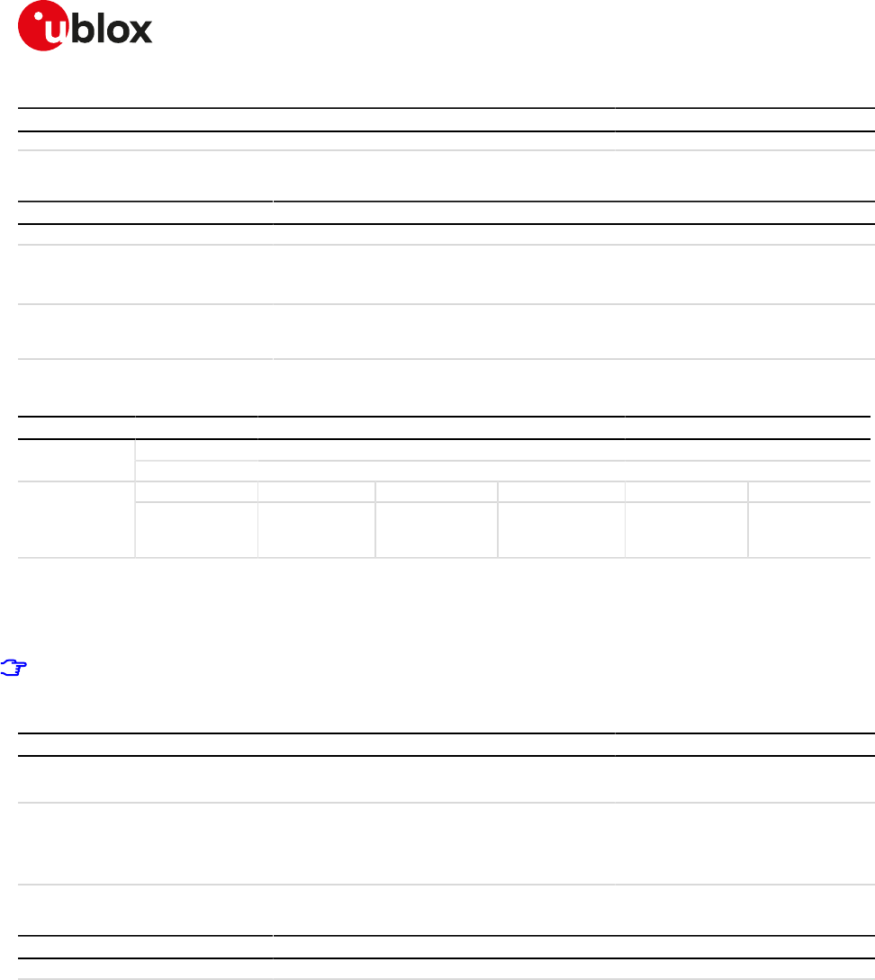
SARA-R4/N4 series-AT Commands Manual
UBX-17003787 - R09
18Internet protocol transport layer
Page 183 of 307
Type Syntax Response Example
OK
18.4.3Defined values
Parameter Type Description
<socket> Number Socket identifier defined by the AT+USOCR command. The range goes from 0 to 6.
<ssl_tls_status> Number • 0 (default value): disable the SSL/TLS on the socket.
• 1: enable the SSL/TLS on the socket; a USECMNG profile can be specified with the
<usecmng_profile_id> parameter.
<usecmng_profile_
id>
Number Defines the USECMNG profile which specifies the SSL/TLS properties to be used
for the SSL/TLS connection. The range goes from 0 to 4. If no profile is set a default
USECMNG profile is used (see USECMNG section).
18.5Set socket option +USOSO
+USOSO
SARA-R404M SARA-R410M-01B SARA-R410M-02B SARA-R410M-52B SARA-R412MModules
SARA-N4
Syntax PIN required Settings saved Can be aborted Response time Error referenceAttributes
full No No No - TCP/UDP/IP
Error +CME
Error
18.5.1Description
Sets the specified standard option (type of service, local address re-use, linger time, time-to-live, etc.) for the
specified socket, like the BSD setsockopt routine.
Issue a set command to set each parameter.
18.5.2Syntax
Type Syntax Response Example
Set AT+USOSO=<socket>,<level>,<opt_
name>,<opt_val>[,<opt_val2>]
OK AT+USOSO=2,6,1,1
OK
Test AT+USOSO=? +USOSO: (list of supported
<socket>s),(list of supported
<level>s)
OK
+USOSO: (0-6),(0,6,65535)
OK
18.5.3Defined values
Parameter Type Description
<socket> Number Socket identifier. The range goes from 0 to 6
<level> Number • 0: IP protocol
<opt_name> for IP protocol level may be:
o 1: type of service (TOS)
<opt_val>: 8 bitmask that represents the flags of IP TOS. The range is 0-255
(the default value is 0). For more information see the RFC 791 [27]
o 2: time-to-live (TTL)
<opt_val>: unsigned 8 bit value representing the TTL. The range is 0-255 (the
default value is 255)
• 6: TCP protocol
<opt_name> for TCP protocol level may be:
o 1: no delay option; do not delay send to coalesce packets;
<opt_val>: numeric parameter, it enables/disables the "no delay" option
- 0 (default value): disabled
- 1: enabled
o 2: keepidle option: send keepidle probes when it is idle for <opt_val> milliseconds

SARA-R4/N4 series-AT Commands Manual
UBX-17003787 - R09
18Internet protocol transport layer
Page 184 of 307
Parameter Type Description
<opt_val>: signed 32 bit numeric parameter representing the milliseconds for
"keepidle" option. The range is 0-2147483647. The default value is 7200000 (2
hours)
• 65535: socket
<opt_name> for socket level options may be:
o 4: local address re-use.
<opt_val>: numeric parameter, it configures the "local address re-use" option.
- 0 (default value): disabled
- 1: enabled
o 8: keep connections alive.
<opt_val>: numeric parameter, it configures "keep connections alive" option.
- 0 (default value): disabled
- 1: enabled
o 32: sending of broadcast messages.
<opt_val>: numeric parameter, it configures "sending of broadcast
messages".
- 0 (default value): disabled
- 1: enabled
o 128: linger on close if data present.
<opt_val>: numeric parameter, it configures the "linger" option.
- 0 (default value): disabled
- 1: enabled
<opt_val2>: signed 16 bit numeric parameter, it sets the linger time, the range
goes from 0 to 32767 in milliseconds. The default value is 0.
o 512: local address and port re-use.
<opt_val>: numeric parameter, it configures the "local address and port re-
use".
- 0 (default value): disabled
- 1: enabled
<opt_name> Number Type and supported content depend on related <level> (details are given above).
<opt_val> Number Type and supported content depend on related <level> (details are given above).
<opt_val2> Number Type and supported content depend on related <level> (details are given above).
18.5.4Notes
SARA-R4 / SARA-N4
• <level> 6: TCP protocol, <opt_name> 2: keepidle option, is not supported.
18.6Get Socket Option +USOGO
+USOGO
SARA-R404M SARA-R410M-01B SARA-R410M-02B SARA-R410M-52B SARA-R412MModules
SARA-N4
Syntax PIN required Settings saved Can be aborted Response time Error referenceAttributes
full No No No - TCP/UDP/IP
Error +CME
Error
18.6.1Description
Retrieves the specified standard option (type of service, local address re-use, linger time, time-to-live, etc) for
the specified socket, like the BSD getsockopt routine.
18.6.2Syntax
Type Syntax Response Example
Set AT+USOGO=<socket>,<level>,<opt_
name>
+USOGO: <opt_val>[,<opt_val2>]
OK
AT+USOGO=0,0,2
+USOGO: 255

SARA-R4/N4 series-AT Commands Manual
UBX-17003787 - R09
18Internet protocol transport layer
Page 185 of 307
Type Syntax Response Example
OK
Test AT+USOGO=? +USOGO: (list of supported
<socket>s),(list of supported
<level>s)
OK
+USOGO: (0-6),(0,6,65535)
OK
18.6.3Defined values
Parameter Type Description
<socket> Number Socket identifier. The range goes from 0 to 6.
<level> Number • 0: IP Protocol
<opt_name> for IP protocol level may be:
o 1: type of service
<opt_val>: 8 bit mask that represents the flags of IP TOS. For more
information see the RFC 791 [27]. The range is 0-255. The default value is 0
o 2: time-to-live
<opt_val>: unsigned 8 bit value representing the TTL. The range is 0-255. The
default value is 0.
• 6: TCP Protocol
<opt_name> for TCP protocol level may be:
o 1: no delay option: do not delay send to coalesce packets
<opt_val>: numeric parameter, it enables/disables the "no delay" option
- 0 (default value): disabled
- 1: enabled
o 2: keepidle option: send keepidle probes when idle for <opt_val> milliseconds
<opt_val>: signed 32 bit number value representing the milliseconds for
"keepidle" option. The range 0-2147483647. The default value is 7200000 (2
hours)
• 65535: socket
<opt_name> for the socket level options may be:
o 4: local address re-use
<opt_val>: numeric parameter, it configures the "local address re-use" option:
- 0 (default value): disabled
- 1: enabled
o 8: keep connections alive
<opt_val>: numeric parameter, it configures the "keep connections alive"
option:
- 0 (default value): disabled
- 1: enabled
o 32: sending of broadcast messages
<opt_val>: numeric parameter, it configures the "sending of broadcast
messages":
- 1: enabled
- 0 (default value): disabled
o 128: linger on close if data present
<opt_val>: numeric parameter, it sets on/off the "linger" option.
- 0 (default value): disabled
- 1: enabled
<opt_val2>: signed 16 bit numeric value, linger time, the range goes from 0 to
32767 in milliseconds. The default value is 0.
o 512: local address and port re-use
<opt_val>: numeric parameter, it enables/disables "local address and port re-
use":
- 0 (default value): disabled
- 1: enabled
18.6.4Notes
SARA-R4 / SARA-N4
• The setting <level>= 6 (TCP protocol) and <opt_name>= 2 (keepidle option) is not supported.
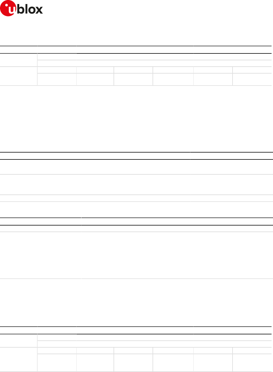
SARA-R4/N4 series-AT Commands Manual
UBX-17003787 - R09
18Internet protocol transport layer
Page 186 of 307
18.7Close Socket +USOCL
+USOCL
SARA-R404M SARA-R410M-01B SARA-R410M-02B SARA-R410M-52B SARA-R412MModules
SARA-N4
Syntax PIN required Settings saved Can be aborted Response time Error referenceAttributes
partial No No No < 120 s (except
URC)
+CME Error
18.7.1Description
Closes the specified socket, like the BSD close routine. In case of remote socket closure the user is notified
via the URC.
By default the command blocks the AT command interface until the the completion of the socket close
operation. By enabling the <async_close> flag, the final result code is sent immediately. The following
+UUSOCL URC will indicate the closure of the specified socket.
18.7.2Syntax
Type Syntax Response Example
Set AT+USOCL=<socket>[,<async_
close>]
OK AT+USOCL=2
OK
Test AT+USOCL=? +USOCL: (list of supported
<socket>s)
OK
+USOCL: (0-6),(0-1)
OK
URC +UUSOCL: <socket> +UUSOCL: 2
18.7.3Defined values
Parameter Type Description
<socket> Number Socket identifier. The range goes from 0 to 6
<async_close> Number Asynchronous close flag. The flag has effect for TCP connections only. Allowed
values:
• 0 (default value): the operation result is returned only once the result of the TCP
close becomes available, locking the AT interface until the connection closes.
• 1: the final result code is returned immediately unlocking the AT interface and
making it available for the execution of other AT commands. Once the result of TCP
close becomes available, it is notified to the AT interface through the +UUSOCL
URC.
18.7.4Notes
SARA-R404M / SARA-R410M-01B
• The <async_connect> parameter is not supported.
18.8Get Socket Error +USOER
+USOER
SARA-R404M SARA-R410M-01B SARA-R410M-02B SARA-R410M-52B SARA-R412MModules
SARA-N4
Syntax PIN required Settings saved Can be aborted Response time Error referenceAttributes
full No No No - TCP/UDP/IP
Error +CME
Error
18.8.1Description
Retrieves the last error occurred in the last socket operation, stored in the BSD standard variable error.
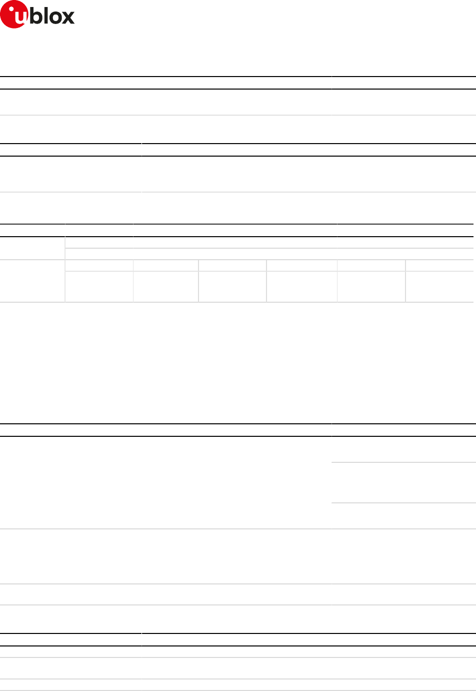
SARA-R4/N4 series-AT Commands Manual
UBX-17003787 - R09
18Internet protocol transport layer
Page 187 of 307
18.8.2Syntax
Type Syntax Response Example
Action AT+USOER +USOER: <socket_error>
OK
+USOER: 104
OK
18.8.3Defined values
Parameter Type Description
<socket_error> Number Code of the last error occurred in a socket operation. The allowed values are listed in
Appendix A.5
• 0: no error
18.9Connect Socket +USOCO
+USOCO
SARA-R404M SARA-R410M-01B SARA-R410M-02B SARA-R410M-52B SARA-R412MModules
SARA-N4
Syntax PIN required Settings saved Can be aborted Response time Error referenceAttributes
partial No No No < 120 s TCP/UDP/IP
Error +CME
Error
18.9.1Description
Establishes a peer-to-peer connection of the socket to the specified remote host on the given remote port, like
the BSD connect routine. If the socket is a TCP socket, the command will actually perform the TCP negotiation
(3-way handshake) to open a connection. If the socket is a UDP socket, this function will just declare the remote
host address and port for later use with other socket operations (e.g. +USOWR, +USORD). This is important
to note because if <socket> refers to a UDP socket, errors will not be reported prior to an attempt to write or
read data on the socket.
18.9.2Syntax
Type Syntax Response Example
AT+USOCO=3,"151.63.16.9",1200
OK
AT+USOCO=2,"151.63.16.9",8200,1
OK
+UUSOCO: 2,0
Set AT+USOCO=<socket>,<remote_
addr>,<remote_port>[,<async_
connect>]
OK
AT+USOCO=2,"151.63.16.9",8230,0
OK
Test AT+USOCO=? +USOCO: (list of supported
<socket>s),"remote_host",(list of
supported <remote_port>s),(list of
supported <async_connect>s)
OK
+USOCO: (0-6),"remote_host",(1-
65535),(0-1)
OK
URC +UUSOCO: <socket>,<socket_
error>
+UUSOCO: 2,0
18.9.3Defined values
Parameter Type Description
<socket> Number Socket identifier. The range goes from 0 to 6
<remote_addr> String Remote host IP address or domain name of the remote host. For IP address format
reference see the IP addressing.
<remote_port> Number Remote host port, in range 1-65535
<async_connect> Number Asynchronous connect flag. The flag has effect for TCP connections only. Allowed
values:
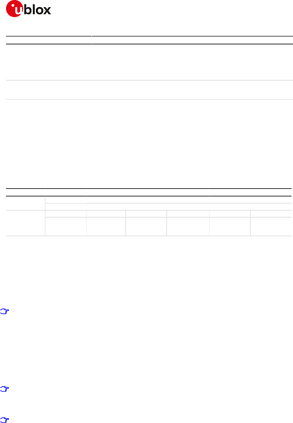
SARA-R4/N4 series-AT Commands Manual
UBX-17003787 - R09
18Internet protocol transport layer
Page 188 of 307
Parameter Type Description
• 0 (default value): the operation result is returned only once the TCP connection is
established, locking the AT interface until the connection activity is running
• 1: the final result code is returned immediately unlocking the AT interface and
making it available for the execution of other AT commands. Once the result of
TCP connection becomes available, it is notified to the AT interface through the
+UUSOCO URC.
<socket_error> Number Code of the last error occurred in a socket operation. The allowed values are listed in
Appendix A.5:
• 0: no error, connection successful
18.9.4Notes
• In case of the socket connection with the asynchronous flag:
o the socket will be closed if a further +USOCO AT command is issued before having received the
+UUSOCO URC of the first AT command.
o it is not possible to connect a second socket before the reception of the +UUSOCO URC related to
the pending socket connection.
SARA-R404M / SARA-R410M-01B
• The <async_connect> parameter and the +UUSOCO URC are not available.
18.10Write socket data +USOWR
+USOWR
SARA-R404M SARA-R410M-01B SARA-R410M-02B SARA-R410M-52B SARA-R412MModules
SARA-N4
Syntax PIN required Settings saved Can be aborted Response time Error referenceAttributes
partial No No No < 120 s TCP/UDP/IP
Error +CME
Error
18.10.1Description
Writes the specified amount of data to the specified socket, like the BSD write routine, and returns the number
of bytes of data actually written. The command applies to UDP sockets too, after a +USOCO command.
There are three kinds of syntax:
• Base syntax normal: writing simple strings to the socket, some characters are forbidden
• Base syntax HEX: writing hexadecimal strings to the socket, the string will be converted in binary data and
sent to the socket; see the AT+UDCONF=1 command description to enable it
• Binary extended syntax: mandatory for writing any character in the ASCII range [0x00, 0xFF]
Some notes about the TCP socket:
• If no network signal is available, the TCP packets are enqueued until the network will become available
again. If the TCP queue is full the +USOWR command will return an error result code. To get the last
socket error use the +USOCTL=1 command. If the error code returned is 11, it means that the queue
is full.
• If the connection is closed by the remote host, the +UUSOCL URC is not sent until all received data is
read using the AT+USORD command. If AT+USOWR command is used in this situation, an error result
code is returned. See also the Notes section about the specific product behaviour
• If the connection is closed by the remote host and binary interface started with AT+USOWR command
is still waiting for data, an error result code is returned indicating that the binary interface was closed.
After the error result code a +UUSOCL URC is reported indicating that the socket was closed.
Some notes about the UDP socket:
• Due to the UDP specific AT commands, it is preferred to use the +USOST command to send data via
UDP socket. This command does not require the usage of +USOCO before sending data.
• If no network signal is available, out going UDP packet may be lost.
The information text response indicates that data has been sent to lower level of protocol stack. This is
not an indication of an acknowledgement received by the remote server the socket is connected to.
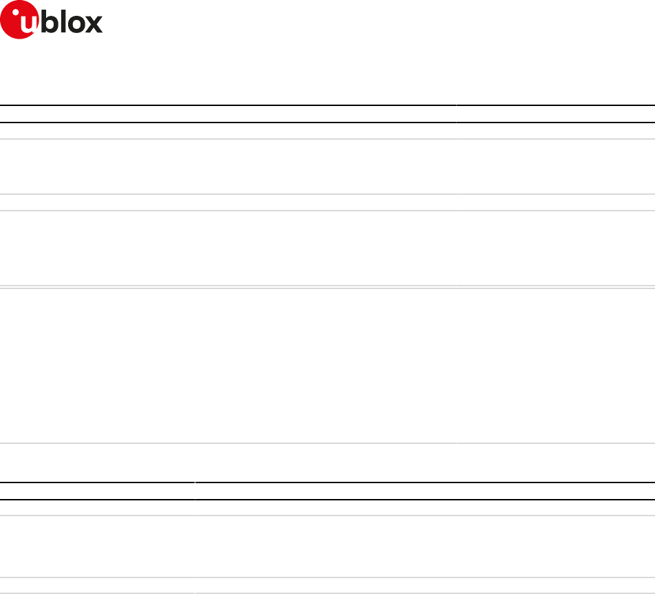
SARA-R4/N4 series-AT Commands Manual
UBX-17003787 - R09
18Internet protocol transport layer
Page 189 of 307
18.10.2Syntax
Type Syntax Response Example
Base syntax
Set AT+USOWR=<socket>,<length>,
<data>
+USOWR: <socket>,<length>
OK
AT+USOWR=3,12,"Hello world!"
+USOWR: 3,12
OK
Binary syntax
Set AT+USOWR=<socket>,<length> @<data>
+USOWR: <socket>,<length>
OK
AT+USOWR=3,16
@16 bytes of data
+USOWR: 3,16
OK
Test AT+USOWR=? +USOWR: (list of supported
<socket>s),(list of supported
<length>s),"HEX data"
+USOWR: (list of supported
<socket>s),(list of supported
<length>s),"data"
+USOWR: (list of supported
<socket>s),(list of supported
<length>s)
OK
+USOWR: (0-6),(0-512),"HEX data"
+USOWR: (0-6),(0-1024),"data"
+USOWR: (0-6),(0-1024)
OK
18.10.3Defined values
Parameter Type Description
<socket> Number Socket identifier. The range goes from 0 to 6.
<length> Number Number of data bytes to write:
• Base syntax normal mode: range 1-1024
• Base syntax HEX mode: range 1-512
• Binary extended syntax: range 1-1024
<data> String Data bytes to be written. Not all of the ASCII charset can be used.
18.10.4Notes
• For base syntax:
o The value of <length> and the actual length of <data> must match
• For base syntax HEX mode:
o Only the ASCII characters 0-9, A-F and a-f are allowed.
o The length of the <data> parameter must be two times the <length> parameter.
• For binary syntax:
o After the command is sent, the user waits for the @ prompt. When it appears the stream of bytes
can be provided. After the specified amount of bytes has been sent, the system provides the final
result code. The feed process cannot be interrupted i.e. the return in the command mode can be
effective only when the number of bytes provided is the declared one.
o After the @ prompt reception, wait for a minimum of 50 ms before sending data.
o The binary extended syntax is the only way for the system to accept control characters as data; for
the AT command specifications 3GPP TS 27.005 [16], characters like <CR>, <CTRL-Z>, quotation
marks, etc. have a specific meaning and they cannot be used like data in the command itself. The
command is so extended with a specific acceptance state identified by the @ prompt.
o This feature can be successfully used when there is need to send a byte stream which belongs to a
protocol that has any kind of characters in the ASCII range [0x00,0xFF].
o In binary mode the module does not display the echo of data bytes.
o Binary syntax is not affected by HEX mode option.
• For <data> parameter not all of the ASCII charset can be used.
SARA-R4/N4 series-AT Commands Manual
UBX-17003787 - R09
18Internet protocol transport layer
Page 190 of 307
18.11SendTo command (UDP only) +USOST
+USOST
SARA-R404M SARA-R410M-01B SARA-R410M-02B SARA-R410M-52B SARA-R412MModules
SARA-N4
Syntax PIN required Settings saved Can be aborted Response time Error referenceAttributes
full No No No < 10 s TCP/UDP/IP
Error +CME
Error
18.11.1Description
Writes the specified amount of data to the remote address, like the BSD sendto routine, and returns the
number of bytes of data actually written. It can be applied to UDP sockets only. This command allows the reuse
of the same socket to send data to many different remote hosts.
There are three kinds of syntax:
• Base syntax normal: writing simple strings to the socket, there are characters which are forbidden
• Base syntax HEX: writing hexadecimal strings to the socket, the string will be converted in binary data and
sent to the socket
• Binary extended syntax: mandatory for writing any character in the ASCII range [0x00, 0xFF]
It is strongly recommended using this command to send data while using UDP sockets. It is also
recommended avoiding +USOCO usage with UDP socket.
(about UDP socket): if no network signal is available, outcoming UDP packet may be lost.
To enable the base syntax HEX mode, see the AT+UDCONF=1 command description.
18.11.2Syntax
Type Syntax Response Example
Base syntax
Set AT+USOST=<socket>,<remote_
addr>,<remote_port>,<length>,
<data>
+USOST: <socket>,<length>
OK
AT+USOST=3,"151.9.34.66",449,16,
"16 bytes of data"
+USOST: 3,16
OK
Binary syntax
Set AT+USOST=<socket>,<remote_
addr>,<remote_port>,<length>
After the"@" prompt <length> bytes
of data are entered
@<data>
+USOST: <socket>,<length>
OK
AT+USOST=3,"151.9.34.66",449,16
@16 bytes of data
+USOST: 3,16
OK
Test AT+USOST=? +USOST: (list of supported
<socket>s),"remote_host",(list of
supported <remote_port>s),(list of
supported <length>s),"HEX data"
+USOST: (list of supported
<socket>s),"remote_host",(list of
supported <remote_port>s),(list of
supported <length>s),"data"
+USOST: (list of supported
<socket>s),"remote_host",(list of
supported <remote_port>s),(list of
supported <length>s)
OK
+USOST: (0-6),"remote_host",(1-
65535),(0-512),"HEX data"
+USOST: (0-6),"remote_host",(1-
65535),(0-1024),"data"
+USOST: (0-6),"remote_host",(1-
65535),(0-1024)
OK
18.11.3Defined values
Parameter Type Description
<socket> Number Socket identifier. The range goes from 0 to 6
SARA-R4/N4 series-AT Commands Manual
UBX-17003787 - R09
18Internet protocol transport layer
Page 191 of 307
Parameter Type Description
<remote_addr> String Remote host IP address or domain name of the remote host. For IP address format
reference see the IP addressing.
<remote_port> Number Remote host port, in range 1-65535
<length> Number Number of data bytes to write
• Base syntax normal mode: range 1-1024
• Base syntax HEX mode: range 1-512
• Binary syntax mode: range 1-1024
<data> String Data bytes to be written (not all of the ASCII charset can be used)
18.11.4Notes
• For base syntax:
o The value of <length> and the actual length of <data> must match
o For base syntax HEX mode, only ASCII characters 0-9, A-F and a-f are allowed. The length of the
<data> parameter must be two times the <length> parameter
• For binary syntax:
o After the command is sent, the user waits for the @ prompt. When it appears the stream of bytes
can be provided. After the specified amount of bytes has been sent, the system returns with final
result code. The feed process cannot be interrupted i.e. the return in the command mode can be
effective only when the number of bytes provided is the declared one
o That binary extended syntax is the only way for the system to accept control characters as data; for
the AT command specifications [16], characters like <CR>, <CTRL-Z>, quotation marks, etc. have
a specific meaning and they cannot be used like data in the command itself. The command is so
extended with a specific acceptance state identified by the @ prompt
o This feature can be successfully used when there is need to send a byte stream which belongs to a
protocol that has any kind of characters in the ASCII range [0x00,0xFF]
o In binary mode the module does not display the echo of data bytes
o Binary syntax is not affected by HEX mode option
18.12Read Socket Data +USORD
+USORD
SARA-R404M SARA-R410M-01B SARA-R410M-02B SARA-R410M-52B SARA-R412MModules
SARA-N4
Syntax PIN required Settings saved Can be aborted Response time Error referenceAttributes
full No No No < 1 s (except
URC)
TCP/UDP/IP
Error +CME
Error
18.12.1Description
Reads the specified amount of data from the specified socket, like the BSD read routine. This command can
be used to know the total amount of unread data.
For the TCP socket type the URC +UUSORD: <socket>,<length> notifies the data bytes available for reading,
either when buffer is empty and new data arrives or after a partial read by the user.
For the UDP socket type the URC +UUSORD: <socket>,<length> notifies that a UDP packet has been received,
either when buffer is empty or after a UDP packet has been read and one or more packets are stored in the
buffer.
In case of a partial read of a UDP packet +UUSORD: <socket>,<length> will show the remaining number of data
bytes of the packet the user is reading.
(about UDP socket) Due to the UDP specific AT command, it is preferred to use the +USORF command
to read data from UDP socket. +USORF command does not require the usage of +USOCO before reading
data.
When applied to UDP active sockets if the UDP socket is not set in listening mode (see +USOLI) it will not
be possible to receive any packet if a previous write operation is not performed.
SARA-R4/N4 series-AT Commands Manual
UBX-17003787 - R09
18Internet protocol transport layer
Page 192 of 307
If the HEX mode is enabled (refer to AT+UDCONF=1 command) the received data will be displayed using
an hexadecimal string.
18.12.2Syntax
Type Syntax Response Example
Set AT+USORD=<socket>,<length> +USORD: <socket>,<length>,<data
in the ASCII [0x00,0xFF] range>
OK
AT+USORD=3,16
+USORD: 3,16,"16 bytes of data"
OK
URC +UUSORD: <socket>,<length> +UUSORD: 3,16
Test AT+USORD=? +USORD: (list of supported
<socket>s),(list of supported
<length>s)
OK
+USORD: (0-6),(0-1024)
OK
18.12.3Defined values
Parameter Type Description
<socket> Number Socket identifier. The range goes from 0 to 6
<length> Number Number of data bytes
• to read stored in buffer, in range 0-1024 in the set command
• read from buffer, in range 0-1024
• stored in buffer for the URC
<data> String Data bytes to be read
18.12.4Notes
• The returned data may be any ASCII character in the range [0x00,0xFF] i.e. control characters. The
starting quotation marks shall not be taken into account like data; the first byte of data starts after
the first quotation marks. Then the other characters are provided for a <length> amount. An application
should rely on the <length> info to count the received number of characters (after the starting quotation
marks) especially if any protocol control characters are expected.
• If an application deals with letter and number characters only i.e. all of the expected characters are
outside the [0x00, 0x1F] range and are not quotation marks, the AT+USORD response quotation marks
can be assumed to identify the start and the end of the received data packet. Always check <length> to
identify the valid data stream.
• If the number of data bytes requested to be read from the buffer is bigger than the number of bytes
stored in the buffer only the available amount of data bytes will be read.
• When <length>= 0, the command returns the total amount of data present in the network buffer.
Example: 23 unread bytes in the socket
AT+USORD=3,0
+USORD: 3,23
OK
• If the HEX mode is enabled, the length of <data> will be 2 times <length>.
18.13Receive From command (UDP only) +USORF
+USORF
SARA-R404M SARA-R410M-01B SARA-R410M-02B SARA-R410M-52B SARA-R412MModules
SARA-N4
Syntax PIN required Settings saved Can be aborted Response time Error referenceAttributes
full No No No < 1 s (except
URC)
TCP/UDP/IP
Error +CME
Error
18.13.1Description
Reads the specified amount of data from the specified UDP socket, like the BSD recvfrom routine. The URC
+UUSORF: <socket>,<length> (or also +UUSORD: <socket>,<length>) notifies that new data is available for
SARA-R4/N4 series-AT Commands Manual
UBX-17003787 - R09
18Internet protocol transport layer
Page 193 of 307
reading, either when new data arrives or after a partial read by the user for the socket. This command can also
return the total amount of unread data.
This command can be applied to UDP sockets only, and it can be used to read data after both +UUSORD and
+UUSORF unsolicited indication.
If the HEX mode is enabled (see +UDCONF=1) the received data will be displayed using an hexadecimal
string.
18.13.2Syntax
Type Syntax Response Example
Set AT+USORF=<socket>,<length> +USORF: <socket>,<remote_ip_
addr>,<remote_port>,<length>,
<data in the ASCII [0x00,0xFF]
range>
OK
AT+USORF=3,16
+USORF: 3,"151.9.34.66",2222,16,"16
bytes of data"
OK
Test AT+USORF=? +USORF: (list of supported
<socket>s),(list of supported
<length>s)
OK
+USORF: (0-6),(0-1024)
OK
URC +UUSORF: <socket>,<length> +UUSORF: 3,16
18.13.3Defined values
Parameter Type Description
<socket> Number Socket identifier. The range goes from 0 to 6
<remote_ip_addr> String Remote host IP address. For IP address format reference see the IP addressing.
<remote_port> Number Remote host port, in range 1-65535
<length> Number Number of data bytes to read, in range 0-1024
<data> String Data bytes to be read
18.13.4Notes
• Each packet received from the network is stored in a separate buffer and the command is capable to read
only a packet (or e portion of it) at time. This means that if <length> is greater than the packet size, the
command will return a maximum amount of data equal to the packet size, also if there are other packets
in the buffer. The remaining data (i.e. the remaining UDP packets) can be read with further reads.
• The returned data may have any kind of ASCII character in the range [0x00,0xFF] i.e. control characters
too. The starting quotation marks shall not be taken into account like data; the first byte of data starts
after the first quotation marks. Then the other characters are provided for a <length> amount. At the
end of the length byte stream, another quotation marks followed by <CR><LF> are provided for user
convenience and visualization purposes. An application should rely on the <length> info to count the
received number of characters (after the starting quotation marks) especially if any protocol control
characters are expected.
• If an application deals with letter and number characters only i.e. all of the expected characters are
outside the [0x00, 0x1F] range and are not quotation marks, the AT+USORD response quotation marks
can be assumed to identify the start and the end of the received data packet, anyway the <length> field
usage to identify the valid data stream is recommended.
• When <length>= 0, the command returns the total amount of data present in the network buffer.
Example: 23 unread bytes in the socket
AT+USORF=3,0
+USORF: 3,23
OK
• If the HEX mode is enabled, the length of <data> will be 2 times <length>.

SARA-R4/N4 series-AT Commands Manual
UBX-17003787 - R09
18Internet protocol transport layer
Page 194 of 307
18.14Set Listening Socket +USOLI
+USOLI
SARA-R404M SARA-R410M-01B SARA-R410M-02B SARA-R410M-52B SARA-R412MModules
SARA-N4
Syntax PIN required Settings saved Can be aborted Response time Error referenceAttributes
full No No No < 1 s (except
URC)
TCP/UDP/IP
Error +CME
Error
18.14.1Description
Sets the specified socket in listening mode on the specified port of service, waiting for incoming connections
(TCP) or data (UDP):
• For TCP sockets, incoming connections will be automatically accepted and notified via the
URC +UUSOLI: <socket>,<ip_address>,<port>,<listening_socket>,<local_ip_address>,<listening_port>,
carrying the connected socket identifier, the remote IP address and port.
• For UDP sockets, incoming data will be notified via URC +UUSORF: <listening_socket>,<length>. To know
from which remote IP address and port the data is coming from, use the AT+USORF command.
18.14.2Syntax
Type Syntax Response Example
TCP sockets
AT+USOLI=2,1200
OK
+UUSOLI: 3,"151.63.16.7",1403,2,
"82.89.67.164",1200
Set AT+USOLI=<socket>,<port> OK
UDP sockets
AT+USOLI=0,1182
OK
+UUSORF: 0,1024
Test AT+USOLI=? +USOLI: (list of supported
<socket>s),(list of supported
<port>s)
OK
+USOLI: (0-6),(1-65535)
OK
URC
(TCP)
+UUSOLI: <socket>,<ip_address>,
<port>,<listening_socket>,<local_
ip_address>,<listening_port>
+UUSOLI: 3,"151.63.16.7",1403,0,
"82.89.67.164",200
URC
(UDP)
+UUSORF: <listening_socket>,
<length>
+UUSORF: 1,967
18.14.3Defined values
Parameter Type Description
<socket> Number Socket identifier. The range goes from 0 to 6
<port> Number Port of service, range 1-65535. Port numbers below 1024 are not recommended since
they are usually reserved
<ip_address> String Remote host IP address (only in URC +UUSOLI). For IP address format reference see
the IP addressing.
<listening_socket> Number Socket identifier specified within the AT+USOLI command, indicates on which
listening socket the connection has been accepted (only in +UUSOLI URC)
<local_ip_address> String TE IP address (only in +UUSOLI URC). For IP address format reference see the IP
addressing.
<listening_port> Number Listening port that has accepted the connection. This port is specified within the AT
+USOLI command (only in +UUSOLI URC)
<length> Number Data length received on the UDP listening socket (only in +UUSORF unsolicited
indication). In order to know the sender IP address and port, use the AT+USORF
command.
SARA-R4/N4 series-AT Commands Manual
UBX-17003787 - R09
18Internet protocol transport layer
Page 195 of 307
18.14.4Notes
• In case of notification via the URC +UUSOLI <port> is intended as the remote port.
18.15HEX mode configuration +UDCONF=1
+UDCONF=1
SARA-R404M SARA-R410M-01B SARA-R410M-02B SARA-R410M-52B SARA-R412MModules
SARA-N4
Syntax PIN required Settings saved Can be aborted Response time Error referenceAttributes
full No No No - +CME Error
18.15.1Description
Enables/disables the HEX mode for +USOWR, +USOST, +USORD and +USORF AT commands.
18.15.2Syntax
Type Syntax Response Example
Set AT+UDCONF=1,<hex_mode_
disable>
OK AT+UDCONF=1,0
OK
Read AT+UDCONF=1 +UDCONF: 1,<hex_mode_disable>
OK
AT+UDCONF=1
+UDCONF: 1,1
OK
18.15.3Defined values
Parameter Type Description
<hex_mode_disable> Number Enables/disables the HEX mode for +USOWR, +USOST, +USORD and +USORF AT
commands. Allowed values:
• 0 (factory-programmed value): HEX mode disabled
• 1: HEX mode enabled
18.16Set socket in Direct Link mode +USODL
+USODL
SARA-R404M SARA-R410M-01B SARA-R410M-02B SARA-R410M-52B SARA-R412MModules
SARA-N4
Syntax PIN required Settings saved Can be aborted Response time Error referenceAttributes
full No No No < 1 s +CME Error
18.16.1Description
Establishes a transparent end to end communication with an already connected TCP or UDP socket via the
serial interface. The data can be sent to the socket and can be received via the serial interface: the HW flow
control usage is strongly recommended to avoid data loss.
The transparent TCP/UDP connection mode can be exited via the +++ sequence, entered after at least 2
s of suspension of transmission to the port. The socket will remain connected and communication can be
re-established any time.
The +UDCONF=5, +UDCONF=6, +UDCONF=7, +UDCONF=8 commands allow the configuration of UDP and TCP
direct link triggers.
When using Direct Link with UDP sockets, if no network signal is available, outgoing UDP packet may be
lost.
SARA-R404M / SARA-R410M-01B / SARA-R410M-02B
The HW flow control is not supported.
SARA-R4/N4 series-AT Commands Manual
UBX-17003787 - R09
18Internet protocol transport layer
Page 196 of 307
18.16.2Syntax
Type Syntax Response Example
Set AT+USODL=<socket> CONNECT AT+USODL=0
CONNECT
Test AT+USODL=? +USODL: (list of supported
<socket>s)
OK
+USODL: (0-6)
OK
18.16.3Defined values
Parameter Type Description
<socket> Number Socket identifier. The range goes from 0 to 6.
18.16.4Enhanced Direct Link
The enhanced DL functionality allows the user set up to three kinds of trigger for data transmission:
• Timer Trigger
• Data Length Trigger
• Character Trigger
The triggers can be applied independently to each socket. A socket may be set with more than one trigger.
The trigger must be set after the socket creation and before switching to direct link mode.
By default Timer Trigger and Data Length Trigger are enabled for UDP sockets.
By default no triggers are enabled for TCP sockets.
See the +UDCONF=5, +UDCONF=6, +UDCONF=7, +UDCONF=8 commands description for the transmission
triggers configuration.
18.16.4.1Timer Trigger (TT)
The user can configure a timeout for sending the data. The timer starts every time a character is read from the
serial interface. When the timer expires, buffered data is sent.
The timer range is between 100 and 120000 ms; the special value 0 (zero) means that the timer is disabled.
By default the timer trigger is disabled for TCP sockets and enabled with a value of 500 ms for UDP sockets.
The +UDCONF=5 command can configure the timer trigger.
18.16.4.2Data Length Trigger (DLT)
The user can configure a maximum buffered data length to reach before sending the data. When this length
is reached the data is sent.
The minimum data length is 3, the maximum data length is 2048 bytes for TCP and 1472 bytes for UDP. If
the data length is set to 0 (zero) the trigger is disabled (every data chunk received from the serial port is
immediately sent to the network).
By default the data length trigger is disabled for TCP sockets and set to 1024 for UDP sockets.
The +UDCONF=6 command can configure the data length trigger.
18.16.4.3Character Trigger (CT)
The user can configure a character that will trigger the data transmission. When the character is detected the
data (including the trigger character) is sent.
If the specified character is -1, the character trigger is disabled.
By default it is disabled for both TCP and UDP sockets.
The +UDCONF=7 command can configure the character trigger.
18.16.4.4Combined Triggers
The user can enable multiple triggers together. The triggers work with an OR logic. This means that the first
trigger reached fires the data transmission.
SARA-R4/N4 series-AT Commands Manual
UBX-17003787 - R09
18Internet protocol transport layer
Page 197 of 307
18.16.4.5About serial data chunks
A data chunk is the amount of data that SIO recognizes as a single data transmission.
If the baud rate is lower than 115200 b/s the time to receive 255 characters is always calculated with
timings for 115200 b/s.
18.16.4.6Data from the network
The data received from the network is immediately forwarded to the serial interface.
18.16.4.7Congestion timer
Is it also possible to set a congestion timer after which, in case of network congestion, the module exits from
direct link.
The timer range is between 1000 and 720000 ms, the special value 0 (zero) means that the timer is disabled.
By default the congestion timer is set to 60000 (60 s) for both TCP and UDP sockets.
The +UDCONF=8 command can configure the congestion timer.
18.17UDP Direct Link Packet Size configuration +UDCONF=2
+UDCONF=2
SARA-R404M SARA-R410M-01B SARA-R410M-02B SARA-R410M-52B SARA-R412MModules
SARA-N4
Syntax PIN required Settings saved Can be aborted Response time Error referenceAttributes
full No No No - +CME Error
18.17.1Description
Set the packet size for the UDP direct link packet.
18.17.2Syntax
Type Syntax Response Example
Set AT+UDCONF=2,<socket_id>,
<packet_size>
OK AT+UDCONF=2,1,1024
OK
Read AT+UDCONF=2,<socket_id> +UDCONF: 2,<socket_id>,<packet_
size>
OK
AT+UDCONF=2,1
+UDCONF: 2,1,1024
OK
18.17.3Defined values
Parameter Type Description
<socket_id> Number Socket identifier; used when changing the UDP Direct Link settings.
Valid range is 0-6
<packet_size> Number Packet size (in bytes) for UDP direct link; valid range is 100-1472; the factory-
programmed value is 1024 bytes
18.18UDP Direct Link Sending timer configuration
+UDCONF=3
+UDCONF=3
SARA-R404M SARA-R410M-01B SARA-R410M-02B SARA-R410M-52B SARA-R412MModules
SARA-N4
Syntax PIN required Settings saved Can be aborted Response time Error referenceAttributes
full No No No - +CME Error
18.18.1Description
Configures the UDP direct link set sending timer.
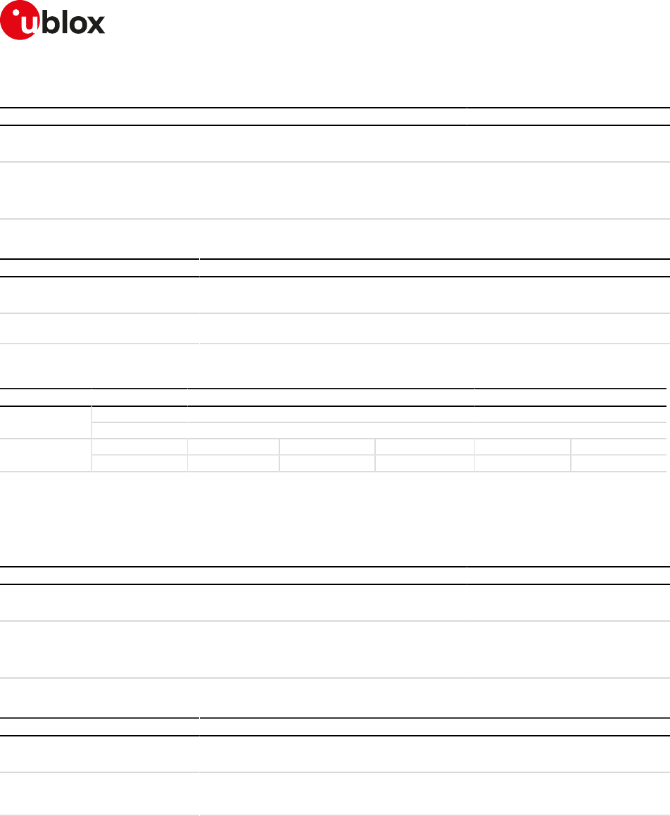
SARA-R4/N4 series-AT Commands Manual
UBX-17003787 - R09
18Internet protocol transport layer
Page 198 of 307
18.18.2Syntax
Type Syntax Response Example
Set AT+UDCONF=3,<socket_id>,
<sending_timer_timeout>
OK AT+UDCONF=3,1,1000
OK
Read AT+UDCONF=3,<socket_id> +UDCONF: 3,<socket_id>,<sending_
timer_timeout>
OK
AT+UDCONF=3,1
+UDCONF: 3,1,1000
OK
18.18.3Defined values
Parameter Type Description
<socket_id> Number Socket identifier; used when changing the UDP Direct Link settings.
Allowed range is 0-6
<sending_timer_
timeout>
Number Sending timer (in milliseconds) for UDP direct link; valid range is 100-120000; the
default value is 1000 ms
18.19Timer Trigger configuration for Direct Link +UDCONF=5
+UDCONF=5
SARA-R404M SARA-R410M-01B SARA-R410M-02B SARA-R410M-52B SARA-R412MModules
SARA-N4
Syntax PIN required Settings saved Can be aborted Response time Error referenceAttributes
full No No No - +CME Error
18.19.1Description
Sets the timer trigger of the interested socket identifier for the data transmission enhanced Direct Link.
18.19.2Syntax
Type Syntax Response Example
Set AT+UDCONF=5,<socket_id>,
<timer_trigger>
OK AT+UDCONF=5,0,500
OK
Read AT+UDCONF=5,<socket_id> +UDCONF: 5,<socket_id>,<timer_
trigger>
OK
AT+UDCONF=5,0
+UDCONF: 5,0,500
OK
18.19.3Defined values
Parameter Type Description
<socket_id> Number Socket identifier; used when changing the UDP Direct Link settings.
Valid range is 0-6
<timer_trigger> Number Enhanced Direct Link sending timer trigger (in milliseconds); valid range is 0, 100 120
000; the factory-programmed value is 500 ms for UDP, 0 for TCP, 0 means trigger
disabled
SARA-R4/N4 series-AT Commands Manual
UBX-17003787 - R09
18Internet protocol transport layer
Page 199 of 307
18.20Data Length Trigger configuration for Direct Link
+UDCONF=6
+UDCONF=6
SARA-R404M SARA-R410M-01B SARA-R410M-02B SARA-R410M-52B SARA-R412MModules
SARA-N4
Syntax PIN required Settings saved Can be aborted Response time Error referenceAttributes
full No No No - +CME Error
18.20.1Description
Sets the data length trigger of the interested socket identifier for the data transmission enhanced Direct Link.
18.20.2Syntax
Type Syntax Response Example
Set AT+UDCONF=6,<socket_id>,<data_
length_trigger>
OK AT+UDCONF=6,0,1024
OK
Read AT+UDCONF=6,<socket_id> +UDCONF: 6,<socket_id>,<data_
length_trigger>
OK
AT+UDCONF=6,0
+UDCONF: 6,0,1024
OK
18.20.3Defined values
Parameter Type Description
<socket_id> Number Socket identifier; used when changing the UDP Direct Link settings.
Valid range is 0-6
<data_length_
trigger>
Number Enhanced Direct Link data length trigger in bytes, valid range is 0, 3 1472 for UDP and
0, 3-2048 for TCP, the factory-programmed value is 1024 for UDP, 0 for TCP, 0 means
trigger disabled
18.21Character trigger configuration for Direct Link
+UDCONF=7
+UDCONF=7
SARA-R404M SARA-R410M-01B SARA-R410M-02B SARA-R410M-52B SARA-R412MModules
SARA-N4
Syntax PIN required Settings saved Can be aborted Response time Error referenceAttributes
full No No No - +CME Error
18.21.1Description
Sets the character trigger of the interested socket identifier for the data transmission enhanced Direct Link.
18.21.2Syntax
Type Syntax Response Example
Set AT+UDCONF=7,<socket_id>,
<character_trigger>
OK AT+UDCONF=7,0,13
OK
Read AT+UDCONF=7,<socket_id> +UDCONF: 7,<socket_id>,
<character_trigger>
OK
AT+UDCONF=7,0
+UDCONF: 7,0,13
OK
18.21.3Defined values
Parameter Type Description
<socket_id> Number Socket identifier; used when changing the Direct Link settings.
SARA-R4/N4 series-AT Commands Manual
UBX-17003787 - R09
18Internet protocol transport layer
Page 200 of 307
Parameter Type Description
The allowed range is 0-6
<character_trigger> Number Enhanced Direct Link character trigger, the value represents the ASCII code (in base
10) of the character to be used as character trigger. The allowed range is -1, 0-255, the
factory-programmed value is -1; -1 means trigger disabled
18.22Congestion timer configuration for Direct Link
+UDCONF=8
+UDCONF=8
SARA-R404M SARA-R410M-01B SARA-R410M-02B SARA-R410M-52B SARA-R412MModules
SARA-N4
Syntax PIN required Settings saved Can be aborted Response time Error referenceAttributes
full No No No - +CME Error
18.22.1Description
Sets the congestion timer of the interested socket identifier for the data transmission enhanced Direct Link.
18.22.2Syntax
Type Syntax Response Example
Set AT+UDCONF=8,<socket_id>,
<congestion_timer>
OK AT+UDCONF=8,0,120000
OK
Read AT+UDCONF=8,<socket_id> +UDCONF: 8,<socket_id>,
<congestion_timer>
OK
AT+UDCONF=8,0
+UDCONF: 8,0,120000
OK
18.22.3Defined values
Parameter Type Description
<socket_id> Number Socket identifier; used when changing the Direct Link settings.
Valid range is 0-6
<congestion_timer> Number Enhanced Direct Link congestion timer (in milliseconds); valid range is 0, 1000-72000
0; the factory-programmed value is 60000, 0 means trigger disabled
18.23Socket control +USOCTL
+USOCTL
SARA-R404M SARA-R410M-01B SARA-R410M-02B SARA-R410M-52B SARA-R412MModules
SARA-N4
Syntax PIN required Settings saved Can be aborted Response time Error referenceAttributes
partial No No No - +CME Error
18.23.1Description
Allows interaction with the low level socket layer.
18.23.2Syntax
Type Syntax Response Example
Set AT+USOCTL=<socket>,<param_id> +USOCTL: <socket>,<param_id>,
<param_val>[,<param_val2>]
OK
AT+USOCTL=0,2
+USOCTL: 0,2,38
OK
Test AT+USOCTL=? +USOCTL: (list of supported
<socket>s),(list of supported
<param_id>s)
OK
+USOCTL: (0-6),(0-4,10-11)
OK

SARA-R4/N4 series-AT Commands Manual
UBX-17003787 - R09
18Internet protocol transport layer
Page 201 of 307
18.23.3Defined values
Parameter Type Description
<socket> Number Socket identifier. The range goes from 0 to 6
<param_id> Number Control request identifier. Possible values are:
• 0: query for socket type
• 1: query for last socket error
• 2: get the total amount of bytes sent from the socket
• 3: get the total amount of bytes received by the socket
• 4: query for remote peer IP address and port
• 10: query for TCP socket status (only TCP sockets)
• 11: query for TCP outgoing unacknowledged data (only TCP sockets)
• 5-9, 12-99: RFU
<param_val> Number /
String
This value may assume different means depending on the <param_id> parameter.
If <param_id>= 0, <param_val> can assume these values:
• 6 TCP socket
• 17: UDP socket
If <param_id>= 1, <param_val> can assume these values:
• N: last socket error
If <param_id>= 2, <param_val> can assume these values:
• N: the total amount (in bytes) of sent (acknowledged + unacknowledged) data
If <param_id>= 3, <param_val> can assume these values:
• N: the total amount (in bytes) of received (read) data
If <param_id>= 4, <param_val> can assume these values:
• A string representing the remote peer IP address expressed in dotted decimal form
If <param_id>= 10, <param_val> can assume these values:
• 0: the socket is in INACTIVE status (it corresponds to CLOSED status defined in
RFC793 "TCP Protocol Specification" [112])
• 1: the socket is in LISTEN status
• 2: the socket is in SYN_SENT status
• 3: the socket is in SYN_RCVD status
• 4: the socket is in ESTABILISHED status
• 5: the socket is in FIN_WAIT_1 status
• 6: the socket is in FIN_WAIT_2 status
• 7: the sokcet is in CLOSE_WAIT status
• 8: the socket is in CLOSING status
• 9: the socket is in LAST_ACK status
• 10: the socket is in TIME_WAIT status
If <param_id>= 11, <param_val> can assume these values:
• N: the total amount of outgoing unacknowledged data
<param_val2> Number This value is present only when <param_id> is 4. It represents the remote peer IP port.
For IP address format reference see the IP addressing.
18.23.4Notes
SARA-R4 / SARA-N4
• <param_id>= 2, 3, 4 and 11 are not supported.
SARA-R4/N4 series-AT Commands Manual
UBX-17003787 - R09
18Internet protocol transport layer
Page 202 of 307
18.24Configure Dormant Close Socket Behavior +USOCLCFG
+USOCLCFG
SARA-R410M-02B SARA-R410M-52B SARA-R412MModules
SARA-N4
Syntax PIN required Settings saved Can be aborted Response time Error referenceAttributes
full Yes NVM No - +CME Error
18.24.1Description
Enables or disables the TCP socket Graceful Dormant Close feature. When enabled, if the RRC connection is
released and a TCP socket is closed with the +USOCL, the module will re-establish the RRC connection to close
the socket both locally and remotely. When this feature is disabled, the module will close the socket locally
without re-establishing the RRC connection. In this case the socket will remain open on the remote side until
it is closed.
18.24.2Syntax
Type Syntax Response Example
Set AT+USOCLCFG=<GDC_enable> OK AT+USOCLCFG=0
OK
Read AT+USOCLCFG? +USOCLCFG: <GDC_enable>
OK
+USOCLCFG: 0
OK
Test AT+USOCLCFG=? +USOCLCFG: (list of supported
<GDC_enable>s)
OK
+USOCLCFG: (0,1)
OK
18.24.3Defined values
Parameter Type Description
<GDC_enable> Number Status of TCP socket Graceful Dormant Close. Allowed values:
• 0: disabled
• 1 (factory-programmed value): enabled

SARA-R4/N4 series-AT Commands Manual
UBX-17003787 - R09
19SSL/TLS
Page 203 of 307
19SSL/TLS
19.1Introduction
SSL/TLS provides a secure connection between two entities using TCP socket for communication (i.e. HTTP/
FTP server and HTTP/FTP client).
The SSL/TLS with digital certificates support provides different connection security aspects:
•Server authentication: use of the server certificate verification against a specific trusted certificate or a
trusted certificates list;
•Client authentication: use of the client certificate and the corresponding private key;
•Data security and integrity: data encryption and Hash Message Authentication Code (HMAC) generation.
The security aspects used in the current connection depend on the SSL/TLS configuration and features
supported by the communicating entities.
u-blox cellular modules support all the described aspects of SSL/TLS security protocol with these AT
commands:
•AT+USECMNG: import, removal, list and information retrieval of certificates or private keys;
•AT+USECPRF: configuration of USECMNG (u-blox SECurity MaNaGement) profiles used for an SSL/TLS
connection.
The USECMNG provides a default SSL/TLS profile which cannot be modified. The default USECMNG profile
provides the following SSL/TLS settings:
Setting Value Meaning
Certificates validation level Level 0 The server certificate will not be checked or verified.
Minimum SSL/TLS version Any The server can use any of the TLS1.0/TLS1.1/TLS1.2 versions for the
connection.
Cipher suite Automatic The cipher suite will be negotiated in the handshake process.
Trusted root certificate internal
name
"" (none) No certificate will be used for the server authentication.
Expected server host-name "" (none) No server host-name is expected.
Client certificate internal name "" (none) No client certificate will be used.
Client private key internal name "" (none) No client private key will be used.
SARA-R4 / SARA-N4
The default USECMNG profile does not provide the client certificate internal name and the client private
key internal name.
19.2SSL/TLS certificates and private keys manager
+USECMNG
+USECMNG
SARA-R410M-01B SARA-R410M-02B SARA-R410M-52B SARA-R412MModules
SARA-N4
Syntax PIN required Settings saved Can be aborted Response time Error referenceAttributes
full No No No - +CME Error
19.2.1Description
Manages the X.509 certificates and private keys with the following functionalities:
• Import of certificates and private keys
• List and information retrieval of imported certificates and private keys
• Removal of certificates and private keys
• MD5 calculation of imported certificate or private key
SARA-R4 / SARA-N4
The command accepts certificates and private keys in DER (Distinguished Encoding Rules) format only.
If the provided format is PEM, the imported certificate or private key will be invalid.
SARA-R4/N4 series-AT Commands Manual
UBX-17003787 - R09
19SSL/TLS
Page 204 of 307
The certificates and private keys are kept in DER format and are not retrievable (i.e. cannot be downloaded
from the module); for data validation purposes an MD5 hash string of the stored certificate or private key
(stored in DER format) can be retrieved.
Up to 16 certificates or private keys can be imported.
Data for certificate or private key import can be provided with a stream of byte similar to +UDWNFILE or
from a file stored on the FS.
When using the stream of byte import functionality:
• If the data transfer is stopped before its competition, a guard timer of 20 s will ensure the termination
of the data transmission. In this case the prompt will switch back in AT command mode and an error
result code will be returned.
• If the module shuts down during the data transfer, all the bytes are discarded.
• If any error occurs during the data transfer, all bytes are discarded.
All the imported certificates or private keys are listed if the type of the security data is omitted.
19.2.2Syntax
Type Syntax Response Example
Generic syntax:
Action AT+USECMNG=<op_code>,
[<type>[,<internal_name>[,
<param1>[,<param2>]]]]
OK -
Import a certificate or private key from serial I/O:
Action AT+USECMNG=0,<type>,<internal_
name>,<data_size>[,<password>]
>
Start transfer of data ...
+USECMNG: 0,<type>,<internal_
name>,<md5_string>
OK
AT+USECMNG=0,0,"AddTrustCA",
1327
>-----BEGIN CERTIFICATE-----
(...other certificate data bytes...)
+USECMNG: 0,0,"AddTrustCA",
"77107370ec4db40a0
8a6e36a64a1435b"
OK
Import a certificate or private key from a file stored on FS:
Action AT+USECMNG=1,<type>,<internal_
name>,<filename>[,<password>]
+USECMNG: 1,<type>,<internal_
name>,<md5_string>
OK
AT+USECMNG=1,0,"AddTrustCA",
"addtrust.cert"
+USECMNG: 1,0,"AddTrustCA","7710
7370ec4db40a08a6e36a64a1435b"
OK
Remove an imported certificate or private key:
Action AT+USECMNG=2,<type>,<internal_
name>
OK AT+USECMNG=2,0,"AddTrustCA"
OK
List imported certificates or private keys:
Read AT+USECMNG=3[,<type>] <cert_type>,<internal_name>[,
<common_name>,<expiration_
date>]
...
OK
AT+USECMNG=3
"CA","AddTrustCA","AddTrust
External CA Root","2020/05/30"
"CA","GlobalSignCA","GlobalSign",
"2029/03/18"
"CC","JohnDoeCC","GlobalSign","20
10/01/01"
"PK","JohnDoePK"
OK
Retrieve the MD5 of an imported certificate or private key:
Read AT+USECMNG=4,<type>,<internal_
name>
+USECMNG: 4,<type>,<internal_
name>,<md5_string>
OK
AT+USECMNG=4,0,"AddTrustCA"
+USECMNG: 4,0,"AddTrustCA",
"77107370ec4db40a0
8a6e36a64a1435b"

SARA-R4/N4 series-AT Commands Manual
UBX-17003787 - R09
19SSL/TLS
Page 205 of 307
Type Syntax Response Example
OK
Test AT+USECMNG=? +USECMNG: (list of supported <op_
code>s),(list of supported <type>s)
OK
+USECMNG: (0-4),(0-2)
OK
19.2.3Defined values
Parameter Type Description
<op_code> Number Type of operation:
• 0: import a certificate or a private key (data provided by the stream of byte)
• 1: import a certificate or a private key (data provided from a file on FS)
• 2: remove an imported certificate or private key
• 3: list imported certificates or private keys
• 4: retrieve the MD5 of an imported certificate or private key
<type> Number Type of the security data:
• 0: trusted root CA (certificate authority) certificate
• 1: client certificate
• 2: client private key
<cert_type> String Type of the security data:
• "CA": trusted root CA (certificate authority) certificate
• "CC": client certificate
• "PK": client private key
<internal_name> String Unique identifier of an imported certificate or private key. If an existing name is used
the data will be overridden. The maximum length is 200 characters.
<data_size> Number Size in bytes of a certificate or private key being imported. The maximum allowed size
is 8192 bytes.
<password> String Decryption password; applicable only for PKCS8 encrypted client private keys. The
maximum length is 128 characters.
<filename> String Name of the FS file containing the certificate or private key data to be imported. The
maximum allowed file size is 8192 bytes.
<md5_string> String MD5 formatted string.
<common_name> String Certificate subject (issued to) common name; applicable only for trusted root and
client certificates.
<expiration_date> String Certificate expiration (valid to date); applicable only for trusted root and client
certificates.
<param1> Number/
String
Type and supported content depend on the related <op_code> parameter; see the
<op_code> specification.
<param2> Number/
String
Type and supported content depend on the related <op_code> parameter; see the
<op_code> specification.
19.2.4Notes
SARA-R4 / SARA-N4
• The <password>, <common_name> and <expiration_date> parameters are not supported.
SARA-R410M
• The certificates in the PEM format are not supported; they will not be automatically converted to the
DER format.
SARA-R4/N4 series-AT Commands Manual
UBX-17003787 - R09
19SSL/TLS
Page 206 of 307
19.3SSL/TLS security layer profile manager +USECPRF
+USECPRF
SARA-R410M-01B SARA-R410M-02B SARA-R410M-52B SARA-R412MModules
SARA-N4
Syntax PIN required Settings saved Can be aborted Response time Error referenceAttributes
full No No No - +CME Error
19.3.1Description
Manages security profiles for the configuration of the following SSL/TLS connections properties:
•Certificate validation level:
o Level 0: no certificate validation; the server certificate will not be checked or verified. No additional
certificates are needed.
o Level 1: certificate validation against a specific or a list of imported trusted root certificates.
o Level 2: certificate validation with an additional URL integrity check (the server certificate common
name must match the server hostname).
o Level 3: certificate validation with an additional check on the certificate validity date.
CA certificates should be imported with the +USECMNG AT command
•Minimum SSL/TLS version to be used:
o Any
o TLS 1.0
o TLS 1.1
o TLS 1.2
•Exact cipher suite to be used (the cipher suite register of Internet Assigned Numbers Authority (IANA) is
provided in brackets):
o (0x002f) TLS_RSA_WITH_AES_128_CBC_SHA
o (0x003C) TLS_RSA_WITH_AES_128_CBC_SHA256
o (0x0035) TLS_RSA_WITH_AES_256_CBC_SHA
o (0x003D) TLS_RSA_WITH_AES_256_CBC_SHA256
o (0x000a) TLS_RSA_WITH_3DES_EDE_CBC_SHA
o (0x008c) TLS_PSK_WITH_AES_128_CBC_SHA
o (0x008d) TLS_PSK_WITH_AES_256_CBC_SHA
o (0x008b) TLS_PSK_WITH_3DES_EDE_CBC_SHA
o (0x0094) TLS_RSA_PSK_WITH_AES_128_CBC_SHA
o (0x0095) TLS_RSA_PSK_WITH_AES_256_CBC_SHA
o (0x0093) TLS_RSA_PSK_WITH_3DES_EDE_CBC_SHA
o (0x00ae) TLS_PSK_WITH_AES_128_CBC_SHA256
o (0x00af) TLS_PSK_WITH_AES_256_CBC_SHA384
o (0x00b6) TLS_RSA_PSK_WITH_AES_128_CBC_SHA256
o (0x00b7) TLS_RSA_PSK_WITH_AES_256_CBC_SHA384
See Table 22 for the applicability of cipher suite depending on the module series.
•Certificate to be used for server and mutual authentication:
o The trusted root certificate. The CA certificate should be imported with the AT+USECMNG command.
o The client certificate that should be imported with the AT+USECMNG command.
o The client private key that should be imported with the AT+USECMNG command.
•Expected server hostname, when using certificate validation level 2 or 3.
•Password for the client private key, if it is password protected.
•Pre-shared key used for connection. Defines a pre-shared key and key-name (PSK), when a TLS_PSK_*
cipher suite is used.
•SNI (Server Name Indication). SNI is a feature of SSL/TLS which uses an additional SSL/TLS extension
header to specify the server name to which the client is connecting to. The extension was introduced to
support the certificate handling used with virtual hosting provided by the various SSL/TLS enabled servers
mostly in cloud based infrastructures. With the SNI a server has the opportunity to present a different
server certificate (or/and whole SSL/TLS configuration) based on the host indicated by the SNI extension.
SARA-R4/N4 series-AT Commands Manual
UBX-17003787 - R09
19SSL/TLS
Page 207 of 307
Table 21 provides the list the applicability of SSL connection properties depending on the module series.
Certificate validation level
Minimum SSL/TLS version
Cipher suite
Trusted root certificate internal name
Expected server hostname
Password for the client private key
Pre-shared key used for connection
SNI
SARA-R4 SARA-N4 * * * * *
Table 21: SSL/TLS connections properties applicability
To set all the parameters in security profile, a set command for each <op_code> needs to be issued (e.g.
certificate validation level, minimum SSL/TLS version, ...).
To reset (set to factory programmed value) all the parameters of a specific security profile, issue the AT
+USECPRF=<profile_id> command.
19.3.2Syntax
Type Syntax Response Example
Set AT+USECPRF=<profile_id>[,<op_
code>[,<param_val>]]
OK AT+USECPRF=0,0,0
OK
Read AT+USECPRF=<profile_id>,<op_
code>
+USECPRF: <profile_id>,<op_code>,
<param_val>
OK
AT+USECPRF=0,0
+USECPRF: 0,0,0
OK
Test AT+USECPRF=? +USECPRF: (list of supported
<profile_id>s),(list of supported
<op_code>s)
OK
+USECPRF: (0-4),(0-6)
OK
19.3.3Defined values
Parameter Type Description
<profile_id> Number USECMNG security profile identifier, in range 0-4; if it is not followed by other parameters the
profile settings will be reset (set to factory programmed value).
<op_code> Number • 0: certificate validation level; allowed values for <param_val>:
o 0 (factory-programmed value): Level 0 - No validation; the server certificate will not be
checked or verified. The server in this case is not authenticated.
o 1: Level 1 - Root certificate validation without URL integrity check. The server certificate
will be verified with a specific trusted certificates or with each of the imported trusted root
certificates.
o 2: Level 2 - Root certificate validation with URL integrity check. Level 1 validation with an
additional URL integrity check.
o 3: Level 3 - Root certificate validation with check of certificate validity date. Level 2
validation with an additional check of certificate validity date.
• 1: minimum SSL/TLS version; allowed values for <param_val>:
o 0 (factory-programmed value): any; server can use any version for the connection.
o 1: TLSv1.0; connection allowed only to TLS/SSL servers which support TLSv1.0/TLSv1.1/
TLSv1.2
o 2: TLSv1.1; connection allowed only to TLS/SSL servers which support TLSv1.1/TLSv1.2
o 3: TLSv1.2; connection allowed only to TLS/SSL servers which support TLSv1.2
• 2: cipher suite; allowed values for <param_val> define which cipher suite will be used:

SARA-R4/N4 series-AT Commands Manual
UBX-17003787 - R09
19SSL/TLS
Page 208 of 307
Parameter Type Description
o 0 (factory-programmed value): (0x0000) Automatic the cipher suite will be negotiated in
the handshake process
o 1: (0x002f) TLS_RSA_WITH_AES_128_CBC_SHA
o 2: (0x003C) TLS_RSA_WITH_AES_128_CBC_SHA256
o 3: (0x0035) TLS_RSA_WITH_AES_256_CBC_SHA
o 4: (0x003D) TLS_RSA_WITH_AES_256_CBC_SHA256
o 5: (0x000a) TLS_RSA_WITH_3DES_EDE_CBC_SHA
o 6: (0x008c) TLS_PSK_WITH_AES_128_CBC_SHA
o 7: (0x008d) TLS_PSK_WITH_AES_256_CBC_SHA
o 8: (0x008b) TLS_PSK_WITH_3DES_EDE_CBC_SHA
o 9: (0x0094) TLS_RSA_PSK_WITH_AES_128_CBC_SHA
o 10: (0x0095) TLS_RSA_PSK_WITH_AES_256_CBC_SHA
o 11: (0x0093) TLS_RSA_PSK_WITH_3DES_EDE_CBC_SHA
o 12: (0x00ae) TLS_PSK_WITH_AES_128_CBC_SHA256
o 13: (0x00af) TLS_PSK_WITH_AES_256_CBC_SHA384
o 14: (0x00b6) TLS_RSA_PSK_WITH_AES_128_CBC_SHA256
o 15: (0x00b7) TLS_RSA_PSK_WITH_AES_256_CBC_SHA384
• 3: trusted root certificate internal name;
o <param_val> (string) is the internal name identifying a trusted root certificate; the
maximum length is 200 characters. The factory programmed value is an empty string.
• 4: expected server hostname;
o <param_val> (string) is the hostname of the server, used when certificate validation level
is set to Level 2; the maximum length is 256 characters. The factory programmed value is
an empty string.
• 5: client certificate internal name;
o <param_val> (string) is the internal name identifying a client certificate to be sent to the
server; the maximum length is 200 characters. The factory programmed value is an empty
string.
• 6: client private key internal name;
o <param_val> (string) is the internal name identifying a private key to be used; the
maximum length is 200 characters. The factory programmed value is an empty string.
• 7: client private key password;
o <param_val> (string) is the password for the client private key if it is password protected;
the maximum length is 128 characters. The factory programmed value is an empty string.
• 8: pre-shared key;
o <param_val> (string) is the pre-shared key used for connection; the maximum length is 64
characters. The factory programmed value is an empty string.
• 9: pre-shared key name;
o <param_val> (string) is the pre-shared key name used for connection; the maximum length
is 128 characters. The factory programmed value is an empty string.
• 10: SNI (Server Name Indication);
o <param_val> (string) value for the additional negotiation header SNI (Server Name
Indication) used in SSL/TLS connection negotiation; the maximum length is 128
characters. The factory programmed value is an empty string.
SARA-R4/N4 series-AT Commands Manual
UBX-17003787 - R09
19SSL/TLS
Page 209 of 307
19.3.4Notes
•
TLS_RSA_WITH_AES_128_CBC_SHA
TLS_RSA_WITH_AES_128_CBC_SHA256
TLS_RSA_WITH_AES_256_CBC_SHA
TLS_RSA_WITH_AES_256_CBC_SHA256
TLS_RSA_WITH_3DES_EDE_CBC_SHA
TLS_PSK_WITH_AES_128_CBC_SHA
TLS_PSK_WITH_AES_256_CBC_SHA
TLS_PSK_WITH_3DES_EDE_CBC_SHA
TLS_RSA_PSK_WITH_AES_128_CBC_SHA
TLS_RSA_PSK_WITH_AES_256_CBC_SHA
TLS_RSA_PSK_WITH_3DES_EDE_CBC_SHA
TLS_PSK_WITH_AES_128_CBC_SHA256
TLS_PSK_WITH_AES_256_CBC_SHA384
TLS_RSA_PSK_WITH_AES_128_CBC_SHA256
TLS_RSA_PSK_WITH_AES_256_CBC_SHA384
SARA-R4 SARA-N4 * * * * * * * * * * * * * * *
SARA-R410M-01B * * * * *
Table 22: Cipher suite applicability
SARA-R4 / SARA-N4
• <op_code>=7, 8, 9 and 10 are not supported.
SARA-R410M-01B
• The unique certificate validation level (<op_code>=0) supported is the level 0 (no validation, <param_
val>=0).
• The unique minimum SSL/TLS version (<op_code>=1) supported is <param_val>=0 (the server can use
any version for the connection).
19.4AT+USECMNG command example
Command Response Description
Step 1: Import a trusted root certificate using the stream of byte similar to +UDWNFILE
AT+USECMNG=0,0,"ThawteCA",
1516
> Start the data transfer using the stream of
byte.
PEM encoded trusted root
certificate data.
+USECMNG: 1,0,"ThawteCA","8ccadc0
b22cef5be72ac411a11a8d812"
OK
Input PEM formatted trusted root
certificate data bytes. Output MD5 hash
string of the stored trusted root certificate
DER.
Step 2: List all available certificates and private keys
AT+USECMNG=3 CA, "ThawteCA","thawte Primary Root CA",
"2036/07/17"
OK
List all available certificates and private
keys.
Step 3: Set the security profile 2 validation level to trusted root
AT+USECPRF=2,0,1 OK Security profile 2 has the validation level
set to trusted root.
Step 4: Set the security profile 2 trusted root certificate to the CA certificate imported as "ThawteCA"
AT+USECPRF=2,3,"ThawteCA" OK Security profile 2 will use the CA certificate
imported as "ThawteCA" for server
certificate validation.
Step 5: Use the configured USECMNG profile 2 with the UHTTP application
AT+UHTTP=0,1,"www.ssl_tls_
test_server.com"
OK Configure the UHTTP server name.
AT+UHTTP=0,6,1,2 OK Enable the SSL/TLS for the UHTTP profile
#0 and specify the SSL/TLS security
profile 2.
AT+UHTTPC=0,1,"/","https.resp" OK Execute the HTTP GET command.
+UUHTTPCR: 0,1,1 HTTP GET URC response.

SARA-R4/N4 series-AT Commands Manual
UBX-17003787 - R09
19SSL/TLS
Page 210 of 307
In the above example the following PEM encoded trusted certificate is used:
-----BEGIN CERTIFICATE-----
MIIEIDCCAwigAwIBAgIQNE7VVyDV7exJ9C/ON9srbTANBgkqhkiG9w0BAQUFADCB
qTELMAkGA1UEBhMCVVMxFTATBgNVBAoTDHRoYXd0ZSwgSW5jLjEoMCYGA1UECxMf
Q2VydGlmaWNhdGlvbiBTZXJ2aWNlcyBEaXZpc2lvbjE4MDYGA1UECxMvKGMpIDIw
MDYgdGhhd3RlLCBJbmMuIC0gRm9yIGF1dGhvcml6ZWQgdXNlIG9ubHkxHzAdBgNV
BAMTFnRoYXd0ZSBQcmltYXJ5IFJvb3QgQ0EwHhcNMDYxMTE3MDAwMDAwWhcNMzYw
NzE2MjM1OTU5WjCBqTELMAkGA1UEBhMCVVMxFTATBgNVBAoTDHRoYXd0ZSwgSW5j
LjEoMCYGA1UECxMfQ2VydGlmaWNhdGlvbiBTZXJ2aWNlcyBEaXZpc2lvbjE4MDYG
A1UECxMvKGMpIDIwMDYgdGhhd3RlLCBJbmMuIC0gRm9yIGF1dGhvcml6ZWQgdXNl
IG9ubHkxHzAdBgNVBAMTFnRoYXd0ZSBQcmltYXJ5IFJvb3QgQ0EwggEiMA0GCSqG
SIb3DQEBAQUAA4IBDwAwggEKAoIBAQCsoPD7gFnUnMekz52hWXMJEEUMDSxuaPFs
W0hoSVk3/AszGcJ3f8wQLZU0HObrTQmnHNK4yZc2AreJ1CRfBsDMRJSUjQJib+ta
3RGNKJpchJAQeg29dGYvajig4tVUROsdB58Hum/u6f1OCyn1PoSgAfGcq/gcfomk
6KHYcWUNo1F77rzSImANuVud37r8UVsLr5iy6S7pBOhih94ryNdOwUxkHt3Ph1i6
Sk/KaAcdHJ1KxtUvkcx8cXIcxcBn6zL9yZJclNqFwJu/U30rCfSMnZEfl2pSy94J
NqR32HuHUETVPm4pafs5SSYeCaWAe0At6+gnhcn+Yf1+5nyXHdWdAgMBAAGjQjBA
MA8GA1UdEwEB/wQFMAMBAf8wDgYDVR0PAQH/BAQDAgEGMB0GA1UdDgQWBBR7W0XP
r87Lev0xkhpqtvNG61dIUDANBgkqhkiG9w0BAQUFAAOCAQEAeRHAS7ORtvzw6WfU
DW5FvlXok9LOAz/t2iWwHVfLHjp2oEzsUHboZHIMpKnxuIvW1oeEuzLlQRHAd9mz
YJ3rG9XRbkREqaYB7FViHXe4XI5ISXycO1cRrK1zN44veFyQaEfZYGDm/Ac9IiAX
xPcW6cTYcvnIc3zfFi8VqT79aie2oetaupgf1eNNZAqdE8hhuvU5HIe6uL17In/2
/qxAeeWsEG89jxt5dovEN7MhGITlNgDrYyCZuen+MwS7QcjBAvlEYyCegc5C09Y/
LHbTY5xZ3Y+m4Q6gLkH3LpVHz7z9M/P2C2F+fpErgUfCJzDupxBdN49cOSvkBPB7
jVaMaA==
-----END CERTIFICATE-----
19.5Notes
Due to significant memory fingerprint of an SSL/TLS connection, the number of concurrent SSL/TLS
connections is limited. The USECMNG and the underlying SSL/TLS infrastructure allows 4 concurrent SSL/
TLS connections (i.e. 4 HTTPS requests or 2 HTTPS and 2 FTPS request).
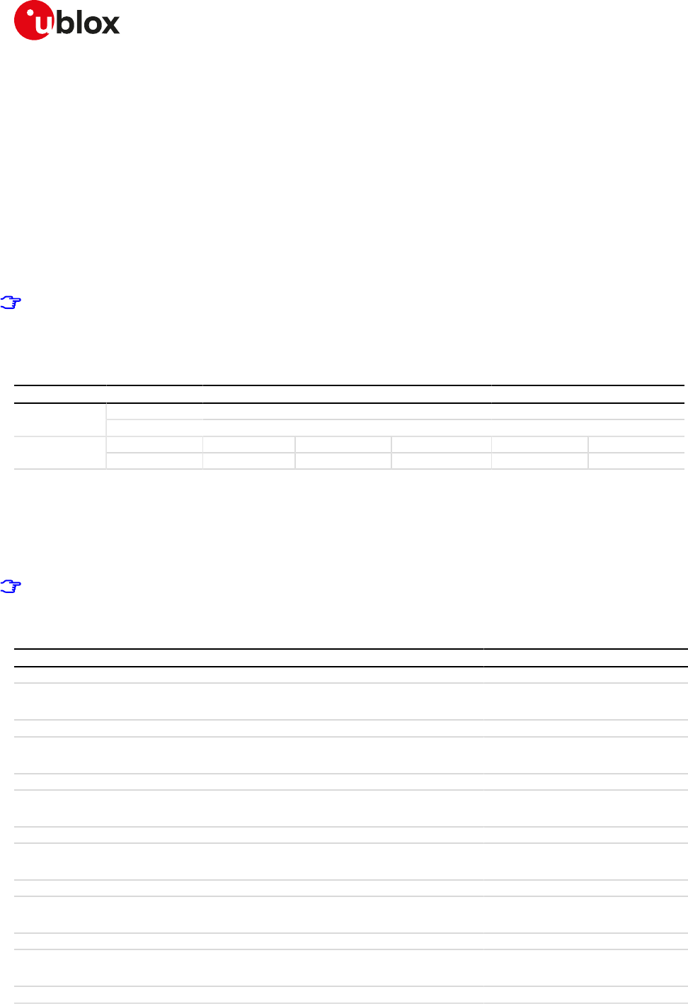
SARA-R4/N4 series-AT Commands Manual
UBX-17003787 - R09
20FTP
Page 211 of 307
20FTP
Proprietary u-blox AT commands. FTP AT commands set can be used for sending and receiving files over
the available bearer, transparently retrieving and storing them in the file system. Standard file and directory
management operations on the remote FTP server are as well possible. PSD or CSD connection must be
activated before using FTP client services.
Basically, two AT commands are necessary for an FTP client service: one AT command (+UFTP) to configure
the FTP profile, a second AT command to execute a specific FTP command (+UFTPC). The final result of an FTP
command will be notified through the +UUFTPCR URC whereas data will be provided through +UUFTPCD URC.
When these commands report an error which is not a +CME ERROR, the error code can be queried using the
+UFTPER AT command.
SARA-R4 / SARA-N4
No need to establish a PSD connection explicitly. This device automatically establishes a PSD connection
as part of the network registration and attach procedure.
20.1FTP service configuration +UFTP
+UFTP
SARA-R404M SARA-R410M-01B SARA-R410M-02B SARA-R410M-52B SARA-R412MModules
SARA-N4
Syntax PIN required Settings saved Can be aborted Response time Error referenceAttributes
partial No No No - Appendix A.6.1
20.1.1Description
Sets up a parameter for FTP service, or resets a parameter to its factory-programmed value. The set/reset
command needs to be executed for each single <op_code>. The read command returns the current setting of
all the FTP parameters, one per line (i.e. the FTP profile). The FTP parameter values set with this command are
all volatile (not stored in non-volatile memory).
If the set command is issued without <param1> parameter, the corresponding <op_code> parameter is
reset to the default value.
20.1.2Syntax
Type Syntax Response Example
Generic syntax
Set AT+UFTP=<op_code>[,<param1>[,
<param2>]]
OK AT+UFTP=7,21
OK
FTP server IP address
Set AT+UFTP=0[,<IP_address>] OK AT+UFTP=0,"192.168.1.0"
OK
FTP server name
Set AT+UFTP=1[,<server_name>] OK AT+UFTP=1,"ftp.server.com"
OK
Username
Set AT+UFTP=2[,<username>] OK AT+UFTP=2,"user_test"
OK
Password
Set AT+UFTP=3[,<password>] OK AT+UFTP=3,"PWD"
OK
Account
Set AT+UFTP=4[,<account>] OK AT+UFTP=4,"test"
OK
Inactivity timeout

SARA-R4/N4 series-AT Commands Manual
UBX-17003787 - R09
20FTP
Page 212 of 307
Type Syntax Response Example
Set AT+UFTP=5[,<timeout>] OK AT+UFTP=5,21
OK
FTP mode
Set AT+UFTP=6[,<FTP_mode>] OK AT+UFTP=6,1
OK
FTP server port
Set AT+UFTP=7[,<FTP_server_port>] OK AT+UFTP=7,30
OK
FTP Secure option in explicit mode
Set AT+UFTP=8[,<FTP_secure>[,
<USECMNG_profile>]]
OK AT+UFTP=8,1,2
OK
Read AT+UFTP? +UFTP: 0,<IP_address>
+UFTP: 1,<server_name>
+UFTP: 2,<username>
+UFTP: 4,<account>
+UFTP: 5,<timeout>
+UFTP: 6,<FTP_mode>
+UFTP: 7,<FTP_server_port>
[+UFTP: 8,<FTP_secure>[,
<USECMNG_profile>]]
OK
+UFTP: 0,"216.239.59.147"
+UFTP: 1,""
+UFTP: 2,"username"
+UFTP: 4,"account"
+UFTP: 5,0
+UFTP: 6,0
+UFTP: 7,21
+UFTP: 8,0
OK
Test AT+UFTP=? +UFTP: (list of supported <param_
tag>s)
OK
+UFTP: (0-8)
OK
20.1.3Defined values
Parameter Type Description
<op_code> String FTP parameter:
• 0: FTP server IP address
• 1: FTP server name
• 2: FTP username
• 3: FTP password
• 4: FTP additional user account
• 5: FTP inactivity timeout period
• 6: FTP mode
• 7: Remote FTP server listening port
• 8: FTP secure
<IP_address> String FTP server IP address. The default value is an empty string. For IP address format
reference see the IP addressing.
<server_name> String FTP server name (e.g. "ftp.server.com"). The maximum length is 128 characters. The
default value is an empty string.
<username> String User name (the maximum length is 30 characters) for the FTP login procedure. The
default value is an empty string.
<password> String Password (the maximum length is 30 characters) for the FTP login procedure. The
default value is an empty string.
<account> String Additional user account (if required) for the FTP login procedure. The maximum
length is 30 characters. The default value is an empty string.
<timeout> Number Inactivity timeout period in seconds. The range goes from 0 to 86400 s; 0 means no
timeout (the FTP session will not be terminated in the absence of incoming traffic).
The default value is 30 s.
<FTP_mode> Number FTP mode:
• 0 (default value): active
• 1: passive
SARA-R4/N4 series-AT Commands Manual
UBX-17003787 - R09
20FTP
Page 213 of 307
Parameter Type Description
<FTP_server_port> Number Remote FTP server listening port; it must be a valid TCP port value. The range goes
from 1 to 65535; the default value is 21.
<FTP_secure> Number Enables / disables the Secure option (explicit mode) of FTP client service. FTP Secure
option in explicit mode (SSL encryption of FTP control channel; FTP data channel is
not encrypted):
• 0 (default value): no SSL encryption
• 1: enable SSL encryption of FTP control connection
<USECMNG_profile> Number USECMNG profile (number). Defines the USECMNG profile which specifies the SSL/
TLS properties to be used for the SSL/TLS connection. The range goes from 0 to 4. If
no profile is set a default USECMNG profile is used (see USECMNG section).
<param1> Number /
String
Type and supported content depend on related <op_code> (details are given above).
If <param1> is not specified the value of the corresponding parameter <op_code> is
reset to default value.
<param2> Number /
String
Type and supported content depend on related <op_code> (details are given above).
If <param2> is not specified the value of the corresponding parameter <op_code> is
reset to default value.
20.1.4Notes
• The information text response to the read command does not display the password.
• The FTP server IP address and the FTP server name are mutually exclusive. If value for <op_code>=0 is
specified by user, then value for <op_code>=1 is reset or vice versa.
• Some network operators do not allow incoming connections. Due to these limitations introduced by
network operators it is possible to encounter problems using FTP active mode. If the FTP active mode
fails to exchange files, try the passive mode to solve the problem.
• Some network operators do not allow FTPS. In this case the +UFTPC=1 command (FTP login) will return
a failure response via +UUFTPCR URC after an SSL timeout of 30 s.
SARA-R404M / SARA-R410M-01B
• <op_code>=8 is not supported.
SARA-R4 / SARA-N4
• During connection to FTP remote server (via FTP login command) the FTP profile parameters cannot be
changed or reset to factory-programmed values until disconnection takes place (FTP logout). Only <op_
code>=5 (inactivity timeout), and <op_code>=6 (FTP mode), can be updated while the FTP connection is
on the go.
20.2FTP command +UFTPC
+UFTPC
SARA-R404M SARA-R410M-01B SARA-R410M-02B SARA-R410M-52B SARA-R412MModules
SARA-N4
Syntax PIN required Settings saved Can be aborted Response time Error referenceAttributes
partial No No No - Appendix A.6.1
20.2.1Description
Triggers the FTP actions corresponding to the <op_code> parameter. The final result code indicates if sending
the command request to the FTP process was successful or not. The +UUFTPCR (FTP command result) URC
returns to the user the final result of the FTP command previously sent with +UFTPC. As well, the +UUFTPCD
FTP unsolicited data URC provides the data requested by the user (e.g. file or directory lists) and received from
the FTP server.
20.2.2Syntax
Type Syntax Response Example
General syntax
Set AT+UFTPC=<op_code>[,<param1>[,
<param2>[,<param3>]]]
OK AT+UFTPC=4,"data.zip","data.zip"
OK
FTP logout

SARA-R4/N4 series-AT Commands Manual
UBX-17003787 - R09
20FTP
Page 214 of 307
Type Syntax Response Example
Set AT+UFTPC=0 OK AT+UFTPC=0
OK
FTP login
Set AT+UFTPC=1 OK AT+UFTPC=1
OK
Delete the file from the FTP server
Set AT+UFTPC=2,<file_name> OK AT+UFTPC=2,"mytest"
OK
Rename a file of FTP server
Set AT+UFTPC=3,<file_name>,<new_
file_name>
OK AT+UFTPC=3,"old_name","final_
name"
OK
Retrieve the file from the FTP server
Set AT+UFTPC=4,<remote_file_name>,
<local_file_name>[,<retrieving_
mode>]
OK AT+UFTPC=4,"data.zip","data.zip"
OK
Store the file on the FTP server
Set AT+UFTPC=5,<local_file_name>,
<remote_file_name>[,<number_of_
byte>]
OK AT+UFTPC=5,"data.zip","data.zip",
30
OK
Retrieve a file from the FTP server using direct link mode
Set AT+UFTPC=6,<remote_file_name>[,
<number_of_byte>]
OK AT+UFTPC=6,"data.zip",30
OK
Send a file to the FTP server using the direct link mode
Set AT+UFTPC=7,<remote_file_name>[,
<number_of_byte>]
OK AT+UFTPC=7,"data.zip",30
OK
Change the working directory to the specified one
Set AT+UFTPC=8,<directory_name> OK AT+UFTPC=8,"data_folder"
OK
Create a directory on the FTP host
Set AT+UFTPC=10,<directory_name> OK AT+UFTPC=10,"new_data_folder"
OK
Remove the directory from the remote FTP server
Set AT+UFTPC=11,<directory_name> OK AT+UFTPC=11,"data_folder"
OK
Information of a file or a directory
Set AT+UFTPC=13[,<file_directory_
name>]
OK AT+UFTPC=13,"data_folder"
OK
List the file names in a specified directory
Set AT+UFTPC=14[,<file_directory_
name>]
OK AT+UFTPC=14,"data.zip"
OK
Retrieve the FOTA update file
Set AT+UFTPC=100,<remote_file_
name>
OK AT+UFTPC=100,"data.zip"
OK
Test AT+UFTPC=? +UFTPC: (list of supported <op_
code>s)
OK
+UFTPC: (0-5,8,10,11,13,14,100)
OK
URC +UUFTPCD: <op_code>,<ftp_data_
len>,<ftp_data>
+UUFTPCD: 13,16,"16 bytes of data"
URC +UUFTPCR: <op_code>,<ftp_
result>[,<md5_sum>]
+UUFTPCR: 1,1
SARA-R4/N4 series-AT Commands Manual
UBX-17003787 - R09
20FTP
Page 215 of 307
20.2.3Defined values
Parameter Type Description
<op_code> Number FTP command request. Allowed values:
• 0: FTP logout; terminates the FTP session by performing a logout.
• 1: FTP login; connects to the FTP server using the parameters of the current FTP
profile (set via AT+UFTP command).
• 2: deletes the file from the FTP server.
• 3: renames the file. This AT command just sends requests to the FTP process.
• 4: retrieves the file from the FTP server.
• 5: stores the file on the FTP server.
• 6: retrieves a file from the FTP server using direct link mode. This command handles
the initial steps of the FTP protocol for retrieving a file; after that it will establish
a transparent end to end communication with the data connection TCP socket via
the serial interface. After the CONNECT result code, the file content will be directly
sent to the serial interface. When the data transfer is completed, the module will
automatically exit from direct link mode (no need to send +++ sequence).
• 7: sends a file to the FTP server using the direct link mode. This command handles
the initial steps of the FTP protocol for sending a file; after that it will establish a
transparent end to end communication with the data connection TCP socket via
the serial interface. After the CONNECT result code, the user can send the file
content via the serial interface. Once finished, the user must wait at least 2 s before
sending the +++ sequence to switch off the direct link mode. This operation may
take a few seconds because the command also handles the final steps of the FTP
protocol
• 8: changes the working directory to the specified one.
• 9: RFU.
• 10: creates a directory on the FTP host.
• 11: removes the directory from the remote FTP server.
• 12: RFU.
• 13: information of a file or a directory. The URC +UUFTPCD returns the information
of the specified file or directory from the FTP server.
• 14: lists the file names in a specified directory. The URC +UUFTPCD returns the list
of the file names received from FTP server. If the directory name is omitted, the list
of the files names of current working directory is requested.
• 100: retrieves the FOTA update file. The downloaded file will not be accessible to the
user. The +UUFTPCR URC will display the MD5 checksum of the downloaded file.
<file_name> String File name to be deleted/renamed from the FTP host. For the limit of the length of the
string, see Command line.
<new_file_name> String New file name. For the limit of the length of the string, see Command line.
<remote_file_name> String Remote file name to be retrieved from the FTP host or stored in it. The maximum
parameter length is 256 characters.
<local_file_name> String Local file name (module file system) text string to be stored/sent on the file system.
For the limit of the length of the string, see the File system limits.
<retrieving_mode> Number Allowed values:
• 0 (default value): the file is retrieved from beginning.
• 1: restart the data retrieving from the last data received during the previous
download interrupted due to error.
<number_of_byte> Number Represents the number of bytes already sent to the FTP server or received from it.
• During a file retrieval the server writes the file from the offset indicated with this
parameter.
• During a file storing the server sends the data from the value indicated with this
parameter.
<directory_name> String Directory name on the FTP server. For the limit of the length of the string, see
Command line.
<file_directory_
name>
String Path file/directory name to be listed. If not specified, the current directory list is
requested. For the limit of the length of the string, see Command line.
• <param1> optional parameter; the text string of the path (file or directory) to be
name listed. If not specified, the list of the files names of current working directory
is requested.
<ftp_data_len> Number Amount of data in bytes

SARA-R4/N4 series-AT Commands Manual
UBX-17003787 - R09
20FTP
Page 216 of 307
Parameter Type Description
<ftp_data> String Data available from the FTP server in the ASCII [0x00,0xFF] range. The starting
quotation mark shall not be taken into account like data, the first byte of data starts
after the first quotation mark. The total number of bytes is <ftp_data_len>. At the
end of the byte stream, another quotation mark is provided for user convenience and
visualization purposes.
<ftp_result> Number • 0: fail
• 1: success
<md5_sum> String MD5 checksum of the FOTA update file downloaded via +UFTPC=100 AT command.
This parameter is issued only for +UFTPC=100 AT command.
<param1> String Content depend on related <op_code> (details are given above)
<param2> String Content depend on related <op_code> (details are given above)
<param3> String Content depend on related <op_code> (details are given above)
20.2.4Notes
• If <op_code>=6 the user must switch off the direct link mode (sending +++ to the serial interface) when
the data stream is finished. This operation may take up to 10 s because the command also handles the
final steps of the FTP protocol.
SARA-R4 / SARA-N4
• <md5_sum> is not supported.
20.3FTP error +UFTPER
+UFTPER
SARA-R404M SARA-R410M-01B SARA-R410M-02B SARA-R410M-52B SARA-R412MModules
SARA-N4
Syntax PIN required Settings saved Can be aborted Response time Error referenceAttributes
full No No No - Appendix A.6.1
20.3.1Description
This command retrieves the error class and code of the last FTP operation.
20.3.2Syntax
Type Syntax Response Example
Action AT+UFTPER +UFTPER: <error_class>,<error_
code>
OK
+UFTPER: 1,1
OK
20.3.3Defined values
Parameter Type Description
<error_class> Number Value of error class. Values are listed in Appendix A.6
<error_code> Number Value of class-specific error code (reply code if <error_class> is 0). The values are
listed in Appendix A.6.1

SARA-R4/N4 series-AT Commands Manual
UBX-17003787 - R09
21HTTP
Page 217 of 307
21HTTP
The section describes the u-blox proprietary AT commands that can be used for sending requests to a remote
HTTP server, receiving the server response and transparently storing it in the file system. The supported
methods are: HEAD, GET, DELETE, PUT, POST file and POST data. A PSD or CSD connection must be activated
before using HTTP AT commands.
When these commands report an HTTP error, the error code can be queried using the +UHTTPER AT command.
SARA-R4
No need to establish a PSD connection explicitly. This device automatically establishes a PSD connection
as part of the network registration and attach procedure.
21.1HTTP control +UHTTP
+UHTTP
SARA-R404M SARA-R410M-01B SARA-R410M-02B SARA-R410M-52B SARA-R412MModules
SARA-N4
Syntax PIN required Settings saved Can be aborted Response time Error referenceAttributes
partial No No No - Appendix A.6
21.1.1Description
Configures, reads or resets (to the factory-programmed values) the HTTP application profile parameters. Up
to 4 different HTTP profiles can be defined. To set all the parameters in an HTTP profile a set command for
each <op_code> needs to be issued.
The configured HTTP profile parameters are not saved in the non volatile memory.
The read command has two possible usages. The functionality of the command differs with the number
of command parameters issued:
• Only the first command parameter (<profile_id>) issued: the module resets all the profile parameters
(to the factory-programmed values) for the profile specified with <profile_id>
• Only the first and second command parameters used (<profile_id>, <op_code>): the module returns
the current value of the profile parameter specified with <op_code> and related to the profile specified
with <profile_id>
21.1.2Syntax
Type Syntax Response Example
Generic syntax
Set AT+UHTTP=<profile_id>,<op_
code>,<param_val>[,<param_val1>]
OK AT+UHTTP=2,0,"125.24.51.133"
OK
Read AT+UHTTP=<profile_id>,<op_code> +UHTTP: <profile_id>,<op_code>,
<param_val>[,<param_val1>]
OK
AT+UHTTP=2,0
+UHTTP: 2,0,"125.24.51.133"
OK
HTTP server IP address
Set AT+UHTTP=<profile_id>,0,<HTTP_
server_IP_address>
OK AT+UHTTP=2,0,"125.24.51.133"
OK
Read AT+UHTTP=<profile_id>,0 +UHTTP: <profile_id>,0,<HTTP_
server_IP_address>
OK
AT+UHTTP=2,0
+UHTTP: 2,0,"125.24.51.133"
OK
HTTP server name
Set AT+UHTTP=<profile_id>,1,<HTTP_
server_name>
OK AT+UHTTP=2,1,"www.u-blox.com"
OK
Read AT+UHTTP=<profile_id>,1 +UHTTP: <profile_id>,1,<HTTP_
server_name>
OK
AT+UHTTP=2,1
+UHTTP: 2,1,"www.u-blox.com"
SARA-R4/N4 series-AT Commands Manual
UBX-17003787 - R09
21HTTP
Page 218 of 307
Type Syntax Response Example
OK
Username
Set AT+UHTTP=<profile_id>,2,
<username>
OK AT+UHTTP=2,2,"my_user"
OK
Read AT+UHTTP=<profile_id>,2 +UHTTP: <profile_id>,2,<username>
OK
AT+UHTTP=2,2
+UHTTP: 2,2,"my_user"
OK
Password
Set AT+UHTTP=<profile_id>,3,
<password>
OK AT+UHTTP=2,3,"pwd"
OK
Read AT+UHTTP=<profile_id>,3 +UHTTP: <profile_id>,3,<password>
OK
AT+UHTTP=2,3
+UHTTP: 2,3,"pwd"
OK
Authentication type
Set AT+UHTTP=<profile_id>,4,<HTTP_
authentication>
OK AT+UHTTP=2,4,1
OK
Read AT+UHTTP=<profile_id>,4 +UHTTP: <profile_id>,4,<HTTP_
authentication>
OK
AT+UHTTP=2,4
+UHTTP: 2,4,1
OK
HTTP server port
Set AT+UHTTP=<profile_id>,5,<HTTP_
port>
OK AT+UHTTP=2,5,30
OK
Read AT+UHTTP=<profile_id>,5 +UHTTP: <profile_id>,5,<HTTP_
port>
OK
AT+UHTTP=2,5
+UHTTP: 2,5,30
OK
HTTP secure option
Set AT+UHTTP=<profile_id>,6,<HTTP_
secure>[,<USECMNG_profile>]
OK AT+UHTTP=2,6,1
OK
Read AT+UHTTP=<profile_id>,6 +UHTTP: <profile_id>,6,<HTTP_
secure>[,<USECMNG_profile>]
OK
AT+UHTTP=2,6
+UHTTP: 2,6,1
OK
HTTP add custom request headers
Set AT+UHTTP=<profile_id>,9,
<custom_request_header>
OK AT+UHTTP=2,9,"0:hdr0:val0"
OK
Read AT+UHTTP=<profile_id>,9 +UHTTP: <profile_id>,9,<custom_
request_header>
OK
AT+UHTTP=2,9
+UHTTP: 2,9,"0:hdr0:val0"
OK
Read AT+UHTTP=<profile_id> OK AT+UHTTP=2
OK
Test AT+UHTTP=? +UHTTP: (list of supported <profile_
id>s),(list of supported <op_code>s)
OK
+UHTTP: (0-3),(0-9)
OK
21.1.3Defined values
Parameter Type Description
<profile_id> Number HTTP profile identifier, in range 0-3
<op_code> Number • 0: HTTP server IP address;
• 1: HTTP server name;
• 2: username
• 3: password

SARA-R4/N4 series-AT Commands Manual
UBX-17003787 - R09
21HTTP
Page 219 of 307
Parameter Type Description
• 4: authentication type
• 5: HTTP server port
• 6: HTTP Secure option (SSL encryption)
• 7: reserved for internal use only
• 8: reserved for internal use only
• 9: HTTP add custom request headers
<HTTP_server_IP_
address>
String HTTP server IP address; The factory-programmed value is an empty text string. For IP
address format reference see the IP addressing.
<HTTP_server_
name>
String HTTP server name; the maximum length is 128 characters (e.g. "http.server.com").
The factory-programmed value is an empty text string.
<username> String User name; the maximum length is 30 characters; it is used for the HTTP login
procedure if the authentication is used. The factory-programmed value is an empty
text string.
<password> String Password; the maximum length is 30 characters; it is used for the HTTP login
procedure if the authentication is used. The factory-programmed value is an empty
text string.
<HTTP_
authentication>
Number HTTP authentication method; the allowed values are:
• 0 (factory-programmed value): no authentication
• 1: basic authentication (the password and username must be set)
<HTTP_port> Number HTTP server port; range 1-65535. It means the HTTP server port to be used in a HTTP
request; the factory-programmed value is 80.
<HTTP_secure> Number HTTP Secure option (SSL encryption). It enables or disables the HTTPS (SSL secured
connection for HTTP application) usage:
• 0 (factory-programmed value): HTTPS (SSL encryption) disabled and the HTTP
server port set to 80
• 1: HTTPS (SSL encryption) enabled and the HTTP server port set to 443; an
USECMNG profile can be specified with an additional parameter.
<USECMNG_profile> Number Defines the USECMNG profile which specifies the SSL/TLS properties to be used
for the SSL/TLS connection. The range goes from 0 to 4. If no profile is set a default
USECMNG profile is used
<custom_request_
header>
String Sets/clears the custom request header (string); the custom header option follows
a defined format "hdr_id:hdr_name:hdr_value"; the hdr_id is a number in the range
[0-4]; the hdr_name and hdr_value are strings having a maximum length of 64
characters (see examples below).
• "0:hdr0:val0": set header 0 with name hdr0 and value val0
• "0:": clear header 0
• "1:hdr1:val1": set header 1 with name hdr1 and value val1
• "1:": clear header 1
• "2:hdr2:val2": set header 2 with name hdr2 and value val2
• "2:": clear header 2
• "3:hdr3:val3": set header 3 with name hdr3 and value val3
• "3:": clear header 3
• "4:hdr4:val4": set header 4 with name hdr4 and value val4
• "4:": clear header 4
The following character is not allowed in the <custom_request_header> parameter:
• 0x3A (:)
<param_val> Number /
String
Type and supported content depend on the related <op_code> parameter; details are
given above
<param_val1> Number /
String
Type and supported content depend on the related <op_code> parameter; details are
given above.
21.1.4Notes
• HTTP server IP address and HTTP server name are mutually exclusive. If the HTTP server IP address is
specified by the user, then the value for the HTTP server name is reset, or vice versa.
SARA-R404M / SARA-R410M-01B
• <op_code>=9 is not supported.
SARA-R404M / SARA-R410M-01B
• <op_code>=6 is not supported.
SARA-R4/N4 series-AT Commands Manual
UBX-17003787 - R09
21HTTP
Page 220 of 307
21.2HTTP advanced control+UHTTPAC
+UHTTPAC
SARA-R404M SARA-R410M-01B SARA-R410M-02B SARA-R410M-52B SARA-R412MModules
SARA-N4
Syntax PIN required Settings saved Can be aborted Response time Error referenceAttributes
full No No No - Appendix A.6
21.2.1Description
Configures, reads or resets (to the factory-programmed values) the HTTP application profile advanced
parameters.
The configured HTTP profile advanced parameters are not saved in the non volatile memory.
21.2.2Syntax
Type Syntax Response Example
Set AT+UHTTPAC=<profile_id>,
<param_tag>,<key>,<value>
OK AT+UHTTPAC=0,0,0,"UBLX_
SESSION_COOKIE_0"
OK
Read AT+UHTTPAC=<profile_id>,
<param_tag>,<key>
+UHTTPAC: <profile_id>,<param_
tag>,<key>,<value>
OK
AT+UHTTPAC=0,0,0
+UHTTP: 0,0,0,"UBLX_SESSION_
COOKIE_0"
OK
Test AT+UHTTPAC=? +UHTTPAC: (list of supported
<profile_id>s),(list of supported
<param_tag>s),(list of supported
<key>s)
OK
+UHTTPAC: (0-3),(0),(0-3)
OK
21.2.3Defined values
Parameter Type Description
<profile_id> Number HTTP profile identifier, in range 0-3
<param_tag> Number • 0: HTTP request COOKIES; manage request COOKIES sent to the HTTP server.
o <key>: index of the cookie (number); range 0-3. Identifies the cookie to be read
if <value> is omitted or configured if <value> is a valid string.
o <value>: value of the cookie (string); the maximum length is 256 characters. The
cookie values respect the following rules:
- Empty string (""): the cookie will be cleared and will not be present in the
request;
- Simple one-value cookie: the cookie will be set and sent in the request;
- Complex multi-value cookie: the cookies will be set and sent in the request.
The multiple cookies must be separated by a left-attached semicolon(";")
and a space(" ");
<key> Number/
String
Content depends on the related <param_tag> (see above).
<value> Number/
String
Content depends on the related <param_tag> (see above).
21.2.4Examples and use cases
In this section some AT+UHTTPAC command examples and use cases are listed.
Command Response Description
Example 1
AT+UHTTPAC=0,0,0,"" OK Clear HTTP request cookie at index 0
Example 2
AT+UHTTPAC=0,0,0,"SIMPLE_COOKIE" OK Set simple HTTP request cookie at index 0
SARA-R4/N4 series-AT Commands Manual
UBX-17003787 - R09
21HTTP
Page 221 of 307
Command Response Description
Example 3
AT+UHTTPAC=0,0,0,"COMPLEX_COOKIE; COMPLEX_
COOKIE"
OK Overwrite HTTP request cookie at index 0
with a complex cookie
21.3HTTP command +UHTTPC
+UHTTPC
SARA-R404M SARA-R410M-01B SARA-R410M-02B SARA-R410M-52B SARA-R412MModules
SARA-N4
Syntax PIN required Settings saved Can be aborted Response time Error referenceAttributes
partial No No No - Appendix A.6
21.3.1Description
Triggers the HTTP command specified with <http_command> parameter, using the HTTP application profile
parameters (previously set up by +UHTTP AT command), specified with <profile_id>. The response indicates
if sending the command request to HTTP process was successful or not. The final result of HTTP command
will be returned to the user via the +UUHTTPCR URC.
21.3.2Syntax
Type Syntax Response Example
Set AT+UHTTPC=<profile_id>,<http_
command>,<path>,<filename>[,
<param1>[,<param2>[,<param3>]]]
OK AT+UHTTPC=0,1,"/path/file.html",
"responseFilename"
OK
Test AT+UHTTPC=? +UHTTPC: (list of supported
<profile_id>s),(list of supported
<http_command>s)
OK
+UHTTPC: (0-3),(0-5),100
OK
URC +UUHTTPCR: <profile_id>,<http_
command>,<http_result>[,<http_
status_code>,<md5_sum>]
+UUHTTPCR: 0,1,1
21.3.3Defined values
Parameter Type Description
<profile_id> Number HTTP profile identifier, in range 0-3
<http_command> Number • 0: HEAD command; issue an HEAD request to the HTTP server.
o <param1>: not allowed
o <param2>: not allowed
o <param3>: not allowed
• 1: GET command; perform a GET request to the HTTP server.
o <param1>: not allowed
o <param2>: not allowed
o <param3>: not allowed
• 2: DELETE command; send a DELETE request to the HTTP server.
o <param1>: not allowed
o <param2>: not allowed
o <param3>: not allowed
• 3: PUT command; perform a PUT request to the HTTP server.
o <param1>: filesystem filename (string). It is a mandatory string representing
the file system filename to be sent to the HTTP server within the PUT request.
For file system file name and data size limits see File system limits.
o <param2>: HTTP Content-Type identifier (number); the range is 0-6. It is an
optional numeric parameter representing the HTTP Content-Type identifier
- 0: application/x-www-form-urlencoded
- 1: text/plain

SARA-R4/N4 series-AT Commands Manual
UBX-17003787 - R09
21HTTP
Page 222 of 307
Parameter Type Description
- 2: application/octet-stream
- 3: multipart/form-data
- 4: application/json
- 5: application/xml
- 6: user defined with <param3>
o <param3>: used only when <param2>=6 (user defined Content-Type). The
maximum length is 64 characters
• 4: POST a file command; issue a POST request for sending a file to the HTTP
server.
o <param1>: filesystem filename (string). It is a mandatory string representing
the file system filename to be sent to the HTTP server within the POST request.
For file system file name and data size limits see File system limits.
o <param2>: HTTP Content-Type identifier (number); the range is 0-6. It is
a mandatory numeric parameter representing the HTTP Content-Type
identifier
- 0: application/x-www-form-urlencoded
- 1: text/plain
- 2: application/octet-stream
- 3: multipart/form-data
- 4: application/json
- 5: application/xml
- 6: user defined with <param3>
o <param3>: used only when <param2>=6 (user defined Content-Type). The
maximum length is 64 characters
• 5: POST data command; send a POST request to the HTTP server using the data
specified in <param1> parameter
o <param1>: data (string); the maximum length is 128 bytes. It is a mandatory
string representing the data to be sent to the HTTP server with the POST
request. The data must be formatted according to the Content-Type specified
in <param2> parameter.
o <param2>: HTTP Content-Type identifier (number); the range is 0-6. It is
a mandatory numeric parameter representing the HTTP Content-Type
identifier
- 0: application/x-www-form-urlencoded
- 1: text/plain
- 2: application/octet-stream
- 3: multipart/form-data
- 5: application/xml
- 6: user defined with <param3>
o <param3>: used when <param2> is set to 6 (user defined Content-Type). The
maximum length of the user defined content type is 64 characters.
• 100: GET FOTA update file; download FOTA update file
o <filename>: not allowed
o <param1>: not allowed
o <param2>: not allowed
o <param3>: not allowed
<path> String Path of HTTP server resource; the maximum length is 128 characters.
<filename> String Filename where the HTTP server response will be stored. If the file already exists,
it will be overwritten. If <filename> is an empty string (""), the default "http_last_
response_<profile_id>" filename will be used. For file system file name and data size
limits see File system limits.
<param1> String Content depends on the related <http_command> (see above).
<param2> Number Content depends on the related <http_command> (see above).
<param3> String Content depends on the related <http_command> (see above).
<http_result> Number • 0: fail
• 1: success
SARA-R4/N4 series-AT Commands Manual
UBX-17003787 - R09
21HTTP
Page 223 of 307
Parameter Type Description
<http_status_code> Number HTTP status code reported in the server response header after a GET FOTA update
file request. This parameter is issued only for AT+UHTTPC=<profile_id>,100,<path>
AT command.
<md5_sum> String MD5 checksum of the FOTA update file. This parameter is issued only for AT
+UHTTPC=<profile_id>,100,<path> AT command.
21.3.4Notes
• The +UHTTPC command has a default timeout setting set to 180 s. The timeout is counted from the last
successful network read or send operation performed by the HTTP application, so in a real timeout case
the application might be executing a command more than 180 s.
• The data string must not exceed the maximum length of 128 bytes.
• If <http_command>=4 (POST a file) and the <param2>=3 (multipart/form-data), then the module
automatically encapsulates the file content in the following multipart/form-data HTTP request:
--U1Blox2Http3Unique4Boundary5\r\n
Content-Disposition: form-data; name="file_post"; filename="<param3>"\r\n
Content-Length: <length of file specified with param3>\r\n
Content-Type: application/octet-stream\r\n
\r\n
<content of file specified with param3>\r\n
--U1Blox2Http3Unique4Boundary5--\r\n
\r\n
SARA-R4 / SARA-N4
• <http_command> = 100 is not supported.
21.4HTTP protocol error +UHTTPER
+UHTTPER
SARA-R404M SARA-R410M-01B SARA-R410M-02B SARA-R410M-52B SARA-R412MModules
SARA-N4
Syntax PIN required Settings saved Can be aborted Response time Error referenceAttributes
full No No No - Appendix A.6
21.4.1Description
Retrieves the error class and code of the latest HTTP operation on the specified HTTP profile.
21.4.2Syntax
Type Syntax Response Example
Set AT+UHTTPER=<profile_id> +UHTTPER: <profile_id>,<error_
class>,<error_code>
OK
AT+UHTTPER=1
+UHTTPER: 1,0,0
OK
21.4.3Defined values
Parameter Type Description
<profile_id> Number HTTP profile identifier, in range 0-3
<error_class> Number List of the allowed values is available in Appendix A.6
<error_code> Number Value of class-specific error codes (reply code if class is 0). When <error_class>=10
(wrong HTTP API usage), the allowed <error_code>; values are listed in Appendix A.6.2

SARA-R4/N4 series-AT Commands Manual
UBX-17003787 - R09
22GNSS
Page 224 of 307
22GNSS
22.1NMEA
u-blox cellular modules support reading NMEA strings from the GNSS receiver through AT commands.
Before being able to read a specific NMEA string, it is necessary to activate the storage of the last value of
that particular NMEA string. If storing a particular NMEA string was not activated, the response to the query
will be "0,NULL". The last value of a specific NMEA string is saved in RAM and is made available even after the
GNSS receiver switch off.
The NMEA standard differentiates between GPS, GLONASS and Multi-GNSS receivers using a different 'Talker
ID'. Depending upon device model and system configuration, the u-blox receiver could output messages using
any one of these Talker IDs.
By default, the receivers configured to support GPS, SBAS and QZSS use the 'GP' Talker ID, receivers configured
to support GLONASS use the 'GL' Talker ID, receivers configured to support BeiDou use the 'GB' Talker ID and
receivers configured for any combinations of multiple GNSS use the 'GN' Talker ID.
Even if the NMEA specification indicates that the GGA message is GPS specific, u-blox receivers support the
output of a GGA message for each of the Talker IDs.
As a factory-programmed setting, the cellular modules configure the GNSS receiver through +UGPS AT
command to not provide the NMEA sentences.
When reading an NMEA message, if the response value is "1,Not available" then the storing of the NMEA
string is activated but this information has not been still sent to the user, if this persist check that the
relative NMEA message is enabled. To enable it use the +UGUBX command (for further information see
the UBX-CFG-MSG message in the u-blox GNSS Protocol Specification).
22.2GNSS power management +UGPS
+UGPS
SARA-R410M-02B SARA-R410M-52BModules
SARA-N4
Syntax PIN required Settings saved Can be aborted Response time Error referenceAttributes
full No No No < 10 s +CME Error
22.2.1Description
Switches on or off a u-blox GNSS receiver connected to the cellular module via a dedicated DDC (I2C) interface.
For more details about the connection between cellular module and u-blox GNSS receiver see the corresponding
module system integration manual.
Furthermore the command sets the aiding type to be used to enhance GNSS performance, e.g. decreasing
Time To First Fix (TTFF), thus allowing to calculate the position in a shorter time with higher accuracy. The
following aiding types are supported:
• Local aiding: the cellular module automatically uploads data such as ephemeris, almanac, last position,
time, etc. from the GNSS receiver into its local memory, and restores back the GNSS receiver at the next
power up of the GNSS module (if the data are still valid, otherwise it uses GSM information such as country
code for a rough position estimation)
• AssistNow Online: a connection profile (either PSD or CSD) must be defined and activated before selecting
the AssistNow Online; see the +UGAOP and +UGSRV command descriptions. If CellLocate® is used, the first
HTTP profile will be properly configured
• AssistNow Offline: a connection profile (either PSD or CSD) must be defined and activated before selecting
the AssistNow Offline if the almanac file must be downloaded; see the +UGAOF and +UGSRV command
descriptions.
• AssistNow Autonomous: based on a broadcast ephemeris downloaded from the satellite (or obtained
by AssistNow Online) the receiver can autonomously generate an accurate satellite orbit representation
(«AssistNow Autonomous data») that is usable for navigation much longer than the underlying broadcast
SARA-R4/N4 series-AT Commands Manual
UBX-17003787 - R09
22GNSS
Page 225 of 307
ephemeris was intended for. This makes downloading new ephemeris or aiding data for the first fix
unnecessary for subsequent start-ups of the receiver.
The AssistNow Autonomous feature may be not fully supported on all Multi-GNSS receivers. For more
details on AssistNow Autonomous feature see the corresponding u-blox-GNSS receiver description.
For a more detailed description on aiding modes and possible suggestions, see the GNSS Implementation
Application Note [52].
It is possible to combine different aiding modes: to enable them the sum of the <mode> value of the interested
aiding modes is needed (e.g.: aiding <mode>=3 means local aiding plus AssistNow Offline). Moreover it is also
possible to switch from one aiding mode to another one without powering off the GNSS receiver. If the following
sequence is provided (AT+UGPS=1,1 and then AT+UGPS=1,5) at the beginning the GNSS receiver will power on
with local aiding support and after the second command will be added the AssistNow Online. After the second
command the local aiding is not restarted, therefore the +UUGIND URC for it will not be sent again.
The latest u-blox GNSS products are multi-GNSS receivers capable of receiving and processing signals from
multiple Global Navigation Satellite Systems (GNSS). u-blox concurrent GNSS receivers are multi-GNSS
receivers that can acquire and track satellites from more than one GNSS system at the same time, and utilize
them for positioning. The <GNSS_systems> parameter configures the GNSS receiver into the required mode
of operation. It is possible to combine different GNSS systems. The combinations of systems, which can be
configured simultaneously depends on the receivers capability to receive several carrier frequencies. See the
corresponding GNSS receiver data sheet for the supported GNSS systems. If the Assisted GNSS unsolicited
indication is enabled, the +UUGIND URC will provide the current activated combinations of systems.
22.2.2Syntax
Type Syntax Response Example
Set AT+UGPS=<mode>[,<aid_mode>[,
<GNSS_systems>]]
OK AT+UGPS=1,0,1
OK
Read AT+UGPS? +UGPS: <mode>[,<aid_mode>[,
<GNSS_systems>]]
OK
+UGPS: 1,0,1
OK
Test AT+UGPS=? +UGPS: (list of supported <mode>s),
(list of supported <aid_mode>),(list
of supported <GNSS_systems>)
OK
+UGPS: (0-1),(0-15),(1-127)
OK
22.2.3Defined values
Parameter Type Description
<mode> Number • 0 (default value): GNSS receiver powered off
• 1: GNSS receiver powered on
<aid_mode> Number Supported aiding modes; the parameter is mandatory if <mode>=1; all these allowed
values can be combined together:
• 0 (default value): no aiding
• 1: automatic local aiding
• 2: AssistNow Offline
• 4: AssistNow Online
• 8: AssistNow Autonomous
<GNSS_systems> Number Bitmask for combining the supported GNSS types; the parameter is optional and the
allowed values can be combined together. The default value is 3 (GPS+SBAS):
• 1: GPS
• 2: SBAS
• 4: Galileo
• 8: BeiDou
• 16: IMES
• 32: QZSS
• 64: GLONASS
SARA-R4/N4 series-AT Commands Manual
UBX-17003787 - R09
22GNSS
Page 226 of 307
22.2.4Notes
• To know the allowed combinations of GNSS type for <GNSS_systems> see the corresponding GNSS
receiver documentation.
• If <GNSS_systems> type is not supported by the GNSS receiver, the set command turns on the GNSS
receiver with built-in supported type. The current <GNSS_systems> can be queried by means of the read
command or the +UUGIND URC.
• An error result code is provided in the following cases:
o <mode>, <aid_mode> or <GNSS_systems> values are out of range
o <mode> is set to 1 without <aid_mode> value
o Attempt to power off the GNSS when it is already off
o The value of <aid_mode> to be set is equal to the current GNSS aiding mode and the value of
<GNSS_systems> to be set is equal to the last requested <GNSS_systems>
• The parameter <GNSS_systems> is displayed in the information text response of the read command only
if the connected GNSS receiver supports Multi-GNSS
22.3Assisted GNSS unsolicited indication +UGIND
+UGIND
SARA-R410M-02B SARA-R410M-52BModules
SARA-N4
Syntax PIN required Settings saved Can be aborted Response time Error referenceAttributes
full No NVM No - +CME Error
22.3.1Description
Enables or disables sending of URCs from MT to TE in the case of GNSS aiding operations. The <mode>
parameter controls the processing of URCs specified within this command.
The URC returns the result of an assisted GNSS operation. This information is sent to all the interfaces. The
URC is provided only if one or more aiding modes are enabled (for more details see the +UGPS and +UGAOP
command descriptions).
There can be more than a +UUGIND URC for a single aiding operation: the +UUGIND is reported for each error.
For instance if the local aiding is enabled and there are no space left in the file system after +UGPS=0, there
will be an error for every failure writing on FFS.
The commands +UGAOS=0 and +UGAOS=1 both relate to the GNSS local aiding, so the unsolicited message
will be +UUGIND=1,x in both cases.
Local aiding and AssistNow Autonomous will produce URC both after GNSS power on and before GNSS power
off because some data are transferred from the GNSS receiver to the cellular module.
If the connected GNSS receiver is Multi-GNSS then an additional +UUGIND=0,<GNSS_systems> URC for the
currently activated GNSS systems is displayed.
22.3.2Syntax
Type Syntax Response Example
Set AT+UGIND=<mode> OK AT+UGIND=1
OK
Read AT+UGIND? +UGIND: <mode>
OK
+UGIND: 1
OK
Test AT+UGIND=? +UGIND: (list of supported
<mode>'s)
OK
+UGIND: (0-1)
OK
Current activated GNSS system:
+UUGIND: 0,<GNSS_systems>
+UUGIND: 0,3URC
GNSS aiding status:
+UUGIND: <aid_mode>,<result>
+UUGIND: 4,5
SARA-R4/N4 series-AT Commands Manual
UBX-17003787 - R09
22GNSS
Page 227 of 307
22.3.3Defined values
Parameter Type Description
<mode> Number URC configuration:
• 0 (default value): disabled
• 1: enabled
<aid_mode> Number Provides the supported aiding mode:
• 0: GNSS system(s)
• 1: automatic local aiding
• 2: AssistNow Offline
• 4: AssistNow Online
• 8: AssistNow Autonomous
<GNSS_systems> Number Current activated GNSS types; the allowed values can be combined together:
• 1: GPS
• 2: SBAS
• 4: Galileo
• 8: BeiDou
• 16: IMES
• 32: QZSS
• 64: GLONASS
<result> Number Represents the result of the aiding operation:
• 0: No error
• 1: Wrong URL (for AssistNow Offline)
• 2: HTTP error (for AssistNow Offline)
• 3: Create socket error (for AssistNow Online)
• 4: Close socket error (for AssistNow Online)
• 5: Write to socket error (for AssistNow Online)
• 6: Read from socket error (for AssistNow Online)
• 7: Connection/DNS error (for AssistNow Online)
• 8: File system error
• 9: Generic error
• 10: No answer from GNSS (for local aiding and AssistNow Autonomous)
• 11: Data collection in progress (for local aiding)
• 12: GNSS configuration failed (for AssistNow Autonomous)
• 13: RTC calibration failed (for local aiding)
• 14: feature not supported (for AssistNow Autonomous)
• 15: feature partially supported (for AssistNow Autonomous)
• 16: authentication token missing (required for aiding for u-blox M8 and future
versions)
22.4GNSS profile configuration +UGPRF
+UGPRF
SARA-R410M-02B SARA-R410M-52BModules
SARA-N4
Syntax PIN required Settings saved Can be aborted Response time Error referenceAttributes
full No NVM No - +CME Error
22.4.1Description
Configures the data flow to and from a u-blox GNSS receiver connected to the cellular module. The data flow
is possible to and from the:
• UART (via multiplexer)
• USB (or alternatively AUX UART)
• Over the air to a remote host: To send data over the air an internet connection must be active and there
must be at least one free TCP socket (the GNSS shares the socket pool with the other applications). Setting
up an Internet connection and network registration is not part of this command and must be handled by
the user separately from this command.
SARA-R4/N4 series-AT Commands Manual
UBX-17003787 - R09
22GNSS
Page 228 of 307
• Into a file on the cellular module: A file with GNSS data can be accessed via +ULSTFILE command. The file
name is automatically chosen by the cellular module as a unique ID based on date and time or a further
incremental number (e.g. "GPS_200910061500" or "GPS_20091006_001" according to the used cellular
module). When the files size reaches 500 kB the file is closed and no more data is saved. It is possible to
save further data by restarting the GNSS (this will create a new file)
It is possible to send GNSS data to multiple destinations at the same time by summing the <GNSS_I/O_
configuration> values of each required destinations (e.g. if AT+UGPRF=6 the data will be sent on multiplexer
and stored in a file in the file system).
The messages to be output by the u-blox GNSS receiver need to be activated separately with UBX-CFG-MSG
configuration messages according to the GNSS Receiver Protocol Specification.
It is not possible to select the GNSS data flow to and from USB (or alternatively AUX UART) and multiplexer
concurrently.
The configuration of the GNSS profile must be performed only when GNSS is switched off, otherwise an
error result code will be displayed.
22.4.2Syntax
Type Syntax Response Example
Set AT+UGPRF=<GNSS_I/O_
configuration>[,<IP Port>,<server
address string>]
OK AT+UGPRF=0
OK
Read AT+UGPRF? +UGPRF: <GNSS_I/O_
configuration>,<IP port>,<server
address string>
OK
+UGPRF: 0,0,""
OK
Test AT+UGPRF=? +UGPRF: (list of supported
<GNSS_I/O_configuration>),(list
of supported <IP port>),<server
address string>
OK
+UGPRF: (0-127),(0-65535),"addr"
OK
22.4.3Defined values
Parameter Type Description
<GNSS_IO_
configuration>
Number • 0 (default value and factory-programmed value): no data flow to multiplexer, file or
IP address
• 1: GNSS data flow to and from USB (or alternatively AUX UART)
• 2: GNSS data flow to and from multiplexer
• 4: GNSS data flow saved to file
• 8: GNSS data flow over the air to an Internet host
• 16: GNSS data ready function
• 32: GNSS RTC sharing function
• 64: reserved
• 128: reset the GNSS after the GNSS power on (see AT+UGPS command description)
• 256: use the auxiliary GNSS receiver instead of the default one. If the feature is not
provided then an error result code will be displayed
<IP port> Number IP port of the server where the GNSS data are sent (default value and factory-
programmed value: 0). If GNSS data flow over the air is enabled the parameter is
mandatory otherwise is forbidden.
<server address
string>
String Address string of the server where the GNSS data are sent (default value and factory-
programmed value: ""). If GNSS data flow over the air is enabled the parameter is
mandatory otherwise is forbidden. The address could be provided in both URL or IP
format and the maximum length of the string is 47 characters.
22.4.4Notes
SARA-R4 / SARA-N4
• <GNSS_IO_configuration>=128 (GNSS reset after the GNSS power on) and <GNSS_IO_configuration>=
256 (use an auxiliary GNSS receiver) are not supported.
SARA-R4/N4 series-AT Commands Manual
UBX-17003787 - R09
22GNSS
Page 229 of 307
22.5Aiding server configuration +UGSRV
+UGSRV
SARA-R410M-02B SARA-R410M-52BModules
SARA-N4
Syntax PIN required Settings saved Can be aborted Response time Error referenceAttributes
full No NVM No - +CME Error
22.5.1Description
Configures the network connection to a Multi GNSS Assistance (MGA) server. The configuration is saved in
NVM and applied at the next GNSS power cycle. The MGA server is accessed with the HTTP. This assistance
mode requires a packet data connection to exchange information with u-blox servers. By default, the cellular
module connects to u-blox' primary MGA server; if the connection fails then the cellular module connects to
u-blox' secondary MGA server. Authorization tokens are used as a means of authorizing access to the u-blox
services and for gathering anonymised statistics. To obtain a token customers should use the form in http://
www.u-blox.com/services-form.html. The set command registers a token for gathering assistance data from
MGA servers. Once a token is set it cannot be cleared so that registered hostnames in +UGAOP and +UGAOF
commands are discarded.
Setting up Internet connection and network registration is not part of this command and must be handled
by the user separately to this command.
22.5.2Syntax
Type Syntax Response Example
Set AT+UGSRV=[<mga_primary_
server>],[<mga_secondary_server>],
<auth_token>[,<days>[,<period>[,
<resolution>[,<GNSS_types>[,
<mode>[,<datatype>]]]]]]
OK AT+UGSRV="cell-
live1.services.u-blox.com","cell-
live2.services.u-blox.com",
"123456789abcdefghijklm",14,4,1,65,
0,1
OK
Read AT+UGSRV? +UGSRV: <mga_primary_server>,
<mga_secondary_server>,
<auth_token>,<days>,<period>,
<resolution>,<GNSS_types>,
<mode>,<datatype>
OK
+UGSRV: "cell-live1.services.u-
blox.com","cell-
live2.services.u-blox.com",
"123456789abcdefghijklm",14,4,1,65,
0,1
OK
Test AT+UGSRV=? +UGSRV: <mga_primary_server>,
<mga_secondary_server>,<auth_
token>,(list of supported <days>s),
(list of supported <period>s),(list
of supported <resolution>s),(list
of supported <GNSS_types>s),
(list of supported <mode>s),(list of
supported <datatype>s)
OK
+UGSRV: "srv1","srv2","token",(1,2,3,
5,7,10,14),(1-5),(1-3),(1,64,65),(0-2),(0
-15)
OK
22.5.3Defined values
Parameter Type Description
<mga_primary_
server>
String Host name of the primary MGA server; the maximum length is 254 characters.
Empty string is not allowed. The default and factory-programmed value is "cell-
live1.services.u-blox.com". If the primary MGA server is omitted, the current stored
value is preserved.
<mga_secondary_
server>
String Host name of the secondary MGA server; the maximum length is 254 characters.
Empty string is not allowed. The default and factory-programmed value is "cell-
live2.services.u-blox.com". If the secondary MGA server is omitted, the current stored
value is preserved.
<auth_token> String Authentication Token for MGA server access.
SARA-R4/N4 series-AT Commands Manual
UBX-17003787 - R09
22GNSS
Page 230 of 307
Parameter Type Description
<days> Number The number of days into the future the Offline data for u-blox 7 and previous version
should be valid for. The allowed values are: 1, 2, 3, 5, 7, 10 and 14. The default and
factory-programmed value is 14.
<period> Number The number of weeks into the future the Offline data for u-blox M8 should be valid
for. The range of the allowed values goes from 1 to 5. The default and factory-
programmed value is 4.
<resolution> Number Resolution of offline data for u-blox M8. Allowed values:
• 1 (default and factory-programmed value): every day
• 2: every other day
• 3: every third day
<GNSS_types> Number Bitmask for combining the desired GNSS for the (offline) aiding
• 1: GPS
• 64: GLONASS
The default and factory-programmed value is all (65). If the parameter is omitted, the
current stored value is preserved.
<mode> Number Mode of operation of AssistNow Online data management
• 0 (default and factory-programmed value): AssistNow Online data are downloaded
at GNSS receiver power up
• 1: AssistNow Online data automatically kept alive
• 2: manual AssistNow Online data download
<datatype> Number Bitmask for combining the desired data types for the (online) aiding
• 0: time
• 1: position
• 2: ephemeris
• 4: almanac
• 8: auxiliary
The default and factory-programmed value is all (15)
22.6GNSS aiding request command +UGAOS
+UGAOS
SARA-R410M-02B SARA-R410M-52BModules
SARA-N4
Syntax PIN required Settings saved Can be aborted Response time Error referenceAttributes
full No No No < 10 s +CME Error
22.6.1Description
Triggers the manual download of AssistNow Online and AssistNow Offline data from the configured server in
case automatic AssistNow operation is not enabled. The command returns only when the received data from
the server are valid or an error occurs.
The command is also used to trigger the manual upload of local aiding data (e.g. ephemeris, almanac, last
position, time, etc) from a u-blox GNSS receiver prior to shutting it down and to restore it into the receiver after
the power up of the GNSS receiver (for more details refer to command +UGPS, Chapter 22.2).
22.6.2Syntax
Type Syntax Response Example
Set AT+UGAOS=<aid_mode> OK AT+UGAOS=0
OK
Test AT+UGAOS=? AT+UGAOS: (list of supported <aid_
mode>s)
OK
+UGAOS: (0-8)
OK
22.6.3Defined values
Parameter Type Description
<aid_mode> Number • 0: Upload of local aiding data from GNSS receiver to cellular module
SARA-R4/N4 series-AT Commands Manual
UBX-17003787 - R09
22GNSS
Page 231 of 307
Parameter Type Description
• 1: Download of local aiding data from the cellular module to the GNSS receiver
• 2: AssistNow Offline file download request (file loaded into cellular module)
• 4: AssistNow Online data download request (data loaded into the GNSS receiver).
This is only needed if AssistNow Online is not used with automatic operation
• 8: AssistNow autonomous
• Other values are reserved for future use
22.7Send of UBX string +UGUBX
+UGUBX
SARA-R410M-02B SARA-R410M-52BModules
SARA-N4
Syntax PIN required Settings saved Can be aborted Response time Error referenceAttributes
full No No No < 10 s +CME Error
22.7.1Description
Sends UBX protocol messages, embedded in an AT command, to a u-blox GNSS receiver. The command is
transparent, that is the data is sent to the GNSS receiver without any check: it is up to the user to control if
the UBX data is valid. The checksum in +UGUBX command string is ignored, this is calculated when the data
is sent to the GNSS receiver.
When the GNSS is off the UBX string is saved in RAM and, later, passed to the GNSS as configuration for "GNSS
data ready" function when the GNSS receiver is used. This message is used only if the GNSS receiver HW is
unknown (newer than the cellular module FW). In this case the UBX checksum bytes must be filled correctly.
It is recommended to not send UBX messages to reset the GNSS receiver while it is in use, this will
cause a misalignment between the configuration of the cellular module and the one of the GNSS receiver.
Furthermore it is recommended to not configure the GNSS power saving with the "GNSS data ready"
active, because the GNSS receiver could send wrong reading requests to the cellular module.
22.7.2Syntax
Type Syntax Response Example
Set AT+UGUBX=<UBX_string> +UGUBX: <UBX_string_response>
OK
AT+UGUBX="B56206010800010600
010000000017DA"
+UGUBX: "B5620501020006010F38"
OK
22.7.3Defined values
Parameter Type Description
<UBX_string> String UBX message in hexadecimal format. The messages can include spaces to simplify
copy/paste from u-center separated with spaces, e.g. AT+UGUBX="B5 62 06 01 08 0
0 01 06 00 01 00 00 00 00 17 DA" (this is important when copying messages from u-
center). For the limit of the length of the string, see Command line.
<UBX_string_
response>
String The response message depends by the request sent: query/poll UBX messages will
return the requested data in hexadecimal format, while the configuration message
will return the corresponding acknowledge or not-acknowledge. See the UBX protocol
specification
22.7.4Notes
• If a +UGUBX command triggers multiple strings answer only a single UBX string is returned. E. g. polling
GPS Aiding Ephemeris Data (AID-EPH) is done by sending a single message to the receiver but returns
32 messages; only the first one is sent to AT interface.
• The answer can be split in multiple information text responses all starting with "+UGUBX:".
SARA-R4/N4 series-AT Commands Manual
UBX-17003787 - R09
22GNSS
Page 232 of 307
22.8GNSS indications timer +UGTMR
+UGTMR
SARA-R410M-02B SARA-R410M-52BModules
SARA-N4
Syntax PIN required Settings saved Can be aborted Response time Error referenceAttributes
full No No No < 10 s +CME Error
22.8.1Description
Sets the date and time format. With the <time_zone> parameter is possible to set the time zone value; the
time and the date will be updated as the local time. With the action command is possible to synchronize the
UTC timing.
22.8.2Syntax
Type Syntax Response Example
Set AT+UGTMR=<time_zone> OK AT+UGTMR=-1
OK
Read AT+UGTMR? +UGTMR: <time_zone>
OK
+UGTMR: -1
OK
Test AT+UGTMR=? +UGTMR: (list of supported <time_
zone>s)
OK
+UGTMR: (-96 - 96)
OK
22.8.3Defined values
Parameter Type Description
<time_zone> Number Indicates the time zone value set by the user; the module can provide an error result
code if the offset has not been calculated. The factory-programmed time zone value
is 0.
• -96, 96: defined range
22.8.4Notes
• The time zone is expressed in quarters of hour.
• The time is updated with the current UTC time plus the time zone and the time zone is unchanged, for
example:
Command Response Remarks
AT+UGTMR=-36 OK The command returns the "OK" final result
code and sets the new date and time if the
GNSS has this information, otherwise a generic
error result code is returned.
AT+CCLK? +CCLK: "12/05/23,21:54:21+00"
22.9Get GNSS time and date +UGZDA
+UGZDA
SARA-R410M-02B SARA-R410M-52BModules
SARA-N4
Syntax PIN required Settings saved Can be aborted Response time Error referenceAttributes
full No NVM No < 10 s +CME Error
22.9.1Description
Enables/disables the storing of the last value of NMEA $ZDA messages, and get the current messaging state.
If the <state> parameter is enabled, the last value of NMEA $ZDA messages can be retrieved with the read
command even when the GNSS is switched off.
The NMEA $ZDA messages are volatile.

SARA-R4/N4 series-AT Commands Manual
UBX-17003787 - R09
22GNSS
Page 233 of 307
22.9.2Syntax
Type Syntax Response Example
Set AT+UGZDA=<state> OK AT+UGZDA=1
OK
Read AT+UGZDA? +UGZDA: <state>,<$ZDA msg>
OK
+UGZDA: 1,$GPZDA,142351.00,12,12,
2013,00,00*66
OK
+UGZDA: 0,NULL
OK
Test AT+UGZDA=? +UGZDA: (list of supported
<state>s)
OK
+UGZDA: (0-1)
OK
22.9.3Defined values
Parameter Type Description
<state> Number • 0 (factory-programmed value): disable the NMEA $ZDA messages
• 1: enable the NMEA $ZDA messages
<$ZDA msg> String NMEA $ZDA messages or "Not available" if the NMEA string is enabled, but this
information has not been still sent to the user.
22.10Get GNSS fix data +UGGGA
+UGGGA
SARA-R410M-02B SARA-R410M-52BModules
SARA-N4
Syntax PIN required Settings saved Can be aborted Response time Error referenceAttributes
full No NVM No < 10 s +CME Error
22.10.1Description
Enables/disables the storing of the last value of NMEA $GGA messages, and gets the current messaging state.
If the <state> parameter is enabled, the last value of NMEA $GGA messages can be retrieved with the read
command even when the GNSS is switched off.
The NMEA $GGA messages are volatile.
22.10.2Syntax
Type Syntax Response Example
Set AT+UGGGA=<state> OK AT+UGGGA=1
OK
Read AT+UGGGA? +UGGGA: <state>,<$GGA msg>
OK
+UGGGA: 1,$GPGGA,142351.00,,,,,0,0
0,99.99,,,,,,*66
OK
+UGGGA: 0,NULL
OK
Test AT+UGGGA=? +UGGGA: (list of supported
<state>s)
OK
+UGGGA: (0-1)
OK
22.10.3Defined values
Parameter Type Description
<state> Number • 0 (factory-programmed value): to disable the NMEA $GGA messages
• 1: to enable the NMEA $GGA messages
SARA-R4/N4 series-AT Commands Manual
UBX-17003787 - R09
22GNSS
Page 234 of 307
Parameter Type Description
<$GGA msg> String NMEA $GGA messages or "Not available" if the NMEA string is enabled, but this
information has not been still sent to the user.
22.11Get geographic position +UGGLL
+UGGLL
SARA-R410M-02B SARA-R410M-52BModules
SARA-N4
Syntax PIN required Settings saved Can be aborted Response time Error referenceAttributes
full No NVM No < 10 s +CME Error
22.11.1Description
Enables/disables the storing of the last value of NMEA $GLL messages, and gets the current messaging state.
If the <state> parameter is enabled, the last value of NMEA $GLL messages can be retrieved with the read
command even when the GNSS is switched off.
The NMEA $GLL messages are volatile.
22.11.2Syntax
Type Syntax Response Example
Set AT+UGGLL=<state> OK AT+UGGLL=1
OK
Read AT+UGGLL? +UGGLL: <state>,<$GLL msg>
OK
+UGGLL: 1,$GPGLL,,,,,142351.00,V,
N*4A
OK
+UGGLL: 0,NULL
OK
Test AT+UGGLL=? +UGGLL: (list of supported
<state>s)
OK
+UGGLL: (0-1)
OK
22.11.3Defined values
Parameter Type Description
<state> Number • 0 (factory-programmed value): to disable the NMEA $GLL messages
• 1: to enable the NMEA $GLL messages
<$GLL msg> String NMEA $GLL messages or "Not available" if the NMEA string is enabled, but this
information has not been still sent to the user.
22.12Get number of GNSS satellites in view +UGGSV
+UGGSV
SARA-R410M-02B SARA-R410M-52BModules
SARA-N4
Syntax PIN required Settings saved Can be aborted Response time Error referenceAttributes
full No NVM No < 10 s +CME Error
22.12.1Description
Enable/disables the storing of the last value of NMEA $GSV messages, and gets the current messaging state.
If the <state> parameter is enabled, the last value of NMEA $GSV messages can be retrieved with the read
command even when the GNSS is switched off.
The NMEA $GSV messages are volatile.
SARA-R4/N4 series-AT Commands Manual
UBX-17003787 - R09
22GNSS
Page 235 of 307
22.12.2Syntax
Type Syntax Response Example
Set AT+UGGSV=<state> OK AT+UGGSV=1
OK
Read AT+UGGSV? +UGGSV: <state>,<$GSV msg>
OK
+UGGSV: 1,$GPGSV,3,1,11,03,67,298,
22,06,88,149,29,07,06,302,,08,05,
332,25*73
$GPGSV,3,2,11,09,02,334,25,14,02,
141,,15,10,041,43,16,46,209,16*7D
$GPGSV,3,3,11,18,48,066,35,21,26,0
70,35,27,80,314,25*40
$GLGSV,1,1,03,73,13,248,,74,23,298,
20,75,09,348,19*51
OK
+UGGSV: 0,NULL
OK
Test AT+UGGSV=? +UGGSV: (list of supported
<state>s)
OK
+UGGSV: (0-1)
OK
22.12.3Defined values
Parameter Type Description
<state> Number • 0 (factory-programmed value): to disable the NMEA $GSV messages
• 1: to enable the NMEA $GSV messages
<$GSV msg> String NMEA $GSV messages or "Not available" if the NMEA string is enabled, but this
information has not been still sent to the user.
22.12.4Notes
• Since the $GSV message reports satellite information, the output of the different GNSS systems is not
combined, but it is reported in sequence as in the example above with GPS and GLONASS.
22.13Get recommended minimum GNSS data +UGRMC
+UGRMC
SARA-R410M-02B SARA-R410M-52BModules
SARA-N4
Syntax PIN required Settings saved Can be aborted Response time Error referenceAttributes
full No NVM No < 10 s +CME Error
22.13.1Description
Enable/disables the storing of the last value of NMEA $RMC messages, and gets the current messaging state.
If the <state> parameter is enabled, the last value of NMEA $RMC messages can be retrieved with the read
command even when the GNSS is switched off.
The NMEA $RMC messages are volatile.
22.13.2Syntax
Type Syntax Response Example
Set AT+UGRMC=<state> OK AT+UGRMC=1
OK
Read AT+UGRMC? +UGRMC: <state>,<$RMC msg>
OK
+UGRMC: 1,$GPRMC,142351.00,V,,,,
,,,121213,,,N*7F
OK
+UGRMC: 0,NULL
SARA-R4/N4 series-AT Commands Manual
UBX-17003787 - R09
22GNSS
Page 236 of 307
Type Syntax Response Example
OK
Test AT+UGRMC=? +UGRMC: (list of supported
<state>s)
OK
+UGRMC: (0-1)
OK
22.13.3Defined values
Parameter Type Description
<state> Number • 0 (factory-programmed value): to disable the NMEA $RMC messages
• 1: to enable the NMEA $RMC messages
<$RMC msg> String NMEA $RMC messages or "Not available" if the NMEA string is enabled, but this
information has not been still sent to the user.
22.14Get course over ground and ground speed +UGVTG
+UGVTG
SARA-R410M-02B SARA-R410M-52BModules
SARA-N4
Syntax PIN required Settings saved Can be aborted Response time Error referenceAttributes
full No NVM No < 10 s +CME Error
22.14.1Description
Enables/disables the storing of the last value of NMEA $VTG messages, and gets know the current messaging
state. If the <state> parameter is enabled, the last value of NMEA $VTG messages can be retrieved with the
read command even when the GNSS is switched off.
The NMEA $VTG messages are volatile.
22.14.2Syntax
Type Syntax Response Example
Set AT+UGVTG=<state> OK AT+UGVTG=1
OK
Read AT+UGVTG? +UGVTG: <state>,<$VTG msg>
OK
+UGVTG: 1,$GPVTG,,,,,,,,,N*30
OK
+UGVTG: 0,NULL
OK
Test AT+UGVTG=? +UGVTG: (list of supported
<state>s)
OK
+UGVTG: (0-1)
OK
22.14.3Defined values
Parameter Type Description
<state> Number • 0 (factory-programmed value): to disable the NMEA $VTG messages
• 1: to enable the NMEA $VTG messages
<$VTG msg> String NMEA $VTG messages or "Not available" if the NMEA string is enabled, but this
information has not been still sent to the user.
SARA-R4/N4 series-AT Commands Manual
UBX-17003787 - R09
22GNSS
Page 237 of 307
22.15Get satellite information +UGGSA
+UGGSA
SARA-R410M-02B SARA-R410M-52BModules
SARA-N4
Syntax PIN required Settings saved Can be aborted Response time Error referenceAttributes
full No NVM No < 10 s +CME Error
22.15.1Description
Enables/disables the storing of the last value of NMEA $GSA messages, and gets the current messaging
state. If <state> parameter is enabled, the last value of NMEA $GSA messages can be retrieved with the read
command even when the GNSS is switched off.
The NMEA $GSA messages are volatile.
22.15.2Syntax
Type Syntax Response Example
Set AT+UGGSA=<state> OK AT+UGGSA=1
OK
Read AT+UGGSA? +UGGSA: <state>,<$GSA msg>
OK
+UGGSA: 1,$GPGSA,A,1,,,,,,,,,,,,,99.99,
99.99,99.99*30
OK
+UGGSA: 0,NULL
OK
Test AT+UGGSA=? +UGGSA: (list of supported
<state>s)
OK
+UGGSA: (0-1)
OK
22.15.3Defined values
Parameter Type Description
<state> Number • 0 (factory-programmed value): to disable the NMEA $GSA messages
• 1: to enable the NMEA $GSA messages
<$GSA msg> String NMEA $GSA messages or "Not available" if the NMEA string is enabled, but this
information has not been still sent to the user.
22.16Ask for localization information +ULOC
+ULOC
SARA-R410M-02B SARA-R410M-52BModules
SARA-N4
Syntax PIN required Settings saved Can be aborted Response time Error referenceAttributes
full No No No < 10 s +CME Error
22.16.1Description
Requests cellular module to provide the location data; the location can be determined using:
• GNSS receiver
• CellLocate® (location based on network cells data)
• Combination of both technologies (hybrid)
The final result code indicates if sending the command request to the localization information process was
successful or not. The URC is issued to provide the requested information via +ULOC set command.
The GNSS interface and CellLocate® can be used at the same time: if the GNSS sensor is reserved to another
interface an error result code is provided ("+CME ERROR: GPS busy" if +CMEE=2).
It is possible to configure the Hybrid Positioning through +ULOCGNSS and +ULOCCELL AT commands even if
it is running: the parameters are stored in NVM and will be applied at the next +ULOC command.
SARA-R4/N4 series-AT Commands Manual
UBX-17003787 - R09
22GNSS
Page 238 of 307
If the +ULOC command is sent while a previous +ULOC activity is still in progress the previous activity is
aborted, the available position is immediately output and the next +ULOC request is served.
The data connection cannot be immediately dropped at the +ULOC timeout expiration. This could lead to
a delay in the expected response time.
Depending on the aiding chosen, a data connection could be required; see the AT+UGPS command
description.
If no position is available (no GNSS coverage, no network information and no previous data available) then
the <lat> latitude and <long> longitude will be set to '0'.
If the previous position degradated by the elapsed time satisfies the desired accuracy then the sensor '0'
is reported in the information text response.
If multi-hypothesis is required the GNSS solution and the CellLocate® solutions are reported, if available.
If no GNSS or CellLocate® solutions are present, the previous position degradated is used instead.
If multi-hypothesis is required but the sensor is set to GNSS (<sensor>=1), only one solution will be
provided: the GNSS one (or the previous position degradated if GNSS solution not available).
If a valid GNSS fix with an accuracy below the required value (<accuracy>) occurs before the end of the
network scan, the GNSS-only solution will be available, even if multi-hypothesis has been required.
22.16.2Syntax
Type Syntax Response Example
Set AT+ULOC=<mode>,<sensor>,
<response_type>,<timeout>,
<accuracy>[,<num_hypothesis>]
OK AT+ULOC=2,3,0,120,1
OK
Read AT+ULOC? +ULOC: <mode>,<sensor>,
<response_type>,<timeout>,
<accuracy>,<num_hypotesis>
OK
+ULOC: 2,3,1,0,20,0
OK
Test AT+ULOC=? +ULOC: (list of supported <mode>s),
(list of supported <sensor>s),(list
of supported <response_type>s),
(list of supported <timeout>s),(list
of supported <accuracy>s),(list of
supported <num_hypotesis>s)
OK
+ULOC: (0-2),(0-3),(0-2),(1-999),(1-
999999),(1-16)
OK
If <response_type>=0:
+UULOC: <date>,<time>,<lat>,
<long>,<alt>,<uncertainty>
+UULOC: 13/04/2011,09:54:51.000,
45.6334520,13.0618620,49,1
If <response_type>=1:
+UULOC: <date>,<time>,<lat>,
<long>,<alt>,<uncertainty>,
<speed>,<direction>,<vertical_
acc>,<sensor_used>,<SV_used>,
<antenna_status>,<jamming_
status>
+UULOC: 25/09/2013,10:13:29.000,
45.7140971,13.7409172,266,17,0,0,18,
1,6,3,9
If <response_type>=2, <sensor_
used>= 1 and <num_hypothesis>=N:
+UULOC: <sol>,<num>,<sensor_
used>,<date>,<time>,<lat>,
<long>,<alt>,<uncertainty>,
<speed>,<direction>,<vertical_acc>,
<SV_used>,<antenna_status>,
<jamming_status>
+UULOC: 1,2,1,08/04/2015,09:0
2:32.000,45.7141652,13.7410666,
266,47,0,0,40,3,0,0
URC
If <response_type>=2, <sensor_
used> = 2 and <num_hypothesis>=
N:
+UULOC: <sol>,<num>,<sensor_
used>,<date>,<time>,<lat>,<long>,
+UULOC: 2,2,2,08/04/2015,09:0
2:19.000,45.7140665,13.7411681,0,
45.7240260,13.7511276,113,10,0,50,
45.7240260,13.7511276,143,41,0,95
SARA-R4/N4 series-AT Commands Manual
UBX-17003787 - R09
22GNSS
Page 239 of 307
Type Syntax Response Example
<alt>,<lat50>,<long50>,<major50
>,<minor50>,<orientation50
>,<confidence50>[,<lat95>,
<long95>,<major95>,<minor95>,
<orientation95>,<confidence95>]
If <response_type>=2, <sensor_
used>= 0:
+UULOC: <sol>,<num>,<sensor_
used>,<date>,<time>,<lat>,<long>,
<alt>,<uncertainty>
+UULOC: 1,1,0,08/04/2015,09:0
3:45.000,45.7140290,13.7410695,0,
32
22.16.3Defined values
Parameter Type Description
<mode> Number • 0: reserved
• 1: reserved
• 2: single shot position
<sensor> Number Sensor selection: it is possible to combine different sensors summing <sensor>
values of the selected sensors:
• 0: use the last fix in the internal database and stop the GNSS receiver
• 1: use the GNSS receiver for localization
• 2: use CellLocate® location information
<response_type> Number Type of response:
• 0: standard (single-hypothesis) response
• 1: detailed (single-hypothesis) response
• 2: multi-hypotheses response
<timeout> Number Timeout period in seconds (1 - 999)
<accuracy> Number Target accuracy in meters (1 - 999999)
<num_hypothesis> Number Maximum desired number of responses from CellLocate® (up to 16): multiple
positions followed by their ellipsoidal uncertainties. This value has to be increased
by 1 (GNSS solution) to get the maximum number of possible solutions. This optional
parameter can be used only if <response_type>=2. The default value is 1.
<date> String GPS date2 (DD/MM/YY) of the estimated position
<time> String GPS time2 (hh:mm:ss.sss) of the estimated position
<lat> String Estimated latitude, in degrees
<long> String Estimated longitude, in degrees
<alt> Number Estimated altitude, in meters3
<uncertainty> Number Maximum possible error, in meters (0 - 20000000)
<speed> Number Speed over ground m/s3
<direction> Number Course over ground in degree (0 deg - 360 deg)(3)
<vertical_acc> Number Vertical accuracy, in meters3
<sensor_used> Number Sensor used for the position calculation
<SV_used> Number Number of satellite used to calculate the position3
<sol> Number Solution index (between 1 and <num>)
<num> Number Total number of the available hypotheses (less than or equal to <num_hypothesis>)
<lat50>/<lat95> String Estimated latitude (50/95% confidence levels), in degrees
<long50>/<long95> String Estimated longitude (50/95% confidence levels), in degrees
<major50>/
<major95>
Number Semi-major axis of the ellipse (50/95% confidence levels), in meters
<minor50>/
<minor95>
Number Semi-minor axis of the ellipse (50/95% confidence levels), in meters
<orientation50>/
<orientation95>
Number Orientation of the ellipse (50/95% confidence levels), in degrees
<confidence50>/
<confidence95>
Number 50/95% confidence levels, in percentage
2Coming either from the CellLocate® server or the GNSS receiver (GPS time)
3only for GNSS positioning, 0 in case of CellLocate®
SARA-R4/N4 series-AT Commands Manual
UBX-17003787 - R09
22GNSS
Page 240 of 307
Parameter Type Description
<antenna_status> Number Antenna status (0 - 4)(3). For more details see the u-blox GNSS receiver protocol
specification
<jamming_status> Number Jamming status3. For more details see the u-blox GNSS receiver protocol
specification
22.16.4Notes
• If AssistNow Online aiding data has been configured by means of the <aiding> parameter of +ULOCGNSS
AT command, the +ULOC request using <sensor>=1 (GNSS receiver only) can provide a +UULOC URC
reporting a CellLocate solution (<sensor_used>=2). This can happen if:
o a GNSS fix is not available.
o the CellLocate solution is more accurate (i.e. CellLocate solution's uncertainty is better than the
GNSS's one).
• The <jamming_status> value must be ignored if the jamming is disabled through +ULOCGNSS command.
• The <date>, <time>, <lat>, <long> values are not enclosed in double quotes in the URC.
22.17Localization information request status unsolicited
indication +ULOCIND
+ULOCIND
SARA-R410M-02B SARA-R410M-52BModules
SARA-N4
Syntax PIN required Settings saved Can be aborted Response time Error referenceAttributes
full No NVM No - +CME Error
22.17.1Description
Configures sending of URCs from MT to TE in the case of +ULOC operations. The URC provides the result of
the steps of an +ULOC operation.
22.17.2Syntax
Type Syntax Response Example
Set AT+ULOCIND=<mode> OK AT+ULOCIND=1
OK
Read AT+ULOCIND? +ULOCIND: <mode>
OK
+ULOCIND: 1
OK
Test AT+ULOCIND=? +ULOCIND: (list of supported
<mode>'s)
OK
+ULOCIND: (0-1)
OK
URC +UULOCIND: <step>,<result>
OK
+UULOCIND: 1,0
OK
22.17.3Defined values
Parameter Type Description
<mode> Number URC configuration:
• 0 (default value): disabled
• 1: enabled
<step> Number Informs the user about the operation in progress:
• 0: network scan start
• 1: network scan end
• 2: requesting data to the server
• 3: received data from the server
• 4: sending feedback to the server
<result> Number Represents the result of the aiding operation:
• 0: no error
SARA-R4/N4 series-AT Commands Manual
UBX-17003787 - R09
22GNSS
Page 241 of 307
Parameter Type Description
• 1: wrong URL
• 2: HTTP error
• 3: create socket error
• 4: close socket error
• 5: write to socket error
• 6: read from socket error
• 7: connection/DNS error
• 8: authentication token missing or wrong (required for aiding for u-blox M8 and
future versions)
• 9: generic error
• 10: user terminated
• 11: no data from server
22.18GNSS sensor configuration +ULOCGNSS
+ULOCGNSS
SARA-R410M-02B SARA-R410M-52BModules
SARA-N4
Syntax PIN required Settings saved Can be aborted Response time Error referenceAttributes
full No NVM No - +CME Error
22.18.1Description
Configures the GNSS sensor used with the +ULOC command.
22.18.2Syntax
Type Syntax Response Example
Set AT+ULOCGNSS=<aiding>[,<psv_
mode>[,<minSV>[,<minCNO>[,
<ini_3d_fix>[,<staticHoldMode>[,
<SBAS>[,<jamming>[,<antenna>[,
<BBthreshold>[,<CWthreshold>[,
<GNSS_system>[,<reserved1>[,
<reserved2>]]]]]]]]]]]]]
OK AT+ULOCGNSS=15
OK
Read AT+ULOCGNSS? +ULOCGNSS: <aiding>,<psv_
mode>,<minSV>,<minCNO>,
<ini_3d_fix>,<staticHoldMode>,
<SBAS>,<jamming>,<antenna>,
<BBthreshold>,<CWthreshold>,
<GNSS_system>,<reserved1>,
<reserved2>
OK
+ULOCGNSS: 15,1,6,8,0,1,1,1,1,1,1,0,0
,0
OK
Test AT+ULOCGNSS=? +ULOCGNSS: (list of supported
<aiding>),(list of supported <psv_
mode>),(list of supported <minSV>),
(list of supported <minCNO>),(list
of supported <ini_3d_fix>),(list of
supported <staticHoldMode>),
(list of supported <SBAS>),(list
of supported <jamming>),(list
of supported <antenna>),(list of
supported <BBthreshold>),(list of
supported <CWthreshold>),(list of
supported <GNSS_system>),(0),(0)
OK
+ULOCGNSS: (0-15),(0-1),(3-32),(0-
50),(0-1),(0-255),(0-1),(0-1),(0-2),(0-
15),(0-31),(1-127),(0),(0)
OK

SARA-R4/N4 series-AT Commands Manual
UBX-17003787 - R09
22GNSS
Page 242 of 307
22.18.3Defined values
Parameter Type Description
<aiding> Number GNSS aiding mode configuration; it is possible the combination of different aiding
modes: to enable more aiding modes it is needed to sum the <mode> value of the
interested aiding modes:
• 1: local aiding (including RTC sharing)
• 2: AssistNow Offline
• 4: AssistNow Online
• 8: AssistNow Autonomous
All the modes (15) are enabled as a factory programmed setting.
<psv_mode> Number Power Save Mode (UBX-CFG-PM2):
• 0 (factory-programmed value): disabled
• 1: enabled
<minSV> Number • Minimum number of satellites for navigation (UBX-CFG-NAVX5). The range goes
from 3 to 32. (factory-programmed value: 3)
<minCNO> Number • Minimum satellite signal level for navigation (UBX-CFG-NAVX5). The range goes
from 0 to 50. (factory-programmed value: 7)
<ini_3d_fix> Number Initial Fix must be 3D flag (UBX-CFG-NAVX5):
• 0 (factory-programmed value): disabled
• 1: enabled
<staticHoldMode> Number Static Hold Mode (UBX-CFG-NAV5). The range goes from 0 to 255 cm/s. (factory-
programmed value: 0).
If the parameter is omitted, the Static Hold Mode threshold will not be configured to
GNSS.
<SBAS> Number SBAS configuration:
• 0 (factory-programmed value): disabled
• 1: enabled
<jamming> Number Jamming indicator (UBX-CFG-ITFM):
• 0 (factory-programmed value): disabled
• 1: enabled
<antenna> Number Antenna setting:
• 0 (factory-programmed value): unknown
• 1: passive
• 2: active
<BBthreshold> Number Broadband jamming detection threshold (dB) (UBX-CFG- ITFM). The range goes from
0 to 15. (factory-programmed value: 0)
<CWthreshold> Number Continuous wave jamming detection threshold (dB) (UBX-CFG- ITFM). The range goes
from 0 to 31. (factory-programmed value: 0)
<GNSS_systems> Number Supported GNSS types; the parameter is optional, the allowed values can be
combined together:
• 1 (factory-programmed value): GPS
• 2: SBAS
• 4: Galileo
• 8: BeiDou
• 16: IMES
• 32: QZSS
• 64: GLONASS
<Reserved1> Number 0 (reserved value)
<Reserved2> Number 0 (reserved value)
22.18.4Notes
• To enable SBAS system opportunely configure both <SBAS> and <GNSS_systems> parameters.
• If a parameter is omitted, the current set value is kept.
• For more details on parameter description see the corresponding u-blox-GNSS receiver description.
SARA-R4/N4 series-AT Commands Manual
UBX-17003787 - R09
23I2C
Page 243 of 307
23I2C
23.1Introduction
The I2C AT commands support communication with more than one connected device via one of the controllers,
but require opening and closing a logical channel for each connected device. Only one logical channel at a time
can be opened.
The availability and hardware description of the I2C interfaces are out of the scope of this document and
are described in a separate document. Refer to the corresponding module System Integration Manual.
The procedure for communicating with two different devices is:
• Open the logical channel for device1 (with AT+UI2CO)
• Read/write to/from device1 (with AT+UI2CR, AT+UI2CW and +UI2CREGR)
• Close the logical channel for device1 (with AT+UI2CC)
• Open the logical channel for device2 (with AT+UI2CO)
• Read/write to/from device2 (with AT+UI2CR, AT+UI2CW and +UI2CREGR)
• Close the logical channel for device2 (with AT+UI2CC)
Once the controller has been configured, it is possible to start I2C communication (read/write) with I2C slave
peripherals.
The I2C controllers available on the u-blox cellular modules module work only in Master Mode so they can
be connected to slave devices only.
In case of a controller/device malfunction, the command's response is only "ERROR".
23.2I2C open logical channel +UI2CO
+UI2CO
SARA-R410M-02B SARA-R410M-52B SARA-R412MModules
SARA-N4
Syntax PIN required Settings saved Can be aborted Response time Error referenceAttributes
full No No No - +CME Error
23.2.1Description
Changes the hardware and logical configuration of the selected I2C controller.
It is only possible to configure the I2C controller in Master Mode.
This command selects:
• The controller available in the u-blox cellular module
• The bus mode type
• The bit rate
• The address size (7-10 bit address)
• The slave device address
Once the selected controller has been configured, a logical channel between it and the selected slave device is
set up and there is no need to further specify it. All the following I2C write, read and close commands refer to
the currently opened logical channel. It is not possible to use the I2C write, read and open commands for writing
or reading to/from a different slave device without first closing the I2C logical channel.
23.2.2Syntax
Type Syntax Response Example
Set AT+UI2CO=<I2C_controller_
number>,<bus_mode>,<bit_rate>,
<device_address>,<address_width>
OK AT+UI2CO=1,0,0,0x42,0
OK
Test AT+UI2CO=? +UI2CO: (list of supported <I2C_
controller_number>s),(list of
+UI2CO: (1),(0-1),(0-1),(0x000-0
x3FF),(0-1)

SARA-R4/N4 series-AT Commands Manual
UBX-17003787 - R09
23I2C
Page 244 of 307
Type Syntax Response Example
supported <bus_mode>s),(list of
supported <bit_rate>),(<device_
address> range),(list of supported
<address_width>s)
OK
OK
23.2.3Defined values
Parameter Type Description
<I2C_controller_
number>
Number I2C HW controller to use:
• 1: controller 1
<bus_mode> Number I2C bus mode type:
• 0: Bus Mode Standard (0 - 100 kbaud)
• 1: Bus Mode Fast (0 - 400 kbaud)
<bit_rate> Number I2C bit rate:
• 0: 100 kb/s
• 1: 400 kb/s
<device_address> Hex Number Device address in HEX format
<address_width> Number I2C size of the controller address:
• 0: 7 bit address
• 1: 10 bit address
23.3I2C write to peripheral +UI2CW
+UI2CW
SARA-R410M-02B SARA-R410M-52B SARA-R412MModules
SARA-N4
Syntax PIN required Settings saved Can be aborted Response time Error referenceAttributes
full No No No - +CME Error
23.3.1Description
Writes the HEX data to the I2C slave device of the current logical channel. The HEX data formats are without
0x prefix (see example).
23.3.2Syntax
Type Syntax Response Example
Set AT+UI2CW=<hex_data>,<nof_byte_
to_write>
OK AT+UI2CW="0011AABBCCDDEEFF",
8
OK
Test AT+UI2CW=? +UI2CW: (byte to write),(range of
supported <nof_byte_to_write>)
OK
+UI2CW: "data", (1-100)
OK
23.3.3Defined values
Parameter Type Description
<hex_data> String Hex data sequence without prefix 0x, enclosed in double quotes, to be written to the
I2C slave device
<nof_bytes_to_
write>
Number Number of byte to write to the slave I2C device. Range: 1-100
SARA-R4/N4 series-AT Commands Manual
UBX-17003787 - R09
23I2C
Page 245 of 307
23.4I2C read from peripheral +UI2CR
+UI2CR
SARA-R410M-02B SARA-R410M-52B SARA-R412MModules
SARA-N4
Syntax PIN required Settings saved Can be aborted Response time Error referenceAttributes
full No No No - +CME Error
23.4.1Description
Reads <nof_bytes_to_read> of data from the I2C slave device of the current logical channel and prints them in
HEX format in separate rows.
23.4.2Syntax
Type Syntax Response Example
Read AT+UI2CR=<nof_bytes_to_read> +UI2CR: <index_1>: <byte_1>
[+UI2CR: <index_n>: <byte_n>
[..]]
OK
AT+UI2CR=3
+UI2CR: 0: 0xA3
+UI2CR: 1: 0x0F
+UI2CR: 2: 0xDB
OK
Test AT+UI2CR=? +UI2CR: (list of supported <nof_
byte_to_read>s)
OK
+UI2CR: (1-100)
OK
23.4.3Defined values
Parameter Type Description
<nof_bytes_to_read> Number Number of bytes to read from the slave I2C device. The range goes from 1 to 100.
<index1>,...,<index_
n>
Number Index of the byte being printed.
<byte_1>,...,<byte_n> Number n-th byte of the data, in hex mode (unquoted, prefixed by 0x).
23.5I2C read from peripheral register +UI2CREGR
+UI2CREGR
SARA-R410M-02B SARA-R410M-52B SARA-R412MModules
SARA-N4
Syntax PIN required Settings saved Can be aborted Response time Error referenceAttributes
full No No No - +CME Error
23.5.1Description
Reads <nof_bytes_to_read> of data from the slave register of the I2C slave device of the current logical channel
and prints them in HEX format in separate rows.
23.5.2Syntax
Type Syntax Response Example
Read AT+UI2CREGR=<register_address>,
<nof_bytes_to_read>
+UI2CREGR: <index_1>: <byte_1>
[+UI2CREGR: <index_n>: <byte_n>
[..]]
OK
AT+UI2CREGR=0x42,3
+UI2CREGR: 0: 0xA3
+UI2CREGR: 1: 0x0F
+UI2CREGR: 2: 0xDB
OK
Test AT+UI2CREGR=? +UI2CREGR: (list of supported
<register_address>s),(list of
supported <nof_bytes_to_read>s)
OK
+UI2CREGR: (0x00-0xFF),(1-100)
OK
SARA-R4/N4 series-AT Commands Manual
UBX-17003787 - R09
23I2C
Page 246 of 307
23.5.3Defined values
Parameter Type Description
<register_address> Number Device address in HEX format
<nof_bytes_to_read> Number Number of bytes to read from the slave I2C register. The range goes from 1 to 100.
<index1>,...,<index_
n>
Number Index of the byte being printed.
<byte_1>,...,<byte_n> Number n-th byte of the data, in hex mode (unquoted, prefixed by 0x).
23.6I2C close logical channel +UI2CC
+UI2CC
SARA-R410M-02B SARA-R410M-52B SARA-R412MModules
SARA-N4
Syntax PIN required Settings saved Can be aborted Response time Error referenceAttributes
full No No No - +CME Error
23.6.1Description
Closes the I2C logical channel being used.
The logical channel must be closed before opening a new one.
23.6.2Syntax
Type Syntax Response Example
Action AT+UI2CC OK AT+UI2CC
OK
Test AT+UI2CC=? OK OK
SARA-R4/N4 series-AT Commands Manual
UBX-17003787 - R09
24MQTT
Page 247 of 307
24MQTT
The MQ Telemetry Transport (MQTT) protocol specifies a simple and lightweight messaging protocol,
designed for constrained devices and low-bandwidth, high-latency, or unreliable networks. An MQTT client
uses publish and subscribe methods to interact over a TCP connection with an MQTT message broker
(henceforth referred to as an MQTT server). The u-blox modules can be configured to operate as an MQTT
client.
To publish or subscribe, the MQTT client must first establish a TCP connection to an MQTT server.
The MQTT protocol specifies case-sensitive Topics, with Topic Names containing Topic Level separators "/" to
which messages will be published. For example, a message of "78 Fahrenheit or 25 Celsius" could be published
to the Topic Name of "/heat/sensor/SD/bldg5/DelMarConfRm". MQTT clients subscribe to Topic Filters to
determine if the client receives messages published to a given Topic name.
The Topic Filters may exactly specify a Topic Name or may contain either of the following wildcards:
•'+' - (Single level wildcard) applies to a single Topic Level
•'#' - (Multi-level wildcard) applies to potentially many Topic Levels (and must be the last character specified
in a Topic Filter);
'#' can be specified on its own or following a topic level separator ('/'). For example, the Topic Filter, "/heat/
sensor/SD/#", would receive any messages published to the "/heat/sensor/SD/bldg5/DelMarConfRm" Topic
Name.
MQTT specification states that Topic Filters starting with either wildcard will not match any Topic Name
that starts with "$".
The MQTT protocol also specifies a Quality of Service (QoS) level to be applied to message transactions:
•0 - At most once delivery [default]
•1 - At least once delivery
•2 - Exactly once delivery
The MQTT protocol also allows an MQTT client to create a Will message, which the MQTT remote server
will store and only publish (to the Topic name specified as the Will Topic name) when the MQTT client gets
disconnected from the MQTT server, but not if the MQTT client explicitly sends a disconnect command.
24.1MQTT profile configuration +UMQTT
+UMQTT
SARA-R410M-02B SARA-R410M-52B SARA-R412MModules
SARA-N4
Syntax PIN required Settings saved Can be aborted Response time Error referenceAttributes
full No No No - MQTT Error
24.1.1Description
Configures or reads the parameter value of an MQTT client profile. Issue a set command for each <op_code>
parameter to set all of the parameters in an MQTT client profile.
24.1.2Syntax
Type Syntax Response Example
Generic syntax
Set AT+UMQTT=<op_code>[,
<param1>[,<param2>]]
+UMQTT: <op_code>,<result>
OK
AT+UMQTT=12,1
+UMQTT: 12,1
OK
MQTT unique client ID
Set AT+UMQTT=0,<client_id> +UMQTT: 0,<result>
OK
AT+UMQTT=0,"352753090041680"
+UMQTT: 0,1
OK
MQTT local TCP port number

SARA-R4/N4 series-AT Commands Manual
UBX-17003787 - R09
24MQTT
Page 248 of 307
Type Syntax Response Example
Set AT+UMQTT=1,<local_port> +UMQTT: 1,<result>
OK
AT+UMQTT=1,1883
+UMQTT: 1,1
OK
MQTT server name
Set AT+UMQTT=2,<server_name>[,
<server_port>]
+UMQTT: 2,<result>
OK
AT+UMQTT=2,
"www.commercialmqttbroker.com"
+UMQTT: 2,1
OK
MQTT server IP address
Set AT+UMQTT=3,<IP_address>[,
<server_port]
+UMQTT: 3,<result>
OK
AT+UMQTT=3,"192.168.1.0",1883
+UMQTT: 3,1
OK
User name and password
Set AT+UMQTT=4,<username>,
<password>
+UMQTT: 4,<result>
OK
AT+UMQTT=4,"test","abc123"
+UMQTT: 4,1
OK
Inactivity timeout
Set AT+UMQTT=10,<timeout> +UMQTT: 10,<result>
OK
AT+UMQTT=10,3600
+UMQTT: 10,1
OK
MQTT secure option
Set AT+UMQTT=11,<MQTT_secure>[,
<USECMNG_profile>]]
+UMQTT: 11,<result>
OK
AT+UMQTT=11,1,2
+UMQTT: 11,1
OK
MQTT clean session
Set AT+UMQTT=12,<clean_session> +UMQTT: 12,<result>
OK
AT+UMQTT=12,1
+UMQTT: 12,1
OK
Read AT+UMQTT? +UMQTT: <(more)>
OK
+UMQTT: (more)
OK
Test AT+UMQTT=? +UMQTT: (list of supported <op_
code>s)
OK
+UMQTT: (0-4,10-12)
OK
URC +UUMQTT<op_code>: <param1>[,
<param2>]
+UUMQTT0: "352753090041680"
24.1.3Defined values
Parameter Type Description
<op_code> Number MQTT parameter:
• 0: MQTT unique client id
• 1: MQTT local port number
• 2: MQTT server name
• 3: MQTT IP address
• 4: MQTT username and password
• 6: MQTT Will QoS value; the set command is not supported
• 7: MQTT Will Retain value; the set command is not supported
• 8: MQTT Will Topic; the set command is not supported
• 9: MQTT Will Message; the set command is not supported
• 10: MQTT inactivity timeout period
• 11: MQTT secure
• 12: MQTT clean session
• 14: MQTT Terse/Verbose mode; the set command is not supported
SARA-R4/N4 series-AT Commands Manual
UBX-17003787 - R09
24MQTT
Page 249 of 307
Parameter Type Description
<client_id> String Uniquely identifies this client connection to a given MQTT message broker. If a new
connection request is received with the same unique client ID as a current connection,
the MQTT message broker disconnects the previous connection and responds to
(and uses the parameters from) the new connection request. If this parameter is not
defined, the module will attempt to create a unique client ID, based on the module's
IMEI value.
<local_port> Number MQTT client TCP port; if the MQTT client port number is not specified, the port
number defaults to the IANA assigned port of 1883 for non-TLS MQTT and 8883 for
TLS MQTT.
<server_name> String Indicates the remote server name. The default value is an empty string.
<IP_address> String Indicates the remote server IP address. The default value is an empty string.
<username> String User name for the MQTT login procedure. The maximum length is 30 characters. The
default value is an empty string.
<password> String Password for the FTP login procedure. The maximum length is 30 characters. The
default value is an empty string.
<timeout> Number Indicates the inactivity timeout expressed in seconds. According to the MQTT
specification, an MQTT server must disconnect a client if it receives nothing from
the client within 1.5x the inactivity timeout. An inactivity timeout value of 0 indicates
no timeout. The default value is 0 s. The maximum value corresponds to 18 hours, 12
minutes and 15 seconds.
<server_port> Number Remote MQTT server listening port; it must be a valid port value. The range goes
from 1 to 65535; the default value is 1883 for non-TLS MQTT and 8883 for TLS
MQTT.
<MQTT_secure> Number Enables / disables the secure option of MQTT service:
• 0 (default value): no TLS encryption
• 1: enable the MQTT TLS encryption
<USECMNG_profile> Number USECMNG profile (number). Defines the USECMNG profile which specifies the SSL/
TLS properties to be used for the SSL/TLS connection. The range goes from 0 to 4. If
no profile is set a default USECMNG profile is used (see USECMNG section).
<clean_session> Number Clean Session value. Allowed values:
• 0: indicates that the client subscription and delivered messages received by the
client should be remembered across disconnects by both the MQTT client and the
MQTT server
• 1: indicates that disconnects clean all session state information
<param1> Number /
String
Type and supported content depend on the related <op_code> parameter (details are
given above). If <param1> is not specified the value of the corresponding parameter
<op_code> is reset to the default value.
<param2> Number /
String
Type and supported content depend on the related <op_code> parameter (details are
given above). If <param2> is not specified the value of the corresponding parameter
<op_code> is reset to the default value.
<result> Number • 0: failure
• 1: success
24.1.4Notes
• The information text response to the read command does not display the password.
• The MQTT server IP address and the MQTT server name are mutually exclusive. If value for <op_code>=
2 is specified by the user, then the value for <op_code>=3 is reset or vice versa.
• Some network operators do not allow Secure MQTT. In this case the +UMQTTC=1 command (MQTT login)
will return a failure response by means of the +UUMQTTC URC after an TLS timeout of 30 s.
SARA-R4 / SARA-N4
• The information text response to the read command provides a continuation string, (more), if more
information remains to be displayed. By issuing again the read command, the MQTT will attempt to
continue the previous display attempt.
• For individual MQTT parameter fields, especially the string fields (double-quote delimited), the
continuation symbol + indicates whether the current display is a continuation from a previous display or
whether the current display has more information to be displayed.
• If the continuation symbol precedes the first double-quote, e.g., Topic: +"is continuing from previous
display", then this MQTT parameter field continues from a previous display command. If the continuation
symbol trails the last double-quote, e.g., Topic: "This message won't fit within the limita"+, then it
SARA-R4/N4 series-AT Commands Manual
UBX-17003787 - R09
24MQTT
Page 250 of 307
indicates that more information from this MQTT parameter remains to be displayed. If the continuation
symbol appears on both sides of the double-quotes, then this message is the continuation of a previous
display (and requires future displays to complete), e.g., Topic: +"is in the middle of a long messa"+.
• The profile parameters 6, 7, 8, 9 and 14 are provided in the read response for informational purposes.
They cannot be set using the +UMQTT set command. Profile parameters 6, 7 and 8 are set with the
+UMQTTWTOPIC command. Profile parameter 9 is set with the +UMQTTWMSG command. Parameter
14 is set with the +UMQTTC command.
• When displaying all of the MQTT Client profile parameters, (AT+UMQTT?), only the non-default string
parameters are displayed. Thus, if Will Message, Will Topic, server name, IP address, username, or
password are not entered, they will not be displayed.
• Only IPv4 is supported.
• Secure MQTT (TLS) is not supported.
• Client subscriptions and delivered messages across disconnects by either the server or the client <clean_
session>=0 is not supported.
• The MQTT <op_code>=8 has no effect on the server behavior because the MQTT client automatically
sends an MQTT ping to the MQTT server prior to the <timeout>
24.2MQTT Will Topic configuration +UMQTTWTOPIC
+UMQTTWTOPIC
SARA-R410M-02B SARA-R410M-52B SARA-R412MModules
SARA-N4
Syntax PIN required Settings saved Can be aborted Response time Error referenceAttributes
full No No No - MQTT Error
24.2.1Description
Configures the MQTT profile parameters related to the MQTT's Will Message ("Last Will and Testament"). In
the MQTT protocol, an MQTT client can configure a Will Message to be broadcast from the MQTT message
broker (MQTT server) whenever the server disconnects the MQTT client outside of a specific MQTT client
disconnect request. Upon disconnect, the MQTT server will publish the Will Message for a given connection
to the specified Will Topic name, with the specified Will QoS (Quality of Service). The Will Retain flag indicates
whether the MQTT server saves the Will Message (and the corresponding Will Message parameters) across
MQTT disconnects.
24.2.2Syntax
Type Syntax Response Example
Set AT+UMQTTWTOPIC=<Will_QoS>,
<Will_Retain>,<Will_Topic>
+UMQTTWTOPIC: <result>
OK
AT+UMQTTWTOPIC=0,0,"sensor/
heat/SD/bldg5/DelMarConfRm/
status"
+UMQTTWTOPIC: 1
OK
Read AT+UMQTTWTOPIC? OK
Test AT+UMQTTWTOPIC=? +UMQTTWTOPIC: (list of supported
<Will_QoS>),(list of supported
<Will_Retain>)
OK
+UMQTTWTOPIC: (0-2),(0-1)
OK
URC +UUMQTTWTOPIC: <Will_QoS>,
<Will_Retain>,<Will_Topic>
+UUMQTTWTOPIC: 0,0,"/user/u-
blox"
24.2.3Defined values
Parameter Type Description
<Will_QoS> Number MQTT Will Quality of Service:
• 0 (default value): at most once delivery
• 1: at least once delivery
• 2: exactly once delivery
<Will_Retain> Number Whether or not the Will Message will be retained across disconnects:
SARA-R4/N4 series-AT Commands Manual
UBX-17003787 - R09
24MQTT
Page 251 of 307
Parameter Type Description
• 0 (default value): the Will Message will not be retained at the MQTT server across
disconnects from MQTT client
• 1: the Will Message will be retained by the MQTT server across disconnects from
MQTT client (until superseded by another message).
<Will_Topic> String Standard MQTT Topic Name. It could include various Topic Separators "/" to form
various Topic levels.
<result> Number Operation result:
• 0: failure
• 1: success
24.2.4Notes
• If a connection is attempted when the Will Message is not valid (i.e., either the empty string or the default
value), then the <Will_QoS> and <Will_Retain> parameters revert to default values.
24.3MQTT Will Message configuration +UMQTTWMSG
+UMQTTWMSG
SARA-R410M-02B SARA-R410M-52B SARA-R412MModules
SARA-N4
Syntax PIN required Settings saved Can be aborted Response time Error referenceAttributes
full No No No - MQTT Error
24.3.1Description
Configures the Will Message associated with the other MQTT profile parameters for an MQTT client's
connection. In the MQTT Protocol, an MQTT client can configure a Will Message to be broadcast from the
MQTT message broker (MQTT server) whenever it disconnects the MQTT client outside of a specific MQTT
client disconnect request.
24.3.2Syntax
Type Syntax Response Example
Set AT+UMQTTWMSG=<Will_Msg> +UMQTTWMSG: <result>
OK
AT+UMQTTWMSG="Unrequested
Disconnect. Please check network
connectivity or battery life."
+UMQTTWMSG: 1
OK
Read AT+UMQTTWMSG? OK
Test AT+UMQTTWMSG=? OK
URC +UUMQTTWMSG: <Will_Msg> +UUMQTTWMSG: "Unrequested
Disconnect. Please check network
connectivity or battery life."
24.3.3Defined values
Parameter Type Description
<Will_Msg> String Standard MQTT message
<result> Number Operation result:
• 0: failure
• 1: success
SARA-R4/N4 series-AT Commands Manual
UBX-17003787 - R09
24MQTT
Page 252 of 307
24.4Save/Restore MQTT profile from NVM +UMQTTNV
+UMQTTNV
SARA-R410M-02B SARA-R410M-52B SARA-R412MModules
SARA-N4
Syntax PIN required Settings saved Can be aborted Response time Error referenceAttributes
full No No No - +CME Error
24.4.1Description
Either saves all of the MQTT client profile parameters to NVM (non-volatile memory) or sets all of the MQTT
client profile parameters to either default or non-volatile stored values.
24.4.2Syntax
Type Syntax Response Example
Set AT+UMQTTNV=<NVM_mode> +UMQTTNV: <NVM_mode>,
<result>
OK
AT+UMQTTNV=2
+UMQTTNV: 2,1
OK
Test AT+UMQTTNV=? +UMQTTNV: (list of <NVM_mode>s)
OK
+UMQTTNV: (0-2)
OK
24.4.3Defined values
Parameter Type Description
<NVM_mode> Number Operation to set or save the MQTT client profile parameters as follows:
• 0: restore MQTT client profile parameters to factory defaults
• 1: set MQTT client profile parameters to values stored previously in NVM
• 2: store current MQTT client profile parameters to NVM
<result> Number Operation result:
• 0: failure
• 1: success
24.5MQTT command +UMQTTC
+UMQTTC
SARA-R410M-02B SARA-R410M-52B SARA-R412MModules
SARA-N4
Syntax PIN required Settings saved Can be aborted Response time Error referenceAttributes
full No No No < 60 s MQTT Error
24.5.1Description
Triggers the MQTT actions corresponding to the <op_code> parameter. The final result code indicates if
sending the command request to the MQTT process was successful or not.
The +UUMQTTC URC provides the result of the requested action from the MQTT server for login and subscribe.
In addition, the +UUMQTTC URC also provides notification to the client that unread messages are available
from the MQTT server. The +UUMQTTC URC is by default enabled.
The +UUMQTTCM URC provides the contents of the received message when after having issued the AT
+UMQTTC=6 command. The +UUMQTTCM URC is enabled by default.
24.5.2Syntax
Type Syntax Response Example
Generic syntax
Set AT+UMQTTC=<op_code>[,
<param1>[,<param2>][,<param3][,
<param4][,<param5]]
+UMQTTC: <op_code>,<MQTT_
result>
OK
AT+UMQTTC=0
+UMQTTC: 0,1
OK

SARA-R4/N4 series-AT Commands Manual
UBX-17003787 - R09
24MQTT
Page 253 of 307
Type Syntax Response Example
MQTT logout
Set AT+UMQTTC=0 +UMQTTC: 0,<MQTT_result>
OK
AT+UMQTTC=0
+UMQTTC: 0,1
OK
MQTT login
Set AT+UMQTTC=1 +UMQTTC: 1,<MQTT_result>
OK
AT+UMQTTC=1
+UMQTTC: 1,1
OK
URC +UUMQTTC: 1,<login_result> +UUMQTTC: 1,0
MQTT publish to a topic
Set AT+UMQTTC=2,<QoS>,<retain>,
[<hex_mode>],<topic>,<message>
+UMQTTC: 2,<MQTT_result>
OK
AT+UMQTTC=2,0,0,"/sensor/heat/
SD/bldg5/DelMarConfRm","23
degrees Celsius"
+UMQTTC: 2,1
OK
MQTT publish a file to a topic
Set AT+UMQTTC=3,<QoS>,<retain>,
<topic_name>,<filename>
+UMQTTC: 3,<MQTT_result>
OK
AT+UMQTTC=3,0,0,"/home/u-blox",
"/home/greetings/will.txt"
+UMQTTC: 3,1
OK
MQTT subscribe to the specified topic filter
Set AT+UMQTTC=4,<max_QoS>,
<topic_filter>
+UMQTTC: 4,<MQTT_result>
OK
AT+UMQTTC=4,0,"/sensor/heat/SD/
#"
+UMQTTC: 4,1
OK
URC +UUMQTTC: 4,<reason>,<QoS>,
<topic_name>
+UUMQTTC: 4,0,2,"/sensor/heat/
SD/#"
MQTT unsubscribe from the specified Topic Filter
Set AT+UMQTTC=5,<topic_filter> +UMQTTC: 5,<MQTT_result>
OK
AT+UMQTTC=5,"/sensor/heat/SD/
#"
+UMQTTC: 5,1
OK
MQTT read message
Set AT+UMQTTC=6 +UMQTTC: 6,<MQTT_result>
OK
AT+UMQTTC=6
+UMQTTC: 6,1
OK
URC +UUMQTTC: 6,<num_unread_
msgs>
+UUMQTTC: 6,3
MQTT verbose/terse Reception format
Set AT+UMQTTC=7,<format> +UMQTTC: 7,<MQTT_result>
OK
AT+UMQTTC=7,1
+UMQTTC: 7,1
OK
Ping MQTT server
Set AT+UMQTTC=8,<mqtt_server> +UMQTTC: 8,<MQTT_result>
OK
AT+UMQTTC=8,"192.168.1.0"
+UMQTTC: 8,1
OK
Test AT+UMQTTC=? +UMQTT: (list of supported <op_
codes>s)
OK
+UMQTTC: (0-8)
OK
Generic syntax
URC +UUMQTTC: <op_code>,<param1>[,
<param2>,<param3>
+UUMQTTC: 4,0,2,"/sensor/heat/
SD/#"
SARA-R4/N4 series-AT Commands Manual
UBX-17003787 - R09
24MQTT
Page 254 of 307
Type Syntax Response Example
MQTT Message
URC +UUMQTTCM: <op_code>,<num_
unread_msgs> [Topic Len: <topic_
length>] [Topic: <topic_name>]
[Len: <msg_length> Qos: <Qos>]
Message: <message_contents>
+UUMQTTCM: 6,1 Topic: "/sensor/
heat/SD/bldg5/DelMarConfRm"
Len: 16 QoS: 0 Message: "16 bytes of
data"
24.5.3Defined values
Parameter Type Description
<op_code> Number MQTT command request. Allowed values:
• 0: logs out/disconnects from MQTT server. Will message will not be sent
• 1: logs in/connects to MQTT server
• 2: publish a message to a specific topic to the MQTT message broker
• 3: publish a message from a file to a specific topic to the MQTT message broker
• 4: subscribe to a topic from the MQTT message broker
• 5: unsubscribe to a topic from the MQTT message broker. This should exactly
match the Topic Filter used during the Subscribe
• 6: read all unread messages received from MQTT message broker, at the terse/
verbose mode set at the time of message reception
• 7: sets the terse/verbose format for received messages (i.e. the amount of
information and headers with each received MQTT message)
• 8: ping the MQTT message broker
<QoS> Number Quality of service:
• 0 (default value): at most once delivery
• 1: at least once delivery
• 2: exactly once delivery
<retain> Number Allowed values:
• 0 (default value): the message will not be retained at the MQTT server across
disconnects from MQTT client
• 1: the message will be retained by the MQTT server across disconnects from MQTT
client (until superceded by another message)
<hex_mode> Number Allowed values:
• 0 (default value): ASCII input for <message_contents>
• 1: hexidecimal input for <message_contents>
<message_
contents>
String ASCII or hexidecimal data. The starting quotation mark shall not be taken into
account like data. At the end of the byte stream, another quotation mark is provided
for user convenience and visualization purposes.
<mqtt_server> String IP address or URL of MQTT server
<num_unread_
msgs>
Number Indicates the number of unread received messages.
<topic_length> Number Specifies the number of octets in <topic_name>
<topic_name> String Indicates the topic to which the given MQTT message was published
<msg_length> Number Specifies the number of octets in <message_contents>
<reason> Number Result of an MQTT subscribe request:
• 0: success
• 128: failure
<MQTT_result> Number Result of an MQTT command request:
• 0: fail
• 1: success
<login_result> Number Result of an MQTT login request.
• 0: connection accepted
• 1: the server does not support the level of the MQTT protocol requested by the Client
• 2: the client identifier is correct UTF-8 but not allowed by the Server
• 3: the network connection has been made but the MQTT service is unavailable
• 4: the data in the user name or password is malformed
• 5: the client is not authorized to connect
• 6-255: reserved for future use
SARA-R4/N4 series-AT Commands Manual
UBX-17003787 - R09
24MQTT
Page 255 of 307
24.5.4Notes
• The topic name should not include any wildcards for the Publish commands.
• The topic filter could include the '+' wildcard to substitute for a single topic folder or the '#' wildcard to
substitute for any number of topic folders. The '#' wildcard must be the last character in a topic filter.
• Login to the MQTT server will have two responses, an immediate "+UMQTTC: 1,1" response that indicates
that the module has sent the MQTT login request to the MQTT server. The MQTT server's login response
will happen asynchronously when the MQTT server has finished processing the MQTT login request and
decided whether or not to accept it.
• Subscription to a given Topic Filter will have two responses, an immediate "+UMQTTC: 4,1" response
that indicates that the module has sent the MQTT Subscription Request to the MQTT server. The
MQTT server's Subscription Response will happen asynchronously when the MQTT server has finished
processing the MQTT Subscription Request and decided whether or not to accept it.
SARA-R4 / SARA-N4
• <op_code>= 3 and 8 are not supported
24.6MQTT error +UMQTTER
+UMQTTER
SARA-R410M-02B SARA-R410M-52B SARA-R412MModules
SARA-N4
Syntax PIN required Settings saved Can be aborted Response time Error referenceAttributes
full No No No - -
24.6.1Description
Retrieves the error code and module (plus possible supplemental information) of the last MQTT operation that
resulted in an error response.
24.6.2Syntax
Type Syntax Response Example
Set AT+UMQTTER +UMQTTER: <error_code>,<suppl_
error_code>
OK
AT+UMQTTER
+UMQTTER: 1,1
OK
24.6.3Defined values
Parameter Type Description
<error_code> Number Value of error code. Values are listed in Appendix A.7.
<suppl_error_code> Number Value of supplemental error code. The values are listed in Appendix A.7.1.

SARA-R4/N4 series-AT Commands Manual
UBX-17003787 - R09
AAppendix: Error result codes
Page 256 of 307
AAppendix: Error result codes
A.1Mobile termination error result codes +CME ERROR
Numeric error code Description
0 Phone failure
1 No connection to phone
2 Phone-adaptor link reserved
3 Operation not allowed
4 Operation not supported
5 PH-SIM PIN required
10 SIM not inserted
11 SIM PIN required
12 SIM PUK required
13 SIM failure
14 SIM busy
15 SIM wrong
16 Incorrect password
17 SIM PIN2 required
18 SIM PUK2 required
20 Memory full
21 Invalid index
22 Network not found
23 Memory failure
24 Text string too long
25 Invalid characters in text string
26 Dial string too long
27 Invalid characters in dial string
30 No network service
31 Network timeout
32 Network not allowed - emergency calls only
40 Network personalisation PIN required
41 Network personalisation PUK required
42 Network subset personalisation PIN required
43 Network subset personalisation PUK required
44 Service provider personalisation PIN required
45 Service provider personalisation PUK required
46 Corporate personalisation PIN required
47 Corporate personalisation PUK required
50 Incorrect parameters
51 Command implemented but currently disabled
52 Command aborted by user
100 Unknown
103 Illegal MS
106 Illegal ME
107 GPRS services not allowed
108 GPRS and non GPRS services not allowed
111 PLMN not allowed
112 Location area not allowed
113 Roaming not allowed in this location area
114 GPRS services not allowed in this PLMN
115 No Suitable Cells In Location Area
122 Congestion
125 Not authorized for this CSG

SARA-R4/N4 series-AT Commands Manual
UBX-17003787 - R09
AAppendix: Error result codes
Page 257 of 307
Numeric error code Description
126 Insufficient resources
132 Service option not supported
133 Requested service option not subscribed
134 Service option temporarily out of order
135 NS-api already used
140 Feature not supported
141 Semantic error in the TFT operation
142 Syntactical error in the TFT operation
143 Unknown PDP context
144 Semantic errors in packet filter(s)
145 Syntactical errors in packet filter(s)
146 PDP context without TFT already activated
148 Unspecified GPRS error
149 PDP authentication failure
150 Invalid mobile class
156 User Busy
159 Uplink Busy/ Flow Control
172 Semantically incorrect message
173 Mandatory information element error
174 Information element non-existent or not implemented
175 Conditional IE error
176 Protocol error, unspecified
254 Invalid error mapping
255 Internal error
300 ME failure
301 SMS service of ME reserved
302 Operation not allowed
303 Operation not supported
304 Invalid PDU mode parameter
305 Invalid text mode parameter
310 (U)SIM not inserted
311 (U)SIM PIN required
312 PH-(U)SIM PIN required
313 (U)SIM failure
314 (U)SIM busy
315 (U)SIM wrong
316 (U)SIM PUK required
317 (U)SIM PIN2 required
318 (U)SIM PUK2 required
320 Memory failure
321 Invalid memory index
322 Memory full
330 SMSC address unknown
331 No network service
332 Network timeout
340 No +CNMA acknowledgement expected
500 Unknown error
701 Incorrect security code
702 Max attempts reached
1001 Unassigned (unallocated) number
1003 No route to destination
1006 Channel unacceptable
1008 Operator determined barring
1016 Normal call clearing
1017 User busy

SARA-R4/N4 series-AT Commands Manual
UBX-17003787 - R09
AAppendix: Error result codes
Page 258 of 307
Numeric error code Description
1018 No user responding
1019 User alerting, no answer
1021 Call rejected
1022 Number changed
1026 Non selected user clearing
1027 Destination out of order
1028 Invalid number format (incomplete number)
1029 Facility rejected
1030 Response to STATUS ENQUIRY
1031 Normal, unspecified
1034 No circuit/channel available
1038 Network out of order
1041 Temporary failure
1042 Switching equipment congestion
1043 Access information discarded
1044 requested circuit/channel not available
1047 Resources unavailable, unspecified
1049 Quality of service unavailable
1050 Requested facility not subscribed
1055 Incoming calls barred within the CUG
1057 Bearer capability not authorized
1058 Bearer capability not presently available
1063 Service or option not available, unspecified
1065 Bearer service not implemented
1068 ACM equal to or greater than ACMmax
1069 Requested facility not implemented
1070 Only restricted digital information bearer capability is available
1079 Service or option not implemented, unspecified
1081 Invalid transaction identifier value
1087 User not member of CUG
1088 Incompatible destination
1091 Invalid transit network selection
1095 Semantically incorrect message
1096 Invalid mandatory information
1097 Message type non-existent or not implemented
1098 Message type not compatible with protocol state
1099 Information element non-existent or not implemented
1100 Conditional IE error
1101 Message not compatible with protocol state
1102 Recovery on timer expiry
1111 Protocol error, unspecified
1127 Interworking, unspecified
1279 Number not allowed
1283 CCBS possible
1500 Wrong GPIO identifier
1501 Set GPIO default error
1502 Select GPIO mode error
1503 Read GPIO error
1504 Write GPIO error
1505 GPIO busy
1520 Wrong ADC identifier
1521 Read ADC error
1530 IPv4 only allowed
1531 IPv6 only allowed
1540 Wrong ringer identifier

SARA-R4/N4 series-AT Commands Manual
UBX-17003787 - R09
AAppendix: Error result codes
Page 259 of 307
Numeric error code Description
1542 LLC or SNDCP failure
1543 Regular deactivation
1544 Reactivation requested
1545 Single address bearers only allowed
1546 Invalid transaction identifier value
1547 APN restriction val incompatible with PDP context
1548 PDP activation rejected
1549 unknown PDP address or PDP type
1550 GPRS generic operation error
1551 GPRS invalid APN
1552 GPRS authentication failure
1553 GPRS QoS parameters inconsistent
1554 GPRS network failure
1555 GPRS context busy
1556 CSD generic operation error
1557 CSD undefined profile
1558 CSD context busy
1559 PLMN scan not allowed
1600 FFS error
1560 PDP type IPv4 only allowed
1561 PDP type IPv6 only allowed
1612 FILE NOT FOUND
1613 Cannot open file
1620 Buffer full
1621 FFS initializing
1622 FFS already open file
1623 FFS not open file
1624 FFS file not found
1625 FFS file already created
1626 FFS illegal id
1627 FFS illegal file handle
1628 FFS illegal type
1629 FFS illegal mode
1630 FFS file range
1631 FFS operation not possible
1632 FFS write error
1633 FFS user id error
1634 FFS internal fatal error
1635 FFS memory resource error
1636 FFS maximum number of files exceeded
1637 FFS memory not available
1638 FFS invalid filename
1639 FFS streaming not enabled
1640 FFS operation not allowed on static file
1641 FFS memory table inconsistency
1642 FFS not a factory default file
1643 FFS requested memory temporary not available
1644 FFS operation not allowed for a directory
1645 FFS directory space not available
1646 FFS too many streaming files open
1647 FFS requested dynamic memory temporary not available
1648 FFS user provided a NULL parameter instead of a suitable buffer
1649 FFS timeout
1650 Command line too long
1660 Call barred - Fixed dialing numbers only

SARA-R4/N4 series-AT Commands Manual
UBX-17003787 - R09
AAppendix: Error result codes
Page 260 of 307
Numeric error code Description
1700 GPS GPIO not configured
1701 GPS GPIO ownership error
1702 Invalid operation with GPS ON
1703 Invalid operation with GPS OFF
1704 Invalid GPS aiding mode
1705 Reserved GPS aiding mode
1706 GPS aiding mode already set
1707 Invalid GPS trace mode
1708 Parameter valid only in case of GPS OTA
1709 GPS trace invalid server
1710 Invalid TimeZone
1711 Invalid value
1712 Invalid parameter
1713 Invalid operation with LOC running / GPS Busy
1801 IBM busy / eCall already armed/active
1802 IBM feature off / eCall feature off
1803 Wrong IBM requested
1804 Audio resource not available
1805 ECALL restriction
1806 eCall invalid dial number
1900 No SAP Server Connection
1901 SAP Protocol Error
1902 SAP Connection failure
1903 SAP Server Disconnection
1904 SAP Other terminal using service
1910 USECMNG import timeout expired (no input for > 20 s)
1911 USECMNG import file size exceeds limit
1912 USECMNG no memory available
1913 USECMNG invalid certificate/key format
1914 USECMNG database full
1950 CDC-ECM is not available
1951 CDC-ECM is busy
1952 No DHCP Packets received from the DTE
2000 Command timeout
3000 Command aborted
4000 APN configuration mismatch
4001 IP type configuration mismatch
A.2Message service error result codes +CMS ERROR
Numeric error code Description
1 Unassigned (unallocated) number
5 Delta firmware unavailable on FOTA server
8 Operator determined barring
10 Call barred
17 Network failure
21 Short message transfer rejected
22 Memory capacity exceeded
27 Destination out of service
28 Unidentified subscriber
29 Facility rejected
30 Unknown Subscriber
38 Network out of order
41 Temporary failure
42 Congestion

SARA-R4/N4 series-AT Commands Manual
UBX-17003787 - R09
AAppendix: Error result codes
Page 261 of 307
Numeric error code Description
47 Resources unavailable, unspecified
50 Requested facility not subscribed
69 Requested facility not implemented
81 Invalid short message reference value
95 Invalid message, unspecified
96 invalid mandatory information
97 Message type non-existent or not implemented
98 Message not compatible with short message protocol state
99 Information element non-existent or not implemented
111 Protocol error, unspecified
127 Interworking, unspecified
128 Telematic interworking not supported
129 Short message type 0 not supported
130 Cannot replace short message
143 Unspecified TP-PID error
144 Data coding scheme (alphabet) not supported
145 Message class not supported
159 Unspecified TP-DCS error
160 Command cannot be actioned
161 Command unsupported
175 Unspecified TP-Command error
176 TPDU not supported
192 SC busy
193 No SC subscription
194 SC system failure
195 Invalid SME address
196 Destination SME barred
197 SM Rejected-Duplicate SM
198 TP-VPF not supported
199 TP-VP not supported
208 SIM SMS storage full
209 No SMS storage capability in SIM
210 Error in MS
211 Memory Capacity Exceeded
212 SIM Application Toolkit Busy
213 SIM data download error
287 Network failure unspecified
290 Network no resource
296 Radio Resources not Aailable due to DUAL SIM operation
297 Out of service due to DUAL SIM operation
300 ME failure
301 SMS service of ME reserved
302 Operation not allowed
303 operation not supported
305 Invalid Text mode parameter
310 SIM not inserted
311 SIM PIN required
312 PH-SIM PIN required
313 SIM failure
314 SIM busy
315 SIM wrong
320 memory failure
321 invalid memory index
322 memory full
330 SMSC address unknown

SARA-R4/N4 series-AT Commands Manual
UBX-17003787 - R09
AAppendix: Error result codes
Page 262 of 307
Numeric error code Description
331 no network service
332 network timeout
340 no +CNMA acknowledgement expected
500 unknown error
512 Relay Protocol Acknowledgement
513 SMS timer expired
514 SMS forwarding availability failed
515 SMS forwarding availability aborted
516 MS invalid TP-Message-Type-Indicator
517 MS no TP-Status-Report in Phase 1
518 MS no TP-Reject-Duplicate in phase 1
519 MS no TP-Replay-Path in Phase 1
520 MS no TP-User-Data-Header in Phase 1
521 MS missing TP-Validity-Period
522 MS invalid TP-Service-Centre-Time-Stamp
523 MS missing TP-Destination-Address
524 MS invalid TP-Destination-Address
525 MS missing Service-Centre-Address
526 MS invalid Service-Centre-Address
527 MS invalid alphabet
528 MS invalid TP-User-Data-length
529 MS missing TP-User-Data
530 MS TP-User-Data to long
531 MS no Command-Request in Phase 1
532 MS Cmd-Req invalid TP-Destination-Address
533 MS Cmd-Req invalid TP-User-Data-Length
534 MS Cmd-Req invalid TP-User-Data
535 MS Cmd-Req invalid TP-Command-Type
536 MN MNR creation failed
537 MS CMM creation failed
538 MS network connection lost
539 MS pending MO SM transfer
540 RP-Error OK
541 RP-Error OK no icon display
542 SMS-PP Unspecified
543 SMS rejected By SMS CONTROL
544 Service Centre Address(SCA) FDN failed
545 Destination Address(DA) FDN failed
546 BDN check failed
547 Unspecified SMS PP error
548 Undefined Result
548 No Route To Destination
549 Channel Unacceptable
555 No Circuit/Channel Available
556 Access Information Discarded
557 Requested Circuit/Channel Not Available By Other Side
558 Quality Of Service Unavailable
560 Bearer Capability Not Authorized
561 Bearer Capability Not Presently Available
562 Service or Option Not Available, Unspecified
563 Bearer Service Not Implemented
564 ACM Equal to or Greater Than ACMmax
565 Only Restricted Digital Information Bearer Capability Is Available
566 Service or Option Not Implemented, Unspecified
567 User Not Member of CUG
SARA-R4/N4 series-AT Commands Manual
UBX-17003787 - R09
AAppendix: Error result codes
Page 263 of 307
Numeric error code Description
568 Incompatible By Destination
569 Invalid Transit Network Selection
571 Message Not Compatible With Protocol State
572 Recovery On Timer Expiry
576 Data Call Active
577 Speech Call Active
579 MOC Setup Rejected Due to Missing ACM Info
580 Temporary Forbidden Call Attempt
581 Called Party is Blacklisted
583 Temporary Forbidden Call Attempt No Service
584 Temporary Forbidden Call Attempt Limited Service
585 Client Temporary Barred
586 Dual Service Call Active
587 Atc Fclass Not Speech
590 Client Not Registrated
591 Active Client Gone
595 Rejected By Call Control
601 Invalid ALS Line
604 MM No Service (out of coverage)
605 MM Access Class Barred (RR_REL_IND During RR Conn. Establishment)
606 ME Busy -CM Service Request Already Pending
608 Rejected Due To SUP Timer Expiry
609 Rejected Due To USSD Busy
610 Rejected Due To SS Busy
612 SIM Toolkit Request Is Rejected, Because Another SIM Toolkit Request
Is Pending
614 Rejected Because SIM Toolkit Request Is Not Yet Answered By The User
615 MN Setup SS Error
616 Call Controller Blocked (Other Call Command Pending)
618 Environment Parameter Not Set Correctly (Fclass/Cmod)
619 Other Blocking Call Present
620 Lower Layer Failure
621 The Authentication Proedure Failed
622 The Packet-Switched Registration Procedure Failed
623 CM Service Reject From The Network
624 The ABORT Message Was Received From The Network
625 Timer Expiry
626 IMSI Deatch Was Initiated
627 Normal RR Connection Release (2G)
628 Registration Failed
630 Failure Due To Handover
631 Link Establishment Failure
632 Random Access Failure
633 Radio Link Aborted
634 Lower Layer Failure in Layer 1
635 Immediate Assignment Reject
636 Failure Due To Paging
637 Abnormal Release Unspecified
638 Abnormal Release Channel Unacceptable
639 Abnormal Release Timer Expired
640 Abnormal Release No Act On Radio Path
641 Preemptive Release
642 UTRAN Configuration Unknown
643 Handover Impossible
644 Channel Mode Unacceptable
SARA-R4/N4 series-AT Commands Manual
UBX-17003787 - R09
AAppendix: Error result codes
Page 264 of 307
Numeric error code Description
647 Lower Layer Failure From NW
649 Conditional IE Error
650 No Cell Allocation Available
653 Re Establishment Reject
654 Directed Sigconn Re Establishment
656 Release of RRC connection Witout Network Activity(3G) Lower Layer
Failure Downlink
657 Lower Layer Failure Uplink
658 Cell Barred Due To Authentication Failure
659 Signalling Connection Release
660 CS Connection Release Triggered By MM
661 RRC Connection Establishment Failure
662 RRC Connection Establsihment Reject With Redirection
663 Resource Conflict
664 Layer Layer Failure in Layer 2
665 L2 Cause T200 Expiry N200 Plus 1 Times
669 RR Connection Release Due to BAND Change (2G)
670 Release of the RRC Connection Due to Out of Service in Cell_Fach (3G)
671 Release of the RRC Connection Due to Not Matching PLMN in Shared
Networks(3G)
672 Error Happens While Call Is Already Disconnected / Late Error
674 SIM Toolkit Cannot Initiate A Call, Because MMI Is Not Registered
675 SIM Toolkit Call Setup Request Is Rejected Due User Did Not Accept
676 Proactive SIM Appl Terminated By User
677 SIM Toolkit Originated SIM Reset (Refresh Request)
680 Dial String/Number Incorrect
A.3Firmware install final result codes
The +UFWINSTALL command issues a final result code providing the result of the FW install procedure. In case
the FW install procedure fails, the error result code provides some indication about the error cause (syntax
error or issue during the installation procedure).
A.3.1SARA-R4 / SARA-N4 final result codes
No error codes are generated.
A.4FOAT error result codes
See +UFWUPD command description.
A.4.1SARA-R4 / SARA-N4 error result codes
No error codes are generated.
A.5Internal TCP/UDP/IP stack class error codes
The following table lists all allowed error classes that can be provided by the internal TCP/UDP/IP stack through
+USOER and +USOCTL (with <param_id>=1) AT commands.
Numeric
error code
Description Resulting from the following commands
0 No error +USOCR, +USOSO, +USOGO, +USOCO,
+USOWR, +USOST, +USORD, +USORF,
+USOLI
1 EPERM - Operation not permitted (internal error) +USOCR, +USOSO, +USOGO, +USOCO,
+USOWR, +USOST, +USORD, +USORF,
+USOLI

SARA-R4/N4 series-AT Commands Manual
UBX-17003787 - R09
AAppendix: Error result codes
Page 265 of 307
Numeric
error code
Description Resulting from the following commands
2 ENOENT - No such resource (internal error) +USOCR, +USOSO, +USOGO, +USOCO,
+USOWR, +USOST, +USORD, +USORF,
+USOLI
4 EINTR - Interrupted system call (internal error) +USOCR, +USOSO, +USOGO, +USOCO,
+USOWR, +USOST, +USORD, +USORF,
+USOLI
5 EIO - I/O error (internal error) +USOCR, +USOSO, +USOGO, +USOCO,
+USOWR, +USOST, +USORD, +USORF,
+USOLI
9 EBADF - Bad file descriptor (internal error) +USOCR, +USOSO, +USOGO, +USOCO,
+USOWR, +USOST, +USORD, +USORF,
+USOLI
10 ECHILD - No child processes (internal error) +USOCR, +USOSO, +USOGO, +USOCO,
+USOWR, +USOST, +USORD, +USORF,
+USOLI
11 EWOULDBLOCK / EAGAIN - Current operation would block, try
again
+USOWR
12 ENOMEM - Out of memory (internal error) +USOCR, +USOSO, +USOGO, +USOCO,
+USOWR, +USOST, +USORD, +USORF,
+USOLI
14 EFAULT - Bad address (internal error) +USOCR, +USOSO, +USOGO, +USOCO,
+USOWR, +USOST, +USORD, +USORF,
+USOLI
22 EINVAL - Invalid argument +USOCR, +USOSO, +USOGO, +USOCO,
+USOWR, +USOST, +USORD, +USORF,
+USOLI
32 EPIPE - Broken pipe (internal error) +USOCR, +USOSO, +USOGO, +USOCO,
+USOWR, +USOST, +USORD, +USORF,
+USOLI
38 ENOSYS - Function not implemented +USOSO, +USOGO
64 ENONET - Machine is not on the internet +USOCR, +USOWR, +USOST, +USORD,
+USORF, +USOLI
65 EEOF - End of file +USOWR, +USOST, +USORD, +USORF
71 EPROTO - Protocol error +USOWR, +USOST, +USORD, +USORF
77 EBADFD - File descriptor in bad state (internal error) +USOCR, +USOSO, +USOGO, +USOCO,
+USOWR, +USOST, +USORD, +USORF,
+USOLI
78 EREMCHG - Remote address changed +USOWR, +USOST, +USORD, +USORF,
+USOCL
89 EDESTADDRREQ - Destination address required +USOCO, +USOST
91 EPROTOTYPE - Wrong protocol type for socket +USOCR
92 ENOPROTOOPT - Protocol not available +USOCR
93 EPROTONOSUPPORT - Protocol not supported +USOCR
94 ESOCKTNNOSUPPORT - Socket type not supported +USOCR
95 EOPNOTSUPP - Operation not supported on transport endpoint +USOWR, +USOST, +USORD, +USORF,
+USOCL
96 EPFNOSUPPORT - Protocol family not supported +USOCR
97 EAFNOSUPPORT - Address family not supported by protocol +USOCR
98 EADDRINUSE - Address already in use +USOLI
99 EADDRNOTAVAIL - Cannot assign requested address +USOCR, +USOLI, +USOCO
100 ENETDOWN - Network is down +USOCR, +USOLI, +USOCO, +USOWR,
+USOST, +USORD, +USORF, +USOCL
101 ENETUNREACH - Network is unreachable +USOCO, +USOST, +USORF
102 ENETRESET - Network dropped connection because of reset +USOCR, +USOLI, +USOCO, +USOWR,
+USOST, +USORD, +USORF, +USOCL
103 ECONNABORTED - Software caused connection abort +USOCR, +USOSO, +USOGO, +USOCO,
+USOWR, +USOST, +USORD, +USORF,
+USOLI

SARA-R4/N4 series-AT Commands Manual
UBX-17003787 - R09
AAppendix: Error result codes
Page 266 of 307
Numeric
error code
Description Resulting from the following commands
104 ECONNRESET - Connection reset by peer +USOCR, +USOSO, +USOGO, +USOCO,
+USOWR, +USOST, +USORD, +USORF,
+USOLI
105 ENOBUFS - No buffer space available +USOCR, +USOSO, +USOGO, +USOCO,
+USOWR, +USOST, +USORD, +USORF,
+USOLI
106 EISCONN - Transport endpoint is already connected +USOCO
107 ENOTCONN - Transport endpoint is not connected +USOCR, +USOSO, +USOGO, +USOCO,
+USOWR, +USOST, +USORD, +USORF,
+USOLI
108 ESHUTDOWN - Cannot send after transport endpoint
shutdown
+USOCR, +USOSO, +USOGO, +USOCO,
+USOWR, +USOST, +USORD, +USORF,
+USOLI
110 ETIMEDOUT - Connection timed out +USOCO, +USOST, +USORD, +USORF
111 ECONNREFUSED - Connection refused +USOCO
112 EHOSTDOWN - Host is down +USOCL, +USOCO, +USOWR, +USOST,
+USORD, +USORF
113 EHOSTUNREACH - No route to host +USOCO, +USOWR, +USOST, +USORD,
+USORF
115 EINPROGRESS - Operation now in progress +USOCR, +USOSO, +USOGO, +USOCO,
+USOWR, +USOST, +USORD, +USORF,
+USOLI
160 ENSRNODATA - DNS server returned answer with no data +UDNSRN
161 ENSRFORMERR - DNS server claims query was misformatted +UDNSRN
162 ENSRSERVFAIL - DNS server returned general failure +UDNSRN
163 ENSRNOTFOUND - Domain name not found +UDNSRN
164 ENSRNOTIMP - DNS server does not implement requested
operation
+UDNSRN
165 ENSRREFUSED - DNS server refused query +UDNSRN
166 ENSRBADQUERY - Misformatted DNS query +UDNSRN
167 ENSRBADNAME - Misformatted domain name +UDNSRN
168 ENSRBADFAMILY - Unsupported address family +UDNSRN
169 ENSRBADRESP - Misformatted DNS reply +UDNSRN
170 ENSRCONNREFUSED - Could not contact DNS servers +UDNSRN
171 ENSRTIMEOUT - Timeout while contacting DNS servers +UDNSRN
172 ENSROF - End of file +UDNSRN
173 ENSRFILE - Error reading file +UDNSRN
174 ENSRNOMEM - Out of memory +UDNSRN
175 ENSRDESTRUCTION - Application terminated lookup +UDNSRN
176 ENSRQUERYDOMAINTOOLONG - Domain name is too long +UDNSRN
177 ENSRCNAMELOOP - Domain name is too long +UDNSRN
A.6Internet suite error classes
The following table lists all allowed error classes that can be provided by the <error_class> parameter for each
AT error command (+UFTPER, +UHTTPER) for FTP and HTTP.
<error_class> Description <error_codes> Resulting from the
following commands
0 OK, no error occurred All
1 FTP Protocol error class See the Appendix A.6.1 +UFTPC, +UFTP,
+UFTPER
3 HTTP Protocol error class See the Appendix A.6.2 +UHTTP, +UHTTPC,
+UHTTPER
4 Flash File System error class See the Appendix A.6.3 +UFTPC, +UFTPER,
+UHTTPC, +UHTTPER
5 DNS error class +UFTPC, +UFTPER,
+UHTTPC, +UHTTPER,
+USMTPC, +USMTPER
SARA-R4/N4 series-AT Commands Manual
UBX-17003787 - R09
AAppendix: Error result codes
Page 267 of 307
<error_class> Description <error_codes> Resulting from the
following commands
6 Socket error class BSD error codes standard All
7 Dynamic Memory error 0 All
8 Wrong FTP API usage (e.g. missing/null parameters) See the Appendix A.6.1 +UFTPC, +UFTP,
+UFTPER
10 Wrong HTTP API usage (e.g. missing/null
parameters)
See the Appendix A.6.2 +UHTTP, +UHTTPC,
+UHTTPER
11 Syntax error in high layer Protocol (wrong/missing/
corrupted data)
+UFTPC, +UFTPER,
+UHTTPC, +UHTTPER,
+USMTPC, +USMTPER
12 Unspecified error 0 All
A.6.1FTP class error codes
The following table lists the available values of <error_code> parameter of the last FTP operation provided
through +UFTPER AT command if <error_class>=1 or 8 (for more details see the AT+UFTP, AT+UFTPC
commands description).
Numeric error code Description
0 No error
1 User missing
2 Password missing
3 Account missing
4 Server missing
5 Directory name missing
6 File name missing
7 Null parameter
8 Unknown FTP command
9 Unknown file action
10 Wrong FTP state
11 Wrong parameter
12 PSD or CSD connection not established
13 No memory available for allocation
14 Reserved internal code
15 Length of given web server (address or hostname) too long or too short
16 Hostname of given web server invalid
17 Address of given web server is invalid
18 Username too long or too short
19 Password too long or too short
20 Account too long or too short
21 Operation not allowed because FTP client is busy
22 Not possible to connect to FTP server
23 Error occurred in FTP request
24 Reserved internal code
25 FFS filename pointer is null or its length is 0
26-30 Reserved internal code
31 Timeout elapsed while performing requested operation
32 Internal processing error
33 Not logged in
34 Login incorrect
35 File unavailable (not found or no access)
36 File not ready
37 Filename not allowed
38 Folder not found
39 Folder no access
40 Operation aborted by user
41 Permission denied

SARA-R4/N4 series-AT Commands Manual
UBX-17003787 - R09
AAppendix: Error result codes
Page 268 of 307
Numeric error code Description
42 Cannot open FTP data channel
43 Socket invalid parameter
44 Invalid socket
45 No socket available
46 Cannot create socket
47 Cannot bind socket to network interface
48 Cannot resolve hostname
49 Cannot connect socket
50 Cannot get socket name
51 Cannot bind socket to port
52 Socket cannot listen
53 Socket cannot accept
54 Socket would block
55 Socket cannot write
56 Socket cannot read
57 Reserved internal code
58 No socket data to send
59 Socket cannot get available data
60 No socket data to read
61 Socket no response code found
62 Socket not connected
63 Cannot set secure socket
64 Socket cannot decode password
65 Socket cannot get size
66 FFS Invalid parameter
67 FFS invalid handle
68 FFS cannot open file
69 FFS cannot seek file
70 FFS cannot get file size
71 FFS cannot read
72 FFS bad offset
73 FFS cannot write
74 Direct link internal error
75 Failed to open extended passive mode
76 Failed to parse extended passive mode server reply
77 Internal error
78 Client IP protocol not supported - try passive mode
79 Data transfer error. The transferred (received/sent) data is not complete
226 Closing data connection; requested file action successful (for example,
file transfer or file abort)
250 Requested file action okay, completed
350 Requested file action pending further information
421 Service not available, closing control connection.
User limit reached
Not authorized to make the connection
Maximum connections reached
Maximum connections exceeded
425 Cannot open data connection
426 Connection closed; transfer aborted. The command opens a data
connection to perform an action, but that action is cancelled, and the
data connection is closed
450 Requested file action not taken. File unavailable (e.g. file busy)
451 Requested action aborted: local error in processing
452 Requested action not taken. Insufficient storage space in system
500 Syntax error, command unrecognized, command line too long
SARA-R4/N4 series-AT Commands Manual
UBX-17003787 - R09
AAppendix: Error result codes
Page 269 of 307
Numeric error code Description
501 Syntax error in parameters or arguments
502 Command not implemented
503 Bad sequence of commands
504 Command not implemented for that parameter
530 User not logged in
532 Need account for storing files
550 Requested action not taken. File unavailable, not found, not accessible
552 Requested file action aborted. Exceeded storage allocation
553 Requested action not taken. Filename not allowed
For all the errors not listed in the table see the RFC 959 [75] and RFC 2428 [76].
A.6.2HTTP class error codes
The following table lists the available values of <error_code> parameter of the last HTTP operation provided
through +UHTTPER AT command if <error_class>=3 or 10 (for more details see the AT+UHTTP and AT
+UHTTPC commands description).
Numeric error code Description
0 No error
1 Invalid profile ID
2 Invalid input
3 Server hostname too long
4 Invalid server hostname
5 Invalid server IP address
6 Invalid authorization method
7 Server missing
8 Username length exceeded
9 Password length exceeded
10 Internal error
11 Server connection error
12 Error occurred in HTTP request
13 Internal error
14 Internal error
15 Invalid POST data size
16 Empty FFS file name
17 Invalid FFS file length
18 Invalid content-type specified
19 Internal error
20 Internal error
21 Internal error
22 PSD or CSD connection not established
23 Server or proxy hostname lookup failed
24 User authentication failed on server
25 User authentication failed on proxy
26 Connection timed out
27 Request prepare timeout expired
28 Response receive timeout expired
29 Request send timeout expired
30 HTTP operation in progress
31 Invalid HTTP parameter TCP port not in range (1-65535)
32 Invalid HTTP parameter secure
33 Invalid HTTP parameter authentication username
34 Invalid HTTP parameter authentication password
35 Invalid HTTP parameter output filename
36 Invalid HTTP parameter output filename length
SARA-R4/N4 series-AT Commands Manual
UBX-17003787 - R09
AAppendix: Error result codes
Page 270 of 307
Numeric error code Description
37 Invalid HTTP parameter server path
38 Invalid HTTP parameter server path length
39 Invalid HTTP parameter content filename length
40 Invalid custom content type string
41 Output file open error
42 Output file close error
43 Output file write error
44 Connection lost
45 Operation not allowed in current state
46 - 72 Internal error
73 Secure socket connect error
A.6.3File system class error codes
SARA-R4 / SARA-N4
The following table lists the available values of <error_code> parameter of the last FTP or HTTP operation
provided through +UFTPER and +UHTTPER.
Numeric error code Description
2 Operation performed with success
3 Initialization in progress
4 File already opened
5 File not opened
6 File not found
7 File already created
8 Illegal id
9 Illegal file handle
10 Illegal type
11 Illegal mode
12 File range error
13 The operation is not possible
14 Write error
15 User id error
16 Internal fatal error
17 Memory resource error
18 Maximum number of files exceeded
19 Memory not available
20 Invalid filename
21 Streaming not enabled
22 Operation not allowed on static file
23 Memory table inconsistency
24 Not a factory default file
25 Requested memory temporary not available
26 Operation not allowed for a directory
27 Space in the directory space not available
28 Too many streaming files opened
29 Requested dynamic memory temporary not available
30 The user provided a NULL parameter instead of a suitable buffer
A.7MQTT error codes
The following table lists the available values of <error_code> parameter of the last MQTT operation provided
through +UMQTTER AT command (for more details see the AT+UMQTT and AT+UMQTTC commands
description).
Numeric error code Description
0 No error

SARA-R4/N4 series-AT Commands Manual
UBX-17003787 - R09
AAppendix: Error result codes
Page 271 of 307
Numeric error code Description
5 Error setting initial Default MQTT values
10 Error creating new MQTT context in response to UMQTT
11 Error in memory allocation for UMQTT command's response
12 Error in UMQTT command number of arguments
13 Error in UMQTT command syntax
14 UMQTT command parameter Invalid Error
15 Length (or termination) Error in UMQTT parameter
16 Range Error in UMQTT command parameter
17 UMQTT context Invalid Error
18 UMQTT memory allocation failure Error
19 UMQTT Profile Restore From or Save To Fail Error
20 Error creating new MQTT context in response to UMQTTC
21 Error in memory allocation for UMQTTC command's response
22 Error in UMQTTC command number of arguments
23 Error in UMQTTC command syntax
24 UMQTTC command parameter Invalid Error
25 Length (or termination) Error in UMQTTC command specifier
26 Range Error in UMQTTC command specifier
27 UMQTTC context Invalid Error
28 No MQTT connection when attempting UMQTTC
29 Error in UMQTTC's parameter length (or termination)
30 Error in UMQTTC parameter range
40 Error in memory allocation for UMQTTER command's response
41 Error in UMQTTER command syntax
50 IP Address invalid error
51 IP Address conversion failed
60 Input parameter invalid Error
61 Error in response to get Device
70 Hex input invalid Error
71 Hex conversion failed Error
80 Attempt to display field(s) that exceed(s) the display size (suppressed)
100 Generic memory allocation failed Error
110 QAPI FS Statvfs failed Error
111 QAPI FS Mk Dir failed Error
112 QAPI FS Open failed Error
113 QAPI FS File Missing (only sometimes checked for explicitly
114 QAPI FS Stat failed Error
115 QAPI FS Read failed Error
116 QAPI FS Write failed Error
117 QAPI FS Close failed Error
118 QAPI FS Unlink failed Error
120 QAPI FS Restore file noexist Error
130 Failed allocation Error during Restore
150 QMI DMS Init failed Error
151 QMI DMS De-Init failed Error
160 QMI DMS send msg fail Error
165 QMI DMS Dev response fail Error
166 QMI DMS Dev no IMEI fail Error
167 QMI DMS Dev IMEI Invalid Error
200 No Unique Client ID specified Error
201 No Remote Server specified Error
202 No Local Client IP Address specified Error
240 Error encountered when setting MQTT Connect callback
241 Error encountered when setting MQTT Subscribe callback
242 Error encountered when setting MQTT Message callback
SARA-R4/N4 series-AT Commands Manual
UBX-17003787 - R09
AAppendix: Error result codes
Page 272 of 307
Numeric error code Description
250 Error in the MQTT Connect callback's parameters
251 Error in the MQTT Subscribe callback's parameters
252 Error in the MQTT Message callback's parameters
350 Error returned when attempting an MQTT Connection
360 Publish parameter invalid Error
361 Error returned when attempting an MQTT Publish
370 Subscribe parameter invalid Error
371 Error returned when attempting an MQTT Subscribe
380 Unsubscribe parameter invalid Error
381 Error returned when attempting an MQTT Unsubscribe
390 Error returned when attempting an MQTT Disconnect
400 Error returned when attempting an MQTT Destroy
410 Error due to PING Failure
411 Error response to IPv4 PING attempt
412 Error response to IPv6 PING attempt
500 Device Info Init Error
501 Device Info Release Error
502 Device Info Get Error
600 DSS Handle Error
601 DSS Init Error
602 DSS Get Device Name Error
603 DSS allocation Fail Error
604 DSS Get IP Address Error
700 DNS Get Server Fail Error
701 DNS Add Server Fail Error
702 DNS Client Start Fail Error
703 DNS Client Stop Fail Error
704 DNS Name Resolution Fail Error
1000 Start Data Call Fail Error
A.7.1MQTT supplimental error codes
The following table lists the available values of <suppl_error_code> parameter of the last MQTT operation
provided through +UMQTTER AT command (for more details see the AT+UMQTT and AT+UMQTTC
commands description).
Numeric error code Description
0 No error
-1 General error (QAPI)
-2 Invalid parameter (QAPI)
-3 Memory allocation error (QAPI)
-4 Resource allocation error (QAPI)
-6 Operation busy (QAPI)
-7 Entry not found (QAPI)
-8 Feature not supported (QAPI)
-9 Operation timed out (QAPI)
-10 Out of bounds (QAPI)
-11 Bad Payload (QAPI)
-12 Entry already exists (QAPI)
-20001 Error in own certificate (QAPI MQTT)
-20002 Error with SSL connection (QAPI MQTT)
-20003 Handshake must be completed before the operation can be attempted
(QAPI MQTT)
-20004 Received SSL warning alert message (QAPI MQTT)
-20005 Received SSL fatal alert message (QAPI MQTT)
-20006 Handshake in progress (QAPI MQTT)

SARA-R4/N4 series-AT Commands Manual
UBX-17003787 - R09
AAppendix: Error result codes
Page 273 of 307
Numeric error code Description
-20007 Handshake successful (QAPI MQTT)
-20008 The SSL certificate of the peer is trusted, CN matches the host name,
time is expired (QAPI MQTT)
-20009 The SSL certificate of the peer is trusted, CN does not match the host
name, time is valid (QAPI MQTT)
-20010 The SSL certificate of the peer is not trusted (QAPI MQTT)
-20011 Connection drops when out of network buffers (QAPI MQTT)
-20012 Socket error (QAPI MQTT)
-20021 IP address is invalid (QAPI MQTT)
-20022 Failed to get the scope ID (QAPI MQTT)
-20023 Socket command timed out (QAPI MQTT)
-20024 Max server add (v4/v6) reached in server's list (QAPI MQTT)
-20025 MQTT Memory allocation failed (QAPI MQTT)
-20026 MQTT Bad parameter while invoking API (QAPI MQTT)
-20027 MQTT Connection is in bad state (QAPI MQTT)
-20028 MQTT Connection closed (QAPI MQTT)
-20029 MQTT Packet decode failed (QAPI MQTT)
-20030 MQTT Packet encode failed (QAPI MQTT)
-20031 MQTT Negative CONNACK received (QAPI MQTT)
-20032 MQTT no data (QAPI MQTT)
-20033 MQTT no zero ref count while disconnecting (QAPI MQTT)
-20034 MQTT Ping req msg creation failed (QAPI MQTT)
-20035 MQTT Puback msg creation failed (QAPI MQTT)
-20036 MQTT Pubcom msg creation failed (QAPI MQTT)
-20037 MQTT Publish msg creation failed (QAPI MQTT)
-20038 MQTT Pubrec msg creation failed (QAPI MQTT)
-20039 MQTT Pubrel msg creation failed (QAPI MQTT)
-20040 MQTT RX incomplete (QAPI MQTT)
-20041 MQTT Socket fatal error (QAPI MQTT)
-20042 MQTT TCP Bind error (QAPI MQTT)
-20043 MQTT TCP connection error (QAPI MQTT)
-20044 MQTT SSL connection failed (QAPI MQTT)
-20045 MQTT Subscribe msg creation failed (QAPI MQTT)
-20046 MQTT Subscribe unknown topic (QAPI MQTT)
-20047 MQTT Unsubscribe message creation failed (QAPI MQTT)
-20048 MQTT unexpected messaged received (QAPI MQTT)
-20049 MQTT Subscription failed (QAPI MQTT)
-20050 MQTT Restore failed (QAPI MQTT)
-150001 Operation is not permitted (QAPI FS)
-150002 Bad file descriptor (QAPI FS)
-150003 Permission denied (QAPI FS)
-150004 Attempt to cross the device (QAPI FS)
-150005 No such device (QAPI FS)
-150006 Not a directory (QAPI FS)
-150007 Is a directory (QAPI FS)
-150008 Too many open files (QAPI FS)
-150009 File or directory is already open (QAPI FS)
-150010 No space is left on the device (QAPI FS)
-150011 Seek is not permitted (QAPI FS)
-150012 File name is too long (QAPI FS)
-150013 Directory is not empty (QAPI FS)
-150014 Too many symbolic links were encountered (QAPI FS)
-150015 Illegal byte sequence (QAPI FS)
-150016 Stale remote file handle (QAPI FS)
-150017 Attempt to write beyond the quota (QAPI FS)
SARA-R4/N4 series-AT Commands Manual
UBX-17003787 - R09
AAppendix: Error result codes
Page 274 of 307
Numeric error code Description
-150018 End of file (QAPI FS)
-150019 Invalid ID was passed by the kernel framework (QAPI FS)
-150020 Unknown error (QAPI FS)
SARA-R4/N4 series-AT Commands Manual
UBX-17003787 - R09
BAppendix: AT Commands List
Page 277 of 307
General commands
AT command
+CCID
+CGMI
+CGMM
+CGMR
+CGSN
+CIMI
+CSCS
+GMI
+GMM
+GMR
+GSN
A/
I
R404M-00B •••••••••••••
R410M-01B •••••••••••••
R410M-02B •••••••••••••
R412M-02B •••••••••••••
R410M-52B •••••••••••••
SARA
N410-02B •••••••••••••

SARA-R4/N4 series-AT Commands Manual
UBX-17003787 - R09
BAppendix: AT Commands List
Page 280 of 307
Internet suite
AT command
+UDNSRN
+UFTP
+UFTPC
+UFTPER
+UHTTP
+UHTTPAC
+UHTTPC
+UHTTPER
+USECMNG
+USECPRF
R404M-00B • • • • • • •
R410M-01B • • • • • • • • •
R410M-02B • • • • • • • • •
R412M-02B • • • • • • • • •
R410M-52B • • • • • • • • • •
SARA
N410-02B • • • • • • • • • •
SARA-R4/N4 series-AT Commands Manual
UBX-17003787 - R09
BAppendix: AT Commands List
Page 281 of 307
Localization features
AT command
+UGAOS
+UGGGA
+UGGLL
+UGGSA
+UGGSV
+UGIND
+UGPRF
+UGPS
+UGRMC
+UGSRV
+UGTMR
+UGUBX
+UGVTG
+UGZDA
+ULOC
+ULOCGNSS
+ULOCIND
R404M-00B
R410M-01B
R410M-02B •••••••••••••••••
R412M-02B
R410M-52B •••••••••••••••••
SARA
N410-02B •••••••••••••••••
SARA-R4/N4 series-AT Commands Manual
UBX-17003787 - R09
BAppendix: AT Commands List
Page 282 of 307
Mobile equipment control and status
AT command
+CCLK
+CFUN
+CIND
+CMEE
+CMER
+CPWROFF
+CSGT
+CTZU
+UCIND
R404M-00B • • • • • • • •
R410M-01B • • • • • • • •
R410M-02B • • • • • • • •
R412M-02B • • • • • • •
R410M-52B • • • • • • • • •
SARA
N410-02B • • • • • • • • •
SARA-R4/N4 series-AT Commands Manual
UBX-17003787 - R09
BAppendix: AT Commands List
Page 283 of 307
Network service
AT command
+CEDRXRDP
+CEDRXS
+CESQ
+CNUM
+COPS
+CREG
+CSQ
+PACSP
+UBANDMASK
+UCGED
+UMNOPROF
+URAT
+VZWAPNE
+VZWRSRP
+VZWRSRQ
R404M-00B • • • • • • • •
R410M-01B • • • • • •
R410M-02B ••••••••••••
R412M-02B • • • • • • • • • •
R410M-52B ••••••••••••
SARA
N410-02B ••••••••••••

SARA-R4/N4 series-AT Commands Manual
UBX-17003787 - R09
BAppendix: AT Commands List
Page 284 of 307
Packet switched data services
AT command
+CEMODE
+CEREG
+CGACT
+CGATT
+CGDCONT
+CGDEL
+CGEREP
+CGPADDR
+CGREG
+UAUTHREQ
+UDCONF=75
+UDCONF=76
+UPSD
D*
H
R404M-00B • • • • • • • • •
R410M-01B • • • • • • • • •
R410M-02B •••••••••••••••
R412M-02B •••••••••••••••
R410M-52B •••••••••••••••
SARA
N410-02B •••••••••••••••

SARA-R4/N4 series-AT Commands Manual
UBX-17003787 - R09
BAppendix: AT Commands List
Page 286 of 307
Serial interface
AT command
&C
&D
&F
&K
&S
&V
+CMUX
+ICF
+IFC
+IPR
E
O
Q
S10
S12
S2
S3
S4
S5
S6
S7
S8
V
R404M-00B •••••••••••••••••••••••
R410M-01B •••••••••••••••••••••••
R410M-02B •••••••••••••••••••••••
R412M-02B •••••••••••••••••••••••
R410M-52B •••••••••••••••••••••••
SARA
N410-02B •••••••••••••••••••••••


SARA-R4/N4 series-AT Commands Manual
UBX-17003787 - R09
BAppendix: AT Commands List
Page 288 of 307
Short Messages Service
AT command
+CMGD
+CMGF
+CMGL
+CMGR
+CMGS
+CMGW
+CMMS
+CMSS
+CNMA
+CNMI
+CPMS
+CRES
+CRTDCP
+CSAS
+CSCA
+CSMP
+CSMS
+CSODCP
+UCMGL
+UCMGR
+UCMGS
+UCMGW
R404M-00B •••••••••••• ••••
R410M-01B •••••••••••• ••••
R410M-02B •••••••••••• •••• ••••
R412M-02B •••••••••••• •••• •• •
R410M-52B •••••••••••• •••• ••••
SARA
N410-02B ••••••••••••••••••••••

SARA-R4/N4 series-AT Commands Manual
UBX-17003787 - R09
BAppendix: AT Commands List
Page 290 of 307
System features
AT command
+CPSMS
+UANTR
+UCPSMS
+UFOTACONF
+UFWINSTALL
+UFWUPD
+ULGASP
+ULWM2M=0
+ULWM2MSTAT
+UPSV
+UTEMP
+UTEST
R404M-00B • • • • • • •
R410M-01B • • • • • • • •
R410M-02B • • • • • • • •
R412M-02B • • • • • • • •
R410M-52B ••••••••••••
SARA
N410-02B ••••••••••••
SARA-R4/N4 series-AT Commands Manual
UBX-17003787 - R09
BAppendix: AT Commands List
Page 291 of 307
Internet protocol transport layer
AT command
+UDCONF=1
+UDCONF=2
+UDCONF=3
+UDCONF=5
+UDCONF=6
+UDCONF=7
+UDCONF=8
+USOCL
+USOCLCFG
+USOCO
+USOCR
+USOCTL
+USODL
+USOER
+USOGO
+USOLI
+USORD
+USORF
+USOSEC
+USOSO
+USOST
+USOWR
R404M-00B •••••••• ••••••••• •••
R410M-01B •••••••• •••••••••••••
R410M-02B ••••••••••••••••••••••
R412M-02B ••••••••••••••••••••••
R410M-52B ••••••••••••••••••••••
SARA
N410-02B ••••••••••••••••••••••
SARA-R4/N4 series-AT Commands Manual
UBX-17003787 - R09
BAppendix: AT Commands List
Page 292 of 307
B.1Parameters stored in profiles
The parameter settings of some commands can be stored in the profiles available in the memory module.
SARA-R4 / SARA-N4
To partially display these profiles, see the AT&V command description. Not all the parameter setting are
displayed through AT&V command.
Some AT commands have a unique configuration for all the AT interfaces while for other AT commands it
is possible to set a different configuration for each AT interface: the "AT interface configuration sharing"
column in the next table provides this information.
Some AT command interfaces have a dynamic activation, which means they are not statically activated
at boot time (MUX AT channel is activated when the MUX protocol is established, USB AT channel is
activated if/when the USB cable is plugged-in, deactivated when it is removed). Since the activation
reloads the AT command profile from NVM for the activated interface, the shared "AT interface
configurations" could be overwritten. It is suggested to reconfigure them at the requested value if an AT
command interface is dynamically activated.
The following table lists the AT commands which setting can be stored in the profiles with their parameters
as well as the factory-programmed values.
AT command Description AT interface
configuration
sharing
Factory-programmed value / Remarks
&C DCD status No 1 (DCD enabled)
&D DTR status No 1 (DTR enabled)
&K Flow control status No 3 (RTS/CTS DTE flow control enabled)
&S DSR override No 1 (DSR line set to ON in data mode and to OFF in command
mode)
+CMGF Preferred message
format
Yes 0 (format of messages in PDU mode)
+CNMI New message
indication
Yes • 1 (discard indication and reject new received message URCs
when MT-DTE link is reserved)
• 0 (no SMS-DELIVER indications are routed to the TE)
• 0 (no CBM indications to the DTE)
• 0 (no SMS-STATUS-REPORTs are routed to the DTE)
• 0 (MT buffer of URCs defined within this command is
flushed to the DTE when >mode< 1...3 is entered)
+COPS Operator selection Yes • 0 (autoregistration enabled)
• 0 (operator expressed in long alphanumeric format)
• FFFF (undefined PLMN to register when COPS=1)
+ICF DTE-DCE character
framing
No • SARA-R4 / SARA-N4 - 3, 1 (framing format: 8 data 1 stop, no
parity)
+IFC DTE-DCE local flow
control
No 2 (<DCE_by_DTE> on circuit 106 (CTS)), 2 (<DTE_by_DCE> on
circuit 105 (RTS))
+IPR Baud rate No • SARA-R4 / SARA-N4 - 115200 (115200 b/s)
+UPSV Power Saving (mode,
timeout)
Yes 0 (power saving disabled)
EEcho status No 1 (echo enabled)
QResult code
suppression
No 0 (DCE transmits result codes)
S0 Automatic answer No 0 (automatic answering disabled)
S2 Escape character
selection
No 43 (043 corresponds the '+' character)
S3 Command line
termination
character
No 13 (0x0d corresponds to the carriage return character)
S4 Response
formatting character
No 10 (0x0a corresponds to the line feed character)
S5 Command line
editing character
No 8 (008 corresponds to the backspace character)
S7 Connection
completion timeout
No 60
SARA-R4/N4 series-AT Commands Manual
UBX-17003787 - R09
BAppendix: AT Commands List
Page 293 of 307
AT command Description AT interface
configuration
sharing
Factory-programmed value / Remarks
VDCE response
format
No 1 (Verbose response text)
XResult code selection
and call progress
monitoring control
No 4 (CONNECT <text> result code is given upon entering online
data state; dial tone and busy detection are both enabled)
B.2Parameters stored in non volatile memory
The following table lists the AT commands which setting can be stored in the non volatile memory with their
parameters and the factory-programmed values.
AT command Description Factory-programmed value / Comment
+CCLK Clock 04/01/01,00:00:00+00
+CEMODE UE modes of operation for EPS • SARA-R4 / SARA-N4 - 2 (CS/PS mode 2 of operation; "data centric")
+CGDCONT PDP context definition • SARA-R4 / SARA-N4 - all contexts are undefined
+CPMS Preferred message storage • SARA-R4 / SARA-N4 - <mem1>, <mem2> and <mem3> are set to
"ME"
+CPSMS Power Save Mode • SARA-R4 / SARA-N4 - 0 (PSM disabled)
+CSAS Save settings 0 (profile 0 where to store the active message settings)
+CSGT Set greeting text Greeting text is empty
+CTZU Automatic time zone update • SARA-R4 / SARA-N4 - 0 (automatic time zone via NITZ disabled)
+UBIP Bearer Independent Protocol
status indication
0 (BIP status indication disabled)
+UDCONF=75 PDP IP configuration when
roaming
• SARA-R4 / SARA-N4 - no context is undefined
+UDCONF=76 Configure data when roaming • SARA-R4 / SARA-N4 - no context is undefined
+UFOTACONF LWM2M configuration 1 (module registration to uFOTA server enabled, 604800 (7 days as
timer for the periodic connection to the uFOTA server)
+UGGGA Get GPS fix data 0 (NMEA $GGA messages disabled)
+UGGLL Get geographic position 0 (NMEA $GLL messages disabled)
+UGGSA Get satellite information 0 (NMEA $GSA messages disabled)
+UGGSV Get number of GNSS satellites
in view
0 (NMEA $GSV messages disabled)
+UGPIOC GPIO functionality setting • SARA-R4 / SARA-N4 - 255 (<gpio1>), 255 (<gpio2>), 255 (<gpio3>),
255 (<gpio4>), 255 (<gpio5>), 255 (<gpio6>)
+UGPRF GNSS profile configuration 0 (No data flow on multiplexer, file and IP address), 0 (IP port not
defined), "" (Server address string not defined)
+UGRMC Get recommended minimum
GNSS data
0 (NMEA $RMC messages disabled)
+UGSRV Aiding server configuration "cell-live1.services.u-blox.com" (primary MGA server), "cell-
live2.services.u-blox.com" (secondary MGA server), 14 (Number of days
for validation of Offline data), 4 (Number of weeks for validation of
Offline data), 1 (Resolution of offline data for MGA), 65 (Desired GNSS
for the (offline) aiding: GPS and GLONASS), 0 (AssistNow Online data
are downloaded at GNSS receiver power up), 15 (all the desired data
types for the (online) aiding are set)
+UGVTG Get course over ground and
ground speed
0 (NMEA $VTG messages disabled)
+UGZDA Get GPS time and date 0 (NMEA $ZDA messages disabled)
+ULGASP Last gasp configuration • SARA-R4 / SARA-N4
o <GPIO_mode>: 0 (disabled)
o <text>: ""
o <msg_format>: 0 (text)
o <profile_id>: 1
o <IP_protocol>: 17 (UDP)
o <IP_addr:PORT>: "" (empty)
o <method>: 1 (use IP (TCP or UDP) connection)
o <urc_enable>: 1 (URC enabled)
SARA-R4/N4 series-AT Commands Manual
UBX-17003787 - R09
BAppendix: AT Commands List
Page 294 of 307
AT command Description Factory-programmed value / Comment
o <nv_upd_freq>: 60 (NVM update frequency in seconds)
o <tx_count>: 1 (number of times to transmit the Last Gasp
message)
+ULOCGNSS Configure GNSS sensor • 15 (Local aiding, AssistNow online, AssistNow offline, AssistNow
autonomous enabled), 0 (power saving disabled), 3 (Minimum
number of satellites for navigation), 7 (Minimum satellite signal level
for navigation), 0 (Disabled initial Fix must be 3D flag), 0 (Static
Hold Mode), 0 (SBAS disabled), 0 (Jamming indicator disabled),
0 (Antenna settings unknown), 0 (Broadband jamming detection
threshold: 0 dB), 0 (Continuous wave jamming detection threshold:
0 dB), 1 (GPS), 0, 0
+UPSD Packet switched data Empty profile
+URAT Selection of Radio Access
Technology
• SARA-R404M - 3 (LTE RAT)
• SARA-R410M - 7 (CAT-M1), 8 (CAT-NB1)
• SARA-N4 - 8 (CAT-NB1)
+USIMSTAT (U)SIM initialization status
reporting
0 (URC +UUSIMSTAT disabled)
+USOCLCFG Configure Dormant Close
Socket Behavior
1 (TCP socket Graceful Dormant Close feature enabled)
+VZWAPNE Edit Verizon wireless APN
table
Verizon wireless APN table (APN list entry, APN class, Network
identifier, APN type, APN bearer, APN status, APN inactivity timer)
• 1,1,"VZWIMS","ipv4v6","LTE","Enabled",0
• 2,2,"VZWADMIN","ipv4v6","LTE","Enabled",0
• 3,3,"VZWINTERNET","ipv4v6","LTE","Enabled",0
• 4,4,"VZWAPP","ipv4v6","LTE","Enabled",0
B.3Saving AT commands configuration
SARA-R4 / SARA-N4
Saving AT commands configuration is not supported.
B.4Estimated command response time
After having sent a command to a u-blox cellular module, the time to obtain a resulting result code depends
on the SIM and the network. It is possible to have an immediate response if the command does not interact
with either the network or the SIM.
The following table reports the maximum time to get the result code for the AT commands. The commands
are grouped by categories.
Category Estimated maximum time to get
response
Commands
Power off < 40 s +CPWROFF
Set module functionality Up to 3 min +CFUN
Call control < 20 s A, H
Dial Up to 3 min D
Network commands Up to 3 min +CGATT, +COPS
Security Up to 3 min +CLCK, +CPWD
Delete all SMSes < 55 s +CMGD
SMS acknowledgement
to MT
< 150 s +CNMA
SMS Up to 3 min (<1 s for prompt ">") +CPMS, +CMGL, +CMSS, +CMGS, +UCMGS, +UCMGL
SIM management < 10 s +CMGW, +UCMGW, +CMGR, +UCMGR, +CNUM, +CPIN,
+CRES, +CSCA, +CSMP
PDP context activation < 150 s +CGACT
PDP context
deactivation
< 40 s +CGACT
GPIO commands < 10 s +UGPIOC, +UGPIOR, +UGPIOW
Internet suite (socket
connect)
• SARA-R4 / SARA-N4 - < 120 s +USOCO
SARA-R4/N4 series-AT Commands Manual
UBX-17003787 - R09
BAppendix: AT Commands List
Page 295 of 307
Category Estimated maximum time to get
response
Commands
Internet suite (socket
connect with SSL)
• SARA-R4 / SARA-N4 - < 1 s +USOSEC
Internet suite (socket
write)
• SARA-R4 / SARA-N4 - < 120 s +USOWR
Internet suite (UDP
socket write)
• SARA-R4 / SARA-N4 - < 10 s +USOST
Internet suite (socket
closure)
• SARA-R4 / SARA-N4 - < 120 s +USOCL
Internet suite • SARA-R4 / SARA-N4 - < 1 s +USODL, +USOLI, +USORD, +USORF
Resolve name/IP number
through DNS
< 70 s (except URC) +UDNSRN
GNSS commands < 10 s (except +UGPS for which
timeout is according to the performed
operation)
+UGAOS, +UGGGA, +UGGLL, +UGGSA, +UGGSV,
+UGPS, +UGRMC, +UGTMR, +UGUBX, +UGVTG,
+UGZDA, +ULOC
Last gasp configuration < 10 s +ULGASP
MQTT command < 60 s +UMQTTC
B.5Multiple AT command interfaces
u-blox cellular modules support multiple AT command interfaces, that means a certain number of virtual or
physical channels that work as described in Definitions.
Each interface maintains an own run-time AT commands configuration (AT command profile); this means that
the AT command profile is different among the interfaces and therefore the AT commands configuration for
the commands belonging to the profile can be different among the interfaces.
At the module start-up, since there is only a set of the profiles (not one for each interface), all the interfaces are
configured in the same way (AT commands configuration for the commands in the profile is the same for all the
interfaces). Subsequently, each interface can change its run-time AT profile (stored in RAM). The commands
AT&W, AT&V manage this run-time AT commands configuration for the interface where they are issued.
The USB interface implements multiple AT command interfaces. Unlike what happens for the other physical
interfaces (e.g. UART, SPI), the AT command interfaces that run on the USB interface only exists as long as the
USB interface connects the module with the DTE. As a result, if the USB connection between the module and
the DTE is interrupted (e.g. by USB cable removal), all the AT command interfaces running on it are destroyed.
This has two main consequences:
• Any data connection (both circuit switched and packet switched) established over an AT command
interface associated to the USB interface is released.
• As already explained in Appendix B.1, whenever the USB connection between the module and the DTE is
re-established, the AT command interfaces running on it are created, and for each of these interfaces the
AT command profile is reloaded from NVM and applied.
The reload of the AT command profile from the NVM also results in the re-application of the +UPSV
setting, which is a shared "AT interface configuration". This must be kept in mind, since the change could
have impacts on the communication over the UART interface.
As mentioned in Definitions, generally there is not difference in the execution of an AT command among the
interfaces. But, there are some exceptions due to interface restrictions. In particular, the differences relate to
AT commands that configure the DCE-DTE interface.
Table 23 provides the major differences.
AT command UART / AUX UART
(where available)
Multiplexer USB (where available) SPI (where available)
&K Effective When it returns OK (the
configuration is allowed),
it is effective
When it returns OK (the
configuration is allowed),
it is not effective (only
change the value in the
AT command profile)
When it returns OK (the
configuration is allowed),
it is not effective (only
change the value in the
AT command profile)
\Q Effective When it returns OK (the
configuration is allowed),
it is effective
When it returns OK (the
configuration is allowed),
it is not effective (only
When it returns OK (the
configuration is allowed),
it is not effective (only
SARA-R4/N4 series-AT Commands Manual
UBX-17003787 - R09
BAppendix: AT Commands List
Page 296 of 307
AT command UART / AUX UART
(where available)
Multiplexer USB (where available) SPI (where available)
change the value in the
AT command profile)
change the value in the
AT command profile)
+ICF Effective Returns OK, but it is not
effective (only change the
value in the AT command
profile)
Returns OK, but it is not
effective (only change the
value in the AT command
profile)
Returns OK, but it is not
effective (only change the
value in the AT command
profile)
+IFC Effective When it returns OK (the
configuration is allowed),
it is effective
When it returns OK (the
configuration is allowed),
it is not effective (only
change the value in the
AT command profile)
When it returns OK (the
configuration is allowed),
it is not effective (only
change the value in the
AT command profile)
+IPR Effective Returns OK, but it is not
effective (only change the
value in the AT command
profile)
Returns OK, but it is not
effective (only change the
value in the AT command
profile)
Returns OK, but it is not
effective (only change the
value in the AT command
profile)
+UPSV Effective Returns OK, but it
changes UART setting
Returns OK, but it
changes UART setting
Returns OK, but it
changes UART setting
Table 23: Interface comparison
SARA-R4/N4 series-AT Commands Manual
UBX-17003787 - R09
CAppendix: UDP Direct Link workflow
Page 297 of 307
CAppendix: UDP Direct Link workflow
C.1Data from the IP network to the external port
When a UDP data packet is received from the network, its payload is forwarded through the external port as
soon as possible (according to the HW flow control, if any).
Data from IP netw ork
Forward it to external port
(according with HW flow control, if any)
Figure 10: Workflow of data from the IP network to the external port
C.2Data from the external port to the IP network
When some data comes from the external port, there are 2 parameters involved:
1. The UDP DL packet size (factory-programmed: 1024 bytes; valid range 100-1472)
2. The UDP DL sending timer delay (factory-programmed: 1000 ms; valid range 100-120000)
Both parameters are specific for each socket and could be modified by the user. These values are not saved
into the NVM and if not specified, the factory-programmed values are used.
There are 3 different cases that may occur while receiving data from the external port in UDP DL mode:
1. The received data from the external port is equal to the UDP DL packet size: the received data is
immediately sent to the network
2. The received data from the external port is more than the UDP DL packet size: the amount of data till
UDP DL packet size is immediately sent to the network, the remaining data is saved into an intermediate
buffer.
3. The received data from the external port is less than UDP DL packet size: the received data is saved into
an intermediate buffer and sent to the network when the UDP DL sending timer expires. The timer is
reset (it restarts the countdown) every time new data is received from the external port, this means that
the data will be sent to the network after N ms (default 1000 ms) since the last received byte.
The data sent from the serial port is not echoed to the sender.
The configuration of UDP DL packet size and UDP DL sending timer are NOT saved in NVM.
The following diagram shows how the events of external data input and sending timer expire are handled.
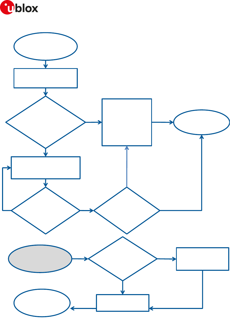
SARA-R4/N4 series-AT Commands Manual
UBX-17003787 - R09
CAppendix: UDP Direct Link workflow
Page 298 of 307
Event:
sending
timer expires
New data + data
into intermediate
buffer
is < than
max_packet_size
?
Reset sending timer
Put data into
intermediate
buffer and
wait sending
timer expires
or new data
YES
Send
max_packet_size
of data to IP network
Remaining
data
is >= max
packet size?
YES
NO
Event: new
data from
external port
Is there any data
into the intermediate
buffer?
Is there
any
data?
Finish,
event
handled
YES
NO
Finish,
event
handled
Reschedule
timer
NO
YES Send data to IP
netw ork
NO
Figure 11: Workflow of data from the external port to the IP network

SARA-R4/N4 series-AT Commands Manual
UBX-17003787 - R09
DAppendix: Glossary
Page 299 of 307
DAppendix: Glossary
2G 2nd Generation
3G 3rd Generation
3GPP 3rd Generation Partnership Project
ADC Analog to Digital Converter
AIeC Automatically Initiated eCall
ADN Abbreviated Dialing Numbers
AMR Adaptive Multi Rate
AP Access Point
APN Access Point Name
ASCII American Standard Code for Information Interchange
AT AT Command Interpreter Software Subsystem, or attention
BL Black List
BSD Berkley Standard Distribution
CB Cell Broadcast
CBM Cell Broadcast Message
CLI Calling Line Identification
CLIP Calling Line Identification Presentation
CLIR Calling Line Identification Restriction
COLP Connected Line Identification Presentation
COLR Connected Line Identification Restriction
CM Connection Management
CPHS Common PCN Handset Specification
CR Carriage Return
CS Circuit Switch
CSD Circuit-Switched Data
CSG Closed Subscriber Group
CTS Clear To Send
CUG Closed User Group
DA Destination Address
DARP Downlink Advanced Receiver Performance
DCD Data Carrier Detect
DCE Data Communication Equipment
DCM Data Connection Management
DHCP Dynamic Host Configuration Protocol
DNS Domain Name Server
DSR DSC transponder response
DTE, TE Data Terminal Equipment
DTMF Dual Tone Multi Frequency
DTR Data Terminal Ready
DUT Device Under Test
EARFCN E-UTRAN Absolute Radio Frequency Channel Number
eCall Emergency Call
EEP EEPROM Emulation Parameters
EF Elementary File
EFCGST Elementary File "Closed Subscriber Group Type"
EFHNBN Elementary File "Home Node B Number"
EFPLMNwAcT Elementary File "User controlled PLMN Selector with Access Technology"
eIM eCall In-band Modem
EONS Enhanced Operator Name from SIM-files EFOPL and EFPNN
EPD Escape Prompt Delay
ETSI European Telecommunications Standards Institute
E-UTRAN Evolved UTRAN
FDN Fixed Dialling Number

SARA-R4/N4 series-AT Commands Manual
UBX-17003787 - R09
DAppendix: Glossary
Page 300 of 307
FOAT Firmware Over AT
FOTA Firmware Over The Air
FS File System
FTP File Transfer Protocol
FW Firmware
FWINSTALL Firmware Install
GAS Grouping information Alpha String
GPIO General Purpose Input Output
GPRS General Packet Radio Service
GPS Global Positioning System
GSM Global System for Mobile Communications
HDLC High Level Data Link Control
HNB Home Node B
HPLMN Home PLMN
HTTP HyperText Transfer Protocol
I Information
I2C Inter-Integrated Circuit
I2S Inter IC Sound or Integrated Interchip Sound
ICCID Integrated Circuit Card ID
ICMP Internet Control Message Protocol
ICP Inter Processor Communication
IMEI International Mobile Equipment Identity
IMSI International Mobile Station Identity
InBM In-Band Modem (generic)
IP Internet Protocol
IRA International Reference Alphabet
IRC Intermediate Result Code
ISDN Integrated Services Digital Network
ISP Internet Service Provider
IVS In-Vehicle System (eCall related)
L3 Layer 3
LCP Link Control Protocol
LF Line Feed
LNS Linux Network Subsystem
M2M Machine-To-Machine
MCC Mobile Country Code
ME Mobile Equipment
MIeC Manually Initiated eCall
MMI Man Machine Interface
MN Mobile Network Software Subsystem
MNC Mobile Network Code
MNO Mobile Network Operator
MO Mobile Originated
MS Mobile Station
MSD Minimum Set of Data (eCall related)
MSIN Mobile Subscriber Identification Number
MSISDN Mobile Systems International Subscriber Identity Number
MSPR Multi-Slot Power Reduction
MT Mobile Terminated
MWI Message Waiting Indication
NITZ Network Identity and Time Zone
NVM Non-Volatile Memory
ODIS OMA-DM IMEI Sync
OLCM On Line Commands Mode
PAD Packet Assembler/Disassembler
P-CID Physical Cell Id

SARA-R4/N4 series-AT Commands Manual
UBX-17003787 - R09
DAppendix: Glossary
Page 301 of 307
PCN Personal Communication Network
PDP Packet Data Protocol
PDU Protocol Data Unit
PIN Personal Identification Number
PLMN Public Land Mobile Network
PPP Point-to-Point Protocol
PSAP Public Safety Answering Point (eCall related)
PSD Packet-Switched Data
PUK Personal Unblocking Key
QoS Quality of Service
RAM Random Access Memory
RDI Restricted Digital Information
RFU Reserved for Future Use
RNDIS Remote Network Driver Interface Specification
RI Ring Indicator
RTC Real Time Clock
RTP Real-time Transport Protocol
RTS Request To Send
Rx Receiver
SAP SIM Access Profile
SC Service Centre
SI SIM Application Part Software Subsystem
SIP Session Initiation Protocol
SIM Subscriber Identity Module
SMS Short Message Service
SMSC Short Message Service Center
SMTP Simple Mail Transfer Protocol
SoR Steering of Roaming
SDIO Secure Digital Input Output
STA station
SSID Service Set Identifier
TA Terminal Adaptor
TCP Transfer Control Protocol
TE Terminal Equipment
TFT Traffic Flow Template
TP Transfer layer Protocol
Tx Transmitter
TZ Time Zone
UCS2 Universal Character Set
UDI Unrestricted Digital Information
UDP User Datagram Protocol
UI Unnumbered Information
UICC Universal Integrated Circuit Card
UIH Unnumbered Information with header Check
URC Unsolicited Result Code
USIM UMTS Subscriber Identity Module
UTRAN Universal Terrestrial Radio Access Network
UUS1 User-to-User Signalling Supplementary Service 1
WLAN Wireless Local Area Network

SARA-R4/N4 series-AT Commands Manual
UBX-17003787 - R09
Related documents
Page 302 of 307
Related documents
1. Stevens. TCP/IP Illustrated Volume1 & 2 Addison-Wesley, 1994.
2. 3GPP TS 27.007 - Technical Specification Group Core Network and Terminals; AT command set for User
Equipment (UE)
3. 3GPP TS 22.004 - General on supplementary services
4. GSM 02.04 - Digital cellular telecommunication system (Phase 2+); Mobile Stations (MS) features
5. 3GPP TS 22.030 - Digital cellular telecommunications system (Phase 2+); Universal Mobile
Telecommunications System (UMTS); Man-Machine Interface (MMI) of the User Equipment (UE)
6. 3GPP TS 22.090 - Unstructured Supplementary Service Data (USSD); Stage 1
7. 3GPP TS 23.038 - Alphabets and language-specific information
8. 3GPP TS 23.040 - Technical realization of Short Message Service (SMS)
9. 3GPP TS 23.041 - Technical realization of Cell Broadcast Service (CBS)
10. 3GPP TS 23.060 - Technical Specification Group Services and System Aspects; General Packet Radio
Service (GPRS); Service description
11. 3GPP TS 24.007 - Mobile radio interface signalling layer 3; General aspects
12. 3GPP TS 24.008 - Mobile radio interface layer 3 specification
13. 3GPP TS 24.011 - Point-to-point (PP) Short Message Service (SMS) support on mobile radio interface
14. GSM 04.12 - Digital cellular telecommunications system (Phase 2+); Short Message Service Cell
Broadcast (SMSCB) Support on Mobile Radio Interface.
15. 3GPP TS 22.030 - Digital cellular telecommunications system (Phase 2+); Universal Mobile
Telecommunications System (UMTS); Man-Machine Interface (MMI) of the User Equipment (UE)
16. 3GPP TS 27.005 - Technical Specification Group Terminals; Use of Data Terminal Equipment -
Data Circuit terminating Equipment (DTE-DCE) interface for Short Message Services (SMS) and Cell
Broadcast Service (CBS)
17. 3GPP TS 27.060 - Technical Specification Group Core Network; Packet Domain; Mobile Station (MS)
supporting Packet Switched Services
18. 3GPP TS 51.011 - Digital cellular telecommunications system (Phase 2+); Specification of the Subscriber
Identity Module - Mobile Equipment (SIM - ME) interface
19. 3GPP TS 31.102 - Characteristics of the Universal Subscriber Identity Module (USIM) application
20. ITU-T Recommendation V250, 05-99.
21. ITU-T V.25ter - ITU-T V.25 ter Recommendation: Data Communications over the Telephone Network;
Serial asynchronous automatic Dialling and control.
22. ITU-T T.32 - ITU-T Recommendation T.32 Asynchronous Facsimile DCE Control - Service Class 2
23. ISO 639 (1988) Code for the representation of names of languages
24. LEON-G1 series Data Sheet, Docu No UBX-13004887
25. LEON-G1 series System Integration Manual, Docu No UBX-13004888
26. ITU-T Recommendation V24, 02-2000. List of definitions for interchange circuits between Data
Terminal Equipment (DTE) and Data Connection Equipment (DCE).
27. RFC 791 - Internet Protocol - http://www.ietf.org/rfc/rfc791.txt
28. 3GPP TS 05.08 - Radio subsystem link control
29. 3GPP TS 22.087 - User-to-User Signalling (UUS)
30. 3GPP TS 24.008 - Mobile radio interface layer 3 specification
31. 3GPP TS 22.022 - Personalisation of Mobile Equipment (ME)
32. 3GPP TS 22.082 - Call Forwarding (CF) supplementary services
33. 3GPP TS 22.083 - Call Waiting (CW) and Call Holding (HOLD)
34. 3GPP TS 22.081 - Line identification Supplementary Services- Stage 1
35. 3GPP TS 23.081 - Line identification supplementary services- Stage 2
36. 3GPP TS 22.086 - Advice of Charge (AoC) Supplementary Services
37. 3GPP TS 22.024 - Description of Charge Advice Information (CAI)
38. 3GPP TS 22.085 - Closed User Group (CUG) Supplementary Services
39. 3GPP TS 22.096 - Name identification supplementary services
40. 3GPP TS 04.18 - Mobile radio interface layer 3 specification; Radio Resource Control (RRC) protocol

SARA-R4/N4 series-AT Commands Manual
UBX-17003787 - R09
Related documents
Page 303 of 307
41. GSM 04.60 - Digital cellular telecommunications system (Phase 2+); General Packet Radio Service
(GPRS); Mobile Station (MS) - Base Station System (BSS) interface; Radio Link Control / Medium Access
Control (RLC/MAC) protocol
42. 3GPP TS 05.02 - Multiplexing and Multiple Access on the Radio Path
43. EVK-G25H Evaluation Kit User Guide, Docu No GSM.G1-EK-09022
44. 3GPP TS 51.014 - Specification of the SIM Application Toolkit for the Subscriber Identity Module - Mobile
Equipment (SIM - ME) interface
45. u-blox 5/6 Receiver Description including Protocol Specification, Docu. No GPS-SW-09017
46. 3GPP TS 27.010 V3.4.0 - Terminal Equipment to User Equipment (TE-UE) multiplexer protocol (Release
1999)
47. LEON-G1 Audio Application Note, Docu No GSM.G1-CS-10005
48. EVK-U12 EVK-U13 User Guide, Docu No 3G.G2-EK-10010
49. LISA-U1 / LISA-U2 series System Integration Manual, Docu No UBX-13001118
50. 3GPP TS 22.060 - General Packet Radio Service (GPRS); Service description; Stage 1
51. ETSI TS 102 223 - Smart cards; Card Application Toolkit (CAT)
52. GNSS Implementation Application Note, Docu No UBX-13001849
53. 3GPP TS 25.306 - UE Radio Access capabilities
54. RFC3267 - Real-Time Transport Protocol (RTP) Payload Format and File Storage Format for the Adaptive
Multi-Rate (AMR) and Adaptive Multi-Rate Wideband (AMR-WB) Audio Codecs
55. EVK-G20 Evaluation Kit User Guide, Docu No GSM.G1-EK-11002
56. LISA-U1 series Data Sheet, Docu No UBX-13002048
57. RFC 792 Internet Control Message Protocol (http://tools.ietf.org/html/rfc0792)
58. 3GPP TS 22.002 - Circuit Bearer Services (BS) supported by a Public Land Mobile Network (PLMN)
59. 3GPP TS 22.067 - enhanced Multi Level Precedence and Pre-emption service (eMLPP); Stage 1
60. LISA-U2 series Data Sheet, Docu No UBX-13001734
61. AT&T: Device Requirements -- Requirements Document -- Document Number 13340 -- Revision 4.6 --
Revision Date 9/2/11
62. 3GPP TS 23.972 - Circuit switched multimedia telephony
63. 3GPP TS 24.615 Communication Waiting (CW) using IP Multimedia (IM) Core Network (CN) subsystem;
Protocol Specification
64. 3GPP TS 25.101 - User Equipment (UE) radio transmission and reception (FDD)
65. 3GPP TS 45.005 - Radio transmission and reception
66. Common PCN Handset Specification v4.2
67. SIM Access Profile - Interoperability Specification - Bluetooth Specification V11r00
68. EVK-U20 EVK-U23 User Guide, Docu No UBX-13001794
69. Maxim MAX9860 16-Bit Mono Audio Voice Codec datasheet, 19-4349; Rev 1; 9/09. Available from the
Maxim website (http://datasheets.maxim-ic.com/en/ds/MAX9860.pdf)
70. 3GPP TS 23.122 - NAS Functions related to Mobile Station (MS) in idle mode
71. ETSI TS 122 101 V8.7.0 (2008-01) Service aspects; Service principles (3GPP TS 22.101 version 8.7.0
Release 8)
72. BS EN 16062:2015 Intelligent transport systems - ESafety - eCall high level application requirements
(HLAP) using GSM/UMTS circuit switched networks, April 2015
73. 3GPP TS 26.267 V12.0.0 (2012-12) eCall Data Transfer; In-band modem solution; General description
(Release 12)
74. 3GPP TS 51.010-1 Mobile Station (MS) conformance specification; Part 1: Conformance specification
75. RFC 959 File Transfer Protocol (http://tools.ietf.org/html/rfc959)
76. RFC 2428 FTP Extensions for IPv6 and NATs (https://tools.ietf.org/html/rfc2428)
77. SARA-G3 Audio Application Note, Docu No UBX-13001793
78. LISA-U1 / LISA-U2 Audio Application Note, Docu No UBX-13001835
79. 3GPP TS 23.014 Support of Dual Tone Multi-Frequency (DTMF) signalling V11.0.0 (2012-09)
80. EVK-G35 Evaluation Kit User Guide, Docu No UBX-13001792
81. SARA-G3 Series Data Sheet, Docu No UBX-13000993
82. SARA-G3 / SARA-U2 Series System Integration Manual, Docu No UBX-13000995
83. ETSI TS 127 007 V10.3.0 (2011-04) AT command set for User Equipment (UE) (3GPP TS 27.007 version
10.3.0 Release 10)

SARA-R4/N4 series-AT Commands Manual
UBX-17003787 - R09
Related documents
Page 304 of 307
84. 3GPP TS 51.010-2 Mobile Station (MS) conformance specification; Part 2: Protocol Implementation
Conformance Statement (PICS) proforma specification
85. 3GPP TS 34.121-2 User Equipment (UE) conformance specification; Radio transmission and reception
(FDD); Part 2: Implementation Conformance Statement (ICS)
86. u-blox Firmware Update Application Note, Docu No UBX-13001845
87. PCCA standard - Command set extensions for CDPD modems, Revision 2.0, March, 1998
88. 3GPP TS 24.301 Non-Access-Stratum (NAS) protocol for Evolved Packet System (EPS); Stage 3
89. 3GPP TS 44.060 General Packet Radio Service (GPRS); Mobile Station (MS) - Base Station System (BSS)
interface; Radio Link Control / Medium Access Control (RLC/MAC) protocol
90. 3GPP TS 23.221 Architectural requirements
91. 3GPP TS 23.203 Policy and charging control architecture
92. 3GPP TS 31.101 UICC-terminal interface; Physical and logical characteristics
93. ETSI TS 102 221 V8.2.0 (2009-06) Smart Cards; UICC-Terminal interface; Physical and logical
characteristics (Release 8)
94. RFC 4291 - IP Version 6 Addressing Architecture (http://tools.ietf.org/html/rfc4291)
95. 3GPP TS 25.305 User Equipment (UE) positioning in Universal Terrestrial Radio Access Network
(UTRAN); Stage 2
96. 3GPP TS 23.032: Universal Geographical Area Description (GAD)
97. TOBY-L2 series Networking Modes Application Note, Docu No UBX-14000479
98. 3GPP TS 25.331 Radio Resource Control (RRC); Protocol specification
99. 3GPP TS 36.101 Evolved Universal Terrestrial Radio Access (E-UTRA); User Equipment (UE) radio
transmission and reception
100. Wi-Fi / Cellular Integration Application Note, Docu No UBX-14003264
101. 3GPP TS 24.173 IMS Multimedia telephony communication service and supplementary services; Stage 3
102. 3GPP TS 24.341 Support of SMS over IP networks; Stage 3
103. 3GPP TS 24.229 IP multimedia call control protocol based on Session Initiation Protocol (SIP) and
Session Description Protocol (SDP); Stage 3
104. 3GPP TS 36.306 Evolved Universal Terrestrial Radio Access (E-UTRA); User Equipment (UE) radio access
capabilities
105. 3GPP TS 36.133 Evolved Universal Terrestrial Radio Access (E-UTRA); Requirements for support of radio
resource management
106. 3GPP TS 25.133 Requirements for support of radio resource management (FDD)
107. 3GPP TS 22.071 Location Services (LCS); Service description
108. IEC 61162 Digital interfaces for navigational equipment within a ship
109. 3GPP TS 36.331 Evolved Universal Terrestrial Radio Access (E-UTRA); Radio Resource Control (RRC);
Protocol specification (Release 10)
110. 3GPP TS 24.167 3GPP IMS Management Object (MO); Stage 3
111. ITU-T E.212 - Series E: Overall network operation, telephone service, service operation and human factors
112. RFC 793 - Transmission Control Protocol (TCP) Protocol Specification (https://www.rfc-editor.org/rfc/
rfc793.txt)
113. 3GPP TS 26.201 Speech codec speech processing functions; Adaptive Multi-Rate - Wideband (AMR-WB)
speech codec; Frame structure
114. 3GPP TS 24.216 Communication Continuity Management Object (MO)
115. 3GPP TS 36.521-2 - Evolved Universal Terrestrial Radio Access (E-UTRA); User Equipment conformance
specification; Radio transmission and reception; Part 2: Implementation Conformance Statement (ICS)
116. 3GPP TS 36.523-2 - Evolved Universal Terrestrial Radio Access (E-UTRA) and Evolved Packet Core (EPC);
User Equipment conformance specification; Part 2: Implementation Conformance Statement (ICS)
117. 3GPP TS 23.003 Numbering, addressing and identification
118. TOBY-L2 series Audio Application Note, Docu No UBX-15015834
119. 3GPP TS 31.111 Universal Subscriber Identity Module (USIM) Application Toolkit (USAT)
120. RFC 3969 - The Internet Assigned Number Authority (IANA) Uniform Resource Identifier (URI) Parameter
Registry for the Session Initiation Protocol (SIP)
121. RFC 3261 - SIP: Session Initiation Protocol
122. RFC 5341 - The Internet Assigned Number Authority (IANA) tel Uniform Resource Identifier (URI)
Parameter Registry

SARA-R4/N4 series-AT Commands Manual
UBX-17003787 - R09
Related documents
Page 305 of 307
123. RFC 3966 - The tel URI for Telephone Numbers
124. RFC 2141 - URN Syntax
125. RFC 3406 - Uniform Resource Names (URN) Namespace Definition Mechanisms
126. RFC 5031 - A Uniform Resource Name (URN) for Emergency and Other Well-Known Services
127. 3GPP TS 22.084 MultiParty (MPTY) supplementary service; Stage 1
128. 3GPP TS 24.607 Originating Identification Presentation (OIP) and Originating Identification Restriction
(OIR) using IP Multimedia (IM) Core Network (CN) subsystem; Protocol specification
129. 3GPP TS 24.608 Terminating Identification Presentation (TIP) and Terminating Identification
Restriction (TIR) using IP Multimedia (IM) Core Network (CN) subsystem; Protocol specification
130. 3GPP TS 36.213 Evolved Universal Terrestrial Radio Access (E-UTRA); Physical layer procedures
131. 3GPP TS 36.212 Evolved Universal Terrestrial Radio Access (E-UTRA); Multiplexing and channel coding
132. RFC 4715 - The Integrated Services Digital Network (ISDN) Subaddress Encoding Type for tel URI
133. End User Test Application Note, Docu No UBX-13001922
134. OMA Device Management V1.2.1 (http://technical.openmobilealliance.org/Technical/
technical-information/release-program/current-releases/dm-v1-2-1)
135. RFC 5626 - Managing Client-Initiated Connections in the Session Initiation Protocol (SIP)
136. 3GPP TS 24.166 - 3GPP IP Multimedia Subsystem (IMS) conferencing Management Object (MO)
137. 3GPP TS 29.061 - Interworking between the Public Land Mobile Network (PLMN) supporting packet
based services and Packet Data Networks (PDN)
138. 3GPP TS 24.303 - Mobility management based on Dual-Stack Mobile IPv6; Stage 3
139. 3GPP TS 24.327 - Mobility between 3GPP Wireless Local Area Network (WLAN) interworking (I-WLAN)
and 3GPP systems; General Packet Radio System (GPRS) and 3GPP I-WLAN aspects; Stage 3
140. 3GPP TS 25.367 - Mobility procedures for Home Node B (HNB); Overall description; Stage 2
141. 3GPP TS 25.304 - User Equipment (UE) procedures in idle mode and procedures for cell reselection in
connected mode
142. 3GPP TS 36.304 - Evolved Universal Terrestrial Radio Access (E-UTRA); User Equipment (UE) procedures
in idle mode
143. RFC 4867 - RTP Payload Format and File Storage Format for the Adaptive Multi-Rate (AMR) and
Adaptive Multi-Rate Wideband (AMR-WB) Audio Codecs
144. RFC 4733 - RTP Payload for DTMF Digits, Telephony Tones, and Telephony Signals
145. 3GPP2 C.S0015-0 - Short Message Service
146. RFC 1518 - An Architecture for IP Address Allocation with CIDR (https://tools.ietf.org/html/rfc1518)
147. RFC 1519 - Classless Inter-Domain Routing (CIDR): an Address Assignment and Aggregation Strategy
(https://tools.ietf.org/html/rfc1519)
148. 3GPP TS 45.008 - GSM/EDGE Radio Access Network; Radio subsystem link control
149. 3GPP TS 25.401 - Universal Mobile Telecommunications System (UMTS); UTRAN Overall Description
150. GSM 04.08 - Digital cellular telecommunications system (Phase 2+); Mobile radio interface layer 3
specification
151. 3GPP TS 24.237 - Technical Specification Group Core Network and Terminals; IP Multimedia (IM) Core
Network (CN) subsystem IP Multimedia Subsystem (IMS) Service Continuity; Stage 3
152. 3GPP TS 36.211 - Evolved Universal Terrestrial Radio Access (E-UTRA); Physical channels and
modulation
153. 3GPP TS 23.682 - Architecture enhancements to facilitate communications with packet data networks
and applications
154. 3GPP TS 23.401 - General Packet Radio Service (GPRS) enhancements for Evolved Universal Terrestrial
Radio Access Network (E-UTRAN) access
155. GSMA TS.34 - IoT Device Connection Efficiency Guidelines
156. SARA-U2 series Audio Extended Tuning Application Note, Docu No UBX-17012797
157. NB-IoT Application Development Guide, Docu No UBX-16017368
158. SARA-N2 Series Data Sheet, Docu No UBX-15025564
For regular updates to u-blox documentation and to receive product change notifications, register on our
homepage.
SARA-R4/N4 series-AT Commands Manual
UBX-17003787 - R09
Revision history
Page 306 of 307
Revision history
Revision Date Name Comments
R01 27-Jan-2017 jole Initial release
R02 03-Apr-2017 jole Removed +UPSV. Added +CPSMS. General document clean-up
R03 04-May-2017 jole Added SARA-R410M
R04 24-May-2017 jole Moved to Advance Information for SARA-R404M
R05 19-Jul-2017 jole Extended document applicability to SARA-R410M-02B.
Added +ULWM2M, +ULWM2MSTAT and +CNUM. Changed +CPSMS
back to it's original 3GPP definition. Added FOAT file tag.
R06 30-Oct-2017 jole Extended document applicability to SARA-R412M-02B.
Added DTR and PPP behavior clarification. Updated max response time
for +USOCL
New commands: +UCPSMS, +CCLK, +CTZU, +CEDRXS, +CEDRXRDP,
+USECMNG, +USECPRF, +USOSEC and O.
R07 09-Feb-2018 jole New commands: +CSCS, +UCGED, +PACSP, +UMNOPROF,
+UBANDMASK, +UCMGR, +UCMGL, +UCMGS, +UCMGW, +USIMSTAT,
+CSIM, +CLAN, +UBIP, +CUSATR, +CUSATW, +CUSATT, +CUSATE,
+UCUSATA, +CEMODE, +UDCONF=75, +UDCONF=76, +UDWNBLOCK,
+URDBLOCK, +USOCLCFG, +UGPS, +UGAOS, +UGSRV, +UGIND,
+UGPRF, +UGUBX, +UGTMR, +UGZDA, +UGGGA, +UGGLL, +UGGSV,
+UGRMC, +UGVTG, +UGGSA, +ULOC, +ULOCIND, +ULOCGNSS, +UI2CO,
+UI2CW, +UI2CR, +UI2CREGR, +UI2CC.
Modified commands: +CMUX, D, +COPS, +URAT, +CEDRXS, +CEDRXRDP,
&D, S2, +IPR, D*, +CEREG, +CGACT, +CPSMS, +UCPSMS, GPIO
introduction, File System Introduction, +USODL, +USOCTL, +USECMNG,
+USECPRF, AT commands.
Updated estimated response time information for these commands:
+USOCL, +USOCO, +USOWR.
R08 27-Apr-2018 jole New commands: +CREG, +UMNOPROF, +UPSD, +CGEREP, +CGREG,
+UMQTT, +UMQTTWTOPIC, +UMQTTWMSG, +UMQTTNV, +UMQTTC,
+UMQTTER.
Modified commands: +COPS, \Q, +CGDCONT, +CEMODE, +UAUTHREQ,
+UTEST, File System Introduction, Internet protocol transport layer,
+USOGO, +USOCL, +USOCLCFG, +USOSEC, +USOCO, Internal TCP/UDP/
IP stack class error codes, Parameters stored in profiles.
Updated estimated response time information for these commands:
+USOCL, +USOCO, +USOST, +USOSEC.
R09 15-Jun-2018 jole Extended the document applicability to SARA-R410M-52B and SARA-
N410-02B
New commands: +CSGT, +CRTDCP, +CSODCP, +UPSV, +UFOTACONF,
+ULGASP, +UTEMP, +UDNSRN
Modified commands: +CMUX, +CFUN, +CSQ, +COPS, +UCGED,
+UMNOPROF, <PDP_Type>, +CEREG, +UDCONF=76, +UFWINSTALL,
+UTEST, +CPSMS, GPIO introduction, +USODL, SSL/TLS introduction,
+USECMNG, +USECPRF, +UHTTP

SARA-R4/N4 series-AT Commands Manual
UBX-17003787 - R09
Contact
Page 307 of 307
Contact
For complete contact information, visit us at www.u-blox.com.
u-blox Offices
North, Central and South America Headquarters
Europe, Middle East, Africa
Asia, Australia, Pacific
u-blox America, Inc.
Phone: +1 703 483 3180
E-mail: info_us@u-blox.com
u-blox Singapore Pte. Ltd.
Phone: +65 6734 3811
E-mail: info_ap@u-blox.com
Support: support_ap@u-blox.com
Regional Office West Coast:
Phone: +1 408 573 3640
E-mail: info_us@u-blox.com
Regional Office Australia:
Phone: +61 2 8448 2016
E-mail: info_anz@u-blox.com
Support: support_ap@u-blox.com
Regional Office China (Beijing):
Phone: +86 10 68 133 545
E-mail: info_cn@u-blox.com
Support: support_cn@u-blox.com
Regional Office China (Chongqing):
Phone: +86 23 6815 1588
E-mail: info_cn@u-blox.com
Support: support_cn@u-blox.com
Regional Office China (Shanghai):
Phone: +86 21 6090 4832
E-mail: info_cn@u-blox.com
Support: support_cn@u-blox.com
Regional Office China (Shenzhen):
Phone: +86 755 8627 1083
E-mail: info_cn@u-blox.com
Support: support_cn@u-blox.com
Regional Office India:
Phone: +91 80 4050 9200
E-mail: info_in@u-blox.com
Support: support_in@u-blox.com
Regional Office Japan (Osaka):
Phone: +81 6 6941 3660
E-mail: info_jp@u-blox.com
Support: support_jp@u-blox.com
Regional Office Japan (Tokyo):
Phone: +81 3 5775 3850
E-mail: info_jp@u-blox.com
Support: support_jp@u-blox.com
Regional Office Korea:
Phone: +82 2 542 0861
E-mail: info_kr@u-blox.com
Support: support_kr@u-blox.com
Technical Support:
Phone: +1 703 483 3185
E-mail: support_us@u-blox.com
u-blox AG
Phone: +41 44 722 74 44
E-mail: info@u-blox.com
Support: support@u-blox.com
Regional Office Taiwan:
Phone: +886 2 2657 1090
E-mail: info_tw@u-blox.com
Support: support_tw@u-blox.com
