SFD OlderCodes.vp Older Codes
User Manual: SFD-OlderCodes
Open the PDF directly: View PDF ![]() .
.
Page Count: 106 [warning: Documents this large are best viewed by clicking the View PDF Link!]
- Table of Contents
- CHAPTER I Introduction 1
- CHAPTER II Design Algorithms 5
- CHAPTER III Check/Design for AISC-ASD01 15
- Design Loading Combinations 18
- Classification of Sections 22
- Special Seismic Provisions of Member Design 24
- Calculation of Stresses 32
- Calculation of Allowable Stresses 33
- Calculation of Stress Ratios 49
- Joint Design 52
- CHAPTER IV Check/Design for AISC-ASD89 65
- CHAPTER XIII Design Output 94

Steel Frame Design Manual
AISC ASD 01 & AISC ASD 89

Steel Frame
Design Manual
AISC ASD-1989 and AISC ASD-01
For CSiBridge®
ISO BRG102816M31 Rev 0
Proudly developed in the United States of America October 2016
Copyright
Copyright Computers & Structures, Inc., 1978-2016
All rights reserved.
The CSI Logo®, SAP2000®, ETABS®, and SAFE® are registered trademarks of
Computers & Structures, Inc. Watch & LearnTM is a trademark of Computers &
Structures, Inc.
The computer programs SAP2000®, CSiBridge®, and ETABS® and all associated
documentation are proprietary and copyrighted products. Worldwide rights of ownership
rest with Computers & Structures, Inc. Unlicensed use of these programs or reproduction
of documentation in any form, without prior written authorization from Computers &
Structures, Inc., is explicitly prohibited.
No part of this publication may be reproduced or distributed in any form or by any
means, or stored in a database or retrieval system, without the prior explicit written
permission of the publisher.
Further information and copies of this documentation may be obtained from:
Computers & Structures, Inc.
http://www.csiamerica.com/
info@csiamerica.com (for general information)
support@csiamerica.com (for technical support)
DISCLAIMER
CONSIDERABLE TIME, EFFORT AND EXPENSE HAVE GONE INTO THE
DEVELOPMENT AND DOCUMENTATION OF THIS SOFTWARE. HOWEVER,
THE USER ACCEPTS AND UNDERSTANDS THAT NO WARRANTY IS
EXPRESSED OR IMPLIED BY THE DEVELOPERS OR THE DISTRIBUTORS ON
THE ACCURACY OR THE RELIABILITY OF THIS PRODUCT.
THIS PRODUCT IS A PRACTICAL AND POWERFUL TOOL FOR STRUCTURAL
DESIGN. HOWEVER, THE USER MUST EXPLICITLY UNDERSTAND THE BASIC
ASSUMPTIONS OF THE SOFTWARE MODELING, ANALYSIS, AND DESIGN
ALGORITHMS AND COMPENSATE FOR THE ASPECTS THAT ARE NOT
ADDRESSED.
THE INFORMATION PRODUCED BY THE SOFTWARE MUST BE CHECKED BY
A QUALIFIED AND EXPERIENCED ENGINEER. THE ENGINEER MUST
INDEPENDENTLY VERIFY THE RESULTS AND TAKE PROFESSIONAL
RESPONSIBILITY FOR THE INFORMATION THAT IS USED.

Ta ble of Con tents
CHAP TER I In tro duc tion 1
Over view .................................1
Or ga ni za tion ...............................3
Rec om mended Read ing .........................4
CHAP TER II De sign Al go rithms 5
De sign Load Com bi na tions........................6
De sign and Check Sta tions ........................8
P-D Ef fects ................................8
El e ment Un sup ported Lengths ......................9
Ef fec tive Length Fac tor (K).......................11
Choice of In put Units ..........................14
CHAP TER III Check/De sign for AISC-ASD01 15
De sign Load ing Com bi na tions .....................18
Clas si fi ca tion of Sec tions ........................22
Spe cial Seis mic Pro vi sions of Mem ber De sign .............24
Or di nary Mo ment Frames (OMF) ...............24
In ter me di ate Mo ment Frames (IMF) .............25
Spe cial Mo ment Frames (SMF) ................25
Or di nary Con cen tri cally Braced Frames (OCBF) .......28
Spe cial Con cen tri cally Braced Frames (SCBF) ........28
Ec cen tri cally Braced Frames (EBF) ..............29
Cal cu la tion of Stresses .........................32
Cal cu la tion of Al low able Stresses ...................33
Al low able Stress in Ten sion ....................33
Al low able Stress in Com pres sion .................34
Flex ural Buck ling .......................34
i

Flex ural-Tor sional Buck ling..................36
Al low able Stress in Bend ing ....................38
I-sec tions............................38
Chan nel sec tions ........................42
T-sec tions and Dou ble an gles .................43
Box Sec tions and Rect an gu lar Tubes .............43
Pipe Sec tions..........................44
Round Bars ..........................45
Rect an gu lar and Square Bars .................45
Sin gle-An gle Sec tions.....................45
Gen eral Sec tions ........................48
Al low able Stress in Shear .....................48
Cal cu la tion of Stress Ra tios .......................49
Ax ial and Bend ing Stresses.....................49
Shear Stresses............................51
Joint De sign ...............................52
De sign of Con ti nu ity Plates ....................52
De sign of Doubler Plates ......................56
Weak Beam Strong Col umn Mea sure ...............59
Eval u a tion of Beam Con nec tion Shears ..............61
Eval u a tion of Brace Con nec tion Forces ..............63
CHAP TER IV Check/De sign for AISC-ASD89 65
De sign Load ing Com bi na tions .....................68
Clas si fi ca tion of Sec tions ........................68
Cal cu la tion of Stresses .........................72
Cal cu la tion of Al low able Stresses ...................73
Al low able Stress in Ten sion ....................73
Al low able Stress in Com pres sion .................73
Flex ural Buck ling .......................73
Flex ural-Tor sional Buck ling..................75
Al low able Stress in Bend ing ....................80
I-sec tions............................80
Chan nel sec tions ........................83
T-sec tions and Dou ble an gles .................84
Box Sec tions and Rect an gu lar Tubes .............85
Pipe Sec tions..........................86
Round Bars ..........................86
Rect an gu lar and Square Bars .................86
Sin gle-An gle Sec tions.....................87
Gen eral Sec tions ........................89
Al low able Stress in Shear .....................89
Cal cu la tion of Stress Ra tios .......................91
Ax ial and Bend ing Stresses.....................91
Shear Stresses............................93
ii
CSI Steel Design Manual

iii
Table of Contents
CHAPTER XIII Design Output 311
Overview. . . . . . . . . . . . . . . . . . . . . . . . . . . . . . . . 311
Graphical Display of Design Output . . . . . . . . . . . . . . . . . 312
Tabular Display of Design Output. . . . . . . . . . . . . . . . . . . 313
Member Specific Information . . . . . . . . . . . . . . . . . . . . . 314

Chapter I
Introduction
Overview
SAP2000 and ETABS fea ture pow er ful and com pletely in te grated mod ules for de -
sign of both steel and re in forced con crete struc tures. The pro gram pro vides the user
with op tions to cre ate, mod ify, ana lyze and de sign struc tural mod els, all from
within the same user in ter face. The pro gram is ca pa ble of per form ing ini tial mem -
ber siz ing and op ti mi za tion from within the same in ter face.
The pro gram pro vides an in ter ac tive en vi ron ment in which the user can study the
stress con di tions, make ap pro pri ate changes, such as re vis ing mem ber prop er ties,
and re- examine the re sults with out the need to re- run the analy sis. A sin gle mouse
click on an ele ment brings up de tailed de sign in for ma tion. Mem bers can be
grouped to gether for de sign pur poses. The out put in both graphi cal and tabu lated
for mats can be read ily printed.
The pro gram is struc tured to sup port a wide va ri ety of the lat est na tional and in ter -
na tional de sign codes for the auto mated de sign and check of con crete and steel
frame mem bers. The pro gram cur rently sup ports the fol low ing steel de sign codes:
•U.S. AISC 360-2005/IBC 2006
•U.S. AISC ASD-2001,
•U.S. AISC LRFD-1999,
Overview 1

•U.S. AISC ASD-1989,
•U.S. AISC-LRFD-1994,
•UBC ASD-1997,
•UBC LRFD-1997,
•Ca na dian CAN/CSA- S16.1-1994,
•Brit ish BS 5950-2200,
•Brit ish BS 5950-1990, and
•Eurocode 3 (ENV 1993-1-1).
The de sign is based upon a set of user- specified load ing com bi na tions. How ever,
the pro gram pro vides a set of de fault load com bi na tions for each de sign code sup -
ported in the program. If the de fault load com bi na tions are ac cept able, no defi ni tion
of ad di tional load com bi na tion is re quired.
In the de sign pro cess the pro gram picks the least weight sec tion re quired for
strength for each ele ment to be de signed, from a set of user speci fied sec tions. Dif -
fer ent sets of avail able sec tions can be speci fied for dif fer ent groups of ele ments.
Also sev eral ele ments can be grouped to be de signed to have the same sec tion.
In the check pro cess the pro gram pro duces de mand/ca pac ity ra tios for ax ial load
and bi ax ial mo ment in ter ac tions and shear. The de mand/ca pac ity ra tios are based
on ele ment stress and al low able stress for al low able stress de sign, and on fac tored
loads (ac tions) and fac tored ca paci ties (re sis tances) for limit state de sign.
The checks are made for each user speci fied (or pro gram de faulted) load com bi na -
tion and at sev eral user con trolled sta tions along the length of the ele ment. Maxi -
mum de mand/ca pac ity ra tios are then re ported and/or used for de sign op ti mi za tion.
All al low able stress val ues or de sign ca pac ity val ues for ax ial, bend ing and shear
ac tions are cal cu lated by the pro gram. Te di ous cal cu la tions as so ci ated with evalu -
at ing ef fec tive length fac tors for col umns in mo ment frame type struc tures are auto -
mated in the al go rithms.
The pres en ta tion of the out put is clear and con cise. The in for ma tion is in a form that
al lows the designer to take ap pro pri ate re me dial meas ures if there is mem ber over -
stress. Backup de sign in for ma tion pro duced by the pro gram is also pro vided for
con ven ient veri fi ca tion of the re sults.
When us ing 1997 UBC-ASD or UBC-LRFD de sign codes, re quire ments for con ti -
nu ity plates at the beam to col umn con nec tions are eval u ated. The pro gram per -
forms a joint shear anal y sis to de ter mine if doubler plates are re quired in any of the
2 Overview
CSI Steel Design Manual

joint panel zones. Max i mum beam shears re quired for the beam shear con nec tion
de sign are re ported. Also max i mum ax ial ten sion or com pres sion val ues that are
gen er ated in the mem ber are re ported.
Spe cial 1997 UBC-ASD and UBC-LRFD seis mic de sign pro vi sions are im ple -
mented in the cur rent ver sion of the pro gram. The ra tio of the beam flex ural ca pac i -
ties with re spect to the col umn re duced flex ural ca pac i ties (re duced for ax ial force
ef fect) as so ci ated with the weak beam-strong col umn as pect of any beam/col umn
in ter sec tion, are re ported for spe cial mo ment re sist ing frames. Ca pac ity re quire -
ments as so ci ated with seis mic fram ing sys tems that re quire duc til ity are checked.
Spe cial re quire ments for seis mic de sign are not im ple mented in the cur rent ver sion
of SAP2000.
Eng lish as well as SI and MKS met ric units can be used to de fine the model ge ome -
try and to spec ify de sign pa rame ters.
Organization
This man ual is or gan ized in the fol low ing way:
Chap ter II out lines vari ous as pects of the steel de sign pro ce dures of the pro gram.
This chap ter de scribes the com mon ter mi nol ogy of steel de sign as im ple mented in
the program.
Each of eleven sub se quent chap ters gives a de tailed de scrip tion of a spe cific code
of prac tice as in ter preted by and im ple mented in the program. Each chap ter de -
scribes the de sign load ing com bi na tions to be con sid ered; al low able stress or ca -
pac ity cal cu la tions for ten sion, com pres sion, bend ing, and shear; cal cu la tions of
de mand/ca pac ity ra tios; and other spe cial con sid era tions re quired by the code.
•Chap ter III gives a de tailed de scrip tion of the AISC ASD code (AISC 2001) as
im ple mented in the pro gram.
•Chap ter IV gives a de tailed de scrip tion of the AISC ASD steel code (AISC
1989) as im ple mented in the pro gram.
•Chap ter V gives a de tailed de scrip tion of the AISC LRFD code (AISC 1999)
as im ple mented in the pro gram.
•Chap ter VI gives a de tailed de scrip tion of the AISC LRFD steel code (AISC
1993) as im ple mented in the pro gram.
•Chap ter VII gives a de tailed de scrip tion of the Brit ish code BS 5950 (BSI
2000) as im ple mented in the pro gram.
Organization 3
Chapter I Introduction

•Chap ter IIIV gives a de tailed de scrip tion of the Brit ish code BS 5950 (BSI
1990) as im ple mented in the pro gram.
•Chap ter IX gives a de tailed de scrip tion of the Ca na dian code (CISC 1994) as
im ple mented in the pro gram.
•Chap ter X gives a de tailed de scrip tion of the Eurocode 3 (CEN 1992) as im ple -
mented in the pro gram.
•Chap ter XI gives a de tailed de scrip tion of the UBC ASD (UBC 1997) as im ple -
mented in the pro gram.
•Chap ter XII gives a de tailed de scrip tion of the UBC (UBC 1997) as im ple -
mented in the pro gram.
Chap ter XIII out lines vari ous as pects of the tabu lar and graphi cal out put from the
program re lated to steel de sign.
Recommended Reading
It is rec om mended that the user read Chap ter II “De sign Al go rithms” and one of
eleven sub se quent chap ters cor re spond ing to the code of in ter est to the user. Fi nally
the user should read “De sign Out put” in Chap ter XIII for un der stand ing and in ter -
pret ing the program out put re lated to steel de sign.
4 Recommended Reading
CSI Steel Design Manual

Chapter II
Design Algorithms
This chap ter out lines vari ous as pects of the steel check and de sign pro ce dures that
are used by the pro gram. The steel de sign and check may be per formed ac cord ing
to one of the fol low ing codes of prac tice.
•Ameri can In sti tute of Steel Con struc tion’s “Al low able Stress De sign and Plas -
tic De sign Speci fi ca tion for Struc tural Steel Build ings”, AISC- ASD (AISC
2001).
•Amer i can In sti tute of Steel Con struc tion’s “Al low able Stress De sign and Plas -
tic De sign Spec i fi ca tion for Struc tural Steel Build ings”, AISC-ASD (AISC
1989).
•Amer i can In sti tute of Steel Con struc tion’s “Load and Re sis tance Fac tor De -
sign Spec i fi ca tion for Struc tural Steel Build ings”, AISC-LRFD (AISC 1999)
•Ameri can In sti tute of Steel Con struc tion’s “Load and Re sis tance Fac tor De -
sign Speci fi ca tion for Struc tural Steel Build ings”, AISC- LRFD (AISC 1994).
•Brit ish Stan dards In sti tu tion’s “Struc tural Use of Steel work in Build ing”, BS
5950 (BSI 2000).
•Brit ish Stan dards In sti tu tion’s “Struc tural Use of Steel work in Build ing”, BS
5950 (BSI 1990).
5

•Ca na dian In sti tute of Steel Con struc tion’s “Limit States De sign of Steel Struc -
tures”, CAN/CSA- S16.1-94 (CISC 1995).
•Euro pean Com mit tee for Stan dardi za tion’s “Eurocode 3: De sign of Steel
Struc tures C Part 1.1: Gen eral Rules and Rules for Build ings”, ENV 1993- 1-1
(CEN 1992).
•In ter na tional Con fer ence of Build ing Of fi cials’ “1997 Uni form Build ing
Code: Vol ume 2: Struc tural En gi neer ing De sign Pro vi sions” Chap ter 22 Di vi -
sion III “De sign Stan dard for Spec i fi ca tion for Struc tural Steel Build ings ¾
Al low able Stress De sign and Plas tic De sign”, UBC-ASD (ICBO 1997).
•In ter na tional Con fer ence of Build ing Of fi cials’ “1997 Uni form Build ing
Code: Vol ume 2: Struc tural En gi neer ing De sign Pro vi sions” Chap ter 22 Di vi -
sion II “De sign Stan dard for Load and Re sis tance fac tor De sign Spec i fi ca tion
for Struc tural Steel Build ings”, UBC-LRFD (ICBO 1997).
De tails of the al go rithms as so ci ated with each of these codes as im ple mented and
in ter preted in the pro gram are de scribed in sub se quent chap ters. How ever, this
chap ter pro vides a back ground which is com mon to all the de sign codes.
It is as sumed that the user has an en gi neer ing back ground in the gen eral area of
struc tural steel de sign and fa mili ar ity with at least one of the above men tioned de -
sign codes.
For re fer ring to per ti nent sec tions of the cor re spond ing code, a unique pre fix is as -
signed for each code. For ex am ple, all ref er ences to the AISC-LRFD code carry the
pre fix of “LRFD”. Sim i larly,
–Ref er ences to the AISC-ASD code carry the pre fix of “ASD”
–Ref er ences to the Ca na dian code carry the pre fix of “CISC”
–Ref er ences to the Brit ish code carry the pre fix of “BS”
–Ref er ences to the Eurocode carry the pre fix of “EC3”
–Ref er ences to the UBC-ASD code carry the pre fix of “UBC
Design Load Combinations
The de sign load com bi na tions are used for de ter min ing the vari ous com bi na tions of
the load cases for which the struc ture needs to be de signed/checked. The load com -
bi na tion fac tors to be used vary with the se lected de sign code. The load com bi na -
tion fac tors are ap plied to the forces and mo ments ob tained from the as so ci ated
6 Design Load Combinations
CSI Steel Design Manual

load cases and the re sults are then summed to ob tain the fac tored de sign forces and
mo ments for the load com bi na tion.
For multi- valued load com bi na tions in volv ing re sponse spec trum, time his tory,
mov ing loads and multi- valued com bi na tions (of type en vel op ing, square- root of
the sum of the squares or ab so lute) where any cor re spon dence be tween in ter act ing
quan ti ties is lost, the pro gram auto mati cally pro duces mul ti ple sub com bi na tions
us ing maxima/min ima per mu ta tions of in ter act ing quan ti ties. Sepa rate com bi na -
tions with nega tive fac tors for re sponse spec trum cases are not re quired be cause the
pro gram auto mati cally takes the min ima to be the nega tive of the maxima for re -
sponse spec trum cases and the above de scribed per mu ta tions gen er ate the re quired
sub com bi na tions.
When a de sign com bi na tion in volves only a sin gle multi- valued case of time his -
tory or mov ing load, fur ther op tions are avail able. The pro gram has an op tion to re -
quest that time his tory com bi na tions pro duce sub com bi na tions for each time step
of the time his tory. Also an op tion is avail able to re quest that mov ing load com bi -
na tions pro duce sub com bi na tions us ing maxima and min ima of each de sign quan -
tity but with cor re spond ing val ues of in ter act ing quan ti ties.
For nor mal load ing con di tions in volv ing static dead load, live load, wind load, and
earth quake load, and/or dy namic re sponse spec trum earth quake load, the pro gram
has built- in de fault load ing com bi na tions for each de sign code. These are based on
the code rec om men da tions and are docu mented for each code in the cor re spond ing
chap ters.
For other load ing con di tions in volv ing mov ing load, time his tory, pat tern live
loads, sepa rate con sid era tion of roof live load, snow load, etc., the user must de fine
de sign load ing com bi na tions ei ther in lieu of or in ad di tion to the de fault de sign
load ing com bi na tions.
The de fault load com bi na tions as sume all static load cases de clared as dead load to
be ad di tive. Simi larly, all cases de clared as live load are as sumed ad di tive. How -
ever, each static load case de clared as wind or earth quake, or re sponse spec trum
cases, is as sumed to be non ad di tive with each other and pro duces mul ti ple lat eral
load com bi na tions. Also wind and static earth quake cases pro duce sepa rate load ing
com bi na tions with the sense (posi tive or nega tive) re versed. If these con di tions are
not cor rect, the user must pro vide the ap pro pri ate de sign com bi na tions.
The de fault load com bi na tions are in cluded in de sign if the user re quests them to be
in cluded or if no other user de fined com bi na tion is avail able for con crete de sign. If
any de fault com bi na tion is in cluded in de sign, then all de fault com bi na tions will
Design Load Combinations 7
Chapter II Design Algorithms

auto mati cally be up dated by the pro gram any time the user changes to a dif fer ent
de sign code or if static or re sponse spec trum load cases are modi fied.
Live load re duc tion fac tors can be ap plied to the mem ber forces of the live load case
on an element- by- element ba sis to re duce the con tri bu tion of the live load to the
fac tored load ing.
The user is cau tioned that if mov ing load or time his tory re sults are not re quested to
be re cov ered in the analy sis for some or all the frame mem bers, then the ef fects of
these loads will be as sumed to be zero in any com bi na tion that in cludes them.
Design and Check Stations
For each load com bi na tion, each el e ment is de signed or checked at a num ber of lo -
ca tions along the length of the el e ment. The lo ca tions are based on equally spaced
seg ments along the clear length of the el e ment. The num ber of seg ments in an el e -
ment is re quested by the user be fore the anal y sis is made. The user can re fine the
de sign along the length of an el e ment by re quest ing more seg ments.
The ax ial-flexure interaction ra tios as well as shear stress ra tios are cal cu lated for
each sta tion along the length of the mem ber for each load com bi na tion. The ac tual
mem ber stress com po nents and cor re spond ing al low able stresses are cal cu lated.
Then, the stress ra tios are evalu ated ac cord ing to the code. The con trol ling com -
pres sion and/or ten sion stress ra tio is then ob tained, along with the cor re spond ing
iden ti fi ca tion of the sta tion, load com bi na tion, and code- equation. A stress ra tio
greater than 1.0 in di cates an over stress or ex ceed ing a limit state.
P-D Effects
The program de sign al go rithms re quire that the analy sis re sults in clude the P-D ef -
fects. The P-D ef fects are con sid ered dif fer ently for “braced” or “non sway” and
“un braced” or “sway” com po nents of mo ments in frames. For the braced mo ments
in frames, the ef fect of P-D is lim ited to “in di vid ual mem ber sta bil ity”. For un -
braced com po nents, “lat eral drift ef fects” should be con sid ered in ad di tion to in di -
vid ual mem ber sta bil ity ef fect. In the program, it is as sumed that “braced” or “non -
sway” mo ments are con trib uted from the “dead” or “live” loads. Whereas, “un -
braced” or “sway” mo ments are con trib uted from all other types of loads.
For the in di vid ual mem ber sta bil ity ef fects, the mo ments are mag ni fied with mo -
ment mag ni fi ca tion fac tors as in the AISC-LRFD code is con sid ered di rectly in the
de sign equa tions as in the Ca na dian, Brit ish, and Eu ro pean codes. No mo ment
mag ni fi ca tion is ap plied to the AISC-ASD code.
8 Design and Check Stations
CSI Steel Design Manual

For lat eral drift ef fects of un braced or sway frames, the program as sumes that the
am pli fi ca tion is al ready in cluded in the re sults be cause P-D ef fects are con sid ered
for all but AISC- ASD code.
The us ers of the pro gram should be aware that the de fault anal y sis op tion in the
program is turned OFF for P-D ef fect. The de fault number of it era tions for P-D
analy sis is 1. The user should turn the P-D analy sis ON and set the maxi mum
number of it era tions for the analy sis. No P-D analy sis is re quired for the AISC-
ASD code. For fur ther ref er ence, the user is re ferred to CSI Analy sis Ref er ence
Man ual (CSI 2005).
Element Unsupported Lengths
To ac count for col umn slen der ness ef fects, the col umn un sup ported lengths are re -
quired. The two un sup ported lengths are l33 and l22. See Figure II-1. These are the
lengths be tween sup port points of the ele ment in the cor re spond ing di rec tions. The
length l33 cor re sponds to in sta bil ity about the 3-3 axis (ma jor axis), and l22 cor re -
sponds to in sta bil ity about the 2-2 axis (mi nor axis). The length l22 is also used for
lateral- torsional buck ling caused by ma jor di rec tion bend ing (i.e., about the 3-3
axis). See Figure II-2 for cor re spon dence be tween the program axes and the axes in
the de sign codes.
Normally, the un sup ported el e ment length is equal to the length of the el e ment, i.e.,
the dis tance be tween END-I and END-J of the el e ment. See Figure II-1. The pro -
gram, how ever, al lows us ers to as sign sev eral el e ments to be treated as a sin gle
mem ber for de sign. This can be done dif fer ently for ma jor and mi nor bend ing.
There fore, ex tra ne ous joints, as shown in Figure II-3, that af fect the un sup ported
length of an el e ment are au to mat i cally taken into con sid er ation.
Element Unsupported Lengths 9
Chapter II Design Algorithms
In de ter min ing the val ues for l22and l33of the el e ments, the pro gram rec og nizes
var i ous as pects of the struc ture that have an ef fect on these lengths, such as mem ber
con nec tiv ity, di a phragm con straints and sup port points. The pro gram au to mat i -
cally lo cates the el e ment sup port points and eval u ates the cor re spond ing un sup -
ported el e ment length.
There fore, the un sup ported length of a col umn may ac tu ally be eval u ated as be ing
greater than the cor re spond ing el e ment length. If the beam frames into only one di -
rec tion of the col umn, the beam is as sumed to give lat eral sup port only in that di rec -
tion. The user has op tions to spec ify the un sup ported lengths of the el e ments on an
el e ment-by-el e ment ba sis.
10 Element Unsupported Lengths
CSI Steel Design Manual
l33
l22
Axis 1
Axis 3
Axis 2
End I
End j
Figure II-1
Major and Minor Axes of Bending
Effective Length Factor (K)
The col umn K-fa ctor al go rithm has been de vel oped for building- type struc tures,
where the col umns are ver ti cal and the beams are hori zon tal, and the be hav ior is ba -
si cally that of a moment- resisting na ture for which the K-fa ctor cal cu la tion is rela -
tively com plex. For the pur pose of cal cu lat ing K-fa ctors, the ele ments are iden ti -
fied as col umns, beams and braces. All ele ments par al lel to the Z- axis are clas si fied
as col umns. All ele ments par al lel to the X-Y plane are clas si fied as beams. The rest
are braces.
Effective Length Factor (K) 11
Chapter II Design Algorithms
2
3
3
2
SAP2000
EUROCODE 3
z
z
yy
ASD89, LRFD95 & AASHTO
y
y
x x
CISC95
y
y
x x
y
y
x x
BS5950
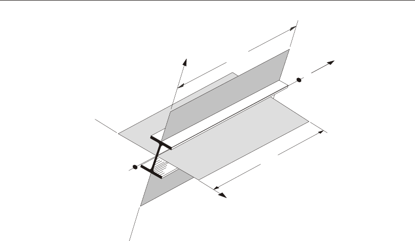
Figure II-2
Correspondence between the program Axes and Code Axes
The beams and braces are as signed K-fac tors of unity. In the cal cu la tion of the
K-fac tors for a col umn el e ment, the pro gram first makes the fol low ing four stiff -
ness sum ma tions for each joint in the struc tural model:
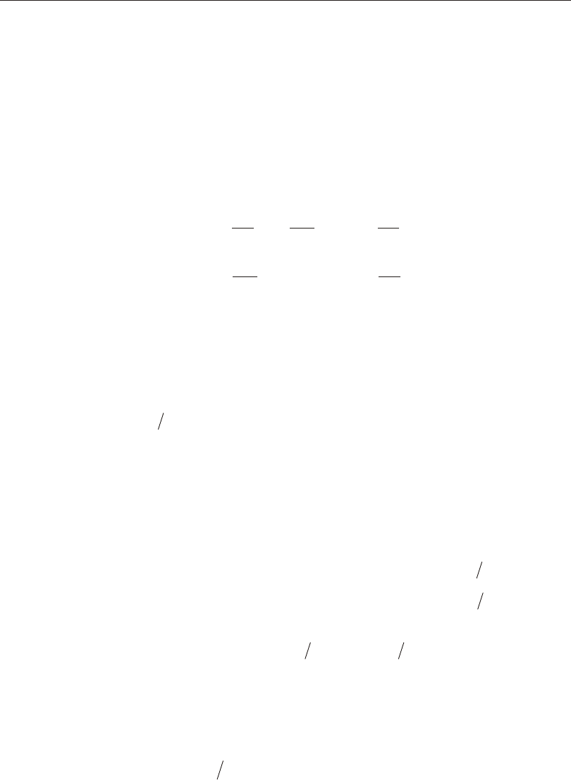
S = EI
L
cxcc
cx
æ
è
ç
çö
ø
÷
÷
å S = EI
L
bxbb
bx
æ
è
ç
çö
ø
÷
÷
å
S = EI
L
cycc
cy
æ
è
ç
çö
ø
÷
÷
å S = EI
L
bybb
by
æ
è
ç
çö
ø
÷
÷
å
where the x and y sub scripts cor re spond to the global X and Y di rec tions and the c
and b sub scripts re fer to col umn and beam. The lo cal 2-2 and 3-3 terms EIl
2222
and EIl
3333 are ro tated to give com po nents along the global X and Y di rec tions to
form the ( / )EI l x and (/)EIly val ues. Then for each col umn, the joint sum ma tions
at END-I and the END-J of the mem ber are trans formed back to the col umn lo cal
1-2-3 co or di nate sys tem and the G-val ues for END-I and the END-J of the mem ber
are cal cu lated about the 2-2 and 3-3 di rec tions as fol lows:
12 Effective Length Factor (K)
CSI Steel Design Manual
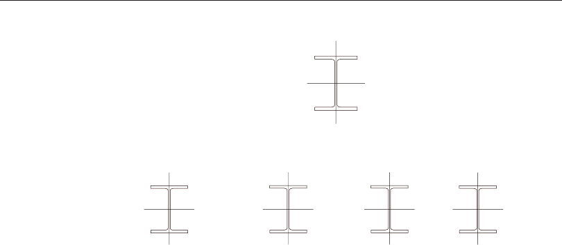
Figure II-3
Unsupported Lengths are Affected by Intermediate Nodal Points
G = S
S
IIc
Ib
22 22
22
G = S
S
JJc
Jb
22 22
22
G = S
S
IIc
Ib
33 33
33
G = S
S
JJc
Jb
33 33
33
If a ro ta tional re lease ex ists at a par tic u lar end (and di rec tion) of an el e ment, the
cor re spond ing value is set to 10.0. If all de grees of free dom for a par tic u lar joint are
de leted, the G-val ues for all mem bers con nect ing to that joint will be set to 1.0 for
the end of the mem ber con nect ing to that joint. Finally, if GI and GJare known for
a par tic u lar di rec tion, the col umn K-fac tor for the cor re spond ing di rec tion is cal cu -
lated by solv ing the fol low ing re la tion ship for a:
aa
a
2IJ
IJ
36
6(+)=tan
GG
GG
-
from which K=p/a. This re la tion ship is the mathe mati cal formulation for the
evalua tion of K fac tors for moment- resisting frames as sum ing sidesway to be un in -
hibi ted. For other struc tures, such as braced frame struc tures, trusses, space frames,
trans mis sion tow ers, etc., the K-fa ctors for all mem bers are usu ally unity and
should be set so by the user. The fol low ing are some im por tant as pects as so ci ated
with the col umn K-fa ctor al go rithm:
•An ele ment that has a pin at the joint un der con sid era tion will not en ter the stiff -
ness sum ma tions cal cu lated above. An ele ment that has a pin at the far end
from the joint un der con sid era tion will con trib ute only 50% of the cal cu lated
EI value. Also, beam ele ments that have no col umn mem ber at the far end from
the joint un der con sid era tion, such as can ti le vers, will not en ter the stiff ness
sum ma tion.
•If there are no beams fram ing into a par ticu lar di rec tion of a col umn ele ment,
the as so ci ated G-value will be in fin ity. If the G-value at any one end of a col -
umn for a par ticu lar di rec tion is in fin ity, the K-fa ctor cor re spond ing to that di -
rec tion is set equal to unity.
•If ro ta tional re leases ex ist at both ends of an ele ment for a par ticu lar di rec tion,
the cor re spond ing K-fa ctor is set to unity.
•The auto mated K-fa ctor cal cu la tion pro ce dure can oc ca sion ally gen er ate ar ti fi -
cially high K-fa ctors, spe cifi cally un der cir cum stances in volv ing skewed
beams, fixed sup port con di tions, and un der other con di tions where the pro -
gram may have dif fi culty rec og niz ing that the mem bers are lat er ally sup ported
and K-fa ctors of unity are to be used.
Effective Length Factor (K) 13
Chapter II Design Algorithms

•All K-fa ctors pro duced by the pro gram can be over writ ten by the user. These
val ues should be re viewed and any un ac cept able val ues should be re placed.
Choice of Input Units
Eng lish as well as SI and MKS met ric units can be used for in put. But the codes are
based on a spe cific sys tem of units. All equa tions and de scrip tions pre sented in the
sub se quent chap ters cor re spond to that spe cific sys tem of units un less oth er wise
noted. For ex am ple, AISC- ASD code is pub lished in kip-inch- second units. By de -
fault, all equa tions and de scrip tions pre sented in the chap ter “Check/De sign for
AIS C-ASD89” cor re spond to kip- inch- second units. How ever, any sys tem of units
can be used to de fine and de sign the struc ture in the program.
14 Choice of Input Units
CSI Steel Design Manual

Chapter III
Check/Design for AISC-ASD01
This chap ter de scribes the de tails of the struc tural steel de sign and stress check al -
go rithms that are used by the program when the user se lects the AISC-ASD01 de -
sign code (AISC 2001). Var i ous no ta tions used in this chap ter are de scribed in
Table IV-1.
For re fer ring to per ti nent sec tions and equa tions of the origi nal ASD code, a unique
pre fix “ASD” is as signed. However, all ref er ences to the “Speci fi ca tions for Al -
low able Stress De sign of Single- Angle Mem bers” carry the pre fix of “ASD SAM”.
The de sign is based on user- specified load ing com bi na tions. But the pro gram pro -
vides a set of de fault load com bi na tions that should sat isfy re quire ments for the de -
sign of most build ing type struc tures.
In the evalua tion of the ax ial force/bi ax ial mo ment ca pac ity ra tios at a sta tion along
the length of the mem ber, first the ac tual mem ber force/mo ment com po nents and
the cor re spond ing ca paci ties are cal cu lated for each load com bi na tion. Then the ca -
pac ity ra tios are evalu ated at each sta tion un der the in flu ence of all load com bi na -
tions us ing the cor re spond ing equa tions that are de fined in this chapter. The con -
trol ling ca pac ity ra tio is then ob tained. A ca pac ity ra tio greater than 1.0 in di cates
over stress. Simi larly, a shear ca pac ity ra tio is also cal cu lated sepa rately.
15

16
CSI Steel Design Manual
A=Cross- sectional area, in2
Ae=Effective cross- sectional area for slen der sections, in2
Af=Area of flange , in2
Ag=Gross cross- sectional area, in2
AA
vv23
,=Ma jor and mi nor shear ar eas, in2
Aw=Web shear area, dtw, in2
Cb=Bend ing Co ef fi cient
Cm=Mo ment Co ef fi cient
Cw=Warp ing con stant, in6
D=Out side di ame ter of pipes, in
E=Modu lus of elas tic ity, ksi
Fa=Al low able ax ial stress, ksi
Fb=Al low able bending stress, ksi
FF
bb3322
,=Al low able ma jor and mi nor bend ing stresses, ksi
Fcr=Criti cal com pres sive stress, ksi
Fe33
¢=()
12
23
2
333333
2
E
Klr
p
Fe22
¢=()
12
23
2
222222
2
E
Klr
p
Fv=Al low able shear stress, ksi
Fy=Yield stress of ma te rial, ksi
K=Ef fec tive length fac tor
KK
3322
,=Ef fec tive length K- factors in the ma jor and mi nor directions
MM
3322
,=Major and mi nor bend ing mo ments in mem ber, kip- in
Mob=Lateral- torsional mo ment for an gle sections, kip- in
P=Axial force in mem ber, kips
Pe=Euler buck ling load, kips
Q=Re duc tion fac tor for slen der sec tion, = QQ
as
Qa=Re duc tion fac tor for stiff ened slen der elements
Qs=Re duc tion fac tor for unstiff ened slen der elements
S=Sec tion modu lus, in3
SS
3322
,=Ma jor and mi nor sec tion moduli, in3
Table III-1
AISC-ASD Notations

17
Chapter III Check/Design for AISC-ASD01
SS
effeff,,
,
3322=Ef fec tive major and mi nor sec tion moduli for slen der sections, in3
Sc=Sec tion modu lus for com pres sion in an an gle section, in3
VV
23
,=Shear forces in major and mi nor directions, kips
b=Nomi nal di men sion of plate in a sec tion, in
longer leg of an gle sections,
bt
fw
-2 for welded and bt
fw
-3 for rolled box sec tions, etc.
be=Ef fec tive width of flange, in
bf=Flange width, in
d=Over all depth of mem ber, in
fa=Axial stress ei ther in com pres sion or in tension, ksi
fb=Nor mal stress in bend ing, ksi
ff
bb3322
,=Nor mal stress in ma jor and minor di rec tion bending, ksi
fv=Shear stress, ksi
f f
v v2 3
,=Shear stress in ma jor and minor di rec tion bending, ksi
h=Clear dis tance be tween flanges for I shaped sec tions ()dtf
-2, in
he=Ef fec tive dis tance be tween flanges less fil lets, in
k=Dis tance from outer face of flange to web toe of fil let , in
kc=Pa rame ter used for clas si fi ca tion of sec tions,
[]
4.05
0.46
htw
if htw>70 ,
1 if htw£70 .
ll
3322
,=Ma jor and mi nor di rec tion un braced mem ber lengths, in
lc=Criti cal length, in
r=Ra dius of gy ra tion, in
rr
3322
,=Ra dii of gy ra tion in the ma jor and mi nor di rec tions, in
rz=Mini mum Ra dius of gy ra tion for an gles, in
t=Thick ness of a plate in I, box, chan nel, an gle, and T sections, in
tf=Flange thick ness, in
tw=Web thick ness, in
bw=Spe cial sec tion prop erty for an gles, in
Table III-1
AISC-ASD Notations (cont.)

Eng lish as well as SI and MKS met ric units can be used for in put. But the code is
based on Kip- Inch- Second units. For sim plic ity, all equa tions and de scrip tions pre -
sented in this chap ter cor re spond to Kip- Inch- Second units un less oth er wise
noted.
Design Loading Combinations
The de sign load com bi na tions are the vari ous com bi na tions of the load cases for
which the struc ture needs to be checked. For the AISC-ASD01 code, if a struc ture
is sub jected to dead load (DL), live load (LL), wind load (WL), and earth quake in -
duced load (EL), and con sid er ing that wind and earth quake forces are re versi ble,
then the fol low ing load com bi na tions may have to be de fined (ASD A4). The
DLmultiplier and r fac tors are spec i fied in ASCE 7-02:
1.0 DL (ASCE 2.4.1-1)
1.0 DL + 1.0 LL (ASCE 2.4.1-2)
1.0 DL ± 1.0 WL (ASCE 2.4.1-5)
0.6 DL ± 1.0 WL (ASCE 2.4.1-7)
1.0 DL + 0.75 (1.0 LL ± 1.0 WL) (ASCE 2.4.1-6)
1.0 DL (0.6 - 0.7 DLmultiplier) ± 0.7 r EL (ASCE 2.4.1-8)
1.0 DL (1 + 0.7 DLmultiplier) ± 1.0 r EL (ASCE 2.4.1-5)
1.0 DL + 0.75 (0.7 DLmultiplier + 1.0 LL ± 0.7 r EL) (ASCE 2.4.1-6)
It is noted here that when ever spe cial seis mic load ing com bi na tions are re quired
by the code for spe cial cir cum stances, the pro gram au to mat i cally gen er ates those
load com bi na tions in ter nally. The fol low ing ad di tional seis mic load com bi na tions
are fre quently checked for spe cific types of mem bers and spe cial cir cum stances.
(0.9-0.2SDS) DL ± W0 EL (ASCE 9.5.2.7.1, 2.3, LRFD SEIS MIC 4.1)
(1.2 + 0.2SSDS) DL + 1.0 LL ± W0 EL
where, W0 is the seis mic force am pli fi ca tion fac tor which is re quired to ac count for
struc tural overstrength. The de fault value of W0 is taken as 3.0 in the pro gram. If
the user de fines one or more auto-seis mic loads, then the value of W0 de fined for
each auto-seis mic load cases. Also if spe cial seis mic data is de fined by the user, the
user spec i fies an W0value, and the user re quests the pro gram to in clude the spe cial
seis mic de sign data, then the user spec i fied W0takes pre ce dence over the de fault
18 Design Loading Combinations
CSI Steel Design Manual
Design Loading Combinations 19
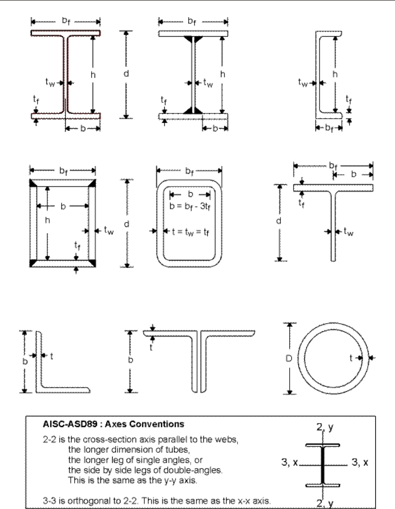
Chapter III Check/Design for AISC-ASD01
Figure III-1
AISC-ASD Definition of Geometric Properties

20 Design Loading Combinations
CSI Steel Design Manual
Section
Description
Ratio
Checked
Compact
Section
Noncompact
Section
Slender
Section
I-SHAPE
bt
f f
2
( rolled) £ F
y
65 £ F
y
95 No limit
bt
f f
2
(welded) £ F
y
65£ 95Fk
yc
/No limit
dt
w
For fF
a y£0.16
£-
6401
F
f
F
y
a
y
()3.74 ,
For fF
ay
/>0.16
£257/Fy .
No limit No limit
ht
wNo limit
If compression only,
£ F
y
253
otherwise
£ F
b
760
( )
£
+
£
14000
16.5
260
F F
y y
BOX
b t
f£ F
y
190 £ F
y
238 No limit
dt
wAs for I-shapes No limit No limit
ht
wNo limit As for I-shapes As for I-shapes
Other tt
wf
³2 , db
wf
£6None None
CHANNEL
bt
fAs for I-shapes As for I-shapes No limit
dt
wAs for I-shapes No limit No limit
ht
wNo limit As for I-shapes As for I-shapes
Other No limit No limit
If welded
b d
f w £0.25,
tt
fw£3.0
If rolled
b d
f w £0.5,
tt
fw£2.0
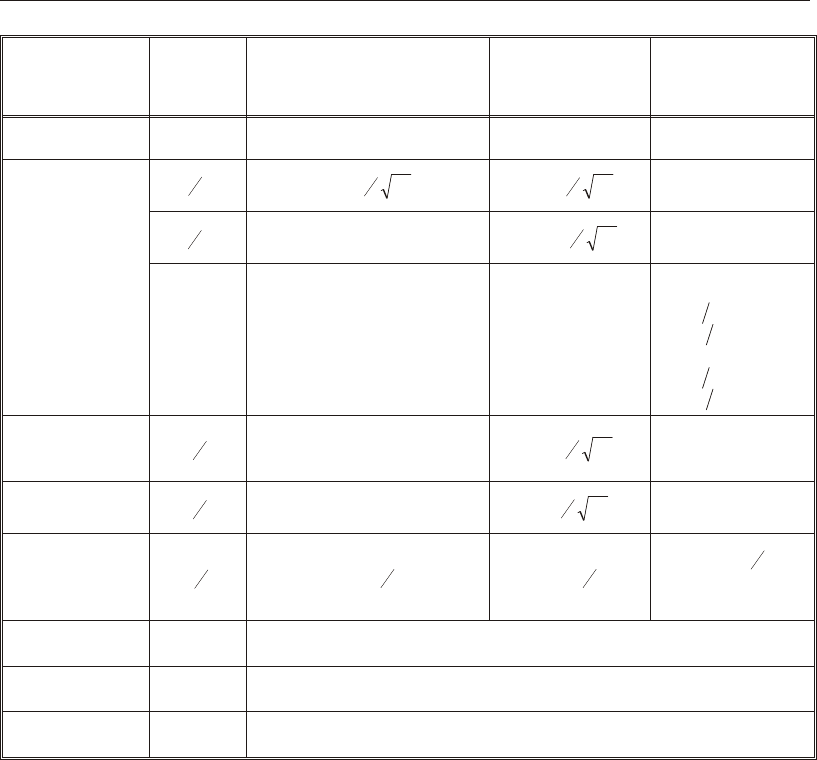
Table III-2
Limiting Width-Thickness Ratios for
Classification of Sections Based on AISC-ASD
val ues and those de fined for the auto-seis mic load cases. More over, W0can be
over writ ten for each in di vid ual mem ber. The over writ ten W0gets the high est pre -
ce dence. The guide lines for se lect ing a rea son able value for W0can be found in
ANSI/AISC 341 SEIS MIC sec tion 4.1 and Ta ble I-4-1.
These are also the de fault de sign load com bi na tions in the program when ever the
AISC-ASD01 code is used. The user should use other ap pro pri ate load ing com bi -
Design Loading Combinations 21
Chapter III Check/Design for AISC-ASD01
Section
Description
Ratio
Checked
Compact
Section
Noncompact
Section
Slender
Section
T-SHAPE
bt
f f
2£ F
y
65£ F
y
95No limit
dt
wNot applicable £ F
y
127 No limit
Other No limit No limit
If welded
b d
f w ³0.5,
tt
fw³1.25
If rolled
b d
f w ³0.5,
tt
fw³1.10
DOUBLE
ANGLES bt
Not applicable £ F
y
76 No limit
ANGLE bt
Not applicable £ F
y
76 No limit
PIPE Dt
£ F
y
3300,£ F
y
3300,£ F
y
13,000
(Compression only)
No limit for flexure
ROUND BAR ¾Assumed Compact
RECTANGLE ¾Assumed Noncompact
GENERAL ¾Assumed Noncompact
Table III-2
Limiting Width-Thickness Ratios for
Classification of Sections Based on AISC-ASD (Cont.)

na tions if roof live load is sepa rately treated, if other types of loads are pres ent, or if
pat tern live loads are to be con sid ered.
When de sign ing for com bi na tions in volv ing earth quake and Wind loads, al low able
stresses are NOT in creased by the 4/3 fac tor per the ASD Sup ple ment No. 1 which
ref er ences ASCE7. For seis mic com bi na tions, the al low able stresses are in creased
by 1.7 fac tor in ac cor dance with ANSI/AISC 341 Seis mic Sec tion 4.2.
Live load re duc tion fac tors can be ap plied to the mem ber forces of the live load case
on an element- by- element ba sis to re duce the con tri bu tion of the live load to the
fac tored load ing.
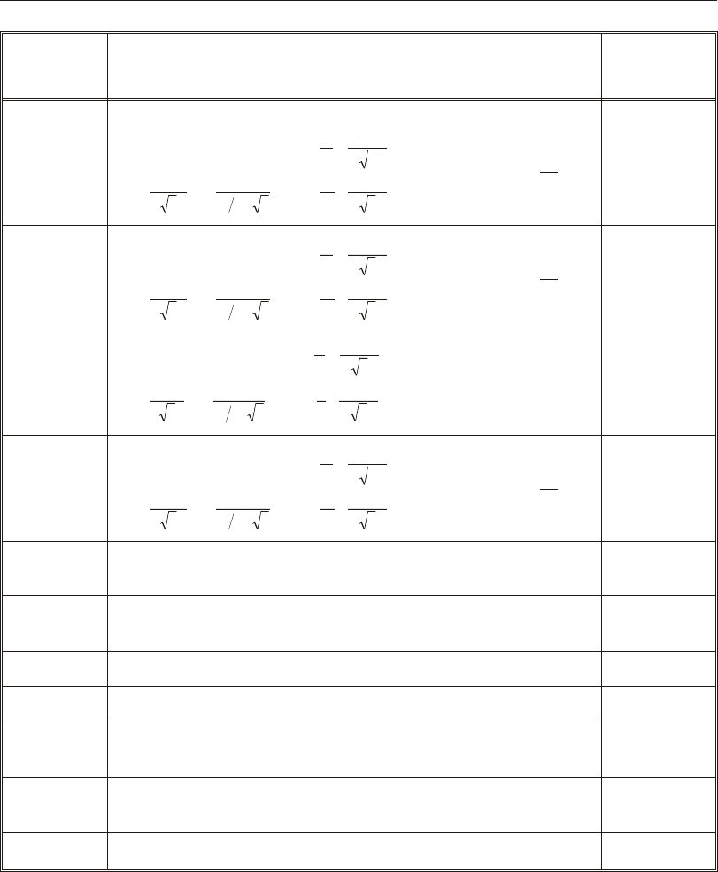
Classification of Sections
The al low able stresses for ax ial com pres sion and flex ure are de pend ent upon the
clas si fi ca tion of sec tions as ei ther Com pact, Non compact, Slen der, or Too Slen der.
The program clas si fies the in di vid ual mem bers ac cord ing to the lim it ing
width/thick ness ra tios given in Table III-2 (ASD B5.1, F3.1, F5, G1, A-B5-2). The
defi ni tion of the sec tion prop er ties re quired in this ta ble is given in Figure III-1 and
Table III-1.
If the sec tion di men sions sat isfy the lim its shown in the ta ble, the sec tion is clas si -
fied as ei ther Com pact, Non com pact, or Slen der. If the sec tion sat is fies the cri te ria
for Com pact sec tions, then the sec tion is clas si fied as Com pact sec tion. If the sec -
tion does not sat is fy the cri te ria for Com pact sec tions but sat is fies the cri te ria for
Non com pact sec tions, the sec tion is clas si fied as Noncom pact sec tion. If the sec -
tion does not satisfy the cri te ria for Com pact and Non com pact sec tions but sat is fies
the cri te ria for Slen der sec tions, the sec tion is clas si fied as Slender sec tion. If the
lim its for Slen der sec tions are not met, the sec tion is clas si fied as Too Slen der.
Stress check of Too Slen der sec tions is be yond the scope of the program.
In gen eral the de sign sec tions need not nec es sar ily be Com pact to sat isfy
ANSI/AISC 341-02 codes. How ever, for cer tain spe cial seis mic cases they have to
be Com pact and have to sat isfy spe cial slen der ness re quire ments. See sub sec tion
“Seis mic Re quire ments” later in this man ual. The sec tions which do sat isfy these
ad di tional re quire ments are clas si fied and re ported as “SEIS MIC” in the pro gram.
These spe cial re quire ments for clas si fy ing the sec tions as “SEIS MIC” in the pro -
gram are given in Table III-3 (ANSI/AISC 341SEISMIC 8.2, Ta ble I-8-1). If these
cri te ria are not sat is fied, when the code re quires them to be sat is fied, the user must
mod ify the sec tion prop erty. In this case the pro gram gives an er ror mes sage in the
out put file.
22 Classification of Sections
CSI Steel Design Manual
Classification of Sections 23
Chapter III Check/Design for AISC-ASD01
Description
of Section
Width-
Thickness
Ratio
(l)
COMPACT
(SEISMIC ZONE)
(lps)
NONCOMPACT
(Uniform
Compression)
(MM
22330»»)
(lr)
I-SHAPE
bt
f f
2
(rolled) £ E
Fy
0 3. £ E F
y
056.
b t
f f
2
(welded) £ E
Fy
03.£ EF
y
056.
ht
c w
For PP
u by
j£0.125,
£æ
è
ç
ç
ö
ø
÷
÷
3141.E
F - P
P
y
u
by
1.54j
For PP
u by
j>0.125
£æ
è
ç
ç
ö
ø
÷
÷³
ì
í
ï
î
ï
ü
ý
ï
þ
ï
112149..
E
F - P
P
E
F
y
u
byy
2.33j
£ E F
y
1 49.
BOX b t
f
h t
c w
0 64. E
Fy
Not applicable
£ E F
y
0 64.
£ E F
y
1 49.
CHANNEL,
DOUBLE CHANNEL
bt
f f
ht
c w
As for I-shapes
As for I-shapes
As for I-shapes
As for I-shapes
T-SHAPE bt
f f
2
dt
w
Not applicable
Not applicable
As for I-shapes
£ E F
y
075.
ANGLE bt
03.E
Fy
£ EF
y
045.
DOUBLE-ANGLE
(Separated) bt
03.E
Fy
£ EF
y
045.
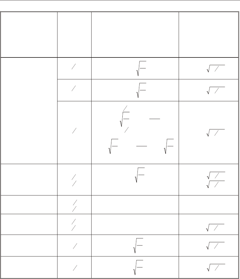
Table III-3
Limiting Width-Thickness Ratios for
Classification of Sections (Special Cases) based on AISC-LRFD

In clas si fy ing web slen der ness of I-shapes, Box, and Chan nel sec tions, it is as -
sumed that there are no in ter me di ate stiff en ers (ASD F5, G1). Dou ble an gles are
con ser va tively as sumed to be sepa rated.
Special Seismic Provisions of Member Design
When us ing the AISC-ASD01 op tion, the fol low ing Fram ing Sys tems are rec og -
nized (ANSI/AISC 341 SEIS MIC 9, 10, 11, 12, 13, 14, 15):
•Or di nary Mo ment Frame (OMF)
•In ter me di ate Mo ment Frame (IMF)
•Spe cial Mo ment Frame (SMF)
•Or di nary Con cen tri cally Braced Frame (OCBF)
•Spe cial Con cen tri cally Braced Frame (SCBF)
•Ec cen tri cally Braced Frame (EBF)
•Spe cial Truss Mo ment Frame (STMF)
By de fault the frame type is taken as Spe cial Mo ment-Re sist ing Frame (SMRF) in
the pro gram. How ever, the frame type can be over writ ten in the Pref er ence form to
change the de fault and in the Overwrites form on a mem ber by mem ber ba sis. If any
mem ber is as signed with a frame type, the change of the frame type in the Pref er -
ence will not mod ify the frame type of the in di vid ual mem ber for which it is as -
signed. Cur rently the pro gram does not ap ply any spe cial re quire ment for STMF.
The spe cial seis mic re quire ments checked by the pro gram for mem ber de sign are
de pend ent on the type of fram ing used and are de scribed be low for each type of
fram ing. Thus spe cial pro vi sions for build ings are only ap plied if the build ing
frame is clas si fied as seis mic de sign cat e gory (SDC) D or E. (ANSI/AISC 341
SEIS MIC 1). No spe cial re quire ment is checked for frames with seis mic de sign
cat e gory A, B, or C.
Or di nary Mo ment Frames (OMF)
For this fram ing sys tem, the fol low ing ad di tional re quire ments are checked and re -
ported (ANSI/AISC 341 SEIS MIC 11):
•When P
P
u
n
jin col umns due to pre scribed load ing com bi na tions with out con sid -
er ation of am pli fied seis mic load is greater than 0.4, the ax ial com pres sive and
ten sile strengths are checked in ab sence of any ap plied mo ment and shear for
24 Special Seismic Provisions of Member Design
CSI Steel Design Manual
the fol low ing Spe cial Seis mic Load Com bi na tions (ANSI/AISC 341 SEIS MIC
8.3, 4.1, ASCE 9.5.2.7.1, 2.3).
()
09020
..-±SDLEL
DSW
()
1202100
...++±SDLLLEL
DSW
Intermediate Mo ment Frames (IMF)
For this fram ing sys tem, the fol low ing ad di tional re quire ments are checked and re -
ported (ANSI/AISC 341 SEIS MIC 10):
•When P
P
u
n
j in col umns due to pre scribed load ing com bi na tions with out con sid -
er ation of am pli fied seis mic load is greater than 0.4, the ax ial com pres sive and
ten sile strengths are checked in ab sence of any ap plied mo ment and shear for
the fol low ing Spe cial Seis mic Load Com bi na tions (ANSI/AISC 341 SEIS MIC
8.3, 4.1, ASCE 9.5.2.7.1, 2.3.2).
()
09020
..-±SDSDLELW
()
1202100
...++±SDSDLLLELW
Spe cial Moment Frames (SMF)
For this fram ing sys tem, the fol low ing ad di tional re quire ments are checked or re -
ported (ANSI/AISC 341 SEIS MIC 9):
•When P
P
u
n
j in col umns due to pre scribed load ing com bi na tions with out con sid -
er ation of am pli fied seis mic load is greater than 0.4, the ax ial com pres sive and
ten sile strengths are checked in ab sence of any ap plied mo ment and shear for
the fol low ing Spe cial Seis mic Load Com bi na tions (AISC SEIS MIC 8.3, 4.1,
ASCE 9.5.2.7.1, 2.3.2).
()
09020
..-±SDLEL
DSW
()
1202100
...++±SDLLLEL
DSW
Special Seismic Provisions of Member Design
25
Chapter III Check/Design for AISC-ASD01

26 Special Seismic Provisions of Member Design
CSI Steel Design Manual
Section
Type
Re duc tion Fac tor for Un stiff ened Slen der Ele ments
(Qs)
Equation
Reference
I-SHAPE []
Q
ifbtFk
btFkifF
s
ffyc
ffycy
=
£
-
1.095
1.2930.00309 95
2
2
,
[ ]
{ }
k b t F k
k b t F if b t F k
c f f y c
c f f y f f y c
< <
³
ì
2
2 2
2
195
26,200 195
,
.
í
ï
ï
î
ï
ï
ASD A-B5-3,
ASD A-B5-4
BOX Qs=1ASD A-B5.2c
CHANNEL As for I-shapes with bt
ff
2 replaced by bt
ff . ASD A-B5-3,
ASD A-B5-4
T-SHAPE
For flanges, as for flanges in I-shapes. For web see below.
[ ]
Q
if d t F
d t F if F d t
s
w y
w y y w
£
£
-<
1.0 , 127
1.908 0.00715 127
,
,
[ ]
{ }
<
³
ì
í
ï
ï
î
ï
ï
176
20,000 176
F
d t F if d t F
y
w y w y
,
, .
2
ASD A-B5-3,
ASD A-B5-4,
ASD A-B5-5,
ASD A-B5-6
DOUBLE-
ANGLE []
Q
ifbtF
btFifFbt
s
y
yy
=
£
-<<
1.0 ,76
1.3400.00447 76 155
,
,
[ ]
{ }
F
b t F if b t F
y
y y
,
, .15,500 155
2³
ì
í
ï
ï
î
ï
ï
ASD A-B5-1,
ASD A-B5-2,
SAM 4-3
ANGLE []
Q
ifbtF
btFifFbt
s
y
yy
=
£
-<<
1.0 ,76
1.3400.00447 76 155
,
,
[ ]
{ }
F
b t F if b t F
y
y y
,
, .15,500 155
2³
ì
í
ï
ï
î
ï
ï
ASD A-B5-1,
ASD A-B5-2,
SAM 4-3
PIPE Qs=1ASD A-B5.2c
ROUND
BAR Qs=1ASD A-B5.2c
RECTAN-
GULAR Qs=1ASD A-B5.2c
GENERAL Qs=1ASD A-B5.2c
Table III-4
Re duc tion Fac tor for Un stiff ened Slen der Ele ments, Qs
Special Seismic Provisions of Member Design
27
Chapter III Check/Design for AISC-ASD01
Section
Type
Effective Width for Stiffened Sections Equation
Reference
I-SHAPE h
hifh
tf
t
fhtfifh
t
e
w
w
ww
=
£
-
é
ë
êù
û
ú>
,,
(),
195.74
253 44.3
1195.74
f.
ì
í
ï
ï
î
ï
ï
(compression only, fP
Ag
=)ASD A-B5-8
BOX
h
h if h
tf
t
f h t f if h
t
e
w
w
ww
=
£
-
é
ë
êù
û
ú>
, ,
( ) ,
195.74
253 44.3
1195.74
f.
ì
í
ï
ï
î
ï
ï
(compression only, fP
Ag
=)
b
bifb
tf
t
fhtfifb
t
e
f
f
f
=
£
-
é
ë
ê
ê
ù
û
ú
ú
,,
(),
183.74
25350.3
1>
ì
í
ï
ï
î
ï
ï
183.74
f.
(compr., flexure, fFy
=0.6)
ASD A-B5-8
ASD A-B5-7
CHANNEL h
hifh
tf
t
fhtfifh
t
e
w
w
ww
=
£
-
é
ë
êù
û
ú>
,,
(),
195.74
253 44.3
1195.74
f.
ì
í
ï
ï
î
ï
ï
(compression only, fP
Ag
=)ASD A-B5-8
T-SHAPE bb
e=ASD A-B5.2c
DOUBLE-
ANGLE bb
e=ASD A-B5.2c
ANGLE bb
e=ASD A-B5.2c
PIPE Qa=1, (However, special expression for allowable axial stress is given.) ASD A-B5-9
ROUND
BAR Not applicable ¾
RECTAN-
GULAR bb
e=ASD A-B5.2c
GENERAL Not applicable ¾
Table III-5
Effective Width for Stiffened Sections
•The I-, Chan nel-, and Dou ble-Chan nel Shaped beams and col umns are ad di -
tion ally checked for com pact ness cri te ria as de scribed in Ta ble VI-1 (AISC
SEIS MIC 9.4, 8.2, Ta ble I-8-1). If this cri te ria is sat is fied the sec tion is re -
ported as SEIS MIC as de scribed ear lier un der sec tion clas si fi ca tions. If this cri -
te ria is not sat is fied the, the pro gram is sues an er ror mes sage.
•The pro gram checks the lat er ally un sup ported length of beams to be less than
()
008.EFyy
r. If this cri te ria is not sat is fied, the pro gram is sues an er ror mes -
sage.(ANSI/AISC 341 SEIS MIC 9.8)
•The pro gram checks the slen der ness ra tio, L®, for col umns to be less than 60
(ANSI/AISC 341 SEIS MIC 9.7.b(2)). If the cri te ria is not sat is fied, the pro -
gram is sues an er ror mes sage.
Ordinary Concentrically Braced Frames (OCBF)
For this fram ing sys tem, the fol low ing ad di tional re quire ments are checked or re -
ported (ANSI/AISC 341 SEIS MIC 14):
•The col umns and beams (NOT braces) are de signed for the fol low ing spe cial
am pli fied seis mic load com bi na tions (AISC/ANSI 341 SEIS MIC 14.2, ASCI
9.5.2.7.1, 2.3.2.1, 2.3.2).
()
09020
..-±SDLEL
DSW
()
1202100
...++±SDLLLEL
DSW
•The max i mum Kl
r ra tio of the braces for V or in verted-V con fig u ra tions is
checked not to ex ceed 423.E
Fy
(ANSI/AISC 341 SEIS MIC 14.2). If this cri te -
ria is not met, an er ror mes sage is re ported in the out put.
Spe cial Con cen tri cally Braced Frames (SCBF)
For this fram ing sys tem, the fol low ing ad di tional re quire ments are checked or re -
ported (ANSI/AISC 341 SEIS MIC 13):
•When P
P
u
n
j in col umns due to pre scribed load ing com bi na tions with out con sid -
er ation of am pli fied seis mic load is greater than 0.4, the ax ial com pres sive and
ten sile strengths are checked in ab sence of any ap plied mo ment and shear for
28 Special Seismic Provisions of Member Design
CSI Steel Design Manual
the fol low ing Spe cial Seis mic Load Com bi na tions (ANSI/AISC 341 SEIS MIC
8.34.1, ASCE 9.5.2.7.1, 2.3.2).
()
09020
..-±SDLEL
DSW
()
1202100
...++±SDLLLEL
DSW
•All beam, col umns and brace mem bers are checked to be Com pact ac cord ing to
Table V-2(ANSI/AISC 341 SEIS MIC 13.5, 13.2d, 8.2, Ta ble I-8-1). If this cri -
te ria is sat is fied the sec tion is re ported as SEIS MIC as de scribed ear lier un der
sec tion clas si fi ca tions. If this cri te ria is not sat is fied the pro gram is sues an er ror
mes sage.
This spe cial cri te ria is only checked for I, Chan nel, Dou ble-Chan nel, An gle,
Dou ble-An gle, Box and Pipe sec tions.
•The com pres sive strength for braces is taken as jcn
P .
PP
ucn
£j(ANSI/AISC 341 SEIS MIC 13.26)
•The max i mum Klr ra tio of the braces is checked not to ex ceed 5.87F
E
y. If
this check is not met, the pro gram is sues an er ror mes sage.
Note: Beams in ter sected by Chev ron (V or in verted-V) braces are NOT cur -
rently checked to have a strength to sup port loads for the fol low ing two con di -
tions (ANSI/AISC 341 SEIS MIC 13.4a):
aA beam that is in ter sected by braces shall be de signed to sup port the ef fects of
all trib u tary dead and live loads form load com bi na tions stip u lated by the code,
as sum ing the brac ings are not pres ent, and
bA beam that is in ter sected by braces shall be de signed to re sist the ef fects of
load com bi na tions stip u lated by the code, ex cept that a load qbshall be sub sti -
tuted for the term E. qbis given by the dif fer ence of RFA
yy for the ten sion
brace and 03.jcn
Pfor the com pres sion brace.
Us ers need to check for this re quire ment in de pend ently.
Ec cen tri cally Braced Frames (EBF)
For this fram ing sys tem, the pro gram looks for and rec og nizes the ec cen tri cally
braced frame con fig u ra tions shown in Fig ure VI-II. The fol low ing ad di tional re -
Special Seismic Provisions of Member Design
29
Chapter III Check/Design for AISC-ASD01
quire ments are checked or re ported for the beams, col umns and braces as so ci ated
with these con fig u ra tions (ANSI/AISC 341 SEIS MIC 15).
•When P
P
u
n
j in col umns due to pre scribed load ing com bi na tions with out con sid -
er ation of am pli fied seis mic load is greater than 0.4, the ax ial com pres sive and
ten sile strengths are checked in ab sence of any ap plied mo ment and shear for
the fol low ing Spe cial Seis mic Load Com bi na tions (ANSI/AISC 341 SEIS MIC
8.3, 4.1, ASCE 9.5.2.7.1, 2.3.2).
()
09020
..-±SDLEL
DSW
()
1202100
...++±SDLLLEL
DSW
•The I-shaped, Chan nel-shaped, and Dou ble-Chan nel Shaped beams are ad di -
tion ally checked for com pact ness cri te ria as de scribed in Ta ble VI-III
(ANSI/AISC 341 SEIS MIC 15.2, 8.2, Ta ble I-8-1). If this cri te ria is sat is fied
the sec tion is re ported as SEIS MIC as de scribed ear lier un der sec tion clas si fi -
ca tions. If this cri te ria is not sat is fied the user must mod ify the pro gram is sues
an er ror mes sage.
•The link beam yield strength, Fy, is checked not to ex ceed the fol low ing (AISC
SEIS MIC 15.2):
Fy£50 ksi (ANSI/AISC 341 SEIS MIC 15.2)
If the check is not sat is fied, the pro gram is sue an er ror mes sage.
•The shear strength for link beams is taken as fol lows (AISC SEIS MIC 15.2):
VV
uvn
£j , (ANSI/AISC 341 SEIS MIC 15.2)
where,
()
jjjVVMe
npapa
=min,2 , (ANSI/AISC 341 SEIS MIC 15.2)
VVP
P
papu
y
=-æ
è
ç
ç
ö
ø
÷
÷
1
2
, (ANSI/AISC 341 SEIS MIC 15.1)
MMP
P
papu
y
=-
é
ë
êù
û
ú
1.18 1 , (ANSI/AISC 341 SEIS MIC 15.2)
30 Special Seismic Provisions of Member Design
CSI Steel Design Manual
V F d t t
p y f w
=-0.6 ( )2 , (ANSI/AISC 341 SEIS MIC 15.2)
MZF
py
= , (ANSI/AISC 341 SEIS MIC 15.2)
jj=v (de fault is 0.9) , (ANSI/AISC 341 SEIS MIC 15.2)
PAF
ygy
= . (ANSI/AISC 341 SEIS MIC 15.2)
•If P A F
u g y
>0.15 , the link beam length, e, is checked not to ex ceed the fol low -
ing (ANSI/AISC 341 SEIS MIC 15.2):
e
A
A
M
VifA
A
w
g
p
p
w
g
£
-¢
é
ë
êù
û
úé
ë
êù
û
ú¢³1.150.51.60.3 ,
1
rr
.60.3 ,
M
VifA
A
p
p
w
g
é
ë
êù
û
ú¢<
ì
í
ï
ï
î
ï
ïr
(ANSI/AISC 341 SEIS MIC 15.2)
where,
Adtt
wfw
=-()2 , and (ANSI/AISC 341 SEIS MIC 15.2)
¢=rPV
uu . (ANSI/AISC 341 SEIS MIC 15.2)
If the check is not sat is fied, the pro gram re ports an er ror mes sage.
•The link beam ro ta tion, q, of the in di vid ual bay rel a tive to the rest of the beam
is cal cu lated as the story drift DM times bay length di vided by the to tal lengths
of link beams in the bay. The link beam ro ta tion, q, is checked as fol lows
(ANSI/AISC 341 SEIS MIC 15.2).
q£0.08 ra dian , where link beam clear length, eMV
ss
£1.6 ,
q£0.03 ra dian , where link beam clear length, eMV
ss
³2.6 , and
q£ value in ter po lated be tween 0.08 and 0.02 as the link beam clear
length var ies from 1.6MV
ss to 2.6MV
ss.
•The beam strength out side the link is checked to be at least 1.1 times the beam
forces cor re spond ing to the con trol ling link beam shear strength (ANSI/AISC
341 SEIS MIC 15.6). The con trol ling link beam nom i nal shear strength is taken
as fol lows:
()
min,VMe
papa
2 , (ANSI/AISC 341 SEIS MIC 15.6, 15.2)
Special Seismic Provisions of Member Design
31
Chapter III Check/Design for AISC-ASD01

The val ues of Vpa and Mpa are cal cu lated fol low ing the pro ce dure de scribed
above (ANSI/AISC 341SEISMIC 15.2). The cor re spon dence be tween brace
force and link beam force is ob tained from the as so ci ated load cases, which ever
has the high est link beam force of in ter est.
All braces are checked to be at least com pact per reg u lar ANSI/AISC 341code
(ANSI/AISC 341 SEIS MIC 15.6). If this cri te ria is not sat is fied, the pro gram
is sues an er ror mes sage.
The brace strength is checked for 1.25Rytimes the brace forces cor re spond ing
to the con trol ling link beam nom i nal shear strength (ANSI/AISC 341 SEIS -
MIC 15.6). The con trol ling link beam nom i nal shear strength and the cor re -
spond ing forces are ob tained by the pro cess de scribed ear lier.
The I-, Chan nel-, and Dou ble-Chan nel- shaped col umn sec tions are checked to
be at least com pact per reg u lar ANSI/AISC 341 code (ANSI/AISC 341 SEIS -
MIC 8.2, Ta ble I-8-1, LRFD B.5.1). If this cri te rion is not sat is fied, the pro -
gram is sues an er ror mes sage.
•The col umn strength is checked for 1.1Rytimes the col umn forces cor re spond -
ing to the con trol ling link beam nom i nal shear strength (ANSI/AISC 341
SEIS MIC 15.8). The con trol ling link beam nom i nal shear strength and the cor -
re spond ing forces are ob tained by the pro cess de scribed above.
Note: Ax ial forces in the beams are in cluded in check ing the beams. The user is re -
minded that us ing a rigid di a phragm model will re sult in zero ax ial forces in the
beams. The user must dis con nect some of the col umn lines from the di a phragm to
al low beams to carry ax ial loads. It is rec om mended that only one col umn line per
ec cen tri cally braced frame be con nected to the rigid di a phragm or a flex i ble di a -
phragm model be used.
Calculation of Stresses
The stresses are cal cu lated at each of the pre vi ously de fined sta tions. The mem ber
stresses for non- slender sec tions that are cal cu lated for each load com bi na tion are,
in gen eral, based on the gross cross- sectional prop er ties.:
f = P/A
a
f = M/S
b333333
f = M/S
b222222
f = V/A
vv222
f = V/A
vv333
32 Calculation of Stresses
CSI Steel Design Manual

If the sec tion is slen der with slen der stiff ened ele ments, like slen der web in I, Chan -
nel, and Box sec tions or slen der flanges in Box, ef fec tive sec tion moduli based on
re duced web and re duced flange di men sions are used in cal cu lat ing stresses.
f = P/A
a(ASD A-B5.2d)
f = M/S
b eff33 33 33, (ASD A-B5.2d)
f = M/S
b eff22 22 22, (ASD A-B5.2d)
f = V/A
v v2 2 2 (ASD A-B5.2d)
f = V/A
v v3 3 3 (ASD A-B5.2d)
The flexural stresses are cal cu lated based on the prop er ties about the principal axes.
For I, Box, Chan nel, T, Dou ble-an gle, Pipe, Cir cu lar and Rec tan gu lar sec tions, the
prin ci pal axes co in cide with the geo met ric axes. For Single- angle sec tions, the de -
sign con sid ers the prin ci pal properties. For gen eral sec tions it is as sumed that all
sec tion prop er ties are given in terms of the prin ci pal di rec tions.
For Single- angle sec tions, the shear stresses are cal cu lated for di rec tions along the
geo met ric axes. For all other sec tions the shear stresses are cal cu lated along the
geo met ric and prin ci ple axes.
Calculation of Allowable Stresses
The al low able stresses in com pres sion, ten sion, bend ing, and shear are com puted
for Com pact, Non com pact, and Slen der sec tions ac cord ing to the fol low ing sub -
sec tions. The al low able flexural stresses for all shapes of sec tions are cal cu lated
based on their prin ci pal axes of bend ing. For the I, Box, Chan nel, Cir cu lar, Pipe, T,
Dou ble-an gle and Rec tan gu lar sec tions, the prin ci pal axes co in cide with their geo -
met ric axes. For the An gle sec tions, the prin ci pal axes are de ter mined and all com -
pu ta tions re lated to flex ural stresses are based on that.
If the user speci fies nonz ero al low able stresses for one or more ele ments in the de -
sign over write form, these val ues will over ride the above men tioned cal cu lated
val ues for those ele ments as de fined in the fol low ing sub sec tions. The speci fied al -
low able stresses should be based on the prin ci pal axes of bend ing.
Allowable Stress in Tension
The al low able ax ial ten sile stress value Fa is as sumed to be 0.60Fy.
F = F
ay
0.6 (ASD D1, ASD SAM 2)
Calculation of Allowable Stresses 33
Chapter III Check/Design for AISC-ASD01
It should be noted that net sec tion checks are not made. For mem bers in ten sion,
if lr is greater than 300, a mes sage to that ef fect is printed (ASD B7, ASD SAM 2).
For sin gle an gles, the mini mum radius of gy ra tion, rz, is used in stead of r22 and r33
in com put ing lr .
Allowable Stress in Compression
The al low able ax ial com pres sive stress is the minimum value ob tained from flex -
ural buck ling and flexural- torsional buck ling. The al low able com pres sive stresses
are de ter mined ac cord ing to the fol low ing sub sec tions.
For mem bers in com pres sion, if Klr is greater than 200, a warn ing mes sage is
printed (ASD B7, ASD SAM 4). For sin gle an gles, the mini mum radius of gy ra -
tion, rz, is used in stead of r22 and r33 in com put ing Klr .
Flex ural Buck ling
The al low able ax ial com pres sive stress value, Fa, de pends on the slen der ness ra tio
Klr based on gross sec tion prop er ties and a cor re spond ing criti cal value, Cc,
where
Kl
r
K l
r
K l
r
=ì
í
î
ü
ý
þ
max ,
33 33
33
22 22
22
, and
Cc=22
pE
Fy
. (ASD E2, ASD SAM 4)
For sin gle an gles, the mini mum radius of gy ra tion, rz, is used in stead of r22 and r33
in com put ing Klr .
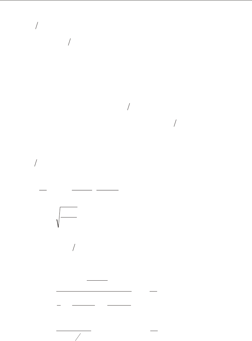
For Com pact or Non com pact sec tions Fa is evalu ated as fol lows:
()
F =
Kl/r
CF
+ Kl/r
C K
a
c
y
c
1.0-
ì
í
î
ü
ý
þ
-
()2
2
2
5
3
3
8
()
l/r
C
c
3
3
8
, if Kl
r Cc
£,(ASD E2-1, SAM 4-1)
F = E
Kl r
a
12
23
2
2
p
() , if Kl
r Cc
>.(ASD E2-2, SAM 4-2)
34 Calculation of Allowable Stresses
CSI Steel Design Manual
If Kl r is greater than 200, then the cal cu lated value of Fa is taken not to ex ceed the
value of Fa cal cu lated by us ing the equa tion ASD E2-2 for Com pact and Non com -
pact sec tions (ASD E1, B7).
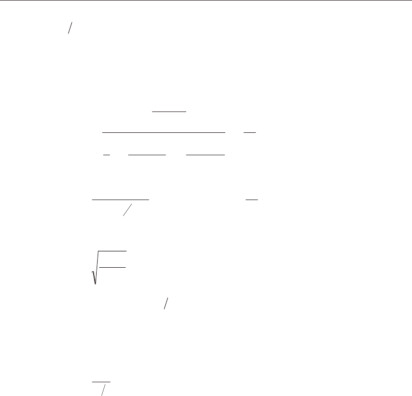
For Slender sec tions, ex cept slen der Pipe sec tions, Fa is evalu ated as fol lows:
()
F = Q
Kl/r
C
F
+ Kl/r
C
a
c
y
1.0-
ì
í
ï
î
ï
ü
ý
ï
þ
ï
¢
()2
2
2
5
3
3
8
()
c
c
Kl/r
C
¢¢
-
3
3
8
, if Kl
r Cc
£¢,(ASD A-B5-11, SAM 4-1)
F = E
Kl r
a
12
23
2
2
p
() , if Kl
r Cc
>¢.(ASD A-B5-12, SAM 4-2)
where,
CE
QF
c
y
¢=22
p . (ASD A-B5.2c, ASD SAM 4)
For slen der sec tions, if Klr is greater than 200, then the cal cu lated value of Fa is
taken not to ex ceed its value cal cu lated by us ing the equa tion ASD A-B5-12 (ASD
B7, E1).
For slen der Pipe sec tions Fa is evalu ated as fol lows:
F = DtF
ay
6620.40+(ASD A- B5-9)
The re duc tion fac tor, Q, for all com pact and non com pact sec tions is taken as 1. For
slen der sec tions, Q is com puted as fol lows:
QQQ
sa
= , where (ASD A-B5.2.c, SAM 4)
Qs = re duc tion fac tor for un stiff ened slen der ele ments, and (ASD A-B5.2.a)
Qa = re duc tion fac tor for stiff ened slen der ele ments. (ASD A-B5.2.c)
The Qs fac tors for slen der sec tions are cal cu lated as de scribed in Table III-4 (ASD
A-B5.2a, ASD SAM 4). The Qa fac tors for slen der sec tions are cal cu lated as the
ra tio of ef fec tive cross- sectional area and the gross cross- sectional area.
Calculation of Allowable Stresses 35
Chapter III Check/Design for AISC-ASD01
QA
A
ae
g
=(ASD A- B5-10)
The ef fec tive cross- sectional area is com puted based on ef fec tive width as fol lows:
()
AAbbt
ege
=--
å
be for un stiff ened el e ments is taken equal to b, and be for stiff ened el e ments is
taken equal to or less than b as given in Table III-5 (ASD A-B5.2b). For webs in I,
box, and Chan nel sec tions, he is used as be and h is used as b in the above equa tion.
Flex ural-Torsional Buck ling
The al low able ax ial com pres sive stress value, Fa, de ter mined by the limit states of
tor sional and flexural- torsional buck ling is de ter mined as fol lows (ASD E3, C-E3):
()
()
F = Q
Kl/r
C
F
+ Kl/r
C
a
e
c
y
e
1.0-
ì
í
ï
î
ï
ü
ý
ï
þ
ï
¢
2
2
2
5
3
3
8
()
c
e
c
Kl/r
C
¢¢
-
3
3
8
, if ()
Kl/r C
ec
£¢,(E2-1, A- B5- 11)
()
F = E
Kl/r
a
e
12
23
2
2
p , if ()
Kl/r C
ec
>¢.(E2-2, A- B5- 12)
where,
CE
QF
c
y
¢=22
p , and (ASD E2, A-B5.2c, SAM 4)
()
Kl/rE
F
ee
=p2 . (ASD C- E2-2, SAM 4-4)
ASD Com men tary (ASD C-E3) re fers to the 1986 ver sion of the AISC-LRFD code
for the cal cu la tion of Fe. The 1993 ver sion of the AISC-LRFD code is the same as
the 1986 ver sion in this respect. Fe is cal cu lated in the pro gram as fol lows:
•For Rec tan gu lar, I, Box, and Pipe sec tions:
36 Calculation of Allowable Stresses
CSI Steel Design Manual
( )
FEC
K l
GJ I I
ew
z z
= +
é
ë
ê
ê
ù
û
ú
ú+
p2
222 33
1 (LRFD A- E3-5)
•For T-sections and Dou ble-angles:
F = FF
H FFH
FF
e
eezeez
eez
2222
22
2
2114+
æ
è
ç
çö
ø
÷
÷--+
é
()
ë
ê
ê
ù
û
ú
ú (LRFD A- E3-6)
•For Channels:
F = FF
H FFH
FF
e
eezeez
eez
3333
33
2
2114+
æ
è
ç
çö
ø
÷
÷--+
é
()
ë
ê
ê
ù
û
ú
ú (LRFD A- E3-6)
•For Sin gle-angle sec tions with equal legs:
F = FF
H FFH
FF
e
eezeez
eez
3333
33
2
2114+
æ
è
ç
çö
ø
÷
÷--+
é
()
ë
ê
ê
ù
û
ú
ú (ASD SAM C- C4-1)
•For Single- angle sec tions with une qual legs, Fe is cal cu lated as the mini mum
real root of the fol low ing cu bic equa tion (ASD SAM C- C4-2, LRFD A- E3-7):
()()()()(FFFFFFFFFx
rF
eeeeeezeeee
------
3322
2
220
2
0
2
2FFy
r
ee
-=
330
2
0
20) ,
where,
xy
00
, are the co or di nates of the shear cen ter with re spect to the cen troid,
x00= for double- angle and T- shaped mem bers (y-axis of sym me -
try),
r x y I I
Ag
0 0
2
0
222 33
= + + + = po lar ra dius of gy ra tion about the shear center,
Hxy
r
=-+
æ
è
ç
çö
ø
÷
÷
10
2
0
2
0
2 , (LRFD A- E3-9)
( )
FE
K l r
e33
2
33 33 33
2
=p , (LRFD A- E3-10)
Calculation of Allowable Stresses 37
Chapter III Check/Design for AISC-ASD01
( )
FE
K l r
e22
2
22 22 22
2
=p , (LRFD A- E3-11)
( )
FEC
K l
GJ Ar
ez w
z z
= +
é
ë
ê
ê
ù
û
ú
ú
p2
2
0
2
1 , (LRFD A- E3-12)
K K
22 33
, are ef fec tive length fac tors in mi nor and ma jor di rec tions,
Kz is the ef fec tive length fac tor for tor sional buck ling, and it is taken equal to
K22 in the pro gram,
ll
2233
, are ef fec tive lengths in the mi nor and ma jor di rec tions,
lz is the ef fec tive length for tor sional buck ling, and it is taken equal to l22.
For an gle sec tions, the prin ci pal mo ment of in er tia and ra dii of gy ra tion are used for
com put ing Fe (ASD SAM 4). Also, the maxi mum value of Kl, i.e,
max(,)KlKl
22223333, is used in place of Kl
2222 or Kl
3333 in cal cu lat ing Fe22 and Fe33
in this case.
Allowable Stress in Bending
The al low able bend ing stress de pends on the fol low ing cri te ria: the geo met ric
shape of the cross- section, the axis of bend ing, the com pact ness of the sec tion, and
a length pa rame ter.
I-sections
For I- sections the length pa rame ter is taken as the lat er ally un braced length, l22,
which is com pared to a criti cal length, lc. The criti cal length is de fined as
lb
F
A
dF
c
f
y
f
y
=
ì
í
ï
î
ï
ü
ý
ï
þ
ï
min,,7620000 , where (ASD F1-2)
Af is the area of com pres sion flange,
38 Calculation of Allowable Stresses
CSI Steel Design Manual
Major Axis of Bending
If l22 is less than lc, the ma jor al low able bend ing stress for Com pact and
Noncom pact sec tions is taken de pend ing on whether the sec tion is welded or
rolled and whether fy is greater than 65 ksi or not.
For Com pact sec tions:
F = F
by330.66 if fy£65ksi , (ASD F1-1)
F = F
b y33 0.60 if fy>65ksi , (ASD F1-5)
For Non com pact sec tions:
F = b
tF F
b
f
f
yy332
0.790.002-
æ
è
ç
ç
ö
ø
÷
÷, if rolled and fy£65ksi,(ASD F1-3)
F= b
t
F
k F
b
f
f
y
c
y33 2
0.79 0.002-
æ
è
ç
ç
ö
ø
÷
÷, if welded and fy£65ksi,(ASDF1-4)
F = F
by33 0.60 if fy>65ksi.. (ASD F1-5)
If the un braced length l22 is greater than lc, then for both Com pact and Non -
com pact I- sections the al low able bend ing stress de pends on the lrT22 ra tio.
For l
r
C
F
T
b
y
22102000
£, ,
FF
by33=0.60 , (ASD F1-6)
for 102 000 510 000
22
, ,C
F
l
r
C
F
b
y T
b
y
<£ ,
FF l r
CF F
b
y T
b
y y33
22
2
2
3 1530 000
=-
é
ë
ê
ê
ù
û
ú
ú£
( / )
,0.60 , and (ASD F1-6)
for l
r
C
F
T
b
y
22 510 000
>, ,
Calculation of Allowable Stresses 39
Chapter III Check/Design for AISC-ASD01
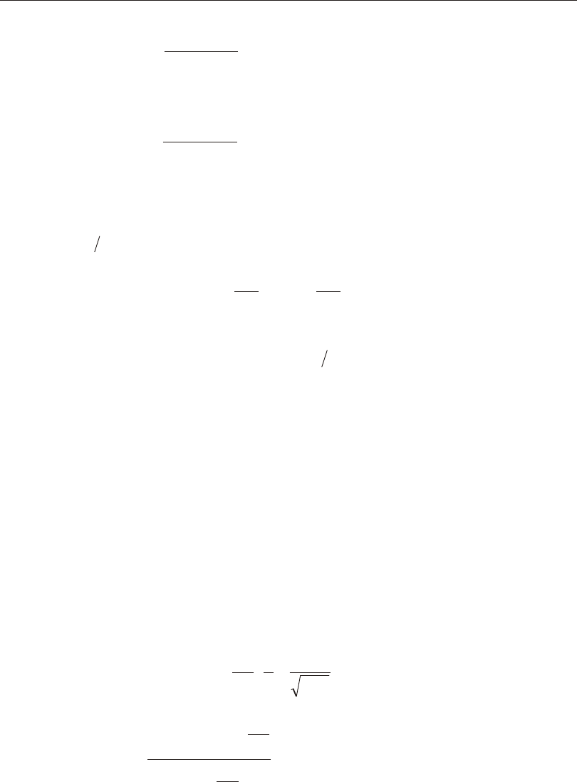
FC
l r F
bb
T
y33
22
2
170 000 0=é
ë
êù
û
ú£
,
( / ) 0.6 , (ASD F1-7)
and Fb33 is taken not to be less than that given by the fol low ing for mula:
()
FC
ldAF
bb
f
y33
22
12000
=0.6
,
/£ (ASD F1-8)
where,
rT is the ra dius of gy ra tion of a sec tion com pris ing the com pres sion flange and
13 the com pres sion web taken about an axis in the plane of the web,
C = + M
M + M
M
ba
b
a
b
1.751.050.3
æ
è
ç
çö
ø
÷
÷
æ
è
ç
çö
ø
÷
÷£
2
2.3, where (ASD F1.3)
MM
ab
and are the end mo ments of any un braced seg ment of the mem ber and
Ma is nu meri cally less than Mb; MM
ab be ing posi tive for dou ble cur va ture
bend ing and nega tive for sin gle cur va ture bend ing. Also, if any mo ment within
the seg ment is greater than Mb, Cb is taken as 1.0. Also, Cb is taken as 1.0 for
can ti le vers and frames braced against joint trans la tion (ASD F1.3). The
program de faults Cb to 1.0 if the un braced length, l22, of the mem ber is re de -
fined by the user (i.e. it is not equal to the length of the mem ber). The user can
over write the value of Cb for any mem ber by speci fy ing it.
The al low able bend ing stress for Slen der sec tions bent about their ma jor axis is
de ter mined in the same way as for a Non com pact sec tion. Then the fol low ing
ad di tional con sid era tions are taken into ac count.
If the web is slen der, then the pre vi ously com puted al low able bend ing stress is
re duced as fol lows:
FRRF
bPGeb3333
¢= , where (ASD G2-1)
RA
A
h
tF
PG w
fb
=- -
é
ë
ê
ê
ù
û
ú
ú£1.0 0.0005 1.0
760
33
, (ASD G2)
()
R
A
A
A
A
e
w
f
w
f
=
+-
+
£
12
12 2
1.0
33
a a
, (hy brid gird ers) (ASD G2)
40 Calculation of Allowable Stresses
CSI Steel Design Manual
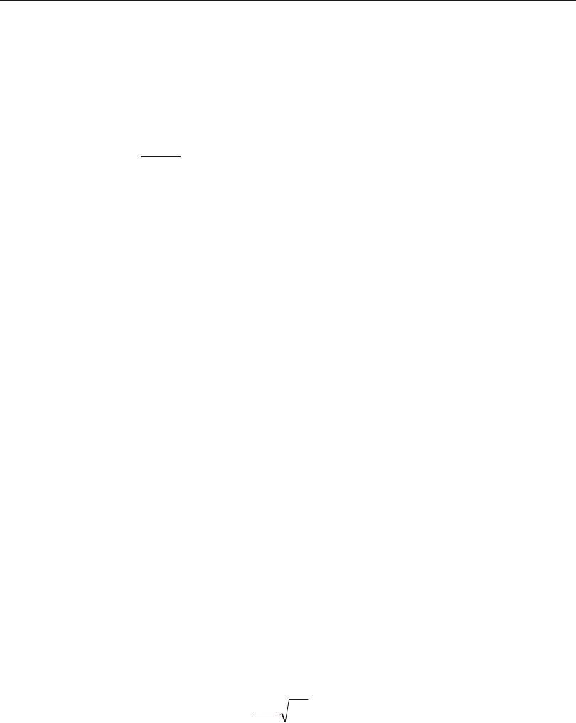
Re=1.0 , (non- hybrid gird ers) (ASD G2)
Aw = Area of web, in2,
Af = Area of com pres sion flange, in2,
a=£
0.61.0
F
F
y
b33
(ASD G2)
Fb33 = Al low able bend ing stress as sum ing the sec tion is non- compact, and
Fb33
¢ = Al low able bend ing stress af ter con sid er ing web slenderness.
In the above ex pres sions, Re is taken as 1, be cause cur rently the pro gram deals
with only non-hy brid gird ers.
If the flange is slen der, then the pre vi ously com puted al low able bend ing stress
is taken to be lim ited as follows.
()
FQF
bsy33
¢£0.6 , where (ASD A-B5.2a, A-B5.2d)
Qs is de fined ear lier.
Minor Axis of Bending
The mi nor di rec tion al low able bend ing stress Fb22 is taken as fol lows:
For Com pact sec tions:
F = F
by220.75 if fy£65ksi , (ASD F2-1)
F = F
b y22 0.60 if fy>65ksi , (ASD F2-2)
For Non com pact and Slen der sec tions:
F = b
tF F
b
f
f
yy222
1.0750.005-
æ
è
ç
ç
ö
ø
÷
÷, if fy£65ksi,(ASD F2-3)
F = F
b y22 0.60 if fy>65ksi.. (ASD F2-2)
Calculation of Allowable Stresses 41
Chapter III Check/Design for AISC-ASD01
42 Calculation of Allowable Stresses
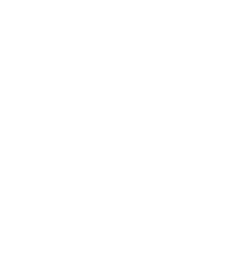
If the web is slen der, then the pre vi ously com puted al low able bend ing stress is
re duced as fol lows:
FRRF
bePGb3333
¢= (ASD G2-1)
If the flange is slen der, the pre vi ously com puted al low able bend ing stress is
taken to be lim ited as follows:
()
FQF
bsy33
¢£0.6(ASD A-B5.2a, A-B5.2d)
The defi ni tion for rT, Cb, Af, Aw, Re, RPG, Qs, Fb33, and Fb33
¢ are given ear lier.
Minor Axis of Bending
The mi nor di rec tion al low able bend ing stress Fb22 is taken as fol lows:
F = F
by220.60(ASD F2-2)
T-sections and Double angles
For T sec tions and Dou ble an gles, the al low able bend ing stress for both ma jor
and mi nor axes bending is taken as,
F = F
by
0.60 .
Box Sections and Rectangular Tubes
For all Box sec tions and Rec tan gu lar tubes, the length pa rame ter is taken as the
lat er ally un braced length, l22, meas ured com pared to a criti cal length, lc. The
criti cal length is de fined as
l M/Mb
F, b
F
cab
yy
=+
ì
í
î
ü
ý
þ
max()195012001200(ASD F3-2)
where Maand Mb have the same defi ni tion as noted ear lier in the for mula for
Cb. If l22 is speci fied by the user, lc is taken as 1200 b
Fy
in the pro gram.
Major Axis of Bending
If l22 is less than lc, the al low able bend ing stress in the ma jor di rec tion of
bend ing is taken as:
Calculation of Allowable Stresses 43
Chapter III Check/Design for AISC-ASD01

F = F
b y33 0.66 (for Com pact sec tions) (ASD F3-1)
F = F
b y33 0.60 (for Non com pact sec tions) (ASD F3-3)
If l22 ex ceeds lc, the al low able bend ing stress in the ma jor di rec tion of bend -
ing for both Com pact and Non com pact sec tions is taken as:
F = F
by330.60(ASD F3-3)
The ma jor di rec tion al low able bend ing stress for Slen der sec tions is de ter -
mined in the same way as for a Non com pact sec tion. Then the fol low ing ad di -
tional con sid era tion is taken into ac count. If the web is slen der, then the pre vi -
ously com puted al low able bend ing stress is re duced as fol lows:
FRRF
bePGb3333
¢= (ASD G2-1)
The defi ni tion for Re, RPG, Fb33, and Fb33
¢ are given ear lier.
If the flange is slen der, no ad di tional con sid er ation is needed in com put ing al -
low able bend ing stress. How ever, ef fec tive sec tion di men sions are cal cu lated
and the sec tion modu lus is modi fied ac cord ing to its slen der ness.
Minor Axis of Bending
If l22 is less than lc, the al low able bend ing stress in the minor di rec tion of bend -
ing is taken as:
F= F
by220.66 (for Com pact sec tions) (ASD F3-1)
F = F
b y22 0.60 (for Non com pact and Slender sec tions) (ASD F3-3)
If l22 ex ceeds lc, the al low able bend ing stress in the minor di rec tion of bend -
ing is taken, ir re spec tive of com pact ness, as:
F = F
by220.60 (ASD F3-3)
Pipe Sections
For Pipe sec tions, the al low able bend ing stress for both ma jor and mi nor axes
of bend ing is taken as
F = F
by
0.66 (for Com pact sec tions), and (ASD F3-1)
F = F
b y
0.60 (for Non com pact and Slen der sec tions). (ASD F3-3)
44 Calculation of Allowable Stresses
CSI Steel Design Manual
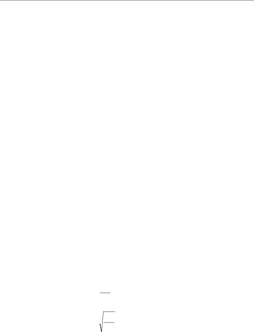
Round Bars
The al low able stress for both the ma jor and mi nor axis of bend ing of round bars
is taken as,
F = F
by
0.75 . (ASD F2-1)
Rectangular and Square Bars
The al low able stress for both the ma jor and mi nor axis of bend ing of solid
square bars is taken as,
F = F
by
0.75 . (ASD F2-1)
For solid rec tan gu lar bars bent about their ma jor axes, the al low able stress is
given by
F = F
by
0.60, And
the al low able stress for mi nor axis bend ing of rec tan gu lar bars is taken as,
F = F
by
0.75 . (ASD F2-1)
Single-Angle Sections
The al low able flex ural stresses for Single- angles are cal cu lated based on their prin -
ci pal axes of bend ing (ASD SAM 5.3).
Major Axis of Bending
The al low able stress for ma jor axis bend ing is the mini mum con sid er ing the limit
state of lateral- torsional buck ling and lo cal buck ling (ASD SAM 5.1).
The al low able ma jor bend ing stress for Single- angles for the limit state of lateral-
torsional buck ling is given as fol lows (ASD SAM 5.1.3):
F = F
FF
bmajorob
y
ob,0.550.10-
é
ë
êù
û
ú, if FF
oby
£(ASD SAM 5-3a)
F = F
FF F
b major
y
ob
y y,0.95 0.50 0.66-
é
ë
ê
ê
ù
û
ú
ú£, if FF
oby
>(ASD SAM 5-3b)
where, Fob is the elas tic lateral- torsional buck ling stress as cal cu lated be low.
Calculation of Allowable Stresses 45
Chapter III Check/Design for AISC-ASD01
The elas tic lateral- torsional buck ling stress, Fob, for equal- leg an gles is taken as
FClt
obb
=28,250 , (ASD SAM 5-5)
and for unequal- leg an gles Fob is cal cu lated as
FCI
Slltr
obb
major
ww
=++
é
ëù
û
143,1000.052
min min
2
2 2
b b( ) , (ASD SAM 5-6)
where,
()
ttt
wf
=min, ,
()
lll=max,
2233 ,
Imin= mi nor prin ci pal mo ment of in er tia,
Imax= major prin ci pal mo ment of in er tia,
Smajor= ma jor sec tion modu lus for com pres sion at the tip of one leg,
rmin = ra dius of gy ra tion for mi nor prin ci pal axis,
bwA
IzwzdAz=+
é
ë
êù
û
ú-
ò
12
22
0
max
() , (ASD SAM 5.3.2)
z = co or di nate along the ma jor prin ci pal axis,
w = co or di nate along the mi nor prin ci pal axis, and
z0= co or di nate of the shear cen ter along the ma jor prin ci pal axis with re spect
to the cen troid.
bw is a spe cial sec tion prop erty for an gles. It is posi tive for short leg in com pres -
sion, nega tive for long leg in com pres sion, and zero for equal- leg an gles (ASD
SAM 5.3.2). How ever, for con ser va tive de sign in the pro gram, it is al ways taken as
nega tive for unequal- leg an gles.
In the above ex pres sions Cb is cal cu lated in the same way as is done for I sec tions
with the ex cep tion that the up per limit of Cb is taken here as 1.5 in stead of 2.3.
C = + M
M + M
M
ba
b
a
b
1.751.050.3
æ
è
ç
çö
ø
÷
÷
æ
è
ç
çö
ø
÷
÷£
2
1.5 (ASD F1.3, SAM 5.2.2)
46 Calculation of Allowable Stresses
CSI Steel Design Manual
The al low able ma jor bend ing stress for Single- angles for the limit state of lo cal
buck ling is given as fol lows (ASD SAM 5.1.1):
F = F
bmajory,0.66, if b
tFy
£65 , (ASD SAM 5-1a)
F = F
b major y,0.60 , if 6576
F
b
tF
yy
<£ , (ASD SAM 5-1b)
()
F = Q F
b major y,0.60 , if b
tFy
>76 , (ASD SAM 5-1c)
where,
t = thick ness of the leg un der consideration,
b = length of the leg un der con sid era tion, and
Q = slen der ness re duc tion fac tor for lo cal buck ling. (ASD A- B5-2, SAM 4)
In cal cu lat ing the al low able bend ing stress for Single- angles for the limit state of
lo cal buck ling, the al low able stresses are cal cu lated con sid er ing the fact that ei ther
of the two tips can be un der com pres sion. The mini mum al low able stress is con sid -
ered.
Minor Axis of Bending
The al low able minor bend ing stress for Single- angles is given as fol lows (ASD
SAM 5.1.1, 5.3.1b, 5.3.2b):
F = Fy
b,minor0.66, if b
tFy
£65 , (ASD SAM 5-1a)
F = Fy
b,minor 0.60 , if 6576
F
b
tF
yy
<£ , (ASD SAM 5-1b)
()
F = Q Fy
b,minor 0.60 , if b
tFy
>76 , (ASD SAM 5-1c)
In cal cu lat ing the al low able bend ing stress for Single- angles it is as sumed that the
sign of the mo ment is such that both the tips are un der com pres sion. The mini mum
al low able stress is con sid ered.
Calculation of Allowable Stresses 47
Chapter III Check/Design for AISC-ASD01
General Sections
For Gen eral sec tions the al low able bend ing stress for both ma jor and mi nor
axes bending is taken as,
F = F
by
0.60 .
Allowable Stress in Shear
The shear stress is cal cu lated along the geo met ric axes for all sec tions. For I, Box,
Chan nel, T, Dou ble an gle, Pipe, Cir cu lar and Rec tan gu lar sec tions, the prin ci pal
axes co in cide with their geo met ric axes. For Single- angle sec tions, prin ci pal axes
do not co in cide with the geometric axes.
Major Axis of Bending
The al low able shear stress for all sec tions ex cept I, Box and Chan nel sec tions is
taken in the pro gram as:
FF
vy
=0.40 (ASD F4-1, SAM 3-1)
The al low able shear stress for ma jor di rec tion shears in I- shapes, boxes and chan -
nels is evalu ated as fol lows:
FF
vy
=0.40 , if h
t F
wy
£380 , and (ASD F4-1)
FCFF
vvy y
=£
2.89 0.40 , if 380260
F
h
t
yw
<£ . (ASD F4-2)
where,
()
C
k
Fht
ifh
t
k
F
ht
k
Fifh
t
v
v
yww
v
y
w
v
y
=
³
45 000
2
,, ,
,
56,250
190
w
v
y
k
F
<
ì
í
ï
ï
î
ï
ï56,250 ,
(ASD F4)
48 Calculation of Allowable Stresses
CSI Steel Design Manual
( )
( )
ka h
if a
h
a h
if a
h
v=
+£
+ >
ì
í
ï
ï
î
ï
ï
4.00 5.34
5.34 4.00
2
2
1
1
, ,
, ,
(ASD F4)
tw= Thick ness of the web,
a = Clear dis tance be tween trans verse stiff en ers, in. Cur rently it is taken
con ser va tively as the length, l22, of the mem ber in the pro -
gram,
h= Clear dis tance be tween flanges at the sec tion, in.
Minor Axis of Bending
The al low able shear stress for mi nor di rec tion shears is taken as:
FF
vy
=0.40 (ASD F4-1, SAM 3-1)
Calculation of Stress Ratios
In the calculation of the ax ial and bend ing stress ca pac ity ra tios, first, for each sta -
tion along the length of the mem ber, the ac tual stresses are cal cu lated for each load
com bi na tion. Then the cor re spond ing al low able stresses are calculated. Then, the
ca pac ity ra tios are calculated at each sta tion for each mem ber un der the in flu ence of
each of the de sign load com bi na tions. The con trol ling ca pac ity ra tio is then ob -
tained, along with the as so ci ated sta tion and load com bi na tion. A ca pac ity ra tio
greater than 1.0 in di cates an overstress.
Dur ing the de sign, the ef fect of the pres ence of bolts or welds is not con sid ered.
Also, the joints are not de signed.
Ax ial and Bend ing Stresses
With the com puted al low able ax ial and bend ing stress val ues and the fac tored ax ial
and bend ing mem ber stresses at each sta tion, an in ter ac tion stress ra tio is pro duced
for each of the load com bi na tions as fol lows (ASD H1, H2, SAM 6):
•If fa is com pres sive and fF
aa>0.15, the com bined stress ra tio is given by
the larger of
Calculation of Stress Ratios 49
Chapter III Check/Design for AISC-ASD01
f
F+C f
f
F' F
+ C f
a
a
m b
a
e
b
m b33 33
33
33
22 22
1 1-
æ
è
ç
çö
ø
÷
÷ f
F' F
a
e
b
-
æ
è
ç
çö
ø
÷
÷
22
22
, and (ASD H1-1, SAM 6.1)
()
f
F f
F f
F
a
y
b
b
b
b
Q 0.60 + +
33
33
22
22
, where (ASD H1-2, SAM 6.1)
fa, fb33, fb22, Fa, Fb33, and Fb22 are de fined ear lier in this chapter,
Cm33 and Cm22 are co ef fi cients rep re sent ing dis tri bu tion of mo ment along the
mem ber length.
Cm=
1.00,if length is overwritten,
1.00,if tension member,
0.85,if sway frame,
0.60.4if -Ma
Mb
,nonsway, no transverse loading,
0.85,if nonsway, trans. load, end restrained,
1.00,if nonsway, trans. load, end unrestrained.
ì
í
ï
ï
ï
ï
î
ï
ï
ï
ï
(ASD H1)
For sway frame Cm=0.85 , for nonsway frame with out trans verse load
CMM
mab
=-0.60.4 , for nonsway frame with trans verse load and end re -
strained com pres sion mem ber Cm=0.85 , and for nonsway frame with trans -
verse load and end un re strained com pres sion mem ber Cm=1.00 (ASD H1),
where MM
ab is the ra tio of the smaller to the larger mo ment at the ends of the
mem ber, MM
ab be ing pos i tive for dou ble cur va ture bend ing and neg a tive for
sin gle cur va ture bend ing. When Mb is zero, Cm is taken as 1.0. The pro gram
de faults Cm to 1.0 if the un braced length fac tor, l, of the mem ber is re de fined
by ei ther the user or the pro gram, i.e., if the un braced length is not equal to the
length of the mem ber. The user can over write the value of Cm for any mem ber.
Cm as sumes two val ues, Cm22 and Cm33, as so ci ated with the ma jor and mi nor di -
rec tions.
Fe
¢ is given by
FE
Klr
e
¢=12
23
2
2
p
(/) . (ASD H1)
•If fa is com pres sive and fF
aa£0.15 , a rel a tively sim pli fied for mula is used
for the com bined stress ra tio.
50 Calculation of Stress Ratios
CSI Steel Design Manual
f
F + f
F + f
F
a
a
b
b
b
b
33
33
22
22
(ASD H1-3, SAM 6.1)
•If fa is ten sile or zero, the com bined stress ra tio is given by the larger of
f
F f
F f
F
a
a
b
b
b
b
++
33
33
22
22
, and (ASD H2-1, SAM 6.2)
f
F f
F
b
b
b
b
33
33
22
22
+ , where
fa, fb33, fb22, Fa, Fb33, and Fb22 are de fined ear lier in this chap ter. How ever, ei -
ther Fb33 or Fb22 need not be less than 0.6Fy in the first equa tion (ASD H2-1).
The sec ond equa tion con sid ers flex ural buck ling with out any be nefi cial ef fect
from ax ial com pres sion.
For cir cu lar and pipe sec tions, an SRSS com bi na tion is first made of the two bend -
ing com po nents be fore add ing the ax ial load com po nent, in stead of the sim ple ad -
di tion im plied by the above for mu lae.
For Single- angle sec tions, the com bined stress ra tio is cal cu lated based on the prop -
er ties about the principal axis (ASD SAM 5.3, 6.1.5). For I, Box, Chan nel, T, Dou -
ble-an gle, Pipe, Cir cu lar and Rec tan gu lar sec tions, the prin ci pal axes co in cide with
their geo met ric axes. For Single- angle sec tions, prin ci pal axes are de ter mined in
the pro gram. For gen eral sec tions no ef fort is made to de ter mine the prin ci pal di rec -
tions.
Shear Stresses
From the al low able shear stress val ues and the fac tored shear stress val ues at each
sta tion, shear stress ra tios for ma jor and minor di rec tions are computed for each of
the load com bi na tions as fol lows:
f
F
v
v
2 , and
f
F
v
v
3 .
For Sin gle-an gle sec tions, the shear stress ra tio is cal cu lated for di rec tions along
the geo met ric axis. For all other sec tions the shear stress is cal cu lated along the
prin ci ple axes which co in cide with the geo met ric axes.
Calculation of Stress Ratios 51
Chapter III Check/Design for AISC-ASD01

Joint Design
When us ing AISC-ASD01 de sign code, the struc tural joints are checked and/or de -
signed for the fol low ing:
•Check for the re quire ment of con ti nu ity plate and de ter mi na tion of its area
•Check for the re quire ment of doubler plate and de ter mi na tion of its thick ness
•Check for the ra tio of beam flex ural strength to col umn flex ural strength
•Re port ing the beam con nec tion shear
•Re port ing the brace con nec tion force
De sign of Con ti nu ity Plates
In a plan view of a beam/col umn con nec tion, a steel beam can frame into a col umn
in the fol low ing ways:
•The steel beam frames in a di rec tion par al lel to the col umn ma jor di rec tion, i.e.
the beam frames into the col umn flange.
•The steel beam frames in a di rec tion par al lel to the col umn mi nor di rec tion, i.e.
the beam frames into the col umn web.
•The steel beam frames in a di rec tion that is at an an gle to both of the prin ci pal
axes of the col umn, i.e. the beam frames par tially into the col umn web and par -
tially into the col umn flange.
To achieve a proper beam/col umn mo ment con nec tion strength, con ti nu ity plates
such as shown in are usu ally placed on the col umn, in line with the top and bot tom
flanges of the beam, to trans fer the com pres sion and ten sion flange forces of the
beam into the col umn.
For con nec tion con di tions de scribed in the last two steps above, the thick ness of
such plates is usu ally set equal to the flange thick ness of the cor re spond ing beam.
How ever, for the con nec tion con di tion de scribed by the first step above, where the
beam frames into the flange of the col umn, such con ti nu ity plates are not al ways
needed. The re quire ment de pends upon the mag ni tude of the beam-flange force
and the prop er ties of the col umn. This is the con di tion that the pro gram in ves ti -
gates. Col umns of I-sec tions only are in ves ti gated. The pro gram eval u ates the con -
ti nu ity plate re quire ments for each of the beams that frame into the col umn flange
(i.e. par al lel to the col umn ma jor di rec tion) and re ports the max i mum con ti nu ity
plate area that is needed for each beam flange. The con ti nu ity plate re quire ments
52 Joint Design
SAP2000 Steel Design Manual
are eval u ated for mo ment frames (OMF, IMF, SMF) only. No check is made for
braced frames (OCBC, SCBF, EBF).
The pro gram first eval u ates the need for con ti nu ity plates. Con ti nu ity plates will be
re quired if any of the fol low ing four con di tions are not sat is fied:
•The col umn flange de sign strength in bend ing must be larger than the beam
flange force, i.e.,
jR = tF P
nfcycbf
(0.9)6.252³ if not at top story (LRFD K1-1)
jRtFP
nfc yc bc
=³( . )( . ) .0 5 0 9 6 25 2if at top story (LRFD K1-2)
•The de sign strength of the col umn web against lo cal yield ing at the toe of the
fil let must be larger than the beam flange force, i.e.,
jRk+tFt P
ncfbycwcbf
=(1.0) (5.0 ) ³, if not at top story (LRFD K1-2)
jRktFtP
n c fb yc wc bf
= + ³( . )( . )10 2 5 , if at top story (LRFD K1-3)
•The de sign strength of the col umn web against crip pling must be larger than the
beam flange force, i.e.,
jRt + t
d
t
t
nwc
fb
c
wc
fc
=(0.75) 0.80 21 3æ
è
ç
ç
ö
ø
÷
÷
æ
è
ç
ç
ö
ø
÷
÷
é
ë
ê
ê
ù
û
ú
ú³
1.5
EF t
t P
yc
fc
wc
bf ,
if not at top story (LRFD K1-4)
jRt + t
d
t
t
n wc
fb
c
wc
fc
=æ
è
ç
ç
ö
ø
÷
÷
æ
è
ç
ç
ö
ø
( . )( . )0 75 0 40 1 3
2÷
÷
é
ë
ê
ê
ù
û
ú
ú³
1.5
EF t
t P
yc
fc
wc
bf ,
it at top story (LRFD K1-5a)
•The de sign com pres sive strength of the col umn web against buck ling must be
larger than the beam flange force, i.e.,
jR t EF
d P
n
wcyc
c
bf
=(0.9)243
³ , if not at top story (LRFD K1-8)
jR t EF
d P
n
wc yc
c
bf
= (0.9)12 3
³, if at top story (LRFD K1.9, E2)
Joint Design 53
Chapter III Check/Design for AISC-ASD01
If any of the con di tions above are not met the pro gram cal cu lates the re quired con ti -
nu ity plate area as,
A = P
F t
cp
bf
yc
wc
(0.85)(0.9)-252, if not at top story (LRFD K1.9, E2)
A = P
F t
cp
bf
yc
wc
(0.85)(0.9)-122, if at top story (LRFD K1.9, E2)
If A
cp £0, no con ti nu ity plates are re quired.
The for mula above as sumes the con ti nu ity plate plus a width of web equal to 12twc
or 25twcact as a com pres sion mem ber to re sist the ap plied load (LRFD K1.9). The
for mula also as sumes j=0.85 and FF
cryc
=0.9. This cor re sponds to an as sump tion
of lc=0.5 in the col umn for mu las (LRFD E2-2). The user should choose the con -
ti nu ity plate cross-sec tion such that this is sat is fied. As an ex am ple when us ing
Fyc=50 ksi and as sum ing the ef fec tive length of the stiff ener as a col umn to be
0.75h (LRFD K1.9) the re quired min i mum ra dius of gy ra tion of the stiff ener
cross-sec tion would be rh=0.02 to ob tain lc=0.5 (LRFD E2-4).
If con ti nu ity plates are re quired, they must sat isfy a min i mum area spec i fi ca tion de -
fined as fol lows:
•The min i mum thick ness of the stiff en ers is taken in th pro gram as fol lows:
t = t b
cp
min
fbfb
0.5max,.179F
E
yc
ì
í
ï
î
ï
ü
ý
ï
þ
ï(LRFD K1.9.2)
•The min i mum width of the con ti nu ity plate on each side plus ½ the thick ness of
the col umn web shall not be less than 1/3 of the beam flange width, or
b = 2 b
3 t
2
cp
minfpwc
-
æ
è
ç
ç
ö
ø
÷
÷(LRFD K1.9.1)
•So that the min i mum area is given by:
A = t b
cp
min
cp
min
cp
min(LRFD K1.9.1)
There fore, the con ti nu ity plate area pro vided by the pro gram is ei ther zero or the
greater of Acp and Acp
min.
In the equa tions above,
54 Joint Design
CSI Steel Design Manual
Acp =Re quired con ti nu ity plate area
Fyc=Yield stress of the col umn and con ti nu ity plate ma te rial
db=Beam depth
dc=Col umn depth
h=Clear dis tance be tween flanges of col umn
less fil lets for rolled shapes
kc=Dis tance be tween outer face of the
col umn flange and web toe of its fil let.
Mu=Fac tored beam mo ment
Pbf=Beam flange force, as sumed as ()
Mdt
ubfb
-
Rn=Nom i nal strength
tfb=Beam flange thick ness
tfc=Col umn flange thick ness
twc=Col umn web thick ness
j=Re sis tance fac tor
The spe cial seis mic re quire ments ad di tion ally checked by the pro gram are de pend -
ent on the type of fram ing used and the Seis mic De sign Cat e gory. If the struc ture is
iden ti fied as Seis mic De sign Cat e gory D or E, the spe cial seis mic re quire ments are
sat is fied (ANSI/AISC 341 SEIS MIC 1). No spe cial check is made if the Seis mic
De sign Cat e gory is A, B, or C.
Con ti nu ity plate re quire ments for seis mic de sign are eval u ated for mo ment frames
(OMF, IMF, SMF) only. No checks are done for braced frames (LCBF, SCBF, and
EBF).
•For OMF the con ti nu ity plates are checked and de signed for a beam flange
force, ( )
P M d t
bf pb b fb
=-.
( )
P M d t
bf pb b fb
=- (ANSI/AISC 341 SEIS MIC 11.5)
•For SMF and IMF, the con ti nu ity plates are checked and de signed for a beam
flange force, PRFbt
bfyyfbfb
=.
PRFbt
bfyyfbfb
=
Note that the code in sists on de sign ing con ti nu ity pate to match with tested
con nec tion (ANSI/AISC 341 SEUISMIC 9.5, 10.5)
Joint Design 55
Chapter III Check/Design for AISC-ASD01
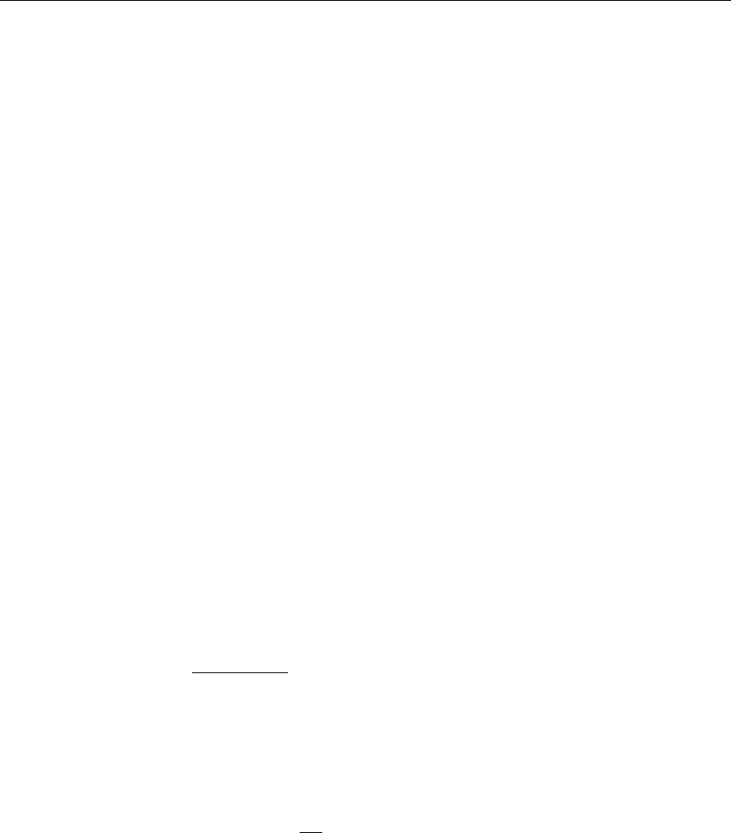
De sign of Dou bler Plates
One as pect of the de sign of a steel fram ing sys tem is an eval u a tion of the shear
forces that ex ist in the re gion of the beam col umn in ter sec tion known as the panel
zone.
Shear stresses sel dom con trol the de sign of a beam or col umn mem ber. How ever,
in a Mo ment-Re sist ing frame, the shear stress in the beam-col umn joint can be crit i -
cal, es pe cially in fram ing sys tems when the col umn is sub jected to ma jor di rec tion
bend ing and the joint shear forces are re sisted by the web of the col umn. In mi nor
di rec tion bend ing, the joint shear is car ried by the col umn flanges, in which case the
shear stresses are sel dom crit i cal, and this con di tion is there fore not in ves ti gated by
the pro gram.
Shear stresses in the panel zone, due to ma jor di rec tion bend ing in the col umn, may
re quire ad di tional plates to be welded onto the col umn web, de pend ing upon the
load ing and the ge om e try of the steel beams that frame into the col umn, ei ther
along the col umn ma jor di rec tion, or at an an gle so that the beams have com po nents
along the col umn ma jor di rec tion. See Fig ure . The pro gram in ves ti gates such sit u -
a tions and re ports the thick ness of any re quired doubler plates. Only col umns with
I-shapes are in ves ti gated for doubler plate re quire ments. Also doubler plate re -
quire ments are eval u ated for mo ment frames (OMF, IMF, SMF) only. No check is
made for braced frames(OCBF, SCBF, EBF).
The pro gram cal cu lates the re quired thick ness of doubler plates us ing the fol low ing
al go rithms. The shear force in the panel zone, is given by
V = M
d - t V
p
n =
nbnn
nfn
c
b
1
å-
cosq
The nom i nal panel shear strength is given by
R = FdtP P
vycruy
0.6for0.4,£ or if Pu is ten sile, and (LRFD K1-9)
R = Fd t P
PP >
v y c r u
y
u
0.6 1.4 , for 0.-
é
ë
êù
û
ú4Py . (LRFD K1-10)
By us ing VR
pv
=j , with j=0.9 (by de fault), the re quired col umn web thick ness
tr can be found.
The ex tra thick ness, or thick ness of the doubler plate is given by
t = t t
dprw
- , (LRFD F2-1)
56 Joint Design
CSI Steel Design Manual

where,
Fy=Col umn and doubler plate yield stress
tr=Re quired col umn web thick ness
tfn = Flange thick ness of n-th beam con nect ing to the col umn
tdp = Re quired doubler plate thick ness
tfc= Col umn Flange thick ness
tw=Col umn web thick ness
h= dt
cfc
-2 if welded, dk
cc
-2 if rolled
Vp=Panel zone shear
Vc=Col umn shear in col umn above
Fy=Beam flange forces
nb=Num ber of beams con nect ing to col umn
dn=Depth of n-th beam con nect ing to col umn
qn=An gle be tween n-th beam and col umn ma jor di rec tion
dc=Depth of col umn clear of fil lets, equals dk-2
Mbn=Cal cu lated fac tored beam mo ment from
the cor re spond ing load ing com bi na tion
Rv=Nom i nal shear strength of panel
Pu=Col umn fac tored ax ial load
Py=Col umn ax ial yield strength, FA
y
The larg est cal cu lated value of tdp cal cu lated for any of the load com bi na tions
based upon the fac tored beam mo ments and fac tored col umn ax ial loads is re -
ported.
The spe cial seis mic re quire ments ad di tion ally checked by the pro gram are de pend -
ent on the type of fram ing used and the Seis mic De sign Cat e gory. If the struc ture is
iden ti fied as Seis mic De sign Cat e gory D or E, the spe cial seis mic re quire ments are
sat is fied (ANSI/AISC 341 SEIS MIC 1). No spe cial check is made if the Seis mic
De sign Cat e gory is A, B, or C.
Doubler plate re quire ments for seis mic de sign are eval u ated for SMF only. No fur -
ther check/de sign is done for other types of frames.
•For Spe cial Mo ment-Re sist ing Frames, the panel zone doubler plate re quire -
ments that are re ported will de velop at least the beam mo ments equal to of the
plas tic mo ment ca pac ity of the beam or beam mo ments due to spec i fied load
com bi na tions in volv ing seis mic load (ANSI/AISC 341 SEIS MIC 9.3a).
•For seis mic de sign, Vpis cal cu lated us ing the same equa tion as given above, ex -
cept that Mpbis taken as RFZ
yy33.
Joint Design 57
Chapter III Check/Design for AISC-ASD01
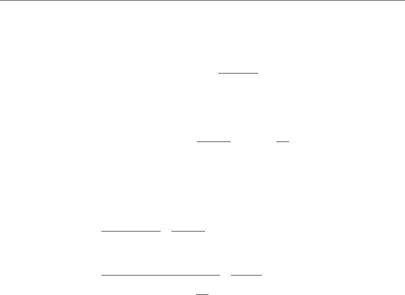
The ca pac ity of the panel zone in re sist ing this shear is taken as (ANSI/AISC
341 SEIS MIC 9-5):
jj
vnvycp
cfcf
bcp
V = F d t + b t
d d t 0.60132
æ
è
ç
ç
ö
ø
÷
÷
for P P
u y
£075. (ANSI/AISC 341 SEIS MIC 9-5)
j j
v n v y c p
cf cf
b c p
u
V F d t b t
d d t
P
P
= +
æ
è
ç
ç
ö
ø
÷
÷-0 6 1 319 12
2
. . .
y
æ
è
ç
ç
ö
ø
÷
÷
for P P
u y
>075. (ANSI/AISC 341 SEIS MIC 9.3a, LRFD K1-12)
giv ing the re quired panel zone thick ness as
tV
F d
bt
d d
p
p
vyc
cfcf
bc
=-
0.6j
32
, if PP
uy
£075.
tV
FdP
P
bt
p
p
vycu
y
cfcf
=
-æ
è
ç
ç
ö
ø
÷
÷
æ
è
ç
ç
ö
ø
÷
÷
-
061912
32
...jdd
bc
, if PP
uy
>075. (by de fault),
(ANSI/AISC 341 SEIS MIC 9.3a)
and the re quired doubler plate thick ness as
t = t - t
dppwc
where,
jv=0.90 by de fault,
bcf=width of col umn flange,
tcf=thick ness of col umn flange,
tp=re quired col umn web thick ness,
h= dt
cfc
-2 if welded, dk
cc
-2 if rolled, and
db=depth of deep est beam fram ing into the ma jor di rec tion of
the col umn.
Py = FA
y
Pu=Ax ial force in col umn
58 Joint Design
CSI Steel Design Manual
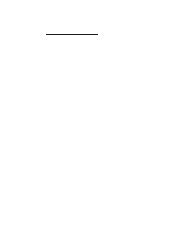
•For Spe cial Mo ment-Re sist ing Frames, the panel zone col umn web thick ness
re quire ment the pro gram checks the fol low ing:
tdtdt
cfcbfb
³-+-()()22
90(ANSI/AISC 341 SEIS MIC 9.36)
Here, t is taken as twc + tdpwhen the dou ble plate is plug welded to pre vent lo cal
buck ling. In such case tdpis in creased if nec es sary to meet this cri te ria. If the
doubler plate is not plug welded to the web, then t is taken as twcand also as tdp
for check ing both the plates. If twccan not sat isfy the cri te ria, then a fail ure con -
di tion is de clared. If tdpdoes not sat isfy this cri te ria, then its value is in creased
to meet this cri te ria.
If the check is not sat is fied, it is noted in the out put.
Weak Beam Strong Column Measure
Only for Spe cial Mo ment Frames with Seis mic De sign Cat e gory D and E, the code
re quires that the sum of col umn flex ure strengths at a joint should be more than the
sum of beam flex ure strengths (ANSI/AISC 341 SEIS MIC 1, 9.6). The col umn
flex ure strength should re flect the pres ence of ax ial force pres ent in the col umn.
The beam flex ural strength should re flect po ten tial in crease in ca pac ity for strain
hard en ing to fa cil i tate the re view of the strong col umn weak beam cri te rion, the
pro gram will re port a beam/col umn plas tic mo ment ca pac ity ra tio for ev ery joint in
the struc ture.
For the ma jor di rec tion of any col umn (top end) the beam to col umn strength ra tio
is ob tained as
R =
M
M + M
maj
n =
n
n
pcaxpcby
b
pbn
1
å*
**
cosq
(ANSI/AISC 341 SEIS MIC 9.6)
For the mi nor di rec tion of any col umn the beam to col umn strength ra tio is ob tained
as
R =
M
M + M
n =
n
pbnn
pcaypcby
b
min
1
åsin q
, (ANSI/AISC 341 SEIS MIC 9.6)
where,
Joint Design 59
Chapter III Check/Design for AISC-ASD01
Rmaj min,=Plas tic mo ment ca pac ity ra tios, in the ma jor and
mi nor di rec tions of the col umn, re spec tively
Mpbn
*=Plas tic mo ment ca pac ity of n-th beam con nect ing
to col umn
qn=An gle be tween the n-th beam and the col umn
ma jor di rec tion
Mpcaxy,
*=Ma jor and mi nor plas tic mo ment ca pac i ties, re duced for
ax ial force ef fects, of col umn above story level
Mpcbxy,
*=Ma jor and mi nor plas tic mo ment ca pac i ties, re duced for
ax ial force ef fects, of col umn be low story level
nb=Num ber of beams con nect ing to the col umn
The plas tic mo ment ca pac i ties of the col umns are re duced for ax ial force ef fects
and are taken as
()
M = Z F - PA
pccycucg
* , (ANSI/AISC 341 SEIS MIC 9.6)
The plas tic mo ment ca pac i ties of the beams are am pli fied for po ten tial in -
crease in ca pac ity for strain hard en ing as,
MRFZf
pbyybbmv
*.=11,
where,
Zb = Plas tic modulus of beam,
Zc= Plas tic modulus of col umn,
Fyb=Yield stress of beam ma te rial,
Fyc=Yield stress of col umn ma te rial,
Puc=Ax ial com pres sion force in col umn for the load com bi na tion un der
con sid er ation,
Agc=Gross area of col umn,
fmv = The mo ment am pli fi ca tion fac tor. It is taken as the ra tio of beam
mo ment at the cen ter line of col umn to the mo ment the col umn face. This
fac tor takes care of the Mvof the code (ANSI/AISC 341 SEIS MIC 9.6).
Fmvis taken as fol lows:
1+d
L
c
b
,
60 Joint Design
CSI Steel Design Manual

dc = Depth of col umn sec tion, and
Lb = Clear span length of the beam.
For the above cal cu la tions the sec tion of the col umn above is taken to be the same
as the sec tion of the col umn be low as sum ing that the col umn splice will be lo cated
some dis tance above the story level.
Evalua tion of Beam Con nec tion Shears
For each steel beam in the struc ture the pro gram will re port the max i mum ma jor
shears at each end of the beam for the de sign of the beam shear con nec tions. The
beam con nec tion shears re ported are the max ima of the fac tored shears ob tained
from the load ing com bi na tions.
For spe cial seis mic de sign, the beam con nec tion shears are not taken less than the
fol low ing spe cial val ues for dif fer ent types of fram ing. The spe cial seis mic re -
quire ments ad di tion ally checked by the pro gram are de pend ent on the type of fram -
ing used and the Seis mic De sign Cat e gory. If the struc ture is iden ti fied as Seis mic
De sign Cat e gory D or E, the spe cial seis mic re quire ments are sat is fied
(ANSI/AISC 341 SEIS MIC 1). No spe cial check is made if the Seis mic De sign
Cat e gory is A, B, or C.
•For spe cial mo ment frames, the beam con nec tion shear is taken as the max i -
mum of those from reg u lar load com bi na tions and those re quired for the de vel -
op ment of full plas tic mo ment ca pac ity of the beams. The con nec tion shear for
the de vel op ment of the full plas tic mo ment ca pac ity of beam is as fol lows:
V = C M
L + VV
u
pb
DLLL
1.20.5+(ANSI/AISC 341 SEIS MIC 9.2.a(3))
where
V=Shear force cor re spond ing to END I or END J of beam,
C=0 if beam ends are pinned, or for can ti le ver beam,
=1 if one end of the beam is pinned,
=2 if no ends of the beam are pinned,
Mpb=Plas tic mo ment ca pac ity of the beam, ZFy ,
L=Clear length of the beam,
VDL=Ab so lute max i mum of the cal cu lated fac tored beam
shears at the cor re spond ing beam ends from the
dead load only, and
VLL=Ab so lute max i mum of the cal cu lated fac tored beam
Joint Design 61
Chapter III Check/Design for AISC-ASD01

shears at the cor re spond ing beam ends from the
live load only.
•For In ter me di ate Mo ment Frames and Or di nary Mo ment Frames, the beam
con nec tion shear is taken as the max i mum of those from reg u lar load com bi na -
tions and those from spe cial seis mic con sid er ation. the beam con nec tion shear
from spe cial seis mic con sid er ation is taken as the min i mum of those re quired
for the de vel op ment of full plas tic mo ment ca pac ity of the beam and those re -
quired for am pli fied seis mic load and those re quired (ANSI/AISC 341 SEIS -
MIC 10.2, 11.2). The con nec tion shear for the de vel op ment of the full plas tic
mo ment ca pac ity of beam is as fol lows:
VCM
LVV
u
pb
DLLL
=++1205.. (ANSI/AISC 341 SEIS MIC 10.2, 11.2)
All pa ram e ters in the above equa tion have been de scribed ear lier.
The load com bi na tions for am pli fied seis mic loads are (ANSI/AISC 341
SEIS MIC 8.3, 4.1, ASCI 9.5.2.7.1, 2.3.2):
()
09020
..+±SDLEL
DSW
()
1202100
..).++±SDLLLEL
DSW
•For OCBF, the beam con nec tion shear is taken as the max i mum of those from
reg u lar load com bi na tions and those from am pli fied seis mic load com bi na tions
(ANSI/AISC 341 SEIS MIC 14.2).
•For SCBF, the beam con nec tion shear is taken as the max i mum of those from
reg u lar load com bi na tions and those from am pli fied seis mic load com bi na tion
(ANSI/AISC 341 SEIS MIC 13.4a(2)).
Note: Beams in ter sected by Chev ron (V or in verted-V) braces are NOT cur -
rently checked to have a strength to sup port loads for the fol low ing two con di -
tions (ANSI/AISC 341 SEIS MIC 13.4a):
aA beam that is in ter sected by braces shall be de signed to sup port the ef fects of
all trib u tary dead and live loads form load com bi na tions stip u lated by the code,
as sum ing the brac ings are not pres ent, and
bA beam that is in ter sected by braces shall be de signed to re sist the ef fects of
load com bi na tions stip u lated by the code, ex cept that a load qbshall be sub sti -
tuted for the term E. qbis given by the dif fer ence of RFA
yy for the ten sion
brace and 03.fcn
Pfor the com pres sion brace.
62 Joint Design
CSI Steel Design Manual

Us ers need to check for this re quire ment in de pend ently.
•For EBF, the beam con nec tion shear is taken as the beam con nec tion shear is
taken as the max i mum of those from reg u lar load com bi na tions and those from
spe cial seis mic con sid er ations. The beam con nec tion shear from spe cial seis -
mic con sid er ation is taken as the min i mum of those re quired for yield ing of
link beam and those re quired for am pli fied seis mic load (ANSI/AISC 341
SEIS MIC 15.1, 15.4, 15.6). The load fac tor for the seis mic com po nent of loads
in the com bi na tion is cal cu lated to achieve forces re lated to yield ing of link
beam. For con nec tion shear de ter mi na tion the forces are fur ther am pli fied by
11.Ry(ANSI/AISC 341 SEIS MIC 15.6(2)). The load com bi na tions for Am pli -
fied Seis mic Loads are given ear lier.
Evalua tion of Brace Con nec tion Forces
For each steel brace in the struc ture the pro gram re ports the max i mum ax ial force at
each end of the brace for the de sign of the brace to beam con nec tions. The brace
con nec tion forces re ported are the max ima of the fac tored brace ax ial forces ob -
tained from the load ing com bi na tions.
For spe cial seis mic de sign, the brace con nec tion forces are not taken less than the
fol low ing spe cial val ues for dif fer ent types of fram ing. The spe cial seis mic re quire -
ments ad di tion ally checked by the pro gram are de pend ent on the type of fram ing
used and the Seis mic De sign Cat e gory. If the struc ture is iden ti fied as Seis mic De -
sign Cat e gory D or E, the spe cial seis mic re quire ments are sat is fied (ANSI/AISC
341 SEIS MIC 1). No spe cial check is made if the Seis mic De sign Cat e gory is A, B,
or C.
Brace ax ial forces for seis mic de sign are eval u ated for braced frames (OCBF,
SCBF, EBF) only. No spe cial checks are done for mo ment frames (OMF, IMF,
SMF).
•For OBF, the brac ing con nec tion force is re ported at least the ex pected ten sile
strength of the brace (RFA
yyg) (ANSI/AISC 341 SEIS MIC 14.2):
•For SCBF, the brac ing con nec tion force is re ported at least as the ex pected the
ten sile strength of the brace (RFA
yyg) (ANSI/AISC 341 SEIS MIC 13.3a).
For EBF, the brace con nec tion force is taken as the max i mum of those from reg u lar
load com bi na tions and those from spe cial seis mic con sid er ation. The brace con -
nec tion force from spe cial seis mic con sid er ation is taken as the min i mum of those
re quired for yield ing of link beam and those re quired for Am pli fied Seis mic Load
(ANSI/AISC 341 SEIS MIC 15.1, 15.4, 15.6). The load fac tor for the seis mic com -
Joint Design 63
Chapter III Check/Design for AISC-ASD01

po nent of loads in the com bi na tion is cal cu lated to achieve forces re lated to yield -
ing of Link beam. for con nec tion force de ter mi na tion, the forces are fur ther am pli -
fied by 125.Ry(ANSI/AISC 341 SEIS MIC 15.6). The load com bi na tions for Am -
pli fied Seis mic Load are given ear lier in this doc u ment.
64 Joint Design
CSI Steel Design Manual

Chapter IV
Check/Design for AISC-ASD89
This chap ter de scribes the de tails of the struc tural steel de sign and stress check al -
go rithms that are used by the pro gram when the user se lects the AISC- ASD89 de -
sign code (AISC 1989). Vari ous no ta tions used in this chap ter are de scribed in
Table III-1.
For re fer ring to per ti nent sec tions and equa tions of the origi nal ASD code, a unique
pre fix “ASD” is as signed. However, all ref er ences to the “Speci fi ca tions for Al -
low able Stress De sign of Single- Angle Mem bers” carry the pre fix of “ASD SAM”.
The de sign is based on user- specified load ing com bi na tions. But the pro gram pro -
vides a set of de fault load com bi na tions that should sat isfy re quire ments for the de -
sign of most build ing type struc tures.
In the evalua tion of the ax ial force/bi ax ial mo ment ca pac ity ra tios at a sta tion along
the length of the mem ber, first the ac tual mem ber force/mo ment com po nents and
the cor re spond ing ca paci ties are cal cu lated for each load com bi na tion. Then the ca -
pac ity ra tios are evalu ated at each sta tion un der the in flu ence of all load com bi na -
tions us ing the cor re spond ing equa tions that are de fined in this chapter. The con -
trol ling ca pac ity ra tio is then ob tained. A ca pac ity ra tio greater than 1.0 in di cates
over stress. Simi larly, a shear ca pac ity ra tio is also cal cu lated sepa rately.
65
66
CSI Steel Design Manual
A=Cross- sectional area, in2
Ae=Effective cross- sectional area for slen der sections, in2
Af=Area of flange , in2
Ag=Gross cross- sectional area, in2
AA
vv23
,=Ma jor and mi nor shear ar eas, in2
Aw=Web shear area, dtw, in2
Cb=Bend ing Co ef fi cient
Cm=Mo ment Co ef fi cient
Cw=Warp ing con stant, in6
D=Out side di ame ter of pipes, in
E=Modu lus of elas tic ity, ksi
Fa=Al low able ax ial stress, ksi
Fb=Al low able bending stress, ksi
FF
bb3322
,=Al low able ma jor and mi nor bend ing stresses, ksi
Fcr=Criti cal com pres sive stress, ksi
Fe33
¢=()
12
23
2
333333
2
E
Klr
p
Fe22
¢=()
12
23
2
222222
2
E
Klr
p
Fv=Al low able shear stress, ksi
Fy=Yield stress of ma te rial, ksi
K=Ef fec tive length fac tor
KK
3322
,=Ef fec tive length K- factors in the ma jor and mi nor directions
MM
3322
,=Major and mi nor bend ing mo ments in mem ber, kip- in
Mob=Lateral- torsional mo ment for an gle sections, kip- in
P=Axial force in mem ber, kips
Pe=Euler buck ling load, kips
Q=Re duc tion fac tor for slen der sec tion, = QQ
as
Qa=Re duc tion fac tor for stiff ened slen der elements
Qs=Re duc tion fac tor for unstiff ened slen der elements
S=Sec tion modu lus, in3
SS
3322
,=Ma jor and mi nor sec tion moduli, in3
Table IV-1
AISC-ASD Notations
67
Chapter IV Check/Design for AISC-ASD89
SS
effeff,,
,
3322=Ef fec tive major and mi nor sec tion moduli for slen der sections, in3
Sc=Sec tion modu lus for com pres sion in an an gle section, in3
VV
23
,=Shear forces in major and mi nor directions, kips
b=Nomi nal di men sion of plate in a sec tion, in
longer leg of an gle sections,
bt
fw
-2 for welded and bt
fw
-3 for rolled box sec tions, etc.
be=Ef fec tive width of flange, in
bf=Flange width, in
d=Over all depth of mem ber, in
fa=Axial stress ei ther in com pres sion or in tension, ksi
fb=Nor mal stress in bend ing, ksi
ff
bb3322
,=Nor mal stress in ma jor and minor di rec tion bending, ksi
fv=Shear stress, ksi
f f
v v2 3
,=Shear stress in ma jor and minor di rec tion bending, ksi
h=Clear dis tance be tween flanges for I shaped sec tions ()dtf
-2, in
he=Ef fec tive dis tance be tween flanges less fil lets, in
k=Dis tance from outer face of flange to web toe of fil let , in
kc=Pa rame ter used for clas si fi ca tion of sec tions,
[]
4.05
0.46
htw
if htw>70 ,
1 if htw£70 .
ll
3322
,=Ma jor and mi nor di rec tion un braced mem ber lengths, in
lc=Criti cal length, in
r=Ra dius of gy ra tion, in
rr
3322
,=Ra dii of gy ra tion in the ma jor and mi nor di rec tions, in
rz=Mini mum Ra dius of gy ra tion for an gles, in
t=Thick ness of a plate in I, box, chan nel, an gle, and T sections, in
tf=Flange thick ness, in
tw=Web thick ness, in
bw=Spe cial sec tion prop erty for an gles, in
Table IV-1
AISC-ASD Notations (cont.)

Eng lish as well as SI and MKS met ric units can be used for in put. But the code is
based on Kip- Inch- Second units. For sim plic ity, all equa tions and de scrip tions pre -
sented in this chap ter cor re spond to Kip- Inch- Second units un less oth er wise
noted.
Design Loading Combinations
The de sign load com bi na tions are the vari ous com bi na tions of the load cases for
which the struc ture needs to be checked. For the AISC- ASD89 code, if a struc ture
is sub jected to dead load (DL), live load (LL), wind load (WL), and earth quake in -
duced load (EL), and con sid er ing that wind and earth quake forces are re versi ble,
then the fol low ing load com bi na tions may have to be de fined (ASD A4):
DL (ASD A4.1)
DL + LL (ASD A4.1)
DL ± WL (ASD A4.1)
DL + LL ± WL (ASD A4.1)
DL ± EL (ASD A4.1)
DL + LL ± EL (ASD A4.1)
These are also the de fault de sign load com bi na tions in the pro gram when ever the
AISC-ASD89 code is used. The user should use other ap pro pri ate load ing com bi -
na tions if roof live load is sepa rately treated, if other types of loads are pres ent, or if
pat tern live loads are to be con sid ered.
When de sign ing for com bi na tions in volv ing earth quake and wind loads, al low able
stresses are in creased by a fac tor of 4/3 of the regu lar al low able value (ASD A5.2).
Live load re duc tion fac tors can be ap plied to the mem ber forces of the live load case
on an element- by- element ba sis to re duce the con tri bu tion of the live load to the
fac tored load ing.
Classification of Sections
The al low able stresses for ax ial com pres sion and flex ure are de pend ent upon the
clas si fi ca tion of sec tions as ei ther Com pact, Non compact, Slen der, or Too Slen der.
The pro gram clas si fies the in di vid ual mem bers ac cord ing to the lim it ing
width/thick ness ra tios given in Table III-2 (ASD B5.1, F3.1, F5, G1, A-B5-2). The
defi ni tion of the sec tion prop er ties re quired in this ta ble is given in Figure III-1 and
Table III-1.
68 Design Loading Combinations
CSI Steel Design Manual

Classification of Sections 69
Chapter IV Check/Design for AISC-ASD89
Figure IV-1
AISC-ASD Definition of Geometric Properties
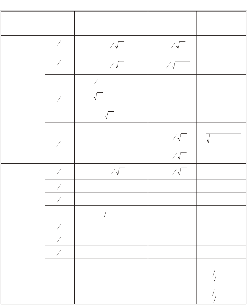
70 Classification of Sections
CSI Steel Design Manual
Section
Description
Ratio
Checked
Compact
Section
Noncompact
Section
Slender
Section
I-SHAPE
bt
f f
2
( rolled) £ F
y
65 £ F
y
95 No limit
bt
f f
2
(welded) £ F
y
65£ 95Fk
yc
/No limit
dt
w
For fF
a y£0.16
£-
6401
F
f
F
y
a
y
()3.74 ,
For fF
ay
/>0.16
£257/Fy .
No limit No limit
ht
wNo limit
If compression only,
£ F
y
253
otherwise
£ F
b
760
( )
£
+
£
14000
16.5
260
F F
y y
BOX
b t
f£ F
y
190 £ F
y
238 No limit
dt
wAs for I-shapes No limit No limit
ht
wNo limit As for I-shapes As for I-shapes
Other tt
wf
³2 , db
wf
£6None None
CHANNEL
bt
fAs for I-shapes As for I-shapes No limit
dt
wAs for I-shapes No limit No limit
ht
wNo limit As for I-shapes As for I-shapes
Other No limit No limit
If welded
b d
f w £0.25,
tt
fw£3.0
If rolled
b d
f w £0.5,
tt
fw£2.0
Table IV-2
Limiting Width-Thickness Ratios for
Classification of Sections Based on AISC-ASD

If the sec tion di men sions sat isfy the lim its shown in the ta ble, the sec tion is clas si -
fied as ei ther Com pact, Non com pact, or Slen der. If the sec tion sat is fies the cri te ria
for Com pact sec tions, then the sec tion is clas si fied as Com pact sec tion. If the sec -
tion does not sat is fy the cri te ria for Com pact sec tions but sat is fies the cri te ria for
Non com pact sec tions, the sec tion is clas si fied as Noncom pact sec tion. If the sec -
tion does not satisfy the cri te ria for Com pact and Non com pact sec tions but sat is fies
Classification of Sections 71
Chapter IV Check/Design for AISC-ASD89
Section
Description
Ratio
Checked
Compact
Section
Noncompact
Section
Slender
Section
T-SHAPE
bt
f f
2£ F
y
65£ F
y
95No limit
dt
wNot applicable £ F
y
127 No limit
Other No limit No limit
If welded
b d
f w ³0.5,
tt
fw³1.25
If rolled
b d
f w ³0.5,
tt
fw³1.10
DOUBLE
ANGLES bt
Not applicable £ F
y
76 No limit
ANGLE bt
Not applicable £ F
y
76 No limit
PIPE Dt
£ F
y
3300,£ F
y
3300,£ F
y
13,000
(Compression only)
No limit for flexure
ROUND BAR ¾Assumed Compact
RECTANGLE ¾Assumed Noncompact
GENERAL ¾Assumed Noncompact
Table IV-2
Limiting Width-Thickness Ratios for
Classification of Sections Based on AISC-ASD (Cont.)

the cri te ria for Slen der sec tions, the sec tion is clas si fied as Slender sec tion. If the
lim its for Slen der sec tions are not met, the sec tion is clas si fied as Too Slen der.
Stress check of Too Slen der sec tions is be yond the scope of SAP2000.
In clas si fy ing web slen der ness of I-shapes, Box, and Chan nel sec tions, it is as -
sumed that there are no in ter me di ate stiff en ers (ASD F5, G1). Dou ble an gles are
con ser va tively as sumed to be sepa rated.
Calculation of Stresses
The stresses are cal cu lated at each of the pre vi ously de fined sta tions. The mem ber
stresses for non- slender sec tions that are cal cu lated for each load com bi na tion are,
in gen eral, based on the gross cross- sectional prop er ties.:
f = P/A
a
f = M/S
b333333
f = M/S
b222222
f = V/A
vv222
f = V/A
vv333
If the sec tion is slen der with slen der stiff ened ele ments, like slen der web in I, Chan -
nel, and Box sec tions or slen der flanges in Box, ef fec tive sec tion moduli based on
re duced web and re duced flange di men sions are used in cal cu lat ing stresses.
f = P/A
a(ASD A-B5.2d)
f = M/S
b eff33 33 33, (ASD A-B5.2d)
f = M/S
b eff22 22 22, (ASD A-B5.2d)
f = V/A
v v2 2 2 (ASD A-B5.2d)
f = V/A
v v3 3 3 (ASD A-B5.2d)
The flexural stresses are cal cu lated based on the prop er ties about the principal axes.
For I, Box, Chan nel, T, Dou ble-an gle, Pipe, Cir cu lar and Rec tan gu lar sec tions, the
prin ci pal axes co in cide with the geo met ric axes. For Single- angle sec tions, the de -
sign con sid ers the prin ci pal properties. For gen eral sec tions it is as sumed that all
sec tion prop er ties are given in terms of the prin ci pal di rec tions.
For Single- angle sec tions, the shear stresses are cal cu lated for di rec tions along the
geo met ric axes. For all other sec tions the shear stresses are cal cu lated along the
geo met ric and prin ci ple axes.
72 Calculation of Stresses
CSI Steel Design Manual

Calculation of Allowable Stresses
The al low able stresses in com pres sion, ten sion, bend ing, and shear are com puted
for Com pact, Non com pact, and Slen der sec tions ac cord ing to the fol low ing sub -
sec tions. The al low able flexural stresses for all shapes of sec tions are cal cu lated
based on their prin ci pal axes of bend ing. For the I, Box, Chan nel, Cir cu lar, Pipe, T,
Dou ble-an gle and Rec tan gu lar sec tions, the prin ci pal axes co in cide with their geo -
met ric axes. For the An gle sec tions, the prin ci pal axes are de ter mined and all com -
pu ta tions re lated to flex ural stresses are based on that.
If the user speci fies nonz ero al low able stresses for one or more ele ments in the pro -
gram “Overwrites Ele ment De sign Data” form, these val ues will over ride the
above men tioned cal cu lated val ues for those ele ments as de fined in the fol low ing
sub sec tions. The speci fied al low able stresses should be based on the prin ci pal axes
of bend ing.
Allowable Stress in Tension
The al low able ax ial ten sile stress value Fa is as sumed to be 0.60Fy.
F = F
ay
0.6 (ASD D1, ASD SAM 2)
It should be noted that net sec tion checks are not made. For mem bers in ten sion,
if lr is greater than 300, a mes sage to that ef fect is printed (ASD B7, ASD SAM 2).
For sin gle an gles, the mini mum radius of gy ra tion, rz, is used in stead of r22 and r33
in com put ing lr .
Allowable Stress in Compression
The al low able ax ial com pres sive stress is the minimum value ob tained from flex -
ural buck ling and flexural- torsional buck ling. The al low able com pres sive stresses
are de ter mined ac cord ing to the fol low ing sub sec tions.
For mem bers in com pres sion, if Klr is greater than 200, a warn ing mes sage is
printed (ASD B7, ASD SAM 4). For sin gle an gles, the mini mum radius of gy ra -
tion, rz, is used in stead of r22 and r33 in com put ing Klr .
Flex ural Buck ling
The al low able ax ial com pres sive stress value, Fa, de pends on the slen der ness ra tio
Klr based on gross sec tion prop er ties and a cor re spond ing criti cal value, Cc,
where
Calculation of Allowable Stresses 73
Chapter IV Check/Design for AISC-ASD89
Kl
r
K l
r
K l
r
=ì
í
î
ü
ý
þ
max ,
33 33
33
22 22
22
, and
Cc=22
pE
Fy
. (ASD E2, ASD SAM 4)
For sin gle an gles, the mini mum radius of gy ra tion, rz, is used in stead of r22 and r33
in com put ing Klr .
For Com pact or Non com pact sec tions Fa is evalu ated as fol lows:
()
F =
Kl/r
CF
+ Kl/r
C K
a
c
y
c
1.0-
ì
í
î
ü
ý
þ
-
()2
2
2
5
3
3
8
()
l/r
C
c
3
3
8
, if Kl
r Cc
£,(ASD E2-1, SAM 4-1)
F = E
Kl r
a
12
23
2
2
p
() , if Kl
r Cc
>.(ASD E2-2, SAM 4-2)
If Kl r is greater than 200, then the cal cu lated value of Fa is taken not to ex ceed the
value of Fa cal cu lated by us ing the equa tion ASD E2-2 for Com pact and Non com -
pact sec tions (ASD E1, B7).
For Slender sec tions, ex cept slen der Pipe sec tions, Fa is evalu ated as fol lows:
()
F = Q
Kl/r
C
F
+ Kl/r
C
a
c
y
1.0-
ì
í
ï
î
ï
ü
ý
ï
þ
ï
¢
()2
2
2
5
3
3
8
()
c
c
Kl/r
C
¢¢
-
3
3
8
, if Kl
r Cc
£¢,(ASD A-B5-11, SAM 4-1)
F = E
Kl r
a
12
23
2
2
p
() , if Kl
r Cc
>¢.(ASD A-B5-12, SAM 4-2)
where,
CE
QF
c
y
¢=22
p . (ASD A-B5.2c, ASD SAM 4)
74 Calculation of Allowable Stresses
CSI Steel Design Manual
For slen der sec tions, if Klr is greater than 200, then the cal cu lated value of Fa is
taken not to ex ceed its value cal cu lated by us ing the equa tion ASD A-B5-12 (ASD
B7, E1).
For slen der Pipe sec tions Fa is evalu ated as fol lows:
F = DtF
ay
6620.40+(ASD A- B5-9)
The re duc tion fac tor, Q, for all com pact and non com pact sec tions is taken as 1. For
slen der sec tions, Q is com puted as fol lows:
QQQ
sa
= , where (ASD A-B5.2.c, SAM 4)
Qs = re duc tion fac tor for un stiff ened slen der ele ments, and (ASD A-B5.2.a)
Qa = re duc tion fac tor for stiff ened slen der ele ments. (ASD A-B5.2.c)
The Qs fac tors for slen der sec tions are cal cu lated as de scribed in Table III-4 (ASD
A-B5.2a, ASD SAM 4). The Qa fac tors for slen der sec tions are cal cu lated as the
ra tio of ef fec tive cross- sectional area and the gross cross- sectional area.
QA
A
ae
g
=(ASD A- B5-10)
The ef fec tive cross- sectional area is com puted based on ef fec tive width as fol lows:
()
AAbbt
ege
=--
å
be for un stiff ened el e ments is taken equal to b, and be for stiff ened el e ments is
taken equal to or less than b as given in Table III-5 (ASD A-B5.2b). For webs in I,
box, and Chan nel sec tions, he is used as be and h is used as b in the above equa tion.
Flex ural-Torsional Buck ling
The al low able ax ial com pres sive stress value, Fa, de ter mined by the limit states of
tor sional and flexural- torsional buck ling is de ter mined as fol lows (ASD E3, C-E3):
()
()
F = Q
Kl/r
C
F
+ Kl/r
C
a
e
c
y
e
1.0-
ì
í
ï
î
ï
ü
ý
ï
þ
ï
¢
2
2
2
5
3
3
8
()
c
e
c
Kl/r
C
¢¢
-
3
3
8
, if ()
Kl/r C
ec
£¢,(E2-1, A- B5- 11)
Calculation of Allowable Stresses 75
Chapter IV Check/Design for AISC-ASD89
76 Calculation of Allowable Stresses
CSI Steel Design Manual
Section
Type
Re duc tion Fac tor for Un stiff ened Slen der Ele ments
(Qs)
Equation
Reference
I-SHAPE []
Q
ifbtFk
btFkifF
s
ffyc
ffycy
=
£
-
1.095
1.2930.00309 95
2
2
,
[ ]
{ }
k b t F k
k b t F if b t F k
c f f y c
c f f y f f y c
< <
³
ì
2
2 2
2
195
26,200 195
,
.
í
ï
ï
î
ï
ï
ASD A-B5-3,
ASD A-B5-4
BOX Qs=1ASD A-B5.2c
CHANNEL As for I-shapes with bt
ff
2 replaced by bt
ff . ASD A-B5-3,
ASD A-B5-4
T-SHAPE
For flanges, as for flanges in I-shapes. For web see below.
[ ]
Q
if d t F
d t F if F d t
s
w y
w y y w
£
£
-<
1.0 , 127
1.908 0.00715 127
,
,
[ ]
{ }
<
³
ì
í
ï
ï
î
ï
ï
176
20,000 176
F
d t F if d t F
y
w y w y
,
, .
2
ASD A-B5-3,
ASD A-B5-4,
ASD A-B5-5,
ASD A-B5-6
DOUBLE-
ANGLE []
Q
ifbtF
btFifFbt
s
y
yy
=
£
-<<
1.0 ,76
1.3400.00447 76 155
,
,
[ ]
{ }
F
b t F if b t F
y
y y
,
, .15,500 155
2³
ì
í
ï
ï
î
ï
ï
ASD A-B5-1,
ASD A-B5-2,
SAM 4-3
ANGLE []
Q
ifbtF
btFifFbt
s
y
yy
=
£
-<<
1.0 ,76
1.3400.00447 76 155
,
,
[ ]
{ }
F
b t F if b t F
y
y y
,
, .15,500 155
2³
ì
í
ï
ï
î
ï
ï
ASD A-B5-1,
ASD A-B5-2,
SAM 4-3
PIPE Qs=1ASD A-B5.2c
ROUND
BAR Qs=1ASD A-B5.2c
RECTAN-
GULAR Qs=1ASD A-B5.2c
GENERAL Qs=1ASD A-B5.2c
Table IV-3
Re duc tion Fac tor for Un stiff ened Slen der Ele ments, Qs

Calculation of Allowable Stresses 77
Chapter IV Check/Design for AISC-ASD89
Section
Type
Effective Width for Stiffened Sections Equation
Reference
I-SHAPE h
hifh
tf
t
fhtfifh
t
e
w
w
ww
=
£
-
é
ë
êù
û
ú>
,,
(),
195.74
253 44.3
1195.74
f.
ì
í
ï
ï
î
ï
ï
(compression only, fP
Ag
=)ASD A-B5-8
BOX
h
h if h
tf
t
f h t f if h
t
e
w
w
ww
=
£
-
é
ë
êù
û
ú>
, ,
( ) ,
195.74
253 44.3
1195.74
f.
ì
í
ï
ï
î
ï
ï
(compression only, fP
Ag
=)
b
bifb
tf
t
fhtfifb
t
e
f
f
f
=
£
-
é
ë
ê
ê
ù
û
ú
ú
,,
(),
183.74
25350.3
1>
ì
í
ï
ï
î
ï
ï
183.74
f.
(compr., flexure, fFy
=0.6)
ASD A-B5-8
ASD A-B5-7
CHANNEL h
hifh
tf
t
fhtfifh
t
e
w
w
ww
=
£
-
é
ë
êù
û
ú>
,,
(),
195.74
253 44.3
1195.74
f.
ì
í
ï
ï
î
ï
ï
(compression only, fP
Ag
=)ASD A-B5-8
T-SHAPE bb
e=ASD A-B5.2c
DOUBLE-
ANGLE bb
e=ASD A-B5.2c
ANGLE bb
e=ASD A-B5.2c
PIPE Qa=1, (However, special expression for allowable axial stress is given.) ASD A-B5-9
ROUND
BAR Not applicable ¾
RECTAN-
GULAR bb
e=ASD A-B5.2c
GENERAL Not applicable ¾
Table IV-4
Effective Width for Stiffened Sections
( )
F = E
Kl/r
a
e
12
23
2
2
p , if ()
Kl/r C
ec
>¢.(E2-2, A- B5- 12)
where,
CE
QF
c
y
¢=22
p , and (ASD E2, A-B5.2c, SAM 4)
()
Kl/rE
F
ee
=p2 . (ASD C- E2-2, SAM 4-4)
ASD Com men tary (ASD C-E3) re fers to the 1986 ver sion of the AISC-LRFD code
for the cal cu la tion of Fe. The 1993 ver sion of the AISC-LRFD code is the same as
the 1986 ver sion in this respect. Fe is cal cu lated in the pro gram as fol lows:
•For Rec tan gu lar, I, Box, and Pipe sec tions:
()
FEC
Kl
GJII
ew
zz
=+
é
ë
ê
ê
ù
û
ú
ú+
p2
22233
1 (LRFD A- E3-5)
•For T-sections and Dou ble-angles:
F = FF
H FFH
FF
e
eezeez
eez
2222
22
2
2114+
æ
è
ç
çö
ø
÷
÷--+
é
()
ë
ê
ê
ù
û
ú
ú (LRFD A- E3-6)
•For Channels:
F = FF
H FFH
FF
e
eezeez
eez
3333
33
2
2114+
æ
è
ç
çö
ø
÷
÷--+
é
()
ë
ê
ê
ù
û
ú
ú (LRFD A- E3-6)
•For Sin gle-angle sec tions with equal legs:
F = FF
H FFH
FF
e
eezeez
eez
3333
33
2
2114+
æ
è
ç
çö
ø
÷
÷--+
é
()
ë
ê
ê
ù
û
ú
ú (ASD SAM C- C4-1)
•For Single- angle sec tions with une qual legs, Fe is cal cu lated as the mini mum
real root of the fol low ing cu bic equa tion (ASD SAM C- C4-2, LRFD A- E3-7):
78 Calculation of Allowable Stresses
CSI Steel Design Manual
( )( )( ) ( ) (F F F F F F F F F x
rF
e e e e e ez e e e e
- - - - - -
33 22
2
22 0
2
0
2
2F F y
r
e e
-=
33 0
2
0
20) ,
where,
xy
00
, are the co or di nates of the shear cen ter with re spect to the cen troid,
x00= for double- angle and T- shaped mem bers (y-axis of sym me -
try),
r x y I I
Ag
0 0
2
0
222 33
= + + + = po lar ra dius of gy ra tion about the shear center,
Hxy
r
=-+
æ
è
ç
çö
ø
÷
÷
10
2
0
2
0
2 , (LRFD A- E3-9)
( )
FE
K l r
e33
2
33 33 33
2
=p , (LRFD A- E3-10)
( )
FE
K l r
e22
2
22 22 22
2
=p , (LRFD A- E3-11)
( )
FEC
K l
GJ Ar
ez w
z z
= +
é
ë
ê
ê
ù
û
ú
ú
p2
2
0
2
1 , (LRFD A- E3-12)
K K
22 33
, are ef fec tive length fac tors in mi nor and ma jor di rec tions,
Kz is the ef fec tive length fac tor for tor sional buck ling, and it is taken equal to
K22 in the pro gram,
ll
2233
, are ef fec tive lengths in the mi nor and ma jor di rec tions,
lz is the ef fec tive length for tor sional buck ling, and it is taken equal to l22.
For an gle sec tions, the prin ci pal mo ment of in er tia and ra dii of gy ra tion are used for
com put ing Fe (ASD SAM 4). Also, the maxi mum value of Kl, i.e,
max(,)KlKl
22223333, is used in place of Kl
2222 or Kl
3333 in cal cu lat ing Fe22 and Fe33
in this case.
Calculation of Allowable Stresses 79
Chapter IV Check/Design for AISC-ASD89
Allowable Stress in Bending
The al low able bend ing stress de pends on the fol low ing cri te ria: the geo met ric
shape of the cross- section, the axis of bend ing, the com pact ness of the sec tion, and
a length pa rame ter.
I-sections
For I- sections the length pa rame ter is taken as the lat er ally un braced length, l22,
which is com pared to a criti cal length, lc. The criti cal length is de fined as
lb
F
A
dF
c
f
y
f
y
=
ì
í
ï
î
ï
ü
ý
ï
þ
ï
min,,7620000 , where (ASD F1-2)
Af is the area of com pres sion flange,
Major Axis of Bending
If l22 is less than lc, the ma jor al low able bend ing stress for Com pact and
Noncom pact sec tions is taken de pend ing on whether the sec tion is welded or
rolled and whether fy is greater than 65 ksi or not.
For Com pact sec tions:
F = F
by330.66 if fy£65ksi , (ASD F1-1)
F = F
b y33 0.60 if fy>65ksi , (ASD F1-5)
For Non com pact sec tions:
F = b
tF F
b
f
f
yy332
0.790.002-
æ
è
ç
ç
ö
ø
÷
÷, if rolled and fy£65ksi,(ASD F1-3)
F= b
t
F
k F
b
f
f
y
c
y33 2
0.79 0.002-
æ
è
ç
ç
ö
ø
÷
÷, if welded and fy£65ksi,(ASDF1-4)
F = F
by33 0.60 if fy>65ksi.. (ASD F1-5)
If the un braced length l22 is greater than lc, then for both Com pact and Non -
com pact I- sections the al low able bend ing stress de pends on the lrT22 ra tio.
80 Calculation of Allowable Stresses
CSI Steel Design Manual
For l
r
C
F
T
b
y
22102000
£, ,
FF
by33=0.60 , (ASD F1-6)
for 102 000 510 000
22
, ,C
F
l
r
C
F
b
y T
b
y
<£ ,
FF l r
CF F
b
y T
b
y y33
22
2
2
3 1530 000
=-
é
ë
ê
ê
ù
û
ú
ú£
( / )
,0.60 , and (ASD F1-6)
for l
r
C
F
T
b
y
22 510 000
>, ,
FC
l r F
bb
T
y33
22
2
170 000 0=é
ë
êù
û
ú£
,
( / ) 0.6 , (ASD F1-7)
and Fb33 is taken not to be less than that given by the fol low ing for mula:
()
FC
ldAF
bb
f
y33
22
12000
=0.6
,
/£ (ASD F1-8)
where,
rT is the ra dius of gy ra tion of a sec tion com pris ing the com pres sion flange and
13 the com pres sion web taken about an axis in the plane of the web,
C = + M
M + M
M
ba
b
a
b
1.751.050.3
æ
è
ç
çö
ø
÷
÷
æ
è
ç
çö
ø
÷
÷£
2
2.3, where (ASD F1.3)
MM
ab
and are the end mo ments of any un braced seg ment of the mem ber and
Ma is nu mer i cally less than Mb; MM
ab be ing pos i tive for dou ble cur va ture
bend ing and neg a tive for sin gle cur va ture bend ing. Also, if any mo ment within
the seg ment is greater than Mb, Cb is taken as 1.0. Also, Cb is taken as 1.0 for
can ti le vers and frames braced against joint trans la tion (ASD F1.3). The pro -
gram de faults Cb to 1.0 if the un braced length, l22, of the mem ber is re de fined
by the user (i.e. it is not equal to the length of the mem ber). The user can over -
write the value of Cb for any mem ber by spec i fy ing it.
Calculation of Allowable Stresses 81
Chapter IV Check/Design for AISC-ASD89
The al low able bend ing stress for Slen der sec tions bent about their ma jor axis is
de ter mined in the same way as for a Non com pact sec tion. Then the fol low ing
ad di tional con sid era tions are taken into ac count.
If the web is slen der, then the pre vi ously com puted al low able bend ing stress is
re duced as fol lows:
FRRF
bPGeb3333
¢= , where (ASD G2-1)
RA
A
h
tF
PG w
fb
=- -
é
ë
ê
ê
ù
û
ú
ú£1.0 0.0005 1.0
760
33
, (ASD G2)
()
R
A
A
A
A
e
w
f
w
f
=
+-
+
£
12
12 2
1.0
33
a a
, (hy brid gird ers) (ASD G2)
Re=1.0 , (non- hybrid gird ers) (ASD G2)
Aw = Area of web, in2,
Af = Area of com pres sion flange, in2,
a=£
0.61.0
F
F
y
b33
(ASD G2)
Fb33 = Al low able bend ing stress as sum ing the sec tion is non- compact, and
Fb33
¢ = Al low able bend ing stress af ter con sid er ing web slenderness.
In the above ex pres sions, Re is taken as 1, be cause cur rently the pro gram deals
with only non-hy brid gird ers.
If the flange is slen der, then the pre vi ously com puted al low able bend ing stress
is taken to be lim ited as follows.
()
FQF
bsy33
¢£0.6 , where (ASD A-B5.2a, A-B5.2d)
Qs is de fined ear lier.
82 Calculation of Allowable Stresses
CSI Steel Design Manual
Minor Axis of Bending
The mi nor di rec tion al low able bend ing stress Fb22 is taken as fol lows:
For Com pact sec tions:
F = F
by220.75 if fy£65ksi , (ASD F2-1)
F = F
b y22 0.60 if fy>65ksi , (ASD F2-2)
For Non com pact and Slen der sec tions:
F = b
tF F
b
f
f
yy222
1.0750.005-
æ
è
ç
ç
ö
ø
÷
÷, if fy£65ksi,(ASD F2-3)
F = F
b y22 0.60 if fy>65ksi.. (ASD F2-2)
Channel sections
For Chan nel sec tions the length pa rame ter is taken as the lat er ally un braced
length, l22, which is com pared to a criti cal length, lc. The criti cal length is de -
fined as
lb
F
A
dF
c
f
y
f
y
=
ì
í
ï
î
ï
ü
ý
ï
þ
ï
min,,7620000 , where (ASD F1-2)
Af is the area of com pres sion flange,
Major Axis of Bending
If l22 is less than lc, the ma jor al low able bend ing stress for Com pact and
Noncom pact sec tions is taken de pend ing on whether the sec tion is welded or
rolled and whether fy is greater than 65 ksi or not.
For Com pact sec tions:
F = F
by330.66 if fy£65ksi , (ASD F1-1)
F = F
b y33 0.60 if fy>65ksi , (ASD F1-5)
For Non com pact sec tions:
F = b
tF F
b
f
f
yy330.790.002-
æ
è
ç
ç
ö
ø
÷
÷, if rolled and fy£65ksi,(ASD F1-3)
Calculation of Allowable Stresses 83
Chapter IV Check/Design for AISC-ASD89

F = b
t
F
k F
b
f
f
y
c
y33 0.79 0.002-
æ
è
ç
ç
ö
ø
÷
÷, if welded and fy£65ksi,(ASD F1-4)
F = F
b y33 0.60 if fy>65ksi.. (ASD F1-5)
If the un braced length l22 is greater than lc, then for both Com pact and
Noncom pact Chan nel sections the al low able bend ing stress is taken as follows:
()
FC
ldAF
bb
f
y33
22
12000
=0.6
,
/£ (ASD F1-8)
The al low able bend ing stress for Slen der sec tions bent about their ma jor axis is
de ter mined in the same way as for a Non com pact sec tion. Then the fol low ing
ad di tional con sid era tions are taken into ac count.
If the web is slen der, then the pre vi ously com puted al low able bend ing stress is
re duced as fol lows:
FRRF
bePGb3333
¢= (ASD G2-1)
If the flange is slen der, the pre vi ously com puted al low able bend ing stress is
taken to be lim ited as follows:
()
FQF
bsy33
¢£0.6(ASD A-B5.2a, A-B5.2d)
The defi ni tion for rT, Cb, Af, Aw, Re, RPG, Qs, Fb33, and Fb33
¢ are given ear lier.
Minor Axis of Bending
The mi nor di rec tion al low able bend ing stress Fb22 is taken as fol lows:
F = F
by220.60(ASD F2-2)
T-sections and Double angles
For T sec tions and Dou ble an gles, the al low able bend ing stress for both ma jor
and mi nor axes bending is taken as,
F = Q F
bsy
0.60 .
84 Calculation of Allowable Stresses
CSI Steel Design Manual

Box Sections and Rectangular Tubes
For all Box sec tions and Rec tan gu lar tubes, the length pa rame ter is taken as the
lat er ally un braced length, l22, meas ured com pared to a criti cal length, lc. The
criti cal length is de fined as
l M/Mb
F, b
F
cab
yy
=+
ì
í
î
ü
ý
þ
max()195012001200(ASD F3-2)
where Maand Mb have the same defi ni tion as noted ear lier in the for mula for
Cb. If l22 is speci fied by the user, lc is taken as 1200 b
Fy
in the pro gram.
Major Axis of Bending
If l22 is less than lc, the al low able bend ing stress in the ma jor di rec tion of
bend ing is taken as:
F= F
by330.66 (for Com pact sec tions) (ASD F3-1)
F = F
b y33 0.60 (for Non com pact sec tions) (ASD F3-3)
If l22 ex ceeds lc, the al low able bend ing stress in the ma jor di rec tion of bend -
ing for both Com pact and Non com pact sec tions is taken as:
F = F
by330.60(ASD F3-3)
The ma jor di rec tion al low able bend ing stress for Slen der sec tions is de ter -
mined in the same way as for a Non com pact sec tion. Then the fol low ing ad di -
tional con sid era tion is taken into ac count. If the web is slen der, then the pre vi -
ously com puted al low able bend ing stress is re duced as fol lows:
FRRF
bePGb3333
¢= (ASD G2-1)
The defi ni tion for Re, RPG, Fb33, and Fb33
¢ are given ear lier.
If the flange is slen der, no ad di tional con sid er ation is needed in com put ing al -
low able bend ing stress. How ever, ef fec tive sec tion di men sions are cal cu lated
and the sec tion modu lus is modi fied ac cord ing to its slen der ness.
Minor Axis of Bending
If l22 is less than lc, the al low able bend ing stress in the minor di rec tion of bend -
ing is taken as:
Calculation of Allowable Stresses 85
Chapter IV Check/Design for AISC-ASD89

F = F
b y22 0.66 (for Com pact sec tions) (ASD F3-1)
F = F
b y22 0.60 (for Non com pact and Slender sec tions) (ASD F3-3)
If l22 ex ceeds lc, the al low able bend ing stress in the minor di rec tion of bend -
ing is taken, ir re spec tive of com pact ness, as:
F = F
by220.60 (ASD F3-3)
Pipe Sections
For Pipe sec tions, the al low able bend ing stress for both ma jor and mi nor axes
of bend ing is taken as
F = F
by
0.66 (for Com pact sec tions), and (ASD F3-1)
F = F
b y
0.60 (for Non com pact and Slen der sec tions). (ASD F3-3)
Round Bars
The al low able stress for both the ma jor and mi nor axis of bend ing of round bars
is taken as,
F = F
by
0.75 . (ASD F2-1)
Rectangular and Square Bars
The al low able stress for both the ma jor and mi nor axis of bend ing of solid
square bars is taken as,
F = F
by
0.75 . (ASD F2-1)
For solid rec tan gu lar bars bent about their ma jor axes, the al low able stress is
given by
F = F
by
0.60, And
the al low able stress for mi nor axis bend ing of rec tan gu lar bars is taken as,
F = F
by
0.75 . (ASD F2-1)
86 Calculation of Allowable Stresses
CSI Steel Design Manual
Single-Angle Sections
The al low able flex ural stresses for Single- angles are cal cu lated based on their prin -
ci pal axes of bend ing (ASD SAM 5.3).
Major Axis of Bending
The al low able stress for ma jor axis bend ing is the mini mum con sid er ing the limit
state of lateral- torsional buck ling and lo cal buck ling (ASD SAM 5.1).
The al low able ma jor bend ing stress for Single- angles for the limit state of lateral-
torsional buck ling is given as fol lows (ASD SAM 5.1.3):
F = F
FF
bmajorob
y
ob,0.550.10-
é
ë
êù
û
ú, if FF
oby
£(ASD SAM 5-3a)
F = F
FF F
b major
y
ob
y y,0.95 0.50 0.66-
é
ë
ê
ê
ù
û
ú
ú£, if FF
oby
>(ASD SAM 5-3b)
where, Fob is the elas tic lateral- torsional buck ling stress as cal cu lated be low.
The elas tic lateral- torsional buck ling stress, Fob, for equal- leg an gles is taken as
FClt
obb
=28,250 , (ASD SAM 5-5)
and for unequal- leg an gles Fob is cal cu lated as
FCI
Slltr
obb
major
ww
=++
é
ëù
û
143,1000.052
min min
2
2 2
b b( ) , (ASD SAM 5-6)
where,
()
ttt
wf
=min, ,
()
lll=max,
2233 ,
Imin= mi nor prin ci pal mo ment of in er tia,
Imax= major prin ci pal mo ment of in er tia,
Smajor= ma jor sec tion modu lus for com pres sion at the tip of one leg,
Calculation of Allowable Stresses 87
Chapter IV Check/Design for AISC-ASD89
rmin = ra dius of gy ra tion for mi nor prin ci pal axis,
bwA
IzwzdAz=+
é
ë
êù
û
ú-
ò
12
22
0
max
() , (ASD SAM 5.3.2)
z = co or di nate along the ma jor prin ci pal axis,
w = co or di nate along the mi nor prin ci pal axis, and
z0= co or di nate of the shear cen ter along the ma jor prin ci pal axis with re spect
to the cen troid.
bw is a spe cial sec tion prop erty for an gles. It is posi tive for short leg in com pres -
sion, nega tive for long leg in com pres sion, and zero for equal- leg an gles (ASD
SAM 5.3.2). How ever, for con ser va tive de sign in the pro gram, it is al ways taken as
nega tive for unequal- leg an gles.
In the above ex pres sions Cb is cal cu lated in the same way as is done for I sec tions
with the ex cep tion that the up per limit of Cb is taken here as 1.5 in stead of 2.3.
C = + M
M + M
M
ba
b
a
b
1.751.050.3
æ
è
ç
çö
ø
÷
÷
æ
è
ç
çö
ø
÷
÷£
2
1.5 (ASD F1.3, SAM 5.2.2)
The al low able ma jor bend ing stress for Single- angles for the limit state of lo cal
buck ling is given as fol lows (ASD SAM 5.1.1):
F = F
bmajory,0.66, if b
tFy
£65 , (ASD SAM 5-1a)
F = F
b major y,0.60 , if 6576
F
b
tF
yy
<£ , (ASD SAM 5-1b)
()
F = Q F
b major y,0.60 , if b
tFy
>76 , (ASD SAM 5-1c)
where,
t = thick ness of the leg un der consideration,
b = length of the leg un der con sid era tion, and
Q = slen der ness re duc tion fac tor for lo cal buck ling. (ASD A- B5-2, SAM 4)
88 Calculation of Allowable Stresses
CSI Steel Design Manual
In cal cu lat ing the al low able bend ing stress for Single- angles for the limit state of
lo cal buck ling, the al low able stresses are cal cu lated con sid er ing the fact that ei ther
of the two tips can be un der com pres sion. The mini mum al low able stress is con sid -
ered.
Minor Axis of Bending
The al low able minor bend ing stress for Single- angles is given as fol lows (ASD
SAM 5.1.1, 5.3.1b, 5.3.2b):
F = Fy
b,minor0.66, if b
tFy
£65 , (ASD SAM 5-1a)
F = Fy
b,minor 0.60 , if 6576
F
b
tF
yy
<£ , (ASD SAM 5-1b)
()
F = Q Fy
b,minor 0.60 , if b
tFy
>76 , (ASD SAM 5-1c)
In cal cu lat ing the al low able bend ing stress for Single- angles it is as sumed that the
sign of the mo ment is such that both the tips are un der com pres sion. The mini mum
al low able stress is con sid ered.
General Sections
For Gen eral sec tions the al low able bend ing stress for both ma jor and mi nor
axes bending is taken as,
F = F
by
0.60 .
Allowable Stress in Shear
The shear stress is cal cu lated along the geo met ric axes for all sec tions. For I, Box,
Chan nel, T, Dou ble an gle, Pipe, Cir cu lar and Rec tan gu lar sec tions, the prin ci pal
axes co in cide with their geo met ric axes. For Single- angle sec tions, prin ci pal axes
do not co in cide with the geometric axes.
Major Axis of Bending
The al low able shear stress for all sec tions ex cept I, Box and Chan nel sec tions is
taken in the pro gram as:
Calculation of Allowable Stresses 89
Chapter IV Check/Design for AISC-ASD89
F F
v y
=0.40 (ASD F4-1, SAM 3-1)
The al low able shear stress for ma jor di rec tion shears in I- shapes, boxes and chan -
nels is evalu ated as fol lows:
FF
vy
=0.40 , if h
t F
wy
£380 , and (ASD F4-1)
FCFF
vvy y
=£
2.89 0.40 , if 380260
F
h
t
yw
<£ . (ASD F4-2)
where,
()
C
k
Fht
ifh
t
k
F
ht
k
Fifh
t
v
v
yww
v
y
w
v
y
=
³
45 000
2
,, ,
,
56,250
190
w
v
y
k
F
<
ì
í
ï
ï
î
ï
ï56,250 ,
(ASD F4)
()
()
kah
if a
h
a h
if a
h
v=
+£
+ >
ì
í
ï
ï
î
ï
ï
4.00 5.34
5.34 4.00
2
2
1
1
, ,
, ,
(ASD F4)
tw= Thick ness of the web,
a = Clear dis tance be tween trans verse stiff en ers, in. Cur rently it is taken
con ser va tively as the length, l22, of the mem ber in the pro -
gram,
h= Clear dis tance be tween flanges at the sec tion, in.
Minor Axis of Bending
The al low able shear stress for mi nor di rec tion shears is taken as:
FF
vy
=0.40 (ASD F4-1, SAM 3-1)
90 Calculation of Allowable Stresses
CSI Steel Design Manual
Calculation of Stress Ratios
In the calculation of the ax ial and bend ing stress ca pac ity ra tios, first, for each sta -
tion along the length of the mem ber, the ac tual stresses are cal cu lated for each load
com bi na tion. Then the cor re spond ing al low able stresses are calculated. Then, the
ca pac ity ra tios are calculated at each sta tion for each mem ber un der the in flu ence of
each of the de sign load com bi na tions. The con trol ling ca pac ity ra tio is then ob -
tained, along with the as so ci ated sta tion and load com bi na tion. A ca pac ity ra tio
greater than 1.0 in di cates an overstress.
Dur ing the de sign, the ef fect of the pres ence of bolts or welds is not con sid ered.
Also, the joints are not de signed.
Ax ial and Bend ing Stresses
With the com puted al low able ax ial and bend ing stress val ues and the fac tored ax ial
and bend ing mem ber stresses at each sta tion, an in ter ac tion stress ra tio is pro duced
for each of the load com bi na tions as fol lows (ASD H1, H2, SAM 6):
•If fa is com pres sive and fF
aa>0.15, the com bined stress ra tio is given by
the larger of
f
F+C f
f
F' F
+ C f
a
a
mb
a
e
b
mb3333
33
33
22 22
1 1-
æ
è
ç
çö
ø
÷
÷ f
F' F
a
e
b
-
æ
è
ç
çö
ø
÷
÷
22
22
, and (ASD H1-1, SAM 6.1)
()
f
F f
F f
F
a
y
b
b
b
b
Q 0.60 + +
33
33
22
22
, where (ASD H1-2, SAM 6.1)
fa, fb33, fb22, Fa, Fb33, and Fb22 are de fined ear lier in this chapter,
Cm33 and Cm22 are co ef fi cients rep re sent ing dis tri bu tion of mo ment along the
mem ber length.
Calculation of Stress Ratios 91
Chapter IV Check/Design for AISC-ASD89
Cm=
1.00 , if length is overwritten,
1.00 , if tension member,
0.85 , if sway frame,
0.6 0.4 if -Ma
Mb
,nonsway, no transverse loading,
0.85 , if nonsway, trans. load, end restrained,
1.00 , if nonsway, trans. load, end unrestrained.
ì
í
ï
ï
ï
ï
î
ï
ï
ï
ï
(ASD H1)
For sway frame Cm=0.85 , for nonsway frame with out trans verse load
CMM
mab
=-0.60.4 , for nonsway frame with trans verse load and end re -
strained com pres sion mem ber Cm=0.85 , and for nonsway frame with trans -
verse load and end un re strained com pres sion mem ber Cm=1.00 (ASD H1),
where MM
ab is the ra tio of the smaller to the larger mo ment at the ends of the
mem ber, MM
ab be ing pos i tive for dou ble cur va ture bend ing and neg a tive for
sin gle cur va ture bend ing. When Mb is zero, Cm is taken as 1.0. The pro gram
de faults Cm to 1.0 if the un braced length fac tor, l, of the mem ber is re de fined
by ei ther the user or the pro gram, i.e., if the un braced length is not equal to the
length of the mem ber. The user can over write the value of Cm for any mem ber.
Cm as sumes two val ues, Cm22 and Cm33, as so ci ated with the ma jor and mi nor di -
rec tions.
Fe
¢ is given by
FE
Klr
e
¢=12
23
2
2
p
(/) . (ASD H1)
A fac tor of 4/3 is ap plied on Fe
¢ and 0.6Fy if the load com bi na tion in cludes any
wind load or seis mic load (ASD H1, ASD A5.2).
•If fa is com pres sive and fF
aa£0.15 , a rela tively sim pli fied for mula is used
for the com bined stress ra tio.
f
F + f
F + f
F
a
a
b
b
b
b
33
33
22
22
(ASD H1-3, SAM 6.1)
•If fa is ten sile or zero, the com bined stress ra tio is given by the larger of
f
F f
F f
F
a
a
b
b
b
b
++
33
33
22
22
, and (ASD H2-1, SAM 6.2)
92 Calculation of Stress Ratios
CSI Steel Design Manual
f
F f
F
b
b
b
b
33
33
22
22
+ , where
fa, fb33, fb22, Fa, Fb33, and Fb22 are de fined ear lier in this chap ter. How ever, ei -
ther Fb33 or Fb22 need not be less than 0.6Fy in the first equa tion (ASD H2-1).
The sec ond equa tion con sid ers flex ural buck ling with out any be nefi cial ef fect
from ax ial com pres sion.
For cir cu lar and pipe sec tions, an SRSS com bi na tion is first made of the two bend -
ing com po nents be fore add ing the ax ial load com po nent, in stead of the sim ple ad -
di tion im plied by the above for mu lae.
For Single- angle sec tions, the com bined stress ra tio is cal cu lated based on the prop -
er ties about the principal axis (ASD SAM 5.3, 6.1.5). For I, Box, Chan nel, T, Dou -
ble-an gle, Pipe, Cir cu lar and Rec tan gu lar sec tions, the prin ci pal axes co in cide with
their geo met ric axes. For Single- angle sec tions, prin ci pal axes are de ter mined in
the pro gram. For gen eral sec tions no ef fort is made to de ter mine the prin ci pal di rec -
tions.
When de sign ing for com bi na tions in volv ing earth quake and wind loads, al low able
stresses are in creased by a fac tor of 4/3 of the regu lar al low able value (ASD A5.2).
Shear Stresses
From the al low able shear stress val ues and the fac tored shear stress val ues at each
sta tion, shear stress ra tios for ma jor and minor di rec tions are computed for each of
the load com bi na tions as fol lows:
f
F
v
v
2 , and
f
F
v
v
3 .
For Sin gle-an gle sec tions, the shear stress ra tio is cal cu lated for di rec tions along
the geo met ric axis. For all other sec tions the shear stress is cal cu lated along the
prin ci ple axes which co in cide with the geo met ric axes.
When de sign ing for com bi na tions in volv ing earth quake and wind loads, al low able
shear stresses are in creased by a fac tor of 4/3 of the regular al low able value (ASD
A5.2).
Calculation of Stress Ratios 93
Chapter IV Check/Design for AISC-ASD89

Chapter XIII
Design Output
Overview
The pro gram cre ates de sign out put in three dif fer ent ma jor for mats: graph i cal dis -
play, tab u lar out put, and mem ber spe cific de tailed de sign in for ma tion.
The graphi cal dis play of steel de sign out put in cludes in put and out put de sign in for -
ma tion. In put de sign in for ma tion in cludes de sign sec tion la bels, K-fa ctors, live
load re duc tion fac tors, and other de sign pa rame ters. The out put de sign in for ma tion
in cludes ax ial and bend ing in ter ac tion ra tios and shear stress ra tios. All graphi cal
out put can be printed.
The tabu lar out put can be saved in a file or printed. The tabu lar out put in cludes
most of the in for ma tion which can be dis played. This is gen er ated for added con -
ven ience to the de signer.
The mem ber-spe cific de tailed de sign in for ma tion shows de tails of the cal cu la tion
from the de sign er’s point of view. It shows the de sign sec tion di men sions, ma te rial
prop er ties, de sign and al low able stresses or fac tored and nomi nal strengths, and
some in ter me di ate re sults for all the load com bi na tions at all the de sign sec tions of
a spe cific frame mem ber.
Overview 311

In the fol low ing sec tions, some of the typi cal graphi cal dis play, tabu lar out put, and
mem ber-spe cific de tailed de sign in for ma tion are de scribed. Some of the de sign in -
for ma tion is spe cific to the cho sen steel de sign codes which are avail able in the pro -
gram and is only de scribed where re quired. The AISC- ASD89 de sign code is de -
scribed in the lat ter part of this chap ter. For all other codes, the de sign out puts are
simi lar.
Graphical Display of Design Output
The graphi cal out put can be pro duced ei ther as color screen dis play or in gray-
scaled printed form. Moreo ver, the ac tive screen dis play can be sent di rectly to the
printer. The graphi cal dis play of de sign out put in cludes in put and out put de sign in -
for ma tion.
In put de sign in for ma tion, for the AISC-ASD89 code, in cludes
•De sign sec tion labels,
•K-fa ctors for ma jor and mi nor di rec tion of buck ling,
•Unbraced Length Ra tios,
•Cm-fa ctors,
•Cb-fa ctors,
•Live Load Re duc tion Fac tors,
•ds-fa ctors,
•db-fa ctors,
•de sign type,
•al low able stresses in ax ial, bend ing, and shear.
The out put de sign in for ma tion which can be dis played is
•Color coded P-M in ter ac tion ra tios with or with out val ues, and
•Color coded shear stress ra tios.
The graphi cal dis plays can be ac cessed from the De sign menu. For ex am ple, the
color coded P-M in ter ac tion ra tios with values can be dis played by se lect ing the
Dis play De sign Info... from the De sign menu. This will pop up a dia log box called
Dis play De sign Re sults. Then the user should switch on the De sign Out put option
but ton (de fault) and se lect P-M Ra tios Col ors & Val ues in the drop-down box.
Then click ing the OK but ton will show the in ter ac tion ra tios in the ac tive win dow.
312 Graphical Display of Design Output
CSI Steel Design Manual

The graph ics can be dis played in ei ther 3D or 2D mode. The pro gram stan dard view
trans for ma tions are avail able for all steel de sign in put and out put dis plays. For
switch ing be tween 3D or 2D view of graphi cal dis plays, there are sev eral but tons
on the main tool bar. Al ter na tively, the view can be set by choos ing Set 3D View...
from the View menu.
The graphi cal dis play in an ac tive win dow can be printed in gray scaled black and
white from the pro gram pro gram. To send the graphi cal out put di rectly to the
printer, click on the Print Graph ics but ton in the File menu. A screen cap ture of
the ac tive win dow can also be made by fol low ing the stan dard pro ce dure pro vided
by the Win dows op er at ing sys tem.
Tabular Display of Design Output
The tabu lar de sign out put can be sent di rectly ei ther to a printer or to a file. The
printed form of tabu lar out put is the same as that pro duced for the file out put with
the ex cep tion that for the printed out put font size is ad justed.
The tabu lar de sign out put in cludes in put and out put de sign in for ma tion which de -
pends on the de sign code of choice. For the AISC- ASD89 code, the tabu lar out put
in cludes the fol low ing. All ta bles have for mal head ings and are self- explanatory, so
fur ther de scrip tion of these ta bles is not given.
In put de sign in for ma tion in cludes the fol low ing:
•Load Com bi na tion Mul ti pli ers
–Com bi na tion name,
–Load types, and
–Load fac tors.
•Steel Stress Check Ele ment In for ma tion (code de pend ent)
–Frame ID,
–De sign Sec tion ID,
–K-fa ctors for ma jor and mi nor di rec tion of buck ling,
–Unbraced Length Ra tios,
–Cm-fa ctors,
–Cb-fa ctors, and
–Live Load Re duc tion Fac tors.
Tabular Display of Design Output 313
Chapter XIII Design Output

•Steel Mo ment Mag ni fi ca tion Fac tors (code de pend ent)
–Frame ID,
–Sec tion ID,
–Fram ing Type,
–db-fa ctors, and
–ds-fa ctors.
The out put de sign in for ma tion in cludes the fol low ing:
•Steel Stress Check Out put (code de pend ent)
–Frame ID,
–Sec tion location,
–Con trol ling load com bi na tion ID for P-M in ter ac tion,
–Ten sion or com pres sion in di ca tion,
–Ax ial and bend ing in ter ac tion ra tio,
–Con trol ling load com bi na tion ID for ma jor and mi nor shear forces, and
–Shear stress ra tios.
The tab u lar out put can be ac cessed by se lect ing Print De sign Ta bles... from the
File menu. This will pop up a di a log box. Then the user can spec ify the de sign
quan ti ties for which the re sults are to be tab u lated. By de fault, the out put will be
sent to the printer. If the user wants the out put stream to be re di rected to a file,
he/she can check the Print to File box. This will pro vide a de fault file name. The
de fault file name can be ed ited. Al ter na tively, a file list can be ob tained by click ing
the File Name but ton to chose a file from. Then click ing the OK but ton will di rect
the tab u lar out put to the re quested stream ¾ the file or the printer.
Member Specific Information
The mem ber spe cific de sign in for ma tion shows the de tails of the cal cu la tion from
the de sign er’s point of view. It pro vides an ac cess to the ge ome try and ma te rial
data, other in put data, de sign sec tion di men sions, de sign and al low able stresses, re -
in force ment de tails, and some of the in ter me di ate re sults for a mem ber. The de sign
de tail in for ma tion can be dis played for a spe cific load com bi na tion and for a spe -
cific sta tion of a frame mem ber.
314 Member Specific Information
CSI Steel Design Manual

The de tailed de sign in for ma tion can be ac cessed by right click ing on the de sired
frame mem ber. This will pop up a dia log box called Steel Stress Check In for ma -
tion which in cludes the fol low ing tabu lated in for ma tion for the spe cific mem ber.
–Frame ID,
–Sec tion ID,
–Load com bi na tion ID,
–Sta tion location,
–Ax ial and bend ing in ter ac tion ra tio, and
–Shear stress ra tio along two axes.
Ad di tional in for ma tion can be ac cessed by click ing on the Re Des ign and De tails
but tons in the dia log box. Ad di tional in for ma tion that is avail able by click ing on
the Re Des ign but ton is as fol lows:
•De sign Fac tors (code de pend ent)
–Ef fec tive length fac tors, K, for ma jor and mi nor di rec tion of buck ling,
–Unbraced Length Ra tios,
–Cm-fa ctors,
–Cb-fa ctors,
–Live Load Re duc tion Fac tors,
–ds-fa ctors, and
–db-fa ctors.
•Ele ment Sec tion ID
•Ele ment Fram ing Type
•Over writ ing al low able stresses
Ad di tional in for ma tion that is avail able by click ing on the De tails but ton is given
be low.
•Frame, Sec tion, Sta tion, and Load Com bi na tion IDs,
•Sec tion geo met ric in for ma tion and graphi cal rep re sen ta tion,
•Ma te rial prop er ties of steel,
•Mo ment fac tors,
•De sign and al low able stresses for ax ial force and bi ax ial mo ments, and
•De sign and al low able stresses for shear.
Member Specific Information 315
Chapter XIII Design Output

De sign of Steel Struc tures, Part 1.1 : Gen eral Rules and Rules for Build ings,
ENV 1993- 1-1 : 1992, Euro pean Com mit tee for Stan dardi za tion, Brus sels,
Bel gium, 1992.
CISC, 1995
Hand book of Steel Con struc tion, CAN/CSA- S16.1-94, 6th Edi tion, Ca na dian
In sti tute of Steel Con struc tion, Willowdale, On tario, Can ada, 1995.
CSI, 2005a
SAP2000 Get ting Started, Com put ers and Struc tures, Inc., Berke ley, Cal i for -
nia, 2005.
CSI, 2005b
Wel come to ETABS,, Com put ers and Struc tures, Inc., Berke ley, Cal i for nia,
2005.
CSI, 2005c
CSI Anal y sis Ref er ence Man ual, Com put ers and Struc tures, Inc., Berke ley,
Cal i for nia, 2005.
ICBO, 1997
Uni form Build ing Code, 1997, In ter na tional Con fer ence of Build ing Of fi cials,
Whit tier, Cali for nia, 1997.
D. W. White and J. F. Hajjar, 1991
“Ap pli ca tion of Second- Order Elas tic Analy sis in LRFD: Re search to Prac -
tice,” En gi neer ing Jour nal, Ameri can In sti tute of Steel Con struc tion, Inc., Vol.
28, No. 4, 1991.
318
CSI Steel Design Manual
