Manual SG2100 New1 HH 2100 SG
User Manual: HH-2100
Open the PDF directly: View PDF ![]() .
.
Page Count: 8
DiSEqC 1.2 Motorized H-H Motor
DiSEqC 1.2 Motorized H
H-
-H Motor
H Motor
SG
SG-
-2100
2100
Compatible with DiSEqC 1.2 Receivers
Adjustable Hardware Limit Switches
Indicating LED for Easy Trouble Shooting
Manual Button for Easy Installation
Compact, Powerful and Quiet
For Dish up to 1.2 M
Goto X Function
- 1 -
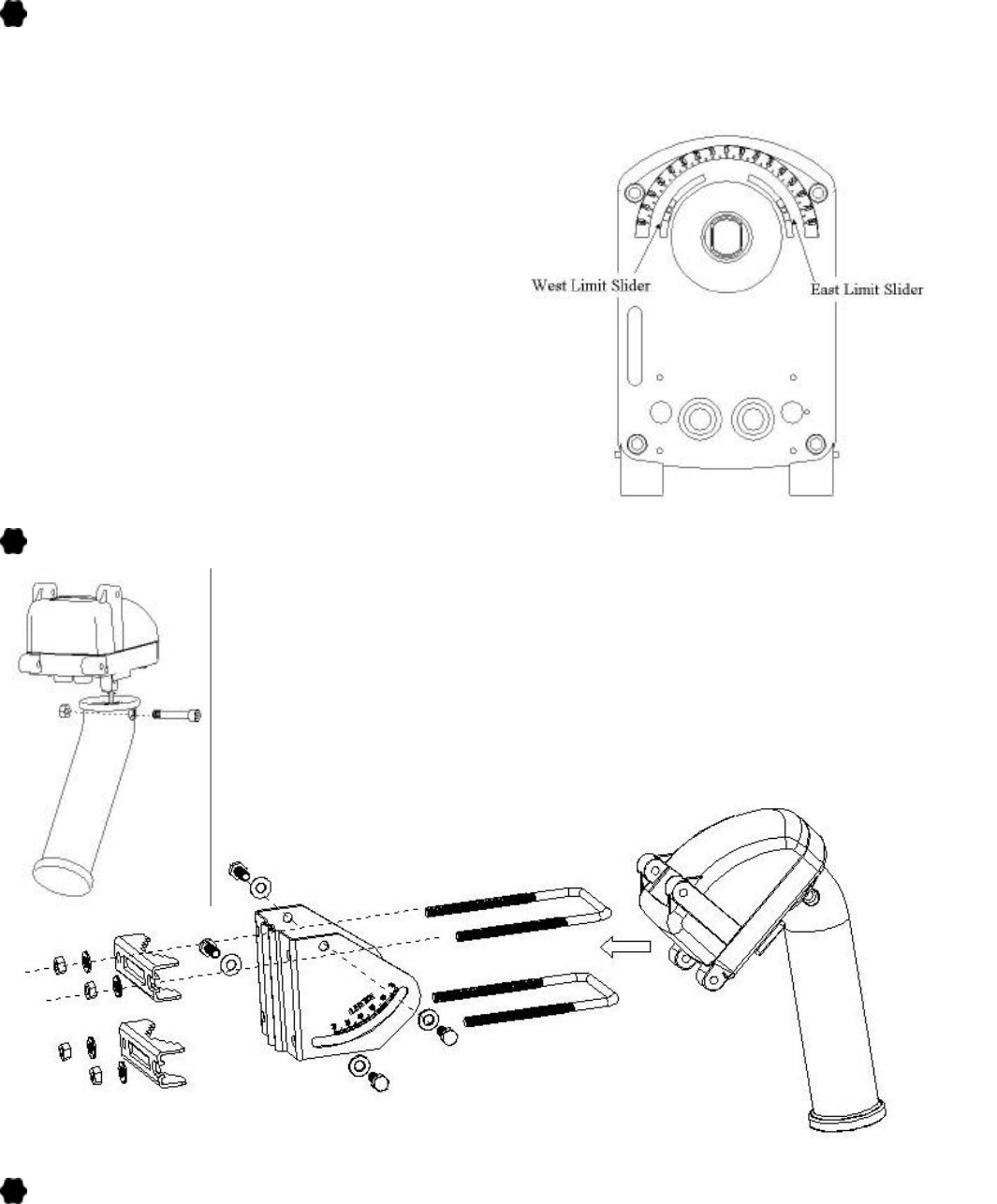
ADJUST THE HARDWARE LIMITS
if necessary
The factory preset hardware limits are from 70°East to 70°West. If smaller azimuth range is required,
adjust the hardware limits as the following:
1. Always drive the motor to 0 position before
adjust the hardware limits.
2. Disassemble the Mounting Tube.
3. Loose the screw on the Limit Slider. Please
don’t loose the screw thoroughly; otherwise,
the Slider might drop into the motor.
4. Adjust the Limit Slider to the wanted angle
( 20~70°for East or West ) .
5. Tighten the screws again.
6. Assemble the Mounting Tube onto the motor.
Drive the motor East and West via the Manual
Button or receiver to make sure the new
hardware limits are well set.
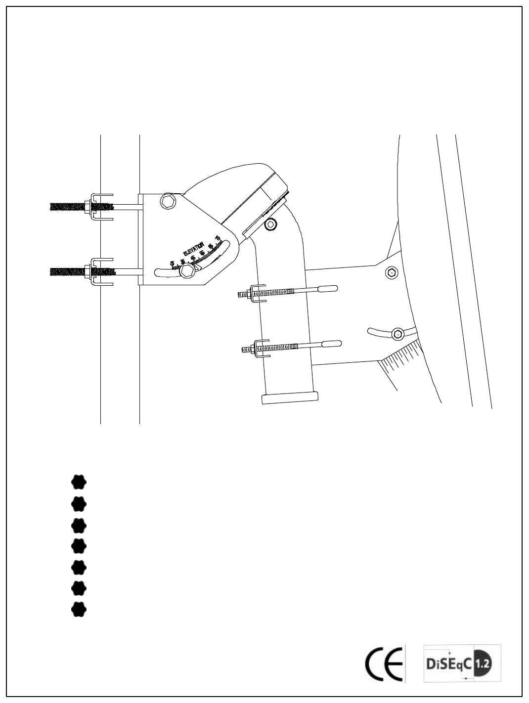
ASSEMBLE THE MOTOR
1. Assemble the H-H Motor as the following diagram.
2. Make sure the mounting pole is exactly vertical before
installation.
3. Fix the H-H Motor onto the mounting pole.
INSTALLING THE MOTOR
I. Traditional Installation:
1. Aiming TRUE SOUTH.
Attaching the Antenna Dish to the Motor. Make sure it is at the center of the mounting tube.
Rotate the motor together with the antenna toward TRUE SOUTH. You can find the TRUE
SOUTH via the magnetic variation table and a compass that indicates the MAGNETIC
SOUTH.
- 2 -
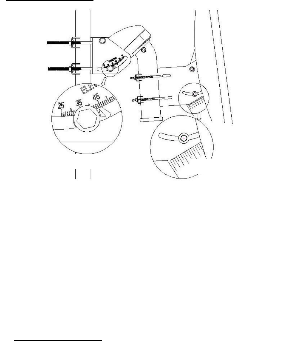
2. Setting Elevation Angle of the Motor.
Adjust the motor elevation angle via the Inclinometer or the Elevation / Latitude scale on
both sides of the Motor.
3. Setting Angle of the Dish.
??Attach the Dish onto the motor. The centerline on the tube of the motor can help to
mount the Dish on the center. Find the Declination Angle by the attached ANGLE
TABLE.
??Set the Declination Angle by the scale on the antenna dish. The reading on the Dish
scale should be:
40° - DECLINATION ANGLE
4. Drive the antenna east and west via the manual button on the bottom of the Motor or via
Receiver to check if the reception arc is correct. If not, adjust the direction, elevation, and
declination angle to find the best reception.
p.s. Please connect the Motor to the receiver via coaxial cable to get the power. The Green LED
will light on if the power from the receiver is on.
II. Quick Installation (A receiver with Goto X Function is recommended):
1. Set Elevation Angle of the motor:
According to the Latitude of your location, set the elevation angle of the motor. There
is also a Latitude scale on the other side of the motor.
2. Mount the Dish:
Mount the Dish onto the motor. The centerline on the tube of the motor can help to
mount the Dish on the center.
Find the Declination Angle by the attached ANGLE TABLE.
Set the Declination Angle by the scale on the antenna dish. The reading on the Dish
scale should be:
40° - DECLINATION ANGLE Please refer to the drawing on Page 2.
Setting Elevation Angle Setting Declination Angle
- 3 -
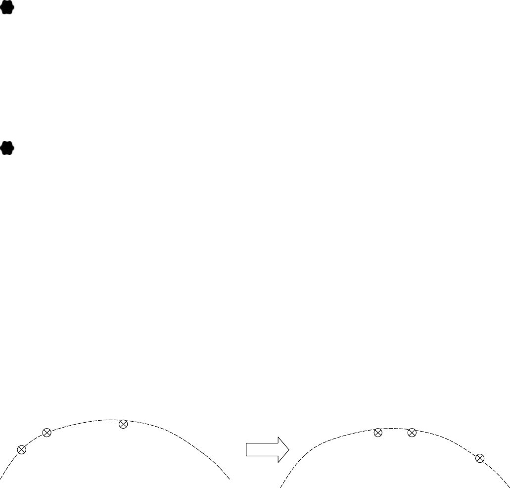
3. Drive the motor to the position for a favorite satellite:
According to your Longitude and the position of the wanted satellite, drive the motor
to the right position. For example, a user in Paris (Longitude is 2.5°E) wants to aim the
Hot Bird (13°E). Just drive the motor to 10.5°E(=13-2.5) via the manual button.
If the receiver has Goto X function, just input the longitude and wanted satellite, the
receiver can calculate and drive the motor to right angle automatically.
4. Aim the Satellite:
Move the whole unit around the pole to find the strongest signal from the wanted
satellite.
Tighten everything and the installation is finished. It will take about only 10 minutes.
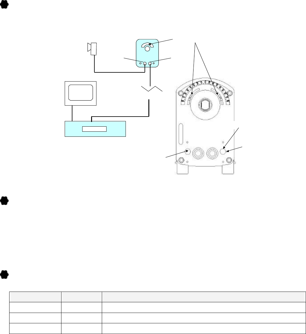
CABLE CONNECTION
Connect the Motor via the coaxial cable (RG-6/U is recommended) as the following diagram.
MANUAL BUTTON
Drive the Motor East / West via only one Manual Button on the bottom of the Motor
1. West: Press once and keep pressing.
2. East: Press twice within 0.5 second and then keep pressing.
3. West Fine-tune: Press Once and release immediately for one step West.
4. East Fine-tune: Press Twice and then release the button for one step East.
INDICATING LED
The LED on the bottom of the Motor can show the following information
Color Status Indication
Green On Power On; Standby Mode
Orange Blink Receiving DiSEqC 1.2 Commands / Reset Mode
Orange On Error Message: Over Current / Reach Hardware Limits …
DiSEqC 1.2 Receiver
H-H Mount
LNB
TV
To
Receiver
To
LNB
Coaxial Cable
Coaxial Cable
Adjustable
Hardware
Limits
Manual Button
Indicating LED
Reset
Key
- 4 -
HARDWARE RESET
1. Make sure the power from the receiver is turn-on. The indicating LED lights on.
2. Drive the motor to 0° via the manual button.
3. Probe the RESET button behind the bottom of the motor via a thin rod for 2 seconds. The LED
blinks in Orange Color. The reset process is OK while the LED is green. The preset Satellite
Table will be re-install and the current position will be set as 0°. Please cut off the power for the
motor first before any operation.
DiSEqC 1.2 OPERATION
The Motor is designed for DiSEqC 1.2 Receiver. The commands on the receivers might be
different, but similar. Please refer to the manual of the receiver.
1. Go East / West: Drive the dish to East / West.
2. Fine Tune East / West: Drive the dish East / West for one step.
3. Store nn: Store Satellites Position nn (01~60).
4. Goto nn: Drive Motor to Satellite Position nn (01~60).
5. East / West Limits: Set software East / West limits.
6. Limit Off: Disable the software limits.
7. Goto 0°: Drive the Motor to 0° as a reference point.
8. Re-synchronize / Shift:
a) Drive the motor to a position by Goto command. For example, P03.
b) Drive the motor East / West to a better position.
c) Send Re-synchronize commands to the motor. The P03 will be shifted to the new position.
All the other Satellite positions are also changed.
d) If step a) is skipped, the P01 will be shifted to the new position.
9. Goto X Function:
e) This function only works with receivers which have goto x function.
f) It can drive the motor to exact x.x° East or West in relative to the 0 position of the motor.
( For example, 15.2° East on the bottom of the motor.)
g) Just input the longitude, some receivers can drive the antenna to focus on the right
Satellites automatically
P03P02
P01
P02
P03
P01
Stored Positions

- 5 -
TROUBLESHOOTING
Symptoms Check points
The Manual Button doesn’t work
1. Make sure the power of receiver is on and the indication
LED on the bottom of the motor lights on.
2. Check every devices between receiver and motor.
The Manual Button can only drive
the motor toward West For East movement: Press the manual button twice within 1
second or shorter.
The Motor doesn’t work
1. Make sure all cables and power are well connected. The
LED on the bottom lights on.
2. Make sure the motor is not blocked by the software limits.
Try to use the manual button, which is only limited by
hardware limits.
3. Check if the receiver supports DiSEqC 1.2 and if the
DiSEqC 1.2 system has been enabled.
The Motor stops at a certain
position and can’t go further.
1. Disable the software limits and drive the motor again.
2. Check if it’s stopped by the hardware limit sliders.
3. Make sure the Motor or antenna is not interfered with any
other item.
The Motor runs discontinuously
1. Make sure the antenna is not too heavy or too large. The
maximum size is 1.2 m.
2. Check if the cable quality is good enough. Try to use a
better RG-6/U cable.
3. Check if the output power of the receiver is less than
350mA.
The Motor runs sometimes fast
and sometimes slowly.
The speed of the Motor is according to the output voltage (13
/18V) of the receiver. Vertical=13V=slow
Horizontal=18V=fast
All satellite positions are not
correct.
1. Goto One satellite position via receiver. Wait for about 30
seconds until the motor stops.
2. Drive the antenna East or West until the reception of this
satellite is clear.
3. Use “Re-calculate” Function to correct position via receiver.
Or
Use Goto 0 position Function to go to 0 degree as a reference
point.
The Motor runs but stops
somehow immediately This could be caused by a loosen magnet on the rear end of the
DC motor inside. Please contact your vendor for repair.
The Motor doesn’t make any
movement, but clicks from inside
of the motor can be heard
1. Check if the dish is too heavy. The maximum size of the
antenna is 1.2 m.
2. The DC motor inside is broken. Please contact your vendor
for repair.
- 6 -
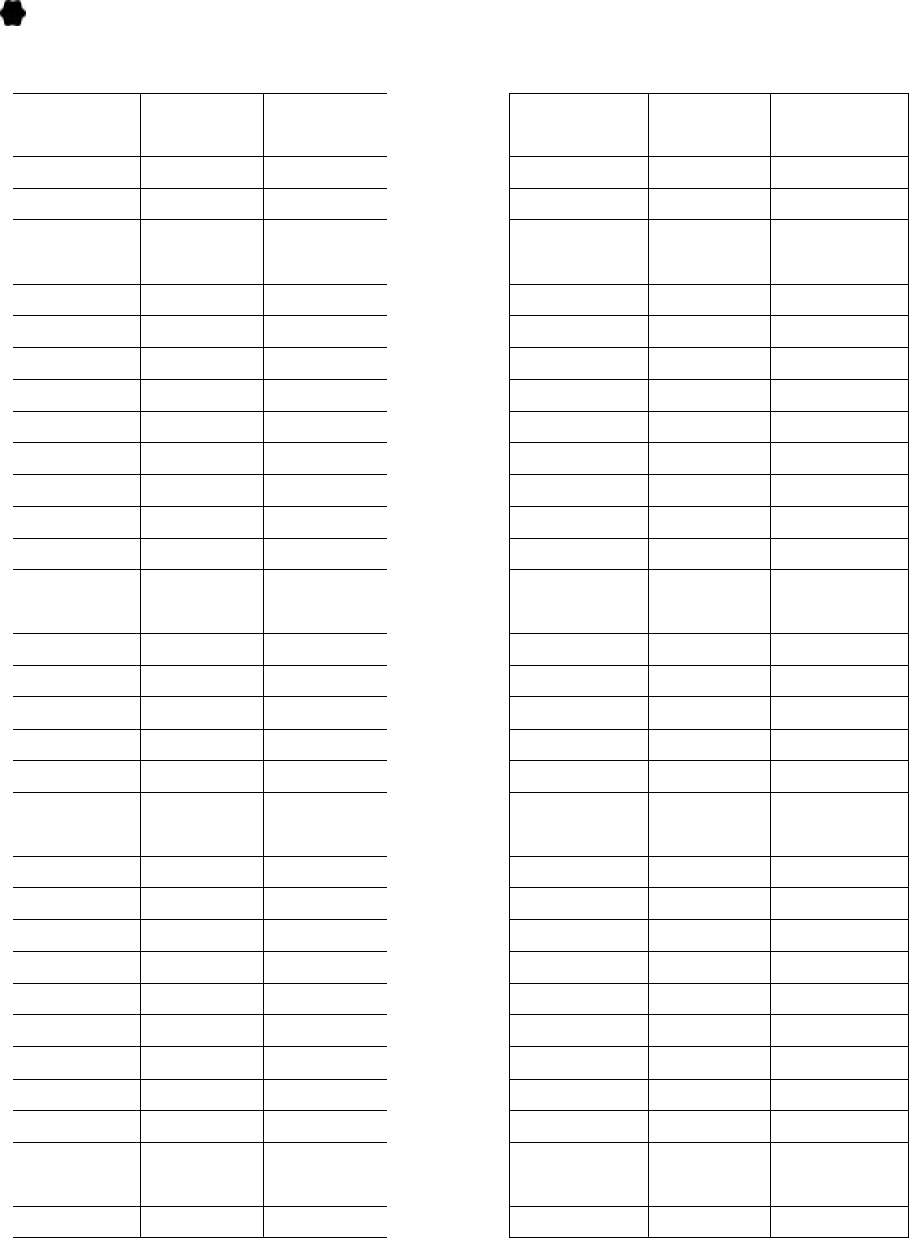
ELEVATION AND DECLINATION ANGLE TABLE
Your Site
Latitude
Elevation
Angle
Declination
Angle
Your Site
Latitude
Elevation
Angle
Declination
Angle
0 90 0.000 34 56 5.510
1 89 0.178 35 55 5.641
2 88 0.355 36 54 5.770
3 87 0.533 37 53 5.897
4 86 0.710 38 52 5.966
5 85 0.887 39 51 6.142
6 84 1.063 40 50 6.260
7 83 1.239 41 49 6.376
8 82 1.415 42 48 6.489
9 81 1.589 43 47 6.600
10 80 1.763 44 46 6.708
11 79 1.936 45 45 6.813
12 78 2.108 46 44 6.799
13 77 2.279 47 43 7.015
14 76 2.449 48 42 7.112
15 75 2.618 49 41 7.205
16 74 2.786 50 40 7.296
17 73 2.952 51 39 7.385
18 72 3.117 52 38 7.470
19 71 3.280 53 37 7.552
20 70 3.442 54 36 7.632
21 69 3.603 56 34 7.782
22 68 3.761 58 32 7.792
23 67 3.918 60 30 8.047
24 66 4.073 62 28 8.162
25 65 4.226 64 26 8.265
26 64 4.377 66 24 8.357
27 63 4.526 68 22 8.437
28 62 4.674 70 20 8.505
29 61 4.819 72 18 8.562
30 60 4.961 74 16 8.608
31 59 5.102 76 14 8.643
32 58 5.241 78 12 8.666
33 57 5.377 80 10 8.678
- 7 -
SPECIFICATION
Protocol :
DiSEqC 1.2
Compatible Receiver :
DiSEqC 1.2 Receiver
Antenna Size :
120 cm Max.
Speed :
1.9°/ sec (at 13V); 2.5°/ sec (at 18V)
Azimuth Angle :
75°East ~ 75°West (150°Max.) Adjustable
Elevation Angle :
10~75°
Tube for Antenna :
Ø 55 x 160L mm
Diameter of Stand-mast :
Ø 35~65 mm
Input Voltage :
13 / 18Vdc
Output Voltage :
13 / 18Vdc (according to input)
Power Consumption :
50 mA (Standby) / 200mA (Normal) / 350mA (Max.)
Satellite Positions :
60 positions
Goto 0 Position Function :
Yes ( Go to 0°)
Recalculation Function :
Yes
Goto X Function :
Yes
Manual Button :
Yes (East /West)
Indicating LED :
Yes (2 Colors)
Limit Protection :
1. Adjustable Hardware Limits
2. Programmable Software Limit
3. Current Limit
Positioning Sensor :
High Resolution Hall Effect Sensor
Weight :
3.1 Kg (Net) / 3.5 Kg (Gross)
Dimension :
345 x 168 x 110 mm3 (Gross)
DiSEqCTM is a trademark of EUTELSAT
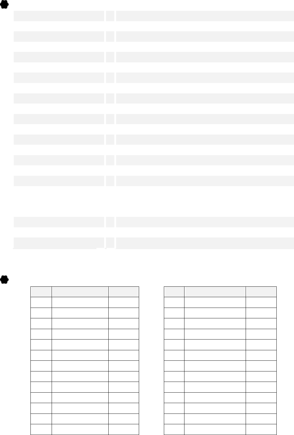
BUILT-IN SAT. TABLE
No. Satellite Position
No. Satellite Position
1 Hot Bird 13°E
14 Hispasat 30°W
2 Astra 19.2°E
15 Telstar 11 37.5°W
3 Eutelsat W2 16°E
16 Kopernicus 23.5°E
4 Eutelsat W1 10°E
17 Arabsat 2A / 3A 26°E
5 Eutelsat W3 7°E
18 Astra 2 28.2°E
6 Sirius 2/3 5°E
19 EuroBird 28.5°E
7 Thor 2/3 0.8°W
20 Arabsat 2B 30.5°E
8 Intelsat 707 1°W
21 Turksat 1B 31.3°E
9 Telecom 2C 5°W
22 Turksat 1C 42°E
10 Telecom 2D 8°W
23 Intelsat 601 34.5°W
11 Intelsat 705 18°W
24 Pas 3R 43°W
12 NSS 803 21.5°W
25 Amos 4°W
13 Intelsat 605 27.5°W
26 Nilesat 7°W
