SKR Manual
User Manual:
Open the PDF directly: View PDF ![]() .
.
Page Count: 72
PL 605 REV H
(01/2019)
STANDARD STRIKER® (SKR-STD)
TRACKED STRIKER (SKR-TRK)
USER MANUAL

2866-795-1586 • WWW.STONEAGETOOLS.COM
MANUFACTURER’S INFORMATION .................................................................. 4
STANDARD STRIKER® (SKR-STD) SPECIFICATIONS ....................................... 4
STANDARD STRIKER® (SKR-STD) DESCRIPTION OF EQUIPMENT
AND INTENDED USE ..................................................................................... 4
STANDARD STRIKER® (SKR-STD) KEY FEATURES ......................................... 4
TRACKED STRIKER® (SKR-TRK) SPECIFICATIONS ......................................... 5
TRACKED STRIKER® (SKR-TRK) DESCRIPTION OF EQUIPMENT
AND INTENDED USE ..................................................................................... 5
TRACKED STRIKER® (SKR-TRK) KEY FEATURES ........................................... 5
CE DECLARATION OF INCORPORATION STANDARD STRIKER® (SKR-STD) .... 6
CE DECLARATION OF INCORPORATION STANDARD STRIKER® (SKR-TRK) .... 7
WARNING AND SAFETY INSTRUCTIONS ......................................................... 8
OPERATOR TRAINING ................................................................................... 8
PERSONAL PROTECTIVE EQUIPMENT REQUIREMENTS ................................ 8
SAFETY LABEL DEFINITIONS......................................................................... 8
PRE-RUN SAFETY CHECK ............................................................................ 9
STRIKER® (SKR-STD) SYSTEM ASSEMBLY - OVERVIEW ................................ 10
STRIKER (SKR-STD) AND CONTROL BOX ...................................................... 10
STRIKER® (SKR-STD) WITH CART- ASSEMBLY ............................................... 11
POSITIONING AND RELOCATING THE STRIKER (SKR-STD) ........................... 11
SWITCHING OUTRIGGER TO DOWNRIGGER LEG ASSEMBLIES .................... 12
INSTALLING THE HORIZONTAL RAIL TO WRIST ............................................. 13
RAIL AND CARRIAGE STOPS ........................................................................ 14
BCK-20 BARRACUDA AND HIGH-PRESSURE HOSE ...................................... 15
WRIST SPEED AND RESISTANCE ADJUSTMENTS ......................................... 16
STRIKER® (CB-SKR) CONTROL BOX - OVERVIEW ........................................... 17
CONTROL BOX ASSEMBLY ........................................................................... 18
CONTROL BOX AIR SUPPLY FITTING AND FOOT PEDAL DUMP ..................... 19
CONTROL BOX TO STRIKER® (SKR-STD) ASSEMBLY CONNECTION ............. 20
STRIKER® (SKR-STD) OPERATION .................................................................... 21
CONTROL BOX, TEST RUN, AND RUN PROCEDURES ................................... 21
STRIKER® (SKR-STD) MAINTENANCE .............................................................. 22
STRIKER® (SKR-STD) STORAGE, TRANSPORTATION, AND HANDLING ......... 22
TABLE OF CONTENTS

3
866-795-1586 • WWW.STONEAGETOOLS.COM
CONVERTING STANDARD TO TRACKED BASE ............................................... 23
SWITCHING 20K AND 40K SWIVEL ASSEMBLIES .......................................... 26
STRIKER® (SKR-TRK) SYSTEM ASSEMBLY - OVERVIEW ............................... 36
STRIKER® (SKR-TRK) WITH WIRELESS REMOTE CONTROLLER .................... 36
STRIKER® (SKR-TRK) - ASSEMBLY .................................................................. 37
UNPACKING AND HORIZONTAL RAIL INSTALLATION ..................................... 37
RAIL STOP INSTALLATION ............................................................................. 38
HIGH-PRESSURE HOSE AND TOOL INSTALLATION ....................................... 39
WRIST SPEED AND RESISTANCE ADJUSTMENTS ......................................... 40
CONTROL LINE UMBILICAL CONNECTION .................................................... 41
AIR AND WATER SUPPLY AND LUBRICATOR SETTING .................................. 42
TRACKED BASE ORIENTATIONS ................................................................... 43
CHANGING TRACKED STRIKER ORIENTATIONS ............................................ 44
WIRELESS CONTROL BOX ............................................................................... 45
WIRELESS REMOTE CONTROLLER ACTIVATION ........................................... 45
WIRELESS REMOTE CONTROLLER OPERATION ........................................... 46
ASSOCIATING WIRELESS REMOTE CONTROLLER TO RECEIVER UNIT ......... 47
WIRELESS REMOTE CONTROLLER TETHERED CONNECTION ...................... 48
STRIKER® (SKR-TRK) OPERATION ................................................................... 48
TEST RUN PROCEDURES ............................................................................. 48
SAFE AND DANGER ZONES .......................................................................... 49
STRIKER® (SKR-TRK) MAINTENANCE .............................................................. 50
STRIKER® (SKR-TRK) STORAGE, TRANSPORTATION, AND HANDLING ......... 50
STRIKER® (SKR-TRK) TROUBLESHOOTING ..................................................... 51
STRIKER® (SKR-STD) AND (SKR-TRK) PARTS DIAGRAMS .............................. 52
TERMS AND CONDITIONS ................................................................................ 70
TABLE OF CONTENTS
4866-795-1586 • WWW.STONEAGETOOLS.COM
DESCRIPTION OF EQUIPMENT AND INTENDED USE
STANDARD STRIKER® AND CONTROL BOX
The powerful and responsive STRIKER® (SKR-STD) combines a rotary
shotgun arm and positioning system for precise remote shotgunning
in tough to reach locations.
KEY FEATURES:
STANDARD STRIKER® (SKR-STD)
• Modular system designed for portability and easy assembly
• Lightweight components for single operator setup and use
• Wheeled base for easy maneuverability
• Fully pneumatic
• Portable control box allows cleaning visibility.
• Affordable alternative to complicated robotic systems
STANDARD CONTROL BOX (CB-SKR)
• Small, lightweight, ergonomic design that includes a
Portable stand and lter-regulator-lubricator assembly
• Body controls: In/Out, Up/Down, and Rotation
• Wrist controls: Rotation and Flex
• OPTIONAL Pneumatic Foot Pedal Dump Control for the non-
wireless control box.
MANUFACTURER’S INFORMATION
StoneAge Inc.
466 S. Skylane Drive
Durango, CO 81303, USA
Phone: 970-259-2869
Toll Free: 866-795-1586
www.stoneagetools.com
StoneAge Europe
Unit 2, Britannia Business Centre
Britannia Way
Malvern WR14 1GZ
United Kingdom
Phone: +44 (0) 1684 892065
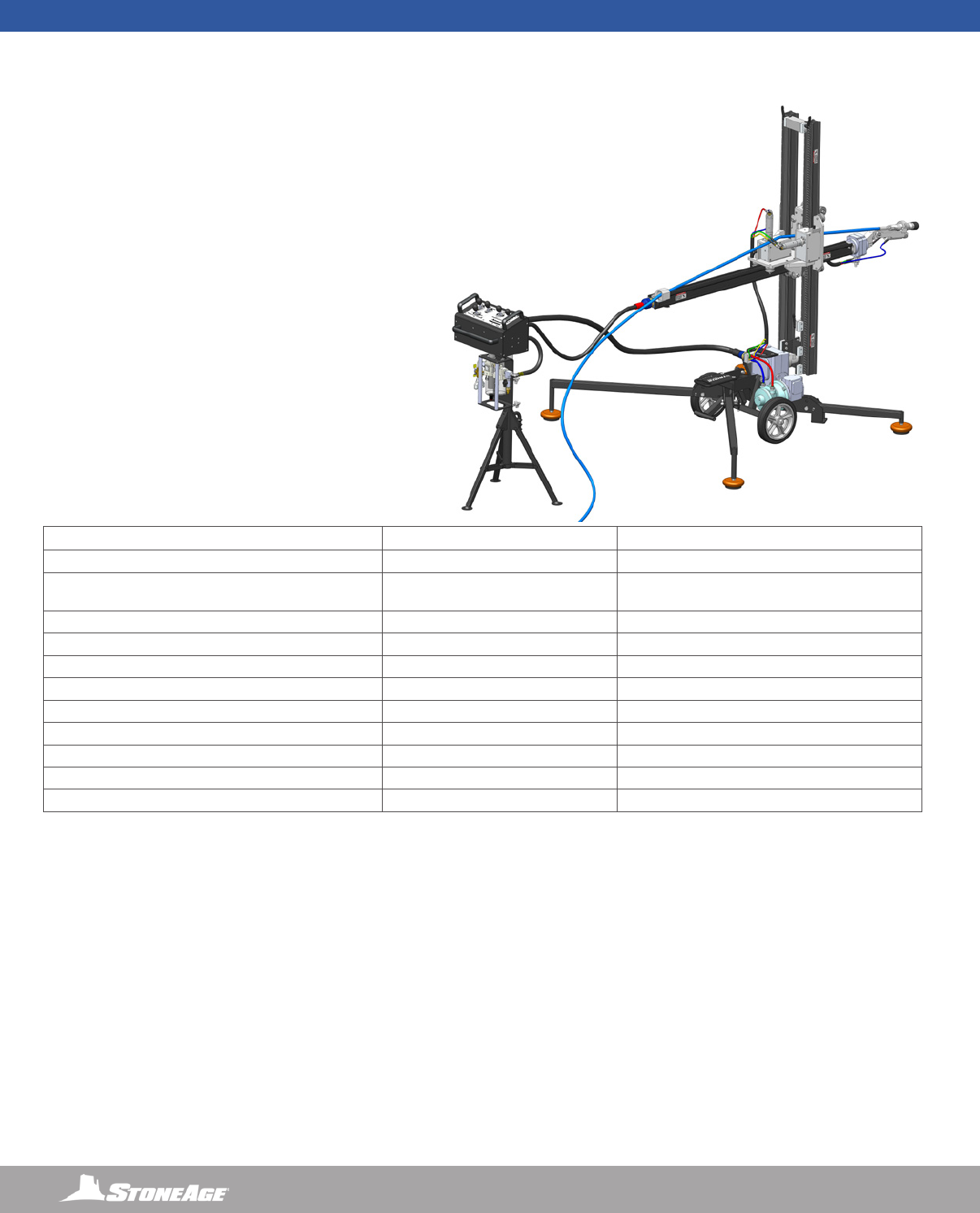
STRIKER® SKR-STD AND
CB-SKR CONTROL BOX SYSTEM
STANDARD STRIKER® SPECIFICATIONS IMPERIAL SYSTEM METRIC SYSTEM
Weight 260 pounds 118 kilograms
Control Box Weight (includes Control Box, FRL and
Stand)
43 pounds 19.5 kilograms
Product Size / Footprint Extended 63 in Wide x 55 in Long x 66 in High 1600 mm Wide x 1397 mm Long x 1676 mm High
Product Size / Footprint Collapsed 25 in Wide x 31 in Long x 66 in High 635 mm Wide x 787 mm Long x 1676 mm High
Cleaning Window 84 in Wide x 54 in Long x 60 in High 2134 mm Wide x 1372 mm Long x 1524 mm High
Maximum Air Supply Pressure 125 PSI 0.86 MPa
Maximum Air Consumption 100 CFM at 100 PSI 2.8 Meters3/Minute at 0.70 MPa
System Air Operating Pressure 80 PSI min, 100 PSI max 0.55 Mpa min, 0.70 Mpa max
Recommended Operational Temperature Range -20 °F to 140 °F -29 °C to 60 °C
Recommended Operational Relative Humidity Range 15 % RH to 100 % RH 15 % RH to 100 % RH
Reaction Force Up to 70 pounds Up to 32 KG
This manual must be used in accordance with all
applicable national laws. The manual shall be regarded
as a part of the machine and shall be kept for reference
until the nal dismantling of the machine, as dened by
applicable national law(s).
Updated manuals can be downloaded at:
https://www.stoneagetools.com/manuals
5
866-795-1586 • WWW.STONEAGETOOLS.COM
DESCRIPTION OF EQUIPMENT AND INTENDED USE
TRACKED STRIKER® AND WIRELESS CONTROLLER
The TRACKED STRIKER® (SKR-TRK) is an automated shotgunning
tool, mounted to a rubber tracked base, wireless controlled, for blast
pad work on structure walkways and platforms, inside tanks and
boilers.
KEY FEATURES:
TRACKED STRIKER® (SKR-TRK)
• Pneumatic powered track base and articulation for easy
maneuverability
• Optional 20,000 or 40,000 PSI Swivel
• Capable of handling jet reaction force up to 100 pounds
• Can be easily and rapidly disassembled for transportation or
installation inside vessels.
WIRELESS REMOTE CONTROL
• Wireless remote controller allows increased mobility.
• Body controls: In/Out, Up/Down, and Rotation
• Wrist controls: Rotation and Flex
MANUFACTURER’S INFORMATION
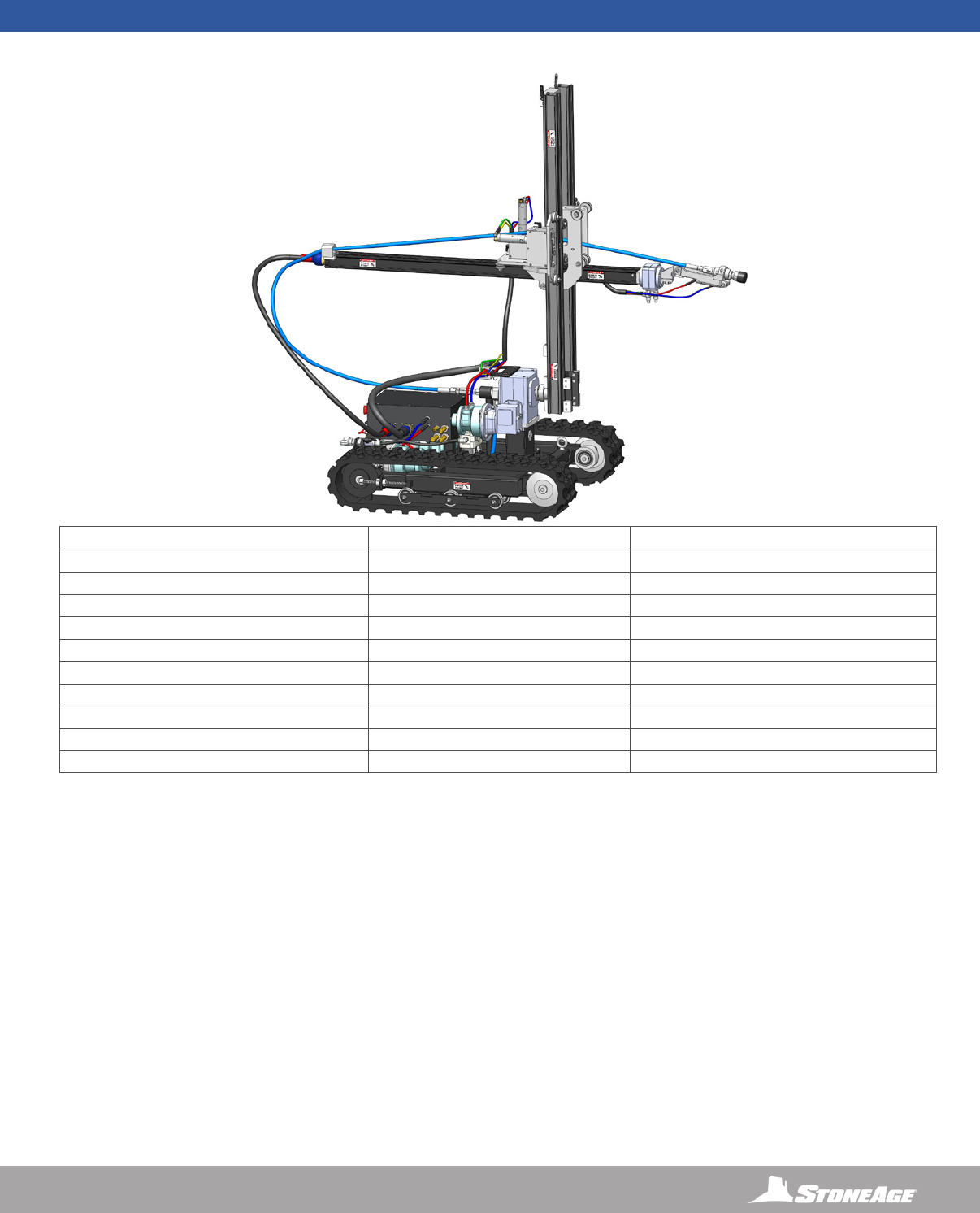
TRACKED STRIKER® SKR-TRK AND
WIRELESS REMOTE CONTROL SYSTEM
TRACKED STRIKER® SPECIFICATIONS IMPERIAL SYSTEM METRIC SYSTEM
Weight 570 pounds 259 kilograms
Wireless Remote Control Weight 4.5 pounds 2 kilograms
Product Size / Footprint 34.5 in Wide x 44 in Long x 66 in High 876 mm Wide x 1118 mm Long x 1676 mm High
Cleaning Window 84 in Wide x Unlimited Long x 66 in High 2134 mm Wide x Unlimited Long x 1676 mm High
Maximum Air Supply Pressure 125 PSI 0.86 MPa
Maximum Air Consumption 120 CFM at 100 PSI 3.4 Meters3/Minute at 0.70 MPa
System Air Operating Pressure 80 PSI min, 100 PSI max 0.55 Mpa min, 0.70 Mpa max
Recommended Operational Temperature Range -20 °F to 140 °F -29 °C to 60 °C
Recommended Operational Relative Humidity Range 15 % RH to 100 % RH 15 % RH to 100 % RH
Reaction Force Up to 100 pounds Up to 45 KG

6866-795-1586 • WWW.STONEAGETOOLS.COM
EU DECLARATION OF CONFORMITY
Manufacturer: StoneAge Incorporated
466 South Skylane Drive
Durango, CO 81303
USA
Authorized Representative: StoneAge Europe
Unit 2, Britannia Business Centre
Britannia Way
Malvern WR14 1GZ
United Kingdom
Steve Ellis, Director StoneAge Europe
Declare that: STRIKER® (SKR-STD) Standard Base Assembly and Control Box (CB-SKR)
for high pressure water cleaning of system parts.
Is compliant with the following Directives and Standards:
Directive 2006/42/EC (Machinery Directive)
EN ISO 12100:2010 (E) Safety of machinery – General principles for design – Risk assessment and risk reduction
The Technical File for STRIKER® (SKR-STD) Standard Base Assembly and Control Box (CB-SKR) is maintained at:
StoneAge Incorporated, 466 South Skylane Drive, Durango, CO 81303, USA and was compiled by the Engineering Manager.
The Technical File is available through the Authorized Representative.
This Declaration of Conformity is issued under the exclusive responsibility of StoneAge Incorporated.
________________________________________ 02/11/2019
StoneAge Incorporated, Durango, CO, USA Date
Adam Markham, Engineering Manager, Robotics

7
866-795-1586 • WWW.STONEAGETOOLS.COM
EU DECLARATION OF CONFORMITY
Manufacturer: StoneAge Incorporated
466 South Skylane Drive
Durango, CO 81303
USA
Authorized Representative: StoneAge Europe
Unit 2, Britannia Business Centre
Britannia Way
Malvern WR14 1GZ
United Kingdom
Steve Ellis, Director StoneAge Europe
Declare that: STRIKER® (SKR-TRK) Tracked Base Assembly and Wireless Controller
for high pressure water cleaning of system parts.
Is compliant with the following Directives and Standards:
Directive 2006/42/EC (Machinery Directive)
EN ISO 12100:2010 (E) Safety of machinery – General principles for design – Risk assessment and risk reduction
ETSI EN 300 328 V1.9.1 (Article 3.2 of R&TTE Directive) - Base Unit
ETSI EN 300 328 V1.9.1 (Article 3.2 of R&TTE Directive) - Console Box
ETSI EN 301 489-1 V1.9.2 (2008-4) & ETSI EN 301 489-17 (Article 3.1(b) of R&TTE Directive) - Console Box
The Technical File for STRIKER® (SKR-TRK) Tracked Base Assembly and Wireless Controller is maintained at:
StoneAge Incorporated, 466 South Skylane Drive, Durango, CO 81303, USA and was compiled by the Engineering Manager.
The Technical File is available through the Authorized Representative.
This Declaration of Conformity is issued under the exclusive responsibility of StoneAge Incorporated.
________________________________________ 02/11/2019
StoneAge Incorporated, Durango, CO, USA Date
Adam Markham, Engineering Manager, Robotics

8866-795-1586 • WWW.STONEAGETOOLS.COM
PERSONAL PROTECTIVE EQUIPMENT REQUIREMENTS
Use of Personal Protective Equipment (PPE) is dependent on the
working pressure of water and the cleaning application. Managers,
Supervisors, and Operators MUST carry out a job specic risk
assessment to dene the exact requirements for PPE. See
Protective Equipment for Personnel (Section 6) of WJTA-IMCA’s
Recommended Practices For The Use Of High-pressure Water
jetting Equipment for additional information.
Hygiene - Operators are advised to wash thoroughly after all
waterjetting operations to remove any waterblast residue which may
contain traces of harmful substances.
First aid provision - users MUST be provided with suitable rst aid
facilities at the operation site.
PPE may include:
• Eye protection: Full face visor
• Foot protection: Kevlar® brand or steel toe capped,
waterproof, non-slip safety boots
• Hand protection: Waterproof gloves
• Ear protection: Ear protection for a minimum of 85 dBA
• Head protection: Hard hat that accepts a full face visor and
ear protection
• Body protection: Multi-layer waterproof clothing approved for
water jetting
• Hose protection: Hose shroud
• Respiratory protection: May be required; refer to job specic
risk assessment
OPERATOR TRAINING
Managers, Supervisors, and Operators MUST be trained in Health
and Safety Awareness of High-pressure Water Jetting and hold
a copy the Water Jetting Association (WJA) Code of Practice, or
equivalent (see www.waterjetting.org.uk).
Operators MUST be trained to identify and understand all applicable
standards for the equipment supplied. Operators should be trained
in manual handling techniques to prevent bodily injury.
Operators MUST read, understand, and follow the Operational and
Training Requirements (Section 7.0) of WJTA-IMCA’s Recommended
Practices For The Use Of High-pressure Water jetting Equipment, or
equivalent.
Operators MUST read, understand and follow the Warnings,
Safety Information, Assembly, Installation, Connection, Operation,
Transport, Handling, Storage, and Maintenance Instructions detailed
in this manual.
StoneAge has designed and manufactured this equipment
considering all hazards associated with its operation. StoneAge
assessed these risks and incorporated safety features in the design.
StoneAge WILL NOT accept responsibility for the results of misuse.
IT IS THE RESPONSIBILITY OF THE INSTALLER/OPERATOR
to conduct a job specic risk assessment prior to use. Job specic
risk assessment MUST be repeated for each different set up,
material, and location.
The risk assessment MUST conform to the Health and Safety at
Work Act 1974 and other relevant Health and Safety legislation.
The risk assessment MUST consider potential material or substance
hazards including:
• Aerosols
• Biological and microbiological (viral or bacterial) agents
• Combustible materials
• Dusts
• Explosion
• Fibers
• Flammable substances
• Fluids
• Fumes
• Gases
• Mists
• Oxidizing Agents
WARNING AND SAFETY INSTRUCTIONS
SAFETY LABEL DEFINITIONS
The STRIKER® (SKR-STD) and TRACKED STRIKER® (SKR-TRK)
have the potential to cause serious injury to ngers or hands if
they become caught between the rollers or rotating connections.
The STRIKER® (SKR-STD) and TRACKED STRIKER® (SKR-TRK)
have the potential to cause serious injury if ngers or hands
become caught between the carriage and rails.
The STRIKER® (SKR-STD) and TRACKED STRIKER® (SKR-TRK)
have a maximum operating air pressure of 100 psi (0.7 MPa).
Never exceed 125 psi (0.86 MPa) supply pressure. Exceeding
125 psi (0.86 MPa) supply pressure may result in injury to the
Operator and/or damage to the equipment.

9
866-795-1586 • WWW.STONEAGETOOLS.COM
WARNING
Operations with this equipment can be potentially hazardous. Caution
MUST be exercised prior to and during machine and water jet tool
use. Please read and follow all of these instructions, in addition to
the guidelines in the WJTA Recommended Practices handbook,
available online at www.wjta.org. Deviating from safety instructions and
recommended practices can lead to severe injury and/or death.
• Do not exceed the maximum operating pressure specied for
any component in a system.
• Inspect the equipment for visible signs of deterioration,
damage, and improper assembly. Do not operate until repaired.
Make sure all threaded connections are tight and free of leaks.
• The immediate work area MUST be marked off to keep out
untrained persons.
• Users of the STRIKER
®
(SKR-STD) and TRACKED STRIKER
®
(SKR-TRK) MUST be trained and/or experienced in the use
and application of high-pressure technology and cleaning, as
well as all associated safety measures, according to the WJTA
Recommended Practices for the use of High-pressure Water
jetting Equipment.
• The Control Box should be located in a safe location where the
Operator has good visibility of the placement of the tool. The
STRIKER
®
(SKR-STD) and TRACKED STRIKER
®
(SKR-TRK )
and Control Box MUST be supervised at all times and should
never be left unattended.
• STAY BEHIND THE VERTICAL RAIL ASSEMBLY AND OUT OF
THE SPRAY ZONE WHEN OPERATING THE STRIKER
®
. Failure
to do so will result in death or serious injury..
• Always de-energize the system before servicing or replace any
parts. Failure to do so can result in severe injury and/or death.
• When moving the STRIKER
®
(SKR-STD) lift with care to prevent
bodily injury.
PRE-RUN SAFETY CHECK
Refer to WJTA-IMCA’s, Recommended Practices For The Use Of
High-pressure Waterjetting Equipment and/or The Water Jetting
Association’s, WJA Code of Practice for additional safety information.
• Complete a job specic risk assessment and act on the resulting
actions.
• Adhere to all site specic safety procedures.
• Ensure the waterblasting zone is properly barricaded and that
warning signs are posted.
• Ensure the work place is free of unnecessary objects (e.g. loose
parts, hoses, tools).
• Ensure all Operators are using the correct Personal Protective
Equipment (PPE).
• Check that the air hoses are properly connected and tight.
• Check all hoses and accessories for damage prior to use. Do
not use damaged items. Only high quality hoses intended for
waterblast applications should be used as high-pressure hoses.
• Check all high-pressure threaded connections for tightness.
• Test the controls before operating the STRIKER
®
(SKR-STD) and
TRACKED STRIKER
®
(SKR-TRK) with high-pressure water to
verify the control valves move the Tool in the intended directions.
• Operate the high-pressure water at full pressure and use the Pneu-
matic Foot Pedal Dump Control to verify that the dump valve is
working properly.
• Ensure that Operators never connect, disconnect, or tighten
hoses, adapters, or accessories with the high-pressure water
pump unit running.
• Ensure no personnel are in the hydroblasting zone.
WARNING AND SAFETY INSTRUCTIONS
10 866-795-1586 • WWW.STONEAGETOOLS.COM
STRIKER® SKR-STD AND
CB-SKR CONTROL BOX SYSTEM
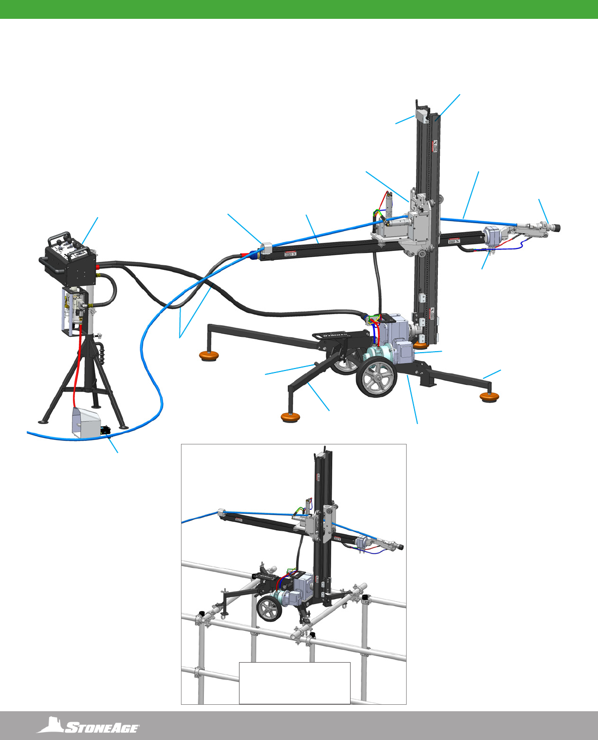
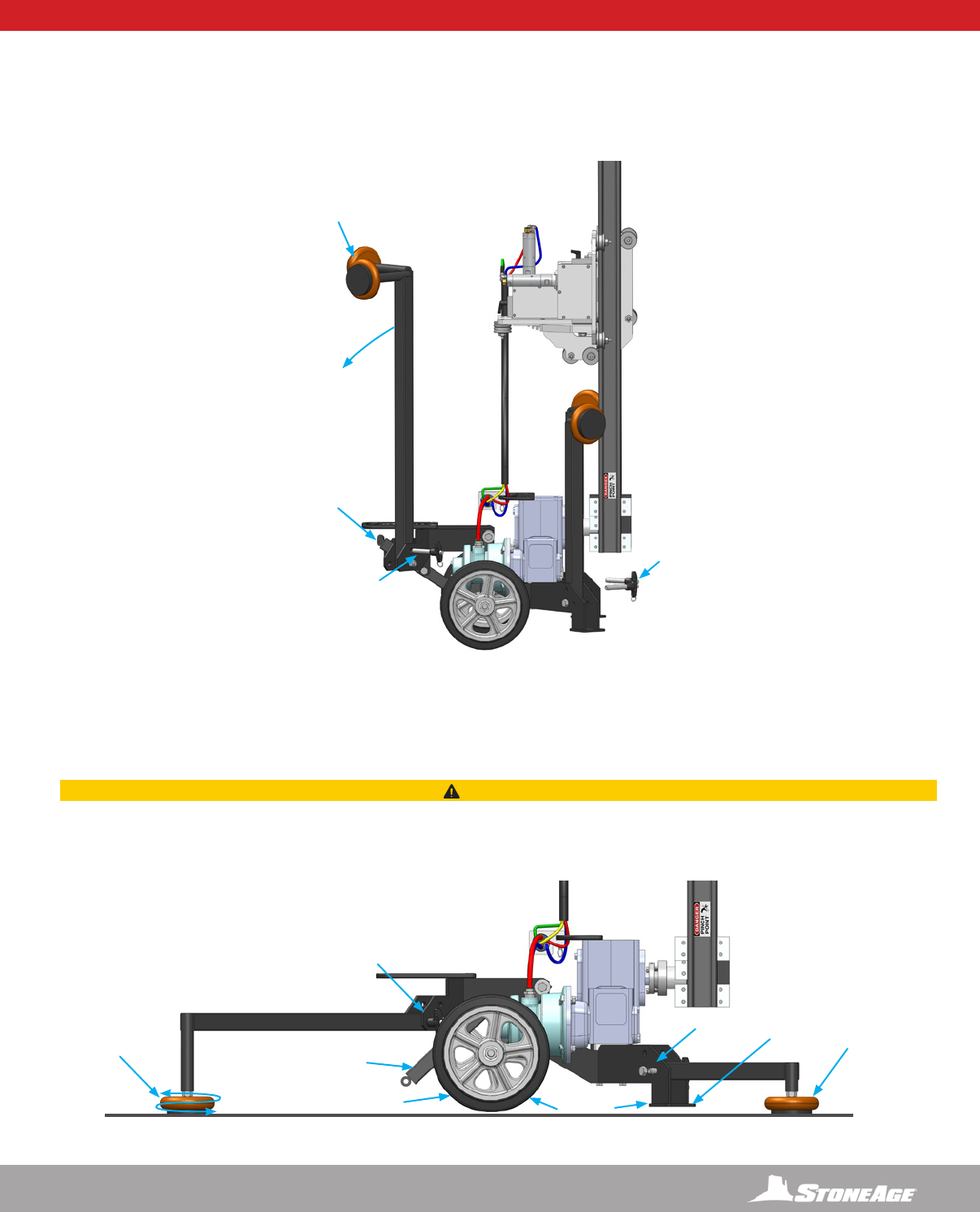
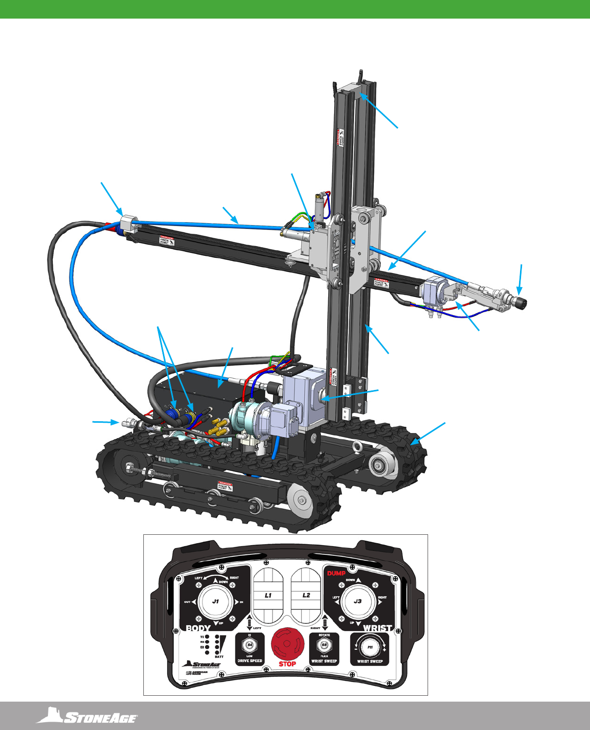
STANDARD STRIKER SYSTEM ASSEMBLY - OVERVIEW
RAIL STOP
WHEELIE BAR
*OPTIONAL
FOOT PEDAL
DUMP CONTROL
TIE STOP
ASSEMBLY
*OPTIONAL
20K HIGH
PRESSURE HOSE
VERTICAL RAIL
ASSEMBLY
HORIZONTAL
RAIL ASSEMBLY
WRIST
ASSEMBLY
*OPTIONAL
BCK-20K
BARRACUDA
CARRIAGE
ASSEMBLY
GEARBOX
ASSEMBLY
STRIKER CART
ASSEMBLY
LONG
OUTRIGGER
SHORT
OUTRIGGER
15FT UMBILICALS
(4572 mm)
CONTROL BOX,
FRL, AND, STAND
ASSEMBLY
*OPTIONAL SKR 500-K
DOWNRIGGER LEG KIT
FOR SCAFFOLD OR GRATE
MOUNTING
11
866-795-1586 • WWW.STONEAGETOOLS.COM
FIGURE 1
HANDLES
QUICK
RELEASE
PINS
QUICK
RELEASE
PINS
LEVER BAR
TILT
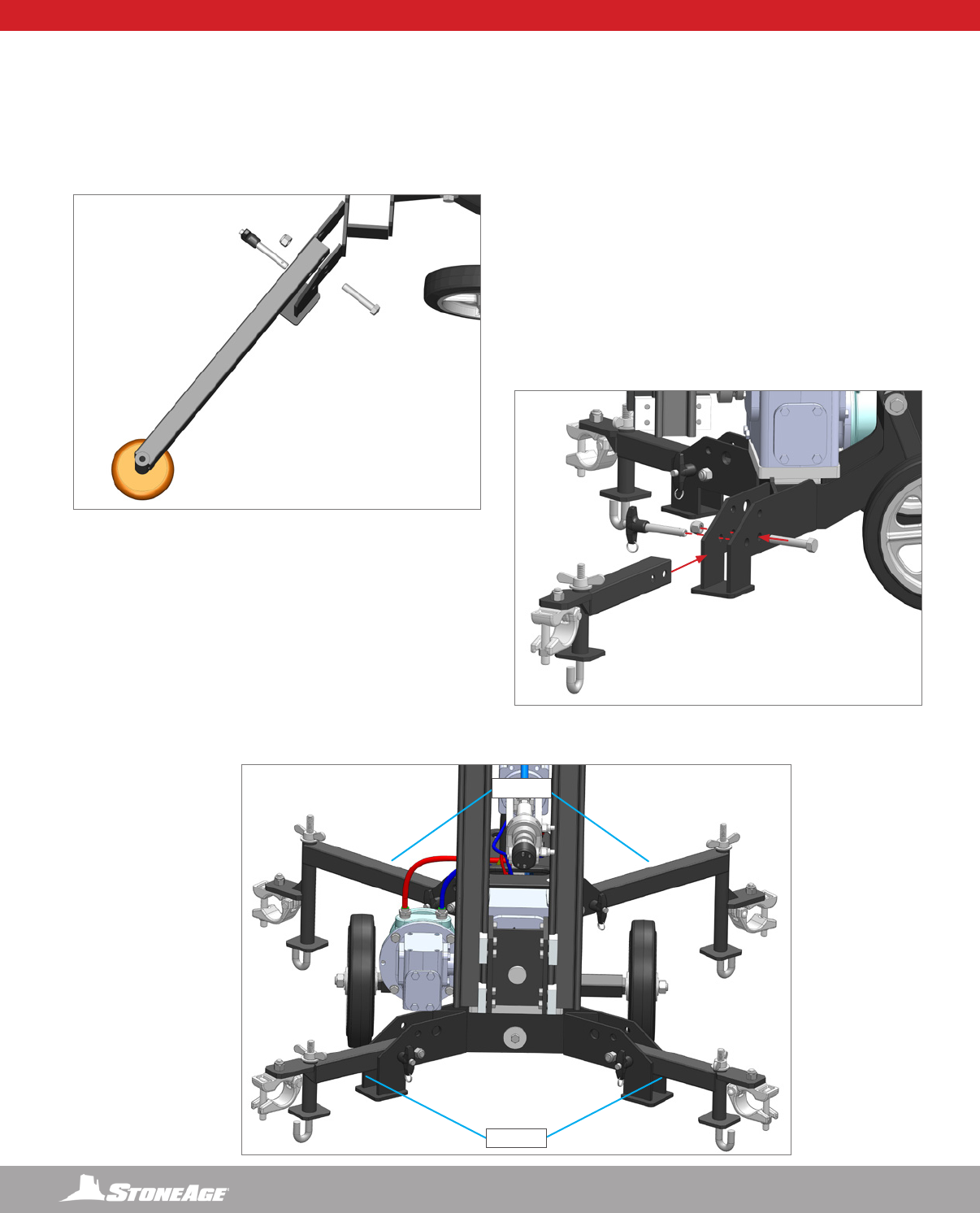
SKR-100 SET-UP - POSITIONING AND RELOCATING THE STRIKER
LEG BASE SET-UP
The leg base on the Striker may come with the legs folded upright.
1. Lift the Lever Bar up, use the longer legs as handles, tilt the Striker back, and roll into place. Once in place, pull the 4 Quick Release
Pins out of the leg assemblies. (Figure 1)
2. Pull the leg assemblies down and insert the Quick Release Pins through the cart and leg base. Push down on the Lever Bar to raise
the wheels and foot plates off the ground. The Striker can be stabilized by screwing the feet in or out. (Figure 2)
FIGURE 2
QUICK
RELEASE
PINS
ADJUSTABLE
FEET
ADJUSTABLE
FEET
OFF THE
GROUND
QUICK
RELEASE
PINS
FOOT
PLATES
LEVER BAR
WHEELS
CAUTION
All four adjustable feet MUST be level to the ground and the lever bar MUST be pressed rmly down to lift the wheels and foot plates off the
ground. (Figure 2) Failure to do so may allow the Striker to slide around on the ground during operation.
12 866-795-1586 • WWW.STONEAGETOOLS.COM
SKR-100 SET-UP - SWITCHING OUTRIGGER TO DOWNRIGGER LEGS
CHANGING FROM THE OUTRIGGER LEG ASSEMBLIES TO THE DOWNRIGGER LEG ASSEMBLIES
The Downrigger Leg Kit is designed to allow the user to mount the Striker onto scaffolding. It comes with two short and two long leg
inserts.
1. Remove the 1/2” Bolts, Lock Nuts, and the Quick Release Pins from the Outrigger Leg Assembly and Cart. (Figure 1)
2. Insert the Downrigger Leg Assembly and secure with the 1/2” Bolt, Lock Nut, and Quick Release Pins as shown in (Figure 2).
3. Conrm that the Short and Long Downrigger Legs are Installed where shown in (Figure 3).
FIGURE 1
FIGURE 2
FIGURE 3 LONG
SHORT
13
866-795-1586 • WWW.STONEAGETOOLS.COM
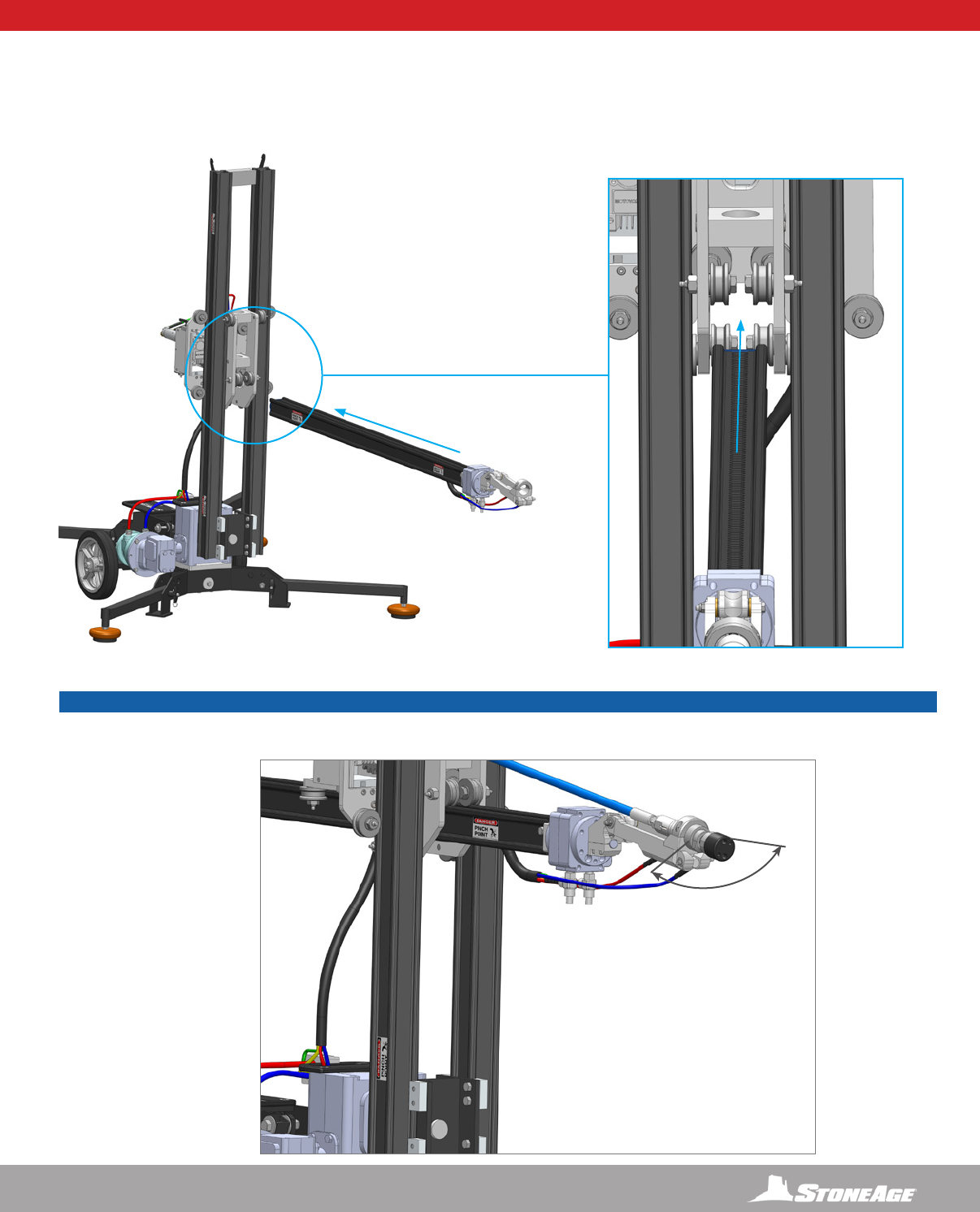
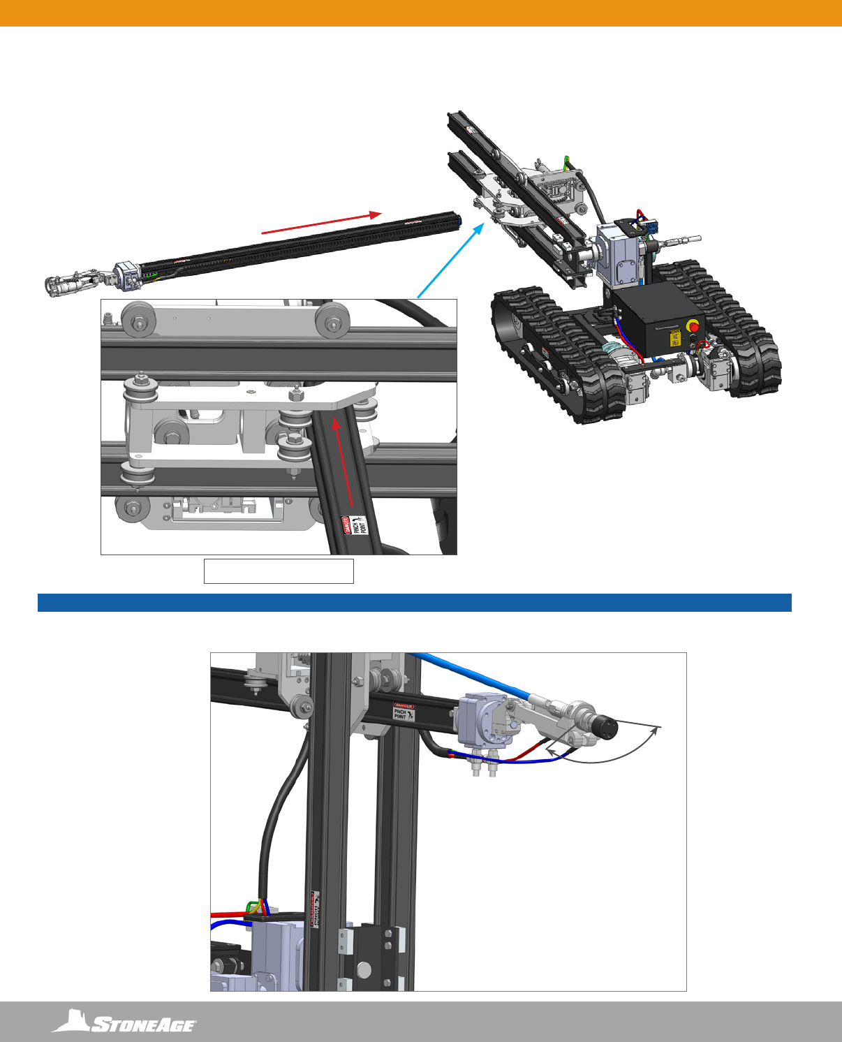
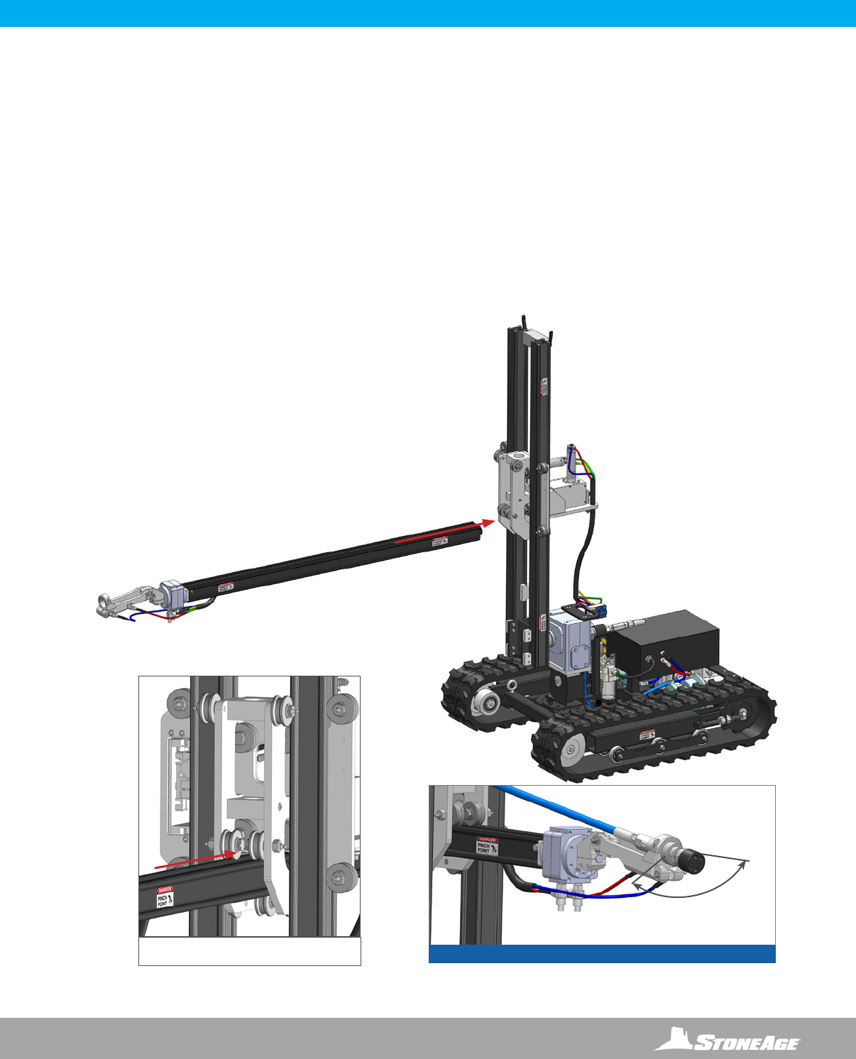
INSTALLING THE HORIZONTAL RAIL AND WRIST ASSEMBLY INTO THE VERTICAL RAIL ASSEMBLY
1. Install the Horizontal Rail Assembly with Wrist through the Carriage Assembly located on the Vertical Rail Assembly. (Figure 1)
Center the Horizontal Rail between the four rollers on the Carriage Assembly (Figure 2) and slide in about half way.
SKR-STD SET-UP - INSTALLING THE HORIZONTAL RAIL AND WRIST
270
ROTATIONAL
SPRAY PATTERN
FIGURE 1 FIGURE 2
FIGURE 3
NOTICE
The Horizontal Rail Assembly is slotted on both sides. Flipping the Horizontal Rail allows the 270 rotational spray pattern to be directed up
or down. (Figure 3)
14 866-795-1586 • WWW.STONEAGETOOLS.COM
SKR-STD SET-UP - RAIL AND CARRIAGE STOPS
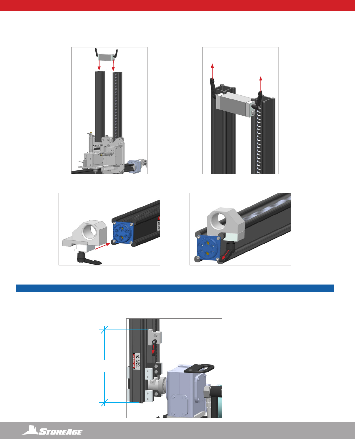
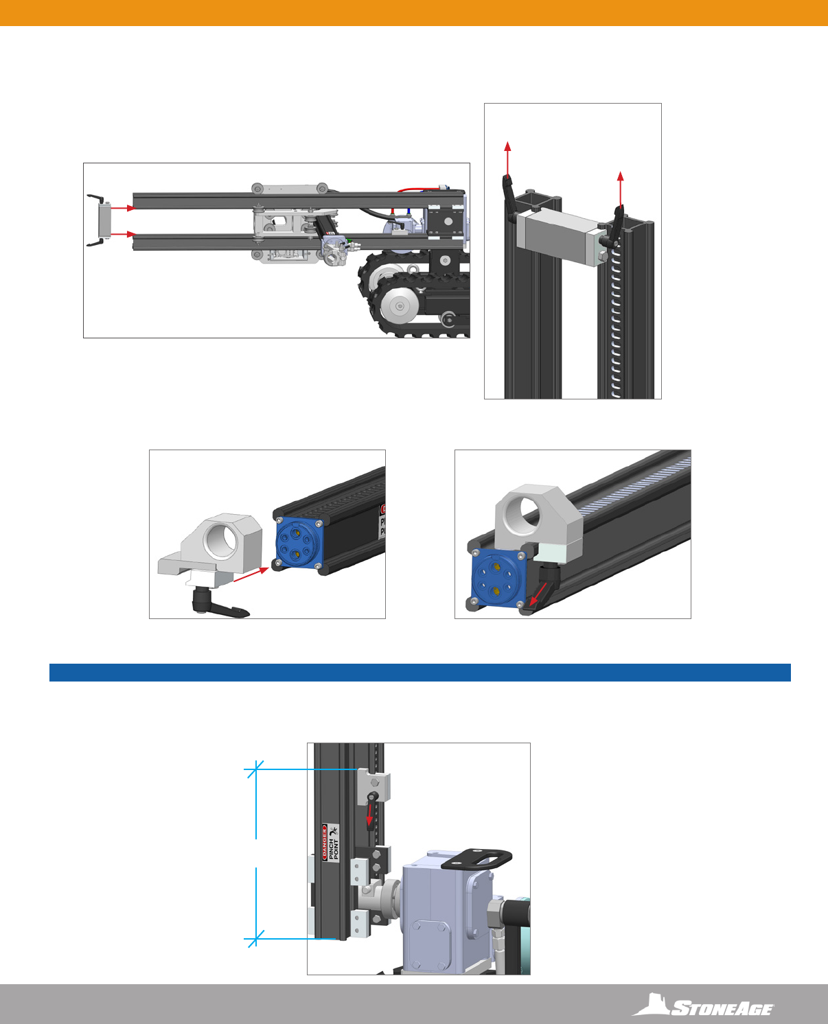
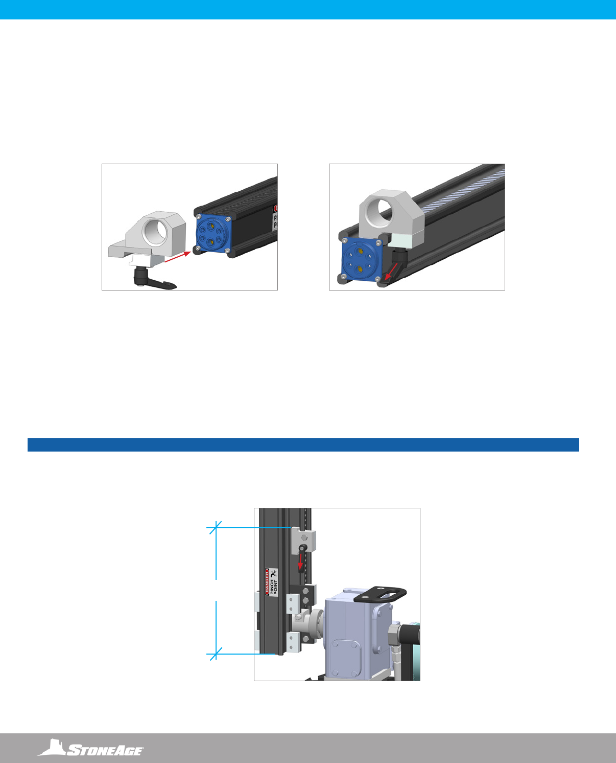
INSTALLING THE RAIL STOPS
1. Slide the Tie Rail Stop onto the end of the Vertical Rail Assembly. (Figure 1) Orient and tighten the Release Levers away from the
Carriage Assembly. (Figure 2)
2. Slide the Rail Stop onto the end of the Horizontal Rail Assembly. (Figure 3) Orient and tighten the Release Lever away from the
Carriage Assembly. (Figure 4)
3. Slide the Carriage Stop along the Vertical Rail Assembly until the top of the block is 12” (305 mm) from the bottom of the Vertical Rail.
Orient and tighten the Release Lever away from the Carriage Assembly.
FIGURE 1
FIGURE 3 FIGURE 4
FIGURE 2
FIGURE 5
12” (305 MM)
MINIMUM
NOTICE
Setting the Carriage Stop at a minimum of 12” (305 mm) ensures the carriage and horizontal rail will clear the gearbox and the base.
If the Carriage Stop is placed lower to gain range of motion, the Operator must pay attention to the horizontal rail and carriage assembly
to ensure that they DO NOT make contact with the gearbox or base. Failure to do so will result in damage to the motors on the carriage
assembly.
15
866-795-1586 • WWW.STONEAGETOOLS.COM
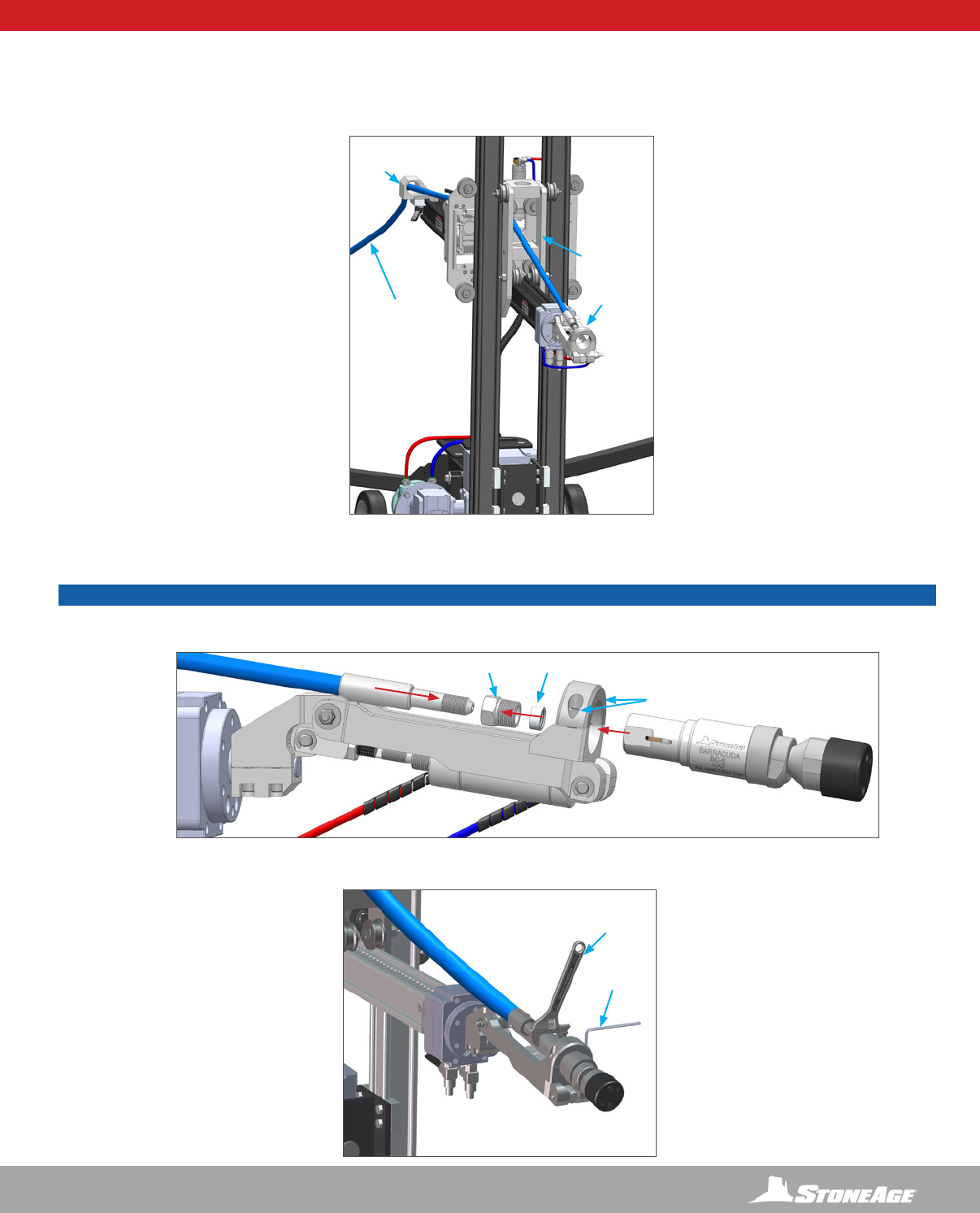
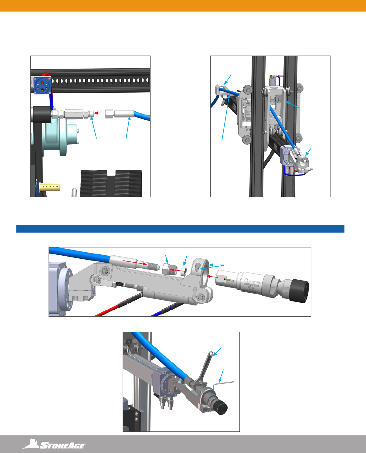
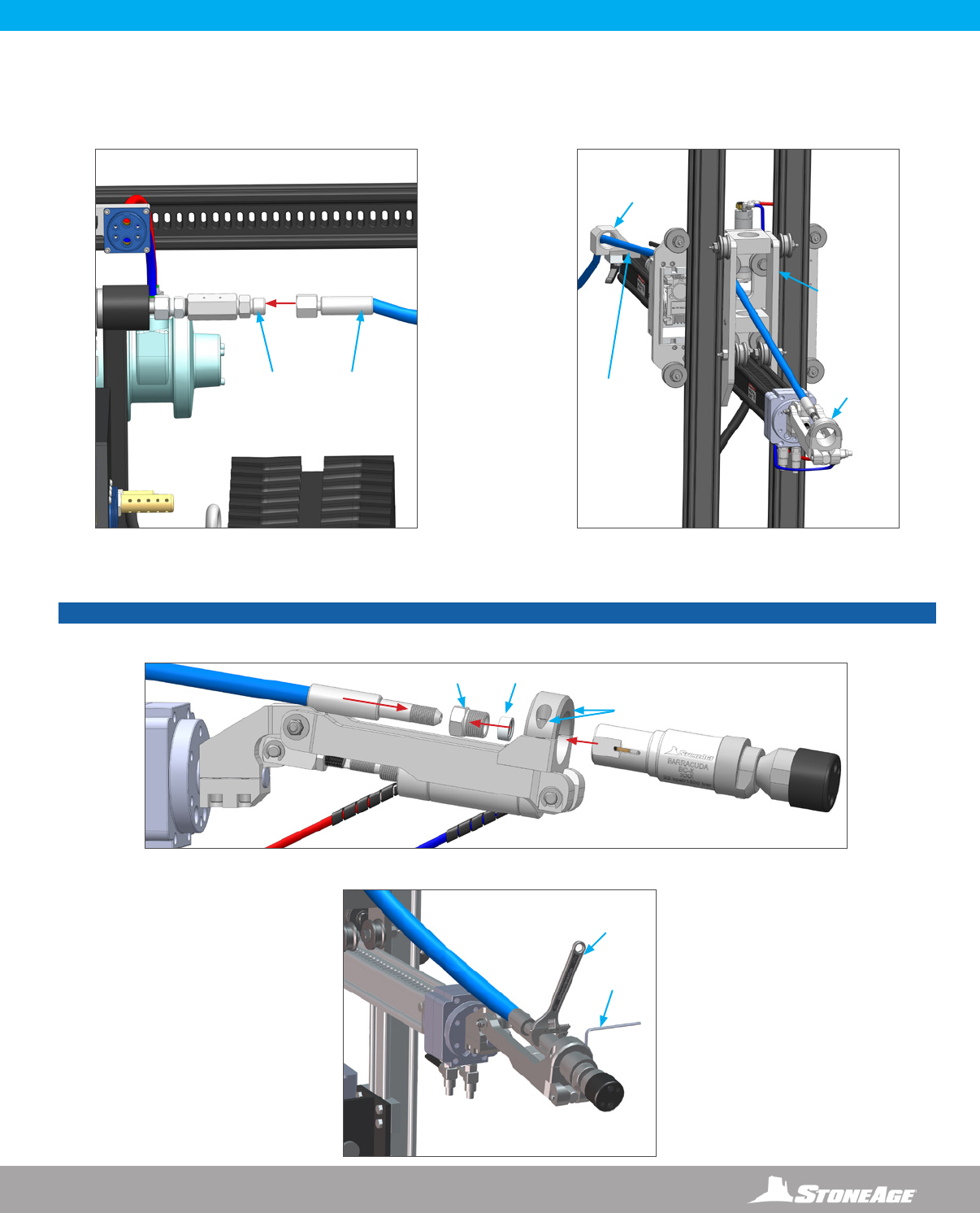
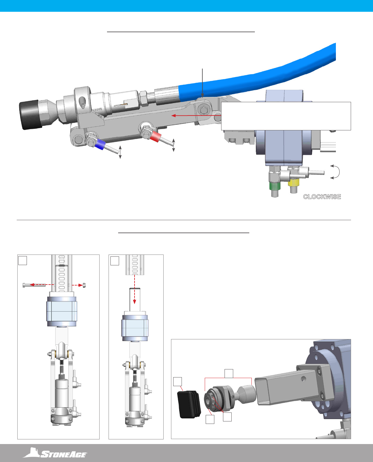
CONNECTING HIGH PRESSURE HOSE AND FITTINGS TO BCK-20K
1. Feed the male connector on the High Pressure Hose through the Rear Rail Stop on the end of the Horizontal Rail, then through the
Carriage towards the BCK-20K Holder. (Figure 1)
2. Fasten High Pressure Hose to BCK-20K Barracuda (Figure 2). The hose end is a 9/16” medium pressure connection, with a modied
gland nut and standard collar.
3. Tighten BCK-20K Barracuda to Gland Nut on the High Pressure Hose (A) and tighten the Wrist Clamp to BCK-20K Barracuda (B).
(Figure 3)
SKR-STD SET-UP - BCK-20K BARRACUDA AND HIGH PRESSURE HOSE
CARRIAGE
BCK-20K
HOLDER
HIGH
PRESSURE
HOSE
REAR
RAIL
STOP
GLAND NUT COLLAR
LOOSEN TO INSTALL
BCK-20K BARRACUDA
FIGURE 1
FIGURE 2
A
B
NOTICE
It is recommended to use BLUE GOOP, A SWAGELOK brand anti-seize, or an equivalent on threaded ttings to avoid galling.
FIGURE 3
16 866-795-1586 • WWW.STONEAGETOOLS.COM
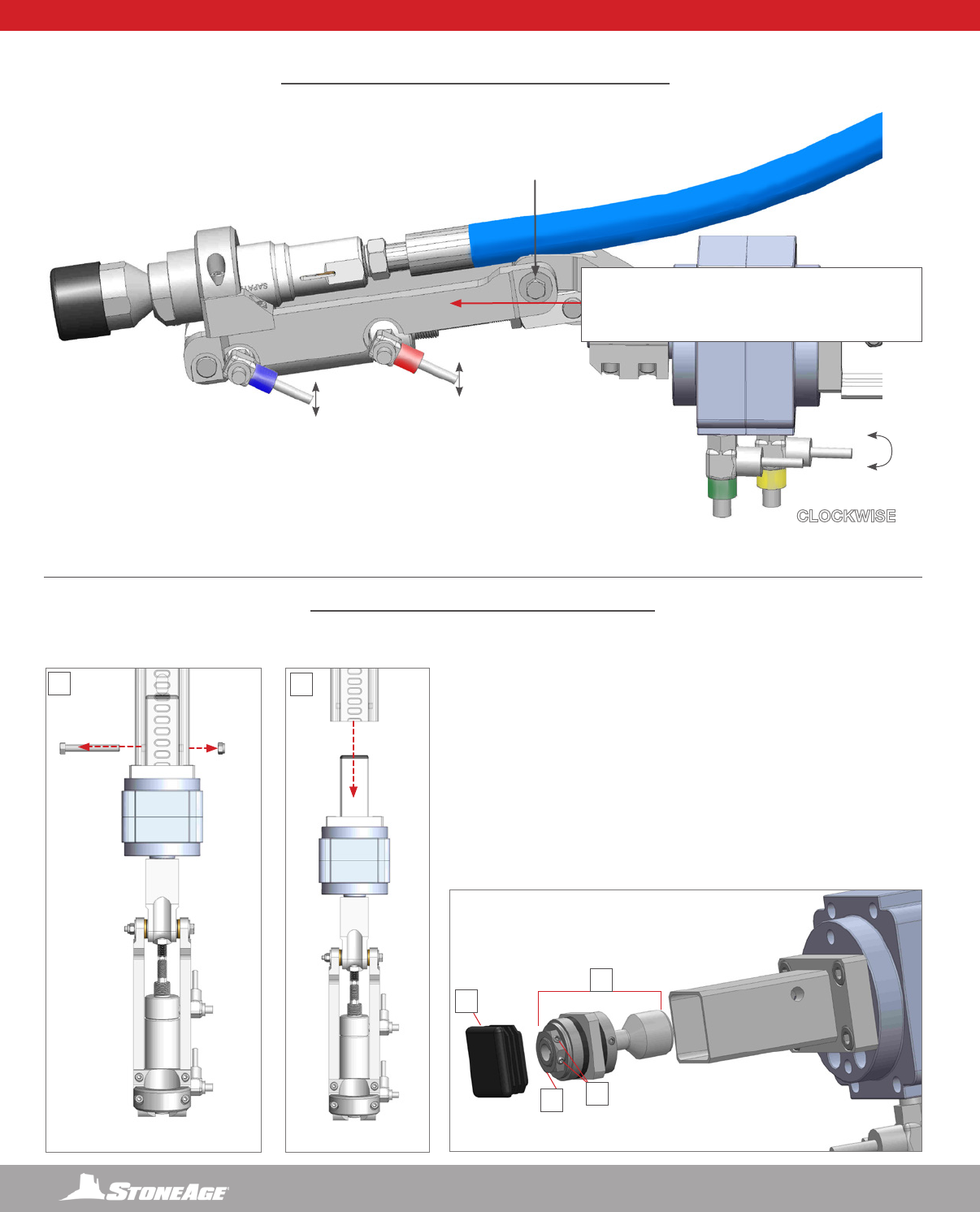
SKR-STD SET-UP - WRIST SPEED AND RESISTANCE ADJUSTMENTS
SLOWER
SLOWER
FASTER
FASTER
DOWNWARD
WRIST FLEX
UPWARD
WRIST FLEX
COUNTER-
CLOCKWISE
WRIST ROTATION
CLOCKWISE
WRIST ROTATION
THE WRIST ROTATION DIRECTION IS REFERENCED
FROM THE BACK OF THE STRIKER, LOOKING DOWN
THE HORIZONTAL RAIL TOWARD THE BCK-20K
WRIST SPEED CONTROL ADJUSTMENTS
WRIST RESISTANCE ADJUSTMENTS
WRIST RESISTANCE
ADJUSTMENTS
1. Remove Bolt and Lock Nut From the Rail and Wrist Assembly.
2. Pull the Wrist Assembly free of the Rail.
3. Remove the black plastic end cap from the end of the Wrist
Assembly.
4. Remove the Friction Torque Limiter and Shaft
5. Loosen set screws.
6. Adjust nut to the left for less resistance and tighten to the right for
increased resistance.
3
4
6
2
1
5
SLOWER
FASTER
17
866-795-1586 • WWW.STONEAGETOOLS.COM
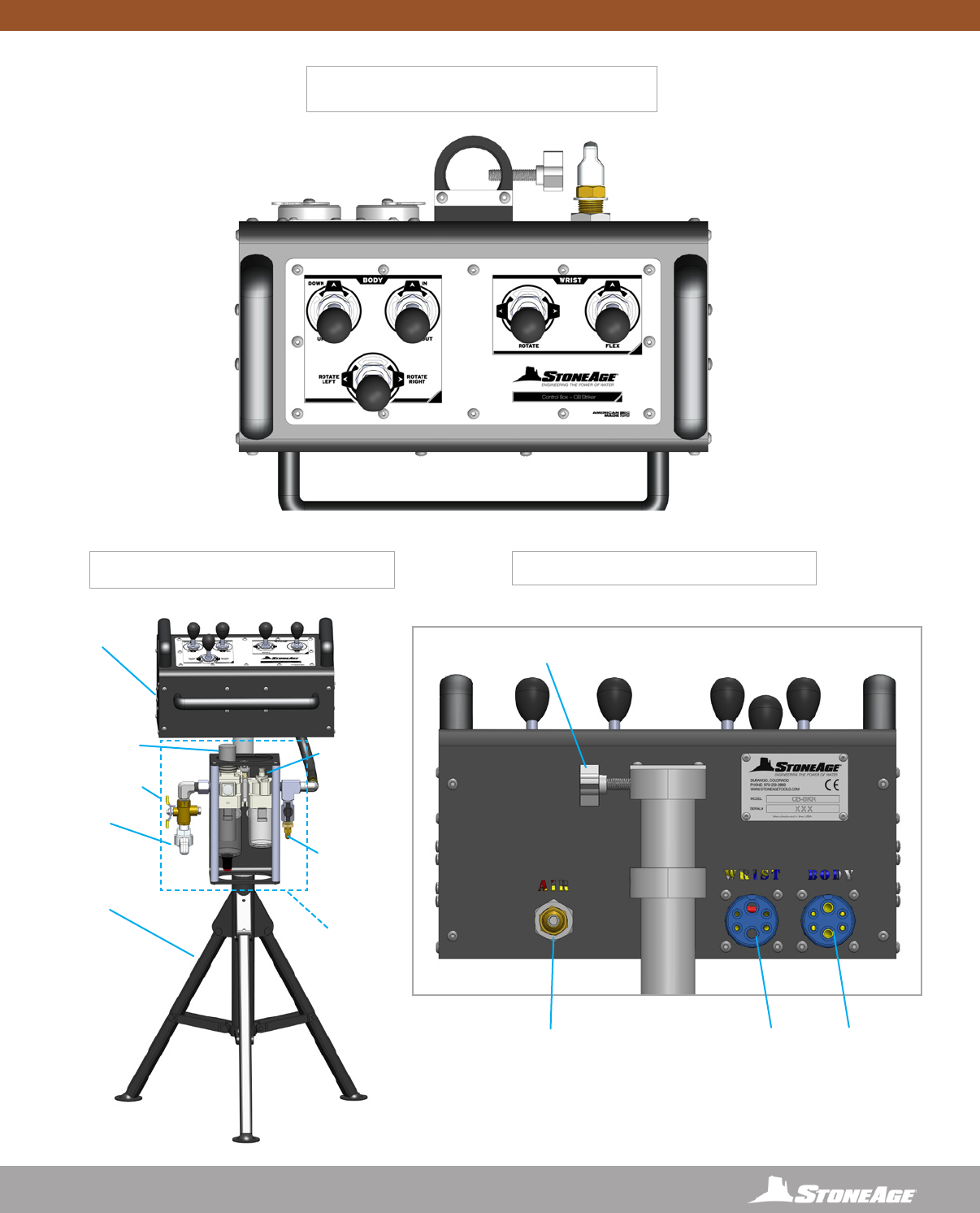
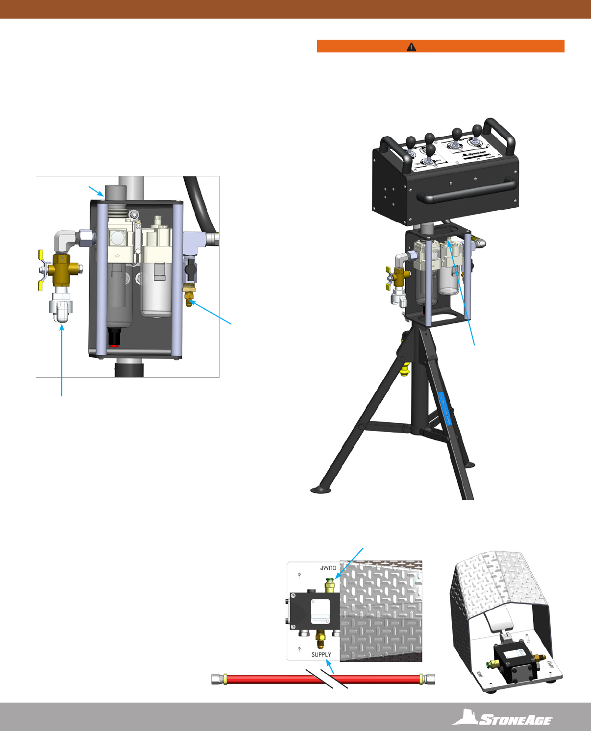
AIR SUPPLY
FITTING
WITH DUST CAP
INLET AIR
FITTING
DUMP
CONNECTION
FITTING
TRIPOD
LEGS
PRESSURE
REGULATOR
PRESSURE
RELIEF VALVE
MAIN BOX
FRAME POLE MOUNT
WITH THUMB SCREW
WRIST
UMBILICAL
PORT RED
SYSTEM UMBILICAL
PORT BLUE
INLINE OILER
FEED
ADJUSTMENT
FILTER,
REGULATOR,
LUBRICATOR
CONTROL BOX
FRONT VIEW
CONTROL BOX
TOP VIEW
CONTROL BOX
REAR VIEW
CONTROL BOX - OVERVIEW
18 866-795-1586 • WWW.STONEAGETOOLS.COM
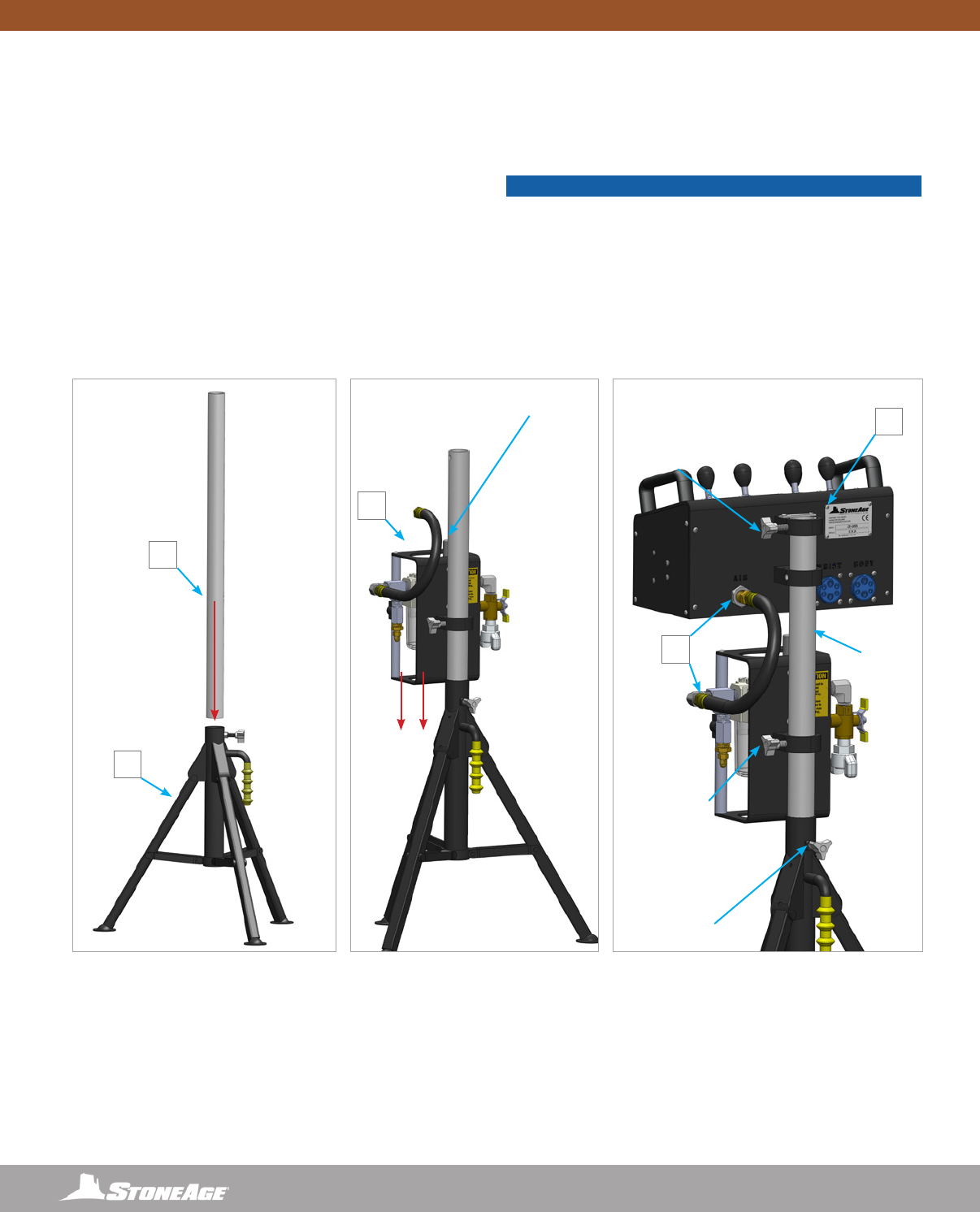
ASSEMBLE CONTROL BOX, FRL, AND TRIPOD BASE
1. Setup the tripod base in a location with good visibility to the
cleaning site, but at a safe distance away from waterblast zone.
2. Slide the vertical tube into the tripod base. Secure with the
supplied thumbscrew knob. Note: The vertical tube has a hole
through one wall that the thumbscrew must engage.
3. Slide the Filter, Regulator, Lubricator (FRL) assembly over the
vertical tube down to the tripod base. Secure with the supplied
thumbscrew knob.
4. Slide the Control Box over the vertical tube. The Control Box has
a stop that keeps it located at the top of the vertical tube. Secure
with the supplied thumbscrew knob.
5. Install the short 1/2 in. (13 mm) I.D. hose between the FRL and
the Control Box.
THUMBSCREW
KNOB
TUBE
INSERT
THUMBSCREW
KNOB
(ALIGN WITH
PRE-DRILLED
HOLE ON
TUBE INSERT)
THUMBSCREW
KNOB
(ALIGN WITH
PRE-DRILLED
HOLE ON
TUBE INSERT)
FILTER, REGULATOR,
LUBRICATOR, ASSEMBLY
(FRL)
2
1
3
5
4
CONTROL BOX ASSEMBLY
NOTICE
The vertical tube has a hole through one wall that the
thumbscrew must engage.
19
866-795-1586 • WWW.STONEAGETOOLS.COM
AIR SUPPLY AND LUBRICATOR SETTING
1. The Control Box is supplied with a twist claw style inlet coupling
(Chicago style) located on the side of the FRL Assembly.
Connect a compatible compressed air line (not included)
according to the Manufacturer’s instructions. If another
pneumatic connection is preferred, this tting can be removed
and any male 1/2 in. NPT tting may be used.
2. Using the regulator adjust the operating pressure to 110 psi
(0.76 MPa) for the application.
ADJUST INLINE OILER
TO FEED 1 DROP OF OIL
EVERY 15-30 SECONDS
FOR HIGH SPEED OR
CONTINUOUS DUTY
USAGE
CONNECTION FITTING
FOR FOOT PEDAL DUMP
CONTROL
REGULATOR
WARNING
Minimum operating pressure is 80 psi (0.55 MPa). Maximum
operating air pressure is 100 psi (0.7 MPa). Exceeding 125 psi
(0.86 MPa) supply pressure may result in injury to the Operator
and/or damage to the equipment.
CONTROL BOX AIR SUPPLY FITTING
AIR SUPPLY FITTING
A universal AIR SUPPLY FITTING (Chicago style) is
located on the side of the FRL. Connect a compatible
compressed air line (not included) according to the
manufacturer’s instructions. If another pneumatic
connection is preferred, this tting can be removed and
any male ½ in. NPT tting may be used.
PNEUMATIC FOOT PEDAL DUMP CONTROL
NOT INCLUDED IN THE STRIKER® PACKAGE
An optional Pneumatic Foot Pedal Dump Control with Air Line
package is available for purchase through StoneAge Tools®.
To install the Pneumatic Foot Pedal Dump Control package,
connect one end of the Air Line to the tting on the Foot
Pedal Dump marked “SUPPLY” and the other end to the
Connection Fitting on the Control Box (See diagram above).
To connect to the Dump Valve, the Operator will need to
install 1/4 in. O.D. Nylon tubing (Not Included in the FPA-SKR
package) between the push tting on the Foot Pedal Dump
marked “DUMP” and the pneumatic dump valve.
INSTALL ¼ IN. O.D. TUBING
(NOT INCLUDED IN THE FPA-SKR
PACKAGE)
AIR LINE
FILTER, REGULATOR, LUBRICATOR
(FRL)
20 866-795-1586 • WWW.STONEAGETOOLS.COM
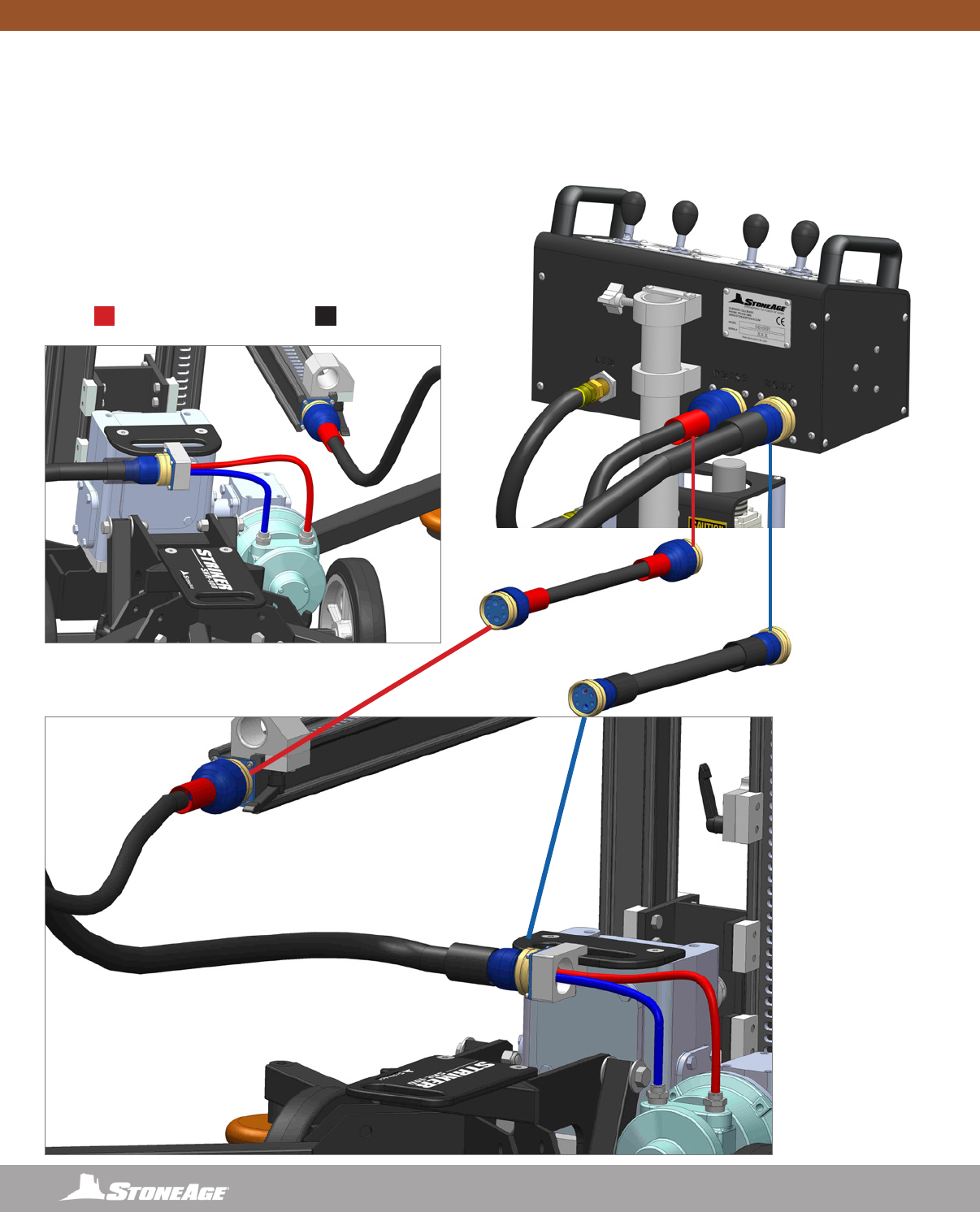
REAR VIEW
BODYWRIST
CONTROL BOX TO STRIKER (SKR-STD) SYSTEM ASSEMBLY CONNECTION
PNEUMATIC SUPPLY LINE CONNECTIONS
1. Remove the dust caps from both plugs on the Control Box and
the STRIKER® (SKR-STD) .
2. Connect the STRIKER® (SKR-STD) to the Control Box by
plugging the RED umbilical into the plug marked “Wrist” and the
BLACK umbilical into the plug marked “Body”. Verify the Control
Box rotates, exes, raises, and lowers, the wrist and rotates the
assembly left and right correctly.
3. Familiarize yourself with the Control Box functions by hooking
up to air, before operating the STRIKER® (SKR-STD) with high
pressure water.
BODY
BLACK
WRIST
RED
15FT (4572 MM)
UMBILICALS
(NOT TO SCALE)
21
866-795-1586 • WWW.STONEAGETOOLS.COM
CONTROL BOX
• There are three levers that control the BODY of the STRIKER®
(SKR-STD).
• The IN/OUT LEVER will move the Horizontal Rail Assembly
in the In (extending) and Out (retracting) directions.
• The UP/DOWN LEVER will move the Carriage Assembly Up
and Down the Vertical Rail Assembly.
• The ROTATE LEFT/RIGHT LEVER will rotate the Vertical
Rail Assembly from the Spline at the bottom in a windshield
wiper motion.
• There are two levers that control the WRIST of the STRIKER®
(SKR-STD).
• The ROTATE LEVER rotates the BCK-20K BARRACUDA
tool from the Wrist in a maximum 270° radius.
NOTE: The Horizontal Rail is slotted on top and bottom to
allow the center of the Wrist rotation point to be pointed
upward or downward.
• The FLEX LEVER exes the BCK-20K BARRACUDA tool
90° from the Wrist.
• The WRIST speed controls are located on the STRIKER® (SKR-
STD) The wrist will operate differently while it is under high pressure
water versus operating with air only. See the Wrist Speed and
Resistance Adjustment page in this manual to adjust the wrist
settings.
• The OFF position for all levers is at the spring centered middle
position.
• To de-energize the system, remove foot from the PNEUMATIC
FOOT PEDAL DUMP CONTROL . This will stop the Carriage
Assembly and BCK-20K BARRACUDA tool from moving and
reroute the high-pressure water away from the STRIKER® (SKR-
STD).
TEST RUN PROCEDURE
• Perform the PRE-RUN SAFETY CHECK (SEE PAGE 8).
• Test the Control Box before operating the STRIKER® (SKR-STD)
with high-pressure water to verify the control valves move the Hori-
zontal and Vertical Rail Assemblies in their intended directions, and
the PNEUMATIC FOOT PEDAL DUMP CONTROL is working
properly. Ensure that the High Pressure Water System cannot be
energized while making adjustments.
• Operate the high-pressure water at full pressure and use the
PNEUMATIC FOOT PEDAL DUMP CONTROL to verify that
the dump valve is working properly. To activate dump, remove foot
from the pedal.
• Operate the high-pressure system and waterjet tool at full pressure
to test the Speed and Resistance settings on the Wrist. Properly
setting up the Wrist will provide good control of the BCK-20K
BARRACUDA tool in Rotation and Flex directions. Detailed
adjustment instructions can be found on the Wrist Speed and
Resistance Adjustment page in this manual.
• The STRIKER® (SKR-STD) has been engineered to stay in posi-
tion with a maximum reaction force of 70lbs when all outriggers
are deployed. The STRIKER® (SKR-STD) may slide on smooth,
oily, or slippery surfaces during operation. Anchoring the STRIK-
ER® (SKR-STD) to the oor, heavy duty scaffolding, or similar
components will aid in keeping the unit in position. The anchor-
ing method MUST be capable of withstanding a minimum of
70 lbs of reaction force from the STRIKER® (SKR-STD). Operate
the high-pressure hose and waterjet tool at full pressure to test
the anchoring method.
RUN PROCEDURE
• After completing the setup, and taking all safety precautions the
STRIKER® (SKR-STD) system is ready for operation.
• To line up the STRIKER® (SKR-STD) with the area to be cleaned,
lift up on the Wheelie Bar to engage wheels, counter balance the
unit, and move into place. Push down on the Wheelie Bar to set
Outriggers down on the oor.
• Operate the in/out, up/down and rotation functions on the upper
rail assembly and the rotate and ex functions on the Wrist, to
begin high pressure cleaning at the preferred location.
• The STRIKER® (SKR-STD) MUST be supervised at all times.
HIGH-PRESSURE HOSE
• The TRACKED STRIKER is designed to be used with a
12ft (3658 mm) SPIR STAR® HP 8mm Hose and SPIR STAR®
standard 9/16”-18 Medium Pressure 8-4 male end at the BC-K
20 KPSI BARRACUDA and a SPIR STAR® 3/4”-16 Type M Swivel
Female End at the coupler on the STRIKER assembly.
• Only high quality hoses intended for waterblast applications should
be used as high-pressure hoses. Pressure rating of high-pressure
hoses MUST NEVER be exceeded.
• Verify that the high-pressure hose is properly installed through
the Carriage Assembly.
• Inspect high-pressure hoses for damage or wear before each
use. Do not use damaged or worn high-pressure hose.
OPERATION
WARNING
Crush Hazard. Keep hands, hair, and clothing, clear of Carriage
Rollers, Wrist joints, Spline Hub, and out of all travel limit zones.
Contact with moving parts can result in severe injury
DANGER
STAY BEHIND THE VERTICAL RAIL ASSEMBLY AND OUT OF
THE SPRAY ZONE WHEN OPERATING THE TRACKED STRIKER.
Failure to do so will result in death or serious injury.

22 866-795-1586 • WWW.STONEAGETOOLS.COM
When moving the STRIKER® (SKR-STD), lift with care to prevent bodily injury. When the Rear (Long) Outriggers are folded upright, and the
wheels on the cart are lowered, the STRIKER® (SKR-STD) can be moved as a two wheeled dolly. Two 3/4” (19 mm) holes, are provided in
the Front (Short) Outrigger mount plates on the cart weldment. They are intended for Clevis Pins to allow for lifting by crane.
The STRIKER® (SKR-STD) is shipped in a custom wooden crate and may be stored upright in the same crate between jobs.
When storing the unit, use compressed air to blow out the air lines to remove debris and moisture. Use mild soapy water to clean the
machine in order to remove corrosive materials.
Apply a small amount of air tool oil directly into the forward and reverse ttings. Then, briey operate the controls at slow speed for a short
duration in each direction to coat the interior parts of the motor. Install the dust caps onto all three ttings to keep moisture and dirt out.
Contact StoneAge for Safety Data Sheets for material usage, a complete list of spare part numbers, and service instructions for the
STRIKER® (SKR-STD) and Control Box.
MAINTENANCE
MAINTENANCE
Maintenance Item Frequency Maintenance Required
All Air Fittings After each use Reinstall all dust caps to protect from dirt and moisture.
Carriage rollers Every 100 Hours of use Lubricate Zerks on all Carriage Rollers using any multipurpose
NLGI 2 grease.
Gearbox oil level Every 100 Hours of use Fill with Mobil SHC™ 634 synthetic gear oil. See individual part
diagram pages for gearbox ll orientations.
Lubricator of Control Box Before each use Add oil when uid drops below minimum level marking. Fill with
a quality air tool oil.
Vertical and Horizontal Rails As Needed Inspect for wear that would allow Carriage Rollers to slip off.
Replace Rail as needed.
Waterblast Tool After each use Remove tool, blow out water, lubricate, and store in clean
container.
STORAGE, TRANSPORTATION, AND HANDLING
23
866-795-1586 • WWW.STONEAGETOOLS.COM
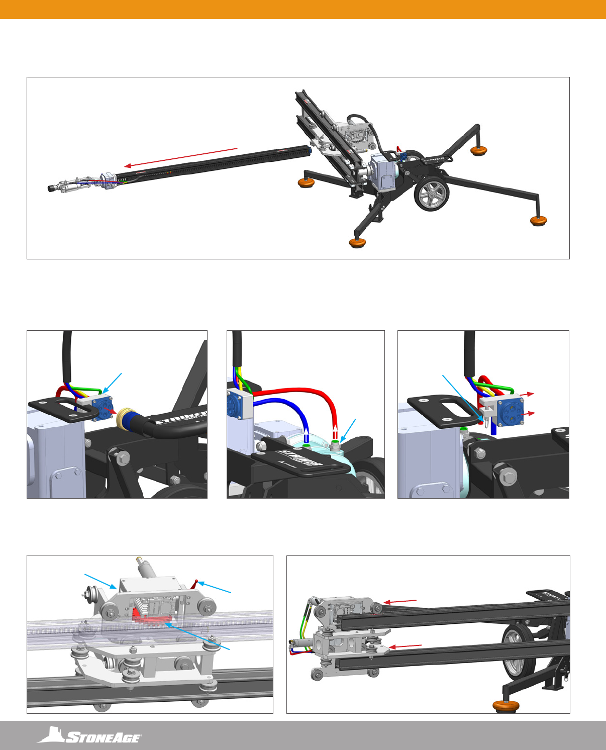
CONVERTING STANDARD STRIKER TO TRACKED STRIKER BASE
USE THIS SECTION OF THE MANUAL TO CONVERT A STANDARD STRIKER TO A TRACKED BASE.
REMOVE THE VERTICAL RAIL ASSEMBLY
1. Using the Control Box rotate the Vertical Rail Assembly into a horizontal position as shown in (Figure 1).
2. Disconnect the High Pressure Hose from the BC-20K tool and pull all the way out through the Rear Rail Stop. (Figure 2)
3. Disconnect the Control Box Umbilical from the end of the Horizontal Rail. (Figure 3)
4. Remove the Rear Rail Stop (Figure 4) from the Horizontal Rail and the Tie Rail Stop from the Vertical Rails. (Figure 5)
WARNING
Always de-energize the system before servicing or replacing any parts. Failure to do so can result in severe injury and/or death.
Keep hands, hair, and clothing clear of moving parts.
FIGURE 3FIGURE 2
FIGURE 1
FIGURE 5FIGURE 4
STORAGE, TRANSPORTATION, AND HANDLING
24 866-795-1586 • WWW.STONEAGETOOLS.COM
CONVERTING STANDARD STRIKER TO TRACKED STRIKER BASE
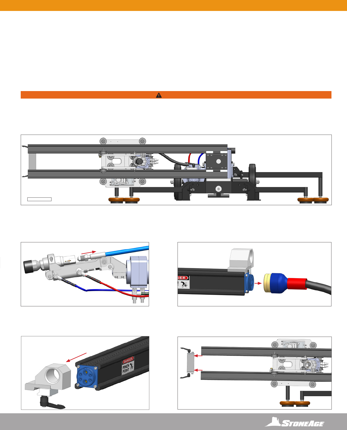
REMOVING THE HORIZONTAL RAIL AND CARRIAGE ASSEMBLY
6. Slide the Horizontal Rail Assembly with Wrist out of the Carriage Assembly. (Figure 6)
7. Disconnect the Control Box Umbilical from the QD Hanger. (Figure 7)
8. Depress the pushlock ttings on the air motor and pull out the red and blue 1/4” tubing. (Figure 8)
9. Pull out the quick release pin on the QD Hanger and slide the assembly off the Gearbox handle. (Figure 9)
10. Disengage the drive gear from the slotted rail by releasing the lever on the motor. (Figure 10)
11. Roll the Carriage off rails with caution so as not drop it. (Figure 11)
FIGURE 11FIGURE 10
FIGURE 6
FIGURE 7 FIGURE 8 FIGURE 9
RELEASE
LEVER
QUICK
RELEASE
PIN
DRIVE
GEAR
CARRIAGE
ASSEMBLY
QD
HANGER
PRESSLOCK
FITTINGS
25
866-795-1586 • WWW.STONEAGETOOLS.COM
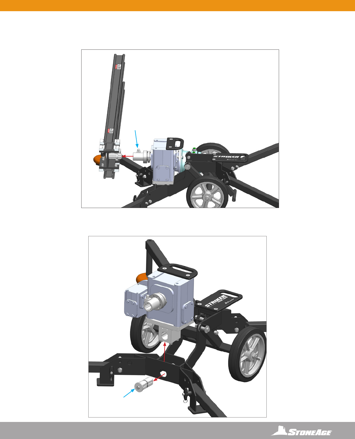
REMOVING THE VERTICAL RAIL AND THE GEARBOX ASSEMBLY
12. Slide the Vertical Rail Assembly off the Spline by depressing the Hub Pin on the Spline coupling. (Figure 12)
13. Remove the Wedge Bolt from the mounting plate and lift the Gearbox Assembly out of the cart. (Figure 13)
HUB PIN
FIGURE 13
FIGURE 12
CONVERTING STANDARD STRIKER TO TRACKED STRIKER BASE
WEDGE
BOLT
26 866-795-1586 • WWW.STONEAGETOOLS.COM
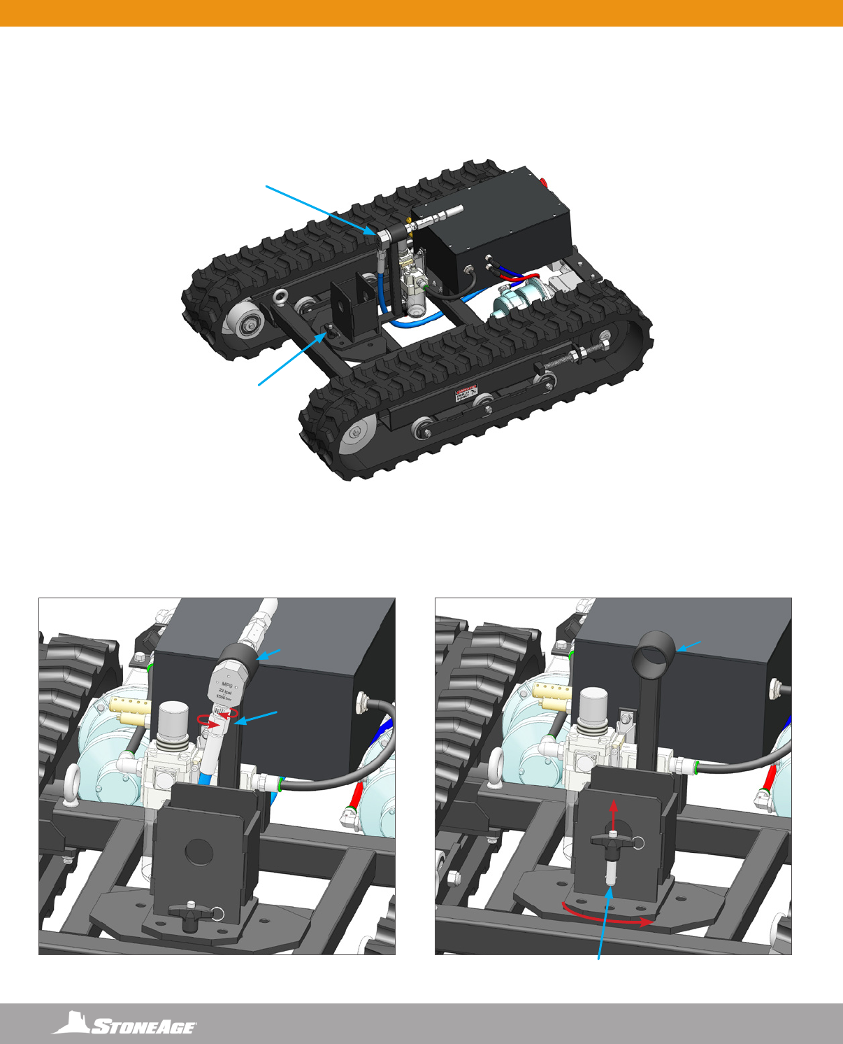
PREPARING THE TRACKED BASE
14. The Tracked Striker Base comes with either a 20K (1500 bar) or 40K (2000 bar) Swivel and Inlet assembly. Additional swivel assemblies
are sold separately through StoneAge Tools®. (Figure 14)
NOTICE
Verify if the Tracked Striker Base is set up with the 20k or 40k. The 20k swivel is an MP9 and the 40k swivel is the H9.
SWITCHING SWIVEL ASSEMBLIES
The following steps are only necessary if changing the pressure rating of the Tracked Striker. Skip to Step 19 if the base is
already assembled with the desired swivel.
15. Remove and retain the four 1/4” hex bolts and washers from the mounting plate. Depress the presslock tting to release the red tubing.
(Figure 15)
16. Loosen the swivel tting with two adjustable end wrenches and slide the swivel out from the holder. (Figure 16)
H9 40K
2000 BAR
SWIVEL
LOCATION
MP9 20K
1500 BAR
FIGURE 14
FIGURE 15
FIGURE 16
CONVERTING STANDARD STRIKER TO TRACKED STRIKER BASE
27
866-795-1586 • WWW.STONEAGETOOLS.COM
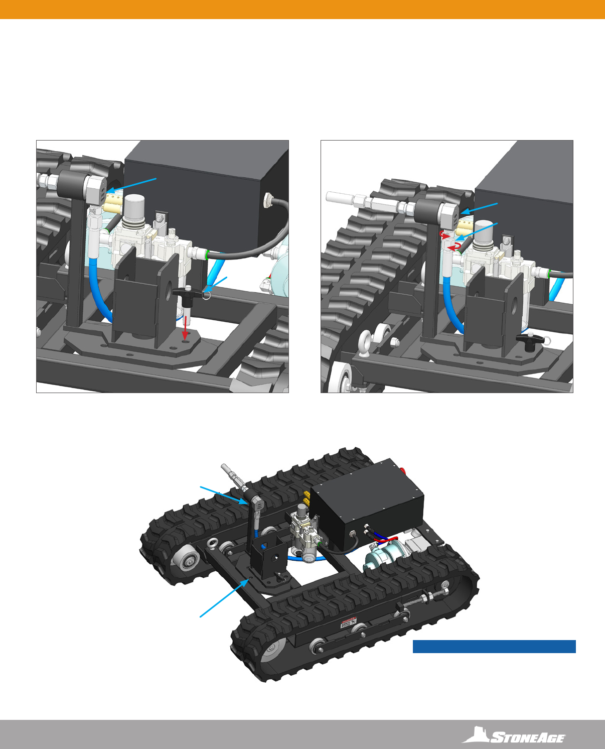
INSTALLING THE SWIVEL
17. Install the four retained 1/4” hex bolts and washers through the base plate into the dump valve. Depress the presslock tting to insert
the red tubing. Pull on the tubing to ensure it is securely fastened. (Figure 17)
18. Tighten the swivel tting with two adjustable end wrenches and slide into the holder. (Figure 18)
NOTICE
At this point it is best to determine the desired orientation of the Tracked Striker. The job location will determine if the Parallel or Perpendicular position will
allow for easier access to the object to be cleaned. The diagrams below illustrate the differences between the two positions.
FIGURE 17
FIGURE 18
PARALLEL ORIENTATION PERPENDICULAR ORIENTATION
FRONT
SPRAY ZONE
SPRAY
ZONE
RIGHT
LEFT
BACK
FRONT
RIGHT
LEFT
BACK
CONVERTING STANDARD STRIKER TO TRACKED STRIKER BASE
28 866-795-1586 • WWW.STONEAGETOOLS.COM
ROTATING THE POSITION OF THE PIVOT
The instructions below are for rotating the position of the pivoting gearbox mount from Parallel to Perpendicular. If the Parallel position is the
desired orientation then skip to Step 23.
19. Loosen the swivel tting with two adjustable end wrenches to allow the hose to rotate when changing positions. (Figure 19)
20. Pull out the Quick Release Pin and rotate the pivoting gearbox mount in the direction shown. (Figure 20)
FIGURE 19 FIGURE 20
PARALLEL ORIENTATION
PARALLEL ORIENTATION
QUICK RELEASE PIN
SWIVEL
HOLDER
SWIVEL
HOLDER
SWIVEL
LOCATION
PIVOTING
GEARBOX
MOUNT
LOCATION
LOOSEN
CONVERTING STANDARD STRIKER TO TRACKED STRIKER BASE
29
866-795-1586 • WWW.STONEAGETOOLS.COM
ROTATING THE POSITION OF THE PIVOT (CONTINUED)
21. Insert the Quick Release Pin in the 3 O’Clock position. (Figure 21)
22. Tighten the swivel tting with two adjustable end wrenches. (Figure 22)
PERPENDICULAR ORIENTATION
PERPENDICULAR ORIENTATION
SWIVEL
SWIVEL
FIGURE 22
FIGURE 21
TIGHTEN
SWIVEL
LOCATION
PIVOTING
GEARBOX
MOUNT
LOCATION
INSERT
CONVERTING STANDARD STRIKER TO TRACKED STRIKER BASE
NOTICE
The Tracked Striker should appear like
this if it has been rotated properly into the
Perpendicular Position
30 866-795-1586 • WWW.STONEAGETOOLS.COM
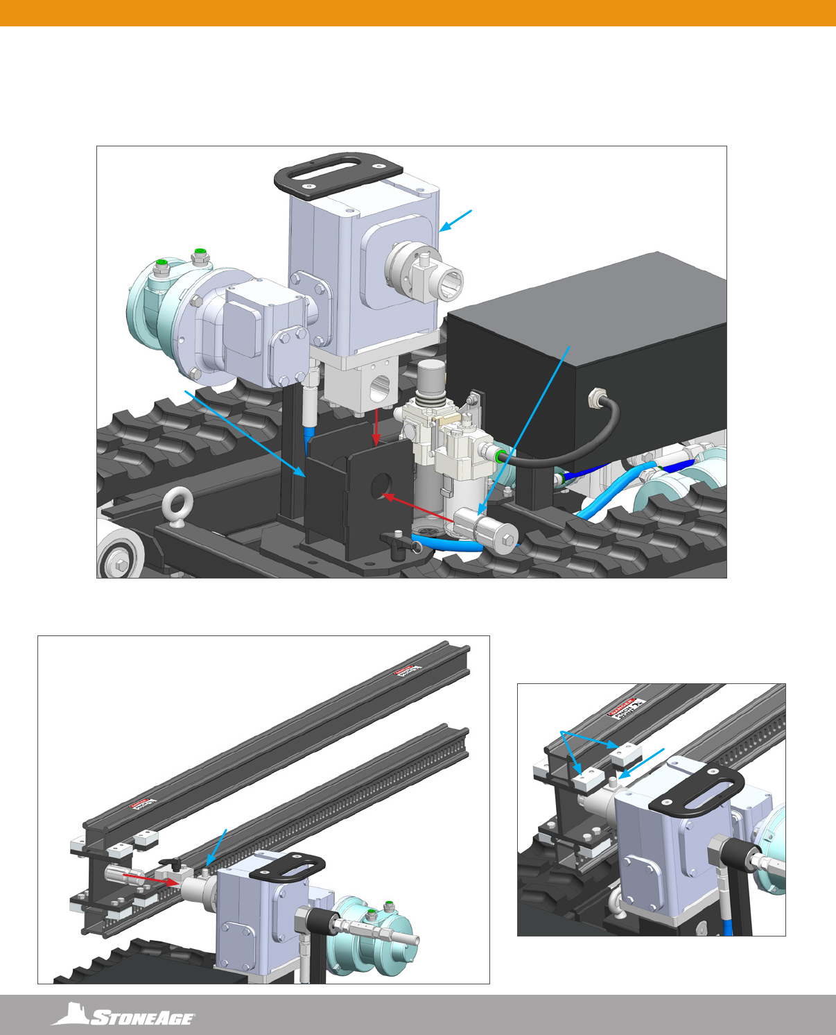
MOUNTING GEARBOX ASSEMBLY ONTO TRACKED BASE
The following assembly instructions are shown with the Tracked Striker in the PERPENDICULAR ORIENTATION.
23. Place the Gearbox Assembly into the mount as shown in (Figure 23). Install Wedge Bolt with the ats lined up through both inboard
and outboard plates and the Gearbox Assembly. Tighten Wedge Bolt with two 9/16” wrenches on both sides until secure.
24. Slide the Vertical Rail Assembly onto the Spline by depressing the Hub Pin on the Spline coupling. (Figure 24)
The Hub Pin should be fully engaged and positioned between Rail Clamps as shown. (Figure 24.1)
FIGURE 23
FIGURE 24
FIGURE 24.1
GEARBOX
ASSEMBLY
HUB
PIN
HUB
PIN
RAIL
CLAMPS
WEDGE
BOLT
GEARBOX
MOUNT
CONVERTING STANDARD STRIKER TO TRACKED STRIKER BASE
31
866-795-1586 • WWW.STONEAGETOOLS.COM
INSTALLING THE CARRIAGE ASSEMBLY
25. Slide the Carriage onto the Vertical Rails (Figure 25) and disengage the drive gear from the slotted rail by releasing the lever on the
motor. This will allow the carriage to move along the rails. (Figure 25.1) Continue to slide the Carriage about half way down the rails
and tighten the lever on the Carriage to engage the drive gear.
26. Connect the QD Hanger to the Gearbox handle by pulling out the quick release pin on the QD Hanger and sliding the pin into the
center hole on the handle. (Figure 26)
27. Depress the pushlock ttings on the air motor and push in the red and blue 1/4” tubing lines as shown. IT IS CRITICAL TO FUNCTION
that the red and blue lines be inserted in the exact positions shown. Pull back on both lines to ensure they are securely connected.
(Figure 27)
RELEASE
LEVER
DRIVE
GEAR
DETAIL CARRIAGE VIEW
FIGURE 25
FIGURE 26 FIGURE 27
QD
HANGER
QUICK
RELEASE
PIN
PUSHLOCK
FITTINGS
CONVERTING STANDARD STRIKER TO TRACKED STRIKER BASE
32 866-795-1586 • WWW.STONEAGETOOLS.COM
INSTALLING THE HORIZONTAL RAIL INTO THE CARRIAGE ASSEMBLY
28. Slide the Horizontal Rail Assembly into the Carriage Assembly. (Figure 28) Line up the box rail with the rollers. (Figure 28.1)
FIGURE 28
FIGURE 28.1
DETAIL CARRIAGE VIEW
270
ROTATIONAL
SPRAY PATTERN
NOTICE
The Horizontal Rail Assembly is slotted on both sides. Flipping the Horizontal Rail allows the 270 rotational spray pattern to be directed up
or down.
CONVERTING STANDARD STRIKER TO TRACKED STRIKER BASE
33
866-795-1586 • WWW.STONEAGETOOLS.COM
INSTALLING THE RAIL STOPS
29. Slide the Tie Rail Stop onto the ends of the Vertical Rail Assembly. (Figure 29) Orient and tighten the Release Levers away from the
Carriage Assembly. (Figure 29.1)
30. Slide the Rail Stop onto the end of the Horizontal Rail Assembly. (Figure 30) Orient and tighten the Release Lever away from the
Carriage Assembly. (Figure 30.1)
31. Slide the Carriage Stop along the Vertical Rail Assembly until the top of the block is 12” (305 mm) from the bottom of the Vertical Rail.
Orient and tighten the Release Lever away from the Carriage Assembly.
FIGURE 30
FIGURE 31
FIGURE 30.1
12” (305 MM)
MINIMUM
NOTICE
Setting the Carriage Stop at a minimum of 12” (305 mm) ensures the carriage and horizontal rail will clear the gearbox and the base.
If the Carriage Stop is placed lower to gain range of motion, the O perator must pay attention to the horizontal rail and carriage assembly
to ensure that they DO NOT make contact with the gearbox or base. Failure to do so will result in damage to the motors on the carriage
assembly.
FIGURE 29
FIGURE 29.1
CONVERTING STANDARD STRIKER TO TRACKED STRIKER BASE
34 866-795-1586 • WWW.STONEAGETOOLS.COM
CONNECTING HIGH PRESSURE HOSE AND FITTINGS TO BCK-20K
32. Connect the female connector on the High Pressure Hose to the Swivel Connection. (Figure 32) Feed the male connector on the High
Pressure Hose through the Rear Rail Stop on the end of the Horizontal Rail, then through the Carriage towards the BCK-20K Holder.
(Figure 32.1)
33. Fasten High Pressure Hose to BCK-20K Barracuda by loosening the two 1/4” square head cap screws and sliding the BCK-20 into the
holder until the shoulder hits the collar. (Figure 33) The hose end is a 9/16” medium pressure connection, with a modied gland nut
and standard collar.
34. Tighten the BCK-20K Barracuda to Gland Nut on the High Pressure Hose (A) and tighten the Wrist Clamp to BCK-20K Barracuda (B).
(Figure 34)
CARRIAGE
BCK-20K
HOLDER
HIGH
PRESSURE
HOSE
HIGH
PRESSURE
HOSE WITH
FEMALE
CONNECTOR
SWIVEL
CONNECTION
REAR
RAIL
STOP
A
GLAND NUT COLLAR
LOOSEN TO INSTALL
BCK-20K BARRACUDA
B
FIGURE 32 FIGURE 32.1
FIGURE 33
FIGURE 34
CONVERTING STANDARD STRIKER TO TRACKED STRIKER BASE
NOTICE
It is recommended to use BLUE GOOP, A SWAGELOK brand anti-seize, or an equivalent on threaded ttings to avoid galling.
35
866-795-1586 • WWW.STONEAGETOOLS.COM
CONVERTING STANDARD STRIKER TO TRACKED STRIKER BASE
TO HORIZONTAL
RAIL END
TO QD
HANGER
WIRELESS
RECEIVER
GEARBOX
ASSEMBLY
QD HANGER HORIZONTAL
RAIL END
FIGURE 36
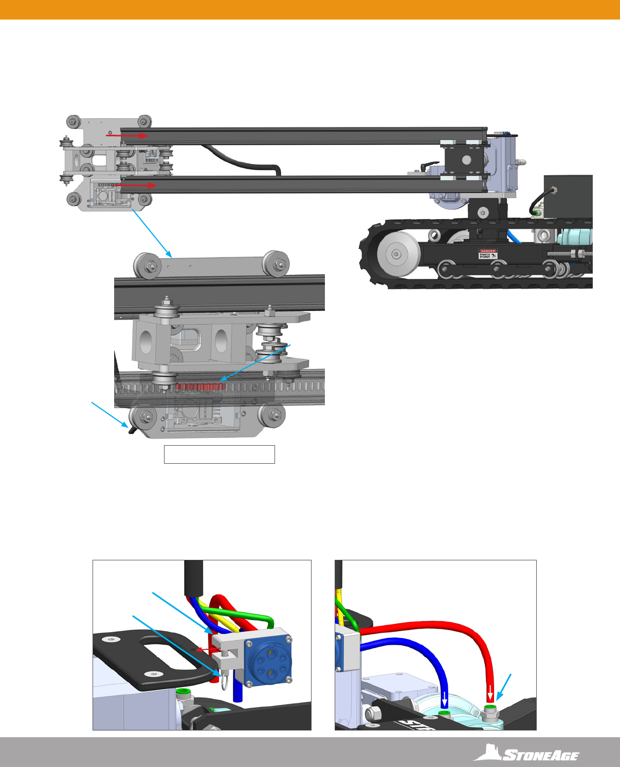
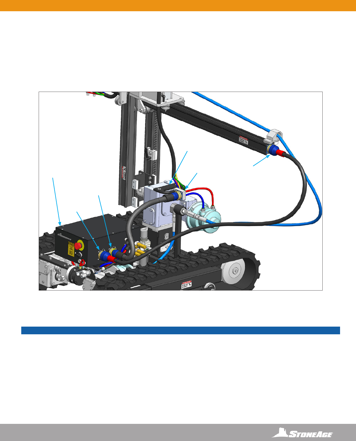
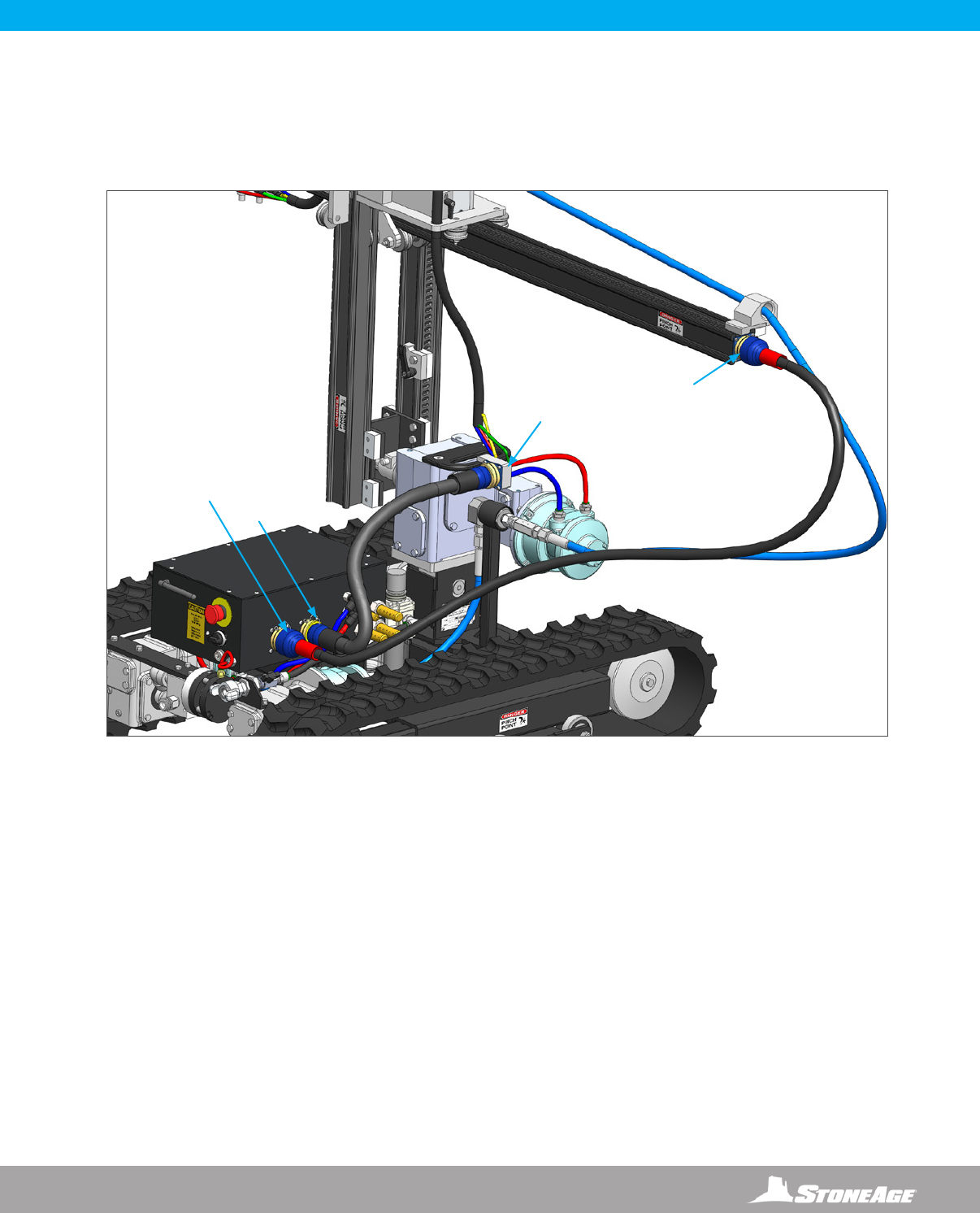
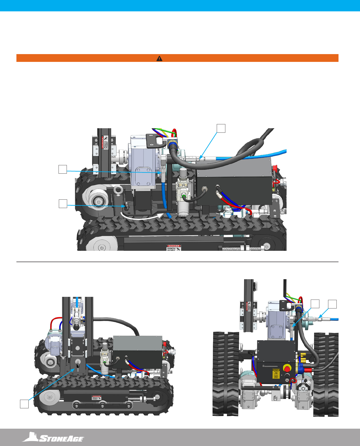
PNEUMATIC SUPPLY LINE CONNECTIONS
Remove the dust caps from the connectors on the Wireless Control Receiver, the Horizontal Rail, and the Gearbox Assembly.
36. Connect the RED umbilical into the Right plug on the Wireless Control Receiver and the end of the Horizontal Rail.
Connect the BLACK umbilical into the Left plug on the Receiver Box and the QD Hanger. (Figure 36)
NOTICE
TO COMPLETE THE SET-UP OF THE TRACKED STRIKER (SKR-TRK), SKIP FORWARD TO THE
“AIR AND WATER SUPPLY AND LUBRICATOR SETTING”
IN THE TRACKED STRIKER SECTION OF THIS MANUAL.
FOLLOW THE INSTRUCTIONS THROUGH TO OPERATION.
36 866-795-1586 • WWW.STONEAGETOOLS.COM
REAR RAIL STOP
TIE STOP
ASSEMBLY
20K OR 40K SWIVEL,
FITTING, AND HIGH
PRESSURE HOSE
ASSEMBLY
VERTICAL RAIL
ASSEMBLY
HORIZONTAL
RAIL ASSEMBLY
WRIST
ASSEMBLY
BCK-20
BARRACUDA
*NOT INCLUDED
CARRIAGE
ASSEMBLY
GEARBOX
ASSEMBLY
STRIKER
TRACKED BASE
ASSEMBLY
CONTROL LINE
UMBILICALS
WIRELESS CONTROL
RECEIVER BOX
TRACKED STRIKER SYSTEM ASSEMBLY - OVERVIEW
WIRELESS CONSOLE CONTROLLER
CHICAGO
AIR SUPPLY
FITTING
TRACKED STRIKER® SKR-TRK AND
WIRELESS REMOTE CONTROL SYSTEM
37
866-795-1586 • WWW.STONEAGETOOLS.COM
INSTALLING THE HORIZONTAL RAIL INTO THE CARRIAGE ASSEMBLY
1. Install the Horizontal Rail Assembly with Wrist through the Carriage Assembly located on the Vertical Rail Assembly. (Figure 1)
Center the Horizontal Rail between the four rollers on the Carriage Assembly (Figure 1.1) and slide in about half way.
REMOVING THE TRACKED BASE FROM THE CRATE
The Tracked Striker is shipped with the Remote Control associated to the Tracked Base. This allows the Operator to drive the tracked
base out of the crate and into location.
• Pull up on the EMERGENCY STOP BUTTONS on both the RECEIVER UNIT and REMOTE CONTROL.
• Stand near the RECEIVER UNIT with the REMOTE CONTROL in hand. Activate the REMOTE CONTROL by ipping the ON/OFF switch UP.
• When the TX lights blink at a rate of once per second on the REMOTE CONTROL, turn ON the power on the RECEIVER UNIT by rotating the
ON/OFF knob clockwise.
• The TX (Transmit) and RX (Receive) LEDs on the REMOTE CONTROL should be active indicating that the communication link is established.
If the unit fails to move, shut both the Remote Control and the Receiver down and follow the association steps on Page 44. See Page 45 for
detailed Remote Controller operating instructions.
FIGURE 1
270
ROTATIONAL
SPRAY PATTERN
NOTICE
The Horizontal Rail Assembly is slotted on both sides. Flipping
the Horizontal Rail allows the 270 rotational spray pattern to
be directed up or down.
SKR-TRK SET-UP - UNPACKING AND HORIZONTAL RAIL INSTALLATION
DETAIL CARRIAGE VIEW FIGURE 1.1
38 866-795-1586 • WWW.STONEAGETOOLS.COM
SKR-TRK SET-UP - RAIL STOP INSTALLATION
INSTALLING THE RAIL STOPS
2. Slide the Rail Stop onto the end of the Horizontal Rail Assembly. (Figure 2) Orient and tighten the Release Lever away from the
Carriage Assembly. (Figure 2.1)
3. Slide the Carriage Stop along the Vertical Rail Assembly until the top of the block is 12” (305 mm) from the bottom of the Vertical Rail.
Orient and tighten the Release Lever away from the Carriage Assembly.
FIGURE 2 FIGURE 2.1
FIGURE 3
12” (305 MM)
MINIMUM
NOTICE
Setting the Carriage Stop at a minimum of 12” (305 mm) ensures the carriage and horizontal rail will clear the gearbox and the base.
If the Carriage Stop is placed lower to gain range of motion, the Operator must pay attention to the horizontal rail and carriage assembly
to ensure that they DO NOT make contact with the gearbox or base. Failure to do so will result in damage to the motors on the carriage
assembly.
39
866-795-1586 • WWW.STONEAGETOOLS.COM
CONNECTING HIGH PRESSURE HOSE AND FITTINGS TO BCK-20K
32. Connect the female connector on the High Pressure Hose to the Swivel Connection. (Figure 4) Feed the male connector on the High
Pressure Hose through the Rear Rail Stop on the end of the Horizontal Rail, then through the Carriage towards the BCK-20K Holder.
(Figure 4.1)
33. Fasten High Pressure Hose to BCK-20K Barracuda by loosening the two 1/4” square head cap screws and sliding the BCK-20 into the
holder until the shoulder hits the collar. (Figure 5) The hose end is a 9/16” medium pressure connection, with a modied gland nut and
standard collar.
34. Tighten the BCK-20K Barracuda to Gland Nut on the High Pressure Hose (A) and tighten the Wrist Clamp to BCK-20K Barracuda (B).
(Figure 6)
CARRIAGE
BCK-20K
HOLDER
HIGH
PRESSURE
HOSE
HIGH
PRESSURE
HOSE WITH
FEMALE
CONNECTOR
SWIVEL
CONNECTION
REAR
RAIL
STOP
A
GLAND NUT COLLAR
LOOSEN TO INSTALL
BCK-20K BARRACUDA
B
NOTICE
It is recommended to use BLUE GOOP, A SWAGELOK brand anti-seize, or an equivalent on threaded ttings to avoid galling.
SKR-TRK SET-UP - HIGH PRESSURE HOSE AND TOOL INSTALLATION
FIGURE 4 FIGURE 4.1
FIGURE 5
FIGURE 6
SKR-TRK SET-UP - RAIL STOP INSTALLATION
40 866-795-1586 • WWW.STONEAGETOOLS.COM
SKR-TRK SET-UP - WRIST SPEED AND RESISTANCE ADJUSTMENTS
SLOWER
SLOWER
FASTER
FASTER
DOWNWARD
WRIST FLEX
UPWARD
WRIST FLEX
COUNTER-
CLOCKWISE
WRIST ROTATION
CLOCKWISE
WRIST ROTATION
THE WRIST ROTATION DIRECTION IS REFERENCED
FROM THE BACK OF THE STRIKER, LOOKING DOWN
THE HORIZONTAL RAIL TOWARD THE BCK-20K
WRIST SPEED CONTROL ADJUSTMENTS
WRIST RESISTANCE ADJUSTMENTS
WRIST RESISTANCE
ADJUSTMENTS
1. Remove Bolt and Lock Nut From the Rail and Wrist Assembly.
2. Pull the Wrist Assembly free of the Rail.
3. Remove the black plastic end cap from the end of the Wrist Assembly.
4. Remove the Friction Torque Limiter and Shaft
5. Loosen set screws.
6. Adjust nut to the left for less resistance and tighten to the right for
increased resistance.
3
4
6
2
1
5
SLOWER
FASTER
41
866-795-1586 • WWW.STONEAGETOOLS.COM
SKR-TRK SET-UP - CONTROL LINE UMBILICAL INSTALLATION
TO HORIZONTAL
RAIL END TO QD
HANGER
QD HANGER
HORIZONTAL
RAIL END
FIGURE 36
PNEUMATIC SUPPLY LINE CONNECTIONS
Remove the dust caps from the connectors on the Wireless Control Receiver, the Horizontal Rail, and the Gearbox Assembly.
36. Connect the RED umbilical into the Right plug on the Wireless Control Receiver and the end of the Horizontal Rail.
Connect the BLACK umbilical into the Left plug on the Receiver Box and the QD Hanger.
42 866-795-1586 • WWW.STONEAGETOOLS.COM
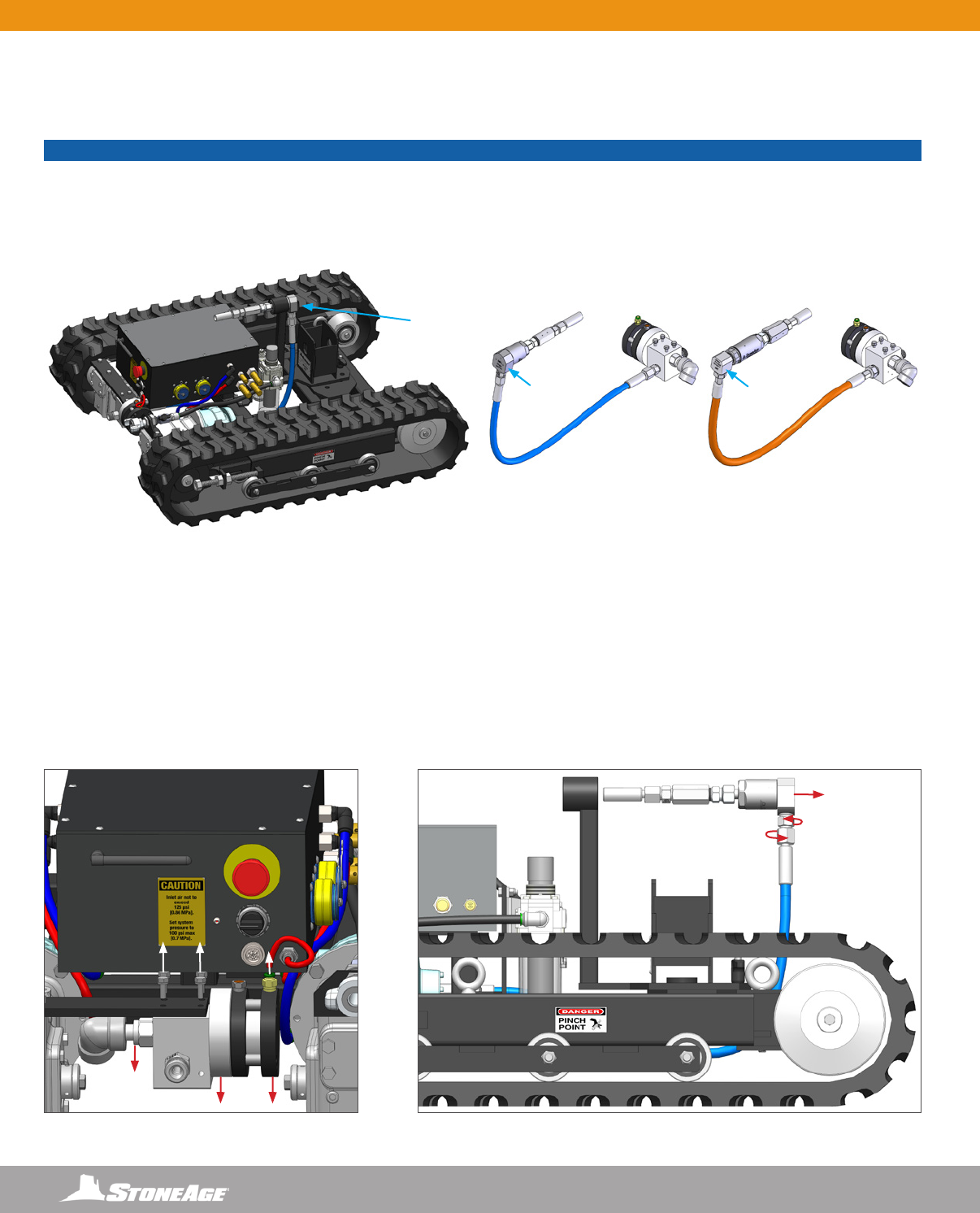
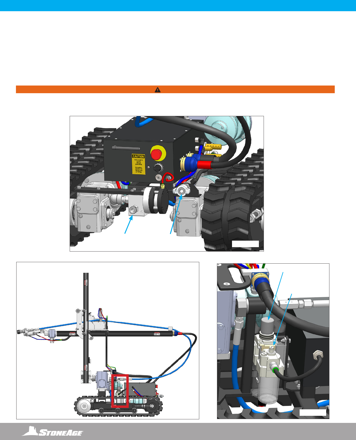
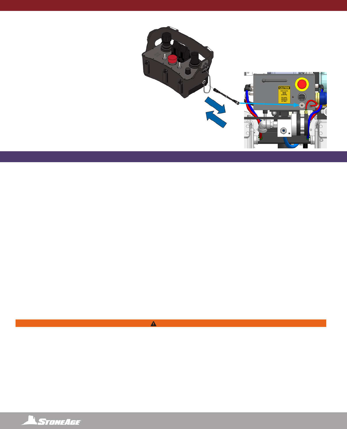
AIR AND WATER SUPPLY AND LUBRICATOR SETTING
1. The Tracked Striker is supplied with a twist claw style inlet coupling (Chicago style) located to the right of the Emergency Shut Off button.
(Figure 1) Connect a compatible compressed air line (not included) according to the Manufacturer’s instructions. If another pneumatic
connection is preferred, this tting can be removed and any male 1/2 in NPT tting may be used. Connect the water supply hose to the
Main Water Inlet/Outlet connection to the left of the Air Supply tting.
2. Use the Regulator on the Filter, Regulator, Lubricator (FRL) to adjust the operating pressure to 110 psi (0.76 MPa) for the application.
(Figure 3)
3. Adjust inline oiler on the FRL to feed 1 drop of oil every 15-30 seconds for high speed or continuous duty usage. (Figure 3)
FIGURE 3
FIGURE 1
FIGURE 2
SKR-TRK SET-UP - AIR AND WATER SUPPLY AND LUBRICATOR SETTING
MAIN WATER
INLET/OUTLET
CONNECTION
CHICAGO
AIR SUPPLY
FITTING
INLINE OILER
ADJUSTMENT
KNOB
REGULATOR
WARNING
Minimum operating pressure is 80 psi (0.55 MPa). Maximum operating air pressure is 125 psi (0.86 MPa). Exceeding 125 psi (0.86
MPa) supply pressure may result in injury to the Operator and/or damage to the equipment.
FILTER, REGULATOR, LUBRICATOR (FRL) LOCATION
43
866-795-1586 • WWW.STONEAGETOOLS.COM
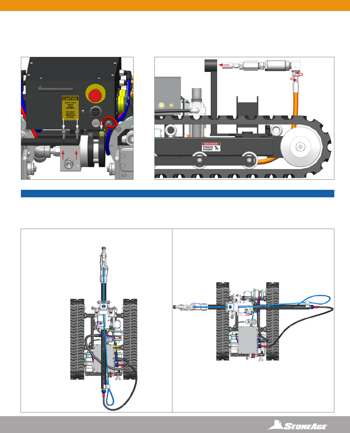
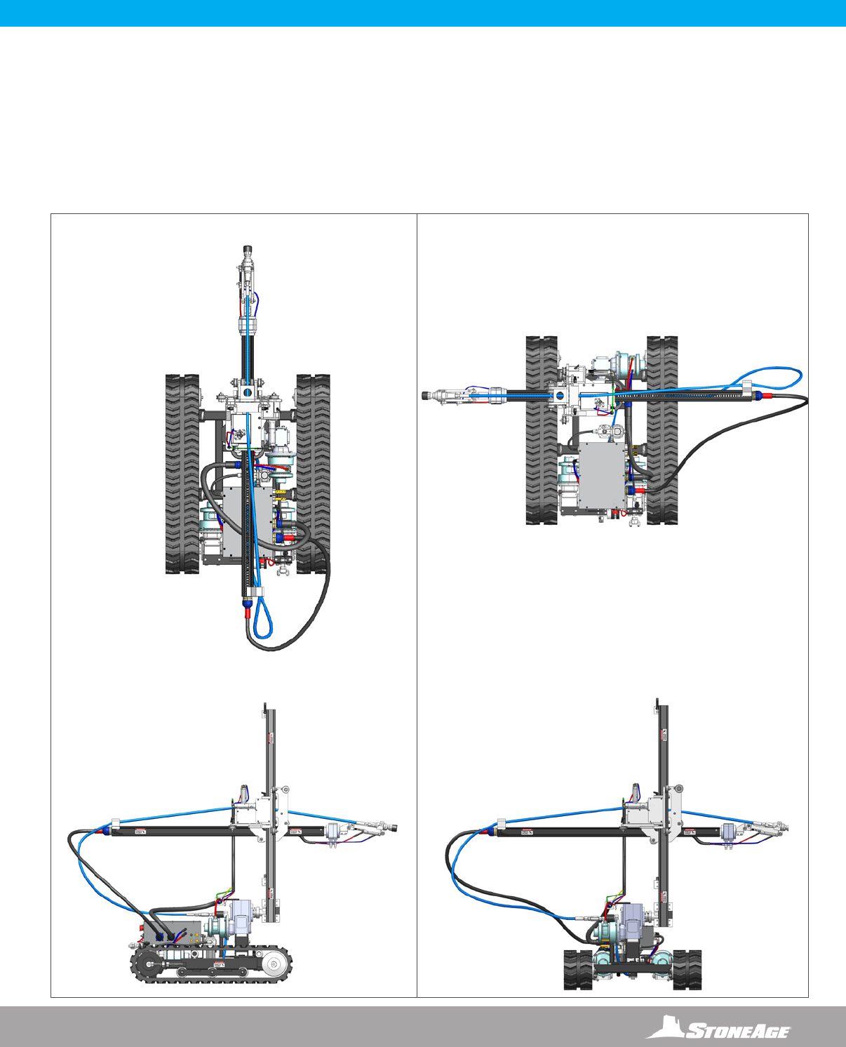
PARALLEL ORIENTATION
TOP VIEW TOP VIEW
PERPENDICULAR ORIENTATION
RAIL ASSEMBLY ORIENTATION
There are two ways to position the rail assembly on the Tracked Striker base. The diagrams below illustrate the differences between the two
positions.
The Tracked Striker is shown in the left column in the Parallel Orientation. The Tracked Striker is in the Parallel Orientation when the
horizontal rail is running parallel with the tracks.
The Tracked Striker is shown in the right column in the Perpendicular Orientation. The Tracked Striker is in the Perpendicular Orientation
when the horizontal rail is running perpendicular to the tracks.
SKR-TRK SET-UP - TRACKED BASE ORIENTATIONS
FRONT
FRONT
FRONT
RIGHT
LEFT
BACK
BACK
FRONT
RIGHT
LEFT
LEFTRIGHT
BACK
FRONT VIEW
SIDE VIEW
44 866-795-1586 • WWW.STONEAGETOOLS.COM
PARALLEL ORIENTATION
ROTATING THE TRACKED STRIKER ORIENTATION
The job location will determine if the Parallel or Perpendicular position will allow for easier access to the object to be cleaned. Changing
the orientation requires rotating the upper rail and gearbox assembly. The Tracked Striker has an easy pivot mechanism located under the
gearbox. The following instruction is to rotate the Tracked Striker from the Parallel Orientation to the Perpendicular Orientation.
WARNING
Always de-energize the system before servicing or replacing any parts. Failure to do so can result in severe injury and/or death.
Keep hands, hair, and clothing clear of rotating parts.
FRONT BACK
SKR-TRK SET-UP - CHANGING TRACKED STRIKER ORIENTATION
2
3
4
8
7
6BACK
BACK
FRONT
PERPENDICULAR ORIENTATION
1. Dump and shut down the main water supply to the Tracked Striker.
2. Disconnect high pressure water hose from the swivel.
3. Loosen the nut on the swivel tting with two adjustable end wrenches to allow the swivel to rotate with the Pivot Base.
4. Pull out the quick release pin on the pivot mechanism.
5. Rotate the upper rail and gearbox assembly in the counterclockwise direction with 12 O’Clock being located at the Front of the
Tracked Striker.
6. Replace the Quick Release Pin.
7. Tighten the swivel tting with two adjustable end wrenches.
8. Connect the high pressure hose to the swivel. Ensure that the it is securely tightened.
45
866-795-1586 • WWW.STONEAGETOOLS.COM
REMOTE CONTROL CONSOLE
REMOTE CONTROL LEFT SIDE VIEW
WIRELESS RECEIVER UNIT ON
TRACKED STRIKER
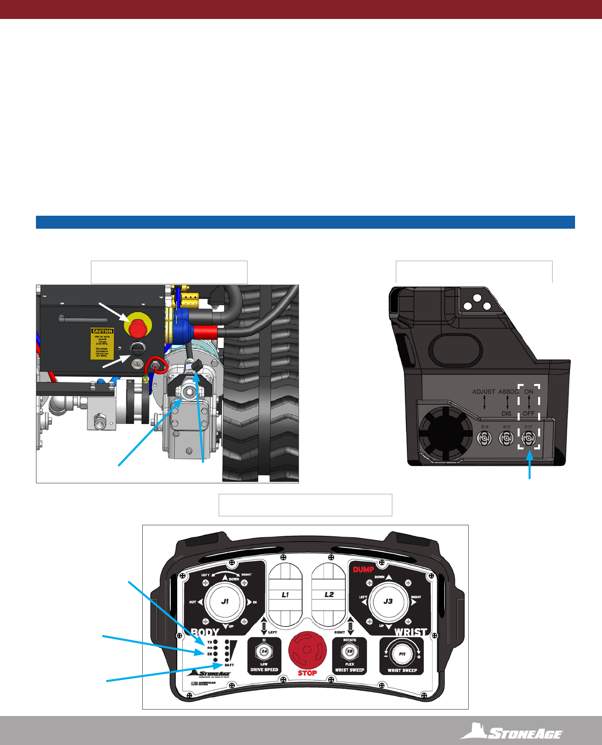
TRACKED STRIKER ACTIVATION
• Push in both the large red EMERGENCY STOP BUTTONS on both the RECEIVER UNIT and REMOTE CONTROL.
• Turn the Air Ball Valve connected to the Chicago Fitting on the Striker parallel to the air line or the “ON” position.
• Check the gauge on the Filter Regulator on the Striker to make sure it reads 80-120 PSI.
• On the REMOTE CONTROL, rotate “Wrist Sweep” knob counterclockwise to “-” or OFF
• Turn the RECEIVER UNIT on and listen for the charger to stop (approximately 20 seconds).
• Pull out the large red EMERGENCY STOP BUTTON out on the RECEIVER UNIT. The green light on the RECEIVER UNIT should be on.
• On the REMOTE CONTROL UNIT, pull up on the EMERGENCY STOP BUTTON.
• On the REMOTE CONTROL, hold the ON/OFF Power Switch in the up position for 2-3 seconds.
• On the REMOTE CONTROL, the TX (Transmit) and RX (Receive) LEDs should be active, indicating that the communication link has been
established.
• Test the Striker’s directional movements with the REMOTE CONTROL.
WIRELESS CONTROL SYSTEM - TRACKED STRIKER ACTIVATION
CHICAGO AIR
FITTING
ON/OFF
AIR BALL VALVE IN THE
“ON” POSITION
TX AND RX LEDs
(TRANSMIT AND RECEIVE)
ER LED
(ERROR)
BATT
(BATTERY
LIFE LEVEL)
EMERGENCY
STOP
OFF/ON
NOTICE
If the ER LED ashes, the Tracked Striker may need to be re-associated. The Association instructions are on PAGE 47.
If a connection issue remains after following the Association instructions, call StoneAge Tools for technical assistance.
46 866-795-1586 • WWW.STONEAGETOOLS.COM
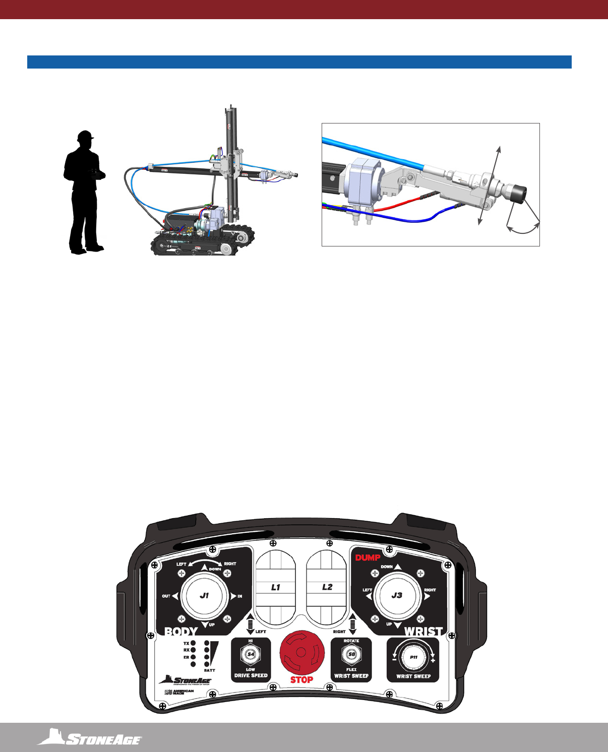
WIRELESS REMOTE CONTROLLER- OPERATION
WIRELESS REMOTE CONTROLLER
NOTICE
The Remote Control performs the functions below with different control mechanisms. The directional markings on the wireless console controller
are based on the Operator standing behind the Tracked Striker in the Parallel Orientation. It is recommended to practice with the controller
before operating the Tracked Striker with high pressure water. The controls will feel slightly different when operating the Tracked Striker in
the Perpendicular orientation.
• The TRACKED BASE of the TRACKED STRIKER is controlled with three controls in the six following directions.
• L1 FORWARD/REVERSE will move the tracked base in forward and reverse directions.
• L2 ROTATE LEFT/RIGHT will operate the left or right tracks so the assembly can turn.
• S4 HI/LOW SPEED adjustment allows the user to preset the speed at which the TRACKED STRIKER will move in the FORWARD/
REVERSE directions.
• The BODY of the TRACKED STRIKER is controlled in the six following directions.
• J1 IN/OUT will move the Horizontal Rail Assembly in the In (extending) and Out (retracting) directions.
• J1 UP/DOWN will move the Carriage Assembly Up and Down along the Vertical Rail Assembly.
• J1 ROTATE LEFT/RIGHT will rotate the Vertical Rail Assembly from the Spline at the bottom in a windshield wiper motion.
• The WRIST of the TRACKED STRIKER is controlled in the four following directions.
• J3 ROTATE rotates the BCK-20K BARRACUDA tool from the Wrist in a maximum 270° radius. The Horizontal Rail is slotted on top
and bottom to allow the center of the Wrist rotation point to be pointed upward or downward.
• J3 FLEX exes the BCK-20K BARRACUDA tool 90° from the Wrist.
• S8 FLEX/ROTATE SWEEP switches the wrist between a sweeping rotation motion and a exing up and down motion
• P11 SWEEP +/- adjusts the speed of the sweeping or exing motion
• The WRIST speed controls are located on the TRACKED STRIKER See the “Wrist Speed and Resistance Adjustment” page for adjustment
instructions. Wrist Speed and Resistance settings will operate differently when operating with high pressure water versus air only.
• The OFF position for all levers is at the spring centered middle position.
• To de-energize the system, depress the DUMP CONTROL . This will stop the Carriage Assembly and BCK-20K BARRACUDA tool from
moving and reroute the high-pressure water away from the TRACKED STRIKER.
REMOTE CONTROL CONSOLE
FLEX
SWEEP
47
866-795-1586 • WWW.STONEAGETOOLS.COM
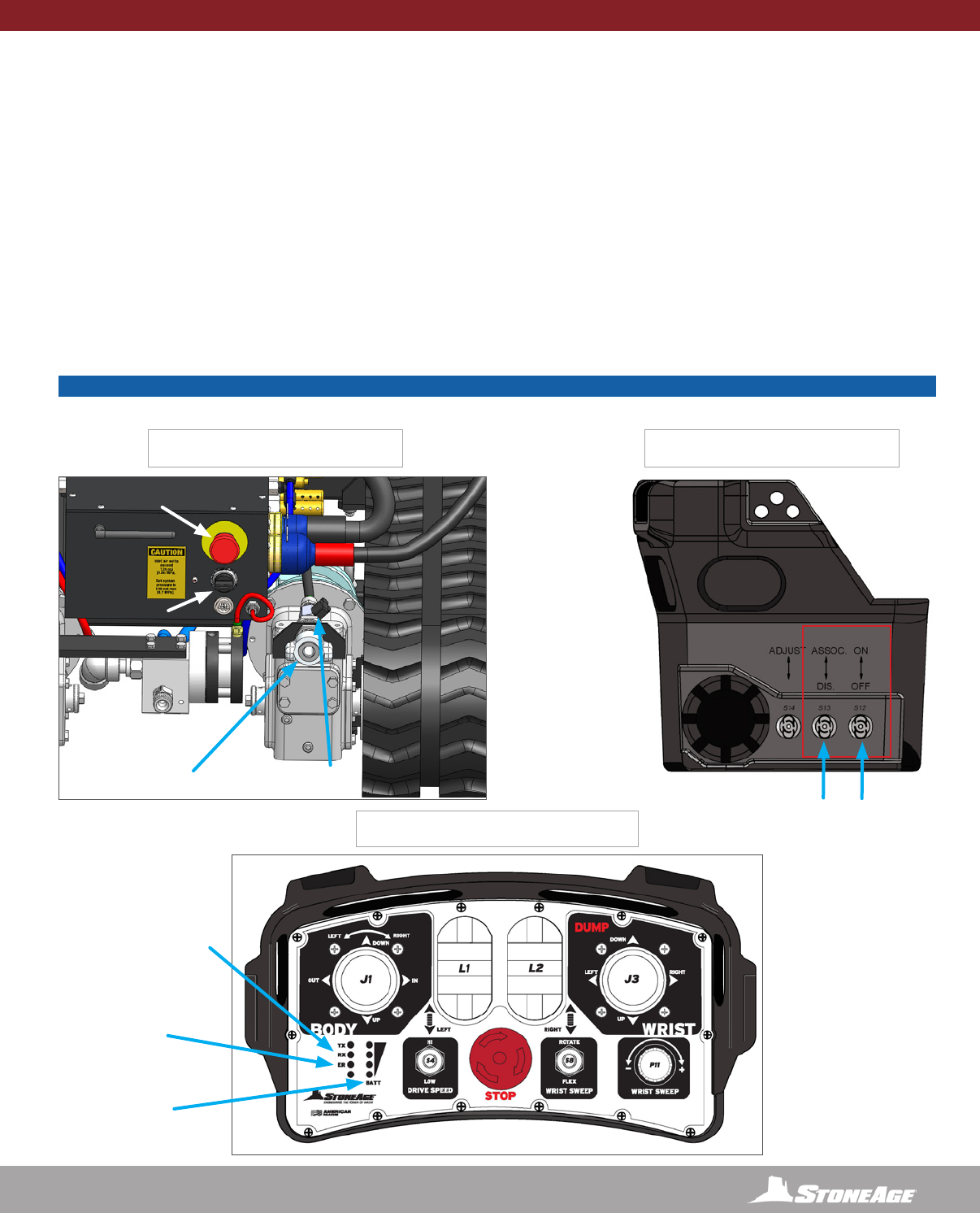
REMOTE CONTROL CONSOLE
REMOTE CONTROL LEFT SIDE VIEW
WIRELESS RECEIVER UNIT ON
TRACKED STRIKER
ASSOCIATING REMOTE CONTROL TO RECEIVER UNIT
The REMOTE CONTROL must be “associated” or linked to the RECEIVER UNIT on the TRACKED STRIKER before the system can be used.
Follow the steps below to properly associate the wireless control system.
STEP 1: Turn air on; conrm 100 psi on FRL.
STEP 2: Engage E-Stop (press in) on tumble box; release E-stop on control box.
STEP 3: Switch on tumble box; wait for system to charge (noise stops); release E-Stop on tumble box (green LED will light).
STEP 4: Place control box on tumble box or hold level. Ensure Wrist Sweep is turned fully counterclockwise.
STEP 5: With the E-Stop released, hold switches on left side of control box up, to ASSOC and ON positions; do not release.
STEP 6: Wait for TX LED to blink on control box while continuing to hold switches on.
NOTE: If LEDs are blinking randomly check controls on control box to ensure they are in the neutral position.
STEP 7: While continuing to hold switches and TX LED is blinking, push and release E-Stop on tumble box.
STEP 8: Release switches on left side of control box.
STEP 9: Wait a few moments for TX and RX LED to start blinking; control box is now associated with tumble box
WIRELESS CONTROL SYSTEM- ASSOCIATING REMOTE CONTROL TO RECEIVER UNIT
CHICAGO AIR
FITTING
ASSOCIATE ON/OFF
AIR CONTROL VALVE
IN THE “ON” POSITION
TX AND RX LEDs
(TRANSMIT AND RECEIVE)
ER LED
(ERROR)
BATT
(BATTERY
LIFE LEVEL)
EMERGENCY
STOP
OFF/ON
NOTICE
If the ER LED ashes, go through the association steps again. If there is a connection issue after, call StoneAge Tools for technical assistance.
48 866-795-1586 • WWW.STONEAGETOOLS.COM
WIRELESS REMOTE CONTROLLER- TETHERED CONNECTION
OPERATION
TEST RUN PROCEDURE
• Perform the PRE-RUN SAFETY CHECK SEE PAGE 8.
• Test the Control Box before operating the TRACKED STRIKER with high-pressure water to verify the control valves move the Horizontal and
Vertical Rail Assemblies in their intended directions, and the DUMP CONTROL is working properly. Ensure that the High Pressure Water
System cannot be energized while making adjustments.
• Operate the Track drive with both high and low speed selection.
• Operate the in/out, up/down and rotation functions on the body and the rotate and ex functions on the Wrist, to begin high pressure cleaning
at the preferred location.
• Operate the high-pressure water at full pressure and use the DUMP CONTROL to verify that the dump valve is working properly.
• Operate the high-pressure system and waterjet tool at full pressure to test the Speed and Resistance settings on the Wrist. Properly setting up
the Wrist will provide good control of the BC-K 20KPSI BARRACUDA tool in Rotation and Flex directions. Detailed adjustment instructions
can be found within this manual in both the SKR-STD and SKR-TRK “SET-UP”sections under “WRIST SPEED AND RESISTANCE ADJUST-
MENTS.
• Test the emergency stop, verifying that it shuts off the system and activates the high pressure dump valve.
• The TRACKED STRIKER has been engineered to stay in position with a maximum reaction force of 100 lbs. The TRACKED STRIKER
may slide on smooth, oily, or slippery surfaces during operation. Anchoring the TRACKED STRIKER to the oor will aid in keeping the
unit in position. The anchoring method MUST be capable of withstanding a minimum of 100 lbs of reaction force from the TRACKED
STRIKER. Operate the high-pressure hose and waterjet tool at full pressure to test the anchoring method.
• Verify that the work environment has been properly marked off and it is a safe environment to operate within. Refer to the WJTA Recommended
Practices and page 7 and 8 of this manual for more safety information.
• The TRACKED STRIKER MUST be supervised at all times.
WARNING
Crush Hazard. Keep hands, hair, and clothing, clear of Carriage Rollers, Wrist joints, Spline Hub, and out of all travel limit zones. Contact
with moving parts can result in severe injury.
HIGH-PRESSURE HOSE
• The TRACKED STRIKER is designed to be used with a 12ft (3658 mm) SPIR STAR® HP 8mm Hose and SPIR STAR® standard 9/16”-18
Medium Pressure 8-4 male end at the BC-K 20KPSI BARRACUDA and a SPIR STAR® 3/4”-16 Type M Swivel Female End at the coupler on
the STRIKER assembly.
• Only high quality hoses intended for waterblast applications should be used as high-pressure hoses. Pressure rating of high-pressure hoses
MUST NEVER be exceeded.
• Verify that the high-pressure hose is properly installed through the Carriage Assembly.
TETHERED CONNECTION FOR WIRELESS
REMOTE CONTROLLER
The TRACKED STRIKER can be connect to the
WIRELESS RECEIVER BOX with a tether if wireless
signal is not permitted. There is a port on the right
side of the WIRELESS REMOTE CONTROLLER.
Remove the dust cap and connect the tether to this
port and the other side to the port on the WIRELESS
RECEIVER BOX.
TETHER CABLE
26 FT (7925 mm)
49
866-795-1586 • WWW.STONEAGETOOLS.COM
OPERATION
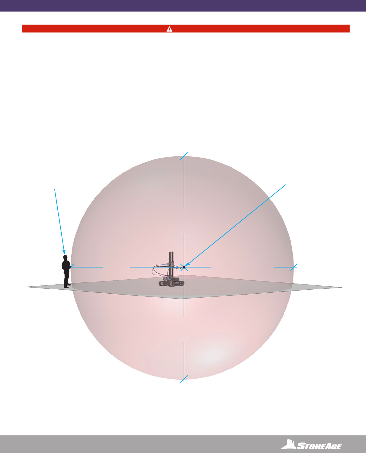
DANGER
STAY BEHIND THE VERTICAL RAIL ASSEMBLY AND OUT OF THE SPRAY ZONE WHEN OPERATING THE TRACKED STRIKER.
Failure to do so will result in death or serious injury.
Operators MUST read and follow, Pre-Operating Procedures (Section 9.0) of WJTA-IMCA’s Best Practices For The Use Of High-pressure
Water jetting Equipment, or equivalent.
StoneAge also recommends following the ACH Waterjet Technology (France) (Section 7.6):
7.6. Layout (workstation)
Distances:
The boundary must be at least 6 meters from the nozzle or (where the water exits the tool). This distance determination is also valid for any
upper or lower oors. The determination of the distance must therefore be three-dimensional.
DANGER ZONE
20FT (6M)
MINIMUM
20FT (6M)
MINIMUM
20FT (6M)
MINIMUM
STONEAGE DOES NOT
RECOMMEND STANDING
IN FRONT OF THE BLAST
ZONE AT ANY DISTANCE
AT STONEAGE,
WE STAND BEHIND
OUR TOOLS
WHERE WATER
EXITS THE TOOL
HEAD

50 866-795-1586 • WWW.STONEAGETOOLS.COM
When storing the TRACKED STRIKER® (SKR-TRK), use compressed air to blow out the air lines to remove debris and moisture. Use
mild soapy water to clean the machine in order to remove corrosive materials. DO NOT USE HIGH PRESSURE WATER TO CLEAN THE
MACHINE. Follow the “After each use” instructions in the maintenance chart above.
SKR-TRK MAINTENANCE
STORAGE, TRANSPORTATION, AND HANDLING
MAINTENANCE
Maintenance Item Frequency Maintenance Required
All Air Fittings After each use Reinstall all dust caps to protect from dirt and moisture.
Carriage rollers Every 100 Hours of use Lubricate Zerks on all Carriage Rollers using any multipurpose
NLGI 2 grease.
Gearbox oil level Every 100 Hours of use Fill with Mobil® and SCH™ 634 synthetic gear oil. See individual
part diagram pages for gearbox ll orientations.
Lubricator by the Tumblebox Before each use • Add a quality air tool oil when uid drops below minimum level
marking.
• Check Drip Rate
• Empty Water
Tumblebox After each use Disconnect umbilical hose with air supply connected and run
each function to purge any collected water from the system. Be
careful to protect the umbilical o-rings
Tumblebox Every 6 months or after opening box for
service.
Inspect, Clean, and, lubricate the gasket on the Tumblebox.
StoneAge recommends using Molykote 111 or equivalent.
Vertical and Horizontal Rails As Needed Inspect for wear that would allow Carriage Rollers to slip off.
Replace Rail as needed.
Waterblast Tool After each use Remove tool, lubricate and store in clean container.
Wireless Controller When battery indicator light is blinking Replace 2 C Cell alkaline batteries
Wireless Receiver Every 600 hours
Every 200-300 hours in humidity
Replace desiccant pack inside the receiver box
Contact StoneAge for Safety Data Sheets for material usage, a complete list of spare part numbers, and service instructions for the
TRACKED STRIKER® (SKR-TRK) and Wireless Remote Controller.

51
866-795-1586 • WWW.STONEAGETOOLS.COM
TROUBLESHOOTING
Problem Solution
No air is delivered to tool • Check that shut-off valve near the air supply connection is open
• Check that regulator is set to 110 psi
Tool is not rotating • Make sure tool is cleaned and serviced per the specications within the respective
tool manual
Tool is not cleaning effectively • Check rotation speed, the tool may be spinning too fast or too slow
Wireless Remote Controller is not working
moving the Striker
• Make certain all controls are set at “0”, or the neutral positions when associating the
controller to the receiver box.
• Check the antenna on the tumblebox for proper connection and no visible damage.
• Replace batteries (2 C Cell alkaline Batteries) in the wireless remote controller even if
showing a charge.
• Re-associate Wireless Remote Controller to the receiver
Wireless Remote Controller lights are not on • Replace batteries (2 C Cell alkaline Batteries) re-associate the wireless remote
controller to the wireless receiver.
• Ensure that the E-Stop is not activated.
Striker is not moving in any direction but has
air ow
• Check batteries in the wireless remote controller. Replace if necessary and re-
associate the wireless remote controller to the wireless receiver.
• Check air connections to the motors on the Carriage Assembly
• Check the air connections to the main motor on the gearbox assembly
Striker is not moving in one direction but has
air ow
• Check for a nonfunctional valve in the wireless receiver box. Nonfunctional valves will
have blinking lights. Go to the “Part Diagram” section in the back of this manual for
part numbers and replacement instructions
SKR-TRK TROUBLESHOOTING
This page is intentionally left blank.

52 866-795-1586 • WWW.STONEAGETOOLS.COM
STRIKER® (SKR 109)
CART BASE ASSEMBLY
#PART NUMBER QTY.
1GB 550-11 BOLT, HEX .50-13 X 2.75 4
2GB 550-10 BOLT, HEX .50-13 X 2.50 4
3GN 550-H HEX NUT 4
4GN 550-L NYLOK NUT 8
5GN 562-H HEX NUT 2
6GSF 337-03 FHCS .37-16 X .75 LG SS 2
7GW 550-F FLAT WASHER 4
8SKR 110 CART 1
9SKR 130 AXLE FRAME WELDMENT 1
10 SKR 140 WHEELIE BAR WELDMENT 1
11 SKR 150 GEAR LINK WELDMENT 2
12 SKR 160 FWD OUTRIGGER WELDMENT 2
13 SKR 170 AFT OUTRIGGER WELDMENT 2
14 SKR 185 HANDLE 1
15 SKR 305 WHEEL 10.0 2
16 SKR 312 WASHER .750 4
17 SKR 330 FOOT, OUTRIGGER 4
18 SKR 331-001 STUD .5 X 2.5 4
19 SKR 335 QR PIN, T-HANDLE .50 X 2.25 4
PARTS DIAGRAM
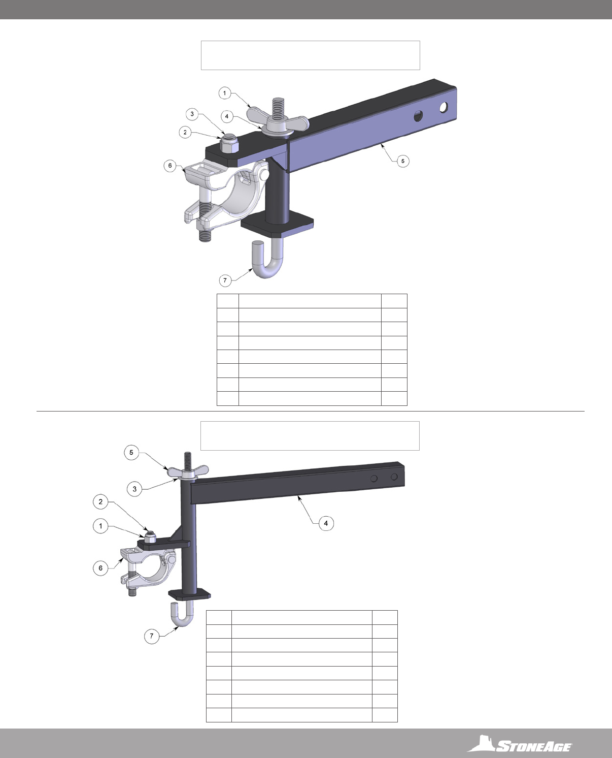
53
866-795-1586 • WWW.STONEAGETOOLS.COM
STRIKER® (SKR 501)
FORWARD DOWNRIGGER ASSEMBLY
STRIKER® (SKR 502)
AFT DOWNRIGGER ASSEMBLY
#PART NUMBER QTY.
1GN 550-L NYLOK NUT 1
2GSF 550-06 FHCS .50-13 X 1.50 LG Z 1
3GW 550-F FLAT WASHER 1
4SKR 502.1 AFT DOWNRIGGER WELDMENT 1
5SKR 509 WING NUT 1
6SKR 510 SCAFFOLD CLAMP ASSY 1
7SKR 512 J BOLT REAR 1
#PART NUMBER QTY.
1SKR 509 WING NUT 1
2GN 550-L NYLOK NUT 1
3GSF 550-06 FHCS .50-13 X 1.50 LG Z 1
4GW 550-F FLAT WASHER 1
5SKR 501.1 FWD DOWNRIGGER WELDMENT 1
6SKR 510 SCAFFOLD CLAMP ASSY 1
7SKR 511 J BOLT FRONT MODIFIED 1
PARTS DIAGRAM PARTS DIAGRAM
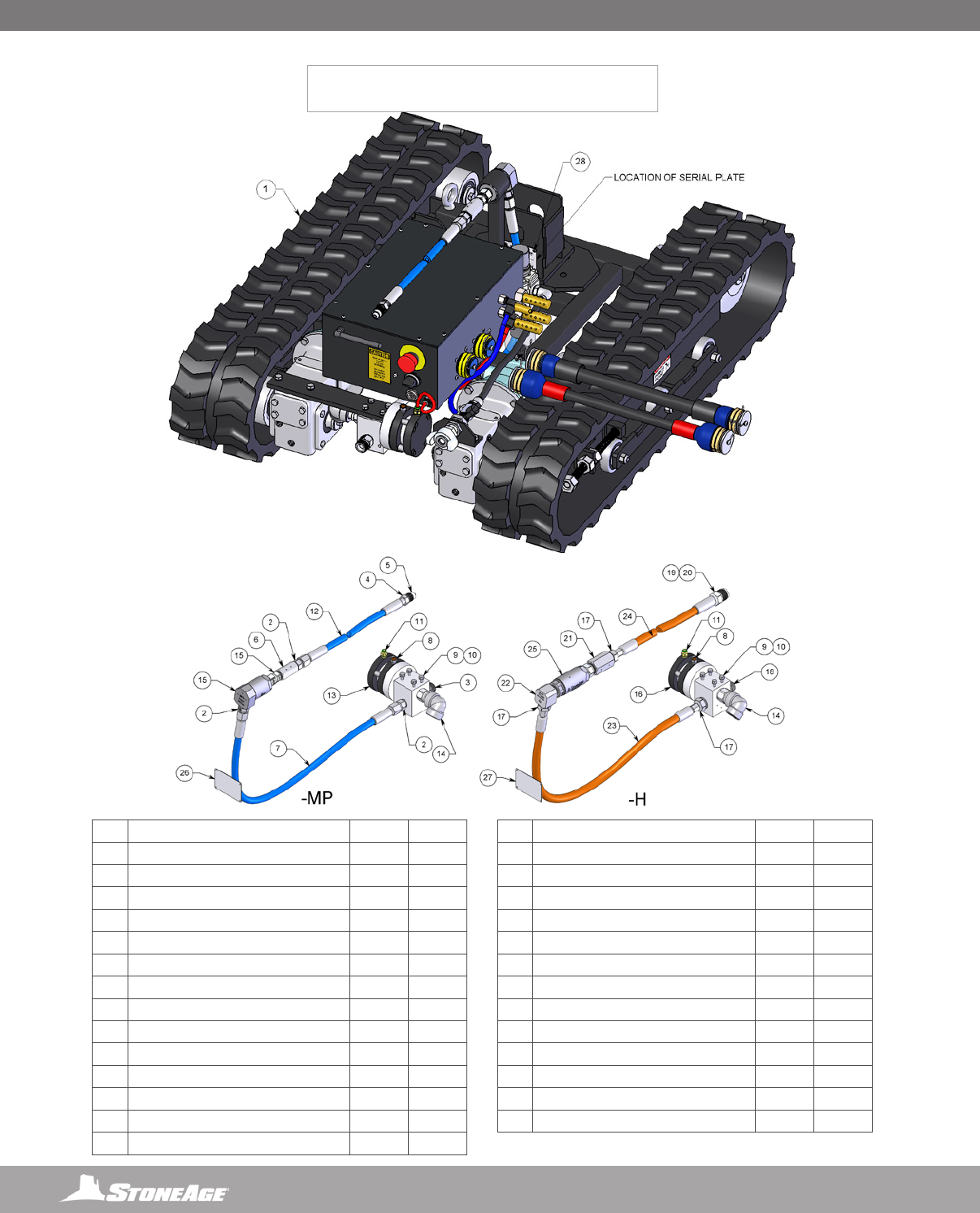
54 866-795-1586 • WWW.STONEAGETOOLS.COM
STRIKER® (SKR 800-XX)
TRACKED BASE ASSEMBLY
#PART NUMBER -MP QTY. -H QTY.
1SKR 800.1 TRACK BASE 1 1
2AF 061-MP9 ADAPTER .75 TYPE M TO MP9 3 -
3AF 063-MP9 ADAPTER 1.00 TYPE M TO MP9 1 -
4AF 070-MP9 GLAND 1 -
5AF 071-MP9 COLLAR .56 MP 1 -
6AF 073-MP9 COUPLER 1 -
7BRLM 268-003 HP HOSE 8-4 31IN OAL 1 -
8DB 026 MUFFLER .250 NPT, DUMP VALVE 1 1
9GB 525-03 BOLT, HEX .25-20 X .75 4 4
10 GW 525-L LOCK WASHER 4 4
11 SM 309 FITTING, BUSHING P4M PL4 1 1
12 SKR 822 HP HOSE 8-4 12FT OAL 1 -
13 SKR 823 DUMP VALVE 20K 1 -
14 SKR 824 DUMP ELBOW 1 1
15 SL-MP9AV9-90 SWIVEL 1 -
16 ACDU 610400072 DUMP VALVE 40K - 1
17 AF 060-H9 ADAPTER .56 TYPE M TO H9 - 3
18 AF 062-H9 ADAPTER .88 TYPE M TO H9 - 1
19 AF 071-H9 COLLAR - 1
20 AF 072-H9 GLAND ASSY, ANTIVIBE - 1
21 AF 073-H9 COUPLING - 1
22 SA 050-H9H9-90 ELBOW - 1
23 SKR 831 HP HOSE 6UHP 31IN OAL - 1
24 SKR 832 HP HOSE 6UHP 12FT OAL - 1
25 UHS-H9H9 ASSY - 1
26 SKR 803-MP9 SERIAL PLATE 1 -
27 SKR 803-H9 SERIAL PLATE - 1
28 GSB 313-0075 BHCS 6-32 X .188 LG SS 4 4
20K MEDIUM
PRESSURE
40K HIGH
PRESSURE
PARTS DIAGRAM
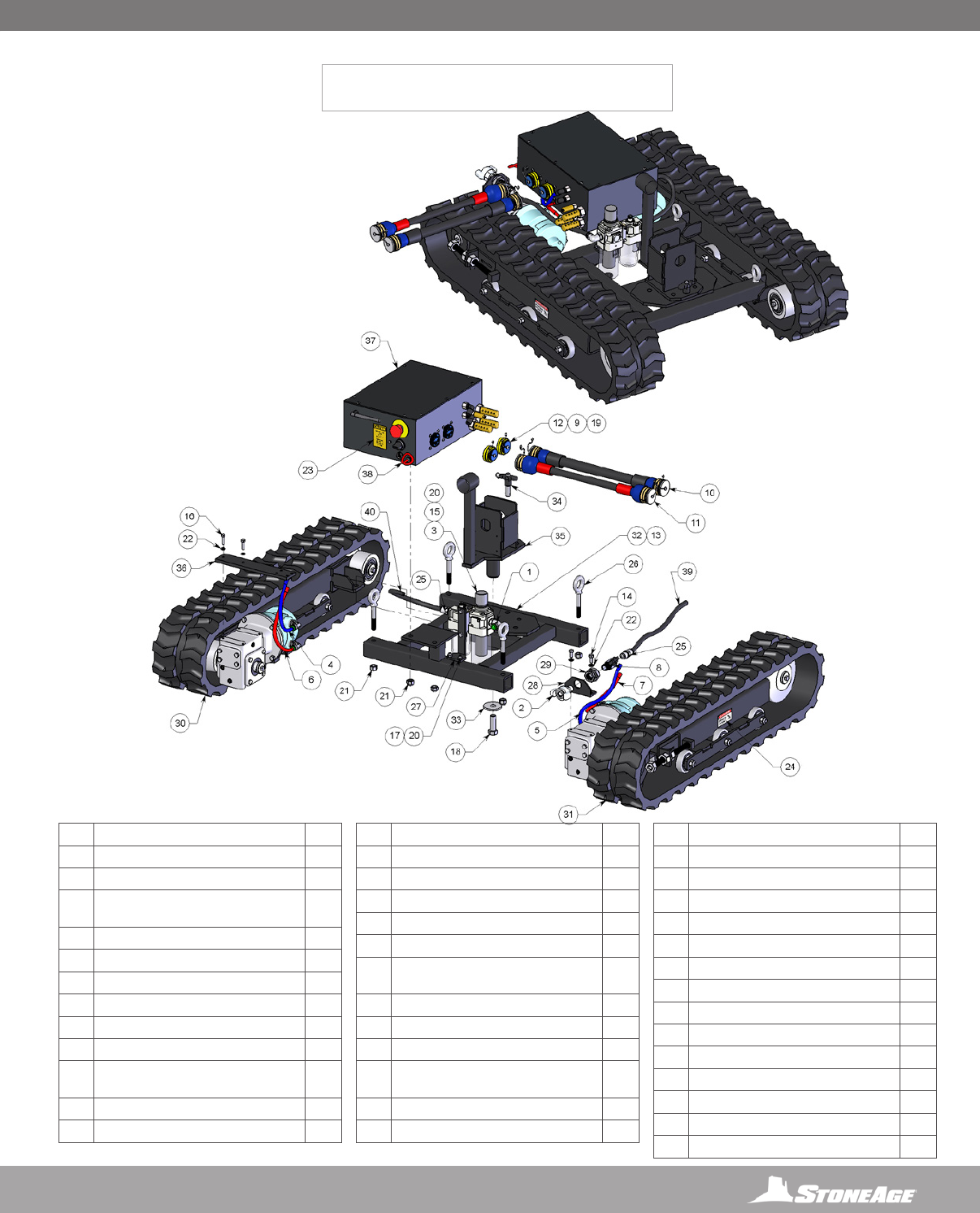
55
866-795-1586 • WWW.STONEAGETOOLS.COM
STRIKER® (SKR 800.1)
TRACKED BASE ASSEMBLY
#PART NUMBER QTY.
1BUD 142 FITTING 90° SWIVEL P8MPL8 1
2CB 114 INLET FITTING 1
3CB 312 GEN3 FILTER-REGULATOR-
LUBRICATOR WITH GEN2 CLAMP
1
4CB 359-B TUBING 1, .38 BLUE 1
5CB 359-B TUBING 2, .38 BLUE 1
6CB 359-R TUBING 1, .38 RED 1
7CB 359-R TUBING 2, .38 RED 1
8CB 393 P8 BALL VALVE 1
9CB 429 LANYARD ASSY UMBILICAL 2
10 CB 450-50 UMBILICAL 4PL4 2PL6 50
INCH
1
11 CB 451-100 UMBILICAL 4PL4 100 INCH 1
12 CB 461 SEALED SOCKET COVER 2
13 FS 004-0 ZERK, STRAIGHT 1
14 GB 531-03 BOLT, HEX .31-18 X .75 4
15 GB 531-035 BOLT, HEX .31-18 X .88 2
16 GB 531-04 BOLT, HEX .31-18 X 1.00 2
17 GB 531-11 BOLT, HEX .31-18 X 2.75 2
18 GB 562-04 BOLT, HEX .62-11 X 1.00 1
19 GMS 319-015-32 PHMS .19-32X.38 LG
PH-SS
2
20 GN 531-L NYLOK NUT 4
21 GN 550-L NYLOK NUT 4
22 GW 531-L LOCK WASHER 6
23 PL 156-125 CAUTION INLET AIR, 125PSI
MAX
1
24 PL 160 PINCH POINT 1.5X3.0 DECAL 2
25 SBT 362 FTG P8MPL8 BUSHING 2
26 SKR 806 LIFTING EYE 4
27 SKR 811 FRL BRACKET WELDMENT 1
28 SKR 812 INLET BRACKET 1
29 SKR 814 FTG, P8P8 BULKHEAD 1
30 SKR 833 LEFT TRACK ASSY 1
31 SKR 843 RIGHT TRACK ASSY 1
32 SKR 870 CHASSIS WELDMENT 1
33 SKR 872 WASHER, PIVOT 1
34 SKR 873 QUICK RELEASE PIN 1
35 SKR 874 PIVOT BASE 1
36 SKR 879 DUMP MOUNT BRACKET 1
37 SKR 880 CERVIS BOX FULL ASSEMBLY 1
38 SKR TUBE 1 .250 1
39 SKR TUBE 1 .500 1
40 SKR TUBE 2 .500 1
PARTS DIAGRAM PARTS DIAGRAM
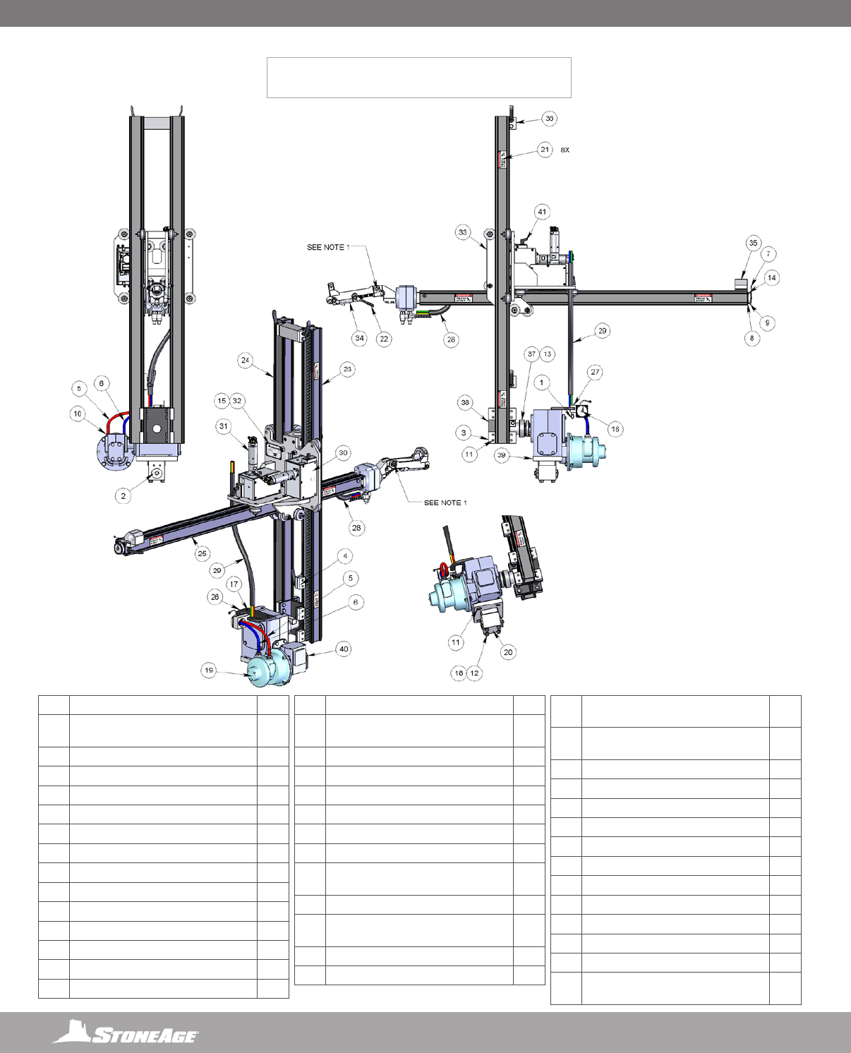
56 866-795-1586 • WWW.STONEAGETOOLS.COM
STRIKER® (SKR 100)
UPPER ASSEMBLY
#PART NUMBER QTY.
1ABX 566 SPRING PLUNGER, PULL RING
LOCKING
1
2BR 008-BU-001 WEDGE BOLT 1
3BR 060 RAIL CLAMP 8
4BU 152 RAIL STOP ASSY 1
5CB 359-R TUBING, .38 RED 1
6CB 359-B TUBING, .38 BLUE 1
7CB 430 LANYARD ASSY BOX 2
8CB 452.2 FTG TWINTEC SOCKET 2
9CB 459 SOCKET COVER 2
10 DB 072 FITTING PUSH CONNECT 2
11 GB 537-04 BOLT, HEX .37-16 X 1.00 24
12 GB 537-16 BOLT, HEX .37-16 X 4.00 4
13 GK 250-250-1000-SE KEY (SG 072) 1
14 GS 316-015 SHCS .16-32 X .38 SS 8
15 GSB 313-0075 BHCS 6-32 X .188 LG SS 4
16 GMS 319-015-32 PHMS .19-32X.38 LG
PH-SS
2
17 GSF 337-04 FHCS .37-16 X 1.00 LG SS 2
18 GW 537-L LOCK WASHER 8
19 LM 016-6 AIR MOTOR 1
20 LP 095-001 CORNER POST 1
21 PL 160 PINCH POINT 1.5X3.0 DECAL 8
22 SBT 511.1 SPIRAL WRAP, .375 3
23 SKR 180-56 BOX RAIL, 2.5 SLOTTED,
56IN VT
1
24 SKR 181-56 BOX RAIL, 2.5, 56IN VT 1
25 SKR 182-56 BOX RAIL, 2.5 DUAL SLOTTED,
56IN HZ
1
26 SKR 186 GBX HANDLE 1
27 SKR 188 QD HANGER 1
28 SKR 189-6.17 TUBE BUNDLE, 4PL4 74IN
WRIST
1
29 SKR 189-5.75 TUBE BUNDLE, 4PL4 69IN
BODY
1
30 SKR 203-L MOTOVARIO DRIVE ASSY 1
31 SKR 203-R MOTOVARIO DRIVE ASSY 1
32 SKR 204 CE SERIAL PLATE 1
33 SKR 210 RIBBED CARRIAGE ASSEMBLY 1
34 SKR 230 3 PIECE PALM 1
35 SKR 250 REAR STOP W HOSE GUIDE 1
36 SKR 260 TIE STOP ASSEMBLY 1
37 SKR 270 SPLINE HUB WELDMENT 1
38 SKR 280 RAIL CLAMP BASE WELDMENT 1
39 SKR 290 GBX MOUNT PLATE 1
40 SKR 302 GEARBOX MODIFIED 1
41 SRT 557 ADJUSTABLE HANDLE .25-20 X
1.19 SS
2
NOTE:
1. TIGHTEN NOTED BOLT OF SKR 230 UNTIL THE END
OF THE SAME ASSEMBLY PROVIDES 10-12LB OF
RESISTANCE TO DOWNWARD PULL WHEN CYLINDER
IS EXTENDED.
PARTS DIAGRAM
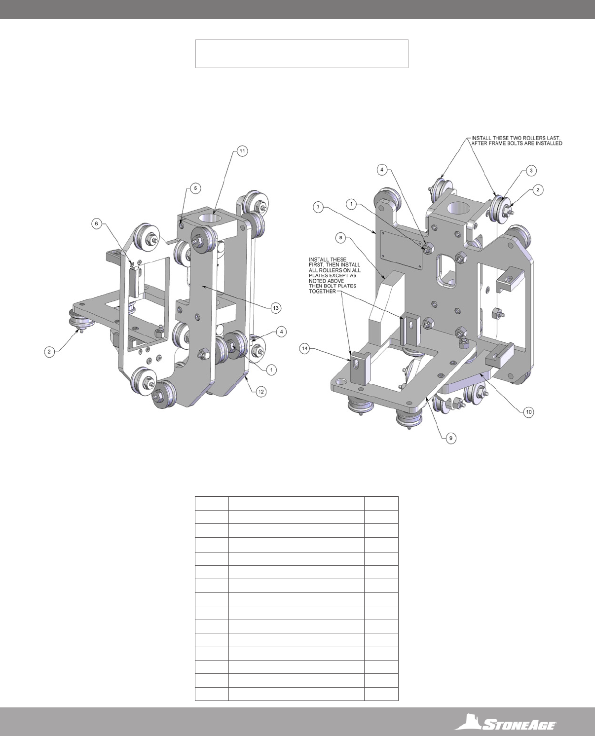
57
866-795-1586 • WWW.STONEAGETOOLS.COM
STRIKER® (SKR 210)
CARRIAGE ASSEMBLY
#PART NUMBER QTY.
1BR 051-2.0-0 AXLE-ZERK 10
2BR 052-1.5 AXLE-ZERK 10
3BR 055 ROLLER ASSY 20
4GN 350-H HEX NUT SS 10
5GS 331-03 SHCS .31-18 X .75 SS 22
6GS 325-03 SHCS .25-20 X .75 SS (TB 050) 8
7SKR 211 VERTICAL FLAT PLATE 1
8SKR 212 CORNER BRACKET 1
9SKR 213 HORIZONTAL CARRIAGE PLATE 1
10 SKR 214 CORNER BONE 1
11 SKR 215 TOP CROSS BLOCK 2
12 SKR 216 LH VERTICAL PLATE 1
13 SKR 217 RH VERTICAL PLATE 1
14 SRT 546 HANDLE MOUNT BLOCK 4
PARTS DIAGRAM PARTS DIAGRAM
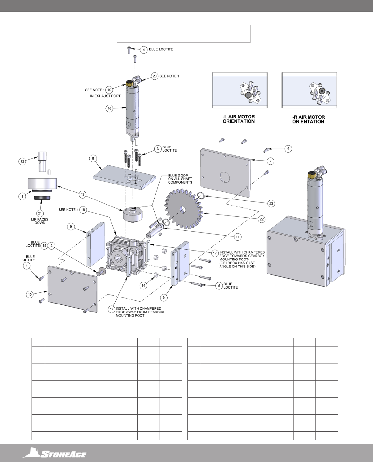
58 866-795-1586 • WWW.STONEAGETOOLS.COM
STRIKER® (SKR 203-X)
MOTOVARIO DRIVE ASSEMBLY, -R OR -L
NOTE:
1. USE THREAD SEALANT ON ALL TAPERED PIPE FITTINGS.
2. BLUE LOCTITE: PN: 243 OR EQUIVALENT
3. BLUE GOOP IS A SWAGELOK BRAND ANTI-SEIZE. AN EQUIVALENT ALTERNATIVE IS
ACCEPTABLE.
4. REMOVE MOUNTING FLANGE THAT COMES WITH GEARBOX. KEEP INPUT SHAFT
FACING UP TO PREVENT OIL LEAKAGE.
#PART NUMBER -L/QTY. -R/QTY.
1DB 169 O-RING, PISTON 1 1
2GB 325-03 BOLT, HEX .25-20 X .75 SS 1 1
3GS 3M6-30-1.0 SHCS M6X1.0 X 30 SS 4 4
4GS 319-025 SHCS .19-24 X .62 SS 12 12
5GS 319-045 SHCS .19-24 X 1.125 SS 4 4
6LWP 504 TOP MOTOR MOUNT PLATE 1 1
7LWP 505 GEAR COVER 1 1
8LWP 506 HANDLE SIDE MOUNTING PLATE 1 1
9LWP 507 IDLE SIDE MOUNTING PLATE 1 1
10 LWP 508 REAR COVER 1 1
11 LWP 509 MOTOVARIO SHAFT 1 1
12 LWP 510-001 STEP SHAFT 1 1
13 LWP 511 TOP GEARBOX SPACER 1 1
14 LWP 515 SPACER 4 4
15 LWP 516 WASHER, OVERSIZED 1 1
16 LWP 520-001 AIR MOTOR 1 1
17 LWP 542 NUT PLATE 2 2
18 LWP 550 MOTOVARIO NMRV030301600_625IN 1 1
19 LWP 557 EXHAUST PROTECTOR, P2M 1 1
20 SKR 382 FTG, ELBOW SWIVEL 90 P2MPL4 2 2
21 SL 010 SEAL 1 1
22 SRT 520 SPUR GEAR SS (6 DP, 14.5 PA, 26 T) 1 1
23 SRT 537 RETAINING RING, SS EXTERNAL 2 2
PARTS DIAGRAM
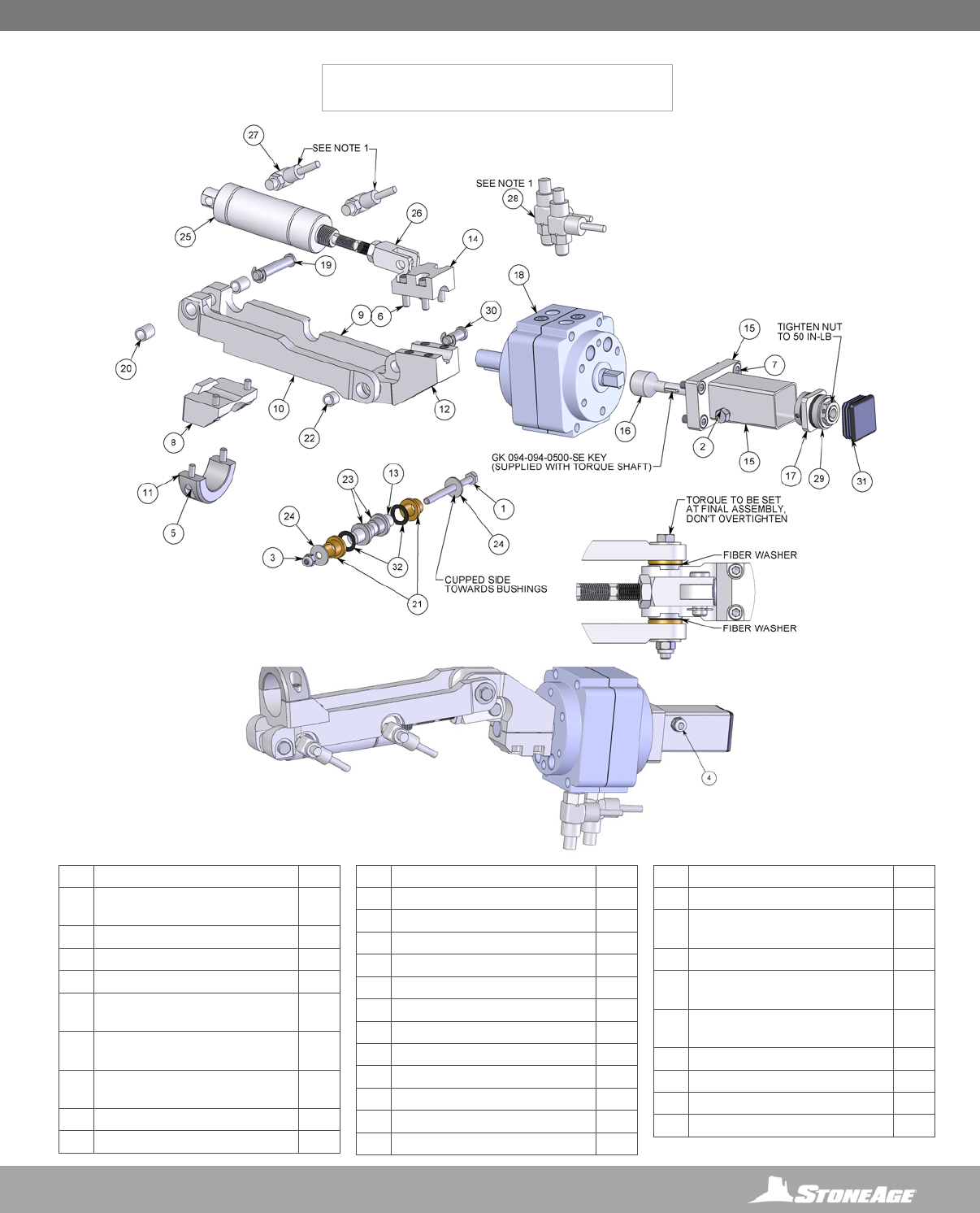
59
866-795-1586 • WWW.STONEAGETOOLS.COM
STRIKER® (SKR 230)
3 PIECE WRIST ASSEMBLY
#PART NUMBER QTY.
1GB 325-12 BOLT, HEX .25-20 X 3.00 SS
(HC 024)
1
2GB 331-09 BOLT, HEX .31-18 X 2.25 SS 1
3GN 325-L NYLOK NUT SS (TB 044.1) 1
4GN 331-L NYLOK NUT SS 1
5GS 325-03 SHCS .25-20 X .75 SS (TB
050)
4
6GS 325-04 SHCS .25-20 X 1.00 SS (BC
053)
4
7GS 3M8-16-1.25 SHCS M8X1.25 X 16
SS
4
8SKR 231 TOOL HOLDER BC 1
9SKR 232 ULNA FORK 1
10 SKR 233 RADIUS FORK 1
11 SKR 235 COLLAR UPPER HALF 1
12 SKR 237 PALM 1
13 SKR 238 WRIST BONE 1
14 SKR 240 SQUARE COLLAR HALF 1
15 SKR 241 END ROTARY MOUNT 1
16 SKR 242 TORQUE SHAFT W KEY 1
17 SKR 245 TORQUE PLATE 1
18 SKR 301 ROTARY AIR CYLINDER 1
19 SKR 340 PIN .375 X 2.25 1
20 SKR 341 BUSHING .375 X .625 2
21 SKR 342 BUSHING, FLANGE SOFT .5 X .5 2
22 SKR 343 BUSHING .375 X .375 1
23 SKR 344 BUSHING, FLANGE .5 X .5 2
24 SKR 345 WASHER, SPRING .265 X .812 2
25 SKR 350 AIR CYLINDER 1.5 DIA 1.5
STROKE
1
26 SKR 351 ROD END 1.5 CYL 1
27 SKR 355 FTG, BIMBA P2 PUSHLOCK
NEEDLE VALVE
2
28 SKR 356 FTG, BIMBA P4 PUSHLOCK
NEEDLE VALVE
2
29 SKR 360 FRICTION TORQUE LIMITER 1
30 SKR 365 CLEVIS .375 X .8125 1
31 SKR 366 RIBBED PLUG 1
32 SKR 370 FIBER WASHER 2
NOTE:
1. SET EACH NEEDLE VALVE TO 2 TURNS FROM CLOSED. TIGHTENING THE
ADJUSTMENT SCREW CLOSES THE VALVE.
2. APPLY BLUE GOOP TO ALL THREADS OF STAINLESS STEEL FASTENERS
3 APPLY ANTI-SEIZE TO SHAFTS AND KEYS
PARTS DIAGRAM PARTS DIAGRAM
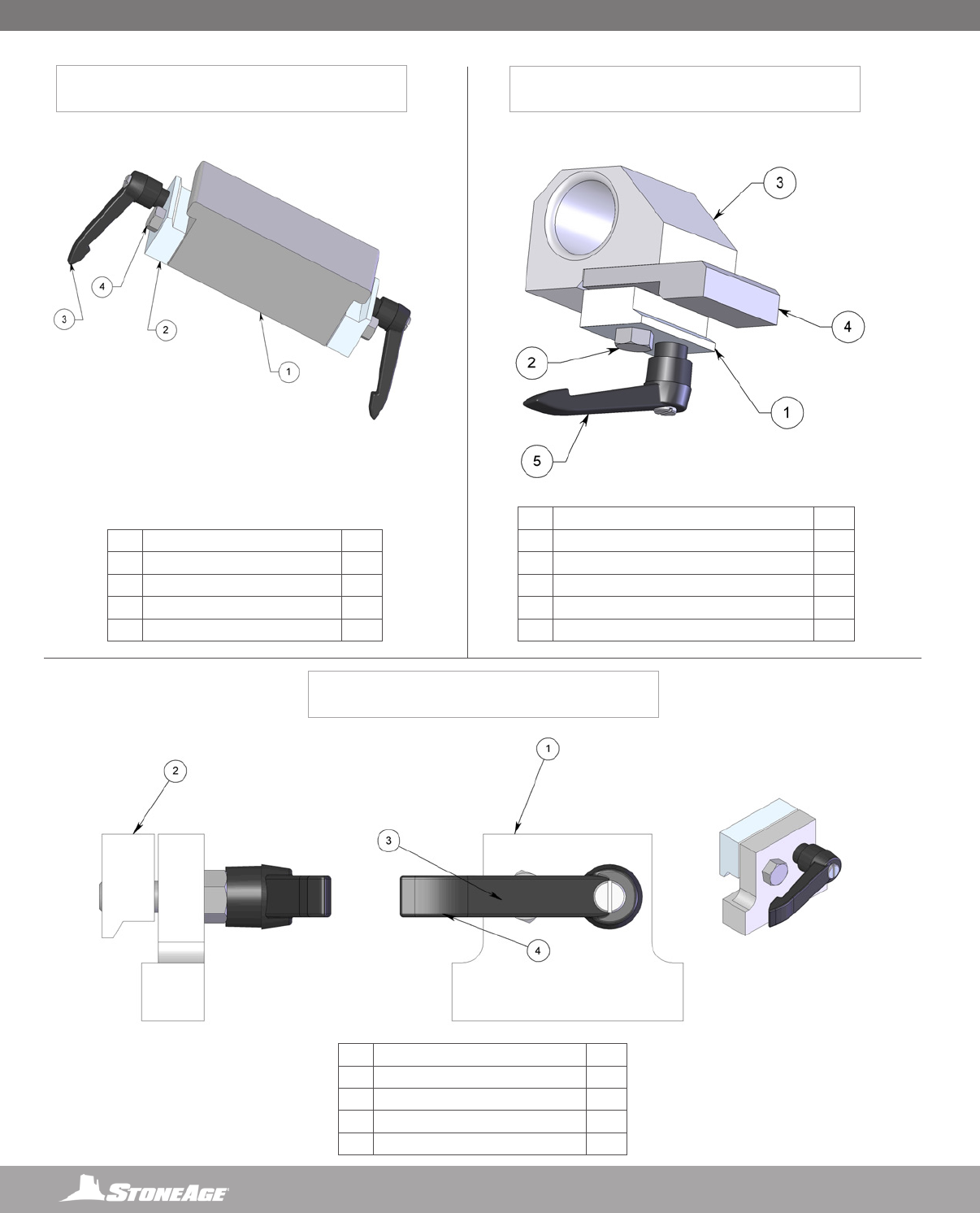
60 866-795-1586 • WWW.STONEAGETOOLS.COM
STRIKER® (SKR 260)
TIE STOP ASSEMBLY
STRIKER® (BU 152)
RAIL STOP ASSEMBLY
# PART NUMBER QTY.
1 SKR 261 TIE STOP 1
2 BR 060-D RAIL CLAMP, DRILLED 2
3 BU 151 HANDLE 2
4 GB 537-05 BOLT, HEX .37-16 X 1.25 2
# PART NUMBER QTY.
1 BU 149 PLATE, RAIL STOP 1
2 BR 060 RAIL CLAMP 1
3 GB 537-05 BOLT, HEX .37-16 X 1.25 1
4 BU 151 HANDLE 1
STRIKER® (SKR 250)
REAR STOP WITH HOSE GUIDE ASSEMBLY
# PART NUMBER QTY.
1 BR 060-D RAIL CLAMP, DRILLED 1
2 GB 537-06 BOLT, HEX .37-16 X 1.50 1
3 SKR 251 REAR STOP 1
4 SKR 252 HOSE BRACKET SPACER PLATE 1
5 SKR 253 HANDLE 1
PARTS DIAGRAM
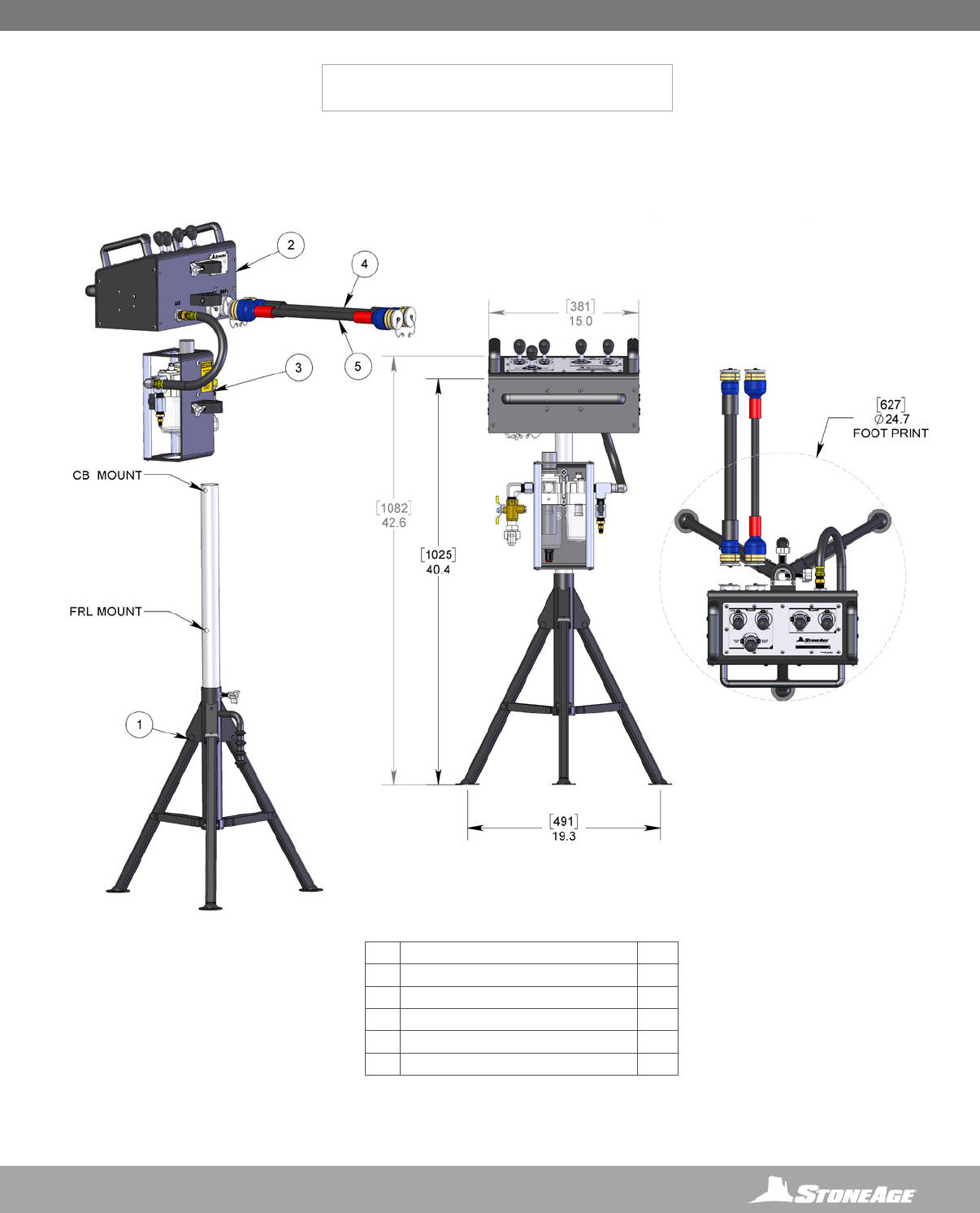
61
866-795-1586 • WWW.STONEAGETOOLS.COM
STRIKER® (CB-SKR)
CONTROL BOX
# PART NUMBER QTY.
1 CB 301 CB STAND ASSEMBLY 1
2 CB 400 CONTROL BOX ASSY 1
3 CB 403 FRL ASSY 1
4 CB 450 UMBILICAL 4PL4 2PL6 1
5 CB 451 UMBILICAL 4PL4 1
PARTS DIAGRAM PARTS DIAGRAM
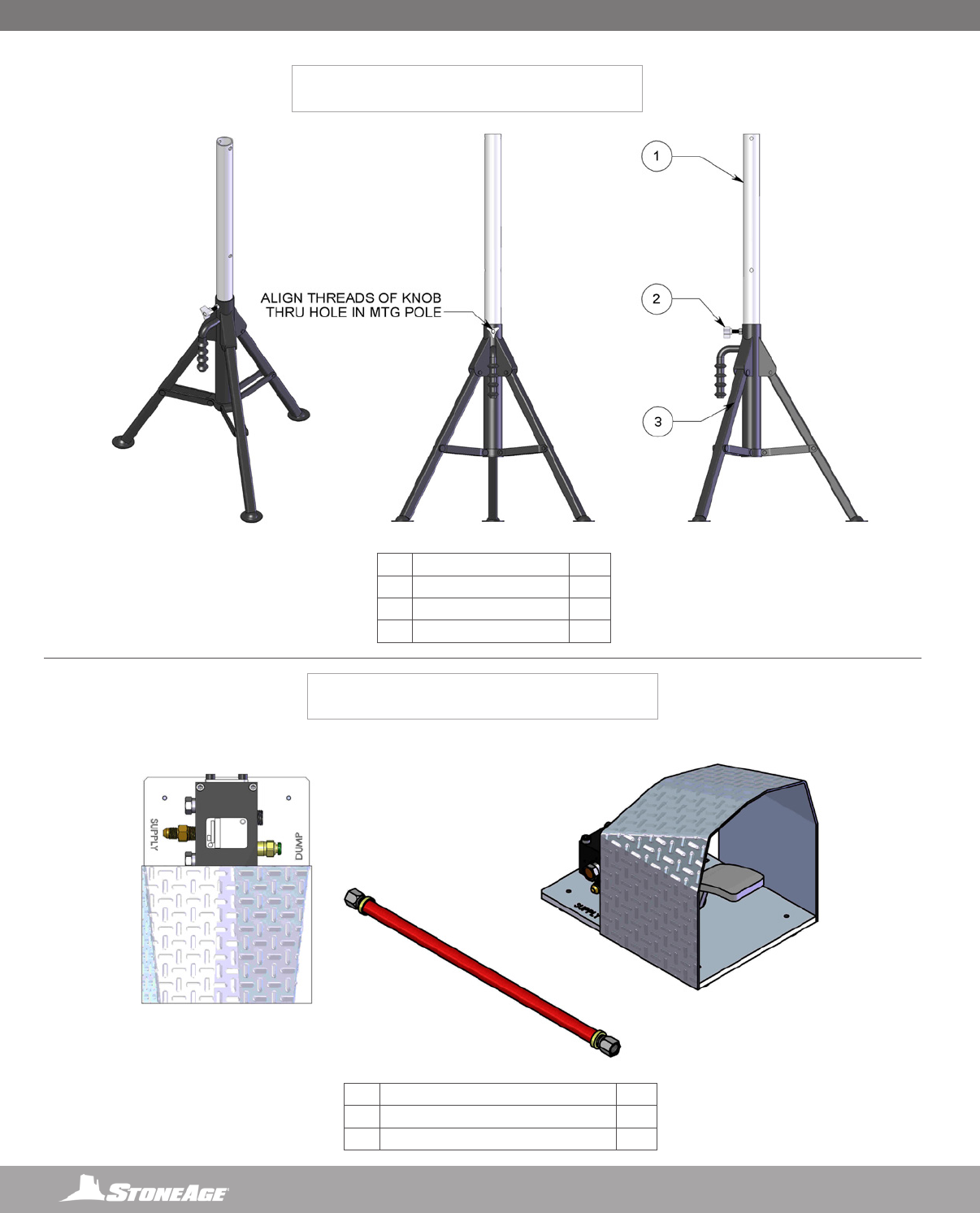
62 866-795-1586 • WWW.STONEAGETOOLS.COM
STRIKER® (CB 301)
CB STAND ASSEMBLY
# PART NUMBER QTY.
1 CB 303 MTG POLE 1
2 CB 314 3-LOBE KNOB 1
3CB 301.1 TRIPOD 1
STRIKER® (FPA-SKR)
FOOT PEDAL DUMP CONTROL
NOT INCLUDED IN PACKAGE
# PART NUMBER QTY.
1 FPA-100 FOOT PEDAL ASSEMBLY 1
2 FPA 102 HOSE ASSEMBLY 2
1
1
2
PARTS DIAGRAM
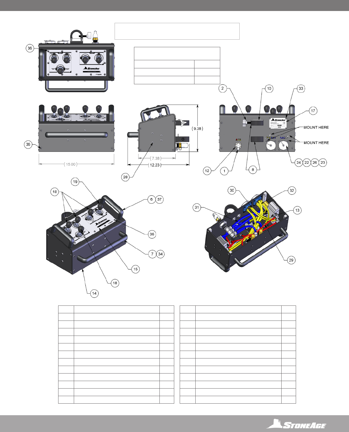
63
866-795-1586 • WWW.STONEAGETOOLS.COM
STRIKER® (CB 400)
CONTROL BOX ASSEMBLY (PAGE 1 OF 2)
NOTES:
1. BALLOONS ON PAGE 2 IDENTIFY INTERNAL COMPONENTS.
2. BALLOONS ON PAGE 1 IDENTIFY EXTERNAL COMPONENTS.
3. ADD BLUE LOCTITE: PN 242 OR EQUIVALENT TO ALL THREADED HARDWARE UNLESS OTHERWISE NOTED.
4. ADD RED LOCTITE: PN 262 OR EQUIVALENT.
CB 615 ORING REPLACEMENT KIT
FOR TWINTEC SOCKETS
PART NUMBER QTY.
BJ 016 ORING 2
TR 127 ORING 4
# PART NUMBER QTY.
1 BR 167 DUST CAP 1
2 CB 314 3-LOBE KNOB 1
6 CB 325 HANDLE TOP 2
7 CB 326 HANDLE FRONT 1
8 CB 328-001 POLE MOUNT 2
10 CB 347 CAP PLATE 1
12 CB 380 FTG P8 BULK HEAD CONNECTOR 1
13 CB 382 FTG PL6-T
14 CB 401 CB FRAME 1
15 CB 402 GRAPHIC OVERLAY_AUTOSHOTSYS 1
18 CB 419-HD PNEUM3WAYASSY NDT 4
19 CB 420-HD PNEUM3WAYASSY_DT 1
22 CB 430 LANYARD ASSY BOX 2
23 CB 452.2 FTG TWINTEC SOCKET 2
24 CB 459 SOCKET COVER 2
26 GMS 319-015-32 PHMS .19-32X.38 LG PH-SS 2
28 GPH 319-08 PHPMS 10-24 X 2.00 SS 12
29 GPTB 0250-PUR95A-RD 5FT
30 GPTB 0250-PUR95A-YL 6FT
31 GPTB 0375-PUR95A-BL 6FT
32 GPTB 0375-PUR95A-YL 2FT
33 GR 125-SS-188-250 RIVET 4
34 GSB 3M8-16-1.25 BHCS M8X1.25 X 16 SS 2
36 GTB 319-02-32 BHTS .19-32 X .50 LG TORX-SS 38
37 GTB 331-025 BHTS .31-18 X .63 LG TORX-SS 4
PARTS DIAGRAM PARTS DIAGRAM
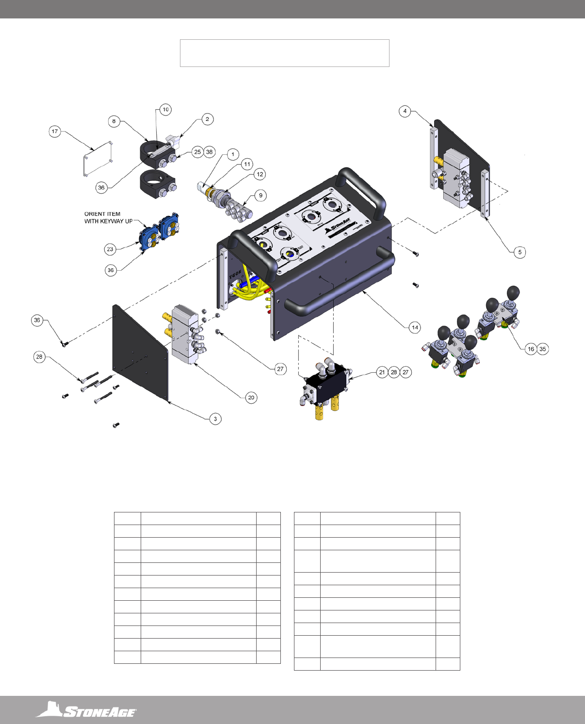
64 866-795-1586 • WWW.STONEAGETOOLS.COM
STRIKER® (CB 400)
CONTROL BOX ASSEMBLY (PAGE 2 OF 2)
# PART NUMBER QTY.
1 BR 167 DUST CAP 1
2 CB 314 3-LOBE KNOB 1
3 CB 322 SIDE PLATE 2
4 CB 323 BRACE REAR 2
5 CB 324 BRACE FRONT 2
8 CB 328-001 POLE MOUNT 2
9 CB 331 P8PL6 6-WAY MANIFOLD 1
10 CB 347 CAP PLATE 1
11 CB 355 FTG P8J8 BRASS MALE TO MALE 1
12 CB 380 FTG P8 BULK HEAD CONNECTOR 1
14 CB 401 CB FRAME 1
16 CB 407 VALVEBRACE 2
17 CB 408 CE SERIAL PLATE 1
20 CB 421 FESTOPILOTEDASSY 2
21 CB 422 RY3 AAA PILOTED SPOOL VALVE
ASSY
1
23 CB 452.2 FTG TWINTEC SOCKET 2
25 GB 337-03 BOLT, HEX .37-16 X .75 SS 4
27 GN 319-L NYLOK NUT SS (HC 025.1) 12
28 GPH 319-08 PHPMS 10-24 X 2.00 SS 12
35 GSF 319-02 FHCS .19-24 X .50 LG SS 4
36 GTB 319-02-32 BHTS .19-32 X .50 LG
TORX-SS
38
38 GW 337-F FLAT WASHER 4
PARTS DIAGRAM
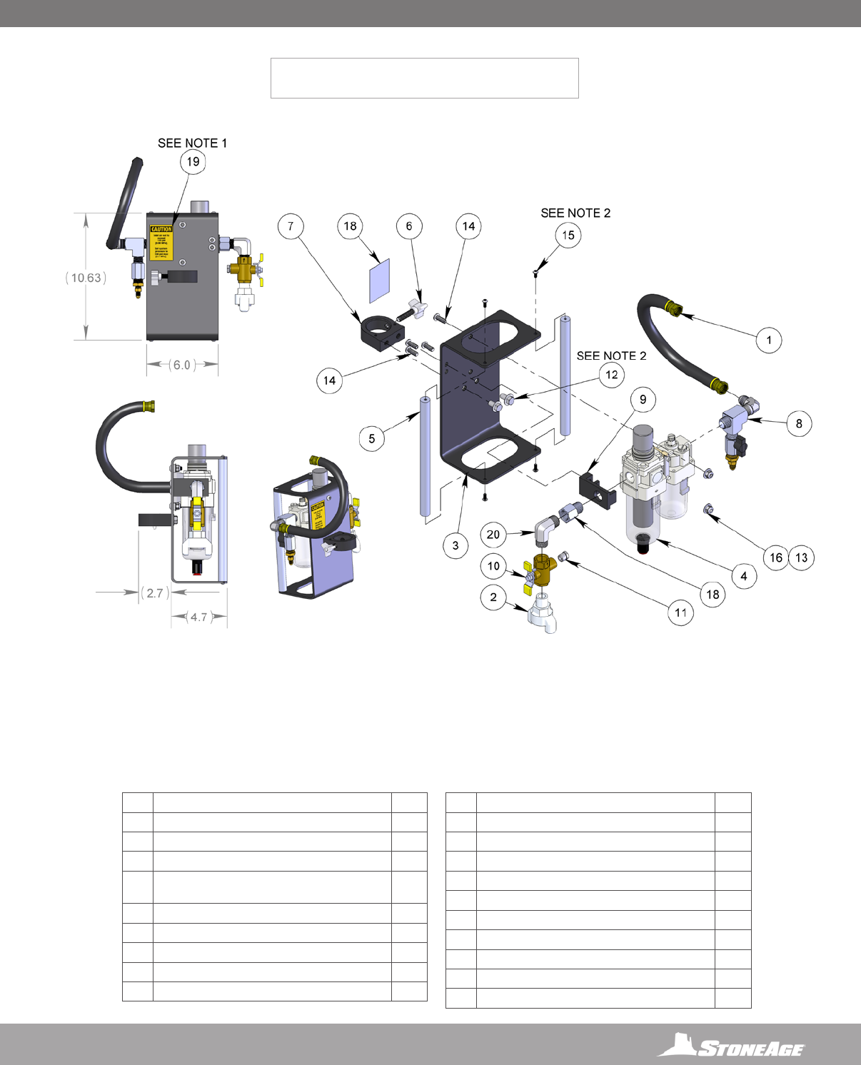
65
866-795-1586 • WWW.STONEAGETOOLS.COM
STRIKER® (CB 403)
(FILTER, REGULATOR, LUBRICATOR) FRL ASSEMBLY
#PART NUMBER QTY.
1CB 052-14 HOSE ASSY (FOR CB PDT) 1
2CB 114 INLET FITTING 1
3CB 311 FRL FRAME 1
4CB 312 GEN3 FILTER-REGULATOR-LUBRICATOR WITH
GEN2 CLAMP
1
5CB 313 ROD 2
6CB 314 3-LOBE KNOB 1
7CB 328-001 POLE MOUNT 1
8CB 390 FRL DUMP SUPPLY ASSY 1
9CB 395 FRL BRACKET
10 CB 792 VALVE, AUTO DRAIN, P8 1
11 CB 793 BREATHER, SINTERED BRONZE, P4 1
12 GB 337-03 BOLT, HEX .37-16 X .75 SS 2
13 GN 331-L NYLOK NUT SS 2
14 GSB 331-035 BHCS .31-18 X .88 LG SS 4
15 GTB 319-02-32 BHTS .19-32 X .50 LG TORX-SS 4
16 GW 331-F FLAT WASHER SS 2
17 GW 337-F FLAT WASHER SS 2
18 ML 077-P8 BUSHING 1
19 PL 156-125 CAUTION INLET AIR, 125PSI MAX 1
20 SBT 292.1 FTG 90° ELBOW P8MP8M 1
NOTES:
1. CLEAN ALL DEBRIS & OILS BEFORE INSTALLING. INSTALL AT APPROXIMATE ORIENTATION AND LOCATION & AT ROOM TEMP.
2. ADD BLUE LOCTITE® 242 OR EQUIVALENT TO ALL NOTED HARDWARE.
3. ADD LOCTITE THREAD SEALANT ® 567 TO ALL NPT THREADS. AN EQUIVALENT ALTERNATIVE IS ACCEPTABLE.
4. ADD BLUE GOOP WHICH IS A SWAGELOK BRAND ANTI-SEIZE TO ALL OTHER THREADED HARDWARE OR AN EQUIVALENT
ALTERNATIVE IS ACCEPTABLE.
PARTS DIAGRAM PARTS DIAGRAM
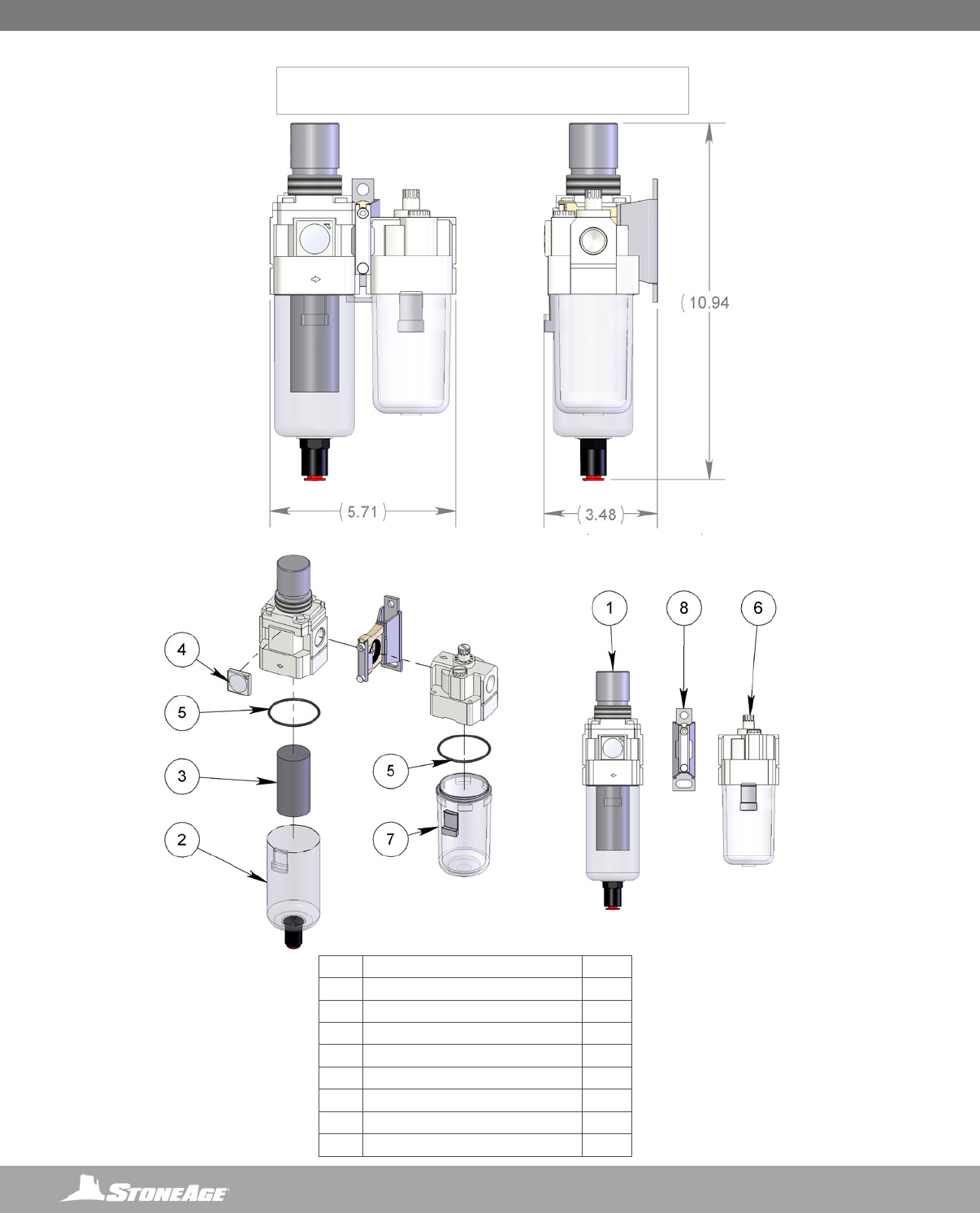
66 866-795-1586 • WWW.STONEAGETOOLS.COM
PARTS DIAGRAM
AUTOBOX® (CB 312)
GEN 3 FILTER, REGULATOR, LUBRICATOR WITH GEN 2 CLAMP
# PART NUMBER QTY.
1 CB 312.1 FILTER REGULATOR ASSEMBLY 1
2 CB 312.1.1 FILTER REGULATOR BOWL 1
3 CB 312.1.6 FILTER 1
4 CB 312.1.7 GAUGE WITH LENS 1
5 CB 312.1.8 ORING 2
6 CB 312.2 LUBRICATOR ASSEMBLY 1
7 CB 312.2.2 LUBRICATOR BOWL 1
8 CB 312.3 SPACER W BRACKET 1
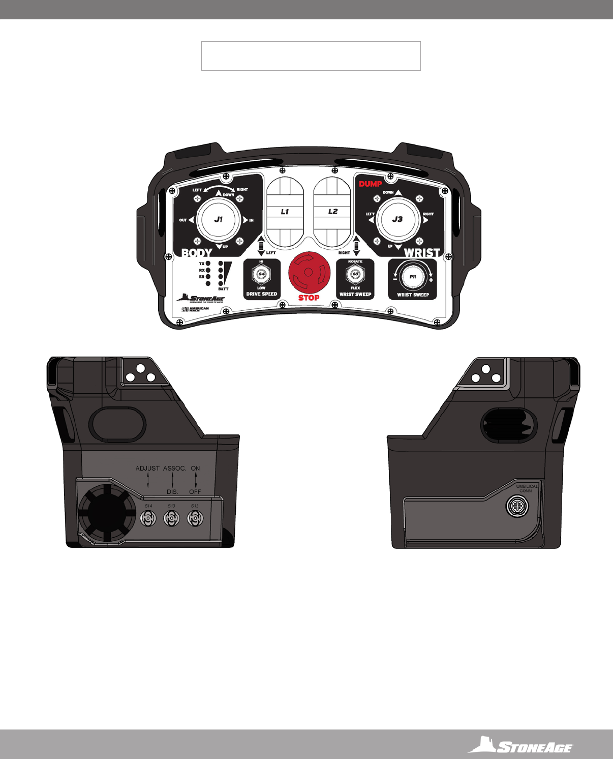
67
866-795-1586 • WWW.STONEAGETOOLS.COM
STRIKER® (SKR 880.1)
REMOTE CONTROL CONSOLE
TOP VIEW
LEFT SIDE SWITCH DETAIL RIGHT SIDE SWITCH DETAIL
PARTS DIAGRAM PARTS DIAGRAM
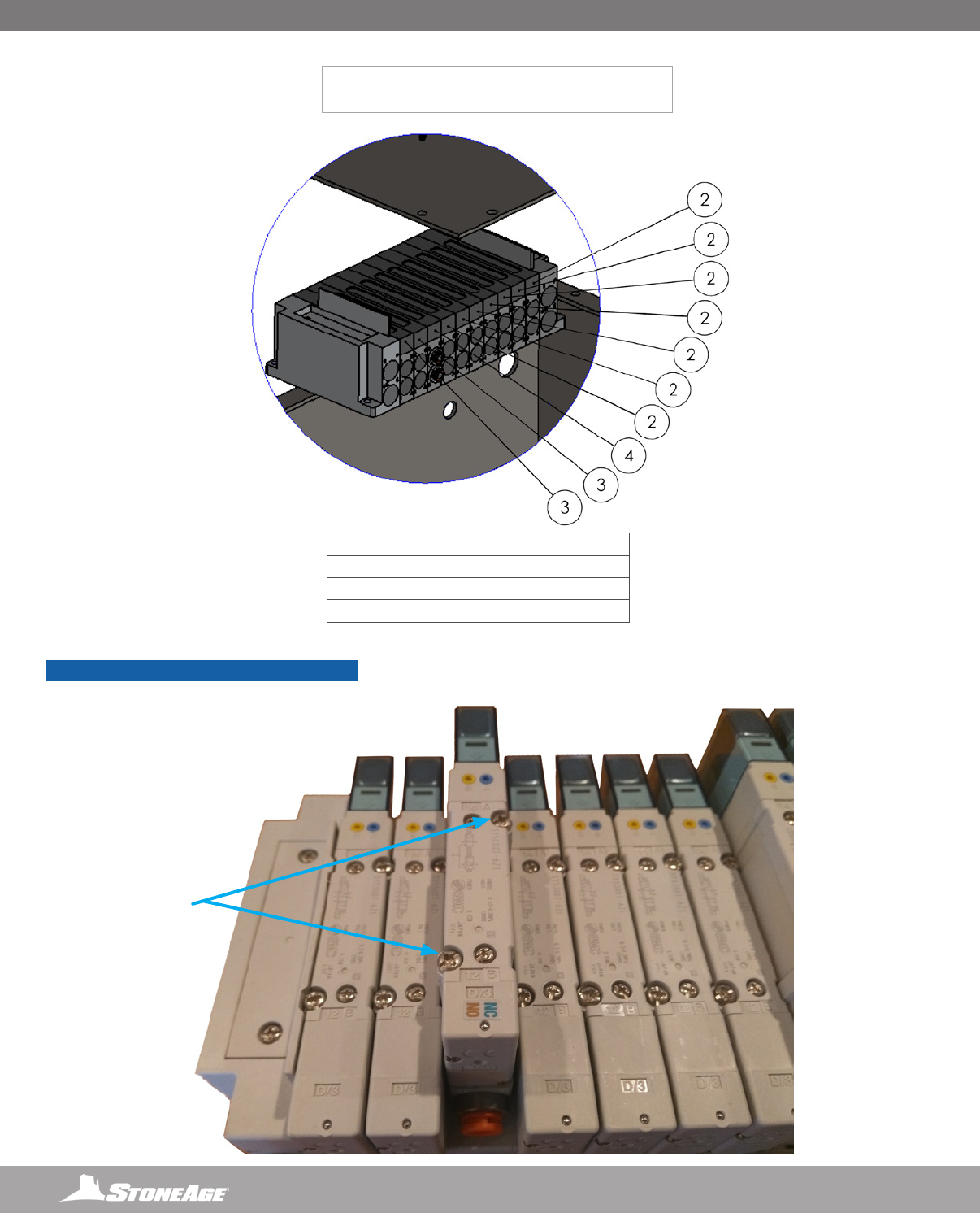
68 866-795-1586 • WWW.STONEAGETOOLS.COM
# PART NUMBER QTY.
2 SKR 880.10.10 SY5300T-6Z1 VALVE 7
3 SKR 880.10.11 SY5500T-6Z1 VALVE 2
4 SKR 880.10.12 SY5C00T-6Z1 VALVE 1
STRIKER® (SKR 880.10.XX)
REPLACEMENT VALVES FOR WIRELESS RECEIVER
NOTICE
Replace any valve that has a blinking light. When
replacing the cover plate, ensure that the gasket
is seated properly and screws are tightened in a
cross pattern.
REMOVE THE TWO
OFFSET STARLOCK
SCREWS AND LIFT THE
VALVE OUT
PARTS DIAGRAM

69
866-795-1586 • WWW.STONEAGETOOLS.COM
NOTES
This page is intentionally left blank.
PARTS DIAGRAM

70 866-795-1586 • WWW.STONEAGETOOLS.COM
TERMS AND CONDITIONS
1. Acceptance of Terms and Conditions. Receipt of these Terms and
Conditions of Sale (“Terms and Conditions”) shall operate as the acceptance
by StoneAge, Inc. (“Seller”) of the order submitted by the purchaser (“Buyer”).
Such acceptance is made expressly conditional on assent by Buyer to these
Terms and Conditions. Such assent shall be deemed to have been given
unless written notice of objection to any of these Terms and Conditions
(including inconsistencies between Buyer’s purchase order and this
acceptance) is given by Buyer to Seller promptly on receipt hereof.
Seller desires to provide Buyer with prompt and efcient service.
However, to individually negotiate the terms of each sales contract would
substantially impair Seller’s ability to provide such service. Accordingly,
the product(s) furnished by Seller are sold only according to the terms and
conditions stated herein and with the terms and conditions stated in any
effective StoneAge Dealer Agreement or StoneAge Reseller Agreement,
if applicable. Notwithstanding any terms and conditions on Buyer’s
order, Seller’s performance of any contract is expressly made conditional
on Buyer’s agreement to these Terms and Conditions unless otherwise
specically agreed to in writing by Seller. In the absence of such agreement,
commencement of performance, shipment and/or delivery shall be for Buyer’s
convenience only and shall not be deemed or construed to be an acceptance
of Buyer’s terms and conditions.
2. Payment/Prices. Unless other arrangements have been made in writing
between Seller and Buyer, payment for the product(s) shall be made upon
receipt of invoice. The prices shown on the face hereof are those currently in
effect. Prices invoiced shall be per pricelist in effect at the time of shipment.
Prices are subject to increase for inclusion of any and all taxes which are
applicable and which arise from the sale, delivery or use of the product(s),
and the collection of which Seller is or may be responsible to provide to any
governmental authority, unless acceptable exemption certicates are provided
by Buyer in accordance with applicable law. Buyer shall pay all charges for
transportation and delivery and all excise, order, occupation, use or similar
taxes, duties, levies, charges or surcharges applicable to the product(s) being
purchased, whether now in effect or hereafter imposed by any governmental
authority, foreign or domestic.
3. Warranty. SELLER MAKES NO WARRANTIES OR REPRESENTATIONS AS
TO THE PERFORMANCE OF ANY PRODUCT EXCEPT AS SET FORTH IN THE
STONEAGE LIMITED WARRANTY PROVIDED WITH THE PRODUCT.
4. Delivery. Seller is not obligated to make delivery by a specied date, but
will always use its best efforts to make delivery within the time requested.
The proposed shipment date is an estimate. Seller will notify Buyer promptly
of any material delay and will specify the revised delivery date as soon as
practicable. UNDER NO CIRCUMSTANCES SHALL SELLER HAVE ANY
LIABILITY WHATSOEVER FOR LOSS OF USE OR FOR ANY DIRECT OR
CONSEQUENTIAL DAMAGES RESULTING FROM DELAY REGARDLESS OF
THE REASON(S).
All product(s) will be shipped F.O.B. point of origin, unless specically agreed
otherwise, and Buyer shall pay all shipping costs and insurance costs from
that point. Seller, in its sole discretion, will determine and arrange the means
and manner of transportation of the product(s). Buyer shall bear all risk of loss
commencing with the shipment or distribution of the product(s) from Seller’s
warehouse. Order shortages or errors must be reported within fteen (15)
business days from receipt of shipment to secure adjustment. No product(s)
may be returned without securing written approval from Seller.
5. Modication. These Terms and Conditions are intended by Seller and
Buyer to constitute a nal, complete and exclusive expression of agreement
relating to the subject matter hereof and cannot be supplemented or amended
without Seller’s prior written approval.
6. Omission. Seller’s waiver of any breach or Seller’s failure to enforce any
of these Terms and Conditions at any time, shall not in any way affect, limit or
waive Seller’s right thereafter to enforce and compel strict compliance with
every term and condition hereof.
7. Severability. If any provision of these Terms and Conditions is held to be
invalid or unenforceable, such invalidity or unenforceability shall not affect the
validity or enforceability of the other portions hereof.
8. Disputes. Seller and Buyer shall attempt in good faith to promptly resolve
any dispute arising under these Terms and Conditions by negotiations
between representatives who have authority to settle the controversy. If
unsuccessful, Seller and Buyer shall further attempt in good faith to settle the
dispute by nonbinding third-party mediation, with fees and expenses of such
mediation apportioned equally to each side. Any dispute not so resolved
by negotiation or mediation may then be submitted to a court of competent
jurisdiction in accordance with the terms hereof. These procedures are the
exclusive procedures for the resolution of all such disputes between the Seller
and Buyer.
9. Governing Law. All sales, agreements for sale, offers to sell, proposals,
acknowledgments and contracts of sale, including, but not limited to,
purchase orders accepted by Seller, shall be considered a contract under the
laws of the State of Colorado and the rights and duties of all persons, and
the construction and effect of all provisions hereof shall be governed by and
construed according to the laws of such state.
10. Jurisdiction and Venue. Seller and Buyer agree that the state or federal
courts located within the City and County of Denver, Colorado shall have
sole and exclusive jurisdiction over any litigation concerning any dispute
arising under these Terms and Conditions not otherwise resolved pursuant
to Section 9 as well as any alleged defects of any Products or damages
sustained as a result of such alleged defects. Seller and Buyer further agree
that should any litigation be commenced in connection with such a dispute,
it shall only be commenced in such courts. Seller and Buyer agree to the
exclusive jurisdiction of such courts and neither will raise any objection to the
jurisdiction and venue of such courts, including as a result of inconvenience.
11. Attorney’s Fees. If any litigation is commenced between Seller and Buyer,
or their personal representatives, concerning any provision hereof, the party
prevailing in the litigation shall be entitled, in addition to such other relief that
is granted, to a reasonable sum as and for their attorneys’ fees and costs in
such litigation or mediation.
STONEAGE TRADEMARK LIST
View the list of StoneAge’s trademarks and service marks and learn how
the trademarks should be used. Use of StoneAge trademarks may be
prohibited, unless expressly authorized.
http://www.StoneAgetools.com/trademark-list/
STONEAGE PATENT DATA
View the list of StoneAge’s current U.S. patent numbers and descriptions.
http://www.sapatents.com
STONEAGE TERMS AND WARRANTY
View StoneAge’s Terms and Warranty Conditions online.
http://www.stoneagetools.com/terms
http://www.stoneagetools.com/warranty

71
866-795-1586 • WWW.STONEAGETOOLS.COM
WARRANTY
Warranties set forth herein extend only to End-Users, meaning customers
acquiring, or that have previously acquired, a product manufactured by
StoneAge (“Product”) for their own use and not for resale, either directly from
StoneAge Inc. (“StoneAge”) or from a StoneAge Authorized Dealer or Reseller
(“Dealer”). No warranty of any kind or nature is made by StoneAge beyond
those expressly stated herein.
1. LIMITED WARRANTY PERIOD. Subject to the limitations and conditions
hereinafter set forth, StoneAge warrants its Product to be free from defects
in workmanship and material for a period of one (1) year from the date of
purchase by the End-User, provided that the end of the limited warranty
period shall not be later than eighteen (18) months from the date of shipment
of the Product to the Dealer or the End-User by StoneAge (“Limited Warranty
Period”). All replacement parts which are furnished under this Limited
Warranty and properly installed shall be warranted to the same extent as
the original Product under this Limited Warranty if, and only if, the original
parts were found to be defective within the original Limited Warranty Period
covering the original Product. Replacement parts are warranted for the
remainder of the original Limited Warranty Period. This Limited Warranty
does not cover any component part of any Product not manufactured by
StoneAge. Any such component part is subject exclusively to the component
manufacturer’s warranty terms and conditions.
2. LIMITED WARRANTY COVERAGE. StoneAge’s sole obligation under
this Limited Warranty shall be, at StoneAge’s option and upon StoneAge’s
inspection, to repair, replace or issue a credit for any Product which
is determined by StoneAge to be defective in material or workmanship.
StoneAge reserves the right to examine the alleged defective Product to
determine whether this Limited Warranty is applicable, and nal determination
of limited warranty coverage lies solely with StoneAge. No statement or
recommendation made by a StoneAge representative, Dealer or agent to End-
User shall constitute a warranty by StoneAge or a waiver or modication to
any of the provisions hereof or create any liability for StoneAge.
3. WARRANTY SERVICE PROVIDERS. Service and repair of the Product
is to be performed only by StoneAge authorized service representatives,
including Dealers who are authorized repair centers, with StoneAge approved
parts. Information about StoneAge authorized service representatives can
be obtained through the StoneAge website at www.stoneagetools.com/
service. Unauthorized service, repair or modication of the Product or use of
parts not approved by StoneAge will void this Limited Warranty. StoneAge
reserves the right to change or improve the material and design of the Product
at any time without notice to End-User, and StoneAge is not obligated to make
the same improvements during warranty service to any Product previously
manufactured.
4. WARRANTY EXCLUSIONS. This Limited Warranty does not cover, and
StoneAge shall not be responsible for the following, or damage caused by
the following: (1) any Product that has been altered or modied in any way
not approved by StoneAge in advance in writing; (2) any Product that has
been operated under more severe conditions or beyond the rated capacity
specied for that Product; (3) depreciation or damage caused by normal
wear and tear, failure to follow operation or installation instructions, misuse,
negligence or lack of proper protection during storage; (4) exposure to re,
moisture, water intrusion, electrical stress, insects, explosions, extraordinary
weather and/or environmental conditions including, but not limited to lightning,
natural disasters, storms, windstorms, hail, earthquakes, acts of God or any
other force majeure event; (5) damage to any Product caused by any attempt
to repair, replace, or service the Product by persons other than StoneAge
authorized service representatives; (6) costs of normal maintenance parts
and services; (7) damage sustained during unloading, shipment or transit of
the Product; or (8) failure to perform the recommended periodic maintenance
procedures listed in the Operator’s Manual accompanying the Product.
5. REQUIRED WARRANTY PROCEDURES. To be eligible for warranty
service, the End-User must: (1) report the Product defect to the entity where
the Product was purchased (i.e. StoneAge or the Dealer) within the Limited
Warranty Period specied in this Limited Warranty; (2) submit the original
invoice to establish ownership and date of purchase; and (3) make the Product
available to a StoneAge authorized service representative for inspection to
determine eligibility for coverage under this Limited Warranty. This Limited
Warranty shall not extend to any person or entity who fails to provide proof of
original purchase from StoneAge or a Dealer. No Product may be returned for
credit or adjustment without prior written permission from StoneAge.
6. DISCLAIMER OF IMPLIED WARRANTIES AND OTHER REMEDIES.
EXCEPT AS EXPRESSLY STATED HEREIN (AND TO THE FULLEST EXTENT
ALLOWED UNDER APPLICABLE LAW), STONEAGE HEREBY DISCLAIMS
ALL OTHER WARRANTIES, EXPRESS OR IMPLIED, INCLUDING WITHOUT
LIMITATION ALL IMPLIED WARRANTIES OF MERCHANTABILITY OR
FITNESS FOR A PARTICULAR PURPOSE, AND ANY AND ALL WARRANTIES,
REPRESENTATIONS OR PROMISES AS TO THE QUALITY, PERFORMANCE
OR FREEDOM FROM DEFECT OF THE PRODUCT COVERED BY THIS
LIMITED WARRANTY. STONEAGE FURTHER DISCLAIMS ALL IMPLIED
INDEMNITIES.
7. LIMITATION OF LIABILITY. End-User specically acknowledges that the
Product may be operated at high speeds and/or pressures, and that as such it
may be inherently dangerous if not used correctly. End-User shall familiarize
itself with all operation materials provided by StoneAge and shall at all times
use and require its agents, employees and contractors to use all necessary
and appropriate safety devices, guards and proper safe operating procedures.
In no event shall StoneAge be responsible for any injuries to persons or
property caused directly or indirectly by the operation of the Product if End-
User or any agent, employee, or contractor of End-User: (1) fails to use all
necessary and appropriate safety devices, guards and proper safe operating
procedures; (2) fails to maintain in good working order such safety devices
and guards; (3) alters or modies the Product in any way not approved
by StoneAge in advance in writing; (4) allows the Product to be operated
under more severe conditions or beyond the rated capacity specied for the
Product; or (5) otherwise negligently operates the Product. End-User shall
indemnify and hold StoneAge harmless from any and all liability or obligation
incurred by or against StoneAge, including costs and attorneys’ fees, to or by
any person so injured.
TO THE FULL EXTENT ALLOWED BY APPLICABLE LAW, STONEAGE
SHALL NOT BE LIABLE FOR ANY INDIRECT, SPECIAL, INCIDENTAL,
CONSEQUENTIAL, OR PUNITIVE DAMAGES (INCLUDING WITHOUT
LIMITATION, LOSS OF PROFITS, LOSS OF GOODWILL, DIMINUTION OF
VALUE, WORK STOPPAGE, INTERRUPTION OF BUSINESS, RENTAL OF
SUBSTITUTE PRODUCT, OR OTHER COMMERCIAL LOSS EVEN TO THE
EXTENT SUCH DAMAGES WOULD CONSTITUTE DIRECT DAMAGES), WITH
RESPECT TO THE COVERED STONEAGE PRODUCT, OR OTHERWISE
IN CONNECTION WITH THIS LIMITED WARRANTY, REGARDLESS OF
WHETHER STONEAGE HAS BEEN ADVISED OF THE POSSIBILITY OF SUCH
DAMAGES.
IT IS UNDERSTOOD THAT STONEAGE’S LIABILITY, WHETHER IN
CONTRACT, IN TORT, UNDER ANY WARRANTY, IN NEGLIGENCE, OR
OTHERWISE SHALL NOT EXCEED THE AMOUNT OF THE PURCHASE
PRICE PAID BY THE END-USER FOR THE PRODUCT. STONEAGE’S
MAXIMUM LIABILITY SHALL NOT EXCEED, AND END-USER’S REMEDY IS
LIMITED TO EITHER (1) REPAIR OR REPLACEMENT OF THE DEFECTIVE
WORKMANSHIP OR MATERIAL OR, AT STONEAGE’S OPTION, (2) REFUND
OF THE PURCHASE PRICE, OR (3) ISSUANCE OF A CREDIT FOR THE
PURCHASE PRICE, AND SUCH REMEDIES SHALL BE END-USER’S ENTIRE
AND EXCLUSIVE REMEDY.
YOU, THE END-USER, UNDERSTAND AND EXPRESSLY AGREE THAT
THE FOREGOING LIMITATIONS ON LIABILITY ARE PART OF THE
CONSIDERATION IN THE PRICE OF THE STONEAGE PRODUCT YOU
PURCHASED.
Some jurisdictions do not allow the limitation or exclusion of liability for
certain damages, so the above limitations and exclusions may not apply to
you. This Limited Warranty gives you specic legal rights, and you may also
have other rights which vary from jurisdiction to jurisdiction. If any provisions
of this Limited Warranty is held to be invalid or unenforceable, such invalidity
or unenforceability shall not affect the validity or enforceability of the other
portions hereof.

1-866-795-1586 • www.STONEAGETOOLS.com
© 2015 StoneAge, Inc. All Rights Reserved
