SMART Payout Manual Set Section 1 Ticket
User Manual:
Open the PDF directly: View PDF ![]() .
.
Page Count: 20

SMART TICKET
INTEGRATION
GUIDE
SMART Ticket Integration Guide
Copyright © Innovative Technology Ltd 2011 GA860-2
MANUAL AMENDMENTS
Rev.
Date
Amendment Details
Issued by
18-01-13
First Issue
AB

SMART Ticket Integration Guide
Copyright © Innovative Technology Ltd 2011 GA860-2
SMART TICKET MANUAL - INTRODUCTION
MANUAL AMENDMENTS 1
COPYRIGHT 4
LIMITED WARRANTY 4
PRODUCT SAFETY INFORMATION 4
INTRODUCTION 5
FEATURES 6
TYPICAL APPLICATIONS 6
1. QUICK START AND CONFIGURATION GUIDE 7
1.1 Assembly 7
1.2 Bezel Removal and Replacement 9
1.3 Earth Bonding 10
1.5 DIP Switch Settings 11
1.5 Connectors and Pinouts 12
1.6 Technical Specifications 15
1.7 SMART Ticket Error Codes 17
1.8 NV200 Bezel Flash Codes 17
SMART Ticket Integration Guide
Copyright © Innovative Technology Ltd 2011 GA860-2
MAIN HEADQUARTERS
Innovative Technology Ltd
Derker Street – Oldham – England - OL1 4EQ
Tel: +44 161 626 9999 Fax: +44 161 620 2090
E-mail: support@innovative-technology.co.uk
Web site: www.innovative-technology.co.uk
BRAZIL
suporte@bellis-technology.com.br
CHINA
support@innovative-technology.co.uk
GERMANY
support@automated-transactions.de
SPAIN
soporte@automated-transactions.es
UNITED KINGDOM
support@innovative-technology.co.uk
UNITED STATES OF AMERICA
supportusa@bellis-technology.com
REST OF THE WORLD
sales@innovative-technology.co.uk

SMART Ticket Integration Guide 4
Copyright © Innovative Technology Ltd 2013 GAxxx
COPYRIGHT
This manual set is Copyright © Innovative Technology Ltd. 2013. No part of this
publication may be reproduced in any form or by any means or used to make any
derivative such as translation, transformation, or adaptation without permission from
Innovative Technology Ltd. The contents of this manual set may be subject to change
without prior notice.
LIMITED WARRANTY
Innovative Technology Ltd warrants each of its hardware products to be free from
defects in workmanship and materials under normal use and service for a period
commencing on the date of purchase from Innovative Technology Ltd or its
Authorized Reseller, and extending for the length of time stipulated by Innovative
Technology Ltd.
A list of Innovative Technology Ltd offices can be found in every section of this
manual set. If the product proves defective within the applicable warranty period,
Innovative Technology Ltd will repair or replace the product. Innovative Technology
Ltd shall have the sole discretion whether to repair or replace, and any replacement
product supplied may be new or reconditioned.
The foregoing warranties and remedies are exclusive and are in lieu of all other
warranties, expressed or implied, either in fact or by operation of law, statutory or
otherwise, including warranties of merchantability and fitness for a particular purpose.
Innovative Technology Ltd shall not be liable under this warranty if it’s testing and
examination disclose that the alleged defect in the product does not exist or was
caused by the customer's or any third person's misuse, neglect, improper installation
or testing, unauthorized attempts to repair, or any other cause beyond the range of
the intended use. In no event will Innovative Technology Ltd be liable for any
damages, including loss of profits, cost of cover or other incidental, consequential or
indirect damages arising out the installation, maintenance, use, performance, failure
or interruption of a Innovative Technology Ltd product, however caused.
PRODUCT SAFETY INFORMATION
Throughout this manual set, we may draw your attention to key safety points that you
should be aware of when using or maintaining the product.
These safety points will be highlighted in
a box, like this:
Caution!
Mains voltage is present on
these terminals
This manual set and the information it contains is only applicable to the model stated
on the front cover, and must not be used with any other make or model.
SMART Ticket Integration Guide 5
Copyright © Innovative Technology Ltd 2013 GAxxx
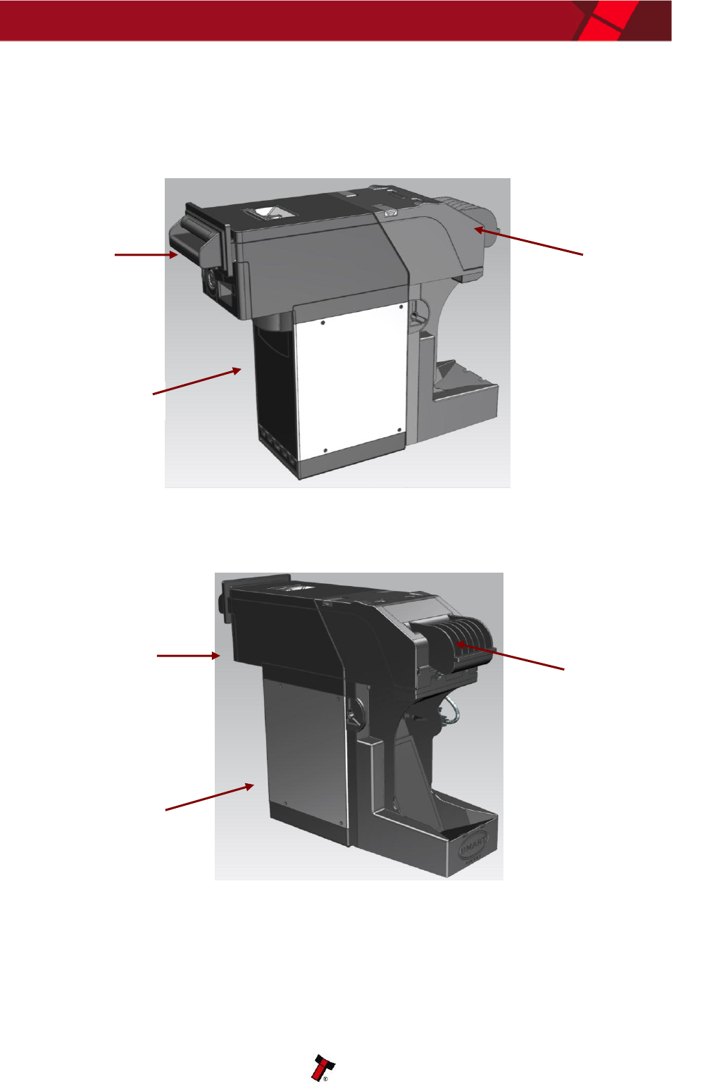
INTRODUCTION
The SMART Ticket unit is made up of three basic components: an NV200 Validator, a
cashbox and a ticket module (as shown below). The smart ticket module is an add-on
designed to be fitted to the Innovative Technology NV200 bank note validator.
Smart Ticket
Front View
Smart Ticket
Rear View
Printer Module
Cashbox
NV200
Validator
Head
Printer Module
NV200
Validator
Head
Cashbox

SMART Ticket Integration Guide 6
Copyright © Innovative Technology Ltd 2013 GAxxx
FEATURES
The SMART Ticket unit has many innovative features, including:
Combined bank note validator & ticket printer
Market leading design
Eliminates the need for coin hoppers
Easy maintenance, free firmware updates
Fan folded or continuous roll ticket options.
TYPICAL APPLICATIONS
The SMART Ticket unit can be used in a variety of situations where bank note
acceptance, validation and ticket printing are needed. Some typical applications are:
AWP and SWP applications
Self-Serve and Retail
Kiosks
Casinos
Parking and Ticketing
Vending
SMART Ticket Integration Guide 7
Copyright © Innovative Technology Ltd 2013 GAxxx
1. QUICK START AND CONFIGURATION GUIDE
This section is one part of a complete manual set: most users should use this section
of the manual - typical users are software engineers looking at how to make it work,
project engineers evaluating their first unit, or installation engineers installing the unit
into a host machine.
This section contains the essential information that a user needs to quickly assemble
and configure the SMART Ticket unit ready for installation into the host machine.
1.1 Assembly
The Smart Ticket module is designed to be fitted to the Innovative Technology NV200
bank note validator. Connecting the SMART Ticket module to an NV200 validator is a
simple operation, described in the steps outlined here:
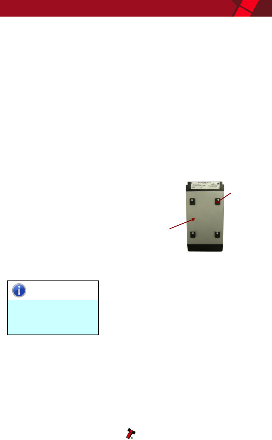
1. Remove the NV200 cash box from
the metal chassis
2. If installing into a host machine,
the NV200 chassis is then
mounted by using the tapped
holes on either side of the chassis
using 4 x M4 fixing screws and a
suitable mounting bracket
Information
Check fixing screw length
before final installation to
avoid damage to the cash
box.
The length of the fixing screws fitted to either side of
the chassis must be no longer than 6 mm plus the
thickness of the mounting bracket.
Mounting
bracket
NV200
chassis
SMART Ticket Integration Guide 8
Copyright © Innovative Technology Ltd 2013 GAxxx
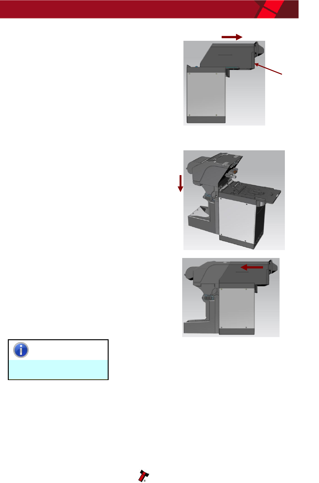
3. Unlock the NV200 cashbox and
head release lock (if fitted)
4. Lift the silver head release catch
located on the front of the NV200
5. Slide the head unit forward and
lift up
6. Mount the printer module using
the mounting brackets on the
rear of the NV200 chassis
7. Replace the NV200 head unit
taking care that the connectors
on the printer module line up with
the connectors on the rear of the
NV200
8. Ensure the NV200 head unit is
securely in place – check that the
release catch is fully down
Information
Printer module removal.
The printer module cannot be removed until the
head unit has been slid forwards.
Head
release
catch

SMART Ticket Integration Guide 9
Copyright © Innovative Technology Ltd 2013 GAxxx
1.2 Bezel Removal and Replacement
WARNING!
Ensure bezel is secured to
validator
The front bezel should be secured to the validator
head using screws if the SMART Ticket unit is
being installed and transported inside a host
machine.
Information
Check bezel fixing screw
length before installation.
The length of the bezel fixing screws must be no
more than 12 mm in length.
The bezel on the front of the validator head has been designed to be removed and
refitted very easily.
To remove or refit the bezel the top cover must be open fully to allow access to the
bezel mounting area.
Validator note path cover
Bezel removal and fitting
Bezel assembly
Bezel connector socket
Screw mounting holes
Cover
release
latch
Electrical
connector
SMART Ticket Integration Guide 10
Copyright © Innovative Technology Ltd 2013 GAxxx
Removing the bezel: Lift the upper cover by pulling the top latch forward. If fitted,
remove the two bezel securing screws and then slide the bezel assembly upwards.
Finally unplug the cable from the socket on the front of the validator head.
Fitting the bezel: Lift the upper cover by pulling the latch forward. Connect the cable
from the bezel assembly to the socket located on the front of the validator head and
slide the assembly down into place and then close the note path upper cover. If
required, the bezel can be secured in place with two M3 screws - these are fitted in
the two holes at the bottom of the bezel.
1.3 Earth Bonding
It is very important that the cashbox chassis is bonded to earth, as lack of proper
bonding can cause communication issues and failures with the SMART Ticket unit.
The earth bond should be made to any of the 8 holes in the side of the cashbox and
be bonded to mains earth, typically through the Power Supply Unit.
Information
Earth resistance.
The resistance between the cashbox and the Earth
pin on the mains plug should be less than 0.7 ohms.
SMART Ticket Integration Guide 11
Copyright © Innovative Technology Ltd 2013 GAxxx
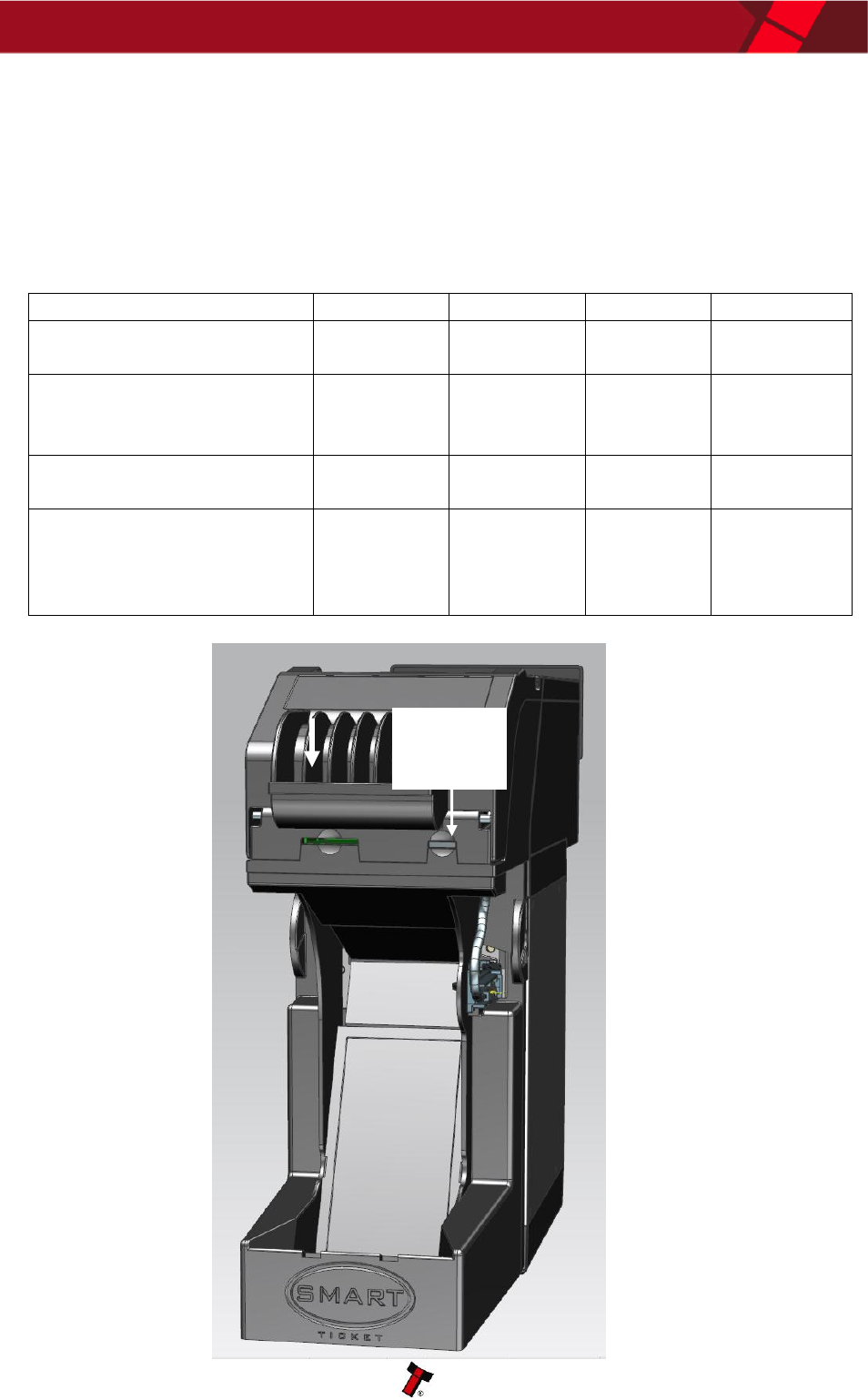
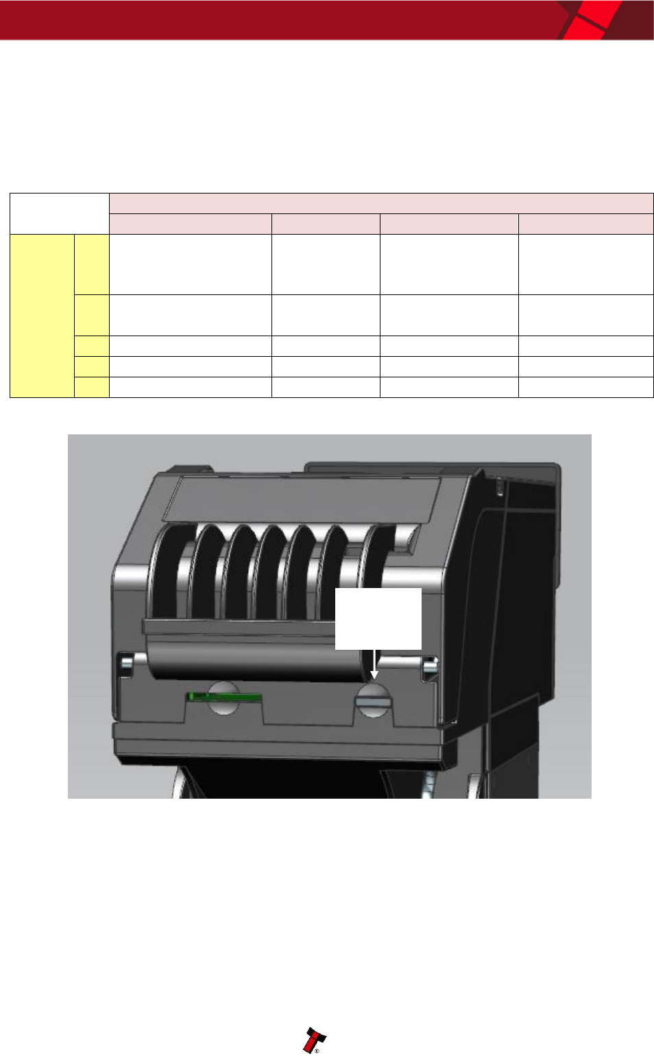
1.5 DIP Switch Settings
The SMART Ticket has 4 configuration switches to set the various options for the unit.
These options are triggered by pressing and holding the action button at the rear of
the SMART Ticket.
Action
Dip 1
Dip 2
Dip 3
Dip 4
Device prints a single test
ticket
OFF
OFF
OFF
OFF
Device prints a single test
ticket. Enters an error state
if the tickets are low.
OFF
OFF
OFF
ON
Device prints a single
barcode ticket.
ON
OFF
OFF
OFF
Device prints a single
barcode ticket. Device
enters an error state if the
tickets are low.
ON
OFF
OFF
ON
ON
OFF
Action
Button
SMART Ticket Integration Guide 12
Copyright © Innovative Technology Ltd 2013 GAxxx
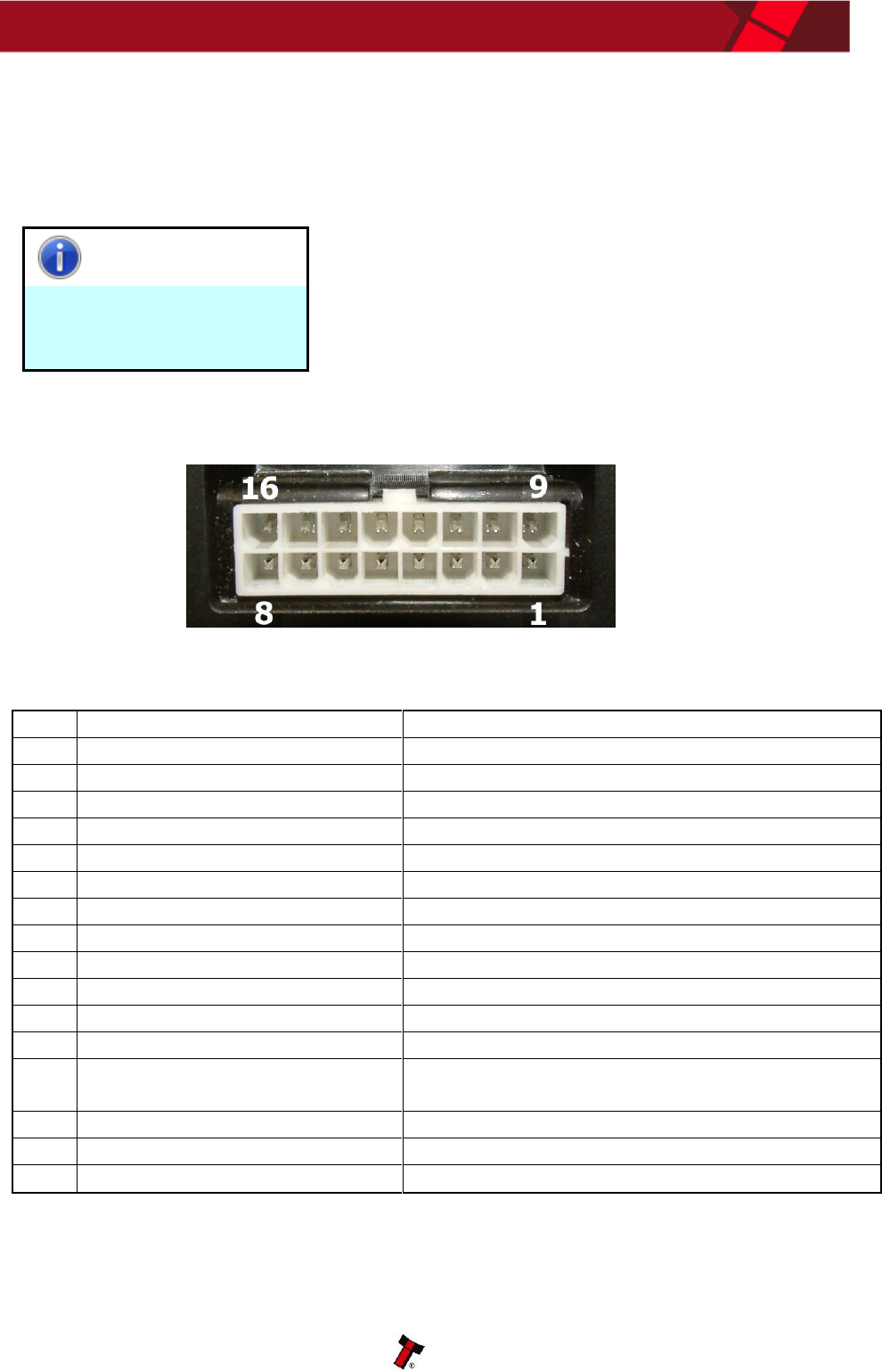
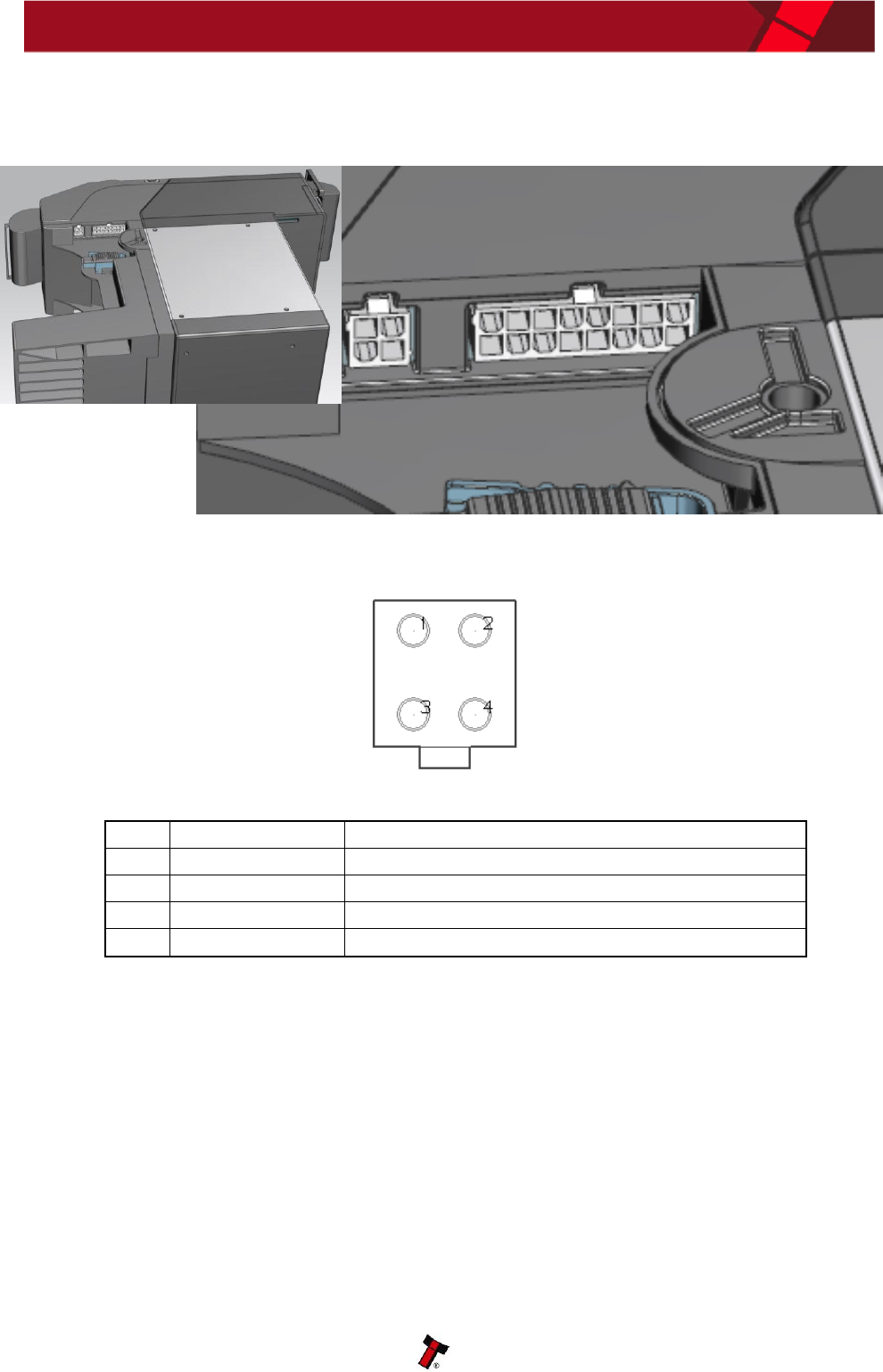
1.5 Connectors and Pinouts
The SMART Ticket has multiple connectors that are used to allow interfacing and
programming.
Information
Power always required
regardless of connection
type.
Power for the NV200 is always required on pins 1
and 9 of the 16 way connector. Power for the Ticket
Module is always required on the 4 way connector.
Pins
Reference
Comment
1
GND_NV200
GND for NV200.
2
N/A
Reserved for future use.
3
RS232_RXD_TITO
RS232 (Host to TITO)
4
OPTO-_RXD_NV200
Opto isolation (Host to NV200)
5
TTL_RXD_TITO
TTL (Host to TITO)
6
OPTO+_RXD_NV200
Opto isolation (Host to NV200)
7
TTL_TXD_TITO
TTL (TITO to Host)
8
OPTO_EMITTER_TXD_NV200
Opto isolation (NV200 to Host)
9
V_IN_NV200
+12V or +24V supply
10
N/A
Not connected
11
RS232_RXD_NV200
RS232 (Host to NV200)
12
RS232_TXD_TITO
RS232 (TITO to Host)
13
OPTO_COLLECTOR_TXD_NV20
0
Opto isolation (NV200 to Host)
14
TTL_RXD_NV200
TTL (Host to NV200)
15
RS232_TXD_NV200
RS232 (NV200 to Host)
16
TTL_TXD_NV200
TTL (NV200 to Host)
SMART Ticket Integration Guide 13
Copyright © Innovative Technology Ltd 2013 GAxxx
Pins
Reference
Comment
1
V_IN_TITO
+24V supply
2
GND
GND for TITO. Also linked to GND for NV200.
3
V_IN_TITO
+24V supply
4
GND
GND for TITO. Also linked to GND for NV200.
SMART Ticket Integration Guide 14
Copyright © Innovative Technology Ltd 2013 GAxxx
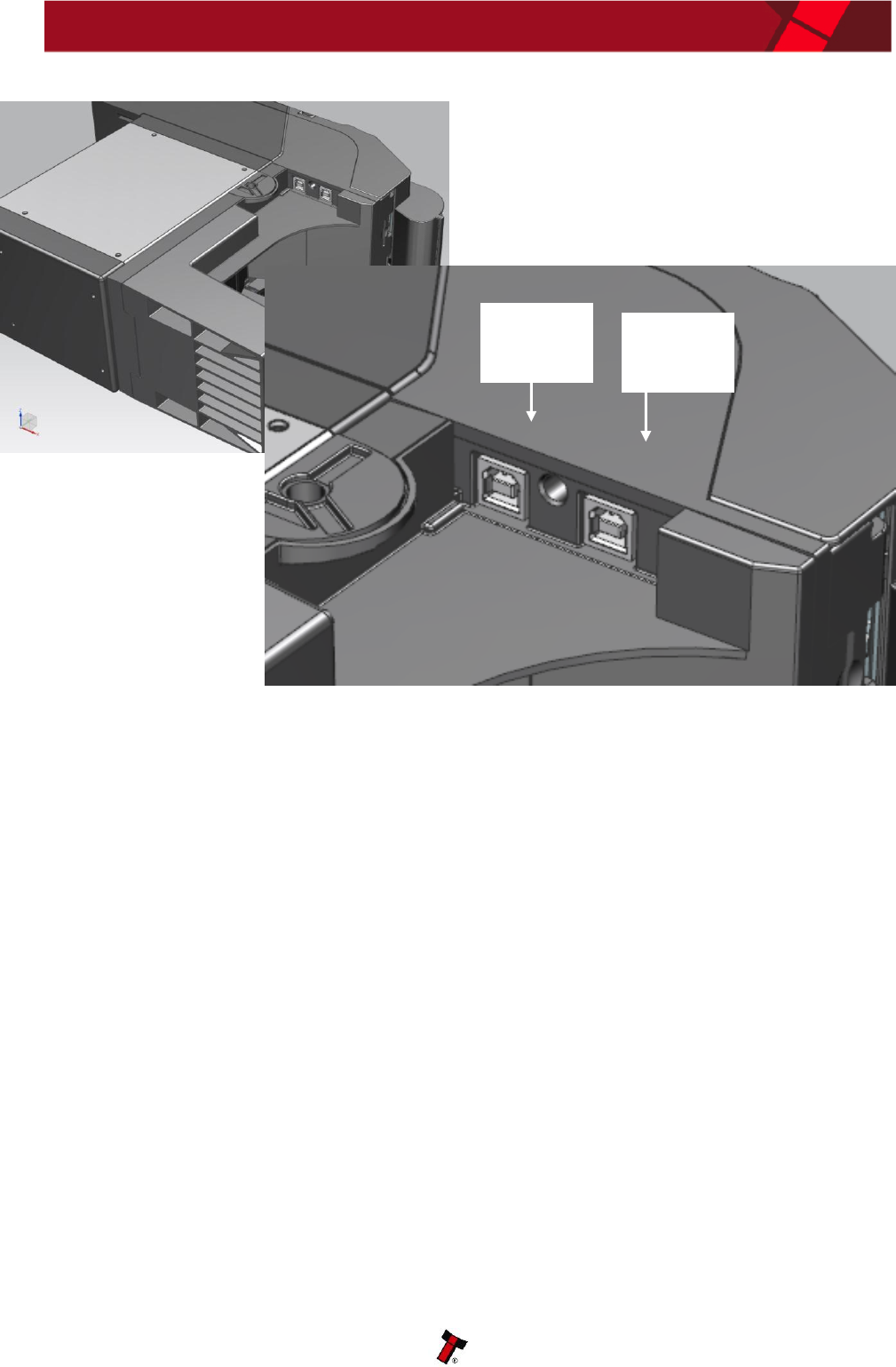
The USB connectors are standard Type ‘B’ USB socket, and can be used for interfacing
to the host machine – in this case, power must be provided through the 16 way
connector & 4 way connector. The USB sockets can also be used for programming the
Printer Module & the NV200 units – USB 2.0 compliant Type ‘A’ to ‘B’ lead can be
used to do this. USB cables should be electrically shielded and less than 5 metres
long.
NV200
Printer
Module
SMART Ticket Integration Guide 15
Copyright © Innovative Technology Ltd 2013 GAxxx
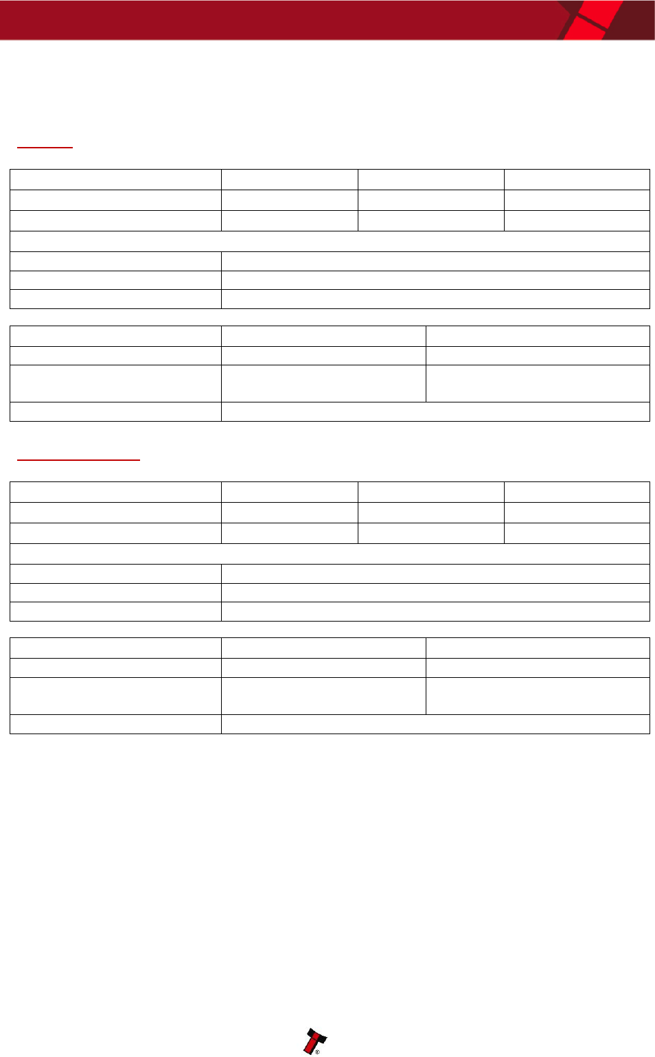
1.6 Technical Specifications
NV200
DC Voltage
Minimum
Nominal
Maximum
Absolute limits
10.8 V
12 V
24 V
Supply ripple voltage
0 V
0V
0.25 V @ 100 Hz
Supply Current
Standby
400 mA
Running
1.5 A
Peak (motor stall)
3 A
Interface Logic Levels
Logic Low
Logic High
Inputs
0 V to 0.5 V
+3.7 V to +12 V
Outputs (2.2 kΩ pull-up)
0.6 V
Pull-up voltage of host
interface
Maximum current sink
50 mA per output
Printer Module
DC Voltage
Minimum
Nominal
Maximum
Absolute limits
22 V
24 V
30 V
Supply ripple voltage
0 V
0V
0.5 V @ 100 Hz
Supply Current
Standby
200 mA
Printing
2.5 A
Peak (motor stall)
8 A
Interface Logic Levels
Logic Low
Logic High
Inputs
0 V to 0.5 V
+3.7 V to +12 V
Outputs (2.2 kΩ pull-up)
0.6 V
Pull-up voltage of host
interface
Maximum current sink
50 mA per output
SMART Ticket Integration Guide 16
Copyright © Innovative Technology Ltd 2013 GAxxx
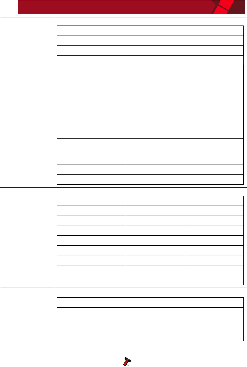
Functionality
Printing Method
Direct Thermal Printing
Dot Pitch
0.125 mm
Resolution
496 dots per line
Print Width
72mm
Print Speed
160mm/s
Ticket Print and Present
< 5 Seconds
Barcode Types
Interleaved 2 of 5, others by request.
Barcode Checking
Tickets checked by the NV200
Paper Loading
Automatic feed
Graphic resources
An SD card slot is available for storage
of extra fonts and images. 16M Bit
internal storage available
Interface: User
Ticket feed button, 4 dip-switches
LEDs: Ready, Paper, Open, Fault.
Interface: Protocols
eSSP,
Interface: Electrical
Open collector, True RS232, USB
Support tools
Template Manager & PIPS
Performance
Parameter
Min (mm)
Max (mm)
Ticket Type
Thermal Fan-Fold & Roll
Fan Fold Ticket Width
62
65
Ticket Length
160
Roll paper width
80
Ticket Thickness
0.1mm
0.13mm
Perforation strength
0.7Kg
1.3Kg
Ticket Capacity
900
Print Head Reliability
320,000 tickets
Environment
Parameter
Min
Max (Design Guide)
Operating temperature
(Ambient)
+5°C
+60°C
Humidity
5%
95% Non
Condensing
SMART Ticket Integration Guide 17
Copyright © Innovative Technology Ltd 2013 GAxxx
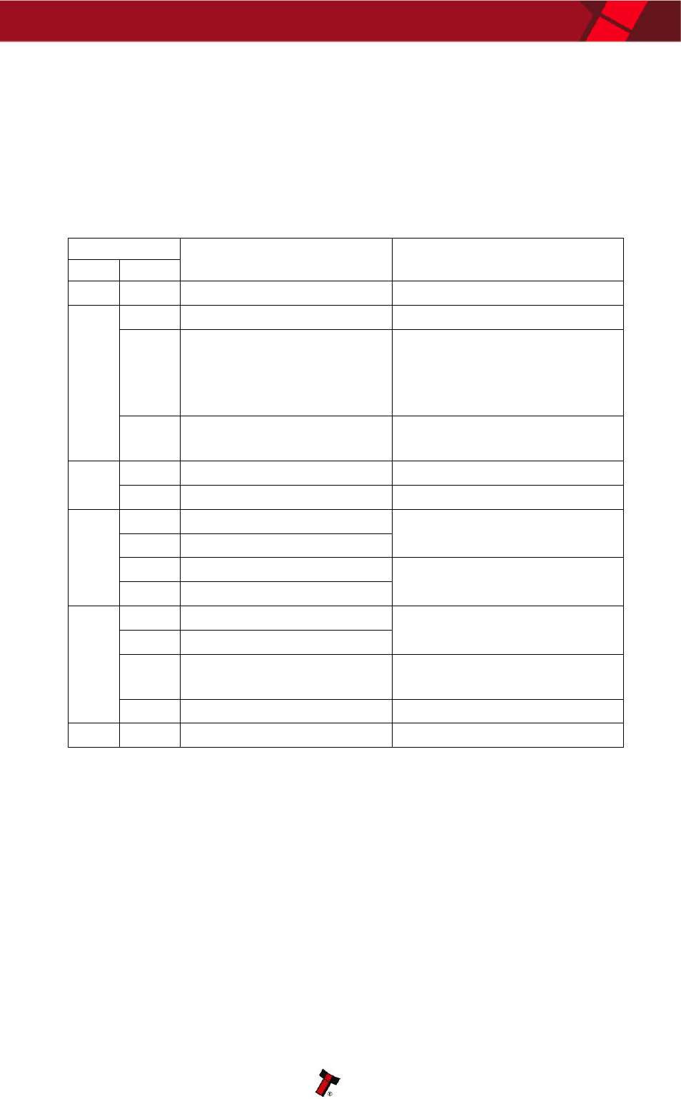
1.7 SMART Ticket Error Codes
The SMART Ticket unit has an inbuilt fault detection facility. If there is a configuration
or other error, the Status Indicator LEDs will flash in a particular sequence; a
summary of the Flash Codes for the SMART Payout unit is shown below:
Red
1
2
3
4
Yellow
1
No NV200
Connection
detected
No Paper
Diverter Not
Opened
Unknown Error
2
Initialisation Fail
Tab Not
Found
Diverter Not
Closed
Tickets Low
3
No Print Head
Load Fail
Burst Fail
4
Ticket Path Open
Cut Fail
5
Unknown Jam
Status
LED
SMART Ticket Integration Guide 18
Copyright © Innovative Technology Ltd 2013 GAxxx
1.8 NV200 Bezel Flash Codes
When the SMART Ticket module is installed on an NV200 bank note validator
additional fault finding help is available, as the NV200 has its own set of Flash Codes.
These are displayed in the front bezel of the validator.
A summary of the Bezel Flash Codes for the NV200 is shown below:
Flashes
Indicated Error
Comments
Red
Blue
0
0
None
1
1
Note path open
Close note path
2
Note path jam
Remove obstruction and
follow the cleaning
procedure in Section 2 of
this manual set
3
Unit not initialised
Contact ITL technical
support
2
1
Cashbox removed
Refit cashbox
2
Cashbox jam
Remove trapped notes
3
1
Firmware checksum error
Download new firmware
2
Interface checksum error
3
Dataset checksum error
Download new firmware
4
EEPROM checksum error
4
1
Power supply too low
Check power supply
2
Power supply too high
3
Card format
Reprogram programming
card
4
Payout reset
Turn power on and off
5
1
Firmware mismatch
Reprogram unit
SMART Payout Manual Set
Copyright © Innovative Technology Ltd 2013 GAxxx
MAIN HEADQUARTERS
Innovative Technology Ltd
Derker Street – Oldham – England - OL1 4EQ
Tel: +44 161 626 9999 Fax: +44 161 620 2090
E-mail: support@innovative-technology.co.uk
Web site: www.innovative-technology.co.uk
BRAZIL
suporte@bellis-technology.com.br
CHINA
support@innovative-technology.co.uk
GERMANY
support@automated-transactions.de
SPAIN
soporte@automated-transactions.es
UNITED KINGDOM
support@innovative-technology.co.uk
UNITED STATES OF AMERICA
supportusa@bellis-technology.com
REST OF THE WORLD
sales@innovative-technology.co.uk
