T10 4_01 S_T10 S
User Manual: S_T10
Open the PDF directly: View PDF ![]() .
.
Page Count: 4
. . . a step ahead
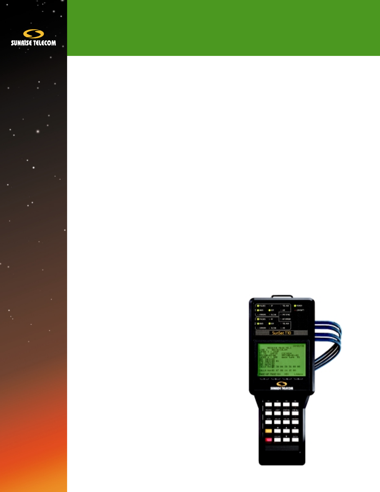
SunSetTM T10
SPECIFICATIONS
Connectors
Bantam jacks, Line 1 and 2 Tx/Rx
Serial Port: 8 DIN, RS232C (V.24), DTE
Datacom Port: SCSI-36 system expansion port
Test Mode
T1SINGLE: T1 line testing
T1DUAL: Bidirectional T1 line testing, DS0/VF
channelized drop/insert, SS7 protocol analysis, ISDN
PRI protocol analysis and call setup, DDS testing
T1-MUX: Fractional T1 datacom port drop/insert testing
DATACOM: V.35, RS449/V.36, X.21/V.11, RS232/V.24
Status/Alarm Indicators
Power and low battery LED indicators
16 dual-color LED indicators for Line 1 & 2: Pulses, B8ZS,
AIS, Yellow Alarm, SF-D4, ESF, SLC-96, Error
Logical: Test Pattern Sync, bit error
T1 Interface
Framing: SF-D4, ESF, SLC-96
Coding: AMI, B8ZS
Access Mode
DSX Monitor: 100Ω, ±1%
Bridge: > 1000Ω
Terminated: 100Ω, ±1%
Transmitter
Line Build Out (LBO): 0, -7.5, -15, -22.5 dB
Clock: Internal (1.544 MHz, ± 5 ppm), looped, external
Pulse shape to TR-TSY-000499; reference: G.703,
CB113, CB119, CB132, CB143, PUB62508, PUB62411
Receiver
Terminate, Bridge: +6 to -36 dB cable loss
DSXMON: -15 to -25 dB, resistive
Frequency range: 1542 kHz to 1546 kHz
Test Patterns
Repeating: 3 in 24, 1 in 8 (1:7), 1 in 16, 55 octet, 55
Daly, Alt 1010, All 0s, All 1s, FOX, T1-T6, DDS1, DDS2,
DDS3, DDS4, DDS6
Pseudo random: QRS, PRBS 2-n - 1, n = 6, 7, 9, 11, 15, 20, 23
Programmable: 10 patterns, 2048 bits long with user
defined alphanumeric labels
Test pattern inversion
Error Injection
BPV, logic, frame errors; programmable error burst 1 to
9999, or error rate 2 x 10⁻³ to 1 x 10⁻⁹
Measurements
Error Types: BPV, Bit error, Framing bit error, CRC-6 error
Error Reports: Total count, error rate, ES, %ES, SES,
%SES, UAS, %UAS, AS, %AS, DGRM, %DGRM
Alarm Statistics: AIS seconds, loss of signal seconds,
Yellow Alarm seconds, loss of frame seconds, change
of frame alignment seconds
G.821 Analysis
Signal Measurements
Signal available seconds count and percent, loss of
signal seconds count & percent, low density seconds
count, excess 0s seconds count, AIS seconds count
Receive bit rate: 1542 to 1546 kbps, ± 1 bps, ext/int
clock
Receive level (volts and dBdsx): Vpeak-peak, V+peak,
V-peak
Simplex current: 1 to 200 mA, ± 1 mA, ± 5%
Frequency Measurements
Moving bar graph of slip count, max frequency, min
frequency, clock slips, frame slips, max positive
wander, max negative wander
General
Measurement Duration: Continuous or timed
(programmable from 1 min to 999 hours)
Printing at timed interval or at end of test
Printing on alarm or event with timestamp
Error/Alarm events and test results may be stored in
NVRam in absence of printer
Other Measurements
View Received Data
View T1 data in binary, hex, ASCII
Shows data in bytes by timeslot
Trap 60 pages of data, 8 bytes per page
Captures 256 consecutive timeslots and stores as user
pattern
Bridge Tap
Automated transmission & measurement of 21 different
patterns to identify possible bridge taps on line
April 2001

Propagation Delay
Measure roundtrip propagation delay in unit intervals ± 1 UI, with
translation to microseconds and one way distance over cable
Quick Tests
Two programmable automated loopback tests that save time when
performing standardized loopback tests
CSU & NI Loopback Control
In-band Codes
CSU, NI, 100000
10 programmable user patterns
ESF-FDL
Payload, Line, Network
10 programmable user patterns
HDSL Span Control
Looping and control of HDSL equipment from DS1 access
Supports loopback commands for HTU-C, HTU-R, HRU, HLU, HRE
Graphical display updates with span status
Includes SF/ESF modes, arm, disarm, loop up, loop down, timeout disable
Westell & Teltrend Looping Device Control (SW184)
Automated looping of Westell and Teltrend line and central office
repeaters. Includes SF and ESF modes, arm, loop up/down, loopback
query, sequential loopback, power loop query, span power down/up,
unblocking
ESF Facility Data Link (SW182)
Read and Send T1.403 message on FDL (PRM and BOM)
Automatic HDLC protocol handling
YEL ALM, LLB ACT, LLB DEA, PLB ACT, PLB DEA
T1.403 24 hour PRM collection per 15 min interval
SLC-96 Data Link (SW182)
Send and receive message
WP1, WP1B, NOTE formats
Alarms, switch-to-protect, far end loop
To Telcordia TR-TSY-000008 specifications, mode I and III
Westell & Teltrend PM NIU and MSS (SW184)
Supports Westell and Teltrend performance monitoring network
interface unit and maintenance switch system with ramp. Set/query
NIU time and date. Query performance data by hour or all. Reset
performance registers. Read data over RAMP line. Perform mainte-
nance switch.
Pulse Mask Analysis (SW190)
Scan Period: 800 ns
Measurements: Pass/Fail, rise time, fall time, pulse width, %over-
shoot, %undershoot
Resolution: 1 ns or 1%, as applicable
Masks: ANSI T1.102, T1.403; AT&T CB119, Pub 62411
Pulse/Mask Display: Test set screen and SS118 printer
DDS Basic Package (SW188)
Test from T1 interfaces
Choose receive and transmit timeslots independently
Test rates: 2.4, 4.8, 9.6, 19.2, 56, 64 kbps
Patterns: 2047, 511, 127, 63, All 1s, All 0s, DDS-1, DDS-2, DDS-3,
DDS-4, DDS-6, 8-bit user, Alt 1010
Loopbacks: Latching, interleaved. CSU, DSU, OCU, DSO-DP, 8-bit user
Measurements: Bit errors, Bit error rate
Control code send/receive: Abnormal, mux out-of-sync, idle
Teleos & Switched 56 Tests (SW187)
Switched 56 call setup and bit error rate testing
Teleos signaling sequence timing analysis and dial digits decoding
Fractional T1
Error measurements, channel configuration verification
Nx64 kbps, Nx56 kbps, N=1 to 24
Sequential, alternating, or random channels
Auto scan and auto configure to any FT1 order
CSU & NI Emulation (SW181)
Bidirectional
Responds to loopback commands, in-band and out-of-band (ESF
datalink T1.403)
Graphic indication of incoming signal status in both directions
Simultaneous display of T1 line measurements
Automatic generation of AIS and Yellow alarm
Loopbacks
Line 1: Line and payload loopback
Line 2: Line loopback
Simultaneous loopbacks in both directions
Local and remote loopback control
Remote Control (SW180)
VT100 emulation with same graphical interface used by test set
Circuit status table provides current and historical information on
test set LEDs
Uses 8 pin MINI DIN, RS232C, 9600 baud preferred
Voice Frequency Capabilities
Monitor speaker with volume control for Line 1 and 2
Built-in microphone for talk
View all 24 channel A, B (C, D) bits for Line 1 and 2
Control A, B (C, D) bits (E&M ground/loop start, FXO, FXS, on/off
hook, wink)
Companding law - µ Law
Programmable idle channel A, B (C, D) bits
Selectable idle channel code, 7F or FF hex
VF Level and Frequency Measurement
Level: +3 to -60 dBm, resolution 0.1 dBm
Frequency: 50 to 3950 Hz, resolution 1 Hz
VF tone generation
Variable tone: 50 to 3950 Hz @ 1 Hz step, +3 to -60 dBm @ 1 dBm
Fixed tones: 404, 1004, 1804, 2713, 2804 Hz @ 0 dBm and -13 dBm
SunSetTM T10

Noise Analysis (SW183)
Signal to noise (S/N)
Noise with filters: 3 kHz flat, C-message, C-notch
MF/DTMF/DP Dialing, Decoding/Analysis (SW185)
MF/DTMF/DP dialing up to 32 digits, 10 user programmable quick
dial number for each tone type
MFR1 digits, 0 - 9, KP, ST, ST1-3, Pause
DTMF digits, 0 - 9, *, #, A, B, C, D, Pause
DP digits, 0 - 9, Pause
MF/DTMF decode up to 40 received digits. Analyze number, high/low
frequencies, high/low levels, twist, tone period, interdigital time.
Analyzer dynamic range: 0 to -25 dBm
DP decode up to 40 digits. Analyze number, %break, PPS, interdigital
time
Programmable interdigital period, tone period, and tone level (MF, DTMF)
Programmable %break and interdigital period @ 10 pps (DP)
Signaling Analysis
Analyze mode
Tracer on A, B (C, D) signaling state changes for Line 1 and 2 with
timestamps
MFR1: Timing analysis of signaling transition states and dialing
digits decoding of MFR1 signaling
MFR1M: Modified MFR1 CO switches signaling analysis
MIXTONE: Decode a signaling sequence that has both MF and
DTMF digits
Protocol Analysis
SS7 (SW189A)
Layer 2, 3, 4 analysis to bit level
SU traffic analysis
Counters for FISU, LSSU, TUP, ISUP, SNM, SNT messages
Counters for FIB and BIB retransmissions
% analysis on different types of messages
MSU tracer
User programmable trace filter; CIC, DPC, OPC, H1H0, Signaling
address
View bidirectional real time message flow
Messages are interpreted up to layer 4 or displayed in hex format.
The trace storage holds up to 1000 messages.
SS7 TCAP Analysis (SW189B)
ANSI T1.114
TCAP filter: And/or filtering on Origination and Destination Transac-
tion ID
Decoding: For Transaction, Dialogue, and Component Portions
Transaction Portion decoding includes Package Type and Transac-
tion ID
Dialogue Portion decoding for Information Element Identifier and
Context
Component decode screen displays Component Type, Correlation
ID, Operation Code (Operation Family & Operation Specifier),
and Parameter Identifier and Contents
ISDN PRI (SW186)
Bidirectional monitoring and call analysis
National ISDN-2, AT&T 5ESS, ETSI, and Northern Telecom DMS-100
compatible
NT and TE emulation
Voice and data call setup and receive
Built-in microphone and speaker for B-channel talk/listen
Supports multirate Nx64k data calls
Generates 2047, 511, 127, 63, All 1s, All 0s, and user programmable
8-bit test patterns
Bit error rate test with G.821 analysis
Supports 23B+D, 47B+D, and 46B+2D
Test for Backup D-channel in 46B+2D
User programmable trace filter, view bidirectional real time message
flow. Messages are interpreted up to layer 3 or displayed in hex
format.
Trace storage holds up to 1000 messages with timestamps
On-screen help for special optional call feature programming
GSM 16K Voice/TRAU Analysis (SW191)
Supports GSM 06.10, 08.60
Drop/Monitor 16 kbps GSM channel at 13 kbps voice rate to built-in speaker
Selectable timeslot (1 to 24) and subchannel (1 to 4)
Codification RPE LTP at 13 kbps
Frame type decode of 16 kbps subchannel (Voice, Data, Idle)
Identify uplink or downlink direction
Transmit encoded 13 kbps voice message on timeslot/subchannel
BERT (G.821) on 16 kbps subchannel: Bit error/rate, ES, SES, EFS, UAS, LOSS
Send test pattern on 16 kbps: 2047, All 1s, All 0s, Alt 1010
GR-303 Analysis (SW193)
Bidirectional monitoring of TMC/CSC/EOC channels
Tricordia GR-303-CORE
TMC/CSC Monitoring
Decode to Layer 3
Statistics counters for each cause value
1000 messages can be stored with date & timestamp, direction,
and full L3 decode
Trace filters for: Call Reference Value, DS0, DS1, Cause Value
EOC Verification
Decode to Layer 2
Errored or discarded frame counters
Filter on SAPI/TEI combination
Frame Relay Analysis (SW194)
Supported from DS1 or V.35 interface
Test Rate: 1.544 Mbps, Nx56 kbps, Nx64 kbps
Supports ITU-T Q.933, ANSI T1.617
Mode: UNI DTE/DCE
Requires factory installation
LMI Analysis
Auto configuration for protocol type
Settings: T391 Status Enquiry, T393 Status, N391 Full Status
Polling, N392 Error Threshold, N393 Monitor Events
Results: Link O.K. Total, Link Errored Total, Timeout Error, Re-
sponse Sequence Number, Wrong message
PVC Status: New, Active, New & Active, or Inactive DLCI indication

Note: Specifications subject to change without notice.
© 2001 Sunrise Telecom Incorporated. All rights reserved.
Printed in USA.
22 Great Oaks Blvd.
San Jose, CA 95119
ph 1 408 363 8000
fax 1 408 363 8313
info@sunrisetelecom.com
www.sunrisetelecom.com
S
U
N
R
I
S
E
T
E
L
E
C
O
M
,
I
N
C
.
I
S
O
9
0
0
1
-
A
6
3
8
0
PING Testing
Transmit and respond to PING messages
Send Settings: DLCI length (2-4 bytes), DLCI value,
Local IP, Destination IP, Network Layer Protocol
Identifier (NLPID), Timeout, Number of PINGS
Results: Number of PINGs, Number sent, PING status
(received, unreached, errored), Round Trip Time
(current, average, maximum, minimum)
Response settings: Local IP
Response results: PVC status, Number of PINGS,
Number received, PING from IP address with
timestamp
Datacom Interface (SS151)
Supports V.35, X.21 (V.11), RS232 (V.24), RS449 (V.36)
RS530 interfaces
DTE, DCE Emulation
SCSI-36 connector to test set: Adapter cables for V.35,
X.21, RS232 (V.24), RS449 (V.36), RS530
Synchronous data rates: 300 bps to 1.544 Mbps
Asynchronous data rates: 50 bps to 19.2 kbps (RS232-
V.24 only)
Send test patterns and make G.821 measurements
Bit error injection
View transmit and receive signal status: TxD, TxC, RxD,
RxC, DTR, RTS, CTS, DSR, RL, LL, RI
Control signal leads: DTR, RTS, CTS, DSR, DCD, RL, LL, RI
Invoke Local Loopback (LL), Remote Loopback (RL)
Internal or received clock selectable
Hitless 1.544k, Nx56k and Nx64k T1 drop and insert, via
V.35, X.21 (V.11), RS232 (V.24), RS449 (V.36) interface;
DCE mode only
GENERAL
Operating temperature: 0˚C to 50˚C
Operating humidity: 5% to 90%, noncondensing
Storage temperature: -20˚C to 70˚C
Size: 2.4" (max.) x 4.2" (max.) x 10.5"
Weight: 2.5 lb [1.1 kg]
Battery operation time: 2 1/2 hr nominal
AC operation: 110V/120V @ 60 Hz, or 220V/240V @ 50 Hz
3 year warranty on chassis
1 year warranty on accessories and battery
ORDERING INFORMATION
Test Set
SS150B SunSet T10 Chassis
Includes chassis, Software cartridge, NiMH
battery, Universal Charger (SS138C), Instru-
ment Stand, and User's Manual
Hardware Option
SS151 Datacom Module
Includes cable adapters for V.35, RS449/V.36,
X.21, RS232, DTE and DCE
Software Options
SW180 Remote control
SW181 CSU/NIU Emulation
SW182 ESF & SLC-96 Data Link Send and Receive
SW183 VF Level, Frequency, and Noise Measurement
SW184 Westell, Teltrend Intelligent Products
SW185 MF/DTMF/DP Dialing, Decoding, and Analysis
SW186 ISDN PRA (also known as PRI) Call Setup &
D-channel Monitor
SW187 Switched Call Setup and BERT
SW188 DDS testing (T1 interface access)
SW189A SS7 Protocol Analysis
SW189B SS7 TCAP Analysis
SW190 Pulse Mask Analysis
SW191 GSM 16K Voice/TRAU Analysis
SW193 GR-303 Analysis
SW194 Frame Relay Analysis (Requires factory installation)
Accessories
SS101 Carrying case
SS104 Cigarette lighter battery charger
SS105 Repeater extender
SS106 Single bantam to bantam cable, 6'
SS107 Dual bantam to bantam cable, 6'
SS108 Single bantam to 310 cable, 6'
SS109 Single bantam to alligator clip cable, 6'
SS110 Dual bantam to 15-pin D-sub connector cable,
Male, 6'
SS111 Dual bantam to 15-pin D-sub connector cable,
Female, 6'
SS112 2 single bantams to RJ-48 8 position modular
plug cable, 6'
SS115B 8-pin mini DIN to DB9 Printer cable
SS116 Instrument stand
SS117 Printer paper, 5 rolls, for SS118
SS118B High capacity thermal printer. Includes SS115B.
SS122C Null Modem Adapter
SS123A SunSet jacket
SS127 Printer 220VAC charger for SS118
SS128A 120V/12V 1.2A SunSet Charger
SS130A 19"/23" SunSet Rack Mount - Removable
SS130B 19"/23" SunSet Rack Mount - Permanent
SS132 Two single bantams to 4-position modular
plug cable
SS136 SunSet T10 User's Manual
SS138C SunSet AC Adapter, 100-240 VAC, 50/60 Hz
input, output 15 VDC @ 2A
SS152 SunSet T10 Training Tape
SS252 V.35 DTE/DCE Adapters
SS253 X.21/V.11 DTE/DCE Adapters
SS254 RS232/V.24 DTE/DCE Adapters
SS255 RS449/V.36 DTE/DCE Adapters
SS262 RS530 DTE/DCE Adapters
SS308 Datacom Cable SCSI-36 (m) to DB-37 (f), 6'
Your representative:
Roman Porenta
rporenta@omnicor.com
Omnicor
1170 Foster City Blvd.
Foster City, CA 94404
Phone: (650) 572 0122
Ext. 111
Fax: (650) 572 0533
www.omnicor.com
