STG 600 Data Sheet Brochure
User Manual: STG-600-Data-Sheet-Brochure
Open the PDF directly: View PDF ![]() .
.
Page Count: 2
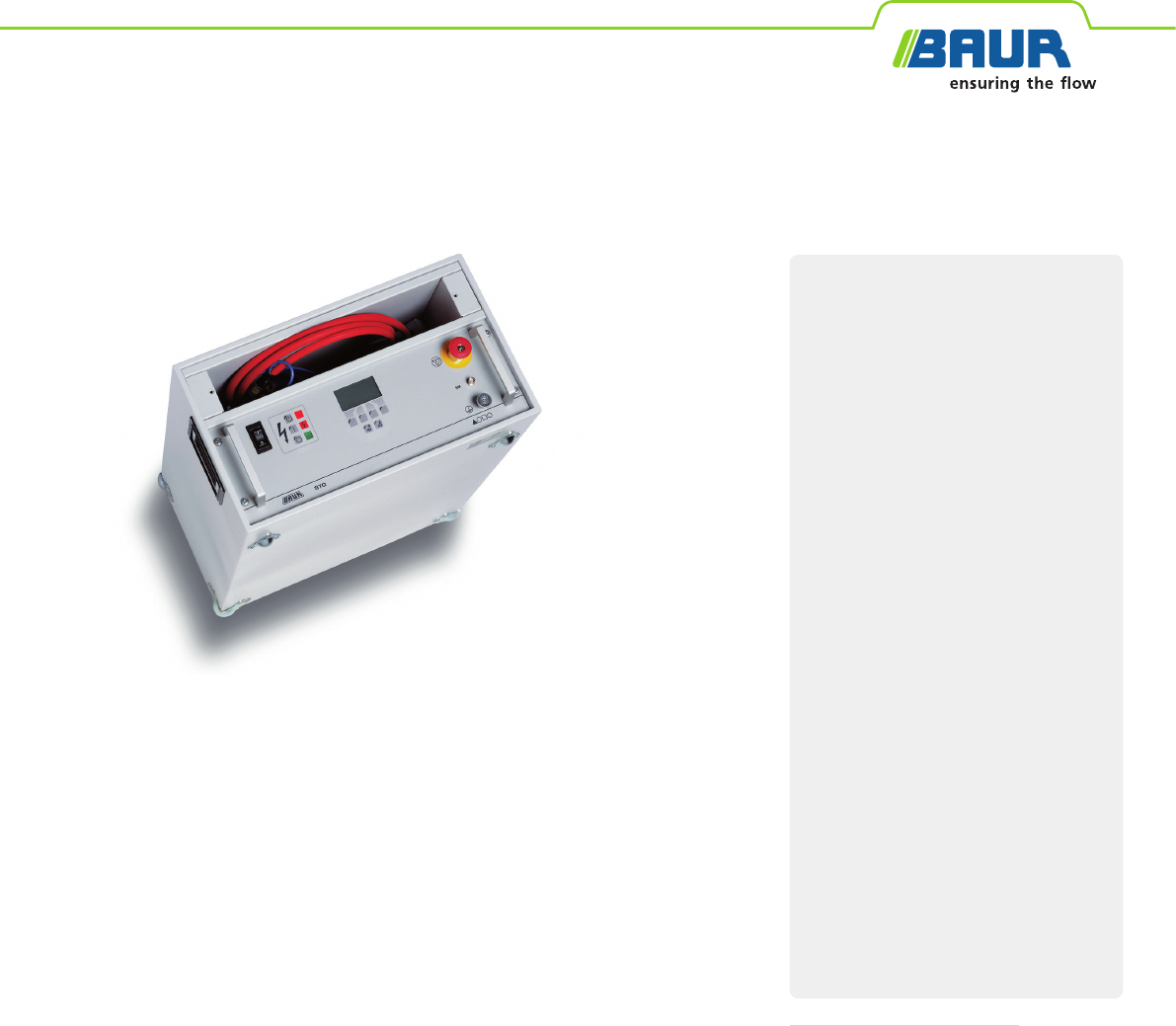
STG 600
BAUR surge and test generator
The STG 600 surge and test generator is used for cable testing as well as for precise
pin-pointing of faults of all types in low voltage cables.
The optional SIM/MIM coupling filter and the IRG2000 time domain reflectometer
make the most eective pre-location methods SIM/MIM (Secondary/multiple
impulse method) and time domain reflectometer available. This allows the precise
location of both high-resistive and low-resistive cable faults.
Thanks to the intuitive operation and operator-friendly menu navigation, cable fault
location with the STG 600 is quick and easy.
Functions
▪ Cable testing with DC voltage
▪ Acoustic pin-pointing
▪ Step voltage method for pin-pointing cable
sheath faults
▪ Insulation resistance measurement*
▪ SIM/MIM Secondary/multiple impulse
method*
Features
▪ Output voltage in adjustable 0.1-kV steps
▪Automatic short-circuit and breakdown
detection in test mode
▪Comprehensive safety concept in accordance
with the latest standards
▪ Two separate discharge units for cable and
internal surge capacitor
▪ Voltage-proof up to AC 400 V*
▪Simple operation and self-explanatory
menu navigation in several languages
▪Switch between operation functions at the
press of a button
▪ Built-in cable compartment
▪ Protective cover for the control panel
BAUR GmbH · Raieisenstraße 8, 6832 Sulz, Austria · T +43 (0)5522 4941-0 · F +43 (0)5522 4941-3 · headoce@baur.at · www.baur.eu
Compact system with many functions
↗Specifically for use in low-voltage networks
↗ Single system for cable testing and fault location
↗High surge energy: 600 or 1000 J*
↗Light, compact and transportable
*Option
Data sheet: BAUR GmbH · 826-051-4 · 07.2016 · Subject to modifications
Technical data
Cable testing
DC voltage (negative) 0.2 – 5 kV
Max. output current (negative) 300 mA
Test time 0.5 min – 60 min or continuous operation
Acoustic pin-pointing
DC voltage (negative) 0.2 – 4 kV
Max. surge energy 600J
Option 1000 J (see the section“Options”)
Surge sequence 1 - 30 pulses/min, single surge
Standard setting: 20 pulses
Step voltage method (sheath fault location)
DC voltage (negative) 0.2 – 5 kV
Max. output current (negative) 700 mA
Pulse rate 5 selectable programmes
Measuring time 0.5 min – 60 min or continuous
operation
Options
Increase in surge energy:
Surge energy 1000 J
Surge sequence 1 – 20 pulses/min, single surge
Max. power consumption 1200 VA
Insulation resistance
measurement
0.1kOhm – 100MOhm
Voltage-proof up to 400 V, 50/60 Hz in all operating
modes
General
Display Colour-LCD, screen resolution 160 x 80
pixels
User interface languages Dutch, English, French, German, Italian,
Spanish
Power supply 200 – 260 V, 50/60 Hz
Option 100 – 130 V, 50/60 Hz
(with isolation transformer)
Max. power consumption 800 VA
Relative humidity ≤ 85%, non-condensing
Ambient temperature (operati-
onal)
0 °C to +50 °C
Storage temperature -20°C to +60°C
Dimensions (W x H x D) Approx. 483 x 267 x 680mm
Weight Approx. 44 kg
Safety and EMC CE-compliant in accordance with Low
Voltage Directive (2014/35/EU),
EMC Directive (2014/30/EU),
EN 60068-2-ff Environmental testing
Standard delivery
▪STG 600 surge and test generator,
incl. HV connection cable, 5 m
▪Isolation transformer 230 V; 1.2 kVA
▪Earth cable, 4 m, with earthing terminal and operational earthing
▪Protective cover for front plate
▪Mains supply cord 2.5 m
▪User manual
Options
▪Increase in surge energy to 1000 J (instead of 600 J)
▪IRG 2000 time domain reflectometer
▪SIM/MIM coupling filter (only in combination with the IRG 2000)
▪Fixing device for fastening of IRG 2000 to STG 600
▪Insulation resistance measurement for the STG 600
▪Reverse voltage protected HV output (AC 0 – 400 V)
▪Isolation transformer 115/230 V; 1.2 kVA
