2pv 20_PV_I Series Service
User Manual: 20_PV_I
Open the PDF directly: View PDF ![]() .
.
Page Count: 32
1
Price - $3.00
INSTALLATION, OPERATING
AND
SERVICE INSTRUCTIONS
SERIES 2PV
GAS BOILER
8141775R9-11/99
For service or repairs to boiler, call your heating contractor. When seeking information on boiler, provide
Boiler Model Number and Serial Number as shown on Rating Label.
Boiler Model Number
20_PV_I-_ _ _ _
Boiler Serial Number
6_ _ _ _ _ _ _
Installation Date
Heating Contractor Phone Number
Address

2
The following terms are used throughout this manual to bring attention to the presence of hazards of various risk
levels, or to important information concerning product life.
Table of Contents
I. Pre-Installation ..................................... 4
II. Unpack Boiler ....................................... 5
III. Water Piping ......................................... 6
IV. Gas Piping ............................................ 8
V. Venting ................................................. 9
VI. Electrical ............................................. 12
VII. System Start-up .................................. 13
VIII. Service Instructions ............................ 20
IX. Repair Parts ........................................ 23
WARNING
Indicates a potentially hazardous situation
which, if not avoided, could result in death,
serious injury or substantial property damage.
CAUTION
Indicates a potentially hazardous situation
which, if not avoided, may result in
moderate or minor injury or property
damage.
NOTICE
Indicates special instructions on
installation, operation, or maintenance
which are important but not related to
personal injury hazards.
DANGER
Indicates an imminently hazardous situation
which, if not avoided, will result in death,
serious injury or substantial property damage.
3
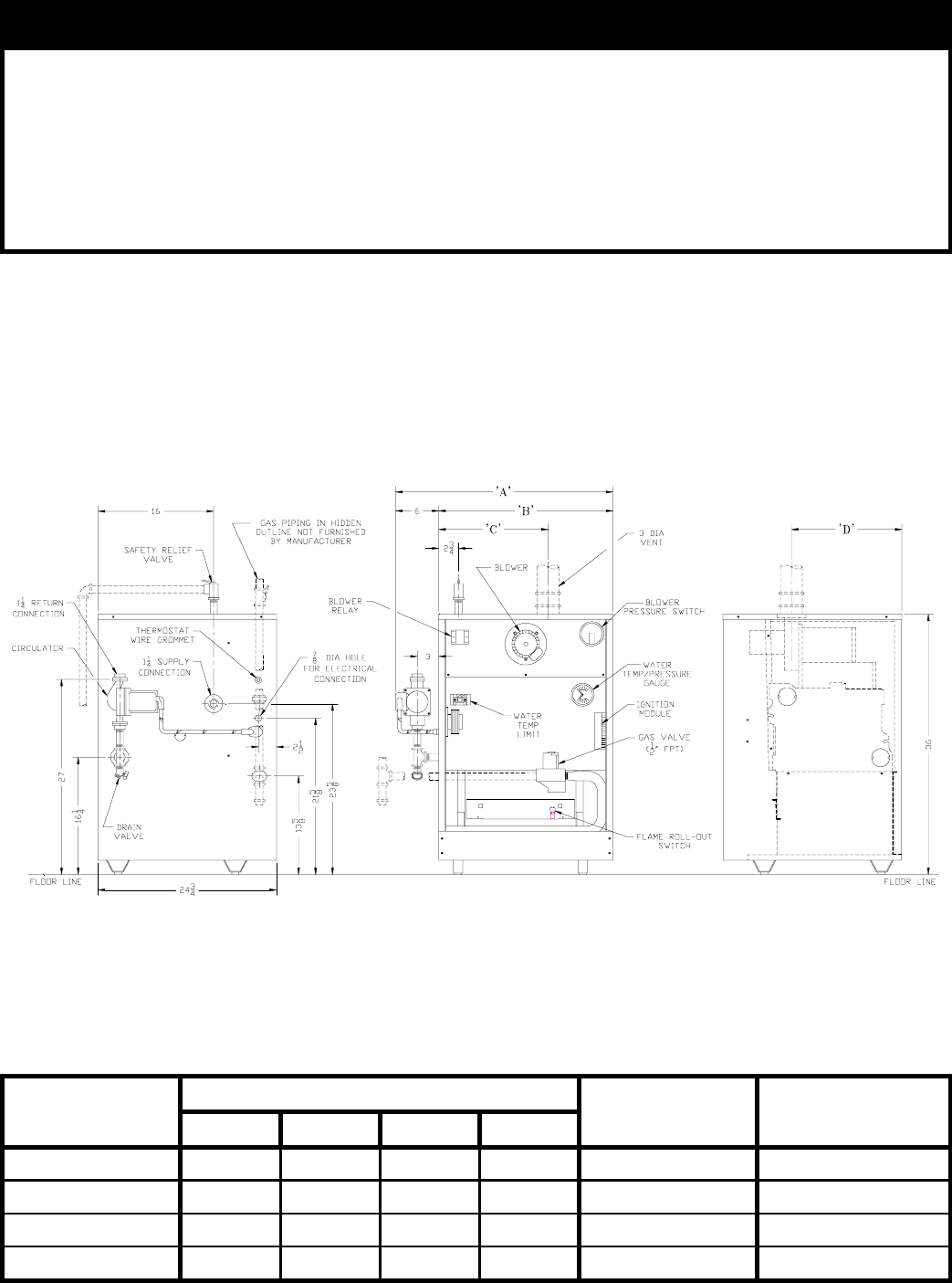
Figure 1: Elevation Views
NOTICE
USA boilers built for installation at altitudes greater than 2,000 feet above sea level have been
specially orificed to reduce gas input rate 4 percent per 1,000 feet above sea level per the National
Fuel Gas Code, NFPA 54/ANSI Z223.1, Section 8.1.2 and Appendix F. Canadian boilers’ orifice
sizing is indicated on the rating label. High altitude boiler models are identifiable by the second
digit in the model number suffix on the rating label:
20_PV_I-__2: Less than 2000 ft. elevation
20_PV_I-__4: 2000 ft. and higher elevation, Canada
20_PV_I-__5: 2000 ft. and higher elevation, USA
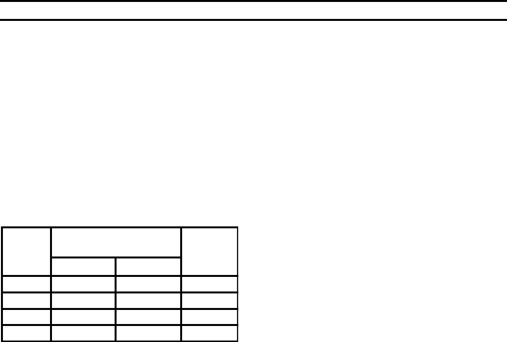
Boiler Model Dimensions [in inches] Water Content
[Gallons]
Approx. Shipping
Weight (lb.)
ABCD
203PV 20‰ 14‰ 10-1/16 15-5/8 3.2 265
204PV 23 17 11 15-5/8 4 309
205PV 27 21 13‰ 15… 4.7 357
206PV 30… 24… 15-1/8 15… 5.5 419
4
I. Pre-Installation
C. Appliance is design certified for installation on
combustible flooring. The boiler must not be installed
on carpeting.
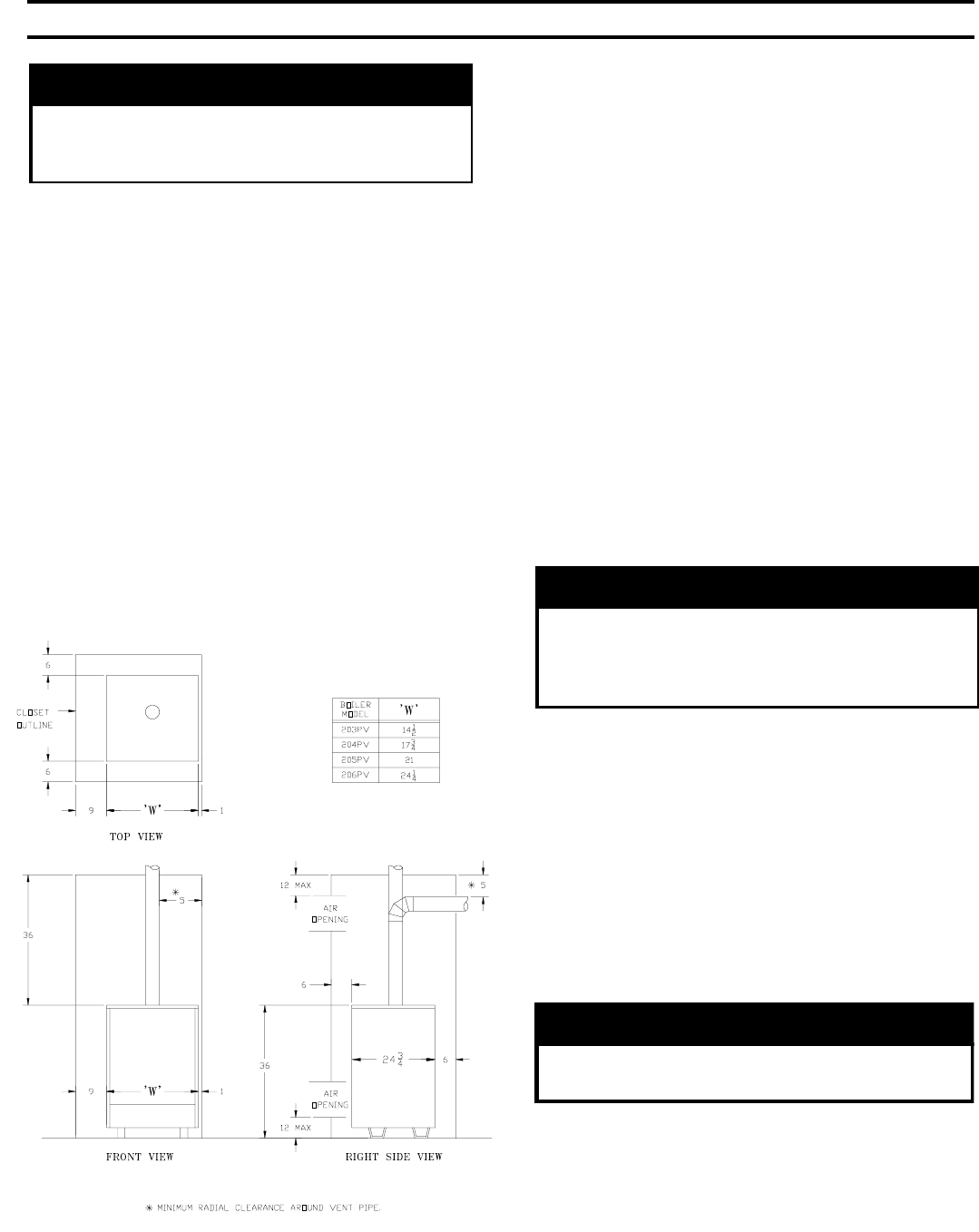
D. Provide clearance between boiler jacket and
combustible material in accordance with local fire
ordinance. See Figure 2 for minimum clearance from
combustible material for closet installation. For alcove
installation provide top clearance of 27 inches and
right side clearance of 6 inches. Recommended service
clearance is 24 inches from left side, right side and
front. Service clearances may be reduced to minimum
clearances to combustible materials.
E. Install on level floor. For basement installation
provide solid base, such as concrete, if floor is not
level or if water may be encountered on floor around
boiler.
F. Install near outside wall for through wall venting.
Refer to Section V: Venting. Certified for minimum
vent length of 2 feet with one (1) elbow and maximum
vent length of 15 feet with one (1) or two (2) elbows.
WARNING
Certified as Category III appliance. Install vent
system in accordance with Section V: Venting.
Do not vent using masonry chimney, Type B gas
vent, or other Category I venting system.
G. Protect gas ignition system components from water
(dripping, spraying, rain, etc.) during boiler operation
and service (circulator replacement, condensate trap,
control replacement, etc.).
H. Provide combustion and ventilation air in
accordance with applicable provisions of local building
codes, or National Fuel Gas Code, NFPA 54/ANSI
Z223.1, Section 5.3, Air for Combustion and
Ventilation, or Sections 7.2, 7.3 or 7.4 of CAN/CGA
B149 Installation Codes.
WARNING
Adequate combustion and ventilation air must
be provided to assure proper combustion.
The following guideline is based on the National Fuel
Gas Code, NFPA 54/ANSI Z223.1.
1. Determine volume of space (boiler room). Rooms
communicating directly with space (through
openings not furnished with doors) are considered
part of space.
Volume [ft³] = Length [ft] x Width [ft] x Height [ft]
WARNING
Carefully read all instructions before installing
boiler. Failure to follow all instructions in proper
order can cause personal injury or death.
A.Inspect shipment carefully for any signs of damage.
All equipment is carefully manufactured, inspected and
packed. Our responsibility ceases upon delivery of
boiler to carrier in good condition. Any claim for
damage or shortage in shipment must be filed
immediately against carrier by consignee. No claims
for variances or shortages will be allowed by Boiler
Manufacturer, unless presented within sixty (60) days
after receipt of equipment.
B. Installation must conform to the requirements of the
authority having jurisdiction. In the absence of such
requirements, installation must conform to National
Fuel Gas Code, NFPA 54/ANSI Z223.1, and/or CAN/
CGA B149 Installation Codes. Where required by the
authority having jurisdiction, the installation must
conform to the Standard for Controls and Safety
Devices for Automatically Fired Boilers, ANSI/ASME
CSD-1.
Figure 2: Minimum Clearances to Combustible
Construction for Closet Installation

5
2. Determine Total Input of all appliances in space.
Round result to nearest 1,000 Btu per hour (Btuh).
3. Determine type of space. Divide Volume by Total
Input.
a. If result is greater than or equal to 50 ft³ per
1,000 Btuh, space is considered an unconfined
space.
b. If result is less than 50 ft³ per 1,000 Btuh, space
is considered a confined space.
4. Determine building type. A building of unusually
tight construction has the following characteristics:
a. Walls and ceiling exposed to outside atmosphere
have a continuous water vapor retarder with a
rating of 1 perm or less with openings gasketed
and sealed, and;
b. Weather-stripping has been added on openable
windows and doors, and;
c. Caulking or sealants applied in joints around
window and door frames, between sole plates
and floors, between wall-ceiling joints, between
wall panels, at plumbing and electrical
penetrations, and at other openings.
5. For boiler located in an unconfined space in a
building of other than unusually tight construction,
adequate combustion and ventilation air is normally
provided by fresh air infiltration through cracks
around windows and doors.
6. For boiler located within unconfined space in
building of unusually tight construction or within
confined space, provide outdoor air through two
permanent openings which communicate directly or
by duct with the outdoors or spaces (crawl or attic)
freely communicating with the outdoors. Locate one
opening within 12 inches of top of space. Locate
remaining opening within 12 inches of bottom of
space. Minimum dimension of air opening is 3
inches. Size each opening per following:
a. Direct communication with outdoors. Minimum
free area of 1 square inch per 4,000 Btu per hour
input of all equipment in space.
b. Vertical ducts. Minimum free area of 1 square
inch per 4,000 Btu per hour input of all
equipment in space. Duct cross-sectional area
shall be same as opening free area.
c. Horizontal ducts. Minimum free area of 1
square inch per 2,000 Btu per hour input of all
equipment in space. Duct cross-sectional area
shall be same as opening free area.
Alternate method for boiler located within confined
space. Use indoor air if two permanent openings
communicate directly with additional space(s) of
sufficient volume such that combined volume of all
spaces meet criteria for unconfined space. Size each
opening for minimum free area of 1 square inch per
1,000 Btu per hour input of all equipment in
spaces, but not less than 100 square inches.
7. Ventilation Duct Louvers and Grilles. Equip
outside openings with louvers to prevent entrance
of rain and snow, and screens to prevent entrance of
insects and rodents. Louvers and grilles must be
fixed in open position or interlocked with
equipment to open automatically before burner
operation. Screens must not be smaller than ¼ inch
mesh.
Consider the blocking effect of louvers, grilles and
screens when calculating the opening size to
provide the required free area. If free area of louver
or grille is not known, assume wood louvers have
20-25 percent free area and metal louvers and
grilles have 60-75 percent free area.
I. Do not install boiler where gasoline or other
flammable vapors or liquids, or sources of
hydrocarbons (i.e. bleaches, cleaners, chemicals,
sprays, paint removers, fabric softeners, etc.) are used
or stored.
II. Unpack Boiler
CAUTION
Do not drop boiler. Do not bump boiler jacket
against floor.
A. Move boiler to approximate installed position.
B. Remove all crate fasteners.
C. Lift outside container and remove with all other inside
protective spacers and bracing. Save two of the
wooden slats from the container sleeve for use in Steps
E and F.
D. Remove all boiler hold-down fasteners.
E. Tilt the boiler to one side and slide a wooden slat
under the two raised feet.
F. Tilt the boiler to the other side and slide another
wooden slat under the two raised feet.
G. Slide the boiler forward or backward off the skid using
the two wooden slats as runners.
H. Move boiler to its permanent location.
6
III. Water Piping and Trim
CAUTION
Failure to properly pipe boiler may result in
improper operation and damage to boiler or
building.
A. Design and install boiler and system piping to prevent
oxygen contamination of boiler water.
CAUTION
Oxygen contamination of boiler water will cause
corrosion of iron and steel boiler components,
and can lead to boiler failure. Burnham’s
standard warranty does not cover problems
caused by oxygen contamination of boiler water.
Oxygen contamination sources are system leaks
requiring addition of makeup water, fittings, and oxygen
permeable materials in distribution system. Eliminate
oxygen contamination by repairing system leaks,
repairing fittings, and using nonpermeable materials in
distribution system.
B. Connect system supply and return piping to boiler. See
Figure 3. Also consult I=B=R Installation and Piping
Guides. Maintain minimum ½ inch clearance from hot
water piping to combustible materials.
C. Install Circulator with flanges, gaskets and bolts
provided. Five foot circulator harness allows circulator
to be mounted on supply or return. Connect harness to
circulator and secure any excess conduit.
D. Install Safety Relief Valve. See Figure 3. Safety Relief
Valve must be installed with spindle in vertical position.
Installation of the relief valve must be consistant with
the ANSI/ASME Boiler and Pressure Vessel Code,
Section IV.
WARNING
Safety relief valve discharge piping must be
piped near floor to eliminate potential of severe
burns. Do not pipe in any area where freezing
could occur. Do not install any shut-off valves.
E. Install Drain Valve in ¾" NPT connection in tee
provided. See Figure 1.
F. Space heating and domestic water heating with Alliance
water heater. Install Alliance water heater as a separate
heating zone. Refer to Alliance Installation, Operating and
Service Instructions for additional information.
G. If boiler is used in connection with refrigeration systems,
boiler must be installed with chilled medium piped in
parallel with the heating boiler using appropriate valves to
prevent chilled medium from entering boiler, see Figure 4.
Also consult I=B=R Installation and Piping Guides.
H. If boiler is connected to heating coils located in air
handling units where they may be exposed to refrigerated
air, boiler piping must be equipped with flow control
valves to prevent gravity circulation of boiler water during
operation of cooling system.
I. Use a boiler bypass if the boiler is to be operated in a
system which has a large volume or excessive radiation
where low boiler water temperatures may be encountered
(i.e. converted gravity circulation system, etc.).
Install pipe tee between circulator and boiler return along
with second tee in supply piping as shown in Figure 5.
Bypass should be same size as the supply and return lines
with valves located in bypass and supply outlet as
illustrated in Figure 5 in order to regulate water flow to
maintain higher boiler water temperatures.
After the boiler is operational (reference Section VII.
System Start-Up) set by-pass and boiler supply valves to
half throttle position to start. Operate boiler until system
water temperature reaches normal operating range.
Adjust valves to provide 180° to 200°F supply water
temperature. Opening the boiler supply valve will raise
system temperature, while opening the by-pass valve will
lower system supply temperature.
J. A hot water boiler installed above radiation level must be
provided with a low water cutoff device as part of
installation.
K. Oil, grease, and other foreign materials which
accumulate in new hot water boilers and a new or
reworked system should be boiled out, and then
thoroughly flushed. A qualified water treatment chemical
specialist should be consulted for recommendations
regarding appropriate chemical compounds and
concentrations which are compatible with local
environmental regulations.
L. After the boiler and system have been cleaned and
flushed, and before refilling the entire system add
appropriate water treatment chemicals, if necessary, to
bring the pH between 7 and 11.
7Figure 5: Recommended Bypass Piping
Figure 3: Recommended Boiler Piping For Series - Loop Hot Water Heating Systems
Figure 4: Recommended Piping for Combination
Heating & Cooling (Refrigeration) Systems
8
IV. Gas Piping
A. Size gas piping. Design system to provide adequate
gas supply to boiler. Consider these factors:
1. Allowable pressure drop from point of delivery to
boiler. Maximum allowable system pressure is ½
psig. Actual point of delivery pressure may be less;
contact gas supplier for additional information.
Minimum gas valve inlet pressure is listed on
rating label.
2. Maximum gas demand. Table 1 lists boiler input
rate. Also consider existing and expected future gas
utilization equipment (i.e. water heater, cooking
equipment).
Boiler
Model
Number
Input Rate
[cubic feet per hour] Gas
Connection
Size
Natural Gas LP/Propane
203PV 62 24 ‰
204PV 96 38‰ ‰
205PV 130 52 ‰
206PV 164 65 ‰
Table 1: Rated Input
3. Length of piping and number of fittings. Refer to
Table 2 for maximum capacity of Schedule 40 pipe.
Table 3 lists equivalent pipe length for standard
fittings.
4. Specific gravity of gas. Gas piping systems for gas
with a specific gravity of 0.70 or less can be sized
directly from Table 2, unless authority having
jurisdiction specifies a gravity factor be applied. For
specific gravity greater than 0.70, apply gravity
factor from Table 4. If exact specific gravity is not
shown choose next higher value.
For materials or conditions other than those listed
above, refer to National Fuel Gas Code, NFPA 54/
ANSI Z223.1, or size system using standard
engineering methods acceptable to authority having
jurisdiction.
B. Connect boiler gas valve to gas supply system.
1. Use methods and materials in accordance with local
plumbing codes and requirements of gas supplier.
In absence of such requirements, follow National
Fuel Gas Code, NFPA 54/ANSI Z223.1 and/or
CAN/CGA B149 Installation Codes.
2. Use thread (joint) compounds (pipe dope) resistant
to action of liquefied petroleum gas.
3. Install sediment trap, ground-joint union and
manual shut-off valve upstream of boiler gas
control valve and outside jacket. See Figure 6.
4. All above ground gas piping upstream from manual
shut-off valve must be electrically continuous and
bonded to a grounding electrode. Do not use gas
piping as grounding electrode. Refer to National
Electrical Code, ANSI/NFPA 70 and/or CSA C22
Electrical Code.
C. Pressure test. The boiler and its gas connection must
be leak tested before placing boiler in operation.
1. Protect boiler gas control valve. For all testing over
½ psig, boiler and its individual shutoff valve must
be disconnected from gas supply piping. For testing
at ½ psig or less, isolate boiler from gas supply
piping by closing boiler's individual manual shutoff
valve.
2. Locate leaks using approved combustible gas
detector, soap and water, or similar nonflammable
solution. Do not use matches, candles, open flames,
or other ignition source.
Figure 6: Recommended Gas Piping
9
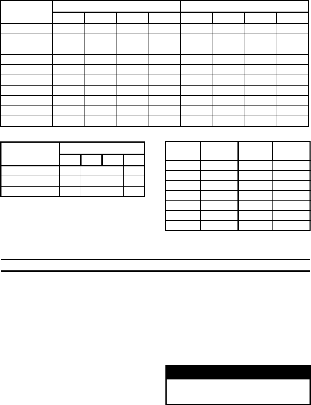
Table 2: Maximum Capacity of Schedule 40 Pipe in CFH For Gas Pressures of 0.5 psig or Less
Table 3: Fitting Equivalent Lengths Table 4: Specific Gravity Correction Factors
Length
[Feet]
0.3 inch w.c. Pressure Drop 0.5 inch w.c. Pressure Drop
‰1 1… ‰ 1 1…
10 132 278 520 1,050 175 360 680 1,400
20 92 190 350 730 120 250 465 950
30 73 152 285 590 97 200 375 770
40 63 130 245 500 82 170 320 660
50 56 115 215 440 73 151 285 580
60 50 105 195 400 66 138 260 530
70 46 96 180 370 61 125 240 490
80 43 90 170 350 57 118 220 460
90 40 84 160 320 53 110 205 430
100 38 79 150 305 50 103 195 400
Fitting Nominal Pipe Size
‰1 1…
45 Ell 0.7 11.2 1.6
90 Ell 1.6 2.1 2.6 3.5
Tee (As Elbow) 3.1 4.1 5.2 6.9
Specific
Gravity Correction
Factor Specific
Gravity Correction
Factor
0.50 1.10 1.30 1.07
0.55 1.04 1.40 1.04
0.60 1.00 1.50 1.00
0.65 0.96 1.6 0.97
0.7 0.93 1.7 0.94
0.75 0.9
0.8 0.87
V. Venting
A. General Guidelines.
1. Vent system installation must be in accordance with
National Fuel Gas Code, NFPA 54/ANSI Z221.3,
Part 7, Venting of Equipment; and/or CAN/CGA
B149 Installation Codes, Section 7, Venting
Systems and Air Supply for Appliances; or
applicable provisions of local building codes.
Contact local building or fire officials about
restrictions and installation inspection in your area.
2. This appliance requires a Special Gas Vent. Use
Vent Connector and Vent Terminal in Vent
Accessory Carton provided with boiler (See Repair
Parts, Key No. 8). The product is designed to use
Burnham supplied AL 29-4C® Stainless Steel vent
system components. The following manufacturers
offer similar AL 29-4C® components and are
approved for use with this product: Heat-Fab Inc. -
Saf-T-Vent, Flex-L International Inc., - Star-34,
Protech Systems, Inc. - FasNSeal™, and Z-Flex U. S.,
Inc. - Z-Vent. The use of these alternate
manufacturer's venting systems will require adapters
to connect to the Burnham supplied vent connector
and vent terminal. These adapters are not supplied
with this unit and should be obtained from the
supplier of the alternate manufacturer's venting
system. See Table 5 for complete list of Burnham
Vent System Components.
WARNING
Do not use this appliance with nonmetallic vent
systems such as Hart & Cooley Ultravent, Plexco
Plexvent, or Selkirk-Metalbestos Sel-Vent.
10
Table 5: Burnham Vent System Components
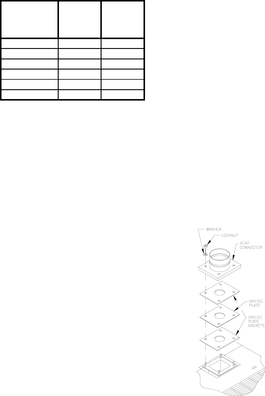
Figure 7: Vent Connector Installation
B. Removal of Existing Boiler. For installations not
involving the replacement of an existing boiler,
proceed to Step C.
When an existing boiler is removed from a common
venting system, the common venting system is likely to
be too large for proper venting of the remaining
appliances. At the time of removal of an existing
boiler, the following steps shall be followed with each
appliance remaining connected to the common venting
system placed in operation, while the other appliances
remaining connected to the common venting system
are not in operation:
(a) Seal any unused openings in the common venting
system.
(b) Visually inspect the venting system for proper size
and horizontal pitch and determine there is no
blockage or restriction, leakage, corrosion, and
other deficiencies which could cause an unsafe
condition.
(c) Insofar as is practical, close all building doors and
windows and all doors between the space in which
the appliances remaining connected to the common
venting system are located and other spaces of the
building. Turn on clothes dryers and any appliance
not connected to the common venting system. Turn
on any exhaust fans, such as range-hoods and
bathroom exhausts, so they will operate at
maximum speed. Do not operate a summer exhaust
fan. Close fireplace dampers.
(d) Place in operation the appliance being inspected.
Follow the Lighting (or Operating) Instructions.
Adjust thermostat so appliance will operate
continuously.
(e) Test for spillage at the drafthood relief opening
after 5 minutes of main burner operation. Use the
flame of a match or candle, or smoke from a
cigarette, cigar or pipe.
(f) After it has been determined that each appliance
remaining connected to the common venting system
properly vents when tested as outlined above, return
doors, windows, exhaust fans, fireplace dampers
and any other gas burning appliance to their
previous conditions of use.
(g) Any improper operation of the common venting
system should be corrected so the installation
conforms with the National Fuel Gas Code, NFPA
54/ANSI Z223.1. When resizing any portion of the
common venting system, the common venting
system should be resized to approach the minimum
size as determined using the appropriate tables in
Part II in the National Fuel Gas Code, NFPA 54/
ANSI Z223.1.
C. Install Vent Connector.
1. Remove vent connector from vent accessory carton.
2. Remove gaskets, orifice plate and hardware from
blower outlet flange.
3. Assemble orifice plate gaskets, orifice plate, and
vent connector. See Figure 7.
4. Secure vent connector with washers and locknuts.
3. Minimum vent length requirement is 2 feet of pipe
and one (1) elbow. Maximum vent length is 15 feet
with one (1) or two (2) elbows.
4. Do not install venting system components on the
exterior of the building except as specifically
required by these instructions.
Vent System
Component
Burnham
*Cartoned
Part
Number
Burnham
Component
Part
Number
3" Dia. Pipe x 1 Ft 61160112 8116135
3" Dia. Pipe x 3 Ft 61160101 8116058
3" Dia. Pipe x 4 Ft ** 8116176
3" Dia. Pipe x 5 Ft 61160111 8116059
3" Dia. 90 Elbow 61160121 8116060
3" Dia. 45 Elbow 61160131 8116061
* Complete with Locking Band(s)
* * 6116033 Contains (4) 4 ft. lengths
6116040 Contains (2) 4 ft. lengths
11
D. Install Vent Pipe, General.
1. Start at vent connector. Work toward vent terminal.
2. Use ¾ inch pipe strap to support horizontal runs,
maintain vent location and slope, and prevent sags.
Do not restrict thermal expansion movement.
Maximum support spacing is 5 feet.
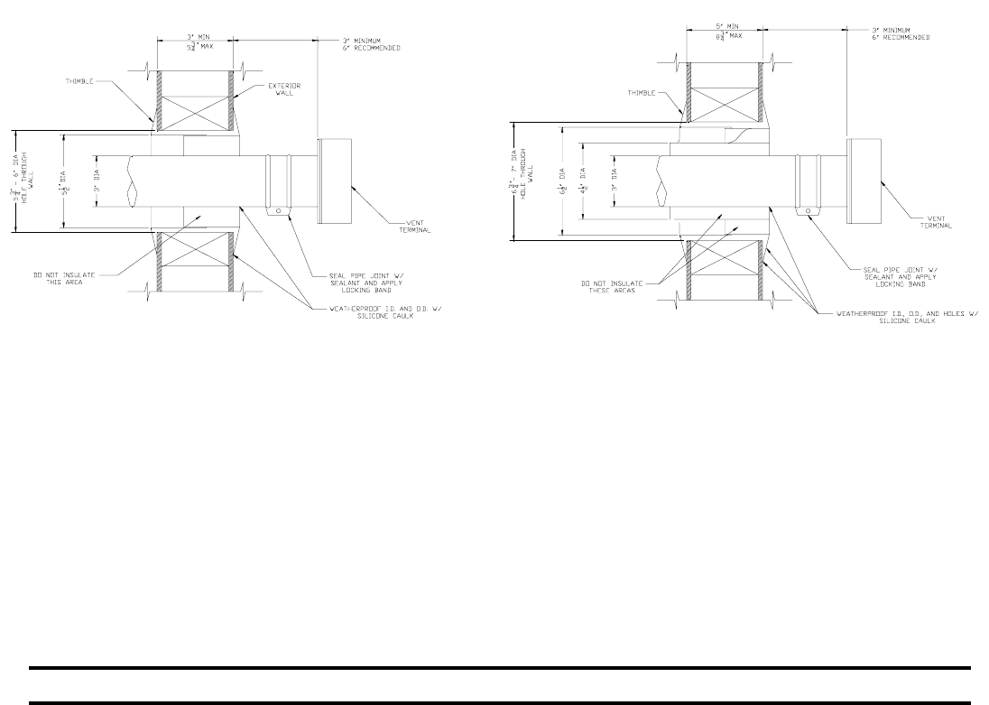
3. Provide minimum 5 inch clearance to combustible
materials. Use thimble when penetrating
combustible wall.
a. 203PV and 204PV - Single wall thimble,
Burnham Part No. 8116116. Other wall thimble
manufacturers are American Metal Products,
Hart & Cooley, and Metal Fab.
b. 205PV and 206PV - Double wall thimble,
Burnham Part No. 8116115 (accomodates 5" to
8¾" wall thickness). Another wall thimble
manufacturer is Hart & Cooley.
4. Cut pipe to length using hacksaw with minimum 32
teeth per inch or circular saw with metal abrasive
wheel. Remove bead end only - bell end accepts
next fitting or pipe. Cut must be square with pipe.
Scrape off burrs with sharp edged tool.
Note: If remaining pipe (less bell) must be used,
beaded end of mating pipe/fitting must be crimped.
5. Seal all joints using Dow Corning Silastic 732
RTV, Dow Corning Silastic 736 RTV, Polybac
#500 RTV, or Sil-bond RTV 4500 (Acetoxy). Do
not use other adhesives or sealants.
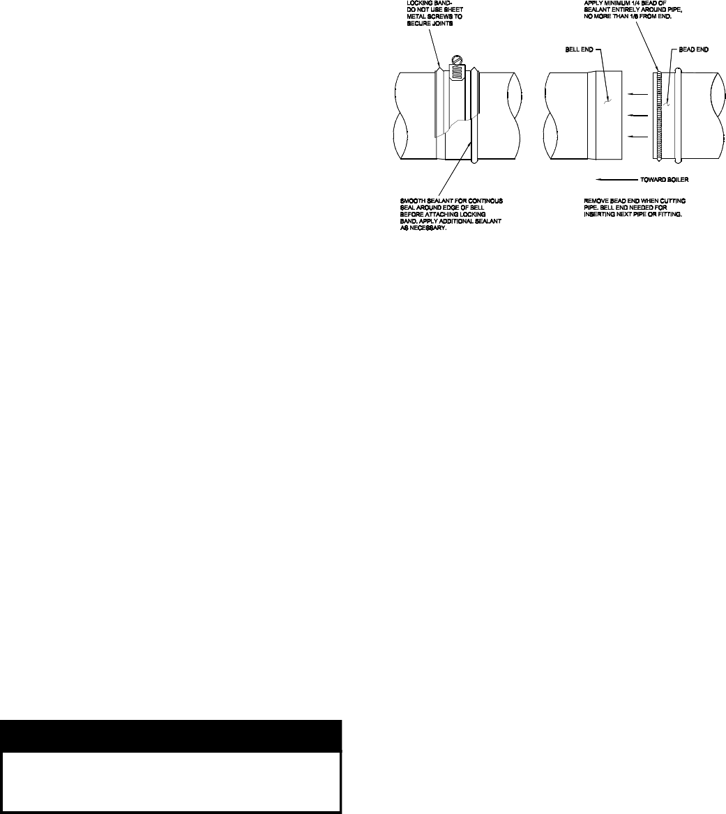
6. Procedure for joining pipe and fittings. See Figure 8.
a. Clean pipe or fitting. Remove all dirt and grease.
b. Slip locking band over pipe/fitting bell.
c. Apply continuous ¼ inch bead of sealant around
bead end of pipe/fitting no more than 1/8 inch
from end.
d. Insert pipe/fitting into bell. Smooth sealant for
continuous seal around gap between bead and
bell. Apply additional sealant if necessary.
e. Slip locking band over joint and tighten. Do not
secure joint with sheet metal screws or pop rivets.
E. Horizontal (Through Wall) Vent Installation.
1. Maintain minimum ¼ inch per foot slope in
horizontal runs. Slope pipe down toward vent
terminal.
CAUTION
Moisture and ice may form on surfaces around
vent terminal. To prevent deterioration, surfaces
should be in good repair (sealed, painted etc.)
2. Vent terminal location restricted per following:
a. Minimum 12 inches above grade or normally
expected snow accumulation level, or 7 feet
above grade if located adjacent to public
walkway. Do not install over public walkway
where local experience indicates condensate or
vapor from Category III appliances creates a
nuisance or hazard.
Figure 8: Typical Joint Detail
b. Minimum 3 feet above any forced air inlet
located within 10 feet.
c. Minimum 4 foot below, 4 foot horizontally
from, or 1 foot above any door, window, or
gravity air inlet.
d. Minimum 4 feet horizontally from, and in no
case above or below, unless a 4-foot horizontal
distance is maintained, from electric meters, gas
meters, regulators and relief equipment.
e. Minimum 12 inches from overhang or corner.
3. Use wall thimble when passing through
combustible outside wall (thimble use optional for
noncombustible wall). Insert thimble through wall
from outside. Secure outside flange to wall with
nails or screws, and seal with adhesive material.
Install inside flange to inside wall, secure with nails
or screws, and seal with adhesive material.
4. For noncombustible wall when thimble is not used,
size opening such that bell with locking band
attached cannot pass through.
5. Join vent terminal to vent pipe. Cut vent pipe to
locate vent terminal 3 inches (minimum) and 6
inches (recommended) from wall when joined to
inside vent piping. See Figure 9. Vent terminal
clearance to vinyl wall surfaces is 6 inches.
6. Insert vent pipe through thimble/opening from
outside and join to vent system. Apply sealant
between vent pipe and opening/thimble to provide
weathertight seal.
12
Figure 9: Recommendations for Thimble and Wall Penetration
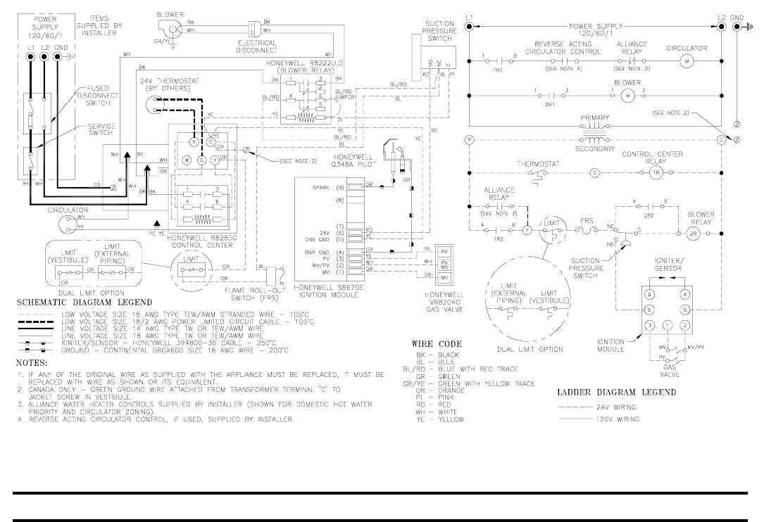
VI. Electrical
A. General. Install wiring and ground boiler in
accordance with requirements of authority having
jurisdiction, or in absence of such requirements the
National Electrical Code, ANSI/NFPA 70, and/or the
CSA C22.1 Electric Code.
B. Install thermostat. Locate on inside wall approximately
4 feet above floor. Do not install on outside wall, near
fireplace, or where influenced by drafts or restricted air
flow, hot or cold water pipes, lighting fixtures,
television, or sunlight. Allow free air movement by
avoiding placement of furniture near thermostat.
C. Wire thermostat. Provide Class II circuit between
thermostat and boiler. Run wires through grommet in
Jacket Left Side Panel. Set thermostat heat anticipator
to 0.6 amps. See Figure 10.
D. Wire boiler. Boiler is rated for 120 VAC, 60 hertz, less
than 12 amperes. Provide individual branch circuit with
fused disconnect. Connect to black and white wires and
green ground screw. See Figure 10.
E. Alliance water heater (if used). See Figure 10. Also refer
to Alliance Installation, Operating and Service
Instructions.
1. Zoning with Circulators, Domestic Hot Water
Priority. Provide DPDT relay (included with PAL).
Connect coil to Alliance thermostat (prewired with
PAL). Connect normally open contacts (red and
white wires in PAL control harness) to transformer
terminals 'R' and 'Y'. Disconnect yellow circulator
wire. Connect normally closed contacts (violet
wires in PAL boiler harness) to yellow relay wire
and yellow circulator wire.
2. Zoning with Circulators, Nonpriority. Connect
Alliance circulator zone control (or red and white
wires in PAL control harness) to transformer
terminals 'R' and 'Y'.
3. Zoning with Zone Valves. Connect Alliance
thermostat to zone valve. Connect zone valve end
switch to relay terminals 'R' and 'G'. See Paragraph
F.
F. For installations using zone valves provide separate
transformer for zone valve wiring. Consult zone valve
manufacturer for assistance.
13
Figure 10: Wiring Diagram
Figure 11: Main Burner Installation
VII. System Start-up
A. Safe operation and other performance criteria were
met with gas manifold and control assembly provided
on boiler when boiler underwent tests specified in
American National Standard for Gas-Fired Low-
Pressure Steam and Hot Water Boilers, ANSI Z21.13.
B. Fill heating system with water and vent air from
system. Use the following procedure on a Series Loop
System equipped with zone valves. See Figure 3.
1. Close isolation valve in boiler supply piping.
2. Isolate all circuits by closing zone valves or
balancing valves.
3. Attach hose to bib cock located just below isolation
valve in boiler supply piping. Terminate hose in
five gallon bucket at a suitable floor drain or
outdoor area).
4. Starting with one circuit, open zone valve.
5. Open bib cock.
6. Open fill valve. Makeup water line should be
located directly above isolation valve in boiler
supply piping.
7. Allow water to overflow from bucket until
discharge from hose is bubble free for 30 seconds.
8. Open zone valve to second zone to be purged, then
close first. Repeat this step until all zones have been
purged, but always have one zone open. At
completion, open all zone valves.
9. Close bib cock, continue filling system until
pressure gauge reads 12 psi. Close fill valve.
Note: If makeup water line is equipped with
pressure reducing valve, system will automatically
fill to 12 psi. Leave globe valve open.
10.Open isolation valve in boiler supply piping.
11.Remove hose from bib cock.
C. Check main burners. See Figure 11. Rear of burner
must be in vertical slot in rear of burner tray. Front of
burner must be seated on orifice.
14
Figure 12: Gas Valve Pressure Tap
D. Prepare to check operation.
1. Obtain gas heating value (in Btu per cubic foot)
from gas supplier.
2. Connect manometer to pressure tap on gas valve.
See Figure 12.
3. For natural gas fired boiler, temporarily turn off all
other gas-fired appliances.
E. Follow Operating Instructions to place boiler in
operation. See Figure 17.
F. Sequence of Operation. See Figure 14. If boiler fails
to operate properly, see Troubleshooting Tree on pages
17-18.
G. Check gas piping and connections between Gas
Valve and Manifold, Orifices and Pilot Tubing. Use
soap solution or other approved method. See Figure 13.
H. Check pilot burner flame. See Figure 15. Flame
should be steady, medium hard blue enveloping 3/8 to
½ inch of sensing probe.
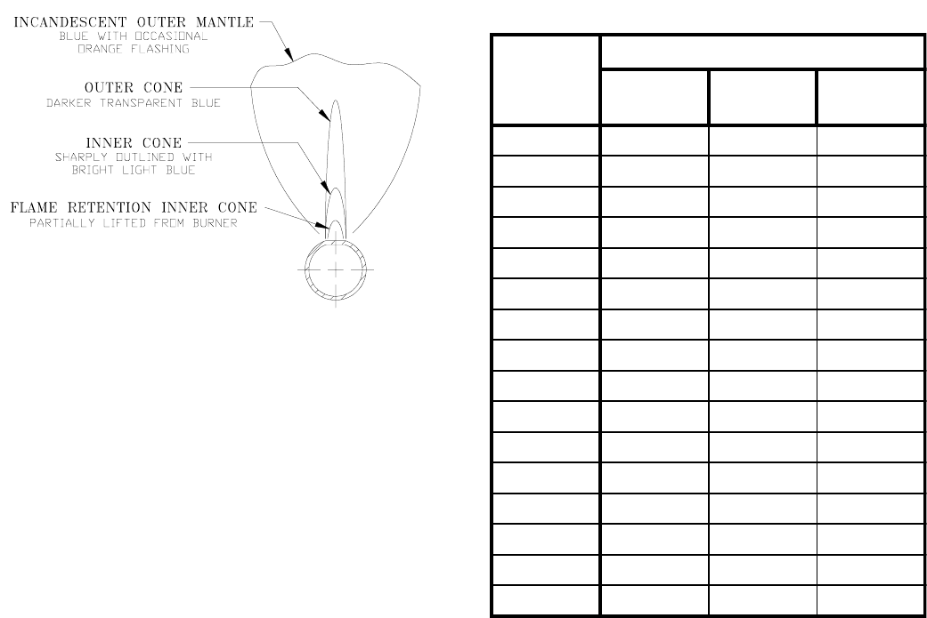
I. Check main burner flame. See Figure 16. Flame
should have clearly defined inner cone with no yellow
tipping. Orange-yellow streaks should not be confused
with true yellow tipping.
Figure 13: Schematic Pilot and Gas Piping Figure 15: Pilot Burner Flame
Figure 14: Sequence of Operation
15
Figure 16: Main Burner Flame
J. Check thermostat operation. Raise and lower
temperature setting to start and stop boiler operation.
K. Check ignition control module shut-off. Disconnect
igniter/sensor cable from Terminal 9 (SPARK). Gas
valve should close and pilot and main burners should
extinguish.
L. Check low water cutoff (if used). Drain boiler water
below LWCO set point. Burners should extinguish.
M. Check limit.
1. Adjust thermostat to highest setting.
2. Observe temperature gauge. When temperature is
indicated, adjust limit to setting below observed
temperature. Main burners and pilot burner should
extinguish and blower stop.
3. Adjust limit to setting above observed temperature.
Ignition sequence should begin.
4. Adjust thermostat to lowest setting. Adjust limit to
desired setting.
N. Adjust gas input rate to boiler (Natural Gas).
1. Adjust thermostat to highest setting.
2. Check manifold gas pressure. Manifold pressure is
listed on rating label. Adjust gas valve pressure
regulator as necessary (turn adjustment screw
counterclockwise to decrease manifold pressure, or
clockwise to increase manifold pressure). If
pressure can not be attained, check gas valve inlet
pressure. If less than minimum gas supply pressure
listed on rating label, contact gas supplier for
assistance.
3. Clock gas meter for at least 30 seconds. Use Table 6
to determine gas flow rate in Cubic Feet per Hour.
4. Determine Input Rate. Multiply gas flow rate by gas
heating value.
5. Compare measured input rate to input rate listed on
rating label.
Seconds
for One
Revolution
Size of Gas Meter Dial
One-Half
Cu. Ft. One
Cu. Ft. Two
Cu. Ft.
30 60 120 240
32 56 113 225
34 53 106 212
36 50 100 200
38 47 95 189
40 45 90 180
42 43 86 172
44 41 82 164
46 39 78 157
48 37 75 150
50 36 72 144
52 35 69 138
54 33 67 133
56 32 64 129
58 31 62 124
60 30 60 120
Table 6: Gas Flow Rate in Cubic Feet per Hour
a. Boiler must not be overfired. Reduce input rate
by decreasing manifold pressure. Do not reduce
more than 0.3 inch w.c. If boiler is still
overfired, contact your Burnham distributor or
Regional Office for replacement Gas Orifice.
b. Increase input rate if less than 98% of rating
label input. Increase manifold gas pressure no
more than 0.3 inch w.c. If measured input rate is
still less than 98% of rated input:
i. Remove Main Burners per procedure in
Section VIII: Service.
ii. Remove gas orifices. Drill one (1) drill size
larger (drill size is stamped on orifice, or
see Key No. 4D).
iii. Reinstall gas orifices and main burners.
Measure input rate.
6. Recheck Main Burner Flame.
7. Adjust thermostat to normal setting.
8. Return other gas-fired appliances to previous
conditions of use.
O. Adjust gas input rate to boiler (LP/Propane).
1. Adjust thermostat to highest setting.
2. Check manifold pressure. Adjust gas valve pressure
regulator to obtain 10 inches w.c. manifold
16
Figure 17: Operating Instructions
pressure. Adjust gas valve pressure regulator as
necessary (turn adjustment screw counterclockwise
to decrease manifold pressure, or clockwise to
increase manifold pressure). If pressure can not be
attained, check gas valve inlet pressure. If less than
minimum gas supply pressure listed on rating label,
contact gas supplier for assistance.
3. Recheck Main Burner Flame
4. Adjust thermostat to normal setting.
P. COMBUSTION CHAMBER BURN-OFF
1. The mineral wool combustion chamber panels
contain a cornstarch based binder that must be
burned out at installation to prevent odors during
subsequent boiler operation.
2. Ventilate the boiler room, set the high limit to its
maximum setting, set the thermostat to call for
heat. Allow the boiler to fire for at least an hour or
until the odor from the cornstarch has dissipated.
3. Return the high limit and thermostat to their
desired settings.
Q. Review User's Information Manual and system
operation with owner or operator.
R. Post instructions near boiler for reference by owner
and service personnel. Maintain instructions in legible
condition.
17
18
19
20
VIII. Service
A. General. Inspection and service should be conducted
annually. Turn off electrical power and gas supply
while conducting service or maintenance. Follow
instructions TO TURN OFF GAS TO APPLIANCE.
See Figure 17.
CAUTION
Label all wires prior to disconnection when
servicing controls. Wiring errors can cause
improper and dangerous operation. Verify proper
operation after servicing.
B. Inspect Housekeeping. Boiler area must be clear and
free from combustible materials, gasoline and other
flammable vapors and liquids. Remove obstructions to
the flow of combustion and ventilation air.
C. Service Low water cutoff (if so equipped). Follow
instructions provided with low water cutoff
D. Inspect Vent System for obstructions in vent pipe,
soot accumulation, deterioration of pipe or joints, and
proper support:
1. Remove vent connector and vent pipe. See Figure
19.
2. Remove all obstructions. Check and clean vent
terminal screens.
3. Remove soot accumulations with wire brush and
vacuum.
4. Replace deteriorated parts.
5. Repair deteriorated joints. See Section V: Venting,
Paragraph D.6.
E. Inspect Boiler Flue Passages for blockage or soot
accumulation. See Figure 19.
1. Disconnect vent connector from blower discharge
flange.
2. Remove sheet metal screws securing Jacket Top
Panel. Lift panel and rotate about relief valve
piping until top of boiler is exposed. If piping or
wall prevent full rotation of top panel for access to
canopy, cut slot into relief valve opening and
remove top panel.
3. Disconnect blower connection from wiring harness
in vestibule.
4. Remove bolts securing canopy to boiler sections.
Cut silastic sealant around base of canopy, pry
canopy from boiler sections and remove canopy/
blower assembly from boiler.
5. Using flashlight, examine all flue passageways.
a. If passageways are free of soot and obstruction,
replace canopy, secure and seal using kit
available from Burnham Distributors, Part No.
6111716.
b. If passageways need cleaning, remove burners
as described in Paragraph F below. Using long
handle wire or bristle flue brush and vacuum,
brush flueways thoroughly from top of boiler as
illustrated in Figure 19. Replace canopy and seal
using kit available from Burnham Distributors,
Part No. 6111716.
WARNING
Canopy must be resealed with RTV-732 Silicone
Rubber Sealant (500 F Intermittent Duty).
6. Reinstall jacket top panel, vent pipe and vent
connector in reverse manner. Reconnect electrical
connector to blower.
F. Clean Main Burners and Firebox.
1. To remove burners for cleaning, changing orifice
plugs, or repairs:
a. Remove jacket Front Panel.
b. Disconnect pilot tubing at gas valve.
c. Disconnect igniter/sensor cable and ground wire
at Ignition Module.
d. Disconnect Flame Rollout Switch wires.
e. Remove Burner Access Panel.
f. Mark Pilot Main Burner location on Manifold.
g. Hold burner on throat. Lift slightly to clear
orifice. Pull burner from combustion chamber.
See Figure 11. Pilot Main Burner can only be
removed by lifting at 45° angle after adjacent
burner to right is removed.
2. Brush top of burners with a soft bristle brush. See
Figure 19. Vacuum burners.
3. Check orifices. Drilled passageways must be free of
lint or dirt.
4. Vacuum tip of Pilot Burner.
5. Clean firebox by vacuuming. Exercise care not to
disturb insulation inside base.
6. Install burners by reversing procedure used to
remove burners. Burner with pilot assembly must
be in same location as original installation. See
Table 7. Burners must be properly located on
21
Table 7: Pilot Burner Location
Boiler
Model Main Burner with
60 Pilot Bracket *
Pilot Burner Located
Between Main Burners
*
203PV 11 & 2
204PV 22 & 3
205PV 33 & 4
206PV 44 & 5
* Main burners numbered left to right as viewed from front of
boiler
Figure 18: Spark Gap Setting
Figure 19: Flueway Cleaning
support bracket at rear of burner. See Figure
11. Slide burner over orifice.
7. Reconnect pilot gas supply, igniter/sensor
cable, and ground wire. Reinstall Burner
Access Panel. Reconnect Flame Rollout
Switch wires.
G. Check operation. Follow steps D through O
from Section VII: System Start-up.
H. Removal or replacement of pilot assembly or
pilot assembly parts. If pilot assembly, sensor
or pilot orifice need replacing, remove main
burner with pilot using procedure described in
Paragraph F.1.
1. To replace orifice.
a. Disconnect pilot tubing. Pilot orifices
screw into Pilot Burner. Replace with
Honeywell 388146NE (Natural Gas) or
Honeywell 388146KP (LP/Propane).
b. Reconnect pilot tubing and check for
leaks.
2. To adjust or check spark gap between
electrode and hood on Honeywell Q348A
intermittent pilot. See Figure 18.
a. Use round wire gauge to check spark
gap.
b. Spark gap should be 1/8 inch for
optimum performance.
3. To replace complete pilot assembly.
a. Remove two machine screws holding
pilot burner to pilot bracket.
b. Disconnect pilot tubing.
c. Disconnect all other leads to pilot.
d. Select pilot assembly with identical
model number, reconnect leads and pilot
tubing. Resecure to pilot bracket.
4. Reinstall main burner following procedure
described in Paragraph F.

22
Table 8: Minimum Suction Pressure
Boiler Model Minimum Suction Pressure
203PV -0.50 inches w.c.
204PV -0.50 inches w.c.
205PV -0.80 inches w.c.
206PV -0.80 inches w.c.
Figure 20: Procedure for Measuring Fan Suction
Pressure
I. Lubrication. There are no parts requiring lubrication
by service technician or owner. Circulator bearings are
water lubricated. Blower motor bearings are factory
sealed.
23
IX. Repair Parts
All Series 2PV Repair Parts may be obtained through your local Burnham Wholesale distributor. Should you require assistance
in locating a Burnham distributor in your area, or have questions regarding the availability of Burnham products or repair parts,
please contact your Burnham Regional Sales Office as listed below.
Contact Regional Office Indicated for your State
Alabama A Nebraska A Oregon A
Alaska A Nevada A Pennsylvania D
Arizona A New Hampshire B Rhode Island B
Arkansas A New Jersey South Carolina A
California AAtlantic, Burlington, Camden,
D
South Dakota A
Colorado A Cape May, Cumberland, Tennessee A
Connecticut B Gloucester, Mercer, Te xas A
Delaware D Monmouth, Ocean, Salem Utah A
Florida A Counties Ve rm ont B
Georgia A All other Counties CVirginia
Hawaii A New Mexico A Arlington,Accomack,Clarke,
D
Idaho A New York Fairfax,Frederick,Fauquier,
Illinois A Albany, Fulton, Montgomery,
B
Loudoun,Northampton and
Indiana A Rensselaer, Saratoga, Prince William Counties
Iowa A Schenectady, Schoharie, All other Counties A
Kansas A Warren, Washington Counties Washington A
Kentucky A All Other Counties C Washington, D.C. D
Louisiana A North Carolina A West Virginia D
Maine B North Dakota A Wisconsin A
Maryland D Ohio Wyoming A
Massachusetts B Athens, Belmont, Gallia, D
Michigan A Jefferson, Lawrence, Meigs,
Minnesota A Monroe, and Washington
Mississippi A Counties
Missouri A All other Counties A
Montana A Oklahoma A Canada A
Burnham Corporation Regional Offices
A. Burnham Corporation - Central & Western Regions
P.O. Box 3079
Lancaster, PA 17604-3079
Phone: (717) 481-8400
FAX: (717) 481-8408
C. Burnham Corporation - Metropolitan Region
P.O. Box 3079
Lancaster, PA 17604-3079
Phone: (717) 481-8400
FAX: (717) 481-8409
B. Burnham Sales Corporation - Northeast Region
19-27 Mystic Avenue
Somerville, MA 02145
Phone: (617) 625-9735
FAX: (617) 625-9736
D. Burnham Corporation - Mid-Atlantic Region
P.O. Box 3079
Lancaster, PA 17604-3079
Phone: (717) 481-8400
FAX: (717) 481-8409

24
1. Section Assembly ............................... 25
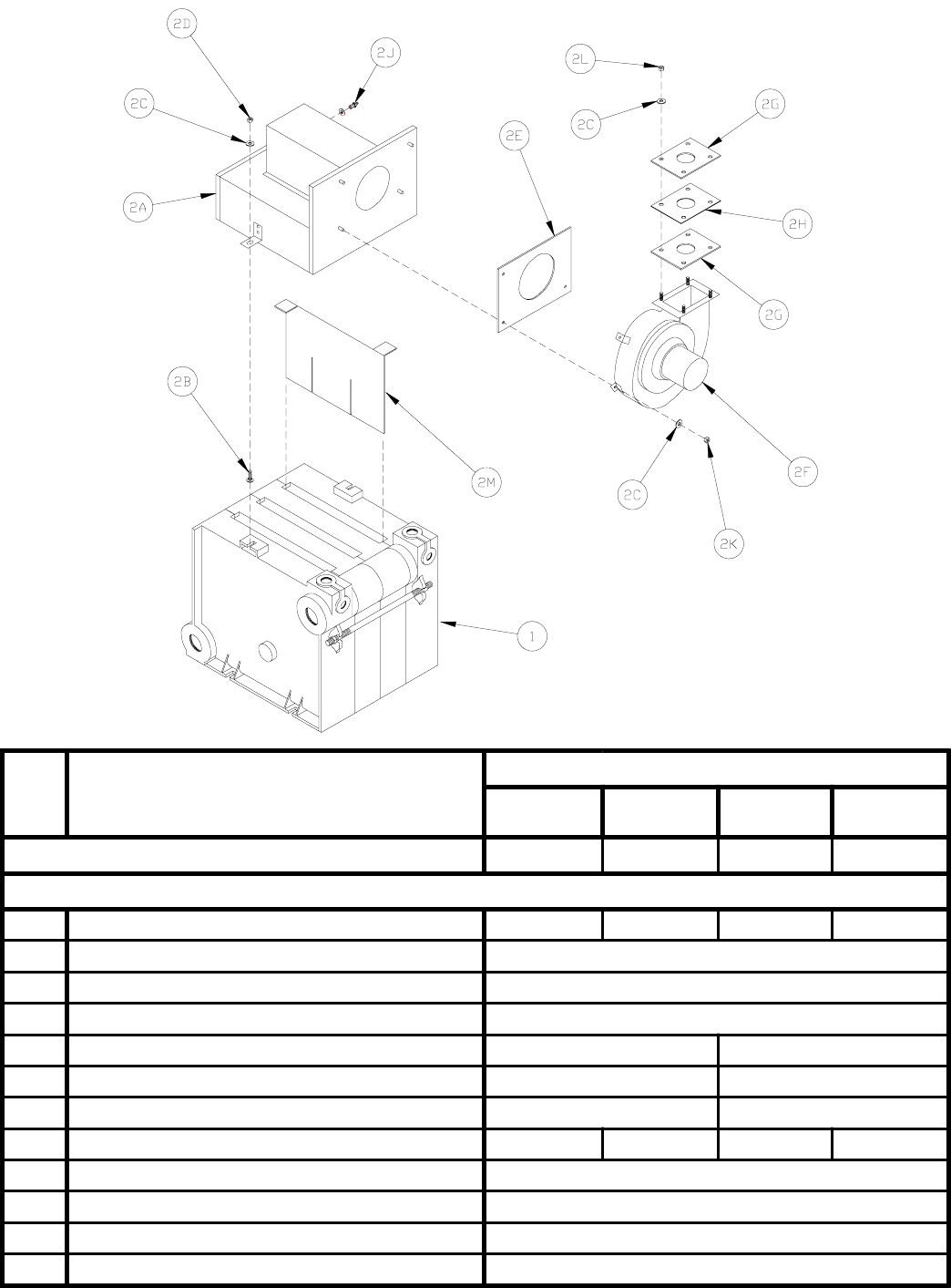
2. Canopy/Blower Assembly .................. 25
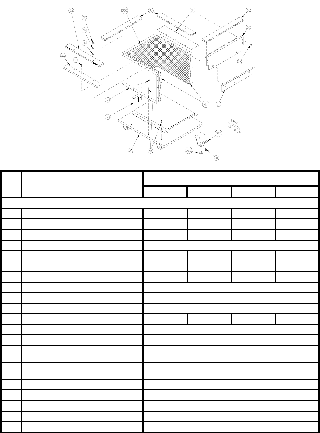
3. Base Assembly Group ........................ 26
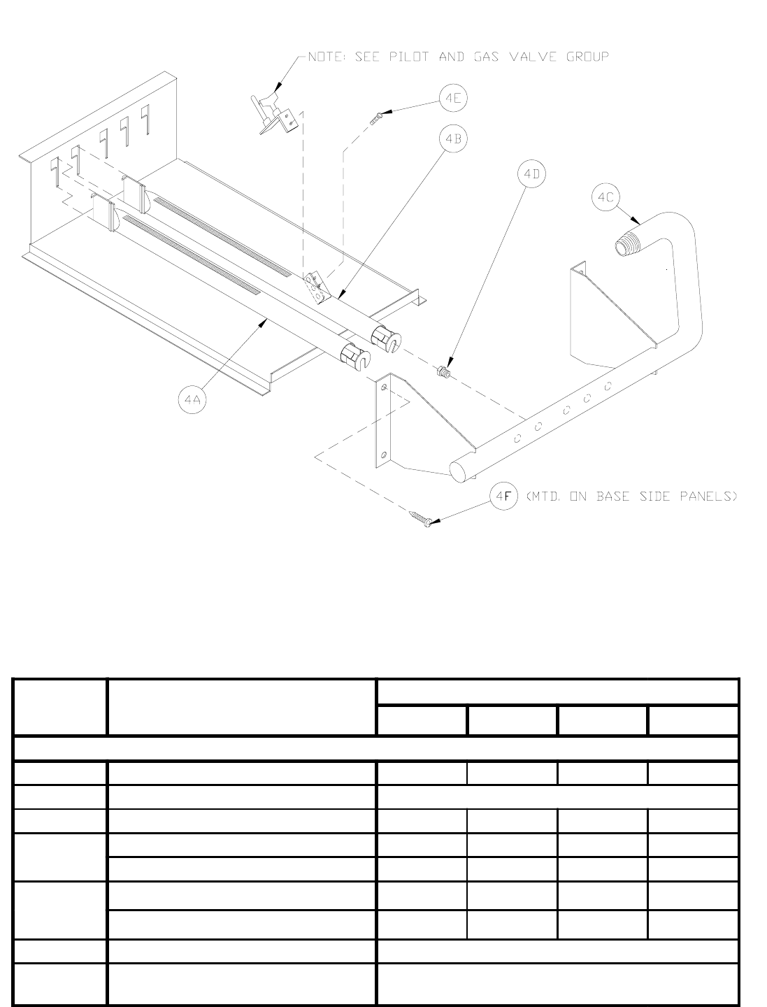
4. Manifold and Main Burners ............... 27
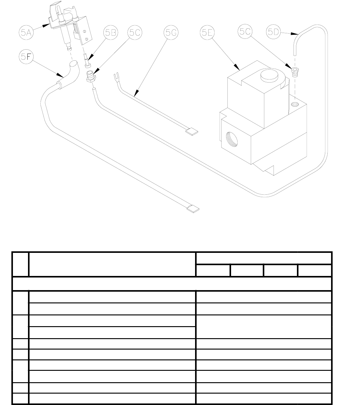
5. Pilot Burner and Gas Valve ............... 28
6. Jacket .................................................. 29
7. Miscellaneous Trim and Controls ...... 31
8. Vent Accessory Carton ....................... 31
SERVICE SCHEDULE
DATE SERVICE PERFORMED
25
Key
No. Description
[Quantity] Part Number
203PV 204PV 205PV 206PV
1. Section Assembly 617170321 617170421 617170521 617170621
2. Canopy/Blower Assembly
2A Canopy [1] 61117034 [1] 61117044 [1] 61117054 [1] 61117064
2B Carriage Bolt, …-20 x 1" [2] Common Hardware
2C Wash er, …, SAE [10] Common Hardware
2D Nut,…-20, Heavy Hex [2] Common Hardware
2E Blower Mounting Gasket [Included in Key No. 2F] [1] 8206048 [1] 8206049
2F Blower [1] 6111714 [1] 6111715
2G Orifice Plate Gasket [(2) Included in Key No. 2F] [2] 8206042 [2] 8206035
2H Orifice Plate [1] 71117035 [1] 71117045 [1] 71117055 [1] 71117065
2J Pressure Fitting, Dwyer A308 [1] 822657
2K Hex Nut, 1/4-20, Brass [(4) Included in Key No. 2F] [4] 80860424
2L Hex Locknut, …-20 [4] Common Hardware
2M Flue Baffle Not Applicable
26
Key
No. Description [Quantity] Part Number
203PV 204PV 205PV 206PV
3. Base Assembly Group
3 Base Assembly, Complete [1] 618600391 [1] 618600491 [1] 618600591 [1] 618600691
3A Base Tray Assembly [1] 718600391 [1] 718600491 [1] 718600591 [1] 718600691
3B Base Wrapper [1] 718600311 [1] 718600411 [1] 718600511 [1] 718600611
3B1 Base End Insulation [2] 720601
3B2 Base Rear Insulation [1] 72060035 [1] 72060045 [1] 72060055 [1] 72060065
3C Base Front Panel Assembly [1] 618600341 [1] 618600441 [1] 618600541 [1] 618600641
3D Burner Tray [1] 718600305 [1] 718600405 [1] 718600505 [1] 718600605
3E Base Leg Assembly [4] 6186001
3E1 Base Leg [4] 71860021
3E2 Nylon Glide 8186006
3F Burner Access Panel [1] 718600361 [1] 718600461 [1] 718600561 [1] 718600661
3G Jacket Attachment Bracket, Left [1] 70460011
3H Jacket Attachment Bracket, Right [1] 70460012
3J Cerafelt Gasket, ‰" x 2"
Johns-Mansville CRF-400 [1] 6206002
3K Screw, Self-Tapping Type F, Phillips Pan
Head, …-20 x ‰", Plated [20] 80860700
3L Screw, Self Tapping, 5/16-18 x 1…" [4] 80860717
3M Washer, 5/16, USS [4] Common Hardware
3N Washer, Lock, USS [4] Common Hardware
3P Nut, Hex, 5/16-18, Brass [4] 80860403
3R Screw, Sheet Metal, Phillips Head, #8 x ‰" [2] Common Hardware
27
Key No. Description [Quantity] Part Number
203PV 204PV 205PV 206PV
4. Manifold and Main Burners
4A Main Burner [2] 8236099 [4] 8236099 [6] 8236099 [8] 8236099
4B Main Burner with 60 Pilot Bracket [1] 8236098
4C Manifold [1] 82260033 [1] 82260043 [1] 82260053 [1] 82260063
4D (Natural
Gas Only)
Main Burner Orifice, #44, Orange [3] 822712 ----- ----- -----
Main Burner Orifice, #45, Pink ----- [5] 822711 [7] 822711 [9] 822711
4D
(LP/Propane
Only)
Main Burner Orifice, #55, Green [3] 822708 ----- ----- -----
Main Burner Orifice, 1.25mm, Purple ----- [5] 822705 [7] 822705 [9] 822705
4E Screw, Machine, #10-32 x 3/16" [2] 80860800
4F Screw, Self-Tapping Type F, Phillips Pan
Head, 1/4-20 x 1/2", Plated [4] 80860700
28
Key
No. Description [Quantity] Part Number
203PV 204PV 205PV 206PV
5. Pilot Burner and Gas Valve
5A Pilot Assembly, Natural Gas, Honeywell Q348A1333 [1] 8236104
Pilot Assembly, LP Gas, Honeywell Q348A1341 [1] 8236107
5B Pilot Orifice, Natural Gas Honeywell 388146NE Included with Key No.5A
Pilot Orifice, LP/Propane Honeywell 388146KP
5C Compression Nut/Fitting, 1/8" OD x … NPT Included with Key No.5A and 5E
5D Pilot Tubing, 1/8" OD x 30" [1] 8236110
5E Gas Valve, ‰ x ‰, Natural Gas, Honeywell VR8204C6000 [1] 81660176
Gas Valve, ‰ x ‰, LP/Propane, Honeywell VR8204C6018 [1] 81660180
5F Igniter/Sensor Cable, 36", Honeywell 394800-36 [1] 8236084
5G Ground Wire Assembly [1] 6136054
29
Key
No. Description [Quantity] Part Number
203PV 204PV 205PV 206PV
6. Jacket
6A Jacket Wrap-A-Round Panel (1) [1] 604170312 [1] 604170412 [1] 604170512 [1] 604170612
6B Jacket Upper Vestibule Panel (1) [1] 6041703221 [1] 6041704221 [1] 6041705221 [1] 6041706221
6C Jacket Lower Vestibule Panel [1] 6041703222 [1] 6041704222 [1] 6041705222 [1] 6041706222
6D Jacket Top Panel (1) (2) [1] 604170334 [1] 604170434 [1] 604170534 [1] 604170634
6E Jacket Front Removable Door [1] 604170344 [1] 604170444 [1] 604170544 [1] 604170644
6F Jacket Lower Front Panel [1] 604170313 [1] 604170413 [1] 604170513 [1] 604170613
6G Screw, Sheet Metal, #8 x ‰" [20] Common Hardware
6H Snap Bushing, Heyco SB-1093-15 [2] 8136257
6J Snap Bushing, Heyco SB-2000-26 [1] 8136266
6K Snap Bushing, Heyco SB-437-5 [1] 8136048
6L Burnham Logo Plate [1] 81460107
(1) For boilers installed in Canada, indicate ’For Canada’ when ordering.
(2) For boilers installed in California, indicate ’For California’ when ordering.
30
31
Key No. Description [Quantity] Part Number
203PV 204PV 205PV 206PV
7. Miscellaneous Trim and Controls
7A Safety Relief Valve, 30 psi, NPT,
Conbraco 10-408-05 [1] 81660319
7B Limit, Honeywell L4080D1036 [1] 80160156
7B1 Immersion Well, ‰ NPT Included with 7B
7B2 Immersion Well, NPT, Honeywell 123870A
(Dual Limit Only) [1] 80160426
7B3 Limit Honeywell L4080B1212 (Dual Limit Only) [1] 80160474
7C Transformer/Relay, Honeywell R8285D5001 [1] 80160155U
7C1 Relay, DPST, Honeywell R8222U1006 [1] 80160096U
7C2 Junction Box, 4" x 4" x 1‰" [1] 8136259
7D Flame Rollout Switch [1] 80160044
7D1 Flame Rollout Switch Bracket [1] 7186018
7E Suction Pressure Switch [1] 80160180 [1] 80160181
7E1
Silicone Tubing, 1/8" x 11"
9016001 (Specify Length)
Silicone Tubing, 1/8" x 12‰"
Silicone Tubing, 1/8" x 13-5/8"
Silicone Tubing, 1/8" x 15…"
7F Ignition Module, Honeywell S8670E1007 [1] 80160108
7G Temperature-Pressure Gauge [1] 8056164U
7H
Circulator with Gaskets, Bell & Gossett NFR-22 [1] 8056174
Circulator with Gaskets, Grundfos UP15-42F [1] 8056173
Circulator with Gaskets, Taco 007F [1] 8056170
Circulator with Gaskets, Taco 0010 [1] 8056176
7H1
Gasket, Bell & Gossett NFR-22 (SLC-30) [2] 806602029
Gasket, Grundfos 510179 [2] 806602016
Gasket, Taco ’00’ Series [2] 806602006
7J Flange, 1… NPT [2] 806602013
7J1 Screw, Cap Hex Head, 7/16-14 x 1‰" [4] Common Hardware
7J2 Nut, Hex, 7/16-14 [4] Common Hardware
7K Drain Valve, NPT, Conbraco 31-606-02 [1] 806603011
Key No. Description [Quantity] Part Number
203PV 204PV 205PV 206PV
8. Vent Accessory Carton 611170322 611170522
8A Vent Connector [1] 8116102 [1] 8116103
8B Vent Terminal [1] 8116063
8C Locking Band [1] 8116101
8D
Silicone Sealant, 3 oz. tube, Dow
Corning Silastic 732 RTV, or Sil-Bond
RTV 4500 (Acetoxy)
[1] 8056052
32
