HL40XP1 SM(090914) Service Manual
User Manual: Service manual HL40XP1
Open the PDF directly: View PDF ![]() .
.
Page Count: 63
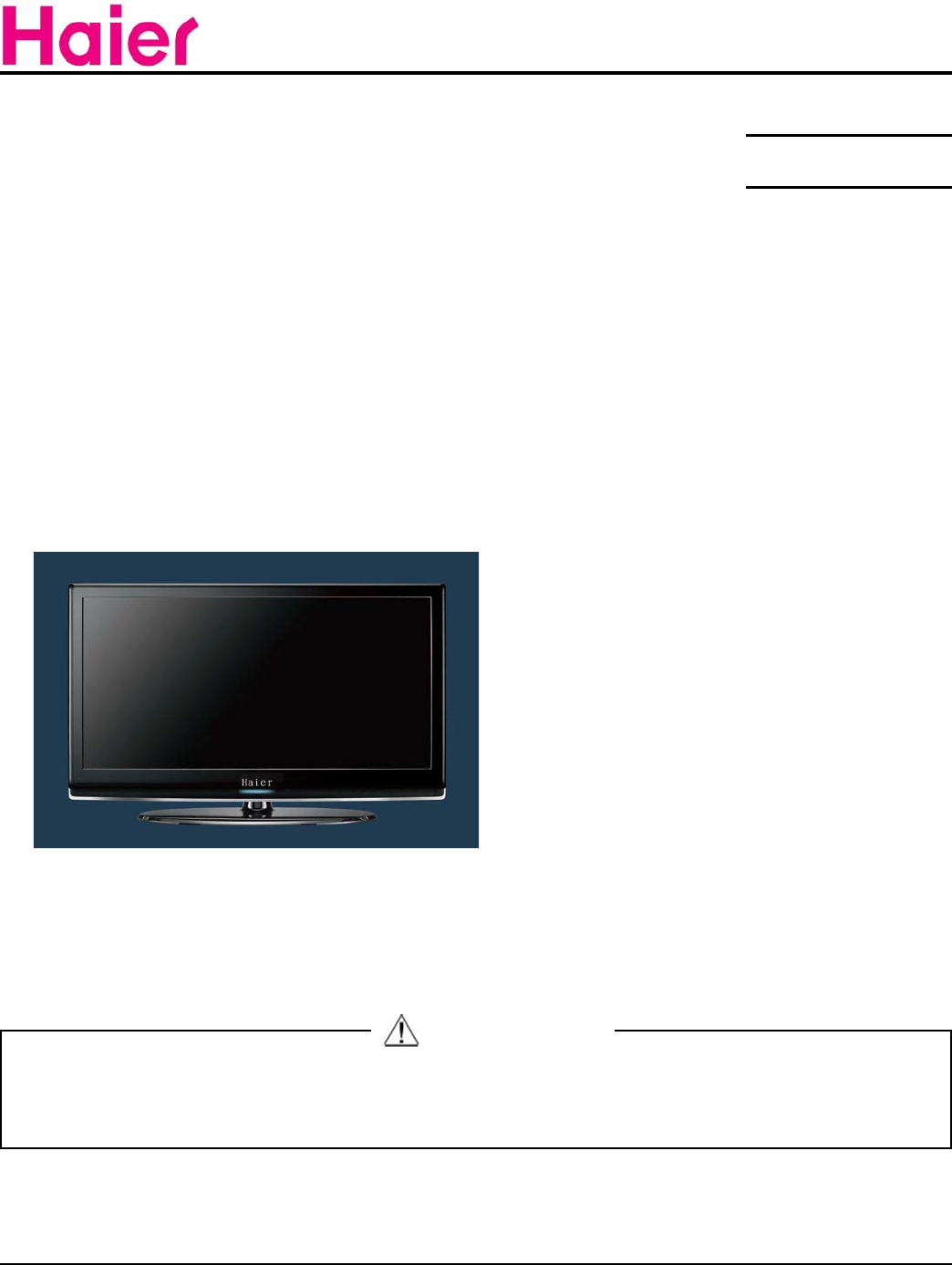
LCD TV
Model No.
Chassis
This service information is designed for experienced repair technicians only and is not designed for use by the general public.
It does not contain warnings or cautions to advise non-technical individuals of potential dangers in attempting to service a product.
Products powered by electricity should be serviced or repaired only by experienced professional technicians. Any attempt to service or repair
the product or products dealt with in this service information by anyone else could result in serious injury or death.
Haier Group
©2009 Qingdao Haier Electronics Co., Ltd.
All rights reserved. Unauthorized copying and distribution is a violation of law.
SERVICE MANUAL
WARNING
ZORAN785
HL40XP1
Service No. HL40XP1a

CONTENTS
Chapter 1: General Information
1-1. Document Information ........................................................................... 3
1-2. General Guidelines ................................................................................ 3
1-3. Important Notice ..................................................................................... 3
1-3-1. Follow the regulations and warnings ..................................................... 3
1-3-2. Be careful to the electrical shock ........................................................... 3
1-3-3. Electro static discharge (ESD) ............................................................... 3
1-3-4. About lead free solder (PbF) .................................................................. 4
8VHWKHJHQHZLQJSDUWVVSHFL¿HGSDUWV .............................................. 4
1-3-6 Safety check after repairment ................................................................. 4
1-3-7. Ordering Spare Parts ............................................................................. 6
1-3-8. Photo used in this manual ..................................................................... 6
1-4. How to Read this Service Manual ...................................................... 6
1-4-1. Using icons: ........................................................................................... 6
&KDSWHU6SHFL¿FDWLRn
6SHFL¿FDWLRQOLVW ...................................................................................... 8
2-2 External pictures (four faces) .............................................................. 9
Chapter 3. Disassemble and Assemble
3-1 Remove the Stand................................................................................. 11
3-2. Remove the Back Cover ..................................................................... 11
3-3. Remove the Adhesive Tape .............................................................. 11
3-4 Remove the Terminal Bracket ............................................................ 11
3-5. Remove the Power Supply Module ................................................. 12
3-6. Remove the Mainboard ...................................................................... 12
3-7. Remove the Keypad Board ................................................................ 12
3-8. Remove the Speaker ........................................................................... 12
3-9. Remove the Remote Control Board ................................................. 12
Chapter 4. Location of Controls and Components
4-1. Board Location ...................................................................................... 13
4-2. Main Board & AV Board ...................................................................... 13
4-2-1 Function Description: ............................................................................ 14
&RQQHFWRUGH¿QLWLRQ .............................................................................. 14

4-3. Power Supply Board ............................................................................ 16
4-3-1. Function description:............................................................................ 16
&RQQHFWRUGH¿QLWLRQ ............................................................................ 16
4-4. LCD Panel .............................................................................................. 16
Chapter 5. Installation Instructions
5-1 External Equipment Connections.......................................................19
Chapter 6. Operation Instructions
6-1. Front Panel Controls ............................................................................ 25
6-2 Back Panel Controls ............................................................................. 26
6-3 Setting Up Your Remote Control ........................................................ 27
Chapter 7. Electrical Parts
7-1. Block Diagram ....................................................................................... 20
7-2. Circuit Diagram ..................................................................................... 29
7-3 .Wiring Connection Diagram ............................................................... 46
Chapter 8. Measurements and Adjustments
8-1. Service Mode ....................................................................................... 47
8-1-1.How to enter into Service Mode............................................................ 47
8-1-2.How to exit ............................................................................................ 47
8-2. Measurements and Adjustments ...................................................... 47
8-2-1. Software Update ................... ............................................................ 47
8-2-2. Auto Color ............................................................................................48
8-2-3. White Balance/Color Temp .................................................................. 49
8-2-4. Picture Mode ....................................................................................... 49
8-2-5. Audio Mode ......................................................................................... 50
8-2-6. SSPLL Setting ..................................................................................... 50
8-2-7. Aging Mode ......................................................................................... 51
Chapter 9. Trouble shooting
9-1. Simple check ......................................................................................... 54
9-2. Power Supply Board Failure Check. ................................................ 55
9-3. Mainboard Failure Check .................................................................. 56
9-4. Pannel Failure ....................................................................................... 57
8-2-9. Camma Table ..................................................................................... 52
8-2-10. Reset to default
..................................................................................52
8-2-8. Power On Mode
..................................................................................51
8-2-11. Reset all setting to default ................................................................. 53

Service Manual
Model No.: HL40XP1
3
Chapter 1: General Information
1-1. Document Information
Document format: Adobe PDF
Author: Zhou Peng
Compiler: Bao Qinghong
1-2. General Guidelines
When servicing, observe the original lead dress. If a short circuit is found, replace all parts which
have been overheated or damaged by the short circuit.
After servicing, see to it that all the protective devices such as insulation barriers, insulation papers
shields are properly installed.
After servicing, make the following leakage current checks to prevent the customer from being
exposed to shock hazards.
1) Leakage Current Cold Check
2) Leakage Current Hot Check
3) Prevention of Electro Static Discharge (ESD) to Electrostatically Sensitive
1-3. Important Notice
1-3-1. Follow the regulations and warnings
Most important thing is to list up the potential hazard or risk for the service personnel to open
the units and disassemble the units. For example, we need to describe properly how to avoid the
possibility to get electrical shock from the live power supply or charged electrical parts (even the
power is off).
This symbol indicates that high voltage is present inside.It is dangerous to make any
king of contact with any inside part of this product.
This symbol indicates that there are important operating and maintenance instructions
in the literture accompanying the appliance.
1-3-2. Be careful to the electrical shock
7RSUHYHQWGDPDJHZKLFKPLJKWUHVXOWLQHOHFWULFVKRFNRU¿UHGRQRWH[SRVHWKLV79VHWWRUDLQ
or excessive moisture. This TV must not be exposed to dripping or splashing water, and objects
¿OOHGZLWKOLTXLGVXFKDVYDVHVPXVWQRWEHSODFHGRQWRSRIRUDERYHWKH79
1-3-3. Electro static discharge (ESD)
Some semiconductor (solid state) devices can be damaged easily by static electricity. Such

Service Manual
Model No.: HL40XP1
4
components commonly are called Electrostatically Sensitive (ES) Devices. The following
WHFKQLTXHVVKRXOGEHXVHGWRKHOSUHGXFHWKHLQFLGHQFHRIFRPSRQHQWGDPDJHFDXVHGE\
electros static discharge (ESD).
Electrostatically Sensitive (ES) Devices
Some semiconductor (solid-state) devices can be damaged easily by static electricity. Such
components commonly are called Electrostatically Sensitive (ES) Devices. Examples of typical
ES devices are integrated circuits and some field-effect transistors and semiconductor "chip"
FRPSRQHQWV7KHIROORZLQJWHFKQLTXHVVKRXOGEHXVHGWRKHOSUHGXFHWKHQFLGHQFHRIFRPSRQHQW
damage caused by static by static electricity.
,PPHGLDWHO\EHIRUHKDQGOLQJDQ\VHPLFRQGXFWRUFRPSRQHQWRUVHPLFRQGXFWRUHTXLSSHG
assembly, drain off any electrostatic charge on your body by touching a known earth ground.
Alternatively, obtain and wear a commercially available discharging wrist strap device, which
should be removed to prevent potential shock reasons prior to applying power to the unit under
test.
$IWHUUHPRYLQJDQHOHFWULFDODVVHPEO\HTXLSSHGZLWK(6GHYLFHVSODFHWKHDVVHPEO\RQD
conductive surface such as aluminum foil, to prevent electrostatic charge buildup or exposure of
the assembly.
1-3-4. About lead free solder (PbF)
This product is manufactured using lead-free solder as a part of a movement within the
consumer products industry at large to be environmentally responsible. Lead-free solder must be
used in the servicing and repairing of this product.
8VHWKHJHQHZLQJSDUWVVSHFL¿HGSDUWV
6SHFLDOSDUWVZKLFKKDYHSXUSRVHVRI¿UHUHWDUGDQWUHVLVWRUVKLJKTXDOLW\VRXQGFDSDFLWRUV
low noise (resistors), etc. are used.
:KHQUHSODFLQJDQ\RIFRPSRQHQWVEHVXUHWRXVHRQO\PDQXIDFWXUHVVSHFL¿HGSDUWVVKRZQLQ
the parts list.
Safety Component
Ɣ&RPSRQHQWVLGHQWL¿HGE\PDUNKDYHVSHFLDOFKDUDFWHULVWLFVLPSRUWDQWIRUVDIHW\
1-3-6 Safety check after repairment
&RQ¿UPWKDWWKHVFUHZVSDUWVDQGZLULQJZKLFKZHUHUHPRYHGLQRUGHUWRVHUYLFHDUHSXWLQWKH
original positions, or whether there are the positions which are deteriorated around the serviced
places serviced or not. Check the insulation between the antenna terminal or external metal and
the AC cord plug blades. And be sure the safety of that.
General Servicing Precautions

Service Manual
Model No.: HL40XP1
5
1. Always unplug the receiver AC power cord from the AC power source before:
a. Removing or reinstalling any component, circuit board module or any other receiver
assembly.
b. Disconnecting or reconnecting any receiver electrical plug or other electrical connection.
c. Connecting a test substitute in parallel with an electrolytic capacitor in the receiver.
CAUTION: A wrong part substitution or incorrect polarity installation of electrolytic capacitors
may result in an explosion hazard.
2. Test high voltage only by measuring it with an appropriate high voltage meter or other voltage
PHDVXULQJGHYLFH'90)(7920HWFHTXLSSHGZLWKDVXLWDEOHKLJKYROWDJHSUREH
Do not test high voltage by "drawing an arc".
3. Do not spray chemicals on or near this receiver or any of its assemblies.
4. Unless specified otherwise in this service manual, clean electrical contacts only by applying
the following mixture to the contacts with a pipe cleaner, cotton-tipped stick or comparable non-
abrasive applicator; 10% (by volume) Acetone and 90% (by volume) isopropyl alcohol (90%-99%
strength).
CAUTION:7KLVLVDÀDPPDEOHPL[WXUH
8QOHVVVSHFL¿HGRWKHUZLVHLQWKLVVHUYLFHPDQXDOOXEULFDWLRQRIFRQWDFWVLVQRWUHTXLUHG
Capacitors may result in an explosion hazard.
5. Do not defeat any plug/socket B+ voltage interlocks with which receivers covered by this
VHUYLFHPDQXDOPLJKWEHHTXLSSHG
6. Do not apply AC power to this instrument and/or any of its electrical assemblies unless all
solid-state device heat sinks are correctly installed.
7. Always connect the test receiver ground lead to the receiver chassis ground before connecting
the test receiver positive lead.
Always remove the test receiver ground lead last. Capacitors may result in an explosion
hazard.
8VHZLWKWKLVUHFHLYHURQO\WKHWHVW¿[WXUHVVSHFL¿HGLQWKLVVHUYLFHPDQXDO
CAUTION: 'RQRWFRQQHFWWKHWHVW¿[WXUHJURXQGVWUDSWRDQ\KHDWVLQNLQWKLVUHFHLYHU
9. Remove the antenna terminal on TV and turn on the TV.
10. Insulation resistance between the cord plug terminals and the eternal exposure metal should
be more than Mohm by using the 500V insulation resistance meter.
,IWKHLQVXODWLRQUHVLVWDQFHLVOHVVWKDQ0RKPWKHLQVSHFWLRQUHSDLUVKRXOGEHUHTXLUHG
If you have not the 500V insulation resistance meter, use a Tester. External exposure metal:
Antenna terminal Headphone jack.

Service Manual
Model No.: HL40XP1
6
3. Use only a grounded-tip soldering iron to solder or unsolder ES devices.
4. Use only an anti-static type solder removal device. Some solder removal devices not
FODVVL¿HGDVDQWLVWDWLFFDQJHQHUDWHHOHFWULFDOFKDUJHVVXI¿FLHQWWRGDPDJH(6GHYLFHV
5. Do not use freon-propelled chemicals. These can generate electrical charges sufficient to
damage ES devices.
6. Do not remove a replacement ES device from its protective package until immediately before
you are ready to install it.
(Most replacement ES devices are packaged with leads electrically shorted together by
conductive foam, aluminum foil or comparable conductive material).
7. Immediately before removing the protective material from the leads of a replacement ES
device, touch the protective material to the chassis or circuit assembly into which the device will
be installed.
CAUTION: Be sure no power is applied to the chassis or circuit, and observe all other safety
precautions.
8. Minimize bodily motions when handling unpackaged replacement ES devices. (Otherwise
harmless motion such as the brushing together of your clothes fabric or the lifting of your foot
IURPDFDUSHWHGÀRRUFDQJHQHUDWHVWDWLFHOHFWULFLW\VXI¿FLHQWWRGDPDJHDQ(6GHYLFH
1-3-7. Ordering Spare Parts
Please include the following informations when you order parts. (Particularly the Version letter)
1. Model number, serial number and software version
The model number and serial number can be found on the back cover of each product. Software
version can be found in the Spare Parts List.
2. Spare part No. and description
Spare part No. and description can be found in the Spare Parts List.
1-3-8. Photo used in this manual
The illustration and photos used in this Service Manual may not base on the final design of
products, which may differ from your products in some way.
1-4. How to Read this Service Manual
1-4-1. Using icons:
,FRQVDUHXVHGWRDWWUDFWWKHDWWHQWLRQRIWKHUHDGHUWRVSHFL¿FLQIRUPDWLRQ7KHPHDQLQJRIHDFK
icon is described in the table below:
Note:
A “note” provides information that is not indispensable, but may nevertheless be
valuable to the reader, such as tips and tricks.
Service Manual
Model No.: HL40XP1
7
Caution:
A “caution” is used when there is danger that the reader, through incorrect
PDQLSXODWLRQPD\GDPDJHHTXLSPHQWORRVHGDWDJHWDQXQH[SHFWHGUHVXOWRUKDVWR
restart(part of) a procedure.
Warning:
A “warning” is used when there is danger of personal injury.
Reference:
A “reference” guides the reader to other places in this binder or in this manual, where
KHVKHZLOO¿QGDGGLWLRQDOLQIRUPDWLRQRQDVSHFL¿FWRSLF

Service Manual
Model No.: HL40XP1
8
Model HL40XP1
Screen Size 40 inch
Aspect Ratio 16:9
Resolution 1920x1080
Response Time (ms) 6.5 (GRAY TO
GRAY)
Angel of View 176o
Color Display 16777216
No. of Preset Channels 181
OSD Language English/French/Spanish
Color System NTSC
Audio System M, BG, I, L, L'
Audio Output Power
(Built-in) (W) 10W×2
Audio Output Power
(outer) (W) No
Total Power Input (W) 210W
Voltage Range (V) AC100V~240V
3RZHU)UHTXHQF\+] 50~60Hz
Time of Sleep Timer
(MINS) 240Min
Net Weight (KG) 21.5
Gross Weight (KG) 26
Net Dimension (MM) 972x290x696
Packaged Dimension
(MM) 1058x330x780
&KDSWHU6SHFL¿FDWLRQ
6SHFL¿FDWLRQOLVW
Service Manual
Model No.: HL40XP1
9
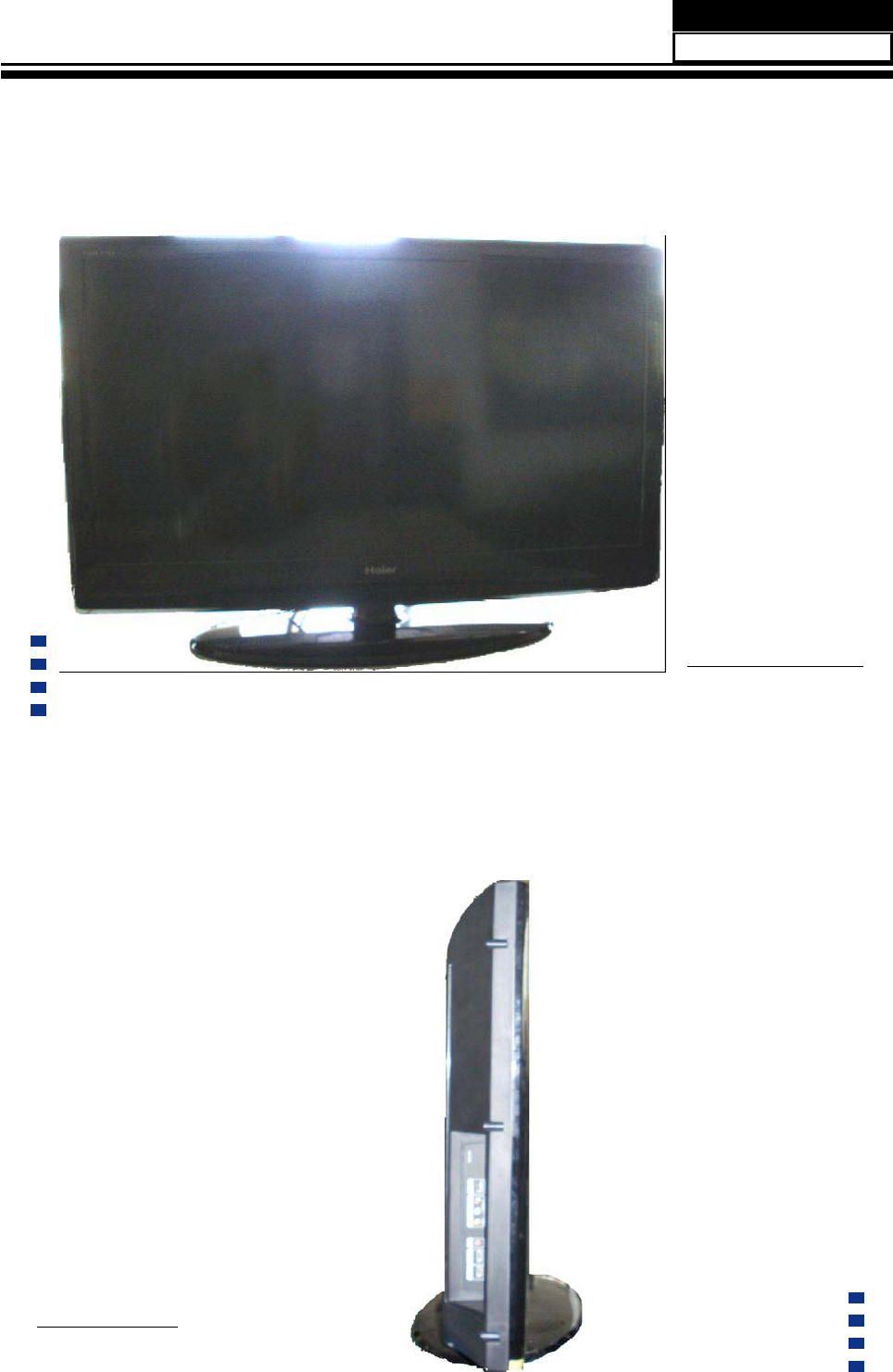
2-2 External pictures (four faces)
Front Side
Left Side
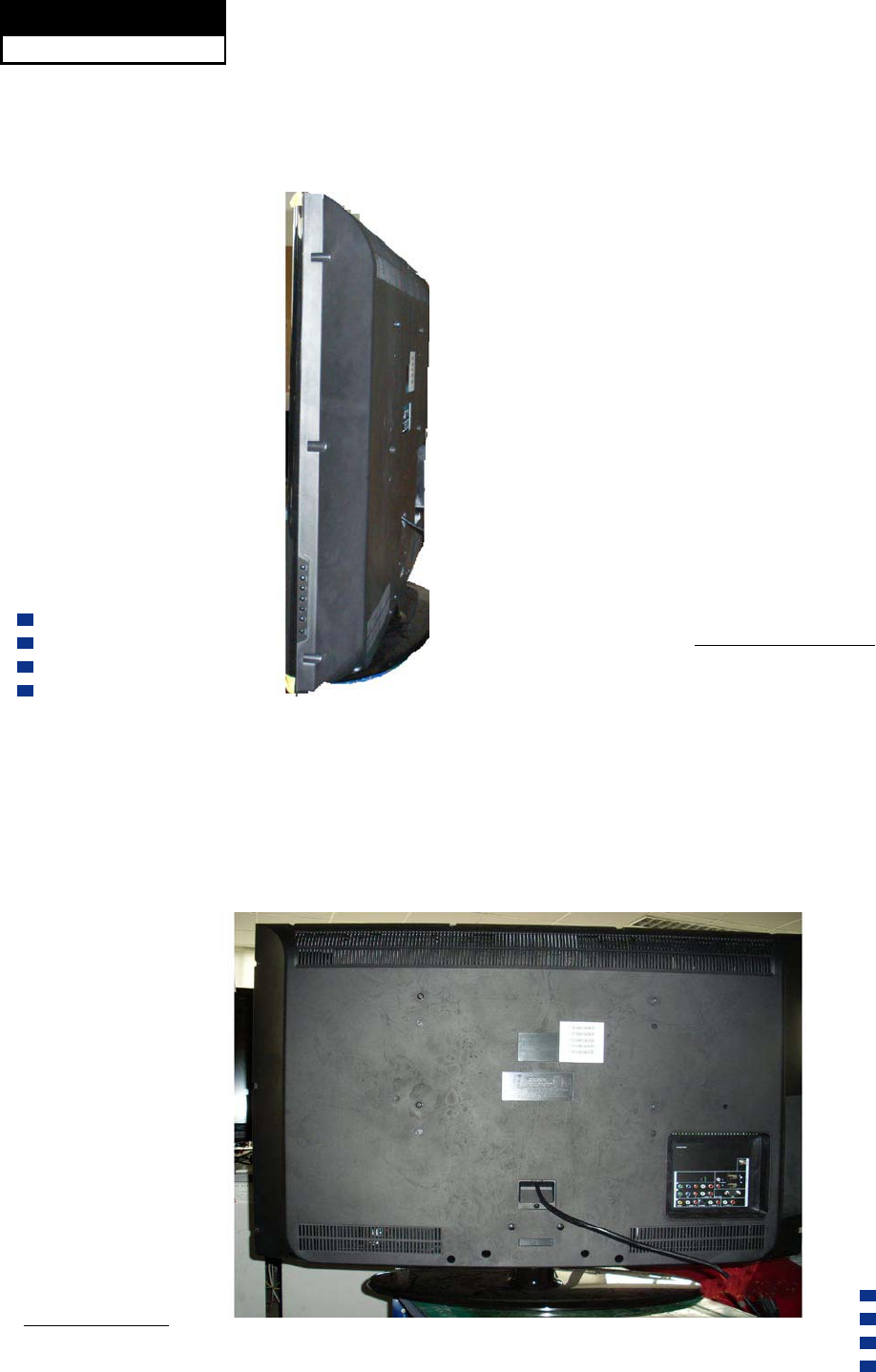
Service Manual
Model No.: HL40XP1
10
Right Side
Back Side
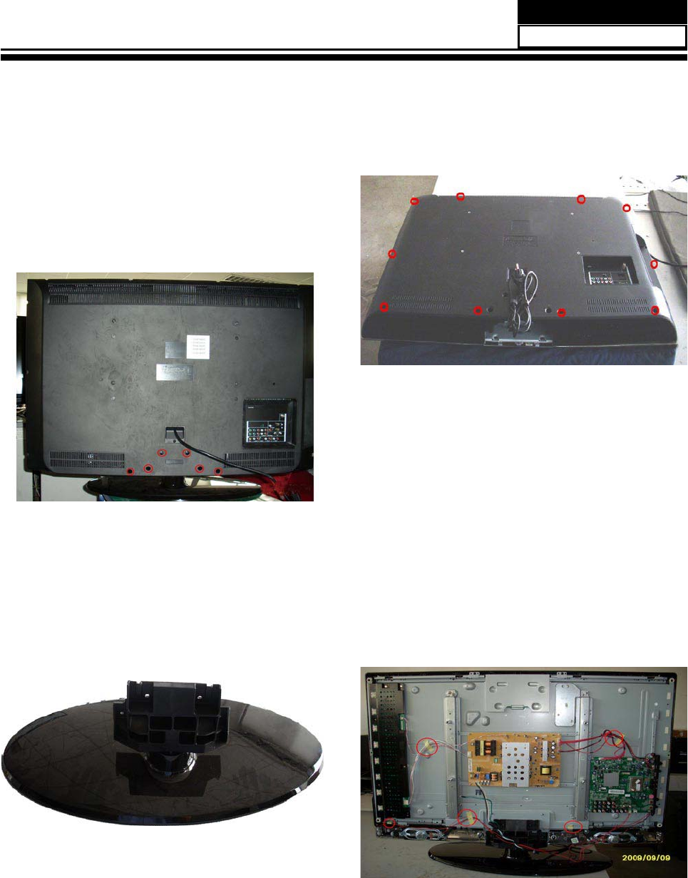
3-4 Remove the Terminal Bracket
Chapter 3. Disassemble and
3-1 Remove the Stand
1. Lay down the unit so that back cover faces
upward
2. Remove the six screws from the back
cover which are indicated with the circles in the
picture above.
3. Remove the stand
3-2. Remove the Back Cover
1. Remove the ten screws indicated (See
picture right.)
2. Then remove the back cover from the unit.
3-3. Remove the Adhesive Tape
The location of the adhesive tape is shown
below.
Remove the adhesive tape.
Remove the four screws indicated by the
red circles in the picture. (See next page.)
Service Manual
Model No.: HL40XP1
11
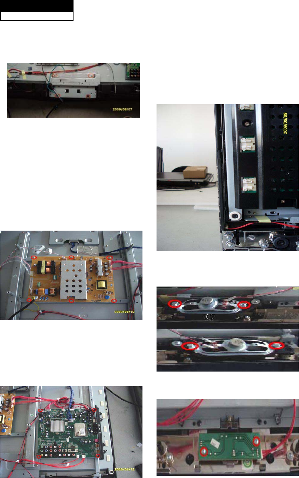
Then put the terminal bracket to the side.
3-5. Remove the Power Supply
Module
Remove the four screws indicated by the
red circles in below picture.
Then remove the power supply module.
3-6. Remove the Mainboard
Remove the eight screws indicated by the
rred circles in below picture.
3-7. Remove the Keypad Board
Disconnected the coupler CN1 CN2 CN3
CN4 CN5 CN7 J25.
Remove the Mainboard.
3-8. Remove the Speaker
3-9. Remove the Remote Control
Service Manual
Model No.: HL40XP1
12
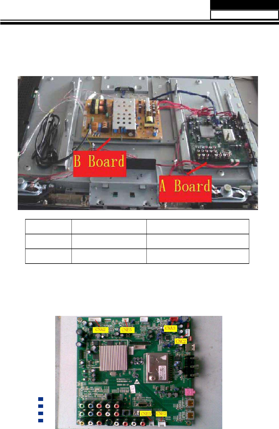
Chapter 4. Location of Controls and Components
4-1.
No. Parts number Description
A BoardMain Board
B BoardPower Board
4-2. Main Board & AV Board
Service Manual
Model No.: HL40XP1
13
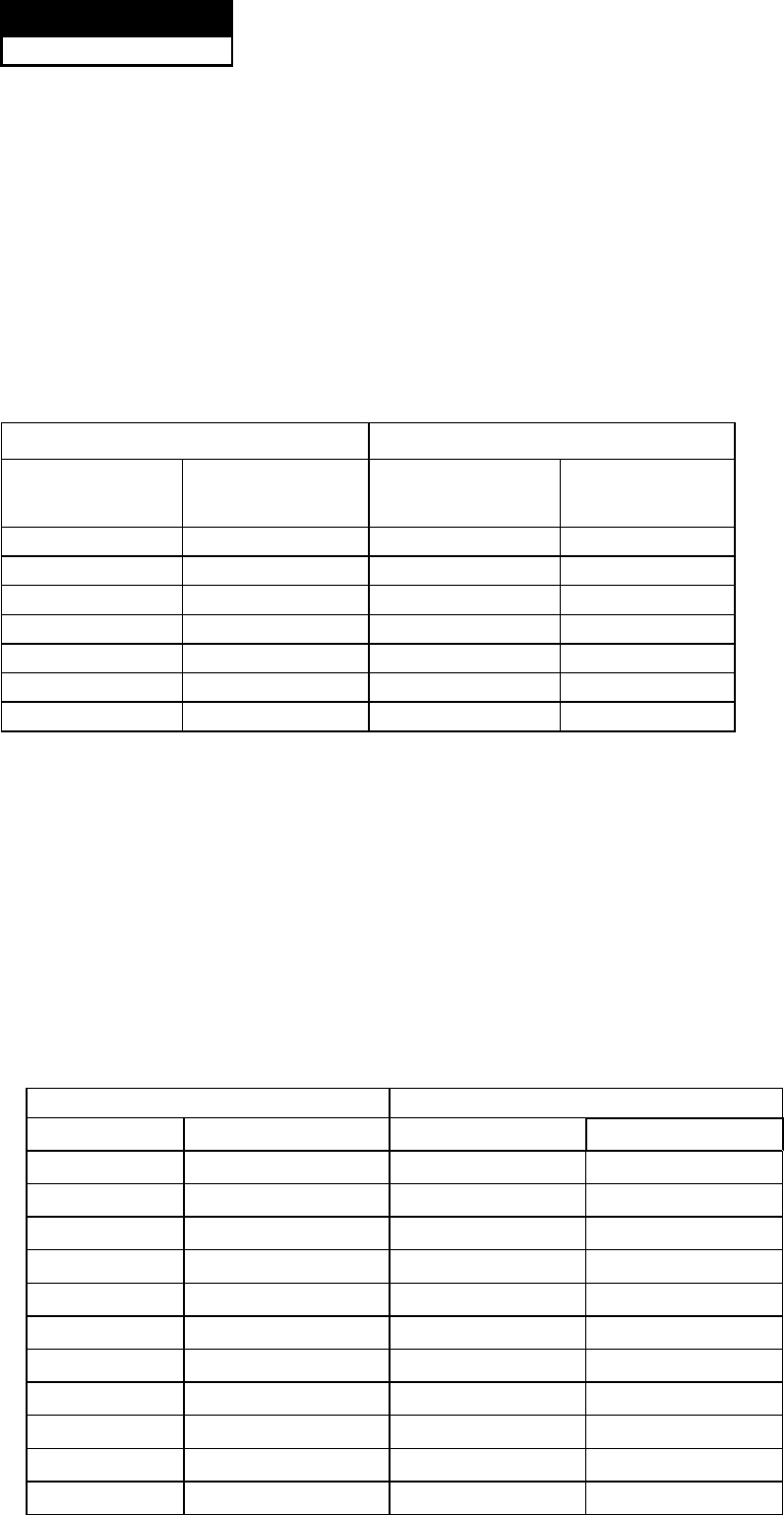
4-2-1 Function Description:
Main Board
3URFHVVVLJQDOZKLFKLQFHSWIURPH[WHULRUHTXLSPHQWWKHQWUDQVODWHLQWRVLJQDOWKDWSDQHOFDQGLVSOD\
&RQQHFWRUGH¿QLWLRQ
Main board connector
Power connectors (CN3, CN5)
CNA2 CNE5
Pin number Signal name Pin number Signal name
1 SW 1 DIMMING
2 GND 2 ON/OFF
3 +5VSB 3 GND
4 GND 4 SELECT
5 GND
6 +12V
7 +12V
Notes:
CNE5-Pin 2: Backlight on/off:
The system can turn on or turn off the backlight of TFT LCD Panel through the power supply
unit path.
CNA2-Pin 1: System power on / standby
System board will use this pin to control system power.
CNE5-Pin 1: Control the luminance of backlight
The system can generate the PWN signal to control the strength of TFT LCD Panel’s
backlight through this connector
CNE2 CNE3
Pin number Signal name Pin number Signal name
1SB5V 1 GND
2IR 2 AD1
3LED_R 3 AD2
4LED_G
5GND
Keypad and remote connector (CNE1,CNE2)
Service Manual
Model No.: HL40XP1
14
Speaker power connector (CNA3)
Pin number Signal name
1 24V
2 24V
3 GND
4 GND
Speaker Connector (CNC2)
Pin number Signal name
1L+
2L-
3R-
4R+
Other connectors:
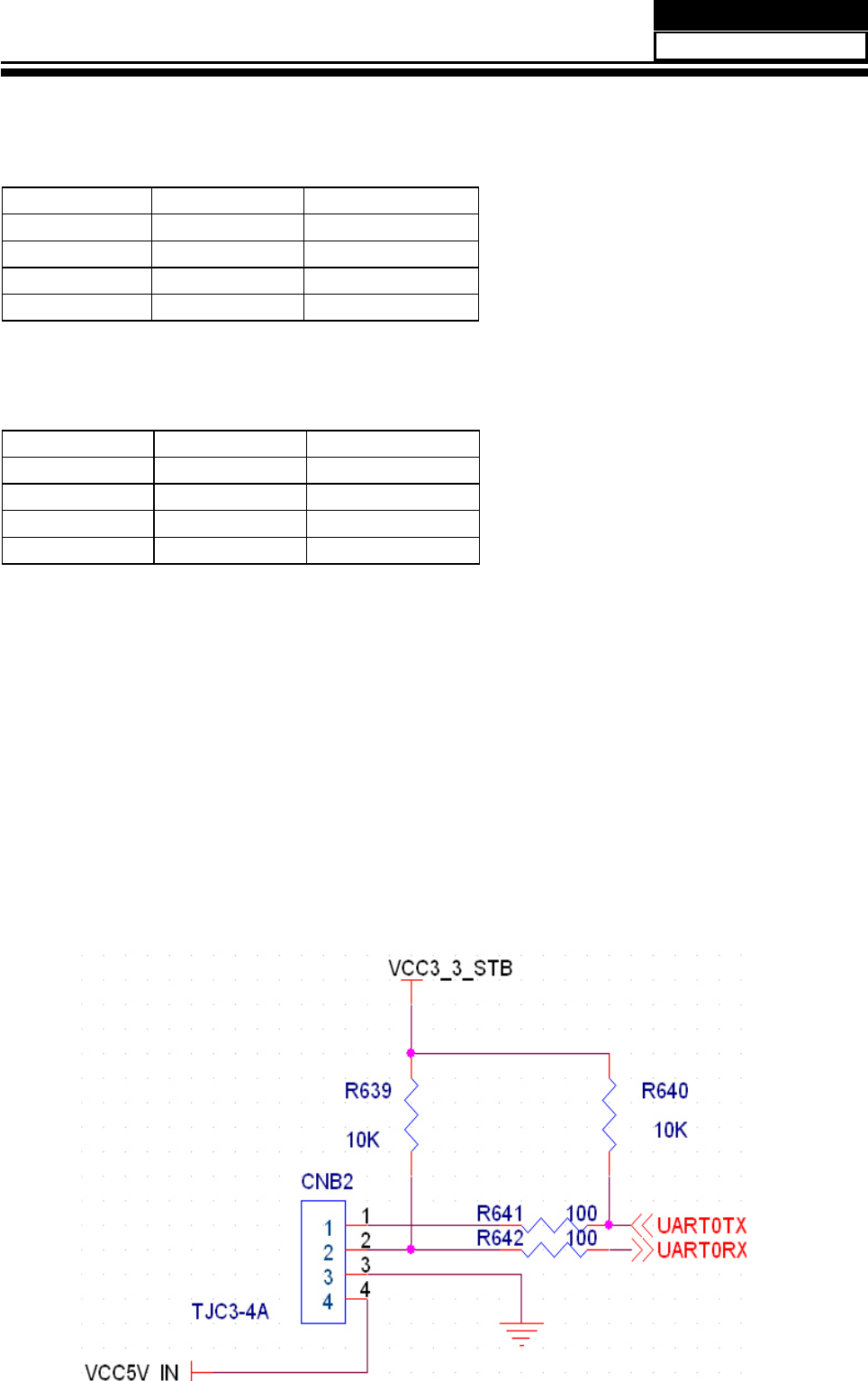
CNB2 to Upgrade the program of ZORAN785 (U1) AND FLASH (U7)
Service Manual
Model No.: HL40XP1
15
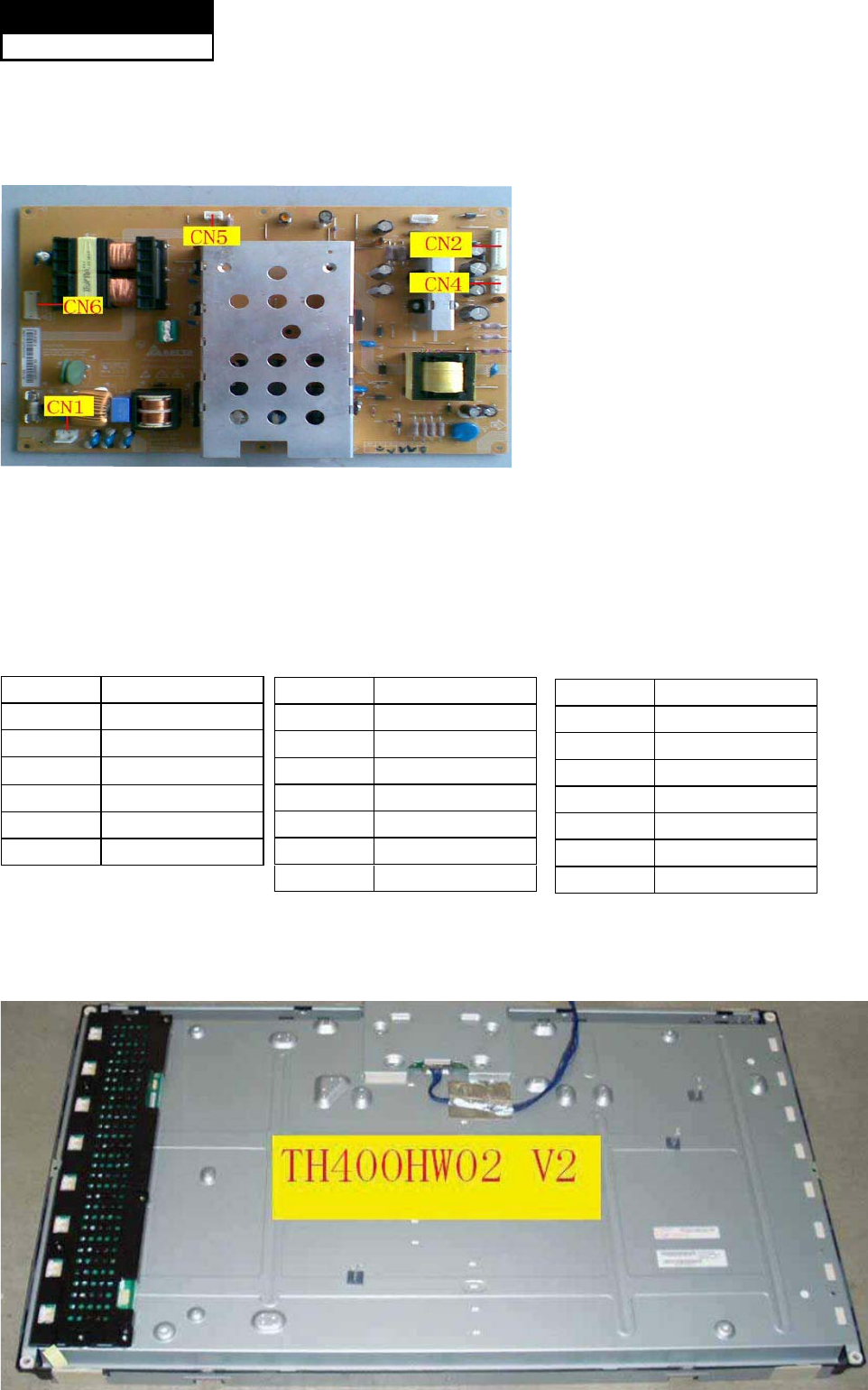
4-3. Power Supply Board
4-3-1. Function description:
To supply power for Mainboard, Panel.
&RQQHFWRUGH¿QLWLRQ
INPUT CONNECTOR (CN2)
CN2 Signal name
1 24V
2 24V
3 SGND1
4 SGND1
5 5VSB
6 SGND1
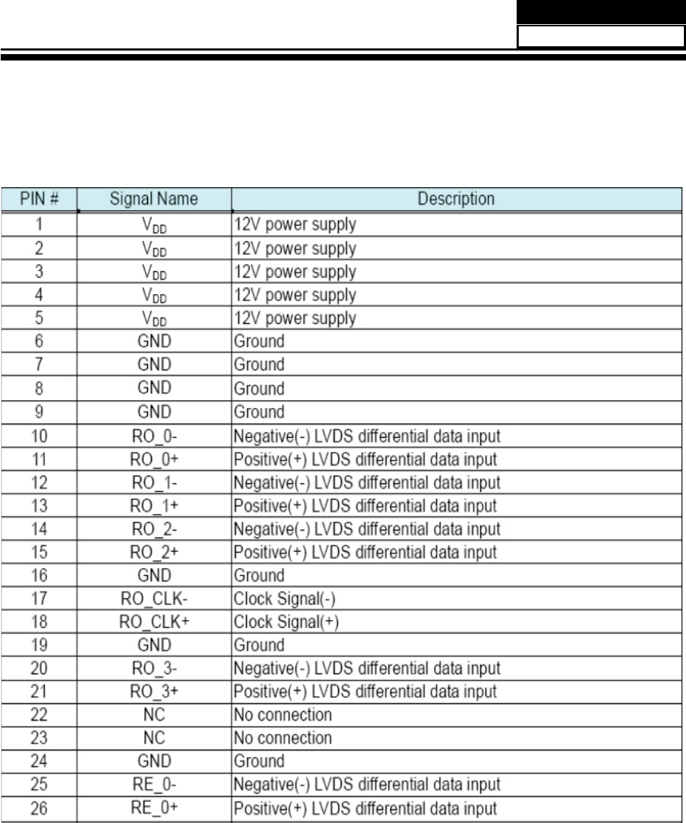
4-4. LCD Panel
CN6 Signal name
7 ON/OFF
8NC
9 I-PWM
10 BL-ON/OFF
11 E-PWM
CN4 Signal name
1 +24V
2 +24V
3 GND
4 GND
Service Manual
Model No.: HL40XP1
16
4-4-1. Function Description: Display the signal.
Service Manual
Model No.: HL40XP1
17
Service Manual
Model No.: HL40XP1
18
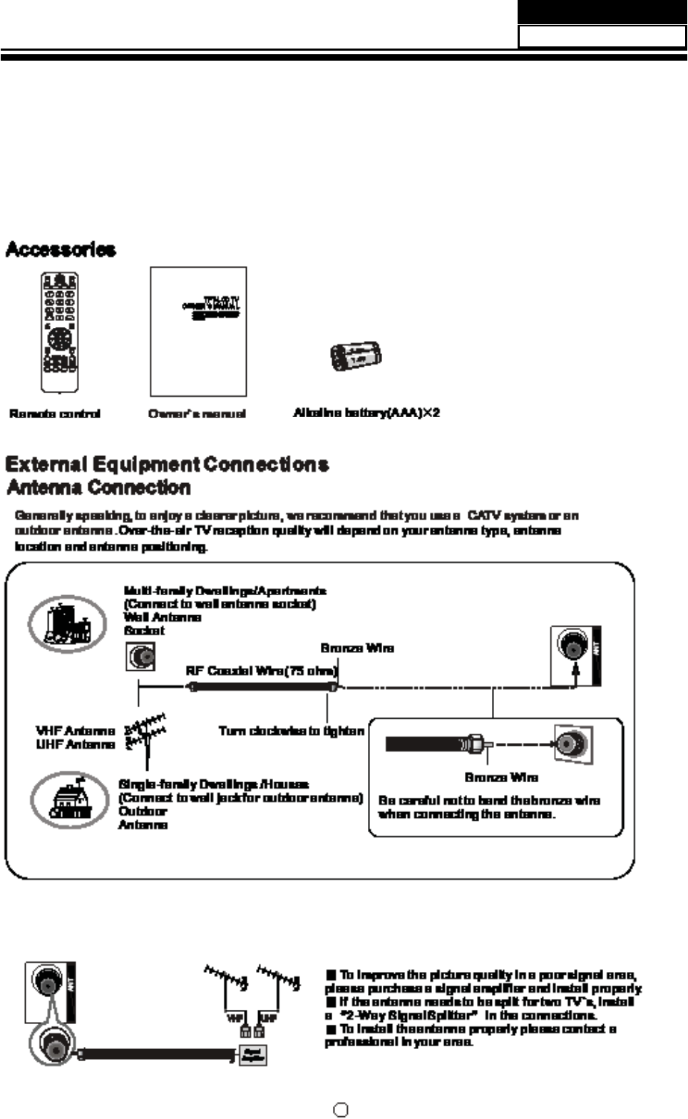
Chapter 5. Installation Instructions
5-1 External Equipment Connections
Service Manual
Model No.: HL40XP1
19
Installation
Choose Your Connection
There are several ways to connect your television,
depending on the components you want to connect
and the quality of the signal you want to achieve. The
following are examples of some dierent ways to
connect your TV with dierent input sources.
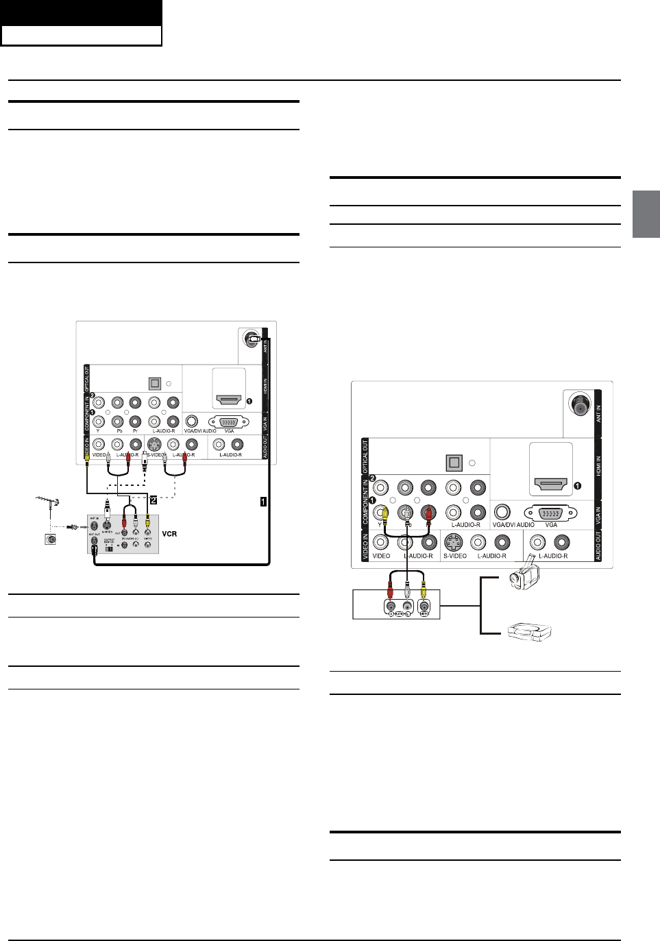
Connecting a VCR
To avoid picture noise (interference), leave an adequate
distance between the VCR and TV.
Connection Option 1
Set VCR output switch to channel 3 or 4 and then tune
the TV to the same channel number.
Connection Option 2
Connect the audio and video cables from the VCR’s
A
output jacks to the TV input jacks, as shown in the
figure. When connecting the TV to VCR, match the
jack colors (Video = yellow, Audio Left = white, and
Audio Right = red). If you connect a S-VIDEO output
from VCR to the S-VIDEO input, the picture quality is
improved; compared to connecting a regular VCR to
the Video input.
Insert a video tape into the VCR and press
B
PLAY on
the VCR. (Refer to the VCR owner’s manual.)
Select the input source with using the
C
INPUT button
on the remote control, and then press
/
button
to select the source, press ENTER button to confirm.
External A/V Source Setup
How to connect
Connect the audio and video cables from the q
external equipment’s output jacks to the TV input
jacks, as shown in the figure.
When connecting the TV to external equipment, q
match the jack colors (Video = yellow, Audio Left =
white, and Audio Right = red).
Vi
deo
Ga
m
eSe
t
Camcorder
How to use
Select the input source with using the AINPUT button
on the remote control.
Press
BCH+/- button to select the desired source.
Press
CENTER button to confirm.
Operate the corresponding external equipment.
D
Connecting a DVD player
Service Manual
Model No.: HL40XP1
20
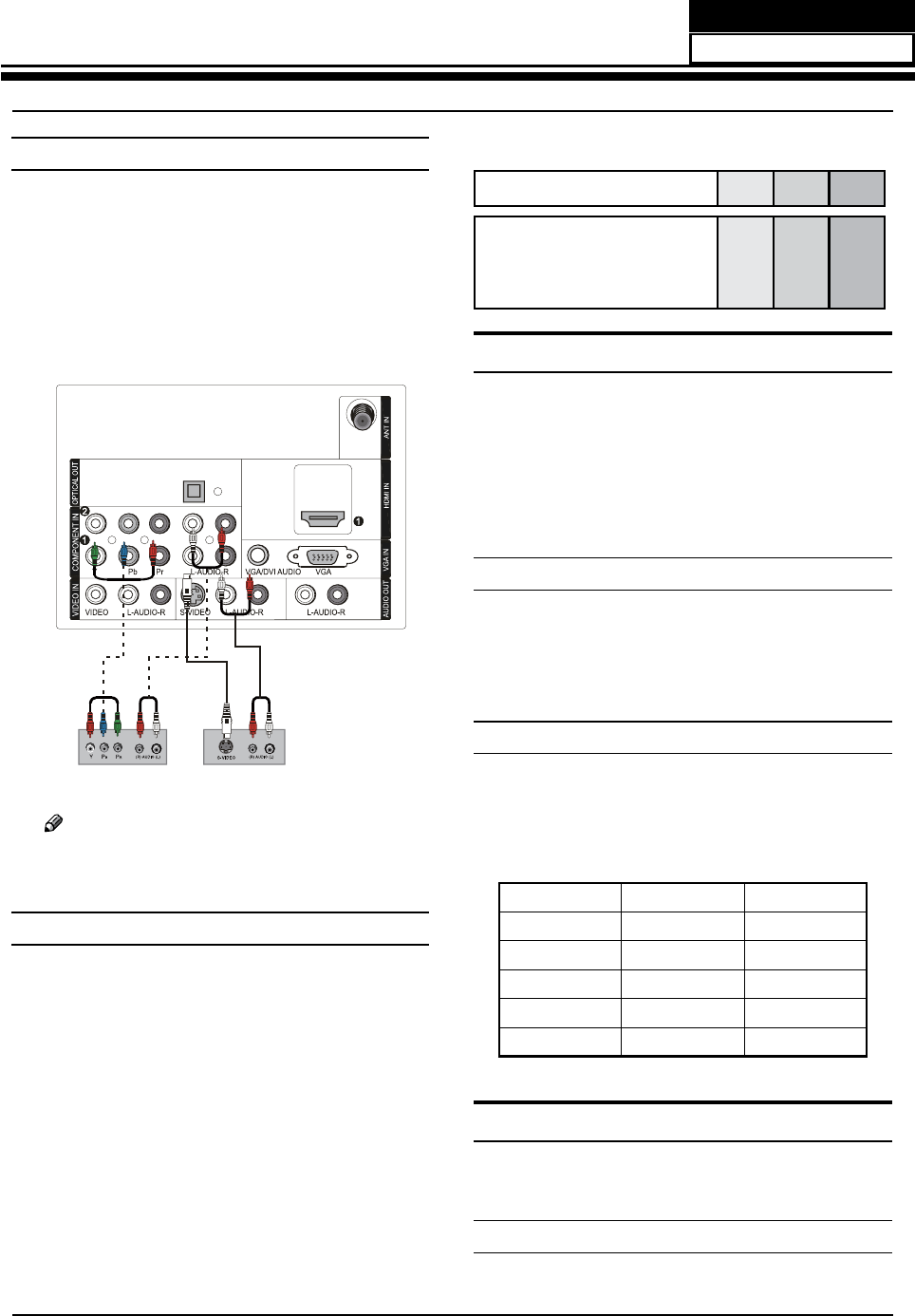
Installation
How to connect
Connect the DVD video outputs (COMPONENT) to
A
the Y Pb Pr jacks on the TV and connect the DVD
audio outputs to the YPbPr Audio IN jacks on the TV,
as shown in the figure.
If your DVD only has an S-VIDEO output jack, connect B
this to the S-VIDEO input on the TV, as shown in the
figure.
DVD
or
Note
If your DVD player does not have component R
video output, use S-Video.
How to use
Turn on the DVD player, insert a DVD disc.
A
Use
B
INPUT button on the remote control to select
component mode.
Press
C
PLAY button on external equipment for
program play.
Refer to the DVD player’s manual for operating
D
instructions.
Component Input portsQ
To get better picture quality, connect a DVD player to
the component input ports as shown below.
Component ports on the TV Y Pb Pr
Video output ports on DVD
player
Y
Y
Y
Y
Pb
B-Y
Cb
PB
Pr
R-Y
Cr
PR
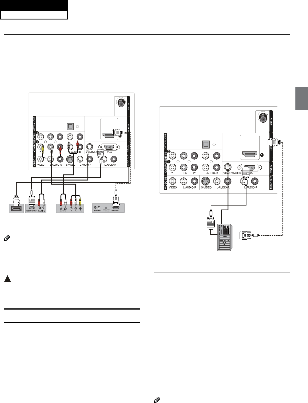
Connecting a DTV (digital TV)
This TV can receive Digital Over-the-air/Cable signals
without an external digital set-top box. However, if you do
receive Digital signals from a digital set-top box or other
digital external device, refer to the figure as shown below.
This TV supports HDCP (High-bandwidth Digital
Contents Protection) protocol for Digital Contents
(480p,720p,1080i).
How to connect
Use the TV’s COMPONENT, VGA or HDMI jack for q
video connections, depending on your set-top box
connector. Then, make the corresponding audio
connections.
How to use
Turn on the digital set-top box. (Refer to the owner’s
A
manual for the digital set-top box.)
Use INPUT on the remote control to select
B
COMPONENT, VGA or HDMI source.
Signal COMPONENT HDMI
480i Yes Yes
480p Yes Yes
720p Yes Yes
1080i Yes Yes
1080p Yes Yes
Connecting a digital audio output
Send the TV’s audio to external audio equipment (stereo
system) via the Digital Audio Output (Optical) port.
How to connect
Connect one end of an optical cable to the TV Digital
A
Service Manual
Model No.: HL40XP1
21
Installation
Audio (Optical) Output port.
Connect the other end of the optical cable to the
B
digital audio (optical) input on the audio equipment.
See the external audio equipment instruction
manual for operation.
Digital Set-top Box
+'0 ,
Note
When connecting with external audio equipments, R
such as amplifers or speakers, please turn the TV
speakers o.
!
Caution:
Do not look into the optical output port. Looking q
at the laser beam may damage your vision.
Connecting a computer
How to connect
To get the best picture quality, adjust the VGA A
graphics card to 1024s768.
Use the TV’s VGA or DVI (Digital Visual Interface)
B
Audio IN port for audio connections, depending on
your computer connector.
If the graphic card on the computer does not q
output analog and digital RGB simultaneously,
connect only one of either VGA IN or HDMI IN to
display the VGA on the TV.
If the graphic card on the computer does output q
analog and digital RGB simultaneously, set the TV
to either VGA or HDMI; (the other mode is set to
Plug and Play automatically by the TV.)
Then, make the corresponding audio connection.
C
If using a sound card, adjust the VGA sound as
required.
How to use
Turn on the computer and the TV.
A
Use INPUT on the remote control to select VGA or
B
HDMI source.
Check the image on your TV. There may be noise
C
associated with the resolution, vertical pattern,
contrast or brightness in VGA mode. If noise
is present, change the VGA mode to another
resolution, change the refresh rate to another rate
or adjust the brightness and contrast on the menu
until the picture is clear. If the refresh rate of the VGA
graphic card can not be changed, change the VGA
graphic card or consult the manufacturer of the VGA
graphic card.
Note
Use a DVI cable.R
Service Manual
Model No.: HL40XP1
22
Installation
Avoid keeping a fixed image on the TV’s screen R
for a long period of time. The fixed image may
become permanently imprinted on the screen.
The synchronization input form for Horizontal and R
Vertical frequencies is separate.
ResolutionY
Mode Resolution
Frame
frequency
(Hz)
VGA 640s480 60Hz
SVGA 800s600 60Hz
75Hz
XGA 1024s768 60Hz
75Hz
HDMI and DVI input
When the source device (DVD player or Set Top Box)
supports HDMI
How To Connect
Connect the source device to HDMI port of this TV
A
with an HDMI cable (not supplied with this product).
No separated audio connection is necessary.
B
How To Use
If the source device supports Auto HDMI function, q
the output resolution of the source device will be
automatically set to 1280s720p.
If the source device does not support Auto HDMI, q
you need to set the output resolution appropriately.
To get the best picture quality, adjust the output
resolution of the source device to 1280s720p.
Select HDMI input source in input source option of q
Select Main source menu.
When the source device (DVD player or Set Top Box)
supports DVI
How To Connect
Connect the source device to HDMI port of this TV
A
with a HDMI-to-DVI cable (not supplied with this
product).
A separated audio connection is necessary.
B
If the source device has an analog audio output C
connector, connect the source device audio output to
DVI Audio In port located on the left side of HDMI port.
How To Use
If the source device supports Auto DVI function, q
the output resolution of the source device will be
automatically set to 1280s720p.
If the source device does not support Auto DVI, you q
need to set the output resolution appropriately.
To get the best picture quality, adjust the output
resolution of the source device to 1280s720p.
Press the qINPUT button to select HDMI input source
in input source option of Select Main source menu.
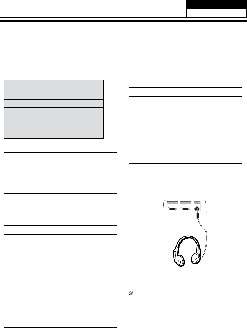
Connecting Headphones
You can connect a set of headphones to your set
if you wish to watch a TV programme without
disturbing the other people in the room.
HDMI4 INHDMI3 IN
Plug a set of headphones into the 3.5mm mini-jack
socket on the side panel of the set.
Note
Prolonged use of headphones at a high volume R
may damage your hearing.
You will not receive sound from the speakers when R
you connect headphones to the system.
Service Manual
Model No.: HL40XP1
23
Installation
Power source
TO USE AC POWER SOURCE
Use the AC polarized line cord provided for q
operation on AC. Insert the AC cord plug into a
standard polarized AC outlet.
Note
Never connect the AC line cord plug to other than R
the specified voltage. Use the attached power cord
only.
If the polarized AC cord does not fit into a non- R
polarized AC outlet, do not attempt to file or cut
the blade. It is the user’s responsibility to have an
electrician replace the obsolete outlet.
If you cause a static discharge when touching the R
unit and the unit fails to function, simply unplug
the unit from the AC outlet and plug it back in. The
unit should return to normal operation.
Polarized AC Cord Plug
AC Outlet
Wider Hole
and Blade
Remove 4 s M4
screws securing
the stand to the
TV, then remove
the stand.
Use 4 s M6
screws to secure
the wall bracket
(not supplied)
to the back of
your TV.
Removing the table stand and install-
ing a wall mount bracket
HLC26R1
HLC32R1
Service Manual
Model No.: HL40XP1
24
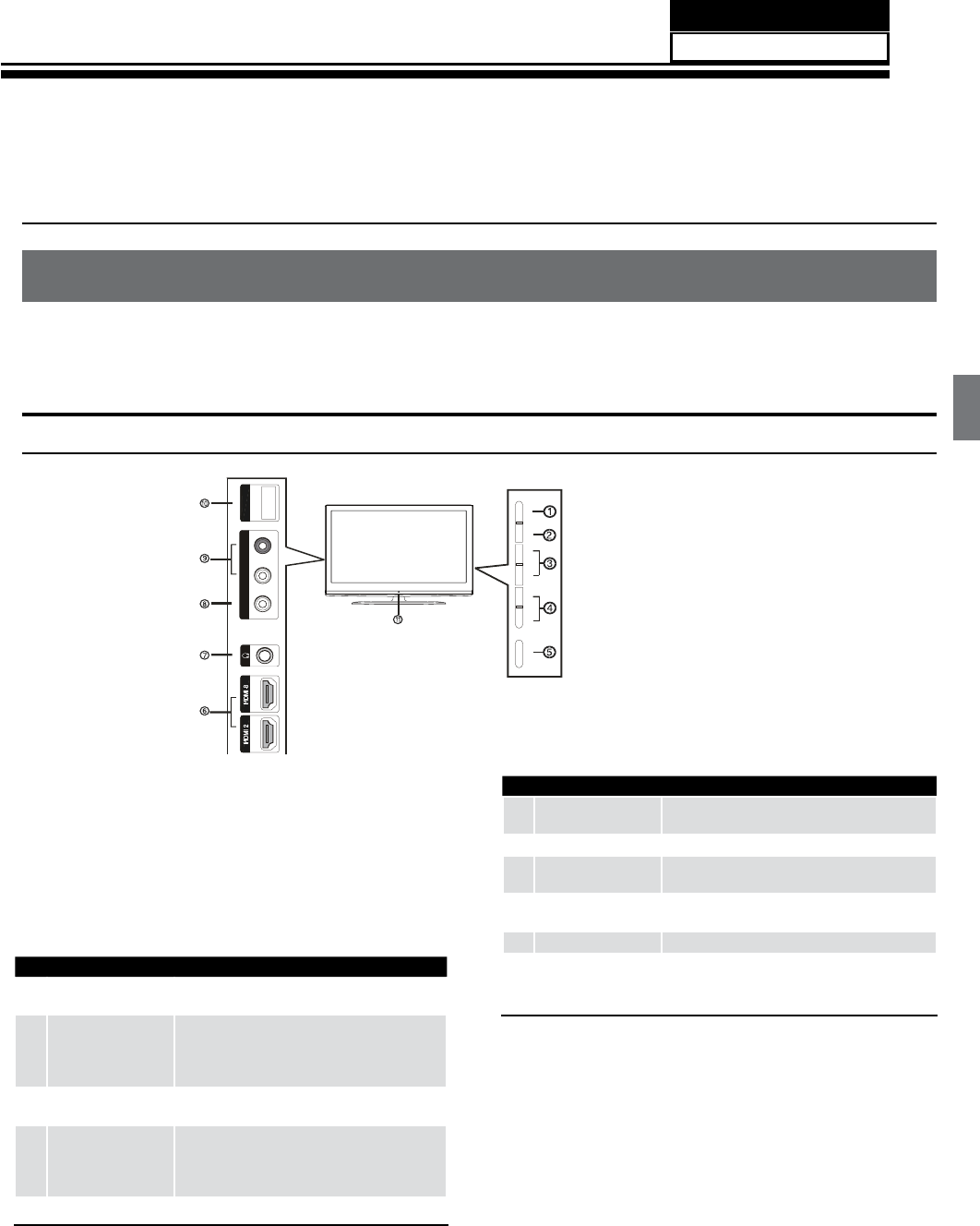
Contents
Introduction
Controls
This is a simplied representation of the TV front panel, side panel control buttons and side inputs.
TV Side panel controls and connections
VIDEO 2 SERVICE
VIDEO L-AUDIO-R
MENU INPUT VOL+ VOL- CH+ CH- POWER
1MENU Menu display. Press to access the on-screen
menu display.
2INPUT
Press to access the input source mode. Press
repeatedly to change the source to the one
you want to watch. In the MENU screen, the
INPUT button serves as the ENTER button.
3VOL +/-
Press to adjust the volume. In the MENU screen,
these buttons serve as left/right buttons.
4CH +/-
Press to scan through channels. To scan quickly
through channels, press and hold down either
+/- . In the MENU screen, these buttons serve
as up/down buttons.
5POWER Press to turn on and o the TV.
6HDMI IN Connect a HDMI device to receive digital audio
and uncompressed digital video signals.
7Headphone jack Headphone audio output terminal.
8AV2 VIDEO IN Connect the composite video cable from an
external signal source to this jack.
9AV2 AUDIO IN Connect the audio L/R cables from the video
signal source to these jacks.
0USB Service only.
ARemote Sensor
Receivers IR signals from the remote control.
Do not put anything near the sensor, which
may block the remote control signal.
Chapter 6. Operation Instructions
6-1. Front Panel Controls
Service Manual
Model No.: HL40XP1
25
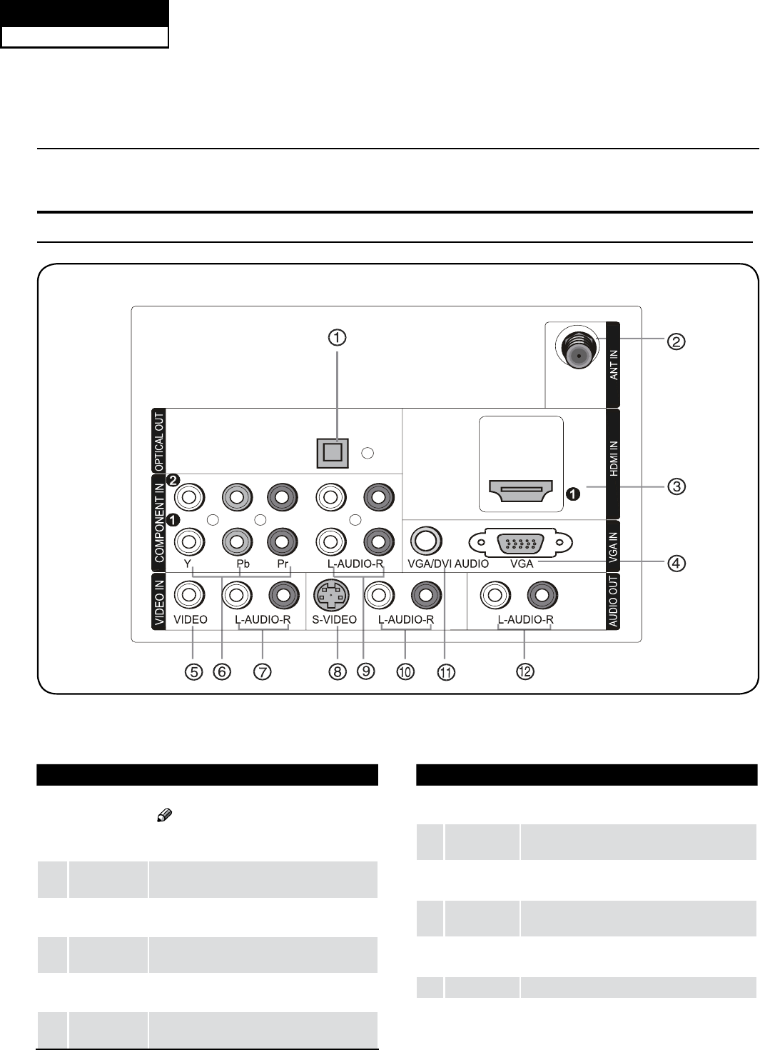
Introduction
1Digital Audio
Output
Connect various types of digital audio equipment.
Note
In standby mode, these ports will not R
work.
2Antenna
Input
Connect cable or antenna signals to the TV,
either directly or through your cable box.
3HDMI In Connect a HDMI device to receive digital audio
and uncompressed digital video.
4VGA Video In Connect a video cable from a computer to this
jack.
5VIDEO In Connect the video signal from a video device to
this jack.
6Component
Video In
Connect a component video device to these
jacks.
7AUDIO In Connect the audio L/R cables from the video signal
source to these jacks.
8S-VIDEO In Connect the S-Video cable from an external signal
source to this jacks.
9COMPONENT
AUDIO In
Connect the audio L/R cables from the component
video signal source to these jacks.
0AUDIO In Connect the audio L/R cables from the S-Video
signal source to these jacks.
AVGA Audio
In
Connect the audio L/R cables from a computer to
this jack.
BAUDIO Out
Connect the audio L/R cables to your audio equipment.
Connection Options
Back panel connections
Service Manual
Model No.: HL40XP1
26
6-2. Back Panel Controls
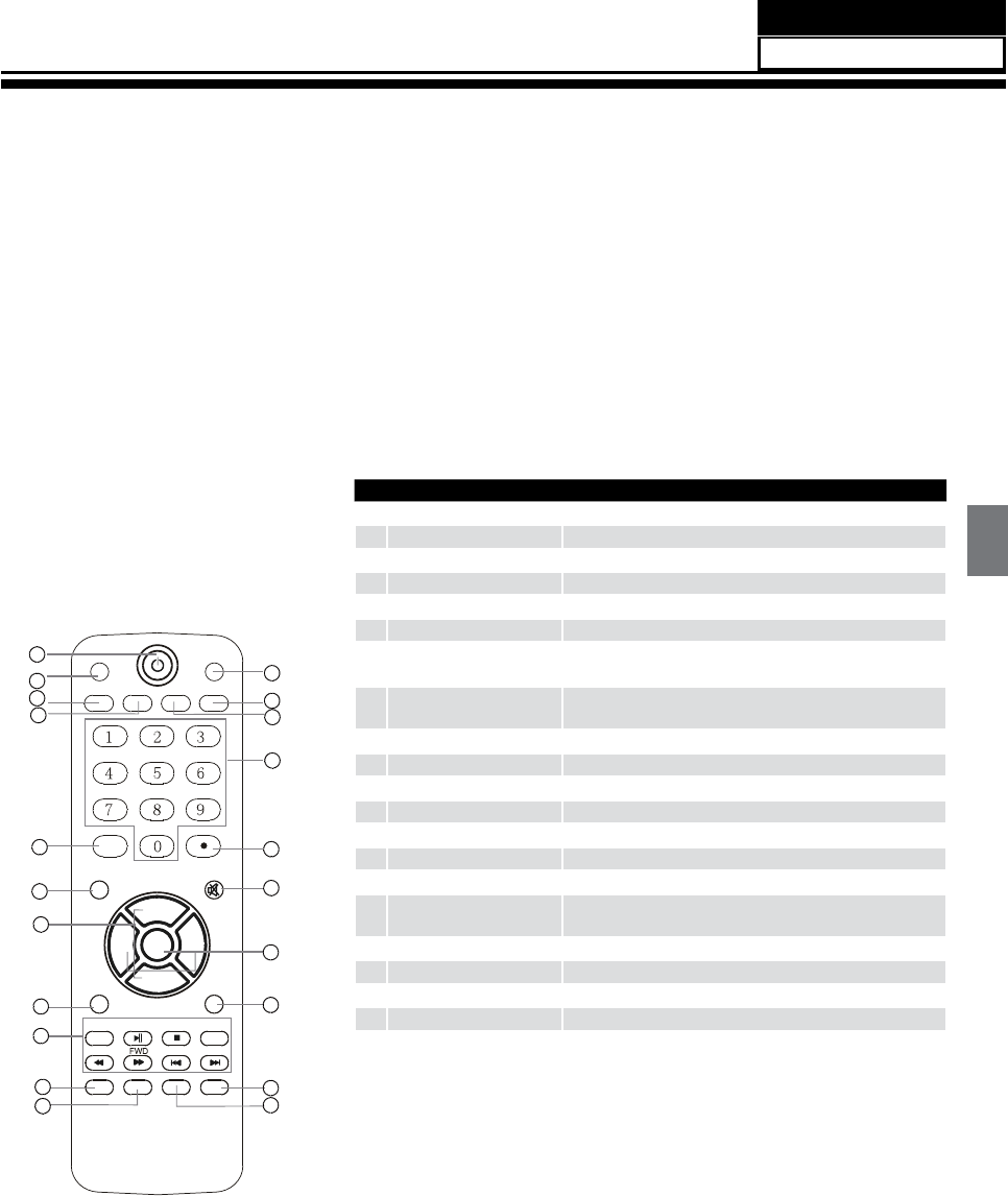
6-3 Setting Up Your Remote Control
After being setting up properly, your remote control can operate in six different modes:
TV, VCR, CABLE, DVD, SETBOX or AUDIO.
Pressing the corresponding button on the remote control allows you to switch between these modes,
DQGFRQWUROZKLFKHYHUSLHFHRIHTXLSPHQW\RXFKRRVH
Note:
The remote control might not be compatible with all DVD Players, VCRs and Cable boxes.
The remote control cannot be operated unless the batteries are properly loaded.
When using the remote control, aim it at the remote sensor on the TV.
1POWER Press to turn on and o the TV
2PICTURE Press repeatedly to cycle through the available picture modes
3ARC
Select the aspect ratio
4CCD (closed caption) Select a closed caption option
5INPUT Show the input source
6MENU Press to open the on-screen menu
7Thumbstick (Up/Down/
Left/Right)
Allows you to navigate the on-screen menus and adjust the
system settings to your preference
8EXIT Clears all on-screen displays and returns to TV viewing from any
menu
9No available
0DISPLAY
Press to display the TV status information on the top of the TV screen
AGUIDE
Display the guide when you are watching analog or digital channels
BAUDIO Press to cycle through dierent sound settings
CSLEEP button Press to display the sleep timer option
DMTS/SAP Select MONO, STEREO, SAP in NTSC system
ENumber buttons Press to change a channel
FtCVUUPO Press to select digital channels. For example, to enter “54-3”,
QSFTTiwitwBOEiw
GMUTE Switches the sound on or o
HRECALL Press to jump back and forth between two channels
ICH.LIST Open the channel list in TV
JFAVORITE Open the favourite channel list in TV
KENTER
Accesses the highlighted item in the on-screen menu
1
2
3
4
5
6
7
8
9
10
11
12
13
14
15
16
17
18
19
20
21
PICTURE AUDIO
ARC CCD MTS/SAP SLEEP
INPUT
MENU MUTE
EXIT RECALL
USB
GUIDE
REV PREV NEXT
STOP REPEAT
CH+
CH-
VOL-
ENTER
VOL+
PLAY/PAUSE
DISPLAY FAVORITE CH.LIST
Service Manual
Model No.: HL40XP1
27
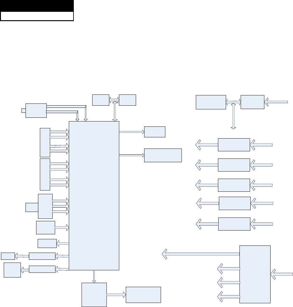
Chapter 7. Electrical Parts
7-1. Block Diagram
ZORAN 785
DDR DDR
FLASH
FLAT PANEL
DISPLAY
TUNER
S
AV
L
R
Y
PB
PR
L
R
RGB
L
R
VGA
SPDIF
HDMI
LM4558
LM4558
HP
AUDIO
OUT
AUDIO
AMP
TAS5708
SPEAKER
U48
NCP1579
U32
NTMD4840
U30
AP1117E33
U31
AP1117E18
U25
AP1117E33
U28
AZ1084-ADJ
Power
Board
To driver the backlight
5VSB
12V
24V To AMP
220V~
12V
5V
5VSB
3.3VSB
3.3VSB
1.8VSB
5V
3.3V
5V
1.8V
24V
U22
AP1534
5V
1.8V
H5PS5162FFR-25C H5PS5162FFR-25C
DVT-8ADC1/GW41F2
EN25B32
T1
U2 U3
U7
U17
U1
Service Manual
Model No.: HL40XP1
28
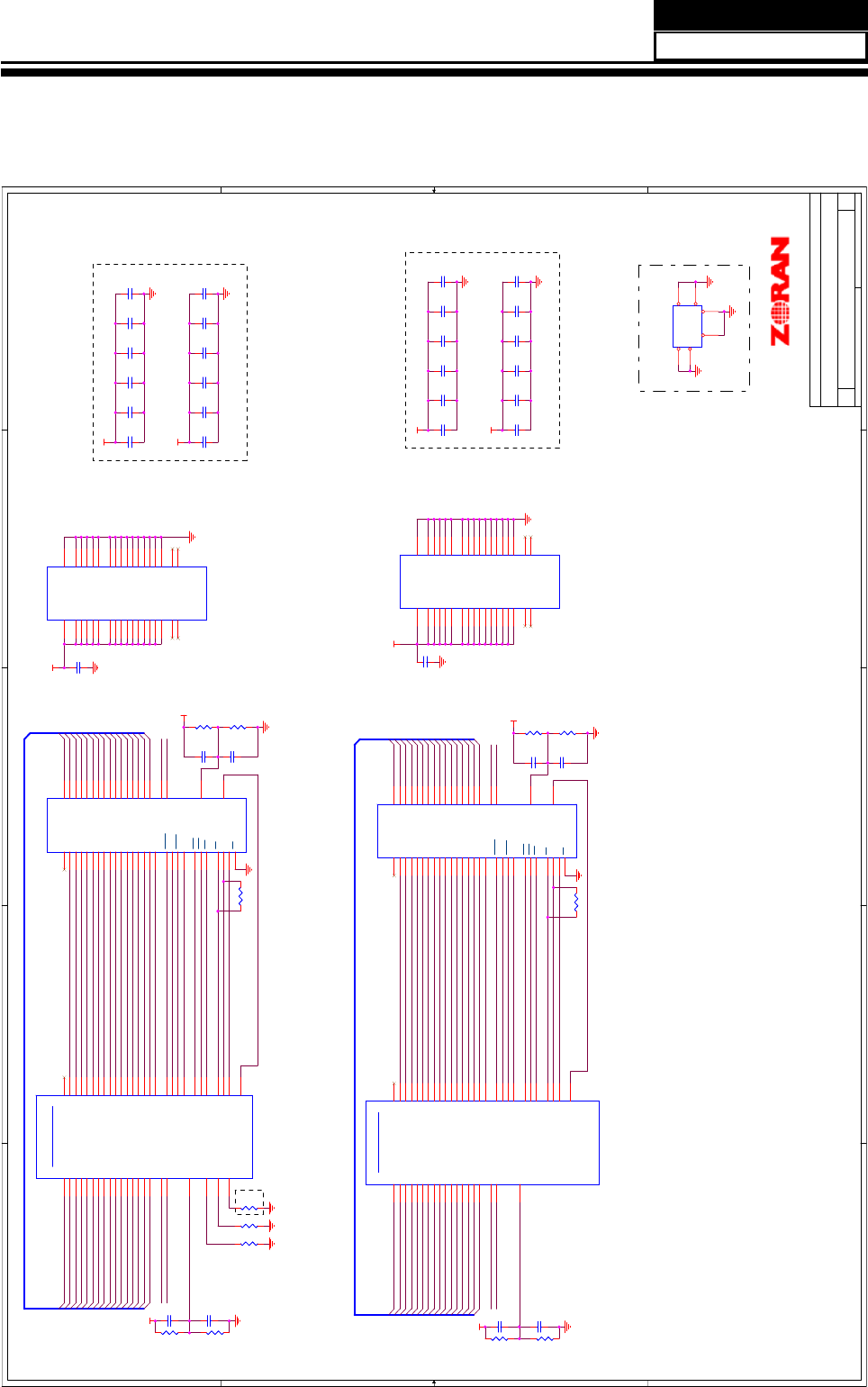
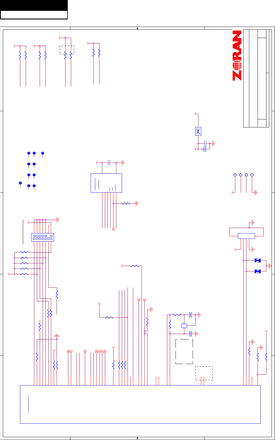
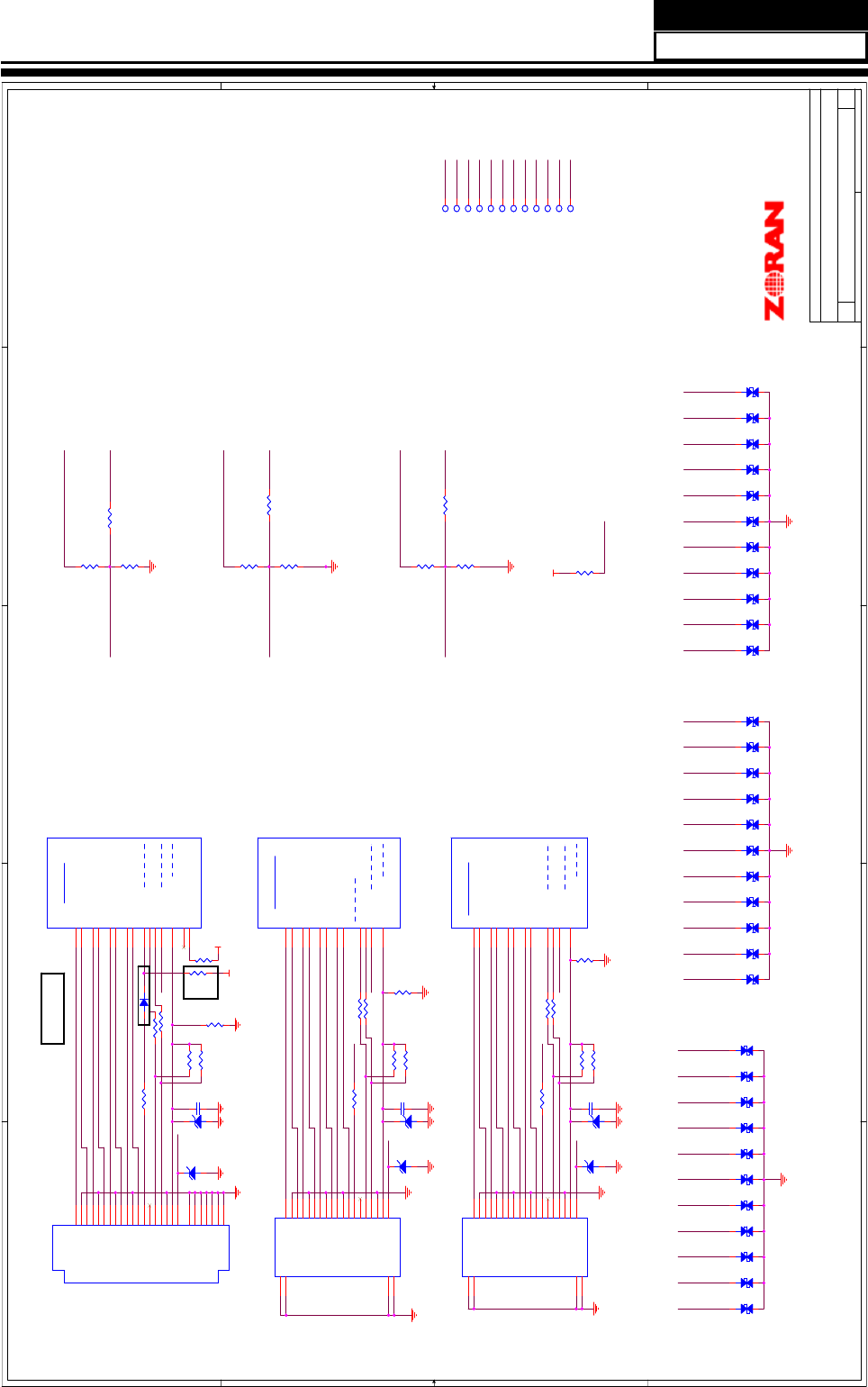
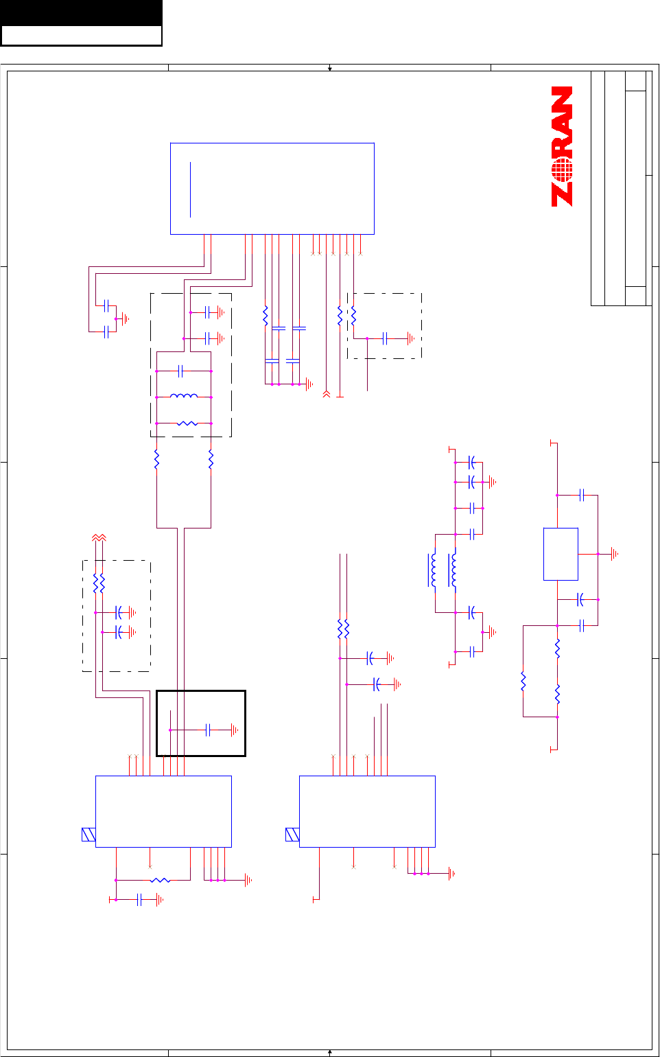
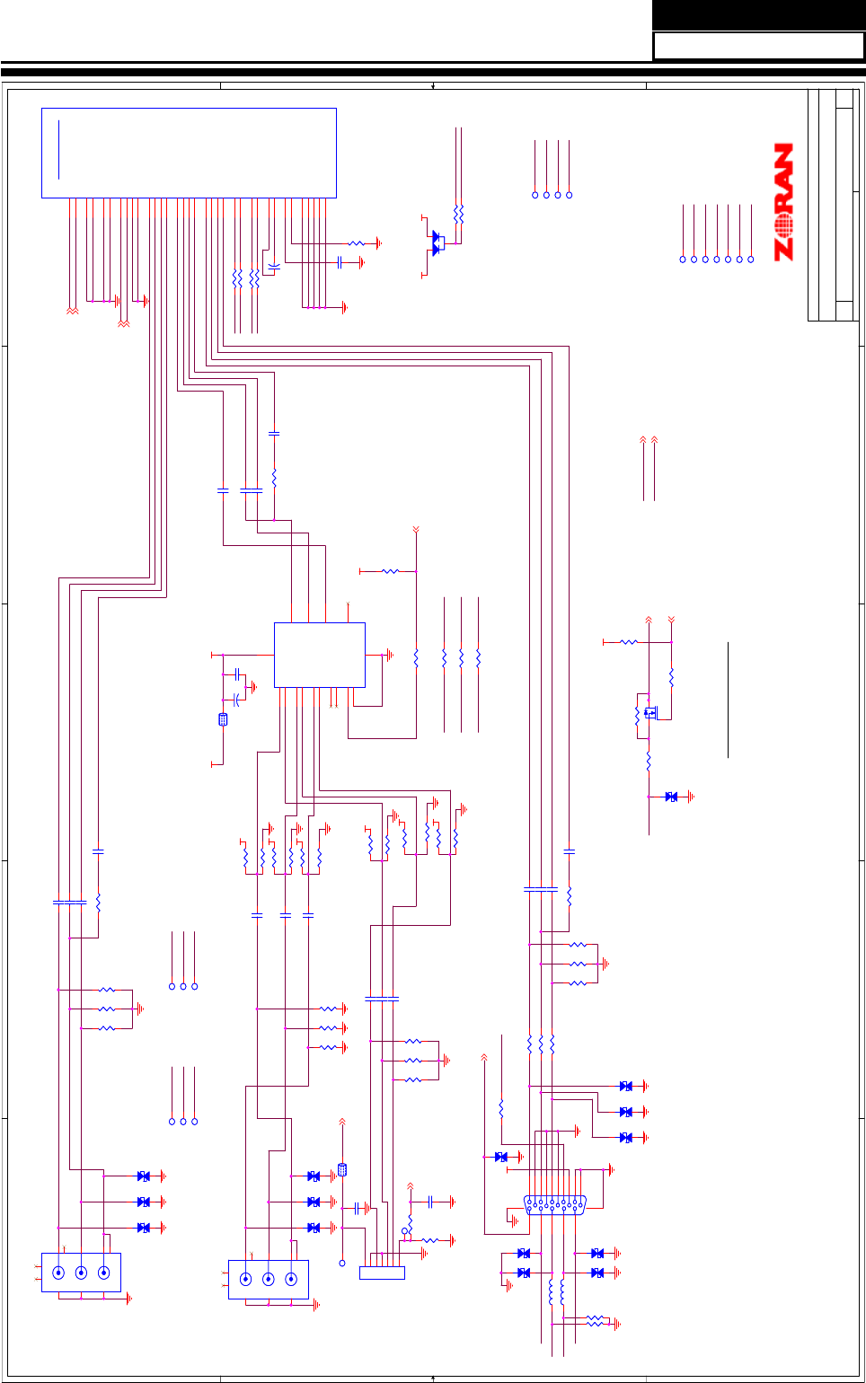
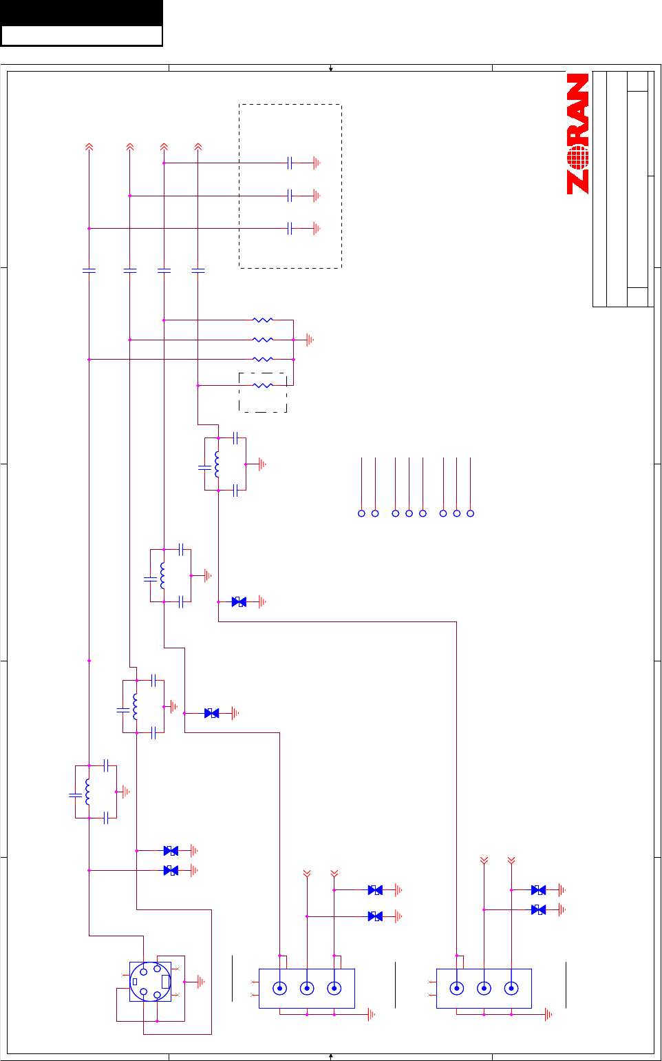
7-2. Circuit Diagram
5
5
4
4
3
3
2
2
1
1
D D
C C
B B
A A
S0_ODT
S0_DQ[15..0]
S0_DQ11
S0_DQ12
S0_DQ13
S0_DQ14
S0_DQ15
S0_DQ2
S0_DQ1
S0_DQ0
S0_DQ3
S0_DQ4
S0_DQ5
S0_DQ6
S0_DQ7
S0_DQ8
S0_DQ9
S0_DQ10
S0_UDM
S0_LDM
S0_VREF
S0_A12
S0_A11
S0_A10
S0_A9
S0_A8
S0_A7
S0_A6
S0_A5
S0_A4
S0_A3
S0_A2
S0_A1
S0_A0
S0_BA2
S0_BA1
S0_BA0
S0_UDQSN
S0_UDQS
S0_LDQSN
S0_LDQS
S0_RASN
S0_CASN
S0_WEN
S0_CKN
S0_CKE
S0_CK
S0_DQ15
S0_DQ14
S0_DQ13
S0_DQ12
S0_DQ11
S0_DQ10
S0_DQ9
S0_DQ8
S0_DQ7
S0_DQ6
S0_DQ5
S0_DQ4
S0_DQ3
S0_DQ2
S0_DQ1
S0_DQ0
S0_UDM
S0_LDM
S1_A7
S1_DQ8
S1_LDQS
S1_A6
S1_DQ7
S1_RASN
S1_A5
S1_CASN
S1_DQ6 S1_A4
S1_WEN
S1_DQ5 S1_A3
S1_CKN
S1_DQ4 S1_A2
S1_DQ11
S1_DQ12
S1_DQ13
S1_DQ14
S1_DQ15
S1_DQ2
S1_DQ1
S1_DQ0
S1_DQ3
S1_DQ4
S1_DQ5
S1_DQ6
S1_DQ7
S1_DQ8
S1_DQ9
S1_DQ10
S1_DQ3 S1_A1
S1_VREF
S1_CKE
S1_DQ15
S1_DQ2 S1_A0
S1_UDM
S1_LDM
S1_DQ14
S1_DQ1 S1_BA2
S1_A12
S1_DQ13
S1_DQ0 S1_BA1
S1_A11
S1_DQ12
S1_UDM
S1_BA0
S1_CK
S1_A10
S1_DQ11
S1_UDQSNS1_LDM
S1_A9
S1_DQ10
S1_UDQS
S1_ODT
S0_DQ[15..0]
S1_A8
S1_DQ9
S1_LDQSN
VCC1_8
VCC1_8
VCC1_8
VCC1_8
VCC1_8
VCC1_8
VCC1_8
VCC1_8
VCC1_8
VCC1_8
Title
Size Document Number Rev
Date: Sheet of
APOLLO - DDR II SDRAM I/F
10
Zoran/HD775 Ref. Platform
219Friday, March 13, 2009
Title
Size Document Number Rev
Date: Sheet of
APOLLO - DDR II SDRAM I/F
10
Zoran/HD775 Ref. Platform
219Friday, March 13, 2009
Title
Size Document Number Rev
Date: Sheet of
APOLLO - DDR II SDRAM I/F
10
Zoran/HD775 Ref. Platform
219Friday, March 13, 2009
ZORAN Confidential
Close to DDR2
ሣ㬑㔽ᇕ㺙䳔㽕ᬍ
BP6BP4 BP5BP1
U3 Bypass Caps
BP2 BP3
BP9 BP10 BP11BP7 BP8 BP12
ࡴⒸ⊶⬉ᆍˈ䴴䖥
DDR
ᬒ㕂
Close to 775
BP6BP4 BP5BP1
U4 Bypass Caps
BP2 BP3
BP9 BP10 BP11BP7 BP8 BP12
ࡴⒸ⊶⬉ᆍˈ䴴䖥
DDR
ᬒ㕂
R4
100_1%
R4
100_1%
C399
0.1uF
C399
0.1uF
C395
0.1uF
C395
0.1uF
C408
0.1uF
C408
0.1uF
C404
0.1uF
C404
0.1uF
S1 Memory I/F
U1BZR39775
S1 Memory I/F
U1BZR39775
S1_DQ15
F25
S1_DQ14
M26
S1_DQ13
E26
S1_DQ8
F26
S1_DQ7
E25
S1_DQ5
D25
S1_DQ3
K25
S1_DQ2
J26
S1_DQ0
D26
S1_LDM
K26
S1_VREF
R26
S1_ODT D24
S1_CK_N C25
S1_CK_P C26
S1_RAS_N G23
S1_CAS_N G24
S1_WE_N L23
S1_UDQS_N G26
S1_UDQS_P G25
S1_LDQS_N J25
S1_LDQS_P H26
S1_A13 E24
S1_A12 R24
S1_A11 J24
S1_A9 J23
S1_A8 E23
S1_A6 H23
S1_A5 K24
S1_A4 F24
S1_A2 H24
S1_A1 K23
S1_A0 F23
S1_BA1 L24
S1_DQ10
H25
S1_A10 N23
S1_BA2 N24
S1_DQ12
N25
S1_DQ6
N26
S1_A7 P23
S1_A3 P24
S1_DQ1
P25
S1_DQ4
P26
S1_CKE M24
S1_DQ9
M25
S1_BA0 M23
S1_UDM
L26
S1_DQ11
L25
DDR II
U2A
K4T51163QC-2CE7_1
DDR II
U2A
K4T51163QC-2CE7_1
DQ14 B1
DQ15 B9
DQ13 D9
DQ12 D1
DQ11 D3
DQ10 D7
DQ9 C2
DQ8 C8
DQ7 F9
DQ6 F1
DQ5 H9
DQ4 H1
DQ3 H3
DQ2 H7
DQ1 G2
DQ0 G8
A0
M8 A1
M3 A2
M7 A3
N2 A4
N8 A5
N3 A6
N7 A7
P2 A8
P8 A9
P3 A10
M2 A11
P7 A12
R2
UDM B3
LDM F3
UDQS
A8
UDQS
B7
LDQS
E8
LDQS
F7
RAS
K7
CAS
L7
CS
L8
BA0
L2 BA1
L3
WE
K3
CKE
K2 CK
J8 CK
K8
BA2
L1
VREF J2
ODT K9
A13
R8
C5
0.1uF
C5
0.1uF
C394
0.1uF
C394
0.1uF
C388
0.1uF
C388
0.1uF
C405
0.1uF
C405
0.1uF
R32
100
R32
100
C400
0.1uF
C400
0.1uF
C72210UFC72210UF
C6
0.1uF
C6
0.1uF
C406
0.1uF
C406
0.1uF
C389
0.1uF
C389
0.1uF
C407
0.1uF
C407
0.1uF
DDR II
U3A
K4T51163QC-2CE7_1
DDR II
U3A
K4T51163QC-2CE7_1
DQ14 B1
DQ15 B9
DQ13 D9
DQ12 D1
DQ11 D3
DQ10 D7
DQ9 C2
DQ8 C8
DQ7 F9
DQ6 F1
DQ5 H9
DQ4 H1
DQ3 H3
DQ2 H7
DQ1 G2
DQ0 G8
A0
M8 A1
M3 A2
M7 A3
N2 A4
N8 A5
N3 A6
N7 A7
P2 A8
P8 A9
P3 A10
M2 A11
P7 A12
R2
UDM B3
LDM F3
UDQS
A8
UDQS
B7
LDQS
E8
LDQS
F7
RAS
K7
CAS
L7
CS
L8
BA0
L2 BA1
L3
WE
K3
CKE
K2 CK
J8 CK
K8
BA2
L1
VREF J2
ODT K9
A13
R8
C401
0.1uF
C401
0.1uF
CON19
U?
CON19
U?
G
1
G
2
G
3
G
4
G5
G6
R2
100_1%
R2
100_1%
R5
100_1%
R5
100_1%
C402
0.1uF
C402
0.1uF
DDR II
U2B
K4T51163QC-2CE7_1
DDR II
U2B
K4T51163QC-2CE7_1
VDD0
A1 VSS0 A3
VSSQ0 A7
VDDQ0
A9
VSSQ1 B2
VSSQ2 B8
VDDQ1
C1
VDDQ2
C3
VDDQ3
C7
VDDQ4
C9 VSSQ3 D2
VSSQ4 D8
VDD1
E1 VSS1 E3
VSSQ5 E7
VDDQ5
E9
VSSQ6 F2
VSSQ7 F8
VDDQ6
G1
VDDQ7
G3
VDDQ8
G7
VDDQ9
G9 VSSQ8 H2
VSSQ9 H8
VDDL
J1
VSS2 J3
VSSDL J7
VDD2
J9
VSS3 N1
VDD3
M9
VSS4 P9
VDD4
R1
NC1
A2
NC2
E2 NC4 R3
NC5 R7
DDR II
U3B
K4T51163QC-2CE7_1
DDR II
U3B
K4T51163QC-2CE7_1
VDD0
A1 VSS0 A3
VSSQ0 A7
VDDQ0
A9
VSSQ1 B2
VSSQ2 B8
VDDQ1
C1
VDDQ2
C3
VDDQ3
C7
VDDQ4
C9 VSSQ3 D2
VSSQ4 D8
VDD1
E1 VSS1 E3
VSSQ5 E7
VDDQ5
E9
VSSQ6 F2
VSSQ7 F8
VDDQ6
G1
VDDQ7
G3
VDDQ8
G7
VDDQ9
G9 VSSQ8 H2
VSSQ9 H8
VDDL
J1
VSS2 J3
VSSDL J7
VDD2
J9
VSS3 N1
VDD3
M9
VSS4 P9
VDD4
R1
NC1
A2
NC2
E2 NC4 R3
NC5 R7
R7
62
R7
62
C3
0.1uF
C3
0.1uF
R8
62
R8
62
S0 Memory I/F
U1A
ZR39775
S0 Memory I/F
U1A
ZR39775
S0_DQ15
B15
S0_DQ14
A21
S0_DQ13
A14
S0_DQ12
B22
S0_DQ11
B20
S0_DQ10
B17
S0_DQ9
B21
S0_DQ8
A15
S0_DQ7
B14
S0_DQ6
A22
S0_DQ5
B13
S0_DQ4
A23
S0_DQ3
B19
S0_DQ2
A18
S0_DQ1
B23
S0_DQ0
A13
S0_UDM
A20
S0_LDM
A19
S0_VREF
A24
S0_A13 C14
S0_A12 C24
S0_A11 C18
S0_A10 D22
S0_A9 D18
S0_A8 D14
S0_A7 D23
S0_A6 D17
S0_A5 C19
S0_A4 C15
S0_A3 C23
S0_A2 C17
S0_A1 D19
S0_A0 D15
S0_BA2 C22
S0_BA1 C20
S0_BA0 D21
S0_UDQS_N A16
S0_UDQS_P B16
S0_LDQS_N B18
S0_LDQS_P A17
S0_RAS_N D16
S0_CAS_N C16
S0_WE_N D20
S0_CK_N B12
S0_CK_P A12
S0_CKE C21
S0_ODT C13
RDRIVER
B26
RDRIVER50
A26
RTERM
A25
R6
100_1%
R6
100_1%
C390
0.1uF
C390
0.1uF
R40
100
R40
100
R9
150
R9
150
R1
100_1%
R1
100_1%
C387
0.1uF
C387
0.1uF
C4
0.1uF
C4
0.1uF
C391
0.1uF
C391
0.1uF
C386
0.1uF
C386
0.1uF
C7
0.1uF
C7
0.1uF
C396
0.1uF
C396
0.1uF
R42
100_1%
R42
100_1%
C397
0.1uF
C397
0.1uF
C393
0.1uF
C393
0.1uF
C2
0.1uF
C2
0.1uF
C1
0.1uF
C1
0.1uF
C385
0.1uF
C385
0.1uF
R46
100_1%
R46
100_1%
C398
0.1uF
C398
0.1uF
C392
0.1uF
C392
0.1uF
C8
0.1uF
C8
0.1uF
C72310UFC72310UF
R3
100_1%
R3
100_1%
C403
0.1uF
C403
0.1uF
Service Manual
Model No.: HL40XP1
29
5
5
4
4
3
3
2
2
1
1
D D
C C
B B
A A
I2C_0_SCL
I2C_0_SDA
I2C_2_SCL
SPI_CLK
SPI_HOLD
SPI_CS_n
TRSTN
EJTCK
RESETN
SPI_RD
SPI_WR
I2C_2_SDA
EJTDI
EJTMS
USB2_DN
USB2_DP
USB2_REXT
TVM_RSTN_OUT
SPI_CS_n
SPI_RD
SPI_WR
SPI_HOLD
SPI_CLK
I2C_2_SCL
I2C_2_SDA
I2C_0_SCL
I2C_0_SDA
UART1TX
UART1RX
UART1TX
UART1RX
I2C_1_SCL
I2C_1_SDA
TDO_M
TDI_M
EJTDO
USB2_DN
USB2_DP
VCC3_3
VCC3_3
VCC3_3
VCC3_3
VCC3_3_STB
VCC3_3
VCC5_0_USB2
VCC3_3
VCC3_3
VCC5_0_USB2
VCC3_3
VCC3_3
VCC5_USB_IN
VCC3_3_STB
VCC5_0_TUNER
VCC5_0_USB2
SPI_WEN12
MORF_RSTN 13
RESETN 13
I2C_1_SCL 5
I2C_1_SDA 5
UART0TX 6,13
UART0RX 6,13
IRR 13
I2C_2_SDA 5
I2C_2_SCL 5
Title
Size Document Number Rev
Date: Sheet of
APOLLO- SIO I/F
10
Zoran/HD775 Ref. Platform
319Thursday, April 23, 2009
Title
Size Document Number Rev
Date: Sheet of
APOLLO- SIO I/F
10
Zoran/HD775 Ref. Platform
319Thursday, April 23, 2009
Title
Size Document Number Rev
Date: Sheet of
APOLLO- SIO I/F
10
Zoran/HD775 Ref. Platform
319Thursday, April 23, 2009
Crystal Y1
35ppm 20C
50ppm 0-70C
EJTAG I/F
SPI FLASH
I2C HEADER
Note: Control differential
impedance at 90 ohms +/- 15%
Place R72, R115,
R117, R17, R91, and
R47 at TOP layer
ZORAN Confidential
USB2.0
CNC11
ऻᓣ
USB
ッষ
CNC11
ऻᓣ
USB
ッষ
1
2
3
4
6 5
C15
27pF
C15
27pF
D129
ESD-0603
D129
ESD-0603
M5M5
R66 4.7KR66 4.7K
R19 4.7KR19 4.7K
R81 6.04K_1%R81 6.04K_1%
SIO I/F
JTAG/EJTAG
UART
I2C
SPI
USB1.1
CLK 25M
USB2.0
CLK 24M
U1C
ZR39775
SIO I/F
JTAG/EJTAG
UART
I2C
SPI
USB1.1
CLK 25M
USB2.0
CLK 24M
U1C
ZR39775
TRST E16
TDI_T E14
TDO_T E18
TMS E15
TCK E17
TAPSEL E13
IRR R22
UART0_TX L22
UART0_RX M22
UART1_TX P22
UART1_RX N22
I2C0_C AC16
I2C0_D AC17
I2C1_C AC18
I2C1_D AC19
TV_I2C_C AC20
TV_I2C_D AC21
I2C_MORPH__ENA AC22
SPI_DI AC25
SPI_DO AB24
SPI_CLK AB25
SPI_SEL0 AC24
SPI_SEL1 AC26
SPI_HOLD AB26
RESET_N W26
CLKIN_25M N1
CLKOUT_25M N2
TAPSEL_CAS D13
TDI_M E19
TRIN_RESET_N AD7
MOR_RESET_N AB22
MOR_RESET_N_OUT AB21
TDO_M B25
USB_PADN AB12
USB_PADP AC12
CLKIN_24M U26
CLKOUT_24M U25
USB2_DN AF26
USB2_DP AE26
USB2_REXT AD26
USB2_ATEST AD25
CLKIN_SEL AF3
R18
4.7K
R18
4.7K
R16 4.7KR16 4.7K
Y1
25MHz
Y1
25MHz
M6M6
R43
4.7K
R43
4.7K
TP2TP2
R20
4.7K
R20
4.7K
R21 4.7KR21 4.7K
R31 47R31 47
R34 1MR34 1M
R552
4.7K_DNS
R552
4.7K_DNS
R30 47R30 47
M7M7
R28
4.7K
R28
4.7K
R10
4.7K
R10
4.7K
R553
4.7K
R553
4.7K
TP3TP3
M1M1
SPI FLASH
16M bit
U7
MX25L1605D
SPI FLASH
16M bit
U7
MX25L1605D
HOLD
7
Vcc 8
CS
1
DIO
5
WP
3
GND 4
DO
2
CLK
6
R88 10KR88 10K
F1
nanoSMDC110F
F1
nanoSMDC110F
R29 47R29 47
R36
300
R36
300
M8M8
R27
4.7K
R27
4.7K
R23 10KR23 10K
R48 0RR48 0R
R82 4.7K_NSR82 4.7K_NS
TP4TP4
M2M2
TP65TP65
R15 1KR15 1K
C115
0.1uF
C115
0.1uF
R13 4.7KR13 4.7K
M9M9
R24 10KR24 10K
R49 0RR49 0R
R14 1KR14 1K
D130
ESD-0603
D130
ESD-0603
+
C472
100uF
+
C472
100uF
M3M3
R38 4.7KR38 4.7K
R11 1KR11 1K
R83 4.7KR83 4.7K
R44 0RR44 0R
R47 47R47 47
C12
0.1uF
C12
0.1uF
R12
4.7K
R12
4.7K
CON29
TSW-107-07-D
CON29
TSW-107-07-D
1 2
3 4
5 6
7 8
9 10
11 12
13 14
M4M4
C14
27pF
C14
27pF
M10M10
Service Manual
Model No.: HL40XP1
30
5
5
4
4
3
3
2
2
1
1
D D
C C
B B
A A
CH1_HDMI_D2P
CH1_HDMI_D1P
CH1_HDMI_D0P
CH1_HDMI_CLKP
HDMI_CEC1
CH1_HDMI_5V
HDMI_CEC2
CH2_HDMI_5V
CH2_HDMI_D2P
CH2_HDMI_D2N
CH2_HDMI_D1P
CH2_HDMI_D1N
CH2_HDMI_D0P
CH2_HDMI_D0N
CH2_HDMI_CLKP
CH2_HDMI_CLKN
CH1_HPD
CH1_HDMI_D2N
CH1_HDMI_D1N
CH1_HDMI_D0N
CH1_HDMI_CLKN
CH2_HPD
HDMI_CEC
HDMI_CEC
CH2_CBL_HPD
CH1_CBL_HPD
CH1_HDMI_D1N
CH1_HDMI_D0P
CH1_HDMI_D0N
CH1_HDMI_CLKP
CH1_HDMI_CLKN
CH1_HDMI_D2P
HDMI_CEC1
CH1_DDC_SCL
CH1_DDC_SDA
CH1_HDMI_D2N
CH1_HDMI_D1P
CH2_HDMI_D2N
CH2_HDMI_D1P
CH2_HDMI_D1N
CH2_HDMI_D0P
CH2_HDMI_D0N
CH2_HDMI_CLKP
CH2_HDMI_CLKN
CH2_HDMI_D2P
HDMI_CEC2
CH2_DDC_SCL
CH2_DDC_SDA
CH1_DDC_SCL
CH1_DDC_SDA
CH2_DDC_SCL
CH2_HDMI_5V
CH1_HDMI_5V
CH1_DDC_SCL
CH1_DDC_SDA
CH1_HDMI_5V
CH1_CBL_HPD
CH2_DDC_SCL
CH2_DDC_SDA
CH2_HDMI_5V
CH2_CBL_HPD
HDMI_CEC
CH1_CBL_HPD
CH2_CBL_HPD
CH1_HPD
CH2_HPD
CH3_HDMI_D2P
HDMI_CEC3
CH3_HDMI_5V
CH3_HDMI_D0N
HDMI_CEC
CH3_HDMI_CLKP
CH3_HDMI_CLKN
CH3_HDMI_D2N
CH3_HPD
CH3_HDMI_D1P
CH3_DDC_SCL
CH3_CBL_HPD
CH3_HDMI_D1N
CH3_DDC_SDA
CH3_HDMI_D0P
CH3_HPDCH3_CBL_HPD
CH3_HDMI_5V
CH3_DDC_SCL
CH3_DDC_SDA
CH3_HDMI_5V
CH3_CBL_HPD
CH3_HDMI_D2N
CH3_HDMI_D1P
CH3_HDMI_D1N
CH3_HDMI_D0P
CH3_HDMI_D0N
CH3_HDMI_CLKP
CH3_HDMI_CLKN
CH3_HDMI_D2P
HDMI_CEC3
CH3_DDC_SCL
CH3_DDC_SDA
CH2_DDC_SDA
VCC3_3_HDMI
VCC3_3_STB
VCC3_3_STB
Title
Size Document Number Rev
Date: Sheet of
APOLLO - HDMI I/F
10
Zoran/HD775 Ref. Platform
419Monday, May 04, 2009
Title
Size Document Number Rev
Date: Sheet of
APOLLO - HDMI I/F
10
Zoran/HD775 Ref. Platform
419Monday, May 04, 2009
Title
Size Document Number Rev
Date: Sheet of
APOLLO - HDMI I/F
10
Zoran/HD775 Ref. Platform
419Monday, May 04, 2009
RUN AS 100 OHM
DIFFERENTIAL PAIRS
ZORAN Confidential
3.3V
催⬉ᑇ
䳔㽕ḍ䍄㒓⹂ᅮાϾッᄤخゟᓣDŽ
D81
ESD-0402_0.15PF
D81
ESD-0402_0.15PF
D106
ESD-0402_0.15PF
D106
ESD-0402_0.15PF
R45
390_1%
R45
390_1%
C22
0.1uF
C22
0.1uF
C21
0.1uF
C21
0.1uF
R395
4.7K
R395
4.7K
D99
ESD-0402_0.15PF
D99
ESD-0402_0.15PF
D95
ESD-0402_0.15PF
D95
ESD-0402_0.15PF
R562
1.2K_DNS
R562
1.2K_DNS
TP45TP45
R50 0R50 0
R382 4.7KR382 4.7K
R389
4.7K
R389
4.7K
R563
10K
R563
10K
D82
ESD-0402_0.15PF
D82
ESD-0402_0.15PF
TP46TP46
D107
ESD-0402
D107
ESD-0402
D88
ESD-0402_0.15PF
D88
ESD-0402_0.15PF
R383 47KR383 47K
D78
ESD-0402_0.15PF
D78
ESD-0402_0.15PF
D100
ESD-0402_0.15PF
D100
ESD-0402_0.15PF
TP47TP47
D89
ESD-0402_0.15PF
D89
ESD-0402_0.15PF
D83
ESD-0402_0.15PF
D83
ESD-0402_0.15PF
D97
ESD-0402
D97
ESD-0402
R559
1.2K_DNS
R559
1.2K_DNS
R385 100R385 100
D108
ESD-0402
D108
ESD-0402
TP48TP48
R557 1KR557 1K
R397
4.7K_DNS
R397
4.7K_DNS
D132
BZV55-C5V1
D132
BZV55-C5V1
1 2
R390 100R390 100
D109
ESD-0402
D109
ESD-0402
D84
ESD-0402_0.15PF
D84
ESD-0402_0.15PF
D79
ESD-0402_0.15PF
D79
ESD-0402_0.15PF
D101
ESD-0402_0.15PF
D101
ESD-0402_0.15PF
D90
ESD-0402_0.15PF
D90
ESD-0402_0.15PF
R561
10K
R561
10K
HDMI2 I/F
GPIO_P18
GPIO_P19
GPIO_P20
U1D
ZR39775
HDMI2 I/F
GPIO_P18
GPIO_P19
GPIO_P20
U1D
ZR39775
HDMI2_D2P
D1
HDMI2_D2N
D2
HDMI2_D1P
C1
HDMI2_D1N
C2
HDMI2_D0P
B1
HDMI2_D0N
B2
HDMI2_CLKP
A1
HDMI2_CLKN
A2
HDMI2_SCL
B3
HDMI2_SDA
A3
HDMI2_5VSENSE
E6
HDMI2_HPD
D4
R558 1KR558 1K
CN4 HDMI_con
CN4 HDMI_con
SHELL1
20
SHELL2
21
D2+ 1
D2 Shield 2
D2- 3
D1+ 4
D1 Shield 5
D1- 6
D0+ 7
D0 Shield 8
D0- 9
CK+ 10
CK Shield 11
CK- 12
CEC 13
NC 14
DDC CLK 15
DDC DATA 16
GND 17
+5V 18
HP DET 19
SHELL3
22
SHELL4
23
D98
ESD-0402
D98
ESD-0402
D131
BZV55-C5V1
D131
BZV55-C5V1
1 2
R554
1.2K_DNS
R554
1.2K_DNS
D133
BZV55-C5V1
D133
BZV55-C5V1
1 2
CN3
HDMI_con
CN3
HDMI_con
SHELL1
20
SHELL2
21
D2+ 1
D2 Shield 2
D2- 3
D1+ 4
D1 Shield 5
D1- 6
D0+ 7
D0 Shield 8
D0- 9
CK+ 10
CK Shield 11
CK- 12
CEC 13
NC 14
DDC CLK 15
DDC DATA 16
GND 17
+5V 18
HP DET 19
SHELL3
22
SHELL4
23
D77
ESD-0402_0.15PF
D77
ESD-0402_0.15PF
R60
27K
R60
27K
R386 4.7KR386 4.7K
R53 0R53 0
D96
ESD-0402
D96
ESD-0402
R365 4.7KR365 4.7K
D86
ESD-0402
D86
ESD-0402
D102
ESD-0402_0.15PF
D102
ESD-0402_0.15PF
R414 47KR414 47K
D91
ESD-0402_0.15PF
D91
ESD-0402_0.15PF
HDMI1 I/F
GPIO_P14
GPIO_P13
GPIO_P12
U1O
ZR39775
HDMI1 I/F
GPIO_P14
GPIO_P13
GPIO_P12
U1O
ZR39775
HDMI1_D2P
B4
HDMI1_D2N
A4
HDMI1_D1P
C4
HDMI1_D1N
C5
HDMI1_D0P
A5
HDMI1_D0N
B5
HDMI1_CLKP
B6
HDMI1_CLKN
A6
HDMI1_SCL
B7
HDMI1_SDA
A7
HDMI1_HPD
D6
HDMI1_5VSENSE
C7
TP9TP9
TP5TP5
R388
4.7K
R388
4.7K
R556
10K
R556
10K
D103
ESD-0402_0.15PF
D103
ESD-0402_0.15PF
R364 47KR364 47K
D134
BZV55-C5V1
D134
BZV55-C5V1
1 2
TP10TP10
TP6TP6
CN5
HDMI_CONN_vert
CN5
HDMI_CONN_vert
TMDSD0+ 7
TMDSD0- 9
TMDSD1+ 4
TMDSD1- 6
TMDSD2+ 1
TMDSD2- 3
SCL 15
DSHLD1 5
VCC5 18
CSHLD0 11
HPD 19
NC 14
DSHLD0 2
CEC 13
SDA 16
DDC_GND 17
DSHLD2 8
TMDSC+ 10
TMDSC- 12
SHLD0 20
SHLD1 21
SHLD2 22
SHLD3 23
SHLD4 24
GND 27
GND 28
D168 1N4148_DNS
D168 1N4148_DNS
TP11TP11
D138
BZV55-C5V1
D138
BZV55-C5V1
1 2
TP7TP7
D92
ESD-0402_0.15PF
D92
ESD-0402_0.15PF
R384 100R384 100
TP12TP12
D85
ESD-0402
D85
ESD-0402
TP8TP8
R560 1KR560 1K
D104
ESD-0402_0.15PF
D104
ESD-0402_0.15PF
HDMI0 I/F
GPIO_P17
GPIO_P16
GPIO_P15
U1G
ZR39775
HDMI0 I/F
GPIO_P17
GPIO_P16
GPIO_P15
U1G
ZR39775
HDMI0_D2P
B8
HDMI0_D2N
A8
HDMI0_D1P
C8
HDMI0_D1N
C9
HDMI0_D0P
A9
HDMI0_D0N
B9
HDMI0_CLKP
B10
HDMI0_CLKN
A10
HDMI0_CEC
D8
HDMI0_SCL
B11
HDMI0_SDA
A11
HDMI0_HPD
D9
HDMI0_5VSENSE
D7
HDMI0_ATEST
D3
HDMI0_REXT
C3
R387 100R387 100
R368 100R368 100
D93
ESD-0402_0.15PF
D93
ESD-0402_0.15PF
D80
ESD-0402_0.15PF
D80
ESD-0402_0.15PF
D87
ESD-0402
D87
ESD-0402
R54 0R54 0
D105
ESD-0402_0.15PF
D105
ESD-0402_0.15PF
C19
0.1uF
C19
0.1uF
D139
BZV55-C5V1
D139
BZV55-C5V1
1 2
D94
ESD-0402_0.15PF
D94
ESD-0402_0.15PF
R370 100R370 100
Service Manual
Model No.: HL40XP1
31
5
5
4
4
3
3
2
2
1
1
D D
C C
B B
A A
IF_P
PARAM0
IF_AGC
IF_N
IF_RBIAS
IFE_VBIAS
IF_VCM
IF_VREFN
SIF_IN_N
SIF_IN_P
IF_VREFP
IF_AGC
IF_AGC
IF_N
IF_P
I2C_1_SCL
I2C_1_SDA VCC3_3
VCC5V_INVCC5_0_TUNER
VCC5_0_TUNER
VCC5_0_TUNER
VCC5_0_TUNER
VCC12V_IN
DEMOD_RSTN12
I2C_1_SDA 3
I2C_1_SCL 3
Title
Size Document Number Rev
Date: Sheet of
APOLLO - Tuner & Demodulator
10
Zoran/HD775 Ref. Platform
519Tuesday, May 26, 2009
Title
Size Document Number Rev
Date: Sheet of
APOLLO - Tuner & Demodulator
10
Zoran/HD775 Ref. Platform
519Tuesday, May 26, 2009
Title
Size Document Number Rev
Date: Sheet of
APOLLO - Tuner & Demodulator
10
Zoran/HD775 Ref. Platform
519Tuesday, May 26, 2009
Place parts very close to U1.
ZORAN Confidential
close to tuner
close to ZR39775
close to tuner pin9
ᇚ
U33
Ң
1117-5.0V
ᬍЎ
7805
ˈࠡ䴶ࡴϔ乫
0
ྚ⬉䰏
R760
0_DNS
R760
0_DNS
R64 2KR64 2K
C26
0.01uF
C26
0.01uF
R546
3.9K
R546
3.9K
T2
DVT-8ADC-T41F0HS
T2
DVT-8ADC-T41F0HS
GND
12
GND
13
GND
14
GND
15
NC
2
NC
1
NC 3
SDA 5
NC 6
IF AGC 9
DIF 10
SCL 4
+5V IF
7
DIF 11
AS_IF 8
C653
47pF_DNS
C653
47pF_DNS
R750
39PF
R750
39PF
R56 100R56 100
+
C677
10uF_DNS
+
C677
10uF_DNS
L52 33uH/300mA
L6-3-5
L52 33uH/300mA
L6-3-5 12
C445
0.1uF
C445
0.1uF
L55 33uH/300mA
L6-3-5
L55 33uH/300mA
L6-3-5 12
R59 100R59 100
R747 100R747 100
R742 100_DNSR742 100_DNS
C436
0.1uF
C436
0.1uF
C443
0.1uF
C443
0.1uF
+
C657
470uF/16V
+
C657
470uF/16V
R743 100_DNSR743 100_DNS
+
C656
10uF
+
C656
10uF
C625
0.1uF
C625
0.1uF
R63 4.7KR63 4.7K
C32
27pF_DNS
C32
27pF_DNS
C437
0.1uF
C437
0.1uF
C28
0.01uF
C28
0.01uF
+
C626
100uF
+
C626
100uF
C42
0.1uF_DNS
C42
0.1uF_DNS
R772
10R/2W_50mm_DNS
R772
10R/2W_50mm_DNS
12
C34
22pF
C34
22pF
R771
10R/2W_50mm_DNS
R771
10R/2W_50mm_DNS
12
R209 0R_DNSR209 0R_DNS
C676
47pF
C676
47pF
C33
22pF
C33
22pF
C41
1nF
C41
1nF
R748 100R748 100
C655
1nF
C655
1nF
12
C624
1nF
C624
1nF
12
T1
TD1636EF-MK2_DNS
T1
TD1636EF-MK2_DNS
GND
12
GND
13
GND
14
GND
15
VT
2
ANT POWER
1
RF_AGC 3
SCL 5
SDA 6
IF AGC 9
DIF 10
AS 4
+5V IF
7
DIF 11
AS_IF 8
C43
0.1uF_DNS
C43
0.1uF_DNS
L2
220nH
L2
220nH
C652
47pF_DNS
C652
47pF_DNS
U33
7805_DNS
TO-263-3/SMDU33
7805_DNS
TO-263-3/SMD
IN
1
GND
2
OUT 3
C40
0.1uF
C40
0.1uF
Demodulator
U1P
ZR39775
Demodulator
U1P
ZR39775
IF_AINN
AF2
IF_AINP
AE2
SIF_AINN
AF4
IF_AGC
AF7 RF_AGC
AF8
DMOD_RST_N
AC8 MPEG_FAIL
AC7
PARAM0
AE7 SA_DATA
AC6
DEMOD_CLKO
AD8
SIF_AINP
AE4
IF_RBIAS
AD3
IF_VINBIAS
AD2
IF_VCM
AD1
IF_VREFN
AF1
IF_VREFP
AE1
IF_DVAL_GPIO
AA5
C654
560pF
C654
560pF
12
C686
47pF
C686
47pF
Service Manual
Model No.: HL40XP1
32
5
5
4
4
3
3
2
2
1
1
D D
C C
B B
A A
VGA_SDA
VGA_SCL
VIN_R1
VIN_G1
VIN_B1
SOY_IN0
VGA_R_IN
VGA_B
VGA_G
VGA_R
VIN_R2
VIN_G2
VIN_B2
SOY_IN1
SOG_IN0
VGA_G_IN
VGA_B_IN
PC_UART0RX
VGA_HSYNC
VGA_VSYNC
VGA_B
VGA_G
VGA_R
SOG_IN0
VGA_HSYNC
VGA_VSYNC
VGA_SCL
VGA_SDA
DVD_Pr
DVD_Y
DVD_Pb
COMP_VIDEO_SW1
COM_PR2_IN
COM_PB2_IN
COM_Y2_IN
Y2_OUT
Pr_IN2
PR2_OUT
PB2_OUT
Pr_IN1
Pb_IN1
Y_IN1
Pr_IN2
Pb_IN2
Y_IN2
VGA_SDA
VGA_SCL
PC_UART0TX
DVD_Pr
IR_DVD
DVD_Pb
DVD_Y
VGA_B_IN
VGA_G_IN
VGA_R_IN
VGA_SCL
VGA_SDA
VGA_VSYNC
VGA_HSYNC
VGA_HSYNC
VGA_VSYNC
PC_UART0TX
COMP_SW1
Y2_OUT
PB2_OUT
PR2_OUT
COM_Y2_IN
COM_PB2_IN
COM_PR2_IN
Y_IN1
Pb_IN1
Pr_IN1 Pr_IN2
Y_IN2
Pb_IN2
VCC5_0_VGA
VCC5_COMP
VCC5_COMP
VCC5_COMP
VCC5_COMPVCC5V_IN
VCC5_0_VGA VCC5V_STB
VCC3_3
VCC3_3
VCC5V_IN
VCC5V_IN
VCC5V_IN
UART0TX 3,13
SVIDEO_Y07
SVIDEO_C07
CVBS_07
IR_DVD 13
DVD_AUTO_SW 12
UART0RX 3,13
VGA_UART_ON/OFF 15
VGA_HSYNC 12
VGA_VSYNC 12
CVBS_17
COMP_SW1 11
Title
Size Document Number Rev
Date: Sheet of
APOLLO - HD Video Input
10
Zoran/HD775 Ref. Platform
619Monday, April 27, 2009
Title
Size Document Number Rev
Date: Sheet of
APOLLO - HD Video Input
10
Zoran/HD775 Ref. Platform
619Monday, April 27, 2009
Title
Size Document Number Rev
Date: Sheet of
APOLLO - HD Video Input
10
Zoran/HD775 Ref. Platform
619Monday, April 27, 2009
Close to U1
close to ZR39775
Analog Video Inputs
11.8
ZORAN Confidential
CON11
DB15ds
CON11
DB15ds
8
15
7
14
6
13
5
4
11
3
10
2
9
1
12
16 17
C113 0.22uFC113 0.22uF
TP1TP1
TP22TP22
D143
ESD-0603
D143
ESD-0603
CON40
3RCA_SA
CON40
3RCA_SA
5
8
1 3
2
7
4
6
R154 10K_DNS_DNSR154 10K_DNS_DNS
TP14TP14
R180 20K_DNSR180 20K_DNS
R571
75R
R571
75R
TP30TP30
R123
75R_DNS
R123
75R_DNS
R116
75R
R116
75R
TP17TP17
C522 0.22uFC522 0.22uF
TP23TP23
D147
ESD-0603
D147
ESD-0603
D149 ESD-0603D149 ESD-0603
R190 100R190 100
R155 20K_DNSR155 20K_DNS
R159
75
R159
75
C106 0.22uFC106 0.22uF
R135
75R
R135
75R
C1290 C1290
R179 10K_DNSR179 10K_DNS
R134 4.7KR134 4.7K
Video In I/F
U1F
ZR39775
Video In I/F
U1F
ZR39775
VIN_R2
W2
VIN_G2
W1
VIN_B2
Y1
SOG_IN0
T4
SOY_IN0
V2
VGA_R0
T2
VGA_G0
T1
VGA_B0
T3
VIN_R1
U2
VIN_G1
U1
VIN_B1
V1
SOY_IN1
Y2
AFE_HS_IN
R5
AFE_VS_IN
T5
VCOM
AB1
VREFP
AA1
VREFN
AA2
SVIDEO0Y
U3
SVIDEO0C
V3
CVBS0
AA3
SVIDEO1Y
U4
SVIDEO1C
V4
CVBS1
AB3
SVIDEO2Y
U5
SVIDEO2C
V5
CVBS2
AB4
CVBS3
AA4
RSET
L4
REFNODE_GND_CVBS
W3
REFNODE_GND_R
L5 REFNODE_GND_G
K5
REFNODE_GND_B
M5
REFNODE_GND_Ch
N5
VGA_SCL_GPIO_P28
AB11
VGA_SDA_GPIO_P29
AE9
R125
75R_DNS
R125
75R_DNS
R119
75R
R119
75R
D140
ESD-0603
D140
ESD-0603
TP26TP26
R163 0R163 0
C523 0.22uFC523 0.22uF
R713 100R713 100
R572 0R572 0
TP29TP29
C1270 C1270
FB7 150_Ohm_600mA_DNSFB7 150_Ohm_600mA_DNS
1 2
R142
75R
R142
75R
TP15TP15
R164 0R164 0
D74
BAV70
D74
BAV70
1
2
3
R577 0R577 0
R161
75
R161
75
R580 0R580 0
D163
ESD-0603
D163
ESD-0603
D146
ESD-0603
D146
ESD-0603
TP27TP27
R156 10K_DNSR156 10K_DNS
C1311uF_DNS C1311uF_DNS
R162 0R162 0
C10
0.1uF_DNS
C10
0.1uF_DNS
D141 ESD-0603D141 ESD-0603
TP28TP28
D164
ESD-0603
D164
ESD-0603
R185 10K_DNSR185 10K_DNS
C108 0.22uFC108 0.22uF
C112 0.22uFC112 0.22uF
C1280 C1280
D142
ESD-0603
D142
ESD-0603
Q48 2N7002LT1Q48 2N7002LT1
1
2 3
R160
75
R160
75
R184 20K_DNSR184 20K_DNS
R122 4.7KR122 4.7K
CNC3
TJC3-7A (7pin/2.0mm)_DNS
CNC3
TJC3-7A (7pin/2.0mm)_DNS
11
22
33
44
55
66
77
+
C627
10uF_DNS
+
C627
10uF_DNS
R187
4.7K
R187
4.7K
R714 100R714 100
C170
0.47uF
C170
0.47uF
C1301uF_DNS C1301uF_DNS
C9
0.1uF
C9
0.1uF
R157 20K_DNSR157 20K_DNS
D145
ESD-0603
D145
ESD-0603
R216
62K
R216
62K
12
R271
0
R271
0
C114 0.22uFC114 0.22uF
CON41
3RCA_SA
CON41
3RCA_SA
5
8
1 3
2
7
4
6
R712 0_DNSR712 0_DNS
C104 0.01uFC104 0.01uF
R124 100R124 100
R570 100_DNSR570 100_DNS
+
C169 4.7uF/16V
+
C169 4.7uF/16V
C1321uF_DNS C1321uF_DNS
R269 0R269 0
R158 10K_DNSR158 10K_DNS
R126 100R126 100
D144
ESD-0603
D144
ESD-0603
FB6
150_Ohm_600mA_DNS
FB6
150_Ohm_600mA_DNS
1 2
R573 0R573 0
D136
ESD-0603
D136
ESD-0603
TP21TP21
R121 100R121 100
C124
0.01uF
C124
0.01uF
TP13TP13
TP24TP24
R421 10K_DNSR421 10K_DNS
R270 0R270 0
D135
ESD-0603
D135
ESD-0603
TP31TP31
U14
PI5V330_DNS
U14
PI5V330_DNS
VCC 16
IN
1
#EN
15
S1a
2
S1d
14
S2a
3
S2d
13
Da 4
Dd 12
S1b
5
S1c
11
S2b
6
S2c
10
Db 7
Dc 9
GND
8
TP39TP39
L45 1uHL45 1uH
R569
6.8K_DNS
R569
6.8K_DNS
L44 1uHL44 1uH
C107 0.22uFC107 0.22uF
D148
ESD-0603
D148
ESD-0603
R711
4.7K
R711
4.7K
C11
0.1uF_DNS
C11
0.1uF_DNS
R127
1K
R127
1K
TP20TP20
R130 100R130 100
R153 20K_DNSR153 20K_DNS
TP16TP16
D137
ESD-0603
D137
ESD-0603
R176 20K_DNSR176 20K_DNS
R120
75R_DNS
R120
75R_DNS
R118
75R
R118
75R
C123 0.01uFC123 0.01uF
R128
1K
R128
1K
TP25TP25
C521 0.22uFC521 0.22uF
Service Manual
Model No.: HL40XP1
33
5
5
4
4
3
3
2
2
1
1
D D
C C
B B
A A
AV_L_IN
CVBS_IN
AV_R_IN
S_C_IN
S_Y_IN
CVBS_IN
AV_L_IN
AV_R_IN
CVBS_IN2
AV_L_IN2
AV_R_IN2
AV_R_IN2
AV_L_IN2
CVBS_IN2
S_Y_IN
S_C_IN
SVIDEO_Y0 6
SVIDEO_C0 6
CVBS_0 6
AV_R_IN 8
AV_L_IN 8
AV_L_IN2 8
AV_R_IN2 8
CVBS_1 6
Title
Size Document Number Rev
Date: Sheet of
APOLLO - SD Video Input
10
Zoran/HD775 Ref. Platform
719Tuesday, April 21, 2009
Title
Size Document Number Rev
Date: Sheet of
APOLLO - SD Video Input
10
Zoran/HD775 Ref. Platform
719Tuesday, April 21, 2009
Title
Size Document Number Rev
Date: Sheet of
APOLLO - SD Video Input
10
Zoran/HD775 Ref. Platform
719Tuesday, April 21, 2009
ZORAN Confidential
S-Video
AV1
AV2(side)
close to 775
090421
TP49TP49
C84
47pF_NS
C84
47pF_NS
TP32TP32
C83
220pF
C83
220pF
L14
1.8uH
L14
1.8uH
C71 0.22uFC71 0.22uF
TP34TP34
C95
220pF
C95
220pF
R103
75
R103
75
D165
ESD-0603
D165
ESD-0603
TP33TP33
TP19TP19
C91
220pF
C91
220pF
TP18TP18
LC
CON10
DIN4
LC
CON10
DIN4
4
32
1
5
6
7
8
C92
220pF
C92
220pF
C93
220pF
C93
220pF
C82
220pF
C82
220pF
L17
1.8uH
L17
1.8uH
D167
ESD-0603
D167
ESD-0603
R95
75
R95
75
C94
18pF
C94
18pF
C96
18pF
C96
18pF
C78
47pF_NS
C78
47pF_NS
D150
ESD-0603
D150
ESD-0603
D151
ESD-0603
D151
ESD-0603
R96
75
R96
75
L16
1.8uH
L16
1.8uH
C70 0.22uFC70 0.22uF
D152
ESD-0603
D152
ESD-0603
CON47
3RCA_H
CON47
3RCA_H
8
9
4 7
3
5
2
1
6
C88
220pF
C88
220pF
D169
ESD-0603
D169
ESD-0603
C89
220pF
C89
220pF
C86
18pF
C86
18pF
D170
ESD-0603
D170
ESD-0603
C90
18pF
C90
18pF
C72 0.22uFC72 0.22uF
R101
75
R101
75
L15
1.8uH
L15
1.8uH
TP35TP35
C73
47pF_NS
C73
47pF_NS
C74 0.22uFC74 0.22uF
D166
ESD-0603
D166
ESD-0603
CON35
3RCA_SA
CON35
3RCA_SA
5
8
1 3
2
7
4
6
TP36TP36
Service Manual
Model No.: HL40XP1
34
5
5
4
4
3
3
2
2
1
1
D D
C C
B B
A A
VGAL_IN
VGAR_IN
AUDIO_MUX_R
AUDIO_MUX_L
DVD_R_IN
DVD_L_IN
VGAL_IN
VGAR_IN
DVD_R_IN
DVD_L_IN
AUDIO_MUX_R
Audio_SEL0
Audio_SEL1
AUDIO_MUX_L
SVIDEO_L
SVIDEO_R
COMP_L
COMP_R
COMP_L2
COMP_R2
DVI_L
DVI_R
COMP_L2
COMP_R2
SVIDEO_L
SVIDEO_R
DVI_L
DVI_R
Audio_SEL0
Audio_SEL1
COMP_L
COMP_R
VCC5V_IN
VCC2.5V
VCC2.5V
VCC3_3
VCC3_3
VCC5V_IN
VCC5V_IN
AV_R_IN7
AV_L_IN7
AV_R_IN27
AV_L_IN27
AUD_SEL011
AUD_SEL115
Title
Size Document Number Rev
Date: Sheet of
APOLLO - Audio IN
10
Zoran/HD775 Ref. Platform
819Monday, April 27, 2009
Title
Size Document Number Rev
Date: Sheet of
APOLLO - Audio IN
10
Zoran/HD775 Ref. Platform
819Monday, April 27, 2009
Title
Size Document Number Rev
Date: Sheet of
APOLLO - Audio IN
10
Zoran/HD775 Ref. Platform
819Monday, April 27, 2009
L
R
AV 1 AUDIO IN
L
R
ZORAN Confidential
VGA AUDIO IN (A4)
AUD_SEL0AUD_SEL1
L
AUD_OUT
L
LH
HH
Audio Source Selection
H
L
L
R
YPBPR2 AUDIO IN
L
R
SVIDEO AUDIO IN
L
R
AV2 AUDIO IN
YPrPb1 AUDIO IN
L
R
DVI AUDIO IN
L
R
R257
22K
R257
22K
D178
ESD-0603_DNS
D178
ESD-0603_DNS
TP53TP53
CON45
RCA_LR
CON45
RCA_LR
R2
GND
1
L5
GND
3
SW 4
NC
6
NC
7
D158
ESD-0603
D158
ESD-0603
R474
10K
R474
10K
R235 22kR235 22k
R248
47k_DNS
R248
47k_DNS
+
C680
10uF_DNS
+
C680
10uF_DNS
R272
47k_DNS
R272
47k_DNS
R239 22kR239 22k
C59 1uFC59 1uF
CON44
RCA_LR
CON44
RCA_LR
R2
GND
1
L5
GND
3
SW 4
NC
6
NC
7
R262
22K_DNS
R262
22K_DNS
R282 0R282 0
R471
1K
R471
1K
FB5
150_Ohm_600mA_DNS
FB5
150_Ohm_600mA_DNS
1 2
R236 22kR236 22k
D175
ESD-0603
D175
ESD-0603
C13
0.1uF_DNS
C13
0.1uF_DNS
R240 22kR240 22k
R247
47k_DNS
R247
47k_DNS
R263
22K_DNS
R263
22K_DNS
D155
ESD-0603
D155
ESD-0603
TP55TP55 R469
4.7K
R469
4.7K
D157
ESD-0603
D157
ESD-0603
R281 0R281 0
D176
ESD-0603
D176
ESD-0603
R254
22K_DNS
R254
22K_DNS
C61 1uFC61 1uF
R243 22k_DNSR243 22k_DNS
R250
22K
R250
22K
R245 10k_DNSR245 10k_DNS
D156
ESD-0603
D156
ESD-0603
TP37TP37
C75 1uFC75 1uF
TP58TP58
D153
ESD-0603
D153
ESD-0603
R260
22K
R260
22K
R255
22K_DNS
R255
22K_DNS
Q18
MMBT3904_DNS
Q18
MMBT3904_DNS
C69 1uF_DNSC69 1uF_DNS
R244 22k_DNSR244 22k_DNS
TP38TP38
R252
22K
R252
22K
C76 1uFC76 1uF
R261
22K
R261
22K
CNC4
DVD AUDIO IN_DNS
CNC4
DVD AUDIO IN_DNS
1
2
3
R253
22K
R253
22K
R297
22K
R297
22K
R229 22kR229 22k
R265
47k_DNS
R265
47k_DNS
R241 22kR241 22k
R231 22kR231 22k
R298
22K
R298
22K
C80 1uF_DNSC80 1uF_DNS
R230 22kR230 22k
R267
47k_DNS
R267
47k_DNS
R251
22K
R251
22K
D154
ESD-0603
D154
ESD-0603
R242 22kR242 22k
TP40TP40
R232 22kR232 22k
C81 1uF_DNSC81 1uF_DNS
TP41TP41
TP56TP56
Q19
MMBT3904_DNS
Q19
MMBT3904_DNS
CON5
PHONEJACK STEREO
CON5
PHONEJACK STEREO
1
4
5
6
2
3
7
8
R256
22K
R256
22K
C62 1uFC62 1uF
CON46
RCA_LR
CON46
RCA_LR
R2
GND
1
L5
GND
3
SW 4
NC
6
NC
7
U12
74LV4052D_DNS
U12
74LV4052D_DNS
2Y0
1
2Y2
2
2-COM 3
2Y3
4
2Y1
5
INH 6
GND 7
GND 8
VCC 16
1Y2
15 1Y1
14
1-COM 13
1Y0
12
1Y3
11
A10
B9
TP57TP57
C60 1uFC60 1uF
R237 22kR237 22k
C77 1uFC77 1uF
R233 22k_DNSR233 22k_DNS
C66 1uFC66 1uF
R246
10k_DNS
R246
10k_DNS
R472
4.7K
R472
4.7K
D173
ESD-0603
D173
ESD-0603
C121 1uFC121 1uF
R238 22kR238 22k
C79 1uFC79 1uF
R234 22k_DNSR234 22k_DNS
C67 1uFC67 1uF
TP50TP50
R249
47k_DNS
R249
47k_DNS
D174
ESD-0603
D174
ESD-0603
CON48
RCA_LR_DNS
CON48
RCA_LR_DNS
R2
GND
1
L5
GND
3
SW 4
NC
6
NC
7
D171
ESD-0603
D171
ESD-0603
TP51TP51
R264
47k_DNS
R264
47k_DNS
C85 0C85 0
C68 1uF_DNSC68 1uF_DNS
R258
22K
R258
22K
D177
ESD-0603_DNS
D177
ESD-0603_DNS
D172
ESD-0603
D172
ESD-0603
R470
10K
R470
10K
R473
1K
R473
1K
C122 1uFC122 1uF
TP52TP52
C87 0C87 0
R268
47k_DNS
R268
47k_DNS
R259
22K
R259
22K
Audio IN
U1E
ZR39775
Audio IN
U1E
ZR39775
ADATAIN_0
AC9
ADATAIN_1
AD13
ADATAIN_2
AF14
LINE_IN1_L
M1
LINE_IN2_L
L1
LINE_IN3_L
K1
LINE_IN4_L
J1
LINE_IN5_L
H1
LINE_IN6_L
K3
LINE_IN1_R
M2
LINE_IN2_R
L2
LINE_IN3_R
K2
LINE_IN4_R
J2
LINE_IN5_R
H2
LINE_IN6_R
J3
Service Manual
Model No.: HL40XP1
35
5
5
4
4
3
3
2
2
1
1
D D
C C
B B
A A
LINE_OUT1_L
LINE_OUT2_R
LINE_OUT2_L
VCM
VREF_ADAC
VREF_AADC
LINE_OUT1_R
LINEOUT1_L 10
LINEOUT1_R 10
LINEOUT2_L 10
LINEOUT2_R 10
I2S_MCLK 15
I2S_LRCLK 15
I2S_SCLK 15
I2S_SDIN 15
SPDIF_OUT 10
Title
Size Document Number Rev
Date: Sheet of
APOLLO - Audio OUT
10
Zoran/HD775 Ref. Platform
919Monday, April 27, 2009
Title
Size Document Number Rev
Date: Sheet of
APOLLO - Audio OUT
10
Zoran/HD775 Ref. Platform
919Monday, April 27, 2009
Title
Size Document Number Rev
Date: Sheet of
APOLLO - Audio OUT
10
Zoran/HD775 Ref. Platform
919Monday, April 27, 2009
Close to ZR39775
ZORAN Confidential
0801
PCB
Ёᵕᗻ䳔㽕䇗ᭈ
+
C524
10uF/16V
+
C524
10uF/16V
+
C126 4.7uF/16V
+
C126 4.7uF/16V
+
C487
10uF/16V
+
C487
10uF/16V
+
C163 4.7uF/16V
+
C163 4.7uF/16V
C311
0.1uF
C311
0.1uF
C377
0.1uF
C377
0.1uF
Audio OUT
U1I
ZR39775
Audio OUT
U1I
ZR39775
ACLK0 AD10
BCLK0 AD9
LRCLK0 AD12
ADATAOUT_0 AC10
ADATAOUT_1 AD14
ADATAOUT_2 AE14
IEC958_0UT AD11
LINE_OUT1_L AF12
LINE_OUT1_R AF11
LINE_OUT2_L AF10
LINE_OUT2_R AF9
VCM AE8
VREF_AADC AE12
VREF_ADAC AE13
AGNDREF AF13
C378
0.1uF
C378
0.1uF
+
C525
10uF/16V
+
C525
10uF/16V
+
C162 4.7uF/16V
+
C162 4.7uF/16V
+
C125 4.7uF/16V
+
C125 4.7uF/16V
Service Manual
Model No.: HL40XP1
36
5
5
4
4
3
3
2
2
1
1
D D
C C
B B
A A
AV_R_OUT
AV_L_OUT
AMP_R_IN
PHONE_OUT_L
PHONE_OUT_R
AMP_L_IN
AV_R_OUT
AV_L_OUT
AUD_AMP_STB
PHONE_OUT_R
PHONE_OUT_L
Speaker-R+
Speaker-R-
Speaker-L+
Speaker-L-
AUD_AMP_MUTE
24V_IN
SPDIF
PHONE_OUT_L
PHONE_OUT_R
PHONE_OUT_R
PHONE_OUT_L
HEADPHONE_PLUG
POWER_UP/DOWN
POWER_UP/DOWN
AV_R_OUT
AV_L_OUT
AUD_AMP_STB
AV_L_OUT
AV_R_OUT
HEADPHONE_PLUG
Speaker-R+
Speaker-R-
Speaker-L-
Speaker-L+
24V_IN
12V_AUDIO
12V_AUDIO
P_GND
P_GND
P_GND
P_GND P_GND
AMP_PWR
P_GND
AMP_AV33
P_GND
P_GND P_GND
AMP_PWR
P_GND P_GND
AMP_PWR
VCC3_3
P_GND
P_GND P_GND
P_GND
P_GND P_GND
P_GND P_GND
P_GND
AVSS
P_GND
AMP_AV33
P_GND
P_GNDP_GND
P_GND
VCC5V_IN
P_GND
P_GND
P_GND
P_GND
P_GND
P_GND P_GND
AMP_PWR
AVSS
AMP_PWR
P_GNDP_GND
AMP_PWR
VCC12V_IN
VCC12V_IN
VCC5V_IN
VCC3_3_STB
VCC12V_INVCC5V_STBAMP_PWR
VCC3_3
AMP_PWR VCC12V_INVCC5V_STB
P_GND
P_GND
VCC12V_IN12V_AUDIO
LINEOUT2_L9
LINEOUT2_R9
LINEOUT1_R9
LINEOUT1_L9
I2S_MCLK15
I2S_LRCLK15
I2S_SCLK15
I2S_SDIN15
AUD_AMP_MUTE15
SPDIF_OUT9
AUD_AMP_STB15
HEADPHONE_PLUG15
I2C_2_SCL5
I2C_2_SDA5
Title
Size Document Number Rev
Date: Sheet of
APOLLO - Audio AMP
10
Zoran/HD775 Ref. Platform
10 19Monday, April 27, 2009
Title
Size Document Number Rev
Date: Sheet of
APOLLO - Audio AMP
10
Zoran/HD775 Ref. Platform
10 19Monday, April 27, 2009
Title
Size Document Number Rev
Date: Sheet of
APOLLO - Audio AMP
10
Zoran/HD775 Ref. Platform
10 19Monday, April 27, 2009
ZORAN Confidential
R575
ǃ
R576
ǃ
R585
ǃ
586
䰏ؐᬍЎ
39K,
Փ䖤ᬒ䕧ߎ
Vp-p=1V
1
SPDIF OUT(Vertical)
5
2
4
Top View
3
AUDIO OUT
HEADPHONE OUT
090421
090421
R579
10K
R579
10K
R784 33R784 33
R1001
4.7K
R1001
4.7K
R998
10K_DNS
R998
10K_DNS
L21 33uH/2A
L5-9
L21 33uH/2A
L5-9
12
R777 0R777 0
R586 39KR586 39K
C168
0.01uF/50V
C168
0.01uF/50V
C565
0.1uF/50V
C565
0.1uF/50V
C171
0.1uF/50V
C171
0.1uF/50V
L36
LI0603G121R
L36
LI0603G121R
L25 33uH/2A
L5-9
L25 33uH/2A
L5-9
12
R782 100R782 100
R785 33R785 33
R589
10K
R589
10K
R731 0R731 0
R289 390RR289 390R
R588
10K
R588
10K
+
C225
47uF/16V
+
C225
47uF/16V
12
+
C226
47uF/16V
+
C226
47uF/16V
12
R761
5.6K
R761
5.6K
D113
ESD-0603
D113
ESD-0603
C560
0.1uF/50V
C560
0.1uF/50V
C558
1uF/50V
C558
1uF/50V
CNA3
TJC3-4A
CNA3
TJC3-4A
1
2
3
4
R744
0
R744
0
C584
1uF/50V
C584
1uF/50V
TP60TP60
+
C670
10uF/35V
+
C670
10uF/35V
R587
10K
R587
10K
C593
0.1uF/50V
C593
0.1uF/50V
R783 100R783 100
+
C531
10uF/16V
+
C531
10uF/16V
R1002
0
R1002
0
R780
18K
R780
18K
+
C537
22uF/16V
+
C537
22uF/16V
L23 33uH/2A
L5-9
L23 33uH/2A
L5-9
12
HTQFP48
U17
TAS5708
HTQFP48
U17
TAS5708
OUT_B 1
PGND_B 2
PGND_B 3
OUT_A 4
PGND_A 5
PGND_A 6
PVCC_A 7
PVCC_A 8
AVSS 9
PLL_FLTM 10
PLL_FLTP 11
VR_ANA 12
AVDD
13
FAULT
14
OSC_RES
16
DVSSO
17
VR_DIG
18
PDN
19
LRCLK
20
SCLK
21
SCL
24
RESET
25
STEST
26
DVDD
27
DVSS
28
PVCC_D
29
PVCC_D
30
PGND_D
31
OUT_C
36
OUT_D
33
PGND_C
34
PGND_C
35
PGND_D
32
PVCC_C 37
BST_C 38
VCLAMP_CD 39
BST_D 40
BYPASS 41
AGND 42
AVCC 43
HIZ 44
BST_A 45
VCLAMP_AB 46
BST_B 47
PVCC_B 48
MCLK
15
SDA
23
SDIN
22
PGND 49
PGND 50
PGND 51
PGND 52
PGND 53
PGND 54
PGND 55
PGND 56
PGND 57
PGND 58
PGND 59
PGND 60
PGND 61
PGND 62
PGND 63
PGND 64
PGND 65
CON49
HEADPHONE_OUT
CON49
HEADPHONE_OUT
5
1
4
2
3
6
7
8
R208 0RR208 0R
R578
10K
R578
10K
C200
0.22uF/25V
C200
0.22uF/25V
C561
0.1uF/50V
C561
0.1uF/50V
R584
10K
R584
10K
Q73
MMBT3904
Q73
MMBT3904
1
2 3
R774
10K
R774
10K
CON34
RCA_LR
CON34
RCA_LR
R2
GND
1
L5
GND
3
SW 4
NC
6
NC
7
D179
ESD-0603
D179
ESD-0603
L35
LI0603G121R
L35
LI0603G121R
R997
22K
R997
22K
C564
1uF/25V
C564
1uF/25V
C566 1uF/25VC566 1uF/25V
C192
0.22uF/25V
C192
0.22uF/25V
C585
1uF/50V
C585
1uF/50V
TP64TP64
R996
10K
R996
10K
+
C534
22uF/16V
+
C534
22uF/16V
R746 10KR746 10K
R575
39K
R575
39K
R1003
0_DNS
R1003
0_DNS
C582
0.1uF/50V
C582
0.1uF/50V
R1005
47K
R1005
47K
C685
47pF
C685
47pF
C588
0.1uF/50V
C588
0.1uF/50V
C562
0.1uF/50V
C562
0.1uF/50V
C559
1uF/50V
C559
1uF/50V
Q72
MMBT3904
Q72
MMBT3904
1
2 3
+
C533
10uF/16V
+
C533
10uF/16V
U19
LM4558
U19
LM4558
OUTA
1
INA-
2
INA+
3
VSS
4INB+ 5
INB- 6
OUTB 7
VDD 8
C191
0.22uF/25V
C191
0.22uF/25V
CNC2
TJC3-4A
CNC2
TJC3-4A
1
2
3
4
TP61TP61
R781
10k
R781
10k
C684
47pF
C684
47pF
R999
0_DNS
R999
0_DNS
C563
0.1uF/50V
C563
0.1uF/50V
R778 0R778 0
R732 0R732 0
+
C539
10uF/16V
+
C539
10uF/16V
C586 1uF/25VC586 1uF/25V
+
C650
100uF/35V
+
C650
100uF/35V
C583
0.1uF/50V
C583
0.1uF/50V
R574
10K
R574
10K
R759
0_DNS
R759
0_DNS
+
C651
100uF/35V
+
C651
100uF/35V
R583
10K
R583
10K
+
C592
1000uF/35V
+
C592
1000uF/35V
Q74
MMBT3904
Q74
MMBT3904
1
2 3
J2
SPDIF_V
GQ-13_Haier_B
J2
SPDIF_V
GQ-13_Haier_B
GND
3
VCC
2
IN
1
44
5
5
C530
470pF
C530
470pF
12
D125
ESD-0603
D125
ESD-0603
R749
47K
R749
47K
R585
39K
R585
39K
+
C532
10uF/16V
+
C532
10uF/16V
R740 10KR740 10K
R576 39KR576 39K
C167
0.1uF/50V
C167
0.1uF/50V
Q75
MMBT3904
Q75
MMBT3904
1
2 3
C590
0.1uF/50V
C590
0.1uF/50V
R582
620
R582
620
1 2
C672
0.047uF/25V
C672
0.047uF/25V
R776
470
R776
470
C649 4700pF/50V
C649 4700pF/50V
R1004
1K
R1004
1K
D126
ESD-0603
D126
ESD-0603
Q41
MMBT3906
Q41
MMBT3906
1
2 3
D127
ESD-0603
D127
ESD-0603
D120
1N4148
D120
1N4148
C589
0.1uF/50V
C589
0.1uF/50V
D124
1N4148
D124
1N4148
C587
0.1uF/50V
C587
0.1uF/50V
J3
SPDIF_V
GQ-13_Haier_shell
J3
SPDIF_V
GQ-13_Haier_shell
GND
3
VCC
2
IN
1
5
544
R581
620
R581
620
1 2
Q55
MMBT3904
Q55
MMBT3904
1
2 3
R786 33R786 33
R1006
22K
R1006
22K
TP62TP62
C197
0.22uF/25V
C197
0.22uF/25V
+
C39 4.7uF/16V
+
C39 4.7uF/16V
TP42TP42
C678 4700pF/50V
C678 4700pF/50V
TP43TP43
C188
0.47uF/50V CBB
C188
0.47uF/50V CBB
U18
LM4558
U18
LM4558
OUTA
1
INA-
2
INA+
3
VSS
4INB+ 5
INB- 6
OUTB 7
VDD 8
R290
100K
R290
100K
Q54
MMBT3904
Q54
MMBT3904
1
2 3
+
C528
470uF/16V
+
C528
470uF/16V
C529
470pF
C529
470pF
12
R787 33R787 33
TP44TP44
R741
1K
R741
1K
+
C160
4.7uF/50V
+
C160
4.7uF/50V
TP63TP63
R1000
4.7K
R1000
4.7K
R775
470
R775
470
+
C683
100uF/35V
+
C683
100uF/35V
TP59TP59
R286
10K
R286
10K
C679
0.047uF/25V
C679
0.047uF/25V C187
0.47uF/50V CBB
C187
0.47uF/50V CBB
R745
0_DNS
R745
0_DNS
+
C527
470uF/16V
+
C527
470uF/16V
R735
4.7K
R735
4.7K
L24 33uH/2A
L5-9
L24 33uH/2A
L5-9
12
R994
10K_DNS
R994
10K_DNS
TP54TP54
+
C671
100uF/35V
+
C671
100uF/35V
R995
10K
R995
10K
R779
10K
R779
10K
C591 0.1uF/50VC591 0.1uF/50V
D112
ESD-0603
D112
ESD-0603
Service Manual
Model No.: HL40XP1
37
5
5
4
4
3
3
2
2
1
1
D D
C C
B B
A A
LVDS_CE_N
LVDS_CE_P
LVDS_CO_P
LVDS_CO_N
LVDS_D2O_N
LVDS_D3O_P
LVDS_D3O_N
LVDS_D2O_P
LVDS_D3E_P
LVDS_D2E_N
LVDS_D1E_P
LVDS_D1E_N
LVDS_D0E_N
LVDS_D0E_P
LVDS_D2E_P
LVDS_D3E_N
LVDS_D0O_N
LVDS_D1O_P
LVDS_D1O_N
LVDS_D0O_P
LVDS_REXT
PWM1
BL_BR_CNTRL
LVDS_D0O_N LVDS_D0O_P
LVDS_D1O_N LVDS_D1O_P
LVDS_D2O_N
LVDS_CO_N
LVDS_D3O_N
LVDS_D4O_N LVDS_D4O_P
LVDS_D3O_P
LVDS_CO_P
LVDS_D2O_P
LVDS_D0E_N
LVDS_D1E_N
LVDS_CE_N
LVDS_D2E_N
LVDS_D3E_N
FORMAT
LVDS_D4E_N
3V_SDA
BRI_CTL_IN BRI_OUT
3V_SCL
LVDS_D4E_P
DCR_EN/DISPEN
LVDS_D3E_P
LVDS_CE_P
LVDS_D2E_P
LVDS_D1E_P
LVDS_D0E_P
BRI_CTL_IN
BRI_OUT
BL_ON/OFF
BL_BR_CNTRL
LVDS_D4E_p
LVDS_D4E_N
LVDS_D4O_P
LVDS_D4O_N
BRI_CTL_IN
BL_ON/OFF
VCC3_3
VCC3_3
VCC3_3
VCC5V_IN
Panel_powerPanel_power
VCC5V_IN
VCC3_3 VCC5V_IN
VCC5V_IN
VCC3_3
LCD_ON12
DISPLAY/HV-ON 12
I2C_2_SCL 5
I2C_2_SDA5
Title
Size Document Number Rev
Date: Sheet of
APOLLO - LVDS I/F
10
Zoran/HD775 Ref. Platform
11 19Monday, April 27, 2009
Title
Size Document Number Rev
Date: Sheet of
APOLLO - LVDS I/F
10
Zoran/HD775 Ref. Platform
11 19Monday, April 27, 2009
Title
Size Document Number Rev
Date: Sheet of
APOLLO - LVDS I/F
10
Zoran/HD775 Ref. Platform
11 19Monday, April 27, 2009
LVDS Video I/F
close to ZR39775
R672
470R
R672
470R
R192
820_1%
R192
820_1%
LVDS I/F
U1J
ZR39775
LVDS I/F
U1J
ZR39775
PWM1 AB23
LVDS_CE_P AF24
LVDS_CE_N AE24
LVDS_CO_P AE19
LVDS_CO_N AF19
LVDS_D0E_P AD23
LVDS_D0E_N AD24
LVDS_D1E_P AE23
LVDS_D1E_N AF23
LVDS_D2E_P AF22
LVDS_D2E_N AE22
LVDS_D3E_P AD21
LVDS_D3E_N AD22
LVDS_D4E_P AE21
LVDS_D4E_N AF21
LVDS_D5E_P AF20
LVDS_D5E_N AE20
LVDS_D0O_P AF18
LVDS_D0O_N AE18
LVDS_D1O_P AD17
LVDS_D1O_N AD18
LVDS_D2O_P AE17
LVDS_D2O_N AF17
LVDS_D3O_P AF16
LVDS_D3O_N AE16
LVDS_REXT AD20
LVDS_TXATST AD19
LVDS_D4O_P AD15
LVDS_D4O_N AD16
LVDS_D5O_P AE15
LVDS_D5O_N AF15
PWM2 AC23
R287
1K_DNS
R287
1K_DNS
R273
4.7K_DNS
R273
4.7K_DNS
12
R993
4.7K
R993
4.7K
R277
4.7K
R277
4.7K
1 2
R274
4.7K_DNS
R274
4.7K_DNS
12
R288
1K
R288
1K
CND2
CON32-LVDS
CND2
CON32-LVDS
1
3
5
7
9
11
13
15
17
19
21
23
25
27
29
31
2
4
6
8
10
12
14
16
18
20
22
24
26
28
30
32
34
33
Q71
MMBT3904
Q71
MMBT3904
1
2 3
R632
4.7K
R632
4.7K
R279
4.7K_dns
R279
4.7K_dns
1 2
R634
10k
R634
10k
CNE5
EJTAG5 (4pin/2.0mm)
CNE5
EJTAG5 (4pin/2.0mm)
1
1
2
2
3
3
4
4
R280 4.7K_DNSR280 4.7K_DNS
1 2
R708 10KR708 10K
CND3
CON16-LVDS
CND3
CON16-LVDS
1
3
5
7
9
11
13
15
2
4
6
8
10
12
14
16
18
17
R631
1K
R631
1K
R651
10k
R651
10k
R276
4.7K_dns
R276
4.7K_dns
1 2
C166
0.01uF
C166
0.01uF
R193
0
R193
0
TP66TP66
+
C681
10uF
+
C681
10uF
Q69
MMBT3904
Q69
MMBT3904
1
2 3
R275 0RR275 0R
12
TP67TP67
Q4
MMBT3904_DNS
Q4
MMBT3904_DNS 1
2 3
Q32
MMBT3904
Q32
MMBT3904
R734
4.7K
R734
4.7K
R633
10K
R633
10K
C161
0.01uF_DNS
C161
0.01uF_DNS
C165
0.1uF_DNS
C165
0.1uF_DNS
R596
0_DNS
R596
0_DNS
12
Service Manual
Model No.: HL40XP1
38
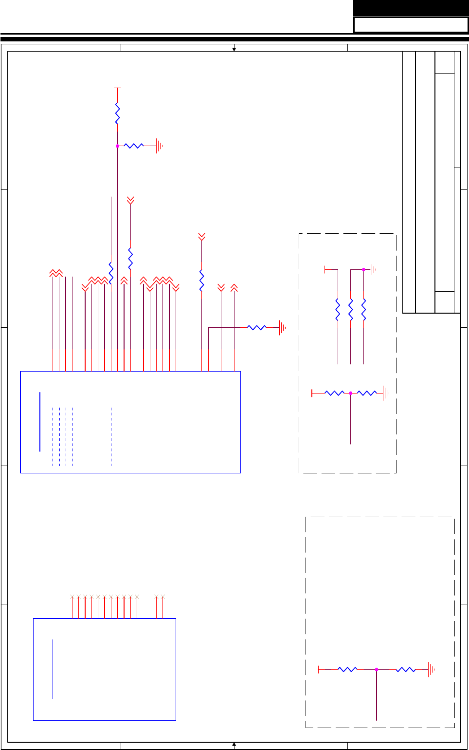
5
5
4
4
3
3
2
2
1
1
D D
C C
B B
A A
BOOT_0
BOOT_2
BOOT_3
BOOT_1
BOOT_3
BOOT_2
BOOT_0
TVM_BOOT
BOOT_1
TVM_BOOTGPIO_P8
TEST_MODE
GPIO_11
VCC3_3_STB
VCC3_3_STB
VCC3_3_STB
VCC3_3
SPI_WEN 3
DEMOD_RSTN 5
TVM_PWR_ON1 17
VGA_VSYNC 6
AUD_AMP_STB 10
FP_LED1 13
FP_LED2 13
VGA_HSYNC 6
LCD_ON 11
PWR_SW_DVD 18
DVD_AUTO_SW 6
DVD_STB 18
AUD_SEL0 11
HEADPHONE_PLUG15
COMP_SW1 11
DISPLAY/HV-ON 11
BOOT_1 14
Title
Size Document Number Rev
Date: Sheet of
APOLLO - GPIO & Guest Bus
10
Zoran/HD775 Ref. Platform
12 19Thursday, April 23, 2009
Title
Size Document Number Rev
Date: Sheet of
APOLLO - GPIO & Guest Bus
10
Zoran/HD775 Ref. Platform
12 19Thursday, April 23, 2009
Title
Size Document Number Rev
Date: Sheet of
APOLLO - GPIO & Guest Bus
10
Zoran/HD775 Ref. Platform
12 19Thursday, April 23, 2009
Bootstrap Configuration
R266: I2C EEPROM BOOT
R355: SPI BOOT
TVMicro Bootstrap Configuration
V-Con
R355
10K
R355
10K
R420 33R420 33
R635 0R635 0
Guest Bus
U1H
ZR39775
Guest Bus
U1H
ZR39775
OE2/GADR0_ALE W22
STV1/GDAT0 Y22
OE1/GDAT1 Y23
CPV/GDAT2 Y24
STH2/GDAT3 Y25
STH1/GDAT4 Y26
TP/GDAT5 W25
CPV2GDAT6 W24
RVS/GDAT7 W23
GOE_N V23
GWE_N V22
STV2/GCS_N0 V24
GPO/GADR1_CLE U22
R211
4.7K
R211
4.7K
GPIO
BOOT_STRAP0
BOOT_STRAP1
BOOT_STRAP2
BOOT_STRAP3
8051_BOOT
U1K
ZR39775
GPIO
BOOT_STRAP0
BOOT_STRAP1
BOOT_STRAP2
BOOT_STRAP3
8051_BOOT
U1K
ZR39775
GPIO_P22 U23
GPIO_P23 R23
GPIO_P25 AB14
GPIO_P24 AB13
GPIO_P3 D10
GPIO_P4 D11
GPIO_P5 D12
GPIO_P6 E12
GPIO_P7 E11
GPIO_P8 AB20
GPIO_P9 AB19
GPIO_P10 AB18
GPIO_P11 AB17
GPIO_P1 C11
GPIO_P2 C12
GPIO_P0 C10
GPIO_P26 AB16
GPIO_P27 AC14
GPIO_P19 D5
GPIO_P21 U24
GPIO_P13 C6
Res_AA6 AA6
R636
0_DNS
R636
0_DNS
R207
4.7K
R207
4.7K
R41
4.7K
R41
4.7K
R417 33R417 33
R206
10K
R206
10K
R424 33R424 33
R266
10K_DNS
R266
10K_DNS
R205
10K
R205
10K
R212
4.7K
R212
4.7K
Service Manual
Model No.: HL40XP1
39
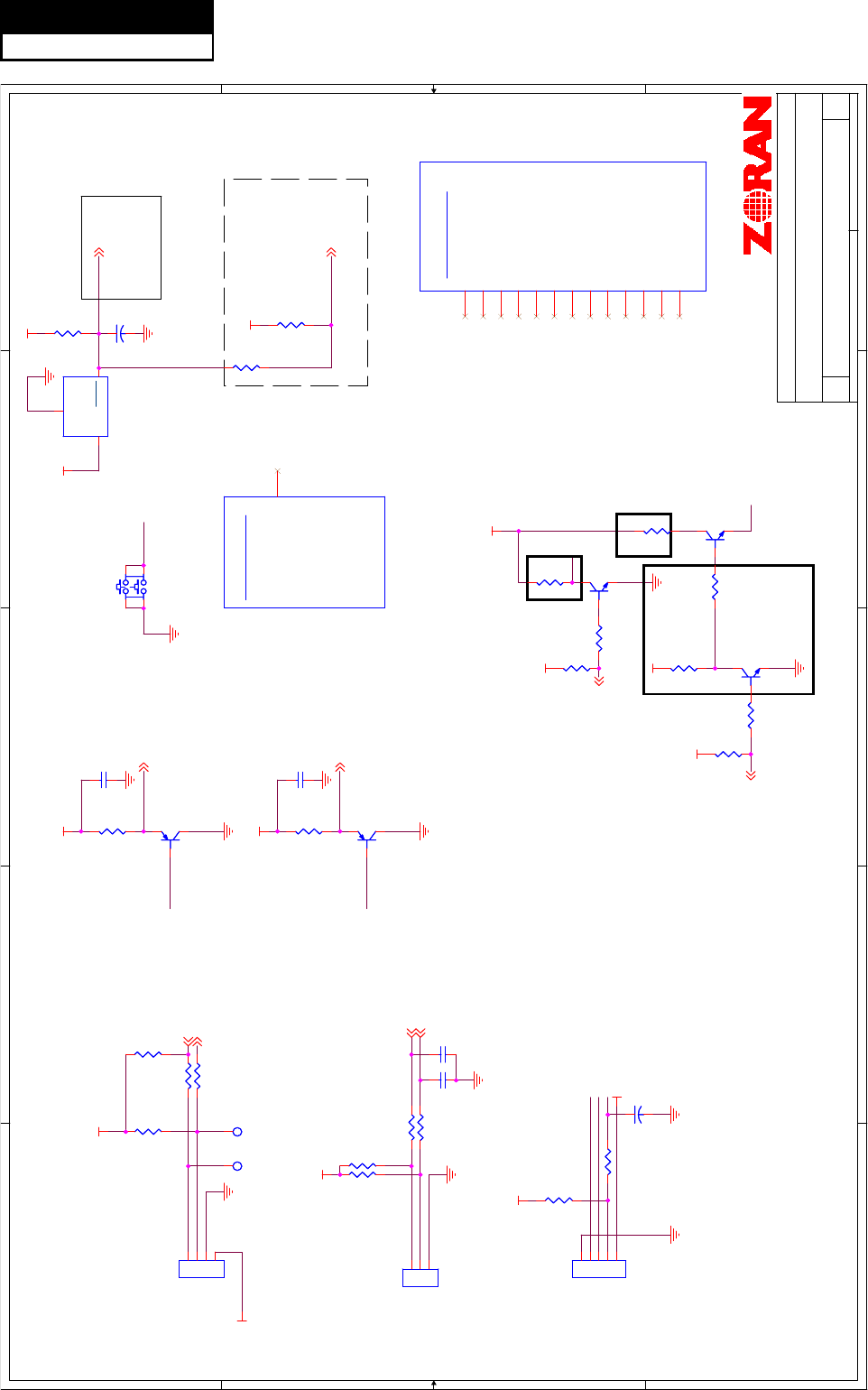
5
5
4
4
3
3
2
2
1
1
D D
C C
B B
A A
LED_R
IRR_IN
IRR_IN
LED_G
RESETN
IRR_IN
LED_R
LED_G
KEY_IN
KEY_IN2
VCC3_3_STB
VCC3_3_STB
VCC3_3_STB
VCC5V_STB
VCC5V_IN
VCC5V_IN
VCC3_3_STB
VCC3_3_STB
VCC3_3_STB
VCC3_3_STB
VCC5V_STB
VCC5V_STB
VCC5V_STB
VCC3_3_STB
MORF_RSTN 3
RESETN 3
UART0RX 3,6
UART0TX 3,6
IRR 3
FP_LED112
FP_LED212
IR_DVD 6
FP_KEY_IN 15
FP_KEY_IN2 15
Title
Size Document Number Rev
Date: Sheet of
APOLLO - MISC
10
Zoran/HD775 Ref. Platform
13 19Monday, April 27, 2009
Title
Size Document Number Rev
Date: Sheet of
APOLLO - MISC
10
Zoran/HD775 Ref. Platform
13 19Monday, April 27, 2009
Title
Size Document Number Rev
Date: Sheet of
APOLLO - MISC
10
Zoran/HD775 Ref. Platform
13 19Monday, April 27, 2009
R&D ONLY
ZORAN Confidential
NEED PULL DOWN?
ᬍЎ
1K,
⬉⌕Ў
2mA
ᬍЎ
330,
⬉⌕Ў
6mA
ᬍᕙᴎࡳ㗫
R300
10K_DNS
R300
10K_DNS
R315
3.3K
R315
3.3K
R638
4.7K
R638
4.7K
C682
47pF
C682
47pF
TP76TP76
TVMM I/F
U1M
ZR39775
TVMM I/F
U1M
ZR39775
VID0
E1
VID1
E2
VID2
E3
VID3
E4
VID4
E5
VID5
F1
VID6
F2
VID7
F3
Vsync_in
F4
Hsync_in
F5
VLCKx2
G3
TEST_G11
G4
TEST_G12
H3
R657
1K
R657
1K
R668
4.7K
R668
4.7K
U21 AP1701
U21 AP1701
GND 1
RESET 2
VCC
3
R641 100R641 100
R647
1K
R647
1K
Q33
MMBT3906
Q33
MMBT3906
1
23
CNE2
EJTAG6 (6pin/2.0mm)
CNE2
EJTAG6 (6pin/2.0mm)
11
22
33
44
55
C581
0.1uF
C581
0.1uF
R642 100R642 100
R316 100R316 100 R650 1KR650 1K
TP75TP75
C567
0.1uF
C567
0.1uF
Q34
MMBT3906
Q34
MMBT3906
1
23
R644
10K_DNS
R644
10K_DNS
C570
0.1uF
C570
0.1uF
R643
0_DNS
R643
0_DNS
R312
3.3K
R312
3.3K
C569
0.1uF
C569
0.1uF
Q35
MMBT3904
Q35
MMBT3904
R667
10K
R667
10K
Q36
MMBT3904
Q36
MMBT3904
No Connect Pins
U1L
ZR39775
No Connect Pins
U1L
ZR39775
NC68 K22
R313 10R313 10
CNE3
PH-3A 3pin/2.0mm
CNE3
PH-3A 3pin/2.0mm
11
22
33
R637
1K_DNS
R637
1K_DNS
CNB2
TJC3-4A
CNB2
TJC3-4A
11
22
33
44
R645
10K
R645
10K
R648
4.7K
R648
4.7K
R314 10R314 10
R639
10K
R639
10K
R653
330
R653
330
R640
10K
R640
10K
R655
4.7K
R655
4.7K
SW1
button_4pin
SW1
button_4pin
1 2
3 4
C568
0.01uF
C568
0.01uF
Q40
MMBT3904
Q40
MMBT3904
Service Manual
Model No.: HL40XP1
40
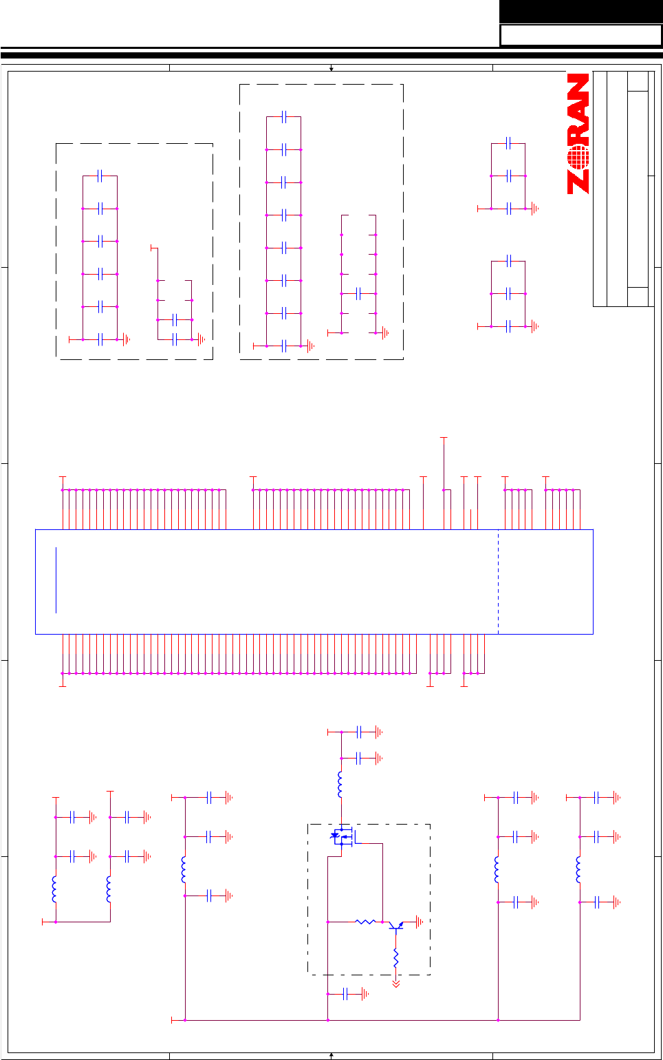
5
5
4
4
3
3
2
2
1
1
D D
C C
B B
A A
VCC1_1V VCC3_3
VCC3_3
VCC1_8
VCC1_8
VCC1_1_USB
VCC1_1V
VCC1_1_HDMI
VCC3_3
VCC3_3
VCC3_3_PLLVDD
VCC3_3_HDMI
VCC3_3_STB VCCA1_8_STB
VCC1_8
VCC3_3_HDMI
VCC1_1_HDMI
VCC3_3_PLLVDD
VCC3_3_LDIVDD
VCC1_1_USB
VCCA1_8_STB
VCC3_3_STB
VCC3_3_USB2
VCC3_3_USB2
VCC3_3_LDIVDD
BOOT_112
Title
Size Document Number Rev
Date: Sheet of
APOLLO - POWER 1
10
Zoran/HD775 Ref. Platform
14 19Tuesday, May 26, 2009
Title
Size Document Number Rev
Date: Sheet of
APOLLO - POWER 1
10
Zoran/HD775 Ref. Platform
14 19Tuesday, May 26, 2009
Title
Size Document Number Rev
Date: Sheet of
APOLLO - POWER 1
10
Zoran/HD775 Ref. Platform
14 19Tuesday, May 26, 2009
1.8V Bypass Caps
3.3V Bypass Caps
ZORAN Confidential
C268
/10uF
C273
/33uF
C289
/10uF
C256
/33uF
C270
/10uF
C271
/10uF
C277
/0.1uF
C272
/0.1uF
090421
L19
LI0603G121R
L19
LI0603G121R
C265
10uF_DNS
C265
10uF_DNS
C241
1.0uF
C241
1.0uF
L20
LI0603G121R
L20
LI0603G121R
C253
1.0uF
C253
1.0uF
C319
0.1uF
C319
0.1uF
C193
0.1uF
C193
0.1uF
C264
10uF
C264
10uF
C230
1.0uF
C230
1.0uF
Q49
AO3401
Q49
AO3401
3
1
2
C251
0.1uF
C251
0.1uF
C198
0.1uF
C198
0.1uF
C186
0.1uF
C186
0.1uF
C299
0.47uF
C299
0.47uF
C237
0.1uF
C237
0.1uF
C178
0.1uF
C178
0.1uF
R707
10K
R707
10K
C267
10uF
C267
10uF
Q50
MMBT3904
Q50
MMBT3904
1
2 3
C180
0.1uF
C180
0.1uF
L18
LI0603G121R
L18
LI0603G121R
C249
1.0uF
C249
1.0uF
C418
1uF
C418
1uF
R715 4.7KR715 4.7K
C199
0.1uF
C199
0.1uF
C417
0.01uF
C417
0.01uF
C238
1.0uF
C238
1.0uF
C189
0.1uF
C189
0.1uF
C247
1.0uF
C247
1.0uF
C252
0.1uF
C252
0.1uF
C257
0.1uF
C257
0.1uF
C239
0.1uF
C239
0.1uF
C195
0.1uF
C195
0.1uF
C242
0.1uF
C242
0.1uF
L22
LI0603G121R
L22
LI0603G121R
C182
0.1uF
C182
0.1uF
C250
0.1uF
C250
0.1uF
C475
1000pF
C475
1000pF
C240
0.1uF
C240
0.1uF
C231
0.1uF
C231
0.1uF
C190
0.1uF
C190
0.1uF
C179
0.1uF
C179
0.1uF
Power
STBY
U1R
ZR39775
Power
STBY
U1R
ZR39775
USB_VDD1 AC11
USB_VDD33 AC13
PLL_VDD33 V26
CORE_VDD18_STBY1 P6
CORE_VDD18_STBY2 R6
LDI_VDD33_0 AC15
LDI_VDD33_1 AB15
CORE_VDD18_STBY3 T6
CORE_VDD55
AA7
CORE_VDD0
F11
CORE_VDD1
F12
CORE_VDD2
F13
CORE_VDD3
F14
CORE_VDD4
F15
HDMI_VDD3P3_0
E7
HDMI_VDD3P3_1
E8
HDMI_VDD3P3_2
F7
HDMI_VDD3P3_3
F8
HDMI_VDD1V_0
E9
HDMI_VDD1V_1
E10
HDMI_VDD1V_2
F9
HDMI_VDD1V_3
F10
CORE_VDD5
G12
CORE_VDD6
G13
CORE_VDD7
G14
CORE_VDD8
G15
CORE_VDD9
G16
CORE_VDD10
L20
CORE_VDD11
L21
CORE_VDD12
M20
CORE_VDD13
M21
CORE_VDD14
N20
CORE_VDD15
N21
CORE_VDD16
P20
CORE_VDD17
P21
CORE_VDD18
R20
CORE_VDD19
R21
CORE_VDD20
T20
CORE_VDD21
T21
CORE_VDD22
T22
CORE_VDD23
T23
CORE_VDD24
T24
CORE_VDD25
U20
CORE_VDD26
U21
CORE_VDD27
V20
CORE_VDD28
V21
CORE_VDD29
W20
CORE_VDD30
W21
CORE_VDD31
V7
CORE_VDD32
W7
CORE_VDD42
AA8
CORE_VDD43
AA9
CORE_VDD44
AA10
CORE_VDD45
AA11
CORE_VDD46
AA12
CORE_VDD47
AA13
CORE_VDD48
AA14
CORE_VDD49
AA15
CORE_VDD18_STBY0 P5
IO_VDD0 G7
IO_VDD1 G8
IO_VDD2 G9
IO_VDD3 G10
IO_VDD4 G11
IO_VDD5 H7
IO_VDD6 H8
IO_VDD7 J7
IO_VDD8 Y16
IO_VDD9 Y17
IO_VDD10 Y18
IO_VDD11 Y19
IO_VDD12 Y20
IO_VDD13 Y21
IO_VDD14 AA16
IO_VDD15 AA17
IO_VDD16 AA18
IO_VDD17 AA19
IO_VDD18 AA20
IO_VDD19 AA21
IO_VDD20 AA22
IO_VDD21 AA23
IO_VDD22 AA24
IOVDD_STBY0 H4
IOVDD_STBY1 J4
CORE_VDD50
T25
CORE_VDD51
T26
M_VDD0 E20
M_VDD1 E21
M_VDD2 E22
M_VDD3 F16
M_VDD4 F17
M_VDD5 F18
M_VDD6 F19
M_VDD7 F20
M_VDD8 F21
M_VDD9 F22
M_VDD10 G17
M_VDD11 G18
M_VDD12 G19
M_VDD13 G20
M_VDD14 G21
M_VDD15 G22
M_VDD16 H20
M_VDD17 H21
M_VDD18 H22
M_VDD19 J20
M_VDD20 J21
M_VDD21 J22
M_VDD22 K20
M_VDD23 K21
CORE_VDD33
Y7
CORE_VDD34
Y8
CORE_VDD35
Y9
CORE_VDD36
Y10
CORE_VDD37
Y11
CORE_VDD38
Y12
CORE_VDD39
Y13
CORE_VDD40
Y14
CORE_VDD41
Y15
IO_VDD23 AA25
IO_VDD24 AA26
IOVDD_STBY2 H5
IOVDD_STBY3 J5
IOVDD_STBY4 K7
CORE_VDD18_STBY5 R7
CORE_VDD18_STBY4 T7
USB2_VDD33 AF25
C194
0.1uF
C194
0.1uF
C229
0.1uF
C229
0.1uF
L41
LI0603G121R
L41
LI0603G121R
L29
LI0603G121R
L29
LI0603G121R
C474
0.47uF
C474
0.47uF
C438
1uF
C438
1uF
C248
1.0uF
C248
1.0uF
Service Manual
Model No.: HL40XP1
41
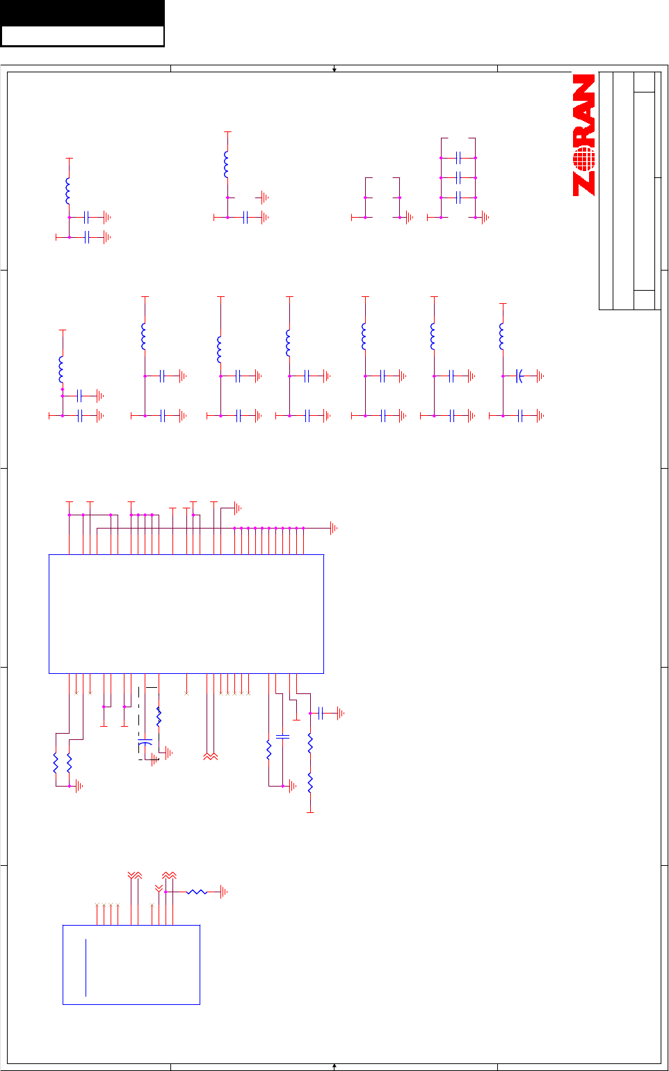
5
5
4
4
3
3
2
2
1
1
D D
C C
B B
A A
VCCA1_8_STB
VCC3_3_STB
VCC3_3_STB
VCC3_3_VSYNC
VCC3_3_VSYNC
VCCA1_8_HPLL
VCCA1_8_HPLL
VCCA1_8_STB
VCC1_8_AVDD
VCC1_8_AVDD
VCC3_3_STB
VCC3_3_IF
VCC3_3_IF
VCC3_3_STB
VCC3_3_ACOD
VCC3_3_ACOD
VCC3_3_STB
VCC3_3_ADC8
VCC3_3_LVDSVCTX
VCC3_3_LVDSVCTX
VCC1_8_AVDD
VCC3_3_VSYNC
VCC3_3_ADC8
VCC3_3_STB
VCC3_3_LVDSVCRX
VCC3_3
VCC3_3_LVDSVCRX
VCC3_3_DM_PLL
VCC3_3_DM_PLL
VCC3_3
VCCA1_8_STBLCD_PWR_SW 10,18
AUD_AMP_MUTE 10
FP_KEY_IN13
PWR_SW_USB 18
VGA_UART_ON/OFF 6
FP_KEY_IN213
AUD_SEL1 8
Title
Size Document Number Rev
Date: Sheet of
APOLLO - Power & Ground 2
10
Zoran/HD775 Ref. Platform
15 19Thursday, April 23, 2009
Title
Size Document Number Rev
Date: Sheet of
APOLLO - Power & Ground 2
10
Zoran/HD775 Ref. Platform
15 19Thursday, April 23, 2009
Title
Size Document Number Rev
Date: Sheet of
APOLLO - Power & Ground 2
10
Zoran/HD775 Ref. Platform
15 19Thursday, April 23, 2009
ZORAN Confidential
0801 PCB
Ёᵕᗻ䳔㽕䇗ᭈ
C453
/1nF
C513/0.1uF C517/0.1uF
C520/0.1uFC518/0.1uF
C519/0.1uF
L43
LI0603G121R
L43
LI0603G121R
C321
22pF
C321
22pF
C511 10uFC511 10uF
C425
0.1uF
C425
0.1uF
L5
LI0603G121R
L5
LI0603G121R
C427
1.0uF
C427
1.0uF
C420
1.0uF
C420
1.0uF
C479
0.1uF
C479
0.1uF
L33
LI0603G121R
L33
LI0603G121R
+
C164 4.7uF/16V
+
C164 4.7uF/16V
C516
0.1uF
C516
0.1uF
R25
8.87K
R25
8.87K
L32
LI0603G121R
L32
LI0603G121R
C423
10uF
C423
10uF
C421
1000pF
C421
1000pF
C38
0.01uF
C38
0.01uF
L42
LI0603G121R
L42
LI0603G121R
+
C37
4.7uF/16V
+
C37
4.7uF/16V
C428
0.1uF
C428
0.1uF
C515
0.1uF
C515
0.1uF
C481
1.0uF
C481
1.0uF
L31
LI0603G121R
L31
LI0603G121R
3.3V
U1Q
ZR39775
3.3V
U1Q
ZR39775
AVDD18_HPLL L3
AVDD3_HPLL M4
AVDD3_SYNC N3
AVDD3_SYNC1 R3
AVDD3_AFE N4
AVDD18_R P2
AVDD18_G P1
AVDD18_B R1
LVDSVCTX_VDD33_0
G5
LVDSVCTX_VDD33_1
G6
LVDSVCTX_REXT
G1
LVDSVCRX_REXT
G2
PGA_LDO0
P4
AFE_AVSS
Y3
LVDSVCRX_VDD33_0
H6
LVDSVCRX_VDD33_1
J6
DVDD18 R4
DM_PLL_VDD AB2
IF_VDD3P3_0 AC1
IF_VDD3P3_1 AC2
AVDD18_SVIDEO R2
AVDD18_CVBS P3
ADC8_RBIAS
AC3
ADC8_VREF
AC4
ADC8_INA
AC5
ADC8_INB
AD6
ADC8_INC
AD5
ADC8_IND
AD4
ADC8_INE
AE5
ADC8_INF
AE6
VDD33_BOD
AB5
AFE_AVSS0 W4
AFE_AVSS1 W5
AFE_AVSS2 W6
VDDADC8
AF5
RC_OSC_REXT
AF6
AFE_AVSS3 Y4
AFE_AVSS4 Y5
AFE_AVSS5 Y6
ACOD3_AVDD AE10
ACOD3_AVSS AE11
AVSS_HPLL M3
LVDSVCRX_ATST
L6
LVDSVCTX_ATST
K6
ADC8_ING
AB6
AFE_AVSS6 L7
AFE_AVSS7 M7
AFE_AVSS8 N7
AFE_AVSS9 P7
AFE_AVSS10 U7
C482
0.1uF
C482
0.1uF
C446
0.1uF
C446
0.1uF
AFE I/F_ GPO
U1S
ZR39775
AFE I/F_ GPO
U1S
ZR39775
AFE_CLK K4
AFE_TEST0 AB10
AFE_TEST1 AB9
AFE_TEST2 AB8
AFE_TCLK_IN U6
AFE_TCLK_OUT V6
AFE_XCLK_TEST AB7
AFE_ATCLK0 M6
AFE_ATCLK1 N6
AFE_XCLK AE3
C413
0.1uF
C413
0.1uF
R551
51K
R551
51K
R213
845R 1%
R213
845R 1%
L37
LI0603G121R
L37
LI0603G121R
C422
0.01uF
C422
0.01uF
R178
10K
R178
10K
L34
LI0603G121R
L34
LI0603G121R
R26
140
R26
140
R67 0RR67 0R
R278
845R 1%
R278
845R 1%
C514
0.1uF
C514
0.1uF
C484
1.0uF
C484
1.0uF
C447
1.0uF
C447
1.0uF
C430
1.0uF
C430
1.0uF
L30
LI0603G121R
L30
LI0603G121R
Service Manual
Model No.: HL40XP1
42
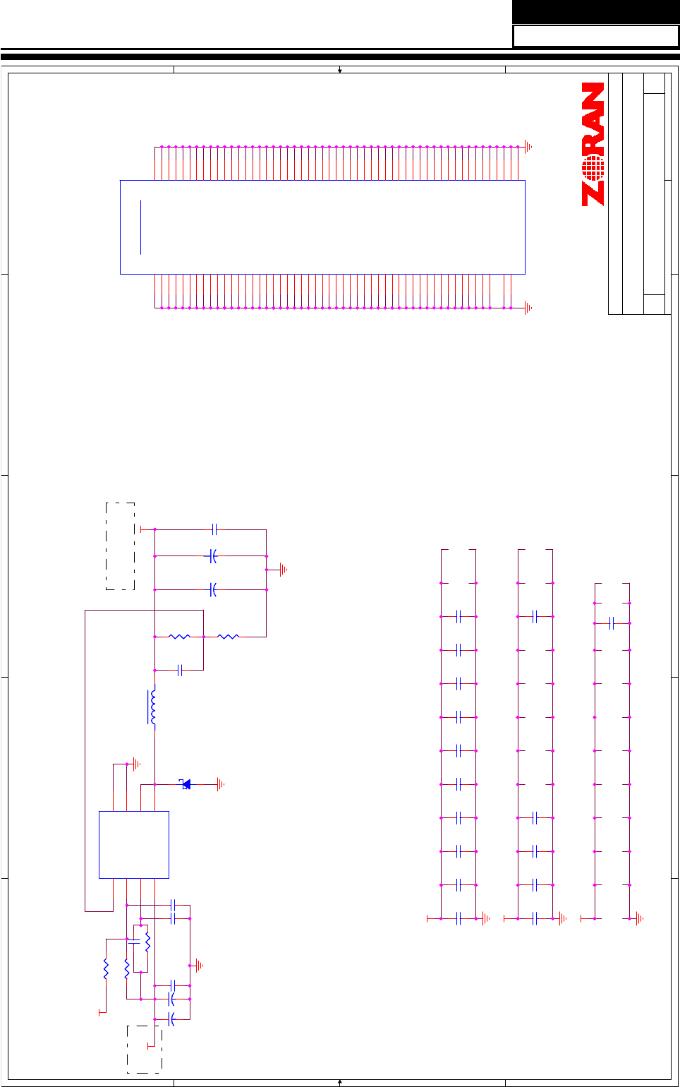
5
5
4
4
3
3
2
2
1
1
D D
C C
B B
A A
VCC1_1V
VCC1_1V
VCC1_1V
VCC5V_IN
VCC1_1V
VCC5V_IN
Title
Size Document Number Rev
Date: Sheet of
APOLLO - Power & Ground 3
10
Zoran/HD775 Ref. Platform
16 19Tuesday, May 26, 2009
Title
Size Document Number Rev
Date: Sheet of
APOLLO - Power & Ground 3
10
Zoran/HD775 Ref. Platform
16 19Tuesday, May 26, 2009
Title
Size Document Number Rev
Date: Sheet of
APOLLO - Power & Ground 3
10
Zoran/HD775 Ref. Platform
16 19Tuesday, May 26, 2009
1.0V Bypass Caps
ZORAN Confidential
Vout=0.8*(1+R347/R350);
R350=0.7K~5K
C263
/10uF
C269
/10uF
C310
/10uF
C286
/10uF
C287
/10uF
C288
/10uF
C280
/33uF
C283
/1uF
C278
/1uF
C292
/0.1uF
C275
/1uF
C278
/1nF
C276
/1uF
C223
/1uF
C274
/1uF
C279
/1uF
C224
/1uF
C225
/1uF
C226
/1uF
C2267/1uF
090421
C210
1.0uF
C210
1.0uF
D119
B240
D119
B240
+
C579
1000uF/16V
+
C579
1000uF/16V
+
C574
470uF/16V
+
C574
470uF/16V
C219
1.0uF
C219
1.0uF
C576
Option
C576
Option
1 2
C209
1.0uF
C209
1.0uF
C228
1.0uF
C228
1.0uF
+
C575
47uF/16V
+
C575
47uF/16V
C573 OptionC573 Option
12
C213
1.0uF
C213
1.0uF
+
C578
220uF/16V
+
C578
220uF/16V
C220
1.0uF
C220
1.0uF
C580
0.1uF
C580
0.1uF
1 2
AP1534
U22
AP1534
U22
FB
1
EN
2
OCSET
3
VCC
4Output 5
VSS 7
Output 6
VSS 8
C221
1.0uF
C221
1.0uF
L50 27uH/3A
L4.5-9
L50 27uH/3A
L4.5-9
C217
1.0uF
C217
1.0uF
R666 3.9kR666 3.9k
C577
0.1uF
C577
0.1uF
1 2
C215
1.0uF
C215
1.0uF
C222
1.0uF
C222
1.0uF
C214
1.0uF
C214
1.0uF
C216
1.0uF
C216
1.0uF
R665
2.49K_1%
R665
2.49K_1%
Ground
U1N
ZR39775
Ground
U1N
ZR39775
GND51 P11
GND50 P10
GND49 P9
GND48
N18
GND47
N17
GND46
N16
GND45
N15
GND44
N14
GND43
N13
GND42
N12
GND41
N11
GND40
N10
GND39
N9
GND38
M18
GND37
M17
GND36
M16
GND35
M15
GND34
M14
GND33
M13
GND32
M12
GND31
M11
GND30
M10
GND29
M9
GND28
L18
GND27
L17
GND26
L16
GND25
L15
GND24
L14
GND23
L13
GND22
L12
GND21
L11
GND20
L10
GND19
L9
GND18
K18
GND17
K17
GND16
K16
GND15
K15
GND14
K14
GND13
K13
GND12
K12
GND11
K11
GND10
K10
GND9
K9
GND8
J18
GND7
J17
GND6
J16
GND5
J15
GND4
J14
GND3
J13
GND2
J12
GND1
J11
GND0
J10
GND52 P12
GND53 P13
GND54 P14
GND55 P15
GND56 P16
GND57 P17
GND58 P18
GND59 R9
GND60 R10
GND61 R11
GND62 R12
GND63 R13
GND64 R14
GND65 R15
GND66 R16
GND67 R17
GND68 R18
GND69 T9
GND70 T10
GND71 T11
GND72 T12
GND73 T13
GND74 T14
GND75 T15
GND76 T16
GND77 T17
GND78 T18
GND79 U9
GND80 U10
GND81 U11
GND82 U12
GND83 U13
GND84 U14
GND85 U15
GND86 U16
GND87 U17
GND88 U18
GND89 V9
GND90 V10
GND91 V11
GND92 V12
GND93 V13
GND94 V14
GND95 V15
GND96 V16
GND97 V17
GND98 V18
GND99 B24
PLL_VSS
V25 GND100 F6
S1_GND R25
USB2_GND
AE25
C218
1.0uF
C218
1.0uF
R662 100kR662 100k
C571
0.1uF
C571
0.1uF
1 2
C262
10uF
C262
10uF
C572
Option
C572
Option
1 2
R664
909R_1%
R664
909R_1%
R663 100k_DNSR663 100k_DNS
C211
1.0uF
C211
1.0uF
C212
1.0uF
C212
1.0uF
Service Manual
Model No.: HL40XP1
43
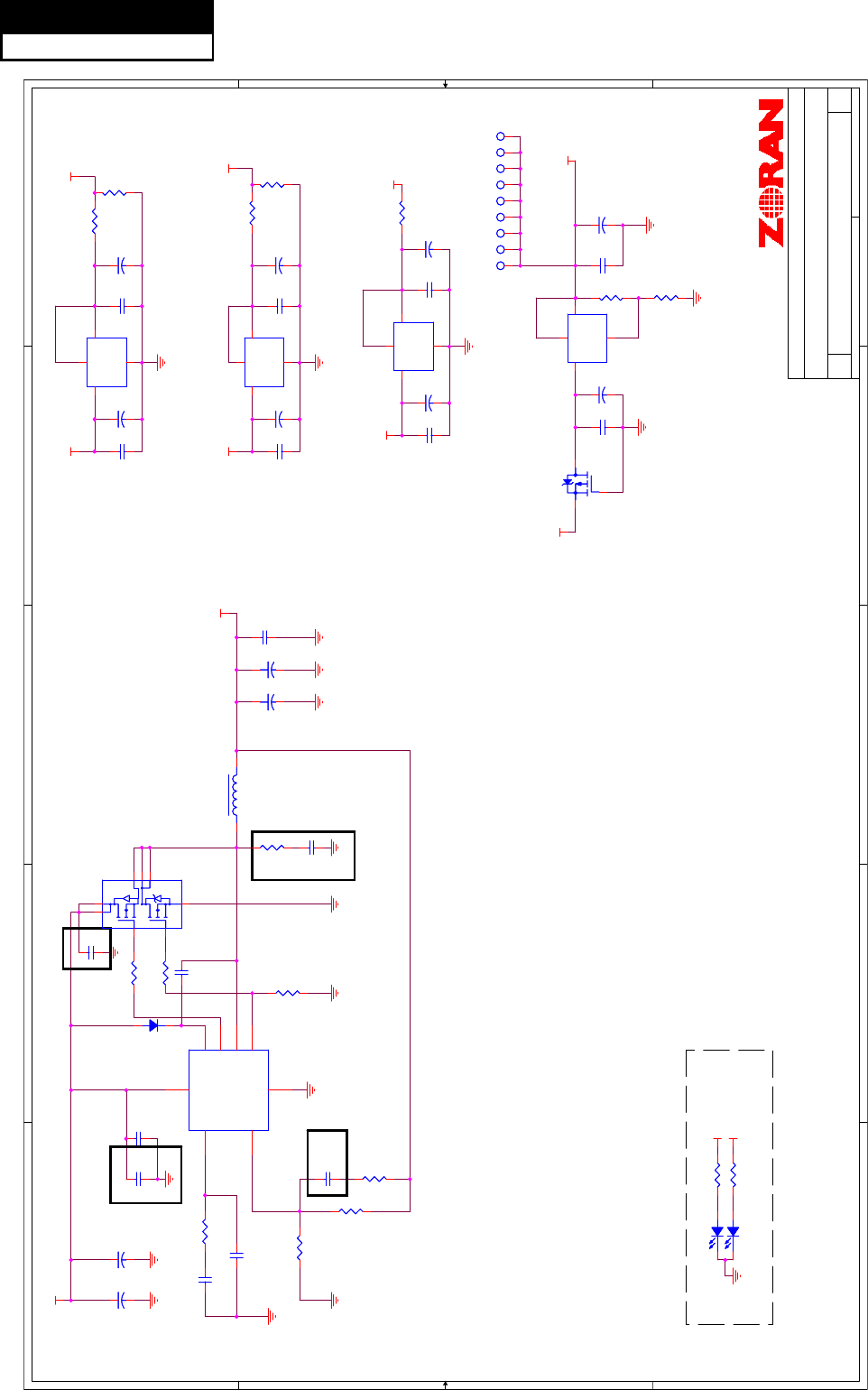
5
5
4
4
3
3
2
2
1
1
D D
C C
B B
A A
VCC1_8
VCC3_3
VCC5V_IN
VCC5V_IN
VCC5V_STB
VCCA1_8_STB
VCC3_3_STB
VCC5V_STB VCC3_3_STB
VCC5V_IN
VCC12V_IN
VCC5V_IN
Title
Size Document Number Rev
Date: Sheet of
APOLLO - Power & Ground 4
10
Zoran/HD775 Ref. Platform
17 19Monday, April 27, 2009
Title
Size Document Number Rev
Date: Sheet of
APOLLO - Power & Ground 4
10
Zoran/HD775 Ref. Platform
17 19Monday, April 27, 2009
Title
Size Document Number Rev
Date: Sheet of
APOLLO - Power & Ground 4
10
Zoran/HD775 Ref. Platform
17 19Monday, April 27, 2009
ZORAN Confidential
POWER LED R&D ONLY
Ⓒ䰸
100K
䇤⊶
ࡴ
C661
ࡴ
C721
ᬍЎ
0402
ᇕ㺙
এᥝ
R773,
ࡴ
Q42,U28
ᬍЎ
263
ᇕ㺙
R753
1K
R753
1K
Q42
AO3401
Q42
AO3401
3
1
2
R484
100R_1%
R484
100R_1%
+
C646
100uF/16V
+
C646
100uF/16V
R756
470_1%
R756
470_1%
P1P1
D122 LED_DNSD122 LED_DNS
12
R755
?
R755
?
C662
0.022uF
C662
0.022uF
12
C599
0.1uF_DNS
C599
0.1uF_DNS
D121 LED_DNS
D121 LED_DNS
12
R739
10K
R739
10K
R752 2.2R752 2.2
U30 AP1117E33U30 AP1117E33
OUT 2
IN
3
GND
1TAB 4
R751 4.7R751 4.7
U25 AP1117E33U25 AP1117E33
OUT 2
IN
3
GND
1TAB 4
P7P7
L53 15uH/6A
L7.5-13
L53 15uH/6A
L7.5-13
+
C648
100uF/16V
+
C648
100uF/16V
+
C665
1000uF/16V
+
C665
1000uF/16V
P8P8
C597
0.1uF
C597
0.1uF
R671 330_DNSR671 330_DNS
U32
NTMD4840
U32
NTMD4840
3
2 1
4
6
5
8
7
+
C608
470uF/16V
+
C608
470uF/16V
C643
0.1uF_DNS
C643
0.1uF_DNS
P2P2 P9P9
R737
10K
R737
10K
C721
0.1uF
C721
0.1uF
1 2
U48
NCP1579
U48
U48
NCP1579
U48
BST 1
TG 2
GND
3
BG 4
VCC 5
COMP
7
FB
6
PHASE 8
U28 AZ1084-ADJU28 AZ1084-ADJ
OUT 2
IN
3
GND
1TAB 4
R670
330_DNS
R670
330_DNS
C641
0.1uF
C641
0.1uF
D162
1N4148W-7-F
D162
1N4148W-7-F
12
C663 0.1uFC663 0.1uF
12
R736 0R736 0
+
C600
100uF/16V
+
C600
100uF/16V
P5P5
C661
1uF
C661
1uF
1 2
+
C658
47uF/16V
+
C658
47uF/16V
+
C660
470uF/16V
+
C660
470uF/16V
C664
100pF
C664
100pF
12
R738 0R738 0
R669 0R669 0
P3P3
U31 AP1117E18U31 AP1117E18
OUT 2
IN
3
GND
1TAB 4
+
C642
10uF/16V
+
C642
10uF/16V
C659
0.1uF
C659
0.1uF
1 2
R758
1K
R758
1K
C605
0.1uF
C605
0.1uF
+
C666
220uF/16V
+
C666
220uF/16V
C647
0.1uF_DNS
C647
0.1uF_DNS
P6P6
+
C598
10uF/16V
+
C598
10uF/16V
+
C644
100uF/16V
+
C644
100uF/16V
R754
10R_DNS
R754
10R_DNS
C669
0.01uF
C669
0.01uF
1 2
C645
0.1uF
C645
0.1uF
+
C606
220uF/16V
+
C606
220uF/16V
R483
220R_1%
R483
220R_1%
C667
0.1uF
C667
0.1uF
1 2
C607
0.1uF_DNS
C607
0.1uF_DNS
C668
3.3nF_DNS
C668
3.3nF_DNS
1 2
R757
2.55K_1%
R757
2.55K_1%
P4P4
Service Manual
Model No.: HL40XP1
44
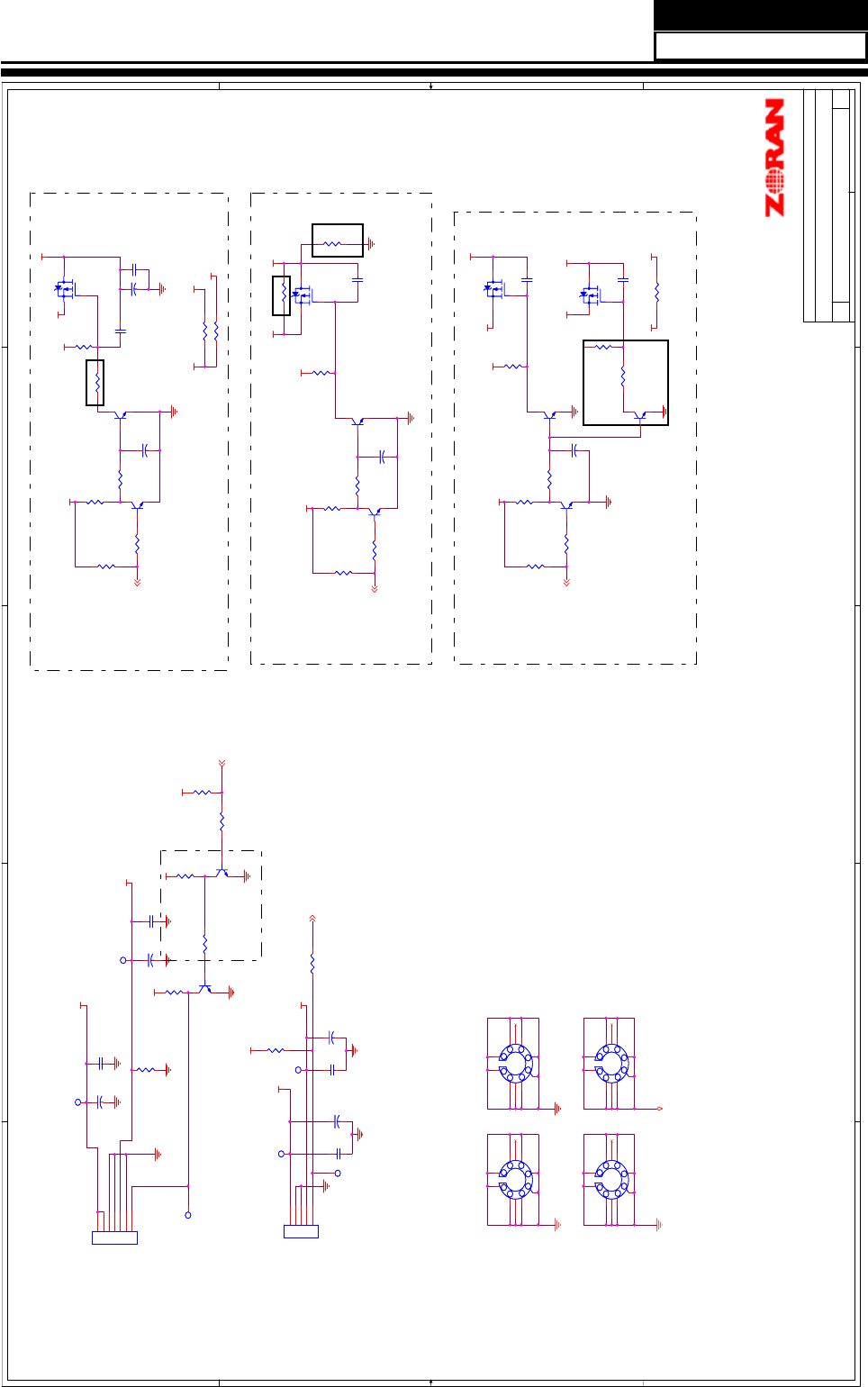
5
5
4
4
3
3
2
2
1
1
D D
C C
B B
A A
VCC5_USB_IN
VCC5_DVD_IN
VCC3_3_STB
VCC12V_INLVDS_VD
VCC12V
Panel_power
LVDS_VD
LVDS_VD
VCC5V_INVCC3_3_STB
VCC_5V_DVDVCC3_3_STB
VCC_5V_DVD
VCC5_DVD_IN
VCC_5V_DVD
VCC12VVCC12V_IN
P_GND
VCC5V_IN
VCC5V_IN
VCC12V_IN
VCC3_3
VCC12V_IN
VCC5V_STB
VCC5V_STB
VCC3_3_STB
VCC5V_IN
VCC3_3_STB
PWR_SW_USB15
LCD_PWR_SW10,15
PWR_SW_DVD12
DVD_STB 12
TVM_PWR_ON1 12
Title
Size Document Number Rev
Date: Sheet of
APOLLO - Power & Ground 5
10
Zoran/HD775 Ref. Platform
18 19Monday, April 27, 2009
Title
Size Document Number Rev
Date: Sheet of
APOLLO - Power & Ground 5
10
Zoran/HD775 Ref. Platform
18 19Monday, April 27, 2009
Title
Size Document Number Rev
Date: Sheet of
APOLLO - Power & Ground 5
10
Zoran/HD775 Ref. Platform
18 19Monday, April 27, 2009
ZORAN Confidential
Panel Power Control
USB Power Control
Inner DVD and AMP Power Control
ࡴ
R704,
ҙ⫼Ѣ
USB
छ㑻
ᔧ
LVDS_VD=12V,
߭
R685=2K
ᔧ
LVDS_VD=5V,
߭
R685=0
⫼Ѣ
USB
ᬒ⬉
090421
+
C622
100uF/16V_DNS
+
C622
100uF/16V_DNS
R681
10K
R681
10K
Q15
MMBT3904
Q15
MMBT3904
1
2 3
R764
10K
R764
10K
C615
0.1uF
C615
0.1uF
H4 GEN315R140-8H4 GEN315R140-8
1
2
3
4
5
6
7
8
9 10
R350
4.7K
R350
4.7K
R706 10K_DNSR706 10K_DNS
C617
0.1uF
C617
0.1uF
1 2
+
C616
220uF/16V
+
C616
220uF/16V
R766 10K_DNSR766 10K_DNS
+
C619
220uF/16V_DNS
+
C619
220uF/16V_DNS
R699
6.8K_DNS
R699
6.8K_DNS
R353
1K
R353
1K
R692 0_DNSR692 0_DNS
Q56
AO3401_DNS
Q56
AO3401_DNS
3
1
2
H2 GEN315R140-8H2 GEN315R140-8
1
2
3
4
5
6
7
8
9 10
Q37
AO3401
Q37
AO3401
3
1
2
R768
100_DNS
R768
100_DNS
R683 4.7KR683 4.7K
TP80TP80
R684 10KR684 10K
Q58
MMBT3904_DNS
Q58
MMBT3904_DNS
1
2 3
+
C674
100uF/16V_DNS
+
C674
100uF/16V_DNS
+
C614
100uF/16V
+
C614
100uF/16V
R354 4.7K
R354 4.7K
Q47
MMBT3904_DNS
Q47
MMBT3904_DNS
1
2 3
CNA2
TJC3-7A(7pin/2.5mm)
CNA2
TJC3-7A(7pin/2.5mm)
1
2
3
4
5
6
7
C613
0.1uF
C613
0.1uF
R705 4.7KR705 4.7K
R770 2K_DNSR770 2K_DNS
TP78TP78
Q14
MMBT3904
Q14
MMBT3904
1
2 3
R352 4.7K
R352 4.7K
Q46
MMBT3904_DNS
Q46
MMBT3904_DNS
1
2 3
TP79TP79
C673
0.1uF_DNS
C673
0.1uF_DNS
R691 0R691 0
C623
0.1uF
C623
0.1uF
Q39
MMBT3904
Q39
MMBT3904
1
2 3
C675 0.1uF_DNSC675 0.1uF_DNS
Q38
MMBT3904
Q38
MMBT3904
1
2 3
H3 GEN315R140-8H3 GEN315R140-8
1
2
3
4
5
6
7
8
9 10
+
C620
47uF/16V_DNS
+
C620
47uF/16V_DNS
C621
0.1uF_DNS
C621
0.1uF_DNS
R702
10K_DNS
R702
10K_DNS
Q57
MMBT3904_DNS
Q57
MMBT3904_DNS
1
2 3
+
C612
220uF/16V
+
C612
220uF/16V
R767 0.1/1W_5mm_DNSR767 0.1/1W_5mm_DNS
12
TP68TP68
R765 4.7K_DNSR765 4.7K_DNS
R704
0
R704
0
R988
100R/0.25W_15mm_DNS
R988
100R/0.25W_15mm_DNS
12
Q68
MMBT3904_DNS
Q68
MMBT3904_DNS
1
2 3
C611
0.1uF_DNS
C611
0.1uF_DNS
CNA4
PH05A(5pin/2.0mm)_DNS
CNA4
PH05A(5pin/2.0mm)_DNS
1
2
3
4
5
R685 0R685 0
R351
10K
R351
10K
R675
10K
R675
10K
R703
10K
R703
10K
R701
10K_DNS
R701
10K_DNS
R677
10K
R677
10K
R769
10K_DNS
R769
10K_DNS
TP81TP81
Q45
AO3401_DNS
Q45
AO3401_DNS
3
1
2
+
C628
47uF/16V
+
C628
47uF/16V
H1 GEN315R140-8H1 GEN315R140-8
1
2
3
4
5
6
7
8
9 10
R709
4.7K
R709
4.7K
R763
10K_DNS
R763
10K_DNS
TP69TP69
R762
10K_DNS
R762
10K_DNS
Q59
AO3401_DNS
Q59
AO3401_DNS
3
1
2
C618
0.1uF_DNS
C618
0.1uF_DNS
1 2
Service Manual
Model No.: HL40XP1
45
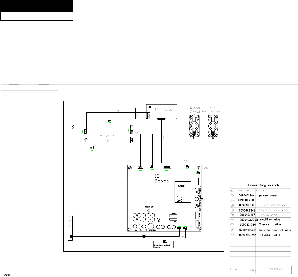
7-3 .Wiring Connection Diagram
ďĐ
HL40XP1
LVDS Connector
$&9+]
YUVLR
YUVLR
9.WIRRING CONNECTION
DIAGRAM
LR
AUDIO OUT
USB
Backlight wire
Brand
Customer
Country CANADA
HAC
Haier
Job Order No.
Serial No.
Factory Model L40K1
DC0XU0E0700
AT08SR0804US12
Service Model HL40XP1a
Customer Model
Service Manual
Model No.: HL40XP1
46
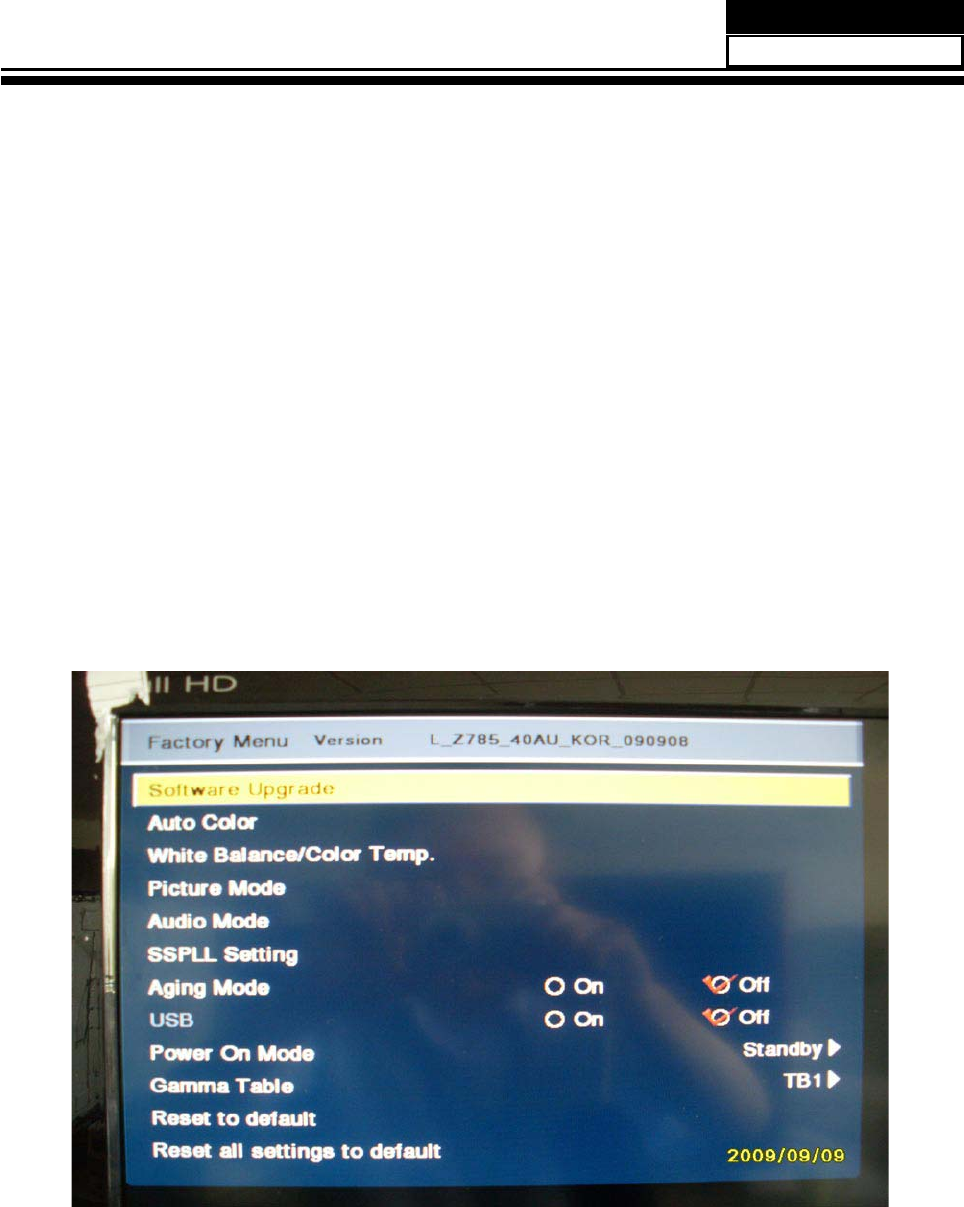
Chapter 8. Measurements and Adjustments
8-1. Service Mode
8-1-1.How to enter into Service Mode
The way to the factory mode menu:
Step 1: Press Menu,
Step 2: Input 8893,
Step 3: Press “OK”
System will be into the factory mode menu when 3 steps above are done.
8-1-2.How to exit
If you want to exit this factory menu, please press the button ”Exit” on the remote.
8-2. Measurements and Adjustments
8-2-1. Software Update
Service Manual
Model No.: HL40XP1
47
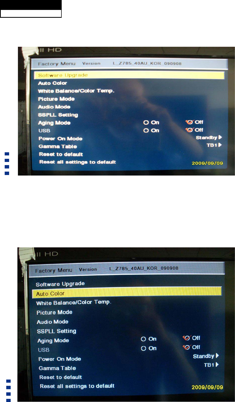
8-2-2. Auto Color
Service Manual
Model No.: HL40XP1
48
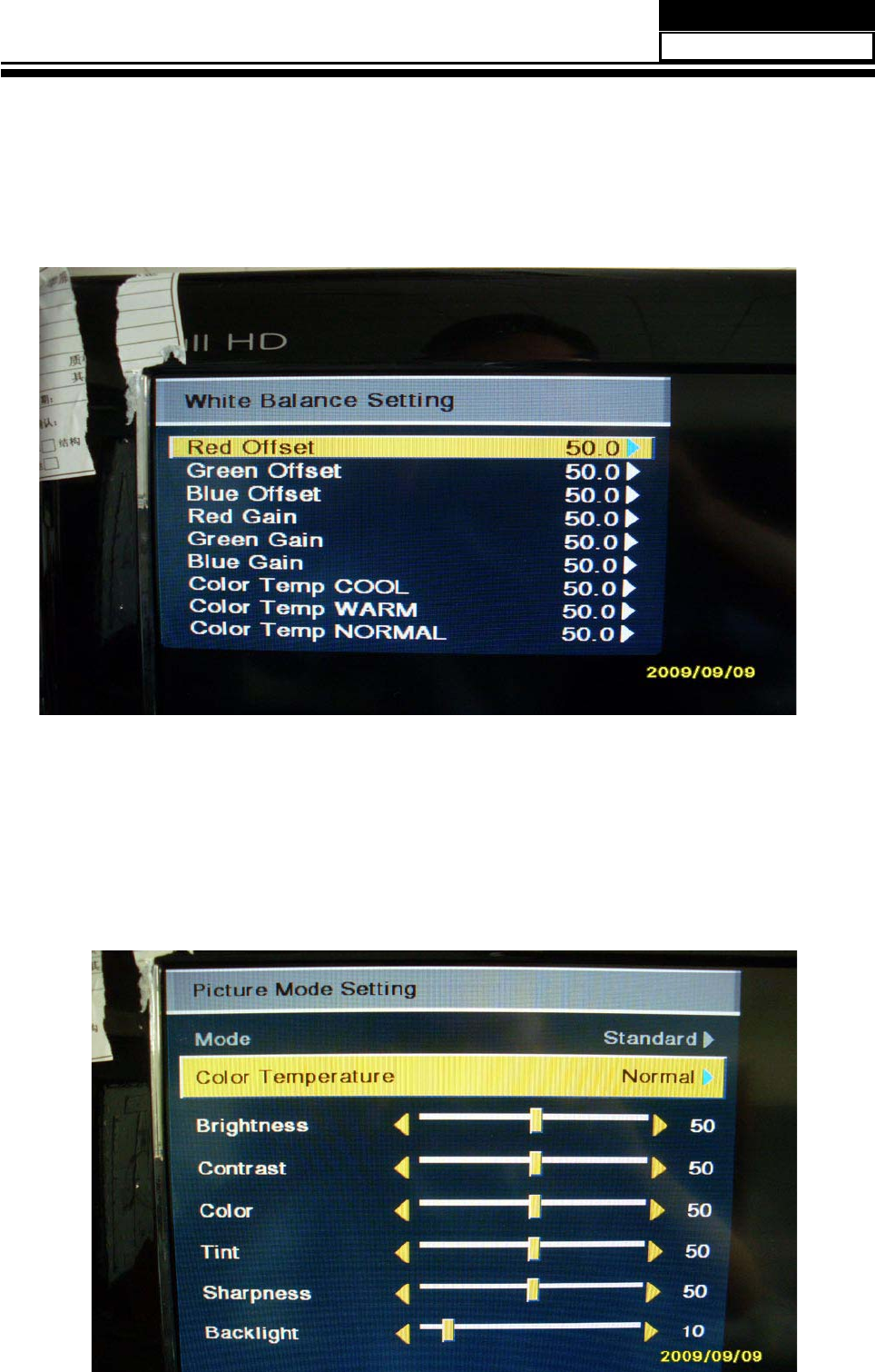
8-2-3. Whinte Balance/Color Temp
8-2-4. Picture Mode
Service Manual
Model No.: HL40XP1
49
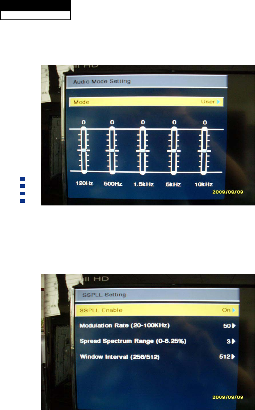
8-2-5. Audio Mode
8-2-6. SSPLL Setting
Tuner Diagnostic: Project debugging setting, used to inspect the audio function.
Service Manual
Model No.: HL40XP1
50
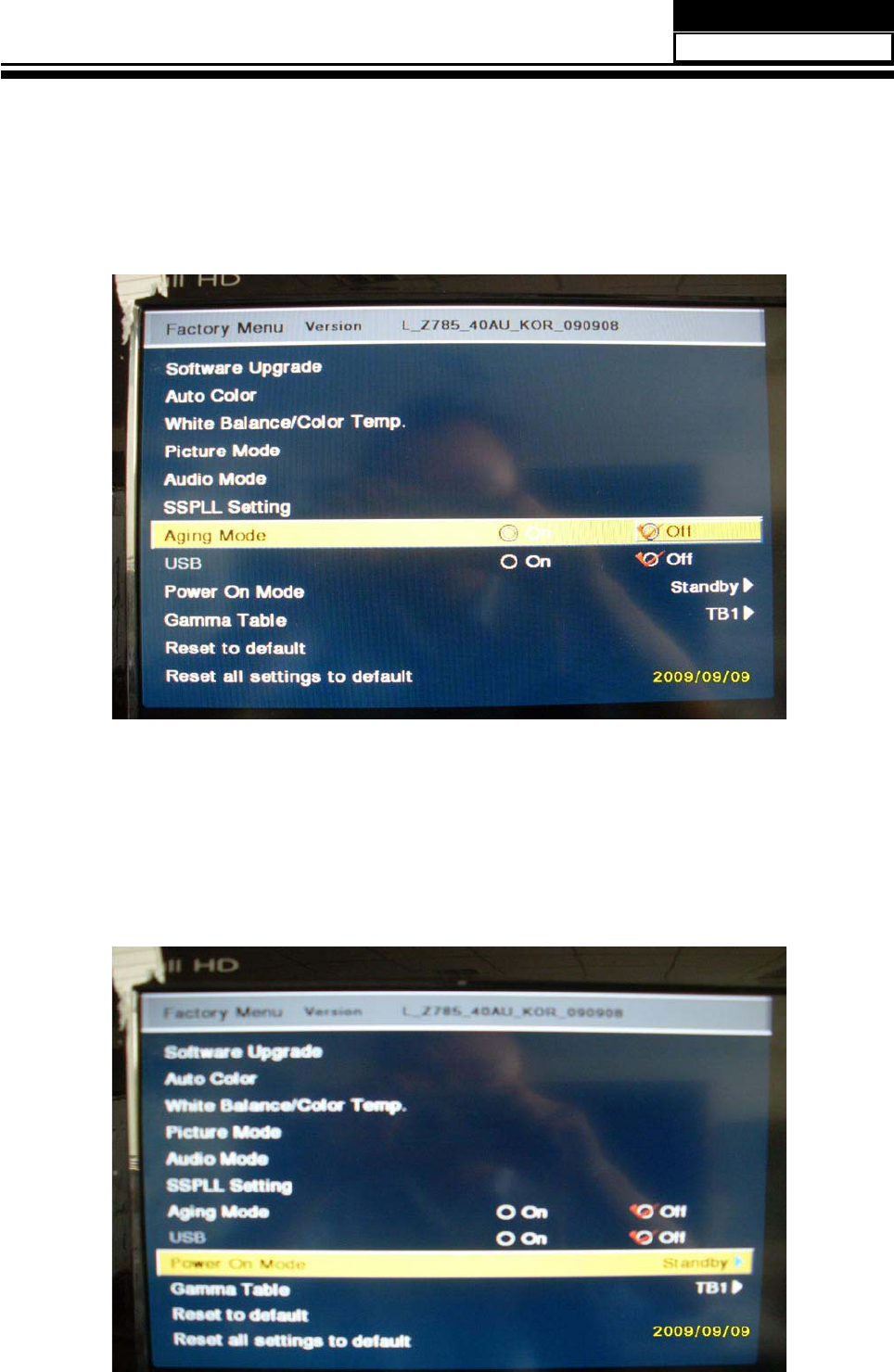
8-2-7. Aging Mode
8-2-8. Power On Mode
Service Manual
Model No.: HL40XP1
51
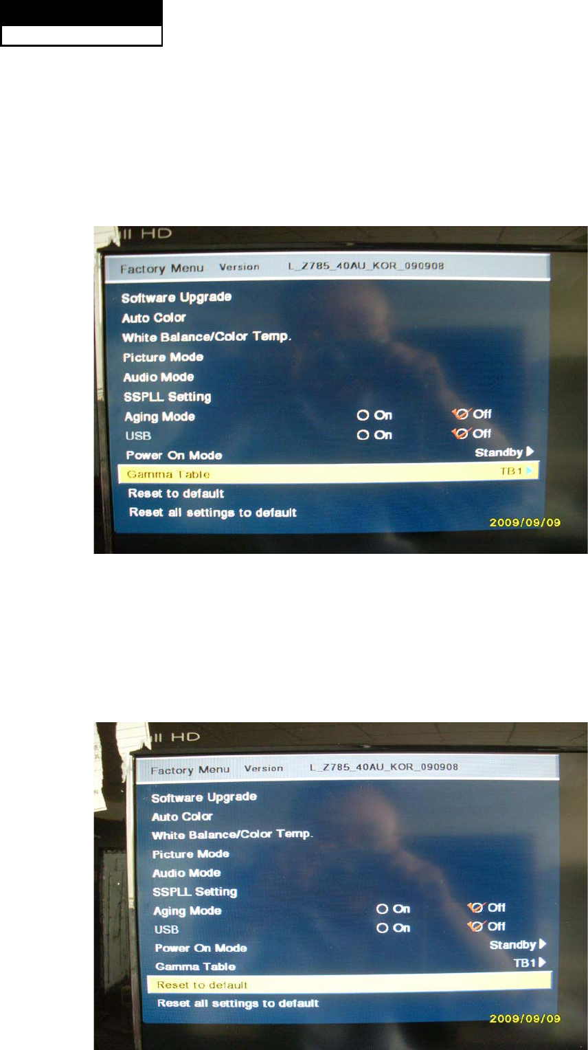
8-2-9. Camma Table
8-2-10. Reste to default
Service Manual
Model No.: HL40XP1
52
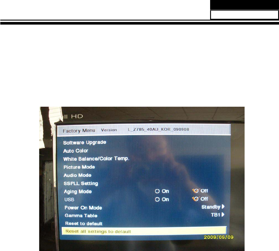
8-2-11. Reset all setting to default
Service Manual
Model No.: HL40XP1
53

Chapter 9. Trouble shooting
9-1. Simple check
No picture/ No sound
Verify if the television is properly plugged
Verify if the television is properly supplied power
Verify if electricity is available.
Blank screen
Verify if correct signals are input
Press INPUT button to change signal input to TV input
Restart the television of power supply is interrupted
No sound
Press Mute button and verify if Mute mode is set.
Switch to otger channel and verify if the same problem
happens.
Press VOL+ button to see of he problem can be
solved.
Poor sound Verufy if sound system is correct .Refer to some
chapter for adjust.
No picture in some channel
Verify if correct channel is selected.
Adjust the antenna.
Make adjustments by Fine Tune and MANUAL Scan.
No color for some channel
program (black and white)
Verify if the same problem exists in other channels.
check out of picture and sound system.
Refer to relative instructions in the Manual for color
adjust.
Spots with some or all pictures
Verify if the antennal is correctly connected.
Verify if the antennal is in good condition.
0DNH¿QHDGMXVWPHQWRIFKDQQHO
Horizontal/ vertical bars or picture
shaking
Check for local interference such as an electrical
appliance or power tool.
Television out of control
Disconnect the television from power supply and 10
seconds later, connect the television to the power
supply. If the problem still exists, contact authorized
after-sales service for technical assistance.
Service Manual
Model No.: HL40XP1
54
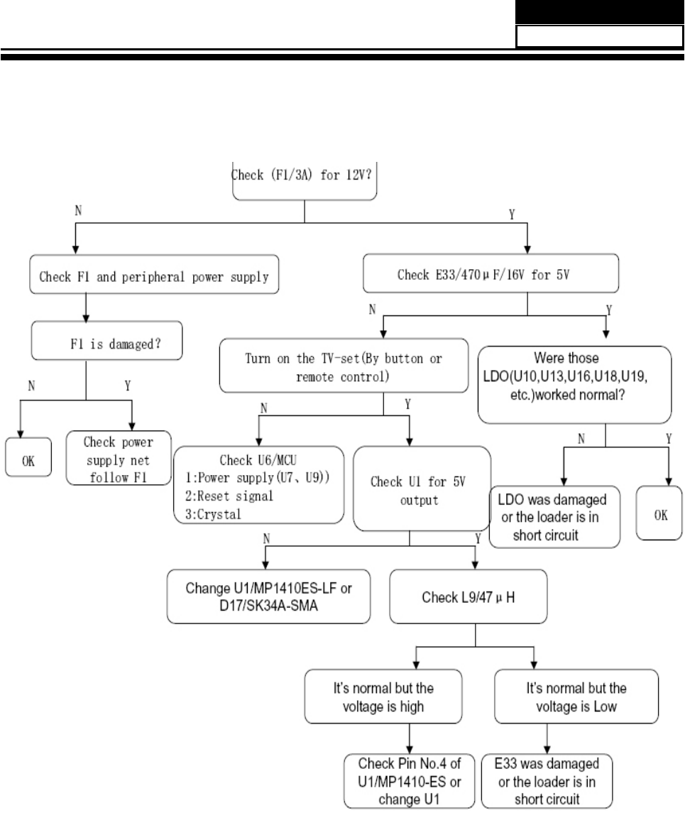
9-2. Power Supply Board Failure Check.
Service Manual
Model No.: HL40XP1
55
9-3. Mainboard Failure Check
Symptom: No Sound
No Sound
(All Mode)
Check the input
Source
Change Source input
Check the
input/output
Re-soldering or change
IC U13
Check the
input/output
Re-soldering or change
IC U55
Check the
input/output
Re-soldering or change
IC U2
Check the
Speaker
Change the Speaker
Check the
Sperker wire
Fail
Pass
Fail
Fail
Fail
Fail
Pass
Pass
Pass
Pass
Service Manual
Model No.: HL40XP1
56
9-4. Pannel Failure
Failure Mode
Part Name Description Phenomena Failure cause
TCP
V B/D Vertical bar
Block Defect :TCP cracking or cracking
Dim or L/D :TCP Sunken
:TCP lead cracking
:ACF bonding short
:Awful environment and
something electric enter
into LCD
:Mis-align between TCP and
Panel
:Panel failure
:TCP failure
V Dim Vertal gray line
V L/D Vertical color line(light or
dark forever)
H B/D Horizontal bar
H Dim Horizontal gary line
H L/D Horizontal line(light or
dark forever)
Service Manual
Model No.: HL40XP1
57
Part Name Description Phenomena Failure Cause
Panel or Polarlzer
Dot Defect Bright dot dark dot in pannel Incoming Inspection Standard
Polarizer Bubble Bladder in Polarizer Bladder between Polarizer and
top glass
Polarizer Scratch Polarizer Scratch Tine or rigidity arose
F/inside Polarizer Eyewinker inside Polarizer Eyewinker inside Polarizer
Circuit
Abnormal Display Abnormal Display
1.Chip lose action
2.IC ahort or jointiog bad
3.Pannel and vsc connect bad
Flashing Bright and dark display alternately
Service Manual
Model No.: HL40XP1
58
Part Name Description Phenomena Failure Cause
Circuit
White Screen B/L normal,
only white screen display
Maybe caused by surge current and EDS
Black Screen B/L normal,
only Black screen display
FIIcker Crosstalk LCD
Vcom imbalance
Abnormal Color Only
color abormal
Capacitance
improper bring crosstalk inside LCD pannel
Abnormal Color Only
color abnormal
1.Chip
lose action
2.IC short or jointion bad
3.Pannel and vsc connect bad
Service Manual
Model No.: HL40XP1
59
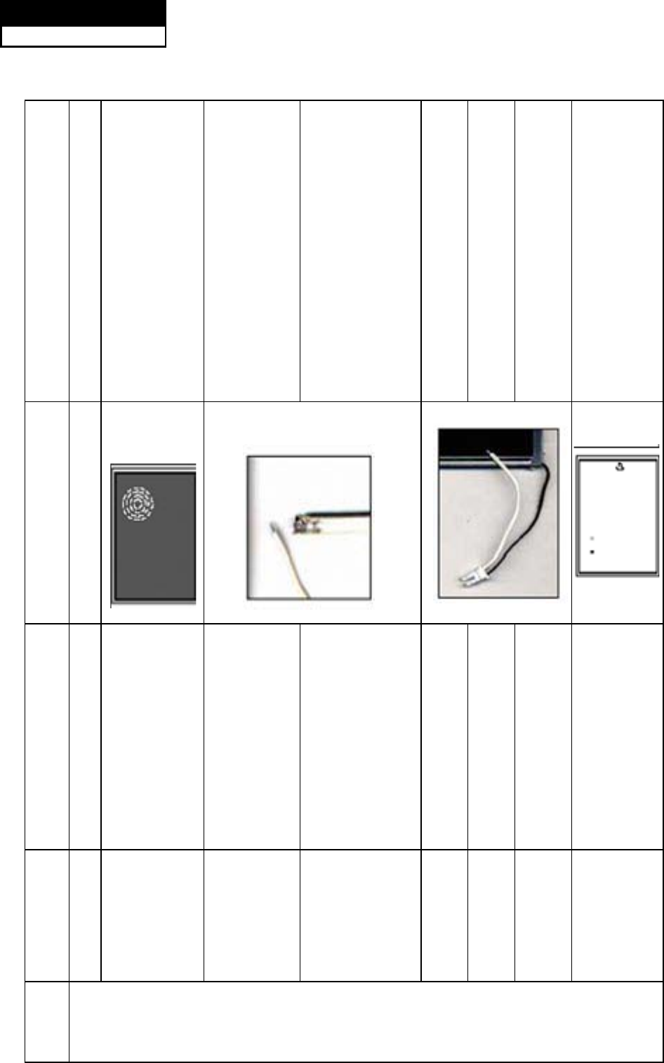
Part Name Description Phenomena Failure cause
Mechanlcal
Nolse
When
turn panel,appear cacophony
Caused
by Mechanica noise of backlight unit
Ripple Connectric circle
Causeed by
between
mechanism and pannel
B/L off B/L lose action
*Connect
badness
between wire and electrode
B/L dark B/L brightness darker than
normal
*Connect
badnessShort between wire and electrode
B/L
wire damaged
B/L
wire damaged
Operation
abnormal
or systemic noise
B/L wire open Without backlight
Operation
abnormal
or systemic noise
B/L shut down B/L shutdown in sometime Short bitween lamp housing and wire, Because
consume power too much
F/M
F/M
inB/L ,white,balck Rotundity
or wirelike
F/M in B/L unit
Service Manual
Model No.: HL40XP1
60
Part Name Description Phenomena Failure Cause
Mechanlcal or B/L
Light leakage
Brightness
at bottom of LCM brighter
than normal
B/L unit badness
Uniformity B/L brightness asymmetric Sheet in B/L unit is uneven
Mount hole Lack screw
or screw damage
*Lack screw
Screw damage
Service Manual
Model No.: HL40XP1
61

Sincere Forever
Printed in China
