SED2 Variable Frequency Drives Siemens Installation Instructions
User Manual: Siemens-SED2-Installation-Instructions Igor's of metalworking and electrical manuals
Open the PDF directly: View PDF ![]() .
.
Page Count: 8
Installation Instructions
Document No. 129-371
October 13, 2003
SED2 Variable Frequency Drives
Product Description
Provides a quick and efficient site installation of the
SED2 Variable Frequency Drive (VFD).
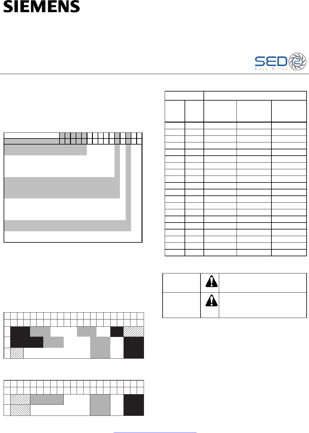
Product Numbers
SED2 -
/
X
SED2 - 0 . 7 5
/
22
X
Model:
SED2-
kW:
0.37, 0.55, 0.75, 1.1, 1.5, 2.2,
22, 30, 37, 45, 55, 75, 90
Voltage:
2 = 200 to 240
3 = 380 to 480
4 = 500 to 600
NEMA:
2 (IP 20)
1NEMA Type 1
5 NEMA Type 12 (IP 54) *
Other:
X include with all part #'s
* Available with Voltage Codes 3 and 4.
Example shown:
SED2-0.75/22X =
SED2 only, 0.75 kW (1hp), 200V to 240V, open type IP20.
(leave blank)
Your Product Number:
3, 4, 5.5, 7.5, 11, 15, 18.5,
Example Product Number:
(uses 2 to 4 spaces
plus a divider "/")
Frame Sizes and Power Ratings
SED2 IP20 and NEMA Type 1 frame sizes and
power ranges are as follows:
HP 4321.51.7.5 5 7.5 403025201510 125100756050
kW 32.21.51.1.75.5.37 4 5.5 30221915117.5 9075554537
240V
480V575V
BC DE
C
ED
BC
A
F
F
A
F
Output Rating Output Current Max (amps)
HP kW
208V to
240V
(3-Phase)
380V to
480V
(3-Phase)
500V to
600V
(3-Phase)
0.5 0.37 2.3 1.2 —
0.75 0.55 3.0 1.6 —
1.0 0.75 3.9 2.1 1.4
1.5 1.1 5.5 3.0 2.1
2.0 1.5 7.4 4.0 2.7
3.0 2.2 10.4 5.9 3.9
4.0 3.0 13.6 7.7 5.4
5.0 4.0 17.5 10.2 6.1
7.5 5.5 22.0 13.2 9.0
10.0 7.5 28.0 18.4 11.0
15.0 11.0 42.0 26.0 17.0
20.0 15.0 54.0 32.0 22.0
25.0 18.5 68.0 38.0 27.0
30.0 22.0 80.0 45.0 32.0
40.0 30.0 104.0 62.0 41.0
50.0 37.0 130.0 75.0 52.0
60.0 45.0 154.0 90.0 62.0
75.0 55.0 — 110.0 77.0
100.0 75.0 — 145.0 99.0
125.0 90.0 — 178.0 125.0
SED2 IP54/NEMA Type 12 frame sizes and power
ranges are as follows:
HP 4321.51.7.5 5 7.5 403025201510 125100756050
kW 32.21.51.1.75.5.37 4 5.5 30221915117.5 9075554537
480V575V
C
BE
CD
Table 1. SED2 Full Load Amp (FLA) Ratings.
Warning/Caution Notations
WARNING: Personal injury/loss of life may
occur if you do not follow the
procedures as specified.
CAUTION: Equipment damage, or loss of
data may occur if you do not
follow the procedures as
specified.
Required Tools
See Mounting and Dimensions to determine correct
tool sizing.
Expected Installation Time
15 minutes
Item Number 129-371, Rev. 012 http://www.sbt.siemens.com/hvp/drives Page 1 of 8
Document No. 129-371
Installation Instructions
October 13, 2003
Installation
Prerequisites
CAUTION:
On installation of a SED2 after extended
storage, see the Extended Storage:
Conditioning of Capacitors section in the
SED2 VFD Startup, Operation, and
Maintenance Manual (Document Number
125-3201). If capacitors are not properly
recharged, catastrophic damage to the
drive can result.
Install the SED2 in a climate-controlled environment
that is free of moisture and conductive
contaminants, such as condensation and dust. The
air entering the unit for ventilation must be clean and
free of corrosive materials. The ambient temperature
must be between 14°F and 104°F (–10°C and 40°C)
and the relative humidity must be 0% to 95%
non-condensing. Do not mount unit in direct sunlight.
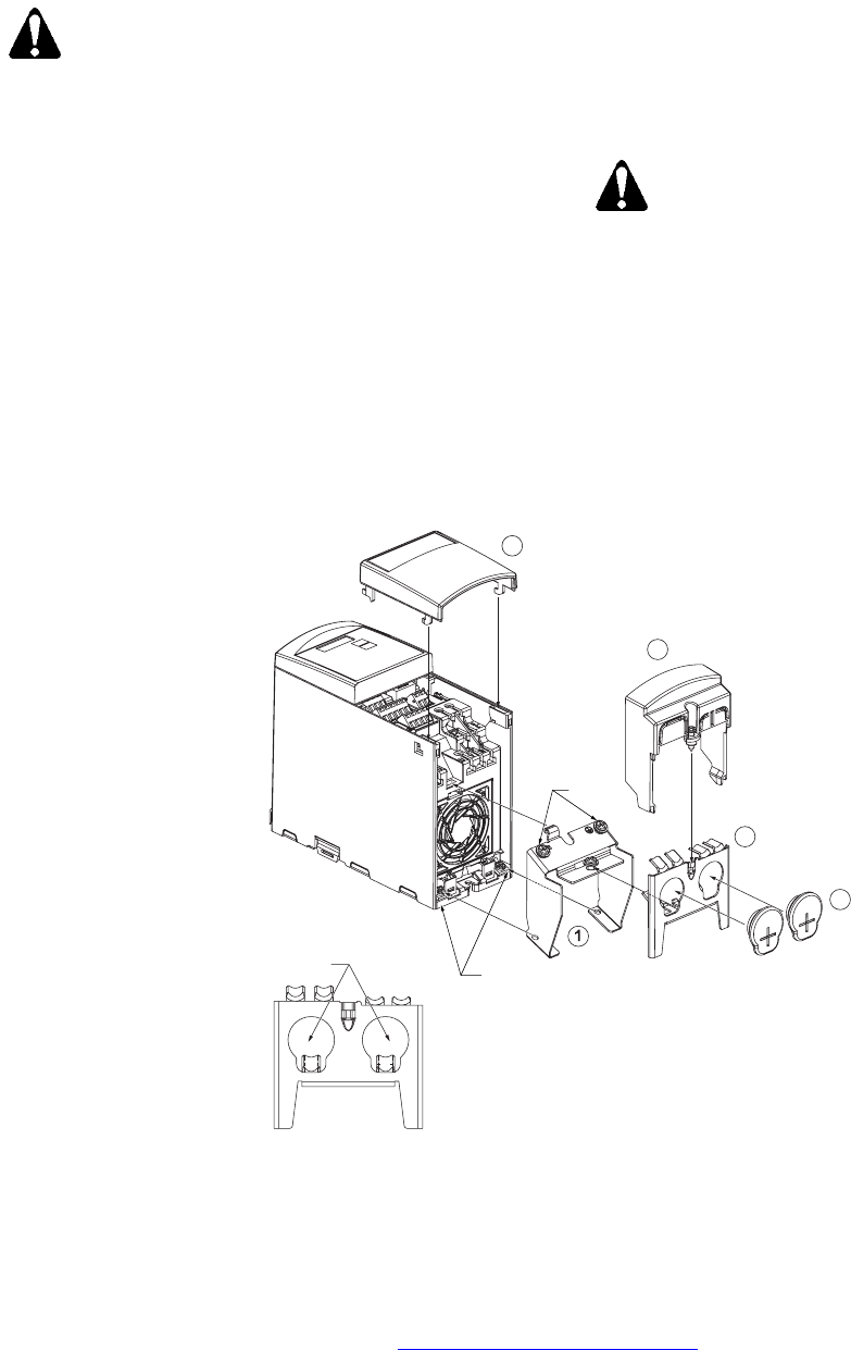
Gland Plate Installation and Conduit
Connections
For Frame Sizes A, B, and C, see Figures 1 and 2
for gland plate installation and for conduit connection
diameters. Circled numbers indicate the order of
assembly.
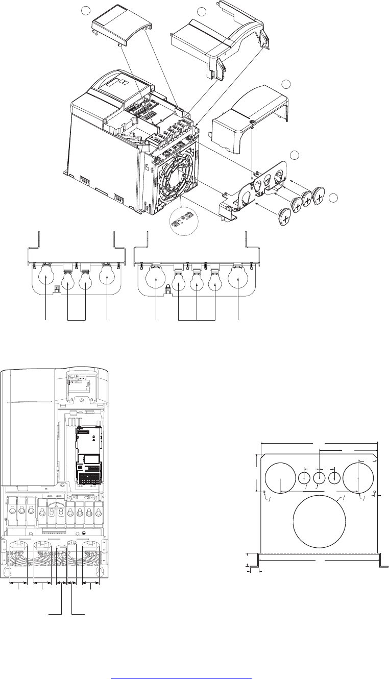
For Frame Sizes D, E, and F, see Figures 3 and 4
for conduit connection diameters.
CAUTION:
• Bonding between conduit
connections is not automatic and
must be provided as part of the
installation.
• Each bonding conductor must be
equal or greater in cross-section to
the power supply cable.
2
3
4
5
.90
(22.8) Ground
Ground
VFD0002R1
Conduit Connections:
Figure 1. Frame Size A Gland Plate Installation and Conduit Connection Diameters in Inches (Millimeters).
Page 2 of 8 http://www.sbt.siemens.com/hvp/drives Siemens Building Technologies, Inc.
Document No. 129-371
Installation Instructions
October 13, 2003
1
4
2
3
5
Frame Size B Frame Size C
.90
(22.8) .90
(22.8)
.74
(18.8) 1.10
(28) 1.10
(28)
.74
(18.8)
Ground
VFD0003R1
Conduit Connections:
Figure 2. Frame Size B & C Gland Plate Installation and Conduit Connection Diameters in Inches (Millimeters).
20 21 22 23 24 25
29 30
17 26 27 28
12 13 14 15 16
10 11
6789
12345
ON
12
PE
VFD0062R1
1.77
(45.0)
.90
(22.8)
1.10
(28.4)
1.77
(45.0)
1.77
(45.0)
Figure 3. Frame Size D & E Conduit Connection
Diameters in Inches (Millimeters).
VFD0091R1
1.0
(25)
14.0
(356)
13.5
(343) 6.8
(173)
1.5
(38)
.35
(9)
0.25
(6)
6.1
(155) 3.5
(89)
1.8
(46) 1.8
(46)
.3
(58)
o
o
9.0
(229)
1.4
(36)
4.4
(112)
o
o
Figure 4. Frame Size F Conduit Connection Diameters
(Bottom View) in Inches (Millimeters).
Siemens Building Technologies, Inc. http://www.sbt.siemens.com/hvp/drives Page 3 of 8
Document No. 129-371
Installation Instructions
October 13, 2003
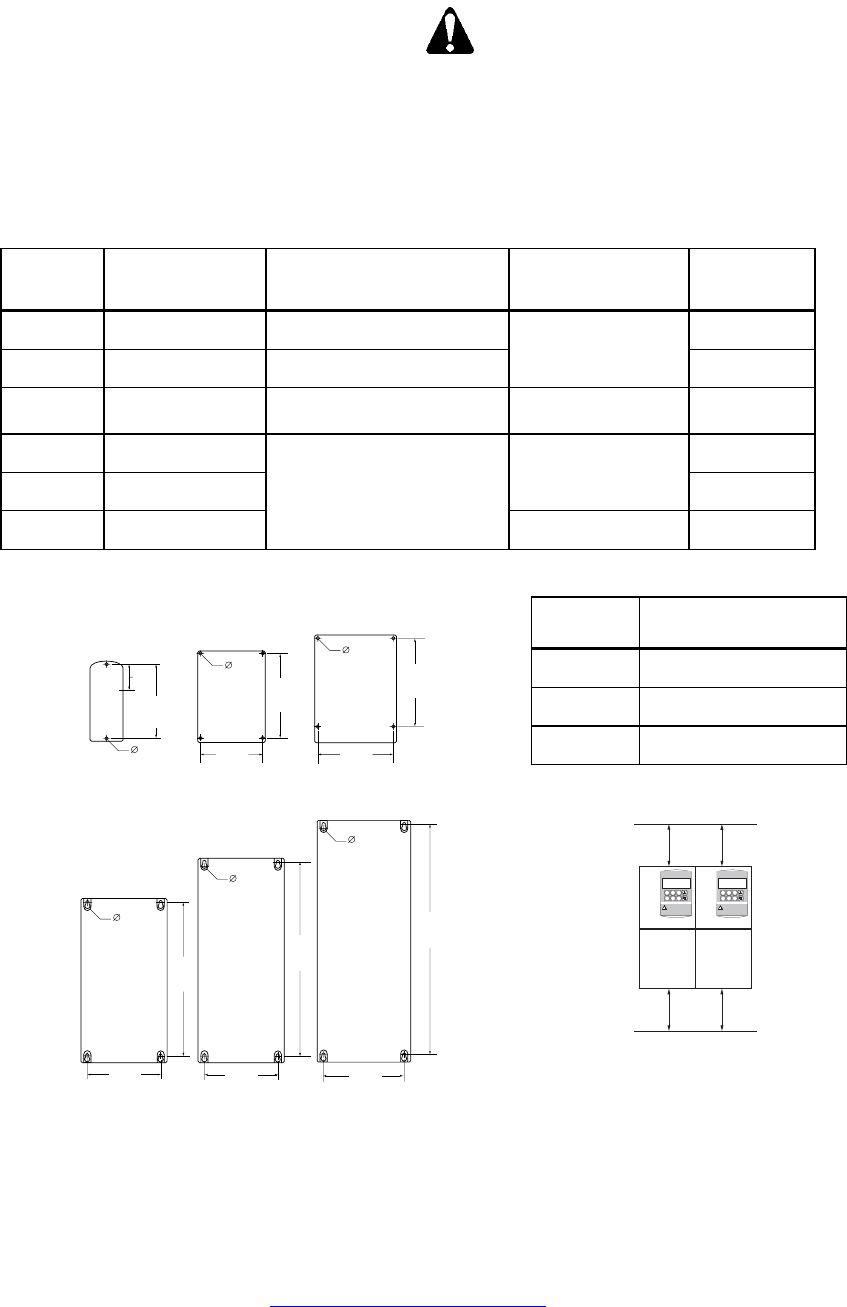
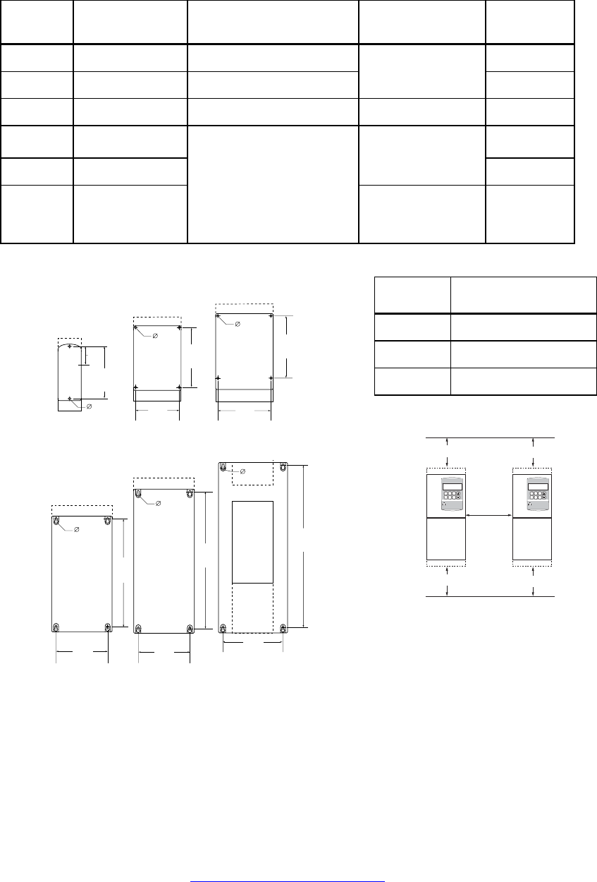
Mounting and Dimensions
Mount the SED2 so there is a minimum clearance for
ventilation and equipment access.
CAUTION:
Overheating/Ventilation:
Install SED2 vertically for optimum
ventilation. Do not obstruct SED2 vents.
Additional ventilation may be required if
SED2 is mounted horizontally.
IP20 SED2s
Table 2. IP20 SED2 Overall Dimensions in Inches (Millimeters).
Frame
Size
Height x Width x
Depth Mounting Specification Tightening Torque
lb-in (Nm)
Weight
lb (kg)
A 6.8 x 2.9 x 5.9
(173 x 73 x 149)
2 × M4 Bolts, nuts, washers, or
connecting to DIN rail
2.9
(1.3)
B 8.0 x 5.9 x 6.8
(202 x 149 x 172) 4 × M4 Bolts, nuts, washers
22
(2.5) 7.5
(3.4)
C 9.6 x 7.3 x 7.7
(245 x 185 x 195) 4 × M5 Bolts, nuts, washers 26
(3.0)
12.1
(5.5)
D 20.5 x 10.8 x 9.6
(520 x 275 x 245)
35.3
(16)
E 25.6 x 10.8 x 9.6
(650 x 275 x 245)
115
(13) 44.1
(20)
F 33.5 x 13.8x x 12.6
(850 x 350 x 320)
4 × M8 Bolts, nuts, washers
221
(25)
116
(53)
Frame
Size
Vmin Clearance in
Inches (Millimeters)
A, B, C 4
(100)
D, E 11-3/4
(300)
F 13-3/4
(350)
Frame Size A Frame Size B Frame Size C
Frame Size D
Frame Size E
Frame Size F
0.19
(4.8)
5.4
(138)
6.9
(174)
0.22
(5.5)
6.9
(174)
8.0
(204)
0.68
(17.5)
19.1
(486)
9.3
(235)
0.68
(17.5)
24.3
(616)
9.3
(235)
0.59
(15)
31.9
(810)
11.8
(300)
6.3
(160)
0.17
(4.5)
0.22
(5.5)
VFD0012R1
Figure 5. IP20 SED2 Mounting Dimensions
in Inches (Millimeters).
SED2
SIEMENS
V
min.
V
min.
VFD0143R1
SED2
SIEMENS
NOTE: When fitted with a protective
shield, allow 12-inches (305 mm) of space
between each SED2.
Page 4 of 8 http://www.sbt.siemens.com/hvp/drives Siemens Building Technologies, Inc.
Document No. 129-371
Installation Instructions
October 13, 2003
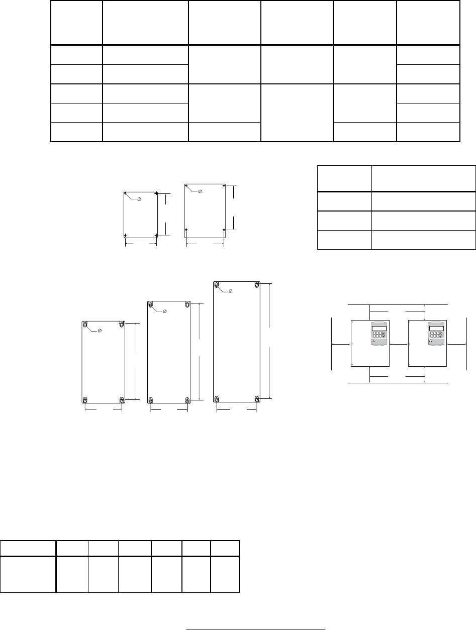
NEMA Type 1 SED2s
Table 3. NEMA Type 1 SED2 Overall Dimensions in Inches (Millimeters).
Frame
Size
Height x Width x
Depth Mounting Specification Tightening Torque
lb-in (Nm)
Weight
lb (kg)
A 9.1 x 2.9 x 5.9
(231 x 73 x 149)
2 × M4 Bolts, nuts, washers, or
connecting to DIN rail
3.2
(1.5)
B 11.8 x 5.9 x 6.8
(300 x 49 x 172) 4 × M4 Bolts, nuts, washers
22
(2.5) 8.3
(3.8)
C 13.8 x 7.3 x 7.7
(351 x 185 x 195) 4 × M5 Bolts, nuts, washers 26
(3.0)
13.6
(6.2)
D 24.6 x 10.8 x 9.6
(625 x 275 x 245)
37,5
(17.1)
E 29.7 x 10.8 x 9.6
(754 x 275 x 245)
115
(13) 46.4
(21.1)
F 54.5 x 16.0 x 14.0
(1384 x 406 x 356)
4 × M8 Bolts, nuts, washers
221
(25)
200
(91)
Frame
Size
Vmin Clearance in
Inches (Millimeters)
A, B, C 4
(100)
D, E 11-3/4
(300)
F 13-3/4
(350)
9.3
(235)
Frame Size A
Frame Size B Frame Size C
Frame Size D
Frame Size E
6.3
(160)
0.17
(4.5)
0.22
(5.5)
5.4
(138)
0.19
(4.8) 6.9
(174)
6.9
(174)
0.22
(5.5) 8.0
(204)
0.68
(17.5)
19.1
(486)
9.3
(235)
0.68
(17.5)
24.3
(616)
Frame Size F
15
(381)
0.59
(15)
51
(1295)
VFD0092R2
Figure 6. NEMA Type 1 SED2 Mounting Dimensions
in Inches (Millimeters).
SED2
VFD0143R1
Vmin. Vmin.
12 in.
(305 mm)
SIEMENS SIEMENS
SED2
Vmin. Vmin.
Siemens Building Technologies, Inc. http://www.sbt.siemens.com/hvp/drives Page 5 of 8
Document No. 129-371
Installation Instructions
October 13, 2003
IP54/NEMA Type 12 SED2s
Table 4. IP54/NEMA Type 12 SED2 Overall Dimensions in Inches (Millimeters).
Frame Size
Overall Dimensions
Height x Width x
Depth
Mounting
Clearance
Top x Bottom x
Sides
Mounting
Specification
Tightening
Torque
lb-in (Nm)
Weight
lb (kg)
B 15.2 x 10.6 x 10.6
(385 x 270 x 270)
22
(10)
C 23.9 x 13.8 x 11.2
(606 x 350 x 284)
5.9 x 5.9 x 3.9
(150 x 150 x 100)
4 × M6 Bolts, nuts,
washers
44
(5) 42
(19)
D 27.0 x 142 x 13.9
(685 x 360 x 200)
77
(35)
E 34.8 x 14.2 x 17.8
(885 x 360 x 453)
7.9 x 7.9 x 5.9
(200 x 200 x 150)
115
(13) 105
(48)
F 45.3 x 17.7 x 18.6
(1150 x 450 x 473)
11.8 x 9.8 x 5.9
(300 x 250 x 150)
4× M8 Bolts, nuts,
washers
177
(20)
178
(81)
Frame Size Vmin Clearance in
Inches (Millimeters)
A, B, C 4
(100)
D, E 11-3/4
(300)
F 13-3/4
(350)
NOTE: In all cases, Smin Clearance is
5-7/8 inches (150 millimeters).
Frame Size B Frame Size C
0.19
(4.8)
9.1
(230)
13.5
(343)
0.22
(5.5)
12.3
(313)
22.2
(564)
Frame Size D
Frame Size E
Frame Size F
0.59
(15)
43.8
(1112)
15.7
(400)
0.68
(17.5)
25.5
(647)
12.2
(310)
0.68
(17.5)
33.5
(847)
12.2
(310)
VFD0013R1
Figure 7. IP54/NEMA Type 12 SED2 Mounting Dimensions in
Inches (Millimeters).
VFD0144R1
S
min.
SED2
SIEMENS
SED2
SIEMENS
V
min.
S
min.
S
min.
V
min.
Wiring
Tightening Torque for Connecton
Terminals
Frame Size A B C D E F
Tightening
Torque
lb-in (Nm)
9.7
(1.1)
13.3
(1.5)
19.9
(2.25)
88.5
(10)
max.
88.5
(10)
max.
442
(50)
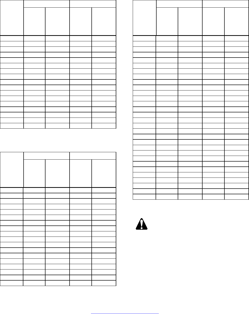
Cable Cross-Sections for Power and
Motor Cables
Tables 5 through 7 provide cable cross-sections for
input power cables and for motor cables.
Page 6 of 8 http://www.sbt.siemens.com/hvp/drives Siemens Building Technologies, Inc.
Document No. 129-371
Installation Instructions
October 13, 2003
Table 5. Cable Cross-Sections for Input Voltage
Range 3ø AC 200V through 240V.
Input Power Cable Motor Cable
Output
Rating
kW (hp)
Min.
Cross-
Section
AWG
(mm2)
Max.
Cross-
Section
AWG
(mm2)
Min.
Cross-
Section
AWG
(mm2)
Max.
Cross-
Section
AWG
(mm2)
0.37 (.50) 17 (1) 13 (2.5) 17 (1) 13 (2.5)
0.55 (.75) 17 (1) 13 (2.5) 17 (1) 13 (2.5)
0.75 (1.0) 17 (1) 13 (2.5) 17 (1) 13 (2.5)
1.1 (1.5) 17 (1) 9 (6) 17 (1) 9 (6)
1.5 (2.0) 15 (1.5) 9 (6) 17 (1) 9 (6)
2.2 (3.0) 13 (2.5) 9 (6) 17 (1) 9 (6)
3 (4.0) 11 (4) 7 (10) 15 (1.5) 7 (10)
4 (5.0) 11 (4) 7 (10) 11 (4) 7 (10)
5.5 (7.5) 11 (4) 7 (10) 11 (4) 7 (10)
7.5 (10) 7 (10) 2 (35) 7 (10) 2 (35)
11 (15) 5 (16) 2 (35) 16 (5) 2 (35)
15 (20) 5 (16) 2 (35) 5 (16) 2 (35)
18.5 (25) 3 (25) 2 (35) 5 (16) 2 (35)
22 (30) 2 (35) 2 (35) 2 (35) 2 (35)
30 (40) 0 (50) -5 (150) 0 (50) -5 (150)
37 (50) -2 (70) -5 (150) -2 (70) -5 (150)
45 (60) -2 (70) -5 (150) -3 (95) -5 (150)
Table 7. Cable Cross-Sections for Input Voltage
Range 3ø AC 500V through 600V.
Input Power Cable Motor Cable
Output
Rating
kW (hp)
Min.
Cross-
Section
AWG
(mm2)
Max.
Cross-
Section
AWG
(mm2)
Min.
Cross-
Section
AWG
(mm2)
Max.
Cross-
Section
AWG
(mm2)
0.75 (1.0) 17 (1) 7 (10) 17 (1) 7 (10)
1.1 (1.5) 17 (1) 7 (10) 17 (1) 7 (10)
1.5 (2.0) 17 (1) 7 (10) 17 (1) 7 (10)
2.2 (3.0) 17 (1) 7 (10) 17 (1) 7 (10)
3 (4.0) 17 (1) 7 (10) 17 (1) 7 (10)
4 (5.0) 17 (1) 7 (10) 17 (1) 7 (10)
5.5 (7.5) 15 (1.5) 7 (10) 15 (1.5) 7 (10)
7.5 (10) 13 (2.5) 7 (10) 13 (2.5) 7 (10)
11 (15) 11 (4) 7 (10) 11 (4) 7 (10)
15 (20) 9 (6) 2 (35) 9 (6) 2 (35)
18.5 (25) 9 (6) 2 (35) 9 (6) 2 (35)
22 (30) 7 (10) 2 (35) 7 (10) 2 (35)
30 (40) 5 (16) 2 (35) 5 (16) 2 (35)
37 (50) 3 (25) 2 (35) 5 (16) 2 (35)
45 (60) 3 (25) -5 (150) 3 (25) -5 (150)
55 (75) 0 (50) -5 (150) 2 (35) -5 (150)
75 (100) -2 (70) -5 (150) 0 (50) -5 (150)
90 (125) -2 (70) -5 (150) 0 (50) -5 (150)
Table 6. Cable Cross-Sections for Input Voltage
Range 3ø AC 380V through 480V.
Input Power Cable Motor Cable
Output
Rating
kW (hp)
Min.
Cross-
Section
AWG
(mm2)
Max.
Cross-
Section
AWG
(mm2)
Min.
Cross-
Section
AWG
(mm2)
Max.
Cross-
Section
AWG
(mm2)
0.37 (.50) 17 (1) 13 (2.5) 17 (1) 13 (2.5)
0.55 (.75) 17 (1) 13 (2.5) 17 (1) 13 (2.5)
0.75 (1.0) 17 (1) 13 (2.5) 17 (1) 13 (2.5)
1.1 (1.5) 17 (1) 13 (2.5) 17 (1) 13 (2.5)
1.5 (2.0) 17 (1) 13 (2.5) 17 (1) 13 (2.5)
2.2 (3.0) 17 (1) 9 (6) 17 (1) 9 (6)
3 (4.0) 17 (1) 9 (6) 17 (1) 9 (6)
4 (5.0) 17 (1) 9 (6) 17 (1) 9 (6)
5.5 (7.5) 13 (2.5) 7 (10) 13 (2.5) 7 (10)
7.5 (10) 11 (4) 7 (10) 11 (4) 7 (10)
11 (15) 9 (6) 7 (10) 9 (6) 7 (10)
15 (20) 7 (10) 2 (35) 7 (10) 2 (35)
18.5 (25) 7 (10) 2 (35) 7 (10) 2 (35)
22 (30) 5 (16) 2 (35) 5 (16) 2 (35)
30 (40) 3 (25) 2 (35) 3 (25) 2 (35)
37 (50) 3 (25) 2 (35) 2 (35) 2 (35)
45 (60) 2 (35) -5 (150) 2 (35) -5 (150)
55 (75) -2 (70) -5 (150) -2 (70) -5 (150)
75 (100) -2 (70) -5 (150) -3 (95) -5 (150)
90 (125) -2 (70) -5 (150) -3 (95) -5 (150)
Input Power Connection
WARNING:
Use only permanently wired input power
connections.
Connect input power to SED2 terminals L1, L2,
and L3.
Siemens Building Technologies, Inc. http://www.sbt.siemens.com/hvp/drives Page 7 of 8
Document No. 129-371
Installation Instructions
October 13, 2003
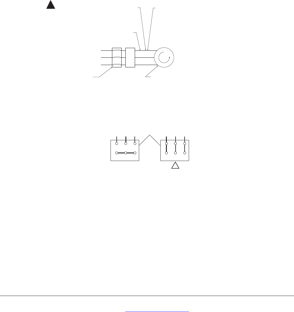
Motor Cable Length
Maximum motor cable length is 164 ft (50 m). Motor
cable length is given to ensure performance of only
the SED2, not the suitability of the motor when
connected to a SED2 at this distance. See Figure 8
for motor cable installation notes.
Motor Connection
The motor nameplate indicates the required supply
voltage and method of connection (delta, ∆, or
star/wye, ‘Y’, configuration). Connect motor wiring to
SED2 terminals U, V, and W. See Figure 9.
VFD0014R2
M
SED2
3. If needed, use
SBT-specified input line reactors
to ensure a good impedance match
with your drive.
1. Never run control or drive input
wires in the same conduit as
the drive output wires.
4. If a disconnect is mounted on the
load side of your drive, it is desirable
to wire an auxiliary contact to the drive
that will disable drive operation when
the disconnect opens. (The wiring for
this contact must not be run in the same
conduit as the drive output wires).
5. Inverter duty motors are recommended.
Install motors within their guidelines. Use
dV/dT filters, output reactors, or other load
conditioners as applicable or as specified
by the motor manufacturer.
2. Keep the distance from the drive
to the motor as short as possible
to maximize motor life.
!
Figure 8. Motor Cable Installation Notes.
MOTOR TERMINALS
U2 V2W2
U1 V1 W1
U2 V2W2
U1 V1 W1
VFD0029R2
Wye "Y"
Figure 9. SED2 Motor Connections.
Information in this publication is based on current specifications. The company reserves the right to make changes in specifications and
models as design improvements are introduced. Other product or company names mentioned herein may be the trademarks of their
respective owners. © 2003 Siemens Building Technologies, Inc.
Siemens Building Technologies, Inc.
1000 Deerfield Parkway
Your feedback is important to us. If you have
comments about this document, please send
Buffalo Grove, IL 60089-4513
U.S.A.
them to technical.editor@siemens.com
Page 8 of 8
Document No.129-371
Printed in the U.S.A.
