Singulaire 7120 Ops&Parts Manual
User Manual: Singulaire 7120 Ops&Parts Manual
Open the PDF directly: View PDF ![]() .
.
Page Count: 61
- sty 7120
- Page 1
- Page 2
- Page 3
- Page 4
- Page 5
- Page 6
- Page 7
- Page 8
- Page 9
- Page 10
- Page 11
- Page 12
- Page 13
- Page 14
- Page 15
- Page 16
- Page 17
- Page 18
- Page 19
- Page 20
- Page 21
- Page 22
- Page 23
- Page 24
- Page 25
- Page 26
- Page 27
- Page 28
- Page 29
- Page 30
- Page 31
- Page 32
- Page 33
- Page 34
- Page 35
- Page 36
- Page 37
- Page 38
- Page 39
- Page 40
- Page 41
- Page 42
- Page 43
- Page 44
- Page 45
- Page 46
- Page 47
- Page 48
- Page 49
- Page 50
- Page 51
- Page 52
- Page 53
- Page 54
- Page 55
- Page 56
- Page 57
- Page 58
- sty 7120_00001
P
AAP
Azi S
cA
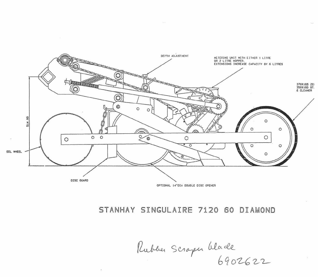
METERING uNIT WITH EITHER I LITPE
On 2 LITRE HOPPER.
EXTENSIONS INCREASE CAPACITY By 6 LITRES
DEPTH A(.60SINENT
3701165 ZE1
3501160 ST.
& CLEANER
DISC GUARD
pooPtiii, u
EEL WHEEL
OPTIONAL 14'0IA DOUBLE DISC OPENER
STANHAY SINGULAIRE 7120 SO DIAMOND
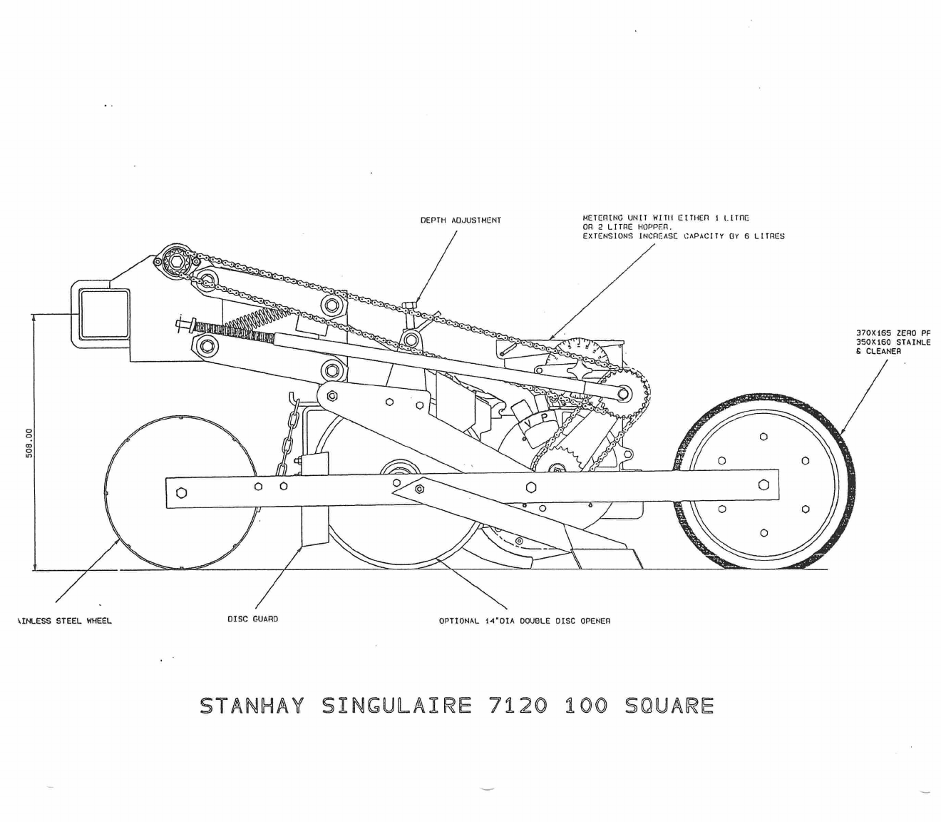
METERING UNIT WITH EITHER I
LITRE
OR 2 LITRE HOPPER.
EXTENSIONS INCREASE CAPACITY GY 6 LITRES
DEPTH ADJUSTMENT
UNLESS STEEL WHEEL
DISC GUARD
OPTIONAL 14
-
0IA DOUBLE DISC OPENER
370X165 ZERO PF
350X160 STAINLE
CLEANER
STANHAY SINGULAIRE 7120 100 SQUARE
1.
Number metering units.
Mark identification number on both halves of
each metering unit and on each singulator.
(Note:
singulators are
factory calibrated to ensure all units perform similarly: they
must
remain fitted to the units as supplied).
2.
Check row units.
Raise machine off the ground. Then check:
Wheels:
check all wheels rotate:
check adjustment of scrapers and
cleaners.
3.
Check P.T.O. shaft.
Start P.T.O., raise machine fully. If shaft angle
is not acceptable, move fan and headstock to lower position.
(Note:
fan cannot be lowered on machines with short extension brackets and
clod deflectors: adjust stop on tractor linkage control lever quadrant
instead).
If necessary, shorten P.T.O. shaft to ensure end float at
all times.
SAFETY INSTRUCTION.
Fit splined P.T.O. shaft couplings securely.
Secure shaft cover to prevent rotation in use.
4.
Check hoses.
Check all hoses are correctly and securely fitted:-
Vacuum: front of fan connects to front tubes on metering unit (marked
V')
Pressure: rear of fan connects to rear tubes on metering unit
(marked'P').
Raise and lower machine: check hoses are not too tight, and do not
contact shafts, sprockets or chains.
(Note:
unused hose stubs on the
fan must be plugged).
5.
Check hydraulics.
Check operation of hydraulic markers or other
hydraulic equipment.
6.
Check drives.
Check all drive chains are in line and drive shaft
locking collars and bearing grub screws are fitted securely.
7.
Check tyre pressures.
Chain Land Drive Wheels:
1.5 bar (22 psi)
Transport Wheels:
4.0 bar (59 psi)
Notes on Disconnecting Unit Drive.
This procedure facilitates removal of
metering unit from chassis for fitting alternative coulters:
a)
Pull long drive chain upwards to compress knee joint spring. With
other hand, transfer the R-clip in the end of the spring rod to a
hole exposed about 50mm down the rod. Release the drive chain from
the knee joint sprocket.
b)
To reconnect drive, re-fit drive chain, pull upwards to compress
knee joint spring, and re-fit R-clip in normal position.
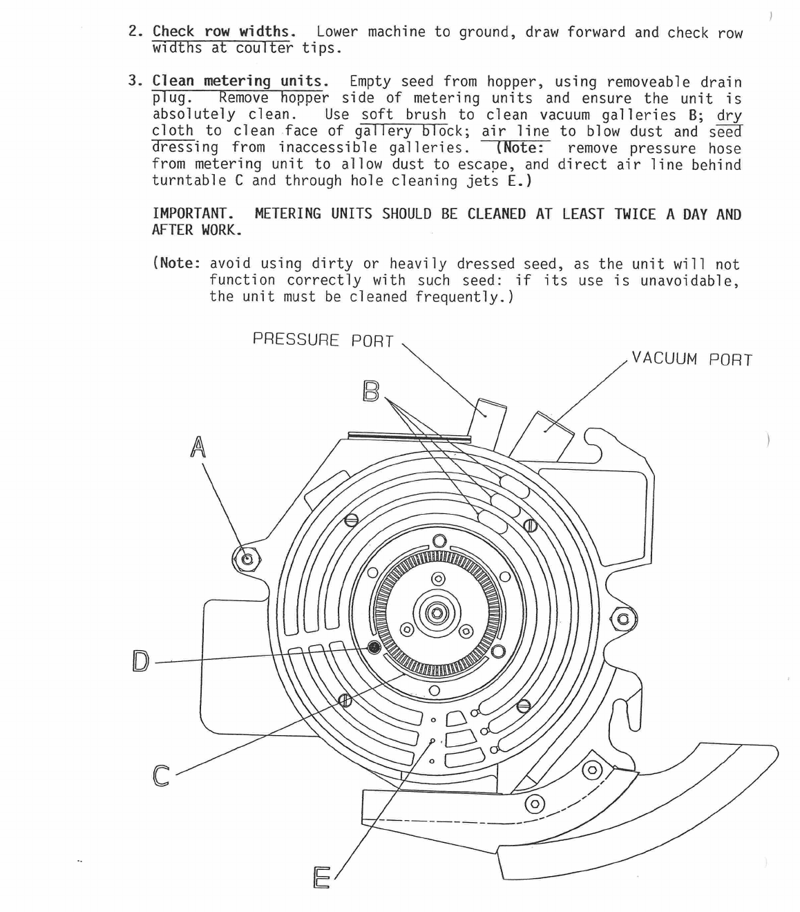
PRESSURE PORT
VACUUM PORT
2.
Check row widths.
Lower machine to ground, draw forward and check row
widths at coulter tips.
3.
Clean metering units.
Empty seed from hopper, using removeable drain
plug.
Remove hopper side of metering units and ensure the unit is
absolutely clean.
Use soft brush to clean vacuum galleries
B;
dry
cloth to clean face of gallery block; air line to blow dust and
s
-
Ea
dressing from inaccessible galleries.
(Note:
remove pressure hose
from metering unit to allow dust to escape, and direct air line behind
turntable C and through hole cleaning jets
E.)
IMPORTANT. METERING UNITS SHOULD BE CLEANED AT LEAST TWICE A DAY AND
AFTER WORK.
(Note:
avoid using dirty or heavily dressed seed, as the unit will not
function correctly with such seed: if its use is unavoidable,
the unit must be cleaned frequently.)
Li
waLuum mcaecte nutc .
uperi
Refer to SEED SETTING GUIDE (see pages 36-42) and check seed to be
planted. Any variation from above standard arrangements is given as a
"special instruction": follow these instructions using procedures on
pages 13-15 (PREPARING METERING UNITS).
(Note:
body side of metering
unit need not be removed from the row unit chassis for cleaning,
preparation or setting).
5.
Choose settings.
Use SEED SETTING GUIDE to identify the following
recommended settings:
a)
Seed disc
(see page 16 for detailed instructions on choosing a
disc).
b)
Rpm seed disc
(i.e. revs/minute)
c)
Vacuum m.b.
d)
Pressure m.b.
Then select correct SEED SPACING CHART for the seed disc and unit drive
shaft sprocket (11T or 16T) you will be using. Use the chart to choose
the
gear setting
that gives the required seeding rate (see left hand
columns). Then note the
forward speed
that gives the recommended rpm
seed disc, and note the corresponding
landwheel rpm.
6.
Set gearbox(es).
The gearbox(es) are incorporated within the main
drive landwheel.
See page 17 for detailed setting instructions
(SETTING SEED SPACING).
7.
Check vacuum.
Ensure seed discs are free of grease and check all holes
are clear of blockage.
(Note:
for care of seed discs, see page 16.)
Fit seed discs carefully over drive pegs
D,
concave side towards vacuum
galleries.
(Note:
if one peg is marked with red paint, fit the disc so
the part number is opposite this peg.) Open fully both valves on the
fan, start tractor, engage P.T.O. Raise engine rpm until recommended
vacuum m.b. shows on vacuum gauge.
(Note:
if the gauge does not
respond immediately, refer to SETTING AIR SUPPLY, page 18.)
SAFETY INSTRUCTION. ONLY ENGAGE P.T.O. WITH ENGINE ON LOW RPM.
NEVER EXCEED 540 RPM P.T.O. SPEED.
Fit calibration handle (if available) to landwheel arm stub shaft (see
page 17). Rotate land drive wheel(s) in forward direction (using
calibration handle), and check all seed discs are seated firmly without
vibration or noise: turn over any offending disc and re-check. Having
decided which side of each seed disc should face towards the vacuum
gallery, mark the centre with a felt tipped pen, and always replace the
disc this way round. A disc may need to be turned over after some
work, but this will occur only once in its life time.
(Note:
always
stop P.T.O. or remove vacuum hose before removing discs: handle discs
carefully by the edges - grease from finger marks can adversely affect
performance.)
8.
Assemble metering units.
Refit hopper side of metering units taking
care
they are
not held
apart by the top sealing brush, seed guides, or
agitator gears: if necessary rotate agitator spindle
F
slightly.
Lightly
tighten
both conical nuts
A
with a wrench or socket.
Aaain
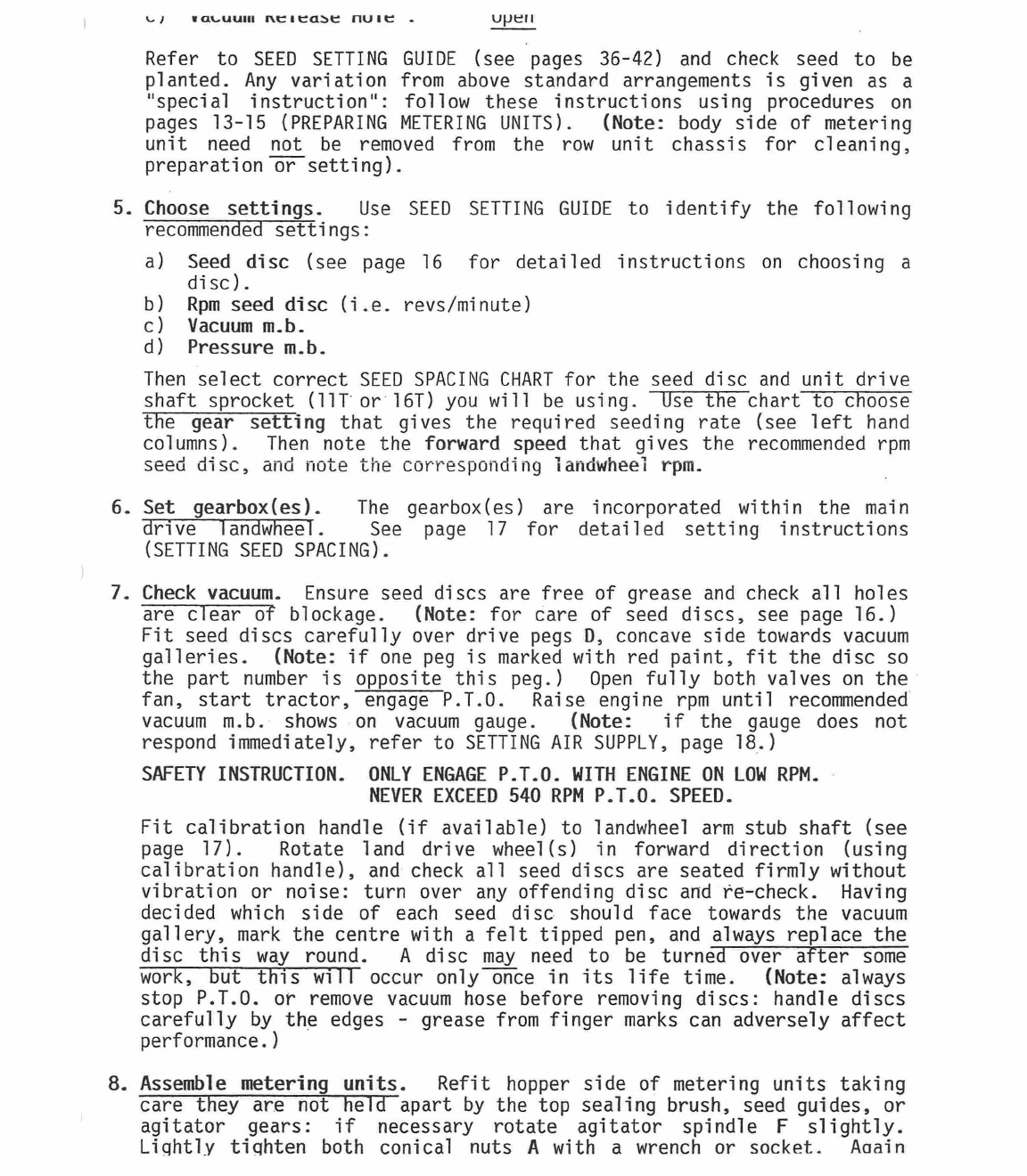
SETTING
POINT
release; repeat several times to ensure singulators are settled in
correct working position flat on seed discs. Rotate cams to setting
16 for zero singulation. Check seed emptying plugs are securely
fitted and put seed in hoppers. Place container for collecting seed
under each unit.
b)
Rotate land drive wheel(s) in forward direction at approx. required
landwheel rpm (see page 5, paragraph 5). Check that all seed discs
are picking up seed with very few misses. (Note: better
distribution is obtained at lower vacuum levels, so do not be
tempted to increase vacuum excessively to eliminate the odd miss,
which is unavoidable with some seed.)
c)
Select a unit whose disc is clearly visible (the "calibration
unit"). Again rotate land drive wheel at approx. required landwheel
rpm and adjust singulator cam on the calibration unit until there
are no seeds on the disc. Then gradually adjust to bring seeds back
on the disc, until there are mainly single seeds. (The lower the
setting number, the less seed will be planted.) Clamp singulator
cam with handwheel J and re-check.
d)
When satisfied, set singulators on all remaining units to the same
setting as the calibration unit. Clamp singulator cams. Empty seed
containers into hoppers.
(Note:
when the machine is new and when fitting new or alternative
singulators, check that all units are calibrated similarly: for
procedure, see pages 14-15.)
LOCK I NG HANDLE
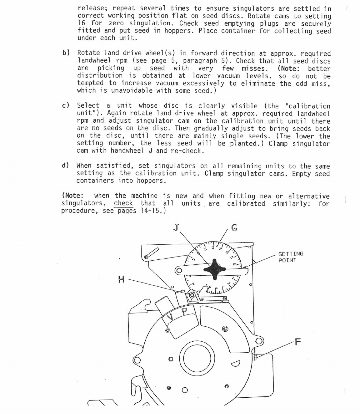
sowing depth is most easily achieved by progressively adjusting
coulters
downwards
until the desired sowing depth is achieved).
EMPTY SEED FROM HOPPERS BEFORE TRANSPORTING MACHINE TO FIELD.
Release the locking handle and adjust the depth screw. Re-tighten
locking handle.
DEPTH SCREW
LOCK ING HANDLE
Set,
'or seeu spdclng.
b)
Singulator setting:
must be the same setting on all units.
c)
Hopper emptying plugs:
must be securely fitted.
2.
Prepare the tractor.
a)
Wheel tracks:
ensure front and rear wheel trackssuit drill row
.
-
widths.
b)
Lower links:
adjust levelling box until headstock pins are
horizontal: stabilizers or check chains must be fitted and adjusted
to be tight when lower links are at workinTheight.
c)
Hydraulics:
connect and test any hydraulic equipment (e.g.
markers).
d)
Top link:
pull forward a few metres and fully lower tractor
linkage: then adjust top link until machine headstock is vertical.
3.
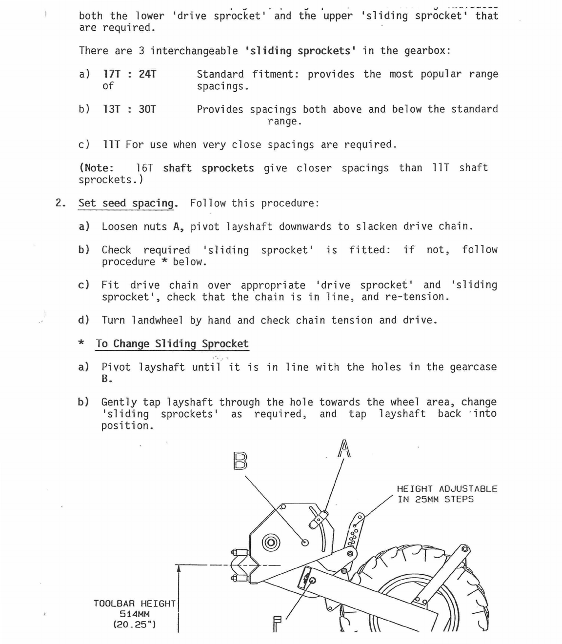
Check toolbar height.
Nominal toolbar height (centre of toolbar to
ground) should be 514mm (20.25 ins.) on 60 diamond bar, and 508 (20
ins.) on 100 square bar.
On level seedbeds this is normally achieved
with landwheel struts in 3rd hole (see diagram page 17). Check height
adjacent to each land drive wheel and adjust struts if necessary.
4. Select tractor gear.
Lift machine, engage P.T.O. and raise engine
speed to achieve desired vacuum and pressure levels. Note tractor
engine speed, and select tractor gear to give recommended forward
speed.
5.
Check seed delivery. Fill hoppers evenly with seed, close lids firmly.
(Note:
seed should be good quality, clean, with no soil, stones, paper,
etc.: avoid using heavily dressed seed, as the dressing will be sucked
off the seed and deposited in the vacuum galleries.) Rotate land drive
wheel(s) by hand and check all seed discs are picking up and delivering
seed evenly.
If there is dampness on the coulter chutes, dry with a
cloth or by blowing air through the units: (fully close valve
A,
then
return it to original setting when chutes are dry).
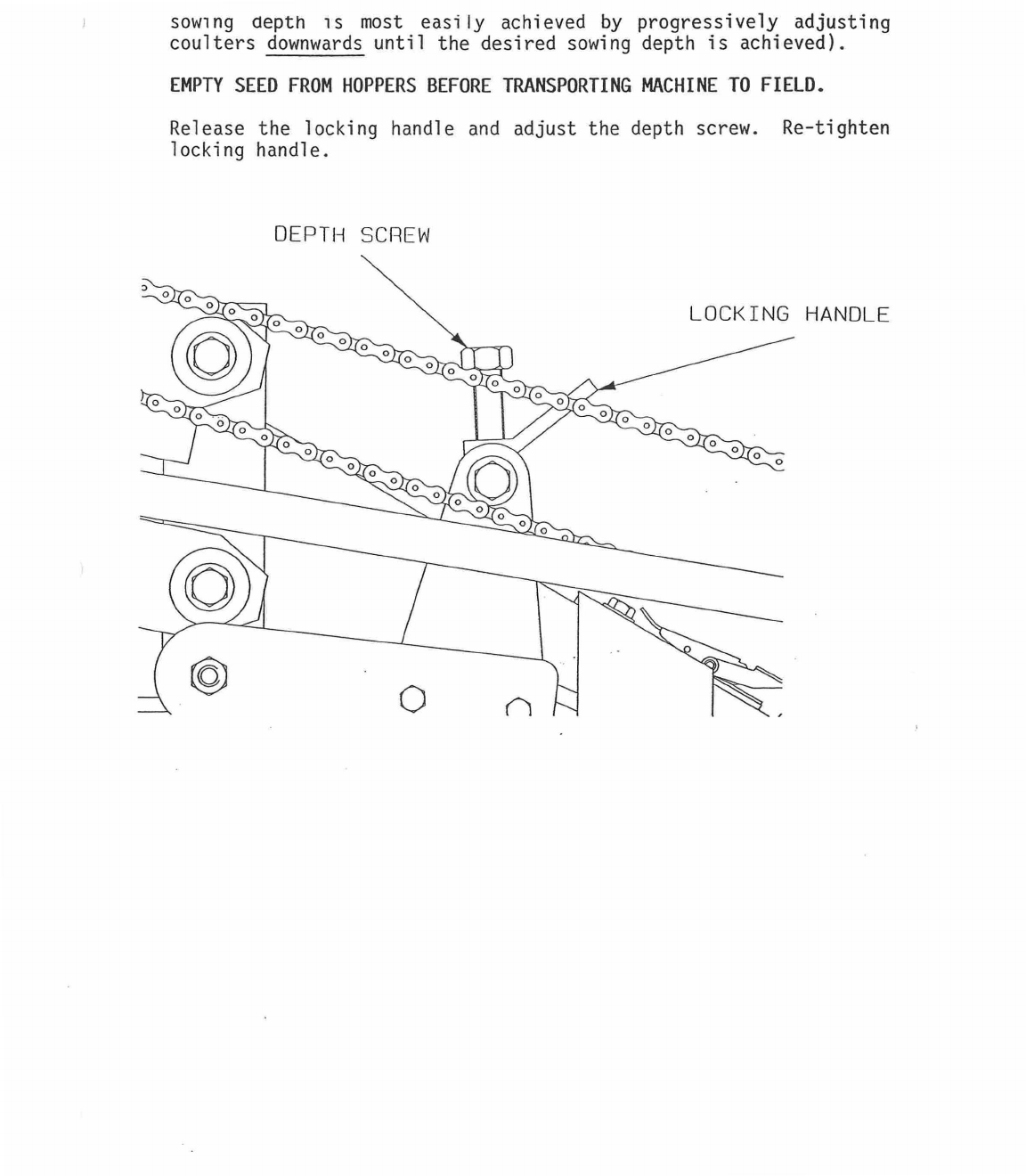
6.
Sowing depth: adjust coverers as necessary to achieve desired results:
re-check sowing depth and adjust all units identically.
Release the
locking handle and adjust the depth screw. Re-tighten locking handle.
CHECK FOR BLOCKED COULTERS
GO TO WORK
markers it necessary.
c)
Pivot limiters:
if a yoke bar with toolbar pivots is used, check
the pivot limiters are set symmetrically and do not restrict the
toolbars pivotting in work.
d)
Clamp fasteners:
after a few hectares, check all clamp fasteners
for tightness, including marker clamps.
e)
Drive shaft:
after a few hectares, check drive shaft locking
collars and bearing grub
screws are secure.
NOTE:
CORRECT OPERATION IS THE RESPONSIBILITY OF THE OPERATOR WHO SHOULD
CHECK PERIODICALLY THAT THE DESIRED SEEDING RATE, PLANTING DEPTH AND
MACHINE PERFORMANCE ARE BEING ACHIEVED.
a)
ALWAYS
lower and raise machine on the move to prevent coulter
blockage.
b)
ALWAYS
raise machine and check coulters for blockage if you have
stopped for any reason whilst drilling.
c)
ALWAYS
move tractor linkage control lever to 'fully down' position
when going into work to ensure adequate land wheel drive.
d)
ALWAYS
raise machine fully when turning at headlands.
2.
Tractor forward speed
a) ALWAYS
operate at the recommended forward speed.
3.
Hoppers and transport
a)
ALWAYS
fill hoppers with seed to the same level, and check periodi-
cally that seed levels go down evenly.
b)
ALWAYS
keep hopper lids firmly closed except when filling.
c)
ALWAYS
empty hoppers of seed before transporting machine or driving
long distances: for short distances, keep PTO engaged to ensure
discs remain seated against vacuum galleries.
4.
Gauges and seed discs
a)
REGULARLY
check vacuum and pressure readings during work:
immediately investigate cause of any unexpected change of readings,
or of any unusual noise from the fan (see page 18). A loud
whistling noise from a metering unit indicates complete loss of
vacuum.
(Note:
the tractor engine can be allowed to idle when the
tractor is turning or is stationary at headlands: only during work
must the vacuum and pressure be maintained.)
b)
REGULARLY
check unit performance.
To check seed disc pick up,
raise machine on the move at normal drilling speed, maintain
vacuum, stop and inspect seed discs.
(Note:
misses usually
indicate blocked holes in disc or unit requires cleaning.) To
check singulator setting, use one of the field check procedures on
page 21, paragraph 6.
c)
ALWAYS
wipe seed off the disc in the area of the singulator before
replacing hopper side of metering unit, to avoid trapping seed
between the singulator and the disc.
d)
ALWAYS
clean units at least twice a day and after work: do not
leave seed, seed dressing or dust in the unit overnight: if the
machine is to be out of use for more than
ONE DAY,
the
seed discs
should be removed and stored in a dry place.
For care of seed
discs see page 16.
NOTES: 1. CORRECT OPERATION IS THE RESPONSIBILITY OF THE OPERATOR WHO
SHOULD CHECK PERIODICALLY THAT THE DESIRED SEEDING RATE,
PLANTING DEPTH AND MACHINE PERFORMANCE ARE BEING ACHIEVED.
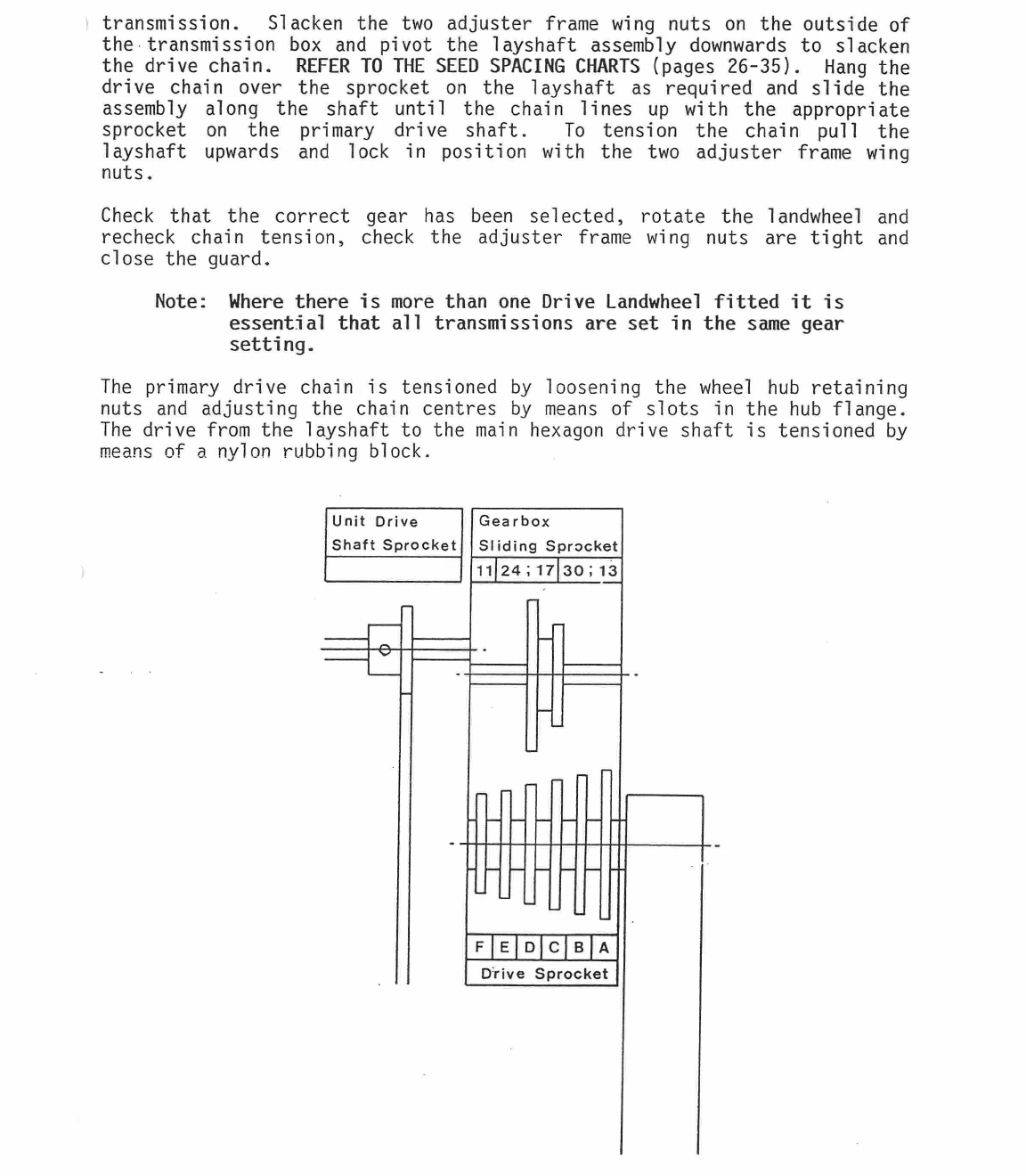
transmission. Slacken the two adjuster frame wing nuts on the outside of
the transmission box and pivot the layshaft assembly downwards to slacken
the drive chain.
REFER TO THE SEED SPACING CHARTS
(pages 26-35). Hang the
drive chain over the sprocket on the layshaft as required and slide the
assembly along the shaft until the chain lines up with the appropriate
sprocket on the primary drive shaft. To tension the chain pull the
layshaft upwards and lock in position with the two adjuster frame wing
nuts.
Check that the correct gear has been selected, rotate the landwheel and
recheck chain tension, check the adjuster frame wing nuts are tight and
close the guard.
Note: Where there is more than one Drive Landwheel fitted it is
essential that all transmissions are set in the same gear
setting.
The primary drive chain is tensioned by loosening the wheel hub retaining
nuts and adjusting the chain centres by means of slots in the hub flange.
The drive from the layshaft to the main hexagon drive shaft is tensioned by
means of a nylon rubbing block.
Unit Drive
Shaft Sprocket
Gearbox
SHding Sprocket
11
24;
17130;13
FIEIDCB
A
Drive Sprocket
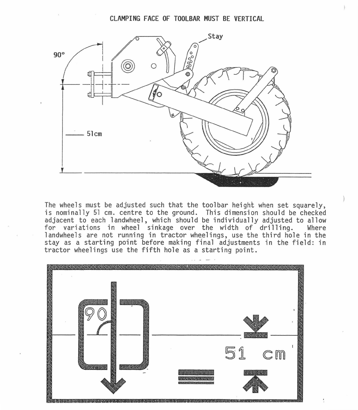
51 cm
s==asassmassav
CLAMPING FACE OF TOOLBAR MUST BE VERTICAL
The wheels must be adjusted such that the toolbar height when set squarely,
is nominally 51 cm. centre to the ground. This dimension should be checked
adjacent to each landwheel, which should be individually adjusted to allow
for variations in wheel sinkage over the width of drilling. Where
landwheels are not running in tractor wheelings, use the third hole in the
stay as a starting point before making final adjustments in the field: in
tractor wheelings use the fifth hole as a starting point.
LEFT HAND
THREAD
n
_p)
LEFT HAND
THREAD
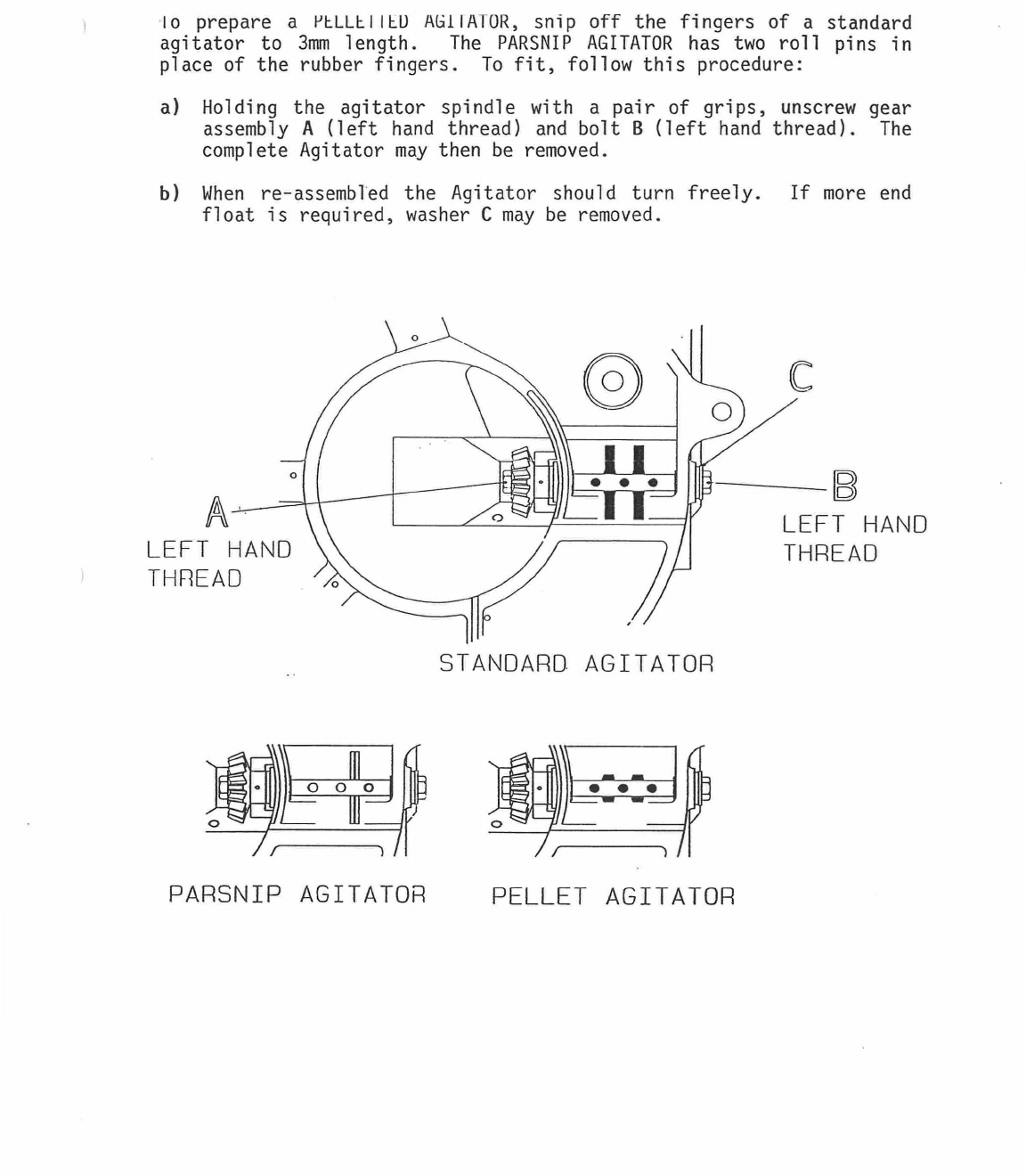
io prepare a
PELLEIIEU A(.i1IATOR, snip
off the fingers of a standard
agitator to 3mm length. The PARSNIP AGITATOR has two roll pins in
place of the rubber fingers. To fit, follow this procedure:
a)
Holding the agitator spindle with a pair of grips, unscrew gear
assembly
A
(left hand thread) and bolt
B
(left hand thread). The
complete Agitator may then be removed.
b)
When re-assembled the Agitator should turn freely. If more end
float is required, washer C may be removed.
STANDARD AGITATOR
PARSNIP AGITATOR PELLET AGITATOR
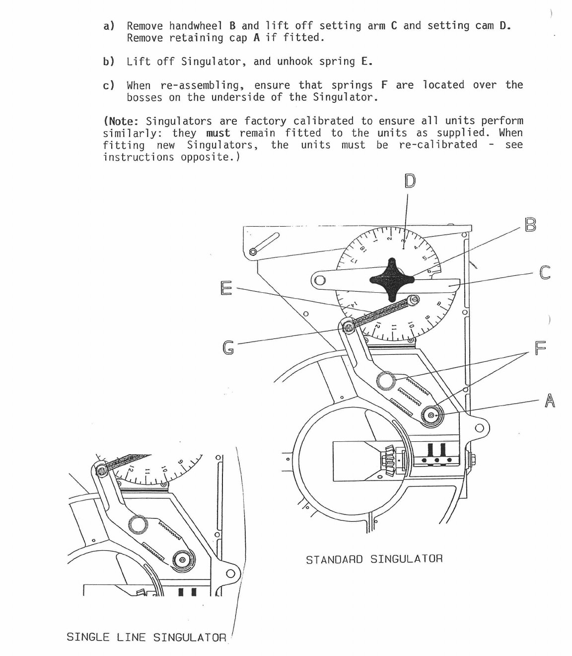
STANDARD SINGULATOR
a)
Remove handwheel
B
and lift off setting arm
C
and setting cam
D.
Remove retaining cap
A
if fitted.
b)
Lift off Singulator, and unhook spring E.
c)
When re-assembling, ensure that springs
F
are located over the
bosses on the underside of the Singulator.
(Note:
Singulators are factory calibrated to ensure all units perform
similarly: they
must
remain fitted to the units as supplied. When
fitting new Singulators, the units must be re-calibrated - see
instructions opposite.)
SINGLE LINE SINGULATOR
a./
I I vvr IIII J
ULeUUI
t.
a)
Select your most difficult seed (for example raw carrot, raw
chicory, raw lettuce).
b)
Follow the calibration instructions for natural carrot seed, pages
20-21, paragraphs 1-4 except clamp the singulator cam on all units
to setting 6 and leave them at this setting throughout the
calibration procedure. Then calibrate each unit individually
paragraph 5a-d) by adjusting the "eccentric boss" G until all
units deliver the same "Target Weight". (To adjust the "eccentric
boss", tighten the nut until the boss can just be turned by a
large screwdriver, then adjust by turning anti-clockwise until the
test collects the "Target Weight".)
c)
Check in work that the seed usage from all units is similar (see
page 21, paragraph 6). If seed usage from any unit is slightly
different from the remainder, adjust the singulator until all
units perform similarly.
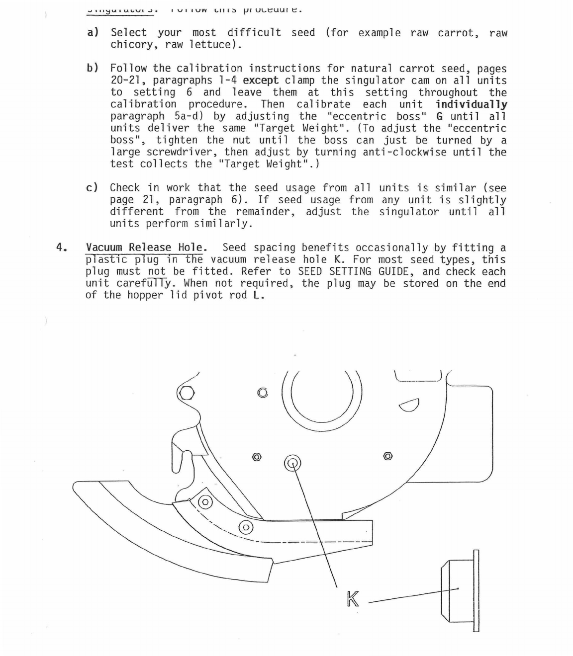
4.
Vacuum Release Hole. Seed spacing benefits occasionally by fitting a
plastic plug in the vacuum release hole K. For most seed types, this
plug must not be fitted. Refer to SEED SETTING GUIDE, and check each
unit
careft5TTY.
When not required, the plug may be stored on the end
of the hopper lid pivot rod L.
a)
Find the seed you wish to plant in the SEED SETTING GUIDE (see pages
36-42).
Select the number of lines you will be planting (1, 2 or 3) and
note the recommended seed disc.
(Note:
the first digit - for example
0.6 - is the diameter of each hole in mm: the second digit - for example
96 - is the number of holes in each line: a single line disc of this
specification is designated
0.6 x 96 x I line,
a two line disc
0.6 x 96 x
2 line,
and a three line disc 0.6 x 96 x 3 line.)
b)
You may be given a choice of seed discs (for example, 96 or 48 holes).
If so, for faster forward speeds, choose the greater number of holes, but
for best accuracy of seed spacing when multi-line drilling , choose the
lesser number of holes.
c)
Three disc speeds are shown: slow (12 rpm), medium (17 rpm) and fast (25
rpm). As a general rule, the slower the disc speed the better the seed
spacing, particularly with multi-line drilling. The special instructions
section on
the SEED SETTING GUIDE indicates where alternative
instructions apply.
d)
Having selected a seed disc, refer to the SEED SPACING CHART for the
appropriate number of holes and the unit drive shaft sprocket you will be
using (11 tooth or 16 tooth).
Then check that the disc speed you have
chosen (rpm seed disc) gives an acceptable forward speed at the seed
spacing you require.
e)
Standard seed discs are shown in the SEED SETTING GUIDE. Other discs ar
available to special order.
These include 3-line discs for carrot and
onion giving 75% seeding rate in the central line (for example 0.6 x
144/144/108; 0.8 x 96/96/72; etc.)
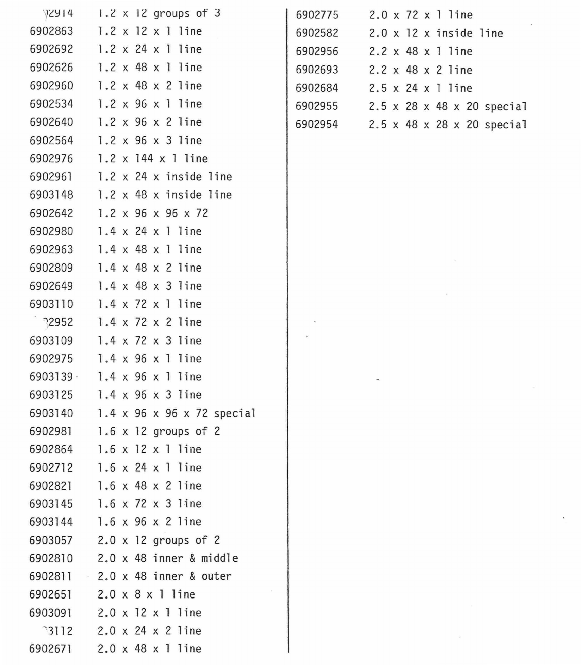
For full list, see page 1 of Parts
List section.
2.
Care of Seed Discs.
Proper care of seed discs is essential to ensure
consistent performance. Follow these guidelines:
a)
Handle gently, by the edges. Do not attempt to remove from unit without
first stopping the fan or disconnecting the vacuum hose from the unit.
b)
Store in a dry place, preferably in the original wrapping. Always remove
from machine if it is to be out of use for more than one day.
c)
If you -suspect the disc is greasy, clean thoroughly with a solvent
solution.
(Grease can cause seeds to stick to the surface of the disc).
Always clean new discs with solvent solution before use.
d)
Always check all holes in seed discs are clear of blockage before
refitting in units.
Blocked holes can be cleaned with fine wire, or
re-sized using a fine drill bit of the correct size.
(Note:
this
operation requires extreme care.)
e)
Always fit discs in metering unit with concave side towards vacuum
galleries.
If the fit over the turntable is too tight, rub the inne
diameter of the disc lightly with fine abrasive paper until an exact fit
Arhipvad
nn nn+
Z1-4
.1_-_
.
- -
HEIGHT ADJUSTABLE
IN 25MM STEPS
TOOLBAR HEIGHT
51AMM
(20.25)
both the lower 'drive sprocket' and the upper 'sliding sprocket' that
are required.
There are 3 interchangeable
'sliding sprockets'
in the gearbox:
a)
17T : 241
Standard fitment: provides the most popular range
of
spacings.
b)
13T : 301
Provides spacings both above and below the standard
range.
c)
111
For use when very close spacings are required.
(Note:
161
shaft sprockets
give closer spacings than 11T shaft
sprockets.)
2. Set seed spacing.
Follow this procedure:
a)
Loosen nuts
A,
pivot layshaft downwards to slacken drive chain.
b)
Check required 'sliding sprocket' is fitted: if not, follow
procedure * below.
c)
Fit drive chain over appropriate 'drive sprocket' and 'sliding
sprocket', check that the chain is in line, and re-tension.
d)
Turn landwheel by hand and check chain tension and drive.
* To Change Sliding Sprocket
-
a)
Pivot layshaft until it is in line with the holes in the gearcase
b)
Gently tap layshaft through the hole towards the wheel area, change
'sliding sprockets' as required, and tap layshaft back 'into
position.
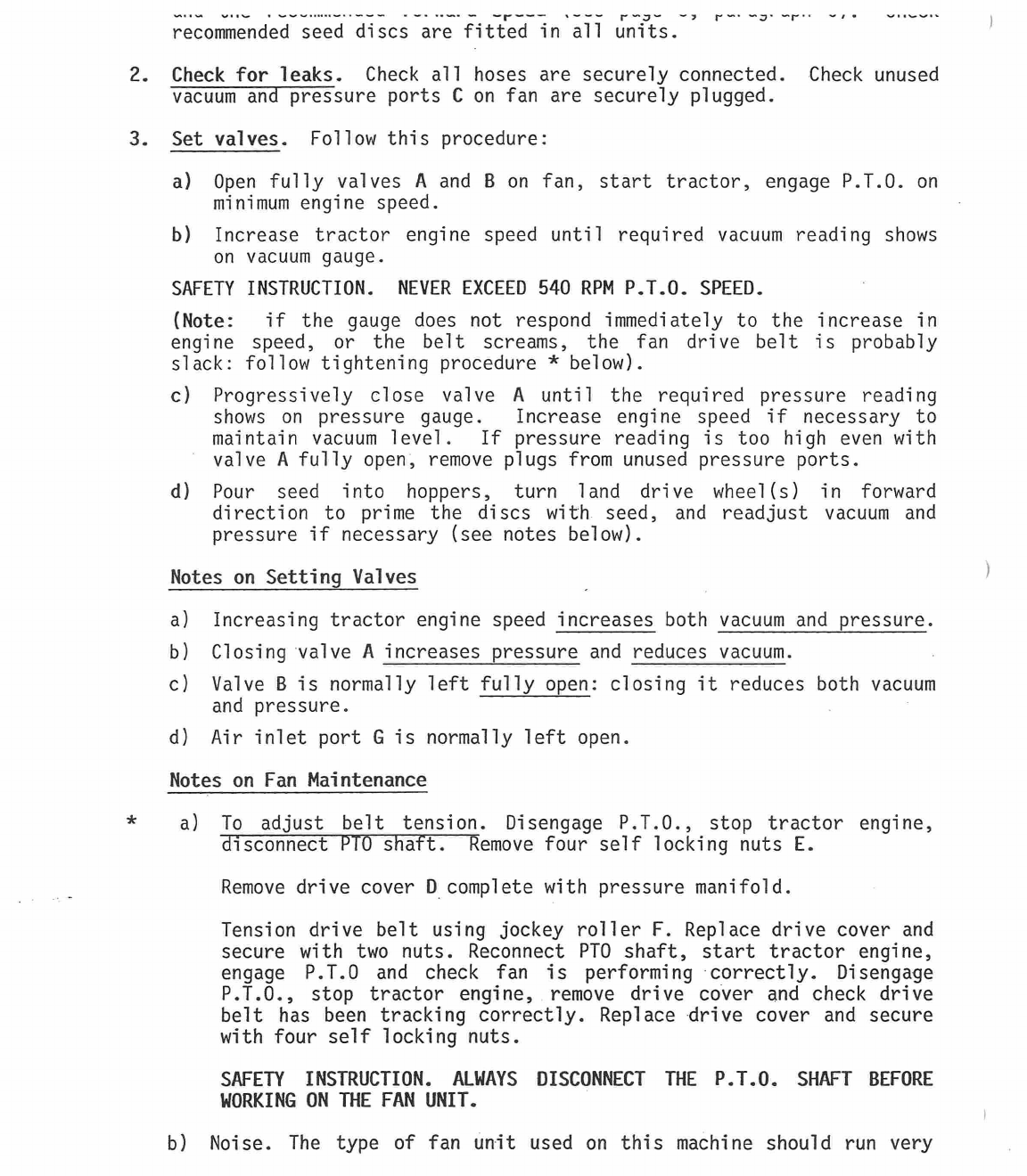
recommended seed discs are fitted in all units.
2.
Check for leaks.
Check all hoses are securely connected. Check unused
vacuum and pressure ports
C
on fan are securely plugged.
3.
Set valves.
Follow this procedure:
a)
Open fully valves
A
and
B
on fan, start tractor, engage P.T.O. on
minimum engine speed.
b)
Increase tractor engine speed until required vacuum reading shows
on vacuum gauge.
SAFETY INSTRUCTION. NEVER EXCEED 540 RPM P.T.O. SPEED.
(Note:
if the gauge does not respond immediately to the increase in
engine speed, or the belt screams, the fan drive belt is probably
slack: follow tightening procedure * below).
c) Progressively close valve
A
until the required pressure reading
shows on pressure gauge.
Increase engine speed if necessary to
maintain vacuum level.
If pressure reading is too high even with
valve
A
fully open, remove plugs from unused pressure ports.
d)
Pour seed into hoppers, turn land drive wheel(s) in forward
direction to prime the discs with seed, and readjust vacuum and
pressure if necessary (see notes below).
Notes on Setting Valves
a)
Increasing tractor engine speed increases both vacuum and pressure.
b)
Closing valve
A
increases pressure and reduces vacuum.
c)
Valve
B
is normally left fully open: closing it reduces both vacuum
and pressure.
d)
Air inlet port G is normally left open.
Notes on Fan Maintenance
a) To adjust belt tension. Disengage P.T.O., stop tractor engine,
disconnect PTO shaft. Remove four self locking nuts
E.
Remove drive cover
D
complete with pressure manifold.
Tension drive belt using jockey roller
F.
Replace drive cover and
secure with two nuts. Reconnect PTO shaft, start tractor engine,
engage P.T.0 and check fan is performing correctly. Disengage
P.T.O., stop tractor engine, remove drive cover and check drive
belt has been tracking correctly. Replace drive cover and secure
with four self locking nuts.
SAFETY INSTRUCTION. ALWAYS DISCONNECT THE P.T.O. SHAFT BEFORE
WORKING ON THE FAN UNIT.
b) Noise. The type of fan unit used on this machine should run very
Vacuum
Gauge N
(a
e
e
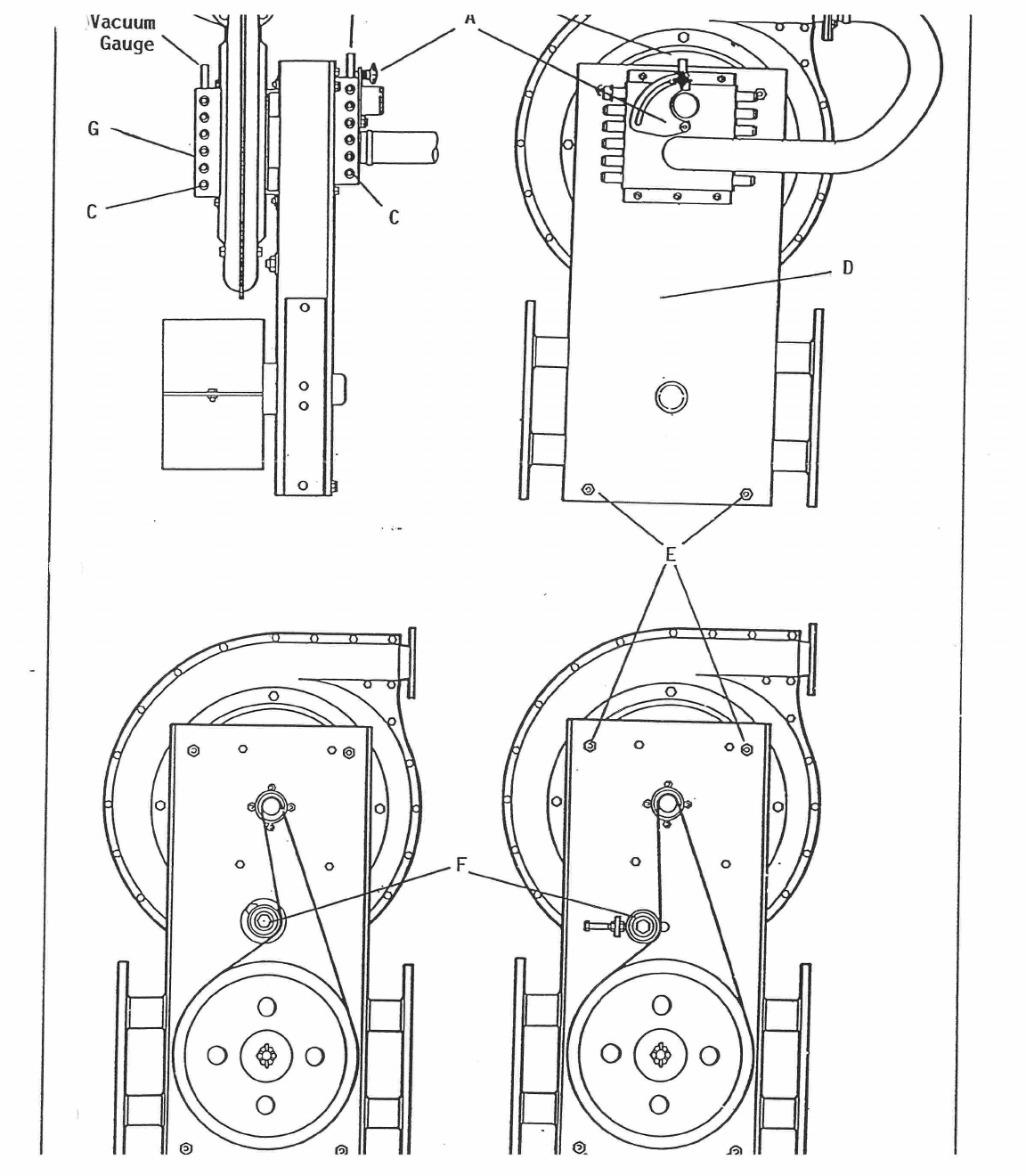
FKUUtUUKE.
1.
You must have:
a)
Scales weighing to +/- 0.1 gram.
b)
Container for placing under the unit to collect seed.
c)
Calibration handle.
2.
Choose settings.
Use SEED SETTING GUIDE for CARROT -
RAW/COATED
(see
page 44) to select required seed disc. (Note: for most
seed spacings
use a 0 0.6 x 96 hole disc, but for seed spacings over 50mm best
results are obtained using a 0 0.6 x 48 hole disc.) Then use
appropriate SEED SPACING CHART to select gear setting that gives
required seeding rate. (Use SEED POPULATION GUIDES to help calculate
field populations). Then choose either
25rpm or 17rpm seed disc speed,
based on your preferred
forward speed,
and note the corresponding
landwheel rpm
(you will need this for the calibration procedure).
3.
Calculate "Target Weight".
From the SEED SPACING CHART (right hand
column) note the number of revs of the seed disc for 25 revs of the
landwheel in selected gear. This figure multiplied by the total number
of holes in the discs give the number of single seeds which should be
delivered for 25 revs of the landwheel.
Use the information given on the seed packet to determine the weight of
this number of seeds: we call this the "Target Weight".
(Note:
seed
packets normally show seeds per 10 gram or seeds per ounce.)
(Example:
machine with 11 tooth unit drive shaft sprocket, target
seeding rate 26 per metre/8 per foot in each of 3 lines: use 0.6 x 96 x
3 line disc, in gear F13, which gives 13.3 revs of the seed disc for 25
revs of the landwheel. Number of single seeds for 25 revs of the
landwheel is therefore 13.3 x 96 x 3 = 3830. If seed packet shows 4670
seeds per 10 gram (467 per gram), the weight of 3830 seeds is 3830 ~
467 = 8.2 gram.)
4.
Set air supply.
Follow this procedure:
a)
Ensure
vacuum release holes
K
of all units are unplugged (see page
15).
b)
Remove
hopper side of all metering units. Fit seed discs, concave
side towards vacuum galleries.
c)
Open valves
A
and
B on fan. Start tractor engine. Raise machine
clear of ground. Engage tractor P.T.O. Increase engine rpm until
vacuum gauge reads
50 m.b.
d)
Rotate land drive wheel(s) in forward direction and check all seed
discs are seated firmly without air leaks or vibration: turn over
any offending disc and re-check.
e)
Replace hopper sides of all metering units, checking unit halves
coat fnnafhos.
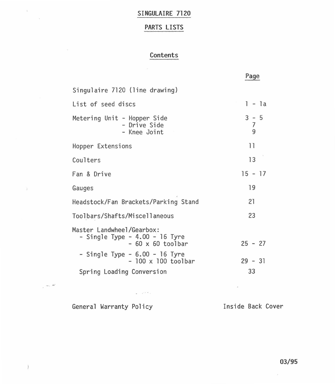
SINGULAIRE 7120
PARTS LISTS
Contents
Singulaire 7120
(line drawing)
List of seed discs
Metering Unit - Hopper Side
- Drive Side
- Knee Joint
Page
1
3
-
la
- 5
7
9
Hopper Extensions
11
Coulters
13
Fan & Drive
15
-
17
Gauges
19
Headstock/Fan Brackets/Parking Stand
21
Toolbars/Shafts/Miscellaneous
23
Master Landwheel/Gearbox:
- Single Type - 4.00 - 16 Tyre
- 60 x 60 toolbar
25
- 27
- Single Type - 6.00 - 16 Tyre
- 100 x 100 toolbar
29
-
31
Spring Loading Conversion
33
General Warranty Policy
Inside Back Cover
03/95
PARTS ENQUIRIES
Stanhay Webb Limited
Exning
Newmarket
Suffolk
CB8 7HD
England.
Tel: +44
(0)1638
577
206
Fax: +44
(0)1638
578 359
WHEN ORDERING PARTS PLEASE QUOTE THE FOLLOWING INFORMATION:
1.
Model - SINGULAIRE 7120
2.
Order number.
3.
Part number and description.
PLEASE NOTE:
The parts listed are not necessarily supplied as unit items, they may
be part of an assembly or be packed in quantities.
Some of the parts shown are optional extras and are not fitted as
standard to new machines.
4,
v.F.447
,
.113%
...
kmoNnyilt
*
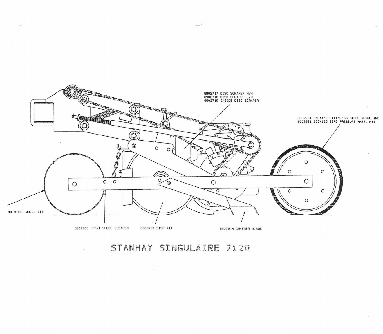
6902717 DISC SCRAPER R/H
6902718 DISC SCRAPER L/H
6902719 INSIDE DISC SCRAPER
8002904 3501160 STAINLESS STEEL WHEEL ANC
8002921 350X165 ZERO PRESSURE WHEEL K/1
0
SS STEEL WHEEL KIT
6902905 FRONT WHEEL CLEANER
8002760 DISC KIT
5902814 COVERER UAW
-
.
STANHAY SINGULAIRE 7120
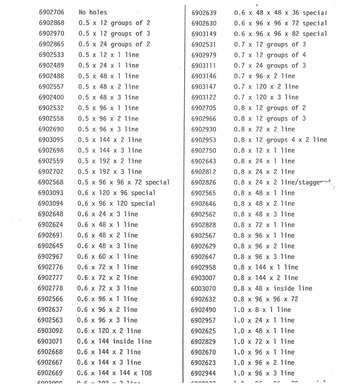
6902639
0.6 x 48 x 48 x 36 special
6902630
0.6 x 96 x 96 x 72 special
6903149
0.6 x 96 x 96 x 82 special
6902531
0.7 x 12 groups of 3
6902979
0.7 x 12 groups of 4
6903111
0.7 x 24 groups of 3
6903146
0.7 x 96 x 2 line
6903147
0.7 x 120 x 2 line
6903122
0.7 x 120 x 3 line
6902705
0.8 x 12 groups of 2
6902966
0.8 x 12 groups of 3
6902930
0.8 x 72 x 2 line
6902953
0.8 x 12 groups 4 x 2 line
6902750
0.8 x 12 x 1 line
6902643
0.8 x 24 x 1 line
6902812
0.8 x 24 x 2 line
6902826
0.8 x 24 x 2 line/staggev
.
"
6902565
0.8 x 48 x 1 line
6902646
0.8 x 48 x 2 line
6902562
0.8 x 48 x 3 line
6902828
0.8 x 72 x 1 line
6902567
0.8 x 96 x 1 line
6902629
0.8 x 96 x 2 line
6902647
0.8 x 96 x 3 line
6902958
0.8 x 144 x 1 line
6903007
0.8 x 144 x 2 line
6003070
0.8 x 48 x inside line
6902632
0.8 x 96 x 96 x 72
6902490
1.0 x 8 x 1 line
6902957
1.0 x 24 x 1 line
6902625
1.0 x 48 x 1 line
6902829
1.0 x 72 x 1 line
6902670
1.0 x 96 x 1 line
6902623
1.0 x 96 x 2 line
6902944
1.0 x 96 x 3 line
"
"
6902706
No holes
6902868
0.5 x 12 groups of 2
6902970
0.5 x 12 groups of 3
6902865
0.5 x 24 groups of 2
6902533
0.5 x 12 x 1 line
6902489
0.5 x 24 x 1 line
6902488
0.5 x 48 x 1 line
6902557
0.5 x 48 x 2 line
6902400
0.5 x 48 x 3 line
6902532
0.5 x 96 x 1 line
6902558
0.5 x 96 x 2 line
6902690
0.5 x 96 x 3 line
6903095
0.5 x 144 x 2 line
6902698
0.5 x 144 x 3 line
6902559
0.5 x 192 x 2 line
6902702
0.5 x 192 x 3 line
6902568
0.5 x 96 x 96 x 72 special
6903093
0.6 x 120 x 96 special
6903094
0.6 x 96 x 120 special
6902648
0.6 x 24 x 3 line
6902624
0.6 x 48 x 1 line
6902691
0.6 x 48 x 2 line
6902645
0.6 x 48 x 3 line
6902967
0.6 x 60 x 1 line
6902776
0.6 x 72 x 1 line
6902777
0.6 x 72 x 2 line
6902778
0.6 x 72 x 3 line
6902566
0.6 x 96 x 1 line
6902637
0.6 x 96 x 2 line
6902563
0.6 x 96 x 3 line
6903092
0.6 x 120 x 2 line
6903071
0.6 x 144 inside line
6902668
0.6 x 144 x 2 line
6902667
0.6 x 144 x 3 line
6902669
0.6 x 144 x 144 x 108
cnnonnn
n
c
- 10
,
1 -
1z_
1
29I4
1.2 x IZ groups of
3
6902863
1.2 x 12 x 1 line
6902692
1.2 x 24 x 1 line
6902626
1.2 x 48 x 1 line
6902960
1.2 x 48 x 2 line
6902534
1.2 x 96 x 1 line
6902640
1.2 x 96 x 2 line
6902564
1.2 x 96 x 3 line
6902976
1.2 x 144 x 1 line
6902961
1.2 x 24 x inside line
6903148
1.2 x 48 x inside line
6902642
1.2 x 96 x 96 x 72
6902980
1.4 x 24 x 1 line
6902963
1.4 x 48 x 1 line
6902809
1.4 x 48 x 2 line
6902649
1.4 x 48 x 3 line
6903110
1.4 x 72 x 1 line
1
2952
1.4 x 72 x 2 line
6903109
1.4 x 72 x 3 line
6902975
1.4 x 96 x 1 line
6903139
1.4 x 96 x 1 line
6903125
1.4 x 96 x 3 line
6903140
1.4 x 96 x 96 x 72 special
6902981
1.6 x 12 groups of 2
6902864
1.6 x 12 x 1 line
6902712
1.6 x 24 x 1 line
6902821
1.6 x 48 x 2 line
6903145
1.6 x 72 x 3 line
6903144
1.6 x 96 x 2 line
6903057
2.0 x 12 groups of 2
6902810
2.0 x 48 inner & middle
6902811
2.0 x 48 inner & outer
6902651
2.0 x 8 x 1 line
6903091
2.0 x 12 x 1 line
-
3112
2.0 x 24 x 2 line
6902671
2.0 x 48 x 1 line
6902775
2.0 x 72 x 1 line
6902582
2.0 x 12 x inside line
6902956
2.2 x 48 x 1 line
6902693
2.2 x 48 x 2 line
6902684
2.5 x 24 x 1 line
6902955
2.5 x 28 x 48 x 20 special
6902954
2.5 x 48 x 28 x 20 special
27 26 23 24,25 22 20,21
40
44
45
41,42,
,
18,19
14
10,11,12,13
9
7,8
2
36,37
48
29
30,31 3562
19
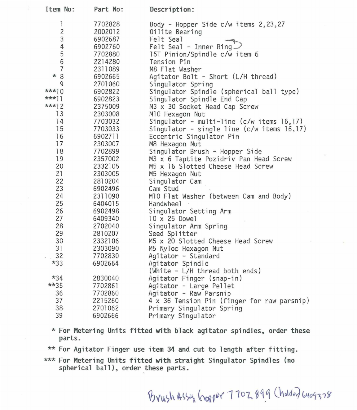
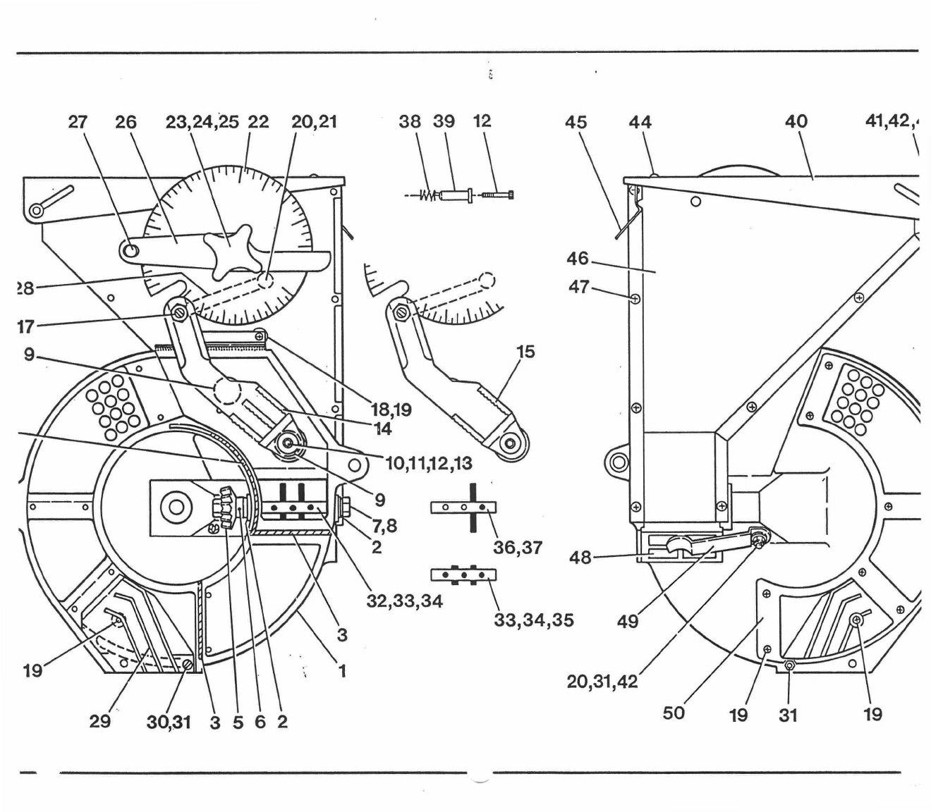
Item No: Part No:
Description:
1
7702828
Body - Hopper Side c/w items 2,23,27
2
2002012
Oilite Bearing
3
6902687
Felt Seal
4
6902760
Felt Seal - Inner Rin
-
g7I)
5
7702880
151 Pinion/Spindle c/w item 6
6
2214280 Tension Pin
7
2311089
M8 Flat Washer
* 8
6902665
Agitator Bolt - Short
(L/H thread)
9
2701060
Singulator Spring
***10
6902822
Singulator Spindle
(spherical
ball
type)
***11
6902823
Singulator Spindle End Cap
***12
2375009
M3 x 30 Socket Head Cap Screw
13
2303008
M10 Hexagon Nut
14
7703032
Singulator - multi-line
(c/w items
16,17)
15
7703033
Singulator - single line
(c/w items 16,17)
16
6902711
Eccentric Singulator Pin
17
2303007
M8 Hexagon Nut
18
7702899
Singulator Brush - Hopper Side
19
2357002
M3 x 6 Taptite Pozidriv Pan Head Screw
20
2332105
M5 x 16 Slotted Cheese Head Screw
21
2303005
M5 Hexagon Nut
22
2810204
Singulator Cam
23
6902496
Cam Stud
24
2311090
M10 Flat Washer (between Cam and Body)
25
6404015
Handwheel
26
6902498
Singulator Setting Arm
27
6409340
10 x 25 Dowel
28
2702040
Singulator Arm Spring
29
2810207
Seed Splitter
30
2332106
M5 x 20 Slotted Cheese Head Screw
31
2303090
M5 Nyloc Hexagon Nut
32
7702830
Agitator - Standard
*33
6902664
Agitator Spindle
(White - L/H thread both ends)
*34 2830040
Agitator Finger (snap-in)
**35
7702861
Agitator - Large Pellet
36
7702860
Agitator - Raw Parsnip
37
2215260
4 x 36 Tension Pin (finger for raw parsnip)
38
2701062
Primary Singulator Spring
39
6902666
Primary Singulator
* For Metering Units fitted with black agitator spindles, order these
parts.
** For Agitator Finger use item 34 and cut to length after fitting.
*** For Metering Units fitted with straight Singulator Spindles (no
spherical ball), order these parts.
9)vu6If
■
6
t
6litW
1
1
0
7,
iSqii
Outd;)(040.0y
27 26 23 24,25 22 20,21
38 39 12
45
40
44
41,42
28
■
•
■
•
.•••••
9
18,19
14
2
32,33,34
19
29
30,31 3562
50
19 19
31
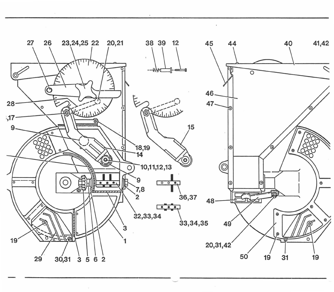
Item No:
Part No:
Description:
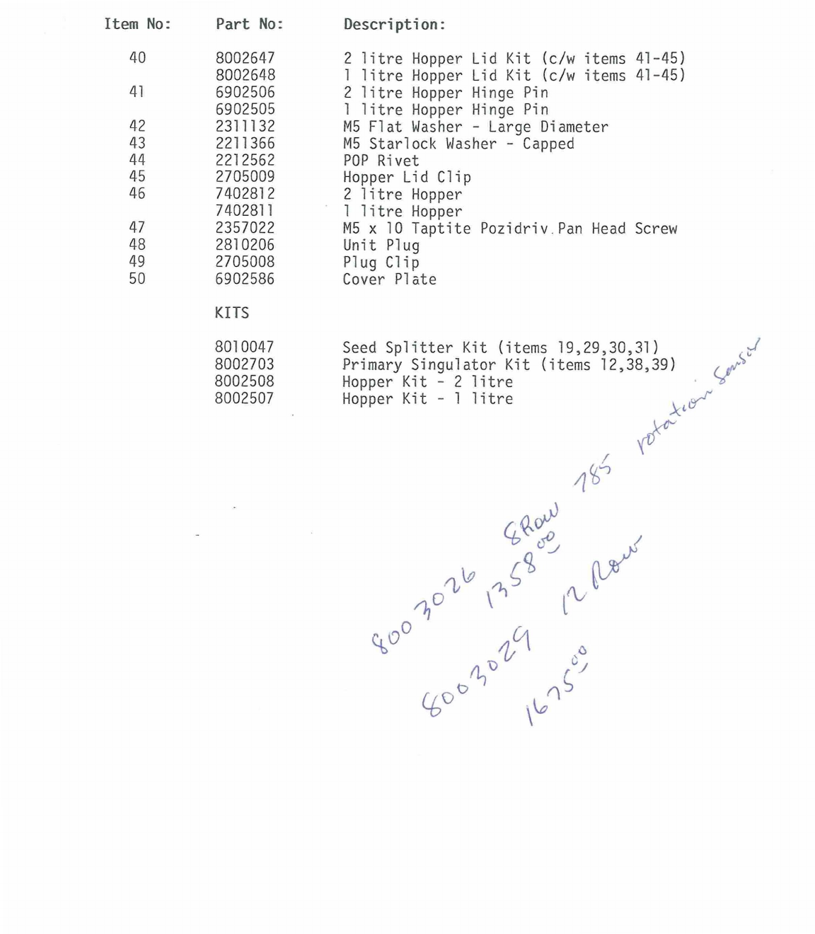
40
8002647
2 litre Hopper Lid Kit (c/w items 41-45)
8002648
1 litre Hopper Lid Kit (c/w items
41-45)
41
6902506
2 litre Hopper Hinge Pin
6902505
1 litre Hopper Hinge Pin
42
2311132
M5 Flat Washer - Large Diameter
43
2211366
M5 Starlock Washer - Capped
44
2212562
POP Rivet
45
2705009
Hopper Lid Clip
46
7402812
2 litre Hopper
7402811
1 litre Hopper
47
2357022
M5 x 10 Taptite Pozidriv Pan Head Screw
48
2810206
Unit Plug
49
2705008
Plug Clip
50
6902586
Cover Plate
KITS
8010047
Seed Splitter Kit (items 19,29,30,31)
8002703
Primary Singulator Kit (items 12,38,39)
y
or
'
8002508
Hopper Kit - 2 litre
8002507
Hopper Kit - 1 litre
)0"
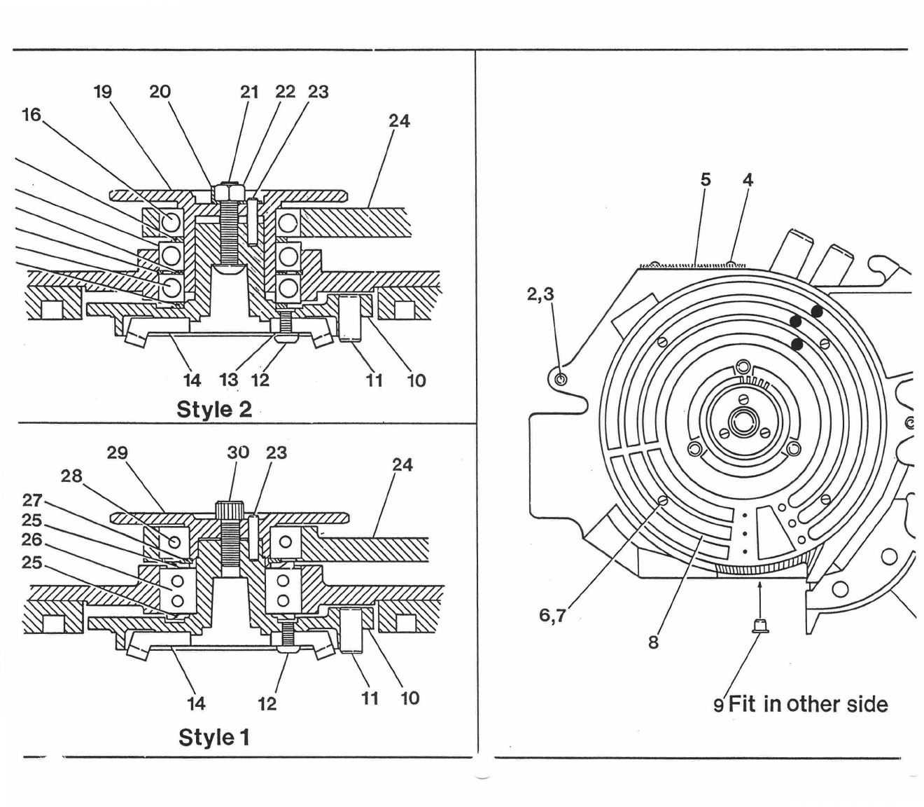
20
19
21 22 23
11 10
14 13 12
Style 2
24
28
27
25
26
25
29
30 23
14
12
Style 1
11 10
5 4
2,3
Fit in other side
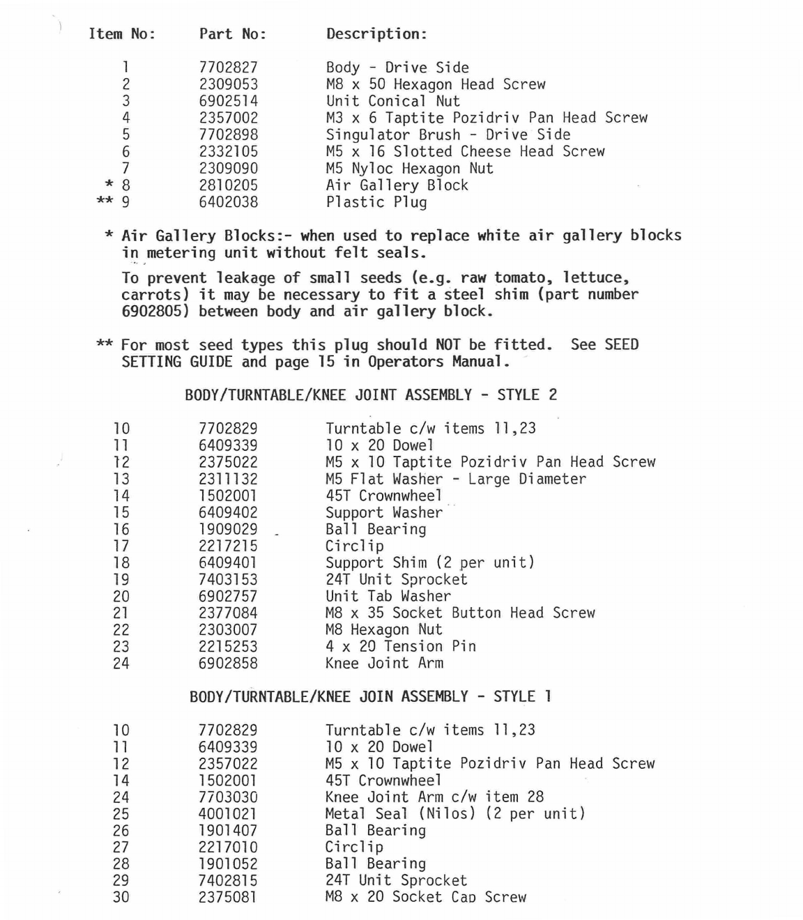
Item
No:
Part No:
Description:
1
7702827
Body - Drive Side
2
2309053
M8 x 50 Hexagon Head Screw
3
6902514
Unit Conical Nut
4
2357002
M3 x 6 Taptite Pozidriv Pan Head Screw
5
7702898
Singulator Brush - Drive Side
6
2332105
M5 x 16 Slotted Cheese Head Screw
7
2309090
M5 Nyloc Hexagon Nut
* 8
2810205
Air Gallery Block
** 9
6402038
Plastic Plug
* Air Gallery Blocks:- when used to replace white air gallery blocks
in metering unit without felt seals.
To prevent leakage of small seeds (e.g. raw tomato, lettuce,
carrots) it may be necessary to fit a steel shim (part number
6902805) between body and air gallery block.
** For most seed types this plug should NOT be fitted. See SEED
SETTING GUIDE and page 15 in Operators Manual.
BODY/TURNTABLE/KNEE JOINT ASSEMBLY - STYLE 2
10
7702829
Turntable c/w items 11,23
11
6409339
10 x 20 Dowel
12
2375022
M5 x 10 Taptite Pozidriv Pan Head Screw
13
2311132
M5 Flat Washer - Large Diameter
14
1502001
45T Crownwheel
15
6409402
Support Washer
16
1909029 -
Ball Bearing
17
2217215
Circlip
18
6409401
Support Shim (2 per unit)
19
7403153
241 Unit Sprocket
20
6902757
Unit Tab Washer
21
2377084
M8 x 35 Socket Button Head Screw
22
2303007
M8 Hexagon Nut
23
2215253
4 x 20 Tension Pin
24
6902858
Knee Joint Arm
BODY/TURNTABLE/KNEE JOIN ASSEMBLY - STYLE 1
10
7702829
Turntable c/w items 11,23
11
6409339
10 x 20 Dowel
12
2357022
M5 x 10 Taptite Pozidriv Pan Head Screw
14
1502001
45T Crownwheel
24
7703030
Knee Joint Arm c/w item 28
25
4001021
Metal Seal (Nilos) (2 per unit)
26
1901407
Ball Bearing
27
2217010
Circlip
28
1901052
Ball Bearing
29
7402815
24T Unit Sprocket
30
2375081
M8 x 20 Socket Cap Screw
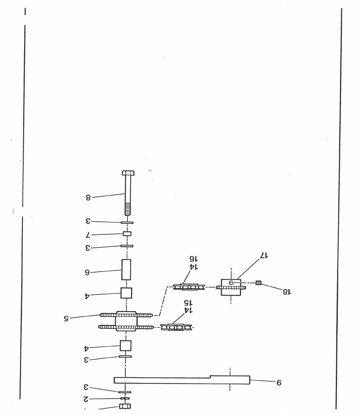
1
•
i
ni
6
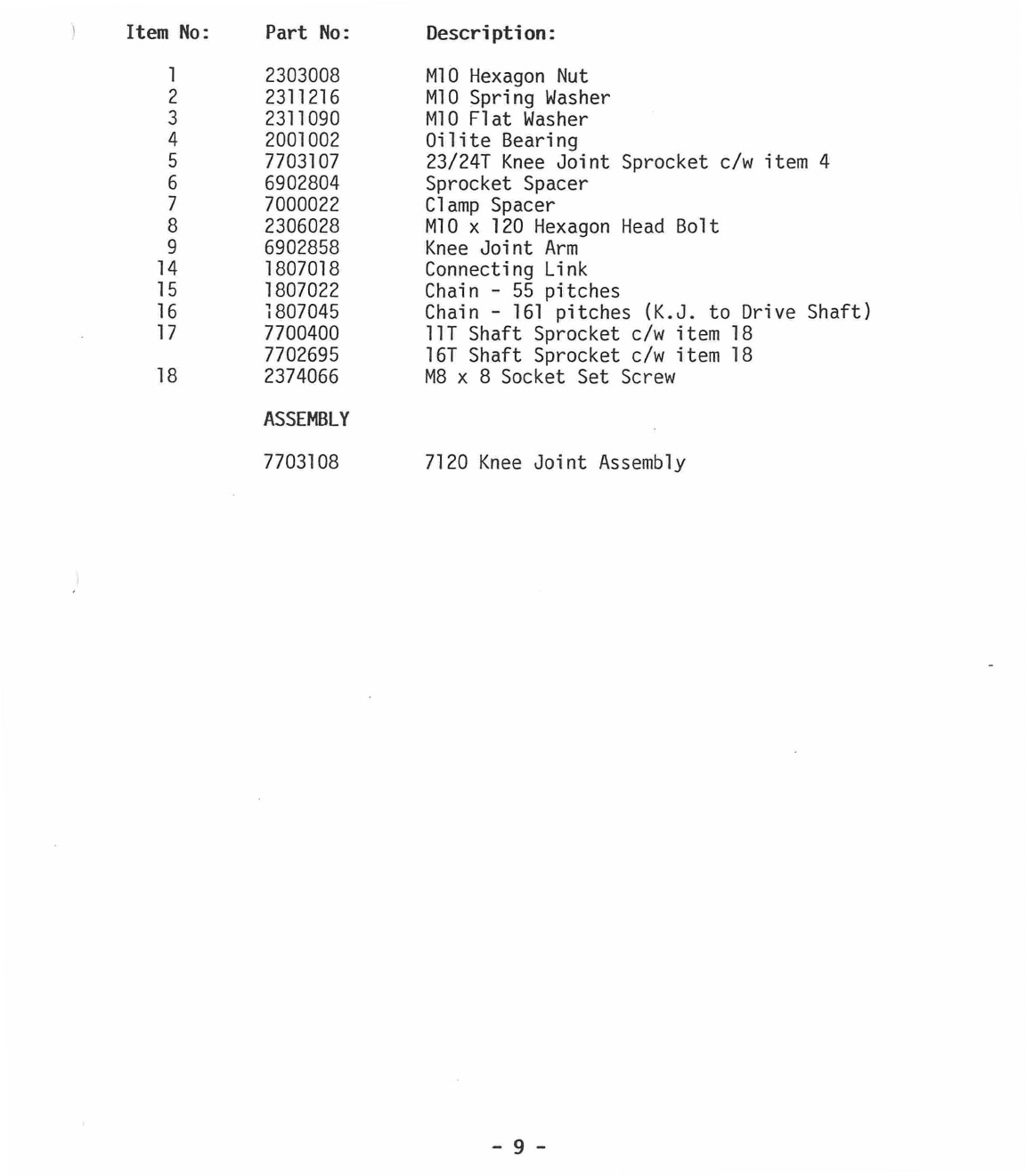
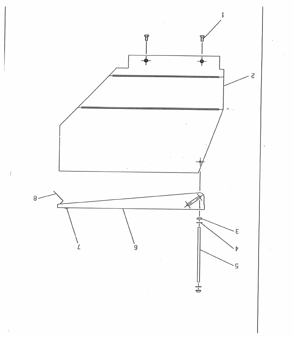
Item No:
Part No:
Description:
1
2303008
M10 Hexagon Nut
2
2311216
M10 Spring Washer
3
2311090
M10 Flat Washer
4
2001002
Oilite Bearing
5
7703107
23/241 Knee Joint Sprocket c/w item 4
6
6902804
Sprocket Spacer
7
7000022
Clamp Spacer
8
2306028
M10 x 120 Hexagon Head Bolt
9
6902858
Knee Joint Arm
14
1807018
Connecting Link
15
1807022
Chain - 55 pitches
16
1807045
Chain -
161
pitches
(K.J.
to Drive Shaft)
17
7700400
11T Shaft Sprocket c/w item 18
7702695
16T Shaft Sprocket c/w item 18
18
2374066
M8 x 8 Socket Set Screw
ASSEMBLY
7703108
7120 Knee Joint Assembly
-
9
-

Item No:
Part No:
Description:
1
2309021
M5 x 10 Hexagon Head Screw
2
7702901
Extension for 2 litre Hopper - complete
7702900
Extension for 1 litre Hopper - complete
3
2211366
M5 Starlock Washer - Capped
4
2311132
M5 Flat Washer - large diameter
5
6902269
Hinge Pin
6
8002646
Lid Kit (c/w items, 3,4,5,7,8)
7
2212562
POP Rivet
8
2705003
Lid Clip
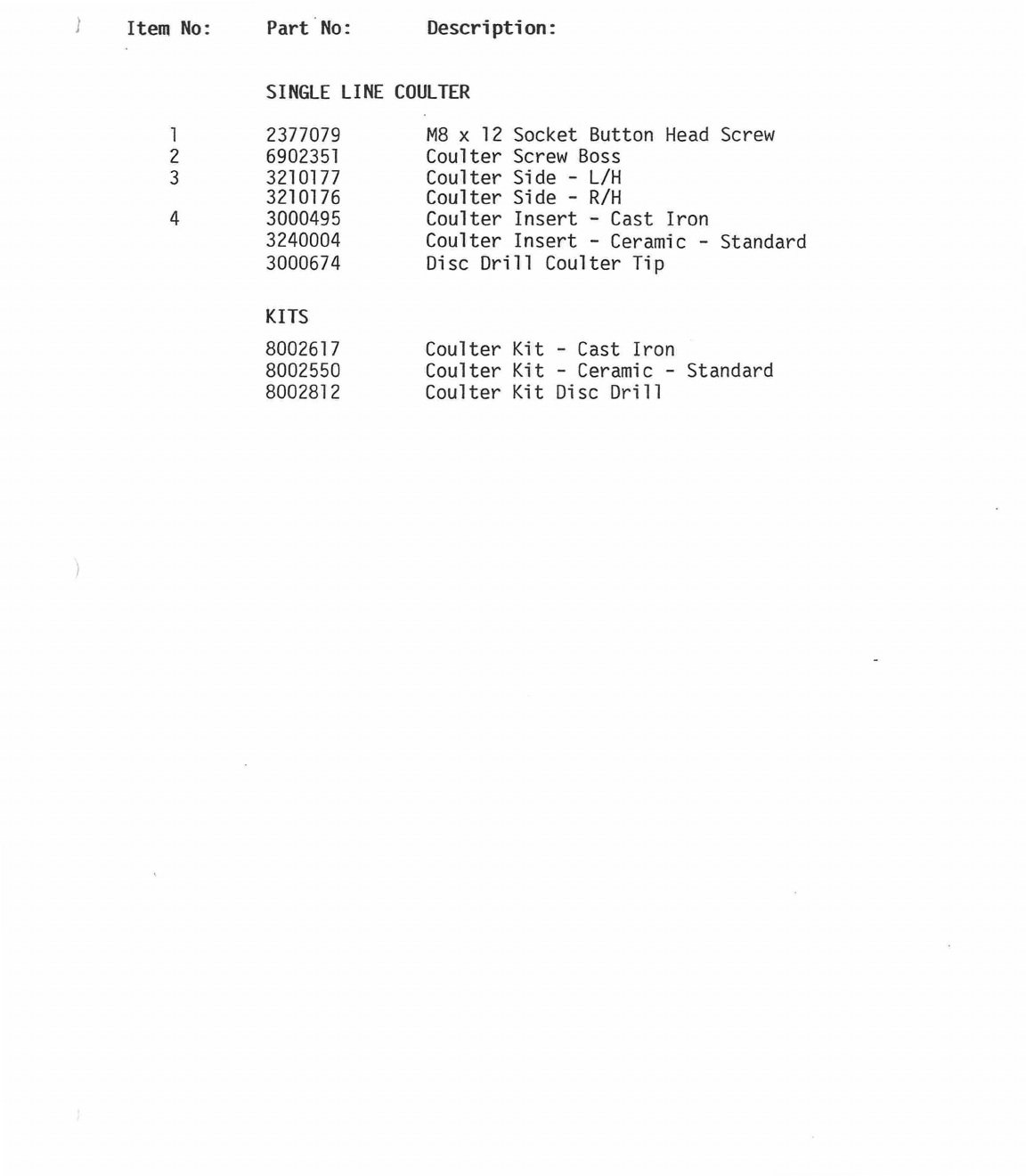
Item No:
Part No:
Description:
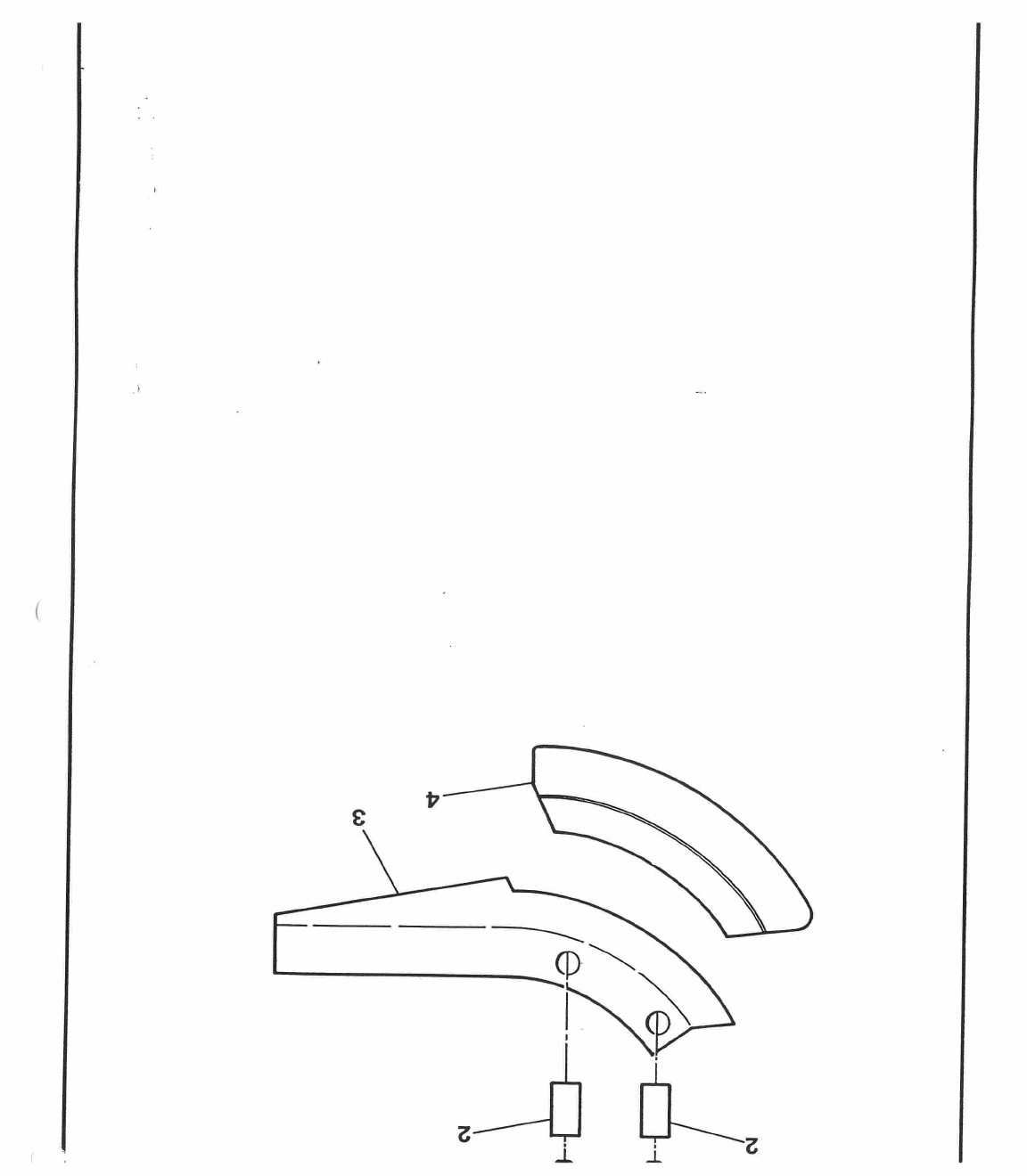
SINGLE LINE COULTER
1
2377079
M8 x 12 Socket Button Head Screw
2
6902351
Coulter Screw Boss
3
3210177
Coulter Side - L/H
3210176
Coulter Side - R/H
4
3000495
Coulter Insert - Cast Iron
3240004
Coulter Insert - Ceramic - Standard
3000674
Disc Drill Coulter Tip
KITS
8002617
Coulter Kit - Cast Iron
8002550
Coulter Kit - Ceramic - Standard
8002812
Coulter Kit Disc Drill
8
,
9
13 14,15
9 11,12
89
16,17
18,19
20,21
22
23
0
0
0
0
0
0
0
0
©
0
0
26
0
25
----,-,
17
18
24
11
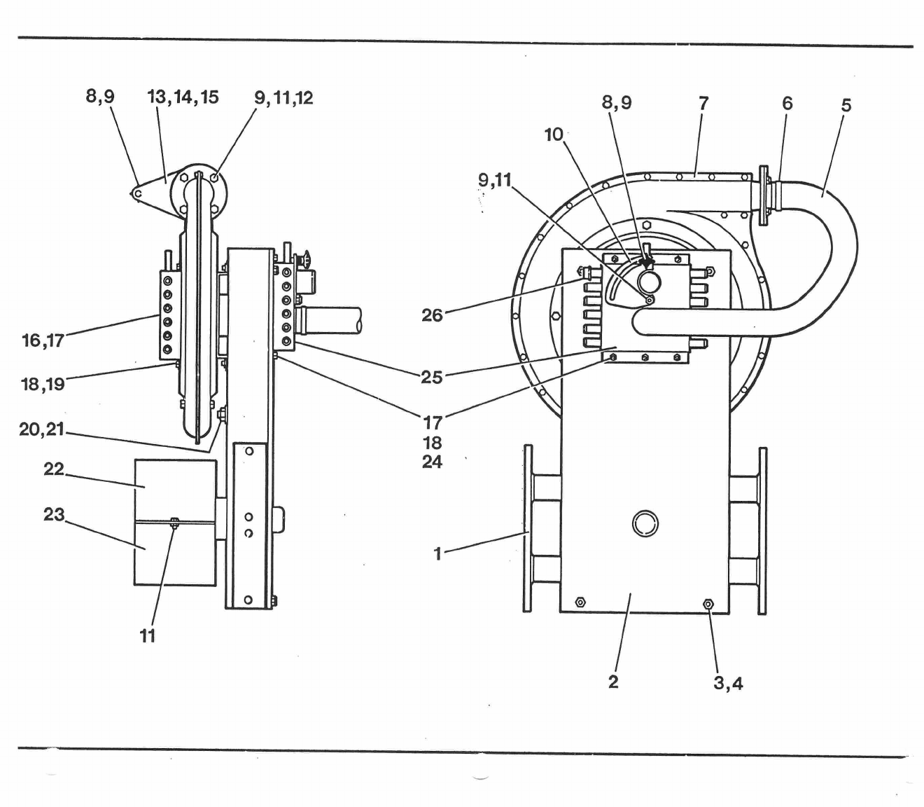
Item
No:
Part No:
Description:
1
7403020
Fan Drive Case - Toolbar
7403021
Fan Drive Case - Yoke Bar
2
7403022
Drive Cover Plate
3
2311090
M10 Flat Washer
4
2303109
M10 Nyloc Hexagon Nut - thin
5
6902592
Pressure Feed Hose
6
2316012
Hose Clip
t
7
4801002
Fan
8
6404026
Handwheel
9
2311089
M8 Flat Washer
10
7402921
Pressure Baffle
11
2303092
M8 Nyloc Hexagon Nut
12
2309047
M8 x 20 Hexagon Head Screw
13
6902526
Vacuum Baffle Guide
14
7402821
Vacuum Baffle Plate
15
7403025
Pressure Outlet
16
7403023
Vacuum Manifold - 12 row
7403189
Vacuum Manifold - 18 row
17
6402039
Plastic Bung (centre hole in manifold)
18
2311088
M6 Flat Washer
19
2303091
M6 Nyloc Hexagon Nut
20
6902522
Jockey Washer
21
2303095
M16 Nyloc Hexagon Nut
22
7403026
PTO Guard
23
6902663
PTO Guard Cover
24
2309033
M6 x 16 Hexagon Head Screw
25
7403024
Pressure Manifold - 12 row
7403190
Pressure Manifold - 18 row
26
6402007
Plastic Cap
-
6902915
Sealing Strip for Fan Casing
and Cover Plates
32,43,44
37 45
42
40
39
41
20
21
27
28
29
30
31
36 28
38
39 40
36
37 38
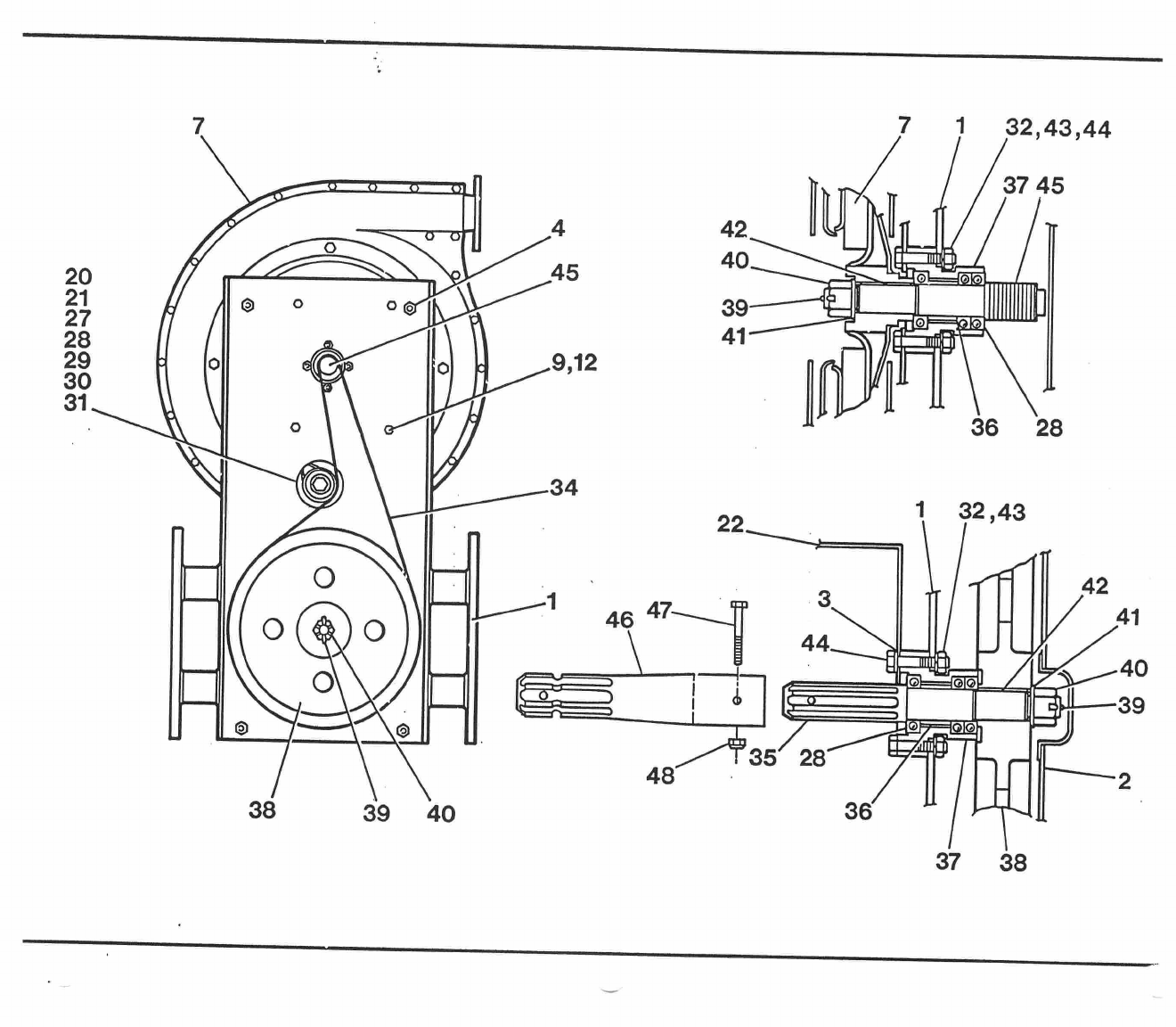
Item No:
1
2
3
4
7
9
12
20
21
27
28
29
30
31
32
34
35
36
37
38
39
40
41
42
43
44
45
Part No:
7403020
7403021
7403022
2311090
2303109
4801002
2311089
2309047
6902522
2303095
2306135
1901051
6902589
6902590
7403191
2303008
1323002
6902587
6902872
6902871
3000632
2215587
2303078
2311093
641 3057
2311216
2306068
6902588
ASSEMBLIES
7702922
7702923
Description:
Fan Drive Case - Toolbar
Fan Drive Case - Yoke Bar
Drive Cover Plate
M10 Flat Washer
M10 Nyloc Hexagon Nut - thin
Fan
M8 Flat Washer
M8 x 20 Hexagon Head Screw
Jockey Washer
M16 Nyloc Hexagon Head Bolt
M16 x 90 Hexagon Head Bolt
Ball Bearing
Jockey Roller
Bearing Spacer - Jockey
Eccentric Jockey
M10 Hexagon Nut
Drive Belt - 20 rib
Drive Shaft
Bearing Spacing - 29 long
Shaft Housing
Double Bearing
PTO Pulley
4 x 40 Split Pin
M20 Hexagon Slotted Nut
M20 Flat Washer
Shaft Key -
M10 Spring Washer
M10 x 50 Hexagon Head Bolt
Fan Impeller Shaft
Fan & Drive - Toolbar Drills
Fan & Drive - Yoke Bar Drills
NOT ILLUSTRATED
4300016
Unit Hose - Black (per metre)
4300018
Unit Hose - Grey (per metre)
5215046
Cable Tie
For Yoke Bar Drills: *
2303010
M16 Hexagon Nut
(for attaching to yoke bar)
46
6409358
PTO Extension Adaptor
47
2303092
M8 Nyloc Hexagon Nut
48
2306042
M8 x 60 Hexagon Head Bolt
* Note: Item 23 not fitted
Item 22 fitted on underside
I
3
FIT PIPE TO
LOWER
NIPPLE
10
Item No:
Part No:
Description:
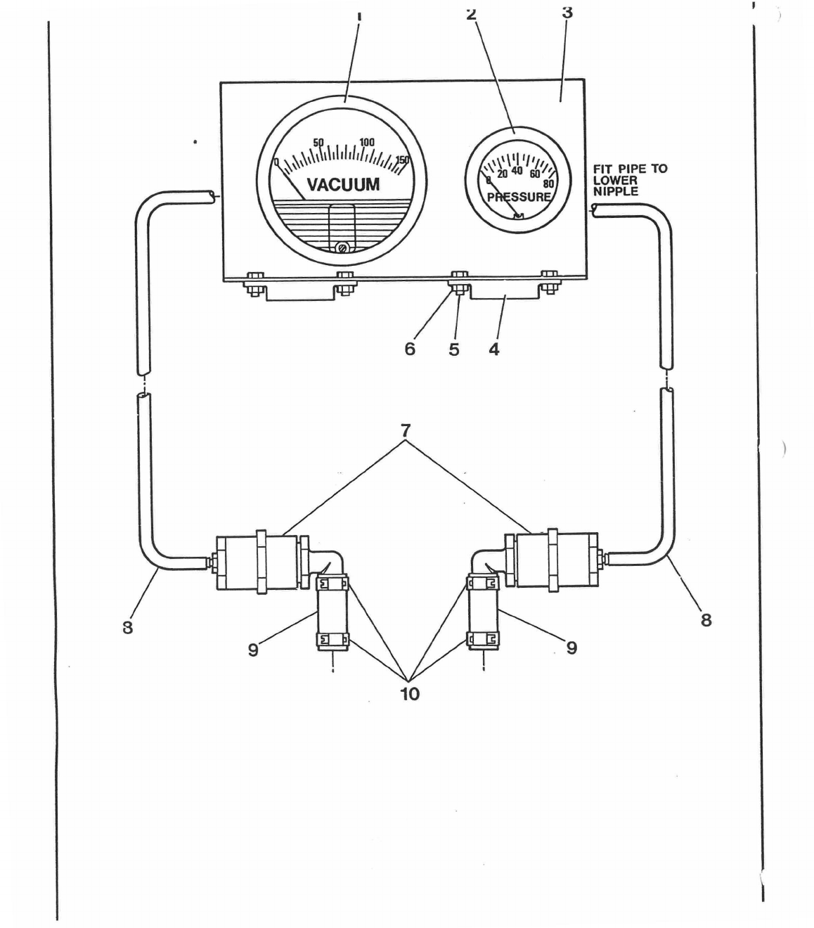
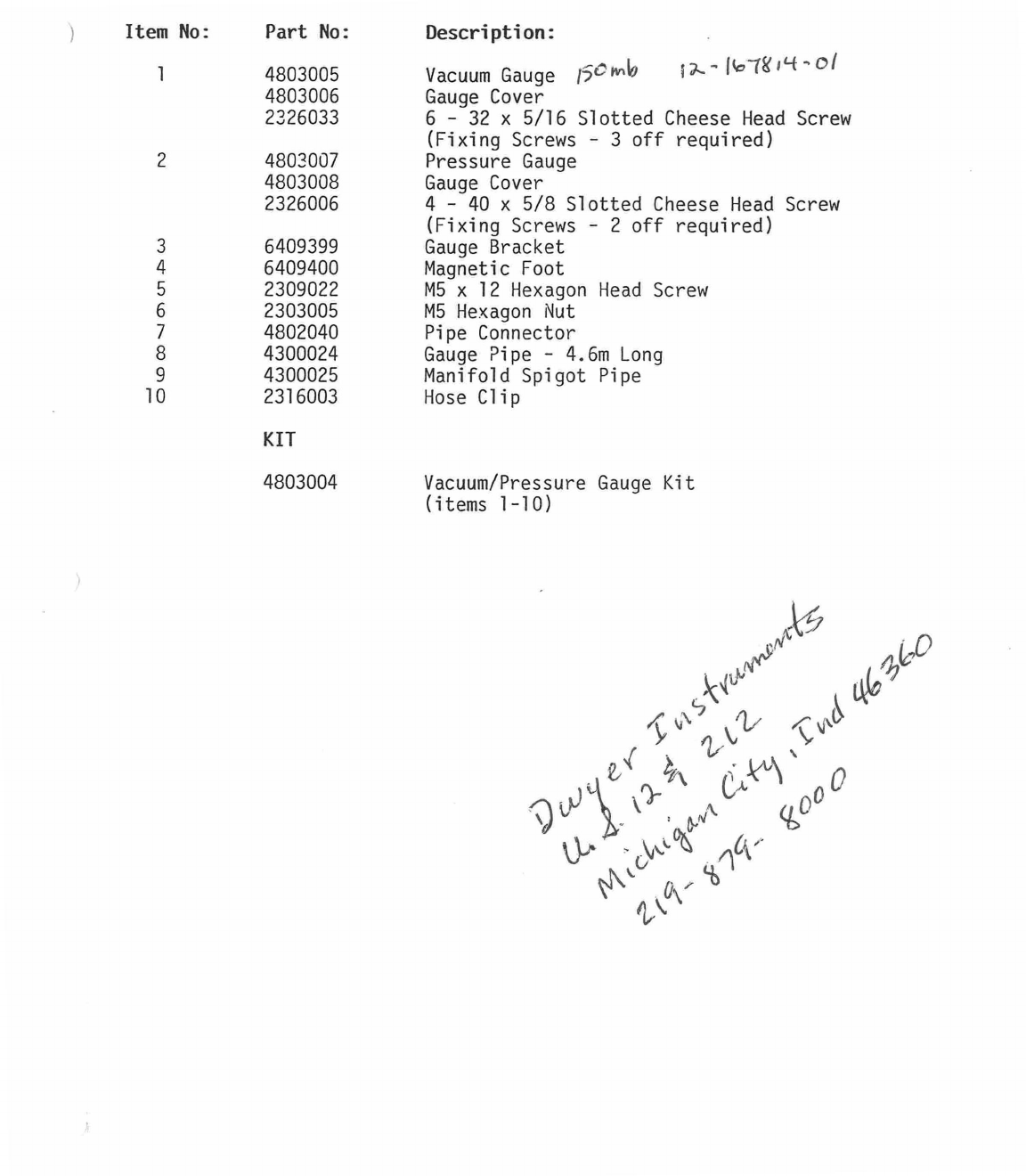
1
4803005
Vacuum Gauge
15
6
'1"
1
9
P-
-1 '
11
"
4-01
4803006
Gauge Cover
2326033
6 - 32 x 5/16 Slotted Cheese Head Screw
(Fixing Screws - 3 off required)
2
4803007
Pressure Gauge
4803008
Gauge Cover
2326006
4 - 40 x 5/8 Slotted Cheese Head Screw
(Fixing Screws - 2 off required)
3
6409399
Gauge Bracket
4
6409400
Magnetic Foot
5
2309022
M5 x 12 Hexagon Head Screw
6
2303005
M5 Hexagon Nut
7
4802040
Pipe Connector
8
4300024
Gauge Pipe - 4.6m Long
9
4300025
Manifold Spigot Pipe
10
2316003
Hose Clip
KIT
4803004
Vacuum/Pressure Gauge Kit
(items 1-10)
12_
11
_
6
1.17 19 20 21 19 18
Item
No:
Part No:
Description:
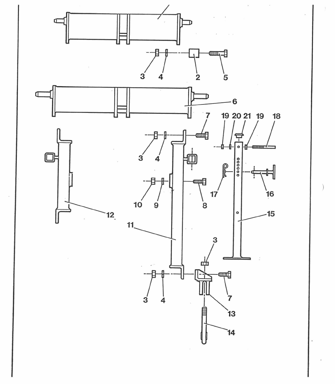
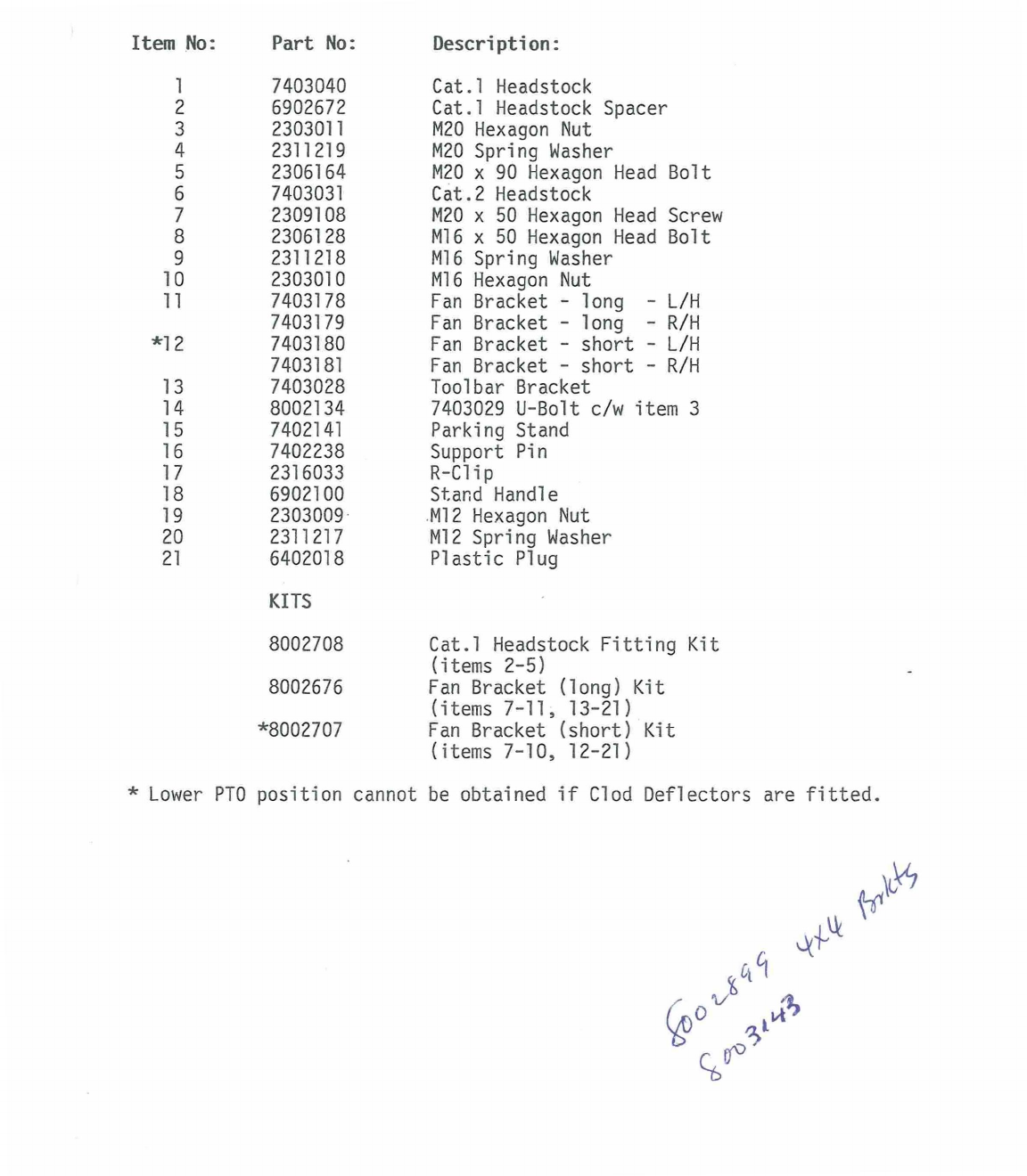
1
7403040
Cat.1 Headstock
2
6902672
Cat.1 Headstock Spacer
3
2303011
M20 Hexagon Nut
4
2311219
M20 Spring Washer
5
2306164
M20 x 90 Hexagon Head Bolt
6
7403031
Cat.2 Headstock
7
2309108
M20 x 50 Hexagon Head Screw
8
2306128
M16 x 50 Hexagon Head Bolt
9
2311218
M16 Spring Washer
10
2303010
M16 Hexagon Nut
11
7403178
Fan Bracket - long - L/H
7403179
Fan Bracket - long - R/H
*12
7403180
Fan Bracket - short - L/H
7403181
Fan Bracket - short - R/H
13
7403028
Toolbar Bracket
14
8002134
7403029 U-Bolt c/w item 3
15
7402141
Parking Stand
16
7402238
Support Pin
17
2316033
R-Clip
18
6902100
Stand Handle
19
2303009
M12 Hexagon Nut
20
2311217
M12 Spring Washer
21
6402018
Plastic Plug
KITS
8002708
Cat.1 Headstock Fitting Kit
(items 2-5)
8002676
Fan Bracket (long) Kit
(items 7-11, 13-21)
*8002707
Fan Bracket (short) Kit
(items 7-10, 12-21)
* Lower PTO position cannot be obtained if Clod Deflectors are fitted.
1
91.
CL
81.
LL
91-
1
/
.
1
RI
In
Item
No:
Part No:
Description:
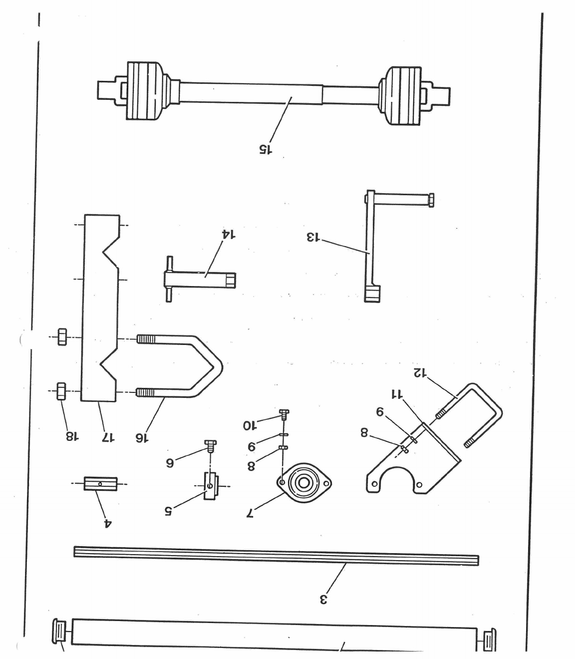
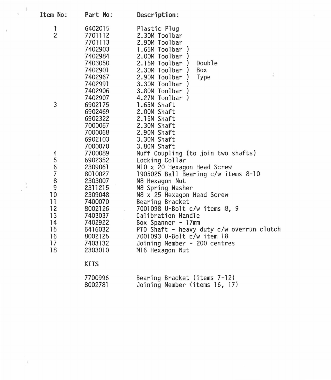
1
6402015
Plastic Plug
2
7701112
2.30M Toolbar
7701113
2.90M Toolbar
7402903
1.65M Toolbar )
7402984
2.00M Toolbar )
7403050
2.15M Toolbar ) Double
7402901
2.30M Toolbar ) Box
7402967
2.90M Toolbar ) Type
7402991
3.30M Toolbar )
7402906
3.80M Toolbar )
7402907
4.27M Toolbar )
3
6902175
1.65M Shaft
6902469
2.00M Shaft
6902322
2.15M Shaft
7000067
2.30M Shaft
7000068
2.90M Shaft
6902103
3.30M Shaft
7000070
3.80M Shaft
4
7700089
Muff Coupling (to join two shafts)
5
6902352
Locking Collar
6
2309061
M10 x 20 Hexagon Head Screw
7
8010027
1905025 Ball Bearing c/w items 8-10
8
2303007
M8 Hexagon Nut
9
2311215
M8 Spring Washer
10
2309048
M8 x 25 Hexagon Head Screw
11
7400070
Bearing Bracket
12
8002126
7001098 U-Bolt c/w items 8, 9
13
7403037
Calibration Handle
14
7402922
Box Spanner - 17mm
15
6416032
PTO Shaft - heavy duty c/w overrun clutch
16
8002125
7001093 U-Bolt c/w item 18
17
7403132
Joining Member - 200 centres
18
2303010
M16 Hexagon Nut
KITS
7700996
Bearing Bracket (items 7-12)
8002781
Joining Member (items 16, 17)
ILLUSTRA1
34 39
22
21
26
7 18
25
45
10
47
4.00-
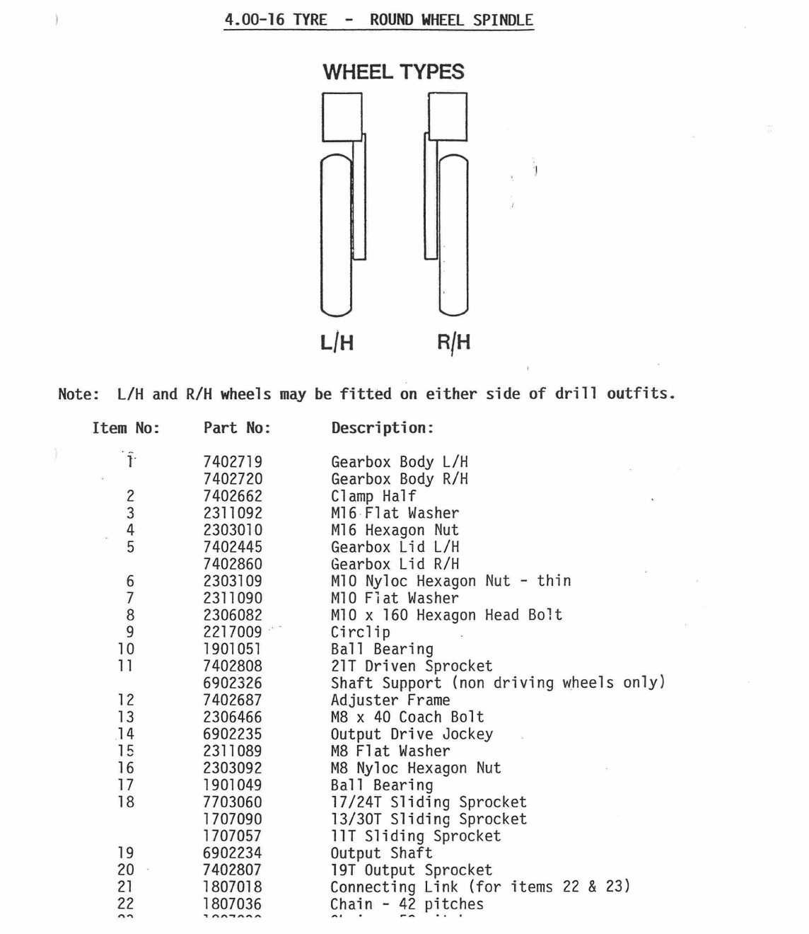
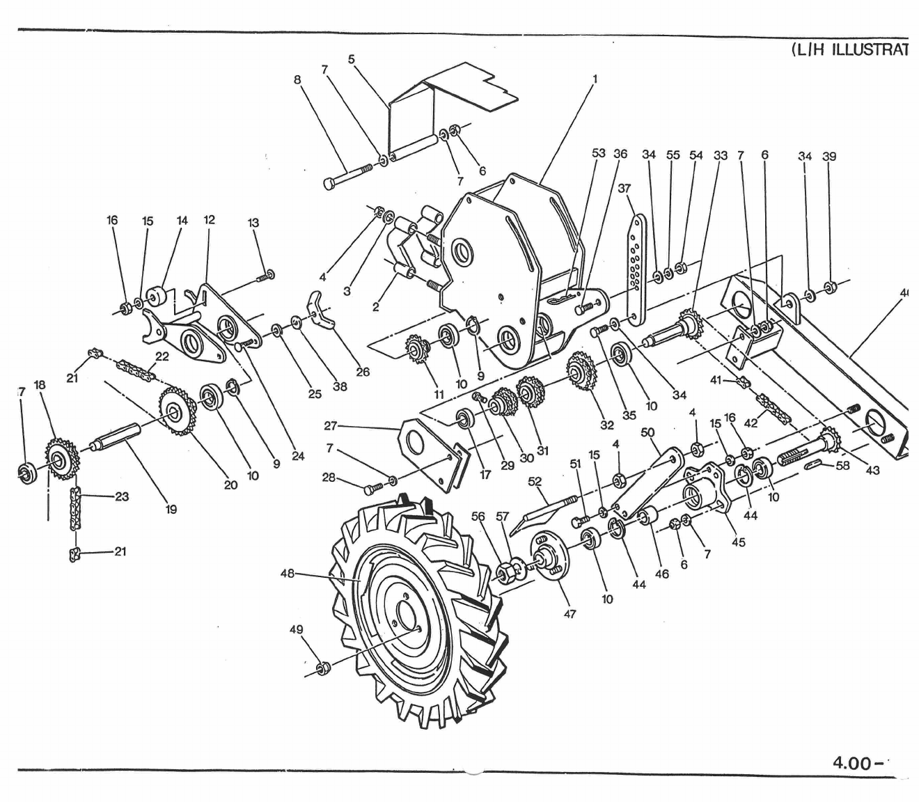
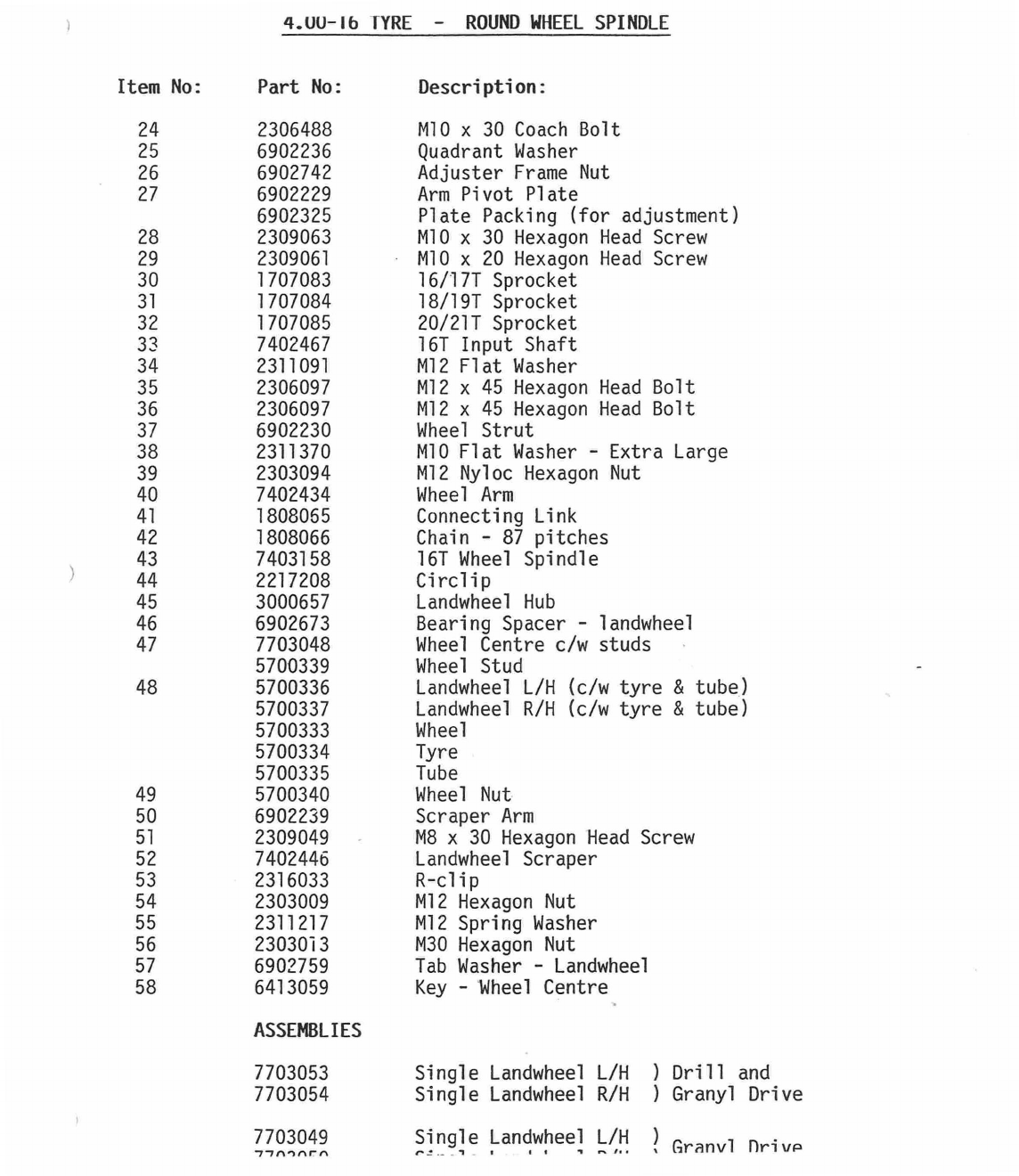
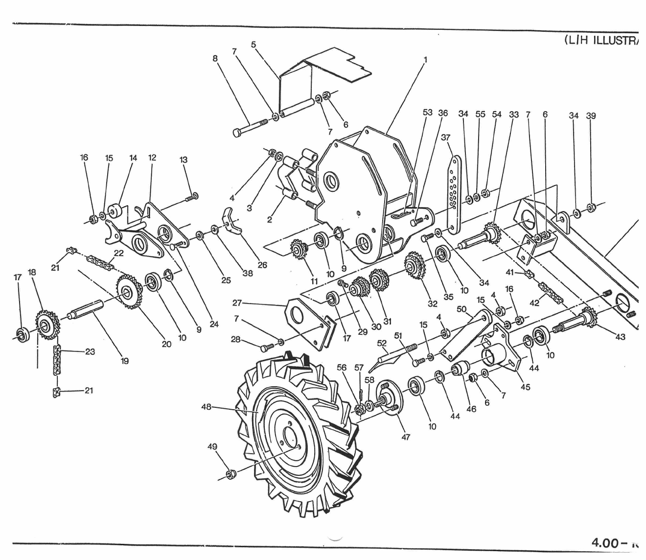
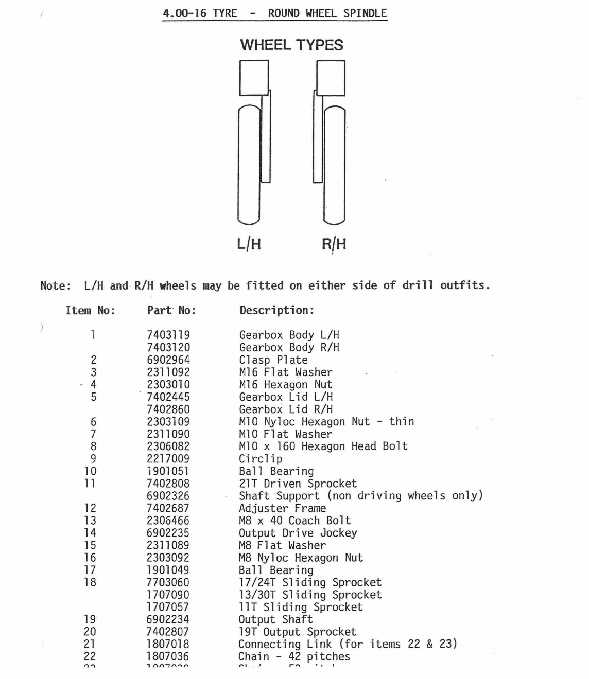
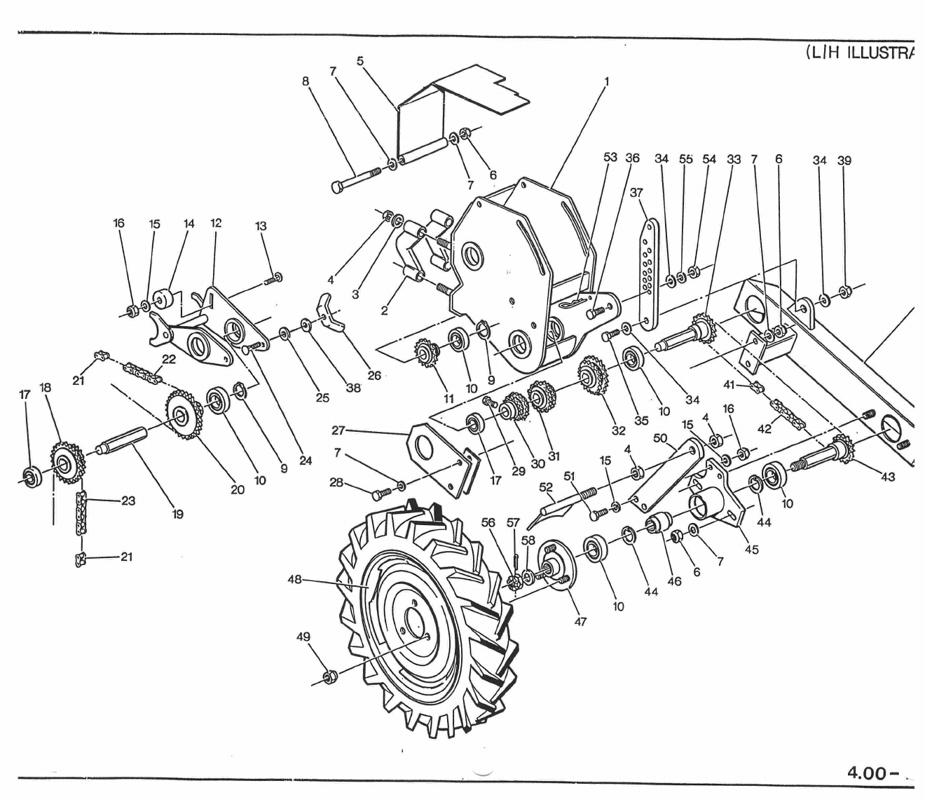
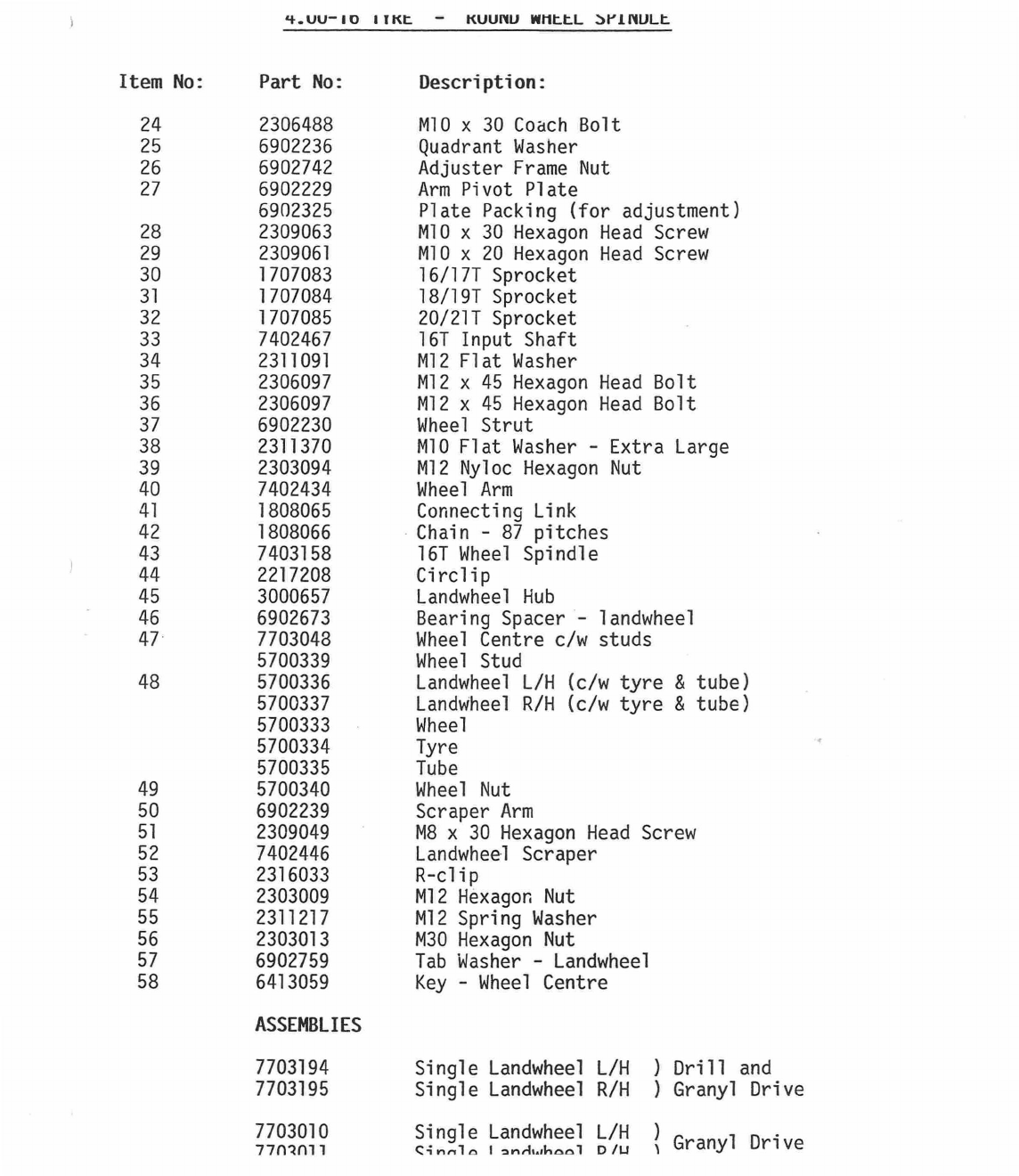
4.00-16 TYRE - ROUND WHEEL SPINDLE
WHEEL TYPES
L/H
RIH
Note: L/H and R/H wheels may be fitted on either side of drill outfits.
Item No: Part No:
Description:
1
7402719
Gearbox Body L/H
7402720
Gearbox Body R/H
2
7402662
Clamp Half
3
2311092
M16 Flat Washer
4
2303010
M16 Hexagon Nut
5
7402445
Gearbox Lid L/H
7402860
Gearbox Lid R/H
6
2303109
M10 Nyloc Hexagon Nut - thin
7
2311090
M10 Flat Washer
8
2306082
M10 x 160 Hexagon Head Bolt
9
2217009
Circlip
10
1901051
Ball Bearing
11
7402808
21T Driven Sprocket
6902326
Shaft Support (non driving wheels only)
12
7402687
Adjuster Frame
13
2306466
M8 x 40 Coach Bolt
14
6902235
Output Drive Jockey
15
2311089
M8 Flat Washer
16
2303092
M8 Nyloc Hexagon Nut
17
1901049
Ball Bearing
18
7703060
17/24T Sliding Sprocket
1707090
13/301 Sliding Sprocket
1707057
111 Sliding Sprocket
19
6902234
Output Shaft
20
7402807
191 Output Sprocket
21
1807018
Connecting Link (for items 22 & 23)
22
1807036
Chain -42 pitches
,...
.
__
..
.

(L I 1
-
1 I LLUSTRAT
53 36 34 55 54 33 7
34 39
37
16
15
14 12
4C
18 21N,
26
3
25 8
27
7
24
6,--
43
23
20 10
28
10
19
44
21
45
48
46
44
10
47
49
7703053
7703054
7703049
-
77nnnrn
Single Landwheel L/H
Single Landwheel R/H
Single Landwheel L/H
r.!
.1 -
I
1.
) Drill and
) Granyl Drive
Granvl Drivp
4.00-16
TYRE - ROUND WHEEL SPINDLE
Item No:
Part No:
24
2306488
25
6902236
26
6902742
27
6902229
6902325
28
2309063
29
2309061
30
1707083
31
1707084
32
1707085
33
7402467
34
2311091
35
2306097
36
2306097
37
6902230
38
2311370
39
2303094
40
7402434
41
1808065
42
1808066
43
7403158
44
2217208
45
3000657
46
6902673
47
7703048
5700339
48 5700336
5700337
5700333
5700334
5700335
49
5700340
50
6902239
51
2309049
52
7402446
53
2316033
54
2303009
55
2311217
56
2303013
57
6902759
58
6413059
Description:
M10 x 30 Coach Bolt
Quadrant Washer
Adjuster Frame Nut
Arm Pivot Plate
Plate Packing (for adjustment)
M10 x 30 Hexagon Head Screw
M10 x 20 Hexagon Head Screw
16/17T Sprocket
18/19T Sprocket
20/21T Sprocket
16T Input Shaft
M12 Flat Washer
M12 x 45 Hexagon Head Bolt
M12 x 45 Hexagon Head Bolt
Wheel Strut
M10 Flat Washer - Extra Large
M12 Nyloc Hexagon Nut
Wheel Arm
Connecting Link
Chain - 87 pitches
161 Wheel Spindle
Circlip
Landwheel Hub
Bearing Spacer - landwheel
Wheel Centre c/w studs
Wheel Stud
Landwheel L/H (c/w tyre & tube)
Landwheel R/H (c/w tyre & tube)
Wheel
Tyre
Tube
Wheel Nut
Scraper Arm
M8 x 30 Hexagon Head Screw
Landwheel Scraper
R-clip
M12 Hexagon Nut
M12 Spring Washer
M30 Hexagon Nut
Tab Washer - Landwheel
Key - Wheel Centre
ASSEMBLIES
(LIH ILLUSTRi
34 39
45
46
44
10
47
4.00-16 TYRE - ROUND WHEEL SPINDLE
WHEEL TYPES
L/H
R/H
Note: L/H and R/H wheels may be fitted on either side of drill outfits.
Item
No:
Part No:
Description:
1
7403119
Gearbox Body L/H
7403120
Gearbox Body R/H
2
6902964
Clasp Plate
3
2311092
M16 Flat Washer
- 4
2303010
M16 Hexagon Nut
5
7402445
Gearbox Lid L/H
7402860
Gearbox Lid R/H
6
2303109
M10 Nyloc Hexagon Nut - thin
7
2311090
M10 Flat Washer
8
2306082
M10 x 160 Hexagon Head Bolt
9
2217009
Circlip
10
1901051
Ball Bearing
11
7402808
21T Driven Sprocket
6902326
Shaft Support (non driving wheels only)
12
7402687
Adjuster Frame
13
2306466
M8 x 40 Coach Bolt
14
6902235
Output Drive Jockey
15
2311089
M8 Flat Washer
16
2303092
M8 Nyloc Hexagon Nut
17
1901049
Ball Bearing
18
7703060
17/241 Sliding Sprocket
1707090
13/301 Sliding Sprocket
1707057
11T Sliding Sprocket
19
6902234
Output Shaft
20
7402807
19T Output Sprocket
21
1807018
Connecting Link (for items 22 & 23)
22
1807036
Chain - 42 pitches
nn
1nn
-
innn
,1
(LIH ILLUSTR?
34 39
45
44
47
4.UU
-
10 ITFL. — KUUMU WIttL
w-inuLt
Item No:
Part No:
24
2306488
25
6902236
26
6902742
27
6902229
6902325
28
2309063
29
2309061
30
1707083
31
1707084
32
1707085
33
7402467
34
2311091
35
2306097
36
2306097
37
6902230
38
2311370
39
2303094
40
7402434
41
1808065
42
1808066
43
7403158
44
2217208
45
3000657
46
6902673
47
7703048
5700339
48 5700336
5700337
5700333
5700334
5700335
49
5700340
50
6902239
51
2309049
52
7402446
53
2316033
54
2303009
55
2311217
56
2303013
57
6902759
58
6413059
ASSEMBLIES
7703194
7703195
7703010
77nlnii
Single Landwheel L/H
Single Landwheel R/H
Single Landwheel L/H
CinrOn InnAwhnell 0/14
) Drill and
) Granyl Drive
) Granyl Drive
Description:
M10 x 30 Coach Bolt
Quadrant Washer
Adjuster Frame Nut
Arm Pivot Plate
Plate Packing (for adjustment)
M10 x 30 Hexagon Head Screw
M10 x 20 Hexagon Head Screw
16/17T Sprocket
18/19T Sprocket
20/211 Sprocket
16T Input Shaft
M12 Flat Washer
M12 x 45 Hexagon Head Bolt
M12 x 45 Hexagon Head Bolt
Wheel Strut
M10 Flat Washer - Extra Large
M12 Nyloc Hexagon Nut
Wheel Arm
Connecting Link
Chain - 87 pitches
16T Wheel Spindle
Circlip
Landwheel Hub
Bearing Spacer - landwheel
Wheel Centre c/w studs
Wheel Stud
Landwheel
L/H
(c/w tyre & tube)
Landwheel
R/H
(c/w tyre & tube)
Wheel
Tyre
Tube
Wheel Nut
Scraper Arm
M8 x 30 Hexagon Head Screw
Landwheel Scraper
R-clip
M12 Hexagon Nut
M12 Spring Washer
M30 Hexagon Nut
Tab Washer - Landwheel
Key - Wheel Centre
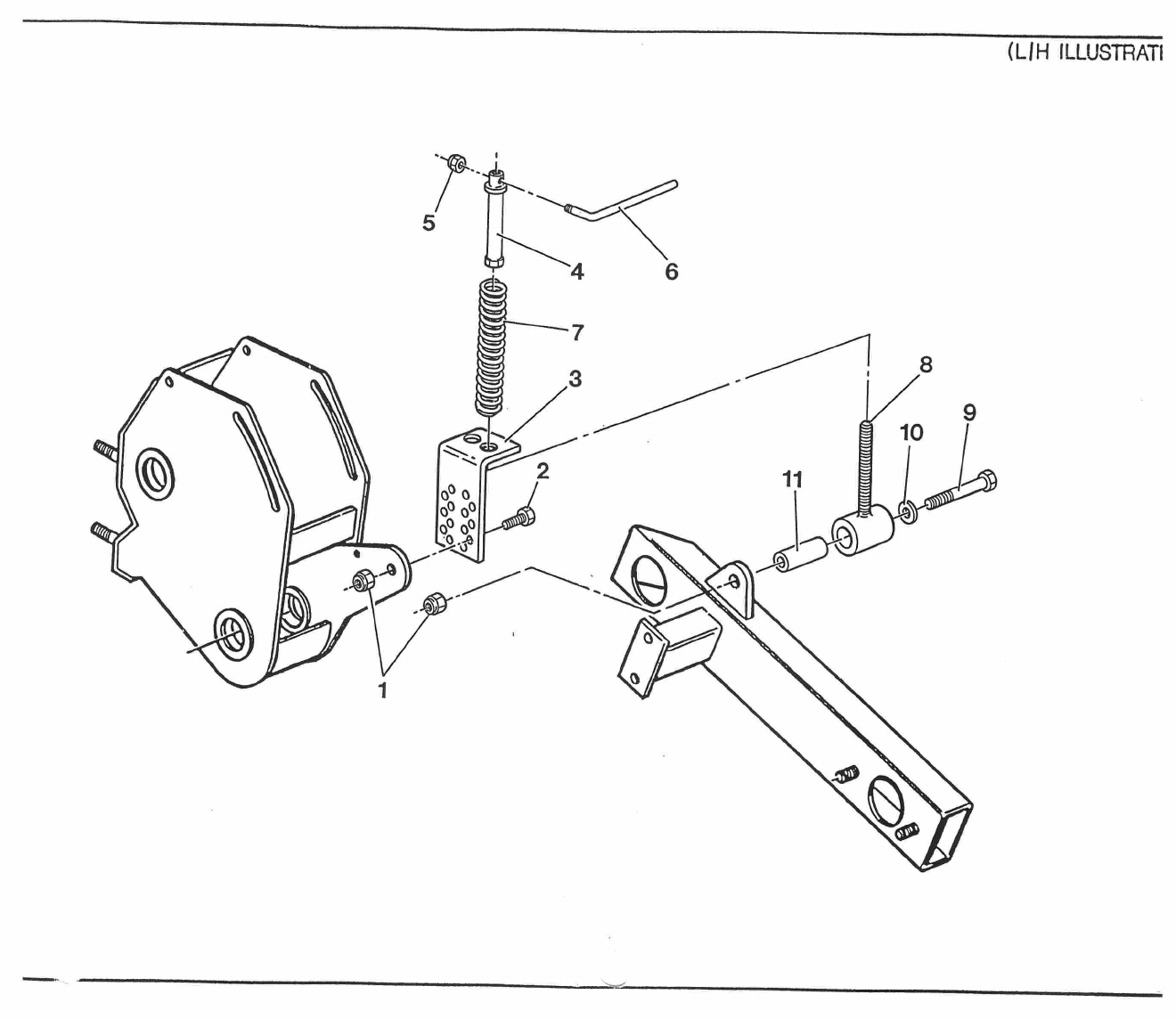
(LIR ILLUSTRATI
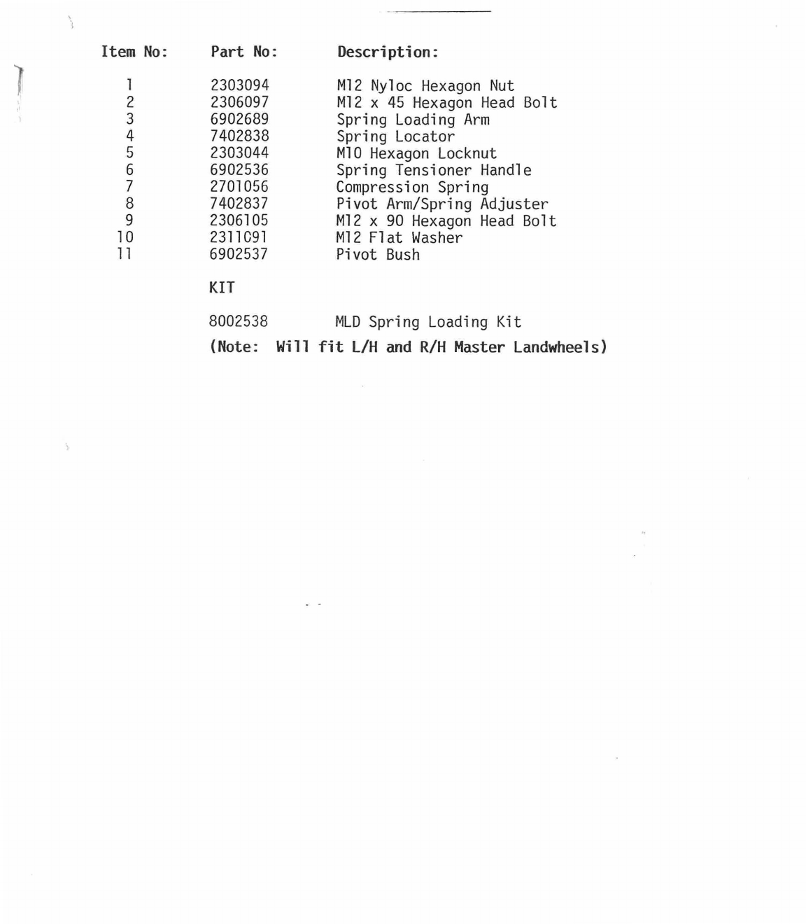
Item No:
Part No:
Description:
1
2303094
M12 Nyloc Hexagon Nut
2
2306097
M12 x 45 Hexagon Head Bolt
3
6902689
Spring Loading Arm
4
7402838
Spring Locator
r
J
2303044
M10 Hexagon Locknut
6
6902536
Spring Tensioner Handle
7
2701056
Compression Spring
8
7402837
Pivot Arm/Spring Adjuster
9
2306105
M12 x 90 Hexagon Head Bolt
10
2311091
M12 Flat Washer
11
6902537
Pivot Bush
KIT
8002538
MLD Spring Loading Kit
(Note: Will fit L/H and R/H Master Landwheels)

40-Da
rtz.a
41d22 1-'44
7
•
(3-
(
el
40
1—
‘b
6PP-
s'
■
C-0
•
•
•
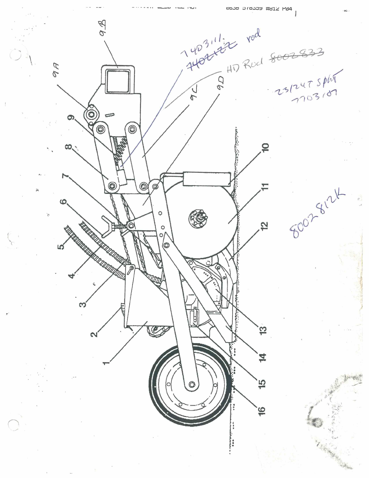
STANHAY WEBB TEL NO:
0638 51
/
4-17-'93 WED 17:38 ID:
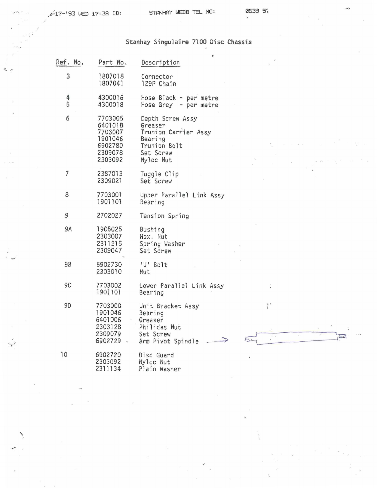
Stanh4y Singulaire 7100 Disc
Chassis
Ref. No.
Part No
Description
3
1807018
Connector
1807041
129P Chain
4
4300016
Hose Black - per metre
5
4300018
Hose Grey - per metre
6
7703005
Depth Screw Assy
6401018
Greaser
.
7703007
Trunion Carrier Assy
1901046
Bearing
6902780
Trunion Bolt
2309078
Set Screw
2303092
Nyloc Nut
7
2387013
Toggle Clip
2309021
Set Screw
8
7703001
Upper Parallel Link Assy
1901101
Bearing
9
2702027
Tension Spring
9A
1905025
Bushing
2303007
Hex. Nut
2311215
Spring Washer
2309047
Set Screw
98
6902730
'U' Bolt
2303010
Nut
9C
7703002
Lower Parallel Link Assy
1901101
Bearing
90
7703000
Unit Bracket Assy
1901046
Bearing
6401006
Greaser
2303128
Philidas Nut
2309079
Set Screw
6902729 .
Arm Pivot Spindle
10
6902720
Disc Guard
2303092
Nyloc Nut
2311134
Plain Washer
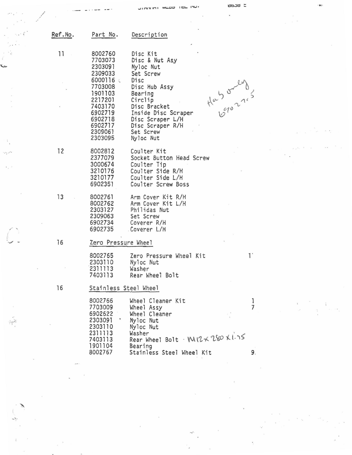
Ref.No.
IML
111-1.
Part No.
Description
UM3d
11
8002760
Disc Kit
7703073
Disc & Nut Asy
2303091
Nyloc Nut
2309033
Set Screw
6000116
Disc
7703008
Disc Hub Assy
1901103
Bearing
■
?
)ji
i
2217201
Circlip
7403170
Disc Bracket
I
'
/li
cia
6902719
Inside Disc Scraper
V
6902718
Disc Scraper L/H
6902717
Disc Scraper R/H
2309061
Set Screw
2303095
Nyloc Nut
12
8002812
Coulter Kit
2377079
Socket Button Head Screw
3000674
Coulter Tip
3210176
Coulter Side R/H
3210177
Coulter Side L/H
6902351
Coulter Screw Boss
13
8002761
Arm Cover Kit R/H
8002762
Arm Cover Kit L/H
2303127
Philidas Nut
2309063
Set Screw
6902734
Coverer R/H
6902735
Coverer L/H
16
Zero Pressure Wheel
8002765
Zero Pressure Wheel Kit
1
2303110
Nyloc Nut
2311113
Washer
7403113
Rear Wheel
Bolt
16
Stainless Steel Wheel
8002766
Wheel
Cleaner Kit
1
7703009
Wheel Assy
7
6902622
Wheel Cleaner
2303091
Nyloc Nut
2303110
Nyloc Nut
2311113
Washer
7403113
Rear Wheel
Bolt
• YV
■
12-/..1.
,
W
1
1,
1-
.)5.
1901104
Bearing
8002767
Stainless Steel Wheel
Kit
9.
