Skilll Crane Operating Instructions (UAI)
Skilll_Crane_Operating_Instructions_(UAI) Skilll_Crane_Operating_Instructions_(UAI)
User Manual: instructions pdf -FilePursuit
Open the PDF directly: View PDF ![]() .
.
Page Count: 16
SKI
L L C
RAN
E
Ope~atin~
Inst~uctions
P'eatu~es
"SKILL
CRANE"
byUAI
is
a
t~ue
state-of-tt,e-a~t.
solid
state
me~chandisin~
unit
offe~in~
features
not
found
on
many
of
the
othe~
C~ane-type
p~od.ucts
found
in
the
ma~ketplace.
Skill
Cont~ol.
two
coin
accepto~s
as
well
as
a
full
complement
of
excitin~
li~hts
and
sounds
a~e
just
a
few
of
the
added
featu~es
which
make
this
unique
p~oduct
stand
apart
f~om
the
crowd.
Th~u
DIP
Switch
selections.
va~ious
~ame
combinations
can
be
offe~ed
·to
the
playe~.
These
will
be
explained.
mo~e
fully
in
a
later
section
of
thi.s
manual.
SECURITY
was
an
important
conside~ation
when
designin~
"SKILL
CRANE".·
Special.
"Anti-St~in~in~"
coin-timin~-senso~s
continually
monito~
the
coin-in
switch
to
p~event
unautho~ized
~ame
play.
In
addition.
special
p~ize
chute
secu~ity
devices
have
been
installed
to
p~event
unautho~ized
int~usion
into
the
inte~nals
of
the
Crane.
If
eithe~
of
these
devices
detect
a
violation.
an
ala~m
will
sound
and
the
Awa~d
Beacon
will
li~ht.
BATTERY
BACK-UP
devices
allow
~etention
of
accumulated
c~edits
fo~
up
to
one
hou~
followin~
any
powe~
failu~e.
"SKILL
CRANE"
has
been
desi~ned
to
accept
both
popula~
types
of
playe~
cont~ols.
joystick
and
buttons.
switchin~
between
the
two
diffe~ent
types
of
cont~ols
can
be
accomplished
at
any
time
by
the
Ope~ato~
with
minimal
effo~t.
"SKILL
CRANE"
will
easily
accept
the
followi
optional
enhancements:
Dolla~
Bill
Accepto~
Ticket
Dispense~
In
addition.
the
P~inted Ci~cuit
Boa~d
has
been
desi~ned
to
allow
fo~
additional
inputs
and
outputs.
the~eby
~uaranteeing
that
the
the
enti~e
Syst.enLw;Lll~J!.iL.QpelL.t.o
f.ut.u~iLo.p.tions~.and.
enhancements
as
they
become
available.
GAME
OPERATION
Upon
inse~tion
of
coin(s),
the
FORWARD
o~
PRESS JOYSTICK
TO
START
GAME
button
~i~~
b~ink.
In
addition,
the
c~edit
/
time~
wi~~
disp~ay
the
numbe~
of
~ame
c~edits
accumulated.
,The
~ame
is
sta~ted
by
pushin~
the
FORWARD
play
'button
o~,
if
the
Joystick
is
installed,
the
"DROP
CLAW"
button
(the
button
on
top
of
the
joystick).
BUTTON
OPERATION:
This
selection
~etalns
all
of
the
featu~es
of
the
o~iginal
"push
button"
~ame
while
optionally
allowing
the
Ope~ato~
to
~un
the
~ame
until
the
TIMER
has
expi~ed.
The
~ame
sta~ts
when
the
FORWARD
button
is
dep~essed.
At
that
time,
the
'ope~ation'
sound
begins
and
the
TIMER
begins
tt's
countdown.
C~ane
movement
can
sta~t
by
p~essi~g
ei,the~
the
FORWARD
o~
RIGHT
button.
When
both
buttons
have
been
p~essed,
the
claw
will
lowe~
and
attempt
to
pick
up
a
p~ize.
The
claw
will
then
be
~etu~ned
to
the
HOME
(f~ont
left)
position
automatically.
JOYSTICK
CONTROL:
This
option
enhances
"SKILL
CRANE"
by
allowing
the
playe~
to
have
complete
cont~ol
ove~
the
movement
of
the
c~ane.
In
this
mode.
the
c~ane
moto~s
a~e
slowed
down
to
inhibit
excessive
swayin~
motion
of
the
claw
assembly.
Fou~
playin~
modes
a~e
possible.
These
a~e
dete~mined
by
DIP
switch
settings.
One
mode
allows
the
piaye~
to
lowe~
the
claw
once
by
p~essin~
the
top
button
on
the
joystick
while
a
diffe~ent
mode
allows
the
playe~
to
lowe~
the
claw
g~aduallY
while
dep~essing
the
same
button.
Both
modes
can
be
set
to
~un
on
ei
the~
a
One-Tim,e-Drop
basis
o~
until
the
TIMER
expires.
In
the
joystick
mode,
'the
playe~
dep~esses
the
joystick
button
to
be~in
the
~ame.
The~e
is
a
,b~ief
pause
wh,ile
the
openin~
theme
is
played
and
the
c~aneis
positioned
in
t'he
cente~
of
the
playfield.
The'
ope~ation'
sound
si~nifies
,the
be~innin~
of
the
TIMER
countdown.
,
After
attemptin~
to
pick
up
a
prize,
the
crane
will
return
to
the
HOME
position
and
open
the
claw.
IF
the
appropriate
DIP
switches
are
set,
the
player
will
then
be
allowed
to
continue
play
until
the
TIMER
counts
down'
to
O.
When
the
TIMER
expires,
the
cra~e
motion
will
cycle
and
allow
for
one
more
pick-up
attempt
UNLESS'the
c~ane-was
"over'
th'e'
home
position
at
which
time
iame
play
will
cease.
Upon
Power-up,
the
c~ane
will
reset
to
the
HOME
position.
If,
on
power-up,
the
coin-in
switch
is
held
down,
the
crane
wil~
~o
into
a TEST
MODE.
SEE TEST FEATURES
FOR
DETAILS.
COINS
DIP
Switch
positions
4
and
5
control
the
number
of
games
per
coin
and
the
denomination.
CRANE
MOVEMENT
DIP
Switch
position
3
controls
whether
the
game
continues
to
play
until
the
TIMER
has
expired
or
whether
the
game
ends
after
one
pick-up
attempt.
GAME
SELECT
DIP
Switch
positions
1
and
2
select
the
game
configuration
mo<le.
TEST FEATURES
NOTE: TEST FEATURES
CAN
ONLY
BE
USED
WHEN
IN
JOYSTICK
MODE
When
in
button
mode,
you
may
use
the
Forwar·d
button
to
step
thru
to
Test
#4
and
then
use
the
Lateral
button
to
change
the
status
of
the
Claw:
Open
or
Closed.
To
enter
the
TES~
FUNCTIONS,
power-up
"SKILL
CRANE"
while
holding
<lown
the
coin-in
switch.
The
TIMER
display
will
then
show
"88"
to
indicate
that
the
TEST
MODE
is
activated.
Advance
through
the
test
functions
by
pressing
the
button
on
top
of
the
joystick.
At
the
end
of
the
test
functions,
the
game
will
resume
normal
operation.
TEST FUNCTIONS
1.
Bulb
Test:
This
test
lights
all
the
lights
in
the
crane
that
are
under
p.c.b.
control.
2.
Crane
Movement
1:
The
Joystick
will
control
the
operation
of
the
crane's
left,
right,
forward
and
backward
motion.
3.
Crane
Movement
2:
The
Joystick
will
control
the
operation
of
the
crane's
up
and
down
motion.
4.
Claw
Position:
The
Joystick
will
control
the
opening
and
closing
of
the
claw
mechanism.
5.
Ticket
Dispenser:
The
Joystick
will
control
the
operation
of
the
ticket
dispenser.

j
TO
REPLACE JOYSTICK
WITH
BUTTONS
1.
Remove
the
four
(U)
screws
which
hold
the
jo~stick
to
the
panel.
2.
Insert
Lateral
Button,
round
wooden
spacer,
washer
in
hole.
Orient
lateral
button
so
that
right
hand
side
of
the
cabinet.
Tighten
nut.
.
and
Large
square
the
arrow
faces
the
3.
Unsolder
the
long
black
wire
with
the
four
(U)
fast-ons
that
goes
to
the
commons
of
the
jo~stick
from
the
forward
lamp.
U.
Remove
the
white
&
white/orange
wires
from
the
"fire
button"
switch
of
the
jo~stick
and
connect
the
white
&
white/orange
wires
to
the
forward
switch
on
the
Normall~
Open
and
Common
terminals.
5.
Remove
the
Red/white
and
White/red
wires
from
the
jo~stick.
Insolate
them
and
tie
them
back.
6.
Remove
the
White/blue
and
the
Blue/white
wirea
from
the
jo~stick
and
convert
them
to
the
Normail~
Open
and
the
Common
of
the
lateral
switch.
7.
Convert
the
Yellow
and
White/Brown
wires
that
were
tied
back
to
the
lateral
lamp
connection.
8.
Change
switch
on
the
crane
controller
board
to
A-C
for
2
button
operation.
Set
DIP
switches
as
needed.
9.
Install
the
Arrow
legend
~n
the
Forward
button.
Conversion
Complete

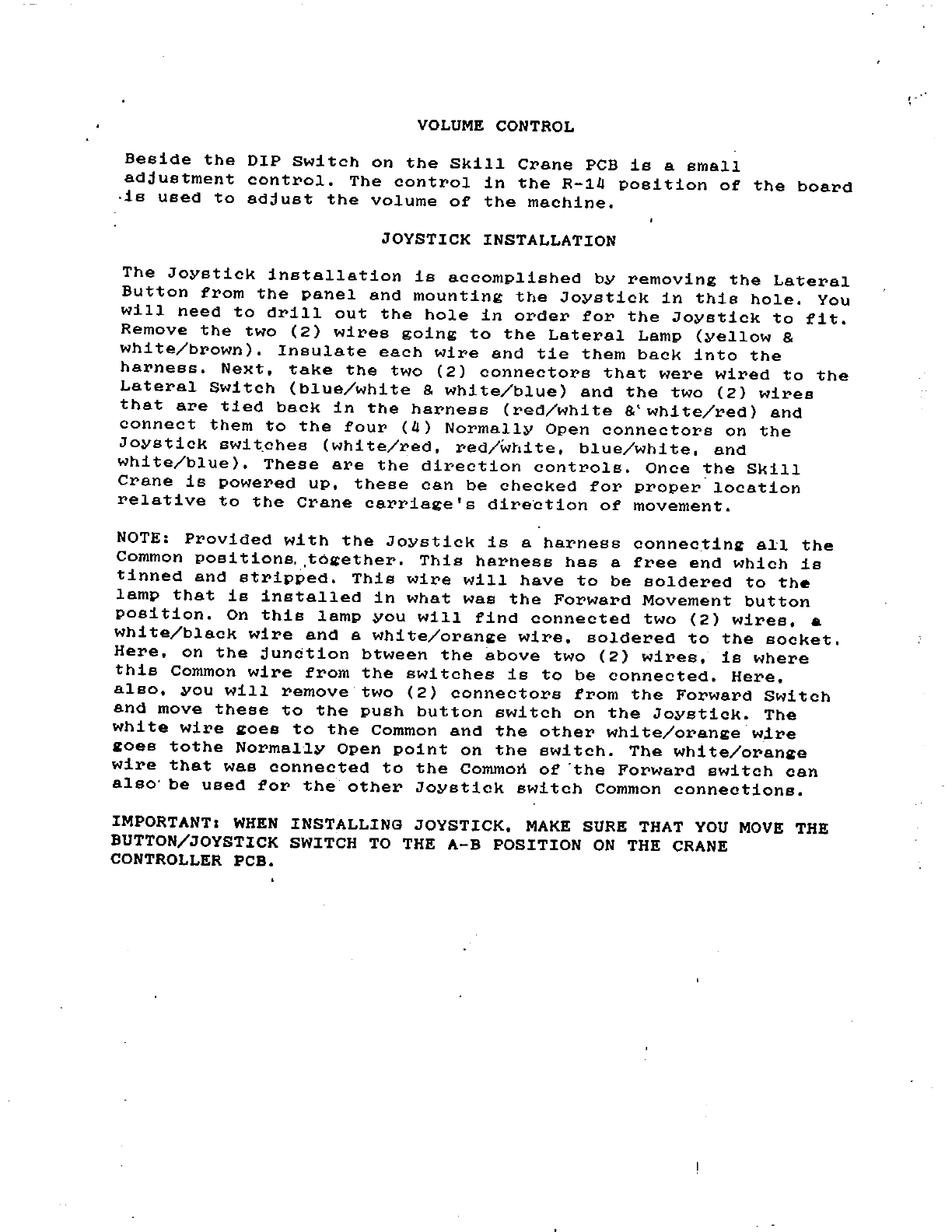
VOLUME
CONTROL
Beside
the
DIP
Switch
on
the
Skill
Crane
PCB
is
a
small
adjustment
control.
The
control
in
the
R-14
position
of
the
board
,is
used
to
adjust
the
volume
of
the
machine.
JOYSTICK INSTALLATION
The
Joystick
installation
is
accomplished
by
removing
the
Lateral
Button
from
the
panel
and
mounting
the
Joystick
in
this
hole.
You
will
need
to
drill
out
the
hole
in
order
for
the
Joystick
to
fit.
Remove
the
two
(2)
wires
going
to
the
Lateral
Lamp
(yellow
&
white/brown).
Insulate
each
wire
and
tie
them
back
into
the
harness.
Next,
take
the
two
(2)
connectors
that
were
wired
to
the
Lateral
Switch
(blue/white
&
white/blue)
and
the
two
(2)
wires
that
are
tied
back
in
the
harness
(red/white
&'white/red)
and
connect
them
to
the
four
(4)
Normally
Open
connectors
on
the
Joystick
swit,ches
(white/red,
red/wtlite,
blue/white,
and
white/blue).
These
are
the
direction
controls.
Once
the
Skill
Crane
is
powered
up,
these
can
be
checked
for
proper
location
relative
to
the
Crane
carriage's
direGtion
of
movement.
NOTE:
Provided
with
the
Joystick
is
a
harness
connectin~
all
the
Common
posi
tions
..
t6~ether.
This
harness
has
a
free
end
which
is
tinned
and
stripped.
This
wire
will
have
to
be
soldered
to
the
lamp
that
is
installed
in
what
was
the
Forward
Movement
button
position.
On
this
lamp
you
will
find
connected
two
(2)
wires,
a
white/black
wire
and
a
white/oran~e
wire,
soldered
to
the
socket.
Here,
on
the
junction
btween
the
above
two
(2)
wires,
is
where
this
Common
wire
from
the
switches
is
to
be
connected.
Here,
also,
you
will
remove
two
(2)
connectors
from
the
Forward
Switch
and
move
these
to
the
push
button
switch
on
the
Joystick.
The
white
wire
~oes
to
the
Common
and
the
other
white/orange'wire
~oes
tothe
Normally
Open
point
on
the
switch.
The
white/oran~e
wire
that
was
connected
to
the
Common
of
'the
Forward
switch
can
also'
be
used
for
the
other
Joystick
switch
Common
connections.
IMPORTANT I
WHEN
INSTALLING
JOYSTICK,
MAKE
SURE
THAT
YOU
MOVE
THE
BUTTON/JOYSTICK SWITCH
TO
THE
A-B
POSITION
ON
THE
CRANE
CONTROLLER PCB.

I
'.
1 '
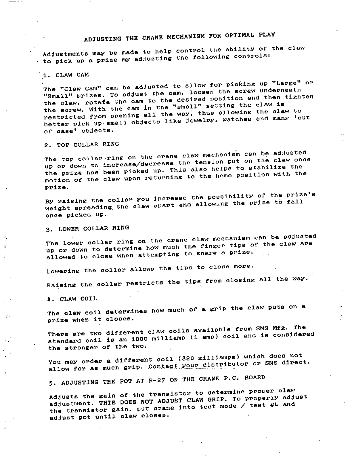
ADJUSTING
THE
CRANE
MECHANISM
FOR
OPTIMAL
PLAY
Adjustments
may
be
made
to
help
control
the
ability
of
the
claw
to
pick
up
a
prize
my
adjusting
the
following
controls:
1.
CLAW
CAM
The
"Claw
Cam"
can
be
adjusted
to
allow
for
picking
up
"Large"
or
"Small"
prizes.
To
adjust
the
cam,
loosen
the
screw
underneath
the
claw,
rotate
the
cam
to
the
desired
position
and
then
tighten
the
screw.
With
the
cam
in
the
"small"
setting
the
claw
is
restricted
from
opening
all
the
way,
thus
allowing
the
claw
to
better
pick
up'
small
objects
like
jewelry,
watches
and
many
'out
of
case'
objects.
2.
TOP
COLLAR
RING
The
top
collar
ring
on
the
crane
claw
mechanis~
can
be
adjusted
up
or
down
to
increase/decrease
the
tension
put
on
the
claw
once
the
prize
has
been
picked
up.
This
also
helps
to
stabilize
the
motion
of
the
claw
upon
returning
to
the
home
position
with
the
prize.
By
raising
the
collar
you
increase
th~
possibility
of
the
prize's
weill:ht
spreadinll::
the
claw
apart
and
allowing
the
prize
to
fall
once
picked
up.
'
3.
LOWER
COLLAR
RING
The
lower
collar
ring
on
the
crane
claw
mechanism
can
be
adjusted
up
or
down
to
determine
how
much
the
finger
tips
of
the
claw
are
allowed
to
close
when
attempting
to
snare
a
prize.
Lowerinll:
the
collar
allows
the
tips
to
close
more.
Ra~sing
the
collar
restricts
the
tips
from
closing
all
the
way.
II.
CLAW
COIL
The
claw
coil
determines
how
much
of
a
II:rip
the
claw
puts
on
a
prize
when
it
closeS.
There
are
two
different
claw
coils
available
from
SMS
Mfll:.
The
standard
coil
is
an
1000
milliamp
(1
amp)
coil
and
is
considered
the
stronll:er
of
the
two.
You
may
order
a
different
coil
(820
milliamps)
Whiph
does
not
allow
for
as
much
grip
..
Con.t,act
your
distributor
or
SMS
direct.
--
--
--
--
---
..
-.
--
5.
ADJUSTING
THE
POT
AT
R-27
ON
THE
CRANE
P.C.
BOARD
Adjusts
the
gain
of
the
transistor
to
determine
proper
claw
adjustment.
THIS
DOES
NOT
ADJUST
CLAW
GRIP.
To
properly
adjust
the
transistor
lI:ain,
put
crane
into
~est
mode
/
test
#11
and
adjust
pot
until
claw
closes.

I
I
I
I
I
I
I
I
I
I
I
I
I
I
I
I
I
I
I
I
I
I
I
I
•
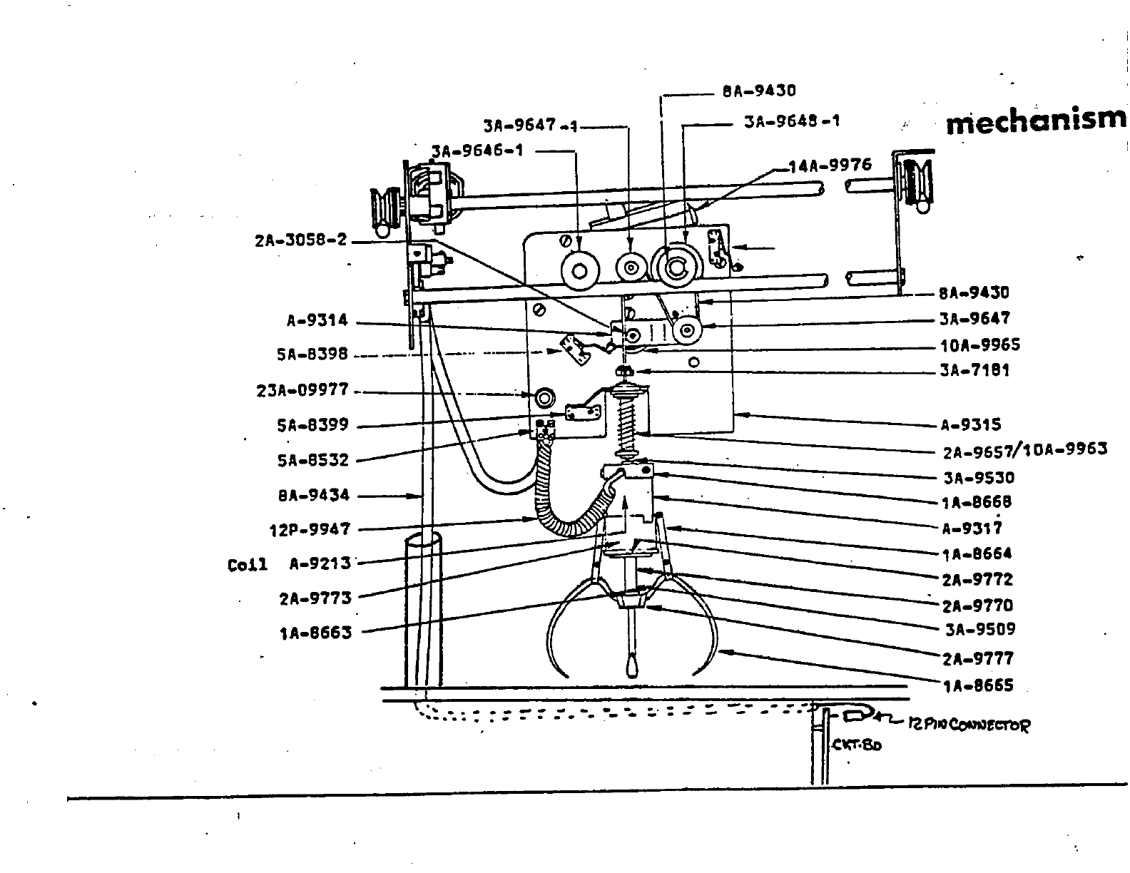
3A-9647
-~-
-9646-1
-,
,
__
8A-9430
3A-9548
-1
" mechanism
~14A-9~
2A-30S8-2
v Z ,
~
ih
--
A-9314
d1[:==::=l~~~=l~~~~~======~~==~
.u
-8A-943D
SA-B398
___
,
.,--t--------3A-9647
23A-09977
_ 0 10A-996S
3A-7181
..
SA-8399
__
-+lH-~_-+~.c-~1
SA-8S32 _ II
A-93'S
BA-9434
2A-9657/10A-9953
12P-9941
3A-9S30
1A-8668
213'
A-9317
~
2A-9773
-
1A-8663
-
2A-9770
---3A-9SD9
II
)-
-----~-2A-9777
II
Q
-,A-866S
""'
......
- • -
:""
~
.....
-.
~-
-
...
:."
:
.:
::..
---
--:.-
~
~
'2"'IOCctN!'crc~
"'
......
-
,.c~'8D

I
I
I
I
I
I
I
I
I
I
I
I
I
I
I
I
I
I
I
I
I
I
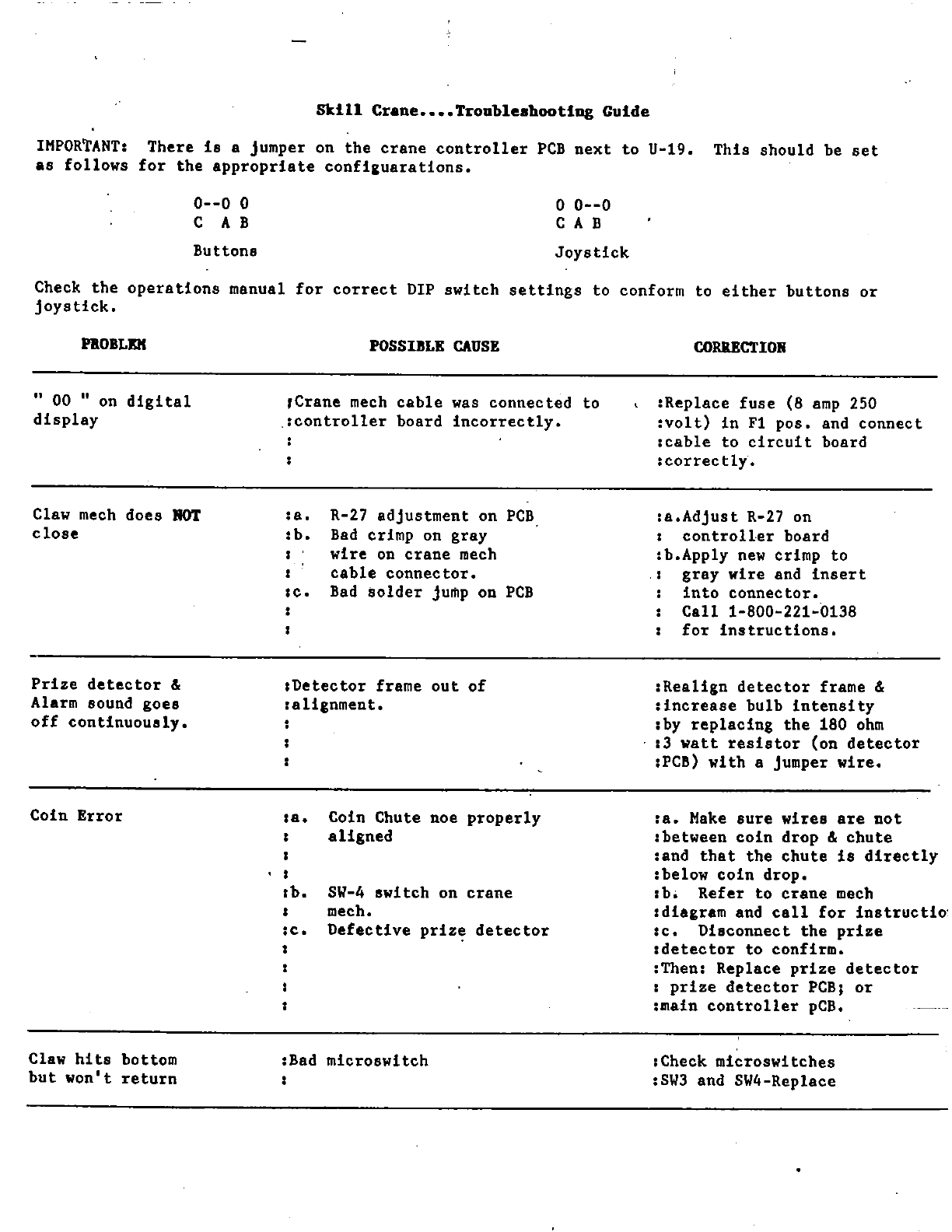
Skill
Cr.ne
••••
Trouble.hootiug
Guide
IHPOR~ANTI
There
is
a jumper on
the
crane
controller
PCB
next
to
U-19.
This
should
be
set
as
follows
for
the
appropriate
confi&uarations.
0--0
0
CAB
Buttons
o
0--0
CAB
Joystick
Check
the
operations
manual
for
correct
DIP
switch
settings
to
conform
to
either
buttons
or
joystick.
nOBLE!(
" 00 " on
digital
display
Claw
mech
does
HOT
close
Prize
detector
&
Alarm sound
goes
off
continuously.
Coin
Error
Claw
hits
bottom
but
won't
return
POSSIIILE
CAUSE
,Crane
mech
cable
was
connected
to
.:controller
board
incorrectly.
la.
R-27
adjustment
on
:b.
Bad
crimp on
gray
wire
on
crane
mech
cable
connector.
IC.
Bad
Bolder
jump on
IDetector
frame
out
of
:alignment.
PCB
PCB
la.
Coin Chute noe
properly
I
aligned
I
I
lb.
SW-4
switch
on
crane
I mech.
:c.
Defective
priz~
detector
1
1
:Bad
microswitch
CORRECTION
IReplace
fuse
(8
amp
250
:volt)
in
Fl
pos.
and
connect
:cable
to
circuit
board
:
correc
tly.
:a.Adjust
R-27 on
I
controller
board
:b.Apply
new
crimp
to
.1
gray
wire
and
insert
into
connector.
Call
1-800-221-~138
for
instructions.
:Realign
detector
frame &
:increase
bulb
intensity
:by
replacing
the
180
ohm
:3
watt
resistor
(on
detector
:PCB)
with
a jumper
wire.
:a.
Hake
sure
wires
are
not
:between
coin
drop
&
chute
land
that
the
chute
is
direetly
:below
coin
drop.
:b.
Refer
to
crane
mech
Idiagram
and
call
for
instructio'
:c.
Disconnect
the
prize
:detector
to
confirm.
:Then: Replace
prize
detector
:
prize
detector
PCB;
or
:main
controller
pCB.
:Check
microswitches
:SW3
and SW4-Replace
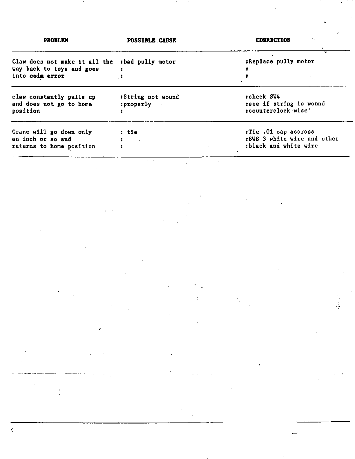
PROBLEM
POSSIBLE
CAUSE
Claw does
not
make
it
all
the
Ibad
pully
motor
way
back
to
toys
and goes
into
coin
error
claw
constantly
pulls
up
and does
not
go
to
home
position
Crane
will
go
down
only
an
inch
or
so
and
returns
to
hom.
position
,
, :
:String
not
wound
:
properly
tie
COIlUCTlOIi
IReplace
pully
motor
:
:check
SW4
Isee
if
string
is
wound
:counterclock"wise'
ITie
.01 cap
accross
:SWS
3
white
wire
and
other
:black
.nd
white
wire
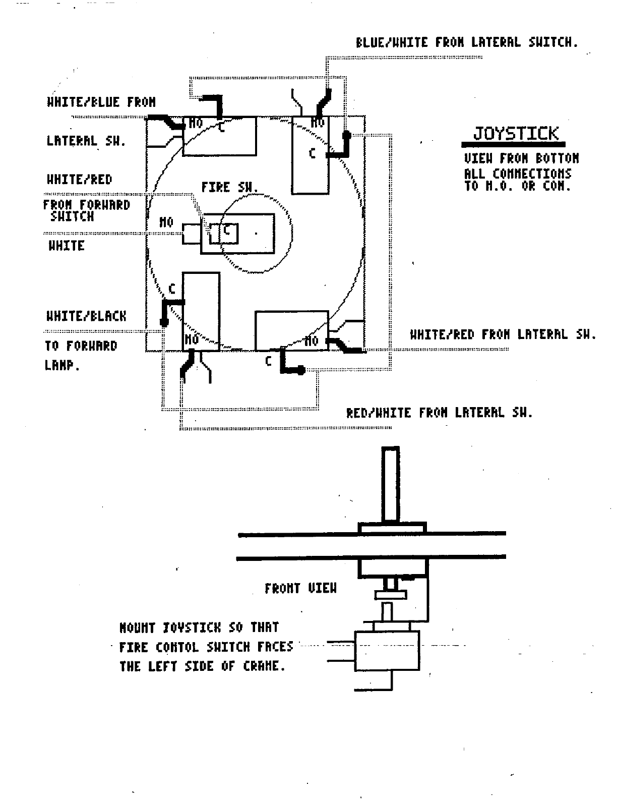
eLUE/UHITE
rRO"
LRTERRL
SUITCH.
w::::::::::::::::::::::::::::::::::::::::::::::::::::::
::::::::::::::::::::::::::::::
-":'r:m"''''''"''''/:'ilmm,,::,'·
g
i[:':"''''''''''''''''''''''''''''''''''''''''''''''''''''''''''''''''''::''''''''ll.
~"""""'~....,."",..,.,..J.....j
.....
-ii!i~
::
::
LflTt~flL
SUo
::::::
..
::::::::::::!!
"OUHT
JOYSTICK
S
.
FI~E
COHTOL
SUIT
THE
LEFT
SIDE
or
nOHT
0
THRT
UIEU
",
"
"
CH
neES
..
..
--
..
-
OFtHE.
"
"
I
I
.
---
I
!!
.,
::
ii
g
u
n I
-.-
..
-_._-
I
.
---,---
-
,
JOYSTICK
UIEU
no"
eOTTO"
RLL
COHHECTIOHS
TO
H.O.
O~
CO".

/
