Copley Controls Corp Step Net Panel Manual
StepNet_panel_Manual
User Manual: StepNet panel Manual
Open the PDF directly: View PDF ![]() .
.
Page Count: 190 [warning: Documents this large are best viewed by clicking the View PDF Link!]
- About This Manual
- 1: Introduction
- 2: Operational Theory
- 2.1: Amplifier Power: Stepnet Panel (STP)
- 2.2: Amplifier Power: Stepnet Panel AC (STX)
- 2.3: Stepper Mode Operation
- 2.4: Servo Mode Operation
- 2.5: Input Command Types
- 2.6: Communication
- 2.7: Limit Switches
- 2.8: Brake Operation
- 2.9: Status Indicators
- 2.10: Protection
- 2.11: Position and Servo Velocity Errors
- 2.12: Inputs
- 2.13: Outputs
- 3: Specifications
- 3.1: Agency Approvals
- 3.2: Power Input
- 3.3: Power Output
- 3.4: Control Loops
- 3.5: Stepnet Panel AC (STX) Internal Regen Circuit
- 3.6: Digital Command Input
- 3.7: Stepnet Panel AC (STX) Analog Command Input
- 3.8: Digital Inputs
- 3.9: Digital Outputs
- 3.10: Encoder Power Supply Output
- 3.11: Incremental Quadrature Encoder Inputs
- 3.12: Stepnet Panel AC (STX) Multi-Mode Port
- 3.13: Serial Interface
- 3.14: CAN Interface
- 3.15: Status Indicators
- 3.16: Fault Levels
- 3.17: Power Dissipation
- 3.18: Thermal Impedance
- 3.19: Mechanical and Environmental
- 3.20: Dimensions
- 4: Wiring
- 4.1: Stepnet Panel (STP) Wiring
- 4.1.1: Stepnet Panel (STP) General Wiring Instructions
- 4.1.2: Stepnet Panel (STP) Connector Locations
- 4.1.3: Stepnet Panel (STP) Power (J1)
- 4.1.4: Stepnet Panel (STP) Motor (J2)
- 4.1.5: Stepnet Panel (STP) Signal (J3)
- 4.1.6: Stepnet Panel (STP) CAN Bus (J5 and J6)
- 4.1.7: Stepnet Panel (STP) RS-232 Serial Communications (J4)
- 4.2: Stepnet Panel AC (STX) Wiring
- 4.2.1: Stepnet Panel AC (STX) General Wiring Instructions
- 4.2.2: Stepnet Panel AC (STX) Connector Locations
- 4.2.3: Stepnet Panel AC (STX) Power (J1)
- 4.2.4: Stepnet Panel AC (STX) Motor (J2)
- 4.2.5: Stepnet Panel AC (STX) Aux HV and Brake (J3)
- 4.2.6: Stepnet Panel AC (STX) CAN Bus (J4 and J5)
- 4.2.7: Stepnet Panel AC (STX) Feedback (J6)
- Stepnet Panel AC (STX) J6 Pin Description
- Stepnet Panel AC (STX) J6 Quad A/B Incremental Encoder Wiring Diagram – With Index
- Stepnet Panel AC (STX) J6 Quad A/B Incremental Encoder Wiring Diagram – No Index
- Stepnet Panel AC (STX) J6 Single-Ended Encoder Wiring Diagram
- Stepnet Panel AC (STX) J6 Motor Over Temperature Wiring Diagram
- 4.2.8: Stepnet Panel AC (STX) Control (J7)
- 4.2.9: Stepnet Panel AC (STX) J7 Digital Inputs Wiring Diagram
- 4.2.10: Stepnet Panel AC (STX) RS-232 Serial Communications (J8)
- 4.1: Stepnet Panel (STP) Wiring
- 5: Mode Selection and General Setup
- 5.1: Warnings
- 5.2: CME 2 Installation and Serial Port Setup
- 5.3: Prerequisites
- 5.4: Basic Setup
- 5.5: Motor Setup
- 5.6: Amplifier Configuration
- 5.6.1: Digital Inputs
- 5.6.2: Digital Input Functions
- 5.6.3: Standard Input Function Assignments
- 5.6.4: Standard Digital Outputs
- 5.6.5: Custom Digital Output Settings: Custom Event
- 5.6.6: Custom Digital Output Settings: Custom Trajectory Status
- 5.6.7: Custom Digital Output Settings: Position Triggered Output
- 5.6.8: Save Input/Output Changes
- 5.6.9: Non-Latched and Latched Custom Outputs
- 5.6.10: Fault Latching
- 5.7: Command Input
- 6: Stepper Mode Phase and Tune
- 7: Servo Mode Phase and Tune
- 8: Using CME 2 (Stepper or Servo Mode)
- A: I2T Time Limit Algorithm
- C: Thermal Considerations
- D: Detent Compensation Gain
- E: Ordering Guide and Accessories

Stepnet™Panel Amplifier
User Guide
P/N CC95-00294-000
Revision A
June 2009
Stepnet Panel Amplifier User Guide
Copley Controls Corp. 3
TABLE OF CONTENTS
About This Manual ................................................................................................................................................................................ 5
1: Introduction ................................................................................................................................................................................. 9
1.1: Amplifier ............................................................................................................................................................................... 10
1.2: Amplifier Commissioning with CME 2 ................................................................................................................................... 11
1.3: CANopen for Distributed Control........................................................................................................................................... 11
2: Operational Theory.................................................................................................................................................................... 13
2.1: Amplifier Power: Stepnet Panel (STP).................................................................................................................................. 14
2.2: Amplifier Power: Stepnet Panel AC (STX) ............................................................................................................................ 15
2.3: Stepper Mode Operation....................................................................................................................................................... 16
2.4: Servo Mode Operation.......................................................................................................................................................... 18
2.5: Input Command Types ......................................................................................................................................................... 25
2.6: Communication .................................................................................................................................................................... 30
2.7: Limit Switches ...................................................................................................................................................................... 33
2.8: Brake Operation ................................................................................................................................................................... 34
2.9: Status Indicators................................................................................................................................................................... 35
2.10: Protection ........................................................................................................................................................................... 37
2.11: Position and Servo Velocity Errors...................................................................................................................................... 39
2.12: Inputs ................................................................................................................................................................................. 42
2.13: Outputs............................................................................................................................................................................... 42
3: Specifications ............................................................................................................................................................................ 43
3.1: Agency Approvals................................................................................................................................................................. 44
3.2: Power Input .......................................................................................................................................................................... 44
3.3: Power Output........................................................................................................................................................................ 45
3.4: Control Loops ....................................................................................................................................................................... 46
3.5: Stepnet Panel AC (STX) Internal Regen Circuit.................................................................................................................... 46
3.6: Digital Command Input ......................................................................................................................................................... 46
3.7: Stepnet Panel AC (STX) Analog Command Input................................................................................................................. 47
3.8: Digital Inputs......................................................................................................................................................................... 47
3.9: Digital Outputs ...................................................................................................................................................................... 49
3.10: Encoder Power Supply Output............................................................................................................................................ 49
3.11: Incremental Quadrature Encoder Inputs ............................................................................................................................. 50
3.12: Stepnet Panel AC (STX) Multi-Mode Port ........................................................................................................................... 51
3.13: Serial Interface ................................................................................................................................................................... 51
3.14: CAN Interface..................................................................................................................................................................... 51
3.15: Status Indicators................................................................................................................................................................. 52
3.16: Fault Levels ........................................................................................................................................................................ 52
3.17: Power Dissipation ............................................................................................................................................................... 52
3.18: Thermal Impedance............................................................................................................................................................ 52
3.19: Mechanical and Environmental........................................................................................................................................... 53
3.20: Dimensions......................................................................................................................................................................... 54
4: Wiring......................................................................................................................................................................................... 57
4.1: Stepnet Panel (STP) Wiring.................................................................................................................................................. 58
4.2: Stepnet Panel AC (STX) Wiring............................................................................................................................................ 67
5: Mode Selection and General Setup.......................................................................................................................................... 85
5.1: Warnings .............................................................................................................................................................................. 86
5.2: CME 2 Installation and Serial Port Setup.............................................................................................................................. 87
5.3: Prerequisites ........................................................................................................................................................................ 91
5.4: Basic Setup .......................................................................................................................................................................... 93
5.5: Motor Setup.......................................................................................................................................................................... 95
5.6: Amplifier Configuration ....................................................................................................................................................... 100
5.7: Command Input.................................................................................................................................................................. 110
6: Stepper Mode Phase and Tune............................................................................................................................................... 115
6.1: Auto Phase (Stepper Mode) ............................................................................................................................................... 116
6.2: Position Limits (Stepper Mode with Encoder) ..................................................................................................................... 120
6.3: Current Loop....................................................................................................................................................................... 122
6.4: Profile Move Tests.............................................................................................................................................................. 125
6.5: Encoder Correction............................................................................................................................................................. 128
6.6: Completion Steps ............................................................................................................................................................... 129
7: Servo Mode Phase and Tune.................................................................................................................................................. 131
7.1: Auto Phase (Servo Mode)................................................................................................................................................... 132
7.2: Current Loop....................................................................................................................................................................... 136
7.3: Velocity Loop...................................................................................................................................................................... 139
7.4: Position Loop...................................................................................................................................................................... 141
7.5: Completion Steps ............................................................................................................................................................... 148
8: Using CME 2 (Stepper or Servo Mode) .................................................................................................................................. 149
8.1: CME 2 Overview................................................................................................................................................................. 150
8.2: Manage Amplifier and Motor Data ...................................................................................................................................... 154
8.3: Downloading Firmware ....................................................................................................................................................... 157
8.4: Control Panel...................................................................................................................................................................... 159
8.5: Home Function ................................................................................................................................................................... 164
Table of Contents Stepnet Panel Amplifier User Guide
4Copley Controls
A: I2TTime Limit Algorithm ......................................................................................................................................................... 167
A.1: I2TAlgorithm ...................................................................................................................................................................... 168
A.2: I2TScope Trace Variables (STX Only) ............................................................................................................................... 172
C: Thermal Considerations.......................................................................................................................................................... 173
C.1: Operating Temperature and Cooling Configurations .......................................................................................................... 174
C.2: Heatsink Mounting Instructions .......................................................................................................................................... 179
D: Detent Compensation Gain..................................................................................................................................................... 181
D.1: Detent Gain Tuning ............................................................................................................................................................ 182
E: Ordering Guide and Accessories ........................................................................................................................................... 185
E.1: Stepnet Panel (STP) Amplifier ........................................................................................................................................... 186
E.2: Stepnet Panel AC (STX) Amplifier...................................................................................................................................... 187
E.3: Stepnet Module (STM) Amplifier ........................................................................................................................................ 188
E.4: Stepnet Micro Module (STL) Amplifier................................................................................................................................ 189

Copley Controls Corp. 5
ABOUT THIS MANUAL
Overview and Scope
This manual describes the operation and installation of the Stepnet Panel (STP) and Stepnet
Panel AC (STX) amplifiers manufactured by Copley Controls. The material in this manual applies
to the entire Stepnet amplifier family with the exception of the specifications and wiring diagrams.
For specifications and wiring information on the Stepnet Module and Stepnet Micro Module, refer
to the appropriate data sheets.
Related Documentation
See the Stepnet data sheets at
http://www.copleycontrols.com/Motion/Downloads/stepnetData.html
Choose the appropriate data sheet.
Related Copley Controls manuals include:
•CME 2 User Guide
•CANopen Programmer’s Manual
•Copley Motion C++ Libraries (CML) Reference Manual (license purchase required)
•Copley Motion Objects (CMO) Programmer’s Guide
•Copley Camming User Guide
•Copley ASCII Interface Programmer’s Guide
•Copley DeviceNet Programmer’s Guide
•Copley Amplifier Parameter Dictionary
Information on Copley Controls Software can be found at:
http://www.copleycontrols.com/Motion/Products/Software/index.html
Comments
Copley Controls welcomes your comments on this manual. See http://www.copleycontrols.com for
contact information.
Copyrights
No part of this document may be reproduced in any form or by any means, electronic or
mechanical, including photocopying, without express written permission of Copley Controls.
Stepnet, STP, STX, CML, CMO, and CME 2 are registered trademarks of Copley Controls.
Windows NT, 2000, XP, Vista, Visual Basic, and .NET are trademarks or registered trademarks of
the Microsoft Corporation. LabVIEW is a registered trademark of National Instruments
Corporation.
Document Validity
We reserve the right to modify our products. The information in this document is subject to change
without notice and does not represent a commitment by Copley Controls. Copley Controls
assumes no responsibility for any errors that may appear in this document.

About this Manual Stepnet Panel Amplifier User Guide
6Copley Controls
Product Warnings
Observe all relevant state, regional, and local safety regulations when installing and using Copley
Controls amplifiers. For safety and to assure compliance with documented system data, only
Copley Controls should perform repairs to amplifiers.
DANGER: Hazardous voltages.
!
DANGER
Exercise caution when installing and adjusting Copley Controls amplifiers.
Failure to heed this warning can cause equipment damage, injury, or death.
DANGER: Risk of electric shock.
High-voltage circuits are connected to DC or AC power.
Failure to heed this warning can cause equipment damage, injury, or death.
DANGER: Motor voltage rating.
Be sure that the motor is rated for the voltage provided by the amplifier’s outputs.
Failure to heed this warning can cause equipment damage, injury, or death.
DANGER: Risk of unexpected motion with non-latched faults.
After the cause of a non-latched fault is corrected, the amplifier re-enables the PWM output stage
without operator intervention. In this case, motion may re-start unexpectedly. Configure faults as
latched unless a specific situation calls for non-latched behavior. When using non-latched faults, be
sure to safeguard against unexpected motion.
Failure to heed this warning can cause equipment damage, injury, or death.
DANGER: Using CME 2 can affect or suspend amplifier operations.
Use of CME 2 to change amplifier parameters while operating the amplifier can affect operations in
progress. Using CME 2 to initiate motion can cause operations to suspend. The operations may
restart unexpectedly when the CME 2 move is stopped.
Failure to heed this warning can cause equipment damage, injury, or death.
DANGER: Latching an output does not eliminate the risk of unexpected motion with non-
latched faults.
Associating a fault with a latched, custom-configured output does not latch the fault itself. After the
cause of a non-latched fault is corrected, the amplifier re-enables without operator intervention. In
this case, motion may re-start unexpectedly.
For more information, see Clearing Non-Latched Faults (p. 37).
Failure to heed this warning can cause equipment damage, injury, or death.

Stepnet Panel Amplifier User Guide About this Manual
Copley Controls Corp. 7
!
WARNING
WARNING: Do not ground mains-connected circuits.
With the exception of the ground pins on the STX connectors J1 and J2, all of the other circuits on
these connectors are mains-connected and must never be grounded.
Failure to heed this warning can cause equipment damage.
WARNING: Do not plug or unplug connectors with power applied.
The connecting or disconnecting of cables while the amplifier has 24Vdc and/or mains power
applied is not recommended.
Failure to heed this warning may cause equipment damage.

About this Manual Stepnet Panel Amplifier User Guide
8Copley Controls
Revision History
Revision Date ECO Comments
1.0 August 2004 Initial publication.
2.0 June 2005 Detent compensation gain feature.
See Detent Compensation Gain (p. 181).
3June 2008 17137 Updated Web page references.
AJune 2009 32822 Updated to include Stepnet Panel AC (STX) amplifiers.

Copley Controls Corp. 9
CHAPTER
1: INTRODUCTION
This chapter provides an overview of the Copley Controls Stepnet amplifier.
Contents include:
Title Page
1.1: Amplifier ............................................................................................................................................................................... 10
1.2: Amplifier Commissioning with CME 2 ................................................................................................................................... 11
1.3: CANopen for Distributed Control........................................................................................................................................... 11

Introduction Stepnet Panel Amplifier User Guide
10 Copley Controls
1.1: Amplifier
Stepnet is a 100% digital stepping motor amplifier which can operate in two control modes,
stepper or servo. In stepper mode, conventional microstepping techniques are used. In servo
mode, stepping motors fitted with encoders can be operated as DC brushless servo motors in
closed loop current, velocity or position modes.
Stepnet can operate as a stand-alone amplifier or as a networked CANopen or DeviceNet node. It
can also be controlled using the Copley ASCII interface over a serial connection. The multi-drop
feature allows CME 2 or other ASCII serial controller to use an RS-232 serial connection to one
amplifier as a gateway to other amplifiers linked together by CAN bus connections. The Stepnet
can also be controlled by a Copley Virtual Machine (CVM) program running on the amplifier.
Stepnet amplifiers can be networked with Copley Accelnet and Xenus digital servo amplifiers.
When operating as a stand-alone amplifier, Stepnet can accept incremental position commands
from step-motor controllers in Pulse and Direction or Count Up/Count Down formats, as well as
A/B quadrature commands from a master-encoder. Pulse to motor position ratio is programmable
for electronic gearing. In servo mode Stepnet can also accept PWM torque or velocity commands.
The amplifier features 12 programmable digital inputs and four programmable digital outputs.
The Stepnet amplifier is RoHS compliant.
1.1.1: Stepper and Servo Modes
Stepper Mode
In stepper mode, the amplifier operates as a traditional, open position loop, stepper amplifier. With
the addition of optional encoder feedback in stepper mode, the amplifier can monitor and report
actual motor position and optionally apply a proportional gain to correct following error. Also, a
position-tracking window can be set up along with a programmable following error warning and
fault.
Servo Mode
In servo mode with motor encoder feedback, the amplifier operates as a true, closed loop, servo
amplifier controlling a stepper motor. Using motor encoder feedback, the amplifier can monitor
actual motor position and velocity and correct its output so the motor follows the commanded input
precisely. The amplifier can be configured to accept current, velocity, or position commands.
Use of the amplifier in servo mode can result in quieter operation and reduced power
consumption.
1.1.2: Amplifier Power
The main power input (+HV) to the Stepnet Panel (STP) amplifier can range from 20 to 75 Vdc.
This power can be supplied by an inexpensive, unregulated DC power supply. An auxiliary power
input allows the digital processor to stay active when the main +HV supply has been removed.
Mains input voltage to the Stepnet Panel AC (STX) can range from 100 to 120 Vac or 200 to 240
Vac single-phase at 50 to 60 Hz. This allows Stepnet the ability to work in the widest possible
range of industrial settings.
Model Continuous
Current
Peak Current Voltage
STP-075-07 5 A 7 A
STP-075-10 10 A 10 A 20 - 75 Vdc
STX-115-07 5 A 7 A 100 - 120 Vac
STX-230-07 5 A 7 A 100 - 240 Vac
Stepnet Panel Amplifier User Guide Introduction
Copley Controls Corp. 11
1.2: Amplifier Commissioning with CME 2
Amplifier commissioning is fast and simple using Copley Controls CME 2 software. All of the
operations needed to configure the amplifier are accessible through CME 2. CME 2 communicates
with Stepnet via an RS-232 link or CAN. The multi-drop feature allows CME 2 to use a single RS-
232 serial connection to one amplifier as a gateway to other amplifiers linked together by CAN bus
connections.
The CME 2 Auto Phasing routine eliminates the "wire and try" method of connecting the motor and
optional encoder to the amplifier. After wiring the motor and encoder to the amplifier, the Auto
Phasing routine determines the correct motor polarity and encoder phasing to match the user’s
"positive" direction.
The amplifier configuration data can be saved to the PC as a file that contains all the amplifier
settings. This file can then be copied to new amplifiers, making it possible to quickly duplicate
amplifier/motor configurations.
1.3: CANopen for Distributed Control
CANopen compliance allows the amplifier to take instruction from a master application over a CAN
network to perform homing operations, point-to-point motion, and interpolated motion. Multiple
drives can be tightly synchronized for high performance coordinated motion.
Copley Motion Libraries (CML) and Copley Motion Objects (CMO) make CANopen system
commissioning fast and simple. All network housekeeping is taken care of automatically by a few
simple commands linked into your application program. CML provides a suite of C++ libraries,
allowing a C++ application program to communicate with and control an amplifier over the
CANopen network. CMO provides a similar suite of COM objects that can be used by Visual
Basic, .NET, LabVIEW, or any other program supporting the COM object interface.
Introduction Stepnet Panel Amplifier User Guide
12 Copley Controls

Copley Controls Corp. 13
CHAPTER
2: OPERATIONAL THEORY
This chapter describes the basics of Stepnet operation.
Contents include:
Title Page
2.1: Amplifier Power: Stepnet Panel (STP).................................................................................................................................. 14
2.2: Amplifier Power: Stepnet Panel AC (STX) ............................................................................................................................ 15
2.3: Stepper Mode Operation....................................................................................................................................................... 16
2.4: Servo Mode Operation.......................................................................................................................................................... 18
2.5: Input Command Types ......................................................................................................................................................... 25
2.6: Communication .................................................................................................................................................................... 30
2.7: Limit Switches ...................................................................................................................................................................... 33
2.8: Brake Operation ................................................................................................................................................................... 34
2.9: Status Indicators................................................................................................................................................................... 35
2.10: Protection ........................................................................................................................................................................... 37
2.11: Position and Servo Velocity Errors...................................................................................................................................... 39
2.12: Inputs ................................................................................................................................................................................. 42
2.13: Outputs............................................................................................................................................................................... 42

Operational Theory Stepnet Panel Amplifier User Guide
14 Copley Controls
2.1: Amplifier Power: Stepnet Panel (STP)
2.1.1: Stepnet Panel (STP) High Voltage (+HV) Power
AStepnet Panel (STP) amplifier typically operates from a transformer-isolated, unregulated DC
power supply. The supply should be sized such that the maximum output voltage under high-line
and no-load conditions does not exceed the amplifier's maximum voltage rating.
Power supply rating depends on the power delivered to the load by the amplifier. In many cases,
the continuous power output rating of the amplifier is considerably higher than the actual power
required the load. By appropriately selecting the boost, run and hold current levels in stepper
mode or by using servo mode, it is often possible to use a smaller power supply then would
normally be required.
Operation from regulated switching power supplies is possible if a diode is placed between the
power supply and amplifier to prevent regenerative energy from reaching the output of the supply.
If this is done, there must be external capacitance between the diode and the amplifier.
2.1.2: Stepnet Panel (STP) Auxiliary Power
Stepnet has an Auxiliary Power input which can keep the amplifier communications and feedback
circuits active when the PWM output stage has been disabled by removing the main +HV supply.
This can occur during EMO (Emergency Off) conditions where the +HV supply must be removed
from the amplifier to ensure operator safety. The Auxiliary Power input operates from any DC
voltage that is within the operating voltage range of the amplifier. The higher of the two voltages,
+HV or Auxiliary, will power the DC/DC converter that supplies operating voltages to the amplifier
DSP and control circuits. As long as the +HV voltage is greater than the auxiliary power voltage it
will power the DC/DC converter and the auxiliary power input will draw no current.
Connection of an Auxiliary power supply is optional.

Stepnet Panel Amplifier User Guide Operational Theory
Copley Controls Corp. 15
2.2: Amplifier Power: Stepnet Panel AC (STX)
Power distribution within the Stepnet Panel AC (STX) is divided into three sections: +24 Vdc,
logic/signal, and high voltage. Each is isolated from the other.
2.2.1: Logic/Signal Power
An internal DC/DC converter operates from the +24 Vdc Logic Supply input and creates the
required logic/signal operating voltages, the isolated voltages required for the high-voltage control
circuits, and a +5 Vdc supply for powering the motor encoder circuits. All the digital and analog
inputs, digital outputs, and encoder inputs are referenced to the same signal common. The CAN
interface is optically isolated.
Deriving internal operating voltages from a separate source enables the amplifier to stay on-line
when the mains have been disconnected for emergency-stop or operator-intervention conditions.
This allows CAN bus and serial communications to remain active so that the amplifier can be
monitored by the control system while the mains power is removed.
2.2.2: High Voltage
Mains power drives the high-voltage section. It is rectified and capacitor-filtered to produce the DC
bus: the DC “link” power that drives the PWM inverter, where it is converted into the voltages that
drive the stepper motor. An internal solid-state switch and power resistor provides dissipation
during regeneration when the mechanical energy of the motor is converted back into electrical
energy. This prevents charging the internal capacitors to an overvoltage condition.
Operational Theory Stepnet Panel Amplifier User Guide
16 Copley Controls
2.3: Stepper Mode Operation
2.3.1: Stepper Mode Control
The amplifier receives target position commands from the digital inputs or over the CAN interface.
When using the digital inputs, the amplifier's internal trajectory generator calculates a trapezoidal
motion profile based on the trajectory limit parameters. The trajectory generator updates the
calculated profile in real time as additional position commands are received. The output of the
generator is an instantaneous limited position command. The vector generator accepts this
command and calculates a limited current command which is the input to the current loop.
For information on the current loop see Servo Current Mode and Current Loop (p. 19).
Refer to Copley Controls’ CANopen Programmer’s Manual for position loop operation while under
CAN control.
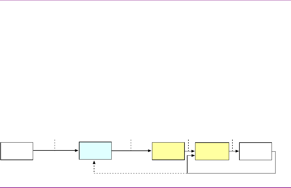
In stepper mode, the trajectory generator accepts a target position and provides a current demand
to the current limiter. The current limiter provides a limited current to the stepper current loop. The
stepper current loop outputs a PWM command to drive the motor. Actual current feedback is used
to close the current loop in the amplifier. Position feedback from an optional encoder can be used
to provide position maintenance data to the external controller program.
Target
Position
Position
Command
Actual CurrentActual Position (w ith optional encoder)
Limited
Current
PWM
Command
Trajectory
Generator
Vector
Generator
Control
Program
Stepper
Current Loop
Motor/
Encoder
2.3.2: Full Stepping
Full stepping is a traditional and simple approach to driving a step motor. The motor moves when
the amplifier stops applying current to one phase and applies it to the other. The amplifier can
apply current to either of these two phases in either direction (i.e., positive current into phase A,
negative into phase A, positive into B, negative into B). This allows the amplifier to make the motor
come to rest in 4 distinct positions for each magnetic poll pair of the motor.
Step motors typically have 50 or 100 poll pairs. This means a full stepping amplifier can make the
motor come to rest at 200 or 400 distinct positions or steps. These motors are often described as
being 1.8 degree / step, or 0.9 degree / step. (360 degrees/200 steps gives 1.8 degrees/step).
The Stepnet amplifier can be set to full stepping mode by the programming the microsteps/rev
value equal to the motors step/rev value.

Stepnet Panel Amplifier User Guide Operational Theory
Copley Controls Corp. 17
2.3.3: Microstepping
Through microstepping, Stepnet amplifiers provide a much higher degree of control over a motor’s
position than does an amplifier that only supports full stepping. The Stepnet amplifier can apply
varying amounts of current into both phases of the motor at the same time, making it possible to
rest the motor not only at the full step locations, but at points or microsteps between them, and
thus allow a high degree of control over the motor’s position.
There is virtually no limit on the number of microsteps/rev that can be programmed into the
Stepnet amplifier. The practical limit depends on the motor, but a value on the order of 4096
microsteps/electrical cycle is generally reasonable. Programming a very high value will limit the
maximum velocity of the motor. When a high resolution encoder is connected to the motor, it is
sometimes advantageous to program the number of microsteps to be equal to the number of
encoder counts.
Some drive manufacturers require that the number of microsteps/rev be an integer multiple of the
number of electrical cycles. The Stepnet amplifiers do not have such a limitation.
2.3.4: Current Control in Stepper Mode
The Stepnet amplifier uses three programmable current settings to control the current applied to
the motor: boost, run, and hold.
Boost current is applied to motor while it is accelerating or decelerating. Since it is only applied for
ashort amount of time, it can typically be set higher then the motor's continuous rated value.
Another parameter, time at boost, specifies how long the boost current may be applied to the
motor. If acceleration or deceleration time exceeds this limit, the current will decrease to the run
value even though the motor is still accelerating/decelerating.
The run current is applied to the motor while it running at a constant velocity.
The hold current is used after the motor has stopped running and after the time specified by the
run to hold parameter has expired.
Asmall amount of jitter can occur when Stepper motors are at rest under hold current. To prevent
this, the Stepnet features an optional voltage mode. After the time specified in the hold to voltage
parameter has expired, the amplifier enters the voltage mode, locking the duty cycle to prevent
jitter.
An I2Talgorithm is used to protect the motor from overheating by basically averaging the amount
of current applied to the motor and not allowing it exceed the run current setting. If boost current is
used, then the motor must spend time with hold current applied so the average does not exceed
the run setting. See I2T Time Limit Algorithm (p. 167).
NOTE: Current loop operation in stepper mode is very similar to current loop operation in servo
mode. Reading the description of servo mode operation can be helpful in understanding stepper
mode operation. When doing so, make the following substitutions: where stepper mode uses run
current, servo mode uses continuous current; where stepper mode uses boost current, servo
mode uses peak current. Also, there is no servo mode equivalent to the stepper mode hold
current. For more details about current loop operation, see Servo Current Mode and Current Loop
(p. 19).
Operational Theory Stepnet Panel Amplifier User Guide
18 Copley Controls
2.4: Servo Mode Operation
2.4.1: Servo Modes and Control Loops
Nesting of Servo Mode Control Loops and Modes
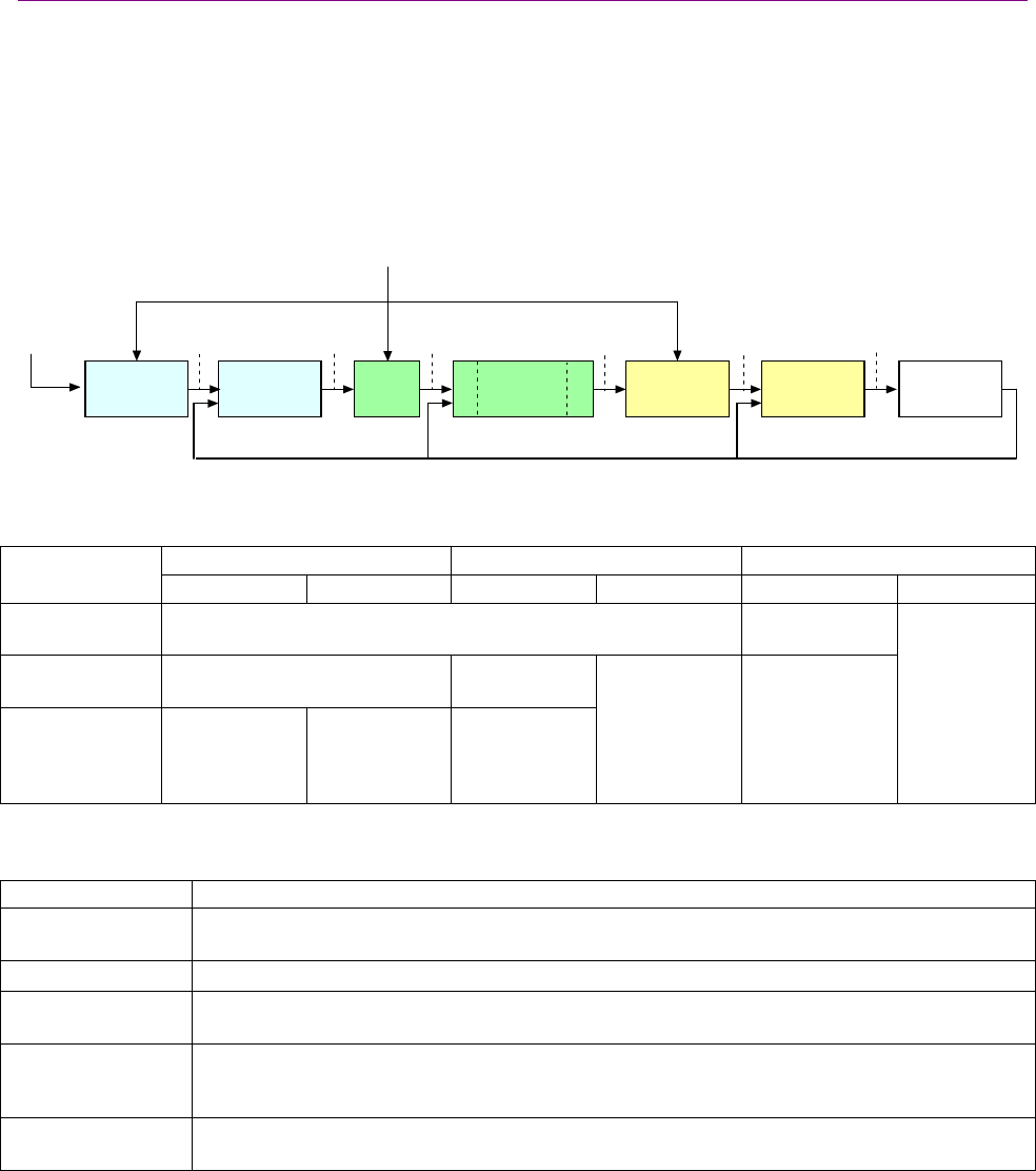
In servo mode, the Stepnet uses up to three nested control loops - current, velocity, and position -
to control a motor in three associated operating modes.
Servo Mode Nested Loops Illustration
In servo position mode, the amplifier uses all three loops, as shown below. The loops are nested:
the current loop within the velocity loop, within the position loop. Stated another way: the position
loop drives the velocity loop, which drives the current loop.
Target
Position
Position
Demand
Actual CurrentDerived VelocityActual Position
Veloc ity
Demand
Current
Demand
Limited
Velocity
Limited
Current
PWM
Command
Trajectory
Generator
Position
Loop
Velocity
Limiter
Cur r ent
Limiter
Current
Loop
Motor/
Sensors
Limits
Veloc ity
Loop
FILTER
FILTER
Servo Control Loops per Operating Mode
The loops are employed in the operating modes as described below.
Servo Position Loop Servo Velocity Loop Servo Current Loop Operating
Mode Input Output Input Output Input Output
Current Velocity and position loops not employed in current mode. External
command.
Velocity Position loop not employed in
velocity mode.
External
command.
Position External
command.
Velocity
command
(input to the
velocity loop).
Velocity
command
from position
loop.
Current
command
(input to
current loop).
Current
command from
velocity loop.
Voltage
command
(input to the
PWM power
stage)
Basic Attributes of All Servo Control Loops
These loops (and servo control loops in general) share several common attributes:
Loop Attribute Description
Command input Every loop is given a value to which it will attempt to control. For example, the velocity loop
receives a velocity command that is the desired motor speed.
Limits Limits are set on each loop to protect the motor and/or mechanical system.
Feedback The nature of servo control loops is that they receive feedback from the device they are
controlling. For example, the position loop uses the actual motor position as feedback.
Gains These are constant values that are used in the mathematical equation of the servo loop. The
values of these gains can be adjusted during amplifier setup to improve the loop
performance. Adjusting these values is often referred to as tuning the loop.
Output The loop generates a control signal. This signal can be used as the command signal to another
control loop or the input to a power amplifier.
Stepnet Panel Amplifier User Guide Operational Theory
Copley Controls Corp. 19
2.4.2: Servo Current Mode and Current Loop
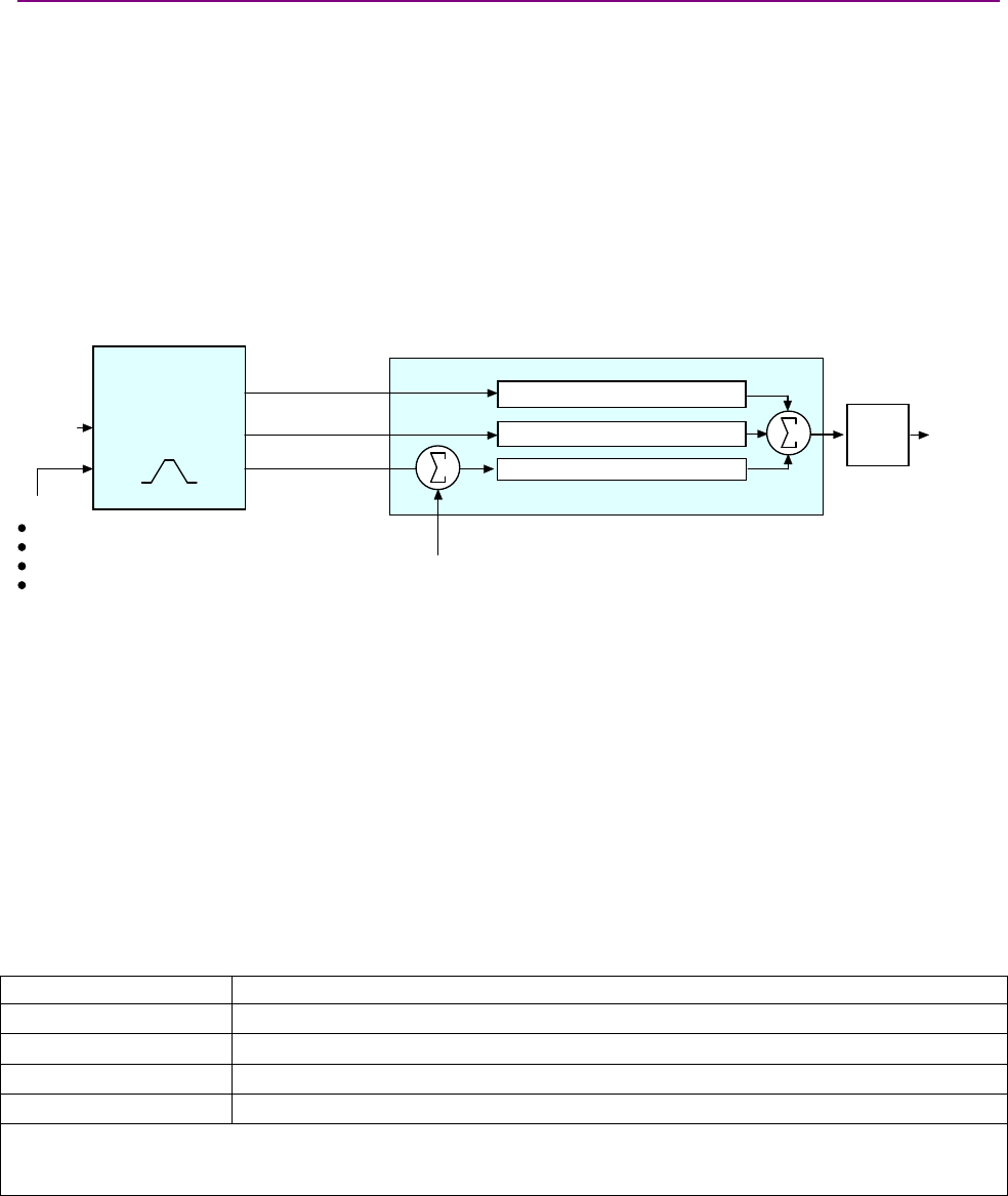
Servo Current Loop Diagram
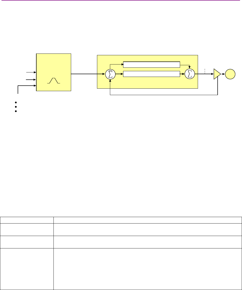
As shown below, the “front end” of the servo current loop is a limiting stage. The limiting stage
accepts a current command, applies limits, and passes a limited current command to the summing
junction. The summing junction takes the commanded current, subtracts the actual current
(represented by the feedback signal), and produces an error signal. This error signal is then
processed using the integral and proportional gains to produce a command. This command is
then applied to the amplifier’s power stage.
Current Demand
PWM
Command
Current Limiter
Current Loop
Feedback (Actual Current)
Limits:
Peak Current
Continuous Current
Peak Current Limit Time
Current Integral Gain (Ci)
Current Proportional Gain (Cp)
Limited Current +
-
+
+Motor
Current Offset
Inputs
In servo current mode, the current command comes from external sources such as the amplifier’s
PWM inputs, or internal sources, such as a Copley Virtual Machine (CVM) program.
See PWM Input (Servo Mode Only) (p. 29).
In servo velocity or position modes, the current command is generated by the velocity loop.
Offset
The servo current loop offset is intended for use in applications where there is a constant force
applied to, or required of, the motor and the system must control this force. Typical applications
would be a vertical axis holding against gravity, or web tensioning. This offset value is summed
with the current command before the limiting stage.
Limits
The current command is limited based on the following parameters:
Limiter Description
Peak Current Limit Maximum current that can be generated by the amplifier for a short duration of time. This
value cannot exceed the peak current rating of the amplifier.
Continuous Current
Limit
Maximum current that can be constantly generated by the amplifier.
I2TTime Limit Maximum amount of time that the peak current can be applied to the motor. The amplifier
can be programmed to fold back the current to the continuous current setting or generate a
latched fault when this time is exceeded.
For more details, see I2TTime Limit Algorithm (p. 167).
Note: Although the current limits set by the user may exceed the amplifier's internal limits,
the amplifier operates using both sets of limits in parallel, and therefore will not exceed its
own internal limits regardless of the values programmed.

Operational Theory Stepnet Panel Amplifier User Guide
20 Copley Controls
Current Loop Gains
The current loop uses these gains:
Gain Description
Cp - Current loop proportional The current error (the difference between the actual and the limited commanded
current) is multiplied by this value. The primary effect of this gain is to increase
bandwidth (or decrease the step-response time) as the gain is increased.
Ci - Current loop integral The integral of the current error is multiplied by this value. Integral gain reduces the
current error to zero over time. It controls the DC accuracy of the loop, or the
flatness of the top of a square wave signal. The error integral is the accumulated
sum of the current error value over time.
Current Loop Output
The output of the current loop is a command that sets the duty cycle of the PWM output stage of
the amplifier.
Auto Tune
CME 2 provides a current loop Auto Tune feature, which automatically determines optimal Cp and
Ci values for the motor. For more information, see the CME 2 User Guide.
Stepnet Panel Amplifier User Guide Operational Theory
Copley Controls Corp. 21
2.4.3: Servo Velocity Mode and Velocity Loop
Servo Velocity Loop Diagram
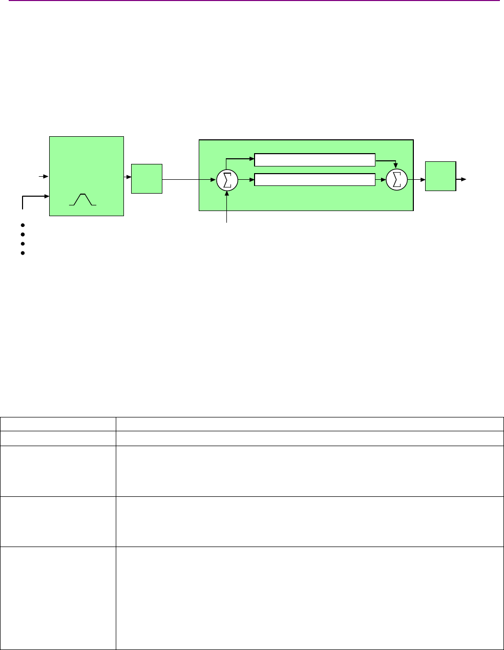
As shown below, the “front end” of the servo velocity loop is a limiting stage. This accepts a
velocity command, applies limits, and passes a limited velocity command to the summing junction.
The summing junction takes the limited velocity command, subtracts the actual velocity,
represented by the feedback signal, and produces an error signal. This error signal is then
processed using the integral and proportional gains to produce a current command. Optional
filters can be used to reduce the excitation of any resonance in the system. They are available on
both the input command and the output current demand, but most typically used on the output
only.
Velocity
Demand Current
Demand
Velocity Limite r
Velocity Loop
Feedback (Derived Velocity)
Limits:
Velocity
Acceleration*
Deceleration*
Emergency Stop Deceleration*
*Not used w hen velocity loop is controlled by position loop. See "Velocity Loop Limits" f or details.
Velocity Integral Gain (Vi)
Velocity Proportional Gain (Vp)
Limited
Velocity +
-
+
+
Filt e r
Filter
Inputs
In servo velocity mode, the velocity command comes from external sources such as the amplifier’s
PWM inputs, or internal sources, such as a Copley Virtual Machine (CVM) program.
See PWM Input (Servo Mode Only) (p. 29).
In servo position mode, the velocity command is generated by the position loop.
Servo Velocity Loop Limits
The velocity command is limited based on the following set of parameters designed to protect the
motor and/or the mechanical system.
Limiter Description
Velocity Limit Sets the maximum velocity command input to the servo velocity loop.
Acceleration Limit Limits the maximum acceleration rate of the commanded velocity input to the servo velocity
loop.
This limit is used in servo velocity mode only. In servo position mode, the trajectory
generator handles acceleration limiting.
Deceleration Limit Limits the maximum deceleration rate of the commanded velocity input to the servo velocity
loop.
This limit is used in servo velocity mode only. In servo position mode, the trajectory
generator handles deceleration limiting.
Fast Stop Ramp Specifies the deceleration rate used by the servo velocity loop when the amplifier is
hardware disabled. (Fast stop ramp is not used when amplifier is software disabled.) If the
brake output is active, the fast stop ramp is used to decelerate the motor before applying
the brake.
Note that Fast Stop Ramp is used only in servo velocity mode. In servo position mode, the
trajectory generator handles controlled stopping of the motor. There is one exception: if a
non-latched following error occurs in position mode, then the amplifier goes into velocity
mode and the Fast Stop Ramp is used.
For more information, see Following Error Fault Details (p. 40).
Operational Theory Stepnet Panel Amplifier User Guide
22 Copley Controls
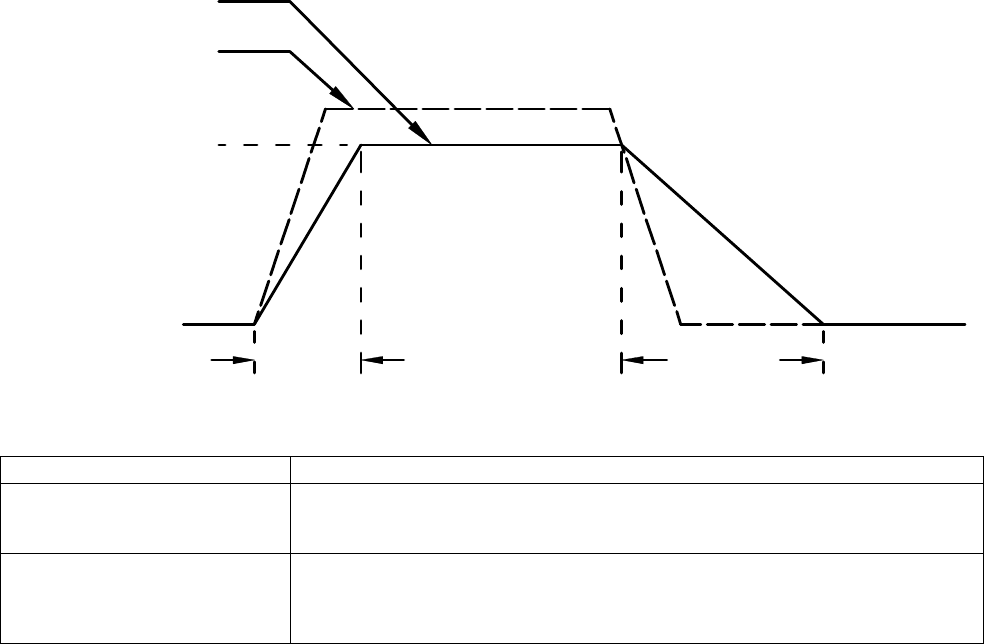
Diagram: Effects of Limits on Velocity Command
The following diagram illustrates the effects of the servo velocity loop limits.
Commanded Velocity
Limited Velocity
Vel Limit
Accel Limit Decel Limit
Servo Velocity Loop Gains
The servo velocity loop uses these gains:
Gain Description
Vp - Velocity loop proportional The velocity error (the difference between the actual and the limited commanded
velocity) is multiplied by this gain. The primary effect of this gain is to increase
bandwidth (or decrease the step-response time) as the gain is increased.
Vi - Velocity loop integral The integral of the velocity error is multiplied by this value. Integral gain reduces the
velocity error to zero over time. It controls the DC accuracy of the loop, or the
flatness of the top of a square wave signal. The error integral is the accumulated
sum of the velocity error value over time.
Servo Velocity Gains Shift
The Velocity Gains Shift feature adjusts the resolution of the units used to express Vp and Vi,
providing more precise tuning. If the non-scaled value of Vp or Vi is 64 or less, the Low Gains
Shift option is available to increase the gains adjustment resolution. (Such low values are likely to
be called for when tuning a linear motor with an encoder resolution finer than a micrometer.) If the
non-scaled value of Vp or Vi is 24001 or higher, the High Gains Shift option is available to
decrease the gains adjustment resolution.
Servo Velocity Loop Command and Output Filters
The servo velocity loop contains two programmable digital filters. The input filter should be used to
reduce the effects of a noisy velocity command signal. The output filter can be used to reduce the
excitation of any resonance in the motion system.
Two filter classes can be programmed: the Low-Pass and the Custom Bi-Quadratic. The Low-
Pass filter class includes the Single-Pole and the Two-Pole Butterworth filter types. The Custom
Bi-Quadratic filter allows advanced users to define their own filters incorporating two poles and two
zeros.
For more information, see the CME 2 User Guide.
Servo Velocity Loop Outputs
The output of the servo velocity loop is a current command used as the input to the servo current
loop.
Stepnet Panel Amplifier User Guide Operational Theory
Copley Controls Corp. 23
2.4.4: Servo Position Mode and Position Loop
Servo Position Loop Diagram
The amplifier receives position commands from internal sources, such as a Copley Virtual
Machine (CVM) program, or external input sources such as the amplifier’s digital inputs or a
CANopen or DeviceNet network.
When using the digital inputs, the amplifier's internal trajectory generator calculates a trapezoidal
motion profile based on the trajectory limit parameters. The trajectory generator updates the
calculated profile in real time as additional position commands are received. The output of the
generator is an instantaneous position command (limited position). In addition, values for the
instantaneous profile velocity and acceleration are generated. These signals, along with the actual
position feedback, are processed by the position loop to generate a velocity command.
The following diagram summarizes the servo position loop.
Target
Position Velocity
Demand
Trajectory
Ge ne r ator
Position Loop
Feedback (Actual Position)
Limits:
Max velocity
Max accel
Max decel
Abort decel
Position Proportional Gain (Pp)
Velocity Feed Forw ard (Vff)
Acceleration Feed Forw ard (Af f)
Prof ile Acceleration
Prof ile V elocity
Limited Position
+
+
-
+
+
Gain
Multiplier
The Clear Limits feature is described in Position Loop Settings,p. 141.
Servo Position Mode Inputs
In servo position mode, various input sources can drive the amplifier:
•The amplifier receives position commands directly from the digital inputs. For more
information, see Digital Inputs (p. 100).
•The amplifier receives position commands over a CANopen or DeviceNet network via the
amplifier’s CAN interface. For more information, see Communication (p. 30) and the Copley
DeviceNet Programmer’s Guide.
Trajectory Limits
In servo position mode, the trajectory generator applies the following user-set limits to generate
the motion profile.
Limiter Description
Maximum Velocity* Limits the maximum speed of the profile.
Maximum Acceleration* Limits the maximum acceleration rate of the profile.
Maximum Deceleration* Limits the maximum deceleration rate of the profile.
Abort Deceleration Specifies the deceleration rate used by the trajectory generator when motion is aborted.
*When the amplifier is driven by pulse and direction commands, Maximum Velocity, Acceleration, and Deceleration
function as maximum values. When the amplifier is driven by any other command input, Maximum Velocity,
Acceleration, and Deceleration function as commanded values.

Operational Theory Stepnet Panel Amplifier User Guide
24 Copley Controls
Servo Position Loop Inputs From the Trajectory Generator
The servo position loop receives the following inputs from the trajectory generator.
Input Description
Profile Velocity The instantaneous velocity value of the profile. Used to calculate the velocity feed forward
value.
Profile Acceleration The instantaneous acceleration/deceleration value of the profile. Used to calculate the
acceleration feed forward value.
Limited Position The instantaneous commanded position of the profile. Used with the actual position feedback to
generate a position error.
Servo Position Loop Gains
The following gains are used by the servo position loop to calculate the velocity command:
Gain Description
Pp - Position loop proportional The loop calculates the position error as the difference between the actual and
limited position values. This error in turn is multiplied by the proportional gain value.
The primary effect of this gain is to reduce the following error.
Vff - Velocity feed forward The value of the profile velocity is multiplied by this value. The primary effect of this
gain is to decrease following error during constant velocity.
Aff - Acceleration feed forward The value of the profile acceleration is multiplied by this value. The primary effect of
this gain is to decrease following error during acceleration and deceleration.
Gain Multiplier The output of the position loop is multiplied by this value before being passed to the
velocity loop.
Servo Position Loop Feedback
The feedback to the loop is the actual motor position, obtained from a quadrature encoder
attached to the motor.
Servo Position Loop Output
The output of the servo position loop is a velocity command used as the input to the velocity loop.

Stepnet Panel Amplifier User Guide Operational Theory
Copley Controls Corp. 25
2.5: Input Command Types
The amplifier can be controlled by a variety of external sources: analog voltage input (STX only),
digital inputs, CAN network (CANopen or DeviceNet), or over an RS-232 serial connection using
ASCII commands. The amplifier can also function as a stand-alone motion controller running an
internal CVM program or using its internal function generator.
2.5.1: Analog Command Input (STX Servo Mode Only)
Overview
The amplifier can be driven by an analog voltage signal through the analog command input. The
amplifier converts the signal to a current, velocity, or position command as appropriate for current,
velocity, or position mode operation, respectively.
The analog input signal is conditioned by the scaling, dead band, and offset settings.
Aprogrammable filter is also available on the analog input. See the “Low-Pass and Bi-Quad
Filters” appendix in the CME 2 User’s Guide.
Scaling
The magnitude of the command generated by an input signal is proportional to the input signal
voltage. Scaling controls the input-to-command ratio, allowing the use of an optimal command
range for any given input voltage signal range.
For example, in current mode, with default scaling, +10 Vdc of input generates a command equal
to the amplifier’s peak current output; +5 Vdc equals half of that.
Scaling could also be useful if, for example, the signal source generates a signal range between 0
and +10 Vdc, but the command range only requires +7.5 Vdc of input. In this case, scaling allows
the amplifier to equate +7.5 Vdc with the amplifier’s peak current (in current mode) or maximum
velocity (in velocity mode), increasing the resolution of control.
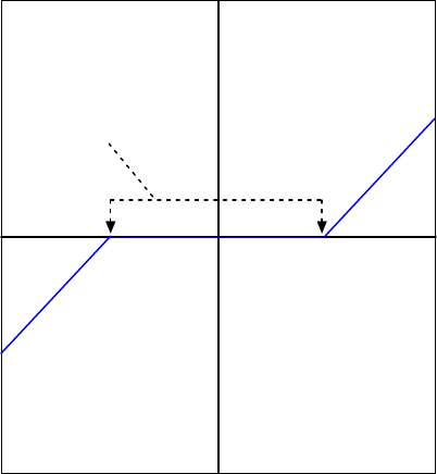
Dead Band
To protect against unintended response to low-level line noise or interference, the amplifier can be
programmed with a “dead band” to condition the response to the input signal voltage. The
amplifier treats anything within the dead band ranges as zero, and subtracts the dead band value
from all other values. For instance, with a dead band of 100 mV, the amplifier ignores signals
between –100 mV and +100 mV, and treats 101 mV as 1 mV, 200 mV as 100 mV, and so on.
Operational Theory Stepnet Panel Amplifier User Guide
26 Copley Controls
Input
Output
0
-100
-200
100
200
0 200-200 -100 100
Dead Band
Offset
To remove the effects of voltage offsets between the controller and the amplifier in open loop
systems, CME 2 provides an Offset parameter and a Measure function. The Measure function
takes 10 readings of the analog input voltage over a period of approximately 200 ms, averages
the readings, and then displays the results. The Offset parameter allows the user to enter a
corrective offset to be applied to the input voltage.
The offset can also set up the amplifier for bi-directional operation from a uni-polar input voltage.
An example of this would be a 0 to +10 Vdc velocity command that had to control 1000 rpm CCW
to 1000 rpm CW. Scale would be set to 2000 rpm for a +10 Vdc input and Offset set to -5V. After
this, a 0 Vdc input command would be interpreted as -5 Vdc, which would produce 1000 rpm CCW
rotation. A +10 Vdc command would be interpreted as +5 Vdc and produce 1000 rpm CW rotation.
Monitoring the Analog Command Voltage
The analog input voltage can be monitored in the CME 2 control panel and oscilloscope. The
voltage displayed in both cases is after both offset and deadband have been applied.
Analog Command in Position Mode
The amplifier’s Analog Position command operates as a relative motion command. When the
amplifier is enabled the voltage on the analog input is read. Then any change in the command
voltage will move the axis a relative distance, equal to the change in voltage, from its position
when enabled.
To use the analog position command as an absolute position command, the amplifier should be
homed every time it is enabled. The Homing sequence may be initiated by CAN, ASCII serial, or
CVM Indexer program commands.
Stepnet Panel Amplifier User Guide Operational Theory
Copley Controls Corp. 27
2.5.2: Digital Position Inputs
Three Formats
In position mode, the amplifier can accept position commands via two digital inputs, using one of
these signal formats: pulse and direction, count up/count down, or quadrature.
In all three formats, the amplifier can be configured to invert the command.
Pulse Smoothing
In position mode, the amplifier’s trajectory generator ensures smooth motion even when the
command source cannot control acceleration and deceleration rates.
Pulse and Direction Format
In pulse and direction format, one input takes a series of pulses as motion step commands, and
another input takes a high or low signal as a direction command, as shown below.
Pulse Input
Velocity
Command
Direction Input
The amplifier can be set to increment position on the rising or falling edge of the signal. Stepping
resolution can be programmed for electronic gearing.
Count Up/Count Down Format
In the count up/count down format, one input takes each pulse as a positive step command, and
another takes each pulse as a negative step command, as shown below.
Up Input
Velocity
Command
Down Input
The amplifier can be set to increment position on the rising or falling edge of the signal. Stepping
resolution can be programmed for electronic gearing.
Operational Theory Stepnet Panel Amplifier User Guide
28 Copley Controls
Quadrature Format
In quadrature format, A/B quadrature commands from a master encoder (via two inputs) provide
velocity and direction commands, as shown below.
BInput
Vel o ci ty
Command
AInput
The ratio can be programmed for electronic gearing.
Stepnet Panel Amplifier User Guide Operational Theory
Copley Controls Corp. 29
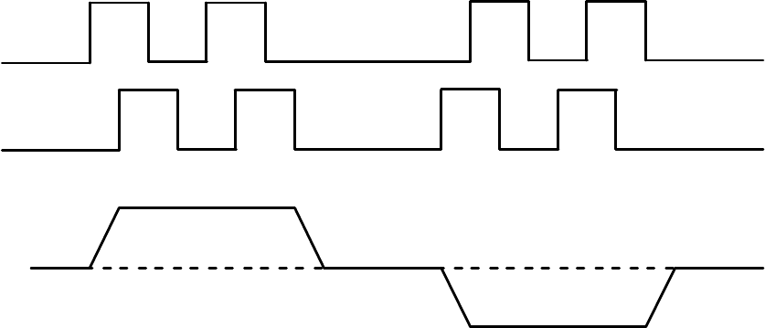
2.5.3: PWM Input (Servo Mode Only)
Two Formats
The amplifier can accept a pulse width modulated signal (PWM) signal to provide a current
command in servo current mode or a velocity command in servo velocity mode. The PWM input
can be programmed for two formats: 50% duty cycle (one-wire) or 100% duty cycle (two-wire).
50% Duty Cycle Format (One-Wire)
The input takes a PWM waveform of fixed frequency and variable duty cycle. As shown below, a
50% duty cycle produces zero output from the amplifier. Increasing the duty cycle toward 100%
commands a positive output; decreasing the duty cycle commands a negative output.
Decreasing Duty Cycle Increasing Duty Cycle
Max -
Max +
0
PWM Input
Amplifier Output
50 % Duty Cycle
The command can be inverted so that increased duty cycle commands negative.
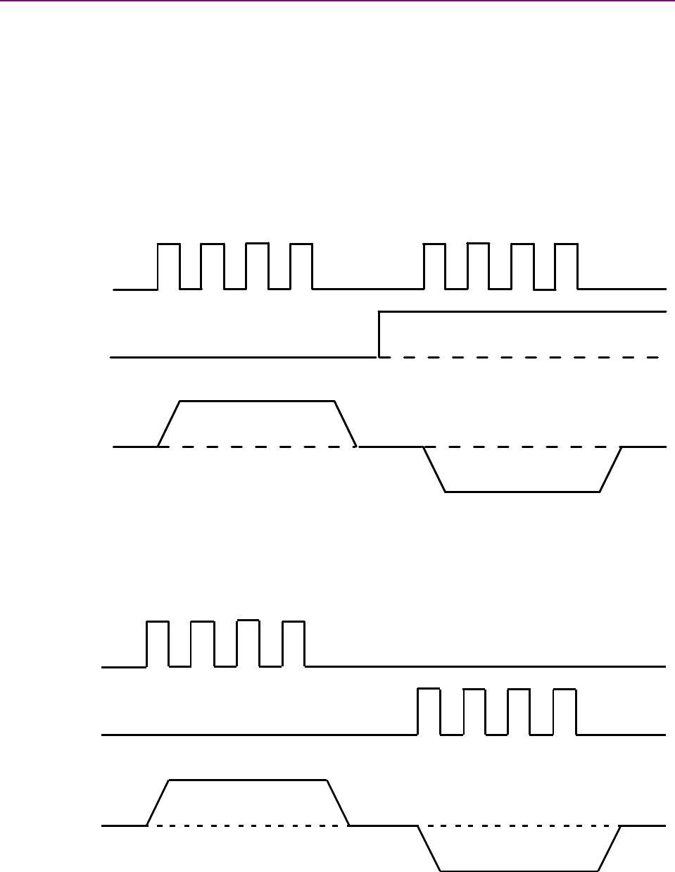
100% Duty Cycle Format (Two-Wire)
One input takes a PWM waveform of fixed frequency and variable duty cycle, and the other input
takes a DC level that controls the polarity of the output. A 0% duty cycle creates a zero command,
and a 100% duty cycle creates a maximum command level. The command can be inverted so that
increasing the duty cycle decreases the output and vice versa.
100% Duty Cycle
PWM Input
Direction Input
Amplifier Output
Max +
Min -
0
100% Duty Cycle0% Duty Cycle
Failsafe Protection from 0 or 100% Duty Cycle Commands
In both formats, the amplifier can be programmed to interpret both 0 and 100% duty cycle as a
zero command. This provides a measure of safety in case of a controller failure or a cable break.
Operational Theory Stepnet Panel Amplifier User Guide
30 Copley Controls
2.6: Communication
As described below, the amplifier features multiple communication interfaces, each used for
different purposes.
Interface Description
RS-232 port The amplifier features a three-wire RS-232 port.
Control commands can be sent over the RS-232 port using Copley Controls ASCII
interface commands.
In addition, CME 2 software communicates with the amplifier (using a binary protocol) over
this link for amplifier commissioning, adjustments, and diagnostics. For RS-232 port
specifications, see Serial Interface (p. 51).For RS-232 port wiring instructions, see
Stepnet Panel (STP) RS-232 Serial Communications (J4) (p. 66) or Stepnet Panel AC
(STX) RS-232 Serial Communications (J8) (p. 83).
Note that CME 2 can be used to make adjustments even when the amplifier is being
controlled over the CAN interface or by the digital inputs.
CAN interface When operating as a CAN node, the amplifier takes command inputs over a CANopen or
DeviceNet network. CAN communications are described in the next section.
Using CME 2 can affect or suspend CAN operations.
!
DANGER
When operating the amplifier as a CANopen or DeviceNet node, use of CME 2 to
change amplifier parameters can affect CANopen or DeviceNet operations in
progress.
Using CME 2 to initiate motion can cause CANopen or DeviceNet operations to
suspend. The operations may restart unexpectedly when the CME 2 move is
stopped.
Failure to heed this warning can cause equipment damage, injury, or death.
2.6.1: CAN Network and CANopen Profiles for Motion
In servo or stepper position mode, the amplifier can take instruction over a two-wire Controller
Area Network (CAN). CAN specifies the data link and physical connection layers of a fast, reliable
network.
CANopen is a set of profiles (specifications) built on a subset of the CAN application layer
protocol. These profiles specify how various types of devices, including motion control devices,
can use the CAN network in a highly efficient manner. Stepnet supports the relevant CANopen
profiles, allowing it to operate in the following modes of operation: profile torque, profile velocity,
profile position, interpolated position, and homing.
2.6.2: Supported CANopen Modes
In profile torque mode, the amplifier is programmed with a torque command. When the amplifier is
enabled, or the torque command is changed, the motor torque ramps to the new value at a
programmable rate. When the amplifier is halted, the torque ramps down at the same rate.
In profile velocity mode, the amplifier is programmed with a velocity, a direction, and acceleration
and deceleration rates. When the amplifier is enabled, the motor accelerates to the set velocity
and continues at that speed. When the amplifier is halted, the velocity decelerates to zero.
In profile position mode, the amplifier is programmed with a velocity, a relative distance or
absolute position, and acceleration and deceleration rates. On command, a complete motion
profile is executed, traveling the programmed distance or ending at the programmed position. The
amplifier supports both trapezoidal and s-curve profiles.
Stepnet Panel Amplifier User Guide Operational Theory
Copley Controls Corp. 31
In interpolated position mode, the controller sends a sequence of points to the amplifier, each of
which is a segment of a larger, more complex move, rather than a single index or profile. The
amplifier then uses cubic polynomial interpolation to “connect the dots” so that the motor reaches
each point at the specified velocity at the programmed time.
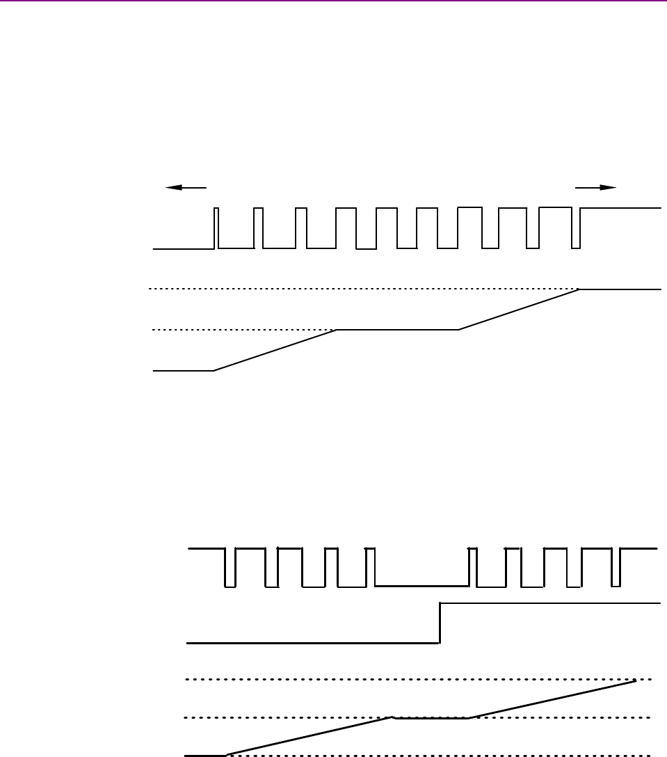
Homing mode is used to move the axis from an unknown position to a known reference or zero
point with respect to the mechanical system. The homing mode is configurable to work with a
variety of combinations of encoder index, home switch, limit switches and mechanical stops.
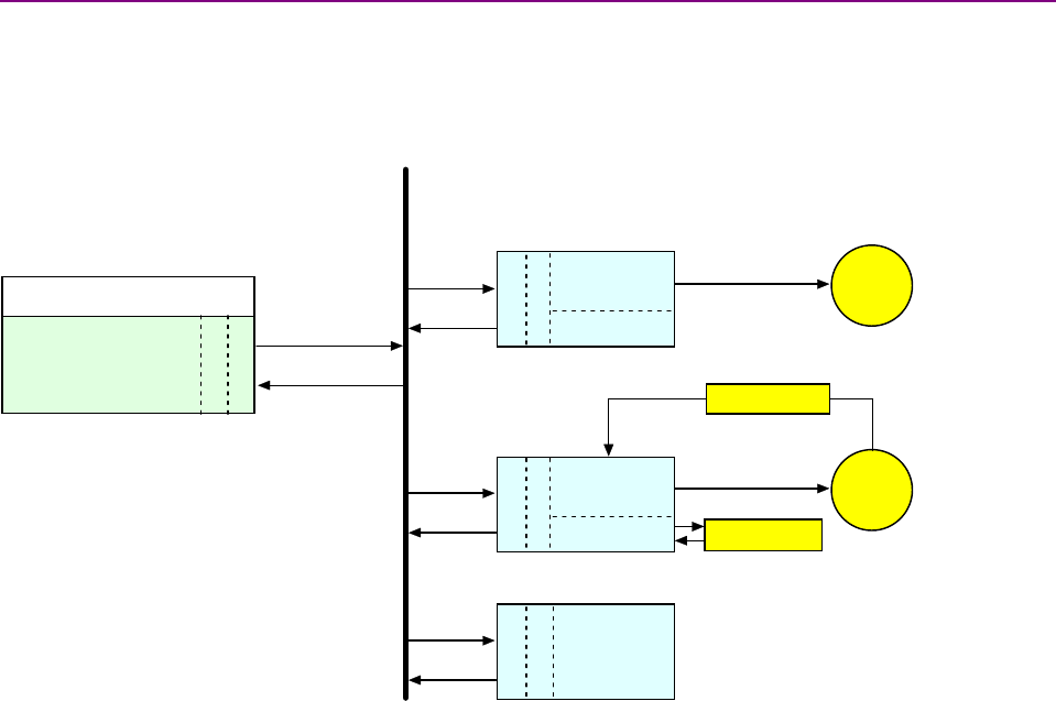
2.6.3: Architecture
As shown below, in a CANopen motion control system, control loops are closed on the individual
amplifiers, not across the network. A master application coordinates multiple devices, using the
network to transmit commands and receive status information. Each device can transmit to the
master or any other device on the network. CANopen provides the protocol for mapping device
and master internal commands to messages that can be shared across the network.
CAN port
Softw are Application
Master Controller
CAN port
CANopen
Other
CANopen
Device
Status
Local Control Motor
Local Control Motor
Sensor
Feedback
CAN port
CANopen
StepNet
A mplif ier
I/O
Control
CAN Network
CAN port
CANopen
StepNet
A mplif ier
I/O
CANopen

Operational Theory Stepnet Panel Amplifier User Guide
32 Copley Controls
2.6.4: CAN Addressing
ACANopen network can support up to 127 nodes. Each node must have a unique and valid
seven-bit address (Node ID) in the range of 1-127. (Address 0 is reserved and should not be
used.)
There are several methods for setting the CAN address, using various combinations of the rotary
CAN ADDR selector switch, programmed values entered into flash memory, and digital input
signals.
Addressing Method Description
Address selector switch If the address number <= 16, CAN address can be set using the CAN ADDR switch only.
Use programmed value Program address into flash only. Ignore switch.
Use address switch with
programmed offset value
Use address switch and an offset value programmed into flash memory. Address is the
sum of the offset value and the switch setting.
Use inputs with
programmed offset value
Use inputs (user selects how many lines, 1-7) and an offset value programmed into flash.
This offset value is added to the value set by the inputs to determine the address.
Programmed value could be zero so that inputs alone determine address. Ignore the CAN
ADDR switch.
Use switch, input lines,
and programmed offset
value
Use switch, inputs (user selects how many lines, 0-3), and an offset value programmed in
to flash memory. Switch provides the lower four bits; inputs provide the next 0 - 3 bits. The
offset is added to the value set by the switch and inputs to determine address. If
programmed value is zero, switch and inputs alone determine address.
For more information on CAN addressing, see CAN Interface (p. 112).
For more information on CAN communications see Communication (p. 30).
For more information on CANopen operations, see the following Copley Controls documents:
•CANopen Programmer’s Manual
•CML Reference Manual
•Copley Motion Objects Programmer’s Guide
Stepnet Panel Amplifier User Guide Operational Theory
Copley Controls Corp. 33
2.7: Limit Switches
2.7.1: Use Digital Inputs to Connect Limit Switches
Limit switches help protect the motion system from unintended travel to the mechanical limits. Any
of the digital inputs 2-12 can be can be programmed as positive or negative limit switch inputs. An
input can also be programmed as a home limit switch for homing operations.
The amplifier also supports software limits, as configured in Homing Functions Settings (p. 164).
2.7.2: How the Amplifier Responds to Limit Switch Activation
In all modes, in response to an active limit switch:
•The amplifier status indicator flashes green at fast rate.
•Awarning is displayed on CME 2 Control Panel and the CME 2 Control Panel limit indicator
turns red.
•(Optional) Appropriately configured digital outputs go active. See Custom Digital Output
Settings: Custom Event (p. 104).
•The amplifier stops driving motion in the direction of an active limit switch, with the mode-
dependent and configurable variations described below.
Mode Response to Active Limit Switch
Servo
Current
Servo
Velocity
Amplifier stops driving motion in the direction of the active limit switch. The amplifier will drive motion
in the opposite direction if commanded.
Stepper
or Servo
Position
Responses depend on the setting of Hold position when limit switch is active (p. 101).
Hold Position… not set: The amplifier aborts the trajectory in progress and stops the axis, using
reverse current only, at the Abort Deceleration rate. After the axis has stopped the amplifier will not
drive current in the direction of the activated limit switch. In any command mode other then a digital
input mode, the amplifier will respond to commands in the opposite direction. If in digital input mode,
the amplifier must be disabled and re-enabled to command motion in the opposite direction.
Hold Position… set: The amplifier aborts the trajectory in progress and stops the axis at the Abort
Deceleration rate. After the axis stops the amplifier servos to hold that position. The amplifier will
respond to commands in the opposite direction.
!
WARNING
WARNING: Limit switches may be disabled.
If the amplifier is switched back to current or velocity mode with Hold position when limit switch is
active (p. 101) set, the limit switches will no longer function.
Failure to heed this warning can cause equipment damage.
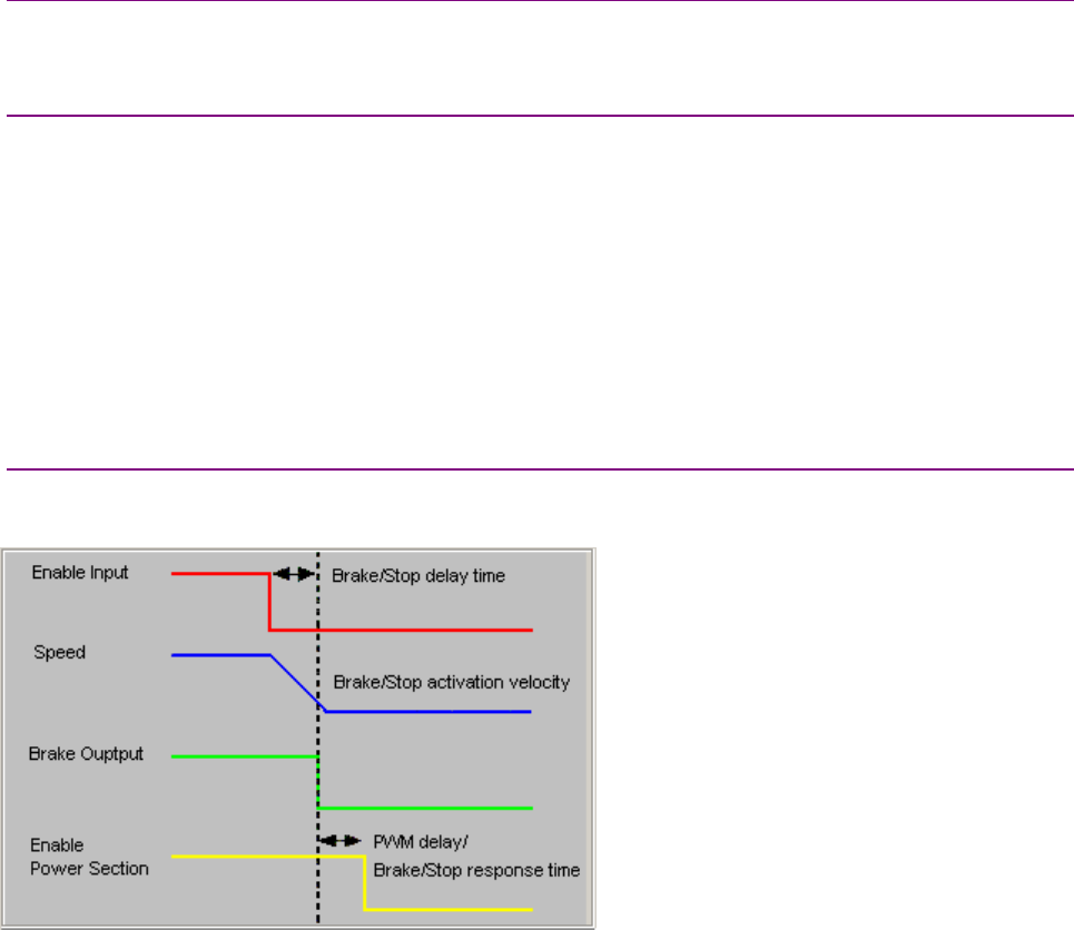
Operational Theory Stepnet Panel Amplifier User Guide
34 Copley Controls
2.8: Brake Operation
2.8.1: Digital Output Controls Brake
Many control systems employ a brake to hold the axis when the amplifier is disabled. Any of the
digital outputs can be programmed for brake control.
2.8.2: Event- and Mode-Specific Brake/Stop Sequences
Braking sequences vary depending on the amplifier’s operating mode.
In current mode, disabling the amplifier activates the brake output and disables the amplifier
output stages immediately.
In position or velocity mode, a hardware or software disable starts a sequence of events:
•The motor begins to decelerate (at Abort Deceleration rate in position mode or Fast Stop
Ramp rate in velocity mode). At the same time, the Brake/Stop Delay Time count begins.
•When the motor slows to Brake/Stop Activation Velocity OR the Brake/Stop Delay Time
expires, the brake output activates and PWM Delay Brake/Stop Response Time count begins.
•When response time has passed, the amplifier’s output stages are disabled.
2.8.3: Brake Settings
As shown below, the brake settings available in position and velocity mode provide control over
the braking sequence.
The pre-braking delay (controlled by the deceleration rate and delay timer) allows the amplifier to
slow the motor before applying the brake. PWM Delay Brake/Stop Response Time makes it
possible to ensure the brake has time to lock in before disabling the power section.

Stepnet Panel Amplifier User Guide Operational Theory
Copley Controls Corp. 35
2.9: Status Indicators
2.9.1: Amplifier and CAN Interface Status Indicators
Stepnet Panel (STP): The amplifier’s status indicator is a bicolor LED labeled STATUS on the J5
connector. The CAN interface status indicator is a bicolor LED on the J6 connector.
Stepnet Panel AC (STX): The amplifier’s status indicator is a bicolor LED labeled STATUS on the
front panel. The CAN interface status indicator is a bicolor LED on the J4 connector.
2.9.2: Amplifier Status Indicator Operation
Amplifier status indicator color/blink codes are described below.
Color/Blink Code Meaning
Not illuminated No power to amplifier.
Steady green Amplifier is enabled and operational.
Slow-blinking green Amplifier is disabled. No faults or warnings are active.
Fast-blinking green A limit switch is active. The amplifier is enabled.
Steady red A non-latched fault has occurred.
Blinking red A latched fault has occurred.
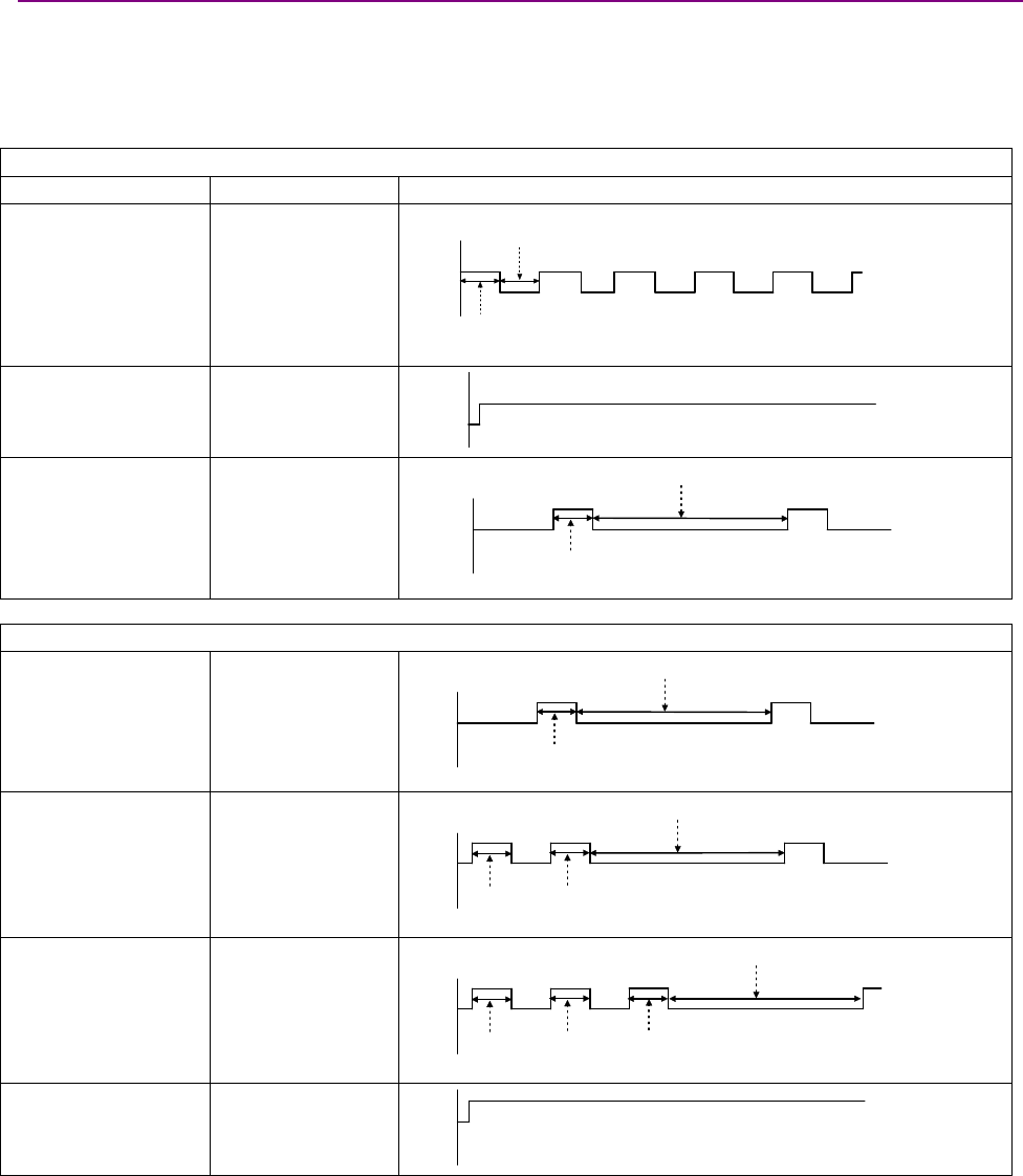
Operational Theory Stepnet Panel Amplifier User Guide
36 Copley Controls
2.9.3: CAN Interface Status Indicator Operation
The amplifier status indicator color/blink codes comply with CAN Indicator Specification 303-3 as
described below. Note that green and red codes are often interlaced, each indicating a different
set of conditions. The green codes indicate the CANopen state machine mode of operation (pre-
operational, operational, or stopped). The red codes indicate the status of the physical bus
(warning or error conditions).
CANopen State Machine Mode of Operation
Indicator State Diagram
Blinking green Pre-operational.
200
ms
off
200
ms
green
Steady green Operational
off
green
Single flash green Stopped
green
200
ms
off
1second
Physical Bus Status
Single flash red Warning Limit
Reached
red
200
ms
off
1second
Double flash red Error Control Event
red
200
ms
off
1second
200
ms
Triple flash red Sync Error
red
200
ms
off
1second
200
ms
200
ms
Steady red Bus Off
red
off
In addition, the CAN status indicator is turned off when the CAN node ID selector (CAN ADDR) is
set to 0. A setting of 0, which is an invalid CAN address, shuts down most operations on the CAN
interface, and the light is shut off to indicate this status.

Stepnet Panel Amplifier User Guide Operational Theory
Copley Controls Corp. 37
2.10: Protection
2.10.1: Faults
Overview
Stepnet detects and responds to a set of conditions regarded as faults, such as amplifier over
temperature and excessive following error. When any fault occurs, with the exception of a
following error, the amplifier’s PWM output stage is disabled, the fault type is recorded in the
amplifier’s internal error log (which can be viewed with CME 2), and the status LED changes to
indicate a fault condition exists. A digital output can also be programmed to activate on a fault
condition. The following error fault behaves with slight differences, as described in
Following Error Fault Details (p. 40).
The amplifier’s PWM output stage can be re-enabled after the fault condition is corrected and the
amplifier faults are cleared. The process for clearing faults varies depending on whether the fault
is configured as non-latched or latched.
The fault-clearing descriptions below apply to all faults except for the following error fault, which is
described in Following Error Fault Details (p. 40).
Clearing Non-Latched Faults
The amplifier clears a non-latched fault, without operator intervention, as soon as the fault
condition is corrected.
Risk of unexpected motion with non-latched faults.
!
DANGER
After the cause of a non-latched fault is corrected, the amplifier re-enables the PWM
output stage without operator intervention. In this case, motion may re-start
unexpectedly. Configure faults as latched unless a specific situation calls for non-
latched behavior. When using non-latched faults, be sure to safeguard against
unexpected motion.
Failure to heed this warning can cause equipment damage, injury, or death.
Clearing Latched Faults
Alatched fault is cleared only after the fault has been corrected and at least one of the following
actions has been taken:
•power-cycle the amplifier
•cycle (disable and then enable) an enable input that is configured as
Enables with Clear Faults or Enables with Reset
•access the CME 2 Control Panel ( )and press Clear Faults or Reset
•clear the fault over the CANopen network
Example: Non-Latched vs. Latched Faults
For example, the amplifier temperature reaches the fault temperature level and the amplifier
reports the fault and disables the PWM output. Then, the amplifier temperature is brought back
into operating range. If the Amplifier Over Temperature fault is not latched, the fault is
automatically cleared and the amplifier’s PWM outputs are enabled. If the fault is latched, the fault
remains active and the amplifier’s PWM outputs remain disabled until the faults are specifically
cleared (as described above).

Operational Theory Stepnet Panel Amplifier User Guide
38 Copley Controls
Fault Descriptions
The set of possible faults is described below. For details on limits and ranges, see
Fault Levels (p. 52).
Fault Description Fault Occurs When… Fault is Corrected When…
*Amplifier Over Temperature Amplifier's internal temperature exceeds
specified temperature.
Temperature falls below specified
temperature.
Motor Phasing Error
(in servo mode only)
Motor fails to properly phase initialize. Amplifier is reset and re-enabled.
Under voltage condition detected on output
of the internal +5 Vdc supply used to
power the encoder.
Encoder power returns to specified
voltage range.
*Feedback error (STX only)
Differential encoder signal fault. Line errors are corrected.
*Motor Over Temperature Motor over-temperature input changes
state to indicate an over-temperature
condition.
Input changes back to normal operating
state.
Under Voltage +HV voltage falls below specified voltage
limit.
+HV voltage returns to specified
voltage range.
Over Voltage +HV voltage exceeds specified voltage
limit.
+HV voltage returns to specified
voltage range.
*Following Error
(with encoder only)
User set following error threshold
exceeded.
See
Position and Servo Velocity Errors (p.
39).
*Short Circuit Detected Output to output, output to ground, internal
PWM bridge fault.
Short circuit has been removed.
Over Current (Latched) Output current I2Tlimit has been
exceeded.
Amplifier is reset and re-enabled.
Command Input Fault PWM command at 0 or 100% duty cycle
with the Allow 100% Output option
disabled.
PWM frequency out of range.
Proper PWM input command is
restored.
*Latched by default.
STX Encoder Loss Detection
The Stepnet Panel AC (STX) amplifier incorporates Encoder Loss Detection circuitry that
continuously monitors the integrity of the differential encoder feedback signals. When a fault in
any of the differential pairs is detected, a feedback error occurs. To enable or disable this
protection, see Enter Motor/Feedback/Brake Settings Manually (p. 96).
In applications where Encoder Loss Detection is enabled and the encoder does not have an index
channel or the index channel is not wired to the amplifier, the amplifier’s index channel connector
pins must be jumpered as shown in Stepnet Panel AC (STX) J6 Quad A/B Incremental Encoder
Wiring Diagram – No Index (p. 76).

Stepnet Panel Amplifier User Guide Operational Theory
Copley Controls Corp. 39
2.11: Position and Servo Velocity Errors
2.11.1: Error-Handling Methods
In stepper mode with encoder or servo position mode, any difference between the limited position
output of the trajectory generator and the actual motor position is a position error. The servo or
stepper position loop uses complementary methods for handling position errors: following error
fault, following error warning, and a position-tracking window.
Likewise, in servo velocity or servo position mode, any difference between the limited velocity
command and actual velocity is a velocity error. The servo velocity loop uses a velocity tracking
window method to handle velocity errors. (There is no velocity error fault.)
2.11.2: Following Error Faults
When the position error reaches the programmed fault threshold, the amplifier immediately faults.
(The following error fault can be disabled.)
For detailed information, see Following Error Fault Details (p. 40).
2.11.3: Following Error Warnings
When the position error reaches the programmed warning threshold, the amplifier immediately
sets the following error warning bit in the status word. This bit can be read over the CAN network.
It can also be used to activate a digital output.
2.11.4: Position and Velocity Tracking Windows
When the position error exceeds the programmed tracking window value, a status word bit is set.
The bit is not reset until the position error remains within the tracking window for the programmed
tracking time.This bit can be read over the CAN network. It can also be used to activate a digital
output.
In servo mode, a similar method is used to handle velocity errors.
For detailed information, see Tracking Window Details (p. 41).

Operational Theory Stepnet Panel Amplifier User Guide
40 Copley Controls
2.11.5: Following Error Fault Details
Position Error Reaches Fault Level
As described earlier, position error is the difference between the limited position output of the
trajectory generator and the actual position. When position error reaches the programmed
Following Error Fault level, the amplifier faults (unless the following error fault is disabled.) As with
awarning, a status bit is set. In addition, the fault is recorded in the error log.
Additional responses and considerations depend on whether the fault is non-latched or latched, as
described below.
Amplifier Response to Non-Latched Following Error Fault
In servo mode, when a non-latched following error fault occurs, the amplifier drops into velocity
mode and applies the Fast Stop Ramp deceleration rate to bring the motor to a halt. The amplifier
PWM output stage remains enabled, and the amplifier holds the velocity at zero, using the velocity
loop.
In stepper mode, when a non-latched following error fault occurs, the current move is aborted and
the amplifier decelerates at the Trajectory Abort Deceleration rate. The amplifier PWM output
stage remains enabled and the Hold current is applied to the motor.
Resuming Operations After a Non-Latched Following Error Fault
The clearing of a non-latched following error depends on the amplifier’s mode of operation. If the
amplifier is operating as a CAN node, starting a new trajectory, using CANopen commands, will
clear the fault and return the amplifier to normal operating condition. If the amplifier is receiving
position commands from the digital inputs, then the amplifier must be disabled and then re-
enabled using a hardware input or though CME 2 software commands. After re-enabling, the
amplifier will operate normally.
Amplifier Response to a Latched Following Error Fault
When a latched following error fault occurs, the amplifier disables the output PWM stage without
first attempting to apply a deceleration rate.
Resuming Operations After a Latched Following Error Fault
Alatched following error fault can be cleared using the steps used to clear other latched faults:
•power-cycle the amplifier
•cycle (disable and then enable) an enable input that is configured as
Enables with Clear Faults or Enables with Reset
•access the CME 2 Control Panel ( )and press Clear Faults or Reset
•clear the fault over the CANopen network
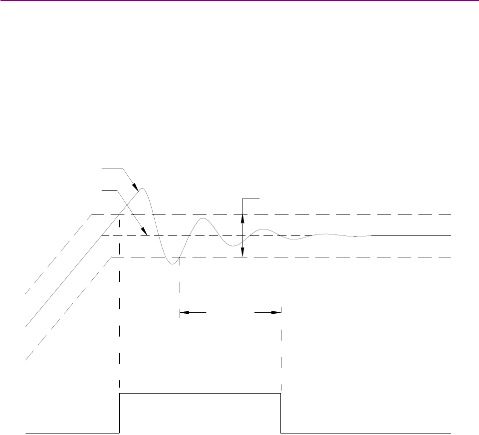
Stepnet Panel Amplifier User Guide Operational Theory
Copley Controls Corp. 41
2.11.6: Tracking Window Details
Proper Tracking Over Time
As described earlier, position error is the difference between the limited position output of the
trajectory generator and the actual position. In servo mode, velocity error is the difference between
commanded and actual velocity.
When the position or velocity error exceeds the programmed tracking window value, a status word
bit is set. The bit is not reset until the error remains within the tracking window for the programmed
tracking time.
Servo Mode Velocity Tracking Illustration
The following diagram illustrates the use of tracking window and time settings in servo velocity
mode.
±Tracking Window
Tracking
Time
Limited Velocity
Actual Velocity
Tracking Window
Output

Operational Theory Stepnet Panel Amplifier User Guide
42 Copley Controls
2.12: Inputs
2.12.1: Digital Inputs
The amplifier has 12 digital inputs (IN1-IN12). IN1 is always used as an enable input. IN2-IN12 are
fully programmable. See Digital Input Functions (p.102).
2.12.2: Input Filters
Two types of input RC filters are used: GP (general-purpose) and HS (high-speed). The digital
command inputs, such as Count Up/Count Down and PWM, are wired to inputs having the HS
filters. Inputs with the GP filters are used for general-purpose logic functions, limit switches, and
the motor temperature sensor.
2.12.3: Debounce Time
To prevent undesired multiple triggering caused by switch bounce upon switch closures, each
input can be programmed with a debounce time. The programmed time specifies how long an
input must remain stable at a new state before the amplifier recognizes the state.
The programmed debounce time is ignored if the input is programmed as a digital position
command, PWM input or encoder input.
2.12.4: Configure for Pull Up/Pull Down Resistors by Groups
Pre-defined groups of inputs can be programmed to have either an internal pull up or pull down
resistor. See Stepnet Panel (STP) J3 Pin Description (p. 62)
or Stepnet Panel AC (STX) J7 Pin Description (p. 79) for groupings.
2.13: Outputs
2.13.1: Digital Outputs
The amplifier has four programmable digital outputs. These outputs are open-drain MOSFETs,
each with a pull-up resistor, in series with a diode, connected to the amplifier’s internal +5 Vdc
supply. This design allows the outputs to be directly connected to optically isolated PLC inputs that
reference a voltage higher than +5 Vdc, typically +24 Vdc. The diode prevents current flow
between the +24 Vdc supply and the internal +5 Vdc supply though the pull-up resistor. This
current, if allowed to flow, could turn on the PLC input, giving a false indication of the amplifier’s
true output state.
The outputs require an external fly-back diode to be installed across any inductive loads, such as
relays, that are connected to them.
NOTE: Outputs will remain off (high) after powering up the amplifier, for a maximum delay of 2
seconds. They will then assume their programmed states. The outputs will also turn off during an
amplifier reset and return to their programmed state after a maximum delay of 0.5 seconds.

Copley Controls Corp. 43
CHAPTER
3: SPECIFICATIONS
This chapter describes the amplifier specifications for the Stepnet Panel (STP) and Stepnet Panel
AC (STX) amplifiers. Contents include:
Title Page
3.1: Agency Approvals................................................................................................................................................................. 44
3.2: Power Input .......................................................................................................................................................................... 44
3.2.1: Stepnet Panel (STP) Power Input ............................................................................................................................ 44
3.2.2: Stepnet Panel AC (STX) Power Input ...................................................................................................................... 44
3.3: Power Output........................................................................................................................................................................ 45
3.3.1: Stepnet Panel (STP) Power Output ......................................................................................................................... 45
3.3.2: Stepnet Panel AC (STX) Power Output.................................................................................................................... 45
3.3.3: Power Output Configuration (STP and STX) ............................................................................................................ 45
3.4: Control Loops ....................................................................................................................................................................... 46
3.5: Stepnet Panel AC (STX) Internal Regen Circuit.................................................................................................................... 46
3.6: Digital Command Input ......................................................................................................................................................... 46
3.7: Stepnet Panel AC (STX) Analog Command Input................................................................................................................. 47
3.8: Digital Inputs......................................................................................................................................................................... 47
3.8.1: Stepnet Panel (STP) Digital Inputs .......................................................................................................................... 47
3.8.2: Stepnet Panel AC (STX) Digital Inputs..................................................................................................................... 48
3.9: Digital Outputs ...................................................................................................................................................................... 49
3.10: Encoder Power Supply Output............................................................................................................................................ 49
3.11: Incremental Quadrature Encoder Inputs ............................................................................................................................. 50
3.11.1: Incremental Differential Encoder Inputs ................................................................................................................. 50
3.11.2: Stepnet Panel AC (STX) Single Ended Encoder Inputs ......................................................................................... 50
3.12: Stepnet Panel AC (STX) Multi-Mode Port ........................................................................................................................... 51
3.13: Serial Interface ................................................................................................................................................................... 51
3.14: CAN Interface..................................................................................................................................................................... 51
3.15: Status Indicators................................................................................................................................................................. 52
3.16: Fault Levels ........................................................................................................................................................................ 52
3.17: Power Dissipation ............................................................................................................................................................... 52
3.17.1: Stepnet Panel (STP) Power Dissipation................................................................................................................. 52
3.17.2: Stepnet Panel AC (STX) Power Dissipation........................................................................................................... 52
3.18: Thermal Impedance............................................................................................................................................................ 52
3.19: Mechanical and Environmental........................................................................................................................................... 53
3.20: Dimensions......................................................................................................................................................................... 54
3.20.1: Stepnet Panel (STP) Dimensions .......................................................................................................................... 54
3.20.2: Stepnet Panel AC (STX) Dimensions..................................................................................................................... 55
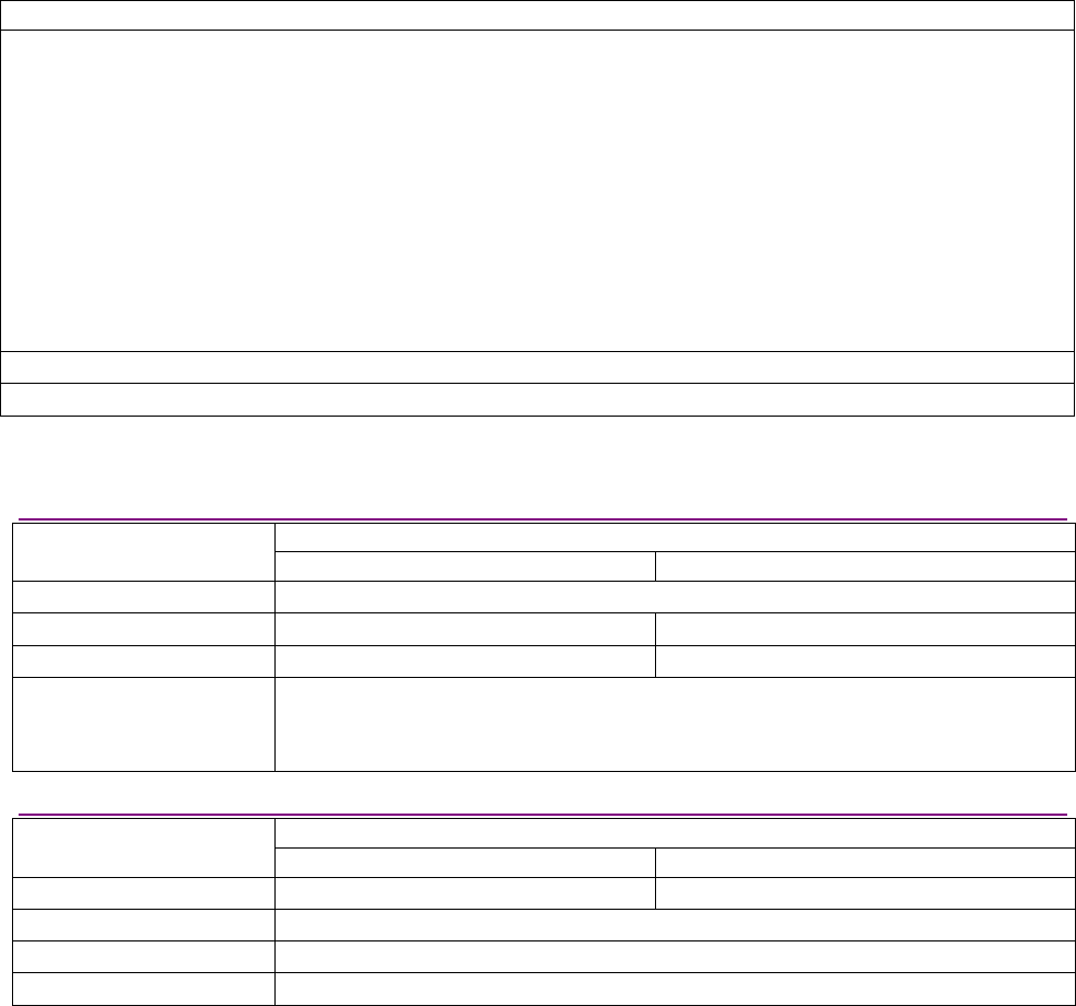
Specifications Stepnet Panel Amplifier User Guide
44 Copley Controls
3.1: Agency Approvals
Stepnet Panel (STP) and Stepnet Panel AC (STX) Agency Approvals
CE Compliance:
EN 55011, 2007
•CiSPR 11 : 2003/A2 : 2006
•Limits and Methods of Measurement of Radio Disturbance Characteristics of Industrial, Scientific, and Medical
(ISM) Radio Frequency equipment
EN 61000-6-1 : 2007
•Electromagnetic Compatibility generic immunity Requirements (Following the provisions of EC Directive
2004/108/EC [EMC Directive])
EN 61010-1 : 2001
•Safety Requirements for Electrical Equipment for Measurement, Control, and Laboratory use. (Following the
provisions of EC Directive 2006/95/EC [Low Voltage Directive])
UL 508C 3rd Ed.: 2002 UL Standard for Safety for Power Conversion Equipment
UL 61010-1 2nd Ed.: 2004 Safety Requirements for Electrical Equipment for Measurement, Control and Laboratory Use
3.2: Power Input
3.2.1: Stepnet Panel (STP) Power Input
Model
Specification STP-075-07 STP-075-10
HV min to HV max +20 to +75 Vdc, transformer-isolated
Peak current 8 Adc (1 Sec) 11 Adc
Continuous current 5.5 Adc 11 Adc
Auxiliary power (optional) +20 to +75 Vdc
3W typical when auxiliary power > HV
0W when auxiliary power < HV
3.2.2: Stepnet Panel AC (STX) Power Input
Model
Specification STX-115-07 STX-230-07
Mains voltage 100 – 120 Vac 100 – 240 Vac
Mains frequency 50-60 Hz
Mains current 8 Arms, continuous
Logic supply (required) 20-32 Vdc @ 500 mAdc maximum

Stepnet Panel Amplifier User Guide Specifications
Copley Controls Corp. 45
3.3: Power Output
3.3.1: Stepnet Panel (STP) Power Output
Model
Specification STP-075-07 STP-075-10
Boost / peak current 7 Adc (5 Arms, sinusoidal) ± 5% 10 Adc (7 Arms, sinusoidal) ± 5%
Boost / peak time 1 Sec n/a
Run / continuous current 5 Adc (3.54 Arms, sinusoidal)± 5% 10 Adc (7 Arms, sinusoidal) ± 5%
Efficiency 97% @ Full rated voltage and continuous output current.
3.3.2: Stepnet Panel AC (STX) Power Output
Model
Specification STX-115-07 STX-230-07
Boost / peak current 7 Adc (5 Arms, sinusoidal) ± 5% 7 Adc (5 Arms, sinusoidal) ± 5%
Boost / peak time 1 Sec 1 Sec
Run / continuous current 5 Adc (3.54 Arms, sinusoidal) ± 5% 5 Adc (3.54 Arms, sinusoidal) ± 5%
(Note 2)
Efficiency 97% @ Full rated voltage and continuous output current.
NOTES:
1. Current ratings are for current vector produced by currents flowing in A and B phases (90º phase difference
between phases).
2. Mounting to heat sink required for operation at continuous current.
3.3.3: Power Output Configuration (STP and STX)
Type Dual MOSFET H-bridges, 15 kHz center-weighted PWM, space-vector modulation
PWM ripple frequency 30 kHz
Minimum load inductance STX > 200 µH per phase
STP > 400 µH per phase
Note: Contact factory if lower inductance is required.

Specifications Stepnet Panel Amplifier User Guide
46 Copley Controls
3.4: Control Loops
Type
Servo mode: current
Servo mode: velocity
Stepper or servo mode: position
100% digital.
Sampling rate (time)
Servo mode: current
Servo mode: velocity
Stepper or servo mode: position
15 kHz (67 Xs)
3kHz (333 Xs)
3kHz (333 Xs)
Current loop small signal bandwidth > 2 kHz
(Tuning and load impedance dependent)
Servo mode velocity loop filters
Type
Frequency range
Programmable
Low Pass, 1 Pole
Low Pass, Butterworth, 2 Poles
Bi-Quadratic, 2 Poles & 2 Zeros
Programmable
20 - 1500 Hz
Voltage compensation Changes in HV or Mains voltage does not affect current-loop bandwidth
3.5: Stepnet Panel AC (STX) Internal Regen Circuit
Model
Specification STX-115-07 STX-230-07
Type Internal MOSFET dissipater
Continuous power 40 W
Peak power 80 W
Turn on voltage(± 2%) Bus voltage > 195 Vdc Bus voltage > 390 Vdc
Turn off voltage(± 2%) Bus voltage < 190 Vdc Bus voltage < 380 Vdc
3.6: Digital Command Input
Step and direction,
Count up/ count down
maximum rate
STP = 1 MHz max pulse rate
STX = 1.5 MHz max pulse rate
Digital position command
Stepper or servo mode
Quadrature A/B encoder
maximum rate
5 M line/sec (20 M count/sec after
quadrature)
PWM frequency range 1 kHz - 100 kHz Digital current & velocity command
Servo mode only PWM minimum pulse width 220 nSec

Stepnet Panel Amplifier User Guide Specifications
Copley Controls Corp. 47
3.7: Stepnet Panel AC (STX) Analog Command Input
Channels 1
Type Differential, non-isolated
Measurement range ±10 Vdc
Maximum voltage
Differential
Input to Ground
±10 Vdc
±10 Vdc
Input impedance 5 k
Resolution 12 Bit
Accuracy ± 2% of reading, ± 0,5% of range
Bandwidth 7 kHz
Sample period 200 µSec
Function Current, velocity, or position commands.
Analog input filter
Type
Frequency range
Programmable:
Low Pass, 1 Pole
Low Pass, Butterworth, 2 Poles
Bi-Quadratic, 2 Poles & 2 Zeros
Programmable: 20 - 1500 Hz
3.8: Digital Inputs
3.8.1: Stepnet Panel (STP) Digital Inputs
Channels 12
5 general-purpose
7 high-speed
Function IN1 dedicated to enable input function
IN2 - IN12 programmable
Logic low input voltage < +1.35 Vdc
Logic high input voltage > +3.65 Vdc
Scan time 333 µSec (pulse and direction, PWM input, and secondary encoder are handled at DSP
clock rate of 25 nSec)
Debounce Digital, programmable from 0 - 10,000 mSec
Type 74HC14 Schmitt trigger w/ RC filter
Inputs 1 – 4, RC time constant = 33uSec
Input 5, RC time constant = 22uSec
10 kresistor programmable as pull down or pull up to internal
+5 Vdc.
General purpose
inputs 1 - 5
Input voltage range 0 V - +30 Vdc
Type 74HC14 Schmitt trigger w/ RC filter
RC time constant = 0.1uSec
10 kresistor programmable as pull down or pull up to internal
+5 Vdc.
High speed
inputs 6 - 12
Input voltage range 0 V - +12 Vdc

Specifications Stepnet Panel Amplifier User Guide
48 Copley Controls
3.8.2: Stepnet Panel AC (STX) Digital Inputs
Channels 12
7 general-purpose
5 high-speed
Function IN1 dedicated to enable input function
IN2 – 11 programmable
IN12 motor over temperature, may be reprogrammed
Scan time 333 µSec (pulse and direction, PWM input, and secondary encoder are handled at DSP
clock rate of 25 nSec)
Debounce Digital, programmable from 0 - 10,000 mSec
Type 74HC14 Schmitt trigger w/ RC filter
RC time constant = 330uSec
10 kresistor programmable as pull down or pull up to internal
+5 Vdc.
Input voltage range 0 V - +24 Vdc
Logic low input voltage < +1.35 Vdc
General purpose
inputs 1 – 4, 10 ,11
Logic high input voltage > +3.65 Vdc
Type 74HC14 Schmitt trigger w/ RC filter
RC time constant = 0.1uSec
10 kresistor programmable as pull down or pull up to internal
+5 Vdc.
Input voltage range 0 V - +12 Vdc
Logic low input voltage < +1.35 Vdc
High speed
input 5
Logic high input voltage > +3.65 Vdc
Type RS422 line receiver w/ RC Filter
RC time constant = 0.1 uSec
10 kresistor programmable as pull down or pull up to internal
+5 Vdc.
May be programmed as 4 independent inputs or 2 differential
inputs
Input voltage range 0 V - +12 Vdc
Logic low input voltage < +2.30 Vdc
High speed
inputs 6 -9
Logic high input voltage > +2.45 Vdc
Type 74HC14 Schmitt trigger w/ RC filter
RC time constant = 500uSec
5 kresistor pull up to internal +5 Vdc.
Input voltage range 0 V - +24 Vdc
Logic low input voltage < +1.35 Vdc
General purpose
input 12
Logic high input voltage > +3.65 Vdc

Stepnet Panel Amplifier User Guide Specifications
Copley Controls Corp. 49
3.9: Digital Outputs
Channels 4
Type
STP 1 – 4
STX 1 – 3
Current-sinking MOSFET, open-drain with 1 kpullup to internal +5 Vdc
through diode
STX 4 (Brake) Opto-isolated, current sinking MOSFET with flyback diode to 24Vdc
Maximum voltage +30 Vdc
Low level output resistance <0.1
Function Programmable
Maximum sink current
STP 1 - 4
STX 1 – 3
STX 4
1A, Total current of outputs 1 – 4 not to exceed 2A
1A, Total current of outputs 1 - 3 not to exceed 1A
1A
3.10: Encoder Power Supply Output
Voltage output +5 Vdc ±5%
Maximum current output 250 mA
Short circuit protection, STX only Fold-back current limiting Note: collapsing this supply will put the amplifier in a
fault condition.
Function Provides power for motor encoder.

Specifications Stepnet Panel Amplifier User Guide
50 Copley Controls
3.11: Incremental Quadrature Encoder Inputs
3.11.1: Incremental Differential Encoder Inputs
Channels 3
Type Differential RS-422 line receiver, Non-isolated
RC filter
Signals A, /A, B, /B, X*, /X*
Common mode Vin range ±7 Vdc
Differential input threshold ±0.2 Vdc
Differential input impedance 121
Maximum frequency 5 MHz Line (20 Mcount/sec)
Function Incremental encoder required for servo mode of operation or for position
monitoring and correction in stepper mode.
* X is equivalent to Marker, Index, or Z channels, depending on the encoder manufacturer. This channel is only required
in certain homing modes.
3.11.2: Stepnet Panel AC (STX) Single Ended Encoder Inputs
Channels 3
Type Single ended 5V CMOS, Non-isolated
RC filter, 2 Kpull up to 5V
Signals A, B, X*
Vin Low <1.35 V
Vin High >3.65 V
Vin Maximum +10 Vdc
Vin Minimum -7 Vdc
Maximum frequency 1 MHz Line (4 Mcount/sec)
Function Incremental encoder required for servo mode of operation or for position
monitoring and correction in stepper mode.
* X is equivalent to Marker, Index, or Z channels, depending on the encoder manufacturer. This channel is only required
in certain homing modes.

Stepnet Panel Amplifier User Guide Specifications
Copley Controls Corp. 51
3.12: Stepnet Panel AC (STX) Multi-Mode Port
Channels 3
Type Bi-Directional, differential RS-422
Non-isolated
Signals A, /A, B, /B, X, /X
Common mode Vin range ±7 Vdc
Differential input threshold ±0.2 Vdc
Termination resistance None
Function
Programmable
Output Mode
Buffered primary incremental encoder
Input Mode
Current / velocity mode, PWM input
Position mode, digital command input
Maximum frequency
Output mode
Buffered encoder
Input Mode
PWM input
Digital command
5MHz Line (20 Mcount/sec)
100Khz
5MHz (50% Duty Cycle)
3.13: Serial Interface
Channels 1
Type RS-232
Signals Rxd, Txd, Gnd
Baud rate 9,600 to 115,200 (defaults to 9600 on power up or reset)
Data format N, 8, 1
Protocol Binary or ASCII format
Function Amplifier set up, control, and diagnostics
3.14: CAN Interface
Channels 1 (optically isolated from amplifier circuits)
Connectors 2 eight-position modular (RJ-45 style) wired as per CAN Cia DR-303-1, V1.1
One connector for signal input.
Second connector for daisy chaining to next node.
Signals CAN H, CAN L, CAN Gnd (CAN Power Pass though only)
Format CAN V2.0b physical layer for high-speed connections compliant
Protocol Motion Control Device
Under DSP-402 of the CANopen DS-301 V4.01 (EN 50325-4) Application
Layer
Supported modes Profile Torque, Profile Velocity, Profile Position, Interpolated Position, and
Homing
Node address selection 16-position rotary switch on front panel OR programmable digital inputs
OR stored in flash memory OR combination of above.
Bus termination External 121 resistor across CAN-H and CAN-L when termination plug is
installed in second connector.
Function Real-time motion control

Specifications Stepnet Panel Amplifier User Guide
52 Copley Controls
3.15: Status Indicators
Amplifier status Stepnet Panel (STP): LED is integrated in connector J5.
Stepnet Panel AC (STX): LED on front panel.
CAN status Stepnet Panel (STP): LED is integrated in connector J6.
Stepnet Panel AC (STX): LED is integrated in connector J4
Conforms to CAN Indicator Specification CiA DR-303-3.
3.16: Fault Levels
Amp over temperature > 70 °C
DC bus under voltage Stepnet Panel (STP): < +20 Vdc
Stepnet Panel AC (STX): < +60 Vdc
DC bus over voltage Stepnet Panel (STP): > +90 Vdc
Stepnet STX -115-07: > +200 Vdc
Stepnet STX-230-07: > +400 Vdc
Encoder power STX only <4.55 Vdc
3.17: Power Dissipation
3.17.1: Stepnet Panel (STP) Power Dissipation
STP-075-07 STP-075-10
Output
Current
+HV Dissipation
0Adc 75 Vdc 3 W
25 Vdc 6.0 W
Maximum
continuous 75 Vdc 7.5 W
3.17.2: Stepnet Panel AC (STX) Power Dissipation
STX-115-07 STX-230-10
Output Power
0Adc 1W 4W
Maximum continuous 30W 40W
3.18: Thermal Impedance
See C: Thermal Considerations (p. 173).

Stepnet Panel Amplifier User Guide Specifications
Copley Controls Corp. 53
3.19: Mechanical and Environmental
Stepnet Panel (STP) Stepnet Panel AC (STX)
Size; inches [mm]
(without heatsink)
5.35 x 3.51 x 1.65 [135.9 x 89.3 x 41.8]
See
Stepnet Panel (STP) Dimensions (p. 54)
5.73 x 4.70 x 2.17 [145.5 x 119.5 x 55.0]
See
Stepnet Panel AC (STX) Dimensions (p. 55)
Weight
Without heat sink
With heat sink
0.94 lb (0.43 kg)
1.34 lb (0.61 kg)
1.73 lb (0.79 kg)
2.65 lb (1.20 kg)
Ambient temperature
Storage
Operating
-40 to +85°C
0to +50°C
-40 to +85 °C
0to 45 °C
Humidity 0% to 95%, non-condensing
Contaminants Pollution degree 2
Environment IEC68-2: 1990
Cover material Meets U.L. Spec 94 V-0 Flammability Rating
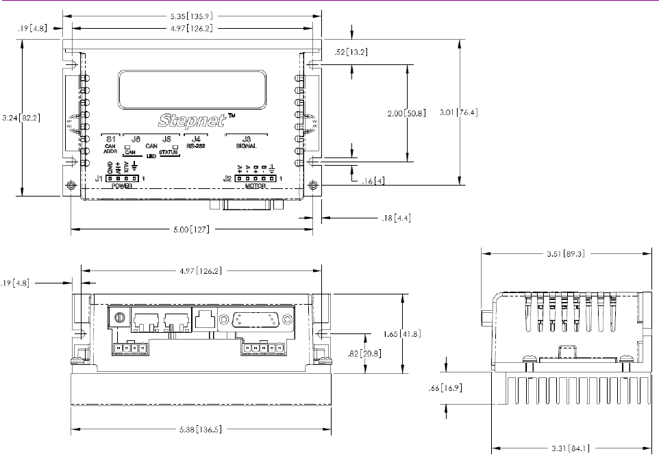
Specifications Stepnet Panel Amplifier User Guide
54 Copley Controls
3.20: Dimensions
3.20.1: Stepnet Panel (STP) Dimensions
Optional
h
eatsink
shown
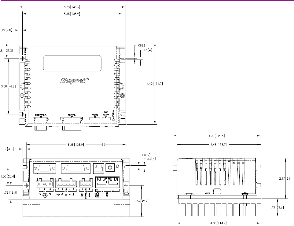
Stepnet Panel Amplifier User Guide Specifications
Copley Controls Corp. 55
3.20.2: Stepnet Panel AC (STX) Dimensions
Optional heatsink shown
Specifications Stepnet Panel Amplifier User Guide
56 Copley Controls

Copley Controls Corp. 57
CHAPTER
4: WIRING
This chapter describes the wiring of amplifier and motor connections. Contents include:
Title Page
4.1.1: Stepnet Panel (STP) General Wiring Instructions .............................................................................................................. 58
4.1.2: Stepnet Panel (STP) Connector Locations ........................................................................................................................ 59
4.1.3: Stepnet Panel (STP) Power (J1)........................................................................................................................................ 60
4.1.4: Stepnet Panel (STP) Motor (J2)......................................................................................................................................... 61
4.1.5: Stepnet Panel (STP) Signal (J3)........................................................................................................................................ 62
4.1.6: Stepnet Panel (STP) CAN Bus (J5 and J6)........................................................................................................................ 65
4.1.7: Stepnet Panel (STP) RS-232 Serial Communications (J4) ................................................................................................ 66
4.2.1: Stepnet Panel AC (STX) General Wiring Instructions ........................................................................................................ 67
4.2.2: Stepnet Panel AC (STX) Connector Locations................................................................................................................... 69
4.2.3: Stepnet Panel AC (STX) Power (J1).................................................................................................................................. 70
4.2.4: Stepnet Panel AC (STX) Motor (J2)................................................................................................................................... 71
4.2.5: Stepnet Panel AC (STX) Aux HV and Brake (J3)............................................................................................................... 72
4.2.6: Stepnet Panel AC (STX) CAN Bus (J4 and J5).................................................................................................................. 73
4.2.7: Stepnet Panel AC (STX) Feedback (J6) ............................................................................................................................ 74
4.2.8: Stepnet Panel AC (STX) Control (J7)................................................................................................................................. 78
4.2.9: Stepnet Panel AC (STX) J7 Digital Inputs Wiring Diagram ................................................................................................ 80
4.2.10: Stepnet Panel AC (STX) RS-232 Serial Communications (J8)......................................................................................... 83
Wiring Stepnet Panel Amplifier User Guide
58 Copley Controls
4.1: Stepnet Panel (STP) Wiring
4.1.1: Stepnet Panel (STP) General Wiring Instructions
Stepnet Panel (STP) Electrical Codes and Warnings
Be sure that all wiring complies with the National Electrical Code (NEC) or its national equivalent,
and all prevailing local codes.
DANGER: Hazardous voltages.
Exercise caution when installing and adjusting.
!
DANGER
Failure to heed this warning can cause equipment damage, injury, or death.
Stepnet Panel (STP) Shielding and Grounding Considerations
Auxillary
Power Supply
+
-
Power Supply
DC
-
+
Amplifier
(optional)
Encoder
Circuit
Circuit
I/O
Inverter
PWM
250 ma
5V
Converter
DC/DC
Encoder
Motor
Controller
J4Serial
J3 Signal
J2 Motor
Transceiver
CAN Network
Isolation Barrier
CAN Bus
Circuit
RS232
J1 Power
J5 & J6 CAN
9
Connections to system ground should
be kept as short as possible.
AUX
+HV
GND
As shown above, power and control circuits in the Stepnet share a common circuit-ground. Digital
inputs are referenced to this common circuit-ground, as are the digital outputs, encoder inputs,
and serial communications port. The CAN ports are electrically isolated from this common circuit-
ground. The Stepnet case (Chassis Ground) is also isolated from any of the internal circuits.
The Stepnet "Gnd" terminal on the power connector (J1-4) should be connected to the users’
system common ground, through the shortest path, so that signals between the controller and the
Stepnet are at the same common potential, and to minimize noise. The system common ground
should, in turn, be connected to an earthing conductor by the shortest wire possible so that the
whole system is referenced to “earth.”
The HV power supply should be connected to the system common ground only at the Stepnet
power connector. In this way, voltage drops across the power conductors due to high motor
currents will not appear at the Stepnet ground, but at the HV power supply negative terminal
where they will have less effect.
Connection to the case is provided on the Chassis Ground terminal of the power connector (J1-1).
This terminal should connect to the system chassis ground, keeping the wire as short as possible.
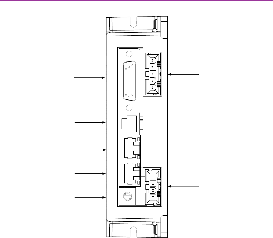
Stepnet Panel Amplifier User Guide Wiring
Copley Controls Corp. 59
This maximizes the shielding effect of the case, and provides a path to ground for noise currents
that may occur in the cable shields.
Stepnet Panel (STP) Shielding
It is recommended that connections to the Stepnet motor, power and signal connectors be made
using shielded cables. Shields on cables reduce emissions from the amplifier and help protect
internal circuits from interference due to external sources of electrical noise. The shields shown in
the wiring diagrams are also required for CE compliance. Cable shields should be tied to earth or
system ground. Provisions are made on each Stepnet connector for connecting the shield to the
chassis ground of the Stepnet which in turn is connected to the system ground.
4.1.2: Stepnet Panel (STP) Connector Locations
Connector locations are shown below.
J3: Signal
J4: RS-232
J5: CAN
J6: CAN
S1: CAN
Address Switch
J2: Motor
J1: Power
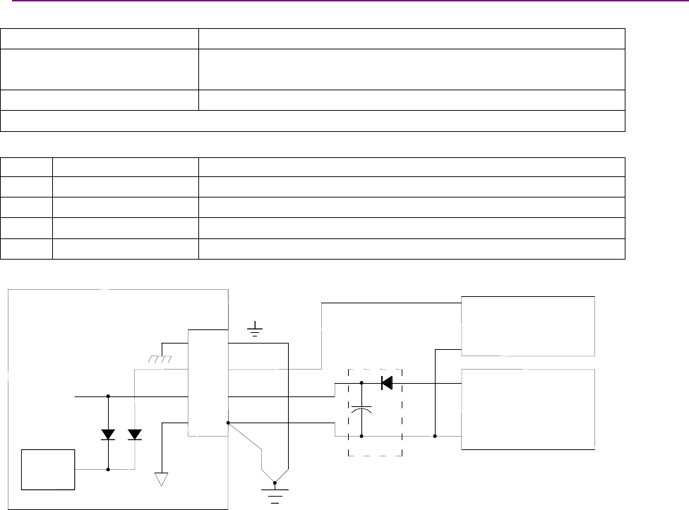
Wiring Stepnet Panel Amplifier User Guide
60 Copley Controls
4.1.3: Stepnet Panel (STP) Power (J1)
Stepnet Panel (STP) J1 Mating Connector
Description Receptacle, Single Row 4 Position
Manufacturer part numbers Housing; Molex 39-01-4041
Crimp Terminal: Molex 39-00-0039 (4 required)
Wire size 18 - 24 AWG
Connector housing and terminals are included in connector kit STP-CK
Stepnet Panel (STP) J1 Pin Description
Pin Signal Function
1Chassis Ground Earth ground connection
2Aux HV Auxiliary power input
3+HV Power input
4Ground Power common
Stepnet Panel (STP) J1 Power Input Wiring Diagram
Note 1: Diode and capacitor should be installed if using a switching power supply.
J1-4
J1-3
J1-2
J1-1
Aux
+HV
Gnd
Auxiliary
Power Supply
+
-
Power Supply
DC
-
+
Logic
Supply
HV Bus
J1Amplifier
Note 1
(optional)
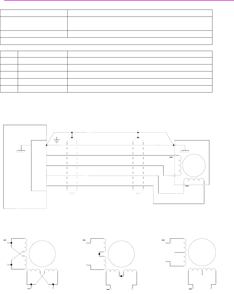
Stepnet Panel Amplifier User Guide Wiring
Copley Controls Corp. 61
4.1.4: Stepnet Panel (STP) Motor (J2)
Stepnet Panel (STP) J2 Mating Connector
Description Receptacle, Single Row 5 Position
Manufacturer part numbers Housing; Molex 39-01-4051
Crimp Terminal: Molex 39-00-0039 (5 required)
Wire Size 18 - 24 AWG
Connector housing and terminals are included in connector kit STP-CK
Stepnet Panel (STP) J2 Pin Description
Pin Signal Function
1Chassis Ground Motor frame ground and cable shield
2Motor B- Phase B- output of amplifier
3Motor B+ Phase B+ output of amplifier
4Motor A- Phase A- output of amplifier
5Motor A+ Phase A+ output of amplifier
Stepnet Panel (STP) J2 Motor Wiring Diagram
Typical wiring for a 4-lead motor:
Typical wiring alternatives:
8-lead motor, coils in parallel 8-lead motor, coils in series 6-lead motor
B
B
AA
B
B
AA
B
B
AA
No
Connection
No
Connection
J2-4
J3-3
J2-2
J2-1
B-
B+
A-
J2Amplifier
J2-5 A+
B
B
A A
Motor
Case
Ground
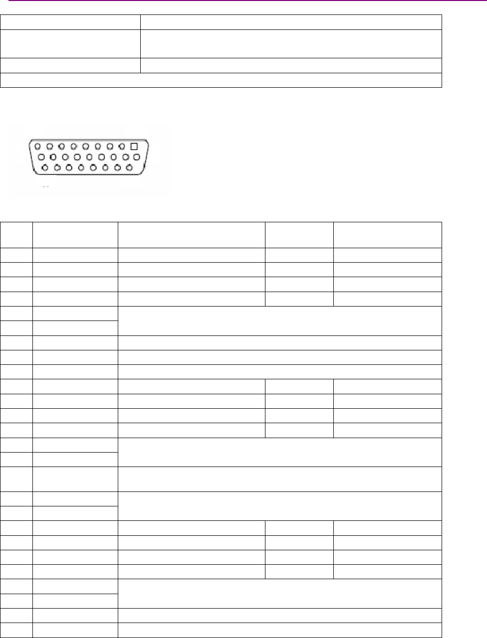
Wiring Stepnet Panel Amplifier User Guide
62 Copley Controls
4.1.5: Stepnet Panel (STP) Signal (J3)
Stepnet Panel (STP) J3 Mating Connector
Description Plug, High Density D-Sub, 26 Position
Manufacturer Part numbers Connector, solder cup; Norcomp 180-026-102-001
Backshell: Norcomp: 979-015-020R121
Wire Size 22 - 26 AWG, shielded cable
Connector and backshell are included in connector kit STP-CK.
Amplifier pin locations are shown here:
9
18
26 19
10
1
Stepnet Panel (STP) J3 Pin Description
Pin Signal Function Speed Pull-Up/Pull-Down
Group
1IN1 Enable Standard Group 1
2IN2 Programmable Standard Group 1
3IN3 Programmable Standard Group 1
4IN4 Programmable Standard Group 2
5Encoder A
6Encoder /A
Motor incremental encoder input
7Signal Ground Signal ground reference for input, outputs and Encoder +5V
8OUT1 General-purpose, programmable output
9Frame Ground Frame Ground
10 IN5 Programmable Standard Group 2
11 IN6 Mode Dependent High Group 3
12 IN7 Mode Dependent High Group 3
13 IN8 Mode Dependent High Group 3
14 Encoder B
15 Encoder /B
Motor incremental encoder input
16 +5V OUT Encoder +5 Vdc power supply output.
Total load current not to exceed 250 mA.
17 OUT2
18 OUT4
General-purpose, programmable output
19 IN9 Mode Dependent High Group 4
20 IN10 Mode Dependent High Group 4
21 IN11 Mode Dependent High Group 4
22 IN12 Mode Dependent High Group 4
23 Encoder X
24 Encoder /X
Motor incremental encoder input
25 Signal Ground Signal ground reference for input, outputs and encoder +5V
26 OUT3 General-purpose, programmable output
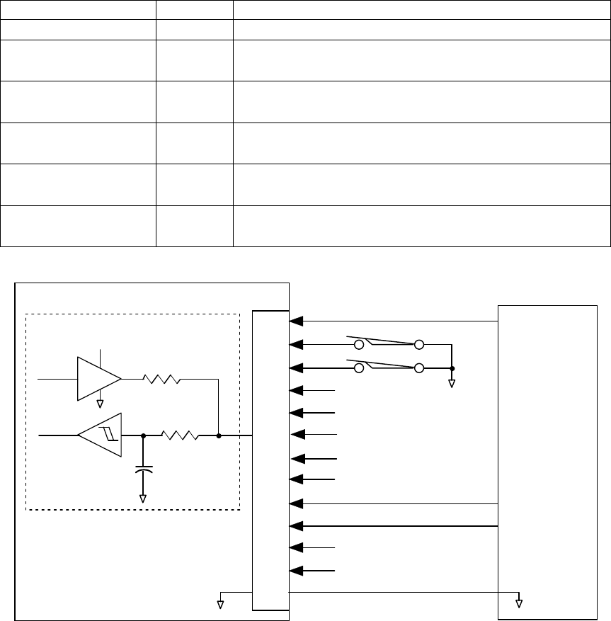
Stepnet Panel Amplifier User Guide Wiring
Copley Controls Corp. 63
Stepnet Panel (STP) J3 Mode-Dependant Dedicated Inputs
These inputs are dedicated to specific functions, depending on operating mode.
Mode Input Function
All IN1 Enable
Current & Velocity
PWM 50%
IN9 PWM Input
IN9 PWM Input Current & Velocity
PWM 100% IN10 Direction Input
IN9 Pulse Input Position
Pulse & Direction IN10 Direction Input
IN9 Count Up Position
Up/Down IN10 Count Down
IN9 Channel B Position
Quadrature IN10 Channel A
Stepnet Panel (STP) J3 Input Wiring Diagram
Amplifier
J3-12
J3-13
J3-19
J3-20
J3-21
J3-25
J3-1
J3-2
J3-3
J3-4
J3-10
J3-11
IN4
IN3
IN2
IN1 (Enable)
IN5
IN7
IN8
IN9 (Pulse)
IN10 (Direction)
IN11
Signal
Ground
J3
Motion
Controller
Standard inputs (IN1-IN4): R1 = 10 K
,R2 =10K
,
C= 3300 pƒ
High speed input (IN6-IN12): R1 = 10 K
,R2 =1K
, C = 100 pƒ
IN5: R1 = 4.99 K
,R2 =10K
, C = 2200 pƒ
R2
R1
pull up / pull dow n
+5Vdc
74HC14
C
Typical
Circuit
J3-22 IN12
IN6
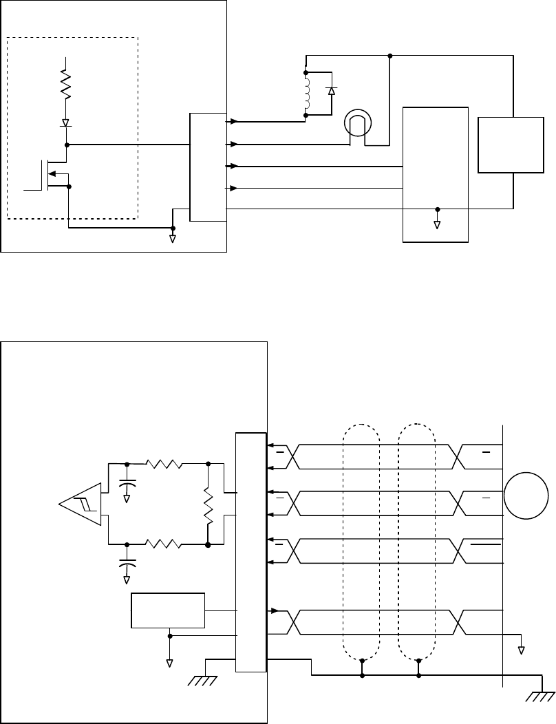
Wiring Stepnet Panel Amplifier User Guide
64 Copley Controls
Stepnet Panel (STP) J3 Digital Outputs Wiring Diagram
Amplifier
J3-8
J3-17
J3-26
J3-25
Typical
Circuit
External
Power
Supply
Motion
Controller
+5Vdc
1K
J3
OUT1
OUT2
OUT3
Signal
Ground
Relay
Lamp
*
Typical Output Loads
* Flyback diode required
for inductive loads
J3-18 OUT4
Stepnet Panel (STP) J3 Incremental Encoder Wiring Diagram
Amplifier J3
Frame Gnd
J3-5
J3-6
J3-15
J3-23
J3-14
J3-24
J3-9
J3-16
J3-7
+5VDC
A
B
Index
Incremental
Encoder
Encoder
Power
Case
Ground
+
-
Typical Circuit
5 V
@250 mA
1K
22 pƒ
22 pƒ
121
1K
A
B
X
Index
B
AA
B
X
Gnd
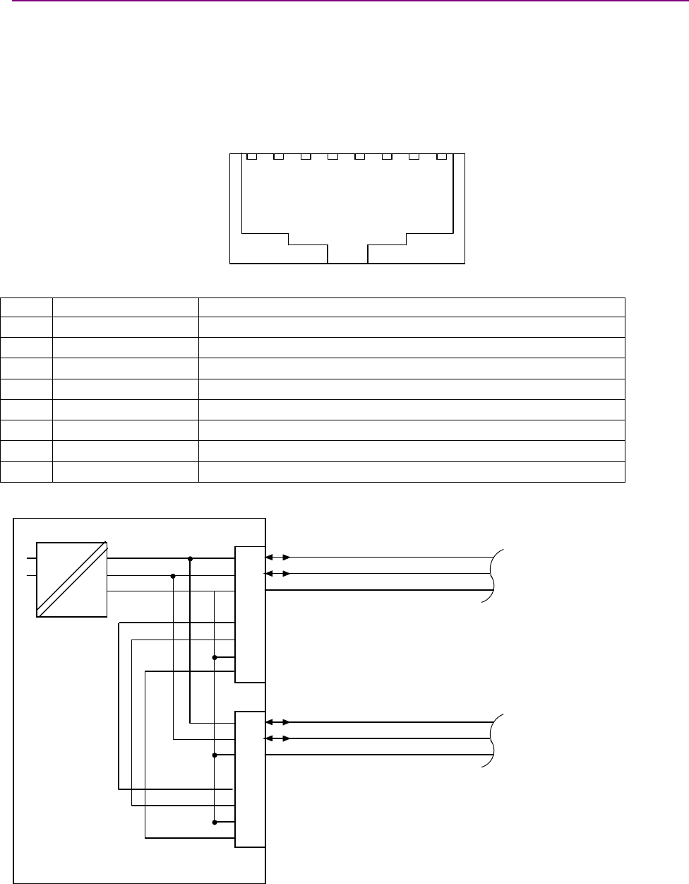
Stepnet Panel Amplifier User Guide Wiring
Copley Controls Corp. 65
4.1.6: Stepnet Panel (STP) CAN Bus (J5 and J6)
Stepnet Panel (STP) J5 and J6 Mating Connector
8-position, modular connector (RJ-45 style). Copley Controls provides the following assemblies:
•Prefabricated 10 foot cable, PN STP-NC-10
•Prefabricated 1 foot cable, PN STP-NC-01
•Terminator Plug, PN STP-NT
Adiagram of the female connector is shown below.
12345678
Stepnet Panel (STP) J5 and J6 Pin Description
Pin Signal Function
1CAN_H CAN_H bus line (dominant high)
2CAN _L CAN_L bus line (dominant low)
3CAN_Gnd Ground / 0 V / V-
4-- Pass though to second connector, no internal connection
5-- Pass though to second connector, no internal connection
6CAN_SHLD Pass though to second connector, no internal connection
7CAN_Gnd Ground / 0 V / V-
8CAN V+ Pass through to second connector, no internal connection
Stepnet Panel (STP) CAN Bus Wiring Diagram
Amplifier J5
CAN +
CAN
-
CAN Gnd
CAN +
CAN
-
CAN Gnd
Note 1: If this is the last amplifier on the network,
use Copley Terminator Plug PN STP-NT
to terminate the bus.
CAN Network
CAN Network
J5-1
J5-2
J5-4
J5-3
J5-5
J5-6
J5-7
J5-8
J6-1
J6-2
J6-4
J6-3
J6-5
J6-6
J6-7
J6-8
Opto-isolation
J6
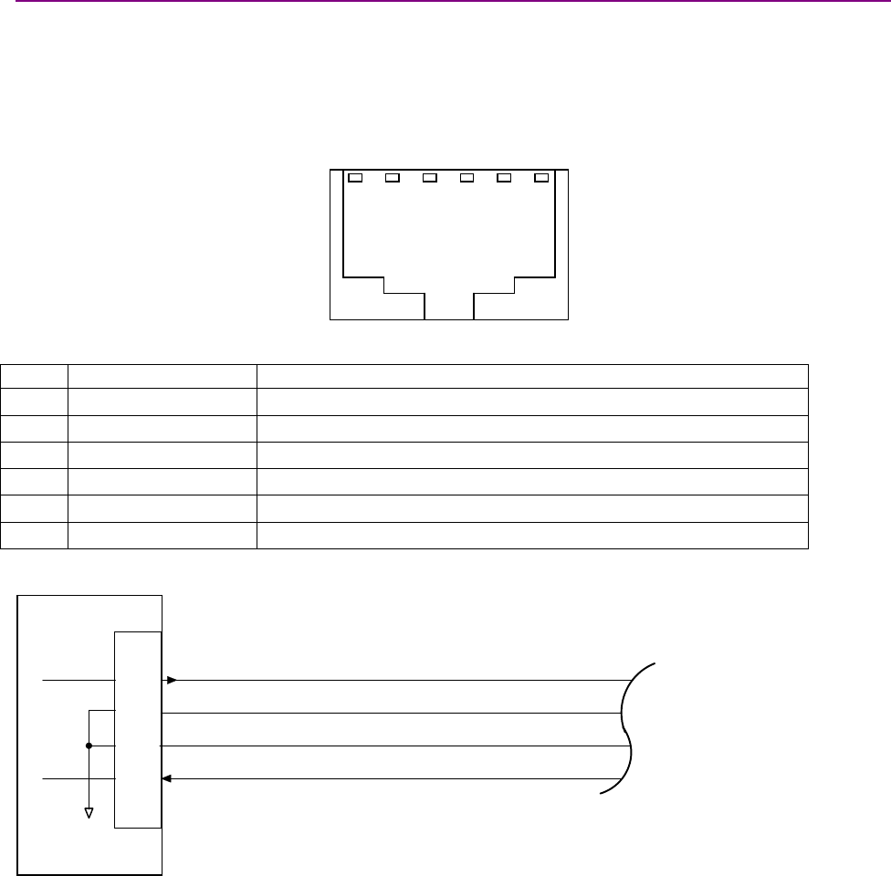
Wiring Stepnet Panel Amplifier User Guide
66 Copley Controls
4.1.7: Stepnet Panel (STP) RS-232 Serial Communications (J4)
Stepnet Panel (STP) J4 Mating Connector
6-position, modular connector (RJ-11 style).
Copley Controls provides a prefabricated cable and modular-to-9-pin sub-D adapter in RS-232
Serial Cable Kit, PN SER-CK.
Adiagram of the female connector is shown below.
123456
Stepnet Panel (STP) J4 Pin Description
Pin Signal Function
1N/C No connection
2RxD Receive data input from computer
3Signal ground Power supply ground
4Signal ground Power supply ground
5TxD Transmit data output to computer
6N/C No connection
Stepnet Panel (STP) J4 RS-232 Serial Communications Wiring Diagram
Amplifier J4
Rx D
ground
ground
Tx D
To P C
RS-232
Port
J4-6
J4-5
J4-4
J4-3
J4-1
J4-2

Stepnet Panel Amplifier User Guide Wiring
Copley Controls Corp. 67
4.2: Stepnet Panel AC (STX) Wiring
4.2.1: Stepnet Panel AC (STX) General Wiring Instructions
Stepnet Panel AC (STX) Electrical Codes and Warnings
Be sure that all wiring complies with the National Electrical Code (NEC) or its national equivalent,
and all prevailing local codes.
DANGER: Hazardous voltages.
!
DANGER
Exercise caution when installing and adjusting.
Failure to heed this warning can cause equipment damage, injury, or death.
Risk of electric shock.
!
DANGER
High-voltage circuits on J1 and J2 are connected to mains power.
Failure to heed this warning can cause equipment damage, injury, or death.
Do not ground mains-connected circuits.
!
WARNING
With the exception of the ground pins on J1 and J2, all of the other circuits on these
connectors are mains-connected and must never be grounded.
Failure to heed this warning can cause equipment damage.
Do not plug or unplug connectors with power applied.
!
WARNING
The connecting or disconnecting of cables while the amplifier has 24Vdc and/or
mains power applied is not recommended.
Failure to heed this warning may cause equipment damage.
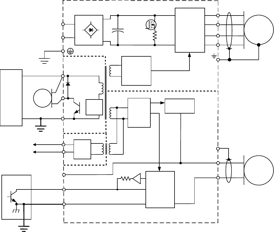
Wiring Stepnet Panel Amplifier User Guide
68 Copley Controls
Power and Grounding Diagram: Stepnet Panel AC (STX)
Stepnet Panel AC (STX) Primary Grounding Functions
Agrounding system has three primary functions: safety, voltage-reference, and shielding.
Stepnet Panel AC (STX) J1-2 Primary Ground
The primary ground at J1-2 is the safety ground and is intended to carry the fault currents from the
mains in the case of an internal failure or short-circuit of electronic components. This ground is
connected to the amplifier chassis. Wiring to this ground should be done using the same gauge
wire as that used for the mains. This wire is a “bonding”’ conductor that should be connected to an
earthed ground point and must not pass through any circuit interrupting devices.
The pin on the amplifier at J1-2 is longer than the other pins on J1, giving it a first-make, last-
break action so that the amplifier chassis is never ungrounded when the mains power is
connected.
+24
VDC LOGIC
&
SIGNAL
POWER
RTN
PWM
INVERTER
CONTROL
LOGIC
MAINS L2
+5 Vdc
A+
A-
B-
MOTOR
ENCODER
CASE
ISOLATION BARRIER
+5 Vdc
DCBUSS(+)
DC BUSS(-)
AMPLIFIER
CHASSIS
CONTROL
SYSTEM
ENABLE [IN1]
SIGNAL GND
SHIELD J6
J7
J1
J2
FRAME
(SAFETY)
GROUND
CONTROL
SIGNAL
GROUND
~
~-
+
+
BRAKE
+24 Vdc
+24 Vdc
GROUND
J3
DC/DC
Cntrl
DC/DC
Converter
+5 Vdc @
250mA
PWM
STAGE
CONTROL
POWER
BRAKE
CAN
Bus
Ckt
CAN
NETWORK
SIGNAL GND
J4 & 5
L1
REGEN B+
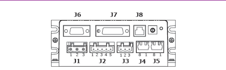
Stepnet Panel Amplifier User Guide Wiring
Copley Controls Corp. 69
Stepnet Panel AC (STX) J2 Ground
The ground terminal at J2-1 also connects to the amplifier chassis.
Motor cases can be safety-grounded in one or optionally both of these ways:
•Direct grounding of the motor frame (assuming the frame of the machine is grounded). Attach
the metal motor case to the metal machine frame or connect the ground wire of the motor to
the metal frame of the machine.
•Grounding of the motor frame through the motor power cable to amplifier J2-1. The ground
wire should be of the same gauge as the power wires.
Cable shields, because of their smaller wire size, must not be used as part of a safety-ground
system.
Stepnet Panel AC (STX) Signal Grounding
The amplifier signal ground must be connected to the control system signal ground. The amplifier
signal ground is not connected to earth ground internal to the amplifier. Therefore, the control
system signal ground can be connected to earth ground without introducing a ground loop.
Stepnet Panel AC (STX) Shielding
Shields on cables reduce emissions from the amplifier and help protect internal circuits from
interference due to external sources of electrical noise. The shields shown in the wiring diagrams
are also required for CE compliance. Cable shields should be tied at both ends to earth or chassis
ground. The housing and pin 1 of both J6 and J7 are connected to the amplifier’s chassis.
4.2.2: Stepnet Panel AC (STX) Connector Locations
Connector locations are shown below.
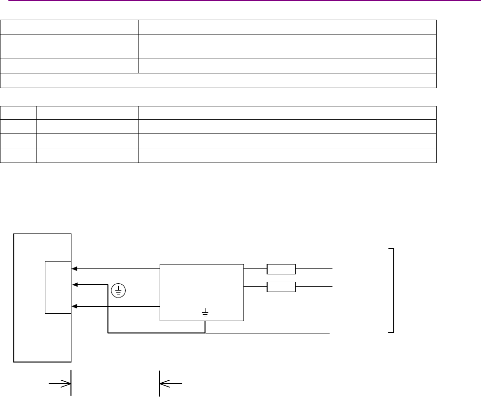
Wiring Stepnet Panel Amplifier User Guide
70 Copley Controls
4.2.3: Stepnet Panel AC (STX) Power (J1)
Stepnet Panel AC (STX) J1 Mating Connector
Description Plug, 3 position, 7.5 mm, female
Manufacturer Part numbers Wago 721-203/026-045/RN01-0000
Insert/extract lever: Wago 231-131
Wire size 12 AWG maximum
Connector housing and terminals are included in connector kit STX-CK
Stepnet Panel AC (STX) J1 Pin Description
Pin Signal Function
1L1 AC power input (hot or L1)
2Frame ground Chassis safety ground
3L2 AC power input (neutral or L2)
Stepnet Panel AC (STX) J1 AC Mains Fuse Recommendation
Recommended fuse type: Class CC, 600 Vac rated, Ferraz-Shawmut ATDR, Littelfuse CCMR,
Bussman LP-CC, or equivalent.
Stepnet Panel AC (STX) J1 AC Mains Wiring Diagram (Single-Phase)
Amplifier
L2
L1 Fuses**
L1 (Line)
L2 (Neut)
Earth
Ground
Keep wire length
as short as
possible. Not to
exceed 1 Meter.
1
Ø
47-63 Hz
100-240 VAC
** Not required on a neutral line.
J1-1
J1-3
J1-2
J1
* Corcom 10VN1
(or equivalent)
used for CE compliance
L
O
A
D
L
I
N
E
Line Filter*
Note: A clamp-on ferrite (Fair-Rite PN 0431164951) was used on the AC input cable between the
filter and drive (single turn) to meet EMC requirements during qualification testing.
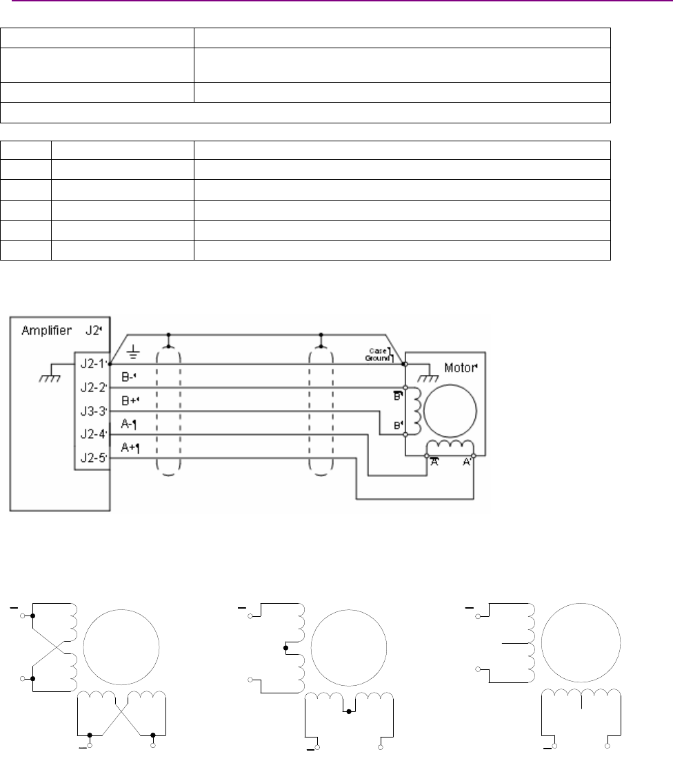
Stepnet Panel Amplifier User Guide Wiring
Copley Controls Corp. 71
4.2.4: Stepnet Panel AC (STX) Motor (J2)
Stepnet Panel AC (STX) J2 Mating Connector
Description Receptacle, Single Row 5 Position
Manufacturer Part numbers Wago: 721-605/000-043/RN01-0000
Insert/extract lever: Wago: 231-131
Wire Size 28 - 12 AWG
Connector housing and terminals are included in connector kit STX-CK
Stepnet Panel AC (STX) J2 Pin Description
Pin Signal Function
1Frame Ground Motor frame ground and cable shield
2Motor /B Phase B- output of amplifier
3Motor B Phase B+ output of amplifier
4Motor /A Phase A- output of amplifier
5Motor A Phase A+ output of amplifier
Stepnet Panel AC (STX) J2 Motor Wiring Diagram
Typical wiring for a 4-lead motor:
Note: A clamp-on ferrite (Fair-Rite PN 0431164281) was used on the motor cable (single turn),
installed close to the amplifier, to meet EMC requirements during qualification testing.
Typical wiring alternatives:
8-lead motor, coils in parallel 8-lead motor, coils in series 6-lead motor
B
B
AA
B
B
AA
B
B
AA
No
Connection
No
Connection
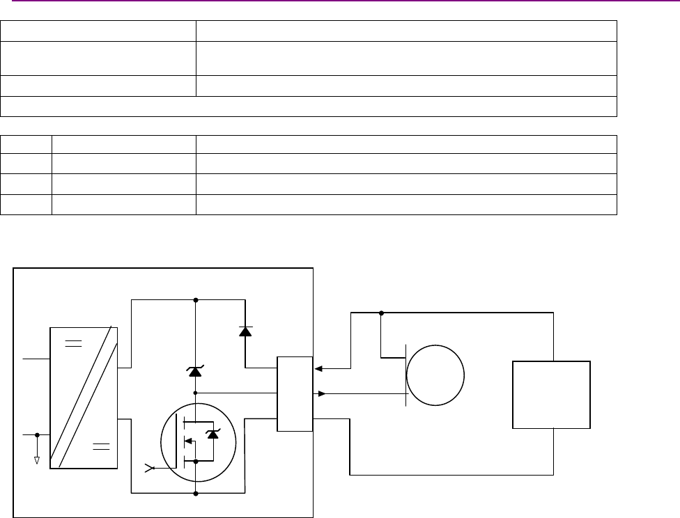
Wiring Stepnet Panel Amplifier User Guide
72 Copley Controls
4.2.5: Stepnet Panel AC (STX) Aux HV and Brake (J3)
Stepnet Panel AC (STX) J3 Mating Connector
Description Plug, 3 position, 5.0 mm, female
Manufacturer Part numbers Wago: 721-103/026-047/RN01-0000
Insert/extract lever: Wago: 231-131
Wire Size 12 AWG maximum
Connector and backshell are included in connector kit STX-CK.
Stepnet Panel AC (STX) J3 Pin Description
Pin Signal Function
1Return +24 Vdc return or common
2Brake Output Return or low side of motor brake
3+24 Vdc +24 Vdc Logic power supply
Stepnet Panel AC (STX) J3 Logic Supply and Brake Wiring Diagram
Amplifier J3
Isolated Logic
Power Supply
+24 V
Brake
RTN
Brake
+24 Vdc
Power
Supply
(Required)
J3-3
J3-2
J3-1

Stepnet Panel Amplifier User Guide Wiring
Copley Controls Corp. 73
4.2.6: Stepnet Panel AC (STX) CAN Bus (J4 and J5)
Stepnet Panel AC (STX) J4-5 Mating Connector
8-position, modular connector (RJ-45 style). Copley Controls provides the following assemblies:
•Prefabricated 10 foot cable, PN STX-NC-10
•Prefabricated 1 foot cable, PN STX-NC-01
•Terminator Plug, PN STX-NT
Adiagram of the female connector is shown below.
12345678
Stepnet Panel AC (STX) J4-5 Pin Description*
Pin Signal Function
1CAN_H CAN_H bus line (dominant high)
2CAN _L CAN_L bus line (dominant low)
3CAN_Gnd Ground / 0 V / V-
4-- Pass though to second connector, no internal connection
5-- Pass though to second connector, no internal connection
6CAN_SHLD Pass though to second connector, no internal connection
7CAN_Gnd Ground / 0 V / V-
8CAN V+ Pass through to second connector, no internal connection
*Table applies to both J4 and J5 CAN connectors
Stepnet Panel AC (STX) J4-5 CAN Bus Wiring Diagram
Amplifier J4
CAN +
CAN
-
CAN Gnd
CAN +
CAN
-
CAN Gnd
Note 1: If this is the last amplifier on the network,
use Copley Terminator Plug PN STX-NT
to terminate the bus.
CAN Network
CAN Network
J4-1
J4-2
J4-4
J4-3
J4-5
J4-6
J4-7
J4-8
J5-1
J5-2
J5-4
J5-3
J5-5
J5-6
J5-7
J5-8
Opto-isolation
J5
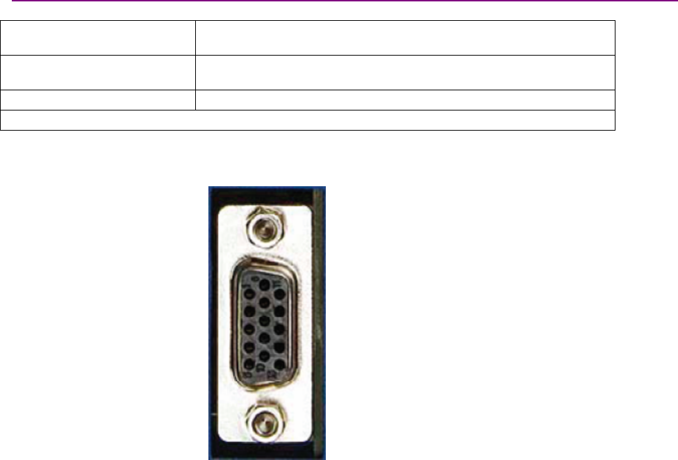
Wiring Stepnet Panel Amplifier User Guide
74 Copley Controls
4.2.7: Stepnet Panel AC (STX) Feedback (J6)
Stepnet Panel AC (STX) J6 Mating Connector
Description 15 Position, High-Density D-Sub Male Solder Style Connector and
backshell.
Manufacturer Part numbers Norcomp: 180-015-103L001 connector
Norcomp: 979-009-020R121 backshell
Wire Size 24-30 AWG
Connector and backshell are included in connector kit STX-CK.
Pin connections are shown here:
1
5
6
10
11
15
J6 pin connections
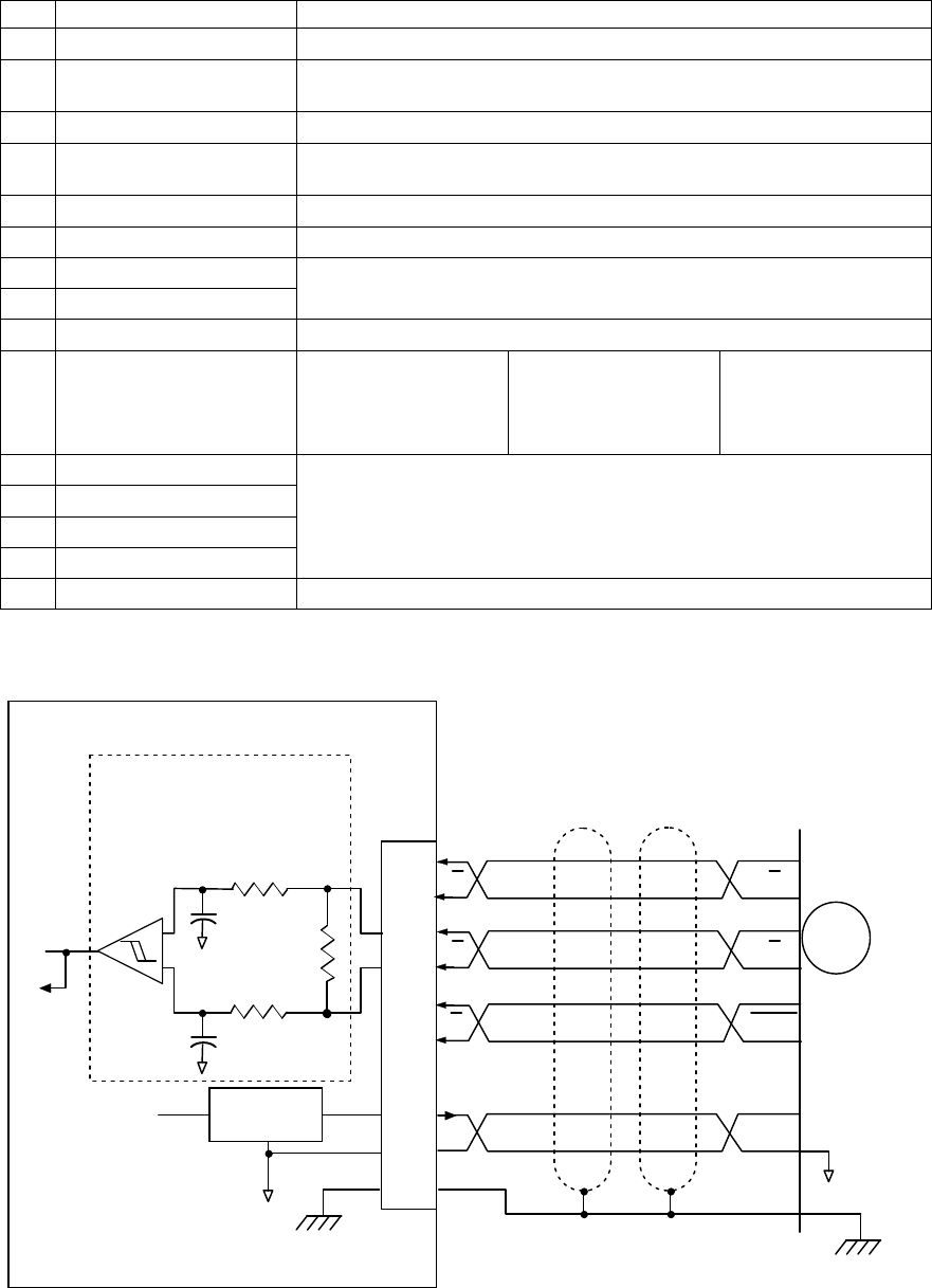
Stepnet Panel Amplifier User Guide Wiring
Copley Controls Corp. 75
Stepnet Panel AC (STX) J6 Pin Description
Pin Signal Function
1Frame Ground Cable shield connection
2+5 Vdc Encoder +5 Vdc power supply output.
Total load current on J7-20 and J6-4 not to exceed 250 mA.
3Encoder B2 Single-ended primary incremental encoder input.
4+5 Vdc Encoder +5 Vdc power supply output.
Total load current on J7-20 and J6-4 not to exceed 250 mA.
5Signal Ground Signal and +5 Vdc ground
6Encoder X2 Single-ended primary incremental encoder input.
7Encoder /X Input
8Encoder X Input Differential primary incremental encoder inputs
9Encoder A2 Single-ended primary incremental encoder input.
10 [IN12] Motemp Motor over
temperature switch
May be programmed
to other functions
Standard speed Pull-up/pull-down
group 2
11 Encoder /B Input
12 Encoder B Input
13 Encoder /A Input
14 Encoder A Input
Differential primary incremental encoder inputs
15 Signal Ground Signal and +5 Vdc ground
Stepnet Panel AC (STX) J6 Quad A/B Incremental Encoder Wiring Diagram – With Index
When the index pulse is used (as in most applications), wire the connection as shown here.
Amplifier J6
Frame Gnd
J6-14
J6-13
J6-11
J6-8
J6-12
J6-7
J6-1
J6-4
J6-2
+5VDC
A
B
Index
Incremental
Encoder
Encoder
Power
Case
Ground
+
-
Typical Circuit
To
Encoder
Output
5 V
@250 mA
1K
22 pƒ
22 pƒ
121
1K
A
B
X
Index
B
AA
B
X
Gnd
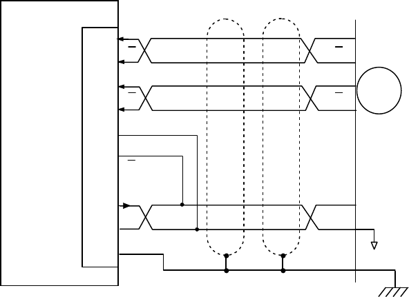
Wiring Stepnet Panel Amplifier User Guide
76 Copley Controls
Stepnet Panel AC (STX) J6 Quad A/B Incremental Encoder Wiring Diagram – No Index
In applications where the encoder index pulse is not used, wire the connector as shown here.
Amplifier J6
Frame Gnd
J6-14
J6-13
J6-11
J6-8
J6-12
J6-7
J6-1
J6-4
J6-2
+5VDC
A
B
Incremental
Encoder
Encoder
Power
Case
Ground
A
B
B
AA
B
Gnd
X
X
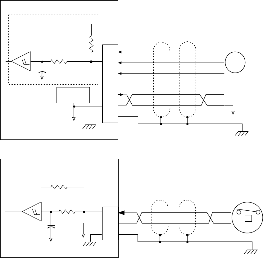
Stepnet Panel Amplifier User Guide Wiring
Copley Controls Corp. 77
Stepnet Panel AC (STX) J6 Single-Ended Encoder Wiring Diagram
The Stepnet "Gnd" terminal on the feedback connector (J6-1) should be connected to the users’
system common ground, through the shortest path, so that signals between the controller and the
Stepnet are at the same common potential, and to minimize noise. The system common ground
should, in turn, be connected to an earthing conductor by the shortest wire possible so that the
whole system is referenced to “earth.”
J6-3
J6-6
J6-9
J6-1
J6-4
J6-2
Typical Circuit
5 V
@250 mA
+5Vdc
100 p
2K
1K
Frame Gnd
5Vdc
Gnd
Encoder
Power
Case
Ground
A2
B2
X2
A
B
X
Encoder
Amplifier J6
Stepnet Panel AC (STX) J6 Motor Over Temperature Wiring Diagram
4.99 K
4.99 K
74HC14
IN12
Ground
0.
1µ
ƒFrame Gnd
Case Ground
Motor Over
Temperature
Switch
Amplifier J6
J6-10
J6-15
J6-1
+5 Vdc
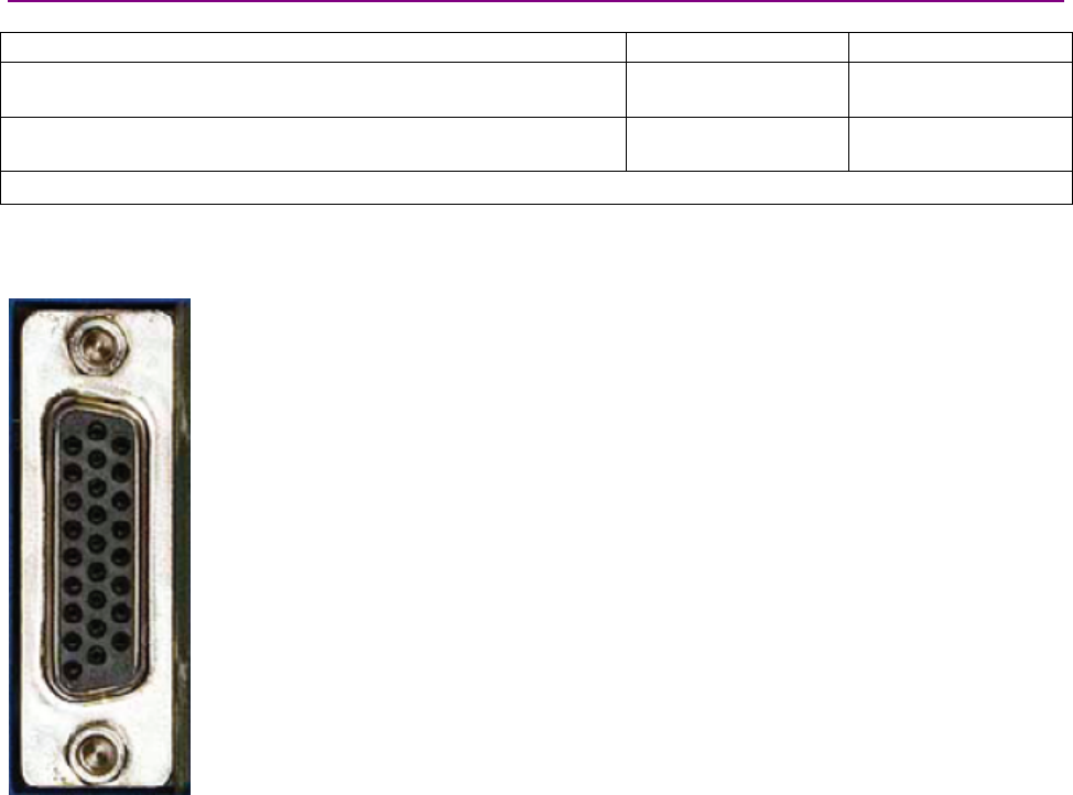
Wiring Stepnet Panel Amplifier User Guide
78 Copley Controls
4.2.8: Stepnet Panel AC (STX) Control (J7)
Stepnet Panel AC (STX) J7 Mating Connectors
Description Manufacturer PN Wire Size
26 Position, 0.1 x 0.09 High Density D-Sub Male, Solder Style
Connector
Norcomp 180-026-
103L001
24 - 30 AWG
Back shell Norcomp 979-015-
020R121
Solder style connector included in Connector Kit PN STX-CK.
Pin connections are shown here:
1
9
10
18
19
26
J7 pin connections

Stepnet Panel Amplifier User Guide Wiring
Copley Controls Corp. 79
Stepnet Panel AC (STX) J7 Pin Description
Pin Signal Function
1Frame Ground Cable shield connection
2Ref - Input Analog command negative input
3Ref + Input Analog command positive input
Speed Pull-Up/Pull-
Down
4IN1 Enable Standard Group 1
5IN2 Standard Group 1
6IN3 Standard Group 1
7IN4 Standard Group 2
8IN10 Standard Group 4
9IN11
Programmable inputs
Standard Group 4
10 IN5 HS Group 3
11 IN6 HS Group 3
12 IN7 HS Group 3
13 IN8 HS Group 4
14 IN9
Mode-dependant. See Mode-Dependant
Dedicated Inputs (p. 80)
HS Group 4
15 Signal Ground Signal ground reference for inputs and outputs
16 OUT1
17 OUT2
18 OUT3
Programmable outputs
19 Signal Ground Signal ground for +5Vdc, inputs and outputs
20 +5 Vdc +5 Vdc output.
Total load current on J7-20, J6-2, and J6-4 not to exceed 250 mA.
21 Multi-Mode Port /X
22 Multi-Mode Port X
23 Multi-Mode Port /B
24 Multi-Mode Port B
25 Multi-Mode Port /A
26 Multi-Mode Port A
Programmable differential input/output port.
See Mode-Dependant Dedicated Inputs (p. 80)
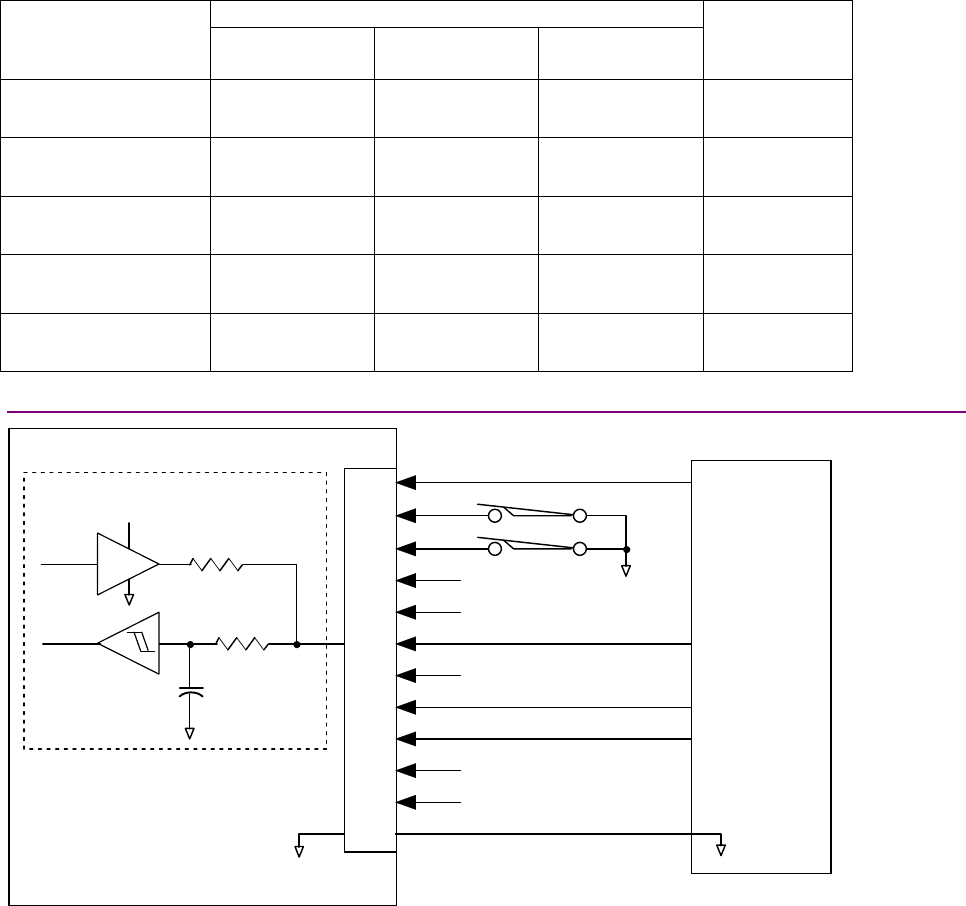
Wiring Stepnet Panel Amplifier User Guide
80 Copley Controls
Mode-Dependant Dedicated Inputs
These inputs are dedicated to specific functions, depending on operating mode.
Selected Command Source
Mode
Digital Input
Single Ended
Digital Input
Differential
Multi-Mode
Port
Function
Current & Velocity
PWM 50%
IN8 IN8(+) & IN6(-) A & /A PWM Input
IN8 IN8(+) & IN6(-) A & /A PWM Input Current & Velocity
PWM 100% IN9 IN9(+) & IN7(-) B & /B Direction Input
IN8 IN8(+) & IN6(-) A & /A Pulse Input Position
Pulse & Direction IN9 IN9(+) & IN7(-) B & /B Direction Input
IN8 IN8(+) & IN6(-) A & /A Count Up Position
Up/Down IN9 IN9(+) & IN7(-) B & /B Count Down
IN9 IN8(+) & IN6(-) A & /A Channel A Position
Quadrature IN8 IN9(+) & IN7(-) B & /B Channel B
4.2.9: Stepnet Panel AC (STX) J7 Digital Inputs Wiring Diagram
Amplifier
J7-10
J7-11
J7-12
J7-13
J7-14
J7-15
J7-4
J7-5
J7-6
J7-7
J7-8
J7-9
IN4
IN3
IN2
IN1 (Enable)
IN11
IN12
IN6
IN7
IN8
IN9
IN10
Signal
Ground
J7
Motion
Controller
*Standard input R = 10 K
C = 0.033
µ
ƒ
High-speed input R = 1K
C = 100 pƒ
R*
10 K
pull up / pull dow n
+5Vdc
C*
Typical
Circuit
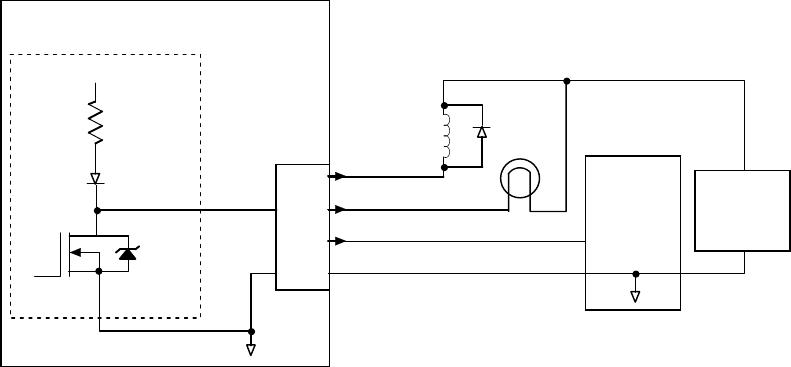
Stepnet Panel Amplifier User Guide Wiring
Copley Controls Corp. 81
Stepnet Panel AC (STX) J7 Digital Outputs Wiring Diagram
Amplifier
J7-16
J7-17
J7-18
J7-15
Typical
Circuit
External
Power
Supply
Motion
Controller
+5Vdc
1K
J7
OUT1
OUT2
OUT3
Signal
Ground
Relay
Lamp
*
Typical Output Loads
* Flyback diode required
for inductive loads
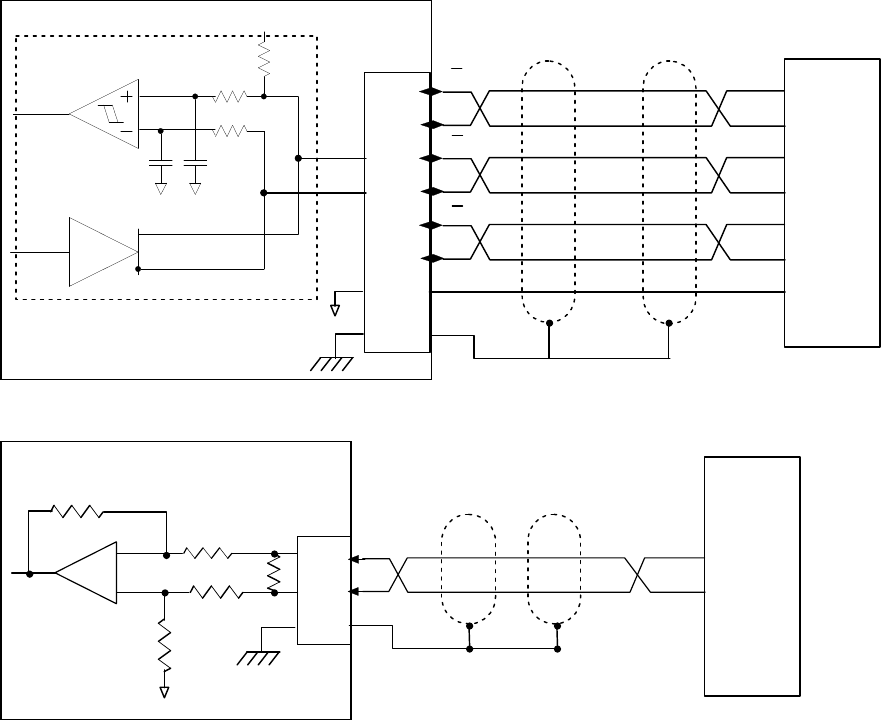
Wiring Stepnet Panel Amplifier User Guide
82 Copley Controls
Stepnet Panel AC (STX) J7 Multi-Mode Port Interface Diagram
J7-23
Amplifier
Typical Circuit
J7
Motion
Controller
or
Position
Encoder
A
B
B
X
Frame Gnd
J7-21
J7-22
J7-24
J7-25
J7-26
J7-1
+5 Vdc
2K
1K
1K
22pF 22pF
26C32
26C31
X
A
J7-15 Signal
Ground
Stepnet Panel AC (STX) J7 Analog Input Wiring Diagram
J7-2
J7-3
J7-1
+
-
5K
37.4 K
37.4 K
5K
Ref -
Ref
+
V CMD -
VCMD
+
Frame Gnd
Amplifier J7
Motion
Controller
5.36 K

Stepnet Panel Amplifier User Guide Wiring
Copley Controls Corp. 83
4.2.10: Stepnet Panel AC (STX) RS-232 Serial Communications (J8)
Stepnet Panel AC (STX) J8 Mating Connector
6-position, modular connector (RJ-11 style).
Copley Controls provides a prefabricated cable and modular-to-9-pin sub-D adapter in RS-232
Serial Cable Kit, PN SER-CK.
Adiagram of the female connector is shown below.
123456
Stepnet Panel AC (STX) J8 Pin Description
Pin Signal Function
1N/C No connection
2RxD Receive data input from computer
3Signal ground Power supply ground
4Signal ground Power supply ground
5TxD Transmit data output to computer
6N/C No connection
Stepnet Panel AC (STX) J8 RS-232 Serial Communications Wiring Diagram
Amplifier J8
Rx D
ground
ground
Tx D
To P C
RS-232
Port
J8-6
J8-5
J8-4
J8-3
J8-1
J8-2
Wiring Stepnet Panel Amplifier User Guide
84 Copley Controls

Copley Controls Corp. 85
CHAPTER
5: MODE SELECTION AND GENERAL
SETUP
The Stepnet amplifier can be operated in stepper mode or servo mode, as described below.
Mode Features
Stepper Amplifier operates as a traditional, open position loop, stepper drive.
With the addition of encoder feedback, the amplifier can monitor and report actual motor position
and provide encoder correction. Also a position-tracking window can be set up along with a
programmable following error warning and fault.
Servo Amplifier operates as a true, closed loop, servo amplifier controlling a stepper motor.
In this mode, the amplifier can be configured to accept current, velocity, or position commands.
Encoder feedback is required for all servo modes of operation.
This chapter contains procedures required for and information relevant to all modes of operation.
Start here to begin amplifier set up, and then continue as instructed to the appropriate mode-
specific chapter.
To copy setup data from an existing Copley Controls axis file (.ccx), skip to Quick Copy Setup
Procedure (p. 156).
NOTE: In the procedures described in this chapter, CME 2 uses a serial connection to a single
amplifier to set up that amplifier. As an alternative, the multi-drop feature allows CME 2 to use a
single RS-232 serial connection to one amplifier as a gateway to other amplifiers linked together
by CAN bus connections. For more information, see the CME 2 User Guide.
Step Page
5.1: Warnings .............................................................................................................................................................................. 86
5.2: CME 2 Installation and Serial Port Setup.............................................................................................................................. 87
5.3: Prerequisites ........................................................................................................................................................................ 91
5.4: Basic Setup .......................................................................................................................................................................... 93
5.5: Motor Setup.......................................................................................................................................................................... 95
5.6: Amplifier Configuration ....................................................................................................................................................... 100
5.7: Command Input.................................................................................................................................................................. 110

Mode Selection and General Setup Stepnet Panel Amplifier User Guide
86 Copley Controls
5.1: Warnings
DANGER: Hazardous voltages.
!
DANGER
Exercise caution when installing and adjusting.
Failure to heed this warning can cause equipment damage, injury, or death.
Make connections with power OFF.
!
WARNING
Do not make connections to motor or drive with power applied.
Failure to heed this warning can cause equipment damage.
Spinning motor with power off may damage amplifier.
!
WARNING
Do not spin motors with power off. Voltages generated by a motor can damage an
amplifier.
Failure to heed this warning can cause equipment damage.

Stepnet Panel Amplifier User Guide Mode Selection and General Setup
Copley Controls Corp. 87
5.2: CME 2 Installation and Serial Port Setup
5.2.1: Requirements
Computer Requirements
Minimal hardware requirements:
•CPU:Minimum: 400 MHZ*
•RAM:Minimum: 128 MB*
*Using the minimum requirements will allow CME 2 to run, but performance will be significantly
reduced.
Communication Requirements
For serial communications:
•At least one standard RS-232 serial port or a USB port with a USB to RS-232 adapter.
•At least one serial communication cable. Available from Copley Controls. Copley Controls
cable part number: SER-CK.
For CAN communications:
•One Copley Controls CAN PCI network card (part number CAN-PCI-02).
CME 2 also supports CAN network cards made by these manufacturers: KVaser, Vector, and
National Instruments.
•One PC-to-amplifier CANopen network cable.
Software Requirements
Copley Controls CME 2 software, Version 5.2 or higher.
Operating System Requirements
Operating Systems Supported: Windows NT, 2000, XP. Vista users see Special Notes for
Windows Vista Users.
5.2.2: Special Notes for Windows Vista Users
When the CME 2 installer starts running under Windows Vista, a message will be displayed
stating that an unidentified program is trying to access the computer. Click the button to allow the
installer to continue, and CME 2 will be installed properly.
On previous versions of Windows, the user data for CME 2 (like ccx, ccm, files, etc.) were stored
in C:\Program Files\Copley Motion\CME 2. Because of Windows Vista security, the CME 2 user
files are stored on Vista systems in C:\Users\Public\Public Documents\Copley Motion\CME 2.
5.2.3: Downloading CME 2 Software from Web (Optional)
5.2.3.1 Choose or create a folder where you will download the software installation file.
5.2.3.2 In an internet browser, navigate to
http://www.copleycontrols.com/Motion/Downloads/index.html
Under Software Releases, click on CME 2.
5.2.3.3 When prompted, save the file to the folder chosen or created in Step 5.2.3.1.
The folder should now contain a file named CME2.zip.
5.2.3.4 Extract the contents of the zip file to the same location.
The folder should now contain the files CME2.zip and Setup.exe.

Mode Selection and General Setup Stepnet Panel Amplifier User Guide
88 Copley Controls
5.2.3.5 If desired, delete CME2.zip to save disk space.
5.2.4: Installing CME 2 Software
5.2.4.1 If installing from a CD, insert the CD (Copley Controls part number CME2).
Normally, inserting the CD causes the installation script to launch, and a CME 2
Installation screen appears. If so, skip to Step 5.2.4.3.
5.2.4.2 If the software installation file was downloaded from the Copley Controls website,
navigate to the folder chosen or created in Step 5.2.3.1,and then double-click on
Setup.exe
OR
if you inserted the CD and the CME 2 Installation screen did not appear, navigate to the
root directory of the installation CD and then double-click on Setup.exe.
5.2.4.3 Respond to the prompts on the CME 2 Installation screens to complete the installation.
We recommend accepting all default installation values.

Stepnet Panel Amplifier User Guide Mode Selection and General Setup
Copley Controls Corp. 89
5.2.5: Serial Port Setup
One or more serial ports on a PC can be used to connect amplifiers. Use the following instructions
to add (enable) ports for amplifiers, to choose baud rates for those ports, and to remove (disable)
ports for amplifiers.
5.2.5.1 Start CME 2 by double-clicking the CME 2 shortcut icon on the Windows
desktop:
If a serial or CAN port has not been selected, the Communications Wizard Select
device screen appears.
5.2.5.2 If the CME 2 Main screen appears instead of Select Devices,
choose ToolsCommunications Wizard.
5.2.5.3 Choose Serial Ports and click Next to open the Communications Wizard Select Ports
screen.
5.2.5.4 From the Available Devices list on the Select Devices screen, choose the serial ports
that will be used to connect to amplifiers.
1To allow connection of an amplifier through a port, highlight the port name and click
Add (or click Add All to enable all available ports).
2To remove a port from the Selected Devices list, highlight the port name and click
Remove.
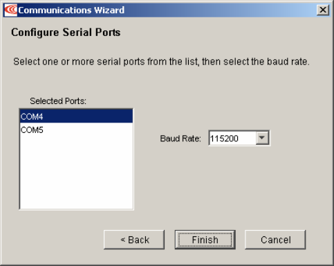
Mode Selection and General Setup Stepnet Panel Amplifier User Guide
90 Copley Controls
5.2.5.5 Click Next to save the choices and open the Communications Wizard Configure Serial
Ports screen.
5.2.5.6 Configure the selected ports.
1Highlight a port in the Selected Devices list.
2Choose a Baud Rate for that port.
3Repeat for each selected port.
5.2.5.7 Click Finish to save the choices.

Stepnet Panel Amplifier User Guide Mode Selection and General Setup
Copley Controls Corp. 91
5.3: Prerequisites
5.3.1: Hardware and Equipment
5.3.1.1 Verify that all power is OFF.
5.3.1.2 Verify wiring to all amplifier connectors
5.3.1.3 Secure the motor.
1Make sure motor is securely fastened.
2Make sure that no load is connected to the motor.
5.3.1.4 STP: Apply Aux voltage if available. If the Aux supply is not wired, verify that the
amplifier enable input (IN1) is in the disabled state and then apply HV power. The
factory default setting for the enable input is open or pulled high for disable.
STX: Apply 24 V only.
Risk of unexpected or uncontrolled motion.
!
DANGER
CME 2 can be used while the amplifier is under other control sources such as
CANopen and DeviceNet. However, some changes made with CME 2 could cause
unexpected or uncontrolled motion.
Failure to heed this warning can cause equipment damage, injury, or death.
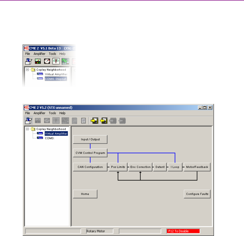
Mode Selection and General Setup Stepnet Panel Amplifier User Guide
92 Copley Controls
5.3.2: Starting CME 2 and Choosing an Amplifier
NOTE: Digital input 1 (IN1) must be configured as a hardware disable. It may be used to
immediately disable the amplifier. To software disable the amplifier at any time while running
CME 2, press function key F12.
5.3.2.1 Verify CME 2 installation and serial port configuration.
Start CME 2 by double-clicking the CME 2 shortcut icon on the Windows desktop. If
there are multiple ports, the Copley Neighborhood root will be selected:
5.3.2.2 Select the desired amplifier to open the CME 2 Main screen (varies with model and
configuration):
If basic setup settings have not been chosen, the Basic Setup screen opens.
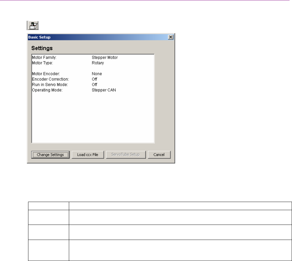
Stepnet Panel Amplifier User Guide Mode Selection and General Setup
Copley Controls Corp. 93
5.4: Basic Setup
5.4.1: Basic Setup Screen
5.4.1.1 To load a .ccx file that was prepared for the amplifier/motor combination, see Quick
Copy Setup Procedure (p. 156).
5.4.1.2 Click the Basic Setup button to display the Basic Setup screen.
5.4.1.3 Click Change Settings to start the Basic Setup wizard. Use Back Next to navigate
screens. Screen details vary depending on amplifier model and mode selection.
5.4.1.4 Select the Motor Type (Rotary or Linear).
5.4.1.5 View or change the Feedback settings described below:
Setting Options
Motor
Encoder
Primary Incremental or none. Encoder is required for servo mode operation. In stepper
mode operation, it can provide position maintenance information.
Run in Servo
Mode
When checked, amplifier runs in closed loop servo mode. See Stepper and Servo Modes
(p. 10).
Enable
Encoder
Correction
When checked, amplifier runs in stepper mode and uses a programmable proportional
gain to correct following errors. See Encoder Correction, p. 128.

Mode Selection and General Setup Stepnet Panel Amplifier User Guide
94 Copley Controls
5.4.1.6 View or change the Operating Mode settings described below:
Setting Options
Operating
Mode
Stepper mode: Position. See Stepper Mode Operation (p. 16).
Servo mode: Current, Velocity, Position. (See Servo Mode Operation (p. 18).
Command
Source
PWM Command (current and velocity mode only): Digital pulse-width modulated signal
provides command input. See Input Command Types (p. 25 ).
Function Generator (current and velocity mode only): Internal function generator provides
command input.
Software Programmed: The amplifier is controlled by software commands from either the
Copley Virtual Machine (CVM) or an external source. See Copley Indexer Program
User’s Guide or the Copley ASCII Interface Programmer’s Guide.
Digital Input (position mode only): Command input is provided via the Input Source
selected from the choices described below. See Digital Position Inputs (p. 27).
CAN: (position mode only): Command input is provided over the CANopen network. See
Communication (p. 30) and the CANopen Programmer’s Guide.
Camming (position mode only): Amplifier runs in Camming Mode. See Copley Camming
User Guide.
5.4.1.7 Click Finish to close the Basic Setup screen.

Stepnet Panel Amplifier User Guide Mode Selection and General Setup
Copley Controls Corp. 95
5.5: Motor Setup
Motor, Feedback, and Brake settings can be loaded from a file or entered manually into the fields.
Choose the appropriate method and perform the steps described:
•Load Motor/Feedback/Brake Data File (p. 95)
•Enter Motor/Feedback/Brake Settings Manually (p. 96)
5.5.1: Load Motor/Feedback/Brake Data File
5.5.1.1 To download motor data files from the website:
1In an internet browser, navigate to
http://www.copleycontrols.com/Motion/Downloads/motorData.html
2Click the appropriate motor name.
When prompted, save the file to the MotorData folder in the CME 2 installation
folder.
(The default installation folder is
C:\Program Files\Copley Motion\CME 2\MotorData.)
3Extract the contents of the zip file to the same location.
4The folder should now contain the new motor data file (with a .ccm filename
extension).
5If desired, delete the .zip file to save disk space.
5.5.1.2 To load motor data from a motor data file:
1Click Motor/Feedback to open the Motor/Feedback screen.
2On the Motor/Feedback screen, click Restore Motor Data from Disk ( ).
When prompted, navigate to the folder containing the file,
then click on the file name, and then click Open.
3Verify motor data files against manufacturer’s specifications.
4Proceed to The Calculate Function (p. 99).
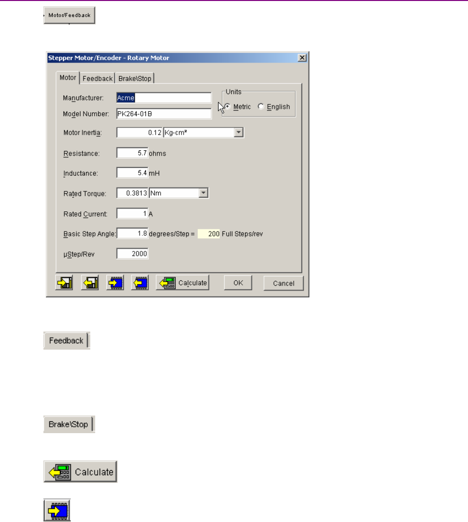
Mode Selection and General Setup Stepnet Panel Amplifier User Guide
96 Copley Controls
5.5.2: Enter Motor/Feedback/Brake Settings Manually
5.5.2.1 Click Motor/Feedback to open the Motor/Feedback screen.
AMotor/Feedback screen representing a typical rotary motor is shown below.
Parameters vary with amplifier model.
5.5.2.2 Click the Motor tab to view or change Rotary Motor Setup Parameters (p. 97) or
Linear Motor Setup Parameters (p. 97).
5.5.2.3
Click the Feedback tab. For rotary motors, enter the number of Encoder Lines. For
linear motors, enter the Encoder Resolution value and select the units for that value
(mm, nm, or um).
5.5.2.4 (STX only) Verify the Enable Encoder Loss Detection setting.
See STX Encoder Loss Detection (p. 38).
5.5.2.5
Click the Brake/Stop tab to view or change Brake/Stop Parameters (p. 98). Read the
Brake/Stop Notes (p. 98) for important related information.
5.5.2.6
Use The Calculate Function (p. 99)to calculate initial gains and limits.
5.5.2.7 On the Main screen, click Save to Flash to avoid losing the changes.

Stepnet Panel Amplifier User Guide Mode Selection and General Setup
Copley Controls Corp. 97
5.5.3: Rotary Motor Setup Parameters
View or change the settings described below. Options vary with amplifier model. Metric units are
shown here.
Setting Description
Manufacturer Motor manufacturer’s name. Saved for reference in the motor data file.
Model Number Motor model number. Saved for reference in the motor data file.
Units Selects whether the parameters entered in this screen are in Metric or English units.
Motor Inertia The rotor inertia of the motor. Used in servo mode for calculating initial velocity loop tuning
values. Min: 0.00001 kg-cm2.Max: 1,000 kg-cm2.Default: 0.00001 kg-cm2.
Resistance Motor resistance line-to-line. Used for calculating the initial current loop tuning values.
Min: 0.01.Max: 327.Default: 0.01.
Inductance Motor inductance line-to-line. Used for calculating the initial current loop tuning values. For
inductance range, see Power Output (p. 45).
Rated Torque Motor’s rated operating torque. Min: .001 N m. Max: 1000 N m.
Rated Current Motor’s rated continuous current. Min: 0.001 A. Max: 1000 A.
Basic Step Angle Fundamental stepper motor step, in degrees. Min: 0.225. Max: 22.5. Default 1.8.
µStep/Rev
(stepper mode only)
Number of microsteps per revolution of the motor.
Min: 4. Max: 100,000,000. Default 4000.
Note: When using encoder feedback, it is desirable to set this value equal to the number of
encoder counts per rev.
5.5.4: Linear Motor Setup Parameters
View or change the settings described below. Options vary with amplifier model. Metric units are
shown here.
Setting Description
Manufacturer Motor manufacturer’s name. Saved for reference in the motor data file.
Model Number Motor model number. Saved for reference in the motor data file.
Units Selects whether the parameters entered in this screen are in Metric or English units.
Motor Mass The mass of the moving component of the motor. Used in servo mode for calculating initial
velocity loop tuning values. Min: .0001 Kg. Max: 100,000 Kg. Default: .0001 Kg.
Resistance Motor resistance line to line. Used for calculating the initial current loop tuning values. Min:
0.01. Max: 327 .Default: 0.01 .
Inductance Motor inductance line to line. Used for calculating the initial current loop tuning values. For
inductance range, see Power Output (p. 45).
Rated Force Motor’s rated operating force. Min .001 N. Max 1000 N.
Rated Current Motor’s rated continuous current. Min: 0.01 A. Max 1000 A.
Full Step Fundamental stepper motor step distance. Min: 0.0001mm. Max: 5000 mm.
µStep/Full Step
(stepper mode only)
Number of microsteps per full step. Min: 1. Max: 25,000,000.

Mode Selection and General Setup Stepnet Panel Amplifier User Guide
98 Copley Controls
5.5.5: Brake/Stop Parameters
Enter the following parameters as appropriate.
Parameter Description
Brake/Stop Delay Time Range of accepted values: 0 to 10,000 mSec.
Brake Activation Velocity Range of accepted values: motor-dependent.
PWM Delay Brake/Stop
Response Time
Range of accepted values: 0 to 10,000 mSec.
Brake/Stop Notes
Many control systems employ a brake to hold the axis when the amplifier is disabled. On brake-
equipped systems, disabling the amplifier by a hardware or software command starts the following
sequence of events.
•The motor begins to decelerate (at Abort Deceleration rate in position mode or Fast Stop
Ramp rate in velocity mode). At the same time, the Brake/Stop Delay Time count begins. This
allows the amplifier to slow the motor before applying the brake.
•When the motor slows to Brake/Stop Activation Velocity OR the Brake/Stop Delay Time
expires, the brake output activates and PWM Delay Brake/Stop Response Time count begins.
•When response time has passed, the amplifier’s output stages are disabled. This delay
ensures the brake has time to lock in before disabling the power section.
This sequence is not available in the current mode of operation. Instead, in current mode, the
amplifier output turns off and the brake output activates immediately when the disable command is
received.
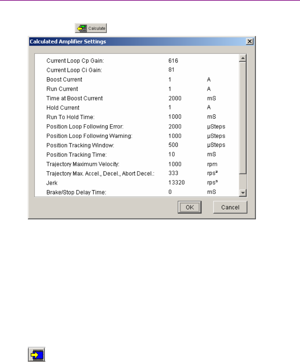
Stepnet Panel Amplifier User Guide Mode Selection and General Setup
Copley Controls Corp. 99
5.5.6: The Calculate Function
The Calculate function uses the motor and encoder values entered to calculate initial loop gains
and limits. These can be modified later to fine-tune the amplifier.
5.5.6.1 Click Calculate ( )to calculate and display the settings.
Note that in servo mode, Peak Current and Continuous Current replace the stepper
mode Boost Current and Run Current settings.
5.5.6.2 Verify the boost (peak) current limit and Run (Continuous) Current limit.
If one or more of these values seems inappropriate, click Cancel and check: Rated
Torque (or Force) and Rated Current. Correct them if needed. See Rotary Motor Setup
Parameters (p. 97)
or Linear Motor Setup Parameters (p. 97).
If the Motor/Feedback values were correct but the peak current limit, continuous
current limit, or velocity loop velocity limit values are not optimal for the application,
change these limits during the tuning process.
5.5.6.3 Load the values into amplifier RAM by clicking OK.
NOTE: If the motor wiring configuration in the motor file does not match the
configuration currently stored in the amplifier, CME prompts for verification on which
configuration to use. Select the file configuration by clicking Yes.The configuration will
be tested during auto phasing.
5.5.6.4 On the Main screen, click Save to Flash to avoid losing the changes.
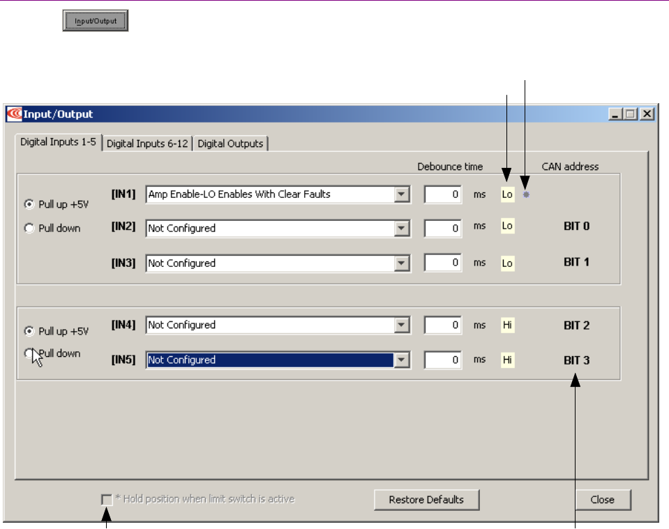
Mode Selection and General Setup Stepnet Panel Amplifier User Guide
100 Copley Controls
5.6: Amplifier Configuration
5.6.1: Digital Inputs
5.6.1.1 Click Input/Output on the Main screen to open the Input/Output screen.
Atypical Input/Output screen is shown below. (Features vary with model and configuration.)
Lo/Hi: Indicates state of input.
Red: inhibited motion or active input, depending on input function. Grey: motion not inhibited. None: not configured.
Indicates input is used as a CAN address bit.Hold position setting

Stepnet Panel Amplifier User Guide Mode Selection and General Setup
Copley Controls Corp. 101
5.6.1.2 Change or verify the following settings:
Setting Description
Pull up +5 V Pulls up the group of inputs up to internal +5 V.
Pull down Pulls the group of inputs down to internal signal ground.
IN1-IN12 Select the function for the input. See Digital Input Functions (p. 102) for input function
descriptions.
Debounce
Time
Sets the input debounce time (how long an input must remain stable at a new state
before the amplifier recognizes the state). Increase to prevent undesired multiple
triggering caused by switch bounce. Debounce time is ignored for digital command
inputs such as PWM. Range: 0 to 10,000 mSec. See Debounce Time (p. 42).
*Hold position
when limit
switch is
active
Available in position mode when one or more inputs are configured as a limit switch
(NEG Limit-HI Inhibits, NEG Limit-LO Inhibits, POS Limit-HI Inhibits, or POS Limit-LO
Inhibits). The Hold position…option prevents any motion while a limit switch is active.
!
WARNING
WARNING: Limit switches may be disabled.
If the amplifier is switched back to current or velocity mode with Hold position when limit switch is
active set, the limit switches will no longer function.
Failure to heed this warning can cause equipment damage.
The Restore Defaults button restores all inputs and outputs to factory defaults. The Close button
closes the screen.

Mode Selection and General Setup Stepnet Panel Amplifier User Guide
102 Copley Controls
5.6.2: Digital Input Functions
Input Function Description
AMP Enable-
LO Enables with clear faults
Alow input will enable the amplifier.
Any transition will clear latched faults and outputs.
AMP Enable-
HI Enables with clear faults
Ahigh input will enable the amplifier.
Any transition will clear latched faults and outputs.
AMP Enable-
LO Enables with reset
Alow input will enable the amplifier.
Alow to high transition will reset the amplifier.
AMP Enable-
HI Enables with reset
Ahigh input will enable the amplifier.
Ahigh to low transition will reset the amplifier.
AMP Enable-
LO Enables
Alow input will enable the amplifier.
AMP Enable-
HI Enables
Ahigh input will enable the amplifier.
Not Configured No function assigned to the input.
NEG Limit-HI Inhibits A high input will inhibit motion in negative direction.
NEG Limit-LO Inhibits A low input will inhibit motion in negative direction.
POS Limit-HI Inhibits A high input will inhibit motion in positive direction.
POS Limit-LO Inhibits A low input will inhibit motion in positive direction.
Reset on LO-HI Transition A low to high transition of the input will reset the amplifier.
Reset on HI-LO Transition A high to low transition of the input will reset the amplifier.
Motor Temp HI Disables A high input will generate a Motor Over Temperature fault.
Motor Temp LO Disables A low input will generate a Motor Over Temperature fault.
Home Switch Active HI A high input indicates the home switch is activated.
Home Switch Active LO A low input indicates the home switch is activated.
Motion Abort Active HI A high input stops motion but amplifier remains enabled.
Motion Abort Active LO A low input stops motion but amplifier remains enabled.
Hi Res Analog Divide Active HI A high input causes the firmware to divide the level of the analog
input signal by 8.
Hi Res Analog Divide Active LO A low input causes the firmware to divide the level of the analog input
signal by 8.
High Speed Position Capture on
LO-HI Transition
Position will be captured on the low to high transition of the input.
High Speed Position Capture on
HI-LO Transition
Position will be captured on the high to low transition of the input.
PWM Sync Input PWM synchronization input.
5.6.3: Standard Input Function Assignments
Enable Input: On the Stepnet amplifier, IN1 is dedicated to the enable function.
Other inputs can be programmed as additional enables. If there is more than one input
programmed as an enable then all the inputs must be in the enabled state before the amplifier
PWM output stage will be enabled.
Motor Over Temperature: On the STX amplifier, IN12 is located on the motor feedback
connector and is intended to be used for Motor Over Temperature.
Other: Other inputs may have predefined functions depending on mode of operation.
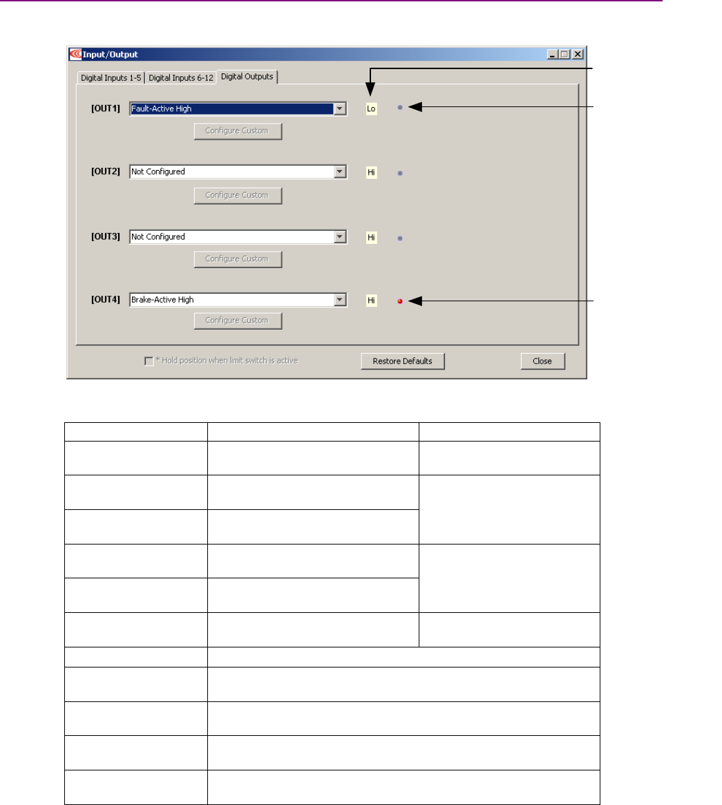
Stepnet Panel Amplifier User Guide Mode Selection and General Setup
Copley Controls Corp. 103
5.6.4: Standard Digital Outputs
5.6.4.1 Click the Digital Outputs tab of the Input/Output screen. A typical Digital Outputs screen
is shown below. (Features may vary with amplifier model and configuration.)
Grey light:
Output is not active
Hi/Lo state of output
Red light:
Output is active
5.6.4.2 Choose any of these functions for any output. OUT4 is recommended for brake
function.
Output Function Description For More Information
Not Configured No function assigned. Output
remains high.
Fault Active High Output goes high when one or
more faults are detected.
Fault-Active Low Output goes low when one or more
faults are detected.
Faults (p. 37).
Brake-Active High Output goes high to activate the
brake.
Brake-Active Low Output goes low to activate the
brake.
Brake Operation (p. 34).
PWM Sync Output
(OUT1 only)
The PWM synchronization output.
Custom Event See Custom Digital Output Settings: Custom Event (p. 104).
Custom Trajectory
Status
See Custom Digital Output Settings: Custom Trajectory Status (p.
106).
Custom Position
Triggered Output
See Custom Digital Output Settings: Position Triggered Output (p.
107).
Program Control
Active High
Output state controlled by CVM or external program.
Program Control
Active Low
Output state controlled by CVM or external program
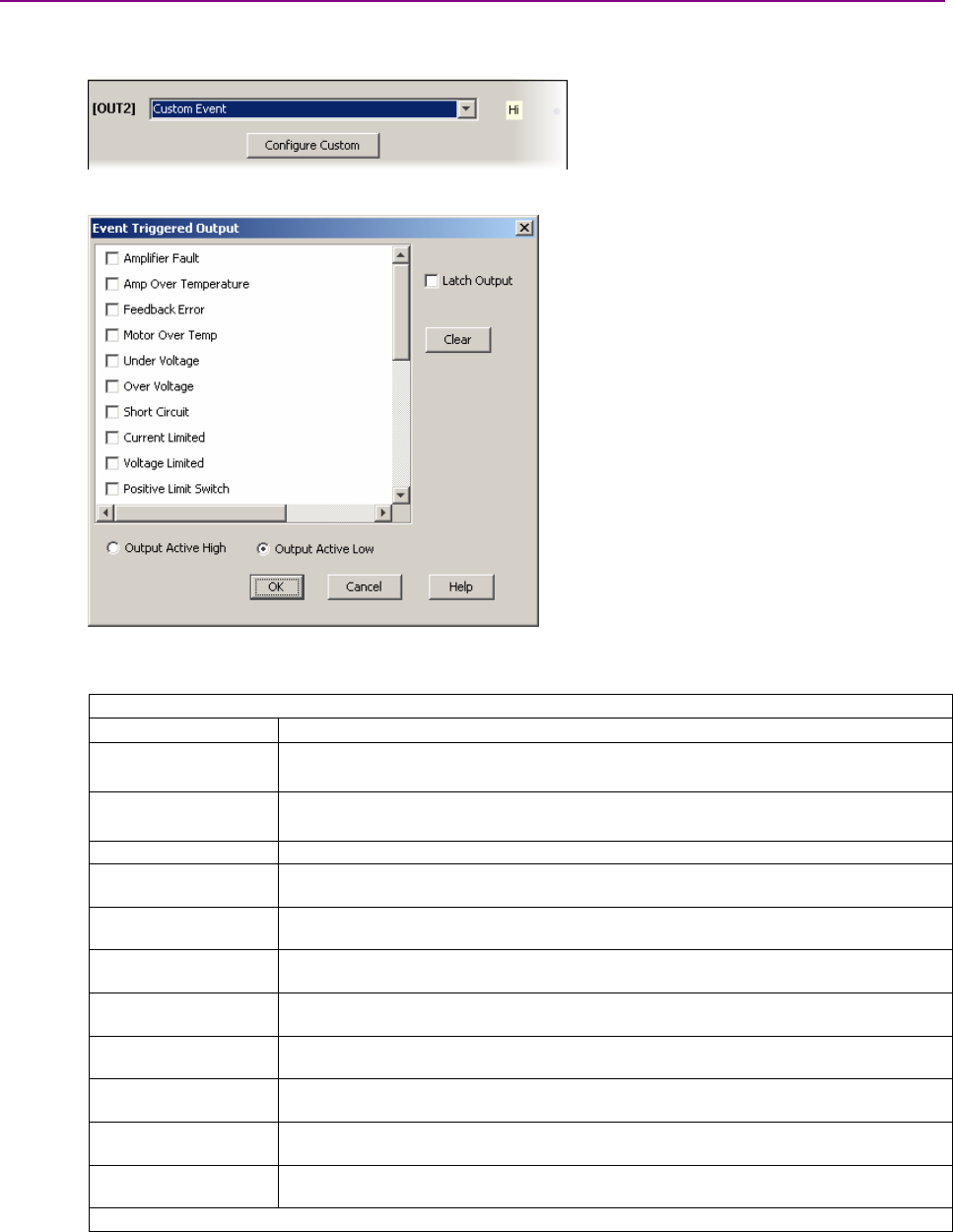
Mode Selection and General Setup Stepnet Panel Amplifier User Guide
104 Copley Controls
5.6.5: Custom Digital Output Settings: Custom Event
Any of the amplifier’s digital outputs can be programmed to respond to a combination of events
including faults, warnings, and status indications. The output goes active when one or more of the
selected events take place.
5.6.5.1
Choose Custom Event for an output and then click Configure Custom to open the Event
Configuration screen.
5.6.5.2 Select one or more of the faults described in Fault Descriptions (p. 38) or any of the
following warnings or status conditions described below.Note that multiple functions
are OR’ed together, so any event activates the output.
Custom Events: Warnings
Warning Description
Current Limited The current output is being limited by the I2Talgorithm or a latched current fault
has occurred. See I2TTime Limit Algorithm (p. 167).
Voltage Limited The current loop is commanding full bus voltage in an attempt to control current.
Commonly occurs when motor is running as fast as available bus voltage allows.
Positive Limit Switch Axis has contacted positive limit switch.
Negative Limit
Switch
Axis has contacted negative limit switch.
Positive Software
Limit
Actual position has exceeded the positive software limit setting.
See Home Function (p. 164).
Negative Software
Limit
Actual position has exceeded the negative software limit setting.
See Home Function (p. 164).
Following Warning Following error has reached programmed warning limit.
See Following Error Fault Details (p. 40).
Velocity Limit
Reached
Velocity command (from analog input, PWM input, or position loop) has exceeded
the velocity limit that was set as described in Servo Velocity Loop Limits (p. 21).
Acceleration Limit
reached
In velocity mode, motor has reached an acceleration or deceleration limit that was
set as described in Servo Velocity Loop Limits (p. 21).
Velocity Outside of
Tracking Window
Difference between target and actual velocity has exceeded the window.
See Tracking Window Details (p. 41).
Position Outside of
Tracking Window
The following error has exceeded the programmed value.
See Tracking Window Details (p. 41).
Continued…
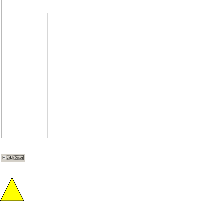
Stepnet Panel Amplifier User Guide Mode Selection and General Setup
Copley Controls Corp. 105
…Continued:
Custom Events: Status
Status Description
Amplifier Disabled by
Hardware
Amplifier enable input(s) is not active.
Amplifier Disabled by
Software
Amplifier is disabled by a software command.
Attempting to Stop
Motor
The amplifier, while in velocity or position mode, has been disabled.
In velocity mode, amplifier is using the Fast Stop Ramp described in
Servo Velocity Loop Limits (p. 21).
In position mode, the amplifier is using the Abort Deceleration rate described in
Trajectory Limits (p. 23).
The output remains active until the amplifier is re-enabled.
Motor Brake
Activated
Motor brake activated. See Brake Operation (p. 34) for more information.
PWM Outputs
Disabled
The amplifier’s PWM outputs are disabled.
Home Switch is
Active
Axis has contacted the home limit switch.
Not Settled The motor is moving, or it has not yet settled after a move. The amplifier is settled
when it comes within the position tracking window and stays there for the tracking
time at the end of a move. Once settled, it remains settled until a new move is
started.
5.6.5.3 Choose Output Active High to have the output go high when active or Output Active
Low to have the output go low when active.
5.6.5.4 To optionally latch the selected events, set Latch Output.For more
information on latching, see Non-Latched and Latched Custom Outputs (p. 108).
Latching an output does not eliminate the risk of unexpected motion with
non-latched faults.
!
DANGER
Associating a fault with a latched, custom-configured output does not latch the
fault itself. After the cause of a non-latched fault is corrected, the amplifier re-
enables without operator intervention. In this case, motion may re-start
unexpectedly.
Failure to heed this warning can cause equipment damage, injury, or death.
5.6.5.5 Click OK to save changes to volatile memory and close the
Custom Output Configuration screen.
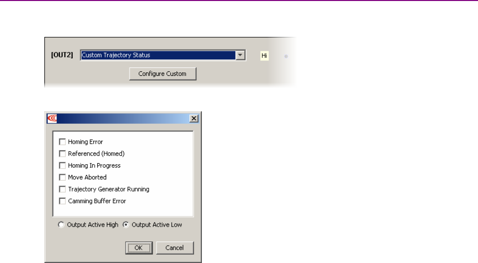
Mode Selection and General Setup Stepnet Panel Amplifier User Guide
106 Copley Controls
5.6.6: Custom Digital Output Settings: Custom Trajectory Status
Any of the amplifier’s digital outputs can be programmed to respond to a combination of amplifier
trajectory status conditions. The output goes active when one or more of the conditions is met.
5.6.6.1
Choose Custom Trajectory Status for an output and then click Configure Custom to
open the Trajectory Status Configuration screen.
5.6.6.2 Select one or more trajectory status conditions described below. Multiple functions are
OR’ed together, so any status match activates the output.
Trajectory Status Functions
Status Description
Homing Error Activate output if an error occurred in the last homing attempt.
Referenced (Homed) Activate output if the most recent homing attempt was successful.
Homing in Progress Activate output when a homing move is in progress.
Move Aborted Activate output if move is aborted.
Trajectory Generator
Running
Activate output while trajectory generator is generating a move.
Camming Buffer Error A camming buffer error has occurred.
5.6.6.3 Choose Output Active High to have the output go high when active or Output Active
Low to have the output go low when active.
5.6.6.4 Click OK to save changes to volatile memory and close the screen.
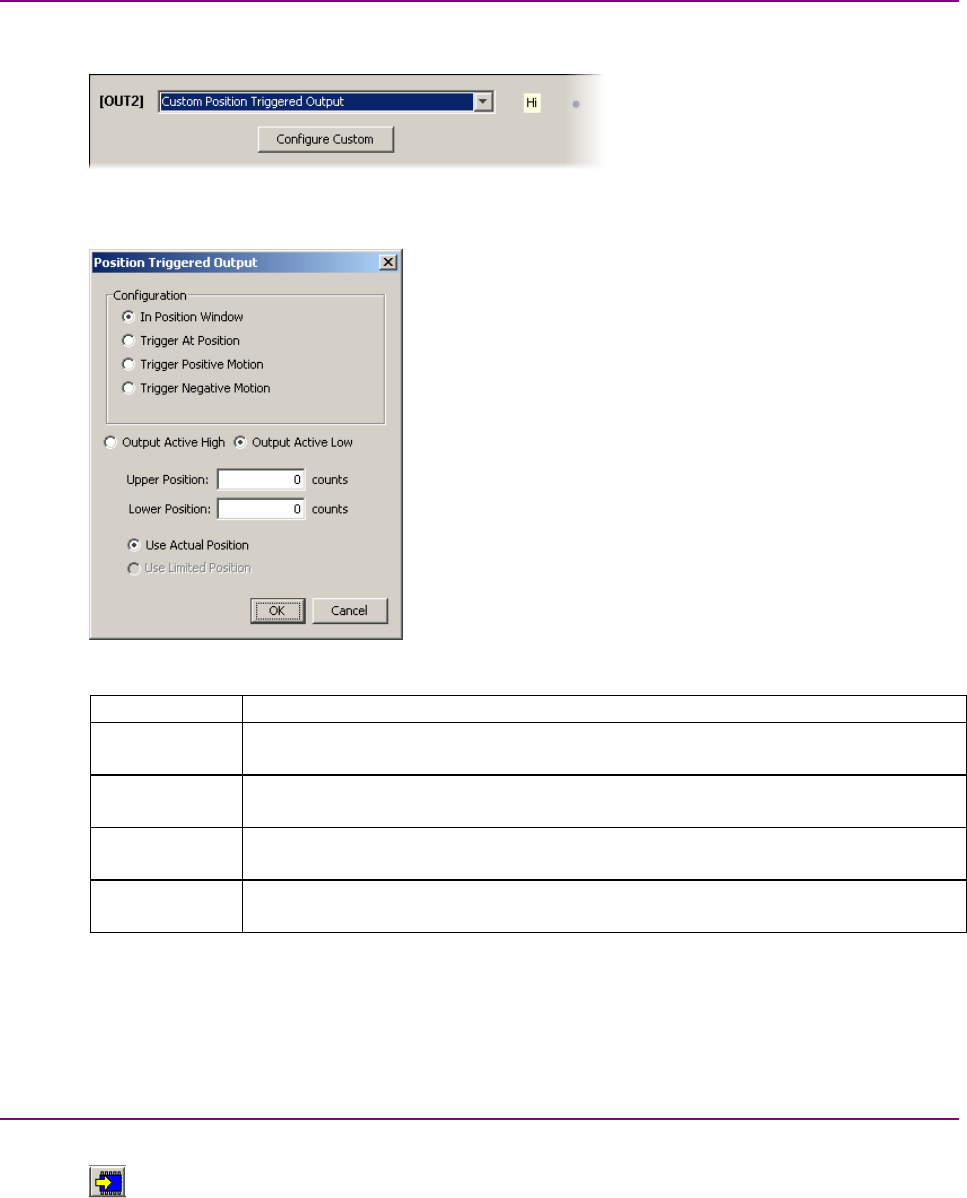
Stepnet Panel Amplifier User Guide Mode Selection and General Setup
Copley Controls Corp. 107
5.6.7: Custom Digital Output Settings: Position Triggered Output
Any of the amplifier’s digital outputs can be programmed to respond in certain ways to the position
of the controlled axis. The output goes active when the axis position meets the specified criteria.
5.6.7.1
5.6.7.2 Choose Custom Position Triggered Output for an output and then click Configure
Custom to open the In Position Configuration screen.
5.6.7.3 Select one of the configurations described below and enter appropriate values for the
parameters.
Configuration Description and Parameters
In Position
Window
Activates the output while the axis is in the window between the programmed Upper
and Lower positions.
Trigger at
Position
Activates the output for the programmed Time when the axis travels through the
programmed Position.
Trigger Positive
Motion
Activates the output for the programmed Time when the axis travels in the positive
direction through the programmed Position.
Trigger
Negative Motion
Activates the output for the programmed Time when the axis travels in the negative
direction through the programmed Position.
5.6.7.4 Choose Output Active High to have the output go high when active or Output Active
Low to have the output go low when active.
5.6.7.5 Choose Use Actual Position (with encoder only) or Use Limited Position.
5.6.7.6 Click OK to save changes to volatile memory and close the
Custom Output Configuration screen.
5.6.8: Save Input/Output Changes
5.6.8.1 On the Input/Output screen, click Close.
5.6.8.2 On the Main screen, click Save to Flash.

Mode Selection and General Setup Stepnet Panel Amplifier User Guide
108 Copley Controls
5.6.9: Non-Latched and Latched Custom Outputs
Like an amplifier fault, a custom-configured output can be non-latched or latched.
If a non-latched, custom-configured digital output goes active, it goes inactive as soon as the last
of the selected events is cleared.
If a latched output goes active, it remains active until at least one of the following actions has been
taken:
•power-cycle the amplifier
•cycle (disable and then enable) an enable input that is configured as
Enables with Clear Faults or Enables with Reset
•access the CME 2 Control Panel and press Clear Faults or Reset
•clear faults over the CANopen network
Latching an output does not eliminate the risk of unexpected motion with non-
latched faults.
!
DANGER
Associating a fault with a latched, custom-configured output does not latch the fault
itself. After the cause of a non-latched fault is corrected, the amplifier re-enables
without operator intervention. In this case, motion may re-start unexpectedly.
For more information, see Clearing Non-Latched Faults (p. 37).
Failure to heed this warning can cause equipment damage, injury, or death.
Custom Event Output Faults
An output configured for Custom Event can be programmed to go active in response to events,
including any of the amplifier faults described in Fault Descriptions (p. 38).
Example: Custom Output Fault Handling vs. Overall Fault Handling
Afault on an output configured for Custom Event is separate from a fault on the amplifier. For
instance, suppose:
•OUT3 has a Custom Event configuration. Only the Under Voltage fault condition is selected,
and the output is latched.
•Under Voltage is not latched on the Configure Faults screen.
An under voltage condition occurs, and the amplifier goes into fault condition, output stages are
disabled, and faults are reported. At the same time, OUT3 goes active.
The under voltage condition is corrected, and:
•The amplifier fault is cleared. Output stages are enabled.
•OUT3 remains active.
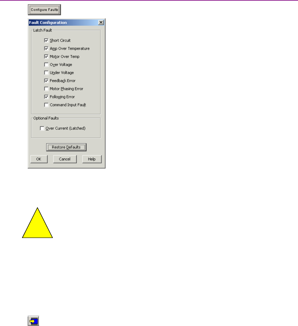
Stepnet Panel Amplifier User Guide Mode Selection and General Setup
Copley Controls Corp. 109
5.6.10: Fault Latching
5.6.10.1 Click Configure Faults to open the Fault Configuration screen.
Note that with no encoder, the Following error fault is not displayed as a choice.
5.6.10.2 To make a fault condition latching, click to put a check mark next to the fault
description.
Risk of unexpected motion with non-latched faults.
!
DANGER
After the cause of a non-latched fault is corrected, the amplifier re-enables the PWM
output stage without operator intervention. In this case, motion may re-start
unexpectedly. Configure faults as latched unless a specific situation calls for non-
latched behavior. When using non-latched faults, be sure to safeguard against
unexpected motion.
Failure to heed this warning can cause equipment damage, injury, or death.
For more information on faults, see Faults (p. 37).
5.6.10.3 To restore factory defaults if needed, click Restore Defaults.
5.6.10.4 Click OK to save fault configuration settings to amplifier RAM and close the
Fault Configuration screen
OR
click Cancel to restore to previous values and close the screen.
5.6.10.5 On the Main screen, click Save to Flash.
Mode Selection and General Setup Stepnet Panel Amplifier User Guide
110 Copley Controls
5.7: Command Input
Choose the appropriate step for the input format.
Input Format Step
Digital Position Digital Position Input (p. 111)
CAN CAN Interface (p. 112)
PWM (servo mode
only)
PWM Input (p. 113)
Analog Analog Command Input (STX Servo Mode Only) (p. 114)
To run the amplifier with Command Input set to Software Programmed or Function Generator,see
the CME 2 User Guide. To run the amplifier with Command Input set to Camming,see the Copley
Camming User’s Guide.
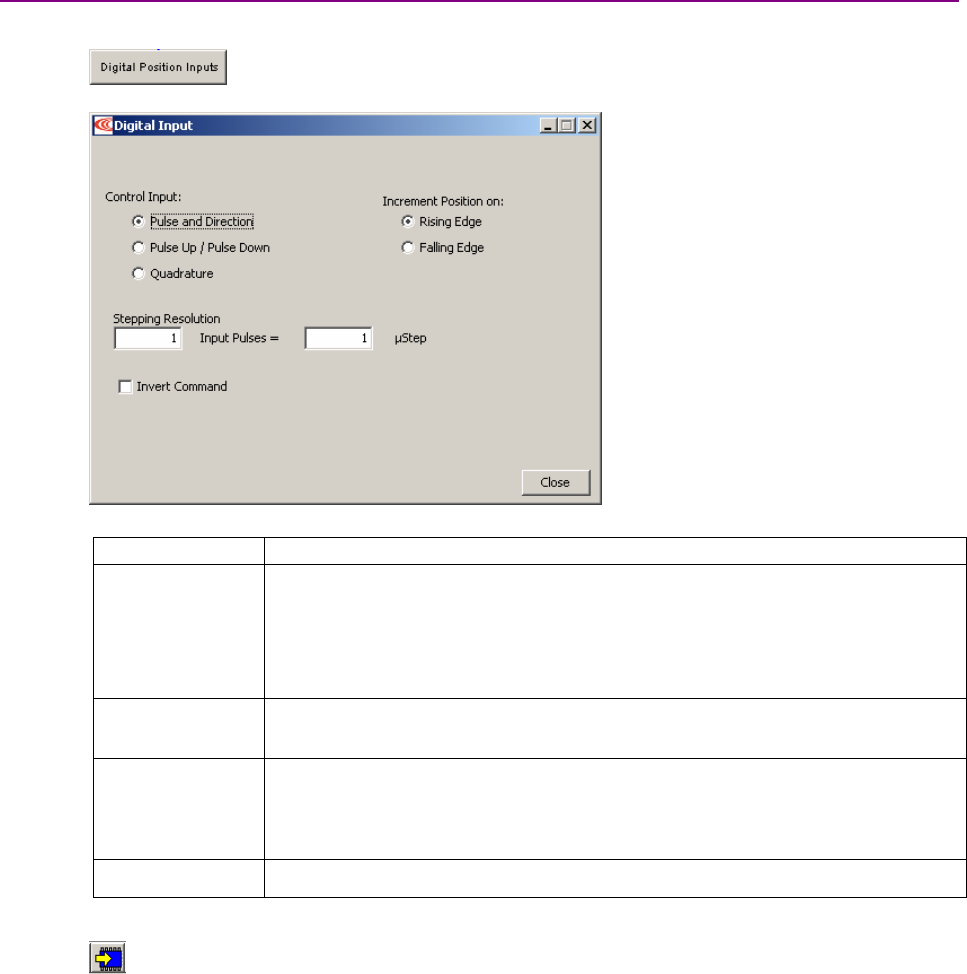
Stepnet Panel Amplifier User Guide Mode Selection and General Setup
Copley Controls Corp. 111
5.7.1: Digital Position Input
For more information, see Digital Position Inputs (p. 27).
5.7.1.1 Click Digital Position Inputs to open the Digital Position Input screen,
Configuration tab.
5.7.1.2 Set the options described below:
Option Description
Control Input Pulse and Direction: One input takes a series of pulses as motion step commands,
and another input takes a high or low signal as a direction command.
Pulse Up / Pulse Down: One input takes each pulse as a positive step command,
and another takes each pulse as a negative step command.
Quadrature: A/B quadrature commands from a master encoder (via two inputs)
provide velocity and direction commands.
Increment position
on
Rising Edge: Increment position on the rising edge of the input pulse.
Falling Edge: Increment position on the falling edge of the input pulse.
Stepping
Resolution
Input Pulses: Number of Input Pulses required to produce output counts.
Range: 1 to 32,767. Default: 1.
Output Counts: Number of Output Counts per given number of input pulses.
Range: 1 to 32,767. Default: 1.
Invert Command When selected, inverts commanded direction.
5.7.1.3 Click Close.
5.7.1.4 On the Main screen, click Save to Flash.
5.7.1.5 Proceed to Stepper Mode Phase and Tune (p. 115).
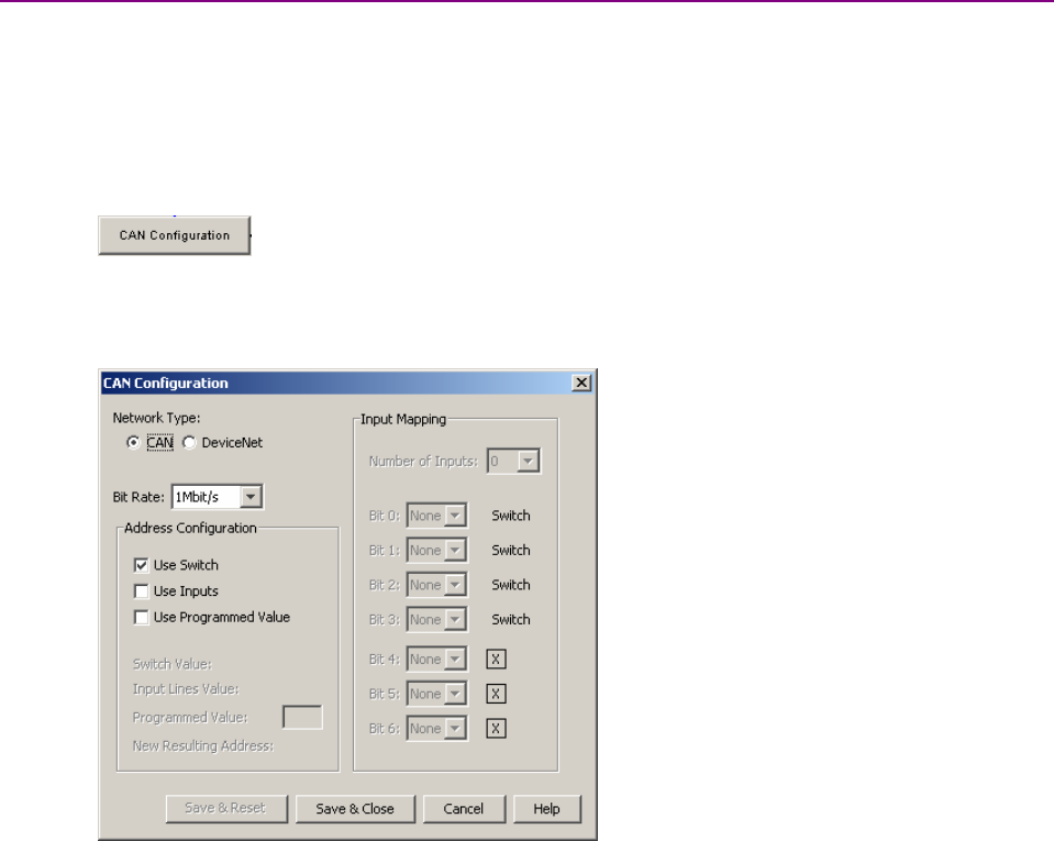
Mode Selection and General Setup Stepnet Panel Amplifier User Guide
112 Copley Controls
5.7.2: CAN Interface
For more information on CAN see CAN Addressing (p. 32).
For information on DeviceNet, see the Copley DeviceNet Programmer’s Guide.
5.7.2.1 Verify that the CAN bus is properly wired and terminated according to the instructions
in Stepnet Panel (STP) CAN Bus (J5 and J6) (p. 65).
1. J6 "CAN" CANopen cable
2. J6 "CAN" Termination plug
5.7.2.2 Click CAN Configuration to open the CAN Configuration screen. (If
CAN is not the Position Loop Input, choose AmplifierNetwork Configuration
instead.)
Here is a typical CAN Configuration screen. (Features may vary based on amplifier
model and configuration.)
5.7.2.3 Choose a Bit Rate and choose any combination of address sources (Switch, Inputs,
and Programmed Value). The address is the sum of the values from these sources.
5.7.2.4 For each source selected, perform the additional steps described below.
Source Additional Steps
Use Switch Verify the S1 switch setting. (Assigns values for Bit 0 – Bit 3 of CAN
address.)
Use Inputs Enter the Number of inputs.Choose the input that will represent each
CAN address bit.
Use Programmed
Value
Enter the Programmed value.
5.7.2.5 Click Save & Reset to save changes to amplifier flash, close the screen, and reset the
amplifier. Click Save & Close to save changes to amplifier flash without resetting.
NOTE: CAN address and bit rate changes take effect only after power-up or reset.
5.7.2.6 Proceed to Stepper Mode Phase and Tune (p. 115) or
Servo Mode Phase and Tune (p. 131) as appropriate.
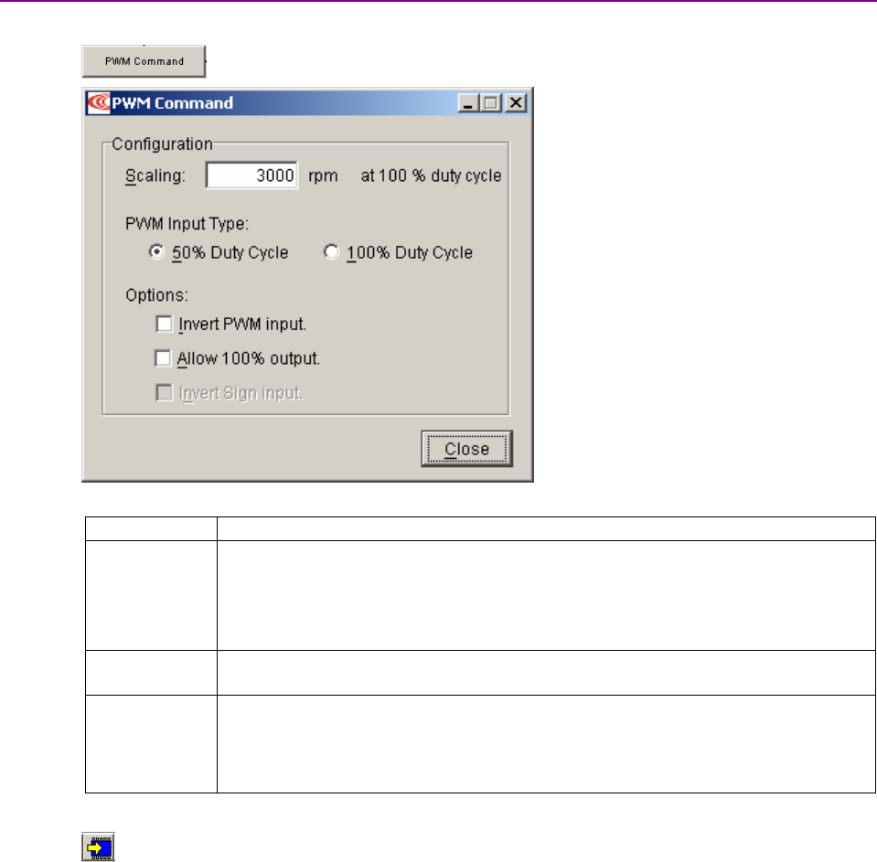
Stepnet Panel Amplifier User Guide Mode Selection and General Setup
Copley Controls Corp. 113
5.7.3: PWM Input (Servo Mode Only)
For more information, see PWM Input (Servo Mode Only) (p. 29).
5.7.3.1 Click PWM Command to open the PWM Command screen.
5.7.3.2 Set the input options described below.
Option Description
Scaling Current mode: output current at 100% duty cycle.
Range: 0 to 10,000,000 A. Default: Peak Current value.
Velocity mode: output velocity at 100% duty cycle.
Range: 0 to 100,000 rpm (mm/sec).
Default: Maximum Velocity value.
PWM Input
Type
One wire 50% or two wire 100% with direction.
Options Invert PWM input: Inverts the PWM logic.
Allow 100% output: Overrides the 100% command safety measure.
See Failsafe Protection from 0 or 100% Duty Cycle Commands (p. 29).
Invert Sign Input: In 100% duty cycle mode, inverts the polarity of the directional input.
5.7.3.3 Click Close.
5.7.3.4 On the Main screen, click Save to Flash.
5.7.3.5 Proceed to Servo Mode Phase and Tune (p. 131).
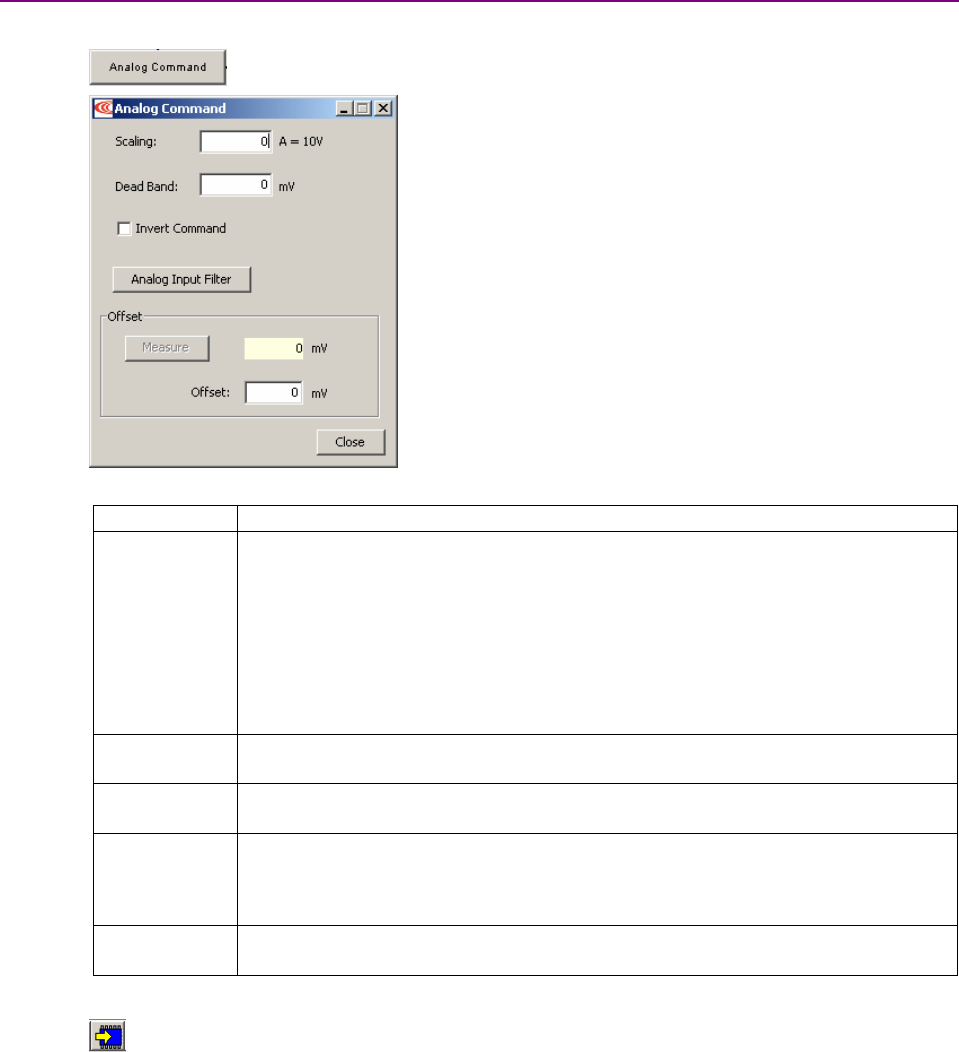
Mode Selection and General Setup Stepnet Panel Amplifier User Guide
114 Copley Controls
5.7.4: Analog Command Input (STX Servo Mode Only)
For more information, see Analog Command Input (STX Servo Mode Only) (p. 25).
5.7.4.1 Click Analog Command to open the Analog Command screen.
5.7.4.2 Set the input options described below.
Option Description
Scaling Current mode: output current produced by +10 Vdc of input.
Range: 0 to 10,000,000 A. Default: Peak Current value.
Velocity mode: output velocity produced by +10 Vdc of input.
Range: 0 to 100,000 rpm (mm/sec).
Default: Maximum Velocity value.
Position mode: position change (counts or mm) produced by +10 Vdc of input.
Range: 0 to 1,000,000,000 counts.
Default: 1 Revolution of a rotary motor or 1 pole pair distance for a linear motor.
For more information, see Scaling (p. 25).
Dead Band Sets dead band. Range: -10,000 to 10,000 mV. Default: 0.
For more information, see Dead Band (p. 25).
Invert
Command
Inverts polarity of amplifier output with respect to input signal.
Offset (Current and Velocity modes only.) Used to offset input voltage error in an open loop
system. Not recommended for use when the amplifier is part of a closed loop system.
Range: -10,000 to 10,000 mV. Default: 0. For more information, see
Offset (p. 26).
Analog Input
Filter
Programmable input filter. Disabled by default. See “Low-Pass and Bi-Quad Filters” in
the CME 2 User’s Guide.
5.7.4.3 Click Close.
5.7.4.4 On the Main screen, click Save to Flash.
5.7.4.5 Proceed to Servo Mode Phase and Tune (p. 131).
.

Copley Controls Corp. 115
CHAPTER
6: STEPPER MODE PHASE AND TUNE
This chapter describes the general procedure for auto phasing and tuning an amplifier with a
motor to operate in stepper mode.
Step Page
6.1: Auto Phase (Stepper Mode) ............................................................................................................................................... 116
6.1.1: Auto Phase Warnings and Notes........................................................................................................................... 116
6.1.2: Auto Phase Preliminary Steps ............................................................................................................................... 117
6.1.3: Auto Phase (Stepper Mode, No Encoder) .............................................................................................................. 117
6.1.4: Auto Phase Procedure (Stepper Mode with Encoder) ............................................................................................ 118
6.1.5: Trouble Shoot Motor Direction Setup..................................................................................................................... 119
6.1.6: Trouble Shoot Motor Wiring Setup......................................................................................................................... 119
6.2: Position Limits (Stepper Mode with Encoder) ..................................................................................................................... 120
6.3: Current Loop....................................................................................................................................................................... 122
6.3.1: Current Loop Settings............................................................................................................................................ 122
6.3.2: Manually Tune Current Loop.................................................................................................................................. 123
6.3.3: Optimize Hold and Run Current Ratings ................................................................................................................ 124
6.4: Profile Move Tests.............................................................................................................................................................. 125
6.4.2: Test S-Curve Profile .............................................................................................................................................. 127
6.5: Encoder Correction............................................................................................................................................................. 128
6.6: Completion Steps ............................................................................................................................................................... 129
6.6.1: Objective................................................................................................................................................................ 129
6.6.2: Steps ..................................................................................................................................................................... 129

Stepper Mode Phase and Tune Stepnet Panel Amplifier User Guide
116 Copley Controls
6.1: Auto Phase (Stepper Mode)
6.1.1: Auto Phase Warnings and Notes
Warnings
Motor Motion
!
DANGER
Applying high voltage power to the amplifier before auto phasing may result in motor
motion. Be sure that motor motion will not cause injury.
Failure to heed this warning can result in equipment damage, injury, or death.
High Voltage
!
Danger
Applying AC power to the STX amplifier applies high voltage to the amplifier-motor
connections and cabling. Protect personnel against electrical shock.
Failure to heed this warning can result in equipment damage, injury, or death.
Notes
•Do not connect a load to the motor before performing Auto Phase procedure.
•Always connect the motor using the same configuration.
•Wire properly and consistently.
•Connections are actually changed within the DSP, not at the motor terminals, and the results
are saved to flash memory. The actual wire configuration should NEVER change.
Phasing a stepper motor establishes positive direction for the motor and (if present) encoder.
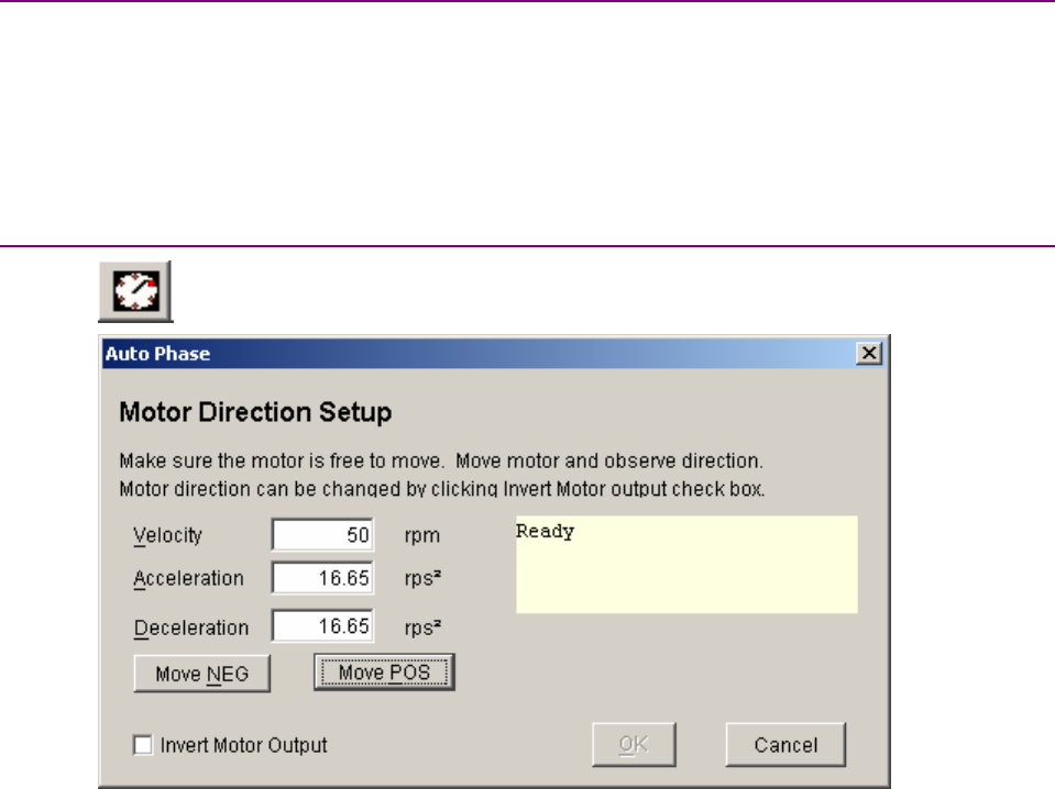
Stepnet Panel Amplifier User Guide Stepper Mode Phase and Tune
Copley Controls Corp. 117
6.1.2: Auto Phase Preliminary Steps
6.1.2.1 Verify that the Enable Input is not activated.
6.1.2.2 Apply power.
6.1.2.3 Choose the appropriate auto phase procedure for the configuration:
Configuration Procedure
Stepper mode, no encoder Auto Phase (Stepper Mode, No Encoder (p. 117))
Stepper mode with encoder Auto Phase Procedure (Stepper Mode with Encoder (p. 118))
6.1.3: Auto Phase (Stepper Mode, No Encoder)
6.1.3.1 Click Auto Phase to open the Auto Phase Motor Direction Setup screen.
6.1.3.2 Activate the Enable Input.
6.1.3.3 Verify the Velocity, Acceleration, and Deceleration values.
6.1.3.4 Hold down Move POS to move the motor in the direction considered positive, and
observe the direction of movement.
If the motor does not move, see Trouble Shoot Motor Wiring Setup (p. 119).
6.1.3.5 If the motor did not move in the direction that you wish to program as the positive
direction, click Invert Motor Output,and repeat 6.1.3.4.
6.1.3.6 Click OK to save the direction setting.
6.1.3.7 Proceed to Current Loop (p. 122).
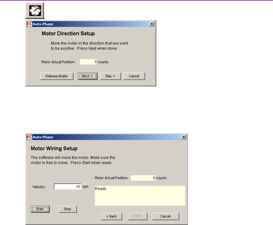
Stepper Mode Phase and Tune Stepnet Panel Amplifier User Guide
118 Copley Controls
6.1.4: Auto Phase Procedure (Stepper Mode with Encoder)
Click Auto Phase to open the Auto Phase Motor Direction Setup screen.
6.1.4.1 Activate the Enable Input.
6.1.4.2 Move the motor at least three counts in the direction considered positive.
6.1.4.3 If the Motor Actual Position count does not change, see Trouble Shoot Motor Direction
Setup (p. 119).
6.1.4.4 Click Next to open the Motor Wiring Setup screen.
6.1.4.5 Verify the Velocity setting.
6.1.4.6 Click Start to begin motor wiring setup.
The software displays messages: Configuring Initial Settings, Microstepping, Test
Complete, Motor Wiring has been configured.
During microstepping, a current vector is applied to the motor windings and
microstepped through an electrical cycle at a set rate, causing the motor to move.
If you chose to Skip the motor direction setup step, Auto Phase will prompt for
confirmation of correct motor direction.
If the step fails see Trouble Shoot Motor Wiring Setup (p. 119).
6.1.4.7 Click Finish to close the screen and save values to amplifier flash.

Stepnet Panel Amplifier User Guide Stepper Mode Phase and Tune
Copley Controls Corp. 119
6.1.5: Trouble Shoot Motor Direction Setup
If motor direction setup step failed:
6.1.5.1 If an encoder is used, check encoder power and signals.
6.1.5.2 Check shielding for proper grounding.
6.1.6: Trouble Shoot Motor Wiring Setup
If motor wiring setup step failed:
6.1.6.1 Verify that amplifier is disabled.
6.1.6.2 Check for mechanical jamming.
6.1.6.3 Check for good connections to the motor power wires.
6.1.6.4 Disconnect motor power wires.
6.1.6.5 Measure for proper motor resistance.
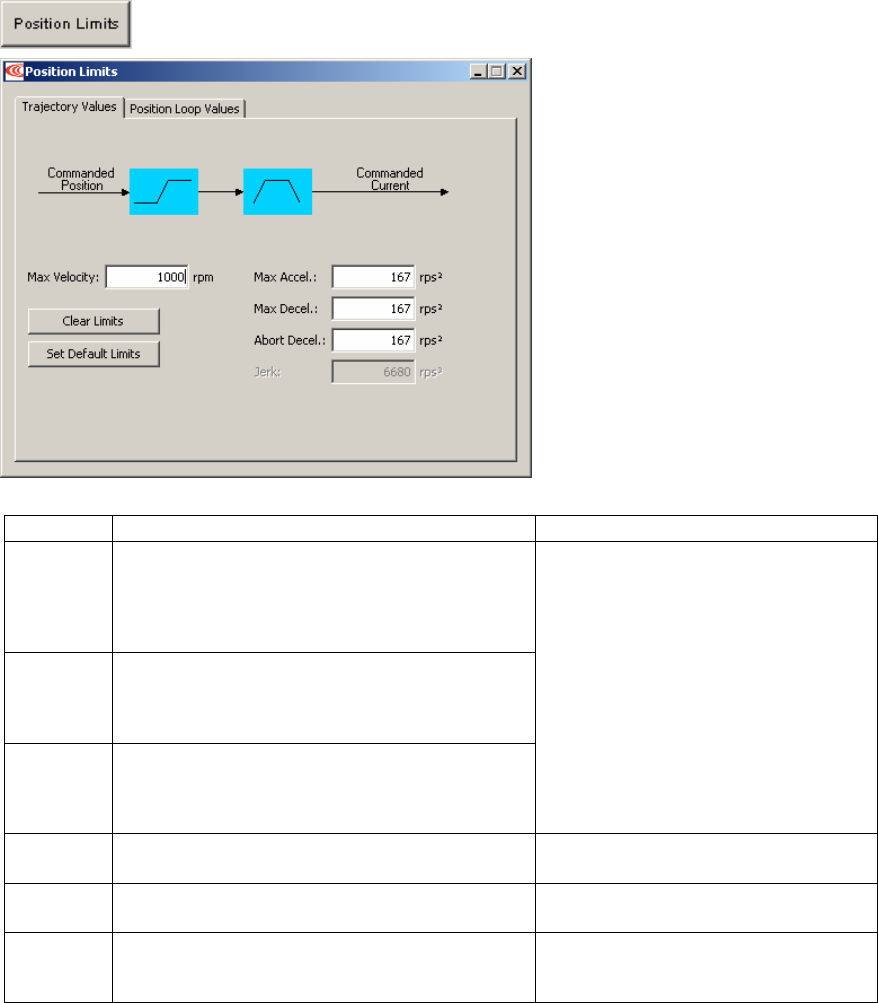
Stepper Mode Phase and Tune Stepnet Panel Amplifier User Guide
120 Copley Controls
6.2: Position Limits (Stepper Mode with Encoder)
6.2.1.1 Click Position Limits to open the Position Limits screen.
6.2.1.2 Set the following Trajectory Values options as needed.
Option Description For More Information
Max
Velocity
Maximum trajectory velocity. Max value may
depend upon the back EMF and the Max
feedback count (servo mode) or maximum
number of microsteps (stepper mode). Min:0.
Default: 0.25 x motor velocity limit.
Max Accel Maximum trajectory acceleration. Max value may
depend upon the load inertia and boost current
(stepper mode) or peak current (servo mode).
Min:0
Max Decel Maximum trajectory deceleration. Max value may
depend upon the load inertia and boost current
(stepper mode) or peak current (servo mode).
Min: 0 (disables limit).
Servo Position Mode and Position Loop
(p. 23).
Abort
Decel
Deceleration rate used by the trajectory generator
when motion is aborted. Min: 0 (disables limit).
Brake Operation (p. 34).
Clear
Limits
Sets Max Velocity, Max Accel, and Max Decel to
zero, disabling the trajectory generator.
Set
Default
Limits
Restores Max Velocity, Max Accel, and Max
Decel to calculated defaults.
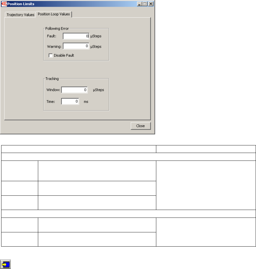
Stepnet Panel Amplifier User Guide Stepper Mode Phase and Tune
Copley Controls Corp. 121
6.2.1.3 Open the Position Loop Values tab.
6.2.1.4 Set the following Position Loop Values options as needed.
Option/Description For More Information
Following Error
Fault The level (in µSteps) at which the following
error produces a fault. We recommend raising
the fault level before tuning the loop.
Warning The level (in µSteps) at which the following
error produces a warning.
Disable
Fault
Prevents following error from triggering a fault.
Following Error Fault Details (p. 40).
Tracking
Tracking
Window
Width of the tracking window in µSteps.
Tracking
Time
Position must remain in the tracking window for
this amount of time to be considered tracking.
Tracking Window Details (p. 41).
6.2.1.5 Click Close.
6.2.1.6 On the Main screen, click Save to Flash to save the changes.
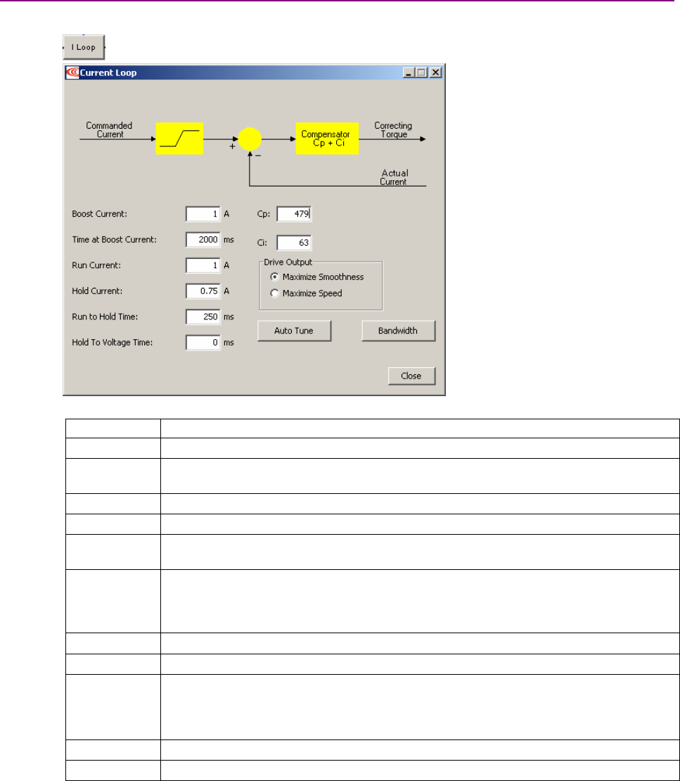
Stepper Mode Phase and Tune Stepnet Panel Amplifier User Guide
122 Copley Controls
6.3: Current Loop
Initial current loop proportional gain (Cp)and current loop integral gain (Ci)values were calculated
during general amplifier setup. For an introductory overview of the control loops, see Stepper
Mode Operation (p. 16).
NOTE: For Copley digital amplifiers, current loop gain is independent of power supply voltage.
6.3.1: Current Loop Settings
For more information, see Current Control in Stepper Mode (p. 17).
6.3.1.1 Click I Loop to open the Current Loop screen:
6.3.1.2 Set the following options as needed.
Options Description
Boost Current Current used during acceleration and deceleration.
Time at Boost
Current.
Maximum time at boost current.
Run Current Current used during continuous velocity portion of moves.
Hold Current Current used to hold motor at rest.
Run to Hold
Time
The period of time, beginning when a move is completed, during which the output stays
at Run Current level before switching to Hold Current level.
Hold to
Voltage Time
The period of time, beginning when a move is completed, during which the output stays
at Hold Current level before switching to the voltage mode in which the amplifier locks the
duty cycle to prevent jitter.
Setting to zero disables Voltage Mode.
Cp Current loop proportional gain. Range 0 – 32,767.
Ci Current loop integral gain. Range 0 – 32,767.
Drive Output Maximize Smoothness: Amplifier uses circular vector limiting to produce smooth
operation even into the voltage limits.
Maximize Speed: Allows for slightly more of the bus voltage to be used when in the
voltage limit. This may produce a small disturbance at top speed.
Auto Tune See the CME 2 User Guide.
Bandwidth Measure bandwidth using the Cp and Ci values now in the amplifier.
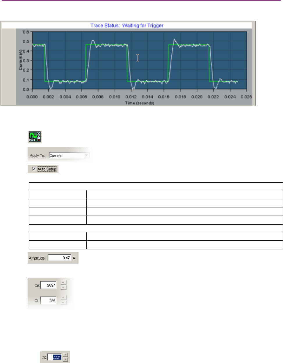
Stepnet Panel Amplifier User Guide Stepper Mode Phase and Tune
Copley Controls Corp. 123
6.3.2: Manually Tune Current Loop
To tune the current loop, apply square-wave excitation to the current loop and adjust current loop
proportional gain (Cp)and current loop integral gain (Ci)to obtain a desired waveform.
NOTE: During tuning, observe any warnings that appear to the left of the trace.
NOTE: For information on the alternate Auto Tune feature, see the CME 2 User Guide.
6.3.2.1 Click the Scope Tool.
6.3.2.2 Choose Current from the Function Generator Apply To: list.
On the Settings tab, make sure Auto Setup is selected.
Auto Setup automatically sets the following parameters:
Function Generator Tab
Function Square Wave.
Amplitude 50 % of current loop Run Current setting.
Frequency 100 Hz.
Amplitude Offset 10 percent of current loop Run Current setting.
Settings Tab
Channel 1 Commanded Current (green).
Channel 2 Actual current (white).
6.3.2.3 Verify that the Amplitude value is not excessive for the motor.
6.3.2.4 Click Start.
6.3.2.5 On the Gains tab, adjust current loop proportional gain (Cp).
1Set current loop integral gain (Ci)to zero.
2Raise or lower Cp until desired step response is obtained. Typically, this means
little or no overshoot with a 100 Hz square wave at 50 percent of Run Current. If
the Cp value is too large, ringing may occur. If the Cp value is too low, bandwidth
decreases. Make sure gain values don’t produce excessive ring.
TIP: To change a value, highlight the value. Then enter value directly, use
mouse and arrow controls, OR use Page Up/Page Down keys to move in increments of
10.

Stepper Mode Phase and Tune Stepnet Panel Amplifier User Guide
124 Copley Controls
6.3.2.6 Adjust current loop integral gain (Ci)until desired settling time is obtained.
6.3.2.7 Press Stop to stop the function generator.
6.3.2.8 On the Main screen, click Save to Flash to avoid losing the changes.
6.3.3: Optimize Hold and Run Current Ratings
6.3.3.1 Reduce Hold Current if possible, to reduce heat generation.
1Test with load OR
2Calculate:
Hold Current requirement >=
hold torque x (rated current/rated torque)
6.3.3.2 Reduce Run Current if possible, to reduce heat generation.
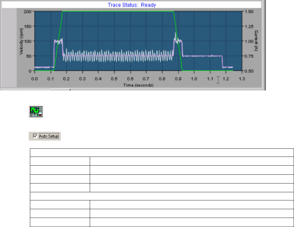
Stepnet Panel Amplifier User Guide Stepper Mode Phase and Tune
Copley Controls Corp. 125
6.4: Profile Move Tests
Test the system with various gains, limits, and load conditions.
NOTE: During profile tests, observe any warnings that appear to the left of the trace.
6.4.1.1 Click the Scope Tool.
6.4.1.2 Select the Profile tab.
6.4.1.3 On the Settings tab, make sure Auto Setup is selected.
Auto Setup automatically sets the following parameters:
Profile Tab
Move Relative
Type Trap
Distance ½ revolution (rotary) or 2 cm (linear)
Reverse and repeat Not checked
Settings Tab
Channel 1 Profile velocity (green)
Channel 2 Actual current (white)
Channel 3 Commanded current (purple)

Stepper Mode Phase and Tune Stepnet Panel Amplifier User Guide
126 Copley Controls
6.4.1.4 Set up a trapezoidal profile by setting the trajectory limits and distance. See table:
Trajectory Limits Tab
Maximum Velocity
Maximum
Acceleration
Maximum
Deceleration
Set values typical of those expected to be used in the application.
Profile Tab
Distance Set the move distance to produce a complete trajectory profile. Be sure that this
distance does not exceed mechanical limits of the system.
Move Relative
Type Trap
NOTES:
1The profile may not reach constant velocity during a short move.
2At higher speeds, motor back EMF may limit Boost and Run currents.
6.4.1.5 Click Start.The Profile Generator executes the move.
6.4.1.6 Verify that the boost, run, and hold currents are appropriate for the move.
6.4.1.7 Try multiple sets of profiles representing typical moves that might be executed in the
application. Starting with Set up a trapezoidal profile,repeat the process as needed.
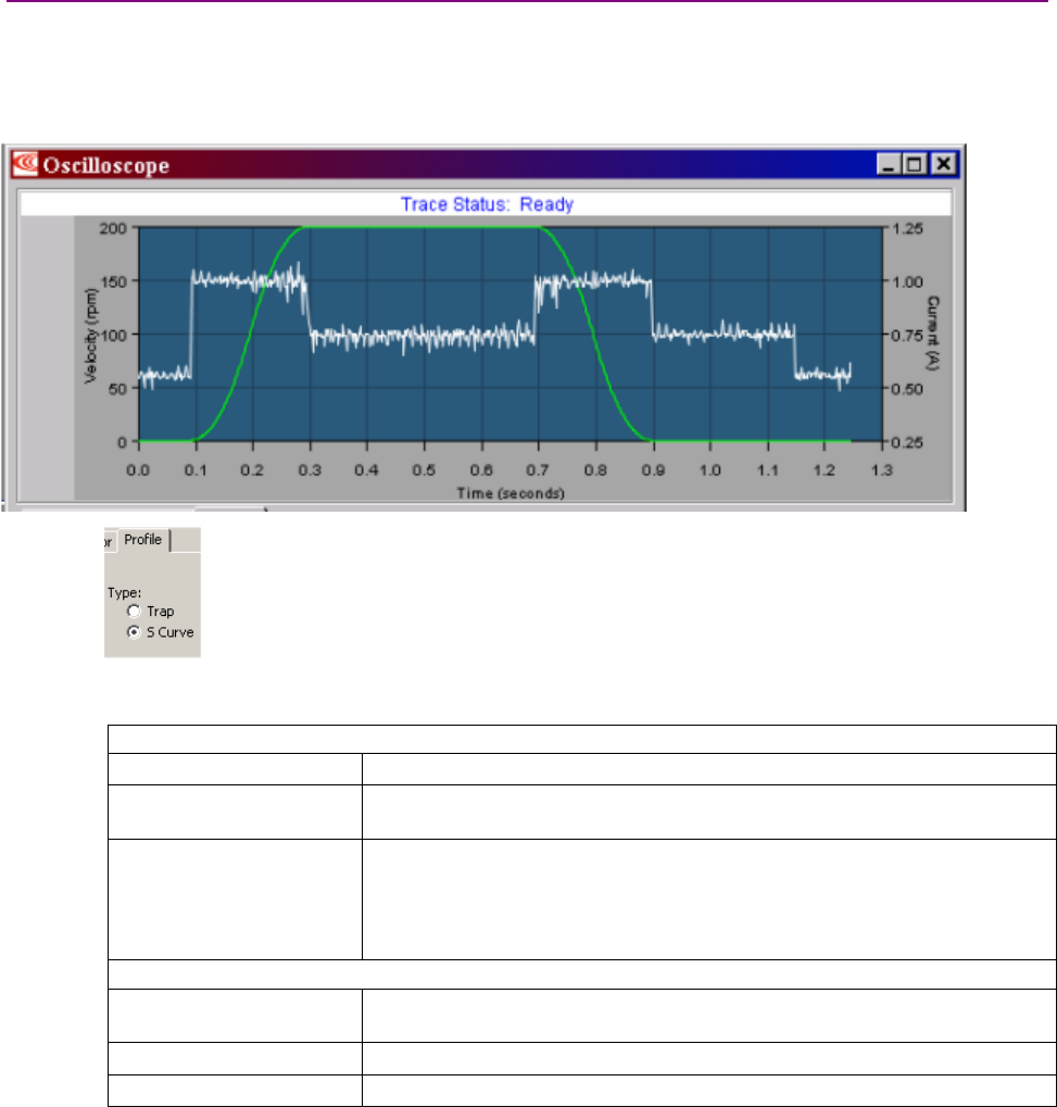
Stepnet Panel Amplifier User Guide Stepper Mode Phase and Tune
Copley Controls Corp. 127
6.4.2: Test S-Curve Profile
NOTE: Skip this step unless the amplifier will perform CANopen S-Curve profile moves.
Jerk is the rate of change of acceleration. S-Curve moves reduce jerk to provide a smooth profile.
To tune the level of jerk, run an S-Curve profile and adjust velocity, acceleration, deceleration, and
jerk levels until the desired profile is obtained.
6.4.2.1 On the Profile tab, click the S-Curve button.
6.4.2.2 Set up an S Curve profile by adjust the following options. Set values that represent a
typical move under normal operation.
Trajectory Limits Tab
Maximum Velocity Maximum speed of the profile.
Maximum
Acceleration/Deceleration
Top acceleration/deceleration of the profile. Deceleration = acceleration.
Maximum Jerk The jerk value set by Calculate procedure gives an S-Curve whose maximum
slope = the trapezoidal profile slope. This value gives a maximum
acceleration no greater than the initial acceleration. Small values produce
less jerking but take longer to complete move. Large values produce more
jerking and a more trapezoidal profile but complete the move faster.
Profile Tab
Distance Increase the move distance to produce a complete trajectory profile. Use an
acceptable value the does not exceed mechanical limits of the system.
Move Relative
Type S-Curve
6.4.2.3 Verify that the boost, run, and hold currents are appropriate for the move.
6.4.2.4 Try multiple sets of profiles representing typical moves that might be executed in the
application. Starting with Set up an S Curve profile,repeat the process as needed.
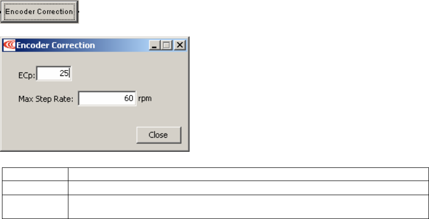
Stepper Mode Phase and Tune Stepnet Panel Amplifier User Guide
128 Copley Controls
6.5: Encoder Correction
Optionally set encoder correction options:
6.5.1.1 Make sure the Encoder Correction option has been set.
See Basic Setup Screen, p. 93.
6.5.1.2 On the CME 2 Main screen, click Encoder Correction to open the
Encoder Correction screen.
6.5.1.3 Set the following options:
Options Description
ECp Gain used to correct following error.
Max Step
Rate
Controls the maximum rate at which the axis is moved to provide encoder correction.

Stepnet Panel Amplifier User Guide Stepper Mode Phase and Tune
Copley Controls Corp. 129
6.6: Completion Steps
6.6.1: Objective
Save the work and perform additional testing with load and under normal control source.
6.6.2: Steps
6.6.2.1 On the Main screen, click Save to Flash.
6.6.2.2 Remove power.
6.6.2.3 Attach load.
6.6.2.4 Reconnect power.
6.6.2.5 Re-test profiles.
6.6.2.6 On the Main screen, click Save to Flash
6.6.2.7 On the Main screen, click Save to Disk (for backup or duplication).
6.6.2.8 Click Control Panel and then click Reset
OR
Power-cycle the amplifier.
6.6.2.9 The amplifier stepper mode tuning procedure is complete.
Stepper Mode Phase and Tune Stepnet Panel Amplifier User Guide
130 Copley Controls
.

Copley Controls Corp. 131
CHAPTER
7: SERVO MODE PHASE AND TUNE
This chapter describes the general procedure for auto phasing and tuning an amplifier with a
motor to operate in servo mode.
Step Page
7.1: Auto Phase (Servo Mode)................................................................................................................................................... 132
7.1.1: Auto Phase Warnings and Notes........................................................................................................................... 132
7.1.2: Auto Phase Preliminary Steps ............................................................................................................................... 132
7.1.3: Auto Phase Procedure........................................................................................................................................... 133
7.1.4: Trouble Shoot Motor Direction Setup..................................................................................................................... 135
7.1.5: Trouble Shoot Motor Wiring Setup......................................................................................................................... 135
7.2: Current Loop....................................................................................................................................................................... 136
7.2.1: Current Loop Settings............................................................................................................................................ 136
7.2.2: Manually Tune Current Loop.................................................................................................................................. 137
7.3: Velocity Loop...................................................................................................................................................................... 139
7.3.1: Velocity Loop Settings ........................................................................................................................................... 139
7.3.2: Manually Tune the Velocity Loop ........................................................................................................................... 140
7.4: Position Loop...................................................................................................................................................................... 141
7.4.1: Position Loop Settings ........................................................................................................................................... 141
7.4.2: Manually Tune the Position Loop........................................................................................................................... 145
7.4.3: Test S-Curve Profile .............................................................................................................................................. 147
7.5: Completion Steps ............................................................................................................................................................... 148
7.5.1: Objective................................................................................................................................................................ 148
7.5.2: Steps ..................................................................................................................................................................... 148

Servo Mode Phase and Tune Stepnet Panel Amplifier User Guide
132 Copley Controls
7.1: Auto Phase (Servo Mode)
7.1.1: Auto Phase Warnings and Notes
Warnings
Motor Motion
!
DANGER
Applying high voltage power to the amplifier before auto phasing may result in motor
motion. Be sure that motor motion will not cause injury.
Failure to heed this warning can result in equipment damage, injury, or death.
High Voltage
!
Danger
Applying AC power to the STX amplifier applies high voltage to the amplifier-motor
connections and cabling. Protect personnel against electrical shock.
Failure to heed this warning can result in equipment damage, injury, or death.
Notes
•Do not connect a load to the motor before performing Auto Phase procedure.
•Always connect the motor using the same configuration.
•Wire properly and consistently.
•Connections are actually changed within the DSP, not at the motor terminals, and the results
are saved to flash memory. The actual wire configuration should NEVER change.
Phasing a stepper motor establishes positive direction for the motor and encoder.
7.1.2: Auto Phase Preliminary Steps
7.1.2.1 Verify that the Enable Input is not activated.
7.1.2.2 Apply power.
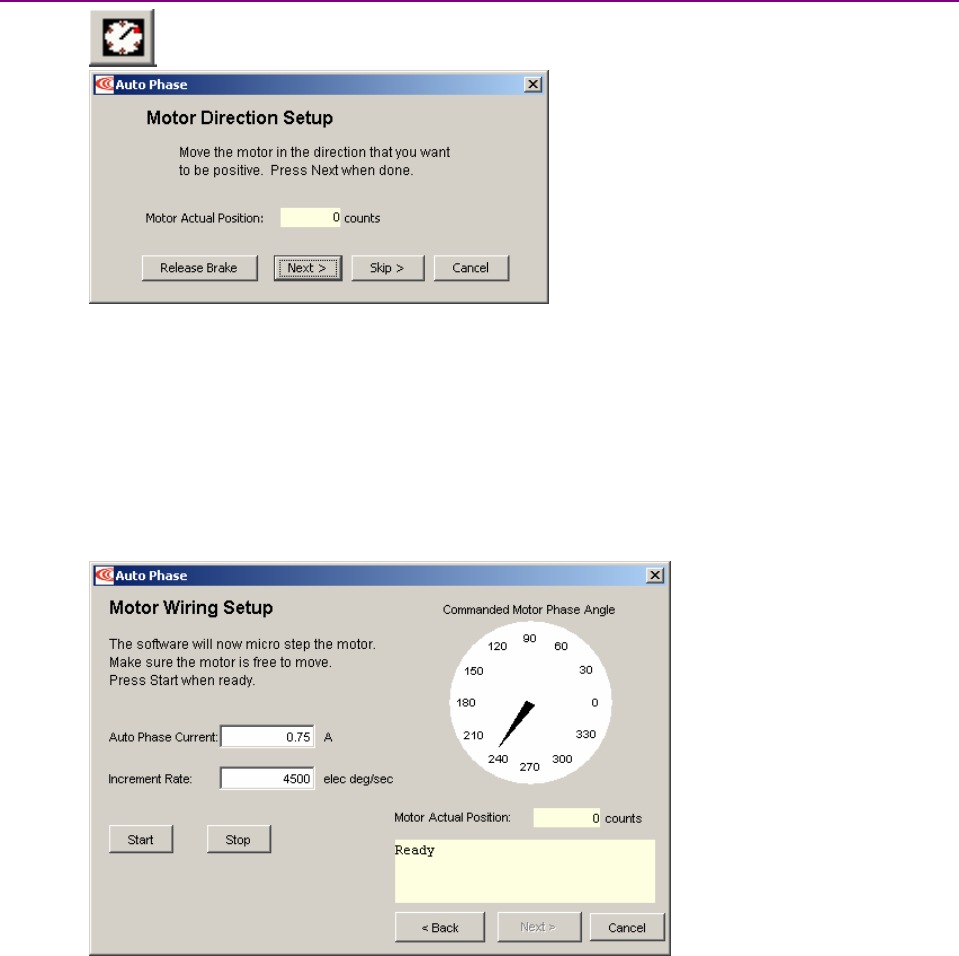
Stepnet Panel Amplifier User Guide Servo Mode Phase and Tune
Copley Controls Corp. 133
7.1.3: Auto Phase Procedure
Click Auto Phase to open the Auto Phase Motor Direction Setup screen.
7.1.3.1 Activate the Enable Input.
7.1.3.2 Move the motor in the direction to be considered positive
OR if you cannot move the motor, click Skip (you will confirm motor direction later).
NOTE: If an output is configured as a brake you can temporarily release the brake by
holding down the Release Brake button. The brake will be reactivated when you
release the button.
7.1.3.3 The Actual Position value on the screen should change. If it does not change, see
Trouble Shoot Motor Direction Setup (p. 119).
7.1.3.4 Click Next to open the Motor Wiring Setup screen.
7.1.3.5 Click Start to begin the motor wiring setup.
The software displays messages: Configuring Initial Settings, Microstepping, Test
Complete, Motor Wiring has been configured.
During microstepping, a current vector is applied to the motor windings and
microstepped through an electrical cycle at a set rate, causing the motor to move.
If you chose to Skip the motor direction setup step, Auto Phase will prompt for
confirmation of correct motor direction.
If the step fails see Trouble Shoot Motor Wiring Setup (p. 119).
NOTE: If incorrect values were entered for inductance and resistance, the calculated
Cp and Ci values may produce current loop oscillation, evidenced by an audible high
frequency squeal during auto phasing.
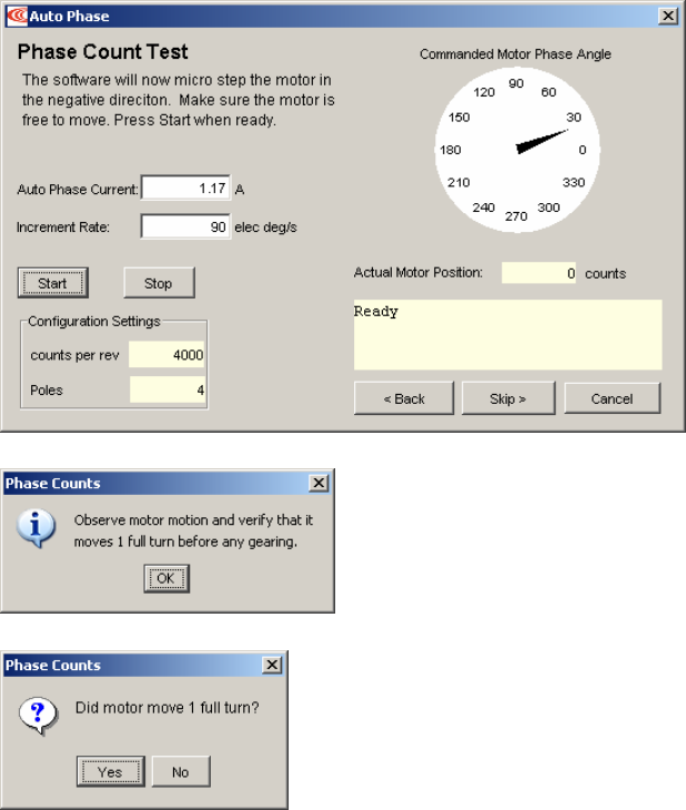
Servo Mode Phase and Tune Stepnet Panel Amplifier User Guide
134 Copley Controls
7.1.3.6 Click Next to open the Phase Count Test screen.
7.1.3.7 Click Start to begin the Phase Count Test. Observe status messages. See the prompt:
7.1.3.8 When you are ready to observe motion, click OK.See the prompt:
7.1.3.9 If motor did not turn 1 full turn, click No and verify that in the Motor/Feedback screen
the following parameters have been set correctly:
Number of Poles for rotary motors.
Magnetic Pole Pair Length for linear motors
Encoder Lines or Fundamental Lines for rotary encoders.
Encoder Resolution for linear encoders.
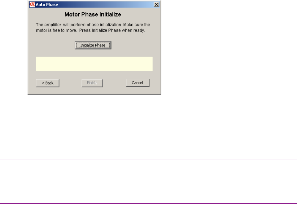
Stepnet Panel Amplifier User Guide Servo Mode Phase and Tune
Copley Controls Corp. 135
7.1.3.10 Ifmotor turned 1 full turn, click Yes.
7.1.3.11 Click Next to open the Motor Phase Initialize screen.
7.1.3.12 Click Initialize Phase.
The screen will display completion messages: Test Complete, Phasing has been
initialized.
7.1.3.13 Click Finish to close the screen and save values to amplifier flash
7.1.3.14 If the Auto Phase algorithm does not produce desired results, try adjusting the Auto
phase Current and Increment Rate values.
7.1.4: Trouble Shoot Motor Direction Setup
If motor direction setup step failed:
7.1.4.1 If an encoder is used, check Encoder power and signals.
7.1.4.2 Check shielding for proper grounding.
7.1.5: Trouble Shoot Motor Wiring Setup
If motor wiring setup step failed:
7.1.5.1 Verify that amplifier is disabled.
7.1.5.2 Check for mechanical jamming.
7.1.5.3 Check for good connections to the motor power wires.
7.1.5.4 Disconnect motor power wires.
7.1.5.5 Measure for proper motor resistance.
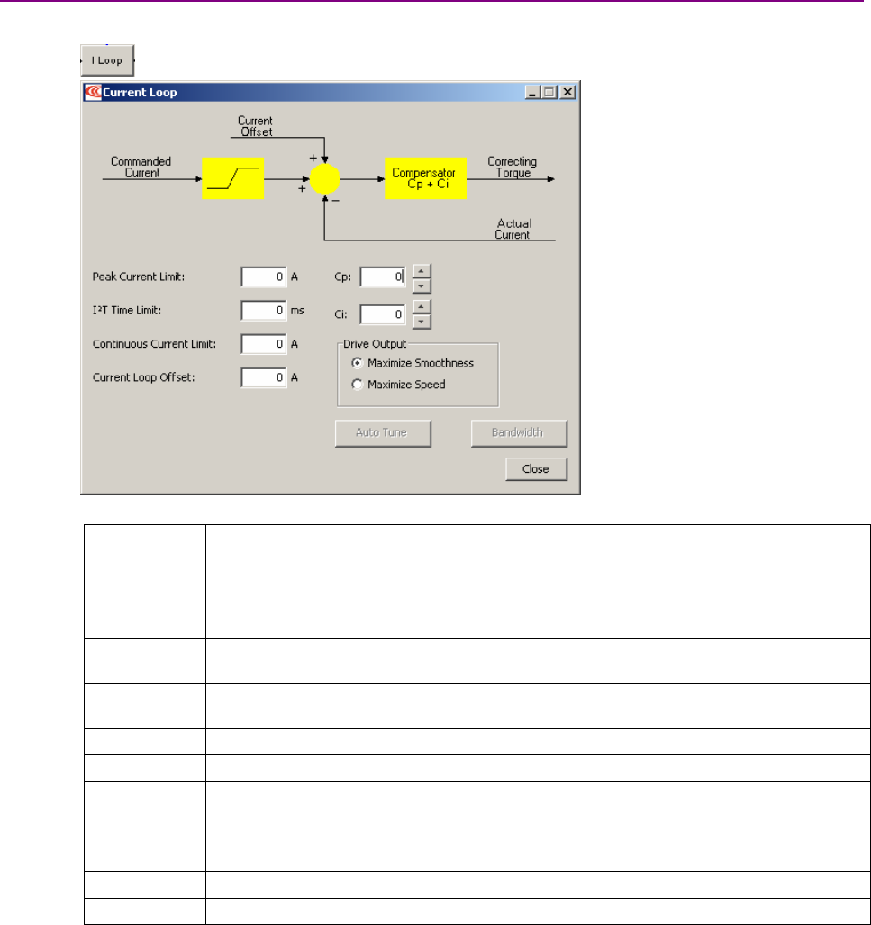
Servo Mode Phase and Tune Stepnet Panel Amplifier User Guide
136 Copley Controls
7.2: Current Loop
Initial current loop proportional gain (Cp)and current loop integral gain (Ci)values were calculated
during general amplifier setup. For an introductory overview of the control loops, see Servo Modes
and Control Loops (p. 19).
NOTE: For Copley Controls digital amplifiers, the current loop gain is independent of the power
supply voltage.
7.2.1: Current Loop Settings
For more information, see Servo Current Mode and Current Loop (p. 19).
7.2.1.1 Click I Loop to open the Current Loop screen:
7.2.1.2 Set the following options as needed.
Options Description
Peak Current
Limit
Used to limit the peak phase current to the motor.
Max value depends upon the amplifier model. Min value > continuous limit.
I2TTime Limit Sets I2TTime Limit in mSec. For more information,
see I2T Time Limit Algorithm (p. 167 ).
Continuous
Current Limit
Used to limit the Phase Current.
Max Value is < Peak Current and depends upon the amplifier model. Min value: 0
Current Loop
Offset
Sets current loop offset. Leave it set to zero until after tuning. For more information, see
Offset (p. 19).
Cp Current loop proportional gain. Range 0 – 32,767.
Ci Current loop integral gain. Range 0 – 32,767.
Drive Output Maximize Smoothness: Amplifier uses circular vector limiting to produce smooth
operation even into the voltage limits.
Maximize Speed: Allows for slightly more of the bus voltage to be used when in the
voltage limit. This may produce a small disturbance at top speed.
Auto Tune See the CME 2 User Guide..
Bandwidth Measure bandwidth using the Cp and Ci values now in the amplifier.
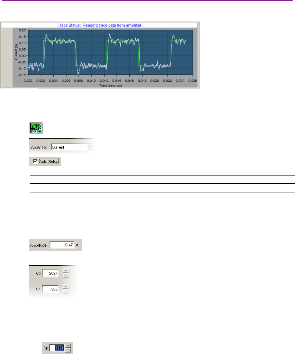
Stepnet Panel Amplifier User Guide Servo Mode Phase and Tune
Copley Controls Corp. 137
7.2.2: Manually Tune Current Loop
To tune the current loop, apply square-wave excitation to the current loop and adjust current loop
proportional gain (Cp)and current loop integral gain (Ci)to obtain a desired waveform.
NOTE: During tuning, observe any warnings that appear to the left of the trace and take
appropriate action.
NOTE: For information on the alternate Auto Tune feature, see the CME 2 User Guide.
7.2.2.1 Click the Scope Tool to open the Oscilloscope window.
7.2.2.2 Choose Current from the Function Generator Apply To: list.
On the Settings tab, make sure Auto Setup is selected.
Auto Setup automatically sets the following parameters:
Function Generator Tab
Function Square Wave
Amplitude 10 % of current loop Continuous Current Limit setting
Frequency 100 Hz
Settings Tab
Channel 1 Commanded Current (green)
Channel 2 Actual current (white)
7.2.2.3 Verify that the Amplitude value is not excessive for the motor.
7.2.2.4 Click Start.
7.2.2.5 On the Gains tab, adjust current loop proportional gain (Cp).
1Set current loop integral gain (Ci)to zero.
2Raise or lower Cp until desired step response is obtained. Typically, this means
little or no overshoot with a 100 Hz, low-current square wave. If the Cp value is too
large, ringing may occur. If the Cp value is too low, bandwidth decreases. Make
sure gain values don’t produce excessive ring.
TIP: To change a value, highlight the value. Then enter value directly, use
mouse and arrow controls, OR use Page Up/Page Down keys to move in increments of
10.

Servo Mode Phase and Tune Stepnet Panel Amplifier User Guide
138 Copley Controls
7.2.2.6 Adjust current loop integral gain (Ci)until desired settling time is obtained.
7.2.2.7 Press Stop to stop the function generator.
7.2.2.8 On the Main screen, click Save to Flash to avoid losing the changes.
7.2.2.9 If the amplifier is to be operated in current mode, skip the velocity and position loop
setup procedures and go to Completion Steps (p. 148).
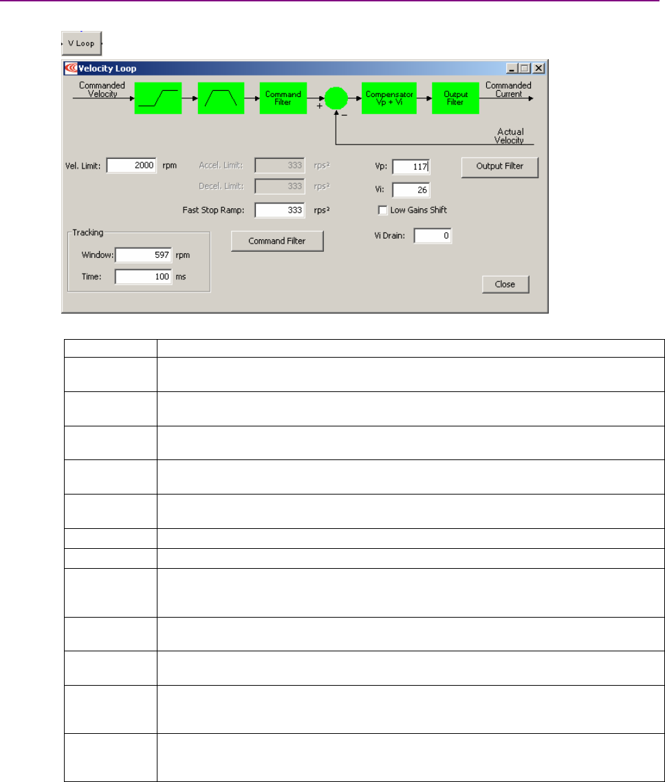
Stepnet Panel Amplifier User Guide Servo Mode Phase and Tune
Copley Controls Corp. 139
7.3: Velocity Loop
Initial velocity loop proportional gain (Vp)and velocity loop integral gain (Vi)values were
calculated during general amplifier setup.
7.3.1: Velocity Loop Settings
For more information, see Servo Velocity Mode and Velocity Loop (p. 21).
Click V Loop.
7.3.1.1 Enter the following options as needed.
Option Description
Velocity Limit Top speed limit. Max value may depend upon the back EMF & the Encoder resolution.
Min value: 0.
Acceleration
Limit
Maximum acceleration rate. Max value may depend upon load, inertia, & peak current.
Min value: 1. (Does not apply in position mode.)
Deceleration
Limit
Maximum deceleration rate. Max value may depend upon load, inertia, & peak current.
Min value: 1. (Does not apply in position mode.)
Tracking
Window
Width of the tracking window in rpm (or mm/s for linear).
Tracking
Time
Position must remain in the tracking window for this amount of time to be considered
tracking.
Vp Velocity loop proportional gain. Range: 0 to 32,767.
Vi Velocity loop integral gain. Range: 0 to 32,767.
Fast Stop
Ramp
Deceleration rate used by the velocity loop when the amplifier is hardware disabled.
Range: 0 to 100,000,000. Default: velocity loop Decel. Limit value. For more information,
see Servo Velocity Loop Limits (p. 21).
Low Gains
Shift
Increases the resolution of the units used to express Vp and Vi, providing more precise
tuning. For more information, see Servo Velocity Gains Shift (p. 22).
High Gains
Shift
Decreases the resolution of the units used to express Vp and Vi, providing more precise
tuning. For more information, see Servo Velocity Gains Shift (p. 22).
Vi Drain
(integral
bleed)
Vi drain modifies the effect of velocity loop integral gain. The higher the Vi Drain value,
the faster the integral sum is lowered. Range: 0 to 32,000. Default: 0.
Command
Filter/
Output Filter
For more information, see the CME 2 User Guide.
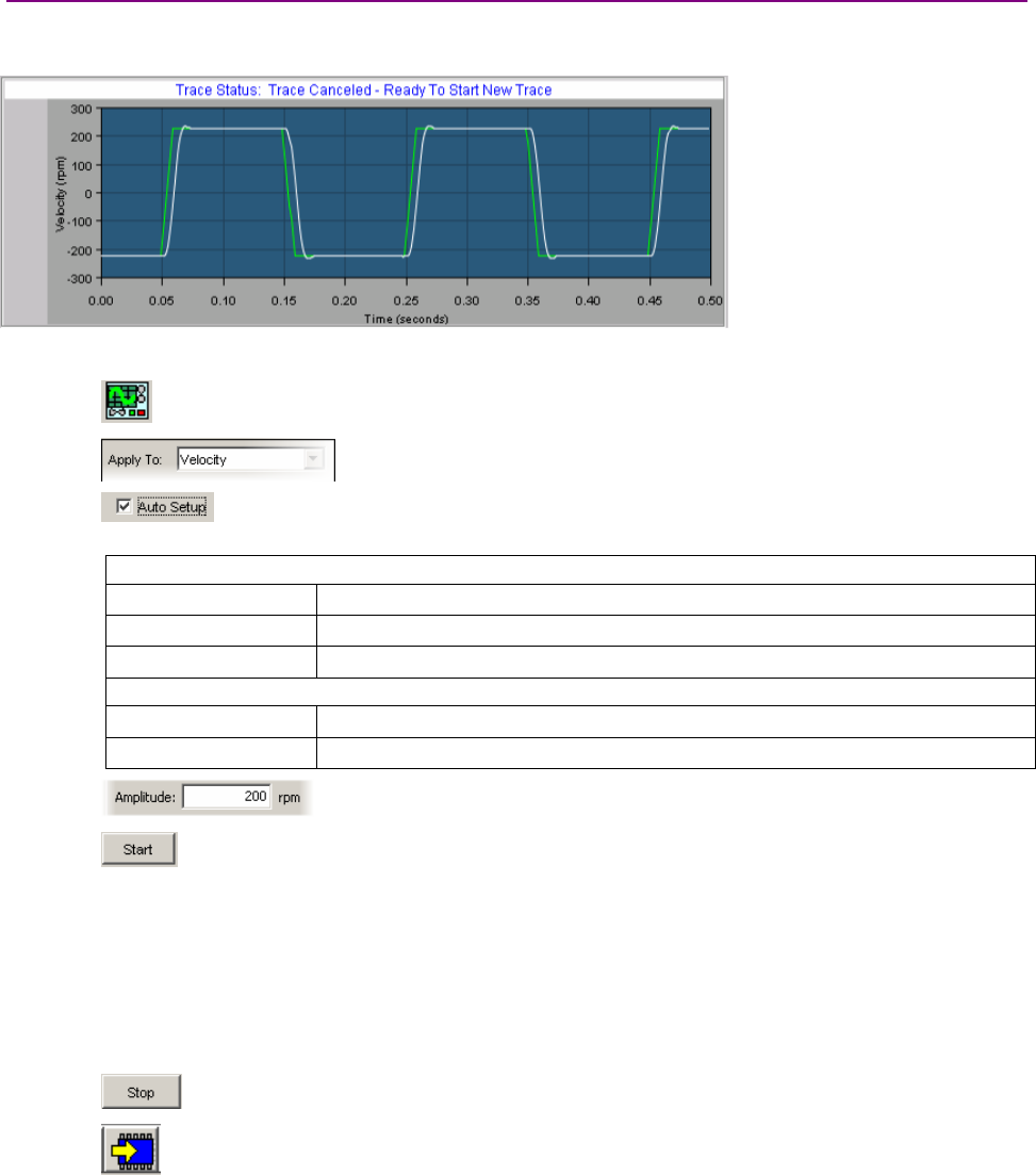
Servo Mode Phase and Tune Stepnet Panel Amplifier User Guide
140 Copley Controls
7.3.2: Manually Tune the Velocity Loop
To tune the velocity loop, apply square-wave excitation to the velocity loop and adjust velocity loop
proportional gain (Vp)and velocity loop integral gain (Vi)to obtain a desired waveform.
NOTE: During tuning, observe any warnings that appear to the left of the trace.
7.3.2.1 Click the Scope Tool to open the Oscilloscope window.
7.3.2.2 Choose Velocity from the Function Generator Apply To: list.
On the Settings tab, make sure Auto Setup is selected.
Auto Setup automatically sets the following parameters:
Function Tab
Function Square Wave
Amplitude 10% velocity loop Vel. Limit setting.
Frequency 5 Hz
Settings Tab
Channel 1 Limited velocity (green)
Channel 2 Actual motor velocity (white)
7.3.2.3 Verify that the Amplitude value is not excessive for the motor.
7.3.2.4 Click Start.
7.3.2.5 On the Gains tab, adjust velocity loop proportional gain (Vp).
1Set velocity loop integral gain (Vi)to zero.
2Raise or lower velocity loop proportional gain (Vp)until desired step response is
obtained. Typically, this means little or no overshoot on a 5 Hz small, slow-speed
square wave.
7.3.2.6 Adjust velocity loop integral gain (Vi)until desired settling time is obtained.
7.3.2.7 Press Stop to stop the function generator.
7.3.2.8 On the Main screen, click Save to Flash to avoid losing the changes.
7.3.2.9 If the amplifier is to be operated in velocity mode, skip the position loop setup
procedures and go to Completion Steps (p. 148).

Stepnet Panel Amplifier User Guide Servo Mode Phase and Tune
Copley Controls Corp. 141
7.4: Position Loop
Initial position loop proportional gain (Pp), velocity feed forward (Vff), and acceleration feed
forward (Aff) values were calculated during general amplifier setup.
7.4.1: Position Loop Settings
For more information, see Servo Position Mode and Position Loop (p. 23).
7.4.1.1 Click P Loop to open the Position Loop screen.

Servo Mode Phase and Tune Stepnet Panel Amplifier User Guide
142 Copley Controls
7.4.1.2 Set the following Trajectory Values as needed:
Option Description For More Information
Max
Velocity
Maximum trajectory velocity. Max value may
depend upon the back EMF and the Max
feedback count (servo mode) or maximum
number of microsteps (stepper mode). Min:0.
Default: 0.25 x motor velocity limit.
Max Accel Maximum trajectory acceleration. Max value may
depend upon the load inertia and boost current
(stepper mode) or peak current (servo mode).
Min:0
Max Decel Maximum trajectory deceleration. Max value may
depend upon the load inertia and boost current
(stepper mode) or peak current (servo mode).
Min: 0 (disables limit).
Servo Position Mode and Position Loop
(p. 23).
Abort
Decel
Deceleration rate used by the trajectory generator
when motion is aborted. Min: 0 (disables limit).
Brake Operation (p. 34).
Jerk The value of jerk set during the calculate
procedure produces an S-Curve whose maximum
slope is equal to the trapezoidal profile slope.
This value will produce a maximum acceleration
that is not more than the initial default value of
acceleration. Small values will produce less
jerking but will take longer to complete move.
Large values will produce more jerking and a
more trapezoidal profile but will complete the
move faster.
Clear
Limits
Sets Max Velocity, Max Accel, and Max Decel to
zero, disabling the trajectory generator.
Set
Default
Limits
Restores Max Velocity, Max Accel, and Max
Decel to calculated defaults.
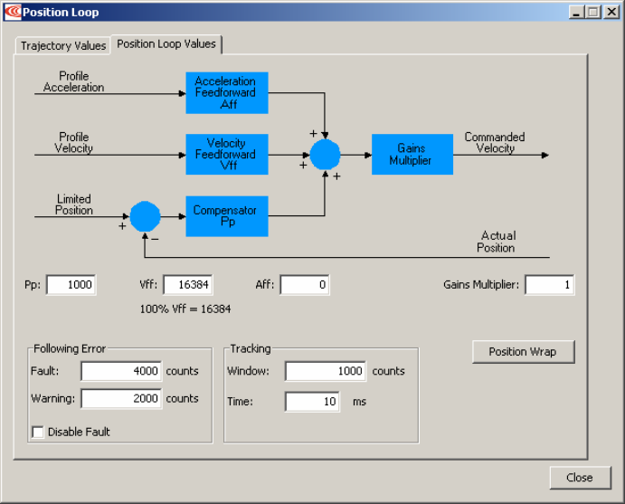
Stepnet Panel Amplifier User Guide Servo Mode Phase and Tune
Copley Controls Corp. 143
7.4.1.3 Open the Position Loop Values tab:

Servo Mode Phase and Tune Stepnet Panel Amplifier User Guide
144 Copley Controls
7.4.1.4 Set the following Position Loop Values as needed:
Option Description For More Information…
Gains
Aff Acceleration feed forward.
Range: 0 to 32,767.
Vff Velocity feed forward.
Range: 0 to 32,767. 100% Vff = 16,384.
Pp Position loop proportional gain. Range: 0 to
32,767.
Gains
Multiplier
The output of the position loop is multiplied by
this value before being passed to the velocity
loop.
Servo Position Loop Gains
(p. 24).
Following Error
Fault The level (in encoder counts) at which the
following error produces a fault. We
recommend raising the fault level before tuning
the loop.
Warning The level (in encoder counts) at which the
following error produces a warning.
Disable
Fault
Prevents following error from triggering a fault.
Following Error Fault Details
(p. 40).
Tracking
Tracking
Window
Width of the tracking window in counts.
Tracking
Time
Position must remain in the tracking window for
this amount of time to be considered tracking.
Tracking Window Details
(p. 41).
Position Wrap
Opens the configuration controls for the Position Wrap feature.
This feature causes the amplifier to “wrap back” the reported
position value (set it back to zero) at a user-defined position,
instead of continually increasing. By default, this feature is
disabled.
CME 2 User Guide.
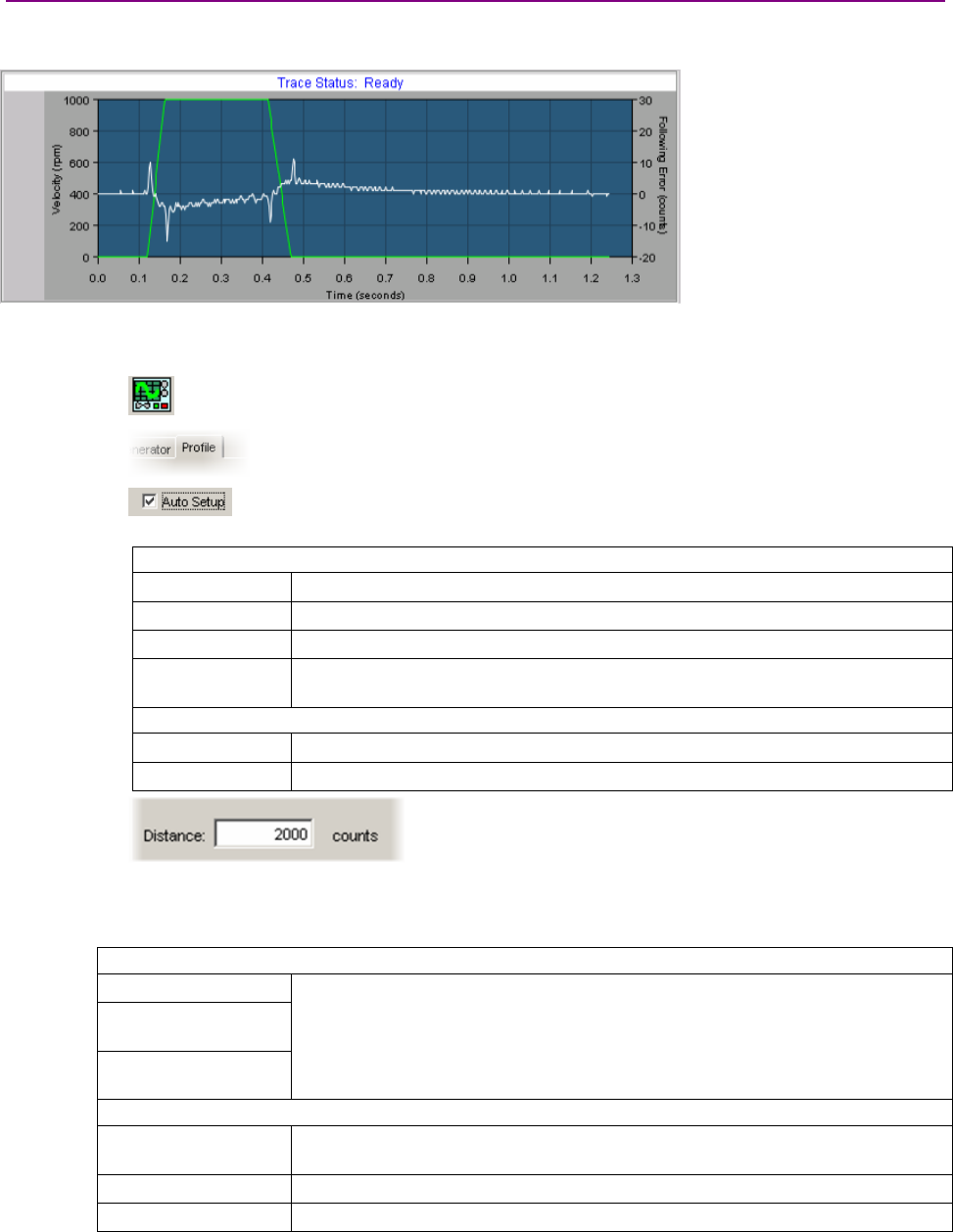
Stepnet Panel Amplifier User Guide Servo Mode Phase and Tune
Copley Controls Corp. 145
7.4.2: Manually Tune the Position Loop
Minimize following error and oscillation by running profiles and adjusting position proportional gain
(Pp), velocity feed forward (Vff), acceleration feed forward (Aff)and other settings.
NOTE: During position loop tuning, observe any warnings that appear to the left of the trace.
7.4.2.1 Perform an auto setup test:
1Click the Scope Tool to open the Oscilloscope window.
2Select the Profile tab.
3On the Settings tab, make sure that Auto Setup is checked. Auto
Setup automatically sets the following options:
Profile Tab
Move Relative
Type Trap
Distance ½ revolution (rotary) or 2 cm (linear)
Reverse and
repeat
Not selected
Settings Tab
Channel 1 Profile velocity (green)
Channel 2 Following error (white)
4If the auto setup default profile distance is not
appropriate, enter an appropriate short distance.
5Set up a trapezoidal profile by setting the trajectory limits and distance on the
Trajectory Limits tab. See table:
Trajectory Limits Tab
Maximum Velocity
Maximum
Acceleration
Maximum
Deceleration
Set values typical of those expected to be used in the application.
Profile Tab
Distance Set the move distance to produce a complete trajectory profile. Be sure that this
distance does not exceed mechanical limits of the system.
Move Relative
Type Trap

Servo Mode Phase and Tune Stepnet Panel Amplifier User Guide
146 Copley Controls
6Click Start.
The Profile Generator executes a short move.
NOTES:
1The profile may not reach constant velocity during a short move.
2If following error occurs, open CME 2 Control Panel ( ) and click Clear Faults.
7.4.2.2 Adjust position proportional gain (Pp)to minimize following error. Note that too much
position loop proportional gain (Pp)might cause oscillation.
1On the Gains tab, set velocity feed forward (Vff) and acceleration feed forward
(Aff) to zero.
2On the Profile tab, click Start.On the Gains tab, adjust position loop proportional
gain (Pp)until best result is obtained.
3Click Start after each adjustment to test the new value on a new profile move.
NOTE: If a following error occurs, open the CME 2 Control Panel ()and click Clear
Faults.
7.4.2.3 Adjust velocity feed forward (Vff):
Velocity feed forward (Vff) reduces following error in the constant velocity portion of the
profile. Often, a velocity feed forward (Vff) value of 16384 (100%) provides best results.
1Click in the Vff field and adjust the value.
2Click Start after each adjustment to test the new value on a new profile move.
7.4.2.4 Adjust acceleration feed forward (Aff):
Acceleration feed forward (Aff)reduces following error during profile acceleration and
deceleration.
1Click in the Aff field and adjust the value.
2Click Start after each adjustment to test the new value on a new profile move.
NOTE: If, after tuning the position loop, the motor makes a low frequency audible noise
while enabled but not moving, the velocity loop gains (Vp and Vi) may be lowered to
reduce the noise. If the gain values are set too low, the response to instantaneous
rates of change might be reduced (i.e., slow correction to disturbances or transients).
7.4.2.5 Try multiple sets of profiles representing typical moves that might be executed in the
application. Starting with Set up a trapezoidal profile,repeat the process as needed.
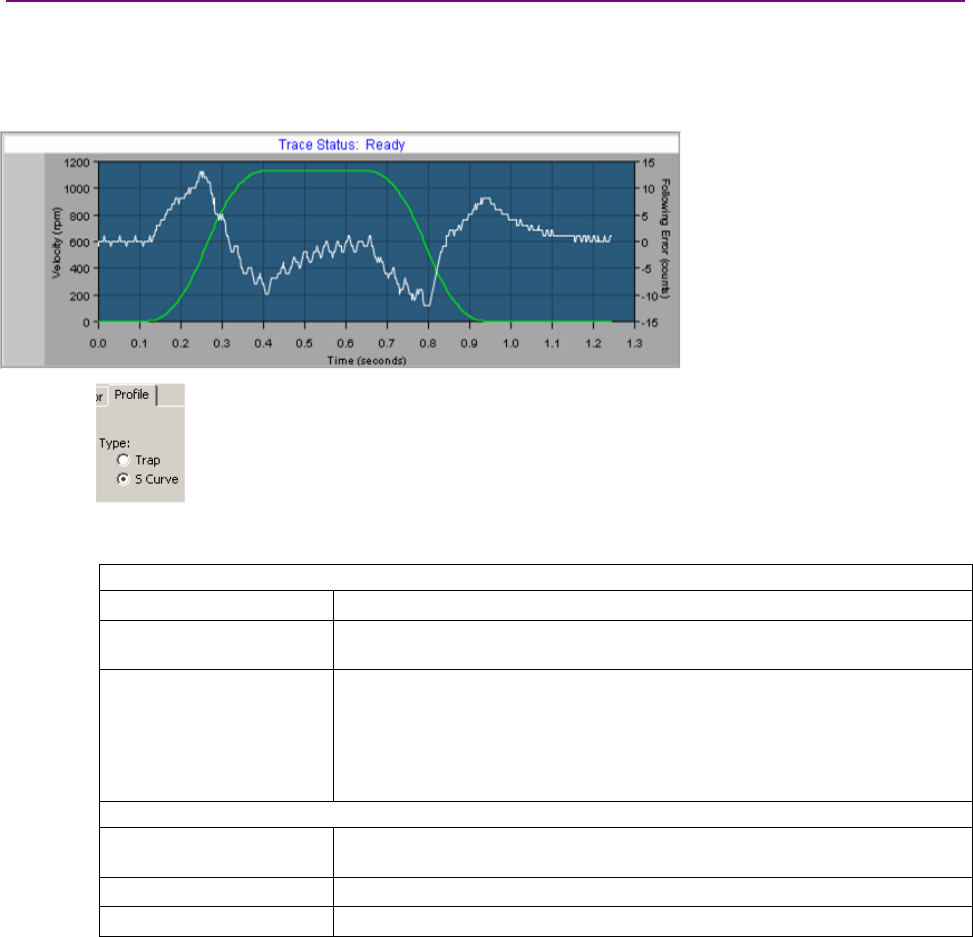
Stepnet Panel Amplifier User Guide Servo Mode Phase and Tune
Copley Controls Corp. 147
7.4.3: Test S-Curve Profile
NOTE: Skip this step unless the amplifier will perform S-Curve profile moves.
Jerk is the rate of change of acceleration. S-Curve moves reduce jerk to provide a smooth profile.
To tune the level of jerk, run an S-Curve profile and adjust velocity, acceleration, deceleration, and
jerk levels until the desired profile is obtained.
7.4.3.1 On the Profile tab, click the S-Curve button.
7.4.3.2 Set up an S-curve profile by adjusting the following options. Set values that represent a
typical move under normal operation.
Trajectory Limits Tab
Maximum Velocity Maximum speed of the profile.
Maximum Acceleration Maximum acceleration/deceleration of the profile. The deceleration is set to
be the same as acceleration.
Maximum Jerk The value of jerk set during the calculate procedure produces an S-Curve
whose maximum slope is equal to the trapezoidal profile slope. This value
will produce a maximum acceleration that is not more than the initial default
value of acceleration. Small values will produce less jerking but will take
longer to complete move. Large values will produce more jerking and a more
trapezoidal profile but will complete the move faster.
Profile Tab
Distance Increase the move distance to produce a complete trajectory profile. Use an
acceptable value the does not exceed mechanical limits of the system.
Move Relative
Type S-Curve
7.4.3.3 Click Start.
7.4.3.4 Adjust values for desired results.
7.4.3.5 Try multiple sets of profiles representing typical moves that might be executed in the
application. Starting with Set up an S-curve profile,repeat the process as needed.

Servo Mode Phase and Tune Stepnet Panel Amplifier User Guide
148 Copley Controls
7.5: Completion Steps
7.5.1: Objective
Save the work and perform additional testing with load and under normal control source.
7.5.2: Steps
7.5.2.1 On the Main screen, click Save to Flash.
7.5.2.2 Remove power.
7.5.2.3 Attach load.
7.5.2.4 Reconnect power.
7.5.2.5 Re-tune velocity and position loops if applicable.
7.5.2.6 On the Main screen, click Save to Flash.
7.5.2.7 On the Main screen, click Save to Disk (for backup or duplication).
7.5.2.8 Click Control Panel and then click Reset
OR
Power-cycle the amplifier.
7.5.2.9 The servo setup procedure is complete.

Copley Controls Corp. 149
CHAPTER
8: USING CME 2 (STEPPER OR SERVO
MODE)
This chapter provides an overview of CME 2 software features. Contents are relevant to operation
in both stepper and servo modes, and include:
Title Page
8.1: CME 2 Overview................................................................................................................................................................. 150
8.1.1: Main Screen Overview........................................................................................................................................... 150
8.1.2: Tool Bar Overview ................................................................................................................................................. 150
8.1.3: Main Menu Overview ............................................................................................................................................. 151
8.1.4: Functional Diagram................................................................................................................................................ 152
8.1.5: CAN or DeviceNet Information and Status Bar ...................................................................................................... 153
8.1.6: Choosing an Amplifier from a List of Amplifiers...................................................................................................... 153
8.1.7: Renaming an Amplifier .......................................................................................................................................... 153
8.2: Manage Amplifier and Motor Data ...................................................................................................................................... 154
8.2.1: Memory.................................................................................................................................................................. 154
8.2.2: Disk Storage.......................................................................................................................................................... 154
8.2.3: Data Management Tools........................................................................................................................................ 155
8.2.4: Quick Copy Setup Procedure................................................................................................................................. 156
8.3: Downloading Firmware ....................................................................................................................................................... 157
8.3.1: Acquiring Firmware Updates from Web Site .......................................................................................................... 157
8.3.2: Downloading Firmware to Amplifier........................................................................................................................ 158
8.4: Control Panel...................................................................................................................................................................... 159
8.4.1: Control Panel Overview ......................................................................................................................................... 159
8.4.2: Status Indicators and Messages ............................................................................................................................ 159
8.4.3: Monitor Functions .................................................................................................................................................. 161
8.4.4: Control Functions................................................................................................................................................... 162
8.4.5: Jog Mode............................................................................................................................................................... 163
8.5: Home Function ................................................................................................................................................................... 164
8.5.1: Overview................................................................................................................................................................ 164
8.5.2: Homing Functions Settings.................................................................................................................................... 164
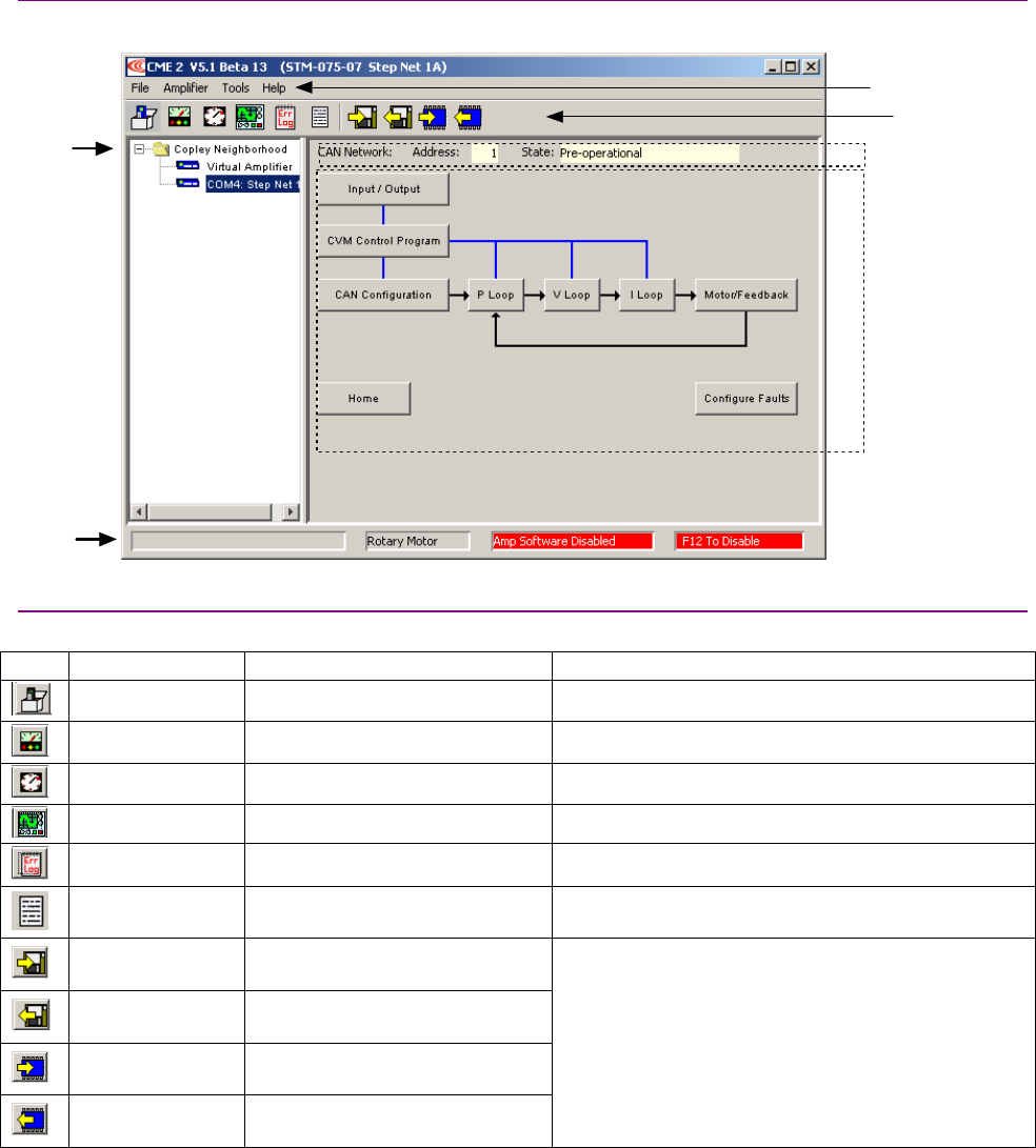
Using CME 2 Stepnet Panel Amplifier User Guide
150 Copley Controls
8.1: CME 2 Overview
8.1.1: Main Screen Overview
The CME 2 features called out in the diagram below are described in the following sections.
Copley
Neighborhood
Tree
Status
Bar
Functional
Diagram
Tool Bar
Main Menu
CAN or DeviceNet
Information
8.1.2: Tool Bar Overview
Click on any of the tools in the toolbar to access the tools described below.
Icon Name Description For More Information
Basic Setup Opens Basic Setup screen. Basic Setup (p. 93).
Control Panel Opens Control Panel. Control Panel (p. 159).
Auto Phase Opens Auto Phase tool. Auto Phase (p. 116) and Auto Phase (p. 132).
Scope Opens Scope. CME 2 User Guide.
Error Log Opens Error Log. CME 2 User Guide.
Amplifier
Properties
Displays basic amplifier
properties.
Save amplifier
data to disk
Saves contents of amplifier RAM
to a disk file.
Restore amplifier
data from disk
Restores contents of an amplifier
file from disk to amplifier RAM.
Save amplifier
data to flash
Saves contents of amplifier RAM
to amplifier flash.
Restore amplifier
data from flash
Restores contents of amplifier
flash to amplifier RAM.
Manage Amplifier and Motor Data (p. 154).

Stepnet Panel Amplifier User Guide Using CME 2
Copley Controls Corp. 151
8.1.3: Main Menu Overview
The CME 2 Main Menu choices are described below.
Menu Selection Description For More Information
Save Amplifier Data Saves contents of amplifier’s RAM to a
disk file.
Restore Amplifier
Data
Restores contents of an amplifier file
from disk to amplifier RAM.
Manage Amplifier and Motor Data (p.
154).
Restore CVM
Control Program
Prompts for a Copley Virtual Machine
program file. The program in this file will
replace the current program in flash.
Copley Indexer 2 Program User
Guide.
Restore Cam Tables Prompts for a saved Cam Table file (.cct
file). All tables in amplifier flash will be
replaced by the ones in this file.
See Copley Camming Users Guide.
File
Exit Closes CME 2. Prompts for data-saving decision.
Basic Setup Opens Basic Setup screen. Basic Setup (p. 93).
Control Panel Opens Control Panel. Control Panel (p. 159).
Auto Phase Opens Auto Phase tool. Auto Phase (p. 116) and Auto Phase
(p. 132).
Scope Opens Scope. CME 2 User Guide
Error Log Opens Error Log. CME 2 User Guide
Amplifier Properties Displays amplifier properties.
Network
Configuration
Opens the CAN or DeviceNet
Configuration screen.
Rename Prompts for new amplifier name. Renaming an Amplifier (p. 153).
Auto Tune Auto Tune for Linear Servo Motors.
Amplifier
Gain Scheduling Opens Gain Scheduling screen. CME 2 User Guide.
Communications
Wizard
Starts sequence of prompts to set up
communications.
Serial Port Setup (p. 89).
Communications Log Opens Communications Log. CME 2 User Guide.
Download Firmware Starts sequence of prompts to download
new firmware image from disk to
amplifier.
Downloading Firmware (p. 157).
View Scope Files Opens Trace Viewer window. CME 2 User Guide
I/O Line States Opens I/O Line States window, showing
high/low status of the amplifier’s inputs
and outputs.
CME 2 Lock/Unlock Opens screen for locking and unlocking
CME 2 functionality.
CME 2 User Guide.
Tools
ASCII Command
Line
Opens screen to accept ASCII format
commands.
CME 2 User Guide.
CME 2 User Guide Opens the CME 2 User Guide.
All Documents Opens the Doc folder in the CME 2 installation folder
(typically c://Program Files/Copley Motion/CME 2/Doc).
This folder contains all of the related documents that were installed with CME 2.
Downloads Web
Page
Software Web Page
Opens default web browser with relevant pages from Copley Controls’ website.
View Release Notes Opens latest CME 2 release notes in a text viewer.
Help
About Displays CME 2 version information.
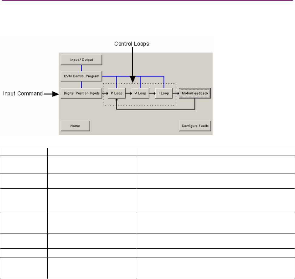
Using CME 2 Stepnet Panel Amplifier User Guide
152 Copley Controls
8.1.4: Functional Diagram
The functional diagram, shown below, provides button-click access to most of the screens used to
configure an amplifier. It also indicates the flow of control from input, across all active control
loops, to motor/feedback. Only those control loop buttons that are appropriate to the operational
mode appear on the diagram.
The command input button reflects the selected command input.
Name Description For More Information
Input/Output Opens Input/Output screen. Theory: Inputs (p. 42)and Outputs (p. 42).
Programming instructions:Amplifier Configuration (p. 100).
CVM Control
Program
Opens Copley Virtual Machine
screen.
Copley Indexer Program User Guide.
Input Command
Configure the input command.
Button label varies depending on
the selected control loop input.
Theory: Input Command Types (p. 25.
Programming instructions: Basic Setup Screen (p. 93).
Control Loops
Each opens a control loop
configuration screen.
Theory: Servo Modes and Control Loops (p. 18).
Programming instructions:Stepper Mode Phase and Tune (p.
115), Servo Mode Phase and Tune (p. 131).
Motor/Feedback Opens the Motor/Feedback
screen.
Motor Setup (p. 95).
Home Configure and test homing. Home Function (p. 164).
Configure Faults
Opens Fault Configuration
screen.
Theory: Faults (p. 37).
Programming instructions:
Non-Latched and Latched Custom Outputs (p. 108).
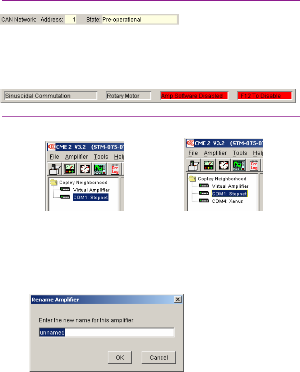
Stepnet Panel Amplifier User Guide Using CME 2
Copley Controls Corp. 153
8.1.5: CAN or DeviceNet Information and Status Bar
The Main screen displays basic CAN or DeviceNet information as shown here:
Address shows the amplifier’s CAN or DeviceNet address. This value is updated on +24 Vdc
power-up or reset only (see CAN Addressing [p.32] or the Copley DeviceNet Programmer’s
Guide). When the Command Source is set to CAN, State shows the state of the amplifier’s
CANopen state machine (see Copley Control’s CANopen Programmer’s Manual).
The status bar describes the present commutation mode, motor type, and amplifier control status
as shown below. It also includes a reminder that pressing the F12 function key while CME 2 is
running disables the amplifier.
8.1.6: Choosing an Amplifier from a List of Amplifiers
If, as shown at left, below, there is only one serial port set up for communications with an
amplifier, CME 2 automatically attempts to connect to the amplifier on that port on CME 2 startup.
One amplifier: Multiple amplifiers:
If, as shown at right, above, multiple serial ports have been set up for communications with
multiple amplifiers, CME polls all the amplifiers and displays their names in the Copley
Neighborhood.To choose an amplifier, click on the amplifier name.
8.1.7: Renaming an Amplifier
Each amplifier represented in the Copley Neighborhood amplifier tree has a name. The default
name for an amplifier is unnamed.Use this procedure to rename an amplifier.
8.1.7.1 Select the amplifier from the Copley Neighborhood.
8.1.7.2 Choose Main Menu AmplifierRename to open the Rename Amplifier screen.
8.1.7.3 Enter the new name.
8.1.7.4 Click OK to close the screen and save the new name
or click Cancel to close the screen without saving the name.

Using CME 2 Stepnet Panel Amplifier User Guide
154 Copley Controls
8.2: Manage Amplifier and Motor Data
8.2.1: Memory
To maintain amplifier and motor settings, the amplifier uses volatile RAM memory and non-volatile
flash memory. Data can also be saved to disk for backup and distribution.
Amplifier RAM and Amplifier Flash Memory
Amplifier RAM holds status data and certain user-entered information data during operation,
whereas flash memory permanently stores the data for loading into amplifier RAM at power-up or
reset, as described below.
Amplifier RAM Amplifier Flash
Contents erased when amplifier is reset or powered off. Permanent. Contents retained when the amplifier is reset
or powered off.
Initial contents read from flash on power-up. Contents
then updated in real time to reflect certain operational
conditions and changes entered with CME 2 software. At
any time, the user can use CME 2 to restore data from
flash into amplifier RAM.
Modified only by using a Save to Flash tool or by closing
certain screens (Motor/Feedback, Basic Setup,or CAN
Configuration), whose contents are automatically saved to
flash upon closing of the screen.
How the Amplifier Uses RAM and Flash Memory
As described below, some data resides in flash only, some in RAM only, and some in both.
Data Resides In Data
Flash only This category includes all data represented on the Motor/Feedback screen, Basic Setup screen,
and CAN Configuration screen. This data is automatically saved to flash as soon as its entry is
confirmed (when the user clicks the appropriate Save to Flash button, or closes the screen).
Flash and RAM Includes all user-entered data represented on other screens, such as gains, limits, and I/O, and
faults. Initial values for this data are factory-set in flash. They are loaded from flash to RAM with
each power-up or amplifier reset. This data is saved to flash only when a user clicks the
appropriate Save to Flash button. It is flushed from RAM with each power-down or amplifier
reset.
RAM only Includes operating status data such as actual position, actual current, and amplifier
temperature. Such data is never stored in flash. It is flushed from RAM with each power-down or
amplifier reset.
8.2.2: Disk Storage
Amplifier Data Files and Motor Data Files
At any time, the user can save certain data from RAM and flash memory to a file on disk. From the
Main screen, the user can save all user-entered data represented on all screens (the data
described as Flash only and Flash and on p. 154). This data is saved in a Copley Controls
amplifier data file with a .ccx filename extension.
From the Motor/Feedback screen, the user can save all data represented on the Motor/Feedback
screen. This data is saved in a Copley Controls motor data file with a .ccm filename extension.
A.ccx file can be restored to return the amplifier to a previous state or to copy settings from one
amplifier to another, as described in Quick Copy Setup Procedure (p. 156).
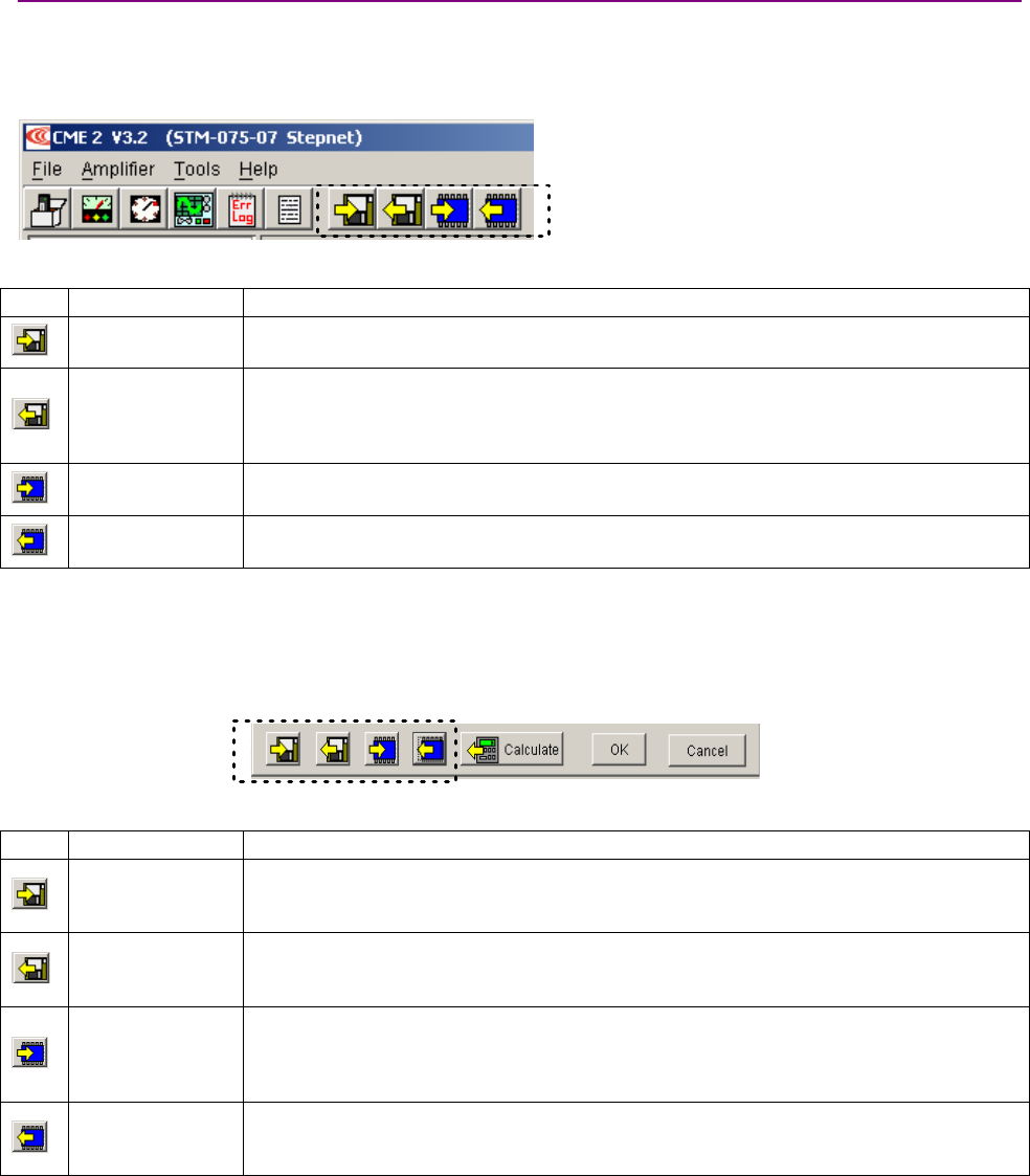
Stepnet Panel Amplifier User Guide Using CME 2
Copley Controls Corp. 155
8.2.3: Data Management Tools
Amplifier Data Management Tools
Operations performed using the amplifier data management tools at the top of the Main screen
(shown below) affect all data, including motor/feedback data.
Amplifier Data Management Tools
The amplifier data management tools are described below.
Icon Name Description
Save amplifier
data to disk
Saves save all user-entered data represented on all screens from volatile and flash
memory to a disk file with a .ccx filename extension.
Restore amplifier
data from disk
Restores amplifier and motor data from a .ccx file to the amplifier’s volatile and flash
memory. Note that only certain data is saved to flash by this operation (the data described
as Flash only on p. 154). To assure that all data (including the data described as
Flash and ) is stored in flash, use the Save amplifier data to flash tool.
Save amplifier
data to flash
Saves contents of amplifier RAM to amplifier flash memory.
Restore amplifier
data from flash
Restores contents the amplifier’s flash memory to amplifier’s volatile RAM.
To use a data management tool, click the icon and respond to prompts.
Motor Data Management Tools
Operations performed using the data management tools at the bottom of the Motor/Feedback
screen (shown below) affect only user-entered data represented on the Motor/Feedback screen.
Motor/Feedback
Data Management Tools
The motor data management tools are described below.
Icon Name Description
Save motor data
to disk
Saves only motor/feedback data from the PC’s RAM to a disk file with a .ccm filename
extension. Amplifier data that is not represented on the Motor/Feedback screen is not
saved in this file.
Restore motor
data from disk
Restores only motor data from a disk file with a .ccm filename extension to the amplifier’s
flash memory. Amplifier data that is not represented on the Motor/Feedback screen is not
affected.
Save motor data
to flash
Saves the contents of the Motor/Feedback screen from a buffer in the PC’s RAM to the
amplifier’s flash memory. Amplifier data that is not represented on the Motor/Feedback
screen is not saved. Can be used to assure that all changes are saved to flash without
closing the Motor/Feedback screen.
Restore motor
data from flash
Restores only motor data from amplifier flash to amplifier RAM. Amplifier data that is not
represented on the Motor/Feedback screen is not affected. Can be used before closing the
Motor/Data screen to restore settings to the previously saved values.
To use a data management tool, click the icon and respond to prompts.
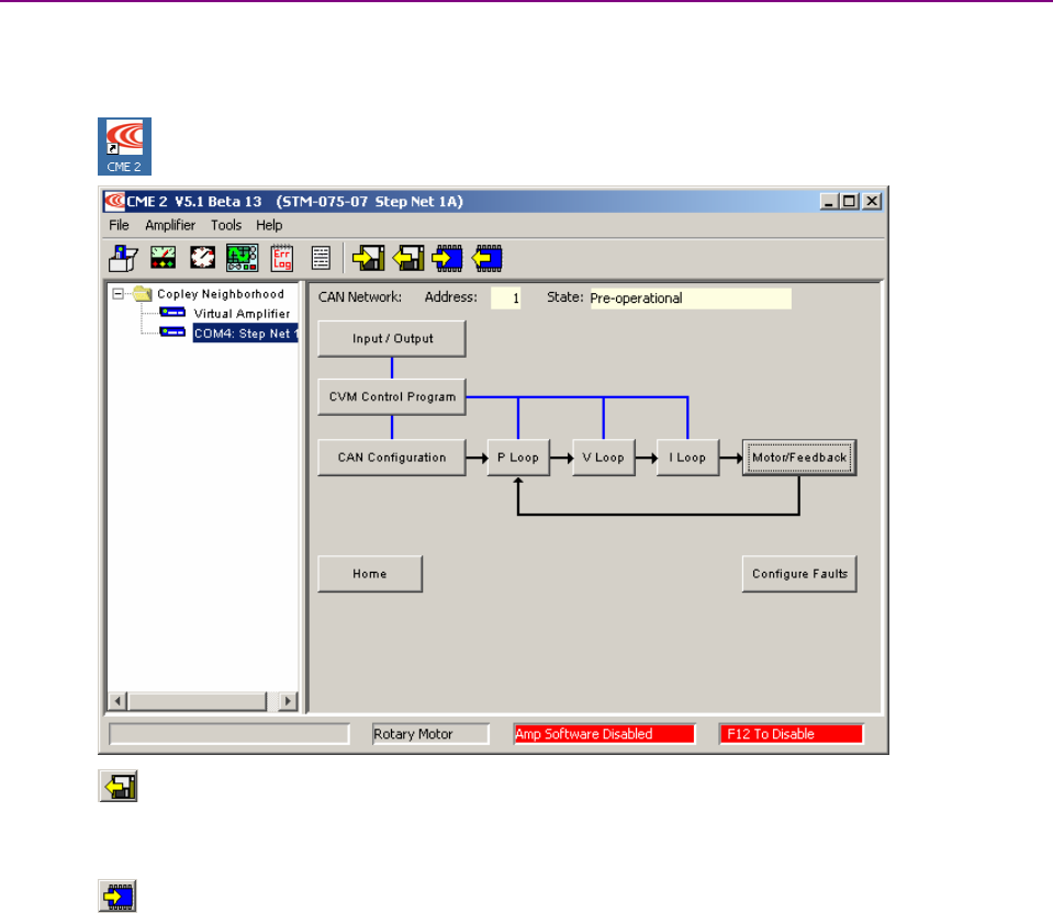
Using CME 2 Stepnet Panel Amplifier User Guide
156 Copley Controls
8.2.4: Quick Copy Setup Procedure
Use this procedure to configure an amplifier/motor pair by copying configuration files that were
prepared for the amplifier/motor combination.
8.2.4.1 Make sure the amplifier is connected to the PC serial port.
8.2.4.2 Start CME 2 by double-clicking the CME 2 desktop shortcut icon
8.2.4.3 On the Main screen, click Restore amplifier data from disk..
8.2.4.4 When prompted, navigate to the folder containing the appropriate .ccx file.
Highlight the file name and then click Open to load the file data into amplifier RAM.
8.2.4.5 On the Main screen, click Save to Flash.
8.2.4.6 If you do not need to load a CVM Control Program, skip to Step 8.2.4.7.
To load a CVM Control Program, choose FileRestore CVM Control Program.
When prompted, navigate to the folder containing the appropriate .ccp file.
Highlight the file name and then click Open to load the file data into flash memory.
This step also results in the setting of the Indexer 2 Program option Enable Control
Program on Startup. This configures the program to auto start when the amplifier is
powered up or reset.
8.2.4.7 If you do not need to load a set of Cam Tables, skip to Step 8.2.4.8.
To load a set of Cam Tables, choose FileRestore Cam Tables.
When prompted, navigate to the folder containing the appropriate .cct file.
Highlight the file name and then click Open to load the file data into flash memory.
8.2.4.8 If you do not need to load a Gain Scheduling Table, the process is complete.
To load a Gain Scheduling Table, choose FileRestore Gain Scheduling Table.
When prompted, navigate to the folder containing the appropriate .ccg file.
Highlight the file name and then click Open to load the file data into flash memory.
TIP: When copying amplifier data to multiple amplifiers, consider locking CME 2 to prevent
accidental changes to settings. See the CME 2 User’s Guide.

Stepnet Panel Amplifier User Guide Using CME 2
Copley Controls Corp. 157
8.3: Downloading Firmware
8.3.1: Acquiring Firmware Updates from Web Site
8.3.1.1 In an Internet browser, navigate to
http://www.copleycontrols.com/Motion/Downloads/firmware.html
8.3.1.2 Click on the appropriate Stepnet firmware icon.
8.3.1.3 When prompted, save the file to the Firmware Image folder in the CME 2 installation
folder.
(The default installation folder is
C:\Program Files\Copley Motion\CME 2\FirmwareImage.)
The folder should now contain a file named Stepnet_Firmware.zip.
8.3.1.4 Extract the contents of the zip file to the same location.
The folder should now contain the files Stepnet_Firmware.zip and the latest .cff file.
8.3.1.5 If desired, delete Stepnet_Firmware.zip to save disk space.
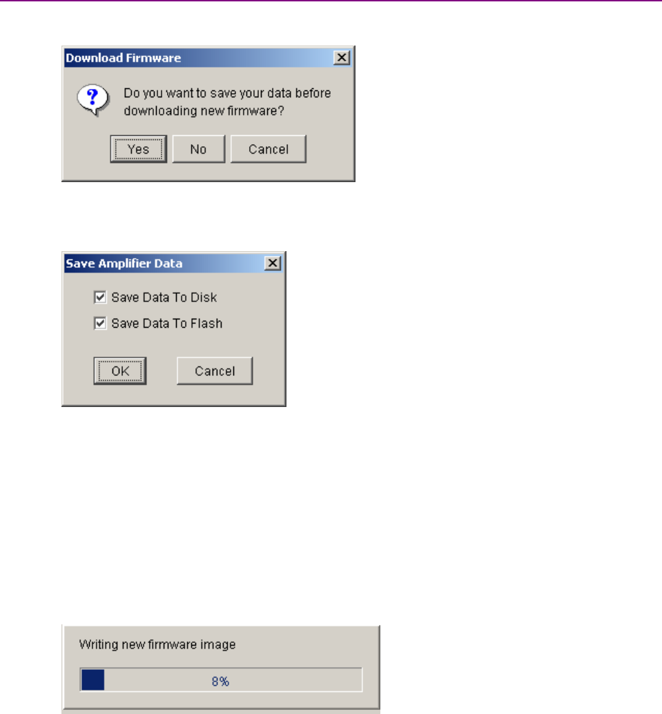
Using CME 2 Stepnet Panel Amplifier User Guide
158 Copley Controls
8.3.2: Downloading Firmware to Amplifier
8.3.2.1 On the Main screen choose ToolsDownload Firmware to open the Download
Firmware window.
8.3.2.2 To download new firmware without saving amplifier and motor data, click No
and then proceed to Step 8.3.2.4.
8.3.2.3 To back up amplifier and motor data before downloading firmware, click Yes.
1Use check marks to select whether to save to disk, flash, both, or neither.
2Click OK to save data and continue to select a firmware image,
or click Cancel to continue without saving data.
3If Save Data to Disk was checked, use the Save Amplifier Data to Disk screen to
browse to the folder where you want to save the .ccx file. Then enter a name in the
Name field. Then click Save.
When the Firmware Images window appears, proceed to Step 8.3.2.4.
8.3.2.4 Use the Firmware Images window to locate and select a firmware image file.
8.3.2.5 Click Open to begin the download.
(Or click Cancel to close the screen without downloading new firmware.)
Amessage window displays a series of progress messages:
When the message window closes, the firmware download is complete.
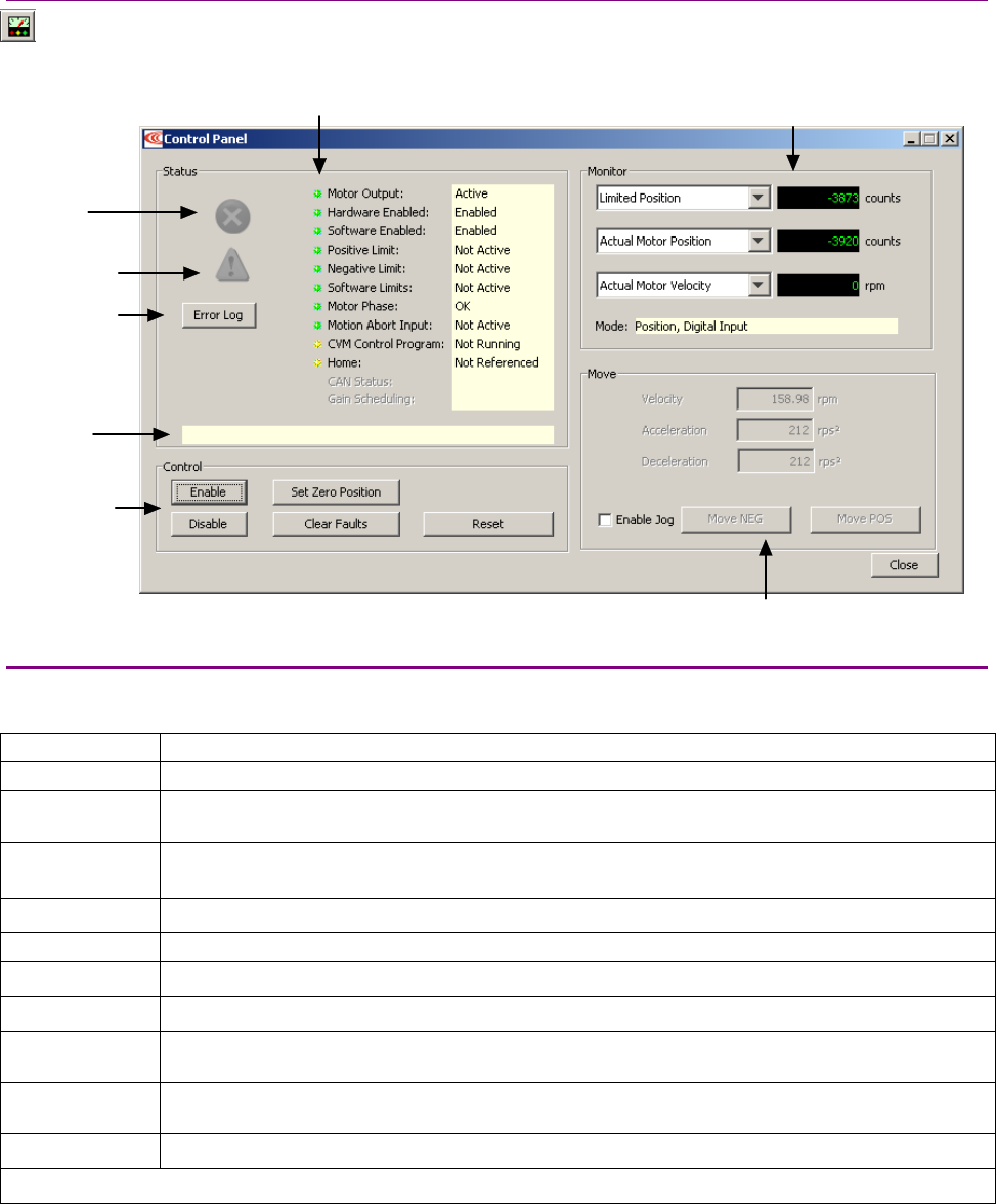
Stepnet Panel Amplifier User Guide Using CME 2
Copley Controls Corp. 159
8.4: Control Panel
8.4.1: Control Panel Overview
To access the control panel, click the Control Panel icon on the Main screen.
Each of the features labeled below is described in the following sections.
Status indicators
Message box
Display error log
Monitor real-time amplifier values
and operational mode
Control functions
Jog mode controls
Red if fault
is active
Yellow if warning
isactive
8.4.2: Status Indicators and Messages
The Status area includes status indicator lights (described below) and a message box. All green
lights indicate the amplifier is enabled and ready to accept motion commands.
Indicator States/Description
Motor Output State of the PWM output stage. Red if the output stage is inactive (disabled)
Hardware
Enabled
State of the hardware enable input(s). Red if one or more enable inputs are inactive.
Software
Enabled
State of the software enable. Red if the amplifier is disabled by software.
Positive Limit State of the positive limit switch input. Red indicates an activated positive limit switch.
Negative Limit State of the negative limit switch input. Red indicates an activated negative limit switch.
Software Limits State of the software limits. Red indicates an activated software limit.
Motor Phase Indicates a motor phasing error. Red indicates a motor phasing error exists.
Motion Abort
Input
State of the programmed Motion Abort Input. Red indicates the input is active.
CVM Control
Program
Status of the CVM Control Program.
Home Indicates whether the axis has successfully been referenced (homed).
Continued…
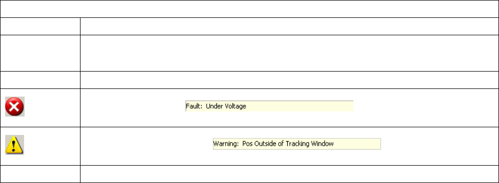
Using CME 2 Stepnet Panel Amplifier User Guide
160 Copley Controls
…continued:
Indicator States/Description
CAN Status The status of the CAN Bus. Yellow indicates a CAN warning limit reached. Red indicates a bus
error detected. (If the CAN Status indicator is replaced by the DeviceNet Status indicator, see the
Copley DeviceNet Programmer’s Guide.)
Gain Scheduling Indicates whether Gain Scheduling is active. See the CME 2 User Guide.
The fault indicator goes red when a fault is active. Check the status message box for a description
of the most recent fault: .
Check the Error Log for a full history of faults and warnings.
The warning indicator goes yellow when a warning is active. Check the status message box for a
description of the most recent: .
Check the Error Log for a full history of faults and warnings.
Message Box The message box below the indicators displays the most recent active fault or warning message.
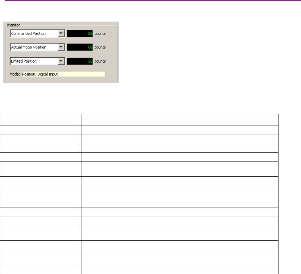
Stepnet Panel Amplifier User Guide Using CME 2
Copley Controls Corp. 161
8.4.3: Monitor Functions
The Control Panel Monitor channels can display real-time values on up to three separate
variables.
To set up a monitor display box, click in the list box and select a variable from the list.
Disabled disables the display. Other options represent the following amplifier variables. Note that
some variables are only applicable when an encoder is present (in stepper or servo mode):
Variable Description
Commanded Current Command input to the internal current loop.
Actual Current Actual current output.
Profile Velocity Instantaneous velocity command output of the trajectory generator.
Profile Acceleration Instantaneous commanded acceleration / deceleration rate.
Commanded Velocity
(Servo mode only)
Command input to the internal velocity loop.
Actual Motor Velocity
(With encoder only)
Actual motor velocity derived from the motor encoder.
Velocity Error
(With encoder only)
Difference between Profile Velocity and Actual Motor Velocity.
Commanded Position Position input to the trajectory generator.
Limited Position Instantaneous position command output of the trajectory generator.
Actual Position
(With encoder only)
Actual motor position measured by the motor encoder.
Following Error
(With encoder only)
Difference between the Limited Position and the Actual Position.
Bus Voltage Applied HV voltage
Amplifier Temperature Internal power stage temperature.
Mode:Displays the amplifier’s present operating mode. In camming it also displays the active cam
table number.
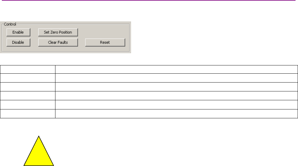
Using CME 2 Stepnet Panel Amplifier User Guide
162 Copley Controls
8.4.4: Control Functions
The Control area of the screen provides functions related to overall amplifier control. The screen
options vary with model and configuration.
Control the operational state of the amplifier using the controls described below.
Control Description
Enable Click to software enable the amplifier.
Disable Click to software disable the amplifier.
Set Zero Position Click to set the amplifier’s actual position counter to zero.
Clear Faults Click to clear all amplifier faults and latched outputs.
Reset Click to reset the amplifier.
Risk of unexpected or uncontrolled motion.
!
DANGER
Using the CME 2 Set Zero Position function while the amplifier is operating under
CANopen control or other command sources could cause unexpected or uncontrolled
motion.
Failure to heed this warning can cause equipment damage, injury, or death.

Stepnet Panel Amplifier User Guide Using CME 2
Copley Controls Corp. 163
8.4.5: Jog Mode
Jog mode provides a simple way to generate forward or reverse commands as described here:
8.4.5.1 To put the amplifier in jog mode, set the Enable Jog option.
8.4.5.2 Set up a jog move by setting the following mode-specific parameters:
Mode Parameter Description
Current Current applied to the motor. Limited by current loop Continuous Current.
Warning: Unloaded motors may, depending on torque setting, ramp up in
speed very quickly.
Current
(servo
mode
only) Current Ramp The rate at which the current will increase and decrease.
Velocity
(servo
mode
only)
Jog Speed Velocity of the jog move. Limited by velocity loop Vel. Limit.
Velocity Velocity of the jog move. Limited by velocity loop Vel. Limit.
Acceleration Acceleration rate of the jog move.
Position
Deceleration Deceleration rate of the jog move.
8.4.5.3 Command the move.
Mode Steps
Current
(servo
mode
only)
Hold Pos to apply positive current to the motor or hold down Neg to apply negative current to
the motor.
Release the button to command zero current.
Velocity
(servo
mode
only)
Hold Jog Pos to command a forward velocity or hold down Jog Neg to command a negative
velocity.
Release the button to command zero velocity.
Position Hold Move Pos to generate a forward move profile or hold Move Neg to generate a negative
move profile.
Release the button to stop movement.
NOTE: A position mode jog move continuously updates the commanded position. If a
following error develops with Following Error Fault is disabled, motion will not stop on button
release. Instead, it stops when actual position = commanded position.
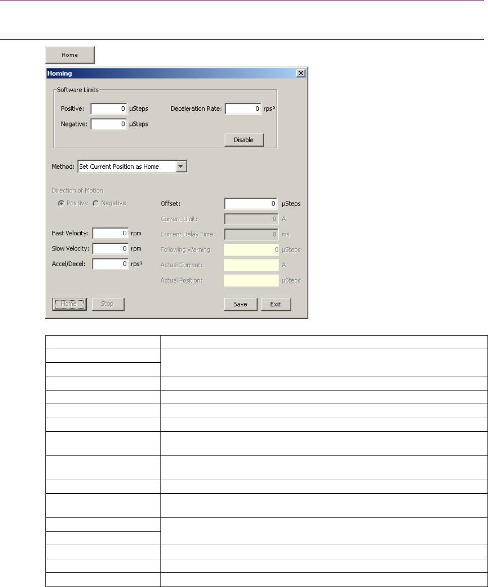
Using CME 2 Stepnet Panel Amplifier User Guide
164 Copley Controls
8.5: Home Function
8.5.1: Overview
The CME 2 Home function can be used to set and test homing parameters.
8.5.2: Homing Functions Settings
8.5.2.1 On Main screen, click Home to open the Homing screen.
8.5.2.2 Select homing options described below.
Parameter Description
Software limits: Positive
Software limits: Negative
Position of user-defined travel limits that take effect after homing operation.
Deceleration Rate Deceleration rate used to stop a motor when approaching a software limit.
Software limits: Disable Disables the use of software limits by setting both limits to zero.
Method Homing method. See Homing Methods in the CME 2 User Guide.
Direction of Motion Initial direction of motion for the homing method (Pos or Neg).
Fast Velocity The velocity used to find a limit or home switch. Also used when moving to an
offset position, or a resolver or Servo Tube index position.
Slow Velocity The velocity used to find a switch edge, incremental or analog encoder index
pulse, or hard stop.
Accel/Decel The acceleration and deceleration rate used during homing.
Offset Execute a move of this distance after the reference is found. Set actual
position to 0 and call the new position home.
Current Limit
Current Delay Time
Hard stop home is reached when the amplifier outputs the homing Current
Limit continuously for the time specified in the Delay Time.
Following Warning Shows the programmed following warning level.
Actual Current Shows actual current being applied to windings during homing.
Actual Position Shows actual position during homing.
Stepnet Panel Amplifier User Guide Using CME 2
Copley Controls Corp. 165
8.5.2.3 Optionally click Home to begin a homing sequence.
8.5.2.4 To stop the homing sequence before it is completed, click Stop.
8.5.2.5 Click Save to save the settings to flash memory. Click Exit to close the screen.
Using CME 2 Stepnet Panel Amplifier User Guide
166 Copley Controls

Copley Controls Corp. 167
APPENDIX
A: I2T TIME LIMIT ALGORITHM
This chapter describes the algorithm used to implement the I2Tlimit.
NOTE: This chapter uses servo mode examples and terminology to describe how the I2Tlimit
works. It works the same way in stepper mode, with the following exceptions:
•servo mode continuous current = stepper mode run current
•servo mode peak current = stepper mode boost current

I2TTime Limit Algorithm Stepnet Panel Amplifier User Guide
168 Copley Controls
A.1: I2TAlgorithm
A.1.1: I2TOverview
The I2Tcurrent limit algorithm continuously monitors the energy being delivered to the motor using
the I2TAccumulator Variable. The value stored in the I2TAccumulator Variable is compared with
the I2Tsetpoint that is calculated from the user-entered Peak Current Limit, I2TTime Limit, and
Continuous Current Limit. Whenever the energy delivered to the motor exceeds the I2Tsetpoint,
the algorithm protects the motor by limiting the output current.
A.1.2: I2TFormulas and Algorithm Operation
Calculating the I2TSetpoint Value
The I2Tsetpoint value has units of Amperes2-seconds (A2S) and is calculated from programmed
motor data. The setpoint is calculated from the Peak Current Limit, the I2TTime Limit, and the
Continuous Current Limit as follows:
I2Tsetpoint =
(Peak Current Limit2–Continuous Current Limit2) * I2TTime Limit
I2TAlgorithm Operation
During amplifier operation, the I2Talgorithm periodically updates the I2TAccumulator Variable at a
rate related to the output current Sampling Frequency. The value of the I2TAccumulator Variable
is incrementally increased for output currents greater than the Continuous Current Limit and is
incrementally decreased for output currents less than the Continuous Current Limit. The I2T
Accumulator Variable is not allowed to have a value less than zero and is initialized to zero upon
reset or +24 Vdc logic supply power-cycle.
Accumulator Increment Formula
At each update, a new value for the I2TAccumulator Variable is calculated as follows:
I2TAccumulator Variable n+1 =
I2TAccumulator Variable n
+(Actual Output Current n+1
2–Continuous Current Limit2) * Update period
After each sample, the updated value of the I2TAccumulator Variable is compared with the I2T
setpoint. If the I2TAccumulator Variable value is greater than the I2TSetpoint value, then the
amplifier limits the output current to the Continuous Current Limit. When current limiting is active,
the output current will be equal to the Continuous Current Limit if the commanded current is
greater than the Continuous Current Limit. If instead the commanded current is less than or equal
to the Continuous Current Limit, the output current will be equal to the commanded current.

Stepnet Panel Amplifier User Guide I2TTime Limit Algorithm
Copley Controls Corp. 169
A.1.3: I2TCurrent Limit Algorithm – Application Example
I2TExample: Parameters
Operation of the I2Tcurrent limit algorithm is best understood through an example. For this
example, a motor with the following characteristics is used:
•Peak Current Limit – 12 A
•I2TTime Limit – 1 S
•Continuous Current Limit – 6 A
From this information, the I2Tsetpoint is:
I2Tsetpoint = (12 A2–6 A2) * 1 S = 108 A2S
See the example plot diagrams on the next page.
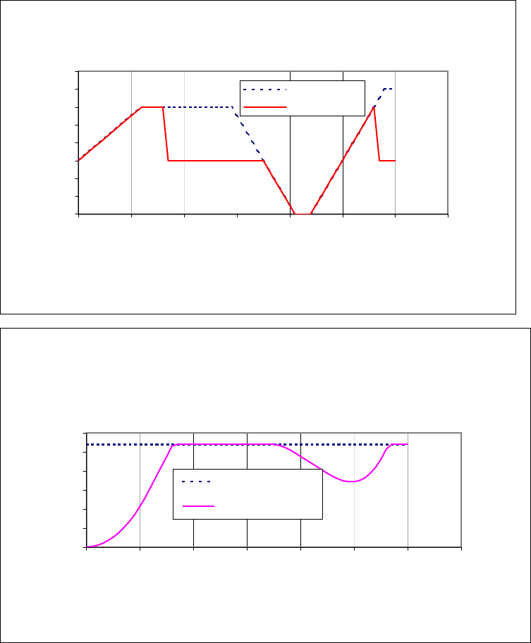
I2TTime Limit Algorithm Stepnet Panel Amplifier User Guide
170 Copley Controls
I2TExample: Plot Diagrams
The plots that follow show the response of an amplifier (configured w/ I2Tsetpoint = 108 A2S) to a
given current command. For this example, DC output currents are shown in order to simplify the
waveforms. The algorithm essentially calculates the RMS value of the output current, and thus
operates the same way regardless of the output current frequency and wave shape.
A)
I2Tcurrent limit
0
2
4
6
8
10
12
14
16
01234567
Time (S)
Current (A)
I_commanded
I_actual
B)
I2TAccumulator
0
20
40
60
80
100
120
01234567
Time (S)
I2T energy (A
2-S)
I^2T Setpoint
I^2T Accumulator
At time 0, plot diagram A shows that the actual output current follows the commanded current.
Note that the current is higher than the continuous current limit setting of 6 A. Under this condition,
the I2TAccumulator Variable begins increasing from its initial value of zero. Initially, the output
current linearly increases from 6 A up to 12 A over the course of 1.2 seconds. During this same
period, the I2TAccumulator Variable increases in a non-linear fashion because of its dependence
on the square of the current.
At about 1.6 seconds, the I2TAccumulator Variable reaches a value equal to the I2Tsetpoint. At
this time, the amplifier limits the output current to the continuous current limit even though the
commanded current remains at 12 A. The I2TAccumulator Variable value remains constant during
I
2
TSetpoint
I
2
T
Stepnet Panel Amplifier User Guide I2TTime Limit Algorithm
Copley Controls Corp. 171
the next 2 seconds since the difference between the actual output current and the continuous
current limit is zero.
At approximately 3.5 seconds, the commanded current falls below the continuous current limit and
once again the output current follows the commanded current. Because the actual current is less
than the continuous current, the I2TAccumulator Variable value begins to fall incrementally.
The I2TAccumulator Variable value continues to fall until at approximately 5.0 seconds when the
commanded current goes above the continuous current limit again. The actual output current
follows the current command until the I2TAccumulator Variable value reaches the I2Tsetpoint and
current limiting is invoked.
I2TTime Limit Algorithm Stepnet Panel Amplifier User Guide
172 Copley Controls
A.2: I2TScope Trace Variables (STX Only)
Two Scope Tool trace variables are available for monitoring whether the I2Taccumulator is
accumulating or discharging.
The I2TAmplifier Accumulator variable evaluates the accumulator against the factory set current
limits of the amplifier.
The I2TMotor Accumulator variable evaluates the accumulator against the user-programmed
current loop values.
The value shown in the scope has been normalized so that 100% equals the I2Tsetpoint.
When either trace variable line reaches 100%, current limiting will be invoked.
For instructions on using these variables in the Scope Tool, see the CME 2 User Guide.

Copley Controls Corp. 173
APPENDIX
C: THERMAL CONSIDERATIONS
This chapter describes Stepnet Panel (STP) and Stepnet Panel AC (STX) amplifier operating
temperature characteristics, heatsink options, and heatsink mounting instructions. Contents
include:
C.1: Operating Temperature and Cooling Configurations .......................................................................................................... 174
C.1.1: Stepnet Panel (STP) ............................................................................................................................................. 174
C.1.2: Stepnet Panel AC (STX) ....................................................................................................................................... 176
C.2: Heatsink Mounting Instructions .......................................................................................................................................... 179
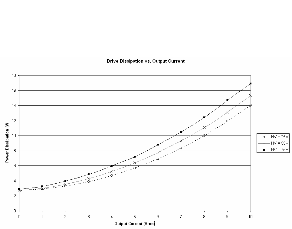
Thermal Considerations Stepnet Panel Amplifier User Guide
174 Copley Controls
C.1: Operating Temperature and Cooling Configurations
C.1.1: Stepnet Panel (STP)
Power Dissipation, Stepnet Panel (STP)
The following chart shows the internal power dissipation for of the Stepnet Panel (STP) amplifier
versus output current levels at different +HV voltages. The output current is calculated from the
motion profile, motor, and load conditions. The values on the chart represent the rms (root-mean
square) current that the amplifier would provide during operation. The +HV values are for the
average DC voltage of the power supply.
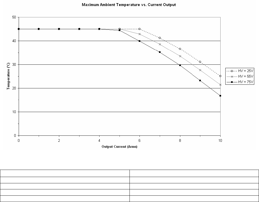
Stepnet Panel Amplifier User Guide Thermal Considerations
Copley Controls Corp. 175
Max Ambient Temperature vs. Current Output, Stepnet Panel (STP)
The following chart shows the maximum allowable ambient temperature of the Stepnet Panel
(STP) amplifier versus output current levels at different +HV voltages. The values shown
represent applications where the amplifier is installed without a heatsink and uses natural
convection cooling. The addition of forced air (100 lfm minimum) or forced air and a heatsink will
allow the Stepnet to operate at maximum voltage and current in a 45°C ambient environment.
Thermal Resistance Stepnet Panel (STP)
Configuration Thermal Resistance
No Heat Sink, Convection Cooled 2.8 °C/W
No Heat Sink, Fan Cooled (100 LFM minimum) 1.3 °C/W
With Heat Sink, Fan Cooled (100 LFM minimum) 0.8 °C/W
With Heat Sink, Fan Cooled (200 LFM minimum) 0.6 °C/W
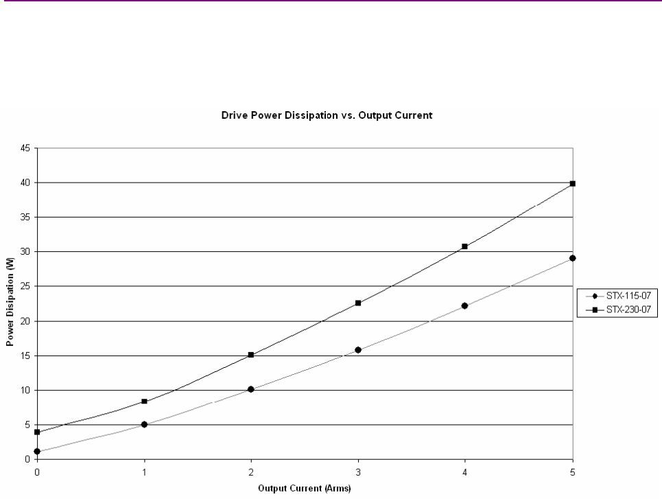
Thermal Considerations Stepnet Panel Amplifier User Guide
176 Copley Controls
C.1.2: Stepnet Panel AC (STX)
Power Dissipation, Stepnet Panel AC (STX)
The following chart shows the internal power dissipation for of the Stepnet Panel AC (STX)
amplifiers versus output current levels at different +HV voltages. The output current is calculated
from the motion profile, motor, and load conditions. The values on the chart represent the rms
(root-mean square) current that the amplifier would provide during operation.
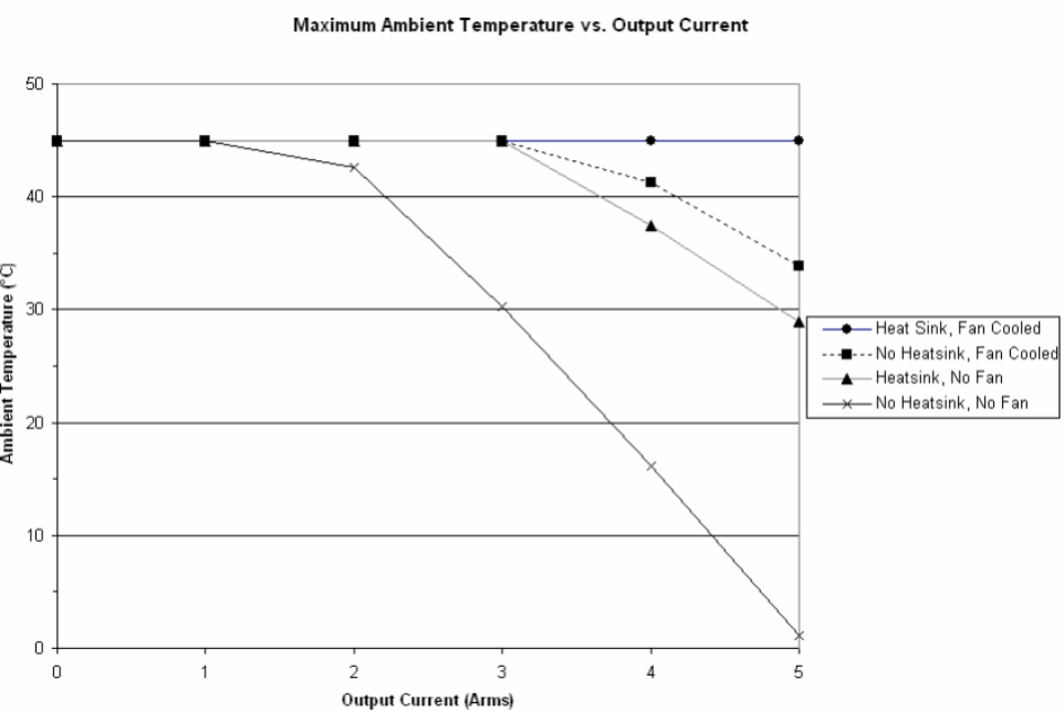
Stepnet Panel Amplifier User Guide Thermal Considerations
Copley Controls Corp. 177
Max Ambient Temperature vs. Current Output, Stepnet Panel AC (STX-120)
The following chart shows the maximum allowable ambient temperature of the Stepnet
STX-120-07 amplifier versus output current levels with different cooling feature configurations.
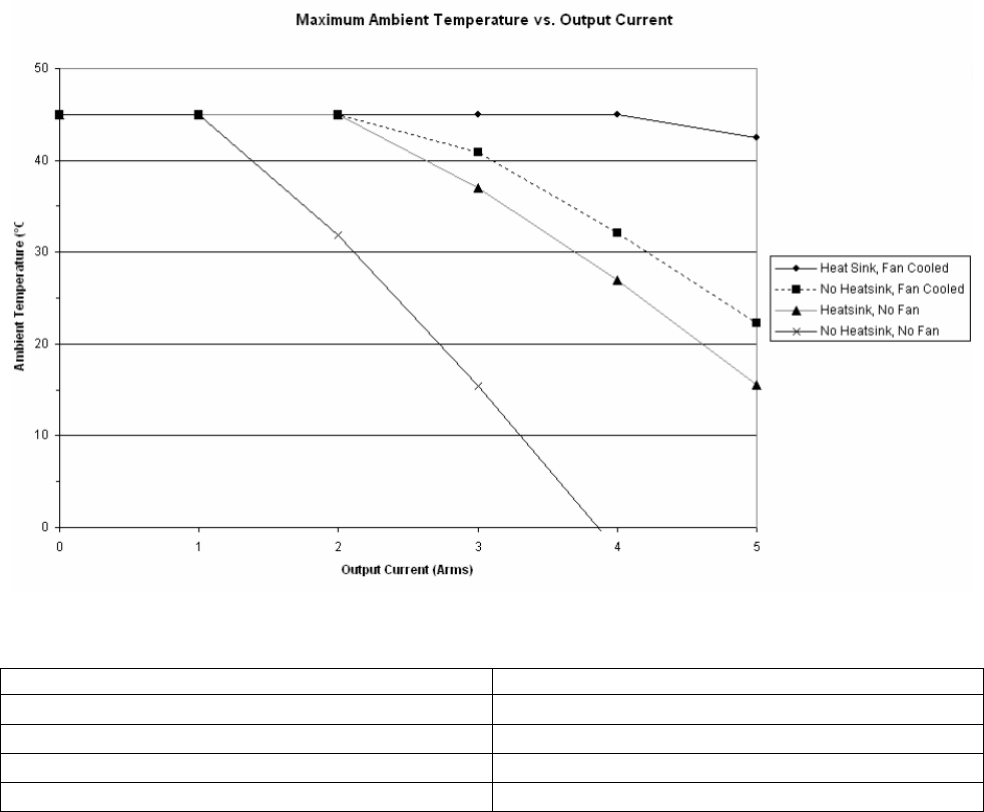
Thermal Considerations Stepnet Panel Amplifier User Guide
178 Copley Controls
Max Ambient Temperature vs. Current Output, Stepnet Panel AC (STX-230-07)
The following chart shows the maximum allowable ambient temperature of the Stepnet
STX-230-07 amplifier versus output current levels with different cooling feature configurations.
Thermal Resistance Stepnet Panel (STX)
Configuration Thermal Resistance
No Heat Sink, Convection Cooled 2.2 °C/W
No Heat Sink, Fan Cooled (200 LFM minimum) 1.1 °C/W
With Heat Sink, Convection Cooled 1.2 °C/W
With Heat Sink, Fan Cooled (200 LFM minimum) 0.6 °C/W
*Air flow 200 LFM minimum.
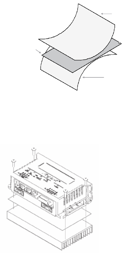
Stepnet Panel Amplifier User Guide Thermal Considerations
Copley Controls Corp. 179
C.2: Heatsink Mounting Instructions
Use the following procedure to mount a heatsink on a Stepnet Panel amplifier. On STP models,
the thermal interface between the amplifier and heat sink is a phase change material pad. On STX
models, the thermal interface is a dry film interface pad.
C.2.1 STX: Remove the blue protective sheet from one side of the pad. Place the phase
change material on the amplifier, taking care to center the pad holes over the holes in
the amplifier. Remove the clear protective sheet from the pad.
Blue Protective Sheet
(Discard)
Dry Film
Interface Pad
Clear Protective Sheet
(Discard)
C.2.2 STP: Place the phase change material (STP) on the amplifier, taking care to center the
pad holes over the holes in the amplifier.
C.2.3 STP and STX: Mount the heatsink onto the amplifier taking care to see that the holes in
the heatsink, phase change material or interface pad, and amplifier all line up.
C.2.4 STP and STX: Install and torque the four #6-32 mounting screws to 8~10 lb-in
(0.9~1.13 Nm). STP diagram shown here:
Thermal Considerations Stepnet Panel Amplifier User Guide
180 Copley Controls

Copley Controls Corp. 181
APPENDIX
D: DETENT COMPENSATION GAIN
This chapter describes the detent compensation gain feature that can be used in stepper mode to
reduce detent noise.
D.1: Detent Gain Tuning ............................................................................................................................................................ 182
D.1.1: Detent Gain Tuning With Encoder......................................................................................................................... 182
D.1.2: Detent Gain Tuning Without Encoder.................................................................................................................... 184
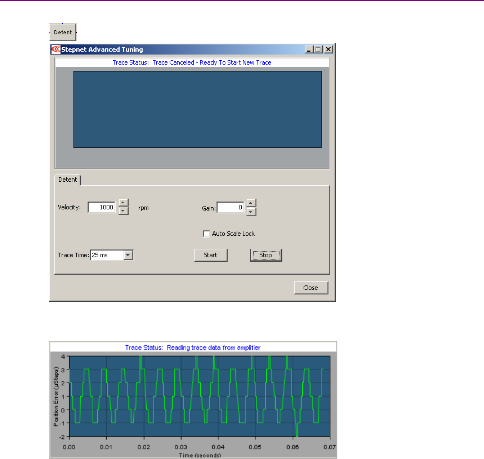
Detent Compensation Gain Stepnet Panel Amplifier User Guide
182 Copley Controls
D.1: Detent Gain Tuning
Some stepper motors are susceptible to detent noise. The detent gain tuning feature can be used
to reduce that noise.
The detent tuning process is different with an encoder than without. With an encoder, actual
position is displayed in a trace and used as the primary tuning reference. Without an encoder,
actual voltage is shown in the trace. With some motors, voltage changes can be subtle. In these
cases, audible noise can be a better tuning reference.
D.1.1: Detent Gain Tuning With Encoder
D.1.1.1 Make sure that amplifier and motor have been set up in stepper mode and tuned.
D.1.1.2. On the CME 2 Main screen, click Detent.
D.1.1.3. With Gain set to 0, adjust the velocity from 0 rpm until the greatest error is seen.
Error may peak and then decrease at higher velocities, so it may be necessary to
reduce velocity to return to the velocity where the greatest error is seen.
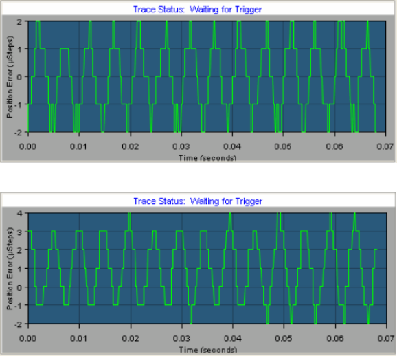
Stepnet Panel Amplifier User Guide Detent Compensation Gain
Copley Controls Corp. 183
D.1.1.4 At the velocity which exhibits the worst position error, adjust Gain until position error is
minimized. See example below.
Note that excessive Gain can introduce more error, as shown below.
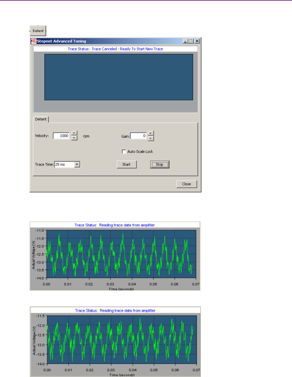
Detent Compensation Gain Stepnet Panel Amplifier User Guide
184 Copley Controls
D.1.2: Detent Gain Tuning Without Encoder
With no encoder the trace display shows actual voltage instead of actual position. With most motors, the
ouput voltage changes are subtle. In these cases, audible noise provides the best reference for tuning.
D.1.2.1. Make sure that amplifier and motor have been set up in stepper mode and tuned.
D.1.2.2. On the CME 2 Main screen, click Detent.
D.1.2.3 With Gain set to zero, adjust velocity from zero until worst noise is heard.
Error may peak at a certain velocity and then decrease at higher velocities, so it may
be necessary to reduce velocity to return to the velocity where the greatest noise is
heard. The trace image below was seen when the noise was loudest.
D.1.2.2. At the velocity where the worst noise is heard, adjust Gain to find lowest noise level.
Note that the voltage changes were subtle. The noise reduction was obvious.

Copley Controls Corp. 185
APPENDIX
E: ORDERING GUIDE AND ACCESSORIES
This chapter lists part numbers for all Stepnet amplifiers and accessories. Contents include:
E.1: Stepnet Panel (STP) Amplifier ........................................................................................................................................... 186
E.2: Stepnet Panel AC (STX) Amplifier...................................................................................................................................... 187
E.3: Stepnet Module (STM) Amplifier ........................................................................................................................................ 188
E.4: Stepnet Micro Module (STL) Amplifier................................................................................................................................ 189

Ordering Guide and Accessories Stepnet Panel Amplifier User Guide
186 Copley Controls
E.1: Stepnet Panel (STP) Amplifier
Stepnet Panel Model Numbers
Model Number Description
STP-075-07 Stepnet Panel amplifier 5/7 Adc @ 75 Vdc.
STP-075-10 Stepnet Panel amplifier 10/10 Adc @ 75 Vdc.
NOTE: Add “-H” to order Panel amplifier with factory-mounted heatsink. Heatsink kits may be ordered separately.
Stepnet Panel (STP) Heatsink Kit
Model Qty Description
1Heatsink
1Heatsink thermal material
STP-HK
1Heatsink hardware mounting kit
Stepnet Panel (STP) Connector Kit with Solder-Cup Feedback and Control Connectors
Model Qty Ref Description Mfr. Model No.
1J1 Housing Molex 39-01-4041
4J1 Crimp terminal Molex 39-00-0039
1J2 Housing Molex 39-01-4051
5J2 Crimp terminal Molex 39-00-0039
1Connector, solder-cup Norcomp: 180-026-103L001
STP-CK
1J3 Back shell Norcomp: 979-015-020R121
Stepnet Panel (STP) CANopen Network Kit
Model Qty Ref Description Copley Controls Model No.
1-- Sub-D 9-position female to RJ-45 adapter STP-CV
1CANopen Network Cable, 10 ft (3 m) generic Cat5E/Cat6E patch cable
STP-NK
1J5/J6 CANopen Network Terminator STP-NT
Stepnet Panel (STP) Individual Cable Assemblies (and Related Accessories)
Model Ref Description Mfr. Model No.
SER-CK J4 RS-232 Serial Cable Kit (for connecting PC to amplifier)
STP-CV -- Sub-D 9-position female to RJ-45 adapter (PC to CANopen cable adapter)
STP-NC-10 CANopen Network Cable, 10 ft (3 m)
STP-NC-01 CANopen Network Cable, 1 ft (0.3 m) generic Cat5E/Cat6E patch cable
STP-NT
J5/J6
CANopen Network Terminator
Software
Model Description
CME2 CME 2 Drive Configuration Software (CD-ROM)
CML Copley Motion Libraries (CD-ROM)
CMO Copley Motion Objects (CD-ROM)
Order Example
Order 1 STP-075-07 amplifier with factory-installed heatsink, CME 2 CD, and serial cable kit:
Qty Item Description
1STP-075-07-H Stepnet Panel (STP) stepper amplifier with heatsink installed
1STP-CK Connector kit
1STP-NK CANopen network kit
1CME 2 CME 2 CD
1SER-CK Serial Cable Kit for connecting the PC to the amplifier

Stepnet Panel Amplifier User Guide Ordering Guide and Accessories
Copley Controls Corp. 187
E.2: Stepnet Panel AC (STX) Amplifier
Stepnet AC Panel Model Numbers
Model Number Description
STX-115-07 Stepnet Panel AC stepper amplifier 5/7 Adc @ 120 Vac single-phase.
STX-230-07 Stepnet Panel AC stepper amplifier 5/7 Adc @ 240 Vac single-phase.
Stepnet Panel AC (STX) Heatsink Kit
Model Qty Description
1Heatsink, standard
1Heatsink thermal material
STX-HK
1Heatsink hardware mounting kit
Stepnet Panel AC (STX) Connector Kit
Model Qty Ref Description Mfr. Model No.
1J1 Plug, 3 position, 7.5 mm, female Wago: 721-203/026-045/RN01-0000
1J2 Plug, 5 position, 5.0 mm, female Wago: 721-605/000-043/RN01-0000
1J3 3 position, 5.0 mm, female Wago: 721-103/026-047/RN01-0000
1High density D-Sub, male, 15 position,
solder-cup
Norcomp: 180-015-103L001
4
J6
Backshell for J6 plug Norcomp: 979-009-020R121
1High density D-Sub, male, 26 position,
solder-cup
Norcomp: 180-026-103L001
1
J7
Backshell for J7 plug Norcomp: 979-015-020R121
STX-CK
2J1
J2
J3
Wire insertion/extraction tool Wago: 231-131
Stepnet Panel AC (STX) CANopen Network Kit
Model Qty Ref Description Copley Controls Model No.
1Sub-D 9-position female to RJ-45 adapter STX-CV
1CANopen cable assembly, 10 ft (3 m ) STX-NC-10
STX-NK
1
J4/J5
CANopen network terminator STX-NT
Stepnet Panel AC (STX) Individual Cable Assemblies (and Related Accessories)
Model Ref Description Mfr. Model No.
SER-CK J8 RS-232 Serial Cable Kit (for connecting PC to amplifier)
STX-CV Sub-D 9-position female to RJ-45 adapter (PC to CANopen cable adapter)
STX-NC-10 CANopen Network Cable, 10 ft (3 m)
STX-NC-01 CANopen Network Cable, 1 ft (0.3 m) generic Cat5E/Cat6E patch cable
STX-NT
J4/J5
CANopen Network Terminator
Software
Model Description
CME2 CME 2 Drive Configuration Software (CD-ROM)
CML Copley Motion Libraries (CD-ROM)
CMO Copley Motion Objects (CD-ROM)

Ordering Guide and Accessories Stepnet Panel Amplifier User Guide
188 Copley Controls
E.3: Stepnet Module (STM) Amplifier
Stepnet Module Model Number
Model Number Description
STM-075-07 Stepnet Module amplifier 5/7 Adc @ 75 Vdc. For more information, see data sheet
(http://www.copleycontrols.com/Motion/Downloads/stepnetData.html).
Stepnet Module Heatsink Kit
Model Qty Description
1Heatsink, standard
1Heatsink thermal material
STM-HS
1Heatsink hardware mounting kit
1Heatsink, low-profile
1Heatsink thermal material
STM-HL
1Heatsink hardware mounting kit
Stepnet Module Development Kit
Model Description
TDK-075-01 Stepnet Module Development Kit
TDK-CK Stepnet Module Development Kit Connector Kit
SER-CK RS-232 Serial Cable Kit (for connecting PC to development kit)
Software
Model Description
CME2 CME 2 Drive Configuration Software (CD-ROM)
CML Copley Motion Libraries (CD-ROM)
CMO Copley Motion Objects (CD-ROM)

Stepnet Panel Amplifier User Guide Ordering Guide and Accessories
Copley Controls Corp. 189
E.4: Stepnet Micro Module (STL) Amplifier
Stepnet Micro Module Model Numbers
Model Number Description
STL-055-04 Stepnet Micro Module amplifier 3/4.5 Adc @ 55 Vdc. For more information, see data sheet
(http://www.copleycontrols.com/Motion/Downloads/stepnetData.html).
STL-075-03 Stepnet Micro Module amplifier 2/3 Adc @ 55 Vdc. For more information, see data sheet
(http://www.copleycontrols.com/Motion/Downloads/stepnetData.html).
Stepnet Micro Development Kit (for Stepnet Micro and Stepnet Micro Module)
Model Description
LDK-075-01 Stepnet Micro Development Kit
LDK-CK Stepnet Micro Development Kit Connector Kit
SER-CK RS-232 Serial Cable Kit (for connecting PC to development kit)
Software
Model Description
CME2 CME 2 Drive Configuration Software (CD-ROM)
CML Copley Motion Libraries (CD-ROM)
CMO Copley Motion Objects (CD-ROM)