PX G5000 S/M Stylus_Photo_R1800_R2400 Stylus Photo R1800 R2400
User Manual: Stylus_Photo_R1800_R2400
Open the PDF directly: View PDF ![]() .
.
Page Count: 234 [warning: Documents this large are best viewed by clicking the View PDF Link!]
- EPSON Stylus Photo R1800/R2400
- Product Description
- Operating Principles
- Troubleshooting
- Disassembly And Assembly
- 4.1 Overview
- 4.2 Disassembly
- 4.2.1 Removing the Housings
- 4.2.2 Waste Ink Pad
- 4.2.3 Front Paper Guide Pad
- 4.2.4 ASF Assy
- 4.2.5 Removing the Boards
- 4.2.6 Disassembling the Printer Mechanism
- 4.2.6.1 Print Head
- 4.2.6.2 CR Scale
- 4.2.6.3 APG Assy
- 4.2.6.4 Carriage Shaft and Carriage Unit
- 4.2.6.5 CSIC Board
- 4.2.6.6 Paper EJ Frame Assy.
- 4.2.6.7 CD-R Release Lever Sub Assy
- 4.2.6.8 Ink System Unit
- 4.2.6.9 Release Holder Assy
- 4.2.6.10 FLAG Release Assy.
- 4.2.6.11 Upper Paper Guide Assys.
- 4.2.6.12 Front Paper Guide and Paper eject roller
- 4.2.6.13 PF Roller Shaft
- 4.2.7 Removing the Motors
- 4.2.8 Removing the Sensors
- Adjustment
- Maintenance
- Appendix
- Stylus Photo R2400

EPSON Stylus Photo R1800/R2400
Color Inkjet Printer
SEIJ04015
SERVICE MANUAL
Download Service Manual And Resetter Printer at http://printer1.blogspot.com
Notice:
All rights reserved. No part of this manual may be reproduced, stored in a retrieval system, or transmitted in any form or by any means, electronic,
mechanical, photocopying, recording, or otherwise, without the prior written permission of SEIKO EPSON CORPORATION.
The contents of this manual are subject to change without notice.
All effort have been made to ensure the accuracy of the contents of this manual. However, should any errors be detected, SEIKO EPSON would greatly
appreciate being informed of them.
The above not withstanding SEIKO EPSON CORPORATION can assume no responsibility for any errors in this manual or the consequences thereof.
EPSON is a registered trademark of SEIKO EPSON CORPORATION.
General Notice: Other product names used herein are for identification purpose only and may be trademarks or registered trademarks of their
respective owners. EPSON disclaims any and all rights in those marks.
Copyright © 2005 SEIKO EPSON CORPORATION.
I&I CS/Quality Management & PL Department
PRECAUTIONS
Precautionary notations throughout the text are categorized relative to 1)Personal injury and 2) damage to equipment.
DANGER Signals a precaution which, if ignored, could result in serious or fatal personal injury. Great caution should be exercised in performing
procedures preceded by DANGER Headings.
WARNING Signals a precaution which, if ignored, could result in damage to equipment.
The precautionary measures itemized below should always be observed when performing repair/maintenance procedures.
DANGER
1. ALWAYS DISCONNECT THE PRODUCT FROM THE POWER SOURCE AND PERIPHERAL DEVICES PERFORMING ANY MAINTENANCE OR REPAIR
PROCEDURES.
2. NO WORK SHOULD BE PERFORMED ON THE UNIT BY PERSONS UNFAMILIAR WITH BASIC SAFETY MEASURES AS DICTATED FOR ALL
ELECTRONICS TECHNICIANS IN THEIR LINE OF WORK.
3. WHEN PERFORMING TESTING AS DICTATED WITHIN THIS MANUAL, DO NOT CONNECT THE UNIT TO A POWER SOURCE UNTIL INSTRUCTED TO
DO SO. WHEN THE POWER SUPPLY CABLE MUST BE CONNECTED, USE EXTREME CAUTION IN WORKING ON POWER SUPPLY AND OTHER
ELECTRONIC COMPONENTS.
WARNING
1. REPAIRS ON EPSON PRODUCT SHOULD BE PERFORMED ONLY BY AN EPSON CERTIFIED REPAIR TECHNICIAN.
2. MAKE CERTAIN THAT THE SOURCE VOLTAGES IS THE SAME AS THE RATED VOLTAGE, LISTED ON THE SERIAL NUMBER/RATING PLATE. IF THE
EPSON PRODUCT HAS A PRIMARY AC RATING DIFFERENT FROM AVAILABLE POWER SOURCE, DO NOT CONNECT IT TO THE POWER SOURCE.
3. ALWAYS VERIFY THAT THE EPSON PRODUCT HAS BEEN DISCONNECTED FROM THE POWER SOURCE BEFORE REMOVING OR REPLACING
PRINTED CIRCUIT BOARDS AND/OR INDIVIDUAL CHIPS.
4. IN ORDER TO PROTECT SENSITIVE MICROPROCESSORS AND CIRCUITRY, USE STATIC DISCHARGE EQUIPMENT, SUCH AS ANTI-STATIC WRIST
STRAPS, WHEN ACCESSING INTERNAL COMPONENTS.
5. REPLACE MALFUNCTIONING COMPONENTS ONLY WITH THOSE COMPONENTS BY THE MANUFACTURE; INTRODUCTION OF SECOND-SOURCE
ICs OR OTHER NON-APPROVED COMPONENTS MAY DAMAGE THE PRODUCT AND VOID ANY APPLICABLE EPSON WARRANTY.
About This Manual
This manual describes basic functions, theory of electrical and mechanical operations, maintenance and repair procedures of the printer. The instructions and
procedures included herein are intended for the experienced repair technicians, and attention should be given to the precautions on the preceding page.
Manual Configuration
This manual consists of six chapters and Appendix.
CHAPTER 1.PRODUCT DESCRIPTIONS
Provides a general overview and specifications of the product.
CHAPTER 2.OPERATING PRINCIPLES
Describes the theory of electrical and mechanical operations of
the product.
CHAPTER 3.TROUBLESHOOTING
Describes the step-by-step procedures for the troubleshooting.
CHAPTER 4.DISASSEMBLY / ASSEMBLY
Describes the step-by-step procedures for disassembling and
assembling the product.
CHAPTER 5.ADJUSTMENT
Provides Epson-approved methods for adjustment.
CHAPTER 6.MAINTENANCE
Provides preventive maintenance procedures and the lists of
Epson-approved lubricants and adhesives required for servicing
the product.
APPENDIX Provides the following additional information for reference:
• Connector pin assignments
• Exploded diagram & Parts List
• Electric circuit boards components layout
• Electrical circuit boards schematics
Symbols Used in this Manual
Various symbols are used throughout this manual either to provide additional
information on a specific topic or to warn of possible danger present during a
procedure or an action. Be aware of all symbols when they are used, and
always read NOTE, CAUTION, or WARNING messages.
Indicates an operating or maintenance procedure, practice or
condition that is necessary to keep the product’s quality.
Indicates an operating or maintenance procedure, practice, or
condition that, if not strictly observed, could result in damage to,
or destruction of, equipment.
May indicate an operating or maintenance procedure, practice or
condition that is necessary to accomplish a task efficiently. It may
also provide additional information that is related to a specific
subject, or comment on the results achieved through a previous
action.
Indicates an operating or maintenance procedure, practice or
condition that, if not strictly observed, could result in injury or loss
of life.
Indicates that a particular task must be carried out according to a
certain standard after disassembly and before re-assembly,
otherwise the quality of the components in question may be
adversely affected.

Revision Status
Revision Date of Issue Description
A January 21, 2005 First Release
B March 31, 2005 Revised Contents
8. Stylus Photo R2400 (p198)
• Stylus Photo specific information is added.
5.2.5.1 Printing Calibration Chart by Users (p165)
• Descriptions of the procedure are added.
5.2.5.2 Writing of Color ID by Users (p169)
• A caution is deleted.
Color Correction Value Entry Procedure (p170)
• Supported OS and ports are added.
Calibration Chart Print Procedure for Users (p166)
• Descriptions of the procedure are added.

EPSON Stylus Photo R1800/R2400 Revision B
6
CONTENTS
Chapter 1 Product Description
1.1 Overview.................................................................................................. 9
1.2 PG Setting ............................................................................................. 10
1.3 Functions .............................................................................................. 11
1.3.1 Control Panel ................................................................................ 11
1.3.2 Switches ........................................................................................ 11
1.3.3 Indicators ....................................................................................... 11
1.3.4 Switch Functions ........................................................................... 11
1.3.5 Indicator Display in Normal Mode ................................................. 12
1.3.6 Error Status ................................................................................... 13
1.4 Casing Specifications .......................................................................... 14
1.5 Accessories .......................................................................................... 14
Chapter 2 Operating Principles
2.1 Overview................................................................................................ 16
2.2 Printer Mechanism ............................................................................... 16
2.2.1 Carriage Mechanism ..................................................................... 17
2.2.2 Printhead Specifications ................................................................ 20
2.2.3 Paper Feeding Mechanism ........................................................... 20
2.2.4 Paper Feeding Mechanism ........................................................... 25
2.2.5 Ink System Mechanism ................................................................. 26
2.2.6 Ink Sequence ................................................................................ 28
2.2.7 Power-On Sequence ..................................................................... 30
2.3 Electrical Circuit Operating Principles............................................... 31
2.3.1 Power Supply Circuit Operating Principle ..................................... 32
2.3.2 C589 MAIN Circuit Operating Principle ......................................... 33
Chapter 3 Troubleshooting
3.1 Overview................................................................................................ 36
3.1.1 Troubleshooting according to Panel Messages ............................ 36
3.1.2 Troubleshooting based on Observed Faults ................................. 59
Chapter 4 Disassembly And Assembly
4.1 Overview ............................................................................................... 69
4.1.1 Precautions ................................................................................... 69
4.1.2 Tools ............................................................................................. 70
4.1.3 Screws .......................................................................................... 71
4.1.4 Work Completion Checklist ........................................................... 72
4.2 Disassembly ......................................................................................... 73
4.2.1 Removing the Housings ................................................................ 74
4.2.2 Waste Ink Pad ............................................................................... 80
4.2.3 Front Paper Guide Pad ................................................................. 82
4.2.4 ASF Assy ...................................................................................... 83
4.2.5 Removing the Boards ................................................................... 87
4.2.6 Disassembling the Printer Mechanism .......................................... 89
4.2.7 Removing the Motors .................................................................. 122
4.2.8 Removing the Sensors ................................................................ 124
Chapter 5 Adjustment
5.1 Adjustment Items and Overview....................................................... 129
5.1.1 Servicing Adjustment Item List .................................................... 129
5.1.2 Replacement Part-Based Adjustment Priorities .......................... 133
5.1.3 Required Adjustment Tools ......................................................... 136
5.2 Adjustment.......................................................................................... 137
5.2.1 PF Belt Tension Adjustment ....................................................... 137
5.2.2 PG Adjustment ............................................................................ 139
5.2.3 PF Roller Shaft Center Support Position Adjustment ................. 143
5.2.4 Colorimetric Calibration ............................................................... 147
5.2.5 Colorimetric Calibration by Users ............................................... 165
Chapter 6 Maintenance
6.1 Overview ............................................................................................. 173
6.1.1 ROM Replacement ..................................................................... 173
6.1.2 Cleaning ...................................................................................... 173
6.1.3 Service Maintenance .................................................................. 174

EPSON Stylus Photo R1800/R2400 Revision B
7
6.1.4 Lubrication ................................................................................... 175
Chapter 7 Appendix
7.1 Connector Summary .......................................................................... 182
7.1.1 Connectors and Pin Layouts ....................................................... 182
7.2 Exploded Diagram.............................................................................. 183
7.3 Parts List for EPSON Stylus Photo R1800 ....................................... 190
7.4 Circuit Diagram................................................................................... 192
Chapter 8 Stylus Photo R2400
8.1 Overview.............................................................................................. 199
8.1.1 Overview ..................................................................................... 199
8.1.2 Indicator Display in Normal Mode ............................................... 200
8.1.3 Error Status ................................................................................. 201
8.2 Casing Specifications ........................................................................ 202
8.3 Accessories ........................................................................................ 202
8.3.1 Printhead Specifications .............................................................. 203
8.3.2 Ink Sequence .............................................................................. 203
8.4 Overview.............................................................................................. 204
8.4.1 Troubleshooting according to Panel Messages .......................... 204
8.5 Parts List for EPSON Stylus Photo R2400 ....................................... 227

CHAPTER
1
PRODUCT DESCRIPTION
EPSON Stylus Photo R1800/R2400 Revision B
Product Description Overview 9
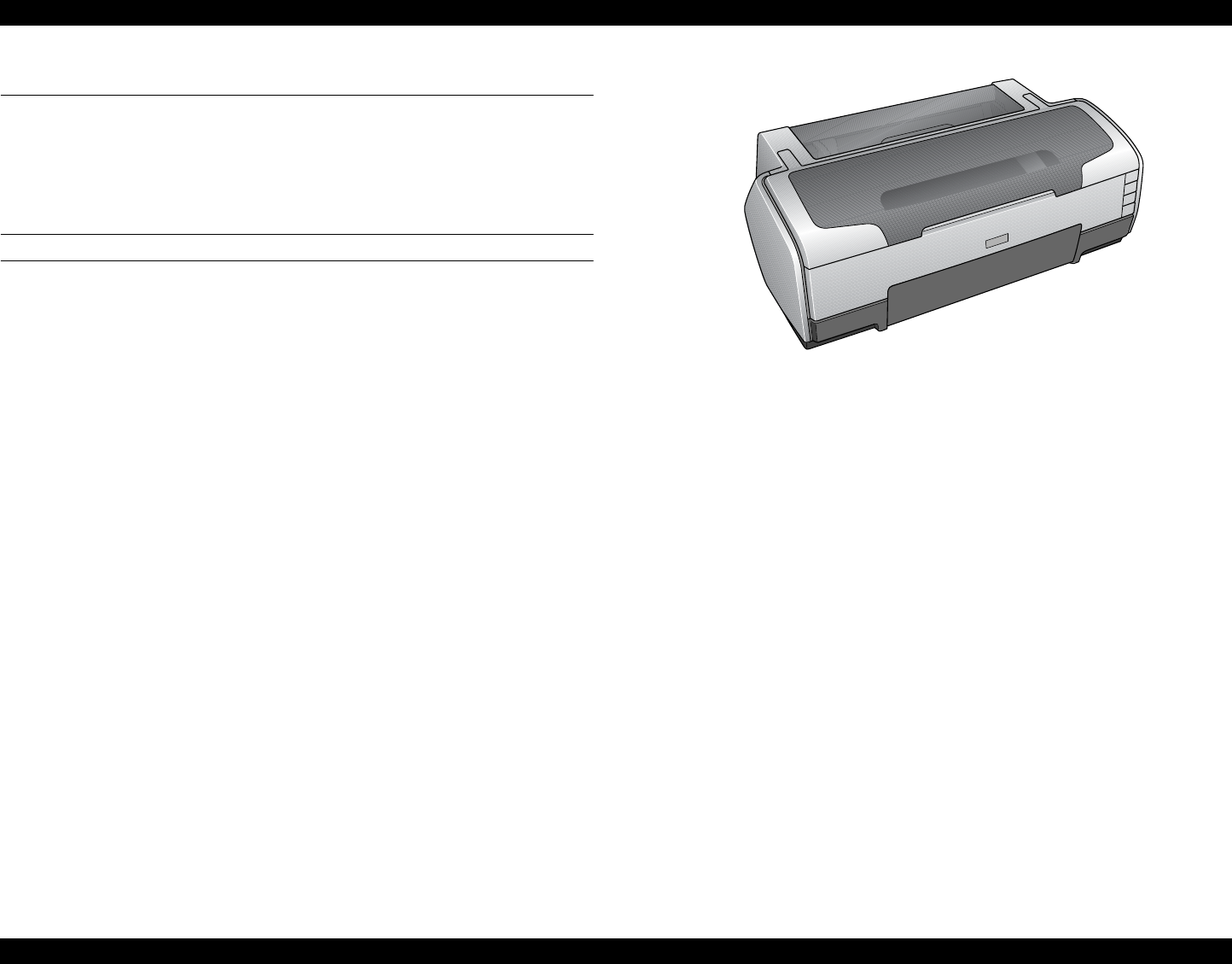
1.1 Overview
The Stylus Photo R1800 is a photo printer designed for a wide range of users
from individual users to commercial users. As a successor to the Stylus Photo
2100/2200, this consumer middle high model is capable of CD-R/DVD-R
printing and roll paper cutter functions.
This product has the following features.
FEATURES
High color print quality
5760 (H) x 1440 (V) dpi printing (Max resolution)
8 color printing
(PPI Black, Photo Black, Cyan, Magenta, Yellow, Red, Violet, Clear)
Pigment Ink supported
Separate Ink Cartridge for each color
Built-in 2 I/F
USB 2.0 (HS compatibility)
IEEE 1394
Windows/Macintosh exclusive
Roll Paper Support
Printable area expand (Bottom margin reduce)
Card printing support
CD-R printing support
Figure 1-1. Product Appearance
EPSON Stylus Photo R1800/R2400 Revision B
Product Description PG Setting 10
1.2 PG Setting
As this printer uses an Auto PG (APG), an appropriate PG position is set according to the used paper type.
The following table indicates the PG positions, the main applications of each position, and the relationships between the two sensors used with the APG.
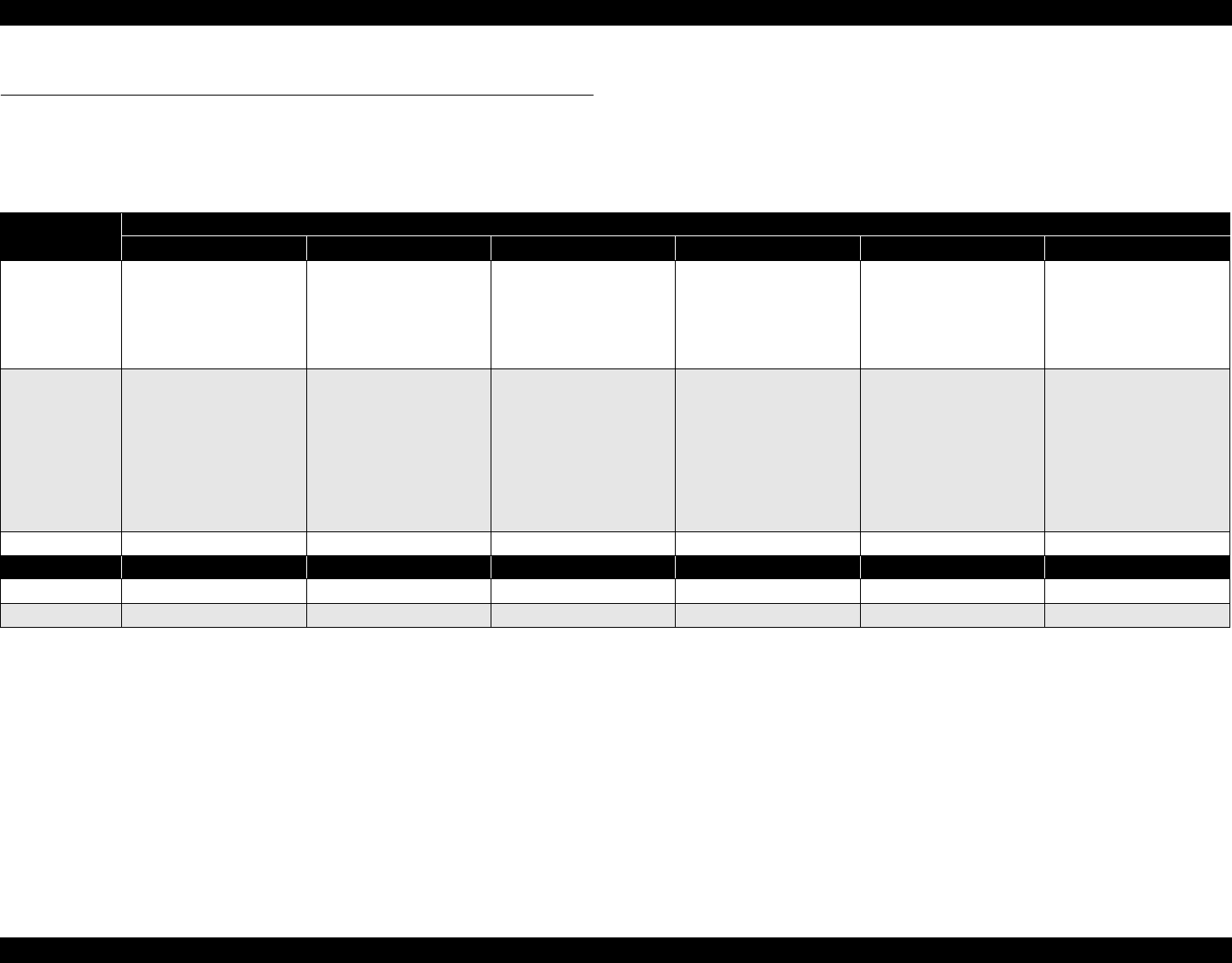
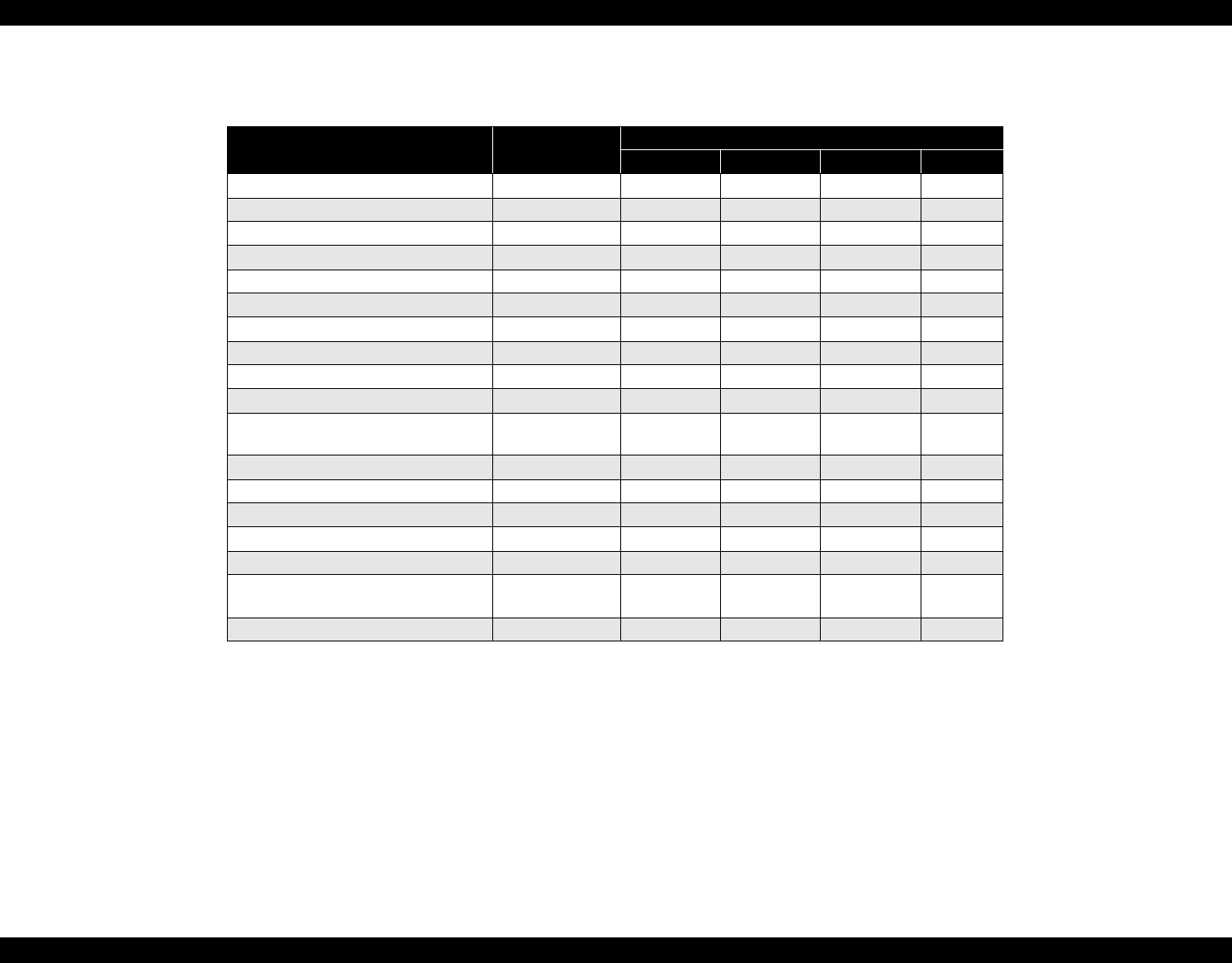
Table 1-1.
Application PG Position
PG (– –) PG (–) PG (Typ) PG (+) PG (++) Release
Printing • PGPP
•A3
•A4
• Exclusive paper • Plain paper
• Photo Album paper
• Photo Matte paper A3
fine
• PG (-) rub avoidance
• Envelope
• PG (Typ) rub
avoidance
• CD-R
• Photo stand paper
–
Non-printing
– –
• Standby position after
power-on (For bottom
stacker)
• At power-off
• The Ink Mark Sensor
operates. (Auto Bi-D,
Detection of dot
missing)
–
• Initialization at power-
on
• Cleaning (wiping)
• Replace the Ink
Cartridge
• Waiting for CD-R/
Board paper to be fed
• Paper jam removal
PG value 1.15mm 1.3mm 1.7mm 2.1mm 4.5mm –
Sensor PG (– –) PG (–) PG (Typ) PG (+) PG (++) Release
APG Sensor 1 OFF OFF OFF OFF OFF OFF
APG Sensor 2 ON ON ON ON OFF OFF
EPSON Stylus Photo R1800/R2400 Revision B
Product Description Functions 11
1.3 Functions
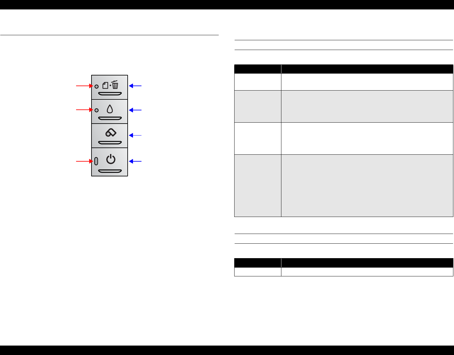
1.3.1 Control Panel
The appearance of the control panel is shown below.
Figure 1-2. Control Panel Appearance
1.3.2 Switches
Power switch
Paper switch
Ink switch
Roll paper switch
1.3.3 Indicators
Power LED : Green
Paper LED : Red
Ink LED : Red
1.3.4 Switch Functions
FUNCTIONS IN NORMAL STATUS
FUNCTION AT POWER-ON
Note "*1": Status printings prints firmware version, ink counter and nozzle check
patterns.
Roll paper switch
Ink switch
Paper switch
Power switch
Ink LED
Paper LED
Power LED
Table 1-2. Normal-status Functions
Switch Function
Power switch • Power On / Off.
• Panel reset (off and on within 10 seconds).
Paper switch
• Loads or Ejects the Paper.
• When carriage is on the Ink Cartridge change position, return
carriage from Ink Cartridge change position.
• In the condition of printing, cancel the print job.
Ink switch
• Starts the Cleaning of head with 3 second pushing.
• Moves the carriage to cartridge change position.
• When carriage is on the ink change position, return carriage from
Ink Cartridge change position.
Roll paper
switch
• Loads the Roll paper.
• Back out the roll paper with 3 second pushing.
• Move to tear off position / Return from tear off position.
• When cartridge is on the Ink Cartridge change position, return
carriage from Ink Cartridge change position.
• When the photo album is used, ejects the paper forwards only.
(At this mode, the printer can’t move backwards without Top of
Form.)
Table 1-3. Power-on Function
Switch Function
Paper switch Starts status printings.*1
EPSON Stylus Photo R1800/R2400 Revision B
Product Description Functions 12
1.3.5 Indicator Display in Normal Mode
Note: • "–" : Don't care
• Blink : 0.5sec on + 0.5sec off repetition
• Blink 2 : 0.2sec on + 0.2sec + 0.2sec on + 0.4sec off repetition
• Fast Blink : 0.1sec on + 0.1sec off repetition
• Blink alternately 1 : 0.5sec on + 0.5sec off repetition
• Blink alternately 2 : 0.5sec off + 0.5sec on repetition
Note"*1": When the Photo album paper is end, the printer goes to this status.
Table 1-4. Printer Condition and LED Status
Printer status Error status Indicators
Power Paper Ink Priority
Idle – On – – 20
Data processing –Blink – – 19
Pause *1 Status 05h – – – 18
Ink sequence processing –Blink – – 17
Ink cartridge change mode – Blink – – 16
Ink low (warning) – – – Blink 15
Tear off status 11h – – – 14
Paper mismatch Error 0Ch –Fast Blink –12
Paper Out 06h – On – 11
Ink end 05h – – On 10
No Ink cartridge or
Ink cartridge error 05h ––On9
Paper Jam Error 04h –Blink – 8
Card loading error 2Ah – Blink 2 – 7
Cover Open Tray Error 2Bh –Fast Blink Blink 2 13
Reset input – On On On –
Fatal error 00h Off Fast Blink Fast Blink 4
Maintenance request 10h Off Blink
alternately 1 Blink
alternately 2 2
Power off –Fast Blink Off Off 1

EPSON Stylus Photo R1800/R2400 Revision B
Product Description Functions 13
1.3.6 Error Status
If any of the following states is detected, this printer is put in an error status and
turns the interface signal -ERROR "Low" and BUSY "High" to inhibit data input.
At this time, the printer is automatically disabled from printing. However, when
communication is being made using the IEEE1284.4 protocol, communication
with the printer is enabled.
General error
After the cause of this type of error is removed, the printer can resume its
operation from where it stopped due to the error
Fatal error
After the cause of this type of error is removed, the printer cannot return to
normal unless it is powered off and then on again
Table 1-5. General error
Error Status Occurring Condition Resuming Condition
Cover open (tray)
error When the front cover is opened at
ASF, roll paper or photo album
printing mode, the printer goes this
error.
Close the front cover.
Paper mismatch
error If the paper path specified by the
print data is different from the
printer’s real paper path, the printer
goes to this error.
Change the printer’s
paper path to the one
specified by the data.
Paper out When printer fails to load a sheet, it
goes paper out error. Set the paper to the ASF
and push the Paper
switch.
Ink out When the printer runs out the most
part of the ink of any one color, it
warns ink-low and keeps printing.
When the printer runs out the whole
ink of any one color, it stops printing
and indicates ink-out error.
Install the new Ink
Cartridge.
No ink-cartridge When printer detects that ink-
cartridge comes off, it goes this error
mode.
Install the new Ink
Cartridge.
Paper jam • Failure of ejecting a sheet
• Failure of loading a sheet to the
loading position
Remove the jammed
paper.
Card loading error When the card was loaded to the
wrong position, the printer goes this
error.
Set an A4 paper to the
ASF, and press the
paper switch.
If the card couldn’t eject
at your first try, repeat
again the same method.
Table 1-6. Fatal error
Error Status Occurring Condition Resuming Condition
Maintenance
request When the total quantity of ink wasted
through the cleanings and flushing is
reaches to the limit, printer indicates
this error and stops.
Replace the absorber in
the printer enclosure by a
service person.
Fatal errors • CR motor control error
• PF motor control error
• ASF motor control error
• Auto Platen Gap control error
• Head temperature error
• PW sensor error
Turn off and turn on.
Table 1-5. General error
Error Status Occurring Condition Resuming Condition
EPSON Stylus Photo R1800/R2400 Revision B
Product Description Casing Specifications 14
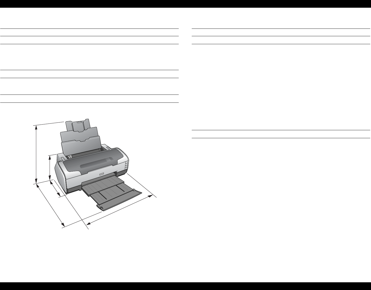
1.4 Casing Specifications
EXTERNAL DIMENSIONS
When tucked : 615 (width) x 314 (depth) x 219 mm (height)
When used : 615 (width) x 453 (depth) x 737 mm (height)
WEIGHT
11.7 kg (without the Ink Cartridges, Roll paper holder and CD-Tray)
EXTERNAL DIMENSION DIAGRAM
Figure 1-3. External Dimension Diagram
1.5 Accessories
STANDARD ACCESSORIES
User’s guide
Ink Cartridge (one for each of 8 colors)
Setup Sheet
Power Cord
Software CD-ROM
CD-R Print Position Check sheet
Roll Paper Holder
8-cm CD/DVD adapter
CD/DVD tray
CONSUMABLES AND OPTIONS
Ink Cartridges
Gloss Optimizer : T0540
Black : T0541
Cyan : T0542
Magenta : T0543
Yellow : T0544
Red : T0547
Matte Black : T0548
Blue : T0549
802.11g Radio printing adapter : PA-W11G
615
314
453
219
737

CHAPTER
2
OPERATING PRINCIPLES
EPSON Stylus Photo R1800/R2400 Revision B
Operating Principles Overview 16
2.1 Overview
This chapter explains the operating principles of the mechanical sections and
electrical circuits in this product. The main components of this product are as
follows.
Control circuit board : C589 MAIN
Power supply circuit board : C589 PSB
Control panel board : C589 PNL
Control panel B board : C589 PNL-B
2.2 Printer Mechanism
Like the conventional model, this product uses DC motors and stepping motors
as power sources. The following table describes the motor types and their
applications.
The basic mechanism is almost same as the Stylus Photo R800.
The most major difference is that this Stylus Photo R1800 is equipped with a
dedicated sensor to detect a open or close status of the Front Cover.
This prevents the Print Head from damaging by mistake.
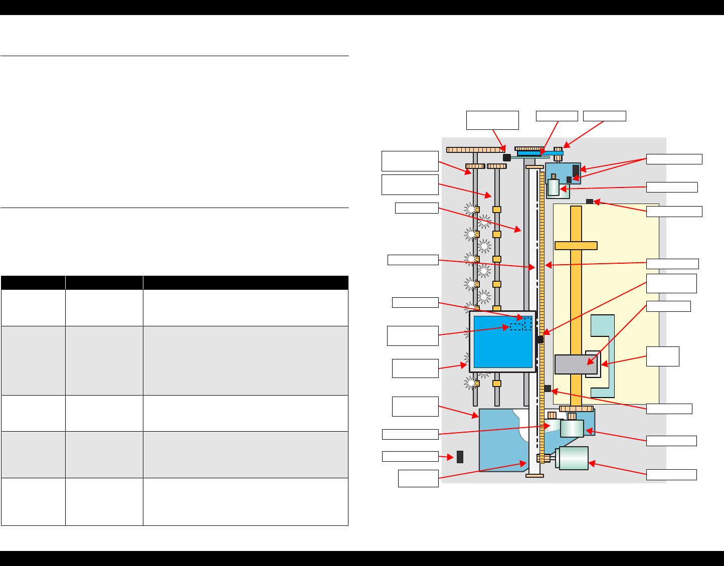
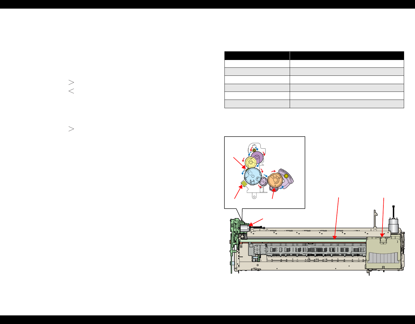
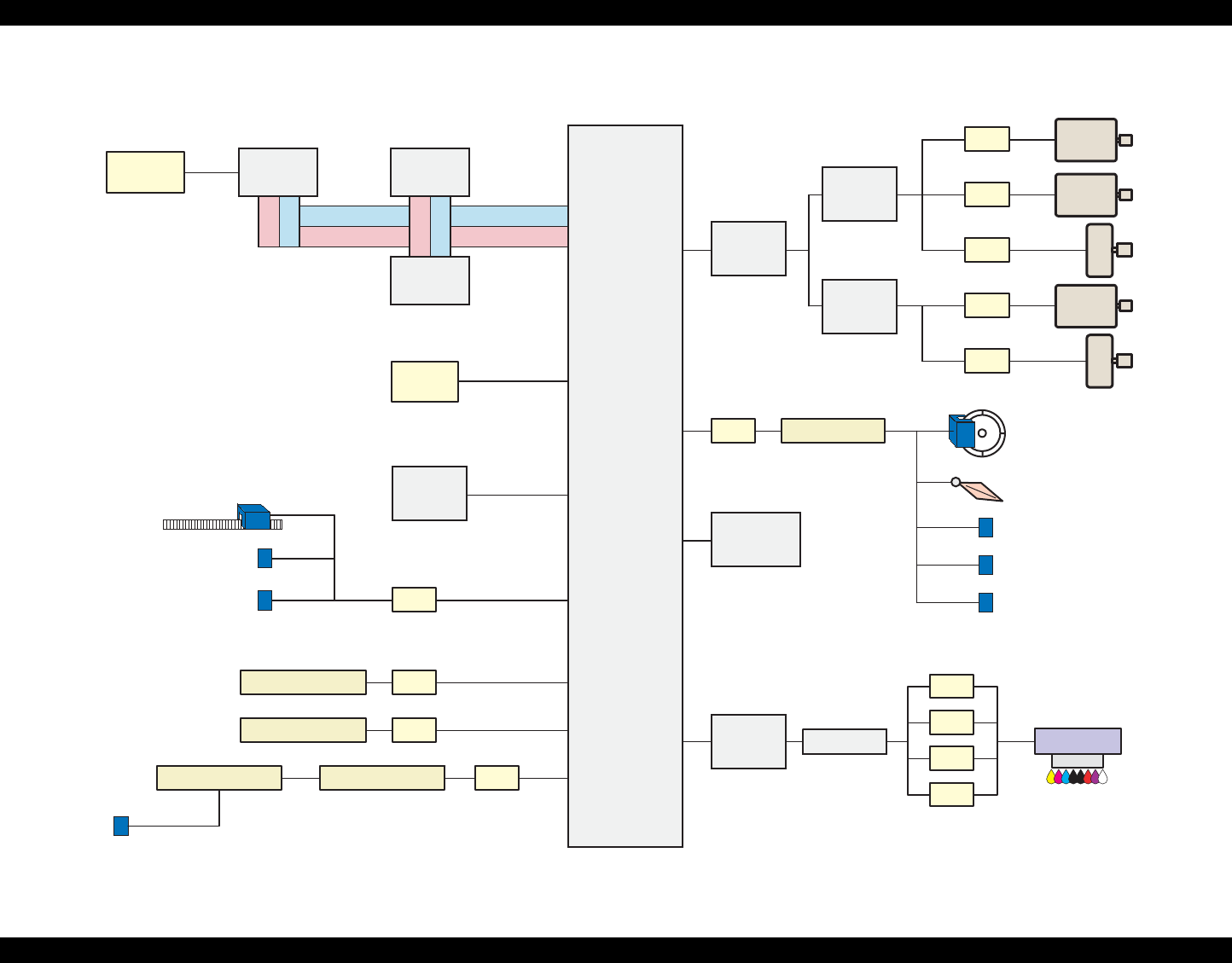
The schematic diagram below shows the printer mechanism.
Figure 2-1. Printer Mechanism Outline
Table 2-1. Motors
Motor Name Type Applications/Functions
CR Motor DC motor with
brushes
Used for carriage driving. Makes little noise
during driving. The CR linear scale and CR
encoder sensor are used to control the motor.
PF Motor DC motor with
brushes
Drives the Paper loading rollers at the time of
fixed-value paper loading or paper feed/eject
operation. To grasp the paper feed pitch, the
precision gear surface is fitted with the PF scale
and the PF encoder sensor is used to control
the motor.
APG Motor DC motor with
brushes
Drives the Carriage Unit at the time of PG
setting. The two APG Sensors and Carriage
Shaft are driven vertically to control the motor.
ASF Motor 4-phase, 48-pole
PM type
stepping motor
Drives the paper feed operation of the ASF.
Since this is a stepping motor, any scales or
photo sensors to know the driving conditions are
not required.
Pump Motor 4-phase, 48-pole
PM type
stepping motor
Drives the pump, wiper, etc. of the Ink System.
Since this is a stepping motor, any scales or
photo sensors to know the driving conditions are
not required.
Rear Paper
Eject Roller
Front Paper
Eject Roller
Ink Mark
Sensor
PW Sensor
CR Scale
PF Roller
PF Encoder
Sensor PF Scale PF Motor
Carriage
Unit
Ink System
Unit
Pump Motor
CD-R Sensor
Carriage
Shaft
APG Sensors
APG Motor
APF Sensor
Timing Belt
CR Encoder
Sensor
LD Roller
Retard
Roller
PE Sensor
ASF Motor
CR Motor
EPSON Stylus Photo R1800/R2400 Revision B
Operating Principles Printer Mechanism 17
2.2.1 Carriage Mechanism
The Carriage mechanism consists of the Carriage Motor (CR Motor), Carriage
Shafts, Platen Gap Adjustment Mechanism, Carriage Lock Mechanism, and
others.
2.2.1.1 Carriage Mechanism
The following indicates the specifications of the CR motor (DC motor) that
drives the Carriage.
Closed loop control based on the CR Motor (DC Motor) and CR Encoder
Sensor has advantages in stabilized print quality and silent operation.
Heat Generation Control
The printer has a machanism to reduce the variations in the torque
constant and coil resistance of the DC motors, and variations in output
voltage of the Power Supply Board to obtain a designated heating value.
CR Variation Measurement Sequence
The variations mentioned above are measured in a CR variation
measurement sequence when the CR mechanical load is in the initial
status and saved into the EEPROM (A6<H>). According to the saved
information, the printer controls the drive voltage to obtain a designated
driving current. This minimizes the unit-to-unit variation.
CR Measurement Sequence
To set the appropriate drive current value according to the CR mechanical
load, the mechanical load is measured in a CR measurement sequence
and saved into the EEPROM A4<H>, A5<H> at power-on or after
replacement of the Ink Cartridge (s). However, if 6E is saved at the
EEPROM A4<H> and 05 at A5<H>, Fatal error will occur since too large
load is applied to the CR drive system.
The above control and sequences correct the drive current value of the CR
Motor according to not only the mechanical load but also the variations of the
motor and like. In addition, the resultant CR drive current value is used to
calculate a heating value, and when the specified heating value is reached,
wait time is provided per CR path for printing.
Table 2-2. CR Motor Specifications
Item Specifications
Type DC motor with brushes
Drive voltage +42V ± 5% (voltage applied to driver)
Armature resistance 29.2Ω ± 10%
Inductance 30.0mH ± 25%
Drive method PWM, constant-current chopping
Drive IC A6628

EPSON Stylus Photo R1800/R2400 Revision B
Operating Principles Printer Mechanism 18
2.2.1.2 Carriage Home Position Detection
As in the conventional model, the Carriage Home Position is detected using the
drive current of the CR Motor and the speed/position signal of the CR Linear
Encoder.
The basic home position detection sequence is as described below.
1. The CR linear encoder pulse counter in the CPU is reset by the
initialization operation performed at power-on.
2. When the CR Motor rotates counterclockwise, the Carriage Unit moves
from left to right. When the following conditions are satisfied, the CPU
assumes that the Carriage Unit made contact with the right frame.
The ASIC detects 1158/1500 counts or more in the PWM output under
CR Motor load positioning control.
P1 (number of output pulses from when power is switched on until the
Carriage Unit makes contact with the right frame) is 19 steps or less.
3. When the CR Motor rotates clockwise, the Carriage Unit moves from right
to left. When the following conditions are satisfied, the CPU assumes that
the Carriage Unit reached the CR lock confirmation position.
The ASIC detects 575/1500 counts or more in the PWM output under
CR Motor load positioning control.
A difference between P1 and P2 (number of output pulses from when
the Carriage Unit made contact with the right frame until it reaches the
Carriage lock confirmation position) is 19 steps or less.
4. When the CR Motor rotates counterclockwise to move the Carriage from
left to right and the CPU detects 1158/1500 counts or more in the PWM
output under CR Motor load positioning control, the printer judges that the
Carriage moved to the far right position (is in contact with the right frame ).
5. When a difference between P1 and P3 (number of output pulses from
when the Carriage Unit reached the Carriage lock confirmation position
until it makes contact with the right frame) is 4 steps or less, the printer
judges that the Carriage Unit is in the home position.
The IC14 (ASIC) sets the drive current value adequate for the Carriage Unit
motion and outputs it to the motor driver.
Based on the signal output from the IC14 (ASIC), the IC5 (Motor Driver)
outputs the CR Motor drive current to the CR Motor.
2.2.1.3 Sequence Used for PW Detection
The PW (paper width detection) Sensor installed on the Carriage Unit bottom is
used to control the printer according to various sequences.
The following briefly describes the PW Sensor operating principle.
A dark voltage is measured by the PW Sensor in three places at the right flat
area (area without the absorber) on the Front Paper Guide every time the
printer is turned on, and the measurement values are saved into the EEPROM
as threshold values.
Threshold value detection voltage: Paper present
Threshold value detection voltage: Paper absent
The following sequences are performed.
Detection of Left and Right Edges of Paper and Control
Before Printing
The printer detects that paper has been loaded. And it sets the print
range according to the paper-size information from the Driver and the
actual paper-size detected by the PW sensor.
During Printing
When executing a borderless printing, the printer sets the off-range
margins by detecting the paper edges with the PW Sensor. And when
the resolution is 1440 x 1440 (VSD3) or 2880 x 1440 (VSD3) dpi, the
printer performs the Off-Range Thinning Out Control to make a further
correction to the off-range margins.
Detection of Top Edge of Paper and Control
Before starting a print job, the printer detects the top edge of a loaded
single sheet of paper, roll paper, or board paper to set the off-range top
margin. (Only when not detecting the top edge of paper with the PW
Sensor.)
Detection of Bottom Edge of Paper and Control
After starting a borderless printing, the printer sets the off-range bottom
margin.
Detection of Edges of CD-R and Control
Before starting to print, the PW Sensor detects top, bottom, left and right
edges of the CD-R. See Section 2.2.3.4 CD-R Printing Mechanism on
page 24.
EPSON Stylus Photo R1800/R2400 Revision B
Operating Principles Printer Mechanism 19
PW sensor dark voltage (VH) measurement
PW sensor dark voltage (VH) measurement is performed at the following
timings and locations and used to calculate the threshold value of whether
paper is present or not.
Cut sheets, Roll paper
The dark voltage is measured and updated at every power-on, and the
threshold value (VS) is calculated and saved in the EPROM area as a
PW detection level.
•Threshold value detection voltage: Paper present
•Threshold value detection voltage: Paper absent
CD-R Tray
When printing on a CD-R, the dark voltage is measured on the CD-R
tray, and the threshold value (VS) is then calculated and saved in the
EPROM area as a PW detection level.
•Threshold value detection voltage: CD-R present
(tray home position detected)
The measurement voltage in the presence of the CD-R is saved into
the EEPROM as a white level. The white level value is used to check
the sensor deterioration condition during servicing or like.
• If the measurement value of the white level is close to that of the PW
detection level, it means that the sensor is dirty or deteriorated.
2.2.1.4 APG (Auto PG) Mechanism
The following indicates the specification of the DC motor that drives the APG.
The APG Motor (DC Motor) and two APG Sensors drive the PG Cam to
automatically adjust the PG amount according to the paper.
Figure 2-2. APG Mechanism
Table 2-3. APG Motor Specifications
Item Specifications
Type DC motor with brushes
Drive voltage +42V ± 5% (voltage applied to driver)
Armature resistance 64.7Ω ± 15%
Inductance 37.6mH ± 25%
Drive method PWM, constant-current chopping
Drive IC A6628
Carriage Shaft Carriage Unit
APG Motor
PG CamAPG Sensor
APG
Sensor
EPSON Stylus Photo R1800/R2400 Revision B
Operating Principles Printer Mechanism 20
2.2.2 Printhead Specifications
The Printhead of this product is a F-Mach head.
The following shows the arrangement of the nozzles and the color
arrangement of each nozzle line when viewed the Print Head from behind.
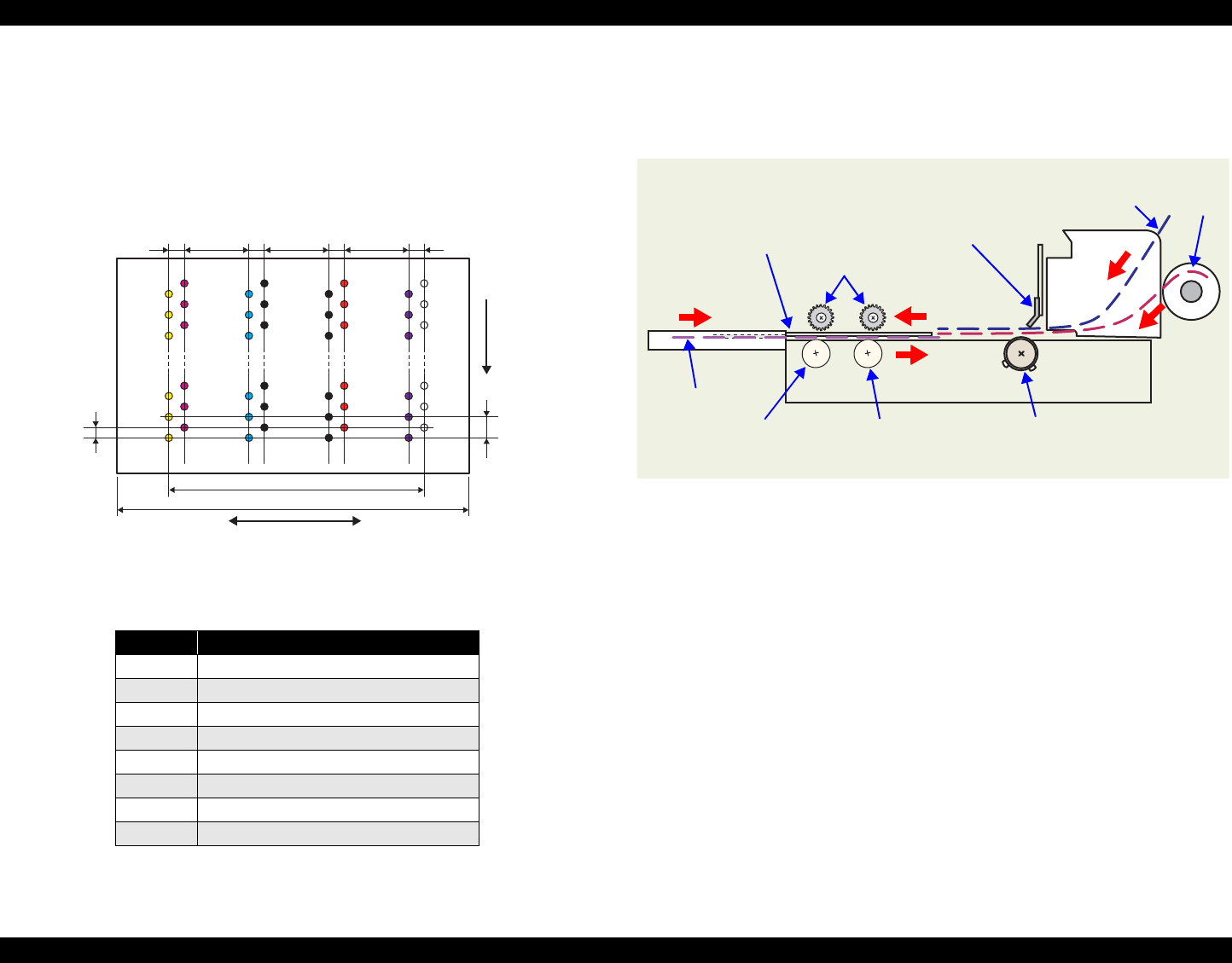
Figure 2-3. Nozzle Arrangement
2.2.3 Paper Feeding Mechanism
The paper feeding mechanism is a mechanism that feeds paper or CD-R Tray
to the PF Roller Shaft.
Figure 2-4. Paper Feeding Mechanism
Table 2-4. Nozzle Lines and the Corresponding Ink Color
Line Ink
AYellow
BMagenta
CCyan
DMatte-black
E Photo-black
FRed
GBlue
HGloss Optimizer
31.89mm
41.66mm
Carriage moving direction
Paper feeding
direction
0.071mm
(1/360inch)
0.141mm
(1/180inch)
Line A Line B
7.620mm
(216/720inch)
2.258mm
(64/720inch) 2.258mm
(64/720inch) 2.258mm
(64/720inch) 2.258mm
(64/720inch)
7.620mm
(216/720inch) 7.620mm
(216/720inch)
Line C Line D
Line E Line F
LineG Line H
CD-R Tray
Front Paper Eject Roller Rear Paper Eject Roller PF Roller
Star Wheel Rollers
PE Sensor
Cut sheet Roll paper
Board paper
EPSON Stylus Photo R1800/R2400 Revision B
Operating Principles Printer Mechanism 21
2.2.3.1 ASF Paper Feeding Mechanism
The following shows the specifications of the stepping motor that drives the
ASF Assy.
Driven by the ASF Motor, the ASF Assy performs the following feeding
operation.
1. When a paper feeding command is issued from the PC or the Paper Switch
of the panel is pressed after power-on, the driving force of the ASF Motor
begins to be transmitted to the LD Roller following the route shown below.
2. When the LD Roller starts rotating, the Flag of the ASF Sensor Wheel
comes free from the notch on the ASF Sensor. And at the same time, the
Paper Back Lever becomes free from the Cams located at the left and right
ends of the LD Roller, then the Paper Holder on the Paper Back Lever
inclines downward by tensile force of the Paper Back Lever Torsion Spring.
3. By the LD Roller's rotation, the Hopper is released from the Hopper Cams
located at the left and right ends of the LD Roller, and the Hopper pops up
by tensile force of the Hopper Compression Spring.
4. When the next sheet of paper is fed by the LD Roller and the Retard Roller,
the Hopper is pressed against the Frame again by the Hopper Cams. And
the Paper Holder of the Paper Back Lever rises by the Cams at the left and
right ends of the LD Roller to prevent the next sheet from being fed with the
previous sheet.
5. The LD Roller stops to rotate when it makes one revolution and the Flag of
the ASF Sensor Wheel returns to the ASF Sensor.
Table 2-5. ASF Motor Specifications
Item Specifications
Type 4-phase, 48-pole PM type stepping motor
Drive voltage +42V ± 5% (voltage applied to driver)
Winding resistance 7.0Ω ± 10% (per phase at 25°C)
Inductance 10.2mH ± 20% (1kH, 1Vrms, 25Åé)
Drive method Bipolar drive/constant-current drive
Drive IC A6628
ASF Motor
Combination Gear 29, 11
LD Shaft Spur Gear
LD Roller
EPSON Stylus Photo R1800/R2400 Revision B
Operating Principles Printer Mechanism 22
Figure 2-5. ASF Paper Feeding Mechanism
2.2.3.2 Roll Paper Feeding
When selecting the Roll Paper Mode, the contol Panel switches function in
different ways from when printing other than roll paper. This section describes
the deifference.
1. The roll peper is fed into the printer after a lapse of three seconds from
when the PE sensor detects the paper.
2. The roll paper is fed backward to be set at the print position.
While the printer is performing the above operation, the switches are disabled.
After the roll peper is set to the print position, the switches operation becomes
defferent from when printing other than roll paper.
The details of the difference are described below.
When Loading Roll Paper.
Pressing the Roll Paper Switch for more than 3 seconds feeds the leading
edge of the roll paper backward to the PE Sensor (the Paper LED flashes).
In this state, draw the roll paper and press the Paper Switch to return the
panel operation to the normal mode that enables paper feeding from the
ASF.
When Received a Print Job for Roll Paper
1. After finished the print job, press the Roll Paper Switch.
2. A cutoff line is printed, and the roll paper is fed to the roll paper cut
position.
3. After cutting the roll paper with a pair of scissors or like, press the
Roll Paper Switch again. This returns the leading edge of the
paper to the print starting position.
ASF Motor
ASF
Sensor Combination
Gear 29.11
LD Shaft
Spur Gear
Relay Board
ASF Sensor
Wheel
Standby State Feeding Paper
LD Roller
Hopper
Hopper
Compression
Spring
Retard
Roller
Paper
Paper Back Lever
LD
Roller
Cam
Paper Back Lever
Torsion Spring
EPSON Stylus Photo R1800/R2400 Revision B
Operating Principles Printer Mechanism 23
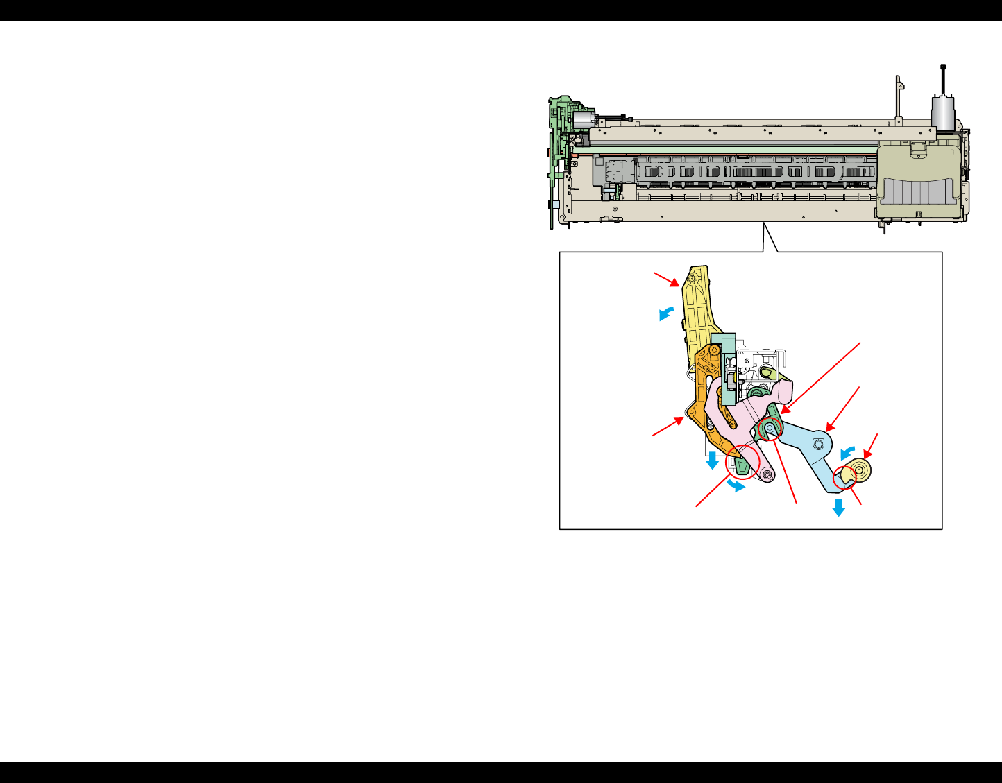
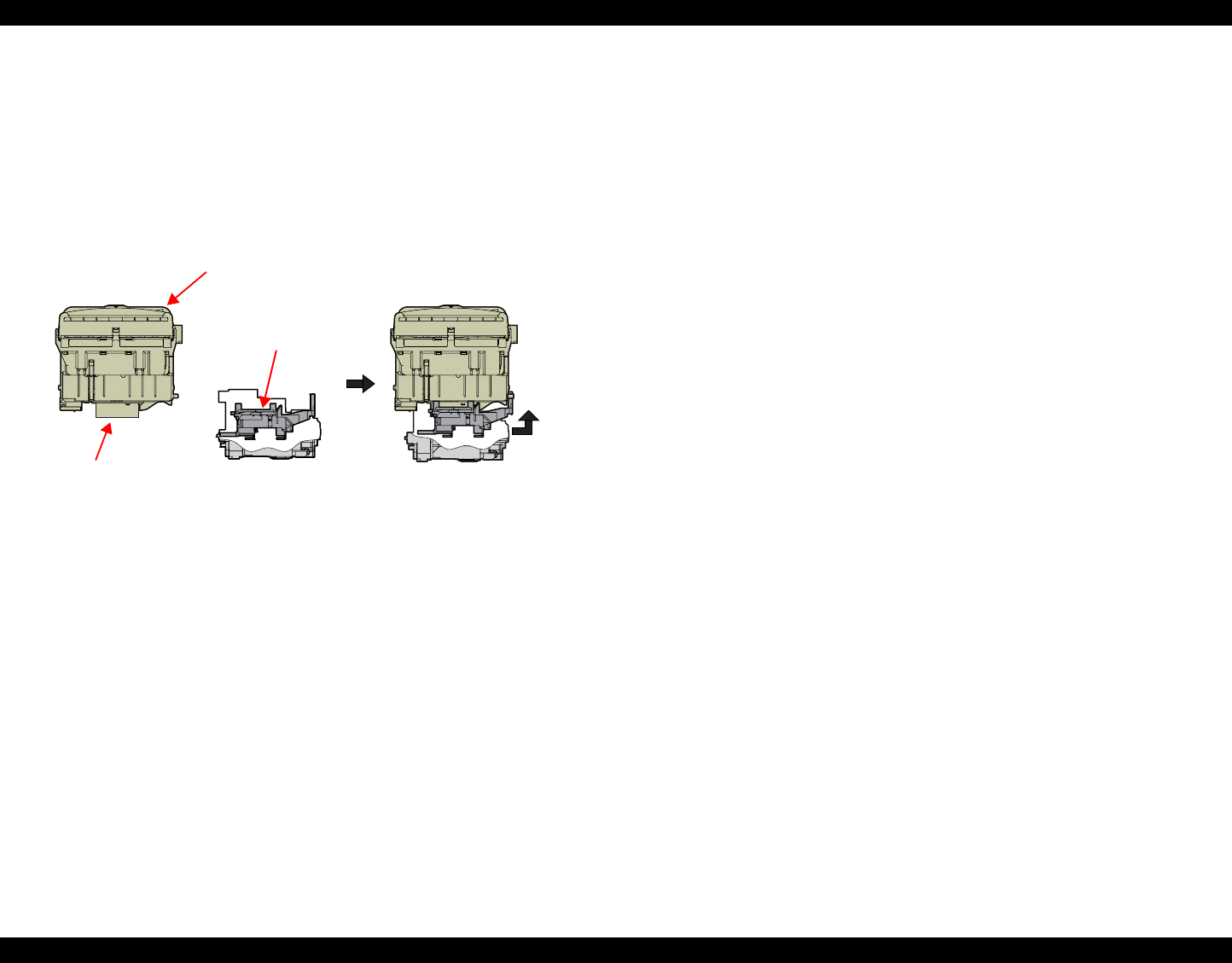
2.2.3.3 CD-R Tray Base Lock Mechanism
To prevent the Print Head from being damaged by mistake, the printer is
designed to lock the CD-R Tray Base when the Carriage Unit is out of its home
position.
The following explains the lock mechanism of the CD-R Tray Base.
Lock Release Sequence
1. When the Carriage Unit returns to its home position, the Pump
Motor drive is transmitted to the Paper EJ Lock Release Cam.
2. The salient of the Cam presses down the Paper EJ Transmission
Lock Lever to release the tab of the Paper EJ Lock Lever from the
Paper EJ Transmission Lock Lever.
3. The CD-R Release Lever comes free from the Paper EJ Lock
Lever and comes down to enable the CD-R Tray Base to open.
When the Carriage Unit is out of its home position, the salient of the Paper EJ
Lock Release Cam does not press down the Paper EJ Transmission Lock
Lever, and the tab of the Paper EJ Lock Lever is not released. Therefore, the
CD-R Tray Base cannot be opened.
Figure 2-6. CD-R Tray Base Lock Mechanism
CD-R Tray Base
Paper EJ
Lock Release
Cam
Salient
Paper EJ
Transmission
Lock Lever
Paper EJ
Lock Lever
Jointed positionTab
CD-R Release Lever
EPSON Stylus Photo R1800/R2400 Revision B
Operating Principles Printer Mechanism 24
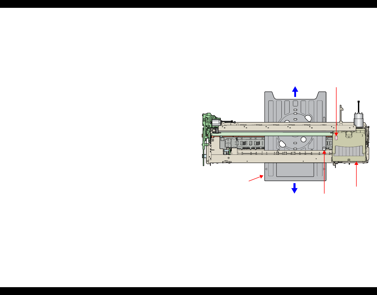
2.2.3.4 CD-R Printing Mechanism
CD-R Tray Home Position Detection Sequence
The following sequence is performed after opening the Front Cover (CD-R
Sensor closing), inserting the CD-R Tray to the specified position, and
pressing the Paper SW.
When the close signal of the CD-R Sensor is detected, no paper is fed
from the ASF if the Paper Switch is pressed. In this case, the Paper Switch
executes a CD-R Tray home position detection sequence.
1. When the APG Assy is driven, the PG position is set to "++" and
the Driven Roller of the Upper Paper Guide presses the CD-R
Tray.
2. When the Carriage Unit moves leftward and the PW Sensor
detects the CD-R, the Carriage Unit returns to its home position
(HP).
3. After waiting for about 5 seconds at the HP, the Carriage Unit
moves to the CD-R Tray HP detectable position (right end of the
CD-R Tray).
4. The CD-R Tray is pulled in the ASF direction, the PW Sensor
detects the CD-R Tray HP, and then the Carriage Unit moves to
the center of the CD-R Tray.
5. When the PW Sensor detects the white marking in the center of
the CD-R Tray, the CD-R Tray is fed in the paper ejection
direction.
6. The Carriage Unit moves leftward, the PW Sensor detects the left
side white marking, then the Carriage Unit moves rightward, and
the PW Sensor detects the right side white marking.
7. The Carriage Unit moves to the center of the CD-R Tray, and the
PW Sensor starts detection in the back-and-forth direction of the
CD-R. After the leading edge of the CD-R is detected, the CD-R
Tray is fed in the paper ejection direction, and the trailing edge of
the CD-R is detected. After that, the CD-R Tray is fed to the center
of the CD-R in the paper ejection direction.
8. The Carriage Unit moves leftward, and the PW Sensor starts
detection in the horizontal direction of the CD-R. After the left end
of the CD-R is detected, the Carriage Unit moves rightward, and
the right end of the CD-R is detected.
9. The Carriage Unit moves to the CD-R Tray HP detectable position
and stops there, and then the CD-R Tray is fed in the ASF
direction.
10. When the CD-R Tray stops operating, the Carriage Unit moves to
the carriage HP and stands by.
If the CD-R Tray HP, white marking or CD-R cannot be detected within the
steps predetermined for the CD-R Tray HP detection sequence, the CD-R Tray
is ejected and Paper Out Error is displayed.
Figure 2-7. CD-R Printing Mechanism
Carriage Unit
PW Sensor
CD-R home position
CD-R Tray
EPSON Stylus Photo R1800/R2400 Revision B
Operating Principles Printer Mechanism 25
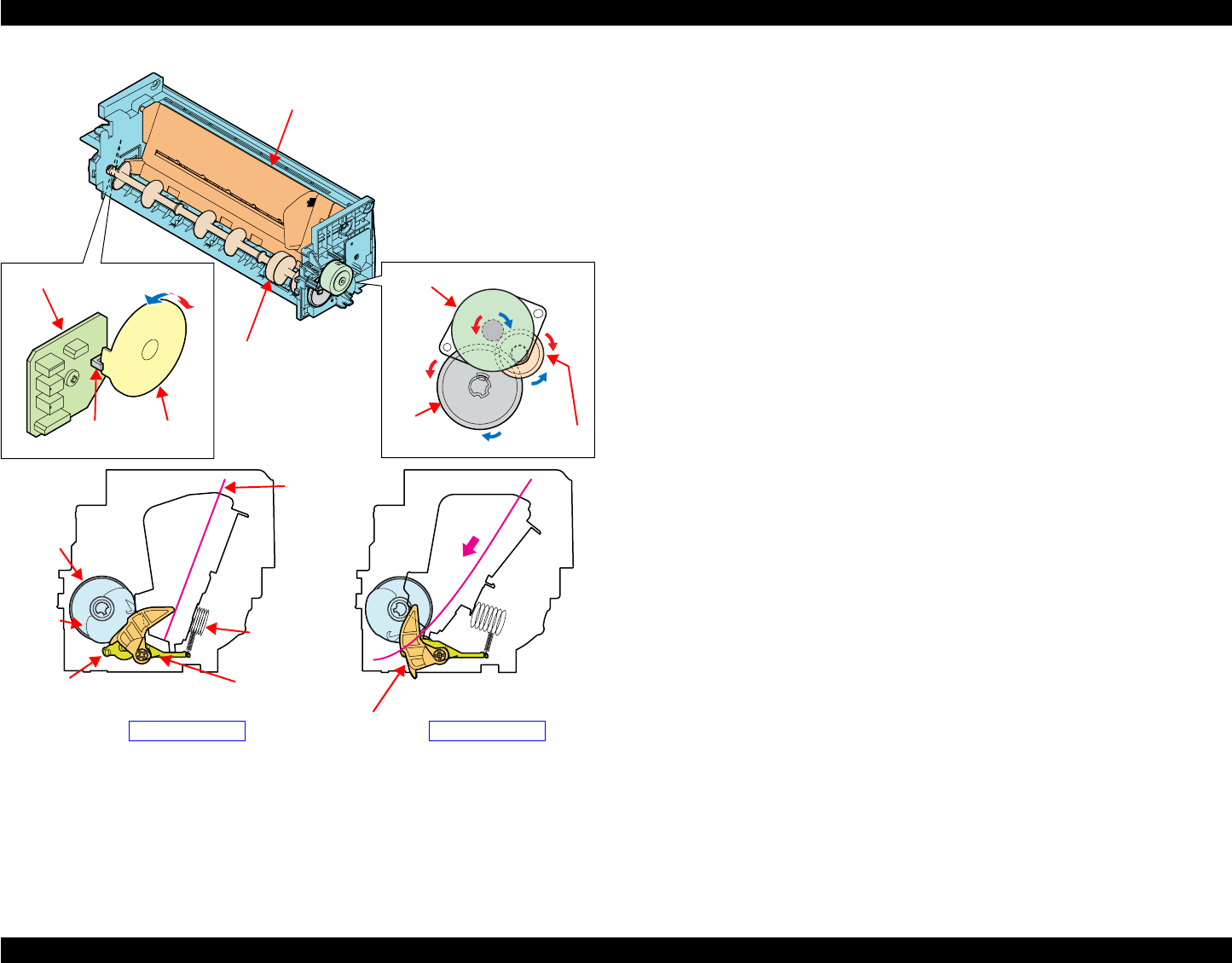
2.2.4 Paper Feeding Mechanism
The Paper Feeding Mechanism is designed to transfer the paper fed from the
ASF, Roll Paper Guide or Board Paper Guide or the CD-R fed from the CD-R
Tray according to the print data.
2.2.4.1 Paper Feeding Mechanism
The following shows the specifications of the DC motor that drives the Paper
Feeding Mechanism.
Like the CR Motor, a DC motor is used as the PF Motor in this product.
Closed loop control based on the DC Motor and Rotary Encoder has the
following advantages.
Improved paper feed accuracy
Paper feed amount control
The PF Motor drive is transmitted to the PF Roller and the Paper EJ Roller
following the route shown below. The route is also followed by the paper.
The following shows the part names and outline of the drive transmission path.
Figure 2-8. Paper Feeding Mechanism
Table 2-6. PF Motor Specifications
Item Specifications
Type DC motor with brushes
Drive voltage +42V ± 5% (voltage applied to driver)
Armature resistance 21.2Ω ± 10%
Inductance 17.2mH (1kHz)
Drive method PWM
Drive IC A6628
PF Motor
PF Timing Belt
PF Roller Spur Gear 31.5
Spur Gear 68
Front Paper Eject Roller Spur Gear 16; B (front)
Spur Gear 15.5
Rear Paper Eject Roller
Combination Gear
36.294, 45.5
Spur Gear 16; B (rear)
Front Paper Guide
PF Roller
PF Motor
Front Paper Eject Roller Rear Paper Eject Roller
PF Timing Belt
Combination Gear
36.294, 45.5
Spur Gear 31.5
Front Paper
Eject Roller
Spur Gear 68
Spur Gear 15.5
Spur Gear 16; B (rear)
EPSON Stylus Photo R1800/R2400 Revision B
Operating Principles Printer Mechanism 26
The fed paper is detected by the PE Sensor, and its leading edge is then
transferred to the front of the Front Paper Guide.
To eliminate the deflection of the paper, the paper is then returned toward the
ASF Assy by the specified number of steps according to the paper feed mode.
The paper is transferred again to the specified paper locating position of the
Front Paper Guide.
2.2.4.2 PF Measurement Sequence
The mechanical load in the paper feeding path is measured in the following
cases to perform control so that an adequate current value is set according
to the mechanical load.
When power is switched on
When the Ink Cartridge is replaced
When the mechanical load in the paper feeding path reaches the specified
value, a Fatal Error is displayed.
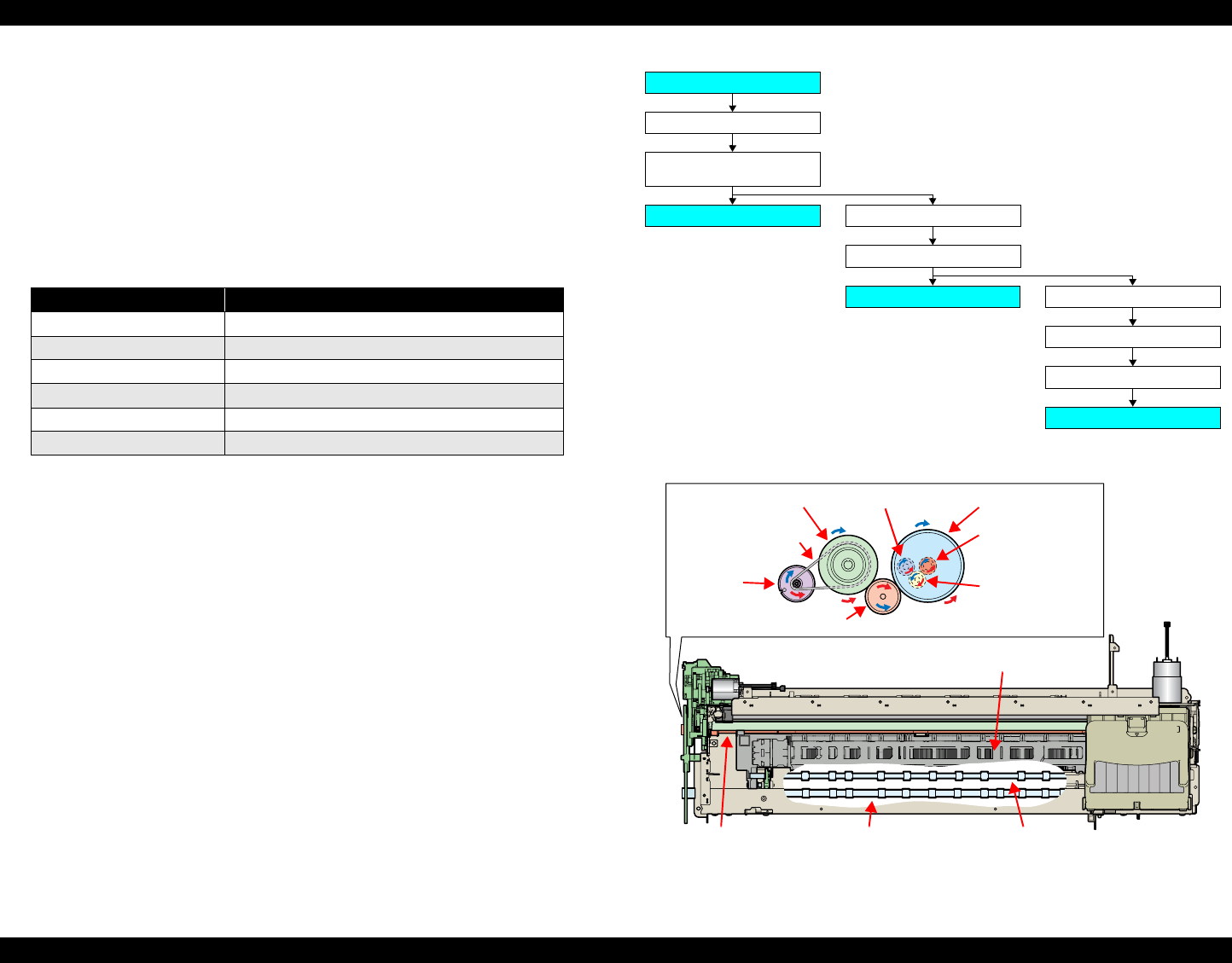
2.2.5 Ink System Mechanism
The Ink System Mechanism consists of the following units.
Pump Unit (including the CR Lock Lever)
Cap Unit
2.2.5.1 Pump Unit
The Pump Unit is designed to suck ink from the Print Head or Cap Unit. The
Cap Unit has a built-in Head Cleaning Wiper.
The following shows the specifications of the stepping motor that drives Pump
Unit.
The following operations are performed when the drive of the Pump Motor is
transmitted to the Pump Unit.
Note "*": The direction (CW or CCW) was determined viewing the motor from the
output shaft of the motor mounting plate.
Table 2-7. Pump Motor Specifications
Item Specifications
Type 4-phase, 48-pole PM type stepping motor
Drive voltage +42V ± 5% (voltage applied to driver)
Winding resistance 10.3Ω ± 10% (per phase at 25°C)
Inductance 13.4mH ± 20% (1kH,1Vrms)
Drive method Bipolar drive/constant-current drive
Drive IC A6628
Table 2-8. Pump Motor Rotation Directions and Functions
Pump Motor Rotation Direction* Functions
CW direction
•Cap closing
• Ink suction
• Wiper resetting
• CR Lock setting
CCW direction
• Cap opening
• Pump release
• Wiper setting
• CR Lock resetting
EPSON Stylus Photo R1800/R2400 Revision B
Operating Principles Printer Mechanism 27
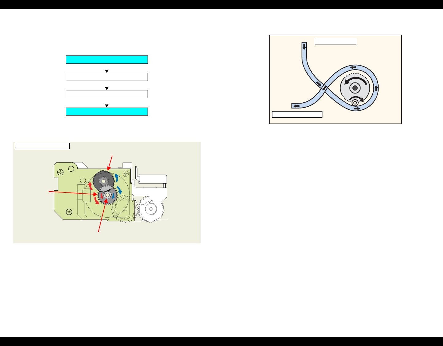
2.2.5.2 Drive Transmission Path to Pump Unit
The drive of the Pump Motor is transmitted to the Pump Unit in the following
path.
The following shows the internal part names and operation outline of the Pump
Unit.
Figure 2-9. Outline of Pump Unit Inside
The following shows the Pump Unit operating principle.
Figure 2-10. Pump Unit Operating Principle
Ink Suction
1. The Pinion Gear of the Pump Motor rotates in the CW direction.
2. The Roller turns and simultaneously presses the tube.
3. Ink is fed from the Cap Unit toward the Waste Ink Pad.
Pump Release
1. The Pinion Gear of the Pump Motor rotates in the CCW direction.
2. The Roller moves away from the tube and releases the tube.
3. Ink is not sucked.
Pump Motor
Combination Gear 10.2, 21.2 IS
Pump Unit
Spur Gear 20.4 IS
Pump Motor and Motor Pinion Gear
<Pump Unit inside>
Combination Gear 10.2, 21.2 IS
Spur Gear
20.4 IS
Cap Unit Side
To Waste ink pad
EPSON Stylus Photo R1800/R2400 Revision B
Operating Principles Printer Mechanism 28
2.2.5.3 Cap Unit
The Cap Unit is designed to make airtight in the Cap sticking fast to the Print
Head surface so that ink suction can be performed by the driving force of the
Pump Unit.
When the printer is in a standby status or its power is OFF, the Cap Unit
prevents the ink from thickening.
The following figures shows the Cap Unit operation.
Figure 2-11. Capping Mechanism
2.2.6 Ink Sequence
The following ink sequence is executed according to various timer, counter,
flag and other information saved on the EEPROM.
CSIC-related sequence
The ink type code stored in the CSIC Memory Chip is saved in the Main
Board EEPROM. At power-on, data is read from each color CSIC and the
CSIC data status becomes valid. If the data read from each CSIC has any
problem, No Ink Cartridge, CSIC Error or Ink Out will be displayed.
After CSIC operation is checked, the ink consumption of the I/C currently
installed per color is compared with the ink consumption saved in the
printer EEPROM, and control is performed under the following conditions.
When the current ink consumption data differs between the Ink
Cartridge and the EEPROM
1. The printer judges that the Ink Cartridge was replaced while the
printer was turned off. Then it resets the 1st I/C flag in the
EEPROM.
2. The printer updates the number of times the CSIC is installed.
3. After incrementing the counter of I/C replacement, the printer
reads the ink consumption data from the CSIC to write it over the
existing data in the EEPROM following the CSIC data replacement
sequence.
4. The printer model name data on the CSIC is rewritten.
Note:The reason why the model name data is rewritten from the printer
to the CSIC is to know for which model was the I/C used at the
time of collecting used I/Cs.
5. The replacement flag 2 (flag that indicates CL after Replacement)
is set and the CL is executed.
Slider cap rises to perform
capping.
Print Head
Cap
Carriage Unit

EPSON Stylus Photo R1800/R2400 Revision B
Operating Principles Printer Mechanism 29
When the current ink consumption data in the Ink Cartridge and that in
the EEPROM is same
1. When the initial filling flag is set and the CSIC ink consumption is 0,
the printer judges that initial filling is not yet performed.
(The printer before initial filling judges that the I/C is fitted in a
power-off status.)
2. Installation count updating, CSIC information rewriting, and initial
filling are executed in that order.
3. If the initial filling flag is not set, the printer judges that I/C(s) has
not been replaced during power-off and regards the current CSIC
data as valid.
Data is written to the CSIC at the following timings.
At power-off
When starting the power saving mode
When replaced an Ink Cartridge(s)
At the time of cleaning
1. Reads the data from the CSIC.
2. Compare the date with the ink consumption data in the EEPROM.
3. If the EEPROM data is same as the CSIC data, ends the
sequence. If they differ, the difference is added to write the sum in
the CSIC.
Initial Ink Filling
When the printer is powered on for the first time after purchase, the printer
executes the initial ink filling operation to fill the ink cavities of the Head
with ink. When the initial ink filling operation is performed properly, the
printer clears the flag in the EEPROM so that initial ink filling operation will
not be performed when it is powered on the next time. The Stylus Photo
R1800 requires about 160 seconds to perform the initial ink filling
operation.
If the sequence does not end normally during initial filling, the initial filling
flag is not cleared and the CL operating flag is set. Because of these flags,
when powered on the next time, the printer assumes that it was powered
off for some reason during initial filling and executes CL3 instead of the
initial filling sequence. (On the conventional mode, initial filling was
executed again. However, when this operation was performed, ink was
wasted and therefore CL3 is executed to cover the ink filling performance.)
When the initial filling flag is set and the CL operating flag is not set, the
printer judges that the initial filling was not executed at all (power was
switched on but the cartridges were not installed), and when the printer is
powered on the next time, it executes initial filling.
Replacement Cleaning
Replacement CL1 is executed when replaced an Ink Cartridge(s).
Amount of Ink Suction
Replacement CL1: 3.09g (0.386g per color)

EPSON Stylus Photo R1800/R2400 Revision B
Operating Principles Printer Mechanism 30
Manual Cleaning
This printer provides three different manual cleanings to remove ink
coagulated by air bubbles, viscous material or foreign matter. Perform the
following manual CL operations by operating the panel or using the utility
included in the printer driver.
Independently of the printing path after the previous CL, perform manual
CL from CL1 to CL3 in order if the cumulative printing timer counter is less
than 7min. Only when the cumulative printing timer counter is more than
7min, execute only CL1.
Amount of Ink Suction
•CL1: 1.55g (0.194g per color)
•CL2: 4.08g (0.510g per color)
•CL3: 6.47g (0.809g per color)
Wiping Operation
Clean the nozzle surface with the right-half rubber part of the wiper.
Flushing Operation
Prevent color mixture. Stabilize the ink surface inside the nozzles.
In addition, the printer determines which CL to perform according to the
remaining amount of ink in the Cartridge. When the printer detects the
amount is low, it automatically choose the CL that uses ink less than the
other CLs. If the remaining amount of ink is extremely low (Ink Low or Ink
Out status), the printer disables the all manual Cleanings and indicates the
status on the EPW3.
Timer Cleaning
Ink is consumed depending on the combination of the cumulative printing
timer, cumulative cleaning count and cleaning timer.
Flushing
There are two types of flushing.
Flushing before printing
This is performed to reduce the viscosity of ink in the Print Head
nozzles before starting to print.
Scheduled Flushing
This is performed to prevent ink in the Print Head nozzles from
increasing its viscosity during printing.
2.2.7 Power-On Sequence
The following describes the printer operation after it is powered on.
When the Carriage Unit is in the Home Position with the CR Locked
1. After power-on, the drive of the APG Motor is transmitted to the Carriage
Shaft, and the PG position changes from PG Typ. to PG++.
2. The drive of the CR Motor is transmitted to the Carriage Unit, and the
Carriage Unit performs HP detection operation in the following path.
Home position ⇒ Right frame ⇒ CR Lock confirmation position
⇒ Right frame ⇒ Home position
3. The drive of the Pump Motor is transmitted to the Cap Unit, the Cap opens
(lowers), and the CR Lock is released.
4. After the Carriage Unit has moved leftward by the specified number of
steps, the Wiper, driven by the Pump Motor, performs the following.
Wiper setting ⇒ Wiper resetting
5. The Carriage Unit returns to the home position, and the PG position
returns from PG++ to PG Typ.
6. The drive of the PF Motor is transmitted to the PF Roller and Paper Eject
Rollers (front and rear), which then rotate for about 2 seconds.
7. After moving between the left and right frames twice, the Carriage Unit
moves to the right end of the Front Paper Guide.
8. The PF Roller and Paper Eject Rollers (front and rear) rotate.
Rotation for about 4 seconds (slow speed) ⇒ Rotation for about 2
seconds
9. The Carriage Unit returns to the home position and is secured by the CR
Lock.
EPSON Stylus Photo R1800/R2400 Revision B
Operating Principles Electrical Circuit Operating Principles 31
When the Carriage Unit is Out of the Home Position
1. When the PG position is other than PG++ after power-on, the drive of the
APG Motor is transmitted to the Carriage Shaft, and the PG position
changes to PG++.
2. The drive of the CR Motor is transmitted to the Carriage Unit, and the
Carriage Unit returns to the home position at slow speed.
3. The drive of the PF Motor is transmitted to the PF Roller and Paper Eject
Rollers (front and rear), which then rotate for about 2 seconds.
4. After the Carriage Unit has moved leftward by the specified number of
steps, the Wiper is set, driven by the Pump.
5. After the Carriage Unit has returned to the home position, it moves leftward
again by the specified number of steps. And, driven by the Pump Motor, ink
is sucked for about 4 seconds and then the Wiper is set, and the CR Lock
is placed.
6. The Carriage Unit performs HP detection operation in the following path.
Home position ⇒ Right frame ⇒ CR Lock confirmation position
⇒ Right frame ⇒ Home position
7. The drive of the Pump Motor is transmitted to the Cap Unit, the Cap opens
(lowers), and the CR Lock is released.
8. The Carriage Unit returns to the home position, and the PG position
returns from PG++ to PG Type.
9. The PF Motor drive is transmitted to the PF Roller and the Paper EJ
Rollers (front and rear) to rotate them for about 2 seconds.
10. The Step 7 to 9 of "When the Carriage Unit is in the Home Position with the
CR Locked (p30)" are performed, and the Carriage Unit is locked.
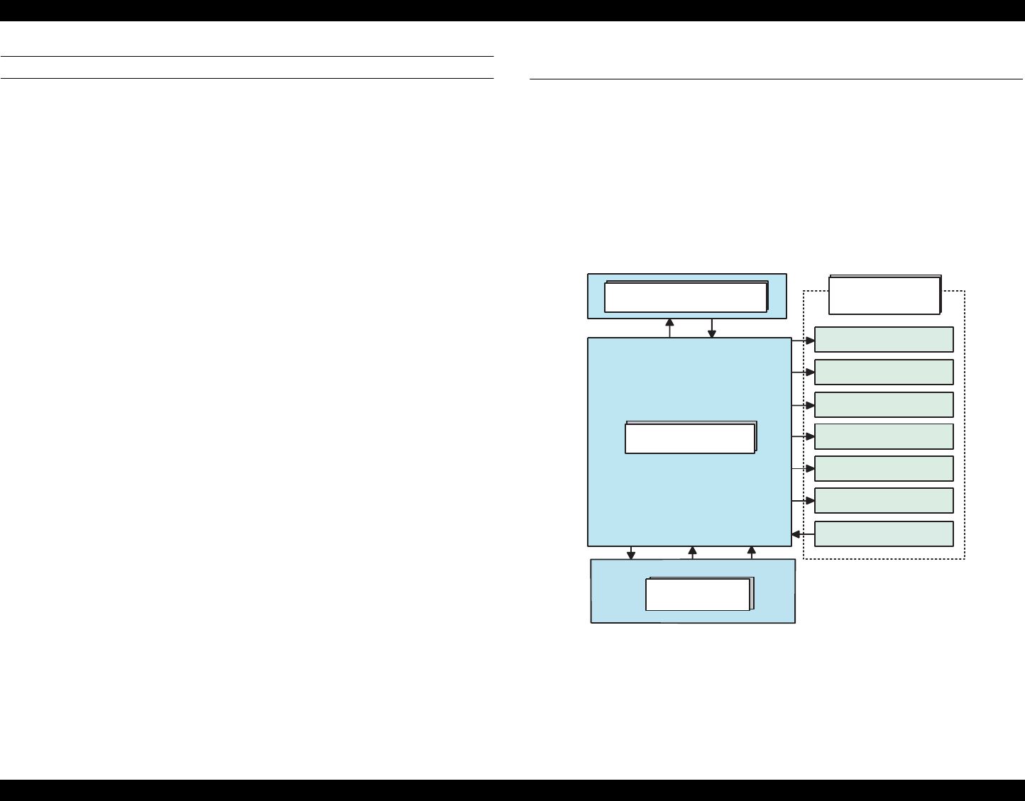
2.3 Electrical Circuit Operating Principles
The electrical circuit of Stylus Photo R1800 consists of the following circuits.
Control circuit board : C589 MAIN
Power supply circuit board : C589 PSB
Control panel board : C589 PNL
Control panel B board : C589 PNL-B
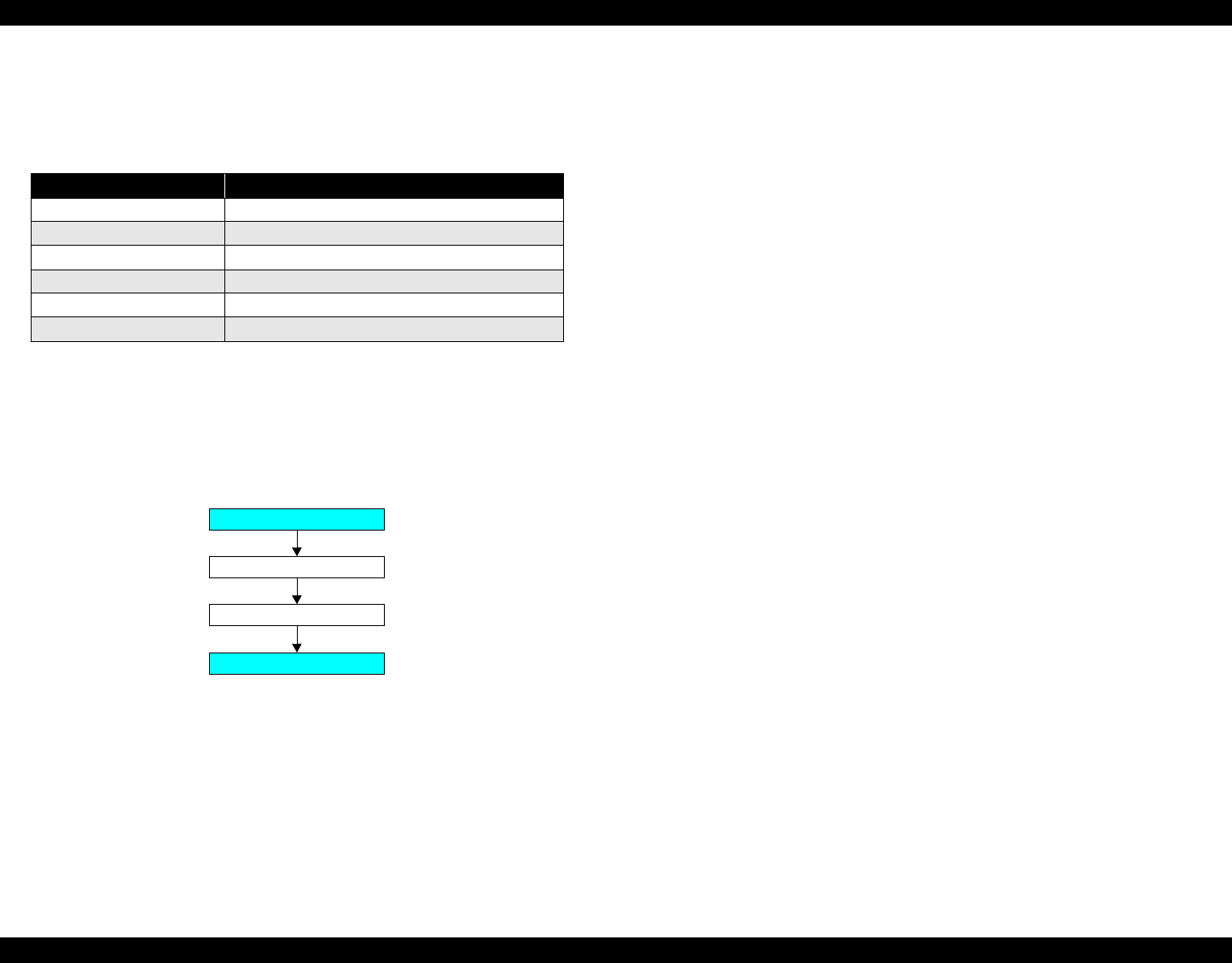
The following shows how the four circuit boards are connected.
Figure 2-12. Electrical Circuit Block Diagram
PNL Board
MAIN Board
PSB/PSE Power
Supply Board
Power OFF +3.3VDC +42VDC
Printer
Mechanism
CR Motor
PF Motor
ASF Motor
Head drive circuit
Sensors
Pump Motor
APG Motor
EPSON Stylus Photo R1800/R2400 Revision B
Operating Principles Electrical Circuit Operating Principles 32
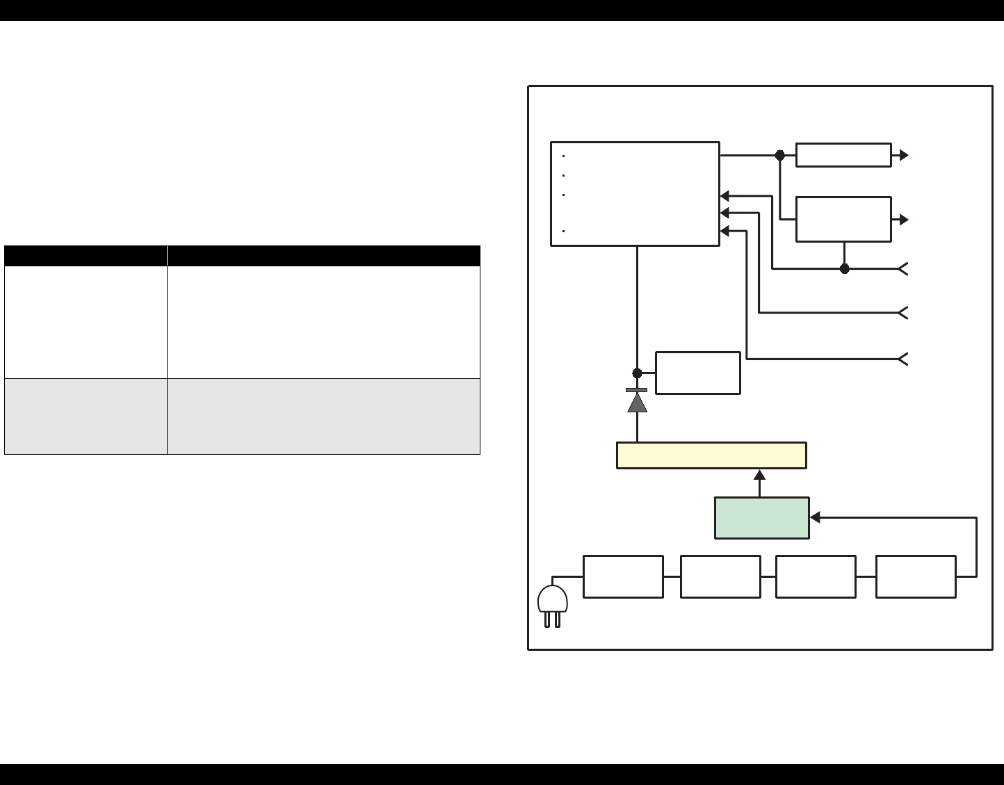
2.3.1 Power Supply Circuit Operating Principle
The power supply circuit board of this product is the C589 PSB.
Basic circuit structure
Flyback switching system
+42VDC and +3.3VDC are supplied to the Printer Mechanism and
Control Board
The following indicates the applications of the voltages generated in this power
supply circuit.
The following is the block diagram of the power supply circuit.
Figure 2-13. Power Supply Circuit Block Diagram
Table 2-9. Supplied Power
Voltage Applications
+42VDC
Rated output current:
0.45A
• CR Motor
•PF Motor
•PG Motor
• ASF Motor
• Pump Motor
• Head drive voltage
+3.3VDC
Rated output current:
0.5A
• Logic sensor circuit
• Sensor circuit
• Nozzle selection circuit (on the Print Head)
• Interface control circuit
C51, C52
C11
D11, D12,
D13, D14
C1, FL1F1, TH1
AC Input
QF1
D51
ESAVE
PSC Signal
+5VDC
+3.3VDC
+42VDC
F51
IC51
Over Current
Protection
TRANS: T1
Smoothing
Circuit
Over Current Limitation
Over Voltage Limitation
Secondary Power
Supply SW function
Low Power mode
Separate-excited
Simulated Resonance
Flyback Converter
Filter Circuit
Full Wave
Rectifier
Circuit
Main Switching
Circuit
Smoothing
Circuit
+3.3V Chopper
Circuit
Fuse for LPS

EPSON Stylus Photo R1800/R2400 Revision B
Operating Principles Electrical Circuit Operating Principles 33
2.3.2 C589 MAIN Circuit Operating Principle
The C589 MAIN Board consists of the following circuits and sensors.
Logic Circuits (CPU-ASIC 2 in 1, PROM, SDRAM)
Circuits for controlling and driving Motors
(CR Motor, PF Motor, APG Motor, ASF Motor, Pump Motor)
Circuits for controlling and driving the Head
Interface Circuits
USB 2.0, IEEE1394
Sensor Circuits
RTC Circuit
DAC Converter Circuit
Low-power Circuit
Logic Circuit Element for 3.3V/1.5V
The +3.3VDC generated on the C589 PSB Board is transformed to +1.5V
by the Regulator IC on the C589 Main Board to use it to drive multiple
components.
This transformation is performed to reduce power consumption of the Logic
Circuit.
The following components operate with the 3.3V/1.5V.
CR Encoder Sensor
PF Encoder Sensor
PW Sensor
Ink Mark Sensor
APG Sensor
PE Sensor
ASF Sensor
Complex Circuit (IC18)
The Complex Circuit (IC18) that consists of EEPROM, RTC, and Reset
circuit is installed on the printer. Employing a large-capacity condenser for
the Timer allows to backup the time recorded at power-off for about a week
after the power-off.
EPSON Stylus Photo R1800/R2400 Revision B
Operating Principles Electrical Circuit Operating Principles 34
The following is the block diagram of the C589 MAIN control board.
Figure 2-14. C589 MAIN Control Board Block Diagram
CPU-ASIC
2 in 1
(IC14)
Data
Address
IEEE 1394
CN3 IEEE 1394
(IC1) PROM
(IC4)
SDRAM
(IC12)
Regulator
(IC8)
USB2.0
CN2
Motor
Driver
(IC5)
Head
Driver
(IC7) Q13, Q14
CN15
PF Encoder Sensor
Print Head
CR Encoder Sensor
CR Motor
CN8
C589 LED Board
CN10
CN7
CSIC Board
C589 PSB Board
RTC
(IC18)
CN9
PW Sensor
Ink Mark Sensor
DAC
(IC2)
Motor
Driver
(IC6)
PF Motor
APG Motor
ASF Motor
Pump Motor
CN5 Relay Board
PE Sensor
ASF Sensor
APG Sensor 1
APG Sensor 2
CN11
CN12
CN13
CN14
CN16
CN17
CN18
CN19
C589 Panel Board
CD-R Sensor

CHAPTER
3
TROUBLESHOOTING
EPSON Stylus Photo R1800/R2400 Revision B
Troubleshooting Overview 36
3.1 Overview
This chapter describes unit-level troubleshooting.
3.1.1 Troubleshooting according to Panel Messages
After checking the printer LED and EPW3 error indications, you can grasp the fault location using the check list in this section. When you find the fault location, refer
to Chapter 4 "Disassembly and Reassembly" and change the corresponding part and/or unit. The following table indicates the check point reference tables
corresponding to the error states (LED and EPW3).
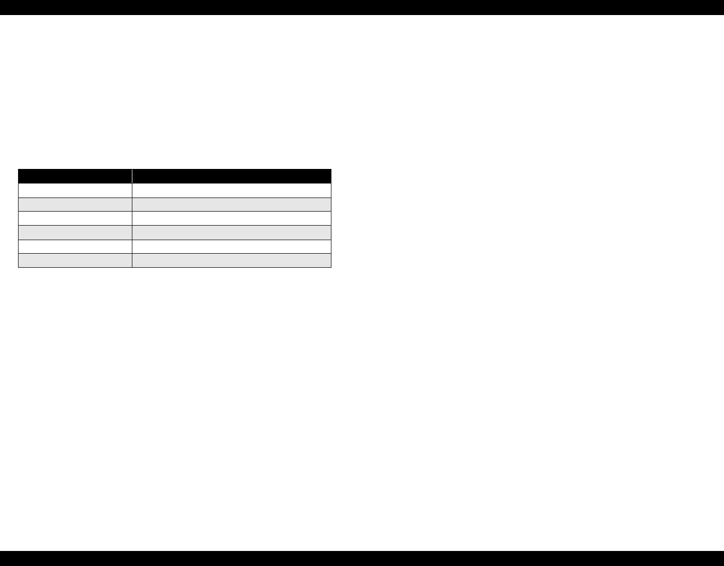
Table 3-1. Reference Tables of Error States
Error State Reference Table
Communication Error Refer to Table 3-2 "Troubleshooting of Communication Error" on page 37
Model Difference Refer to Table 3-2 "Troubleshooting of Communication Error" on page 37
Cover Open (Tray) Error Refer to Table 3-3 "Troubleshooting of Cover Open Error" on page 40
Paper Out Error Refer to Table 3-4 "Troubleshooting of Paper Out Error" on page 40
Paper Jam Error Refer to Table 3-5 "Troubleshooting of Paper Jam Error" on page 44
Card Loading Error Refer to Table 3-6 "Troubleshooting of Card Loading Error" on page 45
Paper Mismatch Error Refer to Table 3-7 "Troubleshooting of Paper Mismatch Error" on page 46
Ink Low Refer to Table 3-8 "Troubleshooting of Ink Low" on page 46
Ink Out Error Refer to Table 3-9 "Troubleshooting of Ink Out Error" on page 46
No Ink Cartridge/CSIC Error Refer to Table 3-10 "Troubleshooting of No Ink Cartridge/Ink Cartridge Error" on page 47
Maintenance Request Error Refer to Table 3-11 "Troubleshooting of Maintenance Request" on page 49
Fatal Error Refer to Table 3-12 "Troubleshooting of Fatal Error" on page 50

EPSON Stylus Photo R1800/R2400 Revision B
Troubleshooting Overview 37
Table 3-2. Troubleshooting of Communication Error
Occurrence
Timing Phenomenon Detail Faulty Part/
Part Name Check Point Remedy
At power-on The printer does not operate at
all. Panel FFC 1. Check that the Panel FFC is connected to the Panel Board
Connector and LED Board Connector. 1. Connect the Panel FFC to the Panel Board
and LED Board connectors.
2. Check the Panel FFC for damages. 2. Replace the Panel FFC with a new one.
Panel Board 1. Check the Panel Board for damages. 1. Replace the Panel Board with a new one.
LED FFC 1. Check that the LED FFC is connected to the LED Board
Connector and Main Board Connector CN8. 1. Connect the LED FFC to the LED Board
Connector and Main Board Connector
CN8.
2. Check the LED FFC for damages. 2. Replace the LED FFC with a new one.
LED Board
Connector
Panel FFC
Panel FFC
Panel Board
connector
CN8
LED FFC
LED Board
Connector

EPSON Stylus Photo R1800/R2400 Revision B
Troubleshooting Overview 38
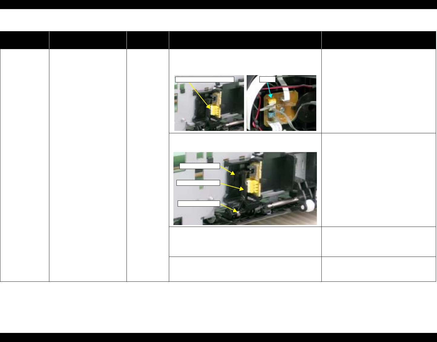
At power-on The printer does not operate at
all. Power Supply
Board 1. Check that the Connector Cable of the Power Supply
Board is connected to the Main Board Connector CN7. 1. Connect the Connector Cable of the Power
Supply Board to the Main Board Connector
CN7.
2. Check that the blue colored pin of the Power Supply Board
Connector cable is inserted into the 1 Pin of the Main
Board Connector CN7 as shown in the above picture.
2. Reconnect the Power Supply Board
Connector cable so that the blue colored
pin is inserted into the 1 Pin.
3. Check that the Fuse F1 on the Power Supply Board has
not blown. 3. Replace the Power Supply Board with a
new one.
4. Check the components on the Power Supply Board for
damage. 4. Replace the Power Supply Board with a
new one.
Table 3-2. Troubleshooting of Communication Error
Occurrence
Timing Phenomenon Detail Faulty Part/
Part Name Check Point Remedy
Connector cable of the
Power Supply Board
Blue line
1Pin side
CN7
Fuse F1
EPSON Stylus Photo R1800/R2400 Revision B
Troubleshooting Overview 39
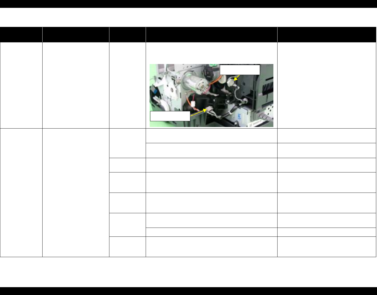
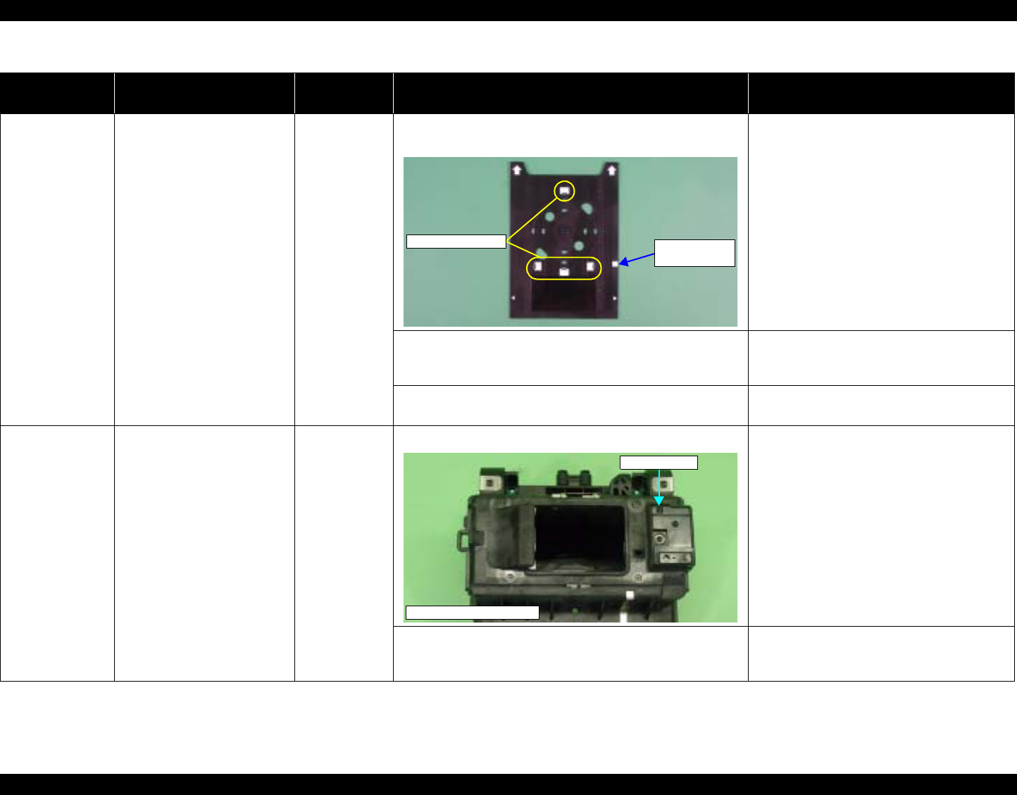
At power-on After the power-on sequence
has started, the LED turns off
and the printer does not
operate.
Main Board 1. Check that the Relay connector of the ASF Motor and the
Relay connector of the Pump Motor are not connected to
the wrong connector causing a short circuit.
1. Connect the Relay Connector of the ASF
Motor and the Relay Connector of the
Pump Motor correctly, and replace the
Main Board with a new one.
At operation Operation at power-on is
normal, but the error appears
when the print job is sent to
the printer.
Interface cable 1. Check that the Interface cable is connected between the
PC and printer. 1. Connect the Interface cable to the PC and
printer.
2. Check the Interface cable for breaking. 2. Replace the Interface cable with a new
one.
EPSON
USB driver 1. When using USB, check that the EPSON USB driver has
been installed on the PC. 1. Install the EPSON USB driver.
USB 1. Check that the PC and printer are connected via the USB
hub. 1. Enter the USB serial No. indicated on the
product nameplate.
Refer to Chapter 5 "Adjustment".
IEEE1394 1. Check that the same code as the IEEE1394 QR label code
is saved in the EEPROM address (from BA-H to BE-H). 1. Input the code given as the IEEE1394 QR
label code.
Refer to Chapter 5 "Adjustment".
Printer Driver 1. Check that the printer driver for Stylus Photo R1800 has
already been installed. 1. Install the printer driver for Stylus Photo
R1800.
2. Check that the connected printer is Stylus Photo R1800. 2. Connect the Stylus Photo R1800 printer.
Main Board 1. Check that a wrong model name has not been input to the
EEPROM address (E0<H<) on the Main Board. 1. Using the Adjustment Program, enter the
correct model name (save 01 into E0<H>).
Refer to Chapter 5"Adjustment".
Table 3-2. Troubleshooting of Communication Error
Occurrence
Timing Phenomenon Detail Faulty Part/
Part Name Check Point Remedy
Relay Connector of
the Pump Motor
Relay Connector of
the ASF Motor
EPSON Stylus Photo R1800/R2400 Revision B
Troubleshooting Overview 40
Table 3-3. Troubleshooting of Cover Open Error
Occurrence
Timing Phenomenon Detail Faulty Part/
Part Name Check Point Remedy
During printing A Cover Open (Tray) Error is
indicated during printing. Printer Cover 1. Check that the CD-R Unit is not open. 1. Close the CD-R Unit.
Table 3-4. Troubleshooting of Paper Out Error
Occurrence
Timing Phenomenon Detail Faulty Part/
Part Name Check Point Remedy
At operation When the Paper Switch is
pressed, the LD Roller attempt
to feed paper but the paper is
not fed.
ASF Assy. 1. Check the LD Roller or Retard Roller of the ASF Assy for
paper dust and foreign matter. 1. Using a cleaning sheet (part
code:1262115), clean the LD Roller and
Retard Roller. The procedure is as follows.
(1) Place the cleaning sheet upside down
and put it into the ASF Assy.
(2) Press the Paper Switch to start paper
feed.
(3) Repeat the above steps several times.
* To remove persistent contamination,
staple an alcohol-dampened cloth to a
postcard and clean the rollers in the
following method.
(1) Place the alcohol-dampened cloth
toward the LD Roller surface of the
ASF Assy.
(2) Hold the mount top end securely and
press the Paper Switch.
(3) Repeat the paper feed sequence
several times to clean the LD Roller
surface of the ASF Assy.
Cleaning sheet Postcard used
as mount
Non-adhesive part
Adhesive part
This side down Stapling
Cloth damped
with alcohol
EPSON Stylus Photo R1800/R2400 Revision B
Troubleshooting Overview 41
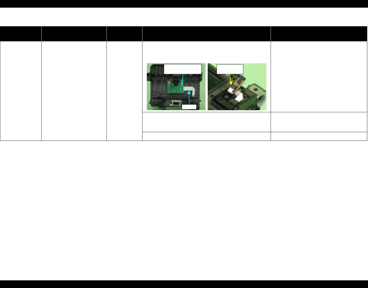
At operation Though paper is fed from the
ASF Assy, it stops near the PE
Sensor Lever.
PE Sensor 1. Check that the Connector cable of the PE Sensor is
securely connected to the PE Sensor and Relay Board
Connector CN2.
1. Connect the Connector cable of the PE
Sensor to the PE Sensor and Relay Board
Connector CN2.
2. Check that the Sensor Holder is mounted to the
Mechanical frame correctly. 2. Install the Sensor Holder correctly.
3. Move the Detection Lever manually as when the paper
passes, and check that the Detection Lever returns to the
original position automatically by the Torsion Spring when
released. Refer to the above photo.
3. Replace the PE Sensor Holder Unit with a
new one.
4. Using a tester, check that the PE Sensor is normal.
⋅ Paper absent : 2.4V or more
⋅ Paper present : 0.4V or less
4. Replace the PE Sensor Holder Unit with a
new one.
Table 3-4. Troubleshooting of Paper Out Error
Occurrence
Timing Phenomenon Detail Faulty Part/
Part Name Check Point Remedy
CN2
PW Sensor Connector
Sensor Holder
Detection Lever
Torsion Spring
EPSON Stylus Photo R1800/R2400 Revision B
Troubleshooting Overview 42
The Paper Switch
was pressed at the
setting of the CD-R
Tray.
The CD-R Tray HP detection
sequence stops and the Tray
is ejected.
CD-R Tray 1. Check the HP detection position or white markings of the
CD-R Tray for paper dust and foreign matter. 1. Remove paper dust and/or foreign matter
from the detection position.
2. Check the Driven Roller surface for contamination such as
paper dust and CD-R coating material. 2. Feed A4-size sheets of plain paper from
the ASF Assy several times to remove the
contamination.
3. Check that the HP detection position or white markings of
the CD-R Tray are not chipped. 3. Replace the CD-R Tray with a new one.
The Paper Switch
was pressed at the
setting of the CD-R
Tray or board
paper
Though the CD-R Tray or the
Board Paper is fed toward the
ASF Assy, but is ejected
immediately.
PW sensor 1. Check the PW Sensor for paper dust, ink, etc. 1. Clean the PW Sensor surface.
2. Compare the EEPROM values in two places (50<H> and
51<H>) and check that they are not approximate to each
other.
2. Replace the PW Sensor with a new one.
Table 3-4. Troubleshooting of Paper Out Error
Occurrence
Timing Phenomenon Detail Faulty Part/
Part Name Check Point Remedy
White Markings HP detection
position
PW sensor
Carriage Unit Bottom
EPSON Stylus Photo R1800/R2400 Revision B
Troubleshooting Overview 43
The Paper Switch
was pressed at the
setting of the CD-R
Tray or board
paper
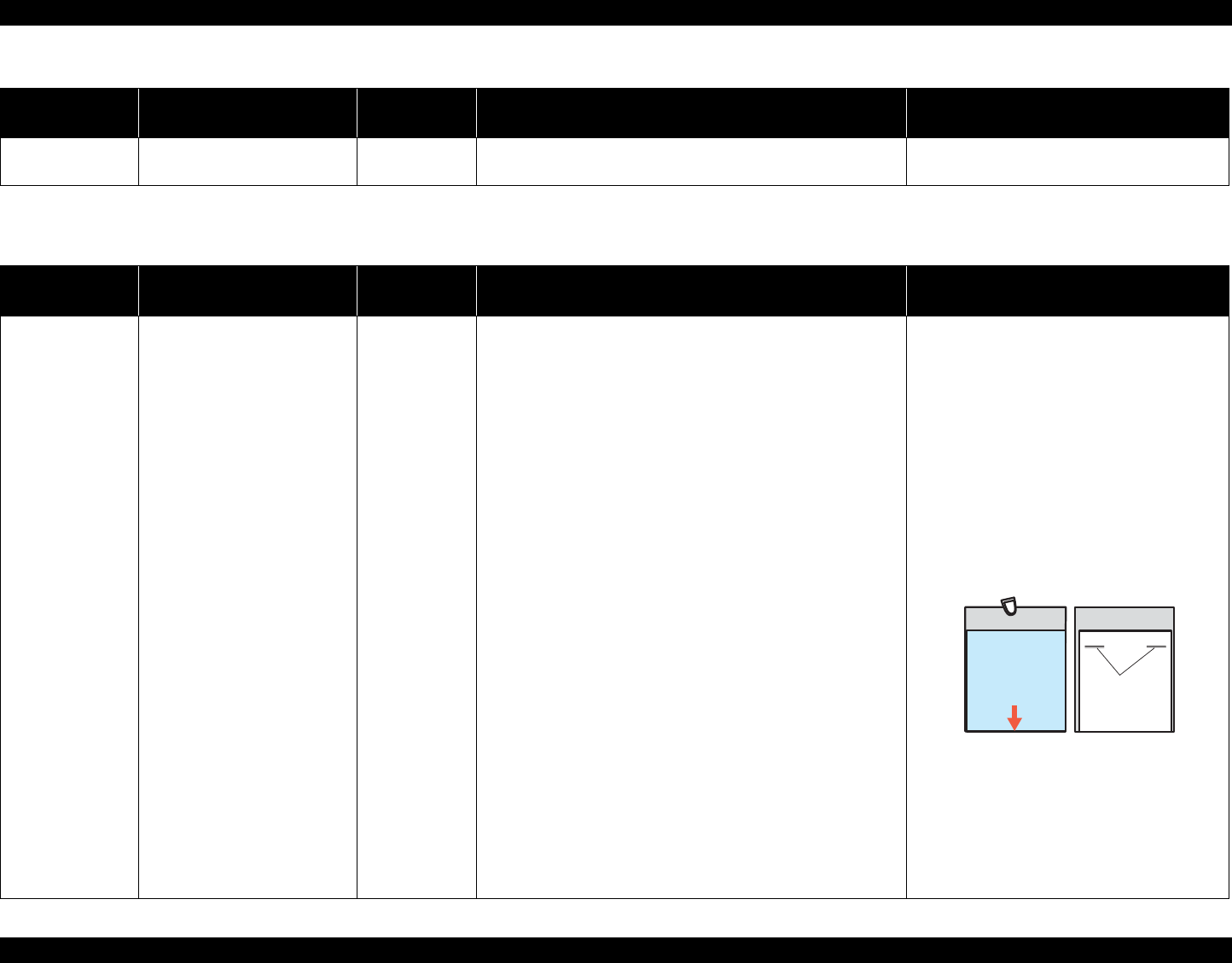
The CD-R Tray moves toward
the ASF and the posterior
edge of it reaches to the
Driven Roller on the Upper
Paper Guide.Then the CD-R
Tray tries to go farther, but it is
ejected.
PW sensor 1. Check that the PW Sensor FFC is placed in the specified
routing positions and does not make contact with any
parts.
1. Place the PW Sensor FFC in the specified
routing positions.
2. Check that the PW Sensor FFC is connected to the CR
Encoder Board and PW Sensor Connectors. Refer to the
above photo.
2. Connect the FFC to the CR Encoder Board
and PW Sensor Connectors.
3. Check the PW Sensor or PW Sensor FFC for damages. 3. Replace the PW Sensor with a new one.
Table 3-4. Troubleshooting of Paper Out Error
Occurrence
Timing Phenomenon Detail Faulty Part/
Part Name Check Point Remedy
PW Sensor
Connector
FFC
CR Encoder Board
Connector

EPSON Stylus Photo R1800/R2400 Revision B
Troubleshooting Overview 44
Table 3-5. Troubleshooting of Paper Jam Error
Occurrence
Timing Phenomenon Detail Faulty Part/
Part Name Check Point Remedy
At operation At the time of paper ejection,
the PF Roller advances the
paper but cannot eject it
completely.
– 1. Check that the size of the fed paper is not larger than that
of the paper specified by the driver. 1. Tell the user that the paper size specified
by the driver is not available for the printer.
Paper is not ejected
completely and causes a jam
near the Paper Eject Frame.
ASF Assy. 1. Check that the paper is fed along the Right Edge Guide. 1. Feed the paper along the Right Edge
Guide.
Paper EJ Frame
Assy. 1. Check that the Star Wheel Units have not come off the
Paper EJ Frame Assy. 1. Securely install the Star Wheel Units to the
Paper EJ Frame Assy.
2. Check the Paper EJ Frame Assy for deformation or
damages. 2. Replace the Paper EJ Frame Assy with a
new one.
Spur Gear 68
Spur Gear 16; B
Paper EJ Roller
Assy.(front/rear)
1. Check the Spur Gear 68 or Spur Gear 16; B for damages. 1. Replace the Front (or Rear) Paper EJ
Roller Assy with a new one.
Paper EJ Frame Assy.
Star Wheel Units
Spur Gear 16; B
Spur Gear 68

EPSON Stylus Photo R1800/R2400 Revision B
Troubleshooting Overview 45
Table 3-6. Troubleshooting of Card Loading Error
Occurrence
Timing Phenomenon Detail Faulty Part/
Part Name Check Point Remedy
During printing Printing starts but paper is not
fed. – 1. Check that the card size paper is loaded in the portrait
orientation. 1. Load the cards of the same size correctly,
and press the Paper Switch to eject the
jammed paper.
The card size paper is loaded
correctly, but Card Loading
Error is displayed.
PW sensor 1. Check that the PW Sensor FFC is connected to the CR
Encoder Board and PW Sensor Connectors. 1. Connect the FFC to the CR Encoder Board
or PW Sensor.
2. Check the PW Sensor or PW Sensor FFC for damages. 2. Replace the PW Sensor with a new one.
PW Sensor
Connector
FFC
CR Encoder Board
Connector
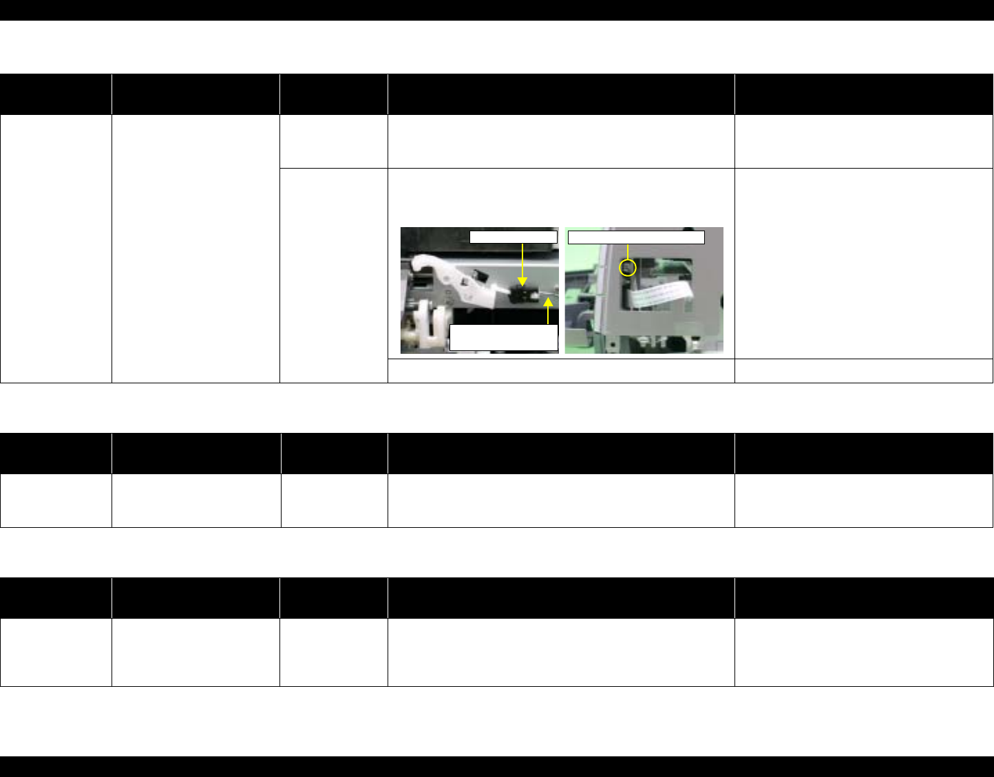
EPSON Stylus Photo R1800/R2400 Revision B
Troubleshooting Overview 46
Table 3-7. Troubleshooting of Paper Mismatch Error
Occurrence
Timing Phenomenon Detail Faulty Part/Part
Name Check Point Remedy
At operation When feeding a CD-R (Board
Paper), an error is displayed
on the LED and EPW3.
Paper EJ Frame
Assy
(CD-R Tray Base)
1. Check if the CD-R Tray Base is closed or not. 1. Open the CD-R Tray Base.
CD-R Sensor 1. Check that the Connector cable of the CD-R Sensor is
securely connected to the connectors of the CD-R Sensor
and Panel Board.
1. Connect the Connector cable of the CD-R
Sensor to the CD-R Sensor and Panel
Board Connectors.
2. Check the CD-R Sensor or Connector cable for damages. 2. Replace the CD-R Sensor with a new one.
Panel Board connector
Connector cable of
the CD-R Sensor
CD-R Sensor
Table 3-8. Troubleshooting of Ink Low
Occurrence
Timing Phenomenon Detail Faulty Part/Part
Name Check Point Remedy
At operation or
during printing A message is displayed on
the LED and EPW3 during
printing.
Ink Cartridge 1. Look at the remaining ink indication of the EPW3 to check
the amount of the ink remaining in the Ink Cartridge. 1. Prepare a new Ink Cartridge.
Table 3-9. Troubleshooting of Ink Out Error
Occurrence
Timing Phenomenon Detail Faulty Part/Part
Name Check Point Remedy
During printing After the Carriage has
detected the HP, an error is
displayed on the LED and
EPW3.
Ink Cartridge 1. Look at the remaining ink indication of the EPW3 to check
whether the ink remains in the Ink Cartridge. 1. Replace the Ink Cartridge with a new one.

EPSON Stylus Photo R1800/R2400 Revision B
Troubleshooting Overview 47
Table 3-10. Troubleshooting of No Ink Cartridge/Ink Cartridge Error
Occurrence
Timing Phenomenon Detail Faulty Part/
Part Name Check Point Remedy
At power-on After the Carriage has
detected the HP, an error is
displayed on the LED and
EPW3.
Ink Cartridge 1. Check that the Ink Cartridge is installed correctly. 1. Install the Ink Cartridge correctly.
2. Check that the tab of the Ink Cartridge is not broken. 2. Replace the Ink Cartridge with a new one.
3. Check that the Memory Chip is not disconnected or not
damaged. 3. Replace the Ink Cartridge with a new one.
Tab
Memory Chip

EPSON Stylus Photo R1800/R2400 Revision B
Troubleshooting Overview 48
At power-on After the Carriage has
detected the HP, an error is
displayed on the LED and
EPW3.
CSIC FFC 1. Check that the CSIC FFC is connected to the CSIC Board
Connector and Main Board Connector CN10. 1. Connect the CSIC FFC to the CSIC Board
Connector and Main Board Connector
CN10.
2. Check the CSIC FFC for damage. 2. Replace the CSIC FFC with a new one.
CSIC Board 1. Check the CSIC Board for damage. 1. Replace the CSIC Board with a new one.
Carriage Unit 1. Check that the electrodes in the Carriage, which make
contact with the CSIC Board, are not bent. 1. Replace the Carriage Unit with a new one.
Table 3-10. Troubleshooting of No Ink Cartridge/Ink Cartridge Error
Occurrence
Timing Phenomenon Detail Faulty Part/
Part Name Check Point Remedy
CN10
CSIC Board
Connector CSIC FFC
CSIC Board
Electrode

EPSON Stylus Photo R1800/R2400 Revision B
Troubleshooting Overview 49
Table 3-11. Troubleshooting of Maintenance Request
Occurrence
Timing Phenomenon Detail Faulty Part/
Part Name Check Point Remedy
At power-on At power-on, the printer does
not operate at all. Waste Ink Pads 1. Using the Adjustment Program, check if the Protection
Counter A+B value has exceeded 17772. 1. Replace the Waste Ink Pads and reset the
Protection Counter A and B value with the
Adjustment Program.
• Home side: 24<H>, 25<H>
• Opposite-to-home side: 26<H>, 27<H>
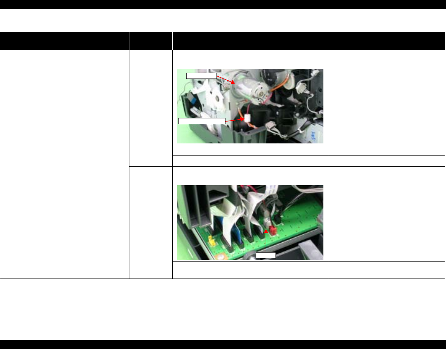
EPSON Stylus Photo R1800/R2400 Revision B
Troubleshooting Overview 50
Table 3-12. Troubleshooting of Fatal Error
Occurrence
Timing Phenomenon Detail Faulty Part/
Part Name Check Point Remedy
At power-on At power-on, the CR Motor
does not operate at all. CR Motor 1. Check that the CR Motor connector cable is connected to
the Relay Connector. 1. Connect the CR Motor connector to the
Relay Connector.
2. Check the CR Motor connector cable for damages. 2. Replace the CR Motor with a new one.
3. Check if the CR Motor operates normally. 3. Replace the CR Motor with a new one.
Relay
Connector
Cables
(for the CR
Motor)
1. Check that the Relay Connector Cable is connected to the
Main Board Connector CN15. 1. Connect the Relay Connector Cable to the
Main Board Connector CN15.
2. Check the Relay Connector Cable for damages. 2. Replace the Relay Connector Cable with a
new one.
CR Motor
Relay Connector
CN15
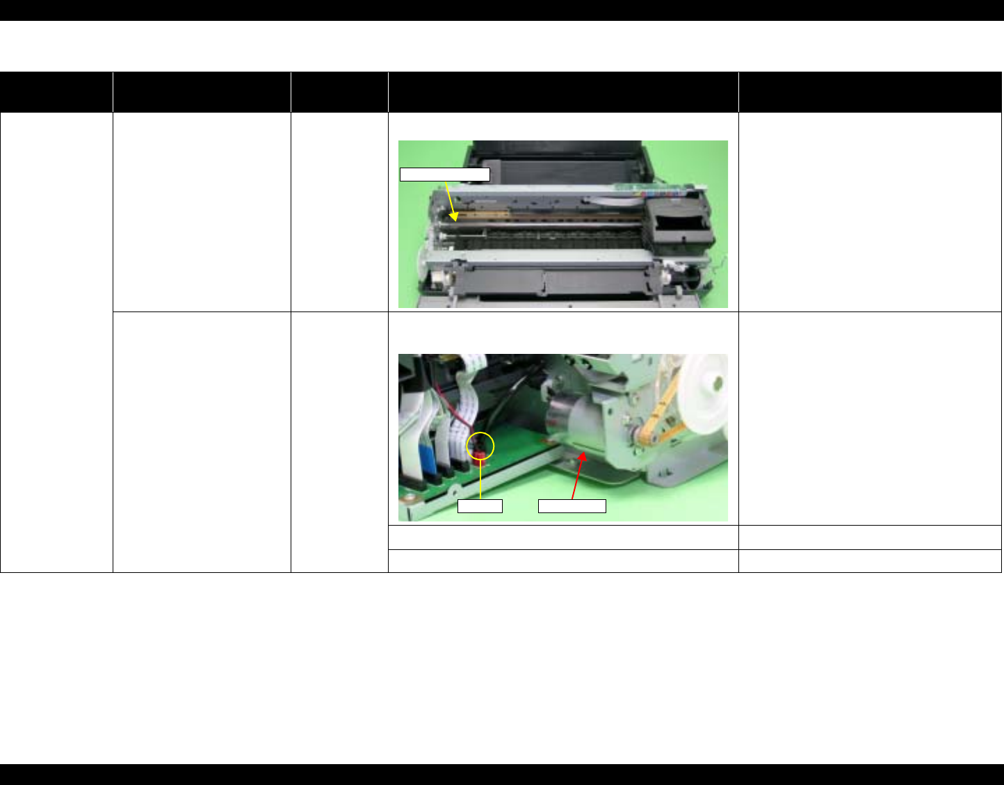
EPSON Stylus Photo R1800/R2400 Revision B
Troubleshooting Overview 51
At power-on The power-on sequence is
executed but Fatal error is
displayed.
CR drive
mechanism 1. Check that the Carriage Shaft is lubricated with grease. 1. Wipe the surface of the Carriage Shaft with
a dry, soft cloth, and lubricate the Carriage
Shaft with grease G-71.
Refer to Chapter 6 "Maintenance".
At power-on, the PF Motor
does not operate at all. PF Motor 1. Check that the Connector Cable of the PF Motor is
connected to the Main Board Connector CN16. 1. Connect the PF Motor connector cable to
the Main Board Connector CN16.
2. Check the PF Motor connector cable for damages. 2. Replace the PF Motor with a new one.
3. Check if the PF Motor operates normally. 3. Replace the PF Motor with a new one.
Table 3-12. Troubleshooting of Fatal Error
Occurrence
Timing Phenomenon Detail Faulty Part/
Part Name Check Point Remedy
Carriage Shaft
CN16 PF Motor

EPSON Stylus Photo R1800/R2400 Revision B
Troubleshooting Overview 52
At power-on At power-on, the APG Motor
does not operate at all. APG Motor 1. Check that the Connector Cable of the APG Motor is
connected to the Main Board Connector CN18. 1. Connect the APG Motor connector cable to
the Main Board Connector CN18.
2. Check the APG Motor connector cable for damage. 2. Replace the APG Motor with a new one.
3. Check if the APG Motor operates normally. 3. Replace the APG Motor with a new one.
At power-on, the Pump Motor
does not operate at all. Pump Motor 1. Check that the Pump Motor connector cable is connected
to the Relay Connector. 1. Connect the Pump Motor connector cable
to the Relay Connector.
2. Using a tester, check the resistance value of the Pump
Motor.
Value of resistance : 10.3Ω ± 10%
2. If the resistance value is abnormal, replace
the Ink System Unit with a new one.
3. Check the Pump Motor connector cable for damages. 3. Replace the Ink System Unit with a new
one.
Table 3-12. Troubleshooting of Fatal Error
Occurrence
Timing Phenomenon Detail Faulty Part/
Part Name Check Point Remedy
CN18
APG Motor
Relay Connector

EPSON Stylus Photo R1800/R2400 Revision B
Troubleshooting Overview 53
At power-on At power-on, the Pump Motor
does not operate at all. Relay
Connector
Cables (for
Pump Motor)
1. Check that the Relay Connector Cable is connected to the
Main Board Connector CN17. 1. Connect the Relay Connector Cable to the
Main Board Connector CN17.
2. Check the Relay Connector Cable for damages. 2. Replace the Relay Connector Cable with a
new one.
While the power-on sequence
is being executed, Fatal error
is displayed.
APG Sensor 1. Check that the APG Sensor Connector cables are
connected to the APG Sensors and Relay Board
Connector CN4 and CN5.
1. Connect the APG Sensor Connector
cables to the APG Sensors and Relay
Board Connector CN4 and CN5.
2. Check the APG Sensors for damages. 2. Replace the APG Sensors with new ones.
Table 3-12. Troubleshooting of Fatal Error
Occurrence
Timing Phenomenon Detail Faulty Part/
Part Name Check Point Remedy
CN17
CN4
CN5
APG Sensors

EPSON Stylus Photo R1800/R2400 Revision B
Troubleshooting Overview 54
At power-on While the power-on sequence
is being executed, Fatal error
is displayed.
ASF Motor 1. Check that the Connector cable of the ASF Motor is
connected to the Relay Connector. 1. Connect the Connector cable of the ASF
Motor to the Relay Connector.
2. Using a tester, check the resistance value of the ASF
Motor.
Value of resistance : 7.0Ω ± 10%
2. If the resistance value is abnormal, replace
the ASF Motor with a new one.
3. Check the ASF Motor connector cable for damages. 3. Replace the ASF Motor with a new one.
Relay
Connector
Cable
(for the ASF
Motor)
1. Check that the Relay Connector Cable is connected to the
Main Board Connector CN19. 1. Connect the Relay Connector Cable to the
Main Board Connector CN19.
2. Check the Relay Connector Cable for damages. 2. Replace the Relay Connector Cable with a
new one.
Table 3-12. Troubleshooting of Fatal Error
Occurrence
Timing Phenomenon Detail Faulty Part/
Part Name Check Point Remedy
Relay Connector
ASF Motor
CN19
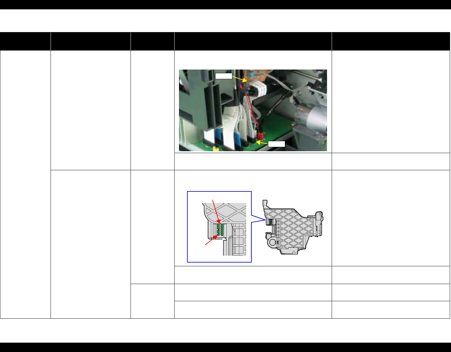
EPSON Stylus Photo R1800/R2400 Revision B
Troubleshooting Overview 55
At power-on While the power-on sequence
is being executed, Fatal error
is displayed.
Relay FFC 1. Check that the Relay FFC is connected to the Relay Board
Connector CN1 and Main Board Connector CN5. 1. Connect the Relay FFC to the Relay Board
Connector CN1 and Main Board
Connector CN5.
2. Check the Relay FFC for damages. 2. Replace the Relay FFC Cable with a new
one.
At power-on, the Carriage Unit
moves away from the home
position and bumps against
the right of the Frame, then
hits the left of the Frame.
CR Scale 1. Check that the CR Scale is inserted in the slit of the CR
Encoder Sensor. 1. Insert the CR Scale into the slit of the CR
Encoder Sensor.
2. Check the CR Scale for damages and dirt. 2. Wipe off the dirt completely or replace the
CR Scale with a new one.
CR Encoder
Sensor Board 1. Check the CR Encoder Sensor for paper dust, etc. 1. Remove the paper dust, etc. from the CR
Encoder Sensor.
2. Check the CR Encoder Sensor Board for damages. 2. Replace the CR Encoder Sensor Board
with a new one.
Table 3-12. Troubleshooting of Fatal Error
Occurrence
Timing Phenomenon Detail Faulty Part/
Part Name Check Point Remedy
CN1
CN5
CR Scale
CR Encoder
Sensor Board

EPSON Stylus Photo R1800/R2400 Revision B
Troubleshooting Overview 56
At power-on At power-on, the Carriage Unit
moves away from the home
position and bumps against
the right of the Frame, then
hits the left of the Frame.
Sensor FFC 1. Check that the Sensor FFC is connected to the CR
Encoder Sensor Board Connector and Main Board
Connector CN9.
1. Connect the Sensor FFC to the CR
Encoder Sensor Board Connector and
Main Board Connector CN9.
2. Check the Sensor FFC for damages. 2. Replace the Sensor FFC with a new one.
At power-on, the PF Roller
rotates fast about a half turn. PF Encoder
Sensor Holder 1. Check that the PF Encoder Sensor Holder is mounted
correctly. 1. Install the PF Encoder Sensor Holder
correctly.
2. Check that the FFC of the PF Encoder Sensor is securely
connected to the PF Encoder Sensor Board Connector
and Relay Board Connector CN6.
2. Connect the PF Encoder Sensor FFC to
the PF Encoder Sensor Board and Relay
Board Connector CN6.
3. Check the PF Encoder Sensor for paper dust, etc. 3. Remove the paper dust, etc. from the PF
Encoder Sensor.
4. Check if the PF Encoder or the FFC is damaged. 4. Replace the PF Encoder with a new one.
Table 3-12. Troubleshooting of Fatal Error
Occurrence
Timing Phenomenon Detail Faulty Part/
Part Name Check Point Remedy
CN9
CR Encoder Sensor
Board Connector
CN6
PF Encoder Sensor
Board Connector
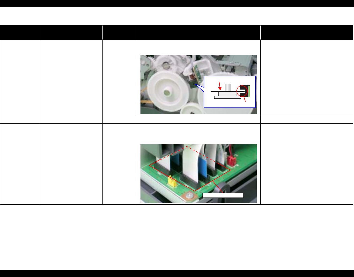
EPSON Stylus Photo R1800/R2400 Revision B
Troubleshooting Overview 57
At power-on At power-on, the PF Roller
rotates fast about a half turn. PF Scale 1. Check that the PF Scale is inserted in the slit of the PF
Encoder Sensor. 1. Install the PF Scale in the slit of the PF
Encoder Sensor correctly.
2. Check the PF Scale for damages and dirt. 2. Replace the PF Scale with a new one.
During printing After receiving a print data, or
while performing the CD-R
Tray home position detection
sequence (Board Paper
detection), an error is
displayed on the LED and
EPW3.
Head FFC
Sensor FFC 1. Check that the Head FFC and the Sensor FFC are
securely connected to the Main Board Connectors CN9
through CN14.
1. Connect the Head FFC and the Sensor
FFC to the Main Board Connectors CN9
through CN14.
Table 3-12. Troubleshooting of Fatal Error
Occurrence
Timing Phenomenon Detail Faulty Part/
Part Name Check Point Remedy
Slit
PF Scale
CN9 through CN14
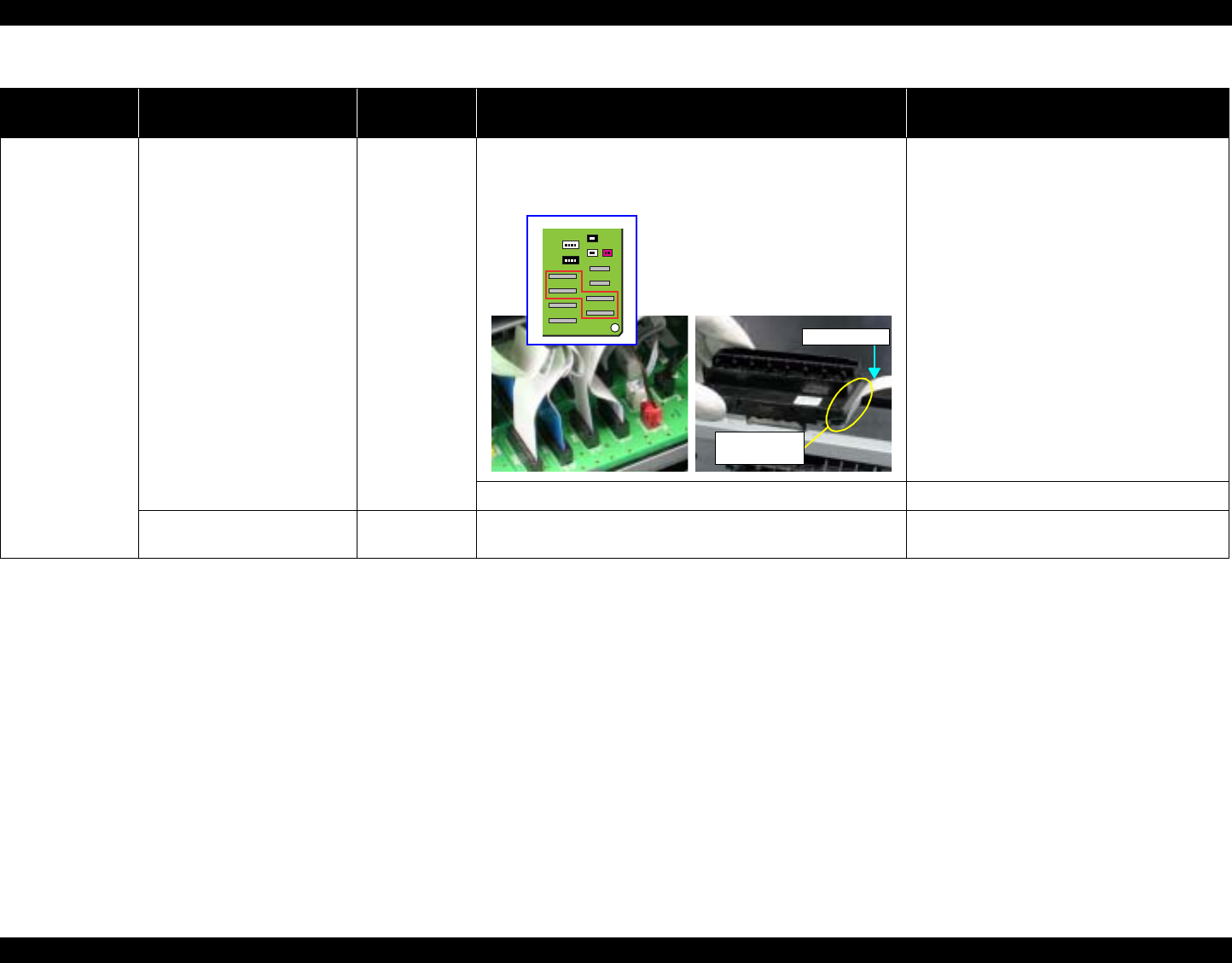
EPSON Stylus Photo R1800/R2400 Revision B
Troubleshooting Overview 58
During printing After starting to print, ink is not
ejected and paper stops
midway.
Head FFC 1. Check that the Head FFC is securely connected to the
Print Head Connector and Main Board Connectors CN10,
CN12, CN13, and CN14.
1. Connect the Head FFC to the Print Head
Connector and Main Board Connectors
CN10, CN12, CN13, and CN14.
2. Check the Head FFC for damages. 2. Replace the Head FFC with a new one.
Ink is not ejected from most
nozzles. Print Head 1. Check for occurrence of Head Hot. 1. Replace the Print Head with a new one.
Table 3-12. Troubleshooting of Fatal Error
Occurrence
Timing Phenomenon Detail Faulty Part/
Part Name Check Point Remedy
Print Head
Connector
Head FFC
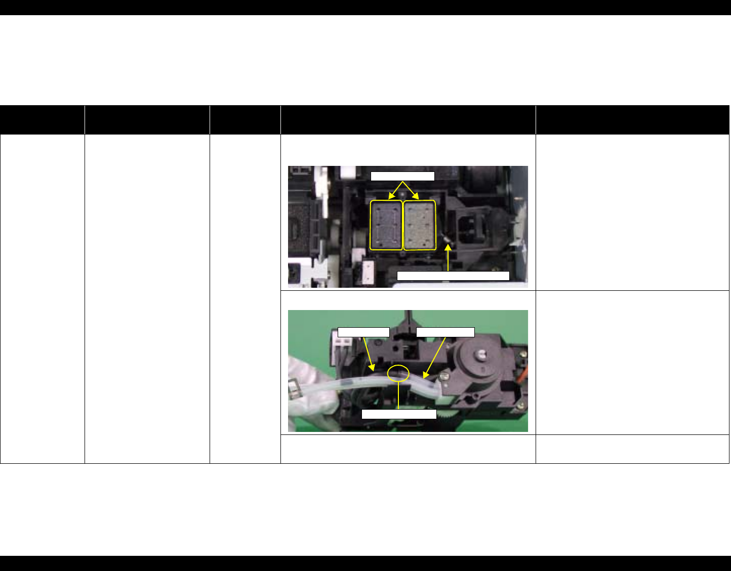
EPSON Stylus Photo R1800/R2400 Revision B
Troubleshooting Overview 59
3.1.2 Troubleshooting based on Observed Faults
This section provides troubleshooting procedures based on observed faults such as print quality troubles and abnormal noise.
Table 3-13. Print Quality Troubles
Observed Faults Details of the Fault Faulty Part/
Part Name Check Point Remedy
Dot missing and
mixed colors Inks are not ejected from the
Print Head to the Cap. Ink System
Unit(Cap) 1. Check for foreign matter around the Seal Rubber on the
Cap Unit. 1. Remove the foreign matter around the Seal
Rubber completely.
2. Check that the Ink Tube is connected to the Pump Tube. 2. Connect the Ink Tube to the Pump Tube
securely.
3. Check that the Extension Spring 1.19 IS is correctly
installed to the Cap Unit. 3. Replace the Ink System Unit with a new
one.
Seal Rubbers
Extension Spring, 1.19 IS
Ink Tubes Pump Tube
Connection point
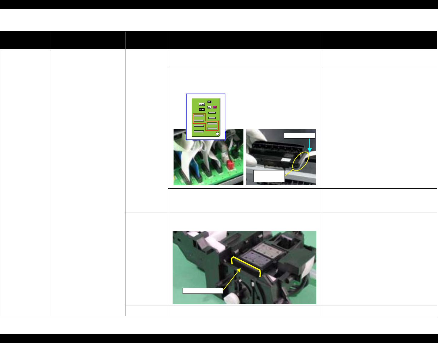
EPSON Stylus Photo R1800/R2400 Revision B
Troubleshooting Overview 60
Dot missing and
mixed colors Although inks are ejected
from the Print Head to the
Cap, the trouble still occurs
after executing a cleaning
cycle or replacing the Ink
Cartridges.
Print Head 1. Run a Nozzle Check, and check the printed pattern if it has
broken lines or missing segments. 1. After running a Head Cleaning, check the
Nozzle Check Pattern again.
2. Check that the Head FFC is securely connected to the
Print Head Connector and Main Board Connectors CN11,
CN12, CN13, and CN14.
2. Connect the Head FFC to the Print Head
Connector and Main Board Connectors
CN11, CN12, CN13, and CN14.
3. Check if the Head FFC is not damaged. 3. Replace the Head FFC with a new one.
If the trouble still occurs after replacing it,
replace the Print Head with a new one.
Ink System Unit
Cleaner Blade 1. Check if the Cleaner Blade is covered with paper dust or is
bent. 1. Replace the Ink System Unit with a new
one.
Main Board 1. Check the Main Board for damages. 1. Replace the Main Board with a new one.
Table 3-13. Print Quality Troubles
Observed Faults Details of the Fault Faulty Part/
Part Name Check Point Remedy
Print Head
Connector
Head FFC
Cleaner Blade
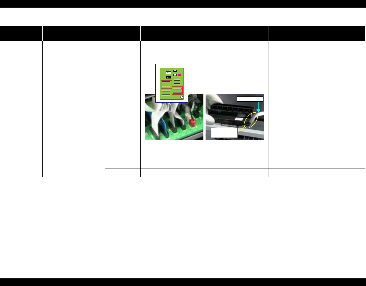
EPSON Stylus Photo R1800/R2400 Revision B
Troubleshooting Overview 61
Horizontal or
vertical banding /
Getting smeared
Although inks are ejected
from the Print Head to the
Cap, almost nothing is printed
or the print gets smeared with
excessive ink after executing
a cleaning cycle or replacing
the Ink Cartridges.
Head FFC 1. Check that the Head FFC is securely connected to the
Print Head Connector and Main Board Connectors CN10,
CN12, CN13, and CN14.
1. Connect the Head FFC to the Print Head
Connector and Main Board Connectors
CN10, CN12, CN13, and CN14.
Print Head 1. Check if the print quality recovers after running a cleaning
or replacing the Ink Cartridges. 1. Run the cleaning and replace the Ink
Cartridges several times. If the trouble still
occurs, replace the Print Head with a new
one.
Main Board 2. Check the Main Board for damages. 2. Replace the Main Board with a new one.
Table 3-13. Print Quality Troubles
Observed Faults Details of the Fault Faulty Part/
Part Name Check Point Remedy
Print Head
Connector
Head FFC
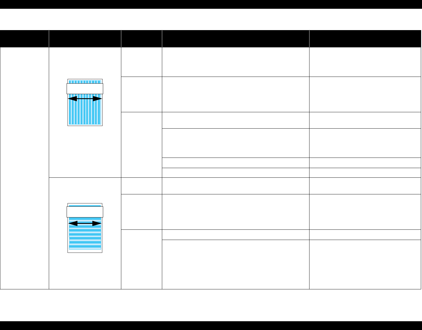
EPSON Stylus Photo R1800/R2400 Revision B
Troubleshooting Overview 62
Vertical or
horizontal banding /
Color shading
The printout has banding
vertical to the CR moving
direction and is not evenly
colored.
* If the trouble still occurs
after doing all measures
described in the right-hand
columns, replace the CR
Motor with a new one.
Adjustment 1. For printing in the Bi-D mode, check that the Bi-D
Adjustment has been performed properly. 1. Perform Bi-D Adjustment to eliminate
displacements between the upper and
lower lines.
Refer to Chapter 5 "Adjustment".
Print Head 1. Run a Nozzle Check, and check the printed pattern if it has
broken lines or missing segments.
1. Perform the Head Cleaning, then check the
Nozzle Check Pattern.
Refer to Chapter 5
"Adjustment"
.
If the trouble still occurs, replace the Print
Head with a new one.
Carriage Shaft 1. Check the surfaces of the Carriage Shaft for foreign
matter. 1. Remove foreign matter from the Carriage
Shaft.
2. Check that the Carriage Shaft is fully lubricated with
grease. 2. Wipe the grease applied to the Carriage
Shaft with a dry, soft cloth, and then apply
G-71 grease.
Refer to Chapter 6 "Maintenance".
3. Check that the Carriage Shaft is mounted horizontally. 3. Reassemble the Carriage Shaft correctly.
4. Check the Carriage Shaft for damages. 4. Replace the Carriage Shaft with a new one.
Narrow stripes of the same
width appear horizontally to
the CR moving direction.
* If the trouble still occurs
after doing all measures
described in the right-hand
columns, replace the PF
Motor with a new one.
Printer Driver
and the Paper 1. Check if appropriate paper is used in accordance with the
Printer Driver settings. 1. Use the appropriate type of paper in
accordance with the Printer Driver.
Print Head 1. Run a Nozzle Check, and check the printed pattern if it has
broken lines or missing segments.
1. Perform the Head Cleaning, then check the
Nozzle Check Pattern.
Refer to Chapter 5
"Adjustment"
.
If the trouble still occurs, replace the Print
Head with a new one.
PF Roller Shaft 1. Check the surface of the PF Roller Shaft for foreign matter. 1. Clean the PF Roller surface carefully.
2. Check the PF Roller Shaft for damages. 2. Replace the PF Roller with a new one.
Table 3-13. Print Quality Troubles
Observed Faults Details of the Fault Faulty Part/
Part Name Check Point Remedy
Direction of
CR movement
Direction of
CR movement
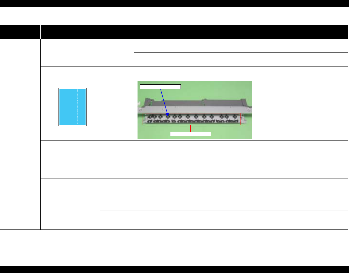
EPSON Stylus Photo R1800/R2400 Revision B
Troubleshooting Overview 63
Vertical or
horizontal banding /
Color shading
When printing at 360 dpi,
horizontal banding and color
unevenness appears at a
constant frequency.
Adjustment 1. Check that PF Adjustment has executed properly. 1. Perform PF Adjustment properly.
Refer to Chapter 5 "Adjustment".
2. Check for Dot missing. 2. Replace the Ink System Unit with a new
one.
Star Wheel Rollers traces
appear in the CR moving
direction.
Paper EJ Frame
Assy. 1. Check that the Star Wheel Units have not come off or the
Star Wheel Rollers turns normally. 1. Install the Star Wheel Units to the Paper EJ
Frame Assy correctly.
Printout is faint or blurry. Printer Driver
and the Paper 1. Check that adequate paper is used according to the setting
of the Printer Driver. 1. Use the appropriate type of paper in
accordance with the Printer Driver.
Print Head 1. Using the Adjustment Program, check that the correct Head
ID has been written to the EEPROM. 1. Using the Adjustment Program, enter the
31- digit code of the Head ID to the
EEPROM.
Refer to Chapter 5 "Adjustment".
The bottom of the printout is
not evenly colored. Adjustment 1. Check if the Positioning Adjustment of PF Roller Shaft
Retainer has been performed properly. 1. Make adjustments according to the
specified adjustment priority.
Refer to Chapter 5 "Adjustment".
Paper EJ Roller
traces appear on
the printout.
Traces of the Paper EJ Roller
appear on the printed paper
or CD-R.
Printer Driver
and the Paper 1. Check if appropriate paper is used in accordance with the
Printer Driver settings. 1. Use the appropriate type of paper in
accordance with the Printer Driver.
Front and Rear
Paper EJ Roller
Assys.
1. Check if the Paper EJ Roller is clean or not. 1. Clean the Paper EJ Roller using the Roller
Cleaning Mode.
Table 3-13. Print Quality Troubles
Observed Faults Details of the Fault Faulty Part/
Part Name Check Point Remedy
Star Wheel Rollers
Star Wheel Units
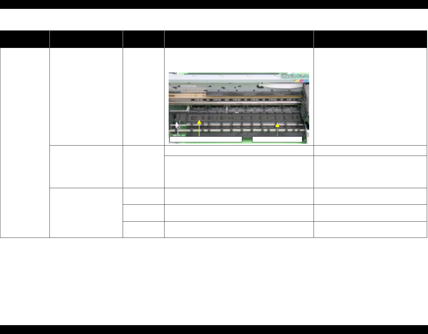
EPSON Stylus Photo R1800/R2400 Revision B
Troubleshooting Overview 64
The printout is
stained with ink. The non-printed side or the
bottom of the printout is dirty
with ink.
Front Paper
Guide Pad 1. Check that heaps of ink are not formed on the Front Paper
Guide Pad and that the Front Paper Guide Pad is installed
securely and evenly in the setting position.
1. If heaps of ink are formed, replace the
Front Paper Guide. If it has been confirmed
that the Ink pads have risen, reinstall the
Front Paper Guide Pad correctly.
When the paper size in the
sent print data is larger than
the size of the fed paper, data
are printed on the Front
Paper Guide, extending off
the paper.
PW sensor 1. Check that the PW Sensor FFC is connected. 1. Connect the PW Sensor FFC.
2. Check that the PW Sensor is not faulty. 2. Replace the PW Sensor with a new one.
Ink smudges appear on the
blank area of the printout. Paper EJ Frame
Assy. 1. Check the Star Wheel Rollers for ink stain. 1. Clean the Star Wheel Rollers with a soft
cloth.
Front Paper
Guide 1. Check the Front Paper Guide for ink stain. 1. Clean the Front Paper Guide with a soft
cloth.
Front Paper
Guide Pad 1. Check if ink heaps are formed on the Front Paper Guide
Pad. 1. Replace the Front Paper Guide with a new
one.
Table 3-13. Print Quality Troubles
Observed Faults Details of the Fault Faulty Part/
Part Name Check Point Remedy
Front Paper Guide Pad Front Paper Guide
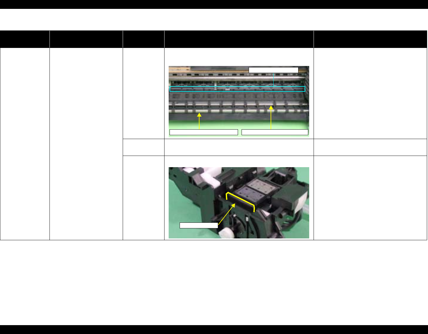
EPSON Stylus Photo R1800/R2400 Revision B
Troubleshooting Overview 65
The printout is
stained with ink. Ink smudges appear on the
blank area of the printout. Front and Rear
Paper EJ Roller
Assys
1. Check the Front and Rear Paper EJ Roller Assys for ink
stain. 1. Clean the Front and Rear Paper EJ Roller
Assys with a soft cloth.
Driven Roller
Shaft 1. Check the Driven Roller Shaft for ink stain. 1. Clean the Driven Roller Shaft with a soft
cloth.
Ink System Unit 1. Check that wiping operation was performed properly. 1. Install the Cleaner blade correctly or
replace it with a new one.
Table 3-13. Print Quality Troubles
Observed Faults Details of the Fault Faulty Part/
Part Name Check Point Remedy
Driven Roller Shaft
Rear Paper EJ Roller AssyFront Paper EJ Roller Assy
Cleaner Blade
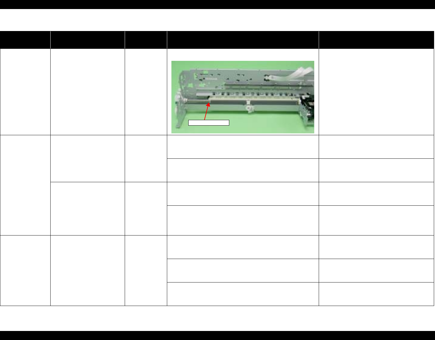
EPSON Stylus Photo R1800/R2400 Revision B
Troubleshooting Overview 66
The printout is
stained with ink. Ink smudges appear on the
blank area of the printout. PF Roller Shaft 1. Check the PF Roller Shaft for ink stain. 1. Clean the PF Roller Shaft with a soft cloth.
The printout is
grainy. Images are printed grainy in
all print modes. Or the image
looks rough.
Adjustment
Main Board
Print Head
1. Check that PG, Bi-D and Head Angular Adjustments have
been made properly. 1. Make the adjustments according to the
specified adjustment priority.
Refer to Chapter 5 "Adjustment".
2. Print the adjustment check patterns and check if they are
grainy. 2. If the images look still grainy after
adjustment, replace the Main Board with a
new one.
When printed at 5760 dpi, the
printed images are poor or
grainy.
Adjustment
Main Board
Print Head
1. After making sure that PG, Bi-D and Head Angular
Adjustments have been made correctly, check whether
PW Sensor has been adjusted properly.
1. Make the adjustment according to the
specified adjustment priority.
Refer to Chapter 5 "Adjustment".
2. Print the adjustment check patterns and check if the
printed images are still poor or grainy. 2. If the image quality does not improve after
the adjustment, replace the Print Head and
Main Board in this order, and check the
image graininess.
Regarding hue of
images The whole image is reddish. Adjustment
Print Head 1. Check if the PG has been adjusted properly. 1. Make the adjustment according to the
specified adjustment priority.
Refer to Chapter 5 "Adjustment".
2. Check that Bi-D and Head Angular Adjustments have been
made properly. 2. Make the adjustments according to the
specified adjustment priority.
Refer to Chapter 5 "Adjustment".
3. Print the adjustment check patterns and check the image
color. 3. If the image color does not change after
adjustment, replace the Print Head with a
new one.
Table 3-13. Print Quality Troubles
Observed Faults Details of the Fault Faulty Part/
Part Name Check Point Remedy
PF Roller Shaft

EPSON Stylus Photo R1800/R2400 Revision B
Troubleshooting Overview 67
Borderless Printing Cannot make a borderless
printing (The printer prints
with margins despite the
borderless setting).
PW sensor 1. Check if the paper dust or scrap of the paper is attached to
the Front Paper Guide. 1. Remove the paper dust or scrap of the
paper.
2. Check that the PW Sensor is operating normally.
Print the adjustment check patterns with the Adjustment
Program, and check that the clip function is executed
normally.
(The clip function is executed normally if an about 5mm
margin is provided on the left of the first gray band pattern
in the patterns.)
2. If it is judged that the clip function is not
executed normally, replace the PW sensor
with a new one.
Refer to Chapter 5 "Adjustment".
Table 3-13. Print Quality Troubles
Observed Faults Details of the Fault Faulty Part/
Part Name Check Point Remedy
Table 3-14. Abnormal Noise
Occurrence
Timing Details of the Fault Faulty Part/
Part Name Check Point Remedy
– Printing operation is
performed normally but
abnormal noise is produced
at power-on or during
operations.
Adjustment 1. Check that PF Belt Tension Adjustment has been
executed properly. 1. Make the adjustment according to the
specified adjustment priority.
Refer to Chapter 5 "Adjustment".
Carriage Shaft 1. Check that the Carriage Shaft is fully lubricated with
grease. 1. Wipe the grease applied to the Carriage
Shaft with a dry, soft cloth, and then apply
grease (G-71).
Refer to Chapter 6 "Maintenance".

CHAPTER
4
DISASSEMBLY AND ASSEMBLY

EPSON Stylus Photo R1800/R2400 Revision B
Disassembly And Assembly Overview 69
4.1 Overview
This chapter describes procedures for disassembling and assembling this
product. Unless otherwise specified, the disassembled units or main
components can be reassembled by reversing the disassembling procedure.
WARNINGs must be followed to avoid personal injury or death.
CAUTIONs must be followed to avoid damaging the printer or test
equipment.
ADJUSTMENT REQUIRED indicates that specific mandatory adjustments
must be carried out to complete the repair.
CHECK POINTs emphasize a particularly important process or procedure.
REASSEMBLY notes provide helpful tips on reassembly procedures,
especially when correct reassembly differs from simple reverse-assembly.
When you need to disassemble any units or parts that are not described in this
chapter, refer to the exploded diagrams in the Appendix.
Before starting your work, always read the precautions described in the next
section.
4.1.1 Precautions
Before starting the disassembling/reassembling work of this product, always
read the following "WARNING" and "CAUTION" carefully.
W ARNING Before starting the disassembling/reassembling work of
this product, always disconnect the power cable.
When the power supply cable must be connected for
voltage measurement or like, be extremely careful not to
get an electric shock and follow the procedures in this
manual to do your work.
Wear protective goggles to protect your eyes from ink. If
ink gets in your eyes, wash your eyes with clean water
and see a doctor.
To prevent injury from sharp metal edges, always wear
gloves for disassembly and reassembly.
If ink has adhered to your skin, wash it with soap and
water. If it has caused skin irritation, see a doctor.
To protect the microprocessors and circuitry, use static
discharge equipment, such as anti-static wrist straps
when accessing the internal components.
EPSON Stylus Photo R1800/R2400 Revision B
Disassembly And Assembly Overview 70
4.1.2 Tools
The following table indicates the tools recommended for use for disassembly,
reassembly and adjustment.
The above tools are all available in the market
C A U T I O N When transporting a printer that uses HAV Ink
Cartridges, remove all the cartridges beforehand.
Especially for air transportation, make sure to remove
cartridges because ink will flow into the Cap Unit via the
Print Head due to the reduction of the atmospheric
pressure, which may cause ink leakage.
Use only the recommended tools for disassembly,
reassembly and adjustment.
Refer to Table 4-1 Tool List on page 74.
Tighten screws to the specified torques.
Use the specified lubricants and adhesives.
Refer to Capter 6 "Maintenance".
Make the necessary adjustments under the instructions
given for disassembling.
Refer to Capter 5 "Adjustment".
Table 4-1. List of Tools
Tool Name Code
Phillips Screw Driver, No.1 1080530
Phillips Screw Driver, No.2 1080532
Flat-blade Screwdriver 1080527
Tweezers 1080561
Needle nose pliers 1080564
Acetate Tape 1003963
PF Tension Measuring Tool 1231678
Penlight –
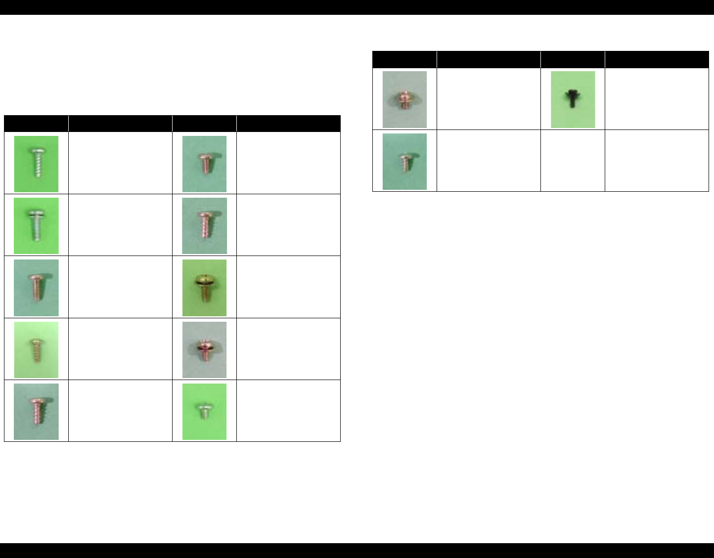
EPSON Stylus Photo R1800/R2400 Revision B
Disassembly And Assembly Overview 71
4.1.3 Screws
The following table lists the screws used in this product. When disassembling
and reassembling the printer, refer to the following table and use the specified
screws in the specified positions.
Table 4-2. List of Screw Types
Image Description Image Description
1) C.B.P. 3x10 2) C.B.S. 3x6
3) C.B.S. (P2) 3x10 4) C.B.P. 3x8
5) C.B.S. 3x8 6) C.B.S. (P4) 3x8
7) C.B.P. 2.6x8 8) C.B.S. (P4) 3x6
9) C.B.P. 3x6 10) C.B.S. 3x4
11) C.C. 3x4 12) C.P.B. (P1) 1.7x5
13) C.B.P. 2.6x5
Table 4-2. List of Screw Types
Image Description Image Description
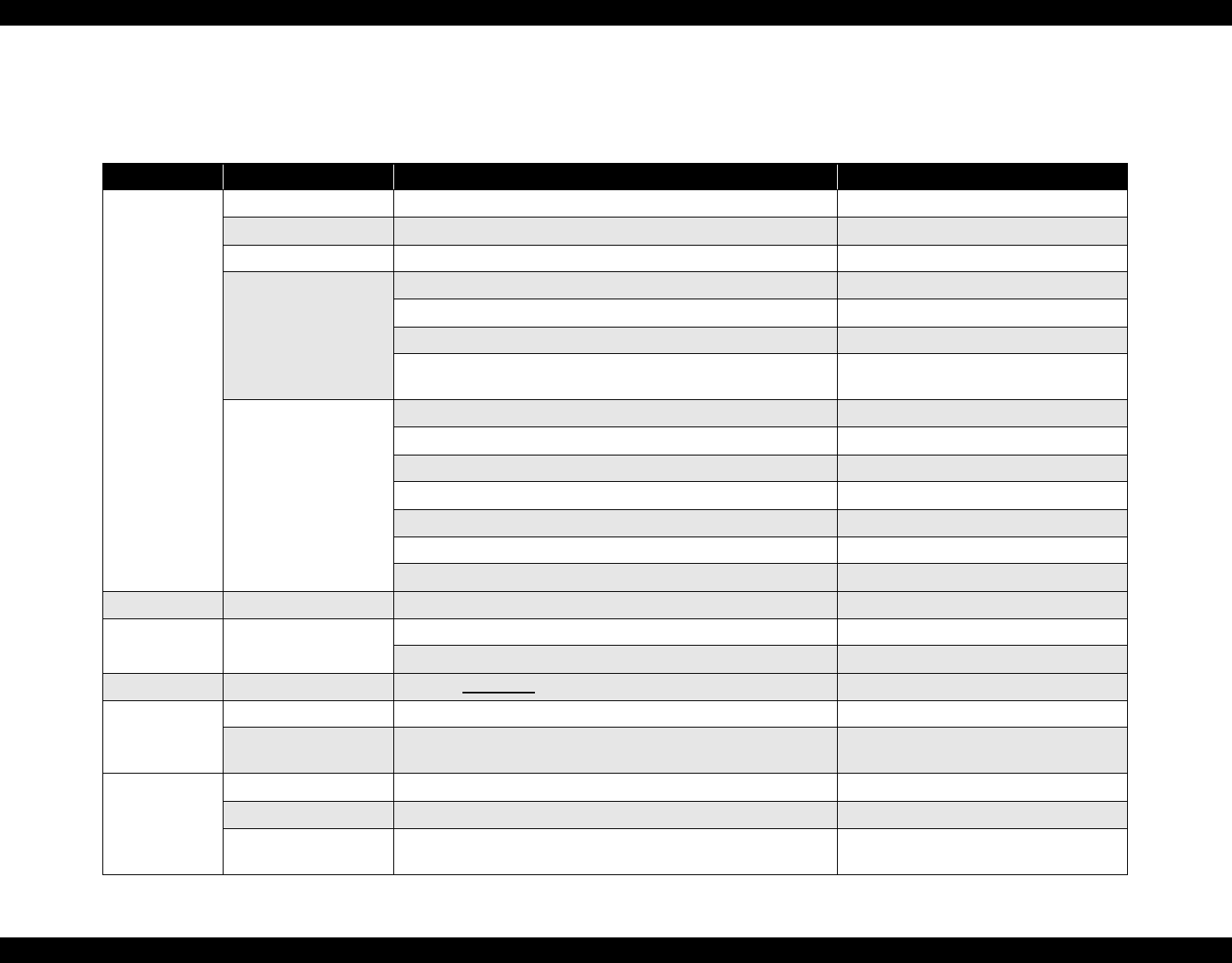
EPSON Stylus Photo R1800/R2400 Revision B
Disassembly And Assembly Overview 72
4.1.4 Work Completion Checklist
Whenever the printer is serviced, use the checklist shown below to confirm all work is completed properly and the printer is ready to be returned to the user.
Table 4-3. Work Completion Check
Classification Item Check Point Check Field
Main Unit Self-test Is the operation normal? Checked / Not necessary
On-line Test Is the printing attempt successful? Checked / Not necessary
Print Head Is ink discharged normally from all the nozzles? Checked / Not necessary
Carriage Mechanism Does it move smoothly? Checked / Not necessary
Are there any abnormal noises during its operation? Checked / Not necessary
Are there any dirt or foreign objects on the CR Shaft? Checked / Not necessary
Is the CR Motor at the correct temperature? (Not too hot to
touch?)
Checked / Not necessary
Paper Feeding
Mechanism Is paper advanced smoothly? Checked / Not necessary
No paper jamming? Checked / Not necessary
No paper skew? Checked / Not necessary
No multiple-sheet feeding? Checked / Not necessary
Is the PF Motor at correct temperature? (Not too hot to touch?) Checked / Not necessary
No abnormal noises? Checked / Not necessary
Is the paper path free of obstructions? Checked / Not necessary
Adjustment Specified Adjustment Are all the adjustments correctly completed? Checked / Not necessary
Lubrication Specified Lubrication Has lubrication been applied at the specified points? Checked / Not necessary
Is the amount of lubrication correct? Checked / Not necessary
Function ROM Version Version: Checked / Not necessary
Packing Ink Cartridge Have the ink cartridges been removed? Checked / Not necessary
Protective Materials Have all relevant protective materials been attached to the
printer?
Checked / Not necessary
Others CD-R Tray Is the operation normal? Checked / Not necessary
Cutter Unit Is the operation normal? Checked / Not necessary
Accessories Have all the accessories sent by the user been included in the
package?
Checked / Not necessary
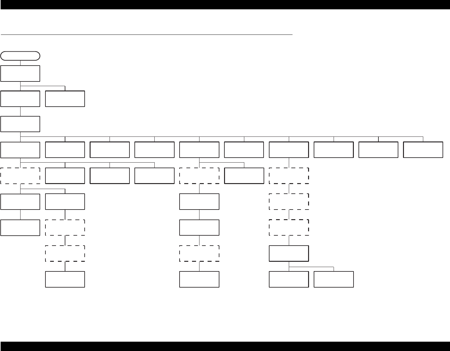
EPSON Stylus Photo R1800/R2400 Revision B
Disassembly And Assembly Disassembly 73
4.2 Disassembly
The flowchart below lists the step-by-step disassembly procedures. When disassembling each unit, refer to the page number shown in the figure.
Figure 4-1. Disassembly Flowchart
The step for the unit or discrete part within the broken line
is not the shortest removal step but is the step necessary
for removing the next unit or discrete part.
"Side Housing"
4.2.1.2 page 74.
"ASF Assy"
4.2.4 page 83.
"Rear Housing"
4.2.1.1 page 74.
"CSIC Board"
4.2.6.5 page 103.
"Paper EJ Frame
Assy."
4.2.6.6 page 105. 4.2.8.4 page 126.
"CR Motor"
4.2.7.1 page 122.
"CR Scale"
4.2.6.2 page 91.
"LED Board"
4.2.5.2 page 89.
"Paper EJ Frame
Assy."
4.2.6.6 page 105.
"LED Board"
4.2.5.2 page 89.
"APG Assy"
4.2.6.3 page 93.
START
"Ink Mark Sensor
and PW sensor"
4.2.8.2 page 125.
"Board Assy"
4.2.5.1 page 87.
"Lower Housing and
Printer Mechanism"
4.2.1.5 page 78.
"Upper Housing"
4.2.1.4 page 76.
"APG Assy"
4.2.6.3 page 93.
"Release Holder
Assy"
4.2.6.9 page 112.
"FLAG Release
Assy."
4.2.6.10 page 113.
"PE Sensor
Holder"
4.2.8.1 page 124.
"Upper Paper
Guide Assys."
4.2.6.11 page 114.
"PE Sensor
Holder"
4.2.8.1 page 124.
"APG Assy"
4.2.6.3 page 93. "Print Head"
4.2.6.1 page 89.
"CR Scale"
4.2.6.2 page 91.
"Ink System Unit"
4.2.6.8 page 109.
"Upper Paper
Guide Assys."
4.2.6.11 page 114.
"PF Roller Shaft"
4.2.6.13 page 119.
"Waste Ink Pad"
4.2.2 page 80.
"Front Paper
Guide Pad"
4.2.3 page 82.
"PF Motor"
4.2.7.2 page 123.
"Carriage Shaft
and Carriage Unit"
4.2.6.4 page 95.
"CD-R Release
Lever Sub Assy"
4.2.6.7 page 106.
"Front Paper Guide
and Paper eject roller"
4.2.6.12 page 116.
"PF Encoder
Sensor Holder"
4.2.8.4 page 126.
"PF Encoder
Sensor Holder"
"CR Encoder
Sensor Board"
4.2.8.3 page 126.
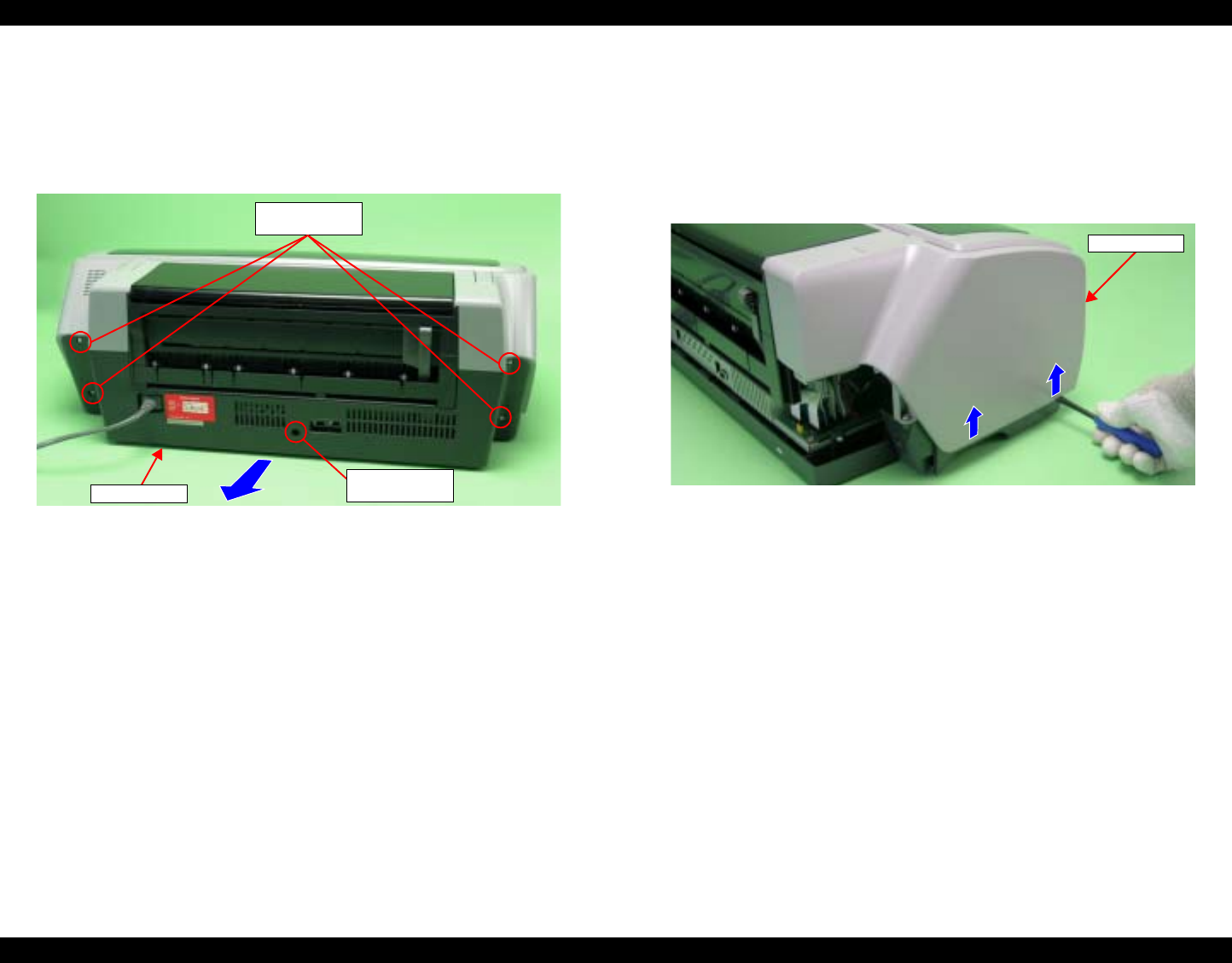
EPSON Stylus Photo R1800/R2400 Revision B
Disassembly And Assembly Disassembly 74
4.2.1 Removing the Housings
4.2.1.1 Rear Housing
1. Remove the four C.B.P. M3 x 10 screws and the C.B.S. M3 x 6 screw that
secure the Rear Housing, and remove it from the printer.
Figure 4-2. Removing the Rear Housing
4.2.1.2 Side Housing
1. Remove the Rear Housing. See Section 4.2.1.1 on page 74.
2. Insert a flat-blade screwdriver into the notch on the side of the Lower
Housing, and lift it in the direction of the arrow to remove the Left Side
Housing releasing the two tabs.
Remove the Right Side Housing in the same way.
Figure 4-3. Removing the Side Housings
Rear Housing
1) C.B.P. 3x10
(6±1 kgf.cm)
2) C.B.S. 3x6
(6±1 kgf.cm)
Side Housing
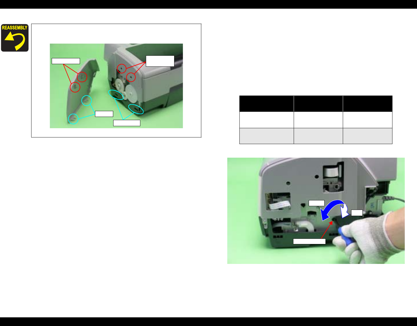
EPSON Stylus Photo R1800/R2400 Revision B
Disassembly And Assembly Disassembly 75
4.2.1.3 Locking/Releasing the Carriage and Opening/Closing
the CD-R Unit
Locking/releasing the Carriage and opening/closing the CD-R Unit are mutually
related. The CD-R Unit cannot be opened when the Carriage Lock is released.
1. Remove the Right Side Housing. See Section 4.2.1.2 on page 74.
2. Insert the flat-blade screwdriver into the hole on the right side of the frame,
and rotate the white shaft of the Ink System Unit.
Figure 4-5. Locking/Releasing the Carriage and
Opening/Closing the CD-R Unit
Match the positioning holes of the Upper Housing with the
guide pins of the Side Housing.
Figure 4-4. Reinstalling the Side Housing
Positioning
Holes
Tabs
Guide Pins
Notches
Table 4-4. Relationship between Carriage Lock and CD-R Unit
Direction of
Rotation Carriage CD-R Unit
Clockwise (CW) Locked Can be
opened/closed.
Counterclockwise
(CCW) Released Locked
White Shaft
CCW
CW
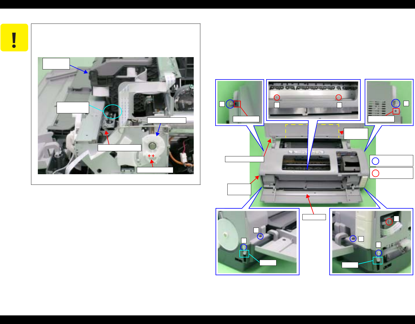
EPSON Stylus Photo R1800/R2400 Revision B
Disassembly And Assembly Disassembly 76
4.2.1.4 Upper Housing
1. Remove the Side Housing. See Section 4.2.1.2 on page 74.
2. Open the Printer Cover and Paper Support.
3. Open the CD-R Unit. See Section 4.2.1.3 on page 75.
4. Remove the six C.B.P. M3 x 10 screws and three C.B.S. M3 x 6 screws
that secure the Upper Housing.
Figure 4-7. Screws that Secure the Upper Housing
C A U T I O N When moving the Carriage Unit with the CD-R Unit opened,
turn the PG CAM (Right) beforehand so that PG++ points
downwards to release the PG in order to prevent interference
between the Paper EJ Frame and Carriage Unit.
Figure 4-6. Interference between the Frame and Carriage Unit
PG Cam (Right)
Point of
Interference
Paper EJ Frame
PG++ position
Carriage
Unit
Paper
Support
1
Guide Pin
3
Guide Pin
5
4
9
Tab
2
6
Tab
78
1) C.B.P. 3x10
(6±1 kgf.cm)
2) C.B.S. 3x6
(6±1 kgf.cm)
CD-RUnit
Upper
Housing
Printer Cover
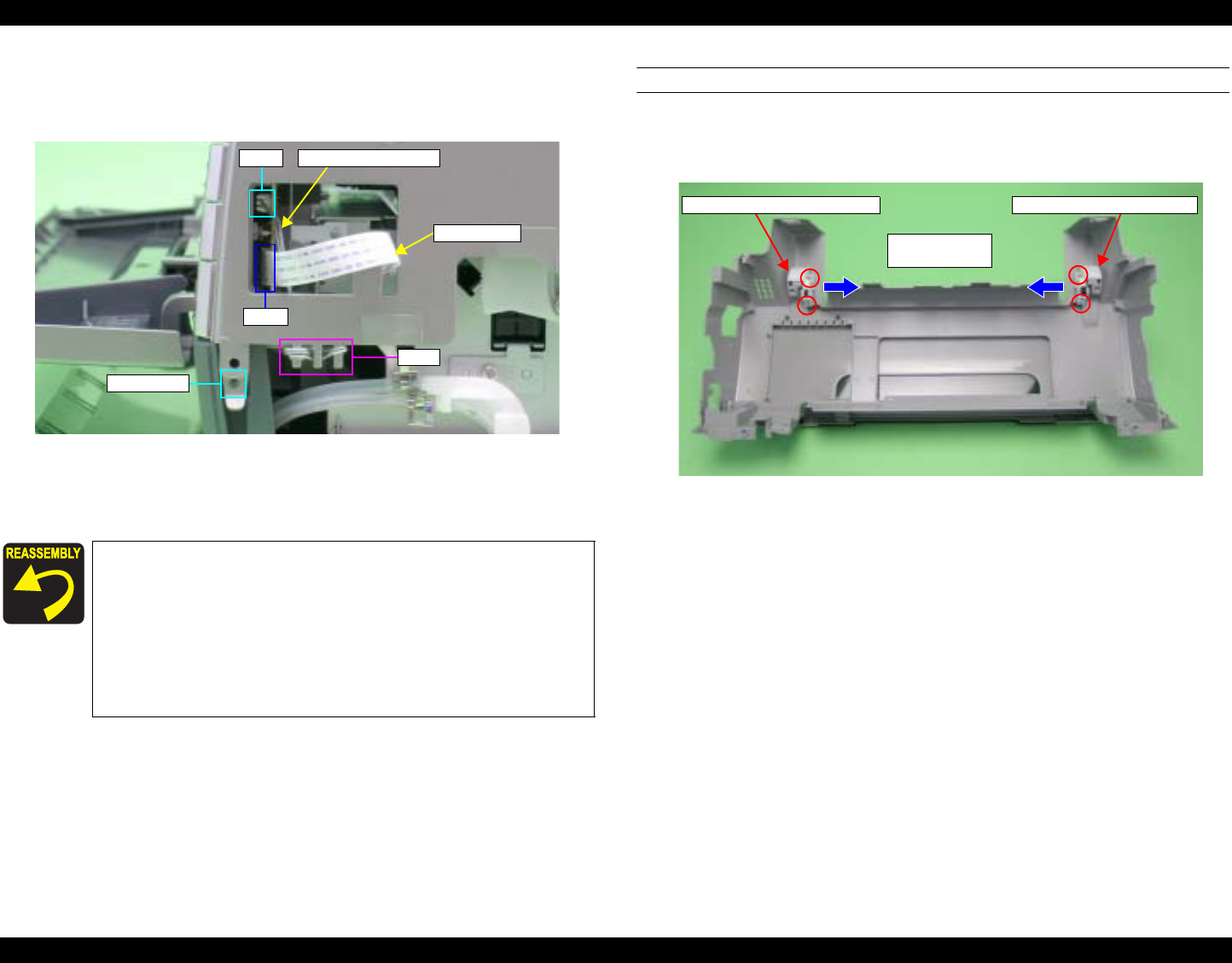
EPSON Stylus Photo R1800/R2400 Revision B
Disassembly And Assembly Disassembly 77
5. Disconnect the Panel FFC and CD-R Sensor Cable from connectors CN1
and CN2 on the Switch Board, and release the CD-R Sensor Cable from
the tabs of the Upper Housing.
Figure 4-8. Disconnecting the CD-R Sensor Cable and Panel FFC
6. Remove the Guide Pins from the two Tabs shown in Figure 4-7., and
remove the Upper Housing upwards.
PRINTER COVER
7. Remove the two C.B.P. M3 x 10 screws that secure the Left Printer Cover
Holder, and draw it out in the direction of the arrows.
Remove the Right Printer Cover Holder in the same way.
Figure 4-9. Disconnecting the Printer Cover Holder
Align the Guide Pins with the positioning holes on the
Upper Housing. See Figure 4-7.
When inserting the CD-R Sensor Cable into the Switch
Board, press the Connector CN2 to make sure that it is
firmly installed on the Switch Board.
Referring to Figure 4-7., correctly route the Panel FFC
and CD-R Sensor Cable.
Tighten the screws in the order shown in Figure 4-7.
Tabs
CN2
CN1
Panel FFC
Guide Pin
CD-R Sensor Cable
1) C.B.P. 3x10
(6±1 kgf.cm)
Right Printer Cover Holder Left Printer Cover Holder
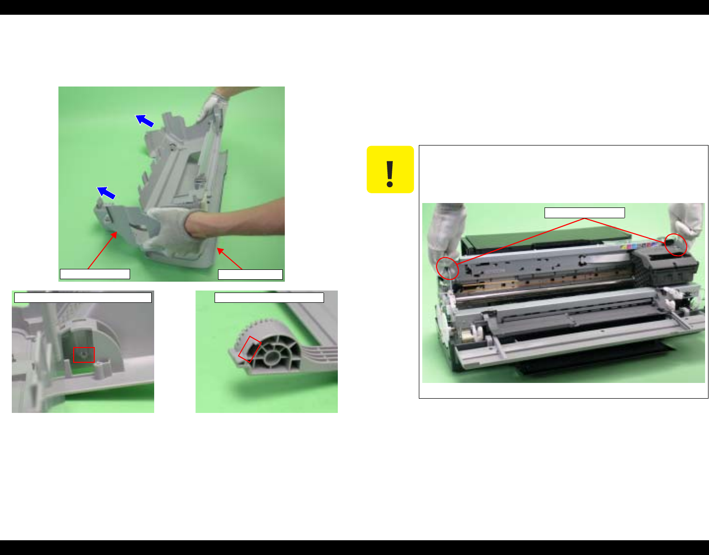
EPSON Stylus Photo R1800/R2400 Revision B
Disassembly And Assembly Disassembly 78
8. Lift the Upper Housing in the direction of the arrows, pull the Guide Pin on
the Upper Housing away from the notch on the printer cover, and remove
the Printer Cover.
Figure 4-10. Removing the Printer Cover
4.2.1.5 Lower Housing and Printer Mechanism
1. Remove the Upper Housing. See Section 4.2.1.4 on page 76.
2. Grip both ends of the two Ink Tube Fasteners with your fingers, slide them
in the direction of the arrows, and draw out the Waste Ink Tubes from the
two Ink Tubes.
3. Remove the four C.B.P. M3 x 10 screws and two C.B.S. (P2) M3 x 10
screws that secure the Printer Mechanism.
4. Hold the Printer Mechanism by its handling positions with both hands, and
remove it from the Lower Housing.
Guide Pin on the Upper Housing
Upper Housing Printer Cover
Notch on the Printer Cover
C A U T I O N If you hold the Printer Mechanism at locations other than the
handling positions when performing the following
procedure, the frame might become deformed. Be sure to
hold the Printer Mechanism by the positions.
Figure 4-11. Handling the Printer Mechanism
Handling Positions
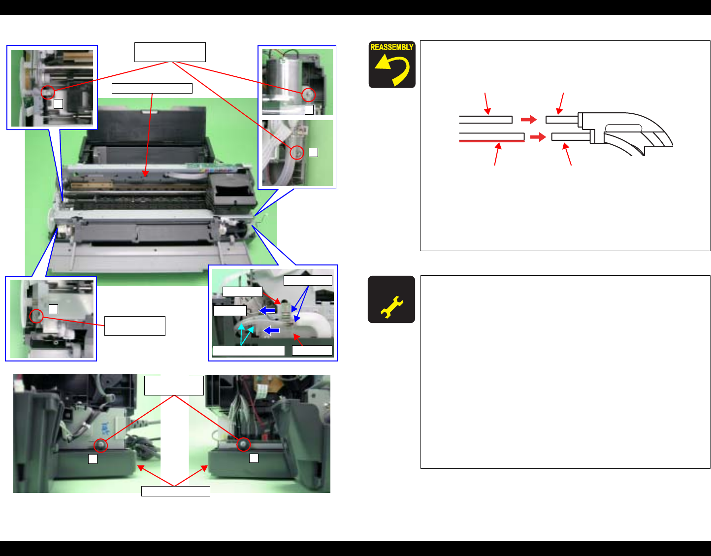
EPSON Stylus Photo R1800/R2400 Revision B
Disassembly And Assembly Disassembly 79
Figure 4-12. Screws that Secure the Printer Mechanism
1
3
4
Fastener
Step 2
Ink Tubes
Waste Ink Tubes Fastener
1) C.B.P. 3x10
(6±1 kgf.cm)
2
1) C.B.P. 3x10
(6±1 kgf.cm)
Printer Mechanism
6
5
3) C.B.S. (P2)
3x10
Lower Housing
Insert the Waste Ink Tube with the red line into the lower
Ink Tube.
Figure 4-13. Installing the Ink Tubes
Make sure that the Waste Ink Tubes are not nipped by
the Printer Mechanism.
Tighten the screws in the order shown in Figure 4-12.
A D J U S T M E N T
R E Q U I R E D After replacing the Printer Mechanism, be sure to make the
following adjustments.
1. Platen Gap (PG) Adjustment
2. Ink Mark Sensor Adjustment
3. Head Angular Adjustment
4. Auto Bi-D Adjustment
5. Ink Mark Sensor Adjustment
6. First dot position
7. PW Sensor Adjustment
8. PF Deterioration Compensation Counter Reset
9. PF Adjustment
10. PF Adjustment (Bottom Margin)
11. CR Motor Drive Dispersion Measurement Sequence
Refer to Chapter 5 "Adjustment" for details of the
adjustments.
0 Digit Side Ink Tube
130 Digit Side Ink Tube
0 Digit Side Waste Ink Tube
130 Digit Side Waste Ink Tube
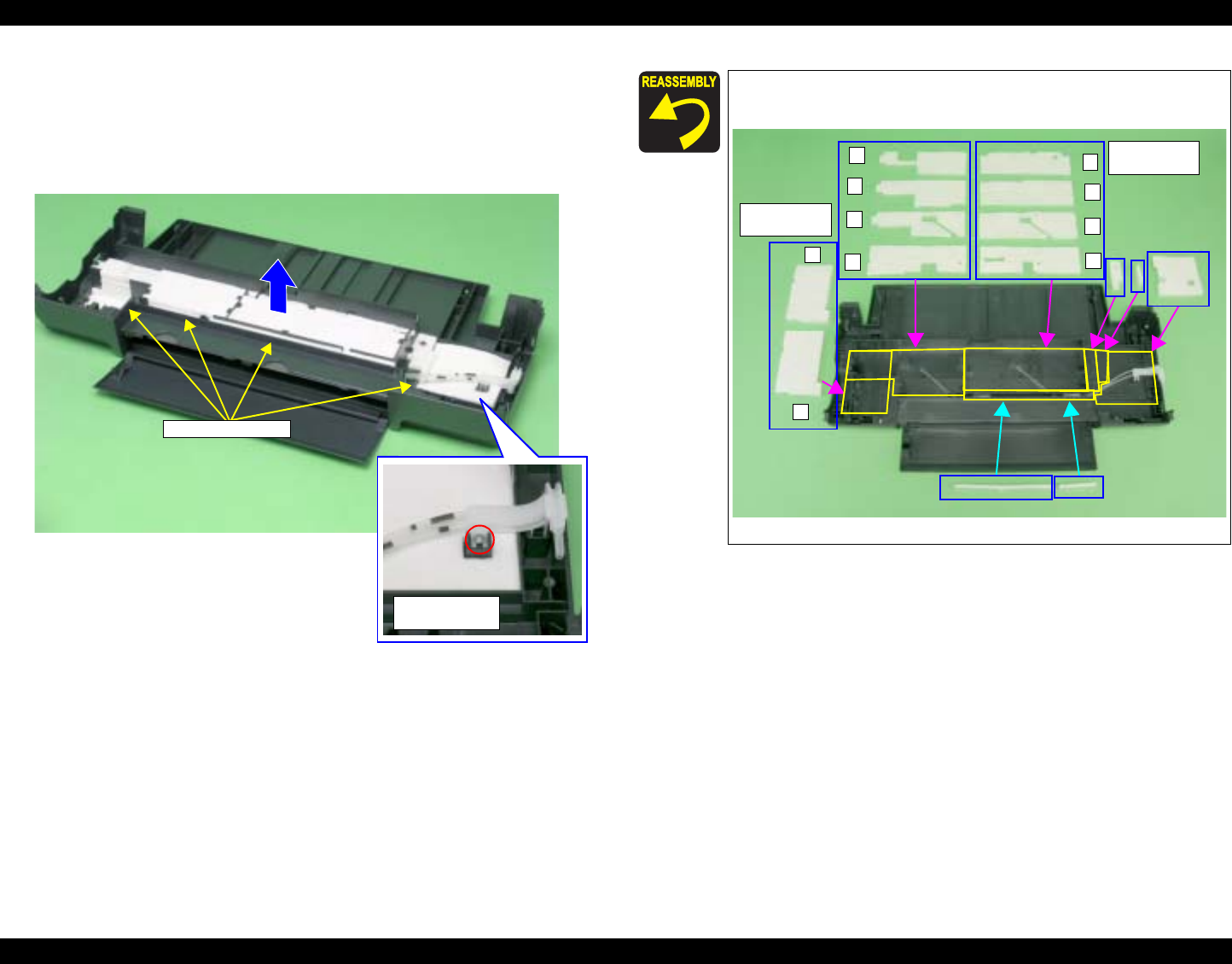
EPSON Stylus Photo R1800/R2400 Revision B
Disassembly And Assembly Disassembly 80
4.2.2 Waste Ink Pad
1. Remove the Lower Housing. See Section 4.2.1.5 on page 78.
2. Remove the C.B.P. M3 x 8 screw that secures the Waste Ink Tube.
3. Remove the 15 Waste Ink Pads from the Lower Housing.
Figure 4-14. Removing the Waste Ink Pads
4) C.B.P. 3x8
(6±1 kgf.cm)
Waste Ink Pads
Referring to Figure 4-15., correctly install the Waste Ink
Pads.
Figure 4-15. Reinstalling the Waste Ink Pads
1
2
3
4
1
2
3
4Installation
Order
1
2
Installation
Order
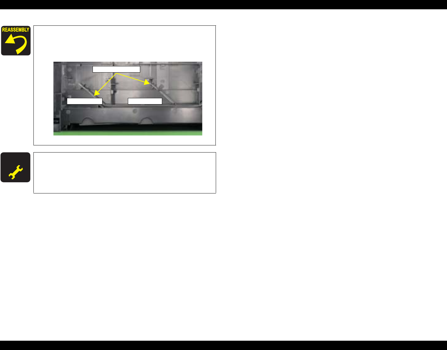
EPSON Stylus Photo R1800/R2400 Revision B
Disassembly And Assembly Disassembly 81
Check the positions and the routing of the Upper and
Lower Waste Ink Tubes.
0 digit side : Lower side
130 digit side : Upper side
Figure 4-16. Positions of Waste Ink Tubes
A D J U S T M E N T
R E Q U I R E D After replacing or removing the Waste Ink Pads, always make
the following adjustment.
Waste Ink Protection Counter Clear
Refer to Chapter 5 "Adjustment" for details of the
adjustment.
0 Digit Side130 Digit Side
Waste Ink Tubes
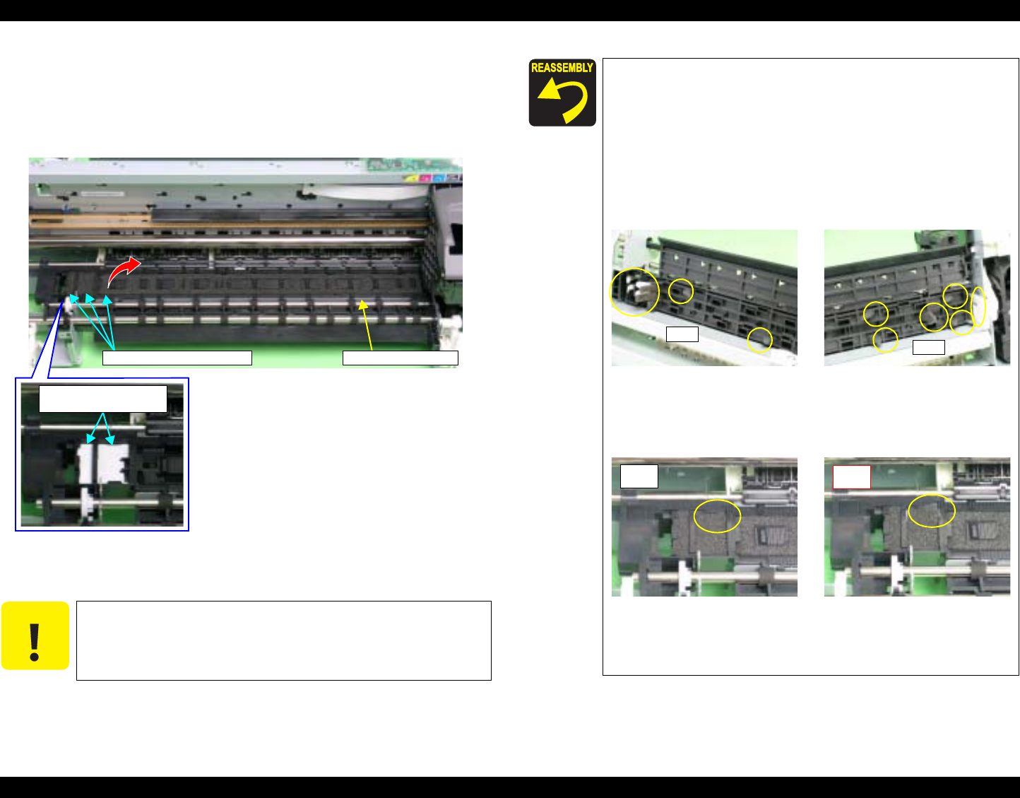
EPSON Stylus Photo R1800/R2400 Revision B
Disassembly And Assembly Disassembly 82
4.2.3 Front Paper Guide Pad
1. Remove the Printer Mechanism. See Section 4.2.1.5 on page 78.
2. Remove the Front Paper Guide Pads and Front Paper Guide Pad
Protection from the Front Paper Guide with tweezers.
Figure 4-17. Removing the Front Paper Guide Pads and
the Front Paper Guide Pad Protection
C A U T I O N Take care to prevent the grease contained on the Front
Paper Guide Pads and Front Paper Guide Pad Protection
from sticking to other parts.
Front Paper GuideFront Paper Guide Pads
Front Paper Guide
Pad Protection
After installing the Front Paper Guide Pads and Front Paper
Guide Pad Protection, lift the Printer Mechanism, and check
the following points.
1. Make sure that the Tabs on the Pads are not cut midway.
2. Make sure that all Tabs are in place on the Front Paper
Guide, and that they are facing down (towards the Waste
Ink Pads) without any folds.
3. Make sure that the Tab foldbacks are protruding
completely from the Front Paper Guide.
Figure 4-18. Reinstalling the Front Paper Guide Pad (1)
4. Make sure that the Pad is placed under a tab of the Front
Paper Guide.
Figure 4-19. Reinstalling the Front Paper Guide Pad (2)
5. Make sure that all the Tabs on the Pads are fitted into the
securing section under the Front Paper Guide.
Tabs Tabs
OK NG
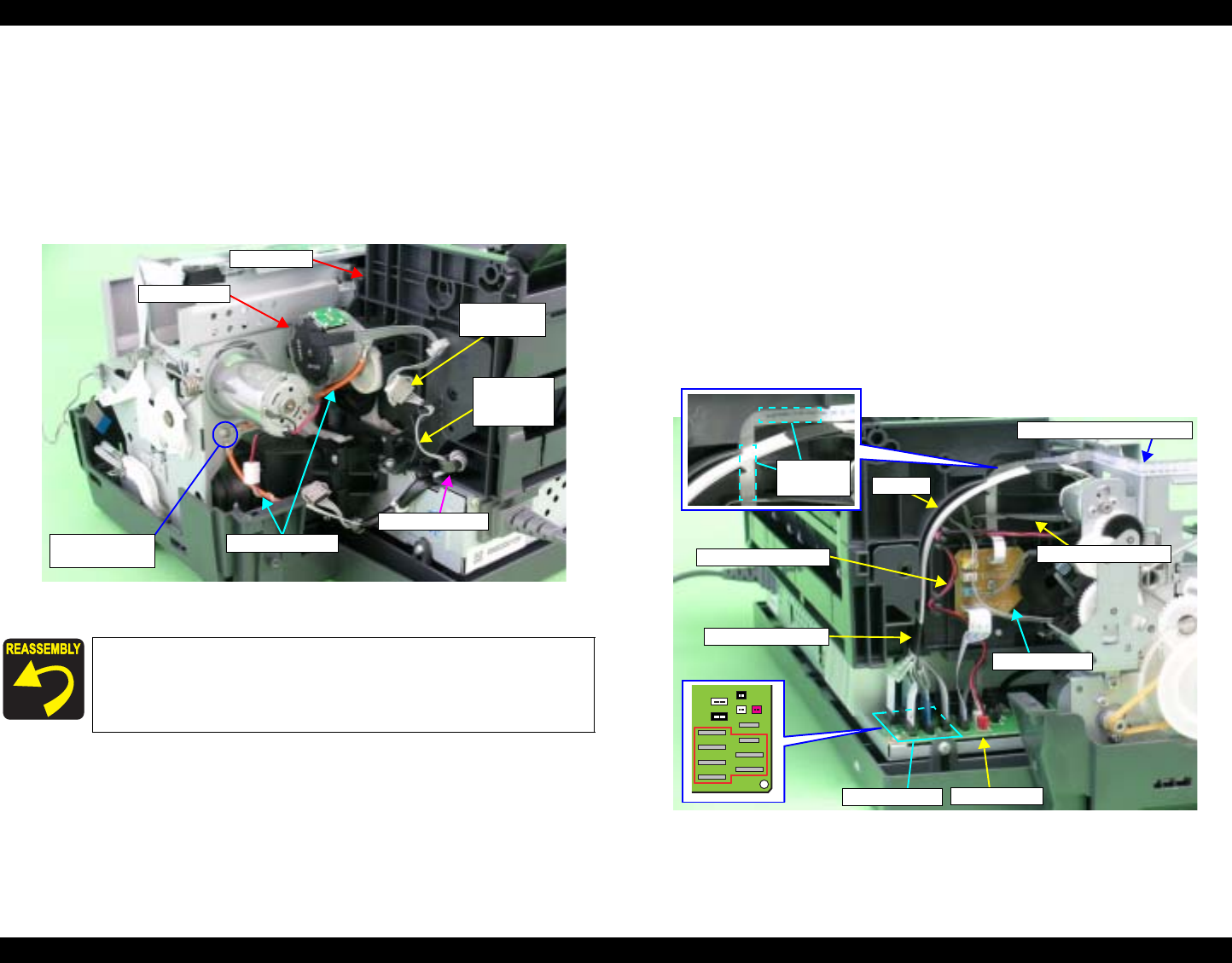
EPSON Stylus Photo R1800/R2400 Revision B
Disassembly And Assembly Disassembly 83
4.2.4 ASF Assy
1. Remove the Upper Housing. See Section 4.2.1.4 on page 76.
2. Remove the C.B.S. M3 x 8 screw that secures the Earth Cables on the
right rear side of the printer, and remove the Earth Cables.
3. Disconnect the ASF Motor Connector from the Relay Connector.
4. Disconnect the Relay Connector Cable from the ASF Assy.
Figure 4-20. Releasing the Cables (1)
5. Disconnect all Cables and the FFC from the connectors on the Relay
Board.
CN1 : Relay FFC
CN2 : PE Sensor Cable
CN4 : APG Sensor Cable (downside)
CN5 : APG Sensor Cable (the upper side)
CN6 : PF Encoder Sensor FFC
6. Disconnect the FFC bundled by the Acetate Tape from the CN8 to CN14
on the Main Board, and release it from the groove on the ASF Assy.
7. Disconnect the APG Motor Cable and PE Sensor Cable from the ASF
Assy.
8. Peel off the PF Encoder FFC secured by two pieces of double-sided
adhesive tape from the ASF Assy.
Figure 4-21. Releasing the Cables (2)
Secure the two Earth Cables together with the screw.
Referring to Figure 4-20., correctly route the Relay
Connector Cable.
5) C.B.S. 3x8
(8±1 kgf.cm)
Relay
Connector
Earth Cables
Relay
Connector
Cable
Ferrite Core
ASF Motor
ASF Assy
Main Board
Relay Board
PF Encoder Sensor FFC
Two-sided
Tapes
Acetate Tape
CN8 to CN14
Groove
APG Motor Cable PE Sensor Cable
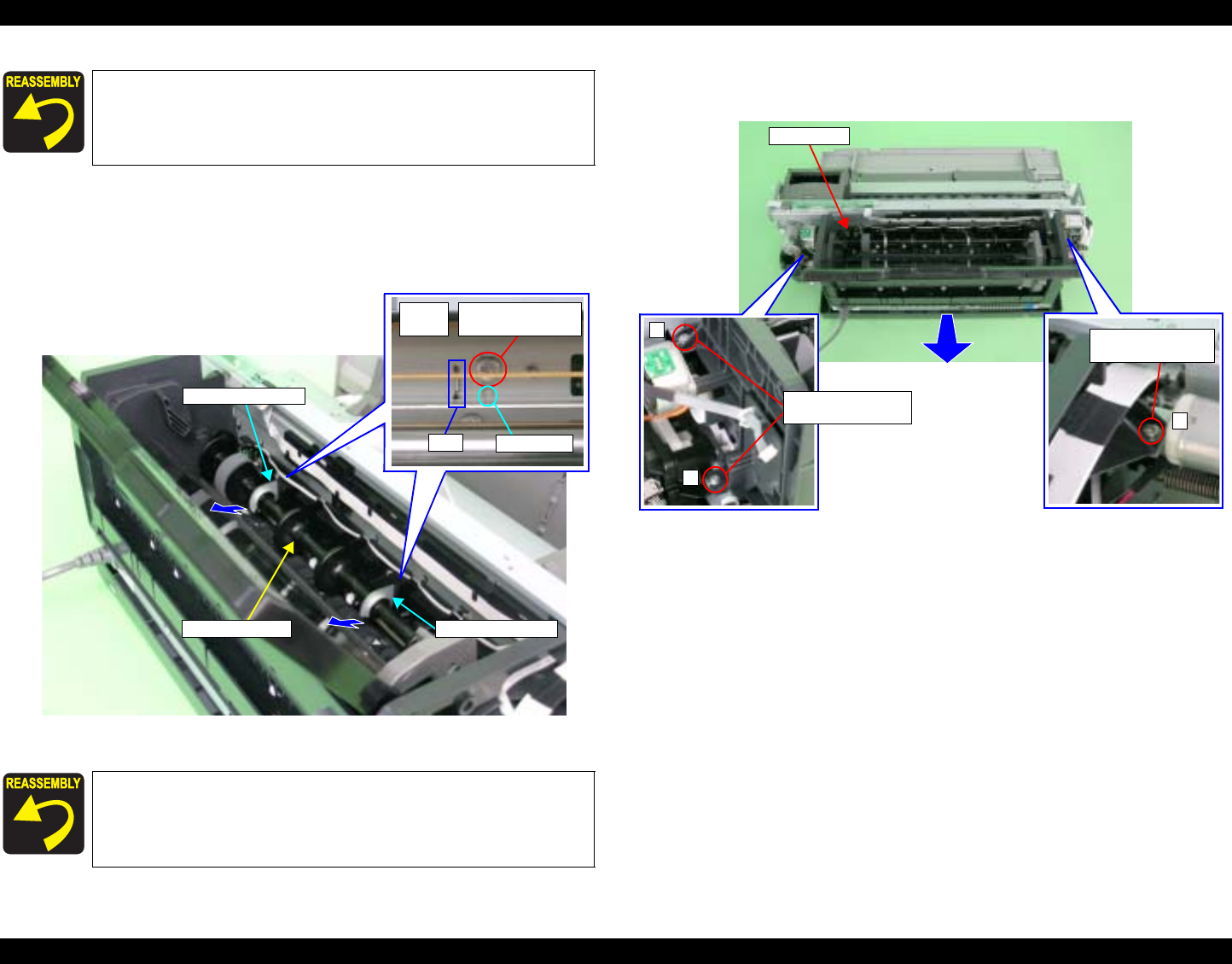
EPSON Stylus Photo R1800/R2400 Revision B
Disassembly And Assembly Disassembly 84
9. Remove the two C.B.S. M3 x 6 screws that secure the two Guide Roller
LDs.
10. Gently pull the LD Roller Shaft to the rear of the printer, and remove the
Guide Roller LDs.
Figure 4-22. Removing the Guide Roller LD
11. Remove the three C.B.S. (P4) M3 x 8 screws that secure the ASF Assy,
and remove the ASF Assy from the Printer Mechanism.
Figure 4-23. Removing the ASF Assy
Referring to Figure 4-21., correctly route each of the Cables
and FFC.
Align the Guide Pins and Tabs on the Guide Roller LDs with
the positioning holes on the Main Frame. Refer to Figure
4-22.
Front
Face 2) C.B.S. 3x6
(8±1 kgf.cm)
Guide Pin
Tab
LD Roller Shaft Guide Roller LD
Guide Roller LD
2
1
6) C.B.S. (P4) 3x8
(6±1 kgf.cm)
ASF Assy
6) C.B.S. (P4) 3x8
(6±1 kgf.cm)
3

EPSON Stylus Photo R1800/R2400 Revision B
Disassembly And Assembly Disassembly 85
Align the Guide Pin and four Tabs on the ASF Assy with
the positioning holes on the Main Frame so that there is
no gap between the ASF Assy and the Main Frame.
Figure 4-24. Reinstalling the ASF Assy.
Tighten the screws in the order shown in Figure 4-23.
Tab Guide Pin
Tab
Tab
Tab
Adjusting the Position of the ASF Guide Roller LDs
When installing the Guide Roller LDs, the position of the
Guide Roller LDs must be adjusted so that the positions
of the LD Roller Shaft and Retard Roller are optimized in
order to maintain the paper feed accuracy.
1. After installing the ASF Assy, loosen the two C.B.S.
M3 x 6 screws that secure the Guide Roller LD. Refer
to Figure 4-22.
2. Turn Combination Gear 29.11 on the right side of the
ASF Assy CCW to raise the Hopper to the upper limit
position (until the Hopper Pad contacts the LD
Roller).
Figure 4-25. Raising the Hopper
Combination Gear 29.11
Hopper Pad
LD Roller
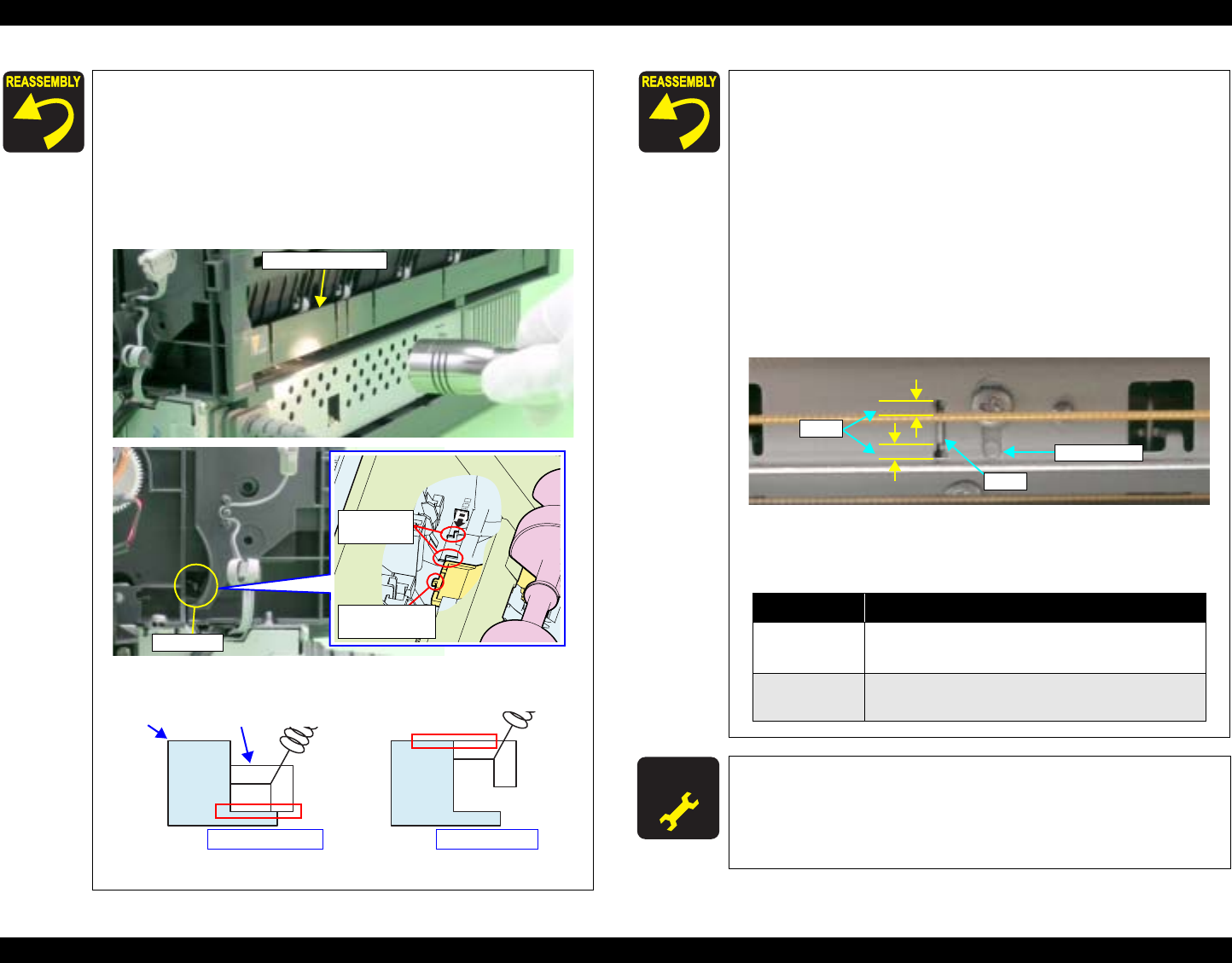
EPSON Stylus Photo R1800/R2400 Revision B
Disassembly And Assembly Disassembly 86
3. Look the printer's inside through a gap between the
Roll Paper Frame and the ASF Assy with a penlight.
You can see the Tab on the Retard Roller Holder at
the back of the two Reference Tabs on the ASF Assy.
After making sure that the two Reference Tabs are
aligned when viewed edge-on, adjust the position of
the Retard Roller Holder Tab by pressing the Guide
Roller LD (0 digit side) so that it is placed within the
range as shown in the simplified diagram below.
The Range of the Retard Roller Holder Tab
Figure 4-26. Aligning the Position of the Guide Roller LD (0 Digit Side)
Roll Paper Frame
Retard Roller
Holder Tab
Reference
Tabs
Notch
Reference Tabs
Lower Limit Upper Limit
Retard Roller Holder Tab
4. Align the Guide Pin and Tab on the 0 Digit Side Guide
Roller LD with the positioning holes on the Main
Frame, and tighten the Guide Roller LD (0 Digit Side)
with the screws. See Figure 4-27.
5. Check the position of the Retard Roller Holder Tab
again through the gap. If it is not inside the range,
remove the screws on the Guide Roller LD (0 Digit
Side), and repeat steps 2 to 4 to set the Tab within
the range.
6. Check the clearance in both ends of the positioning
hole that the Guide Roller LD Tab is inserted. And
align Guide Roller LD (130 Digit Side) to the same
height, and tighten with the screws.
Figure 4-27. Checking the Position of Tab on the Guide Roller LD
A D J U S T M E N T
R E Q U I R E D The following adjustment must be performed when the ASF
Assy is replaced or removed:
First dot position
Refer to Chapter 5 "Adjustment" for details of the
adjustments.
Gap
Tab
Guide Pin
Table 4-5. Trouble Caused by Setting Mistakes
Tab Position Trouble
Above
upper limit • Paper feed mistakes caused by non-feed
• Skewing of business cards
Below
lower limit • Multiple-sheet feeding
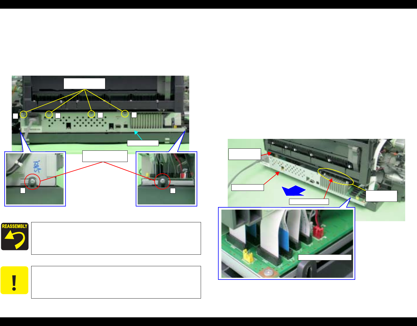
EPSON Stylus Photo R1800/R2400 Revision B
Disassembly And Assembly Disassembly 87
4.2.5 Removing the Boards
4.2.5.1 Board Assy
1. Remove the Rear Housing. See Section 4.2.1.1 on page 74.
2. Remove the four C.B.S. M3 x 6 screws and two C.B.S. (P2) M3 x 10
screws that secure the Board Assy.
Figure 4-28. Screws that Secure the Board Assy
3. Disconnect all the FFCs and Connector Cables connected to the Board
Assy in order from the front, and draw out the Board Assy from the Printer
taking care to avoid interference between the Manual Paper Guide and the
Ground Plates on the Board Assy.
CN5 : Relay FFC
CN8 : LED FFC
CN9 : Sensor FFC
CN10 : Sensor FFC
CN11 : Head FFC
CN12 : Head FFC
CN13 : Head FFC
CN14 : Head FFC
CN16 : PF Motor Connector Cable
CN17 : Relay Connector Cable (for Pump Motor)
CN18 : APG Motor Connector Cable
CN19 : Relay Connector Cable (for CR Motor)
Figure 4-29. Removing the Board Assy
Tighten the screws in the order shown in Figure 4-28.
C A U T I O N When performing the following procedure, prevent the FFC
and Connector Cables from being scratched.
Board Assy
1234
5
6
3) C.B.S. (P2) 3x10
(6±1 kgf.cm)
2) C.B.S. 3x6
(8±1 kgf.cm)
FFCs and Connectors
Point of
Interference
Board Assy
Manual Paper
Guide
Grounding Plate
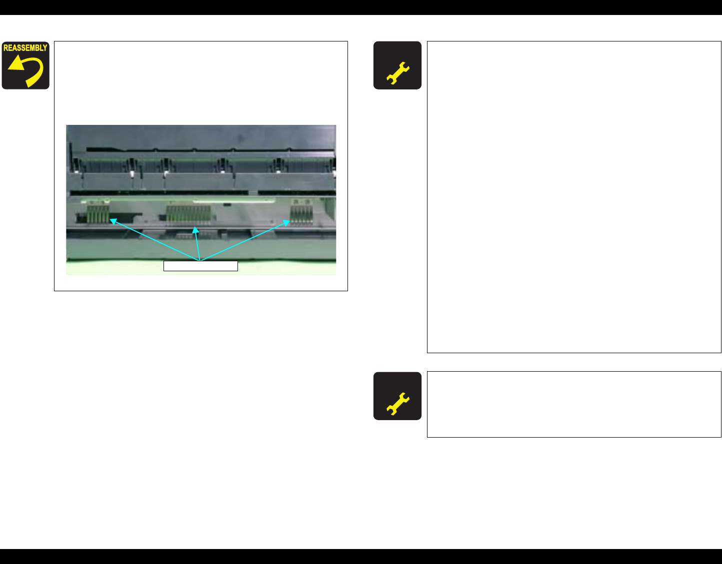
EPSON Stylus Photo R1800/R2400 Revision B
Disassembly And Assembly Disassembly 88
Make sure that the FFCs are not crossing each others,
and connect each of the FFCs and Connector Cables to
the Main Board while paying attention to the edge of the
Shield Plate.
Take care not to put the Board Assy onto the three
Ground Plates.
Figure 4-30. Reinstalling the Board Assy
Grounding Plates
A D J U S T M E N T
R E Q U I R E D The following adjustment must be performed after replacing
the Main Board.
When possible to read data from the old board
1.Main Board Data Read/Write
2.Colorimetric Calibration
When impossible to read data from the old board
1.Market & Initial Settings
2.USB ID Input
3.IEEE-1394 ID Input
4.Head ID Input
5.Ink Mark Sensor Adjustment
6.Head Angular Adjustment
7.Auto Bi-D Adjustment
8.Ink Mark Sensor Adjustment
9.First dot position
10.PW Sensor Adjustment
11.Reset PF Deterioration counter (write the maximum
value)
12.PF Adjustment
13.PF Adjustment (Bottom Margin)
14.Colorimetric Calibration
15.CR Motor Drive Dispersion
Refer to Chapter 5 "Adjustment" for details of the
adjustments.
A D J U S T M E N T
R E Q U I R E D The following adjustment must be performed after replacing
the Power Supply Board.
CR Motor Drive Dispersion
Refer to Chapter 5 "Adjustment" for details of the
adjustments.
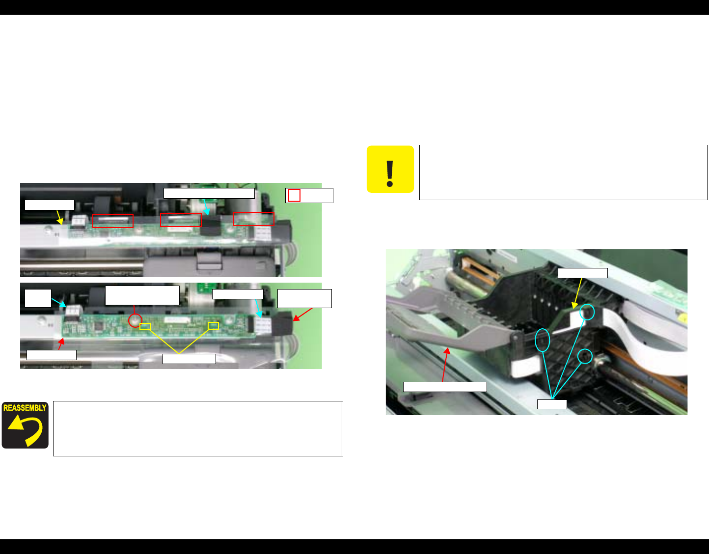
EPSON Stylus Photo R1800/R2400 Revision B
Disassembly And Assembly Disassembly 89
4.2.5.2 LED Board
1. Remove the Upper Housing. See Section 4.2.1.4 on page 76.
2. Peel off a piece of acetate tape from the LED Sheet.
3. Release the three Tabs from the LED sheet, and open the LED sheet.
4. Peel off a piece of acetate tape from the Panel FFC, and remove the Panel
FFC from the LED Board.
5. Remove the LED FFC from the LED Board.
6. Remove the C.B.S. (P4) M3 x 8 screw that secures the LED Board, and
remove the LED Board.
Figure 4-31. Removing the LED Board
4.2.6 Disassembling the Printer Mechanism
4.2.6.1 Print Head
1. Remove the Upper Housing. See Section 4.2.1.4 on page 76.
2. Release the Carriage lock, and move the Carriage Unit to the center.
See Section 4.2.1.3 on page 75.
3. Open the Ink Cartridge Cover.
4. Release the FFC Guide from the three Tabs to remove the FFC Guide
from the Carriage Unit.
Figure 4-32. Removing the FFC Guide
Align the two Tabs on the Upper Housing with the
positioning holes on the LED Board. See Figure 4-31.
Tab
LED Sheet
Acetate Tape (Step 2)
6) C.B.S. (P4) 3x8
(6±1 kgf.cm)
Guide Pins
LED Board
LED
FFC Acetate Tape
(Step 4)
Panel FFC
C A U T I O N When performing the following procedure, take care to
prevent the Tab receptacle on the FFC Guide from being
damaged.
Tabs
FFC Guide
Ink Cartridge Cover
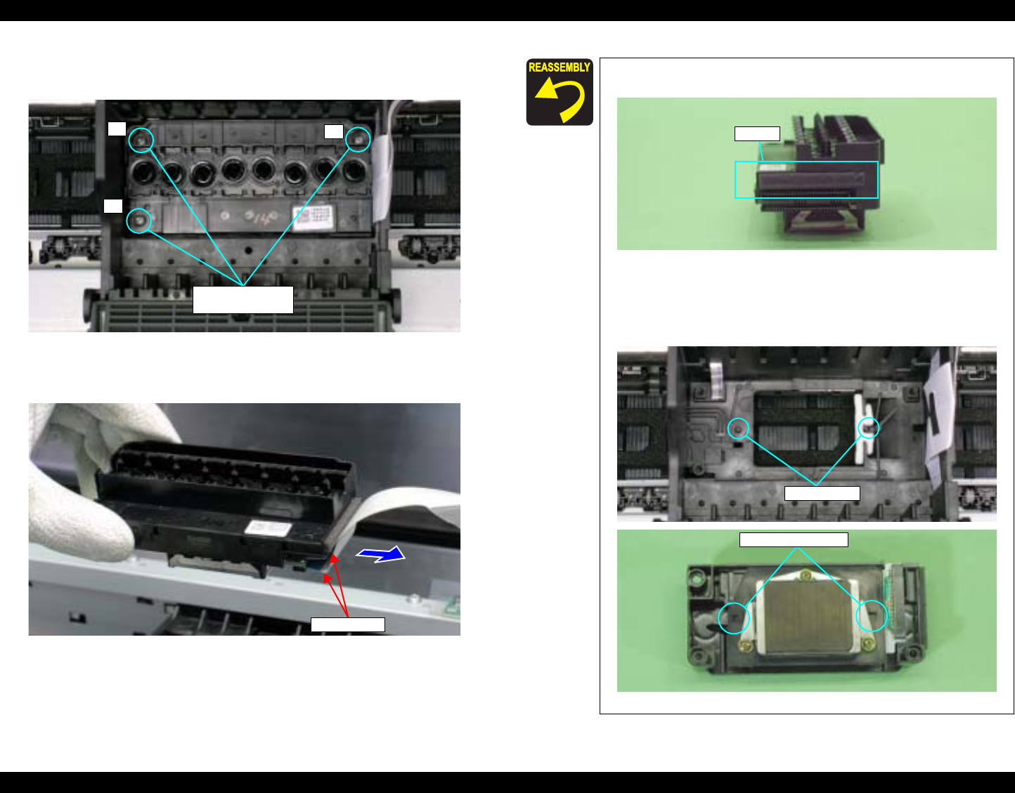
EPSON Stylus Photo R1800/R2400 Revision B
Disassembly And Assembly Disassembly 90
5. Remove the three C.B.P. M2.6 x 8 screws that secure the Print Head using
No.1 Phillips Screw Driver, and vertically lift the Print Head to remove.
Figure 4-33. Removing the Print Head
6. Remove the two Head FFCs from the Print Head.
Figure 4-34. Removing the Head FFC
Head
7) C.B.P. 2.6x8
(3±0.5 kgf.cm)
12
3
Head FFC
Make sure that the Pad is attached at the position in
Figure 4-35..
Figure 4-35. Attaching the Pad
The Print Head must be installed with the Guide Pins of
the Carriage Unit aligned with the positioning holes on
the Print Head.
Figure 4-36. Reinstalling the Print Head (1)
Pad
Guide Pins
Positioning Holes
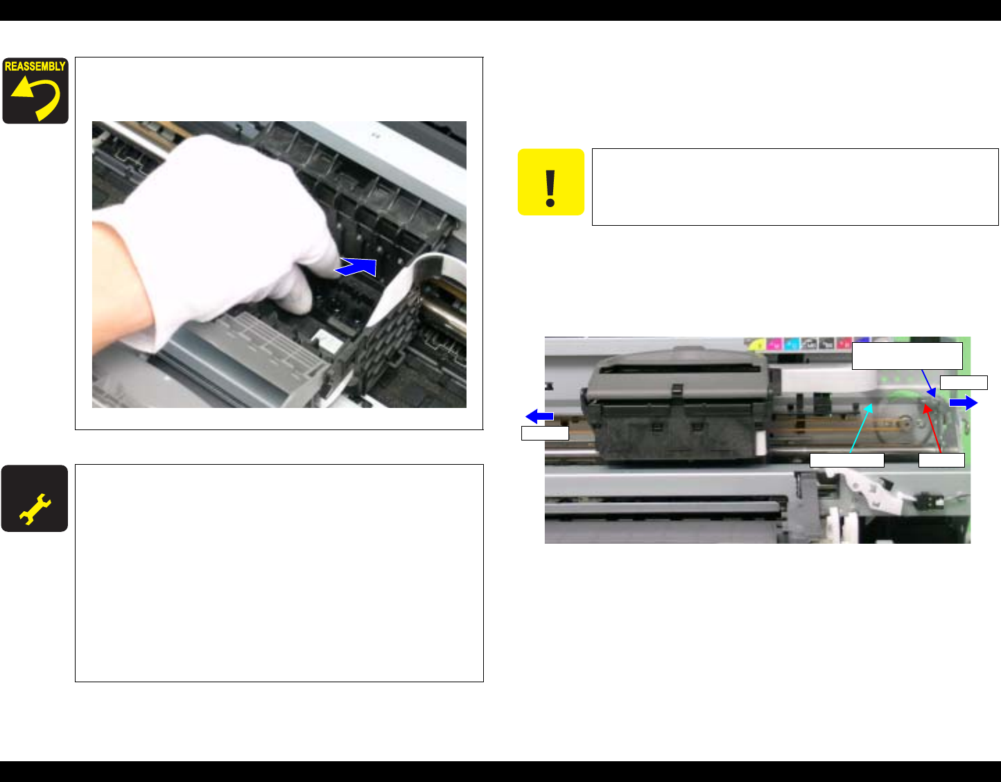
EPSON Stylus Photo R1800/R2400 Revision B
Disassembly And Assembly Disassembly 91
4.2.6.2 CR Scale
1. Remove the Upper Housing. See Section 4.2.1.4 on page 76.
2. Release the Carriage lock, and move the Carriage Unit to the center.
See Section 4.2.1.3 on page 75.
3. Pull the right end of the CR Scale in the direction of the arrow, and remove
the CR Scale from the Tab on the Right CR Shaft Mounting Plate.
4. Draw out the right end of the CR Scale towards the left direction from the
rear of the Carriage Unit.
Figure 4-38. Drawing Out the CR Scale
The screws must be tightened in the order shown in
Figure 4-33. while the Print Head is held down in the
direction of the arrow.
Figure 4-37. Reinstalling the Print Head (2)
A D J U S T M E N T
R E Q U I R E D After replacing or removing the Print Head, always make the
following adjustments.
1. PG Adjustment
2. Head ID Input (only after replacing)
3. Ink Mark Sensor Adjustment
4. Head Angular Adjustment
5. Auto Bi-D Adjustment
6. First dot position
7. PW Sensor Adjustment
8. Colorimetric Calibration (only after replacing)
Refer to Chapter 5 "Adjustment" for details of the
adjustments.
C A U T I O N When performing the following procedure, take care to
prevent both ends of the CR Scale from being broken.
Step 3
Step 4
Right CR Shaft
Mounting Plate
Tab
CR Scale
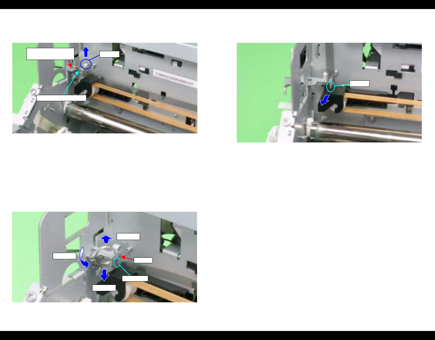
EPSON Stylus Photo R1800/R2400 Revision B
Disassembly And Assembly Disassembly 92
5. Remove the coil section of Torsion Spring 24.7 from the Tab on the Left
CR Shaft Mounting Plate with tweezers.
Figure 4-39. Removing the Torsion Spring 24.7 (1)
6. Remove Torsion Spring 24.7 from the CR Scale by the following
procedure:
6-1. Stand the coil section.
6-2. Lower the coil section downwards to remove Foot 1 from the notch
on the Left CR Shaft Mounting Plate.
6-3. Turn the coil section counterclockwise.
6-4. Remove Torsion Spring 24.7 from the hole on the CR Scale.
Figure 4-40. Removing the Torsion Spring 24.7 (2)
7. Turn the CR Scale 90º, and remove it from the Tab on the Left CR Shaft
Mounting Plate.
Figure 4-41. Removing the CR Scale
Left CR Shaft
Mounting Plate
Torsion Spring 24.7
Tab
Step 6-1
Step 6-2
Step 6-3 Foot 1
Notch
Tab
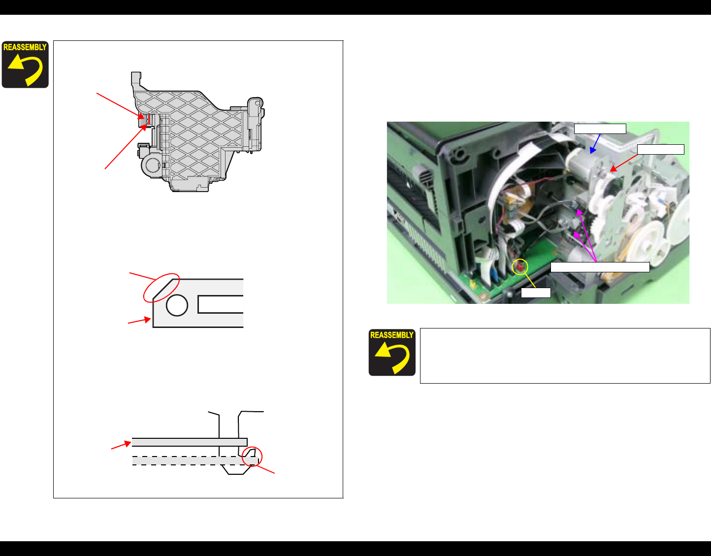
EPSON Stylus Photo R1800/R2400 Revision B
Disassembly And Assembly Disassembly 93
4.2.6.3 APG Assy
1. Remove the Upper Housing. See Section 4.2.1.4 on page 76.
2. Disconnect the APG Motor Connector Cable from Connector CN18 (red)
on the Main Board, and Remove the Cable from the ASF Assy.
3. Disconnect the Connector Cables from the two APG Sensor Connectors.
Figure 4-45. Disconnecting the Connector Cables
Pass the CR Scale through the slot on the CR Encoder.
Figure 4-42. Reinstalling the CR Scale (1)
Set the left end of the CR Scale with the chamfered edge
facing upwards.
Figure 4-43. Reinstalling the CR Scale (2)
Place the right end of the CR Scale correctly so that it is
not hooked onto the Right CR Shaft Mounting Plate.
Figure 4-44. Reinstalling the CR Scale (3)
CR Encoder
CR Scale
CR Scale
Chamfered edge
CR Scale
Hooked Portion
OK
NG
Referring to Figure 4-45., correctly route the APG Connector
Cable.
APG Assy
APG Sensor Connectors
CN18
APG Motor
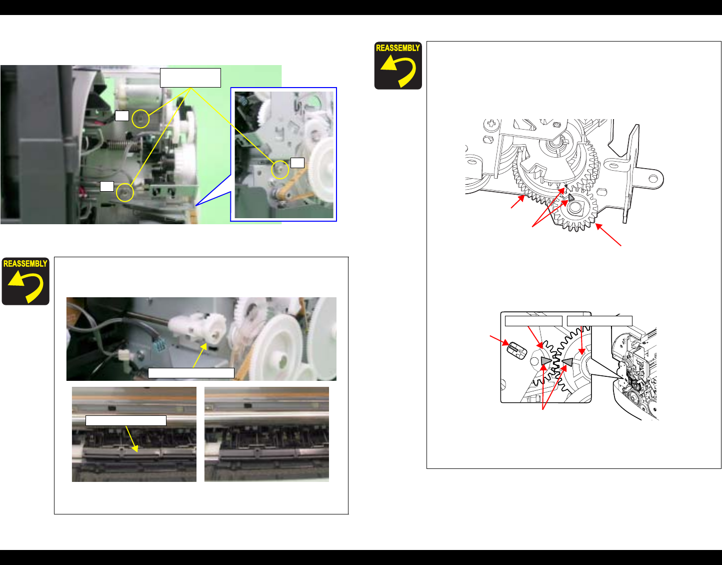
EPSON Stylus Photo R1800/R2400 Revision B
Disassembly And Assembly Disassembly 94
4. Remove the three C.B.S. M3 x 6 screws that secure the APG Assy, and
remove the APG Assy from the Main Frame.
Figure 4-46. Removing the APG Assy
When installing the APG Assy, make sure that the FLAG
Release Assy is not in a released state (Upper Paper
Guide down).
Figure 4-47. Reinstalling the APG Assy
3
1
2
2) C.B.S. 3x6
(8±1 kgf.cm)
FLAG Release Assy.
Released Not Released
Upper Paper Guide
Match the phase of the APG Assy in the following
procedure.
1.Match the delta marks of Spur Gear 16 and
Combination Gear 22, 28.8, 32.4.
2.At the position where the Tab can be identified through
the notch of the PG Frame, match the delta marks of
Spur Gear 16 and PG Cam (Left).
Figure 4-48. Phase Matching
Tighten the screws in the order shown in Figure 4-46.
Delta Marks
Spur Gear 16
Combination Gear,
22, 28.8, 32.4
Delta Marks
Tab Spur Gear 16 PG Cam (Left)
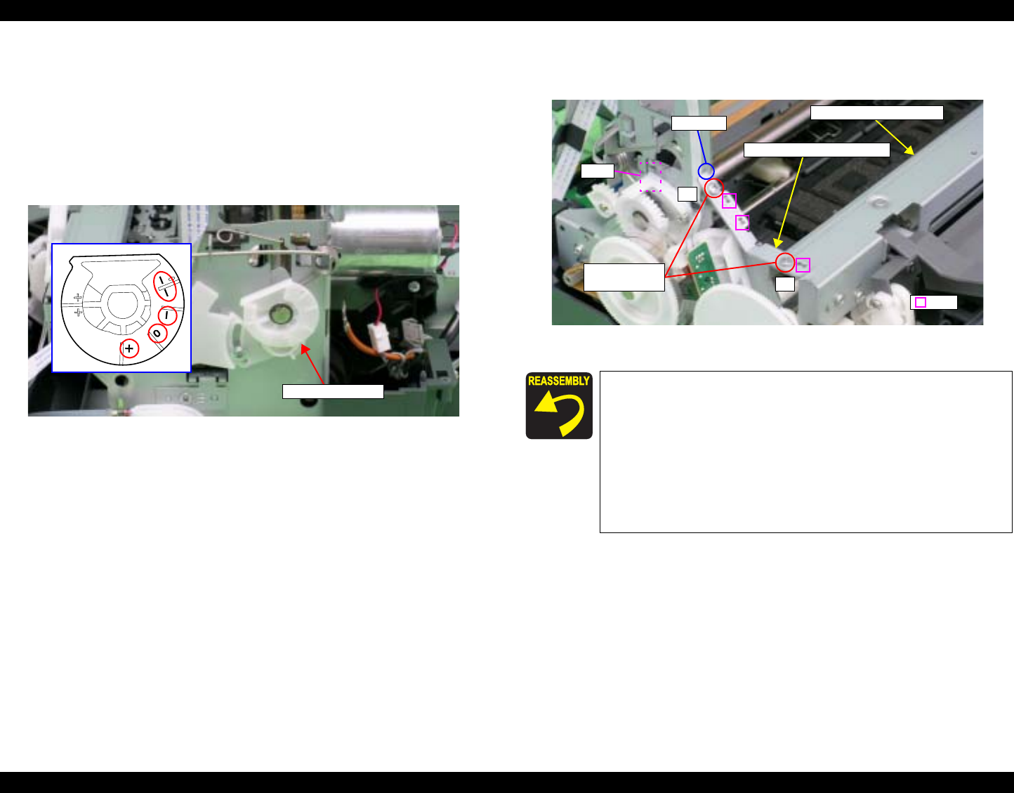
EPSON Stylus Photo R1800/R2400 Revision B
Disassembly And Assembly Disassembly 95
4.2.6.4 Carriage Shaft and Carriage Unit
1. Remove the LED Board. See Section 4.2.5.2 on page 89.
2. Remove the Print Head. See Section 4.2.6.1 on page 89.
3. Remove the CR Scale. See Section 4.2.6.2 on page 91.
4. Remove the APG Assy. See Section 4.2.6.3 on page 93.
5. Point any position other than PG++ on the PG Cam (Right) to face down.
Figure 4-49. Setting the PG Cam
6. Remove the two C.B.S. M3 x 6 screws that secure the Frame Support
Plate (Left), and remove it.
Figure 4-50. Removing the Left Frame Support Plate
PG Cam (Right) Insert the Left Frame Support Plate into the notch on the
Main Frame. See Figure 4-50.
Align the two Tabs on the Main Frame and the Tab on the
Paper EJ Frame Assy with the three positioning holes on
the Frame Support Plate (Left). See Figure 4-50.
Align the Tab (rear side) of the Left Frame Support Plate
with the outside of the Left CR Shaft Mounting Plate. See
Figure 4-50.
Tighten the screws in the order shown in Figure 4-50.
1
2
2) C.B.S. 3x6
(8±1 kgf.cm)
Tab
Tabs
Left Frame Support Plate
Paper EJ Frame Assy.
Notch
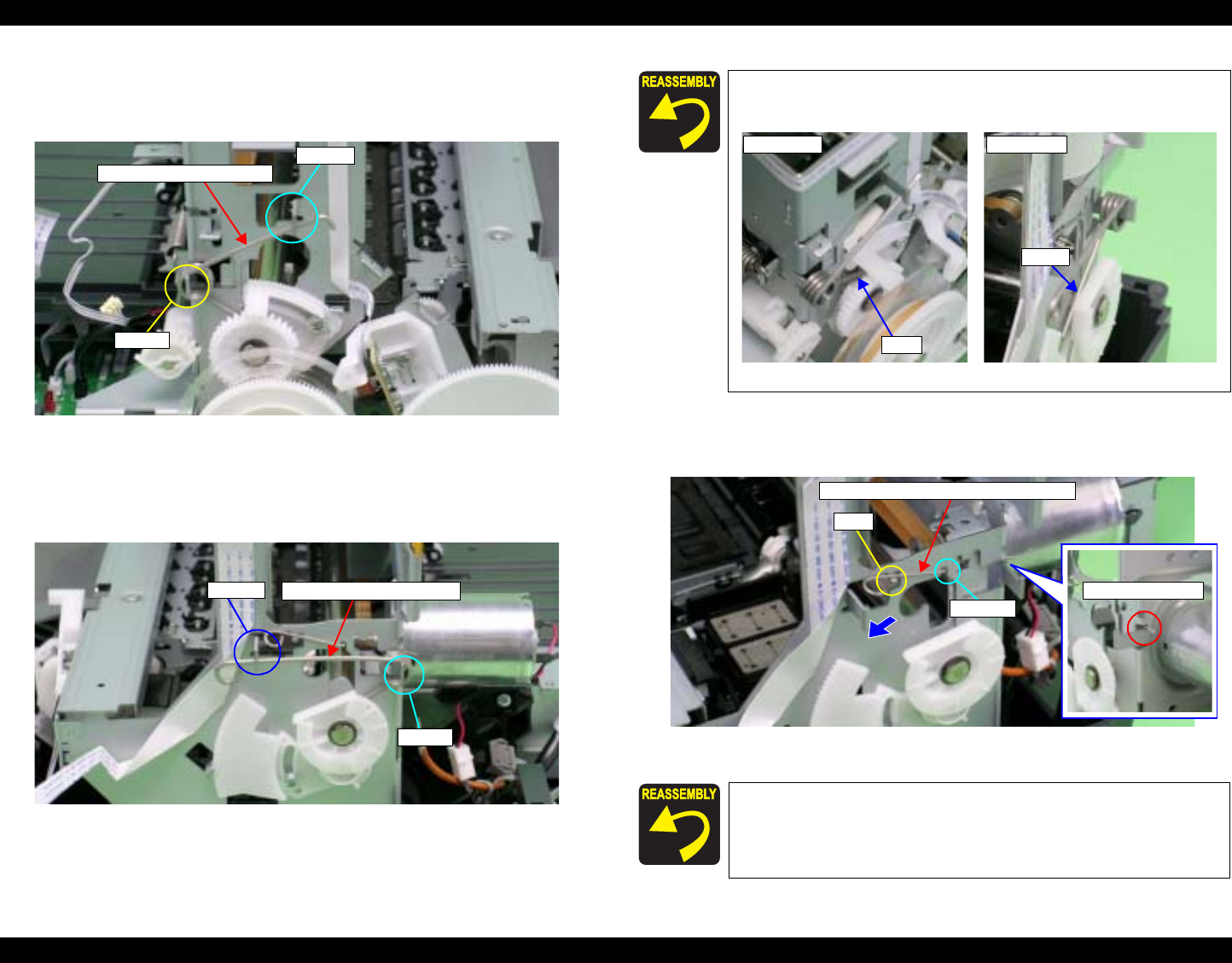
EPSON Stylus Photo R1800/R2400 Revision B
Disassembly And Assembly Disassembly 96
7. Remove the foot of Left PG Torsion Spring from Tab A, and remove the
coil section from Tab B to remove Left PG Torsion Spring from the Main
Frame.
Figure 4-51. Removing Left PG Torsion Spring
8. Remove the foot of Right PG Torsion Spring from Tab A, and remove the
coil section from Tab B to remove Right PG Torsion Spring from the Main
Frame.
Figure 4-52. Removing Right PG Torsion Spring
9. Remove CR Shaft Mounting Plate Fixed Spring from the Tab and Notch on
the Main Frame, and draw out the spring in the direction of the arrow.
Figure 4-54. Removing CR Shaft Mounting Plate Fixed Spring
Left PG Torsion Spring
Tab A
Tab B
Right PG Torsion Spring
Tab A
Tab B
Place the feet of Left PG Torsion Spring and Right PG
Torsion Spring on the Carriage Shaft.
Figure 4-53. Reinstalling PG Torsion Springs
Insert the foot of CR Shaft Mounting Plate Fixed Spring into
the notch on the Main Frame (rear side). See Figure 4-54.
Foot
Left Side
Foot
Right Side
Tab
CR Shaft Mounting Plate Fixed Spring
Notch
Notch (rear side)
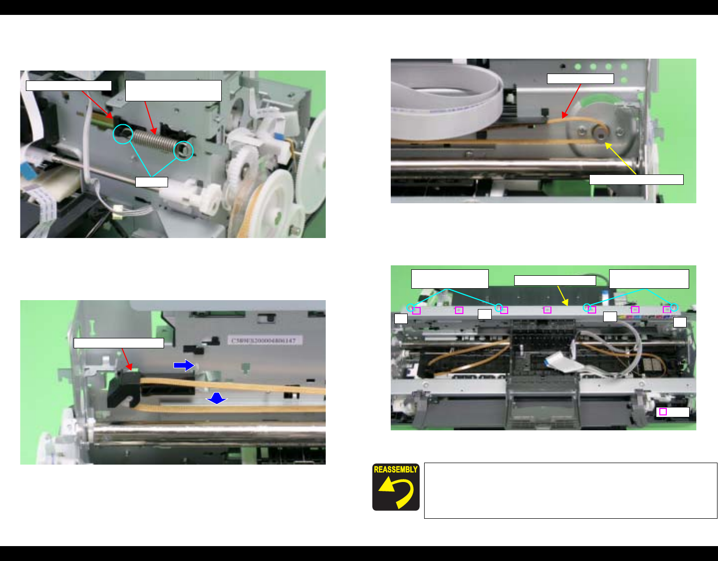
EPSON Stylus Photo R1800/R2400 Revision B
Disassembly And Assembly Disassembly 97
10. Remove the Extension Spring for the Driven Pulley Holder from the Main
Frame and the Tab on the Drive Pulley Holder with needle-nose pliers.
Figure 4-55. Removing the Extension Spring for the Driven Pulley Holder
11. Remove the Driven Pulley Holder toward you after sliding it to the right end
of the notch on the Main Frame.
Figure 4-56. Removing the Driven Pulley Holder
12. Remove the CR Drive Belt from the CR Motor Pinion Gear.
Figure 4-57. Removing the CR Drive Belt
13. Remove the four C.B.S. (P4) M3 x 6 screws that secure the CR Guide
Plate, and remove it from the Main Frame.
Figure 4-58. Removing the CR Guide Plate
Tabs
Extension Spring for the
Driven Pulley Holder
Driven Pulley Holder
Driven Pulley
Driven Pulley Holder
Align the positioning holes on the CR Guide Plate with
the seven Tabs on the Main Frame. See Figure 4-58.
Tighten the screws in the order shown in Figure 4-58.
CR Drive Belt
CR Motor Pinion Gear
CR Guide Plate
4321
8) C.B.S. (P4) 3x6
(8±1 kgf.cm) 8) C.B.S. (P4) 3x6
(8±1 kgf.cm)
Tabs
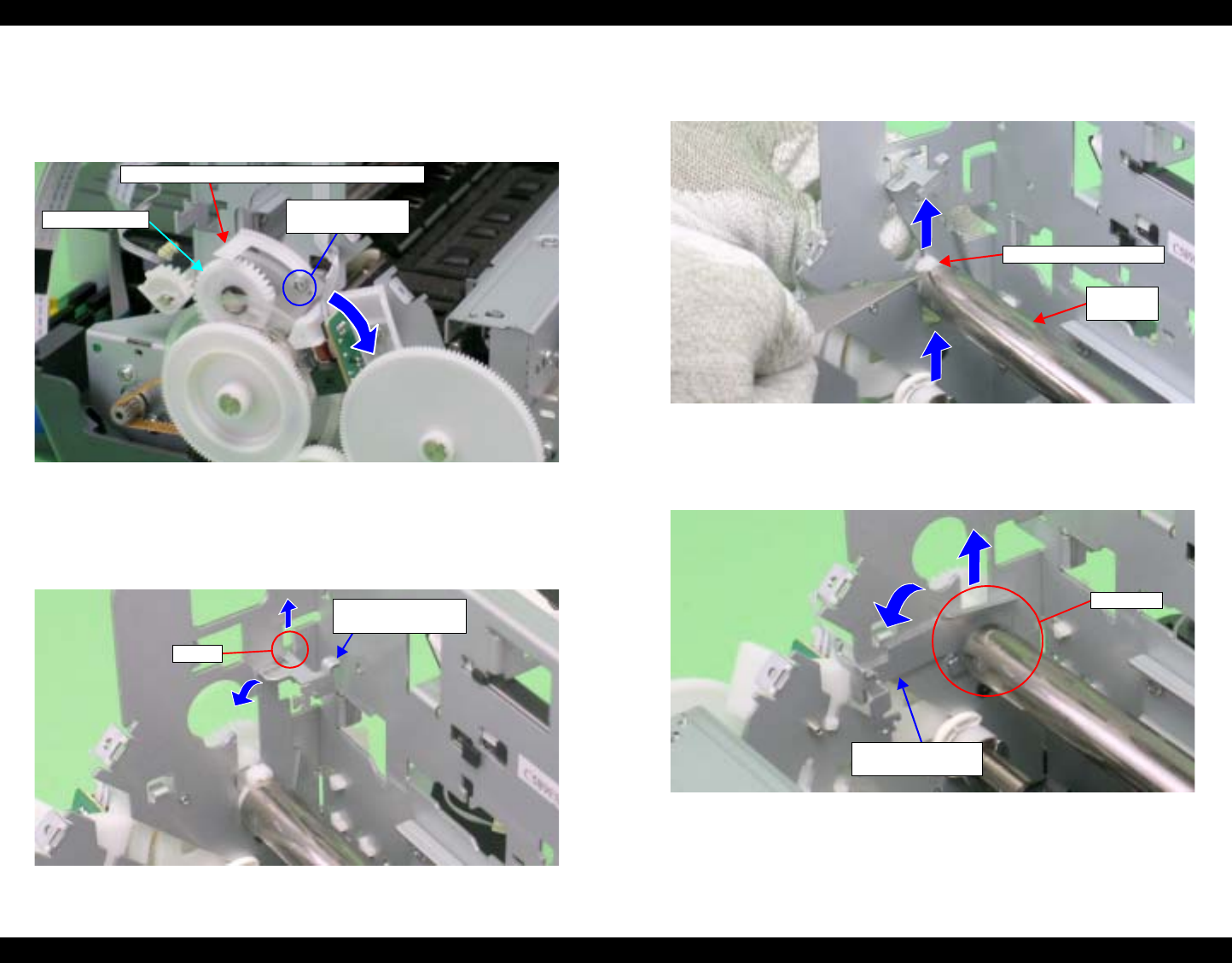
EPSON Stylus Photo R1800/R2400 Revision B
Disassembly And Assembly Disassembly 98
14. Loosen the C.B.S. (P4) M3 x 8 screw that secures the Left Parallelism
Adjust Bushing, and rotate the Bushing toward the front of the Printer
Mechanism to prevent interference between the Flag of the Parallelism
Adjust Bushing and the Left PG Cam.
Figure 4-59. Rotating the Left Parallelism Adjust Bushing
15. Slide the Left CR Shaft Mounting Plate upwards, and release the Tab on
the Left CR Shaft Mounting Plate from the notch on the Main Frame to
rotate the Mounting Plate toward you.
Figure 4-60. Rotating the Left CR Shaft Mounting Plate
16. Lift the Carriage Shaft upwards, and remove the Carriage Shaft Spacer
from the Carriage Shaft with tweezers.
Figure 4-61. Removing the Carriage Shaft Spacer
17. Rotate the Left CR Shaft Mounting Plate toward you to remove the
Bushing on the Left CR Shaft Mounting Plate from the Carriage Shaft.
Figure 4-62. Removing the Left CR Shaft Mounting Plate
6) C.B.S. (P4) 3x8
(5±1 kgf.cm)
Left PG Cam
Flag of the Parallelism Adjust Bushing (Left)
Left CR Shaft
Mounting Plate
Tab
Carriage
Shaft
Carriage Shaft Spacer
Left CR Shaft
Mounting Plate
Bushing
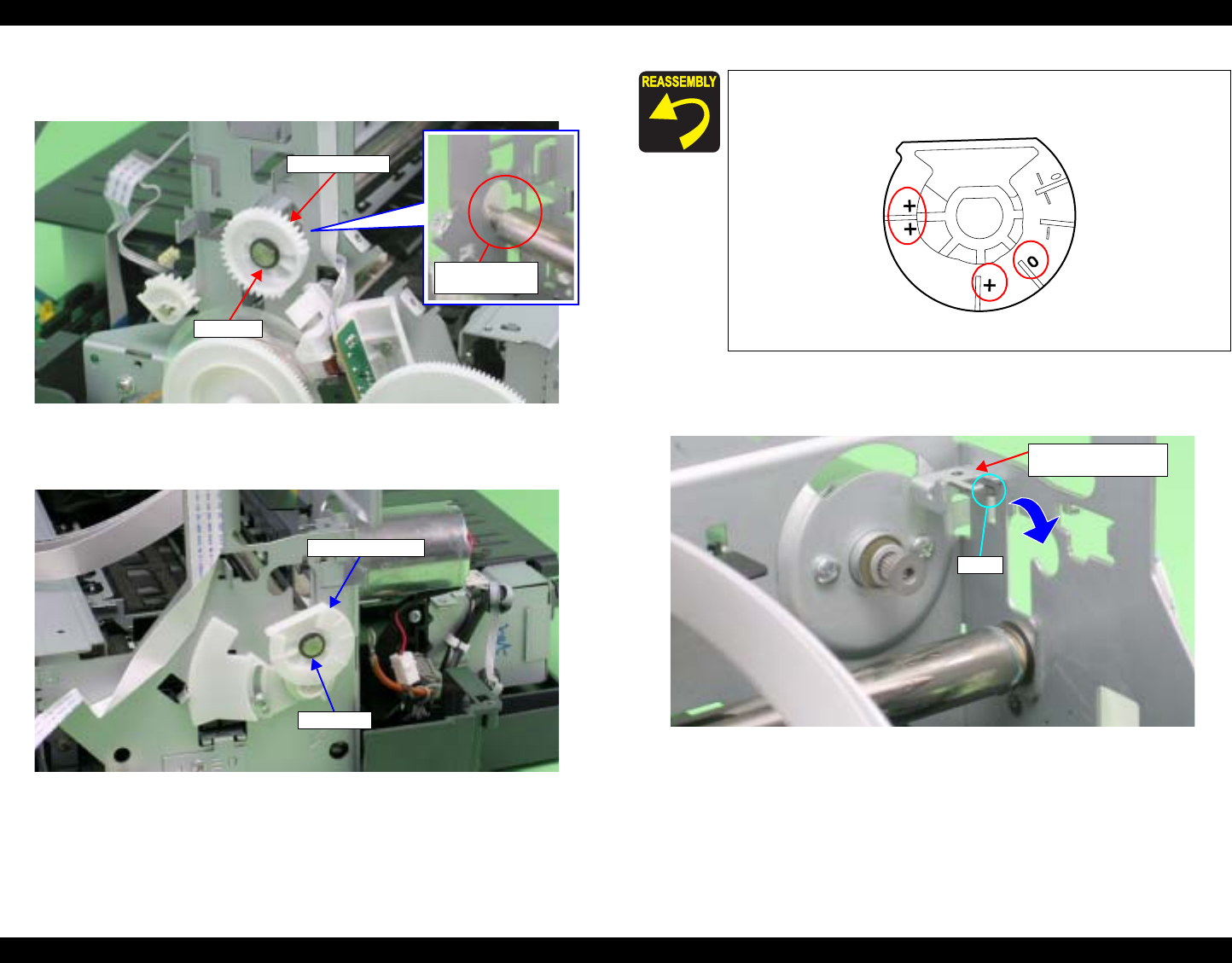
EPSON Stylus Photo R1800/R2400 Revision B
Disassembly And Assembly Disassembly 99
18. Lift the Carriage Shaft within the hole on the Main Frame, and remove the
Spacer and Left PG Cam from the Carriage Shaft.
Figure 4-63. Removing Left PG Cam
19. Remove the Spacer and Right PG Cam from the Carriage Shaft.
Figure 4-64. Removing Right PG Cam
20. Pull the Right CR Shaft Mounting Plate away from the Tab on the Main
Frame and rotate toward you.
Figure 4-66. Rotating the Right CR Shaft Mounting Plate
Spacer
PG Cam (Left)
Hole on Main
Frame
Spacer
Right PG Cam
Install the Right PG Cam so that one of these positions
marked "0", "+" or "++" faces downward.
Figure 4-65. Right PG Cam Installation Direction
Right CR Shaft
Mounting Plate
Ribs
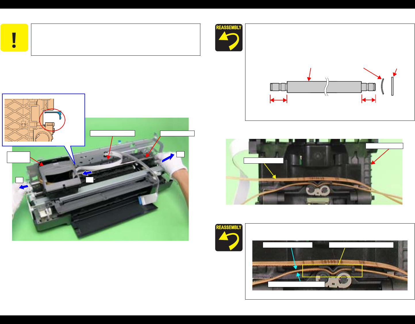
EPSON Stylus Photo R1800/R2400 Revision B
Disassembly And Assembly Disassembly 100
21. Slide the Carriage Unit to the left side to prevent the CR Scale Cover from
interfering with the rear of the Carriage Unit, slide the Carriage Shaft to the
left side and draw out its right end from the Main Frame, and draw out the
Carriage Shaft from the Main Frame and Carriage Unit.
Figure 4-67. Removing the Carriage Shaft
22. Remove the CR Drive Belt from the Carriage Unit.
Figure 4-69. Removing the CR Drive Belt
C A U T I O N When performing the following procedure, take care not to
scratch the Carriage Shaft.
Carriage
Unit
Carriage Shaft
P
o
i
n
t
o
f
Interference
CR Scale Cover
1
2
3
Set the longer end of the Carriage Shaft to the left side.
When the Carriage Shaft is removed, the Plain Spring
and Leaf Spring that are attached to the right end of the
Carriage Shaft may drop off. In such case, be sure to
attach them in the order as shown in the figure below.
Figure 4-68. Reinstalling the Carriage Shaft
Referring to the figure below, install the CR Drive Belt so that
its top and rear sides face the correct way.
Figure 4-70. Reinstalling the CR Drive Belt
Leaf Spring Plain Spring
Carriage Shaft
Left Side Right
Side
Longer Shorter
Carriage Unit
CR Drive Belt
With Tooth Surface
Without Tooth Surface
Both Surfaces have Tooth
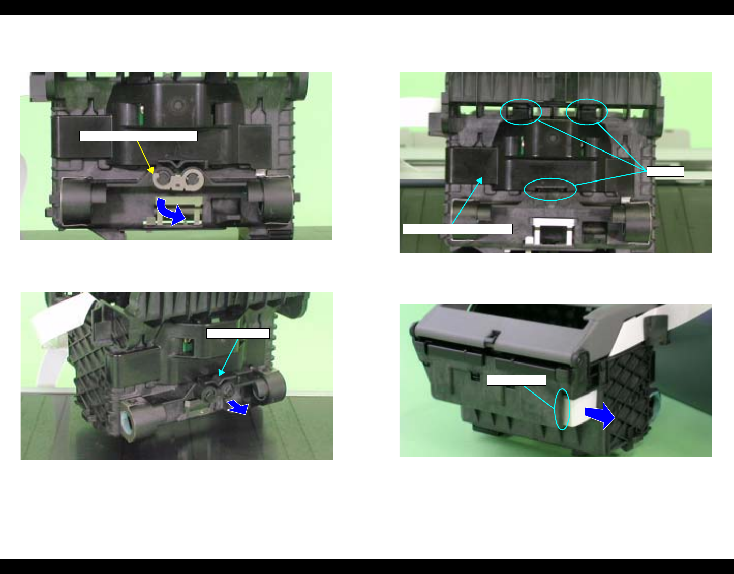
EPSON Stylus Photo R1800/R2400 Revision B
Disassembly And Assembly Disassembly 101
23. Turn the Belt Holder Mounting Plate in the direction of the arrow, and
remove it from the Carriage Unit.
Figure 4-71. Removing the Belt Holder (1)
24. Remove the Belt Holder from the Carriage unit.
Figure 4-72. Removing the Belt Holder (2)
25. Release the CR Encoder Board Holder from the three Tabs to remove it
from the Carriage Unit.
Figure 4-73. Removing the CR Encoder Board Holder
26. Disconnect the Sensor FFC from the Connector on the CSIC Board.
Figure 4-74. Removing the Sensor FFC
Belt Holder Mounting Plate
Belt Holder
CR Encoder Board Holder
Tabs
Sensor FFC
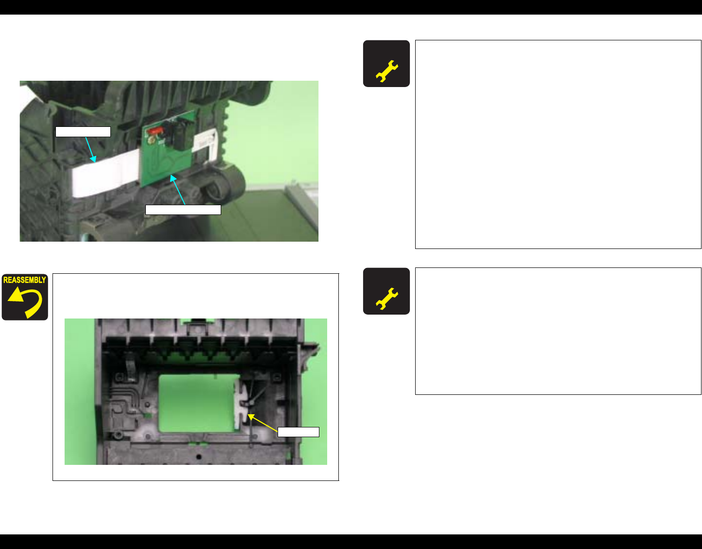
EPSON Stylus Photo R1800/R2400 Revision B
Disassembly And Assembly Disassembly 102
27. Disconnect the Sensor FFC from the Connector on the CR Encoder Board,
draw out the Sensor FFC from the Carriage Unit, and remove the Carriage
Unit.
Figure 4-75. Removing the Carriage Unit
When the Carriage Unit is removed from the Printer
Mechanism, the CR Pad may drop off. In such case,
correctly install it referring to the figure below.
Figure 4-76. Reinstalling the CR Pad
CR Encoder Board
Sensor FFC
CR Pad
A D J U S T M E N T
R E Q U I R E D After replacing the parts listed below, be sure to apply G-26 or
G-71 grease to the area specified for each part.
Left and Right Parallelism Adjust Bushing
See Figure 6-2 on page 175.
Left and Right CR Scale Mounting Plate
See Figure 6-3 on page 175.
Left and Right PG Cam
See Figure 6-5 on page 176.
Left and Right PG Torsion Spring
See Figure 6-6 on page 176.
CR Guide Plate
See Figure 6-7 on page 176.
Driven Pulley Hoder
See Figure 6-8 on page 177.
Carriage Shaft
See Figure 6-4 on page 176. and Section 6.1.4.1 on page
178.
A D J U S T M E N T
R E Q U I R E D Be sure to perform the following adjustments after the Carriage
Shaft and Carriage Unit are replaced or removed:
1. PG Adjustment
2. Ink Mark Sensor Adjustment
3. Head Angular Adjustment
4. Auto Bi-D Adjustment
5. First dot position
6. PW Sensor Adjustment
Refer to Chapter 5 "Adjustment" for details of the
adjustments.
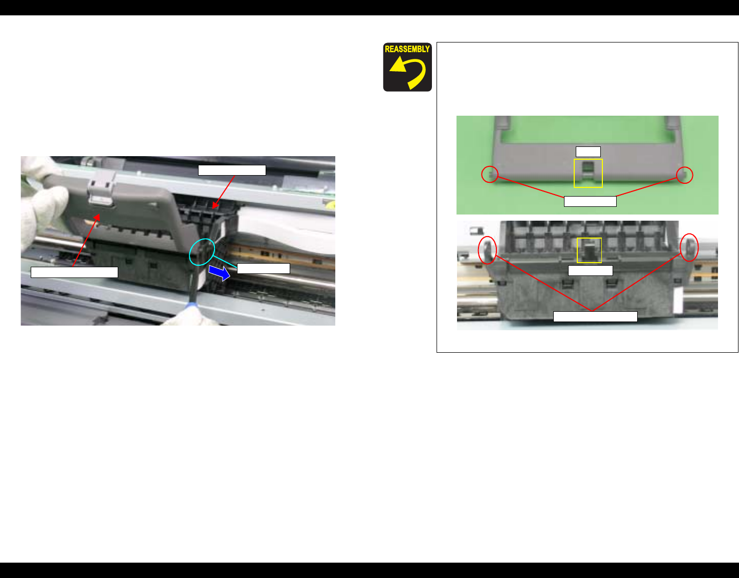
EPSON Stylus Photo R1800/R2400 Revision B
Disassembly And Assembly Disassembly 103
4.2.6.5 CSIC Board
1. Remove the Upper Housing. See Section 4.2.1.4 on page 76.
2. Release the Carriage lock, and move the Carriage Unit to the center.
See Section 4.2.1.3 on page 75.
3. Open the Ink Cartridge Cover.
4. Remove the Guide Pin that secures the Ink Cartridge from the Carriage
Unit with a flat-blade screwdriver, and remove the Ink Cartridge Cover.
Figure 4-77. Removing the Ink Cartridge Cover
Ink Cartridge Cover
Carriage Unit
Guide Pin
Align the positioning holes on the Carriage Unit with the
two Guide Pins on the Ink Cartridge Cover.
Make sure that the shaft on the center of the Ink
Cartridge Cover fits into the Bushing on the Carriage
Unit.
Figure 4-78. Reinstalling Ink Cartridge Cover
Guide Pins
Shaft
Bushing
Positioning Holes
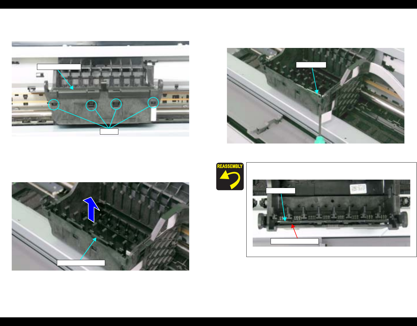
EPSON Stylus Photo R1800/R2400 Revision B
Disassembly And Assembly Disassembly 104
5. Release the CSIC Board Cover from the four Tabs with a flat-blade
screwdriver, and remove the CSIC Board Cover from the Carriage Unit.
Figure 4-79. Removing the CSIC Board Cover
6. Disconnect the Sensor FFC from the CSIC Board Connector. See Step 26
in Section 4.2.6.4 on page 101.
7. Hold the CSIC Board Spacer with your fingers and remove upwards.
Figure 4-80. Removing the CSIC Board Spacer
8. Push up the CSIC Board with a flat-blade screwdriver from the notch on
the right side of the Carriage Unit, and remove the CSIC Board from the
Carriage Unit.
Figure 4-81. Removing CSIC Board
CSIC Board Cover
Tabs
CSIC Board Spacer
The CSIC Board Spacer must be installed at the position
indicated in the figure below.
Figure 4-82. Reinstalling the CSIC Board Spacer
CSIC Board
CSIC Board
CSIC Board Spacer
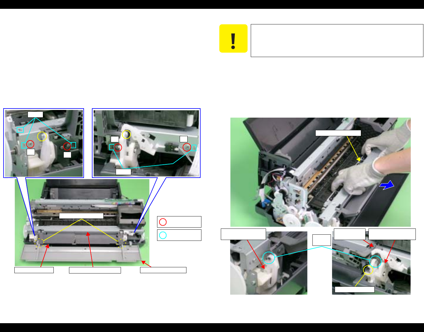
EPSON Stylus Photo R1800/R2400 Revision B
Disassembly And Assembly Disassembly 105
4.2.6.6 Paper EJ Frame Assy.
1. Remove the Upper Housing. See Section 4.2.1.4 on page 76.
2. Remove the CD-R Unit Housing from the CD-R Tray Base by releasing the
Housing from two attaching points to the Tray Base.
3. Remove the Left Frame Support Plate.
See Step 5 and Step 6 in Section 4.2.6.4 on page 95.
4. Return the rotation position of the Right PG Cam.
5. Remove the four C.B.S. M3 x 6 screws and two C.B.P. M3 x 8 screws that
secure the Paper EJ Frame Assy.
Figure 4-83. Screws that Secure the Paper EJ Frame Assy
6. Remove the two Guide Pins on the CD-R Tray Base from the Left and
Right CD-R Release Lever Sub Assy.
7. Pull the Star Wheel Roller toward you, and remove the Paper EJ Frame
Assy from the Printer Mechanism keeping the Assy from coming in contact
with the Right CD-R Release Lever Sub Assy and the Tab on the Right
CD-R Cover.
Figure 4-84. Removing the Paper EJ Frame Assy.
Attaching Points
2
3
Tabs
2) C.B.S. 3x6
(8±1 kgf.cm)
4) C.B.P. 3x8
(8±1 kgf.cm)
4
1
Tabs
CD-R Tray Base CD-R Unit Housing
Paper EJ Frame Assy.
C A U T I O N When performing the following procedure, take care not to
scratch the Star Wheel.
Point of contact
Star Wheel Roller
Left CD-R Release
Lever Sub Assy. Right CD-R Release
Lever Sub Assy.
Guide
pins
Right CD-R
Cover
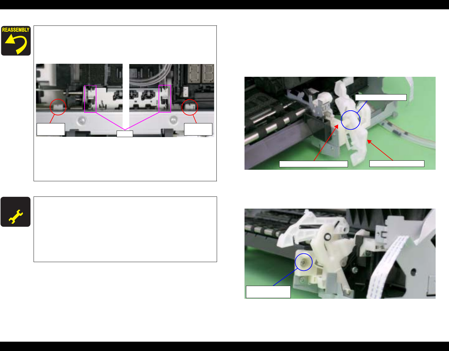
EPSON Stylus Photo R1800/R2400 Revision B
Disassembly And Assembly Disassembly 106
4.2.6.7 CD-R Release Lever Sub Assy
1. Remove the Printer Mechanism. See Section 4.2.1.5 on page 78.
2. Remove the Paper EJ Frame Assy. See Section 4.2.6.6 on page 105.
3. Remove the Shaft on the Right CD-R Release Base from the Bushing on
the CD-R Release Lever.
Figure 4-86. Removing the Right CD-R Release Lever Sub Assy (1)
4. Remove the C.B.S. M3 x 6 screw that secures the Right CD-R Release
Lever Sub Assy.
Figure 4-87. Removing the Right CD-R Release Lever Sub Assy (2)
Hook both rear ends of the Paper EJ Frame Assy onto
the Tabs on the Main Frame.
Align the Bearing of the CD-R Release Level Sub Assy
with the Paper EJ Release Shaft.
Figure 4-85. Reinstalling the Paper EJ Frame Assy.
Match the Tabs with the five Positioning Holes.
See Figure 4-83.
Tighten the screws in the order shown in Figure 4-84.
A D J U S T M E N T
R E Q U I R E D Be sure to perform the following adjustments when the Paper
EJ Frame Assy is replaced or removed:
1. Ink Mark Sensor Adjustment
2. PW Sensor Adjustment
3. PF Adjustment
4. PF Adjustment (Bottom Margin)
Refer to Chapter 5 "Adjustment" for details of the
adjustments.
Shaft and
Bushing Shaft and
Bushing
Tabs
CD-R Release Lever
Shaft and Bushing
Right CD-R Release Base
2) C.B.S. 3x6
(6±1 kgf.cm)
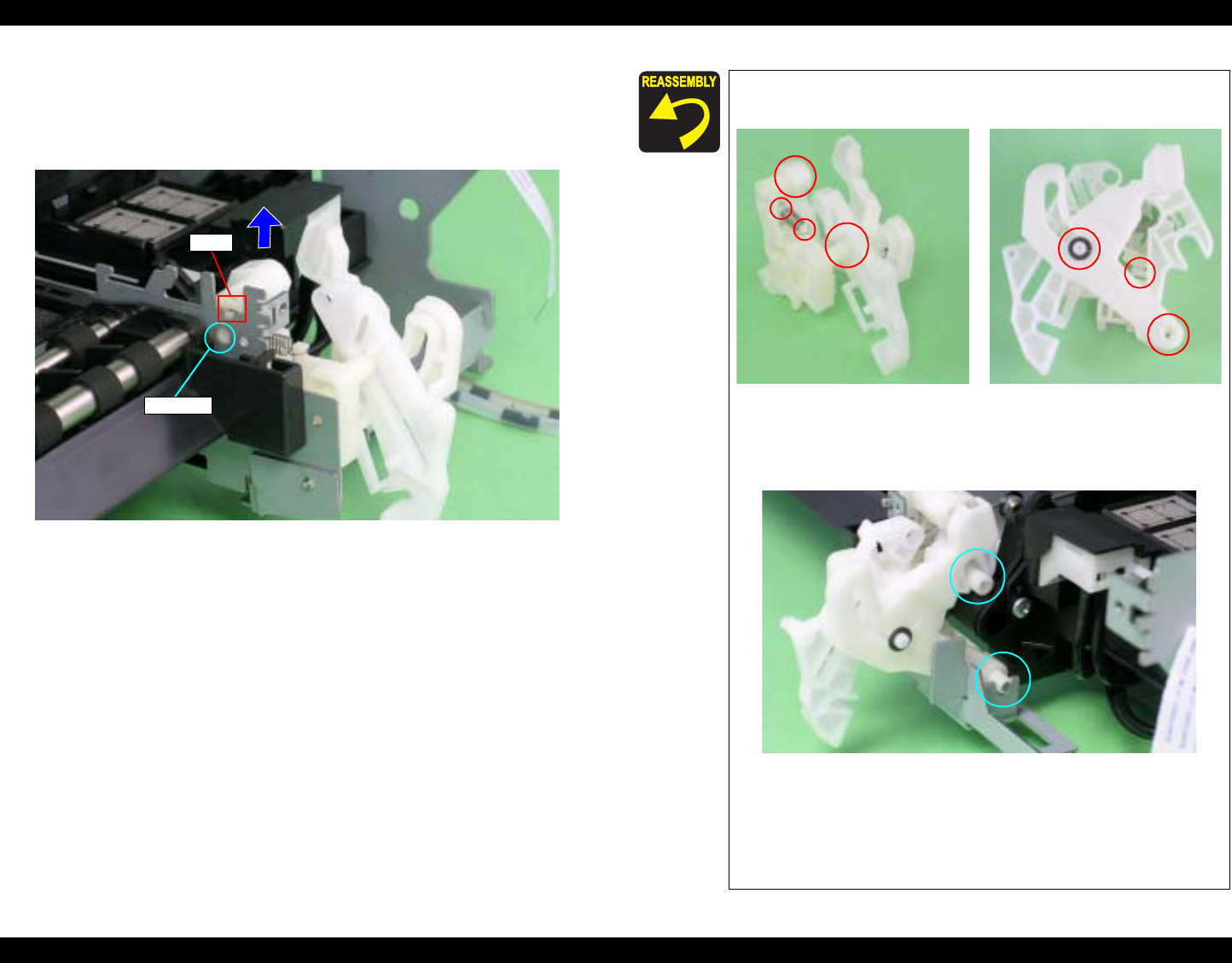
EPSON Stylus Photo R1800/R2400 Revision B
Disassembly And Assembly Disassembly 107
5. To prevent parts from dropping, refit the shaft on the Right CD-R Release
Base into the CD-R Release Lever.
6. Press the Guide Pin that secures the Right CD-R Release Lever Sub Assy
with tweezers, and remove it upwards from the Main Frame.
Figure 4-88. Removing the Right CD-R Release Lever Sub Assy (3)
Tab
Guide Pin
Make sure that the Right CD-R Release Lever Sub Assy
is correctly assembled as shown in the figure below.
Figure 4-89. Reassembling the Right CD-R Release Lever
Sub Assy
Align the Shaft and Bushing.
Figure 4-90. Reinstalling the Right CD-R Release Lever Sub
Assy
Align the positioning hole of the Right CD-R Release
Lever Sub Assy with the Tab on the Main Frame. See
Figure 4-88.
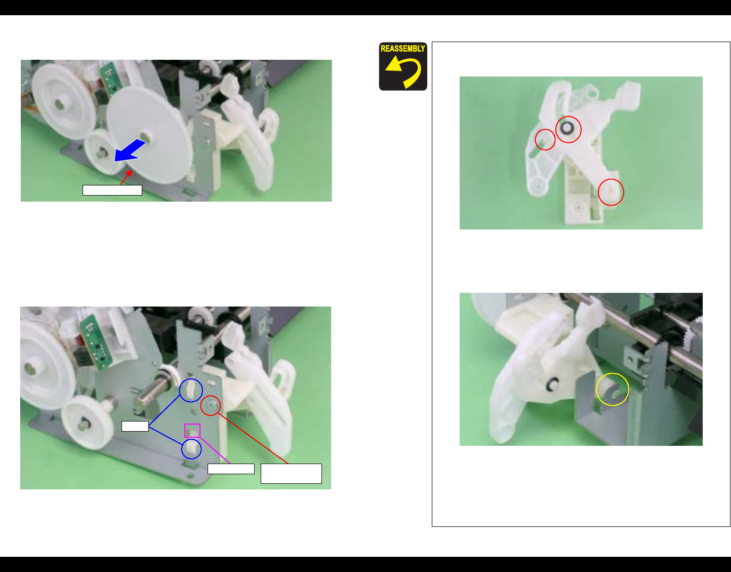
EPSON Stylus Photo R1800/R2400 Revision B
Disassembly And Assembly Disassembly 108
7. Remove Spur Gear 68 from the Paper EJ Roller Shaft.
Figure 4-91. Removing the Spur Gear 68
8. Remove the C.B.P. M3 x 6 screw that secures the Left CD-R Release
Lever Sub Assy.
9. Press the small Tab of the Left CD-R Release Lever Sub Assy with a flat-
blade screwdriver, and remove the Left CD-R Release Lever Sub Assy
upwards from the Main Frame.
Figure 4-92. Removing the Left CD-R Release Lever Sub Assy
Spur Gear 68
Tabs
Small Tab 9) C.B.P. 3x6
(6±1 kgf.cm)
Make sure that the Left CD-R Release Lever Sub Assy is
correctly assembled as shown in the figure below.
Figure 4-93. Reinstalling the Left CD-R Release Lever Sub
Assy (1)
Align the Shaft and Bushing.
Figure 4-94. Removing the Left CD-R Release Lever Sub
Assy (2)
Align the two Tabs on the Left CD-R Release Lever Sub
Assy with the positioning holes on the Main Frame. See
Figure 4-92.
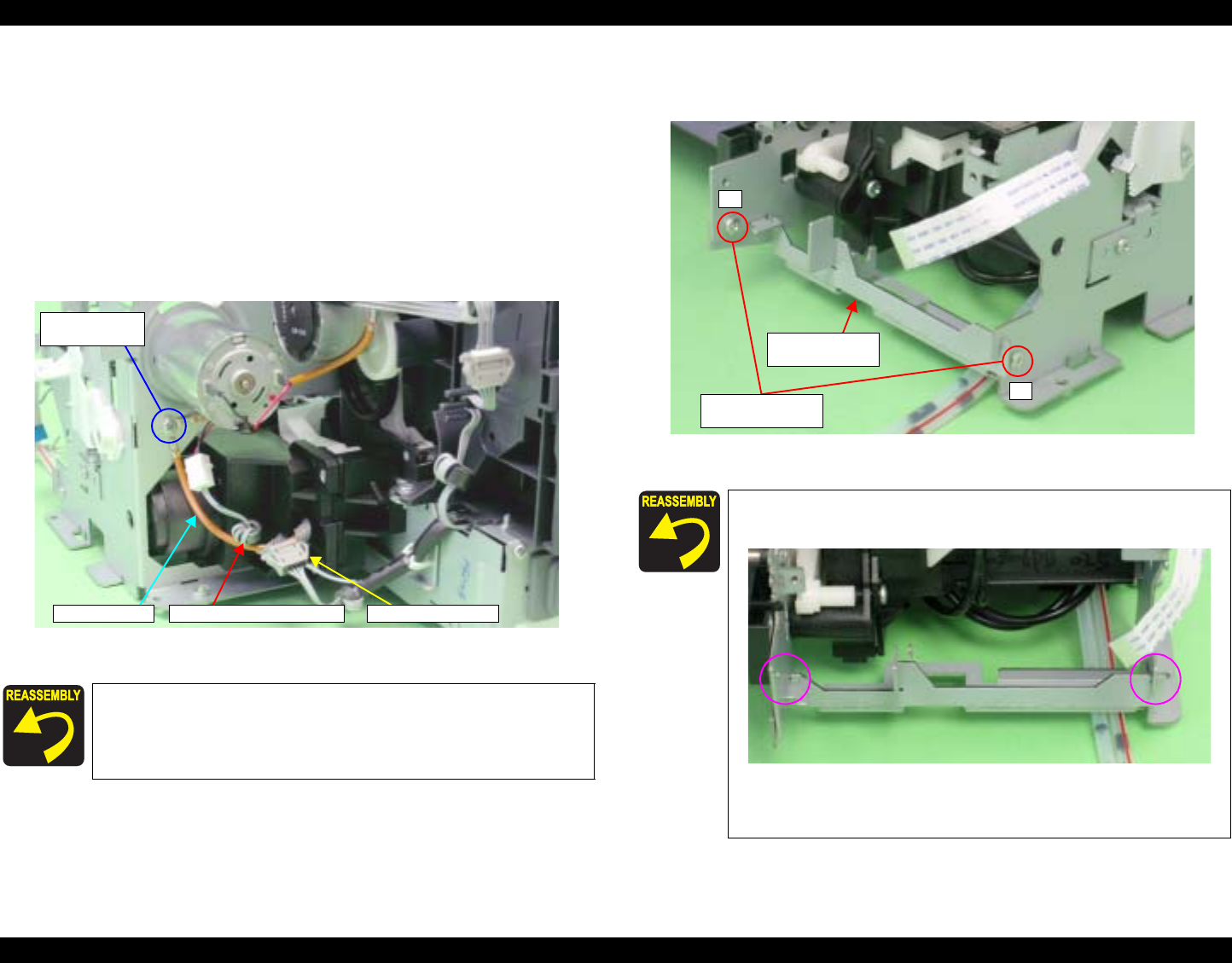
EPSON Stylus Photo R1800/R2400 Revision B
Disassembly And Assembly Disassembly 109
4.2.6.8 Ink System Unit
1. Remove the Right CD-R Release Lever SubAssy. See Section 4.2.6.7 on
page 106.
2. Release the Carriage lock, and move the Carriage Unit to the center. See
Section 4.2.1.3 on page 75.
3. Remove the C.B.S. M3 x 8 screw that secures the Earth Cable to remove
the Earth Cables, and untie the Earth Cable from the Relay Connector
Cable.
4. Disconnect the Pump Motor Connector from the Relay Connector.
Figure 4-95. Disconnecting the Pump Motor Connector
5. Remove the two C.B.S. M3 x 4 screws that secure the Ink System Guide
Plate, and remove it.
Figure 4-96. Removing the Ink System Guide Plate
Be sure to screw the two Earth Cables together.
Referring to Figure 4-95., correctly route the Relay
Connector Cable.
Relay Connector
5) C.B.S. 3x8
(8±1 kgf.cm)
Earth Cable Relay Connector Cable
Align the notch on the Ink System Guide Plate with the
notch on the Main Frame.
Figure 4-97. Reinstalling the Ink System Guide Plate
Tighten the screws in the order shown in Figure 4-96.
1
2
10) C.B.S. 3x4
(8±1 kgf.cm)
Ink System
Guide Plate
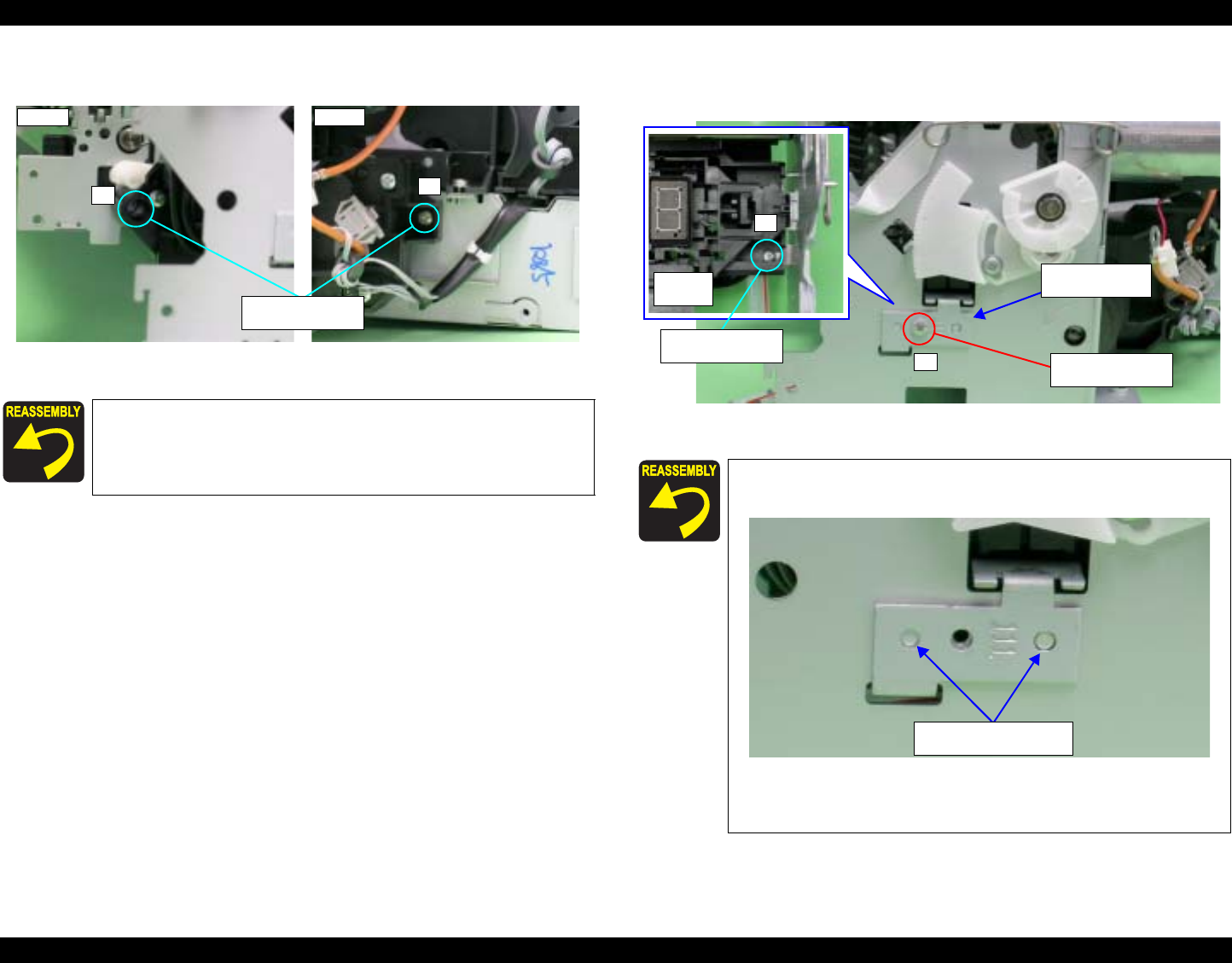
EPSON Stylus Photo R1800/R2400 Revision B
Disassembly And Assembly Disassembly 110
6. Remove the two C.B.S. M3 x 6 screws that secure the Ink System Unit.
Figure 4-98. Screws that Secure the Ink System Unit
7. Remove the two C.B.S. M3 x 6 screws that secure the Right Support
Frame, and remove the Right Support Frame from the Main Frame.
Figure 4-99. Removing the Right Support Frame
Tighten the screws in the order shown in Figure 4-98.
2
Rear
1
Front
2) C.B.S. 3x6
(8±1 kgf.cm)
Align the positioning holes on the Right Support Frame
with the Guide Pins on the Main Frame.
Figure 4-100. Installing the Support Frame (Right)
Tighten the screws in the order shown in Figure 4-99.
Right Support
Frame
2
Upper
surface
2) C.B.S. 3x6
(8±1 kgf.cm) 12) C.B.S. 3x6
(8±1 kgf.cm)
Positioning Holes and
Guide Pins
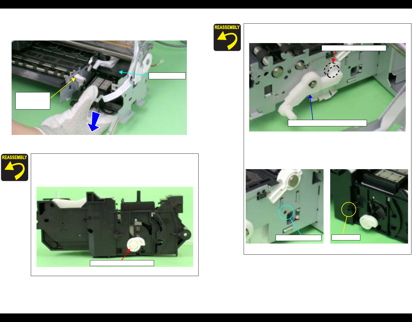
EPSON Stylus Photo R1800/R2400 Revision B
Disassembly And Assembly Disassembly 111
8. Remove the Ink System Unit downwards from the Main Frame keeping the
Unit from coming in contact with the Paper EJ Transmission Lock Lever.
Figure 4-101. Removing the Ink System Unit
When the Ink System Unit is removed from the Printer
Mechanism, the Paper EJ Lock Release Cam may drop
off. In such case, correctly install it referring to the figure
below.
Figure 4-102. Installing the Paper EJ Lock Release Cam
Paper EJ
Transmission
Lock Lever
Ink System Unit
Paper EJ Lock Release Cam
Place the Paper EJ Lock Release Cam on the rear side of
the Paper EJ Transmission Lock Lever.
Figure 4-103. Reinstalling the Ink System Unit (1)
Align the positioning hole on the Main Frame with the
Guide Pin on the Ink System Unit.
Figure 4-104. Reinstalling the Ink System Unit (2)
Paper EJ Lock Release Cam
Paper EJ Transmission
Paper EJ Transmission Lock Lever
Positioning Hole Guide Pin
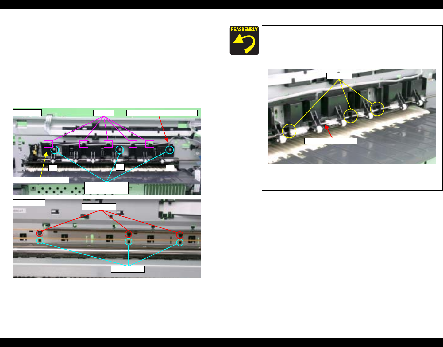
EPSON Stylus Photo R1800/R2400 Revision B
Disassembly And Assembly Disassembly 112
4.2.6.9 Release Holder Assy
1. Remove the ASF Assy. See Section 4.2.4 on page 83.
2. Release the PE Sensor Connector Cable from the five Tabs on the
Release Holder Assy.
3. Remove the three C.B.S. M3 x 6 screws that secure the Release Holder
Assy.
4. Remove the three lower Tabs of the Release Holder Assy from the Main
Frame with a flat-blade screwdriver, and remove the Release Holder Assy
upwards.
Figure 4-105. Removing the Release Holder Assy
2) C.B.S. 3x6
(8±1 kgf.cm)
1
2
3
PE Sensor Connector CableTabs
Release Holder Assy
Rear side
Upper Tabs
Lower Tabs
Front side
Align the three Upper Tabs on the Release Holder Assy
with the positioning holes on the Main Frame. See Figure
4-105.
Fit the FLAG Release Shaft by the Bushings on the
Release Holder Assy.
Figure 4-106. Reinstalling the Release Holder Assy
Tighten the screws in the order shown in Figure 4-105.
Bushings
FLAG Release Shaft
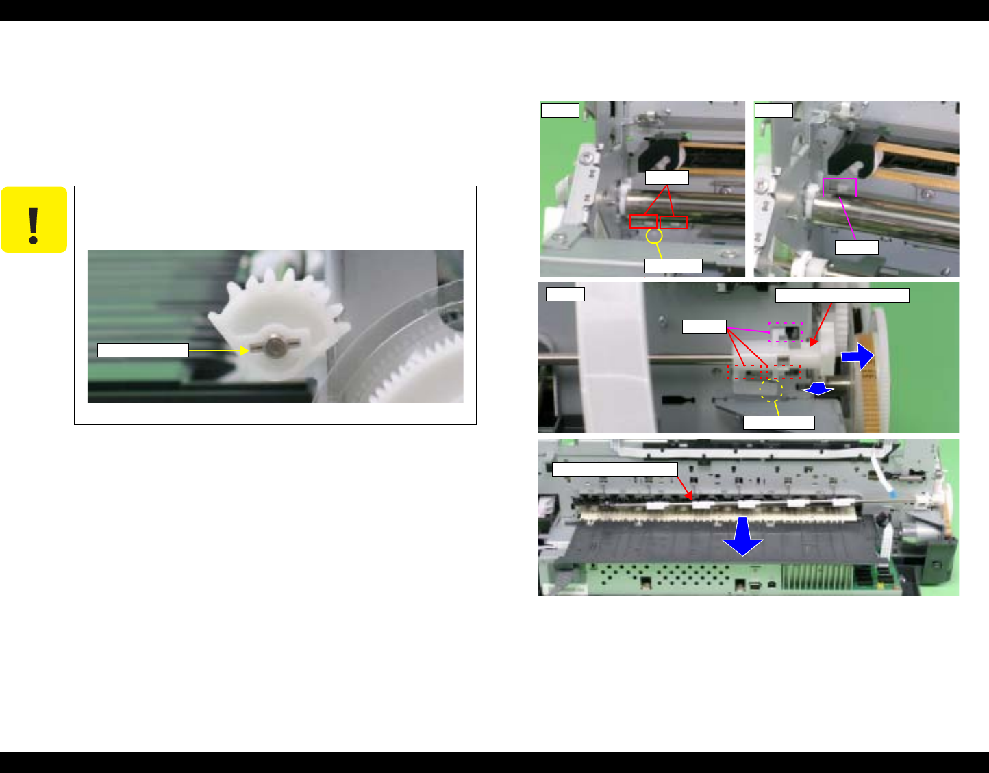
EPSON Stylus Photo R1800/R2400 Revision B
Disassembly And Assembly Disassembly 113
4.2.6.10 FLAG Release Assy.
1. Remove the APG Assy. See Section 4.2.6.3 on page 93.
2. Remove the Release Holder Assy. See Section 4.2.6.9 on page 112.
3. Remove the Guide Pin on the Driven Release Holder from the Main Frame
using tweezers, and slide the Driven Release Holder to the left as viewed
from the front of the Printer Mechanism.
4. Release the three Tabs on the Driven Release Holder from the Main
Frame, and remove the FLAG Release Assy.
Figure 4-108. Removing the FLAG Release Assy
C A U T I O N In the following procedure, Parallel Pin 1.5 may drop off
when the Driven Release Holder is slid. Be careful not to
lose it.
Figure 4-107. Parallel Pin 1.5
Parallel Pin 1.5
Guide Pin
Tabs
Front
Driven Release Holder
Rear
Guide pin
Tabs
Tab
Front
FLAG Release Assy.
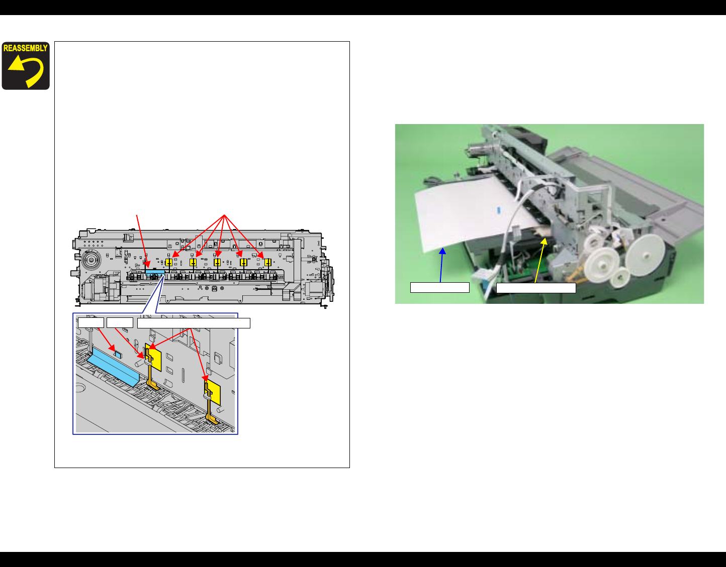
EPSON Stylus Photo R1800/R2400 Revision B
Disassembly And Assembly Disassembly 114
4.2.6.11 Upper Paper Guide Assys.
1. Remove the FLAG Release Assy. See Section 4.2.6.10 on page 113.
2. Remove the PE Sensor Holder. See Section 4.2.8.1 on page 124.
3. Pass a sheet of A3 size paper into the gap between the Upper Paper
Guide Assy and the Rear Paper Guide.
Figure 4-110. Setting the Paper
Attach the five Perforated Sheets and the LD Cover Sheet to
the six locations shown in the figure below to prevent ink
from sticking to the LD Rollers.
Remove the five Paper Guide Torsion Springs from the
Tabs, insert the notches of the Perforated Sheets into
the Tabs to attach them to the Main Frame, and then
hook the Paper Guide Torsion Springs onto the Tabs
again.
Insert the LD Cover Sheet in between the frame so that
the Tabs on the upper side of the LD Cover Sheet are
visible from the notches on the Main Frame, and attach
the LD Cover Sheet.
Figure 4-109. Attaching the Perforated Sheets and the LD
Cover Sheet
LD Cover Sheet Perforated Sheets
Paper Guide Torsion Spring
Tab Tab
A3-size paper Rear Paper Guide
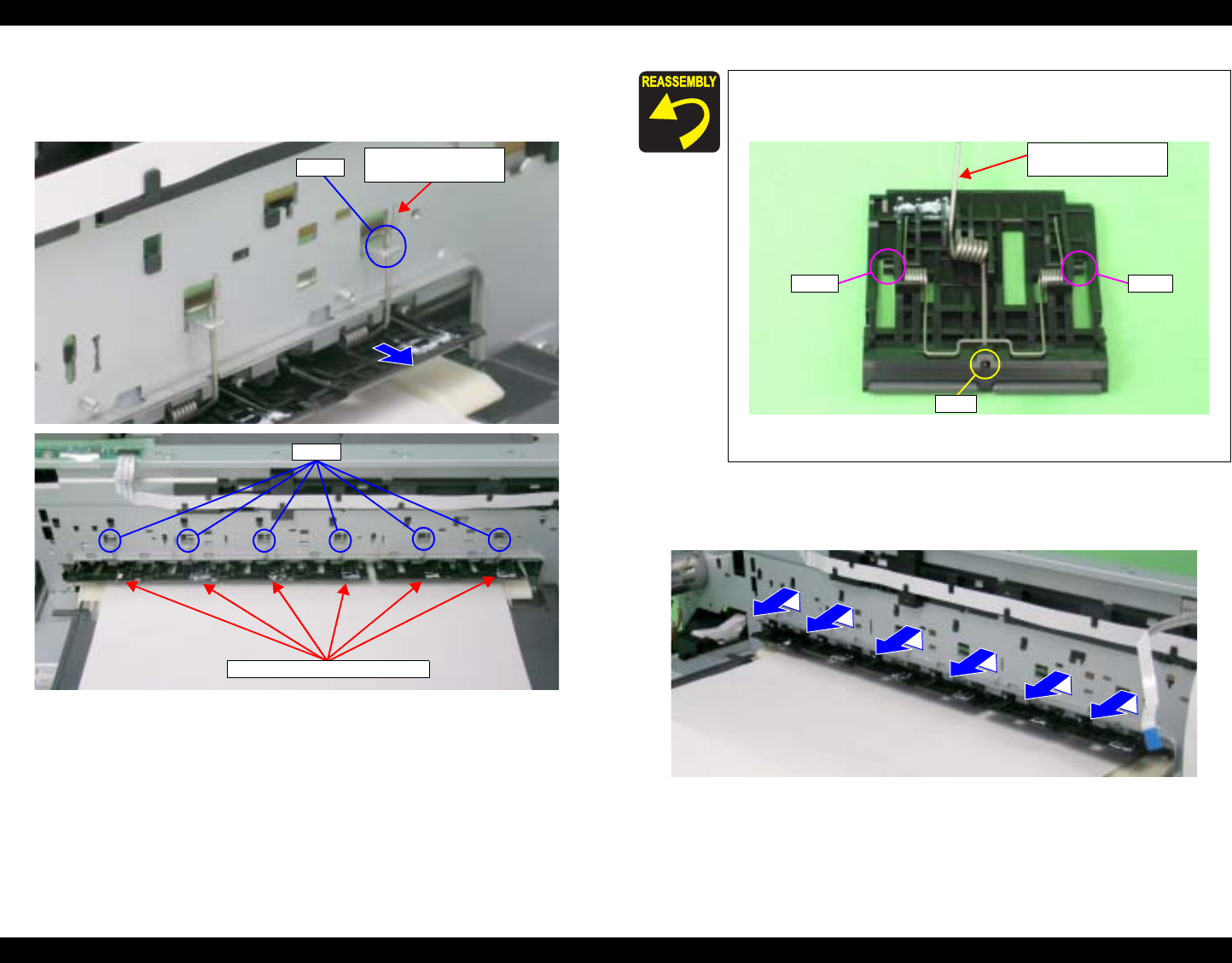
EPSON Stylus Photo R1800/R2400 Revision B
Disassembly And Assembly Disassembly 115
4. Remove the six Upper Paper Guide Torsion Springs from the Tabs on the
Main Frame, and draw out the Upper Paper Guide Torsion Springs from
the six Upper Paper Guide Assys.
Figure 4-111. Removing the Upper Paper Guide Torsion Spring
5. Lift the six Upper Paper Guide Assys from the Main Frame to release the
shaft referring to Figure 4-112., and remove the Upper Paper Guide Assys
to the rear.
Figure 4-113. Removing the Upper Paper Guide Assy
Upper Paper Guide
Torsion Sprig
Tab
Upper Paper Guide Assys.
Tabs
Make sure that the leading end of the Upper Paper Guide
Torsion Spring can be seen through the hole of the Upper
Paper Guide Assy.
Figure 4-112. Reinstalling the Upper Paper Guide Torsion
Spring
Hole
Upper Paper Guide
Torsion Sprig
ShaftShaft
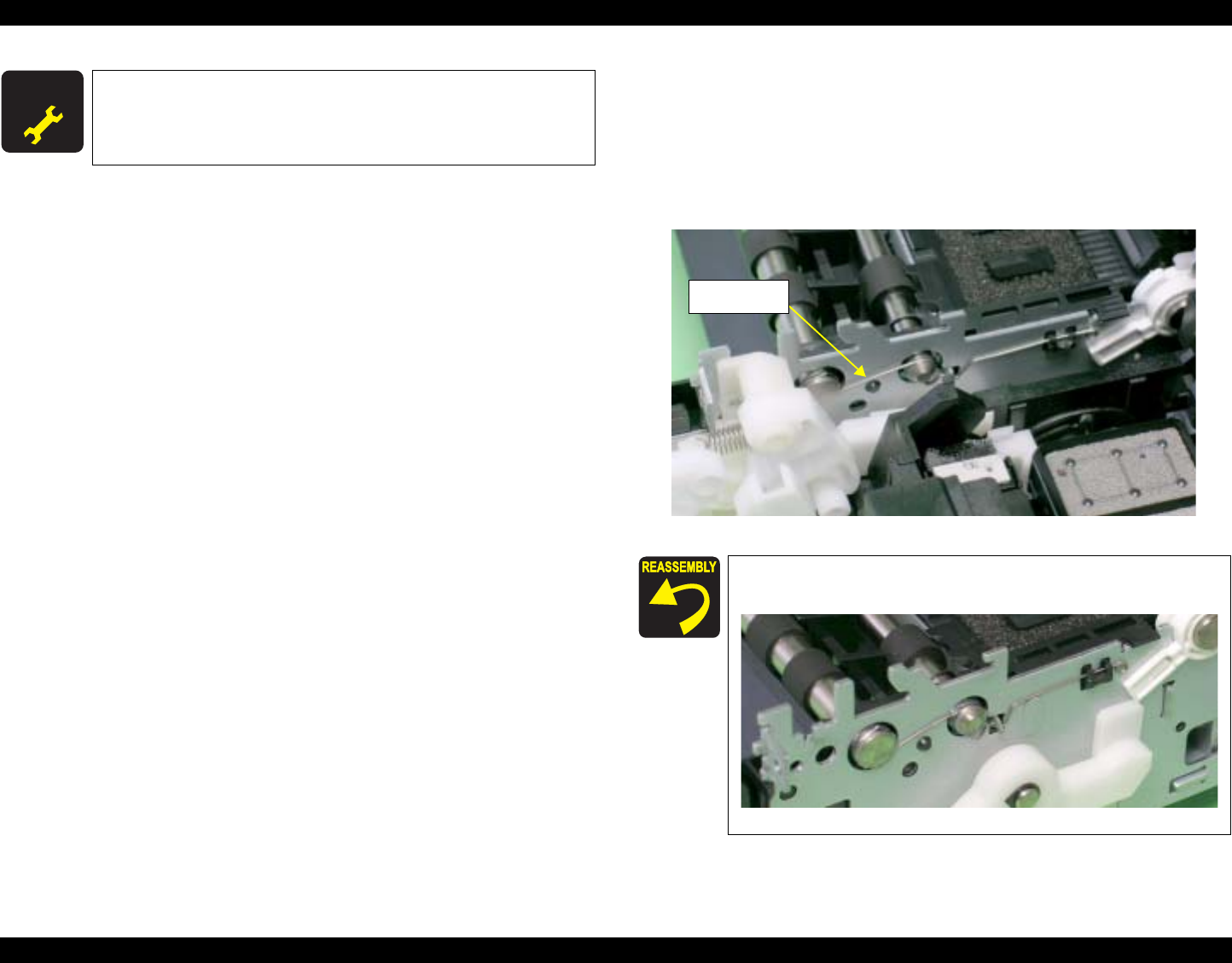
EPSON Stylus Photo R1800/R2400 Revision B
Disassembly And Assembly Disassembly 116
4.2.6.12 Front Paper Guide and Paper eject roller
1. Remove the Printer Mechanism. See Section 4.2.1.5 on page 78.
2. Remove the Paper EJ Frame Assy. See Section 4.2.6.6 on page 105.
3. Release the Carriage lock, and move the Carriage Unit to the center. See
Section 4.2.1.3 on page 75.
4. Remove the EJ Grounding Spring from the Main Frame with tweezers.
Figure 4-114. Removing the EJ Grounding Spring
A D J U S T M E N T
R E Q U I R E D After replacing the following part, be sure to apply G-26 grease
to the specified area. See Figure 6-9 on page 177.
Upper Paper Guide Assy
Referring to Figure 4-115., correctly install the EJ Grounding
Spring.
Figure 4-115. Reinstalling the EJ Grounding Spring
EJ Grounding
Spring
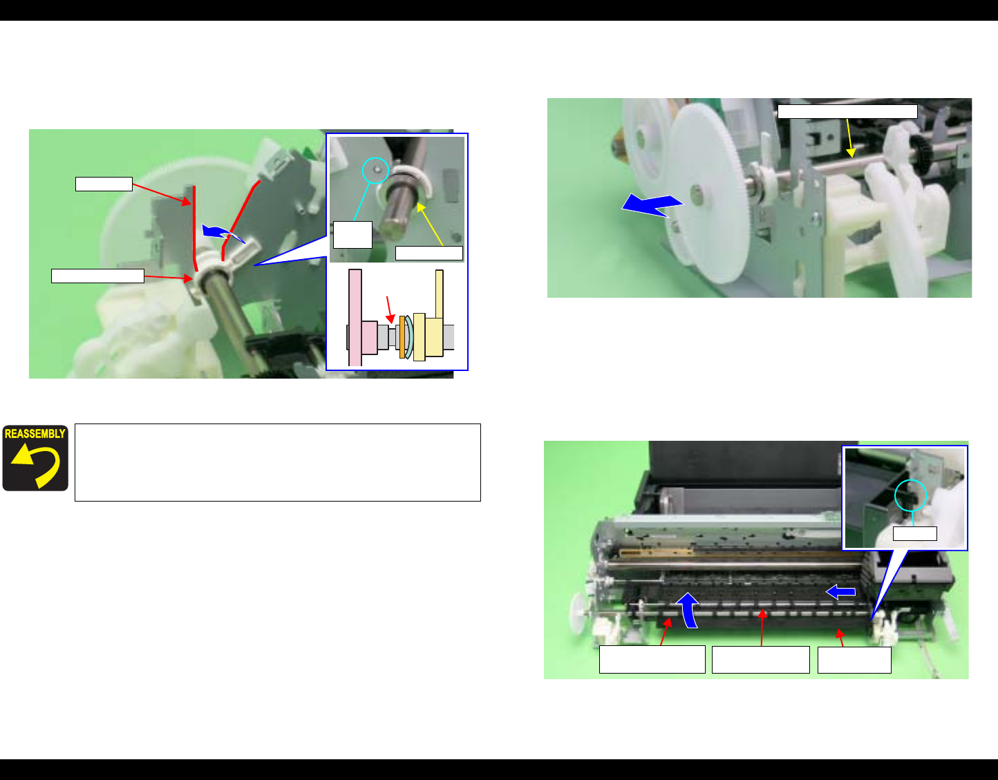
EPSON Stylus Photo R1800/R2400 Revision B
Disassembly And Assembly Disassembly 117
5. Remove the Spacer from the EJ Roller Shaft.
6. Remove the Guide Pins on Left Bushing 8 from the Main Frame using
tweezers, and turn Left Bushing 8 toward you to align with the notches on
the Main Frame.
Figure 4-116. Removing the Spacer and Rotating the Left Bushing 8
7. Slide the Front Paper Eject Roller to the left, and remove the Left Bushing
8 from the Main Frame.
Figure 4-117. Removing the Left Bushing 8
8. Return the Carriage Unit to its home position.
9. Release the Tab that secures the Front Paper Guide from the Main Frame
and slide the Front Paper Guide to the left, and turn it until the front side
faces up to remove the Front Paper Guide together with the Paper Eject
Roller.
Figure 4-118. Removing the Front Paper Guide and Paper Eject Rollers
Insert the Spacer into the groove on the Front Paper Eject
Roller.
Guide
pin Spacer
Left Bushing 8
Notch
Groove
Front Paper Eject Roller
Tab
Front Paper Eject
Roller Front Paper
Guide
Rear Paper Eject
Roller
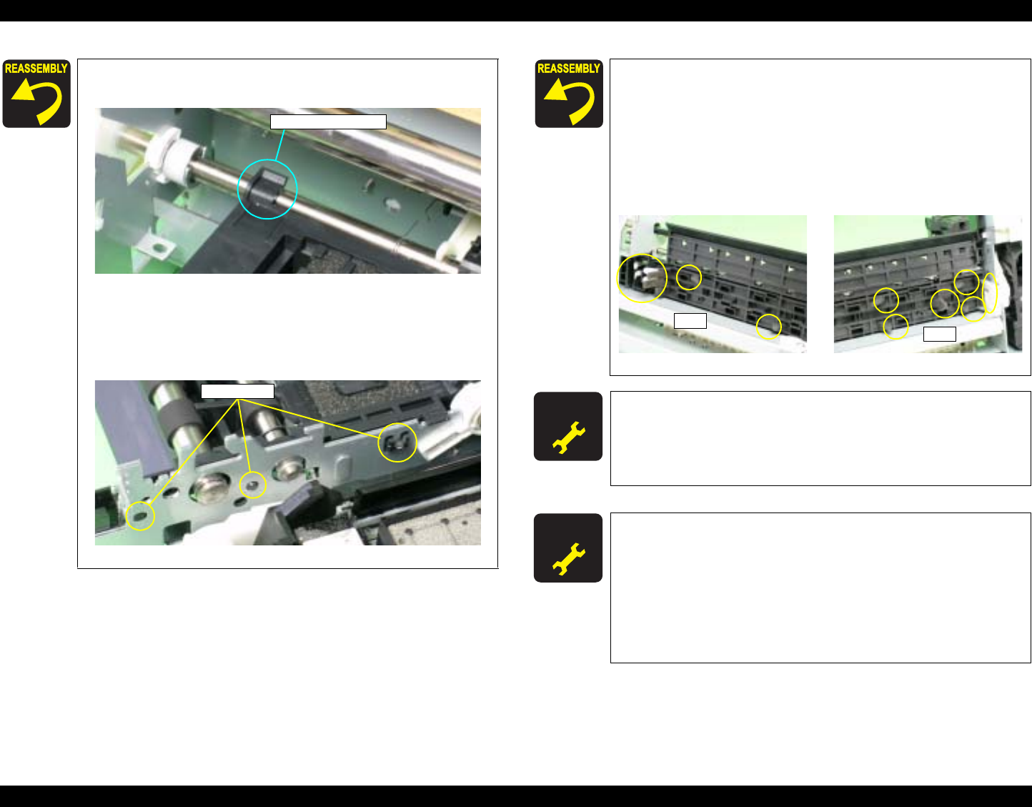
EPSON Stylus Photo R1800/R2400 Revision B
Disassembly And Assembly Disassembly 118
Align the Bushing of the Front Paper Guide with the PF
Roller Shaft.
Figure 4-119. The PF Roller Shaft and the Bushing of the
Front Paper Guide
Align the positioning holes on the Main Frame with the
Guide Pins on the Front Paper Guide.
Figure 4-120. Reinstalling the Front Paper Guide
Shaft and Bushing
Guide Pins
After installing the Front Paper Guide, lift the Printer
Mechanism to check the following points.
1. Make sure that the Tabs on the Paper Guide Pad are not
cut midway.
2. Make sure that all Tabs are facing down (toward the
Waste Ink Pads) without any folds.
3. Make sure that the Tab foldbacks are protruding
completely from the Front Paper Guide.
Figure 4-121. Checking the Front Paper Guide Pad
A D J U S T M E N T
R E Q U I R E D After replacing the following part, be sure to apply G-45 grease
to the area specified for each part.
EJ Grounding Spring See Figure 6-10 on page 177.
Front Paper Guide and Paper Eject Roller See Figure 6-11
on page 177.
A D J U S T M E N T
R E Q U I R E D Be sure to perform the following adjustments after the Front
Paper Guide and Paper eject roller are replaced or removed:
1. Ink Mark Sensor Adjustment
2. PW Sensor Adjustment
3. PF Adjustment
4. PF Adjustment (Bottom Margin)
Refer to Capter 5 "Adjustment" for details of the
adjustments.
Tabs Tabs
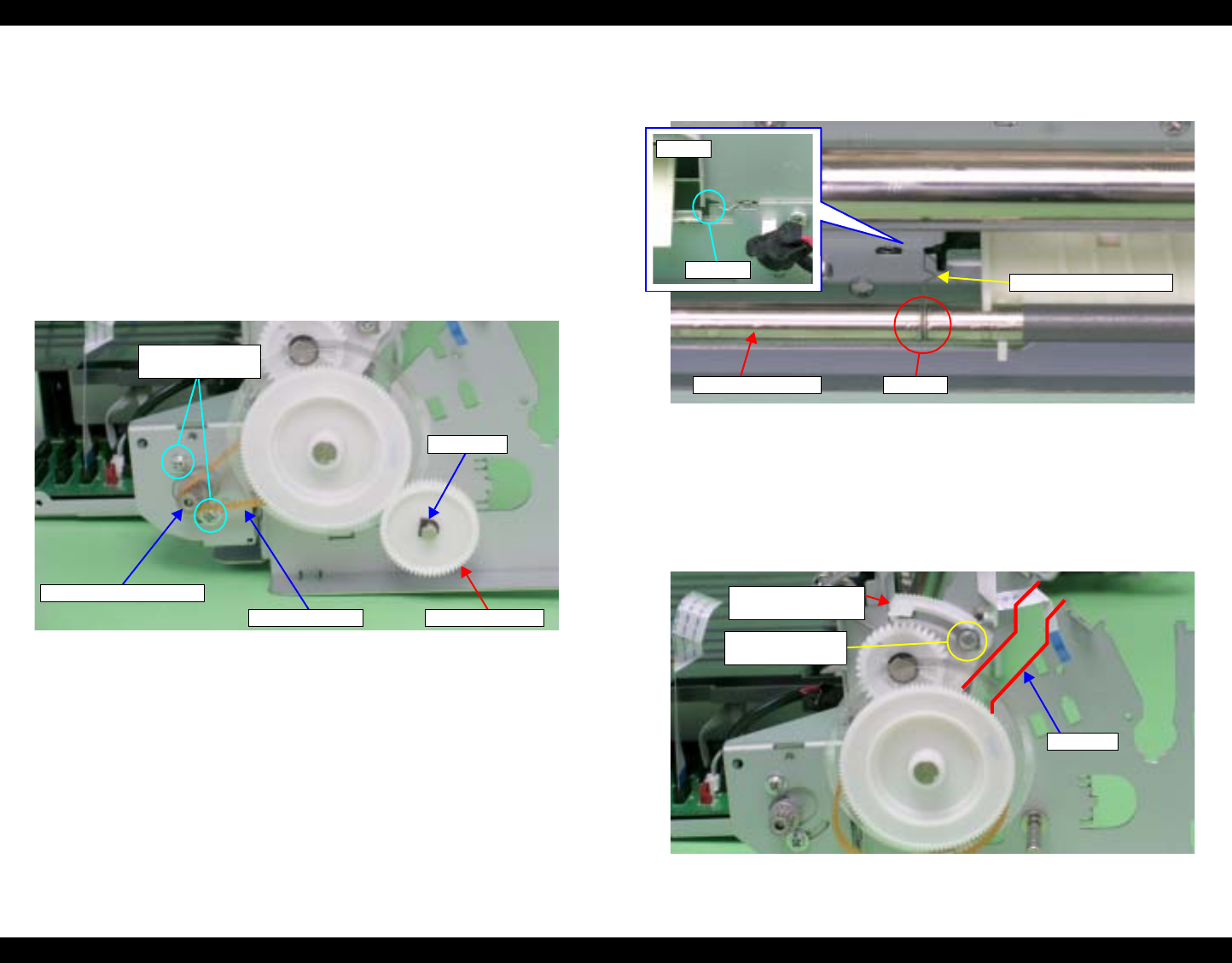
EPSON Stylus Photo R1800/R2400 Revision B
Disassembly And Assembly Disassembly 119
4.2.6.13 PF Roller Shaft
1. Remove the Upper Paper Guide Assys. See Section 4.2.6.11 on page 114.
2. Remove the PF Encoder Sensor Holder. See Section 4.2.8.4 on page 126.
3. Remove the Front Paper Guide and Paper eject roller. See Section
4.2.6.12 on page 116.
4. Loosen the two C.C. M3 x 4 screws that secure the PF Motor, and remove
the PF Drive Belt from the PF Motor Pinion Gear.
5. Remove the Spacer that secures Spur Gear 31.5, and remove Spur Gear
31.5 from the Printer Mechanism.
Figure 4-122. Removing the PF Drive Belt and Spur Gear 31.5
6. Remove the PG Grounding Spring from the notch on the Main Frame, and
remove the PF Grounding Spring from the groove on the PF Roller Shaft.
Figure 4-123. Removing the PF Grounding Spring
7. Make sure that the Left Parallelism Adjust Bushing is not protruding from
the notch on the Main Frame. If it is protruding, loosen the C.B.S. (P4) M3
x 8 screw that secures the Left Parallelism Adjust Bushing, and slide it to
prevent the Left Parallelism Adjust Bushing from becoming hooked on the
notch.
Figure 4-124. Rotating the Left Parallelism Adjust Bushing
PF Drive Belt
PF Motor Pinion Gear
11) C.C. 3x4
(4±0.5 kgf.cm)
Spur Gear 31.5
Spacer
PF Grounding Spring
Rear
Notch
PF Roller Shaft Groove
Left Parallelism
Adjust Bushing
Notch
6) C.B.S. (P4) 3x8
(5±1 kgf.cm)
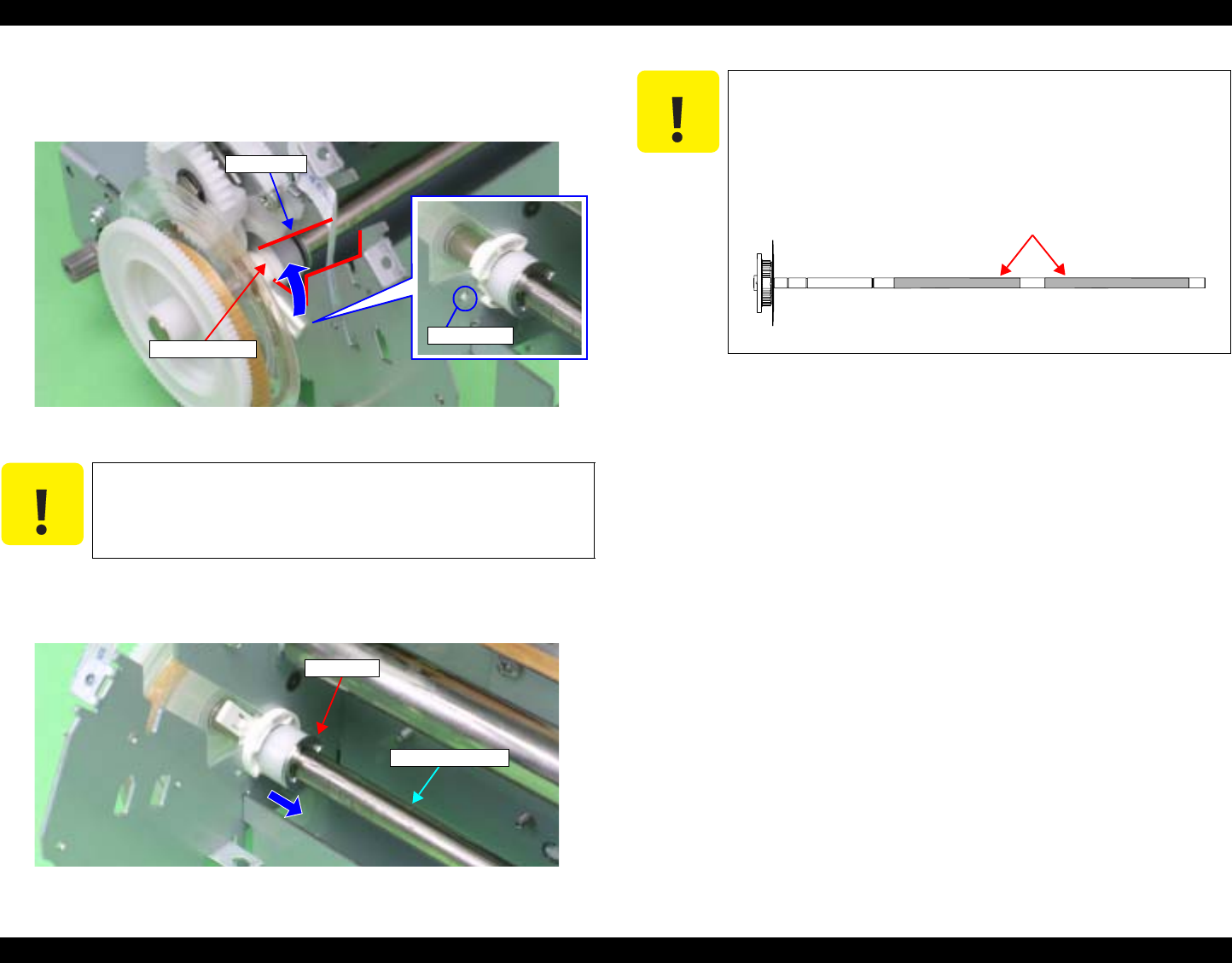
EPSON Stylus Photo R1800/R2400 Revision B
Disassembly And Assembly Disassembly 120
8. Remove the Guide Pin of Left Bushing 8 from the Main Frame using
tweezers, and rotate the Bushing upwards to align with the notch on the
Main Frame.
Figure 4-125. Rotating the Left Bushing 8
9. Remove the E-ring from the PF Roller Shaft with a flat-blade screwdriver,
and slide Left Bushing 8 to the inside of the Printer Mechanism.
Figure 4-126. Removing the Left Bushing 8
C A U T I O N When performing the following procedure, take care not to
lose the E-ring.
Left Bushing 8 Guide pin
Notch
E-Ring
PF Roller Shaft
C A U T I O N When performing the following procedure, pay attention to
the following points.
Prevent the coated surface of the PF Roller Shaft from
being scratched.
Do not touch the coated surface of the PF Roller Shaft
with bare hands.
Figure 4-127. Handling the PF Roller Shaft
Coating Part
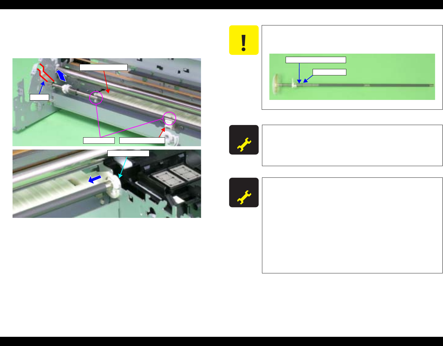
EPSON Stylus Photo R1800/R2400 Revision B
Disassembly And Assembly Disassembly 121
10. Remove the PF Roller Shaft from the Bushings on the Rear Paper Guide
and the Center Support, slide the PF Roller Shaft to the left to remove it
from Right Bushing 8, and remove the PF Roller Shaft along the notch of
the Main Frame.
Figure 4-128. Removing the PF Roller Shaft
Rear Paper Guide
Bushings
Notch
Center Support
Right Bushing 8
C A U T I O N Be careful not to move Compression Spring 4 and the Leaf
Spring on the left side of the PF Roller Shaft to the coated
section on the Shaft after removing the PF Roller Shaft.
Figure 4-129. Handling the PF Roller Shaft
A D J U S T M E N T
R E Q U I R E D After replacing the following part, be sure to apply G-45 grease
to the area specified for each part.
PF Roller Shaft: See Figure 6-12 on page 177.
Rear Paper Guide: See Figure 6-13 on page 178.
PF Grounding Spring: See Figure 6-13 on page 178.
A D J U S T M E N T
R E Q U I R E D After replacing or removing the PF Roller Shaft, be sure to
make the following adjustments.
1. PF Belt Tension Adjustment
2. PF Roller Shaft Center Support Position Adjustment
3. PG Adjustment (Only when moved the Left Parallelism
Adjust Bushing)
4. Ink Mark Sensor Adjustment
5. PW Sensor Adjustment
6. PF Adjustment
7. PF Adjustment (Bottom Margin)
Refer to Chapter 5 "Adjustment" for details of the
adjustments.
Compression Spring 4
Leaf Spring
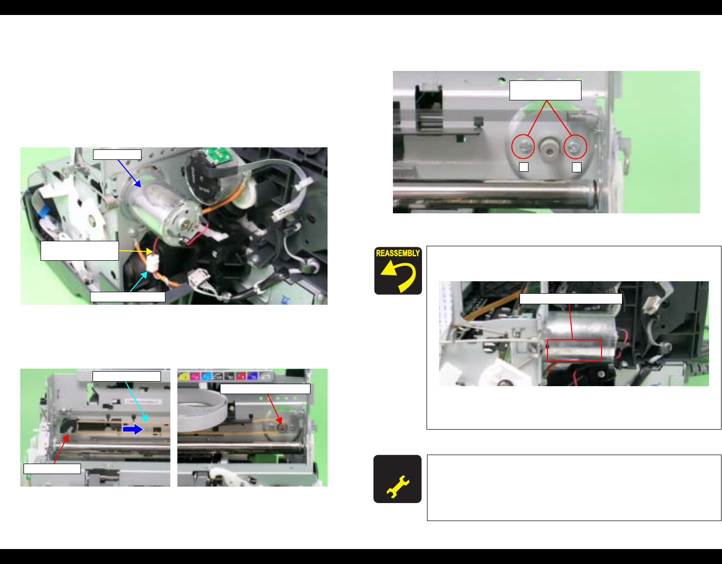
EPSON Stylus Photo R1800/R2400 Revision B
Disassembly And Assembly Disassembly 122
4.2.7 Removing the Motors
4.2.7.1 CR Motor
1. Remove the Upper Housing. See Section 4.2.1.4 on page 76.
2. Release the Carriage lock, and move the Carriage Unit to the center. See
Section 4.2.1.3 on page 75.
3. Disconnect the CR Motor Connector Cable from the Relay Connector.
Figure 4-130. Removing the CR Motor Connector Cable
4. Press the Driven Pulley toward the center to loosen the CR Drive Belt, and
remove the CR Drive Belt from the CR Motor Pinion Gear.
5. Remove the two C.B.S. M3 x 4 screws that secure the CR Motor, and
remove the CR Motor from the Main Frame.
Figure 4-131. Removing the CR Motor
CR Motor
Relay Connector
CR Motor
Connector Cable
CR Drive Belt
Driven Pulley
CR Motor Pinion Gear
Make the Lot No. printed surface on the CR Motor face
the direction shown in the figure below.
Figure 4-132. Reinstalling the CR Motor
Tighten the screws in the order shown in Figure 4-131.
A D J U S T M E N T
R E Q U I R E D Be sure to perform the following adjustments after replacing
the CR Motor.
CR Motor Drive Dispersion
Refer to Chapter 5 "Adjustment" for details of the
adjustments.
21
10) C.B.S. 3x4
(4±0.5 kgf.cm)
Lot No. Printed Surface
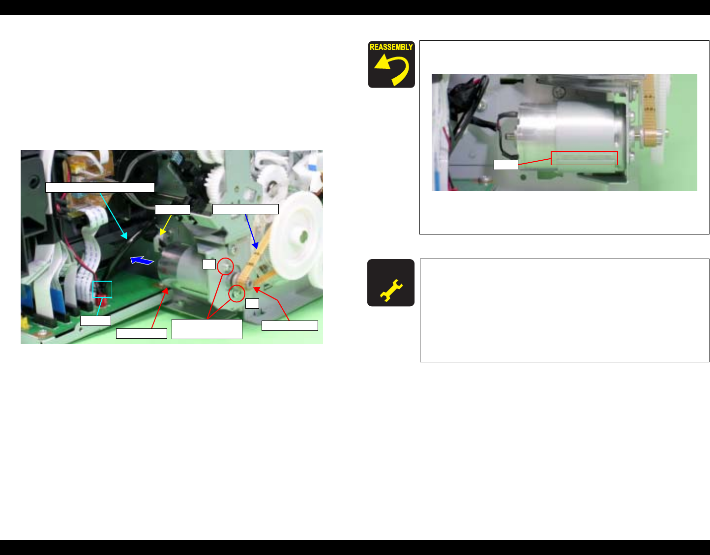
EPSON Stylus Photo R1800/R2400 Revision B
Disassembly And Assembly Disassembly 123
4.2.7.2 PF Motor
1. Remove the Printer Mechanism. See Section 4.2.1.5 on page 78.
2. Disconnect the PF Motor Connector Cable from Connector CN16 (black)
on the Main Board, and remove it from the Clamp on the Main Frame.
3. Remove the two C.C. M3 x 4 screws that secure the PF Motor.
4. Remove the PF Drive Belt from the PF Motor Pinion Gear, and remove the
PF Motor from the Printer Mechanism.
Figure 4-133. Removing the PF Motor
PF Motor
1
2
PF Drive Belt
11) C.C. 3x4
(4±0.5 kgf.cm)
PF Motor Connector Cable
Clamp
CN16 Pinion Gear
Make the slit on the PF Motor face the direction shown in
the figure below.
Figure 4-134. Reinstalling the PF Motor
Tighten the screws in the order shown in Figure 4-133.
A D J U S T M E N T
R E Q U I R E D After replacing or removing the PF Motor, be sure to make the
following adjustments.
1. PF Belt Tension Adjustment
2. PF Roller Shaft Center Support Position Adjustment
3. PF Adjustment
4. PF Adjustment (Bottom Margin)
Refer to Chapter 5 "Adjustment" for details of the
adjustments.
Slit
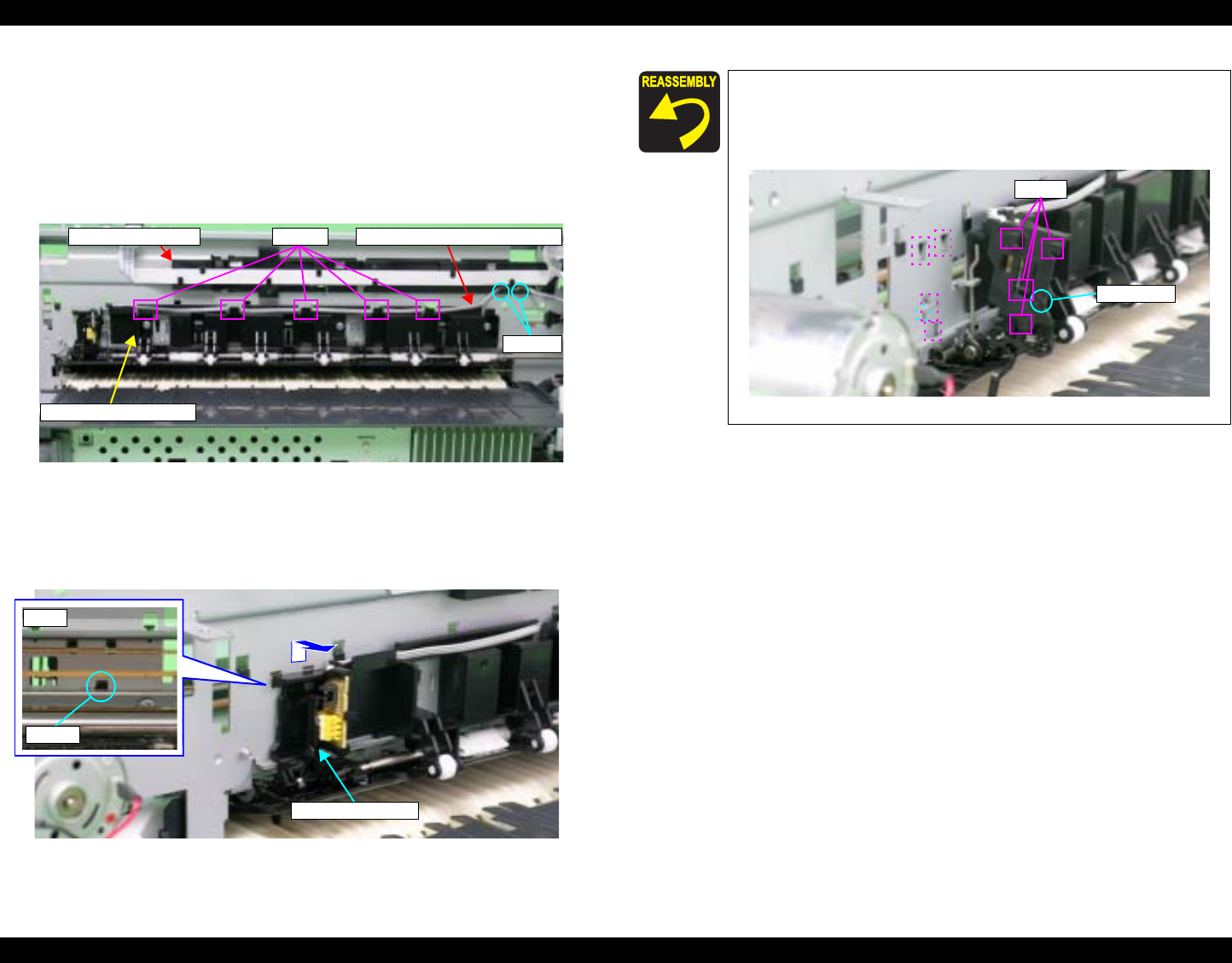
EPSON Stylus Photo R1800/R2400 Revision B
Disassembly And Assembly Disassembly 124
4.2.8 Removing the Sensors
4.2.8.1 PE Sensor Holder
1. Remove the ASF Assy. See Section 4.2.4 on page 83.
2. Remove the PE Sensor Connector Cable from the five Tabs on the
Release Holder Assy and the two Tabs on the Head Cable Cover.
Figure 4-135. Releasing the Cables
3. Release the Tabs that secure the PE Sensor Holder from the notch on the
Main Frame with a flat-blade screwdriver, and slide upwards and then
remove toward you.
Figure 4-136. Removing the PE Sensor Holder
Tabs
PE Sensor Connector CableTabs
Release Holder Assy.
Head Cable Cover
PE Sensor Holder
Front
Tab
Align the four Tabs and Guide Pin on the PE Sensor Holder
with the positioning holes on the Main Frame correctly so
that there is no gap between the PE Sensor Holder and the
Main Frame.
Figure 4-137. Reinstalling the PE Sensor
Tabs
Guid
Guide pin
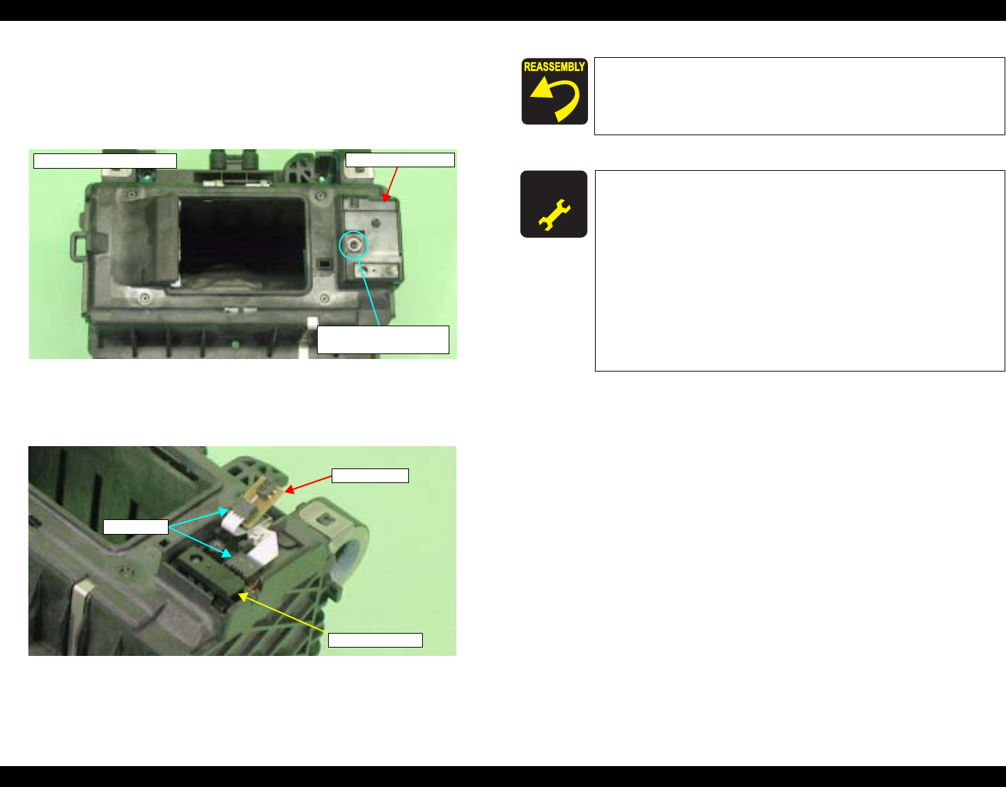
EPSON Stylus Photo R1800/R2400 Revision B
Disassembly And Assembly Disassembly 125
4.2.8.2 Ink Mark Sensor and PW sensor
1. Remove the Carriage Unit. See Section 4.2.6.4 on page 95.
2. Remove the C.P.B. (P1) M1.7 x 5 screw that secures the PW Sensor
Holder, and remove the PW Sensor Holder from the Carriage Unit.
Figure 4-138. Removing the PW Sensor Holder
3. Disconnect the FFC from the Ink Mark Sensor and the PW Sensor
Connector, and remove the Ink Mark Sensor and PW Sensor.
Figure 4-139. Removing the Ink Mark Sensor and PW Sensor
PW Sensor Holder
12) C.P.B. (P1) 1.7x5
(0.8±0.2 kgf.cm)
Carriage Unit Bottom
PW sensor
Connector
Ink Mark Sensor
Make sure that the FFC is routed as shown in Figure 4-139..
A D J U S T M E N T
R E Q U I R E D After replacing or removing the Ink Mark Sensor and the PW
Sensor, be sure to make the following adjustments.
Ink Mark Sensor
1. Ink Mark Sensor Adjustment
2. Ink Mark Sensor Check
3. PW Sensor Adjustment
PW Sensor
1. Ink Mark Sensor Adjustment
2. PW Sensor Adjustment
Refer to Chapter 5 "Adjustment" for details of the
adjustments.
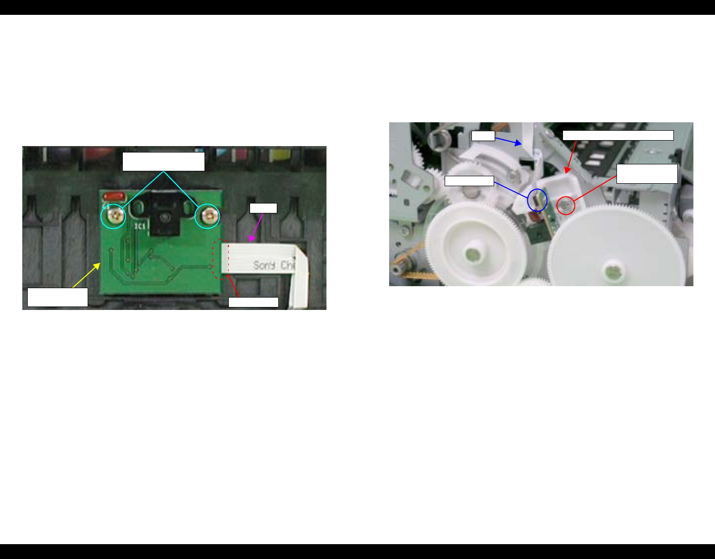
EPSON Stylus Photo R1800/R2400 Revision B
Disassembly And Assembly Disassembly 126
4.2.8.3 CR Encoder Sensor Board
1. Remove the Carriage Unit. See Section 4.2.6.4 on page 95.
2. Remove the two C.B.P. M2.6 x 5 screws that secure the CR Encoder
Sensor Board.
3. Disconnect the FFC of PW Sensor and Ink Mark Sensor from the
Connector on the CR Encoder Sensor Board, and remove the CR Encoder
Sensor Board.
Figure 4-140. Removing CR Encoder Sensor Board
4.2.8.4 PF Encoder Sensor Holder
1. Remove the Upper Housing. See Section 4.2.1.4 on page 76.
2. Disconnect the FFC from the PF Encoder Sensor Board.
3. Remove the C.B.S. M3 x 8 screw that secures the PF Encoder Sensor
Holder.
Figure 4-141. Removing the FFC and the Screw that Secures
the PF Encoder Sensor Holder
CR Encoder
Sensor Board
FFC
13) C.B.P. 2.6x5
(3±0.5 kgf.cm)
Connector
PF Encoder Sensor Holder
5) C.B.S. 3x8
(6±1 kgf.cm)
Connector
FFC
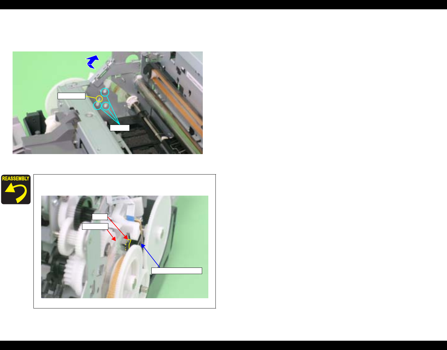
EPSON Stylus Photo R1800/R2400 Revision B
Disassembly And Assembly Disassembly 127
4. While pressing the Guide Pin on the PF Encoder Sensor Holder using
tweezers, slide the Holder upwards to release the three Tabs, and remove
the PF Encoder Sensor Holder.
Figure 4-142. Removing the PF Encoder Sensor Holder
Make sure that the PF Scale is in the slit on the PF Encoder
Sensor.
Figure 4-143. Reinstalling the PF Encoder Sensor Holder
Tabs
Guide Pin
PF Encoder Sensor
PF Scale
Slit

CHAPTER
5
ADJUSTMENT

EPSON Stylus Photo R1800/R2400 Revision B
Adjustment Adjustment Items and Overview 129
5.1 Adjustment Items and Overview
This chapter describes adjustments to be made after the disassembly/
reassembly of this product.
5.1.1 Servicing Adjustment Item List
The items, purposes and outlines of the Adjustment Program are given in the following table.
Table 5-1. Adjustment Items
Adjustment Purpose Method Outline
PF Belt Tension
Adjustment This adjustment is made to reduce the load on the PF
motor and to ensure paper feed accuracy. See Section 5.2.1 on page 137.
PF Roller Shaft Center
Support Position
Adjustment
This adjustment is made to compensate the deflection
amount on the PF Roller Shaft and to maintain the
appropriate paper feed amount.
See Section 5.2.3 on page 143.
PG Adjustment This adjustment is made to ensure the correct distance
between the head surface and the Front Paper Guide, and
to adjust the parallelism between the 0 digit side and the
130 digit side to ensure consistent print quality.
See Section 5.2.2 on page 139.
Main Board Data
Read/Write Function The purpose of this function is to read required information
from EEPROM on a defective Main Board using the D4
function and to reduce the number of ancillary adjustment
items when the board is replaced.
1. Select this function in the Adjustment Program.
2. Read data from the defective Main Board.
3. After replacing the Main Board, write the data to the new board.
Market & Initial
Settings After replacing the Main Board, information common to
Main Boards is written by market setting. 1. Select and execute this function in the Adjustment Program.
2. Write the market-by-market settings and initial settings to the EEPROM.
Market-by-market settings
Market ID
CSIC Printer ID
USB ID Input A USB ID is given to each printer to identify a specific
printer when using multiple printers of same model. 1. Select this function in the Adjustment Program and enter the serial number of the
printer.
2. The correction value is saved to the specific EEPROM address of the Main Board.
IEEE1394 ID Input When multiple printers of the same model are connected
to the PC in a daisy chain, etc., this adjustment is made to
allow the PC to recognize the connected printers
individually.
1. Read the 10-digit unique ID from the label applied to the rear of the Board Unit.
2. Enter the ID in the Adjustment Program to store it in the EEPROM.

EPSON Stylus Photo R1800/R2400 Revision B
Adjustment Adjustment Items and Overview 130
Head ID Input When replacing the Print Head, this adjustment is made to
reduce head manufacturing variations, which may cause
individual differences in print quality.
1. Enter the ID of the Head QR Code Label (31 digits), which is applied to the Print Head,
into the program.
2. The ID is stored in the EEPROM of the Main Board.
Supplement: Read the QR code label from left to right on the top row and from top to
bottom in due order.)
Head Angular
Adjustment This adjustment is made to correct the error in the Print
Head mounting position (Head angle) to make the nozzle
line straight with respect to the paper feeding direction.
Angular displacement is also checked for.
1. Select this function in the Adjustment Program and print the adjustment pattern.
2. After checking the displacement amount of the pattern, enter the pattern number which
has the smallest amount of displacement.
Multi Sensor
Adjustment(Ink Mark
Sensor Adjustment)
This adjustment is made to correct a detection position
error, which is caused by the displacement of the Ink Mark
Sensor mounting position, on a software basis.
1. Select and execute this function in the Adjustment Program.
2. Pattern printing and adjustment are automatically executed.
Supplement: Be sure to confirm that there are no dots missing before executing this
adjustment.
Auto Bi-D Adjustment This adjustment is made to correct the print timing in the
go and return paths in bi-directional printing. 1. Select and execute this function in the Adjustment Program.
2. Pattern printing and adjustment are automatically executed.
Supplement: Be sure to confirm that there are no dots missing before executing this
adjustment.
Ink Mark Sensor
Adjustment This check is made to test whether the Ink Mark Sensor
can detect patterns properly. 1. Print a pattern with no dots missing, and check it with the Sensor.
2. Print a pattern with five dots missing, and check it with the Sensor.
3. The check result is OK if the two patterns are detected correctly. Be sure to confirm that
there are no dots missing before executing this adjustment.
First dot position This function adjusts the print starting position in the CR
main scanning direction. 1. Select this function in the Adjustment Program and print the adjustment pattern.
2. Select a pattern number 5mm away from each edge, and enter that number in the
program.
3. The correction value is saved to the specific EEPROM address of the Main Board.
PW Sensor
Adjustment This adjustment is made to correct the PW Sensor
mounting position on a software basis to improve a paper
detection error caused by the variation of the mounting
position.
1. Select this function in the Adjustment Program and print the adjustment pattern.
2. Select a pattern number 5mm away from each edge, and enter that number in the
program.
3. The correction value is saved to the specific EEPROM address of the Main Board.
PF Deterioration
Compensation
Counter Reset
The deterioration amount of the PF Roller Shaft is
reflected to the paper feed correction amount. Every time
a sheet of paper is fed, the deterioration amount is
counted on the basis of the original counter value
setting.When the PF Roller Shaft or Printer Mechanism
has been replaced during repair, the PF deterioration
counter must be reset.
1. Select and execute this function in the Adjustment Program.
2. Reset the PF deterioration counter.
Table 5-1. Adjustment Items
Adjustment Purpose Method Outline

EPSON Stylus Photo R1800/R2400 Revision B
Adjustment Adjustment Items and Overview 131
Reset the PF
deterioration counter
(write the maximum
value)
The PF deterioration compensation counter can be reset
only when the PF Roller Shaft is new. To reduce the
ancillary work in servicing, enter the maximum value
(value for which deterioration compensation is not made) if
the PF Roller Shaft has not been replaced.
1. Select and execute this function in the Adjustment Program.
2. Reset the PF deterioration counter.
PF Adjustment This correction is made when the actual paper feed
amount differs greatly from the theoretical value due to
paper slip, PF roller tolerances, etc. during paper feed for
printing.
1. Select this function in the Adjustment Program and print the adjustment pattern.
2. Select or measure the adjustment value, and write it to the specific EEPROM address
on the Main Board.
PF Adjustment
(Bottom Margin) This correction is made when the actual paper feed
amount while printing on the bottom of paper differs
greatly from the theoretical value due to paper slip, exit
roller tolerances, etc.
1. Select this function in the Adjustment Program and print the adjustment pattern.
2. Select or measure the adjustment value, and write it to the specific EEPROM address
on the Main Board.
Colorimetric
Calibration This adjustment is made to adjust the ink discharge
amount. See Section 5.2.4 on page 147.
CR Motor Drive
Dispersion This adjustment is made to measure the manufacturing
variations of the CR Motor and PS Board to make the
most of the motor capabilities for motor heat generation
control.
1. Select/execute this function in the Adjustment Program.
2. After execution, the variations are automatically measured and the measurement
values are written to the EEPROM on the Main Board.
CR Motor Drive
Dispersion
(Maximum value)
CR Dispersion Measurement can be performed only when
the Carriage Shaft is new. To reduce the ancillary work in
servicing, enter the worst value (on which heat generation
limit is easily imposed) if the Carriage Shaft has not been
replaced.
1. Select/execute this function in the Adjustment Program.
2. After execution, the dispersions are automatically measured and the worst value is
written to the EEPROM on the Main Board.
Table 5-1. Adjustment Items
Adjustment Purpose Method Outline

EPSON Stylus Photo R1800/R2400 Revision B
Adjustment Adjustment Items and Overview 132
Table 5-2. Maintenance Functions
Function Item Purpose Method Outline
Ink Charge This function is used for Print Head replacement to drain
Shipping Liquid of the after-sales service part in the head
flow path and simultaneously fill ink in the head flow path
to make all nozzles printable and stabilize the ink in the
Print Head.
1. Select this function in the Adjustment Program.
2. Transfer the factory-set command (CL execution command (Initial Ink Charge) is used
as the command) to the printer to make the printer perform Initial Ink Charge operation.
Refurbishment
Function(Shipping
Liquid replacement)
This function is used to refurbish the initially returned
product. Specifically, clean the inside of the Head, and
charge and replace the Shipping Liquid.
1. Select this function in the Adjustment Program.
Cleaning This function is used to execute cleaning 3 (CL3) when ink
is not delivered from the Print Head properly, e.g. dot
missing or skewed injection.
1. Select this function in the Adjustment Program.
2. Execute CL3.
Waste Ink Counter
Reset This function is used to read and reset the Waste Ink
Counters. 1. In the Adjustment Program, select data read or reset from this function.
Before executing this function, replace the Waste Ink Pads on both the 0 digit and 130
digit side.

EPSON Stylus Photo R1800/R2400 Revision B
Adjustment Adjustment Items and Overview 133
5.1.2 Replacement Part-Based Adjustment Priorities
The following table indicates the replacement part-based adjustment item and priority list.
Note : Symbol explanation
~ After removing or replacing the part
{ After replacing the part
NOTE:
The replacement part adjustment item indicates the adjustment to be made when the corresponding replacement part is removed singly, and does not include
adjustment accompanied by ancillary work.
EPSON Stylus Photo R1800/R2400 Revision B
Adjustment Adjustment Items and Overview 134
Note 1 : When data can be read from the old board.
2 : When data cannot be read from the old board.
3 : Nozzle check patterns must be printed for confirmation.
4 : Perform this adjustment when replacing the mechanical unit with a rebuilt
one whose PF Roller is not new.
Table 5-3. Replacement Part-Based Adjustment Item and Priority List (1)
Adjustment Item Priority Print Head Main Board 1Main Board 2PS Board Waste Ink
Pads Ink Mark
Sensor PW Sensor CR Motor
PF Belt Tension Adjustment 1–– – –––––
PF Roller Shaft Center Support Pisition
Adjustment 2 – – – – – – – –
PG Adjustment 3~– – –––––
Main Board Data Read/Write Function 4 – {– – – – – –
Initial Value Write 5– – {–––––
USB ID Input 6 – – {– – – – –
IEEE-1394 ID Input 7– – {–––––
Head ID Input 8{–{– – – – –
Ink Mark Sensor Adjustment 9 3~–{––~~–
Head Angular Adjustment 10 ~–{– – – – –
Auto Bi-D Adjustment 11 3~–{–––––
Ink Mark Sensor CHECK 12 3– – {– – ~– –
First dot position 13 ~–{–––––
PW Sensor Adjustment 14 ~–{– – ~ ~ –
PF Deterioration Compensation Counter
Reset 15–– – –––––
PF Deterioration Compensation Counter
Reset
(write the maximum value) 416 – – {– – – – –
PF Adjustment 17 – – {–––––
PF Adjustment (Bottom Margin) 18 – – {– – – – –
Colorimetric Calibration 19 {{ { { ––––
Waste Ink Counter Reset 20 – – – – {– – –
CR Motor Drive Dispersion 21 – – {{–––{
EPSON Stylus Photo R1800/R2400 Revision B
Adjustment Adjustment Items and Overview 135
Note : Symbol explanation
~ After removing or replacing the part
{ After replacing the part
Note 1 : When data can be read from the old board.
2 : When data cannot be read from the old board.
3 : Nozzle check patterns must be printed for confirmation.
4 : Perform this adjustment when replacing the mechanical unit with a rebuilt
one whose PF Roller is not new.
5 : This adjustment is required only when the Left Parallelism Adjust Bushing is
moved.
Table 5-4. Replacement Part-Based Adjustment Item and Priority List (2)
Adjustment Item Priority Carriage
Shaft Carriage Unit PF Motor Paper EJ
Frame Assy. PF Roller
Shaft
Front Paper
Guide/Paper
Eject Roller
ASP
Mechanism
Unit ASF Assy
PF Belt Tension Adjustment 1––~–~–––
PF Roller Shaft Center Support Pisition
Adjustment 2– – ~–~– – –
PG Adjustment 3~~ –– ~ 5–{–
Reading and Writing Main Board Data 4––––––––
Initial Value Write 5––––––––
USB ID Input 6––––––––
IEEE-1394 ID Input 7––––––––
Head ID Input 8––––––––
Ink Mark Sensor Adjustment 9 3{{ –~~~{–
Head Angular Adjustment 10 { { – – – – {–
Auto Bi-D Adjustment 11 3{{ ––––{–
Ink Mark Sensor CHECK 12 3––––––{–
First dot position 13 {{ ––––{~
PW Sensor Adjustment 14 { { –~ ~ ~ { –
PF Deterioration Compensation Counter
Reset 15 ––––––{–
PF Deterioration Compensation Counter
Reset
(write the maximum value) 416 ––––––––
PF Adjustment 17 ––~~~~{–
PF Adjustment (Bottom Margin) 18 – – ~~~~{–
Colorimetric Calibration 19 ––––––––
Waste Ink Counter Reset 20 ––––––––
CR Motor Drive Dispersion 21 ––––––{–

EPSON Stylus Photo R1800/R2400 Revision B
Adjustment Adjustment Items and Overview 136
5.1.3 Required Adjustment Tools
The following table lists the adjustment tools required for adjustment of this
product.
Note : For tools required for the Colorimetric Calibration, See Section 5.2.4 on page
147.
Table 5-5. List of Tools
No. Name Part Code Category Overview
1Adjustment
Program
–
Software This adjustment program is
designed to display the
required adjustment items in
the appropriate order when a
replacement part is selected,
and provides workers with
the accurate adjustment
order.
2G-26 1080614 Grease For the Parallelism Adjust
Bushing, Lower Paper
Guide, Driven Release Shaft,
etc.
3G-45 1033657 Grease For the PF Roller, Front
Paper Guide, Rear Paper
Guide and etc.
4G-71 1304682 Grease For the Carriage Unit and
Carriage Shaft.
5PG Adjustment
Gauge 1276333 Gauge A gauge exclusively used to
make PG Adjustment. Check
the corrction value by
energizing it in the same way
as for Stylus Photo R800.
6PF Tension
Measuring Tool 1231678 Measuring
tool
Used to check whether or not
the tension of the PF Drive
Belt is within the specified
value. If load is greater than
the specified value, the PF
Motor may generate heat,
burning off the coil.
Reversely, if load is less than
the specified value, the paper
feed position may shift.
7PF Roller Shaft
Position
Adjustment Jig
1304993 Adjusting
jig
Used to check whether or not
the deflection amount of the
PF Roller Shaft is within the
specified value. Adjustment
values are confirmed in a
pair with the level block.
8Level 1304994 Adjusting
jig
Used to check whether or not
deflection amount of the PF
Roller Shaft is within the
specified value. Adjustment
values are confirmed in a
pair with the PF Roller Shaft
Position Adjustment Jig.
Table 5-5. List of Tools
No. Name Part Code Category Overview
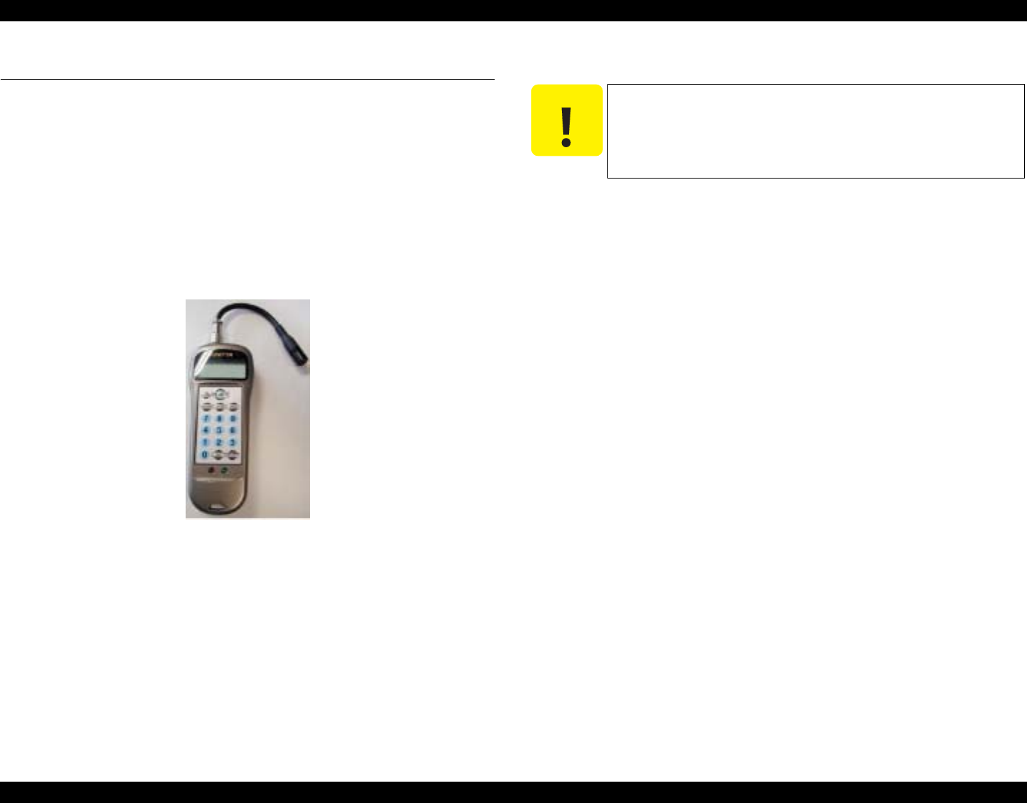
EPSON Stylus Photo R1800/R2400 Revision B
Adjustment Adjustment 137
5.2 Adjustment
This section explains the adjustments that do not use the Adjustment Program.
5.2.1 PF Belt Tension Adjustment
When either of the following parts has been removed or replaced, this
adjustment must be performed to reduce load on the PF Motor and to secure
paper feed accuracy.
PF Motor
PF Roller Shaft
The PF Tension Measuring Tool is used for this adjustment.
Figure 5-1. PF Tension Measuring Tool
5.2.1.1 PF Belt Tension Adjustment Method
1. Secure the PF Motor to the Printer Mechanism, and install the Drive Belt
on the Gear of the PF Scale and the Pinion Gear of the PF Motor.
2. Press the [POWER] button. The LCD of the Measuring Tool displays No. 0
and No. 1.
3. From among No. 0 to No. 9, select the channel you want to store its setting
by pressing the [SELECT] button. The initial value may be selected as the
channel.)
4. Press the [WEIGHT] button. The initial value will be displayed. Type the
ten-key pad so that "1.2g/m" is displayed.
5. Press the [WIDTH] button. The initial value will be displayed. Enter "5.0
mm" with the ten-keypad.
6. Press the [SPAN] button. The initial value will be displayed. Enter "1.89in"
with the ten-keypad.
C A U T I O N
Proper measurement may be interrupted by sounds picked
up from around. Make measurement in silent environment.
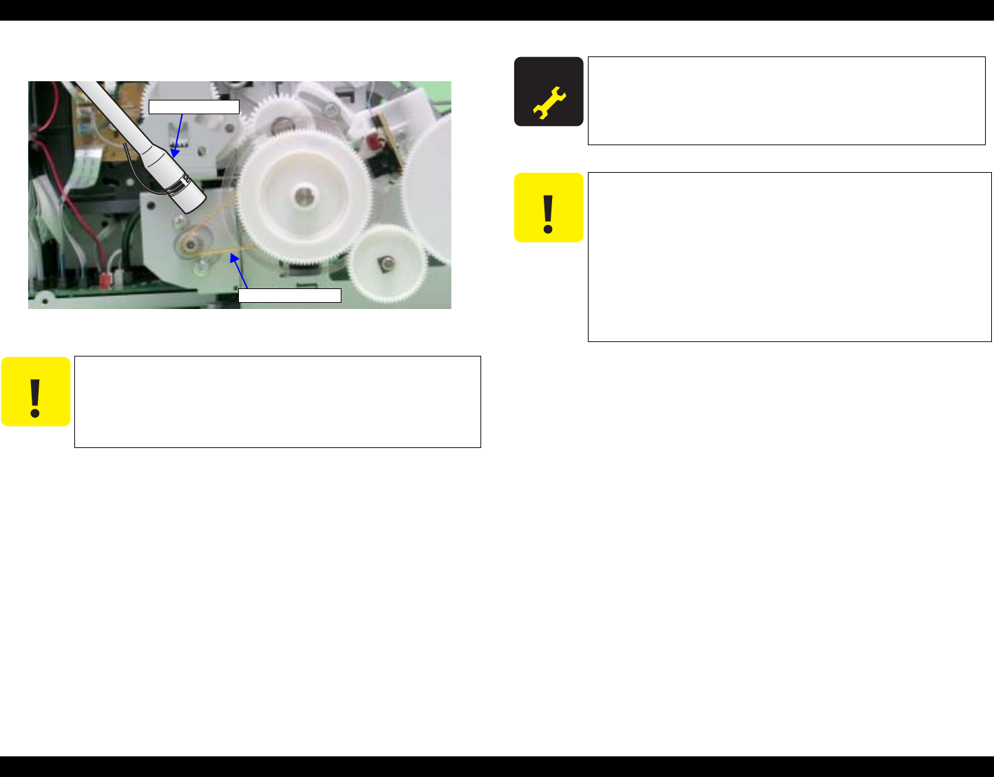
EPSON Stylus Photo R1800/R2400 Revision B
Adjustment Adjustment 138
7. Bring the Microphone as close as possible to the center of the Timing Belt.
Figure 5-2. Microphone Position
8. Press the [MEASURE] button. ("----" is displayed on the LCD screen.)
9. Put the tip of the tweezers on the Drive Belt, and flip it downward in that
position. The "----" displayed on the LCD will become wave pattern during
the measurement. When it has finised, the measurement result will be
displayed by "N" (Newton) after the beep. This jig can pick up and measure
sounds accurately, regardless of the flipping force.
10. Repeating 8 and 9, delicately shift the variable part of the PF Motor
mounting position to adjust the tension until the tension falls within the
allowable standard value.
C A U T I O N
As the Drive Belt is flipped with the tip of tweezers in the
following steps, carefully choose the flipping position so that
the Belt will not make contact with the Microphone by
reaction of flipping.
Microphone of
Timing Belt
A D J U S T M E N T
R E Q U I R E D
Standard Value: 9.0 ± 2N (7.0 ~ 11.0N)
C A U T I O N
Even if the Timing Belt is flipped, the LCD screen may
not change at all. In this case, flip the Timing Belt again
after a few seconds have passed.
If measurement results differ greatly from each other,
acoustic sounds may not be picked up properly in any of
the measurements. Therefore, flip the Timing Belt again
with the tweezers, and record the value at which two
measurement results are approximate. Displaying errors
in the range 1/100 to 5/100, the Measuring Tool has high
reliability.
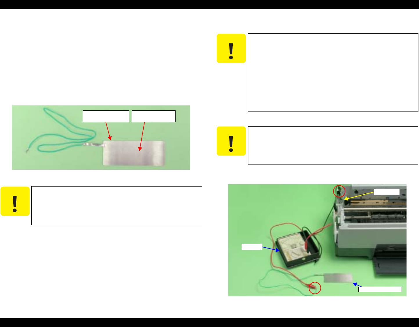
EPSON Stylus Photo R1800/R2400 Revision B
Adjustment Adjustment 139
5.2.2 PG Adjustment
When any of the following parts has been removed or replaced, this adjustment
must be performed to secure the specified clearance between the print surface
of the Print Head and paper.
Print Head
Carriage Unit
Carriage Shaft
Parallelism Adjust Bushing (Including the case when just moved it)
In this adjustment, use the same Adjustment Gauge on the left and right sides.
Figure 5-3. Adjustment Gauge
5.2.2.1 PG Adjustment Method
1. Install the printer on a level base.
2. Connect the Tester to the printer frame and Adjustment Gauge.
Figure 5-4. Connecting the Tester
C A U T I O N
Do not touch the Adjustment Gauge Plate surface with
bare hands.
If the Adjustment Gauge Plate surface is stained by ink
or, etc wipe it with a soft cloth.
Continuty
Measuring Point
Adjustment Gauge
Plate (Top face)
C A U T I O N
Before starting PG adjustment, completely wipe drops of
ink around the Print Head. Remaining drops of ink will
stick to the continuity measurement portion of the
Adjustment Gauge, and generate continuity before the
continuity measurement portion makes contact with the
metal frame around the Print Head, interrupting accurate
PG Adjustment.
As the ink in the Print Head may stick fast and damage
the Print Head during PG Adjustment, make the
continuity time detected with a tester as short as
possible. (Maximum 3 minutes)
C A U T I O N
Place the printer on a level, warp-free table. Normal PG
Adjustment cannot be performed on a warped table.
Tester
Adjustment Gauge
Frame
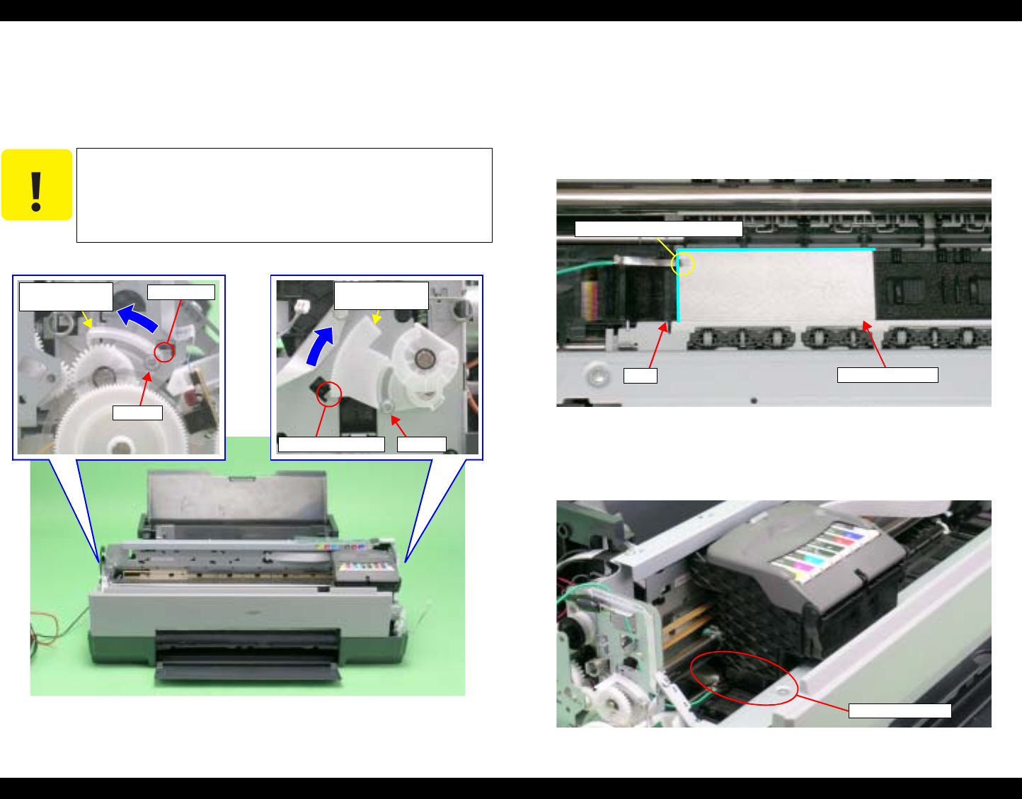
EPSON Stylus Photo R1800/R2400 Revision B
Adjustment Adjustment 140
3. Load unused Ink Cartridges of all colors into the Carriage Unit.
4. Loosen the screw that secures the Parallelism Adjust Bushing.
5. Turn the Parallelism Adjust Bushing upward to match the frame edge and
the bottom of the Parallelism Adjust Bushing gear.
Figure 5-5. Setting the Parallelism Adjust Bushing
6. With its conductor connection portion up, set the Adjustment Gauge in the
specified position (on the left side of the Front Paper Guide).
Setting Position
Rear direction: Match the rear end of the Gauge with the Driven Roller
Shaft of the Upper Paper Guide.
Left direction: Release the left end of the Gauge from the Tab on the
Front Paper Guide in Figure 5-6
Figure 5-6. Setting the Adjustment Gauge
7. Move the Carriage Unit onto the Adjustment Gauge.
Moving position: Match the left end of the Gauge with the left end of
the Carriage Unit.
Figure 5-7. Moving the Carriage Unit
C A U T I O N
When the Parallelism Adjust Bushing is turned upwards, the
frame rises up and PG narrows. Make sure that the frame
does not come into contact with the Print Head when
performing the following procedure.
Parallelism
Adjust Bushing
Positioning Point Screw
Parallelism
Adjust Bushing Positioning
Screw
Setting Position
Conductor Connection Point
Tab
Setting Position
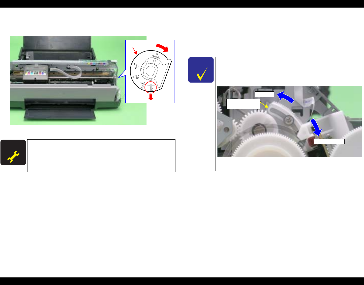
EPSON Stylus Photo R1800/R2400 Revision B
Adjustment Adjustment 141
8. To set the PG position to the "--" position, turn the PG Cam on the right end
of the Carriage Shaft clockwise so that the point marked "--" faces down.
Figure 5-8. Markings of the PG Cam
9. Lower the Gear of the Parallelism Adjust Bushing on the left side of the
frame stepwise, and confirm continuity. When continuity is confirmed,
define the position where the Gear was raised one step up from the
continuity position (where continuity is lost) as the left side PG position.
Move the Parallelism Adjust Bushing at least twice to confirm that the
continuity position and the non-continuity position are the same.
10. To set the PG position to "0" or more, turn the PG Cams on both ends of
the Carriage Shaft CCW so that the point marked "0" (or "+" or "++") faces
down.
A D J U S T M E N T
R E Q U I R E D
PG Standard Value
•PG – – (MInus Minus) :1.05mm~1.25mm
•PG – (Minus) :1.2mm~1.4mm
Adjustment Resolution :0.06mm
PG Cam
CHECK
P O I N T
The following figure shows the states of the Adjust Parallel
Bushing of the left side of the frame and the PG. This also
applies to the Adjust Parallel Bushing on the right side of the
frame.)
Figure 5-9. Relationship between Parallelism Adjust Bushing
and PG
Narrower PG
Wider PG
Parallelism
Adjust Bushing
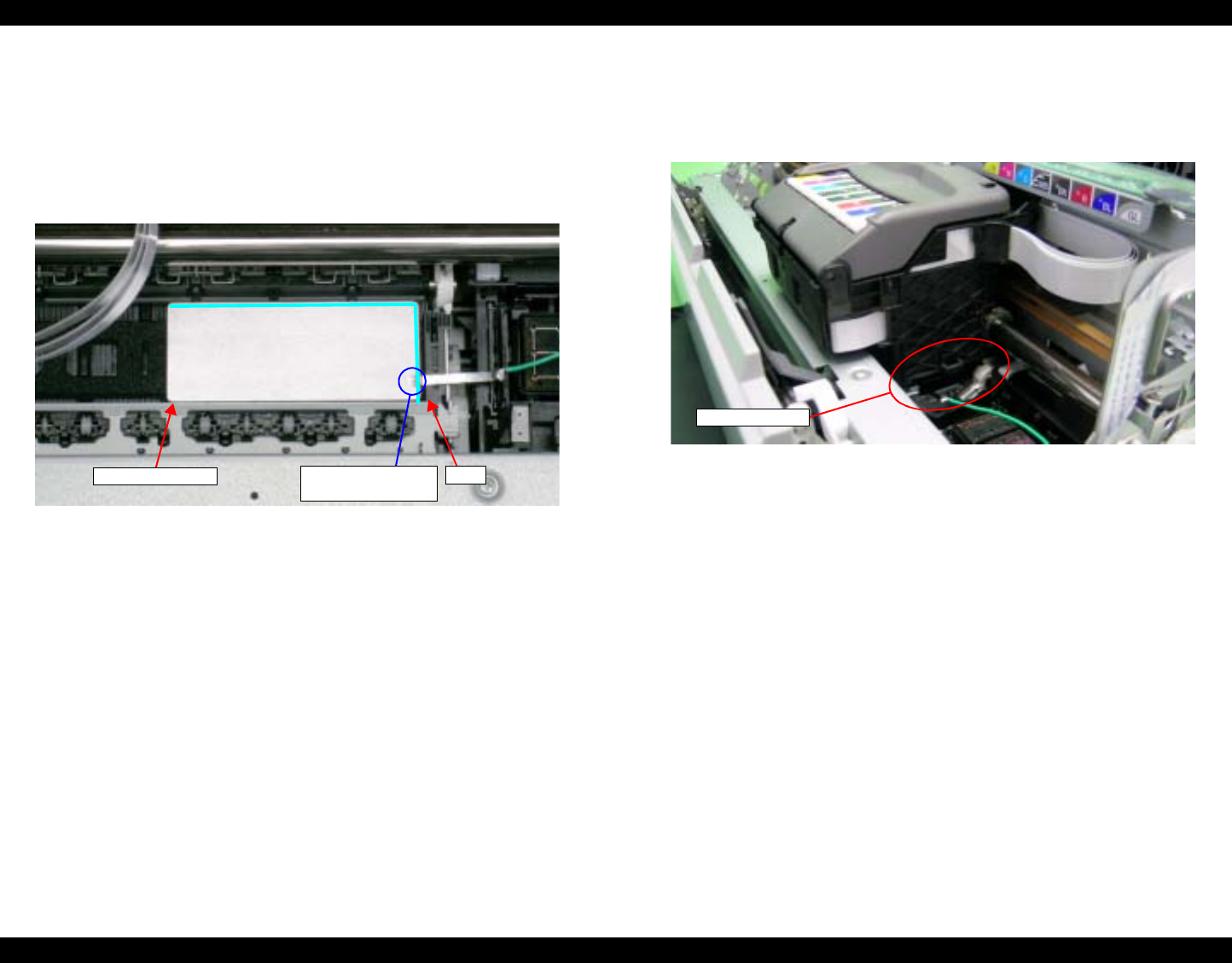
EPSON Stylus Photo R1800/R2400 Revision B
Adjustment Adjustment 142
11. With its conductor connection portion up, set the Adjustment Gauge in the
specified position (on the right side of the Front Paper Guide).
Setting Position
Rear direction: Match the rear end of the Gauge with the Driven Roller
Shaft of the Upper Paper Guide.
Right direction: Release the right end of the Gange from the Tab on the
Front Paper Guide in Figure 5-10.
Figure 5-10. Setting the Adjustment Gauge
12. Move the Carriage Unit onto the Adjustment Gauge.
Moving position
Match the right end of the Gauge with the right end of the Carriage
Unit.
Figure 5-11. Moving the Carriage Unit
13. Return the PG position to "--".
14. As in Step9, move the Parallelism Adjust Bushing on the right side of the
frame to set the right side PG position.
15. Set the PG position to 0 or more.
16. Set the Adjustment Gauge on the left side of the Front Paper Guide.
17. Move the Carriage Unit onto the left side Adjustment Gauge.
18. Return the PG position to "--".
19. Check continuity again at the PG position on the left side. If the PG position
is not out of position, tighten the Parallelism Adjust Bushing with the
screws to end the adjustment. If it is out of position, repeat the adjustment
procedure from step 9.
Setting Position Conductor
Connection Point
Tab
Setting Position
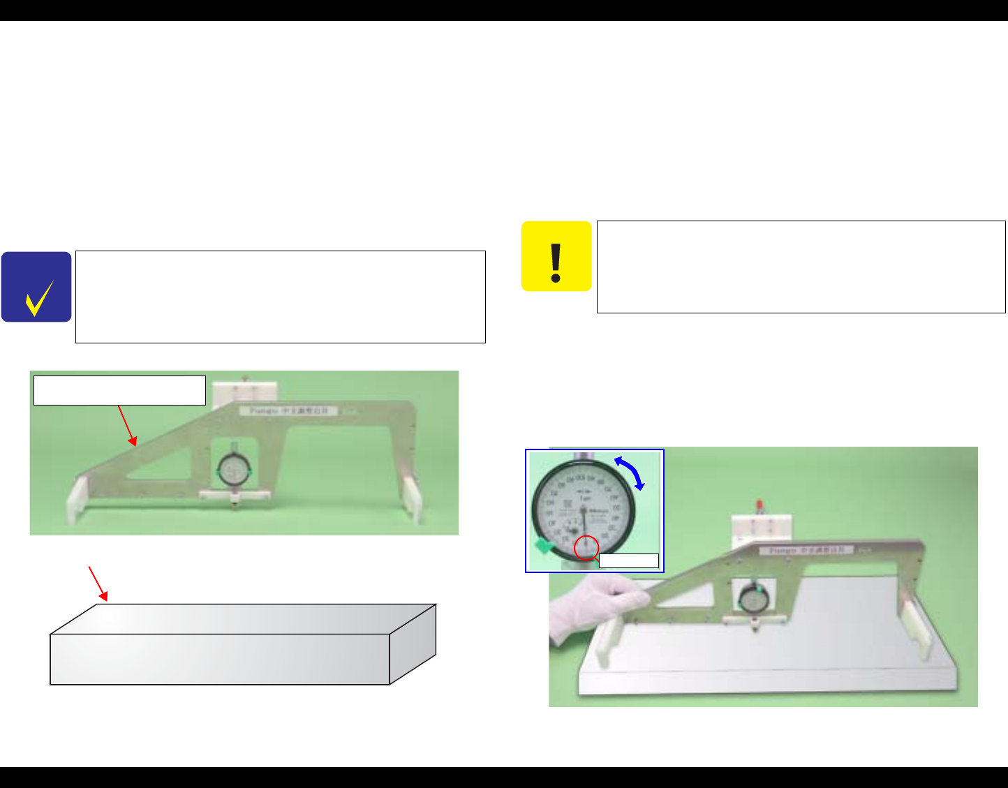
EPSON Stylus Photo R1800/R2400 Revision B
Adjustment Adjustment 143
5.2.3 PF Roller Shaft Center Support Position
Adjustment
This adjustment must be performed to compensate the deflection amount on
the PF Roller Shaft and to maintain an appropriate paper feed amount when
the following parts are removed and replaced.
PF Motor
PF Roller Shaft
The PF Roller Shaft Position Adjustment Jig and Level block are used for this
adjustment.
Figure 5-12. PF Roller Shaft Center Support Position Adjustment Jig
and Level Block
5.2.3.1 How to Adjust the PF Roller Shaft Center
Support Position
1. Before performing this adjustment, remove the following parts:
Lower Housing
ASF Assy See Section 4.2.4 on page 83.
Board Assy See Section 4.2.5.1 on page 87.
Carriage Unit
2. Install the printer on a level base.
3. Set the PF Roller Shaft Position Adjustment Jig in place on the Level block, and
perform zero adjustment.
Long hand position: Turn the dial to adjust the "0" position on the scale
to the long hand position with the jig set in place
on the Level block.
Short hand position: Check it.
Figure 5-13. Setting the PF Roller Shaft Position Adjustment Jig (1)
CHECK
P O I N T
A substitute level block can be used if its surface accuracy is
within 50µ.
PF Roller Shaft Center Support
Position Adjustment Jig
Level Block
C A U T I O N
Place the printer on a level, warp-free table. This adjustment
cannot be performed correctly if it is performed on a warped
table.
0 position
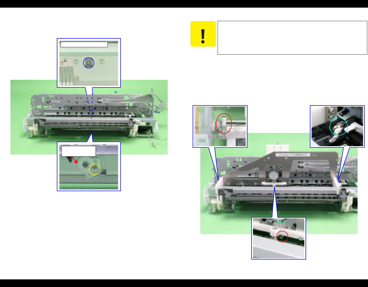
EPSON Stylus Photo R1800/R2400 Revision B
Adjustment Adjustment 144
4. Loosen the screws that secure the Center Support Bushing Cam and the
Center Support Bush.
Figure 5-14. Center Support Bushing Cam and the Screw
5. Set the jig in place on the PF Roller Shaft as shown in the figure below.
Left side: Inside of PF Roller left end (E-ring)
Right side: Clearance between PF Roller right end (Right Bushing 8)
and left end of Upper Paper Guide
Center: Clearance between the 2nd Upper Paper Guide and 3rd one
from the left
Figure 5-15. Setting the PF Roller Shaft Position Adjustment Jig (2)
Center Support
Bushing Cam
Bottom of Rear Center
C A U T I O N
Check for any dirt on the PF Roller Shaft when performing
the following procedure.
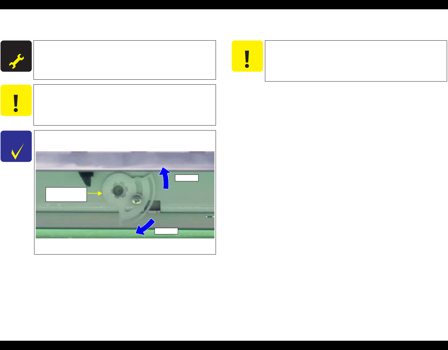
EPSON Stylus Photo R1800/R2400 Revision B
Adjustment Adjustment 145
6. Turn the Center Support Bushing Cam so that the long hand position is
+30µ from the "0" adjustment position. 7. Tighten the Center Support Bushing Cam and the Center Support Bushing
with the screws.
The following page shows print samples when adjustment of the PF Roller Shaft
Center Support Positions are inside and outside the specified value range.
A D J U S T M E N T
R E Q U I R E D
Standard Value: 30 ± 50µ
Adjustment Resolution: 50µ
C A U T I O N
+30µ must be set to compensate for the thickness of the
coating on the PF Roller Shaft.
Make sure that the position of the short hand is the same
as at "0" adjustment.
CHECK
P O I N T
The figure below shows the positional relationship between
the Center Support Bushing Cam and the Dial Gage.
Figure 5-16. Positional Relationship between Center Support
Bushing Cam and the Dial Gage
µ down
µ up
Center Support
Bushing Cam
C A U T I O N
Check the adjustment value again as it deviates slightly
when the screw is tightened.
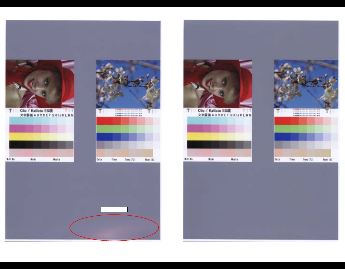
EPSON Stylus Photo R1800/R2400 Revision B
Adjustment Adjustment 146
Figure 5-17. Outside the Specified Value Range Figure 5-18. Inside the Specified Value Range
Unevenness
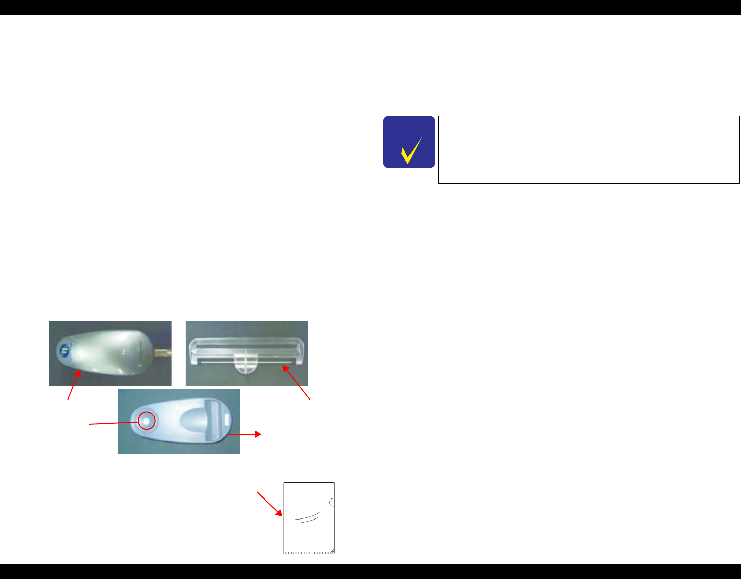
EPSON Stylus Photo R1800/R2400 Revision B
Adjustment Adjustment 147
5.2.4 Colorimetric Calibration
This calibration is performed to compensate the ink discharge amount when
the following parts are replaced:
Print Head
Main Board
PS Board
The following tools are used for this adjustment:
Photo paper (A4 or letter-size): 1 sheet (for printing Calibration Chart)
Plain paper (A4 or letter-size): 1 sheet (for checking the nozzles)
PC (OS: Windows XP/Me/2000/98)
The following drivers must be installed on the PC:
•Printer Driver for Stylus Photo R1800
•USB Driver for the Calibrator
(Interface other than USB are not available.)
Calibrator (GretagMacbeth Eye-One with a UV filter)
•Scanning ruler (supplied with the Calibrator)
•Calibration plate that contains a white reference tile
(Calibrator accessory)
Colorimetric Calibration Tool for Stylus Photo R1800 (program)
Black paper (A4 size or larger) (A paper printed in solid black can also
be used.)
Figure 5-19. The Calibrator and the Accessories
The following tool is used to mail the Calibration
Chart when measuring color at a place different
from the repair work site.
Clear file
Plain paper (A4 or letter-size) : 1 sheet
5.2.4.1 Overview of the Colorimetric Calibration
Purpose
Measuring the color of the ink discharge amount information and
registering/controlling this information improves calibration accuracy and
ensures consistent color quality.
To reduce unit-to-unit and mode-to-mode variations in color.
To improve the accuracy of the Ink Counter.
The Color ID can improve the Ink Counter accuracy, which reduces the
running cost of ink.
Colorimetric Calibration Technology
The Principle
The ink discharge amount characteristic of a printer is measured by
measuring color difference (L*a*b*) of a printed chart with a calibrator.
Created Color ID information based on the obtained L*a*b values is
stored on the printer. When printing, the printer sends the Color ID to
the printer driver to compensate the number of ink droplets (dot
generation rate) for each of nine1 different sized droplets of each color.
This method allows mass-produced printers to provide consistent print
quality reducing unit-to-unit variation.
Example: Compensation of Ink Amount Ejected from a Print Head
(dot generation rate)
•When the standard printer generates ten dots.
If the ink discharge amount is insufficient by 10%, this is compensated by
generating 11 dots.
Note 1: Three different sized droplets (small, medium, large) for each of three
waveforms (VSD1, 2, 3)
Head ID
In the conventional color calibration with a Head ID, the print head
characteristics (weight of discharged ink) are measured and
compensated. The following shows the correlation between
conventional Head ID adjustment and Colorimetric Calibration.
Calibrator Scanning Ruler
White
Reference
Tile Calibration Plate
CHECK
P O I N T
As color measurement is performed with the fully assembled
product, the electrical characteristics which are unique to
each Main/Power Board are also compensated in addition to
the Print Head.
Clear file
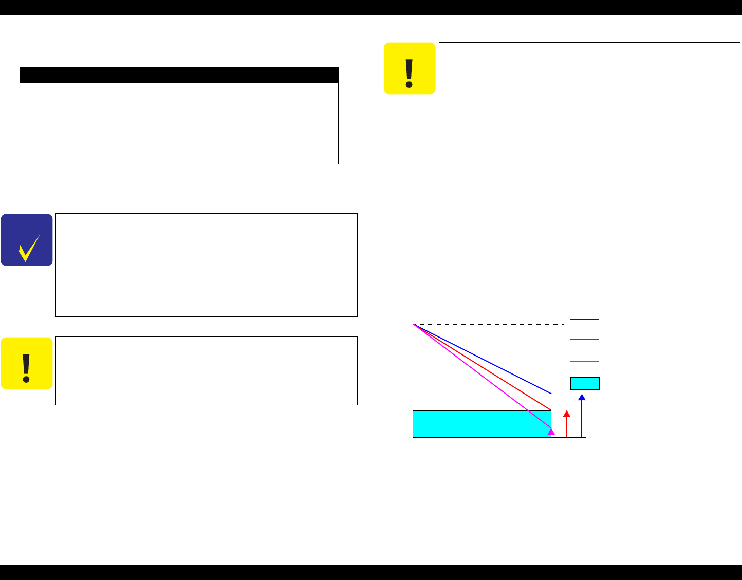
EPSON Stylus Photo R1800/R2400 Revision B
Adjustment Adjustment 148
Note : Calibration processes of "Color ID" and "Head ID" are exactly the same.
Calibration can be made by transmitting the ID to printer drivers and changing
dot generation rate in reference to the same calibration table.
Supplement: Regarding remaining ink amount
When the Ink Counter detects ink out, a certain amount (safety margin) of
ink is still remaining in the cartridge to prevent the print head from
damages caused by printing without ink. This safety margin is important
especially for a ptinter that discharges larger amount of ink.
The figure below illustrates the concept of this safety margin.
Figure 5-20. Concept of Remaining Ink Amount
Table 5-6.The Difference in Calibration Method between Head ID and
Colorimetric Calibration.
Conventional Head ID adjustment Colorimetric Calibration
In the print head manufacturing
process, ink discharge amount of
each head is actually measured to
get individual charateristic
information. The information is
stored on the printer as Head ID to
control the print head.
By printing and measuring a color
chart, a variation from the standard
machine is obtained and registered
as the correction value (Color ID) to
control the amount of ink droplets.
CHECK
P O I N T
Make sure not to confuse Head ID with Color ID.
Head ID
An ID information specific to individual print head. It is
indicated on the Head QR Code Label attached to the
print head.
Color ID
An ID information specific to individual printer. It is
obtained by the Colorimetric Calibration.
C A U T I O N
Before performing Colorimetric Calibration, the conventional
Head ID must be pre-registered. This is because the Head ID
contains information to create a waveform to drive the head,
which is also required for the Colorimetric Calibration.
C A U T I O N
If you do not perform Colorimetric Calibration after
performing Head ID adjustment, the printer will be controlled
only by the Head ID, which affects the following.
Ink Counter
The ink consumption counter table switches from the
table for Color ID to the one for Head ID. This change
causes an ink out error to occur 2 to 5 percent earlier
than when using the table for Color ID.
Color Quality
Color quality will be at the same level as that of printers
adjusted by the conventional Head ID, and the same
color quality as mass-produced printers cannot be
maintained.
100%
100%
Actual ink amount
Ink counter amount
Printer A
Ink discharge amount is low
Printer B
Ink discharge amount is standard
Printer C
Ink discharge amount is high
Remaining amount of ink when
the counter shows ink out.
Margin amount of ink
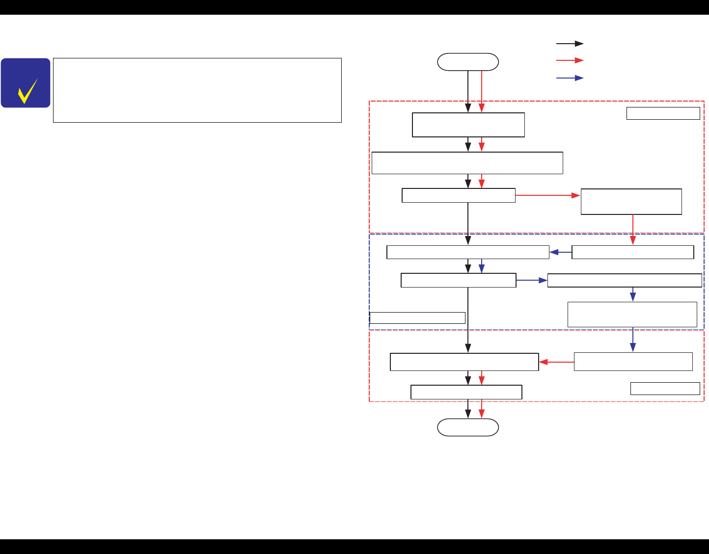
EPSON Stylus Photo R1800/R2400 Revision B
Adjustment Adjustment 149
5.2.4.2 Adjusting Method of the Colorimetric Calibration
When color measurement is performed at the same place as the repair work
site, calibration is batch-processed. When color measurement is performed at
a place different from the repair work site, calibration is performed by separate
processes. The following illustrates the overall workflow.
Figure 5-21. Overall Workflow
CHECK
P O I N T
The Color ID Calibration Chart is designed to be printed in a
completely non-compensated state. Therefore, there is no
need to delete an existing Color ID from EEPROM when
printing out a Calibration Chart.
START
USB ID acquisition
Printing date/time acquisition
Printing of a Calibration Chart
∗USB ID / printing date/time / nozzle check pattern
Drying of the Calibration Chart Mail the Calibration Chart
to color measurement site.
Receive the Calibration Chart.
Save the color measurement data to a file.
Mail the color measurement data
file to repair work site.
Confirmation of USB ID / printing date/time
Measure the Calibration Chart.
Input the color measurement
data from file or enter
Write the Color ID to a printer.
End
[Repair work site]
[Repair work site]
Fl
ow o
f
b
a
t
c
h
process
i
ng
Flow of separate process
(repair work site)
Flow of separate process
(color measurement site)
[Color measurement site]
Convert the color values (Lab) to Color ID
from color measurement data.
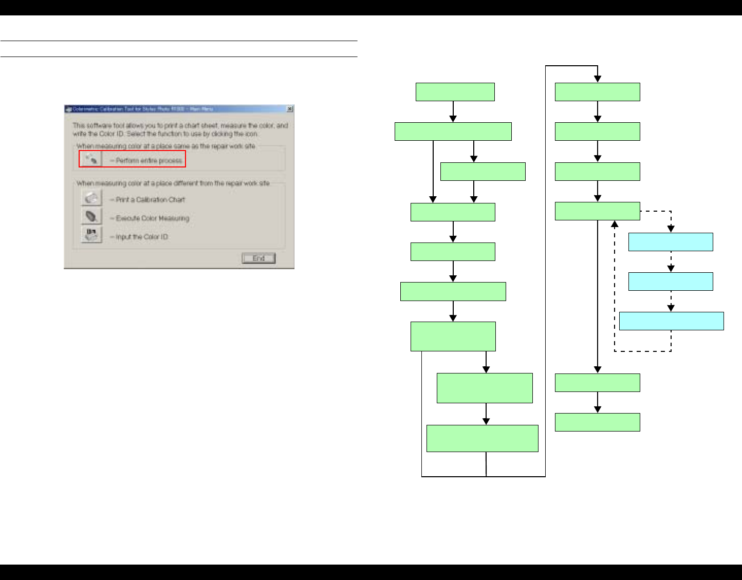
EPSON Stylus Photo R1800/R2400 Revision B
Adjustment Adjustment 150
When Measuring Color at a Place the Same as the Repair Work Site
1. Start up the Colorimetric Calibration Tool for Stylus Photo R1800 on a PC,
and click [Perform entire process].
Figure 5-22. Perform Entire Process
The following shows the process when [Perform entire process] is clicked.
Figure 5-23. Entire Process Workflow
END
Select port
Connect printer
Check printer connection
Ink setup
Perform cleaning
Automatic nozzle check
Printing automatic
nozzle check pattern...
End of printing of automatic
nozzle check pattern
Executing automatic
nozzle check...
Print chart
Printing chart...
Dry chart
Prepare Calibrator
Prepare chart
Measure color
Start color measurement
Write Color ID
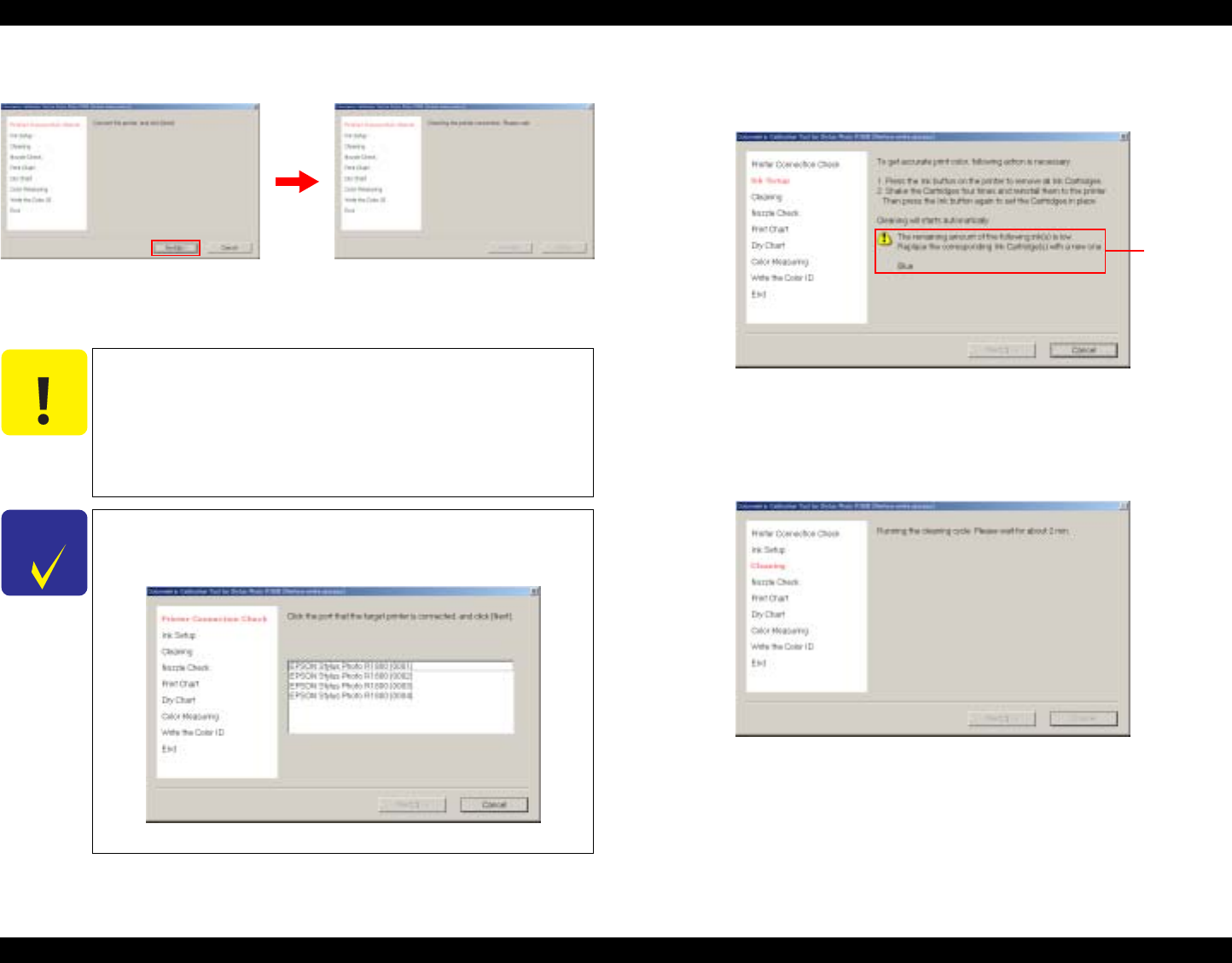
EPSON Stylus Photo R1800/R2400 Revision B
Adjustment Adjustment 151
2. Connect the printer to the PC by a USB cable, and click [Next].
Figure 5-24. Checking the Printer Connection
3. The printer driver for Stylus Photo R1800 is automatically detected, and
the USB ID is automatically acquired.
4. To prevent inks from settling down at the bottom, remove all ink cartridges,
shake them at least four times, and reinstall them to the printer.
Figure 5-26. Ink Setup
5. To prevent inks from settling down at the bottom, cleaning cycles shown
below are performed.
Exchange CL (once) + CL3 (once)
Figure 5-27. Cleaning
C A U T I O N
The remaining amount of the ink is checked before the
USB ID is acquired. If there is an ink cartridge(s) with a
remaining amount of ink of 30% or less (ink low/ink out
states), a warning message is displayed.
As the USB ID is used to recognize printers when
entering color measurement values, do not change the
USB ID after performing the Colorimetric Calibration.
CHECK
P O I N T
Only printers connected with USB are recognized.
When two or more printers are currently connected, the
screen changes to the "port selection" screen.
Figure 5-25. Selecting the Port
Warning
message
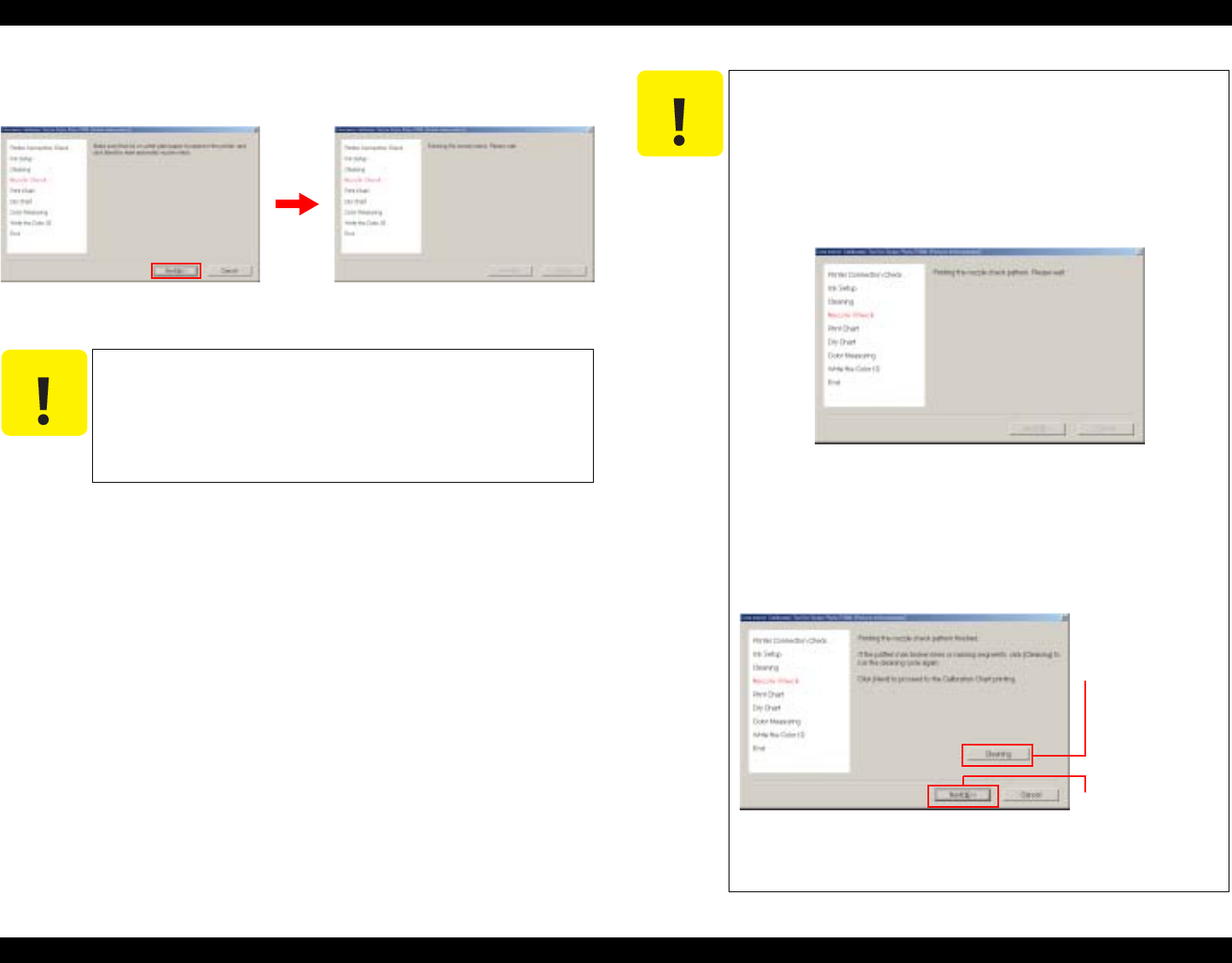
EPSON Stylus Photo R1800/R2400 Revision B
Adjustment Adjustment 152
6. Load one sheet of A4 or letter-size plain paper, and click "Next" to execute
the automatic nozzle check.
Figure 5-28. Automatic Nozzle Check
C A U T I O N
The following error message is displayed if the automatic
nozzle check fails three times in a row:
"The automatic nozzle check has failed. There may be a
problem with the print head."
The print head, ink cartridge(s), or ink system may be
damaged.
C A U T I O N
If an ink sensor abnormality is detected during execution of
the automatic nozzle check, the following error message will
be displayed:
"The automatic nozzle check has finished
unsuccessfully. Click OK to start a nozzle check
manually."
1. Click [OK] to print the nozzle check pattern.
Figure 5-29. Manual Nozzle Check
2. Check the printed nozzle check pattern. If there are
no broken lines or missing segments, click [Next]. If
there are broken lines or missing segments, click
[Cleaning], and return to Step 5.
Figure 5-30. Completion of Printing of
Nozzle Check Pattern
When there are no
broken lines or
missing segments
When there are
broken lines or
missing segments
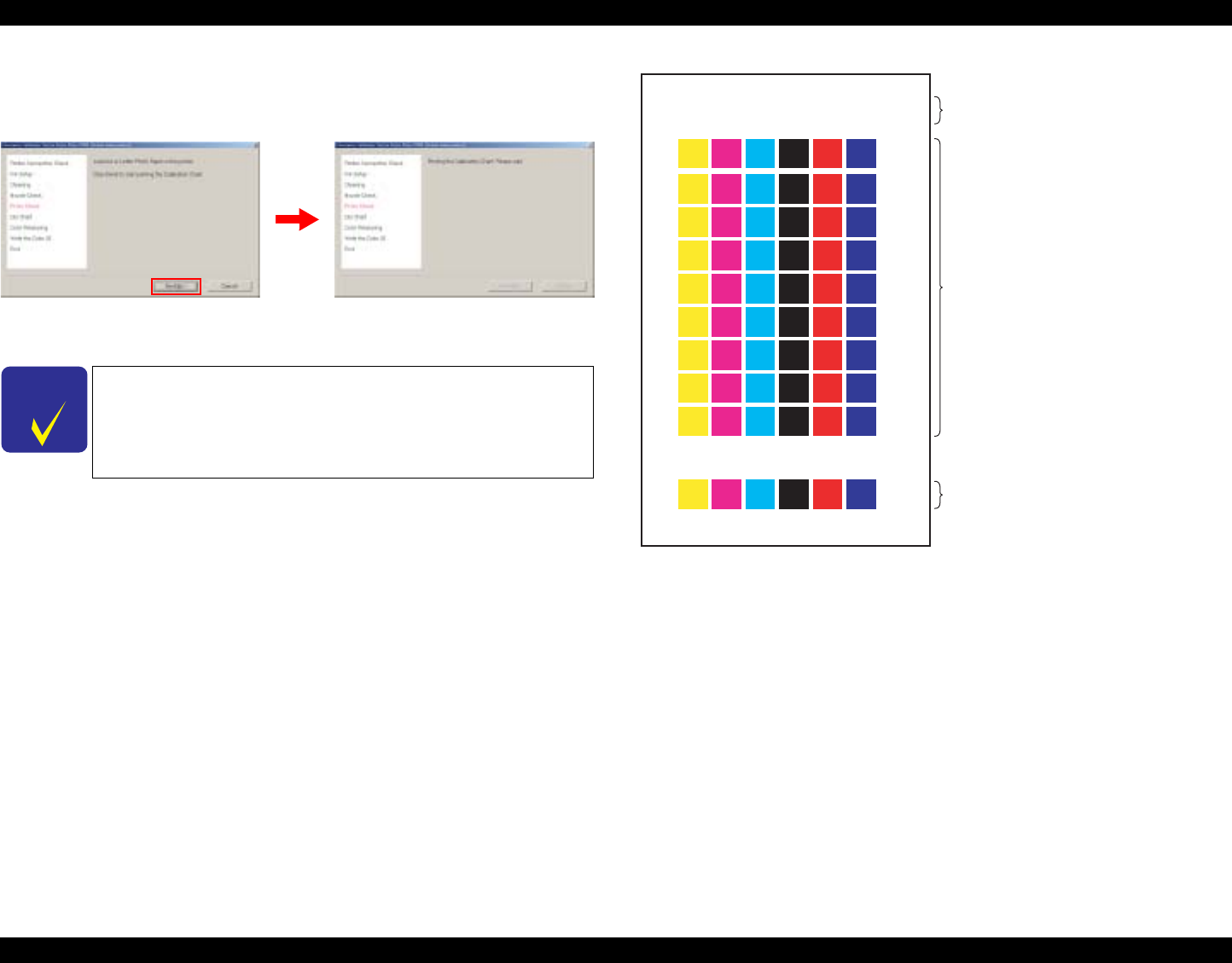
EPSON Stylus Photo R1800/R2400 Revision B
Adjustment Adjustment 153
7. Load one sheet of A4 or letter-size Photo paper, and click "Next" to print
the Calibration Chart.
Figure 5-31. Printing a Calibration Chart
Figure 5-32. Illustration of Calibration Chart
CHECK
P O I N T
The recommended air temperature range for printing a
Calibration Chart is 15°C to 28°C.
2004-07-02135953 USBIDMH01234567
2004-07-05135953
USB ID (All 18 alphanumeric digits are
indicated.)
Print time + Color measurement limit
time (7 days after the print time)
54 calibration patches
(6 colors x 9 dot sizes)
Nozzle check pattern
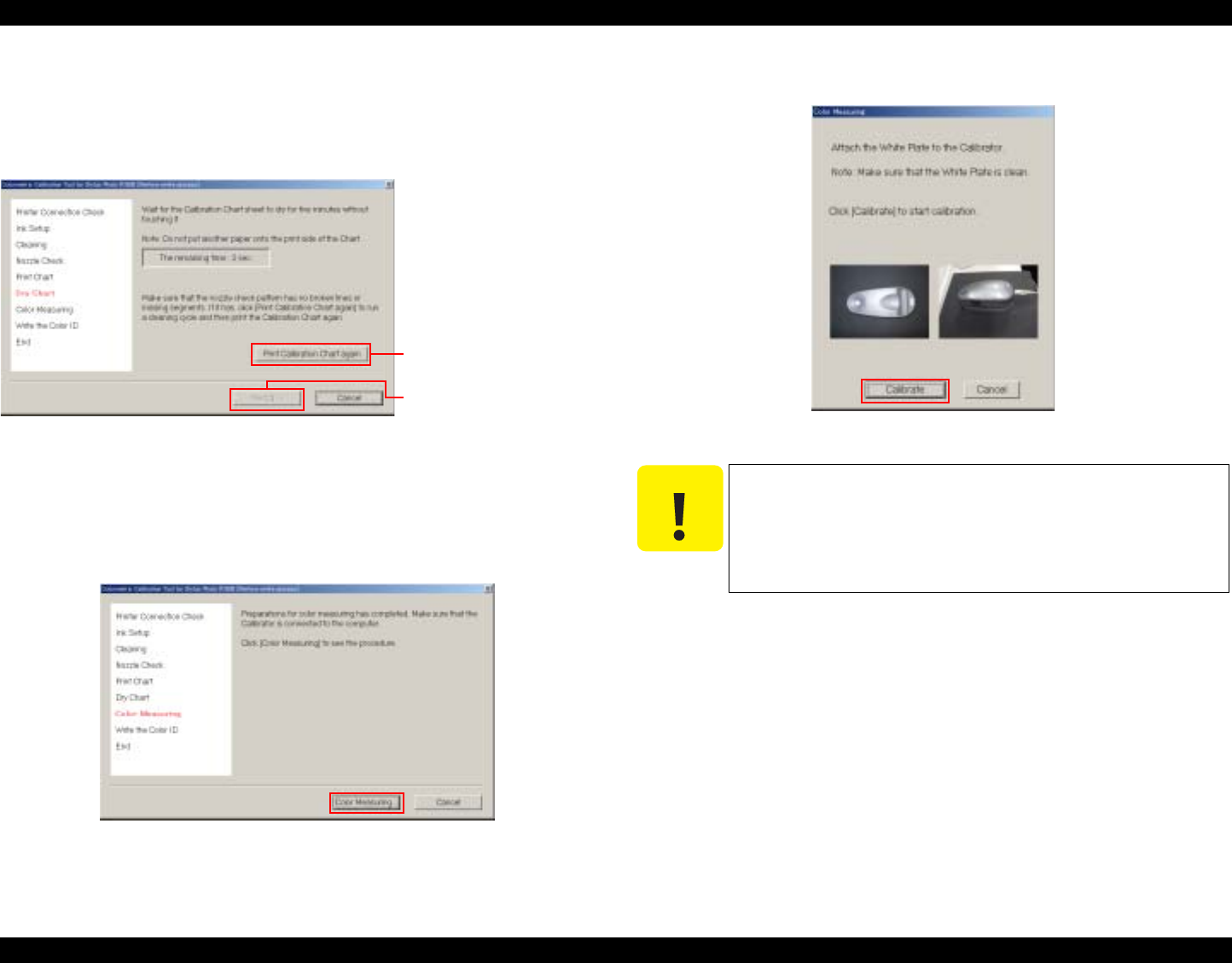
EPSON Stylus Photo R1800/R2400 Revision B
Adjustment Adjustment 154
8. After the Calibration Chart is printed, allow it to dry for five minutes. During
this time, check the nozzle check pattern on the chart. If there are broken
lines or missing segments, click [Print Calibration Chart again], and return
to Step 5. If there are no broken lines or missing segments, click [Next].
Figure 5-33. Drying the Chart
9. Connect the Calibrator to the PC and click [Color Measuring]. The color
measurement procedure screen operated by the Calibrator control plug-in
(DLL) is displayed on screen overlapping the Colorimetric Calibration Tool.
Figure 5-34. Color Measurement
10. Place the Calibrator on the calibration plate, and click [Calibrate]
Figure 5-35. Preparing the Calibrator
When there are broken lines
or missing segments
This button is enabled when
countdown is completed.
C A U T I O N
The white reference tile on the calibration plate should be
clean. Clean off any dirt with alcohol or other organic
solvent.
The calibration plate and the Calibrator are used as a
pair. Do not use a calibration plate supplied with an
another Calibrator.

EPSON Stylus Photo R1800/R2400 Revision B
Adjustment Adjustment 155
11. After confirming that you are within the color measurement time limit, place
the Calibration Chart sheet on a black paper, put the scanning ruler on the
Chart sheet, then click [OK].
Figure 5-36. Preparing the Calibration Chart
12. Follow the on-screen messages to measure the Chart. After the color
measurement is finished, click [OK].
Figure 5-37. Starting the Color Measurement
Color patch grid
Color measurement
"completed" rows Patches in the completed rows are displayed in colors
created according to the measurement result.
Color measurement
"not completed" rows Rows that have not been measured are displayed in pale
color.
Arrow Indicates the start position of color measuring.
Cursor Automatically moves up when color measurement of a
row is completed.
Scroll buttons Scroll the cursor up or down. (These buttons are
available for already measured rows or the row currently
being measured.)
This button is
enabled after color
measurement is
completed.
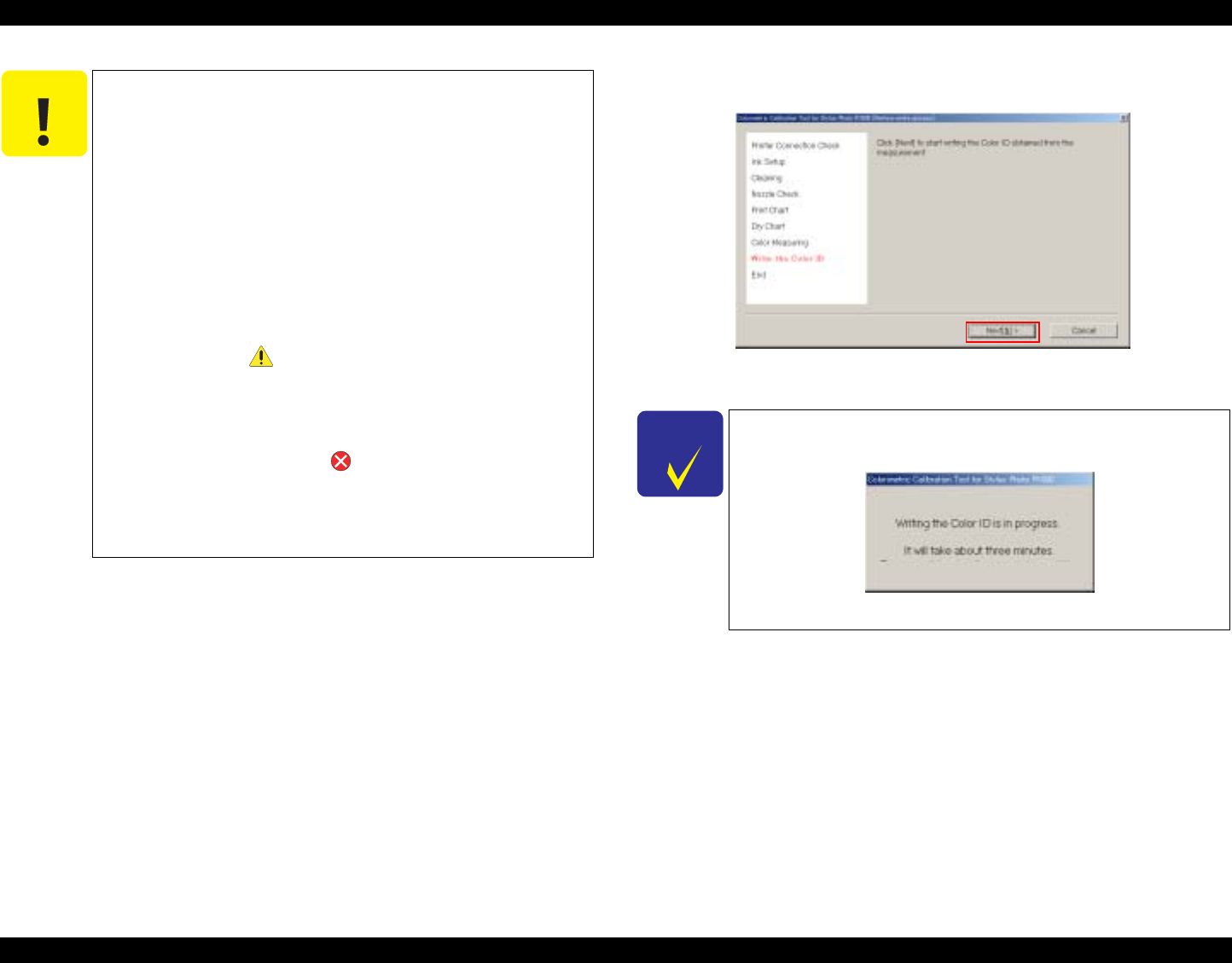
EPSON Stylus Photo R1800/R2400 Revision B
Adjustment Adjustment 156
13. Click [Next], and write the Color ID to the printer.
Figure 5-38. Writing of Color ID
C A U T I O N
Be sure to start the measurement from the top side of the
chart.
Take more than 10 seconds to measure one row.
Slide the calibrator at a constant speed.
During color measurement, do not allow the Calibrator to
rub against unmeasured patches on the chart.
Prevent the ruler and Calibrator from coming off the
chart sheet during color measurement. Doing so will
cause incorrect color measurement.
During color measurement, measure only the patches on
the chart sheet. Do not measure other parts such as the
USB ID text string.
When there is an error possibility in measuring color, a
warning mark ( ) appears at the patch in question. In
such case, make sure to measure the row that includes
the patch with a warning mark again.
If the number of scanned patches does not match the
number of patches on a single row, the cursor stops at
that row, the error mark ( ) appears on all of the
patches on that row, and the following error message is
displayed:
•"Color measuring by Eye-One calibrator has failed.
Measure colors of the failed row again."
CHECK
P O I N T
It takes about three minutes to write the Color ID to the
printer.
Figure 5-39. Writing of Color ID in Progress
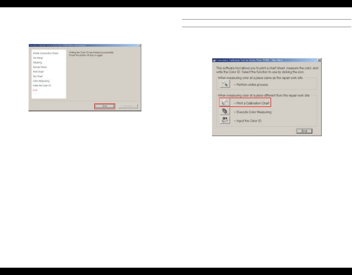
EPSON Stylus Photo R1800/R2400 Revision B
Adjustment Adjustment 157
14. When the following screen is displayed, click [End], and turn the printer
OFF then back ON again to end the adjustment. This action reflects the
color measurement values on the printer.
Figure 5-40. END
When Measuring Color at a Place Different from the Repair Work Site
1. Repair work site
1. Start up the Colorimetric Calibration Tool for Stylus Photo
R1800 on the PC, and click [Print a Calibration Chart].
Figure 5-41. Printing a Calibration Chart
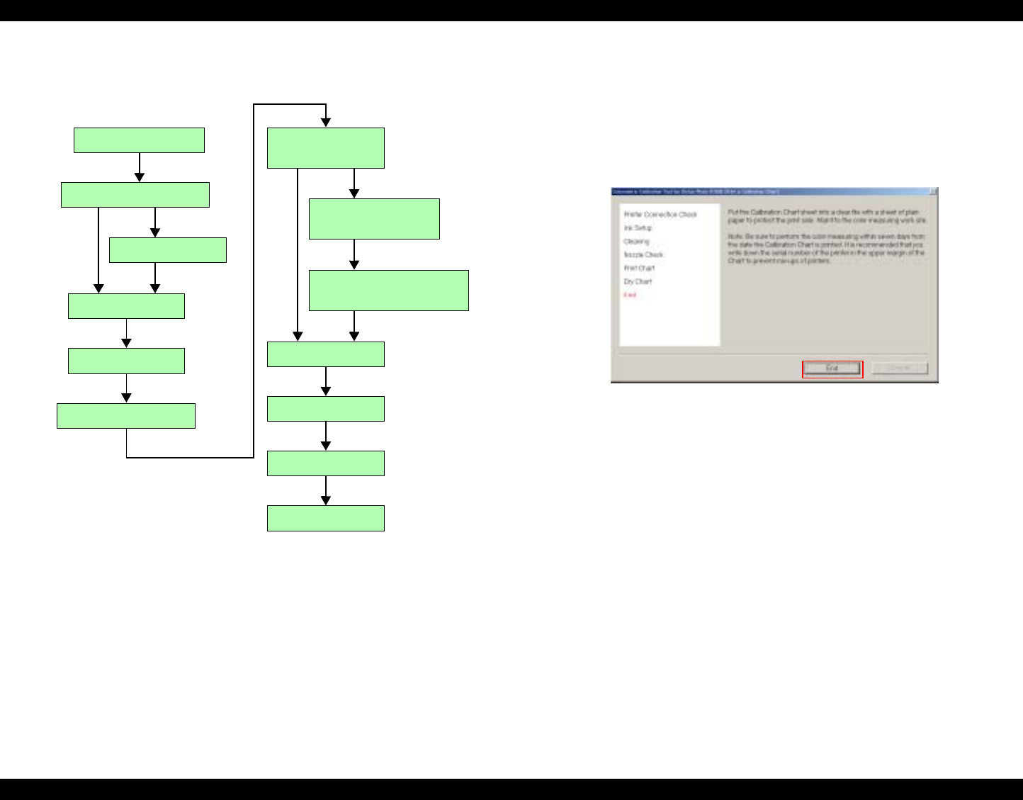
EPSON Stylus Photo R1800/R2400 Revision B
Adjustment Adjustment 158
The following shows the process when [Print a Calibration Chart] is
clicked.
Figure 5-42. Printing a Calibration Chart Workflow
2. Execute Step 2 ~ 8 of the procedure “ When Measuring Color at a
Place the Same as the Repair Work Site” (p150) to make a
Calibration Chart.
3. When the following screen is displayed, click [End], and follow
the on-screen instructions to mail the Calibration Chart to the
repair work site.
Figure 5-43. END
END
Select port
Connect printer
Check printer connection
Ink setup
Perform cleaning
Automatic nozzle check
Print chart
Printing chart...
Dry chart
Printing automatic
nozzle check pattern...
End of printing of automatic
nozzle check pattern
Executing automatic
nozzle check...
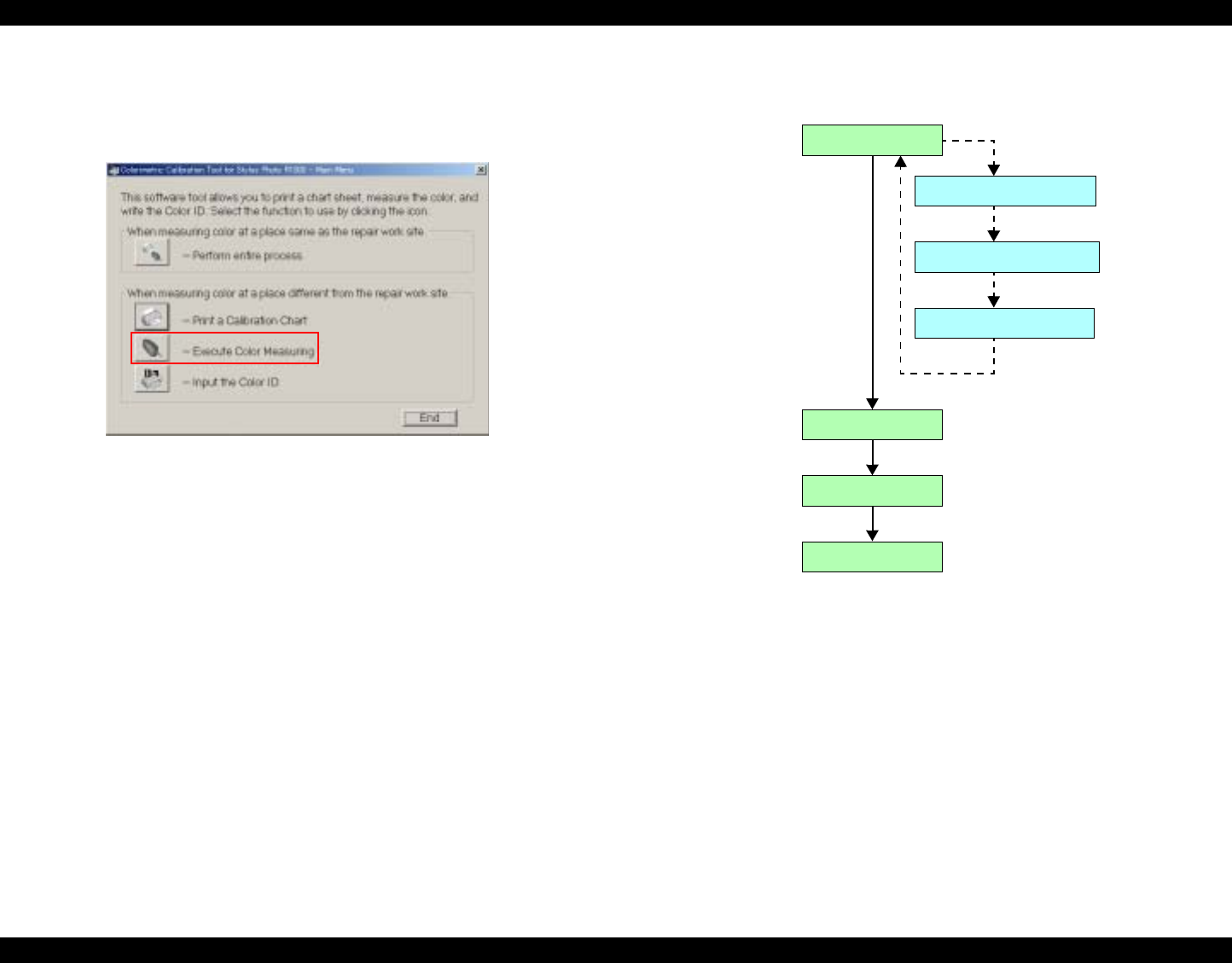
EPSON Stylus Photo R1800/R2400 Revision B
Adjustment Adjustment 159
2. Color measurement work site
1. Start up the Colorimetric Calibration Tool for Stylus Photo
R1800 on the PC, and click [Execute color measuring].
Figure 5-44. Color Measurement
The following shows the process when [Execute color measuring] is
clicked.
Figure 5-45. Color Measurement Workflow
Prepare Color Calibrator
Prepare Calibration Chart
Color measurement
Start color measurement
Enter USB ID
END
Create data file
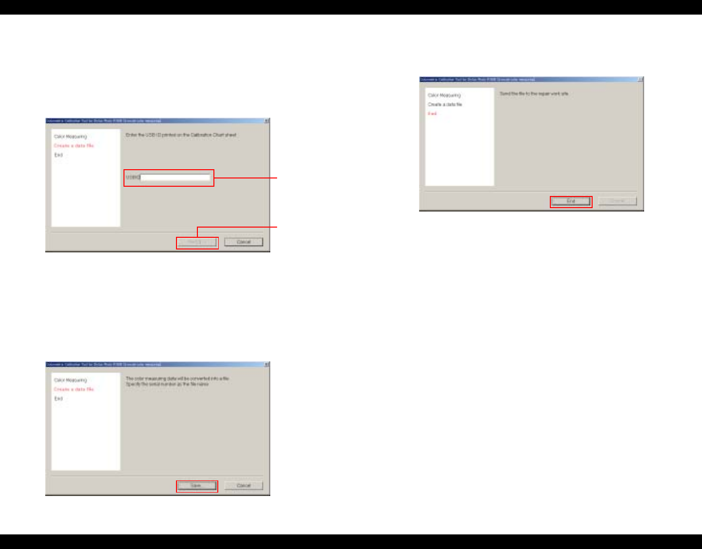
EPSON Stylus Photo R1800/R2400 Revision B
Adjustment Adjustment 160
2. Execute Step 9 ~ 12 of the procedure “ When Measuring Color at a
Place the Same as the Repair Work Site” (p150) and execute color
measurement on the Calibration Chart that was mailed.
3. Enter the USB ID printed on the Calibration Chart's header in the
edit box using 1-byte characters, and click [Next].
Figure5-46. Entering the USB ID
4. Click [Save...] to save the color measurement data.
•Color measurement data file: xxxxxxxx.data
(It is recommend to enter the product's serial No. as the file name
for management purposes.)
Figure 5-47. Creating a Data File
5. When the following screen is displayed, click [End], and mail the
color measurement data file to the repair work site.
Figure 5-48. END
Edit Box
This button is
enabled when
18 characters
are entered in
the edit box.
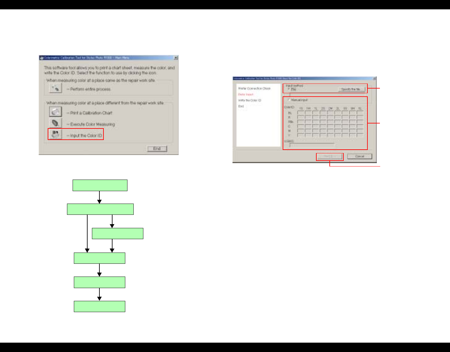
EPSON Stylus Photo R1800/R2400 Revision B
Adjustment Adjustment 161
3. Repair work site
1. Start up the Colorimetric Calibration Tool for Stylus Photo
R1800 on a PC, and click [Input the Color ID].
Figure 5-49. Entering the Color ID
The following shows the process when [Input the Color ID] is clicked.
Figure 5-50. Entering the Color ID Workflow
2. Execute Step 2 ~ 3 of the procedure “ When Measuring Color at a
Place the Same as the Repair Work Site” (p150) to connect the
printer to the PC.
3. Select either of "File" or "Manual input" in "Input method" box,
and input the color measurement data.
Figure 5-51. Entering Data
•When "File" is selected as Input method
When "File" is selected as Input method, and the color
measurement data file is selected, the content of the file is reflected
in the "Color ID" and the "USB ID" edit boxes.
•When "Manual input" is selected as Input method
Select "Manual input" at Input method, and directly enter the
numerical values in the "Color ID" and the "USB ID" edit boxes.
To enter numerical values, start up the correction value data file
confirmation tool (CCAS Data Viewer), open the color
measurement data file, check the Color ID at "Color ID" edit box
and enter the numerical values.
Select port
Connect printer
Check printer connection
Enter data
Write Color ID
END
When "File" is selected
When "Manual input"
is selected
This button is enabled
when "File" is selected or
when all of the data is input
in the "Color ID" and the
"USB ID" edit boxes (when
"Manual" is selected).
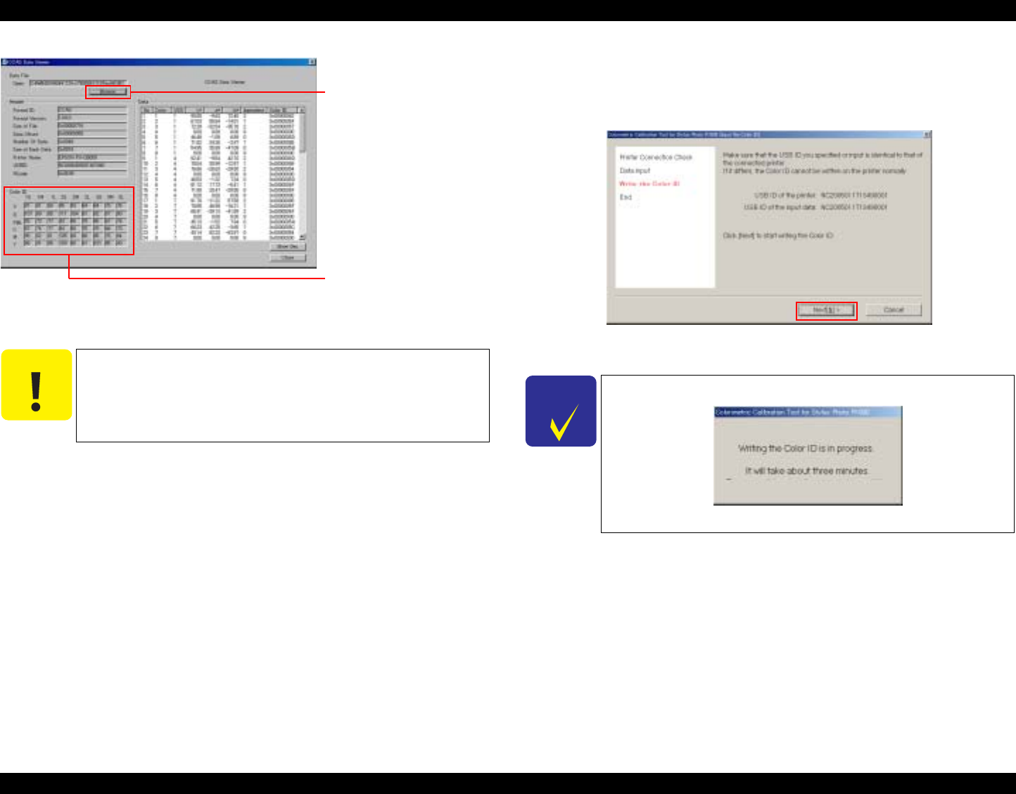
EPSON Stylus Photo R1800/R2400 Revision B
Adjustment Adjustment 162
Figure 5-52. CCAS Data Viewer Screen
4. Make sure that the USB ID reflected (entered) at Step 3 matches
the USB ID of the currently connected printer, then click [Next] to
write the Color ID to the printer.
Figure 5-53. Write the Color ID
C A U T I O N
[Next] will not be enabled even if all of the data has been
entered in the "Color ID" and "USB ID" edit boxes when
selecting "File" as Input method but not specifying a file.
Clicking the "Browse" button
displays the file selection
dialog box.
The Color ID is displayed in
"Color ID" edit box after the
color measurement data file
is selected.
CHECK
P O I N T
It takes about three minutes to write the Color ID.
Figure 5-54. Writing the Color ID
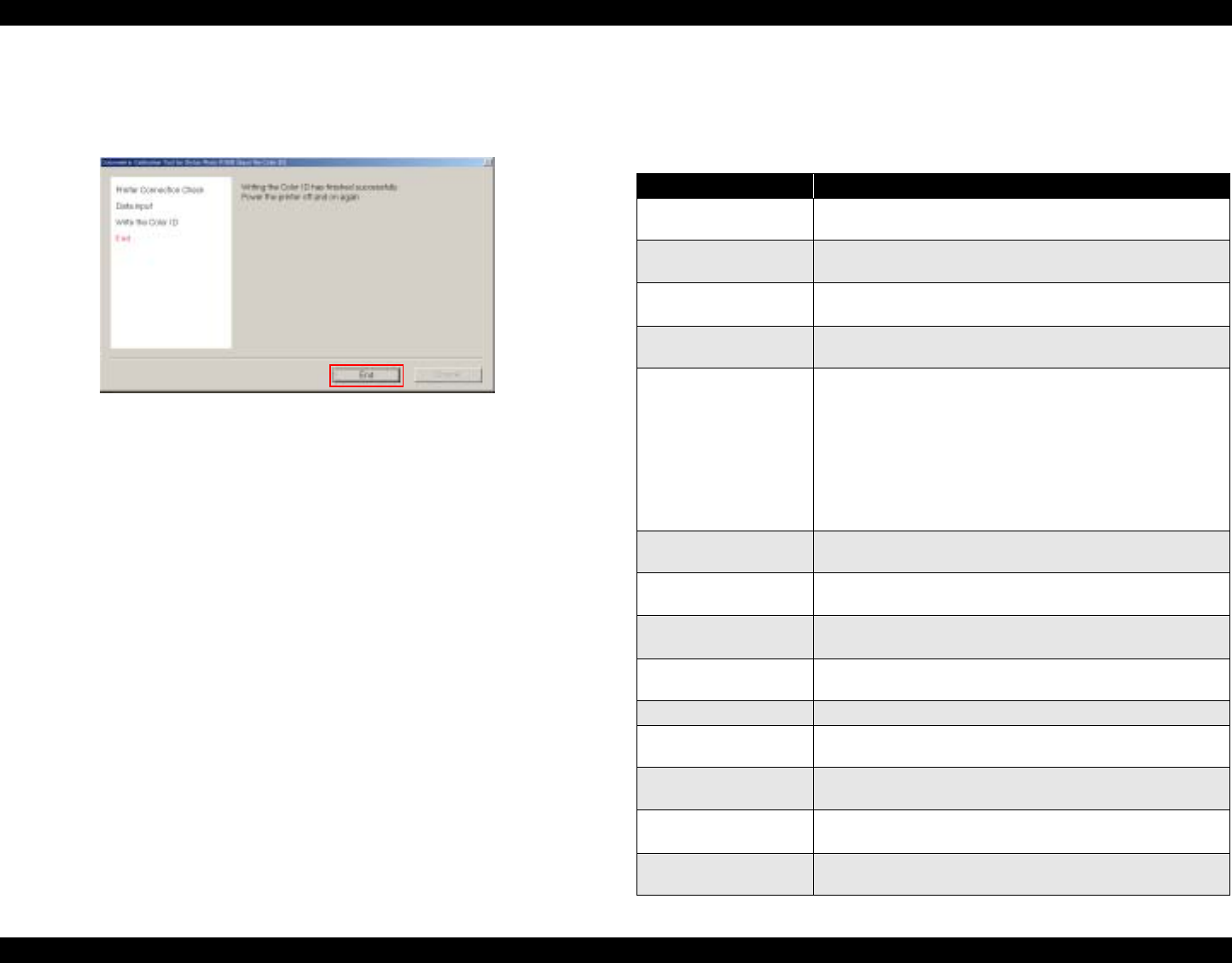
EPSON Stylus Photo R1800/R2400 Revision B
Adjustment Adjustment 163
5. When the following screen is displayed, click [End], and turn the
printer OFF then back ON again to end the adjustment. This
action reflects the color measurement values on the printer.
Figure 5-55. END
5.2.4.3 Error Messages
The following table lists the error and warning messages that are generated by
the Colorimetric Calibration Tool
Table 5-7. List of Error Messages
Error Message
Communication Error Communication error. Check the connection status with
the printer.
Timeout Time-out error. Check the connection status with the
printer.
Printer Driver not
installed The printer driver is not installed. Install the printer driver.
Printer not connected The printer is not connected. Connect the printer and
press [Retry] to check the printer connection again.
Ink Cartridge Low‘ The remaining amount of the following ink(s) is low.
Replace the corresponding ink cartridge(s) with a new
one.
XXXXX, XXXXX
When installing a new cartridge(s), make sure to shake it
(them) at least four times. A cleaning cycle will
automatically start when a new cartridge(s) is installed. To
stop the process, click [End].
Cleaning error Error occurred while running the cleaning cycle. Check
the printer status.
Automatic nozzle
check failure The automatic nozzle check has failed. There may be a
problem with the print head.
Automatic nozzle
check error Error occurred while performing nozzle check. Check the
printer status.
Ink mark sensor error The automatic nozzle check has finished unsuccessfully.
Click OK to start a nozzle check manually.
Color ID write error Writing Color ID has failed. Check the printer status.
File save error Saving the file has failed. Check if the disc has enough
space, or if the folder is writable.
File open error Reading the data file has failed. Check the date and size
of the data file.
File format error The file format is incorrect. Check if the correct file is
selected.
Color ID parameter
error The parameters of the Color ID value are invalid.
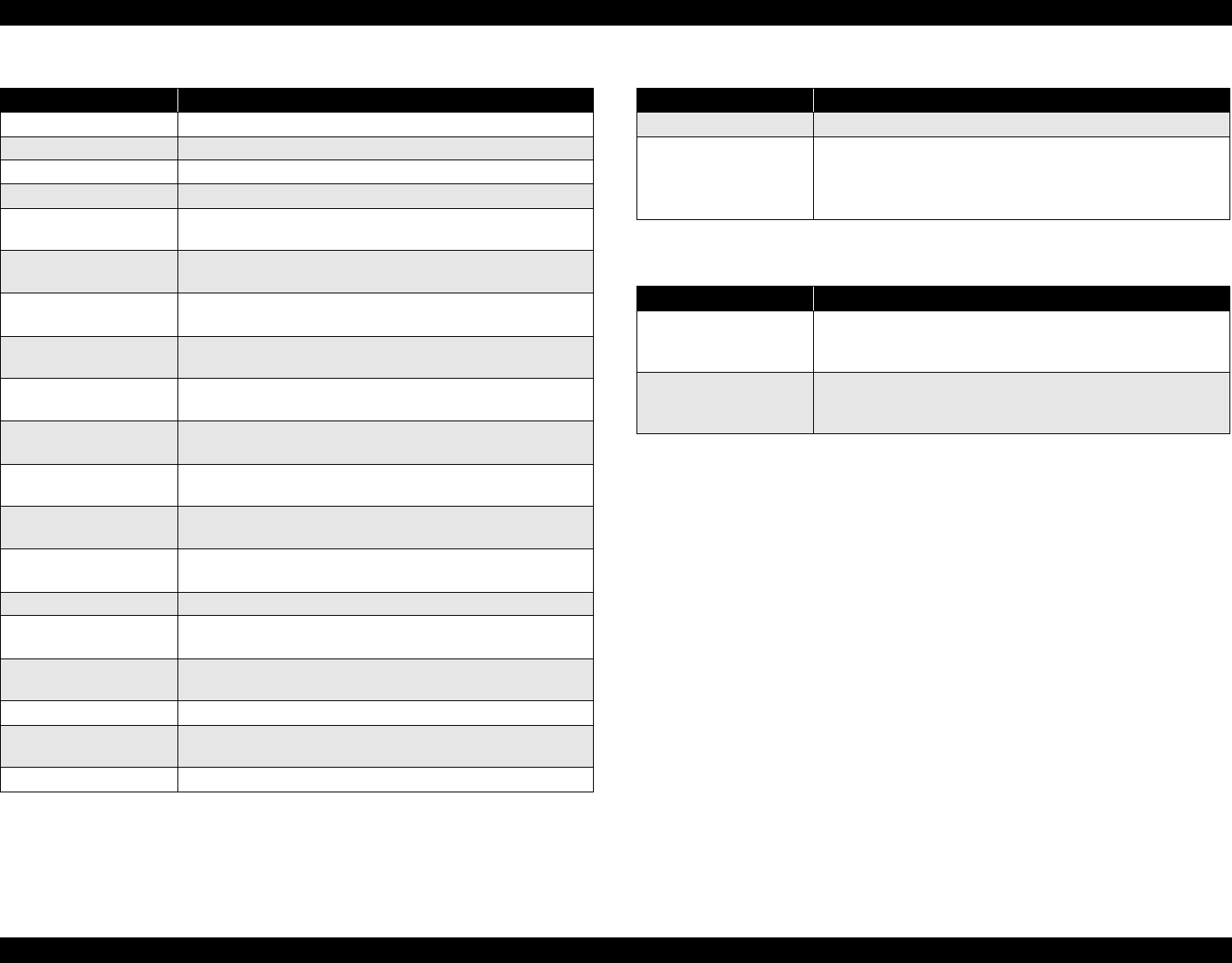
EPSON Stylus Photo R1800/R2400 Revision B
Adjustment Adjustment 164
Preparing printer The printer is not ready. Check the printer status.
Out of paper error There is no paper loaded. Load a paper.
Paper jam error A paper jam has occurred. Start from the printing again.
Print error An error occurred while printing. Check the printer status.
Undefined file read
error Reading the required files has failed. Copy the program
folder again.
Insufficient memory
error Insufficient memory. Exit all applications that are currently
active.
Log file output error Failed to output a log file. To continue the process, click
[OK].
Calibrator plug-in read
error Failed to read the plug-in. Copy the program folder again.
Calibrator parameter
error A parameter error of the calibrator occurred. Check if the
calibrator is Eye-One calibrator with a UV filter.
Calibrator
communication error Communication with the calibrator failed. Check the
calibrator's connection status.
Calibrator calibration
error (retry) The calibration has failed. Put the Eye-One calibrator on
the calibration plate and click [Retry] to recalibrate.
Calibrator calibration
error (failed 3 times) The calibration has failed. Check the calibrator status.
Color measurement
failure Color measuring of the Eye-One calibrator has failed.
Measure colors of the failed row again.
Head ID read error Failed to read the Head ID. Check the printer status.
Color ID mismatch
error The Color ID does not match the printer. Check the printer
status.
Color ID enable flag
invalid error The Color ID enable flag has become invalid. Check the
printer status.
Color ID read error Failed to read the Color ID. Check the printer status.
Multiple data file error There are multiple data files in the start-up folder. Copy
the provided program folders again.
Unknown error An error of unknown origin occurred.
Table 5-7. List of Error Messages
Error Message
Printer offline The printer is off-line. Place the printer online.
Ink Out Error The remaining amount of the following ink(s) is low.
Replace the corresponding ink cartridge(s) with a new one
and retry this wizard.
XXXXX, XXXXX
Table 5-8. List of Warning Messages
Error Message
USB ID mismatch The USB ID is different. The connected printer may be
different from the one that printed the chart. Are you sure
you want to continue?
Color measurement
re-confirmation
warning
There is a patch(s) that could not be measured properly.
Perform the color measuring again.
Table 5-7. List of Error Messages
Error Message

EPSON Stylus Photo R1800/R2400 Revision B
Adjustment Adjustment 165
5.2.5 Colorimetric Calibration by Users
5.2.5.1 Printing Calibration Chart by Users
The Colorimetric Calibration tool is available to the user. The user can print a
Calibration Chart by himself/herself by using the tool.
Prepare the following tools for Colorimetric Calibration:
EPSON Photo Paper :Used for printing a Calibration Chart
(A4 or letter-size)
Plain (standard) Paper :
Used for printing a nozzle check pattern
(A4 or letter-size)
Clear file :for mailing to our service center
Plain paper (A4 or letter-size) :for mailing to our service center
The procedure for printing the Calibration Chart for users is given on the
following pages.
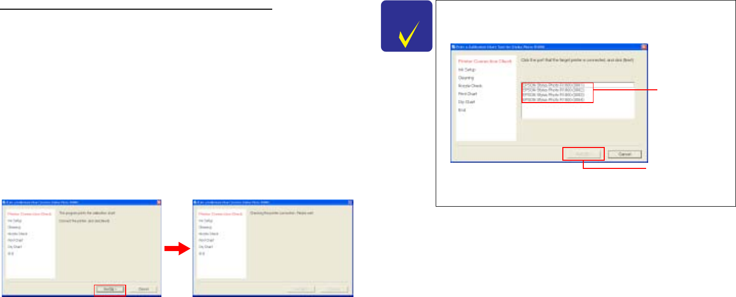
Calibration Chart Print Procedure for Users
OS : Windows XP/Me/2000/98
: MacOS X 10.2x, 10.3x, MacOS 9.x
Port : USB1.1
: USB2.0
: IEEE1394
Input Method
1. Copy the complete set of related files to any one folder.
2. Double click "CCASSPR1800Print.exe" (Windows) or
"CCASSPR1800Print" (Macintosh) to start up the program on the
computer.
3. Connect the printer to the PC using a USB or IEEE cable, and click "Next".
Step3.Printer Connection Check Screen
CHECK
P O I N T
When two or more printers are currently connected, the
screen changes to the "port selection" screen. Select the
target printer, and click [Next].
Port Selection Screen
Select a target
printer.
The button is
enabled when the
printer is selected.
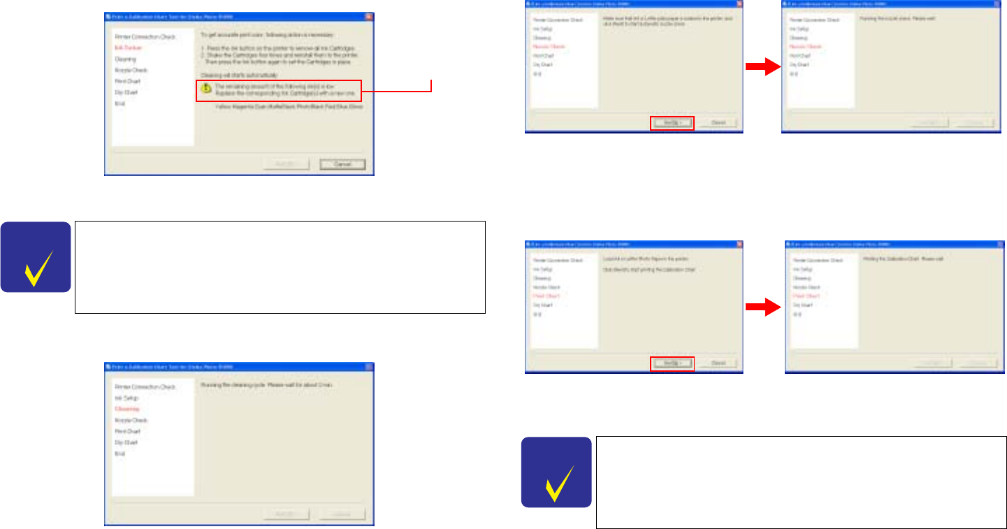
4. To prevent inks from settling down at the bottom, remove all ink cartridges,
shake them at least four times, and reinstall them to the printer. The printer
will automatically run a replacement cleaning cycle.
Step4.Ink Setup
5. Wait for the cleaning to finish.It will take about two minutes.
Step5.Cleaning
6. Load one sheet of A4 or letter- size plain paper, and click "Next" to execute
the automatic nozzle check.
Step6.Automatic Nozzle Check
7. Load one sheet of A4 or letter-size Photo paper, and click "Next" to print
the Calibration Chart.
Step7.Printing a Calibration Chart
CHECK
P O I N T
If a warning message appears on the LCD saying that ink
level is low, replace the indicated ink cartridge(s) with a new
one.
Warning message
CHECK
P O I N T
The recommended air temperature range for printing a
Calibration Chart is 15°C to 28°C.
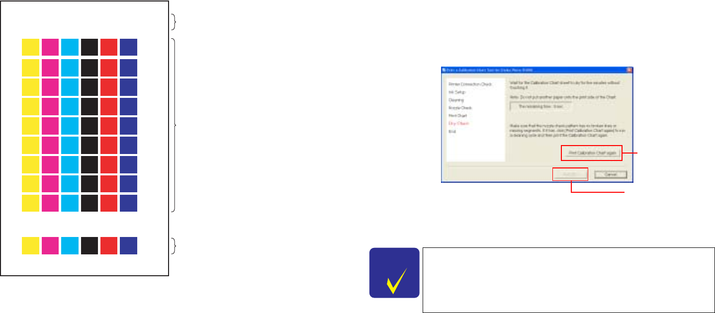
Illustration of Calibration Chart
8. After the Calibration Chart is printed, allow it to dry for five minutes. During
this time, check the nozzle check pattern on the chart. If there are broken
lines or missing segments, click [Print Calibration Chart again], and return
to Step 5. If there are no broken lines or missing segments, click [Next].
Step8.Drying the Chart
9. Mail the Calibration Chart sheet to our service center within two days after
printing it.
To mail the Chart, make sure to put it into a clear file and enclose a sheet
of plain paper to protect the print side.
2004-07-02135953 USBIDMH01234567
2004-07-05135953
USB ID (All 18 alphanumeric digits are indicated.)
Print time + Color measurement limit time
(7 days after the print time)
54 calibration patches
(6 colors x 9 dot sizes)
Nozzle check pattern
CHECK
P O I N T
There is no need to print a Calibration Chart again, even
if you find broken lines or missing segments in Gloss
Optimizer the nozzle check pattern.
Do not touch the printed chart sheet until it dries.To do
so may cause the printed color to change.
When there are
broken lines or
missing segments
This button is enabled
when countdown is
completed.

EPSON Stylus Photo R1800/R2400 Revision B
Adjustment Adjustment 169
5.2.5.2 Writing of Color ID by Users
When servicing, there may be a case that the printer is returned to the user
after printing/measuring a chart for the Colorimetric Calibration and performing
the Head ID adjustment, without writing the Color ID at the repair work site. In
such case, the user required to write the Color ID to the printer by him/herself
using the color measuring data sent from the service site.
The following two files will be sent to the user. The user can reflect the color
measurement values on the printer by executing the EXE file in the same
directory as the color measurement data.
"CCASSPR1800Write.exe" (Windows) or "CCASSPR1800Write"
(Macintosh)(exec file for writing Color ID)
The exec file for writing Color IDs is exclusively for the user, and is
different from the exec file (CCASStylusR1800.exe) for service
personnel.
xxxxxxxx.dat (color measurement data file)
The color measurement data file is the same as the file for service
personnel and is supplied from the color measurement site.
Reflection of correction according to Head ID
Every mass-produced printer is calibrated by the Colorimetric Calibration
at the factory.
To reflect color correction by the Head ID, reinput the Head ID using the
adjustment program. This means that the Head ID will be continuously
reflected until the Color ID is input.
The procedure for writing the Color ID for users is given on the following pages.
C A U T I O N
When the startup folder contains two or more color
measurement data files, the following error message is
displayed and the program is exited:
•"Failed to read the Color ID. Check the printer status."
CHECK
P O I N T
The exec file automatically reads the color measurement
data files in the same directory to prevent the user from
being aware of the file name of the color measurement data.
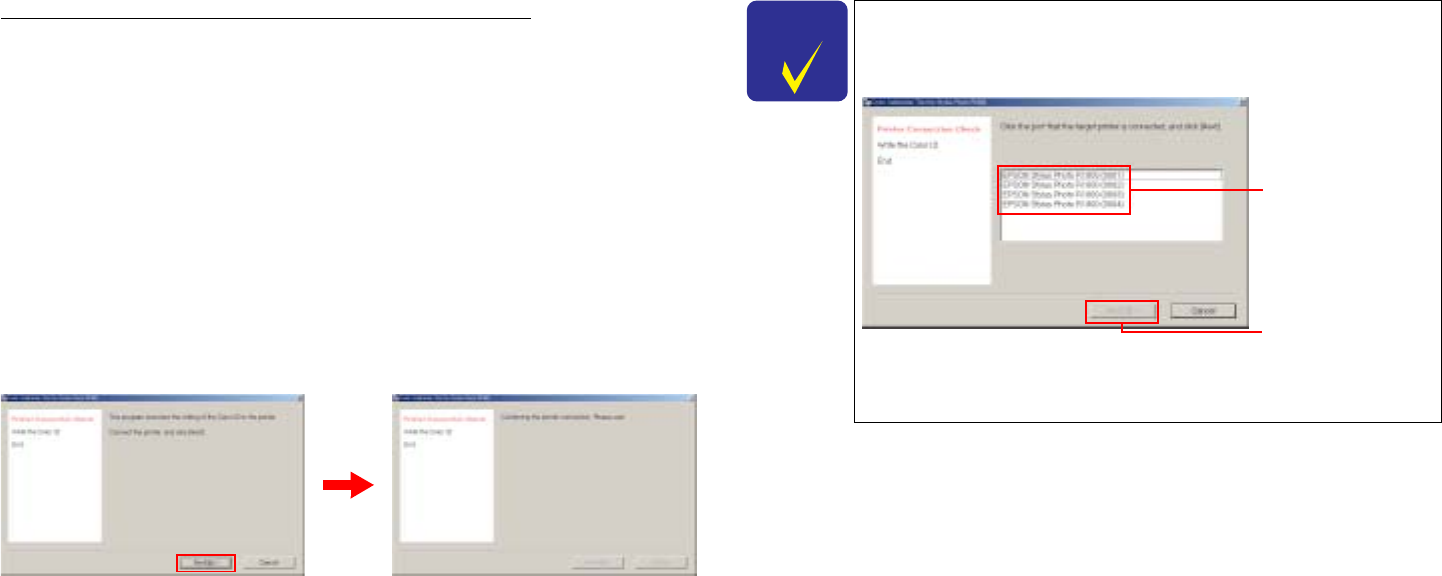
Color Correction Value Entry Procedure
OS : Windows XP/Me/2000/98
: MacOS X 10.2x, 10.3x, MacOS 9.x
Port : USB1.1
: USB2.0
: IEEE1394
Input method
1. Copy the complete set of related files to any one folder.
2. Double click "CCASSPR1800Write.exe" (Windows) or
"CCASSPR1800Write" (Macintosh) to start up the program on the
computer.
3. Connect the printer to the PC using a USB or IEEE cable, and click "Next".
Step3.Printer Connection Check Screen
CHECK
P O I N T
When two or more printers are currently connected, the
screen changes to the "port selection" screen. Select the
target printer, and click [Next].
Port Selection Screen
Select a target
printer.
The button is
enabled when the
printer is selected.
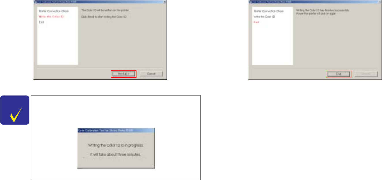
4. Clicking "Next" writes the color correction values automatically to the
printer.
Step4.Color Correction Value Write Screen
5. When the following screen is displayed, click "End" and turn the printer
OFF then back ON again to end the adjustment.
Step5.End Screen
6. Turn the printer OFF.
CHECK
P O I N T
It takes about three minutes to write the color correction
values. Do not turn off both the computor and the printer, or
do not kill the connection between them during the writeing
is in progress.
Writing the Color ID

CHAPTER
6
MAINTENANCE
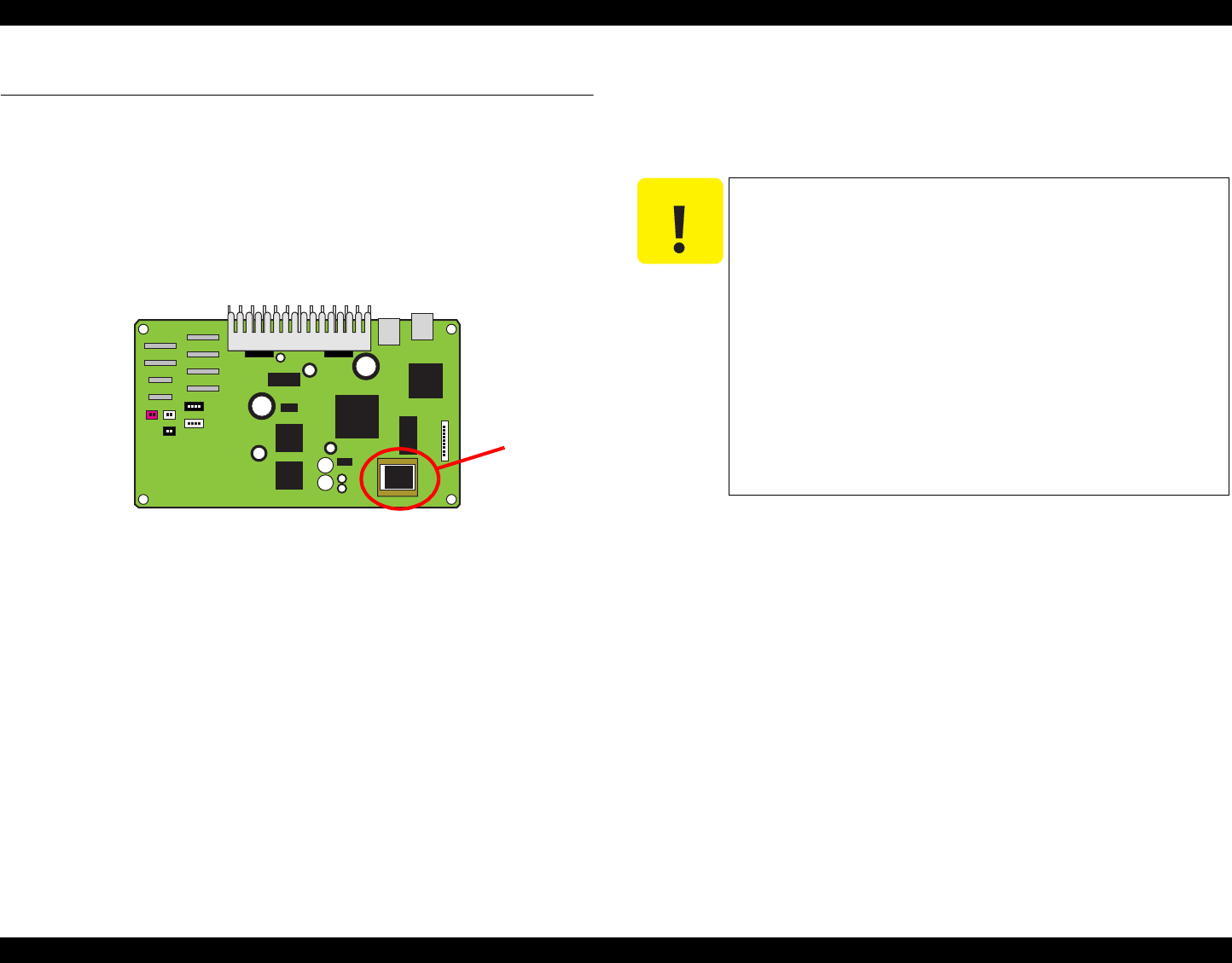
EPSON Stylus Photo R1800/R2400 Revision B
Maintenance Overview 173
6.1 Overview
This section provides information to maintain the printer in its optimum
condition.
6.1.1 ROM Replacement
This printer may require the ROM to be replaced when the program is changed
or added. In such cases, use the special tool (ROM puller: 2035659 (#F749)) to
replace the ROM. The position of the ROM is shown in the figure below.
Figure 6-1. ROM Location
6.1.2 Cleaning
This printer has no mechanical components which require regular cleaning.
Therefore, when returning the printer to the user, check the following parts and
perform appropriate cleaning if stain is noticeable.
Housing
Use a clean soft cloth moistened with water and wipe off any dirt. If the
Housings are stained with ink, use a cloth moistened with neutral detergent
to wipe it off.
Inside the printer
Use a vacuum cleaner to remove any paper dust.
C589 Main Board
ROM
C A U T I O N
Never use chemical solvents, such as thinner, benzine,
and acetone, to clean the exterior parts of the printer like
the housing. These chemicals may degrade or
deteriorate the quality of this product.
Be careful not to damage any components when you
clean inside the printer.
Do not scratch the surface of the PF Roller assembly.
Use a soft brush to wipe off dust.
Use a soft cloth moistened with dilute alcohol to remove
ink stain.
Do not use the supplied cleaning sheet for normal
usage. It may damage the coated surface of the PF
Roller. If the adhesive surface of the cleaning sheet is
set to the ASF LD Roller side and used to clean the ASF
LD Roller surface, it is no problem.

EPSON Stylus Photo R1800/R2400 Revision B
Maintenance Overview 174
6.1.3 Service Maintenance
If print irregularity (missing dot, white line, etc.) has occurred or the printer
indicates "Maintenance Error", take the following actions to clear the error.
6.1.3.1 Head Cleaning
The printer has a built-in head cleaning function, which is activated by
operating the control panel.The procedure is given below.
1. Confirm that the printer is in stand-by state.
Check that the Power LED is not flashing.
2. Hold down the Ink Switch on the control panel for more than 3 seconds.
The Power LED flashes during the cleaning sequence.
6.1.3.2 Maintenance Request
Ink is used for printing and Head Cleaning. Waste ink is drained into the Waste
Ink Pads via the Cap Unit, and its amount is stored into the EEPROM's
Protection Counters (Waste Ink Counter) A and B (located near the home
position or the opposite side). When the preset value is reached, the Waste Ink
Counters detect that the Waste Ink Pads have reached the absorption limit.
The printer displays "Maintenance Request" to request the Waste Ink Pads to
be replaced.
Protection Counter A+B Limit
Up to 17772
Timing for Replacing the Waste Ink Pads
When the Protection Counter reaches the value shown above, a
Maintenance Request is indicated, and the printer disables all switches
except the Power switch.
Since the Protection Counter value can be confirmed in the adjustment
program, be sure to check the value when servicing regardless of
whether the service is related to the Waste Ink Pad or not. If the
Protection Counter value of that printer is close to its limit, inform the
user about that, and replace the Waste Ink Pads and reset the
Counters with the user’s permission. (If the Waste Ink Pads are not
replaced at that time, it is expected that the printer will be returned for
repair in the near future due to a Maintenance Request error.)
Under the specific conditions, the limit level of the counter is preset to
25000 pages for black ink or to 10000 pages for color ink. We assume
that the limit level will be reached in about 3 years in normal use.
Replacement Procedure
Replacement of Waste Ink Pads in Disassembly and Assembly
(Refer to 4.2.2 "Waste Ink Pad" on page 80.)
After the Replacement
Reset the Protection Counter (Refer to Chapter 5 "ADJUSTMENT")
CHECK
P O I N T
For Head Cleaning, it is recommended to run the nozzle
check and the cleaning alternately to minimize ink
consumption.
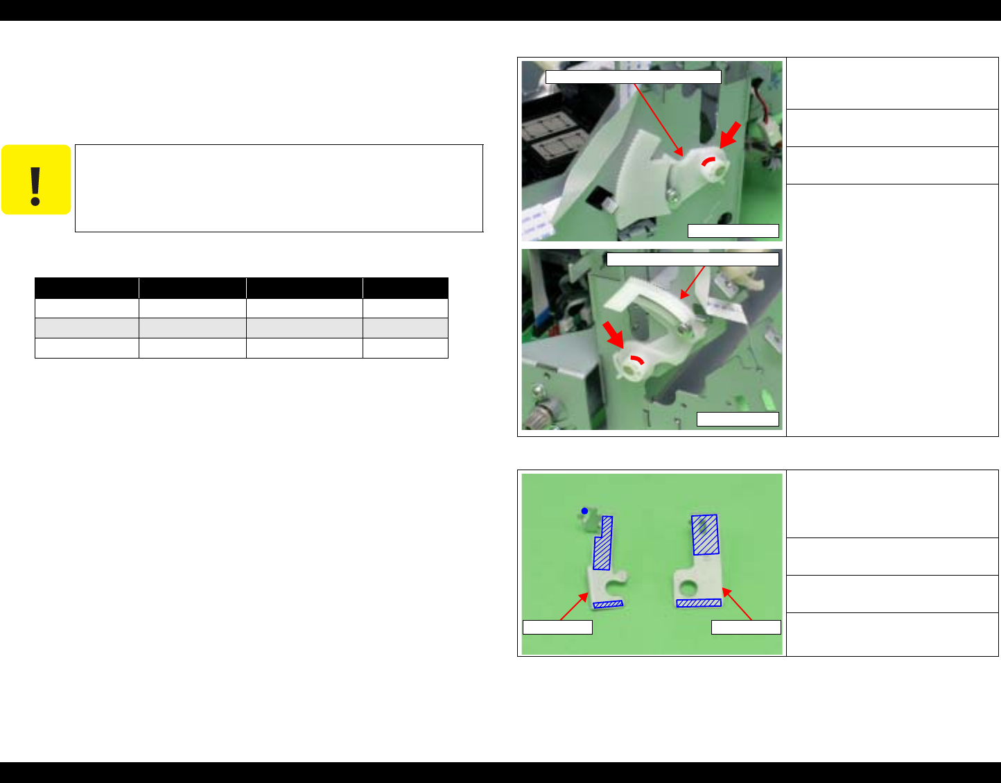
EPSON Stylus Photo R1800/R2400 Revision B
Maintenance Overview 175
6.1.4 Lubrication
The lubrication used for the components of the printer has been decided on
based on evaluation carried out by Epson. Therefore, the specified amount and
places of lubrication given in this section should be strictly observed.
Figure 6-2. Lubrication (1)
Figure 6-3. Lubrication (2)
C A U T I O N
Never use oil or grease other than those specified in this
manual. Use of different types of oil or grease may
damage the components or affect the printer functions.
Never apply a larger amount of oil or grease than
specified in this manual.
Table 6-1. Grease Applied to the Stylus Photo R800
Type Name EPSON CODE Supplier
Grease G-26 1080614 EPSON
Grease G-45 1033657 EPSON
Grease G-71 1304682 EPSON
<Lubrication Point>
Left and Right Adjust Parallel
Bushings (outer circumference)
<Lubrication Type>
G-26
<Lubrication Amount>
φ1mm x 2mm
<Remarks>
• Apply with a syringe.
(Pin Head: φ1mm)
• After lubrication, install and turn
the PG Cam Bush to spread the
grease evenly.
<Lubrication Point>
Contact point of the CR Scale
Mounting Plate (Left/Right) and the
Main Frame
<Lubrication Type>
G-26
<Lubrication Amount>
Apply evenly.
<Remarks>
Apply with a brush.
Right Side Face
Adjust Parallel Bushing (Right)
Left Side Face
Adjust Parallel Bushing (Left)
Left Side Right Side
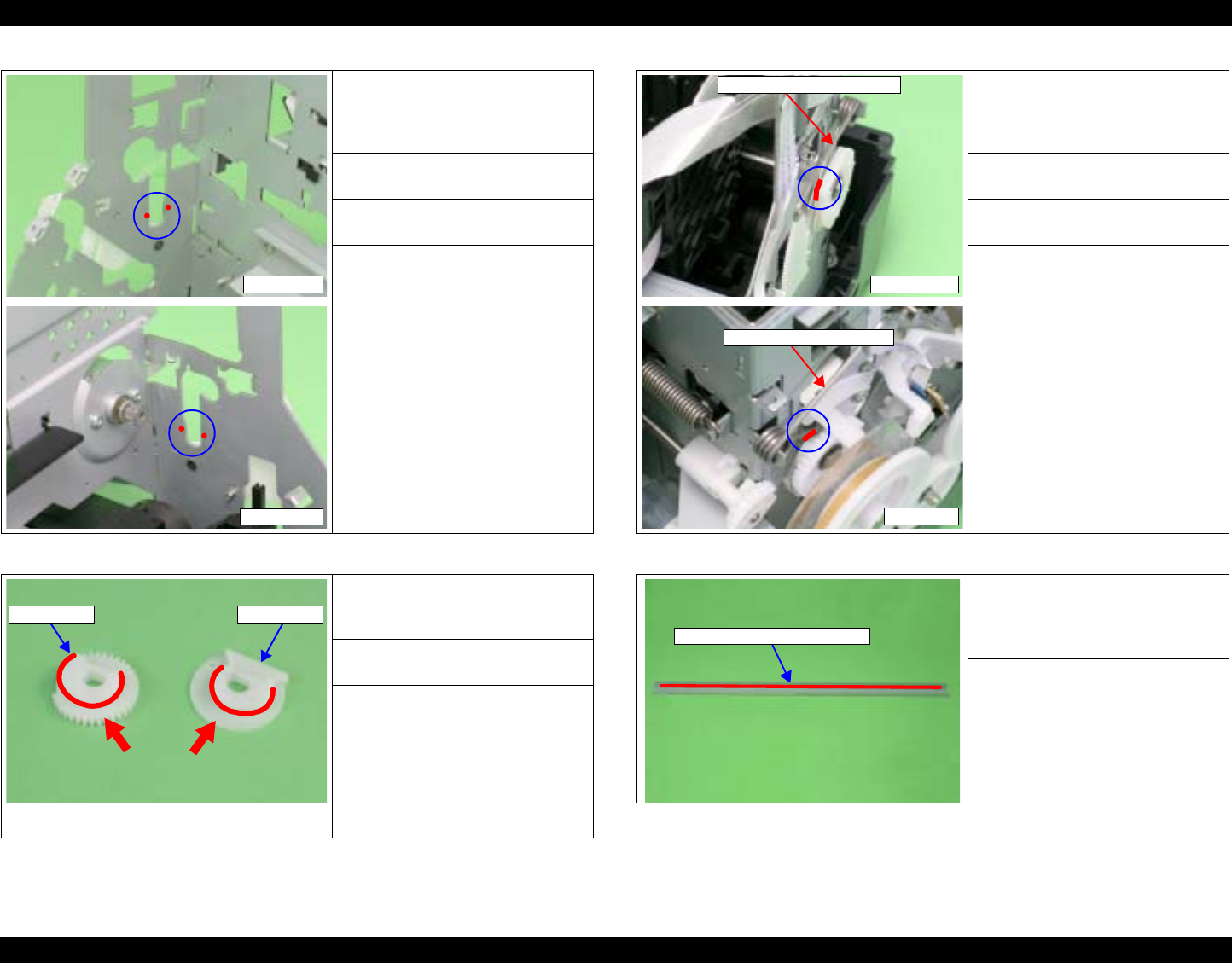
EPSON Stylus Photo R1800/R2400 Revision B
Maintenance Overview 176
Figure 6-4. Lubrication (3)
Figure 6-5. Lubrication (4)
Figure 6-6. Lubrication (5)
Figure 6-7. Lubrication (6)
<Lubrication Point>
Contact point of the Main Frame
and the CR the Scale Mounting
Plate (Left/Right)
<Lubrication Type>
G-26
<Lubrication Amount>
A little at 4 points
<Remarks>
Apply with a brush.
<Lubrication Point>
Bushings of the Left and Right PG
Cams (innner circumference)
<Lubrication Type>
G-26
<Lubrication Amount>
1mm diameter of the innner
circumference
<Remarks>
• Apply with a brush.
• Be careful not to attach the
grease to the PF scale.
Left Side
Right Side
Left Side Right Side
<Lubrication Point>
Contact point of the Left and Right
PG Torsion Springs and the
Carriage Shaft.
<Lubrication Type>
G-26
<Lubrication Amount>
φ1mm x 2mm x 2 points
<Remarks>
Apply with a syringe.
(Pin Head: φ1mm)
<Lubrication Point>
Contact point of the rear side of CR
Guide Plate and the slider of the
Carriage Unit
<Lubrication Type>
G-71
<Lubrication Amount>
150 ± 50mg
<Remarks>
Apply with a brush.
Right PG Torsion Spring
Right Side
Left PG Torsion Spring
Left Side
Rear side of CR Guide Plate
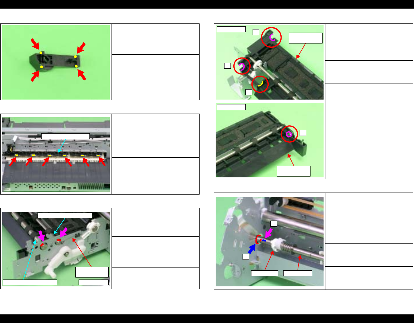
EPSON Stylus Photo R1800/R2400 Revision B
Maintenance Overview 177
Figure 6-8. Lubrication (7)
Figure 6-9. Lubrication (8)
Figure 6-10. Lubrication (9)
Figure 6-11. Lubrication (10)
Figure 6-12. Lubrication (11)
<Lubrication Point>
The Driven Pulley Holder
<Lubrication Type>
G-26
<Lubrication Amount>
φ1mm x 2mm x 4 points
<Remarks>
Apply with a syringe.
(Pin Head: φ1mm)
<Lubrication Point>
Contact point of the Driven
Release FLAG and the Upper
Paper Guide
<Lubrication Type>
G-26
<Lubrication Amount>
φ1mm x 5mm x 6 points
<Remarks>
Apply with a syringe.
(Pin Head: φ1mm)
<Lubrication Point>
Contact point of the EJ Grounding
Spring and Front and Rear Paper
EJ Rollers
<Lubrication Type>
G-45
<Lubrication Amount>
φ1mm x 2mm x 2 points
<Remarks>
Apply with a syringe.
(Pin Head: φ1mm)
Upper Paper Guide
Rear Paper EJ Roller
Front Paper EJ Roller
EJ Grounding
Spring
Right Side
<Lubrication Point>
The bushing of the Front Paper
Guide
<Lubrication Type>
G-45
<Lubrication Amount>
1. Apply evenly.
2. φ1mm x 2mm
<Remarks>
Apply with a brush.
<Lubrication Point>
1. Left side of the PF Roller Shaft
(Left of the E-Ring)
2. Mounting location of the
Bushing 8
<Lubrication Type>
G-45
<Lubrication Amount>
1. Approx. φ1mm x 5mm
2. All around the Shaft
<Remarks>
1. Apply with a syringe.
2. Apply with a brush.
1
1
2
Right Side
Front Paper
Guide
1
Left Side
Front Paper
Guide
Bushing 8
1
2
PF Roller
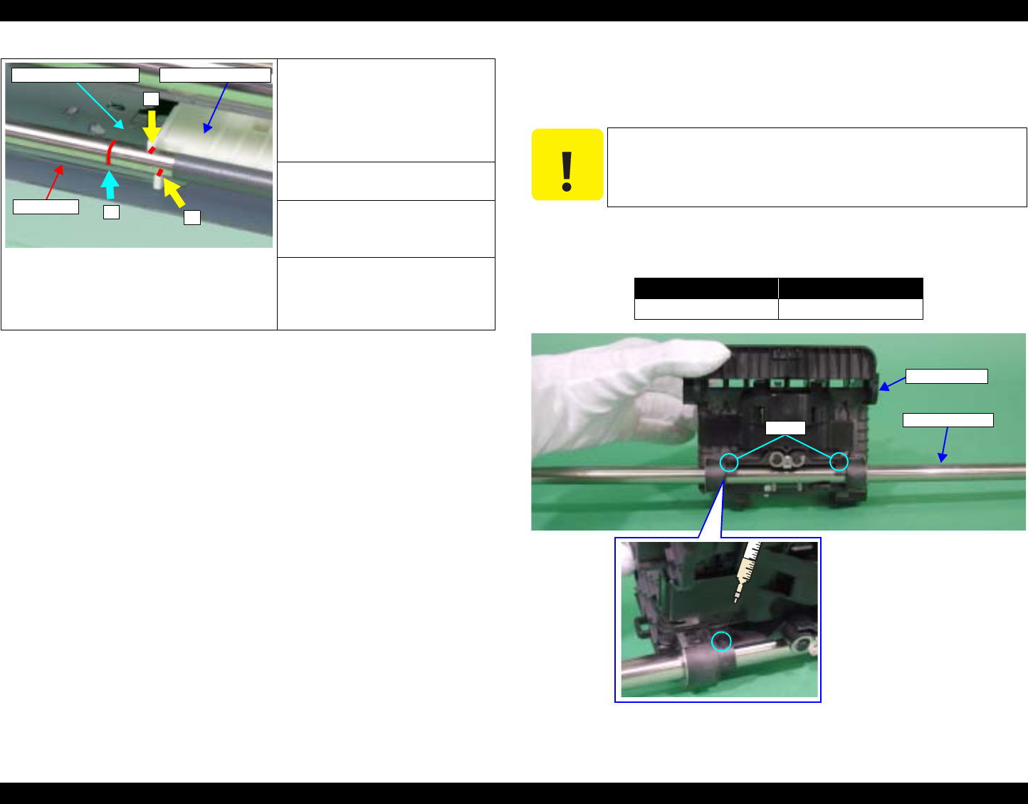
EPSON Stylus Photo R1800/R2400 Revision B
Maintenance Overview 178
Figure 6-13. Lubrication (12)
6.1.4.1 Lubrication of Carriage Shaft
1. Fit the Carriage Unit onto the Carriage Shaft, and move it to the center of
the Shaft.
2. Using a syringe, lubricate the holes (2 places) at both ends of the Carriage
Unit rear side with grease.
Figure 6-14. Lubricating the Carriage Shaft (1)
<Lubrication Point>
1. Contact point of the Rear
Paper Guide and the PF Roller
2. Contact point of the PF
Grounding Spring and the PF
Roller
<Lubrication Type>
G-45
<Lubrication Amount>
1. Apply evenly.
2. φ1mm x 2mm
<Remarks>
1. Apply with a brush.
2. Apply with a syringe.
(Pin Head: φ1mm)
1
1
2
PF Roller
Rear Paper GuidePF Grounding Spring
C A U T I O N
In the following step, do not bring the needle of a syringe
into contact with the Carriage Shaft.
Lubrication Type Lubrication Amount
G-71 280mg x 2 points
Carriage Unit
Carriage Shaft
Holes
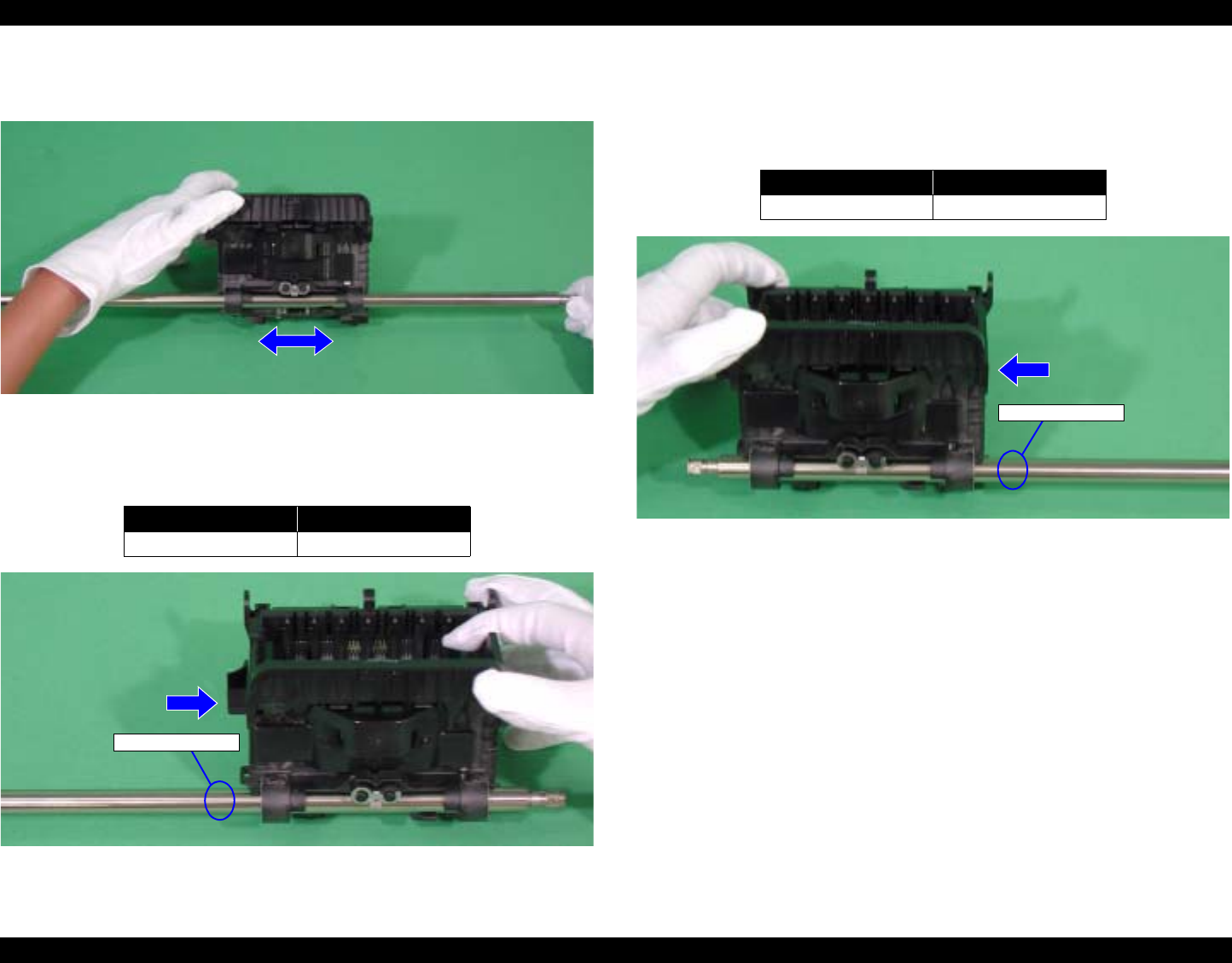
EPSON Stylus Photo R1800/R2400 Revision B
Maintenance Overview 179
3. Hold the Carriage Unit, and while turning the Carriage Shaft clockwise and
counterclockwise, move the Carriage Unit to spread the grease evenly.
Figure 6-15. Lubricating the Carriage Shaft (2)
4. Move the Carriage Unit to the right end of the Carriage Shaft viewing the
Unit from the rear, and lubricate grease with the syringe at the point shown
in Figure 6-16.
Figure 6-16. Lubricating the Carriage Shaft (3)
5. Hold the Carriage Unit, and while turning the Carriage Shaft, move the
Carriage Unit to the left end of the Carriage Shaft to lubricate the grease
evenly.
6. Lubricate grease with the syringe at the point shown in Figure 6-17.
Figure 6-17. Lubricating the Carriage Shaft (4)
Lubrication Type Lubrication Amount
G-71 140mg
Lubrication Point
Lubrication Type Lubrication Amount
G-71 140mg
Lubrication Point


CHAPTER
7
APPENDIX
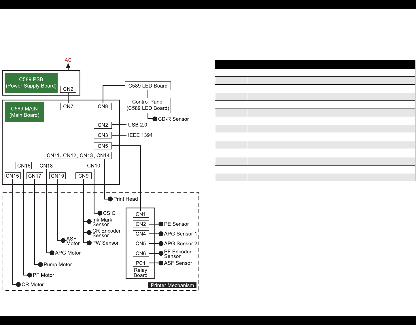
EPSON Stylus Photo R1800/R2400 Revision B
Appendix Connector Summary 182
7.1 Connector Summary
This section shows the connections between the main components of the
printer.
Table 7-1. Connection of the Major Components
7.1.1 Connectors and Pin Layouts
See the following tables for the connector summary for the C589 MAIN Board
and each connector's pin alignment.
Table 7-1. Connector Summary for C589 MAIN
Connector Function
CN5 Sensor 1 (PE Sensor, APG Sensor, PF Encoder Sensor, ASF Sensor)
CN7 Power Supply
CN8 LED Board
CN9 Sensor 2 (Ink Mark Sensor, CR Encoder Sensor, PW Sensor)
CN10 CSIC
CN11 Print Head 1-2 (including head temperature)
CN12 Print Head 1-1
CN13 Print Head 2-2
CN14 Print Head 2-1 (including thermistor)
CN15 CR Motor
CN16 PF Motor
CN17 Pump Motor
CN18 APG Motor
CN19 ASF Motor

EPSON Stylus Photo R1800/R2400 Revision B
Appendix Exploded Diagram 183
7.2 Exploded Diagram
Following pages show exploded diagram.
Exploded Diagram 1
Exploded Diagram 2
Exploded Diagram 3
Exploded Diagram 4
Exploded Diagram 5
Exploded Diagram 6
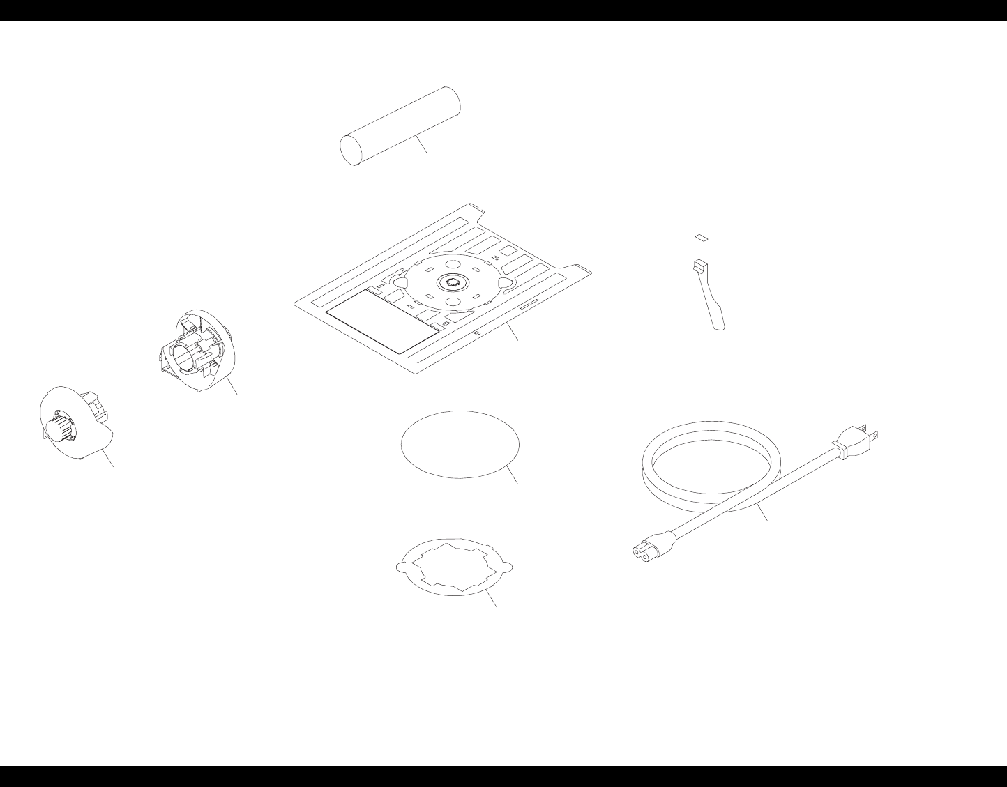
EPSON Stylus Photo R1800/R2400 Revision B
Appendix Exploded Diagram 184
Figure 7-2. Stylus Photo R1800 Exploded Diagram 1
400
08
09
13
12
10
Rev.01 C589-ACCE-011
E
PX-G5000/EPSON STYLUS PHOTO R1800 No.1
11
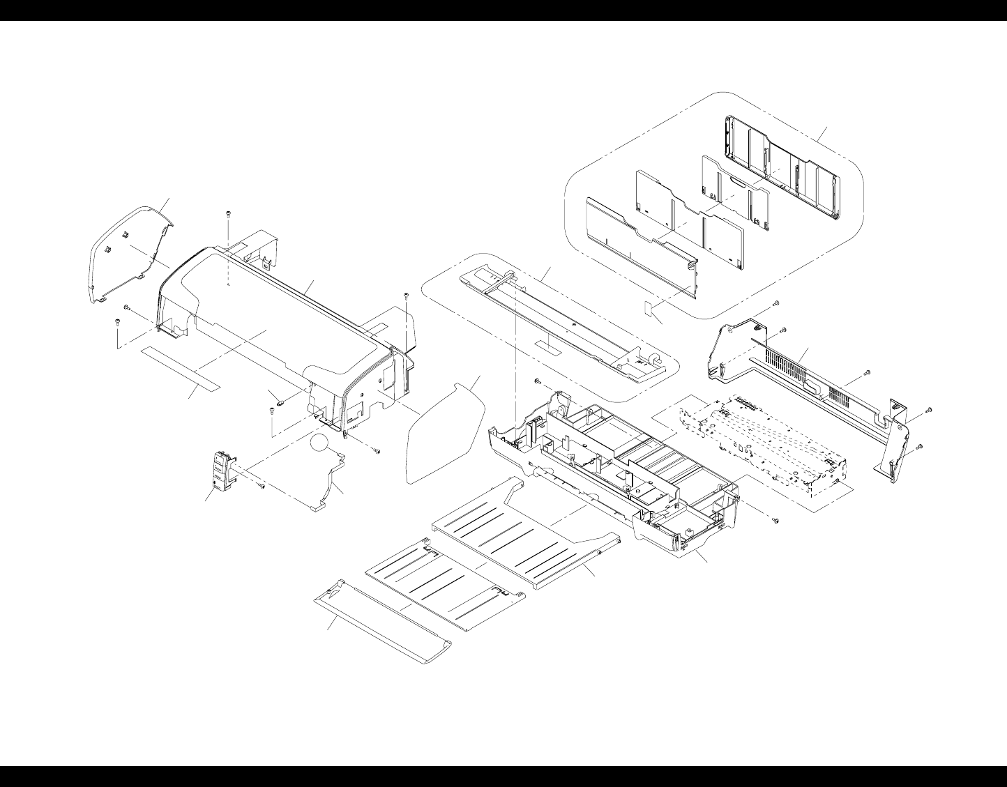
EPSON Stylus Photo R1800/R2400 Revision B
Appendix Exploded Diagram 185
Figure 7-3. Stylus Photo R1800 Exploded Diagram 2
Rev.01 C589-CASE-011
PX-G5000 / EPSON STYLUS PHOTO R1800 No.2
104
106
105
115
108
A
101
107
116
114
103
109
113
102
100
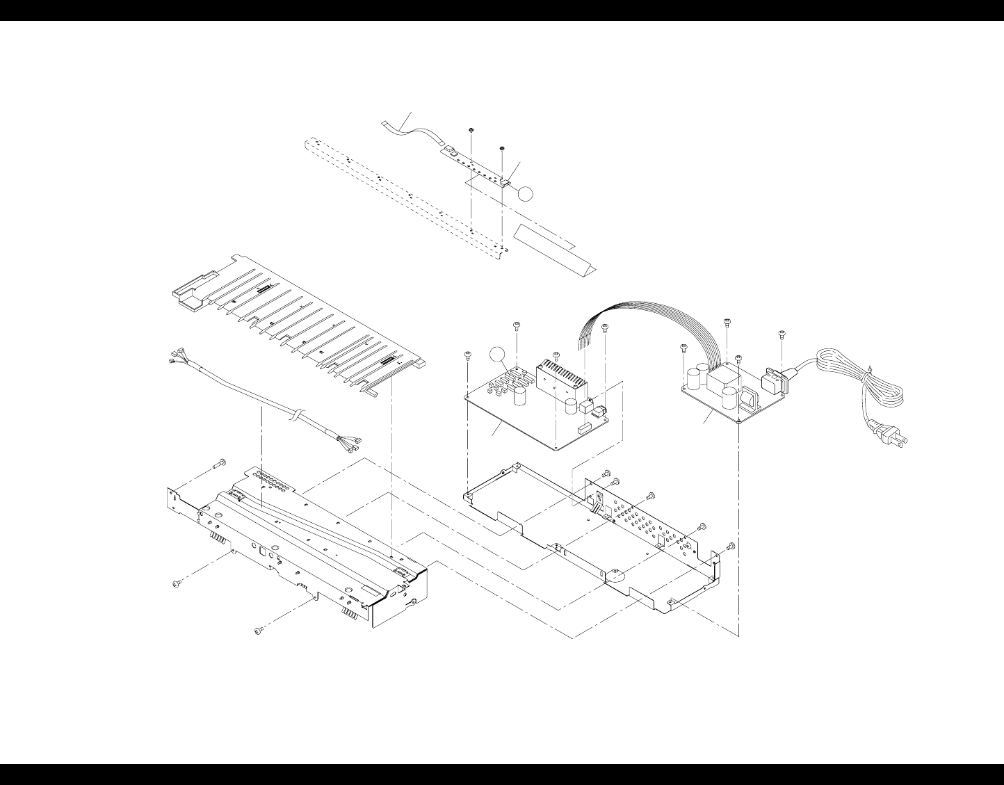
EPSON Stylus Photo R1800/R2400 Revision B
Appendix Exploded Diagram 186
Figure 7-4. Stylus Photo R1800 Exploded Diagram 3
350
360
A
Rev.01 C589-ELEC-011
PX-G5000 / EPSON STYLUS PHOTO R1800 No.3
B
200
300
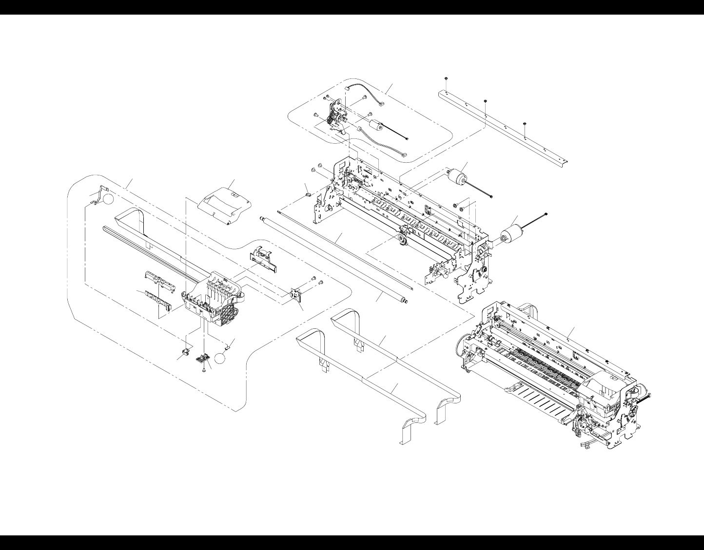
EPSON Stylus Photo R1800/R2400 Revision B
Appendix Exploded Diagram 187
Figure 7-5. Stylus Photo R1800 Exploded Diagram 4
Rev.01 C589-MECH-011
PX-G5000 / EPSON STYLUS PHOTO R1800 No.4
C
549
519
C
500
524
516
513
514
515
512
511
505
501
504
503
506
502
509
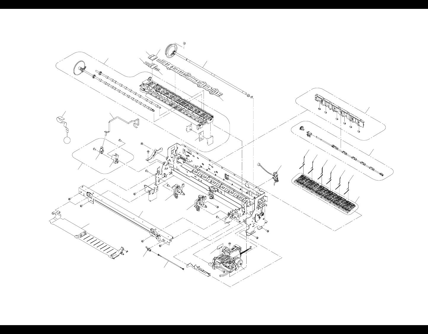
EPSON Stylus Photo R1800/R2400 Revision B
Appendix Exploded Diagram 188
Figure 7-6. Stylus Photo R1800 Exploded Diagram 5
Rev.01 C589-MECH-021
PX-G5000 / EPSON STYLUS PHOTO R1800 No.5
542
B
538
540
539
536 537
534
535
528
522
532
529
521
545
520
525
508
507
550
526
523
523
523
523
523
523
518
517
533
541
547
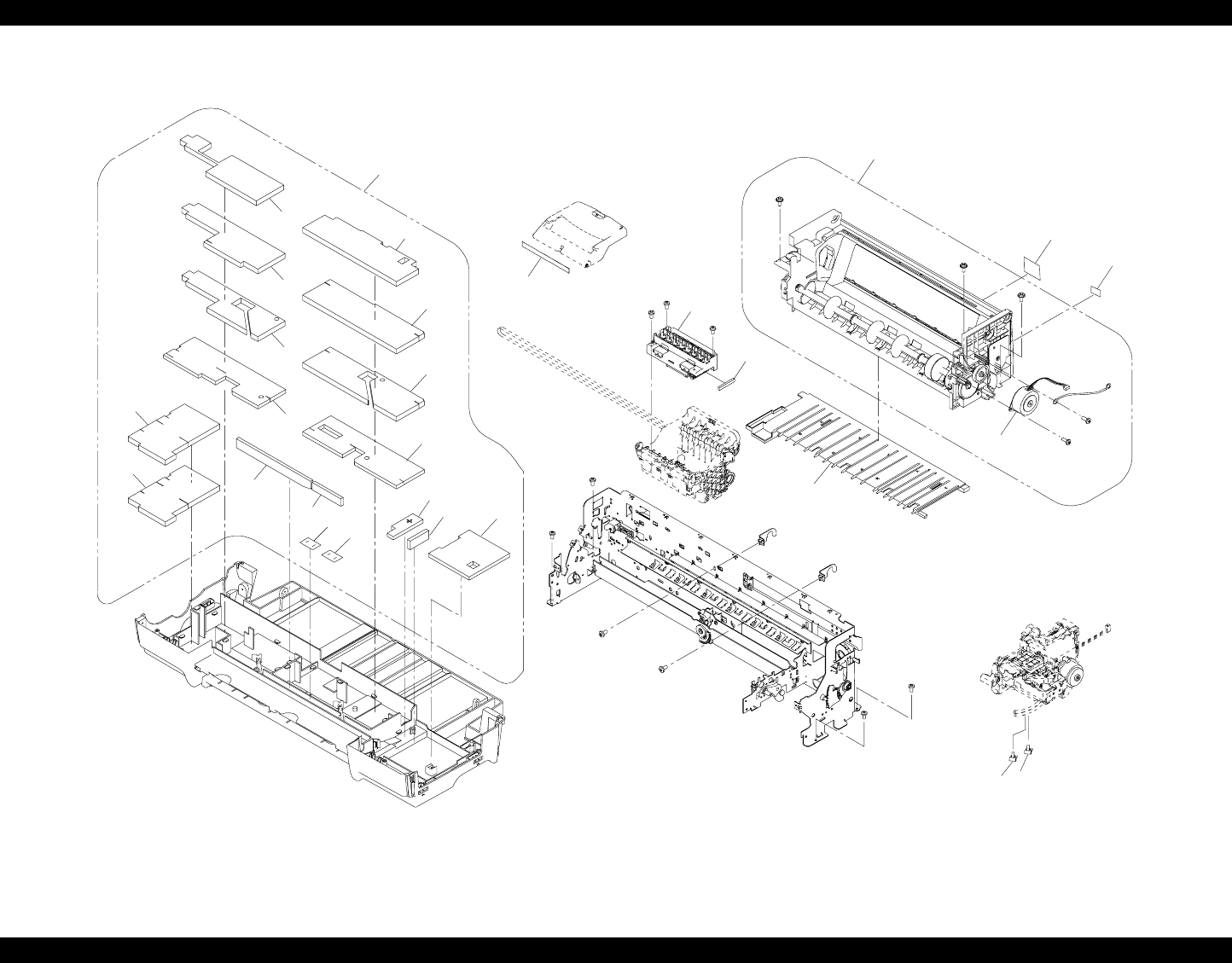
EPSON Stylus Photo R1800/R2400 Revision B
Appendix Exploded Diagram 189
Figure 7-7. Stylus Photo R1800 Exploded Diagram 6
719
704
710
711 719
709
714
708
713
712
707
706
703
701
716
723
722
702
720
700
709
717
705
715
718
724
724
721
Rev.01 C589-MECH-031
PX-G5000 / EPSON STYLUS PHOTO R1800 No.6

EPSON Stylus Photo R1800/R2400 Revision B
Appendix Parts List for EPSON Stylus Photo R1800 190
7.3 Parts List for EPSON Stylus Photo R1800
Table 7-2. Parts List for EPSON Stylus Photo R1800
Code Parts Name
8 ADAPTER,CDR
10 ROLL PAPER ASSY.,LEFT;B,ASP
11 ROLL PAPER ASSY.,RIGHT;B,ASP
12 TRAY,CDR
13 SHEET,CD,DUMMY
16 MATTE PAPER SUPPORT ASSY.,ASP
17 PAPER SUPPORT USFAP ASSY.,ASP
100 HOUSING UPPER ASSY.;B,ASP
101 PANEL ASSY.,ASP
102 COVER,LEFT
103 HOUSING,LOWER ASSY.,ASP
104 HOUSING CD-R ASSY.;B,ASP
105 STACKER
106 COVER,STACKER
107 COVER,RIGHT
108 PAPER SUPPORT ASSY.;B,ASP
109 HOUSING,REAR
113 LABEL,INSTRUCTION
114 HARNESS
115 LABEL,PAPER SUPPORT;B
116 MIN SIDE LOCK#091Y
200 BOARD ASSY.,MAIN
300 BOARD ASSY.,POWER SUPPLY
350 BOARD ASSY.,PANEL
360 HARNESS
500 PRINTER MECHANISM ASP.;ESL
501 CARRIDGE ASSY.,ASP
502 BOARD ASSY.,CSIC
503 HOLDER,DETECTOR,PW
504 BOARD ASSY.,INK MARK
505 BOARD ASSY.,ENCORDER,CR
506 BOARD ASSY.,DETECTOR,PW
507 HOLDER,BOARD ASSY.,ENCORDER,PF
508 BOARD ASSY.,ENCORDER,PF
509 COVER IC ASSY.,ASP
511 SHAFT,CR,GUIDE
512 SCALE,CR
513 TORSION SPRING,24.7
514 MOTOR ASSY.,CR
515 CABLE,HEAD,B
516 CABLE,HEAD
517 DETECTOR,LEAF,B2
518 HARNESS,DETECTOR,CD-R
519 AUTO PG ASSY.,ASP
520 TRAY CDR BASE SUB ASSY.,ASP
521 INK SYSTEM ASSY.;B,ASP
522 PAPER GUIDE UPPER ASSY.,ASP
523 TORSION SPRING,PAPER GUIDE,UPPER
524 MOTOR ASSY.,PF
525 FRAME PAPER EJ ASSY ASP;ESL
526 ROLLER,PF ASSY.,ASP
528 PAPER GUIDE FRONT&ROLLER EJ ASSY,ASP;ESL
529 HOLDER RELEASE SUB ASSY.,ASP
532 PAPER DETECTOR ASSY.,ASP
533 PF ENCORDER ASSY.,ASP
534 RELEASE CD-R,LEFT ASSY.,ASP
535 RELEASE CD-R,RIGHT ASSY ASP; ESL
536 POROUS PAD,PAPER GUIDE,FRONT,LEFT,ASP
537 POROUS PAD,PAPER GUIDE,FRONT,CENTER,ASP
538 POROUS PAD,PAPER GUIDE,FRONT,ASP
539 POROUS PAD,GUIDE,INK EJECT,LEFT
540 POROUS PAD,GUIDE,INK EJECT,CENTER
Table 7-2. Parts List for EPSON Stylus Photo R1800
Code Parts Name
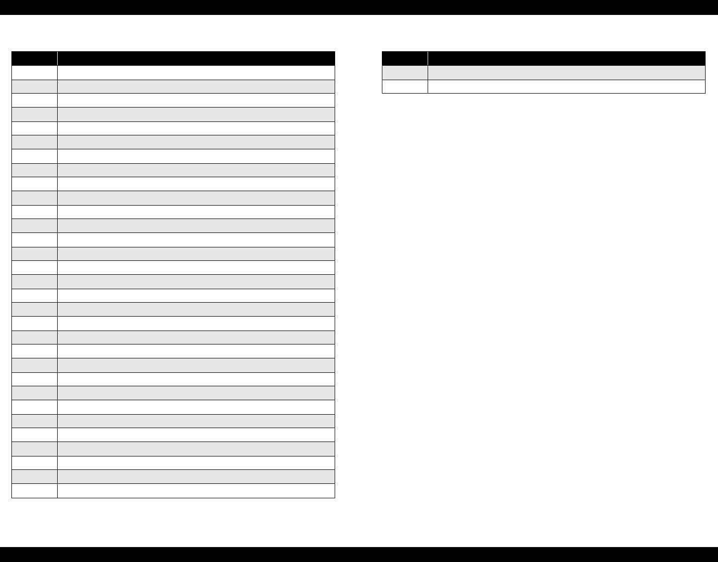
EPSON Stylus Photo R1800/R2400 Revision B
Appendix Parts List for EPSON Stylus Photo R1800 191
541 HARNESS,ENCORDER,PF
542 HARNESS,BOARD ASSY.,RELAY
545 CLEANER,HEAD;C,ASP
547 POROUS PAD,GUIDE,INK EJECT
549 CABLE,DETECTOR,8
550 FRAG RELEASE ASSY.,ASP
551 COVER,ROLLER,LD
552 SHEET,SQUARE HOLE
700 PRINT HEAD
701 ASF UNIT,ASP
702 MOTOR,ASSY.,ASF
703 PAPER GUIDE,MANUAL
704 POROUS PAD SET,ASP
705 POROUS PAD,INK EJECT;LEFT;FA2
706 POROUS PAD,INK EJECT;LEFT;FB2
707 POROUS PAD,INK EJECT;LEFT;FC2
708 POROUS PAD,INK EJECT;LEFT;FD2
709 POROUS PAD,INK EJECT;LEFT;FE2
710 POROUS PAD,TUBE;FA2
711 POROUS PAD,TUBE;FB2
712 POROUS PAD,INK EJECT;RIGHT;FF2
713 POROUS PAD,INK EJECT;RIGHT;FG2
714 POROUS PAD,INK EJECT;RIGHT;FH2
715 POROUS PAD,INK EJECT;RIGHT;FI2
716 POROUS PAD,INK EJECT,IS,LEFT;B
717 POROUS PAD,INK EJECT,IS,LOWER,LEFT;B
718 POROUS PAD,INK EJECT,IS,LOWER;FB2
719 POROUS PAD,INK EJECT;H
720 POROUS PAD,CABLE,HEAD
721 LABEL,INK POSITION;B
723 LABEL,GUIDE,ROLL PAPER
Table 7-2. Parts List for EPSON Stylus Photo R1800
Code Parts Name
723 LABEL,GUIDE,ROLL PAPER INSERT
724 CLAMP,TUBE
Table 7-2. Parts List for EPSON Stylus Photo R1800
Code Parts Name

EPSON Stylus Photo R1800/R2400 Revision B
Appendix Circuit Diagram 192
7.4 Circuit Diagram
Following pages show Circuit Diagram.
C589 MAIN control circuit board 1
C589 MAIN control circuit board 2
C589 PSB power supply circuit board
C589 PNL circuit board
C589 PNL B circuit board
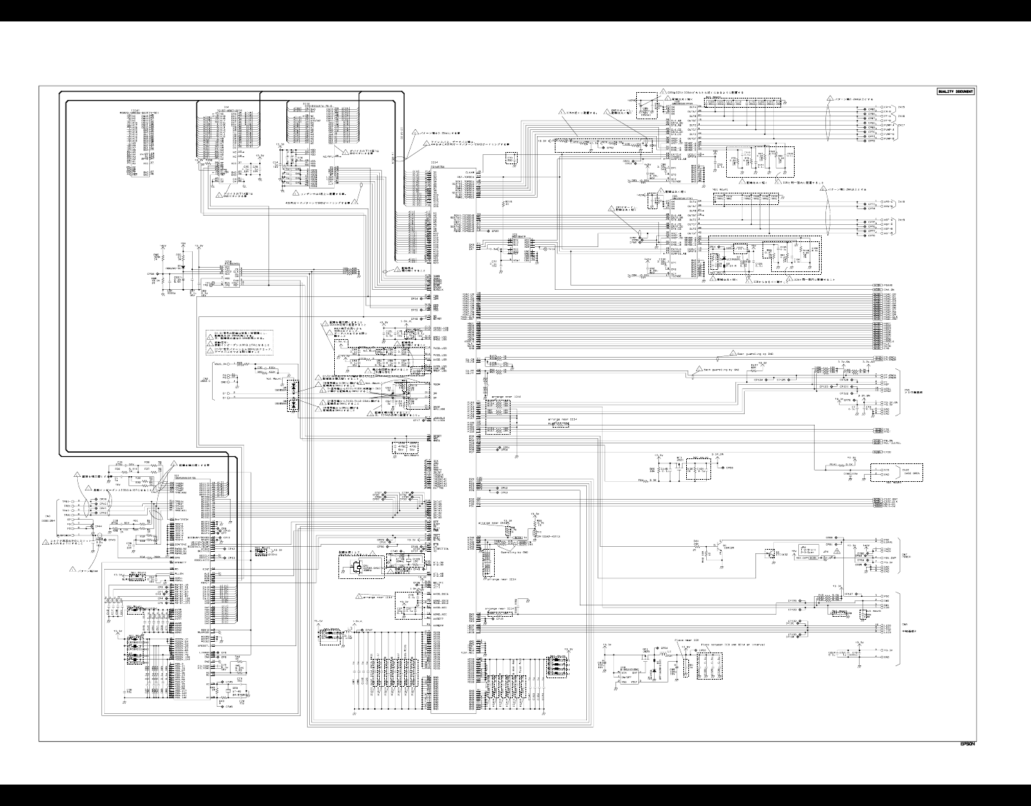
EPSON Stylus Photo R1800/R2400 Revision B
Appendix Circuit Diagram 193
C589 MAIN control circuit board 1
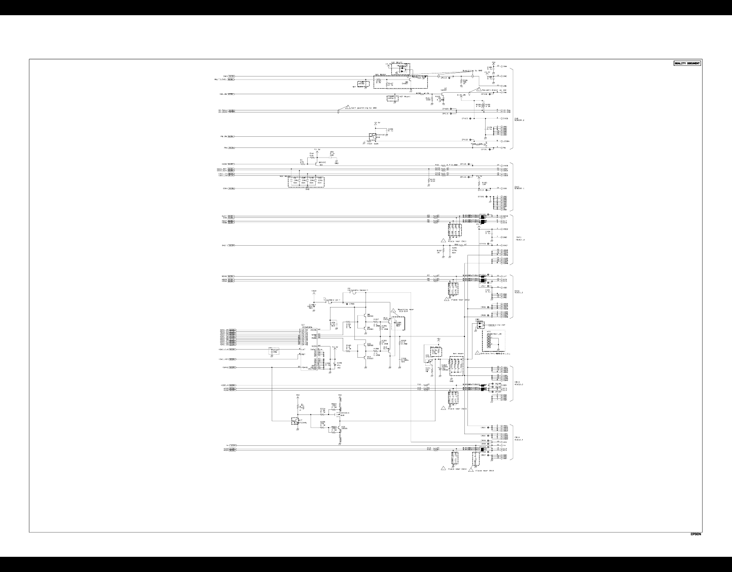
EPSON Stylus Photo R1800/R2400 Revision B
Appendix Circuit Diagram 194
C589 MAIN control circuit board 2
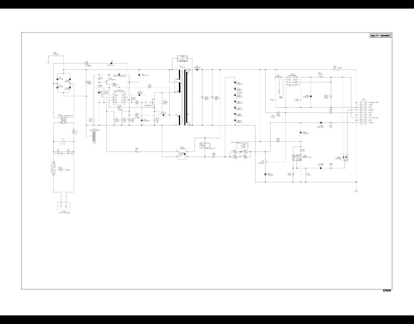
EPSON Stylus Photo R1800/R2400 Revision B
Appendix Circuit Diagram 195
C589 PSB power supply circuit board
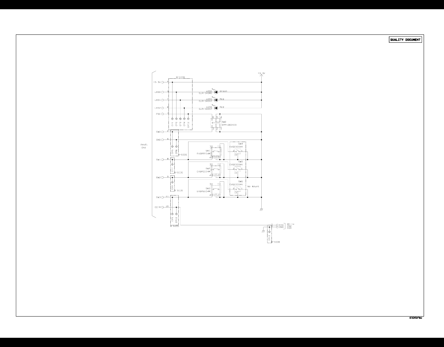
EPSON Stylus Photo R1800/R2400 Revision B
Appendix Circuit Diagram 196
C589 PNL circuit board
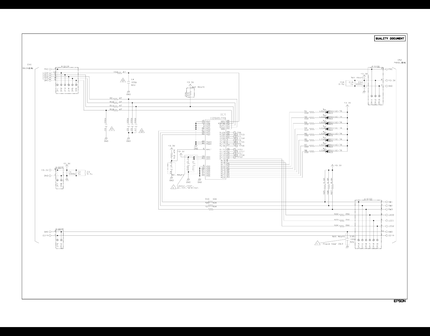
EPSON Stylus Photo R1800/R2400 Revision B
Appendix Circuit Diagram 197
C589 PNL B circuit board

CHAPTER
8
STYLUS PHOTO R2400

EPSON Stylus Photo R1800/R2400 Revision B
Stylus Photo R2400 Overview 199
8.1 Overview
The Stylus Photo R2400 is a Stylus Photo R1800 - based inkjet color printer
that supports a wide range of paper sizes from Letter to A3+. This chapter
describes the specifications and functions that are unique to the Stylus Photo
R2400. Refer to Chapter 1 to 7 for the information on the Stylus Photo R1800.
This chapter includes:
Product Description
Describes the specifications unique to the Stylus Photo R2400.
(Printing area, case specification, accessories, and environmental
specification )
Operating Principles
Describes the operating principles unique to the Stylus Photo R2400.
Trouble Shooting
Describes the troubleshooting unique to the Stylus Photo R2400.
8.1.1 Overview
FEATURES
High quality color printing
High quality phot printing using the Photo Mach technology
Much higher quality using the Microweave and Super Microweave
Highest resolution: 2880 x 1440 dpi minimum dot size: 3.2ng MSDT
High-speed print
Two built-in interfaces
IEEE 1394
USB 2.0 (HS compatible)
Small and Compact
Compatible Windows and Macintosh
Multi paper size support ASF
Automatic Sheet Feeder support for paper sizes from Letter to A3+
CSIC-compatible independent color ink cartridges
Roll paper support
Quiet printing
High-speed Borderless, edge to edge printing
Duplex printing
Preventing printing on the platen using the optical sensor
Thick paper printing using the front paper feed
Automatic Bi-D and dot detection using the multi sensor
EPSON Stylus Photo R1800/R2400 Revision B
Stylus Photo R2400 Overview 200
8.1.2 Indicator Display in Normal Mode
Note: • "–" : Don't care
• Blink : 0.5sec on + 0.5sec off repetition
• Blink 2 : 0.2sec on + 0.2sec + 0.2sec on + 0.4sec off repetition
• Fast Blink : 0.1sec on + 0.1sec off repetition
• Blink alternately 1 : 0.5sec on + 0.5sec off repetition
• Blink alternately 2 : 0.5sec off + 0.5sec on repetition
Note"*1": When reset occurs (when the printer receives IEEE1284.4 "rs" command, or when printing of a
status sheet is finished), the LEDs light for 0.2 second to indicate that the printer accepted the
command.
"*2":The ink LED that corresponds to each cartridge row (A,BC,D,E,F,G, and H) is displayed
independently.
When facing front of printer, insertion locations (rows) of ink cartridges are taken as
A,B,C,D,E,F,G, and H from the left. These rows correspond to LED1, LED2, LED3, LED4, LED5,
LED6, LED7, and LED8, respectively.
Table 8-1. Printer Condition and LED Status
Printer status Error status Indicators
Power Paper Ink Priority
Idle – On – – 20
Data processing –Blink – – 19
Ink sequence processing – Blink – – 17
Ink cartridge change mode –Blink – – 16
Ink low (warning) – – – Blink*2 15
Tear off status 11h – – – 14
Cover Open (Tray) Error 2Bh Fast Blink Blink 2 – –
Paper mismatch Error 0Ch –Fast Blink –12
Paper Out 06h – On – 11
Ink end 05h – – On*2 10
No Ink cartridge or
Ink cartridge error 05h – – On*2 9
Paper Jam Error 04h –Blink – 8
Reset input*1 –OnOnOn–
Fatal error 00h Off Fast Blink Fast Blink 4
Maintenance request 10h Off Blink
alternately 1 Blink
alternately 2 2
Power off –Fast Blink Off Off 1

EPSON Stylus Photo R1800/R2400 Revision B
Stylus Photo R2400 Overview 201
8.1.3 Error Status
If any of the following states is detected, this printer is put in an error status and
turns the interface signal -ERROR "Low" and BUSY "High" to inhibit data input.
At this time, the printer is automatically disabled from printing. However, when
communication is being made using the IEEE1284.4 protocol, communication
with the printer is enabled.
General error
After the cause of this type of error is removed, the printer can resume its
operation from where it stopped due to the error
Fatal error
After the cause of this type of error is removed, the printer cannot return to
normal unless it is powered off and then on again
Table 8-2. General error
Error Status Occurring Condition Resuming Condition
Ink color error This error occurs when you replace a
photo black ink cartridge to a matte
black, or a matte black ink cartridge
to a photo black during printing.
Return the combination
of ink colors to the one
before the error.
Cover open (tray)
error When the front cover is opened at
ASF, roll paper or photo album
printing mode, the printer goes this
error.
Close the front cover.
Paper mismatch
error If the paper path specified by the print
data is different from the printer’s real
paper path, the printer goes to this
error.
Change the printer’s
paper path to the one
specified by the data.
Paper out When printer fails to load a sheet, it
goes paper out error. Set the paper to the ASF
and push the Paper
switch.
Ink out When the printer runs out the most
part of the ink of any one color, it
warns ink-low and keeps printing.
When the printer runs out the whole
ink of any one color, it stops printing
and indicates ink-out error.
Install the new Ink
Cartridge.
No ink-cartridge When printer detects that ink-
cartridge comes off, it goes this error
mode.
Install the new Ink
Cartridge.
Paper jam • Failure of ejecting a sheet
• Failure of loading a sheet to
the loading position
Remove the jammed
paper.
Table 8-3. Fatal error
Error Status Occurring Condition Resuming Condition
Maintenance
request When the total quantity of ink wasted
through the cleanings and flushing is
reaches to the limit, printer indicates
this error and stops.
Replace the absorber in
the printer enclosure by a
service person.
Fatal errors • CR motor control error
• PF motor control error
• ASF motor control error
• Auto Platen Gap control error
• Head temperature error
• PW sensor error
Turn off and turn on.
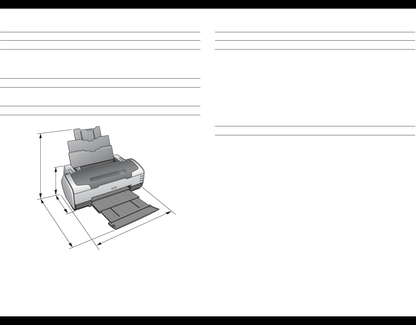
EPSON Stylus Photo R1800/R2400 Revision B
Stylus Photo R2400 Casing Specifications 202
8.2 Casing Specifications
EXTERNAL DIMENSIONS
When tucked: 615 (width) x 314 (depth) x 223 mm (height)
When used: 615 (width) x 737 (depth) x 457 mm (height)
WEIGHT
11.7 kg (without the Ink Cartridges, Roll paper holder)
EXTERNAL DIMENSION DIAGRAM
ê} 8-1. External Dimension Diagram
8.3 Accessories
STANDARD ACCESSORIES
Start Here
Ink Cartridge (one for each of 9 colors)
Power Cord
Software CD-ROM
Roll Paper Holder
Multi-Sheet Matte Guide
Rear Sheet Guide
CONSUMABLES AND OPTIONS
Ink Cartridges
Photo Black: : T0591
Cyan : T0592
Magenta : T0593
Yellow : T0594
Light Cyan : T0595
Light Magenta : T0596
Light Black : T0597
Matte Black : T0598
Light Light Black : T0599
802.11g Radio printing adapter: PA-W11G
615
314
737
223
457
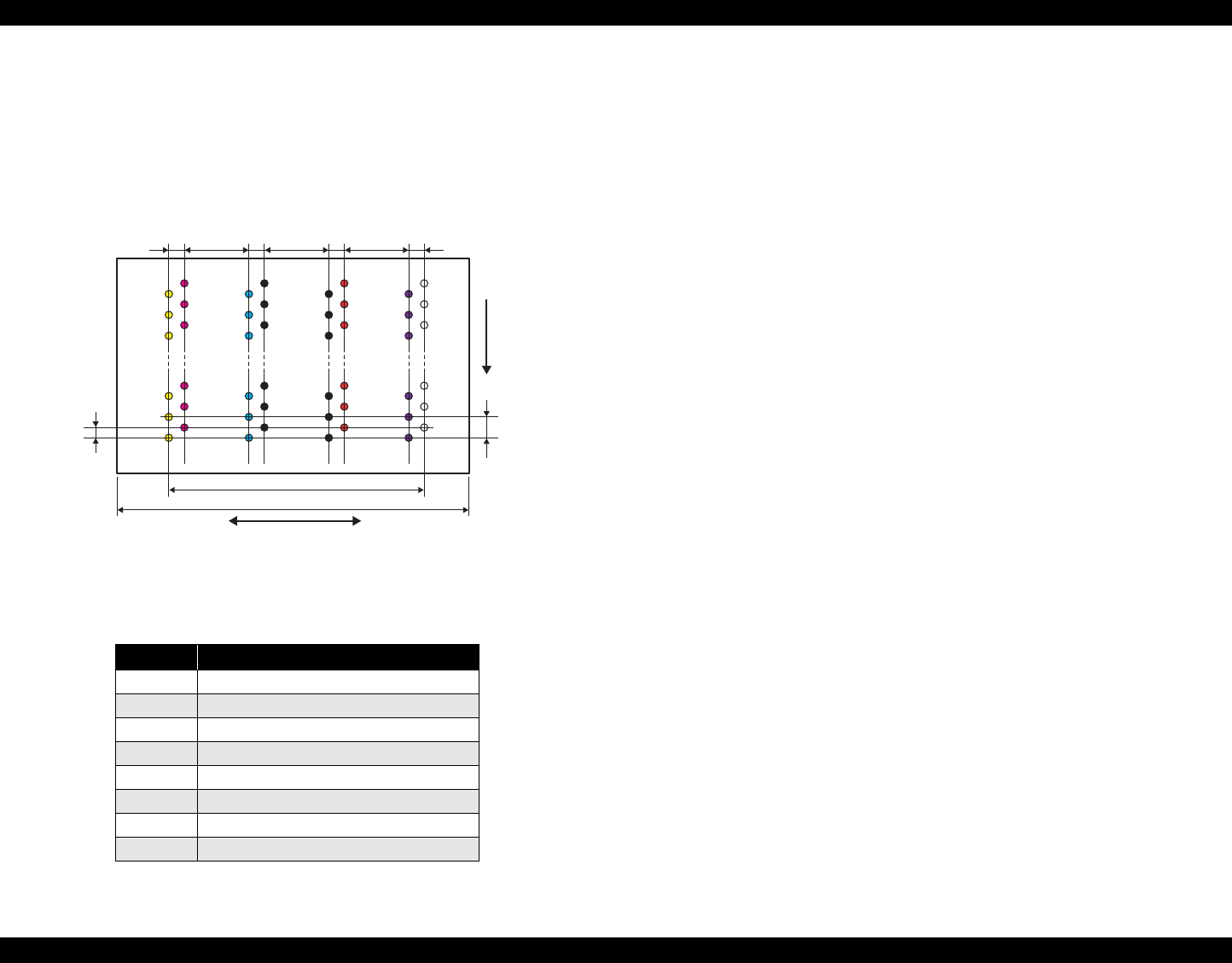
EPSON Stylus Photo R1800/R2400 Revision B
Stylus Photo R2400 Accessories 203
8.3.1 Printhead Specifications
The Printhead of this product is a F-Mach head.
The following shows the arrangement of the nozzles and the color
arrangement of each nozzle line when viewed the Print Head from behind.
Figure 8-2. Nozzle Arrangement
8.3.2 Ink Sequence
Displacement cleaning / replacement cleaning
This printe provides 2 patterns of combination of black inks in the E row.
Refer to Table 8-4 "Nozzle Lines and the Corresponding Ink Color" on page 203 .
When replacing the ink cartridges using the 2 patterns that are mentioned
above with the carriage unit at the home position, 2 types of displacement
cleaning are performed to prevent a new ink from mixing with a old one.
If the ink types are not displaced in the E row, a replacement cleaning is
performed instead of a displacement cleaning.
Cartridge displacement CL
3.09g (0.425g per color)
Cartridge replacement CL1: each color
Suction amount 3.09g (0.386g per color)
Cartridge replacement CL2: each color
Suction amount 3.14g (0.393g per color)
Table 8-4. Nozzle Lines and the Corresponding Ink Color
Line Ink
A Light Light Black
BLight Magenta
C Light Cyan
DLight Black
E Photo-black / Matte-black
FCyan
GMagenta
HYellow
31.89mm
41.66mm
Carriage moving direction
Paper feeding
direction
0.071mm
(1/360inch)
0.141mm
(1/180inch)
Line A Line B
7.620mm
(216/720inch)
2.258mm
(64/720inch) 2.258mm
(64/720inch) 2.258mm
(64/720inch) 2.258mm
(64/720inch)
7.620mm
(216/720inch) 7.620mm
(216/720inch)
Line C Line D
Line E Line F
LineG Line H
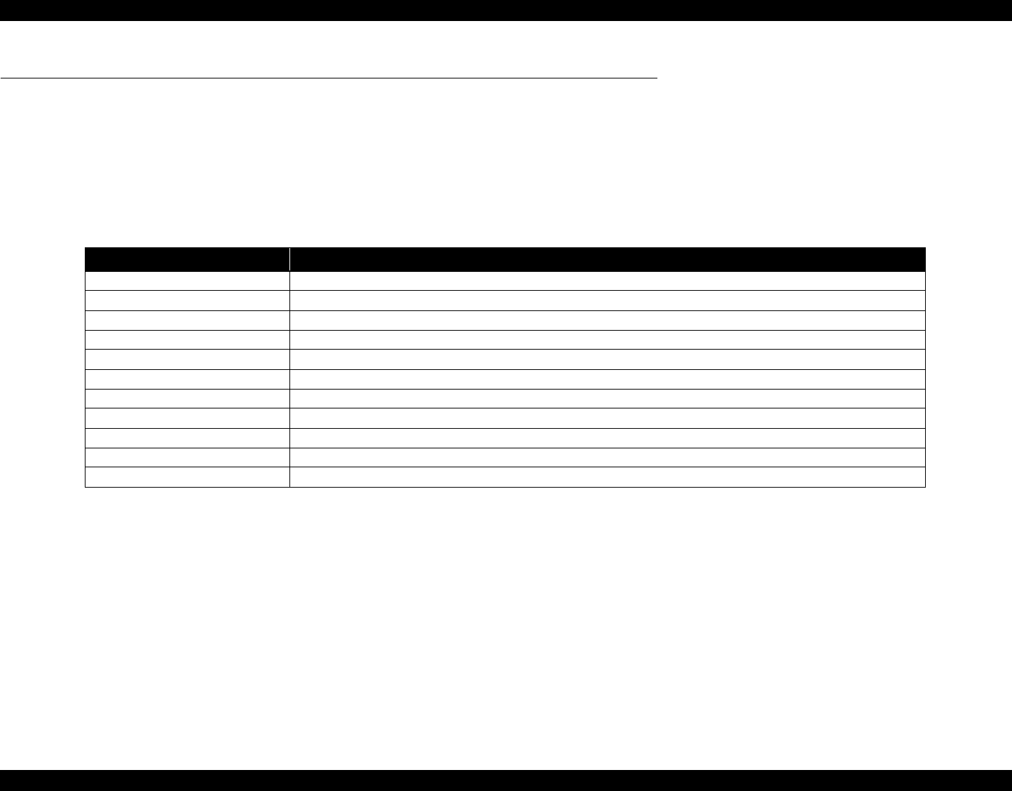
EPSON Stylus Photo R1800/R2400 Revision B
Stylus Photo R2400 Overview 204
8.4 Overview
This chapter describes unit-level troubleshooting.
8.4.1 Troubleshooting according to Panel Messages
After checking the printer LED and EPW3 error indications, you can grasp the fault location using the check list in this section. When you find the fault location, refer
to Chapter 4 "Disassembly and Reassembly" and change the corresponding part and/or unit. The following table indicates the check point reference tables
corresponding to the error states (LED and EPW3).
Table 8-5. Reference Tables of Error States
Error State Reference Table
Communication Error Refer to Table 8-6 "Troubleshooting of Communication Error" on page 205
Model Difference Refer to Table 8-6 "Troubleshooting of Communication Error" on page 205
Cover Open (Tray) Error Refer to Table 8-7 "Troubleshooting of Cover Open Error" on page 208
Paper Out Error Refer to Table 8-8 "Troubleshooting of Paper Out Error" on page 209
Paper Jam Error Refer to Table 8-9 "Troubleshooting of Paper Jam Error" on page 212
Paper Mismatch Error Refer to Table 8-11 "Troubleshooting of Paper Mismatch Error" on page 214
Ink Low Refer to Table 8-12 "Troubleshooting of Ink Low" on page 214
Ink Out Error Refer to Table 8-13 "Troubleshooting of Ink Out Error" on page 214
No Ink Cartridge/CSIC Error Refer to Table 8-14 "Troubleshooting of No Ink Cartridge/Ink Cartridge Error" on page 215
Maintenance Request Error Refer to Table 8-15 "Troubleshooting of Maintenance Request" on page 217
Fatal Error Refer to Table 8-16 "Troubleshooting of Fatal Error" on page 218
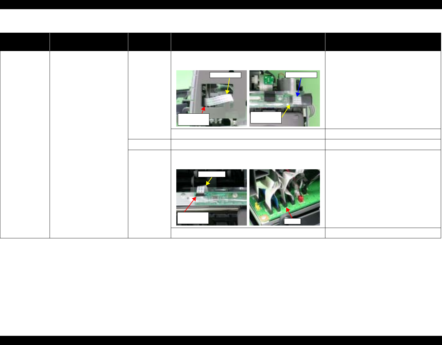
EPSON Stylus Photo R1800/R2400 Revision B
Stylus Photo R2400 Overview 205
Table 8-6. Troubleshooting of Communication Error
Occurrence
Timing Phenomenon Detail Faulty Part/
Part Name Check Point Remedy
At power-on The printer does not operate at
all. Panel FFC 1. Check that the Panel FFC is connected to the Panel Board
Connector and LED Board Connector. 1. Connect the Panel FFC to the Panel Board
and LED Board connectors.
2. Check the Panel FFC for damages. 2. Replace the Panel FFC with a new one.
Panel Board 1. Check the Panel Board for damages. 1. Replace the Panel Board with a new one.
LED FFC 1. Check that the LED FFC is connected to the LED Board
Connector and Main Board Connector CN8. 1. Connect the LED FFC to the LED Board
Connector and Main Board Connector
CN8.
2. Check the LED FFC for damages. 2. Replace the LED FFC with a new one.
LED Board
Connector
Panel FFC
Panel FFC
Panel Board
connector
CN8
LED FFC
LED Board
Connector
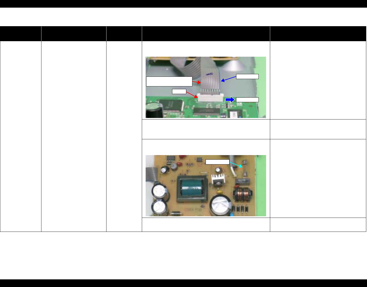
EPSON Stylus Photo R1800/R2400 Revision B
Stylus Photo R2400 Overview 206
At power-on The printer does not operate at
all. Power Supply
Board 1. Check that the Connector Cable of the Power Supply
Board is connected to the Main Board Connector CN7. 1. Connect the Connector Cable of the Power
Supply Board to the Main Board Connector
CN7.
2. Check that the blue colored pin of the Power Supply Board
Connector cable is inserted into the 1 Pin of the Main
Board Connector CN7 as shown in the above picture.
2. Reconnect the Power Supply Board
Connector cable so that the blue colored
pin is inserted into the 1 Pin.
3. Check that the Fuse F1 on the Power Supply Board has
not blown. 3. Replace the Power Supply Board with a
new one.
4. Check the components on the Power Supply Board for
damage. 4. Replace the Power Supply Board with a
new one.
Table 8-6. Troubleshooting of Communication Error
Occurrence
Timing Phenomenon Detail Faulty Part/
Part Name Check Point Remedy
Connector cable of the
Power Supply Board
Blue line
1Pin side
CN7
Fuse F1

EPSON Stylus Photo R1800/R2400 Revision B
Stylus Photo R2400 Overview 207
At power-on After the power-on sequence
has started, the LED turns off
and the printer does not
operate.
Main Board 1. Check that the Relay connector of the ASF Motor and the
Relay connector of the Pump Motor are not connected to
the wrong connector causing a short circuit.
1. Connect the Relay Connector of the ASF
Motor and the Relay Connector of the
Pump Motor correctly, and replace the
Main Board with a new one.
At operation Operation at power-on is
normal, but the error appears
when the print job is sent to
the printer.
Interface cable 1. Check that the Interface cable is connected between the
PC and printer. 1. Connect the Interface cable to the PC and
printer.
2. Check the Interface cable for breaking. 2. Replace the Interface cable with a new
one.
EPSON
USB driver 1. When using USB, check that the EPSON USB driver has
been installed on the PC. 1. Install the EPSON USB driver.
USB 1. Check that the PC and printer are connected via the USB
hub. 1. Enter the USB serial No. indicated on the
product nameplate.
Refer to Chapter 5 "Adjustment".
IEEE1394 1. Check that the same code as the IEEE1394 QR label code
is saved in the EEPROM address (from BA-H to BE-H). 1. Input the code given as the IEEE1394 QR
label code.
Refer to Chapter 5 "Adjustment".
Printer Driver 1. Check that the printer driver for Stylus Photo R2400 has
already been installed. 1. Install the printer driver for Stylus Photo
R2400.
2. Check that the connected printer is Stylus Photo R2400. 2. Connect the Stylus Photo R2400 printer.
Main Board 1. Check that a wrong model name has not been input to the
EEPROM address (E0<H<) on the Main Board. 1. Using the Adjustment Program, enter the
correct model name (save 01 into E0<H>).
Refer to Chapter 5"Adjustment".
Table 8-6. Troubleshooting of Communication Error
Occurrence
Timing Phenomenon Detail Faulty Part/
Part Name Check Point Remedy
Relay Connector of
the Pump Motor
Relay Connector of
the ASF Motor
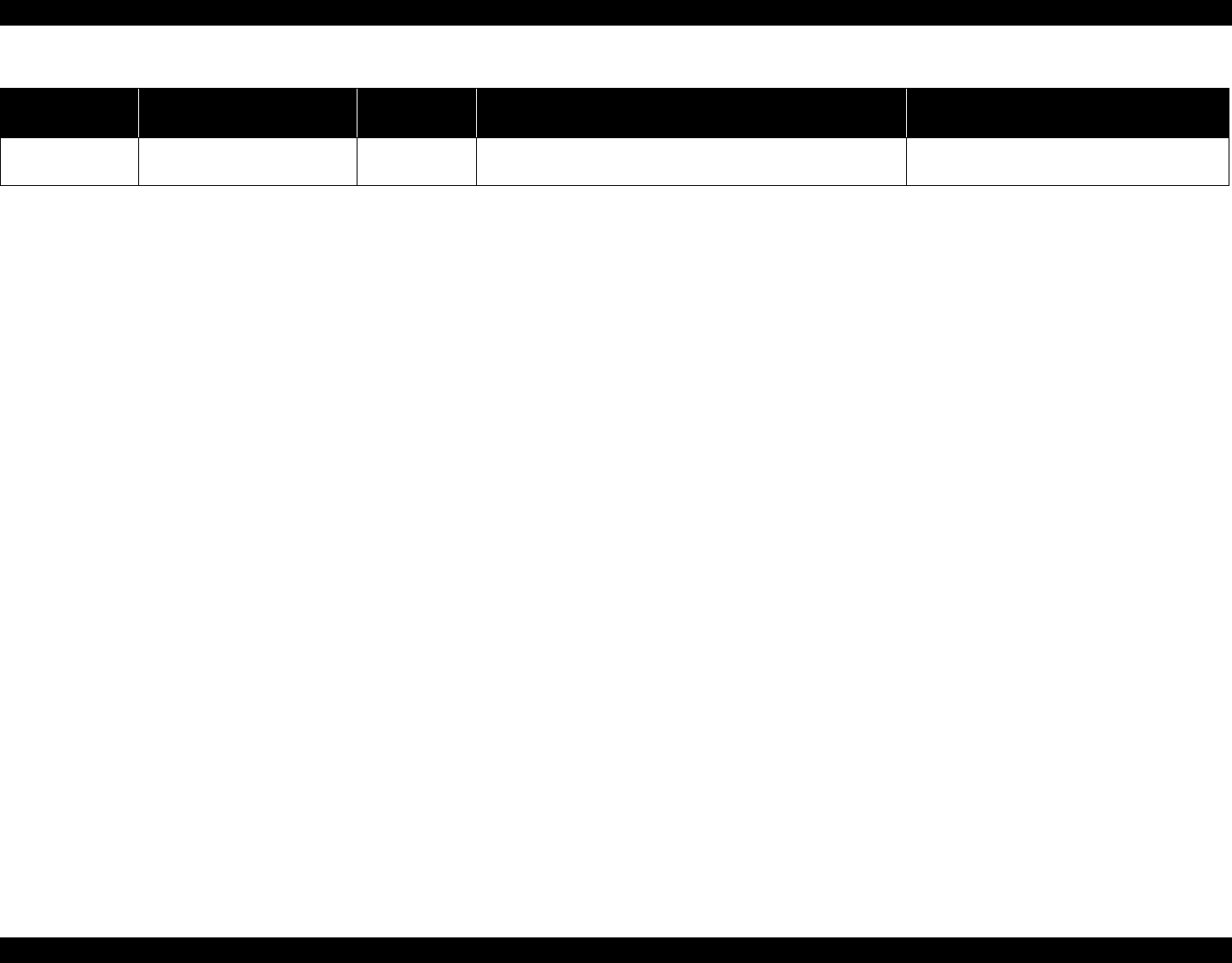
EPSON Stylus Photo R1800/R2400 Revision B
Stylus Photo R2400 Overview 208
Table 8-7. Troubleshooting of Cover Open Error
Occurrence
Timing Phenomenon Detail Faulty Part/
Part Name Check Point Remedy
During printing A Cover Open (Tray) Error is
indicated during printing. Printer Cover 1. Check that the front cover is not open. 1. Close the front cover.
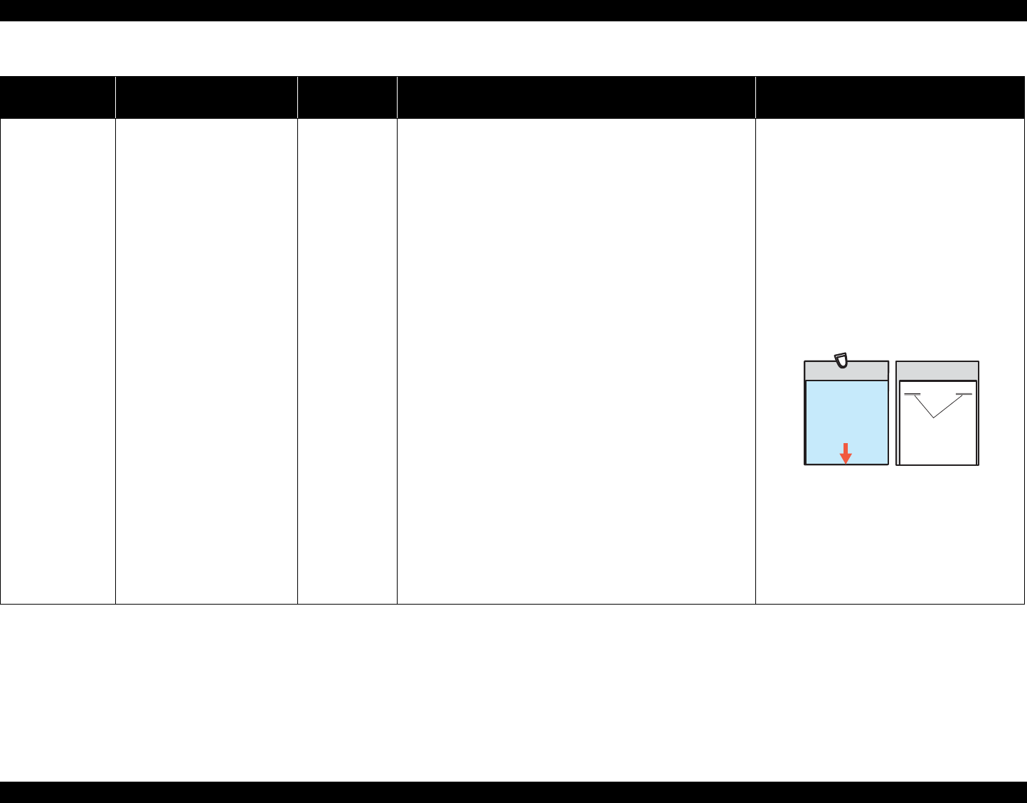
EPSON Stylus Photo R1800/R2400 Revision B
Stylus Photo R2400 Overview 209
Table 8-8. Troubleshooting of Paper Out Error
Occurrence
Timing Phenomenon Detail Faulty Part/
Part Name Check Point Remedy
At operation When the Paper Switch is
pressed, the LD Roller attempt
to feed paper but the paper is
not fed.
ASF Assy. 1. Check the LD Roller or Retard Roller of the ASF Assy for
paper dust and foreign matter. 1. Using a cleaning sheet (part
code:1262115), clean the LD Roller and
Retard Roller. The procedure is as follows.
(1) Place the cleaning sheet upside down
and put it into the ASF Assy.
(2) Press the Paper Switch to start paper
feed.
(3) Repeat the above steps several times.
* To remove persistent contamination,
staple an alcohol-dampened cloth to a
postcard and clean the rollers in the
following method.
(1) Place the alcohol-dampened cloth
toward the LD Roller surface of the
ASF Assy.
(2) Hold the mount top end securely and
press the Paper Switch.
(3) Repeat the paper feed sequence
several times to clean the LD Roller
surface of the ASF Assy.
Cleaning sheet Postcard used
as mount
Non-adhesive
Adhesive part
This side down Stapling
Cloth damped
with alcohol

EPSON Stylus Photo R1800/R2400 Revision B
Stylus Photo R2400 Overview 210
At operation Though paper is fed from the
ASF Assy, it stops near the PE
Sensor Lever.
PE Sensor 1. Check that the Connector cable of the PE Sensor is
securely connected to the PE Sensor and Relay Board
Connector CN2.
1. Connect the Connector cable of the PE
Sensor to the PE Sensor and Relay Board
Connector CN2.
2. Check that the Sensor Holder is mounted to the
Mechanical frame correctly. 2. Install the Sensor Holder correctly.
3. Move the Detection Lever manually as when the paper
passes, and check that the Detection Lever returns to the
original position automatically by the Torsion Spring when
released. Refer to the above photo.
3. Replace the PE Sensor Holder Unit with a
new one.
4. Using a tester, check that the PE Sensor is normal.
⋅ Paper absent : 2.4V or more
⋅ Paper present : 0.4V or less
4. Replace the PE Sensor Holder Unit with a
new one.
Table 8-8. Troubleshooting of Paper Out Error
Occurrence
Timing Phenomenon Detail Faulty Part/
Part Name Check Point Remedy
CN2
PW Sensor Connector
Sensor Holder
Detection Lever
Torsion Spring
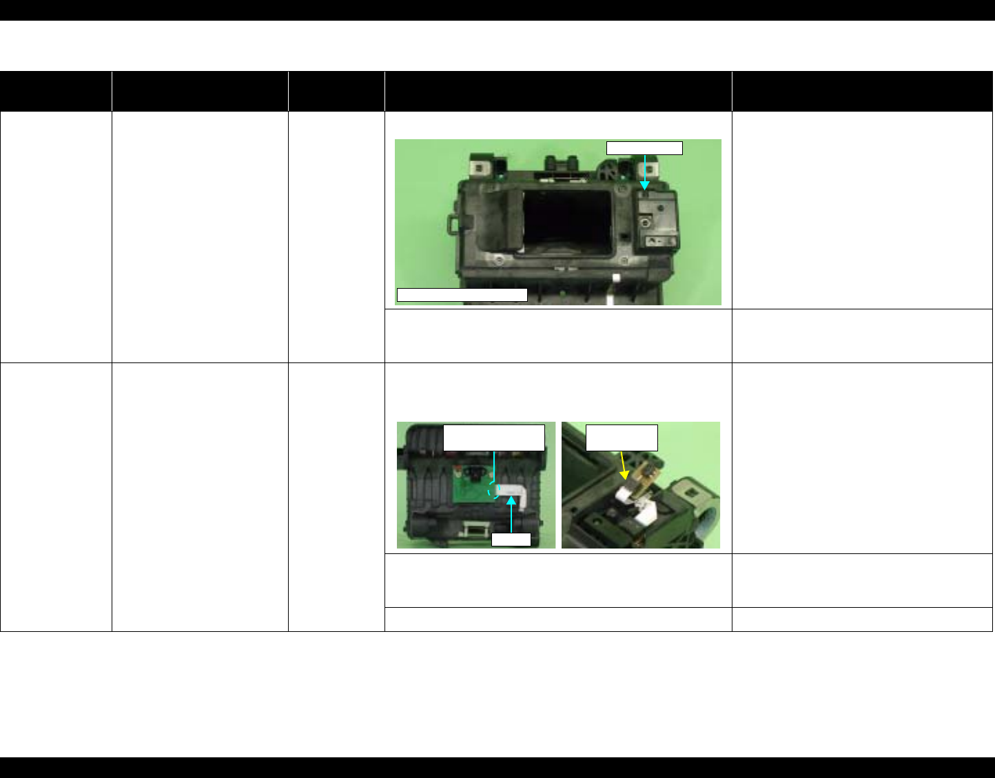
EPSON Stylus Photo R1800/R2400 Revision B
Stylus Photo R2400 Overview 211
The Paper Switch
was pressed at the
setting of the CD-R
Tray or board
paper
Though the CD-R Tray or the
Board Paper is fed toward the
ASF Assy, but is ejected
immediately.
PW sensor 1. Check the PW Sensor for paper dust, ink, etc. 1. Clean the PW Sensor surface.
2. Compare the EEPROM values in two places (50<H> and
51<H>) and check that they are not approximate to each
other.
2. Replace the PW Sensor with a new one.
The Paper Switch
was pressed at the
setting of the
board paper
The Board Tray moves toward
the ASF and the posterior
edge of it reaches to the
Driven Roller on the Upper
Paper Guide.Then the Board
Tray tries to go farther, but it is
ejected.
PW sensor 1. Check that the PW Sensor FFC is placed in the specified
routing positions and does not make contact with any
parts.
1. Place the PW Sensor FFC in the specified
routing positions.
2. Check that the PW Sensor FFC is connected to the CR
Encoder Board and PW Sensor Connectors. Refer to the
above photo.
2. Connect the FFC to the CR Encoder Board
and PW Sensor Connectors.
3. Check the PW Sensor or PW Sensor FFC for damages. 3. Replace the PW Sensor with a new one.
Table 8-8. Troubleshooting of Paper Out Error
Occurrence
Timing Phenomenon Detail Faulty Part/
Part Name Check Point Remedy
PW sensor
Carriage Unit Bottom
PW Sensor
Connector
FFC
CR Encoder Board
Connector
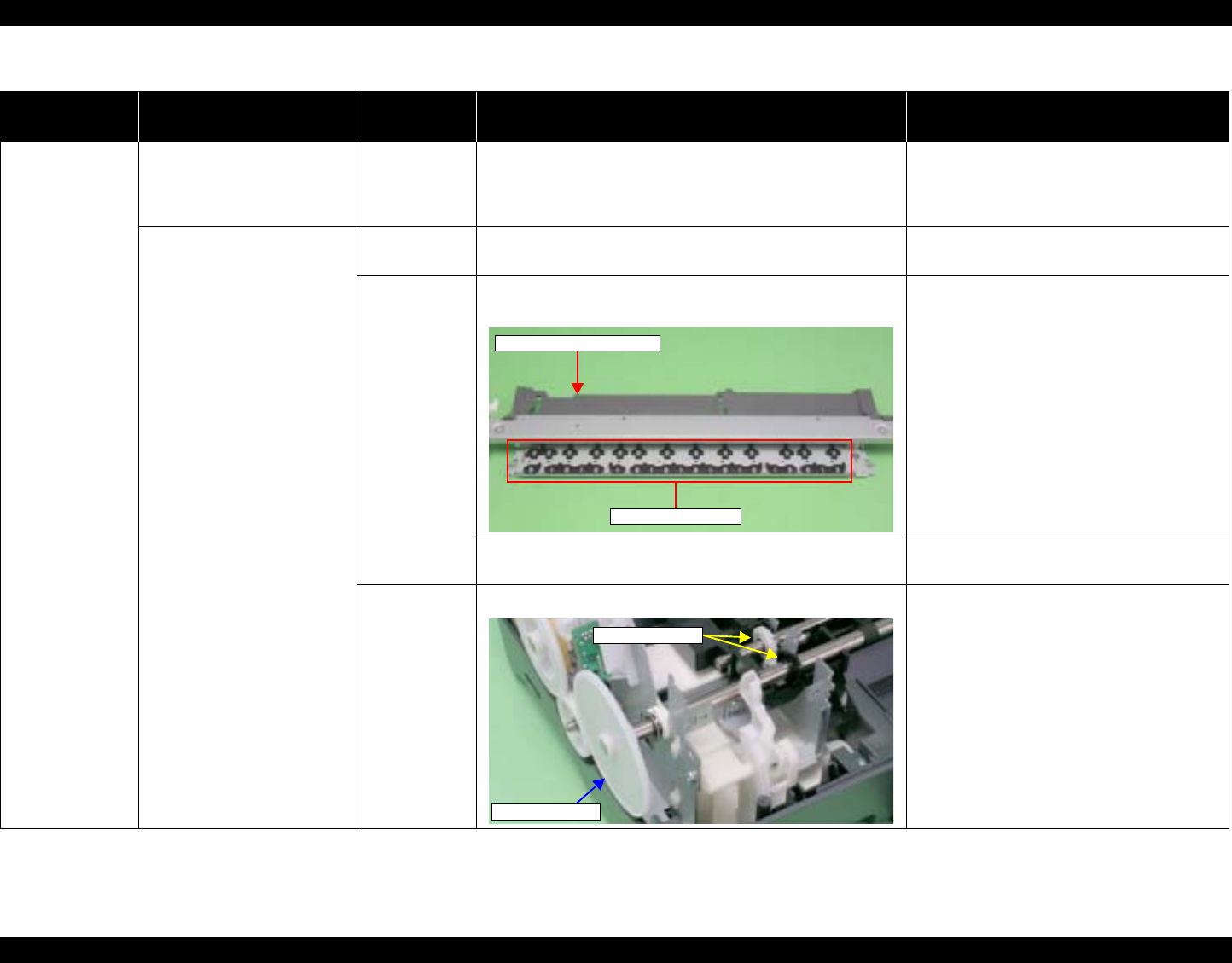
EPSON Stylus Photo R1800/R2400 Revision B
Stylus Photo R2400 Overview 212
Table 8-9. Troubleshooting of Paper Jam Error
Occurrence
Timing Phenomenon Detail Faulty Part/
Part Name Check Point Remedy
At operation At the time of paper ejection,
the PF Roller advances the
paper but cannot eject it
completely.
– 1. Check that the size of the fed paper is not larger than that
of the paper specified by the driver. 1. Tell the user that the paper size specified
by the driver is not available for the printer.
Paper is not ejected
completely and causes a jam
near the Paper Eject Frame.
ASF Assy. 1. Check that the paper is fed along the Right Edge Guide. 1. Feed the paper along the Right Edge
Guide.
Paper EJ Frame
Assy. 1. Check that the Star Wheel Units have not come off the
Paper EJ Frame Assy. 1. Securely install the Star Wheel Units to the
Paper EJ Frame Assy.
2. Check the Paper EJ Frame Assy for deformation or
damages. 2. Replace the Paper EJ Frame Assy with a
new one.
Spur Gear 68
Spur Gear 16; B
Paper EJ Roller
Assy.(front/rear)
1. Check the Spur Gear 68 or Spur Gear 16; B for damages. 1. Replace the Front (or Rear) Paper EJ
Roller Assy with a new one.
Paper EJ Frame Assy.
Star Wheel Units
Spur Gear 16; B
Spur Gear 68
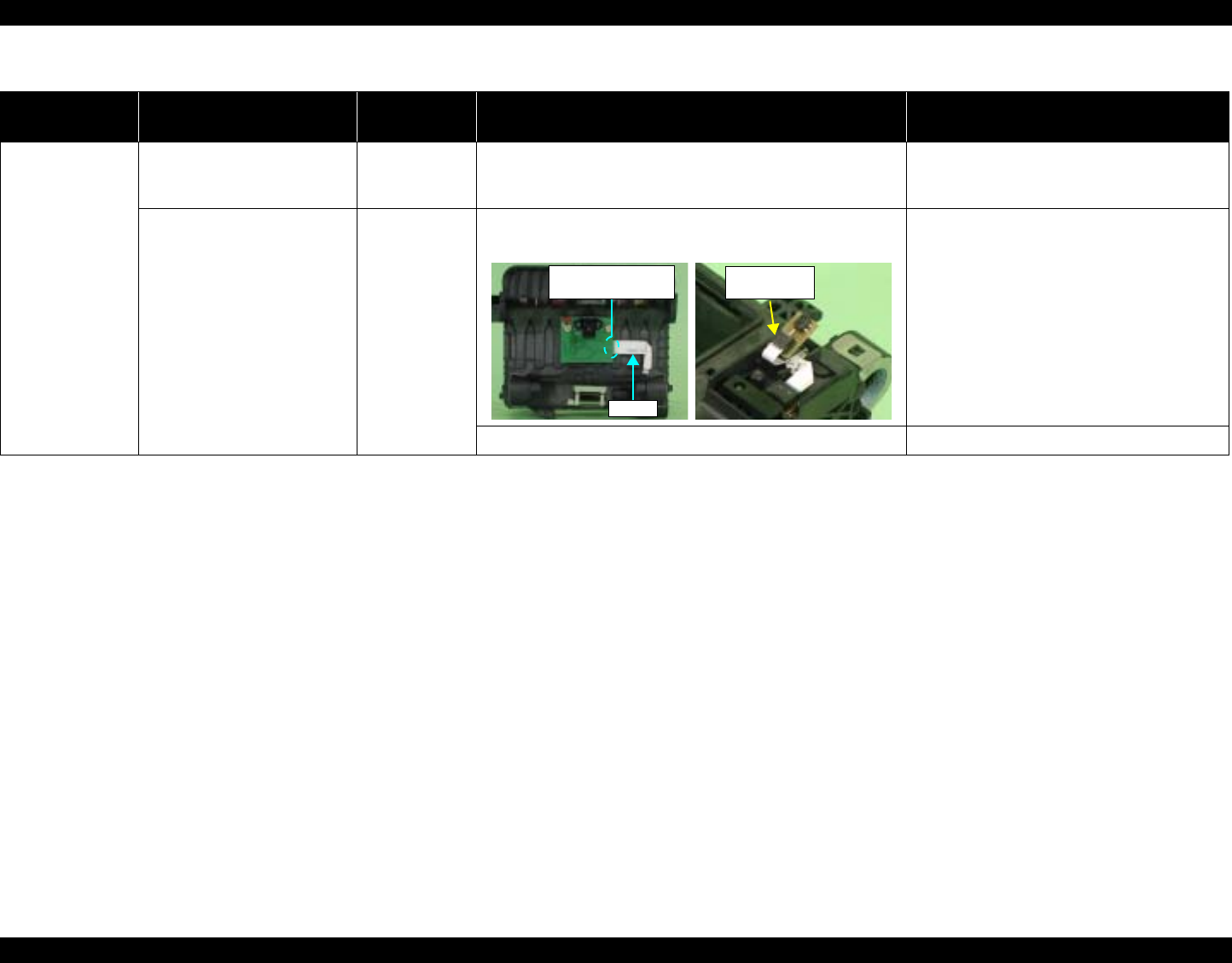
EPSON Stylus Photo R1800/R2400 Revision B
Stylus Photo R2400 Overview 213
Table 8-10. Troubleshooting of Card Loading Error
Occurrence
Timing Phenomenon Detail Faulty Part/
Part Name Check Point Remedy
During printing Printing starts but paper is not
fed. – 1. Check that the card size paper is loaded in the portrait
orientation. 1. Load the cards of the same size correctly,
and press the Paper Switch to eject the
jammed paper.
The card size paper is loaded
correctly, but Card Loading
Error is displayed.
PW sensor 1. Check that the PW Sensor FFC is connected to the CR
Encoder Board and PW Sensor Connectors. 1. Connect the FFC to the CR Encoder Board
or PW Sensor.
2. Check the PW Sensor or PW Sensor FFC for damages. 2. Replace the PW Sensor with a new one.
PW Sensor
Connector
FFC
CR Encoder Board
Connector
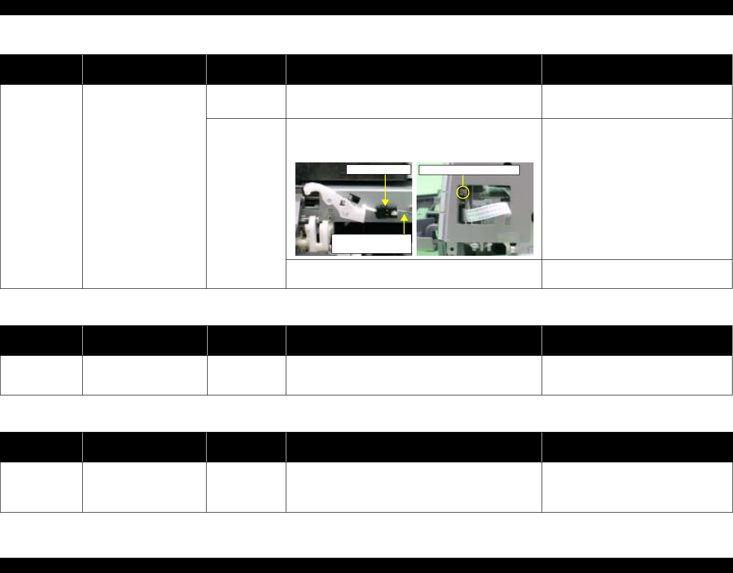
EPSON Stylus Photo R1800/R2400 Revision B
Stylus Photo R2400 Overview 214
Table 8-11. Troubleshooting of Paper Mismatch Error
Occurrence
Timing Phenomenon Detail Faulty Part/Part
Name Check Point Remedy
At operation When feeding a Board
Paper, an error is displayed
on the LED and EPW3.
Paper EJ Frame
Assy 1. Check if the CD-R Tray Base(Board Tray Base) is closed
or not. 1. Open the CD-R Tray Base(Board Tray
Base) .
CD-R Sensor
(Board Sensor) 1. Check that the Connector cable of the CD-R Sensor is
securely connected to the connectors of the CD-R Sensor
and Panel Board.
1. Connect the Connector cable of the CD-R
Sensor (Board Sensor) to the CD-R
Sensor(Board Sensor) and Panel Board
Connectors.
2. Check the CD-R Sensor(Board Sensor) or Connector
cable for damages. 2. Replace the CD-R Sensor(Board Sensor)
with a new one.
Panel Board connector
Connector cable of
the CD-R Sensor
CD-R Sensor
Table 8-12. Troubleshooting of Ink Low
Occurrence
Timing Phenomenon Detail Faulty Part/Part
Name Check Point Remedy
At operation or
during printing A message is displayed on
the LED and EPW3 during
printing.
Ink Cartridge 1. Look at the remaining ink indication of the EPW3 to check
the amount of the ink remaining in the Ink Cartridge. 1. Prepare a new Ink Cartridge.
Table 8-13. Troubleshooting of Ink Out Error
Occurrence
Timing Phenomenon Detail Faulty Part/Part
Name Check Point Remedy
During printing After the Carriage has
detected the HP, an error is
displayed on the LED and
EPW3.
Ink Cartridge 1. Look at the remaining ink indication of the EPW3 to check
whether the ink remains in the Ink Cartridge. 1. Replace the Ink Cartridge with a new one.
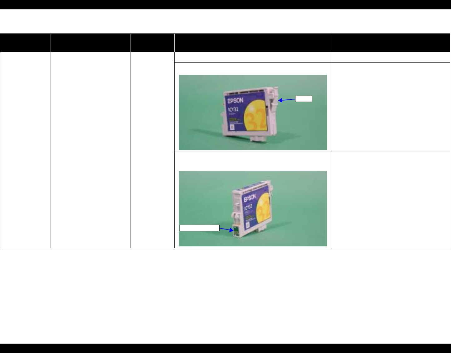
EPSON Stylus Photo R1800/R2400 Revision B
Stylus Photo R2400 Overview 215
Table 8-14. Troubleshooting of No Ink Cartridge/Ink Cartridge Error
Occurrence
Timing Phenomenon Detail Faulty Part/
Part Name Check Point Remedy
At power-on After the Carriage has
detected the HP, an error is
displayed on the LED and
EPW3.
Ink Cartridge 1. Check that the Ink Cartridge is installed correctly. 1. Install the Ink Cartridge correctly.
2. Check that the tab of the Ink Cartridge is not broken. 2. Replace the Ink Cartridge with a new one.
3. Check that the Memory Chip is not disconnected or not
damaged. 3. Replace the Ink Cartridge with a new one.
Tab
Memory Chip
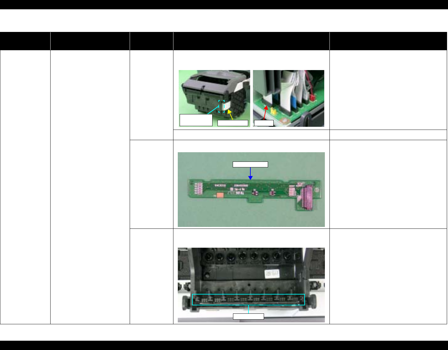
EPSON Stylus Photo R1800/R2400 Revision B
Stylus Photo R2400 Overview 216
At power-on After the Carriage has
detected the HP, an error is
displayed on the LED and
EPW3.
CSIC FFC 1. Check that the CSIC FFC is connected to the CSIC Board
Connector and Main Board Connector CN10. 1. Connect the CSIC FFC to the CSIC Board
Connector and Main Board Connector
CN10.
2. Check the CSIC FFC for damage. 2. Replace the CSIC FFC with a new one.
CSIC Board 1. Check the CSIC Board for damage. 1. Replace the CSIC Board with a new one.
Carriage Unit 1. Check that the electrodes in the Carriage, which make
contact with the CSIC Board, are not bent. 1. Replace the Carriage Unit with a new one.
Table 8-14. Troubleshooting of No Ink Cartridge/Ink Cartridge Error
Occurrence
Timing Phenomenon Detail Faulty Part/
Part Name Check Point Remedy
CN10
CSIC Board
Connector CSIC FFC
CSIC Board
Electrode

EPSON Stylus Photo R1800/R2400 Revision B
Stylus Photo R2400 Overview 217
Table 8-15. Troubleshooting of Maintenance Request
Occurrence
Timing Phenomenon Detail Faulty Part/
Part Name Check Point Remedy
At power-on At power-on, the printer does
not operate at all. Waste Ink Pads 1. Using the Adjustment Program, check if the Protection
Counter A+B value has exceeded 17540. 1. Replace the Waste Ink Pads and reset the
Protection Counter A and B value with the
Adjustment Program.

EPSON Stylus Photo R1800/R2400 Revision B
Stylus Photo R2400 Overview 218
Table 8-16. Troubleshooting of Fatal Error
Occurrence
Timing Phenomenon Detail Faulty Part/
Part Name Check Point Remedy
At power-on At power-on, the CR Motor
does not operate at all. CR Motor 1. Check that the CR Motor connector cable is connected to
the Relay Connector. 1. Connect the CR Motor connector to the
Relay Connector.
2. Check the CR Motor connector cable for damages. 2. Replace the CR Motor with a new one.
3. Check if the CR Motor operates normally. 3. Replace the CR Motor with a new one.
Relay
Connector
Cables
(for the CR
Motor)
1. Check that the Relay Connector Cable is connected to the
Main Board Connector CN15. 1. Connect the Relay Connector Cable to the
Main Board Connector CN15.
2. Check the Relay Connector Cable for damages. 2. Replace the Relay Connector Cable with a
new one.
CR Motor
Relay Connector
CN15

EPSON Stylus Photo R1800/R2400 Revision B
Stylus Photo R2400 Overview 219
At power-on The power-on sequence is
executed but Fatal error is
displayed.
CR drive
mechanism 1. Check that the Carriage Shaft is lubricated with grease. 1. Wipe the surface of the Carriage Shaft with
a dry, soft cloth, and lubricate the Carriage
Shaft with grease G-71.
Refer to Chapter 6 "Maintenance".
At power-on, the PF Motor
does not operate at all. PF Motor 1. Check that the Connector Cable of the PF Motor is
connected to the Main Board Connector CN16. 1. Connect the PF Motor connector cable to
the Main Board Connector CN16.
2. Check the PF Motor connector cable for damages. 2. Replace the PF Motor with a new one.
3. Check if the PF Motor operates normally. 3. Replace the PF Motor with a new one.
Table 8-16. Troubleshooting of Fatal Error
Occurrence
Timing Phenomenon Detail Faulty Part/
Part Name Check Point Remedy
Carriage Shaft
CN16 PF Motor
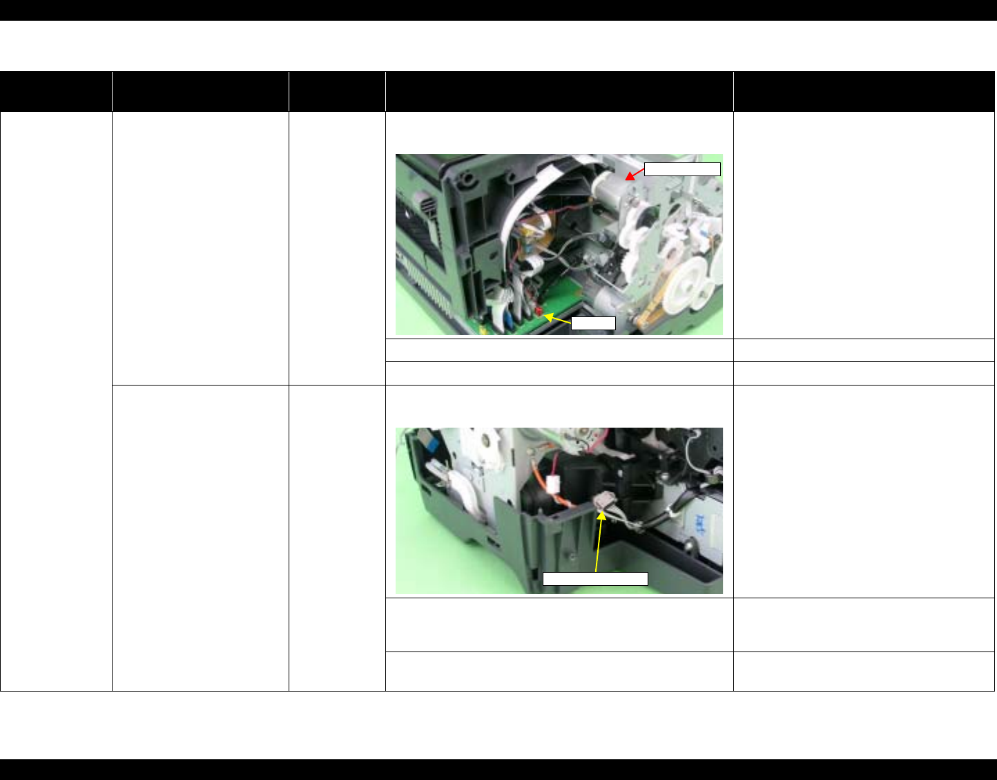
EPSON Stylus Photo R1800/R2400 Revision B
Stylus Photo R2400 Overview 220
At power-on At power-on, the APG Motor
does not operate at all. APG Motor 1. Check that the Connector Cable of the APG Motor is
connected to the Main Board Connector CN18. 1. Connect the APG Motor connector cable to
the Main Board Connector CN18.
2. Check the APG Motor connector cable for damage. 2. Replace the APG Motor with a new one.
3. Check if the APG Motor operates normally. 3. Replace the APG Motor with a new one.
At power-on, the Pump Motor
does not operate at all. Pump Motor 1. Check that the Pump Motor connector cable is connected
to the Relay Connector. 1. Connect the Pump Motor connector cable
to the Relay Connector.
2. Using a tester, check the resistance value of the Pump
Motor.
Value of resistance : 10.3Ω ± 10%
2. If the resistance value is abnormal, replace
the Ink System Unit with a new one.
3. Check the Pump Motor connector cable for damages. 3. Replace the Ink System Unit with a new
one.
Table 8-16. Troubleshooting of Fatal Error
Occurrence
Timing Phenomenon Detail Faulty Part/
Part Name Check Point Remedy
CN18
APG Motor
Relay Connector
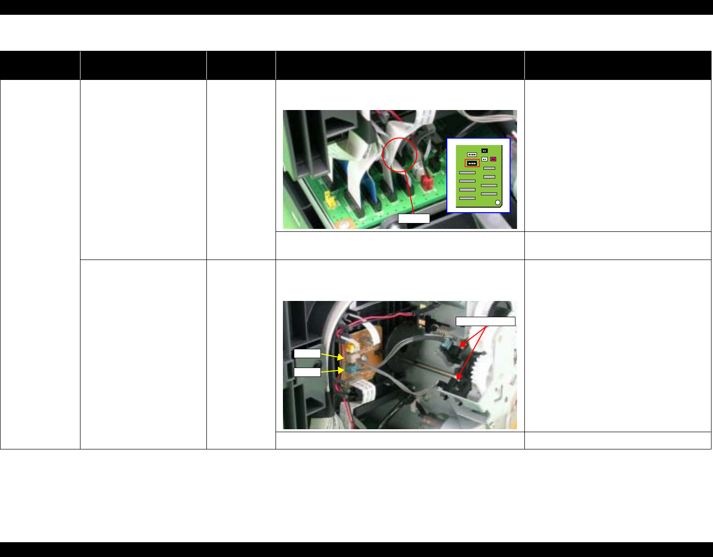
EPSON Stylus Photo R1800/R2400 Revision B
Stylus Photo R2400 Overview 221
At power-on At power-on, the Pump Motor
does not operate at all. Relay
Connector
Cables (for
Pump Motor)
1. Check that the Relay Connector Cable is connected to the
Main Board Connector CN17. 1. Connect the Relay Connector Cable to the
Main Board Connector CN17.
2. Check the Relay Connector Cable for damages. 2. Replace the Relay Connector Cable with a
new one.
While the power-on sequence
is being executed, Fatal error
is displayed.
APG Sensor 1. Check that the APG Sensor Connector cables are
connected to the APG Sensors and Relay Board
Connector CN4 and CN5.
1. Connect the APG Sensor Connector
cables to the APG Sensors and Relay
Board Connector CN4 and CN5.
2. Check the APG Sensors for damages. 2. Replace the APG Sensors with new ones.
Table 8-16. Troubleshooting of Fatal Error
Occurrence
Timing Phenomenon Detail Faulty Part/
Part Name Check Point Remedy
CN17
CN4
CN5
APG Sensors
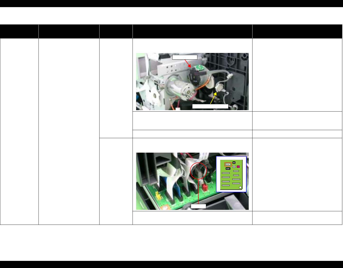
EPSON Stylus Photo R1800/R2400 Revision B
Stylus Photo R2400 Overview 222
At power-on While the power-on sequence
is being executed, Fatal error
is displayed.
ASF Motor 1. Check that the Connector cable of the ASF Motor is
connected to the Relay Connector. 1. Connect the Connector cable of the ASF
Motor to the Relay Connector.
2. Using a tester, check the resistance value of the ASF
Motor.
Value of resistance : 7.0Ω ± 10%
2. If the resistance value is abnormal, replace
the ASF Motor with a new one.
3. Check the ASF Motor connector cable for damages. 3. Replace the ASF Motor with a new one.
Relay
Connector
Cable
(for the ASF
Motor)
1. Check that the Relay Connector Cable is connected to the
Main Board Connector CN19. 1. Connect the Relay Connector Cable to the
Main Board Connector CN19.
2. Check the Relay Connector Cable for damages. 2. Replace the Relay Connector Cable with a
new one.
Table 8-16. Troubleshooting of Fatal Error
Occurrence
Timing Phenomenon Detail Faulty Part/
Part Name Check Point Remedy
Relay Connector
ASF Motor
CN19
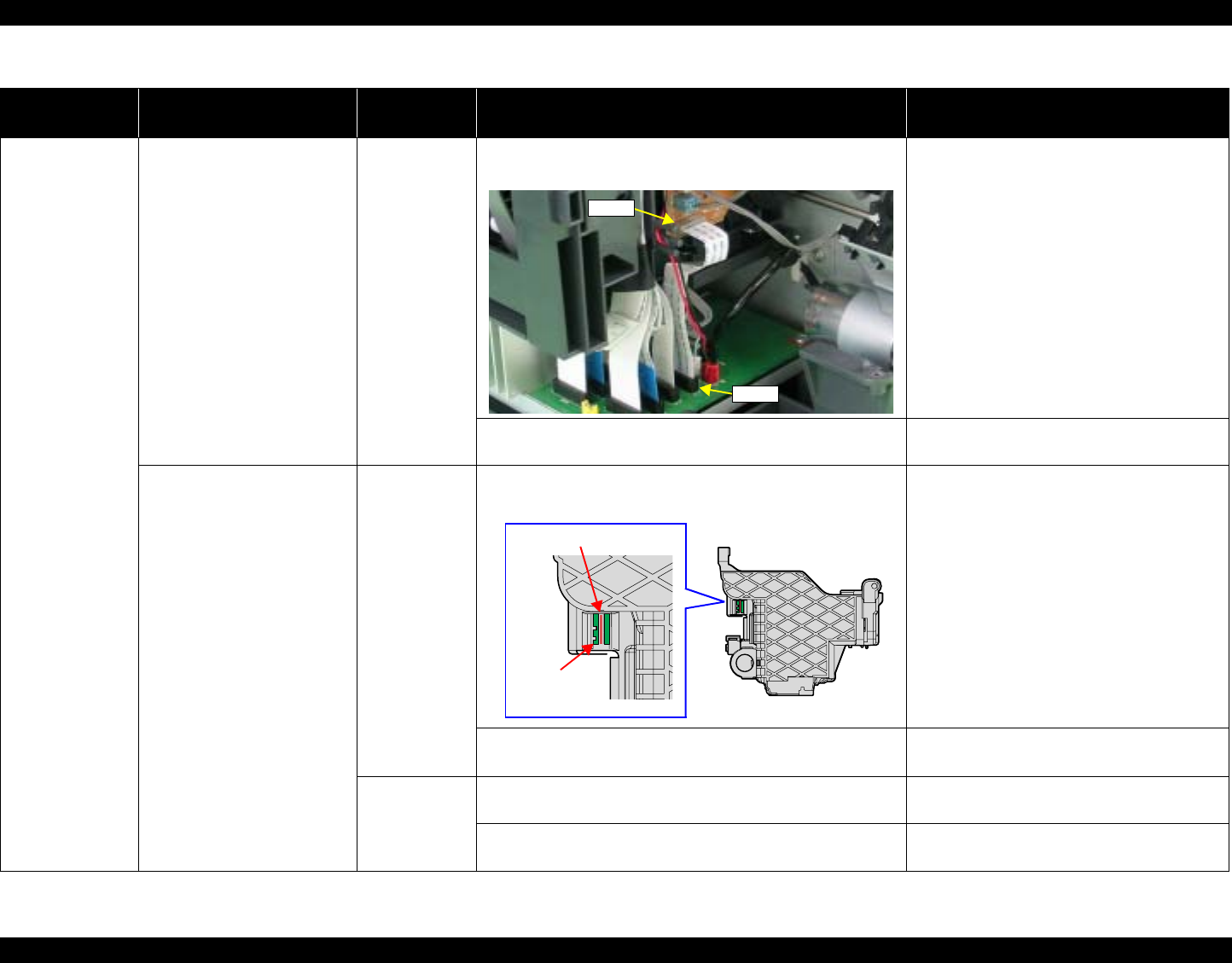
EPSON Stylus Photo R1800/R2400 Revision B
Stylus Photo R2400 Overview 223
At power-on While the power-on sequence
is being executed, Fatal error
is displayed.
Relay FFC 1. Check that the Relay FFC is connected to the Relay Board
Connector CN1 and Main Board Connector CN5. 1. Connect the Relay FFC to the Relay Board
Connector CN1 and Main Board
Connector CN5.
2. Check the Relay FFC for damages. 2. Replace the Relay FFC Cable with a new
one.
At power-on, the Carriage Unit
moves away from the home
position and bumps against
the right of the Frame, then
hits the left of the Frame.
CR Scale 1. Check that the CR Scale is inserted in the slit of the CR
Encoder Sensor. 1. Insert the CR Scale into the slit of the CR
Encoder Sensor.
2. Check the CR Scale for damages and dirt. 2. Wipe off the dirt completely or replace the
CR Scale with a new one.
CR Encoder
Sensor Board 1. Check the CR Encoder Sensor for paper dust, etc. 1. Remove the paper dust, etc. from the CR
Encoder Sensor.
2. Check the CR Encoder Sensor Board for damages. 2. Replace the CR Encoder Sensor Board
with a new one.
Table 8-16. Troubleshooting of Fatal Error
Occurrence
Timing Phenomenon Detail Faulty Part/
Part Name Check Point Remedy
CN1
CN5
CR Scale
CR Encoder
Sensor Board
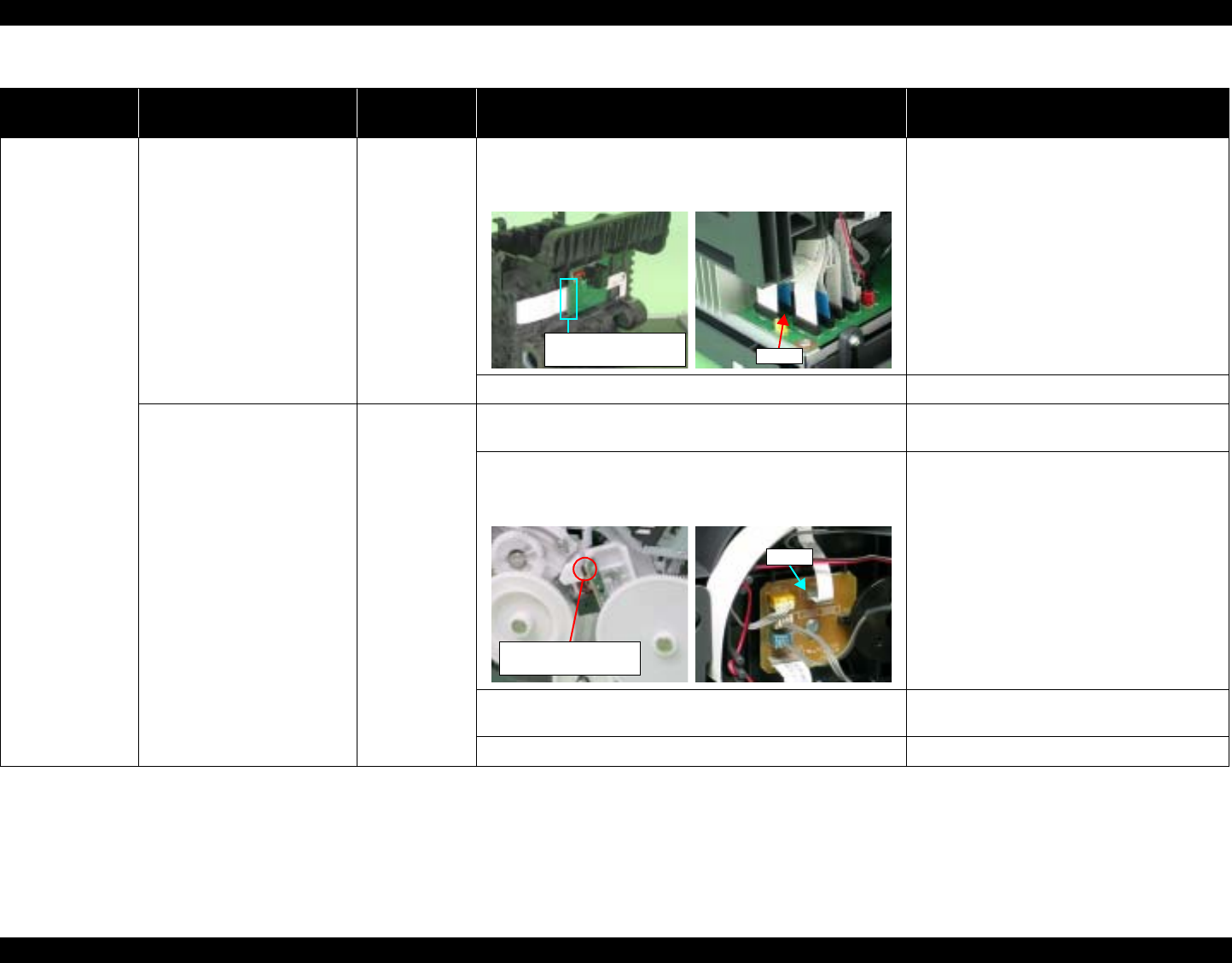
EPSON Stylus Photo R1800/R2400 Revision B
Stylus Photo R2400 Overview 224
At power-on At power-on, the Carriage Unit
moves away from the home
position and bumps against
the right of the Frame, then
hits the left of the Frame.
Sensor FFC 1. Check that the Sensor FFC is connected to the CR
Encoder Sensor Board Connector and Main Board
Connector CN9.
1. Connect the Sensor FFC to the CR
Encoder Sensor Board Connector and
Main Board Connector CN9.
2. Check the Sensor FFC for damages. 2. Replace the Sensor FFC with a new one.
At power-on, the PF Roller
rotates fast about a half turn. PF Encoder
Sensor Holder 1. Check that the PF Encoder Sensor Holder is mounted
correctly. 1. Install the PF Encoder Sensor Holder
correctly.
2. Check that the FFC of the PF Encoder Sensor is securely
connected to the PF Encoder Sensor Board Connector
and Relay Board Connector CN6.
2. Connect the PF Encoder Sensor FFC to
the PF Encoder Sensor Board and Relay
Board Connector CN6.
3. Check the PF Encoder Sensor for paper dust, etc. 3. Remove the paper dust, etc. from the PF
Encoder Sensor.
4. Check if the PF Encoder or the FFC is damaged. 4. Replace the PF Encoder with a new one.
Table 8-16. Troubleshooting of Fatal Error
Occurrence
Timing Phenomenon Detail Faulty Part/
Part Name Check Point Remedy
CN9
CR Encoder Sensor
Board Connector
CN6
PF Encoder Sensor
Board Connector

EPSON Stylus Photo R1800/R2400 Revision B
Stylus Photo R2400 Overview 225
At power-on At power-on, the PF Roller
rotates fast about a half turn. PF Scale 1. Check that the PF Scale is inserted in the slit of the PF
Encoder Sensor. 1. Install the PF Scale in the slit of the PF
Encoder Sensor correctly.
2. Check the PF Scale for damages and dirt. 2. Replace the PF Scale with a new one.
During printing After receiving a print data, or
while performing the CD-R
Tray home position detection
sequence (Board Paper
detection), an error is
displayed on the LED and
EPW3.
Head FFC
Sensor FFC 1. Check that the Head FFC and the Sensor FFC are
securely connected to the Main Board Connectors CN9
through CN14.
1. Connect the Head FFC and the Sensor
FFC to the Main Board Connectors CN9
through CN14.
Table 8-16. Troubleshooting of Fatal Error
Occurrence
Timing Phenomenon Detail Faulty Part/
Part Name Check Point Remedy
Slit
PF Scale
CN9 through CN14

EPSON Stylus Photo R1800/R2400 Revision B
Stylus Photo R2400 Overview 226
During printing After starting to print, ink is not
ejected and paper stops
midway.
Head FFC 1. Check that the Head FFC is securely connected to the
Print Head Connector and Main Board Connectors CN10,
CN12, CN13, and CN14.
1. Connect the Head FFC to the Print Head
Connector and Main Board Connectors
CN10, CN12, CN13, and CN14.
2. Check the Head FFC for damages. 2. Replace the Head FFC with a new one.
Ink is not ejected from most
nozzles. Print Head 1. Check for occurrence of Head Hot. 1. Replace the Print Head with a new one.
Table 8-16. Troubleshooting of Fatal Error
Occurrence
Timing Phenomenon Detail Faulty Part/
Part Name Check Point Remedy
Print Head
Connector
Head FFC

EPSON Stylus Photo R1800/R2400 Revision B
Stylus Photo R2400 Exploded Diagram 227
8.5 Exploded Diagram
Following pages show exploded diagram.
Exploded Diagram 1
Exploded Diagram 2
Exploded Diagram 3
Exploded Diagram 4
Exploded Diagram 5
Exploded Diagram 6
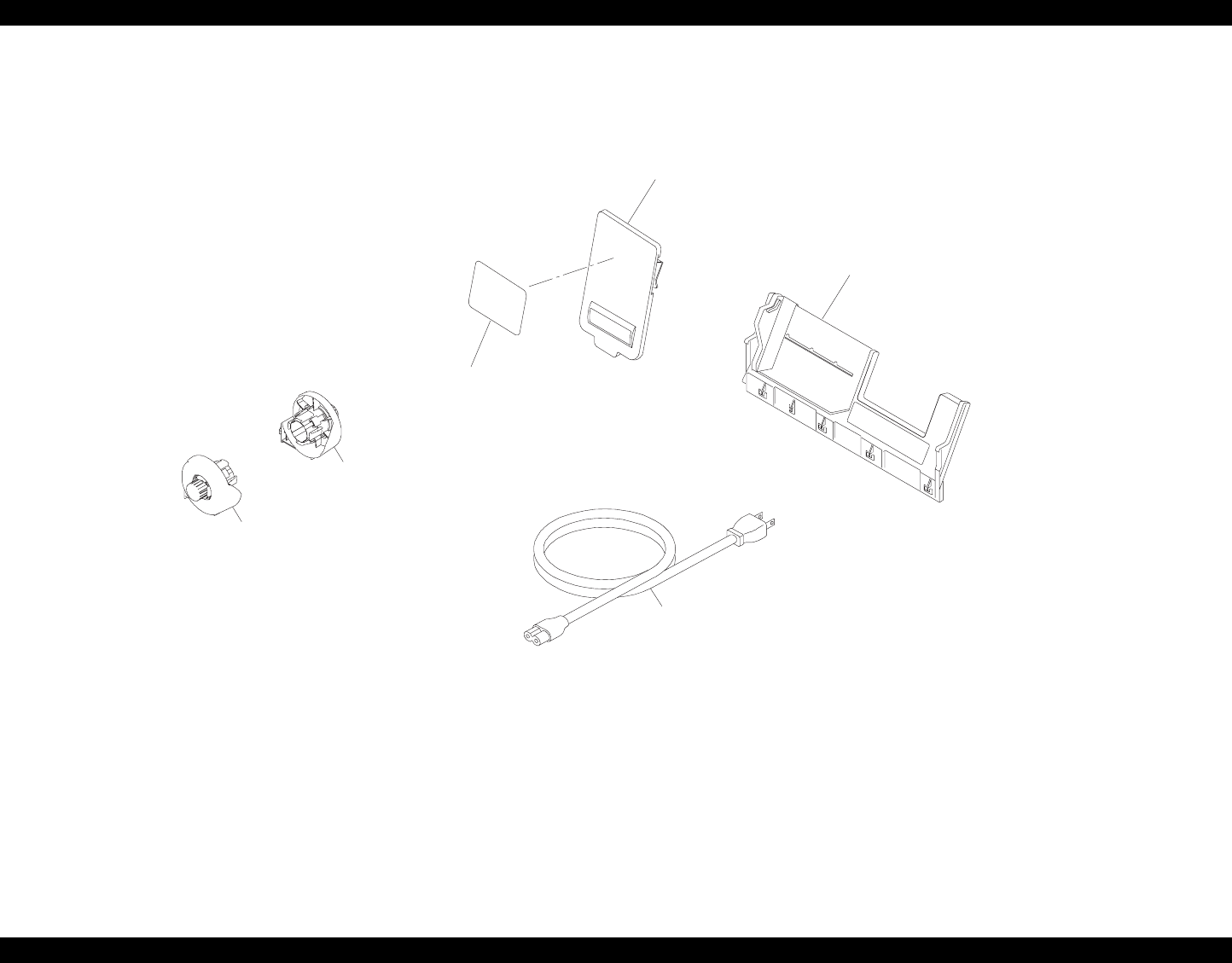
EPSON Stylus Photo R1800/R2400 Revision B
Stylus Photo R2400 Exploded Diagram 228
Figure 8-3. Stylus Photo R2400 Exploded Diagram 1
18
17
16
400
Rev.01 C603-ACCE-00
1
PX-5500 / EPSON STYLUS PHOTO R2400 No.1
10
11
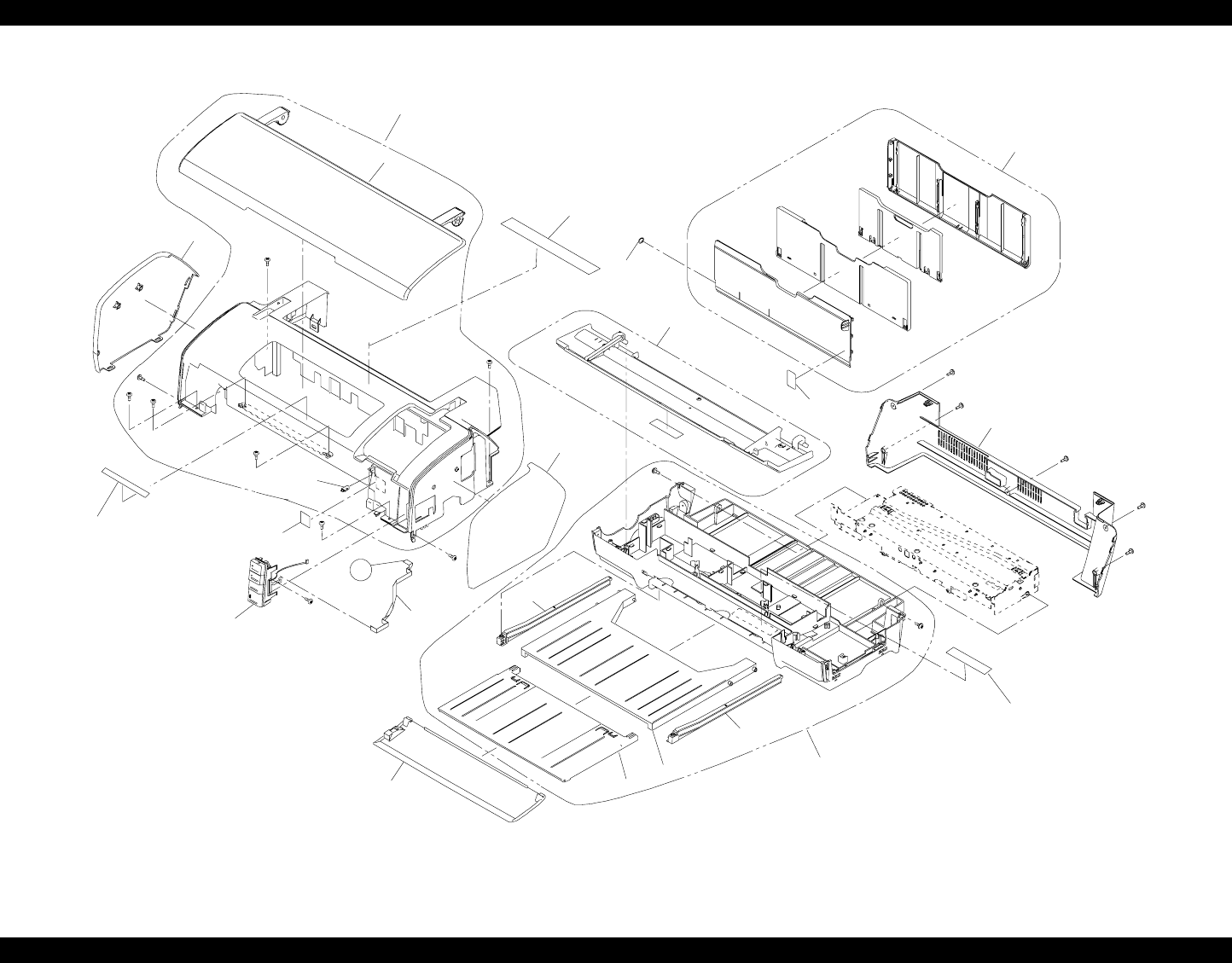
EPSON Stylus Photo R1800/R2400 Revision B
Stylus Photo R2400 Exploded Diagram 229
Figure 8-4. Stylus Photo R2400 Exploded Diagram 1
Rev.01 C603-CASE-001
PX-5500 / EPSON STYLUS PHOTO R2400 No.2
100
For JPN
1
18
123
102
120
119
118
117
104
106
121
122
105
For JPN
115
108
A
101
107
116
114
103
109
113
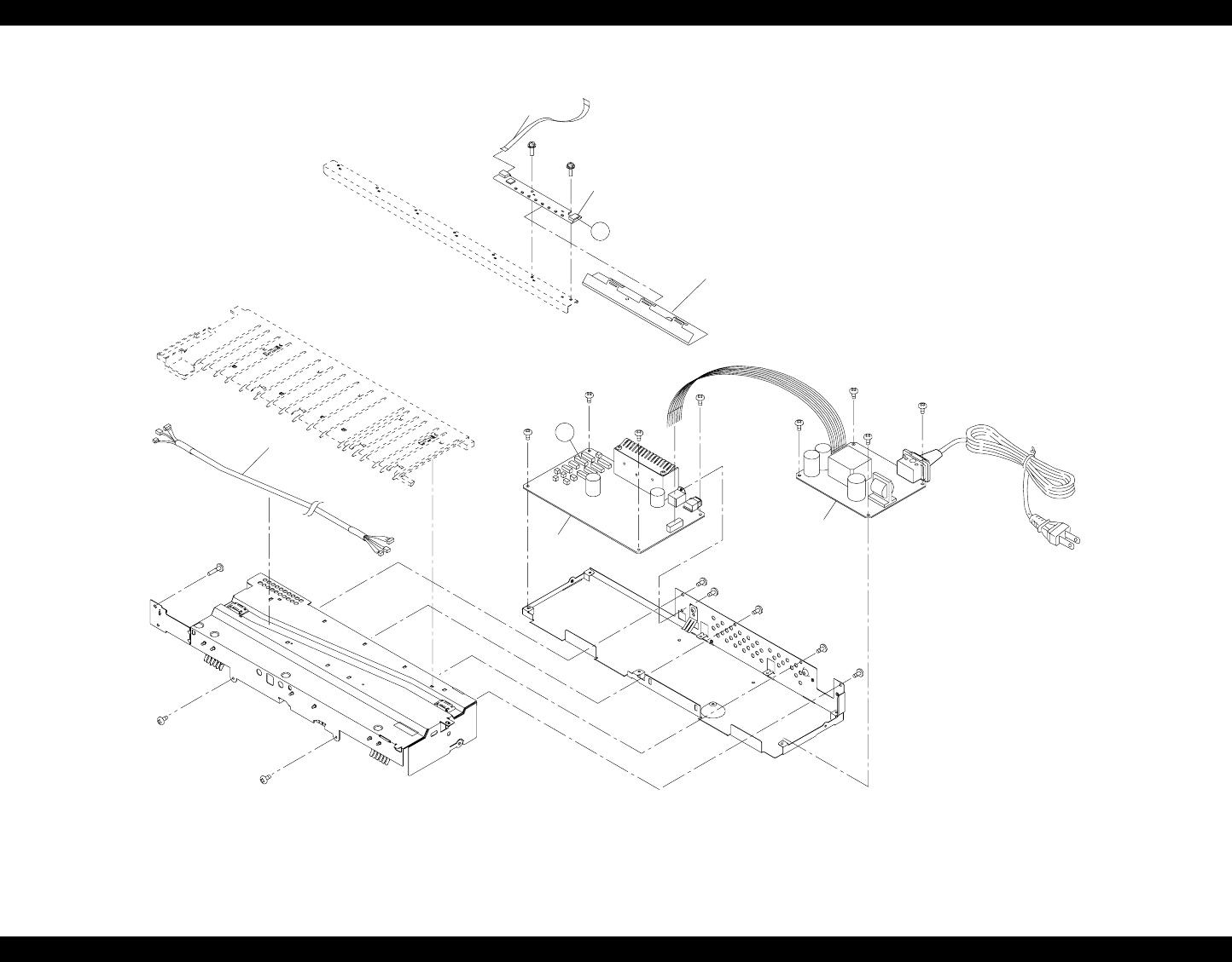
EPSON Stylus Photo R1800/R2400 Revision B
Stylus Photo R2400 Exploded Diagram 230
Figure 8-5. Stylus Photo R2400 Exploded Diagram 1
Rev.01 C603-ELEC-001
PX-5500 / EPSON STYLUS PHOTO R2400 No.3
553
117
350
360
A
B
200
300
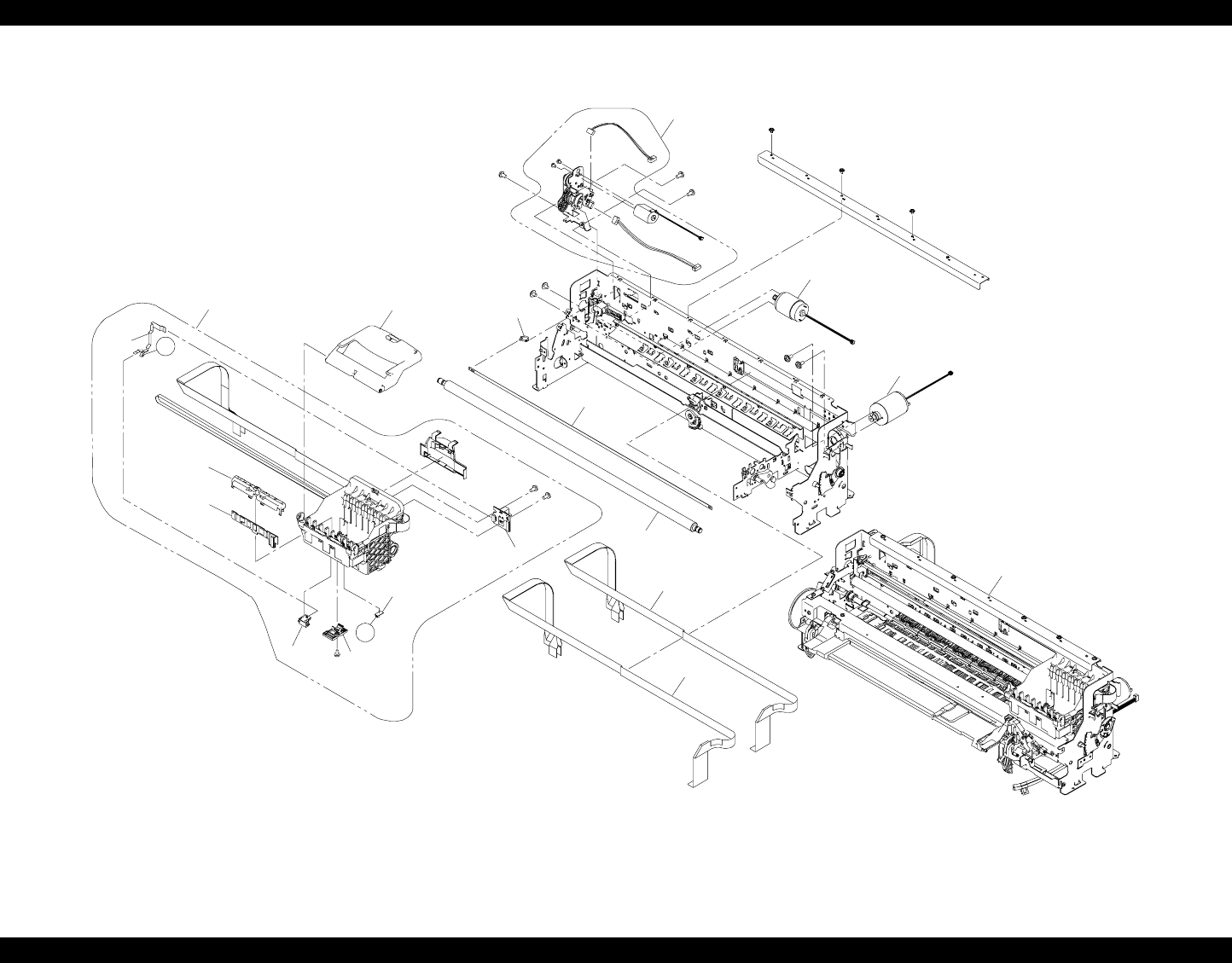
EPSON Stylus Photo R1800/R2400 Revision B
Stylus Photo R2400 Exploded Diagram 231
Figure 8-6. Stylus Photo R2400 Exploded Diagram 1
Rev.01 C603-MECH-001
PX-5500 / EPSON STYLUS PHOTO R2400 No.4
554
C
549
519
C
Without REF.554500
524
516
513
514
515
512
511
505
501
504
503
506
502
509
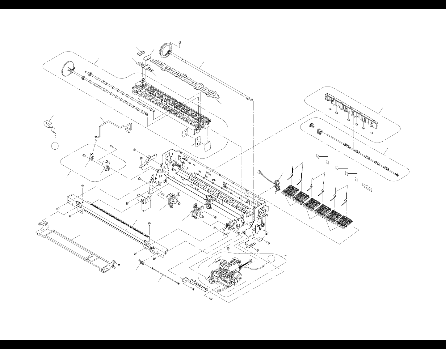
EPSON Stylus Photo R1800/R2400 Revision B
Stylus Photo R2400 Exploded Diagram 232
Figure 8-7. Stylus Photo R2400 Exploded Diagram 1
Rev.01 C603-MECH-002
PX-5500 / EPSON STYLUS PHOTO R2400 No.5
522
552
552
552 552 552
542
G
B
538
540
539
536 537
534
535
528
522
532
529
521
545
520
525
508
507
550
526
551
523
523
523
518
517
533
541
547
522
EPSON Stylus Photo R1800/R2400 Revision B
Stylus Photo R2400 Parts List for EPSON Stylus Photo R2400 233
8.6 Parts List for EPSON Stylus Photo R2400
Table 8-17. Parts List for EPSON Stylus Photo R2400
Code Parts Name
10 ROLL PAPER ASSY.,LEFT;B,ASP
11 ROLL PAPER ASSY.,RIGHT;B,ASP
16 MATTE PAPER SUPPORT ASSY.,ASP
17 PAPER SUPPORT USFAP ASSY.,ASP
18 LABEL,HOLDER MAT PAPER;B
100 HOUSING UPPER ASSY.,ASP
101 PANEL ASSY.,ASP
102 COVER,LEFT;EGM
103 HOUSING LOWER ASSY.,ASP
104 HOUSING CD-R ASSY.;B,ASP
105 STACKER
106 COVER STACKER ASSY.,ASP
107 COVER,RIGHT;EGM
108 PAPER SUPPORT ASSY.;B,ASP
109 HOUSING,REAR
113 LABEL,INSTRUCTION;B
116 MIN SIDE LOCK#091Y
118 STACKER,SUPPORT
120 LABEL,CAUTION ROLL PAPER
121 GIDE,STACKER,LEFT
122 GIDE,STACKER,RIGHT
123 COVER PRINTER ASSY.,ASP
721 LABEL,INK,POSITION;B
114 HARNESS
117 SHEET,LED
200 BOARD ASSY.,MAIN
350 BOARD ASSY.,PANEL
360 HARNESS
500 PRINTER MECHANISM ASP;ESL
501 CARRIAGE ASSY.;B,ASP
502 BOARD ASSY.,CSIC
503 HOLDER,DETECTOR,PW
504 BOARD ASSY.,INK MARK
505 BOARD ASSY.,ENCORDER,CR
506 BOARD ASSY.,DETECTOR,PW
507 HOLDER,BOARD ASSY.,ENCORDER,PF
508 BOARD ASSY.,ENCORDER,PF
509 COVER IC ASSY.,ASP
511 SHAFT,CR,GUIDE
512 SCALE,CR
513 TORSION SPRING,24.7
514 MOTOR ASSY.,CR
515 CABLE,HEAD,B
516 CABLE,HEAD
517 DETECTOR,LEAF,B2
518 HARNESS,DETECTOR,CD-R
519 AUTO PG ASSY.,ASP
520 TRAY PASTE BOARD BASE ASSY.,ASP
521 INK SYSTEM ASSY.;B,ASP
523 TORSION SPRING,PAPER GUIDE,UPPER
524 MOTOR ASSY.,PF
525 FRAME PAPER EJ ASSY ASP;ESL
526 ROLLER,PF ASSY.,ASP
528 PAPER GUIDE FRONT LOWER ASSY.,ASP;ESL
529 HOLDER RELEASE SUB ASSY.,ASP
532 PAPER DETECTOR ASSY.,ASP
533 PF ENCORDER ASSY ASP
534 RELEASE CD-R,LEFT ASSY.,ASP
535 RELEASE CD-R,RIGHT ASSY ASP; ESL
536 POROUS PAD,PAPER GUIDE,FRONT,LEFT,ASP
537 POROUS PAD,PAPER GUIDE,FRONT,CENTER,ASP
538 POROUS PAD,PAPER GUIDE,FRONT,ASP
Table 8-17. Parts List for EPSON Stylus Photo R2400
Code Parts Name
EPSON Stylus Photo R1800/R2400 Revision B
Stylus Photo R2400 Parts List for EPSON Stylus Photo R2400 234
539 POROUS PAD,GUIDE,INK EJECT LEFT
540 POROUS PAD,GUIDE,INK EJECT,CENTER
541 HARNESS,ENCORDER,PF
542 HARNESS,BOARD ASSY.,RELAY
545 CLEANER,HEAD;C,ASP
547 POROUS PAD,GUIDE,INK EJECT
549 CABLE,DETECTOR,8
550 FRAG RELEASE ASSY.,ASP
551 COVER,ROLLER,LD
552 COVER,ROLLER,LD
553 HARNESS,MOTOR
554 GUIDE,IC,OVER SEA
700 PRINT HEAD
701 ASF ASSY.,ASP
702 MOTOR,ASSY.,ASF
703 PAPER GUIDE,MANUAL
705 POROUS PAD,INK EJECT;LEFT;FA2
706 POROUS PAD,INK EJECT;LEFT;FB2
707 POROUS PAD,INK EJECT;LEFT;FC2
708 POROUS PAD,INK EJECT;LEFT;FD2
709 POROUS PAD,INK EJECT;LEFT;FE2
710 POROUS PAD,TUBE;FA2
711 POROUS PAD,TUBE;FB2
712 POROUS PAD,INK EJECT;RIGHT;FF2
713 POROUS PAD,INK EJECT;RIGHT;FG2
714 POROUS PAD,INK EJECT;RIGHT;FH2
715 POROUS PAD,INK EJECT;RIGHT;FI2
716 POROUS PAD,INK EJECT,IS,LEFT;B
717 POROUS PAD,INK EJECT,IS,LOWER,LEFT;B
718 POROUS PAD,INK EJECT,IS,LOWER;FB2
719 POROUS PAD,INK EJECT;H
720 POROUS PAD,CABLE,HEAD
Table 8-17. Parts List for EPSON Stylus Photo R2400
Code Parts Name
722 LABEL,GUIDE,ROLL PAPER INSERT
723 LABEL,GUIDE,ROLL PAPER
724 CLAMP,TUBE
300 BOARD ASSY.,POWER SUPPLY
Table 8-17. Parts List for EPSON Stylus Photo R2400
Code Parts Name
