SNM1501RAW Sunbeam Microwave Service Manual 20060808
User Manual: SNM1501RAW
Open the PDF directly: View PDF ![]() .
.
Page Count: 43
Service Manual
Microwaves
20060808
2-b
BEFORE SERVICING
Before servicing an operative unit, perform a microwave emission check as per the Microwave
Measurement Procedure outlined in this service manual.
If microwave emissions level is in excess of the specified limit, contact us immediately at 1-866-866-6283.
If the unit operates with the door open, service person should:
1) tell the user not to operate the oven and
2) contact us and Food and Drug Administration's Center for Devices and Radiological Health immediately.
Service personnel should inform us of any certified unit found with emissions in excess of 4mW/cm2.
The owner of the unit should be instructed not to use the unit until the oven has been brought into compliance.
WARNING TO SERVICE PERSONNEL
Range units contain circuitry capable of producing very high voltage and current, contact
with following parts may result in a severe, possibly fatal, electrical shock.
(Example)
High Voltage Capacitor, High Voltage Power Transformer, Magnetron, High Voltage
Rectifier Assembly, High Voltage Harness, Heating Elements, etc..
Read the Service Manual carefully and follow all instructions.
PRECAUTIONS FOR USING LEAD-FREE SOLDER
1. Employing lead-free solder
The "Main PWB" of this model employs lead-free solder. This is indicated by the "LF" symbol printed on the PWB
and in the service manual. The suffix letter indicates the alloy type of the solder.
Example:
Indicates lead-free solder of tin, silver and copper.
2. Using lead-free wire solder
When repairing a PWB with the "LF" symbol, only lead-free solder should be used. (Using normal tin/lead alloy
solder may result in cold soldered joints and damage to printed patterns.)
As the melting point of lead-free solder is approximately 40oC higher than tin/lead alloy solder, it is recommend that a
dedicated bit is used, and that the iron temperature is adjusted accordingly.
3. Soldering
As the melting point of lead-free solder (Sn-Ag-Cu) is higher and has poorer wettability, (flow), to prevent damage to
the land of the PWB, extreme care should be taken not to leave the bit in contact with the PWB for an extended
period of time. Remove the bit as soon as a good flow is achieved. The high content of tin in lead free solder will
cause premature corrosion of the bit. To reduce wear on the bit, reduce the temperature or turn off the iron when it is
not required.
Leaving different types of solder on the bit will cause contamination of the different alloys, which will alter their
characteristics, making good soldering more difficult. It will be necessary to clean and replace bits more often when
using lead-free solder. To reduce bit wear, care should be taken to clean the bit thoroughly after each use.
1
MICROWAVE OVEN/HOOD SYSTEM
Model: SNM1501RAW
SNM1501RAQ
SNM1501RAB
SNM1502RAS
INSTALLATION INSTRUCTIONS
Please read all instructions thoroughly before installing the Microwave Oven/Hood System. Two people are
recommended to install this product.
If a new electrical outlet is required, its installation should be finished by a qualified electrician before the
Microwave Oven/Hood is installed. See 3 ELECTRICAL GROUNDING INSTRUCTIONS on page 2.
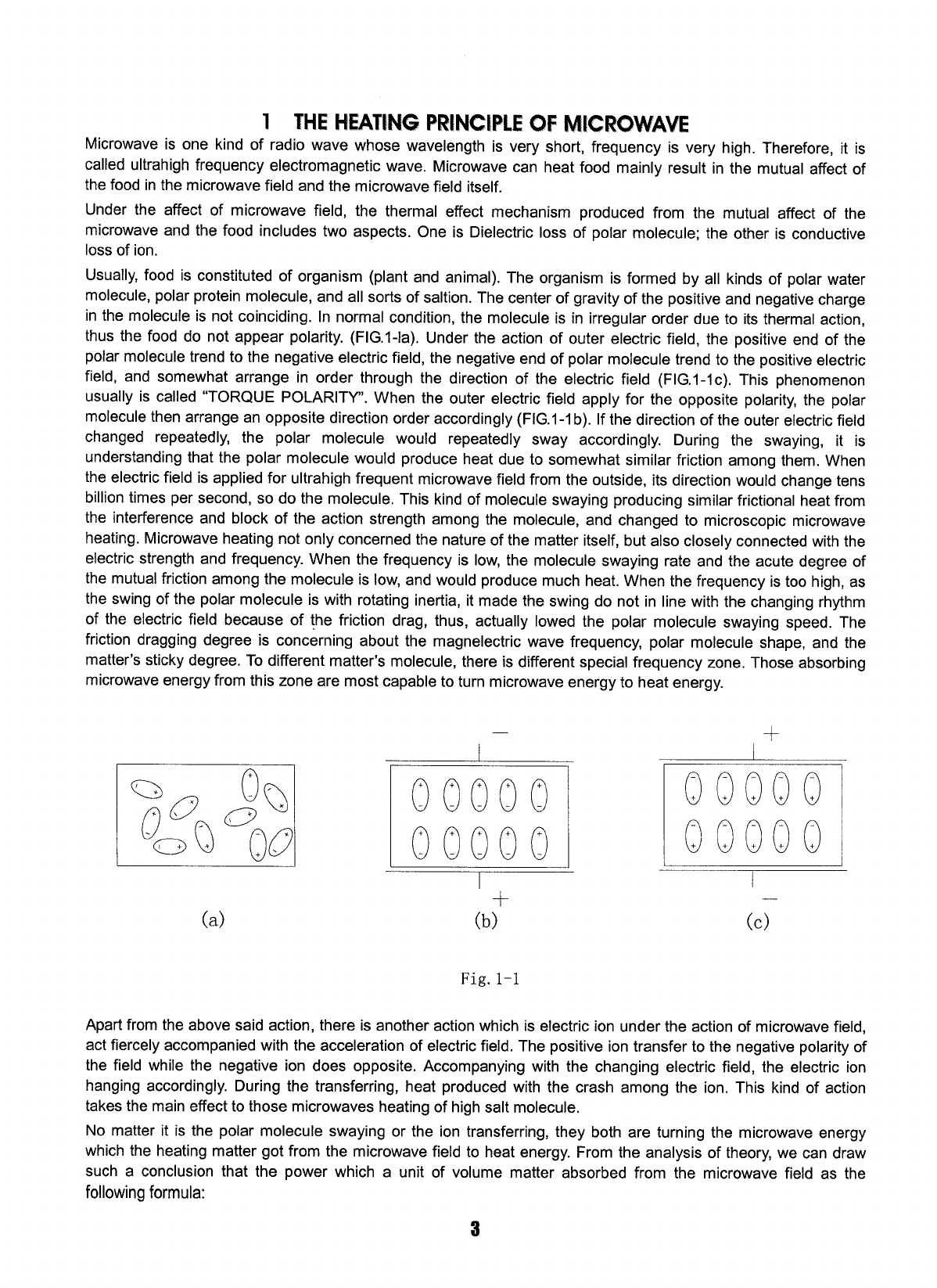
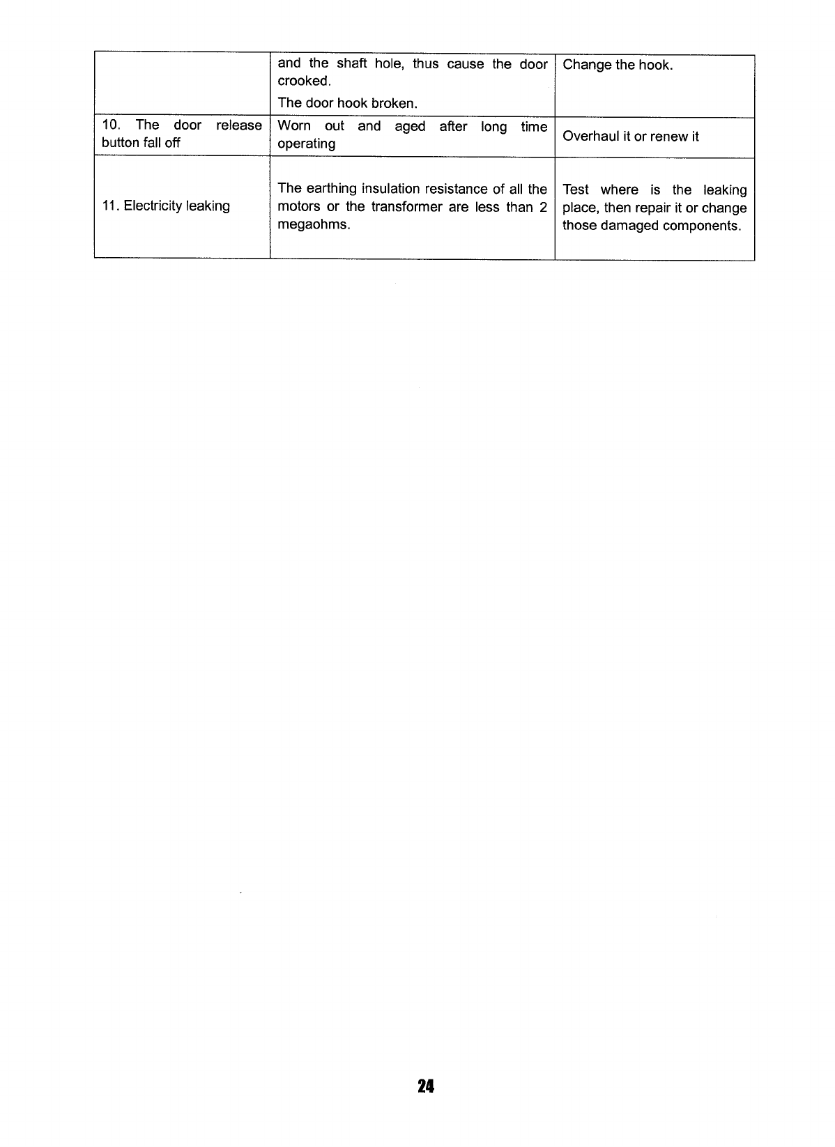
1. MOUNTING SPACE
This Microwave Oven/Hood requires a
mounting space on a wall as shown in Figure 1.
It is designed to be used with standard 12- inch
wall cabinets.
If the space between the wall cabinets is 36 or
42 inches, a Filler Panel Kit can be used to fill
the gap. The metal filler panels come in pairs,
each either 3 or 6 inches wide. The Filler Panel
Kit should be installed before the Microwave
Oven/Hood is installed.
距地面至
少180cm
图 1
距炉灶至
少90cm
76cm 39cm
30cm
至少 40cm
At least
90cm
At least
40cm
At least
180cm
from
ground
Fig. 1
2
2. WALL CONSTRUCTION
This Microwave Oven/Hood should be mounted against and supported by a flat vertical wall. The wall
must be flat for proper installation. If the wall is not flat, use spacers to fill in the gaps. Wall construction
should be a minimum of 2” × 4” wood studding and 3/8” or thicker dry wall or plaster/lath. The
mounting surfaces must be capable of supporting weight of 110 pounds---the oven and contents---and
the weight of all items which would normally be stored in the top cabinet above the unit.
The unit should be attached to a minimum of one 2” × 4” wall stud.
To find the location of the studs, one of the following methods may be used:
A. Use a stud finder, a magnetic device which locates the nails in the stud.
B. Use a hammer to tap lightly across the mounting surface to find a solid sound. This will indicate stud
location.
The center of the stud can be located by probing the wall with a small nail to find the edge of the stud
and then placing a mark halfway between the edges. The center of any adjacent studs will normally be
16 or 24 inches to either side of this mark.
3. ELECTRICAL GROUNDING INSTRUCTIONS
This appliance must be grounded. This oven is equipped with a cord having a grounding wire with a
grounding plug. It must be plugged into a wall receptacle that is properly installed and grounded. In the
event of an electrical short circuit, grounding reduces risk of electric shock by providing an escape wire
for the electric current.
WARNING – Improper use of the grounding plug can result in a risk of electric shock.
The oven is equipped with a 3-prong grounding plug. DO NOT UNDER ANY CIRCUMSTANCES CUT
OR REMOVE THE GROUNDING PIN FROM THE PLUG.
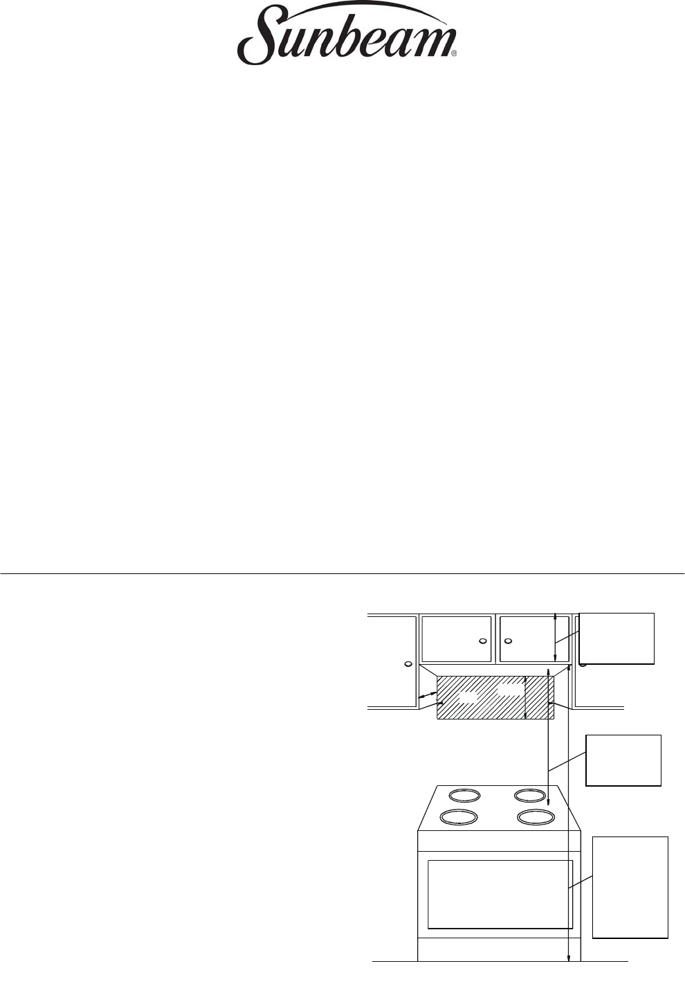
The power supply cord and plug must be connected to a
separate 230Volt AC, 50Hz, 15 Amp, or more branch
circuit, single grounded receptacle. The receptacle should
be located inside the cabinet directly above the
Microwave Oven/Hood mounting location.
NOTE:
1. If you have any questions about the grounding or
electrical instructions, consult a qualified electrician or
service personnel.
2. Neither the manufacturer nor the dealer can accept
any liability for damage to the oven or personal injury
resulting from failure to observe the correct electrical
connection procedures.
插头
源孔电线开
图2
Fig. 2
Cord hole
plug
3
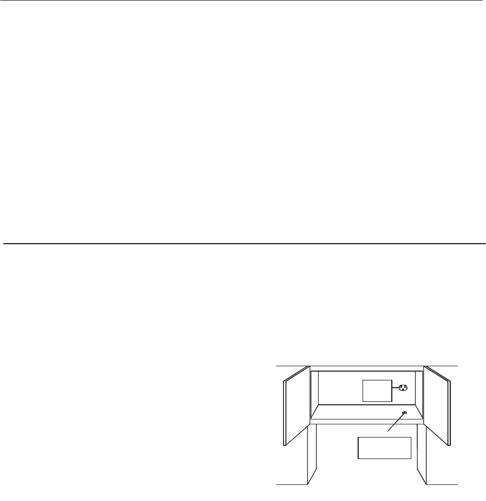
4. HOOD EXHAUST DUCT
When the hood is vented to the outside, a hood exhaust duct is required. All ductwork must be a metal;
absolutely do not use plastic duct. Check that all connections are made securely. Please read the
following carefully:
Exhaust connection - The hood exhaust has been designed to connect to a standard 3-1/4”×10”
rectangular duct. If round duct is required, a rectangular-to-round adapter must be used.
Rear exhaust: If a rear or horizontal exhaust is to be used, care should be taken to align the exhaust
with the space between the studs, or wall should be prepared at the time it is constructed by leaving
enough space between wall studs to accommodate exhaust.
Maximum duct length: for satisfactory air movement, the total duct length of 3-1/4”×10” rectangular or
6” diameter round duct should not exceed 140 feet.
Elbows, adapters, wall, roof caps, etc. present
additional resistance to air flow and are equivalent to
a section of straight duct which is longer than their
actual physical size. When calculating the total length,
add the equivalent lengths of all transitions and
adapters plus the length of all straight duct sections.
Figure 4 shows the approximate feet of equivalent
length of some typical ductwork parts. Use the values
in parentheses for calculating air flow resistance
equivalent, which should total less than 140 feet.
5. TOOLS RECOMMENDED FOR INSTALLATION
·Phillips screwdriver ·Electric drill ·1/2”, 5/8” and 3/32” Drill bits
·1-1/2” Wood bit or metal hole cutter (if metal cabinet is used) ·Saw to cut exhaust opening (if needed)
·Protective drop cloth for product and range – you may also use carton for protection
·Scissors ·Pencil ·Tape Measure ·Tape
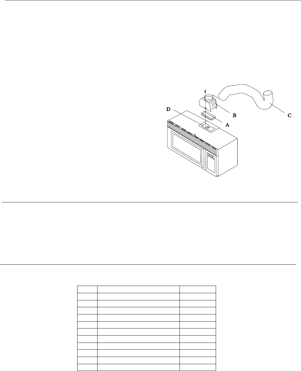
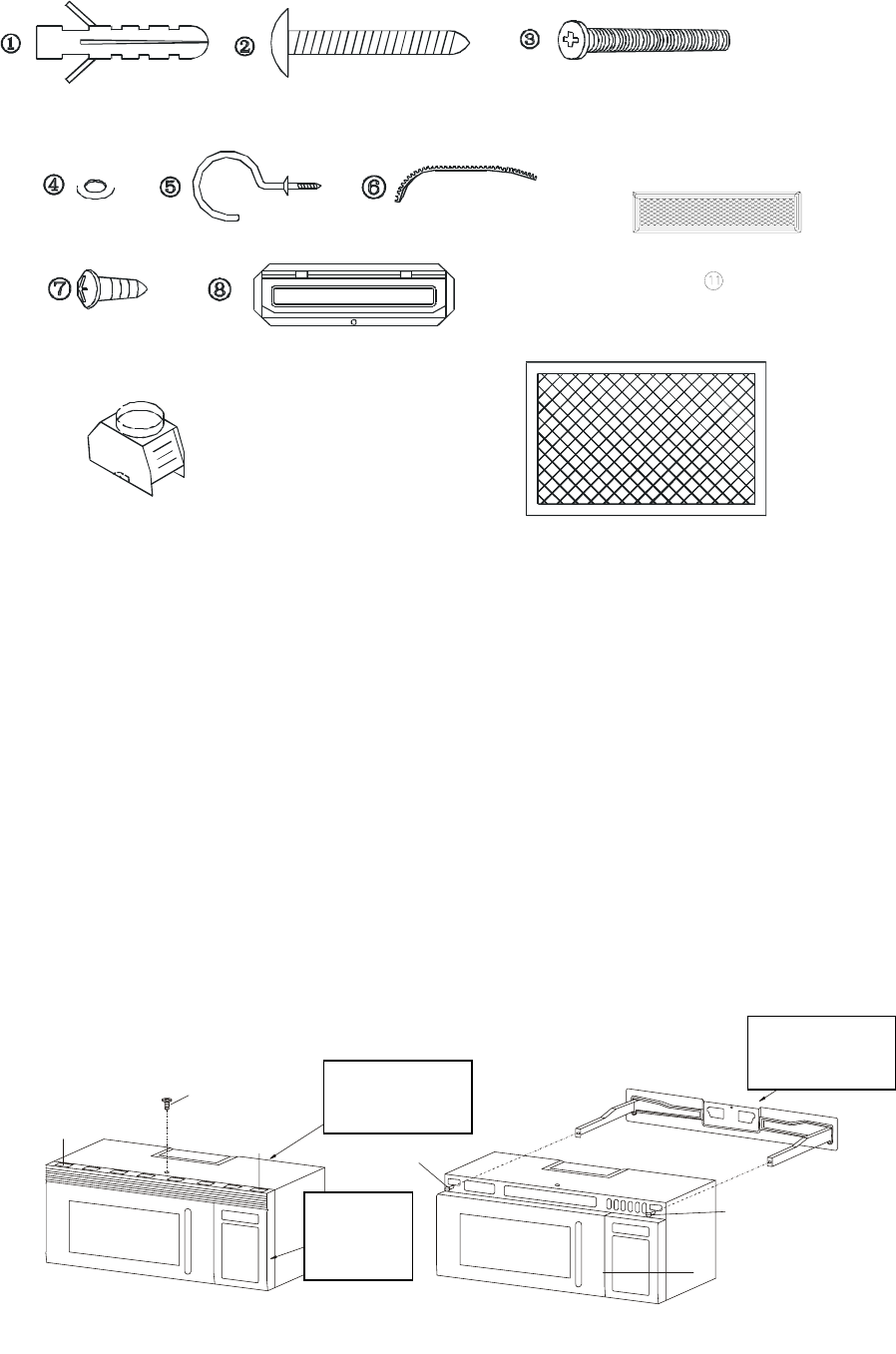
6. INSTALLATION HARDWARE
The INSTALLATION HARDWARE items are in a small carton packed below the oven.
ITEM NAME QUANTITY
1 Inflating stopper 8
2 Tapping screws 4×25mm 8
3 Top Cabinet Screw 5×60 mm 2
4 Flat Washer 30 mm diameter 2
5 Power Cord Hanger 1
6 Grommet 1
7 Tapping Screw 4×12 mm 1
8 Exhaust Damper Assembly 1
9 Metal Exhaust Hood 1
10 Filter assembly 2
11 Air filter 1
Fig. 3
4
图
7 PREPARATION OF THE OVEN
Open the bottom of the carton, remove oven, all packing materials, Installation Instructions, Wall
Template, Top Template and Charcoal Filter; however, DO NOT REMOVE THE WAVEGUIDE COVER,
which is located on the ceiling in the oven cavity.
CHECK THE OVEN.
Check the oven for any damage, such as misaligned or bent door, damaged door seals and
sealing surfaces, bent or loose door hinges and latches and dents inside the cavity or on the door.
If there is any damage, do not operate the oven and contact your dealer.
Remove and save Screw (A) as shown in Figure 5.
Push down carefully on the tabs (B) and (C) at the ends of the Louver to disengage it. Pull the Louver
away from the unit and set aside.
Loosen the two Mounting Screws (D) which lock the Mounting Plate to the rear side of the oven.
Remove the Mounting Plate. See Figure 6.
控制面板
(B) (C)
(A)
图5
边
图6
(D)
(D)
后安装板
后安装板
Back installation
plate
Back installation
plate
Control
board edge
Fig. 5 Fig. 6
Fig. 4
5
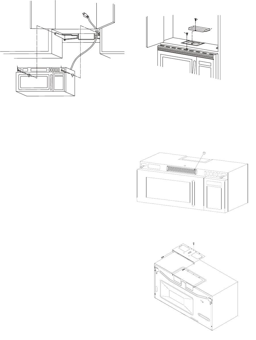
8 VENTILATION SYSTEM
This Microwave Oven/Hood is designed for adaptation to three types of hood ventilation systems.
Select the type required for your installation.
A. Recirculating ─ non-vented, ductless. Follow
installation procedure A. Recirculating requires
the use of the Charcoal Filter 11, which is packed
under the oven in the carton.
B. Horizontal Exhaust ─ outside ventilation. Follow
installation procedure B.
C. Vertical Exhaust ─ outside ventilation. Follow
installation procedure C.
(A) RECIRCULATING: Non-vented, Ductless
Operation
The unit is shipped assembled for recirculating. Attach
the Charcoal Filter to the upper side of the oven
by sliding into the tabs. See Figure 9.
NOTE:
1. The Exhaust Damper Assembly 11 is not required for
recirculating operation.
2. The Charcoal Filter should be replaced every 6 to 12
months, depending on use.
3. The Charcoal Filter is also sold as an accessory.
(B) HORIZONTAL EXHAUST: Outside Ventilation
1. Remove and save 2 screws from back edge and 1 screw from the top center of Fan Cover Bracket.
Remove Fan Cover Bracket by sliding it in the opposite direction of the arrow on the Fan Cover
Bracket, as shown in Figure 10.
Fig. 7
(
A
)
图8
⑦
⑧
(D)
Fig. 8
fig.7
fig.8
Fig. 9
Fig. 10
6
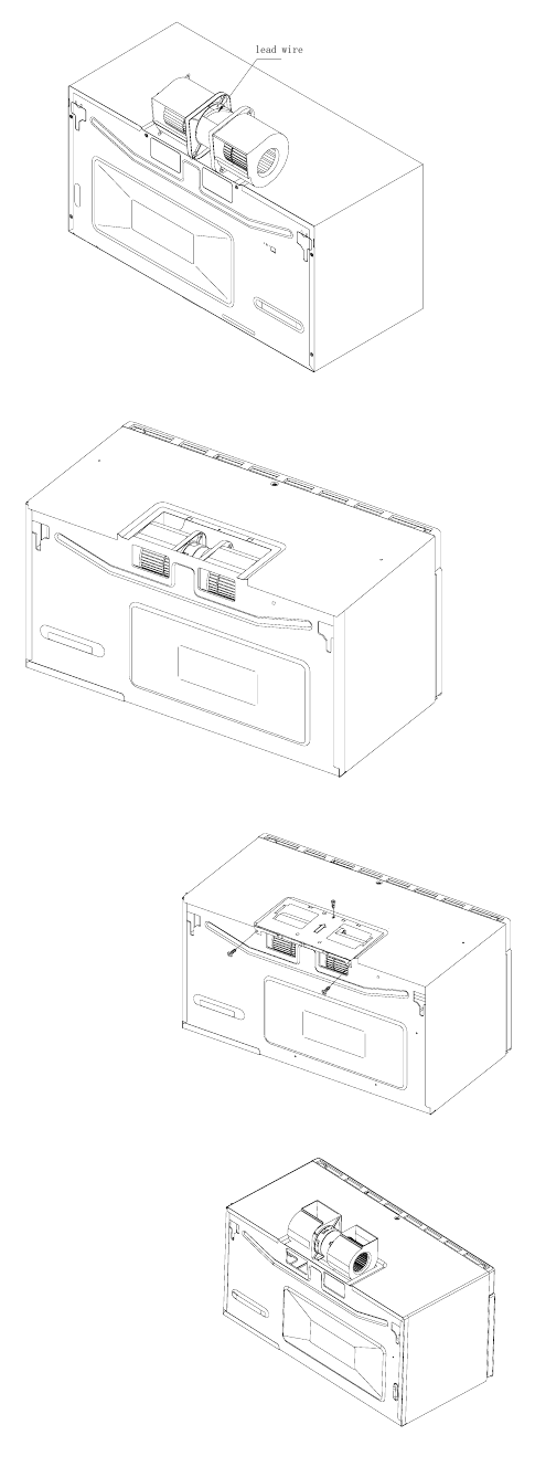
2. Withdraw Hood Fan Unit carefully along with the
lead wire out of the outer case.
3. Rotate the Hood Fan Unit and turn end-over-end
so that the fan blade openings are facing the
back of the oven. Replace Hood Fan Unit into
the oven. Be carefully not to pinch the lead wire
between the inner bracket and the Hood Fan
Unit. See Figure 11.
4. Put the lead wire into the outer case.
5. Replace the Fan Cover Bracket by sliding it into
the slits in the same direction as the arrow on
the Fan Cover Bracket. Make sure the fan
blades are visible through the rear openings
in the oven before proceeding. See Figure
12. Attach Fan Cover Bracket to unit with 3
screws, which were removed in Step 1
above. See Figure 13. The Hood Fan Unit
is now rotated for horizontal exhaust
operation.
6. Attach the Exhaust Damper Assembly to
the back of the Mounting Plate by sliding it
into the slits in the same direction as the
arrow. See Figure 12. Using Tapping screw
4×12 from the INSTALLATION
HARDWARE, tighten into place.
(C) VERTICAL EXHAUST: Outside Ventilation
1. Remove and save 2 screws from back edge and 1 screw
from the top center of the Fan Cover Bracket. Remove Fan
Cover Bracket by sliding it in the opposite direction of the
arrow on the Fan Cover Bracket as shown in Figure 10 on
page 5.
2. Withdraw Hood Fan Unit carefully and slip wires out of Wire
Box. CAUTION: Do not pull or stretch hood fan wiring.
3. Turn the Hood Fan Unit end-over-end. Rotate the Hood
Fan Unit 90 degrees so that the fan blade openings are
facing upward. Figure 12
4. Replace the Fan Cover Bracket by sliding it into the slits in the
same direction as the arrow on the Fan Cover Bracket. Make
sure the fan blades are visible through the top openings in the
oven before proceeding. Attach the Fan Cover Bracket to unit
with 3 screws, which were removed in Step 1 above. See Figure
13. The Hood Fan Unit is now rotated for vertical exhaust
operation.
5. Attach the Exhaust Damper Assembly to the fan cover on the
top of the outer case cabinet after mounting the oven.
fig.9
fig.10
fig.11
fig.12
Fig. 11
Fig. 12
Fig. 13
Fig. 14
7
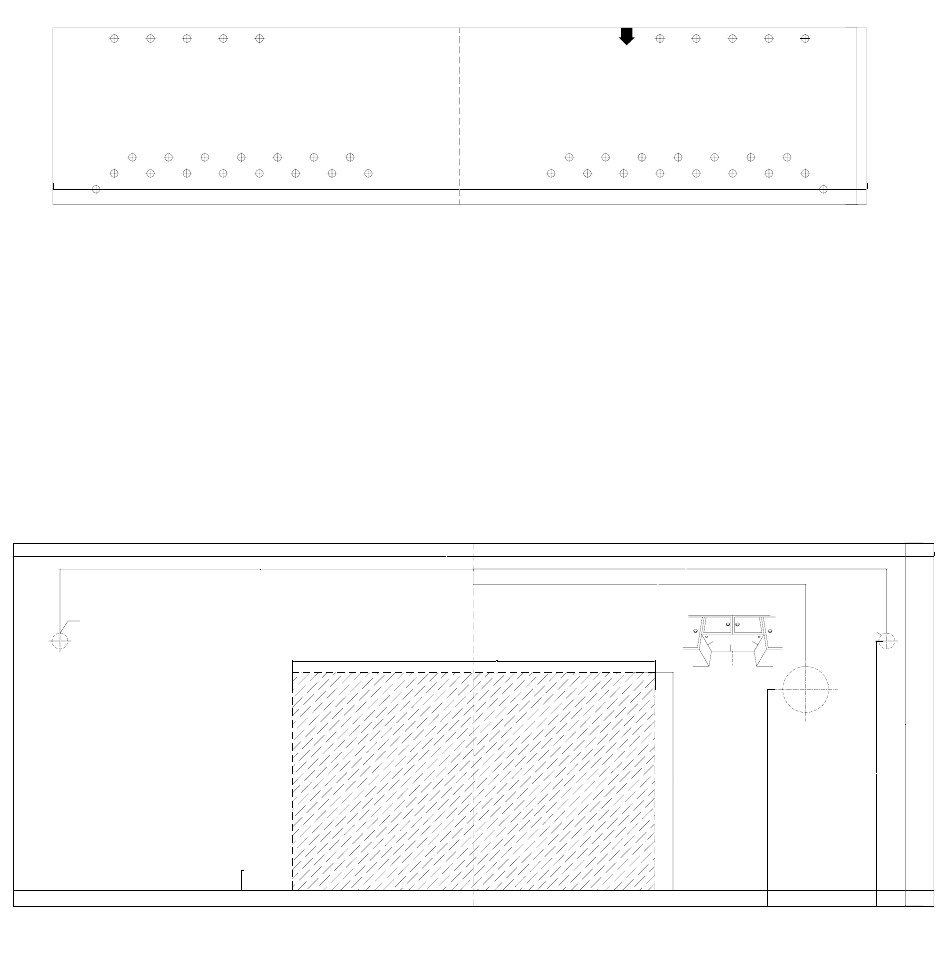
8 MOUNTING OVEN TO WALL
1. Tape Wall Template on the wall. The top should be as close to
the base of the cabinet as possible and should be kept in the
middle. The top should be 1.8m from ground, 0.9m from
cooking area.
Note: if the front is lower than the back edge, make the top
edge parallel with front edge of the cabinet.
2. Bore holes at A, B, C, D diameter 8mm (if not convenient,
select different locations according to the mounting template).
1. Tape the Top Template to the underside of the cabinet as indicated in figure1
2. In D and E of the attached figure, bore a hole 13mm
3. In F of the attached figure 2, bore a hole 38mm
4. Bore a hole along the broken line of the shading part of figure 2
5. Install the oven according to the steps in Figures 7 & 8 on Page 5.
at t ached
figure 1
(fasten on the vertical
face of the cabi net)
762.0000
C
D
1. past e on t he c abi net wal l , t he t op s houl d be as appr oac hi ng
t he bas e of t he cabi net as poss i bl e and t o be kept i n t he middle
t he t op shoul d be 1. 8m from gr ound, 0. 9m from cooki ng area.
note: i f the front l ower than the back edge, make t he t op edge
paral lel with front edge of the cabi net.
2. bor e hol es at A, B, C, D di amet er 8mm ( i f not conv eni ent , s el ect
some ot her pl ace of t he at t ac hed f i gur e) .
3.install the oven according to the steps in the installation
book.
A B
165.0000
D
C
1. 8m at l eas t f r om
gr ound
0. 9m at l east f r om cook
ar ea
B A
fig.15
762.0000
at t ached
figure 2
hole
left
1: pas t e t he at t ached f i gur e 2 on t op of t he cabi net as
i ndi cated i n fi gure1(tape i t rightful l ocation, close on edge
A, take care to be i n middle of it.
2: i n D, and E of t he at t ached f i gur e, bor e a hol e 13mm
3: in F of the attached figure2, bore a hole 38mm
4: bor e a hol e al ong t he br oken l i ne of t he sha di ng par t of
the figure 2.
5: conti nue wi th the installati on to the i nstal l ation book.
B
13.0000
A
φ13mm hol e
D
power cor d
hol e
219.0000
180.0000
wall
C
275.0000
342.0000
B
F
AC
ri ght
φ13mm hol e
(screw
hol e)
F
φ38mm hol e
figure 1
E
Fig. 15
Fig. 16
8
CHECK LIST FOR INSTALLATION
1. Make sure the unit has been installed according to all of the Installation Instructions, the Top Template
and Wall Template.
2. Remove all packing material from the oven.
3. Plug in the power cord.
4. Read the Operation Manual.
5. Keep the Installation Instructions for local electrical inspector’s use.
Catalogo de
Partes
Spare Parts
Catalog

Sunbeam OTR Microwave Part List - Models SNM1501RAB, SNM1501RAQ, SNM1501RAW
P/N Description Available Qty.
SBP01 Door Not Available 1
SBP02 Door Window Not Available 1
SBP04 Capacitor Holder Not Available 1
SBP05 Fan Shroud Not Available 1
SBP06 Fan Blade Y 1
SBP07 Door Frame Not Available 1
SBP08 Choke Cover Not Available 1
SBP10 Shaft Y 1
SBP12 Glass Tray Y 1
SBP16 Cavity Not Available 1
SBP18 Outer Enclosure Not Available 1
SBP21 Lamp Socket Y 1
SBP23 Micro Switch Mounting Not Available 1
SBP25 Transformer Bracket Not Available 1
SBP27 Base Plate Not Available 1
SBP29 Control Panel Not Available 1
SBC14W POWER CORD WHT Y 1
SBC14B POWER CORD BLK Y 1
SBP34 Handle Not Available
SBP34B Handle - Black Y 1
SBP34W Handle - White Y 1
SBP34Q Handle - Bisque Y 1
SBP81 Control Panel Board Holder Not Available 1
SBP82 Panel Window Y 1
SBP83 Glass Plate Y 1
SBP84 Window Frame Not Available
SBP84W Window Frame - WHITE Y 1
SBP84Q Window Frame - BISQUE Y 1
SBP84B Window Frame - BLK Y 1
SBP85 Charcoal Filter Y 2
SBP86 Capacitor Holder Not Available 1
SBP87 Wind Shield Not Available 1
SBP88 Right Fan Shroud Y 1
SBP89 Right Exhaust Fan Y 1
SBP90 Right Fan Holder Y 1
SBP91 Left Fan Holder Y 1
SBP92 Left Exhaust Fan Y 1
SBP93 Flexible Washer Y 1
SBP94 Left Fan Shroud Y 1

SBP95 Back Mounting Plate Not Available 1
SBP96 Mounting Plate Not Available 1
SBP97 Pad Not Available 1
SBP98 Left & Right Joining Bar Not Available 2
SBP99 Exhaust Air Filter Y 1
SBC02 H.V. Diode Y 1
SBC03 H.V. Capacitor Y 1
SBC04 Noise Filter Board Y 1
SBC05 Fan Motor Y 1
SBC06 Lamp Y 1
SBC07 Thermostat Magnetron 180 Y 1
SBC08 Magnetron Y 1
SBC09 Micro Switch A Y 1
SBC10 Micro Switch A Y 1
SBC11 Micro Switch A Y 1
SBC26 Micro Switch B Y 1
SBC12 Transformer Y 1
SBC13 Wiring Harness Y 1
SBC14 Power Cord Not Available
SBC15 Turntable Motor Y 1
SBC17 Control Panel Circuit Board Y 1
SBC18Q Thin Film Panel Cover Black Y 1
SBC18B Thin Film Panel Cover Black Y 1
SBC18W Thin Film Panel Cover White Y 1
SBC18 Thin Film Panel Cover Not Available
SBC19 Thermostat Cavity 140 Y 1
SBC25 Exhaust Fan Motor Y 1
SBC27 Fuse Noise Filter Board Y 1
SBC30 Thermostat 60 Y 1
SBP100 Mounting Screw Not Available 1
SBP101 Deflector Turn Plate Y 1
SBP102 Linker Y 1
SBP103 Spatter Guard Not Available 1
SBP104 Deflector Turn Plate Holder Y 1
SBP105 Louver Not Available 1
SBP106 Left Bottom Enclosure Not Available 1
SBP107 Light Shield Y 1
SBP108 Door Latch Y 1
SBP109 Door Spring Y 1
SBP110 Spring Y 1
SBP112 Inflating stopper Not Available 4
SBP113 Flat Washer Not Available 2

SBP114 Power Cord Hanger Not Available 1
SBP115 Exhaust Damper Assembly Y 1
SBP116 Metal Exhaust Hood US$1.00 1
SBP117 screws 4×25 Not Available 8
SBP118 Screw 5×60 Not Available 2
SBP119 Screw 4×12 Not Available 1
SBB01 Upper Foam Cushion Not Available 1
SBB02 Turntable Cushion Not Available 1
SBB03 Plastic Bag Not Available 1
SBB04 Manual Not Available 1
SBB05 Protection Film Not Available 1
SBB06 Plastic Bag Not Available 1
SBB07 Lower Cushion Not Available 1
SBB08 Carton Not Available 1
SBB09 Wall mount. Template Y 1
SBB10 Cabinet mount. Temp. Y 1
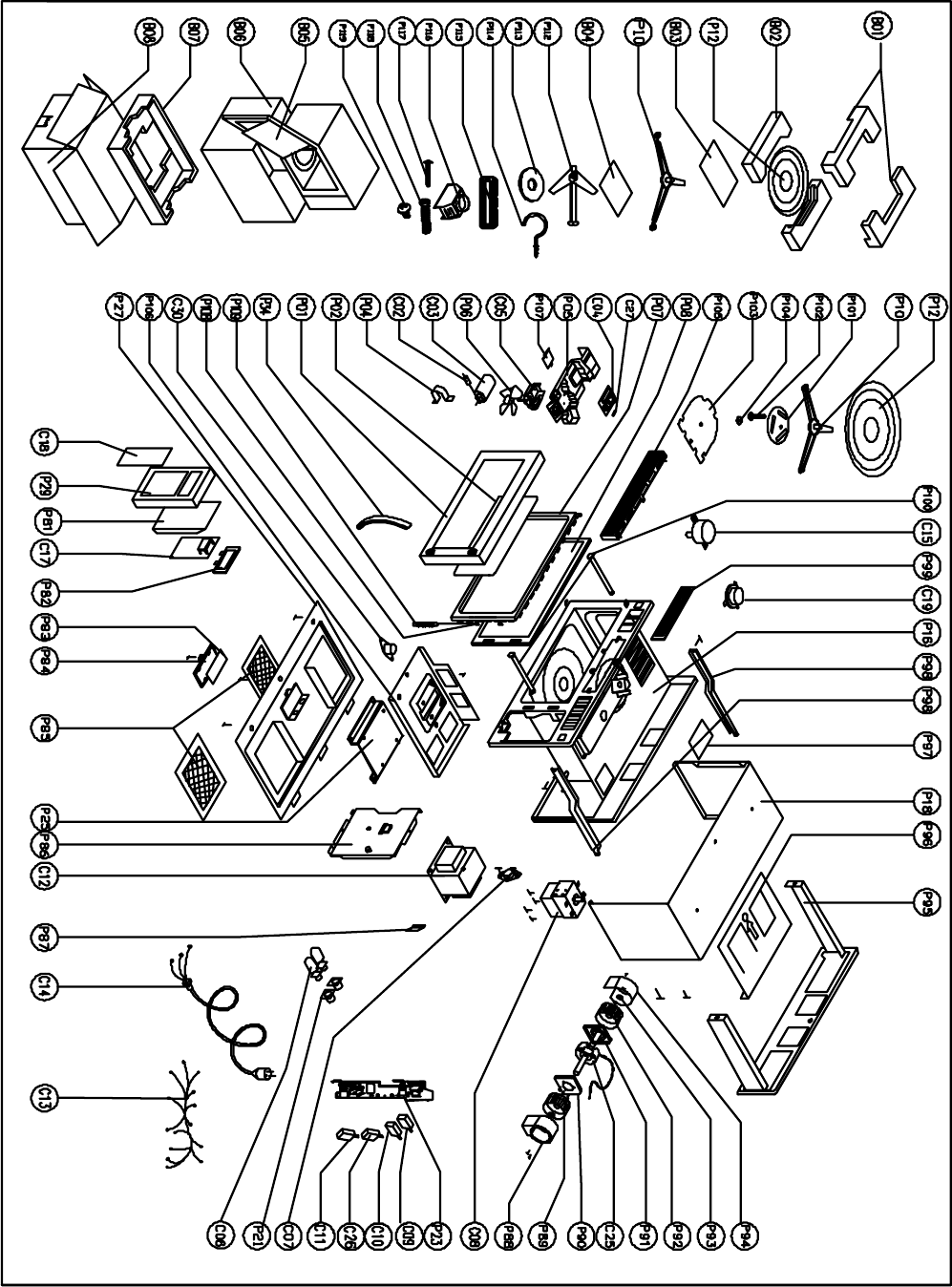
SNM1501RAQ/B/W Microwave Oven Explode Drawing (UL)

Sunbeam OTR Microwave Part List - Stainless model - SNM1502RAS
P/N Description Available Qty.
SBP01 Door Not Available 1
SBP02 Door Window Not Available 1
SBP04 Capacitor Holder Not Available 1
SBP05 Fan Shroud Not Available 1
SBP06 Fan Blade Y 1
SBP07 Door Frame Not Available 1
SBP08 Choke Cover Not Available 1
SBP10 Shaft Y 1
SBP12 Glass Tray Y 1
SBP16 Cavity Not Available 1
SBP18 Outer Enclosure Not Available 1
SBP21 Lamp Socket Y 1
SBP23 Micro Switch Mounting Not Available 1
SBP25 Transformer Bracket Not Available 1
SBP27 Base Plate Not Available 1
SBP29 Control Panel Not Available 1
SBC14W POWER CORD WHT N/A
SBC14B POWER CORD BLK Y 1
SBP34 Handle Not Available
SBP34B Handle - Black N/A 1
SBP34S Handle - Stainless Y 1
SBP34Q Handle - Bisque N/A 1
SBP81 Control Panel Board Holder Not Available 1
SBP82 Panel Window Y 1
SBP83 Glass Plate Y 1
SBP84 Window Frame Not Available
SBP84W Window Frame - WHITE N/A
SBP84Q Window Frame - BISQUE N/A
SBP84B Window Frame - BLK Y 1
SBP85 Charcoal Filter Y 2
SBP86 Capacitor Holder Not Available 1
SBP87 Wind Shield Not Available 1
SBP88 Right Fan Shroud Y 1
SBP89 Right Exhaust Fan Y 1
SBP90 Right Fan Holder Y 1
SBP91 Left Fan Holder Y 1
SBP92 Left Exhaust Fan Y 1
SBP93 Flexible Washer Y 1
SBP94 Left Fan Shroud Y 1
SBP95 Back Mounting Plate Not Available 1
SBP96 Mounting Plate Not Available 1
SBP97 Pad Not Available 1
SBP98 Left & Right Joining Bar Not Available 2
SBP99 Exhaust Air Filter Y 1
SBC02 H.V. Diode Y 1
SBC03 H.V. Capacitor Y 1
SBC04 Noise Filter Board Y 1
SBC05 Fan Motor Y 1

SBC06 Lamp Y 1
SBC07 Thermostat Magnetron 180 Y 1
SBC08 Magnetron Y 1
SBC09 Micro Switch A Y 1
SBC10 Micro Switch A Y 1
SBC11 Micro Switch A Y 1
SBC26 Micro Switch B Y 1
SBC12 Transformer Y 1
SBC13 Wiring Harness Y 1
SBC14 Power Cord Not Available
SBC15 Turntable Motor Y 1
SBC28 Control Panel Circuit Board Y 1
SBC18Q Thin Film Panel Cover Bisque N/A
SBC18B Thin Film Panel Cover Black Y 1
SBC18W Thin Film Panel Cover White N/A
SBC18 Thin Film Panel Cover Not Available
SBC19 Thermostat Cavity 140 Y 1
SBC25 Exhaust Fan Motor Y 1
SBC27 Fuse Noise Filter Board Y 1
SBC30 Thermostat 60 Y 1
SBP100 Mounting Screw Not Available 1
SBP101 Deflector Turn Plate Y 1
SBP102 Linker Y 1
SBP103 Spatter Guard Not Available 1
SBP104 Deflector Turn Plate Holder Y 1
SBP105 Louver Not Available 1
SBP106 Left Bottom Enclosure Not Available 1
SBP107 Light Shield Y 1
SBP108 Door Latch Y 1
SBP109 Door Spring Y 1
SBP110 Spring Y 1
SBP112 Inflating stopper Not Available 4
SBP113 Flat Washer Not Available 2
SBP114 Power Cord Hanger Not Available 1
SBP115 Exhaust Damper Assembly Y 1
SBP116 Metal Exhaust Hood Y 1
SBP117 screws 4×25 Not Available 8
SBP118 Screw 5×60 Not Available 2
SBP119 Screw 4×12 Not Available 1
SBB01 Upper Foam Cushion Not Available 1
SBB02 Turntable Cushion Not Available 1
SBB03 Plastic Bag Not Available 1
SBB04 Manual Not Available 1
SBB05 Protection Film Not Available 1
SBB06 Plastic Bag Not Available 1
SBB07 Lower Cushion Not Available 1
SBB08 Carton Not Available 1
SBB09 Wall mount. Template Y 1
SBB10 Cabinet mount. Temp. Y 1
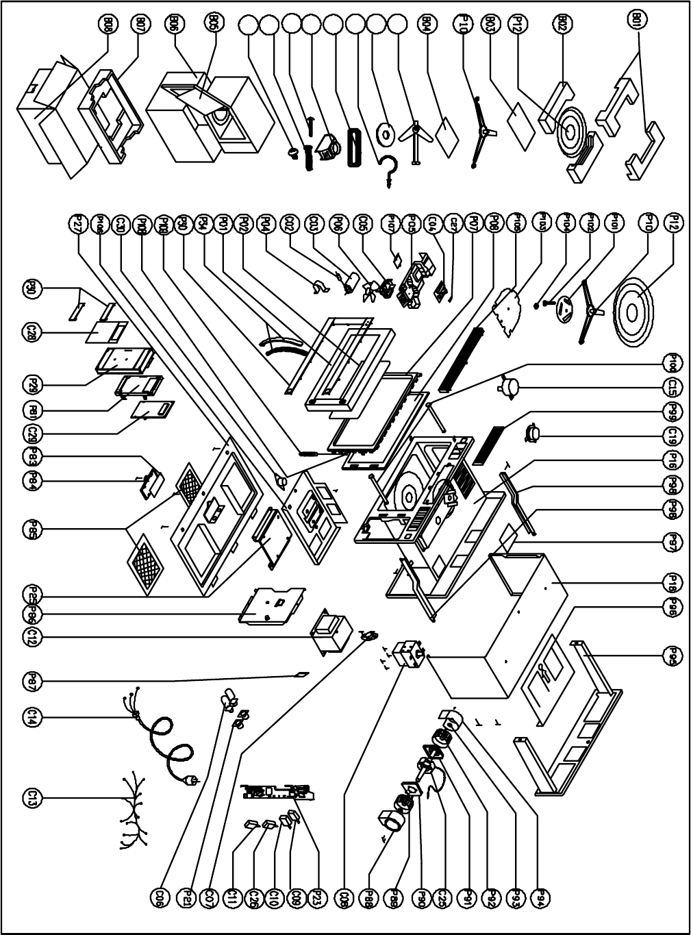
P118
P119
P112
P113
P115
P114
P116
P117
SNM1502RAS Microwave Oven Explode Drawing (UL)

© 2006 Sunbeam Products, Inc. doing business as Jarden Consumer Solutions. All
rights reserved. Sunbeam® is a registered trademark of Sunbeam Products, Inc. used
under license. Distributed by Petters Consumer Brands, LLC. 4400 Baker Road,
Minnetonka, MN 55343.
For service, support and warranty information, visit www.sunbeammajorappliances.com or in the US call 1-866-866-6283.
