T5UID1 Application Guide
User Manual:
Open the PDF directly: View PDF ![]() .
.
Page Count: 14

T5UID1 Development Guide Ver2.1
Beijing DWIN Technologies - 1 - www.dwin.com.cn 400 018 9008 dwinhmi@dwin.com.cn
1 Overview
T5UID1 is DGUS II software platform based on T5 CPU, it is design for low resolution UI application.
Features:
(1) Dual core T5 CPU, GUI core and OS core both run at 250MHz and power consumption is extremely low.
(2) 128Mbytes NAND Flash, 64Mbytes for picture memory, which can store 250 pictures of 480*272 resolution (full screen).
(3) Font memory is 64Mbytes, font file and audio file share the back half (32 Mbytes) of Font Space.
(4) 256×2.048 seconds 32KHz 16bit WAV audio player.
(5) 320Kbytes Nor Flash for user database.
(6) 128Kbytes variables space.
(7) Support upgrade of font, audio, icon and other software.
(8) Support JPEG image decompression and upgrade.
(9) 255 display variables per user interface at most.
(10) Support standard T5 DWIN OS platform and hardware customization. Interface of 20 IO, 6 UART, several AD and PWM can be expanded
on hardware.
(11) 40mS DGUS operating cycle, user interface effect is extremely fluent.
(12) Display variables can be turned on/off or modified to realize complicated display effect.
(13) Touch controls can be turned on/off or modified to realize complicated touch effect.
(14) Download files and configure hardware through SD card. The downloaded files will be counted and displayed for file check. The
downloaded files can be encrypted.
(15) Support adjustment of capacitive touch panel responsiveness, which make the thickness of front toughened glass is up to 6 mm.

T5UID1 Development Guide Ver2.1
Beijing DWIN Technologies - 2 - www.dwin.com.cn 400 018 9008 dwinhmi@dwin.com.cn
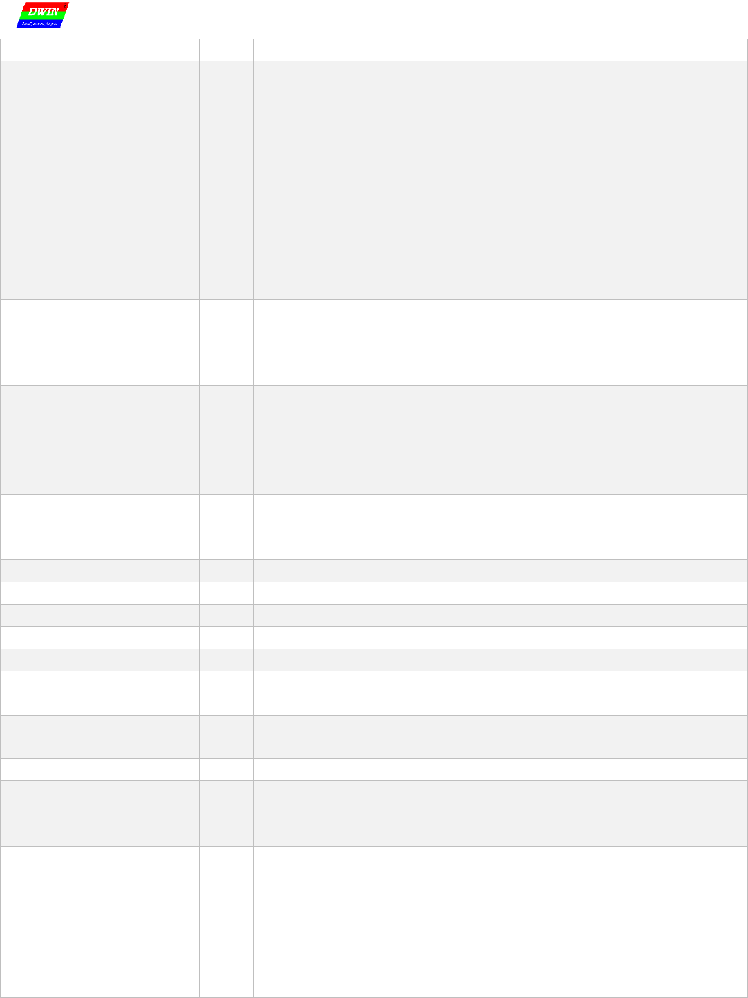
2 Function List
2.1 Display Control
No.
Function
code
Function
Data length
(Word)
Description
1
0x00
Variable Icon
1
Icon display is related with a variable. When variable changes, icon switches accordingly. This
function is used for dashboard, progress bar, etc.
Support superposition of background and transparency set.
2
0x01
Animation Icon
2
3 icon status corresponding to a variable: no display, display selected icon, animation icon.
This function is used for alarm, etc.
Support superposition of background and transparency set. Support animation speed set.
3
0x02
Slider Icon
1
Slider icon is related with a variable. This function is used for display liquid level, dial,
progress bar.
Support superposition of background and transparency set.
4
0x03
Word Art
1/2/4
Use word art icon to display data.
Support superposition of background and transparency set
5
0x04
Image Animation
none
Auto play an image sequence at selected speed. This function is used in welcome page or
screensaver.
6
0x05
Rotation Icon
1
Transform variable range to angle data which linear with variable. Then display icon at
corresponding angle. This function is mainly used for dashboard.
7
0x06
Bit Variable Icon
3
Every bit (0/1) of one variable data stands a status, and the status can be displayed via static
icon or animation. This function is used to display on/off state.
8
0x10
Variable Data
1/2/4
Display a variable in specified format (integer, decimal, unit, etc), font type, and font size.
9
0x11
Text
2K at most
Display character string in specified format (font library) at selected area.
10
0x12_00
Digital RTC
none
Display digital RTC in customized format.
11
0x12_01
Analog Clock
none
Display analog clock via rotation icon.
12
0x15
Data Window
2
Display variable data sequence in specified window, highlight the selected data.
Combined this function with sliding adjustment or increment adjustment, data sequence can
scroll with finger touch. The scrolling speed can be controlled via DWIN OS.
The variable occupy 2 word space, (VP+1) space is reserved.
13
0x20
Dynamic Trend Curve
2K per channel
Display real-time curve via data from curve buffer (auto match). The display area, central axis
coordinates, display scale (zoom in/out), and curve direction of curve can be set.
14
0x21_01
Draw_Dot
User define
Dot set(x, y, color)
15
0x21_02
Draw_Line
Draw a line via dot connection (color, (x0, y0), …, (xn, yn) )
16
0x21_03
Draw_Rectangle
Draw a rectangle. Color/area/size can be set.
17
0x21_04
Draw_ Fill Rectangle Area
Filling specified rectangle area with color. Color, area, size can be set.
18
0x21_05
Draw_Circle
Display entire arc. Color, area, size can be set.
19
0x21_06
Draw_Picture Copy&Paste
Copy a picture area and display it on current page.
20
0x21_07
Draw_Icon Display
Icon display. Icon library is optional.
21
0x21_09
Draw_ Frequency Spectrum
Display frequency spectrum (vertical line), line color and location can be set.
22
0x21_0A
Draw_Segment
Connect line segments. Endpoint and color can be set.
23
0x21_0B
Draw_Arc Display
Display arc. Radius, color and angle range can be set.
24
0x21_0D
Draw_XOR
Do XOR operation at selected rectangular area. Mainly used for highlight display.
25
0x24
Zone Scrolling
1
Loop shift of specified area, move direction can be set. Used for simple dynamic effect of flow
chart and progress bar. The variable is occupied by system, user operation is forbidden.
26
0x25
QR Code Display
259 at most
Display QR code according to specified data.

T5UID1 Development Guide Ver2.1
Beijing DWIN Technologies - 3 - www.dwin.com.cn 400 018 9008 dwinhmi@dwin.com.cn
27
0x26
Adjust brightness of
selected area
1
Adjust the brightness of rectangular area to highlight or weaken background.
Remarks:
1. For more detailed function instruction, please refer to Development Guide of DWIN DGUS.
2. VP is a pointer, which points to the storage location of user variable memory space.
3. User can set SP (stack pointer) in DGUS tool, thus the configuration of display control will be write in to user variable memory space that the
SP pointing to. User can operate configuration of display control via UART or DWIN OS to combine multi-controls.

T5UID1 Development Guide Ver2.1
Beijing DWIN Technologies - 4 - www.dwin.com.cn 400 018 9008 dwinhmi@dwin.com.cn
2.2 Touch Control
No.
Function
Code
Function
Data Length
(Word)
Description
01
00
Variable Data Input
1/2/4
Input integer, fixed-point decimal via touch panel. The inputted data will be saved to variable
space that user define.
The transparency of popup keyboard can be set.
02
01
Popup Window
1
Touch to active a popup window, return menu item key code of the window.
The transparency of popup window can be set.
03
02
Incremental
Adjustment
1
Touch button to do add/minus with variables. The adjustment step and range can be set.
Set adjustment from 0 to 1 circularly, user can get the checkbox effect.
04
03
Slide Adjustment
1
Slide to adjust variable data. The adjustment range can be set.
05
05
Return Key Value
1
Return key code when touch the button on touch panel and write key code in variable space
that VP point to. Support bit variable return.
06
06
Text Input
127 at most
Input ASCII character or GBK Chinese character, support cursor and edit during input process.
(VP-1) space is reserved to save input status and inputted data length.
07
08
Return data based on
touch status
User define
Return data to space that VP pointing to, the rule between data and touch status is set forward.
Combining data auto-uploading function, the data can be returned to UART.
08
0A
Slide Adjust (gesture)
2
Adjust variable data based on slide range on X axis or Y axis within selected area.
Combining data window to realize rolling adjustment.
VP space is reserved, the data is saved in space that (VP+1) pointing to.
09
0B
Page Sliding (gesture)
None
Scrolling touch screen along X-axis to realize page scrolling.
The next page and scrolling area can be set. Display control will move along gesture.
Remarks:
1. Refer to DWIN DGUS Development Guide for detailed description.
2. Touch configuration file(13*.BIN) can not be more than 32Kbytes.
3. The touch control interface is 0x00B0, user can operate touch control via UART or DWIN OS to nest or group functions.

T5UID1 Development Guide Ver2.1
Beijing DWIN Technologies - 5 - www.dwin.com.cn 400 018 9008 dwinhmi@dwin.com.cn
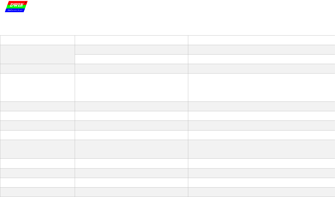
2.3 Serial Port Communication Protocol
UART 2 can be used for system debug, whose mode is fixed at 8N1. Baud rate can be set, data frame is consist of 5 parts.
Data Block
1
2
3
4
Definition
Frame Header
Data length
Instruction
Data
CRC (optional)
Data Length
2
1
1
N
2
Description
0x5AA5
Command+data+CRC
0x80/0x81/0x82/0x83
Example (without CRC)
5A A5
04
83
00 10 04
Example (with CRC)
5A A5
06
83
00 10 04
25 A3
CRC checker can be turn on/off at 0x2C.6 in T5UID1.CFG.
Description of UART2 instruction:
Instruction
Data
Description
0x80
Send:
Register Page (0x00-0x08) + Register Address(0x00-0xFF) + Data to write
Write data string into register.
Answer:
0x4F 0xaB
Answer of write instruction.
0x81
Send:
Register Page(0x00-0x08) + Register Address (0x00-0xFF) + Data Length to
Read (0x01-0xFB)
Read data from register.
Answer:
Register Page (0x00-0x08) + Register Address (0x00-0xFF) + Data Length +
Data
Answer of read instruction.
0x82
Send:
Start Address of SRAM (0x0000-0xFFFF) + Data to Write
Write data in to SRAM. Do not write data
into space reserved for system.
Answer:
0x4F 0xaB
Answer of write instruction.
0x83
Send:
Start Address of SRAM (0x0000-0xFFFF) + Data Length to Read (0x01-0x7D)
Read data form SRAM.
Answer:
Start Address of SRAM + Data Length (word) + Data
Answer of read instruction.
Definition of Register page:
Register page ID
Definition
Description
0x00-0x07
Data Register
256 per group, R0-R255
0x08
Port Register
DR0-DR255
See 3.4 section of DWIN OS development guide based on T5 for more.

T5UID1 Development Guide Ver2.1
Beijing DWIN Technologies - 6 - www.dwin.com.cn 400 018 9008 dwinhmi@dwin.com.cn
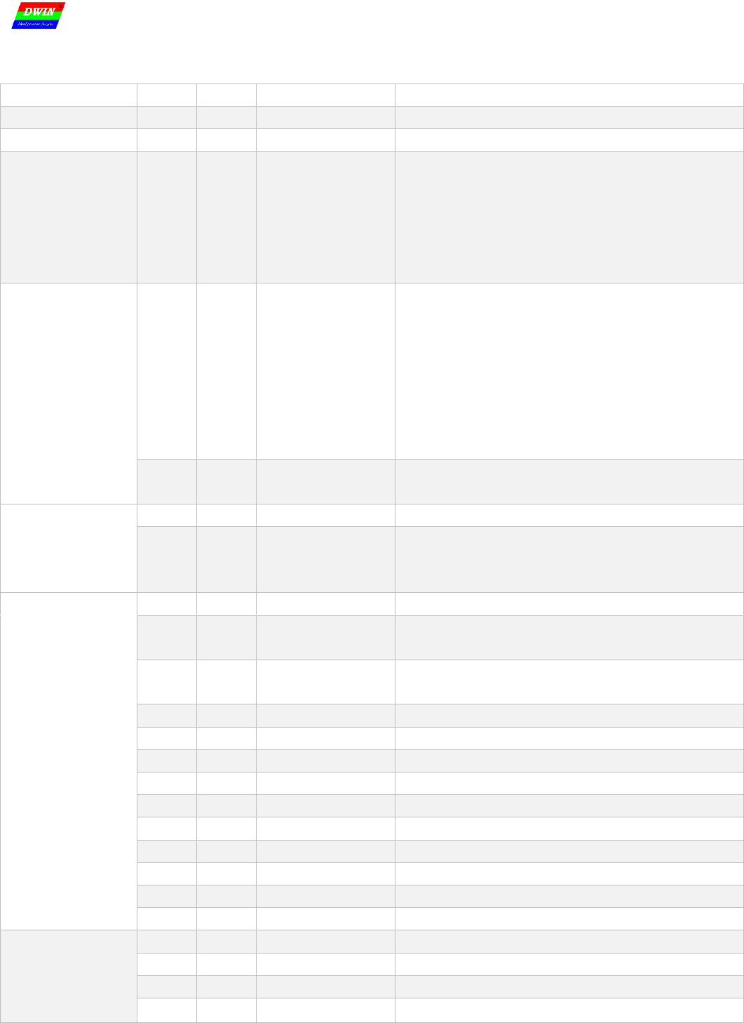
3 System Variable Interface
Data with same background color in table need to be update at the same time.
VP
Definition
Length
(Word)
Description
0x00
Device_ID
4
T5 CPU ID, each T5 CPU has an unique ID.
0x04
System_Reset
2
0x55AA 5AA5=Reset T5; 0x55AA 5A5A=Reset system (including /RST_OUT pin output).
0x06
OS_Update_CMD
2
D3: write 0x5A to enable DWIN OS once (write into 1MB Nor Flash), clear after operation.
D2: Fixed at 0x10. DWIN OS program must start from 0x1000.
D1:0: Start address of SRAM to save program to update, it must be even.
0x08
NOR_FLASH_RW
_CMD
4
D7: Mode. 0x5A=read 0xA5=write, clear after operation.
D6:4: Start address of Nor Flash. Must be even. 0x000000-0x02:7FFE, 160KWords.
D3:2: Start address of SRAM. Must be even.
D1:0: Data length to read/write. Must be even. (Unit: word)
0x0C
Reserved
3
0x0F
Ver
1
Application software version. D1 stands for GUI version, D0 stands for DWIN OS version.
0x10
RTC
4
D7=Year (0-0x63) D6=month(0-0x0C), D5=day(0-0x1F), D4=week(0-0x6), D3=hour(0-0x17),
D2=minute(0-0x3B), D1=second(0-0x3B), D0 undefined. Data format is HEX.
If there is no RTC on hardware, user can write RTC data.
0x14
PIC_Now
1
Display current page ID
0x15
GUI_Status
1
GUI status feedback: 0x0000=free, 0x0001=processing 13.bin and 14.bin.
0x16
TP_Status
4
D7: 0x5A=touch screen data is updated, OS is clear.
D6: Touch panel status. 0x00=release, 0x01=first press, 0x02=lift, 0x03=pressing
D5:D4=X coordinate D3:D2=Y coordinate D1:D0=0x0000.
0x1A-0x2F
Reserved
22
Undefined
0x30
VCC_Now
1
Current 3.3V Voltage AD value, Voltage=AD value*4800/65532 mV.
0x31
LED_Now
1
D1: 0x5A = VCC_Now, backlight brightness value, AD0-AD1 instant value has updated.
D0: Current backlight brightness value, 0x00-0x64.
0x32
AD0-AD3
Instantaneous
value
4
Instantaneous value of AD0-AD3, 1 word per AD. Voltage=AD value*4800/65532 mV.
Hardware support is needed.
0x36
AD compute
update mark
1
D0=0x5A means temperature data and AD0-AD7 compute data is updated. Clear OS.
Hardware support is needed.
0x37
T_Core
1
CPU core temperature, temperature=T_Core*240/929. Unit: 0.1°C (+/ 0.1°C).
0x38
AD0-AD7
compute value
16
16-bit AD compute value of AD0-AD7, reference voltage is 4800mA.
2 words for each AD channel, high word is average value (DC component), low word is root
mean square value (AC component). Sample rate is 5 KSPS, compute based on 256 sample
data.
0x48
IRDA_Data
4
Decode data of IRDA interface, need IRDA hardware.
D7: 0x5A=IRDA key code is updated, clear after OS read the data.
D6: Button mode, 0x01= first press, 0x02=long press
D5:2: 4 bytes remoter decode data.
D1:D0: Count remote single, 0x0000-0xFFFF (cycle).
0x4C-0x7B
Reserved
46
Undefined.
T5UID1 Development Guide Ver2.1
Beijing DWIN Technologies - 7 - www.dwin.com.cn 400 018 9008 dwinhmi@dwin.com.cn
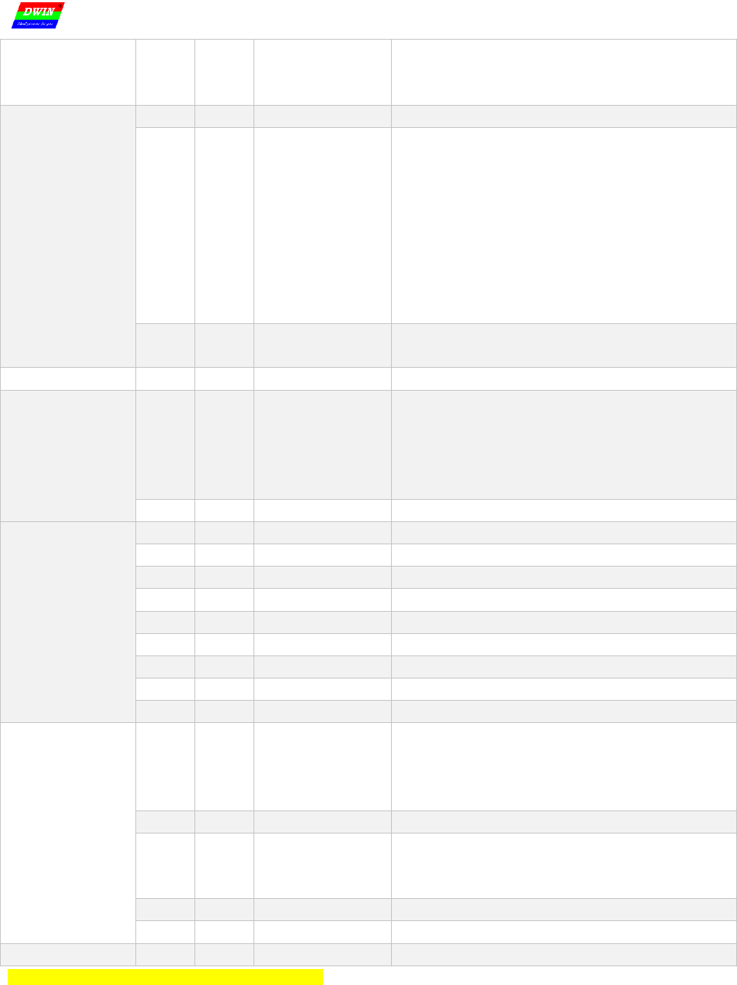
0x7C
Folder Name
4
8 ASCII characters at most, like DWIN_SET. Read only.
0x80
System_Config
2
D3: Undefined, write 0x00.
D2: Touch panel sensitivity configuration, read only.
D1: Touch panel mode configuration, read only.
D0: Set system status.
.7: Reserved, write 0.
.6: Display control number. 0=64 control/page, 1=128 control/page, read only.
.5: Loading 22.bin to initialize SRAM. 1=Load 0=Not load, read only.
.4: SD port status. 1=On 0=Ban, read and write.
.3: Touch tone control. 1=On 0=Off, read and write.
.2: Standby backlight control. 1=On 0=Off, read and write.
.1-.0: display direction 00=0° 01=90° 10=180° 11=270°, read and write.
0x82
LED_Config
2
Set standby backlight.
D3= brightness when system running, 0x00-0x64; When backlight standby control is off, D3
can be used for brightness adjustment via instruction.
D2= brightness when system standby, 0x00-0x64; D1:0=wait time /5mS.
0x84
PIC_Set
2
D3: 0x5A = enable page operation once, clear after CPU operation.
D2: Mode.
0x01=page switch (display the selected picture).
0x02=save page (save background of current page to picture memory).
D1:D0: picture ID.
0x86
PWM1_Set
4
D7= write 0x5A to enable PWM1 setting once, clear after operation. D6= division factor,
D5:D4= PWM1 accuracy, PWM1 carrier frequency =501.35MHz/(division factor*PWM1
accuracy). D3:D0 reserved.
0x8A
PWM2_Set
4
Set PWM2.
0x8E
PWM3_Set
4
Set PWM3
0x92
PWM1_Out
1
D1:D0=PWM1 output high level width, 0x0000-PWM1 accuracy. Need hardware support.
0x93
PWM2_Out
1
D1:D0=PWM2 output high level width, 0x0000-PWM2 accuracy. Need hardware support.
0x94
PWM3_Out
1
D1:D0=PWM3 output high level width, 0x0000-PWM3 accuracy. Need hardware support.
0x95
PWMV1_Out
1
D1:D0=PWMV1 output ratio, 0x0000-0x3E8, output is synchronous with 50Hz pin input pulse.
Need hardware support.
0x96
PWMV2_Out
1
D1:D0=PWMV2 output ratio, 0x0000-0x3E8, output is synchronous with 50Hz pin input pulse.
Need hardware support.
0x97-0x9B
Reserved
5
Undefined
0x9C
RTC_Set
4
D7:D6= write 0x5AA5 to enable RTC setting once; D5:D0=year, month, day, hour, minute,
second, all in HEX format.
Need hardware support.
0xA0
Music_Play_Set
2
Music player setting:
D3: Starting section of music to play, 0x00-0xFF.
D2: Section number, 0x01-0xFF. Clear after DGUS operation. Under buzzer mode, it is buzz
time, unit: 8 mS.
D1: Volume, unit: 1/256.
D0: Return the rest section numbers of music to play, 0x00-0xFF.
D3:D2 both write 0x00 to stop music playing.

T5UID1 Development Guide Ver2.1
Beijing DWIN Technologies - 8 - www.dwin.com.cn 400 018 9008 dwinhmi@dwin.com.cn
0xA2
BMP_Download
4
D7: 0x5A = enable once writing data in SRAM to picture buffer.
D6:D5: Starting address of SRAM, must be even.
D4:D3: Data length, unit: word. Must be even.
D2:D1:D0: Picture buffer address, 0x000000-0x0257FF, 150Kwords.
0xA6
JPEG_Download
4
D7: 0x5A = enable JPEG picture/icon download operation once, clear after CPU operation.
D6: download mode
0x01=Display JPEG picture on current page. (it will be covered when switch page).
0x02=Save JPEG picture to picture memory. (Operating backstage).
D5:D4: starting address of SRAM to save JPEG file, must be even. 64Kbytes per JPEG file at
most.
D3:D0:
0x01 mode: D3:D2= top left corner coordinate of picture displayed on background.
0x02 mode: D3:D2= picture ID,0x0000-0x00F0.
The resolution of JPEG picture must not exceed screen resolution, set coordinate as 0° display.
(for 90° display, users need to rotate picture and coordinate in advance. )
0xAA
Nand
Flash_RW_CMD
6
D11: 0x5A= enable once read/write font library (64Mbytes) operation, clear after operation.
D10: operation mode, 0x01= read font library, 0x02=update font library.
When D10=0x01
D9: font ID, 0x40-0x7F, 256Kwords per font, 16Mbytes at most.
D8:D6: starting address in font, unit: word. 0x00 00 00-0x01 FF FF.
D5:D4: starting address of SRAM to write data, must be even.
D3:D2: data length to read, unit: word. Must be even.
D1:D0: undefined,write 0x00.
When D10=0x02
Update font file (font library, icon, audio), 32Kbytes once.
D9:D8 address of 32Kbytes font file, 0x0000-0x07FF, refer to the entire 64Mbytes font
memory.
D7:D6: starting address of SRAM to save updating data, must be even.
D5:D4: fixed 0x0001.
D3:D0: undefined, write 0x00.
0xB0
Touch Control
interface
36
0xB0: 0x5AA5= enable accessing touch control interface once. Clear after CPU operation.
0xB1: Page ID of touch control.
0xB2: High byte: touch control ID (set in DGUS II development software), 0x00-0xFF;
Low byte: touch control code, 0x00-0x7F.
0xB3: Access mode
0xB4-0xD3: data to modify of mode 0x02, 0x03.
Mode 0x0000: turn off this touch control.
Mode 0x0001: turn on this touch control.
Mode 0x0002: Read this touch control and write it to SRAM that 0xB4 pointing to.
Mode 0x0003: update current touch control with data that 0xB4 pointing to, the format and data
length must be the same.
0xD4
Simulate touch
panel operation
4
0xD4: 0x5AA5=enable the operation once, clear after operation.
0xD5: press mode. 0x0001=press, 0x0002=release, 0x0003=keep pressing, 0x0004=touch
(press+release)
0xD6: X coordinate of press position.

T5UID1 Development Guide Ver2.1
Beijing DWIN Technologies - 9 - www.dwin.com.cn 400 018 9008 dwinhmi@dwin.com.cn
0x1000-0xFFFF SRAM is for user use.
0xD7: Y coordinate of press position.
After simulating mode 0x0001 and 0x0003, must simulate 0x0002.
(x,y) coordinate of TP must be set as 0°, CPU will auto-rotate coordinate.
0xD8-0xFF
Reserved
40
Undefined.
0x100-0x2FF
Reserved
512
0x300-0x37F
Dynamic curve
interface
128
0x300-0x30F: feedback 8 channel of curve buffer (read only), 2 words per channel.
High word: pointer of data (0x0000-0x07FF);
Low word: data length of curve buffer (0x0000-0x0800). Write 0x0000 to hide curve.
0x310-0x311: enable writing curve buffer.
D3:D2: 0x5AA5= enable writing curve buffer, clear after operation.
D1: The number of data block, 0x01-0x08.
D0: Undefined, write 0x00.
0x312-0x37F: The data block to send to curve buffer, 16bit unsigned number.
Single data block defines as channel ID (0x00-0x07)+data word length(0x01-0x6E)+data.
After adopting dynamic curve displaying, from 0x1000, setting data buffer for each curve,as
per 2Kwords aisle.
While dynamic curve display is enabled, data buffer is start from 0x1000, and 2Kwords every
buffer. CHO buffer is 0x1000-0x17FF, CH1 buffer is 0x1800-0x1FFF, etc. Free buffer can be
used for user variable area. User can also rewrite curve buffer data, then modify pointer and
data length in 0x300-0x30F to make sure the curve display right.
0x380-0xFFF
Reserved
3K
Undefined
T5UID1 Development Guide Ver2.1
Beijing DWIN Technologies - 10 - www.dwin.com.cn 400 018 9008 dwinhmi@dwin.com.cn
4 SD Interface
Download and update file via SD/SDHC interface is support.
File Type
Name rule
Description
Core Program
T5UID1*.BIN
The GUI core program.
T5OS_V*.BIN
Common T5 OS platform core program.
DWIN OS program
DWINOS*.BIN
DWIN OS program, code must begin from 0x1000.
NOR Flash database
ID+(Optional) file name.LIB
Each ID points to 2KWords memory, ID range is 0-79.
The NOR Flash is inserted in T5 CPU, 160KWords. It can be used for
save user data or DWIN OS program.
Font Library
ID+(Optional)file name.BIN/HZK/DZK
Generate by font generator.
DGUS Input File
12*.BIN
Save at fixed 12# font space.
DGUS touch File
13*.BIN
Save at fixed 13# font space, 32Kbytes at most.
DGUS variable File
14*.BIN
Save at fixed 14-17# font space
DGUS variable initialize file
22*.BIN
Save at fixed 22# font space, load data in 0x2000-0x1FFF address to
initialize 0x1000-0xFFFF SRAM.
Icon file
ID+(optional)file name.ICO
Generate by DGUS tool. Save in font space.
Audio file
ID+(optional)file name.WAV
32KHz 16bit WAV format. Save in audio space.
BMP image file
ID+(optional)file name .BMP
24bit true color format.
Hardware Configuration File
T5UID1*.CFG
64Mbytes font memory, font memory block is 256KB.
32Mbytes audio memory, audio memory block 128KB.
Audio memory covers last half font memory (128 blocks), each audio memory block covers half font memory block.
All the file must be put into DWIN _SET folder, and the folder must be set in SD card root directory. SD card must be 4KB sectors, FAT32
format.
When power up, DGUS check SD interface once, then check SD interface every 3 seconds.
T5UID1 Development Guide Ver2.1
Beijing DWIN Technologies - 11 - www.dwin.com.cn 400 018 9008 dwinhmi@dwin.com.cn
5 Hardware Configuration File
T5UID1.CFG is hardware configuration file for T5UID1 platform. T5UID1 is binary, it can be edit by UltraEdit.
Type
Address
Length
Definition
Description
Identification Code
0x00
4
0x54 0x35 0x44 0x31
Fixed content.
Format Flash
0x04
2
Write 0x5AA5 to format NAND Flash.
System Clock
Calibration
0x06
2
0x06: write 0x5A to enable system clock calibration
0x07: write 0xA5 is UART calibration mode. During the
calibration process, set UART2 as 115200bps and 8N1 mode,
send more than 30 0x55 data packages every 30 mS.
Write 0xAA is RTC calibration mode. Apply the RTC
hardware to calibrate. It is already be calibrated before sale.
System Configuration
1
0x08
1
System_Config1
(default value is 0x38)
.7: data auto-uploading. 0=On, 1=Off.
.6: display control number. 0=64 control/page, 1=128
control/page.
.5: initialize via 22.bin file. 1=On 0=Off
.4: SD interface status. 1=on 0=ban
.3: touch tone. 1=on 0=off
.2: backlight system standby control. 1=on 0=off
.1-.0: display direction 00=0° 01=90° 10=180° 11=270°
0x09
2
UART2 Baud Rate
Baud rate set value=7833600/real Baud rate.
115200bps, set value=0x0044. Ser value is 0x03E7 at most.
Standby Backlight
0x0B
1
LED_Set_En
0x5A=enable standby backlight.
0x0C
4
LED_Idle_Set
0x0C=brightness when TP is used, 0x0D=brightness when TP is
not used.
0x0E:0F=waiting time, unit: 5mS.
LCD Configuration
0x10
2
Display_Config_En
0x5AA5=enable LCD configuration. Not for user.
0x12
1
PCLK_PHS
Data latch phase: 0x00=PCLK Falling edge, 0x01=PCLK Rising
edge
0x13
1
PCLK_DIV
Pixels clock PCLK frequency set ,PCLK frequency
(MHz)=500/PCLK_DIV.
0x14
1
H_W
0x15
1
H_S
0x16
2
H_D
Horizontal resolution of LCD (X direction).
0x18
1
H_E
0x19
1
V_W
0x1A
1
V_S
0x1B
2
V_D
Vertical resolution of LCD (Y direction).
0x1D
1
V_E
0x1E
1
TCON_SEL
0x00=do not configure TCON.
0x1F
1
Reserved
0x00.
Boot Setting
0x20
1
PIC_Power_On_En
0x5A= enable this configuration.
0x21
2
PIC_Power_On
ID of page to display when power on.
0x23
1
Music_Power_On_En
0x5A= enable this configuration.
0x24
3
Music_Power_On
Strat-up music:
T5UID1 Development Guide Ver2.1
Beijing DWIN Technologies - 12 - www.dwin.com.cn 400 018 9008 dwinhmi@dwin.com.cn
0x24=music ID, 0x25=memory block number that music file
cover, 0x26=volume.
0x25=0x00, no strat-up music.
Touchscreen setting
0x27
1
TP_Set_En
0x5A= enable this configuration. Not for user.
0x28
1
TP_Mode
TP mode.
.7-.4 (high 4bit), TP type:
0x0*=resistance touch panel.
0x1*=Capacitive touch panel (driver: GT911, GT9271, GT9110).
.3-.0 (low 4bit), TP mode:
.3 reserved, wirte 0.
.2 X axis data: 0=0 to Xmax, 1=Xmax to 0;
.1 Y axis data: 0=0 to Ymax, 1=Ymax to 0;
.0 X, Y exchange: 0=XY, 1=YX .
0x29
1
TP_Sense
TP sensitivity: 0x00-0x1F, 0x00 is lowest, 0x1F is highest.
Default value is 0x14.
Undefined
0x2A
2
Reserved
Write 0x00.
System
Configuration2
0x2C
1
System_Config2
(default value is 0x00)
.7: choose audio player/buzzer. 1=buzzer, 0=audio player.
.6: CRC checker for UART2. 1=on, 0=off.
.5: secondary hardware watch dog (WDT). 1=on, 0=off.
.4: synchronous update of display content. 1=on, 0=off.
.3-.0: reserved, write 0.
0x2D
3
Reserved
Write 0x00
SD download check
0x30
2
SD_Check_En
0x5AA5=enable download file check via SD interface.
0x32
1
.LIB file
0x00-0xFF
0x33
1
.BIN font file
0x00-0xFF, OS program is not include.
0x34
1
.DZK font file
0x00-0xFF
0x35
1
.HZK font file
0x00-0xFF
0x36
1
.ICO icon file
0x00-0xFF
0x37
1
.WAV file
0x00-0xFF
0x38
2
.BMP file
0x0000-0xFFFF
0x3A
6
Reserved
0x00
SD encryption
0x40
2
SD_Encrypt_En
0x5AA5=enable SD encryption once.
0x5AAA=disable SD encryption. Folder name returns to
DWIN_SET. The encrypted setting is saved in Flash, and will not
be clear.
0x42
1
Length of Folder name
0x01-0x08
0x43
8
Folder name
8 ASCII characters at most (only 0-9, a-z, A-Z, and -, _ ). If
folder name include invalid characters, default DWIN_SET will
be used.
0x4B
5
Reserved
0x00
0x50
32
Decode key
Undefined
0x70
17
Reserved
0x00
Attention:part of green background must be configured.

T5UID1 Development Guide Ver2.1
Beijing DWIN Technologies 13 www.dwin.com.cn 400 018 9008 dwinhmi@dwin.com.cn
Display Configuration reference:
Size_Resolution
T5UID1.CFG display Configuration(HEX format)
0x12
0x13
0x14
0x15
0x16
0x17
0x18
0x19
0x1A
0x1B
0x1C
0x1D
0x1E
0x1F
2.4_240*320
00
50
0A
14
00
F0
0A
02
02
01
40
02
05
00
2.8_240*320A
00
50
0A
14
00
F0
0A
02
02
01
40
02
03
00
2.8*240*320B
00
50
10
20
00
F0
20
02
0E
01
40
08
01
00
3.5_320*240
00
46
11
14
01
40
40
03
0F
00
F0
10
02
00
3.5_320*480
00
2C
0A
04
01
40
0A
02
02
01
E0
02
04
00
4.3*480*272
00
30
29
02
01
E0
02
0A
02
01
10
02
00
00
5.0*480*272
00
30
29
02
01
E0
02
0A
02
01
10
02
00
00
T5UID1 Development Guide Ver2.1
Beijing DWIN Technologies 14 www.dwin.com.cn 400 018 9008 dwinhmi@dwin.com.cn
Revision Record
Date
Content
Software Version
2017.06.13
Publishing at the first time.
V1.0
2017.09.02
Add UART2 data auto-update by touch.
User need to edit T5UID1.CFG to 0x0008.7=1, touch control code is 0xFE**, and update
T5 OS to V1.2 or above.
V1.1
2017.09.23
Add real-time update of JPEG icon.
V1.1
2017.10.13
Add ASCII input function.
V1.2
2017.12.01
Add sensitivity modification of capacitive touch screen. Set at 0x27-0x29 in T5UID1.CFG
V1.3
2017.12.18
Support 256 control/ page.
Support icon resolution over 255*255.
Add drawing instruction.
V1.4
2018.02.28
Add choose between audio player and buzzer.
ADD Chinese characters input (GBK code) via TP.
Add dynamic curve display.
V1.5
2018.03.10
Add sliding (gesture) page switch, and auto-upload page ID after switching.
Add touch control interface for on\off\read\edit.
Add brightness adjustment of selected area, this function can be used to highlight or fade
the area
V1.6
2018.04.08
Add UART2 CRC checker.
Add SD interface download file count and check.
Add modification of DWIN_SET folder name and encryption of entire program.
Add background transparency set of all icon.
Add icon animation speed adjustment.
Add transparency set of popup area.
Add touch simulation (0xD4) for process control and keyboard UI operation.
V2.0
2018.05.10
Add secondary hardware watch dog (WDT) choice.
Add real-time update of display content.
V2.1
If there is any question when using this file or DWIN product, or willing to know more about DWIN product news, feel free to contact us:
Service call: 400 018 9008
E-mail: dwinhmi@dwin.com.cn
