TM02_Engineering_Specification TM02 Engineering Specification
TM02_Engineering_Specification TM02_Engineering_Specification
User Manual: TM02_Engineering_Specification
Open the PDF directly: View PDF ![]() .
.
Page Count: 47
ENGINEERING
SPE'CIFICATION
CONTINUATION SHEET
TITLE
1.0
System
Description
1.1
Gerieral
Information
The,~U16/TM02
tape
system
will
consist
of
between
,one
and
eight
tape
drives
and
a
single
electronics
package
which
will
serve
'as
an
interface
between
anyone
of
those
drives
and
a
Massbus
controller.
1.2
De'fini'tion
For
the
purposes
of
this
specification','
the
following
'definitions
apply:
1.2.1
'
Controller
-
anY'Massbus
controller.
1.2.2
Slave
- a
tape
transport.
1.2.2.1
,Selected
Slave
-
that
slave
whose
select
code
appears
in
bits
0';'2
of
the
Tape.
Control
(TC)
Register.
1.2.3
T.M02
-
defined
operationally.
The
TM02
electronics
,
package
interfaces
to
the
controller~·
It
accepts
commands
which
a
selected
slave
must
execute
while
providing
the
controller
with
information
about
the
status
of
the
slave.
During
data
transfers
the
TM02
controls
fetching,
formatting,
and·
sending
of
data.
The
TM02also
oversees
the
handling
of
error
conditions
'and
slave
servicing
requirements.
, ,
1.2.4
Drive
-when
bits
0-'2
of
the
Tape
Control
Register
in
the
TM02
contain
the
select
code
of
an
existing
slave,
then
the
Master
and
the
selected
slave
to-
gether
become
equivalent
to
what
is
defin~d
as
a
IIdrive
n
in
the
Massbus
Specification.,
No
more
than
'one
slave
may
be
legally
selected
,at
anytime~
and
commands
cannot
be
issued
tounselected
slaves.
However,unselected
slaves
are
able
to
make
impor~
tant
status
changes
known
to
the
controller.
(See
'SSC
bit
of
Status
Register.)
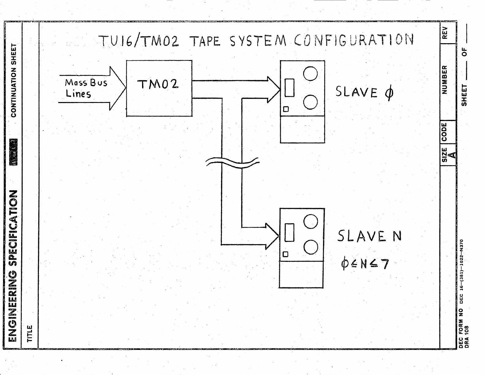
1.3
System
Configuration
The
followingblo~k'diagram
illustrates
the'
configuration
of
a TUl
6/TMO
2
tape
system:
DEC FORM NO
DEC
16-(381)-1022-N370
,D~A
108
NUMBER
SHEET
__
REV
OF
I
I
z
0
-
t-
<.
u
-
I&.
m=-
y
W
A.
'"
.(!)
z
-
at:
.W
w
z·
-
~
Z
W
LLI
-J
t-
t=
TU.IG/TM02.
TAPE.
SY5TEM·(ONFIGURAT10N
Mac:.s
Bus
Lines
TM02
9 6
SLAVE
~
SLAVEN
q,fN~7
>
IJJ
a::
a::
l&J
CD
:IE
::l
Z
iLl
C
0
0
lLI
~t«
(J)
u..
0
I
t-
iLl
iLl
%:
(J)
o
....
I'f)
..
f'
(\I
N
..
o
I
~
co
M
r
.-4
o
w
o
o .
Z
::E
0:
co
00
LL._
oct
LLI
0:.
~~~~~==
__
~~~~
__
~~~~~~~~~-=~~~~
____
~
____
~
__
~aa
E",GINEERING
SPECIFICATION
-- CONTINUATION SHEET
.TITLE
1.4
Applicable
Documents
Befol:'e'.reading
this
document,
the
reader
should
familiarize
himself
with
the
Massbus
Specification.
In
addition,
at~
tempts·
to
program
the
TU16/TM02
system
~hould.beprefaced
by
a
thoro~gh
study
of
the
programming
manual
for
the
par-
ticular
Massbus
controller
with
which
the
program
will,
interface.
NUMBER I
REV
DEC FORM NO
DEC
16-(381)-1022-N370
ORA
108
SHEET
__
OF
__
ENGINEERING
'SPECIFICATION
CONTINUATION
SHEET
, TITLE,
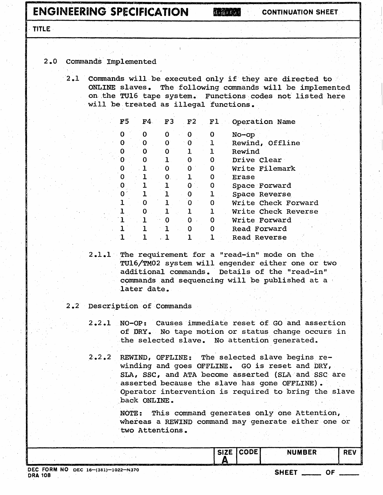
2.0
Commands'Implemented
'2.1
Commands
will,beexecuted
only
if'they
are
directed
to
ONLINE
slaves.
The
following
commands
will
be
implemented
on,
,the
TUl6
tape
system.
Functions,
codes
not
listed
here
will
be
treated
as
illegal
functions.
FS
F4,
F3
000
000
000
o
01
o
,10
010
011
0" 1 1
101
1 0 1
'1
1 0
l'
1 1
111
F2
o
o
1
o
0'
1
o
o
o
1
o
o
1
Fl
o
1
1
o
o
o
o
1
o
1
o
o
1
Ope;ration
Name
No-op
Rewind,
Offline
Rewind
Drive
Clear
write
Fi1emark
Erase
Space
'Forward
Space
Reverse
write
Check
Forward
write
Check
ReYerse
write
Forward
Read
Forward
Read
Reverse
2.1.1'
The
requirement
for
a
"read-in"
mode
on
the
'TU16/TM02
system
will
engender
either
one
or
two
additional
commands.
Details
of
the
,"read-in"
cc;>mmands
,and
sequencing
will
be
published
at
a '
later
date.
2.'2
Description
of
Commands
2.2.1
NO-OP:
Causesinunediate
reset
6f
GO
and
assertion
of
DRY. No
tape
motion
or
status
change
occur's
in
the
selected
slave.
No
attention
generated.
2,.2.2
REWIND, OFFLINE:
The
selected
slave
begins
re-
winding
and
goes
OFFLINE.
GO
i's
reset
and
DRY,
SLA,
SSC,
and
ATA
become
asserted
(SLAand
sse
are
'asserted
because
the
slave
has
gone
OFFLINE).
Operator
intervention
is
required
to
bring
the
slave
back
ONLINE.
NOTE:
This
command
generates,
only
one
Att~ntion,
,
whereas
a
REWIND
command
may
generate
either
one
or
,two
Attentions.
DEC FORM NO
DEC
16-(381)-1022-N370
ORA
108
NUMBER
SHEET
__
REV
OF
__
ENGINEERING
SPECIFICATION
CONTINUATION SHEET
TITLE
2.2.3
..
REWIND:
The
selected
slave
executes
a
rewind
back
to
the
re,flective
strip
marking
beginning
·of
tape
(BOT).
Sequencing
of
a
REWIND
command
proceeds
as
follows
'
2.2.3
01 When a
REWIND
command·is
loaded
with
GO
=
1,
the
drive
first
checks
the
Settledown
.
2.2~302
(SDWN)
bit
in
the
status
Register.
a)
If
SDWN
=
~,
the
selected
slave
im-
mediately
begins
rewinding
•.
b)
If
SDWN
= 1
(indicating
that
the
se-
lected
slave
is
slowing
to
a
halt
after
completion
of
a
prior
command)
and
,the
last
command
loaded
called
for
tape
motion
in
the
REVERSE
direction,
the
selected
slave
immediately
begins
rewinding.
c)
If
SDWN
= 1
and
'the
last
command
loaded
called
for
tape
motion
in
the
FORWARD
direction,
the
TM02
delays
execution
of
the
REWIND
unti.l
SDWN
=~,
indi-
cating
that
tWe
drive
has
stopped.
The
maximum
length
of
the
Settledown
interval
on
TU16
is
15
milliseconds.
As
soon
as
the
slave
has
recognized
the
REWIND
command,
the
drive
returns
to
the
ready
stat~
and
DRY
andATA
become
asserted.
In
cases
2.2.3.1
a)
and
b),
the
time
from
initiation
of
the
control
Bus
write
se-
quence
which
loads
the
REWIND
command
until
re-assertion
of
DRY
is
less
than
2
micro-
seconds.
In
case
c),
·re-asserti,on
of
DRY
may
not
occur
for
up
to
15
milliseconds
after
initiation
of
the
REWIND
sequence.,
SIZE CODEI
A
NUMBER
.1
REV
DEC FORM NO
DEC
16-(381)-1022-N370
D~A
10'8
SHEET,
__
OF
__
ENGINEERING
SPECIFICATION
CONTINUATION SHEET'
TITLE.
2.2.3.3
Once
the
selected
slave.
reaches
BQT,
it
will
cause
SLAVE
ATTENTION
(SLA)
to
be-
Gome
asserted,
.in
turn
,causing
SLAVE
STATUS
eHANGE
(SSe)
and'ATA
to
become
asserted.
If
the·selected
slave
was
al-
ready
at
BOT
when
the
REWIND
cammandwas
.
loaded,
the
ATA
condition
generated'
in
section
2.2.3.2
and
the,
ATA
condition
generated
in
section
2.2.3.3
will
occur
so
close
together
in
.time
that
they
will
be
iridistinguishable
to
the
programmer.
2.2.3.4
The
following
examples
will
indicate·,
the
states
of
important
status
bits
during
a
rewind
sequence.
For
simplicity,
the
possibility
of
SLA
and.
sse
becoming
as-
serted
due
to
status
changes
in
slaves
other
than
the
rewinding
slave
w~ll
not
be
treated.
a)
During
the
time
between
reception
of
the
REWIND
command.
and
initiation
of
a
rewind
by
the
selected
slave:
DRY
=
91,
ATA
=
91,
sse
=
91,
SLA
=
~,
SDWN
=
91
or.
I,
PIP
=
91.
b)
After
initiation
of
the
rewind,
if
the
selected
slave
was
alre,ady
at
Bar:
DRY
=
1,
ATA
=1,
sse
=
.1,
SLA
=
1,
SDWN
=
91,
PIP
=
910
..
'c)
After
initiation
of
the.rewind,
if
the
selected
slave
was
not
at
BOT:
DRY
=
I,
ATA
=
I,.
sse
=
91,
SLA
={4',
SDWN =
¢,
PIP
= 1
•.
d)
After
completion
.,of
the·
rewind,
if
the
selected:
slave
was
not,already
at
BOT:'
DRY
=
I,
ATA
=
I,
SLA.=
1,
sse =
I,
SDWN
=
91,
.
PIP
=
¢.
(Identical
to
case
2.2.3.4
b)
SIZE CODE . NUMBER
REV
A
DEC FORM NO
DEC
16-(381)-1022-N370
SHEET
__
OF
__
ORA
1.0~
.
ENGIN~ERING
SPECIFICATION
CONTINUATION SHEET
TITLE
e)
Note
that
sse
is
an
indication
of
status
changes
in
.2.E.
least
one
slave.
Thus,
it
should
not
be
cleared
until
all
slaves'have
been
polled
to
confirm
their
status.
2.2.3.5
In
a
mUlti-slave
system
the
presence
of
rewinding
slaves
on
the
TM02-TUI6bus
does
not
interfere
with
the
execution
of
com-
mands
by
selected
slaves
which
are
not
re-
winding.
Any command
recognized
as
a
legal
function
by
the
TUl6 may
be
issued
to
a
rewinding
slave
if
DRY
=
1.
If
this
is
done,
the
following
sequence
of
events
will
occur:
.~)
When command
is
loaded,
GO
becomes
asserted;
b)
Execution
of
command
is
deferred
'until
'
rewind
is
complete
'(,until
PIP
becomes
negated);
GO
remains
asserted;
c)
When
rewind
.reaches
completion,
PIP
becomes
negated
and
SLA
becomes
as~
serted;
command
execution
is
initiated.
d)
When command
reaches
completion,
ATA
becomes
asserted
because
of
prior
as-
sertion
of
SLA.
NOTE
THAT,
WORST
CASE,
THIS'
SEQUENCE
COULD
CAUSE
THE
ENTIRE
TUl6
SYSTEM
TO
GO
BUSY
FOR
UP
TO
5 MINUTES.
IF
A
DATA
TRANSFER
COMMAND
IS
ISSUED
TO
A
REWINDING
SLAVE,
DATA
BUS
TIMING·
RESTRICTIONS
MAY
BE
VI
OLA'I'ED
•
2.2.4
DRIVE
CLEAR:
Performs
reset'on
TM02
and
selected
slq,ve,
does
not
affect
unselected
slaves.
Like
any
other
command,
DRIVE
CLEAR
can
be
loaded
into
the
TUl6/TM02
system
only
if
DRY
=
1.
SIZE CODE NUMBER
REV
A
DEC FORM
NO
DEC
16-(381)-~022-N370
ORA
108
SHEET OF
__
..
ENGINEER~NG
SPECIFICATION
_.
CONTINUATION SHEET
TITLE
DRIVE
CLEAR
command'resets:
SLA
in
selected.slave,
sse
'(if
no
other
slaves
have
current
attention-
demanding
conditions),
IDB,ERR,
ATA
in
STATUS
·Register;
resets
all
'but
bit
6
of
MAINTENANCE
Register:
resets
FCL
in
TAPE
CONTROL
Register;
re-
sets
all
bits
in
ERROR
Register
,except
bit
14
(UNS),
~nd
resets
UNS
if
the
TM02
is
not
experiencing
a
,
power-fail.
The
time
from
reception
of
a DRIVE
CLEAR
command
to
re-assertion
of
DRY
= 1
is
2
microseconds
(maximum).
If
DRIVE
CLEAR
is
issued
to
a
TM02
which
is
experi-
encing
a
power-fail,
ATA
and
ERR
will
become
as-
serted
when
DRY
becomes
asserted.
DRIVE
CLEAR
can-
not
affect
a
rewinding
.'slave.··
2'.2.5
WRITE FILEMARK:
The
selected
slave
writes
an
ex-
tended
(3")
inter-record
gap,
a
filemark,
and
stops.
ATA
becomes
asserted
when
DRY
becomes
as-
serted:
EOF
will
be
asserted
if
a
detectable
,file-
',mark
was
'written
(this
is
the
normal
case).
2.2.6
ERASE:
The
selected
slave
writes
an
extended
inter-
record
gap
and
stops.
ATA
becomes
asserted
when
DRY
becomes
asserted.
2.2.7
SPACE
FORWARD:
The
selected
slave
spaces
forward
{lfcDWardsr:E0T)
over
the
n\Unber
of
records
specified
by
the
contents
of
the
Frame
Count
Register.
De-
tection
of
a
filemark
(EOF)
causes
a SPACE
command
to
be
aborted.
All
data
errors
are
inhibited
during,
this
operation.
DRY
becomes
asserted
when
operation
is
complete
and.
a
valid
inter-record
gap
found.,
ATA
becomes
as-
serted
when
DRY
asserted.
2.2
08 SPACE REVERSE:
Like
SPACE
FORWARD,
except
that
de-,
.tection
of
BOT
or
EOF
will
abort
the
operation,
and
that
the
direction
of
tape
motion
is
in
the
'reverse
direction
(towards
BOT)Q
SIZE CODE
A NUMBER I
REV
DEC FORM NO
DEC
16-(~81)-i~22-N370,
ORA
108
,SHEET
__
OF
.
ENGINEERINGSPE(:IFICATION
.-
CONTINUATION SHEET
TITLE.
2.2.9
READ
FORWARD/WRITE
CHECK
FORW~D:
The
tape
'system
makes
no
distinction
between
these
commands.
The
tape
system
reads
one
record.
Data
transmission
will
normally
be
terminated
by
detection
of
FRAME
COUNT
overflow.
See
Chapter
4
for
a
discussion
of
·.othercauses
of
transmission
terminationsG
2.2.10
READ
.REVERSE/WRITE
CHECK
REVERSE:
This
operation
is
identical
to
READ
(WRITE
CHECK)
FORWARD
with
the
following
excep~ions:
Massbus
data
transfers
occur
in
the
order
sl1.own
in
Chapter
6,
and
tape
motion
is
on
the
reverse
direction.
2.2.11
WRITE:
Transport
writes
one
record
while
moving
forward.
Record
length
is
controlled
by.
the
FRAME
COUNT
Register.
See
Chapter
4
for
a
discussion
of
other
types
of
terminations.
2.3
INIT:_
INIT
differs
from
DRIVE
CLEARwi~h
the
following
aspects:
~)
INIT
may
be
issued
at
anytime,
b)
INIT
:~'affects
all
slaves,
not
jus
t
the
selected
slave;
-.
.
c)
INIT
clears
EOF
in
the
STATUS
Regist~r.
INIT
resets:
GO,
SLA
(all
slaves),
SSC,
EOF,
IDB,
ERR,
and
ATA
in·the
STATUS
Register;
resets
all
but
bit
6
of
MAINTENANCE
Regis-
ter,
resets
FeL
in
TAPE
CONTROL
Register;
resets
all
bits
in
ERROR
Register
except
bit
14
(UNS),
and
resets
UNS
if
the
TM02.is
not
experiencing
a
power-fail.
INITsets
DRY.
INIT,
like
DRIVE CLEAR,
requires
2
microseconds
(maximum)
for
completion~
If
the
TM02
is
experiencing
a
power-fail
whenINIT
is
issued,
ATA-and
ERR
will
be
asserted
at
the
completion
of
the
system
reset.
NUMBER I
REV
DEC FORM NO
DEC
16-(381)-1022-N370
-ORA
108
SHEET
__
OF
__
I
ENGINEERING
SPECIFICATION
CONTINUATION SHEET
TITLE'
INIT
has
no
effect
on
a
rewinding
'slave,
but
will
halt
a
slave
which
is
executing
any
other
command •
.
NOTE
:
Iss.uing
an
INITduring
a
wri
te
operation
ruins
the
'record
being
written.
The
only
safe
recovery
from
INIT
is
a
rewind.
NUMBER
REV
DEC
FORM
NO
DEC
16-(381)-1022-N370
ORA
108
SHEET
____
OF
__
·1
• I
ENGINEERiNG
'SPECIFICATION,"
CONTINUATION SHEET
TITLE
3.0
Registers
Implemented
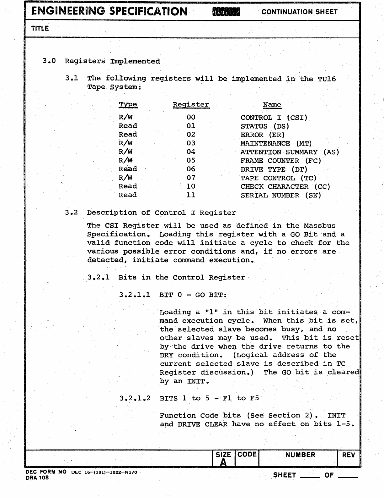
3.1
'
The
following
registers
will
be,
implemented
in
the
TU16
Tape
System:
3.2
Type
Register
Name'
-
R/W
00
CONTROL
I
~CSI)
,
Read
01
STATUS
(DS)
Read
02
ERROR
'(ER)
R/W
03
MAINTENANCE
(MT)
R/W
04
ATTENTION
,SUMMARY
(AS)
R/W'
05
FRAME
COUNTER
(FC)
R~ad
06
DRIVE
TYPE
(DT)
R/W
07
TAPE'
CONTROL
(TC)
Read
10
CHECK
CHARACTER
(CC)
Read'
11
SERIAL
NUMBER
(SN)
Description
of
Control
I
Register
The
CSI
Register
,will
be
used
as,
defined
in
the
Massbus
Specification.
Loading
this
register
with
a
GO
Bit
'and
a
valid
function
code
will
initiate
a
cycle
to
check
for
the'
various
possible
error
conditions
and,
if
no
errors
are
detected,
initiate
command
execution.
,
3.2.'1
Bits
in
the
Control
Register
3.2.1.1
BIT
0 -
GO
BIT:
Loading
a
"I"
in
this
bit
initiates
a
com
....
mand
execution
cycle.
When
this
bit
is
set,
'the
selected
slave
becomes
busy,
and
no
other
slaves
may
be
used.
This
bit
is
reset
by,·the
drive
when
the
'drive
returns
to
the
DRY
condition.
(Logical
address
of'
the
current
selected
slave
is
described
in
TC
Register
disctission.)
The
GO
bit
is
cleared
by
an
INIT.
3.2.102
BITS
1
to
5 -
F1
to
F5
Function
Code
bits
(Se~Section
2).
INIT
and
DRIVE
CLEAR
have
no
effect
on
bits
1-5.
SIZE NUMBER
REV
A
DEC FORM NO
DEC
16-(381)-:-1022-N370
D~A
108
SHEET OF
__
ENGINEERING·.
SPECIFICATION
CONTINUATION SHEET
TITLE'
'3.2
8
1.3
BIT
11
-
DRIVE
AVAILABLE
(DVA)
Always
set
in
TU16.
·3.2.1.4
For
a
description
of
the
other
CSI
bits,
·consult
the
Massbus
spe'cification,
and
the
various
controller
spe~ifications.
3.3
Description
of
the
STATUS
Register:
The
~ta1;.us
register
indicates
the
sta~us
of
various
sections
of·
the
drive.
Individual
bits
which.
are
generated
in'
the
selected
slave
will
be
followed
by
(SS).
Bits
which
can
be
generated
by
any
slaves
will
be
followed
by.(S).
Bits
which
are
generated
in
the'
TM02
will
be
foll-owed
by
(M).
3.3.1
Bi£s~in
the
Status
Register:
3.3.1.1
Bit
0 --SLAVE
ATTENTION
(SLA)
~
(SS):
Asserted
by
a
selected
slave
which
requires
attention
for
one
of
the
following
reasons:
REWIND
complet~d,
detection
of
power
fail,
coming
ONLINE,
going
OFFLINE.
SLA
is
cleared
by
DRIVE
CLEAR
or
INIT
(sections
2 • 2
.4
,
2-
• 3
.1
) .•
3.3.1.2
BIT 1 -
BEGINNING
OF
TAPE
(BOT)
(SS):
Asserted
whenever
the
selected
slave
de-
tects
the
BOT
marker
•.
INIT
and
DRIVE
CLEAR
cannot
affect
this
bit~·
_
3.3.1.3
BIT 2 -
END
OF
FILE (EOF) (M):
Asserted
when a
'filemark
is
detected:
re-
mains
asserted
until
the
next
tape
motion
-operation
is
initia.ted.
The
phase
Encoded
filemark
written
by
TUl6
·consists
of
40
characters
with
zero's
i:Q
tracks
1,
2,
4,
5,
7,
and
8
and
with
tracks
3,
6,
and
9
DC
erased.
The
NRZI
filemark
written
by
the
i
TU16
consists
of
a
single
character
record
followed
by
the
LRC
for
that
record.
SIZE CODE NUMBER
REV
DEC FORM
NO
DEC
16-(381)-1022-N370
ORA
108
SHEET OF
ENGINEERING
.SPECIFICATION
CONTINUATION SHEET
" TITLE
The
single
record
contains
octa1
023
on
9-Track
slaves
and
octal
017
on
7-Track
slaves.
EOF
should
be
high
after
the
com-
pletion
of
a WRITE FILEMARK
command
...
INIT
clears
EOF, DRIVE
CLEAR
does
not
affect
it.
3.3.1
04
BIT
3 - IDENTIFICATION BURST
(IDB)
(M):
Set
on
recog~ition
of
the
PE
identi~ication
burst
o
In
the
forward
direction
the
bit
remains
set
thru
the
READING, WRITING,
OR
SPACING
operation.
On a PE
tape,
IDB
should
be
asserted
after
any
tape
motion
operation
which
began
from
BOT. IDB
becomes
reset
when
another
command
is
issued.
Cleared
by
INIT
or
DRIVE CLEARo.
3.3.1.5
BIT
4 - SLOWING-SETTLING
DOWN
(SDWN)
(SS):
This
bit
is
set
during
the
period
when
tape
motion
is
stopping.
"DRY
is
asserted
on
the
leading
edge
of
SDWN.
DRIVE
CLEAR
and
INIT.
cannot
affect
this
bit.
3.3,,1.6
BIT
5 - PHASE
ENCODED
STATUS
(PES)
(SS):
This
bit
reflects
the
format
mode
in
which
the.
formatter
is
oper.ating.
'PES
originates
in
the
selected
slave
and
in
TU16
should
be
.
identical
to
BIT
10
in
TC
register.
It
is
asserted
when
selected
slave
in
PEmode,
negated
when
selected
slave
in
NRZI
mode.
DRIVE
CLEAR
and
INIT
cannot
affect
this
bit.
(See
also
bits
8-10
of
TAPE
CONTROLRegis~·;
ter)
0
3.3.1.7
BIT
6 -
SLAVE
STATUS
CHANGE
'(SSC)
(M):
This
bit
is
asserted
and
latched
by
the
TM02
whenever
any
slave
has
an
attention
condition
as
defined
in'
Section
3.3.1.1
NUMBER
REV
DEC FORM NO
DEC
16-(381)"';'1022--N370
ORA
108
'SHEET
___
_ OF
__
ENGINEIERINGSPECIFICATION
..
CONTINUATION SHEET
TITLE
Setting
sse
results
in
ATA
becoming
as-
serted
as
soon
as
DRY
becomes
asserted,
(ATA
becomes
asserted
immediately
if
DRY
is
already
asserted.)
INIT
always
clears
sse.
DRIVE
CLEAR
clears
sse
if
only
the
selected
slave
has
a
·current
attention
condition.
Note
that
power-fail
in
a
slave·is
a
transient
attention
condi-
tion,
and
that
sse
should
not
be
cleared
before
polling
all
slaves
to
confim
their
st·atus.
3
'.
3.1.8
BIT
7 - DRIVE
READY
(DRY)
-
(M):
Asserted
at
completion
of
any
command.
INIT
sets
DRY.
.
3.301.9
BIT
8 - DRIVE PRESENT (DPR)
(M):
Always
asserted
in
the
TUl6
system.
3.3.1.10.
BIT
9 -
NEUTRAL
(NTL)
~(M):
Always
negated
in
the
TU16
system.
3.3.1.1IBIT
10
-
END
OF
TAPE
(EOT) -
(SS):
When
the
EOT
marker
is
'recognized
during
forward.
tape
motion,
·th;is,
bit
is
set.
It
is
reset
when
the
EOT
Marker
is
passed
over
during
reverse
tape
motion.
DRIVE
C.LEAR
and
INIT
do
not
affect
EOT.
3.3.1.12
BIT
11
-WRITE
LOCK
(WRLl -
(SS):
Asserted
whenever
a
reel
of
.tape
without
a
write
enable
ring
is
loaded
on
the
selected
slave.
DRIVE
CLEAR
and
INITcannot
affect
this
bit
..
3.3.1.13
BIT
12
-
MEDIUM
ON
LINE
(MOL)
-
(SS):
The
selected
slave
is
loaded
and
the
online
switch
activated.
This
condition
is
neces~
sary
for
response
to
any
commands,
i.e.,
if
'GO
= 1
and
MOL
=~,
cornmandis
aborted,
and
UNS
andATA
become
asserted.
DRIVE
CLEAR
and
INIT
cannot
affect
this
bit.
SIZE CODE NUMBER
REV
DEC FORM
NO
DEC
16-(381)-1022:-N370
ORA 1Q8 SHEET
__
OF
__
ENGINEERING
SPECIFICATION
CONTINUATION SHEET
TITLE
'3.3.1.14
BIT
13
-POSITIONING
IN
PROCESS
(PIP)
-
Asserted
during
SPACE
(.M)
and
REWI~TD
(SS)
operations.
Cleared
by
INIT
during
SPACE
operationsQ
Unaffected
by
DRIVE
CLEAR
or
INIT
during
REWIND
operations,
DRIVE
CLEAR
cannot
be
issued
during
SPACE
operations.
3.3.1.15
BIT
14
-COMPOSITE
ERRO~
(ERR) -
(M):
,Asserted
whenever
any
error
bit
in
the,
Error
(ER)
register
is
asserted.
Reset
by
Drive
Clear
or
INIT.'
(See
Sections
2.2.3.4
and
2.3.)
3.3.1.16
BIT
15
-ATTENTION ACTIVE (ATA) -
(M):
See
Section
50
3.4
Description
of
the
ERROR
Register.
See
Section
4
for
des-
criptions
of
error-handling
algorithms.,
3.4.1
'Bits
in
the
ERROR
Register
~,
3
.4
.1.1
BIT
0 - ILLEGAL FUNCTION (
ILF)
:
Asserted
when
GO
bit
is
loaded
with
a
11111,
and
BITS
F1
to
F5
of
CSI
do
not
denote
a
function
implemented
by
the
TU16.
Cleared
by
INIT
or
DR;I:iJE
CLEAR.
3.4.1.2
BIT
1 - ILLEGAL REGISTER
(ILR):
Asserted
if
the
Controll'er
addresses
a
regi-
ster
which
is
not
implemented
on
the
TU16.
No
register
modification
s~ould
occur.,
On
a
Control
Bus
read,
all
,zeros
are
gated
onto
CONTROL
lines.
Cleared
by
INIT
or
DRIVE
CLEAR.
SIZE CODE NUMBER
REV
A
DEC FOR'" NO
DEC
16-(381)-l022~370
ORA
108
SHEET OF
__
~NGINEERINGSPECIFICATION
CONTINUATION SHEET
TITLE
3.4.1.3
BIT
2 - REGISTER'MODIFICATION REFUSED (RMR):
Asserted
whenever
the
controller
attempts
to
write
into
any
implement'ed
TU16
Register
except
Register
3
(Maintenance)
or
Register
4
(Attention
Summary),while
the
GO
bit
is
asserted.
If
RMR
occurs,
the
addressed
'register
is
not
modified:
ATA
becomes
as-
serted
as
soon
as
DRy'is
asserted.
Cleared
by
INIT
or
DRIVE CLEAR."
3.4.104
BIT
3 -
MASSBUS
PARITY
ERROR
(PAR):
Asserted
whenever
a
parity
error
is
detec-
,ted
on
the
Massbus
DATA,
Lines
or
CONTROL
Lines
when
data
is
being
transmitted
from
the
Controller
to
the
TM02.
ATA
becomes
asserted
as
soon
as
DRY
is
asserted.
No
register
modificationshould'occur
on
CONTROL
bus
writes.,
Cl~ared
by
INIT
or
DRIVE CLEAR.'
3.4.1.5
BIT
4 -
FORMAT
ERROR
(FMT):
Asserted
whenever
a
data
transfer
command
is
loaded
with
GO
= 1
and
the
tape
format
code
loaded
in
the
TC
Reglster
is
not
im-
plemented
on
that
TM0.2.
Tape
motion
is
in-
hibited:
EXC
aridEBL
are
raised.
DRyand
ATA
become
asserted
whenEBL
becomesnega-
ted.
Cleared
by
INIT
or
DRIVE CLEAR. '
304.1.6
BIT
5 -
FORMATTER
PARITY
ERROR
(FPAR):
Asserted
whenever·
a
parity
error
is
detec-
,
ted
during
the
process
of
transfonning
tape
word
images
into
Massbus
word
images.
(Will
not
be
implemented
on
all
tape
formats.),
ATA
becomes
asserted
when
DRY
becomes
as-
serted.
Cleared
by
INIT
or
DRIVE CLEAR.
NUMBER REV,
DEC FORM NO
DEC
16-(381)-~022~370
D~A
10a
SHEET
__
OF
__
ENGINEERING
SPECIFICATION
CONTINUATION SHEET
TITLE,
'
3.4.1.7
,BIT
6 -INCORRECTABLE
DATA
ERROR/VPE
',(INC/VPE) :
Asserted
when
performing
a
data
transfer
on,
a PE
sl~ve
and
multiple
dead
tracks,
dead
tracks
without
parity
errors,
parity
errors
without
dead
tracks,
or
skew
overflow
are
detected.
Asserted
when
performing
a'data
transfer
on
an
NRZ
slave
and
a
vertical
parity
error
is
detected.
Cleared
by
DRIVE
CLEAR
or
INIT.
3.4
..
14»8
BIT
7 -
FORMAT
ERROR/LR~
(PEF/LRC):
In
PE
mode
this
bi
t
is,
asserted
whenever
an
invalid
preamble
or
postamble
is
discovered.
In
NRZ
mode,
the
bit
is
asserted
when
the
LRC
character
generated
from
readback
data
does
not
match
the
LRC
character
read
from
tape.
ATA
becomes
asserted
when
DRY
be-
comes
asserted.
Cleared
by
INIT
or
DRIVE
CLEAR.
3.4.1.9
BIT
8 -
BAD
TAPE
ERROR
(BTE):'",'
Asserted
whenever
any
t~pe
characters
are
read
while
the
read
head
is
scanning
the
first
half
of
the
inter-record
gap.
ATA
becomes
asserted
when
DRY
becomes,
asserted.
Cleared
by
INIT
or
DRIVE CLEAR.
,3.4.1.10
BIT
9 -
FRAME
COUNT
ERROR
(FCE):
Asserted
whenever
a SPACE, READ,
or
WRITE
terminates
and
the
FRAME'C.oUNTERcontains'
,any
number
but
octal
00'00.'
ATA
becomes
as,;..
serted
when
DRY
becomes
asserted.
'
Detec-
tion
of
this
error
is
affected
by
state
of
INHIBIT
RECORD
LENGTH
ERROR
and
IGNORE
FRAME
"C()~T
bits
in
TAPE'
CONTROL
Register
•
FCE
cleared
by
INIT
o~
DRIVE CLEAR.
(See
IFC
bit,
section
3.9.8)
SIZE CODE
NUMBER
REV
A
DEC'
FORM
NO
DEC
16-(381)-1022-N370
O~A
108
SHEET
OF
__
ENGINEERING
SPECIFICATION
-CONTINUATION
SH~ET
TITLE
3.4.1.11
BIT
10
-
CORRECTABLE
SKEW/ILLEGAL
FILE
MARK
I(CS/IFM):
In
PE
mode,
this
bi:t'is
asserted
when
ex-
cessive
but
correctable
skew
is
detected
in
data
read
back
from
tape.
It
is
a
warning
only,
and
does
not
indicate
that
bad
data
was
read
from
tape.
In
NRZ
mode,
this
bit
is
asserted
when
a
bit
pattern
is
detected
on
tape
which
has
the
general
characteristics
of
an
NRZ
fi1e-
mark
(specifically,
a
one-character
record
followed
by
another
one-character
record
spaced
an
appropriate
distance
away
from
the
first)
but
which
"does
riot
contain
the"
exact
data
expected
in
an
NRZ
filemark.
, When
such
a
bit
pattern
is
detected
in
NRZ
mode,
both
EOF
in
the
DSRegister
and
CS/IFM
in
the
ER
Register
will
,become
asserted.
CS/IFM
is
cleared
by
DRIVE
CLEAR
or
INIT.
(See
Figure
4.1.3.1.)
3.4.1.12
BIT
11
-NON-EXECUTABLE FUNCTION
(NEF):
Asserted
whenever
one
of
the
following
occurs:
3.4.1.12.1
write
operation
requested
with
WRL
status
bit
asserted.
3.4.1.12.2
SPACE REVERSE
or
READ,REVERSE
or
WRITE
CHECK
REVERSE
reques-
ted
with'BOT
status
bit
as-
serted.,
3.4.1012.3
PE!NRZI
bit
loaded
into
TC
Register'
does
not
agree
with
PES
status
b~t
asserted
~yse-
1ected
slave.'
NUMBER
REV
DEC
FO,RM
NO
DEC
16-(381)-1022-N'370
ORA
108'
SHEET
OF
ENGINEERING
SPECIFICATION
· CONTINUATIQN SHEET
TITLE
3.4.1.12.4
SPACE,
READ,
or
WRITE
command
is
loaded
with
GO
= 1
and·
peL
in
TAPE
CONTROL
Register
=
~
and
IFC
in
TC
Register
= fl.
3.4.1.12.5
READ
or
WRITE
coinmand
is·loaded
with
DEN2
in
TAPE
CONTROL
Regis-
ter
= 0
and
FRAME
COUNT
Regis-
ter
set
to
two's
complement
of
1
or
2.
angIFC
=
~._~iniJJ!~I1l
NRZ_
recoJ;"q
:Length
:!-.s
3
data
characters.
)
Cleared
by
INIT
or
DRIVE
CLEAR.
304.1·11113
. BIT
12
-
DRIVE
TIMING
ERROR.
(DTE):
DEC FORM
NO
DEC
16-(381)-:-1022-N370
ORA
108
Asserted
whenever
one
of
the
following
occurs:
a)
During
a
WRITE
operation,
a
SCLK
signal
was
generated,
and
a
WCLKsignal
was
not
received·
in
timetoprtivide
valid
data
for
the
next
tape
character
writ-
ten.
b)
A
data
transfer
co~and
was
load~d
into
the
TU16/TM02
system
while
oce =
1.
Case
a)
can
be
distinguished
from
case
b)
by
looking
at.
the
FRAME.
COUNT
Register.
In
case
a),
the.
Fe
Register
will
have
been
in-
cremented
at
least
once
since.its
loading.
In
case
b),
the
FC
Register
will
contain
the
same
number
with
which
it
was
loaded
prior
to
the
loading
of
the
data
transfer
command.
Also,
DTE
during
a
READ
operation
can
occur
only
due
to
case
b)_.
DTE
is
cleared.by
INITor
DRIVE
CLEAR.
NUMBER
REV
SHEET·
__
OF.
__
ENGINEERING
SPECifiCATION
..
CONTINUATION SHEET
,
TITLE
3.4.1.14
BIT
13--
OPERATION INCOMPLETE
(OPI):
Asserted
if
no
record
is
detected
within
7
seconds
after
initiation
of
a
READ
or
SPACE
command.
Asserted
if
no
record
is
detected
within
0.7
seconds
after
initia-
tion
of
a WRITE
command.
(Initiation
of
a
command
==
setting
GO
to
1
with
bits
F1
to
F5
of
CSI
Register
set
to
the
Function
'Code
for
that
command.)'
OPI
is
cleared
by
INIT
or
DRIVE CLEAR.
3.4.1.15
BIT
14
-DRIVE
UNS
(UNS):
Asserted
if
GO
=
,I
and,
MOL
in
STRegister
=
¢.
Also
asserted
if'TM02
detects
irmninent
power-fail
condition.
(AC
LO
signal
is
asserted,
DC
LO
signal
,not
asserted.
See
A-SP-5409728-0-8.)
If
UNS
is
caused
by
GO
='1
while
MOL
=
0,
it
is
cleared
by
INIT
or
DRIVE CLEAR.
If
UNS
is
caused
by
a
transient
voltage
-
low
condition,
it
can
be
cleared
by
INIT
or
DRIVE
CLEAR
when
voltage
returns
to
an
ac-
ceptable
level.
If
UNS
is
caused
by
a
permanent
voltage
-
low
condition,
it
can-
not
be
cleared.
(See,
Figure
4.1.3.20)
304.1.16
BIT
15
-
CORRECTABLE
DATA
ERROR/CRC
ERROR
(COR/CRC):
In
PE
mode,
this
bit
becomes
asserted
when-
ever
a
tape
parity
error
and
a
single
dead
track
occur
on
the
same
tape
character.
In
this
case,
the
data
bit
in
the
dead
track
is
inverted
to
correct
the
parity
error.
In
NRZ
m9de"
thisbi
t
is
asserted
when
the
CRe
character
gerierated
from
readhack
data
does
not
agree
with
the
CRC
read
from
tape.
COR/CRC
is
cleared
by
DRIVE
CLEAR
or
INIT.
(See
Figure
4.1.3.1.)
SIZE CODE
A
NUMBER
I REV
DEC FORM NO
DEC
16-(381)-1022-N310
DRA108
SHEET
__
OF
__
I
ENGINEERING·SPECIFICATION
CONTINUATION SHEET
TITLE
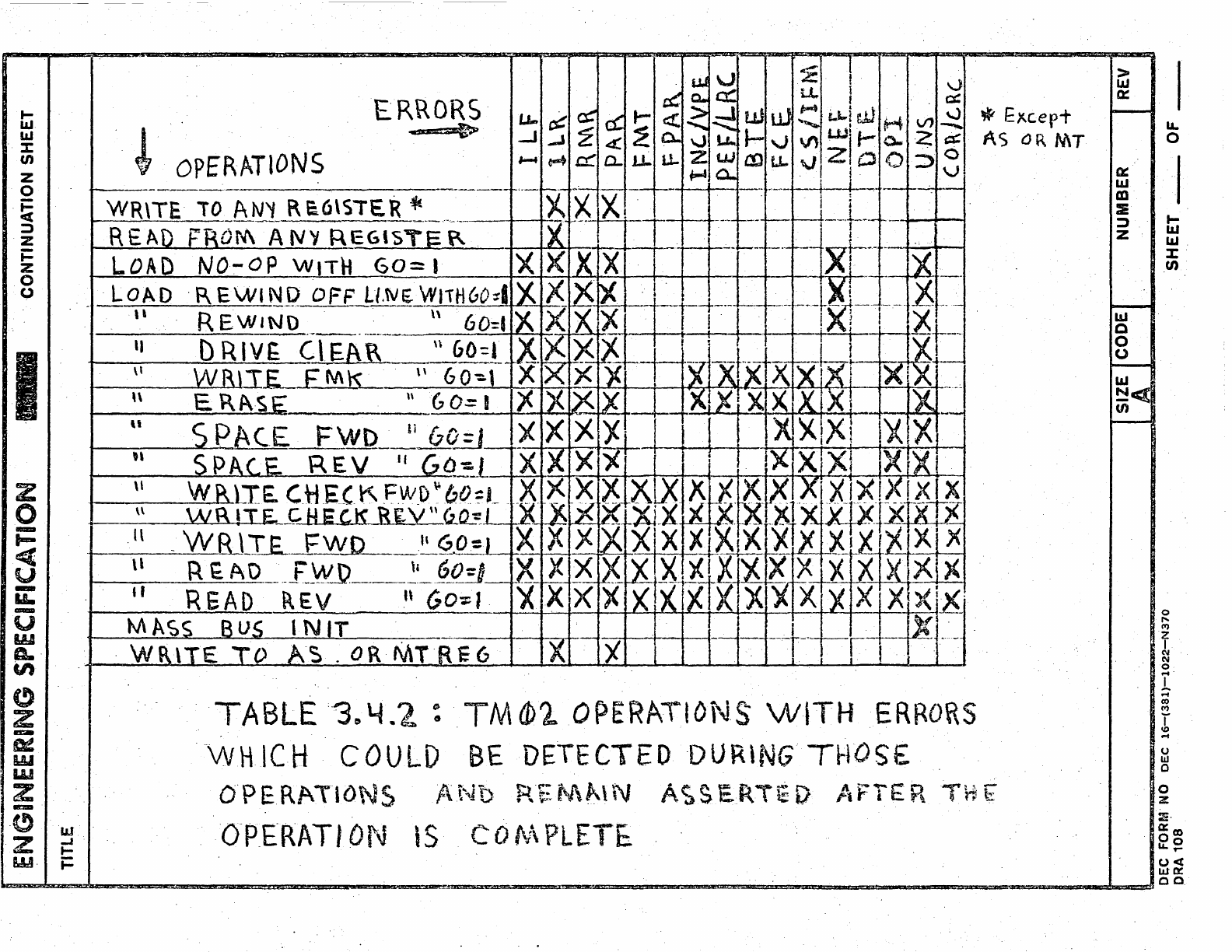
3.4.2
Table
3.4.2
describes
those
errors
which
might
reasonably
be
detected
during
normal
operation
of
the
TU16/TM02
system.
DEC FORM NO
DEC
16-(381)-1022~N370
ORA
108
NUMBER
SHEET
__
OF
__
I
z
0
-
...
<t
u
-
u.
-
U
w
ft..
en
(!)
Z
-
D!
w
'W
Z
-
.(!)
7
-
w·
IJJ
-I
t-
i=
!
OPERATIONS
TABLE '-304.2
:.TMCbl
OPERATIDN·S
WITH
ERRORS
-WHICH
COULD
BE
DETECTED 'DURiNG
TflOS£
~
Exc.ep+
AS
OR
MT
O'p ERf\\IONS ;t'.'-Jb
R~
~J\~\
N
Ac;
S
ERTE
D
I.
FYI::
RTH
E
O-P_ERATI
DI~
is
CO
tv\
PLETE.
>
IJJ
0::
1--
LL.
0
Ct:
I
LIJ
m
:IE
;:)
t-
Z
LIJ
LIJ.
:1:'
CI)
to--
UJ
C
0
(J
~
LIJ
~«
(I)
I--
.
0
I'
C'I)
z
I
C\l
C\l
0
f"4'
1
f"4
co
C'I)
T
r.o
f"4
0
W
0
0
z
:ri.
a:::
co
00
LL,...
0<:
W~
co
ENGINEERING
SPECIFICATION
CONTINUATION SHEET
TITLE
3.5
Description
of
MAINTENANCE
(MT)
Register
The
MT
Register
will
serve
in
the
follciWing
cap~city:
a)
It
will
provide
data
wraparound
paths
for
checking
the
various
sections
of
the
data
formatting
logic
in
the
TM02.
"
b)
It
will
provide
a
means
for
testing
error
dete~tion
circuitry
within
the
TM02.
c)
It
will
act
as
a
storage'buffer
for
the
Longitudinal
Parity
Check
(LRC)
Character
,when:
operating
in
NRZ
mode.
Bits
in
the
MT
Register
are
allocated
in
the
following
manner:
3.5.1
BIT
~
-
Maintenance
Mode
(MM)
Must
be
written
to
'I'
when
any
Maintenance
Mode
function
is
desired.
Setting'
the
MM
bit
to
'I'
does
not
initiate
any
action
on
the
part
of
the
drive,
but
rather,
alters
the
manner
in
which
the
'drive
exe-
,
cutes
various
commands.
The
manner-
in
which
com-
mand
execution
is
altered'depends
on
the
Maintenance
operation
code
resident
in
bits
1-4
of
the
MT
Register.
-,
The
MM
bit
is
cleared
by
DRIVE
CLEAR
or
INIT.
3.5.2
BITS
1
to
4 -
Maintenance
Op
Code
bits
(MOP
%-3):
These
bits
control
the
Maintenance
function
which
will
occur
when
the
MM
bit
is
set
to
III
and
the
TM02
is
loaded
with
the
appropriate
command.,
MOP
~-3
are
cleared
by
DRIVE
CLEAR-
or.:
INIT.
3.5.3
BIT
5 -
Maintenance
Mode
Clock
(Me)
This
bit
controls
the
sequencing
of
data
through
the
TM02
data
paths
when
operating
in
Maintenance
mode.
Cleared
by
DRIVE
CLEAR
or
INIT,
or
by
writing
the
MM
bi
t
to
• ¢ I 0 "
I
S~E
ICODEI
NUMBER
DEC FORM
NO
DEC
16-(381)-1022-N370
'ORA
108 SHEET
__
OF
__
ENGINEERING
SPEC!FICATION
CONTINUATION SHEET
. TITLE
3.5.4
BIT
6 -
Selected
Slave
Clock
(SCK):
This
bit
displays
the
signal
WRT
CLK;
which
is
trans-
mitted
to
the
TM02
from
the·selected
slave.
The
fre-
quency
of
this
clock
is
dependent
both
upon·
the
Density
Select
bits
located
in
bits
8-10
of
the
Tape
Control
Register
and
upon
the
op~rating
speed
of
the
selected
slave.
Its:
pu~pose
is
to
enable
a
check
on
the
proper
decoding
of
the
Density
Select
bits
by
the
selected
slave.
This
bit
cannot
be
cleared.
3.5.5
BITS
7
to
15
-
Maintenance
Data
Field
(MDF
¢~8):
.
These
bits
act
as
a
buffer
for
data
generated
during
checks
of
the
TM02
data
pathso
In
addition,
at
the
end
of
dat~
transfer
operations
in
NRZ
mode,
this
field
holds
the
LRC
character
for
the
last
record
read.
MDF
~
contains
the
parity
bit
for
the
maintenance·
data
character.
MDF
I
contains
the
least
signifi-
cant
bit
of
the
maintenance
data
character,
and
the
remaining
higher
order
bits
are
contained,
in
order,
in
MDF
2.
through
8.
I
REV
SIZE CODE
A NUMBER
DEC FORM
NO
DEC
16-(381)-1022-N370
ORA
108
SHEET
__
OF
__
ENGINEERING
SPECIFICATION
CONTINUATION
SHEET
TITLE
3.6
ATTENTION
SUMMARY
Register
This
Regi~ter
will
be
handled
in
accordance
with
the
Mass-
bus
Specificationo
During
a
Control
Bus
write
to
Register
04,
the
Control
line
corresponding
to
the
TMO'2
I s
logical
address
on
the
Massbus
will
be
gated
to,
the
ATA
bit.
Durin,
a
ControlBus
read
of
Register'
04,
the,
TM02
IS
ATA
bit
will
be
ga~ed
onto
the
Cline
corresponding
,to
the
TM02's
logica
address
on
the
Massbus.
For
further
discussion
of
theATA
bit,
see
Section
4,
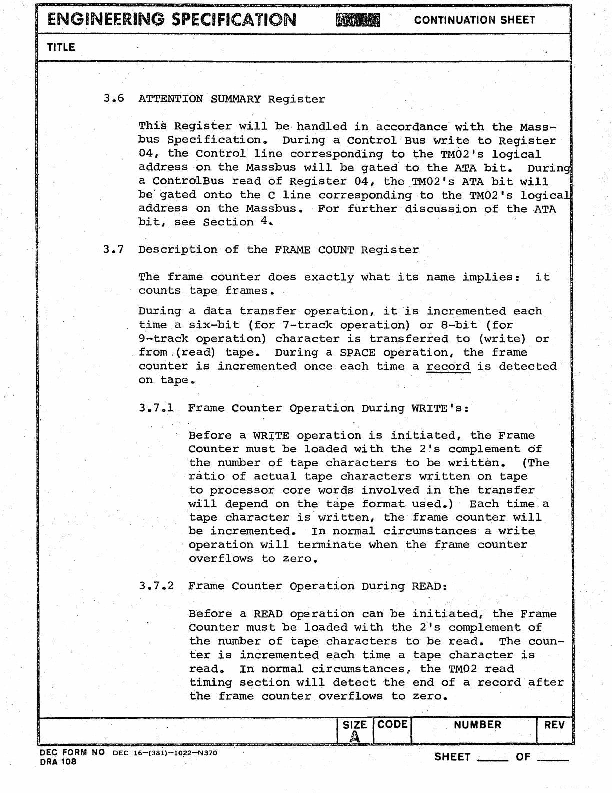
3.7
Description
of
the
FRAME
COUNT
Register
The
frame
counter
does
exactly
what
its
name
implies:
it
counts
tape
frames
•.
During
a
data
transfer
operation,
it
'is
incremented
each
time
a
six-bit
(for
7-track
operation)
or
8-bit
(for
9-track
operation)
character
is
transferred
to
(write)
or
from.(read)
tape.
During
a SPACE
operation,
the
frame
counter
is
i.ncremented
once
each
time
a
record'is
detected'
On
'tape.
38701
Frame
Counter
Operation
During
WRITE's:
Before
a WRITE
operation
is
initiated,
the
Frame
Counter
must
be
loaded
with
the
2's
complement
df
the
number
of
tape
characters
to
be
written.
(The
'ratio
of
actual
tape
characters
written
on
tape
to
processor
core
words
involved
in
the
transfer
will
depend
on
the
tape
format
used.)
Each
time,a
tape
character
is'written,
theframecount.er
will
be
incremented.
In
normal
circumstances
a
write
operation
will
terminate
when
the
frame
counter
overflows
to
zero.
3.7.2
Frame
Counter
Operation
During
READ:
Before
a
READ
operation
can
be
initiated,
the
Frame
counter
must
be
loaded
wi
th
the
2"
s
complement
of
the
number
of
tape
characters
to
be
read.
The
coun-
ter
is
incremented
each
time
a
tape
character
is
reado
In
normal
circumstances,
the
TM02
read
timing
section
will
detect
,the
end
of
a
record
after
the
frame
counter
overflows
to
zero.
NUMBER
REV
DEC FORM NO
DEC
16-(381)-l022~370
ORA
108
SHEET
__
OF
ENGINEERI~G
SPECIFICATION
CONTINUATION SHEET
TITLE
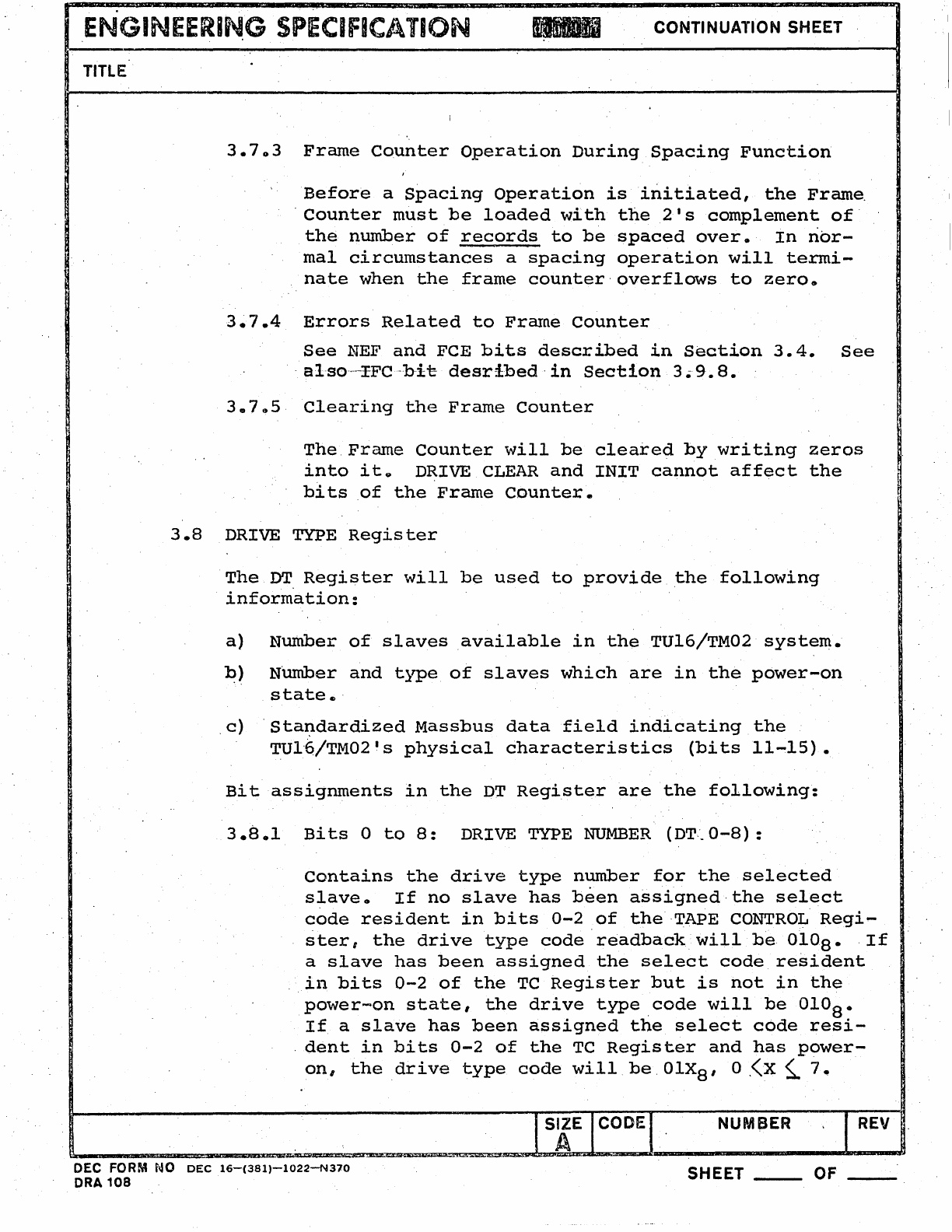
3.703
Frame
Counter
Operation
During
Spacing
Function
Before
a
Spacing
Operation
is
initiated,
the
Frame.
·
Counter
must
be
loaded
with
the
21 s
complement
of·
the
number
of
records
to
be
spaced
over.
In
nor-
mal
circumstances
a
spacing
operation
will
termi-
nate
when
the
frame
counter·
overflows
to
zero
a
3.7.4
Errors
Related
to
Frrune
Counter
3.7
05
See
NEF
and
FCE
bits
described
in
section
3.4.
See
· al·so··---xFC·bi-e
desribed·
in
Section
3.9.
8.
Clearing
the
Frame
Counter
The
Frame
Counter
will
be
cleared
by
writing
zeros
into
it~
DRIVE
CLEAR
and
INIT
cannot
affect
the
bits
of
the
Frame
Counter.
3.8
DRIVE TYPE
Register
The
DT.
Register
will
be
used
to
provide
the
following
information:
a)
Number
of
slaves
available
in
the
TU16/TM02
system.
~)
NUmber
and
type
of
slaves
which
are
in
the
power-on
state
e .
.
c)
Standardized
Massbus
data
field
indicating
the
TUl·6/TM02 1 s
physical
characteristics
(bi
ts
11-15).
Bit
assignments
in
the
DT
Register
are
the
following:
3.8.1
Bi
ts
0
to
8:
DRIVE TYPE
NUMBER
(DT:_
0-8)
:
Contains
the
drive
type
number
for
the
selected
slave.
If
no
slave
has
been
assigned
the
select
code
resident
in
bits
0-2
of
the
TAPE
CONTROL
Regi-
ster,
the
drive
type
code
readbackwillbe
0108.
·If
a
slave
has
been
assigned
the
select
code
resident
in
bits
0-2
of
the
TC
Register
but
is
not
in
the
power-on
state,
the
drive
type
code
will
be
OIOS.
If
a
slave
has
been
assigned
the
select
code
resi-
·
dent
in
bits
0-2
of
the
TC
Register
and
has
power-
on,
the
drive
type
code
will
be.
OlX
S'
O.<X
s..
7.
NUMfjER I
REV
DEC FORM NO
DEC
16-(381)-1022-N370
ORA
108
SHEET
__
OF
__
TITLE
· CONTINUATION SHEET
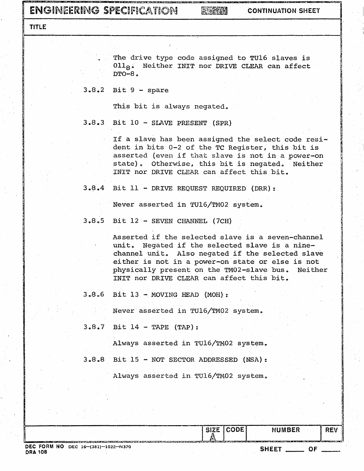
T~e
drive
type
code
assigned
to
TU16
slaves
is
Ol18~'
Ne,ither
INIT
nor
DRIVE CLEAR
can
affect
DTO-8(11
3.8.2
Bit
9 -
spare
This
bit
is
always
negated~
3.8.3
Bit
10
-
SLAVE
PRESENT
(SPR)
If
a
slave
has
been
assigned
the
select
code
resi-
dent
in
bits
0-2
of
the
TC
Register,
this
bit
is
asserted
(even
if
that
slave
is
not
in
a
power-on
state)
&
Otherwise,
this
bit
is
negatedo
Nei,ther
INIT
nor
DRIVE CLEAR
can
affect
this
bit.
3$8.4
Bit
11
-DRIVE REQUEST REQUIRED
(DRR):
'Never
asserted
in
TU16/TM02
systemo
3.805
Bit
12
-SEVEN
CI~~~L
(7CH)
Asserted
if
the
selected
slave
is
a
seven-channel
unit.
Negated
if
the
selected
slave
is
a
nine-
channel
unit
o
Also
negated
if
the
selected
slave
either
is
not
in
a
power-on
state
or
else
is
not
physically
present
on
the
TM02-s1ave
bus",
Neither
INIT
nor
DRIVE CLEAR
can
affect
this
bit.
3.8
06
Bit
13
~
MOVING
HEAD
(MOH):
Never·
asserted
in
TU16/TM02
system.
30
8.7
Bit
14
-'rAPE
(TAP):
,Always
asserted
in
TU16!TM02
syst~mo
3.8.8
Bit
15
-
NOT
SECTOR ADDRESSED
(NSA):
Always
asserted
in
TU16!T.fI.i02
systemQ
pm-=~~~~~-=
____
~~~~=~~=======~==-=~~=-~=-_~
__
~~~5~~~U~~
ENGINEERING
SPEClfICAT~ON
CONTINUATION SHEET
TITLE
.~--~----------------------------------------------------------------------~
I,
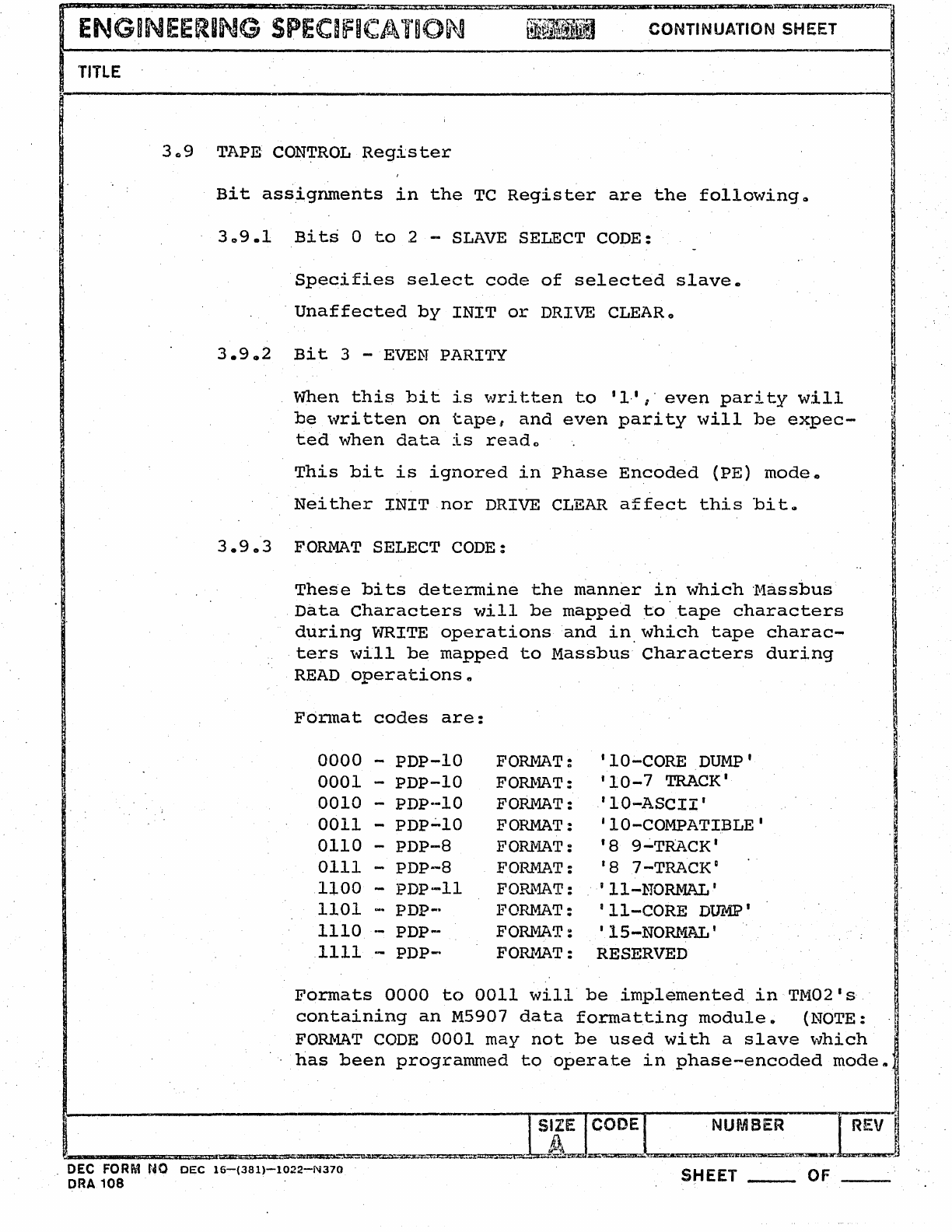
3Q9
I],'APE:
CONTROL
Register
Bi
t
assignmen'ts
in
the
TC
Regis
ter
are
the
following
0
30
9.1
Bits
a
to
2 -
SLAVE
SELECT CODE:
Specifies
select
code
of
selected
slave.
Unaffected
by
INIT
or
DRIVE CLEARo
3.9
02
Bit
3 -
EVEN
PARI1~
When
this
bi
t
is
\,lri
tten
to
'1,'
I'
even
pari
ty
will
be
written
on
tape,
and
even
parity
will
be
expec-
ted
when
data
is
reado
This
bit
is
ignored
in
phase
Encoded
(PE)
mode.
Neither
INIT
nor
DRIVE
CLEAR
affect
this
bitg
3.9.3
FORMAT
SELECT CODE:
These
bits
determine
the
manner
in
which
'Massbus
Data
Characters
will
be
mapped
to'tape
characters
during
WRITE
operations
and
in,which
tape
charac-
ters
will
be
mapped
to
Massbus
Characters
during
READ
operations"
Format
codes
are:
0000
-
PDP-lO
FORMAT:
lID-CORE
DUMP'
0001
-
PDP-IO
FOru.1AT:
'10-7
TRACK'
0010
-
PDp·-lO
FORMAT:
'ID-ASCII'
0011
-PDP';"IO FORMAT:
lID-COMPATIBLE'
0110
-
PDP-8
FORMAT: 18
9~TRACK'
0111
-
PDP-8
l?ORMAT: 18 7-TRACK D
1100
-
PDP-II
FORIVlAT:
'II-NORMAL'
1101
-PDP-- FORMAT:
'II-CORE
DUMP'
1110
-
PDP-
FORMAT:
'lS-NORMAL'
1111
--
PDP-
FOru4AT: RESERVED
Formats
0000
to
0011
will
be
implemented
in
TM02 1s
containing
an
M5907
data
formatting
module.
(NOTE:
FO~l~T
CODE
0001
may
not
be
used
with
a
slave
which
has
been
programmed
to
operate
in
phase-encoded
modes
NUMBER
REV
1
~
I
I.
~
I
I
~
~~~==~~===--r'~~~"U
. DEC FORM
NO
DEC
16-(381)-1022-N370
ORA
108
SHEET
__
OF
ENGINEERING
SPECIF~CATiON
CONTINUATION SHEET
TITLI;
For-
mats
1100
to
1111
will
be
implemented
on
TM02's
containing
an
M5906
data
formatting
module.
Codes
not
listed
here
are
not
implemented.
If
the
FORMAT
SELECT
bits
specify
a
format
not
im-
plemented
on
a
given
TU16/TM02
system,
and
a·valid
data
transfer
command
is
loaded
into
the
CSI
Regis-
ter
setting
GO
=
I,
then
FORMAT
ERROR
(FMT,
bit
4
of
ER
Register)
will
become
asserted,
and
the
opera-
tion
will
be
aborted.
Neither
INIT
nor
DRIVE
CLEAR
affects
the
FORMAT
SELEC'I'
bi
ts
II
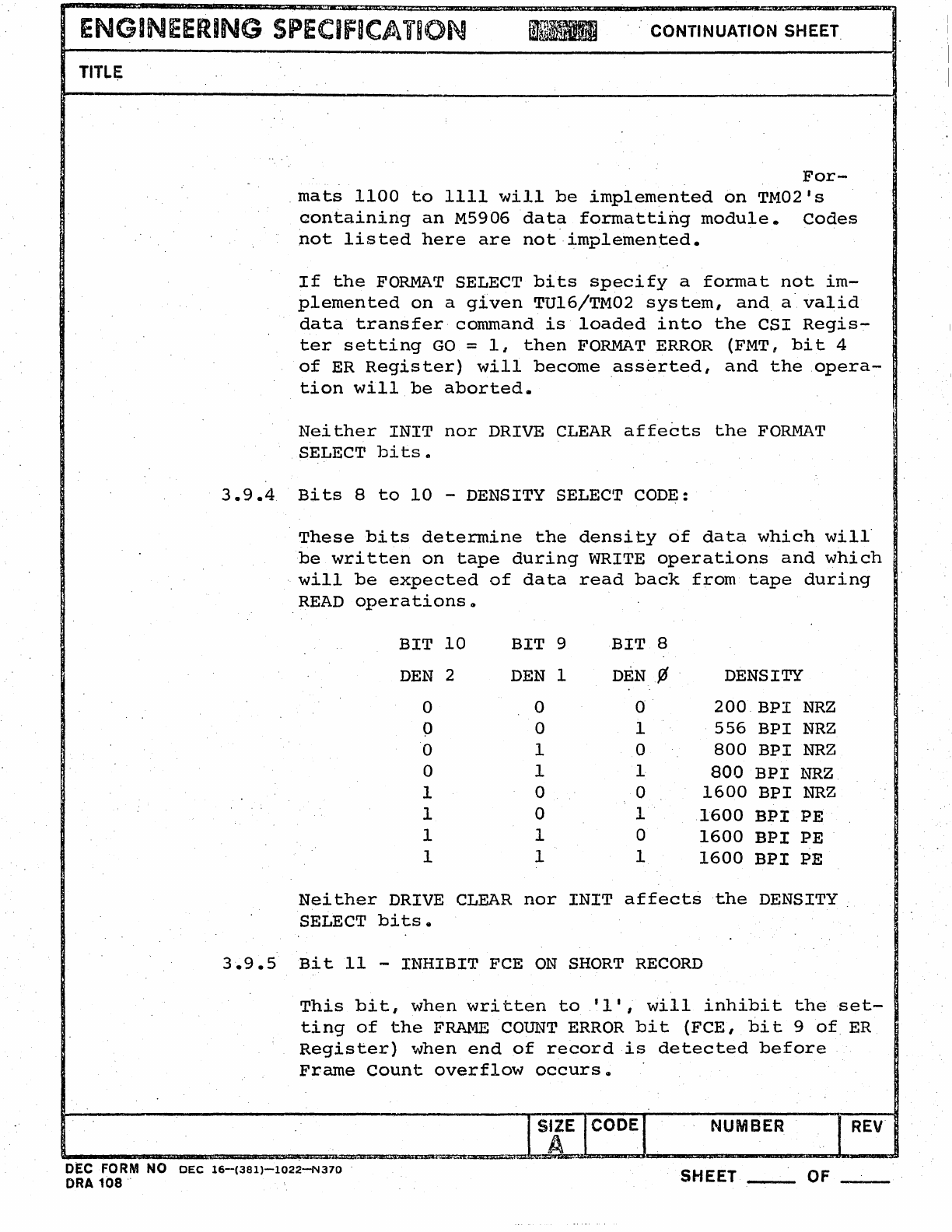
3.9.4
Bi
ts
8
to
10
-DENSITY SELEClr CODE:
These
bits
determine
the
density
of
data
which
will·
be
written
on
tape
during
WRITE
operations
and
which
.
will
be
expected
of
da
ta
read
back
from
t.ape
during
READ
operations
..
BIT
10
BIT
9
BIT
8
DEN
2
DEN
1
DEN
¢ DENSITY
0 0 0
200
BPI
NRZ
0 0 1
556
BPI
NRZ
0 1 a
800
BPI
NRZ
0 1 1
800
BPI
NRZ.
1 0 0
1600
BPI
NRZ
1 0
1·
1600
BPI
PE
1 1 0
1600
BPI
PE
1 1 1
1600
BPI
PE
Neither
DRIVE
CLEAR
nor
INIT
affects
the
DENSITY
SELECT
bits.
3.9.5
Bit
11
-
INHIBIT
FCE
ON
SHORT
RECORD
This
bit,
when
written
to
'I',
will
inhibit
the
set-
ting
of
the
FRAME
COUNT
ERROR
bit
(FeE,
bit
9
of
ER
Register)
when
end
of
record
is
detected
before
Frame
Count
overflow
occurs
..
NUMBER
REV
DEC FORM
NO
DEC
16-(381)-1022-NJ70
.
ORA
108··
SHEET
__
OF
__
I
. I
·'
ENGINEERING
SPECIFICA
liON
CONTINUATION SHEET
TITLE
NOTE:
In
some
cases
the
controller
will
not
res-
pond
to
the
TM02's
assertion
of
END
OF
BLOCK
(EBL:
'Consult
Massbus
Specification)
by
dropping
the
RUN
line
(again,
consult
Massbus
Specification).
Should
this
occur,
the
TM02
will
assert
FRAME
COUNT
ERROR,
indicating
to
the
controller
that
·tne
TM02
has
completed
command
execution.
Consult
the
programming
manual
for
the
various
Massbus
control-
lers
for
further
details.
Nei
the.r
INIT
nor
DRIVE
CLEAR
affects
this
bite
3.9.6
Bit·12-
ENABLE
ABORT
ON
WRITE ERROR:
This
bit,
when
written
to
lID,
will
cause
a
write
operation
to
be
aborted
as
soon
as
one
of
the
fol-
lowing
errors
is
detected:
a)
parity
error
on
Massbus
Data
Bus;
b)
COR/eRC,
bit
15
of
ER
Register;
c)
FMT/LRC,
bit
7
of
ER
Register;
d)
INC/VPE,
bit
6
of
ER
Register;
e)
FPAR,
bit
5,
ER
Register;
Neither
DRIVE
CLEAR
nor
INIT
affects
this
bit
..
3.9.7
Bit
13
-
FRAME
COUNT
LOADED
(FCL)
This
bit
becomes
set
to
III
at
the.
completion
of
a
Massbus
Control
Bus
write
to
theFC
Register.
It
becomes
reset
when
the
FC
Register
is.
clocked
from
the
all-lis
state
to
the
all-Ols
state.
INIT
and
DRIVE
CLEAR
both
cause
this
bit
to
become
reset.
Unless
the
IGNORE
FRAME
COUNT
BIT
is
set,
loading
any
SPACE, READ,
or
WRITE
command
with
GO
=1
while
FCL = 0
\tlill
cause
NON-EXECUTABLE FUNCTION (NEF "
bit
11
of
ST
Register)
to
become
asserted
and
will
.
cause
command
execution
to
be
aborted.
No
ta~e
.
motion
will
occuro
DEC FORM NO
DEC
16-(381)-1022-N370
ORA
108
SHEET
OF
I
p:w~:':.~jj
jll
TITLE
,CONTINUATION
SHEET
3.9uB
Bit
14
-IGNORE
FRAME
COUNT
(IFC):
vlhen
asserted,
.this
bit
inhibits
all
checks
on
the
FRAME
COUNT
Regis,ter
and
FCL
bit,
allowing
execution
of
SPACE" READ,
or
WRITE
operations
to
conunence
re-
gardless
of
the
status
of
the,FC
Register
or
the
FCL
bit.
When
IFC
is
asserted,
READ
operations
will
not,
ter-
minate
until
the
Tfl.102
detects
the
end
Of
a
record
on
tape.
No
check
on
record
length
will
be
made.,
READ
operations
which
take
place
with
IFC
= 1
will
not
terminate
with
FCE = 1
unless
the
condition
described
in
section
309.5
occurs.
When
IFC
is
as-
serted,
READ
or
SPACE
operations
will
still
be
ter-
minated
by
F~m
COUNT
overflow.
'
Neither
DRIVE
CLEAR
nor
INIT'affects
IFC.
3.9.9
Bit
15
~
spare
3.10
CfffiCK
CHARACTER
REGISTER
3.1001
CHECK
CHARACTER
DATA
FIELD
(CCDJ.1-8)
After
the
completion
of
a
READ
or
WRITE
operation,'
this
field
contains
either:
a)
In
PeE.
mode,
the
contents
of.
the
dead
track
register,
or
b)
In
NRZ
mode,
the
contents
of
the
LRC
character.
3.10.101
Dead
Track
Register
Operation
Consider
a
tape
on
\vhich
data
has
been
re-
corded
on
all
nine
tracks
and
which
has
it-
self
been
mounted
on
a
tape
transport.
As-
sign,track
numbers
to
the
various
data,
tracks:
let
track
1
be
the
data
track'
far-
thest
from
the
tape
transport
chassis;
let
track
9
be
the
data
track
closest
to
the
tape
transport
'chassis.
Tracks
2
through
8
are
arranged
in
numerical
order
between
tracks
1
and
90
NUMBER
REV
~_...::r.l~LG:l3lC=.~
__
J~-:JllL!Z!JiiiSi_:s:w::::t;&l,
..
~~~rz;::~:z."iZ:rlr£::~~\".
DEC FORM NO
DEC
16-(381)-:1022-N310
ORA
108
'
SHEET
__
OF
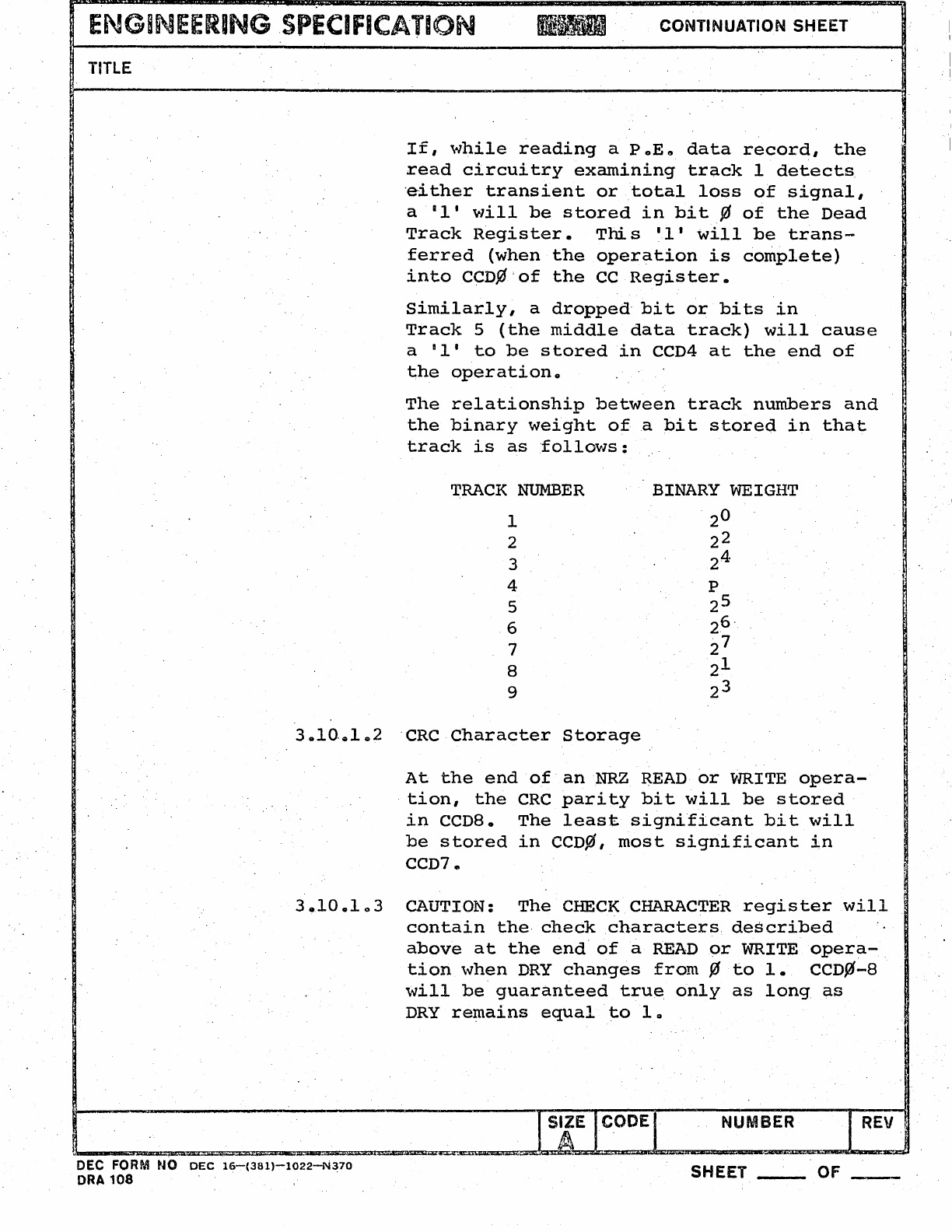
ENGiNEERING
SPECIFICATION
~
..
'l&
""'mAl
~
CONTINUATION SHEET
TITLE
If,
while
reading
a PoEG
data
record,
the
read
circuitry
examining
track
1
detects
'either
transient
or
total
loss
of
signal,
a
III
will
be
stored
in
bit
¢
of
the
Dead
Track
Register.
This
II'
will
be
trans-
ferred
(when
the
operation
is
complete)
into
CCD%'of
the
CC
Register.
Similarly,
a
dropped"
bit
or
bits
in
Track
5
(the
middle
data
track)
will
cause
a
II'
to
be
stored
in
CCD4
at
the
end
of
the
operation.
The
relationship
between
track
numbers
and
the
binary
weight
oia
bit
stored
in
that
track
is
as
follows:
TRACK
NUMBER
1
2
3
4
5
6
7
8
9
3.10..102
"CRC
Character
Storage
BINARY WEIGHT
20
22
24-
p
25
26"
"7
2
21
23
At
the
end
of
anNRZ
READ
or
WRITE
opera-
tion,
the
CRe
parity
bit
will
be
stored
in
CCD8.
The
least
significant
bit
will
be
stored
in
CCD¢,
most
significant
in
CCD7.
3.10.103
CAUTION:
The
CHECK
CHARACTER
register
will
contain
the
check
characters
described
above
at
the
end"
of
a
READ
or
WRITE
opera-
tion
when
DRY
changes
from
¢
to
1.
CCD¢-8
will
be
guaranteed
tru~
only
as
long
as
DRY
remains
equal
to
10
I
S~E
CODEI NUMBER I
REV.
~
____
~~-========--=
__
-=====~~~.~~~_=_=a=~d_~_"=~~=-~~
____
~~-=~--~~.~
DEC FORM NO
DEC
16-(36l)-1022-N370
ORA
108
SHEET
__
OF
I
" I
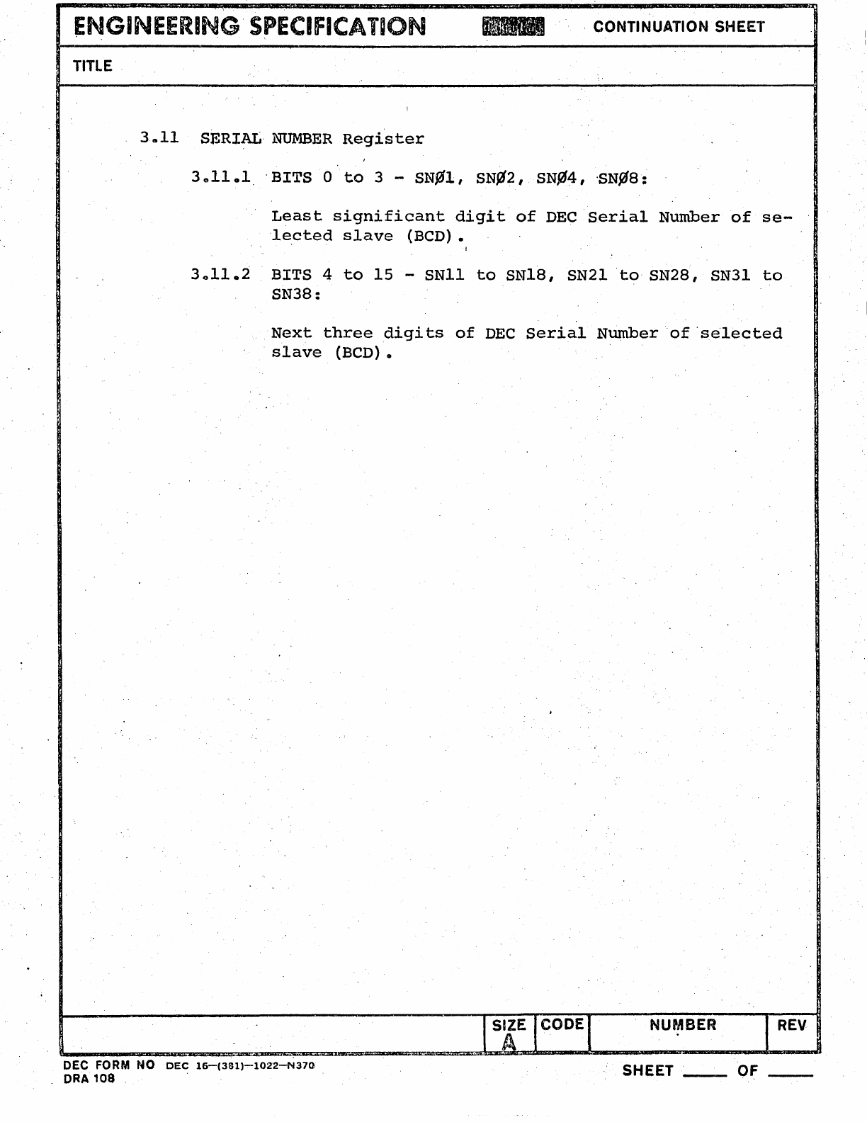
ENGINEERING'
SPECIFICAT~ON
, CONTINUATION SHEET
TITLE
3ca11
SERIAL'
NUMBER
Register
3011.1
'BITS
0
to
3 -
SN911,
SN~2,
SN!l4, 'SNyJ8:
Least
significant
digit
of
DEC
Serial
Number
of
se-
'lected
slave
(BCD).
3011.2
BITS 4
to
15
-SN11
to
SN18, SN21
to
SN28, SN31
to
SN38:
Next
three
digi
ts
of
DEC
Serial
Number"
of
'selected
slave
(BCD).
I
S~E
CODE I
NUMBER
I
REV
~
______
~~
__
-=~~~~~~~~=m~m=m~==~~b~~~--m-
______
~
__________
~
DEC FORM
NO
DEC
16-(381)-1022-N370
ORA
108
' SHEET _'
__
OF
__
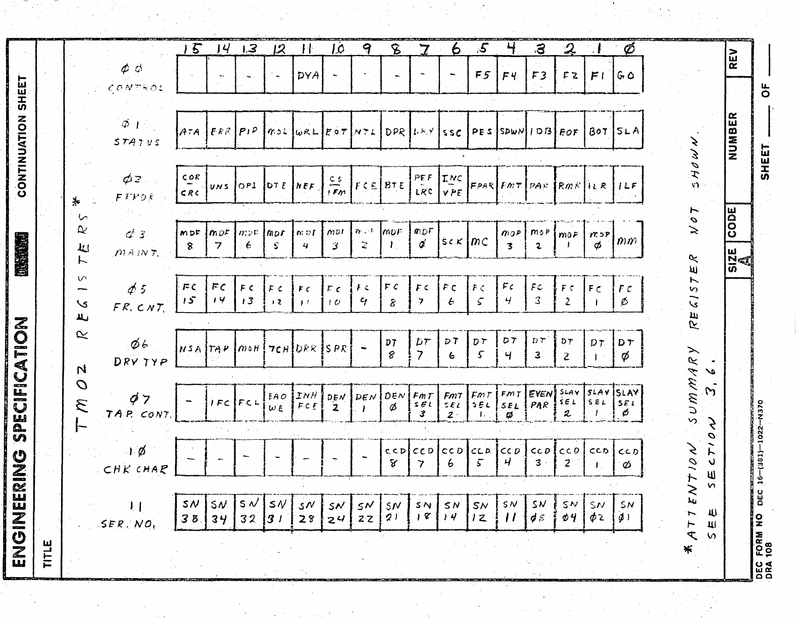
t-
1&1
UJ.
::t:
en
z
o
i=
<t
:l
Z
i=
z
·0
o
·z
0
....
l-
e(
V
IICII!II
LL.
-=-
U
LU
A.
en
.(.')
Z.
-
~
W
'11.1
Z
.-
(!)
Z
w
~
V
D<
~
h
\I!
-
\.5
Jl..i
~
N
~
~
I-
UJ
-I
..-
t=
'.
¢
Ci
(a
0
.tv
~
..
~..
,:)
!-
.j; I
S
""/1
1"1)
5
F
f"}:'
0
:~.
.f}'
A
;N
'i,
¢5
FR.
CN7.
r/>I:.
DRVl'lP
J.
I
.S~f(.·Nq,
It:
-1=(
I
~-
USA
JL/
1.3
I~
1-1'
I.~
---
PYA
-
i-C
I'!
r~p
<;f
~
7 6
;£
'-I
.a
2- ' I
.¢
>
UJ
0::
. -
--
1=5
F'I
J:"3
':'2.
FI
<:'0
I--
La..
0
0:: I
UJ
m
~
:IE
~
j
t-
Z
UJ
&II
~
:c
~
en
v)
'.
t--...
I--
&II
~
C
~
0
0
W
~
N~
10
(/)
h..
~
(r)
-
\s
ll!
~
~
~
-
~
~
I
~
-
~
.M
0
:J
"
If)
V)
~
f
(II
~
(II
0
.
~
.....
....
h 1
....
~.
~.
CO
"
,-
--
~-
'.,.
--.-
-.
1'---'
r--'---n'
.,-
..
-
~--r······-
'-
,'---
-~.-
.........
~.
-1
SN
5('1
5"1
SN
SN
srv
SN!
SN
I
SN
.SN
I
Z·
z ') I I
tz'
} l/ I
2.
'.
r " . .
rJ
is
1
rJ;
'f
!/J
'2.
¢ I
-I
.r-.
U1
\I)
....
"<!
0
)..y
w
a
t--..
!l\ 0
t- III z
~
\t)
:E
~
0::
co
00
Lt...
....
ocr
LLlD:
00
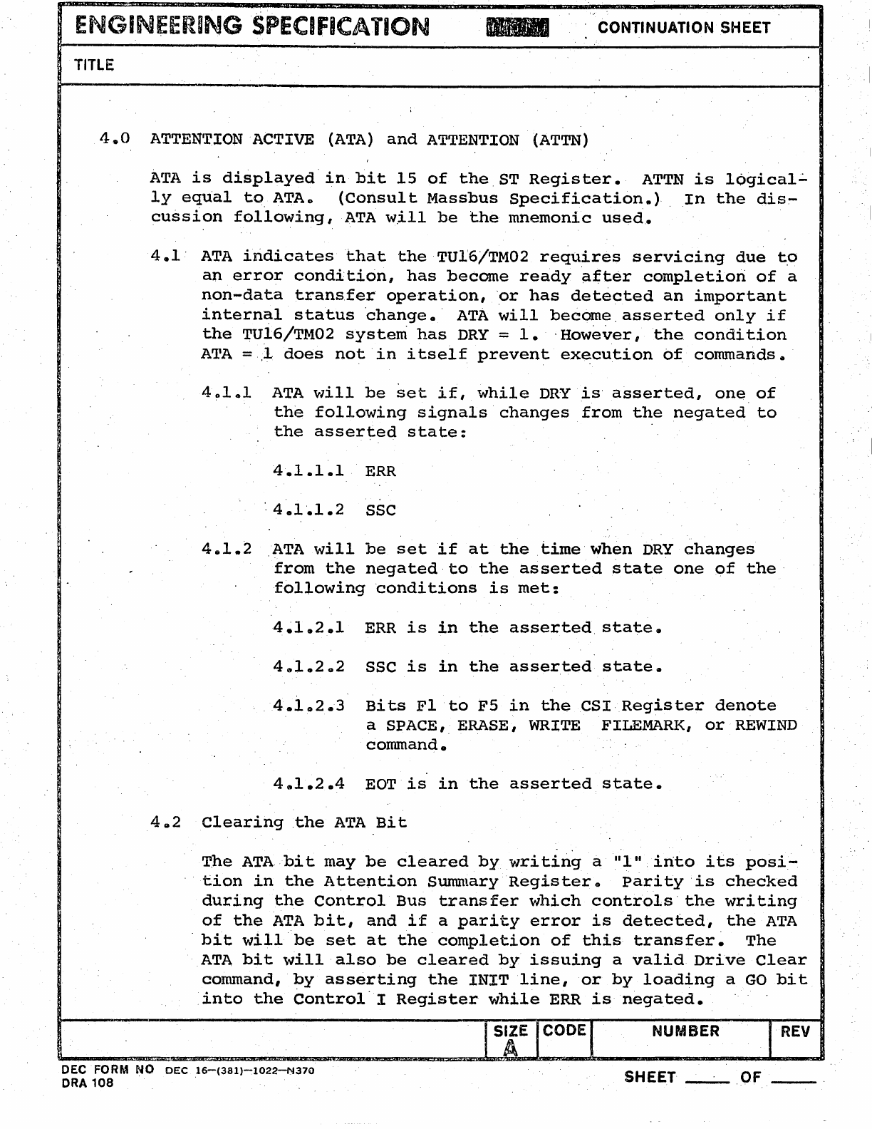
ENGINEERING
SPECIFICATION
CONTINUATION SHEET
TITLE
I
4.0
ATTENTION ACTIVE
(ATA)
and
ATTENTION
(ATTN)
ATA
is
displayed
in
bit
15
of
the
ST
Register.
ATTN
is
l6gical~
ly
equal
to
ATAo
(Consult
Massbus
Specification.)
In
the
dis~
cussion
following
lATA
w.i1l
be
the
mnemonic
used.
. I
4.1'
ATA
iridicatesthat
the
TU1'6/TM02
requires
servicing
due
to
an
error
condition,
has
become
ready
~fter
completion
of
a
non-data
transfer
operation,
'or
has
detected
an
important
internal
status
change.
ATA
will
become.
asserted
only
if
the
TU16/TM02
system
has
DRY
= 1
•.
However,
the
condition
ATA
=.,1
does
not
'in
itself
prevent
execution
of
commands.
401.1
ATA
vli11
be
set
if,
while
DRY
is'
asserted,
one
of
the
following
signals
changes
from
the
negated
to
the
asserted
state:
4.1.1.1
ERR
'·4.1'.1.2
SSC
4.1.2
ATA
\>./i1l
be
set
if
at
the
time
when
DRY
changes
from
the
negated
to
the
asserted
state
one
of
the'
following
conditions
is
met:
4~1.2.l
ERR
is
in
the
asserted.
state.
4.1.202
SSC
is
in
the
asserted
state
•
. .
4.1
0
2.3
Bits
Fl
to
F5
in
the
CSI·
Register
denote
a SPACE, ERASE,
WRITE
FILEMARK,
or
REWIND
command.
4.1.2.4
EOT
is
in
the
asserted
state.
402
Clearing
the
ATA
Bit
T.he
ATAbit
may
be
cleared
by
writing
a
11111.
into
its
posi-
tion
in
the
Attention
Sunuuary
Register.
parity
'is
checked
during
the
Control
Bus
transfer
which
controls'
the
writing
of
the
ATA
bit,
and
if
a
parity
error
is
detected,
the
ATA
.
bit
will
be
set
at
the
completion
of
this
transfer.
The
ATA
bit
will
also
be
cleared
by
issuing
a
valid
Drive
Clear
command,
by
asserting
the
INITline,
or
by
loading
a
GO
bit
into
the
Control
I
Register
while
ERR
is
negated.
NUMBER I
REV
DEC FORM
NO
DEC
16-(381)-1022-N370
SHEET
__
.OF
ORA
108
.
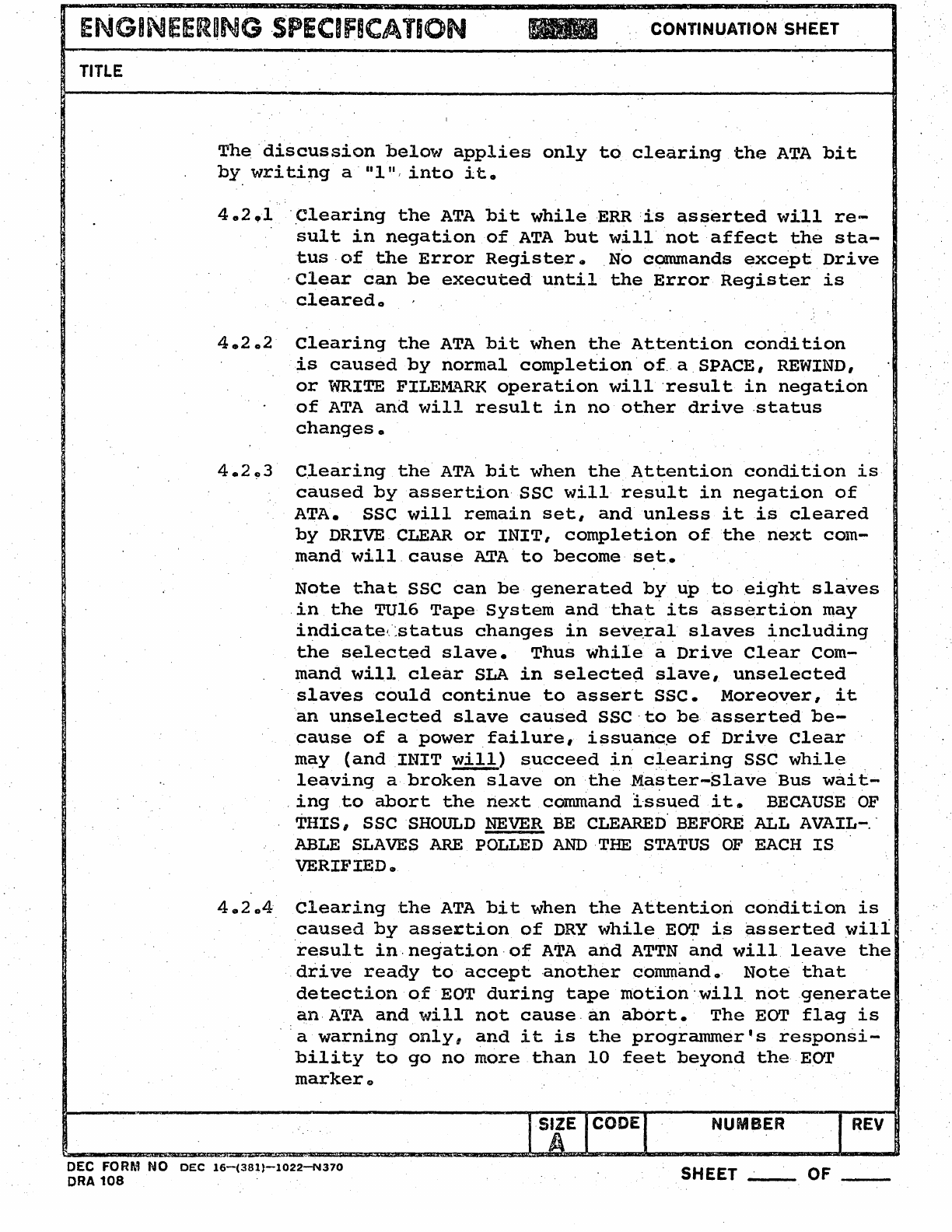
ENGINEERING
·SPECIFICATION
CONTINUATION SHEET
TITLE
The
discussion
below
applies
only
to
clearing
the
ATA
bit
by
writing
a'
11111,
into
it.
4.2.1
·.Clearing
the
ATA
bit
while
ERR
:is
as~erted
\'l~ll
re-
sult
in
negation
of
ATA
but
will
not
affect
the
sta-
tusof
the
Error
Register.
No
commands
except
Drive
-Clear
can
be
executed
until
the
Error
Register
is
cleared.
4.202
Clearing
the
ATA
bit
when
the
Attention
condition
is
caused
by
normal
completion·of.a.SPACE,
REWIND,
or
WRITE
FILEMARK
operation
will'result
in
negation
of
ATA
and
will
result
in
no
other
drive
.status
changes.
4.2~3
C.learing
the
ATA
bit
when
the
Attention
condition
is
caused
by
assertion'SSC
will
result
in
negation
of
ATA.
SSC
will
remain
set,
and
unless
it
is
cleared
by
DRIVE
CLEAR
or
INIT,
completion
of
the
next
com-
mandwill.cause
ATA
to
become
set.
Note
that
SSC
can
be
generated
by
up
to
eight
slaves
.in
the
TUlG
Tape
System
and
that'
its
assertion
may
indicate<status
changes
in
seve.ral
slaves
including
the
selected
slave.
Thus
while
a
Drive
Clear
Com-
mand
will
clear
SLA
in
selected
·slave,.
unselected
slaves
could
continue
to
assert
SSC.
Moreover,
it
an
unselected
slave
caused
SSC·to
be·
asserted
be-
cause
of
a
power
failure,
issuanc.e
of
Drive
Clear
may
(and
INIT
&ll.)
succeed
in
c:learing
SSC
while
.
leaving
a
broken
slave
ontheMa~ter-S1aveBus
wait-
.
ingto
abort
the
next
cOmnland
lssued
it.
BECAUSE
OF
THIS,
sse
SHOULD
NEVER
BE
CLEARED'
BEFORE
ALL
AVAIL-.-
ABLE
SLAVES
ARE
POLLED
AND
·THE
STATUS
OF
EACH
IS
VERIFIEDGJ
4.204'
Clearing
the
ATA
bit
when
the
Attentiori
condition
is
.caused
by
asseJ:tion
of
DRY
while
E~
is
asserted
will
result
in.
negation·
of
ATA
and
ATTN
and
will
leave
the
.drive
ready
to
accept
·another
commando
Note
that
detection
of
EDT
during
tape
rnotion'will
not
generate
an·
ATA
and
will
not
cause
.an
abor.t.
The
EOT
flag
is
a
warning
only,
and
it
is
the
programmer's
responsi-
bility
to
go
no
more
than
10
feet
beyond
the
EOT
markerfl)
SIZE CODE NUMBER
REV
A
DEC FORM NO
DEC
16-(381}-1022-N370
ORA
108
SHEET OF
__
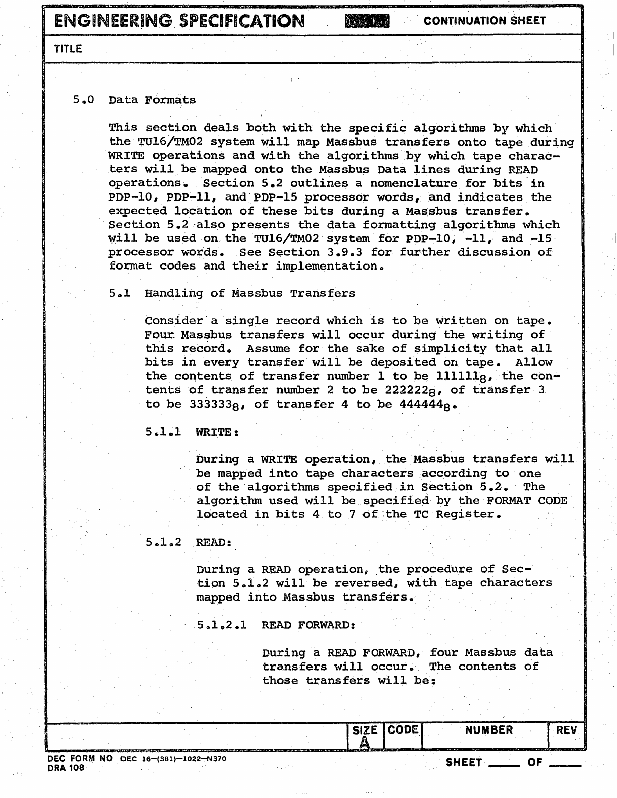
ENGINEER~NG,
SPECIFICATION
,
CONTINUATION
SHEET
TITLE
i '
5.0
Data
Formats
This
section
deals
both
with
the
specific
algorithms
by
which
the'TU16/TM02
system
will
map
Massbustransfers
onto
tape
during
WRITE
operations
and
with
the
algorithms
by
which
tapecharac-
ters
will
be
mapped
onto
the
Massbus
Data
lines
during
READ
operationse
Section
5.2
outlines
a
nomenclature
for
bits·in
PDP-10',PDP-ll,
and'PDP-15
processor
words,
and
indicates
the
expected
location
'of
these
bits
durj.nga
Massbus
transfer.
Section
5.2
"also
pre~ents
the
data
formatting
algorithms
which
, I
I
\9ill
be
used
,on.
the,
'TU16/TM02'
system
for
PDP-:-10,
'-11"
and
-15
,j
processorwo,r,ds.
See
Section
3.9.3
for
further
discussion
of
format
codes
and
their
implementation.
Sol
Handling
of
Massbus
Transfers
consider·
a
single
record
which
is
to
be
~ritten
on
tape.
FOur.
Massbus
transfers
will
occur
during
the
writing
of'
this
record.
Assume
for
the
sake
of
simplicity
that
all
bits
in
every
transfer
will
be
deposited
on
tape.
Allow
the,co~tents
of
transfer
number
lto
be
1111118'
the
con-
tents
of
transfer
number
2
to
be
2222228'
of
transfer
3
to
be
3333338'
of
transfer
4
to
be
4444448_
5.1
~l'
WRITE:
During
a WRITE
operation,
the
Massbus
transfer's
will
be
mapped
into
tape
characters
.acc,ording
to'
one
of
the
algorithms
specified
in
section
S.2.
The
algorithm
used
will
be
specified'
by
the
FORMAT
CODE
.located
in
bits
4
to
7 ,of:,
the
TC
Regis
ter.
5.1.2
READ:
During
a
READ
operation,
.the
procedure
of
Sec-
tion
5.1.2
will
be
reversed,
with
,tape
characters
mapped
into
Massbus
transfers.
5~1.2.1
READ
FORWARD:
DEC FORM
NO
DEC
16-(381)-1022-:-N310
ORA
108
During
a
READ
FORWARD,
four
Massbus
data
transfers
will
occur.,
The
contents
of
those
transfers
wil~
be:
NUMBER
REV
SHEET
__
OF
__
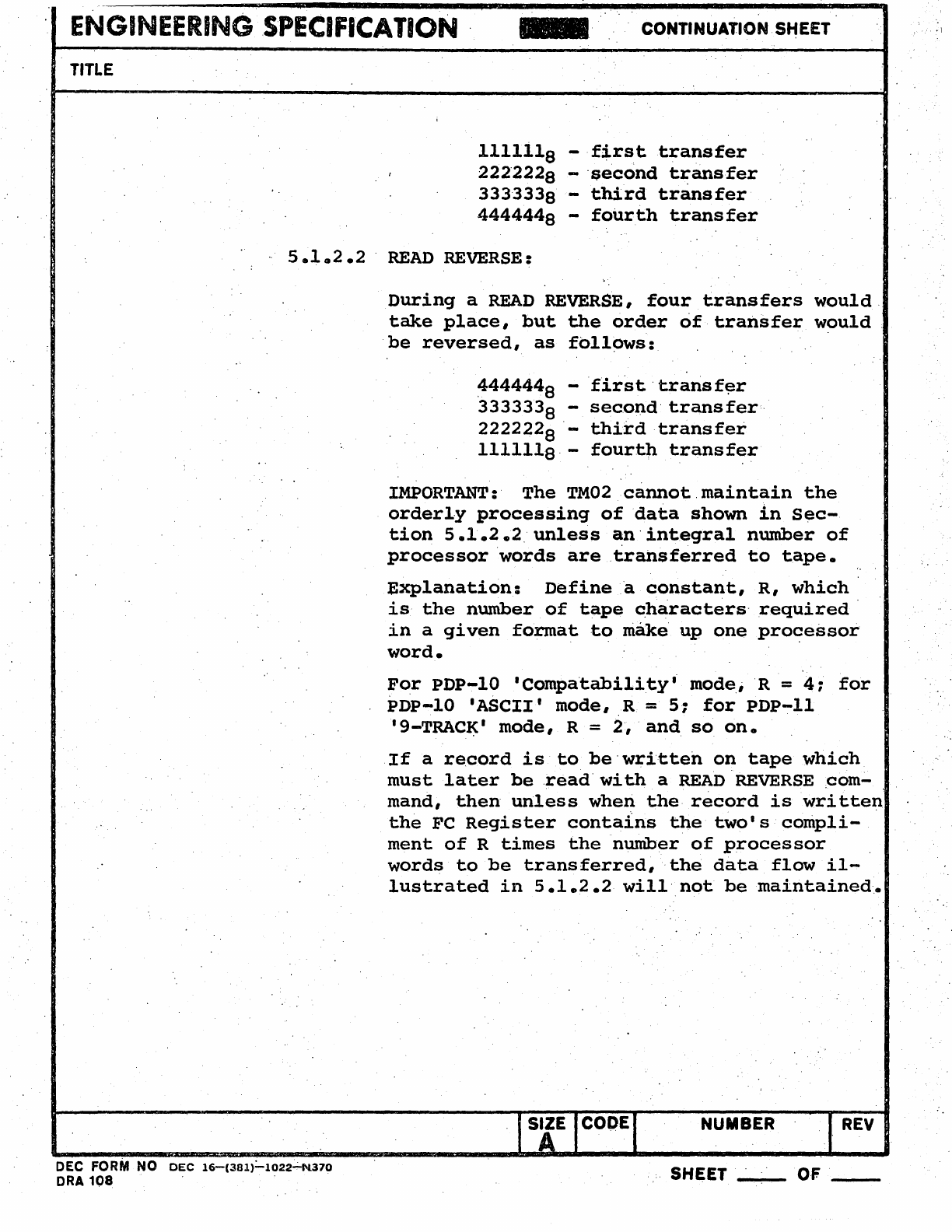
ENGINEERING
SPECIFICATION
-.
CONTINUATION. SHEET
TITLE
llllila
-
first
transfer
I 222·2228 -·f1;econd
transfer
3333338 -
third
transfer
4444448
-
fourth
transfer
5.1
0
2.2
.
READ
REVERSE:
DEC FORM NO
DEC
16-(3al)=-1022~370
ORA
108
During
a
READ
REVERSE,
four
transfers
would
take
place,
but
the
order
of
transfer
would
be
reversed,
as
follows:
~444448
-
·first·transf~r
3333338 -
second·
transfer·
2222228
-
third
transfer
1111118·-
fourth
transfer
IMPORTANT:
The
TM02cannotmaintain
the
orderly
processing
of
data
shown
in
Sec-
tion
5.1.2.2
unless
Cl:n·integral
number
of
processor
·words
are
transferred
to
tape.
Explanation:
Define
a
constant,
R,
which
is
the
number
of
tape
characters·
required
in
a
given
format
to
melke
up
one
proC?essor
word.
For
PDP-10
'Compa·tability'
mode,R
=
4:
for
PDP-lO
'ASCII'
mode, R =
5:
for
PDP-ll
'9-TRAC~'
mode, R = 2·,·
and
so
on.
If
a
record
is
to
be·written
on
tape
which
must
later
be
.read·with
a READ
REVERSE
,com-
mand,
then
unless
wheri
the
record
is
written
the
Fe
Register
conta1ns
the
two's
compli-
ment
of
R
times
the
number
of
processor
words
to
be
transferred,
the
data
flow
il-
lustrated
in
5.1.2.2
will·
not
be
maintained~
SIZE
ICODEI
A
..
NUMBER I
REV
..
SHEET
_.
__
OF
__
·1
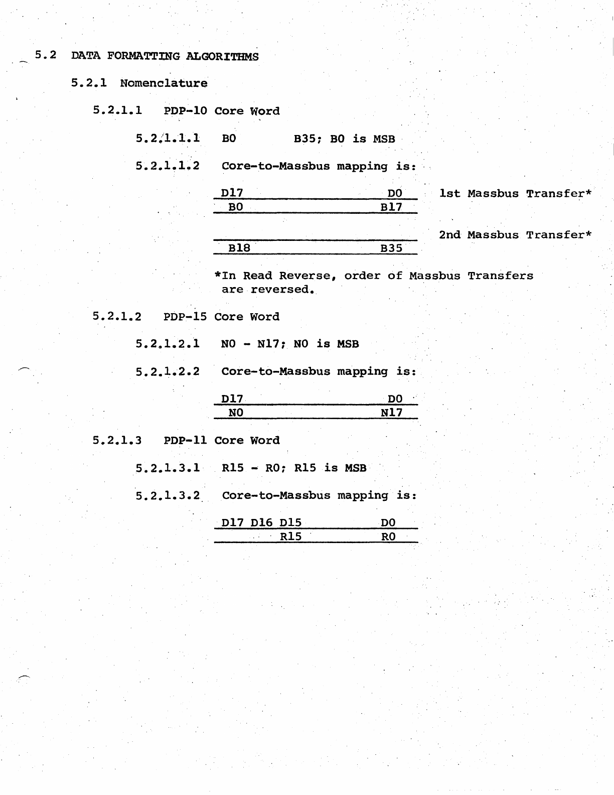
5.
2
DATA
FORMATTING ALGORITHMS
5.2.1
Nomenclat.ure
5.2.1.1
PDP~10
Core
Word
BO
B35:
BO
is
MSB
.
5.
2~"1.'l.1
5.2.1~1~2
Core-to-Massbus
mapping
is:
D17
DO
.
BO
B17
B18
.
B35
1st
Massbus
Transfer*
2nd
Massbus
Transfer*
*In
Read
Reverse,
order
of
Massbus
Transfers
are
reversed
•.
5.2.1.2
pop-IS
Core
Word
5.2,,1.2.1
NO
-
N17:
NO
is
MBB
5.2.1.2.2
Core-to-Massbus
mapping
is:
D17
DO
NO
N17
5.2.1.3
PDP-II
Core
Word
5.2.1.3.1
R15
-
RO:
R15
is
MSB
5.2.1.3.2
Core-tO-Massbus
mapping
is:
D17 DIG
DIS
DO
.'
.
RIS
RO
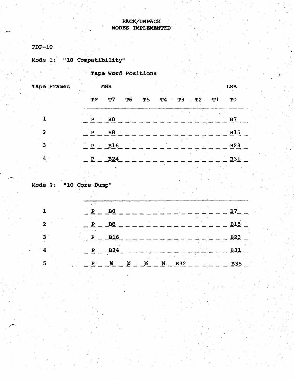
PDP-IO
PACK/UNPACK
MODES IMPLEMENTED'
Mode
1:
"10'
Ccmpatibility"
Tape
Word
positions
Tape, Frames
MBB
LSB
TP
T7
T6
TS
T4
T3
'T2·,
T1
'TO
1
._
P
__
B.O
_____________
.
___
B7
__
2 _ p _
~B8
_____
~
______
....;.
___
.
B15
'_
3
4 _
~
__
B24
________________
B31
_
Mode
2:
UIO
Core
Dump"
1 _
!!
__
B.Q.
___________
~
~
___
B7~
_
PBS
B15
---.---
...
~-----------------
2 , .
3 _ P
__
B16~
____________
,
___
B2~
_
4 P
B24
.
B31
----------------~--.-----
5
I
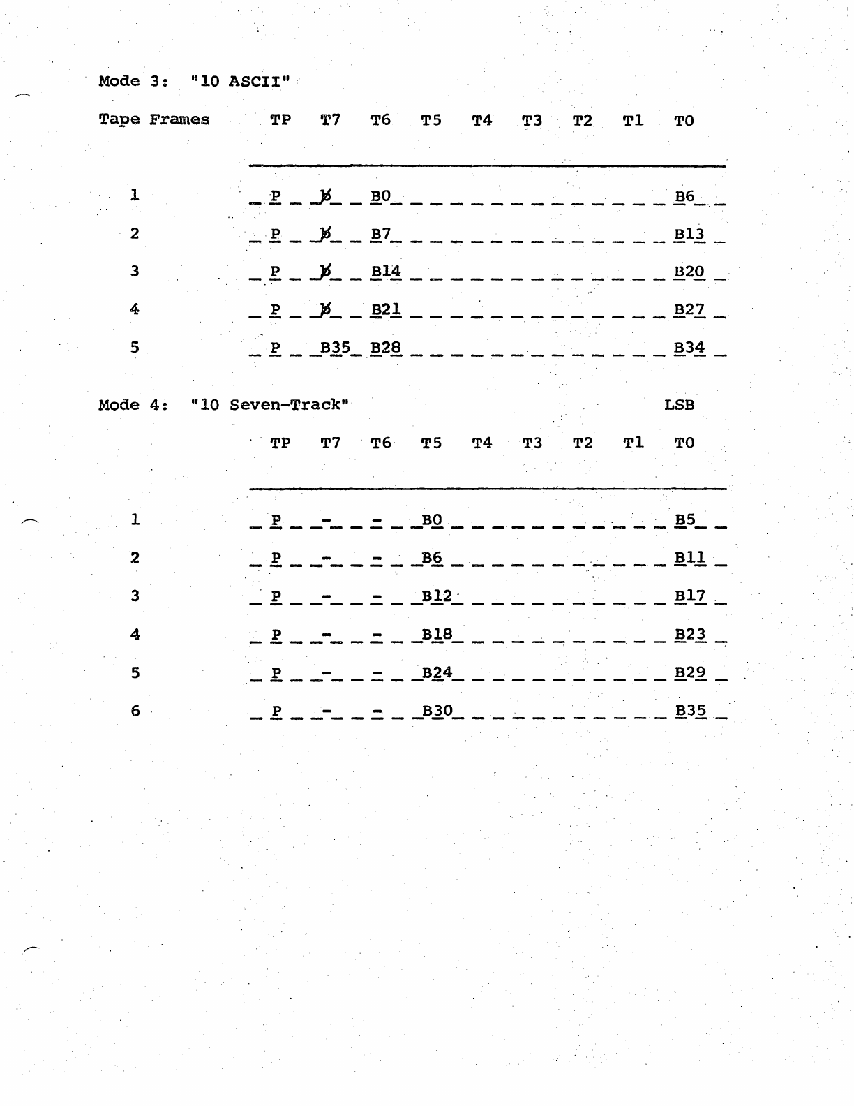
Mode
3:
"10
ASCII"
Tape
Frames
,TP
T7 T6
TS
T4
T3',
T2
Tl
TO
1
",
_ 'P _
~_
~
BO
______
~
__
~
_____
,B6-.:..,_
2 , ,'..:...' p _
..)1
__
B7
________
~_
.:-
____
B13
_
3
_'
P _
.J6
__
B14
_______
~
_ '
____
820
_:
4 _ P _ ..)$
__
B21
___
~
____
~
_____
B22
_
5 _ P
__
B1.5_,
B28
_____________
B34
_
Mode
4::
"10
Seven-Track",
LSB
.
'TP
T7
T6
TS'
T4 'r3 T2
Tl
TO
1
'p
- -
BO
B5
-
....
--- - --
---
-- -
--
-----
--
-
--
---
. ,
2
_'
P
__
-
__
.=
__
B6
_ '
_____
.....;
'
_____
B11
_
3
~
.f.
__
-
__
.=
__
B12,.:.
__________
B17
;.-.
4 _ P
__
-
__
.=
__
B18
____
.....;
~
_____
B21.
--:-
5
,_
P
_____
=.
__
B24
______
~
____
B29
_
6 _ P
__
-
__
.=
__
B30
___________
B3.2._
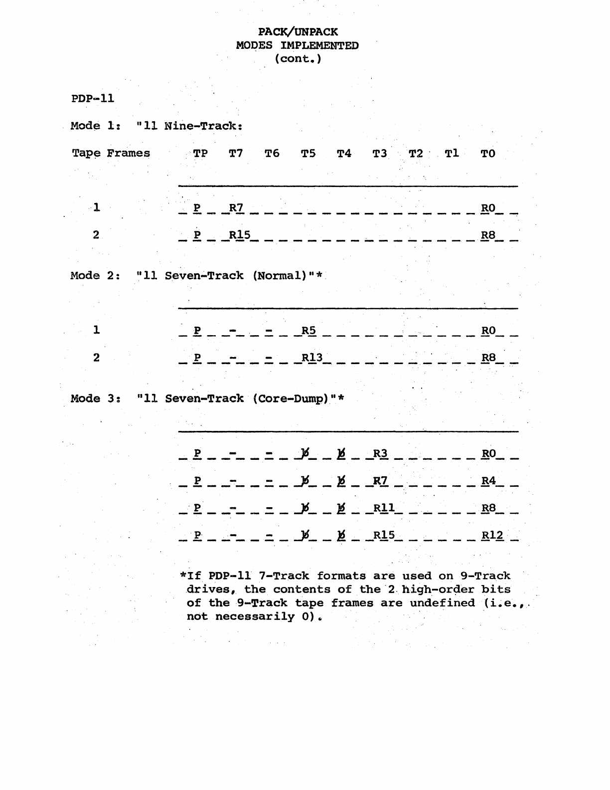
PDP-ll
PACK/UNPACK
MOI?ES
IMPLEMENTED
(cont.
)
Mod~
1:
"11
Nine-Track:
Tap~
Frames
TP
T7
T6
TS
T4
T3
T2',
Tl
TO
,·1 _ P
__
R7
________________
RO_---:"
2 _ P
__
R1S
____________
.;....
____
R8
__
Mode
2:
Itl1
Seven';'Track
(Normal)"*.
1
_l.
__
-_
,_.=
__
RS
___________
RO
__
Mode
3:
till
Seven-Track
(Core-Dump)u*
_
.f
__
-
__
.::.
_ Jd
__
l1
__
R3
______
RO
__
_ P
__
-
__
=.
_
..J6
__
~
__
R7
_.
____
..:..
R4
__
_ '
p'
__
-_
.....
.=
_
-16
__
>i
__
Rll
__
'
....
___
R8
__
_ p, _
~-
__
.::.
_..Jl$ __
~
__
RI5
__
~
___
R12_
*If
PDP-II
7-Track
formats
are
used
on
9-Track
,drives,
the
contents
of
the
'2,
hi9h.-or~er
bits
of
the
·9-Track
tape
frames
are
undefined
(i~e.,.
not
necessarily
0)5
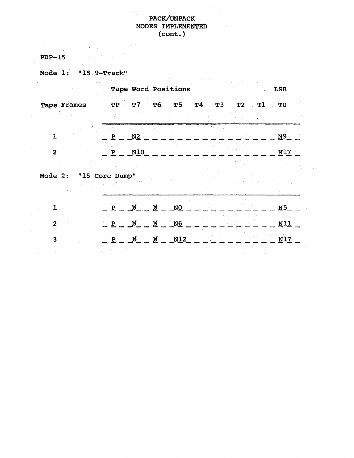
PDP-IS·
PACK/UNPACK
MODES
IMPLEMENTED·
(cont.
)
Mode
1:
1I1S.9-Track"
Tape
Word
positions
.
Tape
Frames
T~
T7
.
T6
TS
T4
T3
LSB
T2
Tl·
TO
1 _ P
__
N2
______
.
___________
N.9
__
2 _ P
__
NIO
________________
N17_
Mode
2:
"15
Core
Dump"
1
_P
_
.l6_._.}!.;-.
_NO
____
.;-.
___
:
___
NS
__
2 _
p.
_
..J6
__
!!
__
N6
______
:.
______
Nil
_
3
_.
P _
~
__
li
__
N12
___
.
____
~
___
N17
_
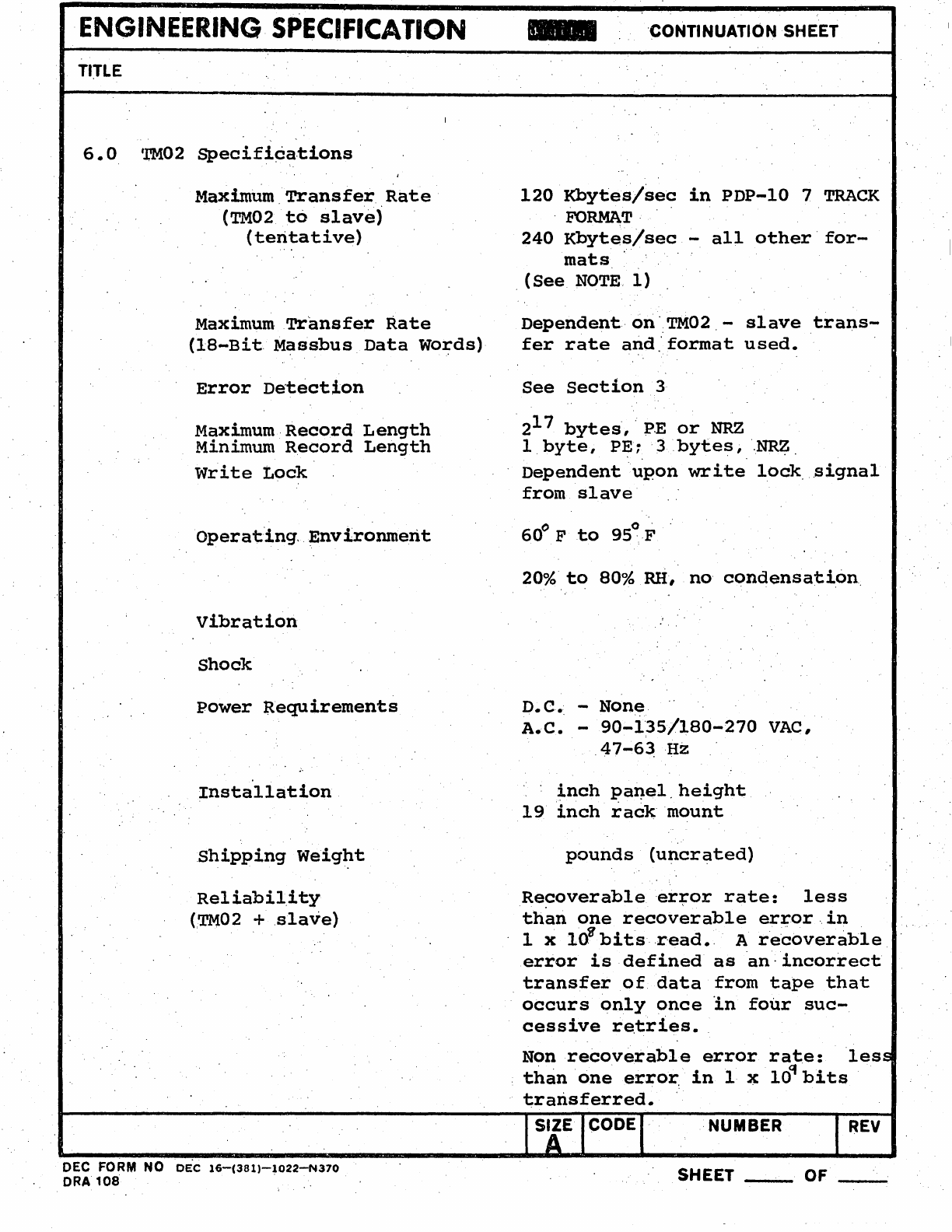
ENGINEERING
SPECIFICATION
TlrLE
6.0.
'l'Mo.2
Specifi¢a.tions·
Maximum.Transfer
Rate
(TMo.2
to
slave)
(tentative)
Maximum
Tr'ansfer
Rate
(lS-Bit.
M~ssbus
Data
Words)
Error
De'taction
Maximum·Record
Length
Minimum
Record
Length
write
t.ock
operat"ing,
Environment
vibration
Shock
Power
Requirements
Installation
Shipping
weight
Reliability
(TM02
+
slave)
DEC FORM NO
DEC
16-(381)-1022-N370
ORA
108
'CONTI N UATIO
NSH
EET
120.
Kbytes/sec
in
PDP-lo. 7 TRACK
.
FORMAT·
240.
Kbytes/sec
-
all
other'for-
mats
.
(See
NOTE.
1)
Dependent·
on·:TM02. -
slave
trans-
fer
rate
and.'
format
used.
See
section
3
. 217
bytes,
··1?E
or
NRZ
1.
byte,
p~~.'
3
.bytes,
·.NR~.
Dependent
upon
write
lock
.signal
from
slave
60
0 F
to
95~F
20%
to
80%
RH,
no
condensation
D.C. None.
A.C. -
9o.-i35/l80-27o.
VAC,
.47-6~Hz
inch
pa~el.height
19
inch
rack
mount
pounds
(uncrated)
Re~overableer~or
rate:
less
than
one
recoverable
error.in
. g . . -
1 x
10.
bitsr-ead..
A
recoverable
error
is
defined
as
·an·
incorrect
transfer
of
data
from
tape
that
occurs
only
once
In
four
suc-
cessive
re.tries
•.
Nonrecoverable
error
rate:
les
than
'one
error:
in
1
J(
ld'
bits
transferred.
NUMBER
REV
SHEET
_
........
OF
__
ENGINEERING
SPECIFICATION
CONTINUATION SHEET
TITLE .
(NOTE
1)
'Ability
to
mix
PE
slaves
of
different
data
rates
on
'TM02
-
slave
b~s··requi.res.
further
evaluation
of
PE
read
circuitry
•.
Maximum
transfer
rates
specified.~i~·
~esigngoals:
and
have.
not
yet
been
evaluated.
NUMBER
DEC FORM
~o
DEC
16-(381)-l02~370
SHEET
__
"",DA
1no
REV
OF
__
..
ENGINEERING
S·PE~IFICATION
CONTINUATION SHEET
TITLE
7.0
Interface
Specificatio~
.'
7.1
Data
.BusSignals
7.l~1
,D,<O:17):
Massbus
data
transfers·are
carried
out
using
the
D(DATA)
lines.
DPA:
'Data
Parity
bit.
Odd
Pari,ty
used.
7.1.2
.
RUN:
Asserted
by
controller
to'indicate
that
a
data
trCinsfer
function
is
to
be
performed.
If
RUN
is
not
'negated
within
1.5
microseconds.
after
the
drive
as-
'serta
EBL,
FRAME
COUNT
ERROR.
(FCE,
'.
bit
,9
of
ER
Regis
....
ter)
will
be
asseited.
7.1.3
'END
OF
BLOCK
(EBL):
Asserted
by
,the
TM02
to
indi-
date
that
data
transmission
has'halted.
7.1.4
EXCEPTION
(EXC):
Asserted
by
drive
to
indic~te
pre~
sence
of
an
error
condition
during
data
transfer.
7.1.5
.
SYNC
CLOCK
(SCLK):
Asserted
by
drive
to
request
new
data
from
controller
(WRITE)
or·to,~ndicate
readiness
of
new
data
from
drive
(READ).
7.1.6
WRITE
CLOCK
(WCLK):
Asserted
by
controller
during
WRITE's
to
indicate.readiness
of
new
write
data.
Asserted·
in
response
to
SCLK.
7.1.7
"Occupied
(OCC):
Asserted
by
the
drive
to
indicate
that
the
drive
has
co~trol
of
the
DATA
(D)l~nes.
'Sampled
by
the
drive
before
seizing
control
of
the'
D
lines
to
determine
availability
of
D
lines.
(See
DTE,
bit
12
of
ER
Register.)
7.2
CONTROL
BUs
7~
2'.1
REGISTER
SELECT(RS
(0:
4»:,
Asserted
by
controller
to
select
drive
registers.
Drive
register
codes
given
in
Section
3.
7.2.2
CONTROLLER
TO
DRIVE
(CTOD):'
Assert~d
by
controller
to
,indicate
direction
of
CO~~TROL
Bus
tr'ans'fer.
DEC
FORM
NQ
DEC
16-(38l)-1022-N370
nDll
1nA
SIZE CODE NUMBER
REV
SHEET,
OF
I
I
ENGINEERING SPECIFICATION CONTINUATION SHEET
TJTLE
7.2.3
DEMAND
(DEM):
Asserted
by
controller
to
initiate
CONTROL
Bus
transfer.
7.2.4
TRANSFER
(TRA):
Asserted
by
TM02to
indicate
that
it
is
responding
to
CONTROL
Bus
transfer.
7.2.5
. ATTEN'rION (ATTN):
Asserted
by
TM02
to
indicate
ab-
normal
condition
or
status
change.·
See
Section
5.
7.2.6
DRIVE SELECT (DS
0:2):
Asserted
by
controller
to
select
one
of
up
to
8
Massbus
drives.
7.2.7
INITIALIZE
(INIT):
Asserted
by
controller
to
return
all
drives
to
a
known
state.
SIZE CODE
A NUMBER
REV
DEC FORM
NO.
DEC
16-(381)-1022-N370
ORA
108
SHEET OF
__
