Techman_pw3000 18000 PW5000 TM (PW 8000 To 20000) 2012
User Manual: PW5000
Open the PDF directly: View PDF ![]() .
.
Page Count: 101 [warning: Documents this large are best viewed by clicking the View PDF Link!]
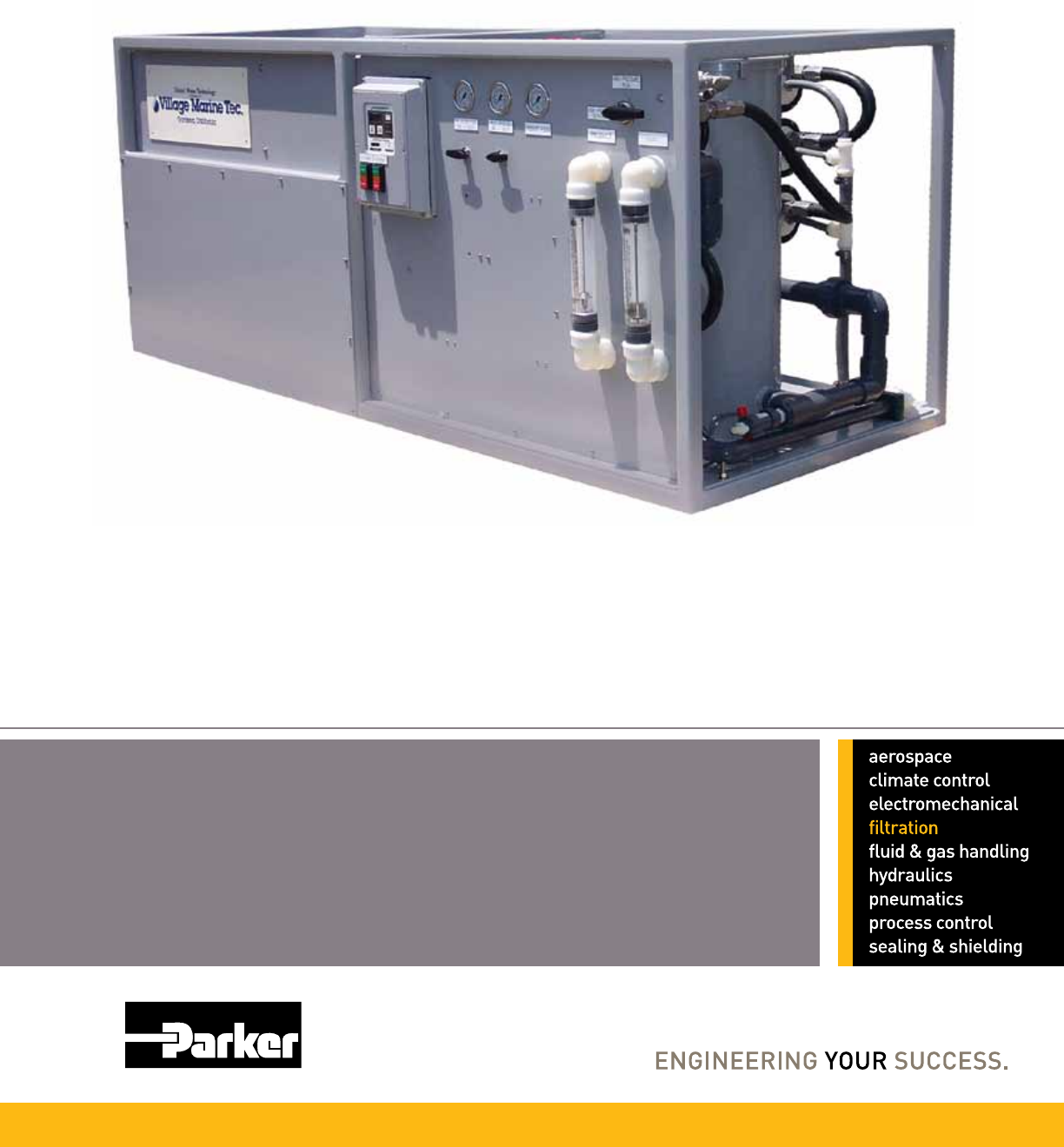
Pure Water Series
PW 8,000-20,000 GPD
Installation, Operation & Maintenance
Village Marine-PW 3000
Part Number: 95-0027

i
TABLE OF CONTENTS
1.0 SYSTEM DESCRIPTION 1
1.1 SPECIFICATIONS 1
1.1.1 PERFORMANCE CHARACTERISTICS 1
1.1.2 PHYSICAL CHARACTERISTICS 2
1.1.3 UTILITY REQUIREMENTS 2
1.1.4 ENVIRONMENTAL REQUIREMENTS 3
1.2 EQUIPMENT REQUIRED FOR OPERATION 3
1.2.1 CONSUMABLES 3
1.2.2 TEST EQUIPMENT 4
2.0 PREPARATION FOR USE, INSTALLATION AND INITIAL ADJUSTMENT 5
2.1 UNPACKING AND HANDLING 5
2.2 LOCATION 5
3.0 GENERAL THEORY OF OPERATION 9
3.1 REVERSE OSMOSIS THEORY 9
3.2 APPLICATION OF REVERSE OSMOSIS 10
3.3 PRODUCT WATER QUALITY STANDARDS 11
3.4 FACTORS AFFECTING PERMEATE PRODUCTION 11
3.4.1 VARIATIONS IN TEMPERATURE, PRESSURE AND SALINITY 11
3.4.2 TEMPERATURE CORRECTION FACTOR 12
3.5 OPERATIONAL DESCRIPTION 14
3.5.1 FILTRATION SYSTEM 14
3.5.2 REVERSE OSMOSIS SYSTEM 14
3.5.3 PRODUCT MONITORING SYSTEM 15
3.5.4 MEMBRANE CLEANING SYSTEM 15
3.6 WATER QUALITY MONITOR 16
3.6.1 PUSHBUTTONS 16
3.6.2 DISPLAYS AND LIGHTS 16
3.7 CONTROLS AND INSTRUMENTATION 16

ii
4.0 OPERATION 19
4.1 START-UP PROCEDURE 19
4.2 SHUTDOWN PROCEDURES 21
4.2.1 SHUTDOWN PROCEDURE (SHORT TERM) 21
4.2.2 SHUTDOWN PROCEDURE (EXTENDED) 22
4.3 FRESH WATER FLUSH PROCEDURE 22
5.0 MAINTENANCE INSTRUCTIONS 23
5.1 GENERAL 23
5.2 RAW WATER STRAINER INSPECTION 24
5.3 FILTER ELEMENT CLEANING OR REPLACEMENT 24
5.4 DRIVE BELT INSPECTION AND REPLACEMENT 25
5.5 RO MEMBRANE CLEANING 26
5.5.1 CLEANING CHEMICALS 26
5.5.2 WHEN TO CLEAN 27
5.6 RO ELEMENT PRESERVATION 30
5.7 RESTARTING UNIT AFTER PRESERVATION 31
5.8 HIGH PRESS7URE PUMP OIL CHANGE 31
5.9 HIGH PRESSURE PUMP MOTOR LUBRICATION 31
5.10 INSPECTION LOG 31
6.0 PRESSURE VESSELS AND MEMBRANES 34
6.1 PRESSURE VESSEL DISASSEMBLY 34
6.3 PRESSURE VESSEL ASSEMBLY 36
7.0 PRESERVATION FOR STORAGE 38
8.0 TROUBLESHOOTING 38
9.0 SYSTEM DRAWINGS AND DIAGRAMS / PARTS LIST 39

iii
LIST OF FIGURES
Figure 2.0 - Recommended Installation (Below Water Line) ............................................ 5
Figure 2.1 - Proper Installation (Above Water Line) ......................................................... 6
Figure 3.0 - Simple (Reverse) Osmotic System ............................................................... 9
Figure 3.1 - Simplified Schematic of an RO System....................................................... 10
Figure 5.0 - Maintenance Task Chart............................................................................. 23
Figure 5.1 - Sample Operational Log ............................................................................. 32
Figure 5.2 - Sample Discrepancy Report ....................................................................... 33
Figure 6.0 - Pressure Vessel End Plug .......................................................................... 34
Figure 6.1 - Brine Seal Orientation................................................................................. 35
Figure 6.2 - End Plug Installation Aid ............................................................................. 36
LIST OF TABLES
Table 1.0 - Performance Specification ............................................................................. 1
Table 1.1 - Unit Dimensions............................................................................................. 2
Table 1.2 - Unit Weights................................................................................................... 2
Table 1.3 - HP Pump Horsepower.................................................................................... 2
Table 1.4 - Utility Requirements ....................................................................................... 2
Table 1.5 - Design Flow ................................................................................................... 3
Table 1.6 - Nominal Operating Conditions ....................................................................... 3
Table 1.7 - Consumables ................................................................................................. 4
Table 1.8 - Recommended Test Equipment..................................................................... 4
Table 3.0 - WHO Drinking Water Standards .................................................................. 11
Table 3.1 - Factors Affecting Permeate Quality.............................................................. 12
Table 3.2 - Temperature Correction Factors (TCF)........................................................ 13
Table 3.3 - Instrumentation and Controls ....................................................................... 18
Table 4.0 - Valve/Switch Line Up - Initial Start-up .......................................................... 19
Table 5.0 - Filter Tank Parts List. ................................................................................... 24
Table 5.1 - Chemical Requirements............................................................................... 26
Table 5.2 - Lubrication Requirements ............................................................................ 31

iv
The following are the types of flags used in this technical manual. They designate safety
related items and important operational instructions and should be given special attention
when they appear in the text:
Text formatted in this manner concerns an operating procedure or practice
that, if not strictly observed, can result in injury to personnel or loss of life.
Text formatted in this manner concerns an operating procedure or practice
that, if not strictly observed, can result in damage to or destruction of
equipment.
Text formatted in this manner concerns an operating procedure or
condition that warrants special attention.
WARNING
CAUTION
NOTE

PW-3000 to PW-20000 Manual 1 Last Revised 01/12
1.0 SYSTEM DESCRIPTION
The Village Marine Tec. (VMT) Seawater Desalinator is a single-pass purification
system that uses reverse osmosis (RO) as its method of seawater desalination. This
unit produces potable (drinking) quality water with salt concentrations of < 500 ppm by
removing approximately 99% of the dissolved salt in seawater.
This manual covers the following models: PW3000, PW4000, PW5000, PW6000,
PW7000, PW8000, PW10000, PW12000, PW16000 and PW20000. The principle of
operation is the same for all models. Specific differences are noted, where applicable.
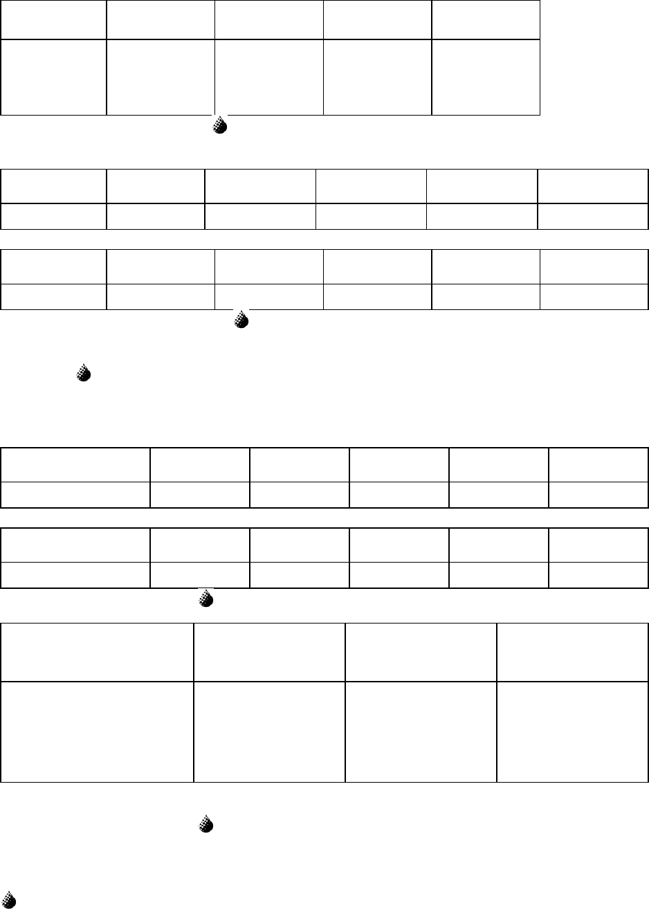
1.1 SPECIFICATIONS
1.1.1 PERFORMANCE CHARACTERISTICS
Parameter Specification
Raw water temperature range: 1-40°C (33-108ºF)
Design RO element pressure: 800 psi
Max. RO element pressure: 1000 psi
Max. feedwater residual chlorine: < 0.1 ppm
pH range (short term for cleaning): 4-10 (3-11)
Membrane type: Thin film composite
Nominal product water production: (2)
PW-3000 2.1 gpm
PW-4000 2.8 gpm
PW-5000 3.5 gpm
PW-6000 4.2 gpm
PW-7000 4.9 gpm
PW-8000 5.6 gpm
PW-10000 6.9 gpm
PW-12000 8.3 gpm
PW-16000 11.1 gpm
PW-20000 13.9 gpm
(2) Raw water temperatures less than 25°C (77ºF) will result in less than rated
product water output. Conversely, higher raw water temperatures will result in
higher than rated output.
Table 1.0 - Performance Specification
PW-3000 to PW-20000 Manual 2 Last Revised 01/12
1.1.2 PHYSICAL CHARACTERISTICS
PW3000
-
5000 PW6000
PW7000
-
12000
PW16000
-
20000
Length 84" 84" 84" 84”
Width 34" 44" 48" 52”
Height 35" 35" 35" 43”
Table 1.1 - Unit Dimensions
PW3000 PW4000 PW5000 PW6000 PW7000
Weight 800 LB 900 LB 1000 LB 1050 LB 1500 LB
PW8000 PW10000 PW12000 PW16000 PW20000
Weight 1600 LB 1800 LB 1900 LB 2200 LB 2250 LB
Table 1.2 – Unit Weights
1.1.3 UTILITY REQUIREMENTS
See the nameplate attached to top of the unit for power requirements.
PW3000 PW4000 PW5000 PW6000 PW7000
Motor HP 10 10 15 15 15
PW8000 PW10000 PW12000 PW16000 PW20000
Motor HP 20 20 25 25 30
Table 1.3 – HP Pump Horsepower
Utility Connection
Design Pressure
Minimum
(psi)
Design Pressure
Maximum
(psi)
Raw water inlet 1 ½” ANSI Flange 0 50
Reject discharge* 1 ½” ANSI Flange 0 15
Product water discharge 1” ANSI Flange 0 15
Flush water inlet 1 ½” NPT 20 50
* Vacuum condition at shutdown is not acceptable, syphon breaker may be reqd.
Table 1.4 - Utility Requirements
PW-3000 to PW-20000 Manual 3 Last Revised 01/12
Unit Raw water inlet
(gpm) Reject discharge
(gpm)
Product water
discharge
(gpm)
PW-3000 14 12 2.1
PW-4000 14 11 2.8
PW-5000 20 16 3.5
PW-6000 20 16 4.2
PW-7000 20 15 4.9
PW-8000 24 19 5.6
PW-10000 30 23 6.9
PW-12000 36 28 8.3
PW-16000 36 26 10.4
PW-20000 43 29 13.9
Table 1.5 – Nominal Design Flow
1.1.4 ENVIRONMENTAL REQUIREMENTS
Parameter Specification
Ambient temperature: 1-40°C (33-108ºF)
List (permanent): 15º
Trim (fore and aft): + 30º
Pitch: ± 10º (6 sec cycle)
Roll: ± 30º (12 sec cycle)
Table 1.6 - Nominal Operating Conditions
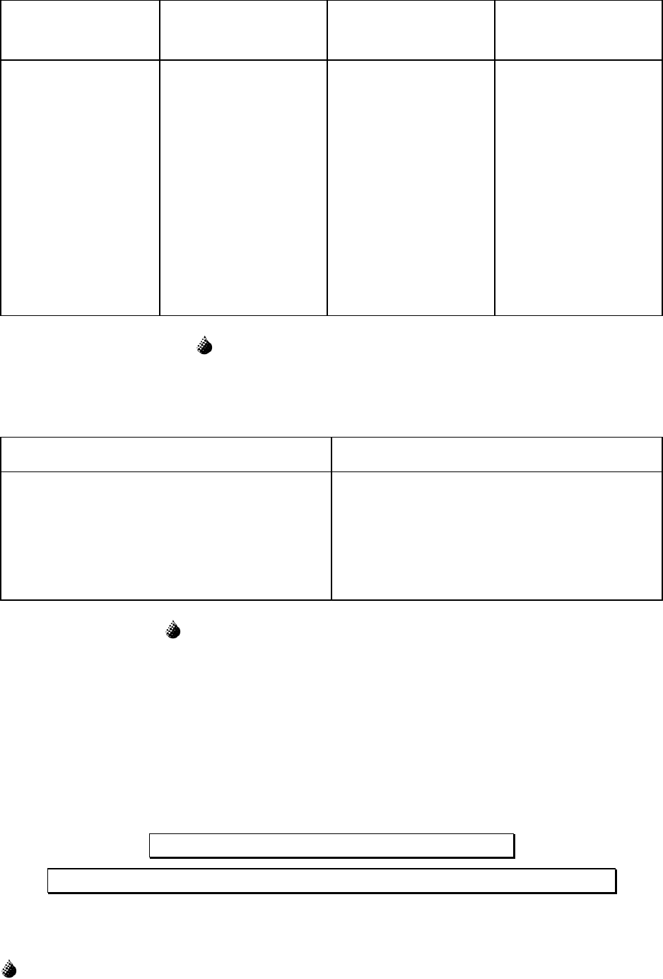
1.2 EQUIPMENT REQUIRED FOR OPERATION
1.2.1 CONSUMABLES
The following is the normal quantity of equipment consumed during 6 months of
standard unit operation:
NOTE
Only Village Marine Tec approved filters and chemicals should be used.
PW-3000 to PW-20000 Manual 4 Last Revised 01/12
Description QTY VMT Part No.
PW3000-6000 PW7000-20000
Cleaning Chemical #1, 25 lbs 2 3 85-0045
Cleaning Chemical #2, 25 lbs 2 3 85-0048
Preservative Chemical #3, 25 lbs 1 1 85-0049
Filter, 100 ft
2
, 5 Micron 6 6 33-5100
Filter, 100 ft
2
, 20 Micron 6 6 33-2100
Flushing Filter 2 2 See Parts Dwg
Oil, HP Pump, Quart 20 20 85-0050
LP Pump Mech Seal Kit 1 1 90-0108
HP Pump Service Kits 1 1 See Pump Manual
Table 1.7 - Consumables
1.2.2 TEST EQUIPMENT
The following table lists the basic equipment recommended to perform most types of
verification testing and system maintenance. The salinity meter allows the operator to
perform routine sampling of the RO membranes:
Description VMT Part No.
Kit, pH Test, 0-14 (10 strips): 90-0135
Meter, Handheld Analog, 0-5000 ppm: 40-5000
10X Range Extender for Analog Meter: 40-5001
Alternate Digital Handheld meter, 0-1000 ppm: 99-1990
Solution, Calibration, 300 ppm: 90-1300
Solution, Calibration, 30,000 ppm: 90-1301
Table 1.8 - Recommended Test Equipment
PW-3000 to PW-20000 Manual 5 Last Revised 01/12
2.0 PREPARATION FOR USE, INSTALLATION AND INITIAL
ADJUSTMENT
2.1 UNPACKING AND HANDLING
Remove unit from shipping crate and inspect for shipping damage.
CAUTION
Do not allow unit or any components to be exposed to freezing
temperatures. If it is anticipated that the unit may be exposed to freezing
temperature, please contact VMT in advance for technical assistance.
2.2 LOCATION
The RO unit should be installed in a dry, sheltered location protected from direct
weather. Some type of drainage should be provided beneath the RO unit to allow
standing water to drain when performing maintenance or repair (see system diagram in
Section 9.0 for skid size, interface locations and minimum maintenance envelope
requirements).
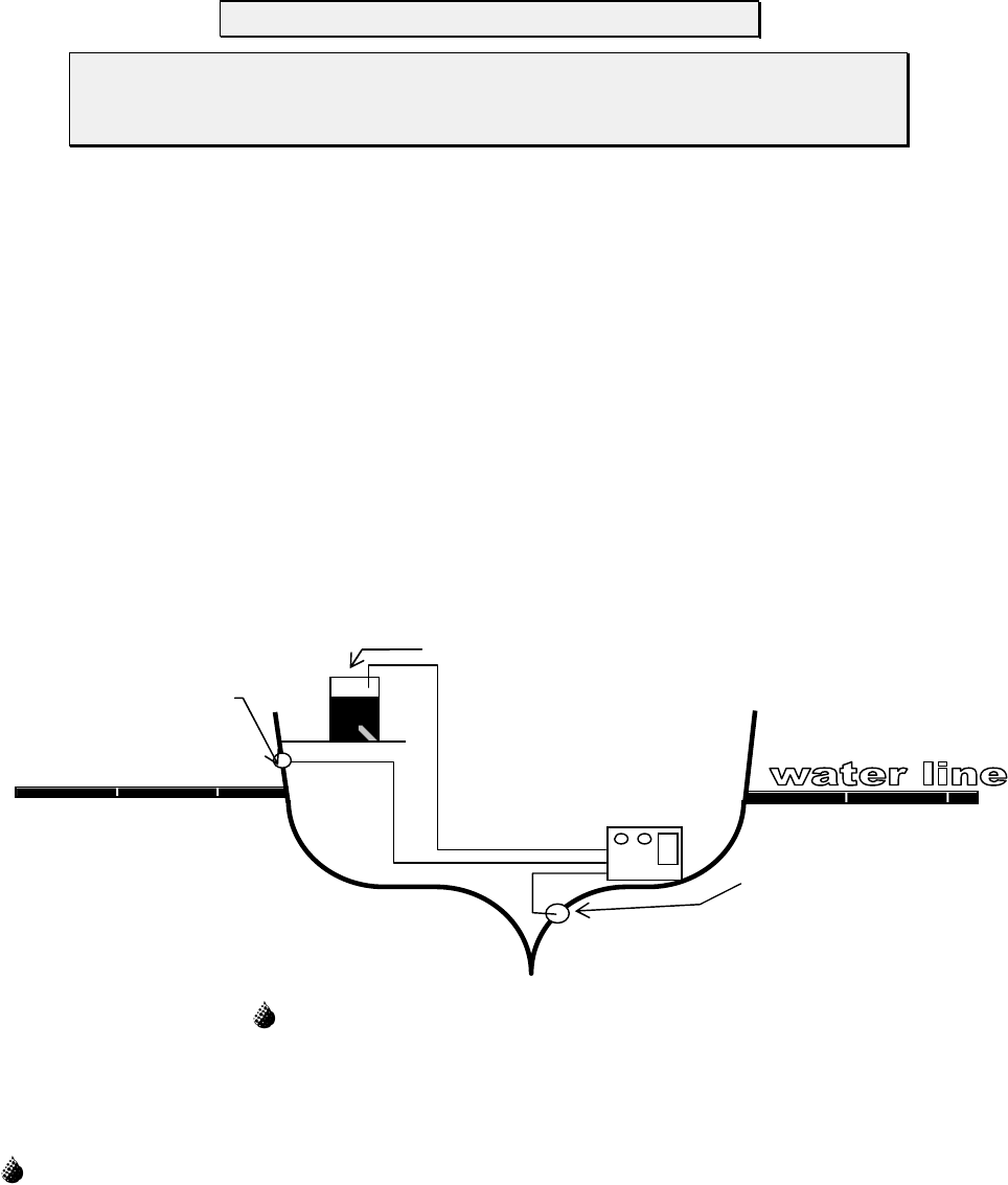
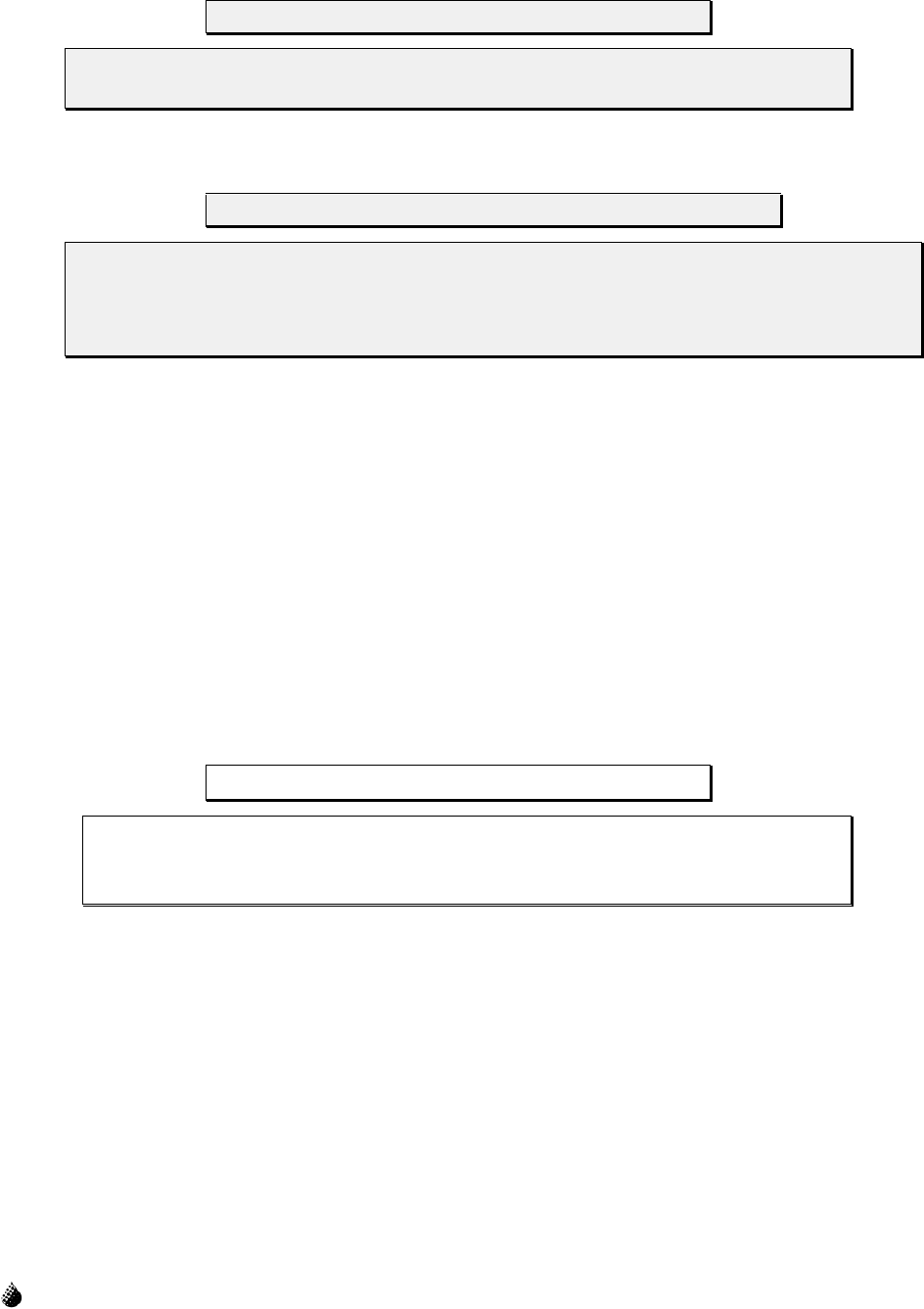
For units without a pressurized feed, it is recommended that the RO unit be mounted in
a location below the vessel's waterline. This will ensure a flooded suction to the unit at
all times.
Figure 2.0 - Recommended Installation (Below Water Line
without Pressurized Feed)
It is important that the product water line is
connected to the top of the storage tank with an
air gap to prevent chlorinated water from
siphoning back into the watermaker.
Raw water inlet, 1½” through
hull with sea cock, as low as
possible and towards the aft of
the boat, forward of the drive.
Reject discharge line
overboard and above
water line.
PW-3000 to PW-20000 Manual 6 Last Revised 01/12
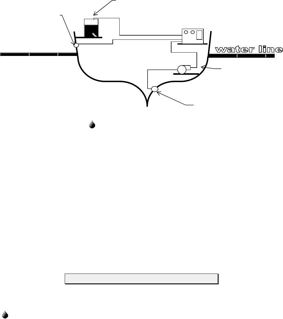
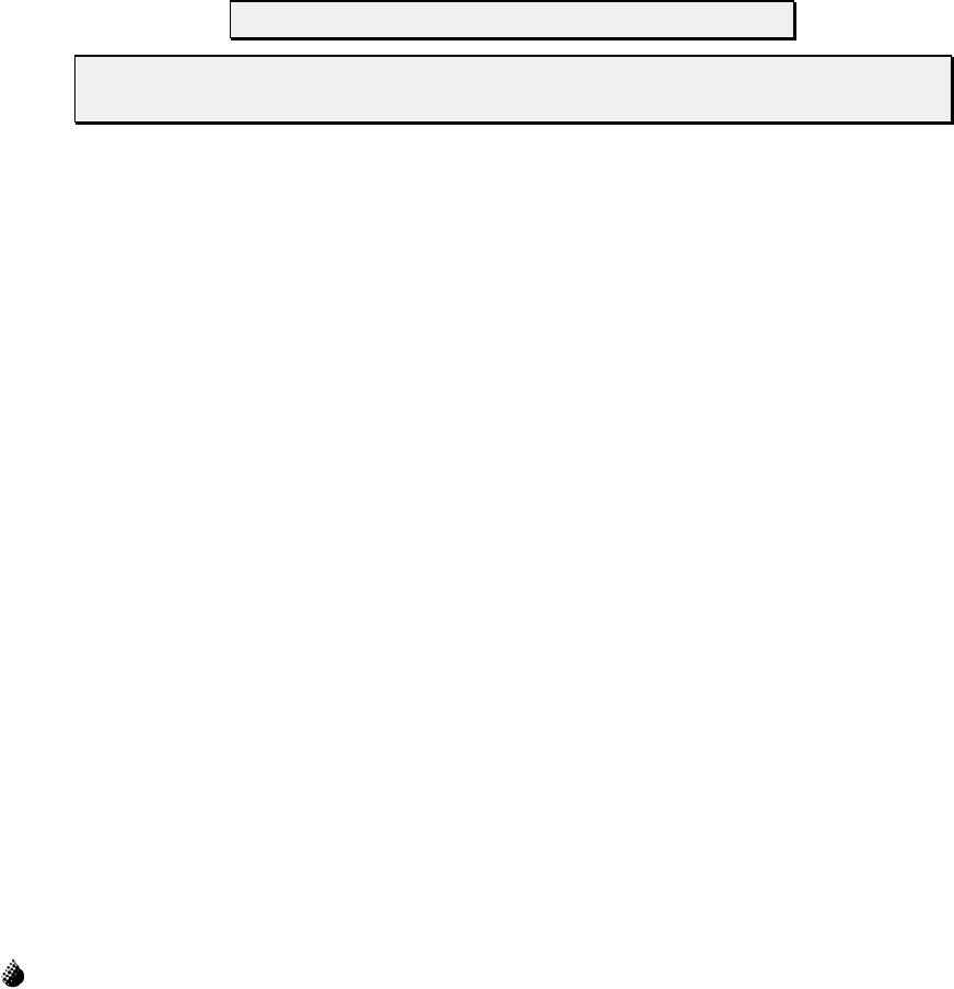
If it is not possible to mount the watermaker below the water line, the boost pump can
lift to a maximum height of 15 feet (5 feet for 50 Hz units) above the water line with the
boost pump removed from the frame and installed below the RO frame near the through
hull. A check valve might be required in the suction line to maintain adequate system
priming. Locating the system any more than 15 feet above the water line requires
installation of external pumps to maintain a pressurized feed.
Figure 2.1 - Proper Installation
(Above Water Line)
Since every installation is unique, the mounting instructions are provided for guidance
only. It is recommended that you use your own discretion as to the exact method of
mounting and placement of any mounting bolts.
1) Place the RO unit in an appropriate location and use existing holes or drill new
holes for a minimum of four point mounting by studs or bolts. Mount the RO unit
securely making sure that the base of the unit is continuously supported.
2) Make the following plumbing connections to the RO unit's piping interfaces (refer
to Section 9.0 for the exact piping interface locations):
a) Connect the raw water supply (1½" flange connection inlet) to a clean
seawater source.
CAUTION
Raw water inlet, 1-1/2” through
hull with sea cock, low as possible
and towards the
Aft of the vessel, forward of the
drive.
Reject discharge
line overboard and
above water line.
It is important that the product water line is
connected to the top of the storage tank to prevent
chlorinated water from siphoning back into the
watermaker.
Boost pump below water line
with flooded suction.
PW-3000 to PW-20000 Manual 7 Last Revised 01/12
Inlet and discharge interconnecting lines should be constructed of a NON-
FERROUS material. Examples of some suitable materials are PVC,
copper-nickel, 316 stainless steel pipe or a reinforced non-collapsing
hose. Ferrous piping produces rust that will irreversibly foul the
membrane and void the RO unit warranty.
NOTE
Avoid connecting the inlet piping to any water line that services any other
piece of equipment. Air could be drawn through the RO unit causing
damage to the RO unit's pumps.
b) Connect the reject discharge 1½" flanged connection to an unobstructed
line connected to an appropriate drain. If the reject is discharged
overboard, the discharge port should be above the waterline. On above
waterline installations where the reject goes down more that 10 feet to its
outlet, install a vacuum breaker or vent to prevent any negative pressure
or vacuum situation at shutdown.
CAUTION
The use of galvanized steel for product piping should be avoided as small
amounts of rust may form that can be drawn back into the RO when the
system is off.
c) Connect the product water discharge 1" flanged connection to an
unobstructed line that is connected to the TOP of the product water storage
tank. If the storage tank water is chlorinated, a check valve or air gap should
be installed in the product line as a precaution to prevent chlorine damage of
the RO membranes. The air gap is often accomplished by teeing the product
connection to a tank vent or tank fill line of suitable size.
d) Connect the flush water inlet to the pressurized fresh water system on the
vessel. Do not exceed 50 psi pressure.
CAUTION
Exposing the membranes to chlorinated water may cause irreversible
damage and will void the RO unit warranty, so use the carbon flush filter
supplied.
3) Connect the following RO unit's electrical interfaces:
NOTE
PW-3000 to PW-20000 Manual 8 Last Revised 01/12
Strictly observe all applicable electrical codes and regulations governing
the installation and wiring of electrical equipment. Typical codes specify
the type and size of conduit, wire diameter and class of wire insulation
depending upon the amperage and environment. The power supply
should always be of a greater service rating than the requirements of the
RO unit. This will assure proper voltage even if power supply voltage is
slightly less than required. Never connect the RO unit to a line that
services another electrical device. The RO unit should have its own
dedicated power supply and breaker.
WARNING
Disconnect electrical power to RO unit and the power source before
connecting to RO unit interface. Failure to do so can cause serious
injury or death to personnel.
a) Connect the correct voltage/power supply to the three-phase or single phase
supply point in the Motor Starter Box. Correct high pressure pump rotation is
clockwise when viewing the motor fan (or counter-clockwise when viewing
from the shaft and pulley end. Correct rotation for the low pressure boost
pump is clockwise when viewing the motor fan.
IMPORTANT NOTE
Three phase power supplies will spin the motors and pumps either
rotation direction, depending on the phase sequence of the three hot
power legs. It is very important not to rotate the low pressure pump
backwards. Even “bumping” the motor for one second can cause
significant damage. The high pressure pump will not be damaged from
running backwards. Either use a phase meter to determine the rotation,
or use the high pressure pump only to check rotation and adjust the
input power legs accordingly prior to checking the low pressure pump. If
the low pressure pump is inadvertently “bumped” backwards, open the
pump and check the impellor is secured on the motor shaft and spins
freely prior to starting it again.
b) Connect a suitable ground to the RO unit skid (as determined by the
specifics of your installation).
PW-3000 to PW-20000 Manual 9 Last Revised 01/12
3.0 GENERAL THEORY OF OPERATION
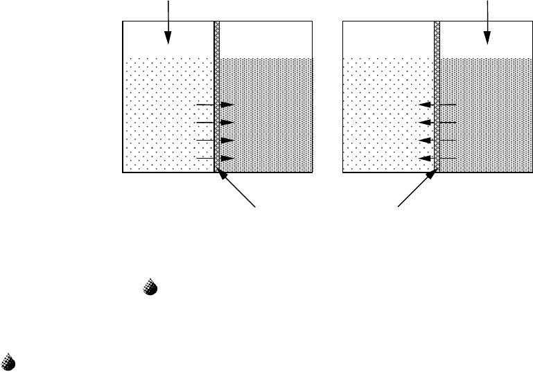
3.1 REVERSE OSMOSIS THEORY
Reverse osmosis, like many other practical scientific methods, has been developed
from processes first observed in nature. Osmosis is a naturally occurring phenomenon
in which a semi-permeable membrane separates a pure and a concentrated solution (a
semi-permeable membrane is defined as one that preferentially passes a particular
substance). Every fluid has an inherent potential that is directly related to the type and
amount of solids in solution. This potential, referred to as osmotic pressure, increases
in proportion to relative concentration of a solution. A concentrated solution, therefore,
has an osmotic pressure that is higher than that of a pure solution.
In an osmotic system, the less concentrated solution will attempt to equalize the
concentrations of both solutions by migrating across the semi-permeable membrane.
When enough pure solution migrates across the membrane such that the inherent
potential difference between the solutions is no longer higher than the osmotic pressure
of the membrane, the purer solution will stop flowing. If the pressure on the
concentrated solution is increased to above the osmotic pressure, fluid flow will be
reversed. This condition, called Reverse Osmosis, can be established by artificially
pressurizing the more concentrated solution using a high pressure pump. In this type of
system, the concentrated solution (normally referred to as feedwater) will become more
concentrated as pure water flows out of solution and across the membrane to the
permeate side. Discounting the effects of feedwater temperature and salinity, the
operating pressure normally required to produce significant amounts of pure water is at
least twice the osmotic pressure of the membrane being used.
SALINE
SOLUTION
PURE
SOLUTION
SEMI-PERMEABLE MEMBRANE
ATMOSPHERIC
PRESSURE
(14.7 PSI)
SALINE
SOLUTION
PURE
SOLUTION
HIGH
PRESSURE
(800 PSI)
OSMOSIS REVERSE OSMOSIS
Figure 3.0 - Simple (Reverse) Osmotic System
PW-3000 to PW-20000 Manual 10 Last Revised 01/12
3.2 APPLICATION OF REVERSE OSMOSIS
Seawater contains many kinds of solids dissolved in solution. The most prevalent is
common table salt (sodium chloride). Other minerals that may be present in solution
are substances that usually contain various compounds of calcium and sulfate. The
sum of all of the solids dissolved in a particular sample of water is referred to as Total
Dissolved Solids or TDS. Seawater normally averages 32,000 to 35,000 ppm (parts per
million) TDS although variations of 5000 ppm are common in various parts of the world.
The fundamental goal any desalination process is a significant reduction in the amount
of dissolved solids in water.
In a Reverse Osmosis desalination system, most of the dissolved solids do not pass
through the membrane but are instead carried along the membrane surface. This
rejected water, referred to as brine, becomes increasingly more concentrated as it flows
along the surface of the membranes and is eventually piped to drain. The product water
that flows through the membrane is referred to as permeate. The percentage of
feedwater converted to permeate is called the recovery rate and is normally somewhere
between 20% and 30%. For example, a unit with a 29% recovery rate will produce 29
gallons of permeate for every 100 gallons of feedwater with the remaining 71 gallons
discharged to waste as brine. A higher than optimal recovery rate (which can be
obtained by increasing the back pressure on the unit above the recommended range)
results in greatly increased membrane fouling rates and a significant decrease in the
operational life of the membranes.
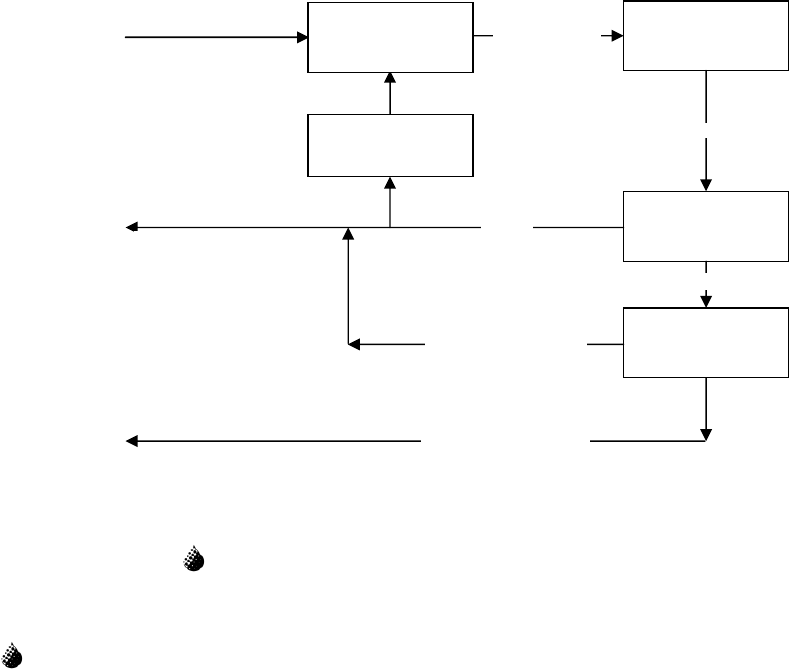
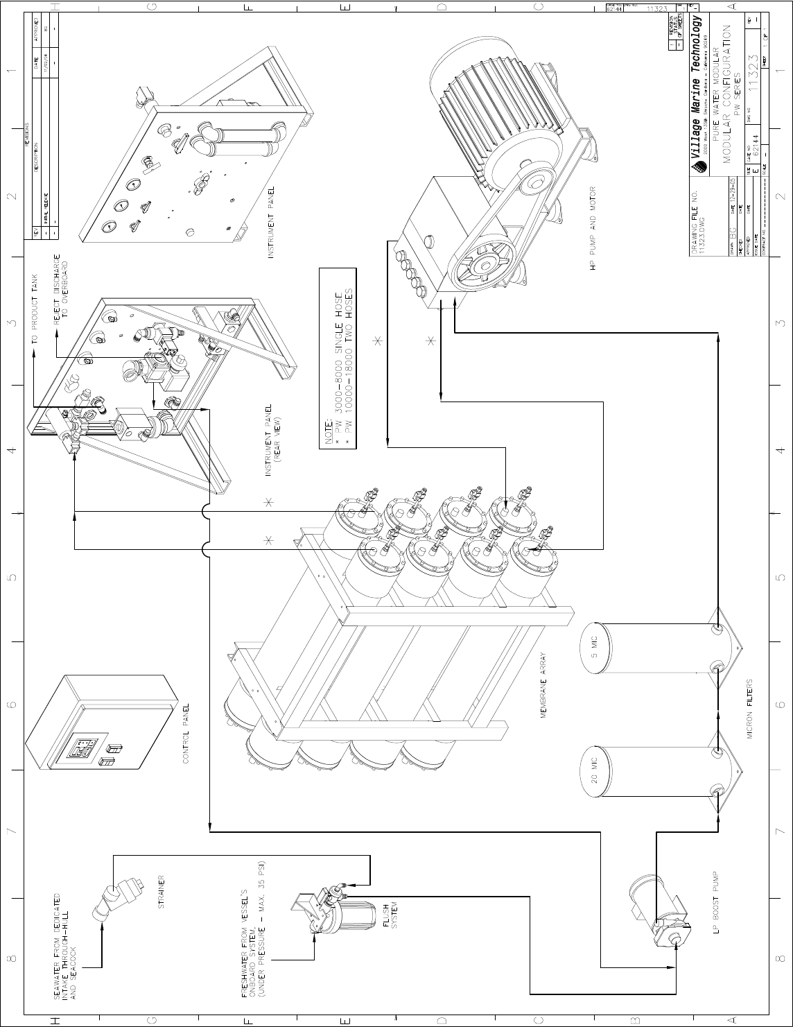
Figure 3.1 - Simplified Schematic of an RO System
FEEDWATER
CLEANING
SYSTEM
PRODUCT
MONITORING
SYSTEM
MEMBRANE
ARRAY
HIGH PRESSURE
PUMPING SYSTEM
FEEDWATER
PERMEATE
REJECT DISCHARGE
PRODUCT DISCHARGE
RAW WATER INLET
BRINE
PERMEATE > 500PPM
PERMEATE < 500PPM
FILTRATION
SYSTEM

PW-3000 to PW-20000 Manual 11 Last Revised 01/12
It should be noted that no system is capable of removing all of the dissolved solids from
seawater. The system is actually designed to reject approximately 99% of the TDS or,
in other words, to allow 1% of the 35,000 ppm TDS in the seawater to pass into the
product water. This yields water of less than 500 ppm, the recommended TDS for
drinking water. A system such as this is said to have a salt passage percentage of 1%
or a salt rejection of 99%.
3.3 PRODUCT WATER QUALITY STANDARDS
This RO unit will produce permeate (product water) with a quality of < 500 ppm TDS
and in accordance with World Health Organization (WHO) standards for drinking water.
General specifications for acceptable drinking water quality are as follows:
Constituent Ion/Molecule Maximum Limits (ppm)
Nitrate 10
Fluorine .1
Sulfate 100
Magnesium 30
Calcium 75
Calcium Carbonate 100
Iron .1
Manganese .05
Total Dissolved Solids 500
Turbidity 5
Oil .1
Detergents (anionic) .2
Phenols .001
Bacteria - E Coli (per 100 ml) 0
Table 3.0 - Drinking Water Standards
3.4 FACTORS AFFECTING PERMEATE PRODUCTION
3.4.1 VARIATIONS IN TEMPERATURE, PRESSURE AND SALINITY
The following table illustrates how the quality and quantity of permeate produced in by
RO system is affected by changes in temperature, salinity and pressure:
PW-3000 to PW-20000 Manual 12 Last Revised 01/12
With constant.... And increasing.... Permeate
TDS Capacity
Salinity and Pressure Temperature Increases Increases
Temperature and Pressure Salinity Increases Decreases
Temperature and Salinity Pressure Decreases Increases
Table 3.1 - Factors Affecting Permeate Quality
NOTE
If feedwater salt concentration decreases, the product water flow rate
should not be allowed to increase more than 20% above rated flow.
Reject pressure will need to be lowered to maintain rated flow in brackish
water or fresh water applications.
The RO system can be adjusted to maintain a constant permeate output when
feedwater salinity is below nominal (near river mouths or in estuaries). The operator
can do this by controlling system pressure manually via the back pressure regulator
valve, V3, located in the system brine piping. For long pump life and low membrane
fouling, VMT recommends that 800 psi is not exceeded except in situations of extreme
low temperature feed water.
CAUTION
Operating the unit at more than 120% of rated capacity in low salinity
water can damage the membranes and will void the RO unit warranty.
3.4.2 TEMPERATURE CORRECTION FACTOR
As previously described, the output capacity of any RO unit is highly dependent on
feedwater temperature. In order to quantify this relationship, theoretical data has been
utilized to develop Temperature Correction Factors (TCF) to compensate measured
flowrate to calculated flowrate at 25°C/77°F. This allows the operator to establish the
baseline flow for a given temperature, allowing more accurate troubleshooting. The
procedure for calculating the temperature compensated flow is as follows:
1) Measure raw water temperature and determine the corresponding correction
factor from Table 3.2 based on the measured temperature.
2) Note the actual product flow rate at the Product Flow meter. Multiply the actual
product flow meter flow rate by the correction factor from Table 3.2 to give
theoretical temperature compensated flow under standard conditions (25°C).

PW-3000 to PW-20000 Manual 13 Last Revised 01/12
Example:
Raw water temp: 15°C
TCF: 1.47
Actual product flow: 113.5 (gph)
Calculation: 113.5 x 1.47 = 167 (gph)
Temperature Corrected flow: 167 (gph)
(167 gph is the normal flow for a PW4000)
°C Factor °C Factor °F Factor °F Factor
1 3.64 26 0.97 34 3.47 84 0.88
2 3.23 26 0.94 36 3.18 86 0.82
3 3.03 28 0.91 38 3.18 88 0.79
4 2.78 29 0.88 40 2.68 90 0.79
5 2.58 30 0.85 42 2.47 92 0.77
6 2.38 31 0.83 44 2.29 94 0.75
7 2.22 32 0.80 46 2.14 96 0.73
8 2.11 33 0.77 48 2.01 98 0.70
9 2.00 34 0.75 50 1.88 100 0.68
10 1.89 35 0.73 52 1.77 102 0.65
11 1.78 36 0.71 54 1.68 104 0.63
12 1.68 37 0.69 56 1.59 106 0.61
13 1.61 38 0.67 58 1.51 108 0.59
14 1.54 39 0.65 60 1.44 110 0.57
15 1.47 40 0.63 62 1.36 112 0.55
16 1.39 41 0.61 64 1.30 114 0.53
17 1.34 42 0.60 66 1.24 116 0.51
18 1.29 43 0.58 68 1.17 118 0.49
19 1.24 44 0.56 70 1.12 120 0.47
20 1.19 45 0.54 72 1.08 122 0.45
21 1.15 46 0.53 74 1.05
22 1.11 47 0.51 76 1.02
23 1.08 48 0.49 78 1.00
24 1.04 49 0.47 80 0.93
25 1.00 50 0.46 82 0.90
Table 3.2 - Temperature Correction Factors (TCF)

PW-3000 to PW-20000 Manual 14 Last Revised 01/12
3.5 OPERATIONAL DESCRIPTION
3.5.1 FILTRATION SYSTEM
Seawater supplied to the intake of the Village Marine RO desalination unit will initially
flow through the raw water strainer, ST1, which removes large particulate matter.
Once through the strainer, the raw water is supplied to the low pressure boost pump,
P1, which raises the pressure of the water in order to provide enough positive feed
pressure to flow through the filtration system and into the suction of the high pressure
pump.
For units equipped with a (optional) Media Filtration System:
When a unit operates in areas where the raw water source of high turbidity or
organic materials, VMT recommends installing a media filtration system (IMF).
The media pump and filter, is installed upstream of the watermaker and will remove
particles as small as 25 microns in diameter. The filtration media is comprised a
multiple layers of specific materials that are specifically designed to remove
suspended particulate matter from the raw water stream. The benefit is to
significantly reduce the cleaning and replacement frequency for the micron filters.
When the media filter is fully loaded (indicated by high filter differential pressure), the
operator initiates a backwash cleaning cycle designed to flush trapped particulate
matter out of the filter and into the system drain. Please see the IMF manual or IMF
bulletin for further details.
The raw water next passes through the micron filter array, F1 & F2, which is designed
to reduce raw water turbidity to a nominal 5 microns in diameter. The micron filter array
consists of one 20 micron filter cartridge and one 5 micron filter cartridge.
Each filter housing contains one (1) filter element with an effective filtering area of 100
ft2and is equipped with an integral air/oil separator bleed. Bleed is continuously
discharged to the reject header and overboard.
The discharge pressure from the filter housings is monitored by a pressure gauge,
PG1, and pressure switch, PS1, that allow the operator to determine when the filter
elements require cleaning or replacement.
3.5.2 REVERSE OSMOSIS SYSTEM
The clean and filtered raw water (now referred to as feedwater) is supplied to the inlet of
the high pressure pump, P2. This pump raises feedwater pressure to 800 psi, the
nominal pressure required for optimal system recovery. The pressurized feedwater

PW-3000 to PW-20000 Manual 15 Last Revised 01/12
then flows directly into the membrane array. The membrane array is an arrangement
of fiberglass pressure vessels each containing a RO membrane element.
The pressurized feedwater flows along the membrane elements where reverse osmosis
takes place (see Section 3.1). The feedwater flow is divided into two streams - the high
purity product stream (referred to as the permeate) and the increasingly concentrated
reject stream (referred to as the brine or reject).
After exiting the membrane array, the brine (which contains higher concentrations of
salts) flows through the back pressure regulator valve, V3. This manually adjustable
valve is used to control the back pressure through the membrane array. After passing
through the back pressure regulator, the brine flows through the reject flow meter, FM1
and exits the RO unit.
3.5.3 PRODUCT MONITORING SYSTEM
The product water stream (or permeate) flows past a conductivity sensor, which
provides a signal to the water quality monitor. Depending on the concentration of total
of dissolved solids (TDS) in the permeate stream, the following occurs:
If permeate TDS is > 500 ppm, indicating poor quality water, a signal is sent to close the
2-way product diversion valve, V6. This causes permeate system pressure to rise
until it equals the activation set point of the permeate relief valve, V7. With the relief
valve open, the poor quality water is diverted to the reject stream and away from your
storage tanks. A product pressure gauge, PG3 is supplied to enable accurate
adjustment of the product relief valve to about 40 psi in most installations.
If the permeate has < 500 ppm TDS, indicating good quality (drinking) water, a signal is
sent to open the product diversion valve. The relief valve then shuts allowing the
permeate to pass through the product flow meter, FM2 and then on to the potable
water storage tank(s).
3.5.4 MEMBRANE CLEANING SYSTEM
This RO unit includes a membrane cleaning system which provides a means for
removing performance degrading organic foulants and scale deposits from the RO
membranes (occurs approximately every 30 – 90 days during constant use). By using
the filter housings as cleaning solution tanks, the pumps, a cleaning valve V5, and a
high pressure bypass valve V4, the membranes can be chemically cleaned in place.
Complete information and cleaning procedures can be found in Section 5.5.

PW-3000 to PW-20000 Manual 16 Last Revised 01/12
3.6 WATER QUALITY MONITOR
The Water Quality Monitor (MON) monitors and displays permeate salinity, temperature
and accumulated unit operating hours. It also provides operational mode control of the
system product valve.
3.6.1 PUSHBUTTONS
Temperature – allows the operator to display permeate temperature (as opposed to
the normal permeate salinity display). By changing a jumper located on the back of
the monitor, the temperature can be displayed in ºF or ºC.
Salinity Alarm Set Point – allows the operator to display and vary (via a control knob
located on the back of the monitor) the salinity alarm set point.
Mode – allows the operator to bypass the normal automatic operation and manually
close the product valve (called DUMP mode, used, for instance, during cleaning).
3.6.2 DISPLAYS AND LIGHTS
Normal Operation – a green light is illuminated when the product valve is energized
and permeate is flowing through the product valve.
Dump/Cleaning – a yellow light is illuminated when the product valve is de-energized
and the product valve is closed.
Salinity Alarm – a red, flashing light indicates that permeate quality is above the
salinity set point.
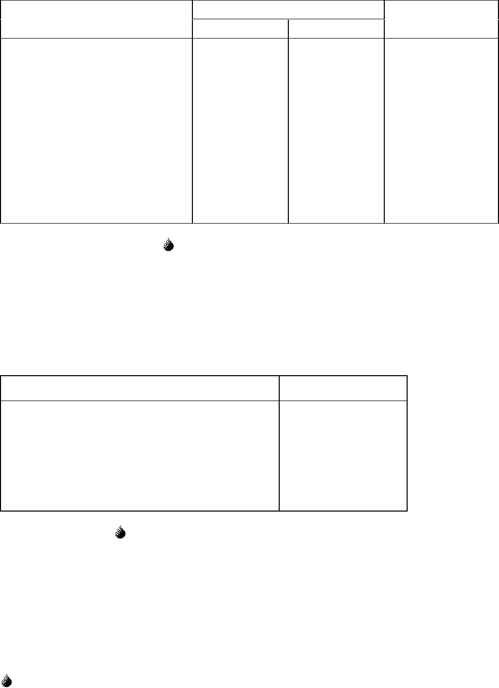
3.7 CONTROLS AND INSTRUMENTATION
The following table provides a brief description of each individual component along with
an explanation of its function. It is intended as a supplement to the more detailed
information contained in Section 9.0 – System/Equipment Drawings and Diagrams.
Call Out Description Function
F1 20 Micron Pre-filter Filters particles > 20 microns in diameter.
F2 5 Micron Pre-filter Filters particles > 5 microns in diameter.

PW-3000 to PW-20000 Manual 17 Last Revised 01/12
FM1 Reject Water Flow
Meter Indicates the amount of reject water discharged
from the RO unit.
FM2 Product Water Flow
Meter Indicates the amount of permeate produced by
the RO unit.
MON Water Quality Monitor See Section 3.6 for detailed description.
MS1 LP Pump Magnetic
Starter Provides ON/OFF control of LP pump.
MS2 HP Pump Magnetic
Starter Provides ON/OFF control of HP pump.
P1 Low Pressure (LP)
Boost Pump Pressurizes raw water to supply the cartridge
filters, F1 and F2.
P2 High Pressure (HP)
Pump Pressurizes feed water to supply the membrane
array at proper (high) pressure.
PG1 Pre-Filter Pressure
Gauge Indicates cartridge filter inlet and discharge
pressure.
PG2 High Pressure Gauge Indicates membrane array discharge (brine
side) pressure.
PG3 Product Water Pressure Indicates membrane array (permeate side)
discharge pressure.
PS1 Low Pressure Switch Will shut down pumps if the pressure is below
setpoint.
SR1 Product Conductivity
Sensor Conductivity probe provides signal to water
monitor (MON).
ST1 Raw Water Strainer Removes large particulate matter from the raw
water stream to prevent system fouling.
SW1 LP Boost Pump Start
Pushbutton Allows operator to START the LP boost pump.
SW2 LP Boost Pump Stop
Pushbutton Allows operator to STOP the LP boost pump.
SW3 HP Pump Start
Pushbutton Allows operator to START the HP pump.
SW4 HP Pump Stop
Pushbutton Allows operator to STOP the HP pump.
V1 Filter Gauge Selector
Valve Allows operator to select and read filter array
inlet or discharge pressure on the gauge.

PW-3000 to PW-20000 Manual 18 Last Revised 01/12
V3 HP Regulating Valve Maintains and controls system back pressure.
V4 HP Bypass Valve Allows operator to bypass the HP Regulating
Valve during start-up, shutdown and cleaning.
V5 Cleaning Valve Used to re-circulate the brine during cleaning
and preservation procedures.
V6 Product Diversion Valve Based on its salinity, directs permeate to either
the potable water tank(s) or to drain.
V7 Product Water Relief
Valve
Discharges product water when Product
Diversion Valve is closed. Typical setting 40
psi.
V8 Filter Bleed Check Valve Prevents reject flow from back flowing through
the filter housings into the feed water stream.
V9 Trim Valve Adjust to get quiet operation at regulator
V10 Flush Valve 3-way feedwater valve used to flush system
Table 3.3 - Instrumentation and Controls
PW-3000 to PW-20000 Manual 19 Last Revised 01/12
4.0 OPERATION
4.1 START-UP PROCEDURE
NOTE
The HP Pump should rotate in the counter-clockwise direction (when
facing the protruding end of the shaft).
1) Check the HP pump oil level by observing sight gauge located on the pump.
2) On initial start up, check the drive belt tension by removing the belt guard. See
Section 5.4 for detailed procedure.
WARNING
De-energize (lock out or disconnect) the electrical supply to RO unit
before attempting to check or adjust drive belt tension. Serious injury to
personnel can result if the RO unit is started while checking drive belt
tension.
3) Open the raw saltwater supply to the unit. On pressurized feed systems, water
may now be flowing through the watermaker.
4) On initial start up, check the tightness of all lines and fittings.
5) If equipped with an IMF or other media filter, backwash and rinse media filter as
required for initial startup or after long periods of standby. With fresh fill of
media, multiple backwash and rinse sequences will be required. See IMF
manual.
6) Place the RO unit's valves and switches in the positions shown in Table 4.0.
ID Description Position
V3 HP Regulating Valve Factory set to 800 psi
V4 High Pressure Bypass Valve Cleaning (open)
V5 Cleaning Valve Normal Flow
V10 Flush Valve Seawater Feed
Table 4.0 - Valve/Switch Line Up - Initial Start-up
PW-3000 to PW-20000 Manual 20 Last Revised 01/12
CAUTION
Failure to open the High Pressure Bypass Valve (which is required to
bleed any entrapped air) can result in hydraulic shock to the system.
6) Verify electrical power is supplied to the RO unit.
CAUTION
The low pressure (LP) boost pump should not be started if the feed system
pressure as read on the inlet side of the Pre-filter Pressure gauge is more than
40 psi. Operate with only the HP pump if feed pressure is in excess of 40 psi to
avoid overpressure to the feed water system components.
7) Start the pumps in turn, feed pump (if equipped), boost pump and then the HP
pump. At least 10 psi must be indicated on the discharge side of the Pre-filter
Pressure gauge.
8) Inspect all plumbing connections in the unit for leakage. Temperature variations
during shipment may cause plumbing connections to seep when initially started
on-site. Secure the unit and repair any leaks prior to proceeding. Once the leaks
have been repaired, open the raw water source and re-start the unit.
9) When flow through the reject discharge flow meter appears to be free of air
bubbles, place the High Pressure Bypass Valve, V4, in the closed position by
slowly turning the handle in the clockwise direction.
NOTE
When the High Pressure Bypass Valve is closed, the salinity of the initial
permeate produced may be temporarily high and will probably be
enough to temporarily energize the salinity alarm.
10) Observe the system pressure on the discharge side of the RO Membrane Array
Pressure gauge. For seawater applications, indicated pressure should be preset
to 800 psi. If the indication is other than 800 psi, adjust the nut on top of the back
pressure regulator valve, V3, using a wrench until the discharge side of the RO
Membrane Array Pressure gauge indicates 800 psi. In conjunction with
adjustment of the regulator, adjust the trim valve, V9, to find the quietest
operating point.

PW-3000 to PW-20000 Manual 21 Last Revised 01/12
WARNING
Pressure, as indicated on the inlet side of the RO Membrane Array gauge,
should never exceed 1000 psi.
NOTE
The system pressure required to produce equivalent amounts of permeate
is lower for fresh water sources (approximately 200 psi) and brackish
water sources (approximately 400 psi) than for seawater applications.
Reduce system pressure as necessary to maintain system output at no
more than 120% of rated capacity.
11) Normally, during start-up using seawater, the Salinity alarm (red) will remain lit
for approximately 2 minutes. When the product water quality drops below 500
ppm TDS, the green lamp will light. The water quality monitor will then open the
product diversion valve, which will direct the product water to the product water
flow meter. If the green lamp does not light within 10 minutes, sample the
product water from the pressure vessel sample valves and confirm with a
handheld salinity meter.
12) Observe the Product Flow meter. This flow meter indicates, in gallons per
minute (gpm), the product water flow rate. Record the product flow after 5 hours
of operation (use the sample log sheet provided in Figure 5.1). This indication
will provide the baseline used to determine RO membrane cleaning
requirements. Normally, a drop of 10-15% in the temperature corrected product
water production rate indicates the need for RO membrane cleaning (see Section
3.4 for a more detailed information concerning variations in product flow).
13) Observe the Reject Flow meter. This flow meter indicates, in gallons per minute
(gpm) the reject flow rate from the RO array. Record the reject flow after the first
5 hours of operation (use the sample log sheet provided in Figure 5.1).
4.2 SHUTDOWN PROCEDURES
4.2.1 SHUTDOWN PROCEDURE (SHORT TERM)
1) Release the pressure from the system by turning the High Pressure Bypass
Valve, V4, counter-clockwise to the Cleaning (open) position.
2) Secure the HP pump by pressing the red HP PUMP STOP button located on the
front panel.
PW-3000 to PW-20000 Manual 22 Last Revised 01/12
3) If required, secure the LP boost pump by pressing the red LP PUMP STOP
button located on the front panel.
4) Secure the feedwater system by closing a feedwater valve upstream of the water
maker or by turning the Flush Valve, V10, to the midway position. If the
anticipated shutdown period will be 24 hours or more, flush the system as per
Section 4.3 - Flushing Procedure.
4.2.2 SHUTDOWN PROCEDURE (EXTENDED)
Since bacteria and biologic growth increases significantly the longer stagnant water is in
contact with the membranes, the fresh flushing procedure (Section 4.3) should be used
whenever the unit will be secured for more than 1 or 2 days. Although they do not
attack the membranes or other system components directly, high concentrations of
biological matter can block enough of the product water channels to cause a reduction
of as much as 40% of the total system capacity.
CAUTION
Failure to follow the extended shutdown procedure can result in
irreversible fouling to the RO membranes.
Bacterial contamination can be avoided by following the following procedures:
Flush the RO unit with non-chlorinated fresh water for 2 - 4 minutes.
Reflush the RO unit for 2 - 4 minutes every 7 days.
Or, Pickle the RO unit with a preservative solution. Refresh the preservative
every 3 months. Follow the preservation instructions provided in Section 5.6.
4.3 FRESH WATER FLUSH PROCEDURE
Note: Fresh flushing water should pass through the carbon flush filter supplied on the
PW unit so it is non-chlorinated. Exposing the membranes to chlorinated water may
cause irreversible membrane damage. The carbon filter element should be changed
once per year or after 50 flushes. It is designed to remove normal concentrations of
free chlorine (0.5 to 1.0 ppm). Do not flush with shock-chlorinated water. Once the
watermaker is shut off and isolated, the flush procedure is:
1) Make sure the HP Bypass Valve, V4, is in the counterclockwise (open) position.
2) Turn the Flush Valve, V10, to the flush position to bring freshwater to the feed of
the watermaker.
3) Start the LP boost pump.

PW-3000 to PW-20000 Manual 23 Last Revised 01/12
4) Once you have observed fresh water flow through Reject Flow meter, run the
system for an additional 2 to 4 minutes. For greater flushing flow, start the HP
pump as well.
5) Secure the pumps. Return the Flush Valve, V10, to midway position, isolating
the watermaker.
5.0 MAINTENANCE INSTRUCTIONS
5.1 GENERAL
The service life of most of the system equipment is directly related to the raw water inlet
conditions. Improper maintenance will also significantly reduce the life expectancy of
the major unit components (such as the membranes, filters and pumps) as well as the
reliability of the unit as a whole. Under normal conditions, and with proper
maintenance, a reverse osmosis membrane (which is the major consumable item)
should have an effective service life somewhere between 1 to 2 years heavy use.
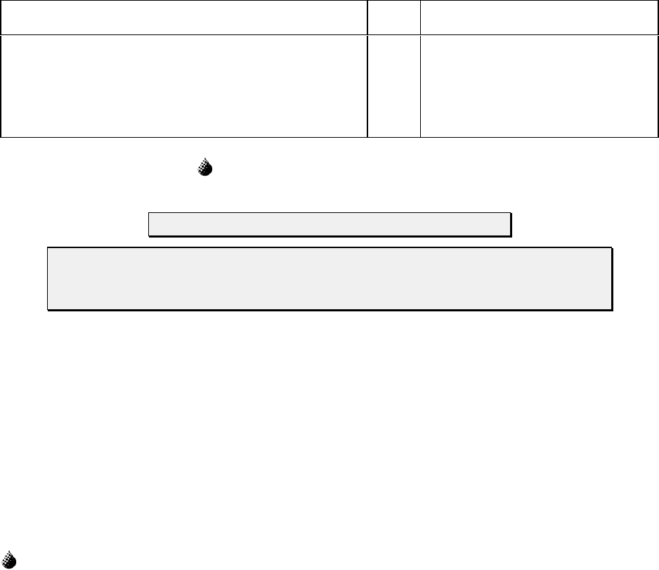
Daily
Weekly
Monthly
Quarterly
Semi-Annually
Annually
As Required
Labor Hours
(approximate)
Clean and inspect strainer basket 0.3
Clean and inspect micron filter(s) 0.5
Replace filter(s) 0.5
Clean membranes 4.0
Replace membranes 2.0
Inspect pump drive belt 1.0
Check pump oil level 0.1
Change pump oil(1) 1.0
Lubricate pump motors 1.0
Backflush media filter(2) 0.3
(1) After first 50 hours and every 500 hours thereafter
(2) For units equipped with the optional media filtration system.
Figure 5.0 - Maintenance Task Chart
PW-3000 to PW-20000 Manual 24 Last Revised 01/12
5.2 RAW WATER STRAINER INSPECTION
1) Isolate the raw water supply and open the strainer housing.
2) Remove the screen from the strainer bowl. Remove any debris from screen and
inspect the screen closely for damage. Replace as required.
3) Check the sealing gasket or o-ring is in good condition, and keeping the seal in
place install the screen and reclose the strainer housing hand tight. Start the RO
and check for leaks.
5.3 FILTER ELEMENT CLEANING OR REPLACEMENT
The filter elements should be replaced when the discharge side of the pressure gauge
drops below 5 psi or the differential pressure is 20 psi. Each PW3000-20000 employs a
filter array consisting of one (1) 20 micron, 100 ft2filter in series with one (1) 5 micron,
100 ft2filter. VMT filters can be washed and re-used 2-3 times provided it is not
contaminated with oil or organic growth.
Description Qty VMT Part #
Micron filter, 20 micron, 100 ft21 33-2100
Micron filter, 5 micron, 100 ft21 33-5100
O-ring, filter lid, 100 ft22 30-0405
Filter, complete assembly, 100 ft22 30-4353
Table 5.0 - Filter Tank Parts List.
CAUTION
VMT filter cartridges are specifically designed for RO applications and
constructed with an oil attractive polypropylene. Use of non-approved
cartridges will void the RO unit warranty.
Replace the filter element(s) using the following procedure:
1) Secure the RO unit. Close the raw water supply (external) to RO unit.
2) Loosen and remove the bolts or wing-nuts that hold the filter tank lid in place.
Remove the tank lid.
3) Remove the filter element. If required, first break the filter seal by rocking the
filter from side to side.
PW-3000 to PW-20000 Manual 25 Last Revised 01/12
4) The filter element may be cleaned by flushing it with water to remove foreign
matter from the filter pleats. If the filter element appears oil-fouled or is damaged
in any way, discard it and install a new element.
5) Reinstall the filter element. Be sure to install the filter element with the end
marked "TOP" upwards. Ensure a proper seal by pressing the filter element
down into place until it reaches the bottom and is fully seated.
6) Reinstall the filter tank lid. Tighten the bolts or nuts.
7) After the filter element has been changed, operate the RO unit and check for
leaks.
5.4 DRIVE BELT INSPECTION AND REPLACEMENT
Proper adjustment of the HP pump drive belt(s) is essential for proper operation of the
system. The drive belt(s) should be inspected for cracking, fraying and excessive wear.
Replace the belts immediately it the inspection indicates that the belt(s) are damaged.
WARNING
Disconnect electrical supply to RO unit before attempting to check.
Serious injury to personnel can result if RO unit is started when checking
drive belt.
1) Remove the mounting screws that hold the left front panel in place and remove
the panel.
2) Inspect drive belt carefully for wear and proper tension. The belt should deflect
approximately ½ " when a force of 6-9 lbs is applied at a point halfway between
the pulleys. Remember that cogged drive belts are never kept as tight as V drive
belts, and overtightened belts will create a squealing sound and can damage
bearings. Adjust the base plate as required to obtain proper belt tension.
3) If the drive belt is damaged or shows any evidence of excessive wear, replace
the drive belt:
a) Locate the HP pump's mounting nuts on the adjustable pump base.
Loosen the nuts to relax the belt tension.
b) Remove the old drive belt and install new one ensuring they are properly
positioned in the pulleys.
PW-3000 to PW-20000 Manual 26 Last Revised 01/12
c) Check the drive belt tension. Adjust the base plate as required to obtain
proper belt tension.
(d) Be sure to properly align the pump and motor pulleys using a straight
edge (at a minimum). After the belt has been sufficiently tightened and
aligned, secure the HP pump by tightening the pump mounting nuts.
4) Replace the side panel on the RO unit
5.5 RO MEMBRANE CLEANING
This section is designed to guide the operator in the periodic chemical cleaning of RO
membrane elements used in the PW3000-20000 unit. The basic procedure for all
cleaning and preservative treatments is the same - a specific chemical solution is
circulated through the system for a pre-determined length of time.
PW3000-6000 PW7000-20000
Cleaning Chemical #1 5 to 15 lbs (8 to 25 cups) 6 to 20 lbs (10 to 33 cups)
Cleaning Chemical #2 4 to 12 lbs (7 to 20 cups) 5 to 15 lbs (8 to 25 cups)
Preservative Chemical #3 4 lbs (6 cups) 5 lbs (8 cups)
Table 5.1 - Chemical Requirements
There is a large variance in the required amount of chemical due to several factors. If
RO product water is used to flush the unit prior to cleaning, the quantity required will be
on the lower side. If the fresh water flush is done with dock or city water that is hard,
then the required amount will rise. If the unit is significantly fouled, the quantity also
rises. The key is to use only enough chemical to achieve the desired pH (pH 11 for #1
and pH 3 for #2). Extreme pH will damage the membranes, so do not exceed the
recommendations. For the first cleaning of a system, use the lower quantities and
measure the pH after circulating as described below. Keep adding chemical as needed
until the cleaning solution maintains the desired pH level. Keep a record of the total
chemical needed, so that on subsequent cleanings the correct amount can be used
without the needed pH measurements and adjustments.
5.5.1 CLEANING CHEMICALS
The alkaline detergent (Cleaning Chemical #1) is used to remove biological matter and
grime from the surface of the RO membranes. The acid cleaner (Cleaning Chemical
#2) is used to remove mineral scale deposits.
CAUTION
PW-3000 to PW-20000 Manual 27 Last Revised 01/12
The use of chemicals or cleaning methods other than those outlined below
will void the RO unit warranty. Non-ionic surfactants for membrane
cleaning or other chemicals not approved in writing by VMT will void the
RO unit warranty.
5.5.2 WHEN TO CLEAN
During normal operations, mineral scale and biological matter will foul the RO
membranes. These deposits build up over time and will eventually cause a loss of
product water output, salt rejection capability, or both. The RO elements should be
cleaned whenever the temperature corrected product water output drops by 10-15%
from the initial baseline established during the first hours of operation with new
membranes. Prior to cleaning the membranes, verify that any reduction in product
output is not the result of a corresponding variation in raw water inlet temperature or
salinity. See Section 3.4 for more detailed information.
NOTE
Product water output of the system is dependent upon feedwater
temperature, RO feed pressure and feedwater salinity. Reductions in
product water output due to these factors are normal and may not indicate
the need for membrane cleaning. See Section 3.4 for more detail.
Use the following procedure to clean the RO elements:
1) Flush the watermaker per section 4.3, so it is filled with fresh water, not
seawater.
2) Dissolve the appropriate amount of Cleaning Chemical #1 (see Table 5.1) in a
pail of fresh water. Make sure that that the chemical is completely dissolved (use
warm water if necessary).
NOTE
Cleaning Chemical #1 is an alkaline detergent. Use appropriate safety
precautions.
3) Verify the High Pressure Bypass Valve, V4, is in its Cleaning (open) position.
4) Place the Cleaning Valve, V5, in the Cleaning Flow position.
5) Remove the filter elements from both filter tanks and replace the 5 micron filter
with a dedicated cleaning filter (5 micron). A dedicated cleaning filter should be
used to prevent fouling of the operational filters. When the cleaning process is

PW-3000 to PW-20000 Manual 28 Last Revised 01/12
complete the dedicated cleaning filter can be cleaned and set aside until the next
membrane cleaning is required. Pour the chemical solution into the empty 20
micron filter housing and the 5 micron housing (drain water first as necessary)
and reinstall the filter housing lids.
6) Start the LP boost pump.
7) Start the HP pump. At least 0 psi must be indicated on the discharge side of the
Pre-filter Pressure gauge. Temporarily cracking open the flush valve will boost
the cleaning loop pressure if required.
a) After the chemical solution has circulated for 3 minutes, secure the
pumps, release any loop pressure by momentarily moving the cleaning
valve, V5, to the normal position and back to cleaning. Take a sample
from the cleaning loop from the filter tank drain valve or by opening the
tank lid. Measure the pH of the sample using a pH meter or test kit VMT#
90-0135.
b) If the pH < 11 then add 10% more of the cleaning solution. Repeat this
step until the pH = 11.
c) Once a pH = 11 can be maintained start the LP and HP pumps and allow
the cleaning solution to circulate for an additional 30-40 minutes.
8) Secure the HP and LP pumps.
9) Place the Cleaning valve, V5, in the Normal Flow position.
10) Open raw water supply to the RO unit external to the unit and make sure the
Flushing Valve, V10, is turned to the Normal, seawater position.
11) Start the LP boost pump and HP pump. Allow both pumps to run for 5 minutes to
flush the chemical solution from the unit.
12) Secure the HP pump and the LP boost pump.
13) Flush the watermaker, so it is filled with fresh water, not seawater.
14) Dissolve the appropriate amount of Cleaning Chemical #2 (see Table 5.1) in a
pail of fresh water. Make sure that that the chemical is completely dissolved (use
warm water if necessary).
NOTE
Cleaning Chemical #2 is an acid used for mineral scale removal. Use
appropriate safety precautions when handling.

PW-3000 to PW-20000 Manual 29 Last Revised 01/12
15) Place the Cleaning Valve, V5, in the Cleaning Flow position.
16) Remove the lid from the 20 micron filter tank, pour the cleaning solution into the
tank (drain water first as necessary) and replace the lid.
17) Start the LP boost pump.
18) Start the HP pump. At least 0 psi must be indicated on the discharge side of the
Pre-filter Pressure gauge, PG1. Temporarily cracking open the flush valve will
boost the cleaning loop pressure if required.
a) After the chemical solution has circulated for 3 minutes, secure the boost
pump, release any loop pressure by momentarily moving the cleaning
valve, V5, to the normal position and back to cleaning. Take a sample
from the cleaning loop from the filter tank drain valve or by opening the
tank lid. Measure the pH of the sample using test kit VMT# 90-0135.
b) If the pH > 3 add 10% more of the cleaning solution. Repeat this step until
the pH < 3.
c) Once a pH of less then 3 can be maintained replace the filter tank lid, start
the LP and HP pumps and allow the cleaning solution to circulate for an
additional 30-40 minutes.
19) Secure the HP and LP pumps.
20) Place the Cleaning valve in the Normal Flow position.
21) Open raw water supply to the RO unit (external to the unit).
22) Start the LP boost pump and HP pump. Allow both pumps to run for 5 minutes to
flush the chemical solution from the unit.
23) Secure the HP pump and the LP boost pump.
24) Close raw water supply to RO unit (external to the unit).
25) Remove, set aside and retain the cleaning filter for future use. Replace the
operational 20 and 5 micron filter elements in the filter housings and replace both
housing lids.
26) Place the unit back into service using the procedure contained in Section 4.1 -
Start-up Procedure.
PW-3000 to PW-20000 Manual 30 Last Revised 01/12
5.6 RO ELEMENT PRESERVATION / PICKLING
During periods when the RO unit is to be shut down for an extended period of time, it is
necessary to circulate a preservative solution through the membranes to prevent the
growth of biological organisms. Use the following procedure to preserve the RO
elements:
1) Secure the raw water supply to RO unit (external to the unit).
2) Dissolve the appropriate amount of Cleaning Chemical #3 (see Table 5.1) in a
pail of non-chlorinated product water. Make sure that that the chemical is
completely dissolved (use warm water if necessary).
NOTE
Preservative Chemical #3 is a food-grade preservative. See warning label
on package and observe all safety precautions on label.
3) Flush the watermaker, so it is filled with fresh water, not seawater (see section
4.3)
4) Make sure the High Pressure Bypass Valve is in the Cleaning (open) position.
5) Place the Cleaning Valve in the Cleaning Flow position.
6) Remove one of the filter housing lids (draining water as necessary) and pour in
the preservative solution prepared in step #1. Reinstall the lid. Leave the filters
elements in place.
7) Start the LP boost pump.
8) Start the HP pump. At least 0 psi must be indicated on the discharge side of the
Pre-filter Pressure gauge. Temporarily cracking open the flush valve will boost
the cleaning loop pressure if required. Allow the chemical solution to circulate for
10 minutes.
9) Secure the LP and HP pumps.
10) The system is now properly conditioned and may be left idle for an extended
period of time. This preservation procedure (including the fresh flush to remove
old pickling solution) should be repeated at least every 3 months during the
shutdown. In colder climates the interval between preservation cycles may be
extended to 6 months.

PW-3000 to PW-20000 Manual 31 Last Revised 01/12
5.7 RESTARTING UNIT AFTER PRESERVATION
Restart unit using the procedure contained in Section 4.1 - Start-up Procedure. Use the
MODE button on the Water Quality Monitor to light the DUMP lamp for the first 15
minutes of production to make sure all preservative is flushed clear prior to filling the
fresh water tanks.
5.8 HIGH PRESSURE PUMP OIL CHANGE
See equipment literature in back of this manual for instructions for changing the oil on
your particular pump.
5.9 MOTOR LUBRICATION
Locate the grease fittings on the electric motor. Use a clean cloth to wipe this fitting
clean. If applicable, remove any caps. Free the drain hole of any hard grease (use a
piece of wire if necessary). Add 2-3 strokes of grease using a low pressure grease gun
(see Table 5.2 for grease type).
Location Type
High pressure pump oil VMT pump oil #85-0050
High pressure pump motor grease
Shell Oil Dolium R
Texaco Premium RB
Exxon Mobil PolyrexEM
Chevron SRI
O-rings & gaskets Glycerin or silicone lubricant
Table 5.2 - Lubrication Requirements
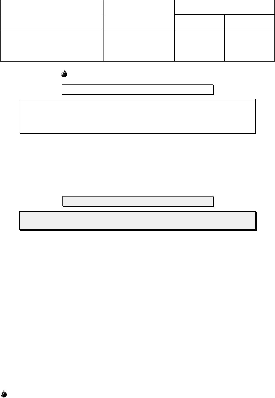
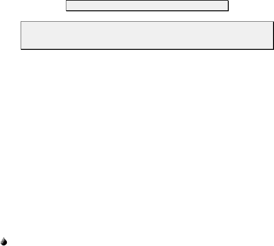
5.10 INSPECTION LOG
Figure 5.2 depicts a sample operation log for the PW3000-20000 RO unit. The operator
of the RO unit should establish a program for entering the required data on a regular
basis. Maintaining accurate operational data is the first, and most important, step in
determining preventative maintenance requirements and reducing system downtime.
The data maintained in the log must be provided by the Purchaser to make any RO
element warranty claim. Figure 5.3 depicts a sample discrepancy report that may be
used for reporting and tracking problems with the RO unit.

PW-3000 to PW-20000 Manual 32 Last Revised 01/12
Date Total
Operating
Hours
PG1,
Pre-filter
Inlet
Pressure
PG1,
Pre-filter
Discharge
Pressure
PG2
RO Array
Discharge
Pressure
FM1,
Reject
Flow
FM2
Product
Flow
Product
Water
TDS
(ppm)
Water
Temp,
(°C) Comments
Figure 5.1 - Sample Operational Log

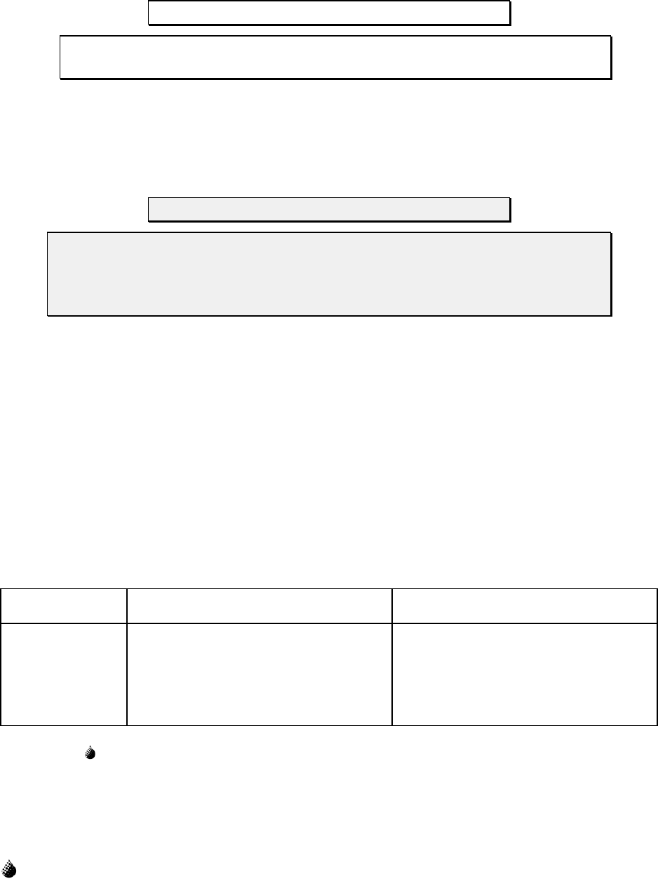
PW-3000 to PW-20000 Manual 33 Last Revised 01/12
COMMENT/DISCREPANCY REPORT
Village Marine Tec.
RO Desalinator Model PW-3000 to PW-20000
Plant No: Date:
Log Task No: Time:
System Affected: Technician :
Comment/Discrepancy:
Corrective Action:
Action Taken:
Date Completed:
Printed Name:
Signature:
Figure 5.2 - Sample Discrepancy Report
PW-3000 to PW-20000 Manual 34 Last Revised 01/12
6.0 PRESSURE VESSEL AND MEMBRANES
6.1 PRESSURE VESSEL DISASSEMBLY
NOTE
It is not necessary to remove a pressure vessel from the RO unit for
disassembly.
1) Disconnect all plumbing connections from the pressure vessel to be
disassembled.
2) Remove the bolts holding each end plug in place with an Allen wrench. Place a
mark on each end plug removed and its corresponding collar. This will ensure
proper orientation during assembly.
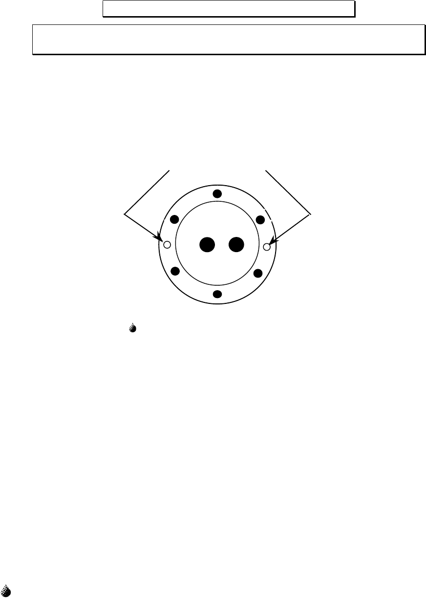
Figure 6.0 - Pressure Vessel End Plug
3) Locate the jacking screws on opposite sides of the end cap (see Figure 6.0).
Screw in the correct size bolt until the end cap is pulled off. There are also
prying slots on either side of the end plug to assist in removal.
JACKING SCREW
HOLES
PW-3000 to PW-20000 Manual 35 Last Revised 01/12
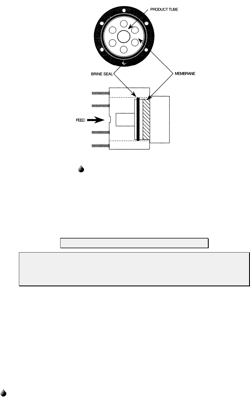
Figure 6.1 - Brine Seal Orientation
4) Note which end of the pressure vessel the brine seal is visible from. This is the
feed end of the pressure vessel. When reinstalling the RO membrane, the brine
seal must be located at the feed end of the pressure vessel. Note the feed flow
direction marked by a sticker on the outside of the pressure vessel, or trace the
flow direction from the high pressure pump to confirm the high pressure flow
direction. See Figure 6.1.
CAUTION
Never force a membrane out of a pressure vessel by applying pressure on
the product water tube (center tube) as this will damage the membrane. If
the membrane is difficult to remove, use a length of 2" plastic pipe to apply
pressure on the protected end of membrane.
5) Whenever possible, remove the membrane from the discharge end of the
pressure vessel (opposite the brine seal). This is accomplished by pushing on
the membrane from the feed end of the pressure vessel until it is visible at the
discharge end. Then grasp the protruding membrane and pull it out of pressure
vessel. Place the membrane in a clean area.
6) Remove the product water o-rings and end plug o-ring from each end plug for
inspection. The product water o-rings are internal o-rings located inside the
center hole in the end cap.
PW-3000 to PW-20000 Manual 36 Last Revised 01/12
6.2 PRESSURE VESSEL ASSEMBLY
1) Clean all parts thoroughly. Inspect the o-rings on all fittings. Replace any parts
that are damaged.
NOTE
Do not apply Teflon tape or other sealant to straight thread fittings such as
those used on HP hose assemblies and their adapters.
2) Install the product water and end plug o-rings onto the end plugs. Lubricate the
o-rings and entrances to the pressure vessel with glycerin or silicone lubricant.
Locate the discharge end of pressure vessel. Install the end plug into the
discharge end making sure to align the end plug holes and the mounting holes
on the pressure vessel while paying particular attention to the reference mark
(see Section 6.3.1, Step 2). Apply pressure to the end plug until screws can be
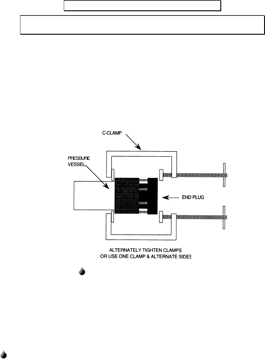
threaded into the collars. If the end plug will not slide into the pressure vessel
sufficiently, see Figure 6.2 for an installation aid. Install and hand tighten the
screws.
Figure 6.2 - End Plug Installation Aid
3) Lubricate the brine seal and product water tubes of RO membrane with glycerin
or silicone lubricant. Do not use a petroleum based lubricant. Orient the
membrane such that the end without the brine seal enters the feed end of the
pressure vessel first. Slide the membrane into the pressure vessel until

PW-3000 to PW-20000 Manual 37 Last Revised 01/12
resistance is felt. Continue to apply moderate pressure until the product water
tube seats in the end plug.
4) Install the remaining end plug making sure to align the end plug holes with the
mounting holes on the pressure vessel while paying particular attention to the
reference mark (see Section 6.3.1, Step 2). Apply moderate pressure to the end
plug until the screws can be threaded into the collar. If the end plug will not slide
into the pressure vessel sufficiently, see Figure 6.2 for installation aid. Install and
hand tighten the capscrews.
5) Make sure that antiseize compound is applied to each screw before the final
tightening and torque the screws to 15 ft-lbs.
6) Reconnect all plumbing connections to pressure vessels.

PW-3000 to PW-20000 Manual 38 Last Revised 01/12
7.0 PRESERVATION FOR STORAGE
When the Village Marine Tec RO unit is to be shut down for an extended period of time,
it is necessary take steps to prevent the growth of biological organisms and to prevent
the water in the RO unit from freezing. Either continue to flush the unit with fresh water
each week, or circulate a preservative solution (see section 5.6). If the unit will at any
time be exposed to air temperatures of 32ºF (0ºC) or less, the membranes must be
removed and the unit fully drained or the unit filled with an anti freeze solution such as
propylene glycol.
8.0 TROUBLESHOOTING
No amount of trouble shooting advice can replace common sense and direct plant
knowledge gained through the operation and maintenance of your unit. However our
experience taking tec calls suggests some points to check.
1. Always verify proper valve configuration for each of the operational modes
selected. Verify valve positions for valves within the unit and also external valves
are open as required.
2. Always check for positive pressure at the HP pump suction. Many problems
stem from low or erratic feed water supply. Check filters, strainer, seacock,
boost pumps, etc to be sure of flooded suction to the HP pump.
3. Always check for loose connections or broken wires when inspecting electrical
parts. Checking for continuity and solid contact can sometimes avoid hours of
troubleshooting effort.
4. Prior to cleaning or replacing membranes, verify that any reduction in product
output is not the result of a corresponding variation in raw water inlet temperature
or salinity. See Section 3.4 for more detailed information.
Call or email us at the Village Marine Tec Service representative or distributor for
assistance.

PW-3000 to PW-20000 Manual 39 Last Revised 01/12
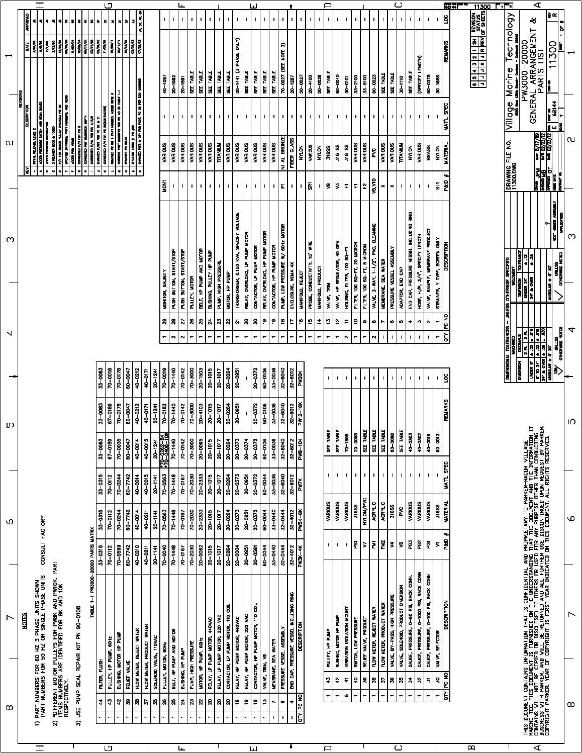
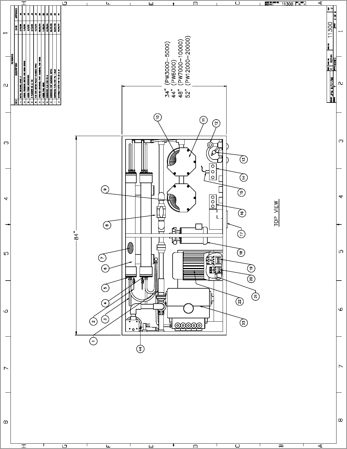
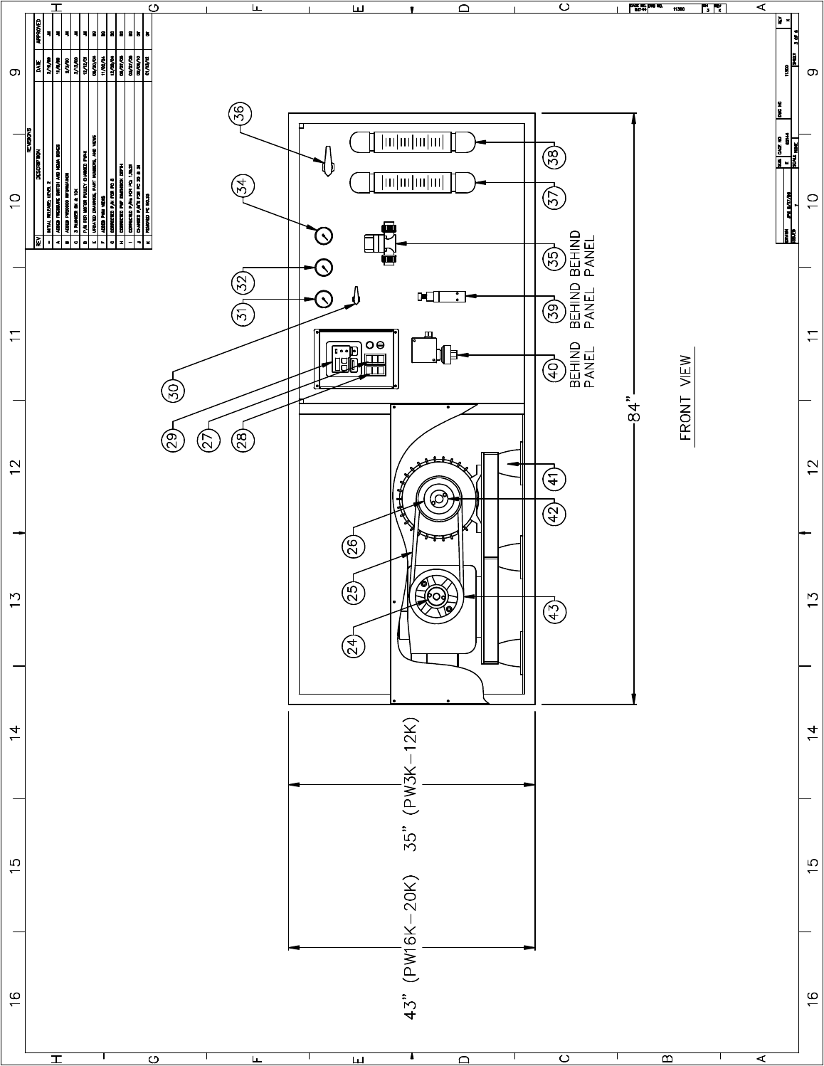
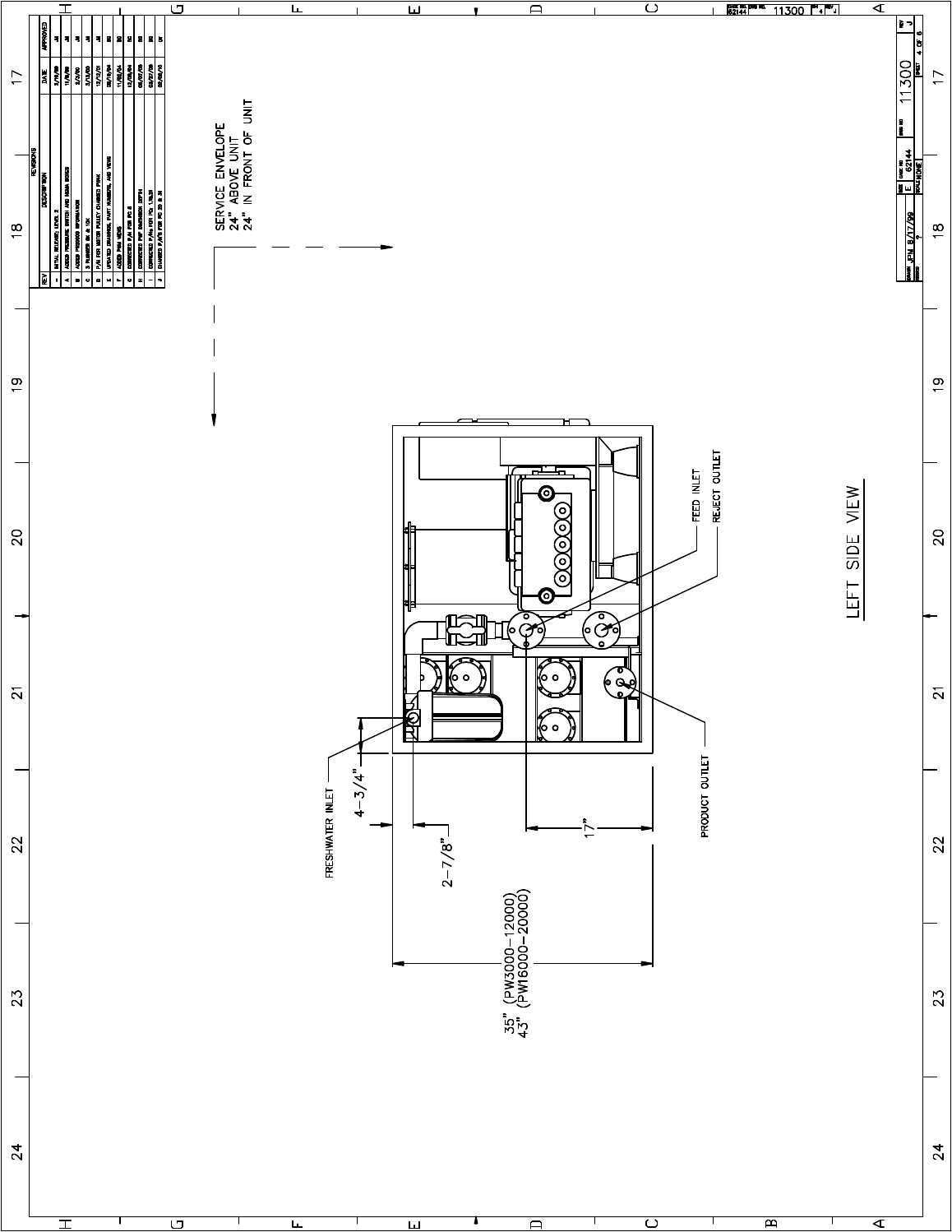
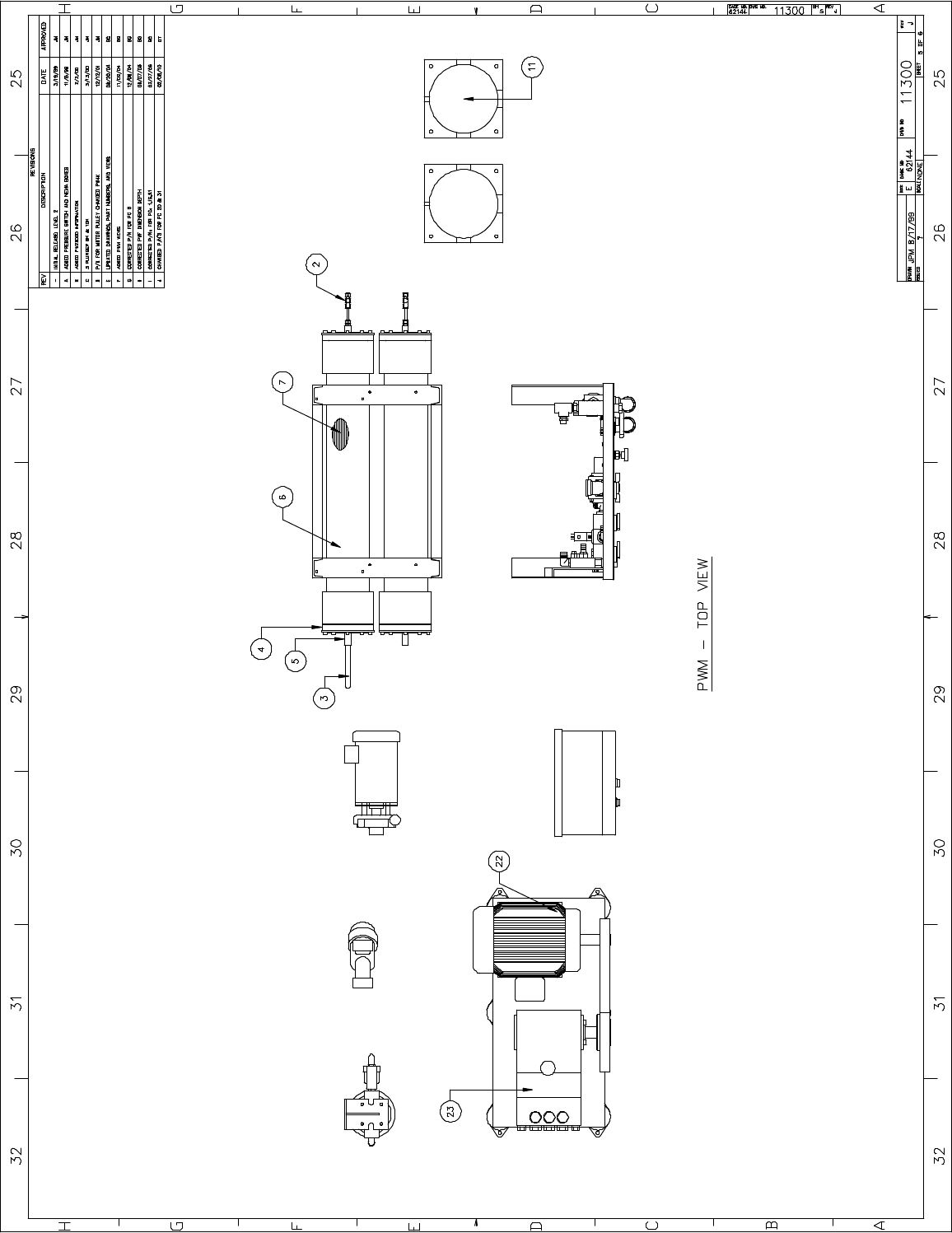
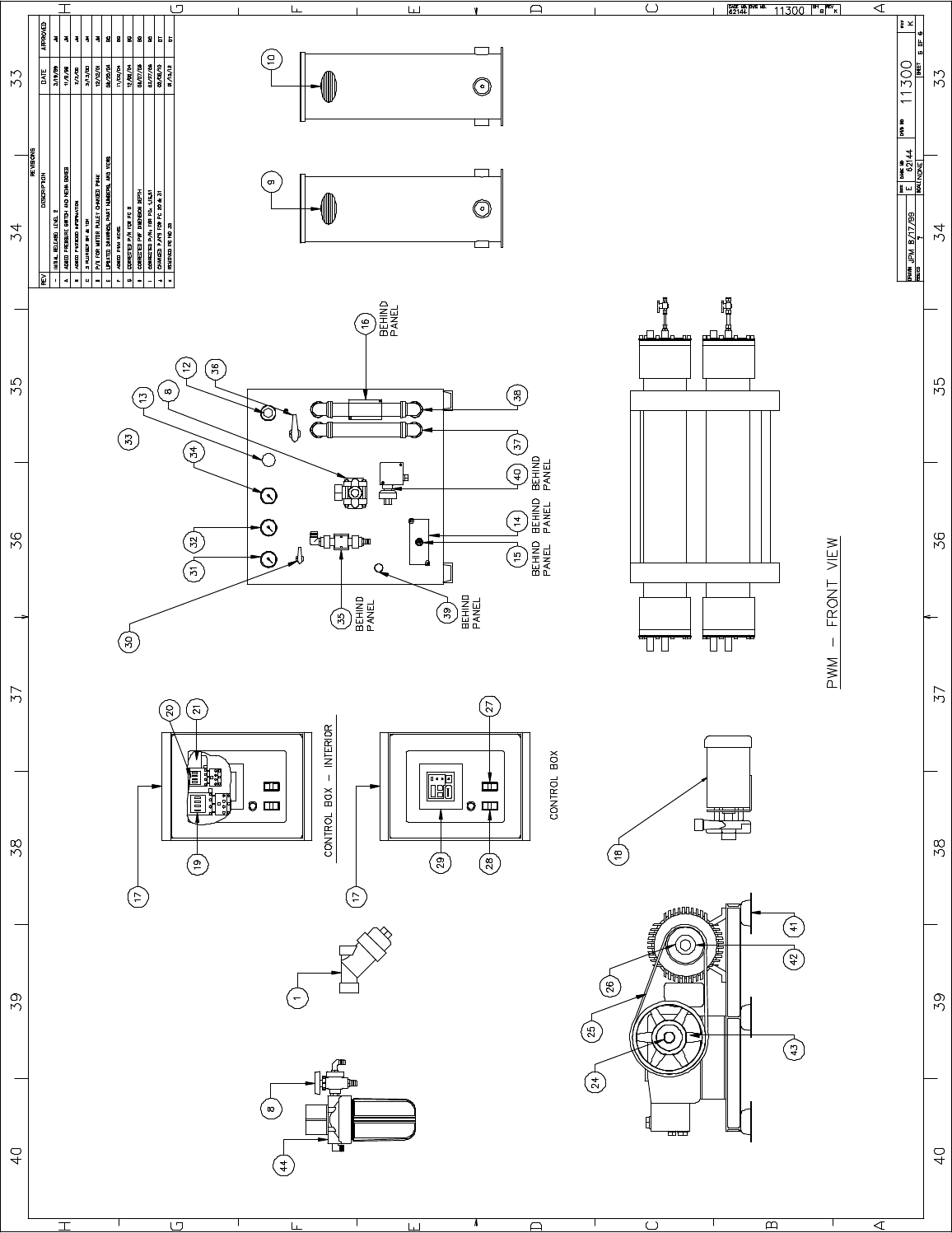
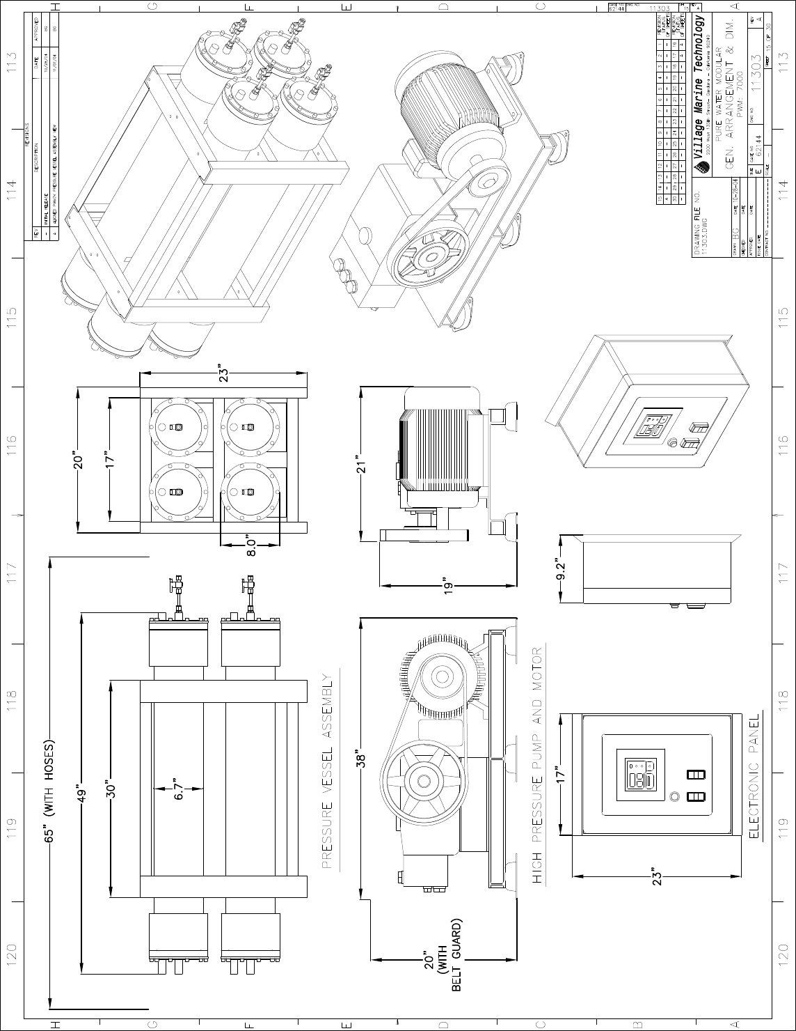
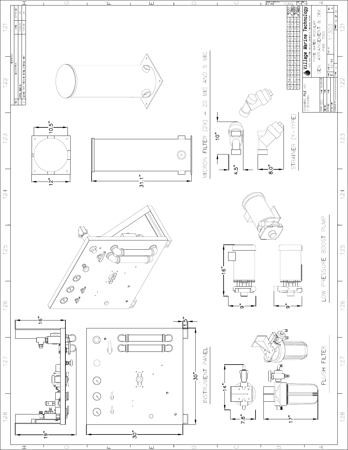
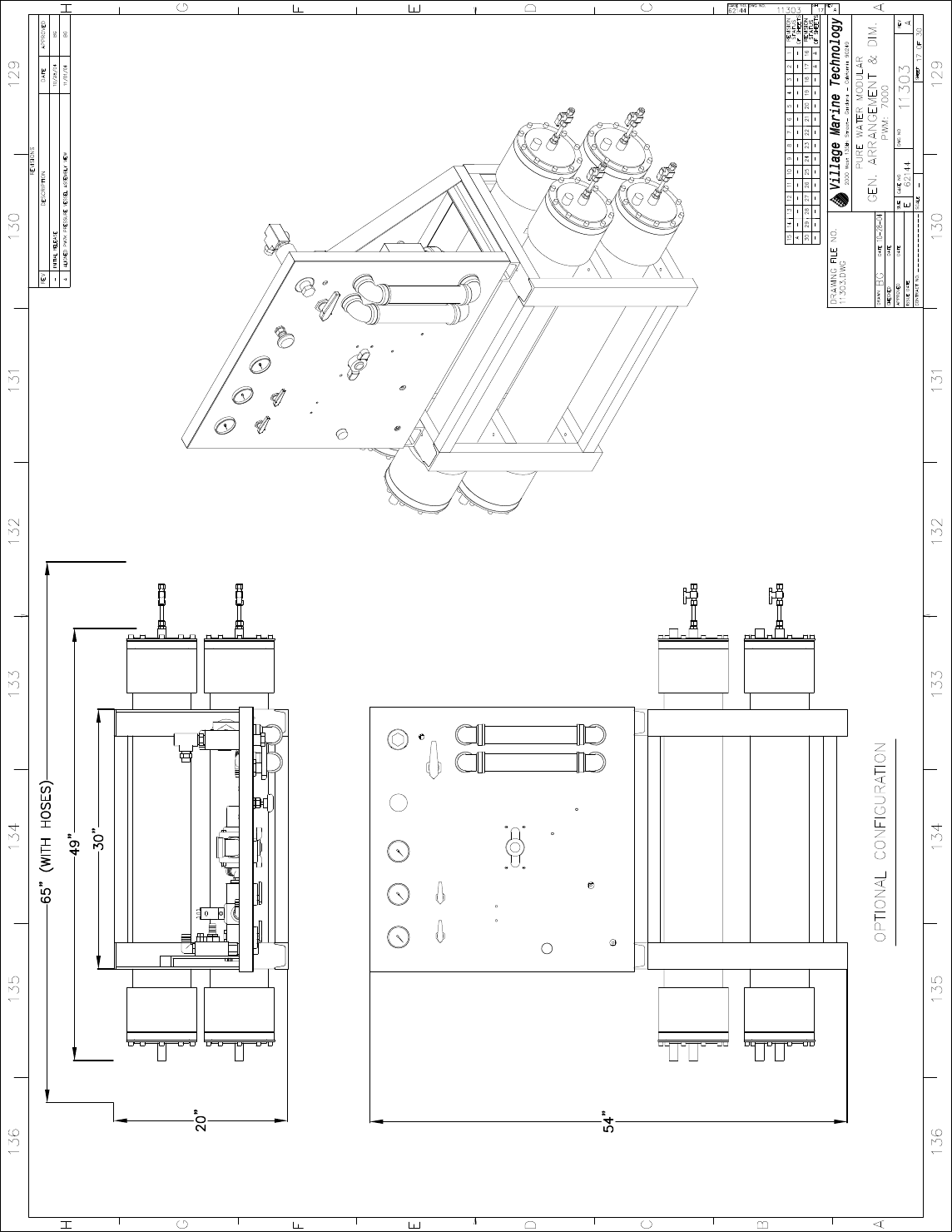
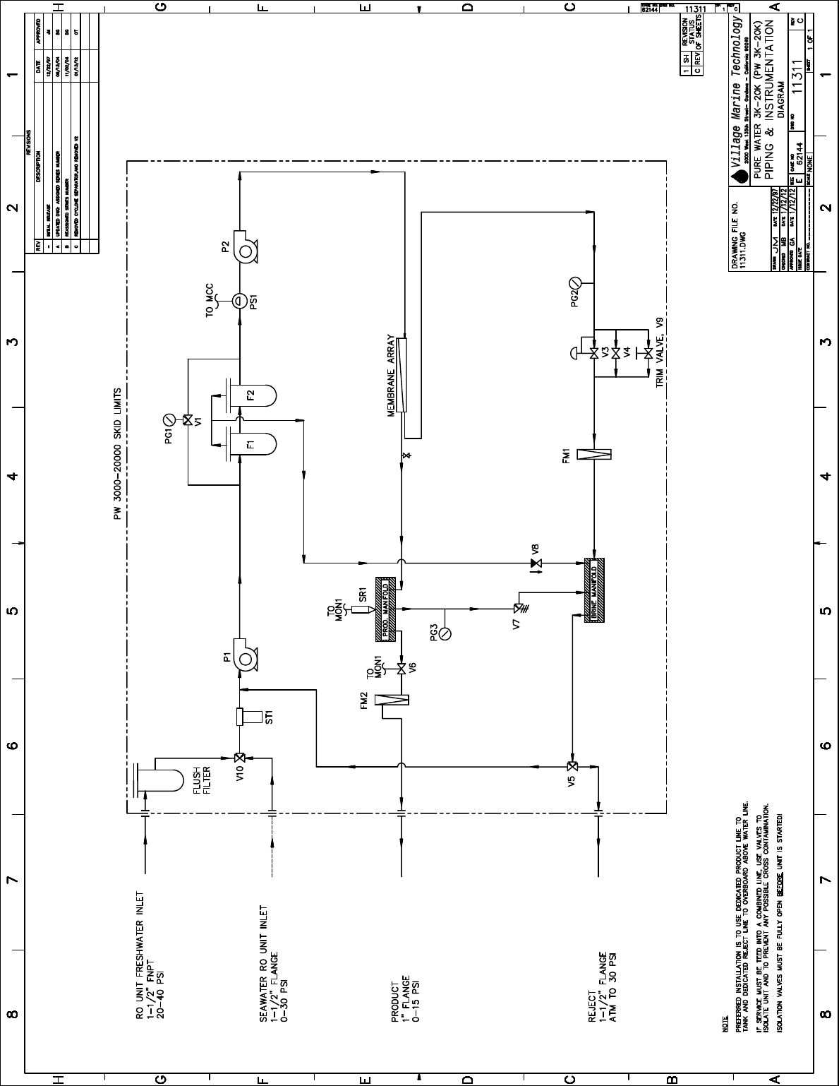
9.0 SYSTEM DRAWINGS AND DIAGRAMS AND PARTS LIST
"Use or disclosure of data contained on this sheet is subject to the restrictions on the title page of this proposal or quotation."
"Use or disclosure of data contained on this sheet is subject to the restrictions on the title page of this proposal or quotation."
"Use or disclosure of data contained on this sheet is subject to the restrictions on the title page of this proposal or quotation."
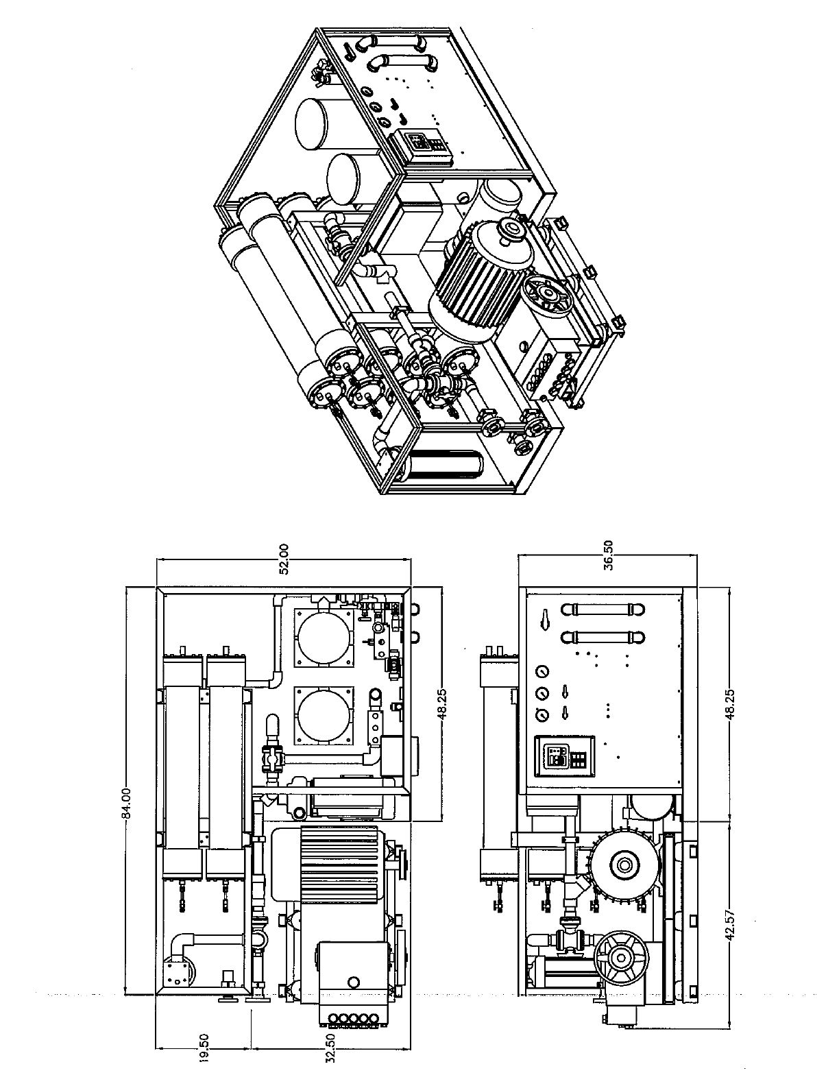
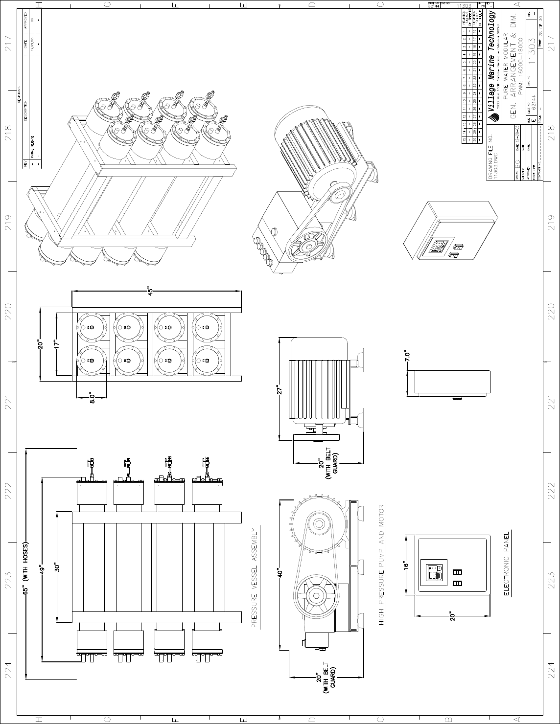
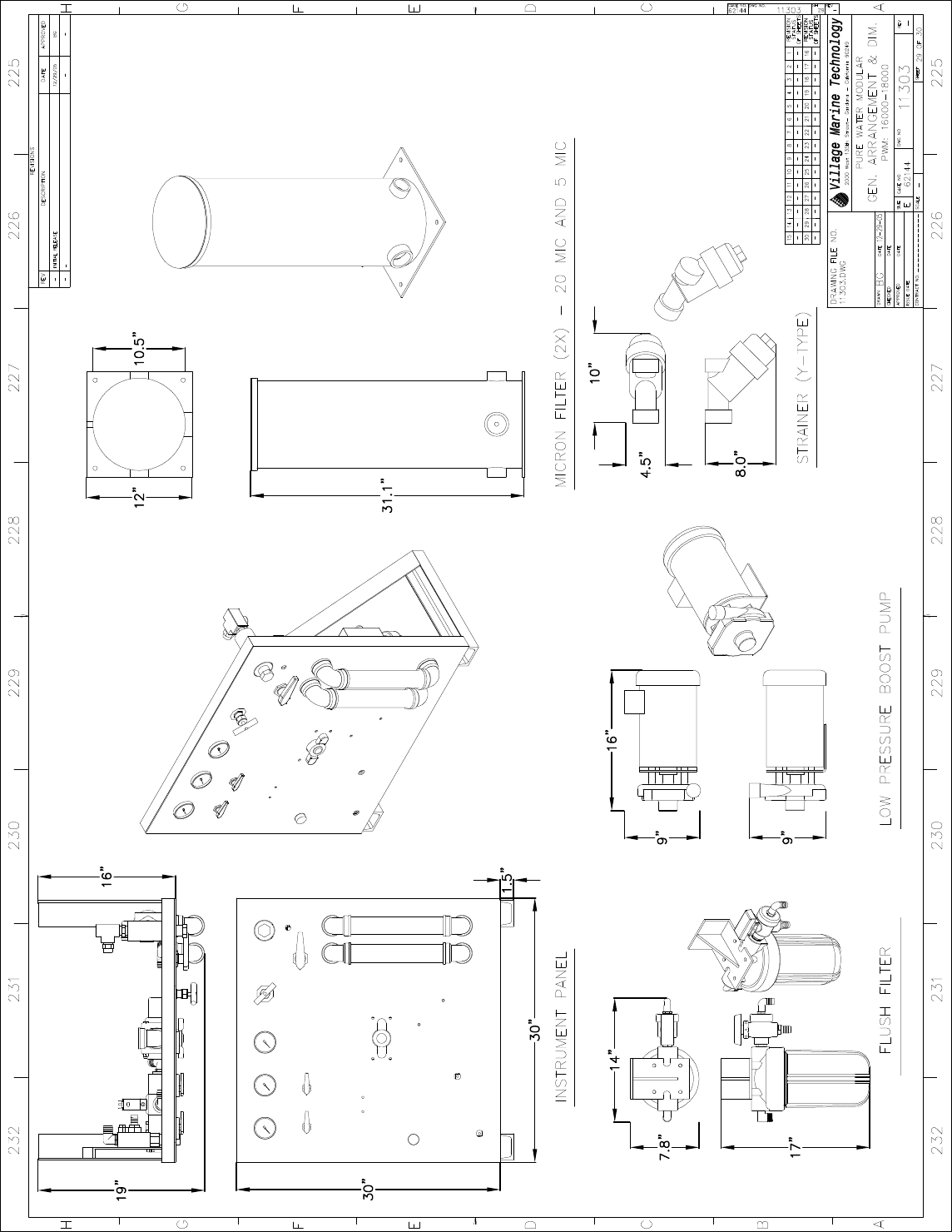
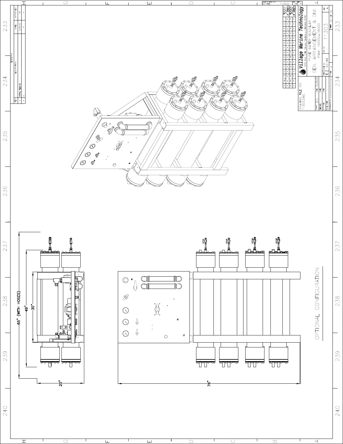
Installation Layout
PW-12000
PW-16000
PW-18000
"This proposal or quotation includes data that shall not be disclosed outside the Government and shall not be duplicated,
used, or disclosed in whole or in part for any purpose other than to evaluate this proposal or quotation. If, however, a
contract is awarded to Parker Hannifin as a result of or in connection with the submission of this data, the Government shall
have the right to duplicate, use or disclose the data to the extent provided in the resulting contract. This restriction does not
limit the Government's right to use information contained in this data if it is obtained from another source without restriction.
The data subject to this restriction are contained in sheet DWG 11311.
The information contained herein is submitted as the privileged and confidential property of the Parker Hannifin Corporation
pursuant to 5 U.S.C. Section 552 (b)(3) and (b)(4), the Freedom of Information Act, exemption Number 3 and Number 4.
This information shall not be duplicated, used or disclosed in whole or in part outside the recipient organization without the
express written consent of the Parker Hannifin Corporation."

PW3000-18000 Manual 43 Last Revised 4/08
10.0 MANUFACTURER'S LITERATURE AND OPTIONS

REVISION D
TABLE OF CONTENTS
_Toc293906105
INTRODUCTION.....................................................................................................................................................................1
INITIAL START-UP INFORMATION......................................................................................................................................2
LUBRICATION.....................................................................................................................................................................2
DISCHARGE PLUMBING ...................................................................................................................................................2
STORAGE ...........................................................................................................................................................................3
PREVENTIVE MAINTENANCE SCHEDULE.........................................................................................................................4
MAINTENANCE RECORD.....................................................................................................................................................5
SERVICE.................................................................................................................................................................................8
INTRODUCTION .................................................................................................................................................................8
TOOLS NEEDED ................................................................................................................................................................8
VALVE INSPECTION AND SERVICE ................................................................................................................................9
DETACHING THE MANIFOLD FROM THE CRANKCASE ................................................................................................9
SEAL REPLACEMENT .....................................................................................................................................................10
SERVICING THE CRANKCASE .......................................................................................................................................10
PLUG, OIL DRAIN, O-RING REPLACEMENT..................................................................................................................10
BEARING CAP O-RING/SEAL REPLACEMENT..............................................................................................................12
COVER, CRANKCASE O-RING REPLACEMENT ...........................................................................................................12
CRANKSHAFT BEARING, CONNECTING ROD-PISTON SERVICE..............................................................................13
CRANKSHAFT REMOVAL................................................................................................................................................13
CRANKSHAFT INSTALLATION........................................................................................................................................15
SERVICING THE MANIFOLD...........................................................................................................................................17
ADAPTER O-RING REPLACEMENT................................................................................................................................17
VALVE ASSEMBLY SERVICING ......................................................................................................................................17
MANIFOLD SEAL SERVICING .........................................................................................................................................19
ATTACHING THE MANIFOLD TO THE CRANKCASE ....................................................................................................21
OIL CHANGE PROCEDURE ............................................................................................................................................21
5P50 DRAWINGS.................................................................................................................................................................22
LIST OF FIGURES
Fig. 1: Oil Level Sight Glass Detail.......................................................................................................................................................2
Fig. 2: Valve Assembly...........................................................................................................................................................................9
Fig. 3: Manifold Assembly Removal.....................................................................................................................................................9
Fig. 4: Plunger Assembly View ...........................................................................................................................................................10
Fig. 5: Plunger Retaining Nut Assembly............................................................................................................................................11
Fig. 6: Seal Retainer.............................................................................................................................................................................11
Fig. 7: Bolt tightening sequence..........................................................................................................................................................13
Fig. 8 Keep parts organized.................................................................................................................................................................14
Fig. 9 Removal of the Crankshaft bearing.........................................................................................................................................15
Fig. 10 Correct Connecting Rod Pairing............................................................................................................................................16
Fig. 11 Incorrect Connecting Rod Pairing..........................................................................................................................................16
Fig. 12: Manifold Assembly..................................................................................................................................................................17
Fig. 13: Valve Assembly.......................................................................................................................................................................18
Fig. 14: Orientation for Manifold Seal Servicing ...............................................................................................................................19
Fig. 15: Weep Ring Extraction ...........................................................................................................................................................20
Fig. 16: High-Pressure Seal Installation View..................................................................................................................................20
Fig. 17: Pump Assembly Orientation View........................................................................................................................................21
LIST OF TABLES
Table 2: Tool List For Pump Service.......................................................................................................................................8

1
INTRODUCTION
Aqua Pro Pumps “Titan Series” High Pressure Pumps are the product of our years of experience in the water treatment
industry, and have been specifically designed and engineered for corrosive and high-pressure applications. Your new
Aqua Pro Pump is made with dependable and proven technology to meet your highest demands.
SPECIFICATIONS
Specifications subject to change without notice.
Pump type: Reciprocating Plunger
Number of Plungers: 5
Bore: 1.259”
Stroke: 1.516”
Oil Capacity: 5.8 Qts.
Oil Type: Village Marine Tec. High Pressure Pump Oil
(Part No. 85-0050-quart size)
Maximum Inlet pressure: Flooded (zero) to 60 PSI
Maximum Fluid Temperature: 120 degrees Fahrenheit (82 degrees Celsius)
Model Number GPM Inlet Port Size Discharge Port
Size Dimensions
L x W x H Weight Shaft
5P50 20-50 1.5” MS16142-24 1” MS16142-16 18.5”x 14.5” x 9” 157 lbs. 1.625
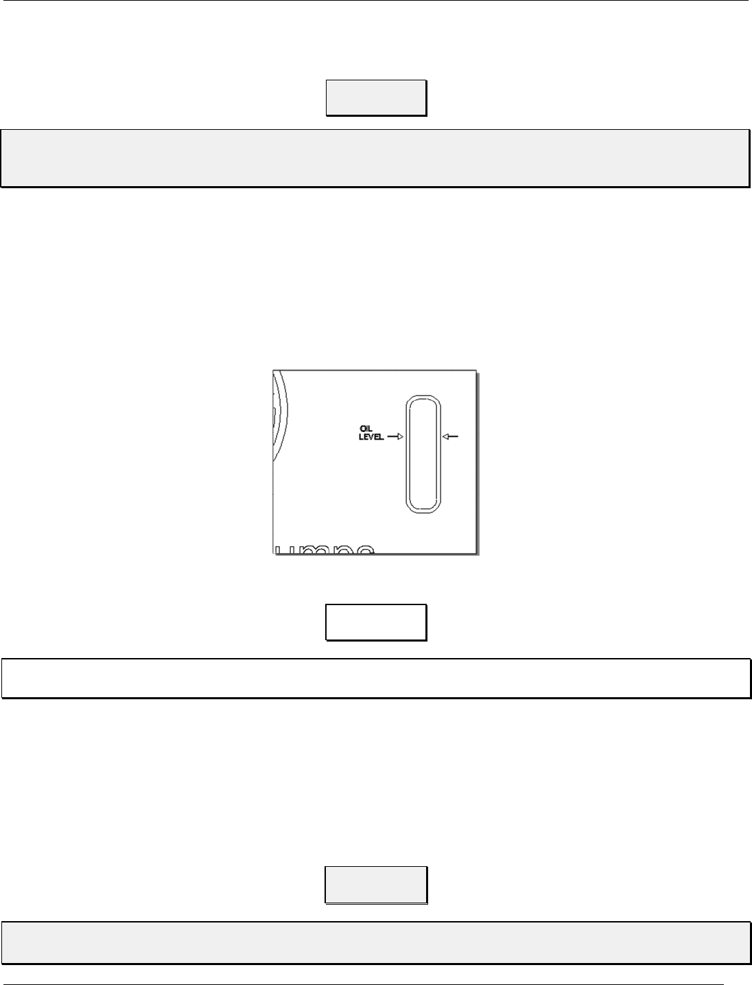
5P50 Titan Series
High Pressure Titanium Positive Displacement Pump
2
INITIAL START-UP INFORMATION
The performance of the pump depends on the entire fluid system and will operate best with the proper installation of
plumbing, operation, and maintenance of the pump.
LUBRICATION
It is recommended that the pump be filled with Village Marine Tec’s specially blended high pressure pump oil (PN 85-
0050). To check the oil level, ensure the pump has stopped running. Observe oil level through the sight glass in the
crankcase cover. The oil should be level with the mark on the sight glass (Fig. 1).
Fig. 1: Oil Level Sight Glass Detail.
Ensure drive belt is adequately sized for system and shaft bearings. Pulley alignment is critical to the proper operation of
the system. To check for proper alignment, place a straight edge, square, or rule against the pulleys to make sure they
are in line. Proper alignment of the drive pulleys will minimize crankshaft bearing and belt wear. Over-tensioning of the
drive belt may cause pump crankshaft bearing damage.
DISCHARGE PLUMBING
WARNING
This is a positive displacement pump. A properly designed pressure relief safety valve must be installed in the discharge
piping. Failure to install such a relief mechanism could result in personal injury or damage to the pump or system. Aqua
Pro Pumps does not assume any liability or responsibility for the operation of a customer’s high-pressure system.
NOTE
Change the original oil in the pump after 50 hours of operation. After the initial oil change, the oil should be changed at
500-hour service intervals.
CAUTION
Start system with all valves open or with minimal flow restriction to avoid deadhead overpressure conditions and severe
damage to the pump or system. Discharge regulating devices should be at minimum pressure setting at start-up.

3
STORAGE
For extended storage or between uses in cold climates, drain all pumped fluids from pump and flush with antifreeze
solution to prevent freezing and damage to the pump.
CAUTION
DO NOT RUN PUMP WITH FROZEN FLUID. DO NOT RUN PUMP DRY.

5P50 Titan Series
High Pressure Titanium Positive Displacement Pump
4
PREVENTIVE MAINTENANCE SCHEDULE
The Required Maintenance Schedule specifies how often you should have your pump inspected and serviced. It is
essential that your pump be serviced as scheduled to retain its high level of safety, dependability, and performance. Not
performing these tasks could result in catastrophic failure.
TASKS DAILY WEEKLY
As
Determined
by
Condition
FIRST
50 HRS. EVERY
500 HRS. EVERY
1500 HRS. EVERY
10000 HRS.
Inspect for Water Leaks/
Oil Leaks X
Check Oil Level X
Check Belt Tension X
Inspect Plumbing X
Inspect Pump Valves X
Change Pump Oil X X
Replace Pump Valves X
Replace Seals X
Crankcase Service and
Inspect Connecting Rods
and Crank Bearings X
Manifold Rebuild X
Replace Connecting Rods
and Bearings X

5
MAINTENANCE RECORD
Keep record of all maintenance activities to ensure maintenance is performed. Note trends and increase maintenance as
necessary.
HOURS RECOMMEND
SERVICE ACTIONS / NOTES ACTUAL
HOURS SIGNATURE DATE
50 Oil
550 Oil
1050 Oil
1550 Valve Inspection, Oil
2050 Oil
2550 Oil
3050 Valve Inspection, Oil
3550 Oil
4050 Oil
4550 Valve Inspection, Oil
5050 Oil
5550 Oil
6050 Valve Inspection, Oil
6550 Oil
7050 Oil
7550 Valve Inspection, Oil
8050 Oil
8550 Oil
9050 Valve Inspection, Oil
9550 Oil
10000 Crankshaft Bearing,
Manifold Rebuild, Oil
*HP seal is not routinely replaced during low pressure seal change. HP seal is replaced only in case of seal failure (see
low-pressure troubleshooting, pg.6).
** Oil changes are mandatory at the specified hour intervals.
5P50 Titan Series
High Pressure Titanium Positive Displacement Pump
6
TROUBLESHOOTING
Use the troubleshooting table below. If problems persist, contact your dealer.
PROBLEM PROBABLE CAUSE SOLUTION
Low Pressure Belt Slippage Make sure the correct belt is used. If the correct belt
is used and the belt is slipping, then t
ighten. Replace
belt if worn.
Leaky discharge hose Check connections. Replace hose if worn or
cracking.
Pressure gauge inoperative or
not registering correctly. Check pressure with new gauge and replace as
needed.
Air leak in inlet plumbing Use PTFE liquid or tape to seal the threads. Make
certain that the PTFE does not go beyond the last
thread. Doing so may damage the pump.
Inlet suction strainer clogged or
improperly sized Clear the obstruction, or use adequate size for inlet
pump connection and fluid being pumped.
Relief valve stuck, partially
plugged or improperly sized Clean and reset relief valve to system pressure and
correct bypass. Check supply tank for
contamination.
Worn or dirty valves Clean valve or replace with a rebuild kit.
Worn high-pressure seals;
abrasives in pump fluid, severe
cavitation; inadequate water
supply; stressful inlet conditions.
Replace seals with rebuild kit. Install and maintain
proper filter, check line size and flow available to
pump
Pulsation Pump runs
extremely rough, pressure low Faulty pulsation dampener (if a
pulsation dampener has been
installed.)
Check pre-charge. Check manufacturer’s literature
on recommended pressure.
Restricted inlet, or air entering
inlet plumbing Be sure that inlet hose is the proper size. Check
filters and clean as needed. Check fittings and use
PTFE liquid or tape for airtight connection.
Valve or spring damage Clean or replace valve and spring, check inlet supply
tank for contamination
Seal damage Replace seals.
Slight water leakage from
under the manifold Possible Condensation No fix needed.
Worn low pressure seals Replace seals with seal kit, check inlet pressure and
inspect ceramic plunger for damage.
Excessive oil leak between
crankcase and pumping
section (1 drop every 15 min)
Worn crankcase oil seals Replace crankcase oil seals.
7
PROBLEM PROBABLE CAUSE SOLUTION
Oil leaking from crankshaft
area Worn crankshaft oil seal Replace damaged oil seals.
Bad bearing Replace bearing.
Cut or worn o-ring on bearing
cap Replace o-ring on bearing cap.
Water in crankcase Humid air condensing into water
inside the crankcase Change oil every three months or 500 hours
Excessive play in the end of
the crankshaft Worn bearing Replace bearing.
Oil leaking in the rear portion
of the crankcase Damaged or improperly installed
crankcase cover, crankcase
cover o-ring, drain-plug, or drain-
plug o-ring.
Replace crankcase cover o-ring or drain-plug o-ring.
Loud knocking noise in pump Pulley loose on crankshaft Check key and pulley bushing.
Restricted Inlet Clear obstruction or replace valve.
Worn bearing, connecting rod or
crankshaft. Service crankcase.
Worn belts Replace belts.
Frequent or premature failure
of the seals Running pump dry NEVER RUN THE PUMP WITHOUT WATER.
Abrasive material in the fluid
being pumped Install proper filtration on pump inlet plumbing.
Excessive temperature of
pumped fluid (120 degrees F
max.)
Reduce fluid inlet temperature to specifications.
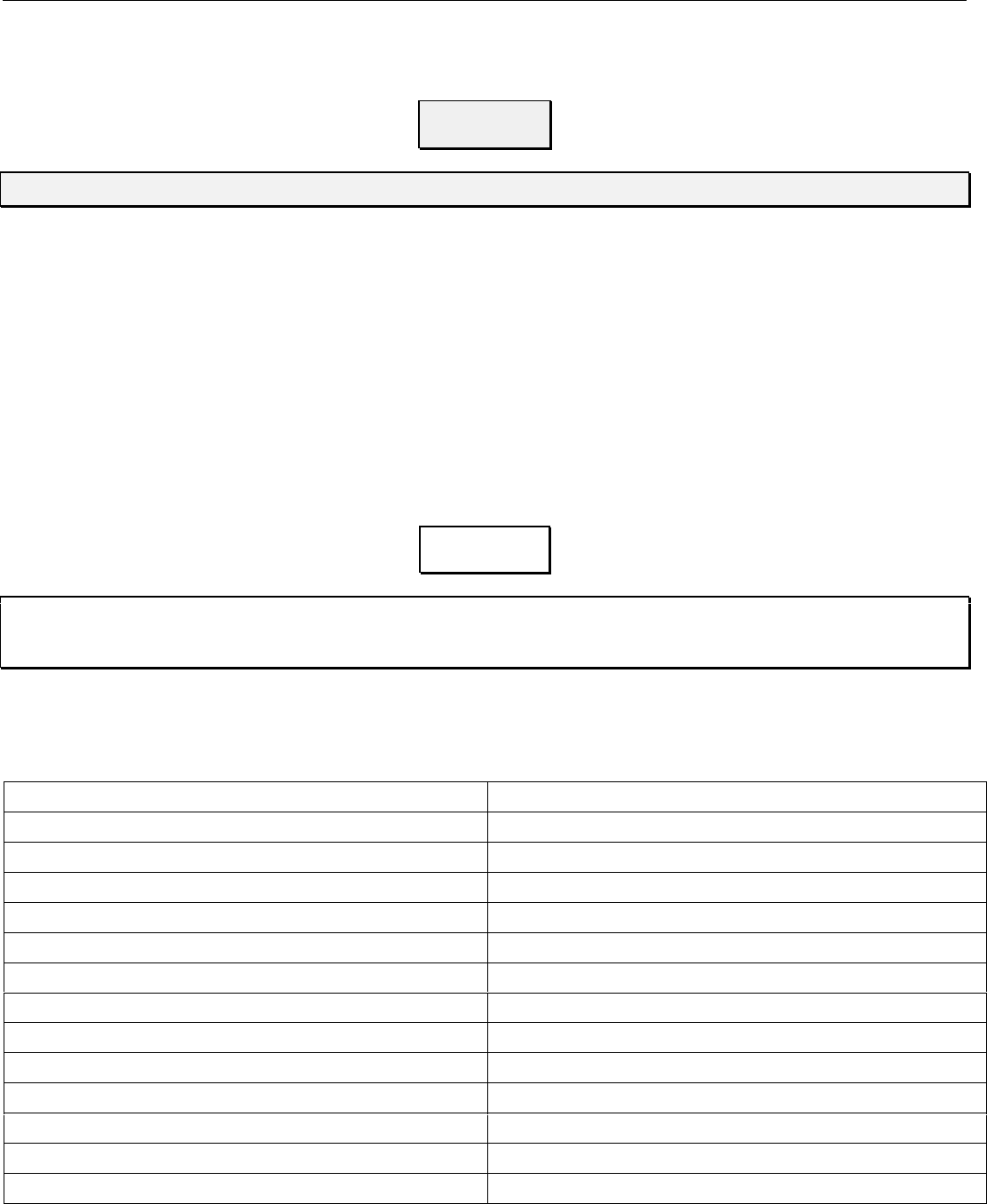
5P50 Titan Series
High Pressure Titanium Positive Displacement Pump
8
SERVICE
Pump rebuild kits are available for valve or seal overhauls. Contact your dealer for ordering information.
INTRODUCTION
All tasks should be performed in a clean environment, free from dust and debris. It is imperative that the utmost
cleanliness be maintained during the rebuild of your Aqua Pro Pump. The numbers following the parts are callout
numbers. They correspond to the parts shown in the figures and in the assembly drawings at the end of the manual.
READ THE INSTRUCTIONS COMPLETELY BEFORE ATTEMPTING TO PERFORM ANY SERVICE.
Before assembling, clean all parts to make free of oil, grease, dirt, and lint. Use a lint-free cloth to wipe any part of the
pump.
TOOLS NEEDED
Table 2: Tool List for Pump Service
3/16” Allen Wrench Wrench Hex Jaw
1/4” Allen Wrench Pick
3/8” 12-point Socket Wrench Pry-bar
9/16" Socket/ Socket Wrench or Combination Wrench Snap Ring Pliers
15/16” Socket/ Socket Wrench or Combination Wrench Torque Wrench (50 ft.-lb.)
1" Socket/ Socket Wrench or Combination Wrench Seal Insertion Tool (PN 91-7228)
1-1/2” Socket/ Socket Wrench or Combination Wrench Weep Ring Removal Tool (PN 91-7230)
Flat-Head Screwdriver Die M7 X 1.0
Phillips-head Screwdriver Bearing Puller
Tap M7 X 1.0 Anti-Seize Lubricant (PN 85-0094)
Silicon Grease (PN 21-1122) Ceramic Lubricant (PN 85-0087)
Arbor press for Connecting Rod/Plunger Pin Press for Crankshaft removal
Torque Wrench Red Loctite
Dead Blow Hammer
CAUTION
Ensure pump is disconnected from the motor or any driving devices. Service the pump in a clean, dirt-free environment.
NOTE
A light coating of Anti-Seize Lubricant (PN. 85-0094) should be applied on all threaded parts, unless otherwise stated.
Only silicon grease (PN. 21-1122) should be used on all o-rings and seals. Use of any other type of grease may result in
o-ring or seal failure.
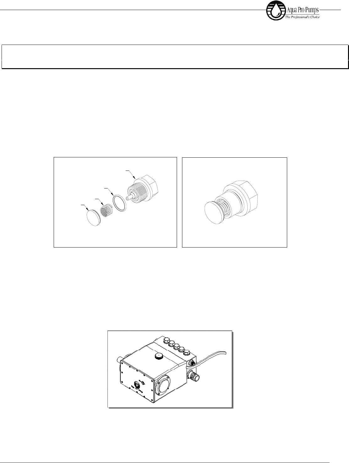
9
VALVE INSPECTION AND SERVICE
Remove ten valve plugs (44) from the manifold using a 1 ½“ socket wrench. Remove the valves (41) and springs (42)
from each valve port. Inspect the curved valve surface for damage or distortion. A circular mark from the valve seat is
normal, but should not advance to distorting the valve shape. If a valve is broken or pitted, use a flashlight to examine the
seat inside the valve port. Inspection will ensure that the valve seat has not been damaged by debris.
Depending on the condition, either replace or clean and reuse valves and springs. A set of 10 valve and 10 springs is
available as PN 70-1057. Apply a light coat of silicon grease (PN 21-1122) to the valve plug o-ring (43). Apply anti-seize
lubricant (PN 85-0094) to the valve plug threads. Assemble the valves, springs and plugs as shown in Fig. 9, and tighten
the valve plugs back into the manifold.
Fig. 2: Valve Assembly
DETACHING THE MANIFOLD FROM THE CRANKCASE
Remove the 2 manifold nuts (53), see Fig. 13, with a 15/16” socket wrench or Combination Wrench. Loosen the manifold
assembly by prying off the manifold using the slots in the crankcase as shown in Fig 2. Set the manifold assembly aside
in a clean work area. If the manifold assembly locating dowel pins (50) fall out, reinsert them into the manifold alignment
pin hole.
Fig. 3: Manifold Assembly Removal
Valves may be serviced while the manifold assembly is attached to the crankcase assembly. In most cases, service can be
completed while the pump is in place within the watermaker system.
44
43
42
41
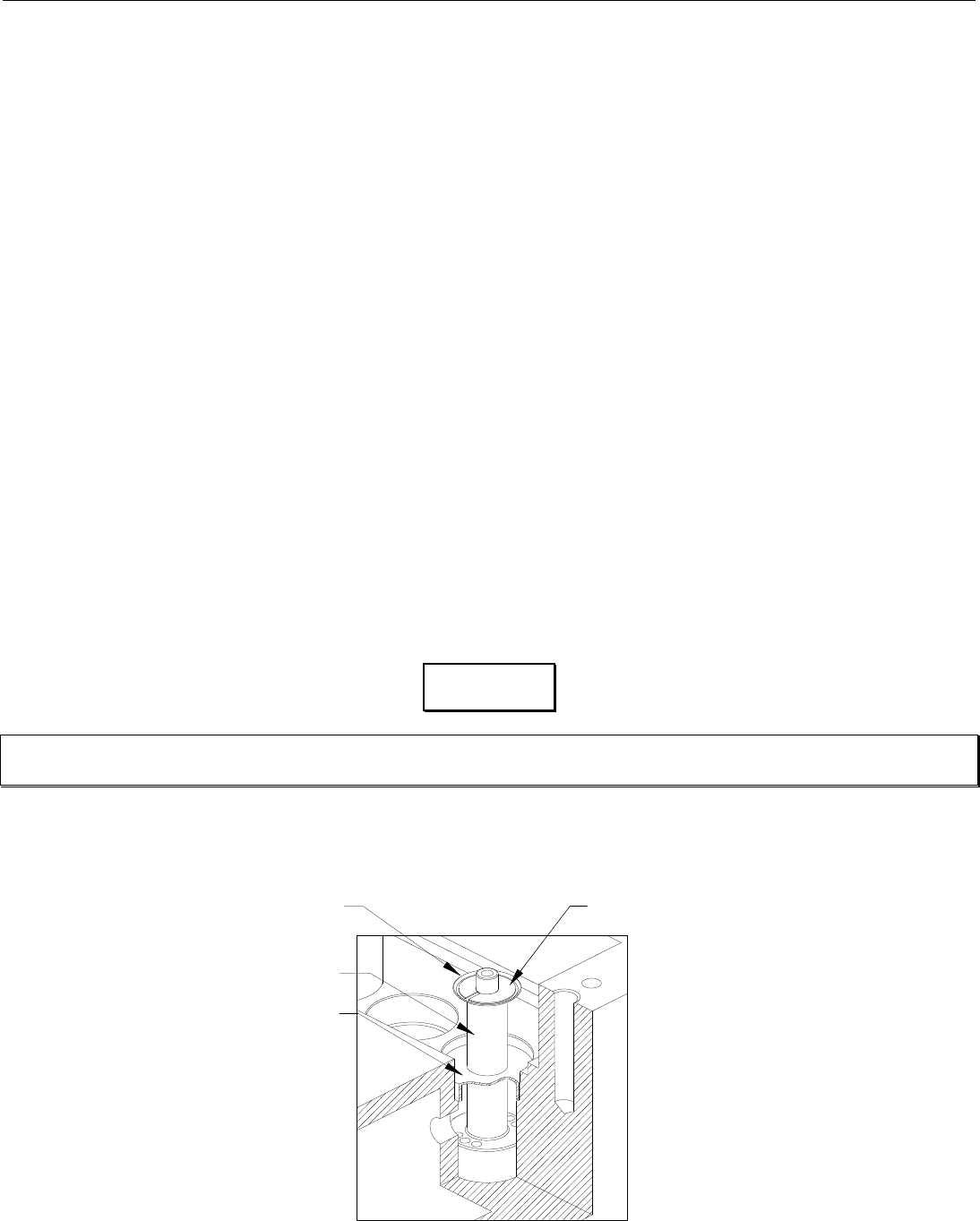
5P50 Titan Series
High Pressure Titanium Positive Displacement Pump
10
SEAL REPLACEMENT
If condition based seal service is required (Seal Kit PN 70-3080), use the following instructions outlined in the OIL SEAL
REPLACEMENT section. To determine the need of condition based service, look for signs of oil or water drip under the
pump. Once the manifold is detached from the crankcase, the low pressure water seals (40) are exposed on the manifold
surface and can easily be replaced. If undertaking the complete 10,000 hour service with kits 70-3075 and 70-3078, then
follow the detailed instructions.
SERVICING THE CRANKCASE
The following are the procedures for servicing the crankcase assembly using the 5P50 Crankcase Rebuild Kit
(PN. 70-3078). The manifold assembly must be detached from the crankcase to do the following service.
PLUG, OIL DRAIN, O-RING REPLACEMENT
Remove the oil drain plug (5) with a 1” wrench and drain the crankcase oil. Clean the drain plug (5), and remove the o-
ring (4) with the aid of the pick if necessary. Replace the o-ring with the new one supplied with kit. Apply anti-seize lube
to the threads of the drain plug (5) and reinstall.
OIL SEAL REPLACEMENT
Remove the seal retainer (33) and set aside, see Fig. 6. Remove the plunger retainer nut (32) with a 9/16” wrench and set
aside. Remove the plunger retainer washer (31) and back-up ring (29), Fig. 5, and remove the ceramic plunger (8).
Remove the keyhole washer (26), then remove the slinger (25), see Fig. 4. Using a flat head screwdriver and hammer,
drive the screwdriver into the meat of the seal (6). Be careful not to scratch the inner or outer metal sealing surfaces. A
quick twist of the screwdriver will remove the seal. Do not attempt to preserve the seal for reuse. Inspect the seal retainer
washers for damage; if none is evident then reuse.
Insert new plunger rod oil seal (6) into crankcase ensuring that the seal is fully seated. Place slinger (25) onto the plunger
rod (8), followed by the keyhole washer (26) as shown in Fig. 4. Chase the thread of the plunger rod and the retainer stud
with the tap and die to ensure the removal of any left over loctite prior to reassembly.
Fig. 4: Plunger Assembly View
NOTE
A light coating of silicon grease (PN. 21-1122) should be used on all new o-rings and seals. Use of any other type of
grease may result in o-ring or seal failure.
25
8
6
26
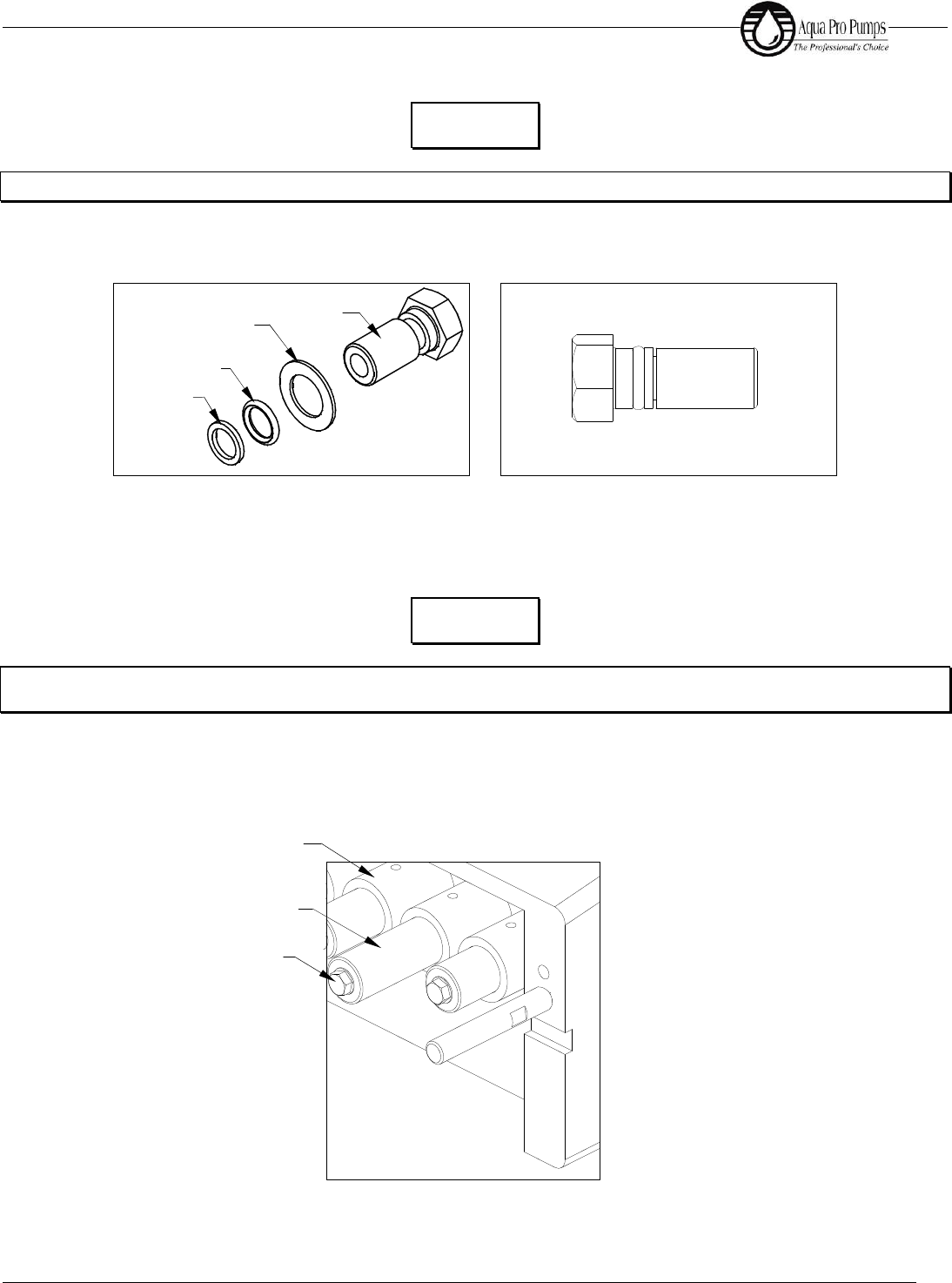
11
Slide ceramic plungers (27) onto plunger rod, and insert the new plunger retainer washer (31) into the plunger. Clean the
plunger retaining nuts (32), Fig. 5. With the aid of a pick remove the plunger retainer back-up ring (29) and the plunger
retainer o-ring (30). Replace the o-ring (30) and back-up ring (29) with the new one supplied in the kit as shown in Fig. 5.
Fig. 5: Plunger Retaining Nut Assembly
Apply Red Loctite # 262 to retainer stud (28) threads. Reinstall the plunger retainer nut (32) and torque to 100 in. lb.
using a 9/16” socket.
Apply Aqua Pro’s special Ceramic Lubricant (PN. 85-0087) to the ceramic plungers (27). Slide the seal retainer (33) over
the ceramic plungers (27). Make sure that the flanged side is in close proximity to the manifold assembly, and that the
hole is oriented downward ensuring that the seal retainer has adequate water drainage. Slide manifold assembly over
plungers and reinstall manifold nuts (53).
Fig. 6: Seal Retainer
NOTE
Examine the ceramic plungers (27), Fig. 6, for cracks, heavy scoring, or unusual wear.
NOTE
Be careful not to get the red loctite on any other components. Failure to use loctite on the retainer stud and nut could lead
to catastrophic failure of the pump.
31
29
30
32
27
32
33
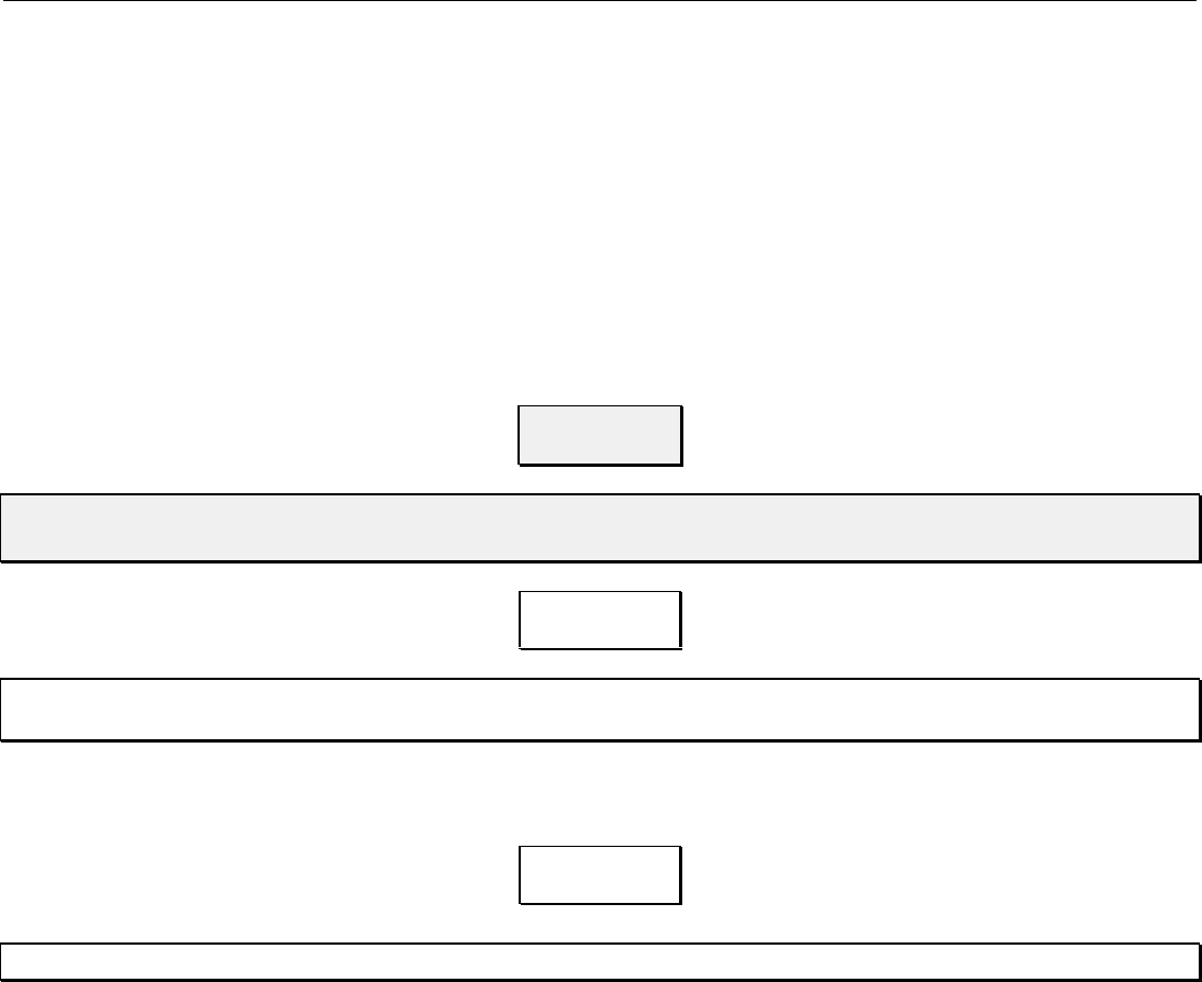
5P50 Titan Series
High Pressure Titanium Positive Displacement Pump
12
BEARING CAP O-RING/SEAL REPLACEMENT
You will need these tools and parts to do the following:
1/4" Allen Wrench
Pick
Seal, Oil, Crankshaft (16): PN. 70-0701
O-Ring, Bearing Cap (15): PN. 70-0703
Silicon Grease Lubricant: PN. 21-1122
Anti-Seize Lubricant: PN. 85-0094
Remove the 4 socket head cap screws (17) with a 1/4” Allen Wrench from each of bearing side plates (13), (14). With the
aid of a pick remove the o-rings from the grooves and remove the crankshaft oil seal (16) from the pulley side bearing cap
(14).
Press new crankshaft oil seal (16) into pulley side bearing cap (14), install o-ring (15) in o-ring groove on the crankshaft
bearing caps (13) and (14), and reinstall caps on pump.
Install the 4 socket head cap screws (17) onto each of the bearing side plates and tighten with a 1/4” Allen Wrench.
COVER, CRANKCASE O-RING REPLACEMENT
In this procedure you will replace the o-rings on the crankcase cover as provided in the rebuild kit.
You will need these tools and parts to do the following:
3/16” Allen Wrench
Phillips-head Screwdriver
Pick
Silicone Grease Lubricant: PN. 21-1122
Red Loctite # 262
Anti-Seize Lubricant: PN. 85-0094
Unscrew the 12 crankcase cover screws (24) with the 3/16” Allen wrench. Remove the 6 sight glass retaining screws (23)
with the Phillips-head screwdriver. Remove the sight glass retaining frame (22) and the sight glass (21). With the aid of
the pick remove the sight glass o-ring (20), and remove the crankcase cover o-ring (18).
CAUTION
Crankshaft oil seal is press-fit at the factory, so care is to be exercised during removal to prevent any damage to sealing
surface.
NOTE
A light coating of silicon grease (PN. 21-1122) should be used on all new o-rings and seals. Use of any other type of
grease may result in o-ring or seal failure.
NOTE
A light coating of Anti-Seize Lubricant (PN. 85-0094) should be applied on all threaded parts, unless otherwise stated.
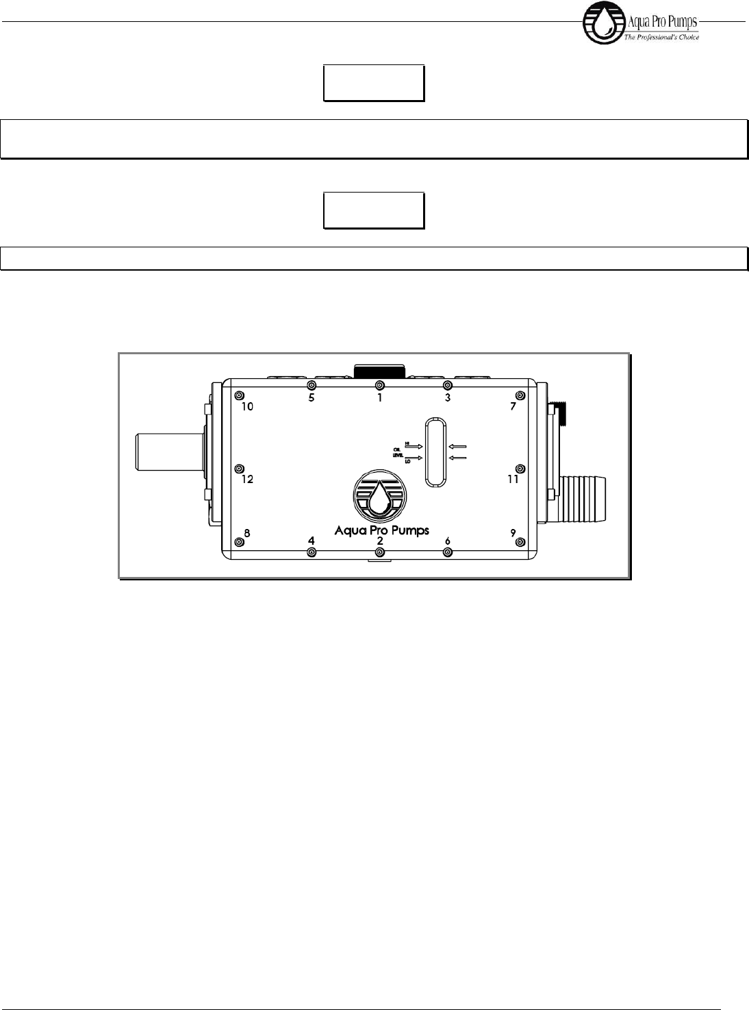
13
Install the new sight glass o-ring (20) and the crankcase cover o-ring (18) provided with the rebuild kit.
Install the sight glass (21) and the sight glass frame (22). Apply Red Loctite #262 to the 6 sight glass retaining screws
(23) and tighten. Reinstall the crankcase cover (19) and tighten the 10 crankcase cover screws (24) with the 3/16” Allen
wrench in the sequence shown in Fig. 7.
Fig. 7: Bolt tightening sequence
CRANKSHAFT BEARING, CONNECTING ROD-PISTON SERVICE
When feasible, it is recommended that any service to the Crankshaft (11), Connecting Rods (10), and Plunger
Rods (8) be done by sending the pump back to the factory for rebuilding.
CRANKSHAFT REMOVAL
Crankshaft removal is not necessary for overhaul of seals.
NOTE: The Manifold, Plunger assembly, Bearing Side Plates, and Crankcase Cover must be removed before attempting
to remove the crankshaft.
You will need these tools and parts to do the following:
3/8” 12-point Socket Wrench
Arbor press for Connecting Rod/Plunger Pin
Bearing Puller
Snap Ringer Pliers
Using a 23-point socket, unscrew the connecting rod Bolts (10)
NOTE
A light coating of silicon grease (PN. 21-1122) should be used on all new o-rings and seals. Use of any other type of
grease may result in o-ring or seal failure.
NOTE
A light coating of Anti-Seize Lubricant (PN. 85-0094) should be applied on all threaded parts, unless otherwise stated.
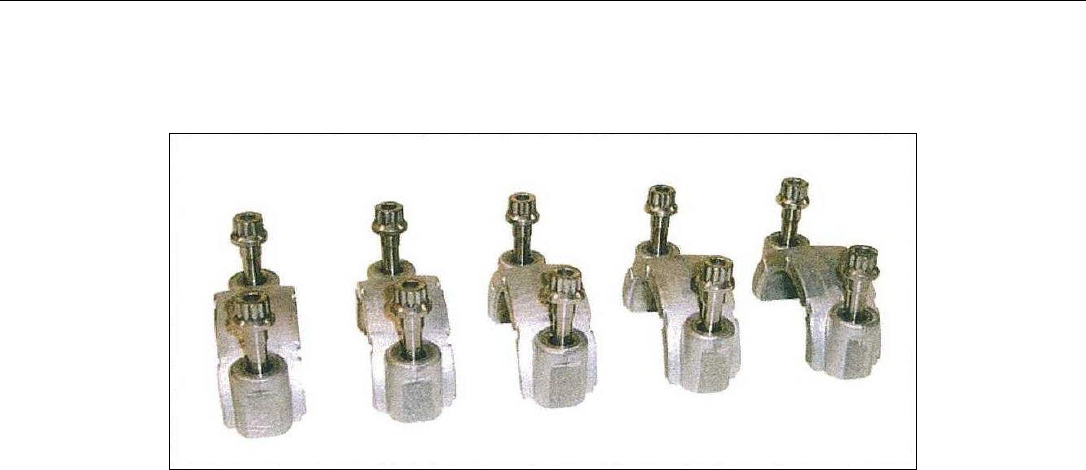
5P50 Titan Series
High Pressure Titanium Positive Displacement Pump
14
(NOTICE: Unscrew one connecting rod cap at a time. Keep the bolts in the same hold it came out of. Store the
connecting rod caps like the picture below in order from 1-5. Fig. 8)
Fig. 8 Keep parts organized
Push the connecting rod assembly in as far as possible away from the Crankshaft (11).
Make sure the Connecting Rods (10) are clear from the path of the crankshaft.
Rotate the Crankshaft (11) by hand to feel for smooth bearing movement. If movement is rough, Bearings (12) needs to
be replaced. Inspect the bearing surface of the connecting rod end caps. Some scoring is considered acceptable, but
irregular wear patterns are not. This is where the decision is made on whether to replace the connecting rods and crank
bearings. If bearing surface passes inspection, reassembly can begin.
If not already done, remove both Bearing Side Plates (13)(14).
Using a press, press out the Crankshaft (11) from the key slotted side.
The crankshaft should come out of the crankcase with one Bearing (12) on the non-key slotted side and one Bearing (12)
still in the Crankcase (1).
Pull off the Bearing (12) on the Crankshaft (11) with a bearing puller (fig. 9).
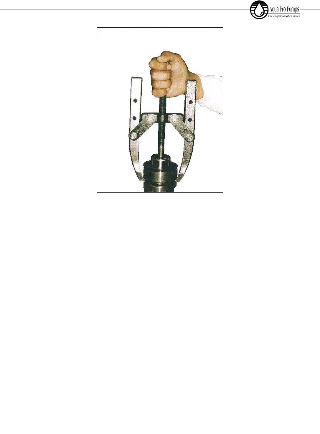
15
Fig. 9 Removal of the Crankshaft bearing
Slide out the Connecting Rods (10) and the Plunger Rod Assembly (8). Check for abnormal wear or scoring.
***Note: Remember where each connecting rod came out of the crankcase. Keep them in the same order. The
connecting Rods and Caps are numbered for this reason. (Lay down connecting rods and caps in order removed.
Ensure connecting rods remain in order with caps.)
Remove the Plunger Rod Seal (6). (Do this step only if not already done.)
The Connecting Rod (10) is attached to the Plunger Rod Assembly (8) by a press fit Pin (9). Unless necessary, do not
disassemble.
CRANKSHAFT INSTALLATION
You will need these tools and parts to do the following:
Arbor press for Connecting Rod/Plunger Pin
Press for Crankshaft removal
Torque Wrench
¼” Allen wrench
3/8” 12-point Socket Wrench
Silicone Grease – PN. 21-1122
Anti-seize lubricant – PN. 85-0094
Red Loctite
Snap Ring Pliers
Press in the Crankshaft Bearing (12) into the right Crankshaft bore of the Crankcase (1). If any wear, rough spinning, or
looseness is noted, then use new bearings. (Freezing the bearing may help with the press fit.)
Apply silicone grease onto the O-ring (15) and the Crankshaft Seal (16). Install the Bearing Plate O-ring (15) and
Crankshaft Seal (16) into the pulley side Bearing Plate (14).
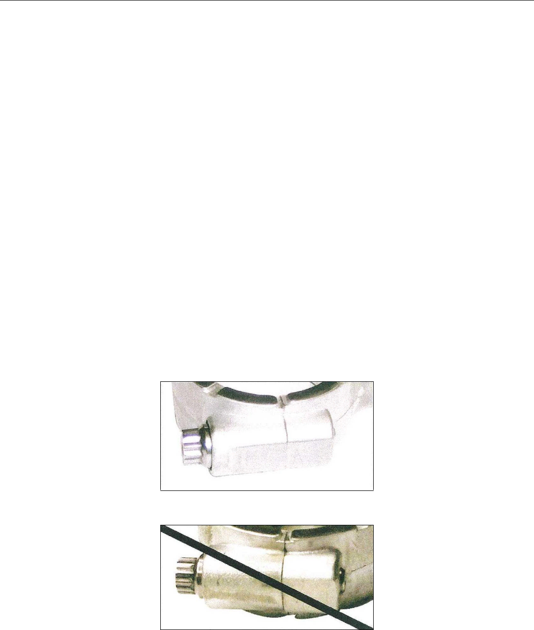
5P50 Titan Series
High Pressure Titanium Positive Displacement Pump
16
Apply a light coat of anti-seize to the 4 Socket Head Cap Screws (17). Install the pulley side Bearing Side Pate (14) using
the 4 Socket Head Cap Screws (17) with a ¼” Allen wrench
Insert Plunger oil Seal (6) into crankcase. Make sure that the seal is fully seated. (Do this step only if not already done.)
Attach the Connecting Rod (10) and Plunger Rod Assembly (8) using the Press Fit Pin (9). Press the pins in using an
arbor press (Freezing the Pins (9) and assembling while cold may help in this process.)
Insert the Connecting Rod (10) and the Plunger Rod Assembly (8) in the Crankcase (1) in the same order as when they
were take out. (The connecting rods are numbered 1, 2, 3… Make certain that the order is correct and that the
connecting rod caps’ number corresponds to the connecting rods’ number. The number one Connecting Rod should be
closest to the pulley side of the Crankshaft.)
Push the connecting rod assembly in as far as possible away from the Crankshaft (11) insertion path. Make sure the
Connecting Rods (10) are clear from the path of the crankshaft.
Slide in the Crankshaft (11), keyed side first, from the right side of the Crankcase (1) to the left side, through the
Crankshaft Bearing (12). A press may be needed to accomplish this step. The connecting rod bearing surfaces must
exactly align with the plunger bores to avoid bending pressure on the connecting rods.
Press in the left Crankshaft Bearing (38) (closed center hole side).
Apply a light coat of silicone grease to the new Bearing Side Plate O-rings (15).
Apply a light coast of anti-seize to the 4 Socket Head Cap Screws (17). Install the Closed Bearing Side Plate (13) using
the 4 Socket Head Cap Screws (17) with a ¼” Allen Wrench.
Apply red loctite to the threads of the Connecting Rod Cap Bolts. Install the Connecting Rod Caps to their corresponding
Connecting Rods (10) (There are numbers inscribed on the connecting rods and the connecting rod caps. Make sure that
they match up, e.g. 1 and 1, 2 and 2, and 3 and 3.) Pre torque the Connecting Rod Bolts to 100 in. lb. Then torque the
Connecting Rod Bolts to 230 in. lb. with a 3/8” 12-point Socket Wrench
Fig. 10 Correct Connecting Rod Pairing
Fig. 11 Incorrect Connecting Rod Pairing
***Make sure the flat sides numbers are matched up together on the Connecting Rods (10) (like figure 10 not figure 11).
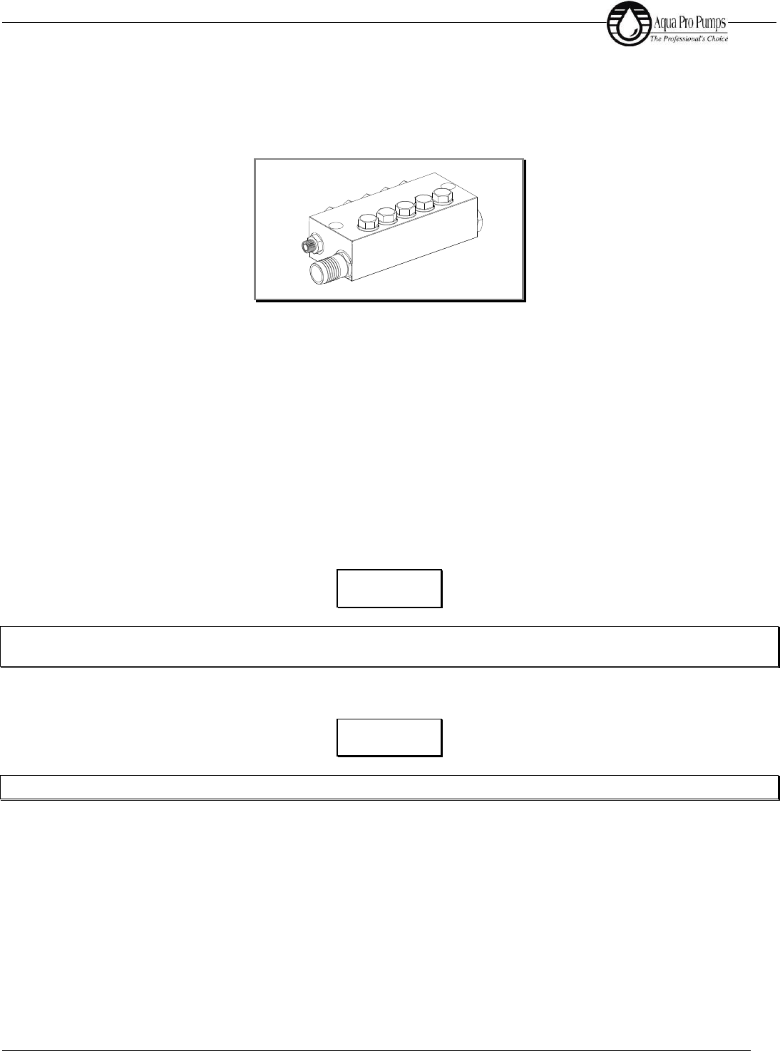
17
SERVICING THE MANIFOLD
The following are the procedures for servicing the manifold assembly using the 5P50 Manifold Rebuild Kit (PN. 70-3075).
The manifold assembly must be detached from the crankcase to do the following service.
Fig. 12: Manifold Assembly
ADAPTER O-RING REPLACEMENT
You will need these tools and parts to do the following:
Wrench Hex Jaw
Pick
O-Ring, Inlet Plug Adapter (43): PN. 70-3002
O-Ring, Discharge Plug Adapter (45): PN. 70-3074
Silicone Grease Lubricant: PN. 21-1122
Anti-Seize Lubricant: PN. 85-0094
Remove the Inlet/Discharge/Plug, (46), (47), (48), and (49) adapters from the manifold assembly with a hex jaw wrench.
With the aid of a pick remove the o-rings (45) and (43) from each of the adapters.
Install the new o-rings, (45) and (43), provided with the kit onto each of the adapters.
Reinstall each of the adapters onto the manifold assembly, then tighten adapter with hex jaw wrench.
VALVE ASSEMBLY SERVICING
You will need these tools and parts to do the following:
1 1/2" Socket Wrench or Combination Wrench
Pick
Spring, Valve (42): PN. 70-7049
Assembly, Valve (41): PN. 70-3004
O-Ring, Valve Plug (43): PN. 70-3002
Silicone Grease Lubricant: PN. 21-1122
Anti-Seize Lubricant: PN. 85-0094
Lint-Free Cloths
NOTE
A light coating of silicon grease (PN. 21-1122) should be used on all new o-rings and seals. Use of any other type of
grease may result in o-ring or seal failure.
NOTE
A light coating of Anti-Seize Lubricant (PN. 85-0094) should be applied on all threaded parts, unless otherwise stated.
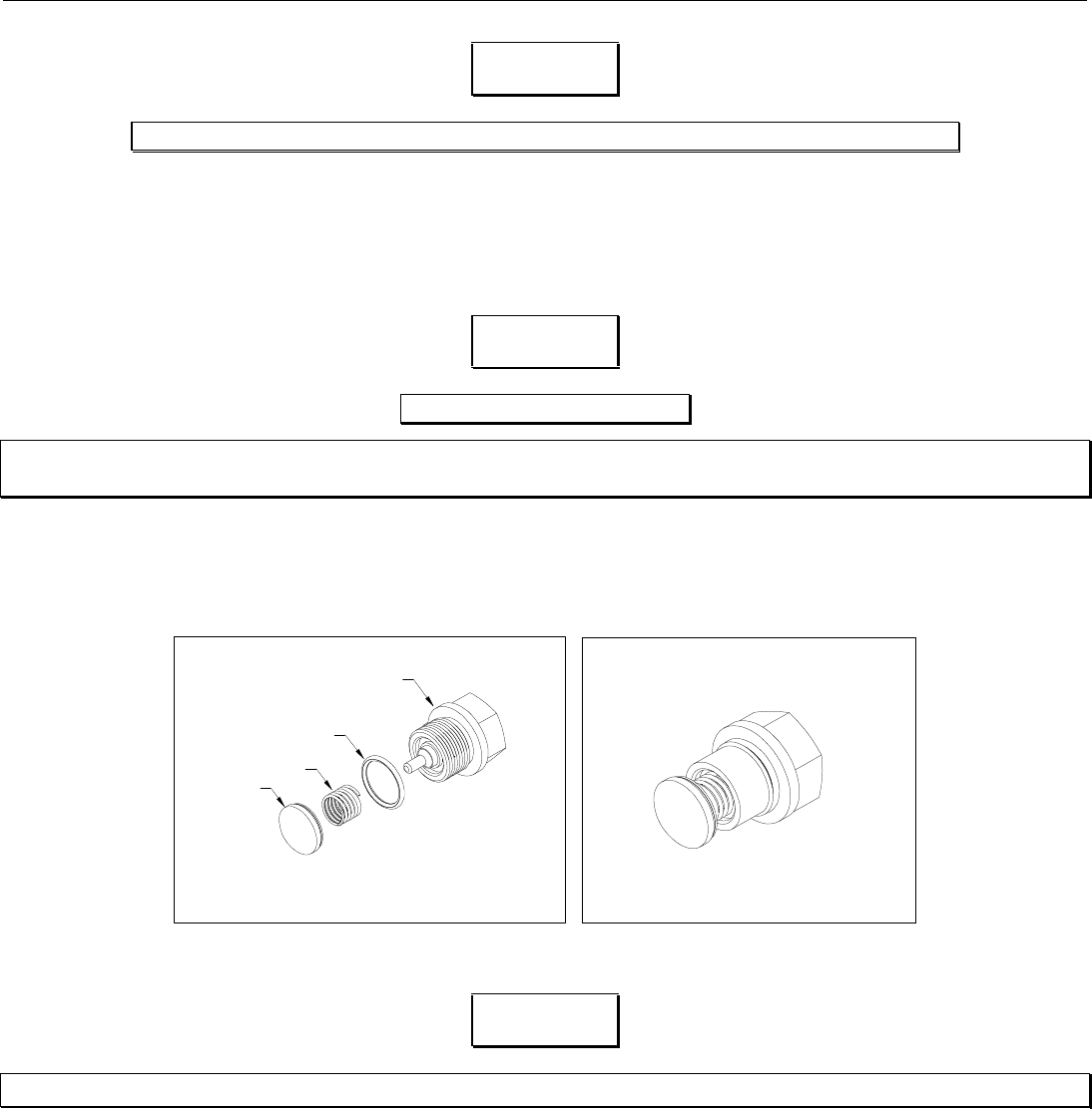
5P50 Titan Series
High Pressure Titanium Positive Displacement Pump
18
If manifold assembly has been removed from the crankcase assembly, place the assembly on a clean work surface.
Remove all of the valve plug assemblies from the manifold assembly using a 1 1/2” socket wrench or combination wrench.
Remove the valve (41) from the assembly, followed by the valve spring (42). With the aid of a pick remove the o-ring (43)
from the valve plug.
Clean and inspect all valve plugs (44) prior to reassembly. Once all valve plugs (44) are clean and dry, install new valve
plug o-ring (43) onto valve plug (44). Install the valve spring (42) onto the valve plug (44). Press the valve (41) onto the
valve spring (42). Complete valve assembly shown in Fig. 13.
Fig. 13: Valve Assembly
Inspect the manifold (34) for debris or other fouling and clean if necessary. Inspect the valve seat surface in the manifold.
Reinstall all the valve plug assemblies with a 1 1/2" socket wrench or combination wrench and tighten.
NOTE
Valves may be serviced while the manifold assembly is attached to the crankcase assembly.
NOTE
Valve plugs (44) will be reused.
A light coating of silicon grease (PN. 21-1122) should be used on all new o-rings and seals. Use of any other type of
grease may result in o-ring or seal failure.
NOTE
A light coating of Anti-Seize Lubricant (PN. 85-0094) should be applied on all threaded parts, unless otherwise stated.
44
43
42
41
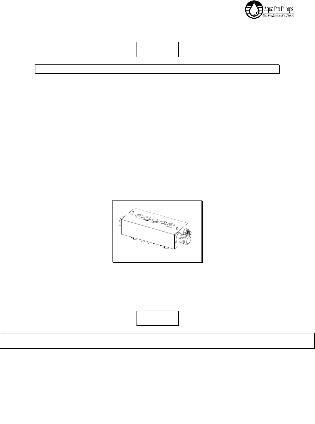
19
MANIFOLD SEAL SERVICING
You will need these tools and parts to do the following:
Snap Ring Pliers
Tool, Seal Insertion: PN. 91-7228
Flat screw driver
Seal, HP (36): PN. 70-2502
Ring, Snap (38): PN. 70-3009
Ring, Weep (37): PN. 70-3008
Seal, LP (40): PN. 70-2501
Silicone Grease Lubricant: PN. 21-1122
Lint-Free Cloths
Routine seal service is the replacement of the exposed low pressure seal (40) only. The following instructions are for a
complete manifold rebuild at the 10,000 hour service mark.
For manifold seal servicing purposes the manifold must be placed with the valve plugs sitting on a flat surface and the
plunger bores facing upward. This will facilitate service technician access to the seals for removal and installation, as
shown in Fig. 14.
Fig. 14: Orientation for Manifold Seal Servicing
With a flat screw driver remove the low-pressure seal (40). Manually remove the low-pressure seal spacer (39). With the
snap ring pliers remove the snap ring (38). Using the weep ring extracting tool, remove the weep ring (37) as shown in
Fig. 15.
NOTE
Pump manifold assembly must be detached from the crankcase assembly to service the seals.
NOTE
Extraction of the weep rings is accomplished by inserting tool in relaxed state into the inner diameter of the rings, then
tightening the expansion bolt to grip the ring.

5P50 Titan Series
High Pressure Titanium Positive Displacement Pump
20
Fig. 15: Weep Ring Extraction
With a flat screwdriver remove the high-pressure seals (36). Manually remove the high-pressure seal spacer (35).
Insert the high-pressure seal spacer (35) into the bore.
Insert the high-pressure seal (36) into the bore until the seal is fully seated on the high-pressure seal spacer (35), using
the seal insertion tool. See Fig. 12 for high-pressure seal installation view.
Fig. 16: High-Pressure Seal Installation View
Insert the weep ring (37) into the bore after the installation of the high-pressure seals (36), using the driver from the seal
insertion tool. Install the snap ring (38) using the snap ring pliers.
Insert the low-pressure seal spacer (39), then install the new low-pressure seal (40). The manifold seal servicing is
complete.
NOTE
A light coating of silicon grease (PN. 21-1122) should be used on all new o-rings and seals. Use of any other type of
grease may result in o-ring or seal failure.
NOTE
Ensure that the snap ring (38) is fully seated in the snap ring groove before continuing.
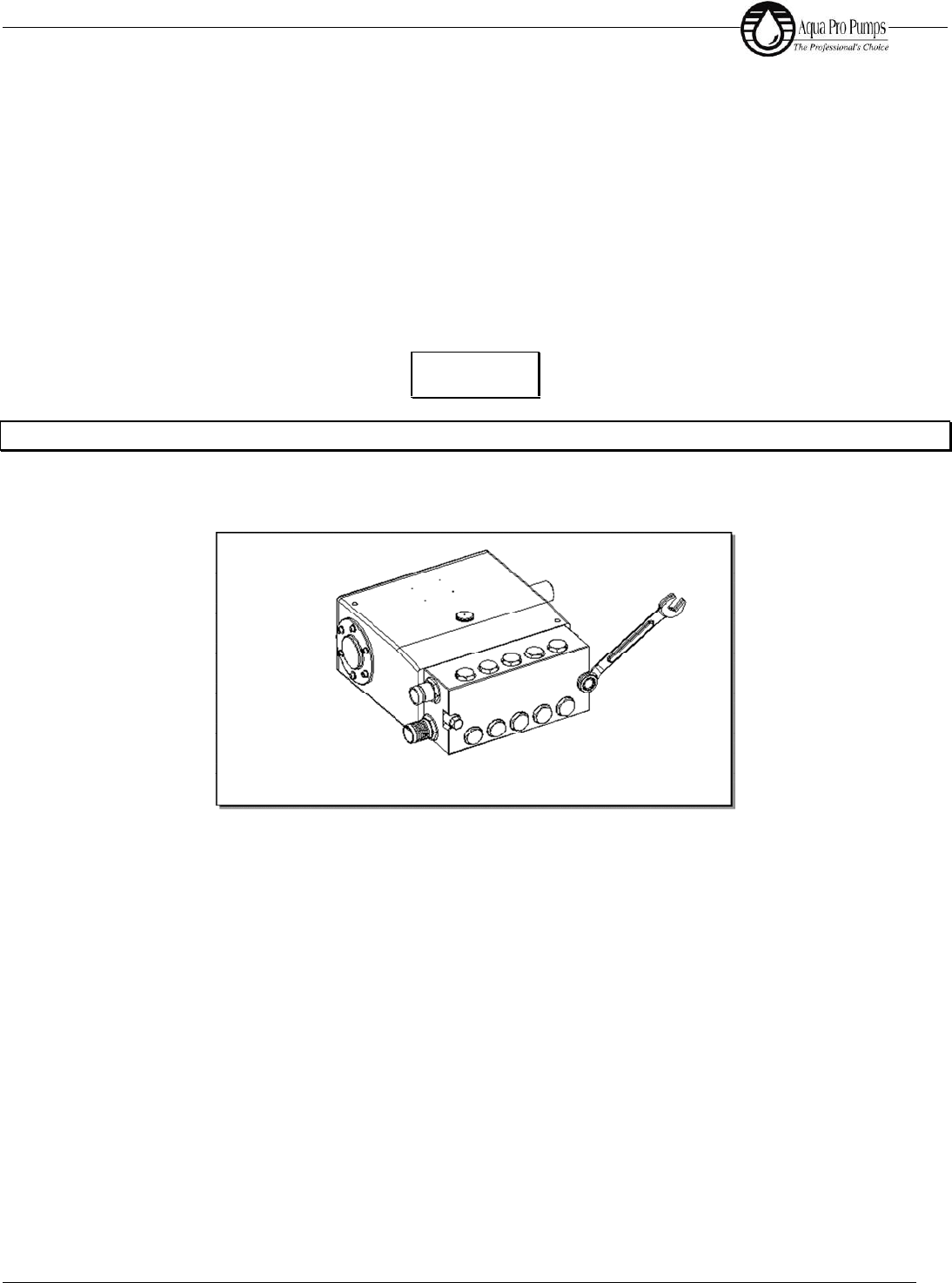
21
ATTACHING THE MANIFOLD TO THE CRANKCASE
You will need these tools and parts to do the following:
15/16” Socket/ Socket Wrench or Combination Wrench
Dead Blow Hammer
Manifold Nut (53): PN. 70-1305
Ceramic Lubricant: PN. 85-0087
Anti-Seize Lubricant: PN. 85-0094
If a crankcase seal rebuild was not performed at this time then ensure that the dowel locating pins (50) are pressed into
their corresponding hole. Ensure that ceramic lubricant is applied to the ceramic plunger assemblies and that the seal
retainers are installed with the flange located away from the crankcase assembly.
Align manifold assembly to crankcase assembly as shown in Fig. 13 and tighten the two manifold nuts (53) with a 15/16”
socket wrench or combination wrench, torque to 90 ft-lbs.
Fig. 17: Pump Assembly Orientation View
OIL CHANGE PROCEDURE
You will need these tools and parts to do the following:
1” Socket/ Socket Wrench
Lint-free Cloths
Funnel, 4 oz, plastic
Village Marine High-Pressure Pump Oil, PN. 85-0050
Clean area around the oil filler cap (3) and the oil drain plug. Remove the oil filler cap, and then drain the crankcase oil.
Once the used oil is completely drained, slowly add high-pressure pump oil to the level shown on the sight glass.
Reinstall oil filler cap (3) and wipe off any excess oil.
NOTE
A light coating of Anti-Seize Lubricant (PN. 85-0094) should be applied on all threaded parts, unless otherwise stated.

5P50 Titan Series
High Pressure Titanium Positive Displacement Pump
22
5P50 DRAWINGS
5P50 PUMP SPECIFICATIONS
5P50 CRANKCASE ASSEMBLY
5P50 MANIFOLD ASSEMBLY
5P50 MAIN ASSEMBLY
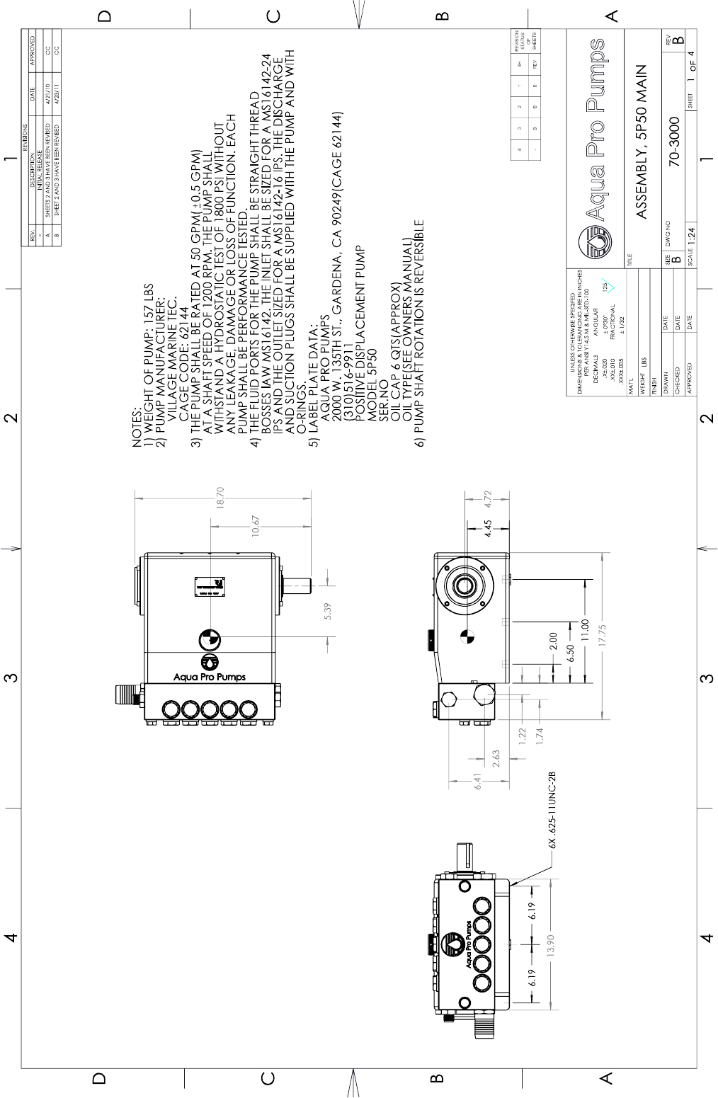
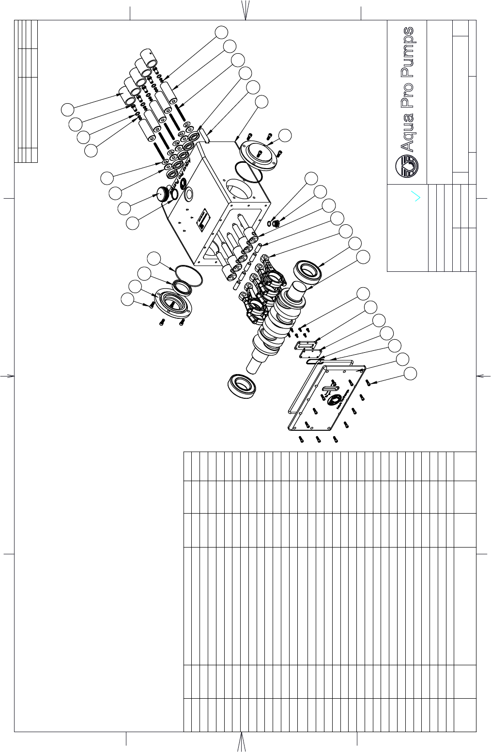
4 3
REV
OF
SHEET
125
.X±.020
DECIMALS
DIMENSIONS & TOLERANCING ARE IN INCHES
PER ANSI Y14.5 M & MIL-STD-100
ANGULAR
± 0°30"
UNLESS OTHERWISE SPECIFED
TITLE
SIZE
SCALE
B
WEIGHT
DRAWN
FINISH
.XX±.010
.XXX±.005
MAT'L
APPROVED
CHECKED
DATE
DATE
DATE
± 1/32
FRACTIONAL
DWG NO
BC
BC
2/5/07
JR
LBS
VARIOUS
42
1:8
B
70-3000
ASSEMBLY, 5P50 CRANKCASE
4/28/08
4/28/08
3 2 14
D
C
B
A
A
D
C
B
2 1
11
19
17
14 2
3
25
27
30
31
33
29
1
6
13
5
4
10
12
22
24
23
21
16
9
26
21-1122 SILICON GREASE
85-0087 CERAMIC LUBRICANT
85-0094 ANTISIEZE
18
32
28
20
7
8
NOTES:
1) ASSEMBLY PART NUMBERS ARE AS FOLLOWS:
70-3073 ASSY, CRANKCASE, 5P50 TITAN SERIES
70-3078 KIT, SERVICE, CRANKCASE, 5P50
70-3080 KIT, PUMP SEAL, 5P50
2) THE FOLLOWING PART NUMBERS ARE NOT SHOWN
IN DRAWING BUT ARE INLCUDED IN EACH KIT:
15
--1CRANKCASE, TITAN SERIES 5P50, AL70-30821
-11O-RING, OIL FILLER CAP70-60292
--1CAP, OIL FILLER70-3044
ITEM PART
NUMBER DESCRIPTION QTY
(70-3073)
QTY KIT
(70-3078)
QTY KIT
(70-3080)
33 70-3012 RETAINER, SEAL 5 - -
32 70-3016 NUT, PLUNGER RETAINER 5 - -
31 70-3017 WASHER, PLUNGER RETAINER 5 5 5
30 70-3411 O-RING, PLUNGER 5 5 5
29 70-3019 RING, BACK-UP, SPLIT 5 5 5
28 70-3020 STUD, M7x1.0, 3.40, PLUNGER 5 - -
27 70-3021 PLUNGER, CERAMIC 5 - -
26 70-3022 WASHER, KEYHOLE 5 - -
25 70-3023 SLINGER, PLUNGER 5 - -
24 86-0151 SCREW, REAR COVER 12 - -
23 86-0120 SCREW, SIGHT GLASS 6 - -
22 70-3060 FRAME, SIGHT GLASS 1 - -
21 70-3039 SIGHTGLASS, OIL, 3P20/5P100 1 - -
20 70-3040 O-RING, SIGHT GLASS 1 1 -
19 70-3087 COVER, CRANKCASE, TITAN SERIES 5P50 1 - -
18 70-6101 O-RING, REAR COVER 1 1 -
17 86-0256 SCREW, SIDE CAP 8 - -
16 70-0701 SEAL, OIL, CRANKSHAFT 1 1 -
15 70-0703 O-RING, BEARING CAP 2 1 -
14 70-3081 CAP,PULLEY BEARING,5P50,AL 1 - -
13 70-3079 CAP, BEARING, CLOSED 1 - -
12 70-0439 BEARING,TAPERED ROLLER,4130-STL 2 - -
11 70-3034 CRANKSHAFT, 5P50 1 - -
10 70-3098 ASSY, CONNECTING ROD, 5P50 5 - -
9 70-3027 PIN, DOWEL 5 - -
8 70-0344M ASSEMBLY, PLUNGER ROD 5 - -
7 70-3006 STUD, MANIFOLD RETAINING 2 - -
6 70-3062 SEAL, OIL, PLUNGER, 3P20/5P50 5 5 5
5 70-3046 PLUG, OIL DRAIN 1 - -
4 30-1286 O-RING, PLUG, OIL DRAIN 1 1 -
3
REVISIONS
REV. DESCRIPTION DATE APPROVED
- INITIAL RELEASE 2/5/2007 BC
A MODIFIED BOM QTY TITLE 3/17/2010 CC
B ADDED PUMP SEAL KIT 5/20/2011 CC
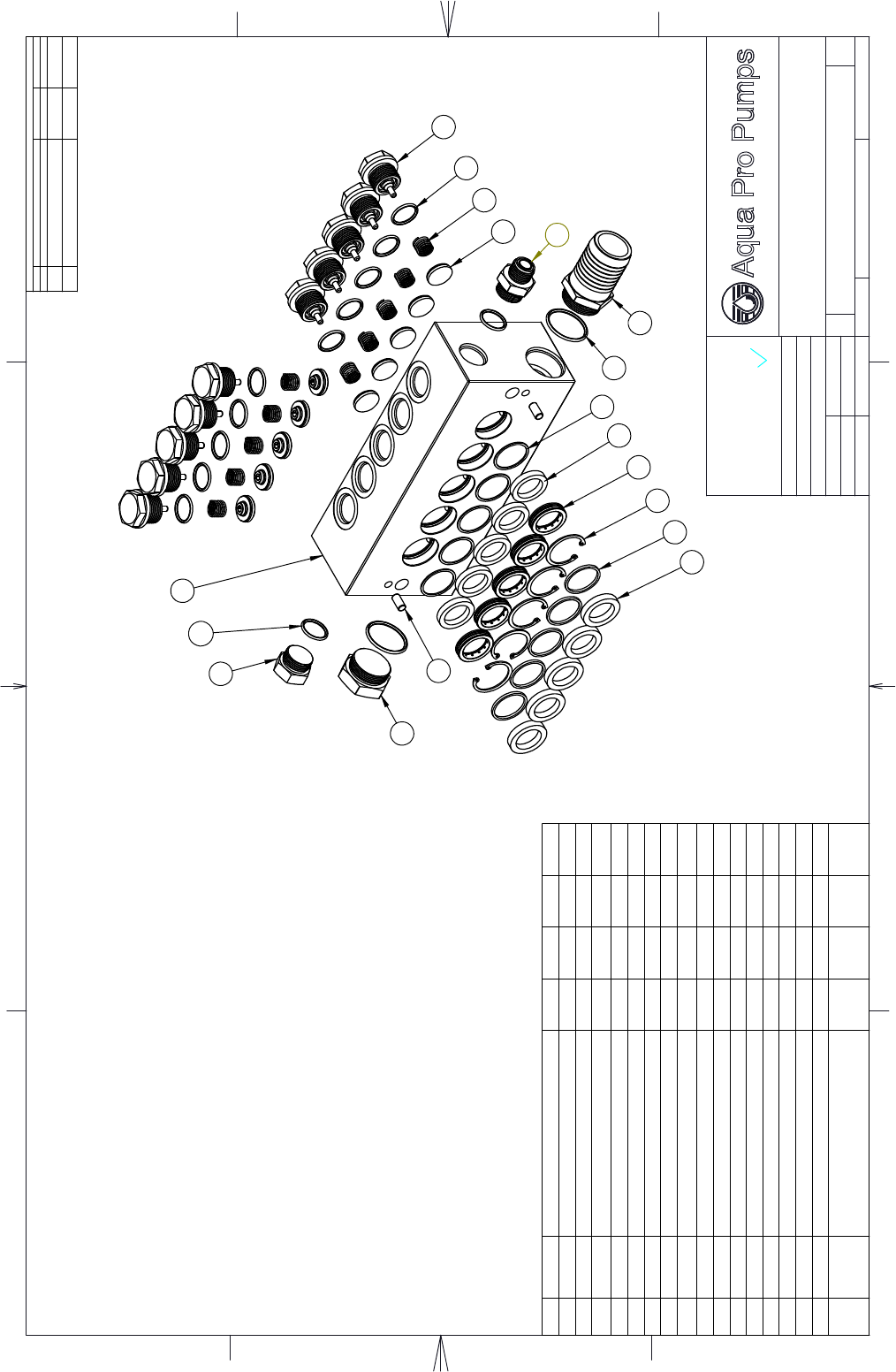
47
48
42
46
45
35
37
36
44
38
40
39
50
34
49
43
41
85-0094 CERAMIC LUBRICANT
85-0087 ANTISIEZE
21-1122 SILICON GREASE
NOTES:
1) ASSEMBLY PART NUMBERS ARE AS FOLLOWS:
70-6120 ASSY, MANIFOLD, 5P50 TITAN SERIES
70-3075 KIT, REBUILD, MANIFOLD, 5P50
70-1057 KIT, PUMP VALVE
70-3080 KIT, PUMP SEAL, 5P50
2) THE FOLLOWING PART NUMBERS ARE NOT SHOWN
IN DRAWING BUT ARE INLCUDED IN EACH KIT:
43
3
REV
OF
SHEET
125
.X±.020
DECIMALS
DIMENSIONS & TOLERANCING ARE IN INCHES
PER ANSI Y14.5 M & MIL-STD-100
ANGULAR
± 0°30"
UNLESS OTHERWISE SPECIFED
TITLE
SIZE
SCALE
B
WEIGHT
DRAWN
FINISH
.XX±.010
.XXX±.005
MAT'L
APPROVED
CHECKED
DATE
DATE
DATE
± 1/32
FRACTIONAL
DWG NO
LBS
43
1:1
B
70-3000
ASSEMBLY, 5P50 MANIFOLD
3 2 14
D
C
B
A
A
D
C
B
24 1
5 5 - -
35 70-0407 RING, SPACER, HP SEAL 5 5 - -
34 70-3005 MANIFOLD, TITAN SERIES 5P50 1 - - -
ITEM PART
NUMBER DESCRIPTION QTY
(70-6120)
QTY KIT
(70-3075)
QTY KIT
(70-3080)
QTY KIT
(70-1057)
50 70-3050 PIN,DOWEL 2 - - -
49 70-3066 PLUG,MS18229-16,TI 1 - - -
48 70-3065 PLUG,MS18829-24 1 - - -
47 70-3059 ADTR, FACE SEAL 1 - - -
46 70-3064 ADTR, 2.0 HB, MS18229-24 1 - - -
45 70-3074 O-RING, APTR, HOSE-BARB 2 2 - -
44 70-3001 PLUG, VALVE, MS18229-16 10 - - -
43 70-3002 O-RING, VALVE 12 12 - -
42 70-7049 SPRING, VALVE, 3P20/5P50, TI 10 10 - 10
41 70-3004 ASSY, VALVE, 3P20/5P50 TITAN SERIES 10 10 - 10
40 70-2501 SEAL, LP,3P20/5P50, XYLAN, BLUE PTFE 5 5 5 -
39 70-3010 SPACER, LOW PRESSURE SEAL 5 5 - -
38 70-3009 RING, RETAINING,3P20/5P50 5 5 - -
37 70-3008 ASSEMBLY, WEEP RING,3P20/5P50 5 5 - -
36 70-2502 SEAL, HIGH PRESSURE
REVISIONS
REV. DESCRIPTION DATE APPROVED
- INITIAL RELEASE - -
AMODIFIED BOM QTY TITLE, NOTE
INCLUDES ITEMS NOT IN BOM TABLE 3/26/10 CC
B ADDED PUMP AND SEAL KITS 5/20/11 CC
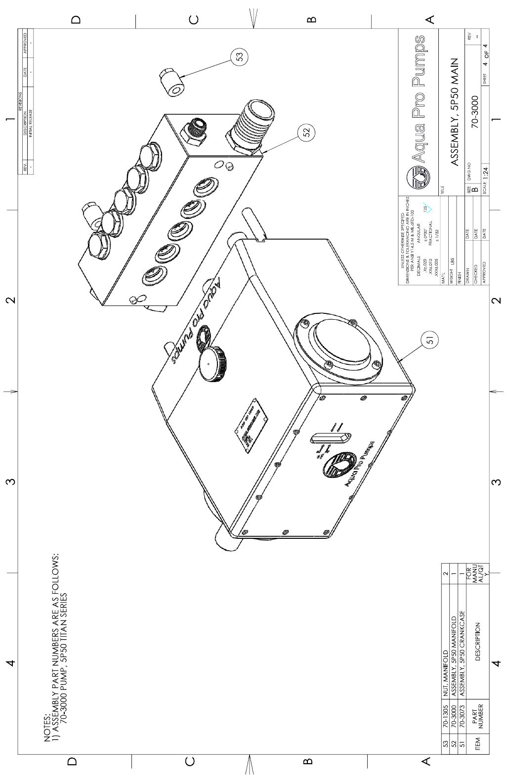
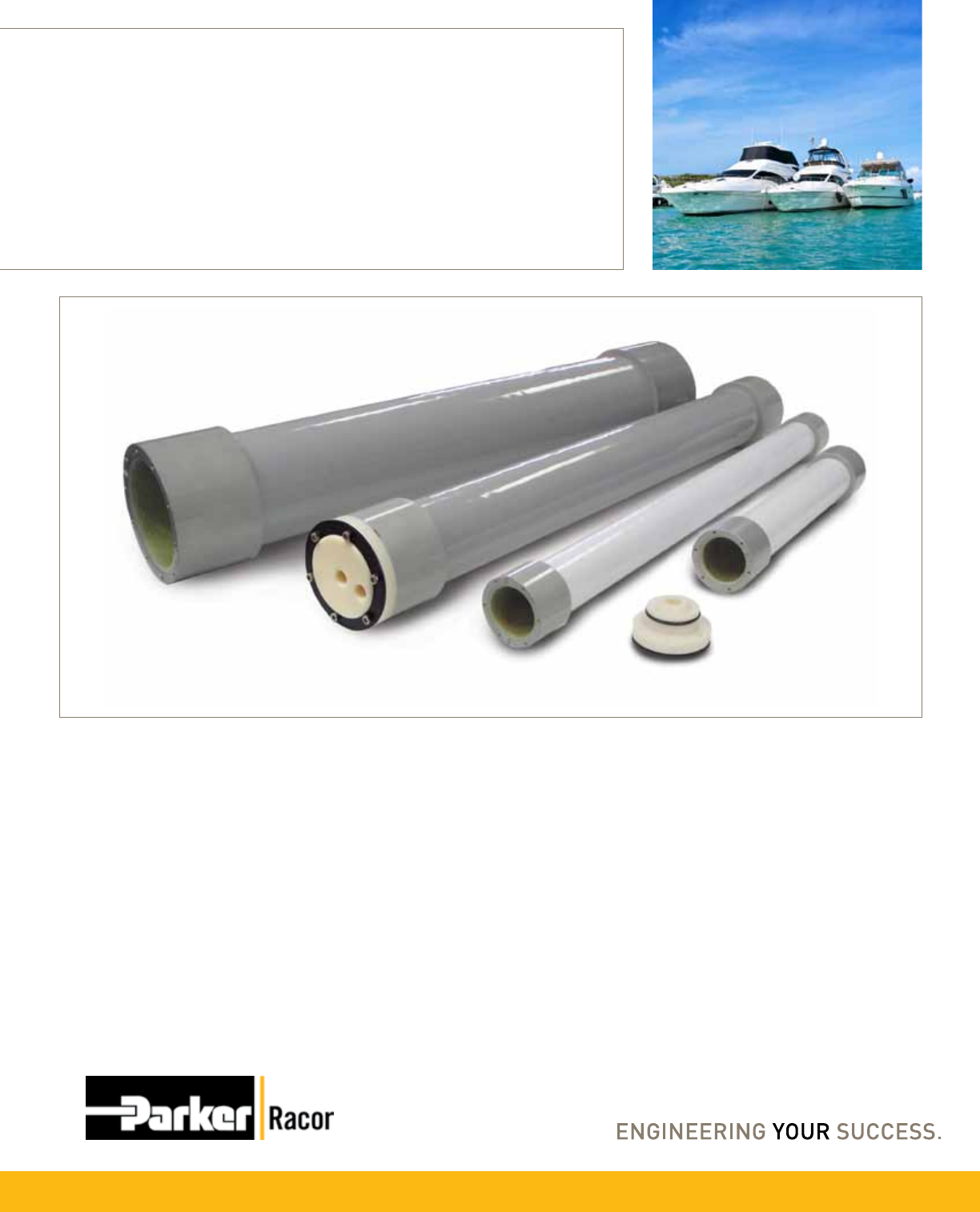
Racor Village Marine RO
membrane pressure vessels
feature non-metallic wetted
surfaces for excellent corrosion
resistance.
Simple end plug design allows
quick removal for element
servicing.
If the size you require is not
shown please contact us for
custom builds.
Pressure Vessel
Assemblies
Contact Information:
Parker Hannin Corporation
Racor Division/Village Marine Tec.
2000 W. 135th St.
Gardena, CA 90249
phone 310 516 9911
fax 310 538 3048
racor@parker.com
www.villagemarine.com
www.parker.com/racor
Key Features:
• Operating Pressure: 1000 psi/68 bar
• Shell: Filament Wound berglass
• Collars: 6061 T-6 Powdercoated
aluminum
• End Plugs: Thermoplastic
• End Ring:
6061 T-6 Anodized aluminum on
2.5” and 4” size
SS316 on 6” size
• Fasteners: SS316
For Seawater Elements
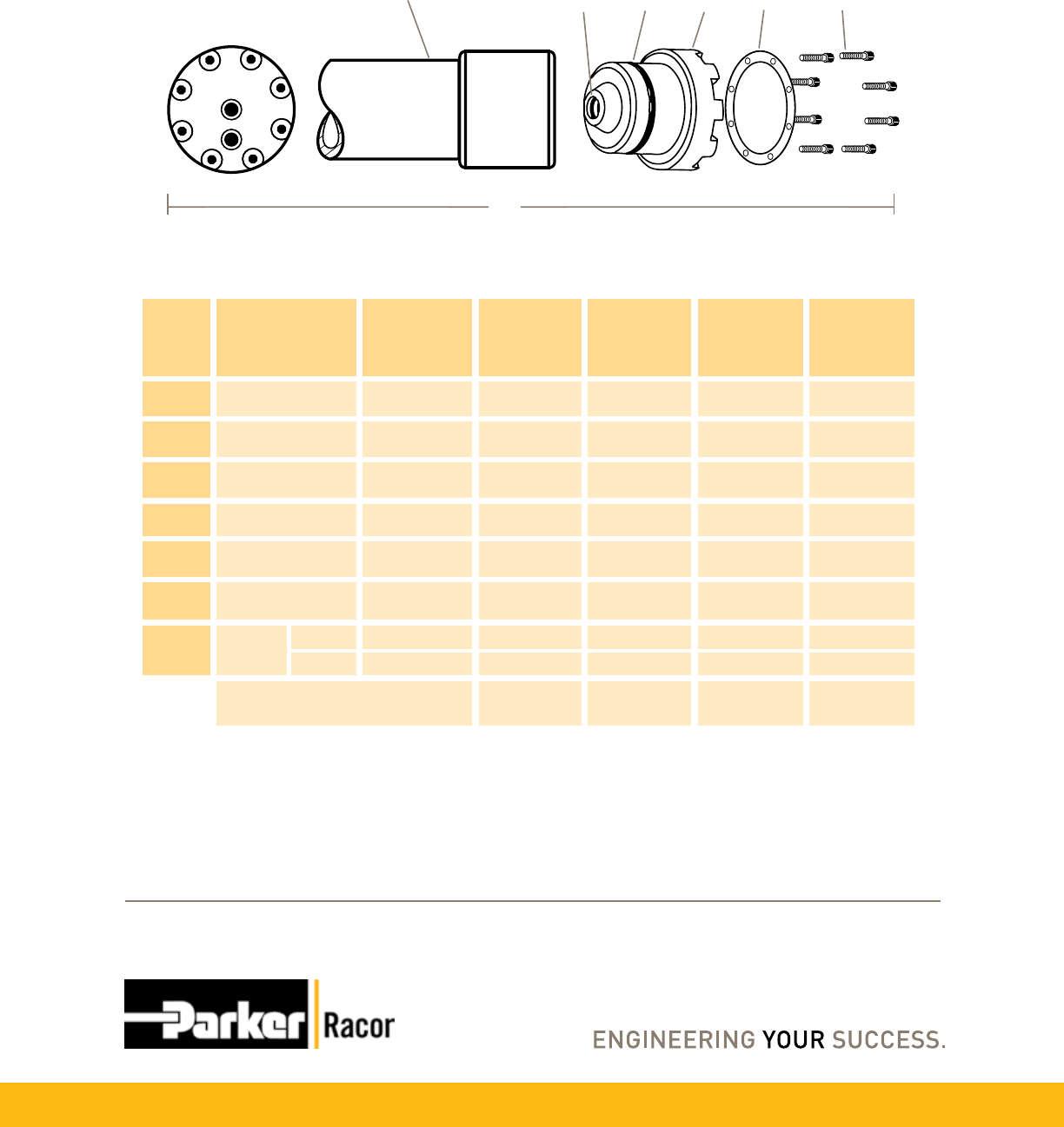
Description
Vessel Assembly**
Product O-ring
End Plug O-ring
End Plug
End Ring
Capscrews
Shell White
Gray
Item
1
2
3
4
5
6
7
Quantity per
Assembly
4
2
2
2
***
1
1
2.5” x 19”
32-2519
32-2116
32-2228
32-2513*
32-4013
86-0106
32-0025
32-0098
5/2
2.5” x 38”
32-2538
32-2116
32-2228
32-2513*
32-4013
86-0106
32-0026
32-0099
7/3
4” x 40”
32-0444
32-2116
32-4342
32-4012
32-4014
86-0123
Please Call
32-4001
22/10
6” x 40”
32-6040
32-2229
32-0640
32-6012
32-0096
86-0136
Please Call
32-0001
45/20
Weight (lbs/kg)
Notes:
*End Plug 32-2517 is also available
for 2.5” vessels, which oers straight,
coarse thread feed/reject port used on
some VMT PW watermakers
**Membrane not included.
For applicable membrane elements
see bulletin No. 7897 (Aqua Pro RO
Membranes)
*** Capscrews:
Order 6 per end plug on 2.5” size
Order 8 per end plug on 4” size
Order 10 per en plug on 6” size
Print Reorder Number 7898 Rev- 10-15-2009© 2009 Parker Hannin Corporation
Pressure Vessel
Assemblies
For Seawater Elements
Part Numbers:
1
2 3 4 5 6
7
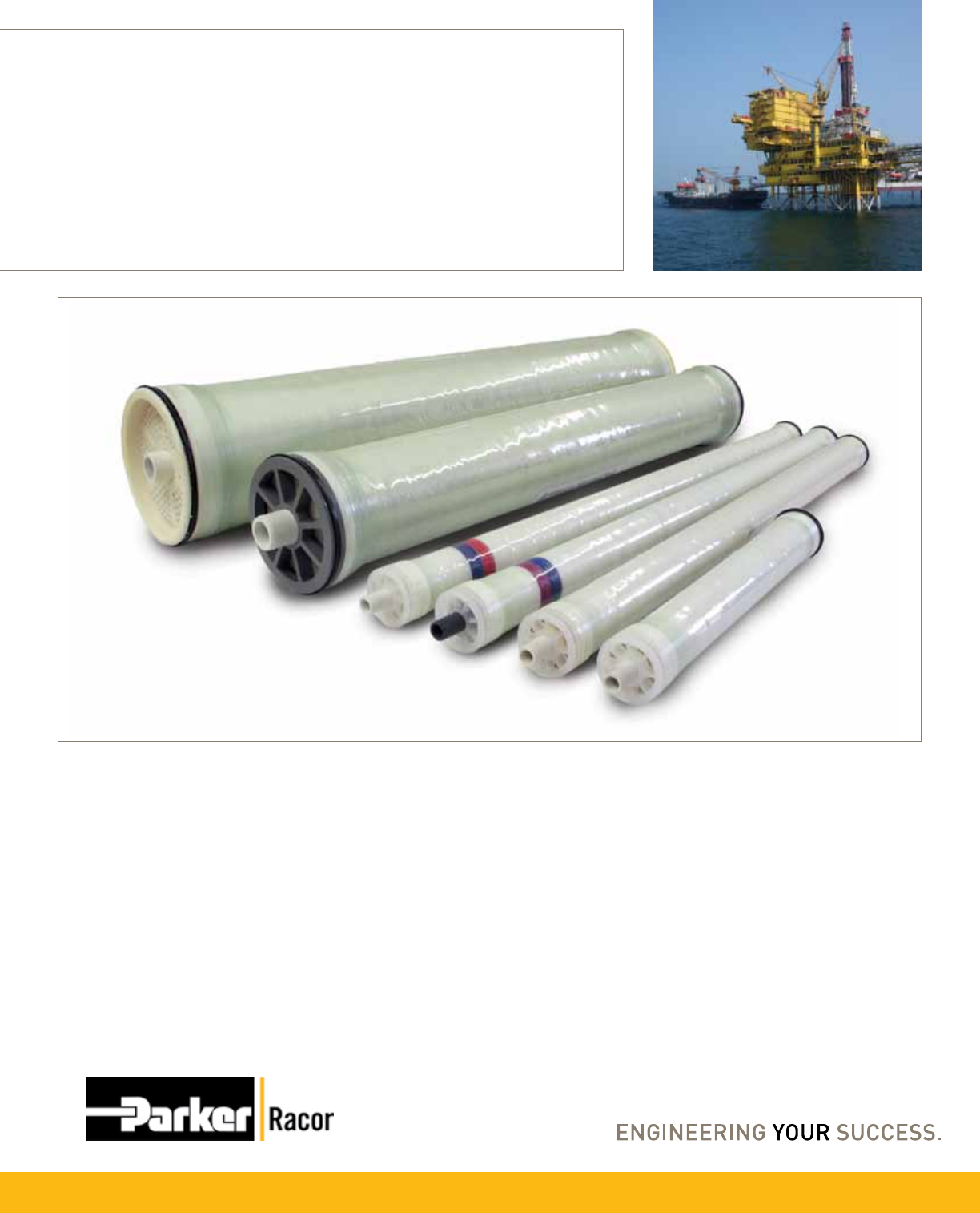
Aqua Pro® Sea Water
RO Membranes
Contact Information:
Parker Hannin Corporation
Racor Division/Village Marine Tec.
2000 W. 135th St.
Gardena, CA 90249
phone 310 516 9911
fax 310 538 3048
racor@parker.com
www.villagemarine.com
www.parker.com/racor
Aqua Pro® thin lm composite
membranes deliver high salt
rejection while maintaining high
production rates to obtain the
energy efciency demanded by
plant operators.
By selecting the highest grade of
materials and thoroughly testing
performance, Racor Village Marine
is able to offer the highest quality
Aqua Pro® products.
Key Feature:
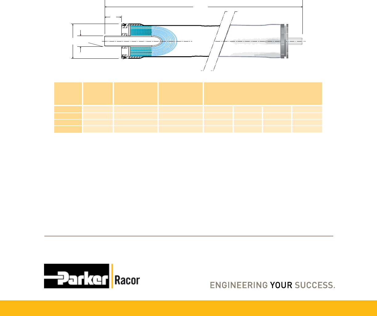
• Maximum Operating Pressure:
1000 psi
• Maximum Operating
Temperature: 113°F (45°C)
• Maximum Feed Turbidity:
1 NTU
• Free Chlorine Tolerance:
0 PPM
• Maximum Feed Silt Density
Index: SDI 5
• pH Range:
Continuous Operation: 4-11
Short-term (30 min)
Cleaning: 2.5-11
Print Reorder Number 7897 Rev- 10-27-2009© 2009 Parker Hannin Corporation
Aqua Pro®
Sea Water RO
Membranes
Notes:
Recommended
Operating Limits:
A
B
TYP
C
D
15°
Nominal
Size
2519
2538
4040
6040
Product Flow
GPD m3/day
220 - 0.83
550 - 2.08
1200 - 4.54
2500 - 9.47
Typical Salt
Rejection %
99.4
99.4
99.4
99.4
VMT
Part No.
33-2519
33-0238
33-0440
33-0036
Dimensions
inches/cm
A
19/48
38/96.5
40/101.6
40/101.6
B
1.1/2.8
1.1/2.8
1.0/2.5
1.27/3.2
C
0.75/1.9
0.75/1.9
0.75/1.9
1.5/3.8
D
2.4/6.1
2.4/6.1
3.96/10.1
5.98/15.2
• Keep elements moist at all
times
• Permeate obtained from rst
two hours of operation should
be discarded
• To prevent biological growth
during storage, shipping,
or system shutdowns it is
recommended that elements
be immersed in a protective
solution. e standard storage
solution for long or short term
storage should contain 1.0
percent (by weight) sodium
metabisulte (food grade)
• Standarized test conditions are
32,000 ppm NaCl at 77° F (25°
C), with 800 psi feed. Production
rates for individual elements
may vary +/- 20% and rejection
may vary +/- 0.4%
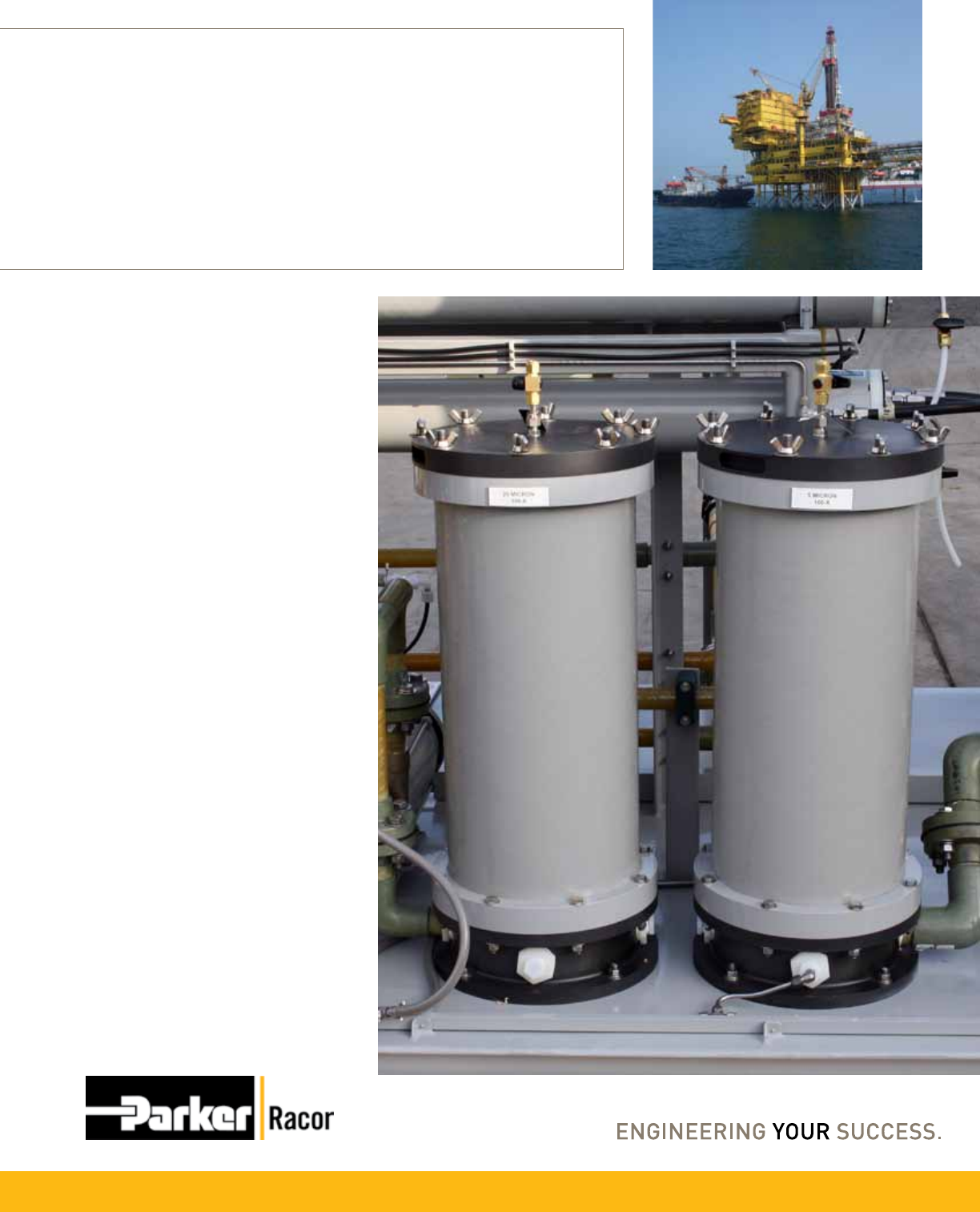
Filter Housings
FRP Shell with Nylon Caps
100X-FRP
Contact Information:
Parker Hannin Corporation
Racor Division/Village Marine Tec.
2000 W. 135th St.
Gardena, CA 90249
phone: 310 516-9911
800 C-Parker
fax: 310 538-3048
email: racor@parker.com
www.villagemarine.com
www.parker.com/racor
Racor Village Marine oers
berglass lter housings
specically designed for
seawater use. Simple but secure
closure systems allow quick
cartridge change. Aluminum
collars are bonded to berglass
shells oer superior corrosion
resistance. e base and lid are
nylon.
e housings t VMT pleated
cartridge elements of 100 square
feet area. Available in 0.5, 1, 5,
20, and 100 micron ratings.
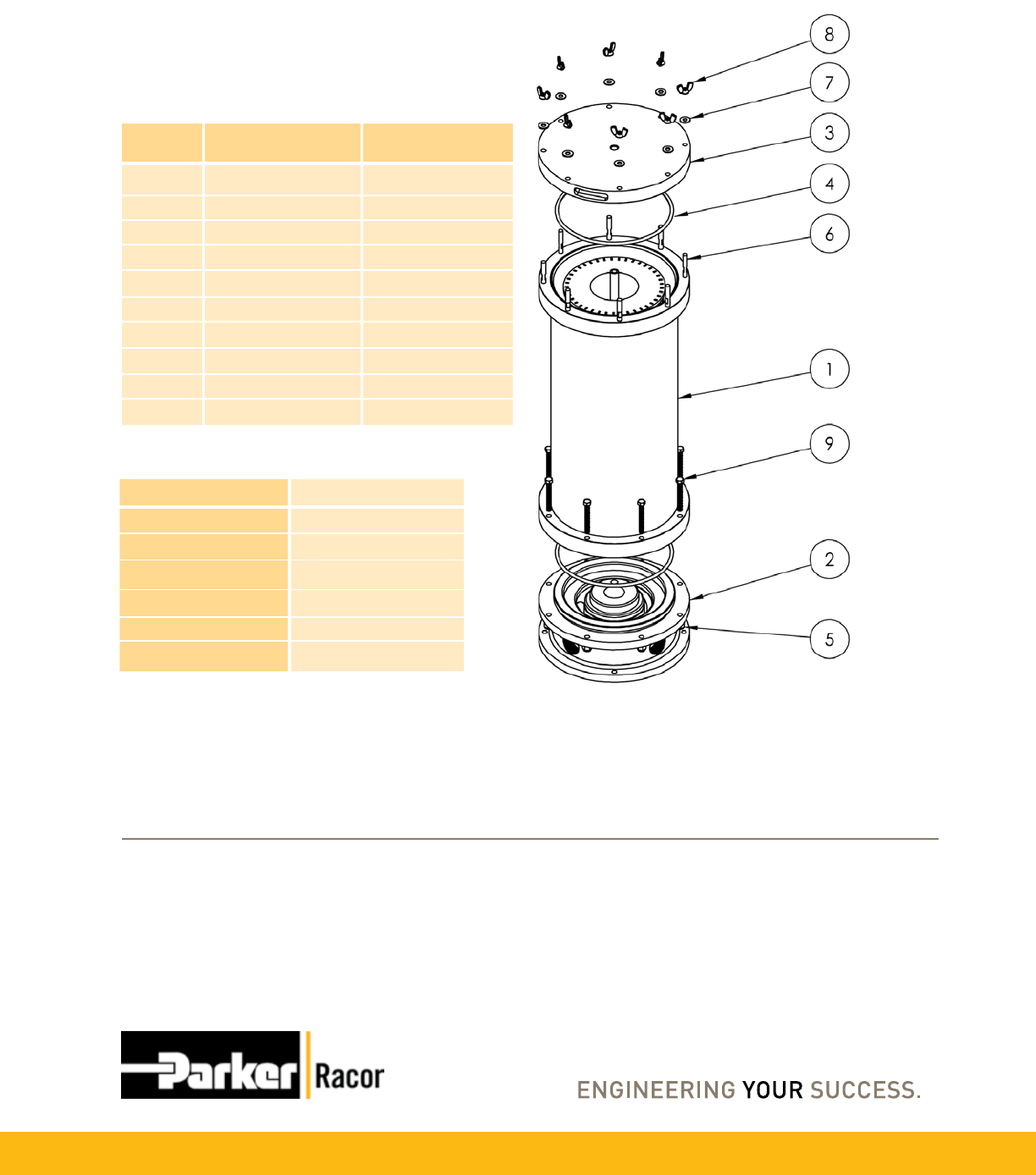
Filter Housings
FRP Shell with Nylon Caps
100X-FRP
DWG
1
2
3
4
5
6
7
8
9
Part Number
30-4353
M4353-4
M1157-1
M4353-2
30-0405
86-0022
86-0264
86-0006
86-0269
86-0260
Description
Filter Assembly
Vessel Shell
Base
Lid
O-Ring
Nuts - Bottom
Studs
Washer
Wingnut
Bolt - Bottom
Specifications
Design Pressure* 80 psi
Test Pressure 120 psi
Inlet 1.5” FPT
Outlet 1.5” FPT
Height 33”/84 cm
Diameter 13”/33 cm
© 2011 Parker Hannin Corporation
To maintain peak performance always use genuine Parker Racor Village Marine replacement parts.
We reserve the right to change our specifications or standards without notice.
*Filter Housing Vessel is designed in accordance with ASME section x pressure vessel code.
Print Reorder Number 7940 Rev-B 09-26-2011
8 Req’d
8 Req’d
8 Req’d
2 Req’d
8 Req’d
8 Req’d
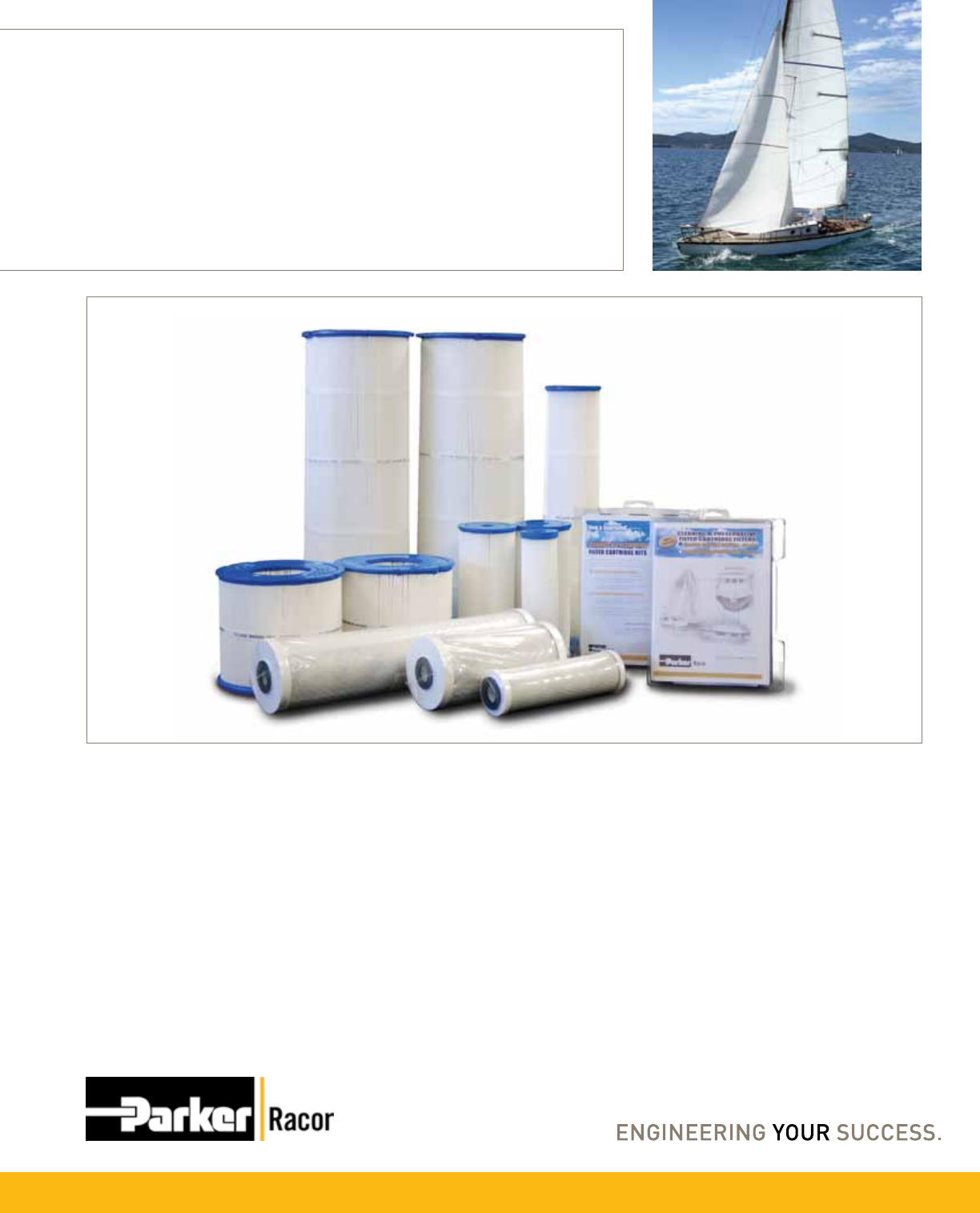
e Village Marine Tec. line of pleated
lters are designed specically for
the RO watermaker industry and
are superior to wound or polyspun
cartridges to give you a longer lter
life as well as increasing ow rates and
keeping cartridge size down.
Available in a wide arrange of sizes
and micron ranges to ensure that every
type of watermaker lter need is taken
care of. Stock sizes t most standard
lter housings, if the size you need is
not shown please contact us with the
dimensions required.
Pleated Filters and
Filter Cartridge Kits
Contact Information:
Parker Hannin Corporation
Racor Division/Village Marine Tec.
2000 W. 135th St.
Gardena, CA 90249
phone: 310 516-9911
800 C-Parker
fax: 310 538-3048
email: racor@parker.com
www.villagemarine.com
www.parker.com/racor
Single use Cleaning and Preservative
Cartridge Kits are designed specically
for small RO Systems. e Cartridges
allow for easy and eective membrane
maintenance.
e Cleaning and Preservative
Cartridge Kits eliminate the trouble
and mess of measuring powdered
chemicals and ensuring correct
chemical concentrations. e Chemical
cartridges t directly into 2.5” x 10” or
4.5” x 10” housings and contain the
correct amount of chemical for a single
use.

Pleated Filters
• Polypropylene pleated
construction
• Longer service life over wound
or polyspun cartridges
• Easily cleaned and reused
• Chemically compatible with
a wide range of alkalies, most
acids and saline solutions
• 0.5, 1, 5, and 20 micron
nominal ratings available
• Pliable ends ensures lter seal
to eliminate bypass
• High packing density reduces
lter size while keeping ow
rates up
Filter Cartridge Kits
• Cartridge with Blue stripe
contains cleaner #1, a
biological cleaner to remove
algae, fungi and bacteria
• Cartridge with Red stripe
contains cleaner #2, an acidic
cleaner to remove scale from
the membrane
• Cartridge with Green stripe
contains the preservative. is
chemical is used for pickling
the membranes
• Cartridges are capable of
being used in any housing that
takes a standard 2.5” (64mm)
x 10” (254mm) lter cartridges
Pleated Filters and Filter Cartridge Kits
Features:
Carbon Flushing Filters
Cartridge Filter Kits
Pleated Sediment Elements
Part Number
33-0118
33-0117
33-0053
33-0052
33-0020
33-0005
33-0058
33-0057
33-0172
33-2100
33-5100
33-1100
33-1105
Microns
20
5
20
5
20
5
20
5
100
20
5
1
0.5
Filter Area
ft3/m3
30/2.79
30/2.79
100/9.29
100/9.29
100/9.29
100/9.29
100/9.29
Diameter
inch/cm
2.75/7
2.75/7
4.5/11.4
4.5/11.4
8.63/22
8.63/22
4.5/11.4
4.5/11.4
8.63/22
8.63/22
8.63/22
8.63/22
8.63/22
Length
inch/cm
9.75/25
9.75/25
9.75/25
9.75/25
7.75/20
7.75/20
20/51
20/51
24.3/62
24.3/62
24.3/62
24.3/62
24.3/62
Diameter
inch/cm
2.75/7
4.5/11.4
4.5/11.4
Length
inch/cm
9.75/25
9.75/25
20/50.8
Part Number
33-0311
33-0315
33-0083
Part Number
85-0102
85-0103
Description
Cleaning Kit
Preservation Kit
Contents
One Blue stripe cleaner #1 plus
One Red stripe cleaner #2
Two Green stripe preservative
Print Reorder Number 7905 Rev- 11-23-2009© 2009 Parker Hannin Corporation
To maintain peak performance always use genuine Parker-Racor/Village Marine Tec. replacement parts.
We reserve the right to change our specifications or standards without notice.
