TN855 11 Telex DSP 223 CI (Vega) Tone Remote Adapter 1
User Manual: TN855 CI-DSP-223 Telex (Vega) DSP Tone-Remote Adapter 8. Other | LMR & HF Radio | Codan Radio
Open the PDF directly: View PDF ![]() .
.
Page Count: 6

TN855 Rev 11-0-0 Aug 16
TN855 CI-DSP-223 Telex (Vega) DSP Tone-Remote Adapter
MT-3/4 Radio Systems
TECHNICAL NOTES
Page 1 of 6
© 2016 Codan Limited All rights reserved.
43 Erie Street
Victoria, B.C.
Canada V8V 1P8
Toll Free Canada & U.S.A.
Phone: 1-800-664-4066
Fax: 1-877-750-0004
International
Phone: 250-382-8268
Fax: 250-382-6139
Internet
Email: LMRsales@codanradio.com
Web: www.codanradio.com
The Telex DSP-223 tone-remote adapter provides a reliable means of remotely controlling Codan base stations
and repeaters. The adapters can be used in conjunction with tone-remote control consoles which use the industry-
standard sequential tone keying format. The DSP-223 adapters are interconnected to the distant remote control
console(s) by any voice grade transmission medium such as a microwave link, a leased telephone line, or a twisted-
pair 600-ohm line. All DSP-223 adapters are capable of decoding the PTT tone sequence and the voice-plus-tone
signals during transmission. The tone portion of the voice-plus-tone signal is removed from the transmitted voice.
All models are prepared for jumper-plug conversion from four-wire-line operation to two-wire-line operation. In the
four-wire mode, the panels are full duplex capable.
The Telex DSP-223 tone-remote adapter provides the following features:
• PTT Relay and Monitor Relay
• 99 digit front panel display
• PTT, Monitor and Power LED indicators
• F1 and F2 Relays (programmable to any function tone)
• Digital outputs for channel selection of the Codan Tx and Rx modules (programmable to any function tone)
• CTCSS encode generation (64 frequencies available)
• Hardware and software gain controls
• Local handset port for monitoring activity through the unit and transmission back to the base or to the radio
• Front panel test points and level set pots
• RS-232C port on front panel for software confi guration via Windows application
• Ability to pass through to a second tone adapter
• Single or Dual function tone recognition (16 or 100 function tones)
• Morse code encoder for Automatic station identifi cation
• Voter / Ring Down Tone Generation
All models have been factory tuned to the following frequencies:
Guard Tone / PTT Tone: 2175 Hz
Monitor Function Tone: 2050 Hz
Frequency Select Function Tones (where used)
F1: 1950 Hz F4: 1650 Hz F7: 1350 Hz F10: 1050 Hz F13: 750 Hz F16: 450 Hz
F2: 1850 Hz F5: 1550 Hz F8: 1250 Hz F11: 950 Hz F14: 650 Hz
F3: 1750 Hz F6: 1450 Hz F9: 1150 Hz F12: 850 Hz F15: 550 Hz

TN855 CI-DSP-223 Telex (Vega) DSP Tone-Remote Adapter
MT-3/4 Radio Systems
TECHNICAL NOTES
TN855 Rev 11-0-0 Aug 16Page 2 of 6 © 2016 Codan Limited All rights reserved.
43 Erie Street
Victoria, B.C.
Canada V8V 1P8
Toll Free Canada & U.S.A.
Phone: 1-800-664-4066
Fax: 1-877-750-0004
International
Phone: 250-382-8268
Fax: 250-382-6139
Internet
Email: LMRsales@codanradio.com
Web: www.codanradio.com
DB-25 Connector Table (Color coding for Codan Interconnect cables):
1 YEL/GRN (PTT NC) 10 RED/BLU (DIG4) 18 WHT/GRY (F2 NC)
2 YEL/BRN (PTT COM) 11 VIO/GRN (CTCSS) 19 WHT/ORG (F2 COM)
3 YEL/GRY (MON NO) 12 VIO/BRN (RX-) 20 WHT/BLU (+POWER)
4 YEL/ORG (F1 NC) 13 VIO/GRY (TX-) 21 BLK/GRN (DIG1)
5 YEL/BLU (F1 COM) 14 VIO/ORG (PTT NO) 22 BLK/BRN (DIG3)
6 RED/GRN (F2 NO) 15 VIO/BLU (MON NC) 23 BLK/GRY (DIG5)
7 RED/BRN (GND) 16 WHT/GRN (MON COM) 24 BLK/ORG (RX+)
8 RED/GRY (DIG0) 17 WHT/BRN (F1 NO) 25 BLK/BLU (TX+)
9 RED/ORG (DIG2)
Installation:
A female DB25 connector on the back of the subrack (J10) can be used for basic base connections to a Telex
DSP-223, using a standard straight-through male-to-male DB25 cable (CBLC40-04225092). (WARNING: JU108
must be confi gured correctly or damage can occur. JU108 A for +13.8 Vdc / DSP-223). The A-PNL-AUX96-3
auxiliary connector can also be used to connect to the Telex board to a Codan Base Station with an AC-3E or CI-
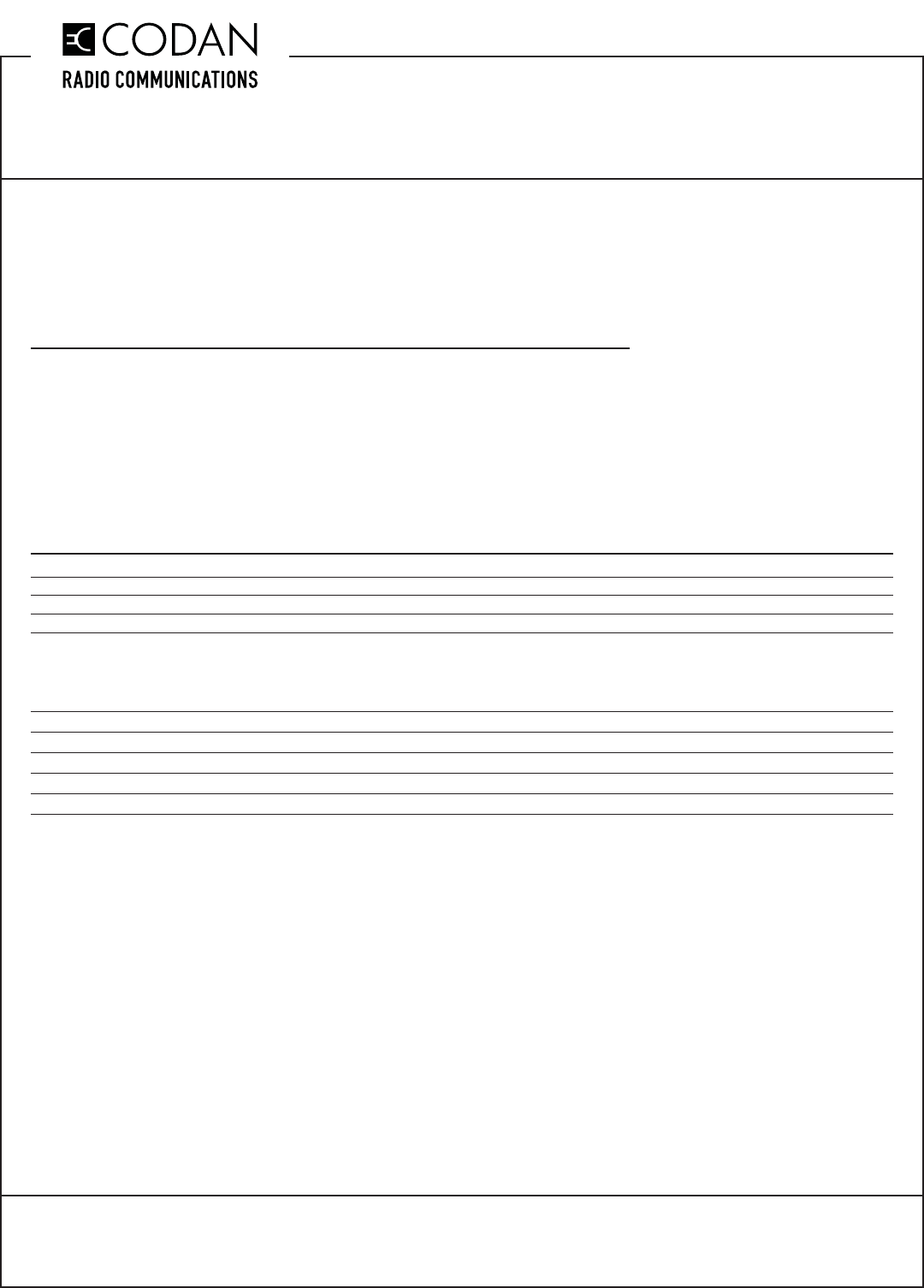
BC-4E, as shown in Figure 1. Select the two or four-wire-line operation and setup jumpers J20 and J21on the Telex.
For four-wire-line operation, set the jumpers in position ‘B’ and connect the four-wire leased line outgoing to Pins 4
and 5 and the receive to Pins 3 and 6 of the RJ45 modular connector. For two-wire-line operation, set the jumpers
in position ‘A’ and connect the two-wire leased line to Pins 4 and 5 of the RJ45 modular connector. Ensure jumpers
JU67A (or JU67X for CI-BC-4E) and JU68 are installed on the AC-3E and CI-BC-4E. On Codan MT-4R and MT-4D
radio systems, the CTCSS to Subtone connection is not connected.
Figure 1: Codan Radio System to Telex DSP-223 connection
CODAN RADIO EQUIPMENT
P1 (A-PNL-AUX96-3 CONTROL CONNECTOR)
13.8V
GND
(GPIO 5) AUX 1 AUDIO O/P1
(GPIO 6) AUX 1 AUDIO O/P2
(GPIO 1) AUX 1 AUDIO I/P1
+POWER
GND
RX+
RX-
TX+
TX-
2/4 WIRE LINE IN/OUT
4 WIRE LINE IN
2/4 WIRE LINE OUT
4 WIRE LINE IN
2/4 WIRE CONNECTIONS
TO CUSTOMER
EQUIPMENT
TELEX CI-DSP-223
TONE REMOTE ADAPTER
B2
B32
B11
A11
C19
C20
(GPIO 2) AUX 1 AUDIO I/P2
(J4-5)
(J4-1)
(J3-5)
(J3-6)
(J3-1)
(J3-2)
(GPIO 14) AUX 1 PTT K PTT NO
(INSTALL JP2)
C13 (J3-14)
CTCSS
C22 (J1-4)
TXA SUBTONE I/P
TXA CSEL D0
TXA CSEL D1
C21 (J2-1)
B21 (J2-2) DIG0
TXA CSEL D2
TXA CSEL D3
A21 (J2-3)
C23 (J2-4) DIG2
DIG1
DIG3
430 OHM
P/N 1101-2A0431JP
Jumpers Required For TXA Channel Select:
TELEX: J16B (+5 V Pullup)
SR-39-1: JU50A, JU51A, JU52A, JU53A, Remove JU48
On older motherboards (Serial # 123125 and earlier)
the jumpers were as follows:
SR-39-1: JU24B, JU25B, JU26B, JU27B, Remove JU41
Jumpers Required For PTT Operation:
TELEX: JP2 Installed
RXA SQUELCH OVERRIDE MONITOR NO
(INSTALL JP3)
C10 (J4-9)
TXA SECURE / CLEAR (OPTIONAL) F1 NO
(INSTALL JP4)
C24 (J5-5)

TN855 Rev 11-0-0 Aug 16
TN855 CI-DSP-223 Telex (Vega) DSP Tone-Remote Adapter
MT-3/4 Radio Systems
TECHNICAL NOTES
Page 3 of 6
© 2016 Codan Limited All rights reserved.
43 Erie Street
Victoria, B.C.
Canada V8V 1P8
Toll Free Canada & U.S.A.
Phone: 1-800-664-4066
Fax: 1-877-750-0004
International
Phone: 250-382-8268
Fax: 250-382-6139
Internet
Email: LMRsales@codanradio.com
Web: www.codanradio.com
Telex DSP Programming:
The Telex DSP-223 is typically factory programmed for the customers requirements, however, reprogramming of
the Telex can be done with the Telex software contained on the CD that comes with the radio system. Ensure that
the embedded fi rmware of the Telex is the same version as the software. To determine the embedded fi rmware
version, turn the Telex on and the words DSP-223 will scroll across the display, then the fi rmware version will
appear. Connect the PC to the Telex programming port on the front panel of the Telex tone remote adapter using the
cable supplied with the Telex. New software and fi rmware for the Telex can be downloaded from www.telex.com.
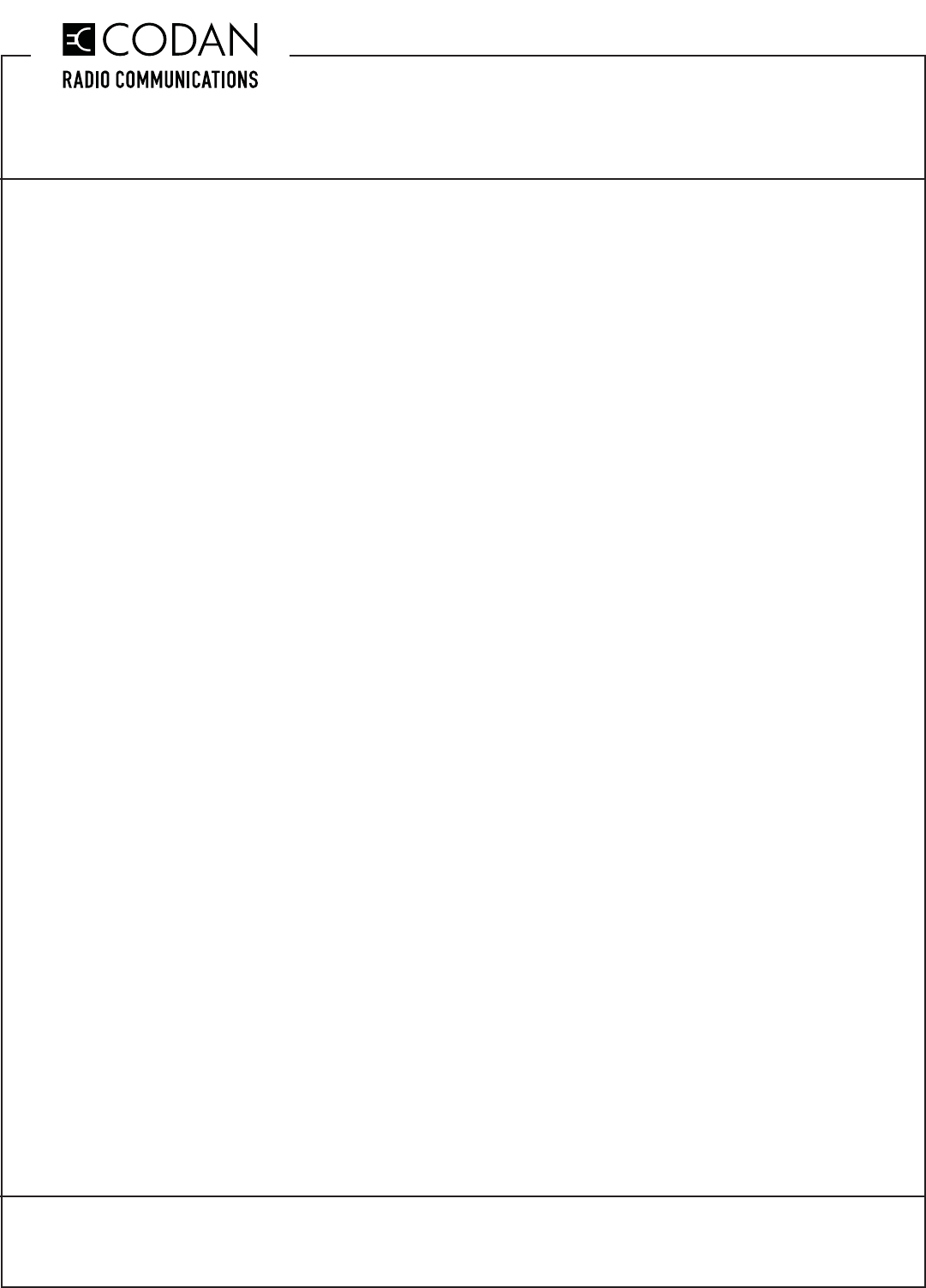
The software shown in Figure 2 is version 2.8 and is programmed for channels 1 through 9 with CTCSS tones of
100.0 Hz on channel 1, 203.5 Hz on channel 2 and no CTCSS on channels 3 through 9. Codan radio systems do
not require the “Set Gains” or “TX Filters” sections to be accessed on the Telex DSP-223 software. The CTCSS
tone is shown as always on, to allowing CTCSS to be transmitted when testing, using the microphone on the
front panel of the transmitter module. On Codan MT-4R and MT-4D P25 radio systems, the CTCSS to Subtone
connection is not connected and CTCSS tones are generated internally in the transmitter.
Figure 2: Telex DSP-223 Programming Software
TN855 CI-DSP-223 Telex (Vega) DSP Tone-Remote Adapter
MT-3/4 Radio Systems
TECHNICAL NOTES
TN855 Rev 11-0-0 Aug 16Page 4 of 6 © 2016 Codan Limited All rights reserved.
43 Erie Street
Victoria, B.C.
Canada V8V 1P8
Toll Free Canada & U.S.A.
Phone: 1-800-664-4066
Fax: 1-877-750-0004
International
Phone: 250-382-8268
Fax: 250-382-6139
Internet
Email: LMRsales@codanradio.com
Web: www.codanradio.com
Telex DSP Alignment / Tuning Procedures:
Initial Setup
Step 1 - Program the Telex using the Telex programming software and ensure all jumpers are correctly installed.
AC-3E Audio Control Card and CI-BC-4E Base Control Card Tuning
Step 2 - Disconnect the Telex tone remote from the Codan radio system.
Step 3 - Apply a 1.0 KHz tone @ 0 dBm (775 mV) to the GPIO 1 (Aux 1 I/P 1) and GPIO 2 (Aux 1 I/P 2) balanced
auxiliary audio input on the Codan radio system.
Step 4 - Adjust R120 (Aux In 1 to TXA) for a transmitter deviation of ± 3 KHz (WB), ± 1.5 KHz (NB).
Step 5 - Inject a 1.0 KHz tone @ a deviation of ± 3 KHz (WB), ± 1.5 KHz (NB) into Receiver A.
Step 6 - Adjust R13 (RXA to Aux Out 1) for an audio level of 0 dBm (775 mV @ 600 ohms) across GPIO 5 (Aux 1
O/P 1) and GPIO 6 (Aux 1 O/P 2) on the Codan radio system. Note: MT-4R and MT-4D P25 Receiver modules
have a higher audio level output when receiving a digital signal (as opposed to analog). When using these receiver
modules in digital mode, adjust R13 for an audio level of -8.0 dBm (308 mV @ 600 ohms).
Step 7 - Connect the Telex tone remote to the Codan radio system.
Telex Line and Radio Level Tuning
Step 8 - Using an appropriate test set (Telex C-2002), apply a 1.0 KHz tone @ 0 dBm into the tone remote.
Step 9 - On the front panel of the Telex, monitor the receive line level (AC Voltmeter across LINE RX and GROUND)
and adjust the LINE RX pot for 500 mV. This level can vary with the cable length between the console and the
remote.
Step 10 - On the front panel of the Telex, monitor the transmit radio level (AC Voltmeter across RADIO TX+ and
RADIO TX-) and adjust the RADIO TX pot for 0 dBm (775 mV) or a transmitter deviation of ± 3 KHz (WB), ± 1.5
KHz (NB).
Step 11 - Inject a 1.0 KHz tone @ a deviation of ± 3 KHz (WB), ± 1.5 KHz (NB) into Receiver A.
Step 12 - On the front panel of the Telex, monitor the receive radio level (AC Voltmeter across RADIO RX and
GROUND) and adjust the RADIO RX pot for 0 dBm (775 mV). Note: When adjusting R13 in Step 6 for an audio
level of -8.0 dBm (308 mV), adjust the RADIO RX pot for -8.0 dBm (308 mV).
Step 13 - On the front panel of the Telex, monitor the transmit line level (AC Voltmeter across LINE TX+ and LINE
TX-) and adjust the LINE TX pot for 0 dBm (775 mV). This level can vary with the cable length between the console
and the remote.
Step 14 - Set the Communications analyzer to monitor the deviation level of the transmitter CTCSS encode tone
(enable 300 Hz Lowpass fi lter).
Step 15 - Key the Telex test set with a CTCSS tone programmed and adjust the CTCSS pot on the front panel of
the Telex for a transmitter deviation of ± 500 Hz (WB), ± 350 Hz (NB).
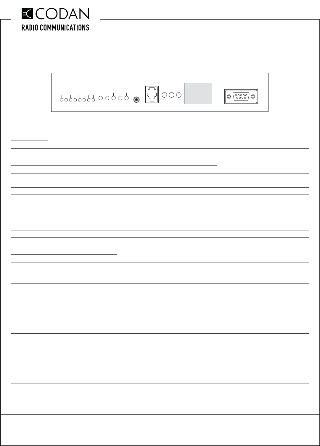
TELEX
PROGRAMMING PORT
DSP-223
PTT IC
HANDSET
POWER PTT MONITOR
FUNCTION
CTCSS
LINE RX
LINE TX +
RADIO TX +
RADIO RX
LINE TX
LINE RX
RADIO TX
RADIO RX
CTCSS
RADIO TX -
GROUND
LINE TX -
TN855 Rev 11-0-0 Aug 16
TN855 CI-DSP-223 Telex (Vega) DSP Tone-Remote Adapter
MT-3/4 Radio Systems
TECHNICAL NOTES
Page 5 of 6
© 2016 Codan Limited All rights reserved.
43 Erie Street
Victoria, B.C.
Canada V8V 1P8
Toll Free Canada & U.S.A.
Phone: 1-800-664-4066
Fax: 1-877-750-0004
International
Phone: 250-382-8268
Fax: 250-382-6139
Internet
Email: LMRsales@codanradio.com
Web: www.codanradio.com
Bypassing the AC-3E Audio Control Card and CI-BC-4E Base Control Card:
The AC-3E Audio Control Card and CI-BC-4E Base Control Card can be bypassed and the MT-4E Receiver
and Transmitter can be connected directly to the Telex adapter. The control card needs to be removed from the
subrack, or unwanted loading could occur.
The following receiver and transmitter tuning changes would be required:
Transmitter Setup - Apply a 1.0 KHz tone @ 0 dBm (775 mV) to the Tx A Bal I/P1 (J1-1) and Tx A Bal I/P 2 (J1-2)
balanced audio input and adjust the RSS software Balanced Audio Deviation Level for a transmitter deviation of ±
3 KHz (WB), ± 1.5 KHz (NB).
Receiver Setup - Inject a 1.0 KHz tone @ a deviation of ± 3 KHz (WB), ± 1.5 KHz (NB) into the receiver and
adjust the RSS software Balanced Output Audio Level for an audio level of 0 dBm (775 mV @ 600 ohms) across
Rx A Bal O/P 1 (J1-5) and Rx A Bal O/P 2 (J1-6).
The DB25 (J10) can be jumpered for Balanced Audio direct to / from the receiver and transmitter as follows:
JU104 A = RX A Bal O/P2 JU107 A = RX A Bal O/P1
JU105 A = TX A Bal I/P2 JU108 A = DSP-223 / +13.8 V
JU106 A = TX A Bal I/P1
On the Wiring diagram for the A-PNLAUX96-3, the following connections change:
(GPIO 5) AUX 1 AUDIO O/P1(J3-5) Rx A Bal O/P 1 (J1-5)
(GPIO 6) AUX 1 AUDIO O/P2 (J3-6) Rx A Bal O/P 2 (J1-6)
(GPIO 1) AUX 1 AUDIO I/P1 (J3-1) Tx A Bal I/P1 (J1-1)
(GPIO 2) AUX 1 AUDIO I/P2 (J3-2) Tx A Bal I/P 2 (J1-2)
(GPIO 14) AUX 1 PTT K (J3-14) Tx A PTT (J1-3)
TN855 CI-DSP-223 Telex (Vega) DSP Tone-Remote Adapter
MT-3/4 Radio Systems
TECHNICAL NOTES
TN855 Rev 11-0-0 Aug 16Page 6 of 6 © 2016 Codan Limited All rights reserved.
43 Erie Street
Victoria, B.C.
Canada V8V 1P8
Toll Free Canada & U.S.A.
Phone: 1-800-664-4066
Fax: 1-877-750-0004
International
Phone: 250-382-8268
Fax: 250-382-6139
Internet
Email: LMRsales@codanradio.com
Web: www.codanradio.com
This Page Intentionally Left Blank
