Tele PACE User And Reference Manual
TelePACE%20User%20and%20Reference%20Manual
User Manual:
Open the PDF directly: View PDF ![]() .
.
Page Count: 1184 [warning: Documents this large are best viewed by clicking the View PDF Link!]
- Ladder Logic Overview
- Ladder Logic Program Development
- TelePACE Program Development
- Ladder Logic Program Reference
- Introduction
- File Menu
- Edit Menu
- Search Menu
- Controller Menu
- Type
- Serial Ports
- IP Configuration
- Register Assignment
- Outputs On Stop
- Store and Forward
- DNP
- DNP Status
- DNP Master Status
- Initialize
- Real Time Clock
- Monitor Element
- List Force Registers
- Remove All Forces
- Lock Controller
- Unlock Controller
- Override Controller Lock
- Show Lock Status
- C/C++ Program Loader
- Flash Loader
- Program Status
- Communications Menu
- Activity Menu
- Operation Menu
- Options Menu
- Help Menu
- Ladder Logic Function Reference
- Register Types
- Ladder Logic Functions
- ABS – Absolute Value
- ABSF - Floating-Point Absolute Value
- ADD – Add Signed Values
- ADDF - Add Floating-Point Values
- ADDU – Add Unsigned Values
- AND – And Block
- CALL - Execute Subroutine
- Coil
- CMPB – Compare Bit
- CMP – Compare Signed Values
- CMPU – Compare Unsigned Values
- DCTR – Down Counter
- DEVT – Generate DNP Event
- DIAL – Control Dial-Up Modem
- DIV – Divide Signed Values
- DIVF - Divide Floating-Point Values
- DIVU – Divide Unsigned Values
- DLOG - Data Logger
- DPOL – Trigger a DNP class poll
- DSYC – Trigger a DNP clock synchronization
- DUNS – Trigger a DNP unsolicited response message
- FIN – FIFO Queue Insert
- FOUT – FIFO Queue Remove
- FLOW – Flow Accumulator
- FTOS - Floating-Point to Signed Integer
- FTOU - Floating-Point to Unsigned Integer
- GETB – Get Bit from Block
- GETL - Data Logger Extract
- GTEF – Floating-Point Greater Than or Equal
- HART – Send HART Command
- INIM – Initialize Dial-Up Modem
- L–>L – List to List Transfer
- L–>R – List to Register Transfer
- LTEF - Floating-Point Less Than or Equal
- MOD – Modulus of Signed Values
- MODU – Modulus of Unsigned Values
- MOVE – Move Block
- MSTR – Master Message
- MSIP – Master IP Message
- MUL – Multiply Signed Values
- MULF - Multiply Floating-Point Values
- MULU – Multiply Unsigned Values
- Normally Closed Contact
- Normally Open Contact
- NOT – Not Block
- One Shot Coil
- OR – Or Block
- OVER – Override Block of Registers
- PID – PID Controller
- PIDA – Analog Output PID
- PIDD – Digital Output PID
- POWR – Floating-Point Raised to Power
- PULM - Pulse Minutes
- PULS - Pulse Seconds
- PUTB – Put Bit into Block
- PUT – Put Signed Value into Registers
- PUTF - Put Floating-Point Value
- PUTU – Put Unsigned Value into Registers
- R–>L – Register to List Transfer
- ROTB – Rotate Bits in Block
- SCAL – Scale Analog Value
- Shunts
- SLP – Put Controller into Sleep Mode
- SQRF - Square Root of Floating-Point Value
- STOF - Signed Integer to Floating-Point
- SUB – Subtract Signed Values
- SUBF – Subtract Floating-Point Values
- SUBR - Start of Subroutine
- SUBU –Subtract Unsigned Values
- Timers
- TOTL – Analog Totalizer
- UCTR – Up Counter
- UTOF - Unsigned Integer to Floating-Point
- XOR – Exclusive Or Block
- Ladder Logic Register Assignment Reference
- Register Assignment Reference
- Register Assignment Specification
- Register Assignment Example
- Analog Input I/O Modules
- Analog Output I/O Modules
- Configuration I/O Modules
- CNFG Clear Protocol Counters
- CNFG Clear Serial Port Counters
- CNFG DTR Off
- CNFG 5904 HART Interface Module
- CNFG IP Settings
- CNFG LED Power Settings
- CNFG Modbus IP Interface
- CNFG Modbus IP Protocols
- CNFG Modbus/TCP Settings
- CNFG PID Control Block
- CNFG Power Mode
- CNFG Protocol Settings Method 1
- CNFG Protocol Settings Method 2
- CNFG Protocol Settings Method 3
- CNFG Real Time Clock and Alarm
- CNFG Save Settings to EEPROM
- CNFG Serial Port Settings
- CNFG Store and Forward
- Counter I/O Modules
- Diagnostic I/O Modules
- Digital Input I/O Modules
- Digital Output I/O Modules
- SCADAPack and SCADASense Series I/O Modules
- Controller Default Register Assignments
- 4202 DR Extended/4203 DR I/O Register Assignment
- SCADASense 4202/4203 DS I/O Default Register Assignment
- Micro16 Default Register Assignment (Backwards Compatible Mo
- Micro16 Default Register Assignment (Controller I/O Only)
- SCADAPack (5601 I/O Module) Default Register Assignment
- SCADAPack (5604 I/O Module) Default Register Assignment
- SCADAPack LIGHT Default Register Assignment
- SCADAPack PLUS (5601 I/O Module) Default Register Assignment
- SCADAPack Plus (5604 I/O Module) Default Register Assignment
- SCADAPack LP Default Register Assignment
- SCADAPack 350 Default Register Assignment
- SCADAPack 32 (5601 I/O Module) Default Register Assignment
- SCADAPack 32 (5604 I/O Module) Default Register Assignment
- SCADAPack 32P Default Register Assignment
- SCADAPack 100 Default Register Assignment
- Register Assignment Reference
- TeleBUS Protocols User Manual
- Table of Contents
- TeleBUS Protocols Overview
- Serial Port Configuration
- I/O Database
- Extended Station Addressing
- Slave Mode
- Modbus Master Mode
- Store and Forward Messaging
- Point–To–Point Protocol (PPP)
- TeleBUS DF1 Protocol User Manual
- Table of Contents
- TeleBUS DF1 Protocol Overview
- Serial Port Configuration
- I/O Database
- Slave Mode
- Master Mode
- DNP3 User and Reference Manual
- Using This Manual
- DNP3 Overview
- DNP Network Architectures
- Configuration of DNP Operation Modes
- DNP Configuration Menu
- Application Layer Configuration
- Data Link Layer Configuration
- Master
- Master Poll
- Address Mapping
- Routing
- Binary Inputs Configuration
- Binary Outputs Configuration
- 16–Bit Analog Inputs Configuration
- 32-Bit Analog Inputs Configuration
- Short Floating Point Analog Inputs
- 16-Bit Analog Outputs Configuration
- 32-Bit Analog Outputs Configuration
- Short Floating Point Analog Outputs
- 16–Bit Counter Inputs Configuration
- 32-Bit Counter Inputs Configuration
- DNP Diagnostics
- DNP Device Profile Document - Master
- DNP Device Profile Document - Slave
- TelePACE C Tools User Manual
- Table of Contents
- TelePACE C Tools Overview
- Getting Started
- C Program Development
- Real Time Operating System
- Overview of Programming Functions
- Controller Operation
- Controller I/O Hardware
- Analog Input Functions
- Analog Output Functions
- Digital Input Functions
- Digital Output Functions
- Counter Input Functions
- Status LED and Output Functions
- Options Switches Functions
- LED Indicators Functions
- LED Power Control Functions
- Software Timer Functions
- Real Time Clock Functions
- The Jiffy Clock
- Watchdog Timer Functions
- Checksum Functions
- Serial Communication
- Communication Protocols
- DNP Communication Protocol
- I/O Database
- HART Communication
- PID Control
- Backward Compatibility Functions
- TelePACE C Tools Function Specifications
- addRegAssignment
- addRegAssignmentEx
- ain
- aioError
- alarmIn
- allocate_envelope
- aout
- auto_pid
- check_error
- checksum
- checkSFTranslationTable
- clearAllForcing
- clear_errors
- clear_pid
- clear_protocol_status
- clearRegAssignment
- clearSFTranslationTable
- clearStatusBit
- clear_tx
- counter
- counterError
- crc_reverse
- create_task
- databaseRead
- databaseWrite
- datalogCreate
- datalogDelete
- datalogPurge
- datalogReadNext
- datalogReadStart
- datalogRecordSize
- datalogSettings
- datalogWrite
- dbase
- deallocate_envelope
- din
- dnpInstallConnectionHandler
- dnpClearEventLog
- dnpConnectionEvent
- dnpCreateRoutingTable
- dnpGenerateEventLog
- dnpGetAI16Config
- dnpGetAI32Config
- dnpGetAISFConfig
- dnpGetAO16Config
- dnpGetAO32Config
- dnpGetAOSFConfig
- dnpGetBIConfig
- dnpGetBIConfigEx
- dnpGetBOConfig
- dnpGetCI16Config
- dnpGetCI32Config
- dnpGetConfiguration
- dnpGetConfigurationEx
- dnpGetRuntimeStatus
- dnpReadRoutingTableDialStrings
- dnpReadRoutingTableEntry
- dnpReadRoutingTableSize
- dnpSaveAI16Config
- dnpSaveAI32Config
- dnpSaveAISFConfig
- dnpSaveAO16Config
- dnpSaveAO32Config
- dnpSaveAOSFConfig
- dnpSaveBIConfig
- dnpSaveBIConfigEx
- dnpSaveBOConfig
- dnpSaveCI16Config
- dnpSaveCI32Config
- dnpSaveConfiguration
- dnpSaveConfigurationEx
- dnpSearchRoutingTable
- dnpSendUnsolicited
- dnpSendUnsolicitedResponse
- dnpWriteRoutingTableEntry
- dnpWriteRoutingTableDialStrings
- dout
- end_application
- end_task
- endTimedEvent
- enronInstallCommandHandler
- forceLed
- getABConfiguration
- getBootType
- getclock
- getClockAlarm
- getClockTime
- getControllerID
- getForceFlag
- getIOErrorIndication
- getOutputsInStopMode
- getPortCharacteristics
- getPowerMode
- get_pid
- get_port
- getProgramStatus
- get_protocol
- getProtocolSettings
- getProtocolSettingsEx
- get_protocol_status
- getSFMapping
- getSFTranslation
- get_status
- getStatusBit
- getTaskInfo
- getVersion
- getWakeSource
- hartIO
- hartIOFromDbase
- hartCommand
- hartCommand0
- hartCommand1
- hartCommand2
- hartCommand3
- hartCommand11
- hartCommand33
- hartStatus
- hartGetConfiguration
- hartSetConfiguration
- hartPackString
- hartUnpackString
- install_handler
- installClockHandler
- installExitHandler
- installModbusHandler
- Handler Function
- installRTCHandler
- RTCHandler Function
- interruptCounter
- interruptInput
- RTCHandler Function
- interrupt_signal_event
- interval
- ioBusReadByte
- ioBusReadLastByte
- ioBusReadMessage
- ioBusSelectForRead
- ioBusSelectForWrite
- ioBusStart
- ioBusStop
- ioBusWriteByte
- ioBusWriteMessage
- ioClear
- ioDatabaseReset
- ioRead16Din
- ioRead32Din
- ioRead4Ain
- ioRead4Counter
- ioRead4202Inputs
- ioRead4202DSInputs
- ioRead5505Inputs
- ioRead5506Inputs
- ioRead5601Inputs
- ioRead5602Inputs
- ioRead5604Inputs
- ioRead5606Inputs
- ioRead8Ain
- ioRead8Din
- ioReadLPInputs
- ioReadSP100Inputs
- ioRefresh
- ioReset
- ioWrite16Dout
- ioWrite32Dout
- ioWrite8Dout
- ioWrite2Aout
- ioWrite4Aout
- ioWrite4AoutChecksum
- ioWrite4202Outputs
- ioWrite4202OutputsEx
- ioWrite4202DSOutputs
- ioWrite5303Aout
- ioWrite5505Outputs
- ioWrite5506Outputs
- ioWrite5601Outputs
- ioWrite5602Outputs
- ioWrite5604Outputs
- ioWrite5606Outputs
- ioWriteLPOutputs
- ioWriteSP100Outputs
- jiffy
- ledGetDefault
- ledPower
- ledPowerSwitch
- ledSetDefault
- load
- master_message
- modbusExceptionStatus
- modbusSlaveID
- modbusProcessCommand Function
- modemAbort
- modemAbortAll
- modemDial
- modemDialEnd
- modemDialStatus
- modemInit
- modemInitEnd
- modemInitStatus
- modemNotification
- off
- on
- optionSwitch
- overrideDbase
- pollABSlave
- poll_event
- poll_message
- poll_resource
- portConfiguration
- portIndex
- portStream
- processModbusCommand
- pulse
- pulse_train
- queue_mode
- readCounter
- readCounterInput
- readBattery
- readInternalAD
- readStopwatch
- readThermistor
- read_timer_info
- receive_message
- release_processor
- release_resource
- report_error
- request_resource
- resetAllABSlaves
- resetClockAlarm
- route
- runLed
- save
- send_message
- setABConfiguration
- setBootType
- setclock
- setClockAlarm
- setdbase
- setDTR
- setForceFlag
- setIOErrorIndication
- setjiffy
- setOutputsInStopMode
- set_pid
- set_port
- setPowerMode
- setProgramStatus
- set_protocol
- setProtocolSettings
- setProtocolSettingsEx
- setSFMapping
- setSFTranslation
- setStatus
- setStatusBit
- settimer
- setWakeSource
- signal_event
- sleep
- start_protocol
- startup_task
- startTimedEvent
- timeout
- timeoutCancel
- timeoutRequest
- timer
- turnoff
- turnon
- wait_event
- wd_auto
- wd_manual
- wd_pulse
- TelePACE C Tools Macro Definitions
- TelePACE C Tools Structures and Types
- ABConfiguration
- ADDRESS_MODE
- ALARM_SETTING
- clock
- DATALOG_CONFIGURATION
- DATALOG_STATUS
- DATALOG_VARIABLE
- DialError
- DialState
- dnpAnalogInput
- dnpAnalogOutput
- dnpBinaryInput
- DNP Binary Input Extended Point
- dnpBinaryOutput
- DNP_CONNECTION_EVENT Type
- dnpConfiguration
- dnpConfigurationEx
- dnpCounterInput
- dnpPointType
- DNP_RUNTIME_STATUS
- envelope
- HART_COMMAND
- HART_DEVICE
- HART_RESPONSE
- HART_RESULT
- HART_SETTINGS
- HART_VARIABLE
- ioModules
- ledControl_tag
- ModemInit
- ModemSetup
- PROTOCOL_SETTINGS
- PROTOCOL_SETTINGS_EX Type
- prot_settings
- prot_status
- pconfig
- PORT_CHARACTERISTICS
- pstatus
- READSTATUS
- regAssign
- routingTable
- SFTranslation
- SFTranslationStatus
- TASKINFO
- taskInfo_tag
- timer_info
- VERSION
- WRITESTATUS
- C Compiler Known Problems
- TelePACE C Tools Warranty and License
- Ladder Logic Modem Commands

TelePACE Ladder Logic
Overview
CONTROL
MICROSYSTEMS
SCADA products... for the distance
48 Steacie Drive Telephone: 613-591-1943
Kanata, Ontario Facsimile: 613-591-1022
K2K 2A9 Technical Support: 888-226-6876
Canada 888-2CONTROL

©2007 Control Microsystems Inc.
All rights reserved.
Printed in Canada.
Trademarks
TelePACE, SCADASense, SCADAServer, SCADALog, RealFLO, TeleSAFE,
TeleSAFE Micro16, SCADAPack, SCADAPack Light, SCADAPack Plus,
SCADAPack 32, SCADAPack 32P, SCADAPack 350, SCADAPack LP,
SCADAPack 100, SCADASense 4202 DS, SCADASense 4202 DR,
SCADASense 4203 DS, SCADASense 4203 DR, SCADASense 4102,
SCADASense 4012, SCADASense 4032 and TeleBUS are registered
trademarks of Control Microsystems.
All other product names are copyright and registered trademarks or trade names
of their respective owners.
Material used in the User and Reference manual section titled SCADAServer
OLE Automation Reference is distributed under license from the OPC
Foundation.
TelePACE Ladder Logic Overview
May 8, 2007
1

Table of Contents
1 TELEPACE LADDER LOGIC OVERVIEW.................................................... 4
1.1 System Requirements .............................................................................. 4
1.2 Installation on a Hard Disk........................................................................ 4
1.3 Running TelePACE Ladder Logic Editor................................................... 4
2 LADDER EDITOR ENVIRONMENT .............................................................. 5
2.1 Introduction............................................................................................... 5
2.2 Ladder Editor Display ............................................................................... 5
2.2.1 Title Bar............................................................................................... 5
2.2.2 Menu Bar............................................................................................. 5
2.3 Tool Bar .................................................................................................... 5
2.3.1 Network Title ....................................................................................... 7
2.3.2 Comment Editor .................................................................................. 7
2.3.3 Splitter Bar........................................................................................... 7
2.3.4 Status Bar............................................................................................ 7
2.3.5 Network Display .................................................................................. 7
2.3.6 Register List ........................................................................................ 7
2.3.7 Cursor.................................................................................................. 8
2.4 TelePACE Major Components.................................................................. 9
2.4.1 Networks ............................................................................................. 9
2.4.2 Network Elements ............................................................................... 9
2.4.3 Subroutines ......................................................................................... 9
2.4.4 Program Execution Order.................................................................. 10
2.4.5 Ladder Logic Memory Usage ............................................................ 10
2.5 TelePACE I/O Database Registers......................................................... 11
2.5.1 16-bit Controller I/O Database........................................................... 11
2.5.1.1 I/O Database register types ......................................................... 12
2.5.1.1.1 Coil Registers ...................................................................................12
2.5.1.1.2 Status Registers ...............................................................................13
2.5.1.1.3 Input Registers .................................................................................13
2.5.1.1.4 Holding Registers .............................................................................13
2.5.2 32-bit Controller I/O Database........................................................... 13
2.5.2.1 I/O Database register types ......................................................... 14
2.5.2.1.1 Coil Registers ...................................................................................14
2.5.2.1.2 Status Registers ...............................................................................14
2.5.2.1.3 Input Registers .................................................................................15
2.5.2.1.4 Holding Registers .............................................................................15
TelePACE Ladder Logic Overview
May 8, 2007
2

2.5.3 SCADAPack 100: 256K I/O Database............................................... 15
2.5.3.1 I/O Database register types ......................................................... 16
2.5.3.1.1 Coil Registers ...................................................................................16
2.5.3.1.2 Status Registers ...............................................................................16
2.5.3.1.3 Input Registers .................................................................................16
2.5.3.1.4 Holding Registers .............................................................................16
TelePACE Ladder Logic Overview
May 8, 2007
3

1 TelePACE Ladder Logic Overview
TelePACE ladder logic is ideal for electricians, engineers, and programmers who program
sequencing and process control. The ladder logic editor is a powerful tool for writing, debugging
and documenting ladder logic programs. The SCADAPack and TeleSAFE family of controllers
executes ladder logic and C application programs simultaneously, providing you with maximum
flexibility in implementing your control strategy.
This manual provides full documentation on the TelePACE program including the Ladder Network
Editor and the ladder logic programming language. We strongly encourage you to read it, and to
notify us if you identify any items that you feel should be clarified, or included in future
documentation releases.
We sincerely hope that the reliability and flexibility afforded by this fully programmable controller
enable you and your company to solve your automation problems in a cost effective and efficient
manner.
To use TelePACE, you need to install the program on your system. The automated installation takes
only a few minutes.
Some virus checking software may interfere with Setup. If you experience problems with Setup,
disable your virus checker and run Setup again.
1.1 System Requirements
The TelePACE ladder editor requires the following minimum system configuration.
• Microsoft Windows NT, Windows 2000 or Windows XP operating systems. Note that
Windows 95, 98 and ME operating systems are no longer supported.
• Mouse or compatible pointing device; and
• Hard disk with approximately 2.5 Mbytes of free disk space.
1.2 Installation on a Hard Disk
To install the TelePACE Ladder Logic Editor:
1. Click Start, then select Run.
2. From the Run dialog box, select Browse and select the setup.exe file in the TelePACE
Demo folder on the CD.
3. Follow the setup directions on the screen.
1.3 Running TelePACE Ladder Logic Editor
To run the ladder logic editor:
• Click Start, then select the TelePACE icon grouping, and select TelePACE Ladder
Editor.
TelePACE Ladder Logic Overview
May 8, 2007
4
2 Ladder Editor Environment
2.1 Introduction
The TelePACE Ladder Network Editor is a powerful programming and monitoring tool that enables
the user to create, edit, document, save, and read or write Ladder Logic programs for the controller.
This section of the manual outlines the features of the Ladder Logic Editor. A full description of the
Editor is described in the TelePACE Program Reference section of this manual. The user is
encouraged to read the following sections to gain an understanding of the many programming and
monitoring features available.
2.2 Ladder Editor Display
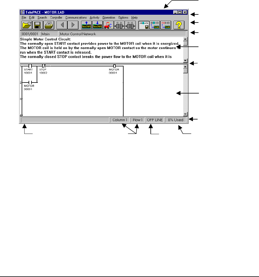
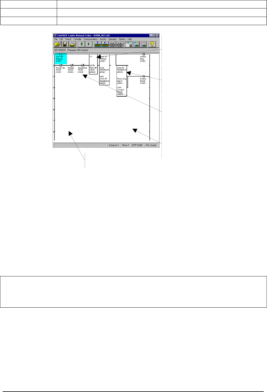
The following figure illustrates the TelePACE Ladder Editor:
St at u s Bar
Tool Bar
Menu Bar
Title Bar
Network Title
Splitter Bar
Command Description Cursor Location Mode Memory Used
Comment Editor
Network Display
Figure 1: TelePACE Ladder Editor Display
2.2.1 Title Bar
The title bar displays the TelePACE program title and the name of the ladder logic file. The file
name area is blank if there is no file in use or the file is new and has not been saved.
2.2.2 Menu Bar
The menu bar displays the programming, editing, monitoring and utility functions available within
the Editor. Menu commands can be displayed by clicking the mouse on the menu item or by
pressing the alt key and the underlined letter of the menu item.
2.3 Tool Bar
The Tool Bar contains buttons for commonly used commands.
TelePACE Ladder Logic Overview
May 8, 2007
5
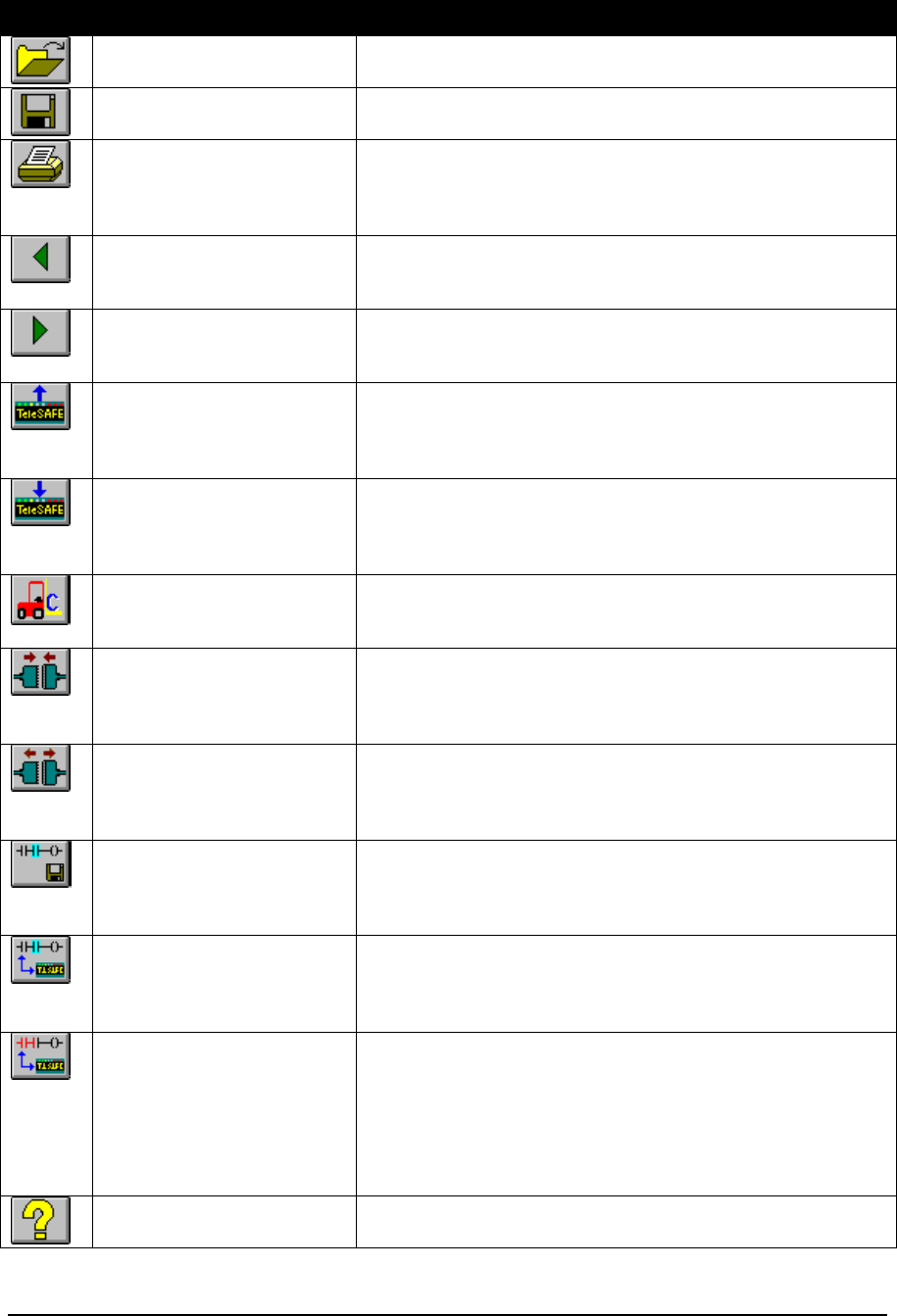
Icon Command Description
Open File Opens an existing ladder program file. This is the same as
the Open command in the File menu.
Save File Saves the currently open ladder program file. This is the
same as the Save command on the File menu.
Print Prints the currently open ladder program file. This is the
same as the Print command on the File menu. The Print
dialog box appears. This option is disabled when the editor
is in Monitor On Line mode.
Previous Network Displays the previous network in the currently open ladder
program. This is the same as selecting Previous from the
Go To Network command in the Search menu.
Next Network Displays the next network in the currently open ladder
program. This is the same as selecting Next from the Go
To Network command in the Search menu.
Read From Controller The ladder logic program, register assignment and serial
port settings in the controller are read into TelePACE
memory. This is the same as the Read From Controller
command on the Communication menu.
Write To Controller The ladder logic program, register assignment and serial
port settings in the TelePACE program are written to the
controller. This is the same as the Write To Controller
command on the Communication menu.
C Program Loader The C Program Loader dialog box appears. This is the
same as the C Program Loader command on the
Controller menu.
Connect to Controller Establishes a connection to a remote unit using a dial up
modem. This button is disabled if the current controller is
not a dial up connection. This is the same as the Connect
To Controller command on the Communication menu.
Disconnect from Controller Ends a connection to a remote unit using a dial up modem.
This button is disabled if the current controller is not a dial
up connection. This is the same as the Disconnect From
Controller command on the Communication menu.
Edit Off Line Places the editor in Off Line editing mode. This mode is
used for creation and editing of a ladder program file. This
is the same as the Edit Off Line command on the Activity
menu.
Edit On Line Places the editor in On Line editing mode. In this mode,
any change to the ladder program is immediately written to
the controller. This is the same as the Edit On Line
command on the Activity menu.
Monitor On Line Places the TelePACE program in Monitor On Line mode.
This mode is used to monitor ladder program execution in
real time. Color is used to indicate power flow within the
displayed network. The contents of a user-defined list of
registers (see Monitor List) are updated in real time. This
is the same as the Monitor On Line command on the
Activity menu.
Help Displays the TelePACE program on-line help file. This is
the same as selecting Contents from the Help menu.
TelePACE Ladder Logic Overview
May 8, 2007
6

2.3.1 Network Title
The network title has three sections. The left section displays the number of the network being
edited and the total number of networks (current/total). Clicking the left mouse button here opens
the Go To Network dialog.
The center section displays Main if the current network is in the main program and Sub x if it’s in a
subroutine.
The right section of the Network Title shows the network title. Clicking here opens the Edit
Network Title pop up dialog box.
2.3.2 Comment Editor
Each network in the ladder program can have approximately three pages of text documentation. The
text in the comment editor can be cut or copied to the Windows clipboard or pasted from the
clipboard.
The comment editor is selected for editing by positioning the mouse pointer anywhere in the
comment editor pane and left clicking the mouse button. A vertical bar indicates the cursor position
within the comment editor pane. The scroll bar to the right of the comment editor pane scrolls the
editor text within the pane.
2.3.3 Splitter Bar
The splitter bar divides the Comment Editor and the Ladder Editor Panes. Positioning the mouse
pointer over the bar and dragging the bar to a new location changes the position of the splitter bar.
2.3.4 Status Bar
The status bar displays command and programming status of the Network Editor. The Status Bar is
divided into five panels.
The leftmost panel describes the Toolbar or Menu command pointed to by the mouse.
The second and third panels show the column and row position of the cursor in the Ladder Editor
pane.
The fourth panel displays the execution mode of the attached controller, or OFFLINE if the Network
Editor is not communicating with a controller.
The last panel displays the percentage of ladder logic memory used in the target controller.
2.3.5 Network Display
The Ladder Editor Pane displays the current network of the open program. This area is used for
creation and editing of the ladder logic. When in Monitor On Line mode, this area also contains the
Monitor list.
2.3.6 Register List
The register list is a display window containing a list of selected I/O database registers and their real
time contents. The I/O database registers to be included in monitor list display window are defined
by selecting Registers from the Edit Menu.
TelePACE Ladder Logic Overview
May 8, 2007
7

2.3.7 Cursor
To position the cursor in the Ladder editor pane move the mouse pointer to any position in the
displayed Ladder network and click the left mouse button. The cursor highlights the element or
function where it is positioned. The cursor can be moved about the network using the arrow keys on
the keyboard.
TelePACE Ladder Logic Overview
May 8, 2007
8
2.4 TelePACE Major Components
The major components of a ladder program are ladder networks, function elements, subroutines, and
comments. Understanding how these components work and how a program is executed is important
to writing an effective program.
NOTE: Program execution order (described below) must be considered when organizing the
ladder logic program.
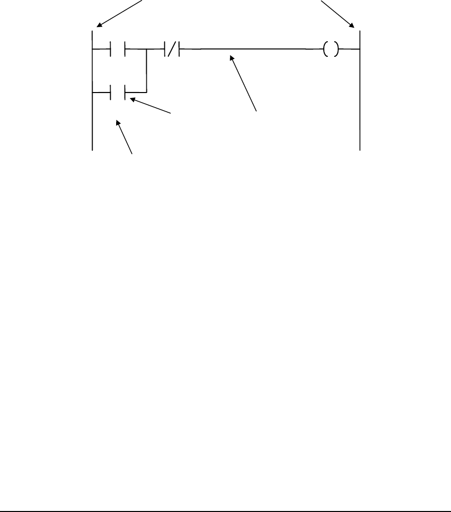
2.4.1 Networks
A network is a diagrammatic representation of control logic similar to a wiring schematic, showing
interconnection of relays, timers, contacts and other control elements.
START
MOTOR
STOP MOTOR
Power Rail Neutral Rail
Ladder Rung
Ladder
Function
Element
Element Tag
Name
Figure 2: A Ladder Network
Networks in the TelePACE Ladder Editor contain up to eight rungs. Each rung can contain a
maximum of 10 logic elements. The highlighted cursor in the Ladder Editor pane occupies one logic
element position.
The number of networks in a program is only limited by the memory available.
2.4.2 Network Elements
Network elements are contacts, coils, and function blocks. Shunts are used to interconnect elements.
Coils are always found connected to the neutral rail and represent either physical outputs in the
controller or internal (memory only) outputs in the I/O database. Contacts represent physical status
inputs from the controller or internal (memory only) status inputs in the I/O database. Function
blocks are used to perform specific functions, such as moving data, manipulating data or
communicating data.
2.4.3 Subroutines
Subroutines permit conditional execution of parts of a Ladder Logic program. Subroutines can be
used to reduce the scan time of a program by only scanning code when it is absolutely needed.
Reduced scan time will increase the frequency of program execution.
Subroutines can also reduce the size of the program by placing frequently used or repeated code into
subroutines that are called from various locations in the main program.
The Ladder Logic program consists of the main program followed by a number of subroutines.
TelePACE Ladder Logic Overview
May 8, 2007
9
The main program is defined as all the logic networks up to the start of the first subroutine, or until
the end of the program if no subroutines exist.
A subroutine is defined as all the logic networks from a subroutine element until the next subroutine
element, or the end of the program if there are no more subroutines.
The program is executed from the start of the main program to the end of the main program. If a
subroutine call function block is encountered, execution transfers to the start of the subroutine and
continues until the end of the subroutine. Execution then returns to the element after the subroutine
call element.
Subroutine execution can be nested. This allows subroutines to call other subroutines.
Subroutine execution cannot be recursive. This prevents potential infinite loops in the ladder logic
program.
Two elements control the definition and execution of subroutines. The SUBR element defines the
start of a subroutine. The CALL element executes a subroutine.
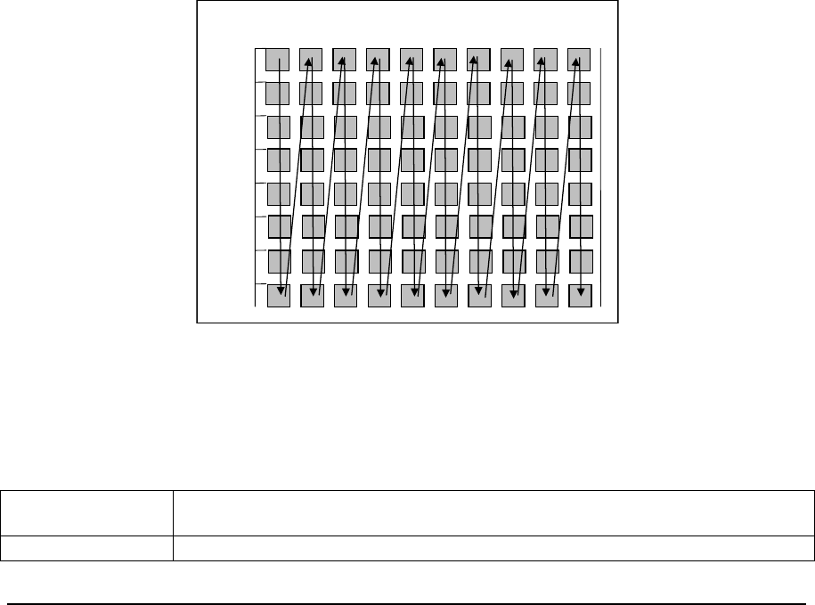
2.4.4 Program Execution Order
The controller evaluates each element, or function block, in the network in a sequence that starts at
the top left hand corner; or ROW 1, COLUMN 1.
The ladder evaluation moves down column 1 until it reaches row 8. The evaluation then continues at
the top of column 2 and moves down to row 8 again.
This process continues until the entire network has been evaluated. If there is more than one
network, evaluation continues to the next sequential network in the program until the entire program
has been evaluated.
Row1
Row2
Row8
Row7
Row6
Row5
Row4
Row3
Col
9
Col
8
Col
7
Col
6
Col
5
Col
4
Col
3
Col
2
Col
1 Col
10
Figure 3: TelePACE Ladder Editor Network Execution
2.4.5 Ladder Logic Memory Usage
Memory usage in a Ladder Logic application program is based on the number of networks and
number of elements used by a program.
Networks Each network in an application requires one word of memory, whether the
network is used or not.
Columns Each column that is occupied in a network requires one word of memory.
TelePACE Ladder Logic Overview
May 8, 2007
10
Single Elements Each single element requires one word of memory.
Double Elements Each double element requires two words of memory.
Triple Elements Each triple element requires three words of memory.
One word of
memory is
required for each
column.
One word of
memory is
required for each
single element.
Two words of
memory are
required for each
double element.
Three words of
memory are
required for each
triple element.
One word of memory is
required for each network.
Figure 4: Ladder Logic Memory Usage
2.5 TelePACE I/O Database Registers
The I/O Database is different on the 16 and 32-bt controllers.
The 16-bit controllers comprise of SCADAPack (Light and Plus), SCADAPack 100, SCADAPack
LP, SCADASense 4202 DR and SCADASense 4202 DS. The SCADAPack 100: 1024K controller
differs from the SCADAPack 100: 256 K controller in that it has the same I/O database as other
SCADAPack controllers. The SCADAPack 100: 1024K controller has firmware version 1.80 or
newer and a controller ID that is greater than or equal to A182922.
The 32-bit controllers comprise SCADAPack 350, SCADAPack 32, SCADASense 4203 DR and
SCADASense 4203 DS.
Note: In this manual, the SCADASense 4202 DR and DS controllers are collectively referred to as
the SCADASense 4202 Series controller. The SCADASense 4203 DR and DS are
collectively referred to as the SCADASense 4203 Series controllers. The 4202 and 4203
controllers are collectively referred to as the SCADASense controllers.
2.5.1 16-bit Controller I/O Database
The 16-bit controllers which comprise of SCADAPack (Light and Plus), SCADAPack 100:1024K,
SCADAPack LP, and SCADASense 4202 Series controllers all have the same IO database. The IO
database in the SCADAPack 100: 256K is different as indicated in section 2.5.3-SCADAPack 100:
256K I/O Database.
The I/O database allows data to be shared between C programs, Ladder Logic programs and
communication protocols. A simplified diagram of the I/O Database is shown in Figure 5:
TelePACE Ladder Logic Overview
May 8, 2007
11
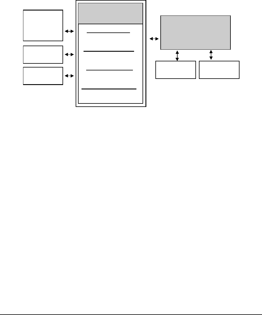
SCADAPack, SCADAPack 100: 1024K, SCADAPack LP, SCADASense 4202 Series I/O
Database Block Diagram.
The I/O database contains general purpose and user-assigned registers. Ladder Logic and C
application programs to store processed information and to receive information from a remote device
may use general-purpose registers. Initially all registers in the I/O Database are general-purpose
registers.
User-assigned registers are mapped directly from the I/O database to physical I/O hardware, or to
controller system configuration and diagnostic parameters. The Register Assignment performs the
mapping of registers from the I/O database to physical I/O hardware and system parameters.
Controller I/O
Database
Coil Registers
00001 to 04096
Holding Registers
40001 to 49999
Input Registers
30001 to 31024
Status Registers
10001 to 14096
TeleBUS
Protocols
C Tools
Programs
Ladder
Logic
Programs Controller
Register
Assignment Table
5000 Series
I/O Modules System
Parameters
Figure 5: SCADAPack, SCADAPack 100: 1024K, SCADAPack LP, SCADASense 4202 Series
I/O Database Block Diagram
User-assigned registers are initialized to the default hardware state or system parameter when the
controller is reset. Assigned output registers do not maintain their values during power failures.
Assigned output registers do retain their values during application program loading.
General-purpose registers retain their values during power failures and application program loading.
The values change only when written by an application program or a communication protocol.
The TeleBUS communication protocols provide a standard communication interface to the
controller. The TeleBUS protocols are compatible with the widely used Modbus RTU and ASCII
protocols. They provide full access to the I/O database in the controller.
2.5.1.1 I/O Database register types
The I/O database is divided into four types of I/O registers. Each of these types is initially
configured as general purpose registers by the controller.
2.5.1.1.1 Coil Registers
Coil registers are single bit registers located in the digital output section of the I/O database. Coil, or
digital output, database registers may be assigned to 5000 Series digital output modules or
SCADAPack I/O modules through the Register Assignment. Coil registers may also be assigned to
controller on board digital outputs and to system configuration modules.
There are 4096 coil registers numbered 00001 to 04096. Ladder logic programs, C language
programs, and the TeleBUS protocols can read from and write to these registers.
TelePACE Ladder Logic Overview
May 8, 2007
12

2.5.1.1.2 Status Registers
Status registers are single bit registers located in the digital input section of the I/O database. Status,
or digital input, database registers may be assigned to 5000 Series digital input modules or
SCADAPack I/O modules through the Register Assignment. Status registers may also be assigned to
controller on board digital inputs and to system diagnostic modules.
There are 4096 status registers numbered 10001 to 14096. Ladder logic programs and the TeleBUS
protocols can only read from these registers. C language programs can read data from and write data
to these registers.
2.5.1.1.3 Input Registers
Input registers are 16 bit registers located in the analog input section of the I/O database. Input
database registers may be assigned to 5000 Series analog input modules or SCADAPack I/O
modules through the Register Assignment. Input registers may also be assigned to controller internal
analog inputs and to system diagnostic modules.
There are 1024 input registers numbered 30001 to 31024. Ladder logic programs and the TeleBUS
protocols can only read from these registers. C language programs can read data from and write data
to these registers.
2.5.1.1.4 Holding Registers
Holding registers are 16 bit registers located in the analog output section of the I/O database.
Holding, or analog output, database registers may be assigned to 5000 Series analog output modules
or SCADAPack analog output modules through the Register Assignment. Holding registers may
also be assigned to system diagnostic and configuration modules.
There are 9999 holding registers numbered 40001 to 49999. Ladder logic programs, C language
programs, and the TeleBUS protocols can read from and write to these registers.
2.5.2 32-bit Controller I/O Database
The 32-bit controllers, which comprise of SCADAPack32, SCADAPack 350, SCADASense 4203
Series (SCADASense 4203 DR and SCADASense 4203 DS) , all have the same IO database.
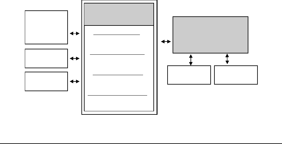
The I/O database allows data to be shared between C programs, Ladder Logic programs and
communication protocols. A simplified diagram of the I/O Database is shown in Figure 6:
SCADASense 4203 Series, SCADAPack 350 and SCADAPack 32 I/O Database Block Diagram.
The I/O database contains general purpose and user-assigned registers. Ladder Logic and C
application programs to store processed information and to receive information from a remote device
may use general-purpose registers. Initially all registers in the I/O Database are general-purpose
registers.
User-assigned registers are mapped directly from the I/O database to physical I/O hardware, or to
controller system configuration and diagnostic parameters. The Register Assignment performs the
mapping of registers from the I/O database to physical I/O hardware and system parameters.
TelePACE Ladder Logic Overview
May 8, 2007
13

Controller I/O
Database
Coil Registers
00001 to 04096
Holding Registers
40001 to 49999
Input Registers
30001 to 39999
Status Registers
10001 to 14096
TeleBUS
Protocols
C Tools
Programs
Ladder
Logic
Programs Controller
Register
Assignment Table
5000 Series
I/O Modules System
Parameters
Figure 6: SCADASense 4203 Series, SCADAPack 350 and SCADAPack 32 I/O Database Block
Diagram
User-assigned registers are initialized to the default hardware state or system parameter when the
controller is reset. Assigned output registers do not maintain their values during power failures.
Assigned output registers do retain their values during application program loading.
General-purpose registers retain their values during power failures and application program loading.
The values change only when written by an application program or a communication protocol.
The TeleBUS communication protocols provide a standard communication interface to the
controller. The TeleBUS protocols are compatible with the widely used Modbus RTU and ASCII
protocols. They provide full access to the I/O database in the controller.
2.5.2.1 I/O Database register types
The I/O database is divided into four types of I/O registers. Each of these types is initially
configured as general purpose registers by the controller.
2.5.2.1.1 Coil Registers
Coil registers are single bit registers located in the digital output section of the I/O database. Coil, or
digital output, database registers may be assigned to 5000 Series digital output modules or
SCADAPack I/O modules through the Register Assignment. Coil registers may also be assigned to
controller on board digital outputs and to system configuration modules.
There are 4096 coil registers numbered 00001 to 04096. Ladder logic programs, C language
programs, and the TeleBUS protocols can read from and write to these registers.
2.5.2.1.2 Status Registers
Status registers are single bit registers located in the digital input section of the I/O database. Status,
or digital input, database registers may be assigned to 5000 Series digital input modules or
SCADAPack I/O modules through the Register Assignment. Status registers may also be assigned to
controller on board digital inputs and to system diagnostic modules.
There are 4096 status registers numbered 10001 to 14096. Ladder logic programs and the TeleBUS
protocols can only read from these registers. C language programs can read data from and write data
to these registers.
TelePACE Ladder Logic Overview
May 8, 2007
14
2.5.2.1.3 Input Registers
Input registers are 16 bit registers located in the analog input section of the I/O database. Input
database registers may be assigned to 5000 Series analog input modules or SCADAPack I/O
modules through the Register Assignment. Input registers may also be assigned to controller internal
analog inputs and to system diagnostic modules.
There are 9999 input registers numbered 30001 to 39999. Ladder logic programs and the TeleBUS
protocols can only read from these registers. C language programs can read data from and write data
to these registers.
2.5.2.1.4 Holding Registers
Holding registers are 16 bit registers located in the analog output section of the I/O database.
Holding, or analog output, database registers may be assigned to 5000 Series analog output modules
or SCADAPack analog output modules through the Register Assignment. Holding registers may
also be assigned to system diagnostic and configuration modules.
There are 9999 holding registers numbered 40001 to 49999. Ladder logic programs, C language
programs, and the TeleBUS protocols can read from and write to these registers.
2.5.3 SCADAPack 100: 256K I/O Database
The SCADAPack 100: 256K controller differs from the SCADAPack 100: 1024K controller in that
it has a limited I/O database. The SCADAPack 100: 256K controller has firmware version older
than 1.80 and a controller ID that is less or equal to A182921.
The SCADAPack 100: 256K I/O database allows data to be shared between C programs, Ladder
Logic programs and communication protocols. A simplified diagram of the I/O Database is shown
in Figure 7: SCADAPack 100 – 256K I/O Database Block Diagram.
The I/O database contains general purpose and user-assigned registers. Ladder Logic and C
application programs to store processed information and to receive information from a remote device
may use general-purpose registers. Initially all registers in the I/O Database are general-purpose
registers.
User-assigned registers are mapped directly from the I/O database to physical I/O hardware, or to
controller system configuration and diagnostic parameters. The Register Assignment performs the
mapping of registers from the I/O database to physical I/O hardware and system parameters.
Controller I/O
Database
Coil Registers
00001 to 04096
Holding Registers
40001 to 44000
Input Registers
30001 to 30512
Status Registers
10001 to 14096
TeleBUS
Protocols
C Tools
Pro
g
rams
Ladder
Logic
Programs Controller
Register
Assignment Table
5000 Series
I/O Modules System
Parameters
Figure 7: SCADAPack 100 – 256K I/O Database Block Diagram
TelePACE Ladder Logic Overview
May 8, 2007
15

User-assigned registers are initialized to the default hardware state or system parameter when the
controller is reset. Assigned output registers do not maintain their values during power failures.
Assigned output registers do retain their values during application program loading.
General-purpose registers retain their values during power failures and application program loading.
The values change only when written by an application program or a communication protocol.
The TeleBUS communication protocols provide a standard communication interface to the
controller. The TeleBUS protocols are compatible with the widely used Modbus RTU and ASCII
protocols. They provide full access to the I/O database in the controller.
2.5.3.1 I/O Database register types
The I/O database is divided into four types of I/O registers. Each of these types is initially
configured as general purpose registers by the controller.
2.5.3.1.1 Coil Registers
Coil registers are single bit registers located in the digital output section of the I/O database. Coil, or
digital output, database registers may be assigned to 5000 Series digital output modules or
SCADAPack I/O modules through the Register Assignment. Coil registers may also be assigned to
controller on board digital outputs and to system configuration modules.
There are 4096 coil registers numbered 00001 to 04096. Ladder logic programs, C language
programs, and the TeleBUS protocols can read from and write to these registers.
2.5.3.1.2 Status Registers
Status registers are single bit registers located in the digital input section of the I/O database. Status,
or digital input, database registers may be assigned to 5000 Series digital input modules or
SCADAPack I/O modules through the Register Assignment. Status registers may also be assigned to
controller on board digital inputs and to system diagnostic modules.
There are 4096 status registers numbered 10001 to 14096. Ladder logic programs and the TeleBUS
protocols can only read from these registers. C language programs can read data from and write data
to these registers.
2.5.3.1.3 Input Registers
Input registers are 16 bit registers located in the analog input section of the I/O database. Input
database registers may be assigned to 5000 Series analog input modules or SCADAPack I/O
modules through the Register Assignment. Input registers may also be assigned to controller internal
analog inputs and to system diagnostic modules.
The I/O database for the SCADAPack 100: 256K controller has 512 input registers numbered 30001
to 30512. Ladder logic programs and the TeleBUS protocols can only read from these registers. C
language programs can read data from and write data to these registers.
2.5.3.1.4 Holding Registers
Holding registers are 16 bit registers located in the analog output section of the I/O database.
Holding, or analog output, database registers may be assigned to 5000 Series analog output modules
or SCADAPack analog output modules through the Register Assignment. Holding registers may
also be assigned to system diagnostic and configuration modules.
The I/O database for the SCADAPack 100: 1924K controller has 4000 holding registers numbered
40001 to 44000. Ladder logic programs, C language programs, and the TeleBUS protocols can read
from and write to these registers.
TelePACE Ladder Logic Overview
May 8, 2007
16

TelePACE Ladder Logic
Program Development
CONTROL
MICROSYSTEMS
SCADA products... for the distance
48 Steacie Drive Telephone: 613-591-1943
Kanata, Ontario Facsimile: 613-591-1022
K2K 2A9 Technical Support: 888-226-6876
Canada 888-2CONTROL

©2007 Control Microsystems Inc.
All rights reserved.
Printed in Canada.
Trademarks
TelePACE, SCADASense, SCADAServer, SCADALog, RealFLO, TeleSAFE,
TeleSAFE Micro16, SCADAPack, SCADAPack Light, SCADAPack Plus,
SCADAPack 32, SCADAPack 32P, SCADAPack 350, SCADAPack LP,
SCADAPack 100, SCADASense 4202 DS, SCADASense 4202 DR,
SCADASense 4203 DS, SCADASense 4203 DR, SCADASense 4102,
SCADASense 4012, SCADASense 4032 and TeleBUS are registered
trademarks of Control Microsystems.
All other product names are copyright and registered trademarks or trade names
of their respective owners.
Material used in the User and Reference manual section titled SCADAServer
OLE Automation Reference is distributed under license from the OPC
Foundation.
TelePACE Ladder Logic Program Development
May 8, 2007
1

Table of Contents
1 TELEPACE PROGRAM DEVELOPMENT .................................................... 3
1.1 Introduction .................................................................................................... 3
1.2 Configuration of the TelePACE Program ....................................................... 3
1.2.1 PC Communication Settings..................................................................... 3
1.2.2 Options ..................................................................................................... 3
1.3 Initializing the Controller................................................................................. 4
1.4 Define Register Assignment........................................................................... 4
1.5 Create Ladder Logic Program........................................................................ 4
1.5.1 Inserting Elements.................................................................................... 4
1.5.2 Inserting Networks.................................................................................... 5
1.5.3 Editing Elements....................................................................................... 5
1.5.4 Deleting Elements..................................................................................... 5
1.5.5 Selecting Elements................................................................................... 5
1.6 Setting Outputs On Stop ................................................................................ 5
1.7 Controller Serial Port Settings........................................................................ 6
1.8 Write program to controller............................................................................. 6
1.9 Monitor Program On Line............................................................................... 6
1.9.1 Contact Monitoring.................................................................................... 6
1.10 Edit Program On Line..................................................................................... 7
1.11 Force Registers.............................................................................................. 7
1.12 Preventing Unauthorized Changes ................................................................ 7
TelePACE Ladder Logic Program Development
May 8, 2007
2

1 TelePACE Program Development
1.1 Introduction
A Ladder Logic program may be developed in any sequence. Best results, particularly for new users,
will be obtained using the following sequence:
1. Configure TelePACE.
2. Create the ladder program.
3. Create the Register Assignment.
4. Select Outputs-On-Stop settings.
5. Define serial port settings.
6. Create Ladder Logic Program.
7. Initialize controller.
8. Write program to the controller.
9. Run and test program.
These steps are described in more detail in the sections that follow.
1.2 Configuration of the TelePACE Program
The configuration of the TelePACE program involves setting the serial port parameters for the target
controller and selecting options to customize the Ladder Editor environment.
1.2.1 PC Communication Settings
Configure TelePACE communications to satisfy the requirements of the communication media
between the TelePACE program and the target controller. Refer to the PC Communication
Settings in the TelePACE Program Reference.
For SCADAPack, SCADAPack Light and SCADAPack Plus controllers, com3 is supported only
when the SCADAPack 5601 or 5604 I/O module is installed. Com4 is supported only when the
SCADAPack 5602 I/O module is installed. To optimize performance, minimize the length of
messages on com3 and com4. Examples of recommended uses for com3 and com4 are for local
operator terminals, and for programming and diagnostics using the TelePACE program.
1.2.2 Options
Set the Ladder Editor environment options to suit the display resolution and color capability of your
computer. From the Options menu select Screen Font to change the Editor screen font and Colors
to change the Ladder Logic display color.
The format of floating point numbers may be changed using the Floating-Point Settings option.
The Tool Bar, Title Bar and the Status Bar may be removed from the Editor Display by selecting
or de-selecting the option in the Option menu.
Select tag names display options to meet your personal preference. The selections are Single Tag
Names, Double Tag Names, Tag and Address and Numeric Address.
In most cases it is recommended that the Allow Multiple Coils and Warning Messages be selected.
TelePACE Ladder Logic Program Development
May 8, 2007
3

1.3 Initializing the Controller
The controller should be initialized before a new program is loaded into the controller. The
Initialize Controller dialog appears when Initialize is selected in the Controller menu. Ladder
Logic programs C programs and the Register Assignment may be erased from this dialog.
WARNING: If the controller is initialized, using the Initialize command in the Controller menu,
all I/O database registers used for Element Configuration are set to zero. The
application program must be re-loaded to the controller. Element Configuration
may be used for the following functions:
• DIAL – Control Dial-Up Modem;
• INIM – Initialize Dial-Up Modem;
• MSTR – Master Message;
• SLP – Put Controller into Sleep Mode;
• HART – Protocol Driver;
• DLOG – Data Logger;
• FLOW – Flow Accumulation;
• TOTL – Flow Totalizer;
• PIDA – PID controller for analog output; and
• PIDD – PID controller for digital output.
Refer to the Ladder Logic Function Reference for a description of these functions.
1.4 Define Register Assignment
All I/O hardware that is used by the controller must be assigned to I/O database registers in order for
the I/O points to be used by the ladder program. Ladder logic programs may read data from, or write
data to, the I/O hardware through user-assigned registers in the I/O database.
The Register Assignment assigns I/O database registers to user-assigned registers using I/O modules.
An I/O Module can refer to an actual I/O hardware module (e.g. 5401 Digital Input Module) or it
may refer to a set of controller parameters, such as serial port settings.
The Register Assignment Reference section describes the purpose of each module and the register
assignment requirements for the module.
Register assignments are stored in the user configured Register Assignment and are downloaded with
the ladder logic application program.
1.5 Create Ladder Logic Program
1.5.1 Inserting Elements
To insert an element in the Ladder network, position the cursor at the network position where the
element is to be inserted. Double click the left mouse button. The Insert/Edit Network Element
dialog box pops up and an element or function can be selected to insert.
The Insert/Edit Network Element dialog box only displays the elements and functions that will fit
from the cursor position.
Elements can be inserted using the right mouse button and selecting Edit Element from the drop
down menu.
Elements can be inserted from the keyboard by positioning the cursor at the desired network position
and pressing the Insert key.
TelePACE Ladder Logic Program Development
May 8, 2007
4

1.5.2 Inserting Networks
To insert another network, select Insert from the Edit menu. The Insert dialog pops up. Selections
are made in this dialog by moving the mouse pointer to the required radio button and clicking the left
mouse button. Networks may be inserted before or after the current network.
1.5.3 Editing Elements
To edit an element in the Ladder network, position the cursor on the element to be edited. Double
click the left mouse button. The Insert/Edit Network Element dialog box pops up and the element
can be edited.
Elements can be edited using the right mouse button and selecting Edit Element from the drop down
menu.
Elements can be edited from the keyboard by positioning the cursor at the desired element the
pressing the Insert key.
1.5.4 Deleting Elements
To remove an element from a network, press the Delete key, or select Delete from the Edit menu.
The element at the cursor position or selected elements, columns, rows or networks can be selected
for deleting.
Selected elements can be deleted using the right mouse button and selecting Delete from the drop
down menu.
1.5.5 Selecting Elements
To select multiple elements position the cursor on the first element or function of the selection and
press the left mouse button. Hold the button down and drag the pointer to the last element or
function. The elements selected will be highlighted in the same way as the cursor. Releasing the
mouse button does not change the highlighting.
Individual disconnected elements may also be selected and copied to the clipboard. To select
disconnected elements position the cursor on the first element. Hold the keyboard shift key down.
Using the left mouse button, click on elements to be copied to the clipboard.
To select elements or functions with the keyboard move the cursor to the first element or function.
Hold the shift key down while using the directional arrow keys to move the cursor to the last element
or function. The selected elements are highlighted.
1.6 Setting Outputs On Stop
Select Outputs on Stop from the Controller menu and the Output Conditions on Program Stop
dialog appears. This dialog controls the state of the controller analog and digital outputs when the
ladder logic program is stopped.
The state of the digital outputs may be set to hold their last value or to turn off when the ladder
program is stopped.
The state of the analog outputs may be set to hold their last value or to go to Zero when the ladder
program is stopped.
TelePACE Ladder Logic Program Development
May 8, 2007
5

1.7 Controller Serial Port Settings
Select the Serial Ports command from the Controller menu to configure the controller serial ports.
The Controller Serial Ports Settings dialog box pops up when the Serial Ports command is
selected.
For SCADAPack, SCADAPack Light, and SCADAPack Plus controllers, Com3 is supported only
when the SCADAPack 5601 or 5604 I/O module is installed. Com4 is supported only when the
SCADAPack 5602 I/O module is installed. To optimize performance, minimize the length of
messages on com3 and com4. Examples of recommended uses for com3 and com4 are for local
operator terminals, and for programming and diagnostics using the TelePACE program.
1.8 Write program to controller
The Write to Controller command in the Communications menu writes the Ladder Logic program
to the controller. The program replaces the program in the controller.
If the program in the controller is executing a dialog box will request whether to stop execution of
the new program when the write is complete or to continue execution of the new program after the
write is complete.
WARNING: Exercise caution when selecting the Continue option. The program will execute
with the changes you make, even if the changes are not complete. This may cause
undesired operation. Select Stop if you are making multiple changes.
1.9 Monitor Program On Line
The Monitor On Line selection in the Activity menu enables the real time monitoring of a program
executing in a controller. The editor shows the power flow through the network on the screen. No
changes can be made to the program in monitor mode. The Register Editor window is displayed
when Monitor On Line is selected.
1.9.1 Contact Monitoring
It is often necessary, while in Monitor On line mode, to determine whether a contact would pass
power if power were supplied to it. This feature is extremely useful when testing the operation of
ladder logic programs.
In Monitor On line mode, TelePACE shows the power flow through the network. It also colors
contacts that are not powered to show how power would flow if they were.
TelePACE Ladder Logic Program Development
May 8, 2007
6

The following diagram illustrates how power flow information is displayed in Monitor On line
mode:
10001 10002 00003
In the above example, normally open contact 10001 and normally closed contact 10002, are not
energized. The shaded background, in contact 10002, indicates power would flow through the
contact if the input side were powered.
• The background of a normally open contact is colored when it is energized and its input
is not powered.
• The background of a normally closed contact is colored when it is not energized and its
input is not powered.
The background is only displayed on contacts if the input side of the contact is not powered.
The color used for contact monitoring can be changed using the Colors command.
1.10 Edit Program On Line
The Edit On Line selection in the Activity menu is used to edit a ladder logic program that is
executing in the controller. All editing commands affect the program in the controller and the
program in the TelePACE Ladder Network Editor.
1.11 Force Registers
The Register Editor dialog allows the user to modify registers in the memory of the controller. This
dialog is only available in the on-line mode. Data modified by the dialog is stored only in the
memory of the controller. It does not form part of the ladder logic program. Refer to the Program
Reference section for detailed information on the Register Editor.
1.12 Preventing Unauthorized Changes
A TeleSAFE Micro16 or SCADAPack controller can be locked to prevent unauthorized changes. A
password is required to unlock the controller to make changes.
The controller will reject commands sent to the unit when it is locked. A controller that is unlocked
operates without restriction. Three levels of locks are provided.
• Locking the programming commands prevents modifying or viewing the program in the
controller. Communication protocols can read and write the I/O database.
• Locking programming and database write a command prevent modifying or viewing the
program; and prevents writing to the I/O database. Communication protocols can read
data from the I/O database, but cannot modify any data.
• Locking programming and database commands prevents modifying or viewing the
program and prevents reading and writing the I/O database. Communication protocols
cannot read or write the I/O database.
Refer to the sections Lock Controller, Unlock Controller, Override Controller Lock and Show Lock
Status for details on using this feature.
TelePACE Ladder Logic Program Development
May 8, 2007
7

TelePACE Ladder Logic
Program Reference
CONTRO
L
MICROSYSTEMS
SCADA products... for the distance
48 Steacie Drive Telephone: 613-591-1943
Kanata, Ontario Facsimile: 613-591-1022
K2K 2A9 Technical Support: 888-226-6876
Canada 888-2CONTROL

©2007 Control Microsystems Inc.
All rights reserved.
Printed in Canada.
Trademarks
TelePACE, SCADASense, SCADAServer, SCADALog, RealFLO, TeleSAFE,
TeleSAFE Micro16, SCADAPack, SCADAPack Light, SCADAPack Plus,
SCADAPack 32, SCADAPack 32P, SCADAPack 350, SCADAPack LP,
SCADAPack 100, SCADASense 4202 DS, SCADASense 4202 DR,
SCADASense 4203 DS, SCADASense 4203 DR, SCADASense 4102,
SCADASense 4012, SCADASense 4032 and TeleBUS are registered
trademarks of Control Microsystems.
All other product names are copyright and registered trademarks or trade names
of their respective owners.
Material used in the User and Reference manual section titled SCADAServer
OLE Automation Reference is distributed under license from the OPC
Foundation.
TelePACE Ladder Logic User and Reference Manual
May 9, 2007
1

Table of Contents
1 INTRODUCTION.......................................................................................... 11
2 FILE MENU.................................................................................................. 12
2.1 New.............................................................................................................. 12
2.2 Open ............................................................................................................ 12
2.3 Save............................................................................................................. 12
2.4 Save As........................................................................................................ 12
2.5 Page Setup .................................................................................................. 12
2.6 Print.............................................................................................................. 13
2.7 Select Print Items......................................................................................... 13
2.8 Quick File List............................................................................................... 14
2.9 Exit............................................................................................................... 14
3 EDIT MENU ................................................................................................. 15
3.1 Undo ............................................................................................................ 15
3.2 Cut Selected................................................................................................. 15
3.3 Copy Selected.............................................................................................. 15
3.4 Copy Networks............................................................................................. 15
3.5 Cut Networks................................................................................................ 15
3.6 Paste............................................................................................................ 15
3.7 Insert............................................................................................................ 16
3.7.1 Insert Vertical Shunt ............................................................................... 16
3.7.2 Insert Element......................................................................................... 16
3.7.3 Address Types........................................................................................ 18
3.7.4 Empty Column ........................................................................................ 18
3.7.5 Empty Row ............................................................................................. 18
3.7.6 Network Before....................................................................................... 18
3.7.7 Network After.......................................................................................... 18
3.8 Delete........................................................................................................... 18
3.8.1 Vertical Shunt ......................................................................................... 19
3.8.2 Element .................................................................................................. 19
3.8.3 Selected Elements.................................................................................. 19
3.8.4 Empty Column ........................................................................................ 19
TelePACE Ladder Logic User and Reference Manual
May 9, 2007
2

3.8.5 Empty Row ............................................................................................. 19
3.8.6 Network .................................................................................................. 19
3.8.7 Delete All Networks ................................................................................ 19
3.9 Toggle Vertical Shunt................................................................................... 20
3.10 Tag Names .................................................................................................. 20
3.11 Erase All Tags.............................................................................................. 21
3.12 Export Tag Names ....................................................................................... 21
3.13 Import Tag Names ....................................................................................... 21
3.14 Network Title ................................................................................................ 22
3.15 Element Configuration.................................................................................. 22
3.16 Registers...................................................................................................... 22
3.16.1 Register Editor........................................................................................ 23
3.16.1.1........................................................................................................................ Groups 23
3.16.1.2...............................................................................................................Update Rate 24
3.16.1.3............................................................................................................... Register List 24
3.16.2 Add Registers Dialog .............................................................................. 25
3.16.2.1........................................................................................................Registers In Use 27
3.16.2.2..........................................................................................................................Range 27
3.16.2.3.............................................................................................................................Tags 27
3.16.3 Edit Register Dialog................................................................................ 28
3.16.4 Register Data File................................................................................... 30
3.16.4.1........................................................................................Register Data File Format 30
3.16.5 Editing the Register Data File ................................................................. 31
4 SEARCH MENU .......................................................................................... 33
4.1 Next Network................................................................................................ 33
4.2 Previous Network......................................................................................... 33
4.3 Go To Network............................................................................................. 33
4.4 Find Address................................................................................................ 33
4.5 Find Device .................................................................................................. 34
4.6 Find Tag Name ............................................................................................ 34
4.7 Repeat Last Find.......................................................................................... 35
4.8 Replace Address.......................................................................................... 35
4.9 Multiple Coils................................................................................................ 36
TelePACE Ladder Logic User and Reference Manual
May 9, 2007
3

5 CONTROLLER MENU................................................................................. 37
5.1 Type............................................................................................................. 37
5.2 Serial Ports .................................................................................................. 37
5.3 IP Configuration ........................................................................................... 49
5.3.1 LAN Port ................................................................................................. 50
5.3.2 com1 Port ............................................................................................... 51
5.3.3 com2 Port ............................................................................................... 53
5.3.4 com3 Port ............................................................................................... 53
5.3.5 com4 Port ............................................................................................... 53
5.3.6 PPP Login............................................................................................... 53
5.3.6.1........................................................................................Add PPP Username dialog 54
5.3.6.2........................................................................................ Edit PPP Username dialog 55
5.3.7 Modbus Common ................................................................................... 55
5.3.8 Modbus/TCP........................................................................................... 57
5.3.9 Modbus RTU in UDP .............................................................................. 58
5.3.10 Modbus ASCII in UDP ............................................................................ 58
5.3.11 DNP in TCP ............................................................................................ 59
5.3.12 DNP in UDP............................................................................................ 61
5.3.13 Friendly IP List........................................................................................ 61
5.3.13.1................................................................. Add Friendly IP Address Range Dialog 63
5.4 Register Assignment.................................................................................... 63
5.4.1 Edit Register Assignment Dialog ............................................................ 66
5.5 Outputs On Stop .......................................................................................... 67
5.6 Store and Forward ....................................................................................... 68
5.6.1 Add/Edit Store and Forward Dialog ........................................................ 70
5.7 DNP ............................................................................................................. 71
5.8 DNP Status .................................................................................................. 71
5.9 DNP Master Status ...................................................................................... 71
5.10 Initialize ........................................................................................................ 71
5.10.1 SCADAPack and SCADAPack 32 Controllers........................................ 72
5.10.2 SCADAPack 350 and SCADASense 4203 Series of Controllers............ 73
5.10.2.1..................................................Actions Performed when Controller is Initialized 74
5.11 Real Time Clock........................................................................................... 75
5.12 Monitor Element........................................................................................... 76
5.13 List Force Registers ..................................................................................... 77
5.14 Remove All Forces....................................................................................... 78
TelePACE Ladder Logic User and Reference Manual
May 9, 2007
4

5.15 Lock Controller............................................................................................. 78
5.16 Unlock Controller.......................................................................................... 79
5.17 Override Controller Lock .............................................................................. 79
5.18 Show Lock Status ........................................................................................ 80
5.19 C/C++ Program Loader................................................................................ 80
5.19.1 SCADAPack and SCADAPack 32 Controllers........................................ 80
5.19.1.1.....................................................................................Add C/C++ Program Dialog 81
5.19.2 SCADAPack 350 and SCADASense 4203 Series Controllers................ 82
5.20 Flash Loader ................................................................................................ 83
5.20.1 Writing Programs to Flash ...................................................................... 84
5.21 Program Status ............................................................................................ 85
5.21.1 SCADAPack and SCADAPack 32 Controllers........................................ 86
5.21.2 SCADAPack 350 and SCADASense 4203 Series of Controllers............ 87
6 COMMUNICATIONS MENU........................................................................ 89
6.1 Read from Controller.................................................................................... 89
6.2 Write to Controller ........................................................................................ 89
6.3 PC Communications Settings....................................................................... 89
6.3.1 ClearSCADA........................................................................................... 90
6.3.1.1................................................................................................... General Parameters 90
6.3.1.2................................................................................................Advanced Parameters 91
6.3.1.3................................................................................................................... Information 92
6.3.1.3.1................................................................................................................... Information 93
6.3.2 DNP ........................................................................................................ 93
6.3.2.1................................................................................................... General Parameters 93
6.3.2.2........................................................................................... Flow Control Parameters 95
6.3.2.2.1................................................................................................ RTS/CTS Flow Control 96
6.3.2.3.....................................................................................................Dial Up Parameters 97
6.3.2.4................................................................................................Advanced Parameters 98
6.3.2.5................................................................................................................... Information 99
6.3.3 DNP/TCP.............................................................................................. 100
6.3.3.1...............................................................................................................General Page 101
6.3.3.1.1.......................................................................................................IP Address / Name 102
6.3.3.2........................................................................................................... Advanced Page 102
6.3.3.3.........................................................................................................Information Page 103
6.3.4 DNP/UDP.............................................................................................. 104
6.3.4.1...............................................................................................................General Page 105
6.3.4.1.1.......................................................................................................IP Address / Name 106
6.3.4.2........................................................................................................... Advanced Page 106
6.3.4.3.........................................................................................................Information Page 107
TelePACE Ladder Logic User and Reference Manual
May 9, 2007
5

6.3.5 Modbus ASCII....................................................................................... 108
6.3.5.1................................................................................................... General Parameters 108
6.3.5.2...........................................................Modbus ASCII Configuration (Flow Control) 110
6.3.5.3....................................................................Modbus ASCII Configuration (Dial Up) 112
6.3.5.4................................................................................................Advanced Parameters 113
6.3.5.5................................................................................................................... Information 114
6.3.6 Modbus ASCII in TCP........................................................................... 115
6.3.6.1................................................................................................... General Parameters 116
6.3.6.2................................................................................................Advanced Parameters 118
6.3.6.3................................................................................................................... Information 119
6.3.7 Modbus ASCII in UDP .......................................................................... 119
6.3.7.1................................................................................................... General Parameters 120
6.3.7.2................................................................................................Advanced Parameters 121
6.3.7.3................................................................................................................... Information 122
6.3.8 Modbus RTU......................................................................................... 123
6.3.8.1...................................................................................................................Introduction 123
6.3.8.2................................................................................................... General Parameters 123
6.3.8.3.............................................................Modbus RTU Configuration (Flow Control) 125
6.3.8.4...................................................................... Modbus RTU Configuration (Dial Up) 127
6.3.8.5................................................................................................Advanced Parameters 129
6.3.8.6................................................................................................................... Information 130
6.3.9 Modbus RTU in TCP............................................................................. 130
6.3.9.1................................................................................................... General Parameters 131
6.3.9.2................................................................................................Advanced Parameters 133
6.3.9.3................................................................................................................... Information 134
6.3.10 Modbus RTU in UDP ............................................................................ 134
6.3.10.1................................................................................................. General Parameters 135
6.3.10.2..............................................................................................Advanced Parameters 136
6.3.10.3................................................................................................................. Information 137
6.3.11 Modbus/TCP......................................................................................... 138
6.3.11.1................................................................................................. General Parameters 139
6.3.11.2..............................................................................................Advanced Parameters 140
6.3.11.3................................................................................................................. Information 141
6.3.12 Modbus/UDP ........................................................................................ 142
6.3.12.1................................................................................................. General Parameters 142
6.3.12.2..............................................................................................Advanced Parameters 143
6.3.12.3................................................................................................................. Information 145
6.3.13 Modbus/USB......................................................................................... 145
6.3.13.1.............................................................................................................General Page 146
6.3.13.2.......................................................................................................Information Page 147
6.3.14 SCADAServer....................................................................................... 148
6.3.14.1................................................................................................. General Parameters 149
6.3.14.2..............................................................................................Advanced Parameters 150
6.3.14.3................................................................................................................. Information 151
TelePACE Ladder Logic User and Reference Manual
May 9, 2007
6

7 ACTIVITY MENU ....................................................................................... 152
7.1 Edit Off Line ............................................................................................... 152
7.2 Edit On Line ............................................................................................... 152
7.3 Monitor On Line.......................................................................................... 152
8 OPERATION MENU .................................................................................. 153
8.1 Stop............................................................................................................ 153
8.2 Debug ........................................................................................................ 153
8.3 Run ............................................................................................................ 153
9 OPTIONS MENU ....................................................................................... 154
9.1 Screen Font ............................................................................................... 154
9.2 Colors......................................................................................................... 154
9.3 Floating-Point Settings............................................................................... 154
9.4 Tool Bar ..................................................................................................... 154
9.5 Title Bar...................................................................................................... 155
9.6 Status Bar .................................................................................................. 155
9.7 Single Tag Names...................................................................................... 155
9.8 Double Tag Names .................................................................................... 155
9.9 Tag and Address........................................................................................ 155
9.10 Numeric Address........................................................................................ 155
9.11 Allow Multiple Coils .................................................................................... 155
9.12 Warning Messages .................................................................................... 156
10 HELP MENU.............................................................................................. 157
10.1 Contents..................................................................................................... 157
10.2 About Program........................................................................................... 157
Index of Figures
Figure 1: Select Print Items Dialog Box ..............................................................................13
Figure 2: Insert Dialog Box .................................................................................................16
Figure 3: Insert / Edit Network Element Dialog Box............................................................17
Figure 4: Delete Dialog Box................................................................................................19
Figure 5: Edit Tag Names Dialog Box.................................................................................20
Figure 6: Erase All Tags Dialog Box...................................................................................21
TelePACE Ladder Logic User and Reference Manual
May 9, 2007
7

Figure 7: Register Editor Dialog Box...................................................................................23
Figure 8: New Group Dialog Box ........................................................................................24
Figure 9: Rename Group Dialog Box..................................................................................24
Figure 10: Add Registers – List Dialog Box ........................................................................26
Figure 11: Edit Register Dialog Box....................................................................................28
Figure 12: Edit Register Dialog Box- Value Off...................................................................29
Figure 13: Go To Network Dialog Box ................................................................................33
Figure 14: Find Network Address Dialog Box.....................................................................33
Figure 15: Find Network Element Dialog Box.....................................................................34
Figure 16: Find Tag Name Dialog Box................................................................................35
Figure 17: Replace Address Dialog Box.............................................................................35
Figure 18: Controller Serial Ports Settings Dialog Box .......................................................38
Figure 19: Controller IP Configuration – LAN Port Dialog Box ...........................................51
Figure 20: Controller IP Configuration – com1 Port Dialog Box..........................................52
Figure 21: Controller IP Configuration – PPP Login Dialog Box.........................................54
Figure 22: Add PPP User Name Dialog Box.......................................................................54
Figure 23: Edit PPP User Name Dialog Box.......................................................................55
Figure 24: Controller IP Configuration - Modbus Common Dialog Box ..............................56
Figure 25: Controller IP Configuration - Modbus/TCP Dialog Box......................................57
Figure 26: Controller IP Configuration Modbus RTU in UDP Dialog Box ...........................58
Figure 27: Controller IP Configuration – Modbus ASCII in UDP Dialog Box ......................59
Figure 28: Controller IP Configuration – DNP in TCP Dialog Box ......................................60
Figure 29: Controller IP Configuration – DNP in UDP Dialog Box......................................61
Figure 30: Controller IP Configuration – Friendly IP List Dialog Box ..................................62
Figure 31: Add Friendly IP Address Range Dialog Box......................................................63
Figure 32: Register Assignment Dialog Box .......................................................................63
Figure 33: Cancel Register Assignment Dialog Box...........................................................64
Figure 34: Select Register Assignment Option Dialog Box.................................................65
Figure 35: Register Assignment Dialog Box .......................................................................66
Figure 36: Edit Register Assignment Dialog Box................................................................66
Figure 37: Output Conditions on Program Stop Dialog Box ...............................................68
Figure 38: Store and Forward Command Reference..........................................................68
Figure 39: Store and Forward Dialog Box...........................................................................69
Figure 40: Add/Edit Store and Forward Dialog Box............................................................70
Figure 41: Initialize Controller Dialog Box SCADAPack and SCADAPack 32 Controllers..72
Figure 42: Initialize Controller Dialog Box...........................................................................73
Figure 43: Initialize Dialog for SCADAPack 350 and SCADASense 4203 Series Controllers
......................................................................................................................................73
Figure 44: Real Time Clock Setting Dialog Box..................................................................75
Figure 45: Monitor Element Dialog Box ..............................................................................76
Figure 46: New Group Dialog Box ......................................................................................76
Figure 47: Forced Registers Dialog Box.............................................................................77
Figure 48: Remove All Forces Dialog Box..........................................................................77
Figure 49: Remove All Forces Dialog Box..........................................................................78
TelePACE Ladder Logic User and Reference Manual
May 9, 2007
8

Figure 50: Lock Controller Dialog Box ................................................................................78
Figure 51: Unlock Controller Dialog Box.............................................................................79
Figure 52: Override Controller Lock....................................................................................80
Figure 53: C/C++ Program Loader dialog for SCADAPack Series.....................................81
Figure 54: Write C/C++ Program dialog..............................................................................81
Figure 55: C/C++ Program Loader dialog...........................................................................82
Figure 56: Flash Loader Dialog Box ...................................................................................83
Figure 57: Flash Loader Dialog Box ...................................................................................84
Figure 58: Flash Loader Dialog Box ...................................................................................84
Figure 59: Flash Loader Dialog Box ...................................................................................85
Figure 60: Program Status Dialog Box SCADAPack and SCADAPack 32 Controllers ......86
Figure 61: Program Status Dialog for SCADAPack 350 and SCADASense 4203 Series
Controllers.....................................................................................................................87
Figure 62: Communication Protocols Configuration dialog..................................................90
Figure 63: ClearSCADA Configuration (General) Dialog Box.............................................91
Figure 64: ClearSCADA Configuration (Advanced) Dialog Box..........................................92
Figure 65: ClearSCADA Configuration (Information) Dialog Box........................................93
Figure 66: DNP Configuration (General) Dialog Box ..........................................................94
Figure 67: DNP Configuration (Flow Control) Dialog Box...................................................96
Figure 68: DNP Configuration (Dial Up) Dialog Box ...........................................................97
Figure 69: DNP Configuration (Advanced) Dialog Box.......................................................99
Figure 70: DNP Configuration (Information) Dialog Box...................................................100
Figure 71: DNP in TCP Configuration (General) Dialog Box ............................................101
Figure 72: DNP n TCP Configuration (Advanced) Dialog Box..........................................103
Figure 73: DNP in TCP Configuration (Information) Dialog Box.......................................104
Figure 74: DNP in UDP Configuration (General) Dialog Box............................................105
Figure 75: DNP in UDP Configuration (Advanced) Dialog Box.........................................106
Figure 76: DNP in UDP Configuration (Information) Dialog Box.......................................107
Figure 77: Modbus ASCII Configuration (General) Dialog Box.........................................109
Figure 78: Modbus ASCII Configuration (Flow Control)....................................................111
Figure 79: Modbus ASCII Configuration (Dial Up)............................................................112
Figure 80: Modbus ASCII Configuration (Advanced) Dialog Box .....................................114
Figure 81: Modbus ASCII Configuration (Information) Dialog Box ...................................115
Figure 82: Modbus ASCII in TCP Configuration (General) Dialog Box.............................116
Figure 83: Modbus ASCII in TCP Configuration (Advanced) Dialog Box .........................118
Figure 84: Modbus ASCII in TCP Configuration (Information) Dialog Box .......................119
Figure 85: Modbus ASCII in UDP Configuration (General) Dialog Box ............................120
Figure 86: Modbus ASCII in UDP Configuration (Advanced) Dialog Box .........................121
Figure 87: Modbus ASCII in UDP Configuration (Information) Dialog Box .......................122
Figure 88: Modbus RTU Configuration (General) Dialog Box...........................................124
Figure 89: Modbus RTU Configuration (Flow Control)......................................................126
Figure 90: Modbus RTU Configuration (Dial Up)..............................................................127
Figure 91: Modbus RTU Configuration (Advanced) Dialog Box .......................................129
Figure 92: Modbus RTU Configuration (Information) Dialog Box .....................................130
TelePACE Ladder Logic User and Reference Manual
May 9, 2007
9

Figure 93: Modbus RTU in TCP Configuration (General) Dialog Box...............................131
Figure 94: Modbus RTU in TCP Configuration (Advanced) Dialog Box ...........................133
Figure 95: Modbus RTU in TCP Configuration (Information) Dialog Box .........................134
Figure 96: Modbus RTU in UDP Configuration (General) Dialog Box ..............................135
Figure 97: Modbus RTU in UDP Configuration (Advanced) Dialog Box ...........................136
Figure 98: Modbus RTU in UDP Configuration (Information) Dialog Box .........................137
Figure 99: Modbus/TCP Configuration (General) Dialog Box...........................................139
Figure 100: Modbus/TCP Configuration (Advanced) Dialog Box......................................140
Figure 101: Modbus/TCP Configuration (Information) Dialog Box....................................141
Figure 102: Modbus/UDP Configuration (General) Dialog Box ........................................142
Figure 103: Modbus/UDP Configuration (Advanced) Dialog Box .....................................144
Figure 104: Modbus/UDP Configuration (Information) Dialog Box ...................................145
Figure 105: Modbus/USB Configuration (General) Dialog Box.........................................146
Figure 106: Multiple Controller USB Error Dialog .............................................................147
Figure 107: Selecting a USB controller from list ...............................................................147
Figure 108: Modbus/USB Configuration (Information) Dialog Box ...................................148
Figure 109: SCADAServer Configuration (General) Dialog Box.......................................149
Figure 110: SCADAServer Configuration (Advanced) Dialog Box....................................150
Figure 111: SCADAServer Configuration (Information) Dialog Box..................................151
Index of Tables
Table 1: Address Types......................................................................................................18
Table 2: Register Formats ..................................................................................................25
Table 3: Register Display Properties ..................................................................................26
Table 4: Register Formats ..................................................................................................29
Table 5: Insert Table Caption Here......................................................................................31
Table 6: Controller Port Settings.........................................................................................39
Table 7: Valid Protocols......................................................................................................40
Table 8: Valid Addressing Modes .......................................................................................40
Table 9: Valid Addresses....................................................................................................40
Table 10: Duplex Settings...................................................................................................41
Table 11: Baud Rates .........................................................................................................42
Table 12: Parity Settings.....................................................................................................43
Table 13: RX Flow Settings ................................................................................................45
Table 14: TX Flow Settings.................................................................................................46
Table 15: Com Port Type Settings I....................................................................................48
Table 16: Com Port Type Settings II.....................................Error! Bookmark not defined.
Table 17: Com Port Type Settings III....................................Error! Bookmark not defined.
Table 18: Com Port Type Settings IV ...................................Error! Bookmark not defined.
Table 19: Enron Modbus Settings.......................................................................................49
Table 20: Enron Modbus Station Settings ..........................................................................49
Table 21: Program Status Settings.....................................................................................87
TelePACE Ladder Logic User and Reference Manual
May 9, 2007
10

1 Introduction
The TelePACE program is a powerful programming and monitoring tool that enables the user to
create, edit, document and save Ladder Logic programs for the controller. TelePACE also loads and
runs C programs in the controller. Ladder Logic programs can be written to a controller or read from
a controller using the TelePACE Ladder Logic Editor. The on-line monitoring and editing features
enable efficient debugging of program and control problems.
The TelePACE program can be used locally – connected directly to the controller – or remotely –
connected to the controller through a communication network or dial up modem. TelePACE supports
connections to remote controllers using SCADAServer and Modbus\IP. All features of TelePACE
are available locally and remotely.
This section of the manual describes each of the TelePACE program commands available from the
TelePACE menu bar. The user is encouraged to read through the following sections to gain an
understanding of the many programming and monitoring features available.
The menu bar selections and the functions available for each selection are described in the following
sections.
TelePACE Ladder Logic User and Reference Manual
May 9, 2007
11

2 File Menu
The File menu contains commands to create, open and save Ladder Logic files; utility commands to
import and export tag names; and commands to configure printer options and print Ladder Logic
programs.
2.1 New
The New command starts a new TelePACE Ladder Logic program. The comment editor window and
the ladder editor window are cleared and the network display shows network one of one. The
TelePACE Ladder Network Editor retains all information from the previous editor settings with the
exception that the I/O Assignments are defaulted to inputs for all channels.
If the current file has not been saved, the editor warns you to save the current file. You may save the
changes, discard the changes or cancel the New command.
2.2 Open
The Open command loads a ladder logic program from disk into the editor. The file replaces the
existing file in the editor. If the current file has not been saved, the editor warns you to save the
current file. You may save the changes, discard the changes or cancel the Open command.
The Open command will cause the Open File dialog box to appear. This dialog box is used to select
the file to Open. Ladder logic files normally end with the file extension LAD. The dialog box
displays these files by default. Press Ctrl-O to execute the Open command.
2.3 Save
The Save command stores the current file on disk. If the current file has not yet been named, the
Save As File dialog box will appear. The file name and working directory can be selected from this
dialog box. The title bar at the top of the editor window shows the current file name. Press Ctrl-S to
execute the Save command.
2.4 Save As
The Save As command stores a file with a different name, or location, than the current file. The Save
As File dialog box is used to specify the file name and directory in which to save the file. Ladder
logic file names normally end with the extension LAD. The editor uses the extension LAD
automatically, if you do not type it. Press Ctrl-A to execute Save As command.
2.5 Page Setup
The Page Setup dialog controls the appearance of printed documentation. The items to be
documented are selected with the Select Print Items command.
The Margins section defines the printing margins for the page. Use the margins to adjust the look of
the printed output. The Measurement Units box selects the units of measurement for the margins.
The Page Headings section selects headers for each page of printed documentation.
• Check the Page Header box to print headings on all pages. The heading includes the file name,
a page description, and the items described below.
• Check the Date and Time box to print the time and date on each page.
• Check the Page Numbers box to print page numbers on each page. Page numbers normally
begin with page 1. You can specify the starting page.
TelePACE Ladder Logic User and Reference Manual
May 9, 2007
12
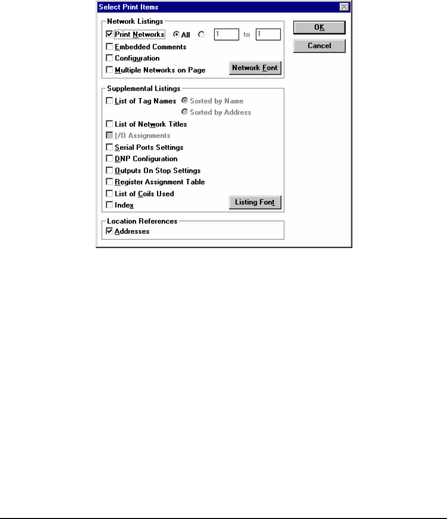
2.6 Print
The Print command is used to print documentation on your printer. The Print dialog box is used to
select the printer and printer options such as page size and orientation for the print job.
The items to be documented are selected with the Select Print Items command. The page layout and
margins are selected with the Page Setup command.
2.7 Select Print Items
The Select Print Items command is used to select the program documentation and print topics to be
printed. Through the selections in the Select Print Items dialog box, shown below, a customized
program print-out can be created.
Figure 1: Select Print Items Dialog Box
The Network Listings section contains selections for defining the networks and comments to be
printed.
The Print Networks selection defines the networks to print. All networks in the ladder program or a
range of networks may be selected for printing.
The Print Embedded Comments selection enables network comments to be printed with the
networks.
The Configuration selection enables the printing of the element configuration parameters for
elements that use the element configuration dialog.
Select Multiple Networks on Page to allow multiple unbroken, networks and embedded comments
to be printed on each page.
Select Network Font to modify the font used in printing the embedded comments and network
functions, addresses, tag names and network titles.
TelePACE Ladder Logic User and Reference Manual
May 9, 2007
13

The Supplemental Listings section contains selections for detailed program information that can be
printed. Each item selected in the supplemental listings section is printed as a separate section with
page header, if selected in page setup.
The List of Tag Names selection adds a complete list of all tag names used to the print out. Tag
names can be sorted by their name or address.
A list of all network titles and network numbers used in the program are printed when the List of
Network Titles is selected.
Selecting the DNP Configuration prints the complete configuration for the DNP protocol if it is
used in the application.
Selecting the Serial Port Settings selection prints complete serial port settings for each serial port.
The Outputs On Stop Settings for the analog and digital outputs are printed when this item is
selected.
Register Assignment selection enables the complete register assignment used in the application to
be printed.
A list of destination coils and tag names in use is added to the print-out when List of Coils Used is
selected.
An index of all print topics selected is added to the print-out by selecting Index.
The font used for printing the supplemental listings is can be modified by selecting Listing Font.
Selecting Addresses in the Location References section adds a complete cross-reference of all
addresses used in the ladder logic program. The addresses are cross-referenced to Network / Row /
Column locations for all occurrences of each address.
• Click OK to accept the selected print items and close the dialog box.
• Click Cancel to discard changes.
2.8 Quick File List
The quick file list area displays the names of the four most recently used Ladder Logic files. Select a
file from this list by clicking the left mouse button on the file name or by pressing the number of the
file.
2.9 Exit
The Exit command terminates the TelePACE program. The editor warns you to save the current file,
if it changed since the last save. You may save the changes, throw away the changes or cancel the
Exit command. Press Ctrl-Q to execute the Exit command.
Selecting Close from the system menu also terminates the program. The editor prompts you to save
changes to your program.
TelePACE Ladder Logic User and Reference Manual
May 9, 2007
14

3 Edit Menu
The Edit menu commands are used to insert, delete and modify the logic elements, function blocks,
comments and networks used in the Ladder Logic program. Clicking the left mouse button on the
desired command, or, from the keyboard by pressing the underlined letter accesses all Edit menu
commands.
3.1 Undo
The Undo command reverses the last change made in the Ladder editor or Comment editor. This is a
single level command and only the last change made before selecting Undo is reversible. Selecting
Undo again reverses the action of the last Undo.
• Press Ctrl-Z to execute the Undo command from the keyboard.
• Right click your mouse and select Undo from the command list.
3.2 Cut Selected
The Cut Selected command removes the selected elements in the Ladder Editor or the Comment
editor and puts them on the Clipboard. Items on the clipboard remain there until they are replaced by
other selected elements.
• Press Ctrl-X to execute the Cut Selected command from the keyboard.
• Right click your mouse and select Cut Selected from the command list.
3.3 Copy Selected
The Copy Selected command copies the selected elements in the Ladder editor to the clipboard.
Items on the clipboard remain there until they are replaced by other selected elements.
• Press Ctrl-C to execute the Copy Selected command from the keyboard.
• Right click your mouse and select Copy Selected from the command list.
3.4 Copy Networks
The Copy Networks command copies a network or block of networks to the clipboard. Comments
for the network are also copied to the clipboard.
Networks to copy are selected from the Copy Networks dialog box. Continuous networks from the
First Network selection to the Last Network selection may be copied to the clipboard.
3.5 Cut Networks
The Cut Networks command cuts a network or block of networks to the clipboard. Comments for the
network are also cut to the clipboard.
Networks to cut are selected from the Cut Networks dialog box. Continuous networks from the First
Network selection to the Last Network selection may be cut to the clipboard.
3.6 Paste
The Paste command is used to paste items on the clipboard to the current cursor position. The paste
command in the Edit menu box is grayed out when there are no items on the clipboard or the cursor
is in the wrong pane for the clipboard items. For example text cannot be pasted into the Ladder
Editor pane and network elements cannot be pasted into the Comment Editor pane.
TelePACE Ladder Logic User and Reference Manual
May 9, 2007
15
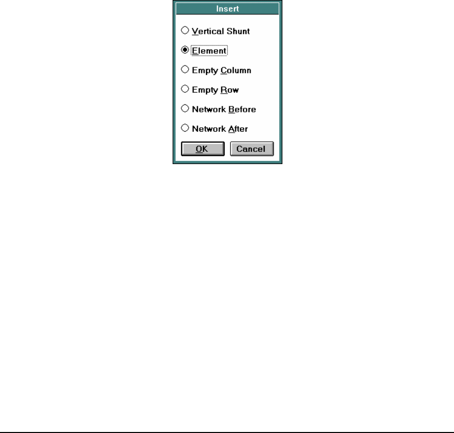
Text cannot be pasted into the Comment Editor if the clipboard text will cause the Comment Editor
to exceed 16 Kbytes of text for the network. In the Ladder Editor pane if there is not enough room
between the cursor and the edge of the network to paste the selected items an error message is
displayed.
When a network or block of networks are pasted from the clipboard the Paste Block of Networks
dialog box appears. This dialog box is used to determine if the block of networks is to be pasted
before or after the current network and whether network titles and comments are pasted with the
block of networks.
• Press Ctrl-V to execute the Paste command from the keyboard.
• Right click your mouse and select Paste from the command list.
3.7 Insert
The Insert command is used to insert changes to the current ladder logic network. When the Insert
command is selected the Insert dialog box pops up. Items that can be inserted into the ladder logic
program are displayed in the dialog box. Items in the dialog are inaccessible (grayed) if they cannot
be used from the current cursor position. Items to be inserted are selected by selecting the radio
button associated with each selection.
Figure 2: Insert Dialog Box
3.7.1 Insert Vertical Shunt
The insert Vertical Shunt selection inserts a vertical shunt on the right side of the element
highlighted by the cursor. Where a multiple cell element is selected, the vertical shunt is inserted in
the cursor position shown on the status bar. This command is not available in the Comment Editor
pane.
• Press F5 to insert a vertical shunt.
• Right click your mouse and select Insert Vertical Shunt from the command list.
3.7.2 Insert Element
The insert Element selection inserts or edits an element at the current cursor position. A dialog box
appears displaying the Ladder Editor function block list. This command is not available in the
Comment Editor pane.
• Press Insert to execute this function from the keyboard.
TelePACE Ladder Logic User and Reference Manual
May 9, 2007
16
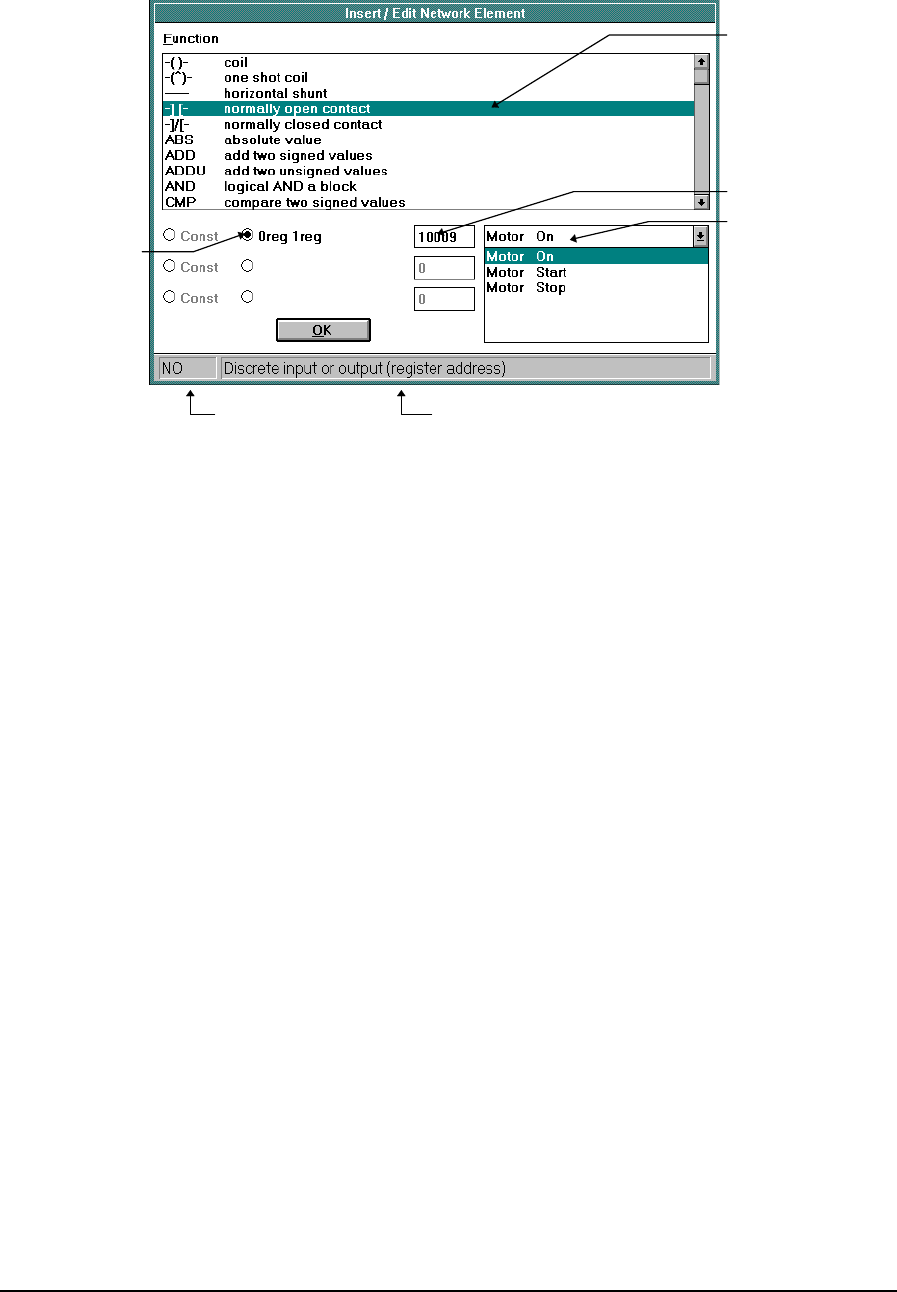
• Right click your mouse and select Insert/Edit Element from the command list.
Function List
Input Type
Selection
Input Tag List
Input Value
Input DescriptionFunction
Figure 3: Insert / Edit Network Element Dialog Box
The function block list shows the function blocks that fit in the current position. If the cursor is over
an existing function block, the list shows only function blocks of the same size. If the cursor is over a
blank space, the list shows all function blocks that fit. Function blocks occupy one, two, or three
cells in a network. The left side of the status bar at the bottom of the dialog shows the selected
function block name.
Selecting a function activates the input boxes at the bottom of the dialog. There are one, two, or three
inputs depending on the function. A description of the input is shown on the status bar, when an
input is selected for editing.
Some function blocks allow either addresses or constants as inputs. The radio buttons on the left of
the input box indicate if the value in the input box is an address or a constant. Click the left radio
button to input a constant. Click the right radio button to input an address of the type displayed. The
radio button defaults to the address type selection.
There are two ways to edit an input:
When an address type is selected the register address can be typed into the input edit box. By default
the first register address, of the type required, is displayed in the edit box. Some functions require a
range of registers to define an input. In these cases the first and last register of the range are
displayed. Edit the displayed address to the meet the requirements of your application. The upper
range limit is recalculated automatically as soon as any valid start register is entered.
When a constant type is selected the constant value can be typed into the input edit box. By default
the number of the first register address, of the type required, is displayed in the edit box. Edit the
displayed constant to the meet the requirements of your application.
A tag name can be selected from the tag selection list. Click the tag list and choose the tag for the
address or constant desired. The tag selection list will show only tags that are allowed on the selected
input.
TelePACE Ladder Logic User and Reference Manual
May 9, 2007
17

3.7.3 Address Types
The text beside the address button indicates the register types that are valid for the current function.
Type Description Registers
0reg Discrete output register address Single bit register
0blk Discrete output register block address 16 single bit registers
1reg Discrete input register address Single bit register
1blk Discrete input register block address 16 single bit registers
3reg Analog input register address Sixteen bit register
4reg Analog output register address Sixteen bit register
Table 1: Address Types
Note: Discrete input and output register blocks (blk types) must begin at the start of a 16-bit word
within the controller memory. Suitable addresses are 00001, 00017, 10001, 10033, etc.
3.7.4 Empty Column
The Empty Column selection inserts an empty column to the left of the current cursor position. This
selection is greyed if an empty column already exists to the left of the cursor or if there is no room
for an empty column in the network. This command is not available in the Comment Editor pane.
3.7.5 Empty Row
The Empty Row selection inserts an empty row above the current cursor position. This selection is
greyed if an empty row already exists to the left of the cursor or if there is no room for an empty row
in the network. This command is not available in the Comment Editor pane.
3.7.6 Network Before
The Network Before selection inserts an empty network before the current network. The cursor
moves to column 1 Row 1 of the new network. This command is available in the Comment Editor
pane.
3.7.7 Network After
The Network After selection inserts an empty network after the current network. The cursor moves
to column 1 Row 1 of the new network. This command is available in the Comment Editor pane.
3.8 Delete
The Delete command removes items from the current Ladder Editor network. Press Delete to execute
this function. A dialog box showing items that can be deleted appears. Items in the dialog box may
be inaccessible (grayed) if they do not apply to the selected elements. The delete command is grayed
out in the Edit menu when the cursor is in the Comment Editor pane. Items to delete are selected by
clicking on the radio button associated with each selection.
TelePACE Ladder Logic User and Reference Manual
May 9, 2007
18

Figure 4: Delete Dialog Box
3.8.1 Vertical Shunt
The Vertical Shunt selection deletes the vertical shunt on the element highlighted by the cursor. This
command is greyed if there is no vertical shunt on the element.
3.8.2 Element
The Element selection deletes the element at the current cursor position. This will delete a single
element only, even if multiple elements are selected.
3.8.3 Selected Elements
The Selected Element selection deletes the elements highlighted in the network. Elements are
highlighted by dragging the network cursor to highlight more than a single element.
3.8.4 Empty Column
The Empty Column selection deletes a column that contains no elements, and moves the elements in
the columns to the right of it one column to the left.
3.8.5 Empty Row
The Empty Row selection deletes a row that contains no elements, and moves the elements in the
rows below it up one row.
3.8.6 Network
The delete Network command deletes the current network and all the elements in it. Deleting a
network does not remove the Tag names from the program.
3.8.7 Delete All Networks
The delete All Networks command deletes all ladder logic networks in the current file. You are
asked to confirm that you wish to delete the networks. Deleting all networks does not change tag
names, I/O assignments or the file name.
TelePACE Ladder Logic User and Reference Manual
May 9, 2007
19
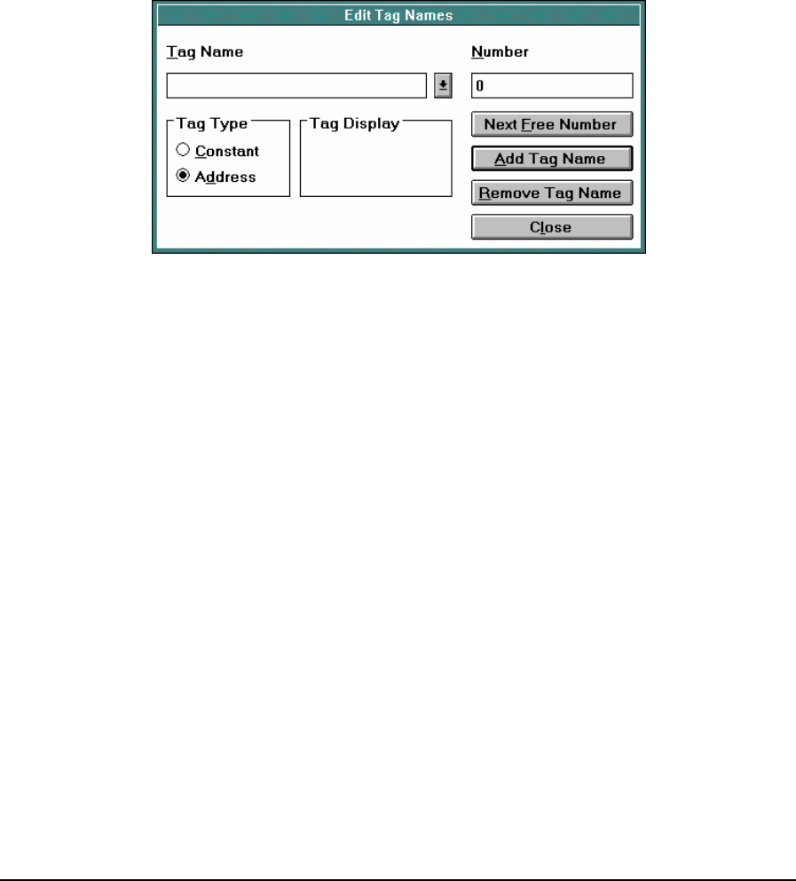
3.9 Toggle Vertical Shunt
The Toggle Vertical Shunt command toggles (inserts or deletes) a vertical shunt on the right side of
the element highlighted by the cursor. The F5 key also performs this command.
3.10 Tag Names
The Tag Names selection is used to edit names that can be used in place of addresses and constants.
Tag names may be used once only for a constant or an address. Numbers can occur once for a
constant and once for an address.
• Tag names must conform to the .CSV file format naming convention.
• Tag names may be up to 16 characters long and up to 2500 tag names can be created.
• The Edit Tag Names dialog box appears allowing the editing of Tag names.
Figure 5: Edit Tag Names Dialog Box
The Edit Tag Names edit box is used to enter tag names. The drop down menu to the right of the
box displays tag names already created.
The Number edit box is used to enter the number associated with the tag.
The Tag Type radio buttons select the type of tag. A Tag Type can be an address or a constant.
The Tag Display edit box displays the Tag Name entered in the Tag Name edit box. Tag names are a
maximum of sixteen characters with eight characters on each line. The tag display box shows the tag
name as it will be displayed in the Ladder Editor.
The Next Free Number button will cause the value in the Number edit box to be replaced by the
next unused address or number of the Tag Type that is not in use.
The Add Tag Name button adds the tag to the list of tag names. An error dialog will appear if the
tag name exists with a different type or number, or if a number exists with the same type and a
different name.
The Remove Tag Name button removes the selected tag from the list of tag names. An error dialog
will appear if the name is in the list but the other data does not match the type button or number box.
The Close button closes the Edit Tag Names dialog.
TelePACE Ladder Logic User and Reference Manual
May 9, 2007
20

3.11 Erase All Tags
The Erase All Tags command is used to erase all tag names in a TelePACE Ladder Logic application
program. This command can be used before importing tags from another program or a CSV file to
eliminate errors when there are conflicts between existing tag names and imported tag names.
The command opens the following message box:
Figure 6: Erase All Tags Dialog Box
• Click on Yes to erase all tags.
• Click on No to abort the command.
Note: Erasing all tags cannot be undone. If you are unsure you should save your file before
executing this command.
3.12 Export Tag Names
The Export Tag Names command is used to write the program tag names into a CSV (comma
separated value) file. A CSV file can be opened, and edited in most spreadsheet programs. Note that
the modified tag names must conform to the .CSV format.
The Export Tag Names to File dialog box is used to specify the file name and directory of the export
file. Tag name files normally end with the extension CSV. The editor uses the extension CSV
automatically, if you do not type it.
The CSV file contains a title line followed by multiple data lines containing the type_specifier,
address and tag_name fields. Commas separate these fields. The type_specifier is A for an address
tag, and C for a constant tag. The tag name can be enclosed in quotes. If the tag name contains a
comma, it must be enclosed in quotes.
Note that if a type and register value is specified, a corresponding tag name must be entered
otherwise an error will result.
Title line: Type, Value, Tag
Data line: type_specifier, address, tag_name
Note: A blank tag name is not allowed. If a type and register value is specified, a corresponding
tag name must be entered otherwise an error will result.
3.13 Import Tag Names
The Import Tag Names command is used to read tag names into the editor. Tag names may be read
from another ladder logic program, or from a CSV file. New tags are added to the existing tag list.
The Import Tag Names From File dialog box is used to select the file containing the tag names. Files
with the extensions LAD and CSV are displayed by default.
TelePACE Ladder Logic User and Reference Manual
May 9, 2007
21

As the tags are imported, they are checked for errors. If a tag is imported that that already exists in
the program an error will occur. If an error occurs, you may continue to process the input file to look
for more errors, or you may abort the import. If an error occurs, no tags are imported.
A CSV file consists of a title line followed by multiple data lines containing the type_specifier,
address and tag_name fields. Commas separate these fields. The type_specifier is A for an address
tag, and C for a constant tag. The tag name can be enclosed in quotes. If the tag name contains a
comma, it must be enclosed in quotes.
Title line: Type, Value, Tag
Data line: type_specifier, address, tag_name
3.14 Network Title
The edit Network Title selection is used to edit the title of the current network. When selected the
Edit Network Title dialog box appears and the title can be edited. The title may be a maximum of 28
characters long.
3.15 Element Configuration
The element configuration command edits initial values for 40000 series registers used by the
MSTR, DIAL, INIM, HART, FLOW, SCAL, TOTL, PIDD, PIDA and SLP elements. The register
values are written to the controller with the program. The register values may be modified later by
other elements of the program.
Right click your mouse and select Element Configuration from the command list.
WARNING
If the controller is initialized, using the Initialize command in the Controller menu, all I/O database
registers used for Element Configuration are set to zero. The application program must be re-loaded
to the controller.
Any change made to an element configuration in the Edit On Line mode will be downloaded to the
controller immediately.
3.16 Registers
The Registers command replaces, and enhances, the Monitor List command from previous versions
of TelePACE. The Registers command allows the online monitoring and control and the offline
editing of registers used in a TelePACE application. These registers may be saved in a single group,
or in multiple groups for monitoring. Individual registers may be selected for on-line and off-line
editing of their data.
When the Registers command is selected the Register Editor is opened. The Register Editor is used
to add registers to the Register list; edit registers in the list and to display register data.
All registers in the Register list are automatically added to the Register data file see the Register
Data File section for complete details on this file. Through using the Register Editor and the
associated Register Data File users are able to easily:
Save a list, or lists, of registers for monitoring and control that is specific for each TelePACE
application program.
Preload registers used in a TelePACE application with data.
Save a ‘snap shot’ of data in registers used in a TelePACE application.
Create meaningful groups of registers for monitoring and control.
TelePACE Ladder Logic User and Reference Manual
May 9, 2007
22
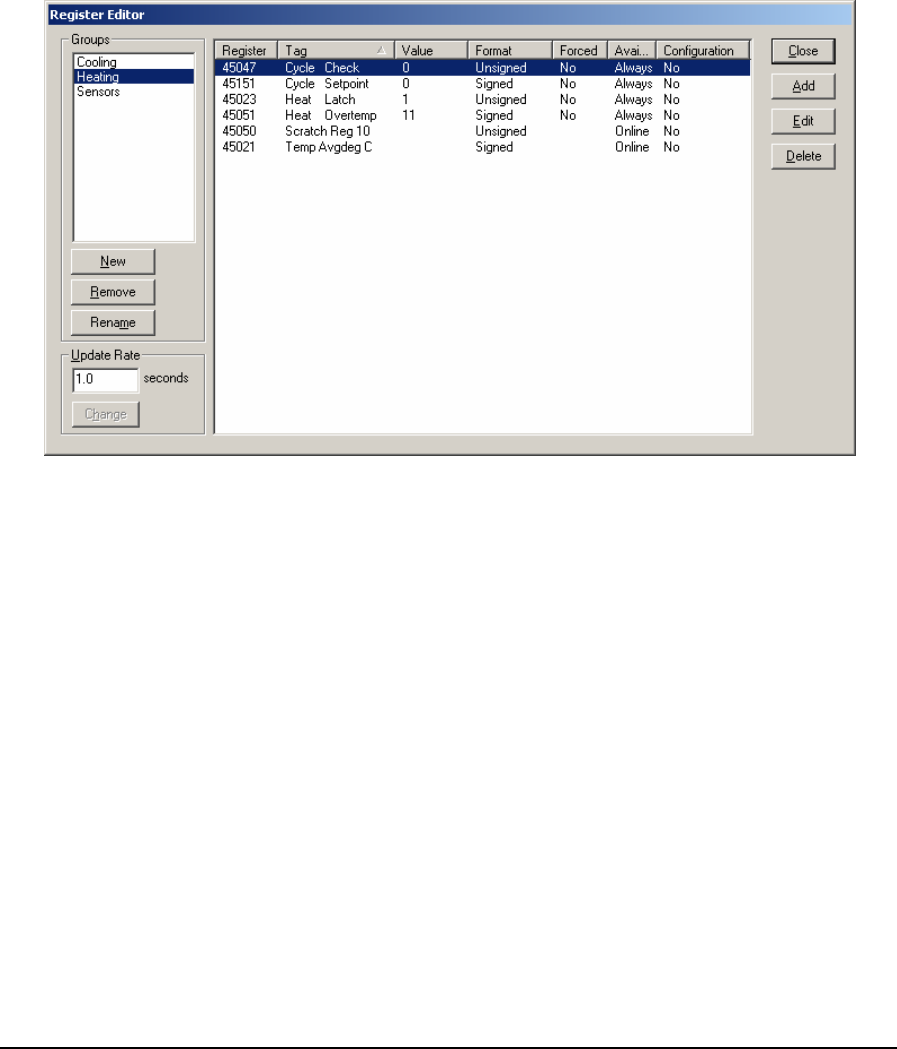
3.16.1 Register Editor
The Register Editor displays registers and allows the editing of register content. The dialog is
divided into three main areas. The Groups section allows the user to create and manage groups of
registers. The Register List section displays the registers, and register attributes, for each register in
a group. The Update Rate section allows the user to control the refresh frequency for the registers
in a displayed group.
The Register Editor may be opened in the off-line and on-line editing modes. When opened the
Register Editor is displayed on top of the Ladder Editor. Ladder Logic cannot be modified while the
Register Editor is open. The Register Editor dialog is opened automatically in the Monitor on-line
mode.
Figure 7: Register Editor Dialog Box
3.16.1.1 Groups
Register groups allows users to manage how registers are viewed in the Register Editor. Registers
that are used in various parts of an application can be grouped together to provide an easy to view,
and edit, list of registers. When in the on-line mode, only the registers in the current group are
updated. This improves response time as large groups of registers can take a long time to update.
Registers may be assigned to more than one group.
The Groups list box displays the register groups that have been created. When a group is selected
the registers in the group are displayed in the Registers window. The group that was last selected the
previous time the Register Editor was opened is displayed. Only one group can be selected at a time.
The New button creates a new group. It opens the New Group dialog.
TelePACE Ladder Logic User and Reference Manual
May 9, 2007
23
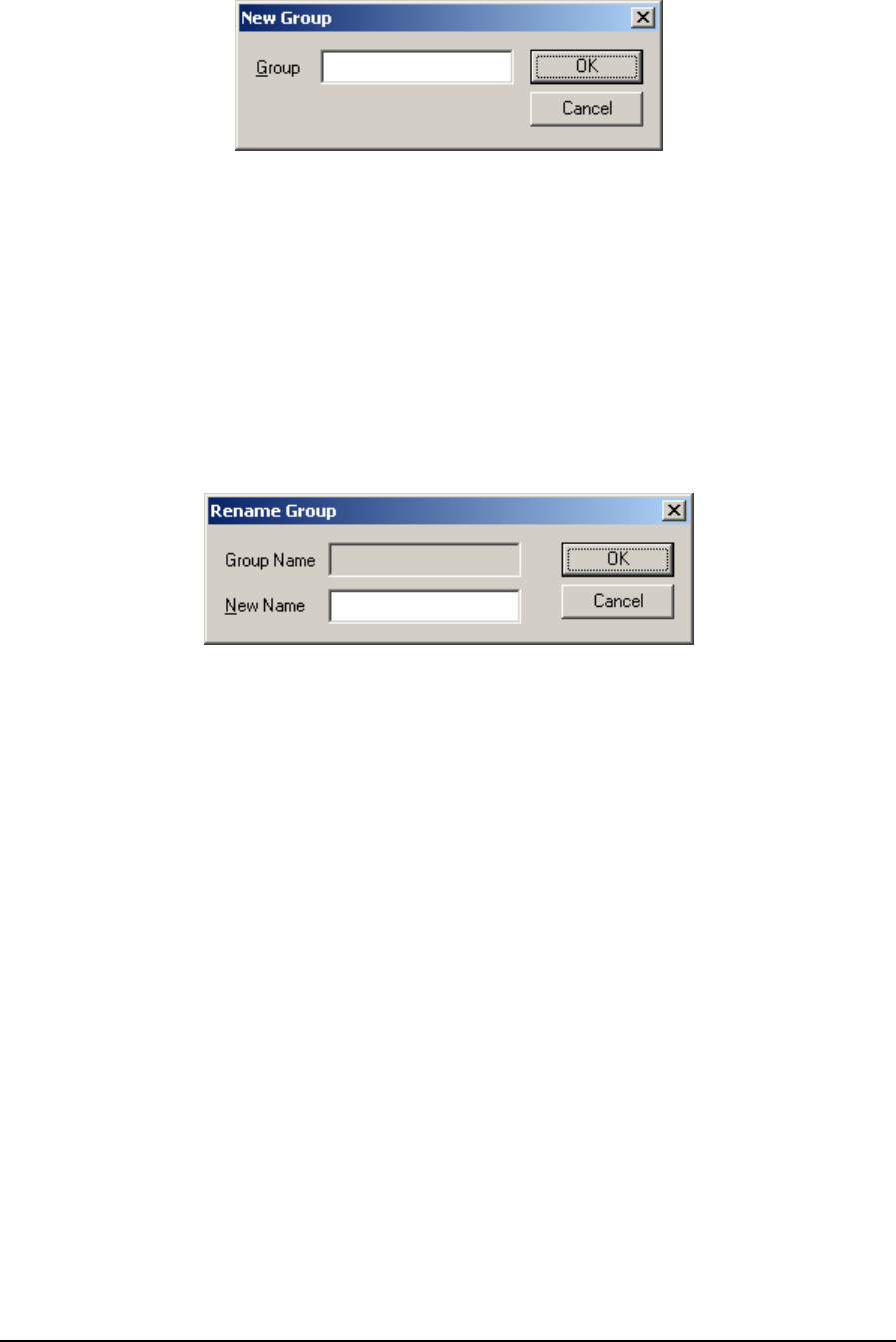
Figure 8: New Group Dialog Box
The Group edit box specifies the name of the new group. The group name may contain letters,
numbers, and spaces. The group name is 1 to 16 characters long. Group names are case insensitive.
The OK button creates the new group and closes the dialog. If the group name already exists an error
message is displayed and the dialog remains open.
The Cancel button closes the dialog.
The Remove button deletes a group from the group list. All the registers in the group are deleted.
The button is disabled (greyed) if no group is selected.
The Rename button renames a group. It opens the Rename Group dialog.
Figure 9: Rename Group Dialog Box
The Group Name field shows the current name of the group.
The New Name edit box specifies the new name of the group. The group name may contain letters,
numbers, and spaces. The group name is 1 to 16 characters long. Group names are case insensitive.
The OK button renames the group and closes the dialog. If the group name already exists an error
message is displayed and the dialog remains open.
The Cancel button closes the dialog.
3.16.1.2 Update Rate
The Update Rate edit box determines how often the register editor updates values when on-line.
Valid values are 0.1 to 1000 seconds. The default value is 1 second. This value is used for all files
opened by TelePACE and is saved when TelePACE is closed.
The Change button sets the current update rate. The modification in the Update Rate edit box will
not take effect until the Change button is pressed. This button is disabled when the Register Editor is
offline.
3.16.1.3 Register List
The Register list is displayed in the center of the Register Editor dialog. The Register List displays
the registers for the selected group. Each register in the list has seven fields, or columns associated
with it. The columns can be resized by dragging the edge of the column heading. The columns may
be sorted by clicking the heading of each column.
TelePACE Ladder Logic User and Reference Manual
May 9, 2007
24

The Register column displays the register number.
The Tag column displays the tag name associated with the register.
The Value column displays the value of the register in the selected format. Coil and status registers
are shown as OFF or ON.
The Format column displays the register format. The register format is one of the following:
Register Format Description
Unsigned Displays a single register as an unsigned integer
Signed Displays a single register as a signed integer
Unsigned Double Displays two consecutive registers as an unsigned double integer
Signed Double Displays two consecutive registers as a signed double integer
Floating Point Displays two consecutive registers as a floating point number
Hexadecimal Displays a single register as a hexadecimal number
Binary Displays a single register as a binary number
ASCII Displays a single register as two ASCII characters
Boolean Displays coil and status registers which have no format
Table 2: Register Formats
The Forced column indicates if the register value is forced. Valid selections are No and Forced.
The Available column indicates if the register value is available always or only when TelePACE is
on-line with the controller.
The Configuration column indicates if the register is part of an element configuration. It is
recommended that registers that are part of an element configuration not be modified in the register
editor. Use the element configuration feature instead.
The Add button adds registers to the selected group. It opens the Add Registers Dialog. This button
is disabled if no group is selected.
The Delete button deletes the selected registers from the group. This button is disabled if no register
is selected. This button is disabled if no group is selected.
The Edit button opens the Edit Register Dialog to edit the selected register value, format, force
status, and register availability. This button is disabled if no register is selected or more than one
register is selected. This button is disabled if no group is selected.
The Close button closes the dialog. This button is disabled in the monitor on-line mode.
The dialog is resizable. Click on the lower right corner and drag to change the size of the dialog.
3.16.2 Add Registers Dialog
The Add Registers dialog adds registers to the current group in the Register Editor dialog. The group
name is displayed in the window title.
TelePACE Ladder Logic User and Reference Manual
May 9, 2007
25
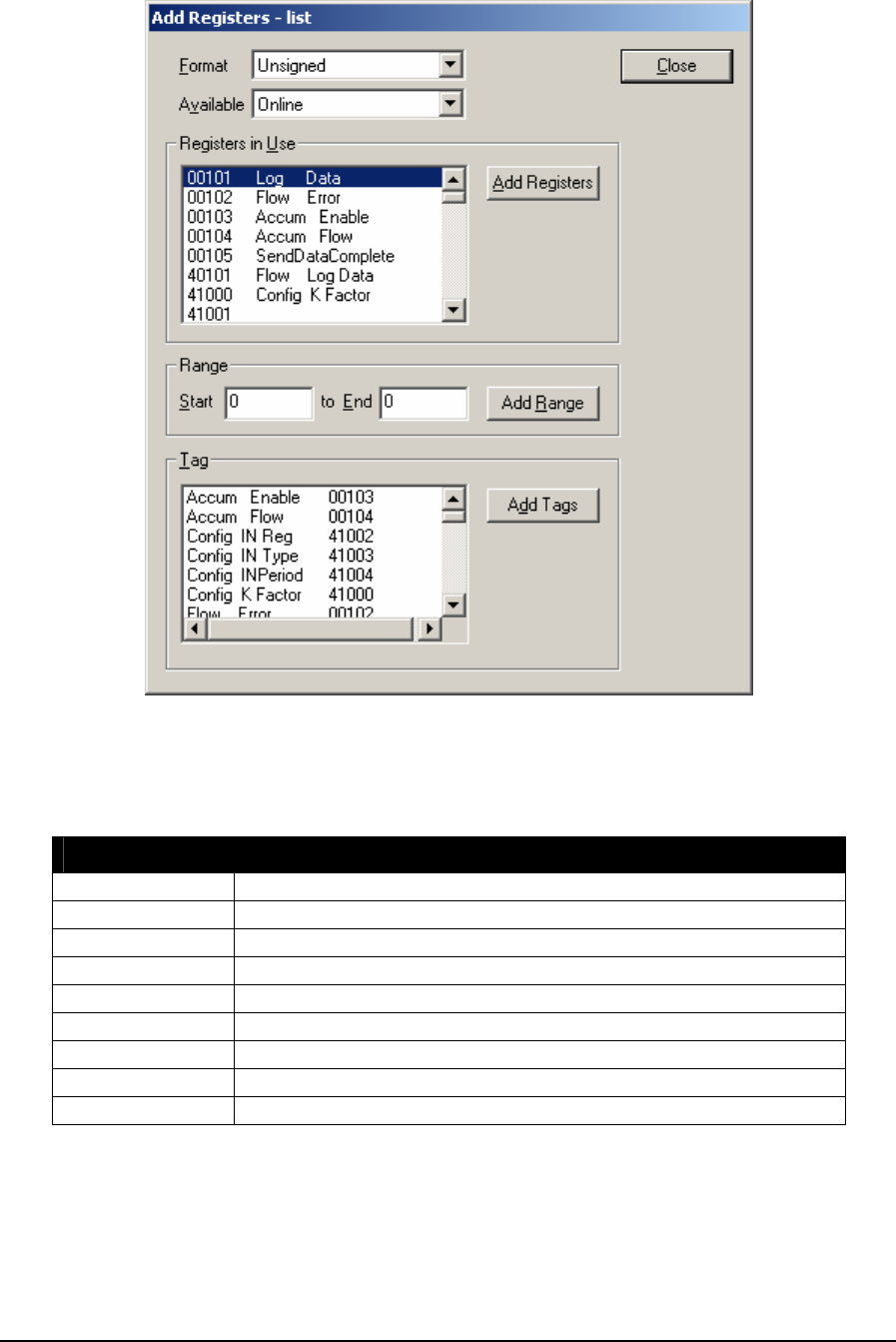
Figure 10: Add Registers – List Dialog Box
The Format drop-down list box specifies how the registers will be displayed. Select the format
before adding registers.
Display Description
Unsigned Displays a single register as an unsigned integer
Signed Displays a single register as a signed integer
Unsigned Double Displays two consecutive registers as an unsigned double integer
Signed Double Displays two consecutive registers as a signed double integer
Floating Point Displays two consecutive registers as a floating point number
Hexadecimal Displays a single register as a hexadecimal number
Binary Displays a single register as a binary number
ASCII Displays a single register as two ASCII characters
Boolean Displays coil and status registers which have no format
Table 3: Register Display Properties
If a register or tag is used by element configuration its format cannot be changed. The register cannot
be merged with adjacent registers or split if the format of an adjacent register is changed.
TelePACE Ladder Logic User and Reference Manual
May 9, 2007
26

If a register or tag is already in the any register editor group but has a different format, the format of
the register is changed in all groups.
The Unsigned Double, Signed Double, and Floating Point formats add two registers to the register
editor group. The pair of registers is displayed as a single number.
If a single register is added that is part of an existing pair, the existing pair will become invalid and
only new single register is displayed.
If a pair of registers is added that overlaps an existing single register, the single register and the
following register will be made part of the register pair. If the following register is a part of the
existing pair, that existing pair will become invalid.
If a pair of registers is added that overlaps one register of an existing pair, or two registers of two
existing pairs, the new pair will be added and the existing overlapped pair will become invalid.
The Available list box specifies when register values can be viewed and edited. Valid values are
Always and Online. The Always selection makes the register values available in both online and
offline editing modes. The Online selection makes the register values available only in the online
editing modes. The default is Online.
3.16.2.1 Registers In Use
The Registers in Use list box displays all registers that are used in the Ladder Logic program. One
or more registers may be selected.
• To select a register, click on it.
• To select more than one register, hold the Ctrl key and click on each register to be added.
• To select a range of registers, click on the first register and hold down the Shift key while
clicking on the last register. A second method is to hold the Shift key and use the Down Arrow
key or Up Arrow key to select the registers.
The Add Registers button adds the selected registers to the register editor group. The registers are
added in the format selected.
3.16.2.2 Range
The Start and End edit boxes specify a range of registers to add.
• To select a range, enter the Start and End registers.
• To select a single register, enter it in the Start edit box and enter 0 in the End edit box.
The Add Range button adds the selected registers to the register editor group. The registers are
added in the format selected.
3.16.2.3 Tags
The Tags list box displays all tags and the corresponding register number that are defined in the
Ladder Logic program. One or more tags may be selected.
• To select a tag, click on it.
• To select more than one tag, hold the Ctrl key and click on tags.
• To select a range of tags, click on the first tag and hold down the Shift key while clicking on the
last tag or use Down Arrow key or Up Arrow key.
TelePACE Ladder Logic User and Reference Manual
May 9, 2007
27
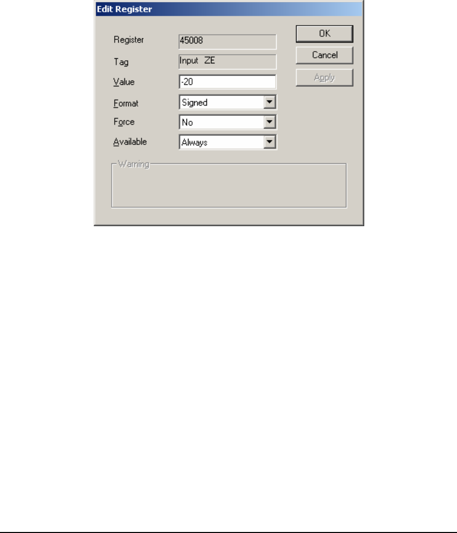
• To select a range of tags, click on the first tag and hold down the Shift key while clicking on the
last tag. A second method is to hold the Shift key and use the Down Arrow key or Up Arrow key
to select the tags.
The Add Tags button adds the selected tags to the register editor group. The tags are added in the
format selected.
The Close button closes the dialog.
3.16.3 Edit Register Dialog
The Edit Register dialog modifies values for a register. There are two forms of the dialog. The
following dialog is used for editing input registers (3xxxx type) and holding registers (4xxxx type).
Figure 11: Edit Register Dialog Box
The following dialog is used for editing coil registers (0xxxx type) and status registers (0xxxx type).
TelePACE Ladder Logic User and Reference Manual
May 9, 2007
28
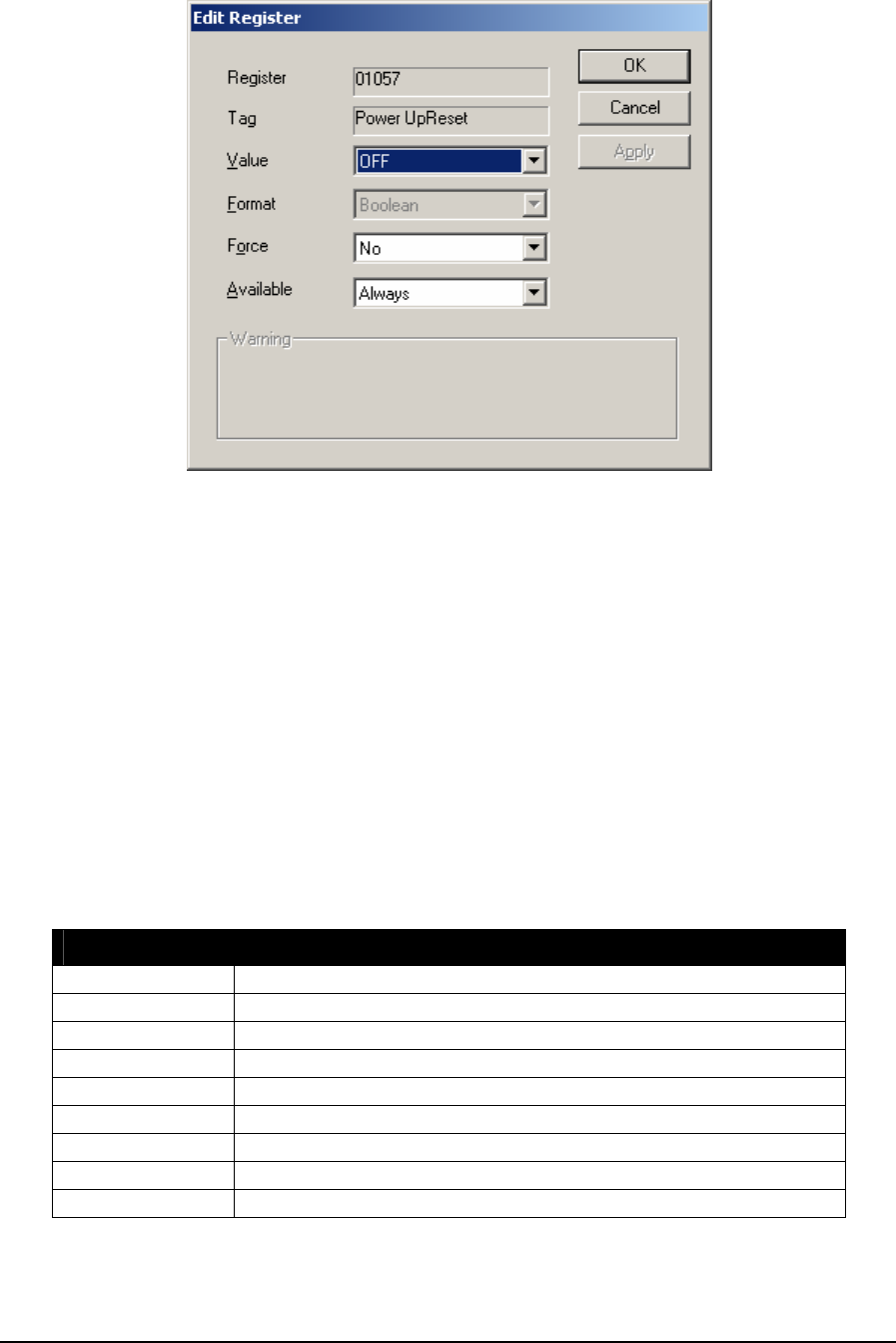
Figure 12: Edit Register Dialog Box- Value Off
The Register field displays the register number. This field cannot be edited.
The Tag field displays the tag for the register. This field cannot be edited.
The Value edit box displays and allows the editing of register values.
For input and holding registers the Value edit box displays the current value of the register. Valid
values depend on the format of the register. The edit box is disabled if the register is not available
Always and the editor is in the off-line mode.
For coil and status registers the Value drop-down list box shows the value of the register. Valid
values are ON and OFF. The list box is disabled if the register is not available Always and the editor
is in the off-line mode.
The Format list box selects the format of the register. The list box is disabled and shows none for
coil and status registers. The list box is disabled if the register is used for Element Configuration -
the format of these registers cannot be changed. The following formats are available.
Format Description
Unsigned Displays a single register as an unsigned integer
Signed Displays a single register as a signed integer
Unsigned Double Displays two consecutive registers as an unsigned double integer
Signed Double Displays two consecutive registers as a signed double integer
Floating Point Displays two consecutive registers as a floating point number
Hexadecimal Displays a single register as a hexadecimal number
Binary Displays a single register as a binary number
ASCII Displays a single register as two ASCII characters
Boolean Displays coil and status registers which have no format
Table 4: Register Formats
TelePACE Ladder Logic User and Reference Manual
May 9, 2007
29

The Force drop-down list box indicates if the value is forced. Valid values are No and Forced. The
list box is disabled if the register is not available Always and the editor is in the off-line mode.
The Available drop-down list box indicates when register values can be viewed and edited. Valid
values are Always and Online. The Always selection makes the register values available in both
online and offline editing modes. The Online selection makes the register values available only in the
online editing modes. The default is Always if the editor is off-line and Online if the editor is on-
line.
The Warning is displayed if the register is used by element configuration. It is recommended
Element Configuration be used to change the register value. The Element Configuration function
performs additional error checking specific to the Ladder Logic element.
The OK button saves changes and closes the dialog. If the Editor is on-line, changes are written to
the controller.
The Cancel button closes the dialog.
The Apply button writes the changes to the controller, when the editor is on-line. The Apply button
is disabled if the editor is off-line.
3.16.4 Register Data File
The register data file is created, saved and opened with the Ladder Logic file. The register data file
contains the information for any registers that have been added to the Register Editor and any
registers used in an element configuration. The Register Data file will contain only the header record
(see Register Data File Format) if there are no Register Editor entries or element configuration.
Users can easily edit the register data file providing a rapid way to add or remove registers or modify
their values or format.
3.16.4.1 Register Data File Format
The register data file is saved as a CSV (comma separated value) format file. The file is saved in the
format: filename - Registers.csv. Where filename is the TelePACE Ladder Logic file name.
Each line in the CSV file is one record. The following is an example of a Register Data file.
Register,Value,Format,Forced,Available,Groups
01057,0,BO,No,Always,Sensors
30002,9440,S,No,Online,Sensors
30004,312,S,No,Online,Sensors
40238,1826,U,No,Always,all
45021,606,U,No,Online,Heating;Cooling
45035,+23.6250,F,No,Always,Cooling
45041,32,B,No,Always,Cooling
48016,1074,U,No,Always,*Element
The first line in the file is a header record and it contains the names of each of the fields. The
following table describes each of the fields in the file.
TelePACE Ladder Logic User and Reference Manual
May 9, 2007
30

Field Description
Register The address of the register or first register of a register pair. Register pairs
are used for unsigned double, signed double and floating point registers.
Valid register addresses are:
00001 to 09999 Digital Output registers.
10001 to 19999 Digital Input registers.
30001 to 39999 Analog Input registers.
40001 to 49999 Analog Output registers.
Value Value of the register or registers.
Boolean: 0 to 1
Unsigned: 0 to 65535
Signed: -32768 to 32767
Unsigned double: 0 to 232-1
Signed double: -231 to 231-1
Hexadecimal: same as unsigned
Binary: same as unsigned
ASCII: same as unsigned
Format Display format for the register or registers.
BO Boolean
U Unsigned
S Signed
UD Unsigned double
SD Signed double
F Floating point
H Hexadecimal
B Binary
A ASCII
Force Indicates if register value is forced.
No Indicates register is not forced
Forced Indicates register is forced
Available Indicates if register is available always or online only.
Always Indicates that the register may be edited in either the Online or Off
line mode.
Online Indicates that the register may be edited in the Online mode only.
Groups List of groups that include this register. If the register is included in more than
one group each group is listed with semicolons separating the group names.
The special value *Element is reserved for registers used by element
configuration.
Table 5: Insert Table Caption Here
3.16.5 Editing the Register Data File
The CSV file may be edited using a text editor, such as Notepad or a spreadsheet program such as
Excel. The following operations can be done easily with a text editor or spreadsheet: adding,
inserting, replacing, removing or editing many registers, searching for registers, and sorting.
Care must be exercised when editing the CSV file. Improper changes may result in loss of element
configuration or register data. The following list gives some suggestions when editing a CSV file.
TelePACE Ladder Logic User and Reference Manual
May 9, 2007
31

• Make a backup copy of the file before changing it. The file can be restored if you make invalid
changes.
• A register can occur only once in the CSV file. Check that a register is listed only once after
copying lines.
• Do not change the header record.
• Do not change the order of the columns.
• Do not use empty fields.
• Avoid including the header record when sorting column.
• Avoid sorting only some of the columns.
• Avoid overlapped registers with different register formats.
• Group names may contain spaces, letters, and numbers only. Don’t use other characters.
• Separate group names with semicolons.
• Group names are case insensitive the case does not matter.
• If registers containing part of an element configuration are deleted, the value for that register will
be missing. This may cause unexpected operation of your ladder logic program.
TelePACE Ladder Logic User and Reference Manual
May 9, 2007
32
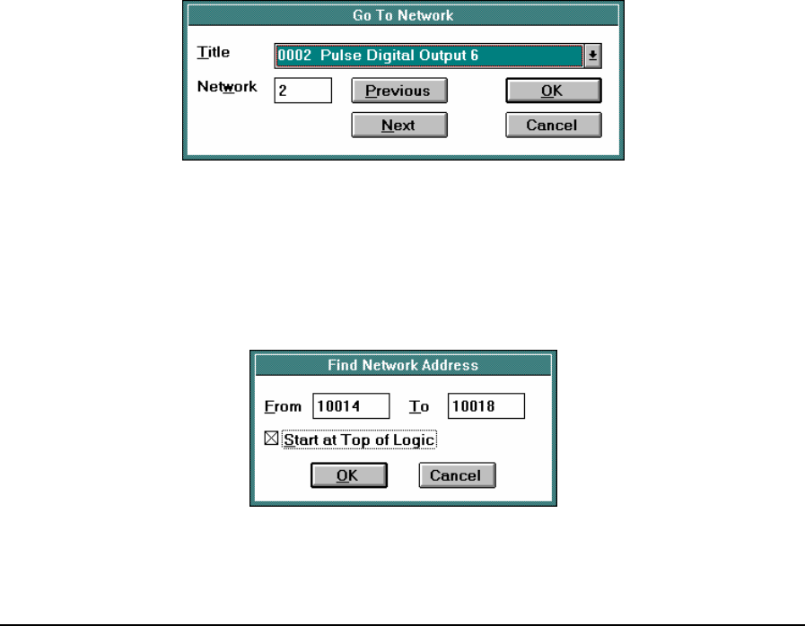
4 Search Menu
Search Menu commands are used to locate networks, devices, addresses and tag names in the current
Ladder Editor program. Addresses may be located, or located and replaced from the Search menu.
4.1 Next Network
Selecting the Next Network command from the Search Menu moves the Ladder Editor to the next
Network in the program. The next network command is grayed out if the current network is the last
network. Press F8 to move the Ladder Editor to the next network.
4.2 Previous Network
Selecting the Previous Network command from the Search Menu moves the Ladder Editor to the
previous Network in the program. The Previous Network command is grayed out if the current
network is the first network. Press F7 on the keyboard to move the Ladder Editor to the previous
network.
4.3 Go To Network
The Go To Network command is used to move the Ladder Editor to a desired network. When the Go
To Network command is selected the Go To Network dialog box pops up. The network titles or
number to go to is entered in this dialog box. The Title box selects the title of the network. A drop
down list shows multiple network titles in use. Networks that have no title are displayed showing the
network number only. The Network box selects the number of the network. The Previous button
moves backward through the list of networks. The Next button moves forwards through the list of
networks.
Figure 13: Go To Network Dialog Box
4.4 Find Address
The Find Address command searches the program for an address, or range of addresses, and moves
to the first element containing any address in the range. The search proceeds down the rows from the
present column, to column ten, row eight in the current network, then moves to the next network.
Figure 14: Find Network Address Dialog Box
TelePACE Ladder Logic User and Reference Manual
May 9, 2007
33
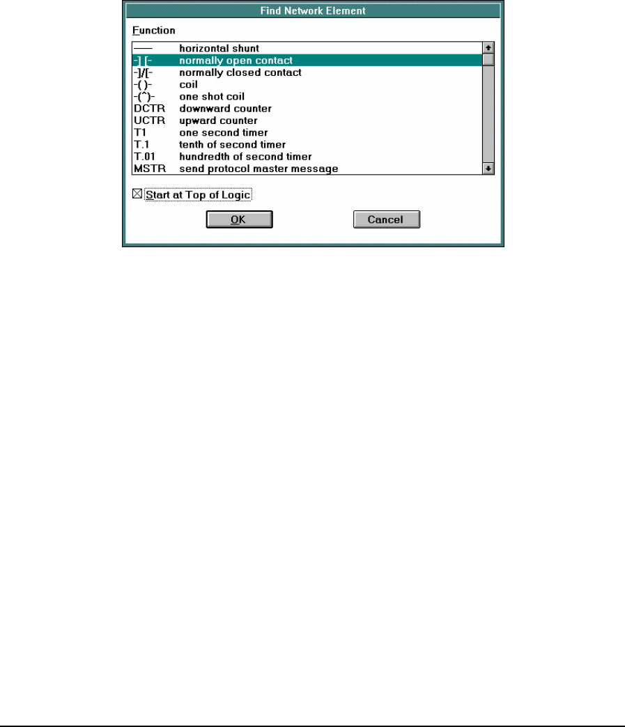
The Find Network Address dialog box is used to enter the address, or range of addresses to find. The
From box specifies the first address to locate. The initial value comes from the element at the current
cursor position. The To box specifies the last address in a range. A value of 0 indicates that only the
address in the From field is to be located. Checking the Start at Top of Logic box starts the search at
the beginning of the program. The search starts at the current cursor position when this box is
unchecked.
4.5 Find Device
The Find Device command is used to search the program for a device, and move to the first element
containing that device. The search proceeds down rows from the present column to column ten row
eight in the current network, then moves to the next network.
Figure 15: Find Network Element Dialog Box
The Find Network Element dialog box pops up when the Find Device command is selected. The
Function list specifies the device to locate. The initial value comes from the element at the current
cursor position. Checking the Start at Top of Logic box starts the search at the beginning of the
program. Leaving this box unchecked starts the search at the current cursor position.
4.6 Find Tag Name
The Find Tag Name command is used to search the program for a tag name, and move to the first
element containing the tag name. The search proceeds down rows from the present column to
column ten, row eight in the current network, then moves to the next network.
TelePACE Ladder Logic User and Reference Manual
May 9, 2007
34
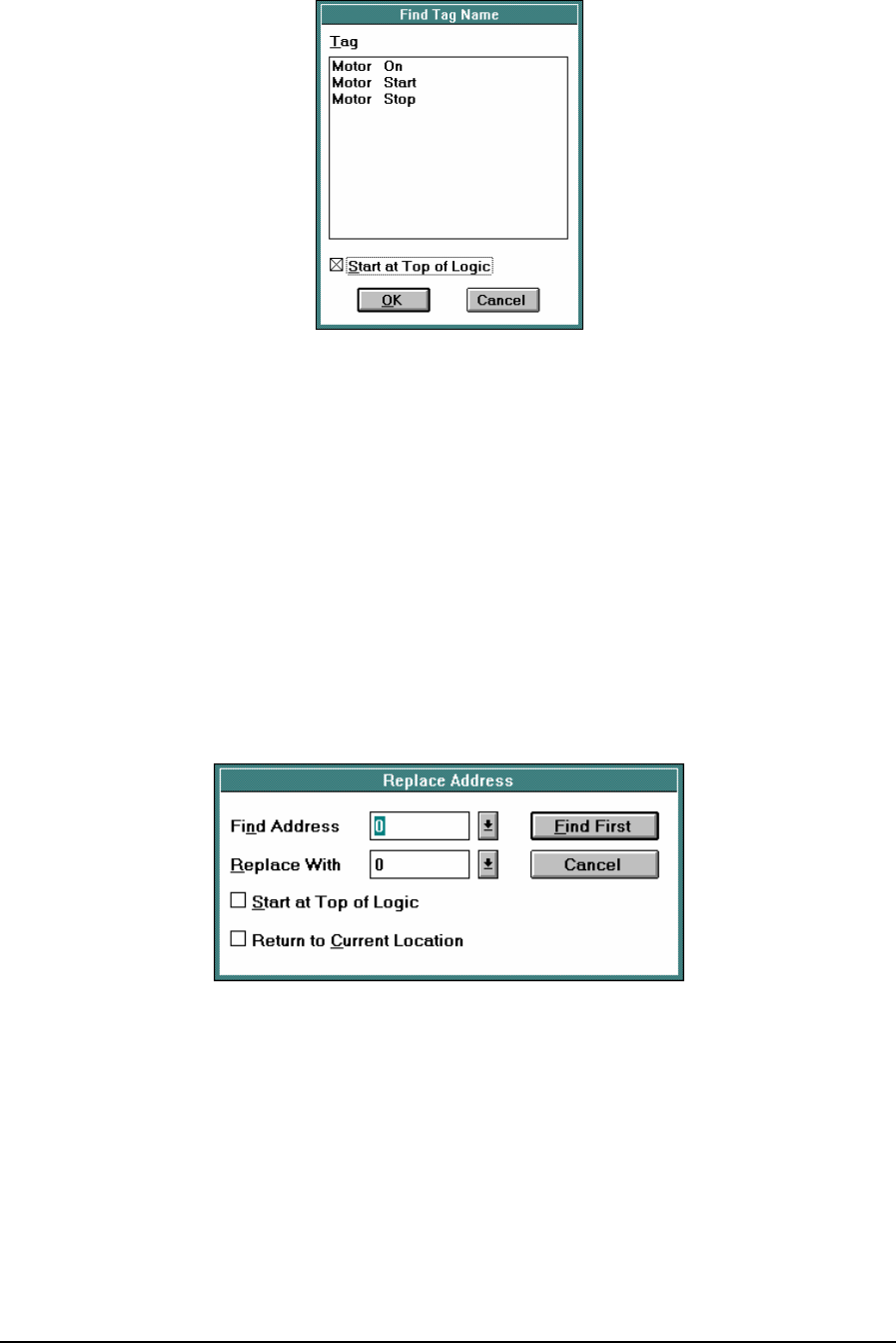
Figure 16: Find Tag Name Dialog Box
The Find Tag Name dialog box, displaying all the tag names used in the program, pops up when the
Find Tag Name command is selected. Select a tag name in the Tag list by left clicking the mouse on
the desired tag name. Checking the Start at Top of Logic box starts the search for the selected tag
name at the beginning of the program. If left unchecked, the search starts at the current cursor
position.
4.7 Repeat Last Find
The Repeat Last Find command repeats the last search performed. Press F3 to repeat the last find.
4.8 Replace Address
The Replace Address command is used to search the program for an address and then replace the
address with another address. The search proceeds down rows from the present column to column
ten, row eight in the current network, then moves to the next network.
Figure 17: Replace Address Dialog Box
When the Replace Address command is selected the Replace Address dialog box pops up. The
address to find and the replacement address are selected from this dialog box.
The Find Address box specifies the address to be replaced. The Replace With box specifies the
replacement address.
Checking the Start at Top of Logic box starts the search at the beginning of the program. If left
unchecked, the search starts at the current cursor position. Checking the Return to Current Location
box returns the cursor to the current network after the command is executed. If left unchecked, the
cursor is in the last program network after the command is executed.
TelePACE Ladder Logic User and Reference Manual
May 9, 2007
35

The Find First button, when selected, will cause the Change Address dialog box to appear each time
the search finds the address to be replaced. The With box allows changing of the replacement
address. Selecting the Replace button replaces the address. The Find Next button continues the
search to the next occurrence of the address to find.
4.9 Multiple Coils
Selecting the Multiple Coils command causes the Multiple Coils dialog box to pop up. This dialog
box displays all coils that are used more than once in the current program.
TelePACE Ladder Logic User and Reference Manual
May 9, 2007
36

5 Controller Menu
The Controller menu commands are used to configure the Micro16 and SCADAPack controllers.
Controller selection, serial port configuration, I/O assignments, register assignment, and outputs on
stop are defined in this menu selection. Controller initialization, I/O forcing and the C Program
Loader are also selected from this menu.
5.1 Type
The TelePACE program is used to program and configure the Micro16, SCADAPack and
SCADASense controllers. The selected controller determines controller specific options for other
menus and communication functions.
TelePACE verifies the controller type when writing to the target controller and when entering the
on-line modes. If the controller type selected in the application is different than the target controller,
the following message appears:
"Cannot write to a different type or model of controller. Do you want to switch the controller
type to xxxx?"
Where xxxx is the detected controller type.
The various controller types available in TelePACE are:
• SCADASense 4202 DR
• SCADASense 4202 DS
• SCADASense 4203 DR
• SCADASense 4203 DS
• Micro16
• SCADAPack
• SCADAPack 100: 1024K: This controller type can only be used when the controller firmware is
version 1.80 or newer and the controller ID is greater than or equal to A182922.
• SCADAPack 100: 256K: This controller type can only be used when the controller firmware is
version older than 1.80 and the controller ID is less than or equal to A182921.
• SCADAPack 32
• SCADAPack 32P
• SCADAPack LIGHT
• SCADAPack LP
• SCADAPack PLUS
• SCADAPack 350
Select the appropriate target controller this application is intended for.
5.2 Serial Ports
The Serial Ports selection is used to configure the serial port settings on the controller. There is a set
of port settings for each serial port on the controller. Each serial port is independently configured for
all serial and protocol parameters.
TelePACE Ladder Logic User and Reference Manual
May 9, 2007
37
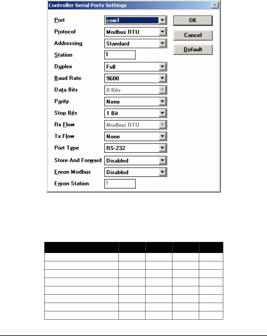
The Controller Serial Ports Settings dialog box pops up when the Serial Ports command is selected.
Changes to serial port parameters are made within this dialog box.
To optimize communication performance on SCADAPack, SCADAPack Light and SCADAPack
Plus controllers, minimize the length of messages on com3 and com4. Examples of recommended
uses for com3 and com4 are for local operator display terminals, and for programming and
diagnostics using the TelePACE program.
Each item in the dialog is explained in the following paragraphs.
Figure 18: Controller Serial Ports Settings Dialog Box
The Port drop down menu selects the controller serial port to configure. The settings for the port are
displayed in the Port Settings controls section of the dialog. The valid serial ports depend on the
controller type. The default serial port is com1.
Controller Type com1 com2 com3 com4
Micro16 X X
SCADAPack X X X
SCADAPack Plus X X X X
SCADAPack Light X X X
SCADAPack LP X X X
SCADAPack 100 X X
SCADAPack 32 X X X X
SCADAPack 32P X X X
TelePACE Ladder Logic User and Reference Manual
May 9, 2007
38

Controller Type com1 com2 com3 com4
SCADAPack 350 X X X
SCADASense 4202 DR X X X
SCADASense 4202 DS X X X
SCADASense 4203 DR X X X
SCADASense 4203 DS X X X
Table 6: Controller Port Settings
The Protocol drop down menu selects the communication protocol type. Valid protocols depend on
the controller type as shown in the following table.
Controller Type Valid Protocols Default Protocol
Micro16
SCADAPack
SCADAPack Plus
SCADAPack Light
SCADAPack LP
SCADAPack 100
None
Modbus RTU
Modbus ASCII
DF1 Full Duplex BCC
DF1 Full Duplex CRC
DF1 Half Duplex BCC
DF1 Half Duplex CRC
DNP
* Note that SCADAPack 100
controllers with firmware older
than version 1.80 do not
support DF1 protocols.
Modbus RTU
SCADAPack 32
SCADAPack 32P
None
Modbus RTU
Modbus ASCII
DF1 Full Duplex BCC
DF1 Full Duplex CRC
DF1 Half Duplex BCC
DF1 Half Duplex CRC
DNP
PPP
Modbus RTU
SCADASense family of
programmable controllers
(4202 DR, 4202 DS, 4203
DR and 4203 DS)
Com 1 fixed as Sensor.
Com 2 and Com 3:
None
Modbus RTU
Modbus ASCII
DF1 Full Duplex BCC
DF1 Full Duplex CRC
DF1 Half Duplex BCC
DF1 Half Duplex CRC
DNP
Com 1 fixed as Sensor.
Com 2 and Com 3 default
is Modbus RTU.
SCADAPack 350 None
Modbus RTU
Modbus ASCII
DF1 Full Duplex BCC
Modbus RTU
TelePACE Ladder Logic User and Reference Manual
May 9, 2007
39

Controller Type Valid Protocols Default Protocol
DF1 Full Duplex CRC
DF1 Half Duplex BCC
DF1 Half Duplex CRC
DNP
Table 7: Valid Protocols
The Addressing drop down menu selects the addressing mode for the selected protocol. The control
is disabled if the protocol does not support it. Valid addressing modes depend on the selected
protocol as shown in the following table.
Protocol Valid Mode Default Mode
Modbus RTU
Modbus ASCII
Standard
Extended
Standard
DF1 Full Duplex BCC
DF1 Full Duplex CRC
DF1 Half Duplex BCC
DF1 Half Duplex CRC
Control is disabled N/A
DNP Control is disabled N/A
PPP Control is disabled N/A
None Control is disabled N/A
Table 8: Valid Addressing Modes
The Station entry sets the station address for the selected controller serial port. Valid addresses
depend on the protocol and addressing mode selected, as shown in the table below.
Protocol Valid Addresses Default Address
Modbus RTU
Modbus ASCII
Standard addressing:
1 to 255
Extended addressing:
1 to 65534
1
DF1 Full Duplex BCC
DF1 Full Duplex CRC
DF1 Half Duplex BCC
DF1 Half Duplex CRC
0 to 254 N/A
DNP Control is disabled N/A
PPP Control is disabled N/A
None Control is disabled N/A
Table 9: Valid Addresses
The Duplex drop down menu selects full or half-duplex operation for the selected Port. Valid and
default duplex settings depend on the serial port and controller type, as shown in the table below.
Note that the duplex is forced to Half if a SCADASense transmitter is configured on the port.
TelePACE Ladder Logic User and Reference Manual
May 9, 2007
40
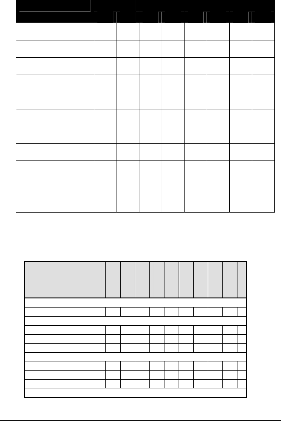
com1 com2 com3 com4 Controller Type
Valid Def. Valid Def. Valid Def. Valid Def.
Micro16 Full
Half
Full Full
Half
Full
SCADAPack Full
Half
Full Full
Half
Full Half Half
SCADAPack Plus Full
Half
Full Full
Half
Full Half Half Half Half
SCADAPack Light Full
Half
Full Full
Half
Full Half Half
SCADAPack LP Half Half Full
Half
Full Half Half
SCADAPack 100 Full
Half
Full Full
Half
Full
SCADAPack 32 Full
Half
Full Full
Half
Full Half Half Full
Half
Full
SCADAPack 32P Full
Half
Full Full
Half
Full Full
Half
Full
SCADASense 4202 DR
SCADASense 4202 DS
Full
Full Half Half Half Half
SCADASense 4203 DR
SCADASense 4203 DS
Half
Half Full
Half
Half Full
Half
Full
SCADAPack 350 Half Half Full
Half
Half Half
Full Full
Table 10: Duplex Settings
The Baud Rate drop down menu selects the communication speed for the selected serial port. Valid
baud rates depend on the serial port and controller type, as shown in the table below. The default
value is always 9600 baud.
Baud Rate
Controller
300
600
1200
2400
4800
9600
19200
38400
57600
115200
Micro 16
Com 1, Com 2 X X X X X X X X
SCADAPack
Com 1, Com 2 X X X X X X X X
Com 3 X X X X X X X X
SCADAPack Plus
Com 1, Com 2 X X X X X X X X
Com 3, Com 4 X X X X X X X X
TelePACE Ladder Logic User and Reference Manual
May 9, 2007
41
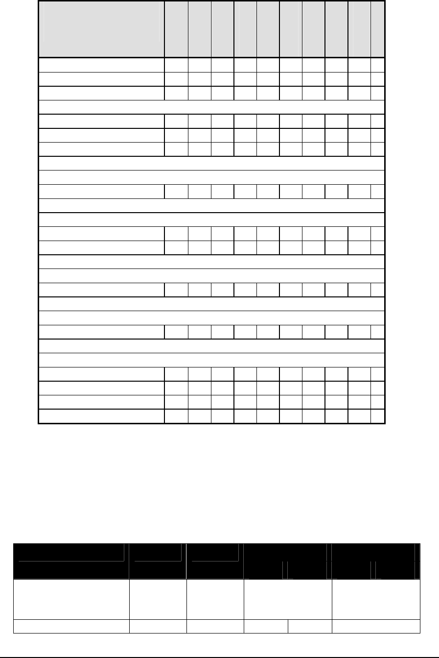
Baud Rate
Controller
300
600
1200
2400
4800
9600
19200
38400
57600
115200
SCADAPack Light
Com 1, Com 2 X X X X X X X X
Com 4 X X X X X X X X
SCADAPack LP
Com 1, Com 2 X X X X X X X X
Com 3 X X X X X X X X
SCADAPack 100: 1024K
Com 1, Com 2 X X X X X X X X
SCADAPack32
Com 1, Com 2, Com 4 X X X X X X X X X X
Com 3 X X X X X X X X
SCADAPack32P
Com 1, Com 2, Com 4 X X X X X X X X X X
SCADAPack 350
Com 1, Com2, Com3 X X X X X X X X X X
SCADASense Series of Programmable Controllers
Com1 X
Com2 X X X X X X X X
Com3 X X X X X X X X
Table 11: Baud Rates
The Data Bits drop down menu selects the number of data bits. Valid selections are 7 and 8 bits.
This parameter is forced to 8 bits when the protocol type is Modbus RTU, PPP or any DF1 protocol.
The default selection is 8 bits.
The Parity drop down menu selects the parity for the selected port. Valid selections depend on the
serial port, controller type and data bits, as shown in the table below. The default selection is always
none.
com3 com4 Controller Type com1 com2
7 bits 8 bits 7 bits 8 bits
Micro16 None
even
odd
none
even
odd
N/A N/A
SCADAPack None none none N/A
TelePACE Ladder Logic User and Reference Manual
May 9, 2007
42

com3 com4 Controller Type com1 com2
7 bits 8 bits 7 bits 8 bits
even
odd
even
odd
even
odd
space
mark
even
odd
mark
SCADAPack Plus None
even
odd
none
even
odd
even
odd
space
mark
none
even
odd
mark
even
odd
space
mark
none
even
odd
mark
SCADAPack Light none
even
odd
none
even
odd
N/A
even
odd
space
mark
none
even
odd
mark
SCADAPack LP none
even
odd
none
even
odd
even
odd
space
mark
none
even
odd
mark
N/A
SCADAPack 100 none
even
odd
none
even
odd
SCADAPack 32 none
even
odd
none
even
odd
even
odd
space
mark
none
even
odd
mark
none
even
odd
SCADAPack 32P none
even
odd
none
even
odd
N/A none
even
odd
SCADASense 4202 DR
SCADASense 4202 DS
none none
even
odd
none
even
odd
mark
N/A
SCADASense 4203 DR
SCADASense 4203 DS
none none
even
odd
none
even
odd
N/A
SCADAPack 350 none
even
odd
none
even
odd
None
even
odd
N/A
Table 12: Parity Settings
TelePACE Ladder Logic User and Reference Manual
May 9, 2007
43

The Stop Bits drop down menu selects the number of stop bits for the selected serial port. Besides
the SCADAPack 350 with a preset stop bit of 1, valid selections are 1 and 2 for all other controllers.
Valid selection for com3 is 1 stop bit. The default selection is 1.
Note: The SCADAPack 350 has only 1 stop bit. This cannot be changed.
The Rx Flow drop down menu selects the receiver flow control for the selected port. Valid selections
depend on the protocol, controller type, and serial port, as shown in the table below. If there is only
one valid value the control is disabled. If there is more than one possible value, the default selection
is none.
Protocol Controller com1 com2 com3 com4
Micro16 None None N/A N/A
SP None None None N/A
SP Plus None None None None
SP Light None None N/A none
SP LP None None None N/A
SP 100 None None N/A N/A
SP 32 None None None None
SP 32P None None N/A None
SCADASense 4202 DR
SCADASense 4202 DS
N/A None None
Ignore CTS
N/A
SCADASense 4203 DR
SCADASense 4203 DS
N/A None None N/A
DF1 Full BCC
DF1 Full CRC
DF1 Half BCC
DF1 Half CRC
DNP
SCADAPack 350 None None None N/A
Micro16 None None N/A N/A
SP None None Modbus
RTU N/A
SP Plus None None Modbus
RTU Modbus
RTU
SP Light None None Modbus
RTU
SP LP None None Modbus
RTU
SP 100 None None N/A N/A
SP 32 Modbus
RTU Modbus
RTU Modbus
RTU Modbus
RTU
SP 32P Modbus
RTU Modbus
RTU Modbus
RTU
SCADASense 4202 DR
SCADASense 4202 DS
None None Modbus
RTU
SCADASense 4203 DR
SCADASense 4203 DS
None Modbus
RTU Modbus
RTU N/A
Modbus RTU
SCADAPack 350 Modbus
RTU Modbus
RTU Modbus
RTU N/A
Micro16 None
Xon/Xoff
none
Xon/Xoff
N/A None
Modbus ASCII
SP None
Xon/Xoff
none
Xon/Xoff
None N/A
TelePACE Ladder Logic User and Reference Manual
May 9, 2007
44

Protocol Controller com1 com2 com3 com4
SP Plus None
Xon/Xoff
none
Xon/Xoff
None None
SP Light None
Xon/Xoff
none
Xon/Xoff
N/A None
SP LP None
Xon/Xoff
none
Xon/Xoff
None N/A
SP 100 None
Xon/Xoff
none
Xon/Xoff
None None
SP 32 None None None None
SP 32P None None N/A None
SCADASense 4202 DR
SCADASense 4202 DS
None None
None
Modbus
RTU
N/A
SCADASense 4203 DR
SCADASense 4203 DS
None None
None
N/A
SCADAPack 350 None None None N/A
SP 32 Queued Queued Queued Queued PPP
SP 32P Queued Queued Queued Queued
Table 13: RX Flow Settings
The Tx Flow drop down menu selects the transmitter flow control for the selected port. Valid
selections depend on the protocol, controller type, and serial port, as shown in the table below. The
default selection is none.
Protocol Controller com1 com2 com3 com4
Micro16 None None N/A N/A
SP None None None
Ignore CTS
N/A
SP Plus None None None
Ignore CTS
None
Ignore CTS
SP Light None None N/A None
Ignore CTS
SP LP None None None
Ignore CTS
N/A
SP 100 None None N/A N/A
SP 32 None
Ignore CTS
None
Ignore
CTS
None
Ignore CTS
None
Ignore CTS
SP 32P None
Ignore CTS
None
Ignore
CTS
N/A None
Ignore CTS
SCADASense 4202 DR
SCADASense 4202 DS
None None
None
Ignore CTS
N/A
SCADASense 4203 DR
SCADASense 4203 DS
None None None N/A
Modbus RTU
DF1 Full BCC
DF1 Full CRC
DF1 Half BCC
DF1 Half CRC
DNP
SCADAPack 350 None None None N/A
TelePACE Ladder Logic User and Reference Manual
May 9, 2007
45

Protocol Controller com1 com2 com3 com4
Micro16 None
Xon/Xoff
None
Xon/Xoff
N/A N/A
SP None
Xon/Xoff
None
Xon/Xoff
None
Ignore CTS
N/A
SP Plus None
Xon/Xoff
None
Xon/Xoff
None
Ignore CTS
None
Ignore CTS
SP Light None
Xon/Xoff
None
Xon/Xoff
N/A None
Ignore CTS
SP LP None
Xon/Xoff
None
Xon/Xoff
None
Ignore CTS
N/A
SP 100 None
Xon/Xoff
None
Xon/Xoff
N/A N/A
SP 32 None
Ignore CTS
None
Ignore
CTS
None
Ignore CTS
None
Ignore CTS
SP 32P None
Ignore CTS
None
Ignore
CTS
N/A None
Ignore CTS
SCADASense 4202 DR
SCADASense 4202 DS
N/A None
None
Ignore CTS
N/A
SCADASense 4203 DR
SCADASense 4203 DS
N/A None None N/A
None
Modbus ASCII
SCADAPack 350 None None None N/A
Table 14: TX Flow Settings
The Port Type drop down menu selects the type of serial port. Valid selections depend on the serial
port and controller type as shown in the table below. The default selection is RS-232. The options
are as follows:
• RS-232 for a regular RS-232 connection.
• RS-232 Dial-up modem: If an external dial-up modem is used on the RS-232 connection.
This setting is required if the RTU is initiating a dialup connection through an external modem
connected to the corresponding serial port. For SCADASense controllers, the digital input point can
be used to provide a DCD signal, as required by the external modem.
• RS-232 Collision Avoidance: RS-232 connection with collision avoidance based on the CD
signal is available only when the DNP protocol type is selected on the serial port, and the
serial port supports handshaking.
When this flow control is enabled, the protocol uses the Carrier Detect (CD) signal provided by the
serial port to detect if the communication medium is in use. If it is, it waits until the medium is free
before transmitting.
Prior to transmitting each Data Link (DL) frame, the controller will test the CD line. If it is active, a
countdown equal to the DL timeout will be set and CD will be monitored every 100 ms throughout
this countdown period. If the Data Link timeout is set to the minimum of 100 ms, the CD line will
be tested once.
TelePACE Ladder Logic User and Reference Manual
May 9, 2007
46

If the CD line reports inactive (line not in use), a frame will be transmitted immediately, and a new
DL timeout is started as normal. On the other hand, if CD remains active during the DL timeout, the
transmission attempt will fail. If a non-zero retry is configured in the Data Link layer, the test will
be repeated until the number of retries has been exhausted.
Note: RS-232 Collision Avoidance is supported only on serial ports which support
handshaking and whose protocol type is set for DNP.
• RS-485: for a regular RS-485 connection.
Controller Type com1 com2, com4 com3
Micro16
SCADAPack
SCADAPack Plus
SCADAPack Light
RS-232
RS-232 dial-up modem
RS-232 Collision Avoidance
RS-485
RS-232
RS-232 dial-up modem
RS-232 Collision Avoidance
Note: com4 is available on
the SCADAPack Light and
Plus only.
S-232
RS-232 dial-up modem
SCADAPack 32
SCADAPack 32P
RS-232
RS-232 dial-up modem
RS-232 Collision Avoidance
NOTE:
Port type RS-232 applies for
RS-232 or RS-485 operation
on COM1. Jumper J9 on the
controller board must be
installed to configure COM1
for RS-485 operation.
RS-232
RS-232 dial-up modem
RS-232 Collision Avoidance
S-232
RS-232 dial-up modem
TelePACE Ladder Logic User and Reference Manual
May 9, 2007
47

Controller Type com1 com2, com3
SCADASense Programmable
Controllers
(4202 DR, 4202 DS, 4203 DR
and 4203 DS).
N/A (RS-232)
RS-232
RS-232 Dialup Up Modem
(com 2 only)
NOTE:
RS-232 Port Type applies
for RS-232 or RS-485
operation.
SCADAPack 100 RS-232
RS-232 Collision Avoidance
NOTE:
Port type RS-232 applies for
RS-232 or RS-485 operation
on Com 1.
RS-232
RS-232 dial-up modem
RS-232 Collision
Avoidance
Com 3: not available
SCADAPack LP RS-485 RS-232
RS-232 dial-up modem
RS-232 Collision
Avoidance
SCADAPack 350 RS-485 RS-232
RS-232 dial-up modem
RS-232 Collision
Avoidance
NOTE:
Port type RS-232 applies
for RS-232 or RS-485
operation on COM2.
Jumper J13 on the
controller board must be
installed to configure
COM2 for RS-485
operation.
Table 15: Serial Port Type
The Store and Forward drop down menu selects whether store and forward messaging is enabled
for the port. Valid selections are enabled and disabled. If this option is enabled, messages will be
forwarded according to the settings in the store and forward routing table. The default selection is
disabled. This control is disabled when PPP protocol is selected for a serial port, or if any of the DF1
protocols are selected and for Com2 and Com3 on the SCADASense series of controllers.
TelePACE Ladder Logic User and Reference Manual
May 9, 2007
48

The Store and Forward menu selection changes to Routing menu selection when DNP protocol is
selected for a serial port. Valid selections are enabled and disabled. Routing must be enabled on a
serial port to enable routing of DNP messages.
The Enron Modbus drop down menu selects whether Enron Modbus is enabled for the port. If this
option is enabled, the controller, in addition to regular Modbus messages, will handle Enron Modbus
messages. Valid selections depend on the protocol as shown in the table below. This control is
disabled when PPP protocol is selected for a serial port and for com 1 on the SCADASense series of
controllers.
Protocol Valid Selections Default Selection
Modbus RTU
Modbus ASCII
Enabled
Disabled
Disabled
DF1 Full Duplex BCC
DF1 Full Duplex CRC
DF1 Half Duplex BCC
DF1 Half Duplex CRC
Control is disabled N/A
DNP Control is disabled N/A
None Control is disabled N/A
Table 16: Enron Modbus Settings
The Enron Station entry selects the Enron Modbus station address for the serial port. Valid entries
depend on the protocol. The Enron station must be different from the Modbus station set in the
Station control. This ensures Enron Modbus and Modbus communication can occur on the same
port. This entry is greyed out if Enron Modbus is not enabled.
Protocol Valid Values Default Value
Modbus RTU
Modbus ASCII
Standard addressing:
1 to 255
Extended addressing:
1 to 65534
2
DF1 Full Duplex BCC
DF1 Full Duplex CRC
DF1 Half Duplex BCC
DF1 Half Duplex CRC
Control is disabled N/A
DNP Control is disabled N/A
None Control is disabled N/A
Table 17: Enron Modbus Station Settings
• The OK button saves the settings for all serial ports and closes the dialog.
• The Cancel button closes the dialog without saving.
• The Default button sets the parameters for the port to their default values.
5.3 IP Configuration
When the IP Configuration menu item is clicked under the Controller menu the IP Configuration
dialog is opened. This dialog is available only when the controller type is set to SCADAPack 350,
SCADAPack 32 or SCADAPack 32P.
TelePACE Ladder Logic User and Reference Manual
May 9, 2007
49

The IP Configuration dialog has a tree control on the left side of the window. The SCADAPack 32
and SCADAPack 32P support Point-To-Point Protocol (PPP) on the serial ports. The tree control
displays headings for com 1 Port through com 4 Port and PPP Login are displayed for configuring
the serial ports for PPP. The SCADAPack 350 does not support PPP on the serial ports and the
headings for com 1 Port through com 4 Port and PPP Login are not displayed.
Each of the tree control selections is explained in the following sections of this user manual.
This tree control for the SCADAPack 32 and SCADAPack 32P contains headings for:
• LAN Port
• com 1 Port
• com 2 Port
• com 3 Port
• com 4 Port
• PPP Login
• Modbus Common
• Modbus/TCP
• Modbus RTU in UDP
• Modbus ASCII in UDP
• DNP in TCP
• DNP in UDP
• Friendly IP List
This tree control for the SCADAPack 350 contains headings for:
• LAN Port
• Modbus Common
• Modbus/TCP
• Modbus RTU in UDP
• Modbus ASCII in UDP
• DNP in TCP
• DNP in UDP
• Friendly IP List
When a tree control is selected by clicking the mouse on a heading, a property page is opened for the
header selected. From the property page the IP configuration parameters for the selected header is
displayed.
The Default button selects the default values for the current property page.
The OK button saves the configuration and closes the Controller IP Configuration dialog.
The Cancel button closes the Controller IP Configuration dialog without saving any changes.
5.3.1 LAN Port
The LAN Port property page is selected for editing by clicking LAN Port in the tree control section
of the Controller IP Configuration dialog. When selected the LAN Port property page is active.
TelePACE Ladder Logic User and Reference Manual
May 9, 2007
50
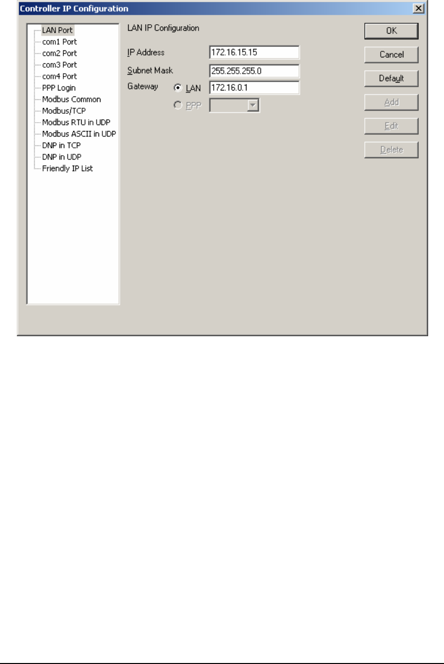
Figure 19: Controller IP Configuration – LAN Port Dialog Box
The IP Address is the address of the controller LAN port. The IP address is statically assigned.
Contact your network administrator to obtain an IP address for the controller. The default value is
0.0.0.0.
The Subnet Mask is determines the subnet on which the controller LAN port is located. The subnet
mask is statically assigned. Contact your network administrator to obtain the subnet mask for the
controller. The default value is 255.255.255.0.
The Gateway determines how your controller communicates with devices outside its subnet. The
LAN radio button selects the gateway specified in the LAN edit box. Enter the IP address of the
gateway. The gateway is located on the LAN port subnet. The gateway is statically assigned. Contact
your network administrator to obtain the gateway IP address. The default value is 0.0.0.0.
The PPP radio button selects the serial port where the gateway is located. The PPP drop down menu
displays only those serial ports currently configured for the PPP protocol. Select a serial port from
this menu to select its remote IP address as the gateway. The gateway is automatically assigned to
the remote IP address of the selected serial port.
5.3.2 com1 Port
The com1 Port property page is selected for editing by clicking com1 Port in the tree control section
of the Controller IP Configuration dialog. When selected the com1 Port property page is active. This
page configures the IP settings for com1 when the PPP protocol is selected for this serial port.
TelePACE Ladder Logic User and Reference Manual
May 9, 2007
51
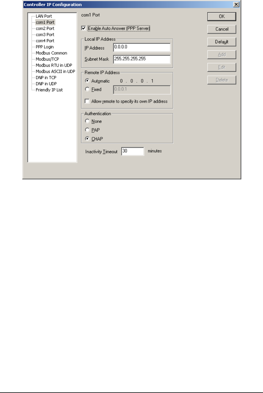
Figure 20: Controller IP Configuration – com1 Port Dialog Box
The Enable Auto Answer (PPP Server) checkbox enables the PPP Server on this serial port. Check
this box if you want to allow a remote PPP client to connect to this port. This checkbox enables the
remaining settings in the page.
The IP Address is the address of this serial port. The IP address is statically assigned. Contact your
network administrator to obtain an IP address for this serial port.
The Subnet Mask determines the subnet on which this serial port is located. The subnet mask is
statically assigned. Contact your network administrator to obtain the subnet mask for this serial port.
In a standard PPP configuration, a subnet mask of 255.255.255.255 is used to restrict routing on this
serial port to a single host (i.e. the Remote IP Address).
If another subnet mask is used, all packets on that subnet will be forwarded to this serial port. Any
address on that subnet in addition to the Remote IP Address can be used for the remote host in this
case.
The Remote IP Address is the address that will be assigned to the remote PPP client connected to
this serial port. The Automatic radio button automatically selects the address to be the serial port’s
IP address + 1. The second radio button selects the address specified in the edit box. Enter the IP
address to assign to the remote client.
The Allow remote to specify its own IP address checkbox allows the remote PPP client to assign
its own IP address. Check this box if you want to allow this option. Note that the client may or may
not request its own IP address. If the client does not make this request, the PPP Server will assign the
IP address selected.
TelePACE Ladder Logic User and Reference Manual
May 9, 2007
52

The Authentication determines the login protocol used at the start of every PPP connection. The
None radio button removes the login step. The PAP radio button selects the Password
Authentication Protocol (PAP). The CHAP radio button selects the Challenge-Handshake
Authentication Protocol (CHAP). PAP and CHAP usernames and passwords are configured on the
PPP Login page.
The Inactivity Timeout is the inactivity timeout for this serial port. If there has been no activity on
an existing PPP connection for the selected number of minutes, then the connection is automatically
closed. If there is a modem connected it is hung up. Setting this value to zero disables the timeout.
5.3.3 com2 Port
The com2 Port property page is selected for editing by clicking com2 Port in the tree control section
of the IP Configuration dialog. When selected the com2 Port property page is active. This page
configures the IP settings for com2 when the PPP protocol is selected for this serial port.
The com2 Port property page provides the same options as the com1 Port page. See the com1 Port
page for a description of these options.
5.3.4 com3 Port
The com3 Port property page is selected for editing by clicking com3 Port in the tree control section
of the IP Configuration dialog. When selected the com3 Port property page is active. This page
configures the IP settings for com3 when the PPP protocol is selected for this serial port.
The com3 Port property page provides the same options as the com1 Port page. See the com1 Port
page for a description of these options.
5.3.5 com4 Port
The com4 Port property page is selected for editing by clicking com4 Port in the tree control section
of the IP Configuration dialog. When selected the com4 Port property page is active. This page
configures the IP settings for com4 when the PPP protocol is selected for this serial port.
The com4 Port property page provides the same options as the com1 Port page. See the com1 Port
page for a description of these options.
5.3.6 PPP Login
The PPP Login property page is selected for editing by clicking PPP Login in the tree control section
of the IP Configuration dialog. When selected the PPP Login property page is active.
This page configures the username and password list for PPP login authentication. The list is used
only by those serial ports configured for the PPP protocol using PAP or CHAP authentication.
TelePACE Ladder Logic User and Reference Manual
May 9, 2007
53
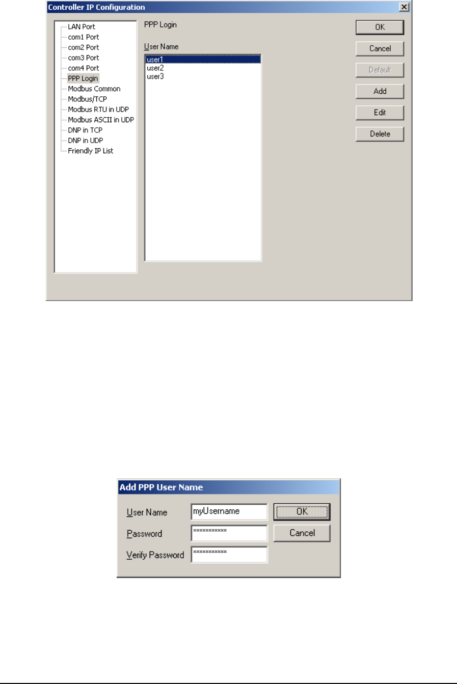
Figure 21: Controller IP Configuration – PPP Login Dialog Box
• Click Add to enter a new username to the list. Selecting the Add button opens the Add PPP
Username dialog.
• Click Edit to edit the username highlighted in the list. Selecting the Edit button opens the Edit
PPP Username dialog. This button is disabled if there are no entries in the list.
• Click Delete to remove the selected usernames from the list. This button is disabled if there are
no entries in the list.
5.3.6.1 Add PPP Username dialog
This dialog selects a new PPP username and password.
Figure 22: Add PPP User Name Dialog Box
The Username edit box selects the username. A username is any alphanumeric string 1 to 16
characters in length, and is case sensitive.
TelePACE Ladder Logic User and Reference Manual
May 9, 2007
54
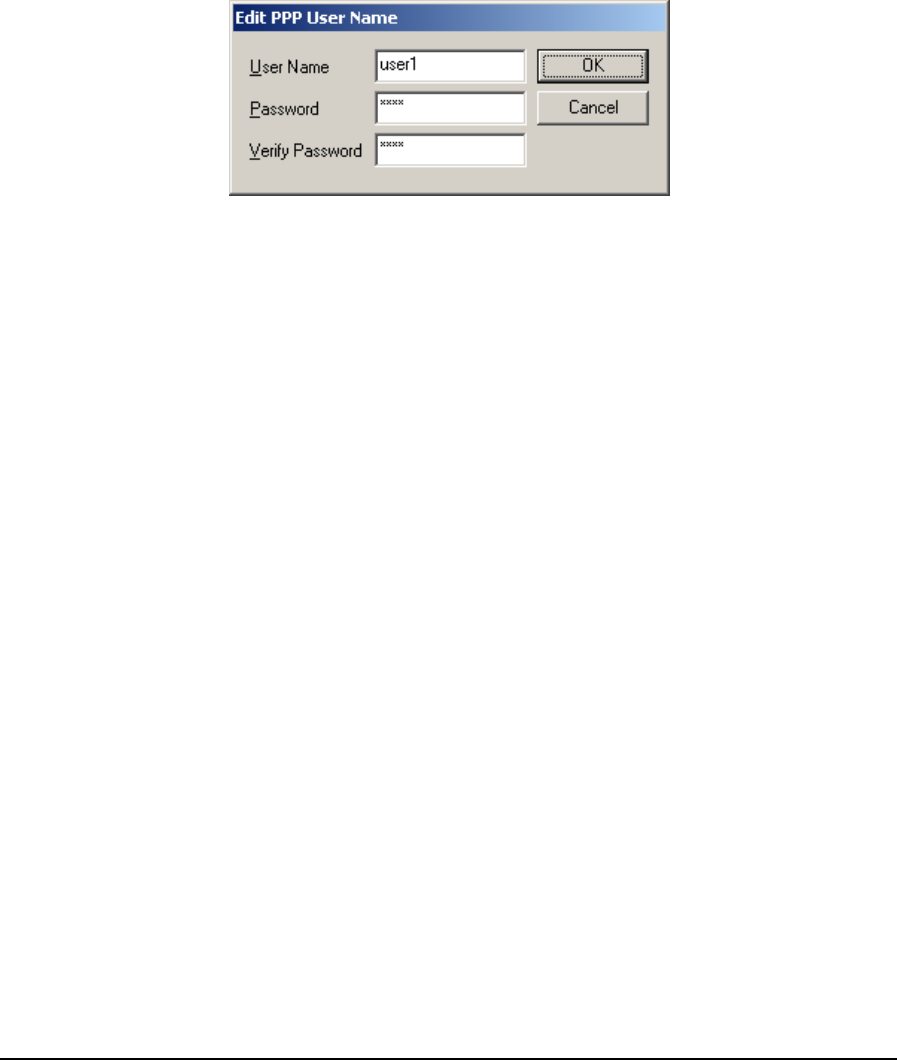
The Password edit box selects the password. A password is any alphanumeric string 1 to 16
characters in length, and is case sensitive.
The Verify Password edit box selects the verify password. Enter the same string entered for the
password.
The Cancel button discards any changes made to this dialog and exits the dialog.
The OK button to accepts all changes made to this dialog and exits the dialog.
5.3.6.2 Edit PPP Username dialog
This dialog edits a PPP username and password selected from the list.
Figure 23: Edit PPP User Name Dialog Box
The Username edit box selects the username. A username is any alphanumeric string 1 to 16
characters in length, and is case sensitive.
The Password edit box selects the password. A password is any alphanumeric string 1 to 16
characters in length, and is case sensitive.
The Verify Password edit box selects the verify password. Enter the same string entered for the
password.
The Cancel button discards any changes made to this dialog and exits the dialog.
The OK button to accepts all changes made to this dialog and exits the dialog.
5.3.7 Modbus Common
The Modbus Common property page is selected for editing by clicking Modbus Common in the tree
control section of the IP Configuration dialog. When selected the Modbus Common property page is
active.
TelePACE Ladder Logic User and Reference Manual
May 9, 2007
55
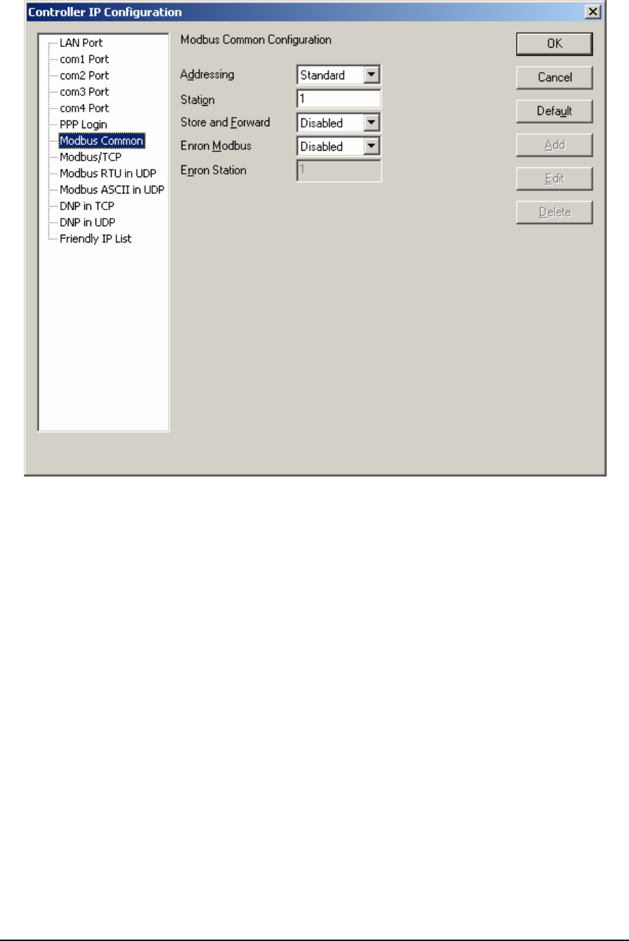
Figure 24: Controller IP Configuration - Modbus Common Dialog Box
The Addressing menu selects standard or extended Modbus addressing. Standard addressing allows
255 stations and is compatible with standard Modbus devices. Extended addressing allows 65534
stations, with stations 1 to 254 compatible with standard Modbus devices. The default value is
standard.
The Station menu sets the station number of the controller. The valid range is 1 to 255 if standard
addressing is used, and 1 to 65534 if extended addressing is used. The default value is 1.
The Store and Forward selection controls forwarding of messages using IP based protocols. If this
option is enabled, messages will be forwarded according to the settings in the store and forward
routing table. The default value is disabled.
The Enron Modbus box selects whether Enron Modbus is enabled for the port. If this option is
enabled, the controller, in addition to regular Modbus messages, will handle Enron Modbus
messages.
The Enron Station box selects the Enron Modbus station address. The valid range for Enron Station
is 1 to 255 if the Addressing control is set to Standard. The valid range for Enron Station is 1 to
65534 if the Addressing control is set to Extended. The Enron station must be different from the
Modbus station set in the Station edit box. This ensures Enron Modbus and Modbus communication
can occur on the same port.
TelePACE Ladder Logic User and Reference Manual
May 9, 2007
56
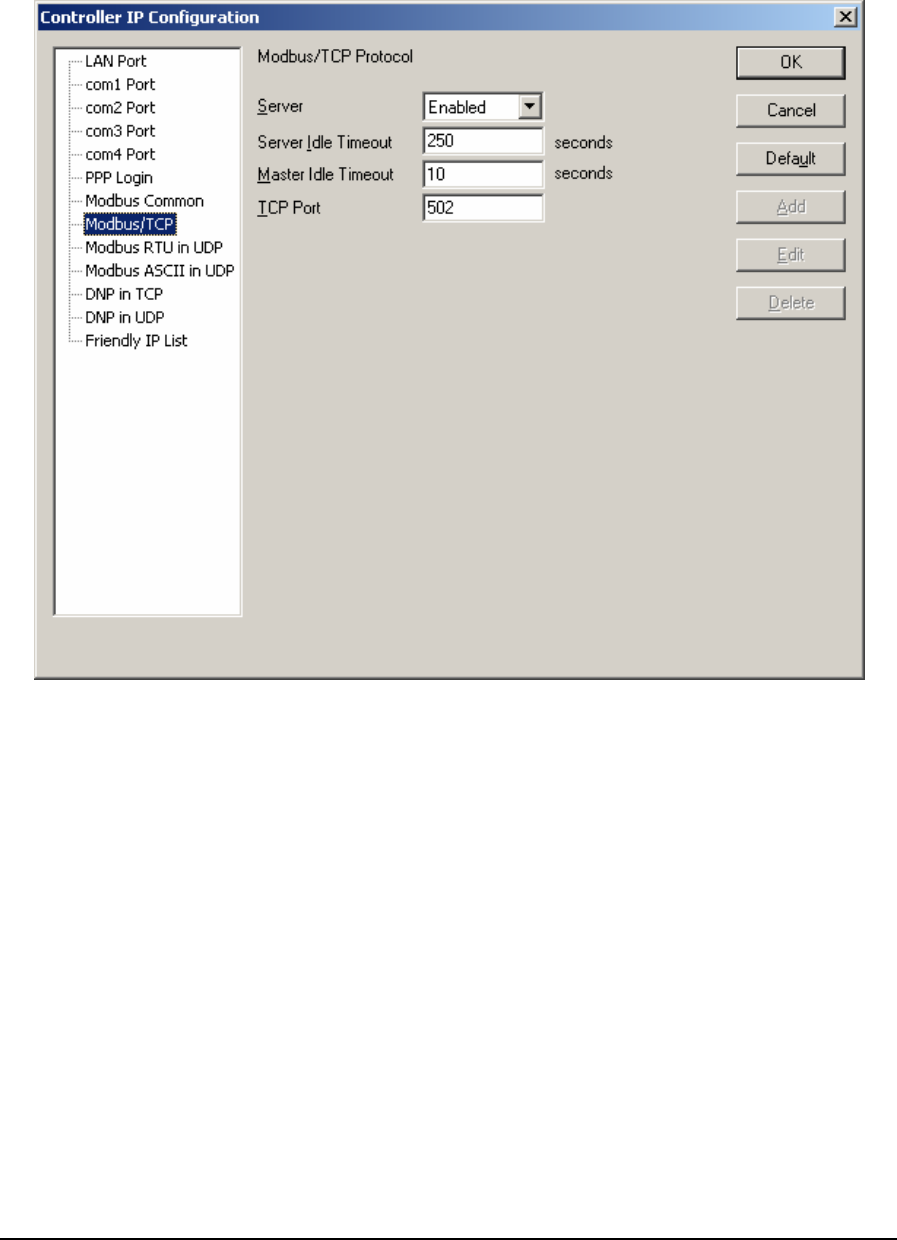
5.3.8 Modbus/TCP
The Modbus/TCP property page is selected for editing by clicking Modbus/TCP in the tree control
section of the IP Configuration dialog. When selected the Modbus/TCP property page is active.
Figure 25: Controller IP Configuration - Modbus/TCP Dialog Box
The Server selection selects whether the server is enabled. If this option is enabled the controller
supports incoming slave messages. Disabling this option prevents the controller from processing
slave messages. Master messaging is always enabled.
The Master Idle Timeout determines when connections to a slave controller are closed. Setting this
value to zero disables the timeout; the connection will be closed only when your program closes it.
Any other value sets the timeout in seconds. The connection will be closed if no messages are sent in
that time. This allows the slave device to free unused connections. Valid timeout range is 0 to
4294967295 seconds. The default value is 10 seconds.
The Server Idle Timeout determines when connections from a remote device are closed. Setting this
value to zero disables the timeout; the connection will be closed only when the remote device closes
it. Any other value sets the timeout in seconds. The connection will be closed if no messages are
received in that time. This allows the controller to free unused connections. Valid timeout range is 0
to 4294967295 seconds. The default value is 250 seconds.
The TCP Port sets the port used by the Modbus/TCP protocol. In almost all cases this should be set
to 502. This is the well-known port number for Modbus/TCP. Modbus/TCP devices use 502 by
TelePACE Ladder Logic User and Reference Manual
May 9, 2007
57
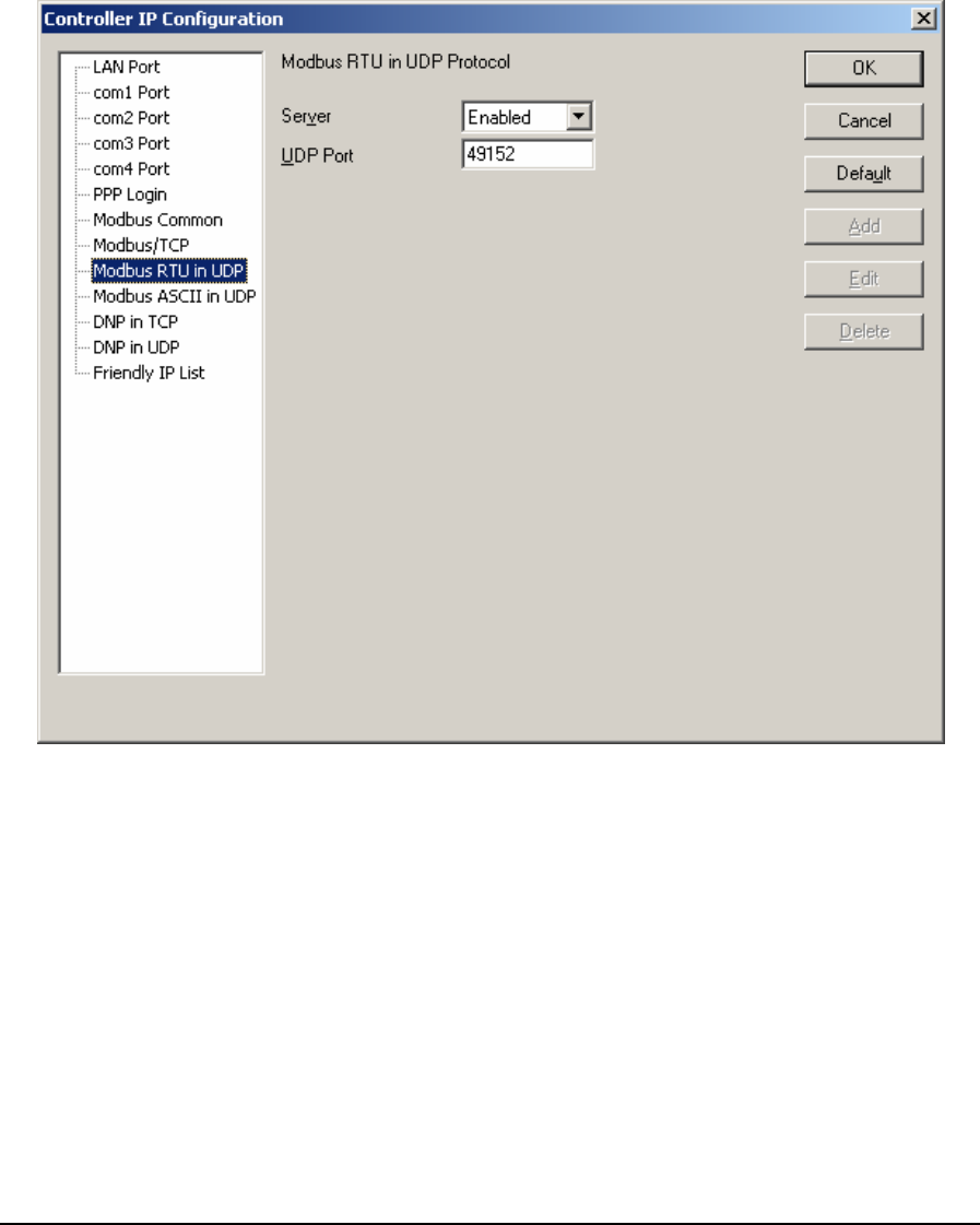
default, and on many devices the value cannot be changed. It is suggested that you change this value
only if this port is used by another service on your network. Valid port number range is 1 to 65534.
Consult your network administrator to obtain a port if you are not using the default.
5.3.9 Modbus RTU in UDP
The Modbus RTU in UDP property page is selected for editing by clicking Modbus RTU in UDP in
the tree control section of the IP Configuration dialog. When selected the Modbus RTU in UDP
property page is active.
Figure 26: Controller IP Configuration Modbus RTU in UDP Dialog Box
The Server selection selects whether the server is enabled. If this option is enabled the controller
supports incoming slave messages. Disabling this option prevents the controller from processing
slave messages. Master messaging is always enabled.
The UDP Port sets the port used by the protocol. Valid port number range is 1 to 65534. The default
value is 49152. This is a recommendation only. Consult your network administrator to obtain a port
if you are not using the default.
5.3.10 Modbus ASCII in UDP
The Modbus ASCII in UDP property page is selected for editing by clicking Modbus ASCII in UDP
in the tree control section of the IP Configuration dialog. When selected the Modbus ASCII in UDP
property page is active.
TelePACE Ladder Logic User and Reference Manual
May 9, 2007
58
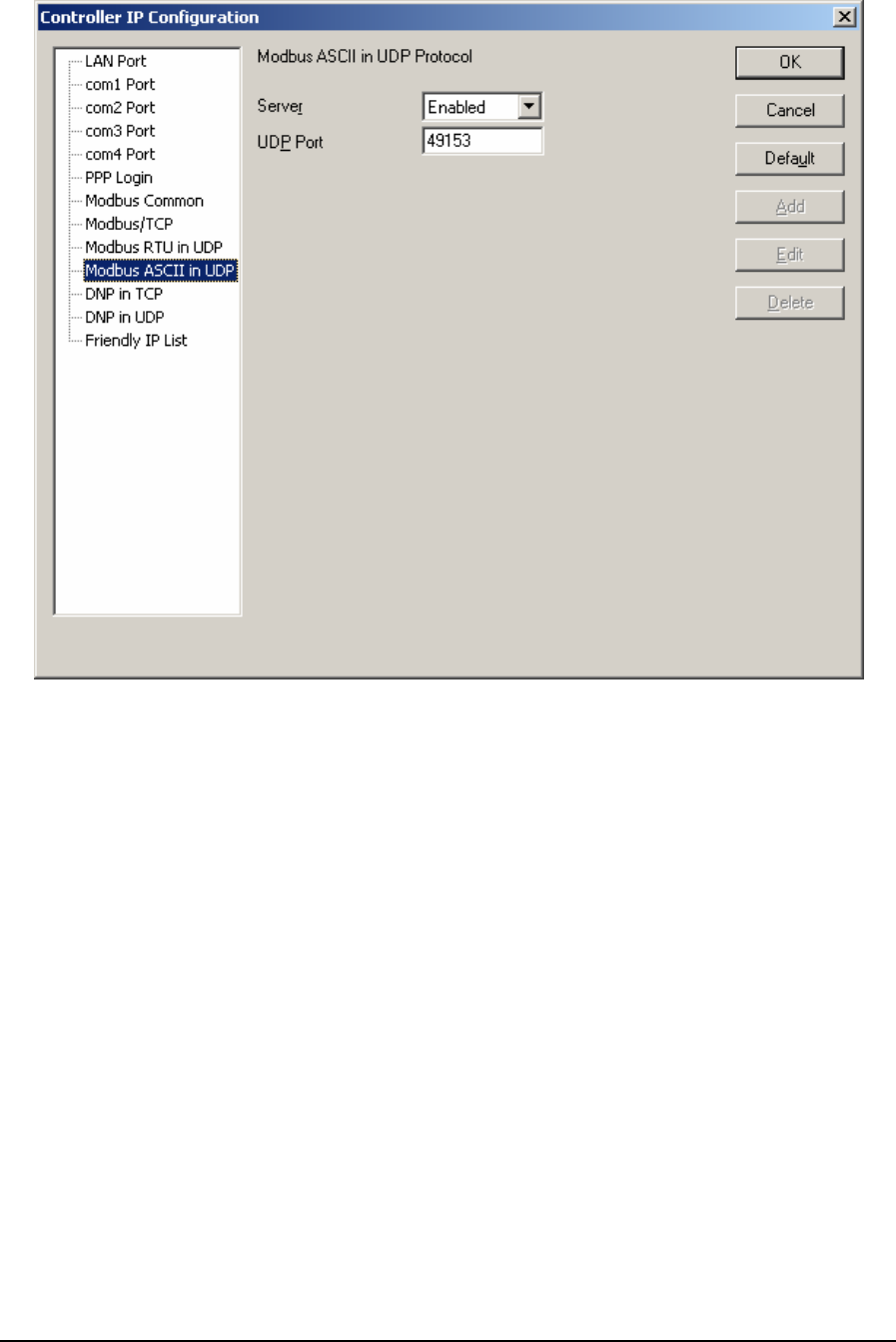
Figure 27: Controller IP Configuration – Modbus ASCII in UDP Dialog Box
The Server selection selects whether the server is enabled. If this option is enabled the controller
supports incoming slave messages. Disabling this option prevents the controller from processing
slave messages. Master messaging is always enabled.
The UDP Port sets the port used by the protocol. Valid port number range is 1 to 65534. The default
value is 49153. This is a recommendation only. Consult your network administrator to obtain a port
if you are not using the default.
5.3.11 DNP in TCP
The DNP in TCP property page is selected for editing by DNP in TCP in the tree control section of
the IP Configuration dialog. When selected the DNP in TCP property page is active.
TelePACE Ladder Logic User and Reference Manual
May 9, 2007
59
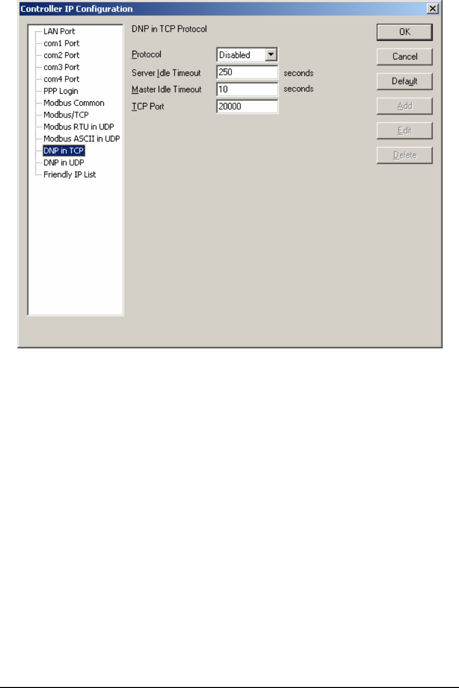
Figure 28: Controller IP Configuration – DNP in TCP Dialog Box
The Protocol selection selects whether the DNP in TCP protocol is enabled. If this option is enabled
the controller supports DNP in TCP protocol. Disabling this option prevents the controller from
processing DNP in TCP protocol messages. Master messaging is always enabled. The default
selection is disabled.
The Server Idle Timeout determines when connections from a remote device are closed. Setting this
value to zero disables the timeout; the connection will be closed only when the remote device closes
it. Any other value sets the timeout in seconds. The connection will be closed if no messages are
received in that time. This allows the controller to free unused connections. Valid timeout range is 0
to 4294967295 seconds. The default value is 250 seconds.
The Master Idle Timeout determines when connections to a slave controller are closed. Setting this
value to zero disables the timeout; the connection will be closed only when your program closes it.
Any other value sets the timeout in seconds. The connection will be closed if no messages are sent in
that time. This allows the slave device to free unused connections. Valid timeout range is 0 to
4294967295 seconds. The default value is 10 seconds.
The TCP Port sets the port used by the DNP in TCP protocol. Valid port number range is 1 to
65534. The default value is 20000. Consult your network administrator to obtain a port if you are not
using the default.
TelePACE Ladder Logic User and Reference Manual
May 9, 2007
60
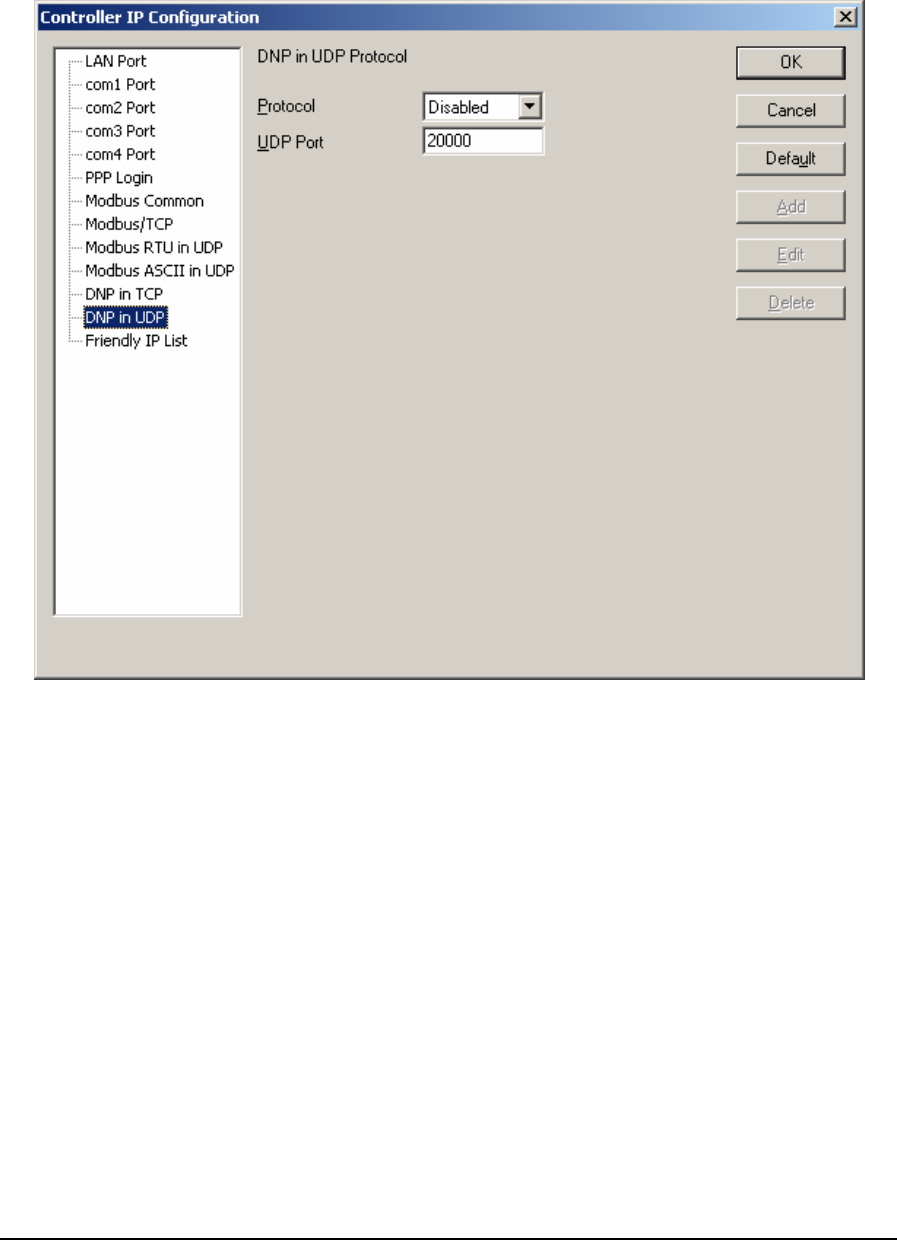
5.3.12 DNP in UDP
The DNP in UDP property page is selected for editing by DNP in UDP in the tree control section of
the IP Configuration dialog. When selected the DNP in UDP property page is active.
Figure 29: Controller IP Configuration – DNP in UDP Dialog Box
The Protocol selection selects whether the DNP in UDP protocol is enabled. If this option is enabled
the controller supports DNP in UDP protocol. Disabling this option prevents the controller from
processing DNP in UDP protocol messages and sending DNP in UDP master messages. The default
selection is disabled.
The UDP Port sets the port used by the DNP in UDP protocol. Valid port number range is 1 to
65534. The default value is 20000. Consult your network administrator to obtain a port if you are not
using the default.
5.3.13 Friendly IP List
The Friendly IP property page is selected for editing by Friendly IP in the tree control section of the
IP Configuration dialog.
TelePACE Ladder Logic User and Reference Manual
May 9, 2007
61
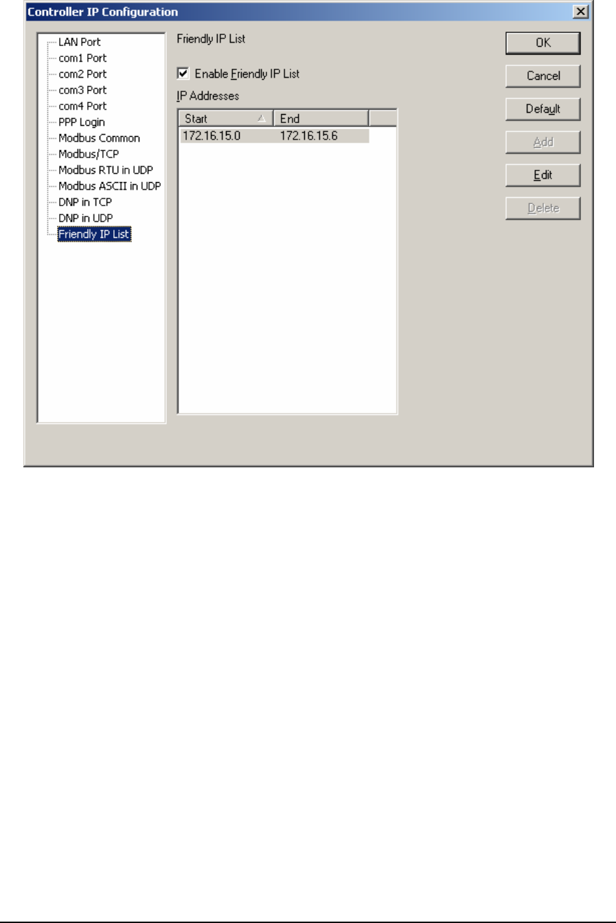
Figure 30: Controller IP Configuration – Friendly IP List Dialog Box
The Enable Friendly IP List checkbox enables or disables the friendly IP list. Check this box to
accept messages from only the IP addresses in the list. Uncheck this to accept message from all IP
addresses.
Click Add to enter a new row in the Friendly IP list. Selecting the Add button opens the Add
Friendly IP address dialog. The button is disabled if the Enable Friendly IP List control is not
checked. The button is disabled if the table is full. Up to 32 entries can be added to the table.
Click Edit to edit range in the Friendly IP list. Selecting the Edit button opens the Edit Friendly IP
address dialog. The button is disabled if the Enable Friendly IP List control is not checked.
The Delete button removes the selected rows from the list. This button is disabled if there are no
entries in the list. The button is disabled if the Enable Friendly IP List control is not checked.
Click on the column headings to sort the list by that column. Click a second time to reverse the sort
order. The order is indicated by the triangle next to the text.
The settings are verified when the OK button is pressed or another settings page is selected.
An error message is displayed if the friendly IP list is enabled and the list is empty.
A warning message is displayed if the IP address of the PC is not in the friendly IP table.
TelePACE Ladder Logic User and Reference Manual
May 9, 2007
62
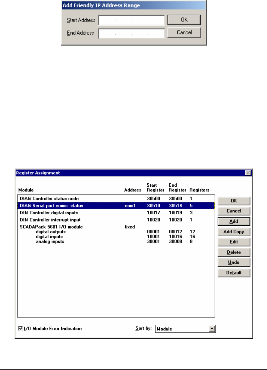
5.3.13.1 Add Friendly IP Address Range Dialog
The Add Friendly IP Address Range dialog specifies an IP address range to add to the Friendly IP
list.
Figure 31: Add Friendly IP Address Range Dialog Box
Start Address specifies the starting IP address in the range. Enter any valid IP address.
End Address specifies the ending IP address in the range. Enter a valid IP address that is
numerically greater than or equal to the IP Start Address. This field can be left blank if only a single
IP address is required.
The OK button adds the IP address range to the list and closes the dialog. An error is displayed if the
address range is invalid.
The Cancel button closes the dialog without making any changes.
5.4 Register Assignment
The Register Assignment dialog displays the current register assignment list. The user may edit the
list or the entries in the list.
Figure 32: Register Assignment Dialog Box
TelePACE Ladder Logic User and Reference Manual
May 9, 2007
63
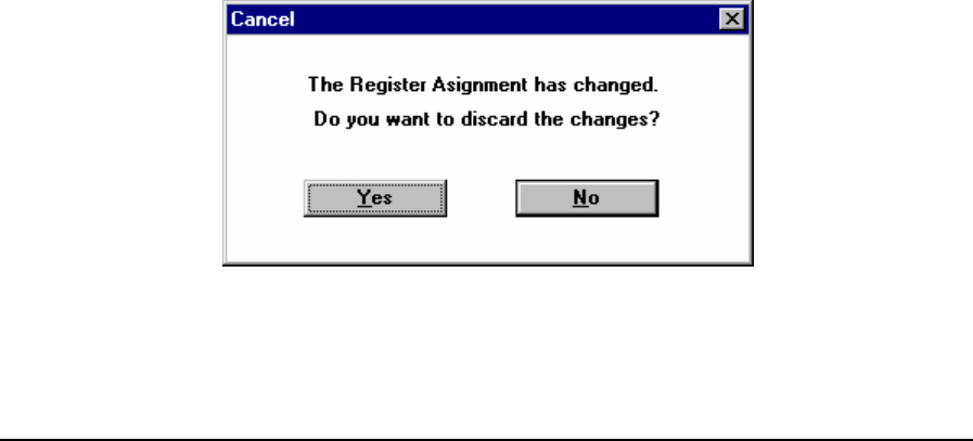
The main portion of the dialog is a list showing the modules in the register assignment list. The
module list displays the Module, Module Address, Start Register, End Register and the number of
Registers for the module.
The Module field displays the type and name of I/O modules that have been added to the Register
Assignment. For modules that support more than one type of I/O, there are multiple lines in the row
of the table, one for each input or output I/O type.
The Address field displays the unique module address of the physical hardware, such as a 5000
Series 5401 Digital I/O module. Some module types have no address that can be set by the user. The
address is blank for these modules.
The Start Register field displays the first register address in the I/O database where the module data
is stored. A start register is required for each type of input or output on the module.
The End Register field displays the last address in the I/O database used by the module. An end
register is required for each type of input or output on the module.
The Registers field displays the number of registers used by the module. A size is required for each
type of input or output on the module.
The I/O Module Error Indication check box determines if the controller displays I/O module
communication errors. If enabled, the controller will blink the Status LED if there is an I/O error.
See the DIAG Controller Status Code diagnostic module for information on the controller status
code. If disabled, the controller will not display the module communication status. The module
communication status is always checked. This option controls only the indication on the Status LED.
The Sort by: window selects how the Register Assignment List is sorted. The selections
are: Module, Start Register, or Address.
Click OK to update the register assignment list and close the dialog.
If the register assignment is changed it is written to the controller as follows.
If TelePACE is Off Line the changes are not written.
If TelePACE is On Line, the changes are downloaded automatically.
Selecting Cancel exits the dialog without saving changes. If changes were made, the user is
prompted for confirmation before exiting. This protects against accidentally discarding a large
number of changes. Press ESC to Cancel.
If changes were made the following dialog appears.
Figure 33: Cancel Register Assignment Dialog Box
Click Yes to close the Register Assignment dialog and the register assignment list is not changed.
TelePACE Ladder Logic User and Reference Manual
May 9, 2007
64
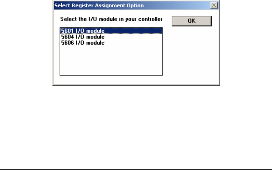
Click No to return to the Register Assignment dialog. No is the default selection. Press Enter or
ESC to select No.
Click Add to open the Edit Register Assignment dialog. The Add function adds a new module to the
register assignment.
Click Add Copy to open the Edit Register Assignment dialog. The Address field is set to the first
unused address for the currently selected module type. All other fields are set to the values from the
currently selected I/O module. The Add Copy button is grayed if:
• the table is empty,
• all I/O modules of the given type are in use (i.e. modules are already defined for all possible
addresses for the selected module type),
Selecting Edit opens the Edit Register Assignment dialog. All fields are set to the values from the
currently selected I/O module. The Edit button is grayed if:
• the table is empty,
• no module is selected in the table.
The Delete function removes the selected module from the register assignment. The Delete button is
grayed if:
• the table is empty,
• no module is selected in the table.
Selecting the Undo button undoes the last change to the register assignment list. A single level of
undo is provided. Selecting the Undo function a second time, restores the list to its state before the
first Undo.
The Default function replaces the current Register Assignment with the Default Register Assignment
for the controller type selected.
If the controller is a SCADAPack or SCADAPack 32 the following prompt is displayed.
Figure 34: Select Register Assignment Option Dialog Box
Select the I/O module, 5601, 5604 or 5606 that you are using in your controller and click OK.
TelePACE Ladder Logic User and Reference Manual
May 9, 2007
65
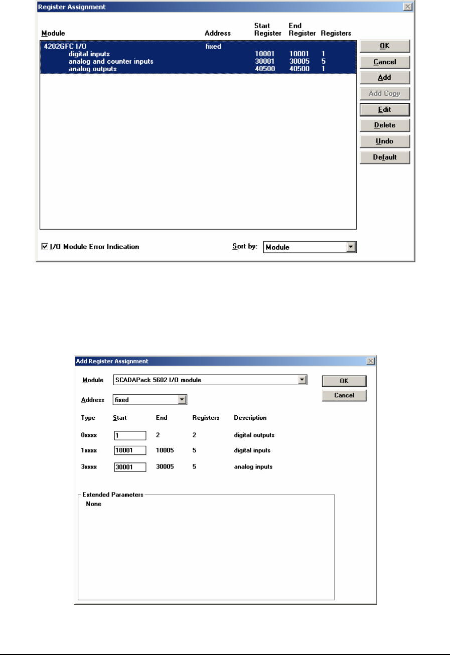
If the controller type is a SCADASense 4202 DR, the following dialog appears.
Figure 35: Register Assignment Dialog Box
5.4.1 Edit Register Assignment Dialog
The Edit Register Assignment dialog modifies an entry in the register assignment. The following
example shows the dialog editing a module with more than one I/O type.
Figure 36: Edit Register Assignment Dialog Box
TelePACE Ladder Logic User and Reference Manual
May 9, 2007
66

The Module drop-down list box shows the current module type. The drop-down list displays all
available modules. If the maximum number of modules of a particular I/O module type is already
configured, no modules of this class are shown in the drop-down list.
The Address drop-down list box shows the current module address. The drop-down list displays all
addresses valid for the current module type that are not already used. If all addresses are in use, the
list will be empty.
There are up to four Type description fields. The text displays the type of the input or output
register. The type descriptions are 0xxxx, 1xxxx, 3xxxx and 4xxxx.
• Digital output data is read from coil (0xxxx) registers. The digital outputs are updated
continuously with data read from the coil registers.
• Digital input data is stored in status (1xxxx) registers. The status registers are updated
continuously with data read from the digital inputs.
• Analog input data is stored in input (3xxxx) registers. The input registers are updated
continuously with data read from the analog inputs.
• Analog output data is stored in holding (4xxxx) registers. The analog output registers are
updated continuously with data read from the holding registers.
The Start edit box holds the starting register in the I/O database for the I/O type. The edit box allows
any number to be entered.
The End field shows the last register used by the module for the I/O type. TelePACE automatically
fills this field.
The Registers field shows the number of registers in the I/O module. TelePACE automatically fills
this field
The Description field displays the I/O type for multiple I/O modules. TelePACE automatically fills
this field
The Extended Parameters window will contain I/O module extended parameters if they are used.
Extended parameters may include such items as analog input type for example. Refer to the Register
Assignment Reference for information on all I/O modules.
Selecting OK checks the data entered. If the data is correct the dialog is closed and the Register
Assignment dialog returns with the changes made. If any data is incorrect, a beep will sound and the
cursor will select the field containing the first error found. Press ENTER to select OK.
Click Cancel to exit the dialog without saving changes. Press ESC to select Cancel.
5.5 Outputs On Stop
Select Outputs on Stop command and the Output Conditions on Program Stop dialog appears. This
dialog controls the state of the controller analog and digital outputs when the ladder logic program is
stopped.
The state of the digital outputs may be set to Hold their last value or to turn Off when the ladder
program is stopped.
The state of the analog outputs may be set to Hold their last value or to go to Zero when the ladder
program is stopped.
TelePACE Ladder Logic User and Reference Manual
May 9, 2007
67
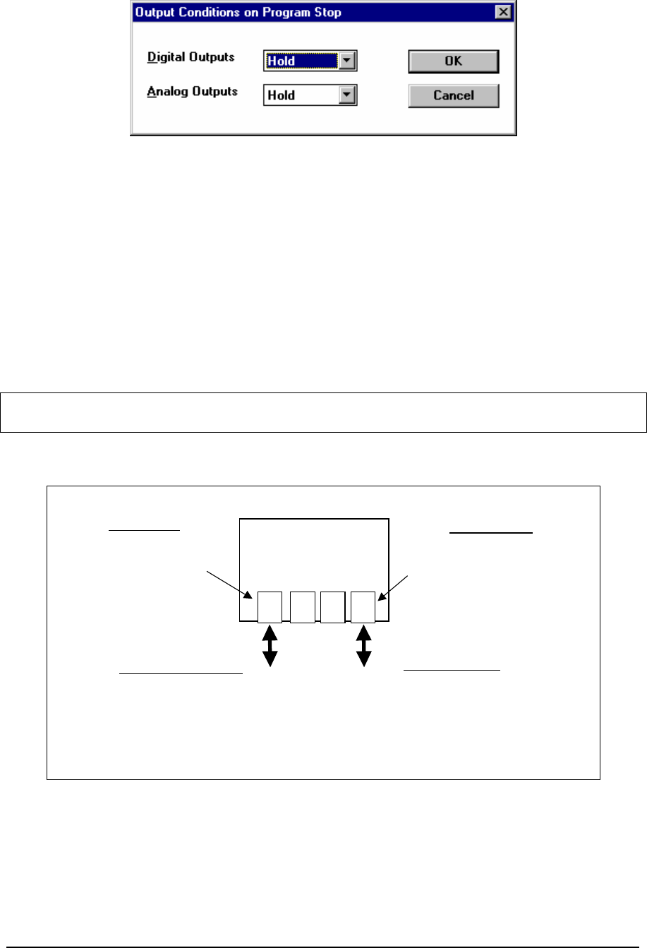
Figure 37: Output Conditions on Program Stop Dialog Box
The Digital Output drop-down list box specifies the state of the digital outputs. It has two options:
Hold and Off.
The Analog Output drop-down list box specifies the state of the analog outputs. It has two options:
Hold and Zero.
5.6 Store and Forward
The Store and Forward command is used to configure store and forward messaging. A controller
configured for store and forward operation receives messages destined for a remote Slave Station on
the Slave Interface. The controller forwards the message on the Forward Interface to the Forward
Station.
Note: This command is available only when the controller type is set to SCADAPack 350,
SCADAPack 32 or SCADAPack 32P.
Refer to the following diagram as a reference for the terminology used in the following Store and
Forward command reference.
COM1 COM2 COM4LAN
SCADAPack 32
Controller
Communication
Interfaces
Slave Interface
The Ethernet port is set for Modbus
address 2. The local SCADAPack
32 will respond to all messages
received for address 2.
Messages that require forwarding
must not be addressed for station
2.
Forward Interface
COM port 4 is set for Modbus
address 2. The local SCADAPack
32 will respond to all messages
received for station 2. Messages
that are forwarded must not be
addressed for station 2.
Message to be Forwarded
The message, from a remote master station,
that is to be forwarded by the SCADAPack 32
controller.
The station address of the message must be in
the Store and Forward table. In this example the
station address must not be 2.
Forwarded Message
The forwarded message, to the remote slave
station, that is forwarded by the SCADAPack
32 controller.
The station address of the message must be in
the Store and Forward table. In this example
the station address must not be 2.
Figure 38: Store and Forward Command Reference
When the Store and Forward command is selected the Store and Forward dialog appears. This dialog
displays the Store and Forward table for the controller.
TelePACE Ladder Logic User and Reference Manual
May 9, 2007
68

Figure 39: Store and Forward Dialog Box
The Store and Forward table displays each Store and Forward translation as a row, with column
headings, in the table. The table may have up to 128 entries. A vertical scroll bar is used if the list
exceeds the window size.
The Slave Interface heading displays the receiving slave interface the message is received from for
each translation.
The Slave Station heading displays the Modbus station address of the slave message.
The Forward Interface heading displays the interface the message is forwarded from. When
forwarding to a Modbus TCP or UDP network, the protocol type is selected for the Forward
Interface. The IP Stack automatically determines the exact interface (e.g. LAN/PPP) to use when it
searches the network for the Forward IP Address. If a serial port is selected for the Forward
Interface, and the serial port is configured for PPP protocol, the message will not be forwarded.
The Forward Station heading displays the Modbus station address of the forwarded message.
The Forward IP Address heading displays the IP address of the Forward Station. This field is blank
unless a TCP or UDP network is selected for Forward Interface.
The Time Out heading displays the maximum time (in tenths of seconds) the forwarding task waits
for a valid response from the Forward Station. The time out should be equal to or less than the time
out set for the master message received on the Slave Interface.
The OK button saves the table data. No error checking is done on the table data.
The Cancel button closes the dialog without saving changes.
Click Add to enter a new row in the store and forward table. Selecting the Add button opens the
Add/Edit Store and Forward dialog.
Click Edit to modify the selected row in the store and forward table. Selecting the Edit button opens
the Add/Edit Store and Forward dialog containing the data from the selected row. This button is
disabled if more than one row is selected. This button is disabled if there are no entries in the table.
The Delete button removes the selected rows from the table. This button is disabled if there are no
entries in the table.
TelePACE Ladder Logic User and Reference Manual
May 9, 2007
69
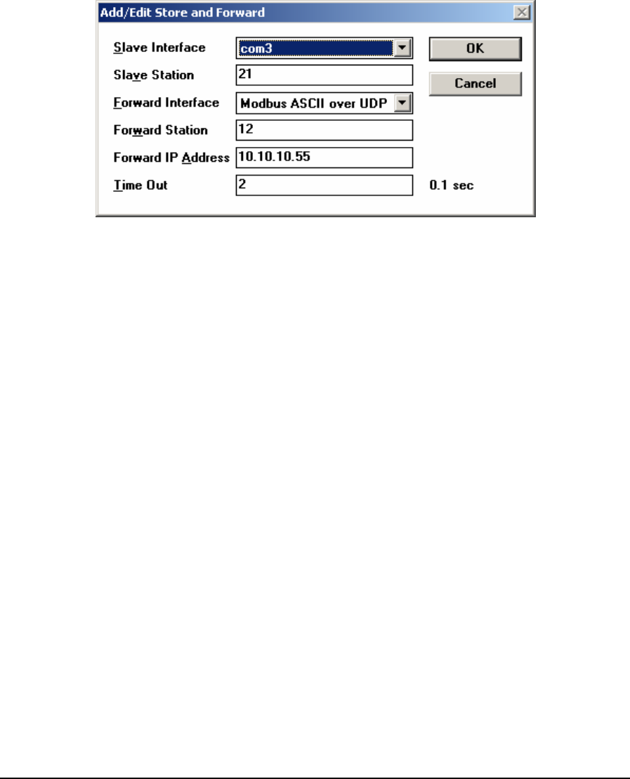
The Undo button undoes the action performed by the last button selection since the dialog was
opened. This applies to the buttons Add, Edit, Delete and Undo. This button is disabled when the
dialog is opened, and is enabled as soon as any of the applicable buttons are selected.
The Sorted by menu box lists each of the five column headings. The rows are sorted according to
the selected heading. Headings in the table are, by default, sorted by the Slave Interface heading.
5.6.1 Add/Edit Store and Forward Dialog
This dialog is used to edit an entry or add a new entry in the store and forward table.
Figure 40: Add/Edit Store and Forward Dialog Box
The Slave Interface is the receiving slave interface the message received from. The drop down list
allows the following selection:
• com1
• com2
• com3
• com4
• LAN/PPP
The Slave Station is the Modbus station address of the slave message. This address must be different
from the Modbus address assigned to the Slave Interface. Valid range for Slave Station is:
1 to 255 when standard addressing is selected for the interface.
1 to 65534 when extended addressing is selected for the interface.
The Forward Interface is the interface the message is forwarded from. The drop down list allows
the following selection:
• com1
• com2
• com3
• com4
• Modbus/TCP
• Modbus RTU in UDP
TelePACE Ladder Logic User and Reference Manual
May 9, 2007
70

• Modbus ASCII in UDP
The Forward Station is the Modbus station address of the forwarded message. This address must be
different from the Modbus address assigned to the Forward Interface. Valid range for Forward
Station is:
1 to 255 when standard addressing is selected for the interface.
1 to 65534 when extended addressing is selected for the interface.
The Forward IP Address edit box is disabled and the address is forced to “0.0.0.0“ whenever the
Forward Interface is set to com1, com2, com3 or com4. The Forward IP Address edit box is enabled
only when the Forward Interface is set to a TCP or UDP network. Valid entries are 0 to 255 for each
byte in the IP address.
The Time Out is the maximum time the forwarding task waits for a valid response from the
Forward Station, in tenths of second. Valid entries are 0 to 65535. The time out should be equal to or
less than the time out set for the master message received on the Slave Interface.
The OK button checks the data for this table entry. If the data is valid the dialog is closed. If the
table data entered is invalid, an error message is displayed and the dialog remains open. The table
entry is invalid if any of the fields is out of range. The data is also invalid if it conflicts with another
entry in the table.
The Cancel button closes the dialog without saving changes.
5.7 DNP
The DNP command is used to configure the DNP protocol settings for the controller. When selected
the DNP Settings window is opened, as shown below.
For complete information on DNP configuration refer to the DNP 3 User and Reference Manual.
5.8 DNP Status
The DNP Status command opens the DNP Status dialog. This dialog shows the run-time DNP
diagnostics and current data values for the local DNP points.
For complete information on the DNP Status command refer to the DNP 3 User and Reference
Manual.
5.9 DNP Master Status
The DNP Status command opens the DNP Master Status dialog. This dialog shows the run-
time DNP diagnostics and status of the DNP outstations defined in the Master Poll table and
current data values for the DNP points in these outstations.
For complete information on the DNP Status command refer to the DNP 3 User and Reference
Manual.
5.10 Initialize
The initialize command is used to restore a controller to default settings. This is typically done when
starting a new project with a controller. The Initialize controller dialog is displayed when this
command is selected. The Initialize Controller dialog presented depends on the type of controller
selected. The dialog is different between the SCADAPack 32 or SCADAPack series controllers
(Micro16, SCADAPack, SCADAPack Light, SCADAPack Plus, SCADAPack 100, SCADAPack
TelePACE Ladder Logic User and Reference Manual
May 9, 2007
71
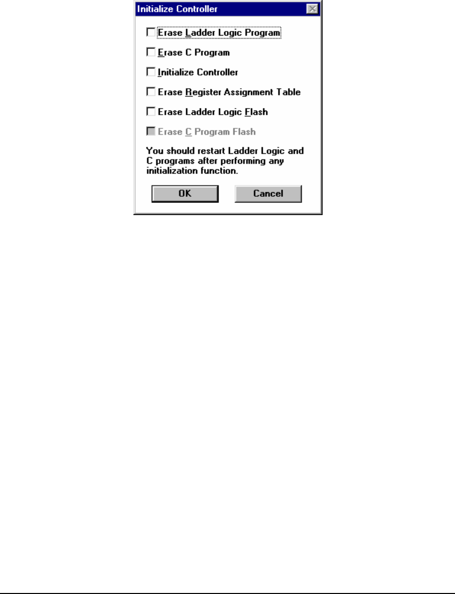
350, and the SCADASense Series of programmable controllers (4202 DR, 4202 DS, 4203 DR and
4203 DS). The different dialogs are described in the following sections.
5.10.1 SCADAPack and SCADAPack 32 Controllers
The Initialize Controller dialog shown below appears when the command is selected and the
Controller Type is SCADAPack or SCADAPack 32 (not SCADAPack 350).
Figure 41: Initialize Controller Dialog Box SCADAPack and SCADAPack 32 Controllers
Check the Erase Ladder Logic Program selection to erase the ladder logic program in the
controller RAM memory.
Check the Erase C Program selection to erase the C application program in the controller RAM
memory.
Check the Initialize Controller selection to reset all values in the I/O database to default settings.
The Initialize controller command will do the following:
• The default communication parameters are set for all serial ports. If you are communicating
using settings other than the default, the PC Communication Settings will have to be changed
once the command is complete. Note that the Ethernet port on SCADAPack 32 controllers is not
changed by the initialize controller command.
• The registers in the I/O database are initialized to their default values.
• All forcing is removed.
• The controller is unlocked.
Check the Erase Register Assignment selection to erase the controller register assignments. The
Register Assignment is cleared and must be reconfigured.
Check the Erase Ladder Logic Flash selection to erase the Ladder Logic program in Flash. This
control is greyed if the controller firmware does not support programs in Flash or if the Flash is used
by the operating system.
TelePACE Ladder Logic User and Reference Manual
May 9, 2007
72
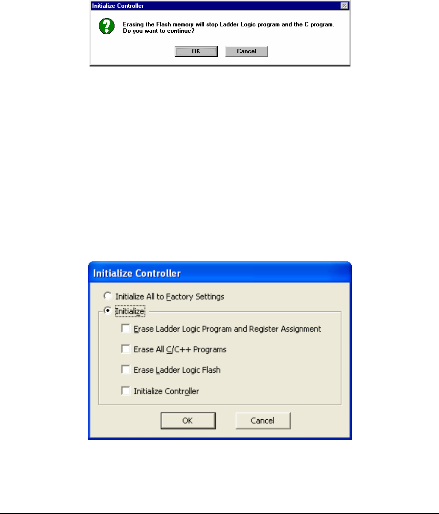
Check the Erase C Program Flash selection to erase the C program in Flash. This control is greyed
if the controller firmware does not support programs in Flash or if the Flash is used by the operating
system.
• Click OK to perform the requested initializations.
• Click Cancel to exit without performing any action.
Erasing Programs in Flash
Erasing the Flash memory requires the Ladder Logic and C programs be stopped. The following
message is displayed if the OK button is selected.
Figure 42: Initialize Controller Dialog Box
• Click OK to stop the execution and erase the flash memory. The following actions occur.
The Ladder Logic and C programs in the controller are stopped.
If it was selected, the Ladder Logic program is erased.
If it was selected, the C program is erased.
Programs that were stopped to allow Flash to be erased are not re-started. These programs must be
re-started.
5.10.2 SCADAPack 350 and SCADASense 4203 Series of Controllers
For SCADAPack 350 and SCADASense 4203 Series of controllers (4203 DR and 4203 DS), the
Initialize dialog shown below appears when the command is selected.
Figure 43: Initialize Dialog for SCADAPack 350 and SCADASense 4203 Series Controllers
TelePACE Ladder Logic User and Reference Manual
May 9, 2007
73

Select the Initialize All to Factory Settings radio button to erase all programs in the controller
memory and initialize the controller to factory settings. Please see Actions Performed when
Controller is Initialized below for details. Erasing all programs includes all C/C++ programs, the
Ladder Logic program in RAM, and the Ladder Logic program in ROM, if applicable.
Select the Initialize radio button to initialize only the selected items. The items that may be selected
are as follows:
• Check the Erase Ladder Logic Program and Register Assignment selection to erase the
ladder logic program and register assignment in the controller RAM memory.
• Check the Erase All C/C++ Programs selection to erase all C/C++ programs in the
controller.
• Check the Erase Ladder Logic Flash selection to erase the Ladder Logic program in Flash
(ROM).
• Check the Initialize Controller selection to initialize the controller to default settings.
Please see Actions Performed when Controller is Initialized below for details. The default
settings used depends on the radio button selected below this selection:
• Click on the OK button to perform the requested initializations.
• Click on the Cancel button to exit without performing any action.
5.10.2.1 Actions Performed when Controller is Initialized
The following actions are performed when the controller is initialized:
• The controller settings below are set to default values. If you are communicating using settings
other than the default, the PC Communication Settings will have to be changed once the
command is complete. Note that the Ethernet port is not changed by the initialize controller
command.
• Serial port communication parameters
• Modbus/IP and DNP/IP protocol settings
• Outputs on Stop settings
• HART modem configurations
• LED power control
• All forcing is cleared.
• All Modbus registers are set to zero.
• If there is a register assignment, the assigned registers are initialized to their default values. For
example, if a configuration module for a group of controller settings is in the register
assignment, the assigned registers are initialized to the default values for those controller
settings.
• All digital outputs and analog outputs are cleared.
• Data logged by all DLOG functions is erased.
• Alarm clock is cleared.
• Serial port event counters are cleared.
• Store and forward table is cleared.
TelePACE Ladder Logic User and Reference Manual
May 9, 2007
74
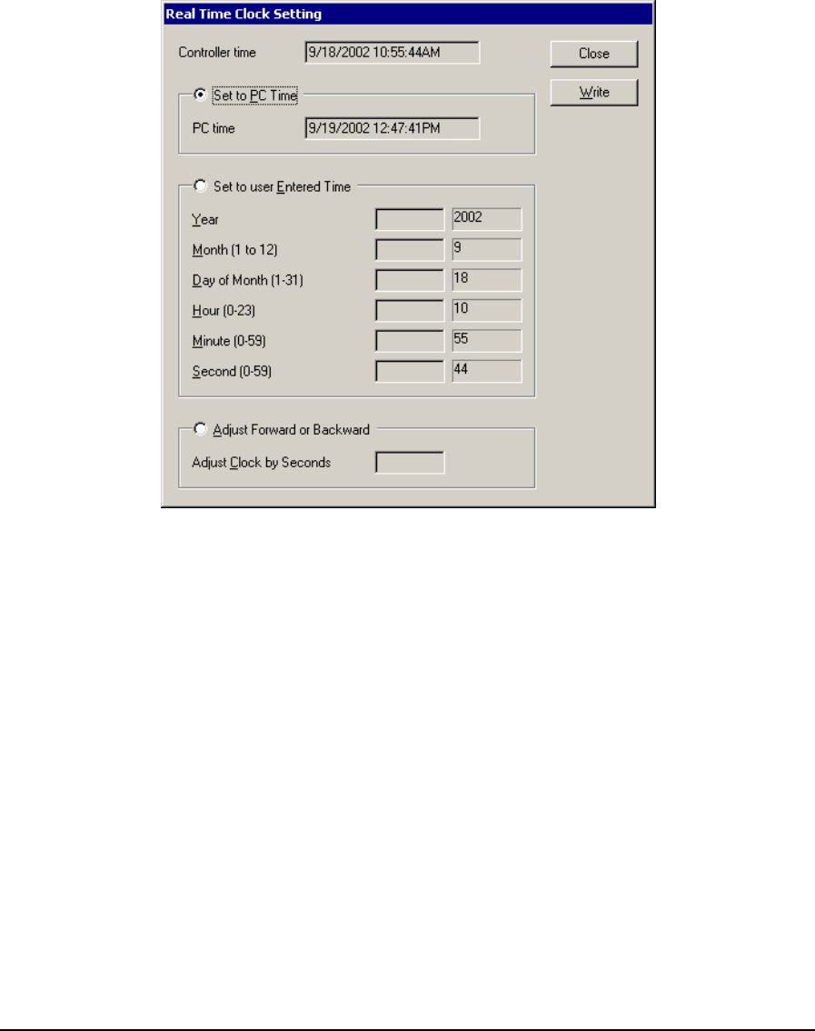
• Friendly IP List is cleared.
• The power mode changes to full power.
5.11 Real Time Clock
The Real Time Clock command is used to set the controller Real Time Clock. The user may set the
clock to the PC time, to a user specified time or adjust the clock forward or back by a number of
seconds. The Real Time Clock Setting dialog shown below appears when the command is selected.
Figure 44: Real Time Clock Setting Dialog Box
The following controls are available from the Real Time Clock Setting dialog.
Controller time shows the current time and date in the controller. It is updated continuously while
the dialog is open. The time and date are displayed in the short time format as defined in the
Windows Control Panel.
The Set to PC Time radio button selects setting the controller time to match the PC time. The
current PC time and date are shown to the right of the button. The time and date are displayed in the
short format as defined in the Windows Control Panel.
The Set to User Entered Time radio button selects setting the time and date to the values specified
by the user in the Year, Month, Day, Hour, Minute and Second controls. The valid values for entry
are shown in the dialog. If the Set to User Entered Time radio button is not selected these controls
are grayed.
The Adjust Forward or Backward radio button selects adjusting the time by the number of seconds
specified in the Adjust Clock by Seconds edit box. The value can be negative or positive. The edit
box is grayed if the Adjust by radio button is not selected.
• The Close button closes the dialog.
TelePACE Ladder Logic User and Reference Manual
May 9, 2007
75
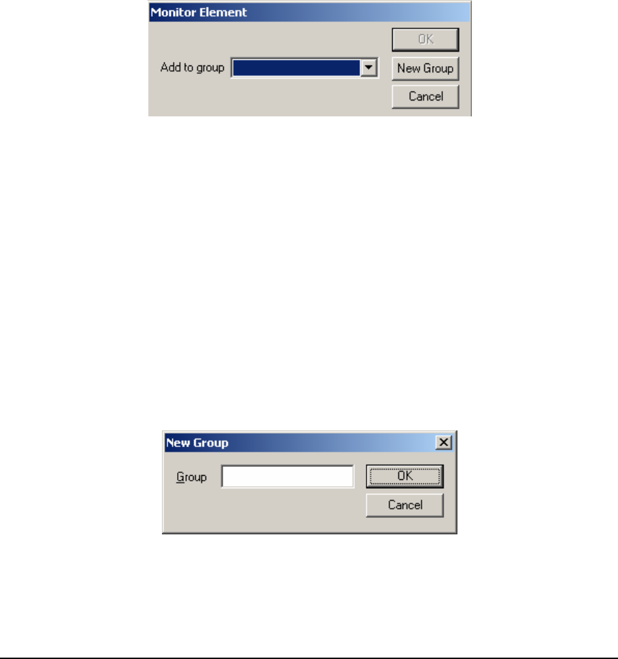
• The Write button writes the selected time to the controller.
5.12 Monitor Element
The Monitor Element command is used to add registers used by selected elements to the Register
Editor. All registers used by the currently selected element, or elements, are added to the Register
Editor. This command is available only if an element, or multiple elements, is selected.
This command may be selected by right click your mouse button on a highlighted element, or group
of elements, and selecting Monitor Element from the list of commands.
To add registers to the Register Editor using the Monitor Registers command first highlight an
element by clicking the left mouse button on an element or dragging the cursor over a group of
elements. Then select the Monitor Element command from the Controller menu or from the mouse
right click menu.
When the Monitor Element command is selected the Monitor Element dialog is displayed.
Figure 45: Monitor Element Dialog Box
The Add to Group list box selects which group the registers are added to. A drop down selection
displays all created groups. If no groups have been created use the New Group button to add a
Register Editor group.
The OK button adds the registers and closes the dialog. The registers are added to the Register
Editor in the format used by the selected element or elements.
The Available status is set to Online for all registers except registers contained in elements that use
Element Configuration.
The Available status is set to Always for all registers contained in elements that use Element
Configuration.
The Cancel button closes the dialog without adding the registers to the Register Editor.
The New Group button opens New group dialog. This dialog is used to create a new group in the
Register Editor.
Figure 46: New Group Dialog Box
TelePACE Ladder Logic User and Reference Manual
May 9, 2007
76
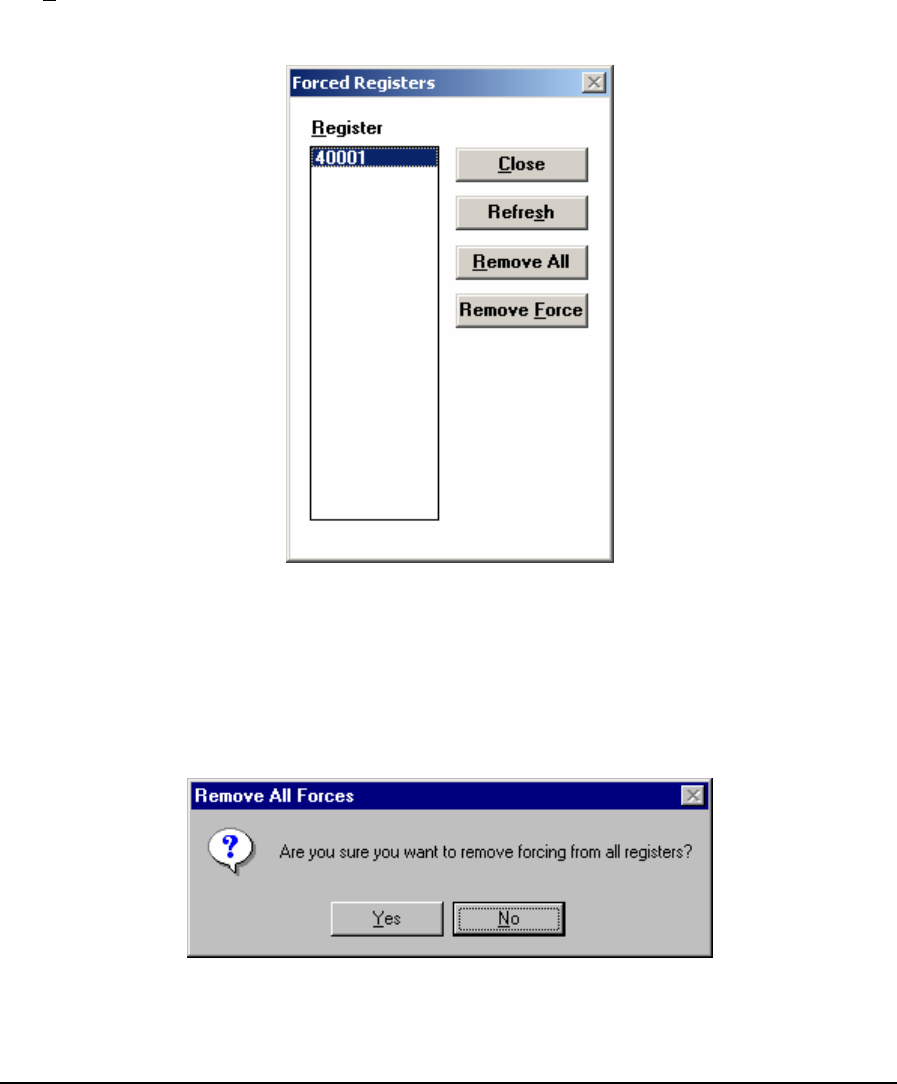
The Group edit box is used to enter the name of the new group. The group name may contain letters,
numbers, and spaces. The group name may be 1 to 16 characters long and the name is not case
sensitive.
The OK button creates the new group and closes the dialog. If the group name already exists an error
message is displayed and the dialog remains open.
The Cancel button closes the dialog.
5.13 List Force Registers
The List Forced Registers command displays the Forced Registers dialog. This dialog displays a list
of registers that are forced. The user may view and edit the registers, add registers to the list, remove
registers from the list and clear all forces. The dialog appears as shown below.
Figure 47: Forced Registers Dialog Box
The Register list box shows all registers in the controller that are currently forced.
Click Close to close the dialog box. Press ESC to select Close.
Selecting the Remove All button clears the force status for all registers. All registers are removed
from the register list box. When selected the user is prompted for confirmation.
Figure 48: Remove All Forces Dialog Box
TelePACE Ladder Logic User and Reference Manual
May 9, 2007
77
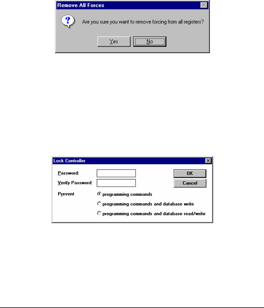
Selecting Yes removes all forcing. Selecting No aborts the command. The No button is the default
selection. Press ENTER or ESC to select No. This button is grayed when there are no registers in
the register list box.
The Remove Force button clears the force status for the selected register. The register is removed
from the register list box. This button is grayed when there are no registers in the register list box.
5.14 Remove All Forces
Selecting the Remove All Forces command clears the force status for all forced registers. This
command is only available in the on-line mode.
Selecting Remove All Forces prompts the user for confirmation:
Figure 49: Remove All Forces Dialog Box
• Selecting Yes removes all forcing.
• Selecting No aborts the command. The No button is the default selection. Press ENTER or ESC
to select No.
5.15 Lock Controller
Locking a controller prevents unauthorized access. Commands sent to the controller when it is
locked will be rejected. A controller that is unlocked operates without restriction.
The Lock Controller dialog specifies a password to be used to lock the controller and the commands
that are locked.
Figure 50: Lock Controller Dialog Box
Enter a password in the Password edit box. Re-enter the password in the Verify Password edit box.
Any character string up to eight characters in length may be entered. Typing in these edit boxes is
masked. An asterisk is shown for each character typed.
The Prevent radio buttons select the commands that are locked.
TelePACE Ladder Logic User and Reference Manual
May 9, 2007
78
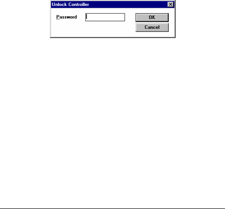
Locking the programming commands prevents modifying or viewing the program in the controller.
Communication protocols can read and write the I/O database.
Locking programming and database write commands prevents modifying or viewing the program
and prevents writing to the I/O database. Communication protocols can read data from the I/O
database, but cannot modify any data.
Locking programming and database commands prevents modifying or viewing the program and
prevents reading and writing the I/O database. Communication protocols cannot read or write the I/O
database.
The OK button verifies the passwords are the same and sends the lock controller command to the
controller. The dialog is closed. If the passwords are not the same an error message is displayed.
Control returns to the dialog.
The Cancel button closes the dialog without any action.
If the controller is already locked, a message indicating this is shown instead of the dialog.
5.16 Unlock Controller
The Unlock Controller dialog prompts the user for a password to be used to unlock the controller. If
the controller is locked, the following dialog is displayed.
Figure 51: Unlock Controller Dialog Box
Enter the password that was used to lock the controller in the Password edit box. Typing in this edit
box is masked. An asterisk is shown for each character typed.
The Cancel button closes the dialog without any action.
The OK button sends the Unlock Controller command to the controller. If the password is correct
the controller will be unlocked. If the password is not correct, the controller will remain locked.
If you forget the controller password, the Override Controller Lock command can be used to unlock
the controller. It will erase all programs in the controller.
5.17 Override Controller Lock
The Override Controller Lock dialog allows the user to unlock a controller without knowing the
password. This can be used in the event that that the password is forgotten.
To prevent unauthorized access to the information in the controller, the C and Ladder Logic
programs are erased. Use this command with caution, as you will lose the programs in the controller.
Selecting the Override Controller Lock command displays the following dialog.
TelePACE Ladder Logic User and Reference Manual
May 9, 2007
79

Figure 52: Override Controller Lock
• The Yes button unlocks the controller and erases all programs.
• The No button closes the dialog without any action.
5.18 Show Lock Status
The Show Lock Status command displays the controller lock state. It opens a dialog showing one of
the following states:
• unlocked
• locked against programming commands
• locked against programming commands and database write
• locked against programming commands and database read/write
• The OK button closes the dialog.
5.19 C/C++ Program Loader
The C/C++ Program Loader command opens the C/C++ Program Loader dialog. This dialog allows
the user to load, run, stop and delete C/C++ programs.
The C/C++ Program Loader dialog presented is the same for all controller types. For all controllers
except the SCADAPack 350, this dialog may be used to load, run, stop or delete just one C/C++
program.
5.19.1 SCADAPack and SCADAPack 32 Controllers
The dialog shown below appears when the C/C++ Program Loader command is selected from the
controller menu and the Controller Type is either a SCADAPack32 or any one of the SCADAPack
series of controllers (Micro16, SCADAPack, SCADAPack Light, SCADAPack Plus, SCADAPack
100 and SCADASense 4202 DR and DS) but not a SCADAPack 350.
For all controllers except the SCADAPack 350, the C/C++ Program Loader dialog may be used to
load just one C/C++ program.
TelePACE Ladder Logic User and Reference Manual
May 9, 2007
80
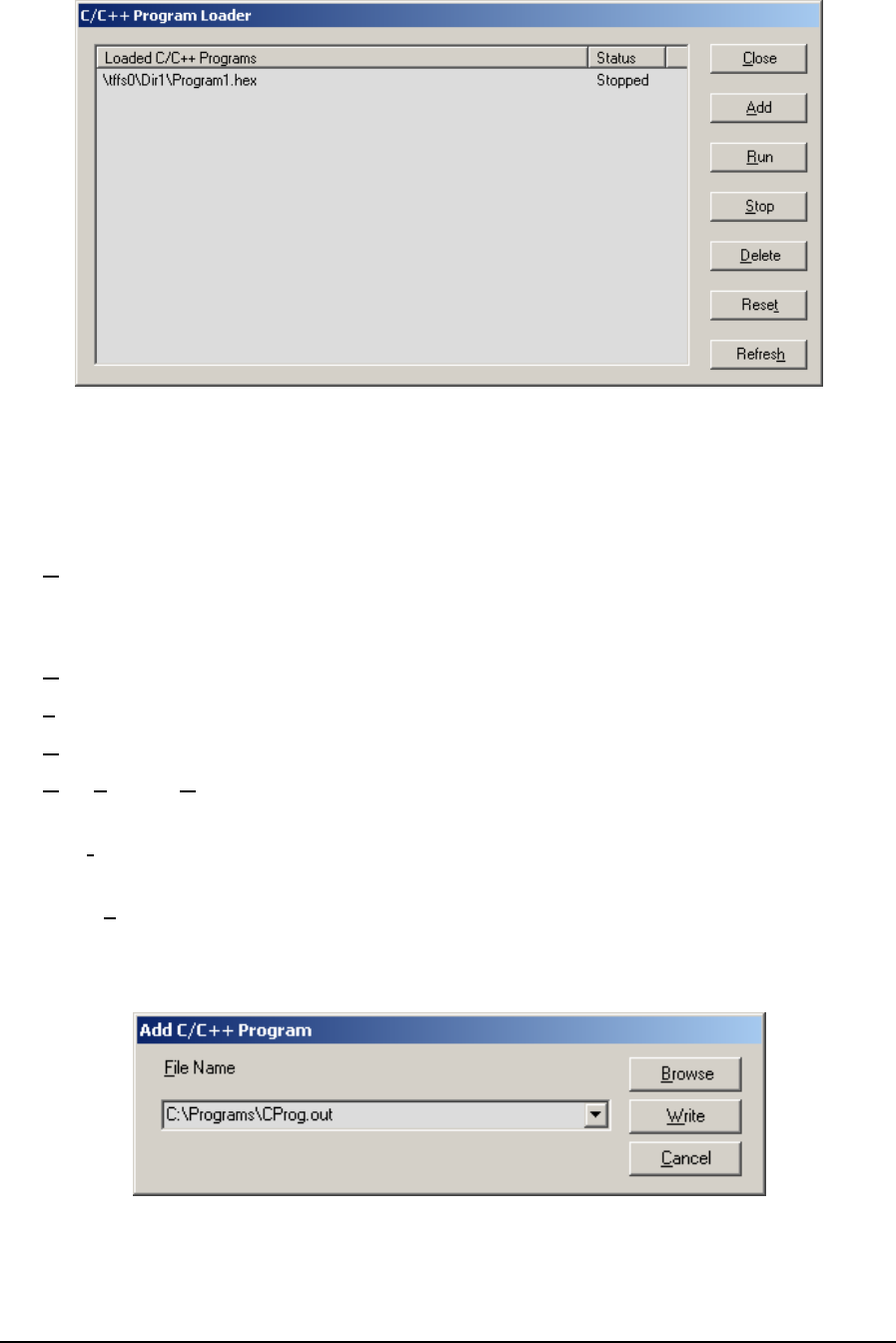
Figure 53: C/C++ Program Loader dialog for SCADAPack Series
The dialog displays the status of the C/C++ Program if one has been loaded in the controller. The
status of the program is indicated as Running or Stopped. The list is empty if there is no C/C++
Program loaded in the controller.
The Close button closes the dialog.
The Add button writes a C/C++ program to the controller. Selecting the Write button opens the Add
C/C++ Program dialog.
The Run button stops and restarts the C/C++ program in the controller.
The Stop button stops the selected C/C++ program in the controller.
The Delete button stops and erases the selected C/C++ program in the controller.
The Run, Stop and Delete buttons are disabled if there is no C/C++ program loaded in the
controller.
The Reset button resets the controller. A reset restarts the controller processor, the C/C++ program
and the Ladder Logic program.
The Refresh button refreshes the status of the loaded C/C++ program.
5.19.1.1 Add C/C++ Program Dialog
The Add C/C++ Program dialog writes a C/C++ Program to the controller.
Figure 54: Write C/C++ Program dialog
TelePACE Ladder Logic User and Reference Manual
May 9, 2007
81
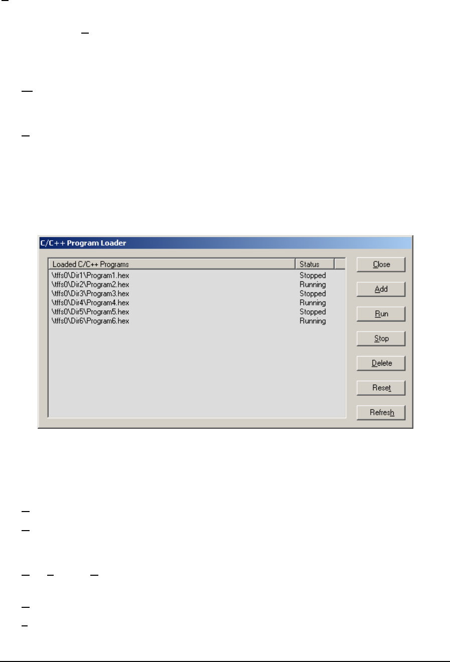
File Name specifies the C/C++ Program to write to controller. The file name may be selected in a
number of ways.
• Click on the Browse button to open a standard file open dialog.
• Use the drop-down menu to select the file from a list of previously written files.
• Type the path and file name directly into the edit box.
The Write button writes the selected file to the controller. The communication progress dialog box
displays information about the write in progress, and allows you to cancel the write. If a C/C++
program is already loaded, it is stopped and erased before the selected file is written to the controller.
The Cancel button exits the dialog without writing to the controller.
5.19.2 SCADAPack 350 and SCADASense 4203 Series Controllers
If the controller type is a SCADAPack 350 or a SCADASense 4203 Series controller, the C/C++
Program Loader dialog displayed is shown below. In contrast to all other SCADAPack controllers,
this dialog allows multiple C/C++ programs to be loaded, monitored, and controlled. The number
of C/C++ programs that can be loaded into a SCADAPack 350 or a SCADASense 4203 Series
controller depends on the memory capacity of RAM of Flash.
Figure 55: C/C++ Program Loader dialog
The dialog displays the C/C++ Programs that have been loaded in the controller. The status of each
program is indicated as Running or Stopped.
The Close button closes the dialog.
The Add button writes a new C/C++ program to the controller. Selecting the Add button opens the
Add C/C++ Program dialog. Refer to 5.19.1.1-Add C/C++ Program Dialog for a description of
the Add C/C++ program dialog.
The Run, Stop and Delete buttons apply to the C/C++ program selected from the list of loaded
C/C++ programs. These buttons are disabled when there are no C/C++ programs loaded.
The Run button stops and restarts the selected C/C++ program in the controller.
The Stop button stops the selected C/C++ program in the controller.
TelePACE Ladder Logic User and Reference Manual
May 9, 2007
82
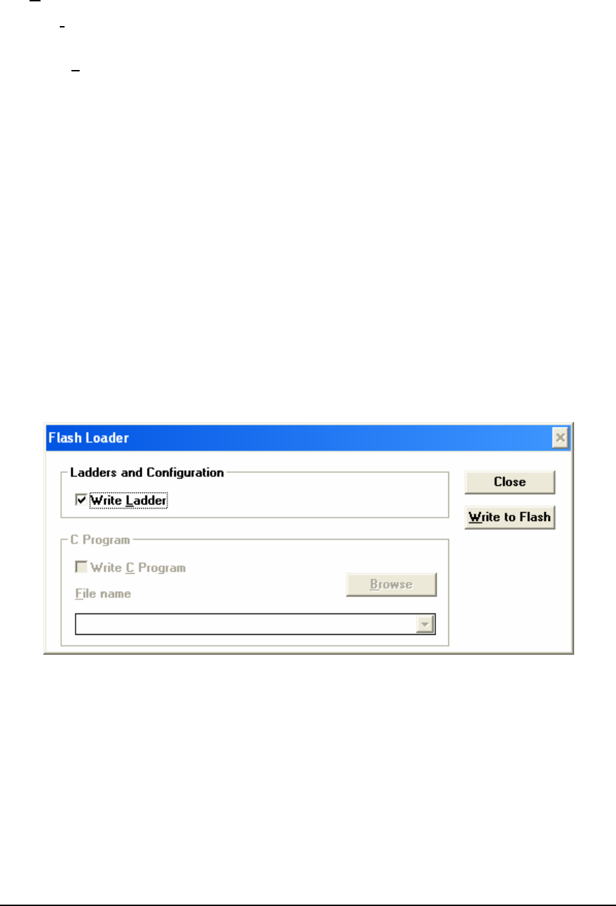
The Delete button stops and erases the selected C/C++ program in the controller.
The Reset button resets the controller. A reset restarts the controller processor, all C/C++ programs
and the Ladder Logic program.
The Refresh button refreshes the list of loaded programs and their status.
Click on the column headings to sort the list by that column. Click a second time to reverse the sort
order.
5.20 Flash Loader
The Flash Loader command opens the Flash Loader dialog. This dialog is used to write Ladder Logic
and C/C++ programs into Flash memory. This memory is permanently programmed and does not
require power or a backup battery. The programs in Flash can be written through all supported
communication media.
When this command is selected TelePACE checks if the controller supports Flash memory and, if a
Flash memory chip is installed.
If the controller does not support Flash memory, the message “Controller does not support Flash
memory” is displayed.
If the controller supports flash memory but there is no Flash memory installed in the application
ROM socket, the message “Flash memory is not installed in the application socket (U14)” is
displayed. Flash memory will have to be installed in the controller.
If there is Flash memory installed in the application program socket U14, the Flash Loader dialog is
displayed as shown below.
Figure 56: Flash Loader Dialog Box
The Write Ladder check-box controls writing of the Ladder Logic program and configuration data.
Configuration data includes serial port settings, register assignment, outputs on stop settings and,
element configuration. The file currently open Ladder Logic program in TelePACE will be written.
This control is disabled if the controller has operating system code in the Ladder Logic section of
Flash.
The Write C Program check-box controls writing of the C/C++ programs. This area is greyed out if
the controller type is one of the following:
• SCADAPack 350
TelePACE Ladder Logic User and Reference Manual
May 9, 2007
83
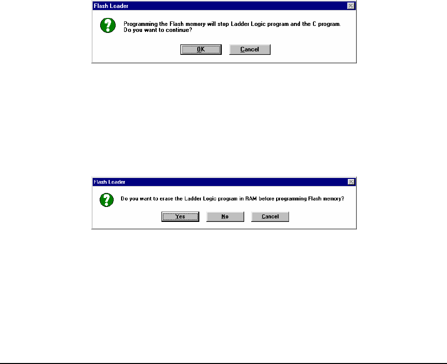
• SCADAPack 32 or SCADAPack 32P
• SCADAPack
• SCADASense 4202 DR and DS with firmware 1.65 or newer
• SCADASense 4203 DR and DS
The following controls select which file will be written. These controls are disabled if the controller
has operating system code in the C Program section of Flash.
The File name edit-box contains the full path name of the file to be written.
The Browse button opens standard file open dialog. It displays files of type *.abs. Selecting a file
fills in the File name edit-box.
The Message Length edit-box selects the maximum message length to be used while writing the
programs to the controller. Control over message length is needed when writing large amounts of
data over certain communication networks. The C program is written more quickly with a longer
message length. The allowable range is 26 to 255 bytes. The default value is 255.
• The Close button closes the dialog.
• The Write to Flash button writes the selected programs to Flash memory in the controller.
5.20.1 Writing Programs to Flash
Programming the Flash memory requires the Ladder Logic and C programs be stopped. The
following message is displayed when the Write to Flash button is selected.
Figure 57: Flash Loader Dialog Box
• Click OK to stop the program execution and proceed with writing the program to Flash.
• Click Cancel to stop the write to Flash operation.
Ladder Logic and C application programs can both be programmed into RAM and into Flash.
If there is a Ladder Logic program in RAM, the following message is displayed.
Figure 58: Flash Loader Dialog Box
• Click Yes to erase the RAM program and continue with the write to Flash.
• Click No to leave the RAM program in its place and continue with the write to Flash.
• Click Cancel to stop the entire operation.
If there is a C program in RAM, the following message is displayed.
TelePACE Ladder Logic User and Reference Manual
May 9, 2007
84

Figure 59: Flash Loader Dialog Box
• Click Yes to erase the RAM program and continue with the write to Flash.
• Click No to leave the RAM program in its place and continue with the write to Flash.
• Click Cancel to stop the entire operation
During the write to Flash operation a communication progress dialog is opened displaying the status
of the write operation. Click on the Cancel button to abort the write to Flash at any time. The
following actions occur during the write to Flash.
• The programs in the controller are stopped.
• The programs in RAM are erased if required.
• The Flash is erased if required.
• If it was selected, the Ladder Logic program is written to the controller.
• If it was selected, the C program is written to the controller.
If a Ladder Logic program is loaded in RAM or Flash in the controller, a prompt is displayed asking
if the program should be started. If there is a Ladder Logic program in RAM the prompt asks if the
Ladder Logic program in RAM should be started. If there is a Ladder Logic program in Flash the
prompt asks it the Ladder Logic program in Flash should be started.
• Click Yes to run the Ladder Logic program. This will happen immediately.
• Click No to leave the program stopped.
If a C program is loaded in RAM or Flash in the controller, a prompt is displayed asking if the
program should be started. If there is a C program in RAM the prompt asks if the C program in RAM
should be started. If there is a C program in Flash the prompt asks it the C program in Flash should
be started.
• Click Yes to run the C Program. This will happen immediately.
• Click No to leave the C Program stopped.
5.21 Program Status
The Program Status dialog displays information about programs loaded in the controller memory.
The Program Status dialog is displayed when this command is selected. The Program Status dialog
displayed is different for SCADAPack 32 controllers and SCADAPack series controllers (Micro16,
SCADAPack, SCADAPack Light, SCADAPack Plus, SCADAPack 100, SCADAPack 350, and
SCADASense Series of programmable controllers. The Program Status is described for each
controller type in the following sections.
TelePACE Ladder Logic User and Reference Manual
May 9, 2007
85
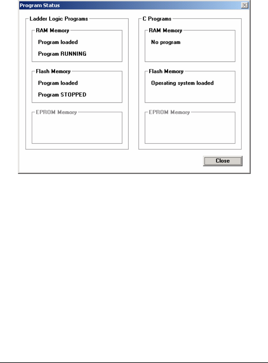
5.21.1 SCADAPack and SCADAPack 32 Controllers
Programs in RAM memory always take precedence over programs in Flash or EPROM memory.
When a command to run a program is received, the controller first checks for a program in RAM,
then for one in Flash or EPROM.
Figure 60: Program Status Dialog Box SCADAPack and SCADAPack 32 Controllers
The Ladder Logic Programs section shows information about the Ladder Logic programs.
The RAM Memory section shows if a program is loaded and the execution state of the program.
The Flash Memory section shows if a program is loaded and the execution state of the program. The
program in Flash will be running only if there is no program in RAM. This section is greyed if the
controller does not have Flash memory installed.
If the controller has operating system code in the Ladder Logic section of Flash then the Flash
Memory or EPROM Memory section displays “Operating System”.
The EPROM Memory section shows if a program is loaded and the execution state of the program.
This section is greyed if the controller has Flash memory installed.
The C Programs section shows information about the C programs.
The RAM Memory section shows if a program is loaded and the execution state of the program.
The Flash Memory section shows if a program is loaded. This section is greyed if the controller
does not have Flash memory installed. If the controller type is SCADAPack 32 or SCADAPack 32P
the section displays “Operating System Loaded”.
If the controller has operating system code in the C Program section of Flash then the Flash Memory
or EPROM Memory section displays “Operating System”.
TelePACE Ladder Logic User and Reference Manual
May 9, 2007
86
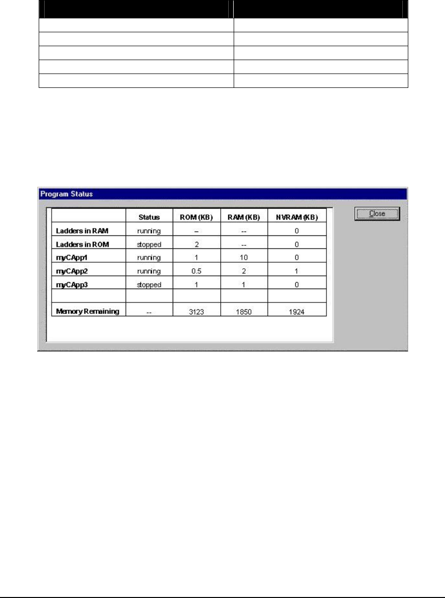
The EPROM Memory section shows if a program is loaded. This section is greyed if the controller
has Flash memory installed.
The Close button closes the dialog.
The table below shows the messages that are displayed for the various conditions.
Condition Message
A program was found in the memory Program loaded
No program was found in the memory No program
Ladder Logic mode is running Program RUNNING
Ladder Logic mode is debug Program RUNNING in DEBUG
Ladder Logic mode is stopped Program STOPPED
Table 18: Program Status Settings
5.21.2 SCADAPack 350 and SCADASense 4203 Series of Controllers
When the controller type is SCADAPack 350 or a member of the SCADASense 4203 series of
controllers, the Program Status dialog displays the current status of the Ladder Logic program and all
C\C++ programs loaded in controller as shown in the diagram below.
Figure 61: Program Status Dialog for SCADAPack 350 and SCADASense 4203 Series Controllers
The status may be one of the following:
• Stopped indicates the program has been downloaded and is currently stopped.
• Running indicates the program has been downloaded and is currently running.
• Debug indicates the program has been downloaded and is currently running in debug mode
(Ladder Logic program only).
• No Program indicates that there is no program in the controller.
The memory used by each program is displayed in addition to the program status.
• The ROM (KB) column describes the amount of memory used in ROM by each program.
• The RAM (KB) column describes the amount of memory used in RAM by each program.
TelePACE Ladder Logic User and Reference Manual
May 9, 2007
87

• The NVRAM (KB) column describes the amount of memory used in non-volatile RAM by each
program.
• The Memory Remaining row describes the unused memory of each type available to all
programs.
The Ladder Logic program in RAM memory always takes precedence over a Ladder Logic program
in ROM. When a command to run a program is received, the controller first checks for a program in
RAM, then for one in ROM. A Ladder Logic program in ROM may only be run if there is no Ladder
Logic program in RAM.
The Close button closes the dialog.
TelePACE Ladder Logic User and Reference Manual
May 9, 2007
88

6 Communications Menu
Communication menu commands are used to transfer programs between the Host PC and the
controller. PC Communication settings for the host PC are configured in this menu selection.
6.1 Read from Controller
The Read from controller command is used to read the ladder logic program, register assignment and
serial port settings from a controller into the TelePACE program. The program replaces the current
program in the ladder editor. The communication progress dialog box displays information about the
read in progress, and allows you to Start or Cancel the read. Click Cancel to abort a read in progress.
6.2 Write to Controller
The Write to controller command writes the ladder logic program, register assignment and serial port
settings in the TelePACE program to the controller. The program replaces the current program in the
controller. The communication progress dialog box displays information about the write progress,
and allows you to Start or Cancel the write. Click Cancel to stop a write in progress.
If the program in the controller is executing, a dialog box appears to request the next action. Press
Stop to stop execution of the ladder logic program when the write is complete. Press Continue to
continue execution of the new program after the write is complete. Press Cancel to abort the write.
TelePACE stops the program in the controller before writing the new program to the controller.
Programs that are executing in the target controller are paused momentarily when commands are
written. The length of the pause depends on the command written.
6.3 PC Communications Settings
The PC Communication Settings command defines the communication protocol and communication
link used for communication between the personal computer (PC) and SCADAPack or 4202 series
controllers.
When the command is select the Communication Protocols Configuration dialog is displayed as
shown below.
TelePACE Ladder Logic User and Reference Manual
May 9, 2007
89
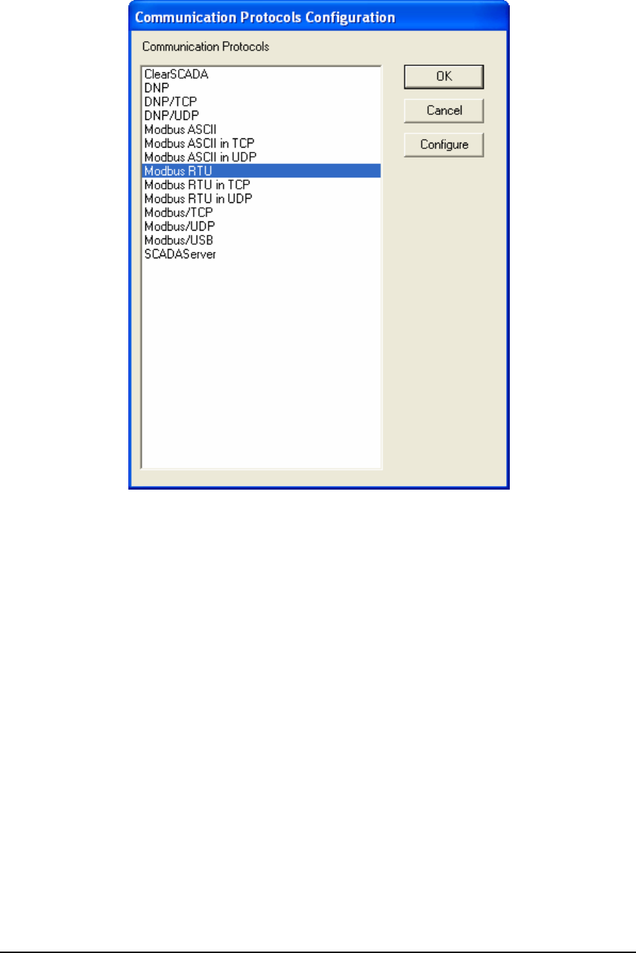
Figure 62: Communication Protocols Configuration dialog.
6.3.1 ClearSCADA
The ClearSCADA protocol driver is used for communicating with a local or remote ClearSCADA
server. The ClearSCADA server will then, in turn, communicate with devices as per its
configuration. The ClearSCADA protocol driver communicates with the ClearSCADA server using
a TCP connection.
• To configure a ClearSCADA protocol connection, highlight ClearSCADA in the
Communication Protocols window and click the Configure button. The ClearSCADA
Configuration window is displayed.
• To select a configured ClearSCADA protocol connection, highlight ClearSCADA in the
Communication Protocols window and click the OK button.
• To close the dialog, without making a selection click the Cancel button.
6.3.1.1 General Parameters
When ClearSCADA protocol is selected for configuration the ClearSCADA Configuration dialog is
opened with the General tab selected as shown below.
TelePACE Ladder Logic User and Reference Manual
May 9, 2007
90
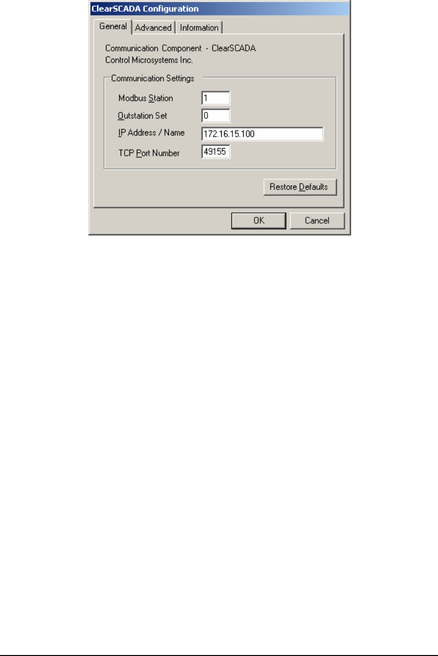
Figure 63: ClearSCADA Configuration (General) Dialog Box
The General tab component information section contains the name of Communication Component
and the author, Control Microsystems.
The Communications Settings grouping contains all the essential details necessary to establish
communication to a device through a local or remote ClearSCADA installation.
The Modbus Station entry specifies the station address of the target device. Valid values are 1 to
65534.
The Outstation Set entry specifies the ClearSCADA outstation set to which the target device is
attached. The valid range is 0 to 65535. The default value is 0.
The IP Address / Name entry specifies the Ethernet IP address in dotted quad notation, or a DNS
host name that can be resolved to an IP address, of the PC where the ClearSCADA server is
installed. The following IP addresses are not supported and will be rejected:
• 0.0.0.0 through 0.255.255.255
• 127.0.0.0 through 127.255.255.255 (except 127.0.0.1)
• 224.0.0.0 through 224.255.255.255
• 255.0.0.0 through 255.255.255.255.
The TCP Port Number entry specifies the TCP port on the ClearSCADA server. The valid range is
0 to 65535. The default value is 49155
• Click Restore Defaults to restore default values to all fields on this page, except for the IP
Address / Name field. The contents of this field will remain unchanged.
6.3.1.2 Advanced Parameters
Advanced parameters are used to control the message size for the protocol. Control over message
length is needed when writing large amounts of data over certain communication networks. A larger
TelePACE Ladder Logic User and Reference Manual
May 9, 2007
91
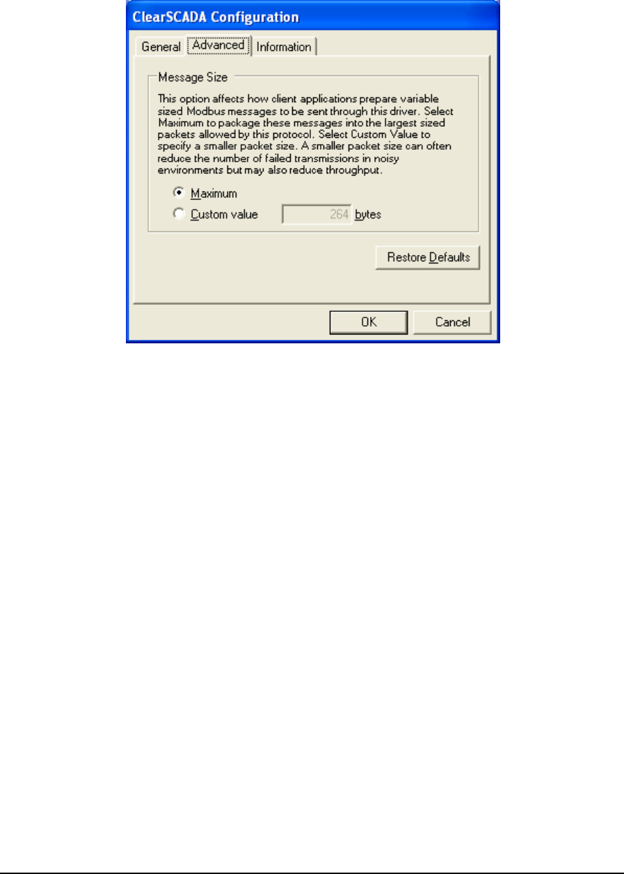
value can improve communication speed but can increase the number of failed transmissions. A
smaller value can reduce the number of failed transmissions but may reduce throughput. When the
Advanced tab heading is clicked the Advanced dialog is opened as shown below.
Figure 64: ClearSCADA Configuration (Advanced) Dialog Box
The Maximum selection indicates that the host application is to package messages using the
maximum size allowable by the protocol.
The Custom Value selection specifies a custom value for the message size. This value will indicate
to the host application to package messages to be no larger than what is specified, if it is possible.
Valid values are 2 to 264. The default value is 264.
• Click Restore Defaults to restore default values to all fields on this page.
6.3.1.3 Information
Information displays detailed driver information. When the Information tab heading is clicked the
Information dialog is opened as shown below.
TelePACE Ladder Logic User and Reference Manual
May 9, 2007
92
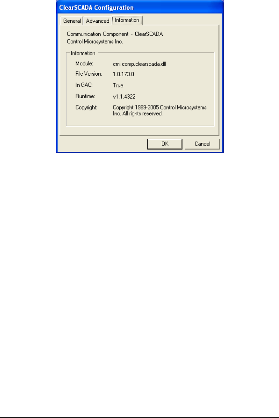
Figure 65: ClearSCADA Configuration (Information) Dialog Box
6.3.1.3.1 Information
The Information grouping presents informative details concerning the executing protocol driver.
Module is the physical name of the driver.
File Version is the version number of the driver.
In GAC indicates whether the module (assembly) was loaded from the Global Assembly Cache
(GAC).
Runtime is the version of the Common Language Runtime (CLR) the driver was built against.
Copyright indicates the copyright information of the protocol driver.
6.3.2 DNP
The DNP protocol driver is used to communicate over a serial DNP network to SCADAPack
controllers configured for DNP communication.
• To configure a DNP protocol connection, highlight DNP in the Communication Protocols
window and click the Configure button. The DNP Configuration window is displayed.
• To select a configured DNP protocol connection, highlight DNP in the Communication
Protocols window and click the OK button.
• To close the dialog, without making a selection click the Cancel button.
6.3.2.1 General Parameters
When DNP is selected for configuration the DNP Configuration dialog is opened with the General
tab selected as shown below.
TelePACE Ladder Logic User and Reference Manual
May 9, 2007
93
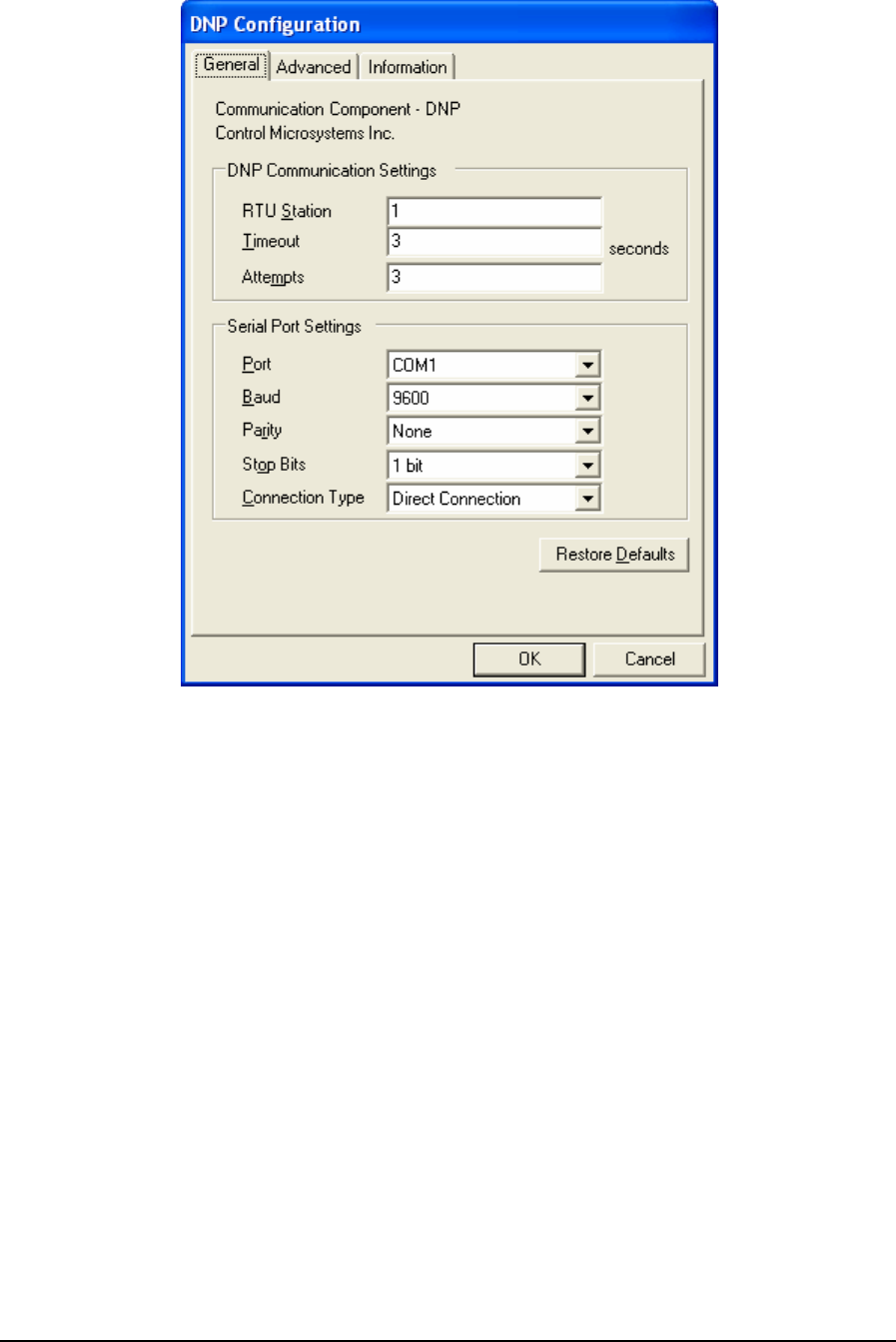
Figure 66: DNP Configuration (General) Dialog Box
The General tab component information section contains the name of Communication Component
and the author, Control Microsystems.
The DNP Communication Settings logical grouping contains DNP specific communication settings
including the DNP Station address, the timeout interval as well as the number of attempts.
The RTU Station parameter sets the target DNP station number. Valid entries are 0 to 65519. The
default address is 1.
The Timeout parameter sets the length of time, in seconds, to wait for a response from the controller
before retrying (see Attempts), or ultimately failing. Valid entries are 1 to 255. The default is 3.
The Attempts parameter sets number of times to send a command to the controller before giving up
and reporting this failure to the host application. Valid entries are 1 to 20. The default is 3.
This Serial Port Settings grouping contains details directly related to the PC’s
communication port including the port number, the baud rate, parity and stop bit settings.
The Port parameter specifies the PC serial port to use. The DNP driver determines what serial ports
are available on the PC and presents these in the drop-down menu list. The available serial ports list
will include any USB to serial converters used on the PC. The default value is the first existing port
found by the driver.
TelePACE Ladder Logic User and Reference Manual
May 9, 2007
94

The Baud parameter specifies the baud rate to use for communication. The menu list displays
selections for 300, 600, 1200, 2400, 4800, 9600, 19200, 38400, and 57600. The default value is
9600.
The Parity parameter specifies the type of parity to use for communication. The menu list displays
selections for none, odd and even parity. The default value is None.
The Stop Bits parameter specifies the number of stop bits to use for communication. The menu list
displays selections for 1 and 2 stop bits. The default value is 1 bit.
The Connection Type parameter specifies the serial connection type. The DNP driver supports
direct serial connection with no flow control, Request-to-send (RTS) and clear-to-send (CTS) flow
control and PSTN dial-up connections. The menu list displays selections for Direct Connection,
RTS/CTS Flow Control and Dial Up Connection. The default selection is Direct Connection.
• Select Direct Connection for RS-232 for RS-485 connections that do not require the hardware
control lines on the serial ports.
• Select RTS/CTS Flow Control to communicate over radio or leased-line networks using
modems that require RTS/CTS handshaking. Selecting RTS/CTS Flow Control adds a new tab,
Flow Control, to the DNP Configuration dialog. Refer to the Flow Control Parameters section
below for configuration details.
• Select Dial Up Connection to communication over dial up modems. Selecting Dial Up
Connection adds a new tab, Dial Up, to the DNP Configuration dialog. Refer to the Dial Up
Parameters section below for configuration details.
• Click Restore Defaults to restore default values to all fields on this page.
6.3.2.2 Flow Control Parameters
Flow Control parameters are used to configure how RTS and CTS control is used. When RTS/CTS
Flow Control is selected for Connection Type the Flow Control tab is added to the DNP
Configuration dialog. When the Flow Control tab heading is clicked the Flow Control dialog is
opened as shown below.
TelePACE Ladder Logic User and Reference Manual
May 9, 2007
95
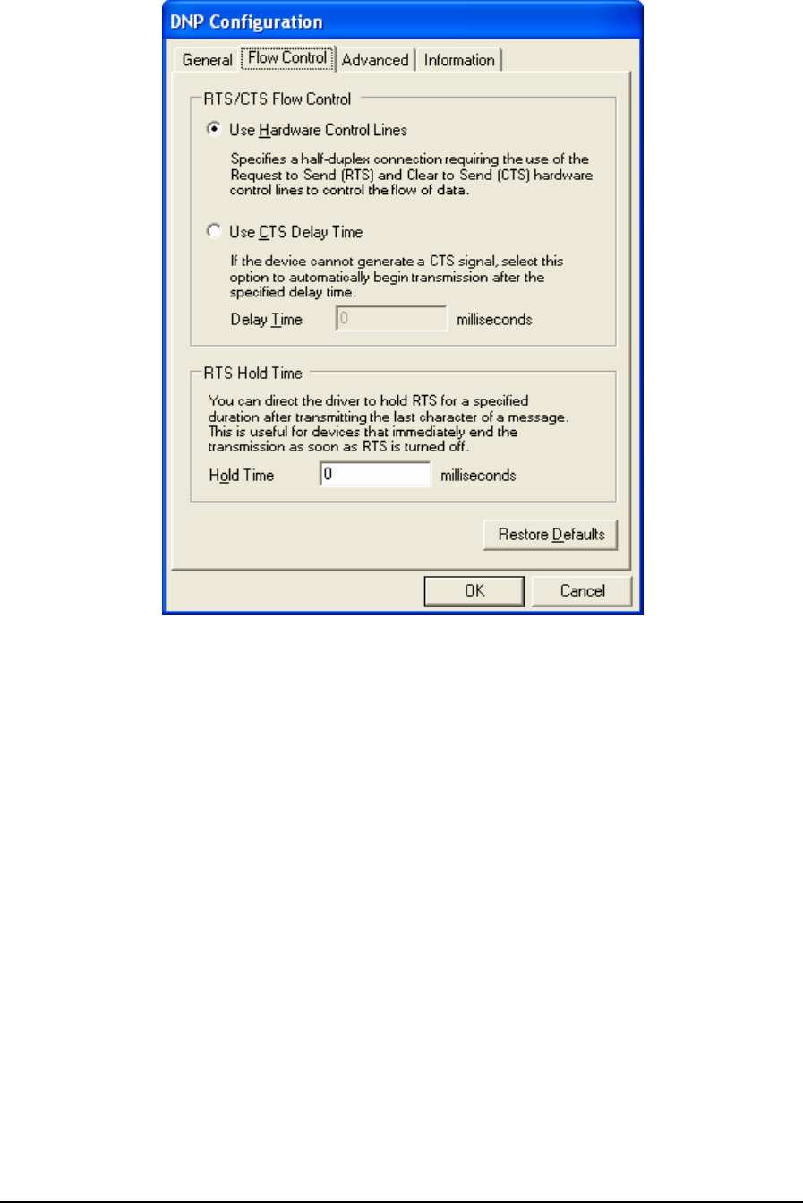
Figure 67: DNP Configuration (Flow Control) Dialog Box
6.3.2.2.1 RTS/CTS Flow Control
The RTS/CTS Flow Control grouping contains two mutually exclusive options, Use Hardware
Control Lines and Use CTS Delay Time. These options enable the driver to communicate over radio
or leased-line networks using modems that require RTS/CTS handshaking.
The Use Hardware Control Lines option specifies a half-duplex connection requiring the use of the
Request to Send (RTS) and Clear to Send (CTS) hardware control lines to control the flow of data.
This selection is used with radios and dedicated telephone line modems. The driver turns on the RTS
signal when it wants to transmit data. The modem or other device then turns on CTS when it is ready
to transmit. The driver transmits the data, and then turns off the RTS signal. This selection is
mutually exclusive of the Use CTS Delay Time selection described below. This is the default
selection.
The Use CTS Delay Time option is selected if the device cannot generate a CTS signal. The driver
will assert RTS then wait the specified Delay Time, in milliseconds, before proceeding. This option
is mutually exclusive with the Use Hardware Control Lines selection described above.
The Delay Time parameter sets the time in milliseconds that the driver will wait after asserting RTS
before proceeding. The value of this field must be smaller than the Time Out value set in the General
parameters dialog. For example, if the Timeout value is set to 3 seconds, the CTS Delay Time can be
TelePACE Ladder Logic User and Reference Manual
May 9, 2007
96
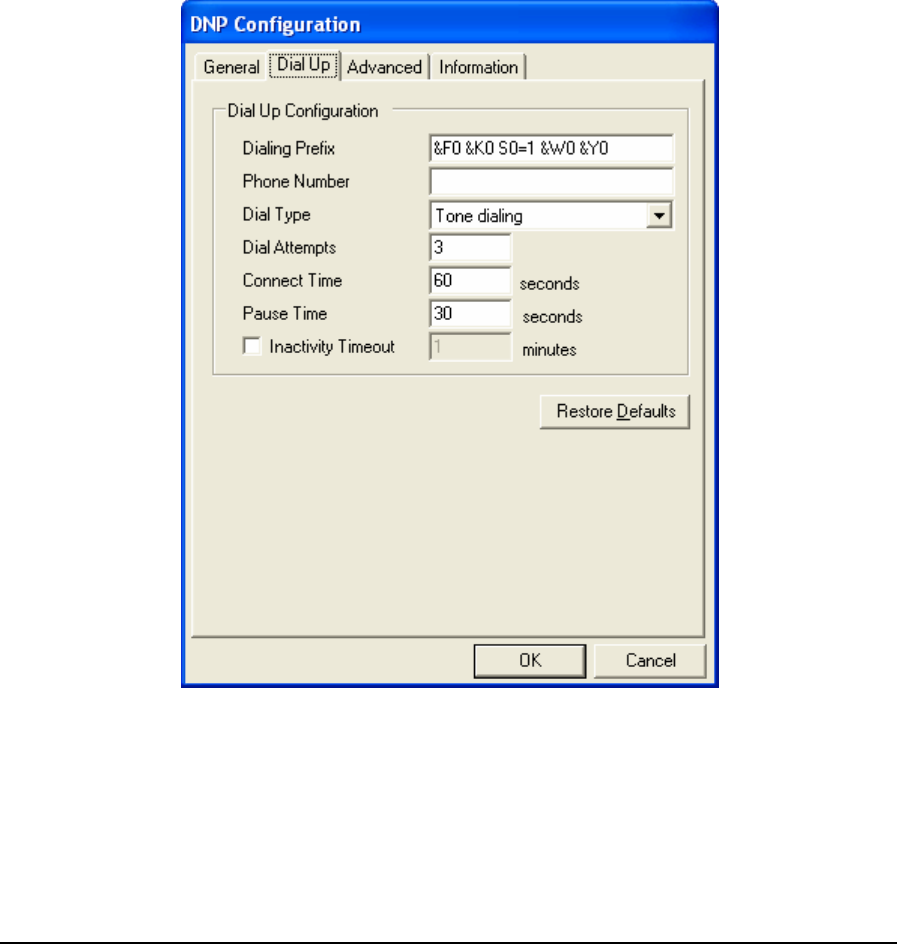
set to 2999 milliseconds or less. The minimum value for this field is 0 milliseconds. The value is
initially set to 0 by default.
The Hold Time parameter specifies the time, in milliseconds, that the driver will hold RTS after the
last character is transmitted. This is useful for devices that immediately end transmission when RTS
is turned off. The value of this field must be smaller than the Time Out value set in the General
parameters dialog. For example, if the Timeout value is set to 3 seconds, the CTS Delay Time can be
set to 2999 milliseconds or less. The minimum value for this field is 0 milliseconds. The value is
initially set to 0 by default.
• Click Restore Defaults to restore default values to all fields on this page.
6.3.2.3 Dial Up Parameters
Dial Up parameters are used to configure a dial up connection. When Dial Up is selected for
Connection Type the Dial Up tab is added to the DNP Configuration dialog. When the Dial Up tab
heading is clicked the Dial Up dialog is opened as shown below.
Figure 68: DNP Configuration (Dial Up) Dialog Box
The Dialing Prefix parameter specifies the commands sent to the modem before dialing. A
maximum of 32 characters can be entered. All characters are valid. The default value is “&F0 &K0
S0=1 &W0 &Y0”.
TelePACE Ladder Logic User and Reference Manual
May 9, 2007
97

The Phone Number parameter specifies the telephone number of the remote controller. A maximum
of 32 characters can be entered. All characters are valid. This field’s default value is blank.
The Dial Type parameter specifies the dialing type. Valid values are Pulse and Tone. The default
value is Tone.
The Dial Attempts parameter specifies how many dialing attempts will be made. Valid values are 1
to 10. The default value is 1.
The Connect Time parameter specifies the amount of time in seconds the modem will wait for a
connection. Valid values are 6 to 300. The default value is 60.
The Pause Time parameter specifies the time in seconds between dialing attempts. Valid values are
6 to 600. The default value is 30.
Check the Inactivity Timeout check box to automatically terminate the dialup connection after a
period of inactivity. The Inactivity Time edit box is enabled only if this option is checked. The
default state is checked.
Enter the inactivity period, in minutes, in the Inactivity Timeout box. The dialup connection will be
terminated automatically after the specified number of minutes of inactivity has lapsed. This option
is only active if the Inactivity Timeout box is checked. Valid values are from 1 to 30 minutes. The
default value is 1.
• Click Restore Defaults to restore default values to all fields on this page, except for the Phone
Number field. The content of this field will remain unchanged.
6.3.2.4 Advanced Parameters
DNP Configuration Advanced parameters set the DNP master station address and message size
control. When the Advanced tab heading is clicked the Advanced dialog is opened as shown below.
TelePACE Ladder Logic User and Reference Manual
May 9, 2007
98
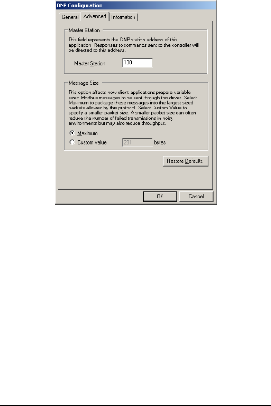
Figure 69: DNP Configuration (Advanced) Dialog Box
The Master Station parameter is the DNP station address assumed by this communication
component. When this driver sends out commands, responses form the controller will be directed to
this address. The default value is 100.
The Message Size grouping parameters are used to control the message size for the protocol. Control
over message length is needed when writing large amounts of data over certain communication
networks. A larger value can improve communication speed but can increase the number of failed
transmissions. A smaller value can reduce the number of failed transmissions but may reduce
throughput.
The Maximum selection indicates that the host application is to package messages using the
maximum size allowable by the protocol.
The Custom Value selection specifies a custom value for the message size. This value indicates to
the host application to package messages to be no larger than what is specified, if it is possible. Valid
values are 2 to 231. The default value is 231.
• Click Restore Defaults to restore default values to all fields on this page.
6.3.2.5 Information
Information displays detailed driver information. When the Information tab heading is clicked the
Information dialog is opened as shown below.
TelePACE Ladder Logic User and Reference Manual
May 9, 2007
99
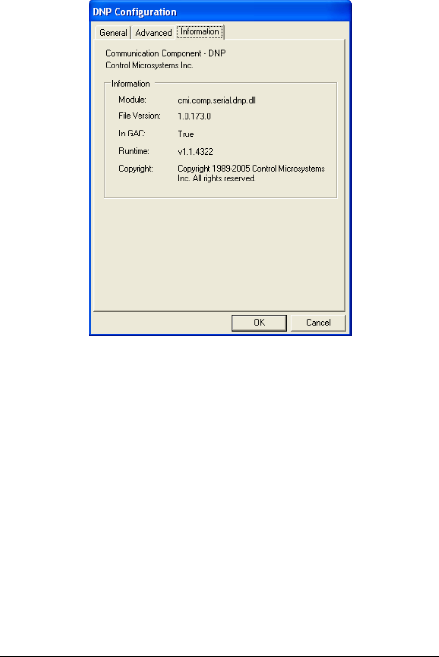
Figure 70: DNP Configuration (Information) Dialog Box
The Information grouping presents informative details concerning the executing protocol driver.
Module is the physical name of the driver.
File Version is the version number of the driver.
In GAC indicates whether the module (assembly) was loaded from the Global Assembly Cache
(GAC).
Runtime is the version of the Common Language Runtime (CLR) the driver was built against.
Copyright indicates the copyright information of the protocol driver.
6.3.3 DNP/TCP
The DNP/TCP protocol driver is used to communicate over an Ethernet DNP network to
SCADAPack controllers configured for DNP/TCP communication.
• To configure a DNP/TCP protocol connection, highlight DNP/TCP in the Communication
Protocols window and click the Configure button. The DNP/TCP Configuration window is
displayed.
• To select a configured DNP/TCP protocol connection, highlight DNP/TCP in the
Communication Protocols window and click the OK button.
TelePACE Ladder Logic User and Reference Manual
May 9, 2007
100
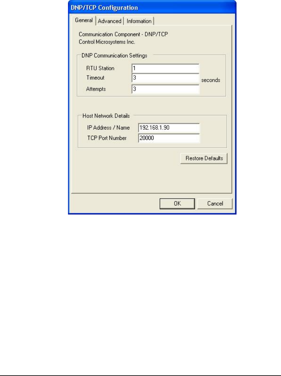
• To close the dialog, without making a selection click the Cancel button.
6.3.3.1 General Page
When DNP/TCP protocol is selected for configuration the DNP/TCP Configuration dialog is opened
with the General tab selected as shown below.
Figure 71: DNP in TCP Configuration (General) Dialog Box
The DNP Communication Settings grouping contains DNP specific communication settings
including the DNP Station address, the timeout interval as well as the number of attempts.
The RTU Station parameter specifies the DNP station number of the target device. The valid range
is 0 to 65519. The default is station 1.
The Timeout parameter specifies the length of time, in seconds, to wait for a response from the
controller before retrying (see Attempts) or ultimately failing. Valid values are 1 to 255. The default
value is 3 seconds.
The Attempts parameter specifies the number of times to send a command to the controller before
giving up and reporting this failure to the host application. Valid values are 1 to 20. The default
value is 3 attempts.
TelePACE Ladder Logic User and Reference Manual
May 9, 2007
101

The Host Network Details grouping contains information about the IP network including the
target’s IP address or name, and the TCP port number on which it is listening. More details on these
below.
6.3.3.1.1 IP Address / Name
The IP Address / Name parameter specifies the Ethernet IP address of the target RTU, or a DNS
name that can be resolved to an IP address. The default value is blank. The following IP addresses
are not supported and will be rejected:
• 0.0.0.0 through 0.255.255.255
• 127.0.0.0 through 127.255.255.255 (except 127.0.0.1)
• 224.0.0.0 through 224.255.255.255
• 255.0.0.0 through 255.255.255.255.
The TCP Port No. field specifies the TCP port of the remote device. Valid values are 0 to 65535.
The default value is 20000.
• Click Restore Defaults to restore default values to all fields on this page, except for the IP
Address / Name field. The content of this field will remain unchanged.
6.3.3.2 Advanced Page
Advanced parameters are used to set the Master Station address and control the message size for the
protocol. Control over message length is needed when writing large amounts of data over certain
communication networks. A larger value can improve communication speed but can increase the
number of failed transmissions. A smaller value can reduce the number of failed transmissions but
may reduce throughput. When the Advanced tab heading is clicked the Advanced dialog is opened as
shown below.
TelePACE Ladder Logic User and Reference Manual
May 9, 2007
102
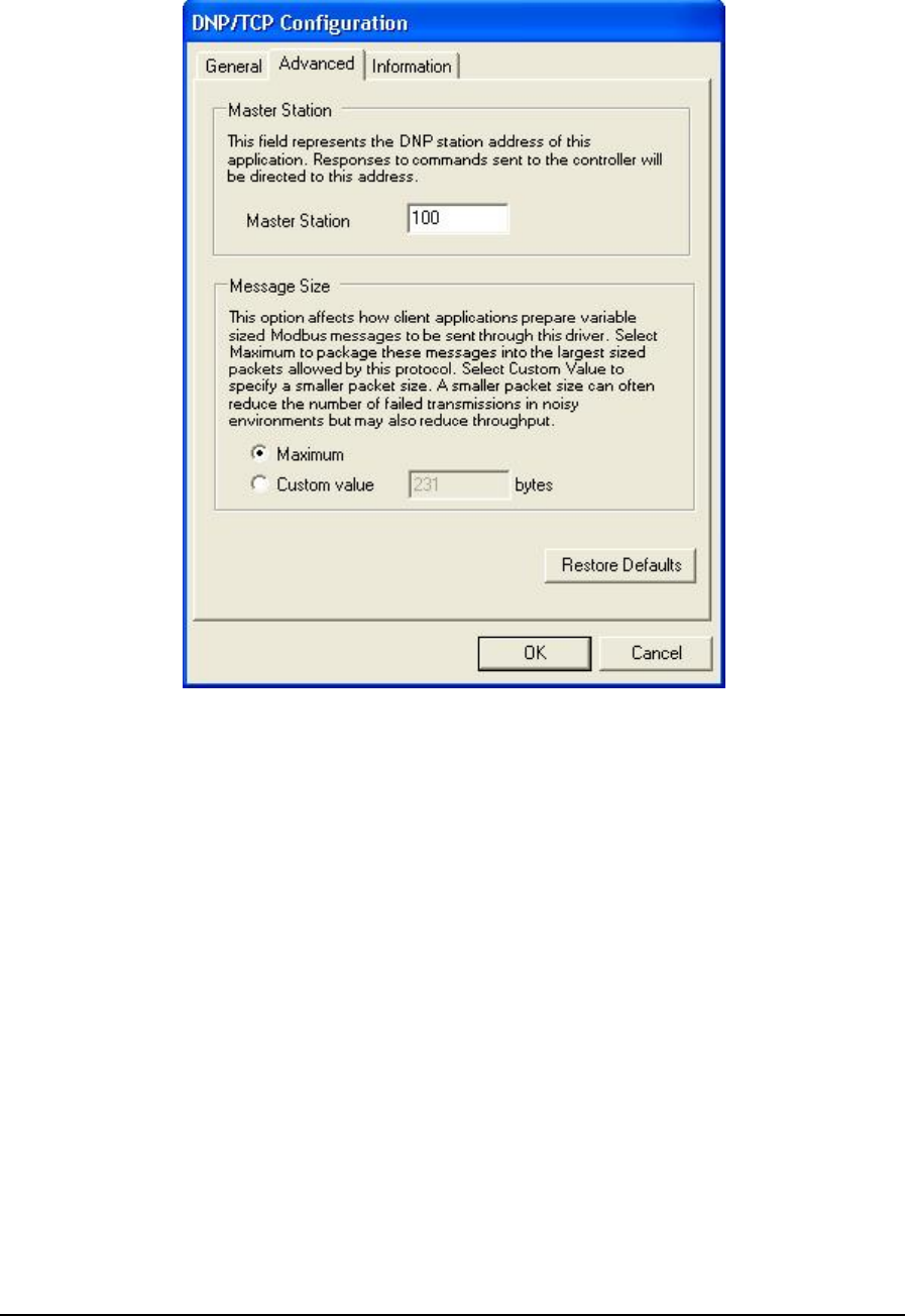
Figure 72: DNP n TCP Configuration (Advanced) Dialog Box
The Master Station parameter specifies the DNP station address of the RealFLO application. When
RealFLO sends out commands, responses from the target controller will be directed to this address.
The valid range is 0 to 65519, except that this value cannot be the same as the target RTU Station
number. The default value is 100.
The Maximum selection indicates that you want the host application to package messages using the
maximum size allowable by the protocol.
The Custom value selection specifies a custom value for message size. This value indicates to the
host application to package messages to be no larger than what is specified if possible. The valid
range for the Custom value field is from 2 to 231. Maximum is selected by default.
• Click Restore Defaults to restore default values to all fields on this page
6.3.3.3 Information Page
The Information page displays detailed driver information. When the Information tab is clicked the
Information dialog is opened as shown below.
TelePACE Ladder Logic User and Reference Manual
May 9, 2007
103
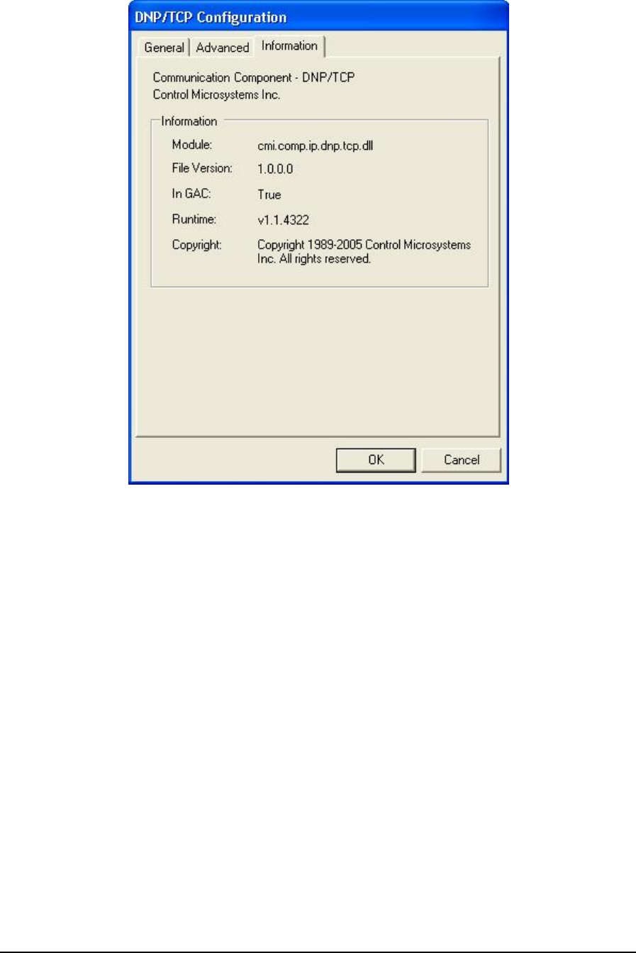
Figure 73: DNP in TCP Configuration (Information) Dialog Box
The Information grouping presents informative details concerning the executing protocol driver.
Module is the physical name of the driver.
File Version is the version number of the driver.
In GAC indicates whether the module (assembly) was loaded from the Global Assembly Cache
(GAC).
Runtime is the version of the Common Language Runtime (CLR) the driver was built against.
Copyright indicates the copyright information of the protocol driver.
6.3.4 DNP/UDP
The DNP/UDP protocol driver is used to communicate over an Ethernet DNP network to
SCADAPack controllers configured for DNP/UDP communication.
• To configure a DNP/UDP protocol connection, highlight DNP/UDP in the Communication
Protocols window and click the Configure button. The DNP/UDP Configuration window is
displayed.
• To select a configured DNP/UDP protocol connection, highlight DNP/UDP in the
Communication Protocols window and click the OK button.
TelePACE Ladder Logic User and Reference Manual
May 9, 2007
104
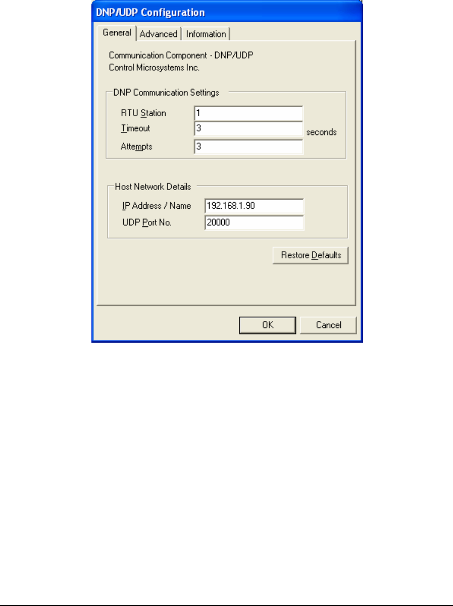
• To close the dialog, without making a selection click the Cancel button.
6.3.4.1 General Page
When DNP/UDP protocol is selected for configuration the DNP/UDP Configuration dialog is
opened with the General tab selected as shown below.
Figure 74: DNP in UDP Configuration (General) Dialog Box
The DNP Communication Settings grouping contains DNP specific communication settings
including the DNP Station address, the timeout interval as well as the number of attempts.
The RTU Station parameter specifies the DNP station number of the target device. The valid range
is 0 to 65519. The default is station 1.
The Timeout parameter specifies the length of time, in seconds, to wait for a response from the
controller before retrying (see Attempts) or ultimately failing. Valid values are 1 to 255. The default
value is 3 seconds.
The Attempts parameter specifies the number of times to send a command to the controller before
giving up and reporting this failure to the host application. Valid values are 1 to 20. The default
value is 3 attempts.
The Host Network Details grouping contains information about the IP network including the
target’s IP address or name, and the UDP port number on which it is listening. More details on these
below.
TelePACE Ladder Logic User and Reference Manual
May 9, 2007
105
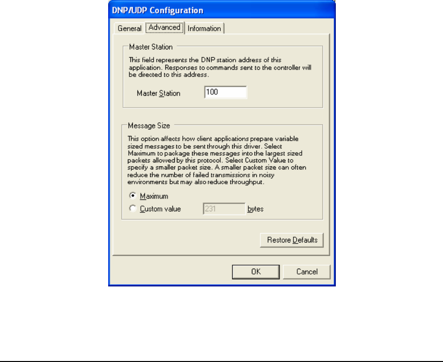
6.3.4.1.1 IP Address / Name
The IP Address / Name parameter specifies the Ethernet IP address of the target RTU, or a DNS
name that can be resolved to an IP address. The default value is blank. The following IP addresses
are not supported and will be rejected:
• 0.0.0.0 through 0.255.255.255
• 127.0.0.0 through 127.255.255.255 (except 127.0.0.1)
• 224.0.0.0 through 224.255.255.255
• 255.0.0.0 through 255.255.255.255.
The UDP Port No. field specifies the UDP port of the remote device. Valid values are 0 to 65534.
The default value is 20000.
• Click Restore Defaults to restore default values to all fields on this page, except for the IP
Address / Name field. The content of this field will remain unchanged.
6.3.4.2 Advanced Page
Advanced parameters are used to set the Master Station address and control the message size for the
protocol. Control over message length is needed when writing large amounts of data over certain
communication networks. A larger value can improve communication speed but can increase the
number of failed transmissions. A smaller value can reduce the number of failed transmissions but
may reduce throughput. When the Advanced tab heading is clicked the Advanced dialog is opened as
shown below.
Figure 75: DNP in UDP Configuration (Advanced) Dialog Box
TelePACE Ladder Logic User and Reference Manual
May 9, 2007
106
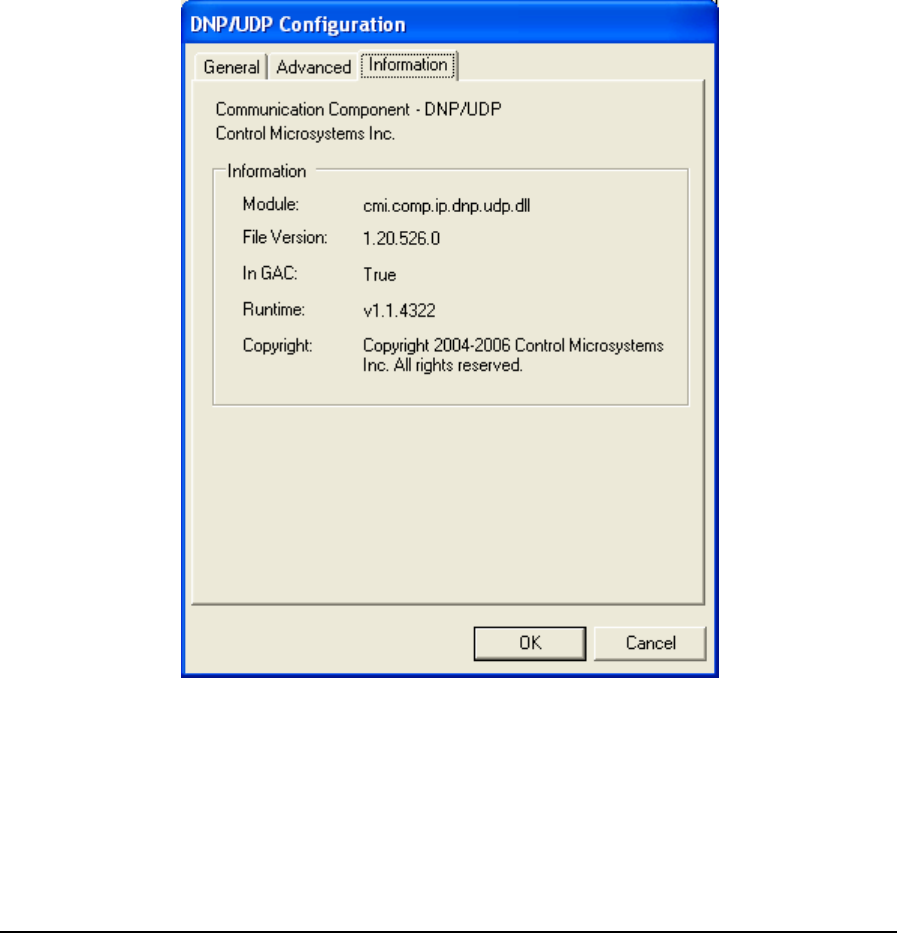
The Master Station parameter specifies the DNP station address of the RealFLO application. When
RealFLO sends out commands, responses from the target controller will be directed to this address.
The valid range is 0 to 65519, except that this value cannot be the same as the target RTU Station
number. The default value is 100.
The Maximum selection indicates that you want the host application to package messages using the
maximum size allowable by the protocol.
The Custom value selection specifies a custom value for message size. This value indicates to the
host application to package messages to be no larger than what is specified if possible. The valid
range for the Custom value field is from 2 to 231. Maximum is selected by default.
• Click Restore Defaults to restore default values to all fields on this page
6.3.4.3 Information Page
The Information page displays detailed driver information. When the Information tab is clicked the
Information dialog is opened as shown below.
Figure 76: DNP in UDP Configuration (Information) Dialog Box
The Information grouping presents informative details concerning the executing protocol driver.
Module is the physical name of the driver.
File Version is the version number of the driver.
TelePACE Ladder Logic User and Reference Manual
May 9, 2007
107

In GAC indicates whether the module (assembly) was loaded from the Global Assembly Cache
(GAC).
Runtime is the version of the Common Language Runtime (CLR) the driver was built against.
Copyright indicates the copyright information of the protocol driver.
6.3.5 Modbus ASCII
The Modbus ASCII protocol driver is used to communicate over a serial network, using Modbus
ASCII framing, to SCADAPack controllers configured for Modbus ASCII protocol.
• To configure a Modbus ASCII protocol connection, highlight Modbus ASCII in the
Communication Protocols window and click the Configure button. The Modbus ASCII
Configuration window is displayed.
• To select a configured Modbus ASCII protocol connection, highlight Modbus ASCII in the
Communication Protocols window and click the OK button.
• To close the dialog, without making a selection click the Cancel button.
6.3.5.1 General Parameters
When Modbus ASCII is selected for configuration the Modbus ASCII Configuration dialog is
opened with the General tab selected as shown below.
TelePACE Ladder Logic User and Reference Manual
May 9, 2007
108
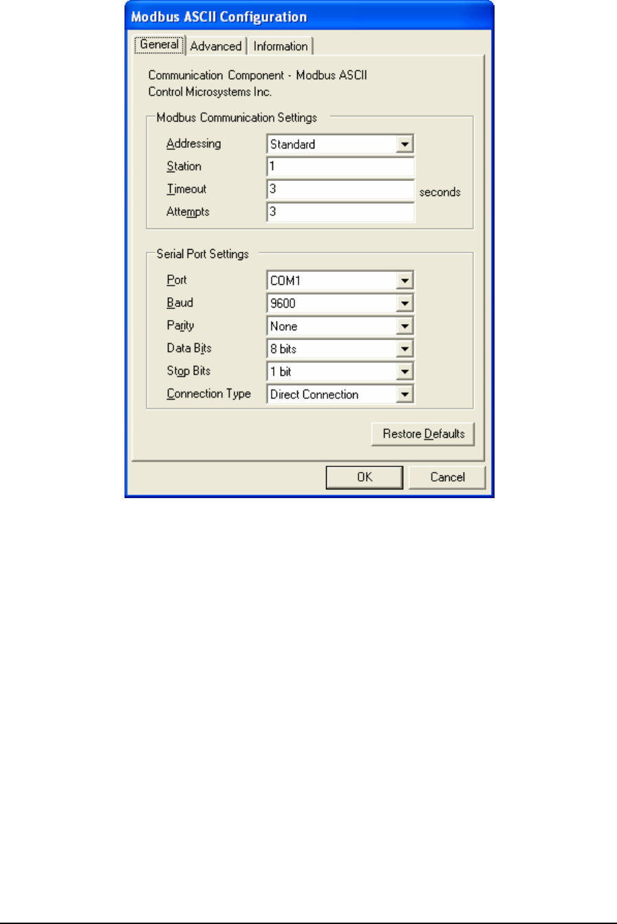
Figure 77: Modbus ASCII Configuration (General) Dialog Box
The Modbus Communication Settings grouping contains Modbus specific communication settings
including the addressing mode, the station address, the timeout interval as well as the number of
attempts.
The Addressing parameter selects standard or extended Modbus addressing. Standard addressing
allows 255 stations and is compatible with standard Modbus devices. Extended addressing allows
65534 stations, with stations 1 to 254 compatible with standard Modbus devices. The default is
Standard.
The Station parameter sets the target station number. The valid range is 1 to 255 if standard
addressing is used, and 1 to 65534 if extended addressing is used. The default is 1.
The Timeout parameter sets the length of time, in seconds, to wait for a response from the controller
before retrying (see Attempts), or ultimately failing. Valid entries are 1 to 255. The default is 3.
The Attempts parameter sets number of times to send a command to the controller before giving up
and reporting this failure to the host application. Valid entries are 1 to 20. The default is 3.
This Serial Port Settings grouping contains details directly related to the PC’s
communication port including the port number, the baud rate, parity and stop bit settings.
TelePACE Ladder Logic User and Reference Manual
May 9, 2007
109

The Port parameter specifies the PC serial port to use. The DNP driver determines what serial ports
are available on the PC and presents these in the drop-down menu list. The available serial ports list
will include any USB to serial converters used on the PC. The default value is the first existing port
found by the driver.
The Baud parameter specifies the baud rate to use for communication. The menu list displays
selections for 300, 600, 1200, 2400, 4800, 9600, 19200, 38400, and 57600. The default value is
9600.
The Parity parameter specifies the type of parity to use for communication. The menu list displays
selections for none, odd and even parity. The default value is None.
The Data Bits parameter specifies the number of data bits contained in the character frame. Valid
values are for this field is 7 and 8 bits. The default value is 8 bits.
The Stop Bits parameter specifies the number of stop bits to use for communication. The menu list
displays selections for 1 and 2 stop bits. The default value is 1 bit.
The Connection Type parameter specifies the serial connection type. The Modbus ASCII driver
supports direct serial connection with no flow control, Request-to-send (RTS) and clear-to-send
(CTS) flow control and PSTN dial-up connections. The menu list displays selections for Direct
Connection, RTS/CTS Flow Control and Dial Up Connection. The default selection is Direct
Connection.
• Select Direct Connection for RS-232 for RS-485 connections that do not require the hardware
control lines on the serial ports.
• Select RTS/CTS Flow Control to communicate over radio or leased-line networks using
modems that require RTS/CTS handshaking. Selecting RTS/CTS Flow Control adds a new tab,
Flow Control, to the Modbus ASCII Configuration dialog. Refer to the Flow Control Parameters
section below for configuration details.
• Select Dial Up Connection to communication over dial up modems. Selecting Dial Up
Connection adds a new tab, Dial Up, to the Modbus ASCII Configuration dialog. Refer to the
Dial Up Parameters section below for configuration details.
• Click Restore Defaults to restore default values to all fields on this page.
6.3.5.2 Modbus ASCII Configuration (Flow Control)
Flow Control parameters are used to configure how RTS and CTS control is used. When RTS/CTS
Flow Control is selected for Connection Type the Flow Control tab is added to the Modbus ASCII
Configuration dialog. When the Flow Control tab heading is clicked the Flow Control dialog is
opened as shown below.
TelePACE Ladder Logic User and Reference Manual
May 9, 2007
110
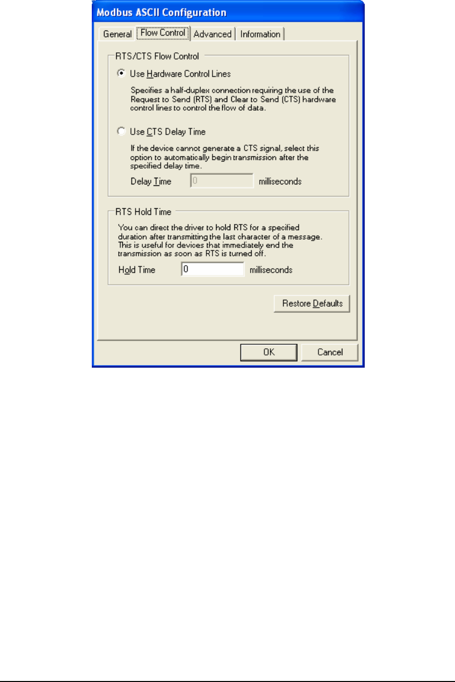
Figure 78: Modbus ASCII Configuration (Flow Control)
The RTS/CTS Flow Control grouping contains two mutually exclusive options, Use Hardware
Control Lines and Use CTS Delay Time. These options enable the driver to communicate over radio
or leased-line networks using modems that require RTS/CTS handshaking.
The Use Hardware Control Lines option specifies a half-duplex connection requiring the use of the
Request to Send (RTS) and Clear to Send (CTS) hardware control lines to control the flow of data.
This selection is used with radios and dedicated telephone line modems. The driver turns on the RTS
signal when it wants to transmit data. The modem or other device then turns on CTS when it is ready
to transmit. The driver transmits the data, and then turns off the RTS signal. This selection is
mutually exclusive of the Use CTS Delay Time selection described below. This is the default
selection.
The Use CTS Delay Time option is selected if the device cannot generate a CTS signal. The driver
will assert RTS then wait the specified Delay Time, in milliseconds, before proceeding. This option
is mutually exclusive with the Use Hardware Control Lines selection described above.
The Delay Time parameter sets the time in milliseconds that the driver will wait after asserting RTS
before proceeding. The value of this field must be smaller than the Time Out value set in the General
parameters dialog. For example, if the Timeout value is set to 3 seconds, the CTS Delay Time can be
TelePACE Ladder Logic User and Reference Manual
May 9, 2007
111
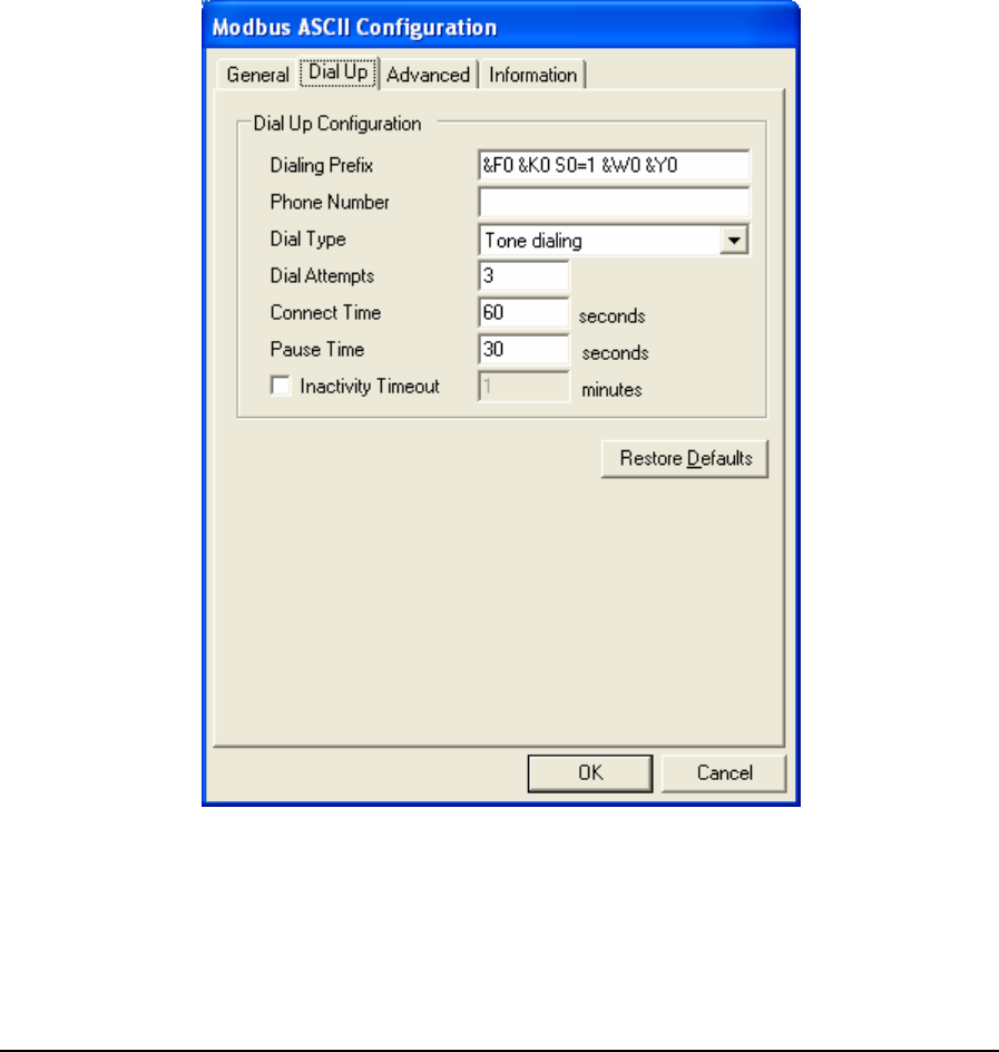
set to 2999 milliseconds or less. The minimum value for this field is 0 milliseconds. The value is
initially set to 0 by default.
The Hold Time parameter specifies the time, in milliseconds, that the driver will hold RTS after the
last character is transmitted. This is useful for devices that immediately end transmission when RTS
is turned off. The value of this field must be smaller than the Time Out value set in the General
parameters dialog. For example, if the Timeout value is set to 3 seconds, the CTS Delay Time can be
set to 2999 milliseconds or less. The minimum value for this field is 0 milliseconds. The value is
initially set to 0 by default.
• Click Restore Defaults to restore default values to all fields on this page.
6.3.5.3 Modbus ASCII Configuration (Dial Up)
Dial Up parameters are used to configure a dial up connection. When Dial Up is selected for
Connection Type the Dial Up tab is added to the Modbus ASCII Configuration dialog. When the
Dial Up tab heading is clicked the Dial Up dialog is opened as shown below.
Figure 79: Modbus ASCII Configuration (Dial Up)
The Dialing Prefix parameter specifies the commands sent to the modem before dialing. A
maximum of 32 characters can be entered. All characters are valid. The default value is “&F0 &K0
S0=1 &W0 &Y0”.
TelePACE Ladder Logic User and Reference Manual
May 9, 2007
112

The Phone Number parameter specifies the telephone number of the remote controller. A maximum
of 32 characters can be entered. All characters are valid. This field’s default value is blank.
The Dial Type parameter specifies the dialing type. Valid values are Pulse and Tone. The default
value is Tone.
The Dial Attempts parameter specifies how many dialing attempts will be made. Valid values are 1
to 10. The default value is 1.
The Connect Time parameter specifies the amount of time in seconds the modem will wait for a
connection. Valid values are 6 to 300. The default value is 60.
The Pause Time parameter specifies the time in seconds between dialing attempts. Valid values are
6 to 600. The default value is 30.
Check the Inactivity Timeout check box to automatically terminate the dialup connection after a
period of inactivity. The Inactivity Time edit box is enabled only if this option is checked. The
default state is checked.
Enter the inactivity period, in minutes, in the Inactivity Timeout box. The dialup connection will be
terminated automatically after the specified number of minutes of inactivity has lapsed. This option
is only active if the Inactivity Timeout box is checked. Valid values are from 1 to 30 minutes. The
default value is 1.
• Click Restore Defaults to restore default values to all fields on this page, except for the Phone
Number field. The content of this field will remain unchanged.
6.3.5.4 Advanced Parameters
Advanced parameters are used to control the message size for the protocol. Control over message
length is needed when writing large amounts of data over certain communication networks. A larger
value can improve communication speed but can increase the number of failed transmissions. A
smaller value can reduce the number of failed transmissions but may reduce throughput. When the
Advanced tab heading is clicked the Advanced dialog is opened as shown below.
TelePACE Ladder Logic User and Reference Manual
May 9, 2007
113
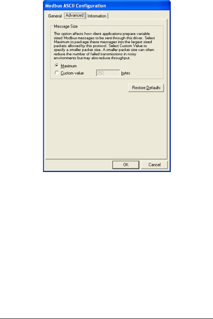
Figure 80: Modbus ASCII Configuration (Advanced) Dialog Box
The Message Size grouping parameters are used to control the message size for the protocol. Control
over message length is needed when writing large amounts of data over certain communication
networks. A larger value can improve communication speed but can increase the number of failed
transmissions. A smaller value can reduce the number of failed transmissions but may reduce
throughput.
The Maximum selection indicates that the host application is to package messages using the
maximum size allowable by the protocol.
The Custom Value selection specifies a custom value for the message size. This value indicates to
the host application to package messages to be no larger than what is specified, if it is possible.
Valid values are 2 to 250 when Addressing is set to Extended and Station is 255 or higher. When
Addressing is set to Extended and Station is less than 255 valid values are 2 to 252. When
Addressing is set to Standard valid values are 2 to 252.
• Click Restore Defaults to restore default values to all fields on this page.
6.3.5.5 Information
Information displays detailed driver information. When the Information tab heading is clicked the
Information dialog is opened as shown below.
TelePACE Ladder Logic User and Reference Manual
May 9, 2007
114
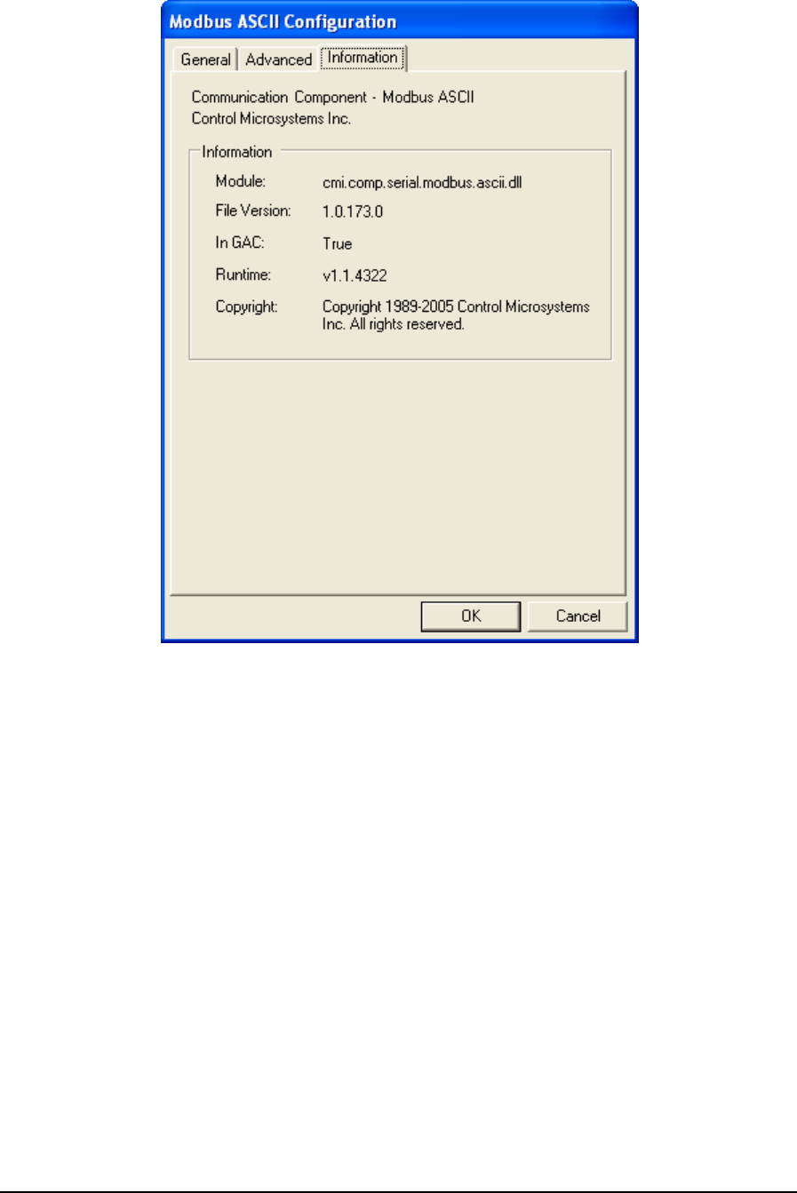
Figure 81: Modbus ASCII Configuration (Information) Dialog Box
The Information grouping presents informative details concerning the executing protocol driver.
Module is the physical name of the driver.
File Version is the version number of the driver.
In GAC indicates whether the module (assembly) was loaded from the Global Assembly Cache
(GAC).
Runtime is the version of the Common Language Runtime (CLR) the driver was built against.
Copyright indicates the copyright information of the protocol driver.
6.3.6 Modbus ASCII in TCP
Modbus ASCII in TCP message format is exactly same as that of the Modbus ASCII protocol. The
main difference is that Modbus ASCII in TCP protocol communicates with a SCADAPack controller
through the Internet and Modbus ASCII through the serial port. The Modbus ASCII in TCP protocol
does not include a six-byte header prefix, as with the Modbus\TCP, but does include the Modbus
‘CRC-16’ or ‘LRC’ check fields.
TelePACE Ladder Logic User and Reference Manual
May 9, 2007
115
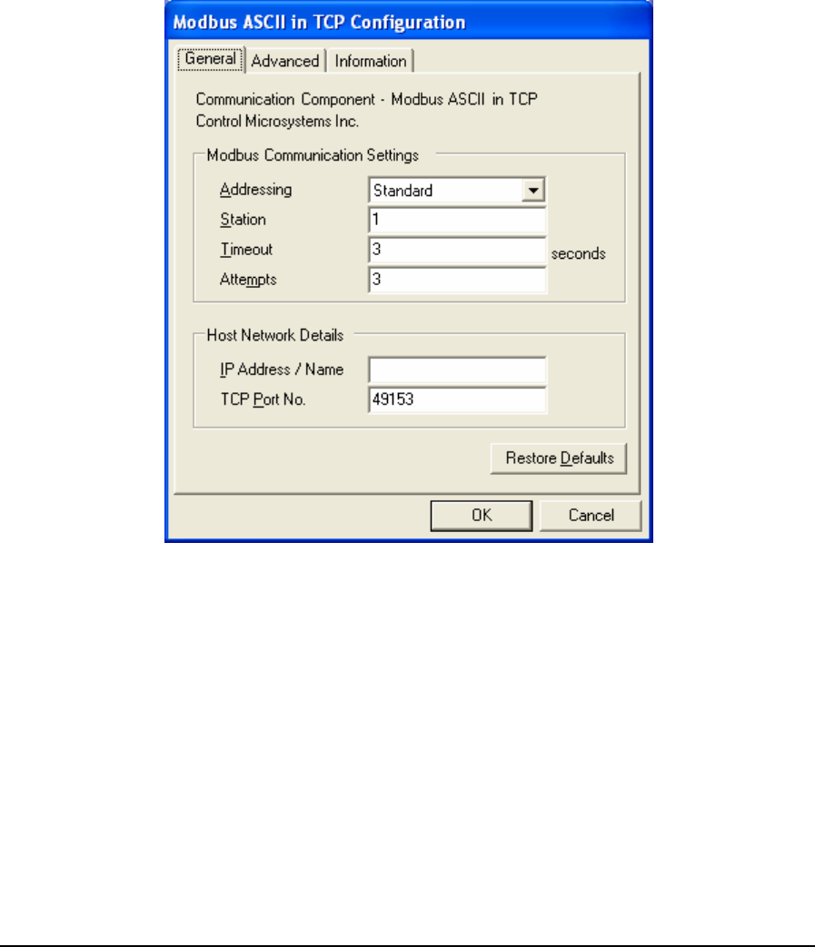
• To configure a Modbus ASCII in TCP protocol connection, highlight Modbus ASCII in TCP in
the Communication Protocols window and click the Configure button. The Modbus ASCII in
TCP Configuration window is displayed.
• To select a configured Modbus ASCII in TCP protocol connection, highlight Modbus ASCII in
TCP in the Communication Protocols window and click the OK button.
• To close the dialog, without making a selection click the Cancel button.
6.3.6.1 General Parameters
When Modbus ASCII in TCP is selected for configuration the Modbus ASCII in TCP Configuration
dialog is opened with the General tab selected as shown below.
Figure 82: Modbus ASCII in TCP Configuration (General) Dialog Box
The Modbus Communication Settings grouping contains Modbus specific communication settings
including the addressing mode, the station address, the timeout interval as well as the number of
attempts.
The Addressing parameter selects standard or extended Modbus addressing. Standard addressing
allows 255 stations and is compatible with standard Modbus devices. Extended addressing allows
65534 stations, with stations 1 to 254 compatible with standard Modbus devices. The default is
Standard.
The Station parameter sets the target station number. The valid range is 1 to 255 if standard
addressing is used, and 1 to 65534 if extended addressing is used. The default is 1.
The Timeout parameter sets the length of time, in seconds, to wait for a response from the controller
before retrying (see Attempts), or ultimately failing. Valid entries are 1 to 255. The default is 3.
TelePACE Ladder Logic User and Reference Manual
May 9, 2007
116

The Attempts parameter sets number of times to send a command to the controller before giving up
and reporting this failure to the host application. Valid entries are 1 to 20. The default is 3.
The Host Network Details grouping contains entries for the host’s IP address or name and
the TCP port on which it is listening.
The IP Address / Name entry specifies the Ethernet IP address in dotted quad notation, or a DNS
host name that can be resolved to an IP address, of the PC where the ClearSCADA server is
installed. The following IP addresses are not supported and will be rejected:
• 0.0.0.0 through 0.255.255.255
• 127.0.0.0 through 127.255.255.255 (except 127.0.0.1)
• 224.0.0.0 through 224.255.255.255
• 255.0.0.0 through 255.255.255.255.
The TCP Port No. field specifies the TCP port of the remote device. Valid values are 0 to
65535. The default value is 49153.
• Click Restore Defaults to restore default values to all fields on this page, except for the IP
Address / Name field. The content of this field will remain unchanged.
TelePACE Ladder Logic User and Reference Manual
May 9, 2007
117
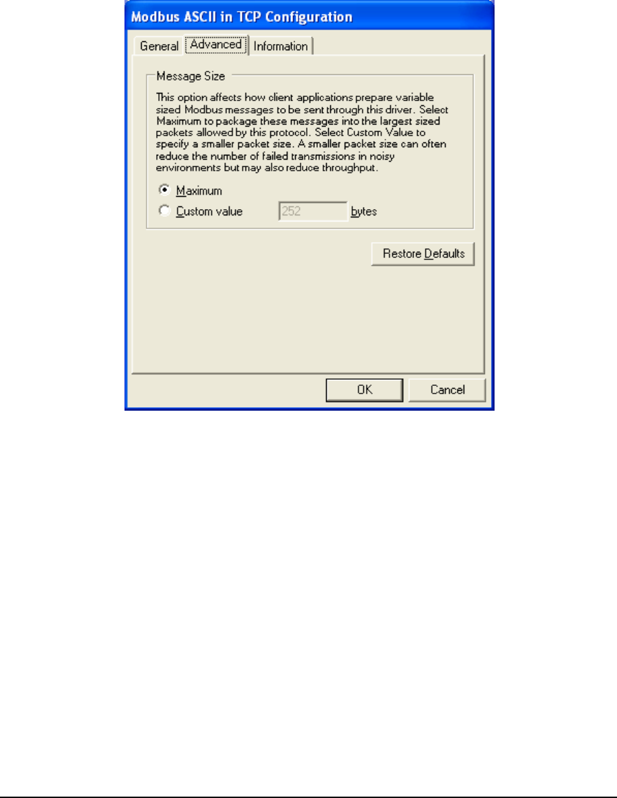
6.3.6.2 Advanced Parameters
Advanced parameters are used to control the message size for the protocol. Control over message
length is needed when writing large amounts of data over certain communication networks. A larger
value can improve communication speed but can increase the number of failed transmissions. A
smaller value can reduce the number of failed transmissions but may reduce throughput. When the
Advanced tab heading is clicked the Advanced dialog is opened as shown below.
Figure 83: Modbus ASCII in TCP Configuration (Advanced) Dialog Box
The Message Size grouping parameters are used to control the message size for the protocol. Control
over message length is needed when writing large amounts of data over certain communication
networks. A larger value can improve communication speed but can increase the number of failed
transmissions. A smaller value can reduce the number of failed transmissions but may reduce
throughput.
The Maximum selection indicates that the host application is to package messages using the
maximum size allowable by the protocol.
The Custom Value selection specifies a custom value for the message size. This value indicates to
the host application to package messages to be no larger than what is specified, if it is possible.
Valid values are 2 to 250 when Addressing is set to Extended and Station is 255 or higher. When
Addressing is set to Extended and Station is less than 255 valid values are 2 to 252. When
Addressing is set to Standard valid values are 2 to 252.
• Click Restore Defaults to restore default values to all fields on this page.
TelePACE Ladder Logic User and Reference Manual
May 9, 2007
118

6.3.6.3 Information
Information displays detailed driver information. When the Information tab heading is clicked the
Information dialog is opened as shown below.
Figure 84: Modbus ASCII in TCP Configuration (Information) Dialog Box
The Information grouping presents informative details concerning the executing protocol driver.
Module is the physical name of the driver.
File Version is the version number of the driver.
In GAC indicates whether the module (assembly) was loaded from the Global Assembly Cache
(GAC).
Runtime is the version of the Common Language Runtime (CLR) the driver was built against.
Copyright indicates the copyright information of the protocol driver.
6.3.7 Modbus ASCII in UDP
Modbus ASCII in UDP protocol is similar to Modbus ASCII in TCP protocol. It has the same
message format as the Modbus ASCII in TCP. The only difference between them is one uses TCP
protocol and another uses UDP protocol.
• To configure a Modbus ASCII in TCP protocol connection, highlight Modbus ASCII in UDP in
the Communication Protocols window and click the Configure button. The Modbus ASCII in
UDP Configuration window is displayed.
TelePACE Ladder Logic User and Reference Manual
May 9, 2007
119
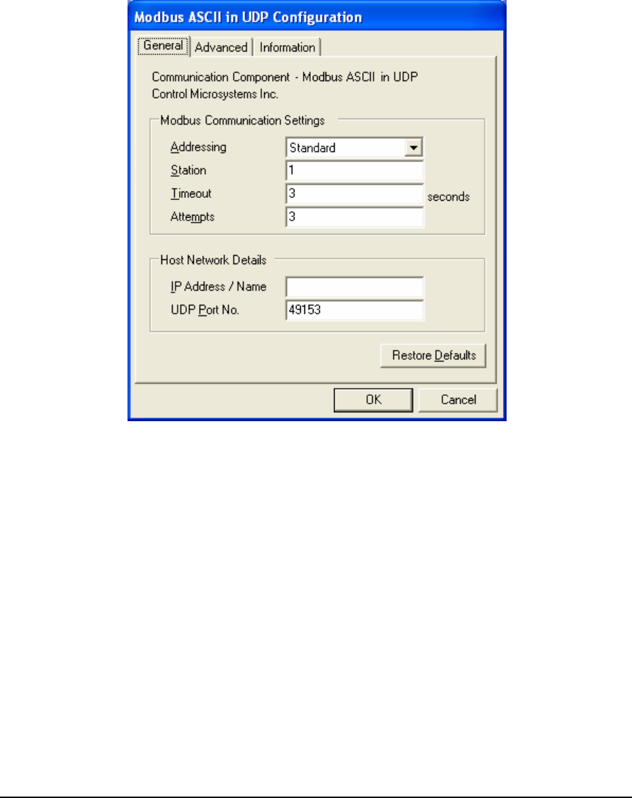
• To select a configured Modbus ASCII in TCP protocol connection, highlight Modbus ASCII in
UDP in the Communication Protocols window and click the OK button.
• To close the dialog, without making a selection click the Cancel button.
6.3.7.1 General Parameters
When Modbus ASCII in UDP is selected for configuration the Modbus ASCII in UDP Configuration
dialog is opened with the General tab selected as shown below.
Figure 85: Modbus ASCII in UDP Configuration (General) Dialog Box
The Modbus Communication Settings grouping contains Modbus specific communication settings
including the addressing mode, the station address, the timeout interval as well as the number of
attempts.
The Addressing parameter selects standard or extended Modbus addressing. Standard addressing
allows 255 stations and is compatible with standard Modbus devices. Extended addressing allows
65534 stations, with stations 1 to 254 compatible with standard Modbus devices. The default is
Standard.
The Station parameter sets the target station number. The valid range is 1 to 255 if standard
addressing is used, and 1 to 65534 if extended addressing is used. The default is 1.
The Timeout parameter sets the length of time, in seconds, to wait for a response from the controller
before retrying (see Attempts), or ultimately failing. Valid entries are 1 to 255. The default is 3.
The Attempts parameter sets number of times to send a command to the controller before giving up
and reporting this failure to the host application. Valid entries are 1 to 20. The default is 3.
TelePACE Ladder Logic User and Reference Manual
May 9, 2007
120
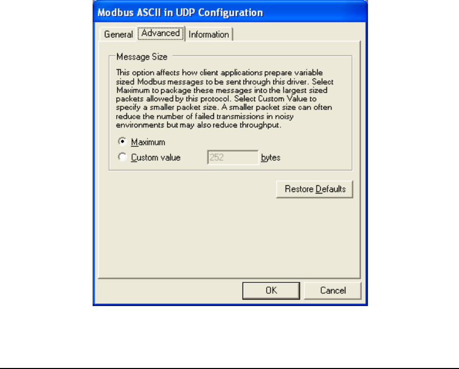
The Host Network Details grouping contains entries for the host’s IP address or name and
the TCP port on which it is listening.
The IP Address / Name entry specifies the Ethernet IP address in dotted quad notation, or a DNS
host name that can be resolved to an IP address, of the PC where the ClearSCADA server is
installed. The following IP addresses are not supported and will be rejected:
• 0.0.0.0 through 0.255.255.255
• 127.0.0.0 through 127.255.255.255 (except 127.0.0.1)
• 224.0.0.0 through 224.255.255.255
• 255.0.0.0 through 255.255.255.255.
The UDP Port No. field specifies the UDP port of the remote device. Valid values are 0 to
65535. The default value is 49153.
• Click Restore Defaults to restore default values to all fields on this page, except for the IP
Address / Name field. The content of this field will remain unchanged.
6.3.7.2 Advanced Parameters
Advanced parameters are used to control the message size for the protocol. Control over message
length is needed when writing large amounts of data over certain communication networks. A larger
value can improve communication speed but can increase the number of failed transmissions. A
smaller value can reduce the number of failed transmissions but may reduce throughput. When the
Advanced tab heading is clicked the Advanced dialog is opened as shown below.
Figure 86: Modbus ASCII in UDP Configuration (Advanced) Dialog Box
TelePACE Ladder Logic User and Reference Manual
May 9, 2007
121
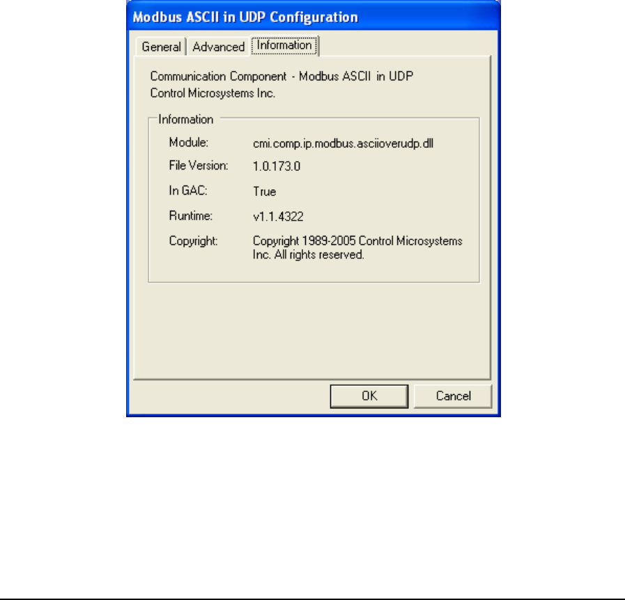
The Message Size grouping parameters are used to control the message size for the protocol. Control
over message length is needed when writing large amounts of data over certain communication
networks. A larger value can improve communication speed but can increase the number of failed
transmissions. A smaller value can reduce the number of failed transmissions but may reduce
throughput.
The Maximum selection indicates that the host application is to package messages using the
maximum size allowable by the protocol.
The Custom Value selection specifies a custom value for the message size. This value indicates to
the host application to package messages to be no larger than what is specified, if it is possible.
Valid values are 2 to 250 when Addressing is set to Extended and Station is 255 or higher. When
Addressing is set to Extended and Station is less than 255 valid values are 2 to 252. When
Addressing is set to Standard valid values are 2 to 252.
• Click Restore Defaults to restore default values to all fields on this page.
6.3.7.3 Information
Information displays detailed driver information. When the Information tab heading is clicked the
Information dialog is opened as shown below.
Figure 87: Modbus ASCII in UDP Configuration (Information) Dialog Box
The Information grouping presents informative details concerning the executing protocol driver.
Module is the physical name of the driver.
File Version is the version number of the driver.
TelePACE Ladder Logic User and Reference Manual
May 9, 2007
122

In GAC indicates whether the module (assembly) was loaded from the Global Assembly Cache
(GAC).
Runtime is the version of the Common Language Runtime (CLR) the driver was built against.
Copyright indicates the copyright information of the protocol driver.
6.3.8 Modbus RTU
6.3.8.1 Introduction
The Modbus RTU protocol driver is used to communicate over a serial network, using Modbus RTU
framing, to SCADAPack controllers configured for Modbus RTU protocol.
• To configure a Modbus RTU protocol connection, highlight Modbus RTU in the
Communication Protocols window and click the Configure button. The Modbus RTU
Configuration window is displayed.
• To select a configured Modbus RTU protocol connection, highlight Modbus RTU in the
Communication Protocols window and click the OK button.
• To close the dialog, without making a selection click the Cancel button.
6.3.8.2 General Parameters
When Modbus RTU is selected for configuration the Modbus RTU Configuration dialog is opened
with the General tab selected as shown below.
TelePACE Ladder Logic User and Reference Manual
May 9, 2007
123
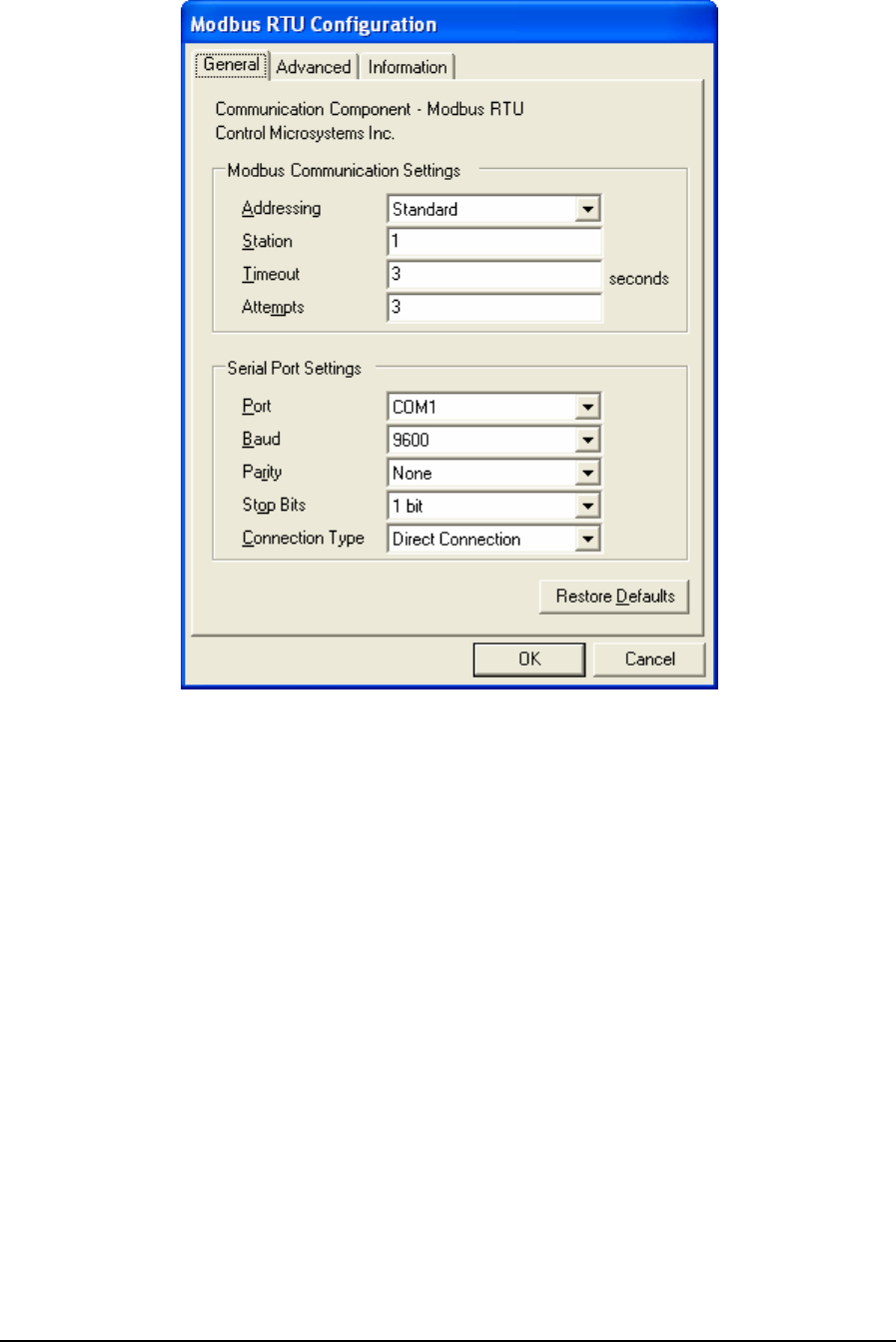
Figure 88: Modbus RTU Configuration (General) Dialog Box
The Modbus Communication Settings grouping contains Modbus specific communication settings
including the addressing mode, the station address, the timeout interval as well as the number of
attempts.
The Addressing parameter selects standard or extended Modbus addressing. Standard addressing
allows 255 stations and is compatible with standard Modbus devices. Extended addressing allows
65534 stations, with stations 1 to 254 compatible with standard Modbus devices. The default is
Standard.
The Station parameter sets the target station number. The valid range is 1 to 255 if standard
addressing is used, and 1 to 65534 if extended addressing is used. The default is 1.
The Timeout parameter sets the length of time, in seconds, to wait for a response from the controller
before retrying (see Attempts), or ultimately failing. Valid entries are 1 to 255. The default is 3.
The Attempts parameter sets number of times to send a command to the controller before giving up
and reporting this failure to the host application. Valid entries are 1 to 20. The default is 3.
This Serial Port Settings grouping contains details directly related to the PC’s
communication port including the port number, the baud rate, parity and stop bit settings.
The Port parameter specifies the PC serial port to use. The DNP driver determines what serial ports
are available on the PC and presents these in the drop-down menu list. The available serial ports list
TelePACE Ladder Logic User and Reference Manual
May 9, 2007
124

will include any USB to serial converters used on the PC. The default value is the first existing port
found by the driver.
The Baud parameter specifies the baud rate to use for communication. The menu list displays
selections for 300, 600, 1200, 2400, 4800, 9600, 19200, 38400, and 57600. The default value is
9600.
The Parity parameter specifies the type of parity to use for communication. The menu list displays
selections for none, odd and even parity. The default value is None.
The Stop Bits parameter specifies the number of stop bits to use for communication. The menu list
displays selections for 1 and 2 stop bits. The default value is 1 bit.
The Connection Type parameter specifies the serial connection type. The Modbus RTU driver
supports direct serial connection with no flow control, Request-to-send (RTS) and clear-to-send
(CTS) flow control and PSTN dial-up connections. The menu list displays selections for Direct
Connection, RTS/CTS Flow Control and Dial Up Connection. The default selection is Direct
Connection.
• Select Direct Connection for RS-232 for RS-485 connections that do not require the hardware
control lines on the serial ports.
• Select RTS/CTS Flow Control to communicate over radio or leased-line networks using
modems that require RTS/CTS handshaking. Selecting RTS/CTS Flow Control adds a new tab,
Flow Control, to the Modbus RTU Configuration dialog. Refer to the Flow Control Parameters
section below for configuration details.
• Select Dial Up Connection to communication over dial up modems. Selecting Dial Up
Connection adds a new tab, Dial Up, to the Modbus RTU Configuration dialog. Refer to the Dial
Up Parameters section below for configuration details.
• Click Restore Defaults to restore default values to all fields on this page.
6.3.8.3 Modbus RTU Configuration (Flow Control)
Flow Control parameters are used to configure how RTS and CTS control is used. When RTS/CTS
Flow Control is selected for Connection Type the Flow Control tab is added to the Modbus RTU
Configuration dialog. When the Flow Control tab heading is clicked the Flow Control dialog is
opened as shown below.
TelePACE Ladder Logic User and Reference Manual
May 9, 2007
125
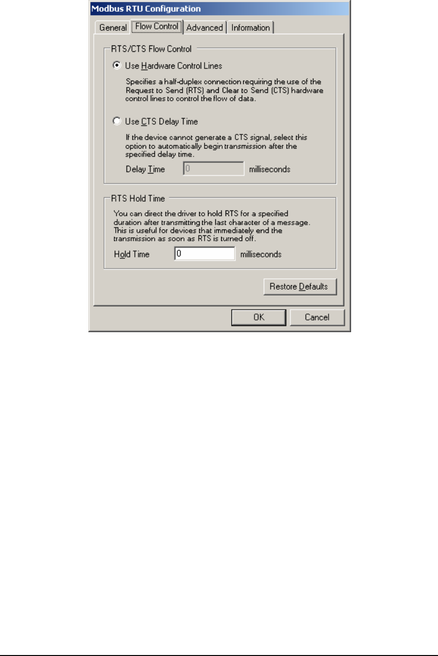
Figure 89: Modbus RTU Configuration (Flow Control)
The RTS/CTS Flow Control grouping contains two mutually exclusive options, Use Hardware
Control Lines and Use CTS Delay Time. These options enable the driver to communicate over radio
or leased-line networks using modems that require RTS/CTS handshaking.
The Use Hardware Control Lines option specifies a half-duplex connection requiring the use of the
Request to Send (RTS) and Clear to Send (CTS) hardware control lines to control the flow of data.
This selection is used with radios and dedicated telephone line modems. The driver turns on the RTS
signal when it wants to transmit data. The modem or other device then turns on CTS when it is ready
to transmit. The driver transmits the data, and then turns off the RTS signal. This selection is
mutually exclusive of the Use CTS Delay Time selection described below. This is the default
selection.
The Use CTS Delay Time option is selected if the device cannot generate a CTS signal. The driver
will assert RTS then wait the specified Delay Time, in milliseconds, before proceeding. This option
is mutually exclusive with the Use Hardware Control Lines selection described above.
The Delay Time parameter sets the time in milliseconds that the driver will wait after asserting RTS
before proceeding. The value of this field must be smaller than the Time Out value set in the General
parameters dialog. For example, if the Timeout value is set to 3 seconds, the CTS Delay Time can be
set to 2999 milliseconds or less. The minimum value for this field is 0 milliseconds. The value is
initially set to 0 by default.
TelePACE Ladder Logic User and Reference Manual
May 9, 2007
126
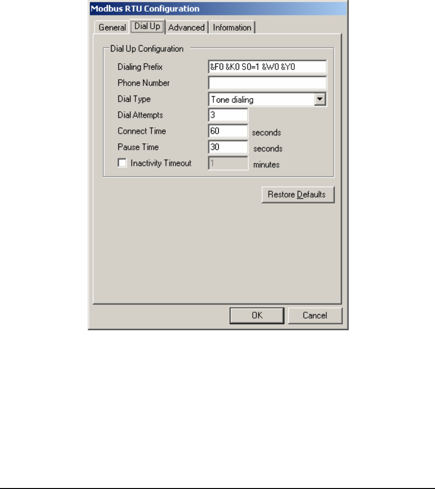
The Hold Time parameter specifies the time, in milliseconds, that the driver will hold RTS after the
last character is transmitted. This is useful for devices that immediately end transmission when RTS
is turned off. The value of this field must be smaller than the Time Out value set in the General
parameters dialog. For example, if the Timeout value is set to 3 seconds, the CTS Delay Time can be
set to 2999 milliseconds or less. The minimum value for this field is 0 milliseconds. The value is
initially set to 0 by default.
• Click Restore Defaults to restore default values to all fields on this page.
6.3.8.4 Modbus RTU Configuration (Dial Up)
Dial Up parameters are used to configure a dial up connection. When Dial Up is selected for
Connection Type the Dial Up tab is added to the Modbus RTU Configuration dialog. When the Dial
Up tab heading is clicked the Dial Up dialog is opened as shown below.
Figure 90: Modbus RTU Configuration (Dial Up)
The Dialing Prefix parameter specifies the commands sent to the modem before dialing. A
maximum of 32 characters can be entered. All characters are valid. The default value is “&F0 &K0
S0=1 &W0 &Y0”.
The Phone Number parameter specifies the telephone number of the remote controller. A maximum
of 32 characters can be entered. All characters are valid. This field’s default value is blank.
TelePACE Ladder Logic User and Reference Manual
May 9, 2007
127

The Dial Type parameter specifies the dialing type. Valid values are Pulse and Tone. The default
value is Tone.
The Dial Attempts parameter specifies how many dialing attempts will be made. Valid values are 1
to 10. The default value is 1.
The Connect Time parameter specifies the amount of time in seconds the modem will wait for a
connection. Valid values are 6 to 300. The default value is 60.
The Pause Time parameter specifies the time in seconds between dialing attempts. Valid values are
6 to 600. The default value is 30.
Check the Inactivity Timeout check box to automatically terminate the dialup connection after a
period of inactivity. The Inactivity Time edit box is enabled only if this option is checked. The
default state is checked.
Enter the inactivity period, in minutes, in the Inactivity Timeout box. The dialup connection will be
terminated automatically after the specified number of minutes of inactivity has lapsed. This option
is only active if the Inactivity Timeout box is checked. Valid values are from 1 to 30 minutes. The
default value is 1.
• Click Restore Defaults to restore default values to all fields on this page, except for the Phone
Number field. The content of this field will remain unchanged.
TelePACE Ladder Logic User and Reference Manual
May 9, 2007
128
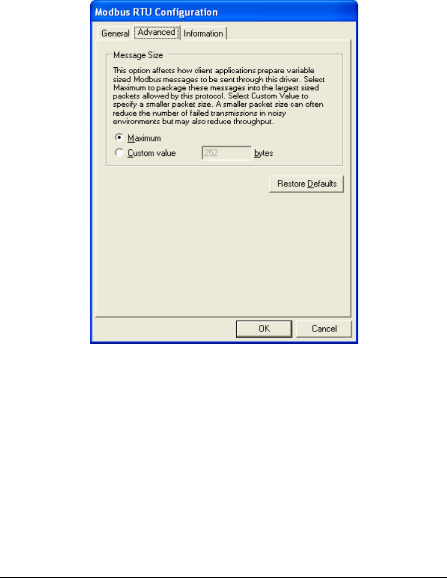
6.3.8.5 Advanced Parameters
Advanced parameters are used to control the message size for the protocol. Control over message
length is needed when writing large amounts of data over certain communication networks. A larger
value can improve communication speed but can increase the number of failed transmissions. A
smaller value can reduce the number of failed transmissions but may reduce throughput. When the
Advanced tab heading is clicked the Advanced dialog is opened as shown below.
Figure 91: Modbus RTU Configuration (Advanced) Dialog Box
The Message Size grouping parameters are used to control the message size for the protocol. Control
over message length is needed when writing large amounts of data over certain communication
networks. A larger value can improve communication speed but can increase the number of failed
transmissions. A smaller value can reduce the number of failed transmissions but may reduce
throughput.
The Maximum selection indicates that the host application is to package messages using the
maximum size allowable by the protocol.
The Custom Value selection specifies a custom value for the message size. This value indicates to
the host application to package messages to be no larger than what is specified, if it is possible.
Valid values are 2 to 250 when Addressing is set to Extended and Station is 255 or higher. When
Addressing is set to Extended and Station is less than 255 valid values are 2 to 252. When
Addressing is set to Standard valid values are 2 to 252.
TelePACE Ladder Logic User and Reference Manual
May 9, 2007
129
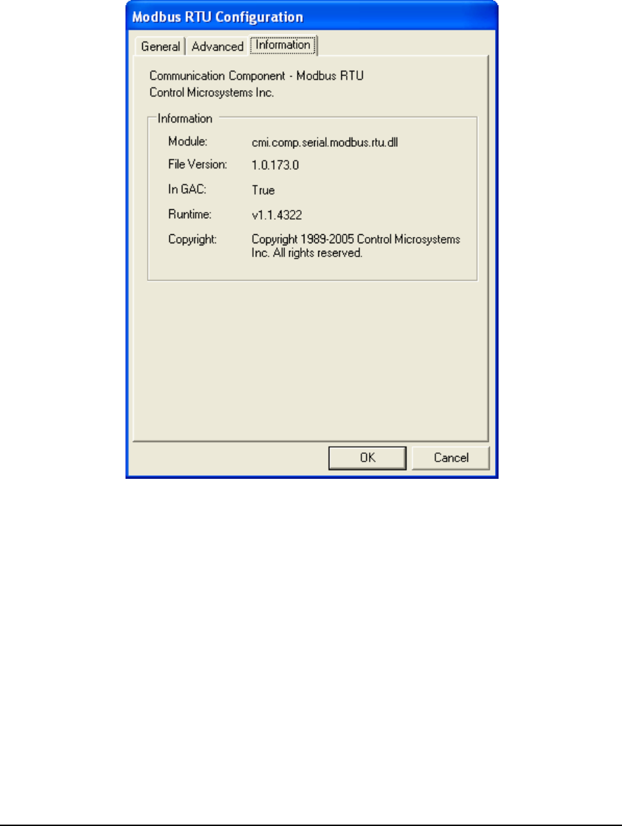
• Click Restore Defaults to restore default values to all fields on this page.
6.3.8.6 Information
Information displays detailed driver information. When the Information tab heading is clicked the
Information dialog is opened as shown below.
Figure 92: Modbus RTU Configuration (Information) Dialog Box
The Information grouping presents informative details concerning the executing protocol driver.
Module is the physical name of the driver.
File Version is the version number of the driver.
In GAC indicates whether the module (assembly) was loaded from the Global Assembly Cache
(GAC).
Runtime is the version of the Common Language Runtime (CLR) the driver was built against.
Copyright indicates the copyright information of the protocol driver.
6.3.9 Modbus RTU in TCP
Modbus RTU in TCP message format is exactly same as that of the Modbus RTU protocol. The main
difference is that Modbus RTU in TCP protocol communicates with a controller through the Internet
and Modbus RTU protocol through the serial port. The Modbus RTU in TCP protocol does not
TelePACE Ladder Logic User and Reference Manual
May 9, 2007
130
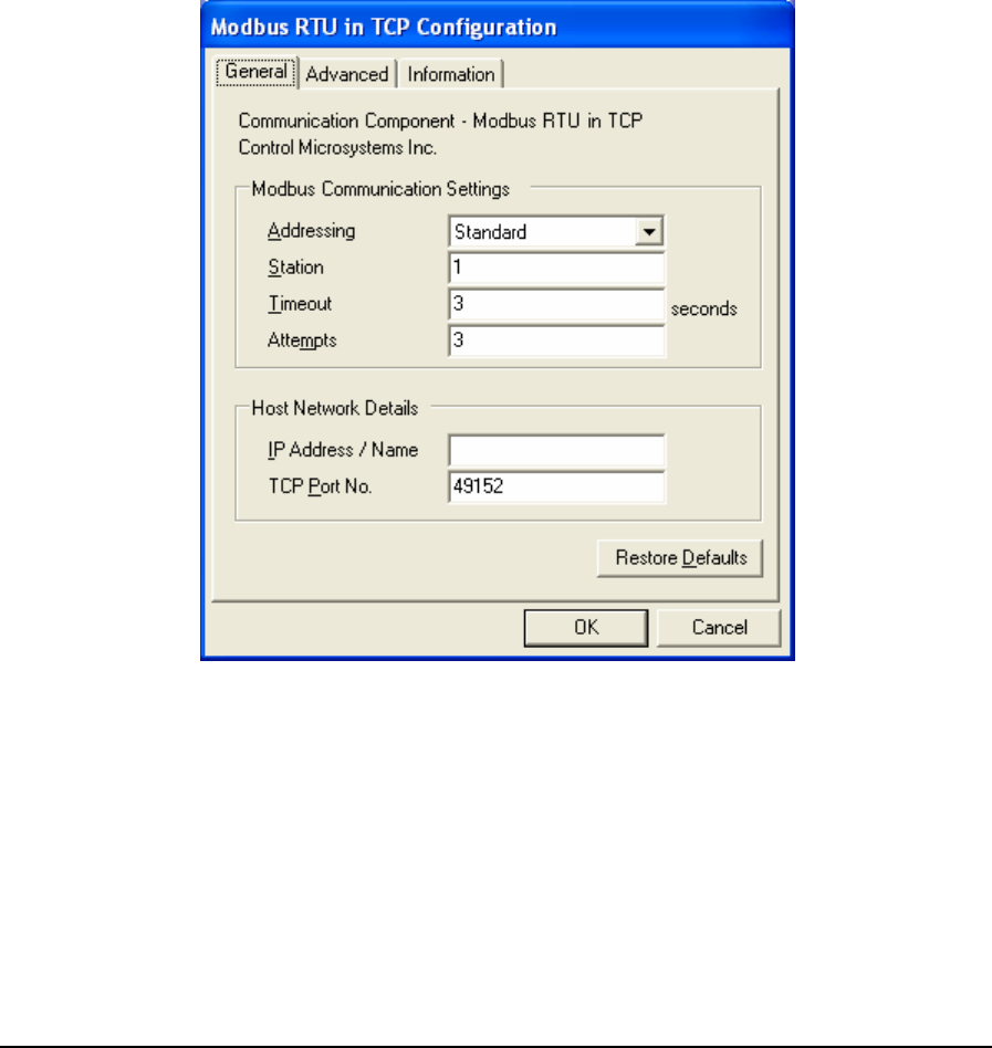
include a six-byte header prefix, as with the Modbus\TCP, but does include the Modbus ‘CRC-16’ or
‘LRC’ check fields. The Modbus RTU in TCP message format supports Modbus RTU message
format.
• To configure a Modbus RTU in TCP protocol connection, highlight Modbus RTU in TCP in
the Communication Protocols window and click the Configure button. The Modbus RTU in
TCP Configuration window is displayed.
• To select a configured Modbus RTU in TCP protocol connection, highlight Modbus RTU in
TCP in the Communication Protocols window and click the OK button.
• To close the dialog, without making a selection click the Cancel button.
6.3.9.1 General Parameters
When Modbus RTU in TCP is selected for configuration the Modbus RTU in TCP Configuration
dialog is opened with the General tab selected as shown below.
Figure 93: Modbus RTU in TCP Configuration (General) Dialog Box
The Modbus Communication Settings grouping contains Modbus specific communication settings
including the addressing mode, the station address, the timeout interval as well as the number of
attempts.
The Addressing parameter selects standard or extended Modbus addressing. Standard addressing
allows 255 stations and is compatible with standard Modbus devices. Extended addressing allows
65534 stations, with stations 1 to 254 compatible with standard Modbus devices. The default is
Standard.
TelePACE Ladder Logic User and Reference Manual
May 9, 2007
131

The Station parameter sets the target station number. The valid range is 1 to 255 if standard
addressing is used, and 1 to 65534 if extended addressing is used. The default is 1.
The Timeout parameter sets the length of time, in seconds, to wait for a response from the controller
before retrying (see Attempts), or ultimately failing. Valid entries are 1 to 255. The default is 3.
The Attempts parameter sets number of times to send a command to the controller before giving up
and reporting this failure to the host application. Valid entries are 1 to 20. The default is 3.
The Host Network Details grouping contains entries for the host’s IP address or name and
the TCP port on which it is listening.
The IP Address / Name entry specifies the Ethernet IP address in dotted quad notation, or a DNS
host name that can be resolved to an IP address, of the PC where the ClearSCADA server is
installed. The following IP addresses are not supported and will be rejected:
• 0.0.0.0 through 0.255.255.255
• 127.0.0.0 through 127.255.255.255 (except 127.0.0.1)
• 224.0.0.0 through 224.255.255.255
• 255.0.0.0 through 255.255.255.255.
The TCP Port No. field specifies the TCP port of the remote device. Valid values are 0 to
65535. The default value is 49152.
• Click Restore Defaults to restore default values to all fields on this page, except for the IP
Address / Name field. The content of this field will remain unchanged.
TelePACE Ladder Logic User and Reference Manual
May 9, 2007
132

6.3.9.2 Advanced Parameters
Advanced parameters are used to control the message size for the protocol. Control over message
length is needed when writing large amounts of data over certain communication networks. A larger
value can improve communication speed but can increase the number of failed transmissions. A
smaller value can reduce the number of failed transmissions but may reduce throughput. When the
Advanced tab heading is clicked the Advanced dialog is opened as shown below.
Figure 94: Modbus RTU in TCP Configuration (Advanced) Dialog Box
The Message Size grouping parameters are used to control the message size for the protocol. Control
over message length is needed when writing large amounts of data over certain communication
networks. A larger value can improve communication speed but can increase the number of failed
transmissions. A smaller value can reduce the number of failed transmissions but may reduce
throughput.
The Maximum selection indicates that the host application is to package messages using the
maximum size allowable by the protocol.
The Custom Value selection specifies a custom value for the message size. This value indicates to
the host application to package messages to be no larger than what is specified, if it is possible.
Valid values are 2 to 250 when Addressing is set to Extended and Station is 255 or higher. When
Addressing is set to Extended and Station is less than 255 valid values are 2 to 252. When
Addressing is set to Standard valid values are 2 to 252.
• Click Restore Defaults to restore default values to all fields on this page.
TelePACE Ladder Logic User and Reference Manual
May 9, 2007
133
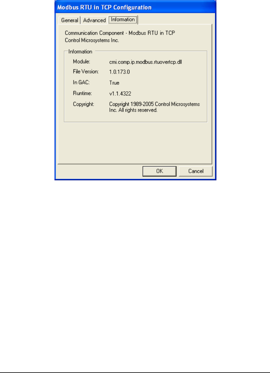
6.3.9.3 Information
Information displays detailed driver information. When the Information tab heading is clicked the
Information dialog is opened as shown below.
Figure 95: Modbus RTU in TCP Configuration (Information) Dialog Box
The Information grouping presents informative details concerning the executing protocol driver.
Module is the physical name of the driver.
File Version is the version number of the driver.
In GAC indicates whether the module (assembly) was loaded from the Global Assembly Cache
(GAC).
Runtime is the version of the Common Language Runtime (CLR) the driver was built against.
Copyright indicates the copyright information of the protocol driver.
6.3.10 Modbus RTU in UDP
Modbus RTU in UDP protocol is similar to Modbus RTU in TCP protocol. It has the same
message format as the RTU in TCP message. The only difference between them is one uses
TCP protocol and another uses UDP protocol.
• To configure a Modbus RTU in UDP protocol connection, highlight Modbus RTU in UDP in
the Communication Protocols window and click the Configure button. The Modbus RTU in
UDP Configuration window is displayed.
TelePACE Ladder Logic User and Reference Manual
May 9, 2007
134

• To select a configured Modbus RTU in UDP protocol connection, highlight Modbus RTU in
UDP in the Communication Protocols window and click the OK button.
• To close the dialog, without making a selection click the Cancel button.
6.3.10.1 General Parameters
When Modbus RTU in UDP is selected for configuration the Modbus RTU in UDP Configuration
dialog is opened with the General tab selected as shown below.
Figure 96: Modbus RTU in UDP Configuration (General) Dialog Box
The Modbus Communication Settings grouping contains Modbus specific communication settings
including the addressing mode, the station address, the timeout interval as well as the number of
attempts.
The Addressing parameter selects standard or extended Modbus addressing. Standard addressing
allows 255 stations and is compatible with standard Modbus devices. Extended addressing allows
65534 stations, with stations 1 to 254 compatible with standard Modbus devices. The default is
Standard.
The Station parameter sets the target station number. The valid range is 1 to 255 if standard
addressing is used, and 1 to 65534 if extended addressing is used. The default is 1.
The Timeout parameter sets the length of time, in seconds, to wait for a response from the controller
before retrying (see Attempts), or ultimately failing. Valid entries are 1 to 255. The default is 3.
The Attempts parameter sets number of times to send a command to the controller before giving up
and reporting this failure to the host application. Valid entries are 1 to 20. The default is 3.
TelePACE Ladder Logic User and Reference Manual
May 9, 2007
135

The Host Network Details grouping contains entries for the host’s IP address or name and
the TCP port on which it is listening.
The IP Address / Name entry specifies the Ethernet IP address in dotted quad notation, or a DNS
host name that can be resolved to an IP address, of the PC where the ClearSCADA server is
installed. The following IP addresses are not supported and will be rejected:
• 0.0.0.0 through 0.255.255.255
• 127.0.0.0 through 127.255.255.255 (except 127.0.0.1)
• 224.0.0.0 through 224.255.255.255
• 255.0.0.0 through 255.255.255.255.
The UDP Port No. field specifies the UDP port of the remote device. Valid values are 0 to
65535. The default value is 49152.
• Click Restore Defaults to restore default values to all fields on this page, except for the IP
Address / Name field. The content of this field will remain unchanged.
6.3.10.2 Advanced Parameters
Advanced parameters are used to control the message size for the protocol. Control over message
length is needed when writing large amounts of data over certain communication networks. A larger
value can improve communication speed but can increase the number of failed transmissions. A
smaller value can reduce the number of failed transmissions but may reduce throughput. When the
Advanced tab heading is clicked the Advanced dialog is opened as shown below.
Figure 97: Modbus RTU in UDP Configuration (Advanced) Dialog Box
TelePACE Ladder Logic User and Reference Manual
May 9, 2007
136
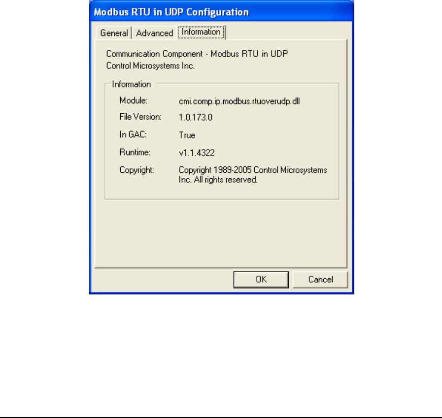
The Message Size grouping parameters are used to control the message size for the protocol. Control
over message length is needed when writing large amounts of data over certain communication
networks. A larger value can improve communication speed but can increase the number of failed
transmissions. A smaller value can reduce the number of failed transmissions but may reduce
throughput.
The Maximum selection indicates that the host application is to package messages using the
maximum size allowable by the protocol.
The Custom Value selection specifies a custom value for the message size. This value indicates to
the host application to package messages to be no larger than what is specified, if it is possible.
Valid values are 2 to 250 when Addressing is set to Extended and Station is 255 or higher. When
Addressing is set to Extended and Station is less than 255 valid values are 2 to 252. When
Addressing is set to Standard valid values are 2 to 252.
• Click Restore Defaults to restore default values to all fields on this page.
6.3.10.3 Information
Information displays detailed driver information. When the Information tab heading is clicked the
Information dialog is opened as shown below.
Figure 98: Modbus RTU in UDP Configuration (Information) Dialog Box
The Information grouping presents informative details concerning the executing protocol driver.
Module is the physical name of the driver.
File Version is the version number of the driver.
TelePACE Ladder Logic User and Reference Manual
May 9, 2007
137

In GAC indicates whether the module (assembly) was loaded from the Global Assembly Cache
(GAC).
Runtime is the version of the Common Language Runtime (CLR) the driver was built against.
Copyright indicates the copyright information of the protocol driver.
6.3.11 Modbus/TCP
Modbus/TCP is an extension of serial Modbus, which defines how Modbus messages are encoded
within and transported over TCP/IP-based networks. The Modbus/TCP protocol uses a custom
Modbus protocol layer on top of the TCP protocol. Its request and response messages are prefixed by
six bytes. These six bytes consist of three fields: transaction ID field, protocol ID field and length
field. The encapsulated Modbus message has exactly the same layout and meaning, from the
function code to the end of the data portion, as other Modbus messages. The Modbus ‘CRC-16’ or
‘LRC’ check fields are not used in Modbus/TCP. The TCP/IP and link layer (e.g. Ethernet)
checksum mechanisms instead are used to verify accurate delivery of the packet.
• To configure a Modbus/TCP protocol connection, highlight Modbus/TCP in the
Communication Protocols window and click the Configure button. The Modbus/TCP
Configuration window is displayed.
• To select a configured Modbus/TCP protocol connection, highlight Modbus/TCP in the
Communication Protocols window and click the OK button.
• To close the dialog, without making a selection click the Cancel button.
TelePACE Ladder Logic User and Reference Manual
May 9, 2007
138
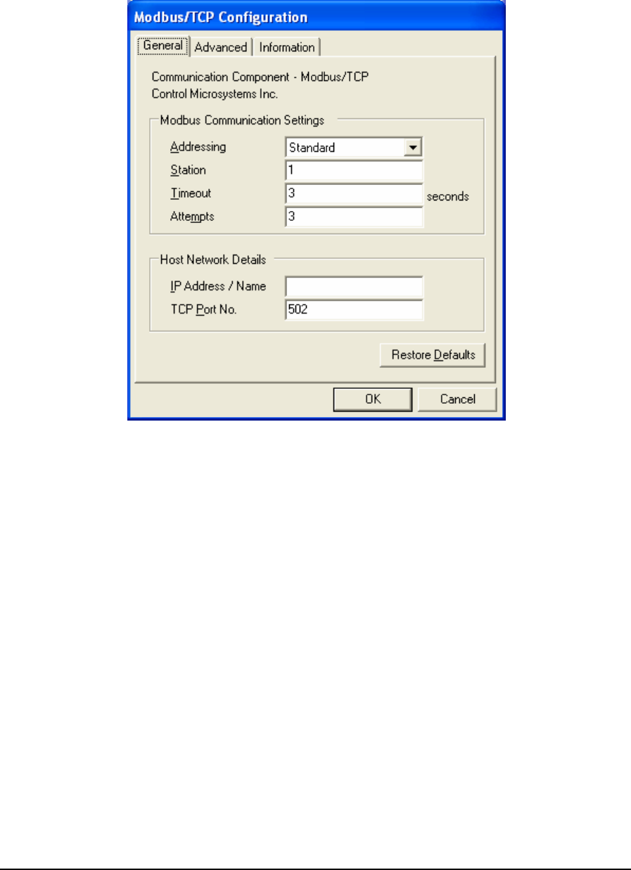
6.3.11.1 General Parameters
When Modbus/TCP is selected for configuration the Modbus/TCP Configuration dialog is opened
with the General tab selected as shown below.
Figure 99: Modbus/TCP Configuration (General) Dialog Box
The Modbus Communication Settings grouping contains Modbus specific communication settings
including the addressing mode, the station address, the timeout interval as well as the number of
attempts.
The Addressing parameter selects standard or extended Modbus addressing. Standard addressing
allows 255 stations and is compatible with standard Modbus devices. Extended addressing allows
65534 stations, with stations 1 to 254 compatible with standard Modbus devices. The default is
Standard.
The Station parameter sets the target station number. The valid range is 1 to 255 if standard
addressing is used, and 1 to 65534 if extended addressing is used. The default is 1.
The Timeout parameter sets the length of time, in seconds, to wait for a response from the controller
before retrying (see Attempts), or ultimately failing. Valid entries are 1 to 255. The default is 3.
The Attempts parameter sets number of times to send a command to the controller before giving up
and reporting this failure to the host application. Valid entries are 1 to 20. The default is 3.
The Host Network Details grouping contains entries for the host’s IP address or name and
the TCP port on which it is listening.
TelePACE Ladder Logic User and Reference Manual
May 9, 2007
139
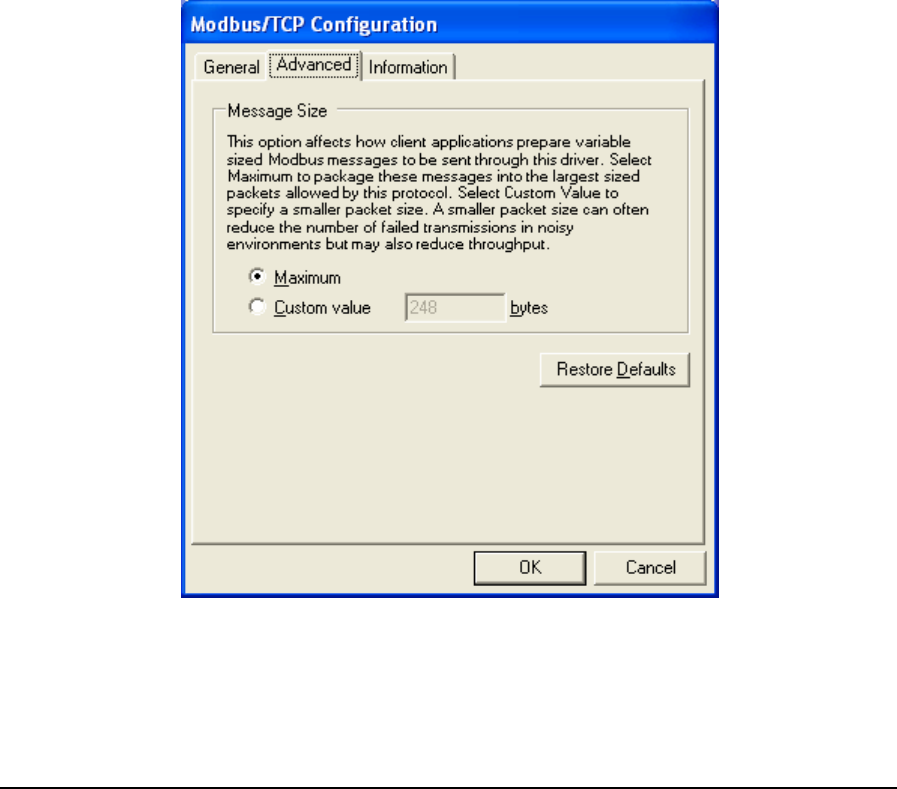
The IP Address / Name entry specifies the Ethernet IP address in dotted quad notation, or a DNS
host name that can be resolved to an IP address, of the PC where the ClearSCADA server is
installed. The following IP addresses are not supported and will be rejected:
• 0.0.0.0 through 0.255.255.255
• 127.0.0.0 through 127.255.255.255 (except 127.0.0.1)
• 224.0.0.0 through 224.255.255.255
• 255.0.0.0 through 255.255.255.255.
The TCP Port No. field specifies the UDP port of the remote device. Valid values are 0 to
65535. The default value is 502.
• Click Restore Defaults to restore default values to all fields on this page, except for the IP
Address / Name field. The content of this field will remain unchanged.
6.3.11.2 Advanced Parameters
Advanced parameters are used to control the message size for the protocol. Control over message
length is needed when writing large amounts of data over certain communication networks. A larger
value can improve communication speed but can increase the number of failed transmissions. A
smaller value can reduce the number of failed transmissions but may reduce throughput. When the
Advanced tab heading is clicked the Advanced dialog is opened as shown below.
Figure 100: Modbus/TCP Configuration (Advanced) Dialog Box
The Message Size grouping parameters are used to control the message size for the protocol. Control
over message length is needed when writing large amounts of data over certain communication
TelePACE Ladder Logic User and Reference Manual
May 9, 2007
140
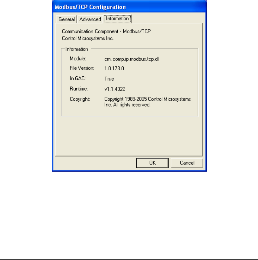
networks. A larger value can improve communication speed but can increase the number of failed
transmissions. A smaller value can reduce the number of failed transmissions but may reduce
throughput.
The Maximum selection indicates that the host application is to package messages using the
maximum size allowable by the protocol.
The Custom Value selection specifies a custom value for the message size. This value indicates to
the host application to package messages to be no larger than what is specified, if it is possible.
Valid values are 2 to 246 when Addressing is set to Extended and Station is 255 or higher. When
Addressing is set to Extended and Station is less than 255 valid values are 2 to 248. When
Addressing is set to Standard valid values are 2 to 248.
• Click Restore Defaults to restore default values to all fields on this page.
6.3.11.3 Information
Information displays detailed driver information. When the Information tab heading is clicked the
Information dialog is opened as shown below.
Figure 101: Modbus/TCP Configuration (Information) Dialog Box
The Information grouping presents informative details concerning the executing protocol driver.
Module is the physical name of the driver.
File Version is the version number of the driver.
In GAC indicates whether the module (assembly) was loaded from the Global Assembly Cache
(GAC).
TelePACE Ladder Logic User and Reference Manual
May 9, 2007
141
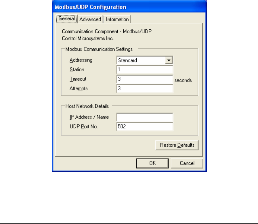
Runtime is the version of the Common Language Runtime (CLR) the driver was built against.
Copyright indicates the copyright information of the protocol driver.
6.3.12 Modbus/UDP
Modbus/UDP communication mode is similar to Modbus/TCP communication mode. It has
the same message format with the Modbus/TCP. The only difference between them is one
uses TCP protocol and another uses UDP protocol.
• To configure a Modbus/UDP protocol connection, highlight Modbus/UDP in the
Communication Protocols window and click the Configure button. The Modbus/ UDP
Configuration window is displayed.
• To select a configured Modbus/UDP protocol connection, highlight Modbus/ UDP in the
Communication Protocols window and click the OK button.
• To close the dialog, without making a selection click the Cancel button.
6.3.12.1 General Parameters
When Modbus/UDP is selected for configuration the Modbus/ UDP Configuration dialog is opened
with the General tab selected as shown below.
Figure 102: Modbus/UDP Configuration (General) Dialog Box
TelePACE Ladder Logic User and Reference Manual
May 9, 2007
142

The Modbus Communication Settings grouping contains Modbus specific communication settings
including the addressing mode, the station address, the timeout interval as well as the number of
attempts.
The Addressing parameter selects standard or extended Modbus addressing. Standard addressing
allows 255 stations and is compatible with standard Modbus devices. Extended addressing allows
65534 stations, with stations 1 to 254 compatible with standard Modbus devices. The default is
Standard.
The Station parameter sets the target station number. The valid range is 1 to 255 if standard
addressing is used, and 1 to 65534 if extended addressing is used. The default is 1.
The Timeout parameter sets the length of time, in seconds, to wait for a response from the controller
before retrying (see Attempts), or ultimately failing. Valid entries are 1 to 255. The default is 3.
The Attempts parameter sets number of times to send a command to the controller before giving up
and reporting this failure to the host application. Valid entries are 1 to 20. The default is 3.
The Host Network Details grouping contains entries for the host’s IP address or name and
the TCP port on which it is listening.
The IP Address / Name entry specifies the Ethernet IP address in dotted quad notation, or a DNS
host name that can be resolved to an IP address, of the PC where the ClearSCADA server is
installed. The following IP addresses are not supported and will be rejected:
• 0.0.0.0 through 0.255.255.255
• 127.0.0.0 through 127.255.255.255 (except 127.0.0.1)
• 224.0.0.0 through 224.255.255.255
• 255.0.0.0 through 255.255.255.255.
The UDP Port No. field specifies the UDP port of the remote device. Valid values are 0 to
65535. The default value is 502.
• Click Restore Defaults to restore default values to all fields on this page, except for the IP
Address / Name field. The content of this field will remain unchanged.
6.3.12.2 Advanced Parameters
Advanced parameters are used to control the message size for the protocol. Control over message
length is needed when writing large amounts of data over certain communication networks. A larger
value can improve communication speed but can increase the number of failed transmissions. A
smaller value can reduce the number of failed transmissions but may reduce throughput. When the
Advanced tab heading is clicked the Advanced dialog is opened as shown below.
TelePACE Ladder Logic User and Reference Manual
May 9, 2007
143
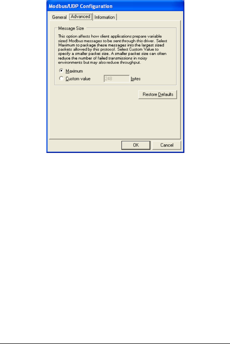
Figure 103: Modbus/UDP Configuration (Advanced) Dialog Box
The Message Size grouping parameters are used to control the message size for the protocol. Control
over message length is needed when writing large amounts of data over certain communication
networks. A larger value can improve communication speed but can increase the number of failed
transmissions. A smaller value can reduce the number of failed transmissions but may reduce
throughput.
The Maximum selection indicates that the host application is to package messages using the
maximum size allowable by the protocol.
The Custom Value selection specifies a custom value for the message size. This value indicates to
the host application to package messages to be no larger than what is specified, if it is possible.
Valid values are 2 to 246 when Addressing is set to Extended and Station is 255 or higher. When
Addressing is set to Extended and Station is less than 255 valid values are 2 to 248. When
Addressing is set to Standard valid values are 2 to 248.
• Click Restore Defaults to restore default values to all fields on this page.
TelePACE Ladder Logic User and Reference Manual
May 9, 2007
144
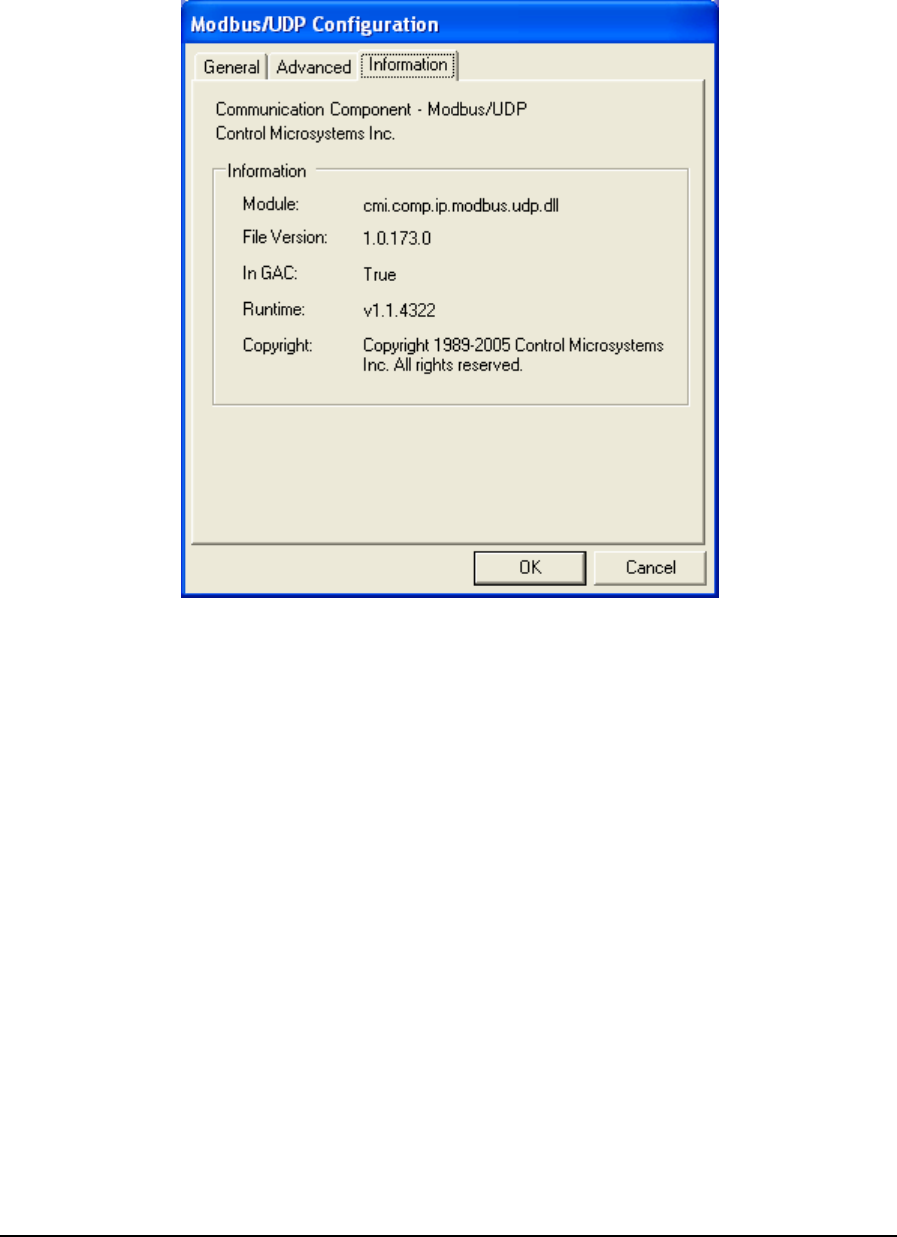
6.3.12.3 Information
Information displays detailed driver information. When the Information tab heading is clicked the
Information dialog is opened as shown below.
Figure 104: Modbus/UDP Configuration (Information) Dialog Box
The Information grouping presents informative details concerning the executing protocol driver.
Module is the physical name of the driver.
File Version is the version number of the driver.
In GAC indicates whether the module (assembly) was loaded from the Global Assembly Cache
(GAC).
Runtime is the version of the Common Language Runtime (CLR) the driver was built against.
Copyright indicates the copyright information of the protocol driver.
6.3.13 Modbus/USB
This driver provides the means to communicate with SCADAPack controllers equipped with a
Universal Serial Bus (USB) peripheral port using Modbus/USB messaging. The driver does not
require configuration making it possible to connect and communicate with a SCADAPack controller
almost instantaneously.
• To configure a Modbus/USB protocol connection, highlight Modbus/USB in the
Communication Protocols window and click the Configure button. The Modbus/ USB
TelePACE Ladder Logic User and Reference Manual
May 9, 2007
145
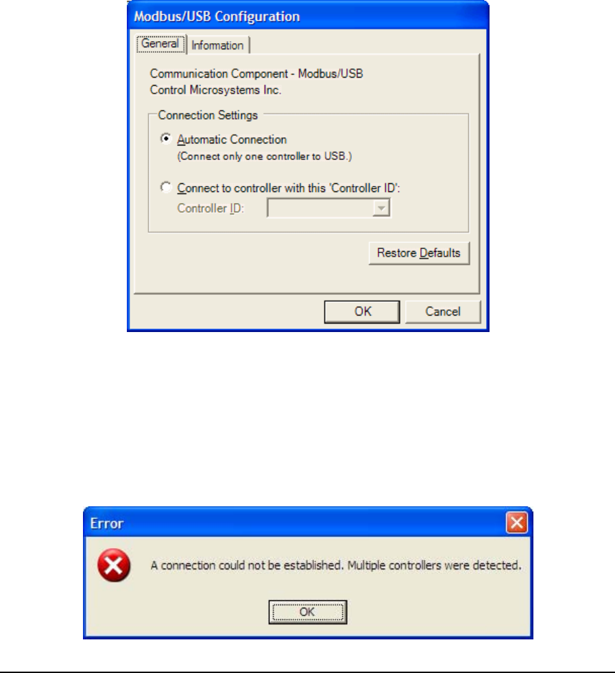
Configuration window is displayed. The pages in this configuration window are described in the
sections below.
• To select a configured Modbus/USB protocol connection, highlight Modbus/ USB in the
Communication Protocols window and click the OK button.
• To close the dialog, without making a selection click the Cancel button.
The following sections describe the information presented and user input required to configure the
Modbus/USB driver.
6.3.13.1 General Page
The general page identifies the type of driver and its author. This page also allows a user to specify
how the application searches and connects to a USB equipped SCADAPack controller. User input
depends on the number of USB equipped controllers connected on the bus.
Figure 105: Modbus/USB Configuration (General) Dialog Box
The Connection Settings grouping presents two connection options:
• Select Automatic Connection when a single controller is present on the bus.
A typical scenario involves a single controller connected directly to a USB port on the host PC.
The driver will reject connection requests by the application if this mode is selected with multiple
controllers detected on the bus. In this case, the following error message is displayed:
TelePACE Ladder Logic User and Reference Manual
May 9, 2007
146
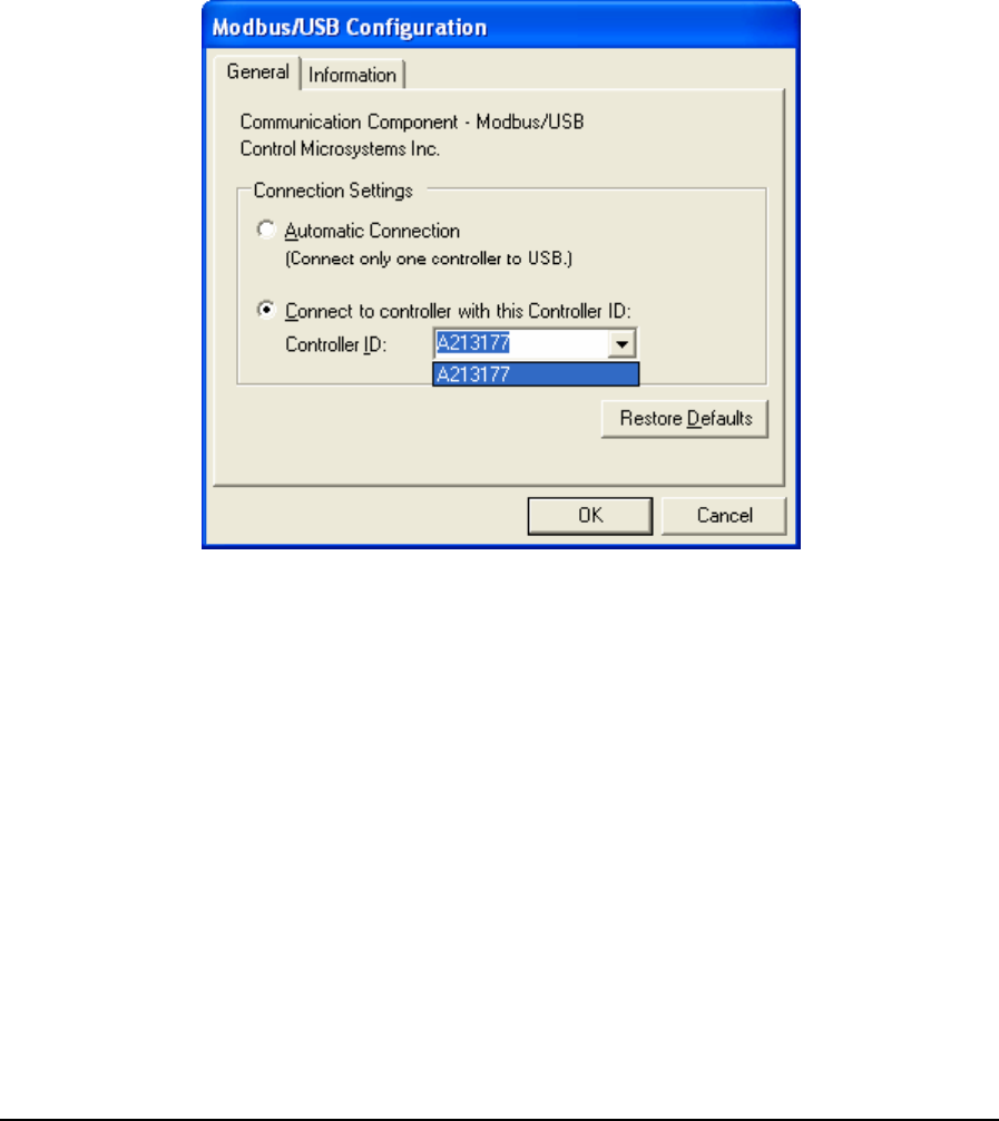
Figure 106: Multiple Controller USB Error Dialog
Note that this option is selected by default.
• Select Connect to controller with this ‘Controller ID when multiple controllers are present on
the bus.
A typical scenario involves more than one USB equipped SCADAPack controller connected via a
USB hub to the host PC.
If multiple controllers exist on the bus, the controller ID drop down box will display a list of all
identifiable devices. The user connects to the controller in question by selecting its Controller ID
from the list. The Controller ID takes on the format ‘A123456’ and can be found printed on the
controller casing or the circuit board.
Figure 107: Selecting a USB controller from list
Note that this option can also be used when there is a single controller present on the bus. However,
the Controller ID must be known and entered in the Controller ID dialog.
The chosen controller does need to be present on the bus at configuration time.
• Click on the Restore Defaults button to reset the page contents to its default state.
In the default state, the Automatic Connection option is selected and the Controller ID text box is
disabled. Any text in the Controller ID text box remains but is displayed in grey.
6.3.13.2 Information Page
The Information page identifies the driver type and author. This page further provides detailed
driver information which can be useful in identification and troubleshooting scenarios.
TelePACE Ladder Logic User and Reference Manual
May 9, 2007
147
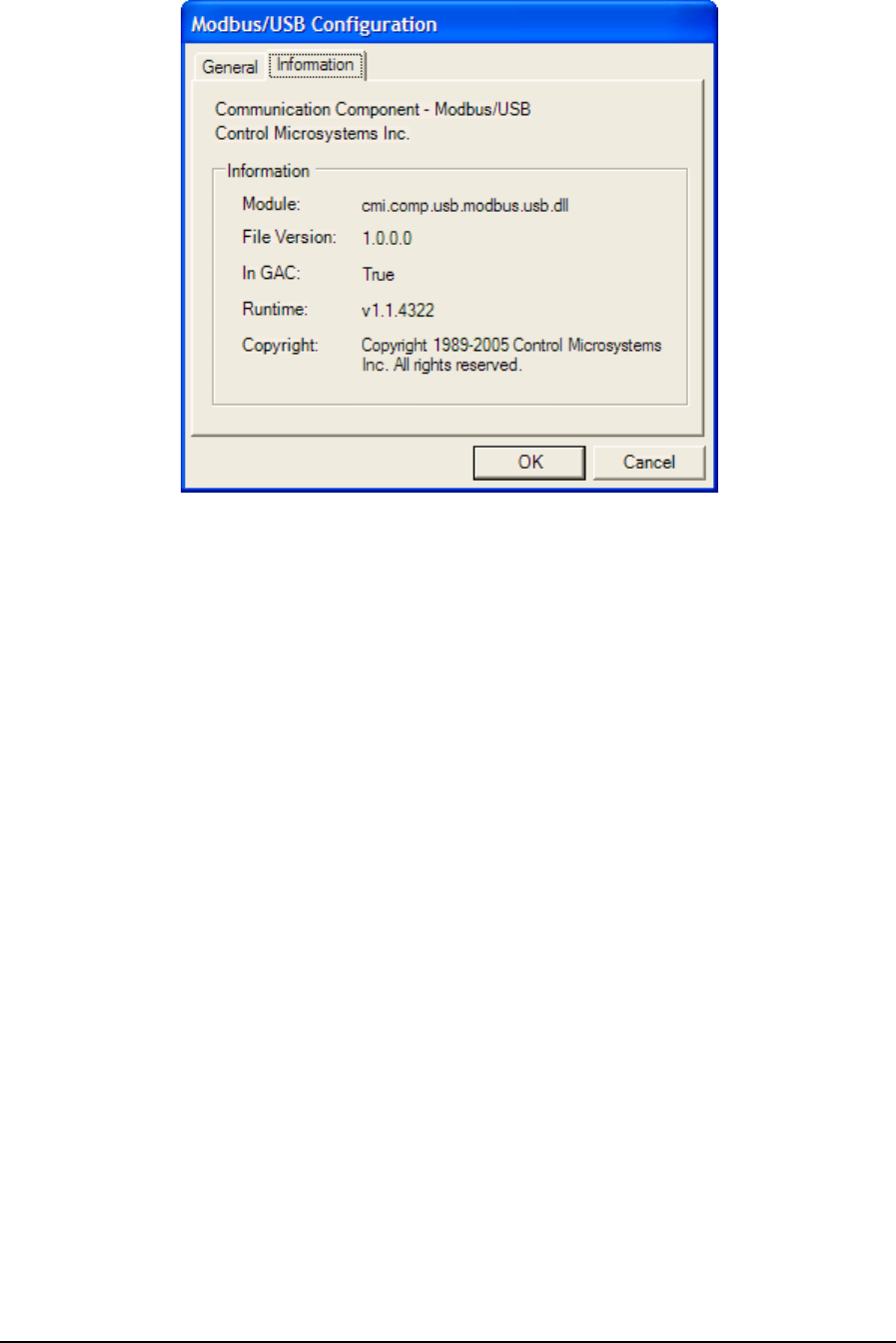
Figure 108: Modbus/USB Configuration (Information) Dialog Box
Module is the physical name of the driver.
File Version is the version number of the driver.
In GAC indicates whether the module (assembly) was loaded from the Global Assembly Cache
(GAC).
Runtime is the version of the Common Language Runtime (CLR) the driver was built against.
Copyright indicates the copyright information of the protocol driver.
6.3.14 SCADAServer
The SCADAServer protocol specifies a SCADAServer Host connection. Applications will act as an
OPC client and route all programming commands through the SCADAServer Host to the
SCADAPack controller. The type of connection to the field device: no flow control, hardware flow
control or dial-up modem is configured in the SCADAServer Host itself.
• To configure a SCADAServer protocol connection, highlight SCADAServer in the
Communication Protocols window and click the Configure button. The SCADAServer
Configuration window is displayed.
• To select a configured SCADAServer protocol connection, highlight SCADAServer in the
Communication Protocols window and click the OK button.
• To close the dialog, without making a selection click the Cancel button.
TelePACE Ladder Logic User and Reference Manual
May 9, 2007
148
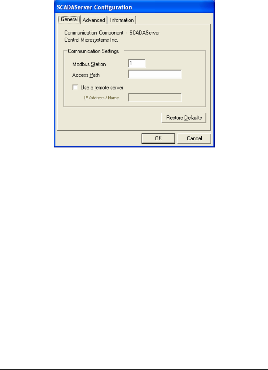
6.3.14.1 General Parameters
When SCADAServer is selected for configuration the SCADAServer Configuration dialog is opened
with the General tab selected as shown below.
Figure 109: SCADAServer Configuration (General) Dialog Box
The Communication Settings grouping contains all essential details necessary to establish
communication to a device through a local or remote SCADAServer installation.
The Modbus Station parameter specifies the station address of the target device. The valid range is
1 to 65534. The default is station 1.
The Access Path parameter specifies the access path to a SCADAServer connection. This parameter
is entered as a string with a maximum size of 16 characters. This access path was named when a
connection was defined within the SCADAServer installation. If the access path is left blank, the
default SCADAServer connection will be used, as defined within the SCADAServer installation.
The default for this entry is blank.
The Use a remote server check box defines whether the SCADAServer connection uses a
SCADAServer installation installed on the same physical PC as the client application or on a remote
PC. If the SCADAServer installation is located on a separate machine, check this option and enter
the host name or IP address of the remote PC into the “IP Address / Name” edit box. If the
SCADAServer installation is located on the same PC as the client application leave this box
unchecked. The default state for this check box is unchecked.
The IP Address / Name entry specifies the Ethernet IP address in dotted quad notation, or a DNS
host name that can be resolved to an IP address, of the PC where the ClearSCADA server is
installed. The following IP addresses are not supported and will be rejected:
• 0.0.0.0 through 0.255.255.255
• 127.0.0.0 through 127.255.255.255 (except 127.0.0.1)
TelePACE Ladder Logic User and Reference Manual
May 9, 2007
149
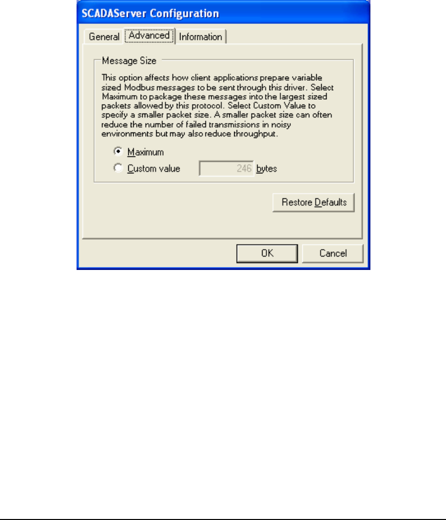
• 224.0.0.0 through 224.255.255.255
• 255.0.0.0 through 255.255.255.255.
• Click Restore Defaults to restore default values to all fields on this page.
6.3.14.2 Advanced Parameters
Advanced parameters are used to control the message size for the protocol. Control over message
length is needed when writing large amounts of data over certain communication networks. A larger
value can improve communication speed but can increase the number of failed transmissions. A
smaller value can reduce the number of failed transmissions but may reduce throughput. When the
Advanced tab heading is clicked the Advanced dialog is opened as shown below.
Figure 110: SCADAServer Configuration (Advanced) Dialog Box
The Message Size grouping parameters are used to control the message size for the protocol. Control
over message length is needed when writing large amounts of data over certain communication
networks. A larger value can improve communication speed but can increase the number of failed
transmissions. A smaller value can reduce the number of failed transmissions but may reduce
throughput.
The Maximum selection indicates that the host application is to package messages using the
maximum size allowable by the protocol.
The Custom Value selection specifies a custom value for the message size. This value indicates to
the host application to package messages to be no larger than what is specified, if it is possible.
Valid values are 2 to 246.
• Click Restore Defaults to restore default values to all fields on this page.
TelePACE Ladder Logic User and Reference Manual
May 9, 2007
150
6.3.14.3 Information
Information displays detailed driver information. When the Information tab heading is clicked the
Information dialog is opened as shown below.
Figure 111: SCADAServer Configuration (Information) Dialog Box
The Information grouping presents informative details concerning the executing protocol driver.
Module is the physical name of the driver.
File Version is the version number of the driver.
In GAC indicates whether the module (assembly) was loaded from the Global Assembly Cache
(GAC).
Runtime is the version of the Common Language Runtime (CLR) the driver was built against.
Copyright indicates the copyright information of the protocol driver.
TelePACE Ladder Logic User and Reference Manual
May 9, 2007
151

7 Activity Menu
The Activity commands select the mode of operation for the TelePACE program. The TelePACE
program can operate in three different programming modes, Edit Off Line, Edit On Line and Monitor
On Line. A check mark on the Activity drop down menu selection indicates the current mode.
7.1 Edit Off Line
The Edit Off Line selection enables editing of a ladder logic program without a connection to a
controller. The editing commands affect only the program file in use in the TelePACE Network
Ladder Editor. Forcing commands cannot be used in this mode. All other TelePACE commands can
be used in this mode.
7.2 Edit On Line
The Edit On Line selection is used to edit a ladder logic program loaded into a controller. All editing
commands affect the program in the controller and the file in the TelePACE Ladder Network Editor.
The multiple element selection and the cut, copy and paste functions of the Editor are not available
in this mode. Forcing commands can be used in this mode.
7.3 Monitor On Line
The Monitor On Line selection enables the monitoring of a program executing in a controller. The
editor shows the power flow through the ladder network on the screen. The Monitor List window is
displayed. No changes can be made to the program in monitor mode. Editing commands are disabled
on the menus. Forcing commands can be used in this mode. The C program loader is disabled in this
mode.
TelePACE Ladder Logic User and Reference Manual
May 9, 2007
152

8 Operation Menu
The Operation menu commands control the execution of the ladder logic program in the controller.
(Control of execution of a C Program in the controller is controlled from the C Program Loader
dialog.) The status of ladder logic program execution in the controller is displayed on the Status Bar.
8.1 Stop
The Stop command stops execution of the ladder logic program in the controller.
8.2 Debug
The Debug command start's the execution of the ladder logic program in debug mode. In debug
mode the monitor on line feature of the editor can be used to monitor the operation of the program.
The program runs slower in debug mode than in run mode.
8.3 Run
The Run command starts execution of the ladder logic program in run mode. The monitor on line
feature of the editor cannot be used to monitor execution in this mode.
TelePACE Ladder Logic User and Reference Manual
May 9, 2007
153

9 Options Menu
The Options menu commands are used to modify the Ladder Network Editor display, the use of
multiple coils and warning message options. The Option drop-down menu allows selection of the
option to modify.
9.1 Screen Font
The Screen Font selection selects the font used to display text on the Ladder Editor pane. This
selection does not affect the font in the Comment Editor pane, this pane uses the system font. A
dialog box appears that allows selection of the Font, Font Style and the Size of the font to be used in
the Ladder Editor pane.
9.2 Colors
The Colors dialog sets the colors used to display networks on the ladder editor and monitor on line
screens. The sample text and elements show how the colors look for the Edit Modes, Monitor Mode,
Forced Elements and the Contact Monitor.
The Item drop-down list box selects which item to modify. The follow items can be changed:
• Element
• Power Flow
• Cursor
• Forced (Foreground)
• Forced (Background)
• Contact Power Flow
• The Color drop-down list box selects the color for the item.
• Click Default to return the color selections to default values.
• Click OK to accept the changes or Cancel to cancel the changes.
9.3 Floating-Point Settings
The Floating Point dialog controls the display precision and format of floating point numbers used in
TelePACE.
The Display Precision selection sets the number of digits after the decimal place that will be
displayed. Valid entries are 1 through 7. The default value is 2.
The Format drop down box selects the format of floating point numbers. The valid selections are:
• Fixed displays numbers in the format ####.##.
• Scientific displays numbers in the format #.### E###.
Click OK to close the dialog and save the settings.
Click Cancel to close the dialog and discards the changes.
9.4 Tool Bar
Selecting the Tool Bar option enables the Tool Bar to be displayed in the Network Editor. A check
mark to the left of the selection indicates the Tool Bar is active.
TelePACE Ladder Logic User and Reference Manual
May 9, 2007
154

9.5 Title Bar
Selecting the Title Bar option enables the Title Bar to be displayed in the Network Editor. A check
mark to the left of the selection indicates the Title Bar is active.
9.6 Status Bar
Selecting the Status Bar option enables the Status Bar to be displayed in the Network Editor. A
check mark to the left of the selection indicates the Status Bar is active.
9.7 Single Tag Names
The Single Tag Names selection enables the Editor to use one line to display tag names and
addresses on the Editor screen and printed network listings. The first 8 characters of the tag name are
displayed. A numeric value will be displayed if no tag name is defined for the address or constant. A
check beside the selection on the pull down menu indicates the mode selected.
9.8 Double Tag Names
The Double Tag Names selection enables the Editor to use two lines to display tag names and
addresses on the Editor screen and printed network listings. The first 16 characters of the tag name
will be displayed. A numeric value will be displayed if no tag name is defined for the address or
constant, or if the tag name is 8 characters or less in length. A check beside the selection on the pull
down menu indicates the mode selected.
9.9 Tag and Address
The Tag and Address selection enables the Editor to use three lines to display tag names and
addresses on the Editor screen and printed network listings. The first 16 characters of the tag name
are displayed, followed by the numeric address. A numeric value alone will be displayed if no tag
name is defined for the address or constant. A check beside this selection on the pull down menu
indicates the mode selected. A check beside the selection on the pull down menu indicates the mode
selected.
9.10 Numeric Address
The Numeric Address selection enables the Editor to use one line for numeric addresses on the editor
screen and printed network listings. No tag name is displayed, even if one is defined. A check beside
the selection on the pull down menu indicates the mode selected.
9.11 Allow Multiple Coils
The Allow Multiple Coils selection enables the use of multiple coils. Multiple coils are coils with the
same address.
When the Allow Multiple Coils is not selected the Editor will not allow the insertion of a coil that
has an address already in use in the program. An error message is displayed when the insertion is
attempted.
When the Allow Multiple Coils is enabled a Dialog box is displayed asking for confirmation when a
coil is inserted that has an address already in use in the program. A check beside this selection in the
pull down menu indicates multiple coils are allowed.
A check mark is displayed beside this command when it is enabled.
TelePACE Ladder Logic User and Reference Manual
May 9, 2007
155

9.12 Warning Messages
The Warning Messages option enables additional warning messages. A check mark is displayed
beside this command when it is enabled.
When this option is enabled warning messages are displayed on all errors.
When this option is disabled, some warning messages are replaced by a beep. This speeds up editing
for experienced users as they do not have to clear a message box when they occasionally make a
mistake.
TelePACE Ladder Logic User and Reference Manual
May 9, 2007
156

10 Help Menu
The Help selection allows access to the TelePACE program extensive on line help. A drop down
menu displays the selections for Contents, How to Use Help and About Program.
10.1 Contents
The Contents selection displays the TelePACE Program Help Window. Help is available on the
following topics.
The TelePACE Program Reference describes how each TelePACE command works.
The Ladder Logic Function Reference describes the logic function blocks.
The Controller Register Assignment describes the I/O modules used in the Register Assignment.
10.2 About Program
The About Program selection displays program version information and technical support phone and
fax numbers.
TelePACE Ladder Logic User and Reference Manual
May 9, 2007
157

TelePACE Ladder Logic
Function Reference
CONTROL
MICROSYSTEMS
SCADA products... for the distance
48 Steacie Drive Telephone: 613-591-1943
Kanata, Ontario Facsimile: 613-591-1022
K2K 2A9 Technical Support: 888-226-6876
Canada 888-2CONTROL

TelePACE Ladder Logic Function Reference
©2006 Control Microsystems Inc.
All rights reserved.
Printed in Canada.
Trademarks
TeleSAFE, TelePACE, SmartWIRE, SCADAPack, TeleSAFE Micro16 and
TeleBUS are registered trademarks of Control Microsystems Inc.
All other product names are copyright and registered trademarks or trade names
of their respective owners.
Material used in the User and Reference manual section titled SCADAServer
OLE Automation Reference is distributed under license from the OPC
Foundation.
TelePACE Ladder Logic Function Reference
February 19, 2007
1

Table of Contents
1 REGISTER TYPES........................................................................................ 5
2 LADDER LOGIC FUNCTIONS...................................................................... 6
2.1 ABS – Absolute Value.................................................................................... 7
2.2 ABSF - Floating-Point Absolute Value ........................................................... 8
2.3 ADD – Add Signed Values ........................................................................... 10
2.4 ADDF - Add Floating-Point Values............................................................... 12
2.5 ADDU – Add Unsigned Values..................................................................... 14
2.6 AND – And Block ......................................................................................... 16
2.7 CALL - Execute Subroutine.......................................................................... 18
2.8 Coil............................................................................................................... 20
2.9 CMPB – Compare Bit................................................................................... 21
2.10 CMP – Compare Signed Values .................................................................. 23
2.11 CMPU – Compare Unsigned Values............................................................ 25
2.12 DCTR – Down Counter ................................................................................ 27
2.13 DEVT – Generate DNP Event...................................................................... 29
2.14 DIAL – Control Dial-Up Modem.................................................................... 30
2.15 DIV – Divide Signed Values ......................................................................... 34
2.16 DIVF - Divide Floating-Point Values............................................................. 36
2.17 DIVU – Divide Unsigned Values................................................................... 38
2.18 DLOG - Data Logger.................................................................................... 40
2.19 DPOL – Trigger a DNP class poll................................................................. 45
2.20 DSYC – Trigger a DNP clock synchronization ............................................. 47
2.21 DUNS – Trigger a DNP unsolicited response message............................... 48
2.22 FIN – FIFO Queue Insert ............................................................................. 50
2.23 FOUT – FIFO Queue Remove ..................................................................... 52
2.24 FLOW – Flow Accumulator .......................................................................... 55
2.25 FTOS - Floating-Point to Signed Integer...................................................... 59
2.26 FTOU - Floating-Point to Unsigned Integer.................................................. 61
2.27 GETB – Get Bit from Block .......................................................................... 63
2.28 GETL - Data Logger Extract......................................................................... 65
TelePACE Ladder Logic Function Reference
February 19, 2007
2

2.29 GTEF – Floating-Point Greater Than or Equal............................................. 67
2.30 HART – Send HART Command................................................................... 69
2.31 INIM – Initialize Dial-Up Modem................................................................... 75
2.32 L–>L – List to List Transfer........................................................................... 78
2.33 L–>R – List to Register Transfer .................................................................. 80
2.34 LTEF - Floating-Point Less Than or Equal ................................................... 82
2.35 MOD – Modulus of Signed Values ............................................................... 84
2.36 MODU – Modulus of Unsigned Values......................................................... 86
2.37 MOVE – Move Block.................................................................................... 88
2.38 MSTR – Master Message ............................................................................ 90
2.39 MSIP – Master IP Message ......................................................................... 96
2.40 MUL – Multiply Signed Values ................................................................... 102
2.41 MULF - Multiply Floating-Point Values....................................................... 104
2.42 MULU – Multiply Unsigned Values............................................................. 106
2.43 Normally Closed Contact ........................................................................... 108
2.44 Normally Open Contact.............................................................................. 109
2.45 NOT – Not Block ........................................................................................ 110
2.46 One Shot Coil............................................................................................. 112
2.47 OR – Or Block............................................................................................ 113
2.48 OVER – Override Block of Registers ......................................................... 115
2.49 PID – PID Controller................................................................................... 118
2.50 PIDA – Analog Output PID......................................................................... 119
2.51 PIDD – Digital Output PID.......................................................................... 123
2.52 POWR – Floating-Point Raised to Power................................................... 127
2.53 PULM - Pulse Minutes ............................................................................... 129
2.54 PULS - Pulse Seconds............................................................................... 130
2.55 PUTB – Put Bit into Block .......................................................................... 131
2.56 PUT – Put Signed Value into Registers ..................................................... 133
2.57 PUTF - Put Floating-Point Value................................................................ 135
2.58 PUTU – Put Unsigned Value into Registers............................................... 137
2.59 R–>L – Register to List Transfer ................................................................ 139
2.60 ROTB – Rotate Bits in Block ...................................................................... 141
2.61 SCAL – Scale Analog Value....................................................................... 143
TelePACE Ladder Logic Function Reference
February 19, 2007
3

2.62 Shunts........................................................................................................ 146
2.63 SLP – Put Controller into Sleep Mode........................................................ 147
2.64 SQRF - Square Root of Floating-Point Value............................................. 150
2.65 STOF - Signed Integer to Floating-Point.................................................... 152
2.66 SUB – Subtract Signed Values .................................................................. 154
2.67 SUBF – Subtract Floating-Point Values ..................................................... 156
2.68 SUBR - Start of Subroutine........................................................................ 158
2.69 SUBU –Subtract Unsigned Values............................................................. 159
2.70 Timers........................................................................................................ 161
2.71 TOTL – Analog Totalizer ............................................................................ 163
2.72 UCTR – Up Counter................................................................................... 167
2.73 UTOF - Unsigned Integer to Floating-Point................................................ 169
2.74 XOR – Exclusive Or Block ......................................................................... 171
TelePACE Ladder Logic Function Reference
February 19, 2007
4

1 Register Types
TelePACE function elements support a number of different register formats. The type of register
format used will depend on the type function. The following table defines the register formats used.
Unsigned Integer Unsigned integer data are in the range 0 to 65535. This data requires
a single 16-bit register, 3xxxx or 4xxxx.
Signed Integer Signed integer data are in the range –32768 to 32767. This data
requires a single 16-bit register, 3xxxx or 4xxxx.
Unsigned Double Unsigned long integer data are in the range 0 to 4,294,967,295. This
data requires two 16 bit registers, 3xxxx or 4xxxx. The lower numbered
register contains the lower order word.
Signed Double Signed long integer data are in the range -2,147,483,648 to
2,147,483,647. This data requires two 16 bit registers, 3xxxx or 4xxxx.
The lower numbered register contains the lower order word.
Floating Point Floating-point data are in the IEEE single precision floating-point
format. This data requires two 16 bit registers, 3xxxx or 4xxxx. The
lower numbered register contains the upper 16 bits of the number. The
higher numbered register contains the lower 16 bits of the number.
TelePACE Ladder Logic Function Reference
February 19, 2007
5

2 Ladder Logic Functions
The function blocks are described in detail in the pages that follow.
TelePACE Ladder Logic Function Reference
February 19, 2007
6
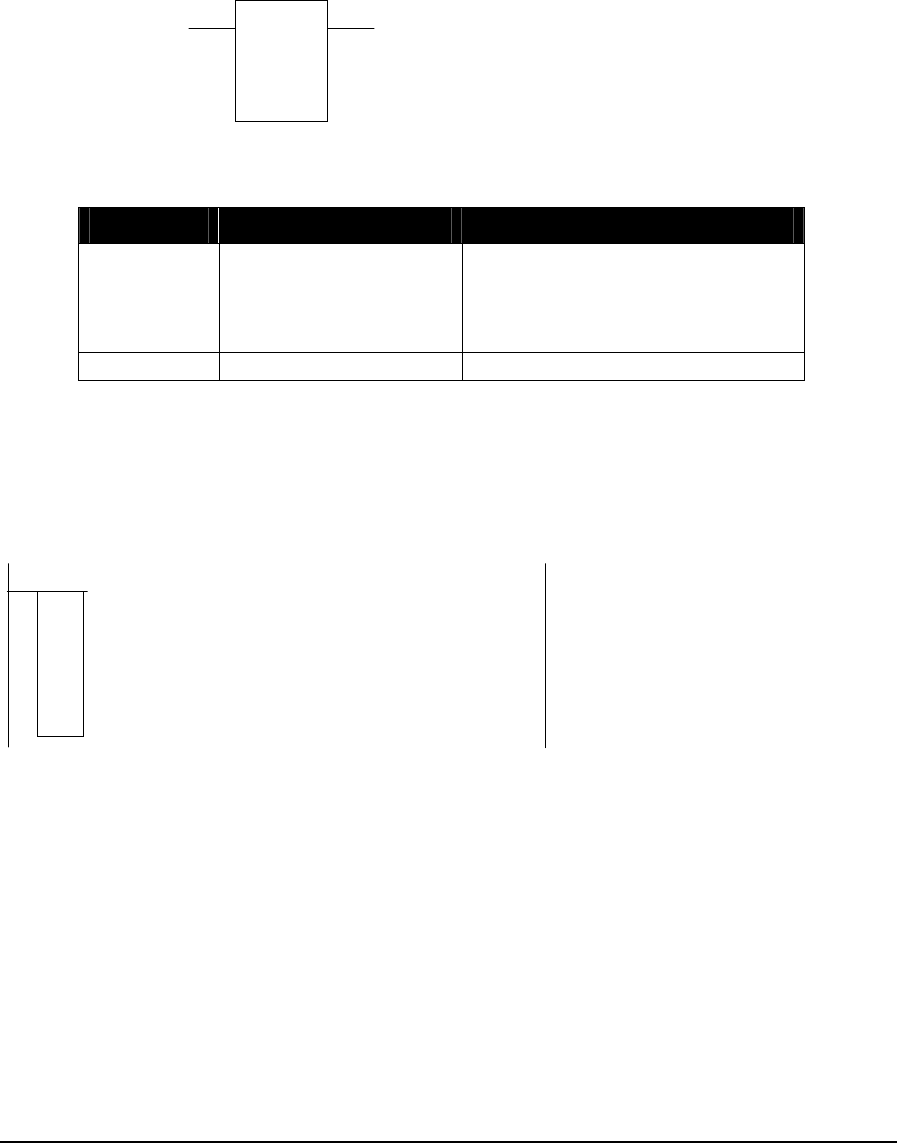
2.1 ABS – Absolute Value
Description
The ABS function stores the absolute value of a signed constant or register into a holding register.
When the enable ABS is ON the absolute value of the source register or constant is stored in the
destination holding register.
source
ABS
destination
ON = enable ABS copies status of input1
Function Variables
Variable Valid Types Description
Source Constant
(-32768...32767)
input register (3xxxx)
holding register (4xxxx)
a signed value or register
Destination holding register (4xxxx) destination = abs(source)
Related Functions
ABSF - Floating-Point Absolute Value
Example
network 1:
44001
45211
A
BS
In this example the absolute value of the source, holding register 44001, is stored in the
destination, holding register 45211. Assuming holding register 44001 has a value of -4455, the
value stored in holding register 45211 would be +4455.
TelePACE Ladder Logic Function Reference
February 19, 2007
7

2.2 ABSF - Floating-Point Absolute Value
Description
The ABSF element stores the absolute value of a floating-point register or constant in a floating-
point holding register.
When the enable input is ON the absolute value of the source is stored in the result floating-point
holding register. The element output is ON when the input is.
source
ABSF
result
ON = enable copies status of input
Function Variables
The element has two parameters.
Variable Valid Types Description
Source FP constant
2 input registers (3xxxx)
2 holding registers (4xxxx)
a floating-point register or constant
value
Result 2 holding registers (4xxxx) floating-point absolute value of
source register
Notes
Floating-point values are stored in two consecutive I/O database registers. The lower numbered
register contains the upper 16 bits of the number. The higher numbered register contains the lower
16 bits of the number.
Floating point numbers can represent positive and negative values in the range –3.402 × 1038 to
3.402 × 1038.
Related Functions
ABS – Absolute Value
Example
network 1:
40001
45555
A
BSF
TelePACE Ladder Logic Function Reference
February 19, 2007
8

In this example the absolute value of the source, holding register 40001, is stored in the result,
floating point register 45555. Assuming floating point register 40001 contains a floating-point value
of – 77988.99, the value stored in floating point register 45555 would be +77988.99.
TelePACE Ladder Logic Function Reference
February 19, 2007
9

2.3 ADD – Add Signed Values
Description
The ADD function block adds two registers or constants and stores the result in a holding register.
Signed addition is used. If the result is out of range, the sum rolls over and the out of range output is
enabled.
When the enable ADD input is ON the sum of value 1 and value 2 is stored in sum holding register.
If the sum is out of range (–32768...32767) the result out of range output is ON.
value1
ADD
sum
value2
ON = enable ADD copies status of input1
ON = result out of range
Function Variables
Variable Valid Types Description
Value 1 Constant
(-32768...32767)
input register (3xxxx)
holding register (4xxxx)
first signed value to add
Value 2 constant
(-32768...32767)
input register (3xxxx)
holding register (4xxxx)
second signed value to add
Sum holding register (4xxxx) sum = value 1 + value 2
Related Functions
ADDF - Add Floating-Point Values
ADDU – Add Unsigned Values
Example
00017
)
(
network 1:
42399
43567
A
DD
44981
TelePACE Ladder Logic Function Reference
February 19, 2007
10

The ADD function in network 1 adds holding register 42399 to holding register 43567 and stores the
result is holding register 44981. When the addition is out of range – less than –32768 or greater than
32767-output coil 00017 is energized. The table below shows some examples.
value 1 Value 2 sum out of range
Holding Register
42399 Holding Register
43567 Holding Register
44981 Output Coil
00017
23411 1098 24509 OFF
–2047 819 –1228 OFF
12767 23000 –29769 ON
TelePACE Ladder Logic Function Reference
February 19, 2007
11

2.4 ADDF - Add Floating-Point Values
Description
The ADDF element adds two floating-point registers or constants and stores the result in a floating-
point holding register.
When the enable input is ON the sum value 1 + value 2 is stored in the sum floating point register.
The element output is ON when the input is.
value1
ADDF
sum
value2
ON = enable copies status of input
Function Variables
The element has three parameters.
Variable Valid Types Description
Value1 FP constant
2 input registers (3xxxx)
2 holding registers (4xxxx)
first floating-point register or constant value to
add
Value2 FP constant
2 input registers (3xxxx)
2 holding registers (4xxxx)
second floating-point register or constant value
to add
Sum 2 holding registers (4xxxx) floating-point sum = value1+value2
Notes
Floating-point values are stored in two consecutive I/O database registers. The lower numbered
register contains the upper 16 bits of the number. The higher numbered register contains the lower
16 bits of the number.
Floating point numbers can represent positive and negative values in the range –3.402 × 1038 to
3.402 × 1038.
Related Functions
ADD – Add Signed Values
ADDU – Add Unsigned Values
TelePACE Ladder Logic Function Reference
February 19, 2007
12

Example
network 1:
+101.3
40098
A
DDF
40100
The ADDF function in network 1 adds floating-point constant +101.3 to floating-point register
40098 (registers 40098 and 40099). Assuming floating point register 40098 contains a value of
+1000.00 then the result is +1101.30. This value is stored in floating-point register 40100 (registers
40100 and 40101).
TelePACE Ladder Logic Function Reference
February 19, 2007
13
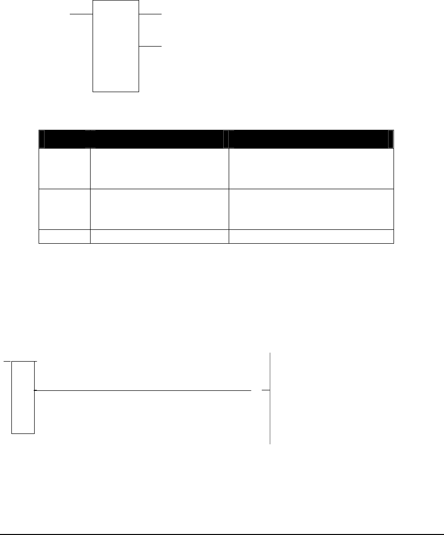
2.5 ADDU – Add Unsigned Values
Description
The ADDU function block adds two registers or constants and stores the result in a holding register.
Unsigned addition is used. If the result is out of range, the sum rolls over and the out of range output
is enabled.
When the enable ADDU input is ON the sum of value 1 and value 2 is stored in sum holding
register. If the sum is out of range (> 65535) the result out of range output is ON.
value1
ADDU
sum
value2
ON = enable ADDU copies status of input1
ON = result out of range
Function Variables
Variable Valid Types Description
Value 1 constant (0...65535)
input register (3xxxx)
holding register (4xxxx)
first unsigned value to add
Value 2 constant (0...65535)
input register (3xxxx)
holding register (4xxxx)
Second unsigned value to add
Sum holding register (4xxxx) Sum = value 1 + value 2
Related Functions
ADD – Add Signed Values
ADDF - Add Floating-Point Values
Example
00021
)
(
network 1:
46549
44723
A
DDU
44483
The ADDU function in network 1 adds holding register 46549 to holding register 44723 and stores
the result is holding register 44483. When the addition is out of range, greater than 65535, output
coil 00021 is energized. The table below shows some examples.
TelePACE Ladder Logic Function Reference
February 19, 2007
14

value 1 Value 2 Sum out of range
Holding Register
46549 Holding Register
44723 Holding Register
44483 Output Coil
00021
2048 819 2867 OFF
23000 42530 65530 OFF
35000 35000 4464 ON
TelePACE Ladder Logic Function Reference
February 19, 2007
15

2.6 AND – And Block
Description
The AND function block logically ANDs the source block of registers with the destination block of
registers and stores the result in the destination block of registers. The number of registers in the
source and destination blocks is determined by the size.
source
AND
size
destination
ON = enable AND copies status of input1
Function Variables
Variable Valid Types Description
Source coil block (0xxxx)
status block (1xxxx)
input register (3xxxx)
holding register (4xxxx)
The first register in the first source block.
The address for a coil or status register block is
the first register in a group of 16 registers that
will be ANDed.
Destination coil block (0xxxx)
holding register (4xxxx)
The first register in the second source block and
destination block.
The address for a coil register block is the first
register in a group of 16 registers that will be
ANDed.
Size constant (1...100) The number of 16 bit words in the block.
Notes
AND accesses 16 bit words. Coil and status register blocks are groups of 16 registers that start with
the register specified as the block address. A block size of 2 corresponds to 32 coils, or two holding
registers.
Coil and status register blocks must begin at the start of a 16 bit word within the controller memory.
Suitable addresses are 00001, 00017, 10001, 10033, etc.
Related Functions
OR – Or Block
XOR – Exclusive Or Block
NOT – Not Block
TelePACE Ladder Logic Function Reference
February 19, 2007
16
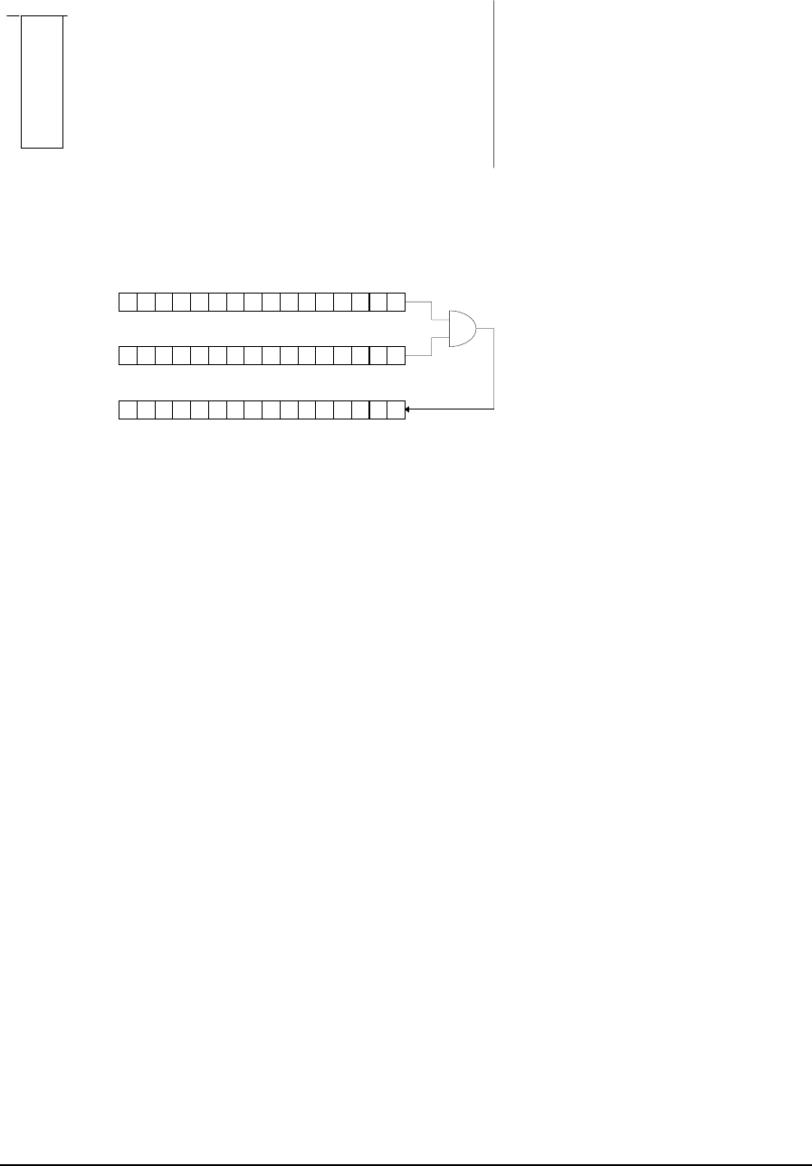
Example
network 1:
11000
01026
A
ND
1
In this example the source register has a value of 1521310 (0011101101101101). The destination
register has a value of 2237910 (0101011101101011) before the AND function and a value of
496910 (0001001101101001) after the AND function.
1100 1101 0110 1011
1010 1110 0110 1101
source register
destination register
before AND
destination register
after AND 1000 1100 0110 1001
TelePACE Ladder Logic Function Reference
February 19, 2007
17

2.7 CALL - Execute Subroutine
Description
The CALL element transfers execution from the main program to a subroutine. Execution of the
main program is suspended until the subroutine returns.
Subroutine calls can be used to execute parts of a program only when needed. The subroutine is
called only if the input to the CALL element is ON.
The function variable number indicates which subroutine to call. The subroutine number must
correspond to the number of a SUBR element.
number
CALL co
py
of in
p
utON = call subroutin
e
Function Variables
The CALL element has one parameter:
Variable Valid Types Description
Number Constant the number of the subroutine. Any number in the range 1 to
500 is valid.
Notes
A subroutine can call other subroutines. This is called nesting. The maximum level of nesting is 20
calls.
Subroutine calls cannot be recursive. For example, subroutine 1 cannot call itself or call another
subroutine that calls subroutine 1. This prevents potential infinite loops in the ladder logic program.
The normal order of network evaluation is followed when executing each network. Execution
proceeds down the columns, then across the rows. When the CALL function is executed, the
execution of the current network is suspended at the point of the CALL until the subroutine returns.
A subroutine can be called by one or more CALL elements.
Related Functions
SUBR - Start of Subroutine
Example
This example calls subroutine 1 when input 10001 is on. Subroutine 1, in turn, calls Subroutine 2.
The sequence of execution is as follows.
The networks in the start of the main program are executed.
If input 10001 is on, Subroutine 1 is called.
At the beginning of Subroutine 1, Subroutine 2 is called.
The body of Subroutine 2 is executed.
The rest of Subroutine 1 is executed.
TelePACE Ladder Logic Function Reference
February 19, 2007
18

The networks in the rest of the main program are executed.
When execution reaches the start of Subroutine 1, the main program is complete. Execution starts
over at the start of the main program.
1
CALL
10001
start of main program
rest of main program
1
SU B
R
rest of subrouti ne 1
2
CALL
2
SUBR
body of subroutine 2
TelePACE Ladder Logic Function Reference
February 19, 2007
19

2.8 Coil
Description
The COIL function block enables an output coil when its input power is ON.
out
p
ut
input powe
r
always connects to right rail
Function Variables
Variable Valid Types Description
Output coil register (0xxxx) output register address
Related Functions
One Shot Coil
Example
01025
)
(
network 1:
00009
00010
)
(
01025
When discrete input contact 00009 is closed power is applied to the input power input of coil
01025. This will enable the coil and the associated contact of 01025 is energized. The NO contacts
01025 are closed and this causes power to be applied to output coil 00010.
TelePACE Ladder Logic Function Reference
February 19, 2007
20

2.9 CMPB – Compare Bit
Description
The CMPB function block compares two blocks of registers, bit by bit and identifies the first bit that
does not match. The bit index will be set to the bit offset of the first mismatched bit.
source 1
CMPB
size
index and
source 2
ON = enable CMPB
ON = difference found ON = Start Compare at bit 0
OFF = Start Compare at last
mismatch
copies status of input 1
ON = status of bit at index in
source 1 block.
Function Variables
Variable Valid Types Description
Source 1 coil block (0xxxx)
status block (1xxxx)
input register (3xxxx)
holding register (4xxxx)
The first register in the first source block.
The address for a coil or status register block
is the first register in a group of 16 registers
that will be compared.
Index and
source 2 holding register (4xxxx) The bit index register and the second block of
source registers. The bit index is in register
[4xxxx]. A bit index of 0 is the most significant
bit of the first register of the source blocks.
The second source register block is at register
[4xxxx+1] to register [4xxxx+ size].
Size constant (1..100) The number of 16 bit words in the blocks.
Notes
Compare accesses 16 bit words. Coil and status register blocks are groups of 16 registers that start
with the register specified as the block address. A block size of 2 corresponds to 32 coils, or two
holding registers.
Coil and status register blocks must begin at the start of a 16 bit word within the controller memory.
Suitable addresses are 00001, 00017, 10001, 10033, etc.
Related Functions
CMP – Compare Signed Values
CMPU – Compare Unsigned Values
GTEF – Floating-Point Greater Than or Equal
LTEF - Floating-Point Less Than or Equal
TelePACE Ladder Logic Function Reference
February 19, 2007
21

Example
01026
)
(
network 1:
10001
42100
CMPB
1
01401
01366 01025
)
(
The CMPB function in network 1 is used to check the status inputs 10001 to 10016. If Holding
Register 42100 is set to zero, with a PUTU function, any status inputs in the range 10001 to 10016
that are on will be detected by the CMPB function.
Using the information in the chart below, status input registers 10004,10013 and 10014 are on.
Closing contacts 01366 will start the index at bit 0 and the index will be set to the bit offset of the
first mismatched bit, bit 2. Discrete output coil 01026 will be on and discrete output coil 01025 will
be on.
If contacts 01366 are left closed the index will start at bit 0 and be set to the bit offset of the first
mismatched bit, bit 2, on each scan of network 1. Discrete output coil 01026 will be on and discrete
output coil 01025 will be on.
Opening contacts 01366 will allow the index to start at bit 2 on the next scan of network 1. The
index will be set to the bit offset of the next mismatched bit, bit 3. Discrete output coil 01026 will be
on and coil register 01025 will be on.
On the next scan of network 1 the index will start at bit 3. The index will be set to the bit offset of
the next mismatched bit, bit 12. Coil 01026 will be on and coil register 01025 will be on.
The next scan of network 1 will have the index starting at bit 12. The remaining bits are compared
and no further mismatches occur. The index will be set to bit 15 and wait for the contacts 01366 to
close to start the compare at bit index 0.
1100 0000 0000 0001
Discrete Input Address:
(read top to bottom)
Discrete Input State:
321076541110981141312
Bit Index:
1
0
0
1
3
1
0
0
1
4
1
0
0
1
5
1
0
0
1
6
1
0
0
0
9
1
0
0
1
0
1
0
0
1
1
1
0
0
1
2
1
0
0
0
5
1
0
0
0
6
1
0
0
0
7
1
0
0
0
8
1
0
0
0
1
1
0
0
0
2
1
0
0
0
3
1
0
0
0
4
5
TelePACE Ladder Logic Function Reference
February 19, 2007
22

2.10 CMP – Compare Signed Values
Description
The CMP function compares two signed registers or constants and stores the difference in a holding
register. When the enable CMP input is energized value 1 is compared to value 2.
If value 1 is greater than value 2 the value 1 > value 2 output is energized and the difference of
value 1 minus value 2 is stored in difference register.
If value 1 is less than value 2 the value 1 < value 2 output is energized and the difference of value 2
minus value 1 is stored in the difference register.
If value 1 equals value 2 the value 1 = value 2 output is energized and zero is stored in the
difference register.
value 1
CMP
difference
value 2
ON = enable CMP
value 1 = value2
value 1 > value 2
value 1 < value 2
Function Variables
Variable Valid Types Description
value 1 Constant
(-32768..32767)
input register (3xxxx)
holding register (4xxxx)
first signed value to compare
Value 2 Constant
(-32768..32767)
input register (3xxxx)
holding register (4xxxx)
Second signed value to compare
Difference holding register (4xxxx) if value 1 > value 2 then
difference = value 1 - value 2
if value 2 > value 1 then
difference = value 2 - value 1
Related Functions
CMPU – Compare Unsigned Values
CMPB – Compare Bit
GTEF – Floating-Point Greater Than or Equal
LTEF - Floating-Point Less Than or Equal
TelePACE Ladder Logic Function Reference
February 19, 2007
23

Example
network 1:
30001
1638
CMP
41040
+10
T.1
41051
+5
T.1
41050
00017
)
(
01257
)(
01257
00017
The CMP function in network 1 above compares the signed value of Analog Input Register 30001
with the value 1638. The output coil 00017 could be tied to a light to indicate when the Input
Register value is over 1638.
The value 1 > value 2 and value 1 = value 2 outputs are tied together. When value of register 30001
is greater than or equal to 1638 these outputs are energized. This will enable the flasher circuit of
Timers 41050 and 41051 to energize and output coil 00017 will cycle at a rate of 1 second on and
0.5 seconds off.
TelePACE Ladder Logic Function Reference
February 19, 2007
24

2.11 CMPU – Compare Unsigned Values
Description
The CMPU function compares two unsigned registers or constants and stores the difference in a
holding register. When enable CMPU input is energized value 1 is compared to value 2.
If value 1 is greater than value 2 the value 1 > value 2 output is energized and the difference of
value 1 minus value 2 is stored in difference register.
If value 1 is less than value 2 the value 1 < value 2 output is energized and the difference of value 2
minus value 1 is stored in the difference register.
If value 1 equals value 2 the value 1 = value 2 output is energized.
value 1
CMPU
difference
value 2
ON = enable CMPU
value 1 = value2
value 1 > value 2
value 1 < value 2
Function Variables
Variable Valid Types Description
value 1 Constant (0..65535)
input register (3xxxx)
holding register (4xxxx)
first unsigned value to compare
Value 2 Constant (0..65535)
input register (3xxxx)
holding register (4xxxx)
Second unsigned value to compare
Difference holding register (4xxxx) If value 1 > value 2 then
Difference = value 1 - value 2.
If value 2 > value 1 then
difference = value 2 - value 1.
Related Functions
CMPB – Compare Bit
CMP – Compare Signed Values
GTEF – Floating-Point Greater Than or Equal
LTEF - Floating-Point Less Than or Equal
TelePACE Ladder Logic Function Reference
February 19, 2007
25

Example
network 1:
40001
+3276
CMP
41040
00017
)(
01257
)(
The CMPU function in network 1 above compares the unsigned value of holding register 40001 with
the value 3276. Coil 00017 is energized when holding register 40001 is greater than or equal to the
constant 3276.
The value 1 > value 2 and value 1 = value 2 outputs are tied together.
TelePACE Ladder Logic Function Reference
February 19, 2007
26
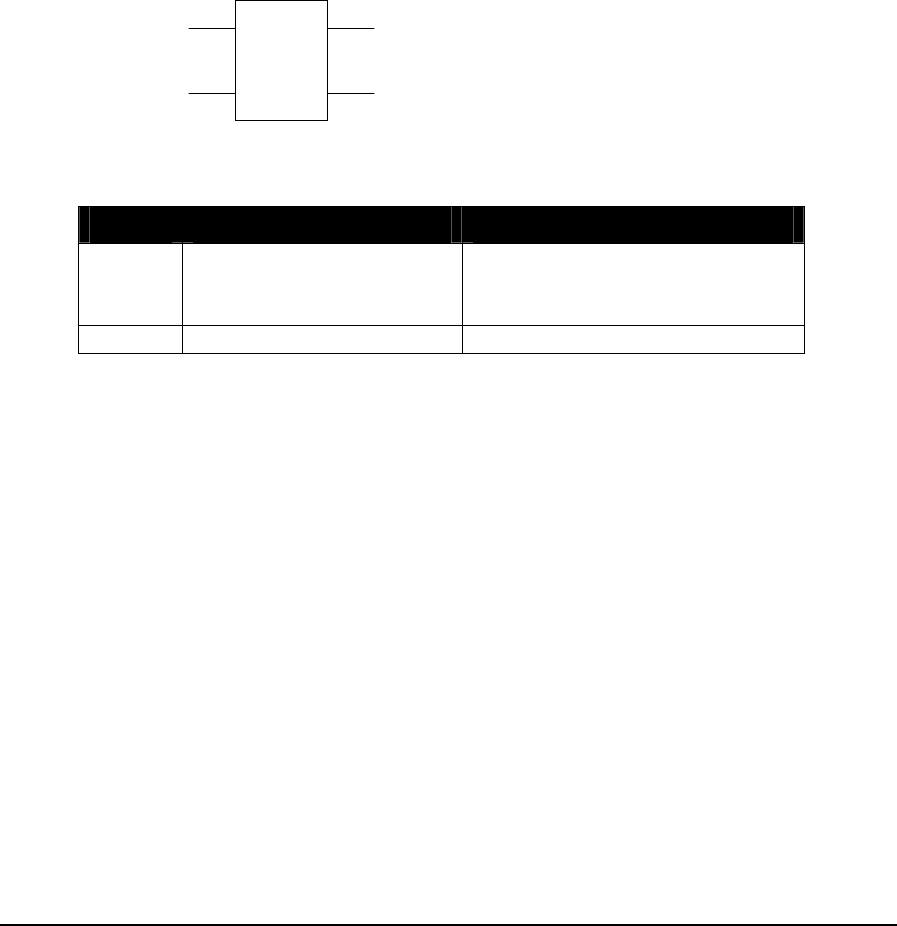
2.12 DCTR – Down Counter
Description
The DCTR function block decrements (subtracts 1 from) the value in the preset register or constant
and stores it in the counter holding register when the decrement count input changes from OFF to
ON. The counter stops counting when it reaches 0.
When the counting enabled input is ON and the decrement count goes from OFF to ON the
counter decrements by one. When the counting enabled input is OFF the counter value is reset to
preset.
When the counting enabled input is ON and the counter has decremented to zero then the counter =
0 output is ON.
When the counting enabled input is ON and the counter is greater than the preset then the counter >
0 output is ON.
p
reset
DCTR
counter
OFF to ON = decrement count
ON = counter > 0ON = counting enabled
OFF = reset counter to preset
ON = counter = 0
Function Variables
Variable Valid Types Description
Preset constant (1..65535)
input register (3xxxx)
holding register (4xxxx)
Preset value for counter
Counter holding register (4xxxx) Current counter value
Related Functions
UCTR – Up Counter
TelePACE Ladder Logic Function Reference
February 19, 2007
27

Example
network 1:
100
DCTR
45776
+1
T.1
46770
01057
)
(
01057
01058
)(
01057
01058
The DCTR function in network 1 decrements each time the timer output is enabled. The timer limit
is 0.1 seconds and it will take 10 seconds for the DCTR to decrement 100 times.
When the DCTR decrements to 0, output coil 01058 is energized. NC contacts 01058 will open and
the DCTR will reset counter to preset. This will happen every 10 seconds.
TelePACE Ladder Logic Function Reference
February 19, 2007
28

2.13 DEVT – Generate DNP Event
Description
This function generates a DNP change event for the specified DNP point.
A change event is generated for the Point Address specified when the enable input changes from
OFF to ON. The status register is set to 0 and the success output is energized if the function is
successful and a change event was generated.
The status register is set to 1 and the failure output is energized if the function failed and a change
event was not generated. The failure output indicates that the specified DNP point is invalid, or the
DNP configuration has not been created.
Point
address
enable
failure
successPoint type
status
DEVT
Function Variables
Variable Valid
Types Description
Point
Type Constant or
holding
register
(4xxxx)
DNP Point Type. Valid values are:
0 = Binary Input,
1 = 16-bit Analog Input,
2 = 32-bit Analog Input,
3 = Float Analog Input,
5 = 16-bit Counter Input,
6 = 32-bit Counter Input.
Point
Address Constant or
holding
register
(4xxxx)
DNP Point Address
Status Holding
register
(4xxxx)
Status of the operation
0 = success
1 = failure
Related Functions
DUNS – Trigger a DNP unsolicited response message
DPOL – Trigger a DNP class poll
Error! Not a valid link.
TelePACE Ladder Logic Function Reference
February 19, 2007
29
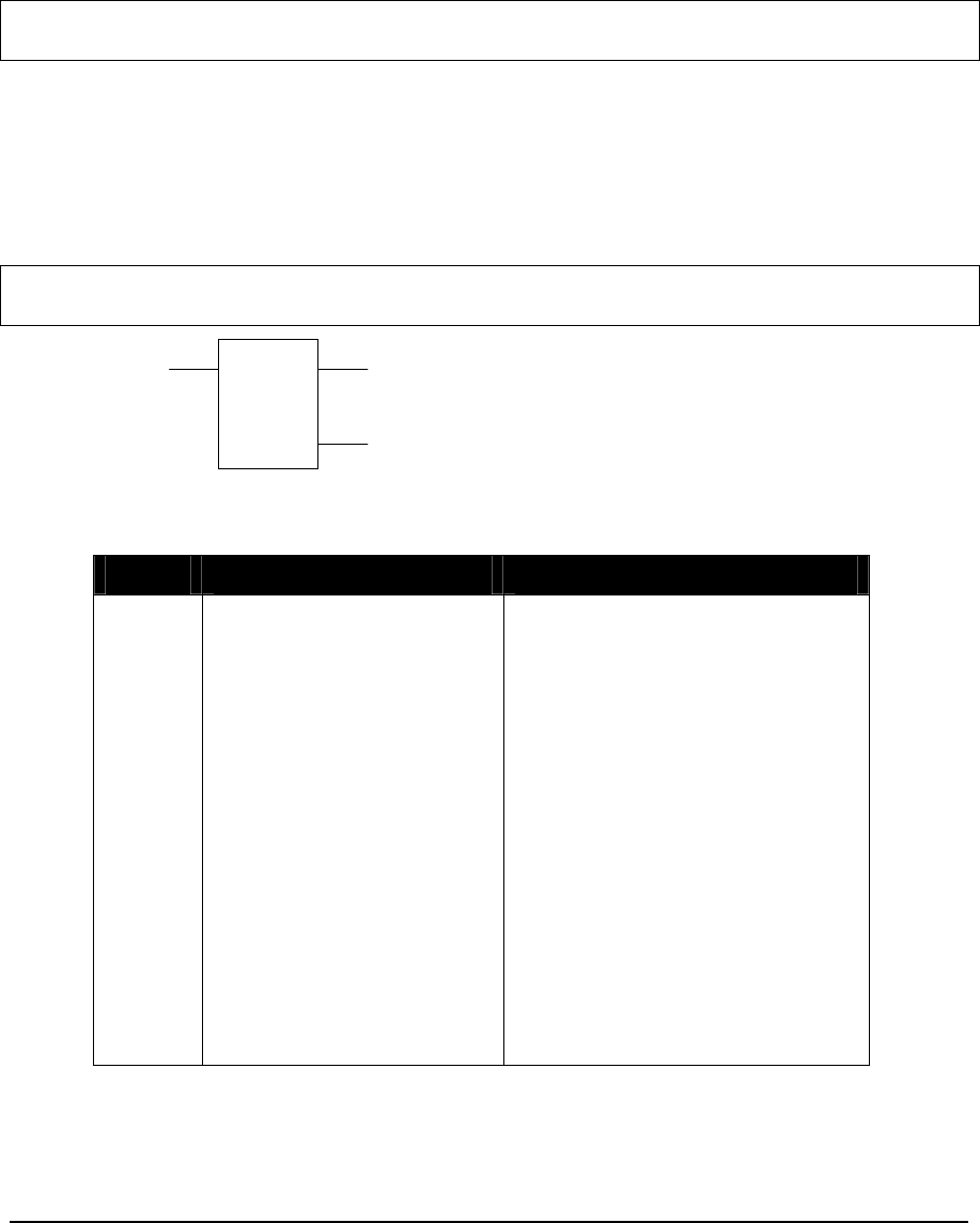
2.14 DIAL – Control Dial-Up Modem
Description
The DIAL function connects an internal modem or an external modem to a remote modem. Only one
DIAL block may be active on each serial communication port at any one time. The DIAL function
handles all port sharing and multiple dialing attempts.
Note: The SCADAPack 100 does not support dial up connections on com port 1. SCADASense
Series controllers do not support dialup connections.
When the enable DIAL input is ON the DIAL element sends the modem initialization string to the
modem. The modem will attempt to connect to the remote modem. If a connection is made the ON
when connection complete output is turned ON. If a connection is not made in the specified number
of attempts the ON when all connect attempts have failed output is turned ON.
The enable DIAL input must be energized for the entire DIAL time, including multiple dial
attempts.
Note: A pause is required between hanging up the phone line after a DIAL and initiating a new
DIAL attempt. This is required for the external modem to hang-up.
config
DIAL
status
ON = enable DIAL
ON when all connect
attempts have failed
ON when connection is
complete
Function Variables
Variable Valid Types Description
Config Holding register (4xxxx) Address of the first register in the
configuration block. There are 39
registers in the block at addresses
config+0 to config+38.
+0 = Communication port
+1 = Dialing attempts
+2 = Connect time
+3 = Pause time
+4 = Dialing type
+5 = Length of modem string
+6 = Modem initialization string
+22 = Length of phone number
+23 = Phone number
NOTE:
Registers should be programmed
using the Element Configuration
command.
TelePACE Ladder Logic Function Reference
February 19, 2007
30

Variable Valid Types Description
Config Holding register (4xxxx) Address of the first register in the
configuration block. There are 39
registers in the block at addresses
config+0 to config+38.
+0 = Communication port
+1 = Dialing attempts
+2 = Connect time
+3 = Pause time
+4 = Dialing type
+5 = Length of modem string
+6 = Modem initialization string
+22 = Length of phone number
+23 = Phone number
NOTE:
Registers should be programmed
using the Element Configuration
command.
Status Holding register (4xxxx) address of the first register in the
status block. There are 2 registers
in the block at addresses
status+0 and status+1.
+0 = error code
+1 = reservation identifier
Element Configuration
This element is configured using the DIAL Element Configuration dialog. Highlight the element by
moving the cursor over the element and then use the Element Configuration command on the Edit
menu to modify the configuration block.
WARNING: If the controller is initialized, using the Initialize command in the Controller menu,
all I/O database registers used for Element Configuration are set to zero. The
application program must be re-loaded to the controller.
TelePACE Ladder Logic Function Reference
February 19, 2007
31
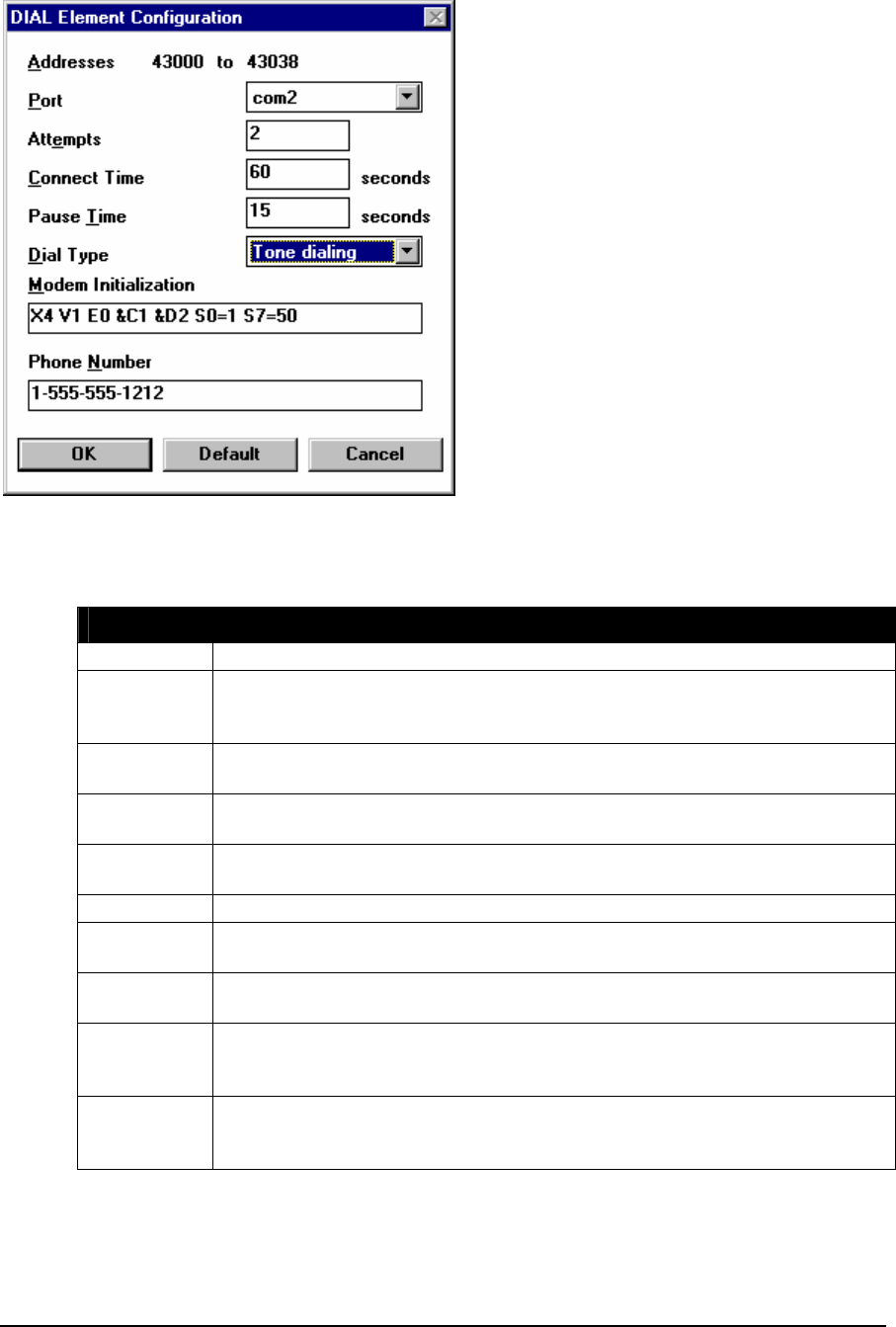
The modem initialization string and the phone number are packed. Two ASCII characters are stored
in each register.
The error codes are:
Error Code Description
0 No Error
1 Bad configuration error occurs when an incorrect initialization string is sent
to the modem. This usually means the modem does not understand a
specific command in the initialization string.
2 No modem connected to the controller serial port, or the controller serial
port is not set to RS232 Modem.
3 Initialization error occurs when the modem does not respond to the
initialization string and may be turned off.
4 No dial tone error indicates modem is not connected to a telephone line or
the S6 setting in the modem is too short.
5 Busy line indicates another device is using the phone line.
6 Call aborted by the program. This will occur if the enable DIAL input goes
OFF before a modem connection occurs.
7 Failed to connect error occurs when there are no other errors but the
modem failed to make a connection with the remote modem.
8 Carrier lost error occurs when carrier is lost for a time exceeding the S10
setting in the modem. Phone lines with call waiting are very susceptible to
this condition.
9 “Serial port is not available” error occurs when the DIAL function attempts
to use the serial port when another ladder communication element, C
program or an incoming call has control of the port.
TelePACE Ladder Logic Function Reference
February 19, 2007
32

Notes
The reservation identifier is required for the operation of the dialer but can be ignored by the ladder
program.
The DIAL function outputs are powered only when the enable DIAL input is powered ON.
The dial-up connection handler prevents outgoing calls from using the serial port when an incoming
call is in progress and communication is active. If communication stops for more than five minutes,
then outgoing call requests are allowed to end the incoming call. This prevents problems with the
modem or the calling application from permanently disabling outgoing calls.
Note: The SCADAPack 100 does not support dial up connections on com port 1.
SCADASense Series controllers do not support dial up connections.
To optimize performance, minimize the length of messages on com3 and com4. Examples of
recommended uses for com3 and com4 are for local operator display terminals, and for programming
and diagnostics using the TelePACE program.
Related Functions
INIM – Initialize Dial-Up Modem
Example
An example of dialing using the DIAL block is the file DIAL.LAD. This file is automatically
installed on the computer when the TelePACE program is installed. It is located in the
TELEPACE\EXAMPLES directory.
TelePACE Ladder Logic Function Reference
February 19, 2007
33

2.15 DIV – Divide Signed Values
Description
The DIV function block divides two registers or a constant, value 1, by a register or constant, value
2, and stores the quotient in a Holding Register, result. Signed division is used. The values and
result are signed numbers.
The result out of range output is enabled if the result is greater than 32767 or less than –32768. The
divide by zero output is enabled if value 2 equals 0.
value 1
DIV
result
value 2
ON = enable DIV
ON = result out of range
copies status of input 1
ON = divide by zero
Function Variables
Variable Valid Types Description
value 1 constant
(-32768..32767)
2 Input registers (3xxxx)
2 holding registers (4xxxx)
Signed value to divide
The low order word is stored in the
first register if registers are used.
Value 2 constant
(-32768..32767)
input register (3xxxx)
holding register (4xxxx)
Signed value to divide by
Result holding registers (4xxxx) Result = value 1 / value 2
Related Functions
DIVF - Divide Floating-Point Values
DIVU – Divide Unsigned Values
TelePACE Ladder Logic Function Reference
February 19, 2007
34

Example
network 1:
-32100
41012
MUL
+1
41204
41012
-200
DIV
01026
)(
01025
)
(
The MUL function is used to create the double precision values required for value 1. A constant is
multiplied by 1 with the result stored in Holding Register 41012. The low order word, 41012, and
the high order word, 41013, are returned from the MUL function.
The following table illustrates various value 1 and value 2 values and the result of the division.
high order low order
Register
41013 Register
41012 Constant
Value Register
41204
value 1 value 2 result
Example
1 -1 -32070 -200 160
Example
2 0 32070 -200 -160
Example
3 -1 -2048 16 -128
Example
4 0 3276 30 109
TelePACE Ladder Logic Function Reference
February 19, 2007
35

2.16 DIVF - Divide Floating-Point Values
Description
The DIVF element divides one floating-point register or constant by another and stores the result in a
floating-point holding register.
When the enable input is ON the result value 1 ÷ value 2 is stored in the result floating-point
register. The top output is ON when the input is. The middle output is ON if value2 equals 0 and the
input is ON.
value1
DIVF
result
value2
ON = enable copies status of input
ON = divide by zero
Function Variables
The element has three parameters.
Variable Valid Types Description
value1 FP constant
2 input registers (3xxxx)
2 holding registers (4xxxx)
Floating-point register or constant
value to divide
Value2 FP constant
2 input registers (3xxxx)
2 holding registers (4xxxx)
Floating-point register or constant
value to divide by
Result 2 holding registers (4xxxx) Floating-point result = value1 ÷
value2
Notes
Floating-point values are stored in two consecutive I/O database registers. The lower numbered
register contains the upper 16 bits of the number. The higher numbered register contains the lower 16
bits of the number.
Floating point numbers can represent positive and negative values in the range –3.402 × 1038 to
3.402 × 1038.
Related Functions
DIV – Divide Signed Values
DIVU – Divide Unsigned Values
TelePACE Ladder Logic Function Reference
February 19, 2007
36

Example
network 1:
+917.15
40100
DIVF
40102
The DIVF function in network 1 divides floating-point constant +917.15 by the contents of floating-
point register 40100 (registers 40100 and 40101). Assuming floating-point register 40100 has a
value of 5.00 then the result is +183.43. This value is stored in floating-point register 40102
(registers 40102 and 40103).
TelePACE Ladder Logic Function Reference
February 19, 2007
37

2.17 DIVU – Divide Unsigned Values
Description
The DIVU function block divides two registers or a constant, value 1, by a register or constant,
value 2. The quotient is stored in a Holding Register, result. Unsigned division is used. The values
and result are unsigned numbers.
The result out of range output is enabled if the result is greater than 65535 or less than 0. The
divide by zero output is enabled if value 2 equals 0.
value 1
DIVU
result
value 2
ON = enable DIVU
ON = result out of range
copies status of input 1
ON = divide by zero
Function Variables
Variabl
e Valid Types
value 1 constant (0..65535)
2 Input registers
(3xxxx)
2 holding registers
(4xxxx)
Unsigned value to divide
The low order word is stored in the
first register if registers are used.
Value 2 constant (0..65535)
input register (3xxxx)
holding register (4xxxx)
Unsigned value to divide by
Result holding registers (4xxxx) Result = value 1 / value 2
Related Functions
DIV – Divide Signed Values
DIVF - Divide Floating-Point Values
TelePACE Ladder Logic Function Reference
February 19, 2007
38

Examples
network 1:
43186
47722
MULU
+1
47742
47722
622
DIVU
02562
)(
02561
)
(
The MULU function is used to create the double precision values required for value 1. A constant is
multiplied by 1 with the result stored in Holding Register 47722. The low order word, 47722, and
the high order word, 47723, are returned from the MULU function. The MULU function ensures a
value of 0 in the high order word.
The following table illustrates various value 1 and value 2 values and the result of the DIVU
function.
high
order low
order
Register
47723 Register
47722 Constant
Value Registe
r 47742
value 1 value 2 result
Example 1 0 53186 622 85
Example 2 0 7000 70 100
Example 3 0 8192 819 10
Example 4 0 42998 226 190
TelePACE Ladder Logic Function Reference
February 19, 2007
39

2.18 DLOG - Data Logger
Description
The DLOG function records entries in a data log. When a low to high transition occurs on the
enable DLOG input, the data log identified by LogID is created and initialized. If the data log
exists and has a different configuration then an error will be generated. If an error is generated (see
status codes below) then a different LogID must be used or the log must be deleted using the delete
log input.
While the enable DLOG is ON and a low to high transition occurs on the grab data input, an entry
is recorded in the data log identified by LogID.
When the delete log input is low, all records in the data log are deleted.
The top output is a copy of the top input. The error output is ON if there was a creation,
configuration or data logging error. The outputs are powered only when the enable input is powered.
NOTE: In order for the changes to an existing DLOG configuration to take effect, the following
steps must be followed:
• Read the data from the log, if desired.
• Disable the DLOG
• Delete the log
• Write the new configuration
• Enable the log
confi
g
DLOG
LogID
status
ON = enable DLOG
ON = error OFF to ON = grab data
copies state of input 1
OFF = delete log
TelePACE Ladder Logic Function Reference
February 19, 2007
40

Function Variables
Variable Valid Types Description
Config 18 holding registers
(4xxxx) Address of the first register of the log configuration
block. There are 18 registers in the block at
config+0 to config+17.
+0 = Maximum number of records in the log.
+1 = number of data fields.
+2 = Field #1 register address
+3 = Field #1 data type (see data types below)
+4 = Field #2 register address
+5 = Field #2 data type
+6 = Field #3 register address
+7 = Field #3 data type
+8 = Field #4 register address
+9 = Field #4 data type
+10 = Field #5 register address
+11 = Field #5 data type
+12 = Field #6 register address
+13 = Field #6 data type
+14 = Field #7 register address
+15 = Field #7 data type
+16 = Field #8 register address
+17 = Field #8 data type
Status Holding register (4xxxx) Address of the status register.
+0 = status code (see status codes below)
Log ID Constant (1 to 16) Identifies the internal log.
Configuration Register
A Field Register Address is the address of a Modbus register, or the address of the first Modbus
register of a small block of consecutive registers. Valid values are any register in the range 00001 to
49999.
The configuration data types are:
Data Type Description
0 16 bit unsigned integer
1 16 bit signed integer
2 32 bit unsigned integer
3 32 bit signed integer
4 32 bit floating point
5 Days and hundredths of seconds in two 32 bit unsigned integers.
The first two registers are an Unsigned Double containing the number of
complete days since 01/01/97
The last two registers are an Unsigned Double containing the number of
hundredths of a second since the start of the current day.
TelePACE Ladder Logic Function Reference
February 19, 2007
41
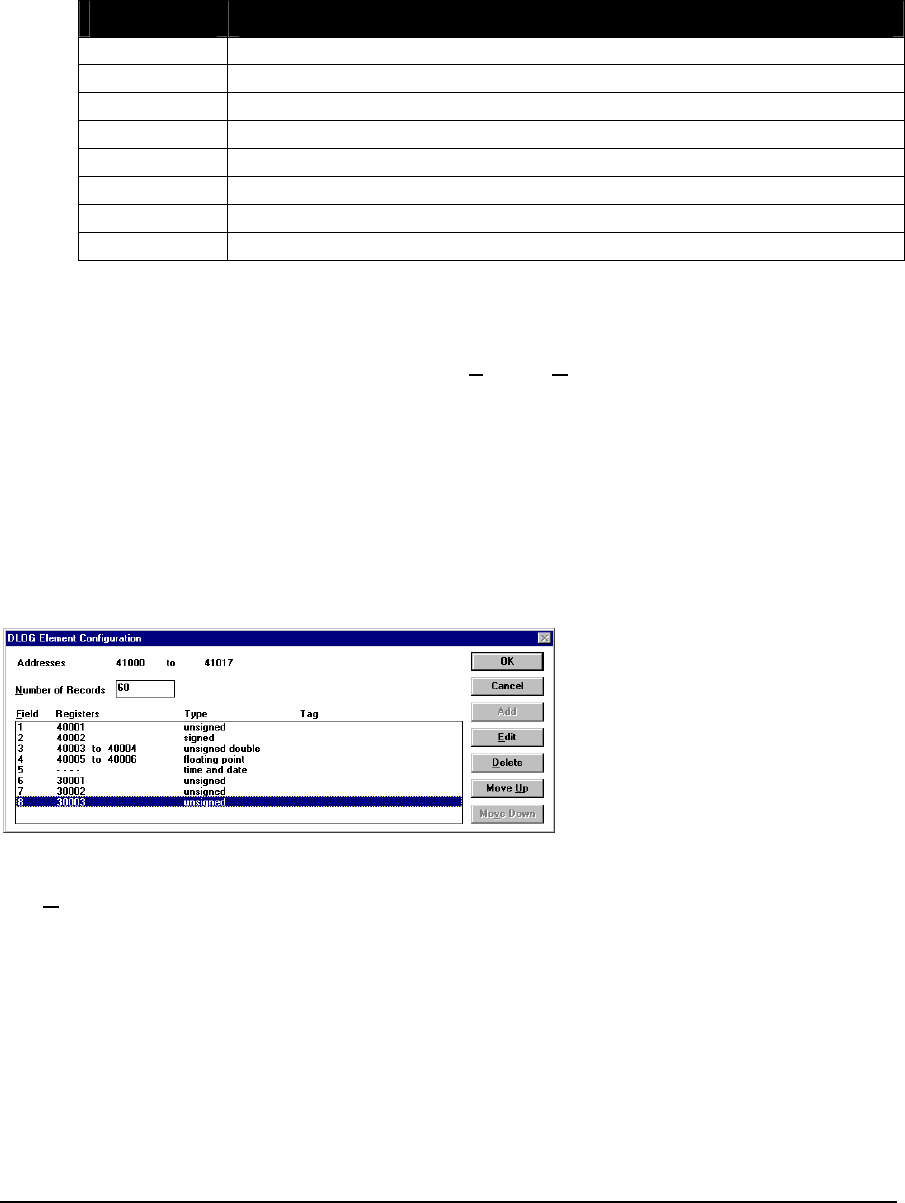
Status Register
The status register stores the result of a log attempt. It can have the following values. If the status
register is not equal to 10 then the error output is turned on.
The status codes are:
Status Code Description
10 The configuration is valid and data can be logged.
11 A different configuration already exists for the log.
12 The log ID is invalid.
13 The configuration was not valid and was rejected.
14 There is not enough memory available to create a log of the request size.
15 The number of data fields was invalid.
16 The log was successfully deleted. No log configuration exists.
17 Undefined status. This should never occur.
DLOG Element Configuration
This element is configured using the DLOG Element Configuration dialog. Highlight the element by
moving the cursor over the element and then use the Element Configuration command on the Edit
menu to modify the configuration block.
WARNING: If the controller is initialized, using the Initialize command in the Controller
menu, all I/O database registers used for Element Configuration are set to
zero. The application program must be re-loaded to the controller.
DLOG Element Configuration Dialog
Selecting Element Configuration from the Edit menu while the cursor is over a DLOG element can
access this dialog.
The addresses are determined from the ladder element. They cannot be modified in this dialog.
The Number of Records selects the number of records in the log. Each record contains the data for
all the fields in the log. The number of records available will depend on the type of controller used.
For SCADAPack 100: 256K controllers the maximum number of records is 190 records of 8
unsigned integer fields.
For SCADAPack LP and SCADAPack 100: 1024K controllers the maximum number of records is
approximately 22970 records of 8 unsigned integer fields.
For SCADAPack and Micro16 controller the number of records depends on the available memory in
socket U10 in the controller. For example a 128K RAM in U10 will allow approximately 190
TelePACE Ladder Logic Function Reference
February 19, 2007
42
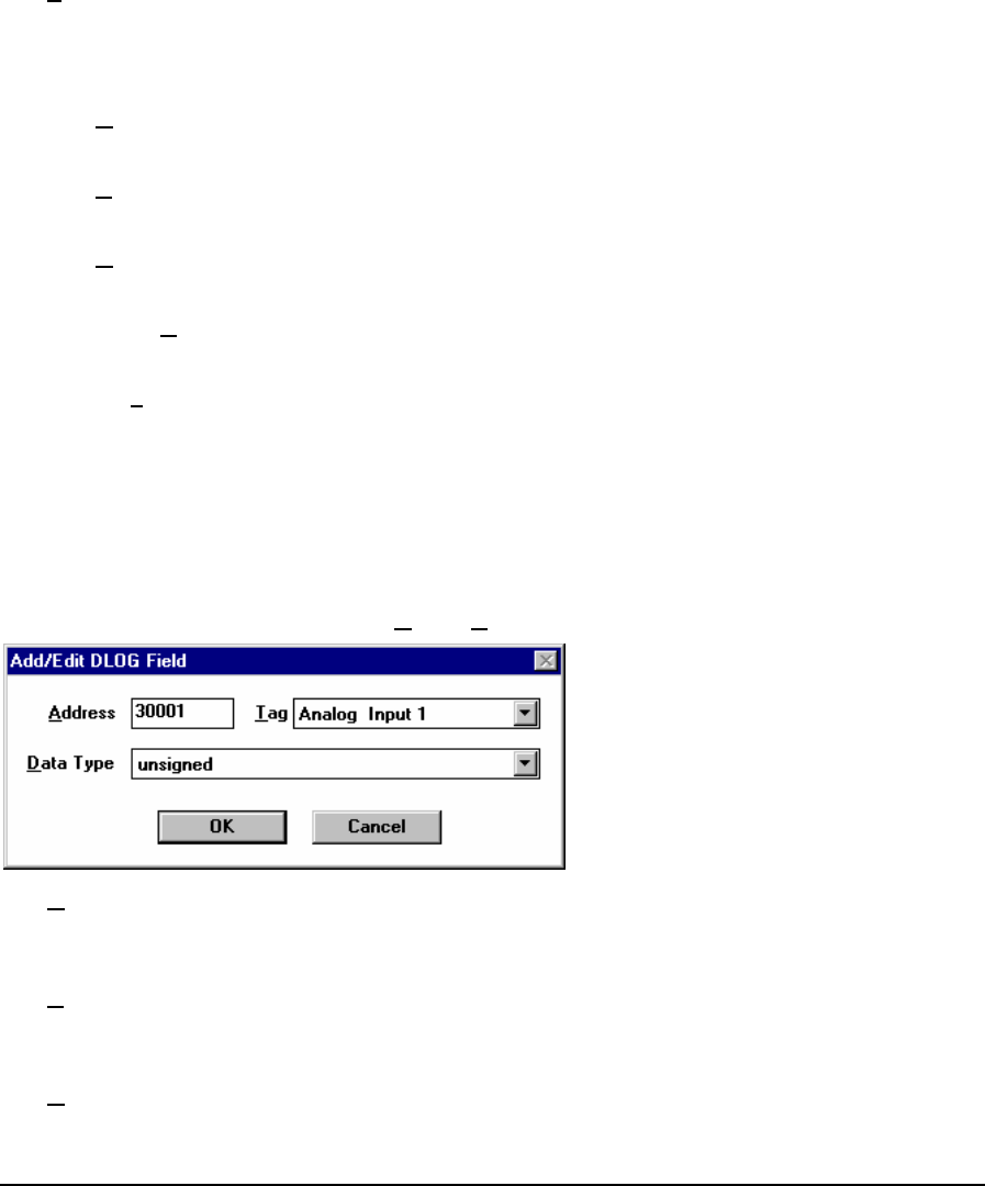
records of 8 unsigned integer fields and a 512K RAM in U10 will allow approximately 22970
records of 8 unsigned integer fields.
For SCADAPack 32 controllers the maximum number of records is 58,352 records of 8 unsigned
integer fields for a total of 466816 words. The maximum number of records will be reduced if DNP
protocol, RealFLO or custom C++ applications are used in the controller.
For SCADAPack 350 controllers the maximum number of records is 56,743 records of 8 unsigned
integer fields for a total of 453947 words. The maximum number of records will be reduced if DNP
protocol, RealFLO or custom C++ applications are used in the controller.
The Field entries contain information about each item in the log. The fields are numbered,1 through
8, as they are added to the record. The Registers column contains the Modbus registers used in for
the field. The Type column contains the Modbus register type and the Tag column contains the tag
name for the Modbus Register.
Press the Add key to add an item to the end of the list. When selected the Add/Edit DLOG Field
dialog is displayed, see description of this dialog below. The key is grayed if the list is full.
Press the Edit key to modify the currently selected item in the list. When selected the Add/Edit
DLOG Field dialog is displayed. The key is grayed if the list is empty.
Press the Delete key to delete the currently selected item from the list. The key is grayed if the list is
empty.
Press the Move Up key to move the currently selected item up one position in the list. The key is
grayed if the list is empty or the selected item is at the top of the list.
Press the Move Down key to move the currently selected item down one position in the list. The key
is grayed if the list is empty or the selected item is at the bottom top of the list.
Press OK to accept the current list.
Press Cancel to discard the changes made to the list.
Data Log Field Dialog
This dialog can be accessed by pressing Add or Edit from the DLOG Element Configuration dialog.
The Address entry will contain the Modbus register address for the record if the Edit button was
selected. This entry will be zero if the Add button was selected. Valid values are any register in the
range 00001 to 49999.
The Tag entry contains the tagname for the selected register address if one exists. The drop down list
will display all tag names for valid address. Selecting a tag name from the list will cause the
associated register address to be displayed in the Address entry.
The Data Type selection allows the selection of one of the following data types:
TelePACE Ladder Logic Function Reference
February 19, 2007
43

16 bit unsigned integer
16 bit signed integer
32 bit unsigned integer
32 bit signed integer
32 bit floating point
Days and hundredths of seconds in two 32 bit unsigned integers
Press OK to validate the data and close the dialog.
Press Cancel to discard the changes made in the dialog.
The output bits are powered only when the enable input is powered.
Related Functions:
GETL - Data Logger Extract
TelePACE Ladder Logic Function Reference
February 19, 2007
44

2.19 DPOL – Trigger a DNP class poll
Description
This function sends a DNP Class Poll message to request the specified data classes from a DNP
slave. The DNP class poll is requested when the enable input changes from OFF to ON.
The status register is set to 0 and the success output is energized if the function was successful.
The 'success' output is energized immediately if the poll was triggered successfully. It does not
provide any information about the success or otherwise of the actual message transaction.
The status register is set to 1 and the failure output is energized if the function failed. Failure
indicates the specified slave address has not been configured in the DNP Routing Table, or the DNP
configuration has not been created.
classes
enable
failure
successslave
address
status
DPOL
Function Variables
Variable Valid Types Description
Slave Address Constant or holding register
(4xxxx) DNP slave station address
Classes Constant or holding register
(4xxxx) This is a bit-mapped register containing
the classes of data to be included in the
class poll message. If multiple classes
are required the following values should
be added together.
1 = class 0 data
2 = class 1 data
4 = class 2 data
8 = class 3 data
Status Holding register (4xxxx) Status of the operation
0 = success
1 = failure
Notes
This function is available on the SCADAPack 350 SCADAPack 32 controllers only.
The function sets internal flags to trigger a DNP poll message, and returns immediately. The DNP
message will be sent some time after the function call.
TelePACE Ladder Logic Function Reference
February 19, 2007
45


2.20 DSYC – Trigger a DNP clock synchronization
Description
This function sends a Clock Synchronization message to a DNP slave.
The Clock Synchronization message is sent to the slave address when the enable input changes
from OFF to ON. The status register is set to 0 and the success output is energized if the function
was successful.
The status register is set to 1 and the failure output is energized if the Time Synchronization
message failed. The failure output indicates the specified slave address has not been configured in
the DNP Routing Table, or the DNP configuration has not been created.
slave
address
enable
failure
success
DSYC
status
Function Variables
Variable Valid Types Description
Slave Address Constant or holding register
(4xxxx) DNP slave station address
Status Holding register (4xxxx) Status of the operation
0 = success
1 = failure
Notes
This function is available on the SCADAPack 32 only.
The function sets internal flags to trigger a DNP message and returns immediately. The DNP
message will be sent some time after the function call.
Related Functions
DEVT – Generate DNP Event
DPOL – Trigger a DNP class poll
DUNS – Trigger a DNP unsolicited response message
TelePACE Ladder Logic Function Reference
February 19, 2007
47

2.21 DUNS – Trigger a DNP unsolicited response message
Description
The DUNS function triggers a DNP unsolicited response message of the specified class or classes.
The unsolicited response for the specified classes is triggered when the enable input changes from
OFF to ON. The status register is set to 0 and the success output is energized if the message was
triggered successfully.
The status register is set to 1 and the failure output is energized if the unsolicited response message
failed. The failure output indicates master addresses have not been configured in the DNP Routing
Table, or the DNP configuration has not been created.
DUNS
enable
failure
success
classes
status
Function Variables
Variable Valid Types Description
Classes Constant or
holding
register
(4xxxx)
This is a bit-mapped register containing the classes of data to
be included in the unsolicited message. If multiple classes are
required the following values should be added together.
1 = class 0 data
2 = class 1 data
4 = class 2 data
8 = class 3 data
Status Holding
register
(4xxxx)
Status of the operation
0 = success
1 = failure
Notes
The function sets internal flags to trigger a DNP unsolicited message, and returns immediately. The
DNP message will be sent some time after the function call.
DNP unsolicited messages do not have to be enabled in the Application Layer configuration for
events to be sent with this function. Unsolicited messages at Start Up must be enabled, or the master
must enable unsolicited messages before the first message can be sent.
If no events are pending an empty unsolicited message will be sent.
The message will be sent to the configured DNP master station or stations.
The return status indicates whether the flags were set. The status will be FALSE if the DNP engine is
not running.
Related Functions
DPOL – Trigger a DNP class poll
TelePACE Ladder Logic Function Reference
February 19, 2007
48


2.22 FIN – FIFO Queue Insert
Description
The FIN function inserts the contents of the source register into the First-In-First-Out (FIFO) queue.
Values in the FIFO queue are pushed down until the queue is full.
When the enable insert input is ON and the FIFO full is not ON, the source register is inserted into
the queue.
The index is incremented by one after each insert until the index value equals the size. When the
index equals the size and enable insert is ON then FIFO full turns ON and no further insertions can
take place.
The FIFO Queue Insert function is used with the FIFO Queue Remove function to enable full control
of the FIFO Queue.
source
FIN
size
queue
ON = enable insert
ON = FIFO full
copies status of input 1
Function Variables
Variable Valid Types Description
Source coil block (0xxxx)
status block (1xxxx)
input register (3xxxx)
holding register (4xxxx)
The address of the source register.
The address for a coil or status
register block is the first register in
a group of 16 registers that will be
inserted.
Queue holding register (4xxxx) The address of the index register
and the queue registers. The index
is stored in register [4xxxx]. The
FIFO queue is located in register
[4xxxx+1] to
register [4xxxx + size].
Size constant (1..9999) The number of registers in the
queue.
Notes
FIN accesses 16 bit words. Coil and status register blocks are groups of 16 registers that start with
the register specified as the block address. Coil and status register blocks must begin at the start of a
16 bit word within the controller memory. Suitable addresses are 00001, 00017, 10001, 10033, etc.
Related Functions
FOUT – FIFO Queue Remove
TelePACE Ladder Logic Function Reference
February 19, 2007
50

Example
See the example for the FOUT function.
TelePACE Ladder Logic Function Reference
February 19, 2007
51

2.23 FOUT – FIFO Queue Remove
Description
The FOUT function removes a value from the first-in-first-out (FIFO) queue and transfers it into the
destination register. Values in the queue are moved up, until the queue is empty.
When the enable remove input is ON and the FIFO empty is not ON, the first queue register is
transferred into the destination register.
The index is decremented by one after each transfer until the index value equals zero. When the
index equals zero and the enable remove input is ON the FIFO empty turns ON and no further
removals can take place.
The FIFO Queue Remove function is used with the FIFO Queue Insert function to enable full control
of the FIFO Queue. See FIFO Queue example.
queue
FOUT
size
destination
ON = enable remove copies status of input 1
ON = FIFO empty
Function Variables
Variable Valid Types Description
Queue Holding register (4xxxx)
The address of the index register
and the queue registers. The index
is stored in register [4xxxx]. The
FIFO queue in located in register
[4xxxx+1] to
Register [4xxxx + size].
Destination coil block (0xxxx)
holding register (4xxxx)
The address of the destination
register.
The address for a coil register block
is the first register in a group of 16
registers.
Size Constant (1..9999) The number of 16 bit registers in
the queue.
Notes
FOUT accesses 16 bit words. Coil blocks are groups of 16 registers that start with the register
specified as the block address. Coil blocks must begin at the start of a 16 bit word within the
controller memory. Suitable addresses are 00001, 00017, 00033, etc.
Related Functions
FIN – FIFO Queue Insert
TelePACE Ladder Logic Function Reference
February 19, 2007
52

Example
00017
)(
01058 42599
42016
FOUT
+4
42012
42599
FIN
+4
01057
00018
)(
The following discussion describes the operation of a FIN function. The queue starts out empty with
the FIFO index register having a value of zero.
Source
Register
Source
Register
Data
FIFO
Queue
Regist
ers
FIFO Index--> 42599
42012 Xxxx FIFO register 0--> 42600
FIFO register 1--> 42601
FIFO register 2--> 42602
FIFO register 3--> 42603
When FIFO queue index register 42599 has a value of 0 and the FIN function is enabled, by closing
contact 1057, the contents of source register 42012 is inserted into FIFO Queue register 42600 and
the index is incremented to 1.
When FIFO queue index register 42599 has a value of 1 and the FIN function is enabled, by closing
contact 1057, the contents of queue register 42600 is transferred to queue register 42601. The
contents of source register 42012 are inserted into FIFO queue register 42600, and the index is
incremented to 2.
When FIFO queue index register 42599 has a value of 2 and the FIN function is enabled, by closing
contact 1057, the contents of queue register 42601 is transferred to queue register 42602. The
contents of queue register 42600 is transferred to queue register 42601, the contents of source
register 42012 is inserted into FIFO queue register 42600 and the index is incremented to 3.
When FIFO queue index register 42599 has a value of 3 and the FIN function is enabled, by closing
contact 1057, the contents of queue register 42602 is transferred to queue register 42603. The
contents of queue register 42601 is transferred to queue register 42602, the contents of queue register
42600 is transferred to queue register 42601, the contents of source register 42012 is inserted into
FIFO queue register 42600 and the index is incremented to 4.
The queue is now full and no further insertions are allowed. Coil 00017 will turn ON. The FOUT
Queue Remove function must be used to remove values from the queue.
The following discussion describes the operation of a FOUT function. The queue starts out full with
the FIFO index register having a value of three.
TelePACE Ladder Logic Function Reference
February 19, 2007
53

FIFO
Queue
Registers
FIFO
Queue
Register
Data
Destination
Register
FIFO Index--> 42599
FIFO register 0-
-> 42600
FIFO register 1-
-> 42601
FIFO register 2-
-> 42602
FIFO register 3-
-> 42603 xxxx 42016
When FIFO queue index register 42599 has a value of 4 and the FOUT function is enabled, by
closing contact 1058, the contents of queue register 42603, pointed to by the index is transferred to
the FIFO destination register 42016 and the index is decremented by one.
When FIFO queue index register 42599 has a value of 3 and the FOUT function is enabled, by
closing contact 1058, the contents of queue register 42602 is transferred to the FIFO destination
register 42016 and the index is decremented by one.
When FIFO queue index register 42599 has a value of 2 and the FOUT function is enabled the
contents of queue register 42601 is transferred to the FIFO destination register 42016 and the index
register is decremented by one.
When FIFO queue index register 42599 has a value of 1 and the FOUT function is enabled, by
closing contact 1058, the contents of queue register 42600 is transferred to the FIFO destination
register 42016 and the index is decremented to 0.
The queue is now empty and no further removals are allowed. Coil 00018 will be now be energized.
The FIN Queue Insert function must be used to insert values into the queue.
TelePACE Ladder Logic Function Reference
February 19, 2007
54
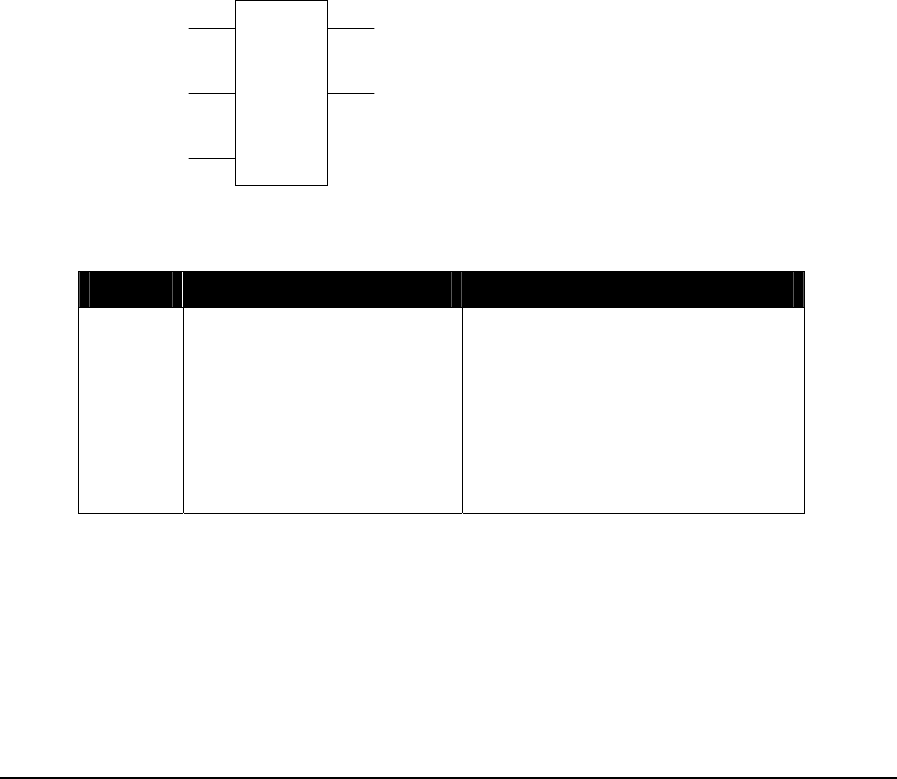
2.24 FLOW – Flow Accumulator
Description
The FLOW function accumulates flow from pulse type devices such as turbine flow meters.
When the accumulate input is ON the function accumulates volume and calculates the flow rate.
When the Log Data input goes from OFF to ON, the accumulated volume, flow time and the time at
the end of the period is saved in the history registers. Older history is pushed down and the oldest
record is discarded. The Log Data input must be triggered at least once every 119 hours (at the
maximum pulse rate). Otherwise the volume accumulator will overflow, and the accumulated
volume will not be accurate.
When the accumulator enabled input is ON, accumulation and rate calculations are enabled. When
the input is OFF, all accumulators and the rate outputs are set to zero.
The function reads and accumulates the number of pulses, and divides by the K factor to calculate
the total volume. This is done on each scan of the controller logic. The function calculates the flow
rate in engineering units based on the K-factor provided. The rate updates once per second if there is
sufficient flow. If the flow is insufficient, the update slows to as little as once every ten seconds to
maintain resolution of the calculated rate.
config
FLOW
records
outputs
ON = accumulate flow
ON = enable accumulation
OFF = clear outputs
ON = errorOFF to ON = log data
copies state of input 1
Function Variables
Variable Valid Types Description
Config holding register (4xxxx) Address of the first register of the
configuration block. There are five
registers in the block at config+0 to
config+4.
+0, 1 = K factor (floating-point)
+2 = input register (3xxxx or 4xxxx)
+3 = input type (see table below)
+4 = rate period (see table below)
TelePACE Ladder Logic Function Reference
February 19, 2007
55

Variable Valid Types Description
Outputs holding register (4xxxx) Address of the first register of the
output block. There are 18 to 222
registers in the block at outputs+0
to outputs+221. The number of
registers used depends on the
records variable.
+0 = status (see table below)
+1,2 = flow rate (floating-point)
+3,4 = internal: rate accumulator
+5,6 = internal: time of last rate
+7,8 = internal: input at last sample
+9,10 = internal: pulse accumulator
+11 = number of records to follow
+12,13 = volume for period 1 (float)
+14,15 = time at end of period 1
+16,17 = flow time for period 1
+18,19= volume for period 2 (float)
+20,21 = time at end of period 2
+22,23 = flow time for period 2
+24,25= volume for period 3 (float)
+26,27 = time at end of period 3
+28,29 = flow time for period 3
…
+216,217 = volume for period 35
(float)
+218,219 = time at end of period 35
+220,221 = flow time for period 35
Records Constant The number of measurement
records stored in the output array.
The valid values are 1 to 35. This
value determines the number of
output registers used by the
function.
Element Configuration
This element is configured using the FLOW Element Configuration dialog. Highlight the element by
moving the cursor over the element and then use the Element Configuration command on the Edit
menu to modify the configuration block.
WARNING: If the controller is initialized, using the Initialize command in the Controller menu,
all I/O database registers used for Element Configuration are set to zero. The
application program must be re-loaded to the controller.
TelePACE Ladder Logic Function Reference
February 19, 2007
56
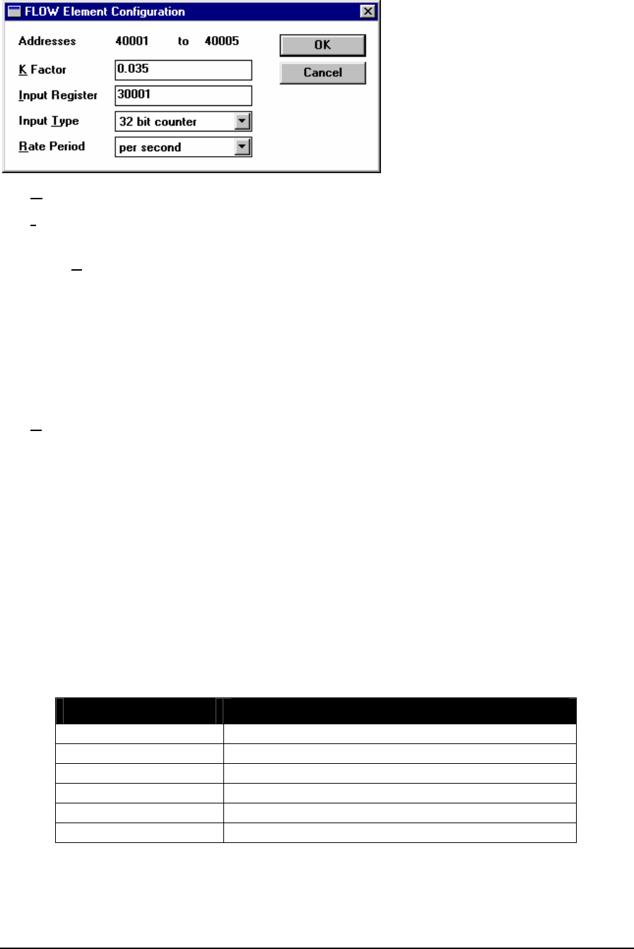
The K Factor is a floating-point value. It may be any non-zero, positive value.
The Input Register is the address of the register that holds the input pulse count. Valid values are
any input or holding register in the range 30001 to 49999.
The Input Type may be one of the following.
16 bit counter A free running 16-bit counter.
Holding register (4xxxx) = 0
32 bit counter A free running 32-bit counter with low word in the first register.
Holding register (4xxxx) = 1
16 bit difference The 16-bit difference between any two counters.
Holding Register (4xxxx) = 2
The Rate Period determines the units of time used to display the flow rate. It may be one of the
following. Note that this value does not affect when the rate calculation is performed.
per second Holding register (4xxxx) = 0
per minute Holding register (4xxxx) = 1
per hour Holding register (4xxxx) = 2
per day Holding Resister (4xxxx) = 3
Output Registers
The output registers store the results of the flow accumulation and act as internal workspace for the
accumulation.
The status register indicates the status of the flow accumulation. It can have the following values. If
the status register is non-zero, the error output is turned ON.
Status Register Value Description
0 no error
1 invalid K factor configuration
2 invalid Input Register configuration
3 invalid Input Type configuration
4 invalid Rate Period configuration
5 pulse rate is too low for accurate flow rate calculation
The flow rate register contains the flow rate in engineering units based on the K-factor and rate
period provided.
TelePACE Ladder Logic Function Reference
February 19, 2007
57

The eight internal registers are used for the accumulation of the flow and calculation of the flow
rate.
The Number of Records register indicates how many sets of flow and time registers follow. This
value is equal to the Records variable. There are four registers in each record.
The Volume for Period n is stored as a floating-point number in two consecutive registers.
The End Time for Period n is stored as a 32-bit integer in two consecutive registers. The registers
hold the number of seconds since January 1, 1970. This is an unsigned number.
The Flow Time for Period n is stored as a 32-bit integer in two consecutive registers. The register
holds the number of seconds flow was accumulated in the period. This measures the time the
Accumulate input is ON, including times when the flow was zero.
Notes
The maximum pulse rate is 10 kHz.
The accumulated flow is calculated by measuring the accumulated pulses and dividing by the K
factor. The K factor cannot be changed while an accumulation is in progress. Only change the K
factor while accumulation is stopped.
Example
network 1:
40001
40100
FLOW
+31
10009
The FLOW function in network 1 has the accumulate flow and enable accumulation inputs
connected to the left power rail. When these inputs are continuously powered the FLOW function
accumulates volume and calculates flow rate.
Each time contact 10009 is closed, powering the log data input, the accumulated volume, flow time
and the time at the end of the period is saved in the history registers.
The records value is set to 31. This means that 31 sets of history registers, volume, flow time and
end of period time, will be logged. In this example the accumulation input is never turned off
meaning that once 31 sets of history registers are saved the next time contact 10009 is closed the 31st
record is removed and the newest record is added to the history.
TelePACE Ladder Logic Function Reference
February 19, 2007
58

2.25 FTOS - Floating-Point to Signed Integer
Description
The FTOS element converts a floating-point register or constant into a signed integer and stores the
result in a holding register.
When the enable input is ON, value is converted into a signed number and stored in the result
register. The value is rounded to the nearest integer. If the value is less than –32768, then –32768 is
stored. If the value is greater than 32767, then 32767 is stored.
The top output is ON when the input is. The bottom output is ON if the floating-point value is less
than –32768 or greater than 32767.
value
FTOS
result
ON = enable copies status of input
ON = result out of range
Function Variables
The element has two parameters.
Variable Valid Types Description
value FP constant
2 input registers (3xxxx)
2 holding registers (4xxxx)
a floating-point register or constant
Result holding register (4xxxx) Converted signed value
Notes
Floating-point values are stored in two consecutive I/O database registers. The lower numbered
register contains the upper 16 bits of the number. The higher numbered register contains the lower 16
bits of the number.
Floating point numbers can represent positive or negative values in the range –3.402 × 1038 to 3.402
× 1038.
Related Functions
UTOF - Unsigned Integer to Floating-Point
STOF - Signed Integer to Floating-Point
FTOU - Floating-Point to Unsigned Integer
TelePACE Ladder Logic Function Reference
February 19, 2007
59

Example
network 1:
-223.51
FTOS
42102
The FTOS function in network 1 converts floating-point constant –223.51 to a signed integer value
and puts the value into register 42102. In this example the content of register 42102 is the signed
integer –224.
TelePACE Ladder Logic Function Reference
February 19, 2007
60

2.26 FTOU - Floating-Point to Unsigned Integer
Description
The FTOU element converts a floating-point register or constant into an unsigned integer and stores
the result in a holding register.
When the enable input is ON, value is converted into an unsigned number and stored in the result
register. The value is rounded to the nearest integer. If the value is less than zero, then zero is stored.
If the value is greater than 65535, then 65535 is stored.
The top output is ON when the input is. The bottom output is ON if the floating-point value is less
than 0 or greater than 65535.
value
FTOU
result
ON = enable copies status of input
ON = result out of range
Function Variables
The element has two parameters.
Variable Valid Types Description
value FP constant
2 input registers (3xxxx)
2 holding registers (4xxxx)
a floating-point register or constant
Result holding register (4xxxx) Converted unsigned value
Notes
Floating-point values are stored in two consecutive I/O database registers. The lower numbered
register contains the upper 16 bits of the number. The higher numbered register contains the lower 16
bits of the number.
Floating point numbers can represent positive or negative values in the range –3.402 × 1038 to 3.402
× 1038.
Related Functions
UTOF - Unsigned Integer to Floating-Point
STOF - Signed Integer to Floating-Point
FTOS - Floating-Point to Signed Integer
TelePACE Ladder Logic Function Reference
February 19, 2007
61

Example
network 1:
+437.501
FTOU
42101
The FTOU function in network 1 converts floating-point constant +437.501 to an unsigned integer
value and puts the value into register 42101. In this example the content of register 42101 is the
unsigned integer +438.
TelePACE Ladder Logic Function Reference
February 19, 2007
62
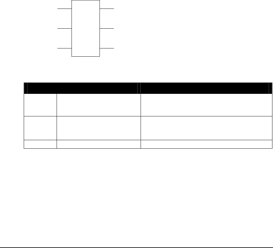
2.27 GETB – Get Bit from Block
Description
The GETB function block reads the status of a bit, at the bit index, from the source block of
registers.
When the bit index is defined as a holding register the enable GETB input must be ON to increment
bit index or reset bit index to zero.
The increment bit index input increments the bit index once, each scan, when enabled.
The reset bit index to 0 input resets the bit index to 0 when enabled.
When the bit index is defined as a constant, the GETB function checks the status of the bit at the bit
index when enable GETB is ON. The increment bit index and reset bit index to 0 inputs have no
effect on the function block in this condition.
When the enable GETB is ON, the state of bit selected output is ON if the source bit is 1 and OFF
if the source bit is 0.
The index>size output is enabled when the bit index is equal to size + 1 and the enable GETB input
is ON. The reset bit index to 0 input must be set to continue function operation.
bit index
GETB
size
source
ON = enable GETB
ON = reset bit index to 0
state of the bit selectedON = increment bit index
copies state of input 1
ON if index > size
Function Variables
Variable Valid Types Description
bit index Constant (0..65535)
holding register (4xxxx)
The index of the bit within the source block. A
bit index of 0 is the most significant bit of the
first register of the source block.
Source coil block (0xxxx)
holding register (4xxxx)
The address of the source register.
The address for a coil register block is the first
register in a group of 16 registers.
Size Constant (1..100) number of 16 bit words in the block.
Notes
The Get bit from block function accesses 16 bit words. Coil blocks are groups of 16 registers that
start with the register specified as the block address. Coil blocks must begin at the start of a 16 bit
word within the controller memory. Suitable addresses are 00001, 00017, 00033, etc.
Related Functions
PUTB – Put Bit into Block
TelePACE Ladder Logic Function Reference
February 19, 2007
63

ROTB – Rotate Bits in Block
CMPB – Compare Bit
Example
10010 +2
40223
GETB
+1
00017
)
(
In this example the GETB function is used to test bit 13 of the PID block 0 Status register to check if
the Control Block is in manual mode.
The twenty-five holding registers used for PID block 0 are assigned to the CNFG PID Control
Block I/O Module in the Register Assignment. In this case holding registers 40220 through 40245
are assigned to the I/O module.
The Control Block status register, 40223 is tested to see if bit 13 is ON. The GETB function uses bit
index of 0 for the most significant bit. This means that a bit index of 2 will test for bit 13 of the
Control Block register.
Closing contacts 10010 sets the enable GETB input on. If PID block 0 is in manual mode output
00017 will turn ON.
TelePACE Ladder Logic Function Reference
February 19, 2007
64

2.28 GETL - Data Logger Extract
Description
The GETL function extracts one record from a data log and writes it into holding registers.
When a low to high transition occurs on the enable GETL input, the error code and sequence
number status registers are updated and the data length is cleared.
When the enable GETL input is ON and a low to high transition occurs on the read data input, the
status registers are updated and the data for the requested sequence number is copied to the data from
log holding registers.
The error output is ON if the log is not configured or if there was a data reading error, see table
below. The outputs are powered only when the enable input is powered.
re
q
uest
GETL
LogID
status
ON = enable GETL
ON = errorOFF to ON = read data
copies state of input 1
Function Variables
Variable Valid Types Description
Request 2 holding registers
(4xxxx)
Unsigned long sequence number requested
from the log.
+0 = least significant word
+1 = most significant word
Status Up to 36 holding registers
(4xxxx) Status and data registers
+0 = error code
+1,2 = sequence number
+3 = length of data
+4 to+35 = data from log
LogID Constant (1 to 16) Identifies the internal log.
Status Register
The status register stores the result of an enable log attempt and a log data attempt. It can have the
following values. If the status register is does not contain the code 20 then the error output is turned
on. The status error codes are:
Error Code Description
20 The configuration is valid and data can be retrieved.
21 The log ID is invalid.
22 The log is not configured.
23 The requested sequence number was not in the valid range.
TelePACE Ladder Logic Function Reference
February 19, 2007
65

Notes:
To get the oldest sequence number in the log toggle the enable GETL input, the error code and
sequence number status registers are updated and the data length is cleared. To clear the error 23 the
enable GETL input must be turned off.
Related Functions:
DLOG - Data Logger
TelePACE Ladder Logic Function Reference
February 19, 2007
66

2.29 GTEF – Floating-Point Greater Than or Equal
Description
The GTEF element tests if a floating-point register or constant is greater than or equal to another
floating-point register or constant.
When the enable input is ON, value1 and value2 are compared. If value1 is greater than value2, the
top output is ON. If value1 is equal to value2 the bottom output is ON.
value1
GTEF
value2
ON = enable ON if value1 > value2
ON if value1 = value2
Function Variables
The element has two parameters.
Variable Valid Types Description
Value1 FP constant
2 input registers (3xxxx)
2 holding registers (4xxxx)
a floating-point register or constant
Value2 FP constant
2 input registers (3xxxx)
2 holding registers (4xxxx)
a floating-point register or constant
Notes
Floating-point values are stored in two consecutive I/O database registers. The lower numbered
register contains the upper 16 bits of the number. The higher numbered register contains the lower 16
bits of the number. Floating point numbers can represent positive and negative values in the range –
3.402 × 1038 to 3.402 × 1038.
Related Functions
CMP – Compare Signed Values
CMPU – Compare Unsigned Values
Example
network 1:
+22.601
GTEF
40001
TelePACE Ladder Logic Function Reference
February 19, 2007
67

The GTEF function in network 1 compares the floating-point constant +22.601 to the contents of
floating-point register 40001. The top output of the GTEF function is ON if the value of register
40001 is less than +22.601. The bottom output of the GTEF is ON if the value of register 40001 is
equal to +22.601.
TelePACE Ladder Logic Function Reference
February 19, 2007
68

2.30 HART – Send HART Command
Description
The HART element sends a HART protocol command and processes the response. The SCADAPack
100 or SCADASense Series controllers do not support this command.
The HART element is a two-cell element, with one input and two outputs. When the enable HART
input changes from OFF to ON, the element sends the HART command to the HART device. When
the enable HART input changes from ON to OFF, the current command is aborted and no response
is processed.
When a response is received, the data in the response is stored in the I/O database and the command
complete output turns ON. If there is an error in the command, or if the HART device fails to
respond to any of the attempts, the command error output turns ON.
The enable HART input must remain ON until the response has been received or an error has
occurred. All outputs turn OFF when the input is OFF.
ON = command error
ON = command completeON = enable HAR
T
HART
status
command
Function Variables
The HART element has two parameters:
Variable Valid Types Description
command Holding register
(4xxxx)
Address of the first register in the HART
command block. There are 5 registers in the
block at addresses command+0 to
command+4.
+0 = 5904 HART interface module number
+1 = HART device address
+2 = command number
+3 = command data register address
+4 = response register address
status Holding register
(4xxxx)
Address of the first register of the status
block. There are two registers in the block at
addresses status+0 and status+1.
+0 = command status
+1 = additional information code
The 5904 HART interface module number must be set to 0, 1, 2 or 3. This must correspond with
the module number of a CNFG 5904 HART Interface module in the Register Assignment.
The HART device address must be in the range 0 to 15.
Valid values for command number are shown below.
TelePACE Ladder Logic Function Reference
February 19, 2007
69

The command data register address specifies an I/O database register where the data for the
command is stored. The program must set the values in these registers. The tables below show how
this address is used.
The response register address specifies an I/O database register where the data in the response is
stored. The tables below show how this address is used. Registers marked as (float) contain floating-
point values.
Command 0
Purpose Read the device identifier
Command Data
Registers Not used
Response
Registers +0 = manufacturer ID
+1 = manufacturer Device Type
+2 = preambles Requested
+3 = command Revision
+4 = transmitter Revision
+5 = software Revision
+6 = hardware Revision
+7 = flags
+8,9 = device ID (double)
Notes This command is also the link initialization command. The
HART element performs link initialization automatically.
The user does not have to send this command unless the
device identifier is needed.
Command 1
Purpose Read primary variable (PV)
Command Data
Registers Not used
Response
Registers +0,1 = PV (float)
+2 = PV units code
Command 2
Purpose Read primary variable current and percent of span
Command Data
Registers Not used
Response
Registers +0,1 = PV current (float)
+2 = PV current units code
+3,4 = PV percent (float)
+5 = PV percent units code
TelePACE Ladder Logic Function Reference
February 19, 2007
70

Command 3
Purpose Read dynamic variables and primary variable current
Command Data
Registers Not used
Response
Registers +0,1 = primary variable current (float)
+2 = primary variable current units code
+3,4 = primary variable value (float)
+5 = primary variable units code
+6,7 = secondary variable value (float)
+8 = secondary variable units code
+9,10 = tertiary variable value (float)
+11 = tertiary variable units code
+12,13 = fourth variable value (float)
+14 = fourth variable units code
Notes Not all devices return primary, secondary, tertiary and
fourth variables. If the device does not support them, zero
is written into the value and units code for that variable.
Command 33
Purpose Read specified transmitter variables
Command Data
Registers +0 = variable code 0
+1 = variable code 1
+2 = variable code 2
+3 = variable code 3
Response
Registers +0,1 = variable 0 value (float)
+2 = variable 0 units code
+3,4 = variable 1 value (float)
+5 = variable 1 units code
+6,7 = variable 2 value (float)
+8 = variable 2 units code
+9,10 = variable 3 value (float)
+11 = variable 3 units code
The status registers contains the current command status and additional code returned from the
HART interface. The table below shows the values.
status Description Code
0 HART interface
module is not
communicating
not used
1 Command ready to
send to device not used
2 Command sent to
device current attempt number
3 Response received response code from HART device (see
Notes)
TelePACE Ladder Logic Function Reference
February 19, 2007
71
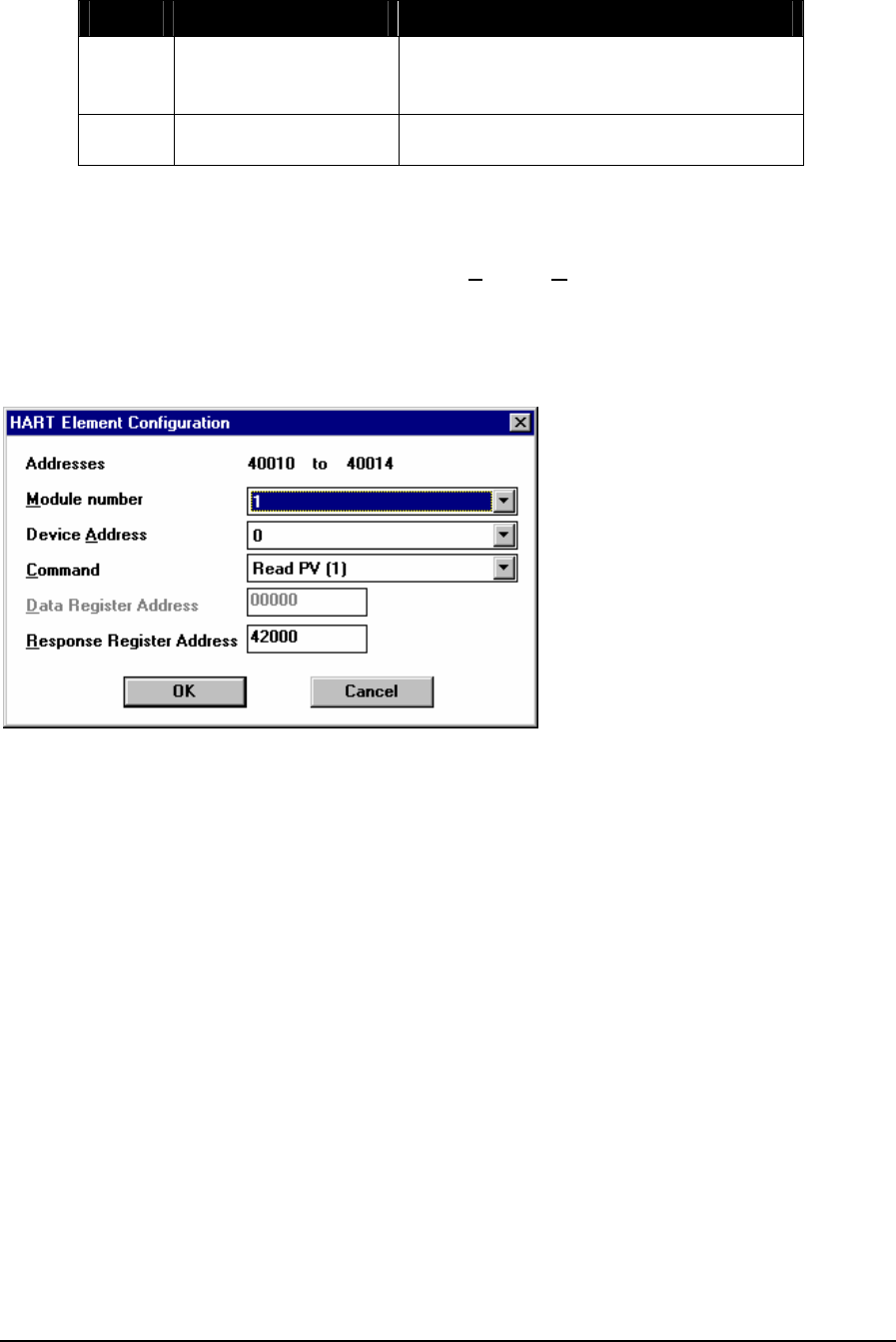
status Description Code
4 No valid response
received after all
attempts made
0=no response from HART device.
Other = error response code from HART
device (see Notes)
5 HART interface is not
ready to transmit not used
Element Configuration
This element is configured using the HART Element Configuration dialog. Highlight the element by
moving the cursor over the element and then use the Element Configuration command on the Edit
menu to modify the configuration block.
WARNING: If the controller is initialized (using the TelePACE Initialize command), all I/O
database registers used for element configuration are set to zero. The Ladder Logic
program must be re-loaded to the controller to restore the element configuration.
Addresses shows the register addresses that will be used by the element.
Module number selects the HART interface module to which the command will be sent. The valid
range is 0 to 3.
Device Address selects the address of the HART device. The valid range is 0 to 15.
Command selects the HART command to be sent to the device. The valid values are:
Read Device Identifier = 0
Read PV = 1
Read PV Current and % = 2
Read Dynamic Variables = 3
Read Specified Variables = 33
Data Register Address selects the resisters where data for the command is stored. This field is
grayed for the Read Device Identifier, Read PV, Read PV Current and %, and Read Dynamic
Variables commands. These commands do not have any data.
Response Register Address selects the registers where the data in the response from the command
will be stored.
TelePACE Ladder Logic Function Reference
February 19, 2007
72

Notes
The HART element performs link initialization automatically. The user does not have to send the
link initialization command. If the command fails after all attempts, the link is automatically
reinitialized by the HART element, at the time of the next command.
Some variables read from HART devices are 32-bit floating-point values. Each floating-point value
is stored in two consecutive database registers. The most significant 16 bits of the value is stored in
the lower numbered register. The least significant 16 bit of the value is stored in the higher numbered
register.
The variable codes specify which variables are read from the HART device. See the documentation
for your HART device for valid values for the variable codes.
The unit codes are standardized for all HART devices. See the HART specification or the
documentation for your HART device for valid values.
The response code from the HART device contains communication error and status information. The
information varies by device, but there are some common values.
If bit 7 of the high byte is set, the high byte contains a communication error summary. This field is
bit-mapped. The following table shows the meaning of each bit as defined by the HART protocol
specifications. Consult the documentation for the HART device for more information.
Bit Description
6 vertical parity error
5 overrun error
4 framing error
3 longitudinal parity error
2 reserved – always 0
1 buffer overflow
0 Undefined
If bit 7 of the high byte is cleared, the high byte contains a command response summary. The
following table shows common values. Other values may be defined for specific commands. Consult
the documentation for the HART device.
Code Description
32 Busy – the device is performing a function that
cannot be interrupted by this command
64 Command not Implemented – the command is not
defined for this device.
The low byte contains the field device status. This field is bit-mapped. The following table shows the
meaning of each bit as defined by the HART protocol specifications. Consult the documentation for
the HART device for more information.
Bit Description
7 field device malfunction
6 Configuration changed
5 cold start
TelePACE Ladder Logic Function Reference
February 19, 2007
73

Bit Description
4 more status available (use command 48 to
read)
3 primary variable analog output fixed
2 primary variable analog output saturated
1 non-primary variable out of limits
0 primary variable out of limits
Example
An example of polling using the HART block is in the file HART.LAD. This file is automatically
installed on the computer when the TelePACE program is installed. It is located in the
TELEPACE\EXAMPLES directory.
See Also
MSTR - Master Message
TelePACE Ladder Logic Function Reference
February 19, 2007
74

2.31 INIM – Initialize Dial-Up Modem
Description
The INIM function initializes an internal modem or an external modem, typically to set it to receive
calls. Only one INIM block may be active on each serial communication port at any one time.
When enable INIM input is ON, the INIM element sends the modem initialization string to the
modem. When the initialization is complete the ON when initialization is complete output is turned
ON. If an error occurs, the ON when initialization failed output is turned ON.
The enable INIM input must be energized for the entire INIM time, including multiple initialization
attempts.
Note: The SCADAPack 100 does not support dial up connections on com port 1.
SCADASense Series controllers do not support dial connections on any serial port.
confi
g
INIM
status
ON = enable INIM
ON when initialization failed
ON when initialization is
complete
Function Variables
Variable Valid Types Description
Config holding register
(4xxxx) Address of the first register in the
configuration block. There are 18
registers in the block at addresses
configuration+0 to configuration+17.
+0 = Communication port
+1 = Length of modem string
+2 = Modem initialization string
Registers should be programmed using
the Element Configuration command.
Status Holding register
(4xxxx) Address of the first register in the status
block. There are 2 registers in the block at
addresses status+0 to status+1.
+0 = error code
+1 = reservation identifier
Notes
The modem initialization string is packed. Two ASCII characters are stored in each register.
The reservation identifier is required for the operation of the dialer but can be ignored by the ladder
program.
TelePACE Ladder Logic Function Reference
February 19, 2007
75
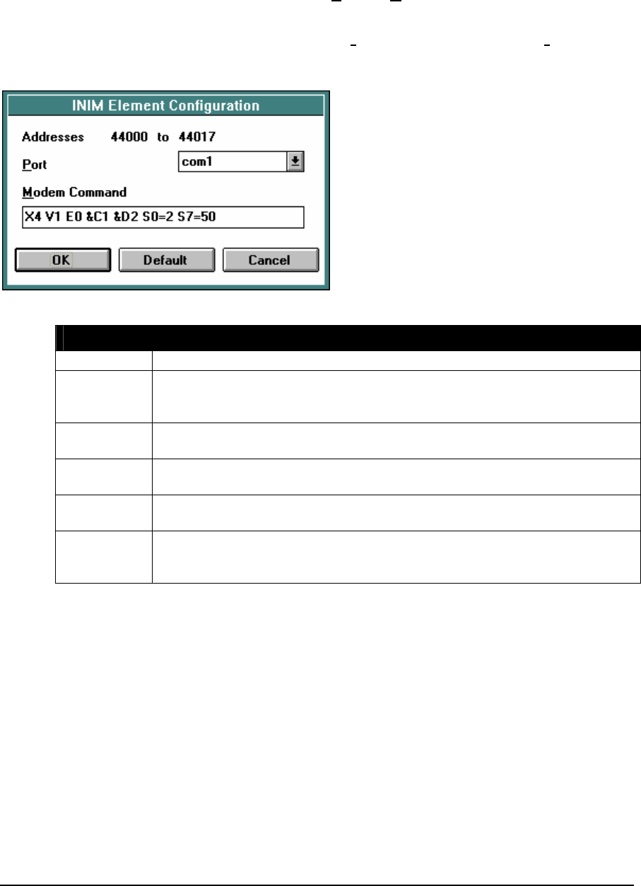
Element Configuration
This element is configured using the INIM Element Configuration dialog. Highlight the element by
moving the cursor over the element and then use the Element Configuration command on the Edit
menu to modify the configuration block.
WARNING: If the controller is initialized, using the Initialize command in the Controller menu,
all I/O database registers used for Element Configuration are set to zero. The
application program must be re-loaded to the controller.
Error Code Description
0 No Error
1 Bad configuration error occurs when an incorrect initialization string is sent
to the modem. This usually means the modem does not understand a
specific command in the initialization string.
2 No modem is connected to the controller serial port, or the controller serial
port is not set to RS232 Modem.
3 Initialization error occurs when the modem does not respond to the
initialization string and may be turned off.
6 Call aborted by the program. This will occur if the enable INIM input goes
OFF before a modem connection occurs.
9 “Serial port is not available” error occurs when the INIM function attempts
to use the serial port when another ladder communication element, C
program or an incoming call has control of the port.
To optimize performance, minimize the length of messages on com3 and com4. Examples of
recommended uses for com3 and com4 are for local operator display terminals, and for programming
and diagnostics using the TelePACE program.
Related Functions
DIAL – Control Dial-Up Modem
Example
The following network configures a generic Hayes compatible modem to answer on the second ring.
The modem is initialized when the controller is powered up.
TelePACE Ladder Logic Function Reference
February 19, 2007
76
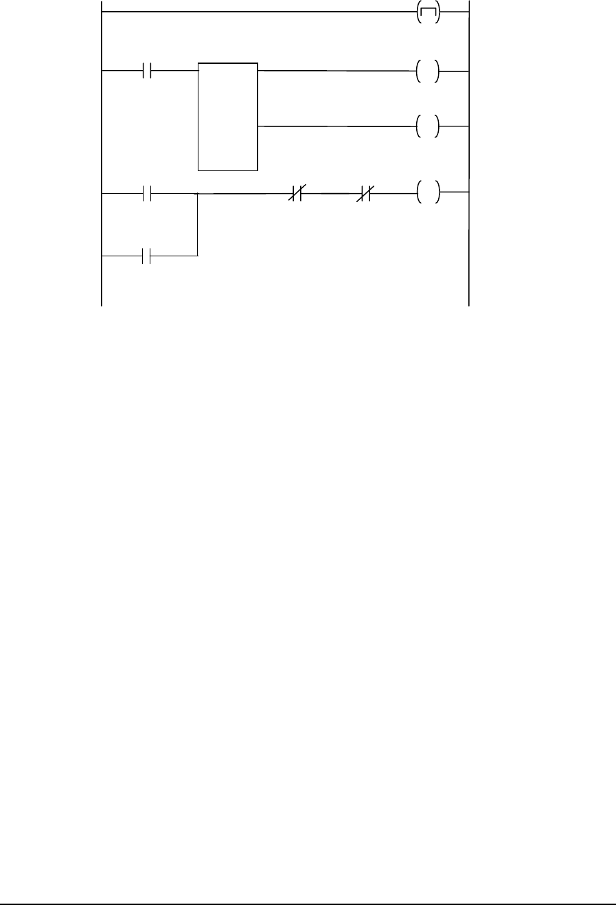
Network 1: Initialize Modem on Power Up
Power-Up
01025
INIM
St at u s
44018
Config
44000
Init_MOD
01028
Complete
01026 Fai l ed
01027
Pow er-U p
01025 Init_MOD
01028
Failed
01027
Complete
01026
Init_MOD
01028
TelePACE Ladder Logic Function Reference
February 19, 2007
77

2.32 L–>L – List to List Transfer
Description
The L–>L function transfers the contents of one register from the source list of registers into one
register from the destination list of registers, at the position of the index. The index register points to
the same position in both the source and the destination list of registers.
When the enable transfer input is ON, and the index equals size output is not ON, the source list
register is transferred to the destination list register at the position of the index in both lists.
The freeze/increment index input allows control of the index. If this input is ON the index is not
incremented. If the input is OFF the index is incremented by one after each transfer.
When the reset index input is ON the index is reset to zero.
The index is incremented by one on each transfer until the index equals size. When the index equals
size output is ON no further increments in index value occur until the index is reset.
source
L->L
size
index and
destination
ON = enable transfer
ON = reset index to 0
ON if index equals size
and enable transfer = ON
ON = freeze index
OFF = increment index
copies state of
enable transfer input
Function Variables
Variable Valid Types Description
source coil block (0xxxx)
status block (1xxxx)
input register (3xxxx)
holding register (4xxxx)
The address of the source register
list.
The address for a coil or status
register block is the first register in
a group of 16 registers that will be
copied.
Index and
destination holding register (4xxxx) The address of the index register
and the destination register list. The
index is stored in register [4xxxx].
The data is stored in register
[4xxxx+1] to register [4xxxx+size]
Size constant (1..9999) The number of registers in the
source and destination lists.
Related Functions
L–>R – List to Register Transfer
R–>L – Register to List Transfer
MOVE – Move Block
TelePACE Ladder Logic Function Reference
February 19, 2007
78
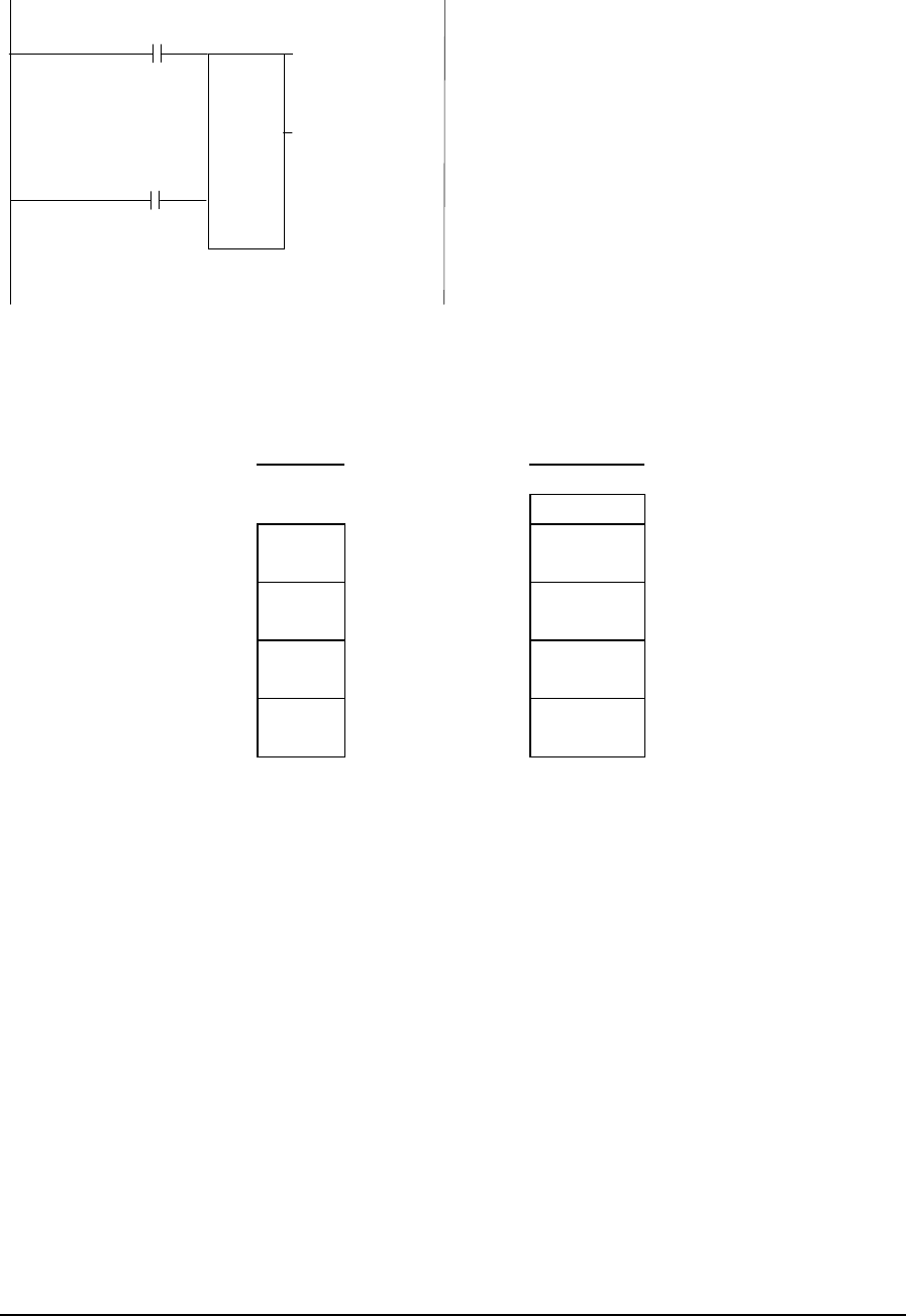
Example
30001
42011
L->L
+3
Enable
Transfer
04082
Reset
Transfer
04081
The List to List function transfers the contents of one register in the source list of registers into one
register of the destination list of registers, at the position of the index. The index register points to
the same position in the source and destination lists.
Sourc
e List Destinati
on List
List Index----> 42011
list register 0--
> 30001 list register 0--> 42012
list register 1--
> 30002 list register 1--> 42013
list register 2--
> 30003 list register 2--> 42014
list register 3--
> 30004 list register 3--> 42015
In this example the source register list starts at input register 30001. The index is holding register
42011 and the destination register list starts at holding register 42012. The source register list
contains the first four analog input registers. The index is a general purpose analog output register
that will have a value of 0, 1, 2 or 3. The destination register list starts at the next sequential register
after the index register. The destination list contains four general purpose analog output registers and
has a size of four.
When list index register 42011 has a value of 0 and the L->L function is enabled the contents of
source list register 30001 is transferred to destination list register 40012.
When list index register 42011 has a value of 1 and the L->L function is enabled the contents of
source list register 30002 is transferred to destination list register 42013.
When list index register 42011 has a value of 2 and the L->L function is enabled the contents of
source list register 30003 is transferred to destination list register 42014.
When list index register 42011 has a value of 3 and the L->L function is enabled the contents of
source list register 30004 is transferred to destination register 42015.
TelePACE Ladder Logic Function Reference
February 19, 2007
79

2.33 L–>R – List to Register Transfer
Description
The L->R function transfers the contents of a register indicated by the index from the source list of
registers into the destination register.
When the enable transfer input is ON, and the index equals size output is OFF, the source list
register pointed to by the index is transferred to the destination register.
The freeze/increment index input allows control of the index. If this input is ON the index is not
incremented. If the input is OFF the index is incremented by one after each transfer.
When the reset index input is ON the index is reset to zero.
The index is incremented by one on each transfer until the index equals size. When the index equals
size output is ON no further increments in the index value occur until the index is reset.
source
L->R
size
index and
destination
ON = enable transfer
ON = reset index to 0
ON if index equals size
and enable transfer = ON
ON = freeze index
OFF = increment index
copies state of input 1
Function Variables
Variable Valid Types Description
Source coil block (0xxxx)
status block (1xxxx)
input register (3xxxx)
holding register (4xxxx)
The address of the source register
list.
The address for a coil or status
register block is the first register in
a group of 16 registers that will be
read.
Index and
destination holding register (4xxxx) The address of the index register
and the destination register. The
index to the source list is stored in
holding register [4xxxx]. The
destination register is holding
register [4xxxx+1].
Size constant (1..9999) The number of registers in the
source list.
Related Functions
R–>L – Register to List Transfer
L–>L – List to List Transfer
MOVE – Move Block
TelePACE Ladder Logic Function Reference
February 19, 2007
80

Example
30001
42009
L->R
+3
03201
03202
The List to Register function transfers the contents of a register indicated by the index from the
source list of registers into the destination register.
Source
Register
List
list register 0--> 30001
list register 1--> 30002 List Index----> 4200
9
list register 2--> 30003 Destination
Register-> 4201
0
list register 3--> 30004
An example of the registers used in a List to Register ( L->R) transfer is shown in the above
diagram. The source register list contains the first four analog input registers and has a size of four.
The index is a general purpose analog output register that will have a value of 0, 1, 2 or 3. The
destination register is a general purpose analog output register that is the next sequential register after
the index register.
When list index register 42009 has a value of 0 and the L->R function is enabled, the contents of
source register 30001 is transferred to destination register 42010.
When list index register 42009 has a value of 1 and the L->R function is enabled, the contents of
source register 30002 is transferred to destination register 42010.
When list index register 42009 has a value of 2 and the L->R function is enabled, the contents of
source register 30003 is transferred to destination register 42010.
When list index register 42009 has a value of 3 and the L->R function is enabled, the contents of
source register 30004 is transferred to destination register 42010.
TelePACE Ladder Logic Function Reference
February 19, 2007
81

2.34 LTEF - Floating-Point Less Than or Equal
Description
The LTEF element tests if a floating-point register or constant is less than or equal to another
floating-point register or constant.
When the enable input is ON, value1 and value2 are compared. If value1 is less than value2, the top
output is ON. If value1 is equal to value2 the bottom output is ON.
value1
LTEF
value2
ON = enable ON if value1 < value2
ON if value1 = value2
Function Variables
The element has two parameters.
Variable Valid Types Description
value1 FP constant
2 input registers (3xxxx)
2 holding registers (4xxxx)
a floating-point register or constant
Value2 FP constant
2 input registers (3xxxx)
2 holding registers (4xxxx)
a floating-point register or constant
Notes
Floating-point values are stored in two consecutive I/O database registers. The lower numbered
register contains the upper 16 bits of the number. The higher numbered register contains the lower 16
bits of the number. Floating point numbers can represent positive and negative values in the range –
3.402 × 1038 to 3.402 × 1038.
Related Functions
CMP – Compare Signed Values
CMPU – Compare Unsigned Values
Example
network 1:
+19.21
LTEF
40101
TelePACE Ladder Logic Function Reference
February 19, 2007
82

The LTEF function in network 1 compares the floating-point constant +19.21 to the contents of
floating-point register 40101. The top output of the LTEF function is ON if the value of register
40101 is greater than +19.21. The bottom output of the LTEF is ON if the value of register 40001 is
equal to +19.21.
TelePACE Ladder Logic Function Reference
February 19, 2007
83

2.35 MOD – Modulus of Signed Values
Description
The MOD function divides two registers or a constant, value 1, by a register or constant, value 2,
and stores the modulus (remainder) in a holding register, result. Signed division is used. The value
1, value 2 and result are signed numbers.
The out of range output is enabled if the result is greater than 32767 or less than -32768. The divide
by zero output is enabled if value 2 equals 0.
value 1
MOD
result
value 2
ON = enable MOD
ON = result out of range
copies status of input 1
ON = divide by zero
Function Variables
Variable Valid Types Description
Value 1 constant
(-32768..32767)
2 Input registers (3xxxx)
2 holding registers (4xxxx)
Signed value to divide.
The low order word is stored in the
first register if registers are used.
Value 2 constant
(-32768..32767)
input register (3xxxx)
holding register (4xxxx)
Signed value to divide by
Result holding register (4xxxx) Result = value 1 modulo value 2
Related Functions
MODU – Modulus of Unsigned Values
TelePACE Ladder Logic Function Reference
February 19, 2007
84

Example
network 1:
45556
45554
MOD
45553
The MOD function in network 1 divides value 1, double word registers 45556 and 45557 by value
2, register 45553. The modulus of this division is stored in register 45554. The table below shows
some examples of different values for the registers in the MOD function.
Value of Register
45556 Value of Register
45553 Modulus Register
45554
example 1 5689 77 68
example 2 -32600 -234 -74
example 3 -22765 7659 -7447
Example 4 19823 -7692 4439
TelePACE Ladder Logic Function Reference
February 19, 2007
85

2.36 MODU – Modulus of Unsigned Values
Description
The MODU function divides two registers or a constant, value 1, by a register or constant, value 2,
and stores the modulus (remainder) in a holding register, result. Unsigned division is used. The
value 1, value 2 and result are unsigned numbers.
The out of range output is enabled if the result is greater than 65535 or less than 0. The divide by
zero output is enabled if value 2 equals 0.
value 1
MODU
result
value 2
ON = enable MODU
ON = result out of range
copies status of input 1
ON = divide by zero
Function Variables
Variable Valid Types Description
Value 1 constant (0..65535)
2 Input registers (3xxxx)
2 holding registers (4xxxx)
Unsigned value to divide.
The low order word is stored in the
first register if registers are used.
Value 2 constant (0..65535)
input register (3xxxx)
holding register (4xxxx)
unsigned value to divide by
Result holding register (4xxxx) result = value 1 modulo value 2
Related Functions
MOD – Modulus of Signed Values
TelePACE Ladder Logic Function Reference
February 19, 2007
86

Example
network 1:
41300
41306
MODU
46444
The MODU function in network 1 divides value 1, double word registers 41300 and 41301 by value
2, register 46444. The modulus of this division is stored in register 41306. The table below shows
some examples of different values for the registers in the MOD function.
Value of Register
45556 Value of Register
45553 Modulus Register
45554
Example 1 26744 320 184
Example 2 56398 34022 20878
Example 3 37697 2366 2207
Example 4 33005 1100 5
TelePACE Ladder Logic Function Reference
February 19, 2007
87

2.37 MOVE – Move Block
Description
The MOVE function block copies the source block of registers into the destination block of coil, or
holding, registers.
source
MOVE
size
destination
ON = move block copies status of input 1
Function Variables
Variable Valid Types Description
Source coil block (0xxxx)
status block (1xxxx)
input register (3xxxx)
holding register (4xxxx)
The first register in the source block.
The address for a coil or status register
block is the first register in a group of 16
registers that will be copied.
Destination coil block (0xxxx)
holding register (4xxxx)
The first register in the destination block.
The address for a coil register block is the
first register in a group of 16 registers into
which data will be copied.
Size constant (1..100) The number of 16 bit words in the block.
Block move copies 16 bit words. Coil and status register blocks are groups of 16 registers that start
with the register specified as the block address. A block size of 2 corresponds to 32 coils, or two
holding registers.
Coil and status register blocks must begin at the start of a 16 bit word within the controller memory.
Suitable addresses are 00001, 00017, 10001, 10033, etc.
Related Functions
Error! Not a valid link.
L–>L – List to List Transfer
L–>R – List to Register Transfer
TelePACE Ladder Logic Function Reference
February 19, 2007
88

Example
30001
40001
MOVE
+4
network 1:
In the above figure the source register entered is 30001 (3reg) and the destination register entered is
40001 (4reg) and the block size entered is 4.
When this MOVE block is enabled:
the contents of register 30001 are copied to register 40001
the contents of register 30002 are copied to register 40002
the contents of register 30003 are copied to register 40003
the contents of register 30004 are copied to register 40004
TelePACE Ladder Logic Function Reference
February 19, 2007
89
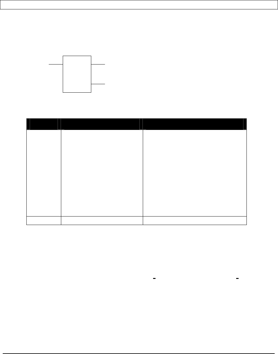
2.38 MSTR – Master Message
Description
The MSTR function exchanges data with another controller using either the Modbus or the DF1
communication protocols.
Note Only one MSTR block may be active on each serial communication port at any one time.
When the enable MSTR goes from OFF to ON the MSTR function will send one master message to
the slave address. The enable MSTR must go from OFF to ON to send another MSTR message. The
message complete output will be energized if the MSTR receives a valid response from the slave
station. The message format or communication error is energized if an error occurs. See the status
code table below for a list of possible errors.
message
MSTR
timer
ON = enable MSTR
ON = message format or
communication error
message complete
Function Variables
Variable Valid Types Description
Message holding register (4xxxx)
Address of the first register in the
message control block. There are 7
registers in the block at addresses
message+0 to message+6.
+0 = port
+1 = function code
+2 = slave controller address
+3 = slave register address
+4 = master register address
+5 = length
+6 = time-out in 0.1s increments
Timer holding register (4xxxx) timer accumulator register
Notes
To optimize performance, minimize the length of messages on com3 and com4. Examples of
recommended uses for com3 and com4 are for local operator display terminals, and for programming
and diagnostics using the TelePACE program.
WARNING: If the controller is initialized, using the Initialize command in the Controller menu,
all I/O database registers used for Element Configuration are set to zero. The
application program must be re-loaded to the controller.
TelePACE Ladder Logic Function Reference
February 19, 2007
90
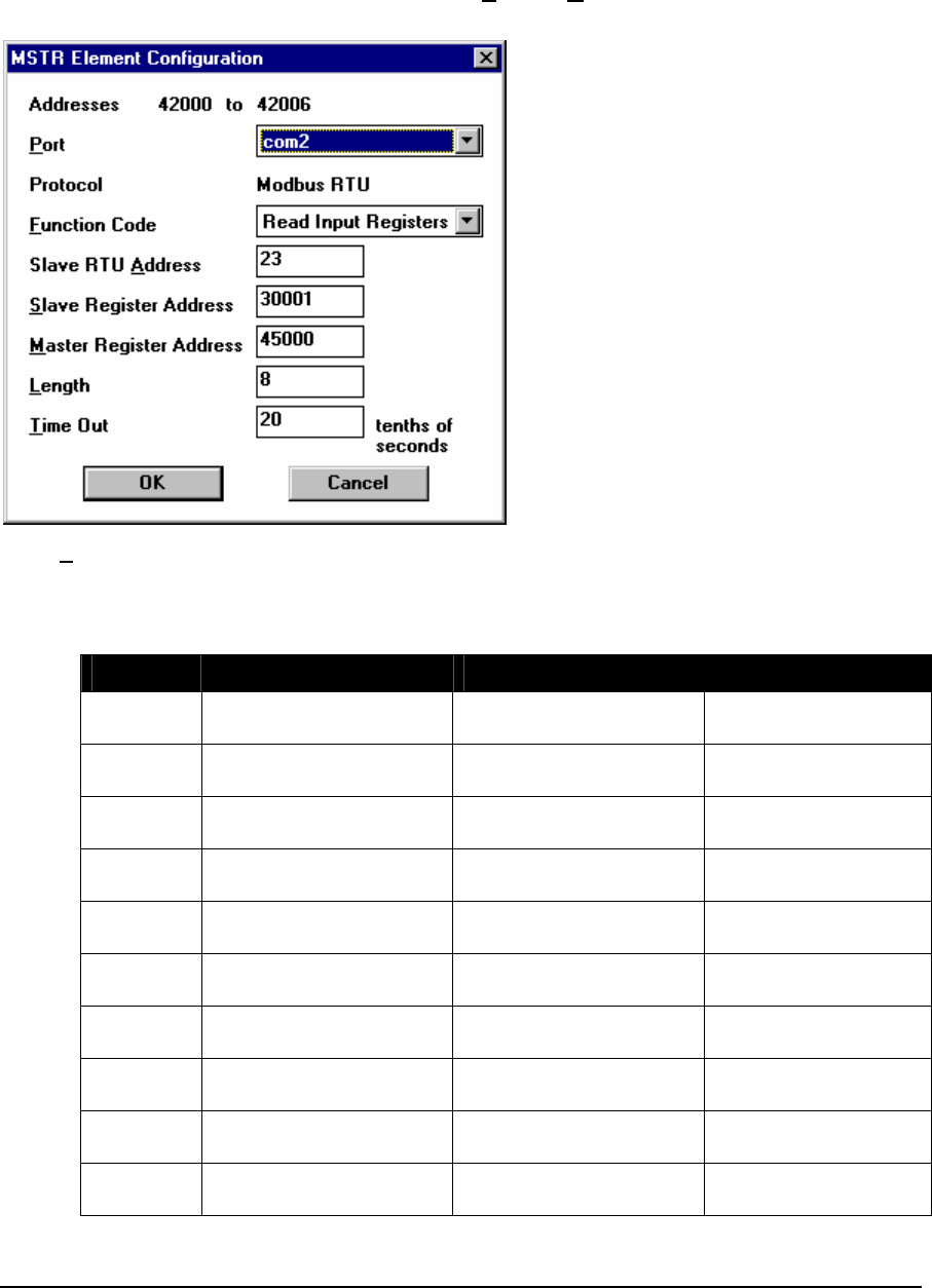
Using MSTR with Modbus Protocol
This element is configured using the MSTR Element Configuration dialog. Highlight the element by
moving the cursor over the element and then use the Element Configuration command on the Edit
menu to modify the configuration block.
Valid Function Codes are shown below. Functions 05, 06, 15, and 16 support broadcast messages.
Functions 129, 130, 132, 133, 135, 136, 138, and 139 may be broadcast, but some Enron Modbus
slave devices may not support broadcast messages. See the TeleBUS Protocols Modbus Compatible
Protocols User Manual for details on each function code.
Function Description Purpose Maximum Registers
01 Read Coil Status Read digital output
registers. 2000
02 Read Input Status Read digital input
registers. 2000
03 Read Holding Register Read analog output
registers. 125
04 Read Input Register Read analog input
registers. 125
05 Write Single Coil Write digital output
register. 1
06 Write Single Register Write analog output
registers. 1
15 Write Multiple Coils Write digital output
registers. 880
16 Write Multiple Registers Write analog output
registers. 60
128 Read Enron Boolean Read Enron Boolean
registers 2000
129 Write Enron Single
Boolean Write Enron Boolean
register 1
TelePACE Ladder Logic Function Reference
February 19, 2007
91

Function Description Purpose Maximum Registers
130 Write Enron Multiple
Booleans Write Enron Boolean
registers 880
131 Read Enron Short
Integers Read Enron short
integer register 125
132 Write Enron Single Short
Integer Write Enron short integer
register 1
133 Write Enron Multiple
Short Integers Write Enron short integer
registers 60
134 Read Enron Long
Integers Read Enron long integer
register 62
135 Write Enron Single Long
Integer Write Enron long integer
register 1
136 Write Enron Multiple
Long Integers Write Enron long integer
registers 30
137 Read Enron Floats Read Enron floating-
point register 62
138 Write Enron Single Float Write Enron floating-
point register 1
139 Write Enron Multiple
Floats Write Enron floating-
point registers 30
The port must be set to 1, 2, 3 or 4 corresponding to the com1, com2, com3 and com4 serial ports.
The slave controller address edit-box sets the station number of the controller. For the Modbus
ASCII and Modbus RTU protocols, the valid range is 0 to 255 if standard addressing is used, and 0
to 65534 if extended addressing is used. Address 0 is reserved for broadcast messages.
The slave register address specifies the first register where data will be read from or written to in
the slave controller. The following table shows the valid slave register addresses for each command.
Function Code Slave Register
Address
Length
Read Coil Status 00001 to 09999 2000
Read Input Status 10001 to 19999 2000
Read Holding Register 40001 to 49999 125
Read Input Register 30001 to 39999 125
Write Single Coil 00001 to 09999 1
Write Single Register 40001 to 49999 1
Write Multiple Coils 00001 to 09999 880
Write Multiple Registers 40001 to 49999 60
Read Enron Boolean 0 to 65535 2000
Write Enron Boolean 0 to 65535 1
Write Enron Multiple Boolean 0 to 65535 880
Read Enron Short Integer 0 to 65535 125
Write Enron Short Integer 0 to 65535 1
Write Enron Multiple Short Integer 0 to 65535 60
Read Enron Long Integer 0 to 65535 62
Write Enron Long Integer 0 to 65535 1
Write Enron Multiple Long Integer 0 to 65535 30
TelePACE Ladder Logic Function Reference
February 19, 2007
92

Function Code Slave Register
Address
Length
Read Enron Floating Point 0 to 65535 62
Write Enron Floating Point 0 to 65535 1
Write Enron Multiple Floating Point 0 to 65535 30
The master register address specifies the first register where data will be written to or read from in
this controller. The register type does not have to match the type of the slave register address. It is
possible to store input registers from a slave into output registers on the master and vice-versa.
The length parameter specifies how many registers are to be transferred. The maximum length for
each function code is shown in the above table. Functions 05 and 06 always transfer 1 register,
regardless of the value of length.
The time-out is in 0.1s increments. The error output is energized if the time-out period ends without
a valid response to the message.
When an error occurs, an error status code is stored in the master command status register in the
analog input database. There is one status register for each port.
The module DIAG Serial port protocol status must be added to the register assignment to monitor
the master command status register for the desired serial port. The status codes are shown in the
following table.
Status Code Description
0 Message sent - waiting for response
1 Response received (no error occurred)
3 bad value in function code register
4 bad value in slave controller address register
5 bad value in slave register address register
6 bad value in length register
7 serial port or protocol is invalid
12 response timeout
24 exception response: invalid function code
25 exception response: invalid address
26 exception response: invalid value
27 protocol is invalid or serial port queue is full
28 slave and master stations are equal; they must be different
29 exception response: slave device failure
30 exception response: slave device busy
Example
An example of polling using the MSTR block is in the file MSTR.LAD. This file is automatically
installed on the computer when the TelePACE program is installed. It is located in the
TELEPACE\EXAMPLES directory.
TelePACE Ladder Logic Function Reference
February 19, 2007
93
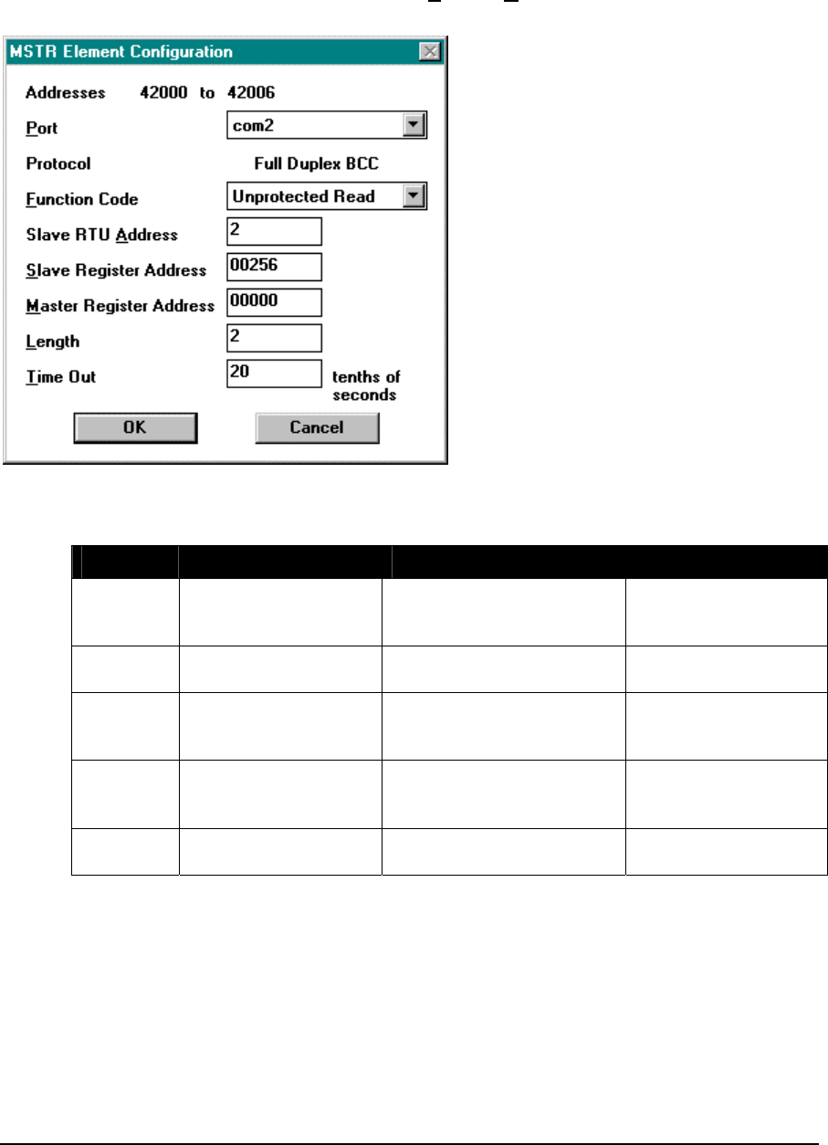
Using MSTR with DF1 Protocol
This element is configured using the MSTR Element Configuration dialog. Highlight the element by
moving the cursor over the element and then use the Element Configuration command on the Edit
menu to modify the configuration block.
DF1 Address
DF1 Address
DF1
The Port must be set to 1, 2, 3 or 4 corresponding to the com1, com2, com3 and com4 serial ports.
Valid Function Codes are:
Function Description Purpose Maximum Registers
00 Protected Write Writes words of data to
limited areas of the
database.
121
01 Unprotected Read Reads words of data from
any area of the database. 122
02 Protected Bit Write Sets or resets individual
bits within limited areas of
the database.
1
05 Unprotected Bit Write Sets or resets individual
bits in any area of the
database.
1
08 Unprotected Write Writes words of data to any
area of the database. 121
The Slave RTU Address must be in the range 0 to 254.
The Slave Register Address specifies the first DF1 physical 16-bit address where data will be read
from or written to in the slave controller.
The Master Register Address specifies the first physical 16-bit address where data will be written
to or read from in this controller. The register type does not have to match the type of the slave
register address. It is possible to store input registers from a slave into output registers on the master
and vice-versa.
TelePACE Ladder Logic Function Reference
February 19, 2007
94

The Length parameter specifies how many 16-bit registers are to be transferred for functions 00, 01
and 08. For function codes 02 and 05, this field is labeled Bit Mask. Bit Mask selects the 16-bit
bitmask specifying which bits in the Master Register to send. If a bit is set in Bit Mask, the
corresponding bit in the register will be sent.
The Time Out is in 0.1s increments. The error output is energized if the time-out period ends
without a valid response to the message. If the MSTR function is used to send a broadcast message,
the Slave RTU Address must be 255 and the Time Out can be set to 0 since there is no response to
wait for.
The module DIAG Serial port protocol status must be added to the register assignment to monitor
the master command status register for the desired serial port. The status codes are shown in the
following table.
Status Code Description
0 Message sent - waiting for response
1 Response received (no error occurred)
3 bad value in function code register
4 bad value in slave controller address register
5 bad value in slave register address register
6 bad value in length register
7 slave has no more responses to send.
8 Response received didn’t match command sent.
9 Specified protocol is not supported by this controller.
16 slave error - illegal command or format.
80 slave error - addressing problem or memory protect rungs.
Other error codes from other DF1 compatible controllers - Consult the
documentation for specific controller.
Notes
Details about the DF1 driver implementation on the SCADAPack controllers can be found in the
TeleBUS DF1 Protocol Booklet in this manual.
An example of polling using the MSTR block is in the file ab_mstr.lad. This file is automatically
installed on the computer when the TelePACE program is installed. It is located in the
TELEPACE\EXAMPLES directory.
TelePACE Ladder Logic Function Reference
February 19, 2007
95

2.39 MSIP – Master IP Message
Description
The MSIP function exchanges data with another controller using the Modbus IP communication
protocol. This function sends a master message to a remote IP address.
Note Unlike the MSTR function, multiple MSIP blocks may be active on the same
communication interface at the same time. The number of active MSIP blocks is limited only by the
number of available connections (typical capacity is 20 connections).
When the open input goes from OFF to ON the MSIP function opens an IP connection. Set the open
input to OFF to close the connection.
When the send message input goes from OFF to ON, and the open input is ON, the MSIP function
will send one Modbus IP master message to the slave address. The send message input must go from
OFF to ON to send another MTCP message. Each master message is complete when either output is
energized: The message complete output will be energized if the MSIP block receives a valid
response from the slave station. The message format or communication error is energized if an
error occurs. See the status code table below for a list of possible errors.
message
MSIP
timer
ON = send message
ON = message format or
communication error
message complete
ON = open
Function Variables
Variable Valid Types Description
message holding register (4xxxx)
Address of the first register in the message
control block. There are 11 registers in the block
at addresses message+0 to message+11.
+0 = byte1 of slave IP address MSB, using format
byte1.byte2.byte3.byte4
+1 = byte2 of slave IP address
+2 = byte3 of slave IP address
+3 = byte4 of slave IP address LSB
+4 = protocol type
+5 = function code
+6 = slave controller address
+7 = slave register address
+8 = master register address
+9 = length
+10 = time-out in 0.1s increments
TelePACE Ladder Logic Function Reference
February 19, 2007
96

Variable Valid Types Description
timer holding register (4xxxx) Address of the first register in the timer control
block. There are 5 registers in the block at
addresses timer+0 and timer+4.
+0 = timer accumulator register
+1 = command status register
+2 = internal: connection ID
+3 = internal: closing state
+4 = internal: initialized
Sending a Message
Set the open input to ON to open an IP connection. This input may be set to ON at the same time as
the send message input in the next step.
If the maximum number of opened connections has been reached, an error occurs: The error output
is energized and the value of the command status register indicates the maximum number of
connections has been reached. Close the connection used by another MSIP function to correct the
error and repeat step 1.
Send one command message by toggling the send message input from OFF to ON.
The value of the command status register is 0 indicating that the message was sent.
Sending is complete when either the message complete output or error output is energized. The
message complete output is energized if the response is received successfully. The error output is
energized if there was a command error, timeout, or connection failure. The value of the command
status register is 1 for success or another value for error conditions.
Repeat steps 2 to 4 to send additional command messages.
Notes
The time-out register determines how long to wait for a response before closing the connection and
reporting an error. The connection is re-connected automatically when the next message is sent. The
open input does not need to be toggled to do this.
Leave the open input ON to keep the connection open for this MTCP function.
WARNING: If the controller is initialized, using the Initialize command in the Controller menu,
all I/O database registers used for Element Configuration are set to zero. The
application program must be re-loaded to the controller.
Element Configuration
This element is configured using the MSIP Element Configuration dialog. Highlight the element by
moving the cursor over the element and then use the Element Configuration command on the Edit
menu to modify the configuration block.
TelePACE Ladder Logic Function Reference
February 19, 2007
97
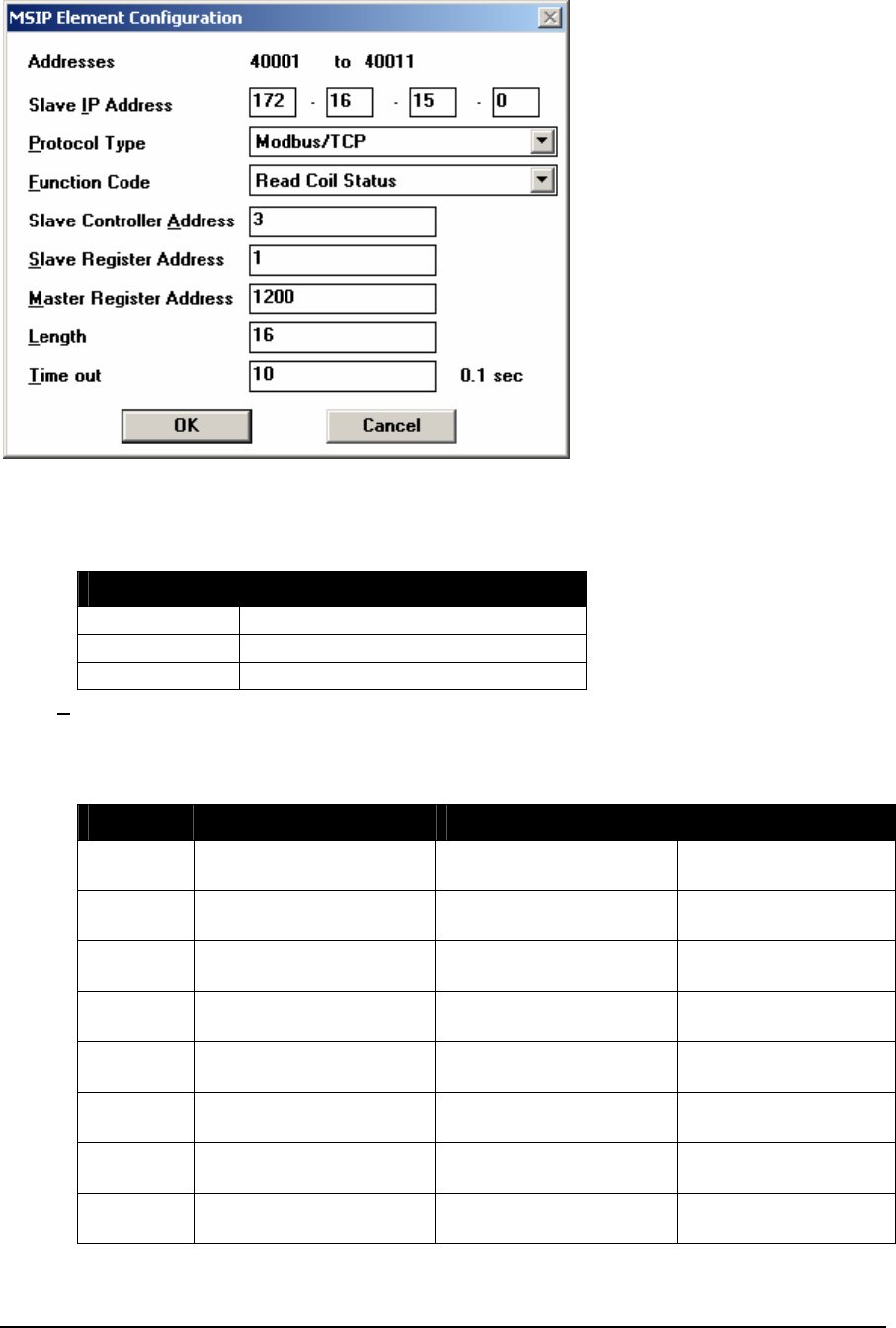
The slave IP address has the format 255.255.255.255 where one register is used for each byte:
byte1.byte2.byte3.byte4
The protocol type must be one of the values shown below:
Protocol Type Description
1 Modbus/TCP
2 Modbus RTU over UDP
3 Modbus ASCII over UDP
Valid Function Codes are shown below. Functions 05, 06, 15, and 16 support broadcast messages.
Functions 129, 130, 132, 133, 135, 136, 138, and 139 may be broadcast, but some Enron Modbus
slave devices may not support broadcast messages. See the TeleBUS Protocols Modbus Compatible
Protocols User Manual for details on each function code.
Function Description Purpose Maximum Registers
01 Read Coil Status Read digital output
registers. 2000
02 Read Input Status Read digital input
registers. 2000
03 Read Holding Register Read analog output
registers. 125 note 1
04 Read Input Register Read analog input
registers. 125 note 1
05 Write Single Coil Write digital output
register. 1
06 Write Single Register Write analog output
registers. 1
15 Write Multiple Coils Write digital output
registers. 880
16 Write Multiple Registers Write analog output
registers. 60
TelePACE Ladder Logic Function Reference
February 19, 2007
98

Function Description Purpose Maximum Registers
128 Read Enron Booleans Read Enron Boolean
registers 2000
129 Write Enron Single
Boolean Write Enron Boolean
register 1
130 Write Enron Multiple
Booleans Write Enron Boolean
registers 880
131 Read Enron Short
Integers Read Enron short
integer register 125 note 1
132 Write Enron Single Short
Integer Write Enron short integer
register 1
133 Write Enron Multiple
Short Integers Write Enron short integer
registers 60
134 Read Enron Long
Integers Read Enron long integer
register 62 note 2
135 Write Enron Single Long
Integer Write Enron long integer
register 1
136 Write Enron Multiple
Long Integers Write Enron long integer
registers 30
137 Read Enron Floats Read Enron floating-
point register 62
138 Write Enron Single Float Write Enron floating-
point register 1
139 Write Enron Multiple
Floats Write Enron floating-
point registers 30
Notes
For SCADASense Series controllers, the MSIP function can read a maximum of 123 registers with a
single MSIP function. Note that SCADASense Series controllers do not support Enron Modbus
commands.
The slave controller address edit-box sets the station number of the controller. The valid range is 0 to
255 if standard addressing is used, and 0 to 65534 if extended addressing is used. Address 0 is
reserved for broadcast messages, which are directed to the IP address specified in the slave IP
address field only.
The slave register address specifies the first register where data will be read from or written to in the
slave controller. The following table shows the valid slave register addresses for each command.
Function Code Slave Register
Address
Length
Read Coil Status 00001 to 09999 2000
Read Input Status 10001 to 19999 2000
Read Holding Register 40001 to 49999 125
Read Input Register 30001 to 39999 125
Write Single Coil 00001 to 09999 1
Write Single Register 40001 to 49999 1
Write Multiple Coils 00001 to 09999 880
Write Multiple Registers 40001 to 49999 60
Read Enron Boolean 0 to 65535 2000
TelePACE Ladder Logic Function Reference
February 19, 2007
99

Function Code Slave Register
Address
Length
Write Enron Boolean 0 to 65535 1
Write Enron Multiple Boolean 0 to 65535 880
Read Enron Short Integer 0 to 65535 125
Write Enron Short Integer 0 to 65535 1
Write Enron Multiple Short Integer 0 to 65535 60
Read Enron Long Integer 0 to 65535 62
Write Enron Long Integer 0 to 65535 1
Write Enron Multiple Long Integer 0 to 65535 30
Read Enron Floating Point 0 to 65535 62
Write Enron Floating Point 0 to 65535 1
Write Enron Multiple Floating Point 0 to 65535 30
The master register address specifies the first register where data will be written to or read from in
this controller. The register type does not have to match the type of the slave register address. It is
possible to store input registers from a slave into output registers on the master and vice-versa.
The length parameter specifies how many registers are to be transferred. The maximum length for
each function code is shown in the above table. Functions 05 and 06 always transfer 1 register,
regardless of the value of length.
The time-out is in 0.1s increments. The error output is energized if the time-out period ends without
a valid response to the message.
When an error occurs, an error status code is stored in the command status register in the timer
control block. The status codes are shown in the following table.
Status Code Description
0 valid command has been sent
1 response was received
2 no message was sent
3 invalid function code
4 invalid slave station address
5 invalid database address
6 invalid message length
7 serial port or protocol is invalid
8 connecting to slave IP address
9 connected to slave IP address
10 timeout while connecting to slave IP address
11 TCP/IP error has occurred while sending message
12 timeout has occurred waiting for response
13 slave has closed connection; incorrect response; or, incorrect response
length
14 disconnecting from slave IP address is in progress
15 connection to slave IP address is disconnected
16 invalid connection ID
17 invalid protocol type
18 invalid slave IP address
TelePACE Ladder Logic Function Reference
February 19, 2007
100

Status Code Description
19 last message is still being processed
20 master connection has been released
21 error while connecting to slave IP address
22 no more connections are available
24 exception response: invalid function code
25 exception response: invalid address
26 exception response: invalid value
27 protocol is invalid or serial port queue is full
28 slave and master stations are equal; they must be different
29 exception response: slave device failure
30 exception response: slave device busy
Example
An example of polling using the MSIP block is in the file MTCP.LAD. This file is automatically
installed on the computer when the TelePACE program is installed. It is located in the
TELEPACE\EXAMPLES directory.
TelePACE Ladder Logic Function Reference
February 19, 2007
101

2.40 MUL – Multiply Signed Values
Description
The MUL function block multiplies a signed register or constant, value 1, by a signed register or
constant, value 2 and stores the result in two consecutive holding registers, product. Signed
multiplication is used.
value 1
MUL
product
value 2
ON = enable MUL copies input 1
Function Variables
Variable Valid Types Description
Value 1 Constant
(-32768..32767)
input register (3xxxx)
holding register (4xxxx)
first signed value to multiply
Value 2 Constant
(-32768..32767)
input register (3xxxx)
holding register (4xxxx)
Second signed value to multiply
Product 2 holding registers (4xxxx) product = value 1 x value 2
The result is stored in two consecutive holding
registers. The low order word is stored in the
first register.
Related Functions
MULF - Multiply Floating-Point Values
MULU – Multiply Unsigned Values
TelePACE Ladder Logic Function Reference
February 19, 2007
102

Example
network 1:
47286
44216
MUL
48661
In network 1 a MUL function is used to multiply the contents of Holding Register 47286, value 1,
with the contents of Holding Register 48661, value 2. The product is stored in Holding Registers
44216, low order word and Holding Register 44217, high order word.
The examples in the table below show the product of the multiplication for various values in
registers 47286 and 48661. The product is displayed as registers 44216, low order word and register
44217, high order word.
high order low order
Register
47286 Register
48661 Register
44217 Register
44216
Value 1 value 2 Product product
example 1 -3057 -10 0 30570
example 2 -15 100 -1 -1500
example 3 1654 17 0 28118
example 4 164 -55 -1 -9020
TelePACE Ladder Logic Function Reference
February 19, 2007
103

2.41 MULF - Multiply Floating-Point Values
Description
The MULF element multiplies two floating-point registers or constants and stores the result in a
floating-point holding register.
When the enable input is ON the product value 1 × value 2 is stored in the product floating-point
register. The element output is ON when the input is.
value1
MULF
product
value2
ON = enable copies status of input
Function Variables
The element has three parameters.
Variable Valid Types Description
Value1 FP constant
2 input registers (3xxxx)
2 holding registers (4xxxx)
first floating-point register or
constant to multiply
Value2 FP constant
2 input registers (3xxxx)
2 holding registers (4xxxx)
second floating-point register or
constant to multiply
Product 2 holding registers (4xxxx) floating-point product = value1 ×
value2
Notes
Floating-point values are stored in two consecutive I/O database registers. The lower numbered
register contains the upper 16 bits of the number. The higher numbered register contains the lower 16
bits of the number. Floating point numbers can represent positive or negative values in the range –
3.402 × 1038 to 3.402 × 1038.
Related Functions
MULU – Multiply Unsigned Values
TelePACE Ladder Logic Function Reference
February 19, 2007
104

Example
network 1:
+44.10
40100
MULF
40102
The MULF function in network 1 multiplies floating-point constant +44.10 by the contents of
floating-point register 40100 (registers 40100 and 40101). Assuming floating-point register 40100
contains a value of +3.5 then the result is +154.35. This value is stored in floating-point register
40102 (registers 40102 and 40103).
TelePACE Ladder Logic Function Reference
February 19, 2007
105

2.42 MULU – Multiply Unsigned Values
Description
The MULU function block multiplies an unsigned register or constant, value 1, and an unsigned
register or constant , value 2. The result is stored in two consecutive Holding Registers, product.
Unsigned multiplication is used.
value 1
MULU
product
value 2
ON = enable MULU copies input 1
Function Variables
Variable Valid Types Description
value 1 Constant (0..65535)
input register (3xxxx)
holding register (4xxxx)
first unsigned value to multiply
value 2 Constant (0..65535)
input register (3xxxx)
holding register (4xxxx)
Second unsigned value to multiply
Product 2 holding registers (4xxxx) Product = value 1 x value 2
The result is stored in two
consecutive holding registers. The
low order word is stored in the first
register.
Related Functions
MULF - Multiply Floating-Point Values
TelePACE Ladder Logic Function Reference
February 19, 2007
106

Example
network 1:
47286
44216
MULU
48661
In network 1 a MULU function is used to multiply the contents of Holding Register 47286, value 1,
with the contents of Holding Register 48661, value 2. The product is stored in Holding Registers
44216, low order word and Holding Register 44217, high order word.
The examples in the table below show the product of the multiplication for various values in
registers 47286 and 48661. The product is displayed as registers 44216, low order word and register
44217, high order word.
high order low order
Register
47286 Register
48661 Register
44217 Register
44216
Value 1 value 2 Product product
Example 1 2048 30 0 61440
Example 2 251 251 0 63001
Example 3 77 77 0 5929
Example 4 650 735 7 18998
TelePACE Ladder Logic Function Reference
February 19, 2007
107

2.43 Normally Closed Contact
Description
The NC contact function block conducts power when the coil or status register is OFF.
contact
input output
Function Variables
Variable Valid Types Description
contact coil register (0xxxx)
status register (1xxxx)
Output is ON if contact is OFF and
input is ON
Related Functions
Normally Open Contact
Example
network 1:
01041
)(
00010
)(
01041
10003
Network 1 shows NO contact 10003 and NC contact 01041. Power conducts through NC contact
01041 keeping coil 00010 ON. When NO contact 10003 is closed coil 01041 turns ON and NC
contact 01041 will open, turning OFF coil 00010.
TelePACE Ladder Logic Function Reference
February 19, 2007
108

2.44 Normally Open Contact
Description
The NO contact function block conducts power when the coil or status register is ON.
contact
input output
Function Variables
Variable Valid Types Description
contact coil register (0xxxx)
status register (1xxxx)
output is ON if contact is ON and
input is ON
Related Functions
Normally Closed Contact
Example
network 1:
00006
)(
04081
)(
00006
10033
Network 1 shows NC contact 10033 and NO contact 00006. Power conducts through NC contact
10033 keeping coil 00006 ON. With coil 00006 ON, NO contact 00006 is closed and coil 04081 is
ON.
TelePACE Ladder Logic Function Reference
February 19, 2007
109

2.45 NOT – Not Block
Description
The NOT function block inverts the source block of registers and stores the result in the destination
block of coil or Holding registers. NOT changes bits that are ON to OFF, and changes bits that are
OFF to ON.
source
NOT
size
destination
ON = enable NOT copies status of input1
Function Variables
Variable Valid Types Description
Source coil block (0xxxx)
status block (1xxxx)
input register (3xxxx)
holding register (4xxxx)
The first register in the source
block.
The address for a coil or status
register block is the first register in
a group of 16 registers that will be
complemented.
Destination coil block (0xxxx)
holding register (4xxxx)
The first register in the destination
block. The address for a coil
register block is the first register in
a group of 16 registers where the
result will be stored.
Size Constant (1..100) The number of 16 bit words in the
block.
Notes
NOT accesses 16 bit words. Coil and status register blocks are groups of 16 registers that start with
the register specified as the block address. A block size of 2 corresponds to 32 coils, or two holding
registers.
Coil and status register blocks must begin at the start of a 16 bit word within the controller memory.
Suitable addresses are 00001, 00017, 10001, 10033, etc.
Related Functions
AND – And Block
OR – Or Block
XOR – Exclusive Or Block
TelePACE Ladder Logic Function Reference
February 19, 2007
110
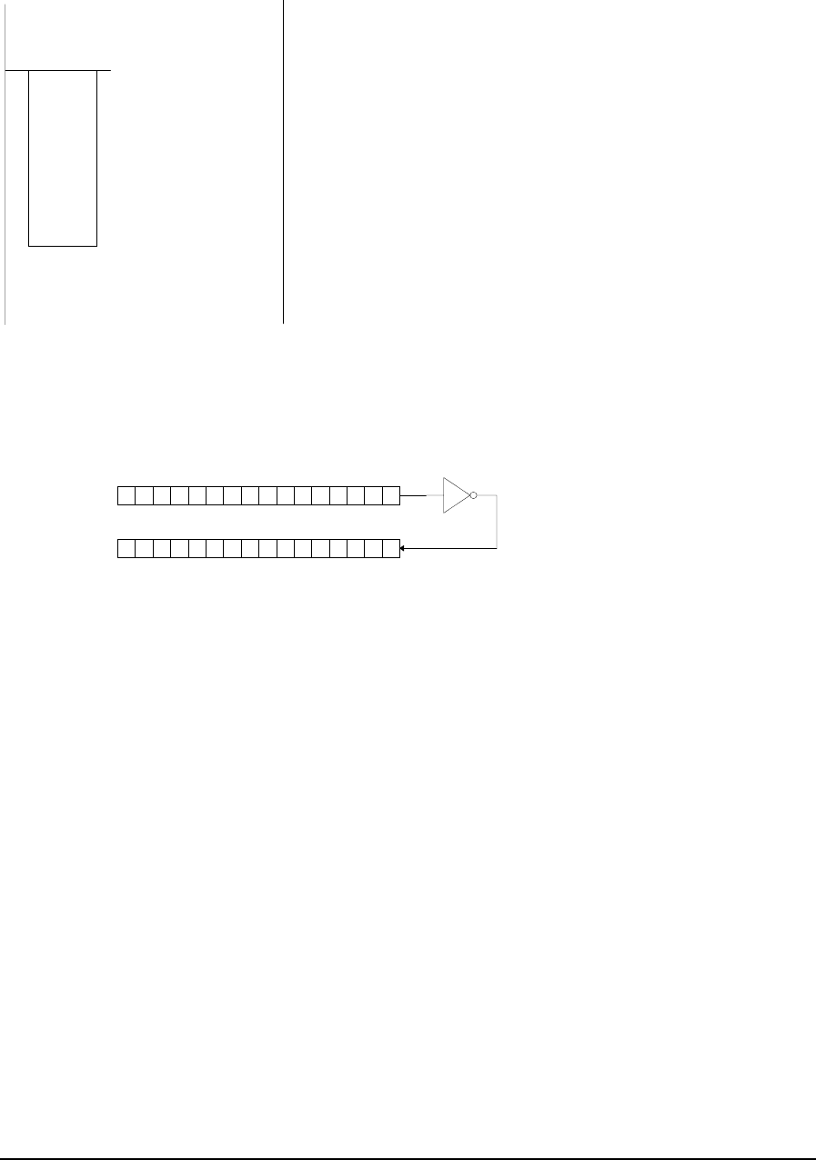
Example
network 1:
10001
+1
NOT
48000
In this example the status of discrete inputs 10001 through 10016 are used as the source for the NOT
function. These inputs are inverted and stored in the destination register 48000.
1000 1101 0110 1011
0111 0010 1001 0100
source register:
destination register
after storing result
1
0
0
1
3
1
0
0
1
4
1
0
0
1
5
1
0
0
1
6
1
0
0
0
9
1
0
0
1
0
1
0
0
1
1
1
0
0
1
2
1
0
0
0
5
1
0
0
0
6
1
0
0
0
7
1
0
0
0
8
1
0
0
0
1
1
0
0
0
2
1
0
0
0
3
1
0
0
0
4
status registers:
read top to bottom
TelePACE Ladder Logic Function Reference
February 19, 2007
111

2.46 One Shot Coil
Description
The One Shot Coil function block enables an output coil for one scan when the input power changes
from OFF to ON.
out
p
ut
input powe
r
always connects to right rail
Function Variables
Variable Valid Types Description
Output coil register (0xxxx) output register
address
Related Functions
Coil
Example
network 1:
00004
)(
One shot coil 00004 is energized for one scan on power up of the ladder logic program.
Refer to the I/O Database Registers section of this manual for more information on coil outputs.
TelePACE Ladder Logic Function Reference
February 19, 2007
112

2.47 OR – Or Block
Description
The OR function block logically ORs the source block of registers with the destination block of
registers and stores the result in the destination block of registers.
source
OR
size
destination
ON = enable OR copies status of input1
Function Variables
Variable Valid Types Description
Source coil block (0xxxx)
status block (1xxxx)
input register (3xxxx)
holding register (4xxxx)
The first register in the source
block.
The address for a coil or status
register block is the first register in
a group of 16 registers that will be
ORed.
Destination coil block (0xxxx)
holding register (4xxxx)
The first register in the destination
block.
The address for a coil register block
is the first register in a group of 16
registers that will be ORed.
Size Constant (1..100) The number of 16 bit words in the
block.
Notes
OR accesses 16 bit words. Coil and status register blocks are groups of 16 registers that start with the
register specified as the block address. A block size of 2 corresponds to 32 coils, or two holding
registers.
Coil and status register blocks must begin at the start of a 16 bit word within the controller memory.
Suitable addresses are 00001, 00017, 10001, 10033, etc.
Related Functions
AND – And Block
NOT – Not Block
XOR – Exclusive Or Block
TelePACE Ladder Logic Function Reference
February 19, 2007
113
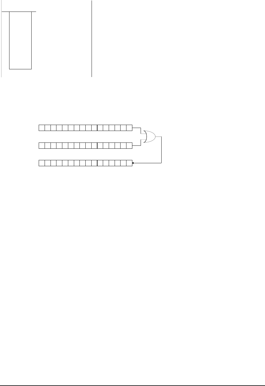
Example
45420
+1
OR
46110
In this example the contents of source register, 45420, are ORed with the destination register, 46110.
The result is stored in the destination register. The content of register 45420 is 1521310
(11101101101101). The content of the destination register before the OR function is 2237910
(101011101101011). The content of the destination register after the OR function is 3262310
(111111101101111).
1100 1101 0110 1011
1010 1110 0110 1101
source re
g
iste
r
destination register
before OR
destination register
after OR 1110 1111 0110 1111
TelePACE Ladder Logic Function Reference
February 19, 2007
114

2.48 OVER – Override Block of Registers
Description
The OVER function copies, in one scan, the source block of registers into the destination block of
registers and forces all registers in the destination block. When the override block input transitions
from OFF to ON the destination registers are forced. The destination register values are overwritten
with the source register values while the override block input is ON. Destination registers are
unforced when the override block input transitions from ON to OFF. The function block output
copies the input state.
The FORCE led on the controller is turned on when the OVER function is enabled. This function is
useful for simulating inputs while debugging a control program.
source
OVER
size
destination
ON = override block copies status of input 1
Function Variables
Variable Valid Types Description
Source coil block (0xxxx)
status block (1xxxx)
input register (3xxxx)
holding register (4xxxx)
The first register in the source
block.
The address for a coil or status
register block is the first register in
a group of 16 registers that will be
copied.
Destination coil block (0xxxx)
status block (1xxxx)
input register (3xxxx)
holding register (4xxxx)
The first register in the destination
block.
The address for a coil or status
register block is the first register in
a group of 16 registers.
Size constant (1 to 100) The number of 16 bit words in the
block.
Notes
The OVER function copies 16-bit words. Coil and status register blocks are groups of 16 registers
that start with the register specified as the block address. A block size of 2 corresponds to 32 coils, or
two holding registers.
Coil and status register blocks must begin at the start of a 16-bit word within the controller memory.
Suitable addresses are 00001, 00017, 10001, 10033, etc.
TelePACE Ladder Logic Function Reference
February 19, 2007
115
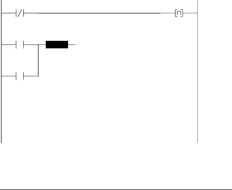
An ON to OFF transition of the input must occur to remove the forcing on the registers. If you place
an OVER function in a subroutine, be sure to execute the subroutine at least once with the input OFF
to clear forcing (see the example below).
If forcing is cleared with a TelePACE command while the OVER function is enabled, the forcing
will not be set again by the OVER function. You must disable and re-enable the function to force the
registers. The function will continue to attempt to write to destination registers even though they are
not forced.
Related Functions
MOVE – Move Block
Example
This example shows how simulated values can be written over input values in the I/O database. For
this example, assume there is a register assignment that connects input hardware to registers 30001 to
30011, and to registers 10001 to 10016.
The simulate contact (10050) enables and disables the simulation. When the contact is ON simulated
values are used. To simulate the values of the inputs, the program overrides the values in registers
30001 to 30011, and registers 10001 to 10016.
The first network calls the subroutine when the simulate contact is ON, and one additional time when
the contact goes from ON to OFF.
simulate
10050
simulate
10050
end
00001
end
00001
+1
CALL
The second network is a subroutine that overrides the destination registers while the simulate contact
is closed. A subroutine is used so that the logic is not scanned when the simulated values are not
needed. In most programs this is the normal operating state, so scanning the functions would add
unnecessarily to the execution time of the program.
TelePACE Ladder Logic Function Reference
February 19, 2007
116

simulate
10050
source1
40100
dest1
30001
OVER
10
source2
00017
dest2
10001
OVER
1
+1
SUBR
TelePACE Ladder Logic Function Reference
February 19, 2007
117
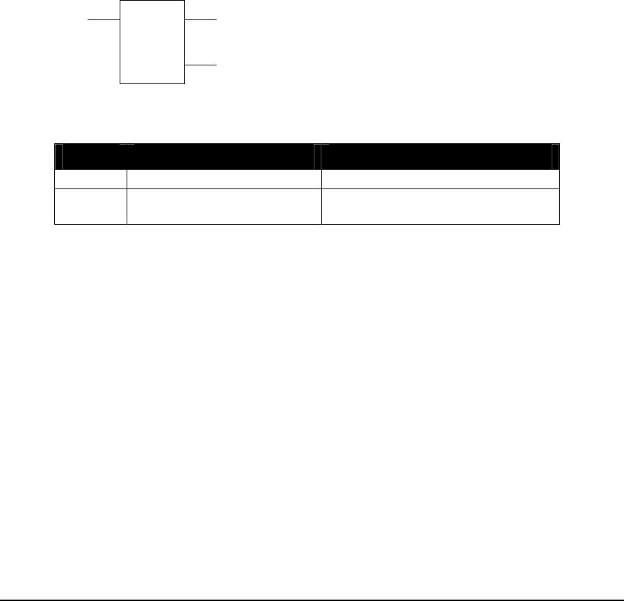
2.49 PID – PID Controller
Description
The PID function controls the execution of a PID controller. PID controllers execute independently
of the ladder logic scan. A PID controller is configured by writing data into the PID controller
registers defined in the register assignment.
The PID block starts execution of the PID controller number on the rising edge of the execute PID
input. Execution of the PID controller is stopped when the execute PID is OFF.
The execute PID input must be toggled from OFF to ON under program control to start PID
execution. The execute PID input cannot be directly connected to the power rail or PID execution
will not restart when the program restarts.
The error output is enabled if the PID number is not found in the Register Assignment. The error
output is also enabled if an error code is present in the PID Status Register (SR).
For a detailed description of the operation of the PID function refer to the TelePACE PID
Controllers User Manual.
number
PID
period
ON = execute PID
OFF = stop PID
ON = error
copies status of input 1
Function Variables
Variable Valid Types Description
number Constant (0..31) PID controller number
period Constant (0..65535) PID controller execution period
(tenths of seconds )
The I/O module, CNFG PID control block, must be configured in the Register Assignment when
PID functions are used. The I/O module CNFG PID control block provides control over the
configuration of a PID control block and provides access to the control block parameters. Control
block parameters are assigned to 25 consecutive holding registers. The I/O module address refers to
the PID control block number.
Notes
The SCADAPack 32 controller does not support the PID function. See the function PIDA – Analog
Output PID and the function PIDD – Digital Output PID.
TelePACE Ladder Logic Function Reference
February 19, 2007
118

2.50 PIDA – Analog Output PID
Description
The PIDA function performs a PID algorithm and calculates an analog output.
When the enable PIDA input is ON, the function executes the PID algorithm. Execution of the PID
algorithm is stopped when the enable PIDA is OFF.
When the auto/manual mode input is ON, the PID is placed in automatic mode. In automatic mode
the output is calculated using the PID algorithm. A new calculation is done at the rate specified by
cycle time.
When the auto/manual mode input is OFF, the PID is placed in manual mode. In manual mode the
output is set to the value specified by manual mode output. The output is limited to the range set
by full and zero.
settings
PIDA
output
ON = enable PIDA copies status of input1
ON = auto mode
OFF = manual mode
Function Variables
Variable Valid Types Description
Settings holding register (4xxxx)
Address of the first register in the settings
control block. There are 20 registers in the block
at addresses settings+0 to settings+19.
+0,1 = process value (float)
+2,3 = setpoint (float)
+4,5 = gain (float)
+6,7 = reset time in seconds (float)
+8,9 = rate time in seconds (float)
+10,11 = deadband (float)
+12,13 = full (float)
+14,15 = zero (float)
+16,17 = cycle time in seconds (float)
+18,19 = manual mode output (float)
Output holding register (4xxxx) +0,1 = PID output (float)
+2,3 = internal: process value N-1st (float)
+4,5 = internal: process value N-2nd (float)
+6,7 = internal: error N-1st (float)
+8,9 = internal: time of last scan (UINT32)
The process value is a value that represents the actual state of the process being controlled. This
value is typically input to the controller as an analog input signal or as a signal from a MVT. The
process value is a floating-point number. If the process value is an analog input signal to the
controller it must be converted to a floating-point number using the STOF function. If the analog
TelePACE Ladder Logic Function Reference
February 19, 2007
119
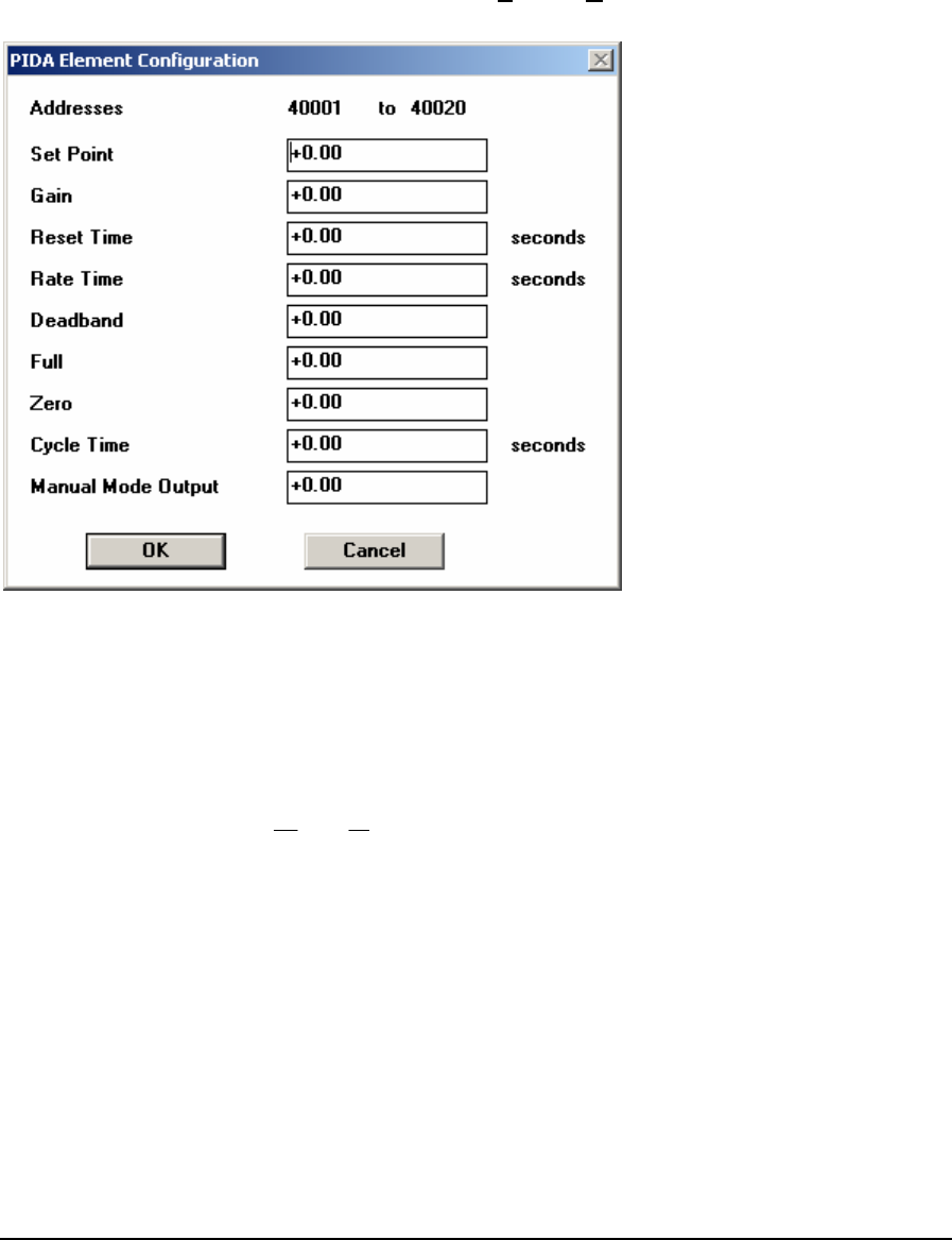
input requires scaling use the SCAL function to scale the input and provide a floating-point number
for the process value.
Element Configuration
This element is configured using the PIDA Element Configuration dialog. Highlight the element by
moving the cursor over the element and then use the Element Configuration command on the Edit
menu to modify the configuration block.
PID Velocity Algorithm
The PIDD function uses the velocity form of the PID algorithm. The velocity form calculates the
change in the output and adds it to the previous output.
nnn pse −=
()
⎥
⎦
⎤
⎢
⎣
⎡+−++−+= −−−− 2111 2nnnn
i
nnnn ppp
T
R
e
T
T
eeKmm
Where: e = error
s = setpoint
p = process value
K = gain
T = execution period
Ti = integral or reset time
R = rate gain
m = output
The Element Configuration dialog is used to input each parameter into the calculation. These
parameters are described below.
TelePACE Ladder Logic Function Reference
February 19, 2007
120

Setpoint
The setpoint is a floating-point value representing the desired value of the process value. The error
value is the difference between the process value and the setpoint.
error = process value – setpoint (+/- deadband).
Process Value
The process value is a value that represents the actual state of the process being controlled. See the
Function Variables section above for the registers to use for the process value input to the PIDD.
Gain
The proportional (P) part of the PID algorithm is the gain. A positive value of gain configures a
forward-acting PID controller and a negative value of gain configures a reverse acting controller.
Reset Time
The integral (I) part of the PID algorithm is the reset time. This value, in seconds, controls the reset
gain (or magnitude of integral action) in a PI or PID controller. This is typically referred to as
Seconds Per Repeat. From the equation above it is seen that the integral action of the PI or PID
controller is a function of the reset time and the execution period (cycle time). A smaller reset time
provides more integral action and a larger reset time provides less integral action. Valid range is any
value greater than 0. A value of 0 disables the reset action.
Rate Gain
The derivative (D) part of the PID algorithm is the rate time. This value, in seconds, controls the
rate gain (or magnitude of derivative action) in a PD or PID controller. From the equation above it is
seen that the derivative action of the PD or PID controller is a function of the rate gain and the
execution period (cycle time). A larger rate gain provides more derivative action and a smaller rate
gain provides less derivative action. Valid range is any value greater than 0. A value of 0 disables the
rate action.
Deadband
The deadband parameter is used by the PID algorithm to determine if the process requires the
control outputs to be changed. If the absolute value of the error is less than the deadband, then the
function block skips execution of the control algorithm. This prevents changes to the output when
the process value is near the setpoint and can reduce wear on the control elements. Valid range is any
value greater than 0.The setpoint is a floating-point value representing the desired value of the
process value.
Full
The full setting is used in limiting the maximum output value of the PIDA function. If the PID
algorithm calculates an output quantity that is greater than the value stored in full, the output
quantity is set equal to the value stored in full. The full setting should always be greater than the
zero setting.
TelePACE Ladder Logic Function Reference
February 19, 2007
121

Zero
The zero setting is used in limiting the minimum output value of the PIDA function. If the PID
algorithm calculates an output quantity that is less than the value stored in zero, the output quantity
is set equal to the value stored in zero. The zero setting should always be less than the full setting.
Cycle Time
The cycle time is the floating-point value of the PID algorithm execution period measured in
seconds. Any value greater than or equal to 0.001 seconds (1 ms) may be specified. If the cycle time
specified is less than the scan time of the TelePACE program, the program scan time becomes the
PID cycle time.
Manual Mode
The manual mode output is the value that the output is set to when the PIDA function is in manual
mode.
Related Functions
PIDD – Digital Output PID
TelePACE Ladder Logic Function Reference
February 19, 2007
122

2.51 PIDD – Digital Output PID
Description
The PIDD function performs a PID velocity algorithm (see description below) and operates two
discrete outputs to maintain PID control.
The output of the PIDD is the output percent value output%. The output% is a duty cycle of the
cycle time as defined by the zero% and full% parameters.
The increase output is cycled when the output% is greater than zero. The decrease output is cycled
when the output% is less than zero.
When the enable PIDD input is ON, the function executes the PID algorithm. Execution of the PID
algorithm is stopped when the enable PIDD is OFF.
When the auto/manual mode input is ON, the PID is placed in automatic mode. In automatic mode
the output is calculated using the PID algorithm. A new calculation is done at the rate specified by
cycle time.
When the auto/manual mode input is OFF, the PID is placed in manual mode. In manual mode the
output% is set to the value specified by manual output%. The output is limited to the range set by
full% and zero%.
settings
PIDD
output%
ON = enable PIDD
ON = decrease; output% < 0
ON = increase; output% > 0
ON = auto mode
OFF = manual mode
Function Variables
Variable Valid Types Description
settings holding register (4xxxx)
Address of the first register in the settings
control block. There are 21 registers in the
block at addresses settings+0 to settings+20.
+0,1 = process value (float)
+2,3 = setpoint (float)
+4,5 = gain (float)
+6,7 = reset time in seconds (float)
+8,9 = rate time in seconds (float)
+10,11 = deadband (float)
+12,13 = full% (float)
+14,15 = zero% (float)
+16,17 = cycle time in seconds (float)
+18,19 = manual mode output% (float)
+20 = motor output enabled
output% holding register (4xxxx) +0,1 = PID output % (float)
+2,3 = internal: process value N-1st (float)
TelePACE Ladder Logic Function Reference
February 19, 2007
123
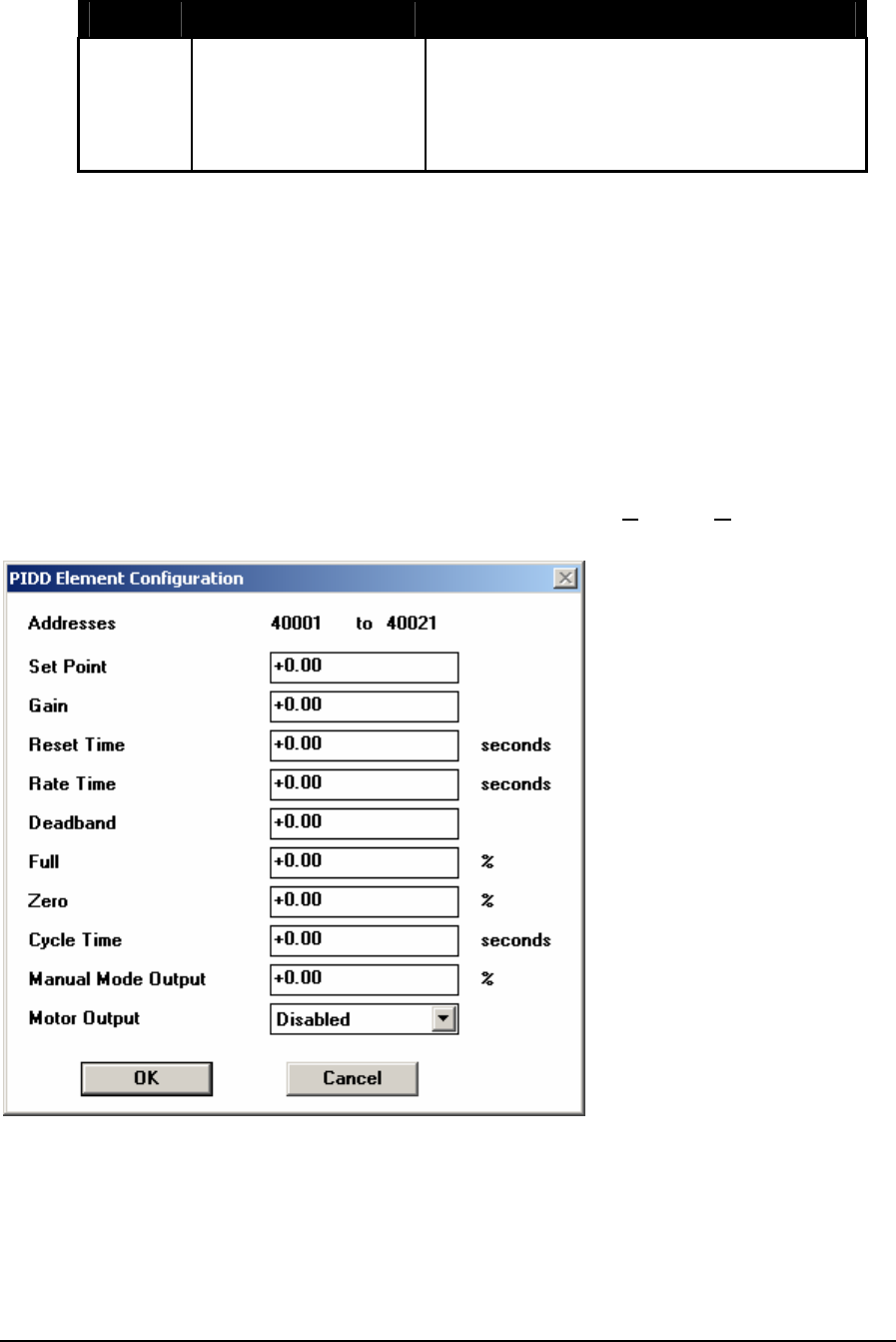
Variable Valid Types Description
+4,5 = internal: process value N-2nd (float)
+6,7 = internal: error N-1st (float)
+8,9 = internal: time of last scan (UINT32)
+10,11 = internal: on time for controller
(UINT32)
The process value is a value that represents the actual state of the process being controlled. This
value is typically input to the controller as an analog input signal or as a signal from a MVT. The
process value is a floating-point number. If the process value is an analog input signal to the
controller it must be converted to a floating-point number using the STOF function. If the analog
input requires scaling use the SCAL function to scale the input and provide a floating-point number
for the process value.
The remaining settings and output% registers are described in the Element Configuration section
below.
Element Configuration
This element is configured using the PIDD Element Configuration dialog. Highlight the
element by moving the cursor over the element and then use the Element Configuration
command on the Edit menu to modify the configuration block.
PID Velocity Algorithm
The PIDD function uses the velocity form of the PID algorithm. The velocity form calculates the
change in the output and adds it to the previous output.
nnn pse −=
TelePACE Ladder Logic Function Reference
February 19, 2007
124

()
⎥
⎦
⎤
⎢
⎣
⎡+−++−+= −−−− 2111 2nnnn
i
nnnn ppp
T
R
e
T
T
eeKmm
Where: e = error
s = setpoint
p = process value
K = gain
T = execution period
Ti = integral or reset time
R = rate gain
m = output
The Element Configuration dialog is used to input each parameter into the calculation. These
parameters are described below.
Setpoint
The setpoint is a floating-point value representing the desired value of the process value. The error
value is the difference between the process value and the setpoint.
error = process value – setpoint (+/- deadband).
Process Value
The process value is a value that represents the actual state of the process being controlled. See the
Function Variables section above for the registers to use for the process value input to the PIDD.
Gain
The proportional (P) part of the PID algorithm is the gain. A positive value of gain configures a
forward-acting PID controller and a negative value of gain configures a reverse acting controller.
Reset Time
The integral (I) part of the PID algorithm is the reset time. This value, in seconds, controls the reset
gain (or magnitude of integral action) in a PI or PID controller. This is typically referred to as
Seconds Per Repeat. From the equation above it is seen that the integral action of the PI or PID
controller is a function of the reset time and the execution period (cycle time). A smaller reset time
provides more integral action and a larger reset time provides less integral action. Valid range is any
value greater than 0. A value of 0 disables the reset action.
Rate Gain
The derivative (D) part of the PID algorithm is the rate time. This value, in seconds, controls the
rate gain (or magnitude of derivative action) in a PD or PID controller. From the equation above it is
seen that the derivative action of the PD or PID controller is a function of the rate gain and the
execution period (cycle time). A larger rate gain provides more derivative action and a smaller rate
gain provides less derivative action. Valid range is any value greater than 0. A value of 0 disables the
rate action.
TelePACE Ladder Logic Function Reference
February 19, 2007
125

Deadband
The deadband parameter is used by the PID algorithm to determine if the process requires the
control outputs to be changed. If the absolute value of the error is less than the deadband, then the
function block skips execution of the control algorithm. This prevents changes to the output when
the process value is near the setpoint and can reduce wear on the control elements. Valid range is any
value greater than 0.
Full Scale Output
The full% setting is the full-scale output limit in percent of cycle time. For example if the cycle time
is 10 seconds and the full% value is 100 then the maximum duty cycle of the output% is 100 percent
or 10 seconds.
When the zero% value is 0 or greater then the increase output is turned on for the duty cycle of the
output%. When the zero% value is less than zero the decrease output is turned on for the duty cycle
of the output% when the output% is negative.
Zero Scale Output
The zero% setting is the zero scale output limit in percent of cycle time. When the zero% value is 0
or greater then the increase output is turned on for the duty cycle of the output%. When the zero%
value is less than zero the decrease output is turned on for the duty cycle of the output% when the
output% is negative.
Cycle Time
The cycle time is the floating-point value of the PID algorithm execution period measured in
seconds. Any value greater than or equal to 0.001 seconds (1 ms) may be specified. If the cycle time
specified is less than the scan time of the TelePACE program, the program scan time becomes the
PID cycle time.
Manual Mode Output
The manual mode output% is the value that the output% is set to when the PIDD function is in
manual mode.
Motor Output
When the motor output is set to enabled the increase and decrease outputs are de-energized when
error is within the deadband. When the motor output is set to disabled the increase and decrease
outputs operate continuously based on the output%.
Related Functions
PIDA – Analog Output PID
TelePACE Ladder Logic Function Reference
February 19, 2007
126

2.52 POWR – Floating-Point Raised to Power
Description
The POWR function calculates the result of a value raised to an exponent and stores the result in a
floating-point holding register.
When the enable input is ON, value is raised to the exponent and stored in the result floating-point
register.
The top output is ON when the input is.
The out-of-range output is ON if the value is zero and exponent is less than zero; and if value is
negative. The result is not calculated in these cases.
value
POWR
result
exponent
ON = enable copies status of input 1
ON = out of range
Function Variables
Variable Valid Types Description
Value Floating Point Constant
2 input registers (3xxxx)
2 holding register (4xxxx)
Floating Point value to be raised.
The high order word is stored in the
first register.
Exponent Floating Point Constant
2 input registers (3xxxx)
2 holding register (4xxxx)
Floating Point value to raise value
to.
The high order word is stored in the
first register.
Result 2 holding register (4xxxx) result = valueexponent
The high order word is stored in the
first register.
Notes
Floating-point values are stored in two consecutive I/O database registers. The lower numbered
register contains the upper 16 bits of the number. The higher numbered register contains the lower 16
bits of the number.
The calculation is performed using a single-precision floating-point number.
Floating point numbers can represent positive or negative values in the range –3.402 × 1038 to 3.402
× 1038.
Related Functions
ABSF - Floating-Point Absolute Value
TelePACE Ladder Logic Function Reference
February 19, 2007
127


2.53 PULM - Pulse Minutes
Description
The PULM function controls a square wave digital signal.
While the enable is ON, the output signal will be active ON or OFF based on the period. The output
is powered only when the enable input is ON.
For example when the enable input is on and a period of 10 minutes is used the result will be an
output square wave that is ON for 5 minutes and then OFF for 5 minutes.
period
PULM
counter
ON = enable Output signal
Function Variables
Variable Valid Types Description
Period Constant (1..65535)
input register (3xxxx)
holding register (4xxxx)
The period of the waveform, in
minutes.
Counter 2 holding registers (4xxxx) Contains the accumulated time of
the period in seconds.
Notes
The Period is from 1 to 65535 minutes.
Related Functions
PULS - Pulse Seconds
Example
network 1:
+10
PULM
46770
01057
)
(
In this example the PULM function has a period value of 10 minutes. Coil 01057 will be on for 5
minutes and then off for 5 minutes. When the program is first run coil 01057 will start in on state for
5 minutes then go off for 5 minutes, repeating this cycle as long as the enable input is true. Registers
46770 and 46771 contain the accumulated time for the period in seconds.
TelePACE Ladder Logic Function Reference
February 19, 2007
129

2.54 PULS - Pulse Seconds
Description
The PULS function controls a square wave digital signal.
While the enable is ON, the output signal will be active ON or OFF based on the period. The output
is powered only when the enable input is ON.
For example when the enable input is on and a period of 10 seconds is used the result will be an
output square wave that is ON for 5 seconds and then OFF for 5 seconds.
period
PULS
counter
ON = enable Output signal
Function Variables
Variable Valid Types Description
Period Constant (1..65535)
input register (3xxxx)
holding register (4xxxx)
The period of the waveform, in
seconds.
Counter 2 holding registers (4xxxx) Contains the accumulated time of
the period in tenths of seconds.
Notes
The Period is from 1 to 65535 seconds. The smallest actual period will depend on the ladder scan
time. Smaller ladder programs will be able to handle smaller periods.
Related Functions
Timers
Example
network 1:
+10
PULS
45660
01057
)
(
In this example the PULM function has a period value of 10 seconds. Coil 01057 will be on for 5
seconds and then off for 5 seconds. When the program is first run coil 01057 will start in on state for
5 seconds then go off for 5 minutes, repeating this cycle as long as the enable input is true. Registers
46770 and 46771 contain the accumulated time for the period in seconds.
TelePACE Ladder Logic Function Reference
February 19, 2007
130

2.55 PUTB – Put Bit into Block
Description
The PUTB function block writes the status of a bit, at the bit index, into the destination block of
registers.
The enable PUTB input must be energized for a PUTB function to execute.
The bit to put into block input is the bit value that will be written into the destination register at the
location of the bit index when enable PUTB is energized.
The increment bit index input increments the index, once each scan, when enable PUTB is
energized.
bit index
PUTB
size
destination
ON = enable PUTB
ON = increment bit index
copies state of input 2 bit to put into block
copies state of input 1
ON if index > size
Function Variables
Variable Valid Types Description
bit index Constant (0..65535)
Holding register (4xxxx)
The index of the bit within the
destination block. A bit index of 0 is
the most significant bit of the first
register of the destination block.
Destination coil block (0xxxx)
holding register (4xxxx)
The address of the destination
register block.
The address for a coil register block
is the first register in a group of 16
registers.
Size Constant (1..100) number of 16 bit words in the block.
Notes
Put bit into block accesses 16 bit words. Coil blocks are groups of 16 registers that start with the
register specified as the block address. Coil blocks must begin at the start of a 16 bit word within the
controller memory. Suitable addresses are 00001, 00017, 00033, etc.
Related Functions
GETB – Get Bit from Block
ROTB – Rotate Bits in Block
CMPB – Compare Bit
TelePACE Ladder Logic Function Reference
February 19, 2007
131

Example
01056 +2
40234
PUTB
+1
03841
)(
01057
In network 1 the PUTB function is being used to set the manual control bit in the PID Block 0
Control Register, bit 13 of register 40234. The bit index of the manual control bit is 2, with 0 being
the most significant bit.
Closing contacts 01056 allows power to be supplied to the enable PUTB input of the PUTB function
block. With the function block enabled, closing contacts 01057 allows power to the put bit into
block input of the function block. The bit at the index is then set in the destination register, the PID
Block 0 Control Register. Output coil 03841 is energized.
TelePACE Ladder Logic Function Reference
February 19, 2007
132

2.56 PUT – Put Signed Value into Registers
Description
The PUT function transfers, in one scan, the source holding register or signed constant into the
destination holding registers. The number of destination registers is determined by size. The same
value is stored in each destination register.
The source register, or signed constant, is transferred to the destination holding register when enable
transfer is ON.
If the source is a register, this function is identical to the PUTU function.
source
PUT
size
destination
ON = enable transfer copies state of input1
Function Variables
Variable Valid Types Description
source Constant
(-32768..32767)
input register (3xxxx)
holding register (4xxxx)
The signed value or address of the
register containing the value to be
stored.
destination Holding register (4xxxx) The address of the first destination
register.
Size Constant
(1..9999)
The number of destination
registers.
Related Functions
PUTU – Put Unsigned Value into Registers
PUTF - Put Floating-Point Value
TelePACE Ladder Logic Function Reference
February 19, 2007
133

Example
01025
)
(
network 1:
-18
44513
PUT
+1
42526
49483
PUT
+3
0
44260
PUT
+8
01025
1 2 3
In this example there are three PUT functions in network 1. On power up One Shot coil 01025 is
energized for one scan. This will cause NO contacts 01025 to close, applying power to the enable
transfer input on PUT functions 1,2 and 3.
In PUT 1 the constant value -18 is transferred to holding register 44513.
In PUT 2 the value of holding register 42526 (1000) is transferred to holding registers 49483 through
49485.
In PUT 3 the constant value 0 is transferred to holding registers 44260 through 44267.
TelePACE Ladder Logic Function Reference
February 19, 2007
134

2.57 PUTF - Put Floating-Point Value
Description
The PUTF element transfers, in one scan, the source floating-point holding register or constant into
the destination floating-point holding registers. The number of floating-point destination registers is
determined by size. The same value is stored in each floating-point register pair.
When the enable input is ON, the source register or constant is transferred to the destination
registers. The element output is ON when the input is.
source
PUTF
size
destination
ON = enable copies status of input
Function Variables
The element has three parameters.
Variable Valid Types Description
source FP constant
2 input registers (3xxxx)
2 holding registers (4xxxx)
Floating-point register or
constant to be stored
Destination Holding register (4xxxx) Address of the first pair of
destination registers
Size Constant (1…4999) the number of floating-point
destination registers pairs to
store
Notes
Floating-point values are stored in two consecutive I/O database registers. The lower numbered
register contains the upper 16 bits of the number. The higher numbered register contains the lower 16
bits of the number. Floating point numbers can represent positive and negative values in the range –
3.402 × 1038 to 3.402 × 1038.
The size parameter determines the number of floating-point register pairs affected. The number of
registers affected is twice the value of size, since each floating-point value uses two registers.
Related Functions
PUT – Put Signed Value into Registers
PUTU – Put Unsigned Value into Registers
TelePACE Ladder Logic Function Reference
February 19, 2007
135

Example
network 1:
+44.10
40100
PUTF
+1
The PUTF function in network 1 puts the floating-point constant +44.10 value into floating-point
register 40100 (registers 40100 and 40101).
TelePACE Ladder Logic Function Reference
February 19, 2007
136
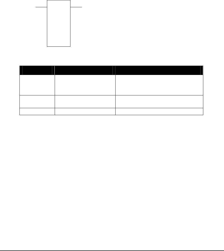
2.58 PUTU – Put Unsigned Value into Registers
Description
The PUTU function transfers, in one scan, the source holding register or unsigned constant into the
destination holding registers. The number of destination registers is determined by size. The same
value is stored in each destination register.
The source register, or unsigned constant, is transferred to the destination holding register when
enable transfer is ON.
If the source is a register, this function is identical to the PUT function.
source
PUTU
size
destination
ON = enable transfer copies state of input1
Function Variables
Variable Valid Types Description
source Constant (0..65535)
input register (3xxxx)
holding register (4xxxx)
The unsigned value or address of
the register containing the value to
be stored.
Destination Holding register (4xxxx) The address of the first destination
register.
Size Constant (1..9999) The number of destination registers.
Related Functions
PUT – Put Signed Value into Registers
PUTF - Put Floating-Point Value
TelePACE Ladder Logic Function Reference
February 19, 2007
137

Example
01057
)
(
network 1:
01057 14
40210
PUTU
+1
30
40211
PUTU
+1
0
40212
PUTU
+1
This example uses two PUTU functions to write the correct time to the Real Time Clock. The time
for this example is 14:30:00.
The holding registers used to in this example must be assigned to the CNFG Real Time Clock and
Alarm I/O Module in the Register Assignment. Holding registers 40210 through 40220 are assigned
to this I/O module.
On power up One Shot coil 01057 is energized for one scan. This will cause NO contacts 01057 to
close, applying power to the enable transfer inputs on the two PUTU functions.
The real time clock continues to run with the new time setting immediately after these PUTU
functions are enabled. Note that all seven clock registers must be set to valid values for the clock to
operate correctly.
Another method for setting the clock, is to use the Edit/Force Register dialog to write the current
time to the appropriate module registers. Leave the force box in the dialog unchecked so that the data
is only written, not forced.
TelePACE Ladder Logic Function Reference
February 19, 2007
138

2.59 R–>L – Register to List Transfer
Description
The R->L function transfers the contents of the source register into a register in the destination list of
registers indicated by the index.
When the enable transfer input is ON and the index equals size output is OFF, the source register is
transferred to the destination list register at the position of the index.
The freeze/increment index input allows control of the index. If this input is ON the index is not
incremented. If the input is OFF the index is incremented by one after each transfer.
When the reset index input is ON the index is reset to zero.
The index is incremented by one on each transfer until the index equals size. When the index equals
size output is ON no further increments of the index value occur until the index is reset.
source
R->L
size
list
ON = enable transfer
ON = reset index to 0
ON if index = size
and enable transfer = ON
ON = freeze index
OFF = increment index
copies state of input 1
Function Variables
Variable Valid Types Description
source coil block (0xxxx)
status block (1xxxx)
input register (3xxxx)
holding register (4xxxx)
The address of the source register.
The address for a coil or status
register block is the first register in
a group of 16 registers that will be
read.
index and
destination Holding register (4xxxx)
The address of the index register
and the data registers. The index is
stored in register [4xxxx]. The data
is stored in register [4xxxx+1] to
register [4xxxx+size]
Size Constant (1..9999) The number of registers in the list.
Related Functions
L–>L – List to List Transfer
L–>R – List to Register Transfer
MOVE – Move Block
TelePACE Ladder Logic Function Reference
February 19, 2007
139

Example
42010
42011
R->L
+4
01386
The Register to List function transfers the contents of the source register 42010 into a register in the
destination list of registers, 42012 to 42015, indicated by the index register 42011.
Destination Register List
List Index--> 42011
Source Register-> 42010 list register 0--> 42012
list register 1--> 42013
list register 2--> 42014
list register 3--> 42015
An example of the registers used in a Register to List (R->L) transfer is shown in the above diagram.
The source register is a general purpose analog output register. The index is a general purpose analog
output register that will have a value of 0, 1, 2 or 3. The destination register list starts at the next
sequential register after the index register. The destination list contains four general purpose analog
output registers and has a size of 4.
When list index register 42011 has a value of 0 and the R->L function is enabled the contents of
source register 42010 is transferred to destination list register 40012.
When list index register 42011 has a value of 1 and the R->L function is enabled the contents of
source register 42010 is transferred to destination list register 42013.
When list index register 42011 has a value of 2 and the R->L function is enabled the contents of
source register 42010 is transferred to destination list register 42014.
When list index register 42011 has a value of 3 and the R->L function is enabled the contents of
source register 42010 is transferred to destination register 42015.
TelePACE Ladder Logic Function Reference
February 19, 2007
140

2.60 ROTB – Rotate Bits in Block
Description
The ROTB function block rotates the bits in the source block by one bit and stores the result in the
destination block. The block can be rotated towards either the most significant bit (MSB) or
towards the least significant bit (LSB).
source
ROTB
size
destination
ON = rotate bits
ON = rotate last bit into start
state of the last bit shifted
out
ON = rotate toward MSB
OFF = rotate towards LSB
copies status of input 1
Function Variables
Variable Valid Types Description
Source coil block (0xxxx)
status block (1xxxx)
input register (3xxxx)
holding register (4xxxx)
The address of the first source
register.
The address for a coil or status
register block is the first register in
a group of 16 registers that will be
rotated.
Destination coil block (0xxxx)
holding register (4xxxx)
The address of the first destination
register.
The address for a coil or status
register block is the first register in
a group of 16 registers that will be
rotated.
Size Constant (1..100) The number of 16 bit words in the
block.
Related Functions
PUTB – Put Bit into Block
GETB – Get Bit from Block
CMPB – Compare Bit
TelePACE Ladder Logic Function Reference
February 19, 2007
141
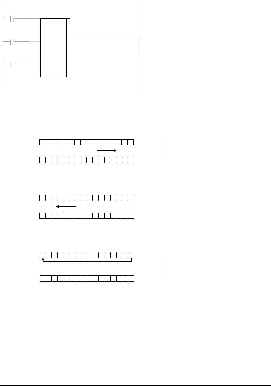
Example
network 1:
10010 40221
42222
ROTB
+1
00017
)
(
10009
10011
The ROTB function in network 1 is configured to demonstrate the operation of the function block.
Register 40221, the source register, has a value of 6985. Register 40222 is the destination register.
The first example is a rotate towards LSB. Closing the rotate bits input, contacts 10010, will cause
the bits in the source register to rotate right by one bit and the result to be stored in the destination
register.
1 0 0 0 1 1 0 1 0010 1001
source register
0 00 0 1 0 1 1 0101 0010
destination register
Rotate towards LSB
The next example is a rotate towards MSB. Closing the rotate towards MSB input, contacts 10009
and then closing the rotate bits input, contacts 10010, will cause the bits in the source register to
rotate once to the left. The result is stored in the destination register.
1000 1101 0010 1001
source register
1100 0110 1001 0100
destination register
Rotate towards MSB
In the last example the rotate bits input is enabled by closing contact 10010. Closing contacts 10011
will enable the rotate last bit to start input. The LSB of the source register is rotated to the MSB
and the remaining bits are rotated right.
1000 1101 0010 1001
source register
0001 1011 0101 0010
destination register
Rotate last bit into start
TelePACE Ladder Logic Function Reference
February 19, 2007
142

2.61 SCAL – Scale Analog Value
Description
The SCAL function scales an integer into a floating-point value and detects changes in the floating-
point value.
When the Enable input is ON the SCAL function calculates the scaled value.
When the Enable input is ON the scaled value is compared to the previous scaled value. If the
difference is greater than the deadband the scaled value changed output is turned ON and the scaled
value is copied to the previous scaled value. The previous scaled value does not change if scaled
value is within the deadband.
When the Enable input changes from OFF to ON, the scaled value is copied to previous scaled
value.
config
SCAL
scaled value
ON = enable
ON = scaled value changed
copies status of input
Function Variables
Variable Valid Types Description
config holding register (4xxxx)
Address of the first register in the configuration
block. There are 9 registers in the block at
addresses message+0 to message+8.
+0 = input register
+1 = zero scale raw input
+2 = full scale raw input
+3-4 = zero scale output (floating point)
+5-6 = full scale output (floating point)
+7-8 = deadband (floating point)
scaled
value 4 holding registers (4xxxx) Address of the first register in the output block.
There are 4 registers in the block at addresses
output+0 to output+3
+0-1: scaled value (floating point)
+2-3: previous scaled value (floating point)
Element Configuration
This element is configured using the SCAL Element Configuration dialog. Highlight the element by
moving the cursor over the element and then use the Element Configuration command on the Edit
menu to modify the configuration block.
TelePACE Ladder Logic Function Reference
February 19, 2007
143
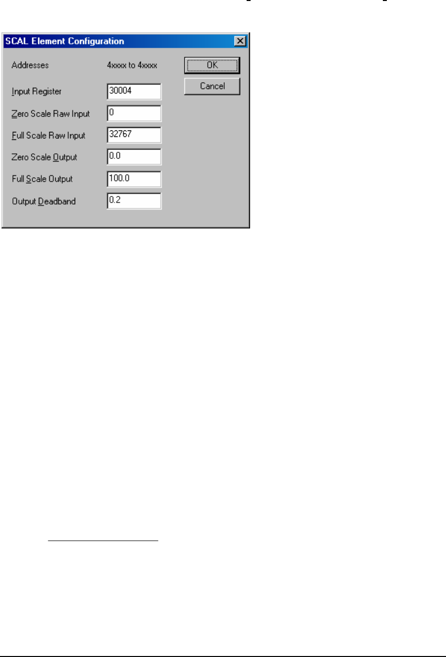
WARNING: If the controller is initialized, using the Initialize command in the Controller menu,
all I/O database registers used for Element Configuration are set to zero. The
application program must be re-loaded to the controller.
The Input Register specifies the register from which the input is read. Valid values are any input
(3xxxx) or holding (4xxxx) register. The range depends upon the registers supported in the selected
controller type.
The Zero Scale Raw Input specifies the minimum raw input value. Valid values are -32768 to
32767. This value must be less than the full-scale raw input.
The Full Scale Raw Input specifies the maximum raw input value. Valid values are -32768 to
32767. This value must be greater than the zero scale raw input.
The Zero Scale Output is the floating-point value calculated when the input is equal to the zero
scale raw input. This value must be less than the full-scale output. Valid values are any floating-point
number.
The Full Scale Output is the floating-point value calculated when the input is equal to the full-scale
raw input. This value must be greater than the zero scale output. Valid values are any floating-point
number.
The Output Deadband is the amount by which the output must change for the scaled value
changed output to be energized. Valid values are any floating-point number greater than or equal to
0.0.
Notes
The input is scaled using this formula.
()
outputzerooutputzerooutputfull
rawzerorawfull
rawzeroinput
scaled ___
__
_+−×
−
−
=
The previous scaled value changes only when difference between the current and previous values is
greater than the deadband. The scaled value changed output is energized when this occurs.
The input register may contain values less than the zero scale raw input or greater than the full-scale
raw input. The scaling calculation is still performed.
TelePACE Ladder Logic Function Reference
February 19, 2007
144
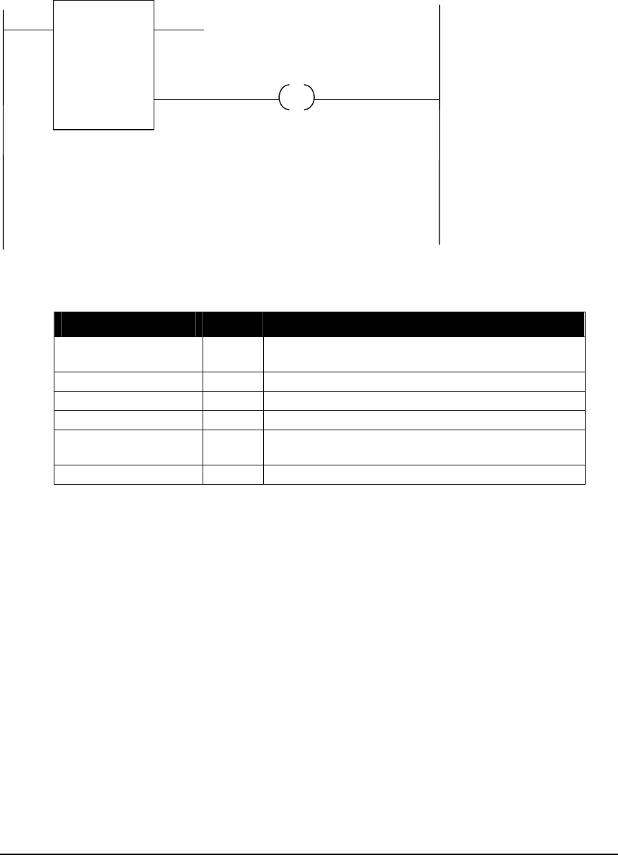
Example
In this example a SCAL block is used to convert an analog input into engineering units and close a
contact each time a change of 10 units occurs.
40020
SCAL
40030 00012
The element configuration for the SCAL block is as follows
Parameter Value Notes
Input Register 30001 assign to analog input module in register
assignment
Zero Scale Raw Input 0 minimum value for unipolar analog input
Full Scale Raw Input 32767 maximum value for analog input
Zero Scale Output 0 corresponds to the minimum value of analog input
Full Scale Output 1000 corresponds to the maximum value of analog
input
Output Deadband 10 change in output to turn on change output
TelePACE Ladder Logic Function Reference
February 19, 2007
145

2.62 Shunts
Horizontal
The horizontal shunt conducts power from left to right.
input output = input
Vertical
The vertical shunt conducts power between rows. If any of the rows connected by vertical shunts are
powered, all output rows will be powered, as shown in the example below.
input = ON output = ON
input = OFF output = ON
TelePACE Ladder Logic Function Reference
February 19, 2007
146

2.63 SLP – Put Controller into Sleep Mode
Description
The SLP function places the controller into sleep mode. Sleep mode reduces power consumption to a
minimum by halting the microprocessor clock and shutting down the power supply. All programs
halt until the controller resumes execution. All output points turn off while the controller is in sleep
mode.
This function is not supported in the SCADAPack 32, SCADAPack 100 or SCADASense Series
controllers.
clock alarm
settings
SLP
wake src
ON = enter sleep mode copy of input 1
Function Variables
Variable Valid Types Description
clock alarm
settings holding register (4xxxx) Address of the first register in the clock alarm
settings block. There are 4 registers in the
block at addresses settings+0 to settings + 3
+0 = type
+1 = hour
+2 = minute
+3 = second
Valid values for type are
0 = no alarm
1 = absolute time alarm
2 = elapsed time alarm
wake src holding register (4xxxx) address of the wake up source register. This
register indicates the reason the controller left
sleep mode. Valid values are:
1 = real time clock alarm
2 = interrupt input
4 = led power switch
8 = counter 0 overflow
16 = counter 1 overflow
32 = counter 2 overflow
256 = Assertion of:
- digital input 0 for SCADAPack 350
- Any digital input on SCADAPack LP
- INT/Cntr digital Input on SCADAPack
with 5203/5204 controller board
TelePACE Ladder Logic Function Reference
February 19, 2007
147
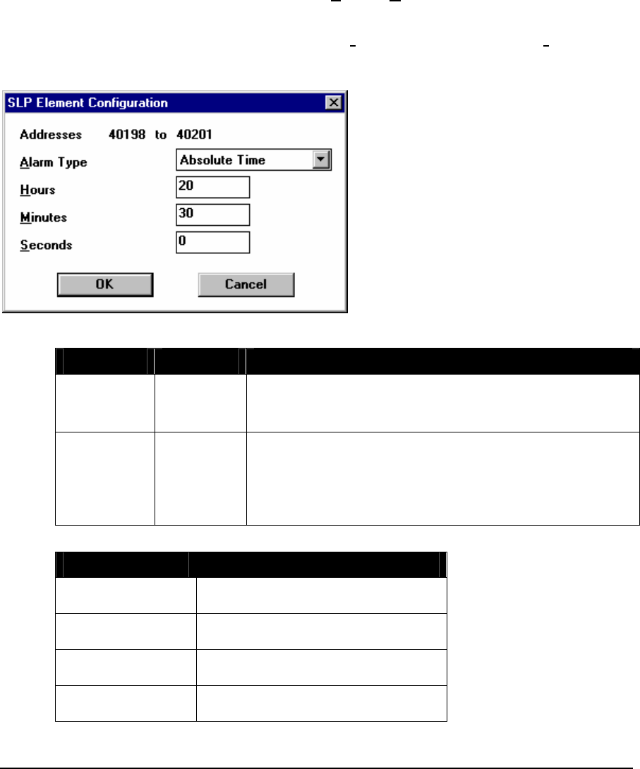
Notes
The SCADAPack 32 and SCADAPack 100 controllers do not support the SLP function
Note that this function block triggers the same interrupt as the CNFG Real Time Clock and Alarm
register assignment. Using both alarm settings, therefore, in the same program is not recommended.
Element Configuration
This element is configured using the SLP Element Configuration dialog. Highlight the element by
moving the cursor over the element and then use the Element Configuration command on the Edit
menu to modify the configuration block.
WARNING: If the controller is initialized, using the Initialize command in the Controller menu,
all I/O database registers used for Element Configuration are set to zero. The
application program must be re-loaded to the controller.
Valid values for the time parameters are listed in the table below.
Alarm Type Parameter Range
Absolute Hours
Minutes
Seconds
0 to 23
0 to 59
0 to 59
Elapsed Hours
Minutes
Seconds
0 to 23
0 to 1439
0 to 65535
Total of all time must be less than 23 hours, 59 minutes, 59
seconds
The controller will wake up under the following conditions.
Condition Wake Up Effects
Hardware Reset Application programs execute from
start of program.
External Interrupt Program execution continues from
point sleep function was executed.
Real Time Clock
Alarm Program execution continues from
point sleep function was executed.
LED Power Button Program execution continues from
point sleep function was executed.
TelePACE Ladder Logic Function Reference
February 19, 2007
148

Condition Wake Up Effects
Hardware Counter
Rollover Software portion of counter is
incremented.
Program execution continues from
point sleep function was executed.
Example
The following network will put the controller into sleep mode. The clock alarm is set to wake the
controller in 60 seconds. Other conditions may wake up the controller before the 60 seconds expires.
network 1:
42001
PU TU
+2
+1
42002
PU TU
0
+1
42003
PU TU
0
+1
42004
PU TU
60
+1
42001
10001
SLP
42100
The Element Configuration dialog may be used to edit the configuration of the SLP block, instead
of PUTU functions. This reduces the memory used by the program. However, the alarm settings are
written to the controller only when the program is loaded. The network using the PUTU elements
configures the alarm settings on every execution of the SLP element.
network 1:
10001 42001
SLP
42100
TelePACE Ladder Logic Function Reference
February 19, 2007
149

2.64 SQRF - Square Root of Floating-Point Value
Description
The SQRF element stores the square root of a floating-point register or constant in a floating-point
holding register.
When the enable input is ON the square root of the source is stored in the result floating-point
holding register. The top output is ON when the input is. The bottom output is ON if the source is
negative, and the input is ON.
source
SQRF
result
ON = enable copies status of input
ON if source < 0
Function Variables
The element has two parameters.
Variable Valid Types Description
source FP constant
2 input registers
(3xxxx)
2 holding registers (4xxxx)
a floating-point register or constant
result 2 holding registers (4xxxx) Floating-point square root of source
Notes
Floating-point values are stored in two consecutive I/O database registers. The lower numbered
register contains the upper 16 bits of the number. The higher numbered register contains the lower 16
bits of the number. Floating point numbers can represent positive or negative values in the range –
3.402 × 1038 to 3.402 × 1038.
The square root of a negative number cannot be calculated. The source must be positive or zero to
calculate a result..
Related Functions
DIV – Divide Signed Values
DIVU – Divide Unsigned Values
TelePACE Ladder Logic Function Reference
February 19, 2007
150

Example
network 1:
+155.230
SQRF
40001
The SQRF function in network 1 takes the square root of the floating-point constant +155.23 and
puts the result in floating-point register 40001 (registers 40001 and 40002). The value in 40001 is
=12.459.
TelePACE Ladder Logic Function Reference
February 19, 2007
151

2.65 STOF - Signed Integer to Floating-Point
Description
The STOF element converts a signed register or constant into a floating-point number and stores the
result in a floating-point holding register.
When the enable input is ON, value is converted into a floating-point number and stored in the
result floating-point register. The element output is ON when the input is.
value
STOF
result
ON = enable copies status of input
Function Variables
The element has two parameters.
Variable Valid Types Description
Value Constant
(–32768…32767)
input register (3xxxx)
holding register (4xxxx)
Signed value to convert
Result 2 holding registers (4xxxx) Converted floating-point value
Notes
Floating-point values are stored in two consecutive I/O database registers. The lower numbered
register contains the upper 16 bits of the number. The higher numbered register contains the lower 16
bits of the number.
Floating point numbers can represent positive or negative values in the range –3.402 × 1038 to 3.402
× 1038.
Related Functions
UTOF - Unsigned Integer to Floating-Point
FTOS - Floating-Point to Signed Integer
FTOU - Floating-Point to Unsigned Integer
TelePACE Ladder Logic Function Reference
February 19, 2007
152

Example
network 1:
-2445
STOF
40001
The STOF function in network 1 converts signed integer constant -2445 to a floating-point value and
puts the value into floating point-register 40001 (registers 40001 and 40002). In this example the
content of floating-point register 40001 is the floating-point value –2445.00.
TelePACE Ladder Logic Function Reference
February 19, 2007
153

2.66 SUB – Subtract Signed Values
Description
The SUB function block subtracts a signed register or constant, value 2, from a signed register or
constant, value 1, and stores the result in a holding register, result. Signed subtraction is used. The
result out of range output is enabled if the result is greater than 32767 or less than -32768.
value 1
SUB
difference
value 2
ON = enable SUB
ON = result out of range
copies status of input1
Function Variables
Variable Valid Types Description
value 1 Constant
(-32768..32767)
input register (3xxxx)
holding register (4xxxx)
Signed value to subtract from
value 2 Constant
(-32768..32767)
input register (3xxxx)
holding register (4xxxx)
Signed value to subtract
Difference holding register (4xxxx) Difference = value 1 - value 2
Related Functions
SUBF – Subtract Floating-Point Values
SUBU –Subtract Unsigned Values
TelePACE Ladder Logic Function Reference
February 19, 2007
154
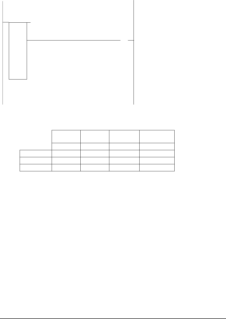
Example
network 1:
41822
41886
SUB
41824 02561
)
(
The SUB function in network 1 subtracts the contents of register 41824, value 2, from the contents
of register 41822, value 1. The difference is stored in register 41886. Some examples of different
values for registers 41822 and 41824 are shown in the table below.
Register
41822 Register
41824 Register
41886 Coil
02561
value 1 value 2 difference out of range
Example 1 -27765 -18755 -9010 OFF
Example 2 3276 -12269 15545 OFF
Example 3 -30000 27881 7655 ON
TelePACE Ladder Logic Function Reference
February 19, 2007
155

2.67 SUBF – Subtract Floating-Point Values
Description
The SUBF element subtracts one floating-point register or constant from another and stores the result
in a floating-point holding register.
When the enable input is ON the difference value 1 – value 2 is stored in the difference holding
register. The element output is ON when the input is.
value1
SUBF
difference
value2
ON = enable copies status of input
Function Variables
The element has three parameters.
Variable Valid Types Description
value1 FP constant
2 input registers (3xxxx)
2 holding registers (4xxxx)
Floating-point register or constant to subtract
from
Value2 FP constant
2 input registers (3xxxx)
2 holding registers (4xxxx)
floating-point register or constant to subtract
Difference 2 holding registers (4xxxx) floating-point difference = value1 – value2
Notes
Floating-point values are stored in two consecutive I/O database registers. The lower numbered
register contains the upper 16 bits of the number. The higher numbered register contains the lower 16
bits of the number.
Floating point numbers can represent positive or negative values in the range –3.402 × 1038 to 3.402
× 1038.
Related Functions
SUB – Subtract Signed Values
SUBU –Subtract Unsigned Values
TelePACE Ladder Logic Function Reference
February 19, 2007
156

Example
network 1:
+101.3
40001
SUBF
40100
The SUBF function in network 1 subtracts floating-point constant +101.3 from floating-point
register 40001 (registers 40001 and 40002). Assuming floating-point register 40001 contains a value
of 1000.00 the result is +898.7. The result is stored in floating-point register 40100 (registers 40100
and 40101).
TelePACE Ladder Logic Function Reference
February 19, 2007
157

2.68 SUBR - Start of Subroutine
Description
The SUBR element defines the start of a subroutine.
A subroutine is a group of logic networks that can be executed conditionally. The subroutine begins
with the network containing the SUBR element. A subroutine ends when another subroutine element
is encountered, or when the end of the ladder logic program is reached.
The element is a single cell element. Visually it covers the entire width of the first row of the
network.
number
SU BR
Function Variables
The SUBR element has one parameter:
Variable Valid Types Description
number Constant The number of the subroutine. Any number in the range 1 to
500 is valid.
Notes
The SUBR element must be located in row 1, column 1 of a network.
No other element can be located to the right of the SUBR element.
Outputs of a subroutine remain in their last state when a subroutine is not called. For example, a coil
that is turned on by a subroutine remains on when the subroutine is not called. The output will only
turn off when the subroutine is called and it turns the output off.
The subroutine number is a constant. Constant tag names are used with this value.
The subroutine number must be unique. No other subroutine can use the same number.
Subroutines do not have to be programmed in any particular numerical order. For example,
subroutine 1 can follow subroutine 2, subroutine 200 can follow subroutine 400.
Related Functions
CALL - Execute Subroutine
Example
See the example for the CALL function.
TelePACE Ladder Logic Function Reference
February 19, 2007
158

2.69 SUBU –Subtract Unsigned Values
Description
The SUBU function block subtracts an unsigned register or constant, value 2, from an unsigned
register or constant, value 1, and stores the result in a holding register, difference. Unsigned
subtraction is used. The result out of range output is enabled if the result is greater than 65535 or
less than 0.
value 1
SUBU
difference
value 2
ON = enable SUBU
ON = result out of range
copies status of input1
Variable Valid Types Description
value 1 Constant (0..65535)
input register (3xxxx)
holding register (4xxxx)
Unsigned value to subtract from
Value 2 Constant (0..65535)
input register (3xxxx)
holding register (4xxxx)
Unsigned value to subtract
Difference holding register (4xxxx) Difference = value 1 - value 2
Related Functions
SUB – Subtract Signed Values
SUBF – Subtract Floating-Point Values
Example
network 1:
49920
44996
SUBU
42992 02011
)
(
TelePACE Ladder Logic Function Reference
February 19, 2007
159

The SUBU function in network 1 subtracts the contents of register 42992, value 2, from the contents
of register 49920, value 1. The difference is stored in register 44996. Some examples of different
values for registers 49920 and 42992 are shown in the table below.
Register
49920 Register
42992 Register
44996 Coil
02011
value 1 value 2 Difference out of range
Example 1 22675 1988 20687 OFF
Example 2 61223 2399 58824 OFF
Example 3 3877 54440 14973 ON
TelePACE Ladder Logic Function Reference
February 19, 2007
160
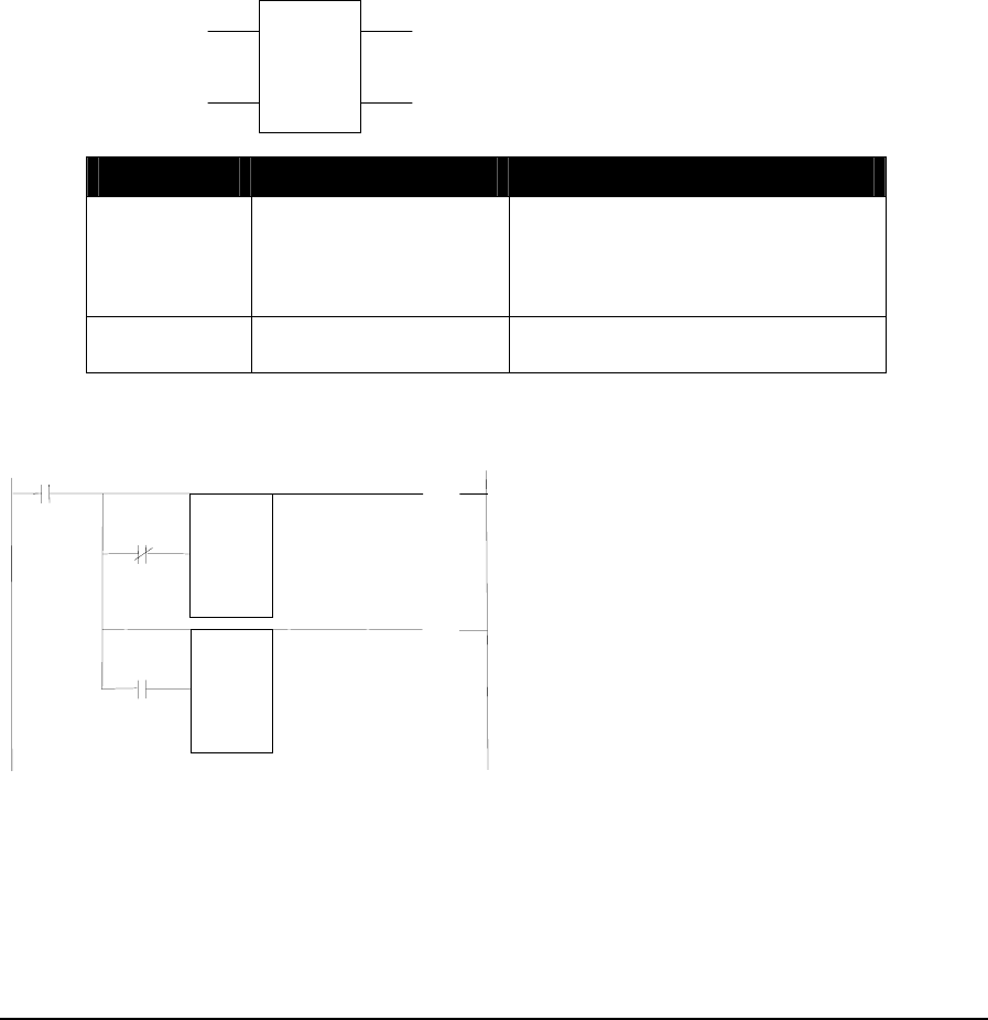
2.70 Timers
Description
The three timer functions measure elapsed time and save it in a holding register, accumulator. The
T1 timer measures time in 1.0 second intervals. The T.1 timer measures time in 0.1 second intervals.
The T.01 timer measures time in 0.01 second intervals.
When the enable timer input is ON and the accumulate time is ON the accumulator increments by
the Timer interval to the value of the limit. When the enable timer is off the accumulator is reset to
zero.
When the enable timer is ON and the accumulator equals the limit then the accumulator = limit
output is On.
When the enable timer is ON and the accumulator is less than the limit then the accumulator <
limit output is On.
limit
T1
accumulator
ON = accumulate time
ON = accumulator < limitON = enable time
r
OFF = reset timer to 0
ON = accumulator = limit
Variable Valid Types Description
Limit Constant (1..65535)
input register (3xxxx)
holding register (4xxxx)
Upper limit for accumulator
Accumulator Holding register (4xxxx) Register holds time during which
accumulate time input has been ON
Example
network 1:
10009 00017
)
(
01257
)(
+10
T.1
41051
+5
T.1
41050
01257
00017
In network 1 two Timer functions are configured such that output coil 00017 is ON for 1.0 second
(10 * 0.1) and OFF for 0.5 second (5 * 0.1).
When power is applied to the circuit by closing contacts 10009, output coil 00017 is OFF and Timer
41050 starts to accumulate time. When the accumulator reaches the limit of 5, output coil 00017
turns ON. Timer 41051 is enabled by the NO contacts of output coil 00017 and starts to accumulate
TelePACE Ladder Logic Function Reference
February 19, 2007
161

time. When the accumulator reaches the limit of 10, output coil 01257 turns ON and resets Timer
41050 by the NC contacts of 01257. Output coil 00017 turns OFF. The process is then repeated until
contacts 10009 are opened.
TelePACE Ladder Logic Function Reference
February 19, 2007
162

2.71 TOTL – Analog Totalizer
Description
The TOTL function reads a rate input and accumulates (integrates) a total. It is used to measure a
flow rate and accumulate a volume, or a similar calculation.
When the Accumulate input is ON and it has been longer than the sample interval since the last
accumulation, the function reads the value of the input, scales it by time difference from the previous
accumulation, and adds it into the total.
When the Log Data input goes from OFF to ON, the accumulated total, accumulation time, and the
time at the end of the period is saved in the history registers. Older history is pushed down and the
oldest record is discarded.
When the Enable Accumulation input is ON, accumulation is enabled. When the input is OFF, all
accumulators and outputs are set to zero.
The Error output is ON if there is an error in the configuration registers.
config
TOTL
records
out
p
uts
ON = accumulate
ON = enable accumulation
OFF = clear outputs
ON = errorOFF to ON = log data
copies state of input 1
Function Variables
Variable Valid Types Description
Config holding register (4xxxx)
Address of the first register in the configuration
block. There are 3 registers in the block at
addresses message+0 to message+2.
+0 = rate input register
+1 = input rate (see table below)
+2 = sample interval (tenths of seconds)
TelePACE Ladder Logic Function Reference
February 19, 2007
163
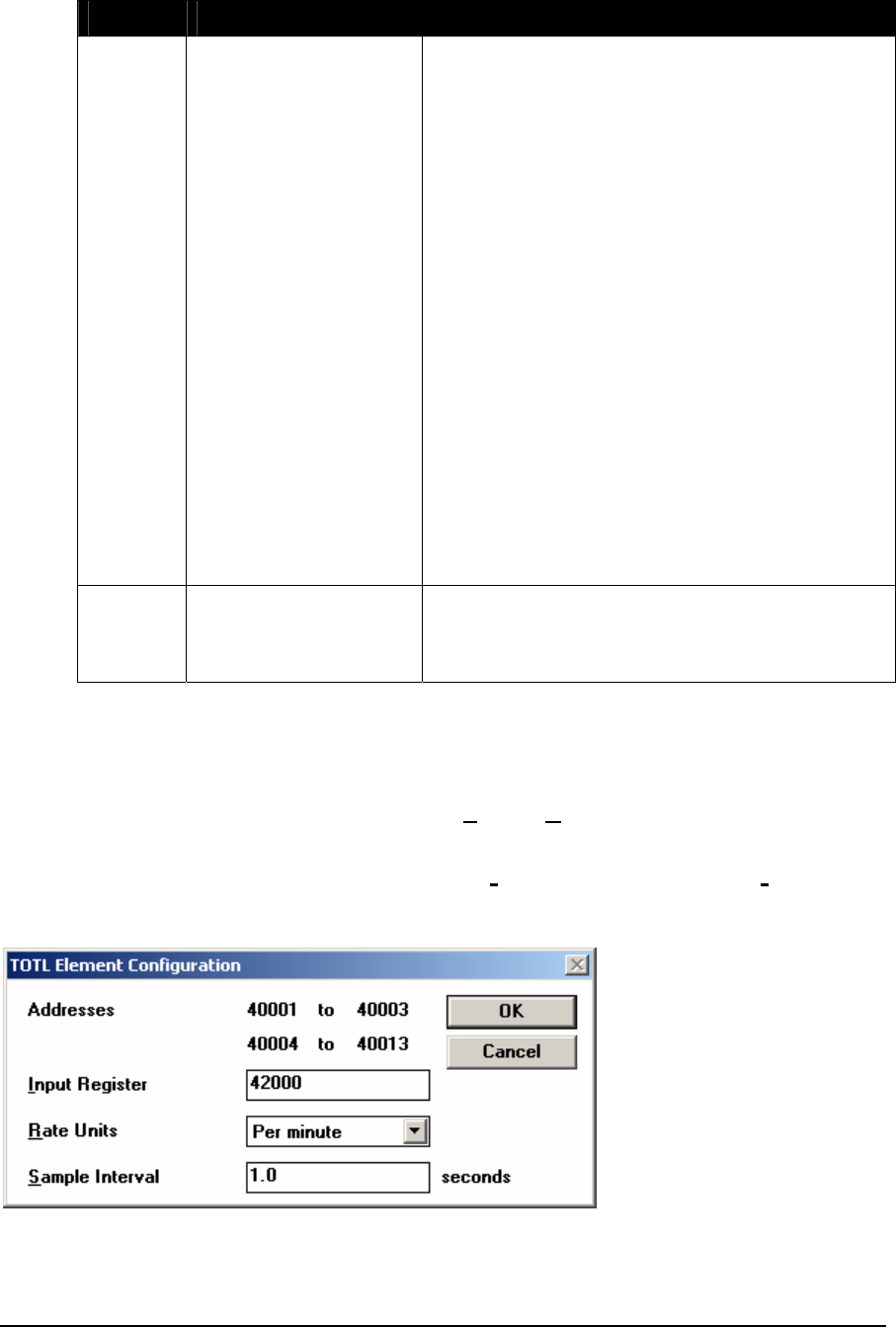
Variable Valid Types Description
Outputs holding register (4xxxx) Address of the first register of the output block.
There are 10 to 214 registers in the block at
outputs+0 to outputs+213. The number of registers
used depends on the records variable.
+0 = number of records to follow
+1 = status
+2,3 = internal: time at last sample
+4,5 = period 1: total (float)
+6,7 = period 1: end time
+8,9 = period 1: accumulation time
+10,11= period 2: total (float)
+12,13 = period 2: end time
+14,15 = period 2: accumulation time
+16,17= period 3: total (float)
+18,19 = period 3: end time
+20,21 = period 3: accumulation time
…
+208,209 = period 35: total (float)
+210,211 = period 35: end time
+212,213 = period 35: accumulation time
Records Constant The number of measurement records stored in the
output array. The valid values are 1 to 35. This
value determines the number of output registers
used by the function.
Element Configuration
This element is configured using the TOTL Element Configuration dialog. Highlight the element by
moving the cursor over the element and then use the Element Configuration command on the Edit
menu to modify the configuration block.
WARNING: If the controller is initialized, using the Initialize command in the Controller menu,
all I/O database registers used for Element Configuration are set to zero. The
application program must be re-loaded to the controller.
The Input Register specifies the register address from which the rate input is read. Valid value for
this register is any floating point register. The function will use the specified register, and the next
TelePACE Ladder Logic Function Reference
February 19, 2007
164

sequential register, as a floating point rate value. The address range depends upon the registers
supported in the selected controller type.
The Rate Units specifies the units of time for the rate input. It may be one of the following.
per second (holding register = 0)
per minute (holding register = 1)
per hour (holding register = 2)
per day (holding register = 3)
The Sample Interval specifies the interval at which the rate input will be sampled. A sample is taken
and a calculation performed if the time since the last sample is greater than or equal to the sample
interval. The exact time depends on the scan time of the logic program. The valid values are 0.1 to
6553.5 seconds (1 to 65535 tenths of a second). The dialog shows the value in seconds; the register
contains an integer value in tenths of seconds.
Output Registers
The output registers store the results of the accumulation and act as internal workspace for the
accumulation.
The Number of Records register indicates how many sets of total and time registers follow. This
value is equal to the Records variable. There are six registers in each record.
The status register indicates the status of the accumulation. It can have the following values. If the
status register is non-zero, the error output is turned ON.
Status Description
0 no error
1 invalid rate units configuration
2 invalid sample interval
The function block uses the two internal registers. The registers are not intended for use in a ladder
logic program.
The Period n: Total is stored as a floating-point number in two consecutive registers.
The Period n: End Time is stored as a 32-bit integer in two consecutive registers. The registers hold
the number of seconds since January 1, 1970. This is an unsigned number.
The Period n: Accumulation is stored as a 32-bit integer in two consecutive registers. The register
holds the number of seconds accumulation occurred in the period. This measures the time the
Accumulate input is ON, including times when the rate was zero.
Notes
The accumulated value is a floating-point number. All floating-point numbers are approximations. If
the accumulated value grows large, then low rate inputs will have little or no effect on the
accumulated value and the accumulated value will not be accurate. Use the Log Data input to save
the accumulated value and start a new accumulation when the accumulated value grows large.
The Log Data input must be triggered at a suitable rate or the accumulator will overflow, and the
accumulated value will not be accurate.
TelePACE Ladder Logic Function Reference
February 19, 2007
165
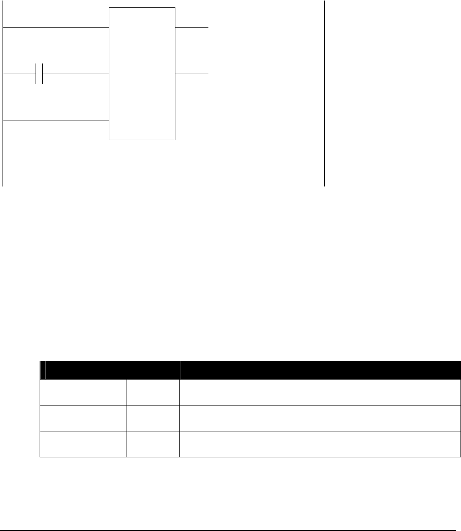
Related Functions
FLOW – Flow Accumulator
Example
In this example a TOTL function is used to read a flow rate from an analog input and accumulate 14
days of data. The analog input measures a flow rate in gallons per minute.
40001
TOTL
14
40100
10009
network 1
The TOTL function in network 1 has the Accumulate and Enable Accumulation inputs connected
to the left power rail. When these inputs are continuously powered the TOTL function accumulates
totals.
The Records variable is set to 14. This means 14 sets of history registers (total, flow time and end of
period time) will be logged. In this example the accumulation input is never turned off meaning that
once 14 sets of history registers are saved the next time contact 10009 is closed the 14th record is
removed and the newest record is added to the history.
Each time contact 10009 is closed it powers the log data input. The accumulated total, accumulation
time and the time at the end of the period is saved in the history registers. The contact should be
closed by another network once per day for this example.
The element configuration for the TOTL block is as follows
Parameter Value Notes
Input Register 42000 The register that contains the rate input. This is a floating
point value contained in register 42000 and 42001.
Rate Units per
minute The value in floating point register 42000 represents the
flow rate in units/minute
Sample Interval 10 sample, calculate, and accumulate approximately every
10.0 seconds
TelePACE Ladder Logic Function Reference
February 19, 2007
166
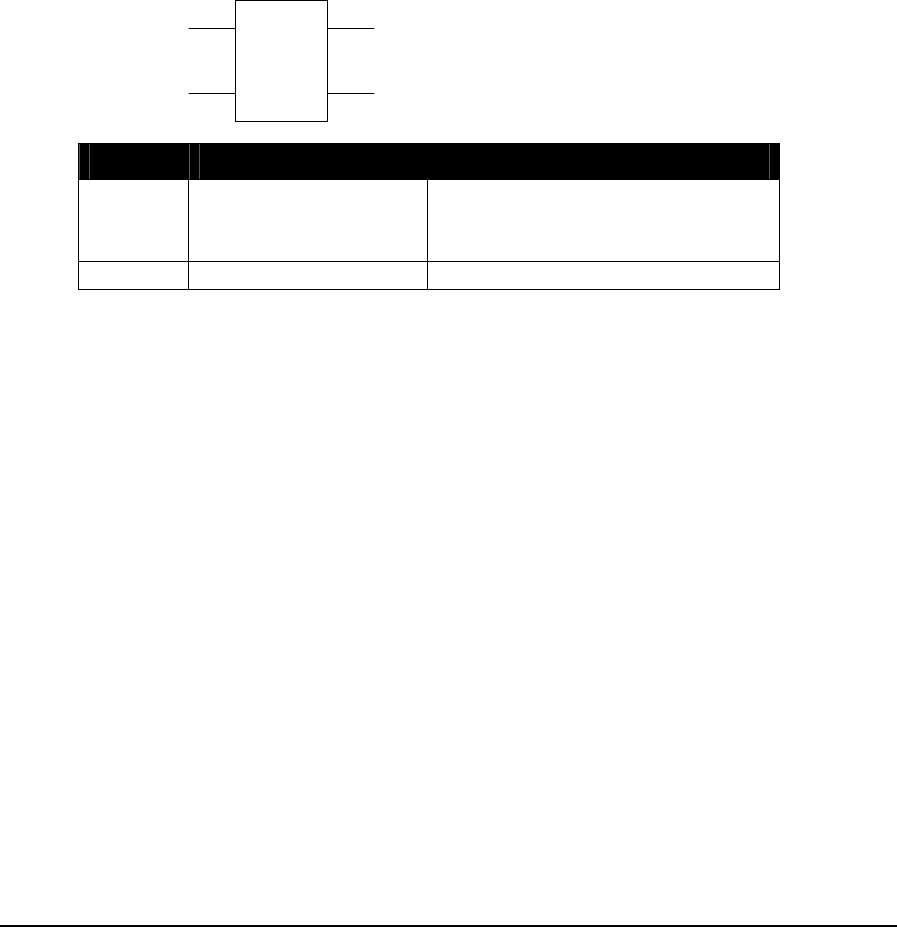
2.72 UCTR – Up Counter
Description
The UCTR function block increments (adds one to) the value in the counter register when the
increment count input changes from OFF to ON. The counter stops counting when the limit register
or constant is reached.
When the counting enabled input is ON and the increment count changes from OFF to ON the
counter value increments by one. When the counting enabled input is OFF the counter is reset to
zero.
When the counting enabled input is ON and the counter equals the limit then the counter = limit
output is ON.
When the counting enabled input is ON and the counter is less than the limit then the counter <
limit output is ON.
limit
UCTR
counter
OFF to ON = increment count
ON = counter < limitON = counting enabled
OFF = reset counter to 0
ON = counter = limit
Variable Valid Types Description
Limit constant (1..65535)
input register (3xxxx)
holding register (4xxxx)
Upper limit for counter
Counter holding register (4xxxx) Register holds current counter value
Related Functions
DCTR – Down Counter
TelePACE Ladder Logic Function Reference
February 19, 2007
167

Example
network 1:
100
UCTR
45776
+1
T.1
46770
01057
)
(
01057
01058
)(
01057
01058
The UCTR function in network 1 increments each time the timer output is enabled. The timer limit is
0.1 seconds and it will take 10 seconds for the UCTR to increment 100 times.
When the timer limit is reached after 0.1 seconds the output coil 01057 is energized. NC contact
01057 will open resetting the timer and NO contact 01057 will close incrementing the UCTR.
When the UCTR increments to 100 output coil 01058 is energized. NC contacts 01058 will open and
the UCTR will reset counter to zero. This will happen every 10 seconds.
TelePACE Ladder Logic Function Reference
February 19, 2007
168

2.73 UTOF - Unsigned Integer to Floating-Point
Description
The UTOF element converts an unsigned register or constant into a floating-point number and stores
the result in a floating-point holding register.
When the enable input is ON, value is converted into a floating-point number and stored in the
result floating-point register. The element output is ON when the input is.
value
UTOF
result
ON = enable copies status of input
Function Variables
The element has two parameters.
Variable Valid Types Description
value Constant (0…65535)
input register (3xxxx)
holding register (4xxxx)
Unsigned value to convert
result 2 holding registers (4xxxx) Converted floating-point value
Notes
Floating-point values are stored in two consecutive I/O database registers. The lower numbered
register contains the upper 16 bits of the number. The higher numbered register contains the lower 16
bits of the number.
Floating point numbers can represent positive or negative values in the range –3.402 × 1038 to 3.402
× 1038.
Related Functions
STOF - Signed Integer to Floating-Point
FTOS - Floating-Point to Signed Integer
FTOU - Floating-Point to Unsigned Integer
TelePACE Ladder Logic Function Reference
February 19, 2007
169

Example
network 1:
+2233
UTOF
40100
The UTOF function in network 1 converts unsigned constant +2233 to a floating-point number and
puts the value into register 40100. In this example the content of floating point-register 40100
(registers 40100 and 40101) is 2233.00.
TelePACE Ladder Logic Function Reference
February 19, 2007
170

2.74 XOR – Exclusive Or Block
Description
The XOR function block logically EXCLUSIVE-ORs the source block of registers with the
destination block of registers and stores the result in the destination block of registers.
source
XOR
size
destination
ON = enable XOR copies status of input1
Variable Valid Types Description
Source coil block (0xxxx)
status block (1xxxx)
input register (3xxxx)
holding register (4xxxx)
The first register in the first source block.
The address for a coil or status register block is
the first register in a group of 16 registers that
will be EXCLUSIVE-ORed.
Destination coil block (0xxxx)
holding register (4xxxx)
The first register in the second source block and
destination block.
The address for a coil register block is the first
register in a group of 16 registers that will be
EXCLUSIVE-ORed.
Size constant (1..100) The number of 16 bit words in the block.
Notes
Exclusive-or accesses 16 bit words. Coil and status register blocks are groups of 16 registers that
start with the register specified as the block address. A block size of 2 corresponds to 32 coils, or two
holding registers.
Coil and status register blocks must begin at the start of a 16 bit word within the controller memory.
Suitable addresses are 00001, 00017, 10001, 10033, etc.
Related Functions
AND – And Block
NOT – Not Block
OR – Or Block
TelePACE Ladder Logic Function Reference
February 19, 2007
171
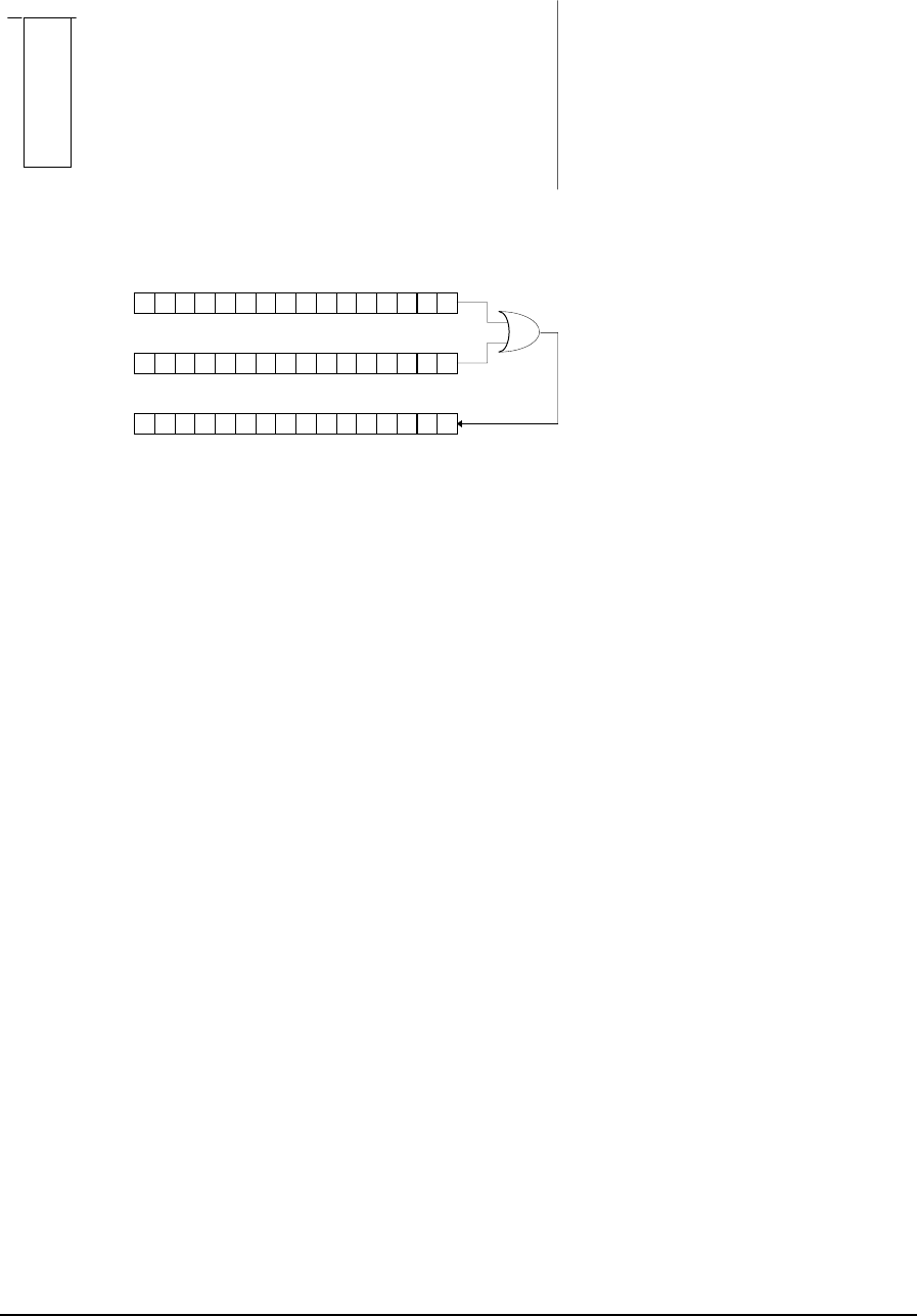
Example
network 1:
11000
01026
XOR
1
In this example the source block has a value of 1521310 (11101101101101). The destination register
has a value of 2237910 (101011101101011) before the XOR function and a value of 2765410 after the
XOR function.
1100 1101 0110 1011
1010 1110 0110 1101
source register
destination register
before XOR
destination register
afterXOR 0110 0011 0000 0110
TelePACE Ladder Logic Function Reference
February 19, 2007
172

TelePACE Ladder Logic
Register Assignment Reference
CONTROL
MICROSYSTEMS
SCADA products... for the distance
48 Steacie Drive Telephone: 613-591-1943
Kanata, Ontario Facsimile: 613-591-1022
K2K 2A9 Technical Support: 888-226-6876
Canada 888-2CONTROL

©2007 Control Microsystems Inc.
All rights reserved.
Printed in Canada.
Trademarks
TelePACE, SCADASense, SCADAServer, SCADALog, RealFLO, TeleSAFE,
TeleSAFE Micro16, SCADAPack, SCADAPack Light, SCADAPack Plus,
SCADAPack 32, SCADAPack 32P, SCADAPack 350, SCADAPack LP,
SCADAPack 100, SCADASense 4202 DS, SCADASense 4202 DR,
SCADASense 4203 DS, SCADASense 4203 DR, SCADASense 4102,
SCADASense 4012, SCADASense 4032 and TeleBUS are registered
trademarks of Control Microsystems.
All other product names are copyright and registered trademarks or trade names
of their respective owners.
Material used in the User and Reference manual section titled SCADAServer
OLE Automation Reference is distributed under license from the OPC
Foundation.
TelePACE Ladder Logic Register Assignment Reference
May 8, 2007
1

Table of Contents
1 REGISTER ASSIGNMENT REFERENCE..................................................... 5
1.1 Register Assignment Specification................................................................. 7
1.2 Register Assignment Example ....................................................................... 8
1.3 Analog Input I/O Modules............................................................................. 10
1.3.1 AIN Controller RAM Battery V................................................................. 11
1.3.2 AIN Controller temperature..................................................................... 12
1.3.3 AIN 5501 Module.................................................................................... 13
1.3.4 AIN 5502 Module.................................................................................... 14
1.3.5 AIN 5503 Module.................................................................................... 15
1.3.6 AIN 5504 Module.................................................................................... 16
1.3.7 AIN 5505 Module.................................................................................... 17
1.3.8 AIN 5506 Module.................................................................................... 21
1.3.9 AIN 5521 Module.................................................................................... 25
1.3.10 AIN Generic 8 Point Module ................................................................... 26
1.4 Analog Output I/O Modules.......................................................................... 27
1.4.1 AOUT 5301 Module................................................................................ 28
1.4.2 AOUT 5302 Module................................................................................ 29
1.4.3 AOUT 5304 Module................................................................................ 30
1.4.4 AOUT Generic 2 Point Module ............................................................... 31
1.4.5 AOUT Generic 4 Point Module ............................................................... 32
1.5 Configuration I/O Modules ........................................................................... 33
1.5.1 CNFG Clear Protocol Counters .............................................................. 34
1.5.2 CNFG Clear Serial Port Counters........................................................... 35
1.5.3 CNFG DTR Off ....................................................................................... 36
1.5.4 CNFG 5904 HART Interface Module ...................................................... 37
1.5.5 CNFG IP Settings ................................................................................... 39
1.5.6 CNFG LED Power Settings..................................................................... 41
1.5.7 CNFG Modbus IP Interface .................................................................... 43
1.5.8 CNFG Modbus IP Protocols.................................................................... 45
1.5.9 CNFG Modbus/TCP Settings.................................................................. 47
1.5.10 CNFG PID Control Block ........................................................................ 49
1.5.11 CNFG Power Mode ................................................................................ 51
1.5.12 CNFG Protocol Settings Method 1.......................................................... 52
1.5.13 CNFG Protocol Settings Method 2.......................................................... 54
1.5.14 CNFG Protocol Settings Method 3.......................................................... 56
TelePACE Ladder Logic Register Assignment Reference
May 8, 2007
2

1.5.15 CNFG Real Time Clock and Alarm......................................................... 59
1.5.16 CNFG Save Settings to EEPROM.......................................................... 61
1.5.17 CNFG Serial Port Settings...................................................................... 62
1.5.18 CNFG Store and Forward....................................................................... 64
1.6 Counter I/O Modules.................................................................................... 66
1.6.1 CNTR Controller Counter Inputs............................................................. 67
1.6.2 CNTR Controller Interrupt Input.............................................................. 68
1.6.3 CNTR 5410 input module ....................................................................... 69
1.7 Diagnostic I/O Modules................................................................................ 70
1.7.1 DIAG Controller Status Code.................................................................. 71
1.7.2 DIAG DNP Connection Status ................................................................ 73
1.7.3 DIAG DNP Event Status Module ............................................................ 74
1.7.4 DIAG DNP Port Status Module............................................................... 76
1.7.5 DIAG DNP Station Status ....................................................................... 78
1.7.6 DIAG Force............................................................................................. 80
1.7.7 DIAG IP Connections.............................................................................. 81
1.7.8 DIAG Logic Status .................................................................................. 82
1.7.9 DIAG Modbus Protocol Status................................................................ 83
1.7.10 DIAG Serial Port Comm. Status.............................................................. 85
1.7.11 DIAG Serial Port Protocol Status............................................................ 87
1.8 Digital Input I/O Modules.............................................................................. 89
1.8.1 DIN Controller Digital Inputs ................................................................... 90
1.8.2 DIN Controller Interrupt Input.................................................................. 91
1.8.3 DIN Controller Option Switches .............................................................. 92
1.8.4 DIN SCADAPack 32 Option Switches .................................................... 93
1.8.5 DIN 5401 Module.................................................................................... 94
1.8.6 DIN 5402 Module.................................................................................... 95
1.8.7 DIN 5403 Module.................................................................................... 97
1.8.8 DIN 5404 Module.................................................................................... 98
1.8.9 DIN 5405 Module.................................................................................... 99
1.8.10 DIN 5421 Module.................................................................................. 101
1.8.11 DIN Generic 16 Point Module ............................................................... 102
1.8.12 DIN Generic 8 Point Module ................................................................. 104
1.9 Digital Output I/O Modules......................................................................... 105
1.9.1 DOUT 5401 Module.............................................................................. 106
1.9.2 DOUT 5402 Module.............................................................................. 107
1.9.3 DOUT 5406 Module.............................................................................. 108
1.9.4 DOUT 5407 Module.............................................................................. 109
TelePACE Ladder Logic Register Assignment Reference
May 8, 2007
3

1.9.5 DOUT 5408 Module.............................................................................. 110
1.9.6 DOUT 5409 Module.............................................................................. 111
1.9.7 DOUT 5411 Module.............................................................................. 112
1.9.8 DOUT Generic 16 Point Module ........................................................... 114
1.9.9 DOUT Generic 8 Point Module ............................................................. 116
1.10 SCADAPack and SCADASense Series I/O Modules................................. 117
1.10.1 4202 DR Extended/4203 DR IO............................................................ 118
1.10.2 4202 DR I/O.......................................................................................... 120
1.10.3 4202/4203 DS I/O................................................................................. 122
1.10.4 SCADAPack AOUT Module.................................................................. 124
1.10.5 SCADAPack 5601 I/O Module.............................................................. 126
1.10.6 SCADAPack 5602 I/O Module.............................................................. 129
1.10.7 SCADAPack 5604 I/O Module.............................................................. 132
1.10.8 SCADAPack 5606 I/O Module.............................................................. 138
1.10.9 SCADAPack LP I/O .............................................................................. 143
1.10.10 SCADAPack 100 I/O............................................................................. 147
1.10.11 SCADAPack 350 I/O............................................................................. 149
1.11 Controller Default Register Assignments ................................................... 153
1.11.1 4202 DR Extended/4203 DR I/O Register Assignment......................... 154
1.11.2 SCADASense 4202/4203 DS I/O Default Register Assignment ........... 155
1.11.3 Micro16 Default Register Assignment (Backwards Compatible Modules)156
1.11.4 Micro16 Default Register Assignment (Controller I/O Only).................. 161
1.11.5 SCADAPack (5601 I/O Module) Default Register Assignment ............. 162
1.11.6 SCADAPack (5604 I/O Module) Default Register Assignment ............. 163
1.11.7 SCADAPack LIGHT Default Register Assignment................................ 164
1.11.8 SCADAPack PLUS (5601 I/O Module) Default Register Assignment... 165
1.11.9 SCADAPack Plus (5604 I/O Module) Default Register Assignment ..... 166
1.11.10 SCADAPack LP Default Register Assignment...................................... 167
1.11.11 SCADAPack 350 Default Register Assignment .................................... 168
1.11.12 SCADAPack 32 (5601 I/O Module) Default Register Assignment ........ 169
1.11.13 SCADAPack 32 (5604 I/O Module) Default Register Assignment ........ 170
1.11.14 SCADAPack 32P Default Register Assignment.................................... 171
1.11.15 SCADAPack 100 Default Register Assignment .................................... 172
TelePACE Ladder Logic Register Assignment Reference
May 8, 2007
4

1 Register Assignment Reference
A complete description of each I/O Module in the Register Assignment is presented in this reference.
The I/O modules are divided into classes that group similar modules together for ease of reference.
All I/O hardware that is used by the controller must be assigned to I/O database registers in order for
the I/O data to be used by the ladder program. Ladder logic programs may read data from, or write
data to the I/O hardware through user-assigned registers in the I/O database.
Register assignments are stored in the user configured Register Assignment and are downloaded with
the ladder logic application program.
The Register Assignment assigns I/O database registers to user-assigned registers using I/O Modules.
An I/O Module can refer to an actual I/O hardware module (e.g. 5401 Digital Input Module) or it
may refer to a set of controller parameters, such as serial port settings.
Analog Input (AIN)
These modules are used to assign data from physical analog inputs to input registers in the I/O
Database. The physical analog inputs are specific 5000 Series I/O modules, generic I/O modules, and
internal controller data such as RAM battery voltage and board temperature.
Note: To properly view analog input/output registers, the register type should be set to type signed.
Setting the register type to anything else may result in inaccurate readings being
displayed/written to these registers.
Analog Output (AOUT)
These modules are used to assign data from the I/O Database to physical analog outputs. The
physical analog outputs are specific 5000 Series I/O modules or generic I/O modules.
Note: To properly view analog input/output registers, the register type should be set to type signed.
Setting the register type to anything else may result in inaccurate readings being
displayed/written to these registers.
Digital Input (DIN)
These modules are used to assign data from physical digital inputs to input registers in the I/O
Database. The physical digital inputs are specific 5000 Series I/O modules, generic I/O modules, and
controller digital inputs.
Digital Output (DOUT)
These modules are used to assign data from the I/O Database to physical digital outputs. The
physical digital outputs are specific 5000 Series I/O modules or generic I/O modules.
Counter Input (CNTR)
These modules are used to assign data from physical counter inputs to input registers in the I/O
Database. The physical counter inputs are specific 5000 Series I/O modules and controller counter
inputs.
TelePACE Ladder Logic Register Assignment Reference
May 8, 2007
5

SCADAPack (SCADAPack 5601, SCADAPack 5602, SCADAPack 5604, and
SCADAPack AOUT)
These modules are used to assign data to registers in the I/O Database, from physical SCADAPack
digital and analog I/O. The physical inputs and outputs are specific SCADAPack I/O modules.
Controller Diagnostic (DIAG)
These modules are used to assign diagnostic data from the controller to input or status registers in the
I/O Database. The diagnostic data is used to monitor internal controller data such as controller status
code, the force LED, serial port communication status and serial port protocol status.
Controller Configuration (CNFG)
These modules are used to assign data from I/O Database coil and holding registers to controller
configuration registers. The configuration data is used to configure controller settings such as
clearing protocol and serial counters, real time clock settings, HART protocol interface and PID
control blocks.
Default Register Assignment
This provides a default assignment of registers for the selected controller type.
TelePACE Ladder Logic Register Assignment Reference
May 8, 2007
6

1.1 Register Assignment Specification
The Register Assignment I/O modules described in this manual are formatted as follows.
Header
The module header displays the I/O module name.
Module Description
The module description section describes the function, data origin and data destination of the I/O
module.
Register Assignment
The register assignment description is used to describe the information required in the Add Register
Assignment dialog. The information required for each section of the Add Register Assignment
dialog is explained in the table shown below.
The column at the left of the table indicates the information that is required for the I/O module in the
Add Register Assignment dialog. The requirements vary depending on the I/O module.
Module Module Name
Address Physical I/O modules are assigned a unique
module address between 0 and 15. No
other similar type modules may use this
module address.
Diagnostic and configuration modules and
SCADAPack 5601, 5602 and 5604 I/O
modules do not require a physical address.
Type Register type of 0xxxx, 1xxxx, 3xxxx or
4xxxx.
Start First register of any unused
block of consecutive registers. 3xxxx
End Last register of block 3xxxx + 7
Registers Number of registers for module.
Description Description of module.
Extended Parameters Additional parameters, if applicable.
Register Data
The register data table describes what data each assigned register will contain.
Notes Section
The notes section is used to provide any additional information that may be useful when using the
module.
TelePACE Ladder Logic Register Assignment Reference
May 8, 2007
7

1.2 Register Assignment Example
In this example, the application program requires a 5501 Analog Input module. The analog input
data from the 5000 Series 5501 module must be assigned to the I/O Database before the Ladder
Logic application program can access it. The register assignment is used to assign the input data to
the I/O database.
Run the TelePACE program.
Select File from the menu bar. From the drop down File menu, select New.
Select Controller from the menu bar. From the drop down Controller menu, select Register
Assignment.
The Register Assignment is displayed. The table is initially empty when a new file is started.
Selecting the Add button opens the Add Register Assignment dialog.
The first I/O module in the I/O module list is displayed and highlighted in the Module window.
Click the left mouse button on the down arrow at the left side of the Module window.
The entire I/O module list is displayed in the drop down window. Use the up and down arrows at the
right side of the list to scroll through the list of I/O modules.
Select the AIN 5501 module by clicking the left mouse button on the AIN 5501 module text. When
selected the AIN 5501 module is highlighted and the module list is closed.
The AIN 5501 module is described in the Register Assignment section of this manual.
The module reference for the AIN module is described in detail below. Each section of the module
reference provides information that is required to configure the register assignment. All modules in
the Register Assignment follow a similar format.
Header
The module header displays the I/O module name. For example, AIN 5501 Module is displayed.
Module Description
The module description section describes the function, data origin and data destination of the I/O
module. The description for the AIN 5501 module indicates that data is received from the 5501
Analog Input module. This data is then assigned to eight consecutive input (3xxxx) registers in the
I/O database. The I/O database registers used by the AIN 5501 module are continuously updated
with data from the 5000 Series 5501 analog input module.
Register Assignment Description
The register assignment description is used to describe the information required in the Add Register
Assignment dialog. The information required for each section of the Add Register Assignment
dialog is explained in the table. A sample is shown below.
Module AIN 5501 Module
Address This module is assigned a unique module
address between 0 and 15. No other AIN-
type module may use this module address.
Type Input Register
TelePACE Ladder Logic Register Assignment Reference
May 8, 2007
8

Start First register of any unused
block of 8 consecutive input
registers.
3xxxx
End Last register of block 3xxxx + 7
Registers 8 input registers.
Description None
Extended Parameters None
The column at the left of the table indicates the information that is required for the I/O module in the
Add Register Assignment dialog. The requirements vary depending on the I/O module.
Module The I/O module highlighted in the Module window.
Address The physical address of the 5000 Series 5501 analog input module. This
address is set equal to the address of 5501 analog input module. See the
5501 Analog Input Module User Manual.
Type The I/O database register type that the I/O module will assign data to. The
I/O database register types are:
Coil Register 0xxxx
Status Register 1xxxx
Input Register 3xxxx
Holding Register 4xxxx
The AIN 5501 module will assign data to input registers (3xxxx).
Start The I/O database register address where the AIN 5501 module begins the
register assignment. For the AIN 5501 module, this is the first of eight
consecutive input registers.
End The I/O database register where the AIN 5501 module ends the register
assignment. This value is automatically set to Start + 8 by the AIN 5501
module.
Registers Number of I/O database registers that the AIN 5501 module assigns. This
is automatically set to 8 for the AIN 5501 module.
Description The register type description for I/O modules that assign multiple
types of registers. The AIN 5501 module does not have an entry for this
field.
Extended Parameters None.
Register Data
The register data table describes what data each assigned register will contain. In the case of the AIN
5501 Module, the data will be the physical analog input channels from the 5000 Series 5501 module.
Notes Section
The notes section is used to provide any additional information that may be useful when using this
module.
TelePACE Ladder Logic Register Assignment Reference
May 8, 2007
9

1.3 Analog Input I/O Modules
Analog input modules are used to assign data from physical analog inputs to input registers in the
I/O Database. The physical analog inputs are specific 5000 Series I/O modules, generic I/O modules,
and internal controller data such as RAM battery voltage and board temperature.
Analog input I/O modules may assign data to any input registers in the I/O database that are not
being used by another Analog Input or Counter I/O module. There are 1024 I/O database input
registers available. These input registers are numbered 30001 - 31024. Input registers are referred to
as 3xxxx registers throughout this manual.
All I/O database input registers that are not assigned to any other I/O modules may be used as
general purpose input registers in a ladder program. The I/O modules available are described in the
following pages.
Note: To properly view analog input/output registers, the register type should be set to type signed.
Setting the register type to anything else may result in inaccurate readings being
displayed/written to these registers.
TelePACE Ladder Logic Register Assignment Reference
May 8, 2007
10

1.3.1 AIN Controller RAM Battery V
Description
The module, AIN Controller RAM battery V, reads the RAM backup battery voltage of the
SCADAPack controllers. This module reads the input voltage for the SCADASense programmable
controllers.( SCADASense 4202 DR, 4202 DS, 4203 DR, and 4203 DS) The voltage value is
assigned to one input register. The input register is updated continuously with voltage data read from
the RAM battery.
Register Assignment
Module AIN Controller RAM battery V
Address No physical address is required.
Type Input Register
Start Any unused input register. 3xxxx
End Same as start register.
Registers 1 input register
Description None
Extended Parameters None
Register Data
Register Assignment Assignment to Module Hardware
1 input register RAM battery voltage (0-5000 millivolts for SCADAPack
controllers).
Input power voltage (0-32767 millivolts for SCADASense
Programmable Controllers.
Notes
One input register is always assigned to the I/O Database when this module is used.
The 3.6V lithium battery will return a typical value of 3600 or 3700. A reading less than 3000 (3.0V)
indicates that the lithium battery requires replacement. The RAM battery voltage resolution is 100
millivolts.
TelePACE Ladder Logic Register Assignment Reference
May 8, 2007
11
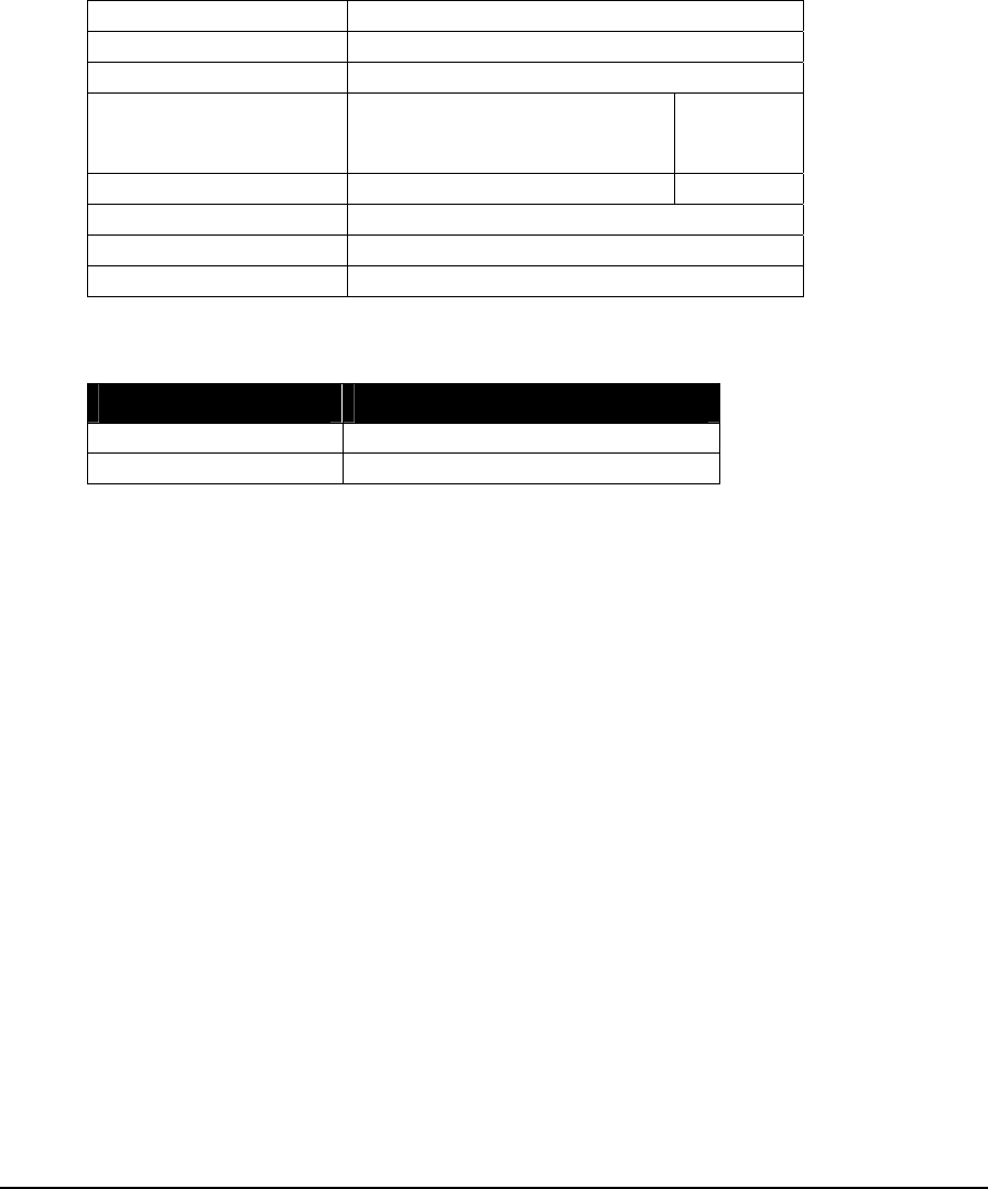
1.3.2 AIN Controller temperature
Description
The module, AIN Controller temperature, reads the circuit board temperature of the 5203 or 5204
controller. The temperature data is assigned to two consecutive input registers. The input registers
are updated continuously with data read from the controller.
Register Assignment
Module AIN Controller temperature
Address No physical address is required.
Type Input Register
Start First register of any unused
block of 2 consecutive input
registers.
3xxxx
End Last register of block 3xxxx + 1
Registers 2 input registers.
Description None
Extended Parameters None
Register Data
Register Assignment Assignment to Module Hardware
Start Register Board temperature (degrees C)
Start Register + 1 Board temperature (degrees F)
Notes
Two input registers are always assigned to the I/O Database when this module is used.
The temperature sensor returns a value in the range -40°C to 75°C or -40°F to 167°F. Temperatures
outside this range cannot be measured.
Refer to the System Manual for further information on the circuit board temperature.
TelePACE Ladder Logic Register Assignment Reference
May 8, 2007
12

1.3.3 AIN 5501 Module
Description
The AIN 5501 module provides eight analog inputs, from the 5501 analog input module, for each
module address. Data from each module is assigned to eight consecutive input registers. The input
registers are updated continuously with data read from the analog inputs.
Register Assignment
Module AIN 5501 module
Address This module is assigned a unique module
address between 0 and 15. No other AIN-
type module may use this module address.
Type Input Register
Start First register of any unused
block of 8 consecutive input
registers.
3xxxx
End Last register of block 3xxxx + 7
Registers 8 input registers.
Description None
Extended Parameters None
Register Data
Registers Assignment to Module Hardware
Start Register Analog input 0
Start Register + 1 Analog input 1
Start Register + 2 Analog input 2
Start Register + 3 Analog input 3
Start Register + 4 Analog input 4
Start Register + 5 Analog input 5
Start Register + 6 Analog input 6
Start Register + 7 Analog input 7
Notes
Eight input registers are always assigned to the I/O Database when this module is used.
Refer to the 5501 Analog Input Module User Manual for further information.
TelePACE Ladder Logic Register Assignment Reference
May 8, 2007
13

1.3.4 AIN 5502 Module
Description
The AIN 5502 module provides eight analog inputs, from the 5502 analog input module, for each
module address. Data from each module is assigned to eight consecutive input registers. The input
registers are updated continuously with data read from the analog inputs.
Register Assignment
Module AIN 5502 module
Address This module is assigned a unique module
address between 0 and 15. No other AIN-
type module may use this module address.
Type Input Register
Start First register of any unused
block of 8 consecutive input
registers.
3xxxx
End Last register of block 3xxxx + 7
Registers 8 input registers.
Description None
Extended Parameters None
Register Data
Registers Assignment to Module Hardware
Start Register Analog input 0
Start Register + 1 Analog input 1
Start Register + 2 Analog input 2
Start Register + 3 Analog input 3
Start Register + 4 Analog input 4
Start Register + 5 Analog input 5
Start Register + 6 Analog input 6
Start Register + 7 Analog input 7
Notes
Eight input registers are always assigned to the I/O Database when this module is used.
Refer to the 5502 Analog Input Module User Manual for further information.
TelePACE Ladder Logic Register Assignment Reference
May 8, 2007
14

1.3.5 AIN 5503 Module
Description
The AIN 5503 module provides four analog inputs, from the 5503 RTD analog input module, for
each module address. Data is assigned to four consecutive input registers. The input registers are
updated continuously with data read from the analog inputs.
Register Assignment
Module AIN 5503 module
Address This module is assigned a unique module
address between 0 and 15. No other AIN-
type module may use this module address.
Type Input Register
Start First register of any unused
block of 4 consecutive input
registers.
3xxxx
End Last register of block 3xxxx + 3
Registers 4 input registers.
Description None
Extended Parameters None
Register Data
Registers Assignment to Module Hardware
Start Register Analog input 0
Start Register + 1 Analog input 1
Start Register + 2 Analog input 2
Start Register + 3 Analog input 3
Notes
Four input registers are always assigned to the I/O Database when this module is used.
Refer to the 5503 RTD Analog Input Module User Manual for further information.
TelePACE Ladder Logic Register Assignment Reference
May 8, 2007
15
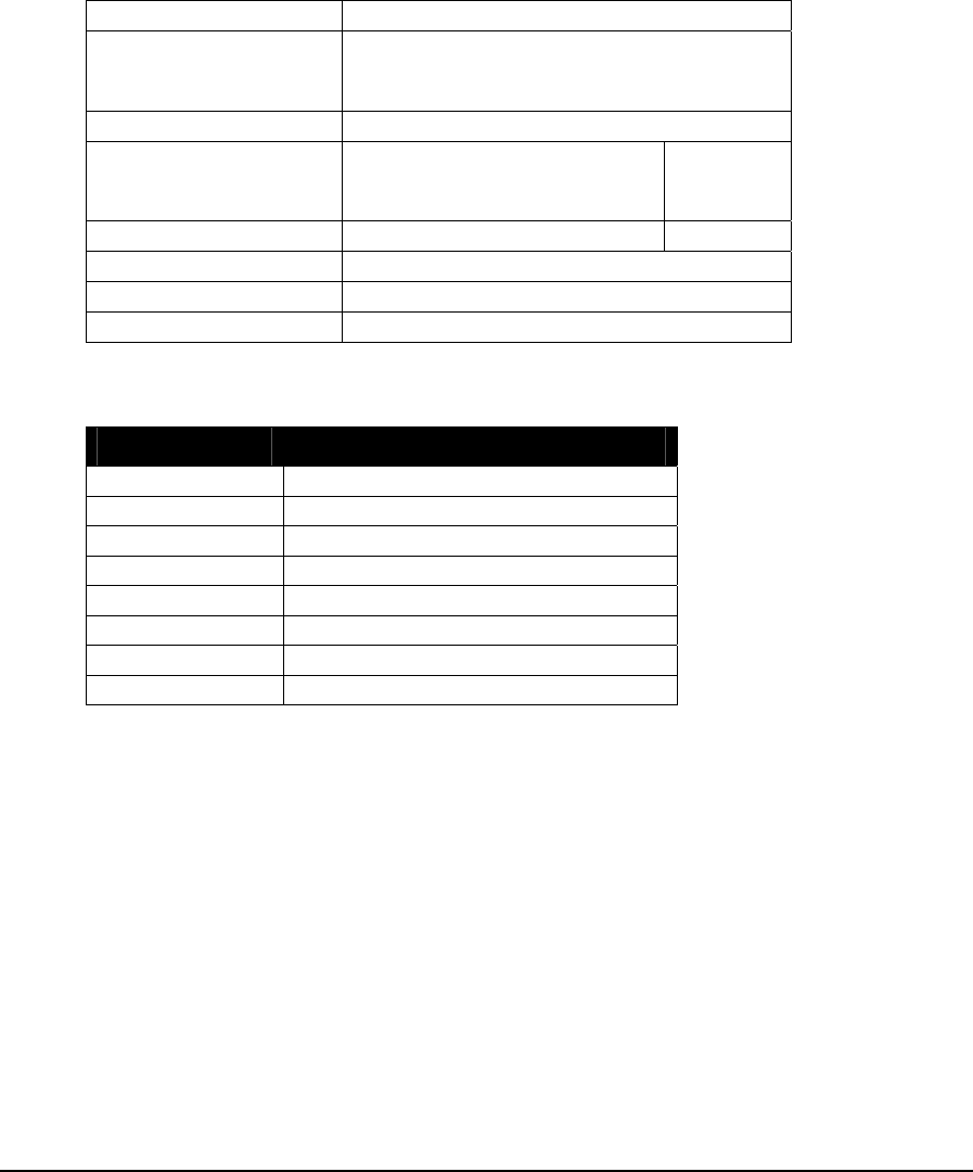
1.3.6 AIN 5504 Module
Description
The AIN 5504 module provides eight analog inputs, from the Thermocouple analog input module,
for each module address. Data is assigned to eight consecutive input registers. The input registers are
updated continuously with data read from the analog inputs.
Register Assignment
Module AIN 5504 module
Address This module is assigned a unique module
address between 0 and 15. No other AIN-
type module may use this module address.
Type Input Register
Start First register of any unused
block of 8 consecutive input
registers.
3xxxx
End Last register of block 3xxxx + 7
Registers 8 input registers.
Description None
Extended Parameters None
Register Data
Registers Assignment to Module Hardware
Start Register Analog input 0
Start Register + 1 Analog input 1
Start Register + 2 Analog input 2
Start Register + 3 Analog input 3
Start Register + 4 Analog input 4
Start Register + 5 Analog input 5
Start Register + 6 Analog input 6
Start Register + 7 Analog input 7
Notes
Eight input registers are always assigned to the I/O Database when this module is used.
Refer to the 5504 Thermocouple Analog Input Module User Manual for further information.
TelePACE Ladder Logic Register Assignment Reference
May 8, 2007
16

1.3.7 AIN 5505 Module
Description
The AIN 5505 module provides four RTD analog input points from a 5505 RTD module. A
maximum of sixteen 5505 RTD modules may be installed on the I/O bus. The 5505 RTD module can
operate in Native mode or in 5503 Emulation Mode. The operating mode is determined via a DIP
switch on the 5505 RTD module. Refer to the Control Microsystems Hardware Manual for details
on the DIP switch settings for the module.
When using the 5505 RTD module in 5503 Emulation mode the AIN 5503 module is used in the
register assignment. See the AIN 5503 Module section if the module is to be used in 5503 Emulation
mode.
The 5505 RTD module native mode provides enhanced capability over the 5503 emulation mode.
The module operates in native mode if the 5503 Emulation DIP switch is open. This mode is
recommended for all new installations.
• Each input is individually configurable for resistance measurement or RTD temperature
measurement
• Each RTD input is configurable to return the measured temperature in degrees Celsius,
Kelvin, or Fahrenheit.
• All inputs have a common configurable filter rate that can be used to dampen process
variations or noise.
• The module returns diagnostic and status information for each input, such as RTD type
(3 or 4 wire), open RTD annunciation, and RTD out of range annunciation.
• Data is returned as an IEEE 32 bit, single precision floating point number that requires no
additional scaling.
RTD data is assigned to eight consecutive input (3xxxx) registers, two for each floating point RTD
value. The input registers are updated continuously with data read from the analog inputs.
The 5505 RTD module provides 16 internal digital input (1xxxx) registers that return status and
diagnostic information about the RTDs. The digital input registers are updated continuously with
data read from the digital inputs.
TelePACE Ladder Logic Register Assignment Reference
May 8, 2007
17
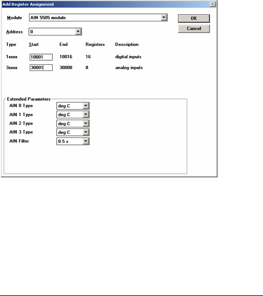
Register Assignment
The register assignment for the AIN 5505 module is used to configure the registers used for the
module data and the Extended Parameters available for the module. To open the register assignment
dialog for the AIN 5505 module:
• Select Register Assignment from the Controller menu in TelePACE.
• In the Register Assignment window select the Add button.
• In the Add Register Assignment dialog select the AIN 5505 module from the list presented in
the Module window.
The register assignment dialog for the AIN 5505 module is shown below.
The Module selection displays the name of the 5505 RTD module used for the register assignment.
dip switches on the module. A maximum of sixteen AIN type modules
y
r the digital input status data. Sixteen sequential
data. Any unused block of sixteen registers may
for an explanation of the digital input status
The register type 3xxxx defines the register range for the analog input data. Eight sequential registers
are needed for the AIN 5505 module analog data. Any unused block of eight registers may be used.
See the Input Register Data section below for an explanation of the analog input.
The Address selection displays the module address of the physical 5505 RTD module. The address
on the module is selected via
ma be added to a system.
The register type 1xxxx defines the register range fo
registers are needed for the AIN 5505 module status
be used. See the Status Register Data section below
data.
TelePACE Ladder Logic Register Assignment Reference
May 8, 2007
18

The Extended Parameters grouping defines the type of data returned from the 5505 RTD module,
n the
• The don sets th grees Celsius.
• The dets the o degrees Fahrenheit.
• The deg K selection sets th
• The ohm selection sets the stance measurement in ohms.
The AIN th used to dampen
process variations or noise.
• The 0e f
• The 1s selection sets the fil
• The 2fil
• The 4fil
Status
Status re gne rs. The following
table beg d
sixteen registers.
for each RTD input, and the filtering used by all RTD inputs.
The Type selection for each input (AIN 0, 1, 2 and 3) defines the measurement type. The data i
input registers assigned to the input is set to the type selected.
eg C selecti e input point measurement type to de
eg F selection s input point data measurement t
e input point data measurement to degrees Kelvin.
s input point data measurement as resi
Filter selection set e input filter rate for all RTD inputs. The filter rate is
.5s selection sets th ilter rate to 0.5 seconds.
ter rate to 1 second.
s selection sets the ter rate to 2 seconds.
s selection sets the ter rate to 4 seconds.
Register Data
gister data is assi d to sixteen consecutive status (1xxxx) registe
signment and continues for ins at the Start ad ress defined in the Register As
Registers Assignment to Module Hardware
Start Register
pen or PWR input is off
OFF = channel 0 RTD is good
ON = channel 0 RTD is o
Start Register + 1 OFF = channel 0 data in range
ON = channel 0 data is out of range
Start Register + 2 OFF = channel 0 RTD is using 3-wire measurement
measurement ON = channel 0 RTD is using 4-wire
Start Register + 3 Reserved for future use
Start Register + 4
pen or PWR input is off
OFF = channel 1 RTD is good
ON = channel 1 RTD is o
Start Register + 5 OFF = channel 1 data in range
ON = channel 1 data is out of range
Start Register + 6 OFF = channel 1 RTD is using 3-wire measurement
ON = channel 1 RTD is using 4-wire measurement
Start Register + 7 Reserved for future use
Start Register + 8 OFF = channel 2 RTD is good
ON = channel 2 RTD is open or PWR input is off
Start Register + 9 OFF = channel 2 data in ra
ON = channel 2 data is out
nge
of range
Start Register + 10 OFF = channel 2
ON = channe
RTD is us urement
l 2 RTD is using 4-wire measurement
ing 3-wire meas
Start Register + 11 Reserved for future use
TelePACE Ladder Logic Register Assignment Reference
May 8, 2007
19

Registers Assignment to Module Hardware
Start Register + 12 OFF = channel 3 RTD is good
is ope is off ON = channel 3 RTD n or PWR input
Start Register + 13 OFF = channel 3 data in range
a is outON = channel 3 dat of range
Start Register + 14 OFF = channel 3 RTD is using 3-wire measurement
is usi rement ON = channel 3 RTD ng 4-wire measu
Start Register + 15 Reserved for future use
ble begins at the Start address defined in the Register Assignment and continues for eight
registers. Note that each input point uses two input registers formatted in IEEE 754 floating
point format.
Input Register Data
onsecutive input (3xxxx) registers. The following Input register data is assigned to eight c
ta
Registers Assignment to Module
Hardware
Start Register and Start Register + 1
(in IEEE 754 floating point format) Analog input 0
Start Register + 2 and Start Register + 3
(in IEEE 754 floating point format)
Analog input 1
Start Register + 4 and Start Register + 5
(in IEEE 754 floating point format)
Analog input 2
Start Register + 6 and Start Register + 7
(in IEEE 754 floating point format)
Analog input 3
Notes
Refer to the 5505 RTD Analog Input Module User Manual for further information.
TelePACE Ladder Logic Register Assignment Reference
May 8, 2007
20

1.3.8 AIN 5506 Module
Description
The AIN 5506 module provides eight analog inputs from a 5506 Analog Input module. A maximum
of sixteen 5506 analog input modules may be installed on the I/O bus. The 5506 Analog Input
module can operate in Native mode or in 5501 Emulation Mode. The operating mode is determined
via a DIP switch on the 5506 Analog Input. Refer to the Control Microsystems Hardware Manual
for details on the DIP switch settings for the module.
When using the 5506 Analog Input module in 5501 Emulation mode the AIN 5501 module is used in
the register assignment. See the AIN 5501 Module section if the module is to be used in 5501
Emulation mode.
5506 native mode provides enhanced capability over the 5501 emulation mode. The module
operates in native mode if the 5501 Emulation DIP switch is open.
• Each input is individually configurable for 0-5V, 1-5V, 0-20mA, or 4-20mA operation.
• Converted analog input data is returned as a signed 15-bit value, providing 8 times more
resolution than in 5501 mode. Negative values are possible, for example if a 4-20mA is
open loop.
• The module returns status information for each analog input indicating if the analog
input is in or out of range for the defined signal type.
• All inputs have a configurable filter rate.
• The input-scanning rate is software configurable to 50 or 60 hertz.
Analog input data is assigned to eight consecutive input (3xxxx) registers. The input registers are
updated continuously with data read from the analog inputs.
The 5506 Analog Input module provides 8 internal digital input (1xxxx) registers that return status
information about the analog inputs. The digital input registers are updated continuously with data
read from the digital inputs.
TelePACE Ladder Logic Register Assignment Reference
May 8, 2007
21
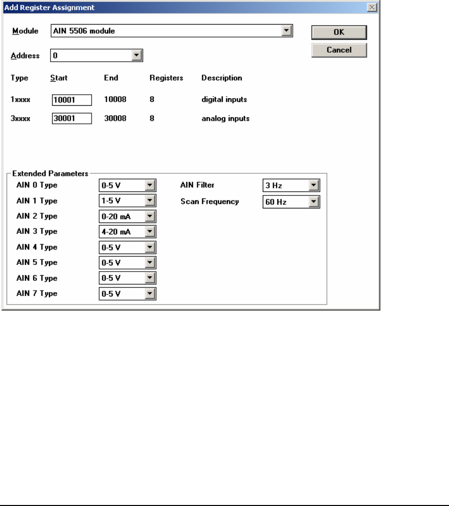
Register Assignment
The register assignment for the AIN 5506 module is used to configure the registers used for the
module data and the Extended Parameters available for the module. To open the register assignment
dialog for the AIN 5505 module:
• Select Register Assignment from the Controller menu in TelePACE.
• In the Register Assignment window select the Add button.
• In the Add Register Assignment dialog select the AIN 5506 module from the list presented in
the Module window.
The register assignment dialog for the AIN 5506 module is shown below.
The Module selection displays the name of the 5506 Analog Input module used for the register
assignment.
The Address selection displays the module address of the physical 5506 Analog Input module. The
address on the module is selected via dip switches on the module. A maximum of sixteen AIN type
modules may be added to a system.
The register type 1xxxx defines the register range for the digital input status data. Eight sequential
registers are needed for the AIN 5506 module status data. Any unused block of eight registers may
be used. See the Status Register Data section below for an explanation of the digital input status
data.
TelePACE Ladder Logic Register Assignment Reference
May 8, 2007
22

The register type 3xxxx defines the register range for the analog input data. Eight sequential registers
are needed for the AIN 5506 module analog data. Any unused block of eight registers may be used.
See the Input Register Data section below for an explanation of the analog input.
The Extended Parameters grouping defines the type of data returned from the 5506 AIN module,
filtering used by all inputs and the scan frequency.
The Type selection for each input (AIN 0, 1, 2, 3, 4, 5, 6, and 7) defines the input measurement type
for the analog input.
• The 0-5V selection sets the input type to measure 0 to 5V input signals.
• The 1-5V selection sets the input type to measure 1 to 5V input signals.
• The 0-20 mA selection sets the input type to measure 0 to 20mA input signals.
• The 4-20 mA selection sets the input type to measure 4 to 20mA input signals.
The AIN Filter selection set the input filter for all analog inputs. Filtering is used to dampen process
variations or noise.
• The 3 Hz filter selection sets the response time to 155ms at 60Hz and 185ms at 50Hz.
• The 6 Hz filter selection sets response time to 85ms at 60Hz and 85ms at 50Hz.
• The 11 Hz filter selection sets response time to 45ms at 60Hz and 55ms at 50Hz.
• The 30 Hz filter selection sets response time to 30ms at 60Hz and 30ms at 50Hz.
The Scan Frequency selection set the input scan rate for all analog inputs. The scan rate selection is
not critical but AC noise rejection is improved at the correct frequency. If the module is used in a DC
environment, the 60 Hz setting will yield slightly faster response time.
• The 60 Hz selection synchronies the input scanning to 60Hz.
• The 50 Hz selection synchronies the input scanning to 50Hz.
Status Register Data
Status register data is assigned to sixteen consecutive status (1xxxx) registers. The following
table begins at the Start address defined in the Register Assignment and continues for
sixteen registers.
Registers Assignment to Module Hardware
Start Register OFF = channel 0 is OK
ON = channel 0 is over or under range
Start Register + 1 OFF = channel 1 is OK
ON = channel 1 is over or under range
Start Register + 2 OFF = channel 2 is OK
ON = channel 2 is over or under range
Start Register + 3 OFF = channel 3 is OK
ON = channel 3 is over or under range
Start Register + 4 OFF = channel 4 is OK
ON = channel 4 is over or under range
Start Register + 5 OFF = channel 5 is OK
ON = channel 5 is over or under range
TelePACE Ladder Logic Register Assignment Reference
May 8, 2007
23

Registers Assignment to Module Hardware
Start Register + 6 OFF = channel 6 is OK
ON = channel 6 is over or under range
Start Register + 7 OFF = channel 7 is OK
ON = channel 7 is over or under range
Input Register Data
Input register data is assigned to eight consecutive input (3xxxx) registers. The following
table begins at the Start address defined in the Register Assignment and continues for eight
registers.
Registers Assignment to Module Hardware
Start Register Analog input 0
Start Register + 1 Analog input 1
Start Register + 2 Analog input 2
Start Register + 3 Analog input 3
Start Register + 4 Analog input 4
Start Register + 5 Analog input 5
Start Register + 6 Analog input 6
Start Register + 7 Analog input 7
Notes
Refer to the 5506 Analog Input Module User Manual for further information.
TelePACE Ladder Logic Register Assignment Reference
May 8, 2007
24
1.3.9 AIN 5521 Module
Description
The AIN 5521 module provides eight analog inputs, from the 5521 Potentiometer analog input
module, for each module used. Data is assigned to eight consecutive input registers. The input
registers are updated continuously with data read from the analog inputs.
Register Assignment
Module AIN 5521 module
Address This module is assigned a unique module
address between 0 and 7. No other AIN-
type module may use this module address.
Type Input Register
Start First register of any unused
block of 8 consecutive input
registers.
3xxxx
End Last register of block 3xxxx + 7
Registers 8 input registers.
Description None
Extended Parameters None
Register Data
Registers Assignment to Module Hardware
Start Register Analog input 0
Start Register + 1 Analog input 1
Start Register + 2 Analog input 2
Start Register + 3 Analog input 3
Start Register + 4 Analog input 4
Start Register + 5 Analog input 5
Start Register + 6 Analog input 6
Start Register + 7 Analog input 7
Notes
Eight input registers are always assigned to the I/O Database when this module is used.
Refer to the 5521 Potentiometer Analog Input Module User Manual for further information.
TelePACE Ladder Logic Register Assignment Reference
May 8, 2007
25

1.3.10 AIN Generic 8 Point Module
Description
The AIN Generic 8 point module provides eight analog inputs. Data is assigned to eight
consecutive input registers. The input registers are updated continuously with data read from the
analog inputs. The AIN Generic 8 point module may be used in place of any other 8 point AIN-
type module.
The AIN Generic 8 point module type is a useful selection early on in the system design stage
before the final selection of the specific AIN module type is known.
Register Assignment
Module AIN Generic 8 Point Module
Address This module is assigned a unique module
address between 0 and 15. No other AIN-
type module may use this module address.
Type Input Register
Start First register of any unused
block of 8 consecutive input
registers.
3xxxx
End Last register of block 3xxxx + 7
Registers 8 input registers.
Description None
Extended Parameters None
Register Data
Registers Assignment to Module Hardware
Start Register Analog input 0
Start Register + 1 Analog input 1
Start Register + 2 Analog input 2
Start Register + 3 Analog input 3
Start Register + 4 Analog input 4
Start Register + 5 Analog input 5
Start Register + 6 Analog input 6
Start Register + 7 Analog input 7
Notes
Eight input registers are always assigned to the I/O Database when this module is used.
TelePACE Ladder Logic Register Assignment Reference
May 8, 2007
26

1.4 Analog Output I/O Modules
Analog output modules are used to assign data from the I/O Database to physical analog outputs. The
physical analog outputs are specific 5000 Series I/O modules or generic I/O modules.
Analog output I/O modules may assign data to any holding registers in the I/O database that are not
being used by another Analog output I/O module. There are 9999 holding registers available. These
holding registers are numbered 40001 - 49999. Holding registers are referred to as 4xxxx registers
throughout this manual.
All holding registers that are not assigned to any other I/O modules may be used as general purpose
holding registers in a ladder program. The I/O modules available are described in the following
pages.
Note: To properly view analog input/output registers, the register type should be set to type signed.
Setting the register type to anything else may result in inaccurate readings being
displayed/written to these registers.
TelePACE Ladder Logic Register Assignment Reference
May 8, 2007
27

1.4.1 AOUT 5301 Module
Description
The AOUT 5301 module provides two analog outputs, to the 5000 Series 5301 Analog output
module, for each module used. Data is assigned from two consecutive holding registers. The analog
outputs are updated continuously with data read from the holding registers.
Register Assignment
Module AOUT 5301 module
Address This module is assigned a unique module
address between 0 and 15. No other AOUT-
type module may use this module address.
Type Holding Register
Start First register of any unused
block of 2 consecutive holding
registers.
4xxxx
End Last register of block 4xxxx + 1
Registers 2 holding registers.
Description None
Extended Parameters None
Register Data
Registers Assignment to Module Hardware
Start Register Analog output 0
Start Register + 1 Analog output 1
Notes
Two holding registers are always assigned to the I/O Database when this module is used.
Refer to the 5301 Analog Output Module User Manual for further information.
TelePACE Ladder Logic Register Assignment Reference
May 8, 2007
28

1.4.2 AOUT 5302 Module
Description
The AOUT 5302 module provides four analog outputs, to the 5000 Series 5302 Analog output
module, for each module used. Data is assigned from four consecutive holding registers. The analog
outputs are updated continuously with data read from the holding registers.
Register Assignment
Module AOUT 5302 module
Address This module is assigned a unique module
address between 0 and 15. No other AOUT-
type module may use this module address.
Type Holding Register
Start First register of any unused
block of 4 consecutive holding
registers.
4xxxx
End Last register of block 4xxxx + 3
Registers 4 holding registers.
Description None
Extended Parameters None
Register Data
Registers Assignment to Module Hardware
Start Register Analog output 0
Start Register + 1 Analog output 1
Start Register + 2 Analog output 2
Start Register + 3 Analog output 3
Notes
Four holding registers are always assigned to the I/O Database when this module is used.
Refer to the 5302 Analog Output Module User Manual for further information.
TelePACE Ladder Logic Register Assignment Reference
May 8, 2007
29

1.4.3 AOUT 5304 Module
Description
The AOUT 5304 module provides four analog outputs, to the 5000 Series 5304 Analog output
module, for each module used. Data is assigned from four consecutive holding registers. The analog
outputs are updated continuously with data read from the holding registers.
Register Assignment
Module AOUT 5304 module
Address This module is assigned a unique module
address between 0 and 15. No other AOUT-
type module may use this module address.
Type Holding Register
Start First register of any unused
block of 4 consecutive holding
registers.
4xxxx
End Last register of block 4xxxx + 3
Registers 4 holding registers.
Description None
Extended Parameters None
Register Data
Registers Assignment to Module Hardware
Start Register Analog output 0
Start Register + 1 Analog output 1
Start Register + 2 Analog output 2
Start Register + 3 Analog output 3
Notes
Four holding registers are always assigned to the I/O Database when this module is used.
Refer to the 5304 Analog Output Module User Manual for further information.
TelePACE Ladder Logic Register Assignment Reference
May 8, 2007
30
1.4.4 AOUT Generic 2 Point Module
Description
The AOUT Generic 2 point module provides two analog outputs. Data is assigned from two
consecutive holding registers. The analog outputs are updated continuously with data read from the
holding registers. The AOUT Generic 2 point module may be used in place of any other 2 point
AOUT-type module.
The AOUT Generic 2 point module type is a useful selection early on in the system design stage
before the final selection of the specific AOUT module type is known.
Register Assignment
Module AOUT Generic 2 point module
Address This module is assigned a unique module
address between 0 and 15. No other AOUT-
type module may use this module address.
Type Holding Register
Start First register of any unused
block of 2 consecutive holding
registers.
4xxxx
End Last register of block 4xxxx + 1
Registers 2 holding registers.
Description None
Extended Parameters None
Register Data
Registers Assignment to Module Hardware
Start Register Analog output 0
Start Register + 1 Analog output 1
Notes
Two holding registers are always assigned to the I/O Database when this module is used.
TelePACE Ladder Logic Register Assignment Reference
May 8, 2007
31
1.4.5 AOUT Generic 4 Point Module
Description
The AOUT Generic 4 point module provides four analog outputs. Data is assigned from four
consecutive holding registers. The analog outputs are updated continuously with data read from the
holding registers. The AOUT Generic 4 point module may be used in place of any other 4 point
AOUT-type module.
The AOUT Generic 4 point module type is a useful selection early on in the system design stage
before the final selection of the specific AOUT module type is known.
Register Assignment
Module AOUT Generic 4 point module
Address This module is assigned a unique module
address between 0 and 15. No other AOUT-
type module may use this module address.
Type Holding Register
Start First register of any unused
block of 4 consecutive holding
registers.
4xxxx
End Last register of block 4xxxx + 3
Registers 4 holding registers.
Description None
Extended Parameters None
Register Data
Registers Assignment to Module Hardware
Start Register Analog output 0
Start Register + 1 Analog output 1
Start Register + 2 Analog output 2
Start Register + 3 Analog output 3
Notes
Four holding registers are always assigned to the I/O Database when this module is used.
TelePACE Ladder Logic Register Assignment Reference
May 8, 2007
32

1.5 Configuration I/O Modules
Configuration modules are used to assign data from the I/O Database coil and holding registers to
controller configuration settings. The configuration data is used to configure controller settings such
as clearing protocol and serial counters, real time clock settings, HART protocol interface and PID
control blocks.
Configuration I/O modules assign data to I/O database coil or holding registers, depending on the
type of data. Configuration I/O modules may assign data to any coil or holding registers in the I/O
database that are not being used by another I/O module.
All I/O database coil or holding registers that are not assigned to any other I/O modules may be used
as general purpose coil or holding registers in a ladder program. The configuration modules available
are described in the following pages.
TelePACE Ladder Logic Register Assignment Reference
May 8, 2007
33
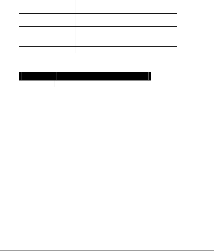
1.5.1 CNFG Clear Protocol Counters
Description
The module, CNFG Clear protocol counters, provides a way of clearing the protocol event
counters for a specific serial port. The protocol event counters for the serial port are cleared when the
assigned coil register is set to 1. Once the counters are cleared, the assigned coil register is
automatically reset to zero.
Register Assignment
Module CNFG Clear protocol counters
Address com1, com2, com3, or com4.
Type Coil Register
Start Any unused coil register. 0xxxx
End Same as start register.
Registers 1 coil register.
Description None
Extended Parameters None
Register Data
Registers Assignment to Module Hardware
Start Register Clear protocol event counters.
Notes
Refer to the module, DIAG Serial port protocol status, for a description of the individual counters.
For SCADAPack, SCADAPack Light and SCADAPack Plus controllers Com3 is supported only
when the SCADAPack 5601 and 5604 I/O module is installed. Com4 is supported only when the
SCADAPack 5602 I/O module is installed. To optimize performance, minimize the length of
messages on com3 and com4. Examples of recommended uses for com3 and com4 are for local
operator terminals, and for programming and diagnostics using the TelePACE program.
TelePACE Ladder Logic Register Assignment Reference
May 8, 2007
34
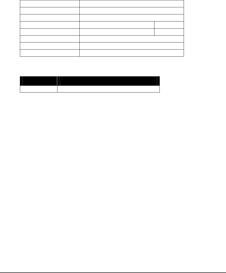
1.5.2 CNFG Clear Serial Port Counters
Description
The module, CNFG Clear serial port counters, provides a way of clearing the communication
event counters for a specific serial port. The serial port counters are cleared when the assigned coil
register is set to 1. Once the counters are cleared the assigned coil register is automatically reset to 0.
Register Assignment
Module CNFG Clear serial port counters
Address Com1, com2, com3, or com4.
Type Coil Register
Start Any unused coil register. 0xxxx
End Same as start register.
Registers 1 coil register.
Description None
Extended Parameters None
Register Data
Registers Assignment to Module Hardware
Start Register Clear communication event counters.
Notes
Refer to the module, DIAG Serial port comm. status, for a description of the individual counters.
For SCADAPack, SCADAPack Light and SCADAPack Plus controllers Com3 is supported only
when the SCADAPack 5601 and 5604 I/O module is installed. Com4 is supported only when the
SCADAPack 5602 I/O module is installed. To optimize performance, minimize the length of
messages on com3 and com4. Examples of recommended uses for com3 and com4 are for local
operator terminals, and for programming and diagnostics using the TelePACE program.
TelePACE Ladder Logic Register Assignment Reference
May 8, 2007
35

1.5.3 CNFG DTR Off
Description
The module, CNFG DTR Off, provides a way of controlling the DTR signal for a specific serial
port. When the assigned coil is energized DTR for the serial port is de-asserted. DTR is constantly
turned off when the coil is energized.
When the assigned coil is de-energized DTR for the serial port is asserted. The DTR signal is not
constantly asserted. It is asserted on the transition from an energized coil to a de-energized coil.
Since DTR is not constantly re-asserted other programs will be able to control the DTR setting. This
way other ladder blocks and programs will be able to control the DTR settings.
Register Assignment
Module CNFG DTR Off
Address com1, com2, com3, or com4.
Type Coil Register
Start Any unused coil register. 0xxxx
End Same as start register.
Registers 1 coil register.
Description None
Extended Parameters None
Register Data
Registers Assignment to Module Hardware
Start Register Controls DTR signal
0 = DTR asserted
1 = DTR not asserted
Default: 0 = DTR asserted
Notes
For SCADAPack, SCADAPack Light and SCADAPack Plus controllers Com3 is supported only
when the SCADAPack 5601 and 5604 I/O module is installed. Com4 is supported only when the
SCADAPack 5602 I/O module is installed. To optimize performance, minimize the length of
messages on com3 and com4. Examples of recommended uses for com3 and com4 are for local
operator terminals, and for programming and diagnostics using the TelePACE program.
TelePACE Ladder Logic Register Assignment Reference
May 8, 2007
36

1.5.4 CNFG 5904 HART Interface Module
Description
The module, CNFG 5904 HART Interface provides control of 5904 HART Interface modules.
When configured the module maintains communication with a 5904 interface. Up to four 5904
interfaces may be attached to a controller.
The interface settings are assigned from four consecutive holding registers. The registers are
initialized with the current value of the module parameters when the controller is reset, and when the
Register Assignment is downloaded to the controller. Thereafter the data from all four holding
registers are written to the module parameters, whenever any of the registers change.
Register Assignment
Module CNFG 5904 HART Interface
Address 0 to 3
Type Holding Register
Start The first register of any
unused block of 4
consecutive holding
registers.
4xxxx
End The last register of the
block 4xxxx + 3
Registers 4 holding registers
Description None
Extended Parameters None
Register Data
Registers Assignment to Module Hardware
Start Register Attempts: the number of times each HART command will be sent.
Valid values are 1 to 4.
Default : = 3
Start Register + 1 Preambles: number of preambles to send if fixed preambles selected.
Valid values are 2 to 15. This value must be set as it is used by link
initialization.
Default : = 15
Start Register + 2 Auto-preamble control:
0 = use fixed number of preambles
1 = use number of preambles requested by device except for link
initialization
Default : = 1
Start Register + 3 Device type
0 = secondary master device
1 = primary master device (recommended)
Default : = 1
TelePACE Ladder Logic Register Assignment Reference
May 8, 2007
37

Notes
This module provides the basis for communication with HART devices connected to the 5904
interface module. It does not send commands to the HART devices. Use the Ladder Logic HART
element or the C Tools HART API functions to send commands to the HART devices.
The number of preambles must be set even if the auto-preamble control is selected. The preambles
value will be used for the link initialization command which determines the number of preambles
requested by the device.
In most sensor networks, the controller is the primary master device. A hand-held programmer is
typically a secondary master device. Set the device type to primary unless another HART primary
master device is connected to the network.
The settings can be saved to EEPROM with the CNFG Save Settings to EEPROM module.
TelePACE Ladder Logic Register Assignment Reference
May 8, 2007
38

1.5.5 CNFG IP Settings
Description
The module, CNFG IP settings, provides control of the IP settings for a specific communication
interface. Settings are assigned from thirteen consecutive holding registers. The registers are
initialized with the current value of the module parameters on power-up, and when the Register
Assignment is downloaded to the controller. Thereafter the data from all thirteen holding registers is
written to the module parameters, whenever any of the registers change.
This module is used by the SCADAPack 32 controller series only.
Use this module only when IP settings need to be changed within a Ladders program. It is more
convenient to use the Controller TCP/IP Settings dialog to download IP settings with the Ladders
program.
Note: Any block transfer Ladder Logic function may be used to write data to the holding
registers used for this module. The data in the holding registers is written to the
module parameters only when the ladder function is energized. Users must ensure
the ladder function is only energized for one program scan. If the ladder function is
always energized problems with the TCP/IP communication will result.
Register Assignment
Module CNFG IP settings
Address Ethernet1
Type Holding Register
Start First register of any unused
block of 13 consecutive
holding registers.
4xxxx
End Last register of block 4xxxx + 12
Registers 13 holding registers.
Description None
Extended Parameters None
Register Data
Registers Assignment to Module Hardware
Start Register Byte1 of the IP Address using format: Byte1.Byte2.Byte3.Byte4
Default: 0
Start Register + 1 Byte2 of the IP Address
Default: 0
Start Register + 2 Byte3 of the IP Address
Default: 0
Start Register + 3 Byte4 of the IP Address
Default: 0
Start Register + 4 Byte1 of the Subnet Mask using format: Byte1.Byte2.Byte3.Byte4
Default: 255
TelePACE Ladder Logic Register Assignment Reference
May 8, 2007
39

Registers Assignment to Module Hardware
Start Register + 5 Byte2 of the Subnet Mask
Default: 255
Start Register + 6 Byte3 of the Subnet Mask
Default: 255
Start Register + 7 Byte4 of the Subnet Mask
Default: 255
Start Register + 8 Byte1 of the Default Gateway using format
Byte1.Byte2.Byte3.Byte4
Default: 0
Start Register + 9 Byte2 of the Default Gateway
Default: 0
Start Register + 10 Byte3 of the Default Gateway
Default: 0
Start Register + 11 Byte4 of the Default Gateway
Default: 0
Start Register + 12 IP Configuration Mode
0 = Default gateway is on the LAN subnet
1 = Default gateway is on the com1 PPP subnet
2 = Default gateway is on the com2 PPP subnet
3 = Default gateway is on the com3 PPP subnet
4 = Default gateway is on the com4 PPP subnet
Notes
Thirteen holding registers are always assigned to the I/O Database when this module is used.
TelePACE Ladder Logic Register Assignment Reference
May 8, 2007
40

1.5.6 CNFG LED Power Settings
Description
The module, CNFG LED power settings, provides control of the power settings for the controller
LEDs. The state of the assigned coil register is the default state for the LED power. The time to
return to the Default State is contained within the assigned holding register.
The registers are initialized with the current value of the module parameters on power-up, and when
the Register Assignment is downloaded to the controller. Thereafter the module parameters are
updated continuously with data read from the assigned registers.
Register Assignment
Module CNFG LED power settings
Address No physical address is required.
Type Coil Register
Start Any unused coil register. 0xxxx
End Same as start register.
Registers 1 coil register.
Description default state
Type Holding Register
Start Any unused holding register 4xxxx
End Same as start register
Registers 1 holding register
Description time to return to default state
Extended Parameters None
Coil Register Data
Registers Assignment to Module Hardware
Start
Register Default state for power to the controller
LEDs
0 = off
1 = on
Default Value: 1 = on
Holding Register Data
Registers Assignment to Module Hardware
Start
Register Time in minutes to return to the default
state.
1 to 65535 minutes
Default Value: 5 minutes
TelePACE Ladder Logic Register Assignment Reference
May 8, 2007
41

Notes
One holding register and one coil register are always assigned to the I/O Database when this module
is used.
Refer to the System Manual for further information on LED power settings.
TelePACE Ladder Logic Register Assignment Reference
May 8, 2007
42

1.5.7 CNFG Modbus IP Interface
Description
The module, CNFG Modbus IP Interface, provides control of the protocol interface settings used
by all Modbus IP protocols on the specified communication interface. Settings are assigned from five
consecutive holding registers. The registers are initialized with the current value of the module
parameters on power-up, and when the Register Assignment is downloaded to the controller.
Thereafter the data from all five holding registers is written to the module parameters, whenever any
of the registers change.
This module is used by the SCADAPack 32 controller series only.
Use this module only when Modbus IP protocol interface settings need to be changed within a
Ladders program. It is more convenient to use the Controller Modbus IP Protocols dialog to
download protocol interface settings with the Ladders program.
Note: Any block transfer Ladder Logic function may be used to write data to the holding
registers used for this module. The data in the holding registers is written to the
module parameters only when the ladder function is energized. Users must ensure
the ladder function is only energized for one program scan. If the ladder function is
always energized problems with the Modbus IP communication will result.
Register Assignment
Module CNFG Modbus IP Interface
Address Ethernet1
Type Holding Register
Start First register of any unused
block of 5 consecutive holding
registers.
4xxxx
End Last register of block 4xxxx + 4
Registers 5 holding registers.
Description None
Extended Parameters None
Register Data
Registers Assignment to Module Hardware
Start Register Modbus station number
1 to 255 in standard Modbus
1 to 65534 in extended Modbus
Default: 1
Start Register + 1 Modbus store and forward enable
0 = disabled
1 = enabled
Default: 0 = disabled
TelePACE Ladder Logic Register Assignment Reference
May 8, 2007
43

Registers Assignment to Module Hardware
Start Register + 2 Modbus addressing mode
0 = standard
1 = extended
Default: 0 = standard
Start Register + 3 Enron Modbus enable
0 = disabled
1 = enabled
Default: 0 = disabled
Start Register + 4 Enron Modbus station number
1 to 255 in standard Modbus
1 to 65534 in extended Modbus
Default: 1
Notes
Five holding registers are always assigned to the I/O Database when this module is used.
TelePACE Ladder Logic Register Assignment Reference
May 8, 2007
44

1.5.8 CNFG Modbus IP Protocols
Description
The module, CNFG Modbus IP Protocols, provides control of the settings for a Modbus IP
protocol. Settings are assigned from ten consecutive holding registers. The registers are initialized
with the current value of the module parameters on power-up, and when the Register Assignment is
downloaded to the controller. Thereafter the data from all ten holding registers is written to the
module parameters, whenever any of the registers change.
This module is used by the SCADAPack 32 controller series only.
Use this module only when Modbus IP protocol settings need to be changed within a Ladders
program. It is more convenient to use the Controller Modbus IP Protocols dialog to download
protocol settings with the Ladders program.
Note: Any block transfer Ladder Logic function may be used to write data to the holding
registers used for this module. The data in the holding registers is written to the
module parameters only when the ladder function is energized. Users must ensure
the ladder function is only energized for one program scan. If the ladder function is
always energized problems with the Modbus IP communication will result.
Register Assignment
Module CNFG Modbus IP Protocols
Address 1 = Modbus/TCP,
2 = Modbus RTU over UDP, or
3 = Modbus ASCII over UDP
Type Holding Register
Start First register of any unused
block of 10 consecutive
holding registers.
4xxxx
End Last register of block 4xxxx + 9
Registers 10 holding registers.
Description None
Extended Parameters None
Register Data
Registers Assignment to Module Hardware
Start Register Protocol Port Number: 1 to 65534
Modbus/TCP Default: 502
Modbus RTU over UDP Default: 49152
Modbus ASCII over UDP Default: 49153
TelePACE Ladder Logic Register Assignment Reference
May 8, 2007
45

Registers Assignment to Module Hardware
Start Register + 1 and
Start Register + 2 Master Idle Timeout: The length of time, in seconds,
that a master connection will wait for the user to send
the next command before ending the connection. This
allows the slave device to free unused connections
while the master application may retain the connection
allocation. (32 bit register)
0 = disable timeout and let application close the
connection.
Default: 10
TCP protocols only. Not used by UDP protocols.
Start Register + 3 and
Start Register + 4 Server Idle Timeout: The length of time, in seconds,
that a server connection will wait for a message
before ending the connection. (32 bit register)
0 = disable timeout and let client close connection.
Default: 250
TCP protocols only. Not used by UDP protocols.
Start Register + 5 Protocol Server Enable:
0 = disable server.
1 = enable server.
Default: 1
Start Register + 6 Reserved
Start Register + 7 Reserved
Start Register + 8 Reserved
Start Register + 9 Reserved
TelePACE Ladder Logic Register Assignment Reference
May 8, 2007
46

1.5.9 CNFG Modbus/TCP Settings
Description
The module, CNFG Modbus/TCP settings, provides control of the Modbus/TCP protocol
settings. Settings are assigned from six consecutive holding registers. The registers are
initialized with the current value of the module parameters on power-up, and when the
Register Assignment is downloaded to the controller. Thereafter the data from all six
holding registers is written to the module parameters, whenever any of the registers change.
This module is used by the SCADAPack 32 controller series only.
Use this module only when Modbus/TCP settings need to be changed within a Ladders
program. It is more convenient to use the Controller Modbus/TCP Settings dialog to
download Modbus/TCP settings with the Ladders program.
Note: Any block transfer Ladder Logic function may be used to write data to the holding
registers used for this module. The data in the holding registers is written to the
module parameters only when the ladder function is energized. Users must ensure
the ladder function is only energized for one program scan. If the ladder function is
always energized problems with the Modbus/TCP communication will result.
Register Assignment
Module CNFG Modbus/TCP settings
Address No physical address is required.
Type Holding Register
Start First register of any unused
block of 6 consecutive holding
registers.
4xxxx
End Last register of block 4xxxx + 5
Registers 6 holding registers.
Description None
Extended Parameters None
Register Data
Registers Assignment to Module Hardware
Start Register Port for Modbus/TCP protocol
Default: 502
Start Register + 1 and
Start Register + 2 Master Idle Timeout: The length of time, in seconds,
that a master connection will wait for the user to send
the next command before ending the connection. (32
bit register)
0 = disable timeout and let user close the connection.
Default: 10
TelePACE Ladder Logic Register Assignment Reference
May 8, 2007
47

Registers Assignment to Module Hardware
Start Register + 3 and
Start Register + 4 Server Idle Timeout: The length of time, in seconds,
that a server connection will wait for a message
before ending the connection. (32 bit register)
0 = disable timeout and let client close connection.
Default: 250
Start Register + 5 Maximum number of server connections up to the
capacity available (typical capacity is 20 connections)
Default: 20
TelePACE Ladder Logic Register Assignment Reference
May 8, 2007
48

1.5.10 CNFG PID Control Block
Description
The module, CNFG PID control block, provides control over the configuration of a PID
control block and provides access to the control block parameters. Control block parameters
are assigned to 25 consecutive holding registers. The module address refers to the PID
control block number.
The holding registers are updated continuously with data read from the module parameters.
Whenever a Ladder Logic program or C Application changes any of the registers, only data
from the changed register is written to the corresponding module parameter.
Register Assignment
Module CNFG PID control block
Address This module is assigned a unique module
address between 0 and 31. No other PID-
type module may use this module address.
Type Holding Register
Start First register of any unused
block of 25 consecutive
holding registers.
4xxxx
End Last register of block 4xxxx +24
Registers 25 holding registers.
Description None
Extended Parameters None
Register Data
Registers Assignment to Module Hardware
Start Register Process Value (PV)
Start Register + 1 Error (ER)
Start Register + 2 Output Quantity (OP)
Start Register + 3 Status Register SR)
Start Register + 4 Integrated Error (IN)
Start Register + 5 Setpoint (SP)
Start Register + 6 Deadband (DB)
Start Register + 7 Gain (GA)
Start Register + 8 Reset Time (RE)
Start Register + 9 Rate Time (RA)
Start Register + 10 Full Scale Output Limit (FS)
Start Register + 11 Zero Scale Output Limit (ZE)
Start Register + 12 High Alarm Level (HI)
Start Register + 13 Low Alarm Level (LO)
Start Register + 14 Control Register (CR)
TelePACE Ladder Logic Register Assignment Reference
May 8, 2007
49

Registers Assignment to Module Hardware
Start Register + 15 Input Source (IP)
Start Register + 16 Increase Output Address (IO)
Start Register + 17 Decrease Output Address (DO)
Start Register + 18 Input Bias (IB)
Start Register + 19 Output Bias (OB)
Start Register + 20 Inhibit Execution Address (IH)
Start Register + 21 Alarm Output Address (AO)
Start Register + 22 Cascade Setpoint Source (CA)
Start Register + 23 Execution Period
Start Register + 24 Execution Period at Power Up
Notes
Twenty-five holding registers are always assigned to the I/O Database when this module is
used.
Refer to the TelePACE PID Controller Reference Manual for further information.
TelePACE Ladder Logic Register Assignment Reference
May 8, 2007
50
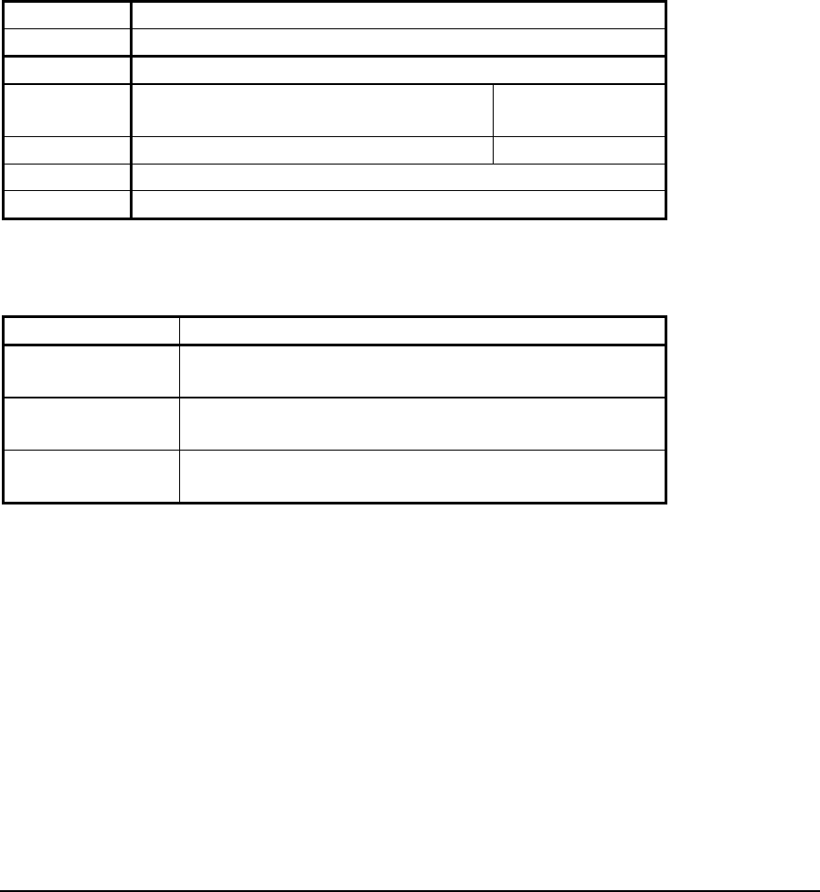
1.5.11 CNFG Power Mode
Description
The module, CNFG Power Mode, provides control over the power consumption of the
controller. The LAN port and USB host port can be individually disabled to conserve
power. The controller can also run at a reduced speed to conserve power.
The status registers are updated continuously with the current LAN, controller, and USB
host power states. The current settings can be changed by writing to the appropriate holding
register.
Register Assignment
Module CNFG Power Mode
Address fixed
Type Holding Register
Start First register of any unused block of 3
consecutive holding registers. 4xxxx
End Last register of block 4xxxx + 2
Registers 3 holding registers
Description None
Holding Register Data
Registers Assignment to Module Hardware
Start Register LAN Operation State (0 = LAN Enabled, 1 = LAN
Disabled)
Start Register + 1 Controller Power State (0 = Normal Power Mode, 1
= Reduced Power Mode)
Start Register + 2 USB Host Port Power State (0 = USB host port
enabled, 1 = USB host port disabled)
Notes
Three holding registers are always assigned to the I/O Database when this module is used.
TelePACE Ladder Logic Register Assignment Reference
May 8, 2007
51

1.5.12 CNFG Protocol Settings Method 1
Description
The module, CNFG Protocol settings method 1, provides control of the protocol settings
for a specific serial port. Settings are assigned from three consecutive holding registers. The
registers are initialized with the current value of the module parameters on power-up, and
when the Register Assignment is downloaded to the controller. Thereafter the data from all
three holding registers is written to the module parameters, whenever any of the registers
change.
Use this module only when protocol settings need to be changed within a Ladders program.
It is more convenient to use the Controller Serial Ports Settings dialog to download protocol
settings with the program. Refer to the Serial Ports section in this manual for further
information on serial port settings.
Note: Any block transfer Ladder Logic function may be used to write data to the holding
registers used for this module. The data in the holding registers is written to the
module parameters only when the ladder function is energized. Users must ensure
the ladder function is only energized for one program scan. If the ladder function is
always energized problems with the serial communication will result.
Register Assignment
Module CNFG Protocol settings
Address com1, com2, com3, or com4.
Type Holding Register
Start First register of any unused
block of 3 consecutive holding
registers.
4xxxx
End Last register of block 4xxxx + 2
Registers 3 holding registers.
Description None
Extended Parameters None
TelePACE Ladder Logic Register Assignment Reference
May 8, 2007
52

Register Data
Registers Assignment to Module Hardware
Start Register Protocol type
0 = none
1 = Modbus RTU
2 = Modbus ASCII
3 = DF1 Full Duplex BCC
4 = DF1 Full Duplex CRC
5 = DF1 Half Duplex BCC
6 = DF1 Half Duplex CRC
7 = DNP
8 = PPP
Default : 1 = Modbus RTU
Start Register + 1 Protocol station number
1 to 255 in Modbus
0 to 254 in DF1
Default : 1
Start Register + 2 Store and forward enable
0 = disabled
1 = enabled
Default : 0 = disabled
Notes
This register assignment module replaces the CNFG Protocol Settings module used in
earlier versions of TelePACE.
For SCADAPack, SCADAPack Light and SCADAPack Plus controllers Com3 is supported
only when the SCADAPack 5601 or 5604 I/O module is installed. Com4 is supported only
when the SCADAPack 5602 I/O module is installed. To optimize performance, minimize
the length of messages on com3 and com4. Examples of recommended uses for com3 and
com4 are for local operator terminals, and for programming and diagnostics using the
TelePACE program.
Refer to the TeleBUS Protocols User Manual for further information on protocols.
Three holding registers are always assigned to the I/O Database when this module is used.
TelePACE Ladder Logic Register Assignment Reference
May 8, 2007
53

1.5.13 CNFG Protocol Settings Method 2
The module, CNFG Protocol settings method 2, provides control of the protocol settings
for a specific serial port. This module supports the use of extended addressing.
Settings are assigned from four consecutive holding registers. The registers are initialized
with the current value of the module parameters on power-up, and when the Register
Assignment is downloaded to the controller. Thereafter the data from all four holding
registers is written to the module parameters, whenever any of the registers change.
Use this module only when protocol settings need to be changed within a Ladders program.
It is more convenient to use the Controller Serial Ports Settings dialog to download protocol
settings with the program. Refer to the Serial Ports section in this manual for further
information on serial port settings.
Note: Any block transfer Ladder Logic function may be used to write data to the holding
registers used for this module. The data in the holding registers is written to the
module parameters only when the ladder function is energized. Users must ensure
the ladder function is only energized for one program scan. If the ladder function is
always energized problems with the serial communication will result.
Register Assignment
Module CNFG Protocol Extended Settings
Address com1, com2, com3, or com4.
Type Holding Register
Start First register of any unused
block of 4 consecutive holding
registers.
4xxxx
End Last register of block 4xxxx + 3
Registers 4 holding registers.
Description None
Extended Parameters None
Register Data
Registers Assignment to Module Hardware
Start Register Protocol type
0 = none
1 = Modbus RTU
2 = Modbus ASCII
3 = DF1 Full Duplex BCC
4 = DF1 Full Duplex CRC
5 = DF1 Half Duplex BCC
6 = DF1 Half Duplex CRC
7 = DNP
8 = PPP
Default : 1 = Modbus RTU
TelePACE Ladder Logic Register Assignment Reference
May 8, 2007
54

Registers Assignment to Module Hardware
Start Register + 1 Protocol station number
1 to 255 in standard Modbus
1 to 65534 in extended Modbus
0 to 254 in DF1
Default : 1
Start Register + 2 Store and forward enable
0 = disabled
1 = enabled
Default : 0 = disabled
Start Register + 3 Protocol addressing mode
0 = standard
1 = extended
Default: 0 = standard
Notes
This register assignment module replaces the CNFG Protocol Extended Settings module
used in earlier versions of TelePACE.
For SCADAPack, SCADAPack Light and SCADAPack Plus controllers Com3 is supported
only when the SCADAPack 5601 and 5604 I/O module is installed. Com4 is supported
only when the SCADAPack 5602 I/O module is installed. To optimize performance,
minimize the length of messages on com3 and com4. Examples of recommended uses for
com3 and com4 are for local operator terminals, and for programming and diagnostics using
the TelePACE program.
Extended addressing is supported only by the Modbus RTU and Modbus ASCII protocols.
To optimize performance, minimize the length of messages on com3 and com4. Examples of
recommended uses for com3 and com4 are for local operator terminals, and for
programming and diagnostics using the TelePACE program.
Refer to the TeleBUS Protocols User Manual for further information on protocols.
Four holding registers are always assigned to the I/O Database when this module is used.
TelePACE Ladder Logic Register Assignment Reference
May 8, 2007
55

1.5.14 CNFG Protocol Settings Method 3
Description
The module, CNFG Protocol Settings Method 3, provides control of the protocol settings
for a specific serial port. This module supports extended addressing and Enron Modbus
parameters.
Settings are assigned from six consecutive holding registers. The registers are initialized
with the current value of the module parameters on power-up, and when the Register
Assignment is downloaded to the controller. Thereafter the data from all six holding
registers is written to the module parameters, whenever any of the registers change.
Use this module only when protocol settings need to be changed within a Ladders program.
It is more convenient to use the Controller Serial Ports Settings dialog to download protocol
settings with the program. Refer to the Serial Ports section in this manual for further
information on serial port settings.
Note: Any block transfer Ladder Logic function may be used to write data to the holding
registers used for this module. The data in the holding registers is written to the
module parameters only when the ladder function is energized. Users must ensure
the ladder function is only energized for one program scan. If the ladder function is
always energized problems with the serial communication will result.
Register Assignment
Module CNFG Protocol Settings Method3
Address com1, com2, com3, or com4.
Type Holding Register
Start First register of any unused
block of 6 consecutive holding
registers.
4xxxx
End Last register of block 4xxxx + 5
Registers 6 holding registers.
Description None
Extended Parameters None
TelePACE Ladder Logic Register Assignment Reference
May 8, 2007
56

Register Data
Registers Assignment to Module Hardware
Start Register Protocol type
0 = none
1 = Modbus RTU
2 = Modbus ASCII
3 = DF1 Full Duplex BCC
4 = DF1 Full Duplex CRC
5 = DF1 Half Duplex BCC
6 = DF1 Half Duplex CRC
7 = DNP
8 = PPP
Default : 1 = Modbus RTU
Start Register + 1 Protocol station number
1 to 255 in standard Modbus
1 to 65534 in extended Modbus
0 to 254 in DF1
Default : 1
Start Register + 2 Store and forward enable
0 = disabled
1 = enabled
Default : 0 = disabled
Start Register + 3 Protocol addressing mode
0 = standard
1 = extended
Default: 0 = standard
Start Register + 4 Enron Modbus enable
0 = disabled
1 = enabled
Default : 0 = disabled
Start Register + 5 Enron Modbus station number
1 to 255 in standard Modbus
1 to 65534 in extended Modbus
Default : 1
Notes
For SCADAPack, SCADAPack Light and SCADAPack Plus controllers Com3 is supported
only when the SCADAPack 5601 and 5604 I/O module is installed. Com4 is supported
only when the SCADAPack 5602 I/O module is installed. To optimize performance,
minimize the length of messages on com3 and com4. Examples of recommended uses for
com3 and com4 are for local operator terminals, and for programming and diagnostics using
the TelePACE program. Extended addressing is supported only by the Modbus RTU and
Modbus ASCII protocols.
TelePACE Ladder Logic Register Assignment Reference
May 8, 2007
57

To optimize performance, minimize the length of messages on com3 and com4. Examples of
recommended uses for com3 and com4 are for local operator terminals, and for
programming and diagnostics using the TelePACE program.
Refer to the TeleBUS Protocols User Manual for further information on protocols.
Six holding registers are always assigned to the I/O Database when this module is used.
TelePACE Ladder Logic Register Assignment Reference
May 8, 2007
58

1.5.15 CNFG Real Time Clock and Alarm
Description
The module, CNFG Real time clock and alarm, provides access to the controller real time
clock data and alarm settings. Real Time Clock and Alarm settings are assigned from eleven
consecutive holding registers. The registers are initialized with the current value of the
module parameters on power-up, and when the Register Assignment is downloaded to the
controller.
The clock data from the first 7 holding registers is written to the module parameters,
whenever any of these registers are changed by a Ladders program or C Application.
Otherwise, these holding registers are updated continuously with data read from the real
time clock.
Note: Any block transfer Ladder Logic function may be used to write data to the holding
registers used for this module. The data in the holding registers is written to the
module parameters only when the ladder function is energized. Users must ensure
the ladder function is only energized for one program scan. If the ladder function is
continuously energized the controller real time clock will not change.
The alarm settings are updated continuously with data read from the last 4 holding registers.
Register Assignment
Module CNFG Real time clock and alarm
Address No physical address is required.
Type Holding Register
Start First register of any unused
block of 11 consecutive
holding registers.
4xxxx
End Last register of block 4xxxx +10
Registers 11 holding registers.
Description None
Extended Parameters None
Register Data
Registers Assignment to Module Hardware
Start Register Real time clock hour 0 to 23
Start Register + 1 Real time clock minute 0 to 59
Start Register + 2 Real time clock second 0 to 59
Start Register + 3 Real time clock year 00 to 99
Start Register + 4 Real time clock month 1 to 12
Start Register + 5 Real time clock day 1 to 31
Start Register + 6 Real time clock day of week 1 to 7,
1=Sunday, 2=Monday…7=Saturday
Start Register + 7 Alarm hour 0 to 23
TelePACE Ladder Logic Register Assignment Reference
May 8, 2007
59

Registers Assignment to Module Hardware
Start Register + 8 Alarm minute 0 to 59
Start Register + 9 Alarm second 0 to 59
Start Register + 10 Alarm control 0 = no alarm
1 = absolute time
2 = elapsed time alarm
(relative from now)
** See note below.
** The Alarm Control register (Start Register + 10) enables or disables the alarm. A value
of 0 in this register disables the alarm. A value of 1 sets an alarm to be triggered in absolute
time, based on the values in the preceding three registers. A value of 2 sets the alarm to be
triggered at a latter time, starting now.
Note that the alarm settings above and those in the Sleep (SLP) function block will trigger
the same interrupt. See the Ladder Logic Function Reference in this book for details on the
SLP function. Using both alarm settings, therefore, in the same program is not
recommended.
Additional Notes
The 5203/4 Controllers have a hardware based real-time clock that independently maintains
the time and date for the operating system. The time and date remain accurate during power-
off. The calendar automatically handles leap years.
One method for setting the clock is to use the Edit/Force Register dialog to write the current
time to the appropriate module registers. Leave the force box in the dialog unchecked so that
the data is only written, not forced.
All seven registers for the real time clock must be set to valid values for the clock to operate
properly. Refer to real time clock specifications in the Controller System Manual for further
information.
Eleven holding registers are always assigned to the I/O Database when this module is used.
TelePACE Ladder Logic Register Assignment Reference
May 8, 2007
60

1.5.16 CNFG Save Settings to EEPROM
Description
The module, CNFG Save settings to EEPROM, provides a way to save controller settings
to EEPROM. Saving to EEPROM is controlled by one assigned coil register. The controller
settings are saved when the coil register is set to 1. Once saved the coil register is
automatically reset to 0.
Register Assignment
Module CNFG Save settings to EEPROM
Address No physical address is required.
Type Coil Register
Start Any unused coil register. 0xxxx
End Same as start register.
Registers 1 coil register.
Description None
Extended Parameters None
Register Data
Registers Assignment to Module Hardware
Start Register Save the following controller settings:
Serial port settings
Protocol settings
Enable store and forward settings
LED power settings
Mask for wake-up sources
HART interface configuration
Execution period on power-up for each PID
TelePACE Ladder Logic Register Assignment Reference
May 8, 2007
61

1.5.17 CNFG Serial Port Settings
Description
The module, CNFG Serial port settings, controls the configuration settings for a serial
port. Settings are assigned from nine consecutive holding registers. The holding registers are
initialized with the current value of the module parameters on power-up, and when the
Register Assignment is downloaded to the controller. Thereafter the data from all 9 holding
registers is written to the module parameters, whenever any of the registers change.
Use this module only when serial port settings need to be changed within a Ladders
program. It is more convenient to use the Controller Serial Ports Settings dialog to
download settings with the program. Refer to the Serial Ports section under Controller
Menu, in this manual, for further information on serial port settings.
Note: Any block transfer Ladder Logic function may be used to write data to the holding
registers used for this module. The data in the holding registers is written to the
module parameters only when the ladder function is energized. Users must ensure
the ladder function is only energized for one program scan. If the ladder function is
always energized problems with the serial communication will result.
Register Assignment
Module CNFG Serial port settings
Address Com1, com2, com3, or com4.
Type Holding Register
Start First register of any unused
block of 9 consecutive
holding registers.
4xxxx
End Last register of block 4xxxx +8
Registers 9 holding registers.
Description None
Extended Parameters None
Register Data
Registers Assignment to Module Hardware
Start Register Baud rate
0 = 75 baud 1 = 110 baud
2 = 150 baud 3 = 300 baud
4 = 600 baud 5 = 1200 baud
6 = 2400 baud 7 = 4800 baud
8 = 9600 baud 9 = 19200 baud
10 =38400
11 = 115200 com3, com4 only
12 = 57600 com3, com4 only
Default : 8 = 9600 baud
TelePACE Ladder Logic Register Assignment Reference
May 8, 2007
62

Start Register + 1 Duplex 0 = half duplex
1 = full duplex
com1, com2 Default : 1 = full
com3, com4 Default : 0 = half
Start Register + 2 Parity 0 = none
1 = even
2 = odd
Default : 0 = none
Start Register + 3 Data bits 0 = 7 bits
1 = 8 bits
Default : 1 = 8 bits
Start Register + 4 Stop bits 0 = 1 bit
1 = 2 bits
Default : 0 = 1 bit
Start Register + 5 Receiver flow control
Com1, Com2 0 = none (default)
1 = XON/XOFF
Com3, Com4 0 = none
1 = Receive Disable (default)
Start Register + 6 Transmitter flow control
Com1, Com2 0 = none (default)
1 = XON/XOFF
Com3, Com4 0 = none (default)
1 = Ignore CTS
Start Register + 7 Port type 0 = automatic
1 = RS232
3 = RS485
6 = RS232 MODEM
7 = RS232 Collision Avoidance
Default : 1 = RS232
Start Register + 8 Serial time-out delay
0 to 65535 (x 0.1 seconds)
Default : 600 = 60 seconds
Notes
For SCADAPack, SCADAPack Light and SCADAPack Plus controllers Com3 is supported
only when the SCADAPack 5601 and 5604 I/O module is installed. Com4 is supported
only when the SCADAPack 5602 I/O module is installed. To optimize performance,
minimize the length of messages on com3 and com4. Examples of recommended uses for
com3 and com4 are for local operator terminals, and for programming and diagnostics using
the TelePACE program.
TelePACE Ladder Logic Register Assignment Reference
May 8, 2007
63

1.5.18 CNFG Store and Forward
Description
The module, CNFG Store and forward, controls the store and forward table. Store and
Forward table data is assigned from 512 consecutive holding registers. One coil register is
assigned to clear the translation table.
This module is used by the SCADAPack controller series only. For SCADAPack 32
controllers use the Store and Forward command in TelePACE.
The holding registers are initialized with the current value of the module parameters on
power-up, and when the Register Assignment is downloaded to the controller. Thereafter the
table is updated continuously with data read from the holding registers. The table is cleared
when the coil register is set to 1. Once cleared the coil register is automatically reset to 0.
Register Assignment
Module CNFG Store and Forward
Address No physical address is required.
Type Coil Register
Start Any unused coil register. 0xxxx
End Same as start register.
Registers 1 coil register.
Description clear Store and Forward table
Type Holding Register
Start First register of any unused
block of 512 consecutive
holding registers.
4xxxx
End Last register in block. 4xxxx +511
Registers 512 holding registers
Description Translation table
Extended Parameters None
Coil Register Data
Registers Assignment to Module Hardware
Start Register Clear Translation table
TelePACE Ladder Logic Register Assignment Reference
May 8, 2007
64

Holding Register Data
Registers Assignment to Module Hardware
Start Register Translation table entry 0
Port A
0 = com1
1 = com2
2 = com3
3 = com4
Default : 0
Start Register + 1 Translation table entry 0
Station A
0 to 255 standard addressing
0 to 65534 extended addressing
65535 = disable
Default : 65535
Start Register + 2 Translation table entry 0
Port B
0 = com1
1 = com2
2 = com3
3 = com4
Default : 0
Start Register + 3 Translation table entry 0
Station B
0 to 255 standard addressing
0 to 65534 extended addressing
65535 = disable
Default : 65535
Start Register + 4 to
Start Register + 7
Translation table entry 1
Start Register + 8 to
Start Register + 11
Translation table entry 2
Start Register + 12 to
Start Register + 511
Translation table entries 3 to 127
Notes
Refer to the TeleBUS Protocols User Manual for further information on Store and Forward
messaging.
For SCADAPack, SCADAPack Light and SCADAPack Plus controllers Com3 is supported
only when the SCADAPack 5601 and 5604 I/O module is installed. Com4 is supported
only when the SCADAPack 5602 I/O module is installed. To optimize performance,
minimize the length of messages on com3 and com4. Examples of recommended uses for
com3 and com4 are for local operator terminals, and for programming and diagnostics using
the TelePACE program.
Store and forward messaging is enabled on the required serial ports using the module CNFG
Protocol settings.
TelePACE Ladder Logic Register Assignment Reference
May 8, 2007
65

1.6 Counter I/O Modules
Counter input modules are used to assign data from physical counter inputs to input registers
in the I/O Database. The physical counter inputs are specific 5000 Series I/O modules and
controller counter inputs.
Counter input modules may assign data to any input registers that are not used by another
Analog Input module or Counter input module. There are 1024 I/O database input registers
available. These input registers are numbered 30001 - 31024. Input registers are referred to
as 3xxxx registers throughout this manual.
All I/O database input registers that are not assigned to any other I/O modules may be used
as general purpose input registers in a ladder program. The I/O modules available are
described in the following pages.
TelePACE Ladder Logic Register Assignment Reference
May 8, 2007
66

1.6.1 CNTR Controller Counter Inputs
Description
The module, CNTR controller counter inputs, reads the three counter inputs on the
Micro16, SCADAPack, SCADAPack Light, SCADAPack, SCADAPack Plus, SCADAPack
32 and SCADAPack 32P controllers. Data is assigned to six consecutive input registers. The
input registers are updated continuously with data read from the counters.
Each counter is a 32-bit number, stored in two 16-bit registers. The first register holds the
least significant 16 bits of the counter. The second register holds the most significant 16 bits
of the counter. To obtain the correct count, both registers must be read with the same
protocol read command. Ladder Logic programs can read the registers in any order,
provided both registers are examined on the same pass through the program.
The maximum count is 4,294,967,295. Counters roll over to 0 when the maximum count is
exceeded.
Register Assignment
Module CNTR controller counter inputs
Address No physical address is required.
Type Input Register
Start First register of any unused
block of 6 consecutive input
registers.
3xxxx
End Last register of block 3xxxx +5
Registers 6 input registers.
Description None
Extended Parameters None
Register Data
Registers Assignment to Module Hardware
Start Register and
Start Register + 1
Controller counter input 0
(32 bit register)
Start Register + 2 and
Start Register + 3
Controller counter input 1
(32 bit register)
Start Register + 4 and
Start Register + 5
Controller counter input 2
(32 bit register)
Notes
Refer to the Hardware User Manual for further information on controller board counter
inputs.
TelePACE Ladder Logic Register Assignment Reference
May 8, 2007
67

1.6.2 CNTR Controller Interrupt Input
Description
The module, CNTR controller interrupt input, reads the interrupt input on the Micro16,
SCADAPack, SCADAPack Light, SCADAPack, SCADAPack Plus, SCADAPack 32 and
SCADAPack 32P controllers as a counter input. Data is assigned to two consecutive input
registers. The input registers are updated continuously with data read from the counter.
The counter is a 32-bit number, stored in two 16-bit registers. The first register holds the
least significant 16 bits of the counter. The second register holds the most significant 16 bits
of the counter. To obtain the correct count, both registers must be read with the same
protocol read command. Ladder Logic programs can read the registers in any order,
provided both registers are examined on the same pass through the program.
The maximum count is 4,294,967,295. The counter rolls over to 0 when the maximum count
is exceeded.
Register Assignment
Module CNTR controller interrupt input
Address No physical address is required.
Type Input Register
Start First register of any unused
block of 2 consecutive input
registers.
3xxxx
End Last register of block 3xxxx +1
Registers 2 input registers.
Description None
Extended Parameters None
Register Data
Registers Assignment to Module Hardware
Start Register
and
Start Register + 1
Interrupt input counter
(32 bit register)
Notes
Refer to the SCADAPack and Micro16 System Manual for further information on controller
board counter inputs.
TelePACE Ladder Logic Register Assignment Reference
May 8, 2007
68

1.6.3 CNTR 5410 input module
Description
The module, CNTR 5410 input module, provides four counter inputs. Data is assigned to
eight consecutive input registers. The input registers are updated continuously with data
read from the counters.
Each counter is a 32-bit number, stored in two 16-bit registers. The first register holds the
least significant 16 bits of the counter. The second register holds the most significant 16 bits
of the counter. To obtain the correct count, both registers must be read with the same
Modbus protocol read command. Ladder Logic programs can read the registers in any order,
provided both registers are examined on the same pass through the program.
The maximum count is 4,294,967,295. Counters roll back to 0 when the maximum count is
exceeded.
Register Assignment
Module CNTR 5203/4 counter inputs
Address This module is assigned a unique module
address between 0 and 15. No other CNTR-
type module may use this module address.
Type Input Register
Start First register of any unused
block of 8 consecutive input
registers.
3xxxx
End Last register of block 3xxxx +7
Registers 8 input registers.
Description None
Extended Parameters None
Register Data
Registers Assignment to Module Hardware
Start Register and
Start Register + 1
Counter input 0
(32 bit register)
Start Register + 2 and
Start Register + 3
Counter input 1
(32 bit register)
Start Register + 4 and
Start Register + 5
Counter input 2
(32 bit register)
Start Register + 6 and
Start Register + 7
Counter input 3
(32 bit register)
Notes
Refer to the 5410 High Speed Counter Input Module User Manual for further information.
TelePACE Ladder Logic Register Assignment Reference
May 8, 2007
69

1.7 Diagnostic I/O Modules
Diagnostic modules are used to assign diagnostic data from the controller to input or status
registers in the I/O Database. The diagnostic data is used to monitor internal controller data
such as controller status code, the force LED, serial communication status and protocol
status.
Diagnostic I/O modules assign data to I/O database input or status registers, depending on
the type of data. Diagnostic I/O modules may assign data to any input or status registers in
the I/O database that are not being used by another I/O module.
All I/O database input and status registers that are not assigned to any other I/O modules
may be used as general purpose input or status registers in a ladder program. The I/O
modules available are described in the following pages.
TelePACE Ladder Logic Register Assignment Reference
May 8, 2007
70
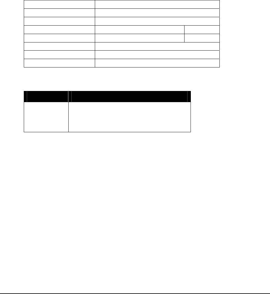
1.7.1 DIAG Controller Status Code
Description
The module, DIAG Controller Status Code, reads the controller status code and assigns it
in one input register. The input register is updated continuously with the status code.
The Status LED blinks a binary sequence equal to the controller status code. Note that if a
“Register assignment table checksum error” occurs, only the Status LED will indicate this
status code. The I/O scan is disabled if this error occurs, so that the module DIAG
Controller status code is no longer updated.
Register Assignment
Module DIAG Controller Status Code
Address No physical address is required.
Type Input Register
Start Any unused input register. 3xxxx
End Same as start register.
Registers 1 input register.
Description None
Extended Parameters None
Register Data
Registers Assignment to Module Hardware
Start Register Controller status code:
0 = Normal
1 = I/O module communication failure
2 = Register Assignment Checksum error
Status LED - I/O Error Indication
When the Status LED flashes the error code 1 (i.e. a short flash, once every second), there is
a communication failure with one or more I/O module. To correct the problem, do one of the
following:
1. Ensure that every module contained in the Register Assignment is connected to the
controller. Check that the module address selected for each module agrees with the
selection made in the Register Assignment.
2. If a module is currently not connected to the controller, delete it from the Register
Assignment. Download the new Register Assignment to the controller.
3. If a module is still suspect of having failed, confirm the failure by removing the module
from the Register Assignment. Download the new Register Assignment to the controller.
The Status LED should stop flashing.
4. If unused modules must be intentionally left in the Register Assignment, the I/O error
indication may be disabled from a selection box on the Register Assignment dialog.
TelePACE Ladder Logic Register Assignment Reference
May 8, 2007
71

Notes
Refer to the 5203/4 System Manual or the SCADAPack System Manual for further information on the
Status LED and Status Output.
TelePACE Ladder Logic Register Assignment Reference
May 8, 2007
72

1.7.2 DIAG DNP Connection Status
Description
This module determines the connection status of a remote DNP station, by repeatedly
sending a short message to the selected remote station and monitoring the response.
The connection status information is assigned to an input register, which is updated
continuously.
One holding register is assigned to specify the repeat time period for polling the
remote station. A second holding register specifies the remote station address.
This register assignment is available for the SCADAPack 32 controller only.
Register Assignment
Module DIAG DNP connection status
Address No address is required
Type Input Register
Start Any unused input register 3xxxx
End Same as start register
Registers 1 input register
Description Connection status:
0 = connection OK
1 = connection failed
Type Holding Register
Start First register of any unused block of 2
consecutive holding registers. 4xxxx
End Last register of block 4xxxx +1
Registers 2 holding registers.
Description Configuration data
Extended Parameters None
Holding Register Data
Registers Assignment to Module Hardware
Start Register DNP station address
Start Register + 1 Repeat rate (in seconds) for connection request message
TelePACE Ladder Logic Register Assignment Reference
May 8, 2007
73

1.7.3 DIAG DNP Event Status Module
Description
This module provides diagnostic data about DNP change events. The number of change
events stored in the event buffers is totalled for all DNP classes, and for all DNP point types.
The status information is assigned to nine consecutive input registers. The input registers are
updated continuously with data concerning the DNP change events.
One coil register is assigned to clear the change event buffers. The data is cleared when the
coil register is set to 1. Once the data is cleared the coil register is automatically reset to 0.
Register Assignment
Module DIAG DNP event status
Address No address is required
Type Input Register
Start First register of any unused block of 9
consecutive input registers. 3xxxx
End Last register of block 3xxxx +8
Registers 12 input registers
Description diagnostic data
Type Coil Register
Start Any unused coil register 0xxxx
End Same as start register
Registers 1 coil register
Description clear event buffers
Extended Parameters None
Input Register Data
Registers Assignment to Module Hardware
Start Register DNP event count for Binary Inputs
Start Register + 1 DNP event count for 16-bit Counter Inputs
Start Register + 2 DNP event count for 32-bit Counter Inputs
Start Register + 3 DNP event count for 16-bit Analog Inputs
Start Register + 4 DNP event count for 32-bit Analog Inputs
Start Register + 5 DNP event count for Short Float Analog Inputs
Start Register + 6 DNP event count for Class 1 Data
Start Register + 7 DNP event count for Class 2 Data
Start Register + 8 DNP event count for Class 3 Data
Start Register + 9 reserved for future use
Start Register
+10 reserved for future use
Start Register
+11 reserved for future use
TelePACE Ladder Logic Register Assignment Reference
May 8, 2007
74

Coil Register Data
Registers Assignment to Module Hardware
Start Register Clear change event buffers
TelePACE Ladder Logic Register Assignment Reference
May 8, 2007
75

1.7.4 DIAG DNP Port Status Module
Description
This module provides DNP diagnostic data for a specific communication port. Diagnostic
information is totaled for all DNP connections on the selected communication port.
The status information is assigned to nine consecutive input registers. The input registers are
updated continuously with the DNP diagnostic data.
One coil register is assigned to clear the diagnostic data. The data is cleared when the coil
register is set to 1. Once the data is cleared the coil register is automatically reset to 0.
Register Assignment
Module DIAG DNP port status
Address com1, com2, com3, com4, or LAN1
Type Input Register
Start First register of any unused block of 7
consecutive input registers. 3xxxx
End Last register of block 3xxxx +6
Registers 10 input registers
Description diagnostic data
Type Coil Register
Start Any unused coil register 0xxxx
End Same as start register
Registers 1 coil register
Description clear diagnostic data
Extended Parameters None
Input Register Data
Registers Assignment to Module Hardware
Start Register DNP message successes
Number of successful DNP message transactions initiated by this
station
Start Register + 1 DNP message failures
Number of failed DNP message transactions initiated by this station
Start Register + 2 DNP fails since last success
Number of consecutive failed DNP message transactions initiated by
this station since the last success
Start Register + 3 DNP format errors
Number of received DNP message frames with formatting errors
(including checksum errors and unrecognized commands)
Start Register + 4 DNP message frames received
Number of DNP message frames received
TelePACE Ladder Logic Register Assignment Reference
May 8, 2007
76

Registers Assignment to Module Hardware
Start Register + 5 DNP message frames sent
Number of DNP message frames sent. This includes any message
retries at application or data link layer.
Start Register + 6 DNP messages received
Number of complete DNP messages received
Start Register + 7 DNP messages sent
Number of complete DNP messages sent. This includes any
message retries at the application layer.
Start Register + 8 reserved for future use
Start Register + 9 reserved for future use
Coil Register Data
Registers Assignment to Module Hardware
Start Register Clear diagnostic data
TelePACE Ladder Logic Register Assignment Reference
May 8, 2007
77

1.7.5 DIAG DNP Station Status
Description
This module provides DNP diagnostic data for a specific DNP remote station address.
Diagnostic information is totaled for all DNP communication with the station.
The status information is assigned to nine consecutive input registers. The input registers are
updated continuously with data concerning the DNP status of the specific interface.
One coil register is assigned to clear the diagnostic data. The data is cleared when the coil
register is set to 1. Once the data is cleared the coil register is automatically reset to 0.
One holding register specifies the remote station address.
Register Assignment
Module DIAG DNP station status
Address No address is required
Type Input Register
Start First register of any unused block of 10
consecutive input registers. 3xxxx
End Last register of block 3xxxx +9
Registers 10 input registers
Description diagnostic data
Type Coil Register
Start Any unused coil register 0xxxx
End Same as start register
Registers 1 coil register
Description clear diagnostic data
Type Holding Register
Start Any unused holding register. 4xxxx
End Same as start register
Registers 1 holding register.
Description DNP station address
Extended Parameters None
Input Register Data
Registers Assignment to Module Hardware
Start Register DNP message successes
Number of successful DNP message transactions initiated by this
station
Start Register + 1 DNP message failures
Number of failed DNP message transactions initiated by this station
Start Register + 2 DNP fails since last success
Number of consecutive failed DNP message transactions initiated by
this station since the last success
TelePACE Ladder Logic Register Assignment Reference
May 8, 2007
78

Registers Assignment to Module Hardware
Start Register + 3 DNP format errors
Number of received DNP message frames with formatting errors
(including checksum errors and unrecognized commands)
Start Register + 4 DNP message frames received
Number of DNP message frames received
Start Register + 5 DNP message frames sent
Number of DNP message frames sent. This includes any message
retries at application or data link layer.
Start Register + 6 DNP messages received
Number of complete DNP messages received
Start Register + 7 DNP messages sent
Number of complete DNP messages sent. This includes any
message retries at the application layer.
Start Register + 8 reserved for future use
Start Register + 9 reserved for future use
Coil Register Data
Registers Assignment to Module Hardware
Start Register Clear diagnostic data
Holding Register Data
Registers Assignment to Module Hardware
Start Register DNP station address
TelePACE Ladder Logic Register Assignment Reference
May 8, 2007
79

1.7.6 DIAG Force
Description
All user accessible Modbus registers in a SCADAPack controller can be forced to a desired
state or value. The DIAG Force module is used to determine if a Modbus register in a
SCADAPack controller is forced to some state or value. This module reads the ‘forced’ state
of a SCADAPack controller, and assigns it to one status register. The status register is
updated continuously with the current ‘forced’ state of the controller.
Note that the Force LED on SCADAPack controllers, excluding the SCADASense
programmable controllers, also indicates if a Modbus register is forced.
Register Assignment
Module DIAG Force
Address No physical address is required.
Type Status Register
Start Any unused status register. 1xxxx
End Same as start register.
Registers 1 status register.
Description None
Extended Parameters None
Register Data
Registers Assignment to Module Hardware
Start Register 0 = Modbus register is not forced
1 = Modbus register is forced
Force LED:
0 = Force LED is OFF
1 = Force LED is ON
TelePACE Ladder Logic Register Assignment Reference
May 8, 2007
80
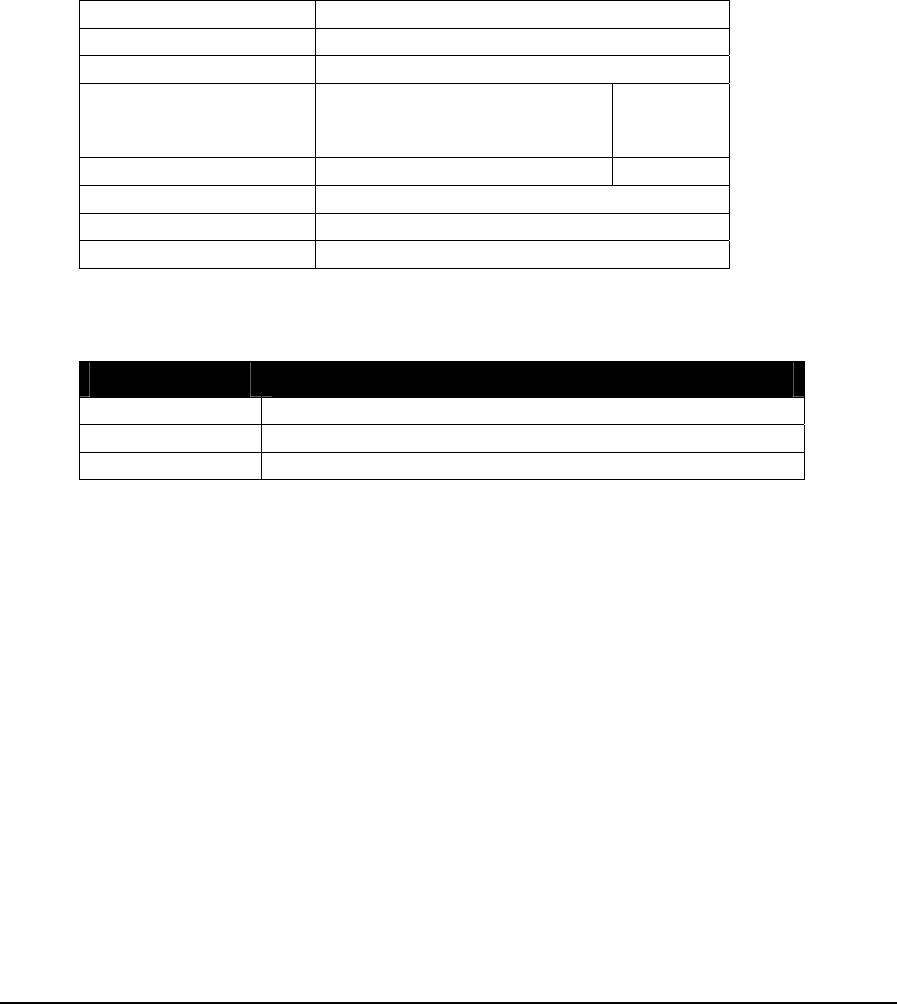
1.7.7 DIAG IP Connections
Description
The module, DIAG IP connections, provides a summary of the IP connections. The
connection information is assigned to three consecutive input registers. The input registers
are updated continuously with connection data.
This module is used by the SCADAPack 32 controller series only. The connection statistics
include all IP connection types.
Register Assignment
Module DIAG IP connections
Address No physical address is required.
Type Input Register
Start First register of any unused
block of 3 consecutive input
registers.
3xxxx
End Last register of block 3xxxx + 2
Registers 3 input registers.
Description None
Extended Parameters None
Register Data
Registers Assignment to Module Hardware
Start Register Number of current slave IP connections.
Start Register + 1 Number of current master IP connections.
Start Register + 2 Number of free IP connections.
TelePACE Ladder Logic Register Assignment Reference
May 8, 2007
81

1.7.8 DIAG Logic Status
Description
The module, DIAG Logic Status, reads the Ladder Logic Application status in the RAM
and FLASH memory and assigns it to two input registers. The input registers are updated
continuously with the current application status.
Register Assignment
Module DIAG Logic Status
Address No physical address is required.
Type Input Register
Start Any unused input register. 3xxxx
End Last register in block. 3xxxx+1
Registers 2 input registers
Description None
Input Register Data
Registers Assignment to Module Hardware
Start Register Ladder Logic Program Status
0 = No Program
1 = Program Stopped
2 = Program Running in Debug Mode
3 = Program Running
Start Register + 1 Type of memory where Ladder Logic program is loaded:
0 = No program in RAM or FLASH;
1 = Program loaded in RAM
2 = Program loaded in FLASH
3 = Program loaded in RAM and FLASH
TelePACE Ladder Logic Register Assignment Reference
May 8, 2007
82

1.7.9 DIAG Modbus Protocol Status
Description
The module, DIAG Modbus protocol status, provides diagnostic data about Modbus
protocols for a specific communication interface. Diagnostic information is totaled for all
Modbus protocols on the selected communication interface. When multiple Modbus IP
connections exist on the same interface, diagnostic information is totaled for all connections.
This module is used by the SCADAPack 32 controller series only.
The status information is assigned to nine consecutive input registers. The input registers are
updated continuously with data concerning the Modbus protocol status of the specific
interface.
One coil register is assigned to clear the diagnostic data. The data is cleared when the coil
register is set to 1. Once the data is cleared the coil register is automatically reset to 0.
Register Assignment
Module DIAG Modbus protocol status
Address com1, com2, com3, com4, or Ethernet1
Type Input Register
Start First register of any unused block of 9
consecutive input registers. 3xxxx
End Last register of block 3xxxx +8
Registers 9 input registers
Description diagnostic data
Type Coil Register
Start Any unused coil register. 0xxxx
End Same as start register.
Registers 1 coil register.
Description clear diagnostic data
Extended Parameters None
Input Register Data
Registers Assignment to Module Hardware
Start Register Modbus command errors
Start Register + 1 Modbus format errors
Start Register + 2 Modbus checksum errors
Start Register + 3 Modbus slave commands received
Start Register + 4 Modbus master commands sent
Start Register + 5 Modbus master responses received
Start Register + 6 Modbus slave responses sent
Start Register + 7 Modbus stored messages
Start Register + 8 Modbus forwarded messages
TelePACE Ladder Logic Register Assignment Reference
May 8, 2007
83

Coil Register Data
Registers Assignment to Module Hardware
Start Register Clear diagnostic data
TelePACE Ladder Logic Register Assignment Reference
May 8, 2007
84

1.7.10 DIAG Serial Port Comm. Status
Description
The module, DIAG Serial port comm. status, provides diagnostic data about a specific
serial port. The status information is assigned to five consecutive input registers. The input
registers are updated continuously with data concerning the communication status of the
serial port.
Register Assignment
Module DIAG Serial port comm. Status
Address com1, com2, com3, or com4.
Type Input Register
Start First register of any unused
block of 5 consecutive input
registers.
3xxxx
End Last register of block 3xxxx + 4
Registers 5 input registers.
Description None
Extended Parameters None
Register Data
Registers Assignment to Module Hardware
Start Register Framing errors
Start Register + 1 Parity errors
Start Register + 2 Character overrun errors
Start Register + 3 Buffer overrun errors
Start Register + 4 Integer value indicating the status of
Port I/O lines CTS and DCD:
The LSB = state of the CTS line.
Second to LSB = state of DCD input
Example:
Value of 3 implies CTS and DCD is
ON.
Value of 1 implies CTS is ON and DCD
is OFF.
Notes
For SCADAPack, SCADAPack Light and SCADAPack Plus controllers Com3 is supported
only when the SCADAPack 5601 and 5604 I/O module is installed. Com4 is supported
only when the SCADAPack 5602 I/O module is installed. To optimize performance,
minimize the length of messages on com3 and com4. Examples of recommended uses for
TelePACE Ladder Logic Register Assignment Reference
May 8, 2007
85

com3 and com4 are for local operator terminals, and for programming and diagnostics using
the TelePACE program.
TelePACE Ladder Logic Register Assignment Reference
May 8, 2007
86
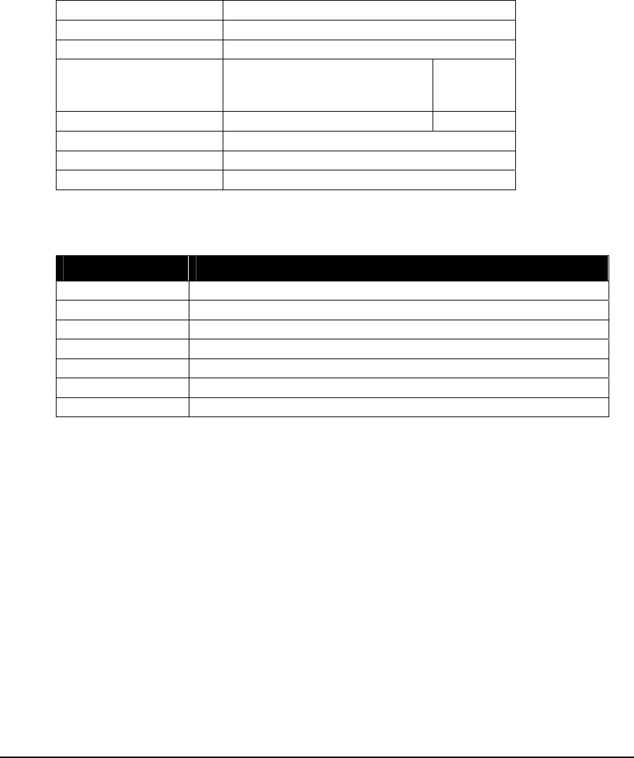
1.7.11 DIAG Serial Port Protocol Status
Description
The module, DIAG Serial port protocol status, provides diagnostic data about a specific
serial port. The status information is assigned to ten consecutive input registers. The input
registers are updated continuously with data concerning the protocol status of the serial port.
Register Assignment
Module DIAG Serial port comm. Status
Address com1, com2, com3, or com4.
Type Input Register
Start First register of any unused
block of 10 consecutive input
registers.
3xxxx
End Last register of block 3xxxx + 9
Registers 10 input registers.
Description None
Extended Parameters None
Register Data
Registers Assignment to Module Hardware
Start Register Protocol command errors
Start Register + 1 Protocol format errors
Start Register + 2 Protocol checksum errors
Start Register + 3 Protocol slave commands received
Start Register + 4 Protocol master commands sent
Start Register + 5 Protocol master responses received
Start Register + 6 Protocol slave responses sent
TelePACE Ladder Logic Register Assignment Reference
May 8, 2007
87

Registers Assignment to Module Hardware
Start Register + 7 Protocol master command status
0 = message sent, waiting for response
1 = response received, no error occurred
2 = not used
3 = bad value in function code register
4 = bad value in slave controller address register
5 = bad value in slave register address
6 = bad value in length register
7 = serial port or protocol is invalid
8 = not used
9 = specified protocol is not supported by this controller
11 = an unexpected length response was received
This means corrupt messages for regular Modbus. Check the
format and checksum counters. For Enron Modbus, this is
normal.
12 = response timeout
24 = exception response: invalid function code
25 = exception response: invalid address
26 = exception response: invalid value
27 = protocol is invalid or serial port queue is full
28 = slave and master stations are equal; they must be different
29 = exception response: slave device failure
30 = exception response: slave device busy
Start Register + 8 Protocol stored messages
Start Register + 9 Protocol forwarded messages
Notes
For SCADAPack, SCADAPack Light and SCADAPack Plus controllers Com3 is supported
only when the SCADAPack 5601 and 5604 I/O module is installed. Com4 is supported
only when the SCADAPack 5602 I/O module is installed. To optimize performance,
minimize the length of messages on com3 and com4. Examples of recommended uses for
com3 and com4 are for local operator terminals, and for programming and diagnostics using
the TelePACE program.
TelePACE Ladder Logic Register Assignment Reference
May 8, 2007
88

1.8 Digital Input I/O Modules
Digital input modules are used to assign data from physical digital inputs to status registers
in the I/O Database. The physical digital inputs are specific 5000 Series I/O modules,
generic I/O modules, and controller digital inputs.
Digital input modules may assign data to any status registers in the I/O database that are not
being used by another Digital input module. There are 4096 I/O database status registers
available. These status registers are numbered 10001 - 14096. Status registers are referred to
as 1xxxx registers throughout this manual.
All I/O database status registers that are not assigned to any other I/O modules may be used
as general-purpose status registers in a ladder program. The I/O modules available are
described in the following pages.
TelePACE Ladder Logic Register Assignment Reference
May 8, 2007
89
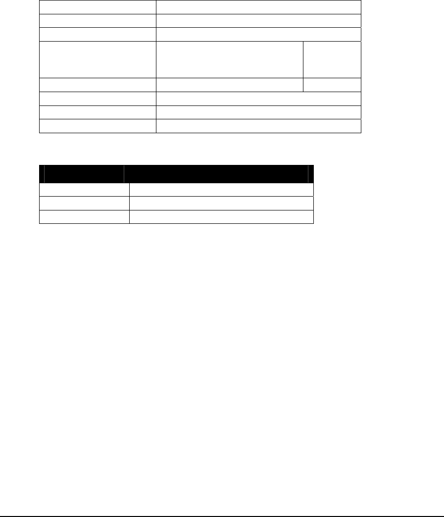
1.8.1 DIN Controller Digital Inputs
Description
The module, DIN controller digital inputs, reads the three digital inputs on the Micro16,
SCADAPack, SCADAPack Light, SCADAPack, SCADAPack Plus, SCADAPack 32 and
SCADAPack 32P controllers. Data is assigned to three consecutive status registers. The
status registers are updated continuously with data read from the digital inputs.
Register Assignment
Module DIN controller digital inputs
Address No physical address is required.
Type Status Register
Start First register of any unused
block of 3 consecutive status
registers.
1xxxx
End Last register of block 1xxxx + 2
Registers 3 status registers.
Description None
Extended Parameters None
Register Data
Registers Assignment to Module Hardware
Start Register Controller board digital input 0
Start Register + 1 Controller board digital input 1
Start Register + 2 Controller board digital input 2
Notes
Refer to the Hardware User Manual for further information.
TelePACE Ladder Logic Register Assignment Reference
May 8, 2007
90
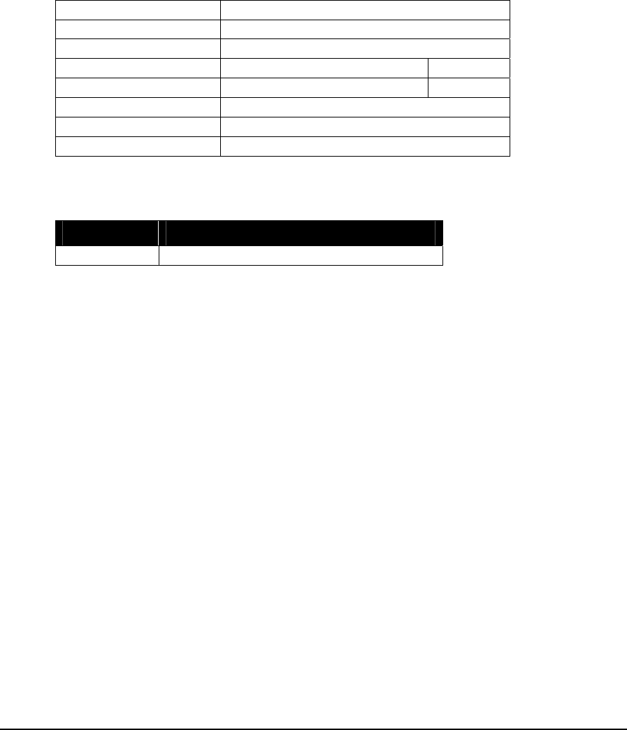
1.8.2 DIN Controller Interrupt Input
Description
The module, DIN controller interrupt input, reads the state of the interrupt input on the
Micro16, SCADAPack, SCADAPack Light, SCADAPack, SCADAPack Plus, SCADAPack
32 and SCADAPack 32P controllers. Data is assigned to one status register. The status
register is updated continuously with the state of the interrupt input.
Register Assignment
Module DIN controller interrupt input
Address No physical address is required.
Type Status Register
Start Any unused status register. 1xxxx
End Same as start register.
Registers 1 status registers.
Description None
Extended Parameters None
Register Data
Registers Assignment to Module Hardware
Start Register Controller board Interrupt Input
Notes
Refer to the Hardware User Manual for further information on the Controller interrupt input.
TelePACE Ladder Logic Register Assignment Reference
May 8, 2007
91
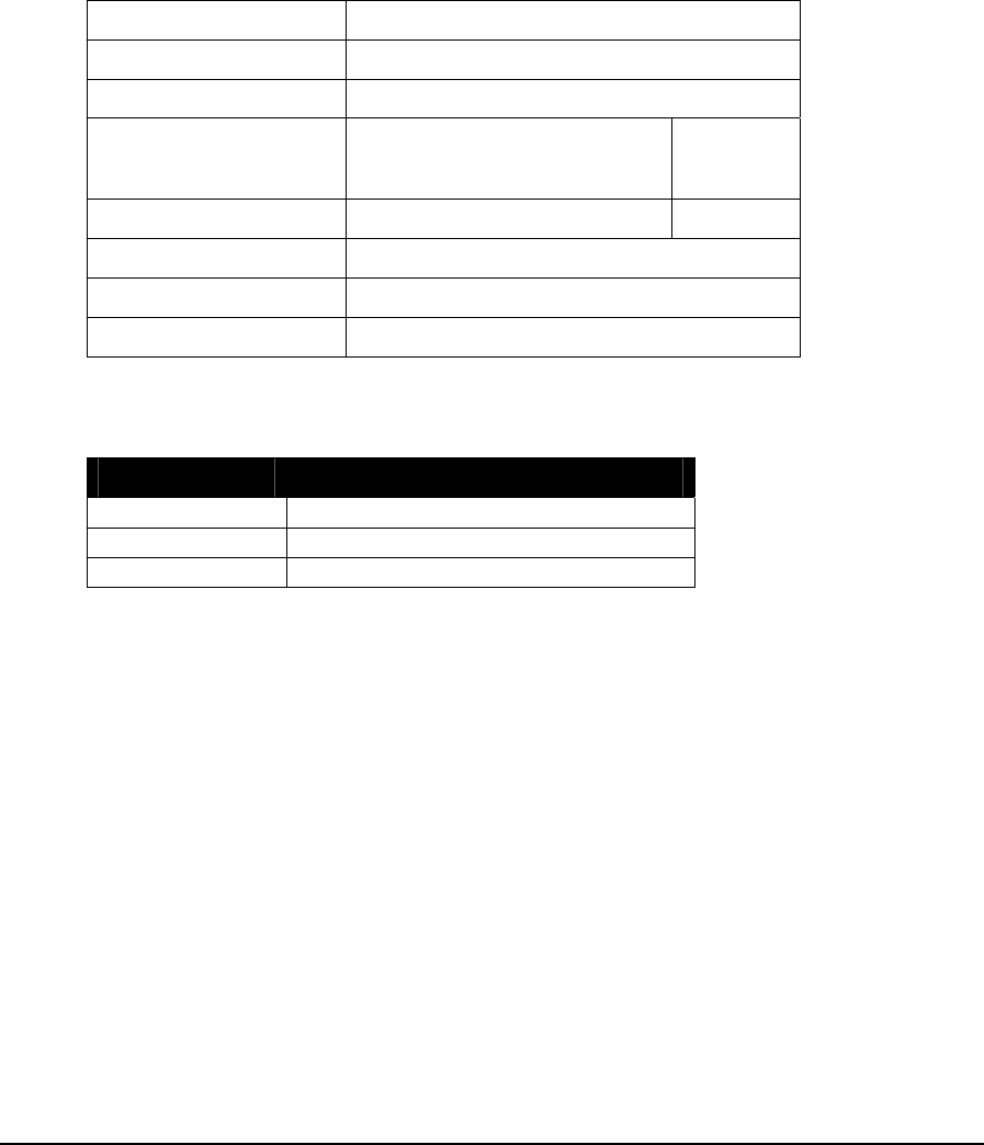
1.8.3 DIN Controller Option Switches
Description
The module, DIN Controller option switches, reads the state of the three option switches
on the Micro16, SCADAPack, SCADAPack Light, SCADAPack, SCADAPack Plus,
SCADAPack 32 and SCADAPack 32P controllers. Data is assigned to three status registers.
The status registers are updated continuously with data read from the option switches.
Register Assignment
Module DIN 5203/4 option switches
Address No physical address is required.
Type Status Register
Start First register of any unused
block of 3 consecutive status
registers.
1xxxx
End Last register of block 1xxxx + 2
Registers 3 status registers.
Description None
Extended Parameters None
Register Data
Registers Assignment to Module Hardware
Start Register Controller board option switch 1
Start Register + 1 Controller board option switch 2
Start Register + 2 Controller board option switch 3
Notes
The option switches are also used as configuration switches for the SCADAPack I/O
modules. Refer to these I/O modules for details.
Refer to the 5203/4 System Manual or the SCADAPack System Manual for further
information on the controller option switches.
TelePACE Ladder Logic Register Assignment Reference
May 8, 2007
92
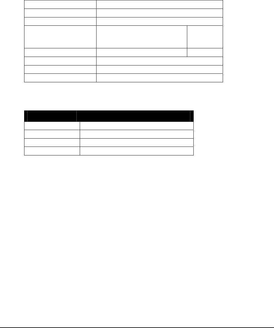
1.8.4 DIN SCADAPack 32 Option Switches
Description
The module, DIN SCADAPack 32 option switches, reads the state of the four option
switches on the SCADAPack 32 controller board. Data is assigned to four status registers.
The status registers are updated continuously with data read from the option switches.
Register Assignment
Module DIN SCADAPack 32 option switches
Address No physical address is required.
Type Status Register
Start First register of any unused
block of 4 consecutive status
registers.
1xxxx
End Last register of block 1xxxx + 3
Registers 4 status registers.
Description None
Extended Parameters None
Register Data
Registers Assignment to Module Hardware
Start Register Controller board option switch 1
Start Register + 1 Controller board option switch 2
Start Register + 2 Controller board option switch 3
Start Register + 3 Controller board option switch 4
Notes
The option switches are also used as configuration switches for the SCADAPack I/O
modules. Refer to these I/O modules for details.
Refer to the SCADAPack 32 System Manual for further information on the controller option
switches.
TelePACE Ladder Logic Register Assignment Reference
May 8, 2007
93

1.8.5 DIN 5401 Module
Description
The DIN 5401 module provides eight digital inputs. Data is assigned to eight consecutive
status registers. The status registers are updated continuously with data read from the digital
inputs.
When there are digital outputs being used in combination with digital inputs on the 5401, a
full 8 status registers must still be assigned to the DIN 5401 module. When this is the case,
a DOUT 5401 module must also be added to the Register Assignment with the same
module address.
Register Assignment
Module DIN 5401 module
Address This module is assigned a unique module
address between 0 and 7. No other DIN-
type module may use this module address.
Type Status Register
Start First register of any unused
block of 8 consecutive status
registers.
1xxxx
End Last register of block 1xxxx + 7
Registers 8 status registers.
Description None
Extended Parameters None
Register Data
Registers Assignment to Module Hardware
Start Register Digital input 0
Start Register + 1 Digital input 1
Start Register + 2 Digital input 2
Start Register + 3 Digital input 3
Start Register + 4 Digital input 4
Start Register + 5 Digital input 5
Start Register + 6 Digital input 6
Start Register + 7 Digital input 7
Notes
Refer to the 5401 Digital I/O Module User Manual for further information.
TelePACE Ladder Logic Register Assignment Reference
May 8, 2007
94

1.8.6 DIN 5402 Module
Description
The DIN 5402 module provides sixteen digital inputs. Data is assigned to sixteen
consecutive status registers. The status registers are updated continuously with data read
from the digital inputs.
Register Assignment
Module DIN 5402 module
Address This module is assigned a unique module
address between 0 and 15. No other DIN-
type module may use this module address.
Type Status Register
Start First register of any unused
block of 16 consecutive
status registers.
1xxxx
End Last register of block 1xxxx + 15
Registers 16 status registers.
Description None
Extended Parameters None
Register Data
Registers Assignment to Module Hardware
Start Register Digital input 0
Start Register + 1 Digital input 1
Start Register + 2 Digital input 2
Start Register + 3 Digital input 3
Start Register + 4 Digital input 4
Start Register + 5 Digital input 5
Start Register + 6 Digital input 6
Start Register + 7 Digital input 7
Start Register + 8 Digital input 8
Start Register + 9 Digital input 9
Start Register + 10 Digital input 10
Start Register + 11 Digital input 11
Start Register + 12 Digital input 12
Start Register + 13 Digital input 13
Start Register + 14 Digital input 14
Start Register + 15 Digital input 15
TelePACE Ladder Logic Register Assignment Reference
May 8, 2007
95

Notes
Refer to the 5402 Digital I/O Module User Manual for further information.
TelePACE Ladder Logic Register Assignment Reference
May 8, 2007
96

1.8.7 DIN 5403 Module
Description
The DIN 5403 module provides eight digital inputs. Data is assigned to eight consecutive
status registers. The status registers are updated continuously with data read from the digital
inputs.
Register Assignment
Module DIN 5403 module
Address This module is assigned a unique module
address between 0 and 7. No other DIN-
type module may use this module address.
Type Status Register
Start First register of any unused
block of 8 consecutive status
registers.
1xxxx
End Last register of block 1xxxx + 7
Registers 8 status registers.
Description None
Extended Parameters None
Register Data
Registers Assignment to Module Hardware
Start Register Digital input 0
Start Register + 1 Digital input 1
Start Register + 2 Digital input 2
Start Register + 3 Digital input 3
Start Register + 4 Digital input 4
Start Register + 5 Digital input 5
Start Register + 6 Digital input 6
Start Register + 7 Digital input 7
Notes
Refer to the 5403 Digital Input Module User Manual for further information.
TelePACE Ladder Logic Register Assignment Reference
May 8, 2007
97

1.8.8 DIN 5404 Module
Description
The DIN 5404 module provides sixteen digital inputs. Data is assigned to sixteen
consecutive status registers. The status registers are updated continuously with data read
from the digital inputs.
Register Assignment
Module DIN 5404 module
Address This module is assigned a unique module
address between 0 and 15. No other DIN-
type module may use this module address.
Type Status Register
Start First register of any unused
block of 16 consecutive
status registers.
1xxxx
End Last register of block 1xxxx + 15
Registers 16 status registers.
Description None
Extended Parameters None
Register Data
Registers Assignment to Module Hardware
Start Register Digital input 0
Start Register + 1 Digital input 1
Start Register + 2 Digital input 2
Start Register + 3 Digital input 3
Start Register + 4 Digital input 4
Start Register + 5 Digital input 5
Start Register + 6 Digital input 6
Start Register + 7 Digital input 7
Start Register + 8 Digital input 8
Start Register + 9 Digital input 9
Start Register + 10 Digital input 10
Start Register + 11 Digital input 11
Start Register + 12 Digital input 12
Start Register + 13 Digital input 13
Start Register + 14 Digital input 14
Start Register + 15 Digital input 15
Notes
Refer to the 5404 Digital Input Module User Manual for further information.
TelePACE Ladder Logic Register Assignment Reference
May 8, 2007
98

1.8.9 DIN 5405 Module
Description
The DIN 5405 module provides thirty-two digital inputs. Data is assigned to thirty-two
consecutive status registers. The status registers are updated continuously with data read
from the digital inputs.
Register Assignment
Module DIN 5404 module
Address This module is assigned a unique module
address between 0 and 15. No other DIN-
type module may use this module address.
Type Status Register
Start First register of any unused
block of 32 consecutive
status registers.
1xxxx
End Last register of block 1xxxx + 31
Registers 32 status registers.
Description None
Extended Parameters None
Register Data
Registers Assignment to Module Hardware
Start Register Digital input 0
Start Register + 1 Digital input 1
Start Register + 2 Digital input 2
Start Register + 3 Digital input 3
Start Register + 4 Digital input 4
Start Register + 5 Digital input 5
Start Register + 6 Digital input 6
Start Register + 7 Digital input 7
Start Register + 8 Digital input 8
Start Register + 9 Digital input 9
Start Register + 10 Digital input 10
Start Register + 11 Digital input 11
Start Register + 12 Digital input 12
Start Register + 13 Digital input 13
Start Register + 14 Digital input 14
Start Register + 15 Digital input 15
Start Register + 16 Digital input 16
Start Register + 17 Digital input 17
Start Register + 18 Digital input 18
Start Register + 19 Digital input 19
Start Register + 20 Digital input 20
TelePACE Ladder Logic Register Assignment Reference
May 8, 2007
99

Registers Assignment to Module Hardware
Start Register + 21 Digital input 21
Start Register + 22 Digital input 22
Start Register + 23 Digital input 23
Start Register + 24 Digital input 24
Start Register + 25 Digital input 25
Start Register + 26 Digital input 26
Start Register + 27 Digital input 27
Start Register + 28 Digital input 28
Start Register + 29 Digital input 29
Start Register + 30 Digital input 30
Start Register + 31 Digital input 31
Notes
Refer to the 5405 Digital Input Module User Manual for further information.
TelePACE Ladder Logic Register Assignment Reference
May 8, 2007
100
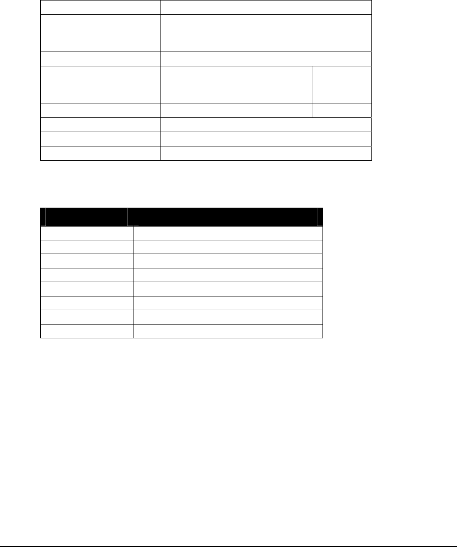
1.8.10 DIN 5421 Module
Description
The DIN 5421 module provides eight digital inputs. Data is assigned to eight consecutive
status registers. The status registers are updated continuously with data read from the digital
inputs.
Register Assignment
Module DIN 5421 module
Address This module is assigned a unique module
address between 0 and 7. No other DIN-
type module may use this module address.
Type Status Register
Start First register of any unused
block of 8 consecutive status
registers.
1xxxx
End Last register of block 1xxxx + 7
Registers 8 status registers.
Description None
Extended Parameters None
Register Data
Registers Assignment to Module Hardware
Start Register Digital input 0
Start Register + 1 Digital input 1
Start Register + 2 Digital input 2
Start Register + 3 Digital input 3
Start Register + 4 Digital input 4
Start Register + 5 Digital input 5
Start Register + 6 Digital input 6
Start Register + 7 Digital input 7
Notes
Refer to the 5421 Switch Input Module Manual for further information.
TelePACE Ladder Logic Register Assignment Reference
May 8, 2007
101

1.8.11 DIN Generic 16 Point Module
Description
The DIN Generic 16 point module provides sixteen digital inputs. Data is assigned to
sixteen consecutive status registers. The status registers are updated continuously with data
read from the digital inputs. The DIN Generic 16 point module may be used in place of
any other 16 point DIN-type module.
The DIN Generic 16 point module type is a useful selection early on in the system design
stage before the final selection of the specific DIN module type is known.
Register Assignment
Module DIN Generic 16 point module
Address This module is assigned a unique module
address between 0 and 15. No other DIN-
type module may use this module address.
Type Status Register
Start First register of any unused
block of 16 consecutive
status registers.
1xxxx
End Last register of block 1xxxx + 15
Registers 16 status registers.
Description None
Extended Parameters None
Register Data
Registers Assignment to Module Hardware
Start Register Digital input 0
Start Register + 1 Digital input 1
Start Register + 2 Digital input 2
Start Register + 3 Digital input 3
Start Register + 4 Digital input 4
Start Register + 5 Digital input 5
Start Register + 6 Digital input 6
Start Register + 7 Digital input 7
Start Register + 8 Digital input 8
Start Register + 9 Digital input 9
Start Register + 10 Digital input 10
Start Register + 11 Digital input 11
Start Register + 12 Digital input 12
Start Register + 13 Digital input 13
Start Register + 14 Digital input 14
Start Register + 15 Digital input 15
TelePACE Ladder Logic Register Assignment Reference
May 8, 2007
102

Notes
For further information, refer to the User Manual for the specific 16 point DIN module
used.
TelePACE Ladder Logic Register Assignment Reference
May 8, 2007
103

1.8.12 DIN Generic 8 Point Module
Description
The DIN Generic 8 point module provides eight digital inputs. Data is stored in eight
consecutive status registers. The status registers are updated continuously with data read
from the digital inputs. The DIN Generic 8 point module may be used in place of any other
8 point DIN-type module.
The DIN Generic 8 point module type is a useful selection early on in the system design stage
before the final selection of the specific DIN module type is known.
Register Assignment
Module DIN Generic 8 point module
Address This module is assigned a unique module
address between 0 and 7. No other DIN-
type module may use this module address.
Type Status Register
Start First register of any unused
block of 8 consecutive status
registers.
1xxxx
End Last register of block 1xxxx + 7
Registers 8 status registers.
Description None
Extended Parameters None
Register Data
Registers Assignment to Module Hardware
Start Register Digital input 0
Start Register + 1 Digital input 1
Start Register + 2 Digital input 2
Start Register + 3 Digital input 3
Start Register + 4 Digital input 4
Start Register + 5 Digital input 5
Start Register + 6 Digital input 6
Start Register + 7 Digital input 7
Notes
For further information, refer to the User Manual for the specific 8 point DIN module used.
TelePACE Ladder Logic Register Assignment Reference
May 8, 2007
104

1.9 Digital Output I/O Modules
Digital output modules are used to assign data from the I/O Database to physical digital
outputs. The physical digital outputs are specific 5000 Series I/O modules or generic I/O
modules.
Digital output modules may assign data to any coil registers in the I/O database that are not
being used by another Digital output module. There are 4096 I/O database coil registers
available. These coil registers are numbered 00001 - 04096. Coil registers are referred to as
0xxxx registers throughout this manual.
All I/O database coil registers that are not assigned to any other I/O modules may be used as
general-purpose coil registers in a ladder program. The I/O modules available are described
in the following pages.
TelePACE Ladder Logic Register Assignment Reference
May 8, 2007
105

1.9.1 DOUT 5401 Module
Description
The DOUT 5401 module provides eight digital outputs. Data is assigned from eight
consecutive coil registers. The digital outputs are updated continuously with data read from
the coil registers.
When there are digital inputs being used in combination with digital outputs on the 5401, a
full 8 coil registers must still be assigned to the DOUT 5401 module. When this is the case,
a DIN 5401 module must also be added to the Register Assignment with the same module
address.
Register Assignment
Module DOUT 5401 module
Address This module is assigned a unique module
address between 0 and 7. No other DOUT-
type module may use this module address.
Type Coil Register
Start First register of any unused
block of 8 consecutive coil
registers.
0xxxx
End Last register of block 0xxxx + 7
Registers 8 coil registers.
Description None
Extended Parameters None
Register Data
Registers Assignment to Module Hardware
Start Register Digital output 0
Start Register + 1 Digital output 1
Start Register + 2 Digital output 2
Start Register + 3 Digital output 3
Start Register + 4 Digital output 4
Start Register + 5 Digital output 5
Start Register + 6 Digital output 6
Start Register + 7 Digital output 7
Notes
Refer to the 5401 Digital I/O Module User Manual for further information.
TelePACE Ladder Logic Register Assignment Reference
May 8, 2007
106

1.9.2 DOUT 5402 Module
Description
The DOUT 5402 module provides sixteen digital outputs. Data is assigned from sixteen
consecutive coil registers. The digital outputs are updated continuously with data read from
the coil registers.
Register Assignment
Module DOUT 5402 module
Address This module is assigned a unique module
address between 0 and 15. No other
DOUT-type module may use this module
address.
Type Coil Register
Start First register of any unused
block of 16 consecutive coil
registers.
0xxxx
End Last register of block 0xxxx + 15
Registers 16 coil registers.
Description None
Extended Parameters None
Register Data
Registers Assignment to Module Hardware
Start Register Digital output 0
Start Register + 1 Digital output 1
Start Register + 2 Digital output 2
Start Register + 3 Digital output 3
Start Register + 4 Digital output 4
Start Register + 5 Digital output 5
Start Register + 6 Digital output 6
Start Register + 7 Digital output 7
Start Register + 8 Digital output 8
Start Register + 9 Digital output 9
Start Register + 10 Digital output 10
Start Register + 11 Digital output 11
Start Register + 12 Digital output 12
Start Register + 13 Digital output 13
Start Register + 14 Digital output 14
Start Register + 15 Digital output 15
Notes
Refer to the 5402 Digital I/O Module User Manual for further information.
TelePACE Ladder Logic Register Assignment Reference
May 8, 2007
107

1.9.3 DOUT 5406 Module
Description
The DOUT 5406 module provides sixteen digital outputs. Data is assigned from sixteen
consecutive coil registers. The digital outputs are updated continuously with data read from
the coil registers.
Register Assignment
Module DOUT 5406 module
Address This module is assigned a unique module
address between 0 and 15. No other
DOUT-type module may use this module
address.
Type Coil Register
Start First register of any unused
block of 16 consecutive coil
registers.
0xxxx
End Last register of block 0xxxx + 15
Registers 16 coil registers.
Description None
Extended Parameters None
Register Data
Registers Assignment to Module Hardware
Start Register Digital output 0
Start Register + 1 Digital output 1
Start Register + 2 Digital output 2
Start Register + 3 Digital output 3
Start Register + 4 Digital output 4
Start Register + 5 Digital output 5
Start Register + 6 Digital output 6
Start Register + 7 Digital output 7
Start Register + 8 Digital output 8
Start Register + 9 Digital output 9
Start Register + 10 Digital output 10
Start Register + 11 Digital output 11
Start Register + 12 Digital output 12
Start Register + 13 Digital output 13
Start Register + 14 Digital output 14
Start Register + 15 Digital output 15
Notes
Refer to the 5406 Digital Output Module User Manual for further information.
TelePACE Ladder Logic Register Assignment Reference
May 8, 2007
108

1.9.4 DOUT 5407 Module
Description
The DOUT 5407 module provides eight digital outputs. Data is assigned from eight
consecutive coil registers. The digital outputs are updated continuously with data read from
the coil registers.
Register Assignment
Module DOUT 5407 module
Address This module is assigned a unique module
address between 0 and 7. No other DOUT-
type module may use this module address.
Type Coil Register
Start First register of any unused
block of 8 consecutive coil
registers.
0xxxx
End Last register of block 0xxxx + 7
Registers 8 coil registers.
Description None
Extended Parameters None
Register Data
Registers Assignment to Module Hardware
Start Register Digital output 0
Start Register + 1 Digital output 1
Start Register + 2 Digital output 2
Start Register + 3 Digital output 3
Start Register + 4 Digital output 4
Start Register + 5 Digital output 5
Start Register + 6 Digital output 6
Start Register + 7 Digital output 7
Notes
Refer to the 5407 Relay Output Module Manual for further information.
TelePACE Ladder Logic Register Assignment Reference
May 8, 2007
109
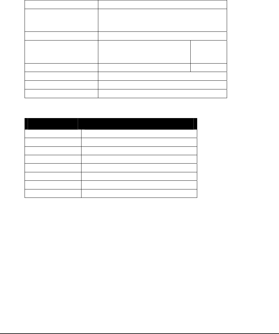
1.9.5 DOUT 5408 Module
Description
The DOUT 5408 module provides eight digital outputs. Data is assigned from eight
consecutive coil registers. The digital outputs are updated continuously with data read from
the coil registers.
Register Assignment
Module DOUT 5408 module
Address This module is assigned a unique module
address between 0 and 7. No other DOUT-
type module may use this module address.
Type Coil Register
Start First register of any unused
block of 8 consecutive coil
registers.
0xxxx
End Last register of block 0xxxx + 7
Registers 8 coil registers.
Description None
Extended Parameters None
Register Data
Registers Assignment to Module Hardware
Start Register Digital output 0
Start Register + 1 Digital output 1
Start Register + 2 Digital output 2
Start Register + 3 Digital output 3
Start Register + 4 Digital output 4
Start Register + 5 Digital output 5
Start Register + 6 Digital output 6
Start Register + 7 Digital output 7
Notes
Refer to the 5408 Digital Output Module Manual for further information.
TelePACE Ladder Logic Register Assignment Reference
May 8, 2007
110

1.9.6 DOUT 5409 Module
Description
The DOUT 5409 module provides eight digital outputs. Data is assigned from eight
consecutive coil registers. The digital outputs are updated continuously with data read from
the coil registers.
Register Assignment
Module DOUT 5409 module
Address This module is assigned a unique module
address between 0 and 7. No other DOUT-
type module may use this module address.
Type Coil Register
Start First register of any unused
block of 8 consecutive coil
registers.
0xxxx
End Last register of block 0xxxx + 7
Registers 8 coil registers.
Description None
Extended Parameters None
Register Data
Registers Assignment to Module Hardware
Start Register Digital output 0
Start Register + 1 Digital output 1
Start Register + 2 Digital output 2
Start Register + 3 Digital output 3
Start Register + 4 Digital output 4
Start Register + 5 Digital output 5
Start Register + 6 Digital output 6
Start Register + 7 Digital output 7
Notes
Refer to the 5409 Digital Output Module Manual for further information.
TelePACE Ladder Logic Register Assignment Reference
May 8, 2007
111

1.9.7 DOUT 5411 Module
Description
The DOUT 5411 module provides thirty-two digital outputs. Data is assigned from thirty-
two consecutive coil registers. The digital outputs are updated continuously with data read
from the coil registers.
Register Assignment
Module DOUT 5411 module
Address This module is assigned a unique module
address between 0 and 15. No other
DOUT-type module may use this module
address.
Type Coil Register
Start First register of any unused
block of 32 consecutive coil
registers.
0xxxx
End Last register of block 0xxxx + 31
Registers 32 coil registers.
Description None
Extended Parameters None
Register Data
Registers Assignment to Module Hardware
Start Register Digital output 0
Start Register + 1 Digital output 1
Start Register + 2 Digital output 2
Start Register + 3 Digital output 3
Start Register + 4 Digital output 4
Start Register + 5 Digital output 5
Start Register + 6 Digital output 6
Start Register + 7 Digital output 7
Start Register + 8 Digital output 8
Start Register + 9 Digital output 9
Start Register + 10 Digital output 10
Start Register + 11 Digital output 11
Start Register + 12 Digital output 12
Start Register + 13 Digital output 13
Start Register + 14 Digital output 14
Start Register + 15 Digital output 15
Start Register + 16 Digital output 16
Start Register + 17 Digital output 17
Start Register + 18 Digital output 18
Start Register + 19 Digital output 19
TelePACE Ladder Logic Register Assignment Reference
May 8, 2007
112

Registers Assignment to Module Hardware
Start Register + 20 Digital output 20
Start Register + 21 Digital output 21
Start Register + 22 Digital output 22
Start Register + 23 Digital output 23
Start Register + 24 Digital output 24
Start Register + 25 Digital output 25
Start Register + 26 Digital output 26
Start Register + 27 Digital output 27
Start Register + 28 Digital output 28
Start Register + 29 Digital output 29
Start Register + 30 Digital output 30
Start Register + 31 Digital output 31
Notes
Refer to the 5411 Digital Output Module User Manual for further information.
TelePACE Ladder Logic Register Assignment Reference
May 8, 2007
113

1.9.8 DOUT Generic 16 Point Module
Description
The DOUT Generic 16 point module provides sixteen digital outputs. Data is assigned
from sixteen consecutive coil registers. The digital outputs are updated continuously with
data read from the coil registers. The DOUT Generic 16 point module may be used in
place of any other 16 point DOUT-type module.
The DOUT Generic 16 point module type is a useful selection early on in the system
design stage before the final selection of the specific DOUT module type is known.
Register Assignment
Module Generic 16 point module
Address This module is assigned a unique module
address between 0 and 15. No other
DOUT-type module may use this module
address.
Type Coil Register
Start First register of any unused
block of 16 consecutive coil
registers.
0xxxx
End Last register of block 0xxxx + 15
Registers 16 coil registers.
Description None
Extended Parameters None
Register Data
Registers Assignment to Module Hardware
Start Register Digital output 0
Start Register + 1 Digital output 1
Start Register + 2 Digital output 2
Start Register + 3 Digital output 3
Start Register + 4 Digital output 4
Start Register + 5 Digital output 5
Start Register + 6 Digital output 6
Start Register + 7 Digital output 7
Start Register + 8 Digital output 8
Start Register + 9 Digital output 9
Start Register + 10 Digital output 10
Start Register + 11 Digital output 11
Start Register + 12 Digital output 12
Start Register + 13 Digital output 13
Start Register + 14 Digital output 14
Start Register + 15 Digital output 15
TelePACE Ladder Logic Register Assignment Reference
May 8, 2007
114

Notes
For further information, refer to the Digital Output Module User Manual for the specific 16-
point DOUT module used.
TelePACE Ladder Logic Register Assignment Reference
May 8, 2007
115

1.9.9 DOUT Generic 8 Point Module
Description
The DOUT Generic 8 point module provides eight digital outputs. Data is assigned from
eight consecutive coil registers. The digital outputs are updated continuously with data read
from the coil registers. The DOUT Generic 8 point module may be used in place of any
other 8 point DOUT-type module.
The DOUT Generic 8 point module type is a useful selection early on in the system design
stage before the final selection of the specific DOUT module type is known.
Register Assignment
DOUT Generic 8 point module
Module
This module is assigned a unique module
address between 0 and 7. No other DOUT-
type module may use this module address.
Address
Coil Register
Type
First register of any unused
block of 8 consecutive coil
registers.
0xxxx
Start
Last register of block
End 0xxxx + 7
Registers 8 coil registers.
Description None
Extended Parameters None
Register Data
Registers Assignment to Module Hardware
Start Register Digital output 0
Start Register + 1 Digital output 1
Start Register + 2 Digital output 2
Start Register + 3 Digital output 3
Start Register + 4 Digital output 4
Start Register + 5 Digital output 5
Start Register + 6 Digital output 6
Start Register + 7 Digital output 7
Notes
For further information, refer to the Digital Output Module Manual for the specific 8 point
DOUT module used.
TelePACE Ladder Logic Register Assignment Reference
May 8, 2007
116

1.10 SCADAPack and SCADASense Series I/O Modules
SCADAPack and SCADASense Series I/O modules assign data from registers to physical
outputs, and assign data from physical inputs to registers. These I/O modules provide analog
I/O points, digital I/O points and may assign data to registers that are not used by any other
I/O module.
The following modules interface with SCADAPack and SCADASense Series I/O hardware.
TelePACE Ladder Logic Register Assignment Reference
May 8, 2007
117

1.10.1 4202 DR Extended/4203 DR IO
Description
The SCADASense 4203 DR, and a SCADASense 4202 DR manufactured after July 13,
2004, may use the 4202 DR Extended/4203 DR I/O register assignment. The 4202 DR must
have controller board version 5 and terminal board version 6.
A SCADASense 4203 DR, or 4202 DR with Extended I/O, provides one digital point, which
may operate as a digital input/counter or as a digital output. The digital output shares the
same physical connections as the digital input. When the output is turned OFF, the point
may be used as input. When the output is turned on it functions only as a digital output.
Digital point data is assigned to a single coil register and a single status register. The coil
register is updated continuously with data read from the coil register. The status register is
updated continuously with data read from the digital input.
Analog and counter input data is assigned to five consecutive input registers. One input
register is used to monitor the controller input power and two counter input double registers
(32 bit). These input registers are updated continuously with data read from the analog
inputs and counter input.
Analog output data is assigned to a single analog output register. The analog output is
updated continuously with the data read from the holding register.
Register Assignment
Module 4202 DR Extended/4203 DR I/O Module
Address Fixed
Type Coil Register
Start Any unused coil register. 0xxxx
End Same as first register. 0xxxx
Registers 1 coil registers
Description digital output
Type Status Register
Start Any unused status register 1xxxx
End Same as first register. 1xxxx
Registers 1 status register
Description Digital input
Type Input Register
Start First register of any unused block of 5
consecutive status registers. 3xxxx
End Last register of block 3xxxx + 4
Registers 5 input registers
Description Analog and counter inputs
Type Analog Output Register
Start Any unused analog output register 4xxxx
End Same as first register 4xxxx
Registers 1 analog output register
TelePACE Ladder Logic Register Assignment Reference
May 8, 2007
118

Description Analog outputs
Extended Parameters None
Coil Register Data
Registers Assignment to Module Hardware
Start Register Digital output 0
Status Register Data
Registers Assignment to Module Hardware
Start Register Digital input 0
Analog and Counter Input Register Data
Registers Assignment to Module Hardware
Start Register Analog input Supply Voltage (mV)
Start Register + 1 and +2 Counter input, 32 bit register
Start Register + 3 and +4 Counter input, 32 bit register
Analog Output Register Data
Registers Assignment to Module Hardware
Start Register Analog output – Input Voltage (mV)
Notes
Only one 4202 DR Extended/4203 DR I/O may be assigned.
Refer to the SCADASense 4202 DR Hardware Manual for information on analog and
digital I/O usage.
TelePACE Ladder Logic Register Assignment Reference
May 8, 2007
119

1.10.2 4202 DR I/O
Description
Digital input data is assigned to a single status register. The status register is updated
continuously with data read from the digital input.
Analog and counter input data is assigned to five consecutive input registers. One input
register is used to monitor the controller input power and two counter input double registers
(32 bit). These input registers are updated continuously with data read from the analog
inputs and counter input.
Analog output data is assigned to a single analog output register. The analog output is
updated continuously with the data read from the holding register.
Register Assignment
Module 4202 DR I/O Module
Address Fixed
Type Status Register
Start Any unused status register 1xxxx
End Same as first register. 1xxxx
Registers 1 status register
Description Digital input
Type Input Register
Start First register of any unused block of 5
consecutive status registers. 3xxxx
End Last register of block 3xxxx + 4
Registers 5 input registers
Description Analog and counter inputs
Type Analog Output Register
Start Any unused analog output register 4xxxx
End Same as first register 4xxxx
Registers 1 analog output register
Description Analog outputs
Extended Parameters None
Status Register Data
Registers Assignment to Module Hardware
Start Register Digital input 0
Analog and Counter Input Register Data
Registers Assignment to Module Hardware
Start Register Analog input Supply Voltage (mV)
Start Register + 1 and +2 Counter input, 32 bit register
TelePACE Ladder Logic Register Assignment Reference
May 8, 2007
120

Registers Assignment to Module Hardware
Start Register + 3 and +4 Counter input, 32 bit register
Analog Output Register Data
Registers Assignment to Module Hardware
Start Register Analog output – Input Voltage (mV)
Notes
Only one 4202 DR I/O may be assigned.
Refer to the SCADASense 4202 DR Hardware Manual for information on analog and
digital I/O usage.
TelePACE Ladder Logic Register Assignment Reference
May 8, 2007
121

1.10.3 4202/4203 DS I/O
Description
The 4202/4203 DS I/O register assignment is used for the SCADASense DS Series of controllers
(4202 DS and 4203 DS). This module provides two digital input/output (I/O) points point. The first
DI/O point may be used as a digital input/counter or as a digital output. The digital output shares the
same physical connections as the digital input/counter. When the output is turned OFF, the point
may be used as input/counter. When the output is turned on it functions only as a digital output.
Digital point data is assigned to a single coil register and a single status register. The coil register is
updated continuously with data read from the coil register. The status register is updated
continuously with data read from the digital input.
The second DI/O point may be used as a turbine meter counter input or as a digital output. The
digital output shares the same physical connections as the turbine meter counter input. When the
output is turned OFF, the point may be used as a turbine meter counter input. When the output is
turned on it functions only as a digital output. Digital point data is assigned to a single coil register.
The coil register is updated continuously with data read from the coil register.
Analog and counter input data is assigned to seven consecutive input registers. Two input registers
are used for the two analog inputs; one input register is used to monitor the controller input power;
two input registers are used for the counter input (32 bit double word uses two registers) and two
input registers are used for the turbine meter counter input (32 bit double word uses two registers).
These input registers are updated continuously with data read from the analog inputs and counter
inputs.
Register Assignment
Module 4202/4203 DS I/O Module
Address Fixed
Type Coil Register
Start Any unused coil register. 0xxxx
End Last register of block. 0xxxx + 1
Registers 2 coil registers
Description Digital output
Type Status Register
Start Any unused status register 1xxxx
End Same as first register. 1xxxx
Registers 1 status register
Description Digital input
Type Input Register
Start First register of any unused block of 7
consecutive status registers. 3xxxx
End Last register of block 3xxxx + 6
Registers 7 input registers
Description Analog and counter inputs
Extended Parameters None
TelePACE Ladder Logic Register Assignment Reference
May 8, 2007
122

Coil Register Data
Registers Assignment to Module Hardware
Start Register Digital output 0
Start Register +1 Digital output 1
Status Register Data
Registers Assignment to Module Hardware
Start Register Digital input 0
Analog and Counter Input Register Data
Registers Assignment to Module Hardware
Start Register Analog Input 0
Start Register +1 Analog Input 1
Start Register +2 Analog input Supply Voltage (mV)
Start Register +3 and +4 Counter 0 input, 32 bit register
Start Register +5 and +6 Counter 1 input, 32 bit register
Notes
Only one 4202/4203 DS I/O may be assigned.
Refer to the SCADASense 4202 DS Hardware Manual for information on analog and
digital I/O usage.
TelePACE Ladder Logic Register Assignment Reference
May 8, 2007
123
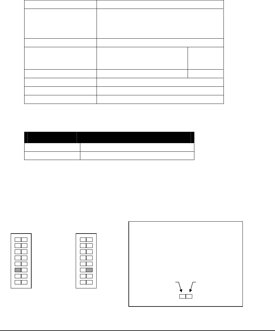
1.10.4 SCADAPack AOUT Module
Description
The SCADAPack AOUT module provides two analog outputs. Data is read from two consecutive
holding (4xxxx) registers. The analog outputs are updated continuously with the data read from the
holding registers.
Register Assignment
Module SCADAPack AOUT module
Address This module has a fixed module address of
0. No other AOUT-type module may use
this module address when this module is
used.
Type Holding Register
Start First register of any unused
block of 2 consecutive holding
registers.
4xxxx
End Last register of block 4xxxx + 1
Registers 2 holding registers.
Description None
Extended Parameters None
Register Data
Registers Assignment to Module Hardware
Start Register Analog output 0
Start Register + 1 Analog output 1
Output Range Selection
The SCADAPack Option Switch 2 selects the signal range. Both analog outputs are set to
the same range.
The figure below shows the switch settings for selecting the output range.
Press this side
for 4-20 mA
Press this side
for 0-20 mA
How to Set the Range Switch
• Determine the desired range.
• Press the side of the switch
shown in gray.
4-20 mA Outputs
0
1
2
2
3
0
1
2
2
3
0-20 mA Outputs
H/W RST
1 H/W RST
1
TelePACE Ladder Logic Register Assignment Reference
May 8, 2007
124

Notes
Refer to the SCADAPack Hardware Manual for further information on the option
t or not.
switches.
Option Switch 2 functions as the Output Range Switch regardless of whether the module,
5203/4 option switches, is added to the Register Assignmen
TelePACE Ladder Logic Register Assignment Reference
May 8, 2007
125

1.10.5 DAPack
Descrip
Digital o e nsecutive coil registers. The digital outputs are
pdated continuously with data read from the coil registers.
ed to sixteen consecutive status registers. The status registers are
the digital inputs.
Analog input data is assigned to eight consecu
updated d he analog inputs.
Registe
ck 5601 I/O Module
SCA 5601 I/O Module
tion
utput data is assign d from twelve co
u
Digital input data is assign
updated continuously with data read from
tive input registers. The input registers are
continuously with ata read from t
r Assignment
Module SCADAPa
Address fixed at 0
Type Coil Register
Start First register of any unused block of 12
e coil registers. 0xxxx
consecutiv
End Last register of block 0xxxx + 11
Registers 12 coil registers
Description digital outputs
Type Status Register
Start First register of any unused block of 16
status registers. 1xxxx
consecutive
End Last register of block 1xxxx + 15
Registers 16 status registers
Description digital inputs
Type Input Register
Start First register of any unused block of 8
ve input registers. 3xxxx
consecuti
End Last register of block 3xxxx +7
Registers 8 input registers
Description analog inputs
Extended Parameters None
Coil Register Data
Registers Assignment to Module Hardware
Start Register Digital output 0
Start Register + 1 Digital output 1
Start Register + 2 Digital output 2
Start Register + 3 Digital output 3
Start Register + 4 Digital output 4
Start Register + 5 Digital output 5
Start Register + 6 Digital output 6
Start Register + 7 Digital output 7
TelePACE Ladder Logic Register Assignment Reference
May 8, 2007
126

Registers Assignment to Module Hardware
Start Register + 8 Digital output 8
Start Register + 9 Digital output 9
Start Register + 10 Digital output 10
Start Register + 11 Digital output 12
Status Register Data
Registers Assignment to Module Hardware
Start Register Digital input 0
Start Register + 1 Digital input 1
Start Register + 2 Digital input 2
Start Register + 3 Digital input 3
Start Register + 4 Digital input 4
Start Register + 5 Digital input 5
Start Register + 6 Digital input 6
Start Register + 7 Digital input 7
Start Register + 8 Digital input 8
Start Register + 9 Digital input 9
Start Register + 10 Digital input 10
Start Register + 11 Digital input 11
Start Register + 12 Digital input 12
Start Register + 13 Digital input 13
Start Register + 14 Digital input 14
Start Register + 15 Digital input 15
Input Register Data
Registers Assignment to Module Hardware
Start Register Analog input 0
Start Register + 1 Analog input 1
Start Register + 2 Analog input 2
Start Register + 3 Analog input 3
Start Register + 4 Analog input 4
Start Register + 5 Analog input 5
Start Register + 6 Analog input 6
Start Register + 7 Analog input 7
Analog Input Measurement Range Selection
The SCADAPack Option Switch 1 selects the measurement range. All 8 analog inputs are
set to the same range.
The figure below shows the switch settings for selecting the measurement range.
TelePACE Ladder Logic Register Assignment Reference
May 8, 2007
127
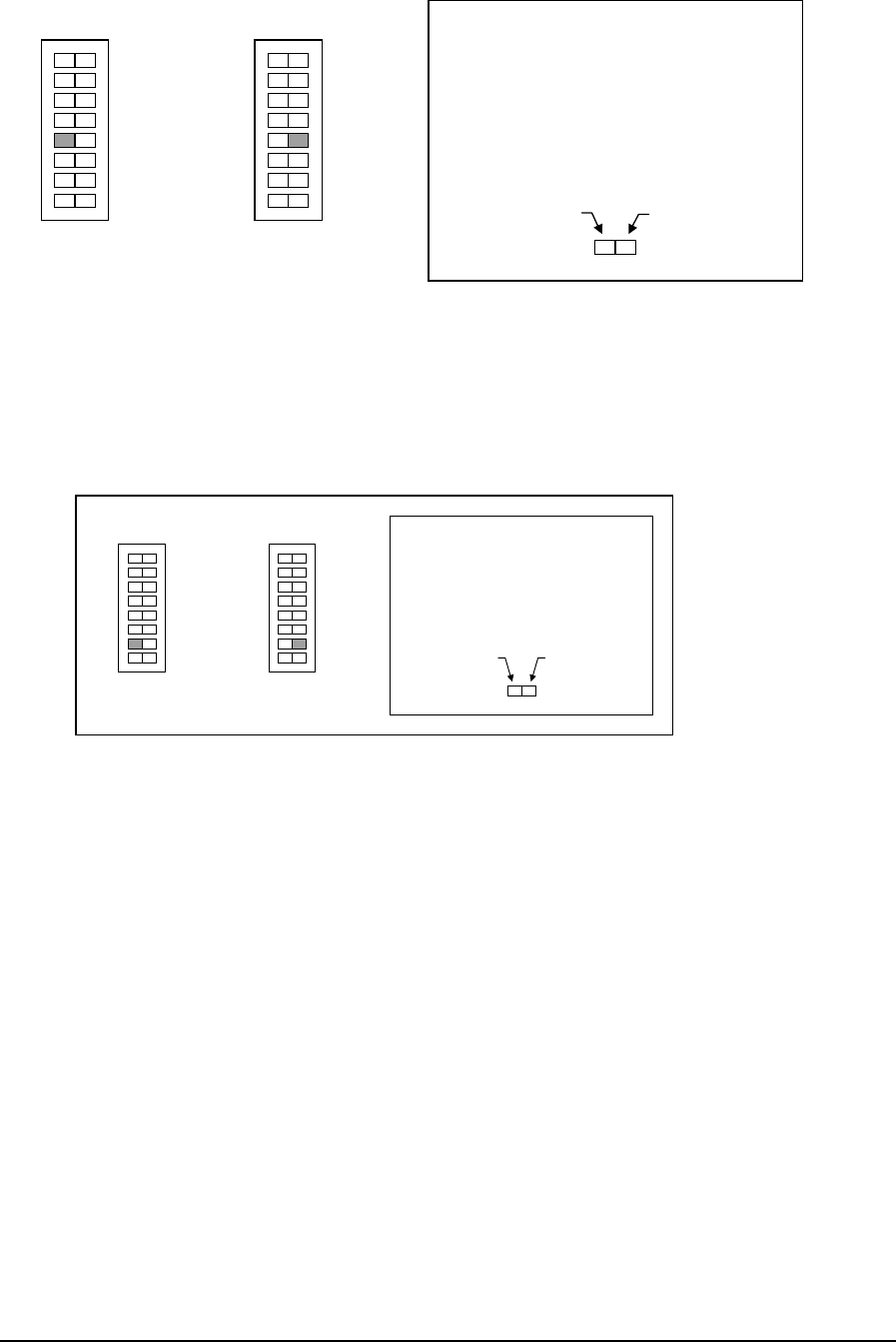
Press this side
for 4-20 mA
(1-5 V)
Press this side
for 0-20 m
A
(0-5 V)
How to Set the Range Switch
• Determine the desired range.
• Press the side of the switch
shown in gray.
4-20 mA (1-5 V) AINs
0-20 mA AINs
0 0
1
2
(0-5 V)
The SCADAPack I/O board may select 50 or 60 Hz line frequency for digital and analog
DAPack Option Switch 3 selects this option. The figure below
1
2
H/W RST
1
2
H/W RST
1
2
3 3
Line Frequency Selection
input processing. The SCA
shows the switch settings for selecting the line frequency.
Press this side
for 50 Hz
Press this side
0 Hzfor 6
How to
• Dete
Set the Frequency Switch
rmine the frequency.
• Press the side of the switch
shown in gray.
50 Hz Operat
0
1
2
H/W RST
1
2
on ion
3
0
1
2
H/W RST
1
2
3
60 Hz Operati
Notes
Only one ack 5601 or may be assigned to the same controller.
Option switches 1 and 3 function as described above regardless of whether the module, DIN
5203/4 option switches, is added
Refer to the SCADAPack Hardw on on the option switches.
Two ana are available Pack 5601 I/O module. Refer to the
SCADA module fo ation.
SCADAP 5604 I/O module
to the Register Assignment or not.
are Manual for informati
log outputs for the SCADA
Pack AOUT r more inform
TelePACE Ladder Logic Register Assignment Reference
May 8, 2007
128

1.10.6 SCADAPack 5602 I/O Module
Descrip
Digital o n secutive coil registers. The digital outputs are
updated d e coil registers.
Analog input data is assigned to five consecutive input registers. The input registers are
log inputs.
gital inputs. The digital input data is assigned
s registers. The status registers are updated continuously with data
read from g inputs
A digital input is ON if the corresponding filtered analog input value is greater than or equal
to 20% of its full-scale value, otherwise it is OFF.
Registe
Module SCADAPack 5602 I/O Module
tion
utput data is assig ed from two con
continuously with ata read from th
updated continuously with data read from the ana
The same five analog inputs are also read as di
to five consecutive statu
the analo .
r Assignment
Address fixed at 0
Type Coil Register
Start First register of any unused block of 2
consecutive coil registers. 0xxxx
End Last register of block 0xxxx + 1
Registers 2 coil registers
Description digital outputs
Type Status Register
Start First register of any unused block of 5
consecutive status registers. 1xxxx
End Last register of block 1xxxx + 4
Registers 5 status registers
Description analog inputs read as digital inputs
Type Input Register
Start First register of any unused block of 5
consecutive input registers. 3xxxx
End Last register of block 3xxxx +4
Registers 5 input registers
Description analog inputs
Extended Parameters None
Coil Register Data
Registers Assignment to Module Hardware
Start Register Digital output 0
Start Register + 1 Digital output 1
TelePACE Ladder Logic Register Assignment Reference
May 8, 2007
129
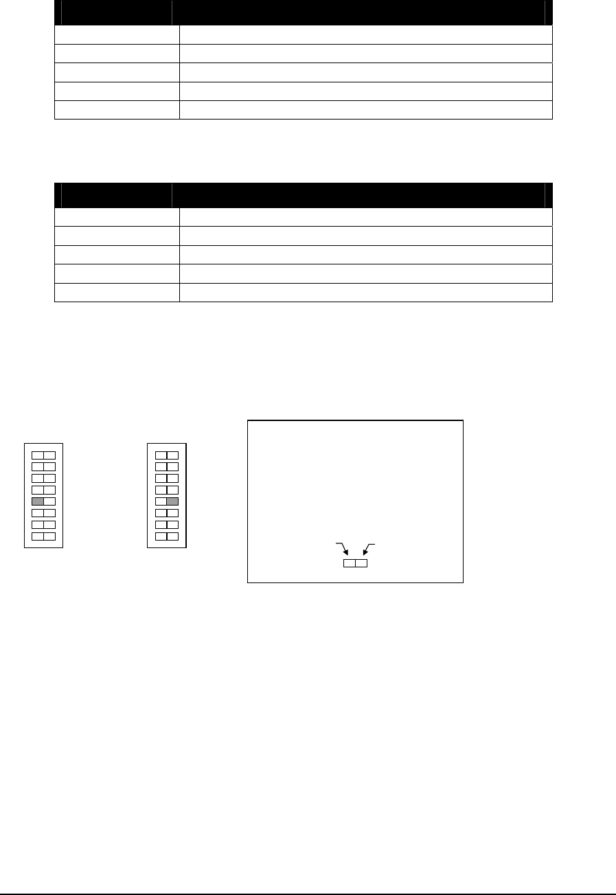
Status Register Data
Registers Assignment to Module Hardware
Start Register Analog input 0 *
Start Register + 1 Analog input 1 *
Start Register + 2 Analog input 2 *
Start Register + 3 Analog input 3 *
Start Register + 4 Analog input 4 *
* Analog inputs are read again as digital inputs.
Input Register Data
Registers Assignment to Module Hardware
Start Register Analog input 0
Start Register + 1 Analog input 1
Start Register + 2 Analog input 2
Start Register + 3 Analog input 3
Start Register + 4 Analog input 4
Analog Input Measurement Range Selection
The SCADAPack Option Switch 1 selects the measurement range. All 5 analog inputs are
set to the same range.
The figure below shows the switch settings for selecting the measurement range.
Press this side
for 4-20 mA
(1-5 V)
Press this side
for 0-20 m
A
(0-5 V)
How to Set the Range Switch
• Determine the desired range.
• Press the side of the switch
shown in gray.
4-20 mA (1-5 V) AINs
0
1
2
H/W RST
1
2
3
0
1
2
H/W RST
1
2
3
0-20 mA (0-5 V) AINs
Line Frequency Selection
The SCADAPack I/O board may select 50 or 60 Hz line frequency for analog input
processing. The SCADAPack Option Switch 3 selects this option. The figure below shows
the switch settings for selecting the line frequency.
TelePACE Ladder Logic Register Assignment Reference
May 8, 2007
130

Press this side
for 50 Hz
Press this side
for 60 Hz
How to Set the Frequency Switch
• Determine the frequency.
• Press the side of the switch
shown in gray.
50 Hz Operation
0
1
2
H/W RST
1
2
3
0
1
2
H/W RST
1
2
3
60 Hz Operation
Notes
Only one SCADAPack 5602 I/O module may be assigned to the same controller. Option
switches 1 and 3 function as described above regardless of whether the module, DIN 5203/4
option switches, is added to the Register Assignment or not. Refer to the SCADAPack
Hardware Manual for information on the option switches.
TelePACE Ladder Logic Register Assignment Reference
May 8, 2007
131

1.10.7 SCADAPack 5604 I/O Module
Description
The SCADAPack 5604 I/O Module is comprised of four different types of I/O channels.
The SCADAPack 5604 I/O hardware contains ten analog inputs, two analog outputs, thirty-
five digital inputs and thirty-six digital outputs.
The analog input assignment provides ten I/O channels for the analog input data from the
SCADAPack 5604 I/O Module hardware.
• Analog input channels 0 to 7 provide eight external analog inputs (0-10V or 0-40mA)
• Analog input channel 8 provides an external analog input for battery monitoring (0 to
32.768V)
• Analog input channel 9 provides an internal analog input for DC/DC converter
monitoring.
The analog output assignment provides two I/O channels for the analog output data for the
SCADAPack 5604 I/O Module hardware.
The digital input assignment provides thirty-five I/O channels for the digital input data
from the SCADAPack 5604 I/O Module hardware.
The SCADAPack 5604 I/O Module provides thirty-two universal digital inputs or outputs.
The inputs are for use with dry contacts such as switches and relay contacts.
• These are defined as digital input channels 0 to 31.
0 = contact open (LED off)
1 = contact closed (LED on)
The SCADAPack 5604 I/O Module also provides three internal digital inputs.
• Digital input channel 32 returns the DC/DC converter status.
0 = DC/DC converter off
1 = DC/DC converter on
• Digital input channel 33 returns the DC/DC converter over current status.
0 = Over current not detected
1 = Over current detected
• Digital output channel 34 returns the digital output mismatch status.
0 = No mismatch
1 = One or more digital outputs mismatch
The digital output assignment provides thirty-six I/O channels for the digital outputs of the
SCADAPack 5604 I/O Module I/O hardware.
The SCADAPack 5604 I/O Module provides thirty-two universal digital inputs or
outputs. Outputs are open-collector/open drain type.
• These are defined as digital output channels 0 to 31.
0 = output transistor off
TelePACE Ladder Logic Register Assignment Reference
May 8, 2007
132

1 = output transistor on
The SCADAPack 5604 I/O Module also provides two internal digital outputs.
• Digital output channel 32 is used to control the DC/DC converter.
0 = DC/DC converter off
1 = DC/DC converter on
• Digital output channel 33 is used to control the VLoop power supply.
0 = VLoop output off
1 = VLoop output on
• Digital output channels 34 and 35 control the SCADAPack 5604 I/O Module Analog
Input filters.
Filter Setting Digital Output 34 Digital Output 35
< 3 Hz OFF OFF
6 Hz OFF ON
11 Hz ON OFF
30 Hz ON ON
Register Assignment
Module SCADAPack 5604 I/O Module
Address Fixed at 0
Type Coil Register
Start First register of any unused block of 36
consecutive coil registers. 0xxxx
End Last register of block 0xxxx + 35
Registers 36 coil registers
Description Digital outputs
Type Status Register
Start First register of any unused block of 35
consecutive status registers. 1xxxx
End Last register of block 1xxxx + 34
Registers 35 status registers
Description Digital inputs
Type Input Register
Start First register of any unused block of 10
consecutive input registers. 3xxxx
End Last register of block 3xxxx +9
Registers 10 input registers
Description analog inputs
Type Holding Register
Start First register of any unused block of 2
consecutive holding registers. 4xxxx
End Last register of block 4xxxx +1
Registers 2 input registers
Description analog outputs
Extended Parameters None
TelePACE Ladder Logic Register Assignment Reference
May 8, 2007
133

Coil Register Data
Registers Assignment to Module Hardware
Start Register Digital output 0
Start Register + 1 Digital output 1
Start Register + 2 Digital output 2
Start Register + 3 Digital output 3
Start Register + 4 Digital output 4
Start Register + 5 Digital output 5
Start Register + 6 Digital output 6
Start Register + 7 Digital output 7
Start Register + 8 Digital output 8
Start Register + 9 Digital output 9
Start Register + 10 Digital output 10
Start Register + 11 Digital output 11
Start Register + 12 Digital output 12
Start Register + 13 Digital output 13
Start Register + 14 Digital output 14
Start Register + 15 Digital output 15
Start Register + 16 Digital output 16
Start Register + 17 Digital output 17
Start Register + 18 Digital output 18
Start Register + 19 Digital output 19
Start Register + 20 Digital output 20
Start Register + 21 Digital output 21
Start Register + 22 Digital output 22
Start Register + 23 Digital output 23
Start Register + 24 Digital output 24
Start Register + 25 Digital output 25
Start Register + 26 Digital output 26
Start Register + 27 Digital output 27
Start Register + 28 Digital output 28
Start Register + 29 Digital output 29
Start Register + 30 Digital output 30
Start Register + 31 Digital output 31
Start Register + 32 Digital output 32
Start Register + 33 Digital output 33
Start Register + 34 Digital output 34
Start Register + 35 Digital output 35
Status Register Data
Registers Assignment to Module Hardware
Start Register Digital input 0
Start Register + 1 Digital input 1
Start Register + 2 Digital input 2
Start Register + 3 Digital input 3
TelePACE Ladder Logic Register Assignment Reference
May 8, 2007
134

Registers Assignment to Module Hardware
Start Register + 4 Digital input 4
Start Register + 5 Digital input 5
Start Register + 6 Digital input 6
Start Register + 7 Digital input 7
Start Register + 8 Digital input 8
Start Register + 9 Digital input 9
Start Register + 10 Digital input 10
Start Register + 11 Digital input 11
Start Register + 12 Digital input 12
Start Register + 13 Digital input 13
Start Register + 14 Digital input 14
Start Register + 15 Digital input 15
Start Register + 16 Digital input 16
Start Register + 17 Digital input 17
Start Register + 18 Digital input 18
Start Register + 19 Digital input 19
Start Register + 20 Digital input 20
Start Register + 21 Digital input 21
Start Register + 22 Digital input 22
Start Register + 23 Digital input 23
Start Register + 24 Digital input 24
Start Register + 25 Digital input 25
Start Register + 26 Digital input 26
Start Register + 27 Digital input 27
Start Register + 28 Digital input 28
Start Register + 29 Digital input 29
Start Register + 30 Digital input 30
Start Register + 31 Digital input 31
Start Register + 32 Digital input 32
Start Register + 33 Digital input 33
Start Register + 34 Digital input 34
Input Register Data
Registers Assignment to Module Hardware
Start Register Analog input 0
Start Register + 1 Analog input 1
Start Register + 2 Analog input 2
Start Register + 3 Analog input 3
Start Register + 4 Analog input 4
Start Register + 5 Analog input 5
Start Register + 6 Analog input 6
Start Register + 7 Analog input 7
TelePACE Ladder Logic Register Assignment Reference
May 8, 2007
135
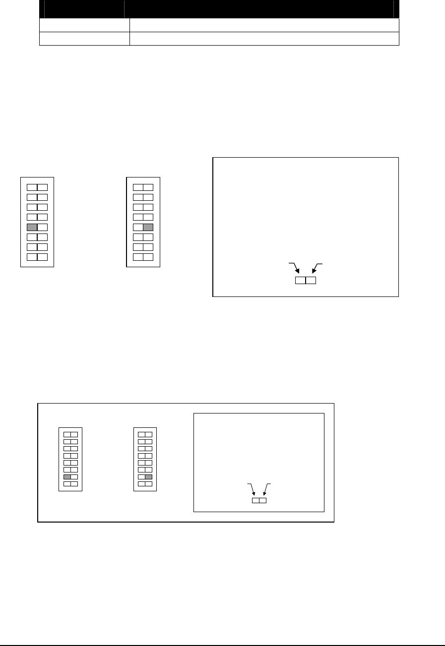
Holding Register Data
Registers Assignment to Module Hardware
Start Register Analog output 0
Start Register + 1 Analog output 1
Analog Input Measurement Range Selection
The SCADAPack Option Switch 1 selects the measurement range. All 8 analog inputs are
set to the same range.
The figure below shows the switch settings for selecting the measurement range.
Press this side
for 4-20 mA
(1-5 V)
Press this side
for 0-20 m
A
(0-5 V)
How to Set the Range Switch
• Determine the desired range.
• Press the side of the switch
shown in gray.
4-20 mA (1-5 V) AINs
0
1
2
H/W RST
1
2
3
0
1
2
H/W RST
1
2
3
0-20 mA (0-5 V) AINs
Line Frequency Selection
The SCADAPack I/O board may select 50 or 60 Hz line frequency for digital and analog
input processing. The SCADAPack Option Switch 3 selects this option. The figure below
shows the switch settings for selecting the line frequency.
Press this side
for 50 Hz
Press this side
for 60 Hz
How to Set the Frequency Switch
• Determine the frequency.
• Press the side of the switch
shown in gray.
50 Hz Operation
0
1
2
H/W RST
1
2
3
0
1
2
H/W RST
1
2
3
60 Hz Operation
Notes
Only one SCADAPack 5601 or 5604 I/O module may be assigned to the same controller.
Option switches 1 and 3 function as described above regardless of whether the module, DIN
5203/4 option switches, is added to the Register Assignment or not.
Refer to the SCADAPack Hardware Manual for information on the option switches.
TelePACE Ladder Logic Register Assignment Reference
May 8, 2007
136

Two analog outputs are available for the SCADAPack 5601 I/O module. Refer to the
SCADAPack AOUT module for more information.
TelePACE Ladder Logic Register Assignment Reference
May 8, 2007
137

1.10.8 SCADAPack 5606 I/O Module
Description
The SCADAPack 5606 I/O Module is comprised of four types of I/O channels, digital inputs,
digital outputs, analog inputs, and analog outputs.
The digital input assignment provides forty I/O channels for the digital input data from the
SCADAPack 5606 I/O Module hardware.
• The 5606 I/O Module provides thirty-two external digital inputs. These are externally wetted
inputs.
• The module provides 8 internal digital inputs, which indicate if the corresponding analog input is
in or out of range.
The digital output assignment provides sixteen digital outputs. All are digital output relays.
The analog input assignment provides eight I/O channels for the analog input data from the
SCADAPack 5606 I/O Module hardware.
The analog output assignment provides two I/O channels for the analog output data for the
SCADAPack 5606 I/O Module hardware when the optional analog output module is installed.
Register Assignment
The register assignment for the SCADAPack 5606 I/O Module is used to configure the registers used
for the module data and the Extended Parameters available for the module. To open the register
assignment dialog for the SCADAPack 5606 I/O module:
• Select Register Assignment from the Controller menu in TelePACE.
• In the Register Assignment window select the Add button.
• In the Add Register Assignment dialog select the SCADAPack 5606 I/O Module from the list
presented in the Module window.
The register assignment dialog for the SCADAPack 5606 I/O Module is shown below.
TelePACE Ladder Logic Register Assignment Reference
May 8, 2007
138
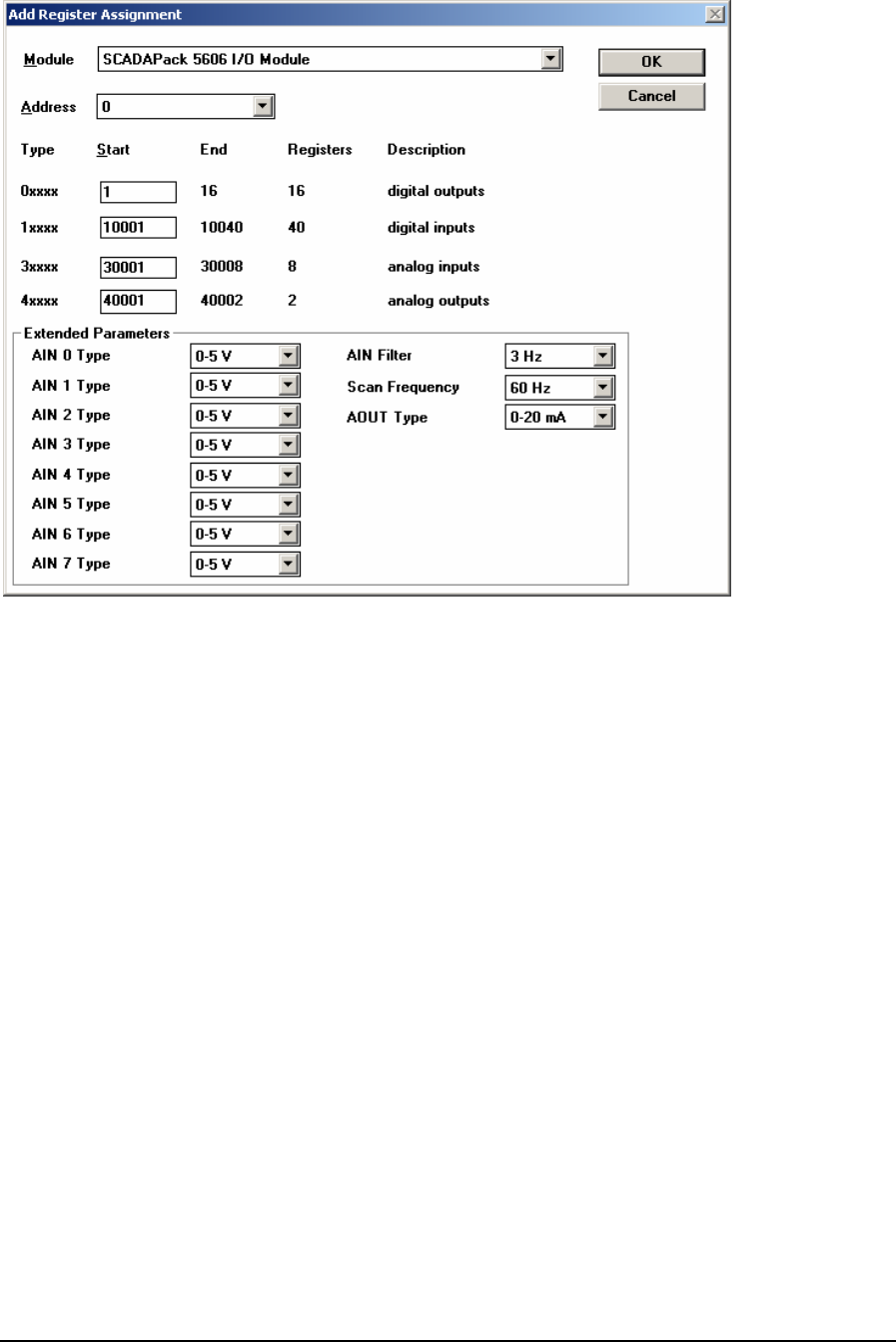
The Module selection displays the name of the SCADAPack 5606 I/O module used for the register
assignment.
The Address selection displays the module address of the physical SCADAPack 5606 I/O module.
The address on the module is selected via dip switches on the module. A maximum of eight
SCADAPack 5606 I/O type modules may be added to a system.
The register type 0xxxx defines the register range for the digital output data. Sixteen sequential
registers are needed for the SCADAPack 5606 I/O module digital output data. Any unused block of
sixteen registers may be used. See the Digital Output Register Data section below for an
explanation of the digital output data.
The register type 1xxxx defines the register range for the digital input status data. Forty sequential
registers are needed for the SCADAPack 5606 I/O module digital Input data. Any unused block of
forty registers may be used. See the Digital Input Register Data section below for an explanation of
the digital input status data.
The register type 3xxxx defines the register range for the analog input data. Eight sequential registers
are needed for the SCADAPack 5606 I/O module analog input data. Any unused block of eight
registers may be used. See the Input Register Data section below for an explanation of the analog
input data.
The register type 4xxxx defines the register range for the analog output data. Two sequential
registers are needed for the SCADAPack 5606 I/O module analog output data. Any unused block of
two registers may be used. See the Analog Output Register Data section below for an explanation
of the analog output data.
The Extended Parameters grouping defines the type of data returned from the SCADAPack 5606
I/O module analog inputs, the type of analog output signal, filtering used by all analog inputs and the
scan frequency.
TelePACE Ladder Logic Register Assignment Reference
May 8, 2007
139

The AIN Type selection for each input (AIN 0, 1, 2, 3, 4, 5, 6, and 7) defines the input measurement
type for the analog input.
• The 0-5V selection sets the input type to measure 0 to 5V input signals.
• The 1-5V selection sets the input type to measure 1 to 5V input signals.
• The 0-20 mA selection sets the input type to measure 0 to 20mA input signals.
• The 4-20 mA selection sets the input type to measure 4 to 20mA input signals.
The AIN Filter selection set the input filter for all analog inputs. Filtering is used to dampen process
variations or noise.
• The 3 Hz filter selection sets the response time to 155ms at 60Hz and 185ms at 50Hz.
• The 6 Hz filter selection sets response time to 85ms at 60Hz and 85ms at 50Hz.
• The 11 Hz filter selection sets response time to 45ms at 60Hz and 55ms at 50Hz.
• The 30 Hz filter selection sets response time to 30ms at 60Hz and 30ms at 50Hz.
The Scan Frequency selection set the input scan rate for all analog inputs. The scan rate selection is
not critical but AC noise rejection is improved at the correct frequency. If the module is used in a DC
environment, the 60 Hz setting will yield slightly faster response time.
• The 60 Hz selection synchronies the input scanning to 60Hz.
• The 50 Hz selection synchronies the input scanning to 50Hz.
The AOUT Type selection for each input (AOUT 0 and 1) defines the output signal type for the
analog output.
• The 0-20 mA selection sets the output type for 0 to 20mA signals.
• The 4-20 mA selection sets the output type for 4 to 20mA signals.
Digital Output Register Data
Digital output data is assigned to sixteen consecutive digital output (0xxxx) registers. The following
table begins at the Start address defined in the Register Assignment and continues for sixteen
registers.
Registers Assignment to Module Hardware
Start Register 0 = OFF (relay open); 1= ON (relay closed)
Start Register + 1 0 = OFF (relay open); 1= ON (relay closed)
Start Register + 2 0 = OFF (relay open); 1= ON (relay closed)
Start Register + 3 0 = OFF (relay open); 1= ON (relay closed)
Start Register + 4 0 = OFF (relay open); 1= ON (relay closed)
Start Register + 5 0 = OFF (relay open); 1= ON (relay closed)
Start Register + 6 0 = OFF (relay open); 1= ON (relay closed)
Start Register + 7 0 = OFF (relay open); 1= ON (relay closed)
Start Register + 8 0 = OFF (relay open); 1= ON (relay closed)
Start Register + 9 0 = OFF (relay open); 1= ON (relay closed)
Start Register + 10 0 = OFF (relay open); 1= ON (relay closed)
Start Register + 11 0 = OFF (relay open); 1= ON (relay closed)
Start Register + 12 0 = OFF (relay open); 1= ON (relay closed)
TelePACE Ladder Logic Register Assignment Reference
May 8, 2007
140

Registers Assignment to Module Hardware
Start Register + 13 0 = OFF (relay open); 1= ON (relay closed)
Start Register + 14 0 = OFF (relay open); 1= ON (relay closed)
Start Register + 15 0 = OFF (relay open); 1= ON (relay closed)
Digital Input Register Data
Status register data is assigned to forty consecutive status (1xxxx) registers. The following table
begins at the Start address defined in the Register Assignment and continues for forty registers.
Registers Assignment to Module Hardware
Start Register 0 = OFF (led off); 1= ON (led on)
Start Register + 1 0 = OFF (led off); 1= ON (led on)
Start Register + 2 0 = OFF (led off); 1= ON (led on)
Start Register + 3 0 = OFF (led off); 1= ON (led on)
Start Register + 4 0 = OFF (led off); 1= ON (led on)
Start Register + 5 0 = OFF (led off); 1= ON (led on)
Start Register + 6 0 = OFF (led off); 1= ON (led on)
Start Register + 7 0 = OFF (led off); 1= ON (led on)
Start Register + 8 0 = OFF (led off); 1= ON (led on)
Start Register + 9 0 = OFF (led off); 1= ON (led on)
Start Register + 10 0 = OFF (led off); 1= ON (led on)
Start Register + 11 0 = OFF (led off); 1= ON (led on)
Start Register + 12 0 = OFF (led off); 1= ON (led on)
Start Register + 13 0 = OFF (led off); 1= ON (led on)
Start Register + 14 0 = OFF (led off); 1= ON (led on)
Start Register + 15 0 = OFF (led off); 1= ON (led on)
Start Register + 16 0 = OFF (led off); 1= ON (led on)
Start Register + 17 0 = OFF (led off); 1= ON (led on)
Start Register + 18 0 = OFF (led off); 1= ON (led on)
Start Register + 19 0 = OFF (led off); 1= ON (led on)
Start Register + 20 0 = OFF (led off); 1= ON (led on)
Start Register + 21 0 = OFF (led off); 1= ON (led on)
Start Register + 22 0 = OFF (led off); 1= ON (led on)
Start Register + 23 0 = OFF (led off); 1= ON (led on)
Start Register + 24 0 = OFF (led off); 1= ON (led on)
Start Register + 25 0 = OFF (led off); 1= ON (led on)
Start Register + 26 0 = OFF (led off); 1= ON (led on)
Start Register + 27 0 = OFF (led off); 1= ON (led on)
Start Register + 28 0 = OFF (led off); 1= ON (led on)
Start Register + 29 0 = OFF (led off); 1= ON (led on)
Start Register + 30 0 = OFF (led off); 1= ON (led on)
Start Register + 31 0 = OFF (led off); 1= ON (led on)
Start Register + 32 OFF = AIN channel 0 is OK
ON = AIN channel 0 is over or under range
Start Register + 33 OFF = AIN channel 1 is OK
ON = AIN channel 1 is over or under range
TelePACE Ladder Logic Register Assignment Reference
May 8, 2007
141

Registers Assignment to Module Hardware
Start Register + 34 OFF = AIN channel 2 is OK
ON = AIN channel 2 is over or under range
Start Register + 35 OFF = AIN channel 3 is OK
ON = AIN channel 3is over or under range
Start Register + 36 OFF = AIN channel 4 is OK
ON = AIN channel 4 is over or under range
Start Register + 37 OFF = AIN channel 5 is OK
ON = AIN channel 5 is over or under range
Start Register + 38 OFF = AIN channel 6 is OK
ON = AIN channel 6is over or under range
Start Register + 39 OFF = AIN channel 7 is OK
ON = AIN channel 7 is over or under range
Input Register Data
Input register data is assigned to eight consecutive analog input (3xxxx) registers. The following
table begins at the Start address defined in the Register Assignment and continues for eight
registers.
Registers Assignment to Module Hardware
Start Register Analog input 0
Start Register + 1 Analog input 1
Start Register + 2 Analog input 2
Start Register + 3 Analog input 3
Start Register + 4 Analog input 4
Start Register + 5 Analog input 5
Start Register + 6 Analog input 6
Start Register + 7 Analog input 7
Analog Output Register Data
Analog output register data is assigned to two consecutive analog output (4xxxx) registers. The
following table begins at the Start address defined in the Register Assignment.
Registers Assignment to Module Hardware
Start Register Analog input 0
Start Register + 1 Analog input 1
Notes
Refer to the SCADAPack Hardware Manual for information on the SCADAPack 5606 I/O
module.
TelePACE Ladder Logic Register Assignment Reference
May 8, 2007
142

1.10.9 SCADAPack LP I/O
Description
The SCADAPack LP I/O Module is comprised of four different types of I/O channels. The
SCADAPack LP I/O hardware contains eight analog inputs, two analog outputs, sixteen digital
inputs and twelve digital outputs.
The analog input assignment provides seven I/O channels for the analog input data. Analog input
data is a signed value in the range –32768 to 32767.
• Analog input channels 0 to 4 provide eight external analog inputs (0-10V or 0-40mA)
• Analog input channel 5 provides an external analog input for battery monitoring (0 to 32.768V)
• Analog input channel 6 provides an internal analog input for DC/DC converter monitoring.
The analog output assignment provides two I/O channels for the analog output data. Analog input
data is a signed value in the range –32768 to 32767.
The digital input assignment provides sixteen I/O channels for the digital input data.
The SCADAPack LP provides eight universal digital inputs or outputs. The inputs are for use with
dry contacts such as switches and relay contacts.
• These are defined as digital input channels 0 to 7.
0 = contact open (LED off)
1 = contact closed (LED on)
The SCADAPack LP also provides eight internal digital inputs.
• Digital input channel 8 returns the Com1 (RS-485) power status.
0 = off
1 = on
• Digital input channel 9 returns the Com3 (HMI) power output status.
0 = off
1 = on
• Digital input channel 10 returns the VLOOP output status.
0 = off
1 = on
• Digital input channel 11 returns the DC/DC converter status. This bit reports the true status of
the DC/DC converter. If over-current causes the converter to be turned off, this bit will clear.
0 = off
1 = on
• Digital input channel 12 returns the VLOOP over-current status. This indicates VLOOP over-
current has been detected. This input clears when VLOOP output is off, or the over-current
condition clears.
0= off
TelePACE Ladder Logic Register Assignment Reference
May 8, 2007
143

1 = on
• Digital input channel 13 returns the digital output mismatch status.
0= No mismatch
1 = One or more digital outputs mismatch
• Digital input channel 14 returns the SCADAPack Vision power.
0 = No power to SCADAPack Vision
1 = Power to SCADAPack Vision
The digital output assignment provides twelve I/O channels for the digital outputs of the
SCADAPack LP.
The SCADAPack LP provides eight universal digital inputs or outputs. Outputs are open-
collector/open drain type.
• These are defined as digital output channels 0 to 7.
0 = output transistor off
1 = output transistor on
The SCADAPack LP also provides four internal digital outputs.
• Digital output channel 8 is not used. This is for internal use only.
• Digital output channel 9 is used to control com3 (HMI) power.
0= off
1 = on
• Digital output channel 10 is used to control the VLoop power supply.
0= VLoop output off
1= VLoop output on
• Digital output channel 11 is used to control the DC/DC converter.
0= off
1 = on
Register Assignment
Module SCADAPack LP I/O Module
Address fixed
Type Coil Register
Start First register of any unused block of 12
consecutive coil registers. 0xxxx
End Last register of block 0xxxx + 11
Registers 12 coil registers
Description digital outputs
Type Status Register
Start First register of any unused block of 16
consecutive status registers. 1xxxx
TelePACE Ladder Logic Register Assignment Reference
May 8, 2007
144

Module SCADAPack LP I/O Module
Address fixed
End Last register of block 1xxxx + 15
Registers 16 status registers
Description digital inputs
Type Input Register
Start First register of any unused block of 8
consecutive input registers. 3xxxx
End Last register of block 3xxxx +7
Registers 8 input registers
Description analog inputs
Type Holding Register
Start First register of any unused block of 2
consecutive holding registers. 4xxxx
End Last register of block 4xxxx +1
Registers 2 output registers
Description analog outputs
Extended Parameters None
Coil Register Data
Registers Assignment to Module Hardware
Start Register Digital output 0
Start Register + 1 Digital output 1
Start Register + 2 Digital output 2
Start Register + 3 Digital output 3
Start Register + 4 Digital output 4
Start Register + 5 Digital output 5
Start Register + 6 Digital output 6
Start Register + 7 Digital output 7
Start Register + 8 Digital output 8
Start Register + 9 Digital output 9
Start Register + 10 Digital output 10
Start Register + 11 Digital output 11
Status Register Data
Registers Assignment to Module Hardware
Start Register Digital input 0
Start Register + 1 Digital input 1
Start Register + 2 Digital input 2
Start Register + 3 Digital input 3
Start Register + 4 Digital input 4
Start Register + 5 Digital input 5
Start Register + 6 Digital input 6
Start Register + 7 Digital input 7
TelePACE Ladder Logic Register Assignment Reference
May 8, 2007
145

Registers Assignment to Module Hardware
Start Register + 8 Digital input 8
Start Register + 9 Digital input 9
Start Register + 10 Digital input 10
Start Register + 11 Digital input 11
Start Register + 12 Digital input 12
Start Register + 13 Digital input 13
Start Register + 14 Digital input 14
Start Register + 15 Digital input 15
Input Register Data
Registers Assignment to Module Hardware
Start Register Analog input 0
Start Register + 1 Analog input 1
Start Register + 2 Analog input 2
Start Register + 3 Analog input 3
Start Register + 4 Analog input 4
Start Register + 5 Analog input 5
Start Register + 6 Analog input 6
Start Register + 7 Analog input 7
Analog Output Register Data
Registers Assignment to Module Hardware
Start Register Analog output 0
Start Register + 1 Analog output 1
Notes
Only one SCADAPack LP I/O may be assigned to the same controller.
Refer to the SCADAPack LP Hardware Manual for information on analog and digital I/O usage.
TelePACE Ladder Logic Register Assignment Reference
May 8, 2007
146

1.10.10 SCADAPack 100 I/O
Description
Digital output data is assigned from six consecutive coil registers. The digital outputs are updated
continuously with data read from the coil registers.
Digital input data is assigned to six consecutive status registers. The status registers are updated
continuously with data read from the digital inputs.
Analog and counter input data is assigned to eight consecutive input registers. There are six analog
input registers, and a counter input double register (32 bit). These input registers are updated
continuously with data read from the analog inputs and counter input.
Register Assignment
Module SCADAPack 100 I/O Module
Address Fixed
Type Coil Register
Start First register of any unused block of 6
consecutive coil registers. 0xxxx
End Last register of block 0xxxx + 5
Registers 6 coil registers
Description digital outputs
Type Status Register
Start First register of any unused block of 6
consecutive status registers. 1xxxx
End Last register of block 1xxxx + 5
Registers 8 status registers
Description digital inputs
Type Input Register
Start First register of any unused block of 4
consecutive input registers. 3xxxx
End Last register of block 3xxxx +8
Registers 8 input registers
Description analog inputs
Extended Parameters None
Coil Register Data
Registers Assignment to Module Hardware
Start Register Digital output 0
Start Register + 1 Digital output 1
Start Register + 2 Digital output 2
Start Register + 3 Digital output 3
Start Register + 4 Digital output 4
Start Register + 5 Digital output 5
TelePACE Ladder Logic Register Assignment Reference
May 8, 2007
147

Status Register Data
Registers Assignment to Module Hardware
Start Register Digital input 0
Start Register + 1 Digital input 1
Start Register + 2 Digital input 2
Start Register + 3 Digital input 3
Start Register + 4 Digital input 4
Start Register + 5 Digital input 5
Start Register + 6 Digital input 6
Analog and Counter Input Register Data
Registers Assignment to Module Hardware
Start Register Analog input 0
Start Register + 1 Analog input 1
Start Register + 2 Analog input 2
Start Register + 3 Analog input 3
Start Register + 4 Analog input 4 Board Temperature (°C)
Start Register + 5 Analog input 5 Ram Battery Voltage (mV)
Start Register + 6 and + 7 Counter input, 32 bit register
Notes
Only one SCADAPack 100 I/O may be assigned to the same controller.
Refer to the SCADAPack 100 Hardware Manual for information on analog and digital I/O usage.
TelePACE Ladder Logic Register Assignment Reference
May 8, 2007
148

1.10.11 SCADAPack 350 I/O
Description
The SCADAPack 350 I/O is comprised of four different types of I/O channels: eight analog inputs,
two analog outputs, thirteen digital inputs and eleven digital outputs.
The analog input assignment provides eight I/O channels for the analog input data.
• Analog input channels 0 to 4 provide five external analog inputs (0-10V or 0-40mA)
• Analog input channel 5 provides an external analog input for battery monitoring (0 to 32.768V)
• Analog input channel 6 provides an internal analog input for DC/DC converter monitoring.
• Analog input channel 7 is used internally by the SCADAPack 350.
The analog output assignment provides two I/O channels for the analog output data.
The digital input assignment provides thirteen I/O channels for the digital input data.
The SCADAPack 350 provides eight universal digital inputs or outputs. The inputs are for use with
dry contacts such as switches and relay contacts.
• These are defined as digital input channels 0 to 7.
0 = contact open (LED off)
1 = contact closed (LED on)
The SCADAPack 350 I/O hardware also provides five internal digital inputs.
• Digital input channel 8 returns the VLOOP output status.
0 = off
1 = on
• Digital input channel 9 returns the DC/DC converter status. This bit reports the true status of the
DC/DC converter. If over-current causes the converter to be turned off, this bit will clear.
0 = off
1 = on
• Digital input channel 10 returns the VLOOP over-current status. This indicates VLOOP over-
current has been detected. This input clears when VLOOP output is off, or the over-current
condition clears.
0 = off
1 = on
• Digital input channel 11 returns the digital output mismatch status.
0 = No mismatch
1 = One or more digital outputs mismatch
• Digital input channel 12 returns the Com3 (HMI) power control status.
0 = off
1 = on
The digital output assignment provides eleven I/O channels for the digital outputs of the
SCADAPack 350.
The SCADAPack 350 provides eight universal digital inputs or outputs. Outputs are open-
collector/open drain type.
TelePACE Ladder Logic Register Assignment Reference
May 8, 2007
149

• These are defined as digital output channels 0 to 7.
0 = output transistor off
1 = output transistor on
The SCADAPack 350 I/O hardware also provides three internal digital outputs.
• Digital output channel 8 is used to control the VLoop power supply.
0 = VLoop output off
1 = VLoop output on
• Digital output channel 9 is used to control the DC/DC converter.
0 = off
1 = on
• Digital output channel 10 is used to control the Com3 (HMI) power.
0 = off
1 = on
Register Assignment
Module SCADAPack 350 I/O
Address fixed
Type Coil Register
Start First register of any unused block of 11
consecutive coil registers. 0xxxx
End Last register of block 0xxxx + 9
Registers 10 coil registers
Description digital outputs
Type Status Register
Start First register of any unused block of 13
consecutive status registers. 1xxxx
End Last register of block 1xxxx + 11
Registers 12 status registers
Description digital inputs
Type Input Register
Start First register of any unused block of 8
consecutive input registers. 3xxxx
End Last register of block 3xxxx +7
Registers 8 input registers
Description analog inputs
Type Holding Register
Start First register of any unused block of 2
consecutive holding registers. 4xxxx
End Last register of block 4xxxx +1
Registers 2 output registers
Description analog outputs
Coil Register Data
Registers Assignment to Module Hardware
TelePACE Ladder Logic Register Assignment Reference
May 8, 2007
150

Registers Assignment to Module Hardware
Start Register Digital output 0
Start Register + 1 Digital output 1
Start Register + 2 Digital output 2
Start Register + 3 Digital output 3
Start Register + 4 Digital output 4
Start Register + 5 Digital output 5
Start Register + 6 Digital output 6
Start Register + 7 Digital output 7
Start Register + 8 Digital output 8
Start Register + 9 Digital output 9
Start Register + 10 Digital output 10
Status Register Data
Registers Assignment to Module Hardware
Start Register Digital input 0
Start Register + 1 Digital input 1
Start Register + 2 Digital input 2
Start Register + 3 Digital input 3
Start Register + 4 Digital input 4
Start Register + 5 Digital input 5
Start Register + 6 Digital input 6
Start Register + 7 Digital input 7
Start Register + 8 Digital input 8
Start Register + 9 Digital input 9
Start Register + 10 Digital input 10
Start Register + 11 Digital input 11
Start Register + 12 Digital input 12
Input Register Data
Registers Assignment to Module Hardware
Start Register Analog input 0
Start Register + 1 Analog input 1
Start Register + 2 Analog input 2
Start Register + 3 Analog input 3
Start Register + 4 Analog input 4
Start Register + 5 Analog input 5
Start Register + 6 Analog input 6
Start Register + 7 Analog input 7
Analog Output Register Data
Registers Assignment to Module Hardware
Start Register Analog output 0
TelePACE Ladder Logic Register Assignment Reference
May 8, 2007
151

Start Register + 1 Analog output 1
Notes
Only one SCADAPack 350 I/O may be assigned to the same controller.
Refer to the SCADAPack 350 Hardware Manual for information on analog and digital I/O usage.
TelePACE Ladder Logic Register Assignment Reference
May 8, 2007
152

1.11 Controller Default Register Assignments
TelePACE Ladder Logic Register Assignment Reference
May 8, 2007
153

1.11.1 4202 DR Extended/4203 DR I/O Register Assignment
A default Register Assignment is provided for the SCADASense series of controllers. The table
below provides the default register assignment for these controllers.
To enable the default register assignment for a SCADASense controller:
• Select Type from the Controller menu.
• Select the appropriate SCADASense controller.
• Select Register Assignment from the Controller menu.
• Select the Default button in the Register Assignment dialog.
• If the controller type selected is a SCADASense 4202 DR, the user is presented with the default
register assignment for a 4202 DR and 4202 DR Extended/4203 DR. Select the appropriate
module depending on your controller type.
Module Address Default Register
Assignment
SCADASense 4202 DR I/O
digital inputs
analog inputs
analog outputs
Fixed
10001 to 10001
30001 to 30005
40500 to 40500
SCADASense 4202 DR Extended/4203 DR
I/O
Digital output
digital inputs
analog inputs
analog outputs
Fixed
00001 to 00001
10001 to 10001
30001 to 30005
40500 to 40500
Note: Note that the SCADASense 4202 DR Extended/4203 DR I/O module, while the default for
the SCADASense 4203 DR, applies to the SCADASense 4202 DR series controllers
manufactured after July 13, 2004.
TelePACE Ladder Logic Register Assignment Reference
May 8, 2007
154

1.11.2 SCADASense 4202/4203 DS I/O Default Register Assignment
A default Register Assignment is provided for the SCADASense DS series of controllers (4202 or
4203 DR). The table below contains a convenient assignment for the 4202 DR and 4203 DR
controllers.
To enable the default register assignment:
• Select Type from the Controller menu.
• Select the appropriate SCADASense DS series controller.
• Select Register Assignment from the Controller menu.
Select the Default button in the Register Assignment dialog.
The following table summarizes the Default Register Assignment for the SCADAPack.
Module Address Default
Register
Assignment
SCADASense 4202/4203 DS I/O
Digital output
digital inputs
analog inputs
Fixed
00001 to 00002
10001 to 10001
30001 to 30007
TelePACE Ladder Logic Register Assignment Reference
May 8, 2007
155

1.11.3 Micro16 Default Register Assignment (Backwards Compatible
Modules)
The purpose of the Default Register Assignment is to provide backward compatibility to programs
written for older TeleSAFE Micro16 controller firmware (versions 1.22 or earlier).
Instead of configurable Register Assignment older versions of the firmware use fixed mapping of the
I/O hardware to the I/O database. The Default Register Assignment assigns all possible I/O modules
according the previously fixed mapping used by the older firmware.
Note 1: It is recommended that all unused modules in the default table be deleted in order to
optimize performance of the I/O scan.
Note 2: Only those I/O modules that were available to the older firmware are assigned in the
default table.
To enable the default register assignment:
• Select Type from the Controller menu.
• Select Micro16.
• Select Register Assignment from the Controller menu.
• Select the Default button in the Register Assignment dialog.
• Select Backwards Compatible Modules in the Select Register Assignment Option dialog.
• Use the Delete button to delete from the default table all modules that are not needed in your
program.
The Default Register Assignment results in the following unassigned I/O database registers:
Coil Registers 01025 to 04096
Status Registers 11025 to 14096
Input Registers 30513 to 31024
Holding Register 41712 to 49999
These registers may be used as general purpose registers in ladder logic programs.
1.11.3.1 Default Analog Input Module Assignment
Module Type Module Address Default Register Assignment
AIN Generic 8 point 0 30001 to 30008
AIN Generic 8 point 1 30009 to 30016
AIN Generic 8 point 2 30017 to 30024
AIN Generic 8 point 3 30025 to 30032
AIN Generic 8 point 4 30033 to 30040
AIN Generic 8 point 5 30041 to 30048
AIN Generic 8 point 6 30049 to 30056
AIN Generic 8 point 7 30057 to 30064
AIN 5203/4 temperature N/A 30193 to 30194
AIN 5203/4 RAM battery voltage N/A 30195
TelePACE Ladder Logic Register Assignment Reference
May 8, 2007
156

1.11.3.2 Default Analog Output Module Assignment
Module Type Module Address Default Register Assignment
AOUT Generic 2 point 0 40001 to 40002
AOUT Generic 2 point 1 40003 to 40004
AOUT Generic 2 point 2 40005 to 40006
AOUT Generic 2 point 3 40007 to 40008
AOUT Generic 2 point 4 40009 to 40010
AOUT Generic 2 point 5 40011 to 40012
AOUT Generic 2 point 6 40013 to 40014
AOUT Generic 2 point 7 40015 to 40016
AOUT Generic 2 point 8 40017 to 40018
AOUT Generic 2 point 9 40019 to 40020
AOUT Generic 2 point 10 40021 to 40022
AOUT Generic 2 point 11 40023 to 40024
AOUT Generic 2 point 12 40025 to 40026
AOUT Generic 2 point 13 40027 to 40028
AOUT Generic 2 point 14 40029 to 40030
AOUT Generic 2 point 15 40031 to 40032
1.11.3.3 Default Configuration Module Assignment
Module Type Module Address Default Register Assignment
CNFG Clear serial port counters 0 00209
CNFG Clear serial port counters 1 00210
CNFG Clear protocol counters 0 00217
CNFG Clear protocol counters 1 00218
CNFG Save settings to EEPROM N/A 00225
CNFG LED power settings
• default state
• time to return to default state
N/A
00242
40211
CNFG Serial port settings 0 40131 to 40139
CNFG Protocol settings 0 40140 to 40142
CNFG Serial port settings 1 40146 to 40154
CNFG Protocol settings 1 40155 to 40157
CNFG Real time clock and alarm N/A 40191 to 40201
CNFG PID control block 0 40220 to 40244
CNFG PID control block 1 40250 to 40274
CNFG PID control block 2 40280 to 40304
CNFG PID control block 3 40310 to 40334
CNFG PID control block 4 40340 to 40364
CNFG PID control block 5 40370 to 40394
CNFG PID control block 6 40400 to 40424
CNFG PID control block 7 40430 to 40454
CNFG PID control block 8 40460 to 40484
CNFG PID control block 9 40490 to 40514
CNFG PID control block 10 40520 to 40544
TelePACE Ladder Logic Register Assignment Reference
May 8, 2007
157

Module Type Module Address Default Register Assignment
CNFG PID control block 11 40550 to 40574
CNFG PID control block 12 40580 to 40604
CNFG PID control block 13 40610 to 40634
CNFG PID control block 14 40640 to 40664
CNFG PID control block 15 40670 to 40694
CNFG PID control block 16 40700 to 40724
CNFG PID control block 17 40730 to 40754
CNFG PID control block 18 40760 to 40784
CNFG PID control block 19 40790 to 40814
CNFG PID control block 20 40820 to 40844
CNFG PID control block 21 40850 to 40874
CNFG PID control block 22 40880 to 40904
CNFG PID control block 23 40910 to 40934
CNFG PID control block 24 40940 to 40964
CNFG PID control block 25 40970 to 40994
CNFG PID control block 26 41000 to 41024
CNFG PID control block 27 41030 to 41054
CNFG PID control block 28 41060 to 41084
CNFG PID control block 29 41090 to 41114
CNFG PID control block 30 41120 to 41144
CNFG PID control block 31 41150 to 41174
CNFG Store and forward
Translation table
Clear store and forward table
N/A
41200 to 41711
00226
1.11.3.4 Default Counter Input Module Assignment
Module Type Module Address Default Register Assignment
CNTR 5410 input 0 30201 to 30208
CNTR 5410 input 1 30209 to 30216
CNTR 5410 input 2 30217 to 30224
CNTR 5410 input 3 30225 to 30232
CNTR 5410 input 4 30233 to 30240
CNTR 5410 input 5 30241 to 30248
CNTR 5410 input 6 30249 to 30256
CNTR 5410 input 7 30257 to 30264
CNTR 5410 input 8 30265 to 30272
CNTR 5410 input 9 30273 to 30280
CNTR 5410 input 10 30281 to 30288
CNTR 5410 input 11 30289 to 30296
CNTR 5410 input 12 30297 to 30304
CNTR 5410 input 13 30305 to 30312
CNTR 5410 input 14 30313 to 30320
CNTR 5410 input 15 30321 to 30328
CNTR 5203/4 counter inputs N/A 30329 to 30334
TelePACE Ladder Logic Register Assignment Reference
May 8, 2007
158

1.11.3.5 Default Diagnostic Module Assignment
Module Type Module Address Default Register Assignment
DIAG Controller status code N/A 30196
DIAG Serial port comm. Status 0 30401 to 30405
DIAG Serial port protocol status 0 30406 to 30415
DIAG Serial port comm. Status 1 30421 to 30425
DIAG Serial port protocol status 1 30426 to 30435
1.11.3.6 Default Digital Input Module Assignment
Module Type Module Address Default Register Assignment
DIN Generic 8 point 0 10001 to 10008
DIN Generic 8 point 1 10009 to 10016
DIN Generic 8 point 2 10017 to 10024
DIN Generic 8 point 3 10025 to 10032
DIN Generic 8 point 4 10033 to 10040
DIN Generic 8 point 5 10041 to 10048
DIN Generic 8 point 6 10049 to 10056
DIN Generic 8 point 7 10057 to 10064
DIN Generic 16 point 8 10065 to 10080
DIN Generic 16 point 9 10081 to 10096
DIN Generic 16 point 10 10097 to 10112
DIN Generic 16 point 11 10113 to 10128
DIN Generic 16 point 12 10129 to 10144
DIN Generic 16 point 13 10145 to 10160
DIN Generic 16 point 14 10161 to 10176
DIN Generic 16 point 15 10177 to 10192
DIN 5203/4 digital inputs N/A 10193 to 10195
DIN 5203/4 option switches N/A 10196 to 10198
DIN 5203/4 interrupt input N/A 10199
1.11.3.7 Default Digital Output Module Assignment
Module Type Module Address Default Register Assignment
DOUT Generic 8 point 0 00001 to 00008
DOUT Generic 8 point 1 00009 to 00016
DOUT Generic 8 point 2 00017 to 00024
DOUT Generic 8 point 3 00025 to 00032
DOUT Generic 8 point 4 00033 to 00040
DOUT Generic 8 point 5 00041 to 00048
DOUT Generic 8 point 6 00049 to 00056
DOUT Generic 8 point 7 00057 to 00064
DOUT Generic 16 point 8 00065 to 00080
DOUT Generic 16 point 9 00081 to 00096
DOUT Generic 16 point 10 00097 to 00112
DOUT Generic 16 point 11 00113 to 00128
DOUT Generic 16 point 12 00129 to 00144
TelePACE Ladder Logic Register Assignment Reference
May 8, 2007
159

Module Type Module Address Default Register Assignment
DOUT Generic 16 point 13 00145 to 00160
DOUT Generic 16 point 14 00161 to 00176
DOUT Generic 16 point 15 00177 to 00192
TelePACE Ladder Logic Register Assignment Reference
May 8, 2007
160

1.11.4 Micro16 Default Register Assignment (Controller I/O Only)
A default Register Assignment is provided for the Micro16 controller. The table contains a
convenient assignment for the Micro16 controller board only.
To enable the SCADAPack LIGHT default register assignment:
• Select Type from the Controller menu.
• Select Micro16.
• Select Register Assignment from the Controller menu.
• Select the Default button in the Register Assignment dialog.
• Select Controller I/O Only in the Select Register Assignment Option dialog.
The following table summarizes the Default Register Assignment for the Micro16.
Module Address Default Register Assignment
DIN Controller digital inputs 10001 to 10003
DIN Controller interrupt input 10004 to 10004
TelePACE Ladder Logic Register Assignment Reference
May 8, 2007
161

1.11.5 SCADAPack (5601 I/O Module) Default Register Assignment
A default Register Assignment is provided for the SCADAPack controller. The table contains a
convenient assignment for the SCADAPack controller and 5601 I/O module.
To enable the SCADAPack default register assignment:
• Select Type from the Controller menu.
• Select SCADAPack.
• Select Register Assignment from the Controller menu.
• Select the Default button in the Register Assignment dialog.
• Select 5601 I/O Module in the Select Register Assignment Option dialog.
The following table summarizes the Default Register Assignment for the SCADAPack.
See the SCADAPack 5601 I/O Module section for information on the registers used.
Module Address Default Register Assignment
DIN Controller digital inputs 10017 to 10019
DIN Controller interrupt input 10020 to 10020
SCADAPack 5601 I/O module
digital outputs
digital inputs
analog inputs
Fixed
00001 to 00012
10001 to 10016
30001 to 30008
TelePACE Ladder Logic Register Assignment Reference
May 8, 2007
162

1.11.6 SCADAPack (5604 I/O Module) Default Register Assignment
A default Register Assignment is provided for the SCADAPack controller. The table contains a
convenient assignment for the SCADAPack controller and 5604 I/O module.
To enable the SCADAPack default register assignment:
• Select Type from the Controller menu.
• Select SCADAPack.
• Select Register Assignment from the Controller menu.
• Select the Default button in the Register Assignment dialog.
• Select 5604 I/O Module in the Select Register Assignment Option dialog.
The following table summarizes the Default Register Assignment for the SCADAPack.
See the SCADAPack 5604 I/O Module section for information on the registers used.
Module Address Default Register Assignment
DIN Controller digital inputs 10017 to 10019
DIN Controller interrupt input 10020 to 10020
SCADAPack 5604 I/O module
digital outputs
digital inputs
analog inputs
analog outputs
Fixed
00001 to 00036
10001 to 10035
30001 to 30010
40001 to 40002
TelePACE Ladder Logic Register Assignment Reference
May 8, 2007
163

1.11.7 SCADAPack LIGHT Default Register Assignment
A default Register Assignment is provided for the SCADAPack LIGHT controller. The table
contains a convenient assignment for the SCADAPack controller and 5602 I/O module.
To enable the SCADAPack LIGHT default register assignment:
• Select Type from the Controller menu.
• Select SCADAPack LIGHT.
• Select Register Assignment from the Controller menu.
• Select the Default button in the Register Assignment dialog.
The following table summarizes the Default Register Assignment for the SCADAPack LIGHT.
See the SCADAPack 5602 I/O Module section for information on the registers used.
Module Address Default Register Assignment
DIN Controller digital inputs 10006 to 10008
DIN Controller interrupt input 10009 to 10009
SCADAPack 5602 I/O module
digital outputs
digital inputs
analog inputs
Fixed
00001 to 00002
10001 to 10005
30001 to 30005
TelePACE Ladder Logic Register Assignment Reference
May 8, 2007
164

1.11.8 SCADAPack PLUS (5601 I/O Module) Default Register
Assignment
A default Register Assignment is provided for the SCADAPack PLUS controller. The table contains
a convenient assignment for the SCADAPack controller the 5601I/O module and 5602 I/O module.
To enable the SCADAPack PLUS default register assignment:
• Select Type from the Controller menu.
• Select SCADAPack PLUS.
• Select Register Assignment from the Controller menu.
• Select the Default button in the Register Assignment dialog.
• Select 5601 I/O Module in the Select Register Assignment Option dialog.
The following table summarizes the Default Register Assignment for the SCADAPack PLUS.
See the SCADAPack 5601 I/O Module and SCADAPack 5602 I/O Module sections for information
on the registers used.
Module Address Default Register Assignment
DIN Controller digital inputs 10022 to 10024
DIN Controller interrupt input 10025 to 10025
SCADAPack 5601 I/O module
digital outputs
digital inputs
analog inputs
fixed
00001 to 00012
10001 to 10016
30001 to 30008
SCADAPack 5602 I/O module
digital outputs
digital inputs
analog inputs
Fixed
00013 to 00014
10017 to 10021
30009 to 30013
TelePACE Ladder Logic Register Assignment Reference
May 8, 2007
165

1.11.9 SCADAPack Plus (5604 I/O Module) Default Register Assignment
A default Register Assignment is provided for the SCADAPack controller. The table contains a
convenient assignment for the SCADAPack controller and 5604 I/O module.
To enable the SCADAPack default register assignment:
• Select Type from the Controller menu.
• Select SCADAPack Plus.
• Select Register Assignment from the Controller menu.
• Select the Default button in the Register Assignment dialog.
• Select 5604 I/O Module in the Select Register Assignment Option dialog.
The following table summarizes the Default Register Assignment for the SCADAPack. See the
SCADAPack 5604 I/O Module section for information on the registers used.
Module Address Default Register Assignment
DIN Controller digital inputs 10041 to 10043
DIN Controller interrupt input 10044 to 10044
SCADAPack 5604 I/O module
digital outputs
digital inputs
analog inputs
analog outputs
Fixed
00001 to 00036
10001 to 10035
30001 to 30010
40001 to 40002
SCADAPack 5602 I/O module
digital outputs
digital inputs
analog inputs
Fixed
00037 to 00038
10036 to 10040
30011 to 30015
TelePACE Ladder Logic Register Assignment Reference
May 8, 2007
166

1.11.10 SCADAPack LP Default Register Assignment
A default Register Assignment is provided for the SCADAPack LP controller. The table contains a
convenient assignment for the SCADAPack LP controller.
To enable the SCADAPack LP default register assignment:
• Select Type from the Controller menu.
• Select SCADAPack LP.
• Select Register Assignment from the Controller menu.
• Select the Default button in the Register Assignment dialog.
The following table summarizes the Default Register Assignment for the SCADAPack LP.
See the SCADAPack LP I/O section for information on the registers used.
Module Address Default Register Assignment
CNTR Controller counter inputs 30009 to 30014
SCADAPack LP I/O
digital outputs
digital inputs
analog inputs
analog outputs
fixed
00001 to 00012
10001 to 10016
30001 to 30008
40001 to 40002
TelePACE Ladder Logic Register Assignment Reference
May 8, 2007
167

1.11.11 SCADAPack 350 Default Register Assignment
A default Register Assignment is provided for the SCADAPack 350 controller. The table contains a
convenient assignment for the SCADAPack 350 controller.
To enable the SCADAPack 350 default register assignment:
• Select Type from the Controller menu.
• Select SCADAPack 350.
• Select Register Assignment from the Controller menu.
• Select the Default button in the Register Assignment dialog.
The following table summarizes the Default Register Assignment for the SCADAPack 350.
See the SCADAPack 5606 I/O Module section for information on the registers used.
Module Address Default
Register
Assignment
CNTR Controller counter
inputs 30009 to
30014
SCADAPack 350 I/O
• digital outputs
• digital inputs
• analog inputs
• analog outputs
fixed
00001 to
00011
10001 to
10013
30001 to
30008
40001 to
40002
TelePACE Ladder Logic Register Assignment Reference
May 8, 2007
168

1.11.12 SCADAPack 32 (5601 I/O Module) Default Register Assignment
A default Register Assignment is provided for the SCADAPack 32 controller. The table contains a
convenient assignment for the SCADAPack 32 controller.
To enable the SCADAPack 32 default register assignment:
• Select Type from the Controller menu.
• Select SCADAPack 32.
• Select Register Assignment from the Controller menu.
• Select the Default button in the Register Assignment dialog.
• Select 5601 I/O Module in the Select Register Assignment Option dialog.
The following table summarizes the Default Register Assignment for the SCADAPack 32.
See the SCADAPack 5601 I/O Module section for information on the registers used.
Module Address Default Register Assignment
DIN Controller digital inputs 10017 to 10019
DIN Controller interrupt input 10020 to 10020
SCADAPack 5601 I/O module
digital outputs
digital inputs
analog inputs
Fixed
00001 to 00012
10001 to 10016
30001 to 30008
TelePACE Ladder Logic Register Assignment Reference
May 8, 2007
169

TelePACE Ladder Logic Register Assignment Reference
May 8, 2007
170
1.11.13 SCADAPack 32 (5604 I/O Module) Default Register Assignment
A default Register Assignment is provided for the SCADAPack 32 controller. The table contains a
convenient assignment for the SCADAPack 32 controller.
To enable the SCADAPack 32 default register assignment:
• Select Type from the Controller menu.
• Select SCADAPack 32.
• Select Register Assignment from the Controller menu.
• Select the Default button in the Register Assignment dialog.
• Select 5601 I/O Module in the Select Register Assignment Option dialog.
The following table summarizes the Default Register Assignment for the SCADAPack 32.
See the SCADAPack 5604 I/O Module section for information on the registers used.
Module Address Default Register Assignment
DIN Controller digital inputs 10017 to 10019
DIN Controller interrupt input 10020 to 10020
SCADAPack LP I/O
digital outputs
digital inputs
analog inputs
analog outputs
fixed
00001 to 00012
10001 to 10016
30001 to 30008
40001 to 40002

TelePACE Ladder Logic Register Assignment Reference
May 8, 2007
171
1.11.14 SCADAPack 32P Default Register Assignment
A default Register Assignment is provided for the SCADAPack 32P controller. The table contains a
convenient assignment for the SCADAPack 32P controller.
To enable the SCADAPack 32P default register assignment:
• Select Type from the Controller menu.
• Select SCADAPack 32P.
• Select Register Assignment from the Controller menu.
• Select the Default button in the Register Assignment dialog.
The following table summarizes the Default Register Assignment for the SCADAPack 32P.
Module Address Default Register Assignment
DIN Controller digital inputs 10001 to 10003
DIN Controller interrupt input 10004 to 10004

TelePACE Ladder Logic Register Assignment Reference
May 8, 2007
172
1.11.15 SCADAPack 100 Default Register Assignment
A default Register Assignment is provided for the SCADAPack 100 controller. The table contains a
convenient assignment for the SCADAPack 100 controller.
To enable the SCADAPack 100 default register assignment:
• Select Type from the Controller menu.
• Select SCADAPack 100.
• Select Register Assignment from the Controller menu.
• Select the Default button in the Register Assignment dialog.
The following table summarizes the Default Register Assignment for the SCADAPack 100.
See the SCADAPack 100 I/O section for information on the registers used.
Module Address Default Register Assignment
SCADAPack 100 I/O
digital outputs
digital inputs
analog inputs and counters
fixed
00001 to 00006
10001 to 10006
30001 to 30008

TeleBUS Protocols
User and Reference Manual
CONTROL
MICROSYSTEMS
SCADA products... for the distance
48 Steacie Drive Telephone: 613-591-1943
Kanata, Ontario Facsimile: 613-591-1022
K2K 2A9 Technical Support: 888-226-6876
Canada 888-2CONTROL

TeleBUS Protocols User and Reference Manual
©2007 Control Microsystems Inc.
All rights reserved.
Printed in Canada.
Trademarks
TelePACE, SCADASense, SCADAServer, SCADALog, RealFLO, TeleSAFE,
TeleSAFE Micro16, SCADAPack, SCADAPack Light, SCADAPack Plus,
SCADAPack 32, SCADAPack 32P, SCADAPack 350, SCADAPack LP,
SCADAPack 100, SCADASense 4202 DS, SCADASense 4202 DR,
SCADASense 4203 DS, SCADASense 4203 DR, SCADASense 4102,
SCADASense 4012, SCADASense 4032 and TeleBUS are registered
trademarks of Control Microsystems.
All other product names are copyright and registered trademarks or trade names
of their respective owners.
Material used in the User and Reference manual section titled SCADAServer
OLE Automation Reference is distributed under license from the OPC
Foundation.
TeleBUS Protocols User and Reference Manual
May 8, 2007 1

Table of Contents
TABLE OF CONTENTS .......................................................................................................... 2
TELEBUS PROTOCOLS OVERVIEW.................................................................................... 4
Compatibility........................................................................................................................ 4
SERIAL PORT CONFIGURATION ......................................................................................... 5
Communication Parameters ............................................................................................... 5
RTU Protocol Parameters.............................................................................................. 5
ASCII Protocol Parameters............................................................................................ 5
Baud Rate...................................................................................................................... 6
Duplex............................................................................................................................ 6
Protocol Parameters ........................................................................................................... 7
Protocol Type................................................................................................................. 7
Station Number.............................................................................................................. 7
Task Priority...................................................................................................................7
Store and Forward Messaging ...................................................................................... 7
I/O DATABASE........................................................................................................................ 9
Accessing the I/O Database ............................................................................................... 9
Coil and Status Registers .............................................................................................. 9
Input and Holding Registers ........................................................................................ 10
Exception Status.......................................................................................................... 10
Slave ID .......................................................................................................................10
EXTENDED STATION ADDRESSING.................................................................................. 11
Theory of Operation .......................................................................................................... 11
SLAVE MODE........................................................................................................................12
Broadcast Messages ........................................................................................................ 12
Function Codes................................................................................................................. 12
Read Coil Status.......................................................................................................... 12
Read Input Status ........................................................................................................ 13
Read Holding Register................................................................................................. 13
Read Input Register..................................................................................................... 13
Force Single Coil ......................................................................................................... 13
Preset Single Register ................................................................................................. 13
Read Exception Status ................................................................................................ 13
Force Multiple Coils ..................................................................................................... 13
Preset Multiple Registers............................................................................................. 13
Report Slave ID............................................................................................................ 13
MODBUS MASTER MODE ...................................................................................................15
Modbus Function Codes................................................................................................... 15
TeleBUS Protocols User and Reference Manual
May 8, 2007 2

Read Coil Status.......................................................................................................... 15
Read Input Status ........................................................................................................ 15
Read Holding Register................................................................................................. 15
Read Input Register..................................................................................................... 16
Force Single Coil ......................................................................................................... 16
Preset Single Register ................................................................................................. 16
Force Multiple Coils ..................................................................................................... 16
Preset Multiple Registers............................................................................................. 16
Enron Modbus Master Mode............................................................................................. 17
Variable Types............................................................................................................. 17
Enron Modbus Function Codes ................................................................................... 18
Sending Messages ........................................................................................................... 19
STORE AND FORWARD MESSAGING............................................................................... 20
Translation Table ..............................................................................................................20
Table Size.................................................................................................................... 21
Invalid Translations ........................................................................................................... 21
Store and Forward Configuration...................................................................................... 21
SCADAPack Controller................................................................................................ 21
SCADAPack Light Controller....................................................................................... 23
SCADAPack Plus Controller........................................................................................ 24
SCADAPack LP Controller .......................................................................................... 26
SCADAPack 100 Controller......................................................................................... 27
SCADAPack 350, SCADAPack 32 and 32P Controller............................................... 28
Diagnostics Counters........................................................................................................ 30
POINT–TO–POINT PROTOCOL (PPP) ................................................................................ 31
PPP Client Setup in Windows 2000.................................................................................. 31
Direct Serial PPP Connection using Windows 2000 ................................................... 31
Dial-up PPP Connection using Windows 2000 ........................................................... 42
TeleBUS Protocols User and Reference Manual
May 8, 2007 3

TeleBUS Protocols Overview
The TeleBUS communication protocols provide a standard communication interface to
SCADAPack and TeleSAFE controllers. The TeleBUS protocols are compatible with the
widely used Modbus RTU and ASCII protocols. Additional TeleBUS commands provide
remote programming and diagnostics capability.
The TeleBUS protocols operate on a wide variety of serial data links. These include RS-232
serial ports, RS-485 serial ports, radios, leased line modems, and dial up modems. The
protocols are generally independent of the communication parameters of the link, with a few
exceptions.
TeleBUS protocol commands may be directed to a specific device, identified by its station
number, or broadcast to all devices. Using extended addressing up to 65534 devices may
connect to one communication network.
The TeleBUS protocols provide full access to the I/O database in the controller. The I/O
database contains user-assigned registers and general purpose registers. Assigned
registers map directly to the I/O hardware or system parameter in the controller. General
purpose registers can be used by ladder logic and C application programs to store
processed information, and to receive information from a remote device.
Application programs can initiate communication with remote devices. A multiple port
controller can be a data concentrator for remote devices, by polling remote devices on one
port and responding as a slave on another port.
The protocol type, communication parameters and station address are configured separately
for each serial port on a controller. One controller can appear as different stations on
different communication networks. The port configuration can be set from an application
program, from the TelePACE programming software, or from another Modbus compatible
device.
Compatibility
There are two TeleBUS protocols. The TeleBUS RTU protocol is compatible with the
Modbus RTU protocol. The TeleBUS ASCII protocol is compatible with the Modbus ASCII
protocol.
Compatibility refers to communication only. The protocol defines communication aspects
such as commands, syntax, message framing, error handling and addressing. The
controllers do not mimic the internal functioning of any programmable controller. Device
specific functions – those that relate to the hardware or programming of a specific
programmable controller – are not implemented.
TeleBUS Protocols User and Reference Manual
May 8, 2007 4

Serial Port Configuration
Communication Parameters
The TeleBUS protocols are, in general, independent of the serial communication
parameters. The baud rate, word length and parity may be chosen to suit the host computer
and the characteristics of the data link.
The port configuration can be set in four ways:
• using the TelePACE program;
• using the set_port function from a C application program;
• writing to the I/O database from a C or ladder logic application program; or
• writing to the I/O database remotely from a Modbus compatible device.
To configure a serial port through the I/O database, add the module, CNFG Serial port
settings, to the Register Assignment Table.
RTU Protocol Parameters
The TeleBUS RTU protocol is an eight bit binary protocol. The table below shows possible
and recommended communication parameters.
Parameter Possible Settings Recommended Setting
Baud Rate see Baud Rate section below see Baud Rate section below
Data Bits 8 data bits 8 data bits
Parity None
Even
Odd
none
Stop bits 1 stop bit
2 stop bits1 1 stop bit
Flow control Disabled disabled
Duplex see Duplex section below see Duplex section below
1 Not applicable to SCADAPack 350
ASCII Protocol Parameters
The TeleBUS ASCII protocol is an seven bit character based protocol. The table below
shows possible and recommended communication parameters.
Parameter Possible Settings Recommended Setting
Baud Rate see Baud Rate section below see Baud Rate section below
Data Bits 7 data bits
8 data bits 7 data bits
Parity None
Even
Odd
none
Stop Bits 1 stop bit
2 stop bits1 1 stop bit
TeleBUS Protocols User and Reference Manual
May 8, 2007 5

Parameter Possible Settings Recommended Setting
Flow Control Enabled
Disabled disabled
Duplex see Duplex section below see Duplex section below
1 Not applicable to SCADAPack 350
NOTE: Flow control should never be enabled with modems or in noisy environments. Noise
can result in the accidental detection of an XOFF character, which shuts down
communication. Flow control is not recommended for any environment, but can be
used on high quality, full duplex, direct wiring where speeds greater than 4800 baud
are required.
Baud Rate
The baud rate sets the communication speed. The type of serial data link used determines
the possible settings. The table below shows the possible settings for SCADAPack and
TeleSAFE controllers. Note that not all port types and baud rates are available on all
controller ports.
Port Type Possible Settings Recommended Setting
RS-232 or
RS-232
Dial-up
modem
75 baud
110 baud
150 baud
300 baud
600 baud
1200 baud
2400 baud
4800 baud
9600 baud
19200 baud
38400 baud
57600 baud
115200 baud
Use the highest rate supported
by all devices on the network.
RS-485 75 baud
110 baud
150 baud
300 baud
600 baud
1200 baud
2400 baud
4800 baud
9600 baud
19200 baud
38400 baud
57600 baud
115200 baud
Use the highest rate supported
by all devices on the network.
Duplex
The TeleBUS protocols communicate in one direction at a time. However the type of serial
data link used determines the duplex setting. The table below shows the possible settings
for SCADAPack and TeleSAFE controllers. Note that not all port types are available on all
controllers.
TeleBUS Protocols User and Reference Manual
May 8, 2007 6

Port Type Possible Settings Recommended Setting
RS-232 or
RS-232
Dial-up
modem
half duplex
full duplex Use full duplex wherever
possible.
Use half duplex for most
external modems.
RS-485 half duplex
full duplex Slave stations always use half
duplex.
Master stations can use full
duplex only on 4 wire systems.
Protocol Parameters
The TeleBUS protocols operate independently on each serial port. Each port may set the
protocol type, station number, protocol task priority and store-and-forward messaging
options.
The port configuration can be set in four ways:
• using the TelePACE or ISaGRAF programs;
• using the set_protocol function from a C or C++ application program;
• writing to the I/O database from a C, C++, ISaGRAF or ladder logic application program;
• writing to the I/O database remotely from a Modbus compatible device.
To configure protocol settings through the I/O database, add the module, CNFG Protocol
settings, to the Register Assignment for TelePACE applications or use the setprot function in
ISaGRAF applications.
Protocol Type
The protocol type may be set to emulate the Modbus ASCII and Modbus RTU protocols, or it
may be disabled. When the protocol is disabled, the port functions as a normal serial port.
Station Number
The TeleBUS protocol allows up to 254 devices on a network using standard addressing
and up to 65534 devices using extended addressing. Station numbers identify each device.
A device responds to commands addressed to it, or to commands broadcast to all stations.
The station number is in the range 1 to 254 for standard addressing and 1 to 65534 for
extended addressing. Address 0 indicates a command broadcast to all stations, and cannot
be used as a station number. Each serial port may have a unique station number.
Task Priority
A task is responsible for monitoring each serial port for messages. The real time operating
system (RTOS) schedules the tasks with the application program tasks according to the task
priority. The priority can be changed only with the set_protocol function from an application
program.
The default task priority is 3. Changing the priority is not recommended.
Store and Forward Messaging
Store and forward messaging re-transmits messages received by a controller. Messages
may be re-transmitted on any serial port, with or without station address translation. A user-
TeleBUS Protocols User and Reference Manual
May 8, 2007 7

defined translation table determines actions performed for each message. The Store and
Forward Messaging section below describes this feature in detail.
Store and forward messaging may be enabled or disabled on each port. It is disabled by
default.
TeleBUS Protocols User and Reference Manual
May 8, 2007 8

I/O Database
The TeleBUS protocols read and write information from the I/O database. The I/O database
contains user-assigned registers and general purpose registers.
User-assigned registers map directly to the I/O hardware or system parameter in the
controller. Assigned registers are initialized to the default hardware state or system
parameter when the controller is reset. Assigned output registers do not maintain their
values during power failures. However, output registers do retain their values during
application program loading.
General purpose registers are used by ladder logic and C application programs to store
processed information, and to receive information from remote devices. General purpose
registers retain their values during power failures and application program loading. The
values change only when written by an application program or a communication protocol.
The I/O database is divided into four sections.
• Coil registers are single bits which the protocols can read and write. Coil registers are
located in the digital output section of the I/O database. The number of registers depends
on the controller. Coil registers are numbered from 1 to the maximum for the controller.
• Status registers are single bits which the protocol can read. Status registers are located
in the digital input section of the I/O database. The number of registers depends on the
controller. Status registers are numbered from 10001 to the maximum for the controller.
• Input registers are 16 bit registers which the protocol can read. Input registers are located
in the analog input section of the I/O database. The number of registers depends on the
controller. Input registers are numbered from 30001 to the maximum for the controller.
• Holding registers are 16 bit registers that the protocol can read and write. Holding
registers are located in the analog output section of the I/O database. The number of
registers depends on the controller. Holding registers are numbered from 40001 to the
maximum for the controller.
Accessing the I/O Database
TelePACE ladder logic programs access the I/O database through function blocks. All
function blocks can access the I/O database. Refer to the TelePACE Ladder Logic
Reference and User Manual for details.
ISaGRAF applications access the I/O database through dictionary variables with assigned
network addresses or using Permanent Non-Volatile Modbus registers. See the ISaGRAF
User and Reference Manual for details.
C language programs access the I/O database with two functions. The dbase function reads
a value from the I/O database. The setdbase function writes a value to the I/O database.
Refer to the TelePACE C Tools Reference and User Manual for full details on these
functions.
Coil and Status Registers
Coil and status registers contain one bit of information, that is, whether a signal is off or on.
TeleBUS Protocols User and Reference Manual
May 8, 2007 9

Writing any non-zero value to the register turns the bit on. Writing zero to the register turns
the bit off. If the register is assigned to an I/O module, the bit status is written to the module
output hardware or parameter.
Reading a coil or status register returns –1 if the bit is on, or 0 if the bit is off. The stored
value is returned from general purpose registers. The I/O module point status is returned
from assigned registers.
Input and Holding Registers
Input and holding registers contain 16 bit values.
Writing any value to a general purpose register stores the value in the register. Writing a
value to an assigned register, writes the value to the assigned I/O module.
Reading a general purpose register returns the value stored in the register. Reading an
assigned register returns the value read from the I/O module.
Exception Status
The exception status is a single byte containing controller specific status information. It is
returned in response to the Read Exception Status function (see the Slave Mode section).
A C language application program can define the status information. The
modbusExceptionStatus function sets the status information. Ladder logic programs
cannot set this information.
Slave ID
The slave ID is a variable length message containing controller specific information. It is
returned in response to the Report Slave ID function (see the Slave Mode section).
A C language application program can define the information and the length of the message.
The modbusSlaveID function sets the information. Ladder logic programs cannot set this
information.
TeleBUS Protocols User and Reference Manual
May 8, 2007 10

Extended Station Addressing
The TeleBUS RTU and ASCII protocols support two type of Modbus station addressing.
Standard Modbus addressing allows a maximum of 255 stations and is compatible with
standard Modbus devices.
Extended Modbus addressing allows a maximum of 65534 stations. Extended Modbus
addressing is fully compatible with standard Modbus addressing for addresses between 0
and 254.
Theory of Operation
The address field of a Modbus message is a single byte. Address 0 is a broadcast address;
messages sent to this address are sent to all stations. Addresses 1 to 255 are station
addresses. Figure 1 shows the format of a standard Modbus message.
Field Address Function ...
Size 1 1 N
Figure 1: Standard Modbus Message
The address field extension adds a two-byte extended address field to the message. Figure
2 shows the format of an extended address Modbus message.
Field Addres
s = 255 Extended
Address
(high)
Extended
Address
(low)
Function ...
Size 1 1 1 1 n
Figure 2: Extended Address Modbus Message
Messages for addresses 0 to 254 use the standard format message. The station address is
stored in the address byte.
Messages for stations 255 to 65534 use the extended address format message. The
address byte is set to 255. This indicates the extended address format is used. The actual
address is stored in the two extended address bytes.
Station address 65535 is reserved and cannot be used as a station number. This station
address is used in store-and-forward tables to indicate a disabled station.
Slave, master and store-and-forward stations treat the addresses in the same manner. The
application program controls the use of the extended addressing format. It may enable or
disable the extended addressing.
TeleBUS Protocols User and Reference Manual
May 8, 2007 11

Slave Mode
The TeleBUS protocols operate in slave and master modes simultaneously. In slave mode
the controller responds to commands sent by another device. Commands may be sent to a
specific device or broadcast to all devices.
The TeleBUS protocols emulate the Modbus protocol functions required for communication
with a host device. These functions are described below. It also implements functions for
programming and remote diagnostics. These functions are not required for host
communication, so are not described here.
A technical specification for the TeleBUS protocol is available from Control Microsystems. It
describes all the functions in detail. In most cases knowledge of the actual commands is not
required.
Broadcast Messages
A broadcast message is sent to all devices on a network. Each device executes the
command. No device responds to a broadcast command. The device sending the command
must query each device to determine if the command was received and processed.
Broadcast messages are supported for some function codes that write information.
A broadcast message is sent to station number 0.
Function Codes
The table summarizes the implemented function codes. The maximum number of registers
that can be read or written with one message is shown in the maximum column.
Function Name Description Maximum
01 Read Coil Status Reads digital output registers. 2000
02 Read Input Status Reads digital input registers. 2000
03 Read Holding Register Reads analog output registers. 125
04 Read Input Register Reads analog input registers. 125
05 Force Single Coil Writes digital output register. 1
06 Preset Single Register Writes analog output registers. 1
07 Read Exception
Status Reads special information. N/A
15 Force Multiple Coils Writes digital output registers. 880
16 Preset Multiple
Registers Writes analog output registers. 60
17 Report Slave ID Reads controller type
information N/A
Functions 5, 6, 15, and 16 support broadcast messages. The functions are described in
detail below.
Read Coil Status
The Read Coil Status function reads data from the digital output section of the I/O database.
Any number of registers may be read up to the maximum number. The read may start at any
address, provided the entire block is within the valid register range. Each register is one bit.
TeleBUS Protocols User and Reference Manual
May 8, 2007 12

Read Input Status
The Read Input Status function reads data from the digital input section of the I/O database.
Any number of registers may be read up to the maximum number. The read may start at any
address, provided the entire block is within the valid register range. Each register is one bit.
Read Holding Register
The Read Holding Register function reads data from the analog output section of the I/O
database. Any number of registers may be read up to the maximum number. The read may
start at any address, provided the entire block is within the valid register range. Each
register is 16 bits.
Read Input Register
The Read Input Register function reads data from the analog input section of the I/O
database. Any number of registers may be read up to the maximum number. The read may
start at any address, provided the entire block is within the valid register range. Each
register is 16 bits.
Force Single Coil
The Force Single Coil function writes one bit into the digital output section of the I/O
database. The write may specify any valid register.
Preset Single Register
The Preset Single Register function writes one 16 bit value into the analog output section of
the I/O database. The write may specify any valid register.
Read Exception Status
The Read Exception Status function reads a single byte containing controller specific status
information. The information is defined by the application program. This function is included
for compatibility with devices expecting to communicate with a Modicon PLC.
Force Multiple Coils
The Force Multiple Coils function writes single bit values into the digital output section of the
I/O database. Any number of registers may be written up to the maximum number. The write
may start at any address, provided the entire block is within the valid register range. Each
register is 1 bit.
Preset Multiple Registers
The Preset Multiple Register function writes 16 bit values into the analog output section of
the I/O database. Any number of registers may be written up to the maximum number. The
write may start at any address, provided the entire block is within the valid register range.
Each register is 16 bits.
Report Slave ID
The Report Slave ID function reads a variable length message containing controller specific
information. The information and the length of the message is defined by the application
TeleBUS Protocols User and Reference Manual
May 8, 2007 13

program. This function is included for compatibility with devices expecting to communicate
with a Modicon PLC.
TeleBUS Protocols User and Reference Manual
May 8, 2007 14

Modbus Master Mode
The TeleBUS protocol may act as a communication master on any serial port. In master
mode, the controller sends commands to other devices on the network. Simultaneous
master messages may be active on all ports.
The protocol cannot support master mode and store-and-forward mode simultaneously on a
serial port. Enabling store and forward messaging disables processing of responses to
master mode commands. Master mode may be used on one port and store-and-forward
mode on another port.
Modbus Function Codes
The table shows the implemented function codes. The maximum number of registers that
can be read or written with one message is shown in the maximum column. The slave
device may support fewer registers than shown; consult the manual for the device for
details.
Function Name Description Maximum
01 Read Coil Status Reads digital output registers. 2000
02 Read Input Status Reads digital input registers. 2000
03 Read Holding Register Reads analog output registers. 125
04 Read Input Register Reads analog input registers. 125
05 Force Single Coil Writes digital output register. 1
06 Preset Single Register Writes analog output registers. 1
15 Force Multiple Coils Writes digital output registers. 880
16 Preset Multiple
Registers Writes analog output registers. 60
Read Coil Status
The Read Coil Status function reads data from coil registers in the remote device. Data can
be written into the digital input or the digital output sections of the I/O database.
Any number of registers may be read up to the maximum number supported by the slave
device or the maximum number above, whichever is less. The read may start at any
address, provided the entire block is within the valid register range. Each register is one bit.
Read Input Status
The Read Input Status function reads data from input registers in the remote device. Data
can be written into the digital input or the digital output sections of the I/O database.
Any number of registers may be read up to the maximum number supported by the slave
device or the maximum number above, whichever is less. The read may start at any
address, provided the entire block is within the valid register range. Each register is one bit.
Read Holding Register
The Read Holding Register function reads data from holding registers in the remote device.
Data can be written into the analog input or the analog output sections of the I/O database.
TeleBUS Protocols User and Reference Manual
May 8, 2007 15

Any number of registers may be read up to the maximum number supported by the slave
device or the maximum number above, whichever is less. The read may start at any
address, provided the entire block is within the valid register range. Each register is 16 bits.
Read Input Register
The Read Input Register function reads data from input registers in the remote device. Data
can be written into the analog input or the analog output sections of the I/O database.
Any number of registers may be read up to the maximum number supported by the slave
device or the maximum number above, whichever is less. The read may start at any
address, provided the entire block is within the valid register range. Each register is 16 bits.
Force Single Coil
The Force Single Coil function writes one bit into a coil register in the remote device. The
data may come from the digital input or digital output sections of the I/O database.
The write may specify any valid coil register in the remote device.
Preset Single Register
The Preset Single Register function writes one 16 bit value into a holding register in the
remote device. The data may come from the analog input or output sections of the I/O
database.
The write may specify any valid holding register in the remote device.
Force Multiple Coils
The Force Multiple Coils function writes single bit values coil registers in the remote device.
The data may come from the digital input or digital output sections of the I/O database.
Any number of registers may be written up to the maximum number supported by the slave
device or the maximum number above, which ever is less. The write may start at any
address, provided the entire block is within the valid register range of the remote device.
Each register is 1 bit.
Preset Multiple Registers
The Preset Multiple Register function writes 16 bit values into holding registers of the remote
device. The data may come from the analog input or output sections of the I/O database.
Any number of registers may be written up to the maximum number supported by the slave
device or the maximum number above, which ever is less. The write may start at any
address, provided the entire block is within the valid register range of the remote device.
Each register is 16 bits.
TeleBUS Protocols User and Reference Manual
May 8, 2007 16

Enron Modbus Master Mode
The Enron Modbus protocol is based on the Modbus ASCII and RTU protocols. Message
framing is identical to the Modbus protocols. However, there are many differences in
message formatting and register numbering, at both the logical and protocol levels.
The document Specifications and Requirements for an Electronic Flow Measurement
Remote Terminal Unit describes the Enron Modbus protocol.
Variable Types
There are ranges of Enron registers to hold short integers, long integers and single precision
floats. The ranges are as follows.
Range Data Type
1001 - 1999 Boolean
3001 - 3999 Short integer
5001 - 5999 Long integer
7000 - 9999 Float
In general, both Numeric and Boolean function codes can be used to read and write all
types of registers. Consult the Enron Modbus specification for details.
Boolean Registers
Enron Modbus Boolean registers are usually numbered 1001 to 1999.
Boolean registers are read using Modbus command 1. Boolean registers are written using
Modbus command 5 for single registers and 15 for multiple registers.
The address offset in the message is equal to the register number.
The number of Modbus registers is equal to the number of Enron registers.
The response format is identical to the Modbus response format.
Short Integer Registers
Enron Modbus Short Integer registers are usually numbered 3001 to 3999.
Short Integer registers are read using Modbus command 3. Short Integer registers are
written using Modbus command 6 for single registers and 16 for multiple registers.
The address offset in the message is equal to the register number.
The number of Modbus registers is equal to the number of Enron registers.
The response format is identical to the Modbus response format.
Long Integer Registers
Enron Modbus Long Integer registers are usually numbered 5001 to 5999.
Long Integer registers are read using Modbus command 3. Long Integer registers are
written using Modbus command 6 for single registers and 16 for multiple registers.
The address offset in the message is equal to the register number.
The number of Modbus registers requested is equal to the number of Enron registers.
The number of Modbus registers expected in the response is equal to two times the number
of Enron registers.
TeleBUS Protocols User and Reference Manual
May 8, 2007 17

Floating Point Registers
Enron Modbus Floating-point registers are usually numbered 7001 to 7999.
Floating-point registers are read using Modbus command 3. Floating-point registers are
written using Modbus command 6 for single registers and 16 for multiple registers.
The address offset in the message is equal to the register number.
The number of Modbus registers requested is equal to the number of Enron registers.
The number of Modbus registers expected in the response is equal to two times the number
of Enron registers.
Enron Modbus Function Codes
The following table shows the implemented function codes for Enron Modbus. The maximum
number of registers that can be read or written with one message is shown in the maximum
column. The slave device may support fewer registers than shown; consult the manual for
the device for details.
Functions 129, 130, 132, 133, 135, 136, 138, and 139 may be broadcast, but some Enron
Modbus slave devices may not support broadcast messages. Consult the manual for the
device for details.
Function Name Description Maximum
128 Read Enron Boolean Read Enron Boolean registers 2000
129 Write Enron Boolean Write Enron Boolean register 1
130 Write Enron Multiple
Boolean Write Enron Boolean registers 880
131 Read Enron Short Integer Read Enron short integer
register 125
132 Write Enron Short Integer Write Enron short integer
register 1
133 Write Enron Multiple Short
Integer Write Enron short integer
registers 60
134 Read Enron Long Integer Read Enron long integer
register 62
135 Write Enron Long Integer Write Enron long integer
register 1
136 Write Enron Multiple Long
Integer Write Enron long integer
registers 30
137 Read Enron Floating Point Read Enron floating-point
register 62
138 Write Enron Floating Point Write Enron floating-point
register 1
139 Write Enron Multiple Floating
Point Write Enron floating-point
registers 30
TeleBUS Protocols User and Reference Manual
May 8, 2007 18

Sending Messages
A master message is initiated in one of five ways:
• using the master_message function from a C or C++ application program; or
• using the MSTR function block from a TelePACE ladder logic program; or
• using the MSIP function block from a TelePACE ladder logic program; or
• using the master function in an ISaGRAF program; or
• using the masterip function in an ISaGRAF program.
These functions specify the port on which to issue the command, the function code, the type
of station addressing, the slave station number, and the location and size of the data in the
slave and master devices. The protocol driver, independent of the application program
receives the response to the command.
The application program detects the completion of the transaction by:
• calling the get_protocol_status function in a C application program; or
• using the output of the MSTR function block in a TelePACE ladder logic program; or
• using the output of the master function in an ISaGRAF program.
A communication error has occurred if the slave does not respond within the expected
maximum time for the complete command and response. The application program is
responsible for detecting this condition. When errors occur, it is recommended that the
application program retry several times before indicating a communication failure.
The completion time depends on the length of the message, the length of the response, the
number of transmitted bits per character, the transmission baud rate, and the maximum
message turn-around time. One to three seconds is usually sufficient. Radio systems may
require longer delays.
TeleBUS Protocols User and Reference Manual
May 8, 2007 19

Store and Forward Messaging
Store and forward messaging is required on systems where there is no direct link between a
host computer and all the remote sites. This occurs on radio systems where the host
computer transmission cannot be heard by all remote sites. It occurs on systems where one
controller is used as a data concentrator for several remote units. With store and forward
messaging, a request to a controller that cannot be directly accessed by a host is routed
through an intermediate controller, which can communicate with both the host and the
remote controller.
The TeleBUS protocol provides store and forward messaging through address translation. A
controller configured for store and forward operation receives messages destined for a
remote station, re-addresses them according to translation table, and forwards the message
to the remote station. Responses from the remote station are processed in the same
manner.
The TeleBUS protocol allows messages to be re-transmitted on the same port with address
translation. This is used with radio systems. The radio at the intermediate site is used as a
type of repeater. The protocol allows messages to be re-transmitted on a different port, with
or without address translation. This is used where the intermediate controller is a bridge
between two networks.
The TeleBUS protocol driver maintains diagnostics counters at the store and forward site on
the number of messages received and transmitted to aid in the diagnosing of communication
problems.
The protocol cannot support master mode and store-and-forward mode simultaneously on a
serial port. Enabling store and forward messaging disables processing of responses to
master mode commands. Master mode may be used on one port and store-and-forward
mode on another port. Applications requiring both modes on a single port must switch the
modes under control of the application program.
Translation Table
The translation table specifies address and communication port translation. The translation
table differs for SCADAPack and SCADAPack 32 controllers. Each entry in the translation
table for SCADAPack controllers has four components, as shown in the table entry below.
Port A Station Address A Port B Station Address B
The entry defines a bi-directional transfer. A message (poll or reply) received for station A on
port A is re-transmitted to station B on port B. A message received for station B on port B is
re-transmitted to station A on port A.
Each entry in the translation table for SCADAPack 32 controllers has five components, as
shown in the table entry below.
Slave Interface Slave Station Forward
Interface Forward Station Forward IP
Address
The Slave Interface entry contains the receiving slave interface the message is received
from for each translation.
The Slave Station entry contains the Modbus station address of the slave message.
The Forward Interface entry contains the interface the message is forwarded from. When
forwarding to a TCP or UDP network, the protocol type is selected for the Forward Interface.
TeleBUS Protocols User and Reference Manual
May 8, 2007 20

The IP Stack automatically determines the exact interface (e.g. Ethernet1) to use when it
searches the network for the Forward IP Address.
The Forward Station entry contains the Modbus station address of the forwarded message.
The Forward IP Address entry contains the IP address of the Forward Station. This field is
blank unless a TCP or UDP network is selected for Forward Interface.
Table Size
The translation table holds 128 translation entries. This is sufficient to re-transmit one-half of
256 possible addresses. On a single port controller only 128 translations are required since
each address must translate to a different address for re-transmission on the same port see
Invalid Translations.
Invalid Translations
The following translations are not valid. The described action is taken when these
translations are encountered.
• Re-transmission on the same port with the same address is not valid, except for
broadcast messages. This restriction is required because many message responses are
identical to the command. It is impossible for the master station to distinguish between
the re-transmitted message and the response from the slave. The re-transmitted
message would appear to be the response.
• The protocol re-transmits broadcast messages on the same port. Some stations will
receive the broadcast message twice. The master station will also receive the message
and may execute it if it is able to operate as a slave. The user must bear these
consequences in mind when forwarding broadcast messages.
• The store and forward controller also processes broadcast messages.
• Translations where either of the station addresses are the same as the controller station
address for the port, are not valid. The protocol processes these messages as if they
were directed to the controller. It does not look up the address in the translation table.
• Translations with non-existent port numbers or invalid addresses are not valid.
• Multiple translations for a port and station address combination are not valid.
• Translations where one station is DISABLED and the other station is not, are not valid. A
DISABLED translation is a valid translation.
Store and Forward Configuration
The Store and Forward configuration varies depending on the controller you are configuring.
The configuration for each type of controller is described in the following sections.
SCADAPack Controller
An application program, written in TelePACE Ladder Logic or TelePACE C Tools and
ISaGRAF IEC61131 or ISaGRAF IEC61131 C Tools programming, enables and configures
store and forward messaging. A HMI host may enable and configure store and forward
messaging through the controller I/O database.
TeleBUS Protocols User and Reference Manual
May 8, 2007 21

TelePACE Ladder Logic
1. To enable the use of store and forward messaging on one or more serial ports the
Configuration I/O Module CNFG Protocol Settings Method 1, 2 or 3 must be added to
the register assignment. The store and forward enable register must be set to enable.
2. Add the Configuration I/O Module CNFG Store and Forward to the register assignment
to configure the translation table.
3. Configure the translation table by writing the necessary translation table entries to the
registers defined in the CNFG Store and Forward I/O module.
The translation table must be initialized before store and forward messaging is enabled.
Forwarding of messages is disabled when TelePACE programming software or a SERVICE
boot initializes the controller. This prevents inadvertent forwarding of messages when new
controllers are installed on networks.
TelePACE C Tools
The TelePACE C language application program interface provides the following functions.
Refer to the TelePACE C Tools Reference and User Manual for details.
• The getSFTranslation function returns an entry from the store and forward translation
table. The entry consists of two port and station address pairs.
• The setSFTranslation function writes an entry into the store and forward translation
table. The entry consists of two port and station address pairs. The function checks for
invalid translations; if the translation is not valid it is not stored. The function returns a
status code indicating success or an error if the translation is not valid. A translation is
cleared from the table by writing a translation with both stations set to DISABLED (station
256).
• The clearSFTranslationTable function clears all entries in the translation table. A
cleared entry has the port set to 0 (com1) and the station set to DISABLED_STATION
(65535).
• The checkSFTranslationTable function checks the translation table for invalid entries. It
returns a status structure indicating if the table is valid and the location and type of the
first error if it is not valid.
ISaGRAF IEC61131
1. To enable the use of store and forward messaging on one or more serial ports the
Custom Function setprot or setprot2 must be added to the project. The SandFEnabled
input must be set to TRUE.
2. Configure the translation table by using the setsf function to write the necessary
translation table entries.
The translation table must be initialized before store and forward messaging is enabled.
Forwarding of messages is disabled when ISaGRAF IEC61131 programming software or a
SERVICE boot initializes the controller. This prevents inadvertent forwarding of messages
when new controllers are installed on networks.
ISaGRAF IEC61131 C Tools
The ISaGRAF C language application program interface provides the following functions.
Refer to the ISaGRAF C Tools Reference and User Manual for details.
• The getSFTranslation function returns an entry from the store and forward translation
table. The entry consists of two port and station address pairs.
TeleBUS Protocols User and Reference Manual
May 8, 2007 22

• The setSFTranslation function writes an entry into the store and forward translation
table. The entry consists of two port and station address pairs. The function checks for
invalid translations; if the translation is not valid it is not stored. The function returns a
status code indicating success or an error if the translation is not valid. A translation is
cleared from the table by writing a translation with both stations set to
DISABLED_STATION (65535).
• The clearSFTranslationTable function clears all entries in the translation table. A
cleared entry has the port set to 0 (com1) and the station set to DISABLED_STATION
(65535).
• The checkSFTranslationTable function checks the translation table for invalid entries. It
returns a status structure indicating if the table is valid and the location and type of the
first error if it is not valid.
SCADAPack Light Controller
An application program, written in TelePACE Ladder Logic or TelePACE C Tools and
ISaGRAF IEC61131 or ISaGRAF IEC61131 C Tools programming, enables and configures
store and forward messaging. A HMI host may enable and configure store and forward
messaging through the controller I/O database.
TelePACE Ladder Logic
1. To enable the use of store and forward messaging on one or more serial ports the
Configuration I/O Module CNFG Protocol Settings Method 1, 2 or 3 must be added to
the register assignment. The store and forward enable register must be set to enable.
2. Add the Configuration I/O Module CNFG Store and Forward to the register assignment
to configure the translation table.
3. Configure the translation table by writing the necessary translation table entries to the
registers defined in the CNFG Store and Forward I/O module.
The translation table must be initialized before store and forward messaging is enabled.
Forwarding of messages is disabled when TelePACE programming software or a SERVICE
boot initializes the controller. This prevents inadvertent forwarding of messages when new
controllers are installed on networks.
TelePACE C Tools
The TelePACE C language application program interface provides the following functions.
Refer to the TelePACE C Tools Reference and User Manual for details.
• The getSFTranslation function returns an entry from the store and forward translation
table. The entry consists of two port and station address pairs.
• The setSFTranslation function writes an entry into the store and forward translation
table. The entry consists of two port and station address pairs. The function checks for
invalid translations; if the translation is not valid it is not stored. The function returns a
status code indicating success or an error if the translation is not valid. A translation is
cleared from the table by writing a translation with both stations set to
DISABLED_STATION (65535).
• The clearSFTranslationTable function clears all entries in the translation table. A
cleared entry has the port set to 0 (com1) and the station set to DISABLED_STATION
(65535).
TeleBUS Protocols User and Reference Manual
May 8, 2007 23

• The checkSFTranslationTable function checks the translation table for invalid entries. It
returns a status structure indicating if the table is valid and the location and type of the
first error if it is not valid.
ISaGRAF IEC61131
1. To enable the use of store and forward messaging on one or more serial ports the
Custom Function setprot or setprot2 must be added to the project. The SandFEnabled
input must be set to TRUE.
2. Configure the translation table by using the setsf function to write the necessary
translation table entries.
The translation table must be initialized before store and forward messaging is enabled.
Forwarding of messages is disabled when ISaGRAF IEC61131 programming software or a
SERVICE boot initializes the controller. This prevents inadvertent forwarding of messages
when new controllers are installed on networks.
ISaGRAF IEC61131 C Tools
The ISaGRAF C language application program interface provides the following functions.
Refer to the ISaGRAF C Tools Reference and User Manual for details.
• The getSFTranslation function returns an entry from the store and forward translation
table. The entry consists of two port and station address pairs.
• The setSFTranslation function writes an entry into the store and forward translation
table. The entry consists of two port and station address pairs. The function checks for
invalid translations; if the translation is not valid it is not stored. The function returns a
status code indicating success or an error if the translation is not valid. A translation is
cleared from the table by writing a translation with both stations set to
DISABLED_STATION (65535).
• The clearSFTranslationTable function clears all entries in the translation table. A
cleared entry has the port set to 0 (com1) and the station set to DISABLED_STATION
(65535).
• The checkSFTranslationTable function checks the translation table for invalid entries. It
returns a status structure indicating if the table is valid and the location and type of the
first error if it is not valid.
SCADAPack Plus Controller
An application program, written in TelePACE Ladder Logic or TelePACE C Tools and
ISaGRAF IEC61131 or ISaGRAF IEC61131 C Tools programming, enables and configures
store and forward messaging. A HMI host may enable and configure store and forward
messaging through the controller I/O database.
TelePACE Ladder Logic
1. To enable the use of store and forward messaging on one or more serial ports the
Configuration I/O Module CNFG Protocol Settings Method 1, 2 or 3 must be added to
the register assignment. The store and forward enable register must be set to enable.
2. Add the Configuration I/O Module CNFG Store and Forward to the register assignment
to configure the translation table.
3. Configure the translation table by writing the necessary translation table entries to the
registers defined in the CNFG Store and Forward I/O module.
TeleBUS Protocols User and Reference Manual
May 8, 2007 24

The translation table must be initialized before store and forward messaging is enabled.
Forwarding of messages is disabled when TelePACE programming software or a SERVICE
boot initializes the controller. This prevents inadvertent forwarding of messages when new
controllers are installed on networks.
TelePACE C Tools
The TelePACE C language application program interface provides the following functions.
Refer to the TelePACE C Tools Reference and User Manual for details.
• The getSFTranslation function returns an entry from the store and forward translation
table. The entry consists of two port and station address pairs.
• The setSFTranslation function writes an entry into the store and forward translation
table. The entry consists of two port and station address pairs. The function checks for
invalid translations; if the translation is not valid it is not stored. The function returns a
status code indicating success or an error if the translation is not valid. A translation is
cleared from the table by writing a translation with both stations set to
DISABLED_STATION (65535).
• The clearSFTranslationTable function clears all entries in the translation table. A
cleared entry has the port set to 0 (com1) and the station set to DISABLED_STATION
(65535).
• The checkSFTranslationTable function checks the translation table for invalid entries. It
returns a status structure indicating if the table is valid and the location and type of the
first error if it is not valid.
ISaGRAF IEC61131
1. To enable the use of store and forward messaging on one or more serial ports the
Custom Function setprot or setprot2 must be added to the project. The SandFEnabled
input must be set to TRUE.
2. Configure the translation table by using the setsf function to write the necessary
translation table entries.
The translation table must be initialized before store and forward messaging is enabled.
Forwarding of messages is disabled when ISaGRAF IEC61131 programming software or a
SERVICE boot initializes the controller. This prevents inadvertent forwarding of messages
when new controllers are installed on networks.
ISaGRAF IEC61131 C Tools
The ISaGRAF C language application program interface provides the following functions.
Refer to the ISaGRAF C Tools Reference and User Manual for details.
• The getSFTranslation function returns an entry from the store and forward translation
table. The entry consists of two port and station address pairs.
• The setSFTranslation function writes an entry into the store and forward translation
table. The entry consists of two port and station address pairs. The function checks for
invalid translations; if the translation is not valid it is not stored. The function returns a
status code indicating success or an error if the translation is not valid. A translation is
cleared from the table by writing a translation with both stations set to
DISABLED_STATION (65535).
• The clearSFTranslationTable function clears all entries in the translation table. A
cleared entry has the port set to 0 (com1) and the station set to DISABLED_STATION
(65535).
TeleBUS Protocols User and Reference Manual
May 8, 2007 25

• The checkSFTranslationTable function checks the translation table for invalid entries. It
returns a status structure indicating if the table is valid and the location and type of the
first error if it is not valid.
SCADAPack LP Controller
An application program, written in TelePACE Ladder Logic or TelePACE C Tools and
ISaGRAF IEC61131 or ISaGRAF IEC61131 C Tools programming, enables and configures
store and forward messaging. A HMI host may enable and configure store and forward
messaging through the controller I/O database.
TelePACE Ladder Logic
1. To enable the use of store and forward messaging on one or more serial ports the
Configuration I/O Module CNFG Protocol Settings Method 1, 2 or 3 must be added to
the register assignment. The store and forward enable register must be set to enable.
2. Add the Configuration I/O Module CNFG Store and Forward to the register assignment
to configure the translation table.
3. Configure the translation table by writing the necessary translation table entries to the
registers defined in the CNFG Store and Forward I/O module.
The translation table must be initialized before store and forward messaging is enabled.
Forwarding of messages is disabled when TelePACE programming software or a SERVICE
boot initializes the controller. This prevents inadvertent forwarding of messages when new
controllers are installed on networks.
TelePACE C Tools
The TelePACE C language application program interface provides the following functions.
Refer to the TelePACE C Tools Reference and User Manual for details.
• The getSFTranslation function returns an entry from the store and forward translation
table. The entry consists of two port and station address pairs.
• The setSFTranslation function writes an entry into the store and forward translation
table. The entry consists of two port and station address pairs. The function checks for
invalid translations; if the translation is not valid it is not stored. The function returns a
status code indicating success or an error if the translation is not valid. A translation is
cleared from the table by writing a translation with both stations set to
DISABLED_STATION (65535).
• The clearSFTranslationTable function clears all entries in the translation table. A
cleared entry has the port set to 0 (com1) and the station set to DISABLED_STATION
(65535).
• The checkSFTranslationTable function checks the translation table for invalid entries. It
returns a status structure indicating if the table is valid and the location and type of the
first error if it is not valid.
ISaGRAF IEC61131
1. To enable the use of store and forward messaging on one or more serial ports the
Custom Function setprot or setprot2 must be added to the project. The SandFEnabled
input must be set to TRUE.
2. Configure the translation table by using the setsf function to write the necessary
translation table entries.
TeleBUS Protocols User and Reference Manual
May 8, 2007 26

The translation table must be initialized before store and forward messaging is enabled.
Forwarding of messages is disabled when ISaGRAF IEC61131 programming software or a
SERVICE boot initializes the controller. This prevents inadvertent forwarding of messages
when new controllers are installed on networks.
ISaGRAF IEC61131 C Tools
The ISaGRAF C language application program interface provides the following functions.
Refer to the ISaGRAF C Tools Reference and User Manual for details.
• The getSFTranslation function returns an entry from the store and forward translation
table. The entry consists of two port and station address pairs.
• The setSFTranslation function writes an entry into the store and forward translation
table. The entry consists of two port and station address pairs. The function checks for
invalid translations; if the translation is not valid it is not stored. The function returns a
status code indicating success or an error if the translation is not valid. A translation is
cleared from the table by writing a translation with both stations set to
DISABLED_STATION (65535).
• The clearSFTranslationTable function clears all entries in the translation table. A
cleared entry has the port set to 0 (com1) and the station set to DISABLED_STATION
(65535).
• The checkSFTranslationTable function checks the translation table for invalid entries. It
returns a status structure indicating if the table is valid and the location and type of the
first error if it is not valid.
SCADAPack 100 Controller
An application program, written in TelePACE Ladder Logic or TelePACE C Tools and
ISaGRAF IEC61131 or ISaGRAF IEC61131 C Tools programming, enables and configures
store and forward messaging. A HMI host may enable and configure store and forward
messaging through the controller I/O database.
TelePACE Ladder Logic
1. To enable the use of store and forward messaging on one or more serial ports the
Configuration I/O Module CNFG Protocol Settings Method 1, 2 or 3 must be added to
the register assignment. The store and forward enable register must be set to enable.
2. Add the Configuration I/O Module CNFG Store and Forward to the register assignment
to configure the translation table.
3. Configure the translation table by writing the necessary translation table entries to the
registers defined in the CNFG Store and Forward I/O module.
The translation table must be initialized before store and forward messaging is enabled.
Forwarding of messages is disabled when TelePACE programming software or a SERVICE
boot initializes the controller. This prevents inadvertent forwarding of messages when new
controllers are installed on networks.
TelePACE C Tools
The TelePACE C language application program interface provides the following functions.
Refer to the TelePACE C Tools Reference and User Manual for details.
• The getSFTranslation function returns an entry from the store and forward translation
table. The entry consists of two port and station address pairs.
TeleBUS Protocols User and Reference Manual
May 8, 2007 27

• The setSFTranslation function writes an entry into the store and forward translation
table. The entry consists of two port and station address pairs. The function checks for
invalid translations; if the translation is not valid it is not stored. The function returns a
status code indicating success or an error if the translation is not valid. A translation is
cleared from the table by writing a translation with both stations set to
DISABLED_STATION (65535).
• The clearSFTranslationTable function clears all entries in the translation table. A
cleared entry has the port set to 0 (com1) and the station set to DISABLED_STATION
(65535).
• The checkSFTranslationTable function checks the translation table for invalid entries. It
returns a status structure indicating if the table is valid and the location and type of the
first error if it is not valid.
ISaGRAF IEC61131
1. To enable the use of store and forward messaging on one or more serial ports the
Custom Function setprot or setprot2 must be added to the project. The SandFEnabled
input must be set to TRUE.
2. Configure the translation table by using the setsf function to write the necessary
translation table entries.
The translation table must be initialized before store and forward messaging is enabled.
Forwarding of messages is disabled when ISaGRAF IEC61131 programming software or a
SERVICE boot initializes the controller. This prevents inadvertent forwarding of messages
when new controllers are installed on networks.
ISaGRAF IEC61131 C Tools
The ISaGRAF C language application program interface provides the following functions.
Refer to the ISaGRAF C Tools Reference and User Manual for details.
• The getSFTranslation function returns an entry from the store and forward translation
table. The entry consists of two port and station address pairs.
• The setSFTranslation function writes an entry into the store and forward translation
table. The entry consists of two port and station address pairs. The function checks for
invalid translations; if the translation is not valid it is not stored. The function returns a
status code indicating success or an error if the translation is not valid. A translation is
cleared from the table by writing a translation with both stations set to
DISABLED_STATION (65535).
• The clearSFTranslationTable function clears all entries in the translation table. A
cleared entry has the port set to 0 (com1) and the station set to DISABLED_STATION
(65535).
• The checkSFTranslationTable function checks the translation table for invalid entries. It
returns a status structure indicating if the table is valid and the location and type of the
first error if it is not valid.
SCADAPack 350, SCADAPack 32 and 32P Controller
An application program, written in TelePACE Ladder Logic or TelePACE C++ Tools and
ISaGRAF IEC61131 or ISaGRAF IEC61131 C++ Tools programming, enables and
configures store and forward messaging. A HMI host may enable and configure store and
forward messaging through the controller I/O database.
TeleBUS Protocols User and Reference Manual
May 8, 2007 28

TelePACE Ladder Logic
When a SCADAPack 350, SCADAPack 32 or SCADAPack 32P controllers are used the
store and forward translation table is configured using an Element Configuration dialog.
From the Controller menu select the Store and Forward command to access the element
configuration. Refer to the TelePACE Ladder Logic Program Reference Manual for complete
information on using the Store and Forward element configuration.
The translation table must be initialized before store and forward messaging is enabled.
Forwarding of messages is disabled when TelePACE programming software or a SERVICE
boot initializes the controller. This prevents inadvertent forwarding of messages when new
controllers are installed on networks.
TelePACE C++ Tools
The SCADAPack 32 C++ language application program interface provides the following
functions. Refer to the SCADAPack 32 C++ Tools Reference and User Manual for details.
• The getSFTranslation function returns an entry from the store and forward translation
table. The entry consists of two port and station address pairs.
• The setSFTranslation function writes an entry into the store and forward translation
table. The entry consists of two port and station address pairs. The function checks for
invalid translations; if the translation is not valid it is not stored. The function returns a
status code indicating success or an error if the translation is not valid. A translation is
cleared from the table by writing a translation with both stations set to
DISABLED_STATION (65535).
• The clearSFTranslationTable function clears all entries in the translation table. A
cleared entry has the port set to 0 (com1) and the station set to DISABLED_STATION
(65535).
• The checkSFTranslationTable function checks the translation table for invalid entries. It
returns a status structure indicating if the table is valid and the location and type of the
first error if it is not valid.
ISaGRAF IEC61131
1. To enable the use of store and forward messaging on one or more serial ports the
Custom Function setprot or setprot2 must be added to the project. The SandFEnabled
input must be set to TRUE.
2. Configure the translation table by using the setsfip2 function to write the necessary
translation table entries.
The translation table must be initialized before store and forward messaging is enabled.
Forwarding of messages is disabled when ISaGRAF IEC61131 programming software or a
SERVICE boot initializes the controller. This prevents inadvertent forwarding of messages
when new controllers are installed on networks.
ISaGRAF IEC61131 C++ Tools
The SCADAPack 32 C++ language application program interface provides the following
functions. Refer to the SCADAPack 32 C++ Tools Reference and User Manual for details.
• The getSFTranslation function returns an entry from the store and forward translation
table. The entry consists of two port and station address pairs.
• The setSFTranslation function writes an entry into the store and forward translation
table. The entry consists of two port and station address pairs. The function checks for
invalid translations; if the translation is not valid it is not stored. The function returns a
TeleBUS Protocols User and Reference Manual
May 8, 2007 29

status code indicating success or an error if the translation is not valid. A translation is
cleared from the table by writing a translation with both stations set to
DISABLED_STATION (65535).
• The clearSFTranslationTable function clears all entries in the translation table. A
cleared entry has the port set to 0 (com1) and the station set to DISABLED_STATION
(65535).
• The checkSFTranslationTable function checks the translation table for invalid entries. It
returns a status structure indicating if the table is valid and the location and type of the
first error if it is not valid.
Diagnostics Counters
The TeleBUS protocol provides diagnostics counters for each serial port. The counters aid in
determining the source of communication errors. Store and forward messaging provides the
following counters for each communication port. All counters have a maximum count of
65535. Counters roll back to zero on the next event.
• Stored Message Counter: the number of messages received, which qualified for
forwarding. A message qualifies for forwarding if a valid translation is found for the port
and station in the translation table.
• Forwarded Message Counter: the number of messages forwarded (transmitted) on this
port.
Refer to the user manual for the controller and programming environment you are using for
information on the diagnostics counters.
TeleBUS Protocols User and Reference Manual
May 8, 2007 30

Point–To–Point Protocol (PPP)
SCADAPack 32 and SCADAPack 32P controllers support Point-to-Point Protocol (PPP) on
the serial ports. Any serial port may be configured for the PPP protocol. Once a PPP
connection is established the serial port has access to all IP protocol servers enabled on the
controller.
A serial port configured for PPP supports an auto answer mode when dialed up through a
modem. After answering the modem the serial port performs the login steps according to the
authentication option selected for the port.
PPP provides two authentication protocols, which automates logins - PAP (Password
Authentication Protocol) and CHAP (Challenge-Handshake Authentication Protocol).
PPP settings are configurable for each serial port on the SCADAPack 32 or SCADAPack
32P controller.
An inactivity timeout closes the PPP connection and hangs up the modem when the
connection becomes idle. The timeout may also be disabled. Timeout range is 1 to 65535
minutes (~1092 hours maximum).
When the PPP protocol is selected for a serial port, the serial port must be assigned a
unique IP address, different from the IP address assigned to Ethernet or any other active
PPP connection.
The remote end of a PPP connection may request an IP address from the controller PPP
Server. The PPP Server will provide this IP address if requested.
Only one default gateway may be assigned to the controller. A PPP connection may be
configured as the gateway.
PPP Client Setup in Windows 2000
This section describes the procedure for setting up a PPP client from a Windows 2000 PC.
Client setup for a dialup PPP connection and a direct serial PPP connection are presented.
Direct Serial PPP Connection using Windows 2000
Connection Setup
Use this connection when an only serial cable is used to establish a PPP connection
between a Windows 2000 PC and a SCADAPack 32, without a dialup modem.
1. From the Start menu, right click Network and Dial-up Connections from the Settings
group, and select Open. The Network and Dial-up Connections dialog is displayed.
TeleBUS Protocols User and Reference Manual
May 8, 2007 31
2. Double click the item Make New Connection from the Network and Dial-up
Connections dialog. The connection wizard dialog is displayed.
3. Select the Next button to display the connection type options dialog.
TeleBUS Protocols User and Reference Manual
May 8, 2007 32
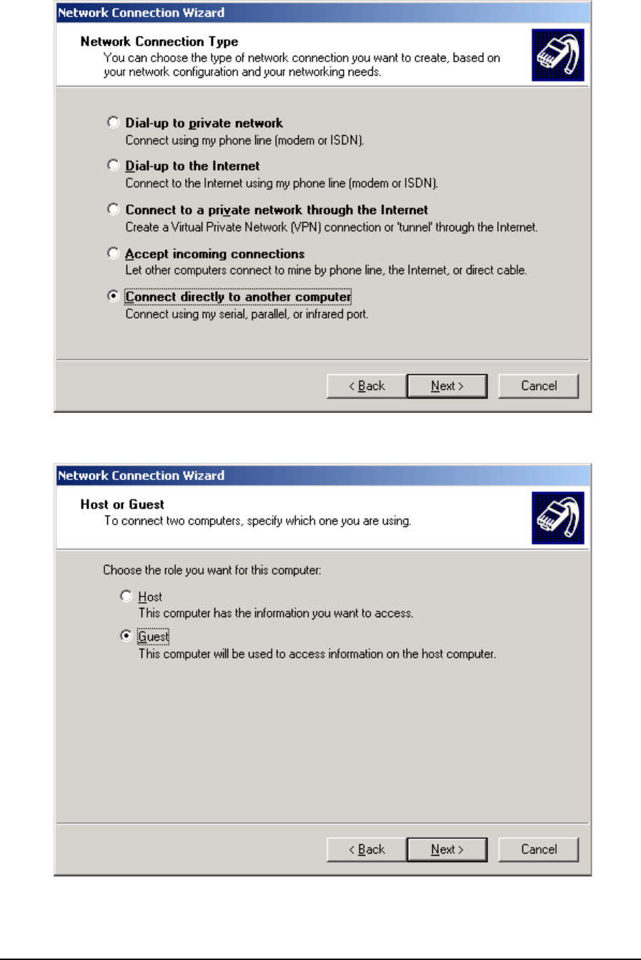
4. For Network Connection Type select the type Connect directly to another computer and
select the Next button. The Host or Guest options dialog is displayed.
5. Select the Guest option and the Next button. The Select a Device dialog is displayed.
TeleBUS Protocols User and Reference Manual
May 8, 2007 33
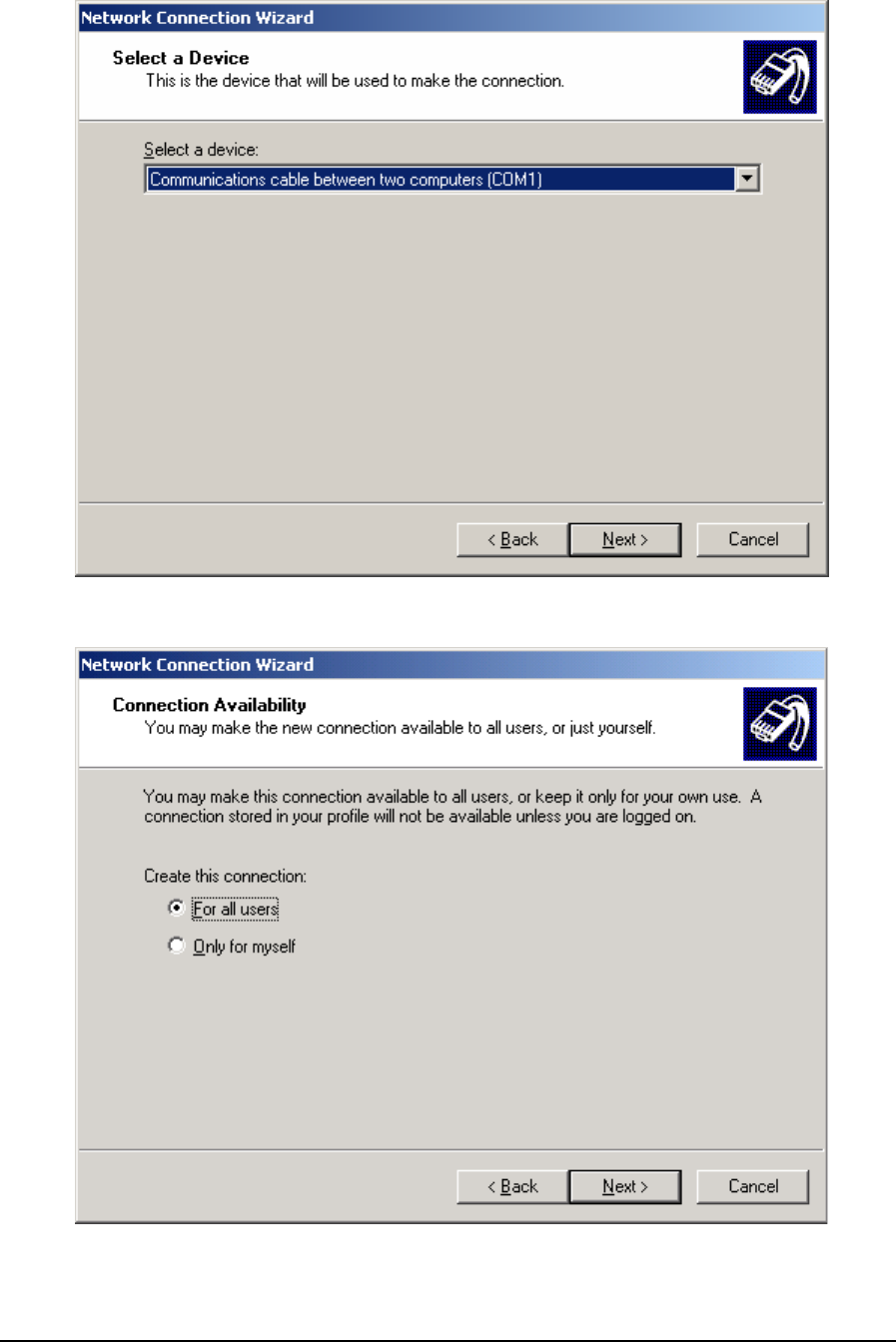
6. From the menu select the serial port on your PC that will be used to connect to the
SCADAPack 32. Select the Next button. The Connection Availability dialog is displayed.
7. Select either option and then select the Next button. The Connection Name dialog is
displayed.
TeleBUS Protocols User and Reference Manual
May 8, 2007 34
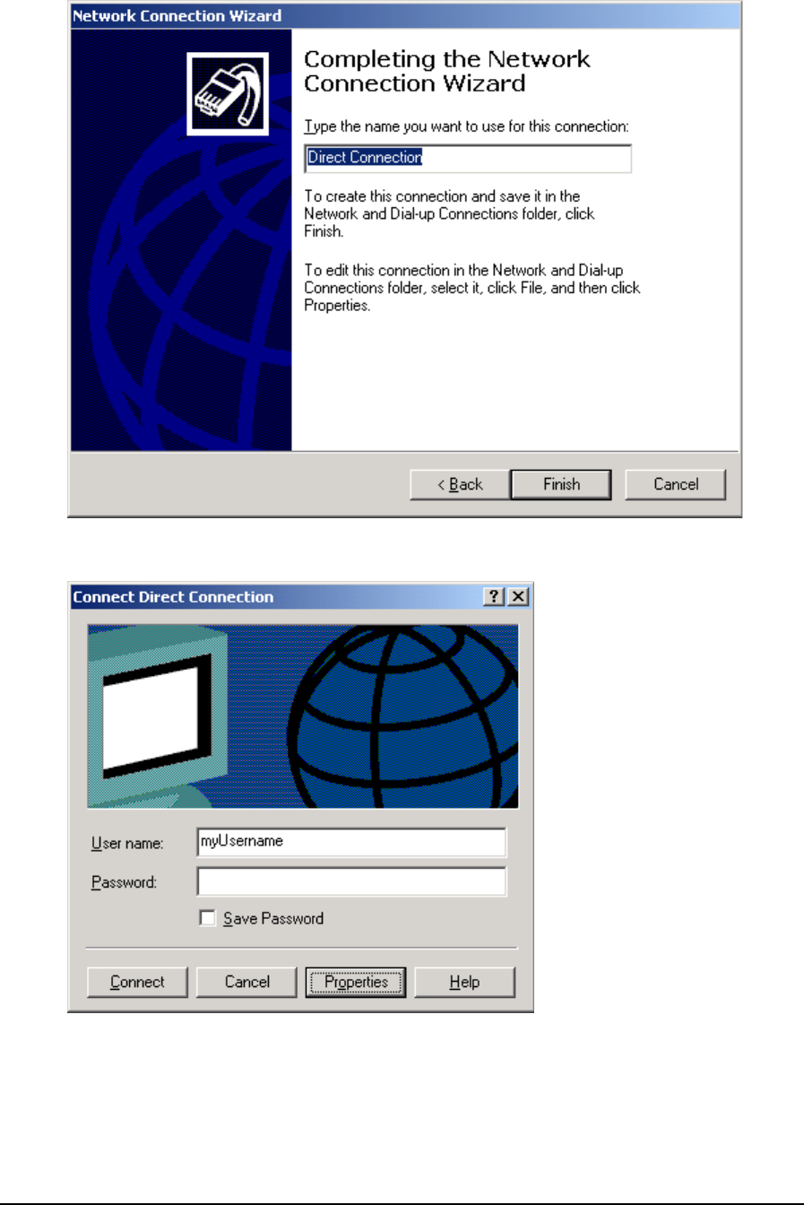
8. Enter a name for the connection and select the Finish button. The username and password
prompt is displayed.
9. Select the Cancel button. The Network and Dial-up Connections dialog should be visible
again.
TeleBUS Protocols User and Reference Manual
May 8, 2007 35
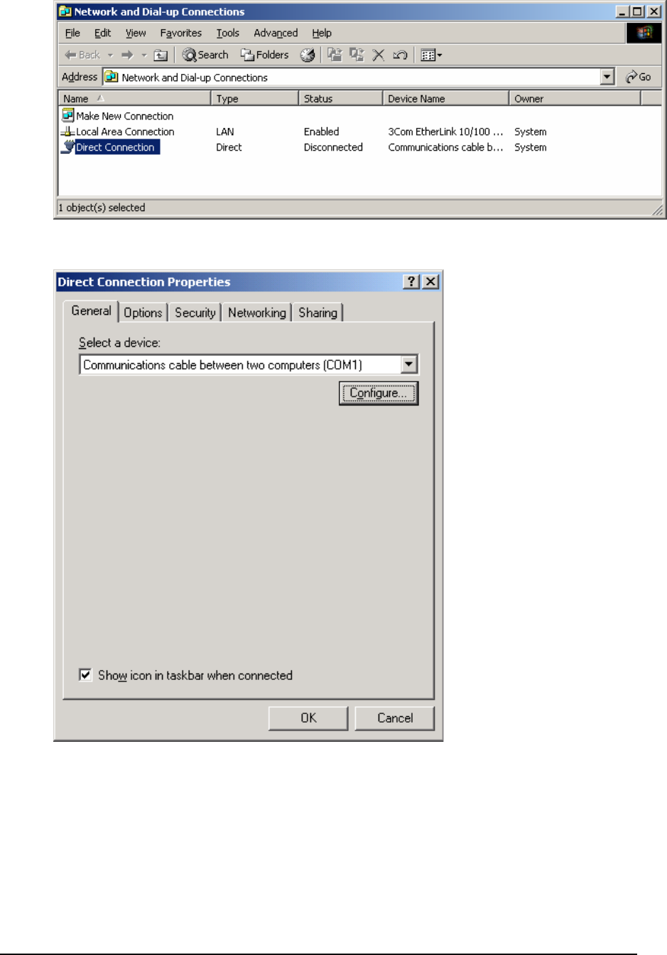
10. Right click your new Direct Connection icon from the Network and Dial-up Connections
dialog and select Properties from the list. The Properties dialog is displayed.
11. Select the Configure button from the General page. The Modem Configuration dialog is
displayed.
TeleBUS Protocols User and Reference Manual
May 8, 2007 36
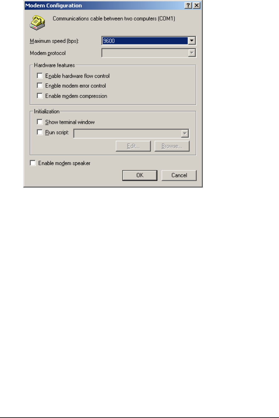
12. There is no modem in this direct serial connection so uncheck all items including hardware
flow control. Select the baud rate you intend to use (e.g. 9600 bps). Select OK to return to
the Properties dialog.
13. From the Properties dialog select the Networking page.
TeleBUS Protocols User and Reference Manual
May 8, 2007 37
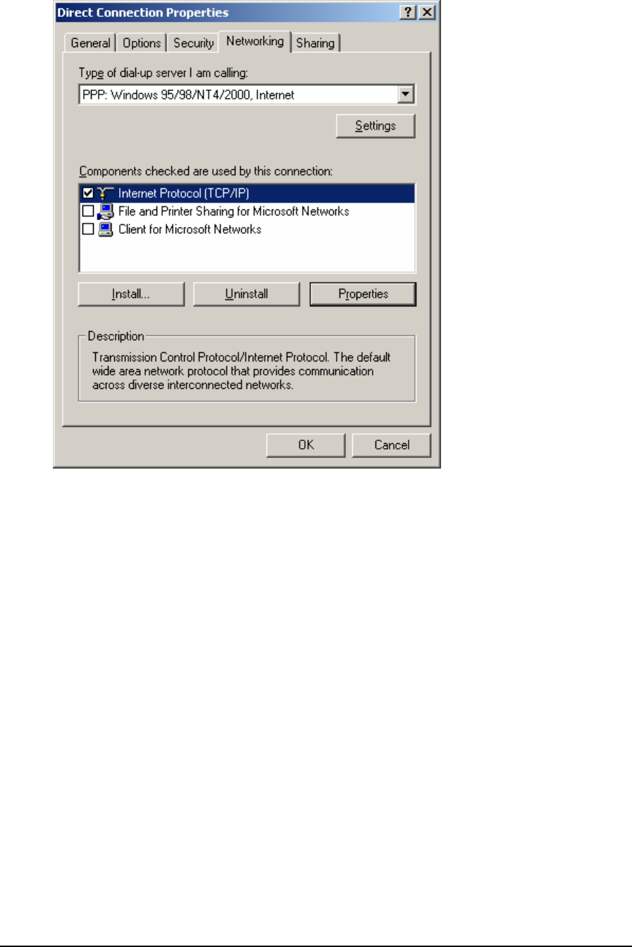
14. Uncheck all components except the component Internet Protocol (TCP/IP). Select the
component Internet Protocol (TCP/IP) and select the Properties button. The Internet
Protocol (TCP/IP) Properties dialog is displayed.
TeleBUS Protocols User and Reference Manual
May 8, 2007 38
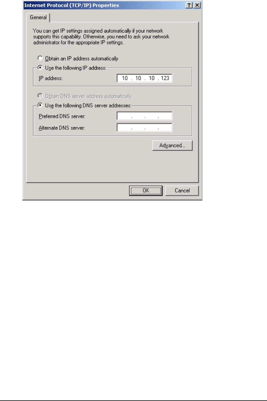
15. The SCADAPack 32 does not have a DHCP server to automatically provide an IP address.
Instead the PC’s serial port must be given a fixed IP address to use for PPP connections.
Select the option Use the following IP address. Enter an IP address to assign to your PC’s
serial port. Obtain this IP address from your Network Administrator. Then select OK to return
to the Properties dialog.
16. Select OK again to close the dialog.
Making a PPP Connection to the SCADAPack 32
A connection can only be made after successfully setting up a Direct Connection icon as
described in the section Connection Setup above. Also, a serial port on the SCADAPack 32
must already be configured for the PPP protocol using the Controller IP Configuration dialog
and must be downloaded to the SCADAPack 32.
1. From the Start menu, double click Network and Dial-up Connections from the
Settings group. The Network and Dial-up Connections dialog is displayed.
TeleBUS Protocols User and Reference Manual
May 8, 2007 39
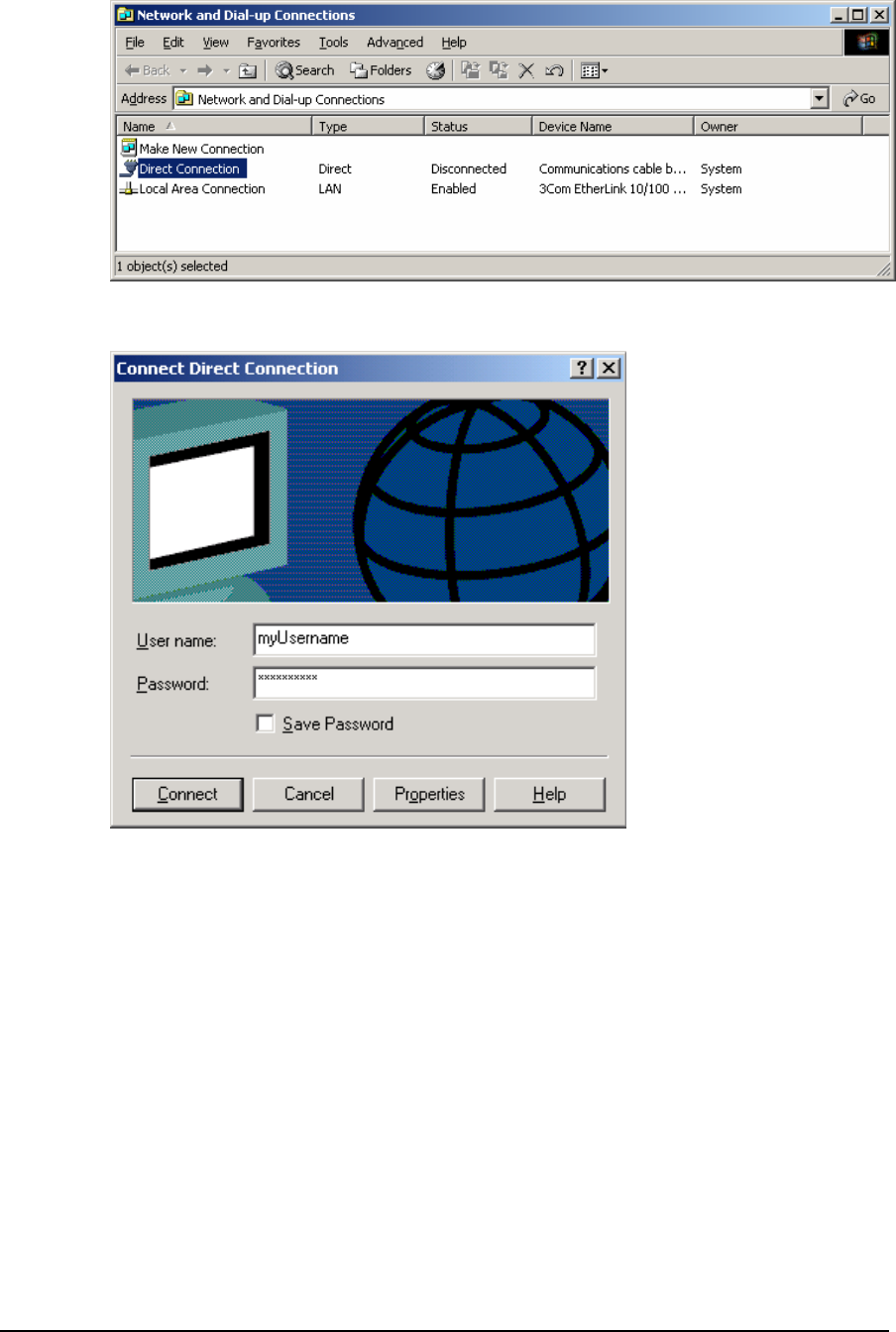
2. Right click your Direct Connection icon that was setup in the previous section and select
Connect from the list. A prompt for username and password is displayed.
3. Enter a valid PAP or CHAP username and password. Valid usernames and passwords
are configured on the PPP Login page of the Controller IP Configuration dialog and must
be downloaded to the SCADAPack 32. Then select the Connect button. If neither PAP
nor CHAP is being used, ignore the prompt and just select the Connect button.
4. A progress message is displayed. If the connection is successful the following message
is displayed.
TeleBUS Protocols User and Reference Manual
May 8, 2007 40
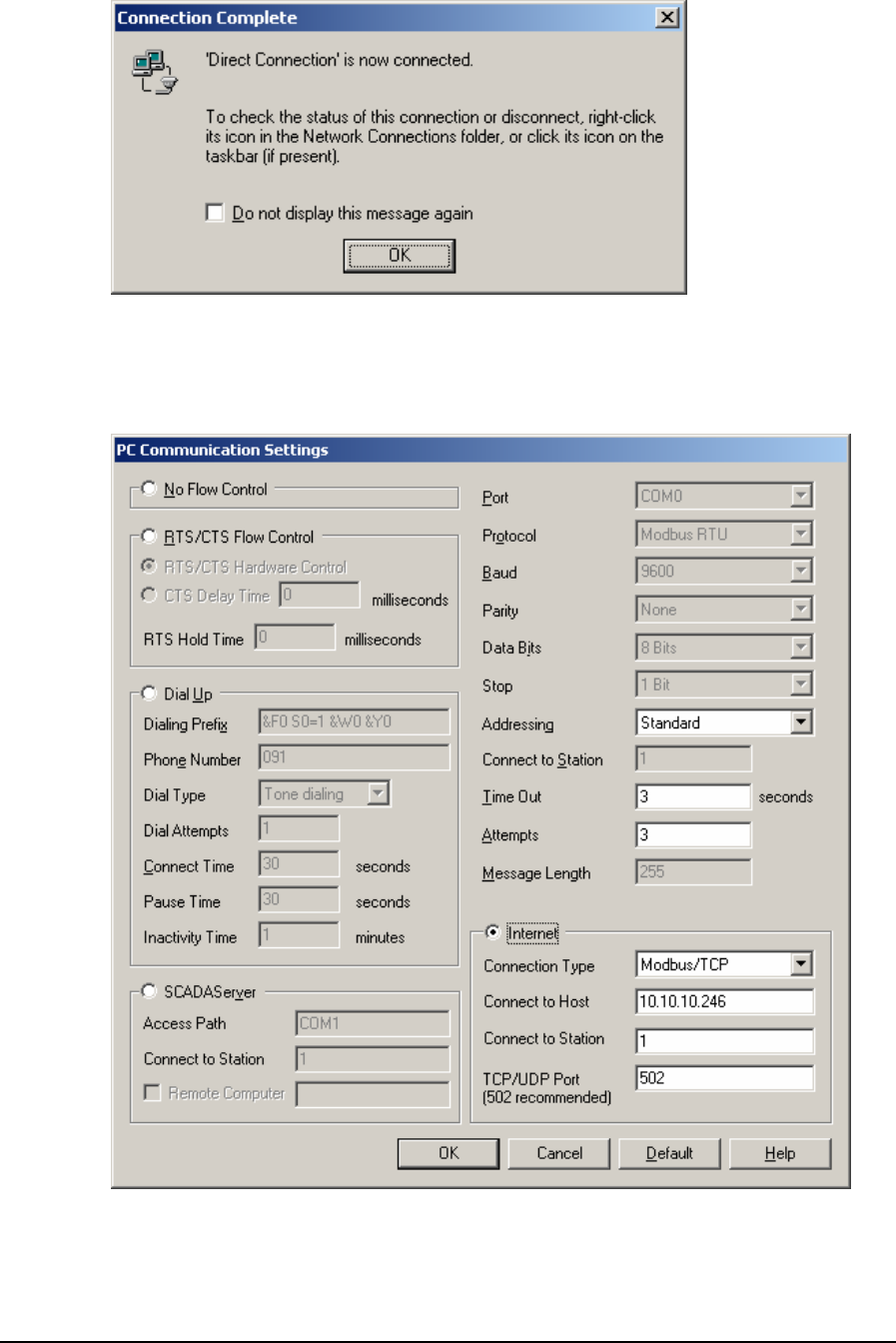
5. You may now connect to the IP address assigned to SCADAPack 32 PPP serial port
using an appropriate application and a supported protocol (e.g. Modbus/TCP). In the
example below, Firmware Loader is used to connect over PPP to the SCADAPack 32.
From the PC Communication Settings dialog, the IP address assigned to the
SCADAPack 32 PPP serial port is selected as the Connect to Host.
Disconnecting a PPP Connection
To disconnect a PPP connection made using the Windows PPP Client, do the following:
TeleBUS Protocols User and Reference Manual
May 8, 2007 41
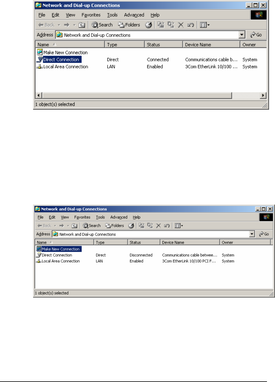
1. From the Start menu, double click Network and Dial-up Connections from the
Settings group. The Network and Dial-up Connections dialog is displayed.
2. Your Direct Connection icon should display the word Connected in the Status column.
To disconnect, right click your Direct Connection icon and select Disconnect from the
list.
Dial-up PPP Connection using Windows 2000
Connection Setup using Windows 2000
Use this connection when a dial-up modem is used to establish a PPP connection between
a Windows 2000 PC and a SCADAPack 32.
1. From the Start menu, right click Network and Dial-up Connections from the Settings
group, and select Open. The Network and Dial-up Connections dialog is displayed.
2. Double click the item Make New Connection from the Network and Dial-up
Connections dialog. The connection wizard dialog is displayed.
TeleBUS Protocols User and Reference Manual
May 8, 2007 42
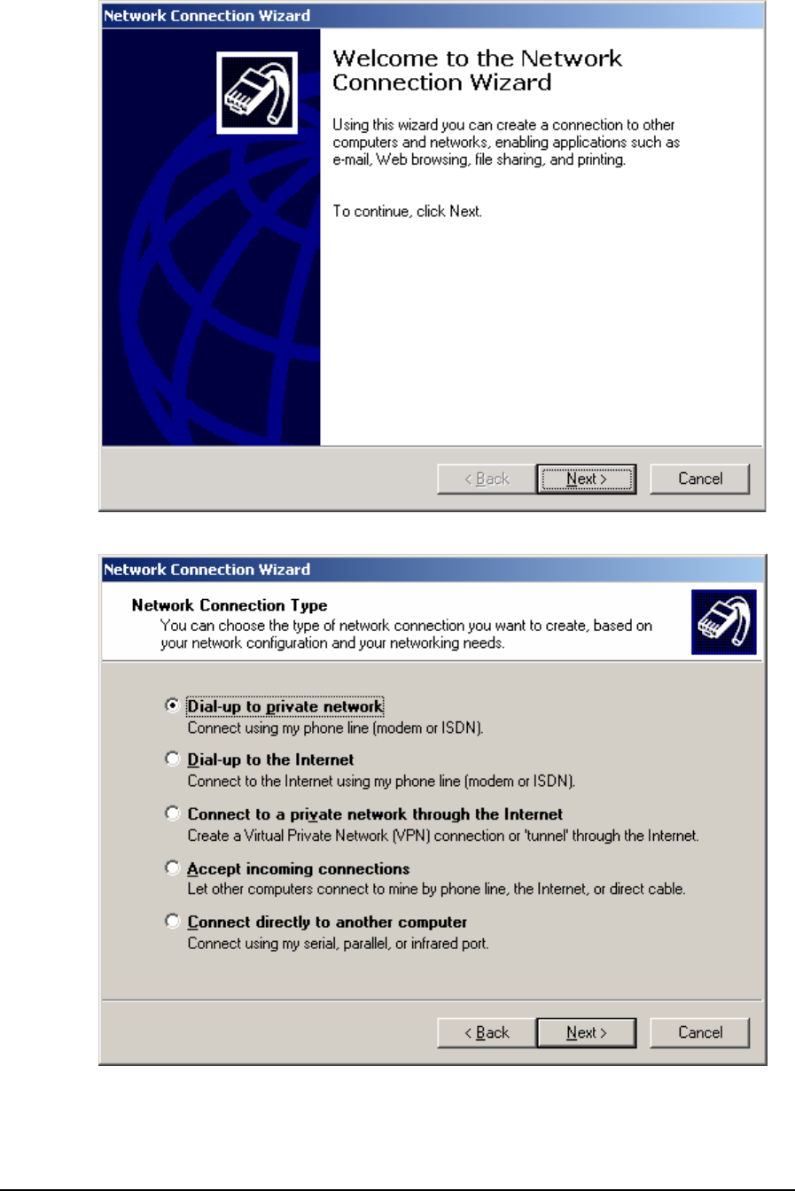
3. Select the Next button to display the connection type options dialog.
4. For Network Connection Type select the type Dial-up to private network and select the
Next button. If there is more than one modem installed on the PC, the Select a Device
dialog is displayed. If not, proceed to the next step.
TeleBUS Protocols User and Reference Manual
May 8, 2007 43
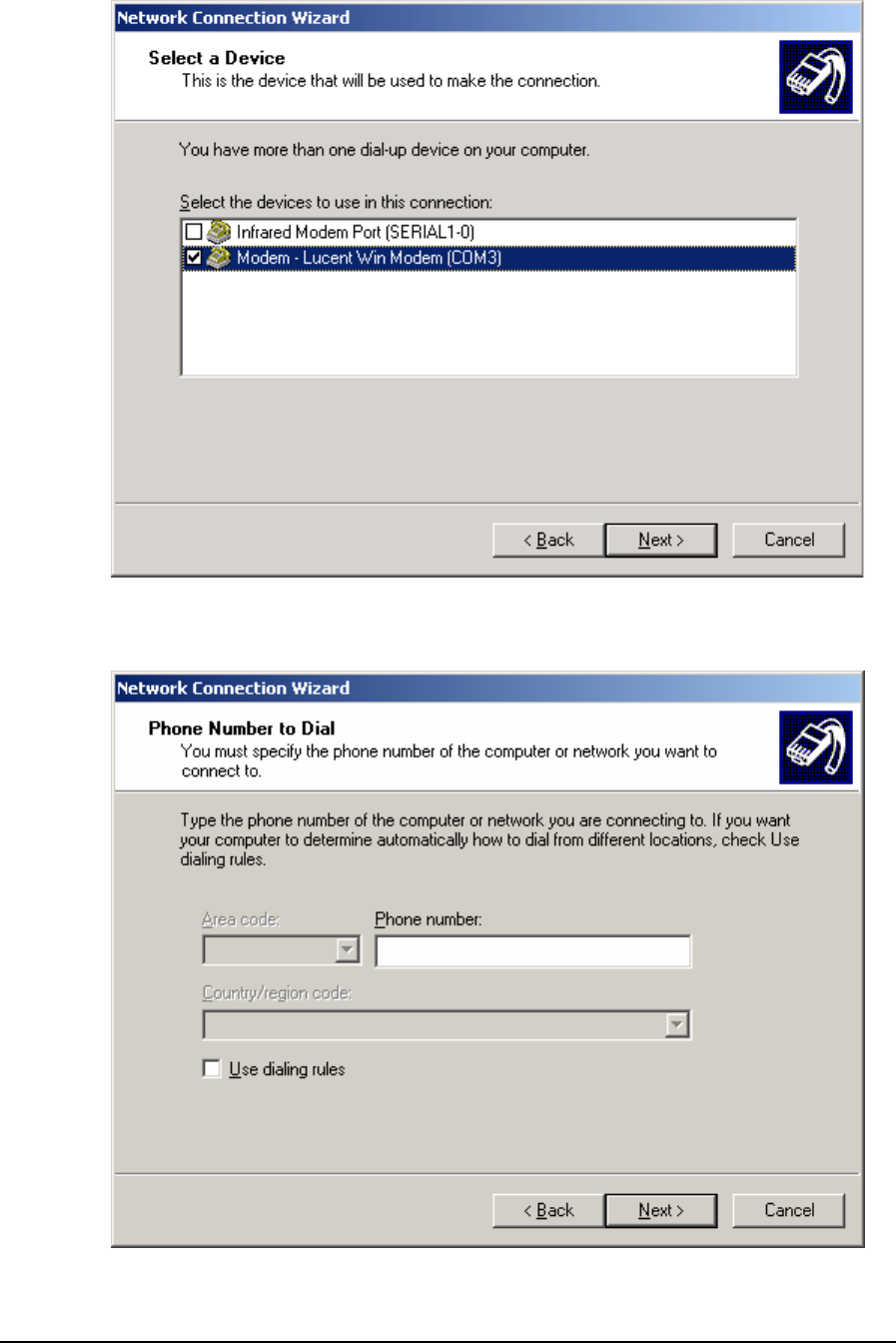
5. From the menu select the modem installed on your PC that will be used to connect to
the SCADAPack 32. Select the Next button. The Phone Number to Dial dialog is
displayed.
TeleBUS Protocols User and Reference Manual
May 8, 2007 44
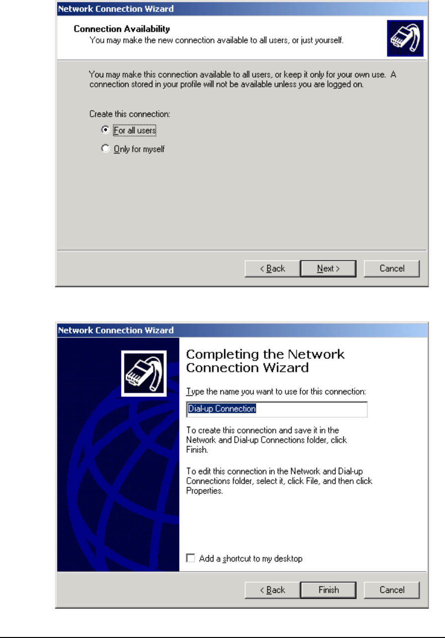
6. Enter the phone number to dial (this can be changed later) and select the Next button.
The Connection Availability dialog is displayed.
7. Select either option and then select the Next button. The Connection Name dialog is
displayed.
TeleBUS Protocols User and Reference Manual
May 8, 2007 45
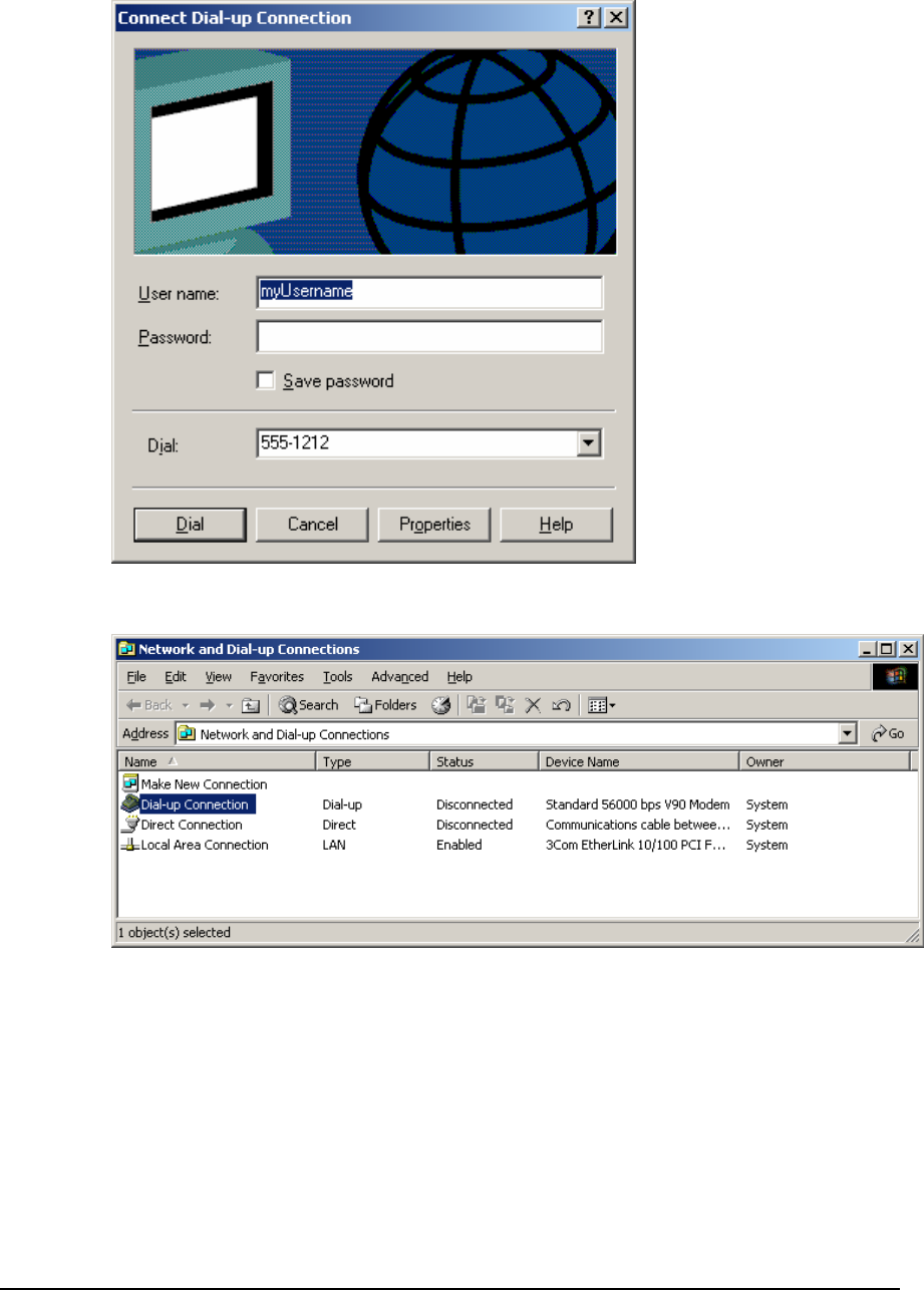
8. Enter a name for the connection and select the Finish button. The username and
password prompt is displayed.
9. Select the Cancel button. The Network and Dial-up Connections dialog should be visible
again.
10. Right click your new Dial-up Connection icon from the Network and Dial-up Connections
dialog and select Properties from the list. The Properties dialog is displayed.
TeleBUS Protocols User and Reference Manual
May 8, 2007 46
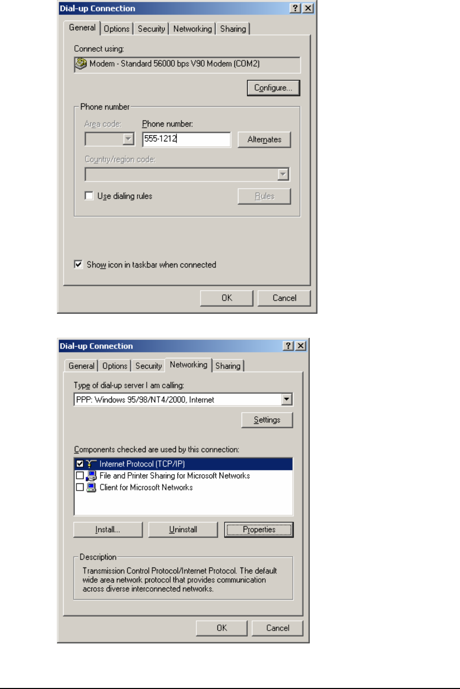
11. From the Properties dialog select the Networking page.
TeleBUS Protocols User and Reference Manual
May 8, 2007 47
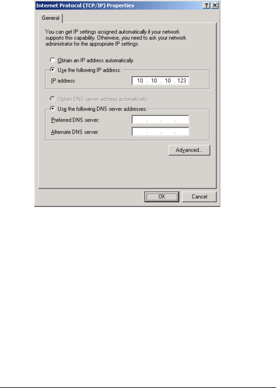
12. Uncheck all components except the component Internet Protocol (TCP/IP). Select the
component Internet Protocol (TCP/IP) and select the Properties button. The Internet
Protocol (TCP/IP) Properties dialog is displayed.
13. The SCADAPack 32 does not have a DHCP server to automatically provide an IP
address. Instead the PC’s serial port must be given a fixed IP address to use for PPP
connections. Select the option Use the following IP address. Enter an IP address to
assign to your PC’s serial port. Obtain this IP address from your Network Administrator.
Then select OK to return to the Properties dialog.
14. Select OK again to close the dialog.
Making a PPP Dial-up Connection to the SCADAPack 32 using Windows
2000
A connection can only be made after successfully setting up a Dial-up Connection icon as
described in the section Connection Setup above. Also, a serial port on the SCADAPack 32
must already be configured for the PPP protocol using the Controller IP Configuration dialog
and must be downloaded to the SCADAPack 32.
1. From the Start menu, right click Network and Dial-up Connections from the Settings
group, and select Open. The Network and Dial-up Connections dialog is displayed.
TeleBUS Protocols User and Reference Manual
May 8, 2007 48
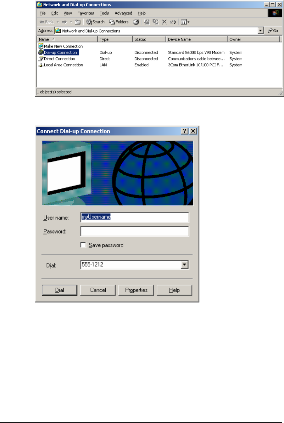
2. Right click your Dial-up Connection icon that was setup in the previous section and
select Connect from the list. A prompt for username and password is displayed.
3. Enter a valid PAP or CHAP username and password. Valid usernames and passwords
are configured on the PPP Login page of the Controller IP Configuration dialog and must
be downloaded to the SCADAPack 32. Then select the Dial button. If neither PAP nor
CHAP is being used, ignore the prompt and just select the Dial button.
4. A progress message is displayed. If the connection is successful your Dial-up
Connection icon should display the word Connected in the Status column.
5. You may now connect to the IP address assigned to SCADAPack 32 PPP serial port
using an appropriate application and a supported protocol (e.g. Modbus/TCP). In the
example below, Firmware Loader is used to connect over PPP to the SCADAPack 32.
From the PC Communication Settings dialog, the IP address assigned to the
SCADAPack 32 PPP serial port is selected as the Connect to Host.
TeleBUS Protocols User and Reference Manual
May 8, 2007 49
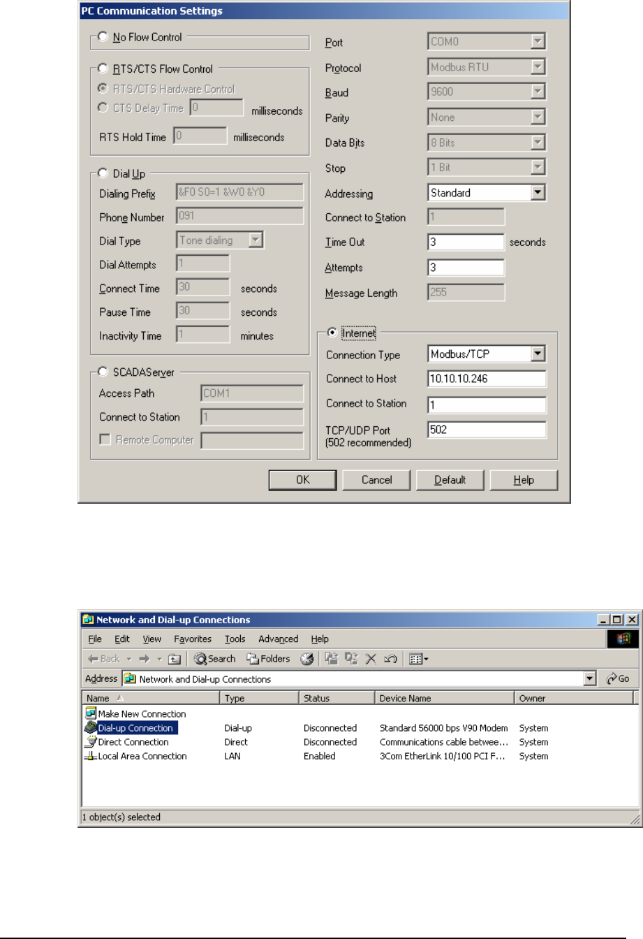
Disconnecting a PPP Connection using Windows 2000
To disconnect a PPP connection made using the Windows PPP Client, do the following:
1. From the Start menu, right click Network and Dial-up Connections from the Settings
group, and select Open. The Network and Dial-up Connections dialog is displayed.
2. Your Dial-up Connection icon should display the word Connected in the Status column.
To disconnect, right click your Dial-up Connection icon and select Disconnect from the
list.
TeleBUS Protocols User and Reference Manual
May 8, 2007 50

TelePACE Ladder Logic
DF1 Protocol User Manual
CONTRO
L
MICROSYSTEMS
SCADA products... for the distance
48 Steacie Drive Telephone: 613-591-1943
Kanata, Ontario Facsimile: 613-591-1022
K2K 2A9 Technical Support: 888-226-6876
Canada 888-2CONTROL

TelePACE Ladder Logic Warranty and License
©2007 Control Microsystems Inc.
All rights reserved.
Printed in Canada.
Trademarks
TelePACE, SCADASense, SCADAServer, SCADALog, RealFLO, TeleSAFE, TeleSAFE
Micro16, SCADAPack, SCADAPack Light, SCADAPack Plus, SCADAPack 32, SCADAPack
32P, SCADAPack 350, SCADAPack LP, SCADAPack 100, SCADASense 4202 DS,
SCADASense 4202 DR, SCADASense 4203 DS, SCADASense 4203 DR, SCADASense
4102, SCADASense 4012, SCADASense 4032 and TeleBUS are registered trademarks of
Control Microsystems.
All other product names are copyright and registered trademarks or trade names of their
respective owners.
Material used in the User and Reference manual section titled SCADAServer OLE
Automation Reference is distributed under license from the OPC Foundation.
TeleBUS DF1 Protocol User and Reference Manual
May 9, 2007
1

Table of Contents
TABLE OF CONTENTS .......................................................................................................... 2
TELEBUS DF1 PROTOCOL OVERVIEW............................................................................... 4
Compatibility........................................................................................................................ 4
SERIAL PORT CONFIGURATION ......................................................................................... 5
Communication Parameters ............................................................................................... 5
Protocol Parameters ...................................................................................................... 5
Baud Rate...................................................................................................................... 5
Duplex............................................................................................................................ 6
Protocol Parameters ........................................................................................................... 7
Protocol Type................................................................................................................. 7
Station Number.............................................................................................................. 7
Task Priority...................................................................................................................7
Store and Forward Messaging ...................................................................................... 7
Default Parameters ............................................................................................................. 7
I/O DATABASE........................................................................................................................ 9
Coil and Status Registers ................................................................................................... 9
Input and Holding Registers................................................................................................ 9
Accessing the I/O Database Using TelePACE ................................................................. 10
Modbus Addressing..................................................................................................... 10
DF1 Addressing ........................................................................................................... 11
Converting Modbus to DF1 Addresses........................................................................ 11
Accessing the I/O Database Using ISaGRAF .................................................................. 13
Modbus Addressing..................................................................................................... 13
DF1 Addressing ........................................................................................................... 13
Converting Modbus to DF1 Addresses........................................................................ 14
SLAVE MODE........................................................................................................................16
Broadcast Messages ........................................................................................................ 16
Function Codes................................................................................................................. 16
Protected Write ............................................................................................................ 17
Unprotected Read........................................................................................................ 17
Protected Bit Write....................................................................................................... 17
Unprotected Bit Write................................................................................................... 17
Unprotected Write........................................................................................................ 17
MASTER MODE ....................................................................................................................18
Function Codes................................................................................................................. 18
Protected Write ............................................................................................................ 18
TeleBUS DF1 Protocol User and Reference Manual
May 9, 2007
2

Unprotected Read........................................................................................................ 18
Protected Bit Write....................................................................................................... 19
Unprotected Bit Write................................................................................................... 19
Unprotected Write........................................................................................................ 19
Sending Messages ........................................................................................................... 19
Polling DF1 PLCs ........................................................................................................ 20
TeleBUS DF1 Protocol User and Reference Manual
May 9, 2007
3

TeleBUS DF1 Protocol Overview
TeleBUS communication protocols provide a standard communication interface to the
controller. The protocols operate on a wide variety of serial data links. These include RS-232
serial ports, RS-485 serial ports, radios, leased line modems, and dial up modems. The
protocols are generally independent of the communication parameters of the link, with a few
exceptions.
TeleBUS protocol commands may be directed to a specific device, identified by its station
number, or broadcast to all devices. Up to 255 devices may connect to one communication
network.
The TeleBUS protocols provide full access to the I/O database in the controller. The I/O
database contains user-assigned registers and general purpose registers. Assigned
registers map directly to the I/O hardware or system parameter in the controller. General
purpose registers can be used by ladder logic and C application programs to store
processed information, and to receive information from a remote device.
Application programs can initiate communication with remote devices. A multiple port
controller can be a data concentrator for remote devices, by polling remote devices on one
port and responding as a slave on another port.
The protocol type, communication parameters and station address are configured separately
for each serial port on a controller. One controller can appear as different stations on
different communication networks. The port configuration can be set from an application
program, from the TelePACE programming software, or from another Modbus or DF1
compatible device.
Compatibility
There are four TeleBUS DF1 protocols:
• The TeleBUS DF1 Full-Duplex BCC protocol is compatible with the DF1 Full-Duplex data
link layer protocol with block check character (BCC) error checking.
• The TeleBUS DF1 Full-Duplex CRC protocol is compatible with the DF1 Full-Duplex data
link layer protocol with 16-bit cyclic redundancy check (CRC-16) error checking.
• The TeleBUS DF1 Half-Duplex BCC protocol is compatible with the DF1 Half-Duplex data
link layer protocol with block check character (BCC) error checking.
• The TeleBUS DF1 Half-Duplex CRC protocol is compatible with the DF1 Half-Duplex data
link layer protocol with 16-bit cyclic redundancy check (CRC-16) error checking.
Compatibility refers to communication only. The protocol defines communication aspects
such as commands, syntax, message framing, error handling and addressing. The
controllers do not mimic the internal functioning of any programmable controller. Device
specific functions – those that relate to the hardware or programming of a specific
programmable controller – are not implemented.
TeleBUS DF1 Protocol User and Reference Manual
May 9, 2007
4

Serial Port Configuration
Communication Parameters
The TeleBUS DF1 protocols are, in general, independent of the serial communication
parameters. The baud rate and parity may be chosen to suit the host computer and the
characteristics of the data link.
The port configuration can be set in four ways:
• using the TelePACE program;
• using the set_port function from a C application program;
• writing to the I/O database from a C or ladder logic application program; or
• writing to the I/O database remotely from a Modbus or DF1 compatible device.
To configure a serial port through the I/O database, add the module, CNFG Serial port
settings, to the Register Assignment.
Protocol Parameters
The TeleBUS DF1 protocols are eight bit character-oriented protocols. The table below
shows possible and recommended communication parameters.
Parameter Possible Settings Recommended
Setting
Baud Rate see Baud Rate
section below see Baud Rate
section below
Data Bits 8 data bits 8 data bits
Parity none
even
odd
none
Stop bits 1 stop bit
2 stop bits11 stop bit
Flow control disabled disabled
Duplex see Duplex section
below see Duplex section
below
1 Not applicable on the SCADAPack 350
TeleBUS DF1 Protocol User and Reference Manual
May 9, 2007
5

Baud Rate
The baud rate sets the communication speed. The possible settings are determined by the
type of serial data link used. The table below shows the possible settings for the controller.
Note that not all port types and baud rates are available on all controller ports.
Port Type Possible
Settings Recommended Setting
RS-232 or
RS-232
Dial-up
modem
75 baud
110 baud
150 baud
300 baud
600 baud
1200 baud
2400 baud
4800 baud
9600 baud
19200 baud
38400 baud
57600 baud
115200 baud
Use the highest rate
supported by all devices on
the network.
RS-485 75 baud
110 baud
150 baud
300 baud
600 baud
1200 baud
2400 baud
4800 baud
9600 baud
19200 baud
38400 baud
Use the highest rate
supported by all devices on
the network.
Duplex
The TeleBUS DF1 protocols communicate in one direction at a time. However the duplex
setting is determined by the type of serial data link used. The table below shows the possible
settings for the controller. Note that not all port types are available on all controllers.
Port Type Possible
Settings Recommended Setting
RS-232 or
RS-232
Dial-up
modem
half duplex
full duplex Use full duplex wherever
possible.
Use half duplex for most
external modems.
RS-485 half duplex
full duplex Slave stations always use
half duplex.
Master stations can use full
duplex only on 4 wire
systems.
TeleBUS DF1 Protocol User and Reference Manual
May 9, 2007
6

Protocol Parameters
The TeleBUS DF1 protocols operate independently on each serial port. Each port may set
the protocol type, station number, protocol task priority and store-and-forward messaging
options.
The protocol configuration can be set in four ways:
• using the TelePACE or ISaGRAF programs;
• using the set_protocol function from a C application program;
• writing to the I/O database from a C or ladder logic application program; or
• writing to the I/O database remotely from a Modbus or DF1 compatible device.
To configure protocol settings through the I/O database, add the module, CNFG Protocol
settings, to the Register Assignment.
Protocol Type
The protocol type may be set to emulate the DF1 or Modbus protocols, or it may be
disabled. When the protocol is disabled, the port functions as a normal serial port.
Station Number
The TeleBUS DF1 protocols allow up to 255 devices on a network. Station numbers identify
each device. A device responds to commands addressed to it, or to commands broadcast to
all stations.
The station number is in the range 0 to 254. Address 255 indicates a command broadcast to
all stations, and cannot be used as a station number. Each serial port may have a unique
station number.
Task Priority
A task is responsible for monitoring each serial port for messages. The real time operating
system (RTOS) schedules the tasks with the application program tasks according to the task
priority. The priority can be changed only with the set_protocol function from a C
application program.
The default task priority is 3. Changing the priority is not recommended.
Store and Forward Messaging
Store and forward messaging is not supported by the TeleBUS DF1 protocols.
Default Parameters
All ports are configured at reset with default parameters when the controller is started in
SERVICE mode. The ports use user-defined parameters when the controller is reset in the
RUN mode. The default parameters are listed below.
Parameter com1 com2 Com3 com4
Baud rate 9600 9600 9600 9600
Parity none none None none
Data bits 8 8 8 8
TeleBUS DF1 Protocol User and Reference Manual
May 9, 2007
7

Parameter com1 com2 Com3 com4
Stop bits 1 1 1 1
Duplex full full Half half
Protocol Modbus
RTU Modbus
RTU Modbus
RTU Modbus
RTU
Station 1 1 1 1
Rx flow control none none Rx
disable Rx
disable
Tx flow control none none None none
Serial time out 60 s 60 s 60 s 60 s
Type RS-232 RS-232 RS-232 RS-232
Minimum
Protected DF1
Address
0 0 0 0
Maximum
Protected DF1
Address
11534 11534 11534 11534
Notes
com3 is supported only when the SCADAPack Lower I/O module is installed. com4 is
supported only when the SCADAPack Upper I/O module is installed.
To optimize performance, minimize the length of messages on com3 and com4. Examples
of recommended uses for com3 and com4 are for local operator display terminals, and for
programming and diagnostics using the TelePACE program.
TeleBUS DF1 Protocol User and Reference Manual
May 9, 2007
8

I/O Database
The TeleBUS protocols read and write information from the I/O database. The I/O database
is an area of memory that can be accessed by C programs, Ladder Logic programs,
ISaGRAF programs and communication protocols. The I/O database allows data to be
shared between these programs. The I/O database contains user-assigned registers and
general purpose registers.
User-assigned registers map directly to the I/O hardware or system parameter in the
controller. Assigned registers are initialized to the default hardware state or system
parameter when the controller is reset. Assigned output registers do not maintain their
values during power failures. However, output registers do retain their values during
application program loading.
General purpose registers are used by ladder logic, ISaGRAFand C application programs to
store processed information, and to receive information from remote devices. General
purpose registers retain their values during power failures and application program loading.
The values change only when written by an application program or a communication
protocol.
Coil and Status Registers
Coil and status registers contain one bit of information, that is whether a signal is off or on.
For TelePACE firmware coil registers are single bits, which the protocols can read and write.
There are 4096 coil registers located in the digital output section of the I/O database. Coil
registers are contained within the DF1 16-bit addresses 0 to 255.
For TelePACE firmware status registers are single bits, which the protocols can read. There
are 4096 status registers located in the digital input section of the I/O database. Status
registers are contained within the DF1 16-bit addresses 256 to 511.
For ISaGRAF firmware coil registers are single bits, which the protocols can read and write.
There are 9999 coil registers located in the digital output section of the I/O database. Coil
registers are contained within the DF1 16-bit addresses 0 to 624.
For ISaGRAF firmware status registers are single bits, which the protocols can read. There
are 9999 status registers located in the digital input section of the I/O database. Status
registers are contained within the DF1 16-bit addresses 625 to 1249.
Coil and status registers are accessed 16 at a time or individually (in some commands)
using a bitmask. Writing a one to a bit within the 16-bit address turns the bit on. Writing zero
to the bit turns the bit off. If the register is assigned to an I/O module, the bit status is written
to the module output hardware or parameter.
Reading a coil or status register returns 1 if the bit is on, or 0 if the bit is off. The stored value
is returned from general purpose registers. The I/O module point status is returned from
assigned registers.
Input and Holding Registers
Input and holding registers contain 16-bit values.
Input registers are 16-bit registers, which the protocol can read. For TelePACE firmware,
there are 1024 input registers located in the analog input section of the I/O database. Input
registers are contained within the DF1 addresses 512 to 1535.
TeleBUS DF1 Protocol User and Reference Manual
May 9, 2007
9

For ISaGRAF firmware there are 9999 input registers located in the analog input section of
the I/O database. Input registers are contained within the DF1 addresses 1250 to 11247.
Holding registers are 16-bit registers that the protocol can read and write. For TelePACE
firmware there are 9999 holding registers located in the analog output section of the I/O
database. Holding registers are contained within the DF1 addresses 1536 to 11534.
For ISaGRAF firmware there are 9999 holding registers located in the analog output section
of the I/O database. Holding registers are contained within the DF1 addresses 11248 to
21247.
Writing any value to a general purpose register stores the value in the register. Writing a
value to an assigned register, writes the value to the assigned I/O module.
Reading a general purpose register returns the value stored in the register. Reading an
assigned register returns the value read from the I/O module.
Accessing the I/O Database Using TelePACE
Ladder logic programs access the I/O database through function blocks. All function blocks
can access the I/O database. The function blocks in ladder logic use only the Modbus
addressing scheme. Refer to the TelePACE Ladder Logic Reference and User Manual for
details.
C language programs access the I/O database with two functions. The dbase function reads
a value from the I/O database. The setdbase function writes a value to the I/O database.
These functions use either Modbus or DF1 physical addressing. Refer to the TelePACE C
Tools Reference and User Manual for full details on these functions.
Modbus Addressing
Modbus addressing is used in all ladder logic program functions. The controller’s Register
Assignment is also configured using Modbus addresses. The C functions dbase and
setdbase support Modbus addressing. When the specified port is configured for one of the
Modbus protocols, the function master_message uses Modbus addressing.
The range of Modbus registers available depends on the controller being used. The
following sections list the Modbus registers available for each controller type.
SCADAPack, SCADAPack 100: 1024K and SCADASense 4202 Series
Coil registers are single bit addresses ranging from 00001 to 04096.
Status registers are single bit addresses ranging from 10001 to 14096.
Input registers are 16-bit addresses in the range 30001 to 31024.
Holding registers are 16-bit addresses in the range 40001 to 49999.
SCADAPack 100: 256K Controllers
Coil registers are single bit addresses ranging from 00001 to 04096.
Status registers are single bit addresses ranging from 10001 to 14096.
Input registers are 16-bit addresses in the range 30001 to 30512.
Holding registers are 16-bit addresses in the range 40001 to 44000.
SCADAPack 350, SCADAPack 32, and SCADASense 4203 Series
Coil registers are single bit addresses ranging from 00001 to 04096.
TeleBUS DF1 Protocol User and Reference Manual
May 9, 2007
10

Status registers are single bit addresses ranging from 10001 to 14096.
Input registers are 16-bit addresses in the range 30001 to 39999.
Holding registers are 16-bit addresses in the range 40001 to 49999.
DF1 Addressing
DF1 addressing is used by the MSTR ladder logic function when the specified port is
configured for one of the DF1 protocols. Modbus addressing must be used in all other ladder
logic program functions.
DF1 addressing is used by function master_message when the specified port is configured
for one of the DF1 protocols. The functions dbase, setdbase, setABConfiguration and
getABConfiguration also support DF1 addressing.
All DF1 addresses are absolute word addresses beginning with the first 16-bit register in the
I/O database at address 0.
Converting Modbus to DF1 Addresses
I/O database registers are assigned within the controller’s Register Assignment using
Modbus addressing. When polling the controller from a DF1 device it is necessary to know
the DF1 address corresponding to each assigned register. Refer to the section for the
controller type being used.
SCADAPack, SCADAPack 100: 1024K and SCADASense 4202 Series
In general, the cross-reference between Modbus and DF1 addressing is shown in the
following table. DF1 addresses in this table are described in the format word/bit where
word is the address of a 16-bit word and bit is the bit within that word. The bit address is
optional.
Address Range Description
Modbus
DF1 00001 to 04096
0/0 to 255/15 Digital Output Database
(single bit registers)
Modbus
DF1 10001 to 14096
256/0 to 511/15 Digital Input Database
(single bit registers)
Modbus
DF1 30001 to 31024
512 to 1535 Analog Input Database
(16-bit registers)
Modbus
DF1 40001 to 49999
1536 to 11534 Analog Output Database
(16-bit registers)
Coil Registers
To convert a Modbus coil register, ModbusCoil, to a DF1 address word/bit:
word = ( ModbusCoil - 00001 ) / 16
bit = remainder of { ( ModbusCoil - 00001 ) / 16 }
Status Registers
To convert a Modbus status register, ModbusStatus, to a DF1 address word/bit:
word = ( ModbusStatus - 10001 ) / 16 + 256
bit = remainder of { ( ModbusStatus - 10001 ) / 16 }
Input Registers
To convert a Modbus input register, ModbusInput, to a DF1 address word:
TeleBUS DF1 Protocol User and Reference Manual
May 9, 2007
11

word = ( ModbusInput - 30001 ) + 512
Holding Registers
To convert a Modbus holding register, ModbusHolding, to a DF1 address word:
word = ( ModbusHolding - 40001 ) + 1536
Example
In this example the equivalent DF1 addresses are shown next to a sample SCADAPack
Register Assignment specified with Modbus addresses.
Module Start
Register End
Register DF1 Address
Range
SCADAPack
5601 I/O module
digital outputs
digital inputs
analog inputs
00001
10001
30001
00012
10016
30008
0/0 to 0/11
256/0 to 256/15
512 to 519
DIN Controller digital inputs 10017 10019 257/0 to 257/2
DIAG Force LED 10020 10020 257/3
SCADAPack AOUT module 40001 40002 1536 to 1537
SCADAPack 350 and SCADAPack 32 Controllers
In general, the cross-reference between Modbus and DF1 addressing is shown in the
following table. DF1 addresses in this table are described in the format word/bit where
word is the address of a 16-bit word and bit is the bit within that word. The bit address is
optional.
Address Range Description
Modbus
DF1 00001 to 04096
0/0 to 255/15 Digital Output Database
(single bit registers)
Modbus
DF1 10001 to 14096
256/0 to 511/15 Digital Input Database
(single bit registers)
Modbus
DF1 30001 to 39999
512 to 10510 Analog Input Database
(16-bit registers)
Modbus
DF1 40001 to 49999
10511 to 20511 Analog Output Database
(16-bit registers)
Coil Registers
To convert a Modbus coil register, ModbusCoil, to a DF1 address word/bit:
word = ( ModbusCoil - 00001 ) / 16
bit = remainder of { ( ModbusCoil - 00001 ) / 16 }
Status Registers
To convert a Modbus status register, ModbusStatus, to a DF1 address word/bit:
word = ( ModbusStatus - 10001 ) / 16 + 256
bit = remainder of { ( ModbusStatus - 10001 ) / 16 }
Input Registers
To convert a Modbus input register, ModbusInput, to a DF1 address word:
word = ( ModbusInput - 30001 ) + 512
TeleBUS DF1 Protocol User and Reference Manual
May 9, 2007
12
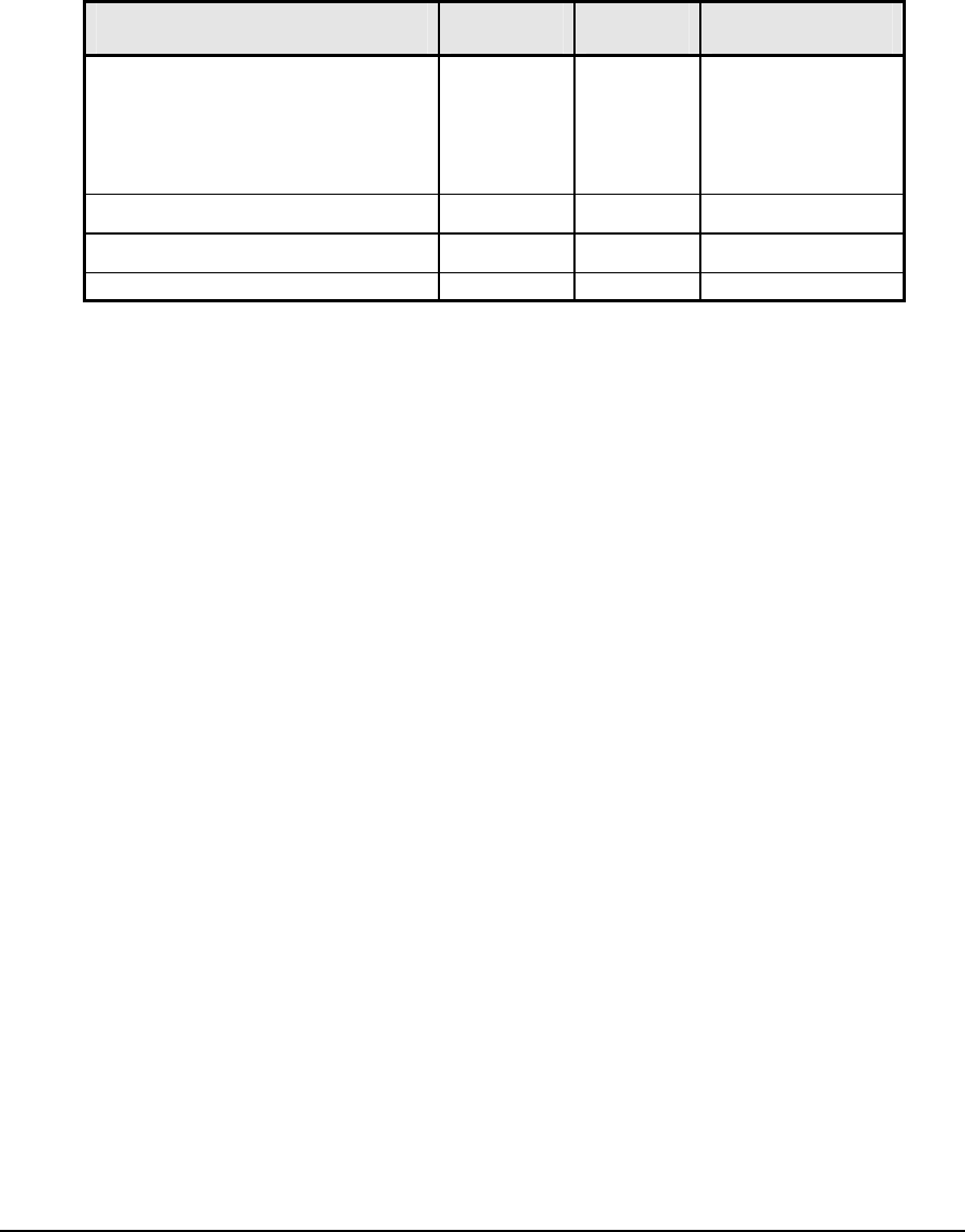
Holding Registers
To convert a Modbus holding register, ModbusHolding, to a DF1 address word:
word = ( ModbusHolding - 40001 ) + 10511
Example
In this example the equivalent DF1 addresses are shown next to a sample SCADAPack
Register Assignment specified with Modbus addresses.
Module Start
Register End
Register DF1 Address
Range
SCADAPack
5601 I/O module
digital outputs
digital inputs
analog inputs
00001
10001
30001
00012
10016
30008
0/0 to 0/11
256/0 to 256/15
512 to 519
DIN Controller digital inputs 10017 10019 257/0 to 257/2
DIAG Force LED 10020 10020 257/3
SCADAPack AOUT module 40001 40002 10511 to 10512
Accessing the I/O Database Using ISaGRAF
ISaGRAF programs access the I/O database through function blocks. The function blocks in
ISaGRAF may use the Modbus addressing scheme when a Network Address is defined for
a variable. Refer to the IEC 61131 User Manual for details.
C language programs access the I/O database with two functions. The dbase function reads
a value from the I/O database. The setdbase function writes a value to the I/O database.
These functions use either Modbus or DF1 physical addressing. Refer to the IEC 61131
User Manual for full details on these functions.
Modbus Addressing
Modbus addressing can be used in ISaGRAF program functions.
The C functions dbase and setdbase support Modbus addressing. When the specified port
is configured for one of the Modbus protocols, the function master_message uses Modbus
addressing.
Modbus addresses coil registers with a single bit address ranging from 00001 to 09999.
Status registers are also addressed with single bit addresses ranging from 10001 to 19999.
Input registers are addressed with 16-bit addresses in the range 30001 to 39999. And
holding registers are addressed with a 16-bit address in the range 40001 to 49999.
DF1 Addressing
DF1 addressing is used by the master function when the specified port is configured for one
of the DF1 protocols. Modbus addressing must be used in all other ladder logic program
functions.
DF1 addressing is used by function master_message when the specified port is configured
for one of the DF1 protocols. The functions dbase, setdbase, setABConfiguration and
getABConfiguration also support DF1 addressing.
All DF1 addresses are absolute word addresses beginning with the first 16-bit register in the
I/O database at address 0 and ending at address 21247.
TeleBUS DF1 Protocol User and Reference Manual
May 9, 2007
13

Converting Modbus to DF1 Addresses
I/O database registers are assigned within the controller’s Register Assignment using
Modbus addressing. When polling the controller from an DF1 device it is necessary to know
the DF1 address corresponding to each assigned register.
In general, the cross-reference between Modbus and DF1 addressing is shown in the
following table. DF1 addresses in this table are described in the format word/bit where
word is the address of a 16-bit word and bit is the bit within that word. The bit address is
optional.
Address Range Description
Modbus
DF1 00001 to 09999
0/0 to 624/15 Digital Output Database
(single bit registers)
Modbus
DF1 10001 to 19999
625/0 to 1249/15 Digital Input Database
(single bit registers)
Modbus
DF1 30001 to 39999
1250 to 11248 Analog Input Database
(16-bit registers)
Modbus
DF1 40001 to 49999
11249 to 21247 Analog Output Database
(16-bit registers)
Coil Registers
To convert a Modbus coil register, ModbusCoil, to an DF1 address word/bit:
word = ( ModbusCoil - 00001 ) / 16
bit = remainder of { ( ModbusCoil - 00001 ) / 16 }
Status Registers
To convert a Modbus status register, ModbusStatus, to an DF1 address word/bit:
word = ( ModbusStatus - 10001 ) / 16 + 625
bit = remainder of { ( ModbusStatus - 10001 ) / 16 }
Input Registers
To convert a Modbus input register, ModbusInput, to an DF1 address word:
word = ( ModbusInput - 30001 ) + 1250
Holding Registers
To convert a Modbus holding register, ModbusHolding, to an DF1 address word:
word = ( ModbusHolding - 40001 ) + 11249
Example
In this example the equivalent DF1 addresses are shown next to a sample SCADAPack
Register Assignment specified with Modbus addresses.
Module Start
Register End
Register DF1 Address
Range
SCADAPack
5601 I/O module
digital outputs
digital inputs
analog inputs
00001
10001
30001
00012
10016
30008
0/0 to 0/11
625/0 to 625/15
1250 to 1257
TeleBUS DF1 Protocol User and Reference Manual
May 9, 2007
14

Module Start
Register End
Register DF1 Address
Range
DIN Controller digital inputs 10017 10019 626/0 to 626/2
DIAG Force LED 10020 10020 626/3
SCADAPack AOUT module 40001 40002 11249 to 111250
TeleBUS DF1 Protocol User and Reference Manual
May 9, 2007
15

Slave Mode
The TeleBUS DF1 protocols operate in slave and master modes simultaneously. In slave
mode the controller responds to commands sent by another device. Commands may be
sent to a specific device or broadcast to all devices.
The TeleBUS DF1 protocols emulate the protocol functions required for communication with
a host device which uses the Non-Privileged commands from the DF1 Basic Command Set.
These functions are described below.
Consult the DF1 I/O driver documentation included with the SCADA package, or specific
DF1 documentation, for details on these commands. In most cases a knowledge of the
actual commands is not required to set up the host system.
Broadcast Messages
A broadcast message is sent to all devices on a network. Each device executes the
command. No device responds to a broadcast command. The device sending the command
must query each device to determine if the command was received and processed.
Broadcast messages are supported for function codes that write information.
A broadcast message is sent to station number 255.
Function Codes
The table summarizes the implemented function codes. Note that slave commands at the
protocol layer access the I/O database in physical byte addresses. However, in master
mode the interface to the TeleBUS DF1 protocol accesses the I/O database in physical 16-
bit word addresses. The interface function block MSTR and C function master_message
are described in the Master Mode section below.
The maximum number of 16-bit words that can be read or written with one slave command
message is shown in the maximum column.
Function Name Description Maximum
00 Protected
Write Writes words of data to limited
areas of the database. 121
01 Unprotected
Read Reads words of data from any
area of the database. 122
02 Protected Bit
Write Sets or resets individual bits
within limited areas of the
database.
30
05 Unprotected Bit
Write Sets or resets individual bits in
any area of the database. 30
08 Unprotected
Write Writes words of data to any area
of the database. 121
Functions 0, 2, 5 and 8 support broadcast messages. The functions are described in detail
below.
TeleBUS DF1 Protocol User and Reference Manual
May 9, 2007
16

Protected Write
The Protected Write function writes 8 bit values into limited areas of the I/O database.
Access to the I/O database is limited to the protected address range.
Any number of bytes may be written up to the maximum number. The write may start at any
byte address, provided the entire block is within the protected address range.
The protected address range is set using the setABConfiguration function from a C
application program.
Unprotected Read
The Unprotected Read function reads 8 bit values from any area of the I/O database.
Access to the I/O database is limited to the unprotected address range.
Any number of bytes may be read up to the maximum number. The read may start at any
byte address, provided the entire block is within the unprotected address range.
Protected Bit Write
The Protected Bit Write function sets or resets individual bits within limited areas of the I/O
database. Access to the I/O database is limited to the protected address range.
Bits are accessed one byte at a time and may be written up to the maximum number of
bytes. The write may start at any byte address, provided the entire block is within the
protected address range.
Unprotected Bit Write
The Unprotected Bit Write function sets or resets individual bits in any area of the I/O
database. Access to the I/O database is limited to the unprotected address range.
Bits are accessed one byte at a time and may be written up to the maximum number of
bytes. The write may start at any byte address, provided the entire block is within the
unprotected address range.
Unprotected Write
The Unprotected Write function writes 8 bit values into any area of the I/O database. Access
to the I/O database is limited to the unprotected address range.
Any number of bytes may be written up to the maximum number. The write may start at any
byte address, provided the entire block is within the unprotected address range.
TeleBUS DF1 Protocol User and Reference Manual
May 9, 2007
17

Master Mode
The TeleBUS DF1 protocols may act as a communication master on any serial port. In
master mode, the controller sends commands to other devices on the network.
Simultaneous master messages may be active on all ports.
Function Codes
The table shows the implemented function codes. Note that slave commands at the protocol
layer access the I/O database in physical byte addresses. However, in master mode the
interface to the TeleBUS DF1 protocol accesses the I/O database in physical 16-bit word
registers. The interface function block MSTR and C function master_message are
described in the Sending Messages section below.
The maximum number of 16-bit registers that can be read or written with one message is
shown in the maximum column. The slave device may support fewer registers than shown;
consult the manual for the device for details.
Function Name Description Maximum
00 Protected
Write Writes words of data to limited
areas of the database. 121
01 Unprotected
Read Reads words of data from any
area of the database. 122
02 Protected Bit
Write Sets or resets individual bits
within limited areas of the
database.
1
05 Unprotected Bit
Write Sets or resets individual bits in
any area of the database. 1
08 Unprotected
Write Writes words of data to any
area of the database. 121
Protected Write
The Protected Write function writes 16-bit values into the I/O database of the slave device.
Access to the I/O database is limited to the protected address range of the slave device. The
data may come from any area of the master I/O database within its unprotected address
range.
Any number of 16-bit registers may be written up to the maximum number supported by the
slave device or the maximum number above, which ever is less. The write may start at any
16-bit register, provided the entire block is within the protected address range of the slave
device.
Unprotected Read
The Unprotected Read function reads 16-bit values from any area of the I/O database of the
slave device. Access to the I/O database is limited to the unprotected address range of the
slave device. Data can be written into any area of the master I/O database within its
unprotected address range.
Any number of 16-bit registers may be read up to the maximum number supported by the
slave device or the maximum number above, which ever is less. The read may start at any
TeleBUS DF1 Protocol User and Reference Manual
May 9, 2007
18

16-bit register, provided the entire block is within the unprotected address range of the slave
device.
Protected Bit Write
The Protected Bit Write function sets or resets individual bits in the I/O database of the slave
device. Access to the I/O database is limited to the protected address range of the slave
device. The data may come from any area of the master I/O database within the unprotected
address range.
One 16-bit register with a bitmask is used to write up to 16 bits of data. The register must be
within the protected address range of the slave device.
Unprotected Bit Write
The Unprotected Bit Write function sets or resets individual bits in any area of the I/O
database of the slave device. Access to the I/O database is limited to the unprotected
address range of the slave device. The data may come from any area of the master I/O
database within its unprotected address range.
One 16-bit register with a bitmask is used to write up to 16 bits of data. The register must be
within the unprotected address range of the slave device.
Unprotected Write
The Unprotected Write function writes 16-bit values into any area of the I/O database of the
slave device. Access to the I/O database is limited to the unprotected address range of the
slave device. The data may come from any area of the master I/O database within its
unprotected address range.
Any number of 16-bit registers may be written up to the maximum number supported by the
slave device or the maximum number above, which ever is less. The write may start at any
16-bit register, provided the entire block is within the unprotected address range of the slave
device.
Sending Messages
A master message is initiated in two ways:
• using the master_message function from a C application program; or
• using the MSTR function block from a ladder logic program.
These functions specify the port on which to issue the command, the function code, the
slave station number, and the location and size of the data in the slave and master devices.
The protocol driver, independent of the application program, receives the response to the
command.
The application program detects the completion of the transaction by:
• calling the get_protocol_status function in a C application program; or
• using the output of the MSTR function block in a ladder logic program.
A communication error has occurred if the slave does not respond within the expected
maximum time for the complete command and response. The application program is
responsible for detecting this condition. When errors occur, it is recommended that the
application program retry several times before indicating a communication failure.
TeleBUS DF1 Protocol User and Reference Manual
May 9, 2007
19

The completion time depends on the length of the message, the length of the response, the
number of transmitted bits per character, the transmission baud rate, and the maximum
message turn-around time. One to three seconds is usually sufficient. Radio systems may
require longer delays.
Polling DF1 PLCs
All DF1 PLCs, except the PLC-5/VME, will support some portion of the basic commands
implemented.
AB PLC Unprotected
Read Unprotected
Write Protected
Write Protected
Bit Write Unprotected
Bit Write
MicroLogix
1000 4√ √
SLC500 1,3 √ √
SLC5/01 1,3 √ √
SLC5/021,2,3 √ √
SLC5/03 2,3 √ √
SLC5/04 2,3 √ √
1774-PLC √ √ √ √ √
PLC-2 √ √ √ √ √
PLC-3 5√ √ √ √ √
PLC-5 5√ √ √ √ √
PLC-5/2505√ √ √ √
PLC-5/VME
Notes
1 At the protocol level these commands convert and send the slave word address as a byte
address. The SLC500, 5/01 (and 5/02, prior to Series C FRN 3) treat this byte address as if
it were a word address in the SLC500. This means that the (desired word address)/2 must
be specified for the Slave Register Address in MSTR or master_message. Note that this
always results in an even starting word address in the slave SLC. (E.g. Slave word address
of 7 specified in MSTR accesses SLC word address 14.)
2 The SLC5/02, 5/03 and 5/04 have a status selection bit (S:2/8) which allows selection of
either word or byte addressing when interpreting only these commands. (Setting SLC bit
S:2/8 = 1 selects byte addressing so that, for example, a slave word address of 7 specified
in MSTR accesses SLC word address 7.)
3 These commands can access SLC memory only in the CIF or Common Interface File: N9.
See further details in section 12-15 of the SLC500 Instruction Set manual.
4 These commands can access MicroLogix memory only in the CIF or Common Interface
File: N7. See further details in section 12-15 of the MicroLogix 1000 Instruction Set manual.
5 These commands can access memory only in the CIF or “PLC-2 compatibility file”: N7.
See further details in section 16-7 of the PLC-5 manual.
TeleBUS DF1 Protocol User and Reference Manual
May 9, 2007
20

DNP3
User and Reference Manual
CONTRO
L
MICROSYSTEMS
SCADA products... for the distance
48 Steacie Drive Telephone: 613-591-1943
Kanata, Ontario Facsimile: 613-591-1022
K2K 2A9 Technical Support: 888-226-6876
Canada 888-2CONTROL

©2007 Control Microsystems Inc.
All rights reserved.
Printed in Canada.
Trademarks
TelePACE, SCADASense, SCADAServer, SCADALog, RealFLO, TeleSAFE,
TeleSAFE Micro16, SCADAPack, SCADAPack Light, SCADAPack Plus,
SCADAPack 32, SCADAPack 32P, SCADAPack 350, SCADAPack LP,
SCADAPack 100, SCADASense 4202 DS, SCADASense 4202 DR,
SCADASense 4203 DS, SCADASense 4203 DR, SCADASense 4102,
SCADASense 4012, SCADASense 4032 and TeleBUS are registered
trademarks of Control Microsystems.
All other product names are copyright and registered trademarks or trade names
of their respective owners.
Material used in the User and Reference manual section titled SCADAServer
OLE Automation Reference is distributed under license from the OPC
Foundation.
DNP3 User and Reference Manual
May 9, 2007
1

Table of Contents
1 USING THIS MANUAL.................................................................................. 5
2 DNP3 OVERVIEW ......................................................................................... 6
2.1 DNP Architecture...................................................................................... 6
2.1.1 Object Library...................................................................................... 6
2.1.1.1 Internal Indication (IIN) Flags......................................................... 7
2.1.2 Application Layer................................................................................. 8
2.1.3 Pseudo-Transport Layer...................................................................... 9
2.1.4 Data Link Layer ................................................................................... 9
2.1.5 Physical Layer..................................................................................... 9
2.2 Modbus Database Mapping...................................................................... 9
3 DNP NETWORK ARCHITECTURES........................................................... 10
3.1 DNP Master and Outstation.................................................................... 10
3.2 DNP Master and Multidrop Outstations .................................................. 10
3.3 DNP Mimic Mode.................................................................................... 10
3.4 DNP Routing........................................................................................... 12
3.5 DNP Address Mapping ........................................................................... 12
4 CONFIGURATION OF DNP OPERATION MODES.................................... 14
4.1 DNP Outstation Configuration................................................................. 14
4.1.1 Configuration Steps........................................................................... 14
4.2 DNP Master Configuration...................................................................... 16
4.2.1 Configuration Steps........................................................................... 16
4.3 DNP Data Router Configuration.............................................................. 18
4.3.1 Configuration Steps........................................................................... 19
4.4 DNP Mimic Mode Configuration.............................................................. 20
4.4.1 Configuration Steps........................................................................... 21
5 DNP CONFIGURATION MENU................................................................... 24
5.1 Application Layer Configuration.............................................................. 25
5.2 Data Link Layer Configuration ................................................................ 29
5.3 Master..................................................................................................... 32
5.4 Master Poll.............................................................................................. 33
DNP3 User and Reference Manual
May 9, 2007
2

5.4.1 Add/Edit Master Poll Dialog............................................................... 34
5.4.2 Poll Offset Example........................................................................... 38
5.5 Address Mapping.................................................................................... 39
5.5.1 Add/Edit Address Mapping Dialog..................................................... 40
5.6 Routing ................................................................................................... 41
5.6.1 Add/Edit DNP Route Dialog............................................................... 43
5.6.2 Dynamic Routing ............................................................................... 44
5.7 Binary Inputs Configuration..................................................................... 44
5.7.1 Adding Binary Inputs ......................................................................... 46
5.8 Binary Outputs Configuration.................................................................. 47
5.8.1 Adding Binary Outputs....................................................................... 48
5.9 16–Bit Analog Inputs Configuration ........................................................ 50
5.9.1 Adding 16-Bit Analog Inputs.............................................................. 51
5.10 32-Bit Analog Inputs Configuration ......................................................... 53
5.10.1 Adding 32-Bit Analog Inputs.............................................................. 54
5.11 Short Floating Point Analog Inputs ......................................................... 56
5.11.1 Adding Short Floating Point Analog Inputs........................................ 58
5.12 16-Bit Analog Outputs Configuration ...................................................... 60
5.12.1 Adding 16-Bit Analog Outputs ........................................................... 61
5.13 32-Bit Analog Outputs Configuration ...................................................... 62
5.13.1 Adding 32-Bit Analog Outputs ........................................................... 63
5.14 Short Floating Point Analog Outputs....................................................... 65
5.14.1 Adding Short Floating Point Analog Outputs ..................................... 66
5.15 16–Bit Counter Inputs Configuration....................................................... 67
5.15.1 Adding 16-Bit Counter Inputs ............................................................ 69
5.16 32-Bit Counter Inputs Configuration........................................................ 71
5.16.1 Adding 32-Bit Counter Inputs ............................................................ 72
6 DNP DIAGNOSTICS.................................................................................... 75
6.1 DNP Status............................................................................................. 75
6.1.1 Overview Tab .................................................................................... 76
6.1.2 Point Status Tabs.............................................................................. 77
6.2 DNP Master Status................................................................................. 78
6.2.1 All Stations Tab ................................................................................. 79
6.2.2 Remote Overview Tab....................................................................... 80
6.2.3 Remote Point Status Tabs................................................................. 82
DNP3 User and Reference Manual
May 9, 2007
3


1 Using This Manual
The manual details implementation of the Distributed Network Protocol (DNP3) on SCADAPack
controllers. The manual describes the functionality of SCADAPack controllers under certain DNP
network topologies and fully details each DNP configuration parameter available on SCADAPack
controllers. Although we continuously add tidbits of relevant information, especially when
explaining each SCADAPack parameter in the overall scheme of the DNP3 concept, this manual
does not serve as a complete DNP3 Technical Reference guide.
The manual is arranges as follows:
Section 2- DNP3 Overview provides background information on DNP.
Section 3-DNP Network describes network configurations for using DNP in a SCADA system.
Section 4-Configuration of DNP Operation Modes describes the configuration guidelines for using
SCADAPack controllers in DNP networks.
Section 5-DNP Configuration is the complete reference for the DNP Configuration command when
selected in TelePACE, ISaGRAF, and RealFLO applications.
Section 6.1-DNP Status is the complete reference for the DNP Status command when selected in
TelePACE, ISaGRAF, and RealFLO applications. DNP Status provides run-time DNP diagnostics
and current data values for the local DNP points.
Section 6.2-DNP Master Status section is the complete reference for the DNP Master Status
command when selected in TelePACE, ISaGRAF, and RealFLO applications. DNP Status provides
run-time DNP diagnostics and status of the DNP outstations defined in the Master station and current
data values for the DNP points in these outstations.
Section 7-DNP Device Profile Document - Master contains the DNP device profile for SCADAPack
DNP master stations. All objects and function codes supported by the DNP master are listed in this
document.
Section 8-DNP Device Profile Document - Slave contains the DNP device profile for SCADAPack
DNP slave stations. All objects and function codes supported by the DNP slave are listed in this
document.
DNP3 User and Reference Manual
May 9, 2007
5

2 DNP3 Overview
DNP, the Distributed Network Protocol, is a standards-based communications protocol developed to
achieve interoperability among systems in the electric utility, oil & gas, water/waste water and
security industries. This robust, flexible non-proprietary protocol is based on existing open standards
to work within a variety of networks.
DNP offers flexibility and functionality that go far beyond conventional communications protocols.
Among its robust and flexible features DNP 3.0 includes:
• Multiple data types (Data Objects) may be included in both request and response messages.
• Multiple master stations are supported for outstations.
• Unsolicited responses may be initiated from outstations to master stations.
• Data types (Objects) may be assigned priorities (Class) and be requested based on the priority.
• Addressing for over 65,000 devices on a single link.
• Time synchronization and time-stamped events.
• Broadcast messages
• Data link and application layer confirmation
2.1 DNP Architecture
DNP is a layered protocol that is based on the Open System Connection (OSI) 7-layer protocol. DNP
supports the physical, data link and application layers only and terms this the Enhanced Performance
Architecture (EPA). In addition to these three layers an additional layer, the pseudo-transport layer,
is added to allow for larger application layer messages to be broken down into smaller frames for the
data link layer to transmit.
Object Library The data objects (Binary Inputs, Binary Outputs, and Analog Inputs
etc.) that reside in the master or outstation.
Application Layer Application tasks for sending of solicited requests (master
messages) to outstations or sending of unsolicited responses from
outstations. These request and response messages are referred to as
fragments in DNP.
Pseudo-Transport Layer Breaks the application layer messages into smaller packets that can
be handled by the data link layer. These packets are referred to as
frames in DNP.
Data Link Layer Handles the transmission and reception of data frames across the
physical layer.
Physical Layer This is the physical media, such as serial or Ethernet, which DNP
communicates.
These layers are described in the following sections of this manual.
2.1.1 Object Library
The data types that are used in DNP are broadly grouped together into Object Groups such as Binary
Input Objects and Analog Input Objects etc. Individual data points, or objects within each group, are
further defined using Object Variations such as Binary Input Change with Time and 16-Bit Analog
Inputs for example.
DNP3 User and Reference Manual
May 9, 2007
6
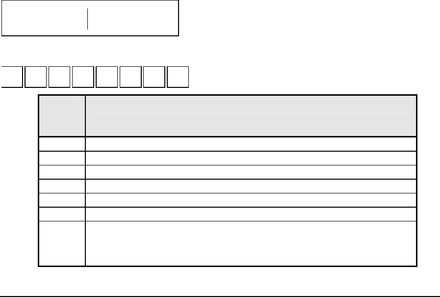
The data objects and variations supported by the SCADAPack series controllers are found in the
DNP Device Profile Document - Slave and DNP Device Profile Document - Master sections of this
user manual.
In general there are two categories of data within each data type, static objects and event objects.
Static objects contain the current value of the field point or software point. Event objects are
generated as a result of the data changing.
In addition to the object group and variation data objects can be assigned to classes. In DNP there are
four object classes, Class 0, Class 1, Class 2 and Class 3. Class 0 contains all static data. Classes 1, 2
and 3 provide a method to assign priority to event objects. While there is no fixed rule for assigning
classes to data objects typically class 1 is assigned to the highest priority data and class 3 is assigned
to the lowest priority data.
This object library structure enables the efficient transfer of data between master stations and
outstations. The master station can poll for high priority data (class 1) more often than it polls for
low priority data (class 3). As the data objects assigned to classes is event data when the master polls
for a class only the changed, or event data, is returned by the outstation. For data in an outstation that
is not assigned a class the master uses a class 0 poll to retrieve all static data from the outstation.
DNP allows outstations to report data to one or more master stations using unsolicited responses
(report by exception) for event data objects. The outstation reports data based on the assigned class
of the data. For example the outstation can be configured to only report high priority class 1 data.
2.1.1.1 Internal Indication (IIN) Flags
An important data object is the Internal Indications (IIN) object. The Internal Indication (IIN) flags
are set by a slave station to indicate internal states and diagnostic results. The following tables show
the IIN flags supported by SCADAPack controllers. All bits except Device Restarted and Time
Synchronization required are cleared when the slave station receives any poll or read data command.
The IIN is set as a 16 bit word divided into two octets of 8 bits. The order of the two octets is:
First Octet Second Octet
2.1.1.1.1 IIN First Octet
6 5 4 3 2 1 07 Bit Number
First
Octet
Bit
Description
0 last received message was a broadcast message
1 Class 1 data available
2 Class 2 data available
3 Class 3 data available
4 Time Synchronization required
5 not used (returns 0)
6 Device trouble
• Indicates memory allocation error in the slave, or
• For master in mimic mode indicates communication failure with the
DNP3 User and Reference Manual
May 9, 2007
7

First
Octet
Bit
Description
slave device.
7 Device restarted (set on a power cycle)
2.1.1.1.2 IIN Second Octet
6 5 4 3 2 1 07 Bit Number
Second
Octet
Bit
Description
0 Function Code not implemented
1 Requested object unknown or there were errors in the application data
2 Parameters out of range
3 Event buffer overflowed
Indicates event buffer overflow in the slave or master. The slave will set
this bit if the event buffer in the slave is overflowed. The master will set
this bit if the event buffer in the master has overflowed with events read
from the slave. Ensure the event buffer size, in the master and slave, is
set to a value that will ensure the buffer does not overflow and events are
lost.
4 not used (returns 0)
5 not used (returns 0)
6 not used (returns 0)
7 not used (returns 0)
2.1.2 Application Layer
The application layer in DNP is responsible for the processing of complete messages for requesting,
or responding to requests, for data.
The following shows the sequence of Application Layer messages between one master and one
outstation.
Master Outstation
Send Request --------------------> Accept request and process
<-------------------- Optional Application
Confirmation
Accept response <-------------------- Send Response
Optional Application
Confirmation -------------------->
Important change detected
Accept response <--------------------- Send Unsolicited Response
Optional Application
Confirmation -------------------->
DNP3 User and Reference Manual
May 9, 2007
8

The complete messages are received from and passed to the pseudo-transport layer. Application layer
messages are broken into fragments with each fragment size usually a maximum of 2048 bytes. An
application layer message may be one or more fragments in size and it is the responsibility of the
application layer to ensure the fragments are properly sequenced.
Application layer fragments are sent with or without a confirmation request. When a confirmation is
requested the receiving device replies with a confirmation indicating the message was received and
parsed without any errors.
2.1.3 Pseudo-Transport Layer
The pseudo-transport layer formats the larger application layer messages into smaller packets that
can be handled by the data link layer. These packets are referred to as frames in DNP. The pseudo-
transport layer inserts a single byte of information in the message header of each frame. This byte
contains information such as whether the frame is the first or last frame of a message as well as a
sequence number for the frame.
2.1.4 Data Link Layer
The data link layer handles the transmission and reception of data frames across the physical layer.
Each data link frame contains a source and destination address to ensure the receiving device knows
where to send the response. To ensure data integrity data link layer frames contain two CRC bytes
every 16 bytes.
Data link layer frames are sent with or without a confirmation request. When a confirmation is
requested the receiving device replies with a confirmation indicating the message was received and
the CRC checks passed.
2.1.5 Physical Layer
The physical layer handles the physical media, such as serial or Ethernet, which DNP communicates.
2.2 Modbus Database Mapping
In SCADAPack series controllers static DNP objects such as binary input, analog input, binary
counter and analog output are associated with Modbus registers. Whenever a DNP object is created
an associated Modbus register(s) is also assigned. Application programs executing in the
SCADAPack controller, C or logic, are able to assign physical I/O to Modbus registers using the
TelePACE Register Assignment or the ISaGRAF I/O Connection and these physical I/O points can
then be assigned to DNP objects. User application data such as runtimes, flow totals etc. may be also
be assigned to DNP objects.
This architecture enables DNP master stations and outstations to pass not only physical data points
between them but also to monitor and control user applications executing in the SCADAPack
controller. For example a master station can monitor a level in an outstation and then, based on the
application program, send a setpoint value to another outstation to control the level.
DNP3 User and Reference Manual
May 9, 2007
9
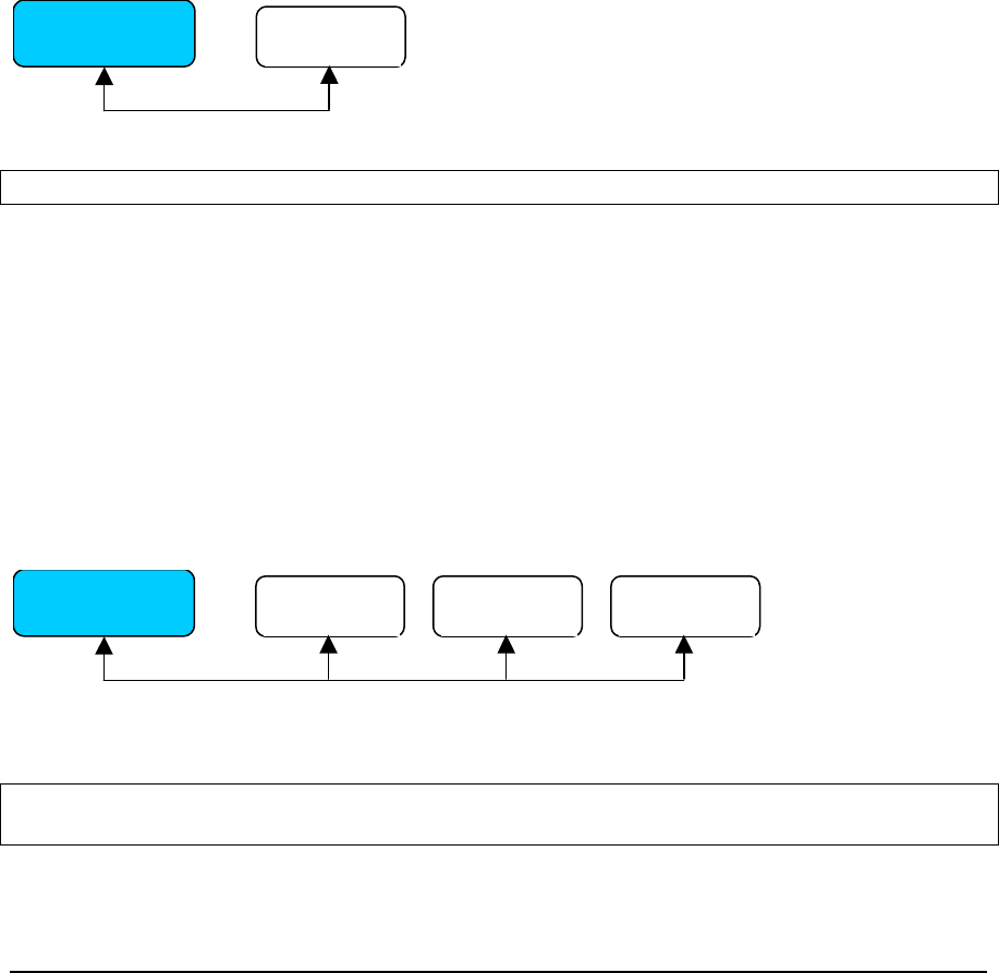
3 DNP Network Architectures
This section of the manual describes some of the DNP networks in which SCADAPack controllers
are used. The network descriptions provide an overview of network. A step-by-step procedure for
configuring a SCADAPack for each network implementation is described in proceeding sections.
3.1 DNP Master and Outstation
This configuration is a simple DNP Master (Client) and Outstation (Server). The SCADAPack DNP
Master may be configured to periodically poll the SCADAPack Outstation for Class 0, 1, 2, and 3
data objects and receive unsolicited responses from the outstation. The SCADAPack outstation may
be configured to report change event data to the master station using unsolicited responses.
The arrowed line between the Master and Outstation in the diagram below represents a
communication path connecting the two stations. This communication medium may be any type that
is supported by both controllers, such as direct serial, leased line modem, dial-up modem and radio
for example.
See the sections DNP Master and DNP Outstation for configuration details on this type of network.
SCADAPack 32
Master SCADAPack
Outstation
A
Note: A DNP Master can be configured on SCADAPack 350 and SCADAPack32 controllers only.
3.2 DNP Master and Multidrop Outstations
This configuration is a modification of the above example. In this configuration a DNP Master is
connected to a number of Outstations. The SCADAPack DNP Master may be configured to
periodically poll each SCADAPack Outstation for Class 0, 1,2, and 3 data objects and receive
unsolicited responses from the outstations. The SCADAPack Outstations may be configured to
report change event data to the master station using unsolicited responses.
The arrowed line between the Master and Outstations in the diagram below represents the
communication path connecting the stations. This communication path may be any type that is
supported by the controllers, such as leased line modem, dial-up modem and radio for example.
See the sections 4.2- DNP Master and 4.1-DNP Outstation for configuration details.
SCADAPack 32
Master SCADAPack
Outstation
A
SCADAPack
Outstation B SCADAPack
Outstation C
Note: A DNP Master can be configured on SCADAPack 350 and SCADAPack32 controllers
only.
3.3 DNP Mimic Mode
DNP3 User and Reference Manual
May 9, 2007
10
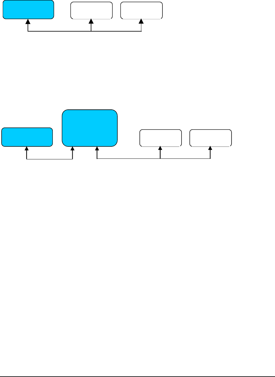
In a typical DNP network a SCADA Host master communicates with a number of outstations. The
SCADA Host will poll each outstation for data and may receive change event data in the form of
unsolicited responses from the outstations. This type of DNP network is shown in the following
diagram.
SCADAPack
Outstation
A
SCADAPack
Outstation B
SCADA Host
Master
In the above configuration the SCADA Host manages the communication path with each outstation
as represented by the arrowed lines in the diagram. When the communication path is slow, such as
with dial-up communication, or subject to high error rates, such as with some radio communication
the data update rate at the SCADA host can become very slow.
Adding a SCADAPack 32 master configured for Mimic Mode to the network, for instance, allows
for the SCADA Host Master to poll the SCADAPack 32 (Mimic Master) for all outstation data
instead. The following diagram shows the addition of the SCADAPack 32 master.
SCADAPack 32
Mimic
Slave Master SCADAPack
Outstation
A
SCADAPack
Outstation B
SCADA Host
Master
In this configuration the outstation side of the network has been decoupled from the host side of the
network, as the SCADAPack 32 mimic master now manages all the communication with the
outstations. The SCADA Host still communicates as before, through one link, targeting each
outstation. However the SCADAPack 32 master now intercepts all these messages, and responds on
behalf of the targeted outstation. From the perspective of the SCADA Host, the response is coming
back from the remote outstation.
In order to provide current outstation data to the SCADA Host, the SCADAPack mimicking master
independently communicates with each outstation to update a local copy of its database with data
from the outstations. This communication may be initiated by the SCADAPack mimicking master,
either by polling each outstation in turn using solicited messages; or the outstations could initiate
unsolicited messages back to the mimicking master. There could also be a combination of solicited
and unsolicited messages between the mimicking master and the outstations.
In the Mimic mode diagram above the SCADAPack mimic master polls each outstation, A and B, for
data and holds images of this data in its memory. When the SCADA Host poll outstations A and B
for data, the mimic master replies from its own images of the outstations. The SCADA Host can also
poll the SCADAPack master for its own local data. See Section 4.4-DNP Mimic Mode
Configuration for configuration details on the Mimic Mode.
Typically the messaging strategy chosen will depend on the relative importance of the data, and the
required maximum end-to-end delays for data being transferred through the network. If the
requirement is for a reasonably short end-to-end delay for all data points, a round-robin polling
scheme is best, without any unsolicited messages. If there are some data points, which are higher
priority and must be transferred as fast as possible, unsolicited messages should be used.
DNP3 User and Reference Manual
May 9, 2007
11
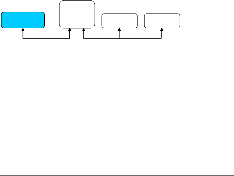
The advantage of having the SCADA system communicating with the SCADAPack 32 mimic,
instead of direct communication to the outstations is that communication delays and high error rates
are effectively removed. The physical connection between the SCADA system and mimic master
SCADAPack is typically a direct high-speed reliable connection and all message transactions are
fast. Outstations may often be connected via slow PSTN or radio links, and therefore message
transactions are subject to substantial delays. They may also be unreliable communication links
subject to high error rates.
By having a multiple-level network the communication between the SCADAPack master and
outstations is separated from communication between SCADA system and the SCADAPack master.
The delays and error rates, which may be inherent in the outstation communication paths, can be
isolated from communications with the SCADA system, thereby increasing overall system
performance.
One particular advantage of Mimic Mode is that the master SCADAPack does not need to
know, or be configured with, any details of the DNP points configured in the outstations. This
makes it relatively simple to insert such a SCADAPack master into any existing DNP network. The
SCADAPack master in Mimic Mode behaves transparently to the higher-level SCADA system, and
can easily be configured with communication paths and polling instructions for each connected
outstation.
3.4 DNP Routing
DNP Routing is similar to DNP Mimic mode in that the SCADA Host has only one connection to a
SCADAPack configured for DNP routing. The following diagram shows a simple DNP routing
system.
SCADA Host
Master
SCADAPack
DNP Router
Outstation A SCADAPack
Outstation B SCADAPack
Outstation C
In this configuration the SCADAPack DNP router (Outstation A above) manages all the
communication with the outstations. The SCADAPack DNP router receives messages from the
SCADA Host for each outstation and routes the messages to the outstations. Change event data in
the form of unsolicited responses from the outstations are routed by the SCADAPack DNP router, to
the SCADA Host in the same manner.
As with Mimic mode, the advantage of using DNP Routing is that the responsibility of managing
multiple communications paths is removed from the SCADA Host. The SCADAPack DNP router
handles all communications paths to outstations, including such tasks as dial-up radio
communication. In contrast to Mimic mode, however, the SCADA Host system still has to handle
the long delays and high error rates that may be present on the communications links to the
outstations.
See the section DNP Data Router for configuration details for using DNP Routing in a SCADA
system.
3.5 DNP Address Mapping
DNP3 User and Reference Manual
May 9, 2007
12
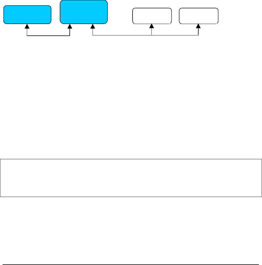
Setting up a SCADAPack controller as a DNP Mimic Master or even a DNP router is relatively
straight forward, as one does not need to explicitly map data from the remote devices into the local
DNP database of the SCADAPack master.
In certain cases, however, data from the remote DNP devices may need to be accessible to an
application program running in the master SCADAPack controller. DNP Address Mapping allows
this capability, by providing a method to map outstation DNP points into local Modbus registers in
the SCADAPack master controller.
By configuring the Address Mapping table these remote DNP points are mapped to local Modbus
registers in the SCADAPack master. As mapped Modbus points the data is available for use in
application programs such as TelePACE and ISaGRAF. In addition a Modbus SCADA Host polling
the SCADAPack master may access these points. See the Section 5.5- Address Mapping for
information on configuring DNP Address Mapping.
The following diagram shows a simple DNP Address Mapping network.
SCADAPack 32
Modbus DNP3
Slave Maste
r
SCADAPack
Outstation
A
SCADAPack
Outstation B
SCADA Host
Modbus Master
In this network the SCADAPack master updates is local database with mapped outstation data. The
manner and frequency with which the SCADAPack master updates the local Modbus registers,
depends on the number and type of I/O object types the registers are mapped to.
For 'Input' object types, address mapping simply links the remote DNP points to local Modbus Input
registers (1xxxx or 3xxxx). These local Modbus registers are updated after the corresponding DNP
point gets updated (usually by a class 0 poll to the remote DNP device).
For ‘Output' object types, there is a similar relationship between the local Modbus registers (0xxxx
or 4xxxx) and the remote DNP point, with one significant difference in the way local changes are
propagated to the remote DNP device. Changes made to the local Modbus register will affect the
value of the associated DNP point, subsequently triggering a DNP Write message to the remote DNP
outstation.
It is, therefore, necessary to ensure that all local Modbus addresses mapped to a remote device via
Address Mapping, are associated with a local DNP address.
Note: Mapping numerous local Modbus output registers (0xxxx and 4xxxx), to a remote DNP
device may cause frequent communications between the master and the slave, if the
associated registers are being changed frequently in the master. On limited bandwidth or
radio networks, care must be taken to ensure that your network capacity can handle all the
traffic that will be generated from these local changes.
DNP3 User and Reference Manual
May 9, 2007
13

4 Configuration of DNP Operation Modes
SCADAPack controllers support a number of DNP operating modes. In this section of the user
manual the operating modes supported and the steps required to configure the operating modes is
explained.
The DNP operating modes described in this section include:
• DNP Outstation
• DNP Master
• DNP Data Router
• DNP Mimic Mode
4.1 DNP Outstation Configuration
A DNP outstation is the basic configuration for a SCADAPack controller operating in a DNP
network. When configured as a DNP outstation a SCADAPack controller is able to:
• Map physical I/O data to DNP points.
• Define DNP points as Class 1, Class 2 or Class 3 data types.
• Respond to requests from one or more master stations such as a SCADA hosts or SCADAPack
32 controllers that are configured for DNP master operation.
• Initiate unsolicited responses to one or more master stations.
See the section DNP Network for examples of where an outstation may be used in typical DNP
networks.
The following describes the general steps required to configure a SCADAPack series controller as a
DNP outstation.
4.1.1 Configuration Steps
The steps below provide an outline of the configuration needed for an outstation. References are
made to sections of this manual and to other user manuals. These sections and manual should be
referred to for complete information.
1. Enable DNP for the serial or Ethernet port.
The SCADAPack controller is connected to a DNP network through one of the serial ports or in the
case of a SCADAPack 32 controller through a serial port or Ethernet port. The serial or Ethernet
ports need to be set to use DNP protocol and to enable DNP Routing.
• For TelePACE applications see the section Controller Menu >> Serial Ports and Controller
Menu >> IP Configuration in the TelePACE User and Reference Manual.
• For ISaGRAF Applications see the section Controller Menu Commands >> Controller Serial
Port Command and Controller Menu Commands >> Controller IP in the ISaGRAF User and
Reference Manual.
2. Configure Register Assignment or I/O Connections.
The physical I/O for a SCADAPack controller is made available to application programs and
protocols by assigning the physical I/O to Modbus registers in TelePACE and to Dictionary
Variables (with Modbus network addresses) in ISaGRAF. SCADAPack controllers use the Modbus
addresses when DNP objects are created.
DNP3 User and Reference Manual
May 9, 2007
14

• For TelePACE applications see the section Controller Menu >> Register Assignment in the
TelePACE User and Reference Manual.
• For ISaGRAF Applications see the section I/O Connection Reference in the ISaGRAF User and
Reference Manual.
3. Configure Application Layer Parameters.
The application layer parameters primarily define how the application layer communicates; how
often time synchronization is done, whether the station initiates unsolicited responses and if
application layer confirmation is used in the communication. In addition the global Operate Timeout
parameter is set for Select Before Operate binary output objects and the Dial Up parameters are set if
dial up communication is used.
• See the section DNP Configuration >> Application Layer Configuration in this manual for
information on the parameters used in the Application layer.
4. Configure Data Link Layer Parameters.
The data link layer parameters define the outstation DNP address, the master station address(s) the
outstation will communicate with and whether data link layer confirmation will be used in the
communication.
• See the section DNP Configuration >> Data Link Layer Configuration in this manual for
information on the parameters used in the Data Link Layer.
5. Configure DNP Routing.
SCADAPack controllers use DNP routing to direct DNP messages based on instructions in the
routing table. The routing table defines which serial port or Ethernet port messages will be sent to
other DNP stations. In the case of an outstation DNP routing defines the station address of the master
station and the communication port to be used when communicating with the master station.
• See the section DNP Configuration >> Routing in this manual for information on the routing
table and adding entries to the routing table.
6. Configure Data Objects.
The SCADAPack controller physical I/O and user application data may be assigned to DNP objects
and given DNP point addresses. DNP input points can be assigned a class (1,2 or 3) for event data.
These change events can be sent to the master station(s) if unsolicited responses are enable for the
assigned class.
The DNP objects that are supported in the SCADAPack controller are shown below. See the
appropriate section in the DNP Configuration section of this manual for complete information on
configuring DNP data objects.
• Binary Inputs
• Binary Outputs
• 16-bit Analog Inputs
• 32-bit Analog Inputs
• Short Floating Point Analog Inputs
• 16-bit Analog Outputs
• 32-bit Analog Outputs
DNP3 User and Reference Manual
May 9, 2007
15

• Short Floating Point Analog Outputs
• 16-bit Counter Inputs
• 32-bit Counter Inputs
4.2 DNP Master Configuration
This option is available on the SCADAPack 350 and SCADAPack 32 controllers only.
The SCADAPack 350 and SCADAPack 32 controllers can be configured as a DNP master station in
a DNP network. When configured as a DNP master station the controller is able to:
• Map local physical I/O data to DNP points.
• Define local DNP points as Class 1, Class 2 or Class 3 data types.
• Respond to requests from one or more master stations such as a SCADA hosts or other
controllers that are configured for DNP master operation.
• Initiate unsolicited responses to one or more master stations.
• Poll DNP outstations for static (Class 0) data and Class 1, 2 and 3 event data.
• Accept unsolicited response messages from polled outstations.
• Map Outstation DNP data to local DNP points and Modbus registers. This data can then be used
in application programs executing in the local controller or made available to other DNP master
station(s) that poll this local controller.
See Section 3-DNP Network Architectures for examples of where a DNP master may be used in
typical DNP networks.
The following describes the general steps required to configure a SCADAPack controller as a DNP
master station.
Note: Only the SCADAPack 350 or SCADAPack32 controller can be configured as a DNP master.
4.2.1 Configuration Steps
The steps below provide an outline of the configuration needed for a SCADAPack master station.
References are made to sections of this manual and to other user manuals. These sections and manual
should be referred to for complete information.
1. Enable DNP for the serial or Ethernet port.
The SCADAPack controller is connected to a DNP network through one of the serial ports or the
Ethernet port. The serial or Ethernet ports need to be set to use DNP protocol and to enable DNP
Routing.
• For TelePACE applications see the section Controller Menu >> Serial Ports and Controller
Menu >> IP Configuration in the TelePACE User and Reference Manual.
• For ISaGRAF Applications see the section Controller Menu Commands >> Controller Serial
Port Command and Controller Menu Commands >> Controller IP in the ISaGRAF User and
Reference Manual.
2. Configure Register Assignment or I/O Connections.
The physical I/O for a SCADAPack controller is made available to application programs and
protocols by assigning the physical I/O to Modbus registers in TelePACE and to Dictionary
DNP3 User and Reference Manual
May 9, 2007
16

Variables (with Modbus network addresses) in ISaGRAF. SCADAPack controllers use the Modbus
addresses when DNP objects are created.
• For TelePACE applications see the section Controller Menu >> Register Assignment in the
TelePACE User and Reference Manual.
• For ISaGRAF Applications see the section I/O Connection Reference in the ISaGRAF User and
Reference Manual.
3. Configure Application Layer Parameters.
The application layer parameters primarily define how the application layer communicates; how
often time synchronization is done, whether the station initiates unsolicited responses and if
application layer confirmation is used in the communication. In addition the global Operate Timeout
parameter is set for Select Before Operate binary output objects and the Dial Up parameters are set if
dial up communication is used.
• See the section DNP Configuration >> Application Layer Configuration in this manual for
information on the parameters used in the Application layer.
4. Configure Data Link Layer Parameters.
The data link layer parameters define the SCADAPack outstation DNP address, the master station
address(s) the SCADAPack master will communicate with and whether data link layer confirmation
will be used in the communication.
• See the section DNP Configuration >> Data Link Layer Configuration in this manual for
information on the parameters used in the Data Link Layer.
5. Configure Master Parameters ( Applicable for SCADAPack 350 and SCADAPack 32 only)
There are two Master parameters, Mimic Mode enable or disable and the Base Poll Interval. The
concept behind Mimic Mode operation is described in section 3.3-DNP Mimic Mode.
The Base Poll interval is used to determine the frequency of master polling of outstations. Each type
of master poll, Class 0, 1, 2 or 3 is polled at a frequency that is based on the Base Poll Interval.
• See the section DNP Configuration >> Master in this manual for information on the parameters
used in the Master.
6. Configure Master Poll Parameters
The Master Poll parameters define how often the master station polls each outstation, how often to
request time synchronization and whether unsolicited responses are accepted from the outstation.
The polling frequency is configured independently for outstation Class 0,1,2 and 3 data. Master
polling interval, or frequency, is based on the number of base poll intervals as set in the Master
parameters.
• See the section DNP Configuration >> Master Poll in this manual for information on the
parameters used in for the Master Poll.
7. Configure Address Mapping Parameters
The Address Mapping parameters define the mapping rules, which allow outstation DNP objects to
be mapped into local SCADAPack master Modbus registers. This allows the outstation data to be
used locally in application programs.
• See the section DNP Configuration >> Address Mapping in this manual for information on the
parameters used in for Address Mapping.
DNP3 User and Reference Manual
May 9, 2007
17

8. Configure DNP Routing.
SCADAPack controllers use DNP routing to direct DNP messages based on instructions in the
routing table. The routing table defines which serial port or Ethernet port messages will be sent to
other DNP outstations or master stations. The DNP routing table defines the station address of the
master station and the communication port to be used when communicating with the master station
and the station addresses of the outstations the SCADAPack master station is polling.
9. See the section DNP Configuration >> Routing in this manual for information on the routing
table and adding entries to the routing table.
10. Configure Data Objects.
The SCADAPack controller physical I/O and user application data may be assigned to DNP objects
and given DNP point addresses. DNP input points can be assigned a class (1,2 or 3) for event data.
These change events can be sent to the master station(s) if unsolicited responses are enable for the
assigned class.
The DNP objects that are supported in the SCADAPack controllers are shown below. See the
appropriate section in the DNP Configuration section of this manual for complete information on
configuring DNP data objects.
• Binary Inputs
• Binary Outputs
• 16-bit Analog Inputs
• 32-bit Analog Inputs
• Short Floating Point Analog Inputs
• 16-bit Analog Outputs
• 32-bit Analog Outputs
• Short Floating Point Analog Outputs
• 16-bit Counter Inputs
• 32-bit Counter Inputs
4.3 DNP Data Router Configuration
All SCADAPack controllers can be configured as a DNP Router. When configured as a DNP router
a SCADAPack controller is able to:
• Map local physical I/O data to DNP points.
• Define local DNP points as Class 1, Class 2 or Class 3 data types.
• Respond to requests from one or more master stations such as a SCADA hosts or other
SCADAPack 32 controllers that are configured for DNP master operation.
• Initiate unsolicited responses to one or more master stations.
• Route DNP messages as defined in the Routing table.
See the Section 3-3-Modbus Database Mapping for examples of where a DNP Data Router may be
used in typical DNP networks.
The following describes the general steps required to configure a SCADAPack series controller as a
DNP Data Router.
DNP3 User and Reference Manual
May 9, 2007
18

4.3.1 Configuration Steps
The steps below provide an outline of the configuration needed for a SCADAPack DNP router.
References are made to sections of this manual and to other user manuals. These sections and manual
should be referred to for complete information.
1. Enable DNP for the serial or Ethernet port.
The SCADAPack controller 32 is connected to a DNP network through one of the serial ports or the
Ethernet port. The serial or Ethernet ports need to be set to use DNP protocol and to enable DNP
Routing.
• For TelePACE applications see the section Controller Menu >> Serial Ports and Controller
Menu >> IP Configuration in the TelePACE User and Reference Manual.
• For ISaGRAF Applications see the section Controller Menu Commands >> Controller Serial
Port Command and Controller Menu Commands >> Controller IP in the ISaGRAF User and
Reference Manual.
2. Configure Register Assignment or I/O Connections.
The physical I/O for a SCADAPack 32 controller is made available to application programs and
protocols by assigning the physical I/O to Modbus registers in TelePACE and to Dictionary
Variables (with Modbus network addresses) in ISaGRAF. SCADAPack controllers use the Modbus
addresses when DNP objects are created.
• For TelePACE applications see the section Controller Menu >> Register Assignment in the
TelePACE User and Reference Manual.
• For ISaGRAF Applications see the section I/O Connection Reference in the ISaGRAF User and
Reference Manual.
3. Configure Application Layer Parameters.
The application layer parameters primarily define how the application layer communicates; how
often time synchronization is done, whether the station initiates unsolicited responses and if
application layer confirmation is used in the communication. In addition the global Operate Timeout
parameter is set for Select Before Operate binary output objects and the Dial Up parameters are set if
dial up communication is used.
• See the section DNP Configuration >> Application Layer Configuration in this manual for
information on the parameters used in the Application layer.
4. Configure Data Link Layer Parameters.
The data link layer parameters define the SCADAPack 32 outstation DNP address, the master station
address(s) the SCADAPack 32 master will communicate with and whether data link layer
confirmation will be used in the communication.
• See the section DNP Configuration >> Data Link Layer Configuration in this manual for
information on the parameters used in the Data Link Layer.
5. Configure DNP Routing.
SCADAPack series controllers use DNP routing to direct DNP messages based on instructions in the
routing table. The routing table defines which serial port or Ethernet port messages will be sent to
other DNP outstations or master stations. The DNP routing table defines the station address of each
outstation and the communication port to be used when communicating with outstations.
DNP3 User and Reference Manual
May 9, 2007
19

• See the section DNP Configuration >> Routing in this manual for information on the routing
table and adding entries to the routing table.
6. Configure Data Objects.
The SCADAPack controller physical I/O and user application data may be assigned to DNP objects
and given DNP point addresses. DNP input points can be assigned a class (1,2 or 3) for event data.
These change events can be sent to the master station(s) if unsolicited responses are enable for the
assigned class.
The DNP objects that are supported in the SCADAPack controller are shown below. See the
appropriate section in the DNP Configuration section of this manual for complete information on
configuring DNP data objects.
• Binary Inputs
• Binary Outputs
• 16-bit Analog Inputs
• 32-bit Analog Inputs
• Short Floating Point Analog Inputs
• 16-bit Analog Outputs
• 32-bit Analog Outputs
• Short Floating Point Analog Outputs
• 16-bit Counter Inputs
• 32-bit Counter Inputs
4.4 DNP Mimic Mode Configuration
This option is applicable to the SCADAPack 350 and SCADPack32 controllers only.
The SCADAPack 350 and SCADAPack 32 controller can be configured as a DNP master station, in
mimic mode, in a DNP network. When configured as a Mimic Mode DNP master station a
SCADAPack 32 controller is able to:
• Map local physical I/O data to DNP points.
• Define local DNP points as Class 1, Class 2 or Class 3 data types.
• Respond to requests from one or more master stations such as a SCADA hosts or other
SCADAPack controllers that are configured for DNP master operation.
• Initiate unsolicited responses to one or more master stations.
• Poll DNP outstations for static (Class 0) data and Class 1, 2 and 3 event data.
• Accept unsolicited response messages from polled outstations.
• Respond directly to SCADA Host polls that are destined for outstations that are defined in its
Master Poll table.
See Section 3-DNP Network Architectures for examples of where a DNP master may be used in
typical DNP networks.
The following describes the general steps required to configure a SCADAPack controller as a Mimic
Mode DNP master station.
DNP3 User and Reference Manual
May 9, 2007
20

4.4.1 Configuration Steps
The steps below provide an outline of the configuration needed for a SCADAPack DNP Mimic
Mode master station. References are made to sections of this manual and to other user manuals.
These sections and manual should be referred to for complete information.
1. Enable DNP for the serial or Ethernet port.
The SCADAPack controller is connected to a DNP network through one of the serial ports or the
Ethernet port.
• For TelePACE applications see the section Controller Menu >> Serial Ports and Controller
Menu >> IP Configuration in the TelePACE User and Reference Manual.
• Enable Routing on the serial or Ethernet ports that have been configured for DNP
communication.
• For ISaGRAF Applications see the section Controller Menu Commands >> Controller Serial
Port Command and Controller Menu Commands >> Controller IP in the ISaGRAF User and
Reference Manual.
2. Configure Register Assignment or I/O Connections.
The physical I/O for a SCADAPack controller is made available to application programs and
protocols by assigning the physical I/O to Modbus registers in TelePACE and to Dictionary
Variables (with Modbus network addresses) in ISaGRAF. SCADAPack controllers use the Modbus
addresses when DNP objects are created.
• For TelePACE applications see the section Controller Menu >> Register Assignment in the
TelePACE User and Reference Manual.
• For ISaGRAF Applications see the section I/O Connection Reference in the ISaGRAF User and
Reference Manual.
3. Configure Application Layer Parameters.
The application layer parameters primarily define how the application layer communicates; how
often time synchronization is done, whether the station initiates unsolicited responses and if
application layer confirmation is used in the communication. In addition the global Operate Timeout
parameter is set for Select Before Operate binary output objects and the Dial Up parameters are set if
dial up communication is used.
• See the section DNP Configuration >> Application Layer Configuration in this manual for
information on the parameters used in the Application layer.
4. Configure Data Link Layer Parameters.
The data link layer parameters define the SCADAPack outstation DNP address, the master station
address(s) the SCADAPack Mimic master will communicate with and whether data link layer
confirmation will be used in the communication.
• See the section DNP Configuration >> Data Link Layer Configuration in this manual for
information on the parameters used in the Data Link Layer.
5. Configure Master Parameters
There are two Master parameters, Mimic Mode enable or disable and the Base Poll Interval. The
Mimic Mode must be set to enable for Mimic Mode. Mimic Mode operation is described in Section
4.4-DNP Mimic Mode.
DNP3 User and Reference Manual
May 9, 2007
21

he Base Poll interval is used to determine the frequency of master polling of outstations. Each type
of master poll, Class 0, 1, 2 or 3 is polled at a frequency that is based on the Base Poll Interval.
• See the section DNP Configuration >> Master in this manual for information on the parameters
used in the Master.
6. Configure Master Poll Parameters
The Master Poll parameters define how often the master station polls each outstation, how often to
request time synchronization and whether unsolicited responses are accepted from the outstation.
The polling frequency is configured independently for outstation Class 0,1,2 and 3 data. Master
polling interval, or frequency, is based on the number of base poll intervals as set in the Master
parameters.
• See the section DNP Configuration >> Master Poll in this manual for information on the
parameters used in for the Master Poll.
7. Configure Address Mapping Parameters
The Address Mapping parameters define the mapping rules, which allow outstation DNP objects to
be mapped into local SCADAPack master Modbus registers and DNP points. This allows the
outstation data to be used locally in application programs.
• See the section DNP Configuration >> Address Mapping in this manual for information on the
parameters used in for Address Mapping.
8. Configure DNP Routing.
SCADAPack controllers use DNP routing to direct DNP messages based on instructions in the
routing table. The routing table defines which serial port or Ethernet port messages will be sent to
other DNP outstations or master stations. The DNP routing table defines the station address of the
master station and the communication port to be used when communicating with the master station
and the station addresses of the outstations the SCADAPack master station is polling.
• See the section DNP Configuration >> Routing in this manual for information on the routing
table and adding entries to the routing table.
9. Configure Data Objects.
The SCADAPack controller physical I/O and user application data may be assigned to DNP objects
and given DNP point addresses. DNP input points can be assigned a class (1,2 or 3) for event data.
These change events can be sent to the master station(s) if unsolicited responses are enable for the
assigned class.
The DNP objects that are supported in the SCADAPack controller are shown below. See the
appropriate section in the DNP Configuration section of this manual for complete information on
configuring DNP data objects.
• Binary Inputs
• Binary Outputs
• 16-bit Analog Inputs
• 32-bit Analog Inputs
• Short Floating Point Analog Inputs
• 16-bit Analog Outputs
• 32-bit Analog Outputs
DNP3 User and Reference Manual
May 9, 2007
22

• Short Floating Point Analog Outputs
• 16-bit Counter Inputs
• 32-bit Counter Inputs
DNP3 User and Reference Manual
May 9, 2007
23
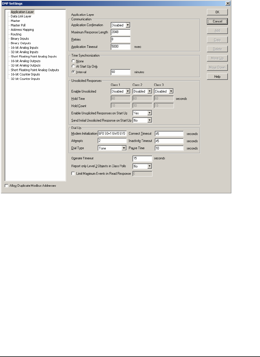
5 DNP Configuration Menu
The DNP command is used to configure the DNP protocol settings for the controller. When selected
the DNP Settings window is opened, as shown below.
The DNP Settings window has a tree control on the left side of the window. The tree control appears
differently depending on the controller type selected. The SCADAPack 350, SCADAPack 32 and
SCADAPack 32P controllers support DNP master and include the bolded items in the following list.
Other SCADAPack controllers do not support DNP master and do not include the bolded items.
This tree control contains headings for:
• Application Layer
• Data Link Layer
• Master
• Master Poll
• Address Mapping
• Routing
• Binary Inputs
• Binary Outputs
• 16-Bit Analog Inputs
• 32-Bit Analog Inputs
DNP3 User and Reference Manual
May 9, 2007
24
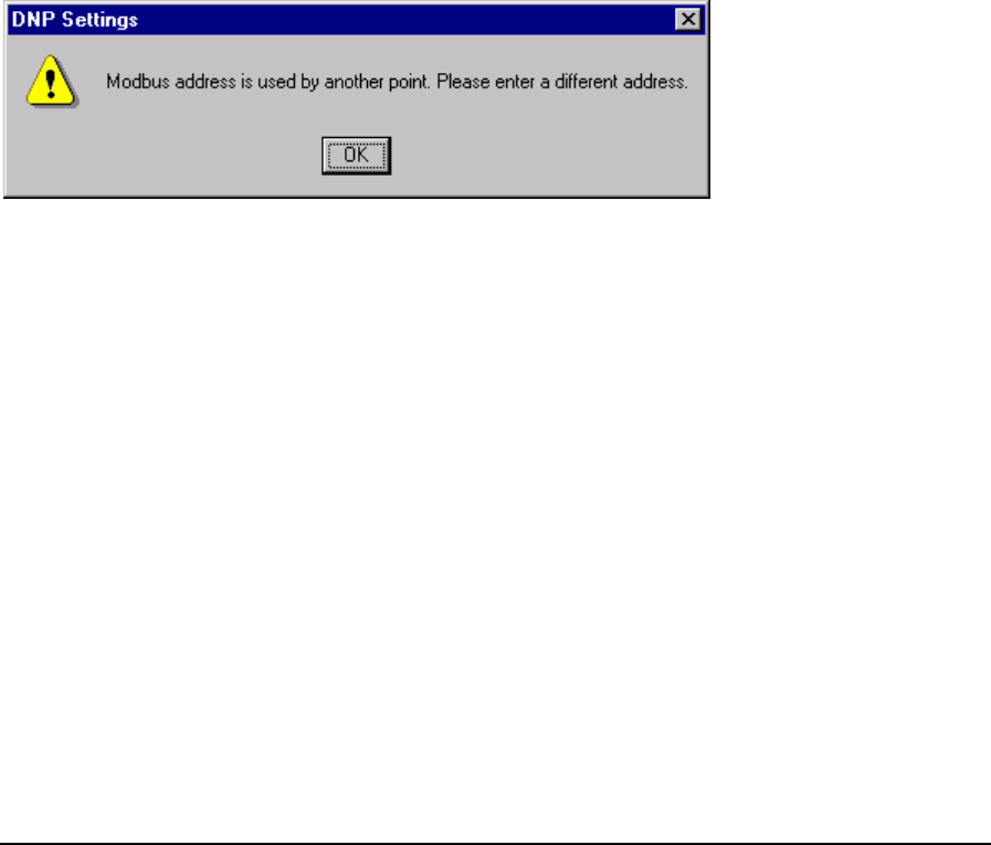
• Short Floating Point Analog Inputs
• 16-Bit Analog Outputs
• 32-Bit Analog Outputs
• Short Floating Point Analog Outputs
• 16-Bit Counter Inputs
• 32-Bit Counter Inputs
When a tree control is selected by clicking the mouse on a heading a property page is opened for the
header selected. From the property page the DNP configuration parameters for the selected header is
displayed.
As DNP objects are defined they are added as leaves to the object branch of the tree control. When
an object is defined the object branch will display a collapse / expand control to the left of the
branch.
The Allow Duplicate Modbus Addresses checkbox (in the bottom left corner) determines if the
Modbus I/O database addresses assigned to the DNP data points must be unique. Check this box if
you want to allow more than one point to use the same Modbus address.
Uncheck the box if you want to be warned about duplicate addresses. If an attempt is made to use a
Modbus address that has already been used for another DNP point the following warning is
displayed.
5.1 Application Layer Configuration
The Application Layer property page is selected for editing by clicking Application Layer in the tree
control section of the DNP Settings window. When selected the Application Link Layer property
page is active.
DNP3 User and Reference Manual
May 9, 2007
25
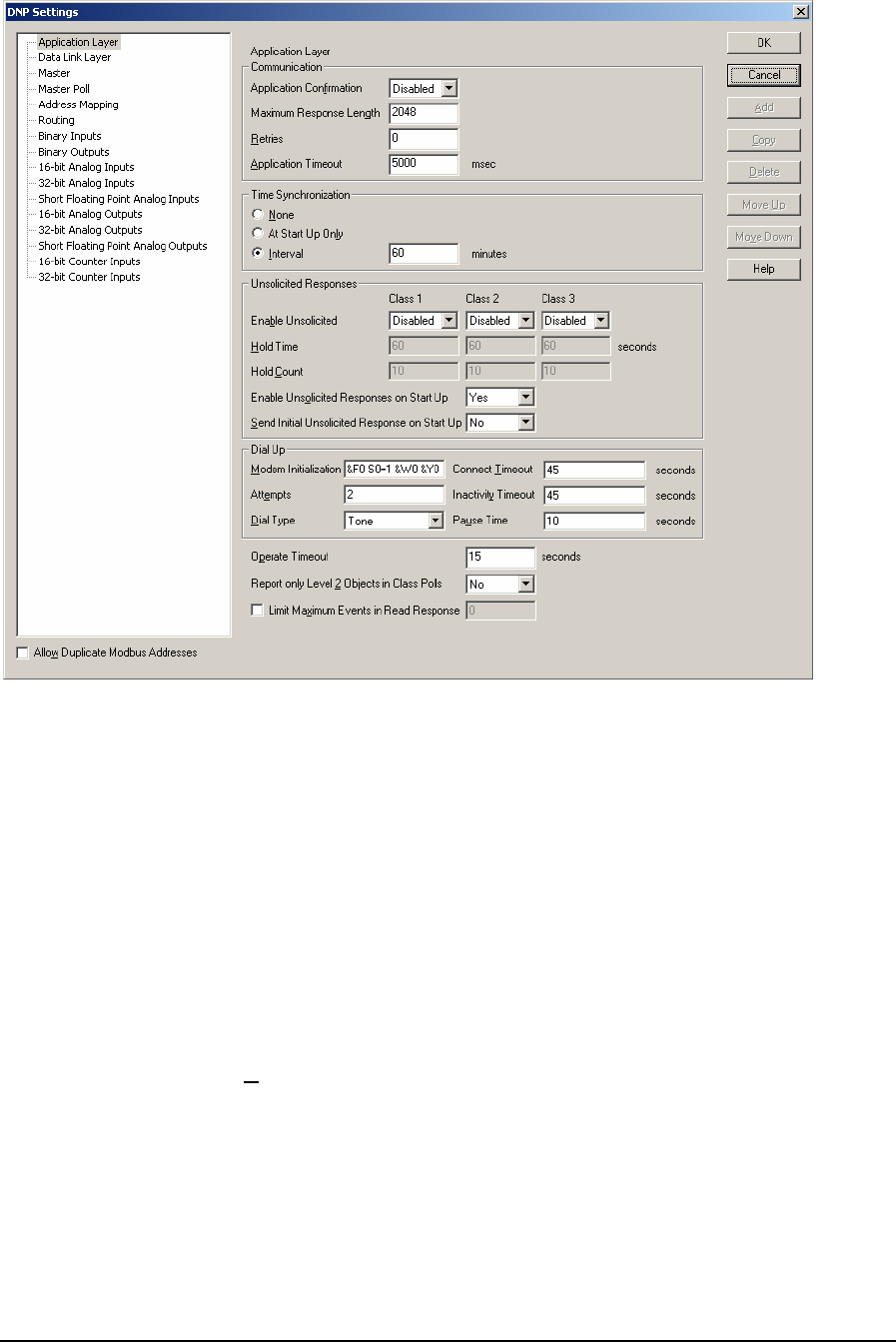
Application Layer parameters are set in this property page. Each parameter is described in the
following paragraphs.
The Communication section of the dialog contains the configurable application layer
communication parameters.
When the Application Confirmation feature is enabled, the SCADAPack controller requests a
confirmation from the master station for any data transmitted. When it is disabled, the controller does
not request a confirmation from the master station and assumes that the master receives the data it
sends successfully. However if the data includes event data (including unsolicited messages), the
controller requests a confirmation from the master regardless of whether this feature is enabled or
disabled. Valid selections for this parameter are:
• Enabled
• Disabled
The Maximum Fragment Length is maximum size of a single response fragment that the RTU will
send. If the complete response message is too large to fit within a single fragment, then the
SCADAPack controller will send the response in multiple fragments. Valid values are between 100
and 2048 bytes.
This parameter is adjustable to allow for interoperability with simple DNP3 devices that require
smaller application layer fragments. Devices with limited memory may restrict the application layer
fragment size to as low as 249 bytes.
DNP3 User and Reference Manual
May 9, 2007
26

Note: The Maximum Fragment Length parameter applies to responses from read commands only.
It does not affect unsolicited responses.
The Retries entry maximum number of times the application layer will retry sending a response or
an unsolicited response to the master station. This does not include any retries performed by the data
link layer. Valid values are between 0 and 255.
Note: Using application layer Confirmation and Retries is inherently more efficient than using data
link layer Confirmation and Retries. Each fragment sent by the Application layer may
require as many as 10 data link layer frames to be sent, each with its own confirmation
message. The application layer is typically preferred for message confirmation for this
reason.
The Application Timeout is the expected time duration (in milliseconds) that the master station's
application layer requires to process and respond to a response from the SCADAPack controller.
This SCADAPack controller uses this value in setting its time-out interval for master station
responses. This value should be large enough to prevent response time-outs. The value must be kept
small enough so as not to degrade system throughput. The value of this element is dependent on the
master station. Valid values are between 100 and 60000 milliseconds.
The Time Synchronization section of the dialog defines when and how often the SCADAPack
outstation prompts the master station to synchronize the SCADAPack controller time. Messages
must be sent between the Master and Remote stations for Time Synchronization to work. Valid
selections for this parameter are:
• The None selection will cause the SCADAPack controller to never request Time
Synchronization.
• The At Start Up Only selection will cause the SCADAPack controller to request Time
Synchronization at startup only.
• The Interval selection will cause the SCADAPack controller to request Time Synchronization at
startup and then every Interval minutes after receiving a time synchronization from the master.
Valid entries for Interval are between 1 and 32767 minutes. The default value is 60 minutes.
Note: Time Synchronization may instead be initiated by the Master for each Outstation. This may
be selected in the Add/Edit Master Poll dialog. It is not required to enable Time
Synchronization at both the Master and the Outstation.
The Unsolicited Response section of the dialog defines which class objects are enabled or disabled
from generating report by exception responses. Unsolicited responses are individually configured for
Class 1, Class 2, and Class 3 data.
The Enable Unsolicited controls enables or disables unsolicited responses for Class 1, Class 2 or
Class 3 data. If unsolicited responses are disabled for a Class the controller never sends unsolicited
responses for that Class. If unsolicited responses are enabled the controller does not start sending
responses until the master enables the classes to report. Valid selections are:
• Enabled
• Disabled
The Hold Time parameter is used only when unsolicited responses are enabled for a Class. This
parameter defines the maximum period (in seconds) the RTU will be allowed to hold its events
before reporting them to the DNP master station. When the hold time has elapsed since the first event
DNP3 User and Reference Manual
May 9, 2007
27

occurred, the RTU will report to the DNP master station all events accumulated up to then. This
parameter is used in conjunction with the Hold Count parameter in customizing the unsolicited
event reporting characteristics. The value used for the Hold Time depends on the frequency of event
generation, topology and performance characteristics of the system. The valid values for this
parameter are 0 - 65535. The default value is 60 seconds.
The Hold Count parameter is used only when unsolicited responses are enabled for a Class. This
parameter defines the maximum number of events the RTU will be allowed to hold before reporting
them to the DNP master station. When the hold count threshold is reached, the RTU will report to
the master, all events accumulated up to that point. This parameter is used in conjunction with the
Hold Time in customizing the unsolicited event reporting characteristics. To guarantee an
unsolicited response is sent as soon as an event occurs, set the Hold Count parameter to 1. The valid
values for this parameter are 1 - 65535. The default value is 10.
The Enable Unsolicited Responses on Start Up parameter enables or disables unsolicited responses
on startup. This affects the default controller behaviour after a start-up or restart. Some hosts require
devices to start up with unsolicited responses enabled. It should be noted this is non-conforming
behaviour according to the DNP standard. Valid selections are:
• Yes
• No
The default selection is Yes.
The Send Initial Unsolicited Response on Startup parameter enables or disables Send Initial
unsolicited responses on startup. This parameter controls whether an initial unsolicited response with
null data is sent after a start-up or restart. Valid selections are:
Yes
No
The default selection is No.
The Dial Up section of the dialog defines modem parameters used when a dial up modem is used to
communicate with stations that use dial up communication. The phone numbers for the stations are
defined in the Routing table.
The Modem Initialization is the string that will be sent to the modem prior to each call. This is an
ASCII null-terminated string. The maximum length of the string is 64 characters, including the null
terminator.
The Attempts controls the maximum number of dial attempts that will be made to establish a Dial
Up connection. The valid values for this parameter are 1 – 10. The default value is 2.
The Dial Type parameter controls whether tone or pulse dialing will be used for the call. Valid
values are Tone dialing or Pulse dialing. The default value is Tone dialing.
The Connect Timeout controls the maximum time (in seconds) after initiating a dial sequence that
the firmware will wait for a carrier signal before hanging up. The valid values for this parameter are
1 – 65535. The default value is 45.
The Inactivity Timeout controls the maximum time after message activity that a connection will be
left open before hanging up. The valid values for this parameter are 1 – 65535 seconds. The default
value is 45 seconds.
The Pause Time controls the delay time (in seconds) between dial events, to allow time for
incoming calls. The valid values for this parameter are 1 – 65535. The default value is 10.
DNP3 User and Reference Manual
May 9, 2007
28

The Operate Timeout parameter specifies the timeout interval between a Select and Operate request
from the Master. If after receiving a valid Select control output request from the master, the RTU
does not receive the corresponding Operate request within this time-out interval, the control output
request fails. The value of this parameter, expressed in seconds, is dependent on the master station,
the data link and physical layer. Valid values are 1 to 6500 seconds. The default value is 15 seconds.
The Master must have the Select/Operate functionally in order to use this feature.
The Report only Level 2 Compliant Objects in Class Polls parameter affects how Short Float
Analog Input, Short Float Analog Output, and 32-bit Analog Output objects are reported. These
objects are converted to 32-bit Analog Input and 16-bit Analog Output objects when this parameter
is selected. Valid selections are:
• Yes
• No
The default selection is No.
The Limit Maximum Events in Read Response parameter allows limiting the number of events in
a read response. Select the checkbox to enable the limit. Valid values are 1 to 65535. The default
value is disabled.
Note: The Maximum Events parameter applies to responses from read commands only. It does not
affect unsolicited responses.
The Allow Duplicate Modbus Addresses checkbox determines if the Modbus I/O database
addresses assigned to the DNP data points must be unique. Check this box if you want to allow more
than one point to use the same Modbus address.
• Click the OK button to accept the configuration changes and close the DNP Settings dialog.
• Click the Cancel button to close the dialog without saving any changes.
5.2 Data Link Layer Configuration
The Data Link Layer property page is selected for editing by clicking Data Link Layer in the tree
control section of the DNP Settings window. When selected the Data Link Layer property page is
active.
DNP3 User and Reference Manual
May 9, 2007
29
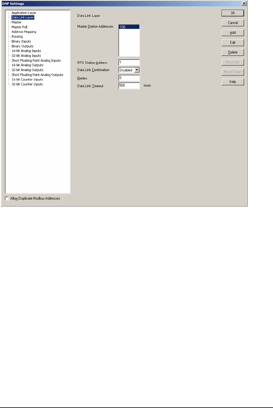
Data Link Layer parameters are set in this property page. Each parameter is described in the
following paragraphs.
The Master Station Addresses list box contains a list of Master station addresses that the
SCADAPack controller will respond to. The default list contains one master address of 100. This
address may be edited, or changed, and up to 8 master stations may be added to the list. Valid entries
for Master Station Addresses are 0 to 65519.
• When a master station polls for event data, the controller will respond with any events that have
not yet been reported to that master station.
• When an unsolicited response becomes due, it will be sent to each configured master station in
turn. A complete unsolicited response message transaction, including retries, will be sent to the
first configured master station. When this transaction has finished, a complete unsolicited
response message transaction including retries will be sent to the next configured master station,
and so on for all the configured master stations.
• Change events will be retained in the event buffer until they have been successfully reported to
all configured master stations.
Select the Add button to enter a new address to the Master Station Address list. Selecting the Add
button opens the Add Master Station Address dialog. Up to 8 entries can be added to the table. An
error message is displayed if the table is full.
DNP3 User and Reference Manual
May 9, 2007
30

Select the Edit button to edit address in the Master Station Address list. Selecting the Edit button
opens the Edit Master Station Address dialog. The button is disabled if there are no entries in the
list.
The Master Station Address edit box specifies the Master Station Address. Enter any valid Station
address from 0 to 65519.
• The OK button adds the Master Station Address to the list and closes the dialog. An error is
displayed if the Master Station Address is invalid, if the address is already in the list, or if the
address conflicts with the RTU station address.
• The Cancel button closes the dialog without making any changes.
The RTU Station Address parameter specifies the address of this RTU. It is the source address used
by this DNP driver when communicating with a master station. Each DNP station in a network must
have a unique address, including the Master station. Valid entries for RTU Station Address are 0 to
65519.
The Data Link Confirmation parameter specifies whether or not the RTU requests the underlying
data link transmitting its response to use a high quality service, which generally means that the data
link requires the receiving data link to confirm receipt of all messages.
The Retries parameter specifies the maximum number of times the data link layer will retry sending
a message to the master station. This parameter is only used when responding to a request from a
Master station, when there is no corresponding entry in the Routing dialog for that station. This is
independent of the application layer retries. The valid values for this parameter are 0 - 255. Setting
the value to 0 disables sending retries.
Note: Using data link layer Confirmation and Retries is inherently less efficient than application
layer Confirmation and Retries. Each fragment sent by the Application layer may require as
many as 10 data link layer frames to be sent, each with its own confirmation message. The
data link layer is typically not used for message confirmation for this reason.
The Data Link Timeout parameter specifies the expected time duration that the master station's data
link layer requires to process and respond to a message from the RTUs data link layer. It is used by
the RTU in setting its time-out interval for master station responses. This value should be large
enough to prevent response time-outs. The value must be kept small enough so as not to degrade
system throughput. The value of this element is dependent on the master station. It is expressed in
milliseconds. Valid values are 10 to 60000 milliseconds. The default value is 500 milliseconds.
• Click the OK button to accept the configuration changes and close the DNP Settings dialog.
• Click the Cancel button to close the dialog without saving any changes.
• Click the Delete button to remove the selected rows from the list. This button is disabled if there
are no entries in the list.
DNP3 User and Reference Manual
May 9, 2007
31
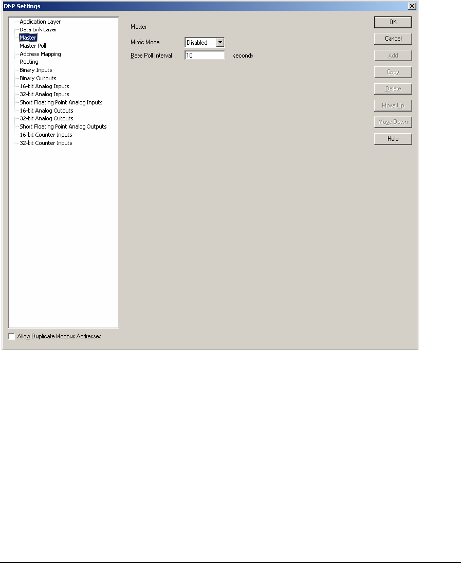
The Allow Duplicate Modbus Addresses checkbox determines if the Modbus I/O database
addresses assigned to the DNP data points must be unique. Check this box if you want to allow more
than one point to use the same Modbus address.
5.3 Master
The Master property page is selected for editing by clicking Master in the tree control section of the
DNP Settings window. This selection is only visible if the controller type is SCADAPack 350,
SCADAPack 32 or SCADAPack 32P. These controllers support DNP Master. When selected the
Master Application Link Layer property page is active.
Master parameters are set in this property page. Each parameter is described in the following
paragraphs.
The Mimic Mode parameter specifies the DNP Mimic Mode. The valid selections are Enable or
Disable. When DNP Mimic Mode is enabled the controller will intercept DNP messages destined for
a remote DNP station address, and will respond directly, as though the controller were the designated
target. For read commands, the controller will respond with data from its Remote DNP Objects
corresponding with the intended target address. For write commands, the controller will write data
into its Remote DNP Objects, and issue a direct response to acknowledge the command. It will then
issue a new command to write the data to the designated target. See Section 3.3-DNP Mimic Mode
section for an explanation of the concept around Mimic Mode. The default selection is Disabled.
The Base Poll Interval parameter is the base interval (in seconds) for polling slave devices. The poll
rates and issuing time synchronisation will be configured in multiples of the base poll interval. The
DNP3 User and Reference Manual
May 9, 2007
32
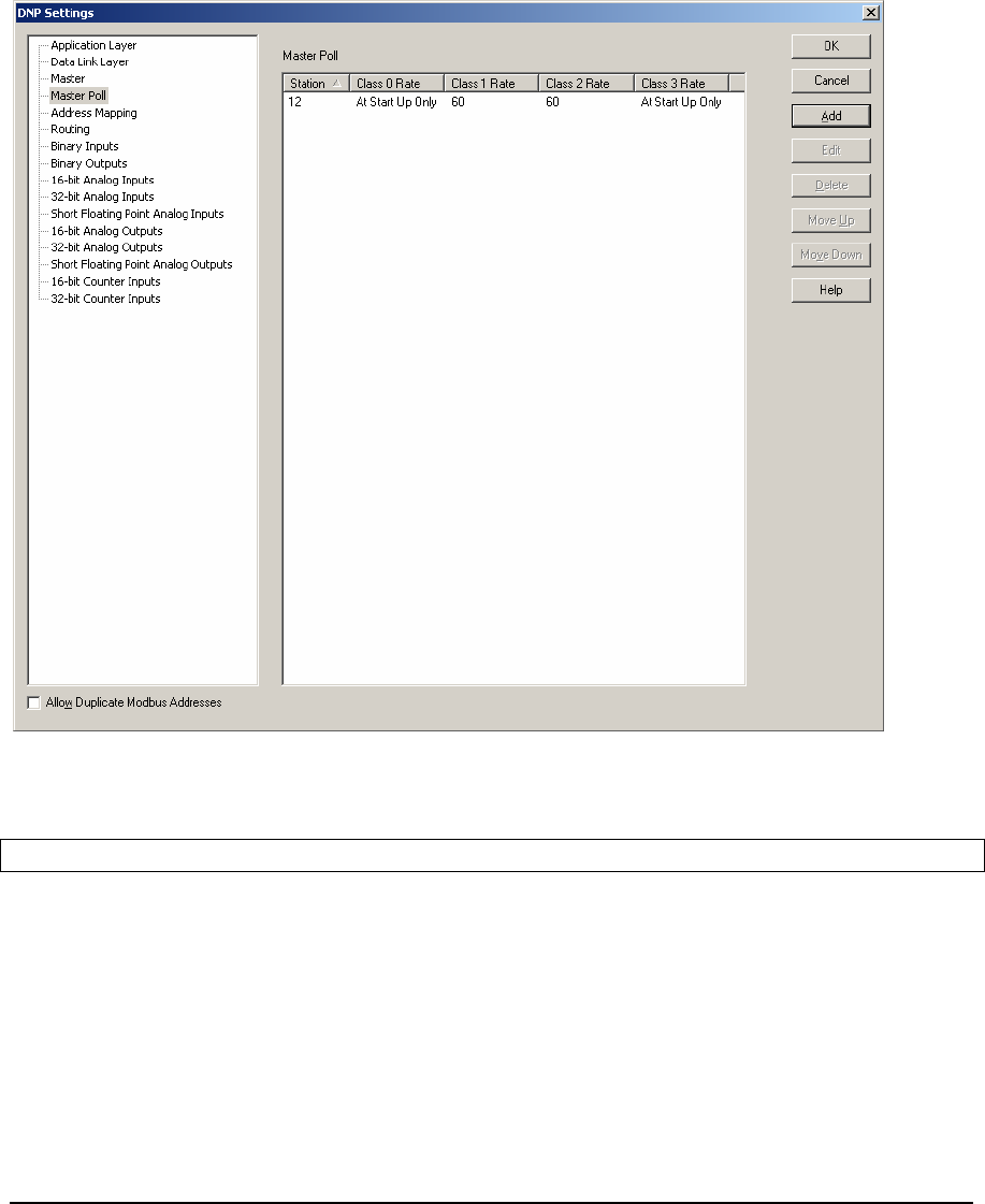
slave devices with the same poll rates will be polled in the order they appear in the poll table. The
valid values for this parameter are 1 to 65535. The default value is 10 seconds.
5.4 Master Poll
The Master Poll property page is selected for editing by clicking Master Poll in the tree control
section of the DNP Settings window. This selection is only visible if the controller type is a
SCADAPack 350, SCADAPack 32 or SCADAPack 32P. These controllers support DNP Master.
When selected the Master Poll property page is active and button Copy is renamed to Edit.
The Master Poll displays slave devices to be polled by this master station as a row, with column
headings, in the table. The table may have up to 1000 entries. A vertical scroll bar is used if the list
exceeds the window size.
Note: All slave devices in the Master Poll table need to be added to the Routing table.
The Station column displays the address of the DNP slave device to be polled. Each entry in the
table should have unique DNP Station Address.
The Class 0 Rate column displays the rate of polling for Class 0 data, as a multiple of the base poll
interval.
The Class 1 Rate column displays the rate of polling for Class 1 data, as a multiple of the base poll
interval.
DNP3 User and Reference Manual
May 9, 2007
33

The Class 2 Rate column displays the rate of polling for Class 2 data, as a multiple of the base poll
interval.
The Class 3 Rate column displays the rate of polling for Class 3 data, as a multiple of the base poll
interval.
• The OK button saves the table data and closes the DNP Settings dialog.
• The Cancel button closes the dialog without saving changes.
Select the Add button to enter a new row in the Master Poll. Selecting the Add button opens the
Add/Edit Master Poll dialog.
Select the Edit button to modify the selected row in the Master Poll. Selecting the Edit button opens
the Add/Edit Master Poll dialog containing the data from the selected row. This button is disabled
if more than one row is selected or if there are no entries in the table.
The Delete button removes the selected rows from the table. This button is disabled if there are no
entries in the table.
The Allow Duplicate Modbus Addresses checkbox determines if the Modbus I/O database
addresses assigned to the DNP data points must be unique. Check this box if you want to allow more
than one point to use the same Modbus address.
Click on the column headings to sort the data. Clicking once sorts the data in ascending order.
Clicking again sorts the data in descending order.
5.4.1 Add/Edit Master Poll Dialog
This dialog is used to edit an entry or add a new entry in the Master Poll.
DNP3 User and Reference Manual
May 9, 2007
34
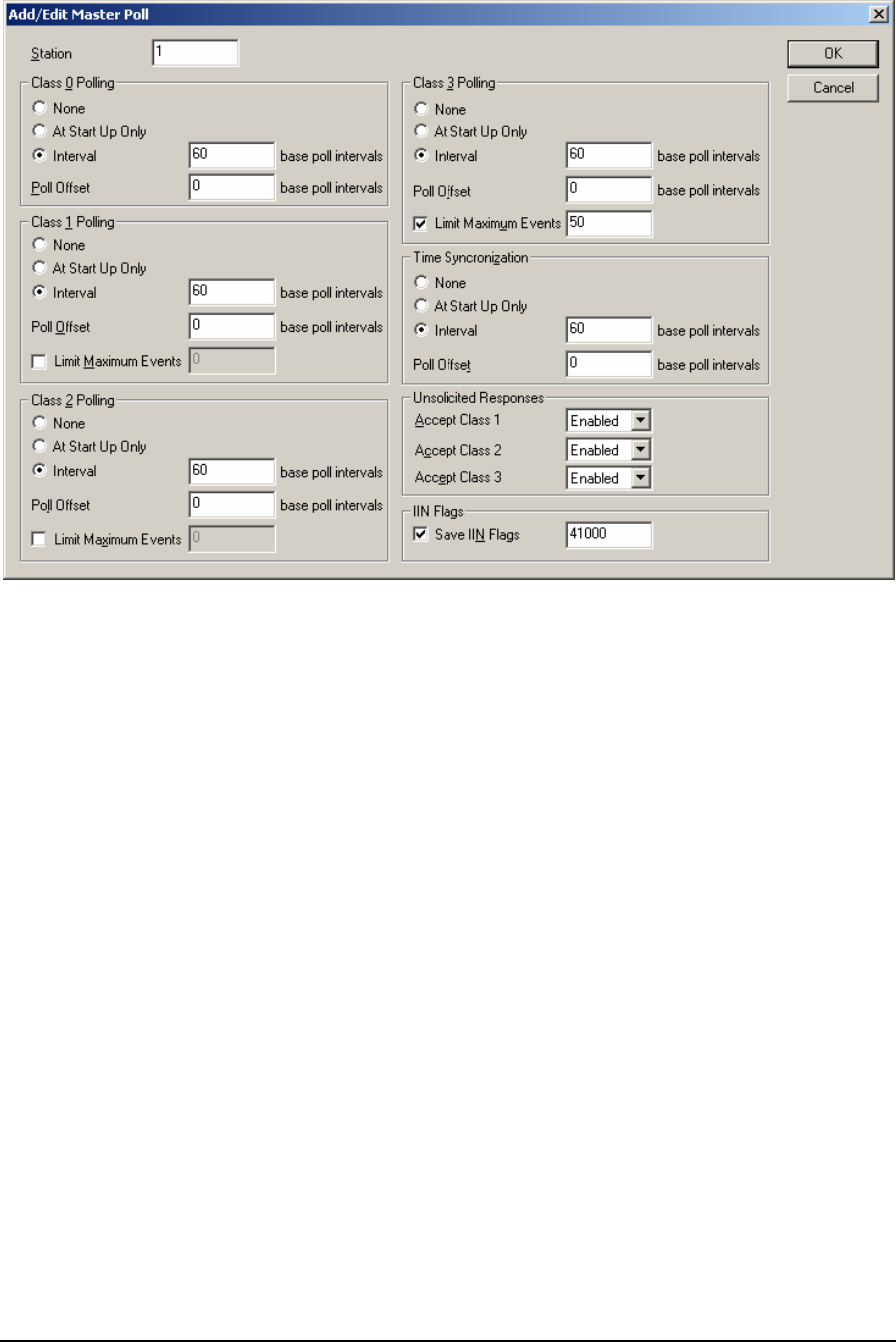
The Station edit control displays the address of the DNP slave device to be polled. Valid values are
0 to 65519.
The Class 0 Polling section of the dialog specifies the type and rate of polling for Class 0 data.
• The None selection disables class 0 polling for the slave station. This is the default selection.
• The At Start Up Only selection will cause the master to poll the slave station at startup only.
• The Interval selection will cause the master to poll the slave station at startup and then every
Interval of the base poll interval. For example if the base poll interval is 60 seconds and the
Interval parameter is set to 60 then the master will poll the slave station every hour. Valid values
are 1 to 32767. The default value is 60.
• The Poll Offset parameter is used to distribute the load on the communication network. The Poll
Offset is entered in multiples of the base poll interval. Valid values for this parameter are 0 to the
Poll Interval value minus 1. Any non-zero value delays the start of polling for the specified
objects by that amount. The default value is 0. This control is disabled when None is selected,
and enabled otherwise. For an example of using the Poll Offset parameter see the Poll Offset
Example at the end of this section.
The Class 1 Polling section of the dialog specifies the type and rate of polling for Class 1 data.
• The None selection disables class 1 polling for the slave station. This is the default selection.
• The At Start Up Only selection will cause the master to poll the slave station at startup only.
• The Interval selection will cause the master to poll the slave station at startup and then every
Interval of the base poll interval. For example if the base poll interval is 60 seconds and the
Interval parameter is set to 60 then the master will poll the slave station every hour. Valid values
are 1 to 32767. The default value is 60.
DNP3 User and Reference Manual
May 9, 2007
35

• The Poll Offset parameter is used to distribute the load on the communication network. The Poll
Offset is entered in multiples of the base poll interval. Valid values for this parameter are 0 to the
Poll Interval value minus 1. Any non-zero value delays the start of polling for the specified
objects by that amount. The default value is 0. This control is disabled when None is selected,
and enabled otherwise. For an example of using the Poll Offset parameter see the Poll Offset
Example at the end of this section.
• Limit Maximum Events allows limiting the number of events in poll responses for Class 1/2/3
data. The checkbox is not checked by default, meaning there is no limit on the number of events.
Select the checkbox to specify a limit. The valid values for this parameter are 1 to 65535. The
default value is 65535. This control is disabled when None is selected, and enabled otherwise.
The Maximum Events parameter can be used to manage communication load on a system.
Consider the example of a master polling some data logging remotes, and the case where one of
the remotes has been offline for a long time. The remote will have built up a large number of
buffered events. If the master polled it for all events, the reply might take a long time, and cause
an unwanted delay in the master's polling cycle. However if the master limits the number of
events returned, the reply message duration will be more deterministic and the master can ensure
its poll loop timing is maintained. In this case, the event retrieval from the data logger will be
distributed over a number of poll cycles.
The Class 2 Polling section of the dialog specifies the type and rate of polling for Class 2 data.
• The None selection disables class 1 polling for the slave station. This is the default selection.
• The At Start Up Only selection will cause the master to poll the slave station at startup only.
• The Interval selection will cause the master to poll the slave station at startup and then every
Interval of the base poll interval. For example if the base poll interval is 60 seconds and the
Interval parameter is set to 60 then the master will poll the slave station every hour. Valid values
are 1 to 32767. The default value is 60.
• The Poll Offset parameter is used to distribute the load on the communication network. The Poll
Offset is entered in multiples of the base poll interval. Valid values for this parameter are 0 to the
Poll Interval value minus 1. Any non-zero value delays the start of polling for the specified
objects by that amount. The default value is 0. This control is disabled when None is selected,
and enabled otherwise. For an example of using the Poll Offset parameter see the Poll Offset
Example at the end of this section.
• Limit Maximum Events allows limiting the number of events in poll responses for Class 1/2/3
data. The checkbox is not checked by default, meaning there is no limit on the number of events.
Select the checkbox to specify a limit. The valid values for this parameter are 1 to 65535. The
default value is 65535. This control is disabled when None is selected, and enabled otherwise.
The Maximum Events parameter can be used to manage communication load on a system.
Consider the example of a master polling some data logging remotes, and the case where one of
the remotes has been offline for a long time. The remote will have built up a large number of
buffered events. If the master polled it for all events, the reply might take a long time, and cause
an unwanted delay in the master's polling cycle. However if the master limits the number of
events returned, the reply message duration will be more deterministic and the master can ensure
its poll loop timing is maintained. In this case, the event retrieval from the data logger will be
distributed over a number of poll cycles.
The Class 3 Polling section of the dialog specifies the type and rate of polling for Class 3 data.
• The None selection disables class 1 polling for the slave station. This is the default selection.
DNP3 User and Reference Manual
May 9, 2007
36

• The At Start Up Only selection will cause the master to poll the slave station at startup only.
• The Interval selection will cause the master to poll the slave station at startup and then every
Interval of the base poll interval. For example if the base poll interval is 60 seconds and the
Interval parameter is set to 60 then the master will poll the slave station every hour. Valid values
are 1 to 32767. The default value is 60.
• The Poll Offset parameter is used to distribute the load on the communication network. The Poll
Offset is entered in multiples of the base poll interval. Valid values for this parameter are 0 to the
Poll Interval value minus 1. Any non-zero value delays the start of polling for the specified
objects by that amount. The default value is 0. This control is disabled when None is selected,
and enabled otherwise. For an example of using the Poll Offset parameter see the Poll Offset
Example at the end of this section.
• Limit Maximum Events allows limiting the number of events in poll responses for Class 1/2/3
data. The checkbox is not checked by default, meaning there is no limit on the number of events.
Select the checkbox to specify a limit. The valid values for this parameter are 1 to 65535. The
default value is 65535. This control is disabled when None is selected, and enabled otherwise.
The Maximum Events parameter can be used to manage communication load on a system.
Consider the example of a master polling some data logging remotes, and the case where one of
the remotes has been offline for a long time. The remote will have built up a large number of
buffered events. If the master polled it for all events, the reply might take a long time, and cause
an unwanted delay in the master's polling cycle. However if the master limits the number of
events returned, the reply message duration will be more deterministic and the master can ensure
its poll loop timing is maintained. In this case, the event retrieval from the data logger will be
distributed over a number of poll cycles.
The Time Synchronization Rate section of the dialog specifies the rate of issuing a time
synchronization to this device, as a multiple of the base poll interval. Valid selections for this
parameter are:
• The None selection will disable issuing a time sync to this device. This is the default selection.
• The At Start Up Only selection will cause issuing a time synchronization at startup only.
• The Interval selection will cause the RTU to issue a time synchronization at startup and then
every Interval of the base poll interval seconds. Valid entries for Interval are between 1 and
32767 the base poll interval seconds. The default value is 60.
The Unsolicited Responses section is used in conjunction with the Enable Unsolicited Responses on
Start Up parameter on the Application Layer page. Certain non-SCADAPack slave devices are
designed to start with their Enable Unsolicited Responses on Start Up parameter set to No. Selecting
Enabled for any class causes the master to (after it detects the slave come online) send a command
allowing the slave to begin sending Unsolicited Responses of that class.
With SCADAPack slaves the Enable Unsolicited Responses on Start Up parameter may be set to
Yes, and the Accept Class parameters may be left at Disabled.
• The Accept Class 1 selection displays the enable/disable status of unsolicited responses from the
slave device for Class 1 events. The default selection is disabled.
• The Accept Class 2 selection displays the enable/disable status of unsolicited responses from the
slave device for Class 1 events. The default selection is disabled.
• The Accept Class 3 selection displays the enable/disable status of unsolicited responses from the
slave device for Class 1 events. The default selection is disabled.
DNP3 User and Reference Manual
May 9, 2007
37

The Save IIN Flags checkbox enables storing the IIN (Internal Indications) flags from the slave
station in a Modbus database register. When this parameter is checked the IIN flags are saved to the
entered Modbus register address. Valid entries are Modbus register addresses 30001 to 39999 and
40001 to 49999. The default value is 0.
The IIN flags are set by the slave to indicate the events in the following table. The events are bit
mapped to the Modbus register. All bits except Device Restarted and Time Synchronization required
are cleared when the slave station receives any poll or read data command. The master will write to
bits 5 and 11 depending on the local conditions in the master.
Bit Description
0 last received message was a broadcast message
1 Class 1 data available
2 Class 2 data available
3 Class 3 data available
4 Time Synchronization required
5 not used (returns 0)
6 Device trouble
Indicates memory allocation error in the slave, or
For master in mimic mode indicates communication failure with the slave
device.
7 Device restarted (set on a power cycle)
8 Function Code not implemented
9 Requested object unknown or there were errors in the application data
10 Parameters out of range
11 Event buffer overflowed
Indicates event buffer overflow in the slave or master. The slave will set this
bit if the event buffer in the slave is overflowed. The master will set this bit if
the event buffer in the master has overflowed with events read from the
slave. Ensure the event buffer size, in the master and slave, is set to a value
that will ensure the buffer does not overflow and events are lost.
12 not used (returns 0)
13 not used (returns 0)
14 not used (returns 0)
15 not used (returns 0)
The OK button checks the data for this table entry. If the data is valid the dialog is closed. If the
table data entered is invalid, an error message is displayed and the dialog remains open. The table
entry is invalid if any of the fields is out of range. The data is also invalid if it conflicts with another
entry in the table. Such conflict occurs when the station number is not unique. The ordering of items
in this table is important.
The Cancel button closes the dialog without saving changes.
5.4.2 Poll Offset Example
The Poll Offset parameter enhances the control over timing of master poll messages, by allowing
master poll messages to be staggered.
For example, a master station may have 10 slaves to poll, and must poll them every hour. If these are
included in the poll table without any poll offset, they will all be polled in quick succession on the
hour – resulting in a large burst of communication activity once per hour. On some types of
DNP3 User and Reference Manual
May 9, 2007
38
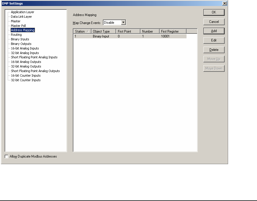
communications networks (particularly radio) it is desirable to distribute communication load more
evenly, to minimize the chance of collisions and to avoid the possibility of consuming bandwidth
continuously for an extended period of time.
The poll offset parameter enables you to distribute the communication load evenly. In the above
example, it is possible to stagger the master polls so slave stations are polled at 6-minute intervals.
To do this, set the base poll interval to 6 minutes, and for each slave station set the poll rate and poll
offset parameters as follows:
Base Poll Poll Rate Poll Offset
6 10 0
6 10 1
6 10 2
6 10 3
6 10 4
6 10 5
6 10 6
6 10 7
6 10 8
6 10 9
5.5 Address Mapping
The Address Mapping property page is selected for editing by clicking Address Mapping in the tree
control section of the DNP Settings window. This selection is only visible if the controller type is a
SCADAPack 350, SCADAPack 32 or SCADAPack 32P. These controllers support DNP Master.
The Address Mapping contains a set of mapping rules, which will allow the Remote DNP Objects to
be mapped into local Modbus registers. This makes the data accessible locally, to be read and/or
DNP3 User and Reference Manual
May 9, 2007
39

written locally in logic. It is also possible to perform data concentration – to map the remote DNP
Objects into the local DNP address space – by defining local DNP objects and then mapping the
remote DNP objects to the same Modbus registers. Change events can also be mapped in the same
way - there is a configuration option to allow mapping of change events from a remote DNP slave
into the local DNP change event buffer. The table may have up to 1000 entries. See the DNP
Address Mapping section for further information. A vertical scroll bar is used if the list exceeds the
window size.
The Station column displays the address of the remote DNP station.
The Object Type column displays the DNP data object type.
The First Point column displays the starting address of the remote DNP data points.
The Number column displays the number of remote points to be mapped.
The First Register column displays the starting address of local Modbus register where the remote
data points are to be mapped.
The Map Change Events combo box enables or disables mapping of change events from a remote
DNP slave into the local DNP change event buffer. Mapped change events may trigger an
Unsolicited message to be sent, after the Hold Count or Hold Time is reached. It may be desired
instead to map only static (live) values into local Modbus registers. The default selection is Disabled.
The default selection is Disabled.
The OK button saves the table data. No error checking is done on the table data.
The Cancel button closes the dialog without saving changes.
Select the Add button to enter a new row in the Address Mapping. Selecting the Add button opens
the Add/Edit Address Mapping dialog.
Select the Edit button to modify the selected row in the Address Mapping. Selecting the Edit button
opens the Add/Edit Address Mapping dialog containing the data from the selected row. This button
is disabled if more than one row is selected. This button is disabled if there are no entries in the table.
The Delete button removes the selected rows from the table. This button is disabled if there are no
entries in the table.
The Allow Duplicate Modbus Addresses checkbox determines if the Modbus I/O database
addresses assigned to the DNP data points must be unique. Check this box if you want to allow more
than one point to use the same Modbus address.
Click on the column headings to sort the data. Clicking once sorts the data in ascending order.
Clicking again sorts the data in descending order.
5.5.1 Add/Edit Address Mapping Dialog
This dialog is used to edit an entry or add a new entry in the Address Mapping.
DNP3 User and Reference Manual
May 9, 2007
40

The Station edit control displays the address of the remote DNP station. Valid values for this field
are from 0 to 65519.
The Object Type combo box displays the DNP data Object Type. The list of available types
includes: Binary Input, Binary Output, 16-bit Analog Input, 32-bit Analog Input, Short Floating
Point Analog Input, 16-bit Analog Output, 32-bit Analog Output, Short Floating Point Analog
Output, 16-bit Counter Input, 32-bit Counter Input. The Default selection is Binary Input.
The First Point edit control displays the starting address of the remote DNP data points. Valid
values are from 0 to 65519.
The Number edit control displays the number of remote points to be mapped. Valid values for this
field are from 1 to 9999.
The First Register edit control displays the starting address of local Modbus register where the
remote data points are to be mapped. Valid values depend on the selection of DNP Object Type and
are as follows:
For Binary Inputs valid range is from 10001 to 14096.
For Binary Outputs valid range is from 00001 to 04096.
For Analog Inputs and Counter Inputs valid range is from 30001 to 39999.
For Analog Outputs valid range is from 40001 to 49999.
The OK button checks the data for this table entry. If the data is valid the dialog is closed. If the
table data entered is invalid, an error message is displayed and the dialog remains open. The table
entry is invalid if any of the fields is out of range. The data is also invalid if it conflicts with another
entry in the table. Such conflict occurs when the combination of station number, object type, and
object address is not unique. The ordering of items in this table is not important.
The Cancel button closes the dialog without saving changes.
5.6 Routing
In a typical application the SCADAPack controller, configured for DNP, will act as a DNP slave
station in a network. The SCADA system will communicate directly with all the DNP slave stations
in the SCADA system.
DNP routing is a method for routing, or forwarding, of messages received from the SCADA system,
through the SCADAPack controller, to a remote DNP slave station. The SCADAPack DNP slave
station will respond to all messages sent to it from the SCADA system, as well as broadcast
messages. When it receives a message that is not sent to it the message is sent on the serial port
defined in the routing table. See section 3.4-DNP Routing for an explanation of using and
configuring DNP Routing.
DNP3 User and Reference Manual
May 9, 2007
41
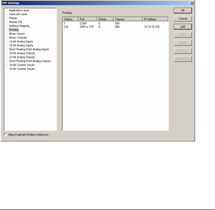
The advantage of this routing ability is that the SCADA system can communicate directly with the
SCADAPack controller and the SCADAPack controller can handle the communication to remote
DNP slave stations.
The DNP Routing table displays each routing translation as a row, with column headings, in the
table. Entries may be added, edited or deleted using the button selections on the table. The table will
hold a maximum of 128 entries.
The DNP Routing property page is selected for editing by clicking DNP Routing in the tree control
section of the DNP Settings window. When selected the DNP Routing property page is displayed.
Notes:
• Routing must be enabled for the controller serial port in order to enable DNP routing.
• TelePACE version 2.63 cannot open files created with version 2.64, unless the Routing table is
empty.
• TelePACE version 2.64 cannot open files created with version 2.65, unless the Routing table is
empty.
The Station column displays the address of the remote DNP station.
The Port column displays the serial communications port, which should be used to communicate
with this DNP station.
The Retries column displays the maximum number of Data Link retries, which should be used for
this DNP station in the case of communication errors.
The Timeout column displays the maximum time (in milliseconds) to wait for a Data Link response
before retrying or failing the message.
DNP3 User and Reference Manual
May 9, 2007
42
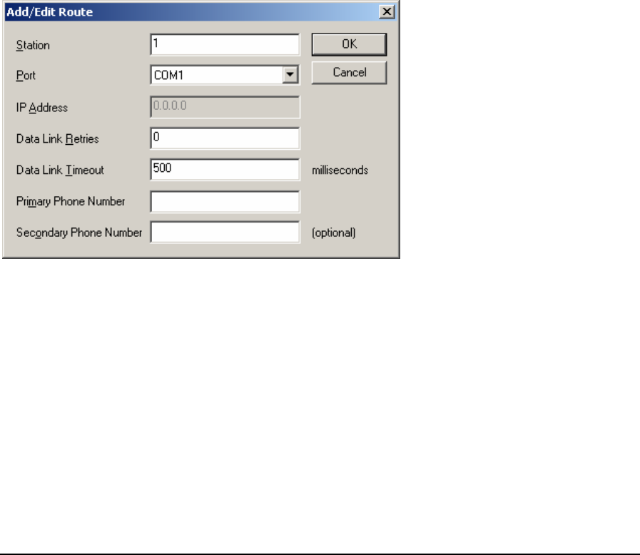
The IP Address column displays the IP address of the remote DNP station.
The OK button saves the table data. No error checking is done on the table data.
The Cancel button closes the dialog without saving changes.
Select the Add button to enter a new row in the DNP Routing table. Selecting the Add button opens
the Add/Edit DNP Route dialog.
Select the Edit button to modify the selected row in the DNP Routing table. Selecting the Edit button
opens the Add/Edit DNP Route dialog containing the data from the selected row. This button is
disabled if more than one row is selected. This button is disabled if there are no entries in the table.
The Delete button removes the selected rows from the table. This button is disabled if there are no
entries in the table.
The Allow Duplicate Modbus Addresses checkbox determines if the Modbus I/O database
addresses assigned to the DNP data points must be unique. Check this box if you want to allow more
than one point to use the same Modbus address.
Click on the column headings to sort the data. Clicking once sorts the data in ascending order.
Clicking again sorts the data in descending order.
5.6.1 Add/Edit DNP Route Dialog
This dialog is used to edit an entry or add a new entry in the DNP Routing table.
The Station edit control displays the address of the remote DNP station. Valid values for this field
are from 0 to 65519.
The Port combo box displays the communications port, which should be used to communicate with
the remote DNP station. This combo box contains list of the valid communications ports, which will
depend on the type of controller. For SCADAPack 350, SCADAPack 32 and SCADAPack 32P
controllers the list will contain DNP in TCP and DNP in UDP in addition to the serial port
designations, COM1, COM2 etc.
The IP Address edit control is only enabled if the controller type is a SCADAPack 350,
SCADAPack 32 or SCADAPack 32P. Enter the IP address of the remote DNP station.
The Data Link Retries edit control displays the maximum number of Data Link retries which
should be used for this DNP station in the case of communication errors. This field overrides the
DNP3 User and Reference Manual
May 9, 2007
43

Data Link Retries field in the global DNP parameters set in the Data Link Layer configuration. Valid
values for this field are 0 to 255.
The Data Link Timeout edit control displays the maximum time (in milliseconds) to wait for a Data
Link response before retrying or failing the message. This field overrides the Data Link Timeout
field in the global DNP parameters in the Data Link Layer configuration. Valid values for this field
are 100 to 60000, in multiples of 100.
The phone number parameters allow automatic dialing for stations that use dial-up ports. The Phone
Number parameters are enabled only when the Port selected is a serial port.
The Primary Phone Number is the dialing string that will be used for the primary connection to the
station. The controller will make 1 or more attempts, as configured in the Application layer, to
connect using this number. If this connection fails then the Secondary Phone Number will be dialed,
if it is entered.
Valid values are any ASCII string. The maximum length is 32 characters. Leave this blank if you are
not using a dial-up connection. The default value is blank. The serial port type must be set to RS-232
Modem for dial-up operation.
The Secondary Phone Number is the dialing string that will be used for the secondary connection
to the station. The controller will make 1 or more attempts, as configured in the Application layer, to
connect using this number. This number is used after the primary connection fails on all attempts.
Valid values are any ASCII string. The maximum length is 32 characters. Leave this blank if you are
not using a dial-up connection. The default value is blank. The serial port type must be set to RS-232
Modem for dial-up operation.
The OK button checks the data for this table entry. If the data is valid the dialog is closed. If the
table data entered is invalid, an error message is displayed and the dialog remains open. The table
entry is invalid if any of the fields is out of range. The data is also invalid if it conflicts with another
entry in the table.
The Cancel button closes the dialog without saving changes.
5.6.2 Dynamic Routing
In addition to the configured routing table, there is an internal dynamic routing entry. This entry is
not shown in the routing table. The dynamic routing entry listens to incoming messages and learns
the address of the remote station and the communication port used for communicating with it.
If there is no entry in the routing table, the RTU will use the dynamic routing entry to respond to a
message on the same communication port as the incoming message.
The dynamic routing entry is not cleared on initialization. This is deliberate, and is important for
controllers that need to be remotely reconfigured. In this case the host can initialize the controller
without losing the communications link.
Note: Dynamic routing should not be used in a master station. Configure all slave stations in the
routing table.
5.7 Binary Inputs Configuration
The Binary Inputs property page is selected for editing by clicking Binary Inputs in the tree control
section of the DNP Settings window. When selected the Binary Inputs property page is active.
DNP3 User and Reference Manual
May 9, 2007
44
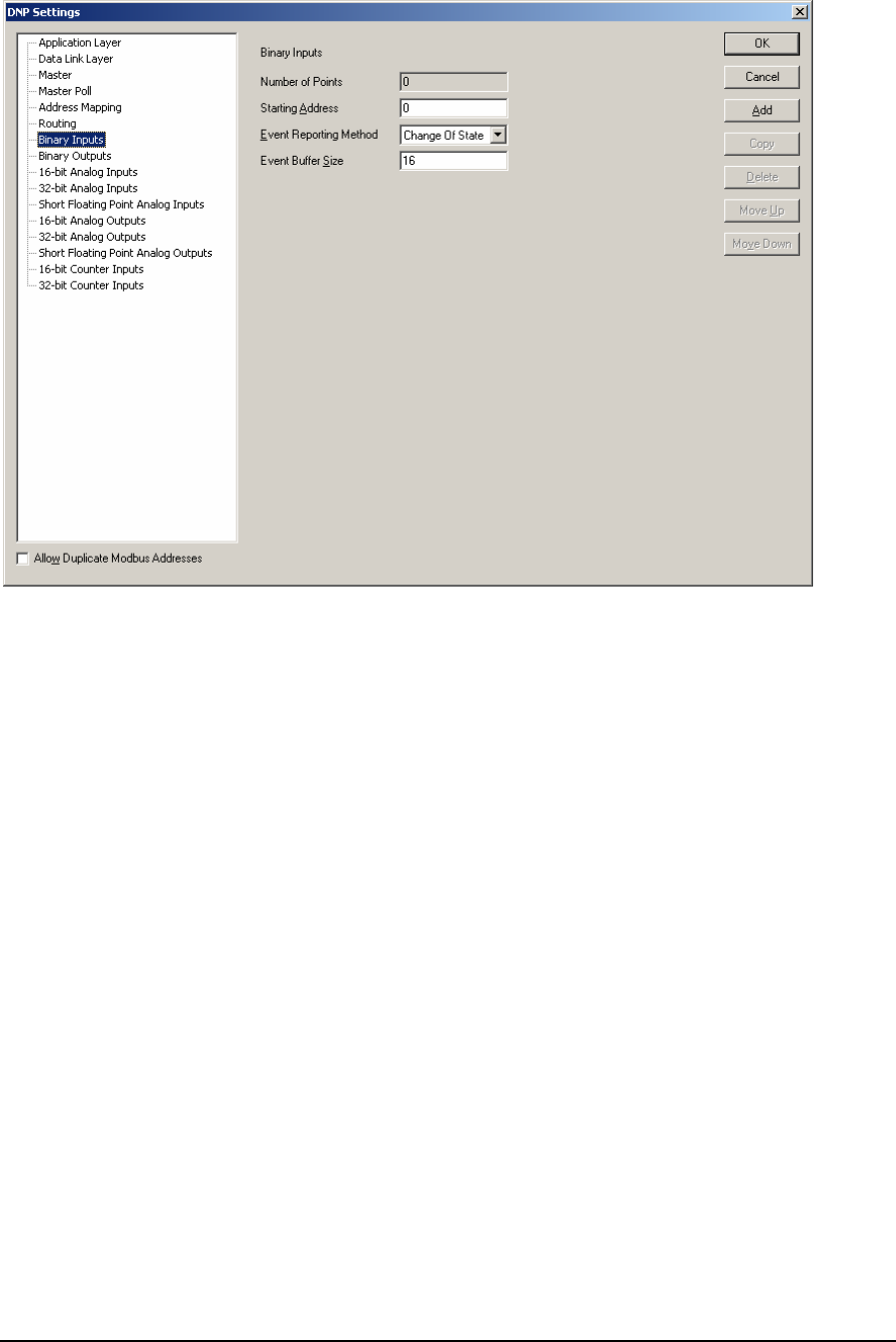
Binary Inputs parameters are set in this property page. Each parameter is described in the following
paragraphs.
The Number of Points displays number of binary inputs reported by this RTU. This value will
increment with the addition of each configured Binary Input point. The maximum number of points
is 9999. The maximum number of actual points will depend on the memory available in the
controller.
The Starting Address parameter specifies the starting DNP address of the first Binary Input point.
The Event Reporting Method selection specifies how binary input events are reported. A Change
Of State event is an event object, without time, that is generated when the point changes state. Only
one event is retained in the buffer for each point. If a subsequent event occurs for a point, the
previous event object will be overwritten. The main purpose of this mode is to allow a master station
to efficiently poll for changed data. A Log All Events is event object with absolute time will be
generated when the point changes state. All events will be retained. The main purpose of this mode is
to allow a master station to obtain a complete historical data log. The selections are:
• Change of State
• Log All Events
The Event Buffer Size is the maximum number of binary input change events, which can be
buffered by the DNP driver. The buffer holds all binary input change events, regardless of the class
to which they are assigned. If the buffer fills to 90 percent the RTU will send a buffer overflow event
to the master station. If the buffer is completely full the RTU will lose the oldest events and retain
the newest. The size of the event buffer should be at least equivalent to the number of Binary Inputs
defined with a Class. This will allow all Binary Inputs to change simultaneously without losing any
events. The value of this parameter is dependent on how often change events occur and the rate at
DNP3 User and Reference Manual
May 9, 2007
45
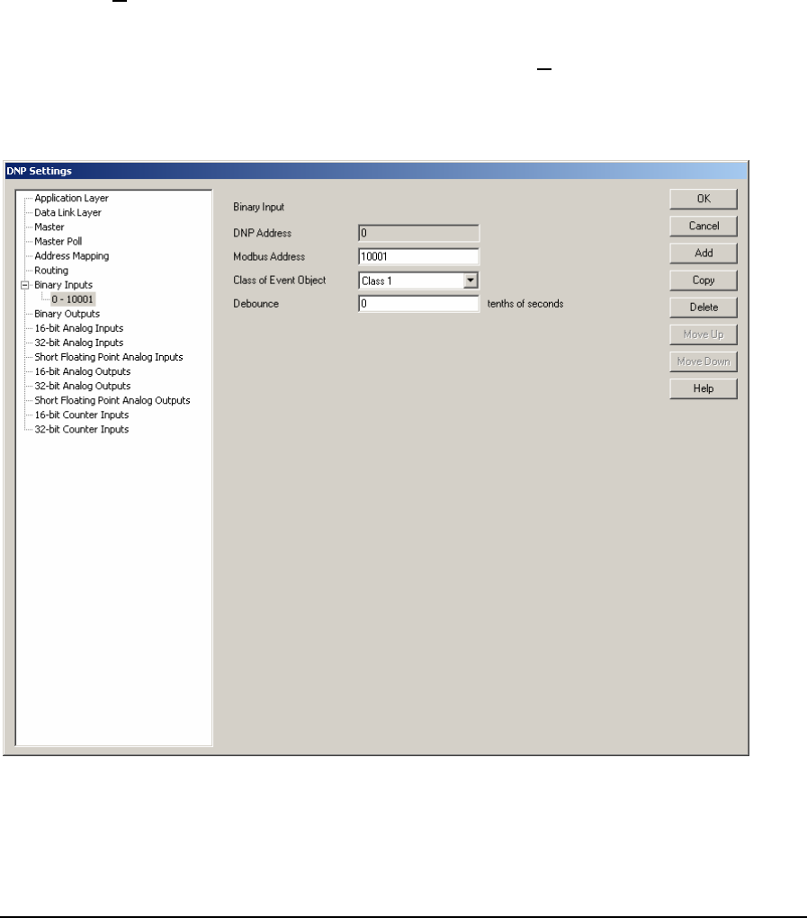
which the events are reported to the master station. The valid values for this parameter are 0 - 65535.
Default value is 16.
The Allow Duplicate Modbus Addresses checkbox determines if the Modbus I/O database
addresses assigned to the DNP data points must be unique. Check this box if you want to allow more
than one point to use the same Modbus address.
5.7.1 Adding Binary Inputs
Binary Inputs are added to the DNP configuration using the Binary Input property page. To add a
Binary Input:
• Select Binary Inputs in the tree control section of the DNP Settings window.
• Click the Add button in the Binary Inputs property page.
• The Binary Input property page is now displayed.
• Edit the Binary Input parameters as required and then click the Add button.
As Binary Inputs are defined they are added as leaves to the Binary Inputs branch of the tree control.
When Binary Inputs are defined the Binary Inputs branch will display a collapse / expand control to
the left of the branch. Click this control to display all defined Binary Inputs.
The Binary Input parameters are described in the following paragraphs.
The DNP Address window displays the DNP Binary Input address of the point. Each Binary Input is
assigned a DNP address as they are defined. The DNP point address starts at the value defined in the
Binary Inputs configuration dialog and increments by one with each defined Input.
DNP3 User and Reference Manual
May 9, 2007
46

The Modbus Address parameter specifies the Modbus address of the Binary Input assigned to the
DNP Address. The SCADAPack and Micro16 controllers use Modbus addressing for all digital
inputs. Refer to the I/O Database Registers section of the TelePACE Ladder Logic Reference and
User Manual for complete information on digital input addressing in the SCADAPack and Micro16
controllers. Valid Modbus addresses are:
• 00001 through 09999
• 10001 through 19999
The Class of Event Object parameter specifies the event object class the Binary Input is assigned.
The selections are:
• None
• Class 1
• Class 2
• Class 3
The Debounce parameter limits the frequency of change events. The input must remain in the same
state for the debounce time for a change of state to be detected. Note that the input is sampled every
0.1s. Changes shorter than the sample time cannot be detected. Valid values are 0 to 65535 tenths of
seconds. The value 0 means no debounce. The default value is 0.
The Allow Duplicate Modbus Addresses checkbox determines if the Modbus I/O database
addresses assigned to the DNP data points must be unique. Check this box if you want to allow more
than one point to use the same Modbus address.
Click the OK button to accept the Binary Input parameters and close the DNP Settings dialog.
Click the Cancel button to close the dialog without saving any changes.
Click the Add button to add the current Binary Input to the DNP configuration.
Click the Copy button to copy the current Binary Input parameters to the next DNP Address.
Click the Delete button to delete the current Binary Input.
Click the Move Up button to move the current Binary Input up one position in the tree control
branch.
Click the Move Down button to move the current Binary Input down one position in the tree control
branch.
5.8 Binary Outputs Configuration
The Binary Outputs property page is selected for editing by clicking Binary Outputs in the tree
control section of the DNP Settings window. When selected the Binary Outputs property page is
active.
DNP3 User and Reference Manual
May 9, 2007
47
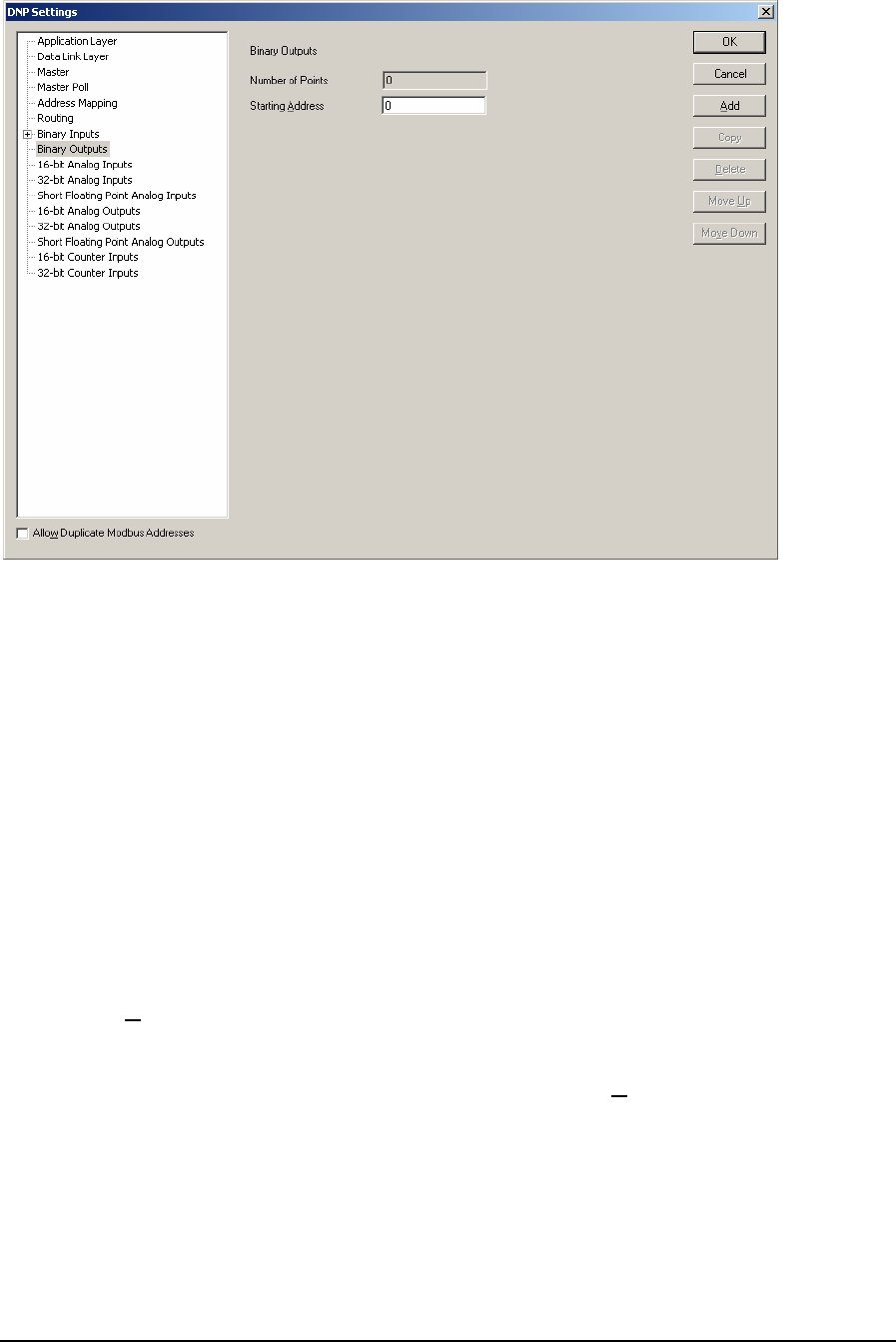
Binary Outputs parameters are viewed in this property page.
The Number of Points displays the number of binary outputs reported by this RTU. This value will
increment with the addition of each configured Binary Output point. The maximum number of points
is 9999. The maximum number of actual points will depend on the memory available in the
controller.
The Starting Address parameter specifies the starting DNP address of the first Binary Output point.
The Allow Duplicate Modbus Addresses checkbox determines if the Modbus I/O database
addresses assigned to the DNP data points must be unique. Check this box if you want to allow more
than one point to use the same Modbus address.
5.8.1 Adding Binary Outputs
Binary Outputs are added to the DNP configuration using the Binary Output property page. To add a
Binary Output:
• Select Binary Outputs in the tree control section of the DNP Settings window.
• Click the Add button in the Binary Outputs property page.
• The Binary Output property page is now displayed.
• Edit the Binary Output parameters as required and then click the Add button.
As Binary Outputs are defined they are added as leaves to the Binary Outputs branch of the tree
control. When Binary Outputs are defined the Binary Outputs branch will display a collapse / expand
control to the left of the branch. Click this control to display all defined Binary Outputs.
DNP3 User and Reference Manual
May 9, 2007
48
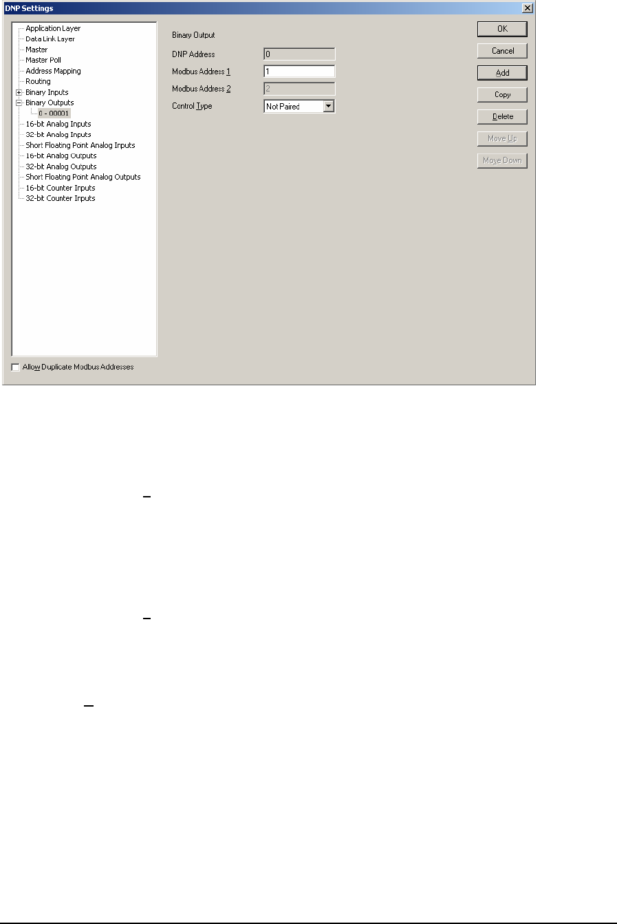
The Binary Output parameters are described in the following paragraphs.
The DNP Address window displays the DNP Binary Output address of the point. Each Binary
Output is assigned a DNP address as they are defined. The DNP point address starts at the value
defined in the Binary Outputs dialog and increments by one with each defined Output.
The Modbus Address 1 parameter specifies the Modbus address of the Binary Output assigned to
the DNP Address. The SCADAPack and Micro16 controllers use Modbus addressing for all digital
outputs. Refer to the I/O Database Registers section of the TelePACE Ladder Logic Reference
Manual for complete information on digital output addressing in the SCADAPack and Micro16
controllers. Valid Modbus addresses are:
• 00001 through 09999
The Modbus Address 2 parameter specifies the second Modbus address of the second Binary
Output assigned to the DNP Address when the Paired control type is selected. This selection is not
active when the control type is Not Paired. Valid Modbus addresses are:
• 00001 through 09999
The Control Type parameter specifies whether the Binary Output is a paired control or not. If it is a
paired control, i.e. trip/close output type, this means that the DNP address is associated to two
physical control outputs and requires two Modbus addresses per DNP address. Control type
selections are:
• Paired
• Not Paired
The Allow Duplicate Modbus Addresses checkbox determines if the Modbus I/O database
addresses assigned to the DNP data points must be unique. Check this box if you want to
allow more than one point to use the same Modbus address.
DNP3 User and Reference Manual
May 9, 2007
49
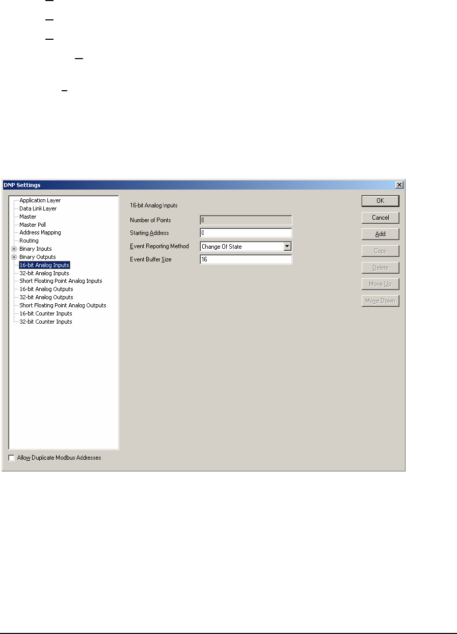
Click the OK button to accept the Binary Output parameters and close the DNP Settings dialog.
Click the Cancel button to close the dialog without saving any changes.
Click the Add button to add the current Binary Output to the DNP configuration.
Click the Copy button to copy the current Binary Output parameters to the next DNP Address.
Click the Delete button to delete the current Binary Output.
Click the Move Up button to move the current Binary Output up one position in the tree control
branch.
Click the Move Down button to move the current Binary Output down one position in the tree
control branch.
5.9 16–Bit Analog Inputs Configuration
The 16-Bit Analog Inputs property page is selected for editing by clicking 16-Bit Analog Inputs in
the tree control section of the DNP Settings window. When selected the 16-Bit Analog Inputs
property page is active.
16-Bit Analog Inputs parameters are set in this property page. Each parameter is described in the
following paragraphs.
The Number of Points displays the number of 16 bit analog inputs reported by the RTU. This value
will increment with the addition of each configured 16-Bit Analog Input point. The maximum
number of points is 9999. The maximum number of actual points will depend on the memory
available in the controller.
The Starting Address parameter specifies the DNP address of the first 16-bit Analog Input point.
DNP3 User and Reference Manual
May 9, 2007
50

The Event Reporting Method selection specifies how 16-bit Analog Input events are reported. A
Change Of State event is an event object, without time, that is generated when the point changes
state. Only one event is retained in the buffer for each point. If a subsequent event occurs for a point,
the previous event object will be overwritten. The main purpose of this mode is to allow a master
station to efficiently poll for changed data. A Log All Events event object with absolute time will be
generated when the point changes state. All events will be retained. The main purpose of this mode is
to allow a master station to obtain a complete historical data log. The selections are:
• Change of State
• Log All Events
The Event Buffer Size parameter specifies the maximum number of 16-Bit Analog Input change
without time events buffered by the RTU. The buffer holds all 16-Bit Analog Input events,
regardless of the class to which they are assigned. If the buffer fills to 90 percent the RTU will send a
buffer overflow event to the master station. If the buffer is completely full the RTU will lose the
oldest events and retain the newest. The Event Buffer size should be at least equivalent to the
number of 16-Bit Analog Inputs defined as Change of State type. That will allow all 16-Bit Analog
Inputs to exceed the deadband simultaneously without losing any events. The value of this parameter
is dependent on how often 16-Bit Analog Input events occur and the rate at which the events are
reported to the master station. The valid values for this parameter are 0 - 65535. Default value is 16.
For SCADAPack 32 and SCADAPack 32P controllers analog input events are processed by the DNP
driver at a rate of 100 events every 100 ms. If more than 100 analog input events need to be
processed they are processed sequentially in blocks of 100 until all events are processed. This allows
the processing of 1000 analog input events per second.
For SCADASense Series of controllers, SCADAPack 100, SCADAPack LP, SCADAPack and
Micro16 controllers analog input events are processed by the DNP driver at a rate of 20 events every
100 ms. If more than 20 analog input events need to be processed they are processed sequentially in
blocks of 20 until all events are processed. This allows the processing of 200 analog input events per
second.
The Allow Duplicate Modbus Addresses checkbox determines if the Modbus I/O database
addresses assigned to the DNP data points must be unique. Check this box if you want to allow more
than one point to use the same Modbus address.
5.9.1 Adding 16-Bit Analog Inputs
16-Bit Analog Inputs are added to the DNP configuration using the 16-Bit Analog Input property
page. To add a 16-Bit Analog Input:
• Select 16-Bit Analog Inputs in the tree control section of the DNP Settings window.
• Click the Add button in the 16-Bit Analog Inputs property page.
• The 16-Bit Analog Input property page is now displayed.
• Edit the 16-Bit Analog Input parameters as required and then click the Add button.
As 16-Bit Analog Inputs are defined they are added as leaves to the 16-Bit Analog Inputs branch of
the tree control. When 16-Bit Analog Inputs are defined the 16-Bit Analog Inputs branch will display
a collapse / expand control to the left of the branch. Click this control to display all defined 16-Bit
Analog Inputs.
DNP3 User and Reference Manual
May 9, 2007
51
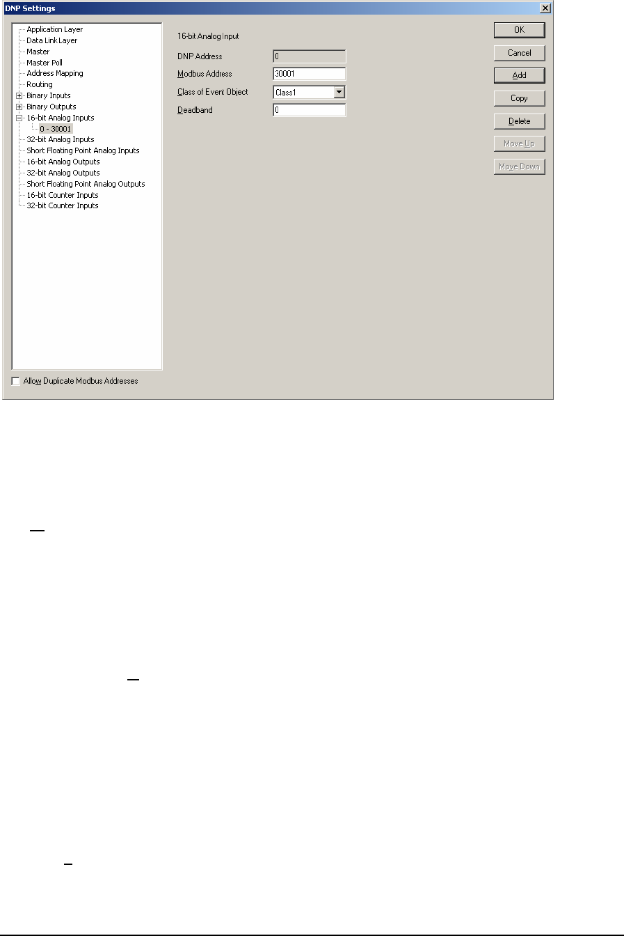
The 16-Bit Analog Input parameters are described in the following paragraphs.
The DNP Address window displays the DNP 16-Bit Analog Input address of the point. Each 16-Bit
Analog Input is assigned a DNP address as they are defined. The DNP point address starts at the
value set in the 16-bit Analog Input configuration dialog and increments by one with each defined
16-Bit Analog Input.
The Modbus Address parameter specifies the Modbus address of the 16-Bit Analog Input assigned
to the DNP Address. The SCADAPack and Micro16 controllers use Modbus addressing for all
analog inputs. Refer to the I/O Database Registers section of the TelePACE Ladder Logic
Reference and User Manual for complete information on analog input addressing in the
SCADAPack and Micro16 controllers. Valid Modbus addresses are:
• 30001 through 39999
• 40001 through 49999
The Class of Event Object parameter specifies the event object class assigned to the 16-Bit Analog
Input is assigned. If Unsolicited reporting is not required for a point, it is recommended to set its
Class to None. All data points automatically become members of Class 0 or None (static data). The
selections are:
• None
• Class 1
• Class 2
• Class 3
The Deadband parameter specifies the minimum number of counts that the 16-Bit Analog Input
must change since it was last reported in order to generate an event. Valid deadband values are 0 to
65535. A deadband of zero will cause any change to create an event.
DNP3 User and Reference Manual
May 9, 2007
52
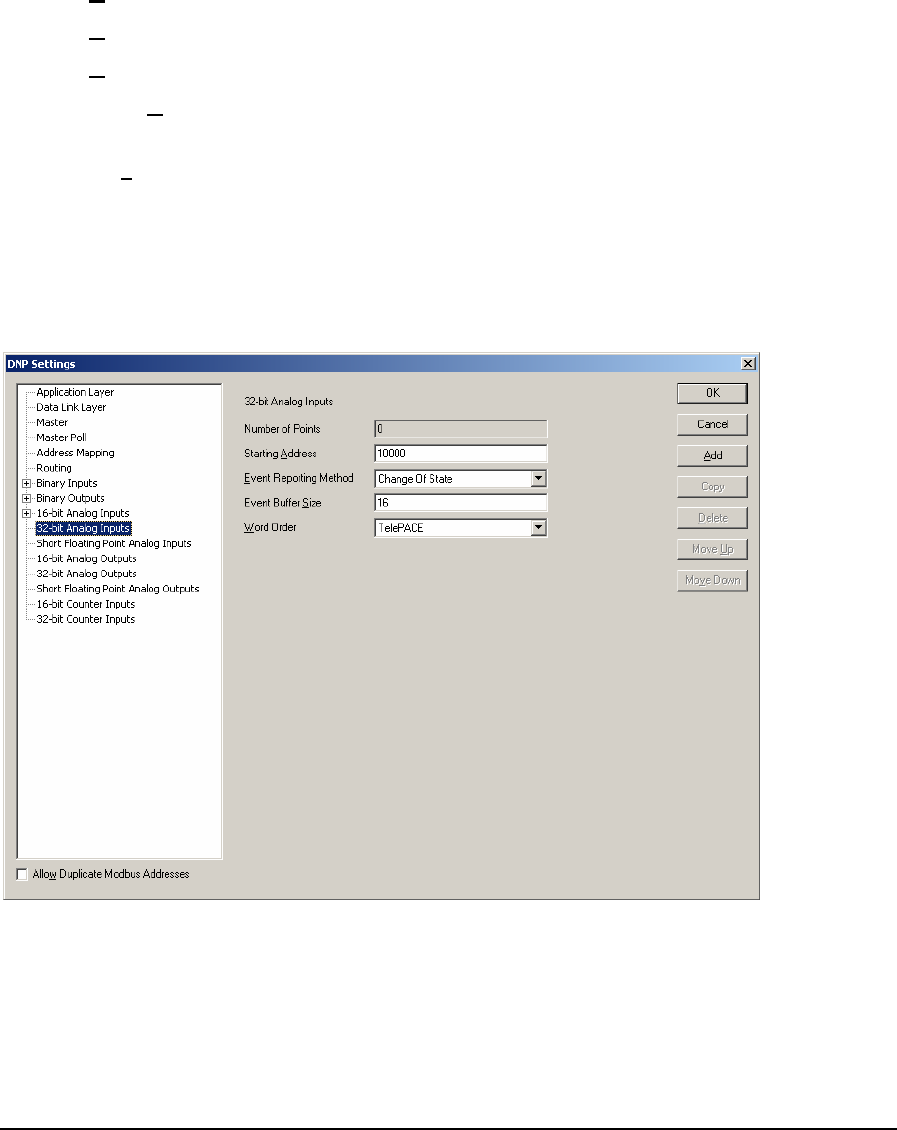
The Allow Duplicate Modbus Addresses checkbox determines if the Modbus I/O database
addresses assigned to the DNP data points must be unique. Check this box if you want to allow more
than one point to use the same Modbus address.
Click the OK button to accept the 16-Bit Analog Input parameters and close the DNP Settings
dialog.
Click the Cancel button to close the dialog without saving any changes.
Click the Add button to add the current 16-Bit Analog Input to the DNP configuration.
Click the Copy button to copy the current 16-Bit Analog Input parameters to the next DNP Address.
Click the Delete button to delete the current 16-Bit Analog Input.
Click the Move Up button to move the current 16-Bit Analog Input up one position in the tree
control branch.
Click the Move Down button to move the current 16-Bit Analog Input down one position in the tree
control branch.
5.10 32-Bit Analog Inputs Configuration
The 32-Bit Analog Inputs property page is selected for editing by clicking 32-Bit Analog Inputs in
the tree control section of the DNP Settings window. When selected the 32-Bit Analog Inputs
property page is active.
32-Bit Analog Inputs parameters are set in this property page. Each parameter is described in the
following paragraphs.
The Number of Points displays the number of 32- bit analog inputs reported by the RTU. This value
will increment with the addition of each configured 32-Bit Analog Input point. The maximum
number of points is 9999. The maximum number of actual points will depend on the memory
available in the controller.
DNP3 User and Reference Manual
May 9, 2007
53

The Starting Address parameter specifies the DNP address of the first 32-bit Analog Input point.
The Event Reporting Method selection specifies how 32-bit Analog Input events are reported. A
Change Of State event is an event object, without time, that is generated when the point changes
state. Only one event is retained in the buffer for each point. If a subsequent event occurs for a point,
the previous event object will be overwritten. The main purpose of this mode is to allow a master
station to efficiently poll for changed data. A Log All Events is event object with absolute time will
be generated when the point changes state. All events will be retained. The main purpose of this
mode is to allow a master station to obtain a complete historical data log. The selections are:
• Change of State
• Log All Events
The Event Buffer Size parameter specifies the maximum number of 32-Bit Analog Input change
without time events buffered by the RTU. The buffer holds all 32-Bit Analog Input events,
regardless of the class to which they are assigned. If the buffer fills to 90 percent the RTU will send a
buffer overflow event to the master station. If the buffer is completely full the RTU will lose the
oldest events and retain the newest. The Event Buffer size should be at least equivalent to the
number of 32-Bit Analog Inputs defined as Change of State type. That will allow all 32-Bit Analog
Inputs to exceed the deadband simultaneously without losing any events. The value of this parameter
is dependent on how often 32-Bit Analog Input events occur and the rate at which the events are
reported to the master station. The valid values for this parameter are 0 - 65535. Default value is 16.
For SCADAPack 32 and SCADAPack 32P controllers analog input events are processed by the DNP
driver at a rate of 100 events every 100 ms. If more than 100 analog input events need to be
processed they are processed sequentially in blocks of 100 until all events are processed. This allows
the processing of 1000 analog input events per second.
For SCADASense Series of controllers, SCADAPack 100, SCADAPack LP, SCADAPack and
Micro16 controllers analog input events are processed by the DNP driver at a rate of 20 events every
100 ms. If more than 20 analog input events need to be processed they are processed sequentially in
blocks of 20 until all events are processed. This allows the processing of 200 analog input events per
second.
The Word Order selection specifies the word order of the 32-bit value. The selections are:
• TelePACE Least Significant Word in first register.
• ISaGRAF Most Significant Word in first register.
The Allow Duplicate Modbus Addresses checkbox determines if the Modbus I/O database
addresses assigned to the DNP data points must be unique. Check this box if you want to allow more
than one point to use the same Modbus address.
5.10.1 Adding 32-Bit Analog Inputs
32-Bit Analog Inputs are added to the DNP configuration using the 16-Bit Analog Input property
page. To add a 32-Bit Analog Input:
• Select 32-Bit Analog Inputs in the tree control section of the DNP Settings window.
• Click the Add button in the 32-Bit Analog Inputs property page.
• The 32-Bit Analog Input property page is now displayed.
• Edit the 32-Bit Analog Input parameters as required and then click the Add button.
DNP3 User and Reference Manual
May 9, 2007
54
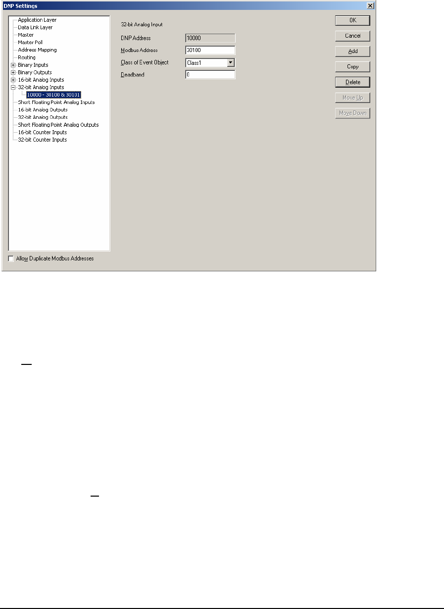
As 32-Bit Analog Inputs are defined they are added as leaves to the 32-Bit Analog Inputs branch of
the tree control. When 32-Bit Analog Inputs are defined the 32-Bit Analog Inputs branch will display
a collapse / expand control to the left of the branch. Click this control to display all defined 32-Bit
Analog Inputs.
The 32-Bit Analog Input parameters are described in the following paragraphs.
The DNP Address window displays the DNP 32-Bit Analog Input address of the point. Each 32-Bit
Analog Input is assigned a DNP address as they are defined. The DNP point address starts at the
value set in the 32-bit Analog Input configuration dialog and increments by one with each defined
32-Bit Analog Input.
The Modbus Address parameter specifies the Modbus addresses of the 32-Bit Analog Input
assigned to the DNP Address. 32-Bit Analog Inputs use two consecutive Modbus registers for each
assigned DNP Address, the address that is entered in this box and the next consecutive Modbus
register. The SCADAPack and Micro16 controllers use Modbus addressing for all analog inputs.
Refer to the I/O Database Registers section of the TelePACE Ladder Logic Reference and User
Manual for complete information on analog input addressing in the SCADAPack and Micro16
controllers. Valid Modbus addresses are:
• 30001 through 39998
• 40001 through 49998
The Class of Event Object parameter specifies the event object class the 32-Bit Analog Input is
assigned. If Unsolicited reporting is not required for a DNP point, it is recommended to set its Class
0 or None. All data points automatically become members of Class 0 or None (static data).The
selections are:
• None
• Class 1
DNP3 User and Reference Manual
May 9, 2007
55

• Class 2
• Class 3
The Deadband parameter specifies whether the RTU generates events. The value entered is the
minimum number of counts that the 32-Bit Analog Input must change since it was last reported.
Valid deadband values are 0 to 4,294,967,295. A deadband of zero will cause any change to create
an event.
The Allow Duplicate Modbus Addresses checkbox determines if the Modbus I/O database
addresses assigned to the DNP data points must be unique. Check this box if you want to allow more
than one point to use the same Modbus address.
Click the OK button to accept the 32-Bit Analog Input parameters and close the DNP Settings
dialog.
Click the Cancel button to close the dialog without saving any changes.
Click the Add button to add the current 32-Bit Analog Input to the DNP configuration.
Click the Copy button to copy the current 32-Bit Analog Input parameters to the next DNP Address.
Click the Delete button to delete the current 32-Bit Analog Input.
Click the Move Up button to move the current 32-Bit Analog Input up one position in the tree
control branch.
Click the Move Down button to move the current 32-Bit Analog Input down one position in the tree
control branch.
5.11 Short Floating Point Analog Inputs
The Short Floating Point Analog Inputs property page is selected for editing by clicking Short
Floating Point Analog Inputs in the tree control section of the DNP Settings window. When selected
the Short Floating Point Analog Inputs property page is active.
DNP3 User and Reference Manual
May 9, 2007
56
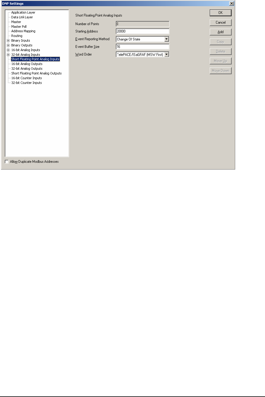
Short Floating Point Analog Input parameters are set in this property page. Each parameter is
described in the following paragraphs.
The Number of Points displays the number of Short Floating Point Analog Inputs reported by the
RTU. This value will increment with the addition of each configured Short Floating Point Analog
Input point. The maximum number of points is 9999. The maximum number of actual points will
depend on the memory available in the controller.
The Starting Address parameter specifies the DNP address of the first Short Floating Point Analog
Input point.
The Event Reporting Method selection specifies how Short Floating Point Analog Input events are
reported. A Change Of State event is an event object, without time, that is generated when the point
changes state. Only one event is retained in the buffer for each point. If a subsequent event occurs for
a point, the previous event object will be overwritten. The main purpose of this mode is to allow a
master station to efficiently poll for changed data. A Log All Events is event object with absolute
time will be generated when the point changes state. All events will be retained. The main purpose of
this mode is to allow a master station to obtain a complete historical data log. The selections are:
• Change of State
• Log All Events
The Event Buffer Size parameter specifies the maximum number of Short Floating Point Analog
Input changes without time events buffered by the RTU. The buffer holds all Short Floating Point
Analog Input events, regardless of the class to which they are assigned. If the buffer fills to 90
percent the RTU will send a buffer overflow event to the master station. If the buffer is completely
full the RTU will lose the oldest events and retain the newest. The Event Buffer size should be at
least equivalent to the number of Short Floating Point Analog Inputs defined as Change of State
type. That will allow all Short Floating Point Analog Inputs to exceed the deadband simultaneously
without losing any events. The value of this parameter is dependent on how often Short Floating
DNP3 User and Reference Manual
May 9, 2007
57

Point Analog Input events occur and the rate at which the events are reported to the master station.
The valid values for this parameter are 0 - 65535. Default value is 16.
For SCADAPack 32 and SCADAPack 32P controllers analog input events are processed by the DNP
driver at a rate of 100 events every 100 ms. If more than 100 analog input events need to be
processed they are processed sequentially in blocks of 100 until all events are processed. This allows
the processing of 1000 analog input events per second.
For SCADASense Series of controllers, SCADAPack 100, SCADAPack LP, SCADAPack and
Micro16 controllers analog input events are processed by the DNP driver at a rate of 20 events every
100 ms. If more than 20 analog input events need to be processed they are processed sequentially in
blocks of 20 until all events are processed. This allows the processing of 200 analog input events per
second.
The Word Order selection specifies the word order of the 32-bit value. The selections are:
• TelePACE / ISaGRAF (MSW First) Most Significant Word in first register.
• Reverse (LSW First) Least Significant Word in first register.
The Allow Duplicate Modbus Addresses checkbox determines if the Modbus I/O database
addresses assigned to the DNP data points must be unique. Check this box if you want to allow more
than one point to use the same Modbus address.
5.11.1 Adding Short Floating Point Analog Inputs
Short Floating Point Analog Inputs are added to the DNP configuration using the 16-Bit Analog
Input property page. To add a Short Floating Point Analog Input:
• Select Short Floating Point Analog Input in the tree control section of the DNP Settings
window.
• Click the Add button in the Short Floating Point Analog Inputs property page.
• The Short Floating Point Analog Input property page is now displayed.
• Edit the Short Floating Point Analog Input parameters as required and then click the Add button.
As Short Floating Point Analog Inputs are defined they are added as leaves to the Short Floating
Point Analog Inputs branch of the tree control. When Short Floating Point Analog Inputs are defined
the Short Floating Point Analog Inputs branch will display a collapse / expand control to the left of
the branch. Click this control to display all defined Short Floating Point Analog Inputs.
DNP3 User and Reference Manual
May 9, 2007
58
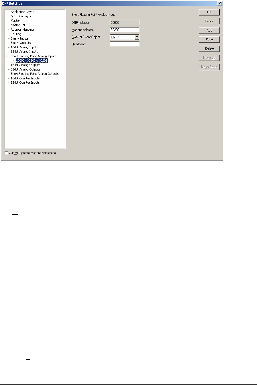
The Short Floating Point Analog Input parameters are described in the following paragraphs.
The DNP Address window displays the DNP Short Floating Point Analog Input address of the
point. Each Short Floating Point Analog Input is assigned a DNP address as they are defined. The
DNP point address starts at the value set in the Short Floating Point Analog Input configuration
dialog and increments by one with each defined Short Floating Point Analog Input.
The Modbus Address parameter specifies the Modbus addresses of the Short Floating Point Analog
Input assigned to the DNP Address. Short Floating Point Analog Inputs use two consecutive Modbus
registers for each assigned DNP Address, the address that is entered in this box and the next
consecutive Modbus register. The SCADAPack and Micro16 controllers use Modbus addressing for
all analog inputs. Refer to the I/O Database Registers section of the TelePACE Ladder Logic
Reference and User Manual for complete information on analog input addressing in the
SCADAPack and Micro16 controllers. Valid Modbus addresses are:
• 30001 through 39998
• 40001 through 49998
The Class of Event Object parameter specifies the event object class the Short Floating Point Analog
Input is assigned. If Unsolicited reporting is not required for a DNP point, it is recommended to set
its Class 0 or None. The selections are:
• None
• Class 1
• Class 2
• Class 3
The Deadband parameter specifies whether the RTU generates events. The value entered is the
minimum number of counts that the Short Floating Point Analog Input must change since it was last
DNP3 User and Reference Manual
May 9, 2007
59
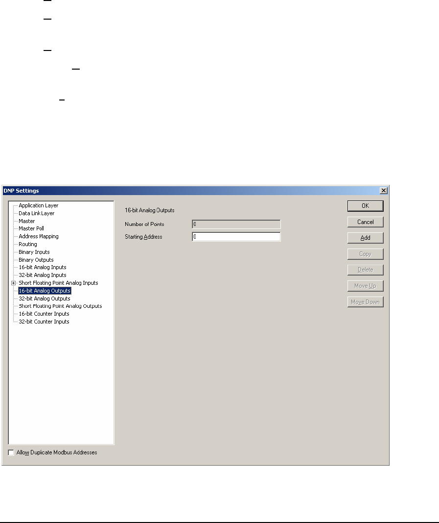
reported. Setting this value to zero disables generating events for the Short Floating Point Analog
Inputs.
The Allow Duplicate Modbus Addresses checkbox determines if the Modbus I/O database
addresses assigned to the DNP data points must be unique. Check this box if you want to allow more
than one point to use the same Modbus address.
Click the OK button to accept the Short Floating Point Analog Input parameters and close the DNP
Settings dialog.
Click the Cancel button to close the dialog without saving any changes.
Click the Add button to add the current Short Floating Point Analog Input to the DNP configuration.
Click the Copy button to copy the current Short Floating Point Analog Input parameters to the next
DNP Address.
Click the Delete button to delete the current Short Floating Point Analog Input.
Click the Move Up button to move the current Short Floating Point Analog Input up one position in
the tree control branch.
Click the Move Down button to move the current Short Floating Point Analog Input down one
position in the tree control branch.
5.12 16-Bit Analog Outputs Configuration
The 16-Bit Analog Outputs property page is selected for editing by clicking 16-Bit Analog Outputs
in the tree control section of the DNP Settings window. When selected the 16-Bit Analog Outputs
property page is active.
16-Bit Analog Outputs parameters are viewed in this property page.
DNP3 User and Reference Manual
May 9, 2007
60
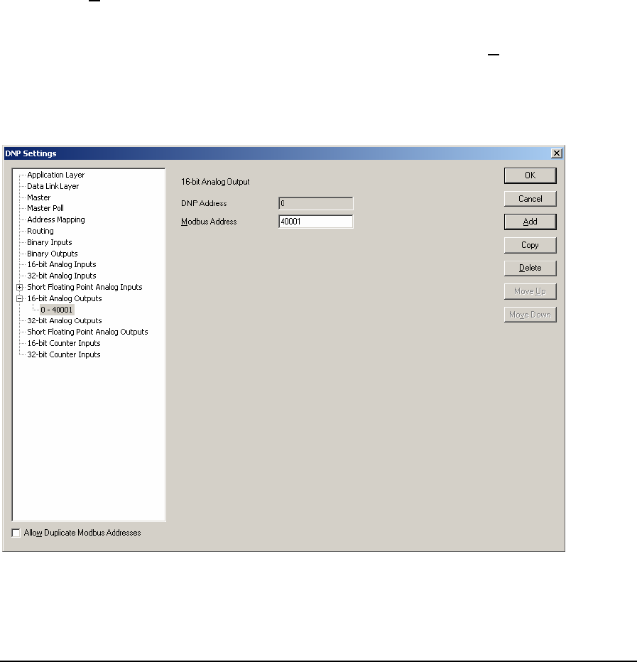
The Number of Points displays the number of 16-Bit Analog Outputs reported by this RTU. This
value will increment with the addition of each configured 16-Bit Analog Input point. The maximum
number of points is 9999. The maximum number of actual points will depend on the memory
available in the controller.
The Starting Address parameter specifies the DNP address of the first 16-bit Analog Output point.
The Allow Duplicate Modbus Addresses checkbox determines if the Modbus I/O database
addresses assigned to the DNP data points must be unique. Check this box if you want to allow more
than one point to use the same Modbus address.
5.12.1 Adding 16-Bit Analog Outputs
16-Bit Analog Outputs are added to the DNP configuration using the 16-Bit Analog Outputs
property page. To add a 16-Bit Analog Output:
• Select 16-Bit Analog Outputs in the tree control section of the DNP Settings window.
• Click the Add button in the 16-Bit Analog Outputs property page.
• The 16-Bit Analog Output property page is now displayed.
• Edit the 16-Bit Analog Outputs parameters as required and then click the Add button.
As 16-Bit Analog Outputs are defined they are added as leaves to the 16-Bit Analog Output branch
of the tree control. When 16-Bit Analog Outputs are defined the 16-Bit Analog Outputs branch will
display a collapse / expand control to the left of the branch. Click this control to display all defined
16-Bit Analog Outputs.
The 16-Bit Analog Outputs parameters are described in the following paragraphs.
The DNP Address window displays the DNP 16-Bit Analog Output address of the point. Each 16-
Bit Analog Output is assigned a DNP address as they are defined. The DNP point address starts at
DNP3 User and Reference Manual
May 9, 2007
61

the value set in the 16-bit Analog Output configuration dialog and increments by one with each
defined 16-Bit Analog Output.
The Modbus Address parameter specifies the Modbus address of the 16-Bit Analog Output assigned
to the DNP Address. The SCADAPack and Micro16 controllers use Modbus addressing for all
analog outputs. Refer to the I/O Database Registers section of the TelePACE Ladder Logic
Reference and User Manual for complete information on analog output addressing in the
SCADAPack and Micro16 controllers. Valid Modbus addresses are:
• 40001 through 49999
The Allow Duplicate Modbus Addresses checkbox determines if the Modbus I/O database
addresses assigned to the DNP data points must be unique. Check this box if you want to allow more
than one point to use the same Modbus address.
Click the OK button to accept the 16-Bit Analog Output parameters and close the DNP Settings
dialog.
Click the Cancel button to close the dialog without saving any changes.
Click the Add button to add the current 16-Bit Analog Output to the DNP configuration.
Click the Copy button to copy the current 16-Bit Analog Output parameters to the next DNP
Address.
Click the Delete button to delete the current 16-Bit Analog Output.
Click the Move Up button to move the current 16-Bit Analog Output up one position in the tree
control branch.
Click the Move Down button to move the current 16-Bit Analog Output down one position in the
tree control branch.
5.13 32-Bit Analog Outputs Configuration
The 32-Bit Analog Outputs property page is selected for editing by clicking 32-Bit Analog Outputs
in the tree control section of the DNP Settings window. When selected the 32-Bit Analog Outputs
property page is active.
DNP3 User and Reference Manual
May 9, 2007
62
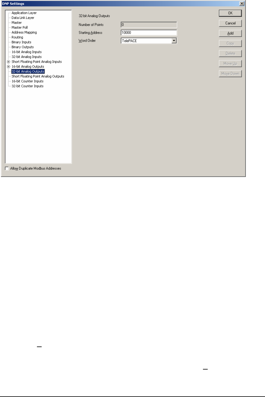
32-Bit Analog Outputs parameters are viewed in this property page.
The Number of Points displays the number of 32-Bit Analog Outputs reported by this RTU. This
value will increment with the addition of each configured 32-Bit Analog Output point. The
maximum number of points is 9999. The maximum number of actual points will depend on the
memory available in the controller.
The Starting Address parameter specifies the DNP address of the first 16-bit Analog Output point.
The Word Order selection specifies the word order of the 32-bit value. The selections are:
• TelePACE Least Significant Word in first register.
• ISaGRAF Most Significant Word in first register.
The Allow Duplicate Modbus Addresses checkbox determines if the Modbus I/O database
addresses assigned to the DNP data points must be unique. Check this box if you want to allow more
than one point to use the same Modbus address.
5.13.1 Adding 32-Bit Analog Outputs
32-Bit Analog Outputs are added to the DNP configuration using the 32-Bit Analog Outputs
property page. To add a 32-Bit Analog Output:
• Select 32-Bit Analog Outputs in the tree control section of the DNP Settings window.
• Click the Add button in the 16-Bit Analog Outputs property page.
• The 32-Bit Analog Output property page is now displayed.
• Edit the 32-Bit Analog Outputs parameters as required and then click the Add button.
DNP3 User and Reference Manual
May 9, 2007
63
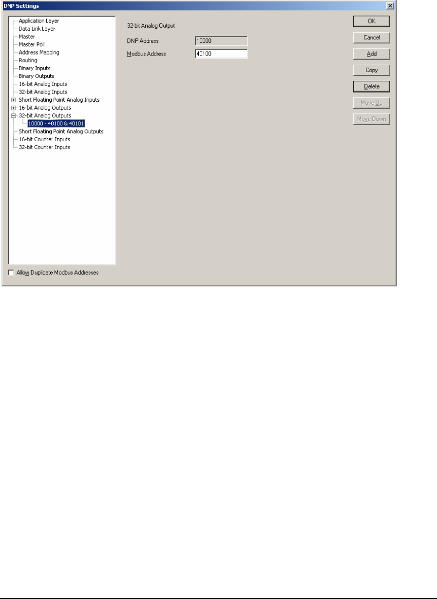
As 32-Bit Analog Outputs are defined they are added as leaves to the Binary Inputs branch of the
tree control. When 32-Bit Analog Outputs are defined the 32-Bit Analog Outputs branch will display
a collapse / expand control to the left of the branch. Click this control to display all defined 32-Bit
Analog Outputs.
The 32-Bit Analog Outputs parameters are described in the following paragraphs.
The DNP Address window displays the DNP 32-Bit Analog Output address of the point. Each 16-
Bit Analog Output is assigned a DNP address s they are defined. The DNP point address starts at the
value set in the 32-bit Analog Output configuration dialog and increments by one with each defined
32-Bit Analog Output.
The Modbus Address parameter specifies the Modbus address of the 32-Bit Analog Output assigned
to the DNP Address. 32-Bit Analog Outputs use two consecutive Modbus registers for each assigned
DNP Address, the address that is entered in this box and the next consecutive Modbus register. The
SCADAPack and Micro16 controllers use Modbus addressing for all analog outputs. Refer to the I/O
Database Registers section of the TelePACE Ladder Logic Reference and User Manual for
complete information on analog output addressing in the SCADAPack and Micro16 controllers.
Valid Modbus addresses are:
• 40001 through 49998
The Allow Duplicate Modbus Addresses checkbox determines if the Modbus I/O database
addresses assigned to the DNP data points must be unique. Check this box if you want to allow more
than one point to use the same Modbus address.
Click the OK button to accept the 16-Bit Analog Output parameters and close the DNP Settings
dialog.
Click the Cancel button to close the dialog without saving any changes.
DNP3 User and Reference Manual
May 9, 2007
64
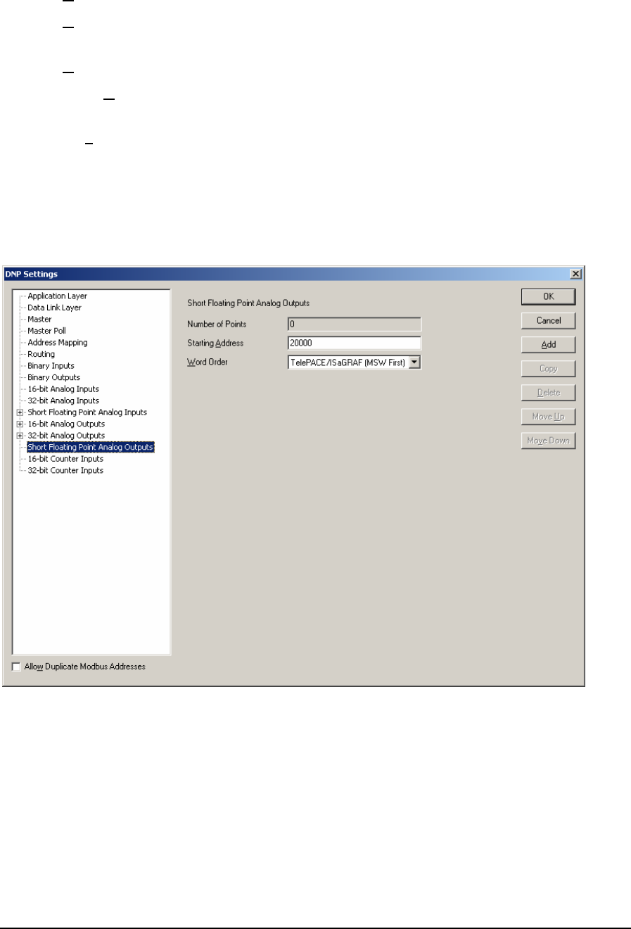
Click the Add button to add the current 32-Bit Analog Output to the DNP configuration.
Click the Copy button to copy the current 32-Bit Analog Output parameters to the next DNP
Address.
Click the Delete button to delete the current 32-Bit Analog Output.
Click the Move Up button to move the current 32-Bit Analog Output up one position in the tree
control branch.
Click the Move Down button to move the current 32-Bit Analog Output down one position in the
tree control branch.
5.14 Short Floating Point Analog Outputs
The Short Floating Point Analog Outputs property page is selected for editing by clicking Short
Floating Point Analog Outputs in the tree control section of the DNP Settings window. When
selected the Short Floating Point Analog Outputs property page is active.
Short Floating Point Analog Output parameters are set in this property page. Each parameter is
described in the following paragraphs.
The Number of Points displays the number of Short Floating Point Analog Outputs reported by the
RTU. This value will increment with the addition of each configured Short Floating Point Analog
Input point. The maximum number of points is 9999. The maximum number of actual points will
depend on the memory available in the controller.
The Starting Address parameter specifies the DNP address of the first Short Floating Point Analog
Output point.
The Word Order selection specifies the word order of the 32-bit value. The selections are:
DNP3 User and Reference Manual
May 9, 2007
65
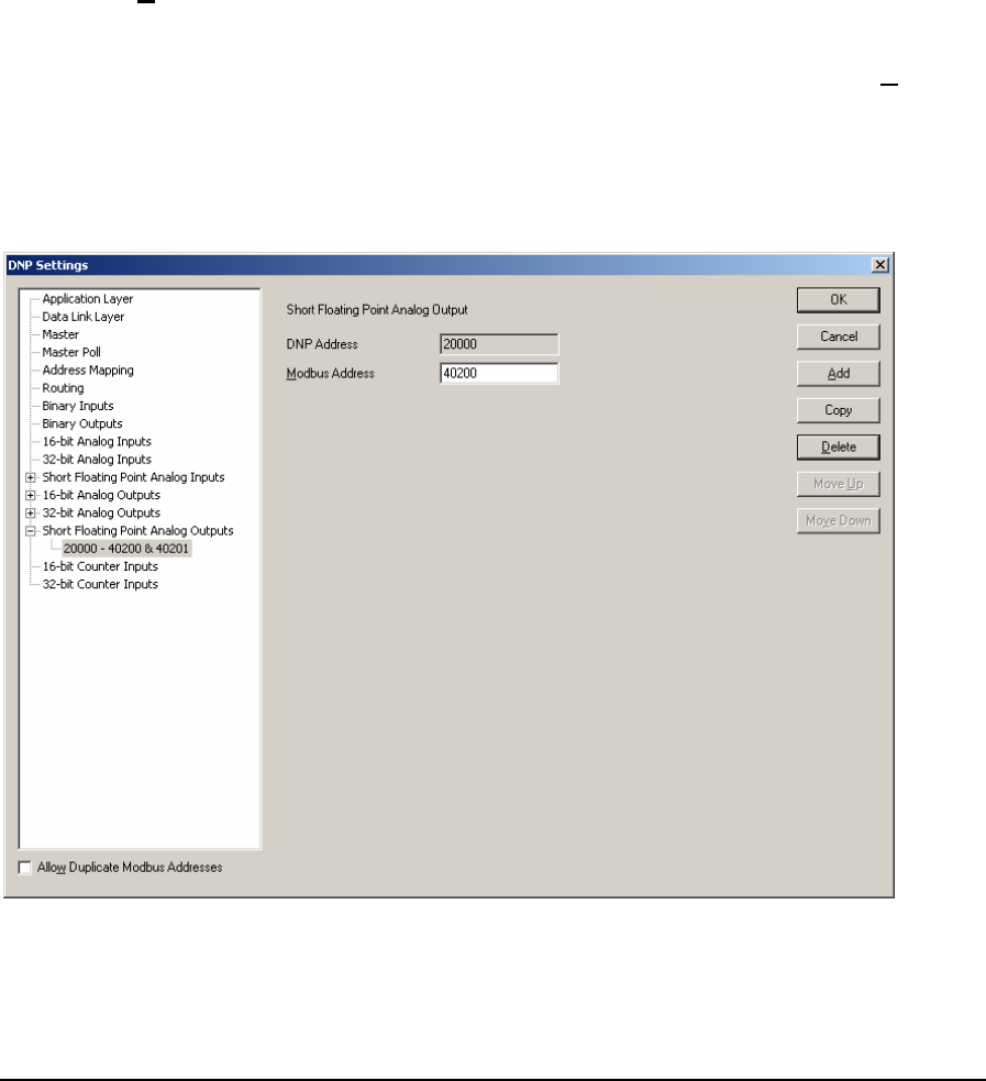
• TelePACE / ISaGRAF (MSW First) Most Significant Word in first register.
• Reverse (LSW First) Least Significant Word in first register.
The Allow Duplicate Modbus Addresses checkbox determines if the Modbus I/O database
addresses assigned to the DNP data points must be unique. Check this box if you want to allow more
than one point to use the same Modbus address.
5.14.1 Adding Short Floating Point Analog Outputs
Short Floating Point Analog Outputs are added to the DNP configuration using the Short Floating
Point Analog Output property page. To add a Short Floating Point Analog Output:
• Select Short Floating Point Analog Output in the tree control section of the DNP Settings
window.
• Click the Add button in the Short Floating Point Analog Inputs property page.
• The Short Floating Point Analog Output property page is now displayed.
• Edit the Short Floating Point Analog Output parameters as required and then click the Add
button.
As Short Floating Point Analog Outputs are defined they are added as leaves to the Short Floating
Point Analog Outputs branch of the tree control. When Short Floating Point Analog Outputs are
defined the Short Floating Point Analog Outputs branch will display a collapse / expand control to
the left of the branch. Click this control to display all defined Short Floating Point Analog Outputs.
The Short Floating Point Analog Output parameters are described in the following paragraphs.
The DNP Address window displays the DNP Short Floating Point Analog Output address of the
point. Each Short Floating Point Analog Output is assigned a DNP address as they are defined. The
DNP3 User and Reference Manual
May 9, 2007
66

DNP point address starts at the value set in the Short Floating Point Analog Output configuration
dialog and increments by one with each defined Short Floating Point Analog Output.
The Modbus Address parameter specifies the Modbus addresses of the Short Floating Point Analog
Output assigned to the DNP Address. Short Floating Point Analog Outputs use two consecutive
Modbus registers for each assigned DNP Address, the address that is entered in this box and the next
consecutive Modbus register. The SCADAPack and Micro16 controllers use Modbus addressing for
all analog inputs. Refer to the I/O Database Registers section of the TelePACE Ladder Logic
Reference and User Manual for complete information on analog input addressing in the
SCADAPack and Micro16 controllers. Valid Modbus addresses are:
• 30001 through 39998
• 40001 through 49998
The Allow Duplicate Modbus Addresses checkbox determines if the Modbus I/O database
addresses assigned to the DNP data points must be unique. Check this box if you want to allow more
than one point to use the same Modbus address.
Click the OK button to accept the Short Floating Point Analog Input parameters and close the DNP
Settings dialog.
Click the Cancel button to close the dialog without saving any changes.
Click the Add button to add the current Short Floating Point Analog Input to the DNP configuration.
Click the Copy button to copy the current Short Floating Point Analog Input parameters to the next
DNP Address.
Click the Delete button to delete the current Short Floating Point Analog Input.
Click the Move Up button to move the current Short Floating Point Analog Input up one position in
the tree control branch.
Click the Move Down button to move the current Short Floating Point Analog Input down one
position in the tree control branch.
5.15 16–Bit Counter Inputs Configuration
The 16-Bit Counter Inputs property page is selected for editing by clicking 16-Bit Counter Inputs in
the tree control section of the DNP Settings window. When selected the 16-Bit Counter Inputs
property page is active.
DNP3 User and Reference Manual
May 9, 2007
67
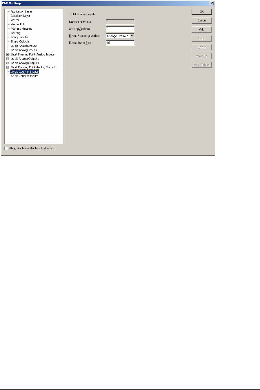
16-Bit Counter Inputs parameters are set in this property page. Each parameter is described in the
following paragraphs.
The Number of Points displays the number of 16-Bit Counter Inputs reported by the RTU. This
value will increment with the addition of each configured 16-Bit Counter Inputs point. The
maximum number of points is 9999. The maximum number of actual points will depend on the
memory available in the controller.
The Starting Address parameter specifies the DNP address of the first 16-Bit Counter Input point.
The Event Reporting Method selection specifies how 16-Bit Counter Input events are reported. A
Change Of State event is an event object, without time, that is generated when the point changes
state. Only one event is retained in the buffer for each point. If a subsequent event occurs for a point,
the previous event object will be overwritten. The main purpose of this mode is to allow a master
station to efficiently poll for changed data. A Log All Events is event object with absolute time will
be generated when the point changes state. All events will be retained. The main purpose of this
mode is to allow a master station to obtain a complete historical data log. The selections are:
• Change of State
• Log All Events
The Event Buffer Size parameter specifies the maximum number of 16-Bit Counter Input change
without time events buffered by the RTU. The buffer holds all 16-Bit Counter Input events,
regardless of the class to which they are assigned. If the buffer fills to 90 percent the RTU will send a
buffer overflow event to the master station. If the buffer is completely full the RTU will lose the
oldest events and retain the newest. The Event Buffer size should be at least equivalent to the
number of 16-Bit Analog Inputs defined as Change of State type. That will allow all 16-Bit Counter
Inputs to exceed the threshold simultaneously without losing any events. The value of this parameter
is dependent on how often 16-Bit Counter Input events occur and the rate at which the events are
reported to the master station. The valid values for this parameter are 0 - 65535. Default value is 16.
DNP3 User and Reference Manual
May 9, 2007
68

For SCADAPack 32 and SCADAPack 32P controllers counter input events are processed by the
DNP driver at a rate of 100 events every 100 ms. If more than 100 counter input events need to be
processed they are processed sequentially in blocks of 100 until all events are processed. This allows
the processing of 1000 counter input events per second.
For SCADASense Series of controllers, SCADAPack 100, SCADAPack LP, SCADAPack and
Micro16 controllers counter input events are processed by the DNP driver at a rate of 20 events
every 100 ms. If more than 20 counter input events need to be processed they are processed
sequentially in blocks of 20 until all events are processed. This allows the processing of 200 counter
input events per second.
The Allow Duplicate Modbus Addresses checkbox determines if the Modbus I/O database
addresses assigned to the DNP data points must be unique. Check this box if you want to allow more
than one point to use the same Modbus address.
5.15.1 Adding 16-Bit Counter Inputs
16-Bit Counter Inputs are added to the DNP configuration using the 16-Bit Counter Inputs property
page. To add a 16-Bit Counter Input:
• Select 16-Bit Counter Inputs in the tree control section of the DNP Settings window.
• Click the Add button in the 16-Bit Counter Inputs property page.
• The 16-Bit Counter Input property page is now displayed.
• Edit the 16-Bit Counter Inputs parameters as required and then click the Add button.
As 16-Bit Counter Inputs are defined they are added as leaves to the 16-Bit Counter Inputs branch of
the tree control. When 16-Bit Counter Inputs are defined the 16-Bit Counter Inputs branch will
display a collapse / expand control to the left of the branch. Click this control to display all defined
16-Bit Counter Inputs.
DNP3 User and Reference Manual
May 9, 2007
69
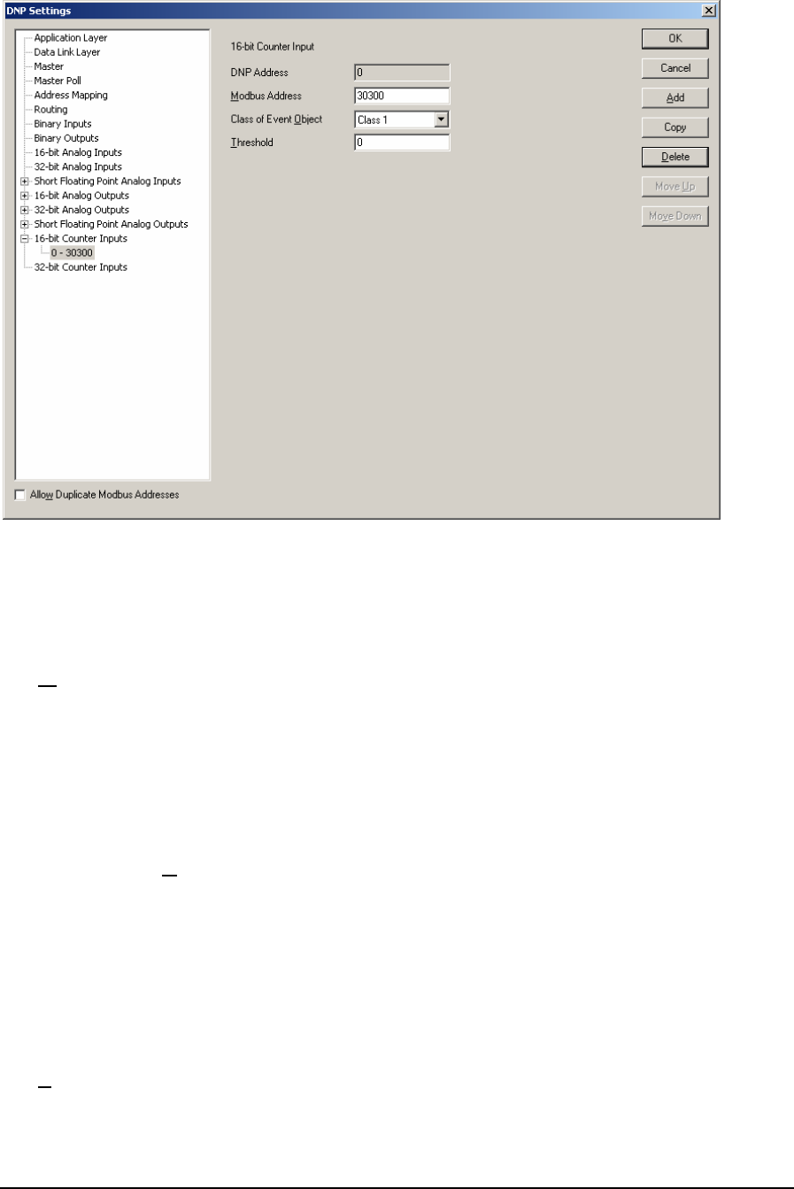
The 16-Bit Counter Input parameters are described in the following paragraphs.
The DNP Address window displays the DNP 16-Bit Counter Input address of the point. Each 16-Bit
Counter Input is assigned a DNP address s they are defined. The DNP point address starts at the
value set in the 16-Bit Counter Input configuration dialog and increments by one with each defined
16-Bit Counter Input.
The Modbus Address parameter specifies the Modbus address of the 16-Bit Counter Input assigned
to the DNP Address. The SCADAPack and Micro16 controllers use Modbus addressing for all
counter inputs. Refer to the I/O Database Registers section of the TelePACE Ladder Logic
Reference and User Manual for complete information on analog input addressing in the
SCADAPack and Micro16 controllers. Valid Modbus addresses are:
• 30001 through 39999
• 40001 through 49999
The Class of Event Object parameter specifies the event object class the 16-Bit Counter Input is
assigned. If Unsolicited reporting is not required for a DNP point, it is recommended to set its Class
0 or None. The selections are:
• None
• Class 1
• Class 2
• Class 3
The Threshold parameter specifies whether the RTU generates events. The value entered is the
minimum number of counts that the 16-Bit Counter Input must change since it was last reported.
DNP3 User and Reference Manual
May 9, 2007
70
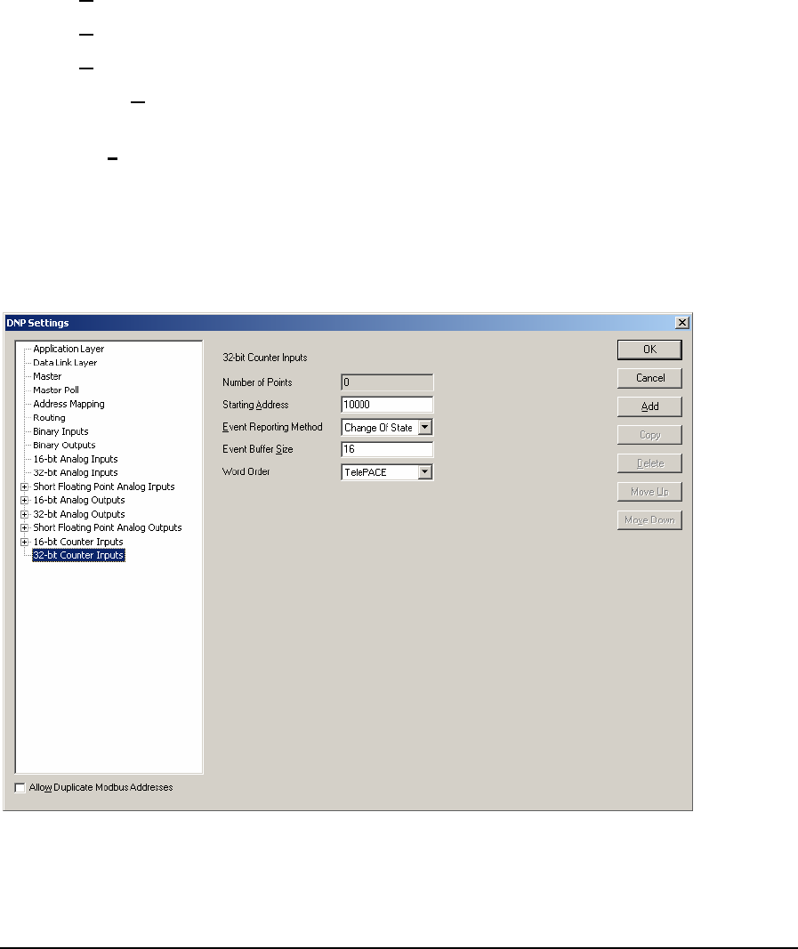
Setting this value to zero disables generating events for the 16-Bit Counter Input point. Valid
deadband values are 0 to 65535.
The Allow Duplicate Modbus Addresses checkbox determines if the Modbus I/O database
addresses assigned to the DNP data points must be unique. Check this box if you want to allow more
than one point to use the same Modbus address.
Click the OK button to accept the 16-Bit Analog Counter parameters and close the DNP Settings
dialog.
Click the Cancel button to close the dialog without saving any changes.
Click the Add button to add the current 16-Bit Analog Input to the DNP configuration.
Click the Copy button to copy the current 16-Bit Analog Input parameters to the next DNP Address.
Click the Delete button to delete the current 16-Bit Analog Input.
Click the Move Up button to move the current 16-Bit Analog Input up one position in the tree
control branch.
Click the Move Down button to move the current 16-Bit Analog Input down one position in the tree
control branch.
5.16 32-Bit Counter Inputs Configuration
The 32-Bit Counter Inputs property page is selected for editing by clicking 32-Bit Counter Inputs in
the tree control section of the DNP Settings window. When selected the 32-Bit Counter Inputs
property page is active.
32-Bit Counter Inputs parameters are set in this property page. Each parameter is described in the
following paragraphs.
DNP3 User and Reference Manual
May 9, 2007
71

The Number of Points displays the number of 32-Bit Counter Inputs reported by the RTU. This
value will increment with the addition of each configured 32-Bit Counter Inputs point. The
maximum number of points is 9999. The maximum number of actual points will depend on the
memory available in the controller.
The Starting Address parameter specifies the DNP address of the first 32-Bit Counter Input point.
The Event Reporting Method selection specifies how 32-Bit Counter Input events are reported. A
Change Of State event is an event object, without time, that is generated when the point changes
state. Only one event is retained in the buffer for each point. If a subsequent event occurs for a point,
the previous event object will be overwritten. The main purpose of this mode is to allow a master
station to efficiently poll for changed data. A Log All Events is event object with absolute time will
be generated when the point changes state. All events will be retained. The main purpose of this
mode is to allow a master station to obtain a complete historical data log. The selections are:
• Change of State
• Log All Events
The Event Buffer Size parameter specifies the maximum number of 32-Bit Counter Input change
without time events buffered by the RTU. The buffer holds all 32-Bit Counter Input events,
regardless of the class to which they are assigned. If the buffer fills to 90 percent the RTU will send a
buffer overflow event to the master station. If the buffer is completely full the RTU will lose the
oldest events and retain the newest. The Event Buffer size should be at least equivalent to the
number of 32-Bit Counter Inputs defined as Change of State type. That will allow all 32-Bit Counter
Inputs to exceed the deadband simultaneously without losing any events. The value of this parameter
is dependent on how often 32-Bit Analog Input events occur and the rate at which the events are
reported to the master station. The valid values for this parameter are 0 - 65535. Default value is 16.
For SCADAPack 32 and SCADAPack 32P controllers counter input events are processed by the
DNP driver at a rate of 100 events every 100 ms. If more than 100 counter input events need to be
processed they are processed sequentially in blocks of 100 until all events are processed. This allows
the processing of 1000 counter input events per second.
For SCADASense Series of controllers, SCADAPack 100, SCADAPack LP, SCADAPack and
Micro16 controllers counter input events are processed by the DNP driver at a rate of 20 events
every 100 ms. If more than 20 counter input events need to be processed they are processed
sequentially in blocks of 20 until all events are processed. This allows the processing of 200 counter
input events per second.
The Word Order selection specifies the word order of the 32-bit value. The selections are:
• TelePACE Least Significant Word in first register.
• ISaGRAF Most Significant Word in first register.
The Allow Duplicate Modbus Addresses checkbox determines if the Modbus I/O database
addresses assigned to the DNP data points must be unique. Check this box if you want to allow more
than one point to use the same Modbus address.
5.16.1 Adding 32-Bit Counter Inputs
32-Bit Counter Inputs are added to the DNP configuration using the 16-Bit Counter Input property
page. To add a 32-Bit Analog Input:
• Select 32-Bit Counter Inputs in the tree control section of the DNP Settings window.
• Click the Add button in the 32-Bit Counter Inputs property page.
DNP3 User and Reference Manual
May 9, 2007
72
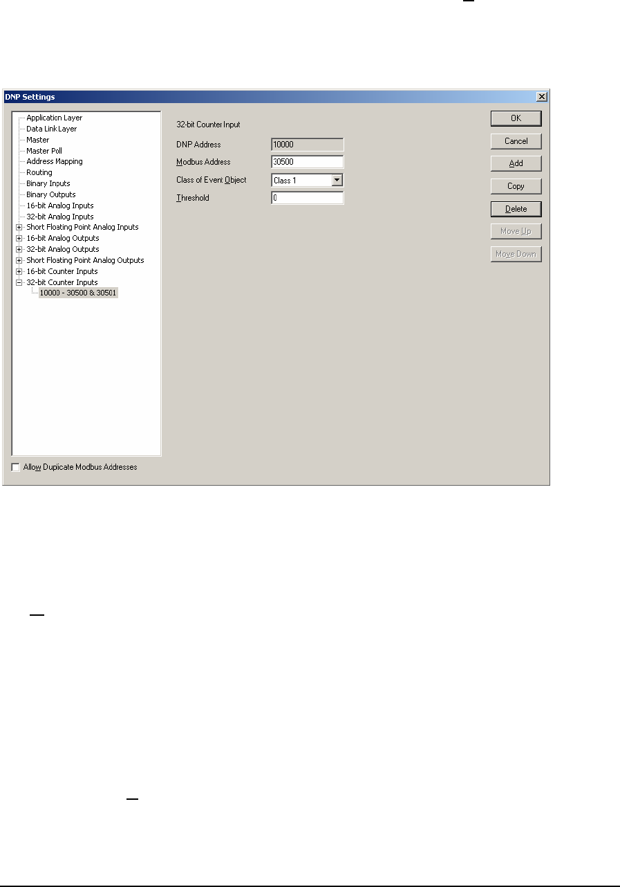
• The 32-Bit Counter Input property page is now displayed.
• Edit the 32-Bit Counter Input parameters as required and then click the Add button.
As 32-Bit Counter Inputs are defined they are added as leaves to the 32-Bit Counter Inputs branch of
the tree control. When 32-Bit Counter Inputs are defined the 32-Bit Counter Inputs branch will
display a collapse / expand control to the left of the branch. Click this control to display all defined
32-Bit Counter Inputs.
The 32-Bit Counter Input parameters are described in the following paragraphs.
The DNP Address window displays the DNP 32-Bit Counter Input address of the point. Each 32-Bit
Counter Input is assigned a DNP address as they are defined. The DNP point address starts at the
value set in the 32-Bit Counter Input configuration dialog and increments by one with each defined
32-Bit Counter Input.
The Modbus Address parameter specifies the Modbus addresses of the 32-Bit Counter Input
assigned to the DNP Address. 32-Bit Counter Inputs use two consecutive Modbus registers for each
assigned DNP Address, the address that is entered in this box and the next consecutive Modbus
register. The SCADAPack and Micro16 controllers use Modbus addressing for all counter inputs.
Refer to the I/O Database Registers section of the TelePACE Ladder Logic Reference and User
Manual for complete information on analog input addressing in the SCADAPack and Micro16
controllers. Valid Modbus addresses are:
• 30001 through 39998
• 40001 through 49998
The Class of Event Object parameter specifies the event object class the 32-Bit Counter Input is
assigned. If Unsolicited reporting is not required for a DNP point, it is recommended to set its Class
0 or None. The selections are:
DNP3 User and Reference Manual
May 9, 2007
73

• None
• Class 1
• Class 2
• Class 3
The Threshold parameter specifies whether the RTU generates events. The value entered is the
minimum number of counts that the 32-Bit Counter Input must change since it was last reported.
Setting this value to zero disables generating events for the 32-Bit Counter Input point. Valid
threshold values are 0 to 4,294,967,295.
The Allow Duplicate Modbus Addresses checkbox determines if the Modbus I/O database
addresses assigned to the DNP data points must be unique. Check this box if you want to allow more
than one point to use the same Modbus address.
Click the OK button to accept the 32-Bit Counter Input parameters and close the DNP Settings
dialog.
Click the Cancel button to close the dialog without saving any changes.
Click the Add button to add the current 32-Bit Counter Input to the DNP configuration.
Click the Copy button to copy the current 32-Bit Counter Input parameters to the next DNP Address.
Click the Delete button to delete the current 32-Bit Counter Input.
Click the Move Up button to move the current 32-Bit Counter Input up one position in the tree
control branch.
Click the Move Down button to move the current 32-Bit Counter Input down one position in the
tree control branch.
DNP3 User and Reference Manual
May 9, 2007
74
6 DNP Diagnostics
DNP Diagnostics provide Master station and Outstation DNP diagnostics. The diagnostics provide
detailed information on the status of DNP communication and DNP data points. This information is
useful when debugging DNP station and network problems that may arise.
DNP diagnostics are available for local DNP information using the DNP Status command.
• For TelePACE applications select Controller >> DNP Status from the menu bar. See the
section DNP Status for information on DNP Status diagnostics.
• For ISaGRAF applications select Tools >> Controller >> DNP Status from the program
window menu bar. See the section DNP Status for information on DNP Status diagnostics.
SCADAPack 32 controllers support DNP master operations. DNP diagnostics are available for
master stations using the DNP Master Status command.
• For TelePACE applications select Controller >> DNP Master Status from the menu bar. See
the section DNP Master Status for information on DNP Master Status diagnostics.
• For ISaGRAF applications select Tools >> Controller >> DNP Master Status from the
program window menu bar. See the section 4.2- DNP Master Status for information on DNP
Master Status diagnostics.
DNP Diagnostics require firmware version 2.20 or newer for SCADAPack controllers and firmware
version 1.50 or newer for SCADAPack 32 controllers. When an attempt is made to select the DNP
Status or DNP Master Status command for controllers with firmware that does not support the
commands an error message is displayed. An example of the error message is shown below.
To enable the use of DNP diagnostics you will need to upgrade the firmware in the controller to the
newer version.
6.1 DNP Status
When the DNP Status command is selected the DNP Status dialog is displayed. This dialog shows
the run-time DNP diagnostics and current data values for the local DNP points.
The DNP Status dialog has a number of selectable tabs and opens with the Overview tab selected.
The following tabs are displayed.
• Overview
• Binary In (binary inputs information)
• Binary Out (binary outputs information)
• AIN-16 (16-bit analog inputs information)
• AIN-32 (32-bit analog inputs information)
• AIN-Float (short float analog inputs information)
DNP3 User and Reference Manual
May 9, 2007
75
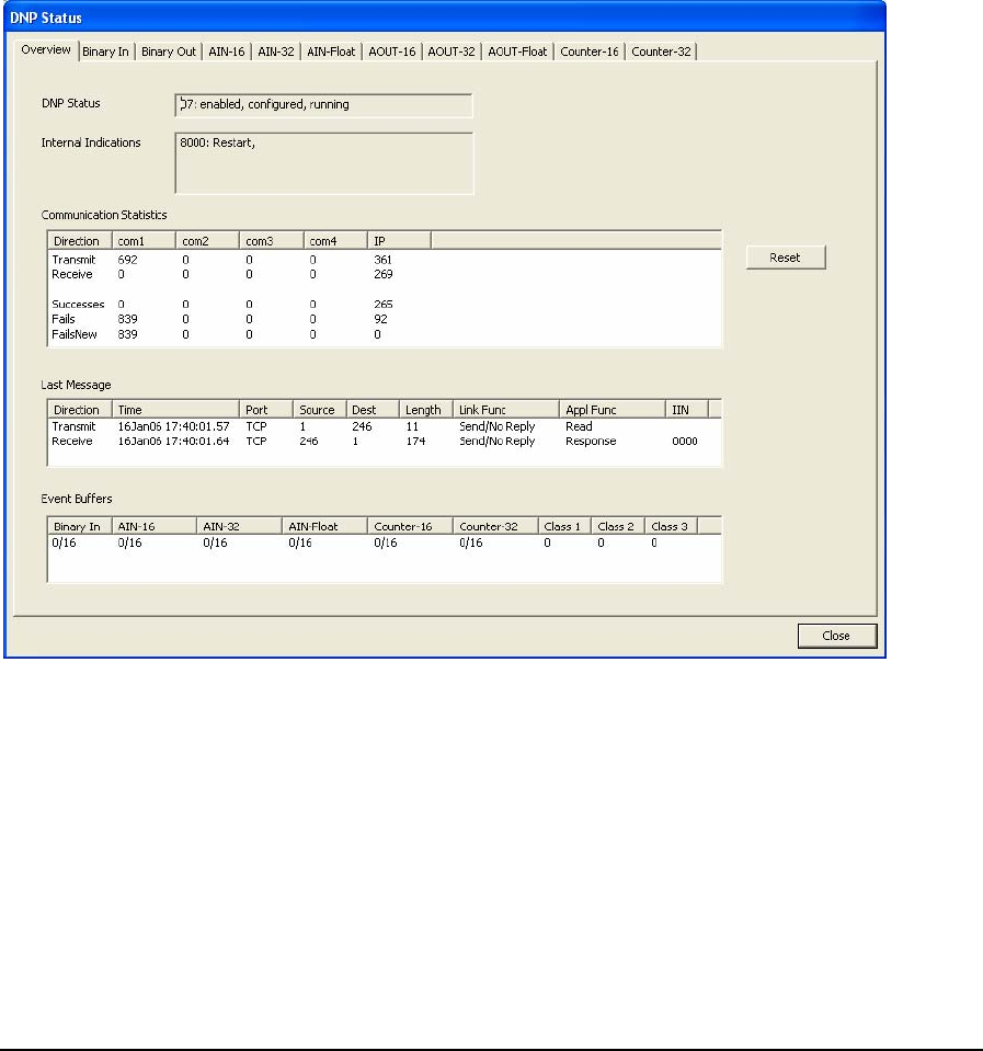
• AOUT-16 (16-bit analog outputs information)
• AOUT-32 (32-bit analog outputs information)
• AOUT-Float (short float analog outputs information)
• Counter-16 (16-bit counter inputs information)
• Counter-32 (32-bit counter inputs information)
Clicking on any tab opens the tab and displays the selected information.
6.1.1 Overview Tab
The Overview Tab displays the run-time diagnostics for the local DNP station. The Overview
display is divided into five areas of diagnostic information: DNP Status, Internal Indications,
Communication Statistics, Last Message and Event Buffer. Each of these is explained in the
following paragraphs.
The DNP Status window provides information on the status of the DNP protocol running in the
controller. Depending on the status the window may contain the following text.
• Enabled or Disabled indicates whether the controller firmware supports DNP protocol.
• Configured or Not Configured indicates whether the controller has been configured with DNP
protocol on at least one communications port.
• Running or Not Running indicates whether the DNP tasks are running in the controller.
The Internal Indications window displays the current state of the DNP internal indications (IIN)
flags in the controller. For a detailed description of the IIN flags see the section Internal Indication
DNP3 User and Reference Manual
May 9, 2007
76

(IIN) Flags section of this manual. Note that bits 0 – 7 (the first octet) are displayed on the left, then
bits 8 - 15 (second octet) on the right.
The Communication Statistics window displays the message statistics for each DNP
communication port. The statistics include the total number of messages transmitted and received
and the total number of successes, failures, and failures since last success (which will only be
updated for messages sent by this controller) for each communication port. The counters increment
whenever a new DNP message is sent or received on the port, and roll over after 65535 messages.
• Click the Reset button to reset the counters to zero.
The Last Message window displays information about the most recent DNP message. The
information is updated each time a new message is received or transmitted. The Last Message
window contains the following information.
• Direction displays whether the message was received or transmitted.
• Time displays the time at which the message was received or sent.
• Port displays which communication port was used for the message.
• Source displays the source DNP station address for the message.
• Dest displays the destination DNP station address for the message.
• Length displays the message length in bytes.
• Link Func displays the Link Layer function code.
• Appl Func displays the Application Layer function code.
• IIN displays the Internal indications received with the last message
The Event Buffers window displays the number of events in each type of event buffer and the
allocated buffer size. The event buffers displayed are:
• Binary In (binary inputs)
• AIN-16 (16-bit analog inputs)
• AIN-32 (32-bit analog inputs)
• AIN-Float (floating point analog inputs)
• Counter-16 (16-bit counter inputs)
• Counter-32 (32-bit counter inputs)
• Class 1 (class 1 events)
• Class 2 (class 2 events)
• Class 3 (class 3 events)
6.1.2 Point Status Tabs
The point status tabs display the state of each point of the selected type in the controller. The
following tabs are displayed.
• Binary In (binary inputs information)
• Binary Out (binary outputs information)
DNP3 User and Reference Manual
May 9, 2007
77
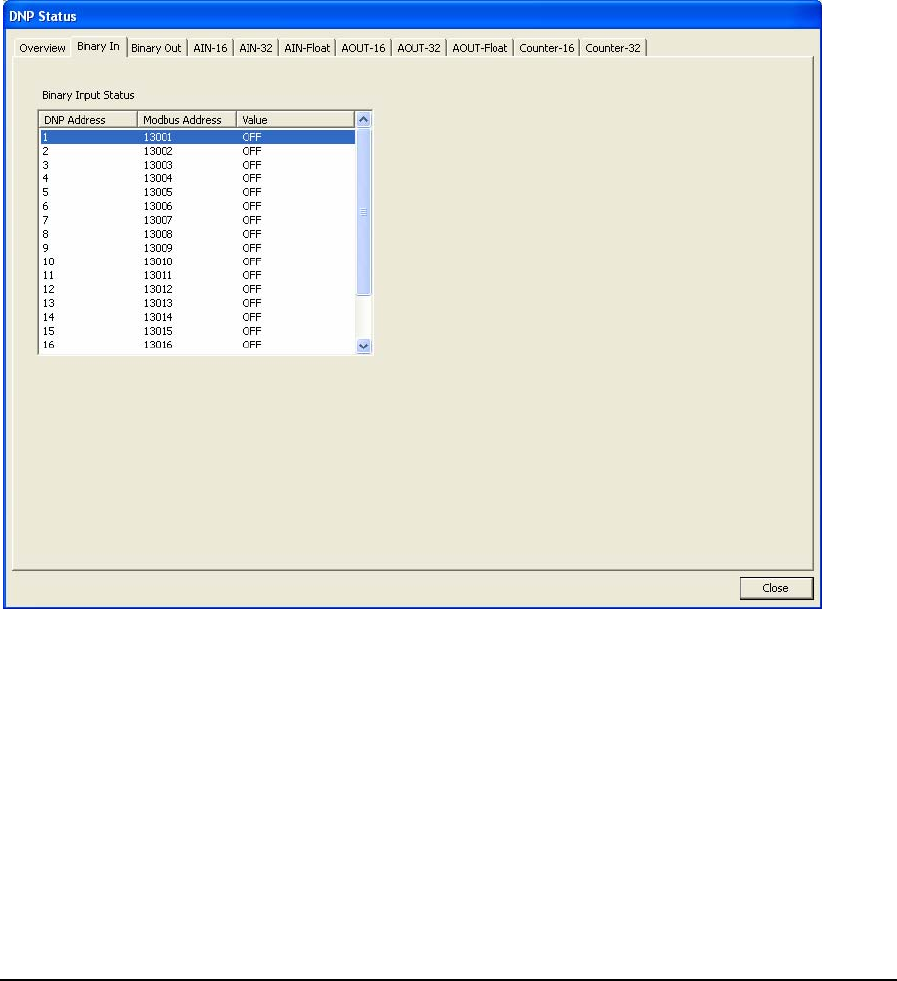
• AIN-16 (16-bit analog inputs information)
• AIN-32 (32-bit analog inputs information)
• AIN-Float (short float analog inputs information)
• AOUT-16 (16-bit analog outputs information)
• AOUT-32 (32-bit analog outputs information)
• AOUT-Float (short float analog outputs information)
• Counter-16 (16-bit counter inputs information)
• Counter-32 (32-bit counter inputs information)
Each of the tabs displays information in the same format. The example below shows the appearance
of the binary input page.
The DNP Address column shows the DNP address of the point.
The Modbus Address column shows the Modbus register address of the point.
The Value column shows the value of the point. Binary points are shown as OFF or ON. Numeric
points show the numeric value of the point.
6.2 DNP Master Status
When the DNP Master Status command is selected the DNP Master Status dialog is displayed. This
dialog shows the run-time DNP diagnostics and status of the DNP outstations and current data values
for the DNP points in these outstations.
DNP3 User and Reference Manual
May 9, 2007
78
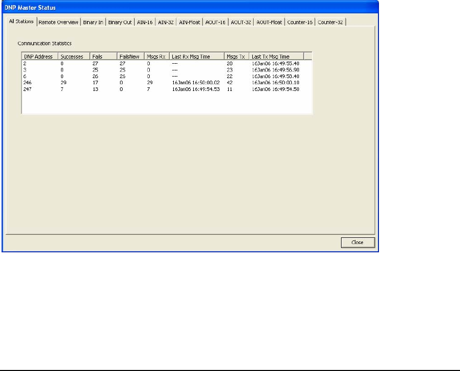
The DNP Master Status dialog has a number of selectable tabs and opens with the All Stations tab
selected. The following tabs are displayed.
• All Stations
• Remote Overview
• Binary In (binary inputs information)
• Binary Out (binary outputs information)
• AIN-16 (16-bit analog inputs information)
• AIN-32 (32-bit analog inputs information)
• AIN-Float (short float analog inputs information)
• AOUT-16 (16-bit analog outputs information)
• AOUT-32 (32-bit analog outputs information)
• AOUT-Float (short float analog outputs information)
• Counter-16 (16-bit counter inputs information)
• Counter-32 (32-bit counter inputs information)
6.2.1 All Stations Tab
The All Stations tab displays the run-time communications diagnostics for all outstations polled by
the master or outstations reporting unsolicited data to the master.
The Communication Statistics window displays a list of all outstations and the communication
statistics for each station in the list. The statistics counters increment whenever a new DNP message
is sent or received, and roll over after 65535 messages. The following statistics are displayed.
• DNP Address displays the DNP address of the outstation.
DNP3 User and Reference Manual
May 9, 2007
79
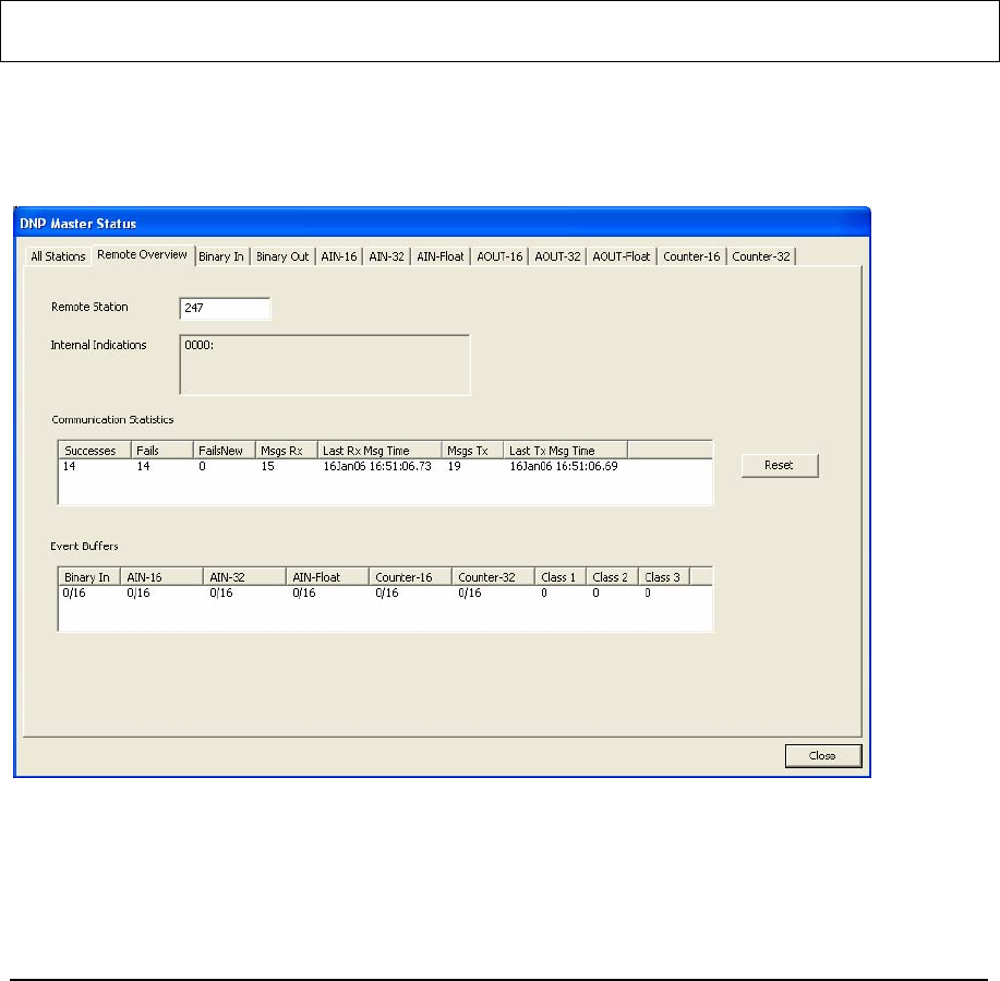
• Successes display the number of successful message transactions between this master and the
corresponding remote station. This number includes master polls to the remote station and
unsolicited responses from the outstation.
• Fails displays the number of failed message transactions between this master and the
corresponding remote station. This counter increments by 1 for a failed message transaction
irrespective of the number of application layer retries.
• FailsNew displays the number failed message transactions between this master and the
corresponding remote station since the last successful poll.
• Msgs Rx displays the number of DNP packets (frames) received from the outstation station. This
number includes frames containing unsolicited responses from the outstation.
• Last Rx Msg Time displays the time the last DNP packet (frame) was received from the
outstation.
• Msgs Tx displays the number of DNP packets (frames) sent to the outstation.
• Last Tx Msg Time displays the time the last DNP packet (frame) was sent to the outstation.
Note: The Msgs Tx and Msgs Rx counters could be greater than or equal to the Successes and
Fails counters.
6.2.2 Remote Overview Tab
The Remote Overview tab displays the run-time diagnostics and current data values for a selected
remote station. The data shown is from the image of the data in the master station.
The Remote Station window is where the DNP address of the remote station is entered. When the
Remote station field is changed all data fields on this tab and the following I/O tabs are updated with
the values for the newly selected Remote Station.
DNP3 User and Reference Manual
May 9, 2007
80

The Internal Indications window displays the current state of the DNP internal indications (IIN)
flags for the selected remote station. For a detailed description of the IIN flags see the section
Internal Indication (IIN) Flags section of this manual.
The Communication Statistics window displays communication statistics for the remote station
selected. The statistics counters increment whenever a new DNP message is sent or received, and roll
over after 65535 messages. The following statistics are displayed.
• Successes displays the number of successful messages received in response to master polls sent
to the station. This number includes unsolicited responses from the outstation.
• Fails displays the number of failed or no responses to master polls sent to the outstation.
• FailsNew displays the number failed or no responses to master polls sent to the outstation since
the last successful poll.
• Msgs Rx displays the number of messages received from the outstation station. This number
includes unsolicited responses from the outstation.
• Last Rx Msg Time displays the time the last message was received from the outstation.
• Msgs Tx displays the number of messages sent to the outstation station.
• Last Tx Msg Time displays the time the last message was sent to the outstation.
Click Reset to reset the counters to zero.
Event Buffers shows the number of events in each type of event buffer and the allocated buffer size.
The buffers shown are for binary inputs, 16-bit analog inputs, 32-bit analog inputs, Floating point
analog inputs, 16-bit counter inputs, and 32-bit counter inputs, and Class 1, 2, and 3 events.
The Event Buffers window displays the number of events in each type of event buffer and the
allocated buffer size for the selected remote station. The event buffers displayed are:
• Binary In (binary inputs)
• AIN-16 (16-bit analog inputs)
• AIN-32 (32-bit analog inputs)
• AIN-Float (floating point analog inputs)
• Counter-16 (16-bit counter inputs)
• Counter-32 (32-bit counter inputs)
• Class 1 (class 1 events)
• Class 2 (class 2 events)
• Class 3 (class 3 events)
Note: Due to a limitation of the DNP3 protocol, an Unsolicited message from an outstation is not
capable of including information stating which data class generated the message. As a result,
all Unsolicited events when received by the master will be counted as Class 1 events. Events
which are polled by the master, however, do contain class information and will be counted in
the Event Buffer for the appropriate class.
DNP3 User and Reference Manual
May 9, 2007
81
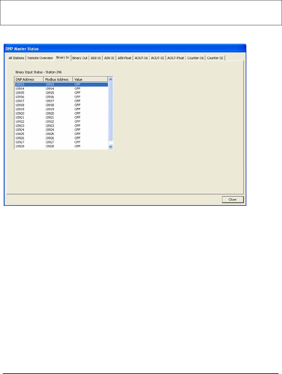
6.2.3 Remote Point Status Tabs
The point status tabs show the state of each point of the selected type in the remote station selected
on the Remote Overview tab. The values shown are from the image of the remote station in the
master station.
Note: Class 0 polling of an outstation must be enabled in the master in order to allow that
outstation’s DNP points to be listed on these tabs. This is the only way for the master to
retrieve a complete list of all points in an outstation.
The example below shows the appearance of the Binary In tab.
The DNP Address column shows the DNP address of the point.
The Modbus Address column shows the Modbus register address of the point. This is only relevant
for points that have an address mapping in the master station. For points that have an address
mapping, this will show the Modbus register address of the point. For points which do not have an
address mapping, this will show ‘---‘.
The Value column shows the value of the point. Binary points are shows as OFF or ON. Numeric
points show the numeric value of the point.
DNP3 User and Reference Manual
May 9, 2007
82

7 DNP Device Profile Document - Master
DNP v3.00
DEVICE PROFILE DOCUMENT
Vendor Name: Control Microsystems Inc.
Device Name: SCADAPack controllers
Highest DNP Level Supported:
For Requests 2
For Responses 2
Device Function:
g Master Slave
Notable objects, functions, and/or qualifiers supported in addition to the Highest DNP Levels
Supported (the complete list is described in the attached table):
• Function code 14 (warm restart)
• Function code 20 (Enable Unsolicited Messages) for class 1, 2, 3 objects only.
• Function code 21 (Disable Unsolicited Messages) for class 1, 2, 3 objects only.
• Object 41, variation 1 (32-bit analog output block)
Maximum Data Link Frame Size (octets):
Transmitted 292
Received (must be 292)
Maximum Application Fragment Size (octets):
Transmitted 2048
Received 2048
DNP3 User and Reference Manual
May 9, 2007
83

Maximum Data Link Re-tries:
None
Fixed at
g Configurable, range 0 to 255
Maximum Application Layer Re-tries:
None
g Configurable, range 0 to 255
Requires Data Link Layer Confirmation:
Never
Always
Sometimes If 'Sometimes', when?
g Configurable for Always or Never
Requires Application Layer Confirmation:
Never
Always (not recommended)
When reporting Event Data (Slave devices only)
When sending multi-fragment responses (Slave devices only)
Sometimes If 'Sometimes', when?
______________________________________________
gConfigurable for always or only when Reporting Event Data and Unsolicited Messages
Timeouts while waiting for:
Data Link Confirm None Fixed at _________ Variable g Configurable
Complete Appl. Fragment None Fixed at _________ Variable g Configurable
Application Confirm None Fixed at _________ Variable g Configurable
Complete Appl. Response None Fixed at _________ Variable g Configurable
Others __________________________________________________________________________
Sends/Executes Control Operations:
WRITE Binary Outputs Never Always Sometimes g Configurable
SELECT/OPERATE Never Always Sometimes g Configurable
DIRECT OPERATE Never Always Sometimes g Configurable
DIRECT OPERATE - NO ACK Never Always Sometimes g Configurable
Count > 1 Never Always Sometimes g Configurable
DNP3 User and Reference Manual
May 9, 2007
84

Pulse On Never Always Sometimes g Configurable
Pulse Off Never Always Sometimes g Configurable
Latch On Never Always Sometimes g Configurable
Latch Off Never Always Sometimes g Configurable
Queue g Never Always Sometimes Configurable
Clear Queue g Never Always Sometimes Configurable
FILL OUT THE FOLLOWING ITEM FOR MASTER DEVICES ONLY:
Expects Binary Input Change Events:
g Either time-tagged or non-time-tagged for a single event
Both time-tagged and non-time-tagged for a single event
Configurable (attach explanation)
FILL OUT THE FOLLOWING ITEMS FOR SLAVE DEVICES ONLY:
Reports Binary Input Change Events when no
specific variation requested:
Never
Only time-tagged
Only non-time-tagged
Configurable to send both, one or the
other (attach explanation)
Reports time-tagged Binary Input Change Events
when no specific variation requested:
Never
Binary Input Change With Time
Binary Input Change With Relative Time
Configurable (attach explanation)
Sends Unsolicited Responses:
Never
Configurable by class
Only certain objects
Sometimes (attach explanation)
g ENABLE/DISABLE UNSOLICITED
Sends Static Data in Unsolicited Responses:
Never
When Device Restarts
When Status Flags Change
No other options are permitted.
Default Counter Object/Variation:
No Counters Reported
Configurable (attach explanation)
Default Object 20
Default Variation 05
Counters Roll Over at:
No Counters Reported
Configurable (attach explanation)
16 Bits
32 Bits
DNP3 User and Reference Manual
May 9, 2007
85

Point-by-point list attached 16 Bits for 16-bit counters
32 Bits for 32-bit counters
Point-by-point list attached
Sends Multi-Fragment Responses: g Yes No
DNP3 User and Reference Manual
May 9, 2007
86

DNP V3.00
DEVICE PROFILE DOCUMENT
IMPLEMENTATION OBJECT
This table describes the objects, function codes and qualifiers used in the device:
OBJECT REQUEST
(slave must parse)
RESPONSE
(master must parse)
Obj Var Description Func
Codes
(dec)
Qual
Codes
(hex)
Func
Codes
Qual
Codes
(hex)
1 0
Binary Input - All Variations
1
06
1 1
Binary Input
129, 130
00, 01
1 2
Binary Input with Status
129, 130
00, 01
2 0
Binary Input Change - All Variations
1
06,07,08
2
1
Binary Input Change without Time
1
06,07,08
129, 130
17, 28
2 2
Binary Input Change with Time
1
06,07,08
129, 130
17, 28
2 3
Binary Input Change with Relative Time
1
06,07,08
129, 130
17, 28
10 0
Binary Output - All Variations
1
06
10 1
Binary Output
10 2
Binary Output Status
129, 130
00, 01
12 0
Control Block - All Variations
12
1
Control Relay Output Block
3, 4, 5,
6
17, 28
129
echo of
request
12 2
Pattern Control Block
12 3
Pattern Mask
20 0
Binary Counter - All Variations
1, 7, 8,
9, 10
06
20 1
32-Bit Binary Counter
129, 130
00, 01
20 2
16-Bit Binary Counter
129, 130
00, 01
20 3
32-Bit Delta Counter
20 4
16-Bit Delta Counter
20 5
32-Bit Binary Counter without Flag
129, 130
00, 01
20 6
16-Bit Binary Counter without Flag
129, 130
00, 01
20 7
32-Bit Delta Counter without Flag
DNP3 User and Reference Manual
May 9, 2007
87

DNP V3.00
DEVICE PROFILE DOCUMENT
IMPLEMENTATION OBJECT
This table describes the objects, function codes and qualifiers used in the device:
OBJECT REQUEST
(slave must parse)
RESPONSE
(master must parse)
Obj Var Description Func
Codes
(dec)
Qual
Codes
(hex)
Func
Codes
Qual
Codes
(hex)
20 8
16-Bit Delta Counter without Flag
21 0
Frozen Counter - All Variations
1
06
21 1
32-Bit Frozen Counter
129, 130
00, 01
21 2
16-Bit Frozen Counter
129, 130
00, 01
21 3
32-Bit Frozen Delta Counter
21 4
16-Bit Frozen Delta Counter
21 5
32-Bit Frozen Counter with Time of Freeze
21 6
16-Bit Frozen Counter with Time of Freeze
21 7
32-Bit Frozen Delta Counter with Time of
Freeze
21 8
16-Bit Frozen Delta Counter with Time of
Freeze
21 9
32-Bit Frozen Counter without Flag
129, 130
00, 01
21 10
16-Bit Frozen Counter without Flag
129, 130
00, 01
21 11
32-Bit Frozen Delta Counter without Flag
21 12
16-Bit Frozen Delta Counter without Flag
22 0
Counter Change Event - All Variations
1
06,07,08
22 1
32-Bit Counter Change Event without Time
129, 130
17, 28
22 2
16-Bit Counter Change Event without Time
129, 130
17, 28
22 3
32-Bit Delta Counter Change Event without
Time
22 4
16-Bit Delta Counter Change Event without
Time
22 5
32-Bit Counter Change Event with Time
22 6
16-Bit Counter Change Event with Time
22 7
32-Bit Delta Counter Change Event with Time
22 8
16-Bit Delta Counter Change Event with Time
DNP3 User and Reference Manual
May 9, 2007
88

DNP V3.00
DEVICE PROFILE DOCUMENT
IMPLEMENTATION OBJECT
This table describes the objects, function codes and qualifiers used in the device:
OBJECT REQUEST
(slave must parse)
RESPONSE
(master must parse)
Obj Var Description Func
Codes
(dec)
Qual
Codes
(hex)
Func
Codes
Qual
Codes
(hex)
23 0
Frozen Counter Event - All Variations
23 1
32-Bit Frozen Counter Event without Time
23 2
16-Bit Frozen Counter Event without Time
23 3
32-Bit Frozen Delta Counter Event without Time
23 4
16-Bit Frozen Delta Counter Event without Time
23 5
32-Bit Frozen Counter Event with Time
23 6
16-Bit Frozen Counter Event with Time
23 7
32-Bit Frozen Delta Counter Event with Time
23 8
16-Bit Frozen Delta Counter Event with Time
30 0
Analog Input - All Variations
1
06
30 1
32-Bit Analog Input
129, 130
00, 01
30 2
16-Bit Analog Input
129, 130
00, 01
30 3
32-Bit Analog Input without Flag
129, 130
00, 01
30 4
16-Bit Analog Input without Flag
129, 130
00, 01
30 5
Short Floating Point Analog Input
129, 130
00, 01
31 0
Frozen Analog Input - All Variations
31 1
32-Bit Frozen Analog Input
31 2
16-Bit Frozen Analog Input
31 3
32-Bit Frozen Analog Input with Time of Freeze
31 4
16-Bit Frozen Analog Input with Time of Freeze
31 5
32-Bit Frozen Analog Input without Flag
31 6
16-Bit Frozen Analog Input without Flag
32 0
Analog Change Event - All Variations
1
06,07,08
32 1
32-Bit Analog Change Event without Time
129,130
17,28
32 2
16-Bit Analog Change Event without Time
129,130
17,28
DNP3 User and Reference Manual
May 9, 2007
89

DNP V3.00
DEVICE PROFILE DOCUMENT
IMPLEMENTATION OBJECT
This table describes the objects, function codes and qualifiers used in the device:
OBJECT REQUEST
(slave must parse)
RESPONSE
(master must parse)
Obj Var Description Func
Codes
(dec)
Qual
Codes
(hex)
Func
Codes
Qual
Codes
(hex)
32 3
32-Bit Analog Change Event with Time
129,130
17,28
32 4
16-Bit Analog Change Event with Time
129,130
17,28
32 5
Short Floating Point Analog Change Event
without Time
129,130
17,28
33 0
Frozen Analog Event - All Variations
33 1
32-Bit Frozen Analog Event without Time
33 2
16-Bit Frozen Analog Event without Time
33 3
32-Bit Frozen Analog Event with Time
33 4
16-Bit Frozen Analog Event with Time
40 0
Analog Output Status - All Variations
1
06
40 1
32-Bit Analog Output Status
129, 130
00, 01
40 2
16-Bit Analog Output Status
129, 130
00, 01
40 3
Short Floating Point Analog Output Status
129, 130
00, 01
41 0
Analog Output Block - All Variations
41 1
32-Bit Analog Output Block
3, 4, 5,
6
17, 28
129
echo of
request
41 2
16-Bit Analog Output Block
3, 4, 5,
6
17, 28
129
echo of
request
41 3
Short Floating Point Analog Output Block
3, 4, 5,
6
17, 28
129
echo of
request
50 0
Time and Date - All Variations
50 1
Time and Date
2 (see
4.14)
07 where
quantity = 1
50 2
Time and Date with Interval
51 0
Time and Date CTO - All Variations
51 1
Time and Date CTO
129, 130
07,
quantity=1
DNP3 User and Reference Manual
May 9, 2007
90

DNP V3.00
DEVICE PROFILE DOCUMENT
IMPLEMENTATION OBJECT
This table describes the objects, function codes and qualifiers used in the device:
OBJECT REQUEST
(slave must parse)
RESPONSE
(master must parse)
Obj Var Description Func
Codes
(dec)
Qual
Codes
(hex)
Func
Codes
Qual
Codes
(hex)
51 2
Unsynchronized Time and Date CTO
129, 130
07,
quantity=1
52 0
Time Delay - All Variations
52 1
Time Delay Coarse
129
07,
quantity=1
52 2
Time Delay Fine
129
07,
quantity=1
60 0
60 1
Class 0 Data
1
06
60 2
Class 1 Data
1
20,21
06,07,08
06
60 3
Class 2 Data
1
20,21
06,07,08
06
60 4
Class 3 Data
1
20,21
06,07,08
06
70 1
File Identifier
80 1
Internal Indications
2
00
index=7
81 1
Storage Object
82 1
Device Profile
83 1
Private Registration Object
83 2
Private Registration Object Descriptor
90 1
Application Identifier
100 1
Short Floating Point
100 2
Long Floating Point
100 3
Extended Floating Point
101 1
Small Packed Binary-Coded Decimal
101 2
Medium Packed Binary-Coded Decimal
DNP3 User and Reference Manual
May 9, 2007
91

DNP V3.00
DEVICE PROFILE DOCUMENT
IMPLEMENTATION OBJECT
This table describes the objects, function codes and qualifiers used in the device:
OBJECT REQUEST
(slave must parse)
RESPONSE
(master must parse)
Obj Var Description Func
Codes
(dec)
Qual
Codes
(hex)
Func
Codes
Qual
Codes
(hex)
101 3
Large Packed Binary-Coded Decimal
No Object
13
No Object
14
No Object
23
(see
4.14)
DNP V3.00
TIME SYNCHRONISATION PARAMETERS
This table describes the worst-case time parameters relating to time synchronisation,
as required by DNP Level 2 Certification Procedure section 8.7
PARAMETER VALUE
Time base drift
+/- 1 minute/month at 25°C
+1 / -3 minutes/month 0 to 50°C
Time base drift over a 10-minute interval
+/- 14 milliseconds at 25°C
+14 / -42 milliseconds 0 to 50°C
Maximum delay measurement error
+/- 100 milliseconds
Maximum internal time reference error when set
from the protocol
+/- 100 milliseconds
Maximum response time
100 milliseconds
DNP3 User and Reference Manual
May 9, 2007
92

8 DNP Device Profile Document - Slave
DNP v3.00
DEVICE PROFILE DOCUMENT
Vendor Name: Control Microsystems Inc.
Device Name: SCADAPack controllers
Highest DNP Level Supported:
For Requests 2
For Responses 2
Device Function:
Master g Slave
Notable objects, functions, and/or qualifiers supported in addition to the Highest DNP Levels
Supported (the complete list is described in the attached table):
Function code 14 (warm restart)
Function code 20 (Enable Unsolicited Messages) for class 1, 2, 3 objects only.
Function code 21 (Disable Unsolicited Messages) for class 1, 2, 3 objects only.
Object 41, variation 1 (32-bit analog output block)
Maximum Data Link Frame Size (octets):
Transmitted 292
Received (must be 292)
Maximum Application Fragment Size (octets):
Transmitted 2048
Received 2048
DNP3 User and Reference Manual
May 9, 2007
93

Maximum Data Link Re-tries:
None
Fixed at
g Configurable, range 0 to 255
Maximum Application Layer Re-tries:
None
g Configurable, range 0 to 255
Requires Data Link Layer Confirmation:
Never
Always
Sometimes If 'Sometimes', when?
g Configurable for Always or Never
Requires Application Layer Confirmation:
Never
Always (not recommended)
When reporting Event Data (Slave devices only)
When sending multi-fragment responses (Slave devices only)
Sometimes If 'Sometimes', when?
______________________________________________
gConfigurable for always or only when Reporting Event Data and Unsolicited Messages
Timeouts while waiting for:
Data Link Confirm None Fixed at _________ Variable g
Configurable
Complete Appl. Fragment None Fixed at _________ Variable g Configurable
Application Confirm None Fixed at _________ Variable g Configurable
Complete Appl. Response None Fixed at _________ Variable g Configurable
Others __________________________________________________________________________
Sends/Executes Control Operations:
WRITE Binary Outputs Never Always Sometimes g Configurable
SELECT/OPERATE Never Always Sometimes g Configurable
DIRECT OPERATE Never Always Sometimes g Configurable
DIRECT OPERATE - NO ACK Never Always Sometimes g Configurable
DNP3 User and Reference Manual
May 9, 2007
94

Count > 1 Never Always Sometimes g Configurable
Pulse On Never Always Sometimes g Configurable
Pulse Off Never Always Sometimes g Configurable
Latch On Never Always Sometimes g Configurable
Latch Off Never Always Sometimes g Configurable
Queue g Never Always Sometimes Configurable
Clear Queue g Never Always Sometimes Configurable
FILL OUT THE FOLLOWING ITEM FOR MASTER DEVICES ONLY:
Expects Binary Input Change Events:
Either time-tagged or non-time-tagged for a single event
Both time-tagged and non-time-tagged for a single event
Configurable (attach explanation)
FILL OUT THE FOLLOWING ITEMS FOR SLAVE DEVICES ONLY:
Reports Binary Input Change Events when no
specific variation requested:
Never
Only time-tagged
g Only non-time-tagged
Configurable to send both, one or the
other (attach explanation)
Reports time-tagged Binary Input Change Events
when no specific variation requested:
g Never
Binary Input Change With Time
Binary Input Change With Relative Time
Configurable (attach explanation)
Sends Unsolicited Responses:
Never
g Configurable by class
Only certain objects
Sometimes (attach explanation)
g ENABLE/DISABLE UNSOLICITED
Sends Static Data in Unsolicited Responses:
g Never
When Device Restarts
When Status Flags Change
No other options are permitted.
Default Counter Object/Variation:
No Counters Reported
Configurable (attach explanation)
g Default Object 20
Counters Roll Over at:
No Counters Reported
Configurable (attach explanation)
16 Bits
DNP3 User and Reference Manual
May 9, 2007
95

Default Variation 05
Point-by-point list attached
32 Bits
g 16 Bits for 16-bit counters
32 Bits for 32-bit counters
Point-by-point list attached
Sends Multi-Fragment Responses: g Yes No
DNP3 User and Reference Manual
May 9, 2007
96

DNP V3.00
DEVICE PROFILE DOCUMENT
IMPLEMENTATION OBJECT
This table describes the objects, function codes and qualifiers used in the device:
OBJECT REQUEST
(slave must parse)
RESPONSE
(master must parse)
Obj Var Description Func
Codes
(dec)
Qual
Codes
(hex)
Func
Codes
Qual
Codes
(hex)
1 0
Binary Input - All Variations
1
06
1 1
Binary Input
129, 130
00, 01
1 2
Binary Input with Status
129, 130
00, 01
2 0
Binary Input Change - All Variations
1
06,07,08
2
1
Binary Input Change without Time
1
06,07,08
129, 130
17, 28
2 2
Binary Input Change with Time
1
06,07,08
129, 130
17, 28
2 3
Binary Input Change with Relative Time
1
06,07,08
129, 130
17, 28
10 0
Binary Output - All Variations
1
06
10 1
Binary Output
10 2
Binary Output Status
129, 130
00, 01
12 0
Control Block - All Variations
12
1
Control Relay Output Block
3, 4, 5,
6
17, 28
129
echo of
request
12 2
Pattern Control Block
12 3
Pattern Mask
20 0
Binary Counter - All Variations
1, 7, 8,
9, 10
06
20 1
32-Bit Binary Counter
129, 130
00, 01
20 2
16-Bit Binary Counter
129, 130
00, 01
20 3
32-Bit Delta Counter
20 4
16-Bit Delta Counter
20 5
32-Bit Binary Counter without Flag
129, 130
00, 01
20 6
16-Bit Binary Counter without Flag
129, 130
00, 01
20 7
32-Bit Delta Counter without Flag
DNP3 User and Reference Manual
May 9, 2007
97

DNP V3.00
DEVICE PROFILE DOCUMENT
IMPLEMENTATION OBJECT
This table describes the objects, function codes and qualifiers used in the device:
OBJECT REQUEST
(slave must parse)
RESPONSE
(master must parse)
Obj Var Description Func
Codes
(dec)
Qual
Codes
(hex)
Func
Codes
Qual
Codes
(hex)
20 8
16-Bit Delta Counter without Flag
21 0
Frozen Counter - All Variations
1
06
21 1
32-Bit Frozen Counter
129, 130
00, 01
21 2
16-Bit Frozen Counter
129, 130
00, 01
21 3
32-Bit Frozen Delta Counter
21 4
16-Bit Frozen Delta Counter
21 5
32-Bit Frozen Counter with Time of Freeze
21 6
16-Bit Frozen Counter with Time of Freeze
21 7
32-Bit Frozen Delta Counter with Time of
Freeze
21 8
16-Bit Frozen Delta Counter with Time of
Freeze
21 9
32-Bit Frozen Counter without Flag
129, 130
00, 01
21 10
16-Bit Frozen Counter without Flag
129, 130
00, 01
21 11
32-Bit Frozen Delta Counter without Flag
21 12
16-Bit Frozen Delta Counter without Flag
22 0
Counter Change Event - All Variations
1
06,07,08
22 1
32-Bit Counter Change Event without Time
129, 130
17, 28
22 2
16-Bit Counter Change Event without Time
129, 130
17, 28
22 3
32-Bit Delta Counter Change Event without
Time
22 4
16-Bit Delta Counter Change Event without
Time
22 5
32-Bit Counter Change Event with Time
22 6
16-Bit Counter Change Event with Time
22 7
32-Bit Delta Counter Change Event with Time
22 8
16-Bit Delta Counter Change Event with Time
DNP3 User and Reference Manual
May 9, 2007
98

DNP V3.00
DEVICE PROFILE DOCUMENT
IMPLEMENTATION OBJECT
This table describes the objects, function codes and qualifiers used in the device:
OBJECT REQUEST
(slave must parse)
RESPONSE
(master must parse)
Obj Var Description Func
Codes
(dec)
Qual
Codes
(hex)
Func
Codes
Qual
Codes
(hex)
23 0
Frozen Counter Event - All Variations
23 1
32-Bit Frozen Counter Event without Time
23 2
16-Bit Frozen Counter Event without Time
23 3
32-Bit Frozen Delta Counter Event without Time
23 4
16-Bit Frozen Delta Counter Event without Time
23 5
32-Bit Frozen Counter Event with Time
23 6
16-Bit Frozen Counter Event with Time
23 7
32-Bit Frozen Delta Counter Event with Time
23 8
16-Bit Frozen Delta Counter Event with Time
30 0
Analog Input - All Variations
1
06
30 1
32-Bit Analog Input
129, 130
00, 01
30 2
16-Bit Analog Input
129, 130
00, 01
30 3
32-Bit Analog Input without Flag
129, 130
00, 01
30 4
16-Bit Analog Input without Flag
129, 130
00, 01
30 5
Short Floating Point Analog Input
129, 130
00, 01
31 0
Frozen Analog Input - All Variations
31 1
32-Bit Frozen Analog Input
31 2
16-Bit Frozen Analog Input
31 3
32-Bit Frozen Analog Input with Time of Freeze
31 4
16-Bit Frozen Analog Input with Time of Freeze
31 5
32-Bit Frozen Analog Input without Flag
31 6
16-Bit Frozen Analog Input without Flag
32 0
Analog Change Event - All Variations
1
06,07,08
32 1
32-Bit Analog Change Event without Time
129,130
17,28
32 2
16-Bit Analog Change Event without Time
129,130
17,28
DNP3 User and Reference Manual
May 9, 2007
99

DNP V3.00
DEVICE PROFILE DOCUMENT
IMPLEMENTATION OBJECT
This table describes the objects, function codes and qualifiers used in the device:
OBJECT REQUEST
(slave must parse)
RESPONSE
(master must parse)
Obj Var Description Func
Codes
(dec)
Qual
Codes
(hex)
Func
Codes
Qual
Codes
(hex)
32 3
32-Bit Analog Change Event with Time
129,130
17,28
32 4
16-Bit Analog Change Event with Time
129,130
17,28
32 5
Short Floating Point Analog Change Event
without Time
129,130
17,28
33 0
Frozen Analog Event - All Variations
33 1
32-Bit Frozen Analog Event without Time
33 2
16-Bit Frozen Analog Event without Time
33 3
32-Bit Frozen Analog Event with Time
33 4
16-Bit Frozen Analog Event with Time
40 0
Analog Output Status - All Variations
1
06
40 1
32-Bit Analog Output Status
129, 130
00, 01
40 2
16-Bit Analog Output Status
129, 130
00, 01
40 3
Short Floating Point Analog Output Status
129, 130
00, 01
41 0
Analog Output Block - All Variations
41 1
32-Bit Analog Output Block
3, 4, 5,
6
17, 28
129
echo of
request
41 2
16-Bit Analog Output Block
3, 4, 5,
6
17, 28
129
echo of
request
41 3
Short Floating Point Analog Output Block
3, 4, 5,
6
17, 28
129
echo of
request
50 0
Time and Date - All Variations
50 1
Time and Date
2 (see
4.14)
07 where
quantity = 1
50 2
Time and Date with Interval
51 0
Time and Date CTO - All Variations
51 1
Time and Date CTO
129, 130
07,
quantity=1
DNP3 User and Reference Manual
May 9, 2007
100

DNP V3.00
DEVICE PROFILE DOCUMENT
IMPLEMENTATION OBJECT
This table describes the objects, function codes and qualifiers used in the device:
OBJECT REQUEST
(slave must parse)
RESPONSE
(master must parse)
Obj Var Description Func
Codes
(dec)
Qual
Codes
(hex)
Func
Codes
Qual
Codes
(hex)
51 2
Unsynchronized Time and Date CTO
129, 130
07,
quantity=1
52 0
Time Delay - All Variations
52 1
Time Delay Coarse
129
07,
quantity=1
52 2
Time Delay Fine
129
07,
quantity=1
60 0
60 1
Class 0 Data
1
06
60 2
Class 1 Data
1
20,21
06,07,08
06
60 3
Class 2 Data
1
20,21
06,07,08
06
60 4
Class 3 Data
1
20,21
06,07,08
06
70 1
File Identifier
80 1
Internal Indications
2
00
index=7
81 1
Storage Object
82 1
Device Profile
83 1
Private Registration Object
83 2
Private Registration Object Descriptor
90 1
Application Identifier
100 1
Short Floating Point
100 2
Long Floating Point
100 3
Extended Floating Point
101 1
Small Packed Binary-Coded Decimal
101 2
Medium Packed Binary-Coded Decimal
DNP3 User and Reference Manual
May 9, 2007
101
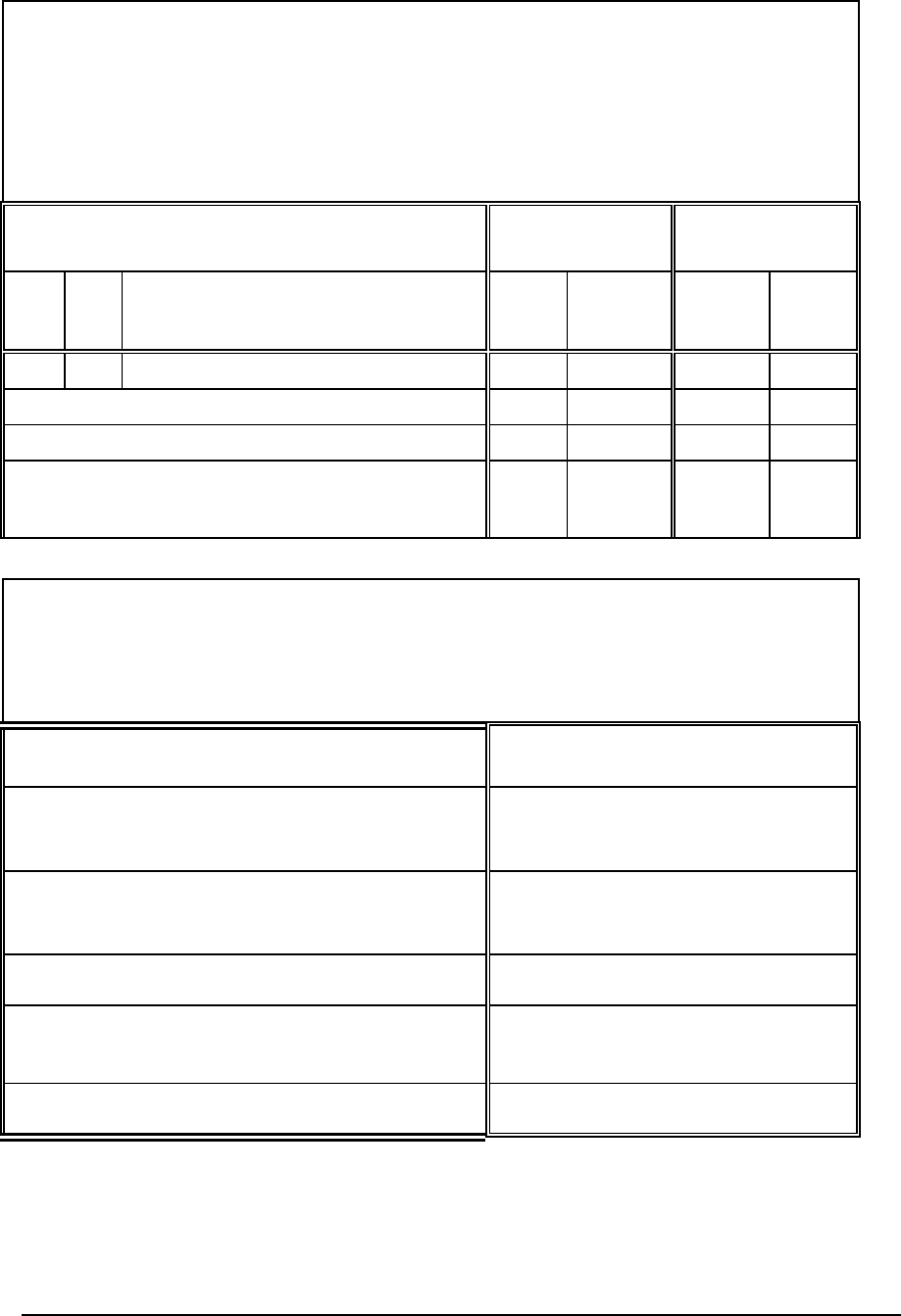
DNP V3.00
DEVICE PROFILE DOCUMENT
IMPLEMENTATION OBJECT
This table describes the objects, function codes and qualifiers used in the device:
OBJECT REQUEST
(slave must parse)
RESPONSE
(master must parse)
Obj Var Description Func
Codes
(dec)
Qual
Codes
(hex)
Func
Codes
Qual
Codes
(hex)
101 3
Large Packed Binary-Coded Decimal
No Object
13
No Object
14
No Object
23
(see
4.14)
DNP V3.00
TIME SYNCHRONISATION PARAMETERS
This table describes the worst-case time parameters relating to time synchronization,
as required by DNP Level 2 Certification Procedure section 8.7
PARAMETER VALUE
Time base drift
+/- 1 minute/month at 25°C
+1 / -3 minutes/month 0 to 50°C
Time base drift over a 10-minute interval
+/- 14 milliseconds at 25°C
+14 / -42 milliseconds 0 to 50°C
Maximum delay measurement error
+/- 100 milliseconds
Maximum internal time reference error when set
from the protocol
+/- 100 milliseconds
Maximum response time
100 milliseconds
DNP3 User and Reference Manual
May 9, 2007
102

TelePACE C Tools
User and Reference Manual
CONTRO
L
MICROSYSTEMS
SCADA products... for the distance
48 Steacie Drive Telephone: 613-591-1943
Kanata, Ontario Facsimile: 613-591-1022
K2K 2A9 Technical Support: 888-226-6876
Canada 888-2CONTROL

TelePACE C Tools User and Reference Manual
©2007 Control Microsystems Inc.
All rights reserved.
Printed in Canada.
Trademarks
TelePACE, SCADASense, SCADAServer, SCADALog, RealFLO, TeleSAFE, TeleSAFE
Micro16, SCADAPack, SCADAPack Light, SCADAPack Plus, SCADAPack 32, SCADAPack
32P, SCADAPack 350, SCADAPack LP, SCADAPack 100, SCADASense 4202 DS,
SCADASense 4202 DR, SCADASense 4203 DS, SCADASense 4203 DR, SCADASense
4102, SCADASense 4012, SCADASense 4032 and TeleBUS are registered trademarks of
Control Microsystems.
All other product names are copyright and registered trademarks or trade names of their
respective owners.
Material used in the User and Reference manual section titled SCADAServer OLE
Automation Reference is distributed under license from the OPC Foundation.
TelePACE C Tools User and Reference Manual
May 9, 2007 1

Table of Contents
TABLE OF CONTENTS .......................................................................................................... 2
TELEPACE C TOOLS OVERVIEW......................................................................................... 3
GETTING STARTED ............................................................................................................... 6
C PROGRAM DEVELOPMENT ............................................................................................ 11
REAL TIME OPERATING SYSTEM...................................................................................... 24
OVERVIEW OF PROGRAMMING FUNCTIONS .................................................................. 37
TELEPACE C TOOLS FUNCTION SPECIFICATIONS........................................................ 73
TELEPACE C TOOLS MACRO DEFINITIONS ..................................................................431
TELEPACE C TOOLS STRUCTURES AND TYPES .........................................................441
C COMPILER KNOWN PROBLEMS.................................................................................. 469
TELEPACE C TOOLS WARRANTY AND LICENSE .........................................................472
TelePACE C Tools User and Reference Manual
May 9, 2007 2

TelePACE C Tools Overview
The TelePACE C Tools are ideal for engineers and programmers who require advanced
programming tools for SCADA applications and process control. The SCADAPack, 4000
Series and TeleSAFE families of controllers execute ladder logic and C application
programs simultaneously, providing you with maximum flexibility in implementing your
control strategy.
This manual provides full documentation on the TelePACE C program loader and the library
of C language process control and SCADA functions. We strongly encourage you to read it,
and to notify us if you find any errors or additional items you feel should be included in our
documentation.
We sincerely hope that the reliability and flexibility afforded by this fully programmable
controller enable you and your company to solve your automation problems in a cost
effective and efficient manner.
The TelePACE C Tools include an ANSI C cross compiler; a customized library of functions
for industrial automation and data acquisition; a real time operating system; and the
TelePACE C program loader. The C function library is similar to many other C
implementations, but contains additional features for real time control, digital and analog I/O.
An overview of the application development environment and its features follows.
Program Development
C programs are written using any text editor. The MCCM77 compiler is used to compile,
assemble and link the programs on a personal computer.
The memory image, which results from this process may then be, loaded either into the
RAM, committed to an EPROM, or both may be used together. Programs may be executed
either manually or automatically at power up.
Modularity
Programs written in TelePACE C may be split into many separately compiled modules.
These modules may be tested individually before being linked together in the final program.
Command files specify how the various files are to be linked.
Assembly Language Code
Assembly language source code may be included directly within C programs. The #asm and
#endasm statements are used to enclose in-line assembly language code, which is then
assembled without passing through the compiler.
C programs are converted to assembly language by the MCCM77 compiler, and this code
may be viewed and modified. The resulting code may also be combined with programs
written directly in assembler.
Program Options
A C application program may reside in RAM or ROM. The normal method of program
development has the program in RAM. The program may call library routines in the
operating system ROM. The RAM is nonvolatile (battery backed), so the program may
remain in RAM once development is completed and the unit is installed.
Application programs may also be committed to EPROM. The RAM is used for data storage
in this case.
TelePACE C Tools User and Reference Manual
May 9, 2007 3

Supported Language Features
The TelePACE C Tools use the Microtec® MCCM77 C compiler. The compiler is ANSI C
compliant, and provides a code optimizer and assembler.
In addition to the standard C operators, data types and library functions, the C tools provide
a set of routines specifically designed for control applications. Some applications and the
descriptions of these functions may be found on the following pages.
Serial Communication
An extensive serial communication library supports simple ASCII communication,
communication protocols and serial port configuration. The default communication mode
uses the TeleBUS RTU communication protocol. It supports access to the I/O database,
serial port reconfiguration and program loading.
The application program can disable the TeleBUS protocol, and use the serial ports for other
purposes.
TeleBUS protocols are compatible with the widely supported, Modbus ASCII and RTU
protocols.
Clock/Calendar
The processor's hardware clock calendar is supported by the C Tools. The time, date and
day of week can be read and set by the application software.
Timers
The controller provides 32 software timers. They are individually programmable for tick rates
from ten per second to once every 25.5 seconds. Timers may be linked to digital outputs to
cause external devices to turn on/off after a specified period. All timers operate in the
background from a hardware interrupt generated by the main system clock.
Duty Cycle and Pulse Outputs
The digital I/O driver provides duty cycle and pulse train outputs. Duty cycle outputs
generate continuous square waves. Pulse train outputs generate finite sequences of pulses.
Outputs are generated independent of the application program.
Watchdog Timer
The controller supports a hardware watchdog timer to detect and respond to hardware or
software failures. Watchdog timer trigger pulses may be generated by the user program or
by the system clock.
Checksums
To simplify the implementation of self-checking communication algorithms, the C Tools
provide four types of checksums: additive, CRC-16, CRC-CCITT, and byte-wise exclusive-
OR. The CRC algorithms are particularly reliable, employing various polynomial methods to
detect nearly all communication errors. Additional types of checksums are easily
implemented using library functions.
TelePACE C Tools User and Reference Manual
May 9, 2007 4

Standard I/O Functions
The TelePACE C Tools are an enhanced version of standard C libraries. Most of the usual
C programming techniques apply. However, with respect to I/O, there are some differences.
The C Tools function library supports all the standard I/O functions. There are no disk-drives
or peripherals associated with the controller. Thus many file handling functions return fixed
responses, indicating that the operation could not be performed.
All standard devices are opened automatically by the operating system and cannot be
closed. The route function may be used to redirect stdin, stdout and stderr.
The TelePACE Program
TelePACE is an easy-to-use interface providing, among several other features, a C Program
Loader and a Ladder Logic program editor. On-line help provides a full reference to all the
features of the TelePACE program. TelePACE runs on the Microsoft Windows operating
system.
This manual references only those features of TelePACE pertaining to the C Program
Loader dialog. Please refer to the section TelePACE Program Reference for a complete
description of TelePACE menus, which will be useful during C Program development.
Additional Documentation
Additional documentation on TelePACE Ladder Logic and the TeleSAFE and SCADAPack
controllers is found in the following documents.
The on-line help for the TelePACE C program loader contains a complete reference to the
operation of the loader. To display on-line help, select Contents from the Help menu.
The SCADAPack & Micro16 System Manual is a complete reference to controller and I/O
modules used with SCADAPack and Micro16 controllers. It contains the SCADAPack
Controller Hardware Manual, the TeleSAFE Micro16 System Manual and hardware
manuals for all 5000 Series I/O modules.
The TelePACE Ladder Logic Reference and User Manual describes the creation of
application programs in the Ladder Logic language.
The TeleBUS Protocols User Manual describes communication using Modbus compatible
protocols.
The TelePACE PID Controller Reference Manual describes PID control concepts and
provides examples using the PID functions.
TelePACE C Tools User and Reference Manual
May 9, 2007 5

Getting Started
This section of the C Tools User Manual describes the installation of C Tools and includes a
Program Development Tutorial. The Program Development Tutorial leads the user through
the steps involved in writing, compiling, linking and loading a C application program.
System Requirements
TelePACE requires the following minimum system configuration.
• Personal computer using 80386 or higher microprocessor.
• Microsoft Windows™ operating system versions including Windows 2000, NT and XP™ .
• Minimum 4 MB of memory.
• Mouse or compatible pointing device.
• Hard disk with approximately 2.5 Mbytes of free disk space.
Making Backup Disks
You should make a backup copy of the TelePACE disk and Microtec C compiler disks
before using the software. A backup copy protects you against damage to the disk. Always
work with the backup copy – if it fails, you can make a new copy from the original disk. Store
the original disk in a safe location.
• In My Computer, click the icon for the disk you want to copy.
• On the File menu, click Copy Disk.
• Click the drive you want to copy from and the drive you want to copy to, and then click
Start.
Installation of C Compiler
Install the Microtec C compiler as described in the installation manuals supplied with the
system.
To run the Microtec Compiler and Linker from any directory, without the need to specify the
full path, you will have to setup the following System Environmental Variables:
Variable Value
mri_m77_bin c:\mccm77;c:\asmm77
mri_m77_inc c:\mccm77
mri_m77_lib c:\mccm77
mri_m77_tmp c:\mccm77\tmp
In addition you would need to add these values to the Path System Variable:
C:\MCCM77;C:\ASMM77;C:\XHSM77
Note that spaces are not tolerated in between entries in the Path value.
TelePACE C Tools User and Reference Manual
May 9, 2007 6

On a Windows XP Control Panel, select System | Advanced | Environmental Variables to
access the dialog where the above variables need to be set.
Installation of TelePACE
Install TelePACE as described in the installation section of the TelePACE Ladder Logic
Reference and User Manual.
Some virus checking software may interfere with Setup. If you experience problems with the
Setup, disable your virus checker and run Setup again.
Installing C Tools as an Upgrade
If you are installing TelePACE as an upgrade to a previous C Tools installation for the
Micro16, note that the C Tools are installed in the new directory
c:\telepace\ctools\520x instead of the directory c:\telepace\ctools\micro16.
If the older version of C Tools is not needed, copy all user data files out of the micro16
directory and delete the directory and its contents.
When linking older programs you will need to modify all older linker command (.cmd) files to
reference the new 520x directory instead of the micro16 directory, or see the sample linker
file appram.cmd for the correct file contents.
The sample linker command file appram.cmd also loads the new ctools.lib library. This
library contains the new C Tools functions defined in the header file ctools.h.
Program Development Tutorial
Program development consists of three stages: writing and editing; compiling and linking;
and loading the program into the controller. Each uses separate tools. To demonstrate these
steps a sample program will be prepared.
Refer to the C Program Development section for a full description of the program
development process.
Traditionally, the first program that is run on a new C compiler is the hello, world program. It
prints the message “hello, world”.
Writing and Editing
A controller C program is written using any text editor or word processor in text mode. The
syntax should correspond to that described in the Microtec MCCM77 Documentation Set,
and the C Program Development section of this manual. This chapter describes non-
standard functions, which are unique to the controller. It should be read carefully to make full
use of the special purpose routines available.
Using your text editor, open the file hello.c file. It is located in the
telepace\ctools\520x directory. The program looks a little different from the traditional
hello, world program.
/* -----------------------------------------------
hello.c
SCADAPack and TeleSAFE Micro16 Test Program
The infamous hello, world program.
-------------------------------------------- */
#include <ctools.h>
TelePACE C Tools User and Reference Manual
May 9, 2007 7

void main(void)
{
PROTOCOL_SETTINGS settings;
/* Disable the protocol on serial port 1 */
settings.type = NO_PROTOCOL;
settings.station = 1;
settings.mode = AM_standard;
settings.priority = 3;
settings.SFMessaging = FALSE;
setProtocolSettings(com1, &settings);
/* Print the message */
fprintf(com1, "hello, world\r\n");
/* Wait here forever */
while (TRUE)
{
NULL;
}
}
The “hello, world” message will be output to the com1 serial port of the controller. A terminal
connected to the port will display the message.
The controller normally communicates on all ports using the TeleBUS communication
protocol. The first section of the program disables the com1 protocol so the serial port can
be used as a normal RS-232 port.
The fprintf function prints the message to the com1 serial port.
When you have completed examining the program, close the hello.c file. It is now ready
to be compiled and linked.
Compiling and Linking
Compiling and linking convert the source code into executable code for the controller. The
TelePACE C Tools use a C cross compiler and linker from Microtec, a respected supplier of
embedded system tools. The compiler produces tight, well-optimized code. The compiler
and linker run under the Microsoft MS-DOS operating system.
The compiler has many command line options. The basic command line and options
required to compile code for the controller are:
mccm77 -v -nQ -Ml -c filename.c
This should be repeated for each file in the application. Note that the command line options
are case sensitive. The character following the M is a lower case l (ell).
Files are linked together using linker command files. To link a program execute the
command:
lnkm77 -c filename.cmd
Sample command files for RAM and ROM based applications are located in the
telepace\ctools\520x directory.
Example
The hello.c program is found in the telepace\ctools\520x directory. To compile and
link the program:
• switch to the telepace\ctools\520x directory;
TelePACE C Tools User and Reference Manual
May 9, 2007 8

• enter the commands
mccm77 -v -nQ -Ml -c hello.c
lnkm77 -c hello.cmd
The file hello.abs contains the executable code in a format ready to load into the
controller.
Loading and Executing
The TelePACE C Program Loader transfers executable files from a PC to the controller and
controls execution of programs in the controller. The loader can also initialize program
memory and serial port configuration.
Controller Initialization
The memory of the controller has to be initialized when beginning a new programming
project or when it is desired to start from default conditions. It is not necessary to initialize
the controller before every program load.
To initialize the controller, first perform a SERVICE boot. A SERVICE boot preserves
programs and data in nonvolatile RAM, but does not start the programs running. Default
communication parameters are used.
To perform a service boot:
• Remove power from the controller.
• Press and hold the LED POWER switch.
• Apply power to the controller.
• Wait until the STAT LED on the top of the board turns on.
• Release the LED POWER switch.
Second, initialize the program and data memory in the controller. A new controller will
require all initializations to be performed. Selected initializations can be performed on a
controller that is in use.
• Run the TelePACE program under Microsoft Windows.
• Connect the PC to the controller with the appropriate serial cable. The hello, world
program will print data on the com1 serial port. Therefore connect to the com2 serial port
on the controller. (All communication ports work the same. We use com2 here because
the sample program is using com1.)
• From the Controller menu, select under Type the controller type that is connected. A
check mark appears beside the desired type when it is selected.
• From the Controller menu, select the Initialize command.
• Select all options: Erase Ladder Logic Program, Erase C Program, Initialize
Controller and Erase Register Assignment Table.
• Click on the OK button.
The controller is now ready for a program.
Loading the Program
To load the hello, world program into the controller:
TelePACE C Tools User and Reference Manual
May 9, 2007 9

• Run the TelePACE program.
• From the Controller menu, select the C Program Loader command.
• Enter hello.abs in the edit box for the C Program file name.
• Select all write options: C Program, Register Assignment and Serial port settings.
• Click on the Write button. The file will be downloaded.
• A warning message about the empty register assignment will appear. Click on the OK
button.
Executing the Program
• Connect a terminal to com1 on the controller. It will display the output of the program. Set
the communication parameters to 9600 baud, 8 data bits, 1 stop bit, and no parity.
• From the C Program Loader dialog, click on the Run button to execute the program.
The “hello, world” message will be displayed on the terminal.
Serial Communication Parameters
When the controller is powered up in the SERVICE mode the serial ports are configured as:
• 9600 baud
• 8 data bits
• 1 stop bit
• no parity
• Modbus RTU protocol emulation
• station address = 1
A program may change these settings with the set_port function. When the controller is
powered up in RUN position, the custom parameters, as stored by the most recent save
function, are used.
TelePACE C Tools User and Reference Manual
May 9, 2007 10

C Program Development
Program Architecture
A C application program may be contained in a single file or in a number of separate files,
called modules. A single file is simple to compile and link. It can become cumbersome to edit
and time-consuming to compile as the file grows in size.
An application stored in separate modules by function is easier to edit, promotes function re-
use, and is quicker to compile when only a few modules are changed. Compiled modules
can be combined into object libraries and shared among users.
The TelePACE C Tools support both single file and multiple module programs. A C
application program consists of support functions provided by the C Tools and the main()
and other functions written by the user.
Main Function Structure
The program sample below shows a typical structure for the main() function.
void main(void)
{
/* Perform initialization actions */
/* Start support tasks */
/* Main Loop*/
while (TRUE)
{
/* Perform application functions */
}
}
Initialization actions typically consist of variable declarations, variable initialization and one-
time actions that must be performed when the program starts running.
Supporting tasks (see Real Time Operating System section) are typically created before
the main loop of the program. Tasks can be created and ended dynamically during the
execution of a program as well.
The main loop of a program is always an infinite loop that continually performs the actions
required by the program. The main() function normally never returns.
Example
The following is an example of a three-module program. Each function is stored in a
separate file. This program will be used in subsequent examples.
File: func1.c
#include <ctools.h>
void func1(void)
{
fputs("This is function 1\r\n", com1);
}
File: func2.c
TelePACE C Tools User and Reference Manual
May 9, 2007 11

#include <ctools.h>
void func2(void)
{
fputs("This is function 2\r\n ", com1);
}
File: main.c
#include <ctools.h>
extern void func1(void);
extern void func2(void);
void main(void)
{
func1();
while (TRUE)
{
func2();
}
}
Start-Up Function Structure
The user’s main() function is called from the appstart function of the C Tools. It is not
necessary to understand the appstart function to write programs. However it performs a
number of useful functions that can be modified by the user.
The start-up code has five major functions:
• create and initialize the application program heap (for dynamic memory allocation);
• specify the number of stack blocks allocated to the main task;
• initialize application program variables;
• control execution of the protocol, ladder logic and background I/O tasks;
• execute the main function.
Source code for the function is supplied with the C Tools. The following discussion refers to
statements found in the file appstart.c.
The heap is a section of memory used by dynamic memory allocation functions such as
malloc. The heap starts at the end of RAM used by the program and continues to the end
of physical RAM. The limit is set by the statement:
end_of_heap .EQU 41ffffh
The limit is set by default to the smallest memory option available for the controller. If your
controller has more memory, change the value of the constant according to the following
table.
RAM Installed C Application Program RAM
Addresses
128 Kbytes none (ladder logic only)
256 Kbytes 400000h – 41FFFFh
640 Kbytes 400000h – 47FFFFh
1024 Kbytes 388000h – 3E7FFFh
400000h – 47FFFFh
TelePACE C Tools User and Reference Manual
May 9, 2007 12

The application program signature section of the file contains a constant that determines the
size of the stack allocated to the main task. The stack size is sufficient for most applications.
It can be changed by modifying the statement:
.WORD 4 ;stack size in blocks
Refer to the Real Time Operating System section for more information on the stack
required by tasks.
The appstart function begins by initializing the heap pointers, setting all non-initialized
variables to zero, and initializing system variables.
It then starts the communication protocols for each serial port, according to the stored
values in the EEPROM (or the standard values on a SERVICE boot). If your application
program never uses the communication protocols, some or all of the following commands
can be removed, to free the stack space used by the protocol tasks.1
start_protocol(com1);
start_protocol(com2);
start_protocol(com3);2
start_protocol(com4);3
The background I/O task is required for the timer functions, dial-up modem communications,
and PID controller functions to operate. If you do not intend to use these functions, you can
reduce the CPU load by changing TRUE to FALSE in the following statement:
runBackgroundIO(TRUE);
The ladder logic interpreter is required for ladder logic programs. If you do not intend to use
ladder logic, you can reduce the CPU load by changing TRUE to FALSE in the following
statement:
runLadderLogic(TRUE);
The final operation is execution of the main function. The _initcopy function copies the
initial values for initialized variables from the __INITDATA section in the program to the
variables. If there are no errors in the data then the user’s application program runs. (An
error is likely only if the program in RAM has been damaged or improperly linked.)
if (_initcopy() == 0)
{
main();
}
If the main function returns, the task is ended. First, any modem control sessions started by
the application are terminated.
abortAllDialupApps();
Then the task is ended. This will cause all other APPLICATION tasks created by main to be
stopped as well.
taskStatus = getTaskInfo(0);
end_task(taskStatus.taskID);
1 Stack space is required to create additional tasks. Refer to the create_task function for more
information.
2 com3 is used only in the SCADAPack and SCADAPack PLUS controllers.
3 com4 is used only in the SCADAPack LIGHT and SCADAPack PLUS controllers.
TelePACE C Tools User and Reference Manual
May 9, 2007 13

Data Storage
All non-initialized variables (local and global) are initialized to zero on program startup by the
Microtec C Compiler. The I/O database is the only section of memory that is not initialized to
zero on startup. Data stored in the I/O database is maintained when power to the controller
is lost, and remains until the controller is initialized from the TelePACE program.
In most cases the I/O database provides adequate space for data storage. However, if
additional non-initialized memory is required, for example for an array of custom data
structures, an non-initialized section of memory can be created as shown in the example
below.
/* ----------------------------------------------------------------
datalog.c
This file contains the global variable definitions for a datalogger
database.
These global variables are placed in a non-initialized section
called "savedata". All data in these variables will be maintained
over powerup.
------------------------------------------------------------------ */
#include <datalog.h>
/* define a non-initialized section called savedata */
#pragma option -NZsavedata
#pragma option -Xp
/* Global variable definitions */
/* log index */
unsigned logIndex;
/* log database */
struct dataLog logData[DATA_LOG_SIZE];
Any variable defined in this file datalog.c will be placed in the non-initialized section
arbitrarily named savedata. Code operating on these variables should be placed in a
separate file, which references these global variables through external definitions placed in a
header file (e.g. datalog.h).
The #pragma option directive is documented in the Microtec MCCM77 Documentation
Set.
Compiling Source Code
The C Compiler converts source code into object files. The basic command line and options
required to compile code for the controller are:
mccm77 -v -nQ -Ml -c filename.c
A complete description of the command line options is given in the Microtec MCCM77 User’s
Guide. The options used here are:
Option Description
-v Issue warnings for features in source file. This option allows you to
detect potential errors in your source code before running the program.
-nQ Do not suppress diagnostic messages. This option provides additional
warnings that allow you to detect potential errors in your source code
before running the program.
-Ml Compile for large memory model (note that the character following the
TelePACE C Tools User and Reference Manual
May 9, 2007 14

M is a lower case ell).
-c Compiler output is an object file.
The following options may be useful.
Option Description
-Jdir Specify the directory containing the standard include files. Adding -
Jc:\telepace\ctools\520x to the command line allows you to
locate your application program files in a different directory. This helps
in organizing your files if you have more than one application program.
-O Enable standard optimizations. This produces smaller and faster
executable code.
-Ot Optimize in favor of execution time rather than code size where a
choice can be made.
-nOc Pop the stack after each function call. This increases code size and
execution time. This option should only be used if there is a large
number of consecutive function calls in your program.
A large number of consecutive calls requires a large stack allocation
for a task. Since the number of stack blocks is limited, using this option
can reduce the stack requirements for a task. See the description for
the create_task function for more information.
Each module in an application should be compiled to produce an object file. The object files
are then linked together to form an executable program.
Example
The following commands are required to compile the program described in the previous
sections.
mccm77 -v -nQ -Ml -c main.c
mccm77 -v -nQ -Ml -c func1.c
mccm77 -v -nQ -Ml -c func2.c
This produces three output files: main.obj; func1.obj and func2.obj. In the next
section these object files will be combined into an executable program.
Linking Object Files
The linker converts object files and object file libraries into an executable program. The
basic command line and options to link a program are:
lnkm77 -c filename.cmd
Controller programs can execute from RAM, Flash or ROM. The linker command file
determines the location of the program.
RAM Based Applications
A sample linker command file for a RAM based program is appram.cmd located in the
telepace\ctools\520x directory.
The file begins by specifying the location and order of memory sections. The far_appcode
section is the first section in all controller C programs. It contains the start-up code that calls
the main() function. In a RAM based program, the start-up code is located at the start of C
application program RAM. This address is fixed at 00400000h.
TelePACE C Tools User and Reference Manual
May 9, 2007 15

The order commands specify the order of the sections. The sections are grouped so all the
code and static data sections are first. The variable data sections follow. The heap is the last
section. It is allowed to grow from the end of the program data to the end of memory (see
Start Up Function Structure section for more information).
The sections may be rearranged, and new sections added, according to the following rules:
• The far_appcode section must be first in the order listing.
• All code sections must follow the far_appcode section.
• The far_endcode section must be the last code section.
• All data sections must follow the code sections.
• The heap section must be last in the order listing.
; ----------------------------------------------
; Specify location and order of memory sections
; ----------------------------------------------
sect far_appcode = 00400000h
order far_appcode, far_code, (CODE), const
order strings, literals, __INITDATA, far_endcode
order far_zerovars, far_initvars, (DATA), heap
The next section of the command file creates initialized data sections. All variables
in the specified section are initialized at start-up of the program. The linker creates a
copy of the data in these sections and stores it in the __INITDATA section.
; ----------------------------------------------
; Create initialized variables section
; ----------------------------------------------
initdata far_initvars
The next section of the command file lists the application program object modules (files) to
be included in the program. You may also include libraries of functions you create here. The
sample command file includes one object module: app.obj.
; ----------------------------------------------
; Load application program object modules
; ----------------------------------------------
load app
The next section of the command file lists the start-up routines and standard libraries to be
included. There are three object modules and two libraries:
Module Description
Appstart.obj This file contains the application program start up routine
(see Program Architecture section above). If you modify the
start-up routine for a particular application, be sure to specify
the path to the modified routine.
Romfunc.obj This file contains addresses of the jump table for calling
functions in the operating system ROM. Only the symbols
are loaded as only the addresses are needed.
Ctools.lib This is the C Tools library, which contains C Tools functions
not found in the operating system ROM.
cm77islf.lib This is the standard Microtec floating point library.
cm77islc.lib This is the standard Microtec function library.
; ----------------------------------------------
; Load start up and library routines
; ----------------------------------------------
load c:\telepace\ctools\520x\appstart
TelePACE C Tools User and Reference Manual
May 9, 2007 16

load_symbols c:\telepace\ctools\520x\romfunc
load c:\telepace\ctools\520x\ctools.lib
load c:\mccm77\cm77islf.lib
load c:\mccm77\cm77islc.lib
The final section of the command file specifies the output file format. The listmap
command specifies what information is to be included in the map file. Refer to the Microtec
manuals for more information on map files.
The format command specifies the executable output will be in Motorola S2 record format.
The TelePACE C Program Loader requires this format.
; ----------------------------------------------
; Specify output file formats and options
; ----------------------------------------------
listmap nopublics, nointernals, nocrossref
format S2
Example
The standard command file must be modified to link the application described in the
previous example. Copy the appram.cmd file to myapp.cmd. Modify the application object
modules section to read:
; ----------------------------------------------
; Load application program object modules
; ----------------------------------------------
load main
load func1
load func2
Link the file with the command
lnkm77 -c myapp.cmd
This will produce one output file: myapp.abs. The next step is to load it into the controller
using the TelePACE C Program Loader.
Flash Based Applications
A sample command file for a Flash based program is appflash.cmd located in the
telepace\ctools\520x directory. This file is very similar to the command file for RAM
based programs.
The file begins by specifying the location and order of memory sections. There are two types
of sections in a Flash based program. The code and static data sections must be stored in
the Flash. The variable data sections must be stored in RAM.
The far_appcode section is the first code section in all controller C programs. In a Flash
based program, the far_appcode section is located at 110000h.
The far_zerovars section is the first data section. In a ROM based program it is normally
located at the start of application program RAM (00400000h). It is possible to start this
section at any RAM address, if your application requires it.
The order commands specify the order of the sections. The sections may be rearranged,
and new sections added, according to the following rules:
• The far_appcode section must be first in the order listing.
• All code sections must follow the far_appcode section.
• The far_endcode section must be the last code section.
TelePACE C Tools User and Reference Manual
May 9, 2007 17

• The far_zerovars section must be the first data section.
• All other data sections must follow the far_zerovars section.
• The heap section must be the last data section.
; ----------------------------------------------
; Specify location and order of memory sections
; ----------------------------------------------
sect far_appcode = 00110000h
sect far_zerovars = 00400000h
order far_appcode, far_code, (CODE), const
order strings, literals, __INITDATA, far_endcode
order far_zerovars, far_initvars, (DATA), heap
The remaining sections of the file are identical to the RAM command file. Refer to the RAM
Based Applications section for a description.
The final section of the command file specifies the output file format. The default format
command specifies the executable output will be in Motorola S2 record format. This is the
format required by the TelePACE Flash Loader.
Example – C Program in Flash
The standard command file must be modified to link the application described in the
previous example. Copy the appflash.cmd file to myapp.cmd. Modify the application
object modules section to read:
; ----------------------------------------------
; Load application program object modules
; ----------------------------------------------
load main
load func1
load func2
Link the file with the command
lnkm77 -c myapp.cmd
This will produce one output file: myapp.abs. The next step is to write the file to the
controller using TelePACE. Use the Flash Loader command on the Controller menu. Consult
the TelePACE documentation for details.
ROM Based Applications
A ROM based program is very similar to a Flash based application. However, an EPROM
programmer must be used to create the ROM. ROM based programs have access to more
program (code) memory than Flash based applications.
It is recommended that Flash based programs be used, unless there is not enough program
memory available.
If a ROM based program is created it should be stored in an EPROM. If a Flash based part
is used the commands in TelePACE to erase Flash may not work as expected. Contact
Control Microsystems for more information about this.
A sample command file for a ROM based program is approm.cmd located in the
telepace\ctools\520x directory. This file is very similar to the command file for Flash
based programs.
The file begins by specifying the location and order of memory sections. There are two types
of sections in a ROM based program. The code and static data sections must be stored in
the ROM. The variable data sections must be stored in RAM.
TelePACE C Tools User and Reference Manual
May 9, 2007 18

The far_appcode section is the first code section in all controller C programs. In a ROM
based program, the far_appcode section can be located at any address that is a multiple
of 100h in the application ROM. The start of application ROM is fixed at 100000h.
A C application program may share the application ROM space with a ladder logic program.
If only a C program is stored in the ROM the far_appcode section is located at 100000h. If
a ladder logic program is stored in ROM it must start at 100000h. The C application can start
anywhere after the end of the ladder logic program. This location is determined by the size
of the ladder logic program and is best determined by examining the memory image of the
ladder logic program in your EPROM programmer.
The far_zerovars section is the first data section. In a ROM based program it is normally
located at the start of application program RAM (00400000h). It is possible to start this
section at any RAM address, if your application requires it.
The order commands specify the order of the sections. The sections may be rearranged,
and new sections added, according to the following rules:
• The far_appcode section must be first in the order listing.
• All code sections must follow the far_appcode section.
• The far_endcode section must be the last code section.
• The far_zerovars section must be the first data section.
• All other data sections must follow the far_zerovars section.
• The heap section must be the last data section.
; ----------------------------------------------
; Specify location and order of memory sections
;
; Note: the far_appcode section address must
; be a multiple of 100h.
; ----------------------------------------------
sect far_appcode = 00100000h
sect far_zerovars = 00400000h
order far_appcode, far_code, (CODE), const
order strings, literals, __INITDATA, far_endcode
order far_zerovars, far_initvars, (DATA), heap
The remaining sections of the file are identical to the RAM command file. Refer to the RAM
Based Applications section for a description.
The final section of the command file specifies the output file format. The default format
command specifies the executable output will be in Motorola S2 record format. Your
EPROM programmer may require a different output format. The following options are
available. Refer to the Microtec Linker manual for a complete description.
Command Description
format ASCII Intel ASCII hex format. This is also known as Intel-86 or
Extended Intel Hex format.
format IEEE Microtec extended IEEE-695 format.
format S1 Motorola S1 record format.
format S2 Motorola S2 record format.
Example – C Program in ROM
The standard command file must be modified to link the application described in the
previous example. Copy the approm.cmd file to myapp.cmd. Modify the application object
modules section to read:
TelePACE C Tools User and Reference Manual
May 9, 2007 19

; ----------------------------------------------
; Load application program object modules
; ----------------------------------------------
load main
load func1
load func2
Link the file with the command
lnkm77 -c myapp.cmd
This will produce one output file: myapp.abs. The next step is to program an EPROM using
this file.
Example – C and Ladder Logic Program in ROM
The C application program may share the ROM with a ladder logic program. The ladder
logic program is always located at 100000h. The C program may start at any address that is
a multiple of 100h following the ladder logic program.
The standard command file must be modified to link the application described in the
previous examples. Copy the approm.cmd file to myapp.cmd.
Assume for this example that the ladder logic program ends at address 100417h. The next
multiple of 100h after this address is 100500h. Modify the section locations to read:
; ----------------------------------------------
; Specify location and order of memory sections
;
; Note: the far_appcode section address must
; be a multiple of 100h.
; ----------------------------------------------
sect far_appcode = 00100500h
Modify the application object modules section to read:
; ----------------------------------------------
; Load application program object modules
; ----------------------------------------------
load main
load func1
load func2
Link the file with the command
lnkm77 -c myapp.cmd
This will produce one output file: myapp.abs. The next step is to program an EPROM using
this file.
Controller Initialization
You should initialize the memory of the controller when beginning a new programming
project or when you wish to start from default conditions. It is not necessary to initialize the
controller before every program load.
To initialize the controller, first perform a SERVICE boot. A SERVICE boot preserves
programs and data in nonvolatile RAM, but does not start the programs running. Default
communication parameters are used.
To perform a service boot:
• Remove power from the controller.
TelePACE C Tools User and Reference Manual
May 9, 2007 20

• Press and hold the LED POWER switch.
• Apply power to the controller.
• Wait until the STAT LED on the top of the board turns on.
• Release the LED POWER switch.
Second, initialize the program and data memory in the controller. A new controller will
require all initializations be performed. Selected initializations can be performed on a
controller that is in use.
• Run the TelePACE program under Microsoft Windows.
• Connect the PC to the controller with the appropriate serial cable.
• From the Controller menu, select under Type the controller type that is connected. A
check mark appears beside the desired type when it is selected.
• From the Controller menu, select the Initialize command.
• Select all options: Erase Ladder Logic Program, Erase C Program, Initialize
Controller and Erase Register Assignment Table.
• Click on the OK button.
Loading Programs into RAM
The C Program Loader dialog transfers executable files from a PC to the controller.
To load a program into RAM:
• Initialize the controller (see Controller Initialization section above).
• Load the program into the controller:
• Run the TelePACE program.
• From the Controller menu, select the C Program Loader command.
• Enter the executable (.abs) file in the edit box for the C Program file name.
• Select the C Program write option and any other write options desired.
• Click on the Write button. The file will be downloaded.
A checksum is calculated for the complete C program. The checksum is verified each time
the program is run. This prevents a damaged program from running.
Loading Programs into EPROM
The procedure for creating an EPROM depends on your EPROM programmer. In general
you must follow these steps:
• Load the executable file into the programmer and program the EPROM.
• Install the EPROM in the controller.
The controller can accept the following EPROMs. Other EPROMs may be compatible.
Contact Control Microsystems if you are considering using an EPROM not in this list.
Size
(Kbytes) Manufacturer Part Number
64 AMD AM27C512-70DC
TelePACE C Tools User and Reference Manual
May 9, 2007 21

64 SGS-Thomson M27C512-80F1
128 AMD AM27C010-70DC
128 Atmel AT27C010-70PI (one time programmable)
128 SGS-Thomson M27C1001-80F1
128 Toshiba TC57H1000AD-85
256 AMD AM27C020-70DC
256 SGS-Thomson M27C2001-80F1
C Programs may be loaded into Flash memory or EPROM when using TelePACE firmware
1.64 or older.
TelePACE firmware 1.65 or newer no longer supports C Programs in Flash memory. C
Programs may be loaded in RAM memory only.
Creating the EPROM
Load the executable (.abs) file into the memory of the EPROM programmer, according to
the instructions for the programmer.
The first byte of the EPROM (offset 0 in the EPROM) maps to address 100000h when the
EPROM is installed in the controller. The linker generates an executable file with address
offsets starting at 100000h. These offsets must be removed with most programmers, so that
the memory image can be placed at offset 0 in the EPROM itself. (Note that this does not
affect the addresses in the program itself, just the address at which it loads.)
Consult your EPROM programmer documentation to determine how to remove the offset.
This is typically done in one of two ways:
• Specify the data is to be loaded from file address 100000h. You may have to specify that
the file is loaded to offset 0h.
• Or, specify a load offset of –100000h when reading the executable file. The programmer
will add –100000h to all load addresses in the file, resulting in a memory image at offset
0h.
Program the EPROM according to the instructions for your programmer.
Installing the EPROM
Install the EPROM in the application ROM socket on the 5203 or 5204 controller board:
• Locate the socket labeled U14. This is the application ROM socket.
• Orient the EPROM so the notch on the EPROM is at the same end as the notch in the
socket.
• Align all pins of the EPROM with the socket.
• Press the EPROM gently into the socket.
• Check that all pins are inserted correctly and that none are bent.
Initialize the controller (see Controller Initialization section above). The Erase C Program
option must be specified. Other initializations may be performed if desired.
Executing Programs
C application programs are executed when a run program command is received from the
TelePACE C Program Loader; or power is applied to the controller (except when a
SERVICE boot is performed).
TelePACE C Tools User and Reference Manual
May 9, 2007 22

To start a program from the program loader:
• Run the TelePACE program.
• From the C Program Loader dialog, click on the Run button to execute the program.
The controller will execute either the program in RAM or the program in ROM. It chooses the
program to execute in the following order:
• C application program in RAM;
• C application program in ROM;
• no C application (standard start-up sequence for other components).
This mode of operation is useful in the following scenario. A controller is installed with a
program in ROM. If new features or corrections are required, a program can be downloaded
into RAM, either locally or remotely. This program will take precedence over the program in
ROM.
If the RAM program is lost or damaged, the ROM program will execute. The ROM program
can be used as a fallback, performing minimal functions to maintain a process in a fail-safe
condition.
TelePACE C Tools User and Reference Manual
May 9, 2007 23

Real Time Operating System
The real time operating system (RTOS) provides the programmer with tools for building
sophisticated applications. The RTOS allows pre-emptive scheduling of event driven tasks
to provide quick response to real-world events. Tasks multi-task cooperatively. Inter-task
communication and event notification functions pass information between tasks. Resource
functions facilitate management of non-sharable resources.
Task Management
The task management functions provide for the creation and termination of tasks. Tasks are
independently executing routines. The RTOS uses a cooperative multi-tasking scheme, with
pre-emptive scheduling of event driven tasks.
The initial task (the main function) may create additional tasks. The RTOS supports up to 16
tasks. There are 5 task priority levels to aid in scheduling of task execution.
Task Execution
SCADAPack controllers can execute one task at a time. The RTOS switches between the
tasks to provide parallel execution of multiple tasks. The application program can be event
driven, or tasks can execute round-robin (one after another).
Task execution is based upon the priority of tasks. There are 5 priority levels. Level 0 is
reserved for the null task. This task runs when there are no other tasks available for
execution. Application programs can use levels 1 to 4. The main task is created at priority
level 1.
Tasks that are not running are held in queues. The Ready Queue holds all tasks that are
ready to run. Event queues hold tasks that are waiting for events. Message queues hold
tasks waiting for messages. Resource queues hold tasks that are waiting for resources. The
envelope queue holds tasks that are waiting for envelopes.
Priority Inversion Prevention
When a higher priority task, Task H, requests a resource, which is already obtained by a
lower priority task, Task L, the higher priority task, is blocked until Task L releases the
resource. If Task L is unable to execute to the point where its releases the resource, Task H
will remain blocked. This is called a Priority Inversion.
To prevent this from occurring, the prevention method known as Priority Inheritance has
been implemented. In the example already described, the lower priority task, Task L, is
promoted to the priority of Task H until it releases the needed resource. At this point Task L
is returned to its original priority. Task H will obtain the resource now that it is available.
Note that this does not prevent deadlocks that occur when each task requests a resource
that the other has already obtained. This “deadly embrace” is a design error in the
application program.
Task Management Functions
There are five RTOS functions for task management. Refer to the Function Specification
section for details on each function listed.
TelePACE C Tools User and Reference Manual
May 9, 2007 24

create_task Create a task and make it ready to execute.
end_task Terminate a task and free the resources and envelopes allocated to
it.
end_application Terminate all application program type tasks. This function is used by
communication protocols to stop the application program prior to
loading new code.
installExitHandler Specify a function that is called when a task is ended with the
end_task or end_application functions.
getTaskInfo Return information about a task.
Task Management Macros
The ctools.h file defines the following macros used for task management. Refer to the C
Tools Macros section for details on each macro listed.
RTOS_PRIORITIES Number of RTOS task priorities.
RTOS_TASKS Number of RTOS tasks.
STACK_SIZE Size of the machine stack.
TS_EXECUTING Task status indicating task is executing
TS_READY Task status indicating task is ready to execute
TS_WAIT_RESOURCE Task status indicating task is blocked waiting for a resource
TS_WAIT_ENVELOPE Task status indicating task is blocked waiting for an envelope
TS_WAIT_EVENT Task status indicating task is blocked waiting for an event
TS_WAIT_MESSAGE Task status indicating task is blocked waiting for a message
Task Management Structures
The ctools.h file defines the structure Task Information Structure for task management
information. Refer to the C Tools Structures and Types section for complete information
on structures and enumeration types.
Resource Management
The resource management functions arbitrate access to non-sharable resources. These
resources include physical devices such as serial ports, and software that is not re-entrant.
The RTOS defines nine system resources, which are used by components of the I/O drivers,
memory allocation functions and communication protocols.
An application program may define other resources as required. Care must be taken not to
duplicate any of the resource numbers declared in ctools.h as system resources.
Resource Management Functions
There are three RTOS functions for resource management. Refer to the Function
Specification section for details on each function listed.
request_resource Request access to a resource and wait if the resource is not
available.
TelePACE C Tools User and Reference Manual
May 9, 2007 25

poll_resource Request access to a resource. Continue execution if the resource is
not available
release_resource Free a resource for use by other tasks.
IO_SYSTEM Resource
The IO_SYSTEM resource regulates access to all functions using the I/O system. C
application programs, ladder logic programs, communication protocols and background I/O
operations share the I/O system. It is imperative the resource is obtained to prevent a
conflict, as protocols and background operations are interrupt driven. Do not retain control of
the resource for more that 0.1 seconds, or background operations will not execute properly.
DYNAMIC_MEMORY Resource
The DYNAMIC_MEMORY resource regulates access to all memory allocation functions.
These functions allocate memory from the system heap. The heap is shared amongst all
tasks. The allocation functions are non-reentrant.
The DYNAMIC_MEMORY resource must be obtained before using any of the following
functions.
calloc allocates data space dynamically
free frees dynamically allocated memory
malloc allocates data space dynamically
realloc changes the size of dynamically allocated space
AB_PARSER Resource
This resource is used by the DF1 communication protocol tasks to allocate access to the
common message parser for each serial port. This resource is of no interest to an
application program. However, an application program may not use the resource number
assigned to it.
MODBUS_PARSER Resource
This resource is used by Modbus communication protocol drivers to allocate access to the
common message parser by tasks for each serial port. This resource is of no interest to an
application program.
Resource Management Macros
The ctools.h file defines the following macros used for resource management. Refer to the
C Tools Macros section for details on each macro listed.
AB_PARSER DF1 protocol message parser.
COM1_DIALUP Resource for dialing functions on com1.
COM2_DIALUP Resource for dialing functions on com2.
COM3_DIALUP Resource for dialing functions on com3.
COM4_DIALUP Resource for dialing functions on com4.
DYNAMIC_MEMORY Memory allocation functions.
HART HART modem resource.
TelePACE C Tools User and Reference Manual
May 9, 2007 26

IO_SYSTEM I/O system hardware functions.
MODBUS_PARSER Modbus protocol message parser.
RTOS_RESOURCES Number of RTOS resource flags.
Inter-task Communication
The inter-task communication functions pass information between tasks. These functions
can be used for data exchange and task synchronization. Messages are queued by the
RTOS until the receiving task is ready to process the data.
Inter-task Communication Functions
There are five RTOS functions for inter-task communication. Refer to the Function
Specification section for details on each function listed.
send_message Send a message envelope to another task.
receive_message Read a received message from the task's message queue or wait if
the queue is empty.
poll_message Read a received message from the task's message queue. Continue
execution of the task if the queue is empty.
allocate_envelope Obtain a message envelope from free pool maintained by the RTOS,
or wait if none is available.
deallocate_envelope Return a message envelope to the free pool maintained by the
RTOS.
Inter-task Communication Macros
The ctools.h file defines the following macros used for inter-task communication. Refer to
the C Tools Macros section for details on each macro listed.
MSG_DATA Specifies the data field in an envelope contains a data value.
MSG_POINTER Specifies the data field in an envelope contains a pointer.
RTOS_ENVELOPES Number of RTOS envelopes.
Inter-task Communication Structures
The ctools.h file defines the structure Message Envelope Structure for inter-task
communication information. Refer to the C Tools Structures and Types section for
complete information on structures and enumeration types.
Event Notification
The event notification functions provide a mechanism for communicating the occurrence
events without specifying the task that will act upon the event. This is different from inter-
task communication, which communicates to a specific task.
Multiple occurrences of a single type of event are queued by the RTOS until a task waits for
or polls the event.
TelePACE C Tools User and Reference Manual
May 9, 2007 27

Event Notification Functions
There are four RTOS functions for event notification. Refer to the Function Specification
section for details on each function listed.
wait_event Wait for an event to occur.
poll_event Check if an event has occurred. Continue execution if one has not
occurred.
signal_event Signal that an event has occurred.
interrupt_signal_event Signal that an event has occurred from an interrupt handler. This
function must only be called from within an interrupt handler.
There are two support functions, which are not part of the RTOS that may be used with
events.
startTimedEvent Enables signaling of an event at regular intervals.
endTimedEvent Terminates signaling of a regular event.
Event Notification Macros
The ctools.h file defines the following macro used for event notification. Refer to the C
Tools Macros section for details.
RTOS_EVENTS Defines the number of available RTOS events.
System Events
The RTOS defines events for communication port management and background I/O
operations. An application program may define other events as required. Care must be
taken not to duplicate any of the event numbers declared in ctools.h as system events.
BACKGROUND This event triggers execution of the background I/O routines. An application
program cannot use it.
COM1_RCVR This event is used by communication protocols to signal a character or
message received on com1. It can be used in a custom character handler
(see install_handler).
COM2_RCVR This event is used by communication protocols to signal a character or
message received on com2. It can be used in a custom character handler
(see install_handler).
COM3_RCVR This event is used by communication protocols to signal a character or
message received on com3. It can be used in a custom character handler
(see install_handler).
COM4_RCVR This event is used by communication protocols to signal a character or
message received on com4. It can be used in a custom character handler
(see install_handler).
FOXCOM_MSG_RECEIVED This event is used when a Foxcom message is received. An
application program cannot use it.
FOXCOM_STARTED This event is used when Foxcom communication has been
established with the sensor. An application program cannot use it.
NEVER This event is guaranteed never to occur. It can be used to disable a task by
waiting for it to occur. However, to end a task it is better to use end_task.
This frees all resources and stack space allocated to the task.
TelePACE C Tools User and Reference Manual
May 9, 2007 28

Error Reporting
Sharable I/O drivers to return error information to the calling task use the error reporting
functions. These functions ensure that an error code generated by one task is not reported
in another task. The errno global variable used by some functions may be modified by
another task, before the current task can read it.
Error Reporting Functions
There are two RTOS functions for error reporting. Refer to the Function Specification
section for details on each function listed.
check_error Check the error code for the current task.
report_error Set the error code for the current task.
Error Reporting Macros
The ctools.h file defines the following macro used for error reporting. Refer to the C Tools
Macros section for details.
NO_ERROR Error code indicating no error has occurred.
TelePACE C Tools User and Reference Manual
May 9, 2007 29

SCA
in AD controller.
DAPack Task Architecture
The diagram shows the tasks present the SC APack
Background I/O Task
Executes every 0.1 s
Timer Interrupt
240 Hz Interrupt
Optional User Tasks
Created by user from
the Main Task.
Priority = 1 to 4
Processes:
• software timers
• dialup modem
• PID controllers
Priority = 4
Processes:
• Ladders timers
• jiffy timer
• watchdog timer
• timed events
Priority =
Com1 Protocol Task
Executes w
sage event
Processes
• messag
Priority = 3
hen mes-
occurs
:
e
h/w interrupt
Ladders &
Task loop
while (TRU
{
request
read da
(Registe
if progr
write da
(Registe
release
release
}
Priority = 1
Com2 Protocol Task Com3 Protocol Task Com4 Protocol Task
Executes when mes-
occurs Executes when mes-
sage event occurssage event
Processes: Processes:
I/O Scan Task
runs continuously:
E)
_resource(IO_SYSTEM);
ta from input modules to I/O database
r Assignment)
am is in RUN mode
xecute ladder logic programe
ta from I/O database to output
r Assignment) modules
_resource(IO_SYSTEM);
_processor();
Main Task (typical)
Task loop runs continuously:
while (TRUE)
{
request_resource(IO_SYSTEM);
functions not requiring IO_SYSTEM resource
}
functions requiring IO_SYSTEM resource
release_resource(IO_SYSTEM);
release_processor();
Priority = 1
• message
Priority = 3
• message
Priority = 3
Executes when mes-
sage event occurs
The hig st prio
interrupt handlers perform their functions tr
importa used in
application programs. It also triggers the background I/O task.
The bac
timers, PID controllers and dialup modem control routines.
There is l
tasks wait for an event signaled by an interrupt handler. This event is signaled when a
complete message is received. The protocol tasks process the received message and
transmi h
protoco
The Ladder Logic and I/O Scan task executes the Ladder Logic program and performs an
I/O scan based on the register assignment. This task is the same priority as the main user
applicat task
Processes:
• message
Priority = 3
he rity routines that execute are hardware interrupt handlers. Most hardware
ansparently. The Timer Interrupt handler is
, because it updates several timers that can bent to application programs
kground I/O task is the highest priority task in the system. It processes software
one protocol task for each serial port where a protocol is enabled. The protoco
t a response when needed. Protocol tasks may be disabled and replaced w
ication program. it
l tasks from the appl
io . n
TelePACE C Tools User and Reference Manual
May 9, 2007 30

The main task is the central task of the user
the use ogic and I/O Scan task. It
may sta
RTOS Ex pl
The foll ing pr f the RTOS functions. It creates several
simple t ks tha task is a C language function that has
as its body an infinite loop so it continues to execute forever.
The main task c is higher priority than main. The
auxiliary tas task then executes round robin
with oth
The aux h the other tasks of its
priority. plify the example.
The ech ter to be received on a serial port, then echoes it back
out the port w lower priority tasks
to execu cter – that signals an
event e oked into the receiver interrupt
handler
The execution of this program is explained in the Explanation of Task Execution section.
--------------------------------------------------------------------
---- */
s several simple tasks for demonstration of the
time operation system.
------------------------------------------- */
-----------------------------------------------
Constants /
HARACTER_RECEIVED 10
-
acter function signals an event when a character is
function must be called from an interrupt handler.
---- ------------------------ */
error)
s received */
nal_event(CHARACTER_RECEIVED);
Prev ode) */
--------------------------------------------------------------------
application. It performs the functions required by
r. Typically, it executes at the same priority as the Ladder L
other urt ser tasks if needed.
am e Application Program
ow ogram is used in the explanation o
as t demonstrate how tasks execute. A
reates two tasks. The echoData ta
e sk
k is the same priority as main. Th main
me priority. er tasks of the sa
iliary task is a simple task that executes round robin wit
cessary for task switching is shown to sim Only the code ne
oData task waits for a charac
. It waits for t handler function – signalChara
he event of the character being received to allo
te. It installs a character
ac a cter is received. This function is hh time chara o
for the serial port.
/*
SCADAPack Real Time Operating System Sample
(c) 1998, Control Microsystems Inc. Copyright
Version History
version 1.00 Wayne Johnston November 10, 1998
------ ----------------------------------------------------------
--- Version 1.00 -------------------------------------------------- /* -
This program create
functionality of the real
------------ -------------
#include <mriext.h>
#include <stdio.h>
#include "ctools,h"
---------------------/*
-------------------------------------------------------------------- *
ine C#def
--------------/* -----------------------------------------------------
signalCharacter
The signalChar
received. This
----------------------------------------
acter(unsigned character, unsigned void signalChar
{ racter wa /* If there was no error, signal that a cha
r == 0) if (erro
{ _sig interrupt
}
/* ent compiler unused variables warning (generates no c
character;
}
/*
TelePACE C Tools User and Reference Manual
May 9, 2007 31

echoData
The echoData function is a task that waits for a character
to be received on com6 and echoes the character back. It installs
a character handler for com6 to generate events on the reception
of characters.
--------------------------------------------------------------------
*/
SABLE;
portSettings.flow_tx = DISABLE;
portSettings.type = RS232;
tings.timeout = 600;
t(com6, &portSettings);
while (TRUE)
{
/* Wait for a character to be received */
wait_event(CHARACTER_RECEIVED);
/* Echo the character back */
character = fgetc(com6);
fputc(character, com6);
}
}
/* --------------------------------------------------------------------
auxiliary
action
that the real time operating system features are clearer.
/* ... add application specific code here ... */
riority to run */
}
}
--------------------------------------------------------
--
void main(void)
{
/* Create serial communication task */
void echoData(void)
{
struct prot_settings protocolSettings;
struct pconfig portSettings;
int character;
3
/* Disable communication protocol */
get_protocol(com6, &protocolSettings);
protocolSettings.type = NO_PROTOCOL;
set_protocol(com6, &protocolSettings);
/* Set serial communication parameters */
portSettings.baud = BAUD9600;
portSettings.duplex = FULL;
portSettings.parity = NONE;
portSettings.data_bits = DATA8;
portSettings.stop_bits = STOP1;
portSettings.flow_rx = DI
portSet
set_por
/* Install handler for received character */
install_handler(com6, signalCharacter);
4 9
8
The auxiliary function is a task that performs some
required by the program. It does not have specific function so
-------------------------------------------------------------------- */
void auxiliary(void)
{
while (TRUE)
{
7
/* Allow other tasks of this p
release_processor();
/* ------------
main
This function creates two tasks: one at priority three and one at
priority 1 to demonstrate the functions of the RTOS.
------------------------------------------------------- ----------- */
1
2
TelePACE C Tools User and Reference Manual
May 9, 2007 32
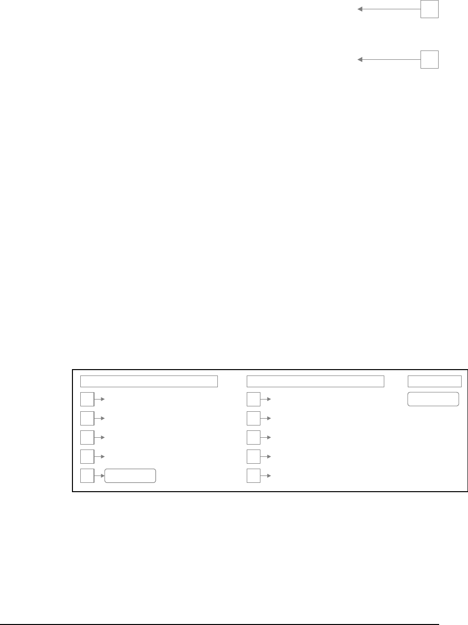
create_task(echoData, 3, APPLICATION, 3);
/* Create a task - same priority as main() task */
create_task(auxiliary, 1, APPLICATION, 2);
while (TRUE)
{
5
/* ... add application specific code here ... */
/* Allow other tasks of this priority to execute */
release_processor();
}
}
Explanation of Task Execution
SCADAPack controllers can execute one task at a time. The Real Time Operating System
(RTOS) switches between the tasks to provide parallel execution of multiple tasks. The
application program can be event driven, or tasks can execute round-robin (one after
another). This program illustrates both types of execution.
Task ex levels. Level 0 is
reserve sks available for
execution. Application programs can use levels 1 to 4. The main task is created at priority
Resource queues hold tasks that are waiting for resources. The
eues at various
points in the program. These points are indicated on the program listing above. The
example ting task. These
are the
Execution Point 2
This point occurs just after the creation of the main task. It is the running task. On the next
instruction it will create the echoData task.
6
ecution is based upon the priority of tasks. There are 5 priority
d for the null task. This task runs when there are no other ta
level 1.
Tasks that are not running are held in queues. The Ready Queue holds all tasks that are
ready to run. Event queues hold tasks that are waiting for events. Message queues hold
tasks waiting for messages.
envelope queue holds tasks that are waiting for envelopes.
The execution of the tasks is illustrated by examining the state of the qu
s show only the Ready queue, the Event 10 queue and the execu
only queues relevant to the example.
Execution Point 1
This point occurs just before the main task begins. The main task has not been created by
the RTOS. The null task has been created, but is not running. No task is executing.
Runnin
g
Task
Event 10 Queue
Read
y
Queue
4
3
2
1
0
none
null()
4
3
2
1
0
Figure 1: Queue Status before Execution of main Task
TelePACE C Tools User and Reference Manual
May 9, 2007 33
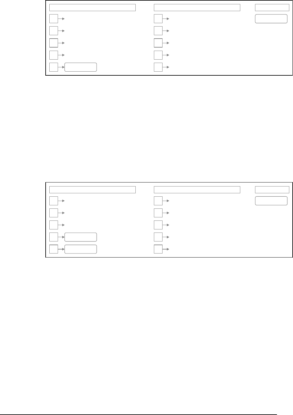
Runn i n
g
Tas
k
Event 10 Queue
Read
y
Queue
4
3
2
1
0
main()
null()
4
3
2
1
0
Figure 2: Queue Status at Start of main Task
Execution Point 3
This point occurs just after the echoData task is created. The echoData task is higher
priority than the main task so it is made the running task. The main task is placed into the
ready queue. It will execute when it becomes the highest priority task.
The echoData task initializes the serial port and installs the serial port handler function
signalCharacter. It will then wait for an event. This will suspend the task until the event
occurs.
The signalCharacter function will generate an event each time a character is received
Execu
This point occurs just after the echoData task waits for event 10. It has been placed on the
.
without an error.
tion Point 4
event queue for event 10
The highest priority task on the ready queue was the main task. It is now running. On the
next instruction it will create another task at the same priority as main.
Runn i n
g
Tas
k
Event 10 Queue
Read
y
Queue
4
3
2
1
0
echoData()
main()
null()
4
3
2
1
0
Figure 3: Queue Status after Creation of echoData Task
TelePACE C Tools User and Reference Manual
May 9, 2007 34
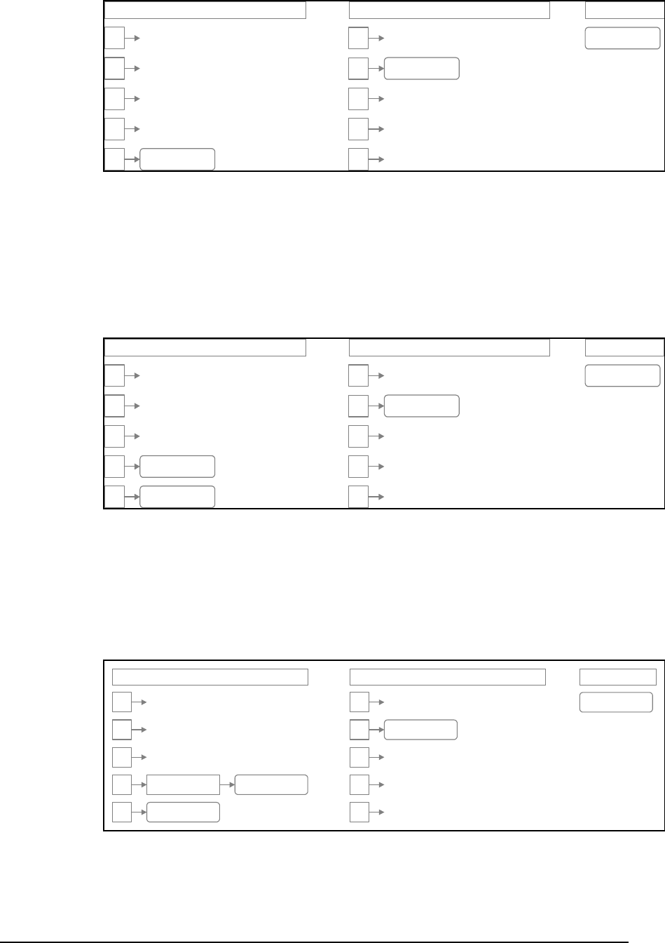
Running TaskEvent 10 QueueReady Q ueue
4
Execution Point 5
This point occurs just after the creation of the auxiliary task. This task is the same priority as
the main task. Therefore the main task remains the running task. The auxiliary task is
ready to run and it is placed on the Ready queue.
Execution Point 6
This point occurs just after the main task releases the processor, but before the next task is
selected to run. The main task is added to the end of the priority 1 list in the Ready queue.
On the next instruction the RTOS will select the highest priority task in the Ready queue.
3
2
1
0
main()
echoData()
null()
4
3
2
1
0
Figure 4: Queue Status After echoData Task Waits for Event
Running TaskEvent 10 QueueReady Q ueue
4
3
2
1
0
echoData()
main()
auxil iary()
null()
4
3
2
1
0
Figure 5 Queue Status after Creation of auxiliary Task
Runn i n
g
Tas
k
Event 10 Queue
Read
y
Queue
4
3
2
1
0
echoData()
none
main()
null()
4
3
2
1
0
auxiliary()
Figure 6: Queue Status After main Task Releases Processor
TelePACE C Tools User and Reference Manual
May 9, 2007 35
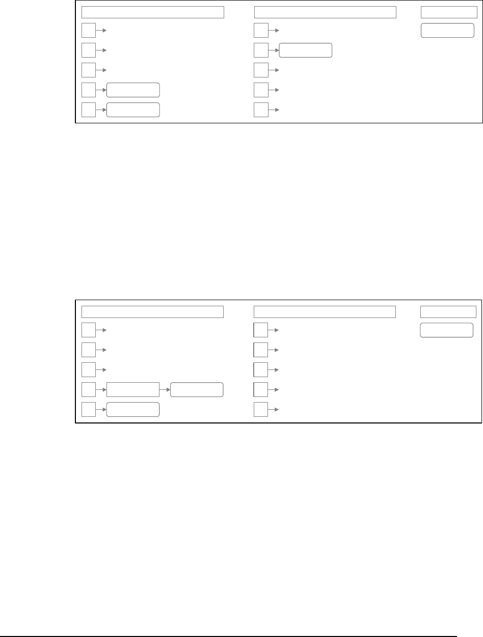
Execution Point 7
This point is just after the auxiliary task has started to run. The main
tasks will continue to alternate execution, as each task releases the processor to the other.
and auxiliary
This point occurs just after a character has been received. The signalCharacter function
t. The RTOS checks the event queue for the event, and makes
executing task. Since
task is higher priority than the ch occurs. The
xecutes.
ueue. The main task will execute before it at
the next task switch.
queue – main – is
Runnin
g
Tas
k
Event 10 Queue
Read
y
Queue
4
Execution Point 8
executes and signals an even
the highest priority task ready to execute. In this case the echoData task is made ready.
The RTOS then determines if the new task is higher priority than the
the echoData auxiliary task, a task swit
auxiliary task is placed on the Ready queue. The echoData task e
Note the position of auxiliary in the Ready q
Execution Point 9
This point occurs just after the echoData task waits for the character-received event. It is
placed on the event 10 queue. The highest priority task on the ready
given the processor and executes.
3
2
1
0
echoData()
auxi l iary()
main()
nullTask()
4
3
2
1
0
us at Start of auxiliary Task Figure 7: Queue Stat
Runnin
g
Tas
k
Event 10 Queue
Read
y
Queue
4
echoData()
4
3 3
2 2
1
0
auxiliary()
1
main()
null() 0
Received Figure 8: Queue Status after Character
TelePACE C Tools User and Reference Manual
May 9, 2007 36

Runnin
g
Tas
k
Event 10 Queue
Read
y
Queue
Overview of Programming
Fun
and overview of the Functions, Macros, Structure
etailed explanations of
ed here.
Cont Operati
of the TelePACE functions relating to
ration. T d in addition to the run-time library supplied
o library f stem or application start up task. Refer to the
ction listed.
etu start up routine.
e C
LICA
STARTUP_SYSTEM Specifies the system start up task.
for use with the
unc r complete
ctions
This section of the User Manual provides
and Types available to the user. The Functions, Macros, Structure and Types overview is
separated into sections of related functions. Refer to the Function Specification, C Tools
Macros and C Tools Structures and Types section of this manual for d
the Functions, Macros, Structure and Types describ
roller on
This section of the manual provides an overview
controller ope hese functions are provide
with the Microtec C compiler.
Start Up Functions
There are tw unctions related to the sy
Function Specification section for details on each fun
startup_task R rns the address of the system
system_start The default start up routine.
Start Up Macros
The ctools.h file defines the following macros for use with the start up task. Refer to th
Tools Macros section for details on each macro listed.
STARTUP_APP TION Specifies the application start up task.
Start Up Task Info Structure
The ctools.h file defines the structure Start Up Information Structure
startup_task f tion. Refer to the C Tools Structures and Types section fo
information on structures and enumeration types.
4
3
2
1
0
echoData()
main()
4
3
2
auxiliary() 1
null() 0
9: ueue Status after echoData Waits for Event Figure Q
TelePACE C Tools User and Reference Manual
May 9, 2007 37

Program Status Information Functions
to the
e controller boot up status.
os for use with controller program information.
s Macros section for details on each macro listed.
pplica ded.
.
COLD_BOOT Controller started in COLD BOOT mode.
ntroller started in RUN mode.
Controller Information Macros
listed.
FT_NONE Unknown firmware type
PLUS SCADAPack PLUS controller
There are five library functions related to controller program status information. Refer
Function Specification section for details on each function listed.
applicationChecksum Returns the application program checksum.
getBootType Returns th
getProgramStatus Returns the application program execution status.
setBootType Sets the controller boot up status.
setProgramStatus Sets the application program execution status.
Program Status Information Macros
The ctools.h file defines the following macr
Refer to the C Tool
NEW_PROGRAM A tion program is newly loa
PROGRAM_EXECUTED Application program has been executed
RUN Co
SERVICE Controller started in SERVICE mode.
REENTRY_BOOT
Controller Information Functions
There is one library function related to controller information. Refer to the Function
Specification section for details on the function listed.
getControllerID Returns the controller ID string.
The ctools.h file defines the following macros for use with controller information. Refer to
the Function Specification section for details on each macro
AB_PROTOCOL DF1 protocol firmware option
BASE_TYPE_MASK Controller type bit mask
FT_TELEPACE TelePACE firmware type
FT_ISAGRAF ISaGRAF firmware type
GASFLOW Gas Flow calculation firmware option
RUNS_2 Set if Gas Flow supports two meter runs
SCADAPACK SCADAPack controller
SCADAPACK_LIGHT SCADAPack LIGHT controller
SCADAPACK_
UNKNOWN_CONTOLLER Unknown controller type
TelePACE C Tools User and Reference Manual
May 9, 2007 38

F mware Version Information Functionir s
e re version. Refer to the Function
Returns controller firmware version information.
irmware version function.
Macros section for details on each macro listed.
VI_DATE_SIZE Number of characters in the version information date field.
rs in the version information copyright field.
re for controller
ection for
Sleep Mode Functions
plication program.
mation on controller
ns the Function Specification
getWakeSource Gets wake up sources
wake up sources enabled
_it mask to enable counter 0 overflow as wake up source
sk to enable counter 1 overflow as wake up source
_ Bit mask to enable counter 2 overflow as wake up source
Bit mask to enable interrupt input as wake up source
ble LED power switch as wake up source
Th re is one function related to the controller firmwa
Specification section for details.
getVersion
Firmware Version Information Macros
The ctools.h file defines the following macros for use with the f
Refer to the C Tools
VI_STRING_SIZE Number of characte
Firmware Version Information Structure
The ctools.h file defines the structure Version Information Structu
firmware version information. Refer to the C Tools Structures and Types s
complete information on structures and enumeration types.
SCADAPack controllers are capable of extremely low power operation when in sleep mode.
SCADAPack controllers enter the sleep mode under control of the ap
Refer to the SCADAPack System Hardware Manual for further infor
sleep mode. The SCADAPack 100 and the SCADASesne series of controllers do not
support sleep mode.
There are three library functio related to sleep mode. Refer to
section for details on each function listed.
setWakeSource Sets wake up sources
sleep Put controller into sleep mode
Sleep Mode Macros
The ctools.h file defines the following macros for use sleep mode. Refer to the C Tools
Macros section for details on each macro listed.
SLEEP_MODE_SUPPORTED Defined if sleep function is supported
WS_ALL All
WS COUNTER_0_OVERFLOW B
WS_COUNTER_1_OVERFLOW Bit ma
WS COUNTER_2_OVERFLOW
WS_INTERRUPT_INPUT
WS_LED_POWER_SWITCH Bit mask to ena
WS_NONE No wake up source enabled
WS_REAL_TIME_CLOCK Bit mask to enable real time clock as wake up source
Undefined wake up source WS_UNDEFINED
TelePACE C Tools User and Reference Manual
May 9, 2007 39

Power Management Functions
Under normal operation, the SCADAPack 350 operates on a CPU clock frequency of 32
MHz. However, the SCADAPack 350 controller is capable of operating on a reduced CPU
g the
The library functions associated with the aforementioned power management allows for the
t c
b erating in Reduced
atures are listed below.
ch function listed.
e
The ctools.h file defines the following macros for use in the power management functions.
etails on each macro listed.
uced speed
to sleep mode
peripheral port is enabled
ED The USB host port is disabled
The status of the device could not be read
tore configuration parameters. The
the system
s: during a RUN boot
gram executes the load function.
rmation is used:
clock frequency of 8 MHz, known as Reduced Power Mode.
Further power savings can be realized on the SCADAPack 350 controller by disablin
LAN or USB peripheral and host ports. Activation of Reduced Power mode as well as the
deactivation of the communication ports can be performed by the application program.
following:
• The CPU speed can be changed from full speed (32 MHz) to reduced speed (8 MHz).
• The LAN port can be enabled or disabled
• The USB peripheral port can be enabled or disabled
• The USB host por an be enabled or disabled.
The Power Mode LED links once a second when the controller is op
Power Mode.
The library functions associated with the power management fe
Refer to the Function Specification section for details on ea
getPowerMode Gets the current power mod
setPowerMode Sets the power mode
Power Management Macros
Refer to the C Tools Macros section for d
PM_CPU_FULL The CPU is set to run at full speed
PM_CPU_REDUCED The CPU is set to run at a red
PM_CPU_SLEEP The CPU is set
PM_LAN_ENABLED The LAN is enabled
PM_LAN_DISABLED The LAN is disabled
PM_USB_PERIPHERAL_ENABLED The USB
PM_USB_PERIPHERAL_DISABLED The USB peripheral port is disabled
PM_USB_HOST_ENABLED The USB host port is enabled
PM_USB_HOST_DISABL
PM_UNAVAILABLE
Configuration Data EEPROM Functions
The EEPROM is nonvolatile memory used to s
application program cannot store application data into this memory. It can cause
configuration parameters to be written, using the save function.
The contents of the EEPROM are copied to RAM under two condition
of the controller; and when the application pro
The following data is loaded on a RUN boot; otherwise default info
TelePACE C Tools User and Reference Manual
May 9, 2007 40

• serial port configuration tables
• protocol configuration tables
• enable store and forward settings
There are two library functions related to the configuration data EEPROM. Refer to the
etails on each function listed.
file defines sted.
reboot.
type boots only.
ORTED ROM in the controller.
The ctools.h file defines the following functions that access the I/O bus. The I/O bus is I2C
d.
ioBusReadByte e byte from an I2C slave device
ad
d
e
ioBusStart n I C bus START condition
ioBusWriteByte 2C slave device
e
The ctools.h file defines the following macros for use with I/O Bus Communication. Refer to
for details on each macro listed.
• LED power settings
• mask for wake-up sources
• execution period on power-up for each PID
Function Specification section for d
Save Writes configuration data from RAM to EEPROM
load Reads configuration data from EEPROM into RAM
Configuration Data EEPROM Macros
The ctools.h the following macros for use with the configuration data EEPROM.
Refer to the C Tools Macros section for details on each macro li
EEPROM_EVERY EEPROM section loaded to RAM on every CPU
EEPROM_RUN EEPROM section loaded to RAM on RUN
EEPROM_SUPP If defined, indicates that there is an EEP
I/O Bus Communication Functions
compatible. Refer to the Function Specification section for details on each function liste
Reads on
ioBusReadLastByte Reads one byte from an I2C slave device and terminates re
ioBusReadMessage Reads a message from an I2C slave device
ioBusSelectForRea Selects an I2C slave device for reading
ioBusSelectForWrit Selects an I2C slave device for writing
Issues a 2
ioBusStop Issues an I2C bus STOP condition
Writes one byte to an I
ioBusWriteMessag Writes a message to an I2C slave device
I/O Bus Communication Macros
the C Tools Macros section
The ctools.h file defines the following macros.
READSTATUS enumeration type ReadStatus
WRITESTATUS enumeration type WriteStatus
TelePACE C Tools User and Reference Manual
May 9, 2007 41

I/O Bus Communication Types
The ctool defines the enumeration types ReadStatuss.h file and WriteStatus. Refer to the
ructur n on structures and
d in the appstart.c routine,
each function listed.
et
Controller I/O Hardware
-
time library supplied with the Microtec C compiler.
dules.
n listed.
ltage.
D er.
I/O
C Tools St es and Types section for complete informatio
enumeration types.
System Functions
The ctools.h file defines the following functions for system initialization and for retrieving
system information. Some of these functions are primarily use
having limited use in an application program.
Refer to the Function Specification section for details on
applicationChecksum Returns the application program checksum.
ioClear Clears all I/O points
ioDatabaseRes Resets the controller to default settings.
ioRefresh Refresh outputs with internal data
ioReset Reset all I/O modules
This section of the manual provides an overview of the TelePACE C Tools functions relating
to controller signal input and output (I/O). These functions are provided in addition to the run
Analog Input Functions
The controller supports internal analog inputs and external analog input modules. Refer to
the SCADAPack System Hardware Manual for further information on controller analog
inputs and analog input mo
There are several library functions related to internal analog inputs and analog input
modules. Refer to the Function Specification section for details on each functio
readBattery Read the controller RAM battery vo
readThermistor Read the controller ambient temperature sensor.
readInternalA Read the controller internal AD convert
ioRead4Ain Read 4 analog inputs into I/O database.
ioRead8Ain Read 8 analog inputs into I/O database.
IoRead4202Inputs Read the digital, counter and analog inputs from a SCADASense
4202 DR.
IoRead4202DSInputs Read the digital, counter and analog inputs from a SCADASense
4202 DS.
ioRead5505Inputs Read the digital and analog inputs from a 5505 I/O Module.
ioRead5506Inputs Read the digital and analog inputs from a 5506 I/O Module.
ioRead5601Inputs Read the digital and analog inputs from a SCADAPack 5601
Module.
TelePACE C Tools User and Reference Manual
May 9, 2007 42

ioRead5602Inputs Read the digital and analog inputs from a SCADAPack 5602 I/O
Module.
ioRead5604Inputs Read the digital and analog inputs from a SCADAPack 5604 I/O
ioReadLPInputs Read the digital and analog inputs from the SCADAPack LP I/O.
and analog inputs from the SCADAPack 100 I/O.
Internal AD channel connected to lithium battery.
Inter
Spec
T_KELVIN Spec
tem
IoWrite4202Outputs to the analog outputs of a SCADASense 4202 DR.
ended
IO (4202 DR with a digital output).
outputs of the 5303 module from I/O database.
s and external digital input modules. Refer to the
ules.
interruptInput Read the controller interrupt input.
Module.
ioRead5606Inputs Read the digital and analog inputs from a 5606 I/O Module.
ioReadSP100Inputs Read the digital
Analog Input Macros
The ctools.h file defines the following macros for use with controller analog inputs. Refer to
the C Tools Macros section for details on each macro listed.
AD_BATTERY
AD_THERMISTOR nal AD channel connected to thermistor.
T_CELSIUS ifies temperatures in degrees Celsius.
T_FAHRENHEIT Specifies temperatures in degrees Fahrenheit.
ifies temperatures in degrees Kelvin.
T_RANKINE Specifies temperatures in degrees Rankine.
Analog Output Functions
The controller supports external analog output modules. Refer to the SCADAPack Sys
Hardware Manual for further information on these modules.
There are three library functions related to analog output modules. Refer to the Function
Specification section for details on each function listed.
ioWriteAout Write to 4 analog outputs from I/O database.
ioWrite2Aout Write to 2 analog outputs from I/O database.
ioWrite4Aout Write to 4 analog outputs from I/O database.
Write
IoWrite4202OutputsEx Write to analog outputs of a SCADASense 4202 DR with ext
ioWrite5303Aout Write to analog
ioWrite5606Outputs Write to the digital and analog outputs of 5606 I/O Module.
ioWriteLPOutputs Writes data to the digital and analog outputs of the SCADAPack LP
I/O.
Digital Input Functions
The controller supports internal digital input
SCADAPack System Hardware Manual for further information on controller digital inputs
and digital input modules.
There are several library functions related to digital inputs and external digital input mod
Refer to the Function Specification section for details on each function listed.
TelePACE C Tools User and Reference Manual
May 9, 2007 43

readCounterInput Read the status of the counter input points on the controller board.
re
ioRead16Din read 16 digital inputs into I/O database.
IoRead4202Inputs Read the digital, counter and analog inputs from a SCADASense
R.
m a 5505 I/O Module.
ioRead5506Inputs Read the digital and analog inputs from a 5506 I/O Module.
puts from a 5601 I/O Module.
ioReadSP100Inputs Read the digital and analog inputs from the SCADAPack 100 I/O.
tions
m
odules. Refer to the Function
Read the controller interrupt input.
6 point Digital output module.
ASense 4202 DR
ADASense 4202 DS from I/O
database.
d analog outputs of SCADAPack 5601 I/O
ioRead8Din ad 8 digital inputs into I/O database.
IoRead32Din read 32 digital inputs into I/O database.
4202 D
IoRead4202DSInputs Read the digital, counter and analog inputs from a SCADASense
4202 DS.
ioRead5505Inputs Read the digital and analog inputs fro
ioRead5601Inputs Read the digital and analog in
ioRead5602Inputs Read the digital or analog inputs from a 5602 I/O Module.
ioRead5604Inputs Read the digital and analog inputs from a SCADAPack 5604 I/O
Module.
ioRead5606Inputs Read the digital and analog inputs from a 5606 I/O Module.
ioReadLPInputs Read the digital and analog inputs from the SCADAPack LP I/O.
Digital Output Func
The controller supports external digital output modules. Refer to the SCADAPack Syste
Hardware Manual for further information on controller digital output modules.
There are several library functions related to digital output m
section for details on each function listed. Specification
interruptInput
ioWrite16Dout Write data to any 1
IoWrite32Dout Write data to any 32 point Digital output module.
IoWrite4202OutputsEx Write to digital and analog outputs of the SCAD
with extended IO (with digital output) from I/O database.
IoWrite4202DSOutputs Write to digital outputs of the SC
ioWrite5601Outputs Write to the digital an
Module.
ioWrite5602Outputs Write to the digital and analog outputs of SCADAPack 5602 I/O
Module.
ioWrite5604Outputs Write to the digital and analog outputs of SCADAPack 5604 I/O
Module.
ioWrite5606Outputs Write to the digital and analog outputs of 5606 I/O Module.
ioWrite8Dout Write data to any 8 point Digital output module.
ioWriteLPOutputs Writes data to the digital and analog outputs of the SCADAPack LP
I/O.
TelePACE C Tools User and Reference Manual
May 9, 2007 44

ioWriteSP100utputs Writes data to the digital outputs of the SCADAPack 100 I/O.
r modules. The counter
. They roll over to 0 on the next
SCADAPack
roller counter inputs and counter
the Function Specification
Pack, SCADAPack LP or SCADAPack 100 counter
counter with or without automatic clearing of the counter value.
Read the digital, counter and analog inputs from a SCADASense
The ctools.h file defines the following macro for use with counter inputs. Refer to the C
ils.
STAT LED blinks and the
output closes when all alarms clear.
for further information on the status
ED and digital output. Refer to the
each function listed.
atus code.
code.
os
Counter Input Functions
The controller supports internal counters and external counte
registers are 32 bits, for a maximum count of 4,294,967,295
count. The counter inputs measure the number of rising inputs. Refer to the
System Hardware Manual for further information on cont
input modules.
There are four library functions related to counters. Refer to
section for details on each function listed.
readCounter Read a SCADA
with or without automatic clearing of the counter register.
interruptCounter Read the SCADAPack or SCADAPack LP interrupt input as a
ioRead4Counter Read any 4 point Counter input module.
IoRead4202Inputs 4202 DR.
IoRead4202DSInputs Read the digital, counter and analog inputs from a SCADAense
4202 DS.
Counter Input Macros
Tools Macros section for deta
LOCAL_COUNTERS Number of controller counter inputs.
Status LED and Output Functions
The status LED and output indicate alarm conditions. The
STATUS output opens when an alarm occurs. The STAT LED turns off and the STATUS
The STAT LED blinks a binary sequence indicating alarm codes. The sequences consist of
long and short flashes, followed by an off delay of 1 second. The sequence then repeats.
The sequence may be read as the Controller Status Code.
Refer to the SCADAPack System Hardware Manual
LED and digital output. There is no status output on the SCADASense series of
programmable controllers.
There are two library functions related to the status L
Function Specification section for details on
clearStatusBit Clears bits in controller st
setStatusBit Sets the bits in controller status
Status LED and Output Macr
The ctools.h file defines the following macros for use with the status LED and digital output.
Refer to the C Tools Macros section for details on each macro listed.
TelePACE C Tools User and Reference Manual
May 9, 2007 45

S_MODULE Status LED code for I/O module co_FAILURE mmunication failure
L
ns
t
ADAPack AOUT module used. In this case option
switches 1 and 2 select the analog ranges. Refer to the SCADAPack System Hardware
switches.
Sense
e ated to the controller option switches. Refer to the Function
s.
ifies switch is in closed position
r off. It
AT LED indicat as a binary sequence.
r code is zero, the status
LED turns off.
ed I/O variables. Use this function with caution in application
indicators. Refer to the Function
section
s M
h file defin ED power control. Refer to the C
Tools Macros section for details on each macro listed.
is to be turned off.
S_NORMA Status LED code for normal status
Options Switches Functio
The controller has three option switches located under the cover of the controller module.
These switches are labeled OPTION 1,2 and 3. The option switches are user defined excep
when a SCADAPack I/O module or SC
Manual for further information on option
There are no option switches on the SCADAPack 100, SCADAPack LP or the SCADA
series of programmable controllers.
Th re is one library function rel
Specification section for detail
optionSwitch Read option switch states.
Option Switches Macros
The ctools.h file defines the following macros for use with option switches. Refer to the C
Tools Macros section for details on each macro listed.
CLOSED Spec
OPEN Specifies switch is in open position
LED Indicators Functions
An application program can control three LED indicators.
The RUN LED indicates the execution status of the program. The LED can be on o
remains in the last state until changed.
The ST es error conditions. It outputs an error code
The sequence repeats until a new error code is output. If the erro
The FORCE LED indicates lock
programs.
There are three library functions related to the LED
Specification for details on each function listed.
runLed Controls the RUN LED status.
setStatus Sets controller status code.
forceLed Sets state of the force LED.
LED Indicator acros
The ctools. es the following macros for use with L
LED_OFF Specifies LED
LED_ON Specifies LED is to be turned on.
TelePACE C Tools User and Reference Manual
May 9, 2007 46

LED Power Control Functions
4
00 Series I/O modules to conserve power. This is particularly useful
in solar ystem Hardware
Manual
There a fer to the Function
Specifi
ledGetD
ledPow
ledPow tch
ledSetD
use with LED power control. Refer to the C
Tools M
LED_OFF
LED_ON
LED P
The cto trol Structure for LED power control
informa s section for complete information
on struc
Softw
The controller provides 32 powerful software timers, which greatly simplify the task of
• timing of process events such as tank fill times
• gen ities
• con
The 32 n per second to once every
25.5 se d than nineteen days can be
measur
All time re interrupt generated by the main
system clock. Once loaded, they count without intervention from the main program.
There a rs. Refer to the Function Specification
section
interval al in tenths of seconds.
settime the set value to zero.
timer remaining in a timer.
read_timer_info Read information about a software timer.
The controller board can disable the LEDs on the controller board, the 5601, 5602 or 560
I/O modules and the 50
powered or unattended installations. Refer to the SCADAPack S
r control. for further information on LED powe
re four library functions related to LED power control. Re
cation section for details on each function listed.
efault Get default LED power state
er Set LED power state
erSwitch Read LED power swi
efault Set default LED power state
LED Power Control Macros
The ctools.h file defines the following macros for
acros section for details on each macro listed.
Specifies LED is to be turned off.
Specifies LED is to be turned on.
o ontrol Structure wer C
ols.h file defines the structure LED Power Con
tion. Refer to the C Tools Structures and Type
enumeration types. tures and
are Timer Functions
programming time-related functions. Uses include:
• generation of time delays
eration of time-based interrupts to schedule regular activ
trol of digital outputs by time periods
tim
n
ers are individually programmable for tick rates from te
co s. Time periods from 0.1 second to greater
ed and controlled.
rs operate in the background from a hardwa
re four library functions related to time
for details on each function listed.
Set timer tick interv
r Set a timer. Timers count down from
Read the time period
TelePACE C Tools User and Reference Manual
May 9, 2007 47

Software Timer Macros
The ctools.h file defines the following macros for use with timers. Refer to the C Too
Macros section for details on each macro listed.
NORMAL Specifies normal count down timer.
TIMED_OUT Specifies timer is has reached zero.
TIMER_BADINTERVAL Error code indicating invalid timer in
ls
terval.
DVALUE
X
rmation for timer information. Refer to the
structures and
ait 5 seconds
off.
interval(0,10); /* timer 0 tick rate = 1 second */
SYSTEM);
seconds */
/* Allow other tasks to execute */
release_p
}
/* shut off output */
asure time.
Contact is assigned to status register 10001.
0.1 second */
S, 10001)) /* wait for turn off */
ther tasks to execute */
e(IO_SYSTEM);
or();
l M)
Examp 3: nd f not full in 1 minute.
Contact is assigned to status register 10001. coil register 1.
TIMER_BADTIMER Error code indicating invalid timer.
TIMER_BA Error code indicating invalid time value.
TIMER_MA Number of last valid software timer.
Timer Information Structure
The ctools.h file defines the structure Timer Info
C Tools Structures and Types section for complete information on
enumeration types.
Timer Example Programs
Example 1: Turn on a digital output assigned to coil register 1 and w
before turning it
request_resource(IO_
setdbase(MODBUS, 1, 1); /* turn on output */
release_resource(IO_SYSTEM);
settimer(0,5); /* load timer 0 with 5
while(timer(0)) /* wait until time expires */
{
rocessor();
request_resource(IO_SYSTEM);
setdbase(MODBUS, 1, 0);
release_resource(IO_SYSTEM);
Example 2: Time the duration a contact is on but wait in loop to me
interval(0,1); /* tick rate =
request_resource(IO_SYSTEM);
if (dbase(MODBUS, 10001)) /* test if contact is on */
{ /* start timer */ settimer(0,63000);
while(dbase(MODBU
{
/* Allow o
release_resourc
release_process
request_resource(IO_SYSTEM);
}
printf("time period = %u\r\n",63000-timer(0));
} TE ; re ease_resource(IO_SYS
le Open valve to fill tank a print alarm message i
Valve is controlled by
TelePACE C Tools User and Reference Manual
May 9, 2007 48

interval(0,10); /* timer 0 tick rate = 1 second */
request_resource(IO_SYSTEM);
; /* open valve */ setdbase(MODBUS, 1, 1)
ttse imer(0,60); /* set timer for 1 minute */
/* tank not full if contact is off
il */
ime Cloc
based real time clock that independently
tains the time and ing system. The time and date remain accurate
during power-off. This allows the controller to be synchronized to time of day for such
atic instrument calibration, energy logging, etc.
ary functions, which access the real-time clock. Refer to the Function
real time clock alarm so it will recur at the same time next
h file defines the following macros for real time clock alarms. Refer to the C
.
The ctools.h file defines the structures Real Time Clock Structure and Alarm Settings
Structure for real time clock information. Refer to the C Tools Structures and Types
section for complete information on structures and enumeration types.
wh e((dbase(MODBUS, 10001)== 0) && timer(0))
{
/* Allow other tasks to execute */
TEM); release_resource(IO_SYS
release_processor();
request_resource(IO_SYSTEM);
}
if (dbase(MODBUS, 10001)== 0)
puts("tank is not filling!!\r\n");
else
puts("tank full\r\n");
setdbase(MODBUS, 1, 0); /* close valve */
release_resource(IO_SYSTEM);
Real T k Functions
The controller is provided with a hardware
main date for the operat
functions as shift production reports, autom
The calendar can be used to automatically take the controller off-line during weekends and
holidays. The calendar automatically handles leap years.
There are eight libr
Specification section for details on each function listed.
alarmIn Returns absolute time of alarm given elapsed time
getclock Read the real time clock.
getClockAlarm Reads the real time clock alarm settings.
getClockTime Read the real time clock.
installClockHandler Installs a handler for real time clock alarms.
resetClockAlarm Resets the
day.
setclock Set the real time clock.
setClockAlarm Sets real time clock alarm.
Real Time Clock Macros
The ctools.
Tools Macros section for details on each macro listed.
AT_ABSOLUTE Specifies a fixed time of day alarm
AT_NONE Disables alarms
Real Time Clock Structures
TelePACE C Tools User and Reference Manual
May 9, 2007 49

Real Time Clock Program Example
The following program illustrates how the date and time can be set and displayed. All field
of the c s
lock structure must be set with valid values for the clock to operate properly.
0;
now.year = 94;
);
now = getclock(); O_SYSTEM);
elays where a fine time base is required. The it
reaches a value of 5183999. This is the number of 1/60-second intervals in 24 hours.
tion
Specification C Func
setjiffy set the jiffy clock
d the jiffy clock
Watchdog Timer Functions
A watchdog timer is a hardware device, which CPU resets and the application
restarts.
eration. The
firmware. A user program can take control of the watchdog timer, so it will detect abnormal
very time
r output in the controller resets the CPU and turns
off all outputs at the I/O system.
#include <ctools.h>
void main(void)
{
struct clock now;
Set to 12:01:00 on January 1, 1994 */ /*
now.hour = 12; /* set the time */
now.minute = 1;
now.second =
now.day = 1; /* set the date */
now.month = 1;
now.dayofweek = 6; /* day is Sat. */
request_resource(IO_SYSTEM);
setclock(&now
release_resource(I
/* Display current hour, minute and second */
printf("%2d:%2d:%2d", now.hour, now.minute,
now.second);
}
The Jiffy Clock
The jiffy clock is a counter that increments 60 times per second. The jiffy clock is useful for
measuring execution times or generating d
clock is reset to zero each time power is applied to the controller. It rolls over to zero after
There are two library functions, which access the real-time clock. Refer to the Func
tion Library chapter for a complete description.
jiffy rea
enables rapid detection of computer hardware
or software problems. In the event of a major problem, the
program
The controller provides an integral watchdog timer to ensure reliable op
watchdog timer resets the CPU if it detects a problem in either the hardware or system
execution of the program.
A watchdog timer is a retriggerable, time delay timer. It begins a timing sequence e
it receives a reset pulse. The time delay is adjusted so that regular reset pulses prevent the
timer from expiring. If the reset pulses cease, the watchdog timer expires and turns on its
output, signifying a malfunction. The time
TelePACE C Tools User and Reference Manual
May 9, 2007 50

The watchdog timer is normally reset by the operating system. This is transparent to the
application program. Operating in such a fashion, the watchdog timer detects any hardware
or firmware problems.
ntrol
nd resets it regularly. If unexpected operation of the program occurs, the reset
pulses cease, and the watchdog timer resets the CPU. The program restarts from the
dog timer to the operating system (default).
ws contr watchd r to an on program.
wnerates a dog res .
A watchdog reset pulse must be generated at least every 500 ms. The CPU resets, and
program execution starts from the beginning of the program, if the watchdog timer is not
re
Watchdog Timer Program Example
The following program segment shows how the watchdog timer could be used to detect the
failure of a section of a program.
l * take ol of wa g timer
/* pro e */
wd_pulse(); /* reset the watchdog timer */
pass control of the watchdog timer back to the operating system before
stem
Checksum Functions
unication algorithms, the C Tools -
to
rs. Additional types of checksums are easily
The ction Specification
che itive, CRC-16, CRC-CCITT and exclusive-OR type
ls
The watchdog timer can detect failure of an application program. The program takes co
of the timer, a
beginning.
There are three library functions related to the watchdog timer. Refer to the Function
Specification section for details on each function listed.
wd_auto Gives control of the watch
d_manual Give ol of the og time applicati
d_pulse Ge watch et pulse
set.
wd_manua
do { (); / contr tchdo */
gram cod
}
while (condition)
wd_auto(); /* return control to OS */
Note: Always
stopping a program, or switching to another task that expects the operating sy
to reset the timer.
To simplify the implementation of self-checking comm
provide four types of checksums: additive, CRC-16, CRC-CCITT, and byte-wise exclusive
OR. The CRC algorithms are particularly reliable, employing various polynomial methods
detect nearly all communication erro
implemented using library functions.
re are two library functions related to checksums. Refer to the Fun
section for details on each function listed.
cksum Calculates add
checksums
crc_reverse Calculates custom CRC type checksum using reverse CRC
algorithm.
Checksum Macros
The ctools.h file defines macros for specifying checksum types. Refer to the C Too
Macros section for details on each macro listed.
TelePACE C Tools User and Reference Manual
May 9, 2007 51

ADDITIVE Additive checksum
BYTE_EOR Byte-wise exclusive OR checksum
CRC_16 CRC-16 type CRC checksum (reverse algorithm)
CRC_CCITT CCITT type CRC checksum (reverse algorithm)
Seria
llers is
m3 and com4. Examples
als, and for
he controller is powered up in
om4
l Communication
The SCADAPack family of controllers offers three or four RS-232 serial ports. The
TeleSAFE Micro16 has two RS-232 serial communication ports. (com1 on all contro
also available as an RS-485 port.) The ports are configurable for baud rate, data bits, stop
bits, parity and communication protocol.
To optimize performance, minimize the length of messages on co
of recommended uses for com3 and com4 are for local operator display termin
programming and diagnostics using the ISaGRAF program.
For the SCADASense series of programmable controllers, com1 is not available for C
applications.
Default Serial Parameters
All ports are configured at reset with default parameters when t
SERVICE mode. The ports use stored parameters when the controller is reset in the RUN
mode. The default parameters are listed below.
Parameter com1 com2 Com3 C
Baud rate 9600 9600 9600 9600
Parity none none None None
Data bits 8 8 8 8
Stop bits 1 1 1 1
Duplex full full Half Half
Protocol Modbus
RTU Modb
RTU us Modbus
RTU Modbus RTU
Station 1 1 1 1
Rx flow control off off Rx disable Rx disable
Tx flow control off off Off Off
Serial time out 60 s 60 s 60 s 60 s
Type RS-232 RS-232 RS-232 RS-232
Serial Communication Time Out
When the controller is transmitting data on the communication po
become full due to receipt of an XOFF character, a slow baud rate
rts, the transmit buffer may
, or improper hardware
ked until space is
le at the conclusion of
nues execution.
es the most common
handshaking.
If the transmit buffers become full, the task transmitting data is bloc
available or the serial time out period expires. If no space is availab
this time period, the transmit buffer is emptied. The task then conti
Debugging Serial Communication
Serial communication can be difficult to debug. This section describ
causes of communication failures.
TelePACE C Tools User and Reference Manual
May 9, 2007 52

• To communicate, the controller and an external device must use the same
rity or stop bit
es is made with
tput of one device to the
ontroller is a DTE device. This
controller.
Equipment (DCE) device
device is connected to the
input of the DTE device is
. Modems are usually DCE devices.
al for your controller.
Communication is not
controller the CTS line must be at
s OFF. If the CTS line is not
ue. If an external device controls this
Serial Communication Functions
. Additional serial
a serial port.
nd error counters.
ndler.
dex
e.
s.
unication parameters.
Serial Communication Macros
g serial communication parameters. Refer to
BAUD150 Specifies 150-baud port speed.
communication parameters. Check the parameters in both units.
• If some but not all characters transmit properly, you probably have a pa
mismatch between the devices.
The connection between two RS-232 Data Terminal Equipment (DTE) devic
a null-modem cable. This cable connects the transmit data ou
receive data input of the other device – and vice versa. The c
cable is described in the System Hardware Manual for your
The connection between a DTE device and a Data Communication
is made with a straight cable. The transmit data output of the DTE
transmit data input of the DCE device. The receive data
connected to the receive data output of the DCE device
This cable is described in the System Hardware Manu
Many RS-232 devices require specific signal levels on certain pins.
possible unless the required signals are present. In the
the proper level. The controller will not transmit if CTS i
connected, the controller will force it to the proper val
line, it must turn it ON for the controller to transmit.
The ctools.h file defines the following serial communication related functions. Refer to the
Function Specification section for details on each function listed
communication functions are included in the Microtec run-time library.
clear_errors Clear serial port error counters.
clear_tx Clear serial port transmit buffer.
get_port Read serial port communication parameters.
GetPortCharacteristics Read information about features supported by
get_status Read serial port status a
install_handler Install serial port character received ha
portConfiguration Get pointer to port configuration table
portIndex Get array index for serial port
portStream Get serial port corresponding to in
queue_mode Set serial port transmitter mod
route Redirect standard I/O stream
setDTR Control RS232 port DTR signal.
set_port Set serial port comm
The ctools.h file defines macros for specifyin
the C Tools Macros section for details on each macro listed.
BAUD75 Specifies 75-baud port speed.
BAUD110 Specifies 110-baud port speed.
TelePACE C Tools User and Reference Manual
May 9, 2007 53

BAUD300 Specifies 300-baud port speed.
s 1200-baud port speed.
00 d port speed.
00 -baud port speed.
00 aud port speed.
200 200-baud port speed.
400 es 38400-baud port speed.
600 ifies 57600-baud port speed.
15200 aud port speed.
erial port.
object for com2 serial port.
a file object for com3 serial port.
object for com4 serial port.
orld length.
E control is disabled.
ntrol is enabled.
EVEN Specifies even parity.
s full duplex.
ODD
_RECE VE_ST message.
OFF
TS.
ON_ OFF
SERIAL_PORTS
SIGNAL_DCD
SIGNAL_OH : off hook signal
BAUD600 Specifies 600-baud port speed.
BAUD1200 Specifie
BAUD24 Specifies 2400-bau
BAUD48 Specifies 4800
BAUD96 Specifies 9600-b
BAUD19 Specifies 19
BAUD38 Specifi
BAUD57 Spec
BAUD1 Specifies 115200-b
com1 Points to a file object for com1 s
com2 Points to a file
com3 Points to
com4 Points to a file
DATA7 Specifies 7 bit w
DATA8 Specifies 8 bit word length.
DISABL Specifies flow
ENABLE Specifies flow co
FULL Specifie
FOPEN_MAX Redefinition of macro from stdio.h
HALF Specifies half duplex.
NONE Specifies no parity.
NOTYPE Specifies serial port type is not known.
Specifies odd parity.
PC_FLOW_RX I OP Receiver disabled after receipt of a
PC_FLOW_RX_XON_X Receiver Xon/Xoff flow control.
PC_FLOW_TX_IGNORE_CTS Transmitter flow control ignores C
PC_FLOW_TX_X X Transmitter Xon/Xoff flow control.
RS232 Specifies serial port is an RS-232 port.
RS232_MODEM Specifies serial port is an RS-232 dial-up modem.
RS485_4WIRE Specifies serial port is a 4 wire RS-485 port.
Number of serial ports.
SIGNAL_CTS I/O line bit mask: clear to send signal
I/O line bit mask: carrier detect signal
SIGNAL_OFF Specifies a signal is de-asserted
I/O line bit mask
TelePACE C Tools User and Reference Manual
May 9, 2007 54

SIGNAL_ON Specifies a signal is asserted
ch signal
C
d Types section for complete information on structures and
enumeration types.
in the
entation Set.
eam
writes a string to a stream
fread
fwrite
getc stream
getchar standard input device
gets ream
initport
printf m
putc m
putchar tput device
puts
scanf am
Dial-Up Modem Functions
These l used with external
modems connected to a serial port. An external modem normally connects to the RS-232
port with a DTE to DCE cable. Consult the System Hardware Manual for your controller for
details. r details on each function listed.
Note: on com port 1.
SIGNAL_RING I/O line bit mask: ring signal
SIGNAL_VOICE I/O line bit mask: voice/data swit
STOP1 Specifies 1 stop bit.
STOP2 Specifies 2 stop bits.
Serial Communication Structures
The ctools.h file defines the structures Serial Port Configuration, Serial Port Status and
Serial Port Characteristics for serial port configuration and information. Refer to the
Tools Structures an
Microtec Serial I/O Functions
These library functions are related to serial communication. They are documented
Microtec MCCM77 Docum
fgetc reads a character from a str
fgets reads a string from a stream
fputc writes a character to a stream
fputs
reads from a stream
writes to a stream
reads a character from a
reads a character from
reads a string from a st
re-initializes serial port
formatted output to a strea
writes a character to a strea
reads a character to standard ou
writes a string to a stream
formatted input from a stre
ibrary functions provide control of dial-up modems. They are
Re r the Function Specification section fofe to
The SCADAPack 100 does not support dial up connections
The SCADASense series of controllers do not support dial up connections.
modem ring to dial-up modem.
modem lization operation.
In send initialization stit
InitStatus read status of modem initia
TelePACE C Tools User and Reference Manual
May 9, 2007 55

modem n operation.
modemDial connect with an external device using a dial-up modem.
using a dial-up
.
onditionally terminate connection with external device or modem
ation (used in task exit handler).
modem s with external device or
k exit handler).
modem interesting event has
ed. This function is usually called whenever a message is
a protocol.
Dial-Up Modem Macros
The cto os of interest to a C application program. Refer
to the Cr details on each macro listed.
MODEM_ of the modem initialization command string
PHONE_ m length of the phone number string
Dial-U es
The cto types DialError and DialState. Refer to the
C Tools mplete information on structures and
enumer
Dial-u
The cto s ModemInit and ModemSetup. Refer to the C
Tools S plete information on structures and
enumer
Modem Initialization Example
The foll em initialization is
used to prepare a modem to answer calls. The example sets up a Hayes modem to answer
incomin
emInit initSettings;
portID;
rt ;
InitEnd terminate modem initializatio
modemDialStatus read status of connection with external device
modem.
modemDialEnd terminate connection with external device using a dial-up modem
modemAbort unc
initializ
AbortAll unconditionally terminate connection
modem initializations (used in tas
Notification notify
occurr
the dial-up modem handler that an
received by
ols.h file defines the following macr
Tools Macros section fo
CMD_MAX_LEN Maximum length
NUM_MAX_LEN Maximu
p Modem Enumeration Typ
ols.h file defines the enumerated
Structures and Types section for co
ation types.
p Modem Structures
ols.h file defines the structure
tructures and Types section for com
ation types.
owing code shows how to initialize a modem. Typically, the mod
g calls.
#include <ctools.h>
void main(void)
{
struct Mod
dreserve_i
enum DialError status;
enum DialState state;
ig portSettings; struct pconf
/* Configure serial port 1 */
ngs.baud = BAUD1200; portSetti
portSettings.duplex = FULL;
ings.parity = NONE; portSett
portSettings.data_bits = DATA8;
po Settings.stop_bits = STOP1;
ngs.flow_rx = DISABLEportSetti
portSettings.flow_tx = DISABLE;
TelePACE C Tools User and Reference Manual
May 9, 2007 56

portSetti
rt ngs.type = RS232_MODEM;
ease_resource(IO_SYSTEM);
{
exit handler.
oid)
{ tup dialSettings;
tID;
portSettings.data_bits = DATA8;
portSettings.stop_bits = STOP1;
w_rx = DISABLE;
w_tx = DISABLE;
po Settings.timeout = 600;
request_resource(IO_SYSTEM);
set_port(com1, &portSettings);
rel
/* Initialize Hayes modem to answer incoming calls */
initSettings.port = com1;
strcpy(initSettings.modemCommand, " F1Q0V1X1 S0=1");
if (modemInit(&initSettings, &portID) == DE_NoError)
do
{
/* Allow other tasks to execute */
release_processor();
/* Wait for the initialization to complete */
modemInitStatus(com1, portID, &status, &state);
}
while (state == DS_Calling);
/* Terminate the initialization */
modemInitEnd(com1, portID, &status);
}
}
Connecting with a Remote Controller Example
The following code shows how to connect to a remote controller using a modem. The
example uses a US Robotics modem. It also demonstrates the use of the modemAbort
function in an
#include <ctools.h>
/* --------------------------------------------
The shutdown function aborts any active
modem connections when the task is ended.
-------------------------------------------- */
void shutdown(void)
{
modemAbort(com1);
}
void main(v
struct ModemSe
reserve_id por
enum DialError status;
enum DialState state;
struct pconfig portSettings;
TASKINFO taskStatus;
/* Configure serial port 1 */
portSettings.baud = BAUD19200;
portSettings.duplex = FULL;
portSettings.parity = NONE;
portSettings.flo
portSettings.flo
portSettings.type = RS232_MODEM;
portSettings.timeout = 600;
request_resource(IO_SYSTEM);
set_port(com1, &portSettings);
release_resource(IO_SYSTEM);
/* Configure US Robotics modem */
dialSettings.port = com1;
dialSettings.dialAttempts = 3;
dialSettings.detectTime = 60;
dialSettings.pauseTime = 30;
dialSettings.dialmethod = 0;
strcpy(dialSettings.modemCommand, "&F1 &A0 &K0 &M0 &B1");
TelePACE C Tools User and Reference Manual
May 9, 2007 57

strcpy(dialSettings.phoneNumber, "555-1212");
/* set up exit handler for this task */
taskStatus = getTaskInfo(0);
installExitHandler(taskStatus.taskID, shutdown);
*/
) == DE_NoError)
}
ds is re
Com rotoco
The TeleBUS protocols are compatible with the widely used Modbus RTU and ASCII
programming and diagnostics ca
. The I/O
system parameter in the controller. General
2
serial ports, RS-485 serial ports, modems, and dial up modems. The
k, with a few
ices on one
The protocol type, communicatio ss are configured separately
program, from the TelePACE pr e, or from another Modbus or DF1
The protocol type may be set to emulate the Modbus ASCII and Modbus RTU protocols, or it
may be disabled. When the protocol is disabled, the port functions as a normal serial port.
/* Connect to the remote controller
if (modemDial(&dialSettings, &portID
{
do
{
/* Allow other tasks to execute */
release_processor();
/* Wait for initialization to complete */
modemDialStatus(com1, portID, &status, &state);
while (state == DS_Calling);
/* If the remote controller connected */
if (state == DS_Connected)
{
/* Talk to remote controller here */
}
/* Terminate the connection */
modemDialEnd(com1, portID, &status);
}
}
Note that a pause of a few secon quired between terminating a connection and
initiating a new call. This pause allows the external modem time to hang up.
munication P ls
protocols. The TeleBUS communication protocols provide a standard communication
interface to SCADAPack controllers. Additional TeleBUS commands provide remote
pability.
The TeleBUS protocols provide full access to the I/O database in the controller
database contains user-assigned registers and general purpose registers. Assigned
registers map directly to the I/O hardware or
purpose registers can be used by ladder logic and C application programs to store
processed information, and to receive information from a remote device.
The TeleBUS protocols operate on a wide variety of serial data links. These include RS-23
radios, leased line
protocols are generally independent of the communication parameters of the lin
exceptions.
Application programs can initiate communication with remote devices. A multiple port
controller can be a data concentrator for remote devices, by polling remote dev
port(s) and responding as a slave on another port(s).
n parameters and station addre
for each serial port on a controller. One controller can appear as different stations on
different communication networks. The port configuration can be set from an application
ogramming softwar
compatible device.
Protocol Type
TelePACE C Tools User and Reference Manual
May 9, 2007 58

The DF1 option enables the emulation of the DF1 protocols.
rotocol) option enables DNP.The DNP (Distributed Network P See the DNP
Protocol secti
and up to 65534 devices using extended addressing. Station numbers identify each device.
o it, or to commands broadcast to all stations.
ue station number.
each device. A device responds to commands addr
broadcast to all stations, and cannot be serial port may
Store and forward messaging re-transm oller. Messages
address translation. A user-
led by default.
BUS DF1 protocol.
to the
section for de
Check
Clears
Clear
enronInstallCommandHandler ndler for Enron Modbus commands.
ration Reads
col Reads
colSettings Reads
serial
ingsEx Reads
param
atus Reads
getSFMapping This function is a stub and no longer performs a necessary
operation.
Read store and forward translation table entry.
This fu
Modbu
Communication on for details on this protocol.
Station Number
The TeleBUS protocol allows up to 254 devices on a network using standard addressing
A device responds to commands addressed t
The station number is in the range 1 to 254 for standard addressing and 1 to 65534 for
extended addressing. Address 0 indicates a command broadcast to all stations, and cannot
be used as a station number. Each serial port may have a uniq
The TeleBUS DF1 protocols allow up to 255 devices on a network. Station numbers identify
essed to it, or to commands broadcast to
all stations. The station number is in the range 0 to 254. Address 255 indicates a command
used as a station number. Each
have a unique station number.
Store and Forward Messaging
its messages received by a contr
may be re-transmitted on any serial port, with or without station
defined translation table determines actions performed for each message. Store and forward
messaging may be enabled or disabled on each port. It is disab
Store and forward messaging is not supported by DNP or Tele
Communication Protocols Functions
There are several library functions related to TeleBUS communication protocol. Refer
Function Specification tails on each function listed.
checkSFTranslationTable translation table for invalid entries.
clear_protocol_status protocol message and error counters.
clearSFTranslationTable all store and forward translation table entries.
Installs ha
getABConfigu DF1 protocol configuration parameters.
get_proto protocol parameters.
getProto extended addressing protocol parameters for a
port.
getProtocolSett extended addressing and Enron Modbus protocol
eters for a serial port.
get_protocol_st protocol message and error counters.
getSFTranslation
installModbusHandler nction allows user-defined extensions to standard
s protocol.
TelePACE C Tools User and Reference Manual
May 9, 2007 59

master_message a protocol message to another device. Sends
modbusExceptionStatus Sets response for the read exception status function.
Sets r
Requests a response from a slave controller using the half-
duplex
aves Clears
slave
ration Define
set_protocol Sets protocol parameters and starts protocol.
s Sets extended addressing protocol parameters for a serial
port.
Sets extended addressing and Enron Modbus protocol
parameters for a serial port.
This function is a stub and no longer performs a necessary
opera
Write store and forward translation table entry.
Starts
fer to
mulation for
AB_FULL_CRC
ex protocol emulation for
hecksum)
or
FORCE_MULTIPLE_COILS Modbus function code
nction code
MM_BAD_FUNCTION Master message status: invalid function code
r message status: invalid message length
ress
t
modbusSlaveID esponse for the read slave ID function.
pollABSlave version of the protocol.
resetAllABSl responses from the response buffers of half-duplex
controllers.
setABConfigu s DF1 protocol configuration parameters.
setProtocolSetting
setProtcolSettingEx
setSFMapping tion.
setSFTranslation
start_protocol protocol execution based on stored parameters.
Communication Protocols Macros
The ctools.h file defines macros for specifying communication protocol parameters. Re
the C Tools Macros section for details on each macro listed.
AB_FULL_BCC Specifies the DF1 Full Duplex protocol e
the serial port. (BCC checksum)
Specifies the DF1 Full Duplex protocol emulation for
the serial port. (CRC checksum)
AB_HALF_BCC Specifies the DF1 Half Dupl
the serial port. (BCC c
AB_HALF_CRC Specifies the DF1 Half Duplex protocol emulation f
the serial port. (CRC checksum)
FORCE_SINGLE_COIL Modbus fu
LOAD_MULTIPLE_REGISTERS Modbus function code
LOAD_SINGLE_REGISTER Modbus function code
MM_BAD_ADDRESS Master message status: invalid database address
MM_BAD_LENGTH Maste
MM_BAD_SLAVE Master message status: invalid slave station add
MM_NO_MESSAGE Master message status: no message was sent.
MM_PROTOCOL_NOT_SUPPORTED Master message status: selected protocol is no
supported.
MM_RECEIVED Master message status: response was received.
TelePACE C Tools User and Reference Manual
May 9, 2007 60

MM_SENT Master message status: message was sent.
MM_EOT Master message status: DF1 slave response was an
slave response did not
match command sent
tatus: DF1 half duplex command
and
Master message status: Modbus slave returned a
ception
an
Specifies the Modbus ASCII protocol emulation for
the serial port.
U protocol emulation for the
protocol for the serial
READ_EXCEPTION_STATUS dbus function code
e
N
NGE
NGE
SF_TABLE_SIZE Number of entries in the store and forward table
Communication Protocol meration Types
ls
s section f
EOT message
MM_WRONG_RSP Master message status: DF1
MM_CMD_ACKED Master message s
has been acknowledged by slave – Master may now
send poll comm
MM_EXCEPTION_FUNCTION function ex
MM_EXCEPTION_ADDRESS Master message status: Modbus slave returned
address exception
MM_EXCEPTION_VALUE Master message status: Modbus slave returned a
value exception
Master message status: response received with MM_RECEIVED_BAD_LENGTH incorrect amount of data.
MODBUS_ASCII
MODBUS_RTU Specifies the Modbus RT
serial port.
NO_PROTOCOL Specifies no communication
port.
READ_COIL_STATUS Modbus function code
Mo
READ_HOLDING_REGISTER Modbus function code
READ_INPUT_REGISTER Modbus function code
READ_INPUT_STATUS Modbus function code
REPORT_SLAVE_ID Modbus function code
SF_ALREADY_DEFINED Result code: translation is already defined in th
table
SF_INDEX_OUT_OF_RANGE Result code: invalid translation table index
SF_NO_TRANSLATIO Result code: entry does not define a translation
SF_PORT_OUT_OF_RA Result code: serial port is not valid
SF_STATION_OUT_OF_RA Result code: station number is not valid
SF_VALID Result code: translation is valid
s Enu
The ctools.h file defines the enumeration type ADDRESS_MODE. Refer to the C Too
Structures and Type or complete information on structures and enumeration
types.
TelePACE C Tools User and Reference Manual
May 9, 2007 61

Communication Protocols Structures
The ctools.h file defines the structures Protocol Status Information, Protocol Settings,
Extended Protocol Settings, Store and Forward Message and Store and Forward n
DNP Communication Protocol
a standards-based communications protocol
can also be implemented in any SCADA system for efficient and reliable communications
DNP offers flexibility and functio ar beyond conventional communications
• Output options
ges
layer defines most commonly a
dnpClearEventLog the DNP change event
buffers.
n Reads the DNP protocol configuration.
dnpGetConfigurationEx Reads the extended DNP configuration parameters.
dnpSaveConfiguration Writes the DNP protocol configuration parameters.
dnpSaveConfigurationEx Writes the extended DNP configuration parameters
Status. Refer to the C Tools Structures and Types section for complete information o
structures and enumeration types.
DNP, the Distributed Network Protocol, is
developed to achieve interoperability among systems in the electric utility, oil & gas,
water/waste water and security industries. This robust, flexible non-proprietary protocol is
based on existing open standards to work within a variety of networks. The IEEE has
recommended DNP for remote terminal unit to intelligent electronic device messaging. DNP
between substation computers, RTUs, IEDs and master stations; over serial or LAN-based
systems.
nality that go f
protocols. Among its robust and flexible features DNP 3.0 includes:
• Addressing for over 65,000 devices on a single link
• Time synchronization and time-stamped events
• Broadcast messa
• Data link and application layer confirmation
DNP 3.0 was originally designed based on three layers of the OSI seven-layer model:
application layer, data link layer and physical layer. The application layer is object-based
with objects provided for most generic data formats. The data link layer provides for several
methods of retrieving data such as polling for classes and object variations. The physical
simple RS-232 or RS-485 interface.
Refer to the DNP User Manual for complete information on DNP protocol, including the
Device Profile Document.
DNP Communication Protocols Functions
There are several library functions related to DNP communication protocol. Refer to the
Function Specification section for details on each function listed.
dnpInstallConnectionHandler Configures the connection handler for DNP.
Deletes all change events from
dnpConnectionEvent Report a DNP connection event
dnpCreateRoutingTable Allocates memory for a new routing table.
dnpGenerateEventLog Generates a change event for the DNP point.
dnpGetConfiguratio
TelePACE C Tools User and Reference Manual
May 9, 2007 62

dnpGetBIConfig Reads the configuration of a DNP binary input point.
t
point
.
nt.
t.
g
ISFConfig Reads the configuration of a DNP 32-bit short floating
input point.
output point.
dnpGetAO32Config Reads the configuration of a DNP 32-bit analog output
DNP 32-bit short floating analog
output point.
ig Sets the configuration of a DNP 32-bit short floating analog
.
ut point.
s Reads the current status of all DNP change event buffers.
protocol.
dnpSearchRoutingTable Searches the routing table for a specific DNP address.
dnpWriteRoutingTableDialStrings Writes a primary and secondary dial string into an
entry in the DNP routing table.
dnpSaveBIConfig Writes the configuration of a DNP binary input point.
dnpSaveBIConfigEx Writes the configuration of an extended DNP Binary Inpu
dnpGetBOConfig Reads the configuration of a DNP binary output point.
dnpGetBIConfigEx Reads the configuration of an extended DNP Binary Input
point.
dnpSaveBOConfig Sets the configuration of a DNP binary output point.
dnpGetAI16Config Reads the configuration of a DNP 16-bit analog input point
dnpSaveAI16Config Sets the configuration of a DNP 16-bit analog input poi
dnpGetAI32Config Reads the configuration of a DNP 32-bit analog input poin
dnpSaveAISFConfig Sets the configuration of a DNP 32-bit short floating analo
input point
dnpGetA analog input point.
dnpSaveAI32Config Sets the configuration of a DNP 32-bit analog
dnpGetAO16Config Reads the configuration of a DNP 16-bit analog output
point.
dnpSaveAO16Config Sets the configuration of a DNP 32-bit analog
point.
dnpSaveAO32Config Sets the configuration of a DNP 32-bit analog output point.
dnpSaveAOSFConfig Sets the configuration of a
dnpGetAOSFConf output point.
dnpGetCI16Config Reads the configuration of a DNP 16-bit counter input point
dnpSaveCI16Config Sets the configuration of a DNP 16-bit counter input point.
dnpGetCI32Config Reads the configuration of a DNP 32-bit counter input point.
dnpSaveCI32Config Sets the configuration of a DNP 32-bit counter inp
dnpGetRuntimeStatu
dnpSendUnsolicited Sends an ‘Unsolicited Response’ message in DNP
dnpSendUnsolicitedResponse Sends an Unsolicited Response message in DNP,
with data from the specified classes.
dnpWriteRoutingTableEntry Wwrites an entry in the DNP routing table.
dnpReadRoutingTableEntry Reads an entry from the routing table.
dnpReadRoutingTableSize Reads the total number of entries in the routing table.
TelePACE C Tools User and Reference Manual
May 9, 2007 63
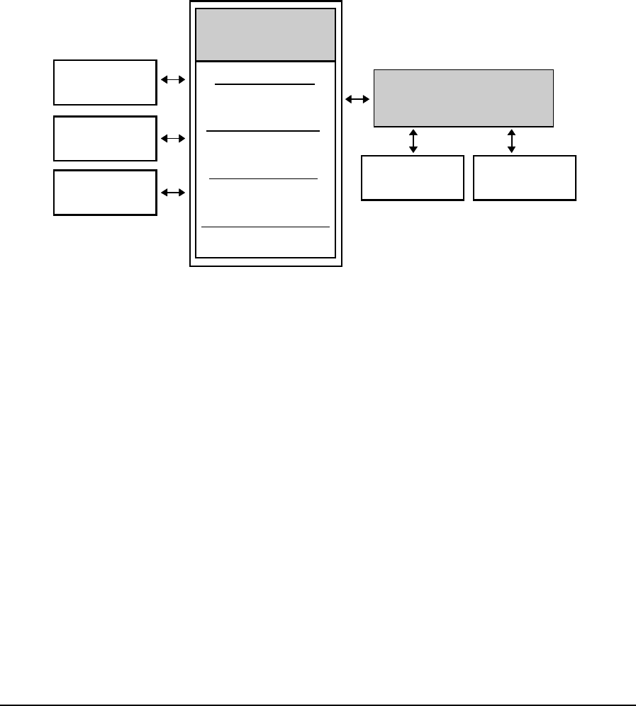
dnpReadRoutingTableDialStrings Reads a primary and secondary dial string from an
r
I/O D
The I/O database allows data to be shared between C programs, Ladder Logic programs
cols. A simplified diagram of the I/O Database is shown below.
entry in the DNP routing table.
DNP Communication Protocol Structures and Types
The ctools.h file defines the structures DNP Configuration, Binary Input Point, Binary
Output Point, Analog Input Point, Analog Output Point and Counter Input Point. Refe
to the C Tools Structures and Types section for complete information on structures and
enumeration types.
atabase
and communication proto
Controller I/O
Database
Coil Registers
00001 to 04096
Holding Registers
40001 to 49999
Input Registers
30001 to 31024
Status Registers
10001 to 14096
TeleBUS
Ladder Logic
Progra
Protocols
C Tools
Programs
ms Controller Register
Assignment Table
5000 Series
I/O Modules System
Parameters
registers. General purpose
ams to store processed
Initially all registers in the I/O
Database are general purpose registers.
mapped directly from the I/O database to physical I/O hardware,
te or system parameter
maintain their values during
s. As pplication program
ing power failures and application program
The valu ication program or a
communication protocol.
The TeleBUS communication protocols provi Modbus RTU and
ontroller.
The I/O database contains general purpose and user-assigned
registers may be used by Ladder Logic and C application progr
information and to receive information from a remote device.
User-assigned registers are
or to controller system configuration and diagnostic parameters. The Register Assignment
performs the mapping of registers from the I/O database to physical I/O hardware and
system parameters.
User-assigned registers are initialized to the default hardware sta
when the controller is reset. Assigned output registers do not
power failure signed output registers do retain their values during a
loading.
General purpose registers retain their values dur
loading. es change only when written by an appl
de a standard communication interface to the
controller. The TeleBUS protocols are compatible with the widely used
ASCII protocols and provide full access to the I/O database in the c
TelePACE C Tools User and Reference Manual
May 9, 2007 64

I/O Database Register Types
The I/O database is divided into four types of I/O registers. Each of these types are initially
Coil Registers
ut eries digital output
modules or SCADAPack I/O modules through the Register Assignment. Coil registers may
puts and to system configuration modules.
l
tic
10001 to 14096. Ladder logic programs and
database.
r Assignment. Input r ay
n
these registers. C language programs can read data from and write data to these registers.
Holding registers are 16 bit registers located in the analog output section of the I/O
database. Holding, or analog output, database registers may be assigned to 5000 Series
odules through the Register
er logic programs, C
language programs, and the TeleBUS protocols can read from and write to these registers.
0 controller has 4000 holding registers numbered
configured as general purpose registers by the controller.
Coil registers are single bit registers located in the digital output section of the I/O database.
Coil, or digital o put, database registers may be assigned to 5000 S
also be assigned to controller on-board digital out
There are 4096 coil registers numbered 00001 to 04096. Ladder logic programs, C language
programs, and the TeleBUS protocols can read from and write to these registers.
Status Registers
Status registers are single bit registers located in the digital input section of the I/O
database. Status, or digital input, database registers may be assigned to 5000 Series digita
input modules or SCADAPack I/O modules through the Register Assignment. Status
registers may also be assigned to controller on-board digital inputs and to system diagnos
modules.
There are 4096 status registers are numbered
the TeleBUS protocols can only read from these registers. C language application programs
can read data from and write data to these registers.
Input Registers
Input registers are 16 bit registers located in the analog input section of the I/O
Input, or analog input, database registers may be assigned to 5000 Series analog input
modules or SCADAPack I/O modules through the Registe egisters m
also be assigned to controller internal analog inputs and to system diagnostic modules.
There are 1024 input registers numbered 30001 to 31024. Ladder logic programs and the
TeleBUS protocols can only read from these registers. C language application programs ca
read data from and write data to these registers.
The I/O database for the SCADAPack 100 controller has 512 input registers numbered
30001 to 30512. Ladder logic programs and the TeleBUS protocols can only read from
Holding Registers
analog output modules or SCADAPack analog output m
Assignment. Holding registers may also be assigned to system diagnostic and configuration
modules.
There are 9999 input registers numbered 40001 to 49999. Ladd
The I/O database for the SCADAPack 10
40001 to 44000. Ladder logic programs, C language programs, and the TeleBUS protocols
can read from and write to these registers.
TelePACE C Tools User and Reference Manual
May 9, 2007 65

I/O Database Functions
or the I/O database. Refer to the C Tools Macros
Error co
DB_OK Error co
Specifie
Specifies Modbus database addressing.
Number of registers in
Number of registers in the Modbus coil section.
Number of registers in the M
Number of registers in the M
ction.
Start of
n the linear database.
e linear database.
Start of e.
e controller must be assigned to I/O database registers in
gram. C programs may read data from, or write
I/O ha .
The Register Assignment assigns I/O database registers to user-assigned registers using
l I/O hardware module (e.g. 5401 Digital
parameters, such as serial port settings.
g the TelePACE Register Assignment dialog may be
r downloaded directly to the controller. To obtain error
nment
nt can then be saved
in a Ladder Logic file (e.g. filename.lad) and downloaded with the C program.
There are two library functions related to the I/O database. Refer to the Function
Specification section for details on each function listed.
dbase Reads a value from the I/O database.
setdbase Writes a value to the I/O database.
I/O Database Macros
The ctools.h file defines library functions f
section for details on each macro listed.
AB Specifies Allan-Bradley database addressing.
Error code: out of range address specified DB_BADSIZE
DB_BADTYPE de: bad database addressing type specified
de: no error occurred
LINEAR s linear database addressing.
MODBUS
the Allan-Bradley database. NUMAB
NUMCOIL
NUMHOLDING odbus holding register section.
NUMINPUT odbus input registers section.
NUMLINEAR Number of registers in the linear database.
NUMSTATUS Number of registers in the Modbus status se
START_COIL the coil section in the linear database.
START_HOLDING Start of the holding registers section i
START_INPUT Start of the input register section in th
START_STATUS the status section in the linear databas
Register Assignment Functions
All I/O hardware that is used by th
order for these I/O points to be scanned continuously. I/O data may then be accessed
through the I/O database within the C pro
data to the rdware through user- assigned registers in the I/O database
I/O modules. An I/O Module can refer to an actua
Input Module) or it may refer to a set of controller
The chapter Register Assignment Reference of the TelePACE Ladder Logic Reference
and User Manual contains a description of what each module is used for and the register
assignment requirements for the I/O module.
Register assignments configured usin
stored in the TelePACE program file o
checking that prevents invalid register assignments, use the TelePACE Register Assig
dialog to initially build the Register Assignment. The Register Assignme
TelePACE C Tools User and Reference Manual
May 9, 2007 66

There are several library functions related to register assignment. Refer to the Function
ssignment Adds one I/O module to the current Register Assignment.
Gets the control flags for state of Outputs in Ladders Stop
Sets the control flag for the I/O module error indication
topMode Sets the control flags for state of Outputs in Ladders Stop
Mode
. The ioModules enumeration type defines a
C Tools Structures and
Types section for complete information on structures and enumeration types.
HAR
ation with smart transmitters.
r uses the model 5904 HART
upported per controller.
unctions
function listed.
tIO odule, processes HART
and writes commands
ce module.
tCommand0 address algorithm
tCommand1
tCommand2 span
tCommand3 mic variables
tCommand11 associated with tag
rtCommand33
Specification section for details on each function listed.
clearRegAssignment Erases the current Register Assignment.
addRegA
getIOErrorIndication Gets the control flag for the I/O module error indication
getOutputsInStopMode Mode
setIOErrorIndication
setOutputsInS
Register Assignment Enumeration Types
The ctools.h file defines one enumeration type
list of results of sending a command. Refer to the C Tools Structures and Types section
for complete information on structures and enumeration types.
Register Assignment Structure
The ctools.h file defines the structure RegAssign. Refer to the
T Communication
The HART ® protocol is a field bus protocol for communic
The HART protocol driver provides communication between TeleSAFE Micro16 and
SCADAPack controllers and HART devices. The protocol drive
modem for communication. Four HART modem modules are s
The driver allows HART transmitters to be used with C application programs and with
RealFLO. The driver can read data from HART devices.
HART Command F
The ctools.h file defines the following HART command related functions. Refer to the
Function Specification section for details on each
har Reads data from the 5904 interface m
responses, processes HART commands,
and configuration data to the 5904 interfa
hartCommand send a HART command string and specify a function to handle the
response
har read unique identifier using short-
har read primary variable
har read primary variable current and percent of
har read primary variable current and dyna
har read unique identifier
ha read specified transmitter variables
TelePACE C Tools User and Reference Manual
May 9, 2007 67

ha return status of last HART rtStatus command sent
rtGetConfiguration
rtSetConfiguration
tPackString tring
rtUnpackString o string
ctools.h file defines the following macro of interest to a C application program. Refer to
C Tools Macros sect
_SIZE Maximum length of the HART command or response field.
enumeration type
s Structures and Types
e defines tructures and Types
types.
he HART device.
HART device.
e HART modem
slave
PID Control
n programs. An
ks. A simple program to
ntrol blocks i
blocks ar They also provide ratio
s. Control blocks may be
rameters.
Controlle al for
ation on c
file defines r to the Function
on section for
tically at the specified rate.
ha read HART module settings
ha write HART module settings
har convert string to HART packed s
ha convert HART packed string t
HART Command Macros
The
the ion for details.
DATA
HART Command Enumeration Types
The ctools.h file defines one enumeration type. The HART_RESULT
defines a list of results of sending a command. Refer to the C Tool
section for complete information on structures and enumeration types.
HART Command Structures
The ctools.h fil five structures. Refer to the C Tools S
section for complete information on structures and enumeration
The HART_DEVICE type is a structure containing information about t
The HART_VARIABLE type is a structure containing a variable read from a
The HART_SETTINGS type is a structure containing the configuration for th
module.
The HART_COMMAND type is a structure containing a command to be sent to a HART
slave device.
The HART_RESPONSE type is a structure containing a response from a HART
device.
TelePACE C Tools provides a total of 32 independent PID (Proportional, Integral, and
Derivative) controllers. PID control blocks operate independent of applicatio
elaborate control program need not be written to use the control bloc
set up the co s all that is required.
The PID control e not limited to the PID control algorithm.
control, ratio/bias control, alarm scanning and square root function
interconnected to exchange setpoints, output limits, and other pa
Refer to the PID rs section of the TelePACE Ladder Logic User Manu
complete inform onfiguring and using PID controllers.
PID Control Functions
The ctools.h the following PID control related functions. Refe
Specificati details on each function listed.
auto_pid Set a PID block to execute automa
TelePACE C Tools User and Reference Manual
May 9, 2007 68

clear_pid Set all PID block variables to zero.
get_pid This function returns the value of a PID control bl ock variable.
.
Macros
file defines the following macros for PID block access. Refer to the C Tools
tion for details
tion period
utput limit
setpoint
s
error
tput
M
M_ABS
M_ACK
V
ALARM_ONLY block
ARM_RATE
ANALOG_IP g input
ANALOG_OP og output
D_BLOCK
O_OP t
set_pid This function assigns value to a PID control block variable
PID Control
The ctools.h
Macros sec on each function listed.
AO Variable name: alarm output address
CA Variable name: cascade setpoint source
CR Variable name: control register
DB Variable name: deadband
DO Variable name: decrease output
ER Variable name: error
EX Variable name: automatic execu
FS Variable name: full scale o
GA Variable name: gain
HI Variable name: high alarm
IB Variable name: input bias
IH Variable name: inhibit execution addres
IN Variable name: integrated
IO Variable name: increase ou
IP Variable name: input source
LO Variable name: low alarm setpoint
OB Variable name: output bias
Variable name: output OP
PE Variable name: period
AR Control register mask: alarms enabled PID_AL
Control register mask: absolute alarms PID_ALAR
PID_ALAR Status register mask: alarm acknowledged
PID_
PID_ Control register mask: alarm only
ALARM_DE Control register mask: deviation alarms
PID_AL Control register mask: rate alarms
PID_ Control register mask: analo
PID_ Control register mask: anal
PID_BA Return code: bad block number specified.
PID_BAD_IO_IP Status register mask: I/O failure on block input
PID_BAD_I Status register mask: I/O failure on block outpu
TelePACE C Tools User and Reference Manual
May 9, 2007 69

PID_BLOC Control register mask: input from ouK_IP tput of another block
PID_BLOCKS Number of PID blocks.
utput is clamped at full scale
IT put is on
RM ed
O
L
OP tion output
han IP)
P_TRACK led
lly.
band
um
ORMAL d in SP
RE Variable name: reset time
SP Variable name: setpoint
SR Variable name: status register
ZE Variable name: zero scale output limit
PID_CLAMP_FULL Status register mask: o
PID_CLAMP_ZERO Status register mask: output is clamped at zero scale
PID_ER_SQR Control register mask: take square root of error
PID_HI_ALARM Status register mask: high alarm detected
PID_INHIB Status register mask: external inhibit in
PID_LO_ALA Status register mask: low alarm detect
PID_MANUAL Status register mask: block is in manual mode
PID_MODE_AUT Control register mask: automatic mode
PID_MODE_MANUA Control register mask: manual mode
PID_MOTOR_ Control register mask: motor pulse dura
PID_NO_ALARM Control register mask: alarms disabled
PID_NO_ER_SQR Control register mask: normal error
PID_NO_IP Control register mask: no input (other t
PID_NO_OP Control register mask: no output
PID_NO_PV_SQR Control register mask: normal PV
PID_NO_S Control register mask: setpoint tracking disab
PID_OK Return code: operation completed successfu
PID_OUT_DB Status register mask: PID controller outside of dead
PID_PID Control register mask: PID control block
PID_PULSE_OP Control register mask: pulse duration output
PID_PV_SQR Control register mask: take square root of PV
PID_RATE_CLAMP Status register mask: rate gain clamed at maxim
PID_RATIO_BIAS Control register mask: ratio/bias control block
PID_RUNNING Status register mask: block is executing
PID_SP_CASCADE Control register mask: cascade setpoint
PID_SP_N Control register mask: setpoint store
PID_SP_TRACK Control register mask: setpoint tracking enabled
PV Variable name: process value
RA Variable name: rate time
TelePACE C Tools User and Reference Manual
May 9, 2007 70

Backward Compatibility Functions
The following functions are provided for backward compatibility. They c
5000 series I/O modules. It is reco
programs. Instead use Register A
directly.
annot access all
mmended that these functions not be used in new
ssignment or call the specific I/O module driver function
These functions are defined in ctools.h for backward compatibility with these programs.
Reads analog I/O communication status
aout
counter
din
dout Writes digital output channel (8 I/O points)
nt is OFF
pulse Generates a square wave on a digital output point
pulse_train Generates a series of pulses on a digital output point
timeout Performs time delayed action on a digital output point
turnoff Writes one digital output point to OFF status
turnon Writes one digital output point to ON status
Backward Compatibility Macros
The following macros may have been used in C programs written for a controller with
firmware version 1.22 or older to support the functions: ain, aioError, aout, counter,
counterError, din, dout, off, on, pulse, pulse_train, timeout, turnoff or turnon.
These macros are defined in ctools.h for backward compatibility with these programs.
AIN_END Number of last analog input channel.
AIN_START Number of first analog input channel.
AIO_BADCHAN Error code: bad analog input channel specified.
AIO_TIMEOUT Error code: input device did not respond.
AIO_SUPPORTED If defined indicates analog I/O supported.
AOUT_END Number of last analog output channel.
AOUT_START Number of first analog output channel.
COUNTER_CHANNELS Specifies number of 5000 Series counter input channels
COUNTER_END Number of last counter input channel
COUNTER_START Number of first counter input channel
COUNTER_SUPPORTED If defined indicates counter I/O hardware supported.
DIN_END Number of last regular digital input channel.
ain Reads analog input
aioError
Writes analog output
Reads counter module input channel
counterError Reads counter module error flag
Reads digital input channel (8 I/O points)
off Tests If one digital I/O poi
on Tests If one digital I/O point is ON
TelePACE C Tools User and Reference Manual
May 9, 2007 71

DIN_START Number of first regular digital input channel
defined indicates digital I/O hardware supported.
DOUT_START Number of first regular digital output channel
E Specifies timer is generating square wave output.
r of last extended digital input channel.
irst extended digital input channel
xtended digital output channel.
tended digital output channel
Specifies timer is generating pulse train output.
DIO_SUPPORTED If
DOUT_END Number of last regular digital output channel.
DUTY_CYCL
EXTENDED_DIN_END Numbe
EXTENDED_DIN_START Number of f
Number of last eEXTENDED_DOUT_END
EXTENDED_DOUT_START Number of first ex
NORMAL Specifies normal count down timer.
PULSE_TRAIN
TIMEOUT Specifies timer is generating timed output change.
TIMER_BADADDR Error code: invalid digital I/O address.
TelePACE C Tools User and Reference Manual
May 9, 2007 72

Tel
Sp
The controller C function specifications are formatted as follows. The functions are listed
alphabe
Name
Syntax
Descrip defines the calling parameters for the function and its return values.
Notes ion on the function, and considerations for
See Als
Examp brief sample of the use of the function.
ePACE C Tools Function
ecifications
tically.
Each specification begins with the name of the function and a brief description.
The syntax shows a prototype for the function, indicating the return type and the
types of its arguments. Any necessary header files are listed.
tion This
This section contains additional informat
its use.
o This section lists related functions.
le The example gives a
TelePACE C Tools User and Reference Manual
May 9, 2007 73

addR
Add R iste
clude <ctools.h>
unsigned addRegAssignment(
unsigned moduleType,
unsigned moduleAddress,
unsigned startingRegister1,
unsigned startingRegister2,
unsigned startingRegister3,
unsigned startingRegister4);
Description
The addRegAssignment function adds one I/O module to the current Register Assignment
of type moduleType. The following symbolic constants are valid values for moduleType:
AIN_520xTemperature DIAG_forceLED
AIN_520xRAMBattery DIAG_IPConnections
AIN_5501 DIAG_ModbusStatus
AIN_5502 DIAG_protocolStatus
AIN_5503 DIN_520xDigitalInputs
AIN_5504 DIN_520xInterruptInput
AIN_5521 DIN_520xOptionSwitches
AIN_generic8 DIN_5401
AOUT_5301 DIN_5402
AOUT_5302 DIN_5403
AOUT_5304 DIN_5404
AOUT_generic2 DIN_5405
AOUT_generic4 DIN_5421
CNFG_5904Modem DIN_generic16
CNFG_clearPortCounters DIN_generic8
CNFG_clearProtocolCounters DIN_SP32OptionSwitches
CNFG_IPSettings DOUT_5401
CNFG_LEDPower DOUT_5402
CNFG_MTCPIfSettings DOUT_5406
CNFG_MTCPSettings DOUT_5407
CNFG_PIDBlock DOUT_5408
CNFG_portSettings DOUT_5409
CNFG_protocolExtended DOUT_5411
CNFG_protocolExtendedEx DOUT_generic16
CNFG_protocolSettings DOUT_generic8
CNFG_realTimeClock SCADAPack_AOUT
CNFG_saveToEEPROM SCADAPack_lowerIO
CNFG_setSerialPortDTR SCADAPack_upperIO
CNFG_storeAndForward SCADAPack_LPIO
CNTR_520xCounterInputs SCADAPack_100IO
CNTR_5410 SCADAPack_5604IO
CNTR_520xInterruptInput GFC_4202IO
DIAG_commStatus GFC_4202IOEx
DIAG_controllerStatus GFC_4202DSIO
DIAG_LogicStatus
moduleAddress specifies a unique address for the module. For the valid range for
moduleAddress refer to the list of modules in the chapter Register Assignment Reference of
the TelePACE Ladder Logic Reference and User Manual. For module addresses com1,
egAssignment
eg r Assignment
Syntax
#in
TelePACE C Tools User and Reference Manual
May 9, 2007 74

com2, com3 or com4 specify 0, 1, 2 or 3 respectively for moduleAddress. For module types
.g. CNFG_LEDPower) specify -1 for moduleAddress. For
have a module address fixed at 0, specify 0 for
startingRegister1 specifies the first register of any unused block of consecutive registers.
e list of modules in the Register Assignment Reference for the type and number
is block. Data read from or written to the module is stored in this
re than one type of I/O, use startingRegister2,
egister specifies the first
e registers for each type of input or output on the
e Register Assignment Reference for the module
, startingRegister3, or startingRegister4 if not
ment is
is returned.
r certain C with the current
module is added to the Register Assignment (e.g.
gAssignment first before t function when
w Register Assignment.
overlapping register assig r by this function.
register assignments may ctivity.
cking that prevents h as these, use the
gister Assignment dialog to build the Register Assignment. Then save the
nment in a Ladder Logic ename.lad) and download it with the C
the Register Assignment to the C program using the
nt and addRegAs ctions.
t be requested before calling this function.
_SYSTE
ster As
);
SCADAPac
10001, 30001, 0);
addRegAssignment(SCADAPack_AOUT, 0, 40001, 0,
0, 0);
addRegAssignment(AOUT_5302, 1, 40003, 0, 0, 0);
that have no module address (e
SCADAPack module types that
moduleAddress.
Refer to th
of registers required for th
block of registers.
If the module type specified has mo
startingRegister3, and startingRegister4 as applicable. Each start r
register of an unused block of consecutiv
module. Refer to the list of modules in th
I/O types. Specify 0 for startingRegister2
applicable.
Notes
Up to 150 modules may be added to the Register Assignment. If the Register Assign
full or if an incorrect value is specified for any argument this function returns FALSE;
otherwise TRUE
Output registers specified fo NFG type modules are initialized
parameter values when the
imeClock). CNFG_realT
Call clearRe using the addRegAssignmen
creating a ne
Duplicate or nments are not checked fo
Overlapping result in unpredictable I/O a
To obtain error che invalid register assignments suc
TelePACE Re
Register Assig file (e.g. fil
program, or transfer
clearRegAssignme signment fun
The IO_SYSTEM resource mus
See Also
clearRegAssignment
Example
#include <primitiv.h>
void main(void)
{ e(IO request_resourc
M);
/* Create the Regi
clearRegAssignment( signment */
addRegAssignment( k_lowerIO, 0, 1,
TelePACE C Tools User and Reference Manual
May 9, 2007 75

addRegAssignment(DIAG_forceLED, -1, 10017, 0,
0, 0);
addRegAssignment(DIAG_controllerStatus, -1,
30009, 0, 0, 0);
addRegAssignment(DIAG_protocolStatus, 2, 30010,
0, 0, 0);
release_resource(IO_SYSTEM);
}
TelePACE C Tools User and Reference Manual
May 9, 2007 76

addRegAssignmentEx
Add Register Assignment
n
O egAssignmentEx(
moduleType, s,
,
startingRegister4,
parameters[16]
x function adds one I/O module to the current Register
Assignment of type moduleType. The following symbolic constants are valid values for
ype:
DIAG_commStatus
DIAG_ModbusStatus
DIN_5209
CNFG_MTCPIfSettings DOUT_5406
ettings DOUT_5407
ock DOUT_5408
409
CNFG_protocolExtended DOUT_5411
CNFG_protocolExtendedEx DOUT_generic16
CNFG_protocolSettings DOUT_generic8
CNFG_realTimeClock SCADAPack_AOUT
CNFG_saveToEEPROM SCADAPack_lowerIO
CNFG_setSerialPortDTR SCADAPack_upperIO
CNFG_storeAndForward SCADAPack_LPIO
SCADAPack_100IO
SCADAPack_5209IO
SCADAPack_5606IO
Syntax
ools.h> #i clude <ct
BO LEAN addR
UINT16
UINT16 moduleAddres
startingRegister1 UINT16 ,
UINT16 startingRegister2,
startingRegister3 UINT16
UINT16
UINT16
);
Description
The addRegAssignmentE
moduleT
AIN_5209Temperature CNTR_5209CounterInputs
AIN_5209RAMBattery CNTR_5410
AIN_5501 CNTR_5209InterruptInput
AIN_5502
AIN_5503 DIAG_controllerStatus
AIN_5504 DIAG_forceLED
AIN_5505 DIAG_IPConnections
AIN_5506
AIN_5521 DIAG_protocolStatus
AIN_generic8 DigitalInputs
AOUT_5301 DIN_5209InterruptInput
AOUT_5302 DIN_5401
AOUT_5304 DIN_5402
AOUT_generic2 DIN_5403
AOUT_generic4 DIN_5404
CNFG_5904Modem DIN_5405
CNFG_clearPortCounters DIN_5421
CNFG_clearProtocolCounters DIN_generic16
CNFG_IPSettings DIN_generic8
CNFG_LEDPower DOUT_5401
CNFG_modbusIpProtocol DOUT_5402
CNFG_MTCPS
CNFG_PIDBl
CNFG_portSettings DOUT_5
TelePACE C Tools User and Reference Manual
May 9, 2007 77

moduleAddress specifies a unique address for the module. For the valid range for
moduleAddress refer to the list of modules in the chapter Register Assignment Reference of
the TelePACE Ladder Logic Reference and User Manual. For module addresses com1,
specify 0, 1, 2 or 3 respectively for moduleAddress. For module
address Ethernet1 specify 4 for moduleAddress. For module types that have no module
moduleAddress. For SCADAPack module
address fixed at 0, specify 0 for moduleAddress.
t register of any unused block of consecutive registers.
Register Assignment Reference for the type and number
ired for this block. Data read from or written to the module is stored in this
s.
ck of consecutive registers for each type of input or output on the
le
nment module.
Most modules do not use the parameters. Use the addRegAssignment function to
these modules. Use parameters with the following modules.
. Valid values are:
• 0 = 0.5 s (minimum)
dule: parameters[0] to [7] define the analog input type for the
d values are:
t
log input filter. Valid values are:
• 0 = < 3 Hz (maximum filter)
• 1 = 6 Hz
• 2 = 11 Hz
• 3 = 30 Hz (minimum filter)
5506 I/O Module: parameter[9] defines the scan frequency. Valid values are:
• 0 = 60 Hz
• 1 = 50 Hz
5606 I/O Module: parameters[0] to [7] define the analog input type for the
corresponding input. Valid values are:
com2, com3 or com4
address (e.g. CNFG_LEDPower) specify -1 for
types that have a module
startingRegister1 specifies the firs
Refer to the list of modules in the
of registers requ
block of register
If the module type specified has more than one type of I/O, use startingRegister2,
startingRegister3, and startingRegister4 as applicable. Each start register specifies the first
register of an unused blo
module. Refer to the list of modules in the Register Assignment Reference for the modu
I/O types. Specify 0 for startingRegister2, startingRegister3, or startingRegister4 if not
applicable.
parameters is an array of configuration parameters for the register assig
configure
5505 I/O Module: parameters[0] to [3] define the analog input type for the
corresponding input. Valid values are:
• 0 = RTD in deg Celsius
• 1 = RTD in deg Fahrenheit
• 2 = RTD in deg Kelvin
• 3 = resistance measurement in ohms.
5505 I/O Module: parameter[4] defines the analog input filter
• 1 = 1 s
• 2 = 2 s
• 3 = 4 s (maximum)
5506 I/O Mo
corresponding input. Vali
• 0 = 0 to 5 V input
1 = 1 to 5 V inpu•
• 2 = 0 to 20 mA input
3 =
• 4 to 20 mA input
5506 I/O Module: parameter[8] defines the ana
TelePACE C Tools User and Reference Manual
May 9, 2007 78

• 0 = 0 to 5 V input
1 to 5 V input
5606 I/O Module: parameter[8] defines the analog input filter. Valid values are:
filter)
inimum filter)
alues are:
5606 I/O Module: parameter[10] defines the analog output type. Valid values are:
to 20 mA output
Notes
dules may be added to the Register Assignment. If the Register Assignment is
correct value is specified for any argument this function returns FALSE;
utput registers specified for certain CNFG type modules are initialized with the current
parameter values when the module is added to the Register Assignment (e.g.
CNFG_realTimeClock).
Call clearRegAssignment first before using the addRegAssignmentEx function when
creating a new Register Assignment.
Duplicate or overlapping register assignments are not checked for by this function.
Overlapping register assignments may result in unpredictable I/O activity.
To obtain error checking that prevents invalid register assignments such as these, use the
TelePACE Register Assignment dialog to build the Register Assignment. Then save the
Register Assignment in a Ladder Logic file (e.g. filename.lad) and download it with the C
program, or transfer the Register Assignment to the C program using the
clearRegAssignment and addRegAssignmentEx functions.
The IO_SYSTEM resource must be requested before calling this function.
See Also
addRegAssignment, clearRegAssignment
• 1 =
• 2 = 0 to 20 mA input
• 3 = 4 to 20 mA input
0 = < 3 Hz (maximum•
• 1 = 6 Hz
• 2 = 11 Hz
• 3 = 30 Hz (m
5606 I/O Module: parameter[9] defines the scan frequency. Valid v
• 0 = 60 Hz
• 1 = 50 Hz
• 0 = 0
• 1 = 4 to 20 mA output
Up to 150 mo
full or if an in
otherwise TRUE is returned.
O
TelePACE C Tools User and Reference Manual
May 9, 2007 79

ain
Read an Analog Input
Syntax
ls
he value output to the channel
tion.
The ain function normally returns a value in the range –32767 to +32767.
T_START and
rotect against future changes to the analog I/O channel numbering.
The IO_SYSTEM resource must be requested before calling this function.
This function is provided for backward compatibility. It cannot access all 5000 series I/O
recommended that this function not be used in new programs. Instead use
driver ioRead8Ain directly.
ad8Ain
_SYSTEM);
ain(2));
;
#include <ctools.h>
int ain(unsigned channel);
Description
The ain function reads from the analog input or output specified by channel. Input channe
read from the analog input hardware. Output channels read t
with the aout function.
The valid range for channel is 0 to AIO_MAX. If an invalid channel is selected, the ain
function returns INT_MIN and the current task's error code is set to AIO_BADCHAN. The
error code is obtained with the check_error func
Notes
Use offsets from the symbolic constants AIN_START, AIN_END, AOU
AOUT_END to reference analog channels. The constants make programs more portable
and p
modules. It is
Register Assignment or call the I/O
See also
aout, check_error, ioRe
Example
#include <ctools.h>
void main(void)
{ request_resource(IO
printf("ain(%d)=%d\r\n", 2,
release_resource(IO_SYSTEM)
}
TelePACE C Tools User and Reference Manual
May 9, 2007 80

aioError
Read Analog I/O Error Flags
Syntax
#include <ctools.h> channelint aioError(unsigned );
; otherwise it returns
INT_MIN. A value of 0 indicates no error occurred. A positive value indicates an error.
ead8Ain
Description
The aioError function reads the I/O error flag for an analog channel.
It returns the error flag for the channel, if the channel number is valid
Notes
This function is provided for backward compatibility. It cannot access all 5000 series I/O
modules. It is recommended that this function not be used in new programs. Instead use
Register Assignment or call the I/O driver ioRead8Ain directly.
See Also
aout, check_error, ioR
TelePACE C Tools User and Reference Manual
May 9, 2007 81

alarmIn
om Elapsed Time
signed minutes, unsigned seconds);
setClockAlarm function. The structure specifies an absolute time alarm at the time offset
by the call to alarmIn. Refer to the Structures and Types section for a description
ds in the ALARM_SETTING structure.
e
thin the current
------------------------------
*/
resource(IO_SYSTEM);
/* Alarm in 10 minutes */
alarm = alarmIn(0, 10, 0);
setClockAlarm(alarm)
/* Put controller in low power mode */
sleep();
release_resource(IO_SYSTEM);
}
Determine Alarm Time fr
Syntax
#include <ctools.h>
ALARM_SETTING alarmIn(unsigned hours, un
Description
The alarmIn function calculates the alarm settings to configure a real time clock alarm to
occur in hours, minutes and seconds from the current time.
The function returns an ALARM_SETTING structure suitable for passing to the
specified
of the fiel
Notes
If second is greater than 60 seconds, the additional time is rolled into the minutes. If minut
is greater than 60 minutes, the additional time is rolled into the hours.
If the offset time is greater that one day, then the alarm time will roll over wi
day.
The IO_SYSTEM resource must be requested before calling this function.
See Also
getClockAlarm, setClockAlarm,
Example
#include <ctools.h>
--------------/*
conservePower
The conservePower function places the
controller into sleep mode for 10 minutes.
-------------------------------- ------------
void conservePower(void)
{
ALARM_SETTING alarm;
request_
TelePACE C Tools User and Reference Manual
May 9, 2007 82

allocate_envelope
oid);
velope function obtains an envelope from the operating system. If no
Notes
s are used to send messages between tasks. The RTOS allocates envelopes from
free envelopes. It returns envelopes to the pool when they are de-allocated.
s
eused.
_task_id;
void task1(void)
velope *letter;
= allocate_envelope();
>destination = other_task_id;
= receive_message
cess the data
_envelope(lett
e rest of the t
}
Obtain an Envelope from the RTOS
Syntax
#include <ctools.h>envelope *allocate_envelope(v
Description
The allocate_en
envelope is available, the task is blocked until one becomes available.
The allocate_envelope function returns a pointer to the envelope.
Envelope
a pool of
An application program must ensure that unneeded envelopes are de-allocated. Envelope
may be r
See Also
deallocate_envelope
Example
#include <ctools.h>
extern unsigned other
{
en
/* send a message to another task */
/* assume it will deallocate the envelope */
letter
letter-
letter->type = MSG_DATA;
letter->data = 5;
send_message(letter);
/* receive a message from any other task */
letter ();
/* ... pro
te here */
dealloca er);
/* ... th ask */
TelePACE C Tools User and Reference Manual
May 9, 2007 83

aout
Write
channel, int value);
escription
The aout function writes value to the analog output specified by channel. The range for
channel is AOUT_START to AOUT_END inclusive. The range for value is -32767 to 32767.
aout returns the value written to the hardware, or -1 if the channel is not an analog output.
Notes
The value output may be limited by the analog output module.
Use offsets from the symbolic constants AIN_START, AIN_END, AOUT_START and
AOUT_END to reference analog channels. The constants make programs more portable
and protect against future changes to the analog I/O channel numbering.
The IO_SYSTEM resource must be requested before calling this function.
This function is provided for backward compatibility. It cannot access all 5000 series I/O
modules. It is recommended that this function not be used in new programs. Instead use
Register Assignment or call the I/O driver ioWrite4Aout directly.
See Also
addRegAssignment, ioWrite4Aout
Example
#include <ctools.h>
void main(void)
{
int value;
/* ramp output from zero to full scale */
for (value = 0; value < 32767; value++)
{
request_resource(IO_SYSTEM);
aout(AOUT_START, value);
release_resource(IO_SYSTEM);
}
}
to Analog Output
Syntax
#include <ctools.h>
int aout(unsigned
D
TelePACE C Tools User and Reference Manual
May 9, 2007 84

auto_pid
Execute a PID Block Automatically
, unsigned period);
0
_BLOCKS – 1.
Setting the period to 0 stops execution of the control block.
control.
lock must be configured properly before it is engaged, or indeterminate
result.
he IO_SYSTEM resource must be requested before calling this function.
See Also
set_pid, getPowerMode
Get Current Power Mode
Syntax
#include <ctools.h>
BOOLEAN getPowerMode(UCHAR* cpuPower, UCHAR* lan, UCHAR* usbPeripheral,
UCHAR* usbHost);
Description
The getPowerMode function places the current state of the CPU, LAN, USB peripheral port,
and USB host port in the passed parameters. The following table lists the possible return
values and their meaning.
Macro Meaning
Syntax
#include <ctools.h>
void auto_pid(unsigned block
Description
The auto_pid routine configures a PID control block to execute automatically at the
specified period. period is measured in 0.1 second increments. block must be in the range
to PID
Notes
See the TelePACE PID Controllers Reference Manual for a detailed description of PID
The control b
operation may
T
PM_CPU_FULL The CPU is set to run at full speed
PM_CPU_REDUCED The CPU is set to run at a reduced speed
PM_CPU_SLEEP The CPU is set to sleep mode
PM_LAN_ENABLED The LAN is enabled
PM_LAN_DISABLED The LAN is disabled
PM_USB_PERIPHERAL_ENABLED The USB peripheral port is enabled
PM_USB_PERIPHERAL_DISABLED The USB peripheral port is disabled
PM_USB_HOST_ENABLED The USB host port is enabled
PM_USB_HOST_DISABLED The USB host port is disabled
PM_UNAVAILABLE The status of the device could not be read.
TelePACE C Tools User and Reference Manual
May 9, 2007 85

TRUE is returned if the values placed in the passed parameters are valid, otherwise FALSE
m may set the current power mode with the setPowerMode function.
eSource, getWakeSource
is returned.
The application progra
See Also
setPowerMode, setWak
get_pid, clear_pid
TelePACE C Tools User and Reference Manual
May 9, 2007 86

check_error
Get Error Code for Current Task
Syntax
#include <ctools.h>
int check_error(void);
Description
The check_error function returns the error code for the current task. The error code is set
by various I/O routines, when errors occur. A separate error code is maintained for each
turn errors in the global variable errno. This
variable is not unique to a task, and may be modified by another task, before it can be read.
See Also
r
task.
Notes
Some routines in the standard C library, re
eport_error
TelePACE C Tools User and Reference Manual
May 9, 2007 87

checksum
Calculate a Checksum
ar *start, unsigned char *end, unsigned
tarts at the byte
may be one of:
16 bit byte-wise sum
CRC-16 polynomial checksum
ynomial checksum
8 bit byte-wise exclusive OR
The CRC checksums use the crc_reverse function.
See Also
crc_reverse
Example
This function displays two types of checksums.
#include <ctools.h>
void checksumExample(void)
{
char str[] = "This is a test";
unsigned sum;
/* Display additive checksum */
sum = checksum(str, str+strlen(str), ADDITIVE);
printf("Additive checksum: %u\r\n", sum);
/* Display CRC-16 checksum */
sum = checksum(str, str+strlen(str), CRC_16);
printf("CRC-16 checksum: %u\r\n", sum);
}
Syntax
#include <ctools.h>
unsigned checksum(unsigned ch
algorithm);
Description
The checksum function calculates a checksum on memory. The memory s
pointed to by start, and ends with the byte pointed to by end. The algorithm
ADDITIVE
CRC_16
CRC_CCITT CRC-CCITT pol
BYTE_EOR
TelePACE C Tools User and Reference Manual
May 9, 2007 88

checkSFTranslationTable
guration Errors
TranslationTable(void);
es and Types
section for a description of the fields in the SFTranslationStatus structure. The code field of
is set to one of the following. If there is an error, the index field is set to the
e translation that is not valid.
Test for Store and Forward Confi
Syntax
#include <ctools.h>
struct SFTranslationStatus checkSF
Description
The checkSFTranslationTable function checks all entries in the address translation table
for validity. It detects the following errors:
The function returns a SFTranslationStatus structure. Refer to the Structur
the structure
location of th
Result code Meaning
SF_VALID All translations are valid
SF_NO_TRANSLATION The entry defines re-transmission of the same
message on the same port
SF_PORT_OUT_OF_RANGE One or both of the serial port indexes is not valid
SF_STATION_OUT_OF_RANG
E One or both of the stations is not valid
Notes
The TeleBUS Protocols User Manual describes store and forward messaging mode.
See Also
getSFTranslation, setSFTranslation, checkSFTranslationTable
Example
See the example for the setSFTranslation function.
TelePACE C Tools User and Reference Manual
May 9, 2007 89

clearAllForcing
ers.
o
Clear All Forcing
Syntax
#include <ctools.h>
void clearAllForcing(void);
Description
The clearAllForcing function removes all forcing conditions from all I/O database regist
The IO_SYSTEM resource must be requested before calling this function.
See Als
setForceFlag, overrideDbase
TelePACE C Tools User and Reference Manual
May 9, 2007 90

clear_errors
Clear
s(FILE *stream);
Description
The clear_errors function clears the serial port error counters for the serial port specified by
stream. If stream does not point to a valid serial port the function has no effect.
The IO_SYSTEM resource must be requested before calling this function.
See Also
get_status
Serial Port Error Counters
Syntax
#include <ctools.h>
void clear_error
TelePACE C Tools User and Reference Manual
May 9, 2007 91

clear_pid
Clear PID Block Variables
to
OCKS – 1.
Notes
PACE PID Controllers Reference Manual for a detailed description of PID
alues stored in PID blocks are not initialized when a program is run, and are guaranteed to
tain their values during power failures and program loading. PID block variables must
lways be initialized by the user program.
The IO_SYSTEM resource must be requested before calling this function.
See Also
set_pid, getPowerMode
Get Current Power Mode
Syntax
#include <ctools.h>
BOOLEAN getPowerMode(UCHAR* cpuPower, UCHAR* lan, UCHAR* usbPeripheral,
UCHAR* usbHost);
Description
The getPowerMode function places the current state of the CPU, LAN, USB peripheral port,
and USB host port in the passed parameters. The following table lists the possible return
values and their meaning.
Macro Meaning
Syntax
#include <ctools.h>
void clear_pid(unsigned block);
Description
The clear_pid routine sets all variables in the specified control block to 0. clear_pid is
normally used as the first step of control block configuration. block must be in the range 0
PID_BL
See the Tele
control.
V
re
a
PM_CPU_FULL The CPU is set to run at full speed
PM_CPU_REDUCED The CPU is set to run at a reduced speed
PM_CPU_SLEEP The CPU is set to sleep mode
PM_LAN_ENABLED The LAN is enabled
PM_LAN_DISABLED The LAN is disabled
PM_USB_PERIPHERAL_ENABLED The USB peripheral port is enabled
PM_USB_PERIPHERAL_DISABLED The USB peripheral port is disabled
PM_USB_HOST_ENABLED The USB host port is enabled
PM_USB_HOST_DISABLED The USB host port is disabled
PM_UNAVAILABLE The status of the device could not be read.
TelePACE C Tools User and Reference Manual
May 9, 2007 92

TRUE is returned if the values placed in the passed parameters are valid, otherwise FALSE
set the current power mode with the setPowerMode function.
eSource, getWakeSource
is returned.
yThe application program ma
See Also
setPowerMode, setWak
get_pid, auto_pid
TelePACE C Tools User and Reference Manual
May 9, 2007 93

clear_protocol_status
Clear Protocol Counters
Syntax
#include <ctools.h>
void clear_protocol_status(FILE *stream);
ecified by stream. If stream does not point to a valid serial port the function has no
effect.
YSTEM resource must be requested before calling this function.
get_protocol_status
Description
The clear_protocol_status function clears the error and message counters for the serial
port sp
The IO_S
See Also
TelePACE C Tools User and Reference Manual
May 9, 2007 94

clearRegAssignment
er
calling this function.
o
Clear Register Assignment
Syntax
#include <ctools.h>
void clearRegAssignment(void);
Description
The clearRegAssignment function erases the current Register Assignment. Call this
function first before using the addRegAssignment function to create a new Regist
Assignment.
The IO_SYSTEM resource must be requested before
See Als
addRegAssignment
Example
See example for addRegAssignment.
TelePACE C Tools User and Reference Manual
May 9, 2007 95

clearSFTranslationTable
on Configuration
oid);
ion
S Protocols User Manual describes store and forward messaging mode.
The IO_SYSTEM resource must be requested before calling this function.
See Also
getSFTranslation, setSFTranslation, checkSFTranslationTable
Example
See the example for the setSFTranslation function.
Clear Store and Forward Translati
Syntax
#include <ctools.h>
void clearSFTranslationTable(v
Description
The clearSFTranslationTable function clears all entries in the store and forward translat
table.
Notes
The TeleBU
TelePACE C Tools User and Reference Manual
May 9, 2007 96

clearStatusBit
s Code
bitMask);
ro, the STAT LED turns off.
The function returns the value of the status register.
s if code is non-zero. Refer to the System Hardware Manual for
is
approximately 1/2 of a
ew bits as en
203 or 5204 controller
board.
of the status code are used by the Register Assignment.
ee Also
setStatusBit, setStatus, getStatusBit
Clear Bits in Controller Statu
Syntax
#include <ctools.h>
unsigned clearStatusBit(unsigned
Description
The clearStatusBit function clears the bits indicated by bitMask in the controller status
code. When the status code is non-zero, the STAT LED blinks a binary sequence
corresponding to the code. If code is ze
Notes
The status output open
more information.
The binary sequence consists of short and long flashes of the error LED. A binary zero
indicated by a short flash of 1/10th of a second. A longer flash of
second indicates a binary one. The least significant digit is output first. As f
possible are displayed – all leading zeros are ignored. There is a two-second delay betwe
repetitions.
The STAT LED is the LED located on the top left hand corner of the 5
Bits 0 and 1
S
TelePACE C Tools User and Reference Manual
May 9, 2007 97

clear_tx
Clear Serial Port Transmit Buffer
get_status
Syntax
#include <ctools.h>
void clear_tx(FILE *stream);
Description
The clear_tx function clears the transmit buffer for the serial port specified by stream. If
stream does not point to a valid serial port the function has no effect.
See Also
TelePACE C Tools User and Reference Manual
May 9, 2007 98

counter
Read Counter Input Module
Syntax
#include <ctools.h>
long counter(unsigned counter);
Description
The counter function reads data from the counter input specified by channel. If the channel
Refer to the TelePACE Ladder Logic User Manual for an explanation of counter input
ssignments.
The IO_SYSTEM resource must be requested before calling this function.
is provided for backward compatibility. It cannot access all 5000 series I/O
s recommended that this function not be used in new programs. Instead use
ioRead4Counter directly.
See Also
counterError, check_error, request_resource, release_resource, ioRead4Counter
number is not valid a COUNTER_BADCOUNTER error is reported for the current task. The
value returned by counter is not valid.
Notes
channel a
Use offsets from the symbolic constants COUNTER_START and COUNTER_END to
reference counter channels. The constants make programs more portable and protect
against future changes to the counter input channel numbering.
This function
modules. It i
Register Assignment or call the I/O driver
TelePACE C Tools User and Reference Manual
May 9, 2007 99

counterError
Error Flag
or function returns the I/O error flag for a counter channel. It returns TRUE if
e
s from able and protect
t or call the I/O driver ioRead4Counter directly.
check_error, ioRead4Counter
Read Counter Input
Syntax
#include <ctools.h>
long counterError(unsigned counter);
Description
The counterErr
an error occurred and FALSE if no occurred on the last read of the input module.
If the channel number is not valid a COUNTER_BADCOUNTER error is reported for th
current task. The value returned is not valid.
Notes
Refer to the TelePACE Ladder Logic User Manual for a explanation of counter input
channel assignments.
Use offset the symbolic constants COUNTER_START and COUNTER_END to
reference counter channels. The constants make programs more port
against future changes to the counter input channel numbering.
This function is provided for backward compatibility. It cannot access all 5000 series I/O
modules. It is recommended that this function not be used in new programs. Instead use
Register Assignmen
See Also
counter,
TelePACE C Tools User and Reference Manual
May 9, 2007 100

crc_reverse
Calculate a CRC Checksum
nclud h> ned char *start, unsigned char *end, unsigned
escr ti
sum on memory using the reverse
gorith T nted to by start, and ends with the byte pointed
by en T poly. poly may be any value, but must be
ecksum accumulator is set to initial
reverse algorithm is named for the direction bits are shifted. In the reverse algorithm,
s the least significant bit. This produces different checksums than the
, using the same polynomials.
Syntax
#i e <ctools.
unsigned crc_reverse(unsig
poly, unsigned initial);
D ip on
The crc_reverse function calculates a CRC type check
al m. he memory starts at the byte poi
to d. he generator polynomial is specified by
carefully chosen to ensure good error detection. The ch
fore the calculation is started. be
No
he
tes
T
bits are shifted toward
classical, or forward algorithm
See Also
ch umecks
TelePACE C Tools User and Reference Manual
May 9, 2007 101

crea
Create a New Task
Syntax
#include <ctools.h>
int create_task(void *function, unsigned priority, unsigned type, unsigned
stack);
Description
The create_task function allocates stack space for a task and places the task on the ready
queue. function specifies the start address of the routine to be executed. The task will
execute immediately if its priority is higher than the current task.
priority is an execution priority between 1 and 4 for the created task. The 4 task priority
levels aid in scheduling task execution.
type specifies if the task is ended when an application program is stopped. Valid values for
type are:
SYSTEM system tasks do not terminate when the program stops
APPLICATION application tasks terminate when the program stops
It is recommended that only APPLICATION type tasks be created.
The stack parameter specifies how many stack blocks are allocated for the task. Each stack
block is 256 bytes.
The create_task function returns the task ID (TID) of the task created. If an error occurs, -1
is returned.
Notes
Refer to the Real Time Operating System section for more information on tasks.
Note that the main task and the Ladder Logic and I/O scanning task have a priority of 1. If
the created task is continuously running processing code, create the task with a priority of 1
and call release_processor periodically; otherwise the remaining priority 1 tasks will be
blocked from executing.
For tasks such as a protocol handler, that wait for an event using the wait_event or
receive_message function, a priority greater than 1 may be selected without blocking other
lower priority tasks.
The number of stack blocks required depends on the functions called within the task, and
the size of local variables created. Most tasks require 2 stack blocks. If any of the printf
functions are used, then at least 4 stack blocks are required. Add local variable usage to
these limits, if large local arrays or structures are created. Large structures and arrays are
usually best handled as static global variables within the task source file. (The variables are
global to all functions in the task, but cannot be seen by functions in other files.)
Additional stack space may be made available by disabling unused protocol tasks. See the
section Program Development or the set_protocol() function for more information.
See Also
end_task
te_task
TelePACE C Tools User and Reference Manual
May 9, 2007 102

Example
1(void)
while (TRUE)
ody of task 1 loop - processing I/O */
}
}
k2(void)
{
/* body of task 2 loop - event handler */
tf("It’s time for a coffee break\r\n");
} ------------------------------------
down function stops the signalling
vents when application is
------------------------------ */
PRINT);
at priority 1 */
for printf function */
4);
/* set up task exit handler to stop
signalling of events when this task ends */
taskStatus = getTaskInfo(0);
installExitHandler(taskStatus.taskID, shutdown);
/* start timed event to occur every 10 sec */
startTimedEvent(TIME_TO_PRINT, 100);
interval(0, 10);
while(TRUE)
{
/* body of main task loop */
/* other processing code */
/* Allow other tasks to execute */
#include <ctools.h>
#define TIME_TO_PRINT 20
void task
{
int a, b;
{
/* b
request_resource(IO_SYSTEM);
a = dbase(MODBUS, 30001);
b = dbase(MODBUS, 30002);
setdbase(MODBUS, 40020, a * b);
release_resource(IO_SYSTEM);
/* Allow other tasks to execute */
release_processor();
void tas
{
while(TRUE)
wait_event(TIME_TO_PRINT);
prin
}
/* --------
The shut
of TIME_TO_PRINT e
stopped.
--------------
void shutdown(void)
{ endTimedEvent(TIME_TO_
} id main(void) vo
{
TASKINFO taskStatus;
/* continuos processing task
create_task(task1, 1, APPLICATION, 2);
/* event handler needs larger stack
create_task(task2, 3, APPLICATION,
TelePACE C Tools User and Reference Manual
May 9, 2007 103

release_processor();
}
}
TelePACE C Tools User and Reference Manual
May 9, 2007 104

data se
Read
Syntax
#include <ctools.h>
BOOLEAN databaseRead(UINT16 type, UINT16 address, INT16* value)
Description
The databaseRead function reads a value from the database. The value is written to the
variable pointed to by value. The variable is not changed if type and address are not valid.
The function has three parameters. type specifies the method of addressing the database.
Valid values are MODBUS and LINEAR. address specifies the location in the database.
value is a pointer to a variable to hold the result.
The function returns TRUE if the specified address is valid and FALSE if the register does not
exist.
Notes
The IO_SYSTEM resource must be requested before calling this function.
See Also
databaseWrite
Example
#include <ctools.h>
void main(void)
{
INT16 value;
BOOLEAN status;
request_resource(IO_SYSTEM);
/* Read Modbus status input point */
status = databaseRead(MODBUS, 10001, &value);
/* Read 16 bit register */
status = databaseRead(LINEAR, 3020, &value);
release_resource(IO_SYSTEM);
}
ba Read
Value from I/O Database
TelePACE C Tools User and Reference Manual
May 9, 2007 105

databaseWrite
Write Value to I/O Database
UINT16 address, INT16 value)
seWrite function writes value to the I/O database.
three parameters. type specifies the method of addressing the database.
• the address is read only on the SCADASense 4202 controller (some registers in the
ters in
EAR digital addresses, value is a bit mask which writes data to 16 1-bit
registers at once. If any of these 1-bit registers is invalid, only the valid registers are written
s returned.
e requested before calling this function.
, 40001, 102);
s */
, 0, 255);
Syntax
#include <ctools.h>
BOOLEAN databaseWrite(UINT16 type,
Description
The databa
The function has
Valid values are MODBUS and LINEAR. address specifies the location in the database.
value is the data to write.
The function returns TRUE if the value was written. The function returns FALSE if
• the type is invalid
• the address is not valid for the controller
range 40001 to 40499).
• the data is not valid for the address on the SCADASense 4202 controller (some
registers in the range 40001 to 40499).
• the hardware write protect is installed on the SCADASense 4202 controller (regis
the range 40001 to 40499).
• the flow computer is running on the SCADASense 4202 controller (registers in the range
40001 to 40499).
Notes
When writing to LIN
and FALSE i
The IO_SYSTEM resource must b
See Also
databaseRead
Example
#include <ctools.h>
void main(void)
{
BOOLEAN status;
ce(IO_SYSTEM); request_resour
status = databaseWrite(MODBUS
/* Tur ON the first 16n coil
status = databaseWrite(LINEAR
TelePACE C Tools User and Reference Manual
May 9, 2007 106

/* Write to a 16 bit register
status = databaseWrite(LINEAR, 3020, 240);
*/
release_resource(IO_SYSTEM);
}
TelePACE C Tools User and Reference Manual
May 9, 2007 107

datalogCreate
Create Data Log Function
Syntax
#include <ctools.h>
DATALOG_STATUS datalogCreate(
ONFIGURATION * pLogConfiguration
creates a data log with the specified configuration. The data log is created in
has two parameters. logID specifies the data log to be created. The valid
The function returns the status of the operation.
The configuration of an existing data log cannot be changed. The log must be deleted and
change the configuration.
. If there is insufficient
OMEMORY.
returns DLS_EXISTS.
s DLS_BADID.
lid the creation operation fails. The function returns
G.
--
*/
e
UINT16 logID,
DATALOG_C
);
Description
This function
the data log memory space.
The function
range is 0 to 15. pLogConfiguration points to a structure with the configuration for the
data log.
Notes
recreated to
All data logs are stored in memory from a pool for all data logs
memory the creation operation fails. The function returns DLS_N
If the data log already exists the creation operation fails. The function
the log ID is not valid the creation operation fails. The function returnIf
If the configuration is not va
DLS_BADCONFI
See Also
datalogDelete datalogSettings
Example
/*--------------------------------------------
The following code shows how to create a
data log and how to write one record into it.
-------------------------------------------- --
#include "ctools.h" ---- /*-----------------------------
cture used only to copy on Stru
record into data log
----- -*/ - --------------------------
struct dataRecord
{
UINT16 value1;
int value2;
double value3;
float value4;
TelePACE C Tools User and Reference Manual
May 9, 2007 108

float value5;
}; ; int logID
/*---------------------------------
/
--- ---- ---------------
lare a struture to hold the
that will be copied in log
-*/
---------------------
Function declaration
----------------------*/
void ConfigureLog(void);
void InitRecord(void);
void main(void)
{
ConfigureLog(); /* function call to cofigure log */
InitRecord();
if(datalogCreate(logID, &dLogConfig) == DLS_CREATED)
{
/* Start writing records in log */
if( datalogWrite(logID, (UINT16 *)&data) )
{
/* one record was written in data log */
}
}
}
/* Log configuration */
void ConfigureLog(void)
{
/* Assign a number to the data log */
logID = 10;
/* Fill in the log configuration structure */
dLogConfig.records = 200;
dLogConfig.fields = 5;
dLogConfig.typesOfFields[0] = DLV_UINT16;
dLogConfig.typesOfFields[1] = DLV_INT32;
dLogConfig.typesOfFields[2] = DLV_DOUBLE;
dLogConfig.typesOfFields[3] = DLV_FLOAT;
dLogConfig.typesOfFields[4] = DLV_FLOAT;
}
/* One record initialization */
void InitRecord(void)
{
/* Assign some data for the log */
data.value1 = 100;
data.value2 = 200;
data.value3 = 30000;
data.value4 = 40.3;
data.value5 = 50.75;
}
Declare a structure for the log
---------------------------------*
CONF GURAT ON dLogConfig;DATALOG_ I I
/*------- -- --
Dec
data
--------------------------------
struct dataRecord data;
/*
TelePACE C Tools User and Reference Manual
May 9, 2007 109

datalogDelete
Delete Data Log Function
Syntax
#include <ctools.h>
BOOLEAN datalogDelete(
UINT16 logID
);
Description
stroys the specified data log. The memory used by the data log is returned
following code shows the only way to
ge the configuration of an existing log
int logID;
a structure for the log */
/* Select logID #10 */
;
tion of logID #10 */
logID, &dLogConfig ) )
s[0] == DLV_INT16)
(logID) )
uration */
fig.records = 200;
pesOfFields[1] = DLV_INT32;
This function de
to the freed.
The function has one parameter. logID specifies the data log to be deleted. The valid range
is 0 to 15.
The function returns TRUE if the data log was deleted. The function returns FALSE if the log
ID is not valid or if the log had not been created.
See Also
datalogCreate
Example
/* The
chan
is to delete the log and recreate the data
log */
#include <ctools.h>
/* Declare
DATALOG_CONFIGURATION dLogConfig;
logID = 10
/* Read the configura
f( datalogSettings( i
{
if(dLogConfig.typesOfField
{ Delete whole log and start from scratch */ /* Wrong type.
if(datalogDelete
{ enter the log config /* Re-
dLogCon
dLogConfig.fields = 5;
ypesOfFields[0] = DLV_UINT16; dLogConfig.t
dLogConfig.ty
dLogConfig.typesOfFields[2] = DLV_DOUBLE;
OfFields[3] = DLV_FLOAT; dLogConfig.types
TelePACE C Tools User and Reference Manual
May 9, 2007 110

dLogConfig.typesOfFields[4] = DLV_FLOAT;
datalogCreate(logID, &dLogConfig);
}
else
/* could not delete log */
{
}
}
} se el
{
/* Could not read settings */
}
TelePACE C Tools User and Reference Manual
May 9, 2007 111

datalogPurge
Purge Data Log Function
Syntax
<ctools.h>
n removes records from a data log. The function can remove all the records, or a
group of records starting with the oldest in the log.
three parameters. specifies the data log. The valid range is 0 to 15.
ed if purgeAll
been read and leaves any records added since the records were read.
uence number specifies a record that is not in the log, no records are removed.
ple
BOOLEAN purgeAll;
g to purge only part of data log */
FALSE;
/* How many of the oldest records to purge */
sequenceNumber = 150;
#include
BOOLEAN datalogPurge(
UINT16 logID,
BOOLEAN purgeAll,
UINT32 sequenceNumber
);
Description
This functio
The function has logID
If purgeAll is TRUE, all records are removed, otherwise the oldest records are removed.
sequenceNumber specifies the sequence number of the most recent record to remove. All
records up to and including this record are removed. This parameter is ignor
is TRUE.
The function returns TRUE if the operation succeeds. The function returns FALSE if the log
ID is invalid, if the log has not been created, or if the sequence number cannot be found in
the log.
Notes
Purging the oldest records in the log is usually done after reading the log. The sequence
number used is that of the last record read from the log. This removes the records that have
If the seq
See Also
datalogReadStart datalogReadNext datalogWrite
Exam
#include <ctools.h>
int logID, sequenceNumber;
/* Declare flag to purge entire of data log or part of it */
/* Which data log to purge? */
logID = 10;
/* Set fla
purgeAll =
TelePACE C Tools User and Reference Manual
May 9, 2007 112

if( datalogPurge(logID, purgeAll, sequenceNumber) )
/* Start writing records again */
log, simply set flag to TRUE */
ame parameters */
ogPurge(logID, purgeAll, sequenceNumber) )
cessful at purging the entire data log */
{
/* Successful at purging the first 150 records of log */
}
/* To purge the entire data
purgeAll = TRUE;
up function with s/* Call
if( datal
{
/* Suc
/* Start writing records again */
}
TelePACE C Tools User and Reference Manual
May 9, 2007 113

data
Read ta L
UINT32 eque
on
he data log starting at the specified sequence
ber. The function returns the record with the specified sequence number if it is present
in the log. If the record no longer exists it returns the next record in the log.
The function has five parameters. logID specifies the data log. The valid range is 0 to 15.
sequenceNumber is sequence number of the record to be read. pSequenceNumber is a
pointer to a variable to hold the sequence number of the record read.
pNextSequenceNumber is a pointer to a variable to hold the sequence number of the next
record in the log. This is normally used for the next call to this function. pData is a pointer to
memory to hold the data read from the log.
The function returns TRUE if a record is read from the log. The function returns FALSE if the
log ID is not valid, if the log has not been created or if there are no more records in the log.
Notes
Use the datalogReadStart function to obtain the sequence number of the oldest record
in the data log.
The pData parameter must point to memory of sufficient size to hold all the data in a record.
It is normally necessary to call this function until it returns FALSE in order to read all the data
from the log. This accommodates cases where data is added to the log while it is being
read.
If data is read from the log at a slower rate than it is logged, it is possible that the sequence
numbers of the records read will not be sequential. This indicates that records were
overwritten between calls to read data.
The sequence number rolls over after reaching its maximum value.
See Also
datalogReadStart datalogPurge datalogWrite
Example
See the example for datalogReadStart.
lo adNext gRe
Da og Next Function
This function returns the next record in the data log.
Syntax
#include <ctools.h>
Next( BOOLEAN datalogRead
INT16 logIDU ,
ceNums n ber,
UINT32 * pSequenceNumber,
UINT32 * pNextSequenceNumber,
UINT16 * pData
; )
Desc pri ti
This function reads the next record from t
num
TelePACE C Tools User and Reference Manual
May 9, 2007 114

datalogReadStart
Read Data Log Start Function
Syntax
<ctools.h> t(
Description
urns the sequence number of the record at the start of the data log. This is
ata log. The valid range is 0 to 15.
SE if the log
Notes
function to read records from the log.
t call
datalogPurge datalogWrite
******************
The following code shows how to read records
from data log.
************************************************/
#include "ctools.h"
#include <stdlib.h>
UINT16 recordSize,
logID,
*pData; /* Pointer to memory to hold data read from log. */
UINT32 sequenceNumber,/* Sequence number of record to be read. */
nextSequenceNumber; /* Sequence number of next record. */
void main(void)
{
/* Select data log #10 */
logID = 10;
/* Find first record in data log #10 and store
its sequence number into sequenceNumber */
#include
BOOLEAN datalogReadStar
UINT16 logID, mber UINT32 * pSequenceNu
);
This function ret
the oldest record in the log.
The function has two parameters. logID specifies the d
pSequenceNumber is a pointer to a variable to hold the sequence number.
The function returns TRUE if the operation succeeded. The function returns FAL
ID is not valid or if the log has not been created.
Use the datalogReadNext
The function will return a sequence number even if the log is empty. In this case the nex
to datalogReadNext will return no data.
See Also
datalogReadNext
Example
/******************************
TelePACE C Tools User and Reference Manual
May 9, 2007 115

if( datalogReadStart(logID, &sequenceNumber) )
size of this record */
rdSize(logID, &recordSize) )
/* Allocate memory of size recordSize */
pData = (UINT16 *) malloc(recordSize);
s from data log #10. */
adNext(logID, sequenceNumber,
) )
/* Use pData and its contents.
Set next sequence number of record to be read. */
{
/* Get the
if( datalogReco
{
/* Read all record
talogRe while( da
&sequenceNumber, &nextSequenceNumber, pData
{
sequenceNumber = nextSequenceNumber;
}
}
}
}
TelePACE C Tools User and Reference Manual
May 9, 2007 116

datalogRecordSize
ction
ze(
Size;
function.
function returns FALSE if the log
Notes
tion is useful in determining how much memory must be allocated for a call to
See Also
ngs
Example
ple for datalogReadStart.
Data Log Record Size Fun
Syntax
#include < ctools.h >
BOOLEAN datalogRecordSi
UINT16 logID,
UINT16 * pRecord
);
Description
This function returns the size of a record for the specified data log. The log must have been
previously created with the datalogCreate
The function has two parameters. logID specifies the data log. The valid range is 0 to 15.
pRecordSize points to a variable that will hold the size of a record in the log.
The function returns TRUE if the operation succeeded. The
ID is invalid or if the data log does not exist.
This func
datalogReadNext or datalogWrite.
datalogSetti
See the exam
TelePACE C Tools User and Reference Manual
May 9, 2007 117

datalogSettings
UINT16 logID,
IGURATION * pLogConfiguration
This function reads the configuration of the specified data log. The log must have been
p ly crea ogCreate function
T h gID specifies the data log. The valid range is 0 to 15.
pLogConfigu will hold the data log configuration.
The function re de unction returns FALSE if the log
ID d or
ted and
for datalogDelete.
Data Log Settings Function
Syntax
#include < ctools.h >
BOOLEAN datalogSettings(
DATALOG_CONF
);
Description
revious ted with the datal .
he function as two parameters. lo
ration points to a structure that
turns TRUE if the operation succee
if the data log does not exist. d. The f
is invali
Notes
The configuration of an existing data log cannot be changed. The log must be dele
recreated to change the configuration.
See Also
datalogRecordSize
Example
See example
TelePACE C Tools User and Reference Manual
May 9, 2007 118

datalogWrite
Write Data Log Function
Syntax
#include <ctools.h>
BOOLEAN datalogWrite(
UINT16 logID,
UINT16 * pData
);
Description
This function writes a record to the specified data log. The log must have been previously
created with the datalogCreate function.
The function has two parameters. logID specifies the data log. The valid range is 0 to 15.
pData is a pointer to the data to be written to the log. The amount of data copied using the
pointer is determined by the configuration of the data log.
The function returns TRUE if the data is added to the log. The function returns FALSE if the
log ID is not valid or if the log does not exist.
Notes
Refer to the datalogCreate function for details on the configuration of the data log.
If the data log is full, then the oldest record in the log is replaced with this record.
See Also
datalogReadStart datalogReadNext datalogPurge
Example
See the example for datalogDelete.
TelePACE C Tools User and Reference Manual
May 9, 2007 119

dbase
Read Value from I/O Database
Syntax
#include <ctools.h>
int dbase(unsigned type, unsigned address);
ion in the database. The table below
shows the valid address types and ranges
Description
The dbase function reads a value from the I/O database. type specifies the method of
addressing the database. address specifies the locat
Type Address Ranges Register
Size
MODBUS 00001 to NUMCOIL
10001 to 10000 + NUMSTATUS
30001 to 30000 + NUMINPUT
1 bit
1 bit
16 bit
6 bit
40001 to 40000 + NUMHOLDING 1
LINEAR 0 to NUMLINEAR-1 16 bit
Notes
Refer to the I/O Database and Register Assignment chapter for more information.
If the specified register is currently forced, dbase returns the forced value for the register.
The I/O database is not modified when the controller is reset. It is a permanent storage area,
which is maintained during power outages.
The IO_SYSTEM resource must be requested before calling this function.
See Also
setdbase
Example
#include <ctools.h>
void main(void)
{
int a;
request_resource(IO_SYSTEM);
/* Read Modbus status input point */
a = dbase(MODBUS, 10001);
/* Read 16 bit register */
a = dbase(LINEAR, 3020);
/* Read 16 bit register beginning at first
status register */
a = dbase(LINEAR, START_STATUS);
/* Read 6th input register */
a = dbase(LINEAR, START_INPUT + 5);
TelePACE C Tools User and Reference Manual
May 9, 2007 120

release_resource(IO_SYSTEM);
}
TelePACE C Tools User and Reference Manual
May 9, 2007 121

deall cat
Return nve p
ntax
#include <ctools.h>
void deallocate_envelope(envelope *penv);
Description
The deallocate_envelope function returns the envelope pointed to by penv to the pool of
free envelopes maintained by the operating system.
See Also
allocate_envelope
Example
See the example for the allocate_envelope function.
o e_envelope
E lo e to the RTOS
Sy
TelePACE C Tools User and Reference Manual
May 9, 2007 122

din
Read Digital I/O
Syntax
#include <ctools.h>
int din(unsigned channel);
Description
reads the value of a digital input or output channel. Reading an input
data read from a digital input module. Reading an output channel returns
f all 8 bits of
Notes
nput signals, and digital output modules.
d
stants DIN_START, DIN_END, DOUT_START,
hannels.
sted before calling this function.
mod
Reg
first 8 digital inputs in binary.
tools.h>
p, value;
ut channel */
/* For each bit in the channel */
for(loop = 8; loop; loop--)
The din function
channel returns
the last value written to the output module.
The din function returns a value corresponding to the sum of the binary states o
the channel.
The din function reads the status of digital i
The din function may be used to read the current values in the I/O disable, forced status an
I/O form tables, and I/O type tables.
Use offsets from the symbolic con
DOUT_END, EXTENDED_DIN_START, EXTENDED_DIN_END,
EXTENDED_DOUT_START and EXTENDED_DOUT_END to reference digital c
The constants make programs more portable and protect against future changes to the
digital I/O channel numbering.
The IO_SYSTEM resource must be reque
This function is provided for backward compatibility. It cannot access all 5000 series I/O
ules. It is recommended that this function not be used in new programs. Instead use
ister Assignment or call the I/O driver ioRead8Din directly.
See Also
pulse, timeout, turnon, turnoff, on, off
Example
This program displays the
#include <c
void main(void)
{
int loo
/* Read the first digital inp
request_resource(IO_SYSTEM);
value = din(DIN_START);
release_resource(IO_SYSTEM);
printf("Channel =");
TelePACE C Tools User and Reference Manual
May 9, 2007 123

{
putchar((value & 0x80) ? '1' :'0')
/* Select the next bit */
value <<= 1;
}
puts( "\r\n" );
}
TelePACE C Tools User and Reference Manual
May 9, 2007 124

dnpInstallConnectionHandler
Configures the connection handler for DNP.
permit user-defined actions to occur when DNP
ation is received, or a timeout occurs.
led.
o return value.
ly. If the required action
ndler function. See the example below
e app the handler when the application ends. This prevents the
handler while the application is stopped. Call the
er. The usual method is to create a
event is DNP event that has occurred. It may be one of CTION_REQUIRED,
ructure definition for
en DNP
eout occurs.
ing the dial-
ed reporting.
lete.
n when the unsolicited report is fails.
Syntax
#include <ctools.h>
void dnpInstallConnectionHandler(void (* function)
NNECTION_EVENT event)); (DNP_CO
Description
This function installs a handler that will
ires a connection, message confirmrequ
function is a pointer to the handler function. If function is NULL the handler is disab
The function has n
Notes
The handler function must process the event and return immediate
involves waiting this must be done outside of the ha
for one possible implementation.
Th lication must disable
protocol driver from calling the
dnpInstallConnectionHandler with a NULL point
task exit handler function to do this. See the example below for details.
The handler function has one parameter.
DNP_CONNE
LETE, or DNP_MESSAGE_TIMEOUT. See the st
•
DNP_MESSAGE_COMP
the eaning f thesm o e events.
The handler function has no return value.
By default no connection handler is installed and no special steps are taken wh
requires a connection, receives a message confirmation, or a tim
See Also
dnpConnectionEvent
E lxamp e
This example shows how a C application can handle the events and inform a log
c application is responsible for making and endic
application of the events. The logi
up connection.
The program uses the following registers.
•01 on when a connection is requested by DNP for unsolicit 100 turns
• 10002 turns on when the unsolicited report is comp
• 10003 turns o
TelePACE C Tools User and Reference Manual
May 9, 2007 125

• The ladder logic progr
off the register when tam turns on register 1 when the connection is complete and turns
he connection is broken.
-------------------------------------------------------
dnp.c ation program for using the DNP connection handler.
ystems Inc.
----------------------------------------------------------------------- */
/* -----------------------------------------------------------------------
---------------------------------------------------------- */
-------------------------------------------------
----------------------------------------------------------------------- */
CTION_REQUIRED 10001 /* register for signaling connection required */
GE_COMPLETE 10002 /* register for signaling unsolicited message is
r signaling unsolicited message
failed */
#define CONNECTION_STATUS 1 /* connection status register */
/* -----------------------------------------------------------------------
Private Functions
----------------------------------------------------------------------- */
/* -----------------------------------------------------------------------
sampleDNPHandler
This function is the user defined DNP connection handler. It will be
called by internal DNP routines when a connection is required, when
confirmation of a message is received, and when a communication timeout
occurs.
The function takes a variable of type DNP_CONNECTION_EVENT as an input.
This input instructs the handler as to what functionality is required.
The valid choices are connection required (DNP_CONNECTION_REQUIRED),
message confirmation received (DNP_MESSAGE_COMPLETE), and timeout occurred
(DNP_MESSAGE_TIMEOUT).
The function does not return any values.
----------------------------------------------------------------------- */
static void sampleDNPHandler(DNP_CONNECTION_EVENT event)
{
/* Determine what connection event is required or just occurred */
switch(event)
{
case DNP_CONNECTION_REQUIRED:
/* indicate connection is needed and clear other bits */
request_resource(IO_SYSTEM);
setdbase(MODBUS, CONNECTION_REQUIRED, 1);
setdbase(MODBUS, MESSAGE_COMPLETE, 0);
setdbase(MODBUS, MESSAGE_FAILED, 0);
release_resource(IO_SYSTEM);
break;
case DNP_MESSAGE_COMPLETE:
/* indicate message sent and clear other bits */
request_resource(IO_SYSTEM);
setdbase(MODBUS, CONNECTION_REQUIRED, 0);
setdbase(MODBUS, MESSAGE_COMPLETE, 1);
setdbase(MODBUS, MESSAGE_FAILED, 0);
release_resource(IO_SYSTEM);
break;
case DNP_MESSAGE_TIMEOUT:
/* indicate message failed and clear other bits */
request_resource(IO_SYSTEM);
setdbase(MODBUS, CONNECTION_REQUIRED, 0);
setdbase(MODBUS, MESSAGE_COMPLETE, 0);
setdbase(MODBUS, MESSAGE_FAILED, 1);
release_resource(IO_SYSTEM);
/* ----------------
Demonstr
Copyright 2001, Control Micros
Include Files
-------------
#include <ctools.h>
/* ----------------------
Constants
#define CONNE
#define MESSA complete */
#define MESSAGE_FAILED 10003 /* register fo
TelePACE C Tools User and Reference Manual
May 9, 2007 126

break;
invalid requests */
}
----------------------------------------------------------------
------- */
-------
/* last state of connection register */
/* current state of connection register */
nstall DNP connection handler */
nstallConnectionHandler(sampleDNPHandler);
/* loop forever */
while (TRUE)
{
request_resource(IO_SYSTEM);
/* get the current connection state */
currentConnectionState = dbase(MODBUS, CONNECTION_STATUS);
/* if the state has changed */
if (currentConnectionState != lastConnectionState)
{
/* if the connection is active */
if (currentConnectionState)
{
/* Inform DNP that a connection exists */
dnpConnectionEvent(DNP_CONNECTED);
/* clear the request flag */
setdbase(MODBUS, CONNECTION_REQUIRED, 0);
}
else
{
/* Inform DNP that the connection is closed */
dnpConnectionEvent(DNP_DISCONNECTED);
/* clear the message flags */
setdbase(MODBUS, MESSAGE_COMPLETE, 0);
setdbase(MODBUS, MESSAGE_FAILED, 0);
}
/* save the new state */
lastConnectionState = currentConnectionState;
}
/* release the processor so other tasks can run */
release_resource(IO_SYSTEM);
release_processor();
}
}
default:
/* ignore
break;
}
/* -------
Public Functions
----------------------------------------------------------------
/* ----------------------------------------------------------------
main
This function is the main task of a user application. It monitors a
register from the ladder logic application. When the register value
changes, the function signals DNP events.
The function has no parameters.
The function does not return.
----------------------------------------------------------------------- */
void main(void)
{
int lastConnectionState;
int currentConnectionState;
/* i
dnpI
/* get the current connection state */
lastConnectionState = dbase(MODBUS, CONNECTION_STATUS);
TelePACE C Tools User and Reference Manual
May 9, 2007 127

dnpClearEventLog
Clear DNP Event Log
Syntax:
#include <ctools.h>
OLEAN dnpClearEventLog(void);
int types.
See the example in the section dnpSendUnsolicited.
BO
Description:
The dnpClearEventLogs function deletes all change events from the DNP change event
buffers, for all po
Example:
TelePACE C Tools User and Reference Manual
May 9, 2007 128

dnpConnectionEvent
Report a DNP connection event
#inclu
void dnpConnectionEvent(DNP_CONNECTION_EVENT event);
Descr
dnpConnectionEvent is used to report a change in connection status to DNP. This
sed if a custom DNP connection handler has been installed.
mple.
Syntax
de <ctools.h>
iption
function is only u
event is current connection status. The valid connection status settings are
DNP_CONNECTED, and DNP_DISCONNECTED.
See Also
dnpInstallConnectionHandler
Example
See the dnpInstallConnectionHandler exa
TelePACE C Tools User and Reference Manual
May 9, 2007 129

dnpCreateRoutingTable
OLEA ze);
stroys any existing DNP routing table, and allocates memory for a new
ion.
le
Create Routing Table
Syntax
#include <ctools.h>
BO N createRoutingTable (UINT16 si
Description
This function de
routing table according to the ‘size’ parameter.
Notes
DNP must be enabled before calling this function in order to create the DNP configurat
The function returns TRUE if successful, FALSE otherwise.
Examp
See the example in the section dnpSendUnsolicited.
TelePACE C Tools User and Reference Manual
May 9, 2007 130

dnpGenerateEventLog
s.h> ent g(
DNP point
e type of DNP point. Allowed values are:
INT 32 bit analog input
CI16_POINT 16 bit counter output
32 bit counter output
ies the DNP address of the point.
A change event is generated for the specified point (with the current time and current value),
the DNP event buffer.
ethod and Class of Event
Object that have been configured for the point.
The function returns TRUE if the event was generated. It returns FALSE if the DNP point is
invalid, or if the DNP configuration has not been created.
Notes
DNP must be enabled before calling this function in order to create the DNP configuration.
Example
See the example in the section dnpSendUnsolicited.
Generate DNP Event Log
Syntax
#include <ctool
BOOLEAN dnpGenerateEv Lo
UINT16 pointType,
UINT16 pointAddress
);
Description
The dnpGenerateEventLog function generates a change event for the
specified by pointType and pointAddress.
pointType specifies th
BI_POINT binary input
AI16_POINT 16 bit analog input
AI32_PO
AISF_POINT short float analog input
CI32_POINT
pointAddress specif
and stored in
The format of the event will depend on the Event Reporting M
TelePACE C Tools User and Reference Manual
May 9, 2007 131

dnpGetAI16Config
Get DNP 16-bit Analog Input Configuration
Syntax
#include <ctools.h>
BOOLEAN dnpGetAI16Config(
point
n structure.
Notes
t be enabled before calling this function in order to create the DNP configuration.
See Also
dnpSaveAI16Config
Example
See example in the dnpGetConfiguration function section.
UINT16 point,
dnpAnalogInput * pAnalogInput
);
Description
This function reads the configuration of a DNP 16-bit analog input point.
The function has two parameters: the point number; and a pointer to an analog input
configuratio
The function returns TRUE if the configuration was read. It returns FALSE if the point
number is not valid, if the pointer is NULL, or if DNP configuration has not been created.
DNP mus
TelePACE C Tools User and Reference Manual
May 9, 2007 132

dnpGetAI32Config
Get DNP 32-bit Analog Input Configuration
Syntax
#include <ctools.h>
BOOLEAN dnpGetAI32Config(
UINT32 point,
dnpAnalogInput * pAnalogInput
);
Description
This function reads the configuration of a DNP 32-bit analog input point.
The function has two parameters: the point number; and a pointer to an analog input point
configuration structure.
The function returns TRUE if the configuration was read. It returns FALSE if the point
number is not valid, if the pointer is NULL, or if DNP configuration has not been created.
Notes
DNP must be enabled before calling this function in order to create the DNP configuration.
See Also
dnpSaveAI32Config
Example
See example in the dnpGetConfiguration function section.
TelePACE C Tools User and Reference Manual
May 9, 2007 133

dnpGetAISFConfig
Get Short Floating Point Analog Input Configuration
put point.
ise (if
created).
DNP must be enabled before calling this function in order to create the DNP configuration.
Syntax
#include <ctools.h>
BOOLEAN dnpGetAISFConfig (
UINT16 point,
dnpAnalogInput *pAnalogInput;
);
Description
This function reads the configuration of a DNP short floating point analog in
The function has two parameters: the point number, and a pointer to a configuration
structure.
The function returns TRUE if the configuration was successfully read, or FALSE otherw
the point number is not valid, or pointer is NULL, or if the DNP configuration has not been
Notes
TelePACE C Tools User and Reference Manual
May 9, 2007 134

dnpGetAO16Config
Get DNP 16-bit Analog Output Configuration
Syntax
#include <ctools.h>
BOOLEAN dnpGetAO16Config(
t point
n structure.
Notes
t be enabled before calling this function in order to create the DNP configuration.
ee Also
dnpSaveAO16Config
Example
See example in the dnpGetConfiguration function section.
UINT16 point,
dnpAnalogOutput * pAnalogOutput
);
Description
This function reads the configuration of a DNP 16-bit analog output point.
The function has two parameters: the point number; and a pointer to an analog outpu
configuratio
The function returns TRUE if the configuration was read. It returns FALSE if the point
number is not valid, if the pointer is NULL, or if DNP configuration has not been created.
DNP mus
S
TelePACE C Tools User and Reference Manual
May 9, 2007 135

dnpGetAO32Config
uration
t point.
nt
ig
Get DNP 32-bit Analog Output Config
Syntax
#include <ctools.h>
BOOLEAN dnpGetAO32Config(
UINT32 point,
dnpAnalogOutput * pAnalogOutput
);
Description
This function reads the configuration of a DNP 32-bit analog outpu
The function has two parameters: the point number; and a pointer to an analog output poi
configuration structure.
The function returns TRUE if the configuration was read. It returns FALSE if the point
number is not valid, if the pointer is NULL, or if DNP configuration has not been created.
Notes
DNP must be enabled before calling this function in order to create the DNP configuration.
See Also
dnpSaveAO32Conf
Example
See example in the dnpGetConfiguration function section.
TelePACE C Tools User and Reference Manual
May 9, 2007 136

dnpGetAOSFConfig
Get Short Floating Point Analog Output Configuration
dnpAnalogOutput *pAnalogOutput;
ut point.
Notes
DNP must be enabled before calling this function in order to create the DNP configuration.
Syntax
#include <ctools.h>
BO N dnpGetAOSFConfOLEA ig (
UINT16 point,
);
Description
This function reads the configuration of a DNP short floating point analog outp
The function has two parameters: the point number, and a pointer to a configuration
structure.
The function returns TRUE if the configuration was successfully read, or FALSE otherwise (if
the point number is not valid, or pointer is NULL, or if the DNP configuration has not been
created).
TelePACE C Tools User and Reference Manual
May 9, 2007 137

dnpGetBIConfig
Get DNP Binary Input Configuration
Syntax
#include <ctools.h>
BOOLEAN dnpGetBIConfig(
UINT16 point,
dnpBinaryInput * pBinaryInput
);
Description
This function reads the configuration of a DNP binary input point.
The function has two parameters: the point number; and a pointer to a binary input point
configuration structure.
The function returns TRUE if the configuration was read. It returns FALSE if the point
number is not valid, if the pointer is NULL, or if DNP configuration has not been created.
Notes
DNP must be enabled before calling this function in order to create the DNP configuration.
See Also
dnpSaveBIConfig
Example
See example in the dnpGetConfiguration function section.
TelePACE C Tools User and Reference Manual
May 9, 2007 138

dnpGetBIConfigEx
Read DNP Binary Input Extended Point
gEx(
int.
structure.
if the
ot
been created.
tion supersedes dnpSaveBIConfig.
Syntax
BOOLEAN dnpGetBIConfi
UINT16 point,
dnpBinaryInputEx *pBinaryInput
);
Description
This function reads the configuration of an extended DNP Binary Input po
The function has two parameters: the point number, and a pointer to an extended binary
input point configuration
The function returns TRUE if the configuration was successfully read. It returns FALSE
point number is not valid, if the configuration is not valid, or if the DNP configuration has n
This func
TelePACE C Tools User and Reference Manual
May 9, 2007 139

dnpGetBOConfig
Get DNP Binary Output Configuration
Syntax
#include <ctools.h>
BOOLEAN dnpGetBOConfig(
UINT16 point,
dnpBinaryOutput * pBinaryOutput
);
Description
This function reads the configuration of a DNP binary output point.
The function has two parameters: the point number; and a pointer to a binary output point
configuration structure.
The function returns TRUE if the configuration was read. It returns FALSE if the point
number is not valid, if the pointer is NULL, or if DNP configuration has not been created.
Notes
DNP must be enabled before calling this function in order to create the DNP configuration.
Example
See example in the dnpGetConfiguration function section.
TelePACE C Tools User and Reference Manual
May 9, 2007 140

dnpGetCI16Config
Get DNP 16-bit Counter Input Configuration
rInput * pCounterInput
ion was read. It returns FALSE if the point
t valid, if the pointer is NULL, or if DNP configuration has not been created.
Notes
enabled before calling this function in order to create the DNP configuration.
fig
funct
Syntax
#include <ctools.h>
BOOLEAN dnpGetCI16Config(
UINT16 point,
dnpCounte
);
Description
This function reads the configuration of a DNP 16-bit counter input point.
The function has two parameters: the point number; and a pointer to a counter input point
configuration structure.
The function returns TRUE if the configurat
number is no
DNP must be
See Also
dnpSaveCI16Con
Example
See example in the dnpGetConfigurat on ion section. i
TelePACE C Tools User and Reference Manual
May 9, 2007 141

dnpG tCI
Get DN 32-
2-bit counter input point.
put point
as read. It returns FALSE if the point
P configuration has not been created.
eate the DNP configuration.
pSav
xamp e
ee exa ple in ction.
e 32Config
P bit Counter Input Configuration
S x ynta
#include <ctools.h>
BOOLEAN dnpGetCI32Config(
UINT32 point,
dnpCounterInput * pCounterInput
);
Description
This function reads the configuration of a DNP 3
The function has two parameters: the point number; and a pointer to a counter in
configuration structure.
The function returns TRUE if the configuration w
number is not valid, if the pointer is NULL, or if DN
Notes
DNP must be enabled before calling this function in order to cr
See Also
dn eCI32Config
E l
S m the dnpGetConfiguration function se
TelePACE C Tools User and Reference Manual
May 9, 2007 142

dnpGetConfiguration
Get DN
ynta
pCon
ucture.
nd FALSE if an error occurred.
pSav
om2. To
rs to points. This
UINT16 index; /* loop index */
struct prot_settings settings; /* protocol settings */
dnpConfiguration configuration; /* configuration settings */
dnpBinaryInput binaryInput; /* binary input settings */
dnpBinaryOutput binaryOutput; /* binary output settings */
dnpAnalogInput analogInput; /* analog input settings */
dnpAnalogOutput analogOutput; /* analog output settings */
dnpCounterInput counterInput; /* counter input settings */
/* Stop any protocol currently active on com port 2 */
get_protocol(com2,&settings);
settings.type = NO_PROTOCOL;
set_protocol(com2,&settings);
/* Load the Configuration Parameters */
configuration.masterAddress = DEFAULT_DNP_MASTER;
configuration.rtuAddress = DEFAULT_DNP_RTU;
configuration.datalinkConfirm = TRUE;
configuration.datalinkRetries = DEFAULT_DLINK_RETRIES;
configuration.datalinkTimeout = DEFAULT_DLINK_TIMEOUT;
configuration.operateTimeout = DEFAULT_OPERATE_TIMEOUT;
configuration.applicationConfirm = TRUE;
configuration.maximumResponse = DEFAULT_MAX_RESP_LENGTH;
configuration.applicationRetries = DEFAULT_APPL_RETRIES;
configuration.applicationTimeout = DEFAULT_APPL_TIMEOUT;
configuration.timeSynchronization = TIME_SYNC;
configuration.BI_number = 8;
configuration.BI_cosBufferSize = DEFAULT_COS_BUFF;
configuration.BI_soeBufferSize = DEFAULT_SOE_BUFF;
configuration.BO_number = 8;
configuration.CI16_number = 24;
configuration.CI16_bufferSize = 48;
configuration.CI32_number = 12;
P Configuration
S x
#include <ctools.h>
BOOLEAN dnpGetConfiguration(
dn figuration * pConfiguratio
); n
Description
This function reads the DNP configuration.
The function has one parameter: a pointer to a DNP configuration str
The function returns TRUE if the configuration was read a
See Also
dn eConfiguration
Example
The following program demonstrates how to configure DNP for operation on c
illustrate creation of points it uses a sequential mapping of Modbus registe
is not required. Any mapping may be used.
void main(void)
{
TelePACE C Tools User and Reference Manual
May 9, 2007 143

configuration.CI32_bufferSize = 24;
r = 24;
tingMethod = CURRENT_VALUE;
ze = 24;
= 12;
Method = CURRENT_VALUE;
configuration.AI32_bufferSize = 12;
nfiguration.AO16_number = 8;
nfiguration.AO32_number = 8;
configuration.holdCount = DEFAULT_HOLD_COUNT;
dnpSaveConfiguration(&configuration);
DNP protocol on com port 2 */
release_resource(IO_SYSTEM);
dnpSaveBOConfig(index, &binaryOutput);
}
/* Configure Binary Input Points */
for (index = 0;index < configuration.BI_number; index++)
{
binaryInput.modbusAddress = 10001 + index;
binaryInput.class = CLASS_1;
binaryInput.eventType = COS;
dnpSaveBIConfig(index, &binaryInput);
}
/* Configure 16 Bit Analog Input Points */
for (index = 0; index < configuration.AI16_number; index++)
{
analogInput.modbusAddress = 30001 + index;
analogInput.class = CLASS_2;
analogInput.deadband = 1;
dnpSaveAI16Config(index, &analogInput);
}
/* Configure32 Bit Analog Input Points */
for (index = 0; index < configuration.AI32_number; index++)
{
analogInput.modbusAddress = 30001 + index * 2;
analogInput.class = CLASS_2;
analogInput.deadband = 1;
dnpSaveAI32Config(index,&analogInput);
}
/* Configure 16 Bit Analog Output Points */
for (index = 0;index < configuration.AO16_number; index++)
{
analogOutput.modbusAddress = 40001 + index;
dnpSaveAO16Config(index, &analogOutput);
}
configuration.AI16_numbe
configuration.AI16_repor
configuration.AI16_bufferSi
configuration.AI32_number
configuration.AI32_reporting
co
co
configuration.unsolicited = TRUE;
configuration.holdTime = DEFAULT_HOLD_TIME;
/* Start
get_protocol(com2,&settings);
settings.type = DNP;
set_protocol(com2,&settings);
/* Save port settings so DNP protocol will automatically start */
request_resource(IO_SYSTEM);
save(EEPROM_RUN);
/* Configure Binary Output Points */
for (index = 0; index < configuration.BO_number; index++)
{
binaryOutput.modbusAddress1 = 1 + index;
binaryOutput.modbusAddress2 = 1 + index;
binaryOutput.controlType = NOT_PAIRED;
TelePACE C Tools User and Reference Manual
May 9, 2007 144

/* Configure 32 Bit Analog Output Points */
< configuration.AO32_number; index++)
odbusAddress = 40101 + index * 2;
O32Config(index, &analogOutput);
}
Configure 16 Bit Counter Input Points */
nfiguration.CI16_number; index++)
1 + index;
S_3;
dnpSaveCI16Config(index, &counterInput);
counterInput.threshold = 1;
dnpSaveCI32Config(index, &counterInput);
/* loop forever */
while (TRUE)
{
/* add additional code for your application here ... */
/* allow other tasks of this priority to execute */
release_processor();
}
return;
}
for (index = 0; index
{
analogOutput.m
dnpSaveA
/*
for (index = 0; index < co
{
counterInput.modbusAddress = 3000
counterInput.class = CLAS
counterInput.threshold = 1;
}
/* Configure 32 bit Counter Input Points */
for (index = 0; index < configuration.CI32_number; index++)
{
counterInput.modbusAddress = 30001 + index * 2;
counterInput.class = CLASS_3;
}
/* add additional initialization code for your application here ... */
TelePACE C Tools User and Reference Manual
May 9, 2007 145

dnpGetConfigurationEx
Read DNP Extended Configuration
Syntax
BOOLEAN dnpGetConfigurationEx (
dnpConfigurationEx *pDnpConfigurationEx
);
function reads the extended DNP configuration parameters.
one parameter: a pointer to the DNP extended configuration structure.
(if
nter is NULL, or if the DNP configuration has not been created).
Des
This
cription
The function has
The function returns TRUE if the configuration was successfully read, or FALSE otherwise
the poi
Notes
DNP must be enabled before calling this function in order to create the DNP configuration.
This function supersedes the function. dnpGetConfiguration
TelePACE C Tools User and Reference Manual
May 9, 2007 146

dnpGetRuntimeStatus
Get DNP Runtime Status
Syntax:
#include <ctools.h>
timeStatus function reads the current status of all DNP change event
re.
te the DNP configuration.
Example:
xample in the section dnpSendUnsolicited.
BOOLEAN dnpGetRuntimeStatus(
*status DNP_RUNTIME_STATUS
);
Description:
The dnpGetRun
buffers, and returns information in the status structu
DNP must be enabled before calling this function in order to crea
See the e
TelePACE C Tools User and Reference Manual
May 9, 2007 147

dnpReadRoutingTableDialStrings
Entry Dial Strings
gTableDialStrings(
primaryDialString,
);
ndex specifies the index of an entry in the DNP routing table.
maxPrimaryDialStringLength specifies the maximum length of primaryDialString
excluding the null-terminator character. The function uses this to limit the size of the returned
string to prevent overflowing the storage passed to the function.
primaryDialString returns the primary dial string of the target station. It must point to an
array of size maxPrimaryDialStringLength.
maxSecondaryDialStringLength specifies the maximum length of
secondaryDialString excluding the null-terminator character. The function uses this to
limit the size of the returned string to prevent overflowing the storage passed to the function.
secondaryDialString returns the secondary dial string of the target station. It must point
to an array of size maxSecondaryDialStringLength.
Notes
This function must be used in conjunction with the dnpReadRoutingTableEntry function
to read a complete entry in the DNP routing table.
Read DNP Routing Table
Syntax
BOOLEAN dnpReadRoutin
UINT16 index,
UINT16 maxPrimaryDialStringLength,
CHAR *
UINT16 maxSecondaryDialStringLength,
CHAR *secondaryDialString
Description
This function reads a primary and secondary dial string from an entry in the DNP routing
table.
i
TelePACE C Tools User and Reference Manual
May 9, 2007 148

dnpReadRoutingTableEntry
ntry (
if pRoute was successfully written or FALSE otherwise.
DNP must be enabled before calling this function in order to create the DNP configuration.
tion returns the total number of entries in the DNP routing table.
Read Routing Table entry
Syntax
#include <ctools.h>
BOOLEAN dnpReadRoutingTableE
UINT16 index,
routingTable *pRoute
);
Description
This function reads an entry from the routing table.
pRoute is a pointer to a table entry; it is written by this function.
The return value is TRUE
Notes
The func
TelePACE C Tools User and Reference Manual
May 9, 2007 149

dnpReadRoutingTableSize
ze (void);
the total number of entries in the routing table.
total number of entries in the routing table.
Read Routing Table size
Syntax
#include <ctools.h>
UINT16 dnpReadRoutingTableSi
Description
This function reads
Notes
DNP must be enabled before calling this function in order to create the DNP configuration.
The function returns the
TelePACE C Tools User and Reference Manual
May 9, 2007 150

dnpSaveAI16Config
Save DNP 16-Bit Analog Input Configuration
Syntax
#include <ctools.h>
BOOLEAN dnpSaveAI16Config(
UINT16 point,
dnpAnalogInput * pAnalogInput
);
Description
This function sets the configuration of a DNP 16-bit analog input point.
The function has two parameters: the point number; and a pointer to an analog input
configuratio point
n structure.
See Also
dnpGetAI16Config
Example
See example in the dnpGetConfiguration function section.
The function returns TRUE if the configuration was written. It returns FALSE if the point
number is not valid, if the configuration is not valid, or if DNP configuration has not been
created.
Notes
DNP must be enabled before calling this function in order to create the DNP configuration.
TelePACE C Tools User and Reference Manual
May 9, 2007 151

dnpSaveAI32Config
Save DNP 32-Bit Analog Input Configuration
Syntax
#include <ctools.h>
BOOLEAN dnpSaveAI32Config(
UINT32 point,
dnpAnalogInput * pAnalogInput
);
Description
This function sets the configuration of a DNP 32-bit analog input point.
The function has two parameters: the point number; and a pointer to an analog input point
configuration structure.
The function returns TRUE if the configuration was written. It returns FALSE if the point
number is not valid, if the configuration is not valid, or if DNP configuration has not been
created.
Notes
DNP must be enabled before calling this function in order to create the DNP configuration.
See Also
dnpGetAI32Config
Example
See example in the dnpGetConfiguration function section.
TelePACE C Tools User and Reference Manual
May 9, 2007 152

dnpSaveAISFConfig
Save Short Floating Point Analog Input Configuration
put point.
ise
n
een created).
Syntax
#include <ctools.h>
BOOLEAN dnpSaveAISFConfig (
UINT16 point,
dnpAnalogInput *pAnalogInput;
);
Description
This function sets the configuration of a DNP short floating point analog in
The function has two parameters: the point number, and a pointer to a configuration
structure.
The function returns TRUE if the configuration was successfully written, or FALSE otherw
(if the point number is not valid, or the configuration is not valid, or if the DNP configuratio
has not b
Notes
DNP must be enabled before calling this function in order to create the DNP configuration.
TelePACE C Tools User and Reference Manual
May 9, 2007 153

dnpSaveAO16Config
Save DNP 16-Bit Analog Output Configuration
Syntax
#include <ctools.h>
BOOLEAN dnpSaveAO16Config(
UINT16 point,
dnpAnalogOutput * pAnalogOutput
);
Description
This function sets the configuration of a DNP 16-bit analog output point.
The function has two parameters: the point number; and a pointer to an analog outpu
configuratio t point
n structure.
onfiguration.
Example
See example in the dnpGetConfiguration function section.
The function returns TRUE if the configuration was written. It returns FALSE if the point
number is not valid, if the configuration is not valid, or if DNP configuration has not been
created.
Notes
DNP must be enabled before calling this function in order to create the DNP c
TelePACE C Tools User and Reference Manual
May 9, 2007 154

dnpSaveAO32Config
uration
t point.
nt
Example
See example in the dnpGetConfiguration function section.
Save DNP 32-Bit Analog Output Config
Syntax
#include <ctools.h>
BOOLEAN dnpSaveAO32Config(
UINT32 point,
dnpAnalogOutput * pAnalogOutput
);
Description
This function sets the configuration of a DNP 32-bit analog outpu
The function has two parameters: the point number; and a pointer to an analog output poi
configuration structure.
The function returns TRUE if the configuration was written. It returns FALSE if the point
number is not valid, if the configuration is not valid, or if DNP configuration has not been
created.
Notes
DNP must be enabled before calling this function in order to create the DNP configuration.
See Also
dnpGetAO32Config
TelePACE C Tools User and Reference Manual
May 9, 2007 155

dnpSaveAOSFConfig
t Configuration
dnpAnalogOutput *pAnalogOutput;
e point number, and a pointer to a configuration
r is not valid, or the configuration is not valid, or if the DNP configuration
Notes
DNP must be enabled before calling this function in order to create the DNP
Save Short Floating Point Analog Outpu
Syntax
#include <ctools.h>
BO N dnpSaveAOSFConOLEA fig (
UINT16 point,
);
Description
This function sets the configuration of a DNP short floating point analog output point.
The function has two parameters: th
structure.
The function returns TRUE if the configuration was successfully written, or FALSE otherwise
(if the point numbe
has not been created).
TelePACE C Tools User and Reference Manual
May 9, 2007 156

dnpSaveBIConfig
Save DNP Binary Input Configuration
Syntax
#include <ctools.h>
BOOLEAN dnpSaveBIConfig(
UINT16 point,
dnpBinaryInput * pBinaryInput
);
Description
This function sets the configuration of a DNP binary input point.
The function has two parameters: the point number; and a pointer to a binary input point
configuration structure.
The function returns TRUE if the configuration was written. It returns FALSE if the point
number is not valid, if the configuration is not valid, or if DNP configuration has not been
created.
Notes
DNP must be enabled before calling this function in order to create the DNP configuration.
Example
See example in the dnpGetConfiguration function section.
TelePACE C Tools User and Reference Manual
May 9, 2007 157

dnpSaveBIConfigEx
Write DNP Binary Input Extended Point
Syntax
BOOLEAN dnpSaveBIConfigEx(
tes the configuration of an extended DNP Binary Input point.
xtended binary
E if the configuration was successfully written. It returns FALSE if
as
tion supersedes dnpSaveBIConfig.
UINT16 point,
dnpBinaryInputEx *pBinaryInput
);
Description
This function wri
The function has two parameters: the point number, and a pointer to an e
input point configuration structure.
The function returns TRU
the point number is not valid, if the configuration is not valid, or if the DNP configuration h
not been created.
This func
TelePACE C Tools User and Reference Manual
May 9, 2007 158

dnpSaveBOConfig
Save DNP Binary Output Configuration
Syntax
#include <ctools.h>
BOOLEAN dnpSaveBOConfig(
UINT16 point,
dnpBinaryOutput * pBinaryOutput
);
Description
This function sets the configuration of a DNP binary output point.
The function has two parameters: the point number; and a pointer to a binary output point
configuration structure.
The function returns TRUE if the configuration was written. It returns FALSE if the point
number is not valid, if the configuration is not valid, or if DNP configuration has not been
created.
Notes
DNP must be enabled before calling this function in order to create the DNP configuration.
Example
See example in the dnpGetConfiguration function section.
TelePACE C Tools User and Reference Manual
May 9, 2007 159

dnpSaveCI16Config
Save DNP 16-Bit Counter Input Configuration
rInput * pCounterInput
The function returns TRUE if the configuration was written. It returns FALSE if the point
not valid, or if DNP configuration has not been
.
tConfiguration function section.
Syntax
#include <ctools.h>
BOOLEAN dnpSaveCI16Config(
UINT16 point,
dnpCounte
);
Description
This function sets the configuration of a DNP 16-bit counter input point.
The function has two parameters: the point number; and a pointer to a counter input point
configuration structure.
number is not valid, if the configuration is
created.
Notes
DNP must be enabled before calling this function in order to create the DNP configuration
See Also
dnpGetCI16Config
Example
See example in the dnpGe
TelePACE C Tools User and Reference Manual
May 9, 2007 160

dnpS v
Save D P Configuration
n ls.h>
32 point,
put * pCounterInput
n
put point.
he function has two parameters: the point number; and a pointer to a counter input point
configuration structure.
The function returns TRUE if the configuration was written. It returns FALSE if the point
number is not valid, if the configuration is not valid, or if DNP configuration has not been
created.
Notes
DNP must be enabled before calling this function in order to create the DNP configuration.
See Also
dnpGetCI32Config
Example
See example in the dnpGetConfiguration function section.
a eCI32Config
N 32-Bit Counter Input
Syntax
#i clude <ctoo
BOOLEAN dnpSaveCI32Config(
UINT
dnpCounterIn
);
Descriptio
This function sets the configuration of a DNP 32-bit counter in
T
TelePACE C Tools User and Reference Manual
May 9, 2007 161

dnpSaveConfiguration
Save DNP Configuration
Syntax
#include <ctools.h>
BOOLEAN dnpSaveConfiguration(
dnpConfiguration * pConfiguration
);
e function will not make
any changes and will return FALSE if this is a
order to make a change involving these parameters.
• BI_number
• BI_cosBufferSize
• BI_soeBufferSize
• BO_number
• CI16_number
• CI16_bufferSize
• CI32_number
• CI32_bufferSize
• AI16_number
• AI16_reportingMethod
• AI16_bufferSize
• AI32_number
• AI32_reportingMethod
• AI32_bufferSize
• AO16_number
• AO32_number
The following parameters can be changed when DNP is enabled.
• masterAddress;
• rtuAddress;
• datalinkConfirm;
• datalinkRetries;
• datalinkTimeout;
• operateTimeout
• applicationConfirm
Description
This function sets the DNP configuration.
The function has one parameter: a pointer to a DNP configuration structure.
The function returns TRUE if the configuration was updated and FALSE if an error occurred.
No changes are made to any parameters if an error occurs.
Notes
This function must be called before enabling DNP.
The following parameters cannot be changed if DNP is enabled. Th
ttempted. The protocol must be disabled in
TelePACE C Tools User and Reference Manual
May 9, 2007 162


dnpSaveConfigurationEx
BOOLEAN dnpSaveConfigurationEx (
nEx
);
extended configuration structure.
FALSE otherwise
th if the DNP configuration has not been created).
Notes
DNP mu is
This function supersedes the dnpSaveConfiguration function.
Write DNP Extended Configuration
Syntax
dnpConfigurationEx *pDnpConfiguratio
Description
This function writes the extended DNP configuration parameters.
The function has one parameter: a pointer to the DNP
The function returns TRUE if the configuration was successfully written, or
(if e pointer is NULL, or
st be enabled before calling th function in order to create the DNP configuration.
TelePACE C Tools User and Reference Manual
May 9, 2007 164

dnpSearc
Search Rout
Synta
#inclu
BOOLEA
UINT16
te
);
Descr
This fun cific DNP address.
pRoute y this function.
The return value is TRUE if pRoute was
Notes
DNP mu
hRoutingTable
g Table in
x
de <ctools.h>
N dnpSearchRoutingTable (
Address
routingTable *pRou
iption
ction searches the routing table for a spe
is a pointer to a table entry; it is written b
successfully written or FALSE otherwise.
st be enabled before calling this function in order to create the DNP configuration.
TelePACE C Tools User and Reference Manual
May 9, 2007 165

dnpSend n
Send DNP U o
Synta
Descr ti
The dnp e ponse’ message in
DNP pr c
• clas sp ssage.
• Allo d
licited Responses
Unsolicited Responses
Unsolicited Responses
Unsolicited Responses
DNP mu eate the DNP configuration.
Examp
------------------------
Copyright 2001 - 2002, Control Microsystems Inc.
is ng DNP on comm port
-------------------------------------------------- */
<ctools.h>
--------------
-- --------------------- */
s :
application detects when these registers have been set,
erforms the specified action and clears the register.
r all DNP Event Log Buffers */
1 /* Generate a change event for BI
U solicited
ns licited Response
x
#include <ctools.h>
UINT16 dnpSendUnsolicitedResponse(
UINT16 classFlags
);
ip on
S ndUnsolicitedResponse function sends an ‘Unsolicited Res
oto ol, with data from the specified class(es).
s ecifies the class(es) of event data to include in the me
we values are
#define CLASS0_FLAG 0x01 /* flag for enabling Class 0 Unso
*/
#define CLASS1_FLAG 0x02 /* flag for enabling Class 1
*/
#define CLASS2_FLAG 0x04 /* flag for enabling Class 2
*/
#define CLASS3_FLAG 0x08 /* flag for enabling Class 3
*/
st be enabled before calling this function in order to cr
le
/* ------------------------------ ------------
SCADAPack 32 C++ Application Main Program
Test application for new DNP API Functions.
en by James Wiles May 2003 writt
runni Th app was written for a ScadaPack 32P,
4.
-------- -----
nclude#i
#include <string.h>
* - --/ - ------------------------------------------------
Constants ------ -- --------------------------------
/* Trigger * Event
This *
* then p
*/ 00 /* Clea#define CLEAR_EVENTS 1
#define GENERATE_BI_EVENT 10
channel 0 */
TelePACE C Tools User and Reference Manual
May 9, 2007 166

#define GENERATE_AI16_EVENT 102
bit AI channel 0 */ /* Generate a change event for 16-
ASS1 110
ASS2 111
S3 112
*/
protocol settings */
= FALSE;
T_DLINK_TIMEOUT;
ATE_TIMEOUT;
= DEFAULT_MAX_RESP_LENGTH;
PPL_TIMEOUT;
= 0;
00;
0;
= 0;
= 0;
#define CLASS0_REPORT 103 /* Send an unsolicited report of Class
0 data */
/*
Status Flags *
*/
#define EVENTS_CL
#d fine EVENTS_CLe
#define EVENTS_CLAS
/*
* Status Registers
*/
ef ne#d i EVENT_COUNT_AI16 40102
#define EVENT_COUNT_BI 40104
#define EVENT_COUNT_CLASS1 40106
#define EVENT_COUNT_CLASS2 40108
#define EVENT_COUNT_CLASS3 40110
/* ------------------------------------------------------------------
main
This routine is the main application loop. ------------------- --------------------------------------------
void main(void)
{
UINT16 index; /* loop index */
struct prot_settings protocolSettings; /*
dnpConfiguration configuration;
dnpBinaryInput binaryInput;
dnpAnalogInput analogInput;
DNP_RUNTIME_STATUS dnpStatus;
int clear_events_flag;
int bi_event_flag;
int ai16_event_flag;
nt i class0_report_flag;
/* Set DNP Configuration */
configuration.masterAddress = 100;
= 1; configuration.rtuAddress
ation.datalinkConfirm configur
configuration.datalinkRetries = DEFAULT_DLINK_RETRIES;
configuration.datalinkTimeout = DEFAUL
configuration.operateTimeout = DEFAULT_OPER
= FALSE; configuration.applicationConfirm
ation.maximumResponse configur
configuration.applicationRetries = DEFAULT_APPL_RETRIES;
configuration.applicationTimeout = DEFAULT_A
configuration.timeSynchronization = NO_TIME_SYNC;
= 2; configuration.BI_number
ation.BI_startAddress configur
configuration.BI_reportingMethod = REPORT_ALL_EVENTS;
configuration.BI_soeBufferSize = 10
configuration.BO_number = 0;
configuration.BO_startAddress = 0;
0; configuration.CI16_number =
ation.CI16_startAddress = configur
configuration.CI16_reportingMethod = REPORT_ALL_EVENTS;
co figuration.CI16_bufferSize n
configuration.CI32_number
configuration.CI32_startAddress = 100;
TelePACE C Tools User and Reference Manual
May 9, 2007 167

configuration.CI32_reportingMethod = REPORT_ALL_EVENTS;
configuration.CI32_bufferSize = 0;
= MSW_FIRST; configuration.CI32_wordOrder
configuration.AI16_number
configuration.AI16_startAddres
ation.AI16_reportingM
= 2;
s = 0;
ethod = REPORT_ALL_EVENTS;
T_ALL_EVENTS;
IRST;
ze = 0; ST;
s1 = 3;
configuration.holdTimeClass2 = 10;
configuration.holdCountClass2 = 3;
configuration.autoUnsolicitedClass3 = TRUE;
configuration.holdTimeClass3 = 10;
configuration.holdCountClass3 = 3;
dnpSaveConfiguration(&configuration);
/* Start DNP protocol on com port 4 */
get_protocol(com4, &protocolSettings);
protocolSettings.type = DNP;
set_protocol(com4, &protocolSettings);
/* Configure Binary Input Points */
for (index = 0;index < configuration.BI_number; index++)
{
binaryInput.modbusAddress = 10001 + index;
binaryInput.eventClass = CLASS_1;
dnpSaveBIConfig(configuration.BI_startAddress + index,
&binaryInput);
}
/* Configure 16 Bit Analog Input Points */
for (index = 0; index < configuration.AI16_number; index++)
{
analogInput.modbusAddress = 40002 + index * 2;
analogInput.eventClass = CLASS_2;
analogInput.deadband = 1;
dnpSaveAI16Config(configuration.AI16_startAddress + index,
&analogInput);
}
/*
* Configure DNP Routing Table :
* station 100 via com4
* station 101 via com4
configur
configuration.AI16_bufferSize = 1000;
configuration.AI32_number = 0;
ddress = 100; configuration.AI32_startA
configuration.AI32_reportingMethod = REPOR
configuration.AI32_bufferSize = 0;
ation.AI32_wordOrder = MSW_F configur
configuration.AISF_number = 0;
configuration.AISF_startAddress = 200;
configurat gMethod = REPORT_CHANGE_EVENTS; ion.AISF_reportin
configuration.AISF_bufferSi
configuration.AISF_wordOrder = MSW_FIR
configuration.AO16_number = 0;
ation.AO16_startAddress = 0; configur
configuration.AO32_number = 0;
configuration.AO32_startAddress = 100;
= MSW_FIRST; configuration.AO32_wordOrder
configuration.AOSF_number = 0;
configuration.AOSF_startAddress = 200;
ation.AOSF_wordOrder = MSW_FIRST; configur
co figuration.autoUnsolicitedClass1 = TRUE;
1 = 10;
n
configuration.holdTimeClass
guration.holdCountClas confi
configuration.autoUnsolicitedClass2 = TRUE;
TelePACE C Tools User and Reference Manual
May 9, 2007 168

*/
100, CIF_Com4, DEFAULT_DLINK_RETRIES,
eEntry(1, 101, CIF_Com4, DEFAULT_DLINK_RETRIES,
DEFAULT_DLINK_TIMEOUT);
{
/* request IO resource */
request_resource(IO_SYSTEM);
tatus);
1
0); etdbas .eventCountClass3 ? 1
tus.eventCountAI16);
s.eventCountBI);
clear_events_flag = FALSE;
= FALSE;
= FALSE;
if (dbase(MODBUS, CLEAR_EVENTS))
{
setdbase(MODBUS, CLEAR_EVENTS, 0);
clear_events_flag = TRUE;
}
if (dbase(MODBUS, GENERATE_BI_EVENT))
{
setdbase(MODBUS, GENERATE_BI_EVENT, 0);
bi_event_flag = FALSE;
}
if (dbase(MODBUS, GENERATE_AI16_EVENT))
{
setdbase(MODBUS, GENERATE_AI16_EVENT, 0);
ai16_event_flag = FALSE;
}
if (dbase(MODBUS, CLASS0_REPORT))
{
setdbase(MODBUS, CLASS0_REPORT, 0);
class0_report_flag = FALSE;
}
/* release IO resource */
release_resource(IO_SYSTEM);
dnpCreateRoutingTable(2);
dnpWriteRoutingTableEntry(0,
DEFAULT_DLINK_TIMEOUT);
dnpWriteRoutingTabl
/*
* main loop
*/
while (TRUE)
/* read DNP status */
dnpGetRuntimeStatus(&dnpS
setdbase(MODBUS, EVENTS_CLASS1, dnpStatus.eventCountClass1 ? 1
: 0);
setdbase(MODBUS, EVENTS_CLASS2, dnpStatus.eventCountClass2 ?
:
s e(MODBUS, EVENTS_CLASS3, dnpStatus
: 0);
setdbase(MODBUS, EVENT_COUNT_AI16, dnpSta
setdbase(MODBUS, EVENT_COUNT_BI, dnpStatu
setdbase(MODBUS, EVENT_COUNT_CLASS1,
dnpStatus.eventCountClass1);
setdbase(MODBUS, EVENT_COUNT_CLASS2,
dnpStatus.eventCountClass2);
setdbase(MODBUS, EVENT_COUNT_CLASS3,
dnpStatus.eventCountClass3);
release_resource(IO_SYSTEM);
bi_event_flag
ai16_event_flag
class0_report_flag = FALSE;
/* Read Event Triggers */
TelePACE C Tools User and Reference Manual
May 9, 2007 169

g buffer if requested */
)
earEventLog();
}
/* Generate a DNP Change Event for BI Point 0 if requested */
nt_flag)
OINT, 0);
nge Event for 16-bit AI Point 0 if
dnpGenerateEventLog(AI16_POINT, 0);
}
Report if requested */
{
}
/* Clear DNP Event Lo
if (clear_events_flag
{
dnpCl
if (bi_eve
{
dnpGenerateEventLog(BI_P
}
Cha /* Generate a DNP
requested */
if (ai16_event_flag)
{
/* Send DNP Class 0 Unsolicited
if (class0_report_flag)
dnpSendUnsolicitedResponse(CLASS0_FLAG);
}
/* release processor to other tasks */
release_processor();
}
TelePACE C Tools User and Reference Manual
May 9, 2007 170

dnpSendUnsolicitedResponse
Send DNP Unsolicited Response
Syntax
BOOLEAN dnpSendUnsolicitedResponse(
UINT16 classFlags
);
Description
dnpSendUnsolicitedResponse function seThe
in DN nds an Unsolicited Response message
P, with data from the specified classes.
data to include in the message. It can contain
of the following values; if multiple values are used they should be ORed
0_FLAG enables Class 0 Unsolicited Responses
NP unsolicited response message was successfully
nts are pending an empty unsolicited message will be sent.
class specifies the class or classes of event
any combination
together:
CLASS
CLASS1_FLAG enables Class 1 Unsolicited Responses
CLASS2_FLAG enables Class 2 Unsolicited Responses
CLASS3_FLAG enables Class 3 Unsolicited Responses
The function returns TRUE if the D
triggered. It returns FALSE if an unsolicited message of the same class is already pending,
or if the DNP configuration has not been created.
Notes
DNP must be enabled before calling this function in order to create the DNP configuration.
If no eve
TelePACE C Tools User and Reference Manual
May 9, 2007 171

dnpWriteRoutingTableEntry
ntry
UINT16 index,
dnpAddress,
nkTimeout
Description
tion writes an entry in the DNP routing table.
Write Routing Table E
Syntax
#include <ctools.h>
BOOLEAN dnpWriteRoutingTableEntry (
UINT16
UINT16 commPort,
UINT16 DataLinkRetries,
UINT16 DataLi
);
This func
Notes
DNP must be enabled before calling this function in order to create the DNP configuration.
The function returns TRUE if successful, FALSE otherwise.
Example
See the example in the section dnpSendUnsolicited.
TelePACE C Tools User and Reference Manual
May 9, 2007 172

dnpWriteRoutingTableDialStrings
al Strings
leDialStrings(
UINT16 primaryDialStringLength,
primaryDialString,
fies the index of an entry in the DNP routing table.
ngth specifies the length of primaryDialString excluding the
primaryDialString specifies the dial string used when dialing the target station. This
string is used on the first attempt.
secondaryDialStringLength specifies the length of secondaryDialString
excluding the null-terminator character.
secondaryDialString specifies the dial string to be used when dialing the target station.
It is used for the next attempt if the first attempt fails.
Notes
This function must be used in conjunction with the dnpWriteRoutingTableEntry
function to write a complete entry in the DNP routing table.
Write DNP Routing Table Entry Di
Syntax
BOOLEAN dnpWriteRoutingTab
UINT16 index,
CHAR *
UINT16 secondaryDialStringLength,
CHAR *secondaryDialString
);
Description
This function writes a primary and secondary dial string into an entry in the DNP routing
table.
index speci
primaryDialStringLe
null-terminator character.
TelePACE C Tools User and Reference Manual
May 9, 2007 173

dout
Write Digital Outputs
d value);
rns the value output to the channel, as modified by the channel
configuration tables. If channel is not valid, –1 is returned.
he dout function modifies all 8 bits (points) in a channel. Use the turnon and turnoff
functions to write to single bits.
Use offsets from the symbolic constants DIN_START, DIN_END, EXTENDED_DIN_START,
EXTENDED_DIN_END, DOUT_START, DOUT_END, EXTENDED_DOUT_START and
EXTENDED_DOUT_END to reference digital channels. The constants make programs more
portable and protect against future changes to the digital I/O channel numbering.
The IO_SYSTEM resource must be requested before calling this function.
This function is provided for backward compatibility. It cannot access all 5000 series I/O
modules. It is recommended that this function not be used in new programs. Instead use
Register Assignment or call the I/O driver ioWrite8Dout directly.
See Also
ioWrite8Dout, din, pulse, timeout, turnon, turnoff, on, off
Example
This program sends all bit combinations to the second digital output channel.
#include <ctools.h>
void main(void)
{
unsigned value; /* output values */
for (value = 0; value; value++)
{
request_resource(IO_SYSTEM);
dout(DOUT_START + 1, value);
release_resource(IO_SYSTEM);
}
}
Syntax
#include <ctools.h>
int dout(unsigned channel, unsigne
Description
The dout function outputs value to the digital input or output specified by channel. It sets the
status of 8 digital points.
The dout function retu
Notes
T
TelePACE C Tools User and Reference Manual
May 9, 2007 174

end_application
Terminates all Application Tasks
Syntax
#include <ctools.h>
void end_application(void);
Description
The end_application function terminates all APPLICATION type tasks created with
create_task function. Stac the
k space and resources used by the tasks are freed.
n
, prior to loading a new program into memory.
o
Notes
This function is used normally by communication protocols to stop an executing applicatio
program
See Als
create_task, end_task
TelePACE C Tools User and Reference Manual
May 9, 2007 175

end_task
Termi
escr tion
e end_task function terminates the task specified by task_ID. Stack space and resources
es both APPLICATION and
d_application, getTaskInfo
nate a Task
Syntax
#include <ctools.h>
void end_task(unsigned task_ID);
D ip
Th
used by the task are freed. The end_task function terminat
ype taSYSTEM t sks.
See Also
create_task, en
TelePACE C Tools User and Reference Manual
May 9, 2007 176

endTimedEvent
Termin la
Syntax
#
u unsi
Description
his endTimedEvent function cancels signaling of a timed event, initialized by the
initiated with the startTimedEvent function. The function has no effect in these
cases.
0 to RTOS_EVENTS - 1. Any events defined in ctools.h are not
plication program.
Event.
ate Signaling of a Regu r Event
include <ctools.h>
nsigned endTimedEvent( gned event);
T
startTimedEvent function.
The function returns TRUE if the event signaling was canceled.
The function returns FALSE if the event number is not valid, or if the event was not
previously
Notes
Valid events are numbered
lid events for use in an apva
Example
See the examples for startTimed
See Also
startTimedEvent
TelePACE C Tools User and Reference Manual
May 9, 2007 177

enro
mands.
(
nd,
mmands. The protocol driver
a command is received for the Enron Modbus station.
r function. If function is NULL the handler is disabled.
er while the application is stopped. Call the
e usual method is to create a
r details.
handler function has five parameters.
ber of characters in the command message.
d message. The first byte in the message is the
func us protocol
spe
the number of characters in
pRe e response message. The buffer size
not write beyond the end of the buffer.
it must set this variable. The data must start with the
ol driver will add the station
ksum, and message framing to the response.
handler function returns the following values.
nInstallCommandHandler
Installs handler for Enron Modbus com
Syntax
#include <ctools.h>
oid enronInstallCommandHandlerv
UINT16 (* function)(
length, UINT16
UCHAR * pComma
UINT16 responseSize,
UINT16 * pResponseLength,
* pResponse UCHAR
)
);
D pescri tion
This function installs a handler function for Enron Modbus co
calls this handler function each time
ction is a pointer to the handlefun
The function has no return value.
Notes
ler when the application ends. This prevents the The application must disable the hand
tocol driver from calling the handlpro
enronInstallCommmandHandler with a NULL pointer. Th
task exit handler function to do this. See the example below fo
The
length is the num•
pCommand is a pointer to the comman• tion code, followed by the Enron Modbus message. See the Enron Modb
ormats. cification for details on the message f
• responseSize is the size of the response buffer in characters.
• sponseLength is a pointer to a variable that will holdpRe
the response. If the handler returns TRUE, it must set this variable.
• sponse is a pointer to a buffer that will hold th
. The handler must is responseSize characters
eturns TRUE, If the handler r
func n cod
address, chec
tio e and end with the last data byte. The protoc
The
Value Description
NORMAL Indicates protocol handler should send a normal
response message. Data are returned using
pResponse and pResponseLength.
ILLEGAL_FUNCTION Indicates protocol handler should send an Illegal
Function exception response message. This
TelePACE C Tools User and Reference Manual
May 9, 2007 178

Value Description
response should be used when the function code
in the command is not recognised.
ILLEGAL_DATA_ADDRESS Indicates protocol handler should send an Illegal
Data Address exception response message. This
response should be used when the data address
in the command is not recognised.
ILLEGAL_DATA_VALUE Indic
Dataates protocol handler should send an Illegal
Value exception response message. This
response should be used when invalid data is
found in the command.
If the function returns NORMAL then the protocol driver sends the response message in the
buffer pointed to by pResponse. If the function returns an exception response protocol
urns the exception response to the caller. The buffer pointed to by pResponse is
Example
installs a simple handler function.
<ctools.h>
/* -----------------------------------------------------
This function processes Enron Modbus commands.
----------------------------------------------------- */
UINT16 commandHandler(
UINT16 length,
UCHAR * pCommand,
UINT16 responseSize,
UINT16 * pResponseLength,
UCHAR * pResponse
)
{
UCHAR command;
UINT16 result;
/* if a command byte was received */
if (length >= 1)
{
/* get the command byte */
command = pCommand[0];
switch (command)
{
/* read unit status command */
case 7:
/* if the response buffer is large enough */
if (responseSize > 2)
{
/* build the response header */
pResponse[0] = pCommand[0];
/* set the unit status */
pResponse[1] = 17;
/* set response length */
*pResponseLength = 2;
driver ret
not used.
This program
#include
TelePACE C Tools User and Reference Manual
May 9, 2007 179

/* indicate the command worked */
result = NORMAL;
/* buffer is to small to respond */
result = ILLEGAL_FUNCTION;
or other commands here */
default:
/* command is too short so return error */
= ILLEGAL_FUNCTION;
/* -----------------------------------------------------
This function unhooks the protocol handler when the
mai
----------------------------------------------------- */
void m n
{
enronInstallCommandHandler(NULL);
}
oid m (void)
TASKINFO thisTask;
/* install handler to execute when this task ends */
thisTask = getTaskInfo(0);
installExitHandler(thisTask.taskID, mainExitHandler);
/* install handler for Enron Modbus */
enronInstallCommandHandler(commandHandler);
/* infinite loop of main task */
while (TRUE)
{
/* add application code here */
}
}
}
else
{
}
break;
/* add cases f
/* command is invalid */
result = ILLEGAL_FUNCTION;
}
}
else
{
result
}
return result;
}
n task ends.
ai ExitHandler(void)
/* unhook the handler function */
v
{ain
TelePACE C Tools User and Reference Manual
May 9, 2007 180

forceLed
s
The FORCE LED is used to indicate forced I/O. Use this function with caution in application
Set State of Force LED
Syntax
#include <ctools.h>
void forceLed(unsigned state);
Description
The forceLed function sets the state of the FORCE LED. state may be either LED_ON or
LED_OFF.
Note
programs.
See Also
Statuset s
TelePACE C Tools User and Reference Manual
May 9, 2007 181

getABConfiguration
ation
onfiguration(FILE *stream, struct
must point to an DF1 protocol configuration structure.
BConfiguration function copies the DF1 configuration parameters into the
This program displays the DF1 configuration parameters for com1.
lude <ctools.h>
void main(void)
fig);
protected address: %u\r\n",
g.min_protected_address);
intf("Max protected address: %u\r\n",
_protected_address);
Get DF1 Protocol Configur
Syntax
#include <ctools.h>
struct ABConfiguration *getABC
ABConfiguration *ABConfig);
Description
The getABConfiguration function gets the DF1 protocol configuration parameters for the
stream. If stream does not point to a valid serial port the function has no effect. ABConfig
The getA
ABConfig structure and returns a pointer to it.
Example
#inc
{
struct ABConfiguration ABConfig;
getABConfiguration(com1, &ABCon
printf("Min
ABConfi
pr
ABConfig.max
}
TelePACE C Tools User and Reference Manual
May 9, 2007 182

getBootType
Get Controller Boot Up State
Syntax
#include <ctools.h>
unsigned getBootType(void);
Description
The getBootType function returns the boot up state of the controller. The possible return
values are:
SERVICE controller started in SERVICE mode
controller started in RUN mode
Example
tools.h>
{
struct prot_settings settings;
/* Disable the protocol on serial port 1 */
settings.type = NO_PROTOCOL;
settings.station = 1;
settings.priority = 3;
settings.SFMessaging = FALSE;
request_resource(IO_SYSTEM);
set_protocol(com1, &settings);
release_resource(IO_SYSTEM);
/* Display the boot status information */
printf("Boot type: %d\r\n", getBootType());
}
RUN
#include <c
void main(void)
TelePACE C Tools User and Reference Manual
May 9, 2007 183

getclock
Read the Real Time Clock
Syntax
#include <rtc.h>
struct clock getclock(void);
Description
The getclock function reads the time and date from the real time clock hardware.
The getclock function returns a struct clock containing the time and date information.
Notes
The time format returned by the ge
style functions supplied by Microte tclock function is not compatible with the standard UNIX
c.
YSTEM resource must be requested before calling this function.
See Also
tClockTime
This program displays the current date and time.
#include <ctools.h>
main(void)
{
struct clock now;
request_resource(IO_SYSTEM);
now = getclock(); /* read the clock */
release_resource(IO_SYSTEM);
printf("%2d/%2d/%2d", now.day,
now.month, now.year);
printf("%2d:%2d\r\n",now.hour, now.minute);
}
The IO_S
setclock, ge
Example
TelePACE C Tools User and Reference Manual
May 9, 2007 184

getClockAlarm
Read the Real Time Clock Alarm Settings
Notes
TEM resource must be requested before calling this function.
larm
Syntax
#include <ctools.h>
ALARM_SETTING getClockAlarm(void);
Description
The getClockAlarm function returns the alarm setting in the real time clock. The alarm is
used to wake the controller from sleep mode.
The IO_SYS
See Also
alarmIn, setClockA
TelePACE C Tools User and Reference Manual
May 9, 2007 185

getClockTime
Read the Real Time Clock
Syntax
#include <ctools.h>
void getClockTime(long * pDays, long * pHundredths);
Description
The getClockTime function reads the read time clock and returns the value as the numbe
whole days since 01/01/97 and the number of hundredths of a second since the start of the
current day. The function wo
r of
rks for 100 years from 01/01/97 to 12/31/96 then rolls over.
inter to
Notes
The IO_SYSTEM resource must be requested before calling this function.
See Also
s getc
The function has two parameters: a pointer to the variable to hold the days; and a po
a variable to hold the hundredths of a second.
The function has no return value.
etclock, lock
TelePACE C Tools User and Reference Manual
May 9, 2007 186

getControllerID
Get Controller ID
Syntax
#include <ctools.h>
void getControllerID(CHAR * pID)
Description
This function writes the Controller ID to the string pointed to by pID. The Controller ID is
unique ID for the controller set at the factory. The pointer pID must point to a characte
of length CONTROLLER_ID_LEN.
a
r string
Example
ram displays the Controller ID.
void main(void)
ctlrID[CONTROLLER_ID_LEN];
getControllerID(ctlrID);
fprintf(com1, "\r\nController ID : ");
for (index=0; index<CONTROLLER_ID_LEN; index++)
{
fputc(ctlrID[index], com1);
}
}
This prog
#include <ctools.h>
{
char
UINT16 index;
TelePACE C Tools User and Reference Manual
May 9, 2007 187

getForceFlag
Get Force Flag State for a Register
*value);
ag function copies the value of the force flag for the specified database
Syntax
#include <ctools.h>
unsigned getForceFlag(unsigned type, unsigned address, unsigned
Description
The getForceFl
register into the integer pointed to by value. The valid range for address is determined by the
database addressing type.
The force flag value is either 1 or 0, or a 16-bit mask for LINEAR digital addresses.
If the address or addressing type is not valid, FALSE is returned and the integer pointed to
by value is 0; otherwise TRUE is returned. The table below shows the valid address types
and ranges.
Type Address Ranges Register
Size
MODBUS 00001 to NUMCOIL
10001 to 10000 + NUM 1 bit
STATUS
30001 to 30000 + NUMINPUT
40001 to 40000 + NUMHOLDING
1 bit
16 bit
16 bit
LINEAR 0 to NUMLINEAR-1 16 bit
Notes
are not modified when the controller is reset. Force Flags are in a permanent
.
Refer to the I/O Database and Register Assignment chapter for more information.
See Also
setForceFlag, clearAllForcing, overrideDbase
Example
This program obtains the force flag state for register 40001, for the 16 status registers at
linear address 302 (i.e. registers 10737 to 10752), and for the holding register at linear
address 1540 (i.e. register 40005).
#include <ctools.h>
void main(void)
{
unsigned flag, bitmask;
getForceFlag(MODBUS, 40001, &flag);
getForceFlag(LINEAR, 302, &bitmask);
getForceFlag(LINEAR, 1540, &flag);
}
Force Flags
storage area, which is maintained during power outages
TelePACE C Tools User and Reference Manual
May 9, 2007 188

getIOErrorIndication
Get I/O Module Error Indication
Syntax
#include <ctools.h>
unsigned getIOErrorIndication(void);
Description
The getIOErrorIndication function returns the state of the I/O module error indication.
Refer to the 5203/4 System Manual or the SCADAPack System Manual for further
n on the Status LED and Status Output.
TRUE is returned if the I/O module communication status is currently reported in the
controller status register and Status LED. FALSE is returned if the I/O module
communication status is not reported.
Notes
informatio
See Also
setIOErrorIndication
TelePACE C Tools User and Reference Manual
May 9, 2007 189

getOutputsInStopMode
utsInStopMode is TRUE, then digital outputs are held at their
last state when the Ladder Logic program is stopped.
If the value pointed to by doutsInStop rned OFF
w gic program is st
If the value pointed to by aoutsInStop tputs are held at their
la Ladder Logic pro
If Stop go to zero when
th ped
S
etOutputsInStopMode
Get Outputs In Stop Mode
Syntax
#include <ctools.h>
void getOutputsInStopMode( unsigned *doutsInStopMode, unsigned
*aoutsInStopMode);
Description
The getOutputsInStopMode function copies the values of the output control flags into the
integers pointed to by doutsInStopMode and aoutsInStopMode.
If the value pointed to by do
Mode is FALSE, then digital outputs are tu
opped. hen the Ladder Lo
Mode is TRUE, then analog ou
st value when the gram is stopped.
the value pointed to by aoutsIn Mode is FALSE, then analog outputs
e Ladder Logic program is stop .
ee Also
s
Example
See the example for setOutputsInStopMode function.
TelePACE C Tools User and Reference Manual
May 9, 2007 190

getPortCharacteristics
aracteristics
to by stream. If stream does not point to a valid serial port the function
has no effect and FALSE is returned; otherwise TRUE is returned.
ortCharacteristics function copies the serial port characteristics into the structure
section for detailed information on serial ports.
the
PORT_CHARACTERISTICS structure.
Example
#include <ctools.h>
void main(void)
{
PORT_CHARACTERISTICS options;
getPortCharacteristics(com3, &options);
fprintf(com1, "Dataflow options: %d\r\n",
options.dataflow);
fprintf(com1, "Protocol options: %d\r\n",
options.protocol);
}
Get Serial Port Ch
Syntax
#include <ctools.h>
unsigned getPortCharacteristics(FILE *stream, PORT_CHARACTERISTICS
*pCharacteristics);
Description
The getPortCharacteristics function gets information about features supported by the
serial port pointed
The getP
pointed to by pCharacteristics.
Notes
Refer to the Overview of Functions
Refer to the Structures and Types section for a description of the fields in
See Also
get_port
TelePACE C Tools User and Reference Manual
May 9, 2007 191

getPowerMode
Get Cu
ral,
of the CPU, LAN, USB peripheral port,
Macro Meaning
rrent Power Mode
Syntax
#include <ctools.h>
BOOLEAN getPowerMode(UCHAR* cpuPower, UCHAR* lan, UCHAR* usbPeriphe
UCHAR* usbHost);
Description
The getPowerMode function places the current state
and USB host port in the passed parameters. The following table lists the possible return
values and their meaning.
PM_CPU_FULL The CPU is set to run at full speed
PM_CPU_REDUCED The CPU is set to run at a reduced speed
PM_CPU_SLEEP The CPU is set to sleep mode
PM_LAN_ENABLED The LAN is enabled
PM_LAN_DISABLED The LAN is disabled
PM_USB_PERIPHERAL_ENABLED The USB peripheral port is enabled
PM_USB_PERIPHERAL_DISABLED The USB peripheral port is disabled
PM_USB_HOST_ENABLED The USB host port is enabled
PM_USB_HOST_DISABLED The USB host port is disabled
PM_UNAVAILABLE The status of the device could not be read.
TRUE is returned if the v
returned. alues placed in the passed parameters are valid, otherwise FALSE
ram may set the current power mode with the setPowerMode function.
tPow
is
The application prog
See Also
se erMode, setWakeSource, getWakeSource
TelePACE C Tools User and Reference Manual
May 9, 2007 192

get_pid
Get PID Variable
Syntax
#include <ctools.h>
int get_pid(unsigned name, unsigned block);
Notes
PACE PID Controllers Manual for a detailed description of PID control.
ID blocks are not initialized when a program is run, and are guaranteed to
power failures and program loading. The user program must
k variables.
equested before calling this function.
o_pid, clear_pid
Description
The get_pid function returns the value of a PID control block variable. name must be
specified by one of the variable name macros in pid.h. block must be in the range 0 to
PID_BLOCKS-1.
See the Tele
Values stored in P
retain their values during
always initialize PID bloc
The IO_SYSTEM resource must be r
See Also
set_pid, aut
TelePACE C Tools User and Reference Manual
May 9, 2007 193

get_port
Get Serial Port Configuration
Syntax
#include <ctools.h>
struct pconfig *get_port(FILE *stream, struct pconfig *settings);
Description
The get_port function gets the serial port configuration for the stream. If stream does not
point to a valid serial port the function has no effect.
The get_port function copies the serial port settings into the structure pointed to by settings
and returns a pointer to the structure.
Notes
Refer to the Overview of Functions section for detailed information on serial ports.
Refer to the Structure and Types section for a description of the fields in the pconfig
structure.
See Also
set_port
Example
#include <ctools.h>
void main(void)
{
struct pconfig settings;
get_port(com1, &settings);
printf("Baud rate: %d\r\n", settings.baud);
printf("Duplex: %d\r\n", settings.duplex);
}
TelePACE C Tools User and Reference Manual
May 9, 2007 194

getProgramStatus
Get Program Status Flag
Syntax
#include <ctools.h>
unsigned getProgramStatus( void );
Description
The getProgramStatus function returns the application program status flag. The status flag
is set to NEW_PROGRAM when the C program is erased or downloaded to the controller
from the program loader.
The application program may modify the status flag with the setProgramStatus function.
See Also
setPowerMode
Set Current Power Mode
Syntax
#include <ctools.h>
BOOLEAN setPowerMode(UCHAR cpuPower, UCHAR lan, UCHAR usbPeripheral, UCHAR
usbHost);
Description
The setPowerMode function returns TRUE if the new settings were successfully applied.
The setPowerMode function allows for power savings to be realized by controlling the power
to the LAN port, changing the clock speed, and individually controlling the host and
peripheral USB power. The following table of macros summarizes the choices available.
Macro Meaning
PM_CPU_FULL The CPU is set to run at full speed
PM_CPU_REDUCED The CPU is set to run at a reduced speed
PM_CPU_SLEEP The CPU is set to sleep mode
PM_LAN_ENABLED The LAN is enabled
PM_LAN_DISABLED The LAN is disabled
PM_USB_PERIPHERAL_ENABLED The USB peripheral port is enabled
PM_USB_PERIPHERAL_DISABLED The USB peripheral port is disabled
PM_USB_HOST_ENABLED The USB host port is enabled
PM_USB_HOST_DISABLED The USB host port is disabled
PM_NO_CHANGE The current value will be used
TRUE is returned if the requested change was made, otherwise FALSE is returned.
The application program may view the current power mode with the getPowerMode
function.
See Also
getPowerMode, setWakeSource, getWakeSource
TelePACE C Tools User and Reference Manual
May 9, 2007 195

setProgramStatus
Example
This program stores a default alarm limit into the I/O database the first time it is run. On
subsequent executions, it uses the limit in the database. The limit in the database can be
modified by a communication protocol during execution.
#include <ctools.h>
#define HI_ALARM 41000
#define ALARM_OUTPUT 1026
void main( void )
{
int inputValue;
if (getProgramStatus() == NEW_PROGRAM)
{
/* Set default alarm limit */
request_resource(IO_SYSTEM);
setdbase(MODBUS, HI_ALARM, 4000);
release_resource(IO_SYSTEM);
/* Use values in database from now on */
setProgramStatus(PROGRAM_EXECUTED);
}
while (TRUE)
{
request_resource(IO_SYSTEM);
/* Test input against alarm limits */
if (ain(INPUT) > dbase(MODBUS, HI_ALARM))
setdbase(MODBUS, ALARM_OUTPUT, 1);
else
setdbase(MODBUS, ALARM_OUTPUT, 0);
release_resource(IO_SYSTEM);
/* Allow other tasks to execute */
release_processor();
}
}
TelePACE C Tools User and Reference Manual
May 9, 2007 196

get_protocol
Get Protocol Configuration
Syntax
#include <ctools.h>
struct prot_settings *get_protocol(FILE *stream, struct prot_settings
*settings);
Description
The get_protocol function gets the communication protocol configuration for the stream. If
stream does not point to a valid serial port the function has no effect. settings must point to a
protocol configuration structure, prot_settings.
The get_protocol function copies the protocol settings into the structure pointed to by
settings and returns a pointer to that structure.
Refer to the ctools.h file for a description of the fields in the prot_settings structure.
Refer to the Overview of Functions section for detailed information on communication
protocols.
See Also
set_protocol
Example
This program displays the protocol configuration for com1.
#include <ctools.h>
void main(void)
{
struct prot_settings settings;
get_protocol(com1, &settings);
printf("Type: %d\r\n", settings.type);
printf("Station: %d\r\n", settings.station);
printf("Priority: %d\r\n", settings.priority);
}
TelePACE C Tools User and Reference Manual
May 9, 2007 197

getProtocolSettings
Get Protocol Extended Addressing Configuration
Syntax
#include <ctools.h>
BOOLEAN getProtocolSettings(
FILE * stream,
PROTOCOL_SETTINGS * settings
);
Description
The getProtocolSettings function reads the protocol parameters for a serial port. This
function supports extended addressing.
The function has two parameters: stream is one of com1, com2, com3 or com4; and
settings, a pointer to a PROTOCOL_SETTINGS structure. Refer to the description of the
structure for an explanation of the parameters.
The function returns TRUE if the structure was changed. It returns FALSE if the stream is
not valid.
Notes
Extended addressing is available on the Modbus RTU and Modbus ASCII protocols only.
See the TeleBUS Protocols User Manual for details.
Refer to the TeleBUS Protocols User Manual section for detailed information on
communication protocols.
See Also
setProtocolSettings, get_protocol
Example
This program displays the protocol configuration for com1.
#include <ctools.h>
void main(void)
{
PROTOCOL_SETTINGS settings;
if (getProtocolSettings(com1, &settings)
{
printf("Type: %d\r\n", settings.type);
printf("Station: %d\r\n", settings.station);
printf("Address Mode: %d\r\n", settings.mode);
printf("SF Messaging: %d\r\n", settings.SFMessaging);
printf("Priority: %d\r\n", settings.priority);
}
else
{
printf(“Serial port is not valid\r\n”);
}
}
TelePACE C Tools User and Reference Manual
May 9, 2007 198

getProtocolSettingsEx
Reads extended protocol settings for a serial port.
Syntax
#include <ctools.h>
BOOLEAN getProtocolSettingsEx(
FILE * stream,
PROTOCOL_SETTINGS_EX * pSettings
);
Description
The setProtocolSettingsEx function sets protocol parameters for a serial port. This
function supports extended addressing and Enron Modbus parameters.
The function has two arguments:
• stream specifies the serial port. It is one of com1, com2, com3 or com4.
• pSettings is a pointer to a PROTOCOL_SETTINGS_EX structure. Refer to the
description of the structure for an explanation of the parameters.
The function returns TRUE if the settings were retrieved. It returns FALSE if the stream is not
valid.
Notes
Extended addressing and the Enron Modbus station are available on the Modbus RTU and
Modbus ASCII protocols only. See the TeleBUS Protocols User Manual for details.
See Also
setProtocolSettingsEx
Example
This program displays the protocol configuration for com1.
#include <ctools.h>
void main(void)
{
PROTOCOL_SETTINGS_EX settings;
if (getProtocolSettingsEx(com1, &settings)
{
printf("Type: %d\r\n", settings.type);
printf("Station: %d\r\n", settings.station);
printf("Address Mode: %d\r\n", settings.mode);
printf("SF: %d\r\n", settings.SFMessaging);
printf("Priority: %d\r\n", settings.priority);
printf("Enron: %d\r\n", settings.enronEnabled);
printf("Enron station: %d\r\n",
settings.enronStation);
}
else
{
printf(“Serial port is not valid\r\n”);
}
TelePACE C Tools User and Reference Manual
May 9, 2007 199

}
TelePACE C Tools User and Reference Manual
May 9, 2007 200

get_protocol_status
Get Protocol Information
Syntax
#include <ctools.h>
struct prot_status get_protocol_status(FILE *stream);
Description
The get_protocol_status function returns the protocol error and message counters for
stream. If stream does not point to a valid serial port the function has no effect.
Refer to the Overview of Functions section for detailed information on communication
protocols.
See Also
clear_protocol_status
Example
This program displays the checksum error counter for com2.
#include <ctools.h>
void main(void)
{
struct prot_status status;
status = get_protocol_status(com2);
printf("Checksum: %d\r\n",
status.checksum_errors);
}
TelePACE C Tools User and Reference Manual
May 9, 2007 201

getSFMapping
Read Translation Table Mapping Control
Syntax
#include <ctools.h>
unsigned getSFMapping(void);
Description
The getSFMapping and setSFMapping functions no longer perform any useful function but
are maintained as stubs for backward compatibility. Include the CNFG_StoreAndForward
module in the Register Assignment to assign a store and forward table to the I/O database.
Notes
The TeleBUS Protocols User Manual describes store and forward messaging mode.
See Also
addRegAssignment
TelePACE C Tools User and Reference Manual
May 9, 2007 202

getSFTranslation
Read Store and Forward Translation
Syntax
#include <ctools.h>
struct SFTranslation getSFTranslation(unsigned index);
Description
The getSFTranslation function returns the entry at index in the store and forward address
translation table. If index is invalid, a disabled table entry is returned.
The function returns a SFTranslation structure. It is described in the Structures and Types
section.
Notes
The TeleBUS Protocols User Manual describes store and forward messaging mode.
See Also
setSFTranslation, clearSFTranslationTable, checkSFTranslationTable
Example
See the example for the setSFTranslation function.
TelePACE C Tools User and Reference Manual
May 9, 2007 203

get_status
Get Serial Port Status
Syntax
#include <ctools.h>
struct pstatus *get_status(FILE *stream, struct pstatus *status);
Description
The get_status function returns serial port error counters, I/O lines status and I/O driver
buffer information for stream. If stream does not point to a valid serial port the function has
no effect. status must point to a valid serial port status structure, pstatus.
The get_status function copies the serial port status into the structure pointed to by status
and returns a pointer to that structure settings.
Refer to the Overview of Functions section for detailed information on serial ports.
See Also
clear_errors
Example
This program displays the framing and parity errors for com1.
#include <ctools.h>
void main(void)
{
struct pstatus status;
get_status(com1, &status);
printf("Framing: %d\r\n", status.framing);
printf("Parity: %d\r\n", status.parity);
}
TelePACE C Tools User and Reference Manual
May 9, 2007 204

getStatusBit
Read Bits in Controller Status Code
Syntax
#include <ctools.h>
unsigned getStatusBit(unsigned bitMask);
Description
The getStatusBit function returns the values of the bits indicated by bitMask in the controller
status code.
See Also
setStatusBit, setStatus, clearStatusBit
TelePACE C Tools User and Reference Manual
May 9, 2007 205

getTaskInfo
Get Information on a Task
Syntax
#include <ctools.h>
TASKINFO getTaskInfo(unsigned taskID);
Description
The getTaskInfo function returns information about the task specified by taskID. If taskID is
0 the function returns information about the current task.
Notes
If the specified task ID does not identify a valid task, all fields in the return data are set to
zero. The calling function should check the taskID field in the TASKINFO structure: if it is
zero the remaining information is not valid.
Refer to the Structures and Types section for a description of the fields in the TASKINFO
structure.
Example
The following program displays information about all valid tasks.
#include <string.h>
#include <ctools.h>
void main(void)
{
struct prot_settings settings;
TASKINFO taskStatus;
unsigned task;
char state[6][20];
char type[2][20];
/* Set up state strings */
strcpy(state[TS_READY], "Ready");
strcpy(state[TS_EXECUTING], "Executing");
strcpy(state[TS_WAIT_ENVELOPE], "Waiting for Envelope");
strcpy(state[TS_WAIT_EVENT], "Waiting for Event");
strcpy(state[TS_WAIT_MESSAGE], "Waiting for Message");
strcpy(state[TS_WAIT_RESOURCE], "Waiting for Resource");
/* Set up type strings */
strcpy(type[APPLICATION], "Application");
strcpy(type[SYSTEM], "System");
/* Disable the protocol on serial port 1 */
settings.type = NO_PROTOCOL;
settings.station = 1;
settings.priority = 3;
settings.SFMessaging = FALSE;
request_resource(IO_SYSTEM);
set_protocol(com1, &settings);
release_resource(IO_SYSTEM);
/* display information about all tasks */
for (task = 0; task <= RTOS_TASKS; task++)
{
taskStatus = getTaskInfo(task);
if (taskStatus.taskID != 0)
{
/* show information for valid task */
TelePACE C Tools User and Reference Manual
May 9, 2007 206

fprintf(com1, "\r\n\r\nInformation about task %d:\r\n", task);
fprintf(com1, " Task ID: %d\r\n", taskStatus.taskID);
fprintf(com1, " Priority: %d\r\n", taskStatus.priority);
fprintf(com1, " Status: %s\r\n", state[taskStatus.status]);
if (taskStatus.status == TS_WAIT_EVENT)
{
fprintf(com1, " Event: %d\r\n", taskStatus.requirement);
}
if (taskStatus.status == TS_WAIT_RESOURCE)
{
fprintf(com1, " Resource: %d\r\n", taskStatus.requirement);
}
fprintf(com1, " Error: %d\r\n", taskStatus.error);
fprintf(com1, " Type: %s\r\n", type[taskStatus.type]);
}
}
while (TRUE)
{
/* Allow other tasks to execute */
release_processor();
}
}
TelePACE C Tools User and Reference Manual
May 9, 2007 207

getVersion
Get Firmware Version Information
Syntax
#include <ctools.h>
VERSION getVersion(void);
Description
The getVersion function obtains firmware version information. It returns a VERSION
structure. Refer to the Structures and Types section for a description of the fields in the
VERSION structure.
Notes
The version information can be used to adapt a program to a specific type of controller or
version of firmware. For example, a bug work-around could be executed only if older
firmware is detected.
Example
This program displays the version information.
#include <ctools.h>
void main(void)
{
struct prot_settings settings;
VERSION versionInfo;
/* Disable the protocol on serial port 1 */
settings.type = NO_PROTOCOL;
settings.station = 1;
settings.priority = 3;
settings.SFMessaging = FALSE;
request_resource(IO_SYSTEM);
set_protocol(com1, &settings);
release_resource(IO_SYSTEM);
/* Display the ROM version information */
versionInfo = getVersion();
fprintf(com1, "\r\nFirmware Information\r\n");
fprintf(com1, " Controller type: %d\r\n", versionInfo.controller &
BASE_TYPE_MASK);
fprintf(com1, " Firmware version: %d\r\n", versionInfo.version);
fprintf(com1, " Creation date: %s\r\n", versionInfo.date);
fprintf(com1, " Copyright: %s\r\n", versionInfo.copyright);
}
TelePACE C Tools User and Reference Manual
May 9, 2007 208

getWakeSource
Gets Conditions for Waking from Sleep Mode
Syntax
#include <ctools.h>
unsigned getWakeSource(void);
Description
The getWakeSource function returns a bit mask of the active wake up sources. Valid wake
up sources are listed below.
• WS_REAL_TIME_CLOCK
• WS_INTERRUPT_INPUT
• WS_LED_POWER_SWITCH
• WS_COUNTER_0_OVERFLOW
• WS_COUNTER_1_OVERFLOW
• WS_COUNTER_2_OVERFLOW
See Also
setWakeSource, sleep
Example
The following code fragment displays the enabled wake up sources.
unsigned enabled;
enabled = getWakeSource();
fputs("Enabled wake up sources:\r\n", com1);
if (enabled & WS_REAL_TIME_CLOCK)
fputs(" Real Time Clock\r\n", com1);
if (enabled & WS_INTERRUPT_INPUT)
fputs(" Interrupt Input\r\n", com1);
if (enabled & WS_LED_POWER_SWITCH)
fputs(" LED Power Switch\r\n", com1);
if (enabled & WS_COUNTER_0_OVERFLOW)
fputs(" Counter 0 Overflow\r\n", com1);
if (enabled & WS_COUNTER_1_OVERFLOW)
fputs(" Counter 1 Overflow\r\n", com1);
if (enabled & WS_COUNTER_2_OVERFLOW)
fputs(" Counter 2 Overflow\r\n", com1);
TelePACE C Tools User and Reference Manual
May 9, 2007 209

hartIO
Read and Write 5904 HART Interface Module
Syntax
#include <ctools.h>
BOOLEAN hartIO(unsigned module);
Description
This function reads the specified 5904 interface module. It checks if a response has been
received and if a corresponding command has been sent. If so, the response to the
command is processed.
This function writes the specified 5904 interface module. It checks if there is a new
command to send. If so, this command is written to the 5904 interface.
The function has one parameter: the module number of the 5904 interface (0 to 3).
The function returns TRUE if the 5904 interface responded and FALSE if it did not or if the
module number is not valid.
Notes
This function is called automatically if the 5904 module is in the register assignment. Use
this function to implement communication with the 5904 if register assignment is not used.
See Also
hartSetConfiguration, hartGetConfiguration, hartCommand
TelePACE C Tools User and Reference Manual
May 9, 2007 210

hartIOFromDbase
Read and Write 5904 HART Interface Module with Settings from Database
Syntax
#include <ctools.h>
BOOLEAN hartIOFromDbase(unsigned module, unsigned firstRegister);
Description
This function reads the specified 5904 interface module. It checks if a response has been
received and if a corresponding command has been sent. If so, the response to the
command is processed.
This function writes configuration and commands to the specified 5904 interface module.
Configuration data is read from the I/O database. It checks if there is a new command to
send. If so, this command is written to the 5904 interface.
The function has two parameters: the module number of the 5904 interface (0 to 3); and the
address of the first register of a group of four containing the HART interface configuration.
The function returns TRUE if the 5904 interface responded and FALSE if it did not or if the
module number is not valid or there is an error in the settings.
See Also
hartIO, hartSetConfiguration
TelePACE C Tools User and Reference Manual
May 9, 2007 211

hartCommand
Send Command using HART Interface Module
Syntax
#include <ctools.h>
BOOLEAN hartCommand(
unsigned module,
HART_DEVICE * const device,
HART_COMMAND * const command,
void (* processResponse)( unsigned,
HART_RESPONSE)
);
Description
This function sends a command to a HART slave device using a HART interface module.
This function can be used to implement HART commands not provided by the Network
Layer API.
The function has four parameters. The first is the module number of the 5904 interface (0 to
3). The second is the device to which the command is to be sent.
The third parameter is a structure describing the command to send. This contains the
command number, and the data field of the HART message. See the HART protocol
documentation for your device for details.
The fourth parameter is a pointer to a function that will process the response. This function
is called when a response to the command is received by the HART interface. The function
is defined as follows:
void function_name(HART_RESPONSE response)
The single parameter is a structure containing the response code and the data field from the
message.
The function returns TRUE if the 5904 interface responded and FALSE if it did not or if the
module number is not valid or there is an error in the command.
Notes
The function returns immediately after the command is sent. The calling program must wait
for the response to be received. Use the hartStatus command to read the status of the
command.
The number of attempts and the number of preambles sent are set with the
hartSetConfiguration command.
A program must initialize the link before executing any other commands.
The function determines if long or short addressing is to be used by the command number.
Long addressing is used for all commands except commands 0 and 11.
The functions hartCommand0, hartCommand1, etc. are used to send commands provided
by the Network Layer.
See Also
hartStatus, hartSetConfiguration, hartCommand0, hartCommand1
TelePACE C Tools User and Reference Manual
May 9, 2007 212

TelePACE C Tools User and Reference Manual
May 9, 2007 213

hartCommand0
Read Unique Identifier
Syntax
#include <ctools.h>
BOOLEAN hartCommand0(unsigned module, unsigned address, HART_DEVICE * const
device);
Description
This function reads the unique identifier of a HART device using command 0 with a short-
form address. This is a link initialization function.
The function has three parameters: the module-number of the 5904 module (0 to 3); the
short-form address of the HART device (0 to 15); and a pointer to a HART_DEVICE
structure. The information read by command 0 is written into the HART_DEVICE structure
when the response is received by the 5904 interface.
The function returns TRUE if the command was sent. The function returns FALSE if the
module number is invalid, or if the device address is invalid.
Notes
The function returns immediately after the command is sent. The calling program must wait
for the response to be received. Use the hartStatus command to read the status of the
command.
The number of attempts and the number of preambles sent are set with the
hartSetConfiguration command.
A program must initialize the link before executing any other commands.
See Also
hartCommand11, hartStatus, hartSetConfiguration
TelePACE C Tools User and Reference Manual
May 9, 2007 214

hartCommand1
Read Primary Variable
Syntax
#include <ctools.h>
BOOLEAN hartCommand1(unsigned module, HART_DEVICE * const device,
HART_VARIABLE * primaryVariable);
Description
This function reads the primary variable of a HART device using command 1.
The function has three parameters: the module-number of the 5904 module (0 to 3); the
device to be read; and a pointer to the primary variable. The variable pointed to by
primaryVariable is updated when the response is received by the 5904 interface.
The primaryVariable must be a static modular or global variable. A primaryVariable should
be declared for each HART I/O module in use. A local variable or dynamically allocated
variable may not be used because a late command response received after the variable is
freed will write data over the freed variable space.
The function returns TRUE if the command was sent. The function returns FALSE if the
module number is invalid.
Notes
The HART_DEVICE structure must be initialized using hartCommand0 or hartCommand11.
The function returns immediately after the command is sent. The calling program must wait
for the response to be received. Use the hartStatus command to read the status of the
command.
The number of attempts and the number of preambles sent are set with the
hartSetConfiguration command.
The code field of the HART_VARIABLE structure not changed. Command 1 does not return
a variable code.
See Also
hartCommand2, hartStatus, hartSetConfiguration
TelePACE C Tools User and Reference Manual
May 9, 2007 215

hartCommand2
Read Primary Variable Current and Percent of Range
Syntax
#include <ctools.h>
BOOLEAN hartCommand2(unsigned module, HART_DEVICE * const device,
HART_VARIABLE * pvCurrent, HART_VARIABLE * pvPercent);
Description
This function reads the primary variable (PV), as current and percent of range, of a HART
device using command 2.
The function has four parameters: the module-number of the 5904 module (0 to 3); the
device to be read; a pointer to the PV current variable; and a pointer to the PV percent
variable. The pvCurrent and pvPercent variables are updated when the response is received
by the 5904 interface.
The pvCurrent and pvPercent variables must be static modular or global variables. A
pvCurrent and pvPercent variable should be declared for each HART I/O module in use. A
local variable or dynamically allocated variable may not be used because a late command
response received after the variable is freed will write data over the freed variable space.
The function returns TRUE if the command was sent. The function returns FALSE if the
module number is invalid.
Notes
The HART_DEVICE structure must be initialized using hartCommand0 or hartCommand11.
The function returns immediately after the command is sent. The calling program must wait
for the response to be received. Use the hartStatus command to read the status of the
command.
The number of attempts and the number of preambles sent are set with the
hartSetConfiguration command.
The code field of both HART_VARIABLE structures is not changed. The response from the
HART device to command 2 does not include variable codes.
The units field of the pvCurrent variable is set to 39 (units = mA). The units field of the
pvPercent variable is set to 57 (units = percent). The response from the HART device to
command 2 does not include units.
See Also
hartCommand1, hartStatus, hartSetConfiguration
TelePACE C Tools User and Reference Manual
May 9, 2007 216
hartCommand3
Read Primary Variable Current and Dynamic Variables
Syntax
#include <ctools.h>
BOOLEAN hartCommand3(unsigned module, HART_DEVICE * const device,
HART_VARIABLE * variables);
Description
This function reads dynamic variables and primary variable current from a HART device
using command 3.
The function has three parameters: the module number of the 5904 module (0 to 3); the
device to be read; and a pointer to an array of five HART_VARIABLE structures.
The variables array must be static modular or global variables. An array of variables should
be declared for each HART I/O module in use. A local variable or dynamically allocated
variable may not be used because a late command response received after the variable is
freed will write data over the freed variable space.
The variables array is updated when the response is received by the 5904 interface as
follows.
Variable Contains
variables[0] primary variable current
variables[1] primary variable
variables[2] secondary variable
variables[3] tertiary variable
variables[4] fourth variable
The function returns TRUE if the command was sent. The function returns FALSE if the
module number is invalid.
Notes
The HART_DEVICE structure must be initialized using hartCommand0 or hartCommand11.
The function returns immediately after the command is sent. The calling program must wait
for the response to be received. Use the hartStatus command to read the status of the
command.
The number of attempts and the number of preambles sent are set with the
hartSetConfiguration command.
Not all devices return primary, secondary, tertiary and fourth variables. If the device does not
support a variable, zero is written into the value and units code for that variable.
The code field of both HART_VARIABLE structures is not changed. The response from the
HART device to command 3 does not include variable codes.
The units field of variable[0] is set to 39 (units = mA). The response from the HART device to
command 3 does not include units.
See Also
hartCommand33, hartStatus, hartSetConfiguration
TelePACE C Tools User and Reference Manual
May 9, 2007 217

hartCommand11
Read Unique Identifier Associated with Tag
Syntax
#include <ctools.h>
BOOLEAN hartCommand11(unsigned module, char * deviceTag, HART_DEVICE *
device);
Description
This function reads the unique identifier of a HART device using command 11. This is a link
initialization function.
The function has three parameters: the module number of the 5904 module (0 to 3); a
pointer to a null terminated string containing the tag of the HART device; and a pointer to a
HART_DEVICE structure. The information read by command 11 is written into the
HART_DEVICE structure when the response is received by the 5904 interface.
The function returns TRUE if the command was sent. The function returns FALSE if the
module number is invalid.
Notes
The function returns immediately after the command is sent. The calling program must wait
for the response to be received. Use the hartStatus command to read the status of the
command.
The number of attempts and the number of preambles sent are set with the
hartSetConfiguration command.
A program must initialize the link before executing any other commands.
See Also
hartCommand0, hartStatus, hartSetConfiguration
TelePACE C Tools User and Reference Manual
May 9, 2007 218

hartCommand33
Read Transmitter Variables
Syntax
#include <ctools.h>
BOOLEAN hartCommand33(unsigned module, HART_DEVICE * const device, unsigned
variableCode[4], HART_VARIABLE * variables);
Description
This function reads selected variables from a HART device using command 33.
The function has four parameters: the module number of the 5904 module (0 to 3); the
device to be read; an array of codes; and a pointer to an array of four HART_VARIABLE
structures.
The variables array must be static modular or global variables. An array of variables should
be declared for each HART I/O module in use. A local variable or dynamically allocated
variable may not be used because a late command response received after the variable is
freed will write data over the freed variable space.
The variableCode array specifies which variables are to be read from the transmitter.
Consult the documentation for the transmitter for valid values.
The variables array is updated when the response is received by the 5904 interface as
follows.
Variable Contains
variables[0] transmitter variable, code and units specified by variableCode[0]
variables[1] transmitter variable, code and units specified by variableCode[1]
variables[2] transmitter variable, code and units specified by variableCode[2]
variables[3] transmitter variable, code and units specified by variableCode[3]
The function returns TRUE if the command was sent. The function returns FALSE if the
module number is invalid.
Notes
The HART_DEVICE structure must be initialized using hartCommand0 or hartCommand11.
The pointer variables must point to an array with at least four elements.
The function returns immediately after the command is sent. The calling program must wait
for the response to be received. Use the hartStatus command to read the status of the
command.
The number of attempts and the number of preambles sent are set with the
hartSetConfiguration command.
The function always requests four variables and expects four variables in the response.
See Also
hartCommand3, hartStatus, hartSetConfiguration
TelePACE C Tools User and Reference Manual
May 9, 2007 219

hartStatus
Return Status of Last HART Command Sent
Syntax
#include <ctools.h>
BOOLEAN hartStatus(unsigned module, HART_RESULT * status, unsigned * code);
Description
This function returns the status of the last HART command sent by a 5904 module (0 to 3).
Use this function to determine if a response has been received to a command sent.
The function has three parameters: the module number of the 5904 module; a pointer to the
status variable; and a pointer to the additional status code variable. The status and code
variables are updated with the following information.
Result Status code
HART interface module is
not communicating HR_NoModuleResponse not used
Command ready to be sent HR_CommandPending not used
Command sent to device HR_CommandSent current attempt number
Response received HR_Response response code from HART
device (see Notes)
No valid response received
after all attempts made HR_NoResponse 0=no response from HART
device.
Other = error response code
from HART device (see
Notes)
HART interface module is
not ready to transmit HR_WaitTransmit not used
The function returns TRUE if the status was read. The function returns FALSE if the module
number is invalid.
Notes
The response code from the HART device contains communication error and status
information. The information varies by device, but there are some common values.
• If bit 7 of the high byte is set, the high byte contains a communication error summary.
This field is bit-mapped. The table shows the meaning of each bit as defined by the
HART protocol specifications. Consult the documentation for the HART device for more
information.
Bit Description
6 vertical parity error
5 overrun error
4 framing error
3 longitudinal parity error
2 reserved – always 0
1 buffer overflow
0 Undefined
TelePACE C Tools User and Reference Manual
May 9, 2007 220

• If bit 7 of the high byte is cleared, the high byte contains a command response
summary. The table shows common values. Other values may be defined for specific
commands. Consult the documentation for the HART device.
Code Description
32 Busy – the device is performing a function
that cannot be interrupted by this command
64 Command not Implemented – the command
is not defined for this device.
• The low byte contains the field device status. This field is bit-mapped. The table shows
the meaning of each bit as defined by the HART protocol specifications. Consult the
documentation for the HART device for more information.
Bit Description
7 field device malfunction
6 configuration changed
5 cold start
4 more status available (use command 48 to
read)
3 primary variable analog output fixed
2 primary variable analog output saturated
1 non-primary variable out of limits
0 primary variable out of limits
See Also
hartSetConfiguration
TelePACE C Tools User and Reference Manual
May 9, 2007 221

hartGetConfiguration
Read HART Module Settings
Syntax
#include <ctools.h>
BOOLEAN hartGetConfiguration(unsigned module, HART_SETTINGS * settings);
Description
This function returns the configuration settings of a 5904 module.
The function has two parameters: the module number of the 5904 module (0 to 3); and a
pointer to the settings structure.
The function returns TRUE if the settings were read. The function returns FALSE if the
module number is invalid.
See Also
hartSetConfiguration
TelePACE C Tools User and Reference Manual
May 9, 2007 222

hartSetConfiguration
Write HART Module Settings
Syntax
#include <ctools.h>
BOOLEAN hartSetConfiguration(unsigned module, HART_SETTINGS settings);
Description
This function writes configuration settings to a 5904 module.
The function has two parameters: the module number of the 5904 module (0 to 3); and a
settings structure.
The function returns TRUE if the settings were written. The function returns FALSE if the
module number or the settings are invalid.
Notes
The configuration settings are stored in the EEPROM_RUN section of the EEPROM. The
user-defined settings are used when the controller is reset in the RUN mode. Default
settings are used when the controller is reset in the SERVICE or COLD BOOT modes.
If a CNFG 5904 HART Interface module is in the register assignment, forced registers from
it take precedence over the settings supplied here.
See Also
hartGetConfiguration
TelePACE C Tools User and Reference Manual
May 9, 2007 223

hartPackString
Convert String to HART Packed String
Syntax
#include <ctools.h>
void hartPackString(char * pPackedString, const char * pString, unsigned
sizePackedString);
Description
This function stores an ASCII string into a HART packed ASCII string.
The function has three parameters: a pointer to a packed array; a pointer to an unpacked
array; and the size of the packed array. The packed array must be a multiple of three in size.
The unpacked array must be a multiple of four in size. It should be padded with spaces at
the end if the string is not long enough.
The function has no return value.
See Also
hartUnpackString
TelePACE C Tools User and Reference Manual
May 9, 2007 224

hartUnpackString
Convert HART Packed String to String
Syntax
#include <ctools.h>
void hartUnpackString(char * pString, const char * pPackedString, unsigned
sizePackedString);
Description
This function unpacks a HART packed ASCII string into a normal ASCII string.
The function has three parameters: a pointer to an unpacked array; a pointer to a packed
array; and the size of the packed array. The packed array must be a multiple of three in size.
The unpacked array must be a multiple of four in size.
The function has no return value.
See Also
hartPackString
TelePACE C Tools User and Reference Manual
May 9, 2007 225

install_handler
Install Serial Port Handler
Syntax
#include <ctools.h>
void install_handler(FILE *stream, void *function(unsigned, unsigned));
Description
The install_handler function installs a serial port character handler function. The serial port
driver calls this function each time it receives a character. If stream does not point to a valid
serial port the function has no effect.
function specifies the handler function, which takes two arguments. The first argument is the
received character. The second argument is an error flag. A non-zero value indicates an
error. If function is NULL, the default handler for the port is installed. The default handler
does nothing.
Notes
The install_handler function can be used to write custom communication protocols.
The handler is called at the completion of the receiver interrupt handler. RTOS calls (see
functions listed in the section Real Time Operating System Functions at the start of this
chapter) may not be made within the interrupt handler, with one exception. The
interrupt_signal_event RTOS call can be used to signal events.
To optimize performance, minimize the length of messages on com3 and com4. Examples
of recommended uses for com3 and com4 are for local operator display terminals, and for
programming and diagnostics using the TelePACE program.
Example
#include <ctools.h>
#define CHAR_RECEIVED 11
/* --------------------------------------------
signal
This routine signals an event when a character
is received on com1. If there is an error, the
character is ignored.
-------------------------------------------- */
void signal(unsigned character, unsigned error)
{
if (error == 0)
interrupt_signal_event( CHAR_RECEIVED );
character;
}
/* --------------------------------------------
main
This program displays all characters received
on com1 using an installed handler to signal
TelePACE C Tools User and Reference Manual
May 9, 2007 226

the reception of a character.
-------------------------------------------- */
void main(void)
{
struct prot_settings protocolSettings;
int character;
/* Disable protocol */
get_protocol(com1, &protocolSettings);
protocolSettings.type = NO_PROTOCOL;
request_resource(IO_SYSTEM);
set_protocol(com1, &protocolSettings);
release_resource(IO_SYSTEM);
/* Enable character handler */
install_handler(com1, signal);
/* Print each character as it is recevied */
while (TRUE)
{
wait_event(CHAR_RECEIVED);
character = fgetc(com1);
fputs("character: ", com1);
fputc(character, com1);
fputs("\r\n", com1);
}
}
TelePACE C Tools User and Reference Manual
May 9, 2007 227

installClockHandler
Install Handler for Real Time Clock
Syntax
#include <ctools.h>
void installClockHandler(void (*function)(void));
Description
The installClockHandler function installs a real time clock alarm handler function. The real
time clock alarm function calls this function each time a real time clock alarm occurs.
function specifies the handler function. If function is NULL, the handler is disabled.
Notes
RTOS calls (see functions listed in the section Real Time Operating System Functions at the
start of this chapter) may not be made within the interrupt handler, with one exception. The
interrupt_signal_event RTOS call can be used to signal events.
See Also
setClockAlarm
Example
/* --------------------------------------------
This program demonstrates how to call a
function at a specific time of day.
-------------------------------------------- */
#include <ctools.h>
#define ALARM_EVENT 20
/* --------------------------------------------
This function signals an event when the alarm
occurs.
-------------------------------------------- */
void alarmHandler(void)
{
interrupt_signal_event( ALARM_EVENT );
}
/* --------------------------------------------
This task processes alarms signaled by the
clock handler
-------------------------------------------- */
void processAlarms(void)
{
while(TRUE)
{
wait_event(ALARM_EVENT);
/* Reset the alarm for the next day */
request_resource(IO_SYSTEM);
resetClockAlarm();
release_resource(IO_SYSTEM);
TelePACE C Tools User and Reference Manual
May 9, 2007 228

fprintf(com1, "It’s quitting time!\r\n");
}
}
void main(void)
{
struct prot_settings settings;
ALARM_SETTING alarm;
/* Disable the protocol on serial port 1 */
settings.type = NO_PROTOCOL;
settings.station = 1;
settings.priority = 3;
settings.SFMessaging = FALSE;
request_resource(IO_SYSTEM);
set_protocol(com1, &settings);
release_resource(IO_SYSTEM);
/* Install clock handler function */
installClockHandler(alarmHandler);
/* Create task for processing alarm events */
create_task(processAlarms, 3, APPLICATION, 4);
/* Set real time clock alarm */
alarm.type = AT_ABSOLUTE;
alarm.hour = 16;
alarm.minute = 0;
alarm.second = 0;
request_resource(IO_SYSTEM);
setClockAlarm(alarm);
release_resource(IO_SYSTEM);
while(TRUE)
{
/* body of main task loop */
/* other processing code */
/* Allow other tasks to execute */
release_processor();
}
}
TelePACE C Tools User and Reference Manual
May 9, 2007 229

installExitHandler
Install Handler Called when Task Ends
Syntax
#include <ctools.h>
unsigned installExitHandler(unsigned taskID, void (*function)(void));
Description
The installExitHandler function defines a function that is called when the task, specified by
taskID, is ended. function specifies the handler function. If function is NULL, the handler is
disabled.
Notes
The exit handler function will be called when:
• the task is ended by the end_task function
• the end_application function is executed and the function is an APPLICATION type
function
• the program is stopped from the TelePACE program and the task is an APPLICATION
type function
• the C program is erased by the TelePACE program.
The exit handler function is not called if power to the controller is removed. In this case all
execution stops when power fails. The application program starts from the beginning when
power is reapplied.
Do not call any RTOS functions from the exit handler.
Example
See the example for startTimedEvent.
TelePACE C Tools User and Reference Manual
May 9, 2007 230

installModbusHandler
Install User Defined Modbus Handler
Syntax
#include <ctools.h>
void installModbusHandler(
unsigned (* handler)(unsigned char *, unsigned,
unsigned char *, unsigned *)
);
Description
The installModbusHandler function allows user-defined extensions to standard Modbus
protocol. This function specifies a function to be called when a Modbus message is received
for the station, but is not understood by the standard Modbus protocol. The installed handler
function is called only if the message is addressed to the station, and the message
checksum is correct.
The function has one parameter: a pointer to a function to handle the messages. See the
section Handler Function for a full description of the function and it’s parameters. If the
pointer is NULL, no function is called for non-standard messages.
The function has no return value.
Notes
This function is used to create a user-defined extension to the standard Modbus protocol.
Call this function with the NULL pointer to disable processing of non-standard Modbus
messages. This must be done when the application program is ended with an exit handler.
Use the installExitHandler function to install the exit handler.
If the Modbus handler is not disabled within an exit handler, it will remain installed and
continue to operate until the controller power is cycled. Changing the protocol type or
Erasing the C Program from TelePACE Initialize dialog will not remove the Modbus handler.
If the handler is located in a RAM-based application and left enabled while a different C
application is downloaded, the original handler will be corrupted and the system will likely
crash.
See Also
installExitHandler, Handler Function
TelePACE C Tools User and Reference Manual
May 9, 2007 231

Handler Function
User Specified Handler Function
The handler function is a user-specified function that handles processing of Modbus
messages not recognized by the protocol. The function can have any name; handler is used
in the description below.
Syntax
#include <ctools.h>
unsigned handler(
unsigned char * message,
unsigned messageLength,
unsigned char * response,
unsigned * responseLength
);
Description
This function handler is a user-defined handler for processing Modbus messages. The
function is called for each Modbus message with a function code that is not recognized by
the standard Modbus protocol.
The handler function should process the message string and create a response string. IF the
message is not understood, one of the error codes should be returned.
The function has four parameters.
• The message parameter is a pointer to the first character of the received message. The
first character of the message is the function code. The format of the data after the
function code is defined by the function code.
• The messageLength parameter is the number of characters in the message.
• The response parameter is a pointer to the first character of a buffer to hold the
response. The function should write the response into this buffer. The buffer is 253
characters long. The first character of the buffer is the function code of the message.
The format of the data after the function code is defined by the function code.
• The responseLength parameter is a pointer to the length of the response. The function
should set the length of the response using this pointer. The length is the number of
characters placed into the response buffer.
The function must return one of four values. The first causes a normal response to be sent.
The others cause an exception response to be sent.
• NORMAL indicates the response and responseLength have been set to valid values.
The Modbus protocol will add the station address and checksum to this string and
transmit the reply to the master station.
• ILLEGAL_FUNCTION indicates the function code in the message was not understood.
The handler function must return this value for all function codes it does not process.
The Modbus protocol will return an Illegal Function exception response.
• ILLEGAL_DATA_ADDRESS indicates the function code in the message was
understood, but that the command referenced an address that is not valid. The Modbus
protocol will return an Illegal Data Address exception response.
TelePACE C Tools User and Reference Manual
May 9, 2007 232

• ILLEGAL_DATA_VALUE indicates the function code in the message was understood,
but that the command included data that is not valid. The Modbus protocol will return an
Illegal Data Address exception response.
Function Codes Used
The following function codes are currently used by the TeleBUS Modbus-compatible
protocol. All other function codes are available for use. For maximum compatibility with other
Modbus and Modbus-compatible devices it is recommended that codes in the user-defined
function code range be used first.
Code Type Description
1 Modbus standard Read coil registers from I/O database
2 Modbus standard Read status registers from I/O database
3 Modbus standard Read holding registers from I/O database
4 Modbus standard Read input registers from I/O database
5 Modbus standard Write a single coil register
6 Modbus standard Write a single holding register
7 Modbus standard Read exception status
15 Modbus standard Write multiple coil registers
16 Modbus standard Write multiple holding registers
17 Modbus standard Report slave identification string
65 TeleBUS extension Used by TelePACE
66 TeleBUS extension Used by TelePACE
67 TeleBUS extension Used by TelePACE
68 TeleBUS extension Used by TelePACE
69 TeleBUS extension Used by TelePACE
70 TeleBUS extension Used by TelePACE
Notes
One handler function is used for all serial ports. Only one port will be active at any time.
Therefore, the function does not have to be re-entrant.
The handler function is called from the Modbus protocol task. This task may pre-empt the
execution of another task. If there are shared resources, the handler function must request
and release the appropriate resources to ensure proper operation.
The station address is not included in the message or response string. It will be added to the
response string before sending the reply.
The checksum is not included in the message or the response string. It will be added to the
response string before sending the reply.
The maximum size of the response string is 253 bytes. If a longer response length is
returned, the Modbus protocol will report an ILLEGAL_DATA_VALUE exception. The
response will not be returned.
See Also
installModbusHandler
Example
/* -----------------------------------------------
handler.c
TelePACE C Tools User and Reference Manual
May 9, 2007 233

This is a sample program for the InstallModbusHandler function. This
sample program uses function code 71 to demonstrate a simple method
for using the installModbusHandler function.
When the handler is installed Modbus ASCII messages using function code
71 that are received on com2 of the controller will
be processed as shown in the program text.
To turn on digital output 00001:
From a terminal send the ASCII command :014701B7
Where;
01 is the station address
47 is the function code in hex
01 is the command for the function code
B7 is the message checksum
To turn off digital output 00001:
From a terminal send the ASCII command :014700B8
Where;
01 is the station address
47 is the function code in hex
00 is the command for the function code
B8 is the message checksum
-------------------------------------------- */
#include <ctools.h>
static unsigned myModbusHandler(
unsigned char * message,
unsigned messageLength,
unsigned char * response,
unsigned * responseLength
)
{
unsigned char * pMessage;
unsigned char * pResponse;
pMessage = message;
if (*pMessage == 71)
{
/* Action for command data */
pMessage++;
if (*pMessage == 0)
{
request_resource(IO_SYSTEM);
setdbase(MODBUS, 1, 0);
release_resource(IO_SYSTEM);
pResponse = response;
*pResponse = 71;
pResponse++;
*pResponse = 'O';
pResponse++;
*pResponse = 'F';
pResponse++;
*pResponse = 'F';
pResponse++;
*responseLength = 4;
return NORMAL;
}
if (*pMessage == 1)
{
TelePACE C Tools User and Reference Manual
May 9, 2007 234

request_resource(IO_SYSTEM);
setdbase(MODBUS, 1, 1);
release_resource(IO_SYSTEM);
pResponse = response;
*pResponse = 71;
pResponse++;
*pResponse = 'O';
pResponse++;
*pResponse = 'N';
pResponse++;
*responseLength = 3;
return NORMAL;
}
}
}
static void shutdown(void)
{
installModbusHandler(NULL);
}
/* -----------------------------------------------
main
This routine is the modbus slave application.
Serial port com2 is configured for Modbus ASCII protocol.
Register Assignment is configured.
The modbus handler is installed.
The exit handler is installed.
-------------------------------------------- */
void main(void)
{
TASKINFO taskStatus;
struct pconfig portSettings;
struct prot_settings protSettings;
portSettings.baud = BAUD9600;
portSettings.duplex = FULL;
portSettings.parity = NONE;
portSettings.data_bits = DATA7;
portSettings.stop_bits = STOP1;
portSettings.flow_rx = DISABLE;
portSettings.flow_tx = DISABLE;
portSettings.type = RS232;
portSettings.timeout = 600;
set_port(com2, &portSettings);
get_protocol(com2, &protSettings);
protSettings.station = 1;
protSettings.type = MODBUS_ASCII;
set_protocol(com2, &protSettings);
/* Configure Register Assignment */
clearRegAssignment();
addRegAssignment(DIN_generic8, 0, 10017, 0, 0, 0);
addRegAssignment(SCADAPack_lowerIO,0, 1, 10001, 30001, 0);
addRegAssignment(DIAG_protocolStatus,1,31000, 0, 0, 0);
/* Install Modbus Handler */
request_resource(IO_SYSTEM);
installModbusHandler(myModbusHandler);
release_resource(IO_SYSTEM);
TelePACE C Tools User and Reference Manual
May 9, 2007 235

/* Install Exit Handler */
taskStatus = getTaskInfo(0);
installExitHandler(taskStatus.taskID, shutdown);
while(TRUE)
{
release_processor();
}
}
TelePACE C Tools User and Reference Manual
May 9, 2007 236

installRTCHandler
Install User Defined Real-Time-Clock Handler
Syntax
#include <ctools.h>
void installRTCHandler(
void (* rtchandler)(TIME *now,
TIME *new)
);
Description
The installRTCHandler function allows an application program to override Modbus protocol
and DNP protocol commands to set the real time clock. This function specifies a function to
be called when a Modbus or DNP message is received for the station. The installed handler
function is called only if the message is intended to set the real time clock.
The function has one parameter: a pointer to a function to handle the messages. See the
section RTCHandler Function for a full description of the function and its parameters. If the
pointer is NULL, no function is called for set the real time clock commands, and the default
method is used set the real time clock.
The function has no return value.
Notes
Call this function with the NULL pointer to disable processing of Set Real Time Clock
messages. This must be done when the application program is ended with an exit handler.
Use the installExitHandler function to install the exit handler.
If the RTC handler is not disabled within an exit handler, it will remain installed and continue
to operate until the controller power is cycled. Changing the protocol type or Erasing the C
Program from the TelePACE Initialize dialog will not remove the handler. If the handler is
located in a RAM-based application and left enabled while a different C application is
downloaded, the original handler will be corrupted and the system will likely crash.
See Also
RTCHandler Function, installExitHandler
TelePACE C Tools User and Reference Manual
May 9, 2007 237

RTCHandler Function
User Specified Real Time Clock Handler Function
The handler function is a user-specified function that handles processing of Modbus
messages or DNP messages for setting the real time clock. The function can have any
name; rtchandler is used in the description below.
Syntax
#include <ctools.h>
void rtchandler(
TIME *now,
TIME *new
);
Description
This function rtchandler is a user-defined handler for processing Modbus messages or DNP
messages. The function is called only for messages that set the real time clock.
The rtchandler function should set the real time clock to the requested time. If there is a
delay before this can be done, the time when the message was received is provided so that
a correction to the requested time can be made.
The function has two parameters.
• The now parameter is a pointer to the structure containing the time when the message
was received.
• The new parameter is a pointer to the structure containing the requested time.
The function does not return a value.
Notes
The IO_SYSTEM resource has already been requested before calling this function. If this
function calls other functions that require the IO_SYSTEM resource (e.g. setclock), there is
no need to request or release the resource.
This function must not request or release the IO_SYSTEM resource.
See Also
installRTCHandler
TelePACE C Tools User and Reference Manual
May 9, 2007 238

interruptCounter
Read Interrupt Input Counter
Syntax
#include <ctools.h>
unsigned long interruptCounter(unsigned clear);
Description
The interruptCounter routine reads the interrupt input as a counter. If clear is TRUE the
counter is cleared after reading; otherwise if it is FALSE the counter continues to
accumulate.
Notes
The interrupt input is located on the 5203 or 5204 controller board. Refer to the System
Hardware Manual for more information on the hardware.
The counter increments on the rising edge of the input signal.
The maximum input frequency that can be counted by the interrupt input is 200 Hz.
See Also
interruptInput, readCounter
TelePACE C Tools User and Reference Manual
May 9, 2007 239

interruptInput
Read State of Interrupt Digital Input
Syntax
#include <ctools.h>
unsigned interruptInput(void);
Description
The interruptInput function reads the status of the interrupt input point on the controller. It
returns TRUE if the input is energized and FALSE if it is not.
Notes
The interrupt input can be used as wake up source for the controller or as an additional a
digital input. Refer to the System Hardware Manual for wiring details.
See Also
installRTCHandler
Install User Defined Real-Time-Clock Handler
Syntax
#include <ctools.h>
void installRTCHandler(
void (* rtchandler)(TIME *now,
TIME *new)
);
Description
The installRTCHandler function allows an application program to override Modbus protocol
and DNP protocol commands to set the real time clock. This function specifies a function to
be called when a Modbus or DNP message is received for the station. The installed handler
function is called only if the message is intended to set the real time clock.
The function has one parameter: a pointer to a function to handle the messages. See the
section RTCHandler Function for a full description of the function and its parameters. If the
pointer is NULL, no function is called for set the real time clock commands, and the default
method is used set the real time clock.
The function has no return value.
Notes
Call this function with the NULL pointer to disable processing of Set Real Time Clock
messages. This must be done when the application program is ended with an exit handler.
Use the installExitHandler function to install the exit handler.
If the RTC handler is not disabled within an exit handler, it will remain installed and continue
to operate until the controller power is cycled. Changing the protocol type or Erasing the C
Program from the TelePACE Initialize dialog will not remove the handler. If the handler is
located in a RAM-based application and left enabled while a different C application is
downloaded, the original handler will be corrupted and the system will likely crash.
TelePACE C Tools User and Reference Manual
May 9, 2007 240


RTCHandler Function
User Specified Real Time Clock Handler Function
The handler function is a user-specified function that handles processing of Modbus
messages or DNP messages for setting the real time clock. The function can have any
name; rtchandler is used in the description below.
Syntax
#include <ctools.h>
void rtchandler(
TIME *now,
TIME *new
);
Description
This function rtchandler is a user-defined handler for processing Modbus messages or DNP
messages. The function is called only for messages that set the real time clock.
The rtchandler function should set the real time clock to the requested time. If there is a
delay before this can be done, the time when the message was received is provided so that
a correction to the requested time can be made.
The function has two parameters.
• The now parameter is a pointer to the structure containing the time when the message
was received.
• The new parameter is a pointer to the structure containing the requested time.
The function does not return a value.
Notes
The IO_SYSTEM resource has already been requested before calling this function. If this
function calls other functions that require the IO_SYSTEM resource (e.g. setclock), there is
no need to request or release the resource.
This function must not request or release the IO_SYSTEM resource.
See Also
installRTCHandler
interruptCounter
TelePACE C Tools User and Reference Manual
May 9, 2007 242

interrupt_signal_event
Signal Event in Interrupt Handler
Syntax
#include <ctools.h>
void interrupt_signal_event(unsigned event_number);
Description
The interrupt_signal_event function is used in an interrupt handler to signal events. The
function signals that the event_number event has occurred.
If there are tasks waiting for the event, the highest priority task is made ready to execute.
Otherwise the event flag is incremented. Up to 255 occurrences of an event will be
recorded. The current task is blocked of there is a higher priority task waiting for the event.
Notes
Refer to the Real Time Operating System section for more information on events.
This function must only be used within an interrupt handler.
Valid events are numbered 0 to RTOS_EVENTS - 1. Any events defined in ctools.h. are not
valid events for use in an application program.
See Also
signal_event, startTimedEvent, installClockHandler
TelePACE C Tools User and Reference Manual
May 9, 2007 243

interval
Set Timer Tick Interval
Syntax
#include <ctools.h>
void interval(unsigned timer, unsigned value);
Description
The interval function sets the tick interval for timer to value. Tick intervals are measured in
multiples of 0.1 second.
If the timer number is invalid, the task's error code is set to TIMER_BADTIMER.
Notes
The default timer tick interval is 1/10 second.
See Also
settimer, read_timer_info, check_error
Example
Set timer 5 to count 12 seconds using 1.0 s ticks.
interval(5, 10); /* 1.0 s ticks */
settimer(5, 12); /* time = 12 seconds */
Set timer 5 to count 12 seconds using 0.1 s ticks.
interval(5, 1); /* 0.1 s ticks */
settimer(5, 120); /* time = 12 seconds */
TelePACE C Tools User and Reference Manual
May 9, 2007 244

ioBusReadByte
Read One Byte from I2C Slave Device
Syntax
#include <ctools.h>
unsigned char ioBusReadByte(void);
Description
The ioBusReadByte function returns one byte read from an I2C slave device. The byte is
acknowledged by the master receiver. This function can be used multiple times in sequence
to read data from a slave device. The last byte read from the slave must be read with the
ioBusReadLastByte function.
If only one byte is to be read from a device, the ioBusReadLastByte function must be used
instead of this function.
Notes
The IO_SYSTEM resource must be requested before calling this function.
See Also
ioBusStart, ioBusStop, ioBusReadLastByte, ioBusReadMessage, ioBusSelectForRead
ioBusSelectForWrite, ioBusWriteByte, ioBusWriteMessage
Example
#include <ctools.h>
void main(void)
{
unsigned char data[3];
unsigned char ioBusAddress = 114;
request_resource(IO_SYSTEM);
ioBusStart();
if (ioBusSelectForRead(ioBusAddress))
{
data[0] = ioBusReadByte();
data[1] = ioBusReadByte();
/* reading the last byte terminates read */
data[2] = ioBusReadLastByte();
}
ioBusStop();
release_resource(IO_SYSTEM);
}
TelePACE C Tools User and Reference Manual
May 9, 2007 245

ioBusReadLastByte
Read Last Byte from I2C Slave Device
Syntax
#include <ctools.h>
unsigned char ioBusReadLastByte(void);
Description
The ioBusReadLastByte function returns one byte read from an I2C slave device and
terminates reading from the slave. The byte is not acknowledged by the master receiver.
This signals to the slave device that the read is complete. This function must be used once
at the end of a read.
Notes
The IO_SYSTEM resource must be requested before calling this function.
See Also
ioBusStart, ioBusStop, ioBusReadByte, ioBusReadMessage, ioBusSelectForRead
ioBusSelectForWrite, ioBusWriteByte, ioBusWriteMessage
Example
See example for ioBusReadByte.
TelePACE C Tools User and Reference Manual
May 9, 2007 246

ioBusReadMessage
Read Message from I2C Slave Device
Syntax
#include <ctools.h>
READSTATUS ioBusReadMessage(unsigned address, unsigned numberBytes, unsigned
char *message);
Description
The ioBusReadMessage function reads a specified number of bytes from an I2C slave
device.
The function issues a START condition, selects the device for reading, reads the specified
number of bytes, and issues a STOP condition. It detects if the device cannot be selected
and, if so, aborts the read.
The function has three parameters: the address of the device; the number of bytes to read,
numberBytes; and a pointer to a buffer, message, capable of holding the data read.
The function returns the status of the read:
Value Description
RS_success read was successful
RS_selectFailed slave device could not be selected
Notes
The IO_SYSTEM resource must be requested before calling this function.
See Also
ioBusWriteMessage, ioBusStart, ioBusStop, ioBusReadByte ioBusReadLastByte,
ioBusSelectForRead ioBusSelectForWrite, ioBusWriteByte, ioBusWriteMessage
Example
#include <ctools.h>
void main(void)
{
unsigned char message[10];
unsigned char ioBusAddress = 114;
READSTATUS status;
request_resource(IO_SYSTEM);
/* Read a 10 byte message from I2C device */
status = ioBusReadMessage(ioBusAddress, 10,
message);
release_resource(IO_SYSTEM);
if (status != RS_success)
{
fprintf(com1, "I/O error = %d\n\r", status);
}
}
TelePACE C Tools User and Reference Manual
May 9, 2007 247

ioBusSelectForRead
Select I2C Slave Device for Reading
Syntax
#include <ctools.h>
unsigned ioBusSelectForRead(unsigned char address);
Description
The ioBusSelectForRead function selects an I2C slave device for reading. It writes the
slave device address with the read/write bit set to the read state. The function handles the
formatting of the address byte.
The function has one parameter, the address of the device. It returns TRUE if the write
succeeded, that is the byte was acknowledged by the slave. It returns FALSE if the write
failed, that is the byte was not acknowledged by the slave.
Notes
This function can only be used immediately after a START condition, e.g. ioBusStart.
The IO_SYSTEM resource must be requested before calling this function.
See Also
ioBusStart, ioBusStop, ioBusReadByte, ioBusReadLastByte, ioBusReadMessage,
ioBusSelectForWrite, ioBusWriteByte, ioBusWriteMessage
Example
See example for ioBusReadByte.
TelePACE C Tools User and Reference Manual
May 9, 2007 248

ioBusSelectForWrite
Select I2C Slave Device for Writing
Syntax
#include <ctools.h>
unsigned ioBusSelectForWrite(unsigned char address);
Description
The ioBusSelectForWrite function selects an I2C slave device for writing. It writes the slave
device address with the read/write bit set to the write state. The function handles the
formatting of the address byte.
The function has one parameter, the address of the device. It returns TRUE if the write
succeeded, that is the byte was acknowledged by the slave. It returns FALSE if the write
failed, that is the byte was not acknowledged by the slave.
Notes
This function can only be used immediately after a START condition, e.g. ioBusStart.
The IO_SYSTEM resource must be requested before calling this function.
See Also
ioBusStart, ioBusStop, ioBusReadByte, ioBusReadLastByte, ioBusReadMessage,
ioBusSelectForRead, ioBusWriteByte, ioBusWriteMessage
Example
See example for ioBusWriteByte.
TelePACE C Tools User and Reference Manual
May 9, 2007 249

ioBusStart
Issue an I2C Bus START Condition
Syntax
#include <ctools.h>
void ioBusStart(void);
Description
The ioBusStart function issues an I2C bus START condition.
Notes
The IO_SYSTEM resource must be requested before calling this function.
See Also
ioBusStop, ioBusReadByte, ioBusReadLastByte, ioBusReadMessage,
ioBusSelectForRead ioBusSelectForWrite, ioBusWriteByte, ioBusWriteMessage
Example
See example for ioBusReadByte.
TelePACE C Tools User and Reference Manual
May 9, 2007 250

ioBusStop
Issue an I2C Bus STOP Condition
Syntax
#include <ctools.h>
void ioBusStop(void);
Description
The ioBusStop function issues an I2C bus STOP condition.
Notes
The IO_SYSTEM resource must be requested before calling this function.
See Also
ioBusStart, ioBusReadByte, ioBusReadLastByte, ioBusReadMessage,
ioBusSelectForRead ioBusSelectForWrite, ioBusWriteByte, ioBusWriteMessage
Example
See example for ioBusReadByte.
TelePACE C Tools User and Reference Manual
May 9, 2007 251

ioBusWriteByte
Write One Byte to I2C Slave Device
Syntax
#include <ctools.h>
unsigned ioBusWriteByte(unsigned char byte);
Description
The ioBusWriteByte function writes one byte to an I2C slave device and returns the
acknowledge signal from the slave. It returns TRUE if the write succeeded, that is the byte
was acknowledged by the slave. It returns FALSE if the write failed, that is the byte was not
acknowledged by the slave.
This function can be used multiple times in sequence to write data to a device.
Notes
ioBusWriteByte can be used to write the address selection byte at the start of an I2C
message; however, the ioBusSelectForRead and ioBusSelectForWrite functions provide
a more convenient interface for doing this.
The IO_SYSTEM resource must be requested before calling this function.
See Also
ioBusStart, ioBusStop, ioBusReadByte, ioBusReadLastByte, ioBusReadMessage,
ioBusSelectForRead ioBusSelectForWrite, ioBusWriteMessage
Example
#include <ctools.h>
void main(void)
{
unsigned char data[2];
unsigned char ioBusAddress = 114;
request_resource(IO_SYSTEM);
ioBusStart();
if (ioBusSelectForWrite(ioBusAddress))
{
ioBusWriteByte(data[0]);
ioBusWriteByte(data[1]);
}
ioBusStop();
release_resource(IO_SYSTEM);
}
TelePACE C Tools User and Reference Manual
May 9, 2007 252

ioBusWriteMessage
Write Message to I2C Slave Device
Syntax
#include <ctools.h>
WRITESTATUS ioBusWriteMessage(unsigned address, unsigned numberBytes,
unsigned char *message);
Description
The ioBusWriteMessage function writes a specified number of bytes to an I2C slave device.
The function issues the START condition, selects the device for writing, writes the specified
number of bytes, and issues a STOP condition. If the slave fails to acknowledge the
selection or any data written to it, the write is aborted immediately.
The function has three parameters: the address of the device; the number of bytes to write,
numberBytes; and a pointer to the buffer, message, containing the data.
The function returns the status of the write:
Value Description
WS_success write was successful
WS_selectFailed slave could not be selected
WS_noAcknowledge slave failed to acknowledge data
Notes
The IO_SYSTEM resource must be requested before calling this function.
See Also
ioBusStart, ioBusStop, ioBusReadByte, ioBusReadLastByte, ioBusReadMessage,
ioBusSelectForRead ioBusSelectForWrite, ioBusWriteByte
Example
#include <ctools.h>
void main(void)
{
unsigned char message[10];
unsigned char ioBusAddress = 114;
WRITESTATUS status;
request_resource(IO_SYSTEM);
/* Write a 10 byte message to I2C device */
status = ioBusWriteMessage(ioBusAddress, 10,
message);
release_resource(IO_SYSTEM);
if (status != WS_success)
{
fprintf(com1, "I/O error = %d\n\r", status);
}
}
TelePACE C Tools User and Reference Manual
May 9, 2007 253

ioClear
Turn Off all Outputs
Syntax
#include <ctools.h>
void ioClear(void);
Description
The ioClear function turns off all outputs in the current Register Assignment as follows.
• analog outputs are set to 0;
• digital outputs are turned set to 0 (turned off).
If the Register Assignment is empty, all outputs are turned off for all possible I/O modules
that exist under the fixed I/O hardware mapping of firmware versions 1.22 or older.
Also, all delayed digital I/O actions started by the pulse, pulse_train and timeout functions
are always canceled.
Notes
Timers referenced by the pulse, pulse_train and timeout functions are set to 0. All other
timers are not affected.
The IO_SYSTEM resource must be requested before calling this function.
TelePACE C Tools User and Reference Manual
May 9, 2007 254

ioDatabaseReset
Initialize I/O Database with Default Values
Syntax
#include <ctools.h>
void ioDatabaseReset(void);
Description
The ioDatabaseReset function resets all I/O database values to their defaults:
• Configuration parameters are reset to default values. All registers assigned to
configuration parameters through the Register Assignment are also reset to default
values.
• All other registers are set to zero. I/O hardware assigned to these registers through the
Register Assignment are also set to zero.
• All forcing is removed.
• Locked variables are unlocked.
• Set all database locations to zero
• Clear real time clock alarm settings
• Clear serial port event counters
• Clear store and forward configuration
• Enable LED power by default and return to default state after 5 minutes
• Set Outputs on Stop settings to Hold
• Set 5904 HART modem configuration for all modems
• Set Modbus/TCP default configuration
• Write new default data to Flash
Notes
This function can be used to restore the controller to its default state. ioDatabaseReset has
the same effect as selecting the Initialize Controller option from the Initialize command in
the TelePACE program.
Use this function carefully as it erases any data stored in the I/O database.
The IO_SYSTEM resource must be requested before calling this function.
Example
#include <ctools.h>
void main(void)
{
/* Power Up Initialization */
request_resource(IO_SYSTEM);
ioDatabaseReset();
release_resource(IO_SYSTEM);
/* ... the rest of the program */
}
TelePACE C Tools User and Reference Manual
May 9, 2007 255

ioRead16Din
Read 16 Digital Inputs into I/O Database
Syntax
#include <ctools.h>
unsigned ioRead16Din(unsigned moduleAddress, unsigned startStatusRegister);
Description
The ioRead16Din function reads any 16 point Digital Input Module at the specified
moduleAddress. Data is read from all 16 digital inputs and copied to 16 consecutive status
registers beginning at startStatusRegister.
The function returns FALSE if the moduleAddress or startStatusRegister is invalid or if an
I/O error has occurred; otherwise TRUE is returned.
The valid range for moduleAddress is 0 to 15. startStatusRegister is any valid Modbus status
register between 10001 and (10000 + NUMSTATUS - 15).
Notes
Data is not copied to the I/O database for registers that are currently forced.
To read data from an I/O Module continuously, add the module to the Register Assignment.
Refer to the section I/O Database and Register Assignment for details.
This function is contained in the ctools.lib library. Load this library in you linker command
(.cmd) file as shown in the sample file appram.cmd in your ctools directory.
The IO_SYSTEM resource must be requested before calling this function.
See Also
ioRead8Din
Example
This program displays the values of the 16 digital inputs read from a 16 point Digital Input
Module at module address 0.
#include <ctools.h>
void main(void)
{
unsigned reg;
request_resource(IO_SYSTEM);
/* Read data from digital input module and write it to I/O database
*/
ioRead16Din(0, 10001);
/* Print data from I/O database */
fprintf(com1, "Register Value");
for (reg = 10001; reg <= 10016; reg++)
{
fprintf(com1, "\n\r%d ", reg);
putchar( dbase(MODBUS, reg) ? '1' :'0');
}
TelePACE C Tools User and Reference Manual
May 9, 2007 256

release_resource(IO_SYSTEM);
}
TelePACE C Tools User and Reference Manual
May 9, 2007 257

ioRead32Din
Read 32 Digital Inputs into I/O Database
Syntax
#include <ctools.h>
unsigned ioRead32Din(
UINT16 moduleAddress,
UINT16 startStatusRegister);
Description
The ioRead32Din function reads any 32 point Digital Input Module at the specified
moduleAddress. Data is read from all 32 digital inputs and copied to 32 consecutive status
registers beginning at startStatusRegister.
The function returns FALSE if the moduleAddress or startStatusRegister is invalid or
if an I/O error has occurred; otherwise TRUE is returned.
The valid range for moduleAddress is 0 to 15. startStatusRegister is any valid
Modbus status register between 10001 and (10001 + NUMSTATUS - 32).
Notes
Data is not copied to the I/O database for registers that are currently forced.
To read data from an I/O Module continuously, add the module to the Register Assignment.
Refer to the section I/O Database and Register Assignment for details.
This function is contained in the ctools.lib library. Load this library in you linker
command (.cmd) file as shown in the sample file appram.cmd in your ctools directory.
The IO_SYSTEM resource must be requested before calling this function.
See Also
ioRead8Din, ioRead16Din
Example
This program displays the values of the 32 digital inputs read from a 32 point Digital Input
Module at module address 0.
#include <ctools.h>
void main(void)
{
unsigned reg;
request_resource(IO_SYSTEM);
/* Read data from module and write to I/O database */
ioRead32Din(0, 10001);
/* Print data from I/O database */
fprintf(com1, "Register Value");
for (reg = 10001; reg <= 10032; reg++)
{
TelePACE C Tools User and Reference Manual
May 9, 2007 258

fprintf(com1, "\n\r%d ", reg);
putchar( dbase(MODBUS, reg) ? '1' :'0');
}
release_resource(IO_SYSTEM);
}
TelePACE C Tools User and Reference Manual
May 9, 2007 259

ioRead4Ain
Read 4 Analog Inputs into I/O Database
Syntax
#include <ctools.h>
unsigned ioRead4Ain(unsigned moduleAddress, unsigned startInputRegister);
Description
The ioRead4Ain function reads any 4 point Analog Input Module at the specified
moduleAddress. Data is read from all 4 analog inputs and copied to 4 consecutive input
registers beginning at startInputRegister.
The function returns FALSE if the moduleAddress or startInputRegister is invalid or if an I/O
error has occurred; otherwise TRUE is returned.
The valid range for moduleAddress is 0 to 15. startInputRegister is any valid Modbus input
register between 30001 and (30000 + NUMINPUT - 3).
Notes
Data is not copied to the I/O database for registers that are currently forced.
To read data from an I/O Module continuously, add the module to the Register Assignment.
Refer to the section I/O Database and Register Assignment for details.
This function is contained in the ctools.lib library. Load this library in you linker command
(.cmd) file as shown in the sample file appram.cmd in your ctools directory.
The IO_SYSTEM resource must be requested before calling this function.
See Also
ioRead8Ain
Example
This program displays the values of the 4 analog inputs read from a 4 point Analog Input
Module at module address 0.
#include <ctools.h>
void main(void)
{
unsigned reg;
request_resource(IO_SYSTEM);
/* Read data from digital input module and write it to I/O database
*/
ioRead4Ain(0, 30001);
/* Print data from I/O database */
fprintf(com1, "Register Value\n\r");
for(reg = 30001; reg <= 30004; reg++)
{
fprintf(com1, "%d %d\n\r", reg, dbase(MODBUS, reg));
}
release_resource(IO_SYSTEM);
TelePACE C Tools User and Reference Manual
May 9, 2007 260

}
TelePACE C Tools User and Reference Manual
May 9, 2007 261

ioRead4Counter
Read 4 Counter Inputs into I/O Database
Syntax
#include <ctools.h>
unsigned ioRead4Counter(unsigned moduleAddress, unsigned
startInputRegister);
Description
The ioRead4Counter function reads any 4 point Counter Input Module at the specified
moduleAddress. Data is read from all 4 counter inputs and copied to 8 consecutive input
registers beginning at startInputRegister.
Each counter is a 32 bit number, stored in two input registers. The first register holds the
least significant 16 bits of the counter. The second register holds the most significant 16 bits
of the counter.
The maximum count is 4,294,967,295. Counters roll back to 0 when the maximum count is
exceeded.
The function returns FALSE if the moduleAddress or startInputRegister is invalid or if an I/O
error has occurred; otherwise TRUE is returned.
The valid range for moduleAddress is 0 to 15. startInputRegister is any valid Modbus input
register between 30001 and (30000 + NUMINPUT - 7).
Notes
Data is not copied to the I/O database for registers that are currently forced.
To read data from an I/O Module continuously, add the module to the Register Assignment.
Refer to the section Overview of Functions for details.
This function is contained in the ctools.lib library. Load this library in you linker command
(.cmd) file as shown in the sample file appram.cmd in your ctools directory.
The IO_SYSTEM resource must be requested before calling this function.
Example
This program displays the values of the 4 counter inputs read from a 4 point Counter Input
Module at module address 0.
#include <ctools.h>
void main(void)
{
unsigned counter, reg;
unsigned long value;
request_resource(IO_SYSTEM);
/* Read data from counter input module and
write it to I/O database */
ioRead4Counter(0, 30001);
/* Print data from I/O database */
fprintf(com1, "Counter Value\n\r");
counter = 0;
TelePACE C Tools User and Reference Manual
May 9, 2007 262

for(reg = 30001; reg <= 30008; reg+=2)
{
value = dbase(MODBUS, reg) +
((long) dbase(MODBUS, reg+1)<<16);
fprintf(com1, "%d %ld\n\r", counter++,
value);
}
release_resource(IO_SYSTEM);
}
TelePACE C Tools User and Reference Manual
May 9, 2007 263

ioRead4202Inputs
Read SCADASense 4202 DR Inputs into I/O Database
Syntax
#include <ctools.h>
unsigned ioRead4202Inputs(
unsigned startStatusRegister,
unsigned startInputRegister
);
Description
The ioRead4202Inputs function reads the digital, counter, and analog inputs from the
SCADASense 4202 DR I/O. Data are read from 1 digital input and copied to 1 consecutive
status registers beginning at startStatusRegister. Data is read from the analog input
and copied to 1 input register beginning at startInputRegister. Data are read from the
counter inputs and copied to 4 consecutive input registers beginning at
startInputRegister + 1.
startStatusRegister is any valid Modbus status register between 10001 and (10000
+ NUMSTATUS - 1). startInputRegister is any valid Modbus input register between
30001 and (30000 + NUMINPUT - 4).
The function returns FALSE if startStatusRegister or startInputRegister is invalid
or if an I/O error has occurred; otherwise TRUE is returned.
Notes
When this function reads data from the transnmitter (controller), it also processes the
receiver buffer for the com3 serial port. The com3 serial port is also continuously processed
automatically. The additional service to the com3 receiver caused by this function does not
affect the normal automatic operation of com3.
Data is not copied to the I/O database for registers that are currently forced.
To read data from an I/O Module continuously, add the module to the Register Assignment.
The IO_SYSTEM resource must be requested before calling this function.
Digital inputs can also be read with the readCounterInput function.
Counters can also be read with the readCounter function.
Analog inputs can also be read with the readInternalAD function.
See Also
ioWrite4202Outputs, readCounter, readCounterInput
Example
This program displays the values of the 1 digital input, 2 counter inputs and 1 analog input
read from SCADASense 4202 DR I/O.
#include <ctools.h>
void main(void)
{
TelePACE C Tools User and Reference Manual
May 9, 2007 264

request_resource(IO_SYSTEM);
/* Read 4202 DR inputs and write to I/O database */
ioRead4202Inputs (10001, 30001);
/* Print digital inputy */
fprintf(com2, "Register Value");
fprintf(com2, "\n\r%d ", 10001);
putchar( dbase(MODBUS, 10001) ? '1' :'0');
/* print analog input */
fprintf(com2, "\n\r%d %d", reg, dbase(MODBUS, 30001));
/* print counter inputs */
fprintf(com2, "Counter Value\n\r");
counter = 0;
for(reg = 30002; reg <= 30005; reg+=2)
{
value = dbase(MODBUS, reg) +
((long) dbase(MODBUS, reg+1)<<16);
fprintf(com2, "%d %ld\n\r", counter++, value);
}
release_resource(IO_SYSTEM);
}
TelePACE C Tools User and Reference Manual
May 9, 2007 265

ioRead4202DSInputs
Read SCADASense 4202 DS Inputs into I/O Database
Syntax
#include <ctools.h>
unsigned ioRead4202DSInputs(
unsigned startStatusRegister,
unsigned startInputRegister
);
Description
The ioRead4202DSInputs function reads the digital, counter, and analog inputs from the
SCADASense 4202 DS I/O. Data are read from 1 digital input and copied to 1 consecutive
status registers beginning at startStatusRegister. Data is read from three analog
inputs and copied to 3 input register beginning at startInputRegister. Data are read
from the counter inputs and copied to 4 consecutive input registers beginning at
startInputRegister + 4.
startStatusRegister is any valid Modbus status register between 10001 and (10000
+ NUMSTATUS).
startInputRegister is any valid Modbus input register between 30001 and (30000 +
NUMINPUT - 6).
The function returns FALSE if startStatusRegister or startInputRegister is invalid
or if an I/O error has occurred; otherwise TRUE is returned.
Notes
When this function reads data from the SCADASense 4202 DS I/O it also processes the
receiver buffer for the com3 serial port. The com3 serial port is also continuously processed
automatically. The additional service to the com3 receiver caused by this function does not
affect the normal automatic operation of com3.
Data is not copied to the I/O database for registers that are currently forced.
To read data from an I/O Module continuously, add the module to the Register Assignment.
The IO_SYSTEM resource must be requested before calling this function.
The digital input can also be read with the readCounterInput function.
Counters can also be read with the readCounter function.
Analog inputs can also be read with the readInternalAD function.
See Also
ioWrite4202DSOutputs, readCounter, readCounterInput, readInternalAD
Example
This program displays the values of the digital input, 2 counter inputs and 3 analog inputs
read from the SCADASense 4202 DS I/O.
#include <ctools.h>
TelePACE C Tools User and Reference Manual
May 9, 2007 266

void main(void)
{
request_resource(IO_SYSTEM);
/* Read 4202 DS inputs and write to I/O database */
ioRead4202DSInputs (10001, 30001);
/* Print digital input */
fprintf(com2, "Register Value");
fprintf(com2, "\n\r%d ", 10001);
putchar( dbase(MODBUS, 10001) ? '1' :'0');
/* print analog inputs */
fprintf(com2, "\n\r%d %d",30001,dbase(MODBUS, 30001));
fprintf(com2, "\n\r%d %d",30002,dbase(MODBUS, 30002));
fprintf(com2, "\n\r%d %d",30003,dbase(MODBUS, 30003));
/* print counter inputs */
fprintf(com12 "Counter Value\n\r");
counter = 0;
for(reg = 30004; reg <= 30007; reg+=2)
{
value = dbase(MODBUS, reg) +
((long) dbase(MODBUS, reg+1)<<16);
fprintf(com2, "%d %ld\n\r", counter++, value);
}
release_resource(IO_SYSTEM);
}
TelePACE C Tools User and Reference Manual
May 9, 2007 267

ioRead5505Inputs
Read 5505 Inputs into I/O Database
Syntax
#include <ctools.h>
UINT16 ioRead5505Inputs(
UINT16 moduleAddress,
UINT16 startStatusRegister,
UINT16 startInputRegister);
Description
The ioRead5505Inputs function reads the digital and analog inputs from the 5505 I/O. Data
is read from all 16 digital inputs and copied to 16 consecutive status registers beginning at
startStatusRegister. Data is read from all 4 analog inputs and copied to 8 consecutive
input registers in floating point format beginning at startInputRegister.
The function of the 16 digital inputs is described in the table below.
Point
Offset Function
0 OFF = channel 0 RTD is good
ON = channel 0 RTD is open or PWR input is off
1 OFF = channel 0 data in range
ON = channel 0 data is out of range
2 OFF = channel 0 RTD is using 3-wire measurement
ON = channel 0 RTD is using 4-wire measurement
3 reserved for future use
4 OFF = channel 1 RTD is good
ON = channel 1 RTD is open or PWR input is off
5 OFF = channel 1 data in range
ON = channel 1 data is out of range
6 OFF = channel 1 RTD is using 3-wire measurement
ON = channel 1 RTD is using 4-wire measurement
7 reserved for future use
8 OFF = channel 2 RTD is good
ON = channel 2 RTD is open or PWR input is off
9 OFF = channel 2 data in range
ON = channel 2 data is out of range
10 OFF = channel 2 RTD is using 3-wire measurement
ON = channel 2 RTD is using 4-wire measurement
11 reserved for future use
12 OFF = channel 3 RTD is good
ON = channel 3 RTD is open or PWR input is off
13 OFF = channel 3 data in range
ON = channel 3 data is out of range
14 OFF = channel 3 RTD is using 3-wire measurement
ON = channel 3 RTD is using 4-wire measurement
15 reserved for future use
The function returns FALSE if the moduleAddress, startStatusRegister or
startInputRegister is invalid or if an I/O error has occurred; otherwise TRUE is
returned.
TelePACE C Tools User and Reference Manual
May 9, 2007 268

moduleAddress is the address of the 5505 module. Valid values are 0 to 15.
startStatusRegister is any valid Modbus status register between 10001 and (10001 +
NUMSTATUS - 15).
startInputRegister is any valid Modbus input register between 30001 and (30001 +
NUMINPUT - 7).
Notes
Data is not copied to the I/O database for registers that are currently forced.
To read data from an I/O Module continuously, add the module to the Register Assignment.
The IO_SYSTEM resource must be requested before calling this function.
Example
This program displays the values of the 16 digital inputs and 4 analog inputs read from 5505
I/O at module address 3.
#include <ctools.h>
void main(void)
{
UINT16 reg;
typedef union
{
UINT16 intValue[2];
float floatValue;
} UF_UNION;
UF_UNION value;
request_resource(IO_SYSTEM);
/* Read data from 5505 I/O into I/O database */
ioRead5505Inputs(3, 10001, 30001);
/* Print data from I/O database */
fprintf(com1, "Register Value");
for (reg = 10001; reg <= 10016; reg++)
{
fprintf(com1, "\n\r%d ", reg);
putchar(dbase(MODBUS, reg) ? '1' :'0');
}
for(reg = 30001; reg <= 30008; reg+2)
{
value.intValue[1] = dbase(MODBUS, reg);
value.intValue[0] = dbase(MODBUS, reg + 1);
fprintf(com1, "\n\r%d %d", reg, value.floatValue);
}
release_resource(IO_SYSTEM);
}
TelePACE C Tools User and Reference Manual
May 9, 2007 269

ioRead5506Inputs
Read 5506 Inputs into I/O Database
Syntax
#include <ctools.h>
UINT16 ioRead5506Inputs(
UINT16 moduleAddress,
UINT16 startStatusRegister,
UINT16 startInputRegister);
Description
The ioRead5506Inputs function reads the digital and analog inputs from the 5506 I/O. Data
is read from all 8 digital inputs and copied to 8 consecutive status registers beginning at
startStatusRegister. Data is read from all 8 analog inputs and copied to 8 consecutive
input registers beginning at startInputRegister.
The function returns FALSE if the moduleAddress, startStatusRegister or
startInputRegister is invalid or if an I/O error has occurred; otherwise TRUE is
returned.
moduleAddress is the address of the 5506 module. Valid values are 0 to 15.
startStatusRegister is any valid Modbus status register between 10001 and (10001 +
NUMSTATUS - 7).
startInputRegister is any valid Modbus input register between 30001 and (30001 +
NUMINPUT - 7).
Notes
Data is not copied to the I/O database for registers that are currently forced.
To read data from an I/O Module continuously, add the module to the Register Assignment.
The IO_SYSTEM resource must be requested before calling this function.
See Also
ioWrite5606Outputs
Example
This program displays the values of the 8 digital inputs and 8 analog inputs read from 5506
I/O at module address 3.
#include <ctools.h>
void main(void)
{
UINT16 reg;
request_resource(IO_SYSTEM);
/* Read data from 5506 I/O into I/O database */
ioRead5506Inputs(3, 10001, 30001);
TelePACE C Tools User and Reference Manual
May 9, 2007 270

/* Print data from I/O database */
fprintf(com1, "Register Value");
for (reg = 10001; reg <= 10008; reg++)
{
fprintf(com1, "\n\r%d ", reg);
putchar(dbase(MODBUS, reg) ? '1' :'0');
}
for(reg = 30001; reg <= 30008; reg++)
{
fprintf(com1, "\n\r%d %d", reg,
dbase(MODBUS, reg));
}
release_resource(IO_SYSTEM);
}
TelePACE C Tools User and Reference Manual
May 9, 2007 271

ioRead5601Inputs
Read 5601 Inputs into I/O Database
Syntax
#include <ctools.h>
unsigned ioRead5601Inputs(unsigned startStatusRegister, unsigned
startInputRegister);
Description
The ioRead5601Inputs function reads the digital and analog inputs from a 5601 I/O Module.
Data is read from all 16 digital inputs and copied to 16 consecutive status registers
beginning at startStatusRegister. Data is read from all 8 analog inputs and copied to 8
consecutive input registers beginning at startInputRegister.
The function returns FALSE if startStatusRegister or startInputRegister is invalid or if an I/O
error has occurred; otherwise TRUE is returned.
startStatusRegister is any valid Modbus status register between 10001 and (10000 +
NUMSTATUS - 15). startInputRegister is any valid Modbus input register between 30001
and (30000 + NUMINPUT - 7).
Notes
Note that when this function reads data from the 5601 it also processes the receiver buffer
for the com3 serial port. If the controller type is a SCADAPack or SCADAPack PLUS, the
com3 serial port is also continuously processed automatically.
The additional service to the com3 receiver caused by this function does not affect the
normal automatic operation of com3.
Data is not copied to the I/O database for registers that are currently forced.
To read data from an I/O Module continuously, add the module to the Register Assignment.
Refer to the section I/O Database and Register Assignment for details.
This function is contained in the ctools.lib library. Load this library in you linker command
(.cmd) file as shown in the sample file appram.cmd in your ctools directory.
The IO_SYSTEM resource must be requested before calling this function.
See Also
ioWrite5601Outputs
Example
This program displays the values of the 16 digital inputs and 8 analog inputs read from a
5601 I/O Module.
#include <ctools.h>
void main(void)
{
unsigned reg;
request_resource(IO_SYSTEM);
/* Read data from 5601 I/O module and write it
TelePACE C Tools User and Reference Manual
May 9, 2007 272

to I/O database */
ioRead5601Inputs(10001, 30001);
/* Print data from I/O database */
fprintf(com1, "Register Value");
for (reg = 10001; reg <= 10016; reg++)
{
fprintf(com1, "\n\r%d ", reg);
putchar( dbase(MODBUS, reg) ? '1' :'0');
}
for(reg = 30001; reg <= 30008; reg++)
{
fprintf(com1, "\n\r%d %d", reg,
dbase(MODBUS, reg));
}
release_resource(IO_SYSTEM);
}
TelePACE C Tools User and Reference Manual
May 9, 2007 273

ioRead5602Inputs
Read 5602 Inputs into I/O Database
Syntax
#include <ctools.h>
unsigned ioRead5602Inputs(unsigned startStatusRegister, unsigned
startInputRegister);
Description
The ioRead5602Inputs function reads the inputs from a 5602 I/O Module as digital or
analog inputs. Data is read from all 5 analog inputs and copied to 5 consecutive input
registers beginning at startInputRegister. The same 5 analog inputs are also read as 5
digital inputs and copied to 5 consecutive status registers beginning at startStatusRegister.
A digital input is ON if the corresponding filtered analog input value is greater than or equal
to 20% of its full scale value, otherwise it is OFF. Analog input 0 to 4 correspond to digital
inputs 0 to 4.
The function returns FALSE if startStatusRegister or startInputRegister is invalid or if an I/O
error has occurred; otherwise TRUE is returned.
startStatusRegister is any valid Modbus status register between 10001 and (10000 +
NUMSTATUS - 4). startInputRegister is any valid Modbus input register between 30001 and
(30000 + NUMINPUT - 4).
Notes
Note that when this function reads data from the 5602 it also processes the receiver buffer
for the com4 serial port. If the controller type is a SCADAPack LIGHT or SCADAPack PLUS,
the com4 serial port is also continuously processed automatically.
The additional service to the com4 receiver caused by this function does not affect the
normal automatic operation of com4.
Data is not copied to the I/O database for registers that are currently forced.
To read data from an I/O Module continuously, add the module to the Register Assignment.
Refer to the section I/O Database and Register Assignment for details.
This function is contained in the ctools.lib library. Load this library in you linker command
(.cmd) file as shown in the sample file appram.cmd in your ctools directory.
The IO_SYSTEM resource must be requested before calling this function.
See Also
ioWrite5602Outputs
Example
This program displays the values of the 5 inputs read from a 5602 I/O Module as both digital
and analog inputs.
#include <ctools.h>
void main(void)
{
unsigned reg;
TelePACE C Tools User and Reference Manual
May 9, 2007 274

request_resource(IO_SYSTEM);
/* Read data from 5602 I/O module and write it
to I/O database */
ioRead5602Inputs(10001, 30001);
/* Print data from I/O database */
fprintf(com1, "Register Value");
for (reg = 10001; reg <= 10005; reg++)
{
fprintf(com1, "\n\r%d ", reg);
putchar( dbase(MODBUS, reg) ? '1' :'0');
}
for(reg = 30001; reg <= 30005; reg++)
{
fprintf(com1, "\n\r%d %d", reg,
dbase(MODBUS, reg));
}
release_resource(IO_SYSTEM);
}
TelePACE C Tools User and Reference Manual
May 9, 2007 275

ioRead5604Inputs
Read 5604 Inputs into I/O Database
Syntax
#include <ctools.h>
unsigned ioRead5604Inputs(
unsigned startStatusRegister,
unsigned startInputRegister);
Description
The ioRead5604Inputs function reads the digital and analog inputs from the 5604 I/O.
Data is read from all 35 digital inputs and copied to 35 consecutive status registers
beginning at startStatusRegister. Data is read from all 10 analog inputs and copied to
10 consecutive input registers beginning at startInputRegister.
The function returns FALSE if startStatusRegister or startInputRegister is invalid
or if an I/O error has occurred; otherwise TRUE is returned.
startStatusRegister is any valid Modbus status register between 10001 and (10001 +
NUMSTATUS - 35).
startInputRegister is any valid Modbus input register between 30001 and (30001 +
NUMINPUT - 10).
Notes
When this function reads data from the 5604 I/O it also processes the receiver buffer for the
com3 serial port. The com3 serial port is also continuously processed automatically. The
additional service to the com3 receiver caused by this function does not affect the normal
automatic operation of com3.
Data is not copied to the I/O database for registers that are currently forced.
To read data from an I/O Module continuously, add the module to the Register Assignment.
The IO_SYSTEM resource must be requested before calling this function.
See Also
ioWrite5604Outputs
Example
This program displays the values of the 35 digital inputs and 10 analog inputs read from
5604 I/O.
#include <ctools.h>
void main(void)
{
unsigned reg;
request_resource(IO_SYSTEM);
/* Read data from 5604 I/O into I/O database */
ioRead5604Inputs(10001, 30001);
TelePACE C Tools User and Reference Manual
May 9, 2007 276

/* Print data from I/O database */
fprintf(com1, "Register Value");
for (reg = 10001; reg <= 10035; reg++)
{
fprintf(com1, "\n\r%d ", reg);
putchar(dbase(MODBUS, reg) ? '1' :'0');
}
for(reg = 30001; reg <= 30010; reg++)
{
fprintf(com1, "\n\r%d %d", reg,
dbase(MODBUS, reg));
}
release_resource(IO_SYSTEM);
}
TelePACE C Tools User and Reference Manual
May 9, 2007 277

ioRead5606Inputs
Read 5606 Inputs into I/O Database
Syntax
#include <ctools.h>
UINT16 ioRead5606Inputs(
UINT16 moduleAddress,
UINT16 startStatusRegister,
UINT16 startInputRegister);
Description
The ioRead5606Inputs function reads the digital and analog inputs from the 5606 I/O. Data
is read from all 40 digital inputs and copied to 40 consecutive status registers beginning at
startStatusRegister. Data is read from all 8 analog inputs and copied to 8 consecutive
input registers beginning at startInputRegister.
The function returns FALSE if the moduleAddress, startStatusRegister or
startInputRegister is invalid or if an I/O error has occurred; otherwise TRUE is
returned.
moduleAddress is the address of the 5606 module. Valid values are 0 to 7.
startStatusRegister is any valid Modbus status register between 10001 and (10001 +
NUMSTATUS - 39).
startInputRegister is any valid Modbus input register between 30001 and (30001 +
NUMINPUT - 7).
Notes
Data is not copied to the I/O database for registers that are currently forced.
To read data from an I/O Module continuously, add the module to the Register Assignment.
The IO_SYSTEM resource must be requested before calling this function.
See Also
ioWrite5606Outputs
Example
This program displays the values of the 40 digital inputs and 8 analog inputs read from 5606
I/O at module address 3.
#include <ctools.h>
void main(void)
{
UINT16 reg;
request_resource(IO_SYSTEM);
/* Read data from 5606 I/O into I/O database */
ioRead5606Inputs(3, 10001, 30001);
TelePACE C Tools User and Reference Manual
May 9, 2007 278

/* Print data from I/O database */
fprintf(com1, "Register Value");
for (reg = 10001; reg <= 10040; reg++)
{
fprintf(com1, "\n\r%d ", reg);
putchar(dbase(MODBUS, reg) ? '1' :'0');
}
for(reg = 30001; reg <= 30008; reg++)
{
fprintf(com1, "\n\r%d %d", reg,
dbase(MODBUS, reg));
}
release_resource(IO_SYSTEM);
}
TelePACE C Tools User and Reference Manual
May 9, 2007 279

ioRead8Ain
Read 8 Analog Inputs into I/O Database
Syntax
#include <ctools.h>
unsigned ioRead8Ain(unsigned moduleAddress, unsigned startInputRegister);
Description
The ioRead8Ain function reads any 8 point Analog Input Module at the specified
moduleAddress. Data is read from all 8 analog inputs and copied to 8 consecutive input
registers beginning at startInputRegister.
The function returns FALSE if the moduleAddress or startInputRegister is invalid or if an I/O
error has occurred; otherwise TRUE is returned.
The valid range for moduleAddress is 0 to 15. startInputRegister is any valid Modbus input
register between 30001 and (30000 + NUMINPUT - 7).
Notes
Data is not copied to the I/O database for registers that are currently forced.
To read data from an I/O Module continuously, add the module to the Register Assignment.
Refer to the section I/O Database and Register Assignment for details.
This function is contained in the ctools.lib library. Load this library in you linker command
(.cmd) file as shown in the sample file appram.cmd in your ctools directory.
The IO_SYSTEM resource must be requested before calling this function.
See Also
ioRead4Ain
Example
This program displays the values of the 8 analog inputs read from an 8 point Analog Input
Module at module address 0.
#include <ctools.h>
void main(void)
{
unsigned reg;
request_resource(IO_SYSTEM);
/* Read data from digital input module and write it to I/O database
*/
ioRead8Ain(0, 30001);
/* Print data from I/O database */
fprintf(com1, "Register Value\n\r");
for(reg = 30001; reg <= 30008; reg++)
{
fprintf(com1, "%d %d\n\r", reg, dbase(MODBUS, reg));
}
release_resource(IO_SYSTEM);
TelePACE C Tools User and Reference Manual
May 9, 2007 280

}
TelePACE C Tools User and Reference Manual
May 9, 2007 281

ioRead8Din
Read 8 Digital Inputs into I/O Database
Syntax
#include <ctools.h>
unsigned ioRead8Din(unsigned moduleAddress, unsigned startStatusRegister);
Description
The ioRead8Din function reads any 8 point Digital Input Module at the specified
moduleAddress. Data is read from all 8 digital inputs and copied to 8 consecutive status
registers beginning at startStatusRegister.
The function returns FALSE if the moduleAddress or startStatusRegister is invalid or if an
I/O error has occurred; otherwise TRUE is returned.
The valid range for moduleAddress is 0 to 15. startStatusRegister is any valid Modbus status
register between 10001 and (10000 + NUMSTATUS - 7).
Notes
Data is not copied to the I/O database for registers that are currently forced.
To read data from an I/O Module continuously, add the module to the Register Assignment.
Refer to the section I/O Database and Register Assignment for details.
This function is contained in the ctools.lib library. Load this library in you linker command
(.cmd) file as shown in the sample file appram.cmd in your ctools directory.
The IO_SYSTEM resource must be requested before calling this function.
See Also
ioRead16Din
Example
This program displays the values of the 8 digital inputs read from an 8 point Digital Input
Module at module address 0.
#include <ctools.h>
void main(void)
{
unsigned reg;
request_resource(IO_SYSTEM);
/* Read data from digital input module and write it to I/O database
*/
ioRead8Din(0, 10001);
/* For each digital input on the module */
fprintf(com1, "Register Value");
for (reg = 10001; reg <= 10008; reg++)
{
fprintf(com1, "\n\r%d ", reg);
putchar( dbase(MODBUS, reg) ? '1' :'0');
}
TelePACE C Tools User and Reference Manual
May 9, 2007 282

release_resource(IO_SYSTEM);
}
TelePACE C Tools User and Reference Manual
May 9, 2007 283

ioReadLPInputs
Read SCADAPack LP Inputs into I/O Database
Syntax
#include <ctools.h>
unsigned ioReadLPInputs (unsigned startStatusRegister, unsigned
startInputRegister);
Description
The ioReadLPInputs function reads the digital and analog inputs from the SCADAPack
LP I/O. Data is read from all 16 digital inputs and copied to 16 consecutive status registers
beginning at startStatusRegister. Data is read from all 8 analog inputs and copied to 8
consecutive input registers beginning at startInputRegister.
The function returns FALSE if startStatusRegister or startInputRegister is invalid
or if an I/O error has occurred; otherwise TRUE is returned.
startStatusRegister is any valid Modbus status register between 10001 and (10000 +
NUMSTATUS - 15). startInputRegister is any valid Modbus input register between
30001 and (30000 + NUMINPUT - 7).
Notes
When this function reads data from the SCADAPack LP I/O it also processes the receiver
buffer for the com3 serial port. The com3 serial port is also continuously processed
automatically. The additional service to the com3 receiver caused by this function does not
affect the normal automatic operation of com3.
Data is not copied to the I/O database for registers that are currently forced.
To read data from an I/O Module continuously, add the module to the Register Assignment.
The IO_SYSTEM resource must be requested before calling this function.
Example
This program displays the values of the 16 digital inputs and 8 analog inputs read from
SCADAPack LP I/O.
#include <ctools.h>
void main(void)
{
unsigned reg;
request_resource(IO_SYSTEM);
/* Read data from LP I/O and write it to I/O database */
ioReadLPInputs (10001, 30001);
/* Print data from I/O database */
fprintf(com1, "Register Value");
for (reg = 10001; reg <= 10016; reg++)
{
fprintf(com1, "\n\r%d ", reg);
putchar( dbase(MODBUS, reg) ? '1' :'0');
TelePACE C Tools User and Reference Manual
May 9, 2007 284

}
for(reg = 30001; reg <= 30008; reg++)
{
fprintf(com1, "\n\r%d %d", reg,
dbase(MODBUS, reg));
}
release_resource(IO_SYSTEM);
}
TelePACE C Tools User and Reference Manual
May 9, 2007 285

ioReadSP100Inputs
Read SCADAPack 100 Inputs into I/O Database
Syntax
#include <ctools.h>
unsigned ioReadSP100Inputs(unsigned startStatusRegister, unsigned
startInputRegister);
Description
The ioReadSP100Inputs function reads the digital and analog inputs from the
SCADAPack 100 I/O. Data is read from all 6 digital inputs and copied to 6 consecutive
status registers beginning at startStatusRegister. Data is read from all 6 analog inputs
and one counter input, and copied to 8 consecutive input registers beginning at
startInputRegister.
The function returns FALSE if startStatusRegister or startInputRegister is invalid
or if an I/O error has occurred; otherwise TRUE is returned.
startStatusRegister is any valid Modbus status register between 10001 and (10000 +
NUMSTATUS - 5). startInputRegister is any valid Modbus input register between 30001
and (30000 + NUMINPUT - 7).
Notes
Data is not copied to the I/O database for registers that are currently forced.
Data from the four external analog inputs is copied to the first four input registers.
Data from the temperature sensor is copied to the fifth input register.
Data from the battery voltage sensor is copied to the sixth input register.
Data from the counter input is copied to the seventh and eighth input registers.
To read data from an I/O Module continuously, add the module to the Register Assignment.
The IO_SYSTEM resource must be requested before calling this function.
See Also
ioWriteSP100Outputs
Example
This program displays the values of the 6 digital inputs, 6 analog inputs, and the counter
input read from SCADAPack 100 I/O.
#include <ctools.h>
void main(void)
{
unsigned reg;
unsigned long count;
request_resource(IO_SYSTEM);
/* Read data from I/O and write it to I/O database */
TelePACE C Tools User and Reference Manual
May 9, 2007 286

ioReadSP100Inputs(10001, 30001);
/* Print digital data from I/O database */
for (reg = 10001; reg <= 10006; reg++)
{
fprintf(com1, "Register %d = %d\r\n", reg,
dbase(MODBUS, reg));
}
fprintf(com1, "\r\n");
/* Print analog data from I/O database */
for(reg = 30001; reg <= 30006; reg++)
{
fprintf(com1, "Regsiter %d = %d\n\r", reg,
dbase(MODBUS, reg));
}
fprintf(com1, "\r\n");
/* Print counter data from I/O database */
count = dbase(MODBUS, 30006);
count += ((unsigned long) dbase(MODBUS, reg)) << 16;
fprintf(com1, "Registers 30006 & 30007 = %ul\r\n", reg,
count);
release_resource(IO_SYSTEM);
}
TelePACE C Tools User and Reference Manual
May 9, 2007 287

ioRefresh
Update Outputs with Internal Data
Syntax
#include <ctools.h>
void ioRefresh(void);
Description
The ioRefresh function resets devices on the 5000 series I/O bus. Input channels are
scanned to update their values from the I/O hardware. Output channels are scanned to write
their values from output tables in memory.
Notes
This function is normally only used by the sleep function to restore output states when the
controller wakes.
The IO_SYSTEM resource must be requested before calling this function.
See Also
ioClear, ioReset
TelePACE C Tools User and Reference Manual
May 9, 2007 288

ioReset
Reset 5000 Series I/O Modules
Syntax
#include <ctools.h>
void ioReset(unsigned state);
Description
The ioReset function sets the state of the 5000 Series I/O bus reset signal. state may be
TRUE or FALSE.
The reset signal restarts all devices on the 5000 Series I/O bus. Output modules clear all
their output points. Input modules restart their input scanning. All modules remain in the
reset state until the reset signal is set to FALSE.
Notes
Do not leave the reset signal in the TRUE state. This will disable I/O.
The ioClear function provides a more effective method of resetting the I/O system.
The IO_SYSTEM resource must be requested before calling this function.
See Also
ioClear
TelePACE C Tools User and Reference Manual
May 9, 2007 289

ioWrite16Dout
Write to 16 Digital Outputs from I/O Database
Syntax
#include <ctools.h>
unsigned ioWrite16Dout(unsigned moduleAddress, unsigned startCoilRegister);
Description
The ioWrite16Dout function writes data to any 16 point Digital Output Module at the
specified moduleAddress. Data is read from 16 consecutive coil registers beginning at
startCoilRegister, and written to the 16 digital outputs.
The function returns FALSE if the moduleAddress or startCoilRegister is invalid or if an I/O
error has occurred; otherwise TRUE is returned.
The valid range for moduleAddress is 0 to 15. startCoilRegister is any valid Modbus coil
register between 00001 and (NUMCOIL - 15).
Notes
To write data to an I/O Module continuously, add the module to the Register Assignment.
Refer to the section Overview of Functions for details.
This function is contained in the ctools.lib library. Load this library in you linker command
(.cmd) file as shown in the sample file appram.cmd in your ctools directory.
The IO_SYSTEM resource must be requested before calling this function.
See Also
ioWrite8Dout
Example
This program turns ON all 16 digital outputs of a 16 point Digital Output Module at module
address 0.
#include <ctools.h>
void main(void)
{
unsigned reg;
request_resource(IO_SYSTEM);
/* Write data to I/O database */
for (reg = 1; reg <= 16; reg++)
{
setdbase(MODBUS, reg, 1);
}
/* Write data from I/O database to digital
output module */
ioWrite16Dout(0, 1);
release_resource(IO_SYSTEM);
TelePACE C Tools User and Reference Manual
May 9, 2007 290

}
TelePACE C Tools User and Reference Manual
May 9, 2007 291

ioWrite32Dout
Write to 32 Digital Outputs from I/O Database
Syntax
#include <ctools.h>
unsigned ioWrite32Dout(
UINT16 moduleAddress,
UINT16 startCoilRegister);
Description
The ioWrite32Dout function writes data to any 32-point Digital Output Module at the
specified moduleAddress. Data is read from 32 consecutive coil registers beginning at
startCoilRegister, and written to the 32 digital outputs.
The function returns FALSE if the moduleAddress or startCoilRegister is invalid or if
an I/O error has occurred; otherwise TRUE is returned.
The valid range for moduleAddress is 0 to 15. startCoilRegister is any valid Modbus
coil register between 00001 and (NUMCOIL - 31).
Notes
To write data to an I/O Module continuously, add the module to the Register Assignment.
This function is contained in the ctools.lib library. Load this library in you linker
command (.cmd) file as shown in the sample file appram.cmd in your ctools directory.
The IO_SYSTEM resource must be requested before calling this function.
See Also
ioWrite8Dout, ioWrite16Dout
Example
This program turns ON all 32 digital outputs of a 32 point Digital Output Module at module
address 0.
#include <ctools.h>
void main(void)
{
unsigned reg;
request_resource(IO_SYSTEM);
/* Write data to I/O database */
for (reg = 1; reg <= 32; reg++)
{
setdbase(MODBUS, reg, 1);
}
/* Write data from I/O database to digital
output module */
ioWrite32Dout(0, 1);
TelePACE C Tools User and Reference Manual
May 9, 2007 292

release_resource(IO_SYSTEM);
}
TelePACE C Tools User and Reference Manual
May 9, 2007 293

ioWrite8Dout
Write to 8 Digital Outputs from I/O Database
Syntax
#include <iomodule.h>
unsigned ioWrite8Dout(unsigned moduleAddress, unsigned startCoilRegister);
Description
The ioWrite8Dout function writes data to any 8 point Digital Output Module at the specified
moduleAddress. Data is read from 8 consecutive coil registers beginning at
startCoilRegister, and written to the 8 digital outputs.
The function returns FALSE if the moduleAddress or startCoilRegister is invalid or if an I/O
error has occurred; otherwise TRUE is returned.
The valid range for moduleAddress is 0 to 15. startCoilRegister is any valid Modbus coil
register between 00001 and (NUMCOIL - 7).
Notes
To write data to an I/O Module continuously, add the module to the Register Assignment.
Refer to the section Overview of Functions for details.
This function is contained in the ctools.lib library. Load this library in you linker command
(.cmd) file as shown in the sample file appram.cmd in your ctools directory.
The IO_SYSTEM resource must be requested before calling this function.
See Also
ioWrite16Dout
Example
This program turns ON all 8 digital outputs of an 8 point Digital Output Module at module
address 0.
#include <ctools.h>
void main(void)
{
unsigned reg;
request_resource(IO_SYSTEM);
/* Write data to I/O database */
for (reg = 1; reg <= 8; reg++)
{
setdbase(MODBUS, reg, 1);
}
/* Write data from I/O database to digital
output module */
ioWrite8Dout(0, 1);
release_resource(IO_SYSTEM);
}
TelePACE C Tools User and Reference Manual
May 9, 2007 294

ioWrite2Aout
Write to 2 Analog Outputs from I/O Database
Syntax
#include <ctools.h>
unsigned ioWrite2Aout(unsigned moduleAddress, unsigned
startHoldingRegister);
Description
The ioWrite2Aout function writes data to any 2 point Analog Output Module at the specified
moduleAddress. Data is read from 2 consecutive holding registers beginning at
startHoldingRegister, and written to the 2 analog outputs.
The function returns FALSE if the moduleAddress or startHoldingRegister is invalid or if an
I/O error has occurred; otherwise TRUE is returned.
The valid range for moduleAddress is 0 to 15. startHoldingRegister is any valid Modbus
holding register between 40001 and (40000 + NUMHOLDING - 1).
To
Ref unctions for details.
your ctools directory.
The IO_SYSTEM resource must be requested before calling this function.
See Also
ioWrite4Aout, ioWrite5303Aout
Example
This program sets both analog outputs to half scale on a 2 point Analog Output Module at
module address 0.
#include <ctools.h>
void main(void)
{
request_resource(IO_SYSTEM);
/* Write data to I/O database */
setdbase(MODBUS, 40001, 16384);
setdbase(MODBUS, 40002, 16384);
/* Write data from I/O database to analog
output module */
ioWrite2Aout(0, 40001);
release_resource(IO_SYSTEM);
}
Notes
write data to an I/O Module continuously, add the module to the Register Assignment.
er to the section Overview of F
This function is contained in the ctools.lib library. Load this library in you linker command
(.cmd) file as shown in the sample file appram.cmd in
TelePACE C Tools User and Reference Manual
May 9, 2007 295

ioWrite4Aout
Write to 4 Analog Outputs from I/O Database
Syntax
#include <ctools.h>
unsigned ioWrite4Aout(unsigned moduleAddress, unsigned
startHoldingRegister);
Description
The ioWrite4Aout function writes data to any 4 point Analog Output Module at the specified
moduleAddress. Data is read from 4 consecutive holding registers beginning at
startHoldingRegister, and written to the 4 analog outputs.
The function returns FALSE if the moduleAddress or startHoldingRegister is invalid or if an
I/O error has occurred; otherwise TRUE is returned.
The valid range for moduleAddress is 0 to 15. startHoldingRegister is any valid Modbus
holding register between 40001 and (40000 + NUMHOLDING - 3).
Notes
To write data to an I/O Module continuously, add the module to the Register Assignment.
Refer to the section Overview of Functions for details.
This function is contained in the ctools.lib library. Load this library in you linker command
(.cmd) file as shown in the sample file appram.cmd in your ctools directory.
The IO_SYSTEM resource must be requested before calling this function.
See Also
ioWrite2Aout, ioWrite5303Aout
Example
This program sets all 4 analog outputs to half scale on a 4 point Analog Output Module at
module address 0.
#include <ctools.h>
void main(void)
{
unsigned reg;
request_resource(IO_SYSTEM);
/* Write data to I/O database */
for (reg = 40001; reg <= 40004; reg++)
{
setdbase(MODBUS, reg, 16384);
}
/* Write data from I/O database to analog
output module */
ioWrite4Aout(0, 40001);
release_resource(IO_SYSTEM);
}
TelePACE C Tools User and Reference Manual
May 9, 2007 296

ioWrite4AoutChecksum
Write to 4 Point Analog Output Module with Checksum
Syntax
#include <ctools.h>
UINT16 ioWrite4AoutChecksum(
UINT16 moduleAddress,
UINT16 startHoldingRegister
)
Description
The ioWrite4AoutChecksum function writes data to a 4-point analog output module with
checksum support. Output data comes from the I/O database. The function can be used with
5304 analog output modules. Use the isaWrite4Aout function for all other analog output
modules.
The function has two parameters.
• moduleAddress is the address of the module. The valid range is 0 to 15.
• Data are read from 4 consecutive holding registers and written to 4 analog outputs.
startHoldingRegister is any valid Modbus holding register between 40001 and
(40001 + NUMHOLDING - 4).
The function returns FALSE if the moduleAddress or startHoldingRegister is invalid,
or if an I/O error occurs; otherwise TRUE is returned.
Notes
The IO_SYSTEM resource must be requested before calling this function.
This function is contained in the ctools.lib library. Load this library in you linker
command (.cmd) file as shown in the sample file appram.cmd in your ctools directory.
To write data to an I/O Module continuously, add the module to the Register Assignment.
See Also
ioWrite2Aout, ioWrite4Aout, ioWrite5303Aout
Example
This program sets all 4 analog outputs to half scale on a 5304 Analog Output Module at
module at address 0.
#include <ctools.h>
void main(void)
{
UINT16 reg;
request_resource(IO_SYSTEM);
/* Write data to I/O database */
for (reg = 40001; reg <= 40004; reg++)
{
setdbase(MODBUS, reg, 16384);
TelePACE C Tools User and Reference Manual
May 9, 2007 297

}
/* Write I/O database to 5304 analog output module */
ioWrite4AoutChecksum(0, 40001);
release_resource(IO_SYSTEM);
}
TelePACE C Tools User and Reference Manual
May 9, 2007 298

ioWrite4202Outputs
Write to SCADASense 4202 DR Outputs from I/O Database
Syntax
#include <ctools.h>
unsigned ioWrite4202Outputs(
unsigned startHoldingRegister
);
Description
The ioWrite4202Outputs function writes data to the analog output of the SCADASense
4202 DR I/O. Analog data is read from 1 holding register beginning at
startHoldingRegister and written to the analog output.
startHoldingRegister is any valid Modbus holding register between 40001 and (4000 +
NUMHOLDING).
The function returns FALSE if startHoldingRegister is invalid, or if an I/O error has
occurred; otherwise TRUE is returned.
Notes
When this function writes data to the SCADASense 4202 DR I/O it also processes the
transmit buffer for the com3 serial port. The com3 serial port is also continuously processed
automatically. The additional service to the com3 receiver caused by this function does not
affect the normal automatic operation of com3.
To write data to an I/O Module continuously, add the module to the Register Assignment.
The IO_SYSTEM resource must be requested before calling this function.
See Also
ioRead4202Inputs, ioWrite4202OutputsEx
Example
This program sets the analog output to full scale.
#include <ctools.h>
void main(void)
{
request_resource(IO_SYSTEM);
/* Write analog data to I/O database */
setdbase(MODBUS, 40001, 32767);
/* Write data from I/O database to 4202 DR output */
ioWrite4202Outputs(40001);
release_resource(IO_SYSTEM);
}
TelePACE C Tools User and Reference Manual
May 9, 2007 299

ioWrite4202OutputsEx
Write to SCADASense 4202 DR with Extended Outputs, from I/O Database
Syntax
#include <ctools.h>
unsigned ioWrite4202OutputsEx(
unsigned startCoilRegister,
unsigned startHoldingRegister
);
Description
The ioWrite4202OutputsEx function writes data to the outputs of the SCADASense
4202 DR with Extended I/O (digital output). Digital data is read from one coil register starting
at startCoilRegister and written to the digital output. Analog data is read from 1 holding
register beginning at startHoldingRegister and written to the analog output.
startCoilRegister is any valid Modbus coil register between 1 and (NUMCOIL).
startHoldingRegister is any valid Modbus holding register between 40001 and (4000 +
NUMHOLDING).
The function returns FALSE if startCoilRegister or startHoldingRegister are
invalid, or if an I/O error has occurred; otherwise TRUE is returned.
Notes
When this function writes data to the SCADASense 4202 DR I/O it also processes the
transmit buffer for the com3 serial port. The com3 serial port is also continuously processed
automatically. The additional service to the com3 receiver caused by this function does not
affect the normal automatic operation of com3.
To write data to an I/O Module continuously, add the module to the Register Assignment.
The IO_SYSTEM resource must be requested before calling this function.
See Also
ioRead4202Inputs
Example
This program sets the analog output to full scale and turns on the digital output.
#include <ctools.h>
void main(void)
{
request_resource(IO_SYSTEM);
/* Write output data to I/O database */
setdbase(MODBUS, 1, 1);
setdbase(MODBUS, 40001, 32767);
/* Write data from I/O database to 4202 DR outputs */
ioWrite4202OutputsEx(1, 40001);
release_resource(IO_SYSTEM);
}
TelePACE C Tools User and Reference Manual
May 9, 2007 300

ioWrite4202DSOutputs
Write to SCADASense 4202 DS Outputs from I/O Database
Syntax
#include <ctools.h>
unsigned ioWrite4202DSOutputs(
unsigned startCoilRegister
);
Description
The ioWrite4202DSOutputs function writes data to the outputs of the SCADASense 4202 DS
I/O module. Digital data is read from two coil registers starting at startCoilRegister and
written to the digital outputs.
startCoilRegister is any valid Modbus coil register between 1 and (NUMCOIL - 1).
The function returns FALSE if startCoilRegister is invalid, or if an I/O error has
occurred; otherwise TRUE is returned.
Notes
When this function writes data to the SCADASense 4202 DS I/O it also processes the
transmit buffer for the com3 serial port. The com3 serial port is also continuously processed
automatically. The additional service to the com3 receiver caused by this function does not
affect the normal automatic operation of com3.
To write data to an I/O Module continuously, add the module to the Register Assignment.
The IO_SYSTEM resource must be requested before calling this function.
See Also
ioRead4202DSInputs
Example
This program turns on the digital outputs.
#include <ctools.h>
void main(void)
{
request_resource(IO_SYSTEM);
/* Write output data to I/O database */
setdbase(MODBUS, 1, 1);
setdbase(MODBUS, 2, 1);
/* Write data from I/O database to 4202 DS outputs */
ioWrite4202DSOutputs(1);
release_resource(IO_SYSTEM);
}
TelePACE C Tools User and Reference Manual
May 9, 2007 301

ioWrite5303Aout
Write to 5303 Analog Outputs from I/O Database
Syntax
#include <ctools.h>
unsigned ioWrite5303Aout(unsigned startHoldingRegister);
Description
The ioWrite5303Aout function writes data to the 2 points on a 5303 SCADAPack Analog
Output Module. Data is read from 2 consecutive holding registers beginning at
startHoldingRegister, and written to the 2 analog outputs.
The function returns FALSE if startHoldingRegister is invalid or if an I/O error has occurred;
otherwise TRUE is returned.
startHoldingRegister is any valid Modbus holding register between 40001 and (40000 +
NUMHOLDING - 1).
Notes
To write data to an I/O Module continuously, add the module to the Register Assignment.
Refer to the section I/O Database and Register Assignment for details.
This function is contained in the ctools.lib library. Load this library in you linker command
(.cmd) file as shown in the sample file appram.cmd in your ctools directory.
The IO_SYSTEM resource must be requested before calling this function.
See Also
ioWrite2Aout, ioWrite5303Aout
Example
This program sets both analog outputs to half scale on a 5303 Analog Output Module.
#include <ctools.h>
void main(void)
{
request_resource(IO_SYSTEM);
/* Write data to I/O database */
setdbase(MODBUS, 40001, 16384);
setdbase(MODBUS, 40002, 16384);
/* Write data from I/O database to analog
output module */
ioWrite5303Aout(40001);
release_resource(IO_SYSTEM);
}
TelePACE C Tools User and Reference Manual
May 9, 2007 302

ioWrite5505Outputs
Write to 5505 Configuration from I/O Database
Syntax
#include <ctools.h>
UINT16 ioWrite5505Outputs(
UINT16 moduleAddress,
UINT16 inputType[4],
UINT16 inputFilter
);
Description
The ioWrite5505Outputs function writes configuration data to the 5505 I/O module.
The function returns FALSE if moduleAddress is invalid, or if an I/O error has occurred;
otherwise TRUE is returned.
moduleAddress is the address of the 5505 module. Valid values are 0 to 15.
inputType is an array of 4 values indicating the input range for the corresponding analog
input. Valid values are
• 0 = RTD in deg Celsius
• 1 = RTD in deg Fahrenheit
• 2 = RTD in deg Kelvin
• 3 = resistance measurement in ohms.
inputFilter is the analog input filter setting. Valid values are.
• 0 = 0.5 s
• 1 = 1 s
• 2 = 2 s
• 3 = 4 s
Notes
To write data to an I/O Module continuously, add the module to the Register Assignment.
The IO_SYSTEM resource must be requested before calling this function.
Example
This program writes configuration data to a 5505 I/O module at module address 5.
#include <ctools.h>
void main(void)
{
UINT16 index;
UINT16 inputType[4];
UINT16 inputFilter;
request_resource(IO_SYSTEM);
/* set the input types */
for (index = 0; index < 4; index++)
TelePACE C Tools User and Reference Manual
May 9, 2007 303

{
inputType[index] = 1; // RTD in deg F
}
/* set filter */
inputFilter = 3; // maximum filter
/* Write configuration data to 5505 I/O module */
ioWrite5505Outputs(5, inputType, inputFilter);
release_resource(IO_SYSTEM);
}
TelePACE C Tools User and Reference Manual
May 9, 2007 304

ioWrite5506Outputs
Write to 5506 Configuration from I/O Database
Syntax
#include <ctools.h>
UINT16 ioWrite5506Outputs(
UINT16 moduleAddress,
UINT16 inputType[8],
UINT16 inputFilter,
UINT16 scanFrequency
);
Description
The ioWrite5506Outputs function writes configuration data to the 5506 I/O module.
The function returns FALSE if moduleAddress is invalid, or if an I/O error has occurred;
otherwise TRUE is returned.
moduleAddress is the address of the 5506 module. Valid values are 0 to 15.
inputType is an array of 8 values indicating the input range for the corresponding analog
input. Valid values are
• 0 = 0 to 5 V
• 1 = 1 to 5 V
• 2 = 0 to 20 mA
• 3 = 4 to 20 mA.
inputFilter is the analog input filter setting. Valid values are.
• 0 = 3 Hz
• 1 = 6 Hz
• 2 = 11 Hz
• 3 = 30 Hz
scanFrequency is the scan frequency setting. Valid values are.
• 0 = 60 Hz
• 1 = 50 Hz
Notes
To write data to an I/O Module continuously, add the module to the Register Assignment.
The IO_SYSTEM resource must be requested before calling this function.
See Also
ioRead5606Inputs
TelePACE C Tools User and Reference Manual
May 9, 2007 305

Example
This program writes configuration data to a 5506 I/O module at module address 5.
#include <ctools.h>
void main(void)
{
UINT16 index;
UINT16 inputType[8];
UINT16 inputFilter;
UINT16 scanFrequency;
request_resource(IO_SYSTEM);
/* set the input types */
for (index = 0; index < 8; index++)
{
inputType[index] = 1; // 1 to 5 V
}
/* set filter and frequency */
inputFilter = 3; // minimum filter
scanFrequency = 0; // 60 Hz
/* Write configuration data to 5506 I/O module */
ioWrite5506Outputs(5, inputType, inputFilter, scanFrequency);
release_resource(IO_SYSTEM);
}
TelePACE C Tools User and Reference Manual
May 9, 2007 306

ioWrite5601Outputs
Write to 5601 Outputs from I/O Database
Syntax
#include <ctools.h>
unsigned ioWrite5601Outputs(unsigned startCoilRegister);
Description
The ioWrite5601Outputs function writes data to the digital outputs of a 5601 I/O Module.
Data is read from 12 consecutive coil registers beginning at startCoilRegister, and written to
the 12 digital outputs.
The function returns FALSE if startCoilRegister is invalid or if an I/O error has occurred;
otherwise TRUE is returned.
startCoilRegister is any valid Modbus coil register between 00001 and (NUMCOIL - 11).
Notes
Note that when this function writes data to the 5601 it also services to the transmit buffer of
the com3 serial port. If the controller type is a SCADAPack or SCADAPack PLUS, the com3
serial port is also continuously processed automatically.
The additional service to the com3 transmitter caused by this function does not affect the
normal automatic operation of com3.
To write data to an I/O Module continuously, add the module to the Register Assignment.
Refer to the section Overview of Functions for details.
This function is contained in the ctools.lib library. Load this library in you linker command
(.cmd) file as shown in the sample file appram.cmd in your ctools directory.
The IO_SYSTEM resource must be requested before calling this function.
See Also
ioRead5601Inputs
Example
This program turns ON all 12 digital outputs of a 5601 I/O Module.
#include <ctools.h>
void main(void)
{
unsigned reg;
request_resource(IO_SYSTEM);
/* Write data to I/O database */
for (reg = 1; reg <= 12; reg++)
{
setdbase(MODBUS, reg, 1);
}
/* Write data from I/O database to 5601 */
ioWrite5601Outputs(1);
TelePACE C Tools User and Reference Manual
May 9, 2007 307

release_resource(IO_SYSTEM);
}
TelePACE C Tools User and Reference Manual
May 9, 2007 308

ioWrite5602Outputs
Write to 5602 Outputs from I/O Database
Syntax
#include <ctools.h>
unsigned ioWrite5602Outputs(unsigned startCoilRegister);
Description
The ioWrite5602Outputs function writes data to the digital outputs of a 5602 I/O Module.
Data is read from 2 consecutive coil registers beginning at startCoilRegister, and written to
the 2 digital outputs.
The function returns FALSE if startCoilRegister is invalid or if an I/O error has occurred;
otherwise TRUE is returned.
startCoilRegister is any valid Modbus coil register between 00001 and (NUMCOIL - 1).
Notes
Note that when this function writes data to the 5602 it also services to the transmit buffer of
the com4 serial port. If the controller type is a SCADAPack LIGHT or SCADAPack PLUS,
the com4 serial port is also continuously processed automatically.
The additional service to the com4 transmitter caused by this function does not affect the
normal automatic operation of com4.
To write data to an I/O Module continuously, add the module to the Register Assignment.
Refer to the section Overview of Functions for details.
This function is contained in the ctools.lib library. Load this library in you linker command
(.cmd) file as shown in the sample file appram.cmd in your ctools directory.
The IO_SYSTEM resource must be requested before calling this function.
See Also
ioRead5602Inputs
Example
This program turns ON both digital outputs of a 5602 I/O Module.
#include <ctools.h>
void main(void)
{
unsigned reg;
request_resource(IO_SYSTEM);
/* Write data to I/O database */
setdbase(MODBUS, 1, 1);
setdbase(MODBUS, 2, 1);
/* Write data from I/O database to 5602 */
ioWrite5602Outputs(1);
release_resource(IO_SYSTEM);
}
TelePACE C Tools User and Reference Manual
May 9, 2007 309

ioWrite5604Outputs
Write to 5604 Outputs from I/O Database
Syntax
#include <ctools.h>
unsigned ioWrite5604Outputs(
unsigned startCoilRegister,
unsigned startHoldingRegister);
Description
The ioWrite5604Outputs function writes data to the digital and analog outputs of the
5604 I/O. Digital data is read from 36 consecutive coil registers beginning at
startCoilRegister, and written to the 36 digital outputs. Analog data is read from 2
consecutive holding registers beginning at startHoldingRegister and written to the 2
analog outputs.
The function returns FALSE if startCoilRegister is invalid, if startHoldingRegister
is invalid, or if an I/O error has occurred; otherwise TRUE is returned.
startCoilRegister is any valid Modbus coil register between 00001 and (1 +
NUMCOIL - 36).
startHoldingRegister is any valid Modbus holding register between 40001 and
(40001 + NUMHOLDING - 2).
Notes
When this function writes data to the 5604 I/O it also processes the transmit buffer for the
com3 serial port. The com3 serial port is also continuously processed automatically. The
additional service to the com3 transmitter caused by this function does not affect the normal
automatic operation of com3.
To write data to an I/O Module continuously, add the module to the Register Assignment.
The IO_SYSTEM resource must be requested before calling this function.
See Also
ioRead5604Inputs
Example
This program turns on all 32 external digital outputs and sets the analog outputs to full scale.
The internal digital outputs are turned off.
#include <ctools.h>
void main(void)
{
unsigned reg;
request_resource(IO_SYSTEM);
/* Write digital data to I/O database */
for (reg = 1; reg <= 32; reg++)
TelePACE C Tools User and Reference Manual
May 9, 2007 310

{
setdbase(MODBUS, reg, 1);
}
for (reg = 33; reg <= 36; reg++)
{
setdbase(MODBUS, reg, 0);
}
/* Write analog data to I/O database */
for (reg = 40001; reg <= 40002; reg++)
{
setdbase(MODBUS, reg, 32767);
}
/* Write data from I/O database to 5604 I/O */
ioWrite5604Outputs(1, 40001);
release_resource(IO_SYSTEM);
}
TelePACE C Tools User and Reference Manual
May 9, 2007 311

ioWrite5606Outputs
Write to 5606 Outputs from I/O Database
Syntax
#include <ctools.h>
UINT16 ioWrite5606Outputs(
UINT16 moduleAddress,
UINT16 startCoilRegister,
UINT16 startHoldingRegister,
UINT16 inputType[8],
UINT16 inputFilter,
UINT16 scanFrequency,
UINT16 outputType
);
Description
The ioWrite5606Outputs function writes data to the digital and analog outputs of the 5606
I/O. Digital data is read from 16 consecutive coil registers beginning at
startCoilRegister, and written to the 16 digital outputs. Analog data is read from 2
consecutive holding registers beginning at startHoldingRegister and written to the 2
analog outputs.
The function returns FALSE if moduleAddress, startCoilRegister or
startHoldingRegister is invalid, or if an I/O error has occurred; otherwise TRUE is
returned.
moduleAddress is the address of the 5606 module. Valid values are 0 to 7.
startCoilRegister is any valid Modbus coil register between 00001 and (1 +
NUMCOIL - 15).
startHoldingRegister is any valid Modbus holding register between 40001 and
(40001 + NUMHOLDING - 1).
inputType is an array of 8 values indicating the input range for the corresponding analog
input. Valid values are
• 0 = 0 to 5V
• 1 = 0 to 10 V
• 2 = 0 to 20 mA
• 3 = 4 to 20 mA.
inputFilter is the analog input filter setting. Valid values are.
• 0 = 3 Hz
• 1 = 6 Hz
• 2 = 11 Hz
• 3 = 30 Hz
scanFrequency is the scan frequency setting. Valid values are.
• 0 = 60 Hz
• 1 = 50 Hz
TelePACE C Tools User and Reference Manual
May 9, 2007 312

outputType selects the type of analog outputs on the module. Valid values are
• 0 = 0 to 20 mA
• 1 = 4 to 20 mA.
Notes
To write data to an I/O Module continuously, add the module to the Register Assignment.
The IO_SYSTEM resource must be requested before calling this function.
See Also
ioRead5606Inputs
Example
This program turns on all 16 external digital outputs and sets the analog outputs to full scale.
The internal digital outputs are turned off. The module address is 5.
#include <ctools.h>
void main(void)
{
UINT16 index;
UINT16 inputType[8];
UINT16 inputFilter;
UINT16 scanFrequency;
UINT16 outputType;
request_resource(IO_SYSTEM);
/* Write digital data to I/O database */
for (index = 1; index <= 16; index ++)
{
setdbase(MODBUS, index, 1);
}
/* Write analog data to I/O database */
for (index = 40001; index <= 40002; index ++)
{
setdbase(MODBUS, index, 32767);
}
/* set the input types */
for (index = 0; index < 8; index++)
{
inputType[index] = 1; // 0 to 10 V
}
/* set filter and frequency */
inputFilter = 3; // minimum filter
scanFrequency = 0; // 60 Hz
/* set analog output type to 4-20 mA */
outputType = 1;
/* Write data from I/O database to 5606 I/O */
TelePACE C Tools User and Reference Manual
May 9, 2007 313

ioWrite5606Outputs(5, 1, 40001, inputType, inputFilter,
scanFrequency, outputType);
release_resource(IO_SYSTEM);
}
TelePACE C Tools User and Reference Manual
May 9, 2007 314

ioWriteLPOutputs
Write to SCADAPack LP Outputs from I/O Database
Syntax
#include <ctools.h>
unsigned ioWriteLPOutputs (unsigned startCoilRegister, unsigned
startHoldingRegister);
Description
The ioWriteLPOutputsfunction writes data to the digital and analog outputs of the
SCADAPack LP I/O. Digital data is read from 12 consecutive coil registers beginning at
startCoilRegister, and written to the 12 digital outputs. Analog data is read from 2
consecutive holding registers beginning at startHoldingRegister and written to the 2
analog outputs.
The function returns FALSE if startCoilRegister is invalid, if startHoldingRegister
is invalid, or if an I/O error has occurred; otherwise TRUE is returned.
startCoilRegister is any valid Modbus coil register between 00001 and (NUMCOIL -
11).
startHoldingRegister is any valid Modbus holding register between 40001 and
(NUMHOLDING - 2).
Notes
When this function writes data to the SCADAPack LP I/O it also processes the transmit
buffer for the com3 serial port. The com3 serial port is also continuously processed
automatically. The additional service to the com3 receiver caused by this function does not
affect the normal automatic operation of com3.
To write data to an I/O Module continuously, add the module to the Register Assignment.
The IO_SYSTEM resource must be requested before calling this function.
See Also
ioReadLPInputs
Example
This program turns on all 12 digital outputs and sets the analog outputs to full scale.
#include <ctools.h>
void main(void)
{
unsigned reg;
request_resource(IO_SYSTEM);
/* Write digital data to I/O database */
for (reg = 1; reg <= 12; reg++)
{
setdbase(MODBUS, reg, 1);
}
TelePACE C Tools User and Reference Manual
May 9, 2007 315

/* Write analog data to I/O database */
for (reg = 40001; reg <= 40002; reg++)
{
setdbase(MODBUS, reg, 32767);
}
/* Write data from I/O database to SCADAPack LP I/O */
ioWriteLPOutputs (1, 40001);
release_resource(IO_SYSTEM);
}
TelePACE C Tools User and Reference Manual
May 9, 2007 316

ioWriteSP100Outputs
Write to SCADAPack 100 Outputs from I/O Database
Syntax
#include <ctools.h>
unsigned ioWriteSP100Outputs(unsigned startCoilRegister);
Description
The ioWriteSP100Outputs function writes data to the digital outputs of the SCADAPack
100 I/O. Digital data is read from 6 consecutive coil registers beginning at
startCoilRegister, and written to the 6 digital outputs.
The function returns FALSE if startCoilRegister is invalid, or if an I/O error has
occurred; otherwise TRUE is returned.
startCoilRegister is any valid Modbus coil register between 00001 and (NUMCOIL - 5).
Notes
To write data to an I/O Module continuously, add the module to the Register Assignment.
The IO_SYSTEM resource must be requested before calling this function.
See Also
ioReadSP100Inputs
Example
This program turns on all 6 digital outputs.
#include <ctools.h>
void main(void)
{
unsigned reg;
request_resource(IO_SYSTEM);
/* Write digital data to I/O database */
for (reg = 1; reg <= 6; reg++)
{
setdbase(MODBUS, reg, 1);
}
/* Write data from I/O database to SCADAPack 100 I/O */
ioWriteSP100Outputs(1);
release_resource(IO_SYSTEM);
}
TelePACE C Tools User and Reference Manual
May 9, 2007 317

jiffy
Read System Clock
Syntax
#include <ctools.h>
unsigned long jiffy(void);
Description
The jiffy function returns the current value of the system jiffy clock. The jiffy clock
increments every 1/60 second. The jiffy clock rolls over to 0 after 5183999. This is the
number of 1/60 second intervals in a day.
Notes
The real time clock and the jiffy clock are not related. They may drift slightly with respect to
each other over several days.
Use the jiffy clock to measure times with resolution better than the 1/10th resolution provided
by timers.
See Also
interval, setjiffy
Example
This program uses the jiffy timer to determine the execution time of a section of code. The
section is run 10 times to provide a longer time base for the measurement.
#include <ctools.h>
void main(void)
{
int iterations = 10;
int i;
setjiffy(0UL);
for(i=0; i<=iterations; i++)
{
/* statements to time */
}
printf("average time=%ld jiffies",
jiffy()/iterations);
}
TelePACE C Tools User and Reference Manual
May 9, 2007 318

ledGetDefault
Read LED Power Control Parameters
Syntax
#include <ctools.h>
struct ledControl_tag ledGetDefault(void);
Description
The ledGetDefault routine returns the default LED power control parameters. The controller
controls LED power to 5000 series I/O modules. To conserve power, the LEDs can be
disabled.
The user can change the LED power setting with the LED POWER switch on the controller.
The LED power returns to its default state after a user specified time period.
Example
See the example for the ledSetDefault function.
TelePACE C Tools User and Reference Manual
May 9, 2007 319

ledPower
Set LED Power State
Syntax
#include <ctools.h>
unsigned ledPower(unsigned state);
Description
The ledPower function sets the LED power state. The LED power will remain in the state
until the default time-out period expires. state must be LED_ON or LED_OFF.
The function returns TRUE if state is valid and FALSE if it is not.
Notes
The LED POWER switch also controls the LED power. A user may override the setting
made by this function.
The ledSetDefault function sets the default state of the LED power. This state overrides the
value set by this function.
See Also
ledPowerSwitch, ledGetDefault, ledSetDefault
TelePACE C Tools User and Reference Manual
May 9, 2007 320

ledPowerSwitch
Read State of the LED Power Switch
Syntax
#include <ctools.h>
unsigned ledPowerSwitch(void);
Description
The ledPowerSwitch function returns the status of the led power switch. The function returns
FALSE if the switch is released and TRUE if the switch is pressed.
Notes
This switch may be used by the program for user input. However, pressing the switch will
have the side effect of changing the LED power state.
See Also
ledPower, ledSetDefault, ledGetDefault
TelePACE C Tools User and Reference Manual
May 9, 2007 321

ledSetDefault
Set Default Parameters for LED Power Control
Syntax
#include <ctools.h>
unsigned ledSetDefault(struct ledControl_tag ledControl);
Description
The ledSetDefault routine sets default parameters for LED power control. The controller
controls LED power to 5000 series I/O modules. To conserve power, the LEDs can be
disabled.
The LED power setting can be changed by the user with the LED POWER switch on the
controller. The LED power returns to its default state after a user specified time period.
The ledControl structure contains the default values. Refer to the Structures and Types
section for a description of the fields in the ledControl_tag structure. Valid values for the
state field are LED_ON and LED_OFF. Valid values for the time field are 1 to 65535
minutes.
The function returns TRUE if the parameters are valid and false if they are not. If either
parameter is not valid, the default values are not changed.
The IO_SYSTEM resource must be requested before calling this function.
Example
#include <ctools.h>
void main(void)
{
struct ledControl_tag ledControl;
request_resource(IO_SYSTEM);
/* Turn LEDS off after 20 minutes */
ledControl.time = 20;
ledControl.state = LED_OFF;
ledSetDefault(ledControl);
release_resource(IO_SYSTEM);
/* ... the reset of the program */
}
TelePACE C Tools User and Reference Manual
May 9, 2007 322

load
Read Parameters from EEPROM
Syntax
#include <ctools.h>
void load(unsigned section);
Description
The load function reads data from the specified section of the EEPROM into RAM.. Valid
values for section are EEPROM_EVERY and EEPROM_RUN.
The save function writes data to the EEPROM.
Notes
The IO_SYSTEM resource must be requested before calling this function.
The EEPROM_EVERY section is not used.
The EEPROM_RUN section is loaded from EEPROM to RAM when the controller is reset
and the Run/Service switch is in the RUN position. Otherwise default information is used for
this section. This section contains:
• serial port configuration tables
• protocol configuration tables
See Also
save
TelePACE C Tools User and Reference Manual
May 9, 2007 323

master_message
Send Protocol Command
Syntax
#include <ctools.h>
extern unsigned master_message(FILE *stream, unsigned function, unsigned
slave_station, unsigned slave_address, unsigned master_address, unsigned
length);
Description
The master_message function sends a command using a communication protocol. The
communication protocol task waits for the response from the slave station. The current task
continues execution.
• stream specifies the serial port.
• function specifies the protocol function code. Refer to the communication protocol
manual for supported function codes.
• slave specifies the network address of the slave station. This is also known as the slave
station number.
• address specifies the location of data in the slave station. Depending on the protocol
function code, data may be read or written at this location.
• master_address specifies the location of data in the master (this controller). Depending
on the protocol function code, data may be read or written at this location.
• length specifies the number or registers.
The master_message function returns the command status from the protocol driver.
Value Description
MM_SENT message transmitted to slave
MM_BAD_FUNCTION function is not recognized
MM_BAD_SLAVE slave station number is not valid
MM_BAD_ADDRESS slave or master database address not valid
MM_BAD_LENGTH too many or too few registers specified
MM_EOT Master message status: DF1 slave
response was an EOT message
MM_WRONG_RSP Master message status: DF1slave response
did not match command sent.
MM_CMD_ACKED Master message status: DF1half duplex
command has been acknowledged by slave
– Master may now send poll command.
MM_EXCEPTION_FUNCTION Master message status: Modbus slave
returned a function exception.
MM_EXCEPTION_ADDRESS Master message status: Modbus slave
returned an address exception.
MM_EXCEPTION_VALUE Master message status: Modbus slave
returned a value exception.
MM_RECEIVED Master message status: response received.
MM_RECEIVED_BAD_LENGTH Master message status: response received
with incorrect amount of data.
TelePACE C Tools User and Reference Manual
May 9, 2007 324

The calling task monitors the status of the command sent using the get_protocol_status
function. The command field of the prot_status structure is set to MM_SENT if a master
message is sent. It will be set to MM_RECEIVED when the response to the message is
received with the proper length. It will be set to MM_RECEIVED_BAD_LENGTH when a
response to the message is received with the improper length.
Notes
Refer to the communication protocol manual for more information.
Users of TeleSAFE BASIC and the TeleSAFE 6000 C compiler should note that the address
parameter now specifies the actual database address, when used with the Modbus protocol.
This parameter specified the address offset on these older TeleSAFE products.
To optimize performance, minimize the length of messages on com3 and com4. Examples
of recommended uses for com3 and com4 are for local operator display terminals, and for
programming and diagnostics using the TelePACE program.
The IO_SYSTEM resource must be requested before calling this function.
See Also
clear_protocol_status
Example Using Modbus Protocol
This program sends a master message, on com2, using the Modbus protocol, then waits for
a response from the slave. The number of good and failed messages is printed to com1.
/* --------------------------------------------
poll.c
Polling program for Modbus slave.
-------------------------------------------- */
#include <ctools.h>
/* --------------------------------------------
wait_for_response
The wait_for_response function waits for a
response to be received to a master_message on
the serial port specified by stream. It returns
when a response is received, or when the period
specified by time (in tenths of a second)
expires.
-------------------------------------------- */
void wait_for_response(FILE *stream, unsigned time)
{
struct prot_status status;
static unsigned long good, bad;
interval(0, 1);
settimer(0, time);
do {
/* Allow other tasks to execute */
release_processor();
status = get_protocol_status(stream);
}
while (timer(0) && status.command == MM_SENT);
if (status.command == MM_RECEIVED)
TelePACE C Tools User and Reference Manual
May 9, 2007 325

good++;
else
bad++;
fprintf(com1, "Good: %8lu Bad: %8lu\r", good,
bad);
}
/* --------------------------------------------
main
The main function sets up serial ports then
sends commands to a Modbus slave.
-------------------------------------------- */
void main(void)
{
struct prot_settings settings;
struct pconfig portset;
request_resource(IO_SYSTEM);
/* disable protocol on serial port 1 */
settings.type = NO_PROTOCOL;
settings.station = 1;
settings.priority = 3;
settings.SFMessaging = FALSE;
set_protocol(com1, &settings);
/* Set communication parameters for port 1 */
portset.baud = BAUD9600;
portset.duplex = FULL;
portset.parity = NONE;
portset.data_bits = DATA8;
portset.stop_bits = STOP1;
portset.flow_rx = DISABLE;
portset.flow_tx = DISABLE;
portset.type = RS232;
portset.timeout = 600;
set_port(com1, &portset);
/* enable Modbus protocol on serial port 2 */
settings.type = MODBUS_ASCII;
settings.station = 2;
settings.priority = 3;
settings.SFMessaging = FALSE;
set_protocol(com2, &settings);
/* Set communication parameters for port 2 */
portset.baud = BAUD9600;
portset.duplex = HALF;
portset.parity = NONE;
portset.data_bits = DATA8;
portset.stop_bits = STOP1;
portset.flow_rx = DISABLE;
portset.flow_tx = DISABLE;
portset.type = RS485_2WIRE;
portset.timeout = 600;
set_port(com2, &portset);
release_resource(IO_SYSTEM);
TelePACE C Tools User and Reference Manual
May 9, 2007 326

/* Main communication loop */
while (TRUE)
{
/* Transfer slave inputs to outputs */
request_resource(IO_SYSTEM);
master_message(com2, 2, 1, 10001, 17, 8);
release_resource(IO_SYSTEM);
wait_for_response(com2, 10);
/* Transfer inputs to slave outputs */
request_resource(IO_SYSTEM);
master_message(com2, 15, 1, 1, 10009, 8);
release_resource(IO_SYSTEM);
wait_for_response(com2, 10);
/* Allow other tasks to execute */
release_processor();
}
}
Examples using DF1 Protocol
Full Duplex
Using the same example program above, apply the following calling format for the
master_message function.
This code fragment uses the protected write command (function=0) to transmit 13
(length=13) 16-bit registers to slave station 10 (slave=10). The data will be read from
registers 127 to 139 (master_address=127), and stored into registers 180 to 192
(address=180) in the slave station. The command will be transmitted on com2
(stream=com2).
master_message(com2, 0, 10, 180, 127, 13);
This code fragment uses the unprotected read command (function=1) to read 74 (length=74)
16-bit registers from slave station 37 (slave=37). The data will be read from registers 300 to
373 in the slave (address=300), and stored in registers 400 to 473 in the master
(master_address=400). The command will be transmitted on com2 (stream=com2).
master_message(com2, 1, 37, 300, 400, 74);
This code fragment will send specific bits from a single 16-bit register in the master to slave
station 33. The unprotected bit write command (function=5) will be used. Bits 0,1,7,12 and
15 of register 100 (master_address=100) will be sent to register 1432 (address=1432) in the
slave. The length parameter is used as a bit mask and is evaluated as follows:
it mask = 1001 0000 1000 0011 in binary
= 9083 in hexadecimal
= 36,995 in decimal
Therefore the command, sent on com2, is:
master_message(com2, 5, 33, 1432, 100, 36995);
Half Duplex
The example program is the same as for Full Duplex except that instead of waiting for a
response after calling master_message, the slave must be polled for a response. Add the
following function poll_for_response to the example program above and call it instead of
wait_for_response:
/* --------------------------------------------
TelePACE C Tools User and Reference Manual
May 9, 2007 327

poll_for_response
The poll_for_response function polls the
specified slave for a response to a master
message sent on the serial port specified by
stream. It returns when the correct response
is received, or when the period specified by
time (in tenths of a second) expires.
-------------------------------------------- */
unsigned poll_for_response(FILE *stream, unsigned slave, unsigned
time)
{
struct prot_status status;
unsigned done;
static unsigned long good, bad;
/* set timeout timer */
interval( 0, 10 );
settimer( 0, time );
do
{
/* wait until command status changes or
timer expires */
do
{
status = get_protocol_status( stream );
release_processor();
}
while(timer(0)&& (status.command==MM_SENT));
/* command has been ACKed, send poll */
if (status.command == MM_CMD_ACKED)
{
pollABSlave(stream, slave);
done = FALSE;
}
/* response/command mismatch, poll again */
else if (status.command == MM_WRONG_RSP)
{
pollABSlave(stream, slave);
done = FALSE;
}
/* correct response was received */
else if (status.command == MM_RECEIVED)
{
good++;
done = TRUE;
}
/* timer has expired or status is MM_EOT */
else
{
bad++;
done = TRUE;
}
} while (!done);
fprintf(com1, "Good: %8lu Bad: %8lu\r", good,
bad);
}
TelePACE C Tools User and Reference Manual
May 9, 2007 328

modbusExceptionStatus
Set Response to Protocol Command
Syntax
#include <ctools.h>
void modbusExceptionStatus(unsigned char status);
Description
The modbusExceptionStatus function is used in conjunction with the Modbus compatible
communication protocol. It sets the result returned in response to the Read Exception Status
command. This command is provided for compatibility with some Modbus protocol drivers
for host computers.
The value of status is determined by the requirements of the host computer.
Notes
The specified result will be sent each time that the protocol command is received, until a
new result is specified.
The result is cleared when the controller is reset. The application program must initialize the
status each time it is run.
See Also
modbusSlaveID
TelePACE C Tools User and Reference Manual
May 9, 2007 329

modbusSlaveID
Set Response to Protocol Command
Syntax
#include <ctools.h>
void modbusSlaveID(unsigned char *string, unsigned length);
Description
The modbusSlaveID function is used in conjunction with the Modbus compatible
communication protocol. It sets the result returned in response to the Report Slave ID
command. This command is provided for compatibility with some Modbus protocol drivers
for host computers.
string points to a string of at least length characters. The contents of the string is determined
by the requirements of the host computer. The string is not NULL terminated and may
contain multiple NULL characters.
The length specifies how many characters are returned by the protocol command. length
must be in the range 1 to REPORT_SLAVE_ID_SIZE. If length is too large only the first
REPORT_SLAVE_ID_SIZE characters of the string will be sent in response to the
command.
Notes
The specified result will be sent each time that the protocol command is received, until a
new result is specified.
The function copies the data pointed to by string. string may be modified after the function is
called.
The result is cleared when the controller is reset. The application program must initialize the
salve ID string each time it is run.
See Also
modbusExceptionStatus
TelePACE C Tools User and Reference Manual
May 9, 2007 330

modbusProcessCommand Function
Process a Modbus command and return the response.
Syntax
#include <ctools.h>
BOOLEAN processModbusCommand(
FILE * stream,
UCHAR * pCommand,
UINT16 commandLength,
UINT16 responseSize,
UCHAR * pResponse,
UINT16 * pResponseLength
)
Description
The processModbusCommand function processes a Modbus protocol command and
returns the response. The function can be used by an application to encapsulate Modbus
RTU commands in another protocol.
stream is a FILE pointer that identifies the serial port where the command was received.
This is used for to accumulate statistics for the serial port.
pCommand is a pointer to a buffer containing the Modbus command. The contents of the
buffer must be a standard Modbus RTU message. The Modbus RTU checksum is not
required.
commandLength is the number of bytes in the Modbus command. The length must include
all the address and data bytes. It must not include the checksum bytes, if any, in the
command buffer.
responseSize is the size of the response buffer in bytes. A 300-byte buffer is
recommended. If this is not practical in the application, a smaller buffer may be supplied.
Some responses may be truncated if a smaller buffer is used.
pResponse is a pointer to a buffer to contain the Modbus response. The function will store
the response in this buffer in standard Modbus RTU format including two checksum bytes at
the end of the response.
pResponseLength is a pointer to a variable to hold response length. The function will store
the number of bytes in the response in this variable. The length will include two checksum
bytes.
The function returns TRUE if the response is valid and can be used. It returns FALSE if the
response is too long to fit into the supplied response buffer.
Notes
To use the function on a serial port, a protocol handler must be created for the
encapsulating protocol. Set the protocol type for the port to NO_PROTOCOL to allow the
custom handler to be used.
The function supports standard and extended addressing. Configure the protocol settings for
the serial port for the appropriate protocol.
The Modbus RTU checksum is not required in the command so the encapsulating protocol
may omit them if they are not needed. This may be useful in host devices that don't create a
Modbus RTU message with checksum prior to encapsulation.
TelePACE C Tools User and Reference Manual
May 9, 2007 331

The Modbus RTU checksum is included in the response to support encapsulating a
complete Modbus RTU format message. If the checksum is not needed by the
encapsulating protocol the checksum bytes may be ignored.
See Also
set_protocol
Example
This example is taken from a protocol driver than encapsulates Modbus RTU messages in
another protocol. It shows how to pass the Modbus RTU command to the Modbus driver,
and obtain the response.
The example assumes the Modbus RTU messages are transmitted with the checksum. The
length of the checksum is subtracted when calling the processModbusCommand function.
The checksum is included when responding.
/* receive the packet in the encapsulating protocol */
/* verify the packet is valid */
/* locate the Modbus RTU command in the command buffer */
pCommandData = commandBuffer + PROTOCOL_HEADER_SIZE;
/* get length of Modbus RTU command from the packet header */
commandLength = commandBuffer[DATA_SIZE] - 2;
/* locate the Modbus RTU response in the response buffer leaving
room for the packet header */
pResponseData = responseBuffer + PROTOCOL_HEADER_SIZE;
/* process the Modbus message */
if (processModbusCommand(
stream,
pCommandData,
commandLength,
MODBUS_BUFFER_SIZE,
pResponseData,
&responseLength))
{
/* put the response length in the header */
responseBuffer[DATA_SIZE] = responseLength;
/* fill in rest of packet header */
/* transmit the encapsulated response */
}
TelePACE C Tools User and Reference Manual
May 9, 2007 332

modemAbort
Unconditionally Terminate Dial-up Connection
Syntax
#include <ctools.h>
void modemAbort(FILE *port);
Description
The modemAbort function unconditionally terminates a dial-up connection, connection in
progress or modem initialization started by the C application. port specifies the serial port
the where the modem is installed.
The connection or initialization is terminated only if it was started from a C application.
Connections made from a Ladder Logic application and answered calls are not terminated.
This function can be used in a task exit handler.
Notes
The serial port type must be set to RS232_MODEM.
Note that a pause of a few seconds is required between terminating a connection and
initiating a new call. This pause allows the external modem time to hang up.
Use this function in a task exit handler to clean-up any open dial-up connections or modem
initializations. If a task is ended by executing end_task from another task, modem
connections or initializations must be aborted in the exit handler. Otherwise, the reservation
ID for the port remains valid. No other task or Ladder Logic program may use modem
functions on the port. Failing to call modemAbort or modemAbortAll in the task exit
handler may result in the port being unavailable to any programs until the controller is reset.
The modem connection or initialization is automatically terminated when TelePACE stops
the C application and when the controller is rebooted.
All reservation IDs returned by the modemDial and modemInit functions on this port are
invalid after calling modemAbort.
See Also
modemAbortAll, modemDial, modemDialEnd, modemDialStatus, modemInit,
modemInitEnd, modemInitStatus, modemNotification
Example
Refer to the examples in the Functions Overview section.
TelePACE C Tools User and Reference Manual
May 9, 2007 333

modemAbortAll
Unconditionally Terminate All Dial-up Connections
Syntax
#include <ctools.h>
void modemAbort(void);
Description
The modemAbortAll function unconditionally terminates all dial-up connections,
connections in progress or modem initializations started by the C application.
The connections or initializations are terminated only if they were started from a C
application. Connections made from a Ladder Logic application and answered calls are not
terminated.
This function can be used in a task exit handler.
Notes
Note that a pause of a few seconds is required between terminating a connection and
initiating a new call. This pause allows the external modem time to hang up.
Use this function in a task exit handler to clean-up any open dial-up connections or modem
initializations. If executing end_task from another task ends a task, modem connections or
initializations must be aborted in the exit handler. Otherwise, the reservation ID for the port
remains valid. No other task or Ladder Logic program may use modem functions on the port.
Failing to call modemAbort or modemAbortAll in the task exit handler may result in the
port being unavailable to any programs until the controller is reset.
The modem connection or initialization is automatically terminated when TelePACE stops
the C application and when the controller is rebooted.
This function will terminate all open dial-up connections or modem initializations started by
the C application - even those started by other tasks. The exit handler can safely call this
function instead of multiple calls to modemAbort if all the connections or initializations were
started from the same task.
All reservation IDs returned by the modemDial and modemInit functions are invalid after
calling modemAbort.
See Also
modemDial, modemDialEnd, modemDialStatus, modemInit, modemInitEnd,
modemInitStatus, modemNotification
Example
This program installs an exit handler for the main task that terminates any dial-up
connections made by the task. This handler is not strictly necessary if TelePACE ends the
main task. However, it demonstrates how to use the modemAbortAll function and an exit
handler for another task in a more complex program.
#include <ctools.h>
/* --------------------------------------------
The shutdown function aborts any active
TelePACE C Tools User and Reference Manual
May 9, 2007 334

modem connections when the task is ended.
-------------------------------------------- */
void shutdown(void)
{
modemAbortAll();
}
void main(void)
{
TASKINFO taskStatus;
/* set up exit handler for this task */
taskStatus = getTaskInfo(0);
installExitHandler(taskStatus.taskID, shutdown);
while(TRUE)
{
/* rest of main task here */
/* Allow other tasks to execute */
release_processor();
}
}
TelePACE C Tools User and Reference Manual
May 9, 2007 335

modemDial
Connect to a Remote Dial-up Controller
Syntax
#include <ctools.h>
enum DialError modemDial(struct ModemSetup *configuration, reserve_id *id);
Description
The modemDial function connects a controller to a remote controller using an external dial-
up modem. One modemDial function may be active on each serial port. The modemDial
function handles all port sharing and multiple dialing attempts.
The ModemSetup structure specified by configuration defines the serial port, dialing
parameters, modem initialization string and the phone number to dial. Refer to the
Structures and Types section for a description of the fields in the ModemSetup structure.
id points to a reservation identifier for the serial port. The identifier ensures that no other
modem control function can access the serial port. This parameter must be supplied to the
modemDialEnd and modemDialStatus functions.
The function returns an error code. DE_NoError indicates that the connect operation has
begun. Any other code indicates an error. Refer to the dialup.h section for a complete
description of error codes.
Notes
The serial port type must be set to RS232_MODEM.
Note: The SCADAPack 100 does not support dial up connections on com port 1.
The SCADASense series controllers do not support dial up connections.
The modemDialStatus function returns the status of the connection attempt initiated by
modemDial.
The modemDialEnd function terminates the connection to the remote controller. Note that a
pause of a few seconds is required between terminating a connection and initiating a new
call. This pause allows the external modem time to hang up.
If a communication protocol is active on the serial port when a connection is initiated, the
protocol will be disabled until the connection is made, then re-enabled. This allows the
controller to communicate with the external modem on the port. The protocol settings will
also be restored when a connection is terminated with the modemDialEnd function.
If a modemInit function or an incoming call is active on the port, the modemDial function
cannot access the port and will return an error code of DE_NotInControl. If communication
stops for more than five minutes, then outgoing call requests are allowed to end the
incoming call. This prevents problems with the modem or the calling application from
permanently disabling outgoing calls.
The reservation identifier is valid until the call is terminated and another modem function or
an incoming call takes control of the port.
To optimize performance, minimize the length of messages on com3 and com4. Examples
of recommended uses for com3 and com4 are for local operator display terminals, and for
programming and diagnostics using the TelePACE program.
Do not call this function in a task exit handler.
TelePACE C Tools User and Reference Manual
May 9, 2007 336


modemDialEnd
Terminate Dial-up Connection
Syntax
#include <ctools.h>
void modemDialEnd(FILE *port, reserve_id id, enum DialError *error);
Description
The modemDialEnd function terminates a dial-up connection or connection in progress.
port specifies the serial port the where the modem is installed. id is the port reservation
identifier returned by the modemDial function.
The function sets the variable pointed to by error. If no error occurred DE_NoError is
returned. Any other value indicates an error. Refer to the Structures and Types section for
a complete description of error codes.
Notes
The serial port type must be set to RS232_MODEM.
A connection can be terminated by any of the following events. Once terminated another
modem function or incoming call can take control of the serial port.
• Execution of the modemDialEnd function.
• Execution of the modemAbort or modemAbortAll functions.
• The remote device hangs up the phone line.
• An accidental loss of carrier occurs due to phone line problems.
Note that a pause of a few seconds is required between terminating a connection and
initiating a new call. This pause allows the external modem time to hang up.
The reservation identifier is valid until the call is terminated and another modem function or
an incoming call takes control of the port. The modemDialEnd function returns a
DE_NotInControl error code, if another modem function or incoming call is in control of the
port.
Do not call this function in a task exit handler. Use modemAbort instead.
See Also
modemAbortAll, modemDial, modemDialStatus, modemInit, modemInitEnd,
modemInitStatus, modemNotification
TelePACE C Tools User and Reference Manual
May 9, 2007 338

modemDialStatus
Return Status of Dial-up Connection
Syntax
#include <ctools.h>
void modemDialStatus(FILE *port, reserve_id id, enum DialError * error, enum
DialState *state);
Description
The modemDialStatus function returns the status of a remote connection initiated by the
modemDial function. port specifies the serial port where the modem is installed. id is the
port reservation identifier returned by the modemDial function.
The function sets the variable pointed to by error. If no error occurred DE_NoError is
returned. Any other value indicates an error. Refer to the Structures and Types section for
a complete description of error codes.
The function sets the variable pointed to by state to the current execution state of dialing
operation. The state value is not valid if the error code is DE_NotInControl. Refer to the
dialup.h section for a complete description of state codes.
Notes
The serial port type must be set to RS232_MODEM.
The reservation identifier is valid until the call is terminated and another modem function or
an incoming call takes control of the port. The modemDialStatus function will return a
DE_NotInControl error code, if another dial function or incoming call is now in control of the
port.
Do not call this function in a task exit handler.
TelePACE C Tools User and Reference Manual
May 9, 2007 339

modemInit
Initialize Dial-up Modem
Syntax
#include <ctools.h>
enum DialError modemInit(struct ModemInit *configuration, reserve_id *id);
Description
The modemInit function sends an initialization string to an external dial-up modem. It is
typically used to set up a modem to answer incoming calls. One modemInit function may be
active on each serial port. The modemInit function handles all port sharing and multiple
dialing attempts.
The ModemInit structure pointed to by configuration defines the serial port and modem
initialization string. Refer to the Structures and Types section for a description of the fields
in the ModemInit structure.
The id variable is set to a reservation identifier for the serial port. The identifier ensures that
no other modem control function can access the serial port. This parameter must be
supplied to the modemInitEnd and modemInitStatus functions.
The function returns an error code. DE_NoError indicates that the initialize operation has
begun. Any other code indicates an error. Refer to the Structures and Types section for a
complete description of error codes.
Notes
The serial port type must be set to RS232_MODEM.
The modemInitStatus function returns the status of the connection attempt initiated by
modemInit.
The modemInitEnd function terminates initialization of the modem.
If a communication protocol is active on the serial port, the protocol will be disabled until the
initialization is complete then re-enabled. This allows the controller to communicate with the
external modem on the port. The protocol settings will also be restored when initialization is
terminated with the modemInitEnd function.
If a modemDial function or an incoming call is active on the port, the modemInit function
cannot access the port and will return an error code of DE_NotInControl.
The reservation identifier is valid until the call is terminated and another modem function or
an incoming call takes control of the port.
To optimize performance, minimize the length of messages on com3 and com4. Examples
of recommended uses for com3 and com4 are for local operator display terminals, and for
programming and diagnostics using the TelePACE program.
Do not call this function in a task exit handler.
See Also
modemAbortAll, modemDial, modemDialEnd, modemDialStatus, modemInitEnd,
modemInitStatus, modemNotification
TelePACE C Tools User and Reference Manual
May 9, 2007 340

Example
Refer to the example in the Functions Overview section.
TelePACE C Tools User and Reference Manual
May 9, 2007 341

modemInitEnd
Abort Initialization of Dial-up Modem
Syntax
#include <ctools.h>
void modemInitEnd(FILE *port, reserve_id id, enum DialError *error);
Description
The modemInitEnd function terminates a modem initialization in progress. port specifies the
serial port where the modem is installed. id is the port reservation identifier returned by the
modemInit function.
The function sets the variable pointed to by error. If no error occurred DE_NoError is
returned. Any other value indicates an error. Refer to the dialup.h section for a complete
description of error codes.
Notes
The serial port type must be set to RS232_MODEM.
Normally this function should be called once the modemInitStatus function indicates the
initialization is complete.
The reservation identifier is valid until the initialization is complete or terminated, and another
modem function or an incoming call takes control of the port. The modemInitEnd function
returns a DE_NotInControl error code, if another modem function or incoming call is in
control of the port.
Do not call this function in a task exit handler. Use modemAbort instead.
See Also
modemAbortAll, modemDial, modemDialEnd, modemDialStatus, modemInit,
modemInitStatus, modemNotification
TelePACE C Tools User and Reference Manual
May 9, 2007 342

modemInitStatus
Return Status of Dial-up Modem Initialization
Syntax
#include <ctools.h>
void modemInitStatus(FILE *port, reserve_id id, enum DialError *error, enum
DialState *state);
Description
The modemInitStatus function returns the status a modem initialization started by the
modemInit function. port specifies the serial port where the modem is installed. id is the port
reservation identifier returned by the modemInit function.
The function sets the variable pointed to by error. If no error occurred DE_NoError is
returned. Any other value indicates an error. Refer to the Structures and Types section for
a complete description of error codes.
The function sets the variable pointed to by state to the current execution state of dialing
operation. The state value is not valid if the error code is DE_NotInControl. Refer to the
dialup.h section for a complete description of state codes.
Notes
The serial port type must be set to RS232_MODEM.
The port will remain in the DS_Calling state until modem initialization is complete or fails.
The application should wait until the state is not DS_Calling before calling the
modemInitEnd function.
The reservation identifier is valid until the initialization is complete or terminated, and another
modem function or an incoming call takes control of the port.
Do not call this function in a task exit handler.
See Also
modemAbortAll, modemDial, modemDialEnd, modemDialStatus, modemInit,
modemInitEnd, modemNotification
TelePACE C Tools User and Reference Manual
May 9, 2007 343

modemNotification
Notify the modem handler of an important event
Syntax
#include <ctools.h>
void modemNotification(UINT16 port_index);
Description
The modemNotification function notifies the dial-up modem handler that an interesting
event has occurred. This informs the modem handler not to disconnect an incoming call
when an outgoing call is requested with modemDial.
This function is used with custom communication protocols. The function is usually called
when a message is received by the protocol, although it can be called for other reasons.
The port_index indicates the serial port that received the message.
Notes
The serial port type must be set to RS232_MODEM.
Use the portIndex function to obtain the index of the serial port.
The dial-up connection handler prevents outgoing calls from using the serial port when an
incoming call is in progress and communication is active. If communication stops for more
than five minutes, then outgoing call requests are allowed to end the incoming call. This
prevents problems with the modem or the calling application from permanently disabling
outgoing calls.
The function is used with programs that dial out through an external modem using the
modemDial function. It is not required where the modem is used for dialing into the
controller only.
See Also
modemAbortAll, modemDial, modemDialEnd, modemDialStatus, modemInit,
modemInitEnd, modemInitStatus
TelePACE C Tools User and Reference Manual
May 9, 2007 344

off
Test Digital I/O Bit
Syntax
#include <ctools.h>
int off(unsigned channel, unsigned bit);
Description
The off function tests the status of the digital I/O point at channel and bit. channel must be in
the range 0 to DIO_MAX. bit must be in the range 0 to 7.
The off function returns TRUE if the bit is off, FALSE if the bit is on, and –1 if channel or bit
is invalid.
Notes
The off function may be used to check the status of digital inputs, outputs and configuration
tables.
Use offsets from the symbolic constants DIN_START, DIN_END, DOUT_START and
DOUT_END to reference digital channels. The constants make programs more portable and
protect against future changes to the digital I/O channel numbering.
The IO_SYSTEM resource must be requested before calling this function.
This function is provided for backward compatibility. It cannot access all 5000 series I/O
modules. It is recommended that this function not be used in new programs. Instead use
Register Assignment or call the I/O driver ioRead8Din directly.
See Also
ioRead8Din, turnoff, turnon, on
Example
This code fragment inverts the digital output point at the first digital output channel, bit 3.
request_resource(IO_SYSTEM);
if (off(DOUT_START, 3))
turnon(DOUT_START, 3);
else
turnoff(DOUT_START, 3);
release_resource(IO_SYSTEM);
TelePACE C Tools User and Reference Manual
May 9, 2007 345

on
Test Digital I/O Bit
Syntax
#include <ctools.h>
int on(unsigned channel, unsigned bit);
Description
The on function tests the status of the digital I/O point at channel and bit. channel must be in
the range 0 to DIO_MAX. bit must be in the range 0 to 7.
The on function returns TRUE if the bit is on, FALSE if the bit is off, and –1 if channel or bit
is invalid.
Notes
The on function may be used to check the status of digital inputs, outputs and configuration
tables.
Use offsets from the symbolic constants DIN_START, DIN_END, DOUT_START and
DOUT_END to reference digital channels. The constants make programs more portable and
protect against future changes to the digital I/O channel numbering.
The IO_SYSTEM resource must be requested before calling this function.
This function is provided for backward compatibility. It cannot access all 5000 series I/O
modules. It is recommended that this function not be used in new programs. Instead use
Register Assignment or call the I/O driver ioRead8Din directly.
See Also
ioRead8Din, turnoff, turnon, off
TelePACE C Tools User and Reference Manual
May 9, 2007 346

optionSwitch
Read State of Controller Option Switches
Syntax
#include <ctools.h>
unsigned optionSwitch(unsigned option);
Description
The optionSwitch function returns the state of the controller option switch specified by
option. option may be 1, 2 or 3.
The function returns OPEN if the switch is in the open position. It returns CLOSED if the
switch is in the closed position.
Notes
The option switches are located under the cover of the controller module. The SCADAPack
LP, SCADAPack 100 and SCADASense series of controllers do not have option switches.
All options are user defined.
However, when a SCADAPack I/O module is placed in the Register Assignment, option
switch 1 selects the input range for analog inputs on this module. When the SCADAPack
AOUT module is placed in the Register Assignment, option switch 2 selects the output range
for analog outputs on this module. Refer to the SCADAPack System Hardware Manual for
further information on option switches.
TelePACE C Tools User and Reference Manual
May 9, 2007 347

overrideDbase
Overwrite Value in Forced I/O Database
Syntax
#include <ctools.h>
unsigned overrideDbase(unsigned type, unsigned address, int value);
Description
The overrideDbase function writes value to the I/O database even if the database register is
currently forced. type specifies the method of addressing the database. address specifies
the location in the database.
If the register is currently forced, the register remains forced but forced to the new value.
If the address or addressing type is not valid, the I/O database is left unchanged and FALSE
is returned; otherwise TRUE is returned. The table below shows the valid address types and
ranges.
Type Address Ranges Register
Size
MODBUS 00001 to NUMCOIL
10001 to 10000 + NUMSTATUS
30001 to 30000 + NUMINPUT
40001 to 40000 + NUMHOLDING
1 bit
1 bit
16 bit
16 bit
LINEAR 0 to NUMLINEAR-1 16 bit
Notes
When writing to LINEAR digital addresses, value is a bit mask which writes data to 16 1-bit
registers at once.
The I/O database is not modified when the controller is reset. It is a permanent storage area,
which is maintained during power outages.
Refer to the Functions Overview chapter for more information.
The IO_SYSTEM resource must be requested before calling this function.
See Also
setdbase, setForceFlag
Example
#include <ctools.h>
void main(void)
{
request_resource(IO_SYSTEM);
overrideDbase(MODBUS, 40001, 102);
overrideDbase(LINEAR, 302, 330);
release_resource(IO_SYSTEM);
}
TelePACE C Tools User and Reference Manual
May 9, 2007 348

pollABSlave
Poll DF1 Slave for Response
Syntax
#include <ctools.h>
unsigned pollABSlave(FILE *stream, unsigned slave);
Description
The pollABSlave function is used to send a poll command to the slave station specified by
slave in the DF1 Half Duplex protocol configured for the specified port. stream specifies the
serial port.
The function returns FALSE if the slave number is invalid, or if the protocol currently
installed on the specified serial port is not an DF1 Half Duplex protocol. Otherwise it returns
TRUE and the protocol command status is set to MM_SENT.
Notes
See the example using the pollABSlave function in the sample polling function
"poll_for_response" shown in the example for the master_message function.
See Also
master_message
Example
This program segment polls slave station 9 for a response communicating on the com2
serial port.
#include <ctools.h>
pollABSlave(com2, 9);
TelePACE C Tools User and Reference Manual
May 9, 2007 349

poll_event
Test for Event Occurrence
Syntax
#include <ctools.h>
int poll_event(int event);
Description
The poll_event function tests if an event has occurred.
The poll_event function returns TRUE, and the event counter is decrements, if the event
has occurred. Otherwise it returns FALSE.
The current task always continues to execute.
Notes
Refer to the Real Time Operating System section for more information on events.
Valid events are numbered 0 to RTOS_EVENTS - 1. Any events defined in primitiv.h are not
valid events for use in an application program.
See Also
signal_event, wait_event, startTimedEvent
Example
This program implements a somewhat inefficient transfer of data between com1 and com2.
(It would be more efficient to test for EOF from getc).
#include <ctools.h>
void main(void)
{
while(TRUE)
{
if (poll_event(COM1_RCVR))
fputc(getc(com1), com2);
if (poll_event(COM2_RCVR))
fputc(getc(com2), com1);
/* Allow other tasks to execute */
release_processor();
}
}
TelePACE C Tools User and Reference Manual
May 9, 2007 350

poll_message
Test for Received Message
Syntax
#include <ctools.h>
envelope *poll_message(void);
Description
The poll_message function tests if a message has been received by the current task.
The poll_message function returns a pointer to an envelope if a message has been
received. It returns NULL if no message has been received.
The current task always continues to execute.
Notes
Refer to the Real Time Operating System section for more information on messages.
See Also
send_message, receive_message
Example
This task performs a function continuously, and processes received messages (from higher
priority tasks) when they are received.
#include <ctools.h>
void task(void)
{
envelope *letter;
while(TRUE)
{
letter=poll_message();
if (letter != NULL)
/* process the message now */
/* more code here */
}
}
TelePACE C Tools User and Reference Manual
May 9, 2007 351

poll_resource
Test Resource Availability
Syntax
#include <ctools.h>
int poll_resource(int resource);
Description
The poll_resource function tests if the resource specified by resource is available. If the
resource is available it is given to the task.
The poll_resource function returns TRUE if the resource is available. It returns FALSE if it
is not available.
The current task always continues to execute.
Notes
Refer to the Real Time Operating System section for more information on resources.
See Also
request_resource, release_resource
TelePACE C Tools User and Reference Manual
May 9, 2007 352

portConfiguration
Get Pointer to Port Configuration Structure
Syntax
#include <ctools.h>
struct pconfig *portConfiguration(FILE *stream);
Description
The portConfiguration function returns a pointer to the configuration structure for stream. A
NULL pointer is returned if stream is not valid.
Notes
It is recommended the get_port and set_port functions be used to access the configuration
table.
TelePACE C Tools User and Reference Manual
May 9, 2007 353

portIndex
Get Index of Serial Port
Syntax
#include <ctools.h>
unsigned portIndex(FILE *stream);
Description
The portIndex function returns an array index for the serial port specified by stream. It is
guaranteed to return a value suitable for an array index, in increasing order of external serial
port numbers, if no error occurs.
If the stream is not recognized, SERIAL_PORTS is returned, to indicate an error.
See Also
portStream
TelePACE C Tools User and Reference Manual
May 9, 2007 354

portStream
Get Serial Port Corresponding to Index
Syntax
#include <ctools.h>
FILE *portStream(unsigned index);
Description
The portStream function returns the file pointer corresponding to index. This function is the
inverse of the portIndex function. If the index is not valid, the NULL pointer is returned.
See Also
portIndex
TelePACE C Tools User and Reference Manual
May 9, 2007 355

processModbusCommand
Process a Modbus Command and Return the Response
Syntax
#include <ctools.h>
BOOLEAN processModbusCommand(
FILE * stream,
UCHAR * pCommand,
UINT16 commandLength,
UINT16 responseSize,
UCHAR * pResponse,
UINT16 * pResponseLength
)
Description
The processModbusCommand function processes a Modbus protocol command and
returns the response. The function can be used by an application to encapsulate Modbus
RTU commands in another protocol.
stream is a FILE pointer that identifies the serial port where the command was received.
This is used for to accumulate statistics for the serial port.
pCommand is a pointer to a buffer containing the Modbus command. The contents of the
buffer must be a standard Modbus RTU message. The Modbus RTU checksum is not
required.
commandLength is the number of bytes in the Modbus command. The length must include
all the address and data bytes. It must not include the checksum bytes, if any, in the
command buffer.
responseSize is the size of the response buffer in bytes. A 300-byte buffer is
recommended. If this is not practical in the application, a smaller buffer may be supplied.
Some responses may be truncated if a smaller buffer is used.
pResponse is a pointer to a buffer to contain the Modbus response. The function will store
the response in this buffer in standard Modbus RTU format including two checksum bytes at
the end of the response.
pResponseLength is a pointer to a variable to hold response length. The function will store
the number of bytes in the response in this variable. The length will include two checksum
bytes.
The function returns TRUE if the response is valid and can be used. It returns FALSE if the
response is too long to fit into the supplied response buffer.
Notes
To use the function on a serial port, a protocol handler must be created for the
encapsulating protocol. Set the protocol type for the port to NO_PROTOCOL to allow the
custom handler to be used.
The function supports standard and extended addressing. Configure the protocol settings for
the serial port for the appropriate protocol.
The Modbus RTU checksum is not required in the command so the encapsulating protocol
may omit them if they are not needed. This may be useful in host devices that don't create a
Modbus RTU message with checksum prior to encapsulation.
TelePACE C Tools User and Reference Manual
May 9, 2007 356

The Modbus RTU checksum is included in the response to support encapsulating a
complete Modbus RTU format message. If the checksum is not needed by the
encapsulating protocol the checksum bytes may be ignored.
See Also
setProtocolSettings
Example
This example is taken from a protocol driver than encapsulates Modbus RTU messages in
another protocol. It shows how to pass the Modbus RTU command to the Modbus driver,
and obtain the response.
The example assumes the Modbus RTU messages are transmitted with the checksum. The
length of the checksum is subtracted when calling the processModbusCommand function.
The checksum is included when responding.
Contact Control Microsystems technical support department for a complete program that
uses this function.
/* receive the packet in the encapsulating protocol */
/* verify the packet is valid */
/* locate the Modbus RTU command in the command buffer */
pCommandData = commandBuffer + PROTOCOL_HEADER_SIZE;
/* get length of Modbus RTU command from the packet header */
commandLength = commandBuffer[DATA_SIZE] - 2;
/* locate the Modbus RTU response in the response buffer leaving room for
the packet header */
pResponseData = responseBuffer + PROTOCOL_HEADER_SIZE;
/* process the Modbus message */
if (processModbusCommand(
stream,
pCommandData,
commandLength,
MODBUS_BUFFER_SIZE,
pResponseData,
&responseLength))
{
/* put the response length in the header */
responseBuffer[DATA_SIZE] = responseLength;
/* fill in rest of packet header */
/* transmit the encapsulated response */
}
TelePACE C Tools User and Reference Manual
May 9, 2007 357

pulse
Generate a Square Wave
Syntax
#include <ctools.h>
void pulse(unsigned channel, unsigned bit, unsigned timer, unsigned on,
unsigned period);
Description
The pulse function generates a square wave with a specified duty cycle on a digital output
point.
• channel specifies the digital output channel;
• bit specified the digital output bit;
• timer specifies the timer used to generate the square wave;
• on specifies the time the output will be on, measured in timer ticks;
• period specifies the period of the wave (on time plus off time), measured in timer ticks.
If an error occurs, the current task's error code is set as follows.
TIMER_BADTIMER if the timer number is invalid
TIMER_BADVALUE if the period is less than the on time
TIMER_BADADDR if the digital channel or bit is invalid
Notes
The length of a timer tick is set with the interval function. The default value is 0.1 seconds.
To stop the square wave, set the timer to 0 with the settimer function. The square wave will
stop if the controller is reset.
To ensure an orderly start of the duty cycle, use the following sequence:
settimer(t, 0); /* stop the timer */
request_resource(IO_SYSTEM);
turnoff(c, b); /* start with a rising edge */
release_resource(IO_SYSTEM);
pulse(c, b, t, o, p); /* start pulses */
If the specified I/O point is on when the pulse function is executed, the square wave will
start with the off portion of the cycle.
Use the timeout function to generate irregular or non-repeating sequences.
Use offsets from the symbolic constants DIN_START, DIN_END, DOUT_START and
DOUT_END to reference digital channels. The constants make programs more portable and
protect against future changes to the digital I/O channel numbering.
This function is provided for backward compatibility. It cannot access all 5000 series I/O
modules. It is recommended that this function not be used in new programs. Instead use
Register Assignment or call the I/O driver ioWrite8Dout directly.
TelePACE C Tools User and Reference Manual
May 9, 2007 358

See Also
pulse_train, settimer, timeout, ioWrite8Dout
Example
This code fragment generates a 60% duty cycle output with a period of 5 seconds. Bit 7 of
channel 3 is controlled. Timer 10 generates the square wave.
settimer(10, 0); /* stop timer */
request_resource(IO_SYSTEM);
turnoff(3, 7); /* turn off the bit */
release_resource(IO_SYSTEM);
interval(10, 10); /* set tick rate to 1.0 s */
pulse(3, 7, 10, 3, 5); /* on = 60% of 5 = 3 */
TelePACE C Tools User and Reference Manual
May 9, 2007 359

pulse_train
Generate Finite Number of Pulses
Syntax
#include <ctools.h>
void pulse_train(unsigned channel, unsigned bit, unsigned timer, unsigned
pulses);
Description
The pulse_train function generates a specified number of pulses on a digital output point.
The output is a square wave with a 50% duty cycle and a period of 200 milliseconds (5 Hz).
• channel specifies the digital output channel.
• bit specified the digital output bit.
• timer specifies the timer used to generate the square wave.
• pulses specifies the number of pulses. The timer interval acts as a multiplier of the
number of pulses. The total number of pulses is pulses * interval.
If an error occurs, the current task's error code is set as follows.
TIMER_BADTIMER if the timer number is invalid
TIMER_BADVALUE if the period is less than the on time
TIMER_BADADDR if the digital channel or bit is invalid
Notes
To stop the square wave, set the timer to 0 with the settimer function. The square wave will
stop if the controller is reset.
To ensure an orderly start to the pulses, use the following sequence:
settimer(t, 0); /* stop the timer */
request_resource(IO_SYSTEM);
turnoff(c, b); /* start with a rising edge */
release_resource(IO_SYSTEM);
pulse_train(c, b, timer, pulses);
Use offsets from the symbolic constants DIN_START, DIN_END, DOUT_START and
DOUT_END to reference digital channels. The constants make programs more portable and
protect against future changes to the digital I/O channel numbering.
This function is provided for backward compatibility. It cannot access all 5000 series I/O
modules. It is recommended that this function not be used in new programs. Instead use
Register Assignment or call the I/O driver ioWrite8Dout directly.
See Also
pulse, settimer, timeout, ioWrite8Dout
Example
This code fragment generates 300 pulses on channel 3, bit 4.
interval(2, 1); /* multiplier = 1 */
pulse_train(3, 4, 2, 300); /* 300 pulses */
TelePACE C Tools User and Reference Manual
May 9, 2007 360

This code fragment also generates 300 pulses on channel 3, bit 4. It shows the use of a
multiplier.
interval(2, 100); /* multiplier = 100 */
pulse_train(3, 4, 2, 3); /* 300 pulses */
TelePACE C Tools User and Reference Manual
May 9, 2007 361

queue_mode
Control Serial Data Transmission
Syntax
#include <ctools.h>
void queue_mode(FILE *stream, int mode);
Description
The queue_mode function controls transmission of the serial data. Normally data output to
a serial port are placed in the transmit buffer and transmitted as soon as the hardware is
ready. If queuing is enabled, the characters are held in the transmit buffer until queuing is
disabled. If the buffer fills, queuing is disabled automatically.
stream specifies the serial port. If it is not valid the function has no effect.
mode specifies the queuing control. It may be DISABLE or ENABLE.
Notes
Queuing is most often used with communication protocols that use character timing for
message framing. Its uses in an application program are limited.
TelePACE C Tools User and Reference Manual
May 9, 2007 362

readCounter
Read Accumulator Input
Syntax
#include <ctools.h>
unsigned long readCounter(unsigned counter, unsigned clear);
Description
The readCounter routine reads the digital input counter specified by counter. The counter
may be 0, 1 or 2. If clear is TRUE the counter is cleared after reading; otherwise if it is
FALSE the counter continues to accumulate.
If counter is not valid, a BAD_COUNTER error is reported for the current task.
Notes
The three DIN/counter inputs are located on the SCADAPack, SCADAPack LP or
SCADAPack 100. Refer to the System Hardware Manual for more information on the
hardware.
The counter increments on the rising edge of the input signal.
See Also
readCounterInput, check_error
TelePACE C Tools User and Reference Manual
May 9, 2007 363

readCounterInput
Read Counter Input Status
Syntax
#include <ctools.h>
unsigned readCounterInput(unsigned input)
Description
The readCounterInput function returns the status of the DIN/counter input point specified by
input. It returns TRUE if the input is ON and FALSE if the input is OFF.
If input is not valid, the function returns FALSE.
Notes
The three DIN/counter inputs are located on the 5203 or 5204 controller board. Refer to the
System Hardware Manual for more information on the hardware.
See Also
readCounter
TelePACE C Tools User and Reference Manual
May 9, 2007 364

readBattery
Read Lithium Battery Voltage
Syntax
#include <ctools.h>
int readBattery(void);
Description
The readBattery function returns the RAM backup battery voltage in millivolts. The range is
0 to 5000 mV. A normal reading is about 3600 mV.
Example
#include <ctools.h>
if (readBattery() < 2500)
{
fprintf(com1, “Battery Voltage is low\r\n”);
}
TelePACE C Tools User and Reference Manual
May 9, 2007 365

readInternalAD
Read Controller Internal Analog Inputs
Syntax
#include <ctools.h>
int readInternalAD(unsigned channel);
Description
The readInternalAD function reads analog inputs connected to the internal AD converter.
channel may be 0 to 7.
The function returns a value in the range 0 to 32767.
Notes
There are only two channels with signals connected to them.
• AD_THERMISTOR reads the thermistor input.
• AD_BATTERY reads the battery input
See Also
readBattery
TelePACE C Tools User and Reference Manual
May 9, 2007 366

readStopwatch
Read Stopwatch Timer
Syntax
#include <ctools.h>
unsigned long readStopwatch(void)
Description
The readStopwatch function reads the stopwatch timer. The stopwatch time is in ms and
has a resolution of 10 ms. The stopwatch time rolls over to 0 when it reaches the maximum
value for an unsigned long integer: 4,294,967,295 ms (or about 49.7 days).
See Also
settimer, timer
Example
This program measures the execution time in ms of an operation.
#include <ctools.h>
void main(void)
{
unsigned long startTime, endTime;
startTime = readStopwatch();
/* operation to be timed */
endTime = readStopwatch();
printf("Execution time = %lu ms\r\n", endTime - startTime);
}
TelePACE C Tools User and Reference Manual
May 9, 2007 367

readThermistor
Read Controller Ambient Temperature
Syntax
#include <ctools.h>
int readThermistor(unsigned scale);
Description
The readThermistor function returns the temperature measured at the main board in the
specified temperature scale. If the temperature scale is not recognized, the temperature is
returned in Celsius. The scale may be T_CELSIUS, T_FAHRENHEIT, T_KELVIN or
T_RANKINE.
The temperature is rounded to the nearest degree.
Example
#include <ctools.h>
void checkTemperature(void)
{
int temperature;
temperature = readThermistor(T_FAHREHEIT);
if (temperature < 0)
fprintf(com1, “It’s COLD!!!\r\n”);
else if (temperature > 90)
fprintf(com1, “It’s HOT!!!\r\n”);
}
TelePACE C Tools User and Reference Manual
May 9, 2007 368

read_timer_info
Get Timer Status
Syntax
#include <ctools.h>
struct timer_info read_timer_info(unsigned timer);
Description
The read_timer_info function gets status information for the timer specified by timer.
The read_timer_info function returns a timer_info structure with information about the
specified timer. Refer to the description of the timer_info structure for information about
the fields.
See Also
settimer, pulse, pulse_train, timeout
Example
This program starts a pulse train and displays timer information.
#include <ctools.h>
void main(void)
{
struct timer_info tinfo;
/* Start Pulse Train */
interval(10, 1); /* multiplier = 1 */
pulse_train(3, 5, 10, 500);
while (timer(10) > 100) /* wait a while */
{
/* Allow other tasks to execute */
release_processor();
}
/* Display Status of Pulse Train */
tinfo = read_timer_info(10);
printf("Pulses Remaining: %d\r\n",
tinfo.time/2);
printf("Output Channel: %d\r\n",
tinfo.channel);
printf("Output Bit: %d\r\n", tinfo.bit);
}
TelePACE C Tools User and Reference Manual
May 9, 2007 369

receive_message
Receive a Message
Syntax
#include <ctools.h>
envelope *receive_message(void);
Description
The receive_message function reads the next available envelope from the message queue
for the current task. If the queue is empty, the task is blocked until a message is sent to it.
The receive_message function returns a pointer to an envelope structure.
Notes
Refer to the Real Time Operating System section for more information on messages.
See Also
send_message, poll_message
Example
This task waits for messages, then prints their contents. The envelopes received are
returned to the operating system.
#include <ctools.h>
void show_message(void)
{
envelope *msg;
while (TRUE)
{
msg = receive_message();
printf("Message data %ld\r\n", msg->data);
deallocate_envelope(msg);
}
}
TelePACE C Tools User and Reference Manual
May 9, 2007 370

release_processor
Release Processor to other Tasks
Syntax
#include <ctools.h>
void release_processor(void);
Description
The release_processor function releases control of the CPU to other tasks. Other tasks of
the same priority will run. Tasks of the same priority run in a round-robin fashion, as each
releases the processor to the next.
Notes
The release_processor function must be called in all idle loops of a program to allow other
tasks to execute.
Release all resources in use by a task before releasing the processor.
Refer to the Real Time Operating System section for more information on tasks and task
scheduling.
See Also
release_resource
TelePACE C Tools User and Reference Manual
May 9, 2007 371

release_resource
Release Control of a Resource
Syntax
#include <ctools.h>
void release_resource(int resource);
Description
The release_resource function releases control of the resource specified by resource.
If other tasks are waiting for the resource, the highest priority of these tasks, is given the
resource and is made ready to execute. If no tasks are waiting the resource is made
available, and the current task continues to run.
Notes
Refer to the Real Time Operating System section for more information on resources.
See Also
request_resource, poll_resource
Example
See the example for the request_resource function.
TelePACE C Tools User and Reference Manual
May 9, 2007 372

report_error
Set Task Error Code
Syntax
#include <ctools.h>
void report_error(int error);
Description
The report_error functions sets the error code for the current task to error. An error code is
maintained for each executing task.
Notes
This function is used in sharable I/O routines to return error codes to the task using the
routine.
Some functions supplied with the Microtec C compiler report errors using the global variable
errno. The error code in this variable may be written over by another task before it can be
used.
See also
check_error
TelePACE C Tools User and Reference Manual
May 9, 2007 373

request_resource
Obtain Control of a Resource
Syntax
#include <ctools.h>
void request_resource(int resource);
Description
The request_resource function obtains control of the resource specified by resource. If the
resource is in use, the task is blocked until it is available.
Notes
Use the request_resource function to control access to non-sharable resources. Refer to
the Real Time Operating System section for more information on resources.
See Also
release_resource, poll_resource
Example
This code fragment obtains the dynamic memory resource, allocates some memory, and
releases the resource.
#include <ctools.h>
void task(void)
{
unsigned *ptr;
/* ... code here */
request_resource(DYNAMIC_MEMORY);
ptr = (unsigned *)malloc((size_t)100);
release_resource(DYNAMIC_MEMORY);
/* ... more code here */
}
TelePACE C Tools User and Reference Manual
May 9, 2007 374

resetAllABSlaves
Erase All DF1 Slave Responses
Syntax
#include <ctools.h>
unsigned resetAllABSlaves(FILE *stream);
Description
The resetAllABSlaves function is used to send a protocol message to all slaves
communicating on the specified port to erase all responses not yet polled. stream specifies
the serial port.
This function applies to the DF1 Half Duplex protocols only. The function returns FALSE if
the protocol currently installed on the specified serial port is not an DF1 Half Duplex
protocol, otherwise it returns TRUE.
Notes
The purpose of this command is to re-synch slaves with the master if the master has lost
track of the order of responses to poll. This situation may exist if the master has been power
cycled, for example. This function should not normally be needed if polling is done using the
sample polling function "poll_for_response" shown in the example for the master_message
function.
Example
This program segment will cause all slaves communicating on the com2 serial port to erase
all pending responses.
#include <protocol.h>
resetAllABSlaves(com2);
TelePACE C Tools User and Reference Manual
May 9, 2007 375

resetClockAlarm
Acknowledge and Reset Real Time Clock Alarm
Syntax
#include <ctools.h>
void resetClockAlarm(void);
Description
Real time clock alarms occur once after being set. The alarm setting remains in the real time
clock. The alarm must be acknowledged before it can occur again.
The resetClockAlarm function acknowledges the last real time clock alarm and re-enables
the alarm. Calling the function after waking up from an alarm will reset the alarm for 24 hours
after the current alarm.
Notes
This function should be called after a real time clock alarm occurs. This includes after
returning from the sleep function with a return code of WS_REAL_TIME_CLOCK.
The alarm time is not changed by this function.
The IO_SYSTEM resource must be requested before calling this function.
See Also
setClockAlarm, getClockAlarm, alarmIn
Example
See the example for the installClockHandler function.
TelePACE C Tools User and Reference Manual
May 9, 2007 376

route
Redirect Standard I/O Streams
Syntax
#include <ctools.h>
void route(FILE *logical, FILE *hardware);
Description
The route function redirects the I/O streams associated with stdout, stdin, and stderr.
These streams are routed to the com1 serial port. logical specifies the stream to redirect.
hardware specifies the hardware device which will output the data. It may be one of com1,
com2, com3 or com4.
Notes
This function has a global effect, so all tasks must agree on the routing.
Output streams must be redirected to a device that supports output. Input streams must be
redirected to a device that supports input.
Example
This program segment will redirect all input, output and errors to the com2 serial port.
#include <ctools.h>
route(stderr, com2); /* send errors to com2 */
route(stdout, com2); /* send output to com2 */
route(stdin, com2); /* get input from com2 */
TelePACE C Tools User and Reference Manual
May 9, 2007 377

runLed
Control Run LED State
Syntax
#include <ctools.h>
void runLed(unsigned state);
Description
The runLed function sets the run light LED to the specified state. state may be one of the
following values.
LED_ON turn on run LED
LED_OFF turn off run LED
The run LED remains in the specified state until changed, or until the controller is reset.
Notes
The ladder logic interpreter controls the state of the RUN LED. If ladder logic is installed in
the controller, a C program should not use this function.
The SCADASense series of programmable controllers do not have a RUN led.
Example
#include <ctools.h>
void main(void)
{
runLed(LED_ON); /* program is running */
/* ... the rest of the code */
}
TelePACE C Tools User and Reference Manual
May 9, 2007 378

save
Write Parameters to EEPROM
Syntax
#include <ctools.h>
void save(unsigned section);
Description
The save function writes data from RAM to the specified section of the EEPROM. Valid
values for section are EEPROM_EVERY and EEPROM_RUN.
Notes
The EEPROM_EVERY section is loaded whenever the controller is reset. It is not used.
The EEPROM_RUN section is loaded from EEPROM to RAM when the controller is reset
and the Run/Service switch is in the RUN position. Otherwise default information is used for
this section. This section contains:
• serial port configuration tables
• protocol configuration tables
• store and forward enable flags
• LED power settings
• make for wake-up sources
• execution period on power-up for PID controllers
• HART modem settings
The IO_SYSTEM resource must be requested before calling this function.
See Also
load
Example
This code fragment saves all parameters.
request_resource(IO_SYSTEM);
save(EEPROM_RUN);
release_resource(IO_SYSTEM);
TelePACE C Tools User and Reference Manual
May 9, 2007 379

send_message
Send a Message to a Task
Syntax
#include <ctools.h>
void send_message(envelope *penv);
Description
The send_message function sends a message to a task. The envelope specified by penv
contains the message destination, type and data.
The envelope is placed in the destination task's message queue. If the destination task is
waiting for a message it is made ready to execute.
The current task is not blocked by the send_message function.
Notes
Envelopes are obtained from the operating system with the allocate_envelope function.
See Also
receive_message, poll_message, allocate_envelope
Example
This program creates a task to display a message and sends a message to it.
#include <ctools.h>
void showIt(void)
{
envelope *msg;
while (TRUE)
{
msg = receive_message();
printf("Message data %ld\r\n", msg->data);
deallocate_envelope(msg);
}
}
void main(void)
{
envelope *msg; /* message pointer */
unsigned tid; /* task ID */
tid = create_task(showIt, 2, APPLICATION, 1);
msg = allocate_envelope();
msg->destination = tid;
msg->type = MSG_DATA;
msg->data = 1002;
send_message(msg);
/* wait for ever so that main and other
APPLICATION tasks won’t end */
while(TRUE)
{
/* Allow other tasks to execute */
TelePACE C Tools User and Reference Manual
May 9, 2007 380

release_processor();
}
}
TelePACE C Tools User and Reference Manual
May 9, 2007 381

setABConfiguration
Set DF1 Protocol Configuration
Syntax
#include <ctools.h>
int setABConfiguration(FILE *stream, struct ABConfiguration *ABConfig);
Description
The setABConfiguration function sets DF1 protocol configuration parameters. stream
specifies the serial port. ABConfig references an DF1protocol configuration structure. Refer
to the description of the ABConfiguration structure for an explanation of the fields.
The setABConfiguration function returns TRUE if the settings were changed. It returns
FALSE if stream does not point to a valid serial port.
Example
This code fragment changes the maximum protected address to 7000. This is the maximum
address accessible by protected DF1 commands received on com2.
#include <ctools.h>
struct ABConfiguration ABConfig;
getABConfiguration(com2, &ABConfig);
ABConfig.max_protected_address = 7000;
setABConfiguration(com2, &ABConfig);
TelePACE C Tools User and Reference Manual
May 9, 2007 382

setBootType
Set Controller Boot Up State
Syntax
#include <ctools.h>
void setBootType(unsigned type);
Description
The setBootType function defines the controller boot up type code. This function is used by
the operating system start up routines. It should not be used in an application program.
Notes
The value set with this function can be read with the getBootType function.
TelePACE C Tools User and Reference Manual
May 9, 2007 383

setclock
Set Real Time Clock
Syntax
#include <ctools.h>
void setclock(struct clock *now);
Description
The setclock function sets the real time clock. now references a clock structure containing
the time and date to be set.
Refer to the Structures and Types section for a description of the fields. All fields of the
clock structure must be set with valid values for the clock to operate properly.
Notes
The IO_SYSTEM resource must be requested before calling this function.
See Also
getclock
Example
This function switches the clock to daylight savings time.
#include <ctools.h>
#include <primitiv.h>
void daylight(void)
{
struct clock now;
request_resource(IO_SYSTEM);
now = getclock();
now.hour = now.hour + 1 % 24;
setclock(&now);
request_resource(IO_SYSTEM);
}
TelePACE C Tools User and Reference Manual
May 9, 2007 384

setClockAlarm
Set the Real Time Clock Alarm
Syntax
#include <ctools.h>
unsigned setClockAlarm(ALARM_SETTING alarm);
Description
The setClockAlarm function configures the real time clock to alarm at the specified alarm
setting. The ALARM_SETTING structure alarm specifies the time of the alarm. Refer to the
rtc.h section for a description of the fields in the structure.
The function returns TRUE if the alarm can be configured, and FALSE if there is an error in
the alarm setting. No change is made to the alarm settings if there is an error.
Notes
An alarm will occur only once, but remains set until disabled. Use the resetClockAlarm
function to acknowledge an alarm that has occurred and re-enable the alarm for the same
time.
Set the alarm type to AT_NONE to disable an alarm. It is not necessary to specify the hour,
minute and second when disabling the alarm.
The IO_SYSTEM resource must be requested before calling this function.
See Also
alarmIn, getclock
Example
#include <ctools.h>
/* --------------------------------------------
wakeUpAtEight
The wakeUpAtEight function sets an alarm
for 08:00 AM and puts the controller into
sleep mode.
-------------------------------------------- */
void wakeUpAtEight(void)
{
ALARM_SETTING alarm;
unsigned wakeSource;
/* Set alarm for 08:00 */
alarm.type = AT_ABSOLUTE;
alarm.hour = 8;
alarm.minute = 0;
alarm.second = 0;
/* Set the alarm */
request_resource(IO_SYSTEM);
setClockAlarm(alarm)
release_resource(IO_SYSTEM);
TelePACE C Tools User and Reference Manual
May 9, 2007 385

/* Sleep until alarm ignoring other wake ups */
do
{
request_resource(IO_SYSTEM);
wakeSource = sleep();
release_resource(IO_SYSTEM);
} until (wakeSource == WS_REAL_TIME_CLOCK);
/* Disable the alarm */
alarm.type = AT_NONE;
request_resource(IO_SYSTEM);
setClockAlarm(alarm);
release_resource(IO_SYSTEM);
}
TelePACE C Tools User and Reference Manual
May 9, 2007 386

setdbase
Write Value to I/O Database
Syntax
#include <ctools.h>
void setdbase(unsigned type, unsigned address, int value);
Description
The setdbase function writes value to the I/O database. type specifies the method of
addressing the database. address specifies the location in the database. The table below
shows the valid address types and ranges
Type Address Ranges Register
Size
MODBUS 00001 to NUMCOIL
10001 to 10000 + NUMSTATUS
30001 to 30000 + NUMINPUT
40001 to 40000 + NUMHOLDING
1 bit
1 bit
16 bit
16 bit
LINEAR 0 to NUMLINEAR-1 16 bit
Notes
If the specified register is currently forced, the I/O database remains unchanged.
When writing to LINEAR digital addresses, value is a bit mask which writes data to 16 1-bit
registers at once. If any of these 1-bit registers is currently forced, only the forced registers
remain unchanged.
The I/O database is not modified when the controller is reset. It is a permanent storage area,
which is maintained during power outages.
Refer to the Functions Overview section for more information.
The IO_SYSTEM resource must be requested before calling this function.
See Also
overrideDbase, setForceFlag
Example
#include <ctools.h>
void main(void)
{
request_resource(IO_SYSTEM);
setdbase(MODBUS, 40001, 102);
/* Turn ON the first 16 coils */
setdbase(LINEAR, START_COIL, 255);
/* Write to a 16 bit register */
setdbase(LINEAR, 3020, 240);
/* Write to the 12th holding register */
setdbase(LINEAR, START_HOLDING, 330);
TelePACE C Tools User and Reference Manual
May 9, 2007 387

/* Write to the 12th holding register */
setdbase(LINEAR, START_HOLDING, 330);
release_resource(IO_SYSTEM);
}
TelePACE C Tools User and Reference Manual
May 9, 2007 388

setDTR
Control RS232 Port DTR Signal
Syntax
#include <ctools.h>
void setDTR(FILE *stream, unsigned state);
Description
The setDTR function sets the status of the DTR signal line for the communication port
specified by stream. When state is SIGNAL_ON the DTR line is asserted. When state is
SIGNAL_OFF the DTR line is de-asserted.
Notes
The DTR line follows the normal RS232 voltage levels for asserted and de-asserted states.
This function is only useful on RS232 ports. The function has no effect if the serial port is not
an RS232 port.
TelePACE C Tools User and Reference Manual
May 9, 2007 389

setForceFlag
Set Force Flag State for a Register
Syntax
#include <ctools.h>
unsigned setForceFlag(unsigned type, unsigned address, unsigned value);
Description
The setForceFlag function sets the force flag(s) for the specified database register(s) to
value. value is either 1 or 0, or a 16-bit mask for LINEAR digital addresses. The valid range
for address is determined by the database addressing type.
If the address or addressing type is not valid, force flags are left unchanged and FALSE is
returned; otherwise TRUE is returned. The table below shows the valid address types and
ranges.
Type Address Ranges Register
Size
MODBUS 00001 to NUMCOIL
10001 to 10000 + NUMSTATUS
30001 to 30000 + NUMINPUT
40001 to 40000 + NUMHOLDING
1 bit
1 bit
16 bit
16 bit
LINEAR 0 to NUMLINEAR-1 16 bit
Notes
When a register’s force flag is set, the value of the I/O database at that register is forced to
its current value. This register’s value can only be modified by using the overrideDbase
function or the Edit/Force Register dialog. While forced this value can not be modified by the
setdbase function, protocols, or Ladder Logic programs.
Force Flags are not modified when the controller is reset. Force Flags are in a permanent
storage area, which is maintained during power outages.
The IO_SYSTEM resource must be requested before calling this function.
See Also
clearAllForcing, overrideDbase
Example
This program clears the force flag for register 40001 and sets the force flags for the 16
registers at linear address 302 (i.e. registers 10737 to 10752).
#include <ctools.h>
void main(void)
{
request_resource(IO_SYSTEM);
setForceFlag(MODBUS, 40001, 0);
setForceFlag(LINEAR, 302, 255);
release_resource(IO_SYSTEM);
}
TelePACE C Tools User and Reference Manual
May 9, 2007 390

setIOErrorIndication
Set I/O Module Error Indication
Syntax
#include <ctools.h>
void setIOErrorIndication(unsigned state);
Description
The setIOErrorIndication function sets the I/O module error indication to the specified
state. If set to TRUE, the I/O module communication status is reported in the controller
status register and Status LED. If set to FALSE, the I/O module communication status is not
reported.
Notes
Refer to the 5203/4 System Manual or the SCADAPack System Manual for further
information on the Status LED and Status Output.
See Also
getIOErrorIndication
TelePACE C Tools User and Reference Manual
May 9, 2007 391

setjiffy
Set the Jiffy Clock
Syntax
#include <ctools.h>
void setjiffy(unsigned long value);
Description
The setjiffy function sets the system jiffy clock. The jiffy clock increments every 1/60
second. The jiffy clock rolls over to 0 after 5183999. This is the number of 1/60-second
intervals in a day.
Notes
The real time clock and the jiffy clock are not related. They may drift slightly with respect to
each other over several days.
Use the jiffy clock to measure times with resolution better than the 1/10th resolution provided
by timers.
See Also
interval
Example
See the example for the jiffy function.
TelePACE C Tools User and Reference Manual
May 9, 2007 392

setOutputsInStopMode
Set Outputs In Stop Mode
Syntax
#include <ctools.h>
void setOutputsInStopMode( unsigned doutsInStopMode, unsigned
aoutsInStopMode);
Description
The setOutputsInStopMode function sets the doutsInStopMode and aoutsInStopMode
control flags to the specified state.
If doutsInStopMode is set to TRUE, then digital outputs are held at their last state when the
Ladder Logic program is stopped. If doutsInStopMode is FALSE, then digital outputs are
turned OFF when the Ladder Logic program is stopped.
If aoutsInStopMode is TRUE, then analog outputs are held at their last value when the
Ladder Logic program is stopped. If aoutsInStopMode is FALSE, then analog outputs go to
zero when the Ladder Logic program is stopped.
See Also
getOutputsInStopMode
Example
This program changes the output conditions to hold analog outputs at their last value when
the Ladder Logic program is stopped.
#include <ctools.h>
void main(void)
{
unsigned holdDoutsOnStop;
unsigned holdAoutsOnStop;
getOutputsInStopMode( &holdDoutsOnStop, &holdAoutsOnStop);
holdAoutsOnStop = TRUE;
setOutputsInStopMode( holdDoutsOnStop, holdAoutsOnStop);
}
TelePACE C Tools User and Reference Manual
May 9, 2007 393

set_pid
Write PID Block Variable
Syntax
#include <ctools.h>
void set_pid(unsigned name, unsigned block, int value);
Description
The set_pid function assigns value to a PID control block variable. name must be specified
by one of the variable name macros in pid.h. block must be in the range 0 to
PID_BLOCKS-1.
Notes
See the TelePACE PID Controllers Manual for a detailed description of PID control.
Values stored in PID blocks are not initialized when a program is run, and are guaranteed to
retain their values during power failures and program loading. PID block variables must
always be initialized by the user program.
The IO_SYSTEM resource must be requested before calling this function.
See Also
auto_pid, clear_pid, getPowerMode
Get Current Power Mode
Syntax
#include <ctools.h>
BOOLEAN getPowerMode(UCHAR* cpuPower, UCHAR* lan, UCHAR* usbPeripheral,
UCHAR* usbHost);
Description
The getPowerMode function places the current state of the CPU, LAN, USB peripheral port,
and USB host port in the passed parameters. The following table lists the possible return
values and their meaning.
Macro Meaning
PM_CPU_FULL The CPU is set to run at full speed
PM_CPU_REDUCED The CPU is set to run at a reduced speed
PM_CPU_SLEEP The CPU is set to sleep mode
PM_LAN_ENABLED The LAN is enabled
PM_LAN_DISABLED The LAN is disabled
PM_USB_PERIPHERAL_ENABLED The USB peripheral port is enabled
PM_USB_PERIPHERAL_DISABLED The USB peripheral port is disabled
PM_USB_HOST_ENABLED The USB host port is enabled
PM_USB_HOST_DISABLED The USB host port is disabled
PM_UNAVAILABLE The status of the device could not be read.
TelePACE C Tools User and Reference Manual
May 9, 2007 394

TRUE is returned if the values placed in the passed parameters are valid, otherwise FALSE
is returned.
The application program may set the current power mode with the setPowerMode function.
See Also
setPowerMode, setWakeSource, getWakeSource
get_pid
TelePACE C Tools User and Reference Manual
May 9, 2007 395

set_port
Set Serial Port Configuration
Syntax
#include <ctools.h>
void set_port(FILE *stream, struct pconfig *settings);
Description
The set_port function sets serial port communication parameters. stream must specify one
of com1, com2, com3 or com4. settings references a serial port configuration structure.
Refer to the description of the pconfig structure for an explanation of the fields.
Notes
If the serial port settings are the same as the current settings, this function has no effect.
The serial port is reset when settings are changed. All data in the receive and transmit
buffers are discarded.
To optimize performance, minimize the length of messages on com3 and com4. Examples
of recommended uses for com3 and com4 are for local operator display terminals, and for
programming and diagnostics using the TelePACE program.
The IO_SYSTEM resource must be requested before calling this function.
See Also
get_port
Example
This code fragment changes the baud rate on com2 to 19200 baud.
#include <ctools.h>
struct pconfig settings;
get_port(com2, &settings);
settings.baud = BAUD19200;
request_resource(IO_SYSTEM);
set_port(com2, &settings);
release_resource(IO_SYSTEM);
This code fragment sets com2 to the same settings as com1.
#include <serial.h>
#include <primitiv.h>
struct pconfig settings;
request_resource(IO_SYSTEM);
set_port(com2, get_port(com1, &settings));
release_resource(IO_SYSTEM);
TelePACE C Tools User and Reference Manual
May 9, 2007 396

setPowerMode
Set Current Power Mode
Syntax
#include <ctools.h>
BOOLEAN setPowerMode(UCHAR cpuPower, UCHAR lan, UCHAR usbPeripheral, UCHAR
usbHost);
Description
The setPowerMode function returns TRUE if the new settings were successfully applied.
The setPowerMode function allows for power savings to be realized by controlling the power
to the LAN port, changing the clock speed, and individually controlling the host and
peripheral USB power. The following table of macros summarizes the choices available.
Macro Meaning
PM_CPU_FULL The CPU is set to run at full speed
PM_CPU_REDUCED The CPU is set to run at a reduced speed
PM_CPU_SLEEP The CPU is set to sleep mode
PM_LAN_ENABLED The LAN is enabled
PM_LAN_DISABLED The LAN is disabled
PM_USB_PERIPHERAL_ENABLED The USB peripheral port is enabled
PM_USB_PERIPHERAL_DISABLED The USB peripheral port is disabled
PM_USB_HOST_ENABLED The USB host port is enabled
PM_USB_HOST_DISABLED The USB host port is disabled
PM_NO_CHANGE The current value will be used
TRUE is returned if the requested change was made, otherwise FALSE is returned.
The application program may view the current power mode with the getPowerMode
function.
See Also
getPowerMode, setWakeSource, getWakeSource
TelePACE C Tools User and Reference Manual
May 9, 2007 397

setProgramStatus
Set Program Status Flag
Syntax
#include <ctools.h>
void setProgramStatus( unsigned status );
Description
The setProgramStatus function sets the application program status flag. The status flag is
set to NEW_PROGRAM when a cold boot of the controller is performed, or a program is
downloaded to the controller from the program loader.
Notes
There are two pre-defined values for the flag. However the application program may make
whatever use of the flag it sees fit.
NEW_PROGRAM indicates the program is newly loaded.
PROGRAM_EXECUTED indicates the program has been executed.
See Also
getProgramStatus
Example
See the example for getProgramStatus.
TelePACE C Tools User and Reference Manual
May 9, 2007 398

set_protocol
Set Communication Protocol Configuration
Syntax
#include <ctools.h>
int set_protocol(FILE *stream, struct prot_settings *settings);
Description
The set_protocol function sets protocol parameters. stream must specify one of com1,
com2, com3 or com4. settings references a protocol configuration structure. Refer to the
description of the prot_settings structure for an explanation of the fields.
The set_protocol function returns TRUE if the settings were changed. It returns FALSE if
there is an error in the settings or if the protocol fails to start.
The IO_SYSTEM resource must be requested before calling this function.
Notes
Setting the protocol type to NO_PROTOCOL ends the protocol task and frees the stack
resources allocated to it.
Be sure to add a call to modemNotification when writing a custom protocol.
See Also
get_protocol, start_protocol, modemNotification
Example
This code fragment changes the station number of the com2 protocol to 4.
#include <ctools.h>
struct prot_settings settings;
get_protocol(com2, &settings);
settings.station = 4;
request_resource(IO_SYSTEM);
set_protocol(com2, &settings);
release_resource(IO_SYSTEM);
TelePACE C Tools User and Reference Manual
May 9, 2007 399

setProtocolSettings
Set Protocol Extended Addressing Configuration
Syntax
#include <ctools.h>
BOOLEAN setProtocolSettings(
FILE * stream,
PROTOCOL_SETTINGS * settings
);
Description
The setProtocolSettings function sets protocol parameters for a serial port. This function
supports extended addressing.
The function has two arguments: stream is one of com1, com2, com3 or com4; and settings,
a pointer to a PROTOCOL_SETTINGS structure. Refer to the description of the structure for
an explanation of the parameters.
The function returns TRUE if the settings were changed. It returns FALSE if the stream is
not valid, or if the protocol fails to start.
The IO_SYSTEM resource must be requested before calling this function.
Notes
Setting the protocol type to NO_PROTOCOL ends the protocol task and frees the stack
resources allocated to it.
Be sure to add a call to modemNotification when writing a custom protocol.
Extended addressing is available on the Modbus RTU and Modbus ASCII protocols only.
See the TeleBUS Protocols User Manual for details.
See Also
getProtocolSettings, start_protocol, get_protocol, set_protocol, modemNotification
Example
This code fragment sets protocol parameters for the com2 serial port.
#include <ctools.h>
PROTOCOL_SETTINGS settings;
settings.type = MODBUS_RTU;
settings.station = 1234;
settings.priority = 3;
settings.SFMessaging = FALSE;
settings.mode = AM_extended;
request_resource(IO_SYSTEM);
setProtocolSettings(com2, &settings);
release_resource(IO_SYSTEM);
TelePACE C Tools User and Reference Manual
May 9, 2007 400

setProtocolSettingsEx
Sets extended protocol settings for a serial port.
Syntax
#include <ctools.h>
BOOLEAN setProtocolSettingsEx(
FILE * stream,
PROTOCOL_SETTINGS_EX * pSettings
);
Description
The setProtocolSettingsEx function sets protocol parameters for a serial port. This
function supports extended addressing and Enron Modbus parameters.
The function has two arguments:
• stream specifies the serial port. It is one of com1, com2, com3 or com4.
• pSettings is a pointer to a PROTOCOL_SETTINGS_EX structure. Refer to the
description of the structure for an explanation of the parameters.
The function returns TRUE if the settings were changed. It returns FALSE if the stream is not
valid, or if the protocol fails to start.
Notes
The IO_SYSTEM resource must be requested before calling this function.
Setting the protocol type to NO_PROTOCOL ends the protocol task and frees the stack
resources allocated to it.
Be sure to add a call to modemNotification when writing a custom protocol.
Extended addressing and the Enron Modbus station are available on the Modbus RTU and
Modbus ASCII protocols only. See the TeleBUS Protocols User Manual for details.
See Also
getProtocolSettingsEx
Example
This code fragment sets protocol parameters for the com2 serial port.
#include <ctools.h>
PROTOCOL_SETTINGS_EX settings;
settings.type = MODBUS_RTU;
settings.station = 1;
settings.priority = 3;
settings.SFMessaging = FALSE;
settings.mode = AM_standard;
settings.enronEnabled = TRUE;
settings.enronStation = 4;
request_resource(IO_SYSTEM);
TelePACE C Tools User and Reference Manual
May 9, 2007 401

setProtocolSettingsEx(com2, &settings);
release_resource(IO_SYSTEM);
TelePACE C Tools User and Reference Manual
May 9, 2007 402

setSFMapping
Control Translation Table Mapping
Syntax
#include <ctools.h>
void setSFMapping(unsigned flag);
Description
The setSFMapping and getSFMapping functions no longer perform any useful function but
are maintained as stubs for backward compatibility. Include the CNFG_StoreAndForward
module in the Register Assignment to assign a store and forward table to the I/O database.
Notes
The TeleBUS Protocols User Manual describes store and forward messaging mode.
See Also
getSFMapping
TelePACE C Tools User and Reference Manual
May 9, 2007 403

setSFTranslation
Write Store and Forward Translation
Syntax
#include <ctools.h>
struct SFTranslationStatus setSFTranslation(unsigned index, struct
SFTranslation translation);
Description
The setSFTranslation function writes translation into the store and forward address
translation table at the location specified by index. translation consists of two port and station
address pairs. The function checks for invalid translations; if the translation is not valid it is
not stored.
The function returns a SFTranslationStatus structure. It is described in the Structures and
Types section. The code field of the structure is set to one of the following. If there is an
error, the index field is set to the location of the translation that is not valid.
Result code Meaning
SF_VALID All translations are valid
SF_NO_TRANSLATION The entry defines re-transmission of the same
message on the same port
SF_PORT_OUT_OF_RANGE One or both of the serial port indexes is not valid
SF_STATION_OUT_OF_RANG
E One or both of the stations is not valid
SF_ALREADY_DEFINED The translation already exists in the table
SF_INDEX_OUT_OF_RANGE The entry referenced by index does not exist in the
table
Notes
The TeleBUS Protocols User Manual describes store and forward messaging mode.
Writing a translation with both stations set to station 256 can clear a translation in the table.
Station 256 is not a valid station.
The protocol type and communication parameters may differ between serial ports. The store
and forward messaging will translate the protocol messages.
The IO_SYSTEM resource must be requested before calling this function.
See Also
getSFTranslation, clearSFTranslationTable, checkSFTranslationTable
Example
This program enables store and forward messaging on com1 and com2. Two entries are
placed into the store and forward table.
Note that the communication parameters and protocol type on com2 are different from
com1.
#include <ctools.h>
void main(void)
{
struct prot_settings settings;
TelePACE C Tools User and Reference Manual
May 9, 2007 404

struct pconfig portset;
struct SFTranslation translation;
struct SFTranslationStatus status;
request_resource(IO_SYSTEM);
/* Set communication parameters for port 1 */
portset.baud = BAUD9600;
portset.duplex = FULL;
portset.parity = NONE;
portset.data_bits = DATA8;
portset.stop_bits = STOP1;
portset.flow_rx = DISABLE;
portset.flow_tx = DISABLE;
portset.type = RS232;
portset.timeout = 600;
set_port(com1, &portset);
/* Set communication parameters for port 2 */
portset.baud = BAUD1200;
portset.duplex = HALF;
portset.parity = NONE;
portset.data_bits = DATA8;
portset.stop_bits = STOP1;
portset.flow_rx = DISABLE;
portset.flow_tx = DISABLE;
portset.type = RS232;
portset.timeout = 600;
set_port(com2, &portset);
/* Set up the translation table */
clearSFTranslationTable();
translation.portA = portIndex(com1);
translation.stationA = 2;
translation.portB = portIndex(com2);
translation.stationB = 3;
setSFTranslation(0, translation);
translation.portA = portIndex(com1);
translation.stationA = 4;
translation.portB = portIndex(com2);
translation.stationB = 5;
setSFTranslation(1, translation);
/* Enable store and forward messaging */
settings.type = MODBUS_RTU;
settings.station = 1;
settings.priority = 3;
settings.SFMessaging = TRUE;
set_protocol(com1, &settings);
settings.type = MODBUS_ASCII;
settings.station = 1;
settings.priority = 3;
settings.SFMessaging = TRUE;
set_protocol(com2, &settings);
release_resource(IO_SYSTEM);
/* Check if everything is correct */
status = checkSFTranslationTable();
if (status.code != SF_VALID)
{
/* Blink the error code on the status LED */
setStatus(status.code);
}
TelePACE C Tools User and Reference Manual
May 9, 2007 405

else
{
setStatus(0);
}
while (TRUE)
{
/* main loop of application program */
}
}
TelePACE C Tools User and Reference Manual
May 9, 2007 406

setStatus
Set Controller Status Code
Syntax
#include <ctools.h>
void setStatus(unsigned code);
Description
The setStatus function sets the controller status code. When the status code is non-zero,
the STAT LED blinks a binary sequence corresponding to the code. If code is zero, the
STAT LED turns off.
Notes
The status output opens if code is non-zero. Refer to the System Hardware Manual for
more information. Note that there is no status output on the SCADASense seires of
programmable controllers.
The binary sequence consists of short and long flashes of the error LED. A short flash of
1/10th of a second indicates a binary zero. A binary one is indicated by a longer flash of
approximately 1/2 of a second. The least significant digit is output first. As few bits as
possible are displayed – all leading zeros are ignored. There is a two second delay between
repetitions.
The Register Assignment uses bits 0 and 1 of the status code. It is recommended that the
setStatusBit function be used instead of setStatus to prevent modification of these bits.
See Also
setStatusBit, clearStatusBit, getStatusBit
TelePACE C Tools User and Reference Manual
May 9, 2007 407

setStatusBit
Set Bits in Controller Status Code
Syntax
#include <ctools.h>
unsigned setStatusBit(unsigned bitMask);
Description
The setStatusBit function sets the bits indicated by bitMask in the controller status code.
When the status code is non-zero, the STAT LED blinks a binary sequence corresponding to
the code. If code is zero, the STAT LED turns off.
The function returns the value of the status register.
Notes
The status output opens if code is non-zero. Refer to the System Hardware Manual for
more information. Note that there is no status output on the SCADASense series of
controllers.
The binary sequence consists of short and long flashes of the STAT LED. A short flash of
1/10th of a second indicates a binary zero. A binary one is indicated by a longer flash of
approximately 1/2 of a second. The least significant digit is output first. As few bits as
possible are displayed – all leading zeros are ignored. There is a two second delay between
repetitions.
The Register Assignment uses bits 0 and 1 of the status code.
See Also
clearStatusBit, clearStatusBit, getStatusBit
TelePACE C Tools User and Reference Manual
May 9, 2007 408

settimer
Set a Timer
Syntax
#include <ctools.h>
void settimer(unsigned timer, unsigned value);
Description
The settimer function loads value into timer specified by timer. The timer counts down at the
timer interval frequency.
The settimer function can reset a timer before it has finished counting down.
Notes
The settimer function cancels delayed digital I/O actions started with the timeout, pulse
and pulse_train functions..
See Also
interval
Example
This code fragment sets timer 8 for 10 seconds, using an interval of 0.5 seconds.
interval(8, 5); /* interval = 1/2 second */
settimer(8, 20); /* 10 second timer */
This code fragment sets timer 9 for 60 seconds using an interval of 1.0 seconds.
interval(9, 10); /* interval = 1 second */
settimer(9, 60); /* 60 second timer */
TelePACE C Tools User and Reference Manual
May 9, 2007 409

setWakeSource
Sets Conditions for Waking from Sleep Mode
Syntax
#include <ctools.h>
void setWakeSource(unsigned enableMask);
Description
The setWakeSource routine enables and disables sources that will wake up the processor. It
enables all sources specified by enableMask. All other sources are disabled.
Valid wake up sources are listed below. Multiple sources may be ORed together.
• WS_NONE
• WS_ALL
• WS_REAL_TIME_CLOCK
• WS_INTERRUPT_INPUT
• WS_LED_POWER_SWITCH
• WS_COUNTER_0_OVERFLOW
• WS_COUNTER_1_OVERFLOW
• WS_COUNTER_2_OVERFLOW
Notes
Specifying WS_NONE as the wake up source will prevent the controller from waking, except
by a power on reset.
See Also
getWakeSource, sleep
Example
The code fragments below show how to enable and disable wake up sources.
/* Wake up on all sources */
setWakeSource(WS_ALL);
/* Enable wake up on real time clock only */
setWakeSource(WS_REAL_TINE_CLOCK);
TelePACE C Tools User and Reference Manual
May 9, 2007 410

signal_event
Signal Occurrence of Event
Syntax
#include <ctools.h>
void signal_event(int event_number);
Description
The signal_event function signals that the event_number event has occurred.
If there are tasks waiting for the event, the highest priority task is made ready to execute.
Otherwise the event flag is incremented. Up to 255 occurrences of an event will be
recorded. The current task is blocked of there is a higher priority task waiting for the event.
Notes
Refer to the Real Time Operating System section for more information on events.
Valid events are numbered 0 to RTOS_EVENTS - 1. Any events defined in ctools.h are not
valid events for use in an application program.
See Also
wait_event
Example
This program creates a task to wait for an event, then signals the event.
#include <ctools.h>
void task1(void)
{
while(TRUE)
{
wait_event(20);
printf("Event 20 occurred\r\n");
}
}
void main(void)
{
create_task(task1, 3, APPLICATION, 4);
while(TRUE)
{
/* body of main task loop */
/* The body of this main task is intended solely for signaling the
event waited for by task1. Normally main would be busy with more
important things to do otherwise the code in task1 could be
executed within main’s wait loop */
settimer(0, 10); /* 1 second interval */
while (timer(0)) /* wait for 1 s */
{
/* Allow other tasks to execute */
release_processor();
}
signal_event(20);
TelePACE C Tools User and Reference Manual
May 9, 2007 411

}
}
TelePACE C Tools User and Reference Manual
May 9, 2007 412

sleep
Suspend Controller Operation
Syntax
#include <ctools.h>
unsigned sleep(void);
Description
The sleep function puts the controller into a sleep mode. Sleep mode reduces the power
consumption to a minimum by halting the microprocessor clock and shutting down the power
supply. All programs halt until the controller resumes execution. All output points turn off
while the controller is in sleep mode.
The sleep function does not work with the SCADAPack 100 or SCADASense series of
programmable controllers. These controllers do not support sleep mode.
The controller resumes execution under the conditions shown in the table below. The
application program may disable some wake up conditions. If a wake up condition is
disabled the controller will not resume execution when the condition occurs. The table below
shows the effect of disabling the various wake up conditions. All wake up conditions will be
enabled by default. Refer to the description of the setWakeSource function for details.
Condition Wake Up Effects Disable
Allowed Disable Effect
Hardware
Reset Application programs
execute from start of
program.
No Not applicable.
External
Interrupt Program execution
continues from point
sleep function was
executed.
Yes Interrupt input ignored
Real Time
Clock Alarm Program execution
continues from point
sleep function was
executed.
Yes Alarm ignored
LED Power
Button Program execution
continues from point
sleep function was
executed.
Yes LED power button
ignored
Hardware
Counter
Rollover
Software portion of
counter is incremented.
Program execution
continues from point
sleep function was
executed.
Yes Software portion of
counter is incremented.
Controller returns to
sleep mode.
The sleep function returns a wake up code indicating which condition caused the controller
to resume execution.
Return Code Condition
WS_REAL_TIME_CLOCK real time clock alarm
WS_INTERRUPT_INPUT rising edge of interrupt input
WS_LED_POWER_SWITCH LED Power switch pushed
TelePACE C Tools User and Reference Manual
May 9, 2007 413

Return Code Condition
WS_COUNTER_0_OVERFLO
W roll over of low word of counter 0 (every 65536
transitions)
WS_COUNTER_1_OVERFLO
W roll over of low word of counter 1 (every 65536
transitions)
WS_COUNTER_2_OVERFLO
W roll over of low word of counter 2 (every 65536
transitions)
Notes
The sleep function does not work with the SCADAPack 100 or SCADASense controller
firmware. These controllers do not support sleep mode.
The IO_SYSTEM resource must be requested before calling this function.
See Also
setclock, alarmIn, setWakeSource, getWakeSource
Example
See the examples for the setClockAlarm and alarmIn functions.
TelePACE C Tools User and Reference Manual
May 9, 2007 414

start_protocol
Enable Protocol Task
Syntax
#include <ctools.h>
int start_protocol(FILE *stream);
Description
The start_protocol function enables a protocol task on the port specified by stream. The
protocol configuration settings stored in memory are used.
The start_protocol function returns TRUE if the protocol started and FALSE if there was an
error.
Notes
The start_protocol function is used by the system start up routine. Application programs
should use the set_protocol function to control protocol operation.
See Also
get_protocol, set_protocol
TelePACE C Tools User and Reference Manual
May 9, 2007 415

startup_task
Identify Start Up Task
Syntax
#include <ctools.h>
void *startup_task(void);
Description
The startup_task function returns the address of the system or application start up task.
Notes
This function is used by the reset routine. It is normally not used in an application program.
TelePACE C Tools User and Reference Manual
May 9, 2007 416

startTimedEvent
Enable Signaling of a Regular Event
Syntax
#include <ctools.h>
unsigned startTimedEvent(unsigned event, unsigned interval);
Description
The startTimedEvent function causes the specified event to be signaled at the specified
interval. interval is measured in multiples of 0.1 seconds. The task that is to receive the
events should use the wait_event or poll_event functions to detect the event.
The function returns TRUE if the event can be signaled. If interval is 0 or if the event number
is not valid, the function returns FALSE and no change is made to the event signaling (a
previously enabled event will not be changed).
Notes
Valid events are numbered 0 to RTOS_EVENTS - 1. Any events defined in primitiv.h are not
valid events for use in an application program.
The application program should stop the signaling of timed events when the task which
waits for the events is ended. If the event signaling is not stopped, events will continue to
build up in the queue until a function waits for them. The example below shows a simple
method using the installExitHandler function.
See Also
endTimedEvent, signal_event, wait_event
Example
The program prints the time every 10 seconds.
#include <string.h>
#include <ctools.h>
#define TIME_TO_PRINT 15
/* --------------------------------------------
The shutdown function stops the signalling
of TIME_TO_PRINT events.
-------------------------------------------- */
void shutdown(void)
{
endTimedEvent(TIME_TO_PRINT);
}
/* --------------------------------------------
The main function sets up signalling of
a timed event, then waits for that event.
The time is printed each time the event
occurs.
-------------------------------------------- */
void main(void)
{
struct prot_settings settings;
struct clock now;
TelePACE C Tools User and Reference Manual
May 9, 2007 417

TASKINFO taskStatus;
/* Disable the protocol on serial port 1 */
settings.type = NO_PROTOCOL;
settings.station = 1;
settings.priority = 3;
settings.SFMessaging = FALSE;
request_resource(IO_SYSTEM);
set_protocol(com1, &settings);
release_resource(IO_SYSTEM);
/* set up task exit handler to stop
signalling of events when this task ends */
taskStatus = getTaskInfo(0);
installExitHandler(taskStatus.taskID, shutdown);
/* start timed event */
startTimedEvent(TIME_TO_PRINT, 100);
while (TRUE)
{
wait_event(TIME_TO_PRINT);
request_resource(IO_SYSTEM);
now = getclock();
release_resource(IO_SYSTEM);
fprintf(com1, "Time %02u:%02u:%02u\r\n", now.hour, now.minute,
now.second);
}
}
TelePACE C Tools User and Reference Manual
May 9, 2007 418

timeout
Delayed Digital Output
Syntax
#include <ctools.h>
void timeout(unsigned channel, unsigned bit, unsigned timer, unsigned
delay);
Description
The timeout function initiates a delayed control action on a digital output. The output
changes state when the delay expires.
• channel specifies the digital output channel.
• bit specifies the output point within channel.
• timer specifies the timer used to measure the delay. It must be in the range 0 to 31.
• delay specifies the delay in timer ticks. The interval function sets the length of a timer
tick.
If an error occurs, the current task's error code is set as follows:
TIMER_BADTIMER if the timer number is invalid
TIMER_BADADDR if the digital channel or bit is invalid
Notes
To cancel a timeout, set the timer to zero.
Use the pulse function to generate a repeating square wave.
The timeout function may start a new timeout sequence before the previous one completes.
In this case, the previous timeout sequence is canceled and the new one begins.
This function is provided for backward compatibility. It cannot access all 5000 series I/O
modules. It is recommended that this function not be used in new programs. Instead use
Register Assignment or call the I/O driver ioWrite8Dout directly.
See Also
interval, ioWrite8Dout, turnoff, turnon, settimer, pulse
TelePACE C Tools User and Reference Manual
May 9, 2007 419

timeoutCancel
Cancel Timeout Notification Function
Syntax
#include <ctools.h>
unsigned timeoutCancel(unsigned timeoutID);
Description
This function cancels a timeout notification that was requested with the timeoutRequest
function. No notification will be sent. The envelope provided when the request was made is
de-allocated.
The function has one parameter: the ID of the timeout request. This is the value returned by
the timeoutRequest function.
The function returns TRUE if the request was cancelled and FALSE if the timeout ID is not
currently active.
Notes
The function will return FALSE if the timeout notification has already been made. In this case
the envelope will not be de-allocated as it has already been given to the destination task.
That task is responsible for de-allocating the envelope.
This function cannot be called from a task exit handler. See installExitHandler
function for details of exit handlers.
See Also
timeoutRequest
Example
See the example for the timeoutRequest function.
TelePACE C Tools User and Reference Manual
May 9, 2007 420

timeoutRequest
Request Timeout Notification Function
Syntax
#include <ctools.h>
unsigned timeoutRequest(unsigned delay, envelope * pEnvelope);
Description
This function requests a timeout notification. A message is sent to the task specified in the
envelope after the specified delay.
A task receives the message using the receive_message or poll_message function. The
envelope received by the receiving task has the following characteristics.
• The source field is set to the task ID of the task that called timeoutRequest.
• The message type field is set to MSG_TIMEOUT.
• The message data is set to the timeout ID.
The function has two parameters: the length of time in tenths of a second before the timeout
occurs, and a pointer to an envelope. The resolution of the delay is –0.1/+0 seconds. The
notification message is sent delay-1 to delay tenths of a second after the function call.
The function returns the ID of the timeout request. This can be used to identify and cancel
the timeout. The timeout ID changes with each call to the function. Although the ID will
eventually repeat, it is sufficiently unique to allow the timeout notification to be identified.
This can be useful in identifying notifications received by a task and matching them with
requests.
Notes
Do not de-allocate the envelope passed to timeoutRequest in the calling function. After a
call to timeoutRequest either use timeoutCancel to free the envelope if the timeout
has not occurred yet, or call deallocate_envelope in the destination task after the
envelope has been delivered.
The timeout may be cancelled using the timeoutCancel function.
The task that receives the notification message must de-allocate the envelope after
receiving it.
No checking is done on the task ID. The caller must ensure it is valid.
If the delay is zero, the message is sent immediately, provided an envelope is available.
This function cannot be called from a task exit handler. See installExitHandler
function for details of exit handlers.
See Also
timeoutCancel
TelePACE C Tools User and Reference Manual
May 9, 2007 421

Example
This example shows a task that acts on messages received from other tasks and when a
timeout occurs. The task waits for a message for up to 10 seconds. If it does not receive
one, it proceeds with other processing anyway.
The task shows how to deal with notifications from older timeout requests. These occur
when the notification was send before the timeout was cancelled. The task ignores timeout
notifications that don’t match the last timeout request.
#include <mriext.h>
#include <ctools.h>
void aTask(void)
{
envelope * pEnvelope;
TASKINFO thisTask;
unsigned timeoutID;
unsigned done;
/* get the task ID for this task */
thisTask = getTaskInfo(0);
while (TRUE)
{
/* allocate an envelope and address it to this task */
pEnvelope = allocate_envelope();
pEnvelope->destination = thisTask.taskID;
/* request a timeout in 10 seconds */
timeoutID = timeoutRequest(100, pEnvelope);
done = FALSE;
while (!done)
{
/* wait for a message or a timeout */
pEnvelope = receive_message();
/* determine the message type */
if (pEnvelope->type == MSG_TIMEOUT)
{
/* does it match the last request? */
if (pEnvelope->data == timeoutID)
{
/* accept the timeout */
done = TRUE;
}
}
else
{
/* cancel the timeout */
timeoutCancel(timeoutID);
done = TRUE;
/* process message from other task here */
}
/* return the envelope to the RTOS */
deallocate_envelope(pEnvelope);
}
TelePACE C Tools User and Reference Manual
May 9, 2007 422

/* proceed with rest of task’s actions here */
}
}
TelePACE C Tools User and Reference Manual
May 9, 2007 423

timer
Read a Timer
Syntax
#include <ctools.h>
unsigned timer(unsigned timer);
Description
The timer function returns the time remaining in timer. timer must be in the range 0 to 31. A
zero value means that the timer has finished counting down.
If the timer number is invalid, the function returns 0 and the task's error code is set to
TIMER_BADTIMER.
Notes
See Also
interval, settimer, timeout, read_timer_info, pulse
Example
This code fragment sets a timer, then displays the time remaining until it reaches 0.
#include <ctools.h>
interval(0, 1);
settimer(0, 10);
while (timer(0))
printf("Time %d\r\n", timer(0));
TelePACE C Tools User and Reference Manual
May 9, 2007 424

turnoff
Turn Off a Digital Output
Syntax
#include <ctools.h>
int turnoff(unsigned channel, unsigned bit);
Description
The turnoff function turns off the digital output specified by channel and bit.
The turnoff function returns the value written to the channel if successful. If channel or bit is
invalid, it returns –1.
Notes
The turnoff function has no effect if the specified point is configured as a digital input.
The state of the physical output is modified by the values in the I/O form, disable, and force
status tables.
Multiple bits in the same channel can be set with the dout function.
Use offsets from the symbolic constants DIN_START, DIN_END, DOUT_START and
DOUT_END to reference digital channels. The constants make programs more portable and
protect against future changes to the digital I/O channel numbering.
The IO_SYSTEM resource must be requested before calling this function.
This function is provided for backward compatibility. It cannot access all 5000 series I/O
modules. It is recommended that this function not be used in new programs. Instead use
Register Assignment or call the I/O driver ioWrite8Dout directly.
See Also
ioWrite8Dout, turnon
TelePACE C Tools User and Reference Manual
May 9, 2007 425

turnon
Turn On a Digital Output
Syntax
#include <ctools.h>
int turnon(unsigned channel, unsigned bit);
Description
The turnon function turns on the digital output specified by channel and bit.
The turnon function returns the value written to the channel if successful. If channel or bit is
invalid, it returns –1.
Notes
The turnon function has no effect if the specified point is configured as a digital input.
The state of the physical output is modified by the values in the I/O form, disable, and force
status tables.
Multiple bits in the same channel can be set with the dout function.
Use offsets from the symbolic constants DIN_START, DIN_END, DOUT_START and
DOUT_END to reference digital channels. The constants make programs more portable and
protect against future changes to the digital I/O channel numbering.
The IO_SYSTEM resource must be requested before calling this function.
This function is provided for backward compatibility. It cannot access all 5000 series I/O
modules. It is recommended that this function not be used in new programs. Instead use
Register Assignment or call the I/O driver ioWrite8Dout directly.
See Also
ioWrite8Dout, turnoff
TelePACE C Tools User and Reference Manual
May 9, 2007 426

wait_event
Wait for an Event
Syntax
#include <ctools.h>
void wait_event(int event);
Description
The wait_event function tests if an event has occurred. If the event has occurred, the event
counter is decrements and the function returns. If the event has not occurred, the task is
blocked until it does occur.
Notes
Refer to the Real Time Operating System section for more information on events.
Valid events are numbered 0 to RTOS_EVENTS - 1. Any events defined in primitiv.h are not
valid events for use in an application program.
See Also
signal_event, startTimedEvent
Example
See the example for the signal_event function.
TelePACE C Tools User and Reference Manual
May 9, 2007 427

wd_auto
Automatic Watchdog Timer Mode
Syntax
#include <ctools.h>
void wd_auto(void);
Description
The wd_auto function gives control of the watchdog timer to the operating system. The
timer is automatically updated by the system.
Notes
Refer to the Functions Overview section for more information.
See Also
wd_manual, wd_pulse
Example
See the example for the wd_manual function
TelePACE C Tools User and Reference Manual
May 9, 2007 428

wd_manual
Manual Watchdog Timer Mode
Syntax
#include <ctools.h>
void wd_manual(void);
Description
The wd_manual function takes control of the watchdog timer.
Notes
The application program must retrigger the watchdog timer at least every 0.5 seconds using
the wd_pulse function, to prevent an controller reset.
Refer to the Functions Overview section for more information.
See Also
wd_auto, wd_pulse
Example
This program takes control of the watchdog timer for a critical section of code, then returns it
to the control of the operating system.
#include <ctools.h>
void main(void)
{
wd_manual();
wd_pulse();
/* ... code executing in less than 0.5 s */
wd_pulse();
/* ... code executing in less than 0.5 s */
wd_auto()
/* ... as much code as you wish */
}
TelePACE C Tools User and Reference Manual
May 9, 2007 429

wd_pulse
Retrigger Watchdog Timer
Syntax
#include <ctools.h>
void wd_pulse(void);
Description
The wd_pulse function retriggers the watchdog timer.
Notes
The wd_pulse function must execute at least every 0.5 seconds, to prevent an controller
reset, if the wd_manual function has been executed.
Refer to the Functions Overview section for more information.
See Also
wd_auto, wd_manual
Example
See the example for the wd_manual function
TelePACE C Tools User and Reference Manual
May 9, 2007 430

TelePACE C Tools Macro Definitions
A
Macro Definition
AB Specifies Allan-Bradley database addressing.
AB_PARSER System resource: DF1 protocol message parser.
AB_FULL_BCC Specifies the DF1 Full Duplex protocol emulation for
the serial port. (BCC checksum)
AB_FULL_CRC Specifies the DF1 Full Duplex protocol emulation for
the serial port. (CRC checksum)
AB_HALF_BCC Specifies the DF1 Half Duplex protocol emulation for
the serial port. (BCC checksum)
AB_HALF_CRC Specifies the DF1 Half Duplex protocol emulation for
the serial port. (CRC checksum)
AB_PROTOCOL DF1 protocol firmware option
AD_BATTERY Internal AD channel connected to lithium battery
AD_THERMISTOR Internal AD channel connected to thermistor
ADDITIVE Additive checksum
AIN_END Number of last analog input channel.
AIN_START Number of first analog input channel.
AIO_BADCHAN Error code: bad analog input channel specified.
AIO_SUPPORTED If defined indicates analog I/O supported.
AIO_TIMEOUT Error code: input device did not respond.
AO Variable name: alarm output address
AOUT_END Number of last analog output channel.
AOUT_START Number of first analog output channel.
APPLICATION Specifies an application type task. All application tasks
are terminated by the end_application function.
AT_ABSOLUTE Specifies a fixed time of day alarm.
AT_NONE Disables alarms
B
Macro Definition
BACKGROUND System event: background I/O requested. The
background I/O task uses this event. It should not be
used in an application program.
BASE_TYPE_MASK Controller type bit mask
BAUD110 Specifies 110-baud port speed.
BAUD115200 Specifies 115200-baud port speed.
BAUD1200 Specifies 1200-baud port speed.
BAUD150 Specifies 150-baud port speed.
BAUD19200 Specifies 19200-baud port speed.
BAUD2400 Specifies 2400-baud port speed.
BAUD300 Specifies 300-baud port speed.
TelePACE C Tools User and Reference Manual
May 9, 2007 431

Macro Definition
BAUD38400 Specifies 38400-baud port speed.
BAUD4800 Specifies 4800-baud port speed.
BAUD57600 Specifies 57600-baud port speed.
BAUD600 Specifies 600-baud port speed.
BAUD75 Specifies 75-baud port speed.
BAUD9600 Specifies 9600-baud port speed.
BYTE_EOR Byte-wise exclusive OR checksum
C
Macro Definition
CA Variable name: cascade setpoint source
CLASS0_FLAG specifies a flag for enabling DNP Class 0 data
CLASS1_FLAG specifies a flag for enabling DNP Class 1 data
CLASS2_FLAG specifies a flag for enabling DNP Class 2 data
CLASS3_FLAG specifies a flag for enabling DNP Class 3 data
CLOSED Specifies switch is in closed position
COLD_BOOT Cold-boot switch depressed when CPU was reset.
com1 Points to a file object for the com1 serial port.
COM1_RCVR System event: indicates activity on com1 receiver. The
meaning depends on the character handler installed.
com2 Points to a file object for the com2 serial port.
COM2_RCVR System event: indicates activity on com2 receiver. The
meaning depends on the character handler installed.
com3 Points to a file object for the com3 serial port.
COM3_RCVR System event: indicates activity on com3 receiver. The
meaning depends on the character handler installed.
com4 Points to a file object for the com4serial port.
COM4_RCVR System event: indicates activity on com4 receiver. The
meaning depends on the character handler installed.
COUNTER_CHANNELS Specifies number of 5000 Series counter input
channels
COUNTER_END Number of last counter input channel
COUNTER_START Number of first counter input channel
COUNTER_SUPPORTED If defined indicates counter I/O hardware supported.
CPU_CLOCK_RATE Frequency of the system clock in cycles per second
CR Variable name: control register
CRC_16 CRC-16 type CRC checksum (reverse algorithm)
CRC_CCITT CCITT type CRC checksum (reverse algorithm)
D
Macro Definition
DATA_SIZE Maximum length of the HART command or response
field.
DATA7 Specifies 7 bit world length.
DATA8 Specifies 8 bit word length.
DB Variable name: deadband
DB_BADSIZE Error code: out of range address specified
TelePACE C Tools User and Reference Manual
May 9, 2007 432

Macro Definition
DB_BADTYPE Error code: bad database addressing type specified
DB_OK Error code: no error occurred
DE_BadConfig The modem configuration structure contains an error
DE_BusyLine The phone number called was busy
DE_CallAborted A call in progress was aborted by the user
DE_CarrierLost The connection to the remote site was lost (modem
reported NO CARRIER). Carrier is lost for a time
exceeding the S10 setting in the modem. Phone lines
with call waiting are very susceptible to this condition.
DE_FailedToConnect The modem could not connect to the remote site
DE_InitError Modem initialization failed (the modem may be turned
off)
DE_NoDialTone Modem did not detect a dial tone or the S6 setting in
the modem is too short.
DE_NoError No error has occurred
DE_NoModem The serial port is not configured as a modem (port type
must be RS232_MODEM). Or no modem is connected
to the controller serial port.
DE_NotInControl The serial port is in use by another modem function or
has answered an incoming call.
DIN_END Number of last regular digital input channel.
DIN_START Number of first regular digital input channel
DIO_SUPPORTED If defined indicates digital I/O hardware supported.
DISABLE Specifies flow control is disabled.
DNP Specifies the DNP protocol for the serial port
DO Variable name: decrease output
DOUT_END Number of last regular digital output channel.
DOUT_START Number of first regular digital output channel
DS_Calling The controller is making a connection to a remote
controller
DS_Connected The controller is connected to a remote controller
DS_Inactive The serial port is not in use by a modem
DS_Terminating The controller is ending a connection to a remote
controller.
DUTY_CYCLE Specifies timer is generating square wave output.
DYNAMIC_MEMORY System resource: all memory allocation functions such
as malloc, alloc, and zalloc.
E
Macro Definition
EEPROM_EVERY EEPROM section loaded to RAM on every CPU reboot
EEPROM_RUN EEPROM section loaded to RAM on RUN type boots
only.
EEPROM_SUPPORTED If defined, indicates that there is an EEPROM in the
controller.
ENABLE Specifies flow control is enabled.
ER Variable name: error
EVEN Specifies even parity.
EX Variable name: automatic execution period
TelePACE C Tools User and Reference Manual
May 9, 2007 433

Macro Definition
EXTENDED_DIN_END Number of last extended digital input channel.
EXTENDED_DIN_START Number of first extended digital input channel
EXTENDED_DOUT_END Number of last extended digital output channel.
EXTENDED_DOUT_START Number of first extended digital output channel
F
Macro Definition
FOPEN_MAX Redefinition of macro from stdio.h
FORCE_MULTIPLE_COILS Modbus function code
FORCE_SINGLE_COIL Modbus function code
FOXCOM_MESSAGE_RECEIVED This event is used when a Foxcom message is
received. An application program cannot use this
event.
FOXCOM_STARTED This event is used when Foxcom communication has
been established with a sensor. An application
program cannot use this event.
FS Variable name: full scale output limit
FULL Specifies full duplex.
G
Macro Definition
GA Variable name: gain
GASFLOW Gas Flow calculation firmware option
GFC_4202 SCADASense 4202 DR controller
GFC_4202DS SCADASense 4202 DS controller
H
Macro Definition
HALF Specifies half duplex.
HI Variable name: high alarm setpoint
I
Macro Definition
IB Variable name: input bias
IH Variable name: inhibit execution address
IN Variable name: integrated error
IO Variable name: increase output
IO_SYSTEM System resource for all I/O hardware functions.
IP Variable name: input source
TelePACE C Tools User and Reference Manual
May 9, 2007 434

L
Macro Definition
LED_OFF Specifies LED is to be turned off.
LED_ON Specifies LED is to be turned on.
LINEAR Specifies linear database addressing.
LO Variable name: low alarm setpoint
LOAD_MULTIPLE_REGISTERS Modbus function code
LOAD_SINGLE_REGISTER Modbus function code
LOCAL_COUNTERS Number of 5203/4 counter inputs
M
Macro Definition
MAX_PRIORITY The maximum task priority.
MM_BAD_ADDRESS Master message status: invalid database
address
MM_BAD_FUNCTION Master message status: invalid function code
MM_BAD_LENGTH Master message status: invalid message length
MM_BAD_SLAVE Master message status: invalid slave station
address
MM_NO_MESSAGE Master message status: no message was sent.
MM_PROTOCOL_NOT_SUPPORTED Master message status: selected protocol is not
supported.
MM_RECEIVED Master message status: response received.
MM_RECEIVED_BAD_LENGTH Master message status: response received with
the incorrect amount of data.
MM_SENT Master message status: message was sent.
MODBUS Specifies Modbus database addressing.
MM_EOT Master message status: DF1 slave response
was an EOT message
MM_WRONG_RSP Master message status: DF1slave response did
not match command sent.
MM_CMD_ACKED Master message status: DF1half duplex
command has been acknowledged by slave –
Master may now send poll command.
MM_EXCEPTION_ADDRESS Master message status: Modbus slave returned
an address exception.
MM_EXCEPTION_DEVICE_BUSY Master message status: Modbus slave returned
a Device Busy exception.
MM_EXCEPTION_DEVICE_FAILURE Master message status: Modbus slave returned
a Device Failure exception
MM_EXCEPTION_FUNCTION Master message status: Modbus slave returned
a function exception.
MM_EXCEPTION_VALUE Master message status: Modbus slave returned
a value exception.
MODBUS_ASCII Specifies the Modbus ASCII protocol emulation
for the serial port.
MODBUS_PARSER System resource: Modbus protocol message
parser.
TelePACE C Tools User and Reference Manual
May 9, 2007 435

Macro Definition
MODBUS_RTU Specifies the Modbus RTU protocol emulation for
the serial port.
MODEM_CMD_MAX_LEN Maximum length of the modem initialization
command string
MODEM_MSG System event: new modem message generated.
MSG_DATA Specifies the data field in an envelope contains a
data value.
MSG_POINTER Specifies the data field in an envelope contains a
pointer.
N
Macro Definition
NEVER System event: this event will never occur.
NEW_PROGRAM Application program is newly loaded.
NO_ERROR Error code: indicates no error has occurred.
NO_PROTOCOL Specifies no communication protocol for the serial
port.
NONE Specifies no parity.
NORMAL Specifies normal count down timer.
NORMAL Specifies normal count down timer.
NOTYPE Specifies serial port type is not known.
NUMAB Number of registers in the Allan-Bradley database.
NUMCOIL Number of registers in the Modbus coil section.
NUMHOLDING Number of registers in the Modbus holding register
section.
NUMINPUT Number of registers in the Modbus input register
section.
NUMLINEAR Number of registers in the linear database.
NUMSTATUS Number of registers in the Modbus status section.
O
Macro Definition
OB Variable name: output bias
ODD Specifies odd parity.
OB Variable name: output bias
OP Variable name: output
OPEN Specifies switch is in open position
P
Macro Definition
PC_FLOW_RX_RECEIVE_STOP Receiver disabled after receipt of a message.
PC_FLOW_RX_XON_XOFF Receiver Xon/Xoff flow control.
PC_FLOW_TX_IGNORE_CTS Transmitter flow control ignores CTS.
PC_FLOW_TX_XON_XOFF Transmitter Xon/Xoff flow control.
TelePACE C Tools User and Reference Manual
May 9, 2007 436

Macro Definition
PC_PROTOCOL_RTU_FRAMING Modbus RTU framing.
PID_ALARM Control register mask: alarms enabled
PID_ALARM_ABS Control register mask: absolute alarms
PID_ALARM_ACK Status register mask: alarm acknowledged
PID_ALARM_DEV Control register mask: deviation alarms
PID_ALARM_ONLY Control register mask: alarm only block
PID_ALARM_RATE Control register mask: rate alarms
PID_ANALOG_IP Control register mask: analog input
PID_ANALOG_OP Control register mask: analog output
PID_BAD_BLOCK Return code: bad block number specified.
PID_BAD_IO_IP Status register mask: I/O failure on block input
PID_BAD_IO_OP Status register mask: I/O failure on block output
PID_BLOCK_IP Control register mask: input from output of another
block
PID_BLOCKS Number of PID blocks.
PID_CLAMP_FULL Status register mask: output is clamped at full scale
PID_CLAMP_ZERO Status register mask: output is clamped at zero scale
PID_ER_SQR Control register mask: take square root of error
PID_HI_ALARM Status register mask: high alarm detected
PID_INHIBIT Status register mask: external inhibit input is on
PID_LO_ALARM Status register mask: low alarm detected
PID_MANUAL Status register mask: block is in manual mode
PID_MODE_AUTO Control register mask: automatic mode
PID_MODE_MANUAL Control register mask: manual mode
PID_MOTOR_OP Control register mask: motor pulse duration output
PID_NO_ALARM Control register mask: alarms disabled
PID_NO_ER_SQR Control register mask: normal error
PID_NO_IP Control register mask: no input (other than IP)
PID_NO_OP Control register mask: no output
PID_NO_PV_SQR Control register mask: normal PV
PID_NO_SP_TRACK Control register mask: setpoint tracking disabled
PID_OK Return code: operation completed successfully.
PID_OUT_DB Status register mask: PID controller outside of
deadband
PID_PID Control register mask: PID control block
PID_PULSE_OP Control register mask: pulse duration output
PID_PV_SQR Control register mask: take square root of PV
PID_RATE_CLAMP Status register mask: rate gain clamed at maximum
PID_RATIO_BIAS Control register mask: ratio/bias control block
PID_RUNNING Status register mask: block is executing
PID_SP_CASCADE Control register mask: cascade setpoint
PID_SP_NORMAL Control register mask: setpoint stored in SP
PID_SP_TRACK Control register mask: setpoint tracking enabled
PE Variable name: period
PHONE_NUM_MAX_LEN Maximum length of the phone number string
PROGRAM_EXECUTED Application program has been executed.
PULSE_TRAIN Specifies timer is generating pulse train output.
PV Variable name: process value
PM_CPU_FULL_CLOCK The CPU is set to run at full speed
PM_CPU_REDUCED_CLOCK The CPU is set to run at a reduced speed
PM_CPU_SLEEP The CPU is set to sleep mode
TelePACE C Tools User and Reference Manual
May 9, 2007 437

Macro Definition
PM_LAN_ENABLED The LAN is enabled
PM_LAN_DISABLED The LAN is disabled
PM_USB_PERIPHERAL_ENABLED The USB peripheral port is enabled
PM_USB_PERIPHERAL_DISABLED The USB peripheral port is disabled
PM_USB_HOST_ENABLED The USB host port is enabled
PM_USB_HOST_DISABLED The USB host port is disabled
PM_UNAVAILABLE The status of the device could not be read.
PM_NO_CHANGE The current value will be used
R
Macro Definition
RA Variable name: rate time
RE Variable name: reset time
READ_COIL_STATUS Modbus function code
READ_EXCEPTION_STATUS Modbus function code
READ_HOLDING_REGISTER Modbus function code
READ_INPUT_REGISTER Modbus function code
READ_INPUT_STATUS Modbus function code
READSTATUS enum ReadStatus
REPORT_SLAVE_ID Modbus function code
RS232 Specifies serial port is an RS-232 port.
RS232_COLLISION_AVOIDAN
CE Specifies serial port is RS232 and uses CD for
collision avoidance.
RS232_MODEM Specifies serial port is an RS-232 dial-up modem.
RS485_4WIRE Specifies serial port is a 4 wire RS-485 port.
RTOS_ENVELOPES Number of RTOS envelopes.
RTOS_EVENTS Number of RTOS events.
RTOS_PRIORITIES Number of RTOS task priorities.
RTOS_RESOURCES Number of RTOS resource flags.
RTOS_TASKS Number of RTOS tasks.
RUN Run/Service switch is in RUN position.
S
Macro Definition
SP Variable name: setpoint
SR Variable name: status register
S_MODULE_FAILURE Status LED code for I/O module communication failure
S_NORMAL Status LED code for normal status
SCADAPACK SCADAPack controller
SCADAPACK_LIGHT SCADAPack LIGHT controller
SCADAPACK_PLUS SCADAPack PLUS controller
SERIAL_PORTS Number of serial ports.
SERVICE Run/Service switch is in SERVICE position.
SF_ALREADY_DEFINED Result code: translation is already defined in the table
SF_INDEX_OUT_OF_RANGE Result code: invalid translation table index
SF_NO_TRANSLATION Result code: entry does not define a translation
TelePACE C Tools User and Reference Manual
May 9, 2007 438

Macro Definition
SF_PORT_OUT_OF_RANGE Result code: serial port is not valid
SF_STATION_OUT_OF_RANGE Result code: station number is not valid
SF_TABLE_SIZE Number of entries in the store and forward table
SF_VALID Result code: translation is valid
SIGNAL_CTS I/O line bit mask: clear to send signal
SIGNAL_CTS Matches status of CTS input.
SIGNAL_DCD I/O line bit mask: carrier detect signal
SIGNAL_DCD Matches status of DCD input.
SIGNAL_OFF Specifies a signal is de-asserted
SIGNAL_OH I/O line bit mask: off hook signal
SIGNAL_OH Not supported – forced low (1).
SIGNAL_ON Specifies a signal is asserted
SIGNAL_RING I/O line bit mask: ring signal
SIGNAL_RING Not supported – forced low (0).
SIGNAL_VOICE I/O line bit mask: voice/data switch signal
SIGNAL_VOICE Not supported – forced low (0).
SLEEP_MODE_SUPPORTED Defined if sleep function is supported
SMARTWIRE_5201_5202 SmartWIRE 5201 and 5202 controllers
SP Variable name: setpoint
SR Variable name: status register
STACK_SIZE Size of the machine stack.
START_COIL Start of the coils section in the linear database.
START_HOLDING Start of the holding register section in the linear
database.
START_INPUT Start of the input register section in the linear
database.
START_STATUS Start of the status section in the linear database.
STARTUP_
APPLICATION Specifies the application start up task.
STARTUP_SYSTEM Specifies the system start up task.
STOP1 Specifies 1 stop bit.
STOP2 Specifies 2 stop bits.
SYSTEM Specifies a system type task. System tasks are not
terminated by the end_application function.
T
Macro Definition
T_CELSIUS Specifies temperatures in degrees Celsius
T_FAHRENHEIT Specifies temperatures in degrees Fahrenheit
T_KELVIN Specifies temperatures in degrees Kelvin
T_RANKINE Specifies temperatures in degrees Rankine
TELESAFE_6000_16EX TeleSAFE 6000-16EX controller
TELESAFE_MICRO_16 TeleSAFE Micro16 controller
TIMED_OUT Specifies timer is has reached zero.
TIMEOUT Specifies timer is generating timed output change.
TIMER_BADADDR Error code: invalid digital I/O address
TIMER_BADINTERVAL Error code: invalid timer interval
TIMER_BADTIMER Error code: invalid timer
TIMER_BADVALUE Error code: invalid time value
TelePACE C Tools User and Reference Manual
May 9, 2007 439

Macro Definition
TIMER_MAX Number of last valid software timer.
TS_EXECUTING Task status indicating task is executing.
TS_READY Task status indicating task is ready to execute
TS_WAIT_
RESOURCE Task status indicating task is blocked waiting for a
resource
TS_WAIT_ENVELOPE Task status indicating task is blocked waiting for an
envelope
TS_WAIT_EVENT Task status indicating task is blocked waiting for an
event
TS_WAIT_MESSAGE Task status indicating task is blocked waiting for a
message
V
Macro Definition
VI_DATE_SIZE Number of characters in version information date field
W
Macro Definition
WRITESTATUS enum WriteStatus
WS_ALL All wake up sources enabled
WS_COUNTER_0_OVERFLOW Bit mask to enable counter 0 overflow as wake up
source
WS_COUNTER_1_OVERFLOW Bit mask to enable counter 1 overflow as wake up
source
WS_COUNTER_2_OVERFLOW Bit mask to enable counter 2 overflow as wake up
source
WS_INTERRUPT_INPUT Bit mask to enable interrupt input as wake up source
WS_LED_POWER_SWITCH Bit mask to enable LED power switch as wake up
source
WS_NONE No wake up source enabled
WS_REAL_TIME_CLOCK Bit mask to enable real time clock as wake up source
WS_UNDEFINED Undefined wake up source
Z
Macro Definition
ZE Variable name: zero scale output limit
TelePACE C Tools User and Reference Manual
May 9, 2007 440

TelePACE C Tools Structures and
Types
ABConfiguration
The ABConfiguration structure defines settings for DF1 communication protocol.
/* DF1 Protocol Configuration */
struct ABConfiguration {
unsigned min_protected_address;
unsigned max_protected_address;
};
• min_protected_address is the minimum allowable DF1 physical 16-bit address
allowed in all protected commands. The default value is 0.
• max_protected_address is the maximum allowable DF1 physical 16-bit address
allowed in all protected commands. The default value is NUMAB.
ADDRESS_MODE
The ADDRESS_MODE enumerated type describes addressing modes for communication
protocols.
typedef enum addressMode_t
{
AM_standard = 0,
AM_extended
}
ADDRESS_MODE;
• AM_standard returns standard Modbus addressing. Standard addressing allows 255
stations and is compatible with standard Modbus devices
• AM_extended returns extended addressing. Extended addressing allows 65534
stations.
ALARM_SETTING
The ALARM_SETTING structure defines a real time clock alarm setting.
typedef struct alarmSetting_tag {
UINT16 type;
UINT16 hour;
UINT16 minute;
UINT16 second;
} ALARM_SETTING;
• type specifies the type of alarm. It may be the AT_NONE or AT_ABSOLUTE macro.
• hour specifies the hour at which the alarm will occur.
• minute specifies the minute at which the alarm will occur.
• second specifies the second at which the alarm will occur.
TelePACE C Tools User and Reference Manual
May 9, 2007 441

clock
The clock structure contains time and date for reading or writing the real time clock.
struct clock {
UINT16 year;
UINT16 month;
UINT16 day;
UINT16 dayofweek;
UINT16 hour;
UINT16 minute;
UINT16 second;
};
• year is the current year. It is two digits in the range 00 to 99.
• month is the current month. It is in the range 1 to 12.
• day is the current day. It is in the range 1 to 31.
• dayofweek is the current day of the week. It is in the range 1 to 7. 1 = Sunday, 2 =
Monday…7 = Saturday.
• hour is the current hour. It is in the range 00 to 23.
• minute is the current minute. It is in the range 00 to 59.
• second is the current second. It is in the range 00 to 59.
DATALOG_CONFIGURATION
The data log configuration structure holds the configuration of the data log. Each record in a
data log may hold up to eight fields. Not all the fields are used if fewer than eight variables
are declared.
The amount of memory used for a record depends on the number of fields in the record and
the size of each field. Use the datalogRecordSize function to determine the memory
needed for each record.
typedef struct datalogConfig_type {
UINT16 records; /* # of records */
UINT16 fields; /* # of fields per record */
DATALOG_VARIABLE typesOfFields[MAX_NUMBER_OF_FIELDS];
} DATALOG_CONFIGURATION;
DATALOG_STATUS
The data log status enumerated type is used to report status information.
typedef enum {
DLS_CREATED, /* data log created */
DLS_BADID, /* invalid log ID */
DLS_EXISTS, /* log already exists */
DLS_NOMEMORY, /* insufficient memory for log */
DLS_BADCONFIG /* invalid configuration */
DLS_BADSEQUENCE /* sequence number not in use */
} DATALOG_STATUS;
DATALOG_VARIABLE
The data log variable enumerated type is specify the type and size of variables to be
recorded in the log.
TelePACE C Tools User and Reference Manual
May 9, 2007 442

typedef enum {
DLV_UINT16 = 0, /* 16 bit unsigned integer */
DLV_INT16, /* 16 bit signed integer */
DLV_UINT32, /* 32 bit unsigned integer */
DLV_INT32, /* 32 bit signed integer */
DLV_FLOAT, /* 32 bit floating point */
DLV_CMITIME, /* 64 bit time */
DLV_DOUBLE /* 64 bit floating point */
} DATALOG_VARIABLE;
DialError
The DialError enumerated type defines error responses from the dial-up modem
functions and may have one of the following values.
enum DialError
{
DE_NoError = 0,
DE_BadConfig,
DE_NoModem,
DE_InitError,
DE_NoDialTone,
DE_BusyLine,
DE_CallAborted,
DE_FailedToConnect,
DE_CarrierLost,
DE_NotInControl
DE_CallCut
};
• DE_NoError returns no error has occurred
• DE_BadConfig returns the modem configuration structure contains an error
• DE_NoModem returns the serial port is not configured as a modem (port type must be
RS232_MODEM). Or no modem is connected to the controller serial port.
• DE_InitError returns modem initialization failed (the modem may be turned off)
• DE_NoDialTone returns modem did not detect a dial tone or the S6 setting in the
modem is too short.
• DE_BusyLine returns the phone number called was busy
• DE_CallAborted returns a call in progress was aborted by the user
• DE_FailedToConnect returns the modem could not connect to the remote site
• DE_CarrierLost returns the connection to the remote site was lost (modem reported
NO CARRIER). Carrier is lost for a time exceeding the S10 setting in the modem. Phone
lines with call waiting are very susceptible to this condition.
• DE_NotInControl returns the serial port is in use by another modem function or has
answered an incoming call.
• DE_CallCut returns an incoming call was disconnected while attempting to dial out.
DialState
The DialState enumerated type defines the state of the modemDial operation and may
have one of the following values.
enum DialState
{
TelePACE C Tools User and Reference Manual
May 9, 2007 443

DS_Inactive,
DS_Calling,
DS_Connected,
DS_Terminating
};
• DS_Inactive returns the serial port is not in use by a modem
• DS_Calling returns the controller is making a connection to a remote controller
• DS_Connected returns the controller is connected to a remote controller
• DS_Terminating returns the controller is ending a connection to a remote controller.
dnpAnalogInput
The dnpAnalogInput type describes a DNP analog input point. This type is used for both
16-bit and 32-bit points.
typedef struct dnpAnalogInput_type
{
UINT16 modbusAddress;
UCHAR class;
UINT32 deadband;
} dnpAnalogInput;
• modbusAddress is the address of the Modbus register number associated with the
point.
• class is the reporting class for the object. It may be set to CLASS_1, CLASS_2 or
CLASS_3.
• deadband is the amount by which the analog input value must change before an event
will be reported for the point.
dnpAnalogOutput
The dnpAnalogOutput type describes a DNP analog output point. This type is used for
both 16-bit and 32-bit points.
typedef struct dnpAnalogOutput_type
{
UINT16 modbusAddress;
} dnpAnalogOutput;
• modbusAddress is the address of the Modbus register associated with the point.
dnpBinaryInput
The dnpBinaryInput type describes a DNP binary input point.
typedef struct dnpBinaryInput_type
{
UINT16 modbusAddress;
UCHAR class;
} dnpBinaryInput;
• modbusAddress is the address of the Modbus register associated with the point.
• class is the reporting class for the object. It may be set to CLASS_1, CLASS_2 or
CLASS_3.
TelePACE C Tools User and Reference Manual
May 9, 2007 444

DNP Binary Input Extended Point
The dnpBinaryInputEx type describes an extended DNP Binary Input point.
typedef struct dnpBinaryInputEx_type
{
UINT16 modbusAddress;
UCHAR eventClass;
UCHAR debounce;
} dnpBinaryInputEx;
• modbusAddress is the address of the Modbus register associated with the point.
• class is the reporting class for the object. It may be set to CLASS_1, CLASS_2 or
CLASS_3.
• debounceTime is the debounce time for thebinary input.
dnpBinaryOutput
The dnpBinaryOutput type describes a DNP binary output point.
typedef struct dnpBinaryOutput_type
{
UINT16 modbusAddress1;
UINT16 modbusAddress2;
UCHAR controlType;
} dnpBinaryOutput;
• modbusAddress1 is the address of the first Modbus register associated with the point.
This field is always used.
• modbusAddress2 is the address of the second Modbus register associated with the
point. This field is used only with paired outputs. See the controlType field.
• controlType determines if one or two outputs are associated with this output point. It
may be set to PAIRED or NOT_PAIRED.
• A paired output uses two Modbus registers for output. The first output is the Trip
output and the second is the Close output. This is used with Control Relay Output
Block objects.
• A non-paired output uses one Modbus register for output. This is used with Binary
Output objects.
DNP_CONNECTION_EVENT Type
This enumerated type lists DNP events.
typedef enum dnpConnectionEventType
{
DNP_CONNECTED=0,
DNP_DISCONNECTED,
DNP_CONNECTION_REQUIRED,
DNP_MESSAGE_COMPLETE,
DNP_MESSAGE_TIMEOUT
} DNP_CONNECTION_EVENT;
• The DNP_CONNECTED event indicates that the handler has connected to the master
station. The application sends this event to DNP. When DNP receives this event it will
send unsolicited messages.
TelePACE C Tools User and Reference Manual
May 9, 2007 445

• The DNP_DISCONNECTED event indicates that the handler has disconnected from the
master station. The application sends this event to DNP. When DNP receives this event
it will request a new connection before sending unsolicited messages.
• The DNP_CONNECTION_REQUIRED event indicates that DNP wishes to connect to
the master station. DNP sends this event to the application. The application should
process this event by making a connection.
• The DNP_MESSAGE_COMPLETE event indicates that DNP has received confirmation
of unsolicited messages from the master station. DNP sends this event to the
application. The application should process this event by disconnecting. In many
applications a short delay before disconnecting is useful as it allows the master station
to send commands to the slave after the unsolicited reporting is complete.
• The DNP_MESSAGE_TIMEOUT event indicates that DNP has attempted to send an
unsolicited message but did not receive confirmation after all attempts. This usually
means there is a communication problem. DNP sends this event to the application. The
application should process this event by disconnecting.
dnpConfiguration
The dnpConfiguration type describes the DNP parameters.
typedef struct dnpConfiguration_type
{
UINT16 masterAddress;
UINT16 rtuAddress;
CHAR datalinkConfirm;
CHAR datalinkRetries;
UINT16 datalinkTimeout;
UINT16 operateTimeout;
UCHAR applicationConfirm;
UINT16 maximumResponse;
UCHAR applicationRetries;
UINT16 applicationTimeout;
INT16 timeSynchronization;
UINT16 BI_number;
UINT16 BI_startAddress;
CHAR BI_reportingMethod;
UINT16 BI_soebufferSize;
UINT16 BO_number;
UINT16 BO_startAddress;
UINT16 CI16_number;
UINT16 CI16_startAddress;
CHAR CI16_reportingMethod;
UINT16 CI16_bufferSize;
UINT16 CI32_number;
UINT16 CI32_startAddress;
CHAR CI32_reportingMethod;
UINT16 CI32_bufferSize;
CHAR CI32_wordOrder;
UINT16 AI16_number;
UINT16 AI16_startAddress;
CHAR AI16_reportingMethod;
UINT16 AI16_bufferSize;
UINT16 AI32_number;
UINT16 AI32_startAddress;
CHAR AI32_reportingMethod;
UINT16 AI32_bufferSize;
TelePACE C Tools User and Reference Manual
May 9, 2007 446

CHAR AI32_wordOrder;
UINT16 AISF_number;
UINT16 AISF_startAddress;
CHAR AISF_reportingMethod;
UINT16 AISF_bufferSize;
CHAR AISF_wordOrder;
UINT16 AO16_number;
UINT16 AO16_startAddress;
UINT16 AO32_number;
UINT16 AO32_startAddress;
CHAR AO32_wordOrder;
UINT16 AOSF_number;
UINT16 AOSF_startAddress;
CHAR AOSF_wordOrder;
UINT16 autoUnsolicitedClass1;
UINT16 holdTimeClass1;
UINT16 holdCountClass1;
UINT16 autoUnsolicitedClass2;
UINT16 holdTimeClass2;
UINT16 holdCountClass2;
UINT16 autoUnsolicitedClass3;
UINT16 holdTimeClass3;
UINT16 holdCountClass3;
} dnpConfiguration;
• masterAddress is the address of the master station. Unsolicited messages are sent to
this station. Solicited messages must come from this station. Valid values are 0 to
65534.
• rtuAddress is the address of the RTU. The master station must send messages to this
address. Valid values are 0 to 65534.
• datalinkConfirm enables requesting data link layer confirmations. Valid values are
TRUE and FALSE.
• datalinkRetries is the number of times the data link layer will retry a failed
message. Valid values are 0 to 255.
• datalinkTimeout is the length of time the data link layer will wait for a response
before trying again or aborting the transmission. The value is measured in milliseconds.
Valid values are 100 to 60000 in multiples of 100 milliseconds.
• operateTimeout is the length of time an operate command is valid after receiving a
select command. The value is measured in seconds. Valid values are 1 to 6500.
• applicationConfirm enables requesting application layer confirmations. Valid
values are TRUE and FALSE.
• maximumResponse is the maximum length of an application layer response. Valid
values are 20 to 2048. The recommended value is 2048 unless the master cannot
handle responses this large.
• applicationRetries is the number of times the application layer will retry a
transmission. Valid values are 0 to 255.
• applicationTimeout is the length of time the application layer will wait for a
response before trying again or aborting the transmission. The value is measured in
milliseconds. Valid values are 100 to 60000 in multiples of 100 milliseconds. This value
must be larger than the data link timeout.
TelePACE C Tools User and Reference Manual
May 9, 2007 447

• timeSynchronization defines how often the RTU will request a time synchronization
from the master.
• Set this to NO_TIME_SYNC to disable time synchronization requests.
• Set this to STARTUP_TIME_SYNC to request time synchronization at start up only.
• Set this to 1 to 32767 to set the time synchronization period in seconds.
• BI_number is the number of binary input points. Valid values are 0 to 9999.
• BI_startAddress is the DNP address of the first Binary Input point.
• BI_reportingMethod determines how binary inputs are reported either Change Of
State or Log All Events.
• BI_bufferSize is the Binary Input Change Event Buffer Size.
• BO_number is the number of binary output points. Valid values are 0 to 9999.
• BO_startAddress is the DNP address of the first Binary Output point.
• CI16_number is the number of 16-bit counter input points. Valid values are 0 to 9999.
• CI16_startAddress is the DNP address of the first CI16 point.
• CI16_reportingMethod determines how CI16 inputs are reported either Change Of
State or Log All Events.
• CI16_bufferSize is the number of events in the 16-bit counter change buffer. Valid
values are 0 to 9999.
• CI32_number is the number of 32-bit counter input points. Valid values are 0 to 9999.
• CI32_startAddress is the DNP address of the first CI32 point.
• CI32_reportingMethod determines how CI32 inputs are reported either Change Of
State or Log All Events.
• CI32_bufferSize is the number of events in the 32-bit counter change buffer. Valid
values are 0 to 9999.
• CI32_wordOrder is the Word Order of CI32 points (0=LSW first, 1=MSW first).
• AI16_number is the number of 16-bit analog input points. Valid values are 0 to 9999.
• AI16_startAddress is the DNP address of the first AI16 point.
• AI16_reportingMethod determines how 16-bit analog changes are reported.
• Set this to FIRST_VALUE to report the value of the first change event measured.
• Set this to CURRENT_VALUE to report the value of the latest change event
measured.
• AI16_bufferSize is the number of events in the 16-bit analog input change buffer.
Valid values are 0 to 9999.
• AI32_number is the number of 32-bit analog input points. Valid values are 0 to 9999.
• AI32_startAddress is the DNP address of the first AI32 point.
• AI32_reportingMethod determines how 32-bit analog changes are reported.
• Set this to FIRST_VALUE to report the value of the first change event measured.
TelePACE C Tools User and Reference Manual
May 9, 2007 448

• Set this to CURRENT_VALUE to report the value of the latest change event
measured.
• AI32_bufferSize is the number of events in the 32-bit analog input change buffer.
Valid values are 0 to 9999.
• AI32_wordOrder is the Word Order of AI32 points (0=LSW first, 1=MSW first)
• AO16_number is the number of 16-bit analog output points. Valid values are 0 to 9999.
• AO16_startAddress is the DNP address of the first AO16 point.
• AO32_number is the number of 32-bit analog output points. Valid values are 0 to 9999.
• AO32_startAddress is the DNP address of the first AO32 point.
• AO32_wordOrder is the Word Order of AO32 points (0=LSW first, 1=MSW first)
• AOSF_number is the number of short float Analog Outputs.
• AOSF_startAddress is the DNP address of first AOSF point.
• AOSF_wordOrder is the Word Order of AOSF points (0=LSW first, 1=MSW first).
• autoUnsolicitedClass1 enables or disables automatic Unsolicited reporting of
Class 1 events.
• holdTimeClass1 is the maximum period to hold Class 1 events before
reporting
• holdCountClass1 is the maximum number of Class 1 events to hold before reporting.
• autoUnsolicitedClass2 enables or disables automatic Unsolicited reporting of
Class 2 events.
• holdTimeClass2 is the maximum period to hold Class 2 events before reporting
• holdCountClass2 is the maximum number of Class 2 events to hold before reporting.
• autoUnsolicitedClass3 enables or disables automatic Unsolicited reporting of
Class 3 events.
• holdTimeClass3 is the maximum period to hold Class 3 events before reporting.
• holdCountClass2 is the maximum number of Class 3 events to hold before reporting.
dnpConfigurationEx
The dnpConfigurationEx type includes extra parameters in the DNP Configuration.
typedef struct dnpConfigurationEx_type
{
UINT16 rtuAddress;
UCHAR datalinkConfirm;
UCHAR datalinkRetries;
UINT16 datalinkTimeout;
UINT16 operateTimeout;
UCHAR applicationConfirm;
UINT16 maximumResponse;
UCHAR applicationRetries;
UINT16 applicationTimeout;
INT16 timeSynchronization;
UINT16 BI_number;
UINT16 BI_startAddress;
TelePACE C Tools User and Reference Manual
May 9, 2007 449

UCHAR BI_reportingMethod;
UINT16 BI_soeBufferSize;
UINT16 BO_number;
UINT16 BO_startAddress;
UINT16 CI16_number;
UINT16 CI16_startAddress;
UCHAR CI16_reportingMethod;
UINT16 CI16_bufferSize;
UINT16 CI32_number;
UINT16 CI32_startAddress;
UCHAR CI32_reportingMethod;
UINT16 CI32_bufferSize;
UCHAR CI32_wordOrder;
UINT16 AI16_number;
UINT16 AI16_startAddress;
UCHAR AI16_reportingMethod;
UINT16 AI16_bufferSize;
UINT16 AI32_number;
UINT16 AI32_startAddress;
UCHAR AI32_reportingMethod;
UINT16 AI32_bufferSize;
UCHAR AI32_wordOrder;
UINT16 AISF_number;
UINT16 AISF_startAddress;
UCHAR AISF_reportingMethod;
UINT16 AISF_bufferSize;
UCHAR AISF_wordOrder;
UINT16 AO16_number;
UINT16 AO16_startAddress;
UINT16 AO32_number;
UINT16 AO32_startAddress;
UCHAR AO32_wordOrder;
UINT16 AOSF_number;
UINT16 AOSF_startAddress;
UCHAR AOSF_wordOrder;
UINT16 autoUnsolicitedClass1;
UINT16 holdTimeClass1;
UINT16 holdCountClass1;
UINT16 autoUnsolicitedClass2;
UINT16 holdTimeClass2;
UINT16 holdCountClass2;
UINT16 autoUnsolicitedClass3;
UINT16 holdTimeClass3;
UINT16 holdCountClass3;
UINT16 enableUnsolicitedOnStartup;
UINT16 sendUnsolicitedOnStartup;
UINT16 level2Compliance;
UINT16 masterAddressCount;
UINT16 masterAddress[8];
UINT16 maxEventsInResponse;
UINT16 dialAttempts;
UINT16 dialTimeout;
UINT16 pauseTime;
UINT16 onlineInactivity;
UINT16 dialType;
Char modemInitString[64];
} dnpConfigurationEx;
• rtuAddress is the address of the RTU. The master station must send messages to this
address. Valid values are 0 to 65534.
TelePACE C Tools User and Reference Manual
May 9, 2007 450

• datalinkConfirm enables requesting data link layer confirmations. Valid values are
TRUE and FALSE.
• datalinkRetries is the number of times the data link layer will retry a failed
message. Valid values are 0 to 255.
• datalinkTimeout is the length of time the data link layer will wait for a response
before trying again or aborting the transmission. The value is measured in milliseconds.
Valid values are 100 to 60000 in multiples of 100 milliseconds.
• operateTimeout is the length of time an operate command is valid after receiving a
select command. The value is measured in seconds. Valid values are 1 to 6500.
• applicationConfirm enables requesting application layer confirmations. Valid
values are TRUE and FALSE.
• maximumResponse is the maximum length of an application layer response. Valid
values are 20 to 2048. The recommended value is 2048 unless the master cannot
handle responses this large.
• applicationRetries is the number of times the application layer will retry a
transmission. Valid values are 0 to 255.
• applicationTimeout is the length of time the application layer will wait for a
response before trying again or aborting the transmission. The value is measured in
milliseconds. Valid values are 100 to 60000 in multiples of 100 milliseconds. This value
must be larger than the data link timeout.
• timeSynchronization defines how often the RTU will request a time synchronization
from the master.
• Set this to NO_TIME_SYNC to disable time synchronization requests.
• Set this to STARTUP_TIME_SYNC to request time synchronization at start up only.
• Set this to 1 to 32767 to set the time synchronization period in seconds.
• BI_number is the number of binary input points. Valid values are 0 to 9999.
• BI_startAddress is the DNP address of the first Binary Input point.
• BI_reportingMethod determines how binary inputs are reported either Change Of
State or Log All Events.
• BI_soebufferSize is the Binary Input Change Event Buffer Size.
• BO_number is the number of binary output points. Valid values are 0 to 9999.
• BO_startAddress is the DNP address of the first Binary Output point.
• CI16_number is the number of 16-bit counter input points. Valid values are 0 to 9999.
• CI16_startAddress is the DNP address of the first CI16 point.
• CI16_reportingMethod determines how CI16 inputs are reported either Change Of
State or Log All Events.
• CI16_bufferSize is the number of events in the 16-bit counter change buffer. Valid
values are 0 to 9999.
• CI32_number is the number of 32-bit counter input points. Valid values are 0 to 9999.
• CI32_startAddress is the DNP address of the first CI32 point.
TelePACE C Tools User and Reference Manual
May 9, 2007 451

• CI32_reportingMethod determines how CI32 inputs are reported either Change Of
State or Log All Events.
• CI32_bufferSize is the number of events in the 32-bit counter change buffer. Valid
values are 0 to 9999.
• CI32_wordOrder is the Word Order of CI32 points (0=LSW first, 1=MSW first).
• AI16_number is the number of 16-bit analog input points. Valid values are 0 to 9999.
• AI16_startAddress is the DNP address of the first AI16 point.
• AI16_reportingMethod determines how 16-bit analog changes are reported.
• Set this to FIRST_VALUE to report the value of the first change event measured.
• Set this to CURRENT_VALUE to report the value of the latest change event
measured.
• AI16_bufferSize is the number of events in the 16-bit analog input change buffer.
Valid values are 0 to 9999.
• AI32_number is the number of 32-bit analog input points. Valid values are 0 to 9999.
• AI32_startAddress is the DNP address of the first AI32 point.
• AI32_reportingMethod determines how 32-bit analog changes are reported.
• Set this to FIRST_VALUE to report the value of the first change event measured.
• Set this to CURRENT_VALUE to report the value of the latest change event
measured.
• AI32_bufferSize is the number of events in the 32-bit analog input change buffer.
Valid values are 0 to 9999.
• AI32_wordOrder is the Word Order of AI32 points (0=LSW first, 1=MSW first)
• AISF_number is the number of short float Analog Inputs.
• AISF_startAddress is the DNP address of first AISF point.
• AISF_reportingMethod is the event reporting method, Change Of State or Log All
Events.
• AISF_bufferSize is the short float Analog Input Event Buffer Size.
• AISF_wordOrder is the word order of AISF points (0=LSW first, 1=MSW first) */
• AO16_number is the number of 16-bit analog output points. Valid values are 0 to 9999.
• AO16_startAddress is the DNP address of the first AO16 point.
• AO32_number is the number of 32-bit analog output points. Valid values are 0 to 9999.
• AO32_startAddress is the DNP address of the first AO32 point.
• AO32_wordOrder is the Word Order of AO32 points (0=LSW first, 1=MSW first)
• AOSF_number is the number of short float Analog Outputs.
• AOSF_startAddress is the DNP address of first AOSF point.
• AOSF_wordOrder is the Word Order of AOSF points (0=LSW first, 1=MSW first).
TelePACE C Tools User and Reference Manual
May 9, 2007 452

• autoUnsolicitedClass1 enables or disables automatic Unsolicited reporting of
Class 1 events.
• holdTimeClass1 is the maximum period to hold Class 1 events before
reporting
• holdCountClass1 is the maximum number of Class 1 events to hold before reporting.
• autoUnsolicitedClass2 enables or disables automatic Unsolicited reporting of
Class 2 events.
• holdTimeClass2 is the maximum period to hold Class 2 events before reporting
• holdCountClass2 is the maximum number of Class 2 events to hold before reporting.
• autoUnsolicitedClass3 enables or disables automatic Unsolicited reporting of
Class 3 events.
• holdTimeClass3 is the maximum period to hold Class 3 events before reporting.
• HoldCountClass3 is the maximum number of Class 3 events to hold before reporting.
• EnableUnsolicitedOnStartup enables or disables unsolicited reporting at start-up.
• SendUnsolicitedOnStartup sends an unsolicited report at start-up.
• level2Compliance reports only level 2 compliant data types (excludes floats, AO-32).
• MasterAddressCount is the number of master stations.
• masterAddress[8] is the number of master station addresses.
• MaxEventsInResponse is the maximum number of change events to include in read
response.
• PSTNDialAttempts is the maximum number of dial attempts to establish a PSTN
connection.
• PSTNDialTimeout is the maximum time after initiating a PSTN dial sequence to wait
for a carrier signal.
• PSTNPauseTime is the pause time between dial events.
• PSTNOnlineInactivity is the maximum time after message activity to leave a PSTN
connection open before hanging up.
• PSTNDialType is the dial type: tone or pulse dialling.
• modemInitString[64] is the initialization string to send to the modem.
dnpCounterInput
The dnpCounterInput type describes a DNP counter input point. This type is used for
both 16-bit and 32-bit points.
typedef struct dnpCounterInput_type
{
UINT16 modbusAddress;
UCHAR class;
UINT32 threshold;
} dnpCounterInput;
• modbusAddress is the address of the Modbus register number associated with the
point.
TelePACE C Tools User and Reference Manual
May 9, 2007 453

• class is the reporting class for the object. It may be set to CLASS_1, CLASS_2 or
CLASS_3.
• threshold is the amount by which the counter input value must change before an
event will be reported for the point.
dnpPointType
The enumerated type DNP_POINT_TYPE includes all allowed DNP data point types.
typedef enum dnpPointType
{
BI_POINT=0, /* binary input */
AI16_POINT, /* 16 bit analog input */
AI32_POINT, /* 32 bit analog input */
AISF_POINT, /* short float analog input */
AILF_POINT, /* long float analog input */
CI16_POINT, /* 16 bit counter output */
CI32_POINT, /* 32 bit counter output */
BO_POINT, /* binary output */
AO16_POINT, /* 16 bit analog output */
AO32_POINT, /* 32 bit analog output */
AOSF_POINT, /* short float analog output */
AOLF_POINT /* long float analog output */
} DNP_POINT_TYPE;
DNP_RUNTIME_STATUS
The DNP_RUNTIME_STATUS type describes a structure for holding status information
about DNP event log buffers.
/* DNP Runtime Status */
typedef struct dnp_runtime_status
{
UINT16 eventCountBI;
UINT16 eventCountCI16;
UINT16 eventCountCI32;
UINT16 eventCountAI16;
UINT16 eventCountAI32;
UINT16 eventCountAISF;
UINT16 eventCountClass1;
UINT16 eventCountClass2;
UINT16 eventCountClass3;
} DNP_RUNTIME_STATUS;
• eventCountBI is number of binary input events.
• eventCountCI16 is number of 16-bit counter events.
• eventCountCI32 is number of 32-bit counter events.
• eventCountAI16 is number of 16-bit analog input events.
• eventCountAI32 is number of 32-bit analog input events.
• eventCountAISF is number of short floating-point analog input events.
• eventCountClass1 is the class 1 event counter.
• eventCountClass2 is the class 2 event counter.
TelePACE C Tools User and Reference Manual
May 9, 2007 454

• eventCountClass3 is the class 3 event counter.
envelope
The envelope type is a structure containing a message envelope. Envelopes are used for
inter-task communication.
typedef struct env {
struct env *link;
unsigned source;
unsigned destination;
unsigned type;
unsigned long data;
unsigned owner;
}
envelope;
• link is a pointer to the next envelope in a queue. This field is used by the RTOS. It is of
no interest to an application program.
• source is the task ID of the task sending the message. This field is specified
automatically by the send_message function. The receiving task may read this field to
determine the source of the message.
• destination is the task ID of the task to receive the message. It must be specified
before calling the send_message function.
• type specifies the type of data in the data field. It may be MSG_DATA,
MSG_POINTER, or any other value defined by the application program. This field is not
required.
• data is the message data. The field may contain a datum or pointer. The application
program determines the use of this field.
• owner is the task that owns the envelope. This field is set by the RTOS and must not be
changed by an application program.
HART_COMMAND
The HART_COMMAND type is a structure containing a command to be sent to a HART
slave device. The command field contains the HART command number. The length field
contains the length of the data string to be transmitted (the byte count in HART
documentation). The data field contains the data to be sent to the slave.
typedef struct hartCommand_t
{
unsigned command;
unsigned length;
char data[DATA_SIZE];
}
HART_COMMAND;
• command is the HART command number.
• length is the number of characters in the data string.
• data[DATA_SIZE] is the data field for the command.
TelePACE C Tools User and Reference Manual
May 9, 2007 455

HART_DEVICE
The HART_DEVICE type is a structure containing information about the HART device. The
information is read from the device using command 0 or command 11. The fields are
identical to those read by the commands. Refer to the command documentation for more
information.
typedef struct hartDevice_t
{
unsigned char manufacturerID;
unsigned char manufacturerDeviceType;
unsigned char preamblesRequested;
unsigned char commandRevision;
unsigned char transmitterRevision;
unsigned char softwareRevision;
unsigned char hardwareRevision;
unsigned char flags;
unsigned long deviceID;
}
HART_DEVICE;
HART_RESPONSE
The HART_RESPONSE type is a structure containing a response from a HART slave
device. The command field contains the HART command number. The length field contains
the length of the data string to be transmitted (the byte count in HART documentation). The
data field contains the data to be sent to the slave.
typedef struct hartResponse_t
{
unsigned responseCode,
unsigned length,
char data[DATA_SIZE];
}
HART_RESPONSE;
• response is the response code from the device.
• length is the length of response data.
• data[DATA_SIZE] is the data field for the response.
HART_RESULT
The HART_RESULT enumeration type defines a list of results of sending a command.
typedef enum hartResult_t
{
HR_NoModuleResponse=0,
HR_CommandPending,
HR_CommandSent,
HR_Response,
HR_NoResponse,
HR_WaitTransmit
}
HART_RESULT;
• HR_NoModuleResponse returns no response from HART modem module.
• HR_CommandPending returns command ready to be sent, but not sent.
• HR_CommandSent returns command sent.
TelePACE C Tools User and Reference Manual
May 9, 2007 456

• HR_Response returns response received.
• HR_NoResponse returns no response after all attempts.
• HR_WaitTransmit returns modem is not ready to transmit.
HART_SETTINGS
The HART_SETTINGS type is a structure containing the configuration for the HART modem
module. The useAutoPreamble field indicates if the number of preambles is set by the
value in the HART_SETTINGS structure (FALSE) or the value in the HART_DEVICE
structure (TRUE). The deviceType field determines if the 5904 modem is a HART primary
master or secondary master device (primary master is the recommended setting).
typedef struct hartSettings_t
{
unsigned attempts;
unsigned preambles;
BOOLEAN useAutoPreamble;
unsigned deviceType;
}
HART_SETTINGS;
• attempts is the number of command attempts (1 to 4).
• preambles is the number of preambles to send (2 to 15).
• useAutoPreamble is a flag to use the requested preambles.
• deviceType is the type of HART master (1 = primary; 0 = secondary).
HART_VARIABLE
The HART_VARIABLE type is a structure containing a variable read from a HART device.
The structure contains three fields that are used by various commands. Note that not all
fields will be used by all commands. Refer to the command specific documentation.
typedef struct hartVariable_t
{
float value;
unsigned units;
unsigned variableCode;
}
HART_VARIABLE;
• value is the value of the variable.
• units are the units of measurement.
• variableCode is the transmitter specific variable ID.
ioModules
The ioModules enumerated type describes I/O modules used with register assignment.
enum ioModules
{
DOUT_generic8 = 0,
DOUT_generic16,
DOUT_5401,
DOUT_5402,
DOUT_5406,
TelePACE C Tools User and Reference Manual
May 9, 2007 457

DOUT_5407,
DOUT_5408,
DOUT_5409,
DOUT_5411,
CNFG_clearPortCounters,
CNFG_clearProtocolCounters,
CNFG_saveToEEPROM,
CNFG_LEDPower,
SCADAPack_lowerIO,
SCADAPack_upperIO,
DIN_generic8,
DIN_generic16,
DIN_5401,
DIN_5402,
DIN_5403,
DIN_5404,
DIN_5405,
DIN_5421,
DIN_520xDigitalInputs,
DIN_520xOptionSwitches,
DIN_520xInterruptInput,
DIAG_forceLED,
AIN_generic8,
AIN_5501,
AIN_5503,
AIN_5504,
AIN_5521,
CNTR_5410,
CNTR_520xCounterInputs,
AIN_520xTemperature,
AIN_520xRAMBattery,
DIAG_controllerStatus,
DIAG_commStatus,
DIAG_protocolStatus,
AOUT_generic2,
AOUT_generic4,
AOUT_5301,
AOUT_5302,
SCADAPack_AOUT,
CNFG_portSettings,
CNFG_protocolSettings,
CNFG_realTimeClock,
CNFG_PIDBlock,
CNFG_storeAndForward,
CNFG_5904Modem,
CNFG_protocolExtended,
AIN_5502,
CNTR_520xInterruptInput,
CNFG_setSerialPortDTR,
SCADAPack_LPIO,
SCADAPack_10
CNFG_protocolExtendedEx,
SCADAPack_5604IO,
AOUT_5304,
GFC_4202IO
};
TelePACE C Tools User and Reference Manual
May 9, 2007 458

ledControl_tag
The ledControl_tag structure defines LED power control parameters.
struct ledControl_tag {
unsigned state;
unsigned time;
};
• state is the default LED state. It is either the LED_ON or LED_OFF macro.
• time is the period, in minutes, after which the LED power returns to its default state.
ModemInit
The ModemInit structure specifies modem initialization parameters for the modemInit
function.
struct ModemInit
{
FILE * port;
char modemCommand[MODEM_CMD_MAX_LEN + 2];
};
• port is the serial port where the modem is connected.
• modemCommand is the initialization string for the modem. The characters AT will be
prefixed to the command, and a carriage returned suffixed to the command when it is sent
to the modem. Refer to the section Modem Commands for suggested command strings
for your modem.
ModemSetup
The ModemSetup structure specifies modem initialization and dialing control parameters for
the modemDial function.
struct ModemSetup
{
FILE * port;
unsigned short dialAttempts;
unsigned short detectTime;
unsigned short pauseTime;
unsigned short dialmethod;
char modemCommand[MODEM_CMD_MAX_LEN + 2];
char phoneNumber[PHONE_NUM_MAX_LEN + 2];
};
• port is the serial port where the modem is connected.
• dialAttempts is the number of times the controller will attempt to dial the remote
controller before giving up and reporting an error.
• detectTime is the length of time in seconds that the controller will wait for carrier to be
detected. It is measured from the start of the dialing attempt.
• pauseTime is the length of time in seconds that the controller will wait between dialing
attempts.
• dialmethod selects pulse or tone dialing. Set dialmethod to 0 for tone dialing or 1 for
pulse dialing.
• modemCommand is the initialization string for the modem. The characters AT will be
prepended to the command, and a carriage returned appended to the command when it
TelePACE C Tools User and Reference Manual
May 9, 2007 459

is sent to the modem. Refer to the section Modem Commands for suggested command
strings for your modem.
• phoneNumber is the phone number of the remote controller. The characters ATD and
the dialing method will be prepended to the command, and a carriage returned appended
to the command when it is sent to the modem.
PROTOCOL_SETTINGS
The Extended Protocol Settings structure defines settings for a communication protocol.
This structure differs from the standard settings in that it allows additional settings to be
specified.
typedef struct protocolSettings_t
{
unsigned char type;
unsigned station;
unsigned char priority;
unsigned SFMessaging;
ADDRESS_MODE mode;
}
PROTOCOL_SETTINGS;
• type is the protocol type. It may be one of NO_PROTOCOL, MODBUS_RTU, or
MODBUS_ASCII macros.
• station is the station address of the controller. Note that each serial port may have a
different address. The valid values are determined by the communication protocol. This
field is not used if the protocol type is NO_PROTOCOL.
• priority is the task priority of the protocol task. This field is not used if the protocol
type is NO_PROTOCOL.
• SFMessaging is the enable Store and Forward messaging control flag.
• ADDRESS_MODE is the addressing mode, standard or extended.
PROTOCOL_SETTINGS_EX Type
This structure contains serial port protocol settings including Enron Modbus support.
typedef struct protocolSettingsEx_t
{
UCHAR type;
UINT16 station;
UCHAR priority;
UINT16 SFMessaging;
ADDRESS_MODE mode;
BOOLEAN enronEnabled;
UINT16 enronStation;
}
PROTOCOL_SETTINGS_EX;
• type is the protocol type. It may be one of NO_PROTOCOL, MODBUS_RTU, or
MODBUS_ASCII.
• station is the station address of the controller. Note that each serial port may have a
different address. The valid values are determined by the communication protocol. This
field is not used if the protocol type is NO_PROTOCOL.
TelePACE C Tools User and Reference Manual
May 9, 2007 460

• priority is the task priority of the protocol task. This field is not used if the protocol
type is NO_PROTOCOL.
• SFMessaging is the enable Store and Forward messaging control flag.
• ADDRESS_MODE is the addressing mode, AM_standard or AM_extended.
• enronEnabled determines if the Enron Modbus station is enabled. It may be TRUE or
FALSE.
• enronStation is the station address for the Enron Modbus protocol. It is used if
enronEnabled is set to TRUE. Valid values are 1 to 255 for standard addressing, and
1 to 65534 for extended addressing.
prot_settings
The Protocol Settings structure defines settings for a communication protocol. This structure
differs from the extended settings in that it allows fewer settings to be specified.
struct prot_settings {
unsigned char type;
unsigned char station;
unsigned char priority;
unsigned SFMessaging;
};
• type is the protocol type. It may be one of NO_PROTOCOL, MODBUS_RTU,
MODBUS_ASCII, AB_FULL_BCC, AB_HALF_BCC, AB_FULL_CRC, AB_HALF_CRC or
DNP macros.
• station is the station address of the controller. Note that each serial port may have a
different address. The valid values are determined by the communication protocol. This
field is not used if the protocol type is NO_PROTOCOL.
• priority is the task priority of the protocol task. This field is not used if the protocol
type is NO_PROTOCOL.
• SFMessaging is the enable Store and Forward messaging control flag.
prot_status
The prot_status structure contains protocol status information.
struct prot_status {
unsigned command_errors;
unsigned format_errors;
unsigned checksum_errors;
unsigned cmd_received;
unsigned cmd_sent;
unsigned rsp_received;
unsigned rsp_sent;
unsigned command;
int task_id;
unsigned stored_messages;
unsigned forwarded_messages;
};
• command_errors is the number of messages received with invalid command codes.
• format_errors is the number of messages received with bad message data.
• checksum_errors is the number of messages received with bad checksums.
TelePACE C Tools User and Reference Manual
May 9, 2007 461

• cmd_received is the number of commands received.
• cmd_sent is the number of commands sent by the master_message function.
• rsp_received is the number of responses received by the master_message function.
• rsp_sent is the number of responses sent.
• command is the status of the last protocol command sent.
• task_id is the ID of the protocol task. This field is used by the set_protocol function
to control protocol execution.
• stored_messages is the number of messages stored for forwarding.
• forwarded_messages is the number of messages forwarded.
pconfig
The pconfig structure contains serial port settings.
struct pconfig {
unsigned baud;
unsigned duplex;
unsigned parity;
unsigned data_bits;
unsigned stop_bits;
unsigned flow_rx;
unsigned flow_tx;
unsigned type;
unsigned timeout;
};
• baud is the communication speed. It is one of the BAUD_xxx macros.
• duplex is either the FULL or HALF macro.
• parity is one of NONE, EVEN or ODD macros.
• data_bits is the word length. It is either the DATA7 or DATA8 macro.
• stop_bits in the number of stop bits transmitted. It is either the STOP1 or STOP2
macro.
• flow_rx specifies flow control on the receiver. It is either the DISABLE or ENABLE
macro.
• For com1 and com2 setting this parameter selects XON/XOFF flow control. It may be
enabled or disabled.
If any protocol, other than Modbus ASCII, is used on the port you must set flow_rx
to DISABLE. If Modbus ASCII or no protocol is used, you can set flow_rx to
ENABLE or DISABLE. In most cases DISABLE is recommended.
• For com3 and com4 setting this parameter selects Receiver Disable after message
reception. This is used with the Modbus RTU protocol only. If the Modbus RTU
protocol is used, set flow_rx to ENABLE. Otherwise set flow_rx to DISABLE.
• flow_tx specifies flow control on the transmitter. It is either the DISABLE or ENABLE
macro.
• For com1 and com2 setting this parameter selects XON/XOFF flow control. It may be
enabled or disabled.
TelePACE C Tools User and Reference Manual
May 9, 2007 462

If any protocol, other than Modbus ASCII, is used on the port you must set flow_tx
to DISABLE. If Modbus ASCII or no protocol is used, you can set flow_tx to
ENABLE or DISABLE. In most cases DISABLE is recommended.
• For com3 and com4 setting this parameter indicates if the port should ignore the CTS
signal. Setting the parameter to ENABLE causes the port to ignore the CTS signal.
• type specifies the serial port type. It is one of NOTYPE, RS232, RS232_MODEM,
RS485, or RS232_COLLISION_AVOID macros.
• timeout specifies the time the driver will wait when the transmit buffer fills, before it
clears the buffer.
PORT_CHARACTERISTICS
The PORT_CHARACTERISTICS type is a structure that contains serial port characteristics.
typedef struct portCharacteristics_tag {
unsigned dataflow;
unsigned buffering;
unsigned protocol;
unsigned long options;
} PORT_CHARACTERISTICS;
• dataflow is a bit mapped field describing the data flow options supported on the serial
port. ANDing can isolate the options with the PC_FLOW_RX_RECEIVE_STOP,
PC_FLOW_RX_XON_XOFF, PC_FLOW_TX_IGNORE_CTS or
PC_FLOW_TX_XON_XOFF macros.
• buffering describes the buffering options supported. No buffering options are
currently supported.
• protocol describes the protocol options supported. The macro,
PC_PROTOCOL_RTU_FRAMING is the only option supported.
• options describes additional options supported. No additional options are currently
supported.
pstatus
The pstatus structure contains serial port status information.
struct pstatus {
unsigned framing;
unsigned parity;
unsigned c_overrun;
unsigned b_overrun;
unsigned rx_buffer_size;
unsigned rx_buffer_used;
unsigned tx_buffer_size;
unsigned tx_buffer_used;
unsigned io_lines;
};
• framing is the number of received characters with framing errors.
• parity is the number of received characters with parity errors.
• c_overrun is the number of received character overrun errors.
• b_overrun is the number of receive buffer overrun errors.
TelePACE C Tools User and Reference Manual
May 9, 2007 463

• rx_buffer_size is the size of the receive buffer in characters.
• rx_buffer_used is the number of characters in the receive buffer.
• tx_buffer_size is the size of the transmit buffer in characters.
• tx_buffer_used is the number of characters in the transmit buffer.
• io_lines is a bit mapped field indicating the status of the I/O lines on the serial port.
The values for these lines differ between serial ports (see tables below). ANDing can
isolate the signals with the SIGNAL_CTS, SIGNAL_DCD, SIGNAL_OH, SIGNAL_RING
or SIGNAL_VOICE macros.
READSTATUS
The READSTATUS enumerated type indicates the status of an I2C bus message read and
may have one of the following values.
enum ReadStatus {
RS_success,
RS_selectFailed
};
typedef enum ReadStatus READSTATUS;
• RS_success returns read was successful.
• RS_selectFailed returns slave device could not be selected
regAssign
The regAssign structure is used to construct a register assignment. It is one entry in the
register assignment.
struct regAssign {
unsigned ioDriverType;
unsigned moduleAddress;
unsigned startingRegister1;
unsigned startingRegister2;
unsigned startingRegister3;
unsigned startingRegister4;
unsigned moduleType;
unsigned modbusStartReg1;
unsigned modbusStartReg2;
unsigned modbusStartReg3;
unsigned modbusStartReg4;
};
• ioDriverType is the i/o module driver type
• moduleAddress is the address or group index for module
• startingRegister1 is the starting linear address of 1st group of consecutive
registers mapped to module
• startingRegister2 is the starting linear address of 2nd group of registers
• startingRegister3 is the starting linear address of 3rd group of registers
• startingRegister4 is the starting linear address of 4th group of registers
• moduleType is the hardware or pseudo module type
TelePACE C Tools User and Reference Manual
May 9, 2007 464

• modbusStartReg1 is the starting Modbus register of 1st group
• modbusStartReg2 is the starting Modbus register of 2nd group
• modbusStartReg3 is the starting Modbus register of 3rd group
• modbusStartReg4 is the starting Modbus register of 4th group
routingTable
The routingTable type describes an entry in the DNP Routing Table.
Note that the DNP Routing Table is a list of routes, which are maintained in ascending order
of DNP addresses.
typedef struct RoutingTable_type
{
UINT16 address; /* station address */
UINT16 comPort; /* com port interface */
UINT16 retries; /* number of retries */
UINT16 timeout; /* timeout in milliseconds */
} routingTable;
• adress is the DNP address.
• comPort is the serial port interface.
• retries is the number of data link retires for this table entry.
• timeout is the timeout in milliseconds.
SFTranslation
The SFTranslation structure contains Store and Forward Messaging translation
information. This is used to define an address and port translation.
struct SFTranslation {
unsigned portA;
unsigned stationA;
unsigned portB;
unsigned stationB;
};
• portA is the index of the first serial port. The index is obtained with the portIndex
function.
• stationA is the station address of the first station.
• portB is the index of the second serial port. The index is obtained with the portIndex
function.
• stationB is the station address of the second station.
SFTranslationStatus
The SFTranslationStatus structure contains information about a Store and Forward
Translation table entry. It is used to report information about specific table entries.
struct SFTranslationStatus {
unsigned index;
TelePACE C Tools User and Reference Manual
May 9, 2007 465

unsigned code;
};
• index is the location in the store and forward table to which the status code applies.
• code is the status code. It is one of SF_VALID, SF_INDEX_OUT_OF_RANGE,
SF_NO_TRANSLATION, SF_PORT_OUT_OF_RANGE,
SF_STATION_OUT_OF_RANGE, or SF_ALREADY_DEFINED macros.
TASKINFO
The TASKINFO type is a structure containing information about a task.
/* Task Information Structure */
typedef struct taskInformation_tag {
unsigned taskID;
unsigned priority;
unsigned status;
unsigned requirement;
unsigned error;
unsigned type;
} TASKINFO;
• taskID is the identifier of the task.
• priority is the execution priority of the task.
• status is the current execution status the task. This may be one of TS_READY,
TS_EXECUTING, TS_WAIT_ENVELOPE, TS_WAIT_EVENT, TS_WAIT_MESSAGE, or
TS_WAIT_RESOURCE macros.
• requirement is used if the task is waiting for an event or resource. If the status field
is TS_WAIT_EVENT, then requirement indicates on which event it is waiting. If the
status field is TS_WAIT_RESOURCE then requirement indicates on which resource
it is waiting.
• error is the task error code. This is the same value as returned by the check_error
function.
• type is the task type. It will be either SYSTEM or APPLICATION.
taskInfo_tag
The taskInfo_tag structure contains start up task information.
struct taskInfo_tag {
void *address;
unsigned stack;
unsigned identity;
};
• address is the pointer to the start up routine.
• stack is the required stack size for the routine
• identity is the type of routine found (STARTUP_APPLICATION or
STARTUP_SYSTEM)
timer_info
The timer_info structure contains information about a timer.
TelePACE C Tools User and Reference Manual
May 9, 2007 466

struct timer_info {
unsigned time;
unsigned interval;
unsigned interval_remaining;
unsigned flags;
unsigned duty_on;
unsigned duty_period;
unsigned channel;
unsigned bit;
};
• time is the time remaining in the timer in ticks.
• interval is the length of a timer tick in 10ths of a second.
• interval_remaining is the time remaining in the interval count down register in 10ths
of a second.
• flags is the timer type and status bits (NORMAL, PULSE TRAIN, DUTY_CYCLE,
TIMEOUT, and TIMED_OUT). More than one condition may be true at any time.
• duty_on is the length of the on high portion of the square wave output. This is used
only by the pulse function.
• duty_period is the period of the square wave output This is used only by the pulse
function.
• channel and bit specify the digital output point. This is used by pulse, pulse_train
and timeout functions.
VERSION
The Firmware Version Information Structure holds information about the firmware.
typedef struct versionInfo_tag {
unsigned version;
unsigned controller;
char date[VI_DATE_SIZE + 1];
char copyright[VI_STRING_SIZE + 1];
} VERSION;
• version is the firmware version number.
• controller is target controller for the firmware.
• date is a string containing the date the firmware was created.
• copyright is a string containing Control Microsystems copyright information.
WRITESTATUS
The WRITESTATUS enumerated type indicates the status of an I2C bus message read and
may have one of the following values.
enum WriteStatus {
WS_success,
WS_selectFailed,
WS_noAcknowledge
};
typedef enum WriteStatus WRITESTATUS;
• WS_success returns write was successful
• WS_selectFailed returns slave could not be selected
TelePACE C Tools User and Reference Manual
May 9, 2007 467

• WS_noAcknowledge returns slave failed to acknowledge data
TelePACE C Tools User and Reference Manual
May 9, 2007 468

C Compiler Known Problems
The C compiler supplied with the TelePACE C Tools is a product of Microtec. There are two
known problems with the compiler.
Use of Initialized Static Local Variables
The compiler incorrectly allocates storage for initialized static local variables. The storage is
allocated incorrectly in memory reserved for constant string data. The storage should be
allocated in memory for initialized variables.
Problems Caused
A program loaded in ROM cannot modify a variable declared in this fashion.
A program loaded in RAM can modify the variable. However, the variable is in a section of
program memory that the operating system expects to remain constant. Modifying the
variable causes the operating system to think the program has been modified. The program
continues to run correctly, but will not run again if it is stopped by the C Program Loader or if
the controller is reset. The operating system detects that the program memory is corrupt and
does not execute the program.
Example
The compiler generates incorrect code for the following example. Storage for the variable a
is allocated in the strings section. It should be in the initvars section.
If the program is loaded in ROM, it cannot modify the variable a.
If the program is loaded in RAM, it can be run once after being written to a controller
memory. All subsequent attempts to run the program will fail.
void main(void)
{
static int a = 1;
a++;
/* other code here */
}
Working Around the Problem
There are two ways to work around the problem.
1. Use global variable instead of a local variable. For example:
static int a = 1;
void main(void)
{
a++;
/* other code here */
}
TelePACE C Tools User and Reference Manual
May 9, 2007 469

2. If the local variable is to be initialized to zero, then a non-initialized static local variable
can be used. For example:
void main(void)
{
static int a;
a++;
/* other code here */
}
In this example the declaration:
static int a;
is the same as the following:
static int a = 0;
The operating systems sets non-initialized variables (stored in the zerovars section) to
zero before running the program.
Correction to the Problem
This problem exists with the C Compiler supplied by Microtec. It will not be corrected. Users
must work around the problem as described above.
Use of pow Function
The compiler sometimes incorrectly evaluates expressions involving the pow function with
other arithmetic.
Also, a task calling the pow function requires at least 5 stack blocks. The need for more
stack space by the pow function is not a compiler problem, it is simply a requirement of pow.
Problems Caused
Some arithmetic expressions involving the pow function may result in incorrect results.
When testing expressions that call pow, if the result is found to be incorrect, it will be
consistently incorrect for all values used by variables in the expression.
The pow function requires at least 5 stack blocks. If 4 or less stack blocks are used by the
task calling pow, the controller will overflow its stack space. When the stack space overflows
the behavior is unpredictable, and will most likely cause the controller to reset.
Example
The compiler generates incorrect code for the following example. The result of this
expression is incorrect for all values used for its variables.
void main(void)
{
double a, b, c, d, e;
a = pow(b, c) * (d + e);
/* other code here */
}
TelePACE C Tools User and Reference Manual
May 9, 2007 470

TelePACE C Tools User and Reference Manual
May 9, 2007 471
Working Around the Problem
There are two ways to work around the problem.
1. To work around the problem compute the pow result on a separate line and use the
result in the arithmetic expression afterwards. For example:
void main(void)
{
double a, b, c, d, e, result;
result = pow(b, c);
a = result * (d + e);
/* other code here */
}
Note that when a task calls the pow function it requires at least 5 stack blocks. The
default stack space allocated to the main task is only 4 blocks. To modify the number of
stack blocks allocated to the main task refer to the section Start-Up Function Structure
for details on editing appstart.c. See the function create_task to specify the stack used
by other tasks.
2. The powf function may be used instead of pow where double precision is not required.
Correction to the Problem
This problem exists with the C Compiler supplied by Microtec. It will not be corrected. Users
must work around the problem as described above.

TelePACE C Tools User and Reference Manual
May 9, 2007 472
TelePACE C Tools Warranty and
License
Warranty Disclaimer
Control Microsystems makes no representation or warranty with respect to the TelePACE C
Tools. The sole obligation of Control Microsystems shall be to make available all published
updates or modifications to the TelePACE C Tools at a price which will not exceed the
current market price.
Limitation of Liability
The foregoing warranty is in lieu of all other warranties, expressed or implied, including but
not limited to, the implied warranties of merchantability and fitness for a particular purpose.
The user shall at their own discretion determine the suitability of the TelePACE C Tools for
their intended use. In no event will Control Microsystems, its agents, distributors,
representatives, employees, officers, directors, or contractors be liable for any special,
direct, indirect or consequential damages, losses, costs, claims, demands or claim for lost
profits, fees or expenses of any nature or kind arising from the use of the TelePACE C
Tools. In accepting this product, you agree to these terms.
Modifications
Control Microsystems reserves the right to make modifications to the TelePACE C Tools and
to change its specifications without notice.
Non-Disclosure
SCADAPack, TeleSAFE and TelePACE are registered trademarks of Control Microsystems.
The TelePACE C Tools is a copyrighted product of Control Microsystems. Users are
specifically prohibited from copying the TelePACE C Tools, in whole or in part, by any
means whatsoever, except for purposes of a backup copy, and from disclosing proprietary
information belonging to Control Microsystems.

TelePACE Ladder Logic
Modem Commands
CONTROL
MICROSYSTEMS
SCADA products... for the distance
28 Steacie Drive Telephone: 613-591-1943
Kanata, Ontario Facsimile: 613-591-1022
K2K 2A9 Technical Support: 888-226-6876
Canada 888-2CONTROL

TelePACE Ladder Logic Modem Commands
©2006 Control Microsystems Inc.
All rights reserved.
Printed in Canada.
Trademarks
TeleSAFE, TelePACE, SmartWIRE, SCADAPack, TeleSAFE Micro16 and TeleBUS are
registered trademarks of Control Microsystems Inc.
All other product names are copyright and registered trademarks or trade names of their
respective owners.
Material used in the User and Reference manual section titled SCADAServer OLE
Automation Reference is distributed under license from the OPC Foundation.
TelePACE Ladder Logic Modem Commands
1

Table of Contents
TABLE OF CONTENTS .......................................................................................................... 2
MODEM COMMANDS............................................................................................................. 3
Modem Settings ..................................................................................................................3
Generic Modem .................................................................................................................. 3
5901 High Speed Dial-up Modem....................................................................................... 4
ATI 14400 ETC-Express..................................................................................................... 4
ATI 14400 ETC-E, ETC-I .................................................................................................... 4
Hayes Smartmodem 1200 .................................................................................................. 4
Hayes ACCURA 96, 144 and 288 Modems........................................................................ 5
Kama 2400 EI ..................................................................................................................... 5
Megahertz XJ4288 28.8 PC Card Modem.......................................................................... 5
Multitech 224E7B................................................................................................................5
TeleSAFE 6901 Bell 212 Modem........................................................................................ 6
US Robotics Sportster 28,800 ............................................................................................ 6
TelePACE Ladder Logic Modem Commands
2

Modem Commands
The DIAL and INIM elements, and the TelePACE program dial-up connection operate with
Hayes AT command set compatible external modems. The commands specify how the
modem behaves. Each modem manufacturer has a different set of modem commands
required to initialize the modem.
This appendix lists modem initialization command strings for a number of modems. If your
modem is not on the list try the generic modem settings.
Modem Settings
If generic modem settings do not work, fill out the table below by looking up the commands
in your modem manual. Construct a command string from the results. Your modem may not
require all the commands or may require additional commands. Please contact our
Technical Support department if you require assistance.
Command Description
reset modem to factory or default settings
(This command should be sent first.)
select extended result code set
return verbal responses
do not echo characters in command state
return actual state of carrier detect (CD) signal
hang up when DTR signal is dropped
disable (local) flow control
Communicate at a constant speed between DTE and modem
answer incoming calls on the first ring
carrier wait time = 50 seconds
Note that command strings do not begin with AT. The AT will be inserted automatically when
the commands are sent to the modem.
Generic Modem
This command string works with many Hayes compatible modems.
String X4 V1 E0 &C1 &D2 S0=1 S7=50
Command Description
X4 select extended result code set
V1 return verbal responses
E0 do not echo characters in command state
&C1 return actual state of carrier detect (CD) signal
&D2 hang up when DTR signal is dropped
S0=1 answer incoming calls on the first ring
S7=50 carrier wait time = 50 seconds
TelePACE Ladder Logic Modem Commands
3

5901 High Speed Dial-up Modem
Command Description
&F0 reset modem to factory or default settings
(This command should be sent first.)
X4 select extended result code set
V1 return verbal responses
E0 do not echo characters in command state
&C1 return actual state of carrier detect (CD) signal
&D2 hang up when DTR signal is dropped
&K0 disable (local) flow control
Nn and S37
see user
manual
Communicate at a constant speed between DTE and modem
S0=1 answer incoming calls on the first ring
S7=50 carrier wait time = 50 seconds
ATI 14400 ETC-Express
String &F0 X4 &C1 &D2 &K0 &Q0
Command Description
&F0 recall factory (configuration) profile 0
X4 select extended result code set
&C1 return actual state of carrier detect (CD) signal
&D2 hang up when DTR signal is dropped
&K0 disable flow control
&Q0 select direct asynchronous operation
ATI 14400 ETC-E, ETC-I
String &F0 &B1 &C1 &D2 &E0
Command Description
&F0 recall factory (configuration) profile 0
&B1 DTE speed equals default value or the AT command speed
&C1 return actual state of carrier detect (CD) signal
&D2 hang up when DTR signal is dropped
&E0 Automatic retrying disabled
Hayes Smartmodem 1200
String F1 Q0 V1 X1
Command Description
F1 full duplex
Q0 result codes sent
V1 result codes transmitted as words (verbal)
X1 extended result code set
TelePACE Ladder Logic Modem Commands
4

Hayes ACCURA 96, 144 and 288 Modems
String &F &C1 &D2 &K0 &Q6
Command Description
&F recall factory configuration
&C1 return actual state of carrier detect (CD) signal
&D2 hang up when DTR signal is dropped
&K0 disable local flow control
&Q6 Communicate in asynchronous mode with automatic speed
buffering (constant speed between DTE and modem)
Kama 2400 EI
String &F &C1 &D2
Command Description
&F factory settings
&C1 DCD asserted when carrier detected
&D2 DTR controls the modem
Megahertz XJ4288 28.8 PC Card Modem
String &F0 &Q0 %C0 S7=60
Command Description
&F0 recall factory profile 0
&Q0 select direct asynchronous mode
%C0 disable data compression
S7=60 wait time for carrier = 60 seconds
Multitech 224E7B
String F Q0 V1 X4 &C1 &D2 &E3
Command Description
F factory settings
Q0 send result codes
V1 verbal result codes
X4 extended result code set
&C1 DCD asserted when carrier detected
&D2 DTR controls the modem
&E3 no flow control correction
TelePACE Ladder Logic Modem Commands
5

TeleSAFE 6901 Bell 212 Modem
String
Command Description Default
S0 register Rings to answer 1
S2 register CTS-on delay
measured in units of 8.3 ms. 14
(116 ms)
S3 register Anti-streaming timer
measured in 10’s of seconds. 0
(disabled)
S4 register CTS-off delay
measured in units of 8.3 ms. 4
(33 ms)
S6 register Dial tone wait time
measured in 10ths of a second. 30
(3 seconds)
S7 register Carrier wait time
measured in seconds. 15
(15 seconds)
S9 register Carrier detect delay time
measured in units of 8.3 ms. 10
(83 ms)
S10 register Carrier loss time
measured in units of 8.3 ms. 10
(83 ms)
S11 register Tone dial speed
measured in 0.050 seconds. 2
(5 p/p second)
US Robotics Sportster 28,800
String &F1 &A0 &H0 &K0 &M0 &R1 &B1 S0=1
Command Description
&F1 generic factory configuration
&A0 ARQ result codes disabled
&K0 data compression disabled
&M0 error control (ARQ) disabled
&B1 fixed serial port rate
&H0 Flow control disabled
&R1 Modem ignores RTS
S0=1 answer phone on first ring (optional)
TelePACE Ladder Logic Modem Commands
6
