Tempo Installation Manual
User Manual:
Open the PDF directly: View PDF ![]() .
.
Page Count: 2
Installation Guide:
for the Warmup tempo Digital Programmable Thermostat
Part of the Element Series
Introduction
The tempo thermostat is designed to aid in the comfort of your home by providing timed regulation of your Warmup
underoor heating system. The thermostat is designed to receive temperature input signals from the following
sensors:
1. Air sensor located inside the thermostat
2. Floor sensor installed in the oor to be heated (see Warmup heater instructions for details)
The thermostat is not a safety device and should only be used with Warmup heating products. In order to avoid
damaging your ooring the correct oor type must be selected during the thermostat programming process.
Electrical Specication:
• Supply voltage: 230V +/-15% at 50Hz
• Thermostat is not designed for use with intermittent power supply.
• Maximum Switch Load: 16A resistive
• Insulation Class : II
• Housing : IP20
• Sensor NTC : 10K @ 25°C
• Standards: EN60730-1 & EN60730-2-9
• Meets LVD and EMC directives for safety and electromagnetic compatibility
WARNING – Important safety note
This product uses mains voltage electricity and work should only be carried out by a qualied electrician. You should
always isolate the power supply before attempting to install or repair the tempo thermostat. The thermostat should
not be put into operation unless you are certain that the entire heating installation complies with current general
safety requirements for electrical installations. Electrical installation must be in accordance with the latest IEE Wiring
Regulations and appropriate Statutory Regulations.
The thermostat should be installed inside a single gang electrical wall box that is at least 32mm deep. For optimal
performance, the thermostat should be located in an area with good ventilation. It should not be installed beside a
drafty window/door, in direct sunlight or above another heat generating device (e.g. Radiator or TV).
The thermostat is designed for operation between 0°C and 50°C with relative humidity less than 80%.
Location and installation of oor sensor
The optimum location of the oor sensor is described in each Warmup heater installation manual. Refer to that manual
when selecting oor sensor location.
Warmup recommend the use of conduit when installing the oor sensor. The conduit will protect the sensor and will
allow easier repair of the sensor in the case of sensor damage after ooring has been laid.
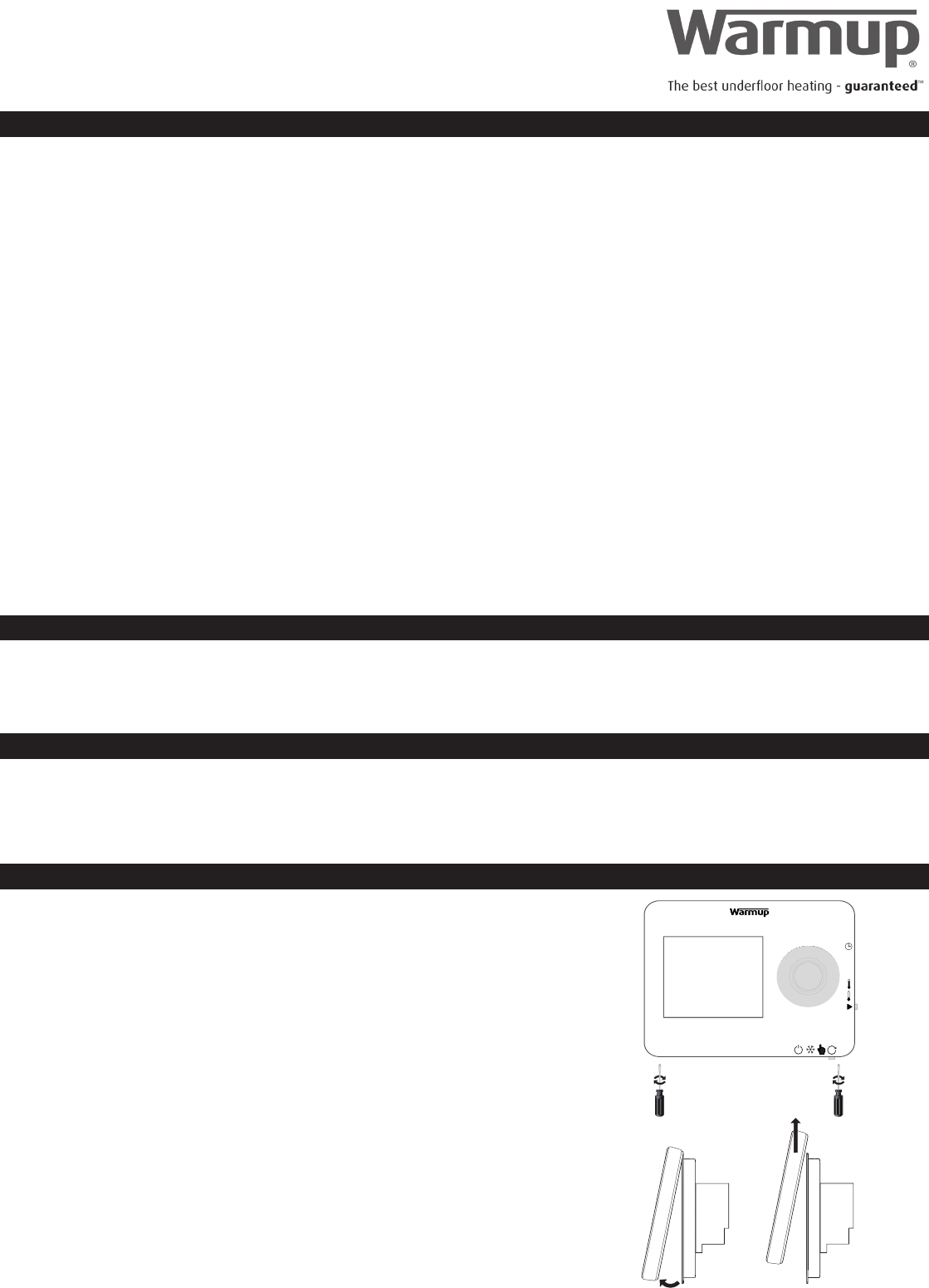
Installation:
Separate the front housing of thermostat from the wall module:
1. Unscrew both closing screws (bottom of thermostat) until they will not turn any
further.
2. Release front housing by gripping the lower half of outer frame and pulling
outwards then upwards.
3. Place front housing somewhere safe.
4. Run all wires to the wall box. Check to ensure that you have included the
following:
• Power (Live and Neutral)
• Heater (Live and Neutral)
• Floor sensor
• Fil pilote (France only)
5. Pull wires through the wall box and complete terminal wiring.
IMPORTANT: Ensure that multi strand wires are fully inserted into the terminal and
secured tightly. Any loose strands should be trimmed as they could cause a
short-circuit.
If connecting more than two heaters, an electrical junction box will be required.
Thermostat location
1
2
3
4
ELT-01-XX-01 - Installation guide V1.0 © Warmup plc - 2013
(NOT USED)
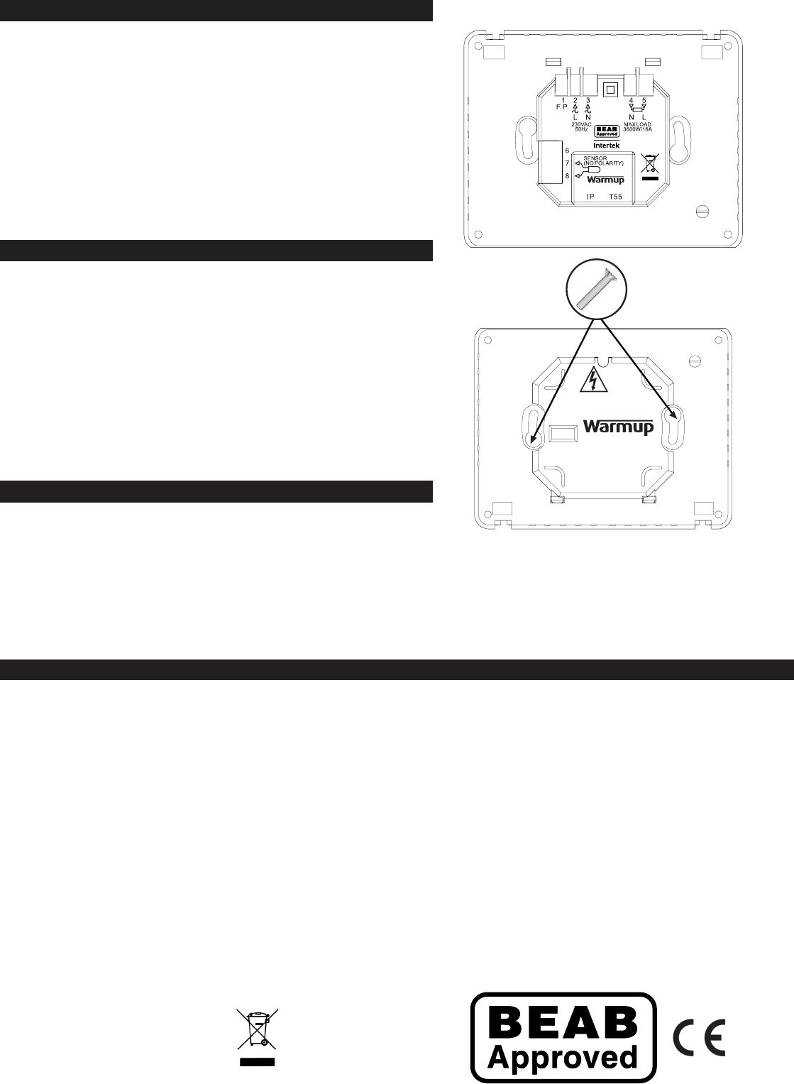
Normal electrical installation (see numbering on diagram to right)
1. Connect to Fil Pilote (F.P.) - only for use in France
2. Connect to Power Supply (Live – MAX 240V)
3. Connect to Power Supply (Neutral – MAX 240V)
4. Connect to Warmup heater(s) (Neutral – MAX 3600W/ 16 Amps)
5. Connect to Warmup heater(s) (Live – MAX 3600W/ 16 Amps)
6. Not Used
7. Connect to 1st wire of oor sensor (colour not important)
8. Connect to 2nd wire of oor sensor (colour not important)
Mounting thermostat into the wall box
1. Push excess wire back through the wall box and insert
thermostat back module into wall box.
2. Put xing screws through mounting holes and tighten.
3. Ensure that thermostat is straight before tightening completely.
4. Replace thermostat front housing:
5. Ensure front housing is securely xed.
6. IMPORTANT: Tighten both retaining screws.
Powering-up
You can now power-up the thermostat and begin the programming
process.
UK
Warmup Plc
702 Tudor Estate
Abbey Road
London
NW10 7UW
T: 0845 345 2288
International: + 44 208 453 6868
F: 0845 345 2299
E-mail: uk@warmup.com
Website: www.warmup.co.uk
Disposal
Appliances with this symbol must
not be disposed of with general
waste. Seek guidance from your local
government or the retailer where you
purchased the product.
Contact Warmup
ELT-01-XX-01 - Installation guide V1.0 © Warmup plc - 2013
20
• Align and sit front housing on to hinges
• Push lower half of front housing until a ‘click’ is heard.
Patent Pending
