The Red Book Introduction RRP502
User Manual: RRP502
Open the PDF directly: View PDF ![]() .
.
Page Count: 22
- The Red Book
- Table of Contents.
- Index to Systems.
- Contact Details
- SECTION ‘A’ Introduction
- Contents.
- An Introduction to The Red Book™.
- Components.
- Physical Properties.
- Material & Construction Standards.
- Fire Testing.
- Building Acoustics.
- Building Acoustics in Practice.
- Detailing for Acoustics.
- Definitions.
- www.gyprock.com.au
- Literature On-line
GYP500 October 2004. RRP $24.95
The Red Book™
Table of Contents.
SECTION SUBJECT
‘A’ Introductory Information.
‘B’ Steel Stud Wall Systems.
‘C’ Timber Stud Wall Systems.
‘D’ Masonry Wall Systems.
‘E’ Ceiling Systems.
‘F’ Services Systems.
‘G’ Rain Noise Reduction Ceiling Systems.
‘Z’ Penetration & Perimeter Detailing.
Inside Back Cover . . . . . Index to Systems - by System Nº.
Outside Back Cover . . . Contact Details.
ADDITIONAL
INFORMATION

The Red Book™
Index to Systems.
System Nº Page Nº
005 B9
010 B9
015 B9
020 B9
025 B9
030 B9
31 B12
32 B14
035 B10
39 B14
40 B11
41 B11
42 B11
050 B10
051 B10
055 B10
60 B24
61 B24
62 B24
075 B10
080 B10
089 B15
090 B15
091 B15
092 B15
093 B15
105 B16
110 B16
121 B29
122 B29
125 B16
127 B29
128 B29
130 B16
131 B16
135 B16
150 B18
152 B18
154 B18
155 B18
157 B18
160 B18
161 B19
162 B19
165 B31
167 B31
168 B31
170 B32
171 B32
175 B19
178 B32
179 B32
180 B19
185 B30
186 B30
191 B19
192 B35
193 B35
194 B35
195 B35
196 B35
197 B35
198 B35
205 B20
System Nº Page Nº
206 B21
207 B21
208 B20
209 B20
210 B20
211 B20
212 B21
215 B20
217 B22
218 B21
219 B22
220 B22
250 B21
255 B21
275 B22
280 B22
290 B25
291 B25
292 B25
293 B25
294 B26
295 B26
296 B27
297 B26
298 B27
305 C6
310 C6
315 C6
320 C6
325 C6
330 C6
335 C7
350 C7
352 C7
354 C7
355 C7
375 C8
380 C8
390 C15
391 C15
392 C15
393 C15
403 C14
410 C14
411 C14
415 C14
419 C14
425 C12
430 C12
450 C12
455 C12
475 C12
480 C12
493 C22
494 C22
495 C22
496 C22
497 C22
498 C22
500 C11
501 C11
502 C11
503 C11
530 D12
System Nº Page Nº
531 D12
532 D12
533 D12
534 D12
535 D12
536 D12
537 D12
540 D10
541 D10
542 D10
543 D10
544 D11
545 D11
546 D11
547 D11
550 C9
555 C9
575 C9
580 C9
582 C9
600 B12
601 B12
602 B12
605 B12
606 B12
610 B13
611 B13
613 B13
614 B13
620 B17
630 B19
631 B17
632 B17
633 B17
640 B22
652 C7
653 C8
654 C8
660 C8
661 C13
662 C13
663 C13
664 C13
665 C8
670 C13
671 C13
672 C13
674 C10
675 C10
677 C9
678 C9
680 C10
681 C10
682 C10
690 C20
693 C20
694 C21
695 C21
696 C20
697 C21
698 C21
722 D15
723 D15
724 D15
System Nº Page Nº
730 D15
731 D15
732 D15
735 SC13
736 SC13
760 D6
761 D6
762 D6
764 D6
765 D6
766 D6
767 D7
768 D7
769 D7
770 D7
771 D7
772 D7
780 D8
781 D8
782 D8
783 D8
784 D8
785 D8
786 D9
787 D9
788 D9
789 D9
790 D9
791 D9
795 D16
796 D16
797 D16
798 D16
800 E7
801 E7
802 E7
803 E7
804 E7
805 E8
806 E8
807 E8
808 E8
809 E8
810 E9
811 E9
812 E9
813 E9
814 E9
815 E9
816 E9
817 E9
818 E9
819 E9
821 E10
822 E10
823 E10
824 E10
825 E10
826 E10
827 E10
829 E10
831 E11
832 E11
833 E11
System Nº Page Nº
834 E11
835 E11
836 E11
837 E11
838 E11
839 E11
841 E12
845 E12
846 E12
847 E12
848 E12
849 E12
851 E15
852 E15
853 E15
856 E15
857 E15
858 E15
859 E15
860 E16
862 E14
863 E14
864 E14
865 E16
866 E16
867 E14
868 E14
869 E16
870 E13
871 E13
874 E14
875 E14
876 E14
890 E19
900 C16
901 C16
902 C16
903 C16
911 C17
912 C17
915 C17
916 C17
920 C19
921 C19
923 C19
924 C19
925 C19
927 C19
928 C19
940 B28
940+
ExpressWall B28
941 B28
942 B28
945 B34
946 B34
947 B34
950 E13
951 E13
952 E13
953 E13
955 E13
960 G5
961 G5
System Nº Page Nº
965 G5
966 G5
967 B33
968 B33
969 B33
970 B23
971 B23
972 B23
974 G6
975 G6
976 G6
980 G6
981 E17
982 E17
983 E17
985 E17
986 E17
987 E18
992 E18
993 E18
994 E18
995 E18
997 E18
75PP D13
75PP-DC D13
75SS D14
75SS-DC D14
RWS Timber C18
RWS Steel B30
SF001 E17
SS01 F4
SS02 F4
SS03 F4
SS04 F4
SS05 F4
SS06 F4
SS07 F4
SS10 F5
SS11 F5
SS12 F5
SS13 F5
SS14 F5
SS15 F5
SS16 F5
SS20 F6
SS21 F6
SS22 F6
SS23 F6
SS24 F6
SS25 F6
SS26 F6
SS27 F6
SS30 F7
SS31 F7
SS32 F7
SS33 F7
SS34 F7
SS35 F7
SS36 F7
SS37 F7
SS40 F8
SS41 F8
SS42 F8

The Red Book™
October 2004
GYP500.BMS7993.1004
© CSR Gyprock®, CSR Building Products A.B.N. 55 008 631 356.
The following are trade marks of CSR Limited and are under license.
CSR™, Gyprock®, Supaceil™, Fyrchek™, Soundchek™, Aquachek™, Bracechek™, Impactchek™, FlamechekMR™,
Freshtone™, Supatone™, Bradford™, designLINK®.
Health & Safety.
Information on any known health risks of our products and how to handle them
safely is on their package and/or the documentation accompanying them.
Additional information is listed in the Material Safety Data sheet.
To obtain a copy, telephone 1800 807 668.
Guarantee.
CSR Building Products guarantees its Gyprock®products to be free of defects in materials and manufacture.
If a CSR product does not meet our standard, we will, at our option, replace or repair it, supply an
equivalent product, or pay for doing one of these.
CSR recommends that only products, components and systems recommended by it be used.
If this is not done, CSR will need to be satisfied that any defect in its product is attributable to our failure to
meet our standard (and not another cause) before this guarantee applies.
This guarantee excludes all other guarantees and liability for damage or loss in connection with defects in
CSR's product, other than those imposed by legislation.
CSR Gyprock Web Site.
www.gyprock.com.au
CSR Gyprock Sales Support.
Telephone: 13 17 44
Facsimile: 1800 646 364
CSR designLINK®Technical Support Service.
Telephone: 1800 621 117.
New South Wales and ACT.
376 Victoria Street, Wetherill Park NSW 2164.
Queensland.
768 Boundary Road, Coopers Plains QLD 4108.
Victoria.
277 Whitehall Street, Yarraville VIC 3013.
South Australia.
Lot 100 Sharp Court, Mawson Lakes SA 5095.
Western Australia.
21 Sheffield Road, Welshpool WA 6106.
Tasmania.
PO Box 61, Glenorchy TAS 7010.
Northern Territory.
Cnr Stuart Hwy & Angliss Rd, Berrimah NT 0828.
The Red Book™
A1.
Introduction
Contents.
SUBJECT PAGE
An Introduction to The Red Book™A2
Components A2
Product Properties A10
Material & Construction Standards A12
Fire Testing A12
Building Acoustics A13
Building Acoustics in Practice A14
Detailing for Acoustics A15
Definitions A17
SECTION ‘A’
CSR Gyprock™ On-Line
Literature On-Line

A2. The Red Book™
An
Introduction to
The Red
Book™.
The CSR Gyprock and Fibre Cement Fire & Acoustic
Design Guide…‘The Red Book™’, provides a ready
reference to the performance of an extensive range of
CSR Gyprock and Fibre Cement (GFC) fire and acoustic
wall, ceiling and column/beam systems.
Over the last 50 years, CSR has developed effective,
practical and cost effective fire and acoustic systems for
most applications. Fire, acoustic and structural testing
has been carried out for all GFC products as well as
those of CSR Bradford Insulation and Rondo Building
Products. To complement this extensive testing program,
CSR GFC has obtained certified assessments from
appropriate authorities on the likely performance of
some systems. These assessments are based on test results
and expert opinion.
CSR GFC fire rated systems have been tested or
assessed to AS1530.4 : 1990 or 1997 at approved testing
laboratories. Test reports and assessments are available
on request.
CSR GFC has developed systems with ‘Fire
Resistance Levels’ (FRL) up to –/180/180 (3 hours). The
systems and performance specifications detailed in this
manual are guaranteed only for the construction specified.
Any variation or substitution of materials or assembly
requirements, or any compromise in assembly may result
in failure under critical conditions. It is recommended that
only accredited plasterboard fixers install fire rated systems.
CSR GFC acoustic rated systems have been assessed
by PKA Consulting, acoustic engineers.
CSR is continuously developing its products, which
may result in changes to product specifications, range and
performance. The systems and products in this Fire and
Acoustic Design Guide are current at the publication date.
Components.
CSR GFC manufactures and supplies a diverse range
of plasterboard and fibre cement sheets, acoustic panels
and accessories to suit a multitude of wall, ceiling and
encasement applications.
GYPROCK®Plasterboard CD is machine made
sheet composed of a gypsum core encased in a heavy duty
linerboard. Available with long edges recessed to assist in
producing a smooth, even and continuous surface once
jointed, or in square edge. GYPROCK Plasterboard CD
is manufactured to AS2588 – ‘Gypsum Plasterboard’,
and incorporates CD (Controlled Density) technology.
GYPROCK Plasterboard CD is suitable for internal walls
and ceilings.
GYPROCK SUPACEIL™is a 10mm thick sheet
designed to span up to 600mm in ceiling applications.
GYPROCK Supaceil™is machine made sheet composed
of a gypsum core encased in a heavy duty linerboard.
Long edges are recessed for flush jointing. GYPROCK
Supaceil™is manufactured to AS2588 –‘Gypsum
Plasterboard’, and incorporates CD (Controlled Density)
technology.
GYPROCK SOUNDCHEK™has been designed to
provide increased acoustic resistance in wall and ceiling
systems. GYPROCK Soundchek™is machine made sheet
composed of a high density gypsum core encased in a
heavy duty linerboard. Long edges are recessed to assist
in producing a smooth, even and continuous surface
once jointed. GYPROCK Soundchek™is manufactured
to AS2588 – ‘Gypsum Plasterboard’, and is suitable for
internal walls and ceilings.
GYPROCK IMPACTCHEK™is high strength
plasterboard designed for impact areas. It is composed of
a glass fibre reinforced gypsum core plus a fibreglass mesh
bonded to the inside of the back face. 13mm
IMPACTCHEK is encased in a violet linerboard and may
be used in fire rated applications, and 10mm
IMPACTCHEK is encased in white linerboard. The
long edges of both are recessed for flush jointing.
GYPROCK AQUACHEK™is designed for use in
lining the walls of ‘wet areas’ of residential and commercial
buildings. It is machine made gypsum plasterboard with
a core treated to make it resistant to moisture and
humidity. It is manufactured to satisfy the requirements
of AS2588 – ‘Gypsum Plasterboard’, and the water
resistant requirements of ASTM C630. It is encased with
light blue linerboard and the long edges are recessed.
The Red Book™
A3.
GYPROCK FYRCHEK™can be used in wall and
ceiling systems where an FRL is to be achieved, or where
acoustic performance is required. GYPROCK Fyrchek™
is machine made sheet composed of a specially processed
glass fibre reinforced gypsum core encased in a heavy duty
pink liner board.
GYPROCK FYRCHEK MR™is primarily
intended for walls and ceilings in ‘wet area rooms’ and for
soffits and external walls that must achieve fire resistance.
GYPROCK Fyrchek MR™is machine made sheet
composed of a specially processed glass fibre reinforced
gypsum core which is treated in manufacture to withstand
the effects of moisture, and encased in a heavy duty light
blue liner board.
GYPROCK FLAMECHEK MR™is a fire and
moisture resistant high performance 10mm thick
plasterboard. GYPROCK FlamechekMR™is a machine
made gypsum plasterboard with a treated core to make
it resistant to moisture and fire. It is manufactured to satisfy
the requirements of AS2588 –‘Gypsum Plasterboard’,
and the water resistant requirements of ASTM C630. It
is encased with blue linerboard and the long edges are
recessed.
GYPROCK®Shaft Liner Panel is a 25mm thick
machine made sheet composed of a glass fibre reinforced
gypsum core encased in a heavy duty linerboard.
GYPROCK Shaft Liner Panel is used to enclose lift
shafts, stairwells and service shafts in multistorey
construction. GYPROCK Shaft Liner Panel can be used
to achieve fire resistance in wall and ceiling systems.
GYPROCK®Flexible Plasterboard has been
designed for curved wall and ceiling systems and has an
enhanced core to enable bending to a small radius. It is
machine made sheet composed of a gypsum core encased
in a heavy duty linerboard. Long edges are recessed to
assist in producing a smooth, even and continuous surface
once jointed. GYPROCK Flexible Plasterboard is 6.5mm
thick and is installed in two layers.
CSR Fibre Cement Wallboard is an autoclaved,
cellulose fibre reinforced cement sheet that is immune to
permanent water damage and has high impact resistance.
CSR Fibre Cement Wallboard is suitable for internal
walls as well as internal and external ceiling applications.
It has a recess on both long edges so that sheets may be
flush jointed, using CSR Gyprock®plasterboard jointing
materials.
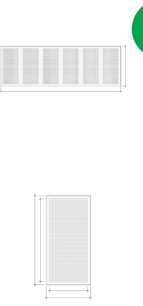
GYPROCK®Perforated Plasterboard has been
designed for use in ceilings where additional sound
absorption is required. It is a machine made sheet
composed of a gypsum core encased in a heavy duty
linerboard and incorporates CD technology. Long edges
are recessed for flush jointing. Perforations total 8.2% of
the sheet area. For detailed pattern information, refer to
Section ‘E’.
GYPROCK®PLASTERBOARD PANELS.
GYPROCK Plasterboard Panels have a gypsum core
and various face treatments. GYPROCK Panels are
produced to fit metric grid specifications of (600 x
1200mm nominal).
Perforated Panel has a white vinyl face finish, and
a regular grid of 6mm full depth holes. Perforations are
approximately 10% of the panel area, and combined with
suitable insulation, provide a medium level of acoustic
absorption.
Supatone™is a paper faced white ceiling tile suited
to basic commercial ceilings. A low maintenance bright
white panel, it can be wiped clean with a damp cloth.
Freshtone™UltraMatt has a low sheen, white vinyl
face that can easily be wiped clean. It is ideally suited to
large commercial environments, such as supermarkets
and shopping centres, where high reflectivity is required.
1200mm (nominal)
3600mm (nominal)
FIG A1. PERFORATION PATTERN.
1200mm (nominal)
1100mm
600mm (nominal)
500mm
FIG A2. GYPROCK PERFORATED PANEL
DIMENSIONS.
A4. The Red Book™
Freshtone™Diamond White has a lightly textured
vinyl surface which resists fading and mould growth.
With a white finish, it is suitable for shopping centres,
factories and offices.
Freshtone™Platinum combines a contemporary
metallic look with the simplicity of plasterboard ceiling
panels. Appropriate for office foyers, administration areas
or any modern space that requires a refined ceiling feature.
ECOPHON™
CEILING PANELS.
Ecophon™ceiling panels have a bonded glasswool core
for high acoustic absorption performance and the Akutex
T finish to provide an attractive easy care surface.
The range includes:
Focus: 20mm thickness panels with a range of edge
profiles. Also available for direct fixing to battens or
existing ceiling. The Akutex T surface is micro-perforated
vinyl paint that can be easily wiped clean.
Advantage: 15mm thickness panels with a glass tissue
facing to meet general conditions and good acoustic
performance.
Master: 40mm thickness panels with the highest
acoustic performance plus Akutex T finish.
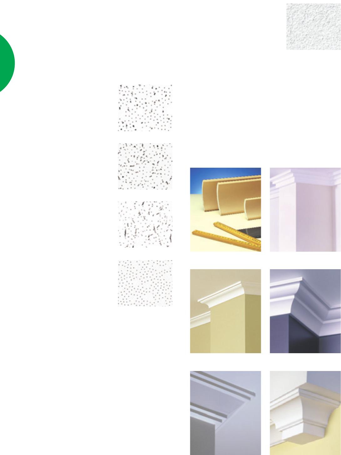
CELOTEX™
CEILING PANELS.
Celotex™ceiling panels have a
mineral fibre core and offer a range
of attractive textured finishes and
acoustic absorption ratings to meet
basic requirements. The range
includes:
Fine Fissured: 16mm
thickness panels with a discrete
non-directional pattern. Also
available in 19mm thickness with
scored bands.
Concorde: 16mm thickness
panels with various fissure sizes.
Directional Fissured: 16mm
thickness panels with an aligned
fissure pattern.
Sand Perforated: 16mm
thickness panels with a sand
grain-like texture and small round
perforations.
For detailed information,
please refer to the ‘CSR
Gyprock®Celotex Acoustic
Ceiling Systems’ guide.
Fine Fissured
Concorde
Directional Fissured
Sand Perforated
GYPROCK®CORNICE.
CSR Gyprock manufactures six popular machine
made cornice profiles which cater for many styles and
applications. Please refer to Table A1 in this section for
detailed product size and availability information. It is
recommended that cornice be attached with Gyprock®
Cornice Cement.
GYPROCK®
COVE CORNICE.
GYPROCK®
JAZZ CORNICE.
Hygiene: 20mm thickness
panels with a ‘cleanroom’
classification. Provides excellent
acoustic performance and the
Akutex T finish is suitable for
pressure wash-down situations. For
detailed information, please refer to
the ‘Ecophon Product Catalogue’.
Akutex T
GYPROCK®
TEMPO CORNICE.
GYPROCK®
CLASSIC CORNICE.
GYPROCK®
SYMPHONY CORNICE.
GYPROCK®
CONCERTO CORNICE.

The Red Book™
A5.
10.5
12.5
✓W✓✓
✓SN ✓W✓✓
13
16
1200
1200
FYRCHEK™
FLAMECHEK MR™✓
135010 8.0
PERFORATED SHEET ✓
120013 10.0
SHAFT LINER PANEL ✓
60025 19.8
CLASSIC CORNICE ✓
90– 1.2kg/m
TEMPO CORNICE ✓
90– 1.6kg/m
JAZZ CORNICE ✓
75– 1.8kg/m
SYMPHON Y CORNICE ✓
75– 0.90kg/m
CONCERTO CORNICE ✓
90– 1.4kg/m
Indicates available in: ✓= Australia wide; W = Western Aust.; S = South Aust.; N = Northern Territory.
Indicates NOT available in: W = Western Aust.; S = South Aust.; N = Northern Territory.
* = Length is 2740. ▲= 3300 and 3900mm lengths also available in WA only.
In Western Australia only, additional Recessed Edge/Square Edge products are available.
Additional sizes may be available in some products. Call your state office for details.
9.3
13.0
✓
✓
10
13
1350
1200
SOUNDCHEK™
8.0
10.4
✓✓SN ✓✓✓
SN SN WSN ✓SN ✓WSN
✓W✓W
10
13
1200
1350
1200
AQUACHEK™
7.2
WWWW
✓SN W✓✓▲✓ ✓✓✓
W✓✓✓✓ ✓
10
900
1200
1350
SUPACEIL™
GYPROCK Product
✓W✓W✓W✓W✓W✓W✓W✓W
✓W✓W✓W✓W✓W✓W
*✓WSN WW
✓SN ✓✓✓✓W✓SN ✓WSN
✓✓SN ✓W
2400 2700 3000 3600 4200 4800 5400 6000
Mass
kg/m2
10 6.5
8.5
6.5
8.5
1200
1350
W SN WSN W
SN SN
10
13
1200
1200
13
900
1200
1350
Thickness
mm
Width
mm
0.68kg/m
0.93kg/m
1.3kg/m
✓✓✓✓
WWWW
✓✓✓✓✓
–
–
–
55
75
90
COVE CORNICE
Sheet Length (mm)
CD
RECESSED EDGE
CD SQUARE EDGE
IMPACTCHEK™✓
120013 10.3
BRACECHEK™✓
120010 8.4
FLEXIBLE ✓
12006.5 4.25
10.7
13.5
✓WSN SN
✓WSN WSN
13
16
1200
1200
FYRCHEK™MR
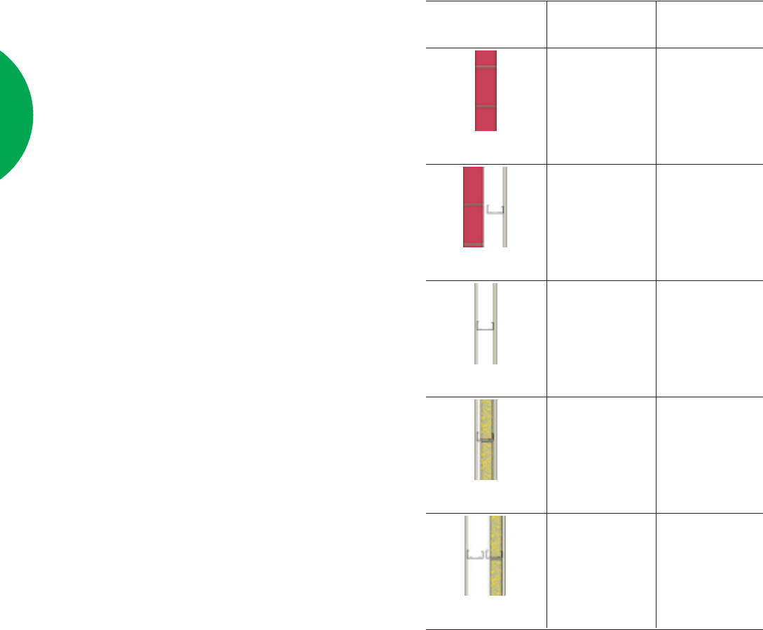
TABLE A1. GYPROCK PLASTERBOARD AVAILABILITY.
Colour shading behind each product approximates the colour of the product face liner sheets.
A6. The Red Book™
Width mm.
Length
mm.
1800
2400
2700
3000
3600
4200
900
✓
✓
✓
1200
✓
✓ ■ ✤
✓ ■ ✤
✓ ■ ✤
✓
✓
1350
✓
✓
✓
Thickness
(6mm RE = ✓) (9mm RE = ■) (12mm RE = ✤)
Mass 6mm thickness (nominal) 9kg/m2
Mass 9mm thickness (nominal) 13.5kg/m2
Mass 12mm thickness (nominal) 18.3kg/m2
Length +0 to -4mm
Width +0 to -3mm
Thickness +0.25 to -0.25mm
Diagonals Difference (max) 3mm
TABLE A2.
CSR FIBRE CEMENT WALLBOARD
AVAILABILITY AND MANUFACTURING
TOLERANCES.
CSR Fibre Cement Wallboard is manufactured in
the following sizes and available in all states.
CSR Fibre Cement Wallboard has two long edges
recessed to allow seamless jointing.
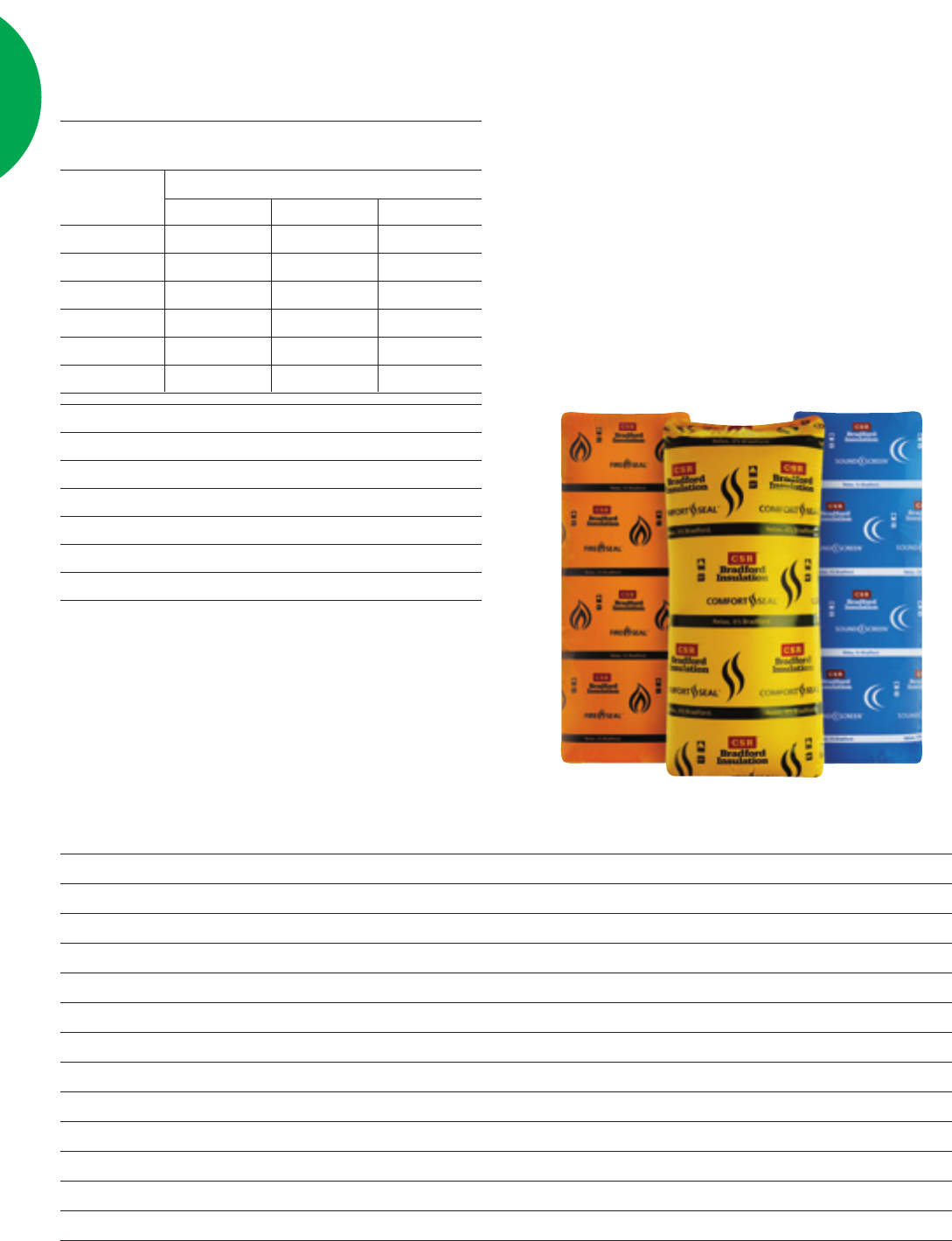
in service. Additional information on CSR Bradford
Insulation materials is available by telephoning CSR
Bradford on (02) 9765 7100.
Although insulation materials are often specified for
thermal resistance, they can contribute significantly to the
acoustic performance of wall and ceiling systems. CSR
GFC only recommends materials that have been tested
for fire and acoustic applications, have proven durability,
and are supported by their manufacturer for these
applications. Should other insulation materials be used,
the manufacturer of those materials must verify the
performance of the complete system, CSR GFC will not
support the performance of substitute materials.
Acoustic Polyester insulation manufactured by Tontine
and Autex have been tested in acoustic applications by the
manufacturer and are specifically made for that purpose.
CSR accepts the use of Tontine and Autex Polyester
insulation.
Product Abbreviation
75mm Bradford SoundScreen™R2.0 batts (rockwool) 75mm Soundscreen™2.0 batts
60mm Bradford SoundScreen™R1.6 batts (rockwool) 60mm Soundscreen™1.6 batts
45mm Bradford Rockwool Fibertex Partition batts, 38kg/m345mm Rockwool Partition batts
75mm Bradford Comfortseal™R1.5 batts wall (glasswool) 75mm Comfortseal™R1.5 batts
105mm Bradford Comfortseal™R2.0 ceiling batts (glasswool) 105mm Comfortseal™R2.0 batts
50mm Bradford Glasswool Partition batts, 10.8kg/m250mm Glasswool Partition batts
75mm Bradford Glasswool Partition batts, 10.8kg/m275mm Glasswool Partition batts
Autex ASB 2 (50mm) / Tontine TSB 2 (50mm) Polyester Insulation ASB2/TSB2 Polyester batts
Tontine TSB 3 (65mm) / Autex ASB 3 (60mm) Polyester Insulation ASB3/TSB3 Polyester batts
Tontine TSB 4 (75mm) / Autex ASB 4 (70mm) Polyester Insulation ASB4/TSB4 Polyester batts
Tontine TSB 5 (85mm) / Autex ASB 5 (80mm) Polyester Insulation ASB5/TSB5 Polyester batts
Tontine Blanket (25mm) 10kg/m3Polyester Insulation TBL/1025 Polyester
TABLE A3. SPECIFIED INSULATION AND ABBREVIATIONS.
(Abbreviated names have been used in system tables).
BRADFORD INSULATION.
INSULATION.
CSR GFC Fire and Acoustic Systems incorporate
CSR Bradford glasswool and rockwool insulation. These
products have undergone significant acoustic testing and
have a proven track record of performance and durability
The Red Book™
A7.
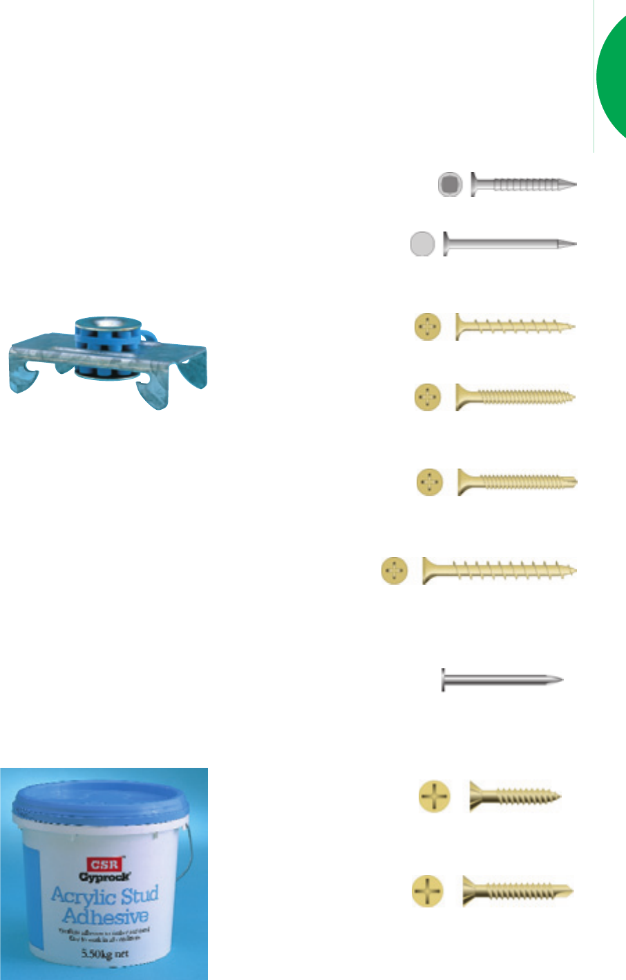
STUD ADHESIVE.
CSR Gyprock®Acrylic Stud Adhesive is coloured
blue for easy identification. It can be used on both timber
and steel in temperatures not less than 5ºC.
Contact surfaces must be free of oil, grease or other
foreign materials before application. The adhesive is
applied with a broad knife to form 25mm diameter by
15mm high walnuts. This product is suitable for use with
pre-painted metal battens and some treated timbers.
Always follow
directions on
packaging when
using CSR stud
adhesive.
• GYPROCK Ring Shanked Nails.
Hardwood 25 x 2.8mm.
Softwood 30 x 2.8mm.
• GYPROCK Clouts.
(Hot-dip galvanised).
30, 40 and 50mm x 2.8mm.
• GYPROCK Plasterboard Screws.
Nº6 Type ‘W’
for timber framing.
Nº6 Type ‘S’ Needle Point
for lightweight steel studs
and furring channel up
to 0.8mm thickness
FASTENERS.
CSR Gyprock distributes a comprehensive range of
ring shank nails, hot-dip galvanised clouts, and screws for
use with timber and steel framing to accommodate most
installation applications.
Nº6 Type ‘S’ Drill Point
for steel framing
0.8mm to 1.2mm
thickness.
GYPROCK Plasterboard Laminating Screws.
40mm x Nº10.
for laminating
layers of plasterboard together at butt joints and
control joints (where permitted).
CSR Fibre Cement Nails: Galvanised 2.0mm x
30mm for softwood and
2.0mm x 25mm for
hardwood.
CSR Fibre Cement Screws: For 6mm thickness
sheets only.
Nº 8 x 20mm self
embedding head, needle
point for light gauge steel
frames up to 0.8mm.
Nº 8 x 25mm self
embedding head, drill
point for heavy gauge
steel frames from 0.8mm to 1.2mm.
MASONRY ADHESIVE.
CSR Gyprock®Masonry Adhesive is used to adhere
GYPROCK plasterboards to CSR Hebel Aerated
Autoclaved Concrete substrates and all masonry substrates.
STEEL COMPONENTS.
CSR GFC recommends steel building elements
manufactured by Rondo Building Services Pty Ltd, for
our systems. Top hats manufactured by Stramit, Lysaght
and Rhino Steel are also specified in some systems.
General information on Rondo steel building
components is provided throughout this manual.
Additional information can be obtained from the Rondo
Building Services Pty Ltd office in your state, or telephone
1300 367 663.
CSR GFC will not support the performance of
substitute materials. It is the responsibility of the
manufacturer of the component to substantiate equivalent
performance in any particular application.
CSR GYPROCK®RESILIENT MOUNT.
The CSR Gyprock®Resilient Mount is a proprietary
component used in conjunction with Rondo steel
sections for fastening GYPROCK plasterboard to a
supporting structure
while simultaneously
isolating it from
structure borne
vibration.
This significantly reduces the amount of impact noise,
speech and low frequency sound filtering through to
rooms above, below or alongside the noise generating
room. The resilient mount has been design for use on
ceilings and can be used on walls provided plasterboard
with minimum mass of 15kg/m2is fixed on the resilient
mount side of the wall. The mount can be used in fire
rated and non fire rated systems.
A8. The Red Book™
TABLE A4. FIXING PLASTERBOARD TO SOFTWOOD.
Plasterboard
Thickness
10mm Plasterboard
13mm Plasterboard
16mm Plasterboard
2x6.5mm Plasterboard
13mm+16mm Plasterboard
1st Layer
2.8x40mm Gal Nail or Nº6-18 x 25mm
Bugle, NP or 2.8x30mm Ring Shank Nail
2.8x40mm Gal Nail or Nº6-18 x 32mm
Bugle, NP or 2.8x30mm Ring Shank Nail
2.8x50mm Gal Nail or Nº6-18 x 32mm
Bugle, NP
2.8x40mm Gal Nail or Nº6-18 x 25mm
Bugle, NP or 2.8x25mm Ring Shank Nail
2.8x40mm Gal Nail or Nº6-18 x 32mm
Bugle, NP or 2.8x30mm Ring Shank Nail
2nd Layer
2.8x50mm Gal Nail or Nº6-18 x 40mm
Bugle, NP
2.8x50mm Gal Nail or Nº6-18 x 45mm
Bugle, NP
3.15x65mm Gal Nail or Nº6-18 x 50mm
Bugle, NP
2.8x40mm Gal Nail or Nº6-18 x 32mm
Bugle, NP or 2.8x30mm Ring Shank Nail
2.8x50mm Gal Nail or Nº6-18 x 45mm
Bugle, NP
3rd Layer
3.75x75mm Gal Nail or Nº8-15 x 65mm
Bugle, NP or Nº10-40 Laminating
3.75x75mm Gal Nail or Nº8-15 x 65mm
Bugle, NP or Nº10-40 Laminating
TABLE A5. FIXING PLASTERBOARD TO HARDWOOD.
Plasterboard
Thickness
1 x 10mm Plasterboard
2 x 10mm Plasterboard
1 x 13mm Plasterboard
2 x 13mm Plasterboard
3 x 13mm Plasterboard
1, 2 or 3 x 16mm Plasterboard
2 x 6.5mm Plasterboard
13mm+16mm Plasterboard
1st Layer
2.8x30mm Gal Nail or #6-18 x 30mm
Bugle, NP or 2.8x25mm Ring Shank Nail
2.8x30mm Gal Nail or #6-18 x 25mm
Bugle, NP or 2.8x25mm Ring Shank Nail
2.8x30mm Gal Nail or #6-18 x 30mm
Bugle, NP or 2.8x25mm Ring Shank Nail
2.8x30mm Gal Nail or #6-18 x 32mm
Bugle, NP or 2.8x25mm Ring Shank Nail
2.8x30mm Gal Nail or #6-18 x 32mm
Bugle, NP or 2.8x25mm Ring Shank Nail
2.8x40mm Gal Nail or #6-18 x 32mm
Bugle, NP
2.8x30mm Gal Nail or #6-18 x 25mm
Bugle, NP or 2.8x25mm Ring Shank Nail
2.8x30mm Gal Nail or #6-18 x 32mm
Bugle, NP or 2.8x25mm Ring Shank Nail
2nd Layer
2.8x40mm Gal Nail or #6-18 x 32mm
Bugle, NP
2.8x40mm Gal Nail or #6-18 x 40mm
Bugle, NP
2.8x40mm Gal Nail or #6-18 x 45mm
Bugle, NP
2.8x50mm Gal Nail or #6-18 x 45mm
Bugle, NP
2.8x30mm Gal Nail or #6-18 x 32mm
Bugle, NP or 2.8x25mm Ring Shank Nail
2.8x50mm Gal Nail or #6-18 x 45mm
Bugle, NP
3rd Layer
3.15x65mm Gal Nail or #8-15 x 65mm
Bugle, NP or #10-40 Laminating
3.15x65mm Gal Nail or #8-15 x 65mm
Bugle, NP or #10-40 Laminating
TABLE A6. FIXING FIBRE CEMENT AND
PLASTERBOARD TO TIMBER.
Fibre Cement
Thickness
6mm Wallboard
9mm Wallboard
6/9mm Wallboard over
13mm Plasterboard
6/9mm Wallboard over
16mm Plasterboard
13/16mm Plasterboard over
6mm Wallboard
13/16mm Plasterboard over
9mm Wallboard
1st Layer
Nº8-15 x 20 CSK NP or
2.8x40mm Gal nail
Nº8-15 x 30 CSK NP or
2.8x40mm Gal nail
2.8x40mm Gal Nail or Nº6-18 x 32mm
Bugle, NP or 2.8x30mm Ring Shank Nail
2.8x50mm Gal Nail or
Nº6-18 x 32mm Bugle, NP
Nº8-15 x 20 CSK NP or
2.8x40mm Gal nail
Nº8-15 x 30 CSK NP or
2.8x40mm Gal nail
2nd Layer
2.8x50mm Gal Nail or
Nº8-15x40mm CSK, NP
2.8x50mm Gal Nail or
Nº8-15x40mm CSK, NP
2.8x50mm Gal Nail or
Nº6-18 x 45mm Bugle, NP
2.8x50mm Gal Nail or
Nº6-18 x 45mm Bugle, NP
NOTES:
Predrill 9mm and 12mm Wallboard for easier fixing.
Fixings are suitable for internal applications only.
Type 'W' screws of equivalent length may be used as an alternative to ‘NP’.
NP = Needle Point Screws.
DP = Dill Point Screws.
Bugle = Bugle Head Screws.
CSK = Countersunk Head Screws.
GAL = Galvanised.
The Red Book™
A9.
TABLE A7. FIXING TO STEEL 0.5-0.8mm BMT.
Plasterboard
Thickness
1 or 2 x 6.5mm Plasterboard
1 or 2 x 10mm Plasterboard
1, 2 or 3 x 13mm Plasterboard
1, 2 or 3 x 16mm Plasterboard
13mm + 16mm Plasterboard
2nd Layer
#6-18 x 25mm Bugle, NP
#6-18 x 40mm Bugle, NP
#6-18 x 40mm Bugle, NP
#6-18 x 45mm Bugle, NP
#6-18 x 45mm Bugle, NP
3rd Layer
#10-40 Laminating
#10-40 Laminating
1st Layer
#6-18 x 25mm Bugle, NP
#6-18 x 25mm Bugle, NP
#6-18 x 25mm Bugle, NP
#6-18 x 30mm Bugle, NP
#6-18 x 25mm Bugle, NP
TABLE A8. FIXING TO STEEL 0.8-2.0mm BMT.
Plasterboard
Thickness
1 or 2 x 6.5mm Plasterboard
1 or 2 x 10mm Plasterboard
1, 2 or 3 x 13mm Plasterboard
1, 2 or 3 x 16mm Plasterboard
13mm + 16mm Plasterboard
2nd Layer
#6-18 x 25mm Bugle, DP
#6-18 x 40mm Bugle, DP
#6-18 x 40mm Bugle, DP
#6-18 x 45mm Bugle, DP
#6-18 x 45mm Bugle, DP
3rd Layer
#10-40 Laminating
#10-40 Laminating
1st Layer
#6-18 x 25mm Bugle, DP
#6-18 x 25mm Bugle, DP
#6-18 x 25mm Bugle, DP
#6-18 x 30mm Bugle, DP
#6-18 x 25mm Bugle, DP
TABLE A9. FIXING TO STEEL 0.5-0.8mm BMT.
Fibre Cement
Thickness
6mm Wallboard
9mm Wallboard
6/9mm Wallboard over
13mm Plasterboard
6/9mm Wallboard over
16mm Plasterboard
13/16mm Plasterboard over
6mm Wallboard
13/16mm Plasterboard over
9mm Wallboard
1st Layer
#8-15 x 20 CSK NP or 9-18x20 Fibretek
#8-15 x 30 CSK NP or 9-18x30 Fibretek
#6-18 x 25mm Bugle, NP
#6-18 x 30mm Bugle, NP
#8-15 x 20 CSK NP or 9-18x20 Fibretek
#8-15 x 30 CSK NP or 9-18x30 Fibretek
2nd Layer
#8-15x40mm CSK NP
#8-15x40mm CSK NP
#6-18 x 40mm Bugle, NP
#6-18 x 40mm Bugle, NP
TABLE A10. FIXING TO STEEL 0.8-2.0mm BMT.
Fibre Cement
Thickness
6mm Wallboard
9mm Wallboard
6/9mm Wallboard over
13mm Plasterboard
6/9mm Wallboard over
16mm Plasterboard
13/16mm Plasterboard over
6mm Wallboard
13/16mm Plasterboard over
9mm Wallboard
1st Layer
#8-15 x 20 CSK DP
#8-15 x 30 CSK DP
#6-18 x 25mm Bugle, DP
#6-18 x 30mm Bugle, DP
#8-15 x 20mm CSK DP
#8-15 x 30mm CSK DP
2nd Layer
#8-15x40mm CSK DP
#8-15x40mm CSK DP
#6-18 x 40mm Bugle, DP
#6-18 x 40mm Bugle, DP
Notes:
Predrill 9mm and 12mm Wallboard for easier fixing.
Fixings are suitable for internal applications only.
NP = Needle Point Screws.
DP = Dill Point Screws.
Bugle = Bugle Head Screws.
CSK = Countersunk Head Screws.
GAL = Galvanised.
A10. The Red Book™
Physical
Properties.
THERMAL AND MOISTURE STABILITY.
CSR GFC plasterboard and fibre cement products are
stable building materials when subjected to the normal
range of interior temperature and humidity conditions.
Thermal coefficient of Linear Expansion (α).
• Plasterboard: α=16.2 x 10⁻⁶ mm (mm/ºC) in the
temperature range 4°C to 38°C.
• Fibre cement: α= 7.5 x 10⁻⁶/°C.
• Final length is calculated as follows:
Lf = Li (1 + α∆T).
The hygrometric coefficient of expansion (δ).
• Plasterboard: δ=7.2 x 10⁻⁶ mm/mm/% R.H.
(5% – 90% R.H.). Final length is calculated as follows:
Lf=Li (1 + δ∆RH).
• Fibre cement: δ= 0.18% (expansion from equilibrium
to saturated). Final length is calculated Lf= Lix δx
(% of saturation).
INTERNAL MOISTURE.
GYPROCK plasterboard must not be used where it
will be in contact with liquid water or constant relative
humidity above 90%.
GYPROCK Plasterboard CD, GYPROCK
SUPACEIL and GYPROCK SOUNDCHEK are
designed for use in dry areas only.
For wet area walls and external ceilings subject to
intermittent high humidity where plasterboard is
specified, GYPROCK AQUACHEK or GYPROCK
FYRCHEK MR or CSR Fibre Cement Wallboard must
be used. In all cases follow product installation brochures.
THERMAL PERFORMANCE.
The ‘R’ values for GYPROCK plasterboards are:
• 10mm thickness = 0.062 m2k/w.
• 13mm thickness = 0.074 m2k/w.
• 16mm thickness = 0.086 m2k/w.
The ‘R’ values for CSR Fibre Cement are:
• 6mm thickness = 0.02 m2k/w.
• 7.5mm thickness = 0.025 m2k/w.
• 8mm thickness = 0.027 m2k/w.
• 9mm thickness = 0.03 m2k/w.
STRUCTURAL PROPERTIES.
CSR Fibre Cement Wallboard properties at
EMC*/Saturated.
• Density (kg/m3) 1350/–.
• Compressive Strength.
Parallel to sheet length (MPa) 20/15.
Parallel to sheet width (MPa) –/50.
• Flexural Strength.
Parallel to sheet length.
- ultimate (MPa) 13/9.
- yield (MPa) 10/6.
Parallel to sheet width.
- ultimate (MPa) 16/11.
- yield (MPa) 12/8.
• Modulus of Elasticity (GPa) 6/4.
NOTE: *EMC = Equilibrium Moisture Content.
JOINTING ACCESSORIES AND
COMPOUNDS.
CSR GFC has a wide range of compounds, cements
and accessories for finishing plasterboard installations.
Refer to the Gyprock®Residential Installation Guide,
NºGYP547 for detailed jointing and finishing
information.
CSR GFC MASTICS AND SEALANTS.
CSR Gyprock®Fire Mastic must be used in fire rated
systems where caulking is indicated and is recommended
for caulking acoustic systems.
CSR Gyprock®Wet Area Acrylic Sealant is
recommended for sealing non fire rated wet area systems.
The Red Book™
A11.
IMPACT RESISTANCE.
GYPROCK plasterboard of 10mm and 13mm
thickness provide adequate resistance to soft body impacts
likely in domestic or light commercial use respectively.
Walls lined with Gyprock Fyrchek™, Impactchek™
and CSR Fibre Cement Wallboard can meet various
requirements of Specification C1.8 of the Building Code
of Australia 2004. This clause specifies resistance to
Uniform Distributed Loads (UDLs), surface indentation
and impact from a weighted sand bag that is dropped from
a specified height. Refer to Table A11 for performance
details.
FIRE HAZARD PROPERTIES.
The BCA limits the materials used in Class 2 to 9
buildings by controlling the Fire Hazard properties of
linings. These properties may be assessed by two methods.
AS/NZS1530.3 (Simultaneous determination of,
ignitability, flame propagation, heat release and smoke
release) known as Early Fire Hazard Indices. This method
is expected to be phased out for wall and ceiling lining
materials.
AS ISO9705 room burn test or AS/NZS3837 the
cone calorimeter test. The room burn test is a large scale
test to determine SMOGRARC, and the cone
calorimeter is a small scale test to determine a Group
Number.
Please refer to Table A12 for Gyprock®plasterboard
and CSR Fibre Cement product performance details.
GYPROCK Group
Product EFHI SMOGRARC Number
10 – 13mm
Plasterboard CD 13/0/1/2 0 1
10mm
SUPACEIL™ 14/0/1/1 0 1
10mm
SOUNDCHEK™ 0/0/0/3 0 1
10 – 13mm
AQUACHEK 13/0/2/3 0 1
6.5mm
FLEXIBLE 13/0/1/2 0 1
13mm
Perforated Sheet 0/0/0/3 0 1
13 – 16mm
FYRCHEK™ 0/0/0/3 0 1
13 – 16mm
FYRCHEK MR™ 13/0/2/2 0 1
25mm
SHAFT LINER 0/0/0/3 0 1
10mm
FLAMECHEK MR™ 13/0/2/2 0 1
13mm
IMPACTCHEK™ 0/0/0/3 0 1
13mm
Perforated Panels 0/0/0/4 0 1
10mm FRESHTONE™
Diamond White 0/0/0/3 0 1
10mm FRESHTONE™
UltraMatt & Platinum 0/0/0/3 0 1
10mm
SUPATONE™ 13/0/2/3 0 1
10 – 13mm
Unpainted Panel 13/0/1/3 0 1
Celotex 0/0/0/2 0 2
Ecophon ADVANTAGE 0/0/0/2 0 1
Ecophon FOCUS 0/0/0/3 0 1
Fibre Cement Wallboard 0/0/0/0 0 1
Wall Lining Material
1 x 13mm GYPROCK Impactchek
1 x 13mm GYPROCK Impactchek +
1 x 13mm GYPROCK Fyrchek
1 x 13mm GYPROCK Fyrchek +
1 x 6mm CSR Fibre Cement Wallboard
1 x 9mm CSR Fibre Cement Wallboard
2 x 16mm GYPROCK Fyrchek
2 x 13mm GYPROCK Fyrchek
1 x 16mm GYPROCK Fyrchek
1 x 13mm GYPROCK Fyrchek
1 x 10mm GYPROCK Impactchek
1 x 6mm CSR Fibre Cement Wallboard
Stud
Spacing
600mm
600mm
600mm
600mm
400mm
600mm
600mm
600mm
600mm
600mm
UDL
Resistance
≥1.0 kPa
≥1.0 kPa
≥1.0 kPa
≥1.0 kPa
≥1.0 kPa
≥0.35 kPa
≥0.35 kPa
≥0.25 kPa
≥0.25 kPa
≥0.25 kPa
Typical Wall Application
Public corridor, stair
shaft and fire isolated exit
in a spectator stand,
sports stadium, cinema,
theatre, railway station,
bus or airport terminal.
(Some Class 9 Buildings)
Walls of stairways and
service shafts and fire
isolated exits generally.
Fire resisting walls
generally.
Walls generally.
TABLE A11. IMPACT AND UDL RESISTANCE FOR
STUD SPACING AND LINING MATERIAL COMBINATIONS.
Soft Body Impact
Resistance
400mm
400mm
350mm
350mm
350mm
175mm
150mm
125mm
300mm
250mm
TABLE A12. FIRE HAZARD PROPERTIES.
NOTES: EFHI = Early Fire Hazard Indices (Ignitability/Spread of
Flame/Heat Evolved/Smoke Developed.
SMOGRARC = Smoke Growth Rate Index
A12. The Red Book™
Material &
Construction
Standards.
All materials and procedures shall comply with the
following standards where applicable, and all additional
details contained in CSR Gyprock and CSR Fibre
Cement Technical Literature.
Plasterboard Manufacture.
AS/NZS2588 : 1998 ‘Gypsum plasterboard’.
Plasterboard Installation.
AS/NZS2589 : 1997 ‘Gypsum linings in residential
and light commercial construction – Application and
Finishing’.
Plasterboard in Wet Areas.
AS3740 : 2004 ‘Waterproofing of Wet Areas Within
Residential Buildings’.
Fire Testing.
Fire resistance testing is conducted to the Australian
Standard AS1530 – part 4 ‘Fire Resistance Tests of
Elements of Building Construction’.
This standard gives the test method and criteria of
failure for the various elements of construction such as
partition walls, floor/ceilings and roof/ceilings.
The specimen assemblies are built into the test furnace
and subjected to furnace temperatures in accordance
with AS1530.4 ‘Standard Time vs Temperature Curve’.
0 30 60 90 120 150 180 210 240 270 300 330 360
500
600
700
800
900
1000
1100
1200
TEMPERATURE (°C)
TIME (minutes)
FIG. A3.
STANDARD TIME vs TEMPERATURE CURVE.
HOW IS THE SPECIMEN ASSESSED?
The test specimen is heated in the prescribed manner
until the failure criteria has been reached, or is terminated
by agreement between parties.
Assessment criteria are represented by three
performance measurements known as ‘Fire Resistance
Levels’ (FRL).
Structural Adequacy.
Failure occurs when the specimen collapses under load.
Integrity.
Failure occurs when the specimen develops cracks or
openings through which flames or hot gases can pass.
Insulation.
Failure occurs when the average temperature of the
unexposed surface of the specimen increases by more than
140°C above the initial temperature, or the temperature
at any point of the unexposed surface increases by more
than 180°C above the initial temperature.
The test performance of the specimen is expressed as
a ‘Fire Resistance Level’, which indicates the number of
minutes for which the specimen fulfils the requirements
of the three fire test criteria.
These numbers are then rounded down to the nearest
regulatory requirement.
The common regulatory ‘FRL’ requirements are:
For Example: – /120/120.
• The dash indicates no requirement for ‘Structural
Adequacy’, which applies to all non loadbearing
systems.
• The first 120 indicates ‘Integrity’ for 120 minutes.
• The second 120 indicates ‘Insulation’ for 120 minutes.
For any specified FRL, a system having equal or
higher respective criteria may be used. Some systems
have multiple FRLs stated. FRLs expressed as –/y/z
relate to non-loadbearing walls; FRLs expressed as x/y/z
relate to loadbearing walls; or FRLs expressed as x/y/z*
relate to walls with additional design limits.
Non Loadbearing Loadbearing
– /30/30 30/30/30
– /60/60 60/60/60
– /90/90 90/90/90
– /120/120 120/120/120
– /180/180 180/180/180
The Red Book™
A13.
WHAT IS RESISTANCE TO THE
INCIPIENT SPREAD OF FIRE?
Ceiling systems may be required to achieve a
‘Resistance to the Incipient Spread of Fire’.
This requires the ceiling to provide adequate thermal
insulation to prevent combustibles in a roof/ceiling or
floor/ceiling cavity from igniting for the specified time.
The Building Code of Australia requirement for some
ceiling systems is to provide ‘Resistance to the Incipient
Spread of Fire (RISF), into the space above itself, for not
less than 60 minutes’. Systems that meet this requirement
are indicated in the system tables.
FIRE HAZARD PROPERTIES.
Fire hazard properties of wall and ceiling linings in
some classes of building are specified by the BCA. Refer
to Table A12 for fire hazard properties of CSR GFC
products.
SMOKE PROOF WALLS.
Smoke proof walls are required in some Class 9a
buildings, and they must be built from non-combustible
materials.
Where smoke proof walls do not require an FRL, steel
framed wall systems clad with GYPROCK Plasterboard
CD (eg. CSR 010) may be used.
Fire rated smoke proof walls should be selected from
the steel framed systems (refer to Section ‘B’) with an
appropriate FRL.
Building
Acoustics.
Building acoustics can be separated into sound
absorption and sound transmission.
Sound absorption relates to control of sound that is
generated within a room and how it affects people in that
room.
Sound transmission relates to sound that passes through
a dividing element (direct sound, controlled by the
element’s sound insulation), and through the surrounding
structure (indirect or flanking transmission).
Methods of controlling noise in buildings can be
based on systems, structure and lining materials and their
absorption and transmission properties.
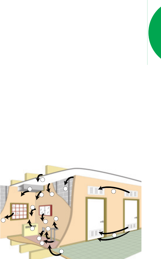
FLANKING TRANSMISSION.
Flanking sounds reach adjoining areas by indirect
paths, rather than through the dividing element. The
walls, floors and ceilings that surround the dividing
element are the main paths for flanking transmission.
Other paths are via open windows, ducts, doorways
and suspended ceilings. Noise sources that have a high
degree of low frequency noise such as traffic, aircraft and
DVD sound systems have more potential for flanking
transmission through the building structure.
Transmission of this type of noise follows structural
load paths and can be controlled by breaking these load
paths or providing complete separation of the structure.
Noise sources that generate a high amount of mid and
high frequency noise, such as services and speech, tend
to transmit via air paths and direct transmission in
lightweight construction.
Typical problem areas for this type of transmission
include doors and door frames, glazing, suspended ceiling
cavities and ductwork. Practical methods for addressing
common situations within buildings can be seen in
Section ‘Z’.
SOUND IMPACT RATINGS.
The BCA has performance requirements relating to
sound impact for floors and some walls.
For floors, this is specified as a maximum value such
as: Lnw+CI= 62. Note that lower values of Lnw+CI
indicates better acoustic impact performance.
Walls required to have an impact rating must meet the
definition of ‘Discontinuous Construction’. This means
that wall leaves must be separated by at least 20mm and
no mechanical connection is permitted, except that
masonry may have resilient ties.
Systems that meet this specification are noted in the
appropriate system specifications.
1
2
2
2
5
6
6
4
4
2
2
1
3
3
3
1
FIG A4.
COMMON FLANKING TRANSMISSION PATHS.
1. Ceiling plenums, floors, walls.
2. Poor seals between structural
elements and around service
penetrations.
3. External air-borne paths.
4. Heating and ventilation ducting.
5. Rigid plumbing connections and
penetrations.
6. Back-to-back cabinets and
switches/power outlets.
A14. The Red Book™
Building
Acoustics in
Practice.
SYSTEM PERFORMANCE.
The Rw, Rw+ Ctr and Ln,w+CIvalues in this
manual refer to expected results of a laboratory test on an
element.
The mathematical model used to make the predictions
has been verified statistically on a large body of test data.
The accuracy of the prediction is generally within
measurement tolerance of results from different acoustic
laboratories, that is 2dB.
All care has been taken with preparation of these
predictions and it is assumed that construction is strictly
in accordance with this manual and relevant Gyprock and
Fibre Cement installation guides.
CSR GFC recommends that an acoustic engineer
be consulted for all projects where acoustics are important.
SITE PERFORMANCE vs. LABORATORY
PERFORMANCE.
As houses are not built like laboratories, it is unlikely
that performance measured in ideal test conditions will
be achieved in a building. Designers should take care to
select systems compatible with the support structure to
provide the desired level of insulation.
Field performance is typically 10% less than laboratory
performance. Additionally, some forms of surrounding
construction have upper limits unrelated to the rating of
the element. In these cases, the difference between
laboratory and site performance could be larger.
ACOUSTIC INTEGRITY.
The acoustic integrity of a system can be influenced
by the combination of elements that make up the system.
Single leaf and uninsulated systems are more dependant
on high quality installation, as relatively minor defects can
cause major degradation of the system performance.
Building systems that allow defects to be hidden from
view have a higher chance of gaps being left unsealed,
making them more vulnerable to performance
degradation.
The likelihood and effect of defects occurring with
typical systems is shown in Table A13.
Single skin masonry
wall
Masonry with stud
uninsulated
Single stud,
uninsulated
Single stud,
insulated
Double stud,
insulated
High High
Degradation
High
Degradation
High
Degradation
Low
Degradation
Low
Degradation
High
Low
Low
Low
Wall System Effect of
Defects on
Performance
Chance of Gaps
Being Left
Unsealed
BACKGROUND NOISE.
Low levels of noise transmitted from other areas can
be partially obscured by background noise.
Where the background noise level is low, such as in
remote areas, consideration should be given to providing
a higher than standard level of sound insulation.
VARIATION IN OCCUPANT
PERCEPTION OF NOISE.
Tolerance for noise varies greatly between people,
and variations of up to 15dB can be considered acceptable.
This means consideration should be given to the
occupant’s expectation of the internal acoustic
environment. Users of concert halls and practice rooms
may have higher acoustic expectations than guests of
inner city hotels.
TABLE A13. ACOUSTIC INTEGRITY.

The Red Book™
A15.
DESIGNING FOR OPTIMUM
SOUND INSULATION.
Acoustic design issues are different for every building,
and for internal and external noise sources.
When designing apartments and townhouses,
reference can be made to the Association of Australian
Acoustical Consultants (AAAC) ‘Acoustical Star Ratings
for Apartments and Townhouses’ (www.aaac.org.au), a
rating system that considers both internal and external
sound transmission. It provides a graded rating system for
the acoustic quality of apartments, from 2 Star to 6 Star,
and is intended to provide assurance that an occupant’s
expectations of quality are met.
Where expectations are not met, remedial measures
can be expensive and inconvenient.
Some local government areas have adopted the AAAC
4 Star level as a minimum. This exceeds the current
BCA requirements in some respects.
MINIMUM PERFORMANCE LEVELS FOR
INTERNAL WALLS AND CEILINGS.
The BCA sets out minimum performance levels for
internal walls and ceilings based on acceptable standards
for affordable housing. The performance requirements are
in terms of Rw, Rw+Ctr and Ln,w+CI.
These levels may need to be increased for:
• Variation in occupant perceptions of noise,
e.g. high, medium or low cost housing.
• Local authorities have higher requirements such as the
AAAC Star rating system.
• Background noise levels are low.
• Flanking transmission of the surrounding structure.
Lightweight structures can be more prone to low
frequency flanking.
• The presence of services will vary which BCA
provisions are applicable, and could mean separate
construction is required.
• The lack of simplicity in construction could reduce
actual performance.
MINIMUM PERFORMANCE LEVELS
FOR SERVICES.
The BCA sets out minimum performance levels for
isolation of noise from services based on acceptable
standards for affordable housing. The performance levels
are in terms of Rwand Rw+Ctr.
These levels may need to be increased for:
• The nature of the noise source and adjacent occupant
activity. Some noises are particularly annoying to
occupants.
• Systems that meet the new BCA minimum Rw+Ctr
requirements may have lower performance than
systems that meet the corresponding Rw
requirements.
• Variation in occupant perceptions of noise,
e.g. high, medium or low cost housing.
• Background noise levels may be very low.
• The lack of simplicity in construction could reduce
actual performance.
MINIMUM PERFORMANCE LEVELS
FOR EXTERNAL WALLS.
The BCA does not set minimum performance levels
of transmission for external walls. Guidance should be
sought from an acoustic consultant or local authority for
setting the design requirements of these elements, as they
may be affected by road or aircraft noise.
Issues that may affect the design levels for external walls
are:
• Variation in occupant perceptions of noise,
e.g. high, medium or low cost housing.
• Background noise levels are low.
• Flanking transmission of the surrounding structure,
particularly at windows and doors.
• The lack of simplicity in construction could reduce
actual performance.
Detailing for
Acoustics.
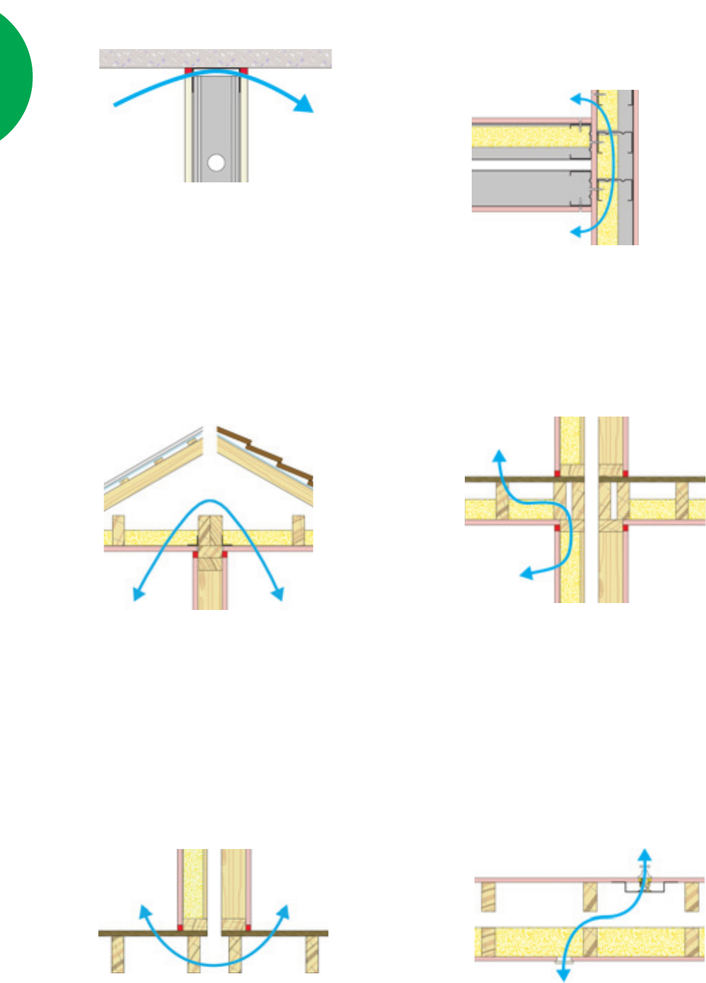
GAPS, CRACK AND HOLES.
Small openings allow airborne sound to pass through
an element and can significantly reduce sound insulation
performance. For optimum sound insulation, the element
must be airtight.
Perimeters and penetrations for services can be sealed
with CSR Gyprock Fire Mastic. It is a dense, flexible
compound capable of accommodating minor building
movement. Where major movement is expected, use a
polyurethane fire and acoustic rated sealant.
For systems that are multi-layered, such as masonry
composite systems, each layer must be air tight, as services
such as power points and switches can act as airborne
flanking paths. To remedy this, consider using acoustic
rated power boxes, the Gyprock®Silencer, and insulation
in the cavity. Refer to flanking details, Section ‘Z’.
A16. The Red Book™
SOUND FLANKING VIA THE CEILING.
This is a common source of sound transmission,
particularly where the ceiling has low sound insulation.
It is recommended that, wherever possible, walls pass
through the ceiling and be sealed to the floor or roof. This
can maintain the desired sound rating of the wall.
Details to treat sound flanking in this situation are
given in Section ‘Z’ for a range of plasterboard and
acoustic panel linings.
SOUND FLANKING VIA THE FLOOR.
This is also a common source of sound transmission,
particularly where the floor is lightweight and continues
under the wall.
High flanking transmission performance can be
achieved if there is a break in construction, or floor slabs
are thick enough.
Refer to Section ‘Z’ for potential performance of
various construction details.
SOUND FLANKING A FLOOR VIA
THE PARTITION BELOW.
This source of sound transmission particularly affects
lightweight floors and walls. Both impact and airborne
sound can travel through the floor and support walls.
Refer to Section ‘Z’ for potential performance of
various construction details.
SOUND FLANKING VIA ELECTRICAL AND
SERVICE PENETRATIONS.
Electrical power outlets, switch boxes and similar
penetrations produce areas of low sound insulation in a
partition. These should not be placed back to back as they
could limit the acoustic rating of the wall.
Penetrations should be avoided where sound insulation
is important. Treatment options include using acoustic
rated power boxes, the Gyprock®Silencer, and insulation
in the cavity. Refer to Section ‘Z’ for potential performance
of various construction details
SOUND FLANKING VIA
PERIMETER WALLS.
This is similar to flanking via the ceiling. The
recommended detail is for the partition wall to continue
through the perimeter wall.
Details to treat sound flanking in this situation are
given in Section ‘Z’ for a range of plasterboard panel
linings.
SOUND FLANKING VIA HEAD & BASE.
Particular attention should be paid to sealing the joints
at the top and base of walls with flexible sealant. Such
joints are usually required to accommodate some building
movement.

The Red Book™
A17.
SOUND FLANKING VIA DOWNLIGHTS.
Downlights installed in ceilings penetrate the linings
and create a path through which sound can pass.
Insulation may be ineffective as it must be clear of the light
fitting and transformer to reduce the likelihood of the
light overheating.
When ceiling downlights are required in acoustically
sensitive (non fire rated) locations, fire and sound rated
lights can be used. Refer to manufacturer’s information
for limitations.
Refer to Service Systems Section ‘F’ for performance
details for various combinations of linings and downlights
in selected systems.
Definitions.
Rw– Weighted Sound Reduction Index. A
measure of the sound insulation performance of a building
element. Rwis a laboratory measurement similar to
STC.
All BCA references to STC have been removed and
upgraded to refer to either Rwor Rw+Ctr. Rwis
measured and calculated using the procedures from
AS1276 and AS1191. The related field measurement is
abbreviated as DnT,w.
The higher the number the better the insulation
performance.
DnT,w – Weighted Standardised Field Level
Difference. A measurement of the sound insulation
performance of a building element. It describes the
difference in noise level on each side of a wall or floor,
and indicates the level of speech privacy between spaces.
It is measured in the field and is therefore subject to the
inherent inaccuracies involved in such a measurement.
The higher the number the better the insulation
performance.
Ctr – A spectrum adaptation value used to modify the
sound insulation performance of a wall or floor. Sound
insulation performance can be described by Rwor the
DnT,w but these are not accurate for all noises, especially
for low frequency bass noise from modern stereo systems.
Ctr values are negative value which is added to either the
Rwor DnT,w. AS/NZS1276 - sets out testing
methodologies for the sound insulation properties of
building elements and incorporates these factors and
explains their use.
Smaller negative Ctr values are more favourable than
large negative values.
dB(A) – The ‘A’-scale and dB(A) noise level are
used to degrade the performance of a sound level meter
to simulate what humans hear. The human ear is not a
perfect listening device, it is poor at hearing low frequency
noise. dB(A) is used to compare measured sound with
perceived sound.
A number of noise criteria refer to, and are measured
in dB(A). The larger the dB(A) level the louder the
noise.
Ln,w – Weighted Normalised Impact Sound
Pressure Level. A measure of the noise impact
performance of a floor/ceiling. It is measured in very
controlled conditions in a laboratory and is characterised
by how much impact sound reaches the receiving room
via the ceiling/floor from a standard tapping machine test.
The lower the number the better the performance.
L’nT,w – Weighted Standardised Field Impact
Sound Pressure Level. A measure of the noise impact
performance of a floor/ceiling. It is similar to Ln,w except
it is measured in the field and is therefore subject to the
inherent inaccuracies involved in such a measurement.
The lower the number the better the performance.
CI– A spectrum adaptation term used to modify the
measured impact sound pressure level, Ln,w or L’nT,w.
Impact sound is generated by a laboratory grade tapping
machine placed on the floor to be tested. This tapping
machine does not accurately simulate the noise of a person’s
foot steps on the floor above, so the CIterm was developed
to more closely simulate foot step noise.
The term is defined in ISO717-2. The Ln,w or L’nT,w
alone is sufficient to characterise concrete floors covered
with carpet. Other types of floors such as timber joist
floors, bare concrete floors or polished timber or tiles laid
on concrete floors require the CI term to properly
characterise footstep noise.
Timber joist floors can have a CIvalue slightly positive.
Concrete floors with an effective covering such as carpet
have CIterms approximately equal to 0dB. Concrete
floors with a hard, or less effective covering, can have CI
terms varying between –15dB and 0dB.

A18. The Red Book™
NRC – Noise Reduction Coefficient. A measure
of the ability of a material to absorb sound.
NRC is generally a number between 0 and 1. A
material with an NRC rating of 1 absorbs 100 % of
incoming sound, that is, no sound is reflected back from
the material.
STC – Sound Transmission Class. A measure of
the sound insulation performance of a building element.
It is measured in very controlled conditions in a
laboratory.
STC is an old term and is now obsolete. The BCA has
replaced all references to STC with Rw.
NOTE: Source Building Code of Australia, Sound
Insulation Guideline.
