TP2030 TP30 Tillerpilot2030
User Manual: TP30
Open the PDF directly: View PDF ![]() .
.
Page Count: 13

Manual
Navico TP20 & TP30
Tillerpilots

Page 3
CONTENTS
1. General
1.1 Introduction
1.2 Technical Summary
1.3 The Complete Navigation System
2. Operation
2.1 General
2.2 Autopilot Mode
2.3 Adjusting Course
2.4 Autotack
2.5 Tiller Movement (Gain)
2.6 Seastate
2.7 Autotrim
3. Advanced Features
3.1 Navlock™
3.2 Sail To Wind
3.3 Using External Compass
4. Configuration
4.1 Porthand Mounting
4.2 Calibration Mode
4.3 Adjusting Gain
4.4 Adjusting Seastate
5. Installation
5.1 Fitting Tillerpilot
5.2 Electrical Installation
5.3 Interfacing Via NMEA
5.4 NMEA Sentences Received
6. Appendix
6.1 Advice On Operation
6.2 Fault Finding
6.3 Auto Compass Calibration
6.4 Spares & Accessories
6.5 Service & Warranty
Page 2
E03547 Issue 1.0
The technical data, information and illustrations contained in this publication were to the best of our knowledge correct at the time of going to print. We reserve the right
to change specifications, equipment, installation and maintenance instructions without notice as part of our policy of continuous development and improvement.
No part of this publication may be reproduced, stored in a retrieval system or transmitted in any form, electronic or otherwise without prior permission from Simrad
Navico Ltd.
No liability can be accepted for any inaccuracies or omissions in the publication, although every care has been taken to make it as complete and accurate as possible.
MDL 2/12/98
© 1998 Simrad Navico Ltd
For service and advice please contact the main Simrad dealer in your country of residence.
Page 5Page 4
1 General
1.1 Introduction
The TP20 & TP30 Tillerpilots from Simrad are suitable
for a wide variety of tiller steered sailing yachts up to
12.8M (42 Ft) in length.
Combining highly sophisticated electronics with
advanced software and a powerful mechanical drive,
it is capable of providing reliable and accurate steer-
ing performance under a variety of different condi-
tions with minimal current consumption.
The Tillerpilots have been designed so that, while they
represent the state of the art in marine autopilots with
many advanced features, they remain very simple to
operate, using only five keys to access all functions.
Sophisticated functions available include Sail To Wind
Mode and Navlock Mode (Steer To GPS) using exter-
nal equipment linked directly to the Tillerpilot
through the inbuilt NMEA0183 interface.
There is also the option to operate the Tillerpilot
remotely, either using the simple HR20 Hand
Remotee. For more details, refer to the separate
instruction card supplied with this unit.
To ensure the best results from your Tillerpilot it is
essential that the unit is installed correctly. Please
read this manual thoroughly before installation.
Thank you for choosing Simrad
If you are pleased with your Tillerpilot we hope you
will be interested in our range of marine electronic
equipment, which is manufactured to the same high
standards as the Tillerpilot. Please contact your near-
est Simrad Agent for a catalogue showing our increas-
ing range of high tech navigational instruments, GPS,
CHart Plotters, autopilots, Radar, Fishfinders and
VHF radio sets.
Simrad operate a policy of continual development
and reserve the right to alter and improve the
specification of their products without notice.
Tillerpilot¨is a Registered Trade Mark of
Simrad Navico Ltd
NAV
STBY
TACK
STBY
AUTO
Tillerpilots TP20 & TP30
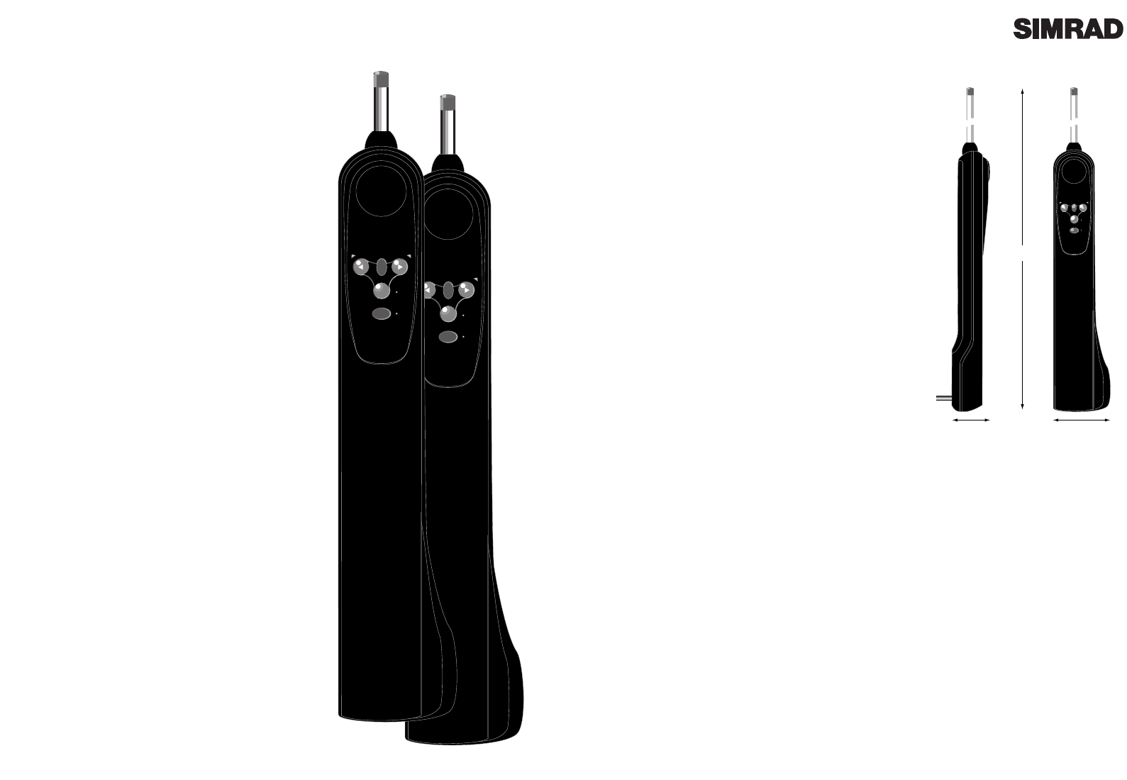
1.2 Technical Summary
TILLERPILOT SPECIFICATIONS
TP20 TP30
Drive System Screw Recirculating
Thread Ballscrew
Hardover time 0kg 6.9 secs 4.0 secs
20kg 8.0 secs 4.7 secs
40kg 12.0 secs 6.0 secs
50kg 8.0 secs
Peak Thrust 65kg (143lbs) 85kg (187lbs)
Operating Stroke 250mm (10in)
Supply Voltage 12v DC (10v-16v)
Power Consumption 0.06A (Stby)
(Typical) 0.5A (Auto)
Mounting Starboard as default
(Can be reversed)
NAV
STBY
TACK
STBY
AUTO
105mm
(4.0in)
60mm
(2.3in)
610mm (24in)
MID STROKE
Fig 1.1 - Tillerpilot dimensions
NAV
STBY
TACK
STBY
AUTO
SIMRAD TP20
SIMRAD TP30
1.3 The Complete Navigation System
The TP20 and TP30 are fully compatible with the Navico Corus instrument system, so not only do
they operate as a stand alone autopilot, but by connecting it to a Corus instrument network, they
can form part of a complete navigation system, offering additonal functions such as connection to
an external compass, wind sensor or navigational receiver, as well as additional remote control
options. For more details, contact Simrad Navico at the address on page 2.
The new range of IS15 instruments from Simrad will interface with the T20 & TP30 to provide wind
information and (when connected to a GPS) crosstrack error and bearing to waypoint information.
Please refer to the relevant IS15 manual for further information
Page 7Page 6
STBY
NAV
TACK
STBY
AUTO
Fig 2.1 - Tillerpilot keypad
STBY
TACK
STBY
AUTO
Fig 2.2 - Standby Mode
STBY
TACK
STBY
AUTO
STBY
AUTO
Fig 2.3 - Engaging Autopilot Mode
STBY
NAV
TACK
STBY
AUTO
Fig 2.4 - Course adjustment to Port
2.4 Autotack
The Tillerpilot has a built-in autotack facility, allowing
easy tacking of the vessel when single or short handed.
An autotack is only possible when in Autopilot Mode
To initiate autotack, press and hold the Tack key, fol-
lowed by either the Port or Starboard key, depending
on which direction you wish to tack (Fig 2.5).
The operation of the Tillerpilot will differ during an
autotack depending on whether the pilot is in Sail To
Compass or Sail To Wind Mode:
2.5.1 Autotacking In Compass Mode
If in Sail To Compass Mode (default), the Tillerpilot
will then tack the vessel in the selected direction. The
WP30 has a factory preset autotack angle of 100¼, how
ever this can be adjusted to any value between 40 and
140¼ using either a C600AD Active Display (configured
to PILOT) or a CP600 Corus Programmer. Please refer
to the relevant unitÕs instruction manual for more
details.
2.5.2 Autotacking In Wind Mode (Section 3.2)
The Tillerpilot will only allow an autotack if the
apparent wind is less than 90¼ i.e autotack is disabled
if sailing downwind. The Tillerpilot will tack the
vessel through to the same apparent wind angle, but
on the opposite tack.
NB - In this mode, the Tillerpilot automatically pre
vents tacking in the wrong direction eg, If on Port
tack, only an autotack onto Starboard tack will be
possible.
In all cases, the autotack is confirmed by a long
beep, with the relevant Port or Starboard LED flash-
ing during the course change.
2.5.3 NavLock (Section 3.1)
The autotack facility is disabled while in NavLock
mode.
STBY
TACK
STBY
AUTO
STBY
TACK
STBY
AUTO
TACK
TACK
Fig 2.5 - Initiating Starboard autotack
2 Operation
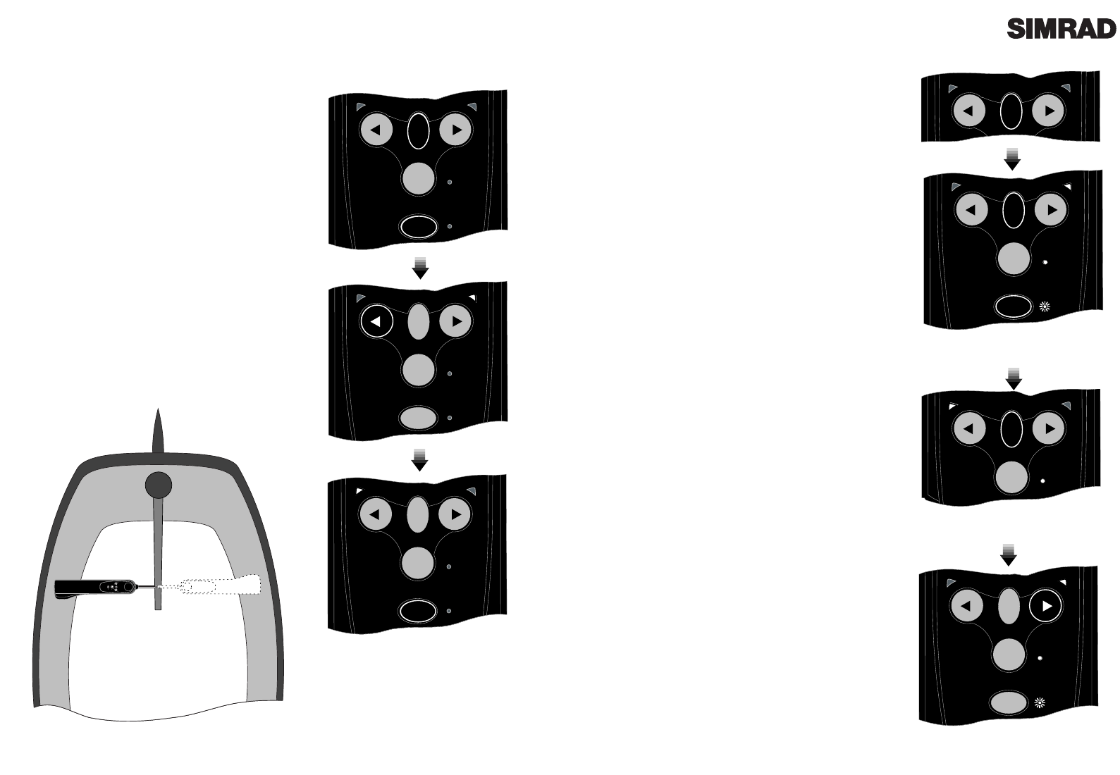
2.1 General
The keypad of the Tillerpilot has been designed to be as
simple and intuitive to operate as possible. Using only five
keys (Fig 2.1) it is possible to perform precise course
adjustments and navigational functions.
The unit powers up in Standby Mode, indicated by a flash-
ing LED next to the STBY AUTO key (Fig 2.2). The two
direction LEDs above the Port and Starboard keys are
always dimly lit, which provides night illumination for the
keypad. All functions are confirmed audibly by a ÒbeepÓ
and visually by the LEDs, so the status of the unit can
always be confirmed at a glance.
2.2 Autopilot Mode
While in Standby Mode, the pushrod can be manually dri-
ven in and out by pressing the arrowed Port and
Starboard keys, which allows Òpower steeringÓ of the ves-
sel.
To engage Autopilot Mode, simply press the STBY AUTO
key, and the Tillerpilot will lock onto the current course.
The LED next to this key will stop flashing and remain per-
manently lit as long as the pilot is in Autopilot Mode (Fig
2.3). To lock the pilot onto the desired course, either steer
the correct course and then engage the autopilot, or engage
the autopilot and then adjust the heading until the correct
course is being sailed (see section 2.3). If the STBY AUTO
key is pressed and held, the pilot will beep a second time
and lock onto the previously used heading (this feature
will not be available if the unit has just been switched on).
2.3 Adjusting Course
While in Autopilot Mode, precise course adjustments can
be easily made. By pressing either the Port or Starboard
key once, a 1¼ course adjustment will be made in the spec-
ified direction. This is confirmed by a single beep, and the
relevant Port or Starboard LED will flash once. By press-
ing and holding the key, 10¼ course adjustments will be
made, confirmed by a double beep and a double flash of
the Port or Starboard LED (Fig 2.4).
N.B - When in NavLock Mode (see section 3.1), the
Tillerpilot will gradually return to the original track.
Page 8 Page 9
2.5 Tiller Movement (Gain)
The Tillerpilot will apply adjustments to the tiller in
order to compensate for heading variations, the amount
of movement being proportional to the heading error
detected by the compass unit. The amount of move-
ment is set by the Gain (sometimes referred to as the
rudder ratio).
The Gain setting can be likened to driving a car - at high
speeds, very little wheel movement is necessary to steer
the car (LOW gain). When driving at slow speeds, more
wheel movement is necessary (HIGH gain).
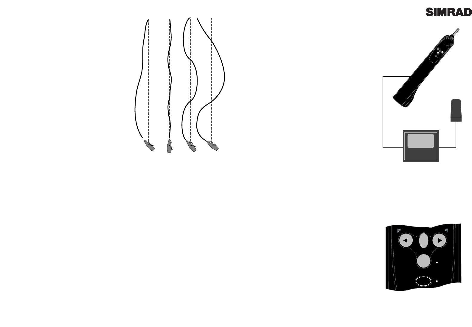
Fig 2.6A shows the effect of setting the Gain too low: the
vessel takes a long time to return to the correct heading.
Fig 2.6B shows the ideal setting, where errors are quick-
ly corrected. Fig 2.6C illustrates the effects of setting the
Gain too high, which causes the vessel to oscillate
around the correct heading. Excessive Gain (Fig 2.6D)
creates a tendency to instability of course, leading to
increasing error.
The Gain setting can be adjusted manually - see section
4.2. Additionally, if Speed data is available (through
Corus or NMEA), the Tillerpilot will automatically opti-
mise the Gain within the manually set value.
2.6 Seastate
In rough weather, more variations in heading will be detected by the Tillerpilot due to the heavy
seas yawing the vessel. If no account of this was taken, then the Tillerpilot would be overworked,
causing unnecessary strain on the unit and excessive drain on the batteries. The Tillerpilot will
continuously monitor corrections applied to the tiller over the course of a voyage, and allow a
Òdead bandÓ within which the boat can go off course without corrections being made. The dead
band is automatically set and updated by the Tillerpilot to give the best compromise between
course holding and battery consumption. However, this can be manually set if so desired. To man-
ually adjust the Seastate, please refer to section 4.4.
2.7 Autotrim
Under differing conditions a tiller bias (sometimes known as standing helm or rudder trim) is
applied in order to steer a straight course. An example is when sailing close hauled where the ves-
sel will normally pull into the wind, and the helmsman applies a standing helm to leeward in order
to maintain course. The amount of this standing helm varies according to factors such as strength
of wind, boat speed, sail trim and amount of sail set. If no account of these were taken, then the
vessel would tend to veer off course, or pull round head to wind if sailing close hauled.
The Tillerpilot continuously monitors the average course error and applies a bias to the tiller to
compensate until the optimum condition is reached. This bias or standing helm is applied gradu-
ally, so as not to upset the normal performance of the Tillerpilot. Thus, it may take up to a minute
or so to fully compensate after changing tack. Once optimum trim is reached, the pilot will still
monitor for changes in the prevailing conditions and update the trim accordingly.
3 Advanced Features
The TP20 and TP30 Tillerpilots contain many
advanced features, one of which is the ability to
accept course data from a variety of sources apart
from the internal fluxgate compass, including
NMEA compatible navigational receivers (GPS etc)
and windvanes. An external compass option is also
available via the inbuilt Corus network connection,
which can also accept wind and navigational data
from the relevant Corus active transducers.
Section 3 describes in detail the advanced facilities
available with the Tillerpilots when interfaced with
other equipment.
3.1 NavLock™
The TP20 and TP30 has a built in NMEA interface
which allows direct connection with NMEA0183
compatible equipment such as GPS and Plotters.
Once interfaced with navigation equipment via
NMEA, the Tillerpilot can steer using data from this
source in addition to the internal compass, allowing
a highly accurate course to waypoint.
To access NavLock the unit must be in Autopilot
Mode. Simply activate a waypoint or route pro-
grammed into the navigational receiver, and press
the NAV key. The LED next to the NAV key will
light and the Tillerpilot will steer to the first way-
point, using Cross Track Error and Bearing To
Waypoint information from the navigational receiv-
er to maintain an accurate course.
On arrival at the target waypoint an intermittent
alarm will sound. As a safety feature to avoid an
unexpected course change, the next waypoint will
not be automatically loaded until the NAV key is
pressed. When the vessel reaches the final way-
point, the Tillerpilot will continue its current course
under Compass Mode.
Note that some of the standard key stroke functions
may have a different effect in NavLock than when
in Compass Mode. Please refer to sections 2.5.2 and
2.5.3
NMEA
TP20/TP30
NMEA Compatible
Equipment
NAV
STBY
TACK
STBY
AUTO
Fig 3.1 - Interfacing via NMEA
STBY
NAV
TACK
STBY
AUTO
NAV
Fig 3.2 - Initiating NavLock
ABCD
Fig 2.6 - Effects of Gain setting
3.3 Using External Compass
Normally, the accurate operation of a self-con-
tained autopilot is very difficult on a ferrous
hulled boat (steel, ferro cement etc) as the hull
will affect the bearing read by the internal flux-
gate compass.
Although the TP20 and TP30 Tillerpilots oper-
ates using a built-in fluxgate compass, they have
the facility to accept data from an external source
- the Navico Corus ATC600 active compass.
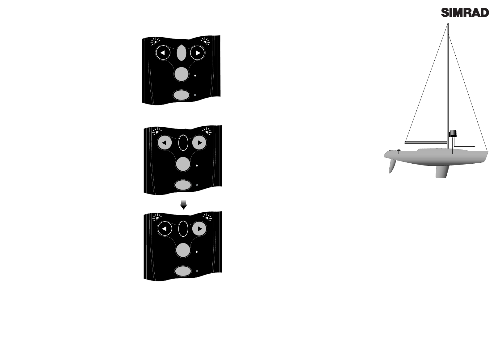
On a steel or ferro hulled boat, the correct loca-
tion for the ATC600 would be on the mast,
between 1 and 2 metres above the deck (Fig 3.5).
On a non-ferrous hulled boat, the ATC600
should be situated low down ,as near the centre
point of the boat as possible, but away from any
sources of magnetic interference such as speak-
ers etc.
The ATC600 is connected to the Tillerpilot via
the Navico Corus Network connection. Note
that in order to operate, the ATC600 will require
a separate 12v power supply through a CPC02
or CPC05 power cable.
Once connected, the Tillerpilot will automati-
cally accept bearing data from the ATC600
active compass transducer in preference to the
internal fluxgate compass.
ATC60
TP20/30
CMC-TP
CPC05 12v
Fig 3.5 - Using TP20 / TP30 with external compass
Page 11Page 10
3.2 Sail To Wind
The TP20 and TP30 are able to sail to the apparent
wind angle rather than a compass course, using
wind data via the NMEA interface. The use of a
Simrad IS15 wind instrument is recommended.
If no wind information is present, the Tillerpilot
will not enter Sail To Wind Mode.
To select Sail To Wind Mode, the unit must be in
Autopilot Mode. To enter Sail To Wind Mode, press
and hold both the Port and Starboard keys togeth-
er until a double beep is heard (Fig 3.3). Both the
Port and Starboard LEDs will flash simultaneously
while the pilot is in Sail To Wind Mode.
To switch back to Compass Mode, simply press and
hold the Port and Starboard key together again
until a double beep is heard.
While in Sail To Wind Mode, engaging the autopilot
will lock the Tillerpilot onto the current apparent
wind angle being sailed. Any course adjustments
made will be relative to the apparent wind angle,
rather than the compass heading as when in
Compass Mode. Please note that some of the stan-
dard key stroke functions may have a different
effect in Sail To Wind Mode than when in Compass
or NavLock Mode. Refer to section 2.5.3 for more
details.
Note that NavLock cannot be selected while in Sail
To Wind Mode - to initiate, first return to Compass
Mode.
STBY
NAV
TACK
STBY
AUTO
Fig 3.3 - Selecting Sail To Wind Mode
STBY
NAV
TACK
STBY
AUTO
TACK
STBY
NAV
TACK
STBY
AUTO
TACK
Fig 3.4 - Initiating Port Autotack in Sail To Wind
Mode
TACK
Page 13Page 12
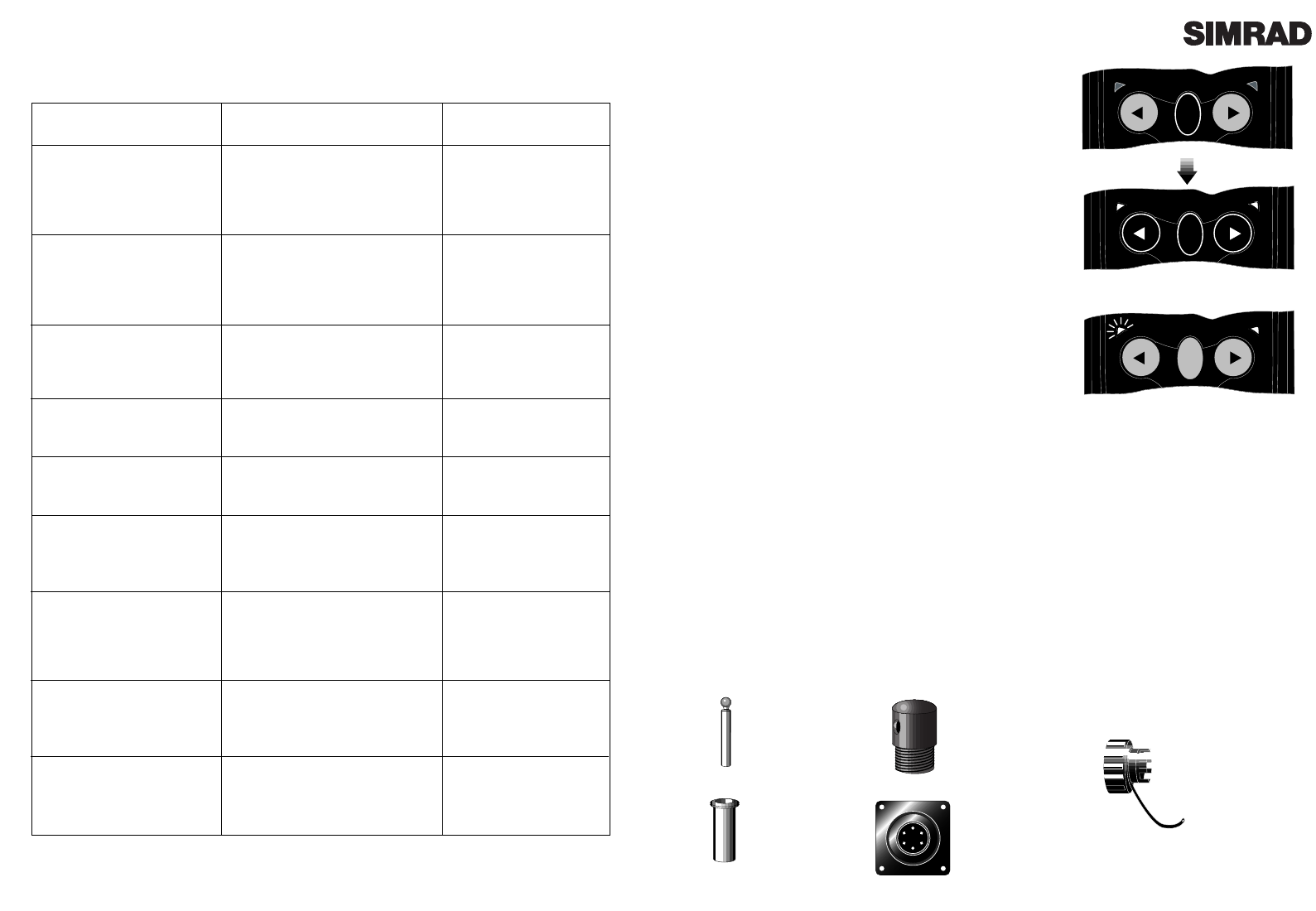
4 Configuration
4.1 Porthand Mounting
Although the Tillerpilot is factory preset for
Starboard side mounting, it is possible to reconfig-
ure it for mounting on the Port side of the cockpit,
to facilitate easy installation on most types of
yacht.
With the power off, hold down the NAV and
TAC K keys and switch on the power. Either the
Port or Starboard LED will illuminate, depending
on the current mounting configuration. Press the
PORT key to select Port side mounting. The Port
LED only will remain illuminated to indicate selec-
tion. Confirm selection and exit to Standby Mode
by pressing NAV. (Fig 4.2)
To select Starboard mounting, repeat the above
procedure, but press the Starboard key instead of
Port.
STBY
NAV
TACK
STBY
AUTO
TACK
NAV
STBY
NAV
TACK
STBY
AUTO
STBY
NAV
TACK
STBY
AUTO
NAV
Fig 4.2 - Configuring for Port mounting
POWER ON
NAV
STBY
TACK
STBY
AUTO
Fig 4.1 - Starboard and Port mounting options
TACK
STBY
NAV
TACK
STBY
AUTO
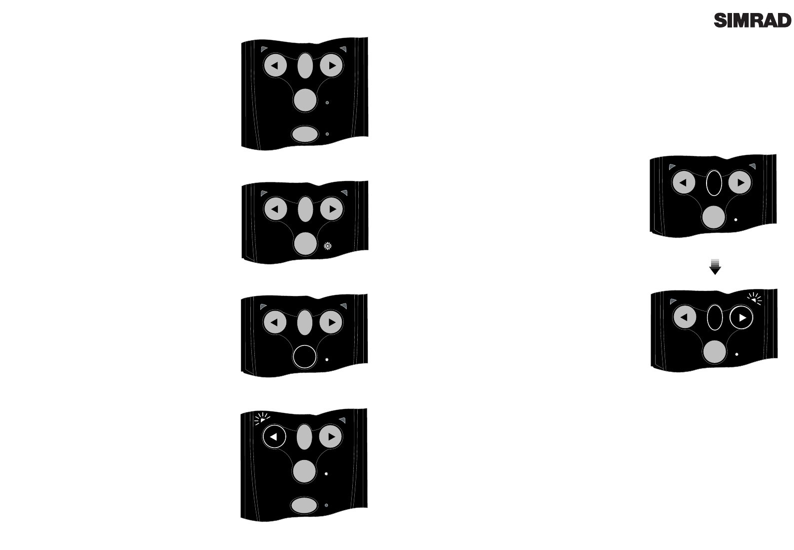
Fig 4.3 - Entering Calibration Mode
Fig 4.5 - Increasing Gain level
4.2 Calibration Mode
To adjust the Gain and Seastate settings of the Tillerpilot
(refer to sections 2.5 & 2.6), it is necessary to enter
Calibration Mode, which can be done whilst the Tillerpilot
is in either Standby or Autopilot Mode.
Press and hold the TAC K key, followed by the NAV key
(Fig 4.3). The Starboard green LED will illuminate to indi-
cate that the pilot is in Gain Mode. To toggle between Gain
and Seastate Mode, press the TAC K key (Fig 4.4). The Port
red LED will illuminate to indicate Seastate Mode.
4.3 Adjusting Gain
When Gain Mode is selected (indicated by the Starboard
green LED illuminated), the Nav LED will flash and a
repeated sequence of beeps will be heard. The number of
flashes and beeps in the sequence indicates the level of the
Gain setting.
To increase the Gain press the Starboard key the required
number of times, to a maximum level of 9 (Fig 4.5). To
decrease the Gain press the Port key the required number
of times, to a minimum level of 1.
For example, if the Gain was set at 4 (indicated by a
sequence of four flashes of the Nav LED and four beeps),
and the Gain needed to be increased to 7, pressing the
Starboard key three times would adjust the Gain accord-
ingly. The Nav LED would then flash seven times and
seven beeps would be heard.
4.4 Adjusting Seastate
When adjusting Seastate (indicated by the Port red LED
illuminated), the Seastate level is indicated by the number
of audible beeps and flashes of the Nav LED. No beeps or
flashes of the Nav LED indicates that the Tillerpilot is set
to automatic seastate (see section 2.6).
To switch from Manual to Auto Seastate and increase the
Seastate level, press the Starboard key the required num-
ber of times to a maximum level of 9. To decrease the
Seastate press the Port key the required number of times,
to a minimum level of 0- which will switch the Tillerpilot
back to Auto Seastate.
To confirm Gain/Seastate settings and return to Standby
Mode, press the NAV key.
STBY
TACK
STBY
AUTO
Fig 4.4 - Toggling between Adjust Gain and
Seastate
TACK
STBY
NAV
TACK
STBY
AUTO
TACK
NAV
NAV
STBY
TACK
STBY
AUTO
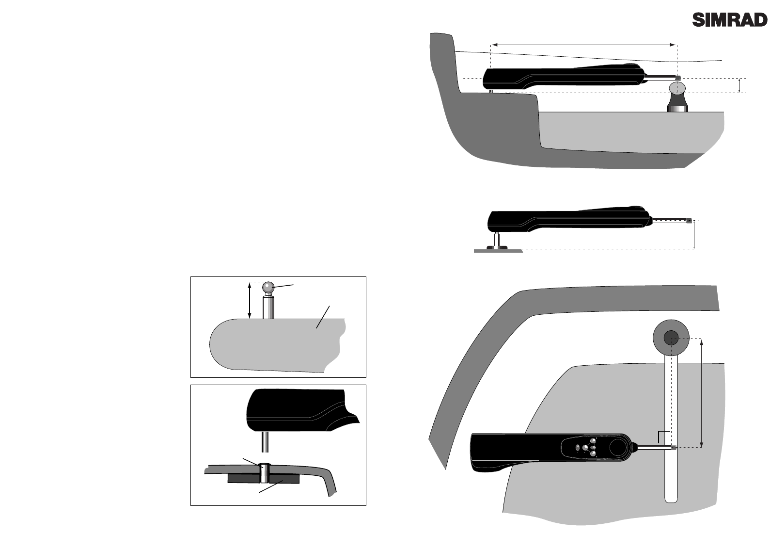
460mm (18in)
90º
595mm (23 in) Pushrod at mid-stroke
12
/
Horizontal
PB30 8mm
PB60 105mm
PB90 135mm
38mm
Pedestal Bracket (PB)
Page 15
Fig 5.2 - Installation, cross section
Fig 5.3 - Installation , plan view
Page 14
5 Installation
5.1 Fitting Tillerpilot
The Tillerpilot is a very sophisticated piece of equipment, and therefore in order for it to function
to its full capabilities, it is essential that it is installed correctly. Please read this section thorough-
ly before attempting installation and use.
The Tillerpilot should be installed so that it is level (horizontal - Fig 5.2), and 90¼ to the tiller when
it is amidships and the pushrod is in the midstroke position (Fig 5.3). The pilot is factory preset to
be mounted on the Starboard side as shown, but this can be reconfigured for Port side mounting
(see section 4.1).
The dimensions given in Figs 5.2 & 5.3 should be adhered to as far as possible, especially Fig 5.2.
Some tolerance on the distance from tiller stock (Fig 5.3 dimension) is permissible, but the
Tillerpilot may require a Gain adjustment to compensate (see section 4.3). If the dimension given
in Fig 5.2 is not practical for the vessel to which it is to be fitted, a range of fitting accessories are
available to facilitate correct installation. Please refer to section 6.4.
The Tillerpilot houses an internal fluxgate compass, and should therefore be mounted away from
sources of magnetic interference, such as the vesselÕs steering compass. The minimum safe dis-
tance is 1M (3Ft).
The Tillerpilot is mounted using a supplied tiller
pin and mounting cup, which allows the unit to
be fitted and stowed easily.
To fit the tillerpin, drill a 6.3mm (1/4 in) hole in
the tiller (ensure that this is on the centreline of
the tiller and is vertical). Drill to a depth that
allows only the top 18.0mm (3/4 in) to protrude.
Fix in place using an epoxy adhesive.
To fit the mounting cup, drill a 12.7mm (1/2 in)
hole into the cockpit seat and mount so that only
the flange protrudes. Ensure that the cup is a
tight fit (use an epoxy adhesive), and is support-
ed over its entire depth. If necessary, reinforce
the underside of the cockpit seat with hardwood
or marine plywood.
NOTE - Due to the high loads exerted, do not
fit the Tillerpilot to the mounting cup and pin
until the adhesive has completely set.
Tillerpin
Tiller
18.0mm
(0.75in)
Mounting Cup
Hardwood
Reinforcing
Fig 5.1 - Tillerpin & mounting cup
Page 17
The Tillerpilot is linked to the ATC600 external com-
pass via a connecting lead CMC-TP (not supplied),
which is wired to the Tillerpilot bulkhead socketÕs
Corus input (terminals 3 & 4), and then plugged into
the Compass.
The CMC-TP is used purely to supply Corus data to
the Tillerpilot, and does not carry any power supply.
The ATC600 must always have itÕs own 12v power
supplied via a CPC02 or CPC05 Corus Power Cable.
5.3 Interfacing Via NMEA
The TillerpilotÕs state-of-the-art electronics include a
built-in NMEA processor, which means that
NMEA0183 compatible equipment can be connected
directly to the Wheelpilot, without any need for a sep-
arate interface unit (Fig 5.6).
Due to the vast number of different manufacturers and
models of navigational equipment, Simrad cannot
guarantee correct operation and installation of this
equipment. Therefore, before connecting any equip-
ment to the Tillerpilot it is important that the unitÕs
manual is referred to with regard to interfacing via
NMEA.
When connecting to the TillerpilotÕs NMEA interface,
two wires are used - a DATA wire and a COMMON
(Com) wire. These should be connected to the six-pin
bulkhead socket as follows:
It should be noted that some manufacturerÕs equip-
ment does not have a dedicated Common connection.
In this case, the DATA connection will usually be
labelled NMEA OUT, and the NMEA Common con-
nection on the Tillerpilot (terminal 5) should be con-
nected directly to 0v (terminal 2). If in any doubt,
refer to the manufacturer, or SimradÕs Product
Support department for advice.
If a navigational receiver (GPS etc) is connected to the
Tillerpilot, it can extract the NMEA sentences neces-
sary for the NavLock function to operate. Other func-
tions such as Sail To Wind may also be available if
NMEA0183 compatible equipment transmitting the
correct NMEA sentences is interfaced.
12v DC
NMEA
NAV
STBY
TACK
STBY
AUTO
Fig 5.6 - Interfacing to Tillerpilot via NMEA
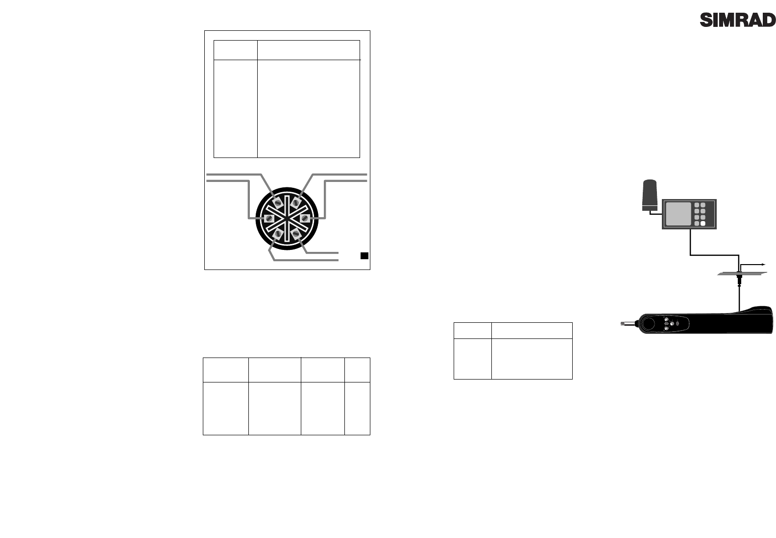
Pin No. Wired To
5 NMEA-Com (-)
6 NMEA-Data (+)
61
34
52
12V Red
0V Black
NMEA Data
NMEA Com
(Green)
(White)
CMC-TP
External
Compass
Cable
Page 16
Fig 5.4 - Six pin socket connections - rear view
5.2 Electrical Installation
The Tillerpilot operates from a 12v DC supply. It is
supplied with a high quality six pin waterproof
connector ready fitted, which is used to supply the
power, NMEA and (where appropriate) Corus
data. The mating 6-pin bulkhead socket is also
supplied with the unit.
The six pin bulkhead socket should be mounted in
a convenient position close to where the Tillerpilot
is to be fitted, and wired in accordance with Fig 5.4.
Important - If the vessel has more than one sepa-
rate battery bank, when connecting the Tillerpilot
to the power supply always ensure that the pilot
and all interfaced equipment - whether Corus or
NMEA - are connected to the same battery bank,
even though they each have independent con-
nections to the switch panel. This is to avoid a
possible voltage drop between the interfaced
equipment which would render the equipment
inoperative.
* Mount the bulkhead socket on a vertical surface
to prevent standing water gathering around or in
the socket. Always fit the protective cap when the
pilot is not plugged in.
* Use a suitable gauge cable for the run from the
socket to the supply (see Fig 5.5).
* Connect to the vesselÕs switch panel via a 10 Amp
fuse or breaker.
* Do not fit other electronic or electrical equipment
to this cable, or Òtap intoÓ the supply from a near-
by cable - always wire each piece of equipment to
its own breaker in the switch panel.
* Ensure all wire ends are tinned, and any connec-
tions are well made. Poor contact will result in loss
of thrust from the Tillerpilot and slower speed of
response.
* If in any doubt, employ a qualified engineer to
install the equipment.
Length of
Cable Run
Under 4M
(13Ft)
4-8M
(27Ft)
Cross Section
Area
1.5mm2
2.5mm2
Conductor
Type
30/0.25
50/0.25
AWG
16
14
Fig 5.5 - Cable selection table
Pin No. Wired To
1 +12v DC
20v
(3 Corus Green)
(4 Corus White)
5 NMEA0183 Com
6 NMEA0183 Data

Page 19
6 Appendix
6.1 Advice On Operation
The Simrad Tillerpilot when used correctly can maintain as good a course, on most points of sail as
a skilled helmsman, with the advantage that they never lose concentration where a human may
begin to show lapses of concentration after as little as ten minutes.
There are certain circumstances however, where a human pilot has the advantage in being able to
anticipate events which no autopilot can sense, typically in a heavy following sea. The
following advice should improve efficiency when sailing using Tillerpilot:
1. When sailing close to the wind, it is easy to forget to trim the mainsail, allowing excessive weath-
er helm to build up. Where a human helmsman would quickly complain, the autopilot will strug-
gle on, and the boat will be sailed less efficiently. Whereas a human normally likes to feel some
weather helm, this is not necessary for the functioning of the Tillerpilot. Power consumption, wear
and drag will be greatly reduced if the mainsail is freed or reefed a little sooner than normal when
sailing manually.
2. It is also advisable when sailing close hauled to set a course a few degrees free of that normally
sailed under manual control, to avoid luffing into the wind.
3. When running dead downwind, a human pilot can see visual signs warning him if the boat is
about to gybe, which the Tillerpilot cannot sense. Therefore, when under autopilot it is advisable
not to sail as close to the gybe as you may do when sailing manually.
4. When broad reaching or running fast, particularly with quartering waves, a helmsman will nat-
urally apply periodic larger angles of helm than when beating or sailing slowly. This is the equiv-
alent of increasing rudder Gain, and it may be a good idea to adjust the Gain on the Tillerpilot.
Many people prefer to find a compromise setting which is used for all sailing, but with practice it
can be optimised for different conditions e.g. low for motoring in a calm sea or high for running
fast. If the Gain is set too low, the boat will yaw because insufficient rudder is applied in time; if
the gain is too high, the boat will continually overcorrect on each deviation, increasing power con-
sumption.
5. The Tillerpilot is a highly advanced piece of equipment - as such, it is a valuable aid to enjoy-
able sailing. However, it would be a mistake to become complacent. As with all electronic navi-
gational equipment, it is an aid to navigation and should not be used as a substitute for conven-
tional navigational practice. Remember - Maritime Law* requires that you keep a good look out
at all times.
*IMO International Regulations for Preventing Collisions at Sea, Part B Rule 5 (1972)
Page 18
5.4 NMEA Sentences Received
The NMEA0183 information required for full functionality whilst in NavLock is as follows -
Cross track error
Bearing to destination waypoint
Arrival at waypoint indication
Magnetic Variation
This information is extracted from the following NMEA0183 sentences -
NOTE - The Cross Track Error (XTE) information has a maximum value of 1.21 Nautical Miles. If
the XTE exceeds this while using NavLock, the Wheelpilot will sound an alarm, exit NavLock
Mode and return to Compass Auto Mode.
The TP20 & TP30 also extracts the apparent wind angle from the following NMEA0183 sentences -
VWR Apparent Wind Speed & Angle
MWV Wind Speed & Angle
XTE Cross Track Error and Arrival At Waypoint
BWC Bearing To Destination Waypoint and Arrival At Waypoint (Great Circle)
BWR Bearing To Destination Waypoint and Arrival At Waypoint (Rhumb Line)
APA Cross Track Error, Bearing To Destination Waypoint and Arrival At Waypoint
APB Cross Track Error, Bearing To Destination Waypoint and Arrival At Waypoint
RMA Speed Over Ground (SOG) & Magnetic Variation
RMB Cross Track Error, Bearing To Destination Waypoint and Arrival At Waypoint
RMC Speed Over Ground (SOG) & Magnetic Variation
Page 21
6.3 Auto Compass Calibration
Although the Tillerpilot internal compass is extremely
accurate, for long distance sailing it may be necessary to
calibrate the compass, to compensate for any deviations
caused by objects surrounding it on board the vessel.
With the vessel motoring along slowly (2-3 knots) in
calm conditions and the Tillerpilot in Standby Mode,
press the Starboard key a number of times to induce a
slow clockwise rotation of the vessel. Press and hold the
TAC K key, followed by the Port and Starboard keys
simultaneously to enter Auto Compass Calibration
Mode (Fig 6.1). The Port and Starboard LEDs will both
light. Allow the vessel to turn through a minimum of
11Ú4 turns (450¼) in approximately two minutes, during
which time the fluxgate compass will automatically cali-
brate itself.
If the rate of turn or the boat speed is too high, the Port
LED will flash (FIg 6.2) indicating that it is necessary to
either slow the boat or decrease the angle of turn. If the
rate or turn or boat speed is too slow the Starboard LED
will flash, indicating that it is necessary to either increase the boat speed or increase the angle of
turn. A short beep will indicate that the calibration has been successful, and the Tillerpilot will
return to Standby Mode. If the calibration has been unsuccessful after a period of four minutes, a
long beep will sound. Try again carefully following the above directions.
Note that this function is only available for auto calibrating the internal fluxgate compass. If an
ATC600 external compass is being used, this is calibrated using a separate display head. Please
contact Simrad Product Support for more information.
6.4 Spares and Accessories
The following spare parts can be ordered from your local authorised Simrad Technical Dealer.
Please quote the relevant part number when ordering.
E02648
Tiller Pin
E00099
Mounting Cup
E00111
Push Rod End
170153
Bulkhead Socket
170090
Protective Cover
for Bulkhead
Socket
TACK
TACK
TACK
TACK
Fig 6.1 - Auto Compass Calibration
TACK
Fig 6.2 - Rate of turn too fast
Page 20
6.2 Fault Finding
Symptom
When engaged, the pilot
immediately applies a large
helm angle and increases
course error.
After functioning normally
course is suddenly lost and the
Tillerpilot goes into Standby
Mode.
Helm is hard over and alarm is
continuously on.
Power socket is live, but pilot
is
not on.
Loss of course under Sail To
Wind Mode.
Cannot select Sail To Wind
Mode.
Cannot select NavLock Mode.
Autotack function not
working.
Pilot exits NavLock before
waypoint is reached.
Probable Cause
Tillerpilot is configured for Porthand
setting but installed on Starboard side
(or vice versa).
* Power interrupted briefly, or low
voltage.
* Cable used to socket too small.
* Intermittent connection.
* Steerage way insufficient to control
course, or sails are aback. Pulsing is a
correct safety feature when tiller is at
full travel.
* Socket is wired incorrectly.
* Apparent wind has become too light
to give a consistent direction.
* Masthead unit is not connected.
* Corus system is not switched on.
* Required NMEA sentence not being
transmitted.
* Navigational receiver not connected.
* No waypoints have been
programmed.
* Wrong NMEA format is being used.
* Pilot is in NavLock Mode.
* Pilot is in Steer To Wind Mode and
a) apparent wind is >90¼
b) autotack being attempted is in
the wrong direction.
* Cross Track Error has exceeded 1.21
Nm.
Remedy
* Refer to section 4.1.
* Increase size of cable.
* Check all connections.
* Charge batteries.
* Uprate batteries.
* Reset the vessel on course
and re-engage pilot
* Check wiring of socket
(see section 5.2).
* Change to Compass
Mode.
* Fit ATM601 Masthead
Unit.
* Check Corus Monocable
connections.
* See section 5.5.
* Check NMEA interface
connections.
* Check NMEA0183 format
is being transmitted by
navigational receiver.
* Exit NavLock.
* Luff up until apparent
wind is less than 90¼.
* Reset the vessel on course
and re-engage NavLock.
Page 23
6.5 Service & Warranty
Your Tillerpilot should seldom need servicing, but will benefit from an application of silicone or
Teflon grease to the pushrod and connectors each season, and by keeping the connectorÕs protec-
tive cover in place when not in use.
The unit is guaranteed for 12 months from date of retail sale. If it is necessary to have the unit
repaired, return it carriage prepaid to the agent in the country of purchase with a copy of the
receipted invoice showing the date of purchase. Where possible, return all the components unless
you are certain that you have located the source of the fault. If the original packing is not avail-
able, ensure that it is well cushioned in packing; the rigours of freight handling can be very differ-
ent from the loads encountered in the marine environment for which the unit is designed.
For Worldwide Warranty details, please refer to the Warranty Card supplied with this unit.
A list of official worldwide Simrad dealers is included in the Warranty Card.
STBY
TACK
STBY
AUTO
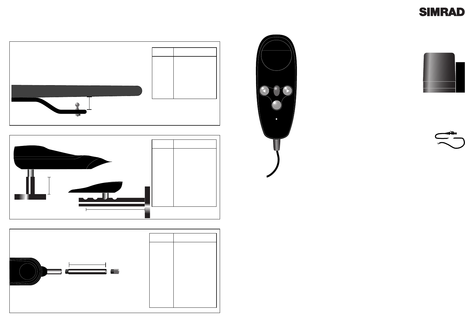
HR20
Hand Remote Unit.
ATC600
External
Compass
CMC-TP
Corus interface cable
(5M)
Page 22
Accessories
Height
Tiller Brackets
Push Rod Extensions
PRE30:GY
PRE60:GY
PRE90:GY
PRE120:GY
PRE150:GY
PRE300:GY
Part No. Length
30mm (1.18")
60mm (2.36")
90mm (3.54")
120mm (4.72")
150mm (5.90")
300mm (11.81")
TB30
TB60
TB90
TB120
Part No. Height
30mm (1.18")
60mm (2.36")
90mm (3.54")
120mm (4.72")
Length
PB30
PB60
PB90
CB1 135-240mm
(5.31-9.44")
Part No Height / Length
30mm (1.18")
60mm (2.36")
90mm (3.54")
Height
Length
Cantilever Bracket CB1
Pedestal & Cantilever Brackets

Manufacturer:
Simrad Navico
Star Lane, Margate
Kent CT9 4NP
United Kingdom
Telephone: +44 (0) 1843 290290
Telefax: +44 (0) 1843 290471
E-Mail: simrad-navico.co.uk
WORLDWIDE MANUFACTURER OF MARINE ELECTRONICS
