Torsional Catalog
User Manual: TorsionalCatalog
Open the PDF directly: View PDF ![]() .
.
Page Count: 42
259
www.lovejoy-inc.com T-
JWJISCJSFMCGHPGDDTSPUJVSDRSLDED
JW
JIS CJ SF MC G HP GD D T SP UJ VSD R SLD ED
259
www.lovejoy-inc.com
JWJISCJSFMCGHPGDDTSPUJVSDRSLDED
JW JIS CJ SF MC G HP GD D
T
SP UJ VSD R SLD ED
In This Section:
■■Selection■Process
■■L-LOC■Clamping■Feature
■■LF■Series
■■LVK■Series
■■LV■Series
■■LM■Series
■■LK■Series
■■Pump■Mounting■Plates
■■Pump■Mounting■Housings
T-1
Torsional

JW
JISCJSFMCGHPGDDTSPUJVSDRSLDED
JW JIS CJ SF MC G HP GD D T SP UJ VSD R SLD ED
260 630-852-0500
Safety Warning
When■using■Lovejoy■products,■you■must■follow■these■instructions■and■take■the■following■precautions.■Failure■
to■do■so■may■cause■the■power■transmission■product■to■break■and■parts■to■be■thrown■with■sufficient■force■to■
cause■severe■injury■or■death.
Refer■to■this■Lovejoy■Catalog■for■proper■selection,■sizing,■horsepower,■torque■range,■and■speed■range■
of■power■transmission■products,■including■elastomeric■elements■for■couplings.■Follow■the■installation■
instructions■included■with■the■product,■and■in■the■individual■product■catalogs■for■proper■installation■of■power■
transmission■products.■Do■not■exceed■catalog■ratings.
During■start■up■and■operation■of■power■transmission■product,■avoid■sudden■shock■loads.■Coupling■assembly■
should■operate■quietly■and■smoothly.■If■coupling■assembly■vibrates■or■makes■beating■sound,■shut■down■
immediately,■and■recheck■alignment.■Shortly■after■initial■operation■and■periodically■thereafter,■where■
applicable,■inspect■coupling■assembly■for:■alignment,■wear■of■elastomeric■element,■bolt■torques,■and■flexing■
elements■for■signs■of■fatigue.■Do■not■operate■coupling■assembly■if■alignment■is■improper,■or■where■applicable,■
if■elastomeric■element■is■damaged■or■worn■to■less■than■75%■of■its■original■thickness.■
Do■not■use■any■of■these■power■transmission■products■for■elevators,■man■lifts,■or■other■devices■that■carry■
people.■If■the■power■transmission■product■fails,■the■lift■device■could■fall■resulting■in■severe■injury■or■death.
For■all■power■transmission■products,■you■must■install■suitable■guards■in■accordance■with■OSHA■and■
American■Society■of■Mechanical■Engineers■Standards.■Do■not■start■power■transmission■product■before■
suitable■guards■are■in■place.■Failure■to■properly■guard■these■products■may■result■in■severe■injury■or■death■
from■personnel■contacting■moving■parts■or■from■parts■being■thrown■from■assembly■in■the■event■the■power■
transmission■product■fails.
If■you■have■any■questions,■contact■the■Lovejoy■Engineering■Department■at■1-630-852-0500.
T-2
Torsional
JWJISCJSFMCGHPGDD
T
SPUJVSDRSLDED
JW JIS CJ SF MC G HP GD D T SP UJ VSD R SLD ED

261
www.lovejoy-inc.com
Table of Contents
T-3
Torsional
Overview■......................................................................................................................................262■....................... T-4
Engine■Application■■>■Selection■Process■.....................................................................................264■....................... T-6
Industrial■Application■>■Selection■Process■■..................................................................................266■....................... T-8
Applications■Service■Factors■>■Selection■Data■............................................................................267■....................... T-9
Coupling■Selection■Worksheet■■...................................................................................................268■..................... T-10
L-LOC■Clamping■Feature■and■Spline■Identification■>■Overview■..................................................269■......................T-11
LF■Series■>■Overview■■.................................................................................................................270■..................... T-12
LF■Series■–■Elements■>■Overview■...............................................................................................271■..................... T-13
LF■Series■–■Base■Element,■Models■1,■1/S,■2■and■2/S■>■Selection■Data■......................................272■..................... T-14
LF■Series■–■Models■3,■3/S,■6,■6/S■and■6B■>■Selection■Data■■.......................................................273■..................... T-15
LF■Series■>■Performance■Data■....................................................................................................274■..................... T-16
LF■Series■–■Base■Element■and■Model■1■>■Dimensional■Data■.....................................................276■..................... T-18
LF■Series■–■Models■1/S,■2■and■2/S■>■Dimensional■Data■.............................................................277■..................... T-19
LF■Series■–■Models■3■and■3/S■>■Dimensional■Data■.....................................................................278■..................... T-20
LF■Series■–■Models■3,■3/S■and■Flywheel■Housings■>■Dimensional■Data■....................................279■..................... T-21
LF■Series■–■Models■6,■6/S■and■6B■>■Selection■Process■..............................................................280■..................... T-22
LF■Series■–■Models■6,■6/S■and■6B■>■Dimensional■Data■..............................................................281■..................... T-23
LF■Series■–■Models■6■and■6B■>■Maximum■Length■and■Speed■Data■...........................................282■..................... T-24
LF■Series■–■Weights■and■Mass■Moment■of■Inertia■.......................................................................283■..................... T-26
LF■Series■Floating-Shaft■–■Models■6■and■6B■>■Selection■Process■..............................................285■..................... T-27
LVK■Series■>■Overview■/■Performance■Data................................................................................286■..................... T-28
LVK■Series■–■SAE■J620■Flywheel■Application■>■Dimensional■Data■.............................................287■..................... T-29
LV■Series■>■Overview■/■Performance■Data■..................................................................................288■..................... T-30
LV■Series■–■SAE■J620■Flywheel■Application■>■Dimensional■Data■...............................................289■..................... T-31
LM■Series■>■Overview■.................................................................................................................290■..................... T-32
LM■Series■–■Types■SB,■SC,■SBE■and■SCE■>■Selection■Data■......................................................291■..................... T-33
LM■Series■–■Types■SB,■SCA■and■SCB■(HTR)■>■Performance■Data■............................................292■..................... T-34
LM■Series■–■Types■SB,■SCA■and■SCB■(HTR)■>■Dimensional■Data■.............................................293■..................... T-35
LM■Series■–■Types■SBE■and■SCE■(HTR)■>■Performance■Data■...................................................294■..................... T-36
LM■Series■–■Types■SBE■and■SCE■(HTR)■>■Dimensional■Data■....................................................295■..................... T-37
LK■Series■>■Overview■/■Performance■Data■■.................................................................................296■..................... T-38
LK■Series■>■Dimensional■Data■....................................................................................................297■..................... T-39
Pump■Mounting■Plates■–■SAE■J744■>■Dimensional■Data■............................................................298■..................... T-40
Pump■Mounting■Plates■–■SAE■J620■>■Dimensional■Data■............................................................299■..................... T-41
Pump■Mounting■Housings■–■Overview■........................................................................................300■..................... T-42
Running Section
Page No. Page No.
JWJISCJSFMCGHPGDDTSPUJVSDRSLDED
JW JIS CJ SF MC G HP GD D
T
SP UJ VSD R SLD ED
262 630-852-0500
T-4
Torsional
Overview
Torsional Couplings
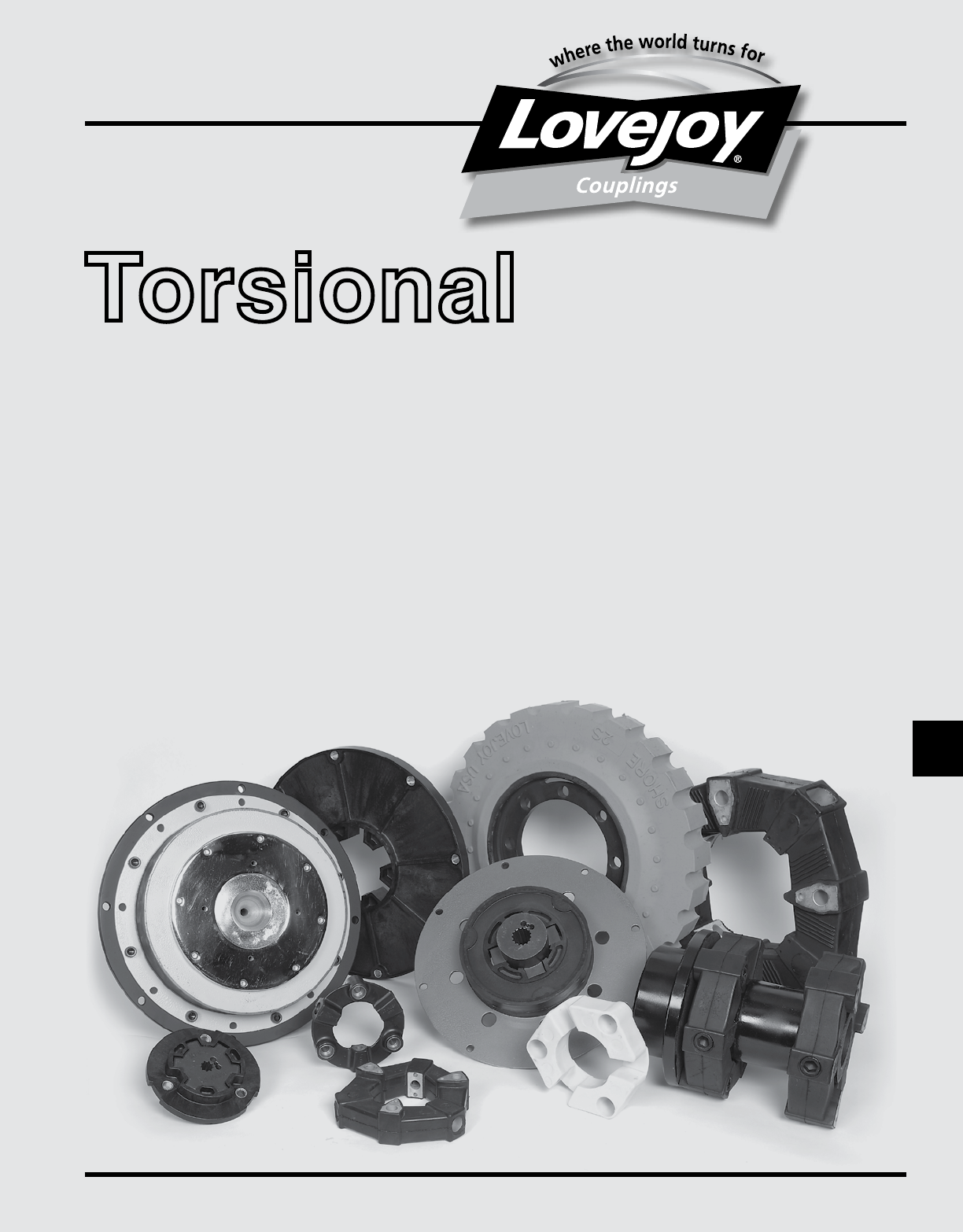
Lovejoy■offers■a■wide■range■of■torsional■couplings■engineered■to■solve■torsional■vibration■
problems■found■in■diesel■engine■driven■equipment■and■other■applications■where■torsional■
vibrations■are■prevalent.■■These■include■all■internal■combustion■engines,■reciprocating■
pumps■and■compressors,■as■well■as■variable■frequency■drives■(VFD).■■
Lovejoy■torsional■coupling■are■designed■to■dampen■torsional■vibrations■and■tune,■or■
adjust■the■system’s■critical■speeds■away■from■the■application’s■operating■range.■■With■
the■proper■information■(see■Torsional■Worksheet■on■page■T-10)■Lovejoy■engineers■
can■perform■a■Torsional■Vibration■Analysis,■or■TVA■for■your■application■to■assist■in■the■
selection■of■a■torsional■coupling.■See■sample■TVA■in■the■graph■to■the■right.
Lovejoy Torsional Coupling Product Overview
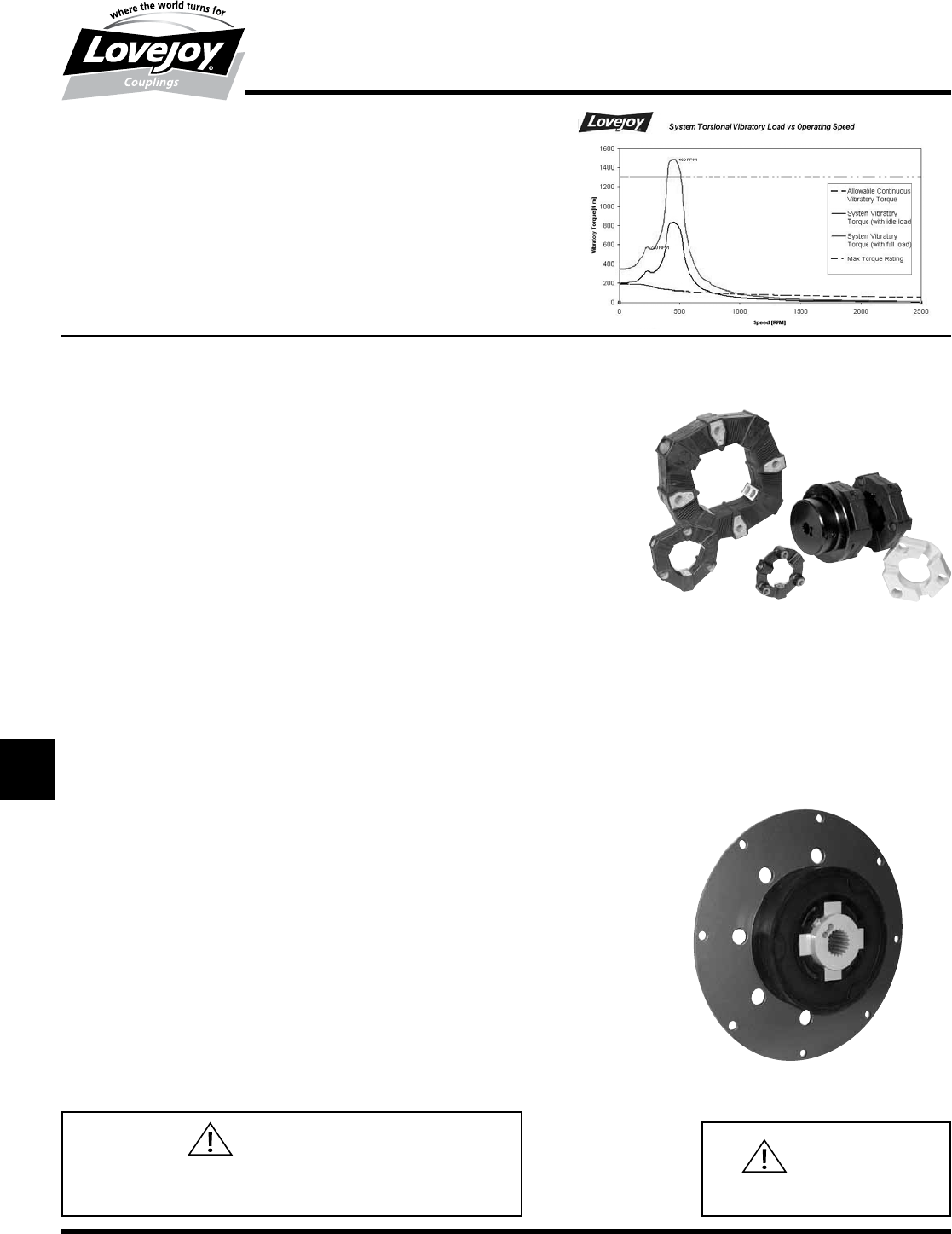
LF Series
The■unique■and■highly■versatile■design■of■the■elastomeric■element■makes■the■LF■Series■the■most■versatile■
product■in■Lovejoy’s■line■of■■torsional■coupling■products.■It■is■available■in■high■temperature■rubber■(HTR),■
Hytrel®,■or■Zytel®.■■The■element■can■be■easily■mounted■in■a■number■of■configurations■depending■on■the■
application.■■The■element■is■connected■axially■to■a■flanged■hub,■flywheel■adapter■plate,■or■flywheel■on■
the■engine■side■using■axial■screws■or■special■“S”■bolts■designed■for■blind■assembly.■■The■element■is■also■
connected■to■a■cylindrical■hub■on■the■driven■equipment■side■using■radial■screws.■■This■unique■design■
is■remarkably■simple,■highly■effective■and■provides■users■of■LF■torsional■couplings■with■unmatched■
performance.■■It■is■recommended■that■coupling■selections■should■be■verified■with■a■Torsional■Vibration■
Analysis■of■the■system■(see■page■T-10).■
Configuration: ■ Flange■to■shaft,■shaft■to■shaft,■and■floating■shaft■applications
Application: ■ ■The■LF■coupling■is■ideal■for■coupling■engines■to■pumps,■compressors,■generators,■
fans,■blowers,■■and■other■industrial■driven■equipment■connecting■to■either■the■
engine■flywheel■or■a■power■take-off■(PTO).■
Nominal torque range (TKN): up■to■26,500■in-lb■(3000■Nm)
Max angular misalignment (Kw): HTR■up■to■3°,■Hytrel®■and■Zytel®■see■table■on■page■T-17■
Max parallel misalignment (KR):■HTR■up■to■0.08■inches■(2■mm),■Hytrel®■and■Zytel®■see■table■on■page■T-17■
Axial end float (Ka): HTR■up■to■0.2■inches■(5■mm),■Hytrel®■and■Zytel®■see■table■on■page■T-17■
Element material:■■ HTR,■Neoprene,■Hytrel®■or■Zytel®
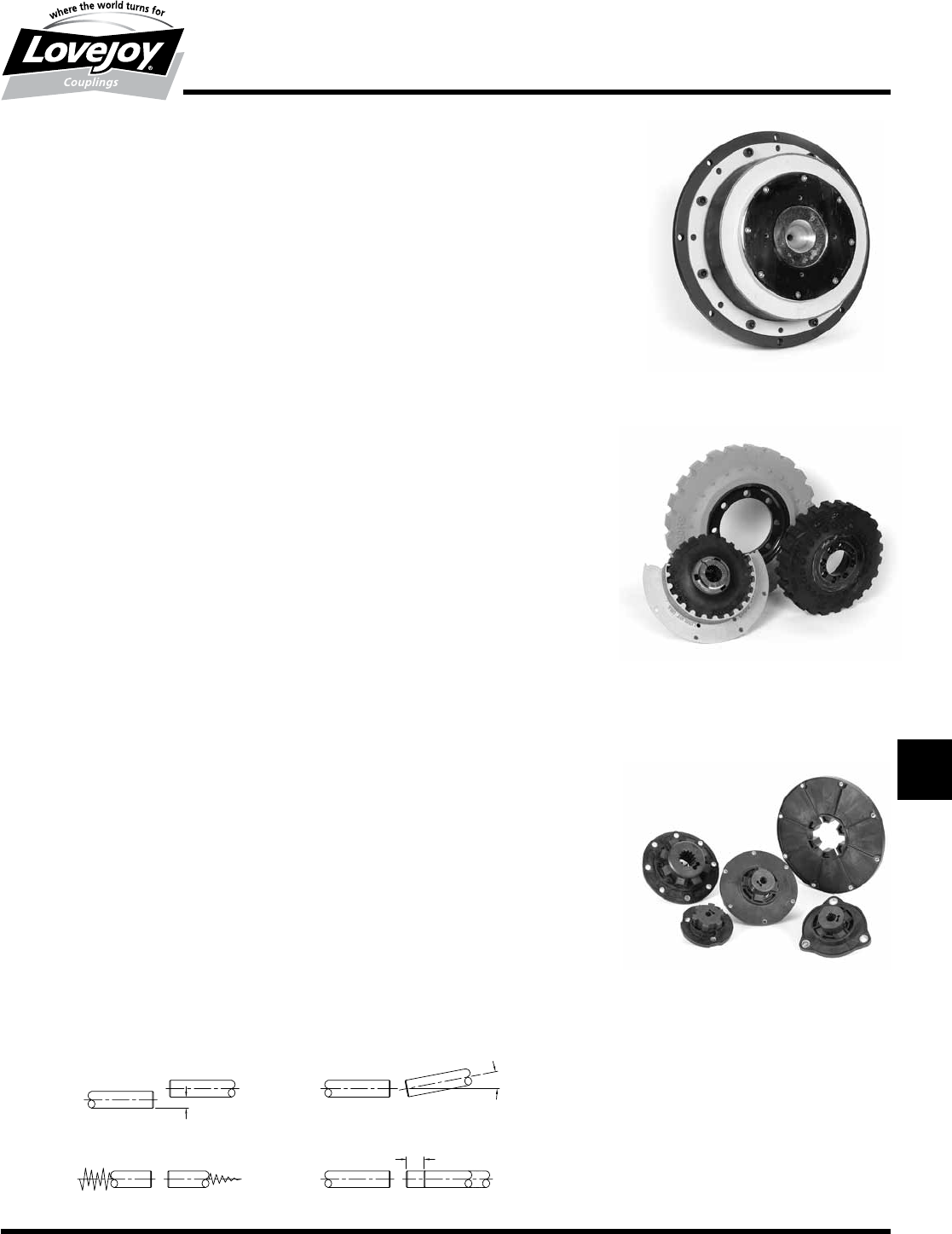
LVK Series
The■LVK■Series■torsional■couplings■accommodate■configurations■where■internal■combustion■engines■are■
connected■to■a■variety■of■driven■equipment,■while■protecting■the■equipment■from■potentially■damaging■
torsional■vibrations■by■tuning■engine■critical■speeds■away■from■the■application■operating■speed.■■It■is■
recommended■that■coupling■selections■should■be■verified■with■a■Torsional■Vibration■Analysis■of■the■system■
(see■page■T-10).■
Configuration:■■ ■The■LVK■Style■couplings■are■designed■for■mounting■on■standard■SAE■J620■
flywheels.■■The■element■is■bonded■to■the■flywheel■mounting■plate■and■the■unique■
‘star’■shaped■LK■Style■hub■housing.■■The■mating■hub■mounts■onto■the■equipment■
shaft■and■slides■into■an■interlocking■position■during■installation■for■a■blind■assembly.
Application:■■ ■The■LVK■coupling■is■ideal■for■coupling■engines■to■pumps,■compressors,■generators,■
fans,■blowers■and■other■equipment■requiring■a■direct■interface■via■the■engine■
flywheel.
Nominal torque range (TKN): up■to■5,800■in-lb■(655■Nm)
Max angular, parallel, and axial misalignment:■based■on■SAE■design■parameters■
Element material: ■High■Temperature■Rubber■(HTR)■or■EPDM
WARNING
You■must■refer■to■page■T-2■(Page■260)■for■Important■Safety■Instructions■and■
Precautions■for■the■selection■and■use■of■these■products.■Failure■to■follow■the■
instructions■and■precautions■can■result■in■severe■injury■or■death.
WARNING
Do■not■use■anaerobic■adhesives■with■any■
Torsional■components.
JWJISCJSFMCGHPGDD
T
SPUJVSDRSLDED
JW JIS CJ SF MC G HP GD D T SP UJ VSD R SLD ED
263
www.lovejoy-inc.com T-5
Torsional
Overview
LV Series
The■LV■Series■torsional■couplings■provide■an■inexpensive■and■economical■alternative■for■the■agricultural■
and■off-highway■industrial■equipment■market.■■The■standard■configuration■is■used■for■connecting■internal■
combustion■engines■to■a■variety■of■driven■equipment■through■a■specially■designed■plate■manufactured■
which■can■support■universal■joint■drive■shaft■systems.■■It■protects■the■equipment■from■potentially■damaging■
torsional■vibrations■by■tuning■engine■critical■speeds■away■from■the■application■operating■speed.■■It■is■highly■
recommended■that■coupling■selections■should■be■verified■with■a■Torsional■Vibration■Analysis■of■the■system■
(see■page■T-10).■
■
Configuration:■ ■The■LV■Series■couplings■are■designed■for■mounting■on■standard■SAE■J620■flywheels■with■
the■element■bonded■to■the■mounting■plate.■■The■face■plate■is■specially■designed■to■interface■
with■flange■mounted■universal■joints■popular■in■the■agricultural■deep■well■pump■markets.
Application: ■ ■Any■diesel■engine■driven■equipment,■flange■interfaces,■and■universal■joint■driveshaft■driven■
equipment.
Nominal torque range (TKN):■up■to■10,820■in-lb■(1223■Nm)
Max angular, parallel, and axial misalignment:■based■on■SAE■design■parameters■
Element material:■High■Temperature■Rubber■(HTR)■or■EPDM
LM Series
The■Lovejoy■LM■Series■torsional■couplings■are■designed■specifically■for■diesel■driven■applications■where■the■
couplings■are■flywheel■mounted.■■The■LM■coupling■is■popular■in■small■to■large■equipment■configurations■where■
it■is■necessary■to■protect■the■equipment■from■potentially■damaging■torsional■vibrations.■■This■is■accomplished■
by■tuning■engine■critical■speeds■away■from■the■application■operating■speed.■■It■is■highly■recommended■that■
coupling■selections■should■be■verified■with■a■Torsional■Vibration■Analysis■of■the■system■(see■page■T-10).■
Configuration: ■ ■Drive■rings■are■designed■for■many■SAE■J620■flywheel■sizes■and■mount■directly■on■the■
flywheel.■■The■element■and■center■hub■mount■on■the■driven■equipment■shaft■and■easily■
slide■into■the■drive■ring.■■This■coupling■is■excellent■for■normal■or■blind■installations.
Application: ■ ■Any■diesel■driven■equipment■■that■includes■generator■sets■(2■bearing),■hydraulic■pumps■
(single■or■multiple■in■parallel■or■series■configurations),■locomotive■applications,■centrifugal■
pumps,■compressors,■fans,■blowers,■and■more.
Nominal torque range (TKN):■■up■to■33,600■in-lb■(3800■Nm)
Max angular, parallel, and axial misalignment:■■based■on■SAE■design■parameters■
Element material:■HTR,■EPDM■or■Silicone
LK Series
The■LK■Series■coupling■is■a■simple■two-piece■design■consisting■of■an■flywheel■or■flange■mounted■element■and■
an■interlocking■hub.■■The■couplings■are■designed■for■use■with■diesel■engine■driven■hydraulic■pump■systems■
which■are■plate■mounted■directly■to■SAE■flywheel■housings.■■The■couplings■are■torsionally■stiff■enabling■
hydraulic■pumps■and■similar■equipment■with■low■mass■or■inertia■to■operate■below■critical■speeds.■■The■
torsionally■stiff■LK■Series■coupling■tunes■the■engine■critical■speed■away■from■the■operating■range.■■A■Torsional■
Vibration■Analysis■is■typically■not■necessary■for■the■LK■Style■couplings■because■the■LK■Series■is■torsionally■stiff■
and■puts■the■critical■speed■above■the■normal■operating■range.■■■
Configuration:■■ ■The■LK■Series■coupling■consists■of■a■flywheel■mounted■element,■or■an■adapter■plate■
mounted■universal■element,■and■a■star■shaped■hub.■■The■hub■is■mounted■on■the■driven■
equipment■and■its■design■is■excellent■for■blind■installations.
Application: ■ ■The■LK■coupling’s■design■is■excellent■for■virtually■all■diesel■engine■driven■hydraulic■systems■
in■the■low■to■mid■power■range.
Nominal torque range (TKN):■■up■to■21,240■in-lb■(2400■Nm)
Max angular, parallel, and axial misalignment:■■based■on■SAE■design■parameters■
Element material:■■Zytel®
Parallel Misalignment Angular Misalignment
Torsional Misalignment Axial Misalignment
JWJISCJSFMCGHPGDDTSPUJVSDRSLDED
JW JIS CJ SF MC G HP GD D
T
SP UJ VSD R SLD ED
264 630-852-0500
T-6
Torsional
Engine Application
Selection Process
When■correctly■sized,■the■Lovejoy■Torsional■Coupling■will■effectively■dampen■vibration■and■tune■critical■frequencies■out■of■the■operating■range■of■
systems■driven■by■diesel,■gasoline,■or■natural■gas■reciprocating■engines.■Some■coupling■selections■can■be■verified■using■a■Torsional■Vibration■
Analysis■performed■by■Lovejoy■Engineering■(see■worksheet■page■T-10).
Misapplication of the coupling in an engine application will frequently lead to coupling
failure or system damage. Lovejoy strongly recommends that you contact Technical
Support for assistance in selecting a coupling.
Please■complete■the■information■worksheet■on■page■T-10■and■fax■it■to■800-446-0878■
or■access■“Engineering■Assistance”■on-line■at■www.lovejoy-inc.com
Use■the■following■steps■in■conjunction■with■the■technical■data■and■
dimensional■tables■contained■in■the■following■sections■to■make■the■
preliminary■coupling■selection■for■internal■combustion■engine■applications.
Step 1: Coupling Selection
Select■the■torsional■coupling■model■that■best■suits■your■drive■
arrangement.
Step 2: Application Torque
Select■a■coupling■size■with■a■nominal■torque■rating■(TKN)■greater■
or■equal■to■the■application■torque■(TLN)■calculated■with■the■
following■equation:
■ ■ TKN ≥ TLN • St
■ Provided■■TLN (in-lb) = HP • 63025 / RPM
■ ■ ■■■■■■■■■■■■or
■ ■ TLN (Nm) = HP • 9555 / RPM
St■is■the■temperature■factor■for■the■nominal■torque■found■in■
Figure■1■(page■T-9)■for■HTR.■■This■number■will■be■at■least■1.6■or■
1.7■(for■typical■ambient■temperature■of■at■least■140°■to■160°■F■
inside■the■flywheel■housing).
Step 3: SAE Flywheel Size
Select■the■appropriate■SAE■J620■flange■size■to■match■your■
flywheel.
Step 4: Shaft Dimensions
Make■sure■the■maximum■bore■capacity■of■the■coupling■will■
accommodate■the■dimensions■of■your■drive■shaft.■■Coupling■
hub■length■can■usually■be■shortened■if■necessary■to■fit■into■tight■
space■envelope.
Important:
■ ■Final■selection■of■coupling■size■requires■verification■by■torsional■
vibration■analysis.■■This■analysis■will■identify■the■location■of■the■
critical■speeds■and■confirm■the■absence■of■excessive■steady-
state■and■peak■resonance■conditions■over■the■normal■operating■
cycle■of■the■equipment.
Step 5: Peak Torque Pulses
The■magnitude■of■the■maximum■torque■pulses■that■occur■during■
operation■(Tmax)■at■all■operating■temperatures■must■not■exceed■
the■maximum■torque■rating■of■the■coupling■(TKmax).■■These■are■
short■duration■transient■pulses■that■result■from■start-up,■shock,■
or■acceleration■through■a■system■resonance■to■reach■operating■
speed.■■By■definition,■these■pulses■may■occur■over■the■life■of■the■
coupling■105■times■in■one■direction■of■rotation,■or■5■X■104■times■
reversing.
TKmax ≥ Tmax • St
JWJISCJSFMCGHPGDD
T
SPUJVSDRSLDED
JW JIS CJ SF MC G HP GD D T SP UJ VSD R SLD ED
265
www.lovejoy-inc.com T-7
Torsional
Engine Application
Selection Process
Step 6: Critical Speeds Due to Resonance
Select■coupling■stiffness■so■the■system■does■not■run■at■high■
resonance■as■well■as■the■normal■running■and■idle■speeds■are■not■
at■or■near■critical■speeds.■■
■ ■Critical■speeds■are■related■to■the■system■natural■frequency■and■
the■number■of■pulses■or■excitations■generated■per■revolution■
i■(order).■■For■analysis,■if■possible,■reduce■the■application■to■a■
2-mass■system■and■apply■the■following■equations:
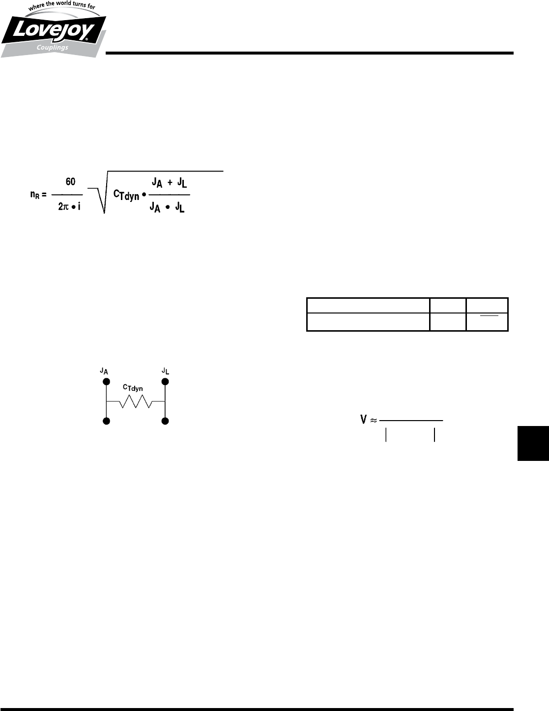
Where:
nR = ■ critical■resonance■speed■of■the■system■(RPM)
CTdyn =■■ dynamic■torsional■stiffness■of■the■coupling■(lb-in/rad)
JA =■■ mass■moment■of■inertia■for■the■drive■side■(lb-in-sec²)
JL = ■ mass■moment■of■inertia■for■the■load■side■(lb-in-sec²)
i =■■ number■of■oscillations■generated■per■revolution
■ ■The■coupling■will■be■modeled■as■the■spring■controlling■torsional■
oscillations■of■the■engine■and■flywheel■on■one■side■and■the■driven■
equipment■on■the■other:
■ ■Use■the■dynamic■torsional■stiffness■values■(CTdyn)■from■the■
Performance■Data■tables■which■can■be■found■in■representative■
coupling■section.■■Mass■moment■of■inertia■values■may■
be■obtained■from■the■respective■engine■and■equipment■
manufactures.
Note:■■ n■■■System■steady-state■operating■speeds■should■be■
1.5■to■2■times■the■major■critical■speed■for■safe,■low-
resonance■operation.
Step 7: Allowable Continuous Vibratory Torque
The■amplitude■of■the■continuously■oscillating■(vibratory)■torque■
generated■in■the■system■must■not■exceed■the■coupling’s■
rating■(TKW)■at■a■particular■steady-state■frequency■(RPM)■and■
temperature.■■This■torque■is■superimposed■on■(co-exists■with)■
the■basic■load■(TLN).
TKW > TW • St • Sf •V
Where:
■TKW =■■ Coupling■rating■for■continuously■oscillating■torque■at■10Hz
■Sf =■■ ■Frequency■factor■that■relates■the■operating■frequency■to■
the■coupling’s■10Hz■rating■(see■Figure■2■on■page■T-9)
■St =■■ Temperature■factor■(for■HTR■only)
■V =■■ ■Amplifing■factor■outside■the■resonance.■Substitute■Vr■for■
V■with■run-through■of■resonance■application■(see■Figure■3■
on■page■T-9)
■Tw =■■ Generating■torque
■
■
Operating■Frequency■f (Hz) ≤ 10 >10
Frequency■Factor■Sf1√■f■/■10
■ ■The■magnitude■of■the■continuously■oscillating■torque■generated■
in■the■system■(TW)■is■dependent■on■an■amplifying■factor■(V)■
based■on■the■system■steady-state■operating■speed■n■relative■to■
the■resonance■speed■nR:
Step 8: Dimensional & Alignment Considerations
Refer■to■the■Performance■Data■tables,■figures,■and■dimension■
tables■to■make■certain■final■coupling■selection■meets■application■
constraints■for■the■working■envelope■(O.C.,■length,■bore■
dimensions,■etc.),■maximum■speed■limitations■and■allowable■
misalignment.
1-(n/nR)2
1
JWJISCJSFMCGHPGDDTSPUJVSDRSLDED
JW JIS CJ SF MC G HP GD D
T
SP UJ VSD R SLD ED

266 630-852-0500
T-8
Torsional
Industrial Application
Selection Process
While■the■Torsional■coupler■was■developed■to■solve■the■unique■problems■associated■with■the■torsional■vibration■in■equipment■driven■by■internal■
combustion■engines,■the■coupling■works■equally■well■in■general■industrial■applications.■For■these■electric■motor-powered■and■other■non-engine■
applications,■use■the■following■simple■selection■procedure■(Refer■to■page■T-6■for■engine-driven■applications).■
Misapplication of the coupling in an engine application will frequently lead to coupling
failure or system damage. Lovejoy strongly recommends that you contact Technical
Support for assistance in selecting a coupling.
Please■complete■the■information■worksheet■on■page■T-10■and■fax■it■to■800-446-0878■
or■access■“Engineering■Assistance”■on-line■at■www.lovejoy-inc.com
Use■the■following■steps■in■conjunction■with■the■technical■data■and■
dimensional■tables■contained■in■the■following■sections■to■make■the■
preliminary■coupling■selection■for■industrial■applications.
Step 1: Coupling Selection
Select■the■torsional■coupling■model■that■best■suits■your■drive■
arrangement.
Step 2: Choose Element Material
Most■common■used■is■the■HTR■(High■Temperature■Rubber)■
element■is■used■because■of■the■high■flexibility.■■This■feature■
provides■benefits■of■vibration■and■shock■damping,■noise■
silencing,■and■a■high■tolerance■for■misalignment.
■ ■When■required,■the■Zytel®■element■provides■a■torsionally■rigid■
connection■yet■is■still■flexible■in■terms■of■accommodating■small■
angular■misalignment■as■well.■■Use■of■the■floating-shaft■Model■
6■version■will■allow■for■parallel■misalignment■as■well.■The■Zytel®■
material■is■also■chemical■resistant.
Please note that the optional Hytrel® element requires
almost perfect alignment which is unlikely in most
applications and is not recommended, except when used as
intended on a flange mounted hydraulic pump to an engine
flywheel.
Step 3: Determine Service Factor
■ ■Choose■a■representative■application■Service■Factor■(SF)■from■
the■chart■on■page■T-9.
Step 4: Calculate Nominal Torque Requirement, TKN
Use■the■actual■torque■or■horsepower■requirement■for■the■
driven■equipment■if■known.■■Otherwise,■use■the■rated■motor■
horsepower.
TKN (in-lb) ≥ HP•SF•63025 / RPM
■
Step 5: Other Considerations
Refer■to■the■Performance■Data■tables,■figures,■and■dimension■
tables■to■make■certain■final■coupling■selection■meets■application■
constraints■for■envelope■(O.D.,■length,■bore■dimensions,■etc.)■
and■maximum■speed■limitations.
■ ■Example:
■ ■Find■a■LF■coupling■for■a■15■hp■centrifugal■pump■running■at■
1,750■RPM.
■Model 2■–■Most■common■for■shaft-to-shaft■applications.
Model 2/S■–■For■shaft-to-shaft■applications■that■require■free■end-
float■or■quick,■blind■“plug-in”■assembly.
Model 1 or 1/S■–■or■connecting■a■shaft■to■a■flange■or■flywheel.
Model 6■–■floating■shaft■applications■(see■pages■T-22■through■
T-25).
■ SF■=■1.0■(from■Application■Service■Factor■(SF)■on■page■T-9)
■ TKN■=■(15hp•1.0•63025)■/■1,750■RPM■=■540■in-lb
■ »■use■a■LF8■torsional■coupler■or■larger
JWJISCJSFMCGHPGDD
T
SPUJVSDRSLDED
JW JIS CJ SF MC G HP GD D T SP UJ VSD R SLD ED
267
www.lovejoy-inc.com T-9
Torsional
Application Service Factors
Selection Data
Application Service Factors
Agitators■.........................1.0
Beaters■..........................1.5
Blowers■..........................1.0-1.25
Can■filling■machinery■. . . . . . . . . . . . . . . .1.0
Car■dumpers■......................2.5
Car■pullers■........................1.5
Compressors■(screw) ■. . . . . . . . . . . . . . .1.0
Compressors■(reciprocating)■. . . . . . . . . . Consult■Lovejoy
Conveyors■........................1.0-2.5
Love■Roll,■Shaker■&■Recip.■. . . . . . . . . . .3.0
Conveyors■(heavy■duty) ■. . . . . . . . . . . . .1.25-2.5
Cranes■&■Hoists1■...................2.0
Crushers■.........................3.0
Dredges■..........................1.5-2.0
Elevators■.........................1.0
Fans.■.■.■.■.■.■.■.■.■.■.■.■.■.■.■.■.■.■.■.■.■.■.■.■.■.■.■.■.1.0-1.5
Feeders■..........................1.0
■ Reciprocating■. . . . . . . . . . . . . . . . . .2.5
Generators:
■ Not■Welding■...................1.0
■ Welding■.......................2.0
■ Hoist■.........................1.5
Hammer■mills■.....................2.0
Kilns■.............................1.5
Laundry■washers:
■ Reversing■.....................2.0
Line■shafting■......................1.5
Lumber■machinery■. . . . . . . . . . . . . . . . . . 2.0
Machine■tools ■. . . . . . . . . . . . . . . . . . . . .1.5-2.0
Metal■forming■machinery■. . . . . . . . . . . . .1.5-2.5
Mills,■rotary■type ■. . . . . . . . . . . . . . . . . . .2.0
Mixers■...........................1.5-1.8
Paper■mill■equipment■. . . . . . . . . . . . . . . . 1.2-2.0
Pumps:
■ Centrifugal■....................1.0
■ Gear,■Rotary■or■Vane■. . . . . . . . . . . . 1.25
■ Reciprocating■1■Cyl.■. . . . . . . . . . . . .2.0
■ Or■double■acting
■ 2■Cyl.■Single■Acting■. . . . . . . . . . . . . .2.0
■ 2■Cyl.■Double■Acting■. . . . . . . . . . . . . 1.75
■ 3■or■more■Cyl.■. . . . . . . . . . . . . . . . . .1.5
Rubber■machinery■. . . . . . . . . . . . . . . . . . 2.0-2.5
Stokers■..........................1.0
Textile■machinery■. . . . . . . . . . . . . . . . . . .1.2
Windlass■.........................2.0
Woodworking■machinery■. . . . . . . . . . . . .1.0
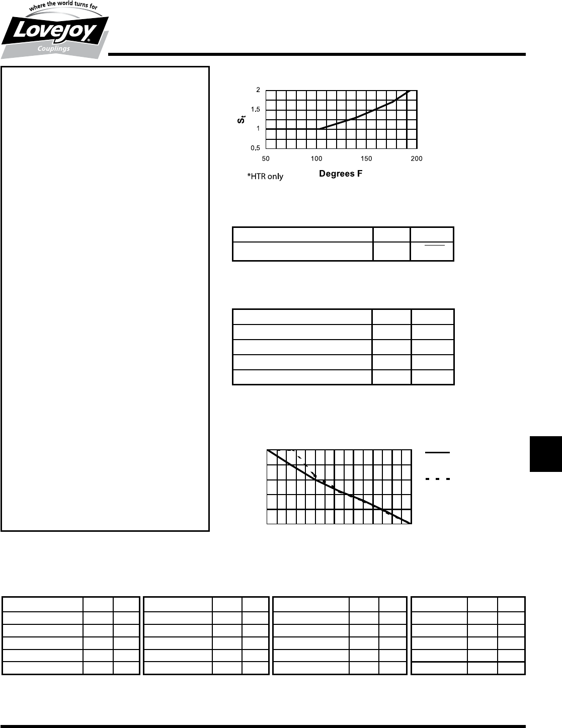
Figure 1: Temperature Factor*, St (HTR)
Figure 2: Frequency Factor
Operating■Frequency■f (Hz) ≤ 10 > 10
Frequency■Factor■Sf1√■f■/■10
Figure 3: Resonance Factor Vr
Coupling Element VrΨ
HTR■50■Shore 10 0.6
HTR■60■Shore 8 0.78
Hytrel®– 0.5
Zytel®– 0.4
Figure 4: Permissible Misalignment vs. Speed
Oils & Hydraulic Fluids Hytrel®Zytel®Solvents & Fuels Hytrel®Zytel®Acids & Bases Hytrel®Zytel®Miscellaneous Hytrel®Zytel®
Automatic■Transmissions A A Gasoline A A Sulfuric■Acid■(20%) A C Ethylene■Glycol* A A,B
Fluid■Type■A■&■F■ A A Nujol,■JP4■Kerosene A A Hydrochloric■Acid■(20%) B C Steam B B
Hydraulic■Fluid A A Halocarbons,■Freon A A Potassium■or■Sodium — — Liquid■Ammonia — A
Phosophate■Ester A A Trichlorethylene C C Hydroxide■(20%) A B — — —
Lube■Oil A A Carbon■Tetrachloride B A — — — — — —
Chemical Resistance Chart
Notes:■■ n■■■Avoid■contact■with■hydrocarbon■base■lubricants■or■use■of■any■anaerobic■adhesives.
■n■■■A■indicates:■Little■or■no■effect.
■n■■■B■indicates:■Moderate■effect.
■n■■C■indicates:■Severe■effect.
Note:■■ n■■HTR■is■High■Temperature■Rubber.
Note:■■ n■■■1■indicates:■If■people■are■transported,■Lovejoy■does■
not■recommend■and■will■not■warranty■the■use■of■the■
coupling.
Permissible Misalignment vs. Speed
0
1000
2000
3000
4000
5000
0 50 100 150
Percent of Rating for Allowable
Misalignment at TKN
Operating Speed
HTR (Angular &
Parallel)
Zytel (Angular)
JWJISCJSFMCGHPGDDTSPUJVSDRSLDED
JW JIS CJ SF MC G HP GD D
T
SP UJ VSD R SLD ED

268 630-852-0500
Driven Equipment
o■Hydraulic■Pump■ Shaft■Diameter■or■Spline■details■ Driven■From:
o■Water■Pump■ ___________________________■ o Flywheel
o Compressor■■Type:______________■ ___________________________■ o Front■/■Side■PTO
■■■■■■■■■■(Screw,■Reciprocating,■Lobe■Etc)
■ ■ o Other■(Explain)
o Generator■/■Alternator■ Type■of■Equipment■Mounting■ ____________________________
■ ■
o Other:■■_________________________■■ o Flange■mount■to■engine■pilot■ ____________________________
■ ■ ■ ■ ■ ■
Ambient■Operating■Temperature:■______■°F■/■°C■■■■■ o Independent■of■engine
Customer Information ■■■■■■■■■■■■■■■■■■■■■■■■■■■■■■■■■■■■■■■■■■■■■■■■■■■■■■■■■■■■■■■■■■■■■■■■■■■■■■■■■■■■■■■■■■■■■■■■■■■■■■■■■■■■■■■■Date:■ __________________________________________
Company■Name:■_______________________________________________________■■Contact■Name:_____________________________________________
Phone■Number:■________________________________________________________■■email■address:■_____________________________________________
Fax■Number:■__________________________________________________________■■Anticipated■Order■Quantity■/■Annual■Usage:■______________________
Brief■Description■of■Application:■______________________________________________________________________________________________________
_______________________________________________________________________________________________________________________________
Engine Information■ Type:■ Piston■configuration
Engine■Manufacturer:__________________________________________■ o Diesel■ o■In-Line
Engine■Model:________________________________________________■ o Gasoline■ o Vee■ o Vee-angle:■______
Number■of■Cylinders:■_________■■■Displacement:■___________■ o Natural■Gas
■ ■ SAE■(J620D)
Rated■Horsepower:________________________■ o Other:■______■ Flywheel■Size:■___________
■ ■ 6-1/2,7-1/2,8,10,11-1/2,14,16,etc
@■Rated■Speed:__________________________■ o 2-Stroke■■■■■■■■o 4-Stroke■■ (Attach■Drawing■if■non■standard)
Operating■Speed■(Constant):■________________■■■■■■■■■■■■■■■■■■■Idle■Speed:■____________________■ SAE■(J617C)
■ ■ Flywheel■Housing■Size:■______
PTO■Shaft■or■Output■Shaft■Diameter:______________________________________■ 6,■5,■4,■3,■2■or■1
Mass Moment of Inertia (J or WR2)
The■following■must■be■provided■for■Torsional■Vibration■Analysis.
Please■include■type■of■units■(J■or■WR2)■
Engine■Inertia:■__________________
Flywheel■Inertia:■_________________
Driven■Equipment■Inertia(s):■1._____________■2._____________3.____________4.___________■
T-10
Torsional
Coupling Selection Worksheet
Coupling Selection Worksheet for Internal Combustion Engines (diesel, gas, natural gas)
For■assistance■in■selecting■a■Torsional■coupling■for■your■internal■combustion■engine■application,■please■complete■the■entire■worksheet■and■fax■it■to■800-446-0878■
or■send■via■email■to■appleng@lovejoy-inc.com.■■Direct■questions■to■630-852-0500.
Add■sketch■or■Mass■Elastic■Diagram■if■necessary
Return■completed■worksheet■to■Lovejoy■Technical■Support■at■■email:■■appleng@lovejoy-inc.com■■■or■■Fax■to■800-446-0878
JWJISCJSFMCGHPGDD
T
SPUJVSDRSLDED
JW JIS CJ SF MC G HP GD D T SP UJ VSD R SLD ED
269
www.lovejoy-inc.com T-11
Torsional
L-LOC Clamping Feature and Spline Identification
Overview
Lovejoy’s L-LOC Spline Clamping Feature
Spline■shaft■wear,■profile■distortion,■and■fretting■corrosion■all■are■major■concerns■in■spline■
shaft■applications■such■as■hydraulic■pumps.■■We■are■pleased■to■state■that■Lovejoy■has■a■
solution.■■It’s■called■the■L-LOC.
It■is■common■knowledge■that■typical■manufacturing■tolerances■between■spline■shafts■and■
mating■coupling■hubs■create■some■unavoidable■play■or■backlash.■■This■backlash■is■defined■
as■the■minor■movement■between■the■shaft■and■hub,■typically■resulting■in■wear.■■This■tolerance■
related■movement■and■wear■is■often■further■compounded■by■misalignment■and■hammering■
forces■common■in■power■transmission.■■As■a■result,■fretting■wear■and■profile■distortion■can■
occur,■even■when■shafts■are■manufactured■with■high■quality■hardened■steel■using■tight■
tolerances.■■If■not■checked,■abnormal■stresses■on■seals,■bearings,■and■other■engine■or■pump■
components■can■occur.■■The■results■are■costly■‘down■time’.■■A■great■deal■of■money■is■spent■
each■year■on■maintenance■caused■by■this■premature■wear■and■equipment■failure.
The■ideal■solution■to■spline■distortion■and■wear■is■to■eliminate■the■backlash■or■clearance■
related■to■mating■tolerances■and■assembly■misalignment.■■There■are■many■solutions■
available,■but■most■are■expensive,■time■consuming,■and■often■unsuccessful■causing■
additional■damage.
Lovejoy■coupling■hubs■with■the■L-LOC■spline■clamping■feature■have■proven■themselves■
successful■by■eliminating■the■backlash,■clearance■issues,■and■damage■caused■by■the■
hammering■effects■of■vibration,■including■torsional■vibration.■■The■result■is■longer■lasting■
spline■profiles■in■both■shafts■and■couplings■that■decrease■costly■downtime.
The■L-LOC■feature■is■a■remarkably■simple,■yet■effective■design,■consisting■of■a■unique■’dog■
bone’■shaped■slot■that■is■placed■slightly■above■and■parallel■to■the■spline■bore.■■When■these■
set■screws■are■tightened,■the■hub■becomes■firmly■locked■in■place,■gripping■the■full■diameter■
of■the■spline■shaft■and■the■set■screws■never■come■in■contact■with■the■spline.■■As■a■result,■
users■will■never■see■dents,■gouges,■or■burrs■on■the■shaft■from■mounting■the■hub.■■While■in■
use■the■hub■and■shaft■virtually■become■a■single■entity,■yet■when■the■set■screws■are■loosened,■
the■L-LOC■releases■its■grip■and■the■hub■can■be■easily■removed■from■the■spline■shaft.
Features
■■L-LOC■eliminates■premature■spline■shaft■maintenance■or■
replacement
■■Reduces■potentially■damaging■stress■on■equipment■
components
■■Quick■and■easy■to■assemble■and/or■removal
■■Improves■the■effectiveness■of■the■connection■between■the■
hub■and■shaft
■■Helps■reduce■equipment■noise■often■related■to■couplings
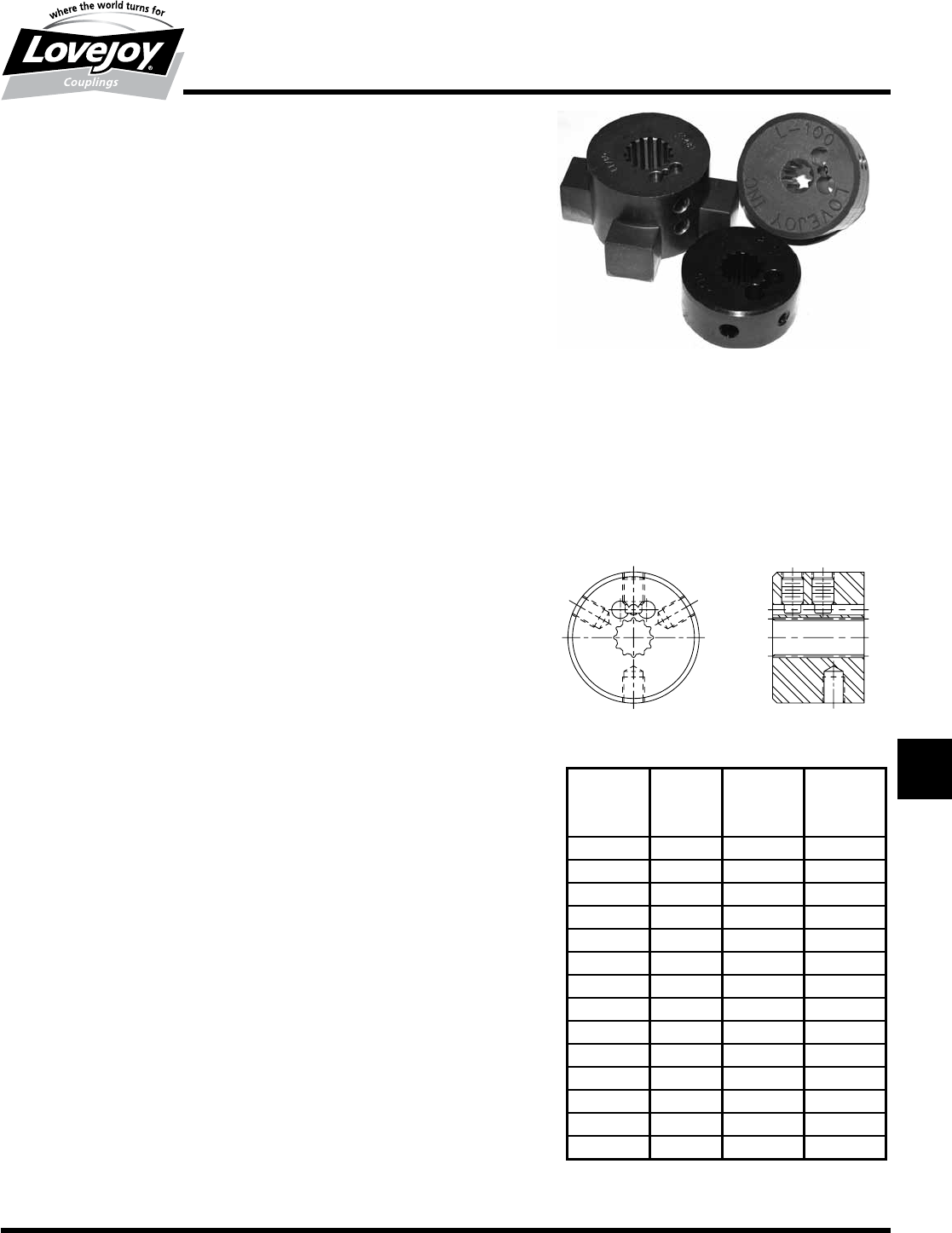
Spline Identification and Selection
There■are■hundreds■of■combinations■of■splines■used■in■industry■today■and,■while■Lovejoy■
does■not■stock■all■of■these■splines,■many■are■maintained■in■inventory■while■a■large■variety■can■
be■quickly■machined■for■your■specific■needs.
When■identifying■splines,■it■is■important■to■know■what■Industry■Standard■the■spline■falls■under■
such■as■ANSI■B92.1A■(SAE■J744)■or■DIN5480.■■Manuals■and■data■sheets■provided■by■most■
original■equipment■manufacturers■contain■the■necessary■spine■data■for■users■to■identify■and■
order■a■hub■with■the■proper■spline.■■
Lovejoy’s■Customer■Service■and■Technical■Support■teams■can■help■pick■out■couplings■or■
hubs■containing■most■splines,■but■certain■information■will■need■to■be■provided■prior■to■making■
the■proper■selection.
SAE■Standard■Involute■splines■are■the■most■common■spline■in■use■in■the■United■States■and■
many■are■represented■in■the■ANSI■chart■shown■on■the■right.■Information■required■to■identify■
most■ANSI■(SAE)■splines■contains■the■number■of■teeth,■the■diametral■pitch,■and■the■major■
spline■diameter.■■Lovejoy’s■ANSI■splines■are■machined■to■meet■the■ANSI■standard■Class-5■fit.
When■specifying■DIN-5480■splines,■it■is■necessary■to■provide■the■number■of■teeth,■the■major■
diameter■in■mm,■and■the■DIN■Module■number,■usually■in■format:
DIN■5480■x■Major■Dia■x■Module■x■Pressure■angle■(usually■30*)■x■number■of■teeth.
Lovejoy’s■DIN-5480■splines■are■machined■to■meet■the■DIN■standard■9H■fit.
DIN-5482■metric■splines,■JIS■splines,■and■SAE■J499■parallel■side■splines,■can■be■quoted■
based■on■individual■applications.
SAE Code Number Diametral Major
of Teeth Pitch Diameter
Size (DP) in
A-A 9 20/40 0.500
A9 16/32 0.625
—11 16/32 0.750
B13 16/32 0.875
B-B 15 16/32 1.000
C14 12/24 1.250
—21 16/32 1.375
C-C 17 12/24 1.500
—23 16/32 1.500
D13 8/16 1.750
E13 8/16 1.750
—20 12/24 1.750
—27 16/32 1.750
F15 8/16 2.000
SAE Splines ANSI B92.1A (SAE J744)
Note:■■ n■■■Please■contact■Lovejoy■Technical■
Support■regarding■additional■spline■sizes■
not■included■in■this■chart.
JWJISCJSFMCGHPGDDTSPUJVSDRSLDED
JW JIS CJ SF MC G HP GD D
T
SP UJ VSD R SLD ED
270 630-852-0500
T-12
Torsional
LF Series
Overview
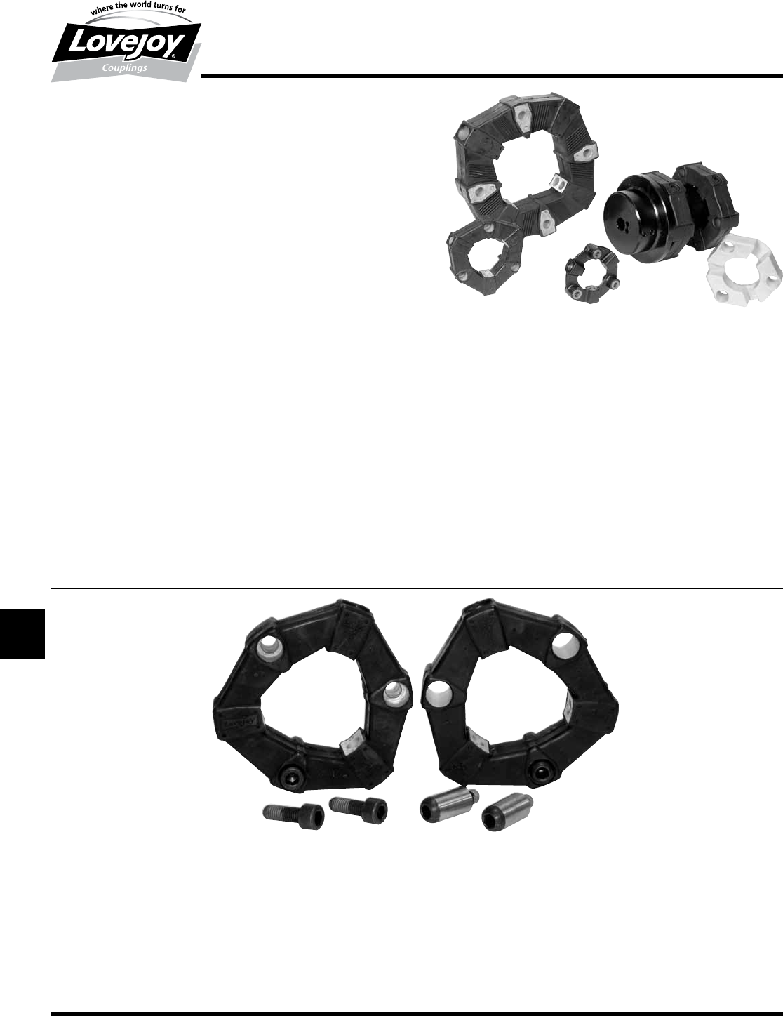
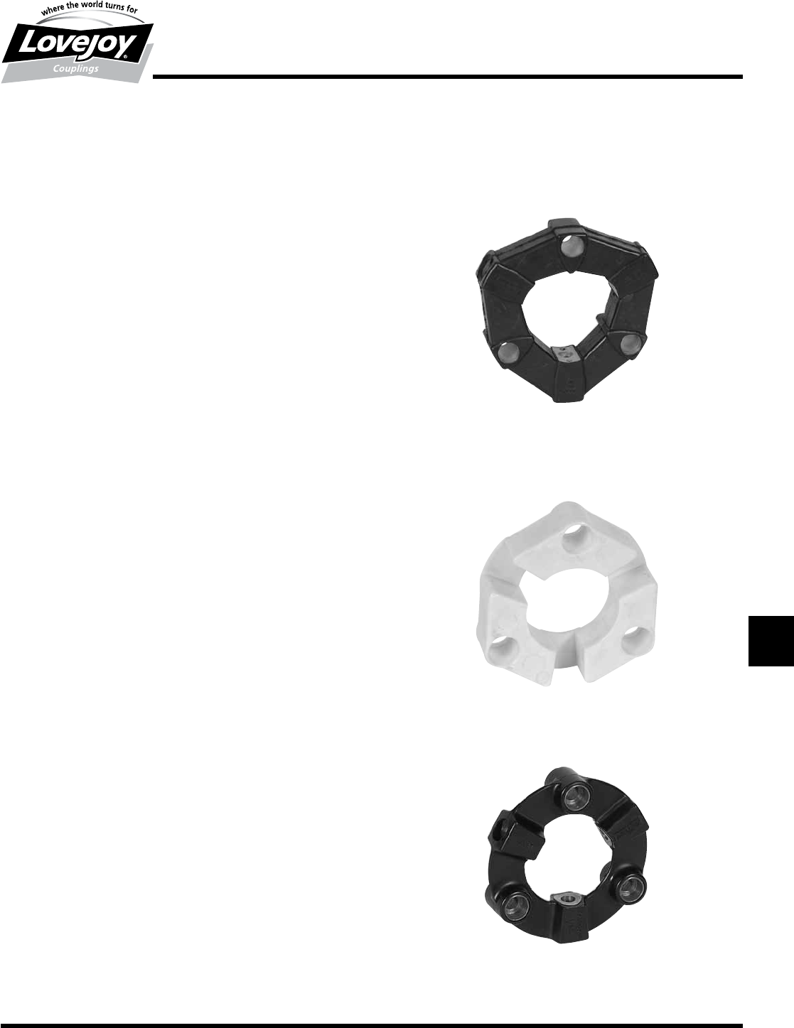
LF Series Torsional Coupling
The■LF■Series■coupling■is■designed■with■a■unique■and■highly■versatile■elastomeric■
element.■These■can■be■easily■integrated■into■a■variety■of■coupling■configurations■
to■meet■several■application■needs.■■LF■Style■elements■are■available■in■a■variety■of■
materials■to■match■the■necessary■coupling■dampening■characteristics■for■tuning■the■
systems■critical■speed■away■from■the■application■operating■speed.■■The■element■
can■be■connected■axially■to■a■flywheel■adapter■plate■or■flanged■hub■and■radially■to■
a■cylindrical■center■hub■using■the■appropriate■bolts.■■Axial■bolt■styles■include■either■
socket■head■bolts■with■a■special■dry■adhesive,■or■S-Style■bolts,■which■are■similar■to■
dowel■pins■(seen■picture■below).■■The■radial■bolts■are■used■to■connect■the■element■
to■the■cylindrical■hub.■This■unique■design■is■remarkably■simple,■highly■effective■and■
gives■the■LF■torsional■coupling■unmatched■performance■capabilities.■■The■coupling■
selection■should■be■verified■with■a■Torsional■Vibration■Analysis■(TVA)■of■the■system.■
The■information■required■to■perform■a■TVA■can■be■found■in■the■Coupling■Selection■
Worksheet■on■page■T-10.
■■Wide■range■of■standard■designs■and■materials
■■Application■versatility
■■Shaft■to■shaft■or■flywheel■to■shaft■designs
■■Designed■to■accommodate■substantial■shock■loads,■vibration,■and■
misalignment
■■Low■moment■of■inertia
■■Electrically■insulating
■■No■lubrication,■maintenance■free
■■Unique■air-flow■cooling■design
■■Different■element■stiffness■values■allow■for■torsional■tuning■of■
applications■with■diesel■engines
■■Economic■design■allows■for■cost■effective■solutions■for■torsional■
applications
■■Proven■L-LOC■spline-clamping■hub■virtually■eliminates■spline■shaft■
profile■wear■and■“fretting”
■■Oil,■heat,■and■corrosion■resistant■elements■(Hytrel®,■Zytel®)
■■When■used■with■S-bolts,■the■coupling■can■accommodate■some■end■
float.
■■S-bolts■accommodate■applications■requiring■“blind”■assembly
■■Model■6■unique■spacer■designs■span■gaps■between■equipment■in■
excess■of■the■normal■equipment■separation
■■Model■6■design■available■with■bearings■for■high■speeds■and■large■
amounts■of■equipment■separation
Features
Lovejoy’s■LF■product■line■supports■both■standard■style■elements■(above■left)■and■the■S-Style■elements■(above■right).■■The■standard■style■elements■bolt■to■the■
cylindrical■(center)■hub■and■the■flywheel,■flywheel■adapter,■or■flange■hub.■■The■S-Style■utilizes■bolts■which■look■like■dowel■pins■and■are■designed■for■“blind”■
installations,■where■the■axial■bolts■may■not■be■accessible■for■tightening■during■the■installation■process.■■One■application■would■be■inside■a■bell■housing■when■all■
the■components■are■assembled■and■the■bolts■cannot■be■reached.■■The■S-Style■bolts■also■accommodate■a■small■amount■of■end■float■when■necessary■to■prevent■
unnecessary■axial■stress■on■the■element.■■■When■looking■to■replace■elements,■please■note■the■difference■in■the■axial■holes.■■The■standard■elements■have■
stepped■holes■to■accommodate■the■cap■screws■(above■left)■which■are■used■to■mount■the■element.■■The■S-Style■elements■have■straight■holes■(above■right)■to■
accommodate■the■S-Style■pins.
Further■installation■instructions■can■be■found■at■www.lovejoy-inc.com■in■the■Technical■Resources■section.
Standard S-Style
JWJISCJSFMCGHPGDD
T
SPUJVSDRSLDED
JW JIS CJ SF MC G HP GD D T SP UJ VSD R SLD ED
271
www.lovejoy-inc.com T-13
Torsional
LF Series – Elements
Overview
LF Series Torsional Elements
The■focus■of■any■coupling■is■the■flexible■elements,■or■the■“working■component”.■
The■element■must■effectively■absorb■the■shock■loads,■misalignment■forces,■
and■torsional■vibrations,■under■a■variety■of■environmental■conditions.■The■
following■materials■are■used■to■accommodate■the■different■conditions■and■
environments■where■the■couplings■are■used.
High Temperature Rubber (HTR)
There■are■two■different■rubber■element■materials■available,■High■Temperature■
Rubber■(HTR)■and■Neoprene■(CR).■Both■elements■are■torsionally■soft■and■
are■placed■into■compression■during■assembly.■Rubber■under■compression■
can■carry■up■to■5■times■the■amount■of■torque■as■non-compressed■elements.■
The■elements■effectively■accommodate■shock,■misalignment,■and■vibration■
plus■minimize■harmful■radial■and■axial■forces■on■the■connected■equipment.■
Neoprene■(CR)■is■used■in■environments■that■are■hostile■to■High■Temperature■
Rubber■(HTR).
Available■Durometer■Hardness■:■ 50,■60■(Shore■A■scale)
Operating■Temperature■Range:■ HTR:■■■ -40°■to■194°■F■■
■ CR:■ -40°■to■175°■F
Maximum■Angular■Misalignment:■ Up■to■3°
Hytrel®
Elements■made■of■DuPont’s■Hytrel®■elastomer■compound■are■torsionally■
much■stiffer■than■natural■rubber■(20■times■stiffer)■and■were■developed■for■
combustion■engine■/■hydraulic■pump■applications.■Hytrel®■elements■have■20%■
greater■torque■capacity■as■compared■to■rubber■elements.■The■torsionally■stiff■
Hytrel®■element■moves■the■harmful■vibration■resonance■frequency■above■the■
operating■RPM■range.■The■element■design■also■reduces■harmful■radial■and■
axial■reactionary■forces.
Operating■Temperature■Range:■ -60°■to■250°■F
Maximum■Angular■Misalignment:■ 0.25°
Zytel®
Elements■made■of■DuPont’s■highly■stressable■Zytel®■elastomeric■compound■
have■excellent■chemical■compatibility■and■corrosion■resistance.■The■element■
composition■is■3-times■stiffer■then■Hytrel®■elements.■Zytel®■elements■exhibit■
less■than■1°■wind■up■at■normal■torque■and■zero■backlash.■Most■suited■for■
applications■where■heat,■moisture,■high■torque■/■high■speed,■and■corrosion■
resistance■are■critical■factors■in■the■coupling■selection.
Operating■Temperature■Range:■ -40°■to■300°■F
Maximum■Angular■Misalignment:■ 1°
HTR
Hytrel®
Zytel®
JWJISCJSFMCGHPGDDTSPUJVSDRSLDED
JW JIS CJ SF MC G HP GD D
T
SP UJ VSD R SLD ED
272 630-852-0500
T-14
Torsional
LF Series – Base Element, Models 1, 1/S, 2 and 2/S
Selection Data
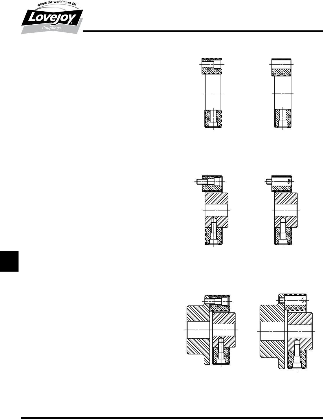
The■following■are■standard■LF■Series■torsional■coupling■models.■The■
simple,■unique■design■permits■a■wide■range■of■models■from■common■
components■to■meet■each■application■requirement.■
Base Element
The■heart■of■the■LF■Series■coupling■is■the■flexible■base■element.■This■
element■allows■the■customer■to■make■their■own■shaft■hubs■from■steel■bar■
stock■or■use■existing■hubs.■Ideal■for■quick■prototype■testing,■retrofit■and■high■
volume■applications.■
■
Model 1 and 1/S
Consists■of■the■flexible■base■element■with■a■simple■steel■cylindrical■hub.■
The■1/S■is■shown■with■the■S-Style■axial■screw■(similar■to■a■dowel)■for■quick■
blind■assembly■of■the■drive■package.■The■same■combinations■available■in■
Model■1■are■also■available■in■the■Model■1/S.
■
Model 2 and 2/S
Provides■a■complete■shaft-to-shaft■coupling■in■a■range■of■sizes■for■
all■industrial■power■transmission■applications.■It■is■similar■to■Model■1■
shown■above,■except■a■flanged■hub■is■added■to■make■the■shaft■to■shaft■
connection.
Model■2/S■allows■the■drive■package■to■be■“blind”■connected.■As■with■all■
S-Style■models,■axial■end■float■of■equipment■shafts■can■be■accommodated■
without■harmful■push-pull■force.
Standard
Base Element
Model 1
Model 2
S-Style
Base Element
Model 1/S
Model 2/S
JWJISCJSFMCGHPGDD
T
SPUJVSDRSLDED
JW JIS CJ SF MC G HP GD D T SP UJ VSD R SLD ED
273
www.lovejoy-inc.com T-15
Torsional
LF Series – Models 3, 3/S, 6, 6/S and 6B
Selection Data
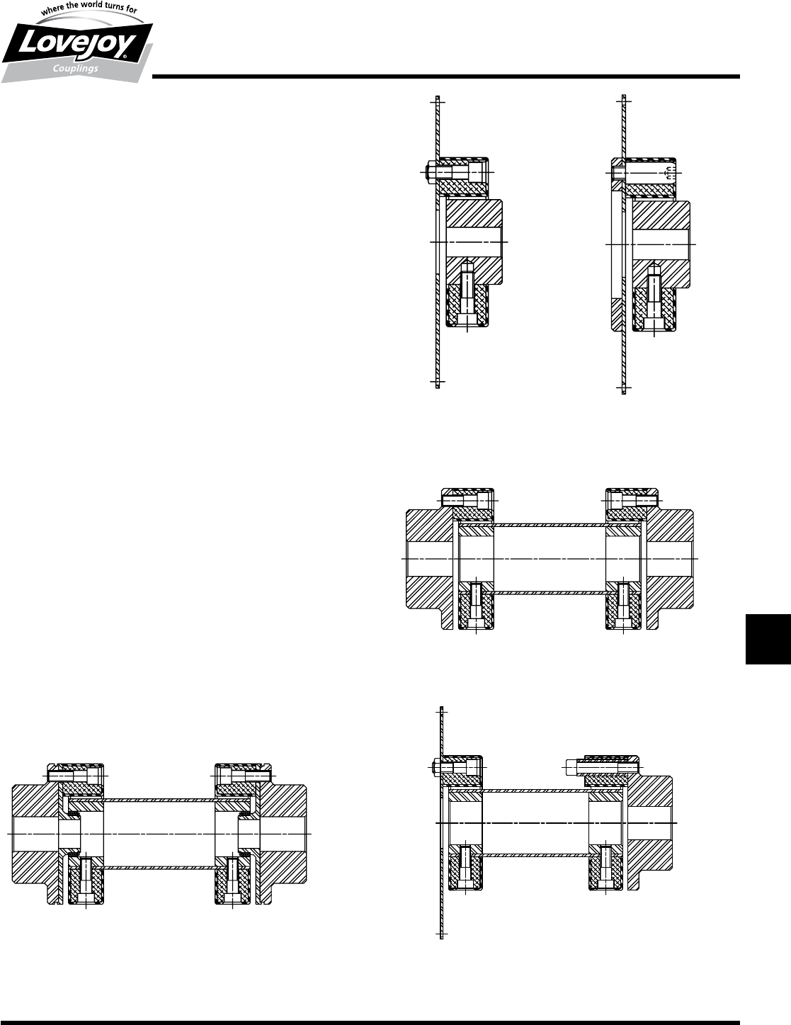
Model 3 and 3/S
A■Model■1■or■1/S■with■the■addition■of■an■engine■mounting■plate■
becomes■a■Model■3■or■3/S.■It■is■available■in■standard■SAE■
flywheel■sizes■as■well■as■made-to-order■sizes.■The■standard■
cylindrical■hub■is■available■in■a■variety■of■ANSI■(SAE),■DIN,■JIS,■
and■agricultural■spline■bores■for■hydraulic■pumps■and■other■
applications.■Various■standard■flexible■element■materials■are■
available■for■specific■torsional,■misalignment■and■environmental■
requirements.
Model 6, 6/S and 6B
The■Model■6■is■available■with■floating■shafts■at■customer■specified■
assembly■lengths,■with■special■corrosion■and■heat■resistant■elements■
and■materials.■This■model■surpasses■all■other■floating■shaft■designs■
in■assembly,■simplicity■and■reliability.■Model■6/S■accommodates■
free■endplay■without■harmful■push-pull■reaction■forces.■Model■6/B■is■
a■highly■elastic■floating■shaft■coupling■with■accurate,■maintenance■
free■centering■flanges■for■applications■with■long■spans■and■high■
misalignment■and■or■speed■requirements.
Model 3 Model 3/S
Model 6
Model 6B Model 6 and 6/S
JWJISCJSFMCGHPGDDTSPUJVSDRSLDED
JW JIS CJ SF MC G HP GD D
T
SP UJ VSD R SLD ED
274 630-852-0500
T-16
Torsional
LF Series
Performance Data
LF Series Performance Data
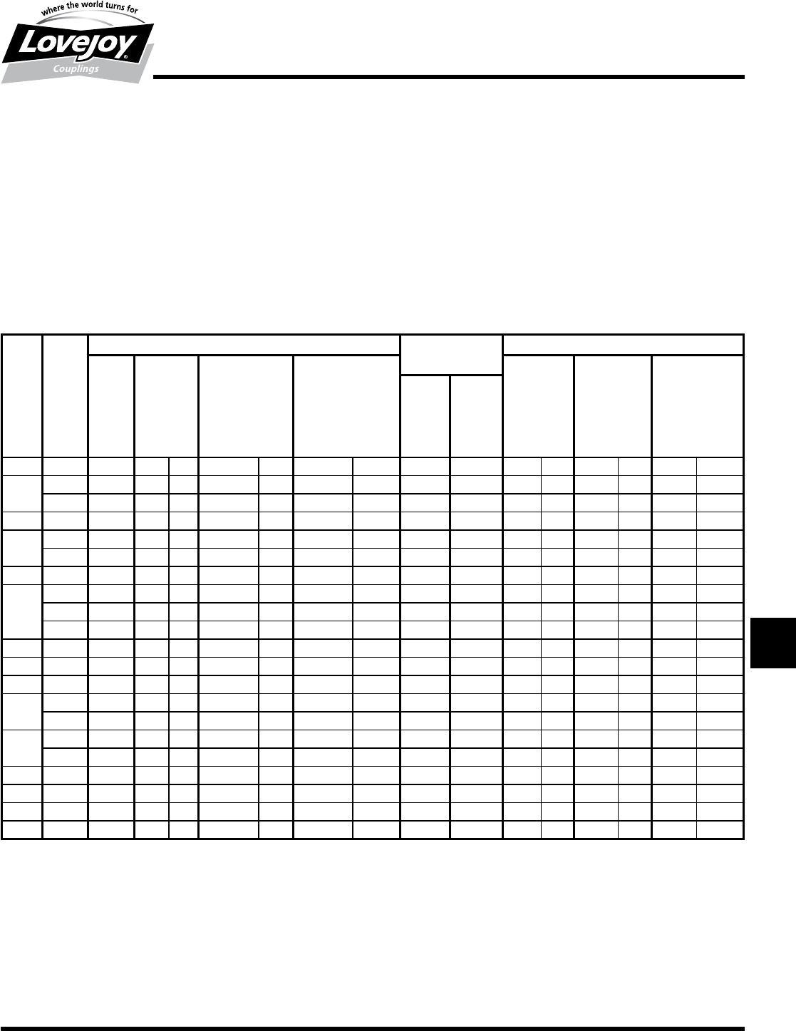
Element Nominal Maximum Max Allowable Dynamic Torsional Stiffness CTdyn
Material Torque Torque Speed Continuous Rubber 60 Shore Rubber 50 Shore Hytrel® 1 Zytel®
TKN TKmax Nmax Vibratory Trq (Standard) (Optional)
TKW
Size in-lb Nm in-lb Nm RPM in-lb Nm in-lb/rad Nm/rad in-lb/rad Nm/rad in-lb/rad Nm/rad in-lb/rad Nm/rad
LF1 HTR ■90■ ■10 ■200■ ■25 10,000 44 ■5 ■1,240■ ■140 ■800■ ■90 — — — —
LF2
HTR ■180■ ■20 ■530■ ■60 8,000 89 ■10 ■2,570■ ■290 ■1,600■ ■180 — — — —
Zytel®■265■ ■30 ■530■ ■60 10,000 N/A N/A — — — — — — ■55,150■ 6■230
LF4 HTR ■440■ ■50 ■1,100■ ■125 7,000 180 ■20 ■7,500■ ■850 ■4,870■ ■550 — — — —
LF8
HTR ■885■ ■100 ■2,480■ ■280 6,500 355 ■40 ■13,300■ 1■500 ■7,970■ ■900 — — — —
Zytel®■1,060■ ■120 ■2,480■ ■280 7,000 N/A N/A — — — — — — ■414,370■ 46■820
LF12 HTR ■1,240■ ■140 ■3,190■ ■360 6,500 440 ■50 ■38,900■ 4■400 ■23,900■ 2■700 — — — —
LF16
HTR ■1,770■ ■200 ■4,960■ ■560 6,000 710 ■80 ■30,100■ 3■400 ■17,700■ 2■000 — — — —
Hytrel®■1,770■ ■200 ■4,960■ ■560 5,500 N/A N/A — — — — ■320,000 36■000 — —
Zytel®■2,120■ ■240 ■4,960■ ■560 6,000 N/A N/A — — — — — — ■654,800■ 74■000
LF22 HTR ■2,430■ ■275 ■6,640■ ■750 6,000 885 ■100 ■79,600■ 9■000 ■54,000■ 6■100 — — — —
LF25 HTR ■2,790■ ■315 ■7,740■ ■875 5,000 1,100 ■125 ■39,800■ 4■500 ■4,800■ 2■800 — — — —
LF28 HTR ■3,700 ■420 ■10,600■ 1■200 5,000 1,330 ■150 ■106,200■ 12■000 ■66,400■ 7■500 — — — —
LF30
HTR ■4,400■ ■500 ■12,400■ 1■400 4,000 1,770 ■200 ■69,000■ 7■800 ■42,500■ 4■800 — — — —
Hytrel®■4,400■ ■500 ■12,400■ 1■400 4,000 N/A N/A — — — — ■780,000 88■000 — —
LF50
HTR ■6,200■ ■700 ■18,600■ 2■100 4,000 2,650 ■300 ■168,100■ 19■000 ■106,200■ 12■000 — — — —
Hytrel®■7,100■ ■800 ■17,700■ 2■000 4,000 N/A N/A — — — — 2,300,000 262■000 — —
LF80 HTR ■7,960■ ■900 ■18,600■ 2■100 4,000 2,830 ■320 ■221,200■ 25■000 ■141,600■ 16■000 — — — —
LF90 HTR ■9,700■ 1■100 ■27,900■ 3■150 3,600 3,980 ■450 ■141,600■ 16■000 ■92,900■ 10■500 — — — —
LF140 HTR ■15,000■ 1■700 ■43,400■ 4■900 3,600 6,200 ■700 ■354,000■ 40■000 ■234,500■ 26■500 — — — —
LF250 HTR ■26,500■ 3■000 ■77,400■ 8■750 3,000 11,000 1■250 ■592,900■ 67■000 ■380,500■ 43■000 — — — —
Notes:■■ n■■1■indicates:■For■Hytrel,■dynamic■torsional■stiffness■values■are■non-linear■with■respect■to■torque.■■Value■given■is■for■100%■of■nominal■torque.■
■n■■■N/A■indicates:■Not■Applicable.
■n■■■HTR■is■High■Temperature■Rubber.
JWJISCJSFMCGHPGDD
T
SPUJVSDRSLDED
JW JIS CJ SF MC G HP GD D T SP UJ VSD R SLD ED
275
www.lovejoy-inc.com T-17
Torsional
LF Series
Performance Data
Notes:■■ n■■■*■indicates:■Angular■and■parallel■misalignment■values■are■dependent■on■speed,■and■for■rubber■elements,■should■be■adjusted■according■to■figure■4■on■
page■T-9.■Hytrel®■elements■are■only■for■applications■where■the■driven■component■is■piloted■to■the■driver■for■SAE■and■DIN■established■alignments■(i.e.■
Hydraulic■pump■flange-mounted■to■engine■flywheel■housing).
■n■■■**■■indicates:■The■“S-Style”■design■is■not■constrained■axially■and■allows■the■hubs■to■move■apart■without■creating■axial■force■on■the■connected■
equipment.
■n■■■N/A■indicates:■Not■Applicable.
■n■■■Hytrel®■elements■are■only■for■applications■where■the■driven■component■is■piloted■to■the■driver■for■essentially■perfect■alignment■(hydraulic■pump■
flange-mounted■to■engine■housing).
■n■■■Special■length■S-Style■fastener■sleeves■can■further■increase■the■allowable■end■float.
■n■■■HTR■is■High■Temperature■Rubber.
LF Series Performance Data Continued
Element Max Allowable Misalignment* Wind Up Static Stiffness
Material Angular Parellel Axial (End Float) Axial (End Float) (angle of twist) Axial CaRadial CrAngular Cw
∆Kw∆Kr Standard S-Style** at at
∆KaNominal Maximum
Torque Torque
Size Degrees in mm in mm in mm Degrees Degrees lb/in N/mm lb/in N/mm in-lb/deg Nm/deg
LF1 HTR 3.00 0.060 1.5 +/-0.08 +/-2 +0.18■/■-0.08 +4.6■/■-2 6 17.0 ■220■ ■38 ■860■ ■150 2.66 0.3
LF2
HTR 3.00 0.060 1.5 +/-0.12 +/-3 +0.12■/■-0.12 +3■/■-3 6 17.0 ■130■ ■22 ■860■ ■150 2.66 0.3
Zytel®1.00 0.004 0.1 +/-0.02 +/-0.5 +0.12■/■-0.02 +3■/■-0.5 — — — — — — — —
LF4 HTR 3.00 0.060 1.5 +/-0.12 +/-3 +0.17■/■-0.12 +4.3■/■-3 5 ■12.0 ■430■ ■75 ■2,860■ ■500 21.30 2.4
LF8
HTR 3.00 0.080 2.0 +/-0.16 +/-4 +0.20■/■-0.16 +5■/■-4 5 14.0 ■430■ ■75 ■2,860■ ■500 31.90 3.6
Zytel®1.00 0.004 0.1 +/-0.02 +/-0.5 +0.20■/-0.02 +5■/■-0.5 — — — — — — — —
LF12 HTR 2.00 0.080 2.0 +/-0.12 +/-3 +0.20■/-0.16 +5■/■-4 3 7.5 ■1,430■ ■250 ■5,710■ 1■000 80.00 9.0
LF16
HTR 3.00 0.080 2.0 +/-0.20 +/-5 +0.23■/■-0.20 +5.8■/■-5 5 14.0 ■570■ ■100 ■2,860■ ■500 44.00 5.0
Hytrel®0.25 0.000 0.0 +0.12■/■-0.08 +3■/■-2 N/A N/A — — — — — — — —
Zytel®1.00 0.004 0.1 +/-0.02 +/-0.5 +0.23■/-0.02 +5.8■/■-0.5 — — — — — — — —
LF22 HTR 2.00 0.080 2.0 +/-0.12 +/-3 +0.23■/-0.20 +5.8■/■-5 3 7.5 ■2,860■ ■500 ■7,420■ 1■300 106.00 12.0
LF25 HTR 3.00 0.080 2.0 +/-0.20 +/-5 +0.26■/■-0.20 +6.6■/■-5 5 14.0 ■800■ ■140 ■3,400■ ■600 62.00 7.0
LF28 HTR 2.00 0.080 2.0 +/-0.12 +/-3 +0.26■/■-0.20 +6.6■/■-5 3 7.5 ■3,140■ ■550 ■8,000■ 1■400 150.00 17.0
LF30
HTR 3.00 0.080 2.0 +/-0.20 +/-5 +0.26■/■-0.20 +6.6■/■-5 5 14.0 ■1,090■ ■190 ■4,280■ ■750 80.00 9.0
Hytrel®0.25 0.000 0.0 +0.12■/■-0.08 +3■/■-2 N/A N/A — — — — — — — —
LF50
HTR 3.00 0.080 2.0 +/-0.20 +/-5 +0.26■/■-0.20 +6.6■/■-5 3 7.5 ■3,700■ ■650 ■12,600■ 2■200 230.00 26.0
Hytrel®0.25 0.000 0.0 +0.12■/■-0.08 +3■/■-2 N/A N/A — — — — — — — —
LF80 HTR 2.00 0.060 1.5 +/-0.20 +/-5 +0.26■/■-0.12 +6.6■/■-3 3 7.5 ■4,850■ ■850 ■16,600■ 2■900 300.00 34.0
LF90 HTR 3.00 0.080 2.0 +/-0.20 +/-5 +0.34■/■-0.20 +8.6■/■-5 5 14.0 ■1,260■ ■220 ■5,700■ 1■000 150.00 17.0■
LF140 HTR 2.00 0.080 2.0 +/-0.20 +/-5 +0.34■/■-0.20 +8.6■/■-5 3 7.5 ■3,700■ ■650 ■13,100■ 2■300 336.00 38.0
LF250 HTR 2.00 0.080 2.0 +/-0.20 +/-5 +0.40■/■-0.20 +10■/■-5 3 7.5 ■6,570■ 1■150 ■23,400■ 4■100 600.00 68.0
JWJISCJSFMCGHPGDDTSPUJVSDRSLDED
JW JIS CJ SF MC G HP GD D
T
SP UJ VSD R SLD ED
276 630-852-0500
T-18
Torsional
LF Series – Base Element and Model 1
Dimensional Data
Base Element (HTR)
Model 1 (HTR)
Base Element (Hytrel®)
Model 1 (Hytrel®)
Base Element (Zytrel®)
Model 1 (Zytel®)
Note:■■ n■■HTR■is■High■Temperature■Rubber.
JWJISCJSFMCGHPGDD
T
SPUJVSDRSLDED
JW JIS CJ SF MC G HP GD D T SP UJ VSD R SLD ED
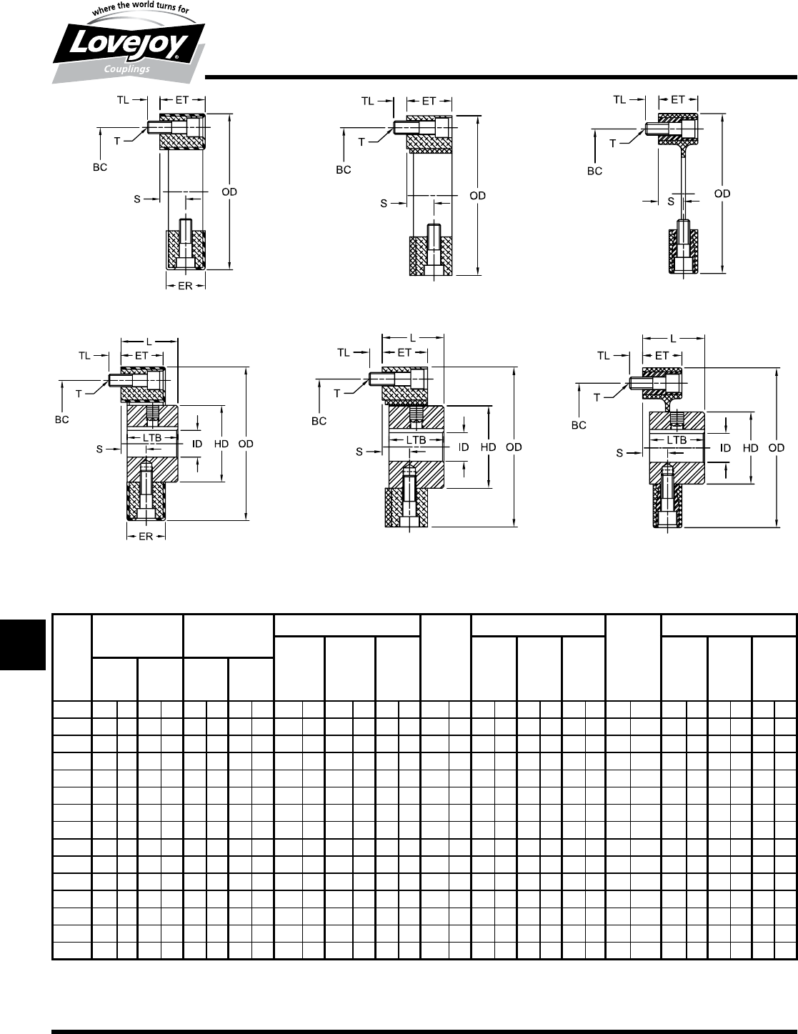
LF Series Base Element and Model 1 Dimensional Data
ID 1 ID 2 OD FOD ET OAL L
(Cylindrical Hub) (Flange Hub) HTR Hytrel®Zytel®HTR Hytrel®Zytel®HTR Hytrel®Zytel®
Min Bore Max Bore Min Bore Max Bore
Size in mm in mm in mm in mm in mm in mm in mm in mm in mm in mm in mm in mm in mm in mm in mm
LF1 0.31 8 0.63 19 0.31 8 0.88 25 2.20 56 — — — — 2.20 56 0.94 24 — — — — 1.97 50.0 1.02 26 — — — —
LF2 0.44 10 0.88 26 0.50 12 1.38 38 3.35 85 — — 3.48 32 3.35 85 0.94 24 — — 0.94 32 2.36 60.0 1.26 32 — — 1.26 32.0
LF4 0.47 12 1.00 30 0.63 15 1.75 45 3.94 100 — — — — 3.94 100 1.10 28 — — — — 2.52 64.0 1.34 34 — — — —
LF8 0.50 12 1.38 38 0.75 18 2.00 55 4.72 120 — — 4.92 45 4.72 120 1.26 32 — — 1.18 45 3.46 88.0 1.81 46 — — 1.77 45.0
LF12 0.50 12 1.38 38 0.75 18 2.00 55 4.80 122 — — — — 4.72 120 1.26 32 — — — — 3.46 88.0 1.81 46 — — — —
LF16 0.63 15 1.63 48 0.81 20 2.63 70 5.91 150 6.10 155 6.10 53 5.91 150 1.65 42 1.69 58 1.38 53 4.17 106.0 2.20 56 2.28 58 2.08 53.0
LF22 0.63 15 1.63 48 0.81 20 2.63 70 5.91 150 — — — — 5.91 150 1.65 42 — — — — 4.17 106.0 2.20 56 — — — —
LF25 0.63 15 2.13 55 0.81 20 2.75 85 6.69 170 7.17 182 — — 6.69 170 1.81 46 1.85 62 — — 4.57 116.0 2.40 61 2.44 62 — —
LF28 0.63 15 2.13 55 0.81 20 2.75 85 6.69 170 — — — — 6.69 170 1.81 46 — — — — 4.57 116.0 2.40 61 — — — —
LF30 0.81 20 2.44 65 1.00 25 3.75 100 7.87 200 8.07 205 — — 7.87 200 2.28 56 2.28 76 — — 5.51 140.0 2.91 74 2.99 76 — —
LF50 0.81 20 2.44 65 1.00 25 3.75 100 7.87 200 8.07 205 — — 7.87 200 2.28 56 2.28 76 — — 5.51 140.0 2.91 74 2.99 76 — —
LF80 0.81 20 2.44 65 1.00 25 3.75 100 8.07 205 — — — — 7.87 200 2.56 65 — — — — 5.51 141.5 2.97 76 — — — —
LF90 1.19 30 3.35 85 1.19 30 4.25 110 10.24 260 — — — — 10.24 260 2.76 70 — — — — 6.61 168.0 3.46 88 — — — —
LF140 1.19 30 3.35 85 1.19 30 4.25 110 10.24 260 — — — — 10.24 260 2.76 70 — — — — 6.61 168.0 3.46 88 — — — —
LF250 1.63 40 4.25 105 1.63 40 5.00 130 13.38 340 — — — — 13.38 340 3.34 84 — — — — 8.18 208.0 4.25 108 — — — —
277
www.lovejoy-inc.com T-19
Torsional
LF Series – Models 1/S, 2 and 2/S
Dimensional Data
Model 1S (HTR) Model 2 (HTR)
Model 2 (Hytrel®)Model 2/S (HTR) Model 2 (Zytel®)
LF Series Base Element and Model 1 Dimensional Data Continued
LTB HD FD FW BE S* ER** R BC T TS TL
(+/-0.11) (+/-3) Axial HTR Zytel®
Hole
and
Size in mm in mm in mm in mm in mm in mm in mm in mm in mm Division in mm in mm in mm
LF1 0.94 24 1.18 30 1.44 36 0.27 7 0.08 2 — — 0.87 22 0.43 11.0 1.73 44 2@180° ■■M6 0.39 10 — — 0.28 7
LF2 1.10 28 1.57 40 2.17 55 0.31 8 0.16 4 — — 0.79 20 0.39 10.0 2.68 68 2@180° ■■M8 0.55 14 0.59 15 0.31 8
LF4 1.18 30 1.77 45 2.56 65 0.31 8 0.16 4 — — 0.94 24 0.47 12.0 3.15 80 3@120° ■■M8 0.55 14 — — 0.31 8
LF8 1.65 42 2.36 60 3.15 80 0.39 10 0.16 4 — — 1.10 28 0.55 14.0 3.94 100 3@120° M10 0.67 17 0.75 19 0.39 10
LF12 1.65 42 2.36 60 3.15 80 0.39 10 0.16 4 — — 1.10 28 0.55 14.0 3.94 100 4@■■90° M11 0.67 17 — — 0.39 10
LF16 1.97 50 2.76 70 3.94 100 0.47 12 0.24 6 1.02 26 1.42 36 0.71 18.0 4.92 125 3@120° M12 0.75 19 0.86 22 0.47 12
LF22 1.97 50 2.76 70 3.94 100 0.47 12 0.24 6 — — 1.42 36 0.71 18.0 4.92 125 4@■■90° M12 0.75 19 — — 0.47 12
LF25 2.16 55 3.35 85 4.53 115 0.55 14 0.24 6 1.06 27 1.57 40 0.79 20.0 5.51 140 3@120° M14 0.86 22 — — 0.55 14
LF28 2.16 55 3.35 85 4.53 115 0.55 14 0.24 6 — — 1.57 40 0.79 20.0 5.51 140 4@■■90° M14 0.86 22 — — 0.55 14
LF30 2.60 66 3.94 100 5.51 140 0.63 16 0.31 8 1.38 35 1.97 50 0.98 25.0 6.50 165 3@120° M16 0.98 25 — — 0.63 16
LF50 2.60 66 3.94 100 5.51 140 0.63 16 0.31 8 1.38 35 1.99 50 0.98 25.0 6.50 165 4@■■90° M16 0.98 25 — — 0.63 16
LF80 2.60 66 3.94 100 5.51 140 0.63 16 0.31 8 — — 2.40 61 1.20 30.5 6.50 165 4@■■90° M16 0.98 25 — — 0.63 16
LF90 3.15 80 4.92 125 6.30 160 0.75 19 0.31 8 — — 2.44 62 1.22 31.0 8.46 215 3@120° M20 1.26 32 — — 0.79 20
LF140 3.15 80 4.92 125 6.30 160 0.75 19 0.31 8 — — 2.44 62 1.22 31.0 8.46 215 4@■■90° M20 1.26 32 — — 0.79 20
LF250 3.94 100 6.30 160 7.68 195 0.75 19 0.31 8 — — 3.03 77 0.89 22.5 11.02 280 4@■■90° M20 1.26 32 — — 0.79 20
Notes:■■ n■■■*■indicates:■Dimenstion■S■for■Hytrel®■only.
■n■■■**■indicates:■Dimension■ER■for■HTR■(rubber)■only.
■n■■■■Dimensions■for■basic■Models■1,■2,■3■and■6.
■n■■HTR■is■High■Temperature■Rubber.
JWJISCJSFMCGHPGDDTSPUJVSDRSLDED
JW JIS CJ SF MC G HP GD D
T
SP UJ VSD R SLD ED
278 630-852-0500
T-20
Torsional
LF Series – Models 3 and 3/S
Dimensional Data
Notes:■■ n■■■*■indicates:■Dimension■ER■for■HTR■(rubber)■only.
■n■■■HTR■is■High■Temperature■Rubber.
Model 3 (HTR) Model 3/S (HTR)
Model 3 and 3/S (Zytel®)Model 3 (Hytrel®)
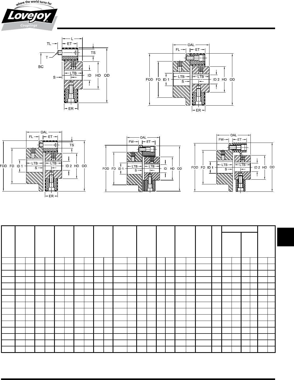
LF Series Flywheel Models 3 and 3/S Dimensional Data
ID OD ET TL L W
Min Max HTR Hytrel®Zytel®HTR Hytrel®Zytel®HTR Hytrel®Zytel®
Size in mm in mm in mm in mm in mm in mm in mm in mm in mm in mm in mm in mm in mm
LF1 0.31 8 0.63 19 2.20 56 — — — — 0.94 24 — — — — 0.28 7 1.02 26.0 — — — — — —
LF2 0.44 10 0.88 26 3.35 85 — — 3.48 88 0.94 24 — — 0.94 24 0.31 8 1.26 32.0 — — 1.26 32 — —
LF4 0.47 12 1.00 30 3.94 100 — — — — 1.10 28 — — — — 0.31 8 1.34 34.0 — — — — — —
LF8 0.50 12 1.38 38 4.72 120 — — 4.92 125 1.26 32 — — 1.18 30 0.39 10 1.81 46.0 — — 1.77 45 0.19 5
LF12 0.50 12 1.38 38 4.80 122 — — — — 1.26 32 — — — — 0.39 10 1.81 46.0 — — — — 0.19 5
LF16 0.63 15 1.63 48 5.91 150 6.10 155 6.10 155 1.65 42 1.69 43 1.38 36 0.47 12 2.20 56.0 2.28 58 2.08 53 0.19 5
LF22 0.63 15 1.63 48 5.91 150 — — — — 1.65 42 — — — — 0.47 12 2.20 56.0 — — — — 0.19 5
LF25 0.63 15 2.13 55 6.69 170 — — — — 1.81 46 — — — — 0.55 14 2.40 61.0 — — — — 0.19 5
LF28 0.63 15 2.13 55 6.69 170 — — — — 1.81 46 — — — — 0.55 14 2.40 61.0 — — — — 0.19 5
LF30 0.81 20 2.44 65 7.87 200 8.07 205 — — 2.28 58 2.28 58 — — 0.63 16 2.91 74.0 2.99 76 — — 0.19 5
LF50 0.81 20 2.44 65 7.87 200 8.07 250 — — 2.28 58 2.28 58 — — 0.46 12 2.91 74.0 2.99 76 — — 0.19 5
LF80 0.81 20 2.44 65 8.07 205 — — — — 2.56 65 — — — — 0.63 16 2.97 75.5 — — — — 0.19 5
LF90 1.19 30 3.35 85 10.24 260 — — — — 2.76 70 — — — — 0.79 20 3.46 88.0 — — — — 0.19 5
LF140 1.19 30 3.35 85 10.24 260 — — — — 2.76 70 — — — — 0.79 20 3.46 88.0 — — — — 0.19 5
LF250 1.63 40 4.25 105 13.38 340 — — — — 3.34 85 — — — — 0.79 20 4.25 108.0 — — — — 0.50 13
JWJISCJSFMCGHPGDD
T
SPUJVSDRSLDED
JW JIS CJ SF MC G HP GD D T SP UJ VSD R SLD ED
279
www.lovejoy-inc.com T-21
Torsional
LF Series – Models 3, 3/S and Flywheel Housings
Dimensional Data
Typical Flywheel Housing Combinations
SAE LF Series LK Series SAE J617C Flywheel Housing
J620D
Flywheel
Size Size Size 6 5 4 3 2 1
6.5 8■thru■28 100 s s
7.5 8■thru■28 100 l l
88■thru■30 100 s
10 8■thru■140 100,■125 l s s
11.5 16■thru■140 100,■125,■150,■150D l l s
14 28■thru■250 150,■UNIV l
18 250 UNIV l
Notes:■■ s■indicates:■Preferred■combinations.
■l ■indicates:■Optional■sizes■available.
Notes:■■ n■■■*■indicates:■Hytrel®■only.
■n■■HTR■is■High■Temperature■Rubber.
Notes:■■ n■■■SAE■J620■Flywheel■dimensions.
■n■■N/A■indicates:■Not■Applicable.
■n■■HTR■is■High■Temperature■Rubber.
LF Series Flywheel Models 3/S Dimensional Data
P FBC
SAE Pilot Bolt Circle Thru Holes LF Coupling Size for SAE
Flywheel Diameter Diameter Nominal Flywheel Sizes
HTR Hytrel® Zytel®
Size in mm in mm Qty Dia Model 3 & 3/S Model 3 Model 3
6.5 8.499 215.90 7.875 200.02 6 0.31 8,■16 8,■16 8,■16
7.5 9.499 241.30 8.750 222.25 8 0.31 8,■16 8,■16 8,■16
810.374 263.52 9.625 244.47 6 0.41 16,■25 6,■30 16,■25,■30
10 12.374 314.32 11.625 295.27 8 0.41 25,■30,■50,■90 30,■50 25,■30
11.5 13.874 352.42 13.125 333.37 8 0.41 30,■50,■90,■140,■250 50,■140,■250 30
14 18.374 466.72 17.250 438.15 8 0.53 90,■140,■250 140 N/A
16 20.374 517.50 19.250 488.95 8 0.53 250 250 N/A
LF Series Flywheel Models 3 and 3/S Dimensional Data Continued
LTB BE S* ER* R HD BC T TS
(±0.11) (+/-3) Axial HTR Zytel®
Hole
and
Size in mm in mm in mm in mm in mm in mm in mm Division in mm in mm
LF1 0.94 24 0.08 2 — — 0.87 22 0.43 11.0 1.18 30 1.73 44 2@180° M6 0.39 10 — —
LF2 1.10 28 0.16 4 — — 0.79 20 0.39 10.0 1.57 40 2.68 68 2@180° M8 0.55 14 0.59 15
LF4 1.18 30 0.16 4 — — 0.94 24 0.47 12.0 1.77 45 3.15 80 3@120° M8 0.55 14 — —
LF8 1.65 42 0.16 4 — — 1.10 28 0.55 14.0 2.36 60 3.94 100 3@120° M10 0.67 17 0.75 19
LF12 1.65 42 0.16 4 — — 1.10 28 0.55 14.0 2.36 60 3.94 100 4@■■90° M11 0.67 17 — —
LF16 1.97 50 0.24 6 1.02 26 1.42 36 0.71 18.0 2.76 70 4.92 125 3@120° M12 0.75 19 0.86 22
LF22 1.97 50 0.24 6 — — 1.42 36 0.71 18.0 2.76 70 4.92 125 4@■■90° M12 0.75 19 — —
LF25 2.16 55 0.24 6 1.06 27 1.57 40 0.79 20.0 3.35 85 5.51 140 3@120° M14 0.86 22 — —
LF28 2.16 55 0.24 6 — — 1.57 40 0.79 20.0 3.35 85 5.51 140 4@■■90° M14 0.86 22 — —
LF30 2.60 66 0.31 8 1.38 35 1.97 50 0.98 25.0 3.94 100 6.50 165 3@120° M16 0.98 25 — —
LF50 2.60 66 0.31 8 1.38 35 1.97 50 0.98 25.0 3.94 100 6.50 165 4@■■90° M16 0.98 25 — —
LF80 2.60 66 0.16 4 — — 2.40 61 1.20 30.5 3.94 100 6.50 165 4@■■90° M16 0.98 25 — —
LF90 3.15 80 0.31 8 — — 2.44 62 1.22 31.0 4.92 125 8.46 215 3@120° M20 1.26 32 — —
LF140 3.15 80 0.31 8 — — 2.44 62 1.22 31.0 4.92 125 8.46 215 4@■■90° M20 1.26 32 — —
LF250 3.94 100 0.31 8 — — 3.03 77 0.89 22.5 6.30 160 11.02 280 4@■■90° M20 1.26 32 — —
2.15 54.5
JWJISCJSFMCGHPGDDTSPUJVSDRSLDED
JW JIS CJ SF MC G HP GD D
T
SP UJ VSD R SLD ED
280 630-852-0500
T-22
Torsional
LF Series – Models 6, 6/S and 6B
Selection Process
Model 6 (HTR)
Model 6 (Zytel®)
Model 6 and 6/S (HTR)
Model 6B (HTR)
Model 6 and 6/S (Rubber Base Elements HTR and CR)
This■model■compensates■for■considerable■axial,■radial■and■angular■misalignment.■■
The■rubber■elements■torsionally■soft.■■Lengths■are■made■to■customer■requirements.■■
S-Style■axial■mounting■screws■allow■the■hubs■to■have■free■end■float■without■exerting■
axial■loads■on■the■connected■equipment,■while■allowing■for■quick■assembly.
Model 6 and 6/S (Zytel® Elements)
Elements■made■of■DuPont’s■super-tough,■corrosion■resistant■Zytel®■are■torsionally■
stiff■without■backlash,■with■less■than■1°■windup.■■Large■spans,■equal■to■all-metal■
couplings,■can■be■accommodated■without■internal■support■bearings■when■lightweight■
Zytel®■are■used.■■Hubs,■hardware■and■tubes■are■available■in■stainless■steel■or■with■
plating■and■corrosion■resistant■coatings.■■S-Style,■axial■mounting■screws■allow■for■free■
end-float■without■harmful■reactionary■forces.
Model 6B (HTR Elements)
Similar■to■Model■6■except■the■center■shaft■is■supported■by■internal■maintenance■
free■bearing■material.■■This■allows■greater■equipment■separation■and■high■
speeds,■as■well■as■high■angular■misalignment,■which■can■be■obtained■with■
rubber■elements.
The■drawing■at■the■lower■left■shows■one■of■the■many■special■designs■available.■■
A■standard■flywheel■adapter■plate■(see■model■3)■is■used■to■couple■to■a■diesel■
engine■flywheel.■■The■flanged■hub■on■the■other■end■is■supplied■with■extra■long■
S-Style■connecting■screws■(Notice■the■element■is■reversed■from■its■normal■
direction).■■This■arrangement■permits■extensive■axial■movement■(free■end■float)■
of■the■drive■package.
One■of■the■many■features■of■the■Model■6■is■the■center■floating■shaft■can■be■
radially■removed■without■displacing■the■coupled■machines.■■Flexible■elements■
may■be■pre-assembled■to■the■center■segment■and■then■final■assembled■to■the■
hubs■quickly,■with■little■hardware.
JWJISCJSFMCGHPGDD
T
SPUJVSDRSLDED
JW JIS CJ SF MC G HP GD D T SP UJ VSD R SLD ED
281
www.lovejoy-inc.com T-23
Torsional
LF Series – Models 6, 6/S and 6B
Dimensional Data
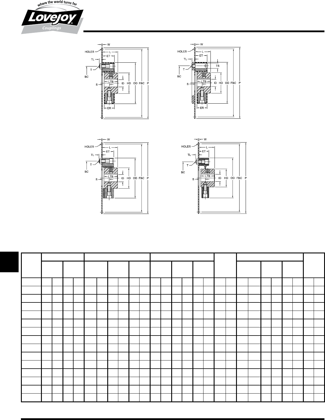
LF Series Models 6, 6/S and 6/B Dimensional Data
ID1 - ID2 OD BC
Nominal Torque Min Bore Max Bore Element Axial
HTR Zytel®HTR Zytel®Hole
and
Size in-lb Nm in-lb Nm in mm in mm in mm in mm in mm Division
LF1 90 ■10 — — 0.31 8 0.88 25 2.20 56 — — 1.73 44 2@180°
LF2 180 ■20 265 30 0.50 12 1.38 38 3.35 85 3.48 88 2.68 68 2@180°
LF4 440 ■50 — — 0.63 15 1.75 45 3.94 100 — — 3.15 80 3@120°
LF8 885 ■100 1,060 120 0.75 18 2.00 55 4.72 120 4.92 125 3.94 100 3@120°
LF12 1,240 ■140 — — 0.75 18 2.00 55 4.80 122 — — 3.94 100 4@■■90°
LF16 1,770 ■200 2,120 240 0.81 20 2.63 70 5.91 150 6.1 155 4.92 125 3@120°
LF22 2,430 ■275 — — 0.81 20 2.63 70 5.91 150 — — 4.92 125 4@■■90°
LF25 2,790 ■315 — — 0.81 20 2.75 85 6.69 170 — — 5.51 140 3@120°
LF28 3,700 ■420 — — 0.81 20 2.75 85 6.69 170 — — 5.51 140 4@■■90°
LF30 4,425 ■500 — — 1.00 25 3.75 100 7.87 200 — — 6.50 165 3@120°
LF50 6,195 ■700 — — 1.00 25 3.75 100 7.87 200 — — 6.50 165 4@■■90°
LF80 7,960 ■900 — — 1.00 25 3.75 100 8.07 205 — — 6.50 165 4@■■90°
LF90 9,735 1■100 — — 1.19 30 4.25 110 10.24 260 — — 8.46 215 3@120°
LF140 15,000 1■700 — — 1.19 30 4.25 110 10.24 260 — — 8.46 215 4@■■90°
LF250 26,500 3■000 — — 1.63 40 5.00 130 13.38 340 — — 11.02 280 4@■■90°
Note:■■ n■■■Refer■to■Speed■and■Length■Performance■Data■table■(page■T-24)■for■maximum■and■minimum■values.
LF Series Models 6, 6/S and 6/B Dimensional Data Continued
FOD LTB BSE S PT FW TD ET
Flange Hub Span HTR Zytel®
Size in mm in mm in mm in mm in mm in mm in mm in mm
LF1 2.20 56 0.94 24 * 0.51 13 0.20 5 0.28 7 1.18 30 0.94 24 — —
LF2 3.35 85 1.10 28 * 0.55 14 0.20 5 0.31 8 1.62 40 0.94 24 0.94 24
LF4 3.94 100 1.18 30 * 0.63 16 0.20 5 0.31 8 1.81 45 1.10 28 — —
LF8 4.72 120 1.65 42 * 0.71 18 0.20 5 0.39 10 2.38 60 1.26 32 1.18 30
LF12 4.80 120 1.65 42 * 0.71 18 0.20 5 0.39 10 2.38 60 1.26 32 — —
LF16 5.91 150 1.97 50 * 0.94 24 0.20 5 0.47 12 2.75 70 1.65 42 1.38 36
LF22 5.91 150 1.97 50 * 0.94 24 0.20 5 0.47 12 2.75 70 1.65 42 — —
LF25 6.69 170 2.16 55 * 1.02 26 0.20 5 0.55 14 3.38 85 1.81 46 — —
LF28 6.69 170 2.16 55 * 1.02 26 0.20 5 0.55 14 3.38 85 1.81 46 — —
LF30 7.87 200 2.60 66 * 1.30 33 0.20 5 0.63 16 4.00 100 2.28 58 — —
LF50 7.87 200 2.60 66 * 1.30 33 0.20 5 0.63 16 4.00 100 2.28 58 — —
LF80 8.07 200 2.60 80 * 1.36 35 0.20 5 0.63 16 4.00 100 2.56 65 — —
LF90 10.24 260 3.15 80 * 1.54 39 0.20 5 0.75 19 5.00 125 2.76 70 — —
LF140 10.24 260 3.15 100 * 1.54 39 0.20 5 0.75 19 5.00 125 2.76 70 — —
LF250 13.38 340 3.94 125 * 1.81 46 0.39 10 0.75 19 6.25 160 3.35 85 — —
Notes:■■ n■■■*■indicates:■■Contact■Lovejoy■Technical■Support■when■specifying■shaft■separation.
■n■■■Refer■to■Speed■and■Length■Performance■Data■table■(page■T-24)■for■maximum■and■minimum■values.
JWJISCJSFMCGHPGDDTSPUJVSDRSLDED
JW JIS CJ SF MC G HP GD D
T
SP UJ VSD R SLD ED
282 630-852-0500
T-24
LF Series Models 6 and 6/B Speed and Length Performance Data
BSE BSE
Maximum Speed Minimum Length Maximum Length
(short length only) (all versions) @ 1750 RPM
HTR Zytel®HTR Zytel®
Model 6 Model 6B Model 6 Model 6 Model 6B Model 6
Size RPM RPM RPM in mm in mm in mm in mm
LF1 1,500 6,000 — 3.10 79 45 1140 52 1320 — —
LF2 1,500 6,000 10,000 3.10 79 52 1320 58 1475 58 1475
LF4 2,900 6,000 — 3.61 92 59 1500 62 1575 — —
LF8 2,900 6,000 7,000 4.17 106 64 1625 72 1830 72 1830
LF12 2,900 6,000 — 4.17 106 64 1625 72 1830 — —
LF16 2,900 6,000 6,000 5.42 138 65 1650 77 1955 77 1955
LF22 2,900 6,000 — 5.42 138 65 1650 77 1955 — —
LF25 2,900 5,000 — 5.98 152 58 1475 84 2130 — —
LF28 2,900 5,000 — 5.98 152 58 1475 84 2130 — —
LF30 2,900 4,000 — 7.47 190 59 1500 91 2310 — —
LF50 2,500 4,000 — 7.47 190 83 2100 91 2310 — —
LF80 2,500 4,000 — 7.47 190 83 2100 91 2310 — —
LF90 1,500 3,600 — 9.03 230 34 865 99 2515 — —
LF140 1,500 3,600 — 9.03 230 73 1855 99 2515 — —
LF250 1,500 3,000 — 10.80 274 86 2185 117 2970 — —
Torsional
LF Series – Models 6 and 6B
Maximum Length and Speed Data
Model 6 Model 6B
JWJISCJSFMCGHPGDD
T
SPUJVSDRSLDED
JW JIS CJ SF MC G HP GD D T SP UJ VSD R SLD ED
283
www.lovejoy-inc.com T-25
Torsional
LF Series – Models 6 and 6B
Maximum Length and Speed Data
LF Series Model 6 (HTR) Maximum Length “BSE” at Various Speeds - Dimensional Data*
Maximum Span Length “BSE”
Speed (RPM) →500 600 720 750 900 1000 1200 1500 1800
Size in mm in mm in mm in mm in mm in mm in mm in mm in mm
LF1 94 2390 86 2185 78 1980 76 1930 69 1750 65 1650 58 1470 51 1300 45 1140
LF2 109 2770 99 2515 89 2260 88 2235 79 2000 74 1880 66 1680 57 1450 52 1320
LF4 116 2950 106 2690 96 2440 94 2390 86 2190 81 2060 73 1850 64 1630 59 1500
LF8 134 3400 121 3070 110 2795 107 3720 97 2460 91 2370 81 2060 70 1780 64 1630
LF12 134 3400 121 3070 110 2795 107 2720 97 2460 91 2370 81 2060 70 1780 64 1630
LF16 144 3660 129 2375 117 2970 114 2900 103 2610 96 2440 85 2160 72 1830 65 1650
LF22 144 3660 129 3275 117 2970 114 2900 103 2610 96 2440 85 2160 72 1930 65 1650
LF25 154 3970 138 3505 123 3125 120 3050 106 2690 98 2490 83 2110 64 1630 58 1470
LF28 154 3970 138 3505 123 3125 120 3050 106 2690 98 2490 83 2110 64 1630 58 1470
LF30 168 4270 151 3835 134 3400 131 3330 115 2920 106 2690 90 2290 68 1730 59 1500
LF50 173 4395 157 3990 143 3630 139 3530 126 3200 119 3020 106 2670 92 2340 83 2100
LF80 173 4395 157 3990 143 3630 139 3530 126 3200 119 3020 106 2690 92 2340 83 2100
LF90 177 4495 155 3940 134 3400 130 3300 107 2720 94 2390 69 1750 38 965 34 860
LF140 187 4750 169 4290 151 3835 147 3730 130 3300 121 3070 104 2640 83 2100 73 1860
LF250 211 5360 190 4830 171 4340 167 4240 148 3760 137 3480 118 3000 94 2390 86 2190
Notes:■■ n■■■*■indicates:■Longer■span■length■for■given■speed■is■possible■with■model■6B.■
■n■■■Please■consult■Lovejoy■Technical■Support■for■maximum■span■for■higher■speeds.
LF Series Model 6 (Zytrel®) Maximum Length “BSE” at Various Speeds - Dimensional Data*
LF Series Model 6 with (Zytrel® ) Maximum Span Length “BSE”
Speed (RPM) →500 600 720 750 900 1000 1200 1500 1800
Size in mm in mm in mm in mm in mm in mm in mm in mm in mm
LF2X 110 2794 101 2565 92 2337 90 2286 82 2083 82 2083 71 1803 64 1626 58 1473
LF8X 136 3454 124 3150 113 2870 110 2794 101 2565 101 2565 87 2210 78 1981 72 1829
LF16X 147 3734 134 3404 122 3099 120 3048 109 2769 109 2769 94 2388 84 2134 72 1829
Note:■■ n■■*■indicates:■Maximum■span■length■is■based■on■tube■deflection■and■a■critical■speed■1.5■times■above■operating■speed.
JWJISCJSFMCGHPGDDTSPUJVSDRSLDED
JW JIS CJ SF MC G HP GD D
T
SP UJ VSD R SLD ED
284 630-852-0500
T-26
Torsional
LF Series
Weights and Mass Moment of Inertia
LF Series Weight and Mass Moment of Inertia for Couplings with HTR Elements
Weights* Inertia**
Base Model 1 Model 1/S Model 2 Model 2/S Base Model 1 Model 1/S Model 2 Model 2/S
Element Element
Size lb kg lb kg lb kg lb kg lb kg lb-in2kg-cm2lb-in2kg-cm2lb-in2kg-cm2lb-in2kg-cm2lb-in2kg-cm2
LF1 0.13 0.06 0.46 0.21 0.53 0.24 1.04 0.47 1.08 0.49 0.12 0.35 0.26 0.75 0.29 0.86 0.55 1.60 0.58 1.70
LF2 0.33 0.15 1.01 0.46 1.08 0.49 2.34 1.06 2.40 1.09 0.43 1.25 0.85 2.5 1.13 3.3 2.5 7.3 2.8 8.1
LF4 0.46 0.21 2.89 1.31 1.54 0.70 5.09 2.31 3.75 1.70 1.13 3.30 1.71 5.0 2.22 6.5 3.9 11.3 4.4 12.8
LF8 0.71 0.32 2.98 1.35 3.17 1.44 7.61 3.45 7.80 3.54 2.39 7.0 5.13 15.0 6.36 18.6 14.0 41.0 15.2 44.6
LF12 0.77 0.35 3.20 1.45 3.44 1.56 7.83 3.55 8.07 3.66 2.87 8.4 6.22 18.2 6.83 20.0 15.1 44.2 15.8 46.1
LF16 1.43 0.65 5.03 2.28 5.14 2.33 13.58 6.16 13.69 6.21 8.00 23.4 14.5■ 42.5 16.8 49.1 40.6 118.8 42.9 125.4
LF22 1.54 0.70 5.56 2.52 5.78 2.62 14.15 6.42 14.59 6.62 9.09 26.6 17.2 50.4 24.0 70.2 43.2 126.5 50.0 146.3
LF25 1.85 0.84 7.91 3.59 8.31 3.77 20.53 9.31 20.92 9.49 17.2 50.2 31.0 90.7 35.1 102.7 73.5 215.0 77.6 227.0
LF28 2.09 0.95 8.36 3.79 8.93 4.05 20.97 9.51 21.52 9.76 19.0 55.6 35.0 102.4 38.7 113.2 84.7 247.8 88.3 258.5
LF30 3.15 1.43 12.48 5.66 13.27 6.02 33.53 15.21 34.33 15.57 34.9 102.0 68.3 200.0 75.3 220.4 186.4 545.5 193.4 565.9
LF50 3.53 1.60 13.32 6.04 14.33 6.50 34.39 15.60 35.38 16.05 35.5 104.0 70.1 205.0 86.6 253.4 188.1 550.5 204.7 598.9
LF80 4.63 2.10 15.10 6.85 15.98 7.25 36.60 16.60 37.48 17.00 45.0 131.8 82.1 240.3 90.2 263.9 200.1 585.5 208.1 609.1
LF90 7.28 3.30 25.46 11.55 26.96 12.23 63.21 28.67 64.71 29.35 153.8 450.0 224.7 657.5 259.4 759.2 557.0 1630.1 591.8 1731.8
LF140 8.05 3.65 27.18 12.33 29.15 13.22 64.93 29.45 66.93 30.36 195.5 573.0 263.1 770.0 298.3 873.0 595.5 1742.6 630.7 1845.6
LF250 15.65 7.10 41.84 18.98 44.11 20.01 97.93 44.42 100.18 45.44 599.4 1754.0 821.5 2404.0 864.2 2529.0 1798.8 5264.0 18471.5 5389.0
Notes:■■ n■■■■■■*■To■obtain■Weight■of■Model-3:
1.■Select■weight■of■flywheel■plate■(from■chart■below■labeled■SAE■Flywheel■Adapter■Plates)■
2.■Select■weight■of■Model■1■or■1/S■coupling■(from■chart■above)■
3.■Add■flywheel■plate■and■coupling■weight■together
■n■■■**■To■obtain■Inertia■of■Model-3:
1.■Select■inertia■of■flywheel■plate■(from■chart■below■labeled■SAE■Flywheel■Adapter■Plates)■
2.■Select■inertia■of■Model■1■or■1/S■coupling■(from■chart■above)■
3.■Add■flywheel■plate■and■coupling■inertia■together
LF Series Weight and Mass Moment of Inertia for Couplings with Hytrel® Elements
Weight Inertia
Model 1 Model 2 Hytrel®Model 1 Model 2 Hytrel®
Size lb kg lb kg lb kg lb-in2kg-cm2lb-in2kg-cm2lb-in2kg-cm2
LF16 5.07 2.30 10.58 4.80 – – 17.7 206.6 43.7 512.0 – –
LF30 11.46 5.20 29.32 13.30 14.33 6.50 68.4 800.7 186.5 2183.2 150.3 1759.4■(SAE10)
LF50 12.35 5.60 30.20 13.70 15.43 7.00 80.5 942.3 198.7 2326.0 197.4 2310.8■(SAE■11.5)
LF Series Weight and Mass Moment of Inertia for Couplings with Zytel® Elements
Weight Inertia
Base
Element
Model 1/1S Model 2/2S Base
Element
Model 1/1S Model 2/2S
Size lb kg lb kg lb kg lb-in2kg-cm2lb-in2kg-cm2lb-in2kg-cm2
LF2X 0.2 0.1 0.9 0.4 2.2 1.0 17.7 206.6 43.7 512.0 – –
LF8X 0.6 0.3 3.3 1.5 7.7 3.5 68.4 800.7 186.5 2183.2 150.3 1759.4■(SAE10)
LF16X 1.0 0.5 4.6 2.1 13.1 5.9 80.5 942.3 198.7 2326.0 197.4 2310.8■(SAE■11.5)
SAE Flywheel Adapter Plates
(3/16" thick)
SAE Flywheel Weight Inertia
Size (J620) lb kg lb-in2kg-cm2
6.5 2.6 1.2 26 76
7.5 3.4 1.5 42 123
8 4.1 1.9 60 176
10 6.0 2.7 122 357
11.5 7.7 3.5 193 565
14 12.8 5.8 589 1724
JWJISCJSFMCGHPGDD
T
SPUJVSDRSLDED
JW JIS CJ SF MC G HP GD D T SP UJ VSD R SLD ED

285
www.lovejoy-inc.com T-27
Torsional
LF Series Floating-Shaft – Models 6 and 6B
Selection Process
Step 1: Torque Capacity
Values■for■normal■torque■TKN,■maximum■torque■TKmax,■and■
continuous■vibratory■torque■TKw■remain■the■same■and■are■found■in■
the■table■of■Performance■Data■on■page■16■and■23.
Step 2: Stiffness Values and Wind-Up
Since■2■torsional■rubber■elements■are■used■together■in■series,■
values■from■the■Performance■Data■table■on■page■16■and■17■for■
dynamic■torsional■stiffness■CTdyn,■static■angular■stiffness■Cw■and■
static■axial■stiffness■Ca,■should■be■multiplied■by■1/2.■Values■for■
wind-up■should■be■multiplied■by■2.
Step 3: Misalignment
Performance■Data■table■values■for■allowable■axial■misalignment■
are■doubled■for■the■standard■element■design.■Values■for■the■
S-Style■version■will■be■the■same■but■can■be■increased■by■use■of■
special-length■sleeves■(consult■Lovejoy■Technical■Support).
Angular■misalignment■will■be■equal■at■both■ends■and■should■
be■kept■within■the■limits■given■in■the■Performance■Data■table.■■
Allowable■parallel■misalignment■is■related■to■the■angular■
misalignment■and■the■distance■between■shaft■ends■(BSE).■It■is■■
calculated■by■applying■one■of■the■following■equations:
Model■6:■ r=(L-2Y)tan ( )
Model■6B:■ r=[(L-2(Y+BT)]tan ( )
■■=■angular■misalignment■(degrees)
r■=■parallel■misalignment■inches■(mm)
and■BSE,Y,■and■BT■inches■(mm)■are■from■the■dimension■table.
The■angular■and■parallel■misalignment■values■are■dependent■on■speed.
Step 4: Selecting Model 6 or Model 6B (HTR only)
The■basic■model■6■is■suitable■for■most■short■or■medium■length■
spans■(distance■between■shaft■ends).■Longer■spans■and■higher■
speeds■will■require■the■bearing-supported■floating■shaft■feature■of■
Model■6B.■■Regardless■of■length,■some■applications■will■require■the■
Model■6B■design■based■on■speed■alone.■Use■the■Maximum■Speed■
and■Length■table■to■guide■your■choice■or■consult■Lovejoy■Technical■
Support■for■assistance.
LF Series Floating-Shaft – Models 6 and 6B
The■following■guidelines■cover■additional■considerations■unique■to■the■floating-shaft■versions■of■the■LF■coupling.■Use■them■together■with■the■selection■information■
for■engine■applications■or■general■applications■found■on■pages■T-6■through■T-8.
Permissible Misalignment vs. Speed
Percent of Rating for Allowable
Misalignment at TKN
Operating Speed
5000
4000
3000
2000
1000
0
0 50 100 150
HTR (Angular & Parallel)
Zytel® (Angular)
Percent of Rating for Allowable
Misalignment at TKN
JWJISCJSFMCGHPGDDTSPUJVSDRSLDED
JW JIS CJ SF MC G HP GD D
T
SP UJ VSD R SLD ED
286 630-852-0500
T-28
Torsional
LVK Series
Overview / Performance Data
LVK Series
The■LVK■Series■is■designed■for■direct■coupled■equipment.■■The■LVK■Series■coupling■is■highly■torsionally■
compliant,■allowing■the■engine■to■drive■a■large■inertia■load■safely■away■from■damaging■torsional■
resonance■or■critical■speeds.■■The■coupling■selection■should■be■verified■with■a■Torsional■Vibration■
Analysis■of■the■system■(see■page■T-10).
Element Features
■■50■&■60■Durometer■(Shore■A■scale)■available
■■-40°■to■194°■F■temperature■range
■■Available■in■SAE■J620■6.5■through■14■Flywheel■sizes■(some■metric■sizes■available■upon■request)
■■Blind■assembly,■no■lubrication
■■Material■available■in■HTR■and■EPDM
Hub Features
■■High■quality■powdered-metal■construction
■■Splined■hubs■available■with■L-LOC■clamping■system
■■Engagement■Dogs■are■slightly■crowned■to■avoid■edge■pressure■due■to■misalignment
■■Available■in■bore■with■keyway■and■spline■connections
LVK Series Performance Data
SAE Hardness Power Nominal Maximum Continuous Dynamic
Flywheel at Torque Torque Vibratory Torque Stiffness
Size Shore A 2100 RPM TKN TKmax TWCTdyn
Size scale HP kW in-lbs Nm in-lb Nm in-lb Nm in-lbs/rad Nm
LVK25
7.5,■8 50 62 46 1,875 212 ■4,500■ 508 750 85 12,586 1■422
10,■11.5 60 90 67 2,700 305 ■5,750■ 650 1,080 122 21,658 2■447
LVK30
8,■10 50 98 73 2,945 333 ■7,089■ 801 1,180 133 18,201 2■056
11.5 60 142 106 4,250 480 ■10,825■ 1■223 1,700 192 21,970 2■482
LVK35
10,■11.5 50 136 101 4,075 460 ■9,781■ 1■105 1,630 184 25,820 2■917
14 60 193 144 5,800 655 ■14,500■ 1■638 2,320 262 31,167 3■521
Typical Applications
Compressors,■centrifugal■pumps,■hydraulic■
pumps■and■generator■sets.
SAE J620 Flywheel Dimensional Data
P1 BC P2 J H G D T
Nominal Tapped
Clutch Holes
(flywheel)
Size in mm in mm in mm in mm in mm in mm in mm Qty Size
6.5 8.500 215.90 7.875 200.02 7.25 184.2 0.38 9.7 0.50 12.7 1.19 30.2 ■■5.00 127.0 ■■6 5/16-18
7.5 9.500 241.30 8.750 222.25 8.12 206.4 0.50 12.7 0.50 12.7 1.19 30.2 — — ■■8 5/16-18
8 10.375 263.52 9.625 244.48 8.88 225.6 0.50 12.7 0.50 12.7 2.44 62.0 — — ■■6 3/8-16
10 12.375 314.32 11.625 295.28 10.88 276.4 0.50 12.7 0.62 15.7 2.12 53.8 ■■7.75 196.9 ■■8 3/8-16
11.5 13.875 352.42 13.125 333.38 12.38 314.5 0.88 22.4 1.12 28.4 1.56 39.6 ■■8.00 203.2 ■■8 3/8-16
14 18.375 466.72 17.250 438.15 16.12 409.4 0.88 22.4 1.12 28.4 1.00 25.4 ■■8.75 222.2 ■■8 1/2-13
16 20.375 517.52 19.250 488.95 18.12 460.2 0.88 22.4 1.12 28.4 0.62 15.7 10.00 254.0 ■■8 1/2-13
18 22.500 571.50 21.375 542.92 19.62 498.3 1.25 31.8 1.25 31.8 0.62 15.7 — — ■■6 5/8-11
21 26.500 673.10 25.250 641.35 23.00 584.2 1.25 31.8 1.25 31.8 0.00 0.0 — — 12 5/8-11
24 28.875 733.43 27.250 692.15 25.38 644.7 1.25 31.8 1.25 31.8 0.00 0.0 — — 12 3/4-10
JWJISCJSFMCGHPGDD
T
SPUJVSDRSLDED
JW JIS CJ SF MC G HP GD D T SP UJ VSD R SLD ED
287
www.lovejoy-inc.com T-29
Torsional
LVK Series – SAE J620 Flywheel Application
Dimensional Data
LVK Series - SAE J620 Flywheel Application Dimensional Data
FOD BC FL ML OAL OD HD LTB* ID
Flange Dimensions Element Dimensions Hub Dimensions Min Max
SAE Number / Flange Mounting Element Hubstar Bore Bore
Flywheel Dia of Holes Thickness Length
Size
Size in mm in mm in mm in mm in mm in mm in mm in mm in mm in mm in mm
LVK25
6.5 8.50 215.9 7.875 200.0 6■x■0.33 6■x■8.5
0.19 4.8 1.83 46.50
– –
6.90 175.3 2.56 65
— —
9/16 15 1-9/16 40
7.5 9.50 241.3 8.750 222.3 8■x■3.30 8■x■8.5 2.17 55 1.26 32
8 10.38 263.5 9.625 244.5 6■x■0.41 6■x■10.5 2.68 68 1.89 48
10 12.38 314.3 11.625 295.3 6■x■0.41 8■x■10.5 3.00 76 2.20 56
11.5 13.88 352.4 13.125 333.4 8■x■0.41 8■x■10.5 – – – –
LVK30
8 10.38 263.5 9.625 244.5 6■x■0.41 6■x■10.5
0.19 4.8 2.13 54.10
2.72 69
8.10 205.7 3.35 85
1.97 42
13/16 20 2-1/8 5510 12.38 314.3 11.625 295.3 8■x■0.41 8■x■10.5
2.95 75 1.89 48
11.5 13.88 352.4 13.125 333.4 8■x■0.41 8■x■10.5
LVK35 11.5 13.88 352.4 3.125 333.4 8■x■0.41 8■x■10.5 0.19 4.8 2.20 55.88 2.80 71 8.65 219.7 3.35 85 1.97 42 13/16 20 2-1/8 55
14 18.38 466.7 17.250 438.2 8■x■0.50 8■x■12.7 3.03 77 1.89 48
Note:■■ n■■*■indicates:■Shorter■or■longer■hub■lengths■available■upon■request.
JWJISCJSFMCGHPGDDTSPUJVSDRSLDED
JW JIS CJ SF MC G HP GD D
T
SP UJ VSD R SLD ED
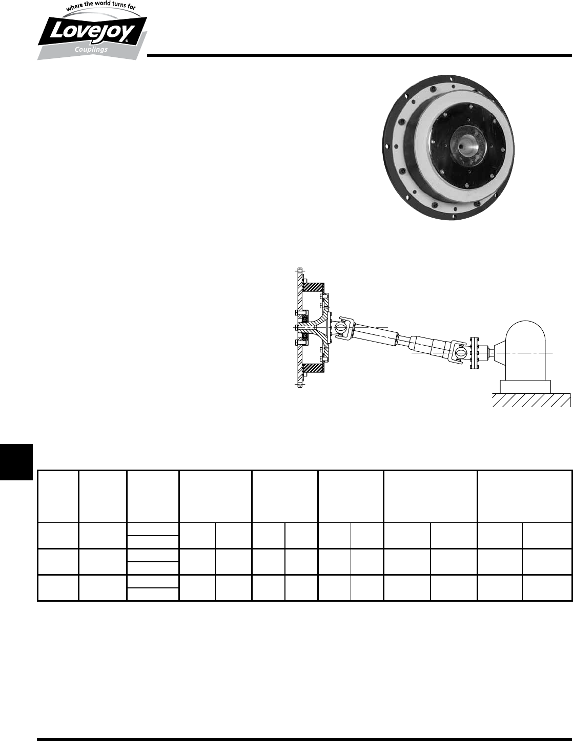
288 630-852-0500
T-30
Torsional
LV Series
Overview / Performance Data
LV Series
The■LV■Series■coupling■is■designed■and■built■for■diesel■engine■driven■
equipment■such■as■agricultural■and■offroad■equipment■using■universal■
joint■drive■shafts.■The■LV■Series■is■ideal■for■universal■joint■driven■
equipment■applications■as■well■as■other■arrangements.■The■LV■Series■
couplings■are■highly■torsionally■compliant,■allowing■the■engine■to■drive■
a■large■inertia■load■safely■away■from■damaging■torsional■resonance■
and■critical■speeds.■The■coupling■selection■should■be■verified■with■a■
Torsional■Vibration■Analysis■of■the■system■(see■page■T-10).■
Element Features:
■■50■&■60■Durometer■(Shore■A■scale)■available
■■-■40°■to■194°■F■temperature■range
■■Available■in■SAE■J620■6.5■through■14■flywheel■sizes■and■varies■in■
metric■sizes
■■Blind■assembly,■no■lubrication
■■Material■available■in■HTR■and■EPDM
Optional Hub Features:
■■LVC■Style■hub■available■for■straight■and■spline■bores■upon■request
■■Splined■hubs■available■with■L-LOC■clamping■system■
LV Series Performance Data
SAE Hardness Power Nominal Maximum Continuous Dynamic Torsional
Flywheel at 2000 RPM Torque Torque Vibratory Torque Stiffness
Size Shore A TKN TKmax TWCTdyn
Size scale HP kW in-lbs Nm in-lb Nm in-lb Nm in-lb/rad Nm/rad
LV200 10,■11.5,■14 50 177 132 5,578 630 16,815 1■900 1,395 158 ■726■ 82
60
LV250 10,■11.5,■14 50 238 178 7,500 847 21,596 2■440 1,875 212 ■871■ 98
60
LV350 10,■11.5,■14 50 343 256 10,820 1■223 31,860 3■600 2,705 306 ■1,417■ 160
60
Typical Applications
LVC■style■is■excellent■for■adapting■the■LV■coupling■to■applications■with■
generators,■reciprocation■pumps■and■compressors,■screw■compressors,■
and■other■equipment■driven■directly■off■an■SAE■flywheel.
JWJISCJSFMCGHPGDD
T
SPUJVSDRSLDED
JW JIS CJ SF MC G HP GD D T SP UJ VSD R SLD ED
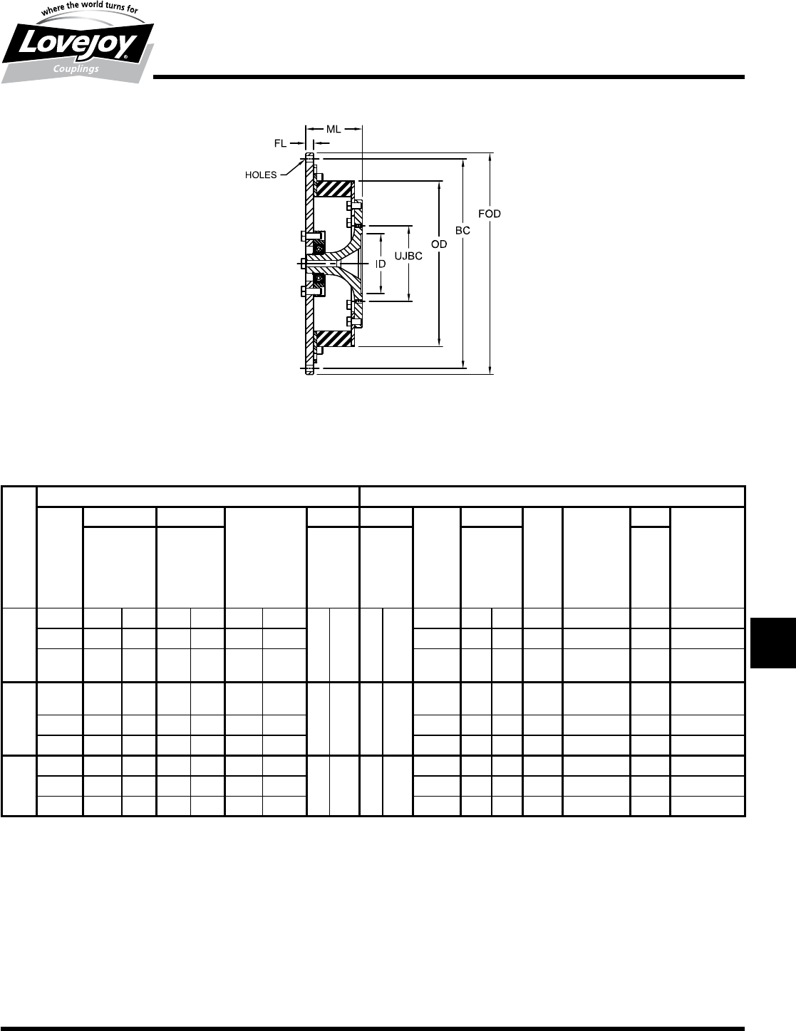
289
www.lovejoy-inc.com T-31
Torsional
LV Series – SAE J620 Flywheel Application
Dimensional Data
LV Series - SAE J620 Flywheel Application Dimensional Data
Flange Dimensions U-Joint Adapter Plate
SAE FOD BC Number / Dia FL ML U-Joint UJBC Number Thread ID Pilot
Flywheel of Holes Flange Mounting Adapter Bolt of Size Pilot ID Depth 2.54 mm
Size Thickness Length Model Circle Dia Holes 0.100
Inch
Size in mm in mm in mm in mm in mm Number in mm UNF in mm
LV200
10 12.375 314.3 11.625 295.3 8■x■0.41 8■x■10.5
0.50 12.7 3.55 90.2■
— — — — — — —
11.5 13.875 352.4 13.125 333.4 8■x■0.41 8■x■10.5 31 3.125 79.4 4 3/8-24■UNF■2B 2.375 60.4■
14 18.375 466.7 17.250 438.2 8■x■0.50 8■x■12.7 35/41 3.750 95.3 4 7/16-20■UNF■
2B 2.750 69.9
LV250
10 12.375 314.3 11.625 295.3 8■x■0.41 8■x■10.5
0.50 12.7 3.55 90.2■
35/41 3.750 95.3 4 7/16-20■UNF■
2B 2.750 69.9
11.5 13.875 352.4 13.125 333.4 8■x■0.41 8■x■10.5 48/55 4.750 120.7 4 1/2-20■UNF■2B 3.750 95.3■
14 18.375 466.7 17.250 438.2 8■x■0.50 8■x■12.7 61 6.125 155.6 8 3/8-24■UNF■2B 6.625 168.3
LV350
10 12.375 314.3 11.625 295.3 8■x■0.41 8■x■10.5
0.50 12.7 3.55 90.2■
61 6.125 155.6 8 3/8-24■UNF■2B 6.625 168.3
11.5 13.875 352.4 13.125 333.4 8■x■0.41 8■x■10.5 71 7.250 184.2 8 3/8-24■UNF■2B 7.750 196.9■
14 18.375 466.7 17.250 438.2 8■x■0.50 8■x■12.7 — — — — — — —
JWJISCJSFMCGHPGDDTSPUJVSDRSLDED
JW JIS CJ SF MC G HP GD D
T
SP UJ VSD R SLD ED
290 630-852-0500
T-32
Torsional
LM Series
Overview
LM Series
The■LM■Series■torsional■couplings■are■designed■specifically■for■
diesel■engine■driven■equipment.■■The■LM■couplings■are■highly■
torsionally■compliant,■allowing■the■engine■to■drive■a■relatively■
small■inertia■load■safely■from■damaging■torsional■resonance■
over■a■wide■speed■range■from■low■idle■RPM■to■full■engine■
speed.■■This■task■is■accomplished■by■shifting■the■critical■speeds■
far■enough■below■the■idle■speed■allowing■full■use■of■the■entire■
working■speed■range■of■the■engine■with■very■few■limitations.■■
These■engineered■couplings■affect■an■attenuated■level■of■stress■
throughout■the■whole■drive■train■by■reducing■vibratory■torque■to■
a■very■low■level.■■The■coupling■selection■should■be■verified■with■
a■Torsional■Vibration■Analysis■of■the■system.■
Materials
Elastomeric Element
■■Temperature-resistant■natural■rubber■available■in■a■variety■of■Shore■A■
scale■hardness■to■suite■individual■application■requirements
■■-49°■to■200°■F■operating■temperature■range
■■Silicone■element■available■for■high■ambient■temperatures
■■EPDM■available■for■chemical■resistant
■■-49°■to■250°■F■operating■temperature■range
Outer Ring
■■High-grade■cast■aluminum■alloy
Inner Hub
■■Steel■with■minimum■tensile■strength■of■85,000■psi■(600■N/mm²)
■■Available■in■bore■with■keyway■and■spline■connections■
■■Taper-Loc■spline■hubs■available
■■Splines■with■L-LOC■available
Typical Applications
■■Splitter-gear■multiple■pump■drives
■■Generator■sets■(2-bearing)
■■Locomotives
■■Hydraulic■pumps
■■Centrifugal■pumps
■■Compressors
Range of Sizes
■■8■sizes■ranging■from■nominal■torques■of■2,210■to■33,600■in-lb■■
(250■to■3800■Nm)
■■SAE■J620■Flywheel■sizes■available■from■6■through■18
■■3■coupling■design■types
JWJISCJSFMCGHPGDD
T
SPUJVSDRSLDED
JW JIS CJ SF MC G HP GD D T SP UJ VSD R SLD ED
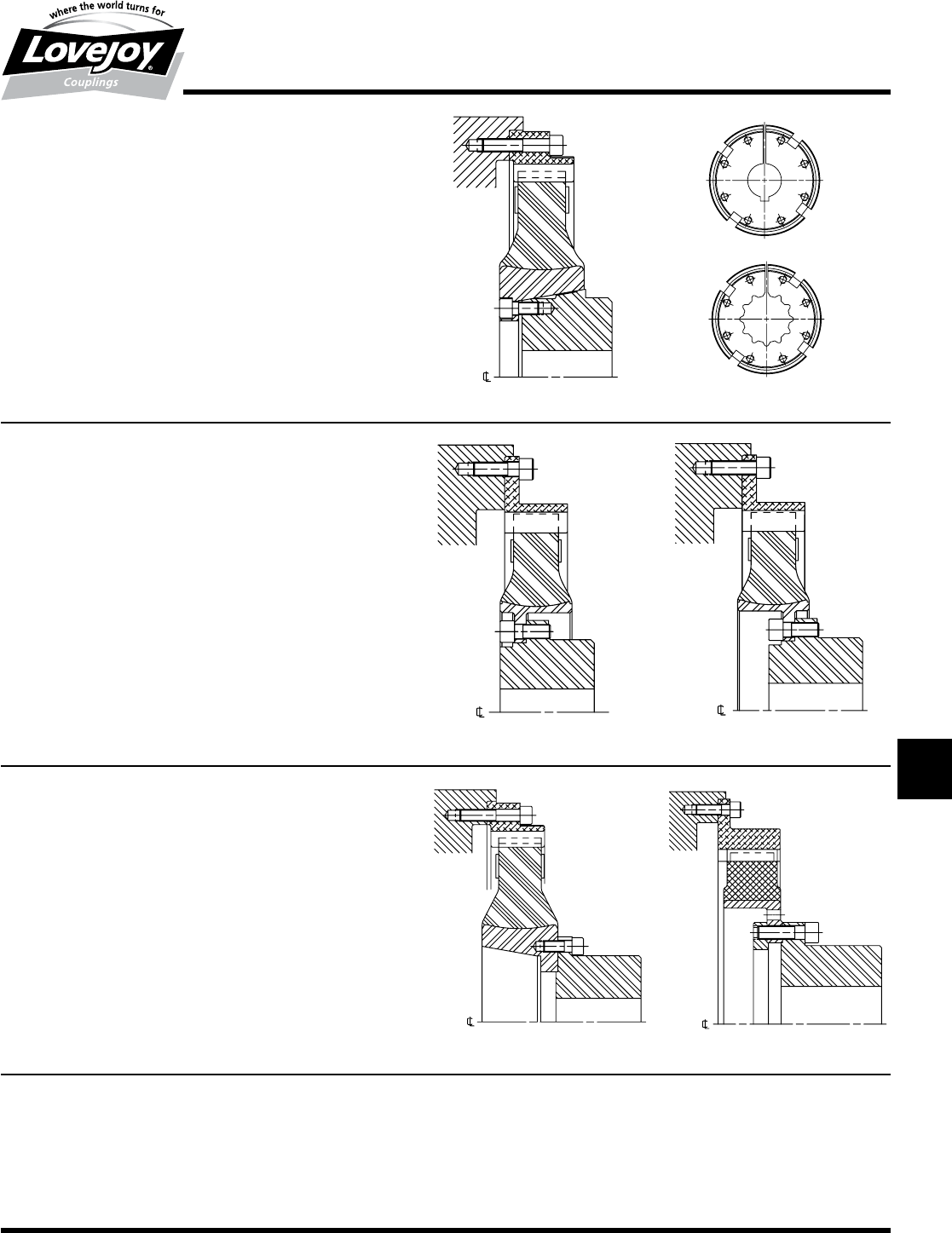
291
www.lovejoy-inc.com T-33
Torsional
LM Series – Types SB, SC, SBE and SCE
Selection Data
Type SB
Type SCBType SCA
Type SCEType SBE
Tapered Locking Hubs
LM Torsional Coupling Design Types
Type SB
Sizes 240 to 2400
The■driven■inner■hub■consists■of■two■pieces:■the■vulcanized■steel■ring■and■
the■inner■tapered■hub.■These■two■parts■are■bolted■together■and■the■torque■
is■transmitted■by■the■friction■force■created■by■the■axial■bolts,■drawing■the■
tapered■hub■into■the■mating■taper■in■the■element.
This■is■a■long■tapered■fit,■but■can■easily■disassembled■if■the■coupling■has■to■
be■removed.■The■vulcanized■steel■ring■creates■a■very■high■inward■pressure■
acting■on■the■inner■driven■tapered■hub.■To■utilize■this■pressure,■the■driven■hub■
is■slotted■in■an■axial■direction.■This■compresses■the■driven■hub■and■driven■
shaft.■This■clamping■effect■can■be■used■equally■well■on■cylindrical■shafts■with■
keys■or■splined■shafts.
Type SC
Sizes 2800 to 3500
An■inner■ring■made■of■spheroidal■cast■iron■is■vulcanized■into■the■
elastomeric■element.■This■flange■is■bolted■to■the■inner■tapered■hub.■
Depending■upon■the■arrangement■of■the■elastomeric■element,■two■
different■lengths■are■possible■utilizing■the■same■components.
Standard Configuration: SCA
Reversed Element: SCB
(extended mounting length)
Types SBE and SCE
Special Radial Assembly / Disassembly Types
(Drop-Out Types) All Sizes
The■elastomeric■element■can■be■changed■quickly■and■easily■without■
disturbing■the■coupling■shaft,■provided■the■flywheel■housing■does■not■
protrude■too■much.■These■versions■can■be■particularly■advantageous■on■
larger■sizes,■especially■if■the■hub■is■interference■fit.■
Special Types
In■addition■to■the■standard■types■shown■here,■many■special■
types■have■been■developed.■Please■contact■Lovejoy■Technical■
Support■for■more■information.
JWJISCJSFMCGHPGDDTSPUJVSDRSLDED
JW JIS CJ SF MC G HP GD D
T
SP UJ VSD R SLD ED

292 630-852-0500
T-34
Torsional
LM Series – Types SB, SCA and SCB (HTR)
Performance Data
Notes:■■ n■■■*■indicates:■At■10■Hz.
■n■■**■indicates:■Constant■value■for■natural■rubber.
■n■■***■indicates:■Flywheel■side■of■the■coupling.
Silicone Temperature
Factor St
2.5
2
1.5
1
0.5
0
80 100 120 140 160 180 200
Degrees °F
St
TKN ≥ TLN • S t
Temperature Factor St2
for Cont. Vibr. Torque Tkw
and Allowable Power Loss Pkv
0
0.5
1
80 100 120 140 160 180 200
Degrees F
HTR
St2
Tkw
Pv< Pkv * St2
Tw< Tkw * St2 * (1/Sf)
Pkv
Resonance Factor VR
Relative Damping Factor y
High Temperature Rubber (HTR)
f in Hz Vry
35-40 12.0 0.52
50 6.0 1.05
60 5.7 1.10
70 5.5 1.15
LM Series - SB, SCA and SCB (HTR) Performance Data
Hardness Nominal Max Continuous* Allowable Dynamic** Flange Max Mass Moment of Inertia
(Durometer) Torque Rating Torque Rating Vibratory Power Torsional Size for Speed Primary*** Secondary
TKN TKmax Torque Loss Stiffness J620 Nmax J1J2
Shore A TKW PKV CTdyn Flywheel
Size scale in-lb Nm in-lb Nm in-lb Nm Watts in-lb/rad Nm/rad RPM lb-in2kg-m2lb-in2kg-m2
LM240
50 ■2,210■ 250 ■4,430■ 500 ■885■ 100
37
■8,190■ ■925 ■■8 4,000 17.77 0.021 3.25 0.004
60 ■2,660■ 300 ■5,310■ 600 ■1,060■ 120 ■12,400■ 1■400 10 3,600 26.74 0.031 3.25 0.004
70 ■3,100■ 350 ■6,640■ 750 ■1,240■ 140 ■19,900■ 2■250 — — — — — —
LM400
50 ■3,540■ 400 ■7,080■ 800 ■1,420■ 160
62
■14,200■ 1■600 10
3,600 0.04 0.037 0.01 0.01160 ■4,430■ 500 ■8,850■ 1■000 ■1,770■ 200 ■22,100■ 2■500 11.5
70 ■4,870■ 550 ■9,740■ 1■100 ■1,950■ 220 ■35,400■ 4■000 14
LM800
50 ■6,200■ 700 ■12,400■ 1■400 ■2,480■ 280
105
■24,800■ 2■800 10 3,600 51.17 0.060 25.29 0.030
60 ■7,520■ 850 ■15,000■ 1■700 ■3,000■ 340 ■37,200■ 4■200 11.5 3,500 62.53 0.073 25.29 0.030
70 ■8,400■ 950 ■17,700■ 2■000 ■3,360■ 380 ■60,200■ 6■800 14 3,000 117.70 0.138 25.29 0.030
LM1200
50 ■8,850■ 1■000 ■17,700■ 2■000 ■3,540■ 400
150
■39,800■ 4■500 11.5 3,500 65.61 0.077 38.95 0.046
60 ■10,600■ 1■200 ■21,200■ 2■400 ■4,250■ 480 ■61,900■ 7■000 14 3,000 12.23 0.014 38.95 0.046
70 ■11,500■ 1■300 ■26,600■ 3■000 ■4,600■ 520 ■104,000■ 11■700 — — — — — —
LM1600
50 ■12,800■ 1■450 ■26,700■ 2■900 ■5,130■ 580
220
■53,100■ 6■000 11.5 3,200 191.40 0.224 66.63 0.078
60 ■15,900■ 1■800 ■31,900■ 3■600 ■6,370■ 720 ■79,600■ 9■000
14 3,000 168.30 0.020 66.63 0.078
16 2,500 234.10 0.274 66.63 0.078
70 ■17,700■ 2■000 ■35,400■ 4■000 ■7,080■ 800 ■133,000■ 15■000 18 2,300 329.30 0.386 66.63 0.078
LM2400
50 ■17,700■ 2■000 ■35,400■ 4■000 ■7,080■ 800
300
■88,500■ 1■000 14 3,000 182.00 0.213 130.70 0.153
60 ■22,100■ 2■500 ■44,300■ 5■000 ■8,850■ 1■000 ■133,000■ 15■000 16 2,500 247.70 0.290 130.70 0.153
70 ■24,800■ 2■800 ■53,100■ 6■000 ■9,910■ 1■120 ■221,000■ 25■000 18 2,300 343.00 0.402 130.70 0.153
LM2800
50 ■24,800■ 2■800 ■53,100■ 6■000 ■9,910■ 1■120
360
■221,000■ 25■000 14 3,000 242.30 0.284 192.80 0.226
60 ■26,600■ 3■000 ■66,400■ 7■500 ■10,600■ 1■200 ■332,000■ 37■500 16 2,500 269.80 0.316 192.80 0.226
70 ■28,300■ 3■200 ■70,800■ 8■000 ■11,300■ 1■280 ■558,000■ 63■000 18 2,300 364.90 0.427 192.80 0.226
LM3500
50 ■28,300■ 3■200 ■57,500■ 6■500 ■11,300■ 1■280
450
■142,000■ 16■000 14 3,000 242.30 0.284 196.10 0.230
60 ■31,000■ 3■500 ■70,800■ 8■000 ■12,400■ 1■400 ■212,000■ 24■000 16 2,500 374.90 0.439 196.10 0.230
70 ■33,600■ 3■800 ■75,200■ 8■500 ■13,500■ 1■520 ■336,000■ 38■000 18 2,300 501.70 0.587 196.10 0.230
Frequency Factor Sf
f in Hz≤10 ≥10
Sf 1 √■f■/■10
JWJISCJSFMCGHPGDD
T
SPUJVSDRSLDED
JW JIS CJ SF MC G HP GD D T SP UJ VSD R SLD ED
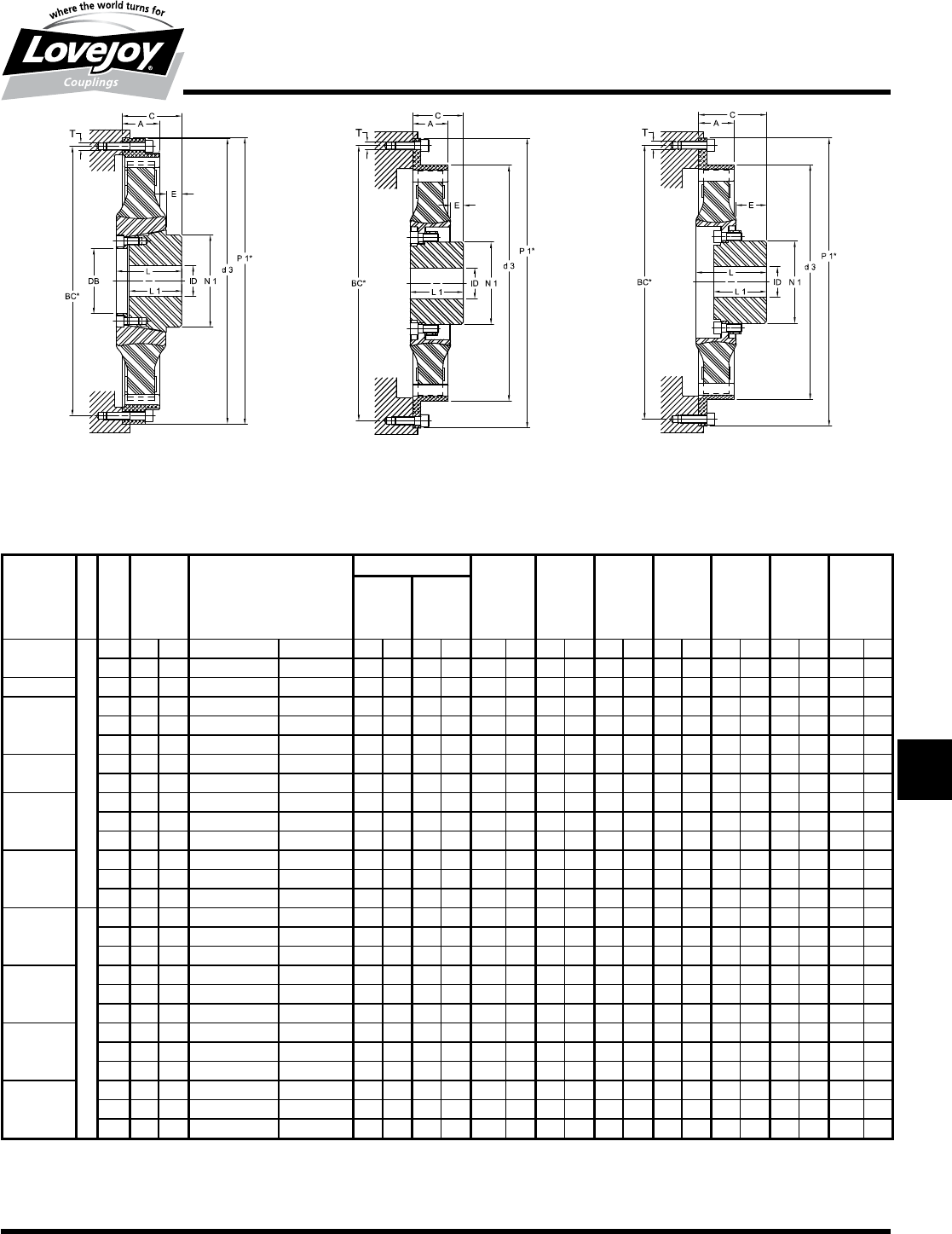
293
www.lovejoy-inc.com
LM Series - SB, SCA and SCB (HTR) Dimensional Data
A C** ID d3 DB E L L1 N1
SAE Min Bore Max Bore Weight
J620
Size in mm in mm in mm in mm in mm in mm in mm in mm in mm in mm lb kg
240 SB
Tapered
■■8 1.81 46 2.95 ± 0.35 75 ± 9 0.59 15 1.97 50 10.31 262 1.97 50 1.06 27 2.95 75 2.36 60 2.87 73 2.77 6.1
10 1.81 46 2.95 ± 0.35 75 ± 9 0.59 15 1.97 50 8.86 225 1.97 50 1.06 27 2.95 75 2.36 60 2.87 73 2.95 6.5
400 SB 10 1.77 45 2.95 ± 0.28 75 ± 7 0.79 20 2.36 60 12.32 313 2.40 61 0.98 25 3.15 80 2.56 65 3.54 90 3.90 8.6
800 SB
10 1.97 50 3.22 ± 0.08 82 ± 2 0.79 20 2.76 70 12.44 316 2.80 71 0.71 18 3.31 84 2.60 66 4.21 107 5.03 11.1
11.5 1.54 39 2.80 ± 0.12 71 ± 3 0.79 20 2.76 70 13.82 351 2.80 71 0.71 18 3.31 84 2.60 66 4.21 107 4.58 10.1
14 1.81 46 2.91 ± 0.24 74 ± 6 0.79 20 2.76 70 12.52 318 2.80 71 0.71 18 3.31 84 2.60 66 4.21 107 5.22 11.5
1200 SB 11.5 1.54 39 2.56 ± 0.16 65 ± 4 0.79 20 2.76 70 13.82 351 2.80 71 0.71 18 3.31 84 2.60 66 4.21 107 6.58 14.5
14 1.81 46 2.91 ± 0.24 74 ± 6 0.79 20 2.76 70 13.82 351 2.80 71 0.71 18 3.31 84 2.60 66 4.21 107 7.44 16.4
1600 SB
14 2.40 61 3.82 ± 0.43 97 ± 11 1.18 30 4.13 105 18.31 465 4.17 106 1.02 26 4.17 106 3.35 85 5.91 150 10.21 22.5
16 2.40 61 3.82 ± 0.43 97 ± 11 1.18 30 4.13 105 16.42 417 4.17 106 1.02 26 4.17 106 3.35 85 5.91 150 10.80 23.8
18 2.40 61 3.82 ± 0.43 97 ± 11 1.18 30 4.13 105 16.42 417 4.17 106 1.02 26 4.17 106 3.35 85 5.91 150 11.48 25.3
2400 SB
14 2.40 61 3.82 ± 0.24 97 ± 6 1.18 30 4.13 105 18.31 465 4.17 106 1.02 26 4.17 106 3.35 85 5.91 150 14.11 31.1
16 2.40 61 3.82 ± 0.24 97 ± 6 1.18 30 4.13 105 16.42 417 4.17 106 1.02 26 4.17 106 3.35 85 5.91 150 14.70 32.4
18 2.40 61 3.82 ± 0.24 97 ± 6 1.18 30 4.13 105 16.42 417 4.17 106 1.02 26 4.17 106 3.35 85 5.91 150 15.38 33.9
2800 SCA
Bolted
14 2.40 61 3.66 ± 0.16 93 ± 4 1.38 35 4.33 110 18.31 465 — — 1.34 34 — — 4.13 105 6.38 162 14.29 31.5
16 2.40 61 3.66 ± 0.16 93 ± 4 1.38 35 4.33 110 16.42 417 — — 1.34 34 — — 4.13 105 6.38 162 14.88 32.8
18 2.40 61 3.66 ± 0.16 93 ± 4 1.38 35 4.33 110 16.42 417 — — 1.34 34 — — 4.13 105 6.38 162 15.56 34.3
2800 SCB
14 2.40 61 5.31 ± 0.16 135 ± 4 1.38 35 4.33 110 18.31 465 — — 2.99 76 5.16 131 4.13 105 6.38 162 14.29 31.5
16 2.40 61 5.31 ± 0.16 135 ± 4 1.38 35 4.33 110 16.42 417 — — 2.99 76 5.16 131 4.13 105 6.38 162 14.88 32.8
18 2.40 61 5.31 ± 0.16 135 ± 4 1.38 35 4.33 110 16.42 417 — — 2.99 76 4.96 126 4.13 105 6.38 162 15.56 34.3
3500 SCA
14 2.76 70 3.94 ± 0.31 100 ± 8 1.38 35 4.33 110 18.31 465 — — 0.98 25 — — 4.13 105 6.38 162 15.38 33.9
16 2.76 70 3.94 ± 0.31 100 ± 8 1.38 35 4.33 110 18.31 465 — — 0.98 25 — — 4.13 105 6.38 162 16.60 36.6
18 2.76 70 3.94 ± 0.31 100 ± 8 1.38 35 4.33 110 18.31 465 — — 0.98 25 — — 4.13 105 6.38 162 17.46 38.5
3500 SCB
14 2.76 70 5.31 ± 0.31 135 ± 8 0.24 6 4.33 110 18.31 465 — — 2.36 60 5.51 140 4.13 105 6.38 162 15.38 33.9
16 2.76 70 5.31 ± 0.31 135 ± 8 1.38 35 4.33 110 18.31 465 — — 2.36 60 5.51 140 4.13 105 6.38 162 16.60 36.6
18 2.76 70 5.31 ± 0.31 135 ± 8 1.38 35 4.33 110 18.31 465 — — 2.36 60 5.51 140 4.13 105 6.38 162 17.46 38.5
T-35
Torsional
LM Series – Types SB, SCA and SCB (HTR)
Dimensional Data
240 – 2400 SB 2800 – 3500 SCA 2800 – 3500 SCB
Note:■■ n■■■■■**■indicates:■At■10■Hz.
Note:■■ n■■■*■indicates:■SAE■J620■Flywheel■Dimensional■Data■can■be■found■on■page■T-41.
JWJISCJSFMCGHPGDDTSPUJVSDRSLDED
JW JIS CJ SF MC G HP GD D
T
SP UJ VSD R SLD ED
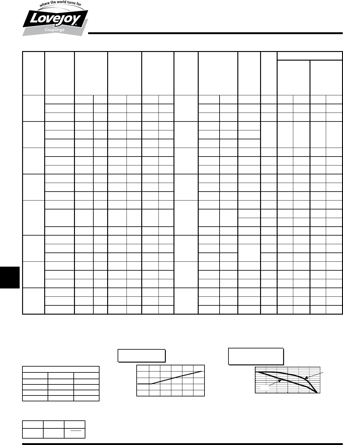
294 630-852-0500
T-36
Torsional
LM Series – Types SBE and SCE (HTR)
Performance Data
Notes:■■ n■■■*■indicates:■At■10■Hz.
■n■■**■indicates:■Constant■value■for■natural■rubber.
■n■■***■indicates:■Flywheel■side■of■the■coupling.
LM Series - SBE and SCE (HTR) Performance Data
Hardness Nominal Max Continuous* Allowable Dynamic** Flange Max Mass Moment of Inertia
(Durometer) Torque Rating Torque Rating Vibratory Power Torsional Size for Speed Primary*** Secondary
TKN TKmax Torque Loss Stiffness J620 Nmax J1J2
Shore A TKW PKV CTdyn Flywheel
Size scale in-lb Nm in-lb Nm in-lb Nm Watts in-lb/rad Nm/rad RPM lb-in2kg-m2lb-in2kg-m2
LM240
50 ■2,210■ 250 ■4,430■ 500 ■885■ 100
37
■8,190■ ■925 ■■8 4,000 17.77 0.021 3.25 0.004
60 ■2,660■ 300 ■5,310■ 600 ■1,060■ 120 ■12,400■ 1■400 10 3,600 26.74 0.031 3.25 0.004
70 ■3,100■ 350 ■6,640■ 750 ■1,240■ 140 ■19,900■ 2■250 — — — — — —
LM400
50 ■3,540■ 400 ■7,080■ 800 ■1,420■ 160
62
■14,200■ 1■600 10
3,600 0.04 0.037 0.01 0.01160 ■4,430■ 500 ■8,850■ 1■000 ■1,770■ 200 ■22,100■ 2■500 11.5
70 ■4,870■ 550 ■9,740■ 1■100 ■1,950■ 220 ■35,400■ 4■000 14
LM800
50 ■6,200■ 700 ■12,400■ 1■400 ■2,480■ 280
105
■24,800■ 2■800 10 3,600 51.17 0.060 25.29 0.030
60 ■7,520■ 850 ■15,000■ 1■700 ■3,000■ 340 ■37,200■ 4■200 11.5 3,500 62.53 0.073 25.29 0.030
70 ■8,400■ 950 ■17,700■ 2■000 ■3,360■ 380 ■60,200■ 6■800 14 3,000 117.70 0.138 25.29 0.030
LM1200
50 ■8,850■ 1■000 ■17,700■ 2■000 ■3,540■ 400
150
■39,800■ 4■500 11.5 3,500 65.61 0.077 38.95 0.046
60 ■10,600■ 1■200 ■21,200■ 2■400 ■4,250■ 480 ■61,900■ 7■000 14 3,000 12.23 0.014 38.95 0.046
70 ■11,500■ 1■300 ■26,600■ 3■000 ■4,600■ 520 ■104,000■ 11■700 — — — — — —
LM1600
50 ■12,800■ 1■450 ■26,700■ 2■900 ■5,130■ 580
220
■53,100■ 6■000 11.5 3,200 191.40 0.224 66.63 0.078
60 ■15,900■ 1■800 ■31,900■ 3■600 ■6,370■ 720 ■79,600■ 9■000
14 3,000 168.30 0.020 66.63 0.078
16 2,500 234.10 0.274 66.63 0.078
70 ■17,700■ 2■000 ■35,400■ 4■000 ■7,080■ 800 ■133,000■ 15■000 18 2,300 329.30 0.386 66.63 0.078
LM2400
50 ■17,700■ 2■000 ■35,400■ 4■000 ■7,080■ 800
300
■88,500■ 1■000 14 3,000 182.00 0.213 130.70 0.153
60 ■22,100■ 2■500 ■44,300■ 5■000 ■8,850■ 1■000 ■133,000■ 15■000 16 2,500 247.70 0.290 130.70 0.153
70 ■24,800■ 2■800 ■53,100■ 6■000 ■9,910■ 1■120 ■221,000■ 25■000 18 2,300 343.00 0.402 130.70 0.153
LM2800
50 ■24,800■ 2■800 ■53,100■ 6■000 ■9,910■ 1■120
360
■221,000■ 25■000 14 3,000 242.30 0.284 192.80 0.226
60 ■26,600■ 3■000 ■66,400■ 7■500 ■10,600■ 1■200 ■332,000■ 37■500 16 2,500 269.80 0.316 192.80 0.226
70 ■28,300■ 3■200 ■70,800■ 8■000 ■11,300■ 1■280 ■558,000■ 63■000 18 2,300 364.90 0.427 192.80 0.226
LM3500
50 ■28,300■ 3■200 ■57,500■ 6■500 ■11,300■ 1■280
450
■142,000■ 16■000 14 3,000 242.30 0.284 196.10 0.230
60 ■31,000■ 3■500 ■70,800■ 8■000 ■12,400■ 1■400 ■212,000■ 24■000 16 2,500 374.90 0.439 196.10 0.230
70 ■33,600■ 3■800 ■75,200■ 8■500 ■13,500■ 1■520 ■336,000■ 38■000 18 2,300 501.70 0.587 196.10 0.230
Silicone Temperature
Factor St
2.5
2
1.5
1
0.5
0
80 100 120 140 160 180 200
Degrees °F
St
TKN ≥ TLN • S t
Temperature Factor St2
for Cont. Vibr. Torque Tkw
and Allowable Power Loss Pkv
0
0.5
1
80 100 120 140 160 180 200
Degrees F
HTR
St2
Tkw
Pv< Pkv * St2
Tw< Tkw * St2 * (1/Sf)
Pkv
Resonance Factor VR
Relative Damping Factor y
High Temperature Rubber (HTR)
f in Hz Vry
35-40 12.0 0.52
50 6.0 1.05
60 5.7 1.10
70 5.5 1.15
Frequency Factor Sf
f in Hz≤10 ≥10
Sf 1 √■f■/■10
JWJISCJSFMCGHPGDD
T
SPUJVSDRSLDED
JW JIS CJ SF MC G HP GD D T SP UJ VSD R SLD ED
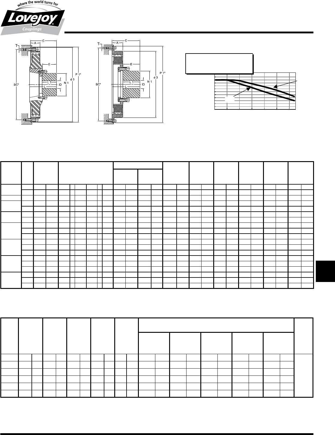
295
www.lovejoy-inc.com T-37
Torsional
LM Series – Types SBE and SCE (HTR)
Dimensional Data
2800 - 3500 SBE 2800 - 3500 SCE
LM Series - SBE and SCE (HTR) Radial Dimensional Data
A C** ID d3 E L L1 N1
SAE Min Bore Max Bore Weight
Size J620 in mm in mm in mm in mm in mm in mm in mm in mm in mm lb kg
240 SBE ■■8 1.81 46 4.45 ± 0.08 113 ± 2 0.59 15 1.77 45 10.31 262 2.28 58 4.17 106 2.36 60 2.60 66 2.18 4.8
10 1.81 46 4.45 ± 0.08 113 ± 2 0.59 15 1.77 45 8.86 225 2.28 58 4.17 106 2.36 60 2.60 66 2.36 5.2
400 SBE 10 1.77 45 4.61 ± 0.08 117 ± 2 0.79 20 2.17 55 12.32 313 2.48 63 4.65 118 2.56 65 3.35 85 3.45 7.6
800 SBE 11.5 1.54 39 4.61 ± 0.08 117 ± 2 0.79 20 2.56 65 13.82 351 2.52 64 5.12 130 2.60 66 3.94 100 5.03 11.1
14 1.81 46 4.69 ± 0.08 119 ± 2 0.79 20 2.56 65 12.52 318 2.52 64 5.12 130 2.60 66 3.94 100 6.35 14.0
1200 SBE 11.5 1.54 39 4.45 ± 0.08 113 ± 2 0.79 20 2.56 65 13.82 351 2.52 64 5.12 130 2.60 66 3.94 100 6.89 15.2
14 1.81 46 4.72 ± 0.08 120 ± 2 0.79 20 2.56 65 13.82 351 2.52 64 5.12 130 2.60 66 3.94 100 8.30 18.3
1600 SBE
14 2.40 61 6.61 ± 0.08 168 ± 2 1.18 30 3.94 100 18.31 465 3.46 88 6.61 168 3.54 90 5.51 140 11.43 25.2
16 2.40 61 6.61 ± 0.08 168 ± 2 1.18 30 3.94 100 16.42 417 3.46 88 6.61 168 3.54 90 5.51 140 12.02 26.5
18 2.40 61 6.61 ± 0.08 168 ± 2 1.18 30 3.94 100 16.42 417 3.46 88 6.61 168 3.54 90 5.51 140 12.70 28.0
2400 SBE
14 2.40 61 6.42 ± 0.08 163 ± 2 1.18 30 3.94 100 18.31 465 3.46 88 6.61 168 3.54 90 5.51 140 14.83 32.7
16 2.40 61 6.42 ± 0.08 163 ± 2 1.18 30 3.94 100 16.42 417 3.46 88 6.61 168 3.54 90 5.51 140 15.42 34.0
18 2.40 61 6.42 ± 0.08 163 ± 2 1.18 30 3.94 100 16.42 417 3.46 88 6.61 168 3.54 90 5.51 140 16.10 35.5
2800 SCE
14 2.40 61 6.46 ± 0.08 164 ± 2 1.38 35 4.13 105 18.31 465 4.06 103 6.22 158 4.13 105 6.06 154 14.65 32.3
16 2.40 61 6.46 ± 0.08 164 ± 2 1.38 35 4.13 105 16.42 417 4.06 103 6.22 158 4.13 105 6.06 154 15.24 33.6
18 2.40 61 6.46 ± 0.08 164 ± 2 1.38 35 4.13 105 16.42 417 4.06 103 6.22 158 4.13 105 6.06 154 15.92 35.1
3500 SCE
14 2.76 70 7.28 ± 0.08 185 ± 2 0.24 ■■6 4.13 105 18.31 465 4.06 103 7.20 183 4.13 105 6.06 154 16.92 37.3
16 2.76 70 7.28 ± 0.08 185 ± 2 1.38 35 4.13 105 18.31 465 4.06 103 7.20 183 4.13 105 6.06 154 18.14 40.0
18 2.76 70 7.28 ± 0.08 185 ± 2 1.38 35 4.13 105 18.31 465 4.06 103 7.20 126 4.13 105 6.06 154 19.01 41.9
LM Series - Silicone (50 shore A) Performance Data
Nominal *Max **Max Continuous Allowable Dynamic Torsional Stiffness*** Relative
Torque Torque1 Torque2 Vibratory Power CTdyn Damping
Rating TKmax1 TKmax2 Torque Loss 10% TKN 25% TKN 50% TKN 75% TKN 100% TKN Ψ
TKN TKW PKV
Size in-lb Nm in-lb Nm in-lb Nm in-lb Nm HP Watts in-lb/rad Nm/rad in-lb/rad Nm/rad in-lb/rad Nm/rad in-lb/rad Nm/rad in-lb/rad Nm/rad
LM800 ■6,200 700 ■9,290 1■050 12,400 1■400 ■2,480 280 0.14 105 ■19,500 2■200 ■21,200 2■400 ■24,800 2■800 ■31,000 3■500 ■40,700 4■600
1.15
LM1200 ■8,850 1■000 13,300 1■500 17,700 2■000 ■3,540 400 0.20 150 ■31,900 3■600 ■34,500 3■900 ■39,800 4■500 ■49,600 5■600 ■65,500 7■400
LM1600 12,800 1■450 19,500 2■200 25,700 2■900 ■5,100 580 0.30 220 ■42,500 4■800 ■46,000 5■200 ■53,100 6■000 ■66,400 7■500 ■87,600 9■900
LM2400 17,700 2■000 26,600 3■000 35,400 4■000 ■7,080 800 0.40 300 ■70,800 8■000 ■77,000 8■700 ■88,500 10■000 ■111,000 12■500 146,000 16■500
LM2800 24,800 2■800 37,200 4■200 49,600 5■600 ■9,910 1■120 0.48 360 186,000 21■000 ■20,400 2■300 221,000 25■000 288,000 32■500 376,000 42■500
LM3500 28,300 3■200 42,500 4■800 56,600 6■400 11,300 1■280 0.60 450 ■113,000 12■800 123,000 13■900 142,000 16■000 177,000 20■000 235,000 26■500
Notes:■■ n■■■*■indicates:■Tmax1■is■the■maximum■accelerating■value■for■transient■torque■spikes■during■the■normal■work■cycle,■for■example,■form■accelerating■through■
a■resonance■during■starting■and■stopping■or■clutching.
■n■■■**■indicates:■Tmax2■represents■the■absolute■maximum■peak■torque■allowable■during■rare■occasions■such■as■during■a■short■circuit■of■a■gen-set■or■
incorrect■synchronization.
■n■■■***■indicates:■The■silicone■material■creates■a■progressive■stiffness■characteristic■dependent■on■load.■These■values■have■the■tolerance■of■±■15%.
Note:■■ n■■■■**■indicates:■The■rubber■element■can■be■positioned■closer■to■or■farther■from■the■flywheel■within■the■limits■shown■for■this■dimension,■while■maintaining■
full■engagement■with■the■outer■drive■ring.■Hub■length■L1■is■adjustable■as■well■with■corresponding■changes■to■mounting■length■dimension■C.■
Note:■■ n■■■*■indicates:■SAE■J620■Flywheel■Dimensional■Data■can■be■found■on■page■T-41.
Temperature Factor St2SI
for Cont. Vibr. Torque Tkw
and Allowable Power Loss Pkv
0
0.5
1
120 140 160 180 200 220 240
Degrees F
SILICONE
St2SI
Tkw
Pv< Pkv * St2SI
Tw< Tk w * St2SI * (1/Sf)
Pkv
JWJISCJSFMCGHPGDDTSPUJVSDRSLDED
JW JIS CJ SF MC G HP GD D
T
SP UJ VSD R SLD ED
296 630-852-0500
T-38
Torsional
LK Series
Overview / Performance Data
The■LK■Series■coupling■is■a■simple■two-piece■design■consisting■of■an■element■and■
hub.■■The■couplings■are■designed■to■be■used■with■engine■driven,■flange■mounted,■
hydraulic■pump■systems.■■The■couplings■are■“torsionally■stiff”■enabling■hydraulic■
pumps■and■similar■equipment■with■low■mass■or■inertia■to■operate■below■critical■
speeds.■■The■“torsionally■stiff”■LK■Series■coupling■raises■the■critical■speed■above■
the■operating■range■providing■a■system■free■of■harmful■torsional■vibrations.■■The■LK■
Series■is■ideal■for■hydrostatic■drives■on■construction■equipment,■cranes,■forklifts,■
excavators,■vibratory■rollers,■tractors,■etc.■■Virtually■all■engine■driven■hydraulic■
systems■in■the■low■to■mid■power■range■can■use■the■LK■Series■coupling.
Element Features
■■Fiberglass■reinforced■polyamide■construction
■■Impact■and■oil■resistant
■■–40°■to■320°■F■temperature■range
■■SAE■J620■flywheel■sizes■6.5■through■14■and■various■metric■sizes
■■Universal■element■can■be■mounted■to■and■adapter■plate
■■Blind■assembly,■no■lubrication
Hub Features
■■High■quality■powdered-metal■construction
■■Splined■hubs■available■with■L-LOC■clamping■system
■■Engagement■“dogs”■are■slightly■crowned■to■avoid■edge■pressure■when■slight■
misalignment■occurs
■■Available■in■bore■with■keyway■and■spline■connections
Typical Applications
Applications■where■a■hydraulic■pump■is■directly■connected■to■the■engine■such■
as■wheel■loaders,■hydraulic■excavators,■vibration■rollers,■fork■lift■trucks,■concrete■
cutters,■compact■loaders,■asphalt■finishers■and■mobile■cranes.
LK Series Performance Data
Size
SAE Flywheel
Size
Nominal Torque
TKN
Maxium Torque
TKmax
Maximum
Speed
Dynamic Torsional Stiffness Relative
Damping
CTdyn
0.25TKN 0.50TKN 0.75TKN 1.00TKN
in-lb Nm in-lb Nm RPM lb-in/rad kNm/rad lb-in/rad kNm/rad lb-in/rad kNm/rad lb-in/rad kNm/rad Ψ
LK80 — 1,080 ■125 2,880 ■330 6,000 Consult■Lovejoy
0.4
LK100 6.5,■7.5,■8,■10 3,540 ■400 7,080 ■800 5,000 490 ■55 550 ■62 800 ■90 1,060 ■120
LK125 10,■11.5 7,080 ■800 14,160 1■600 4,500 1,370 ■155 1,590 ■180 2,800 ■315 4,070 ■460
LK150 11.5,■14 10,620 1■200 26,400 3■000 4,000 2,300 ■260 2,480 ■280 3,700 ■420 7,950 ■900
LK150D 14 21,240 2■400 58,200 6■000 4,000 4,600 ■520 4,960 ■560 7,400 ■840 15,900 1■800
JWJISCJSFMCGHPGDD
T
SPUJVSDRSLDED
JW JIS CJ SF MC G HP GD D T SP UJ VSD R SLD ED
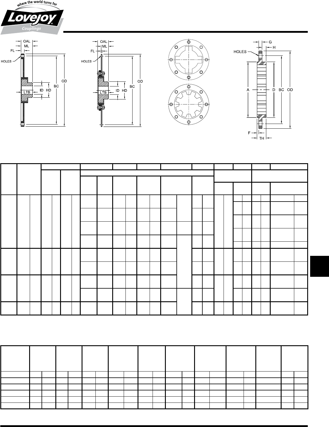
297
www.lovejoy-inc.com T-39
Torsional
LK Series
Dimensional Data
1-Piece Flange 2-Piece Flange
Universal + Plate
4, 6 and 8 Dog Patterns
Dependent on Size
LK Series - SAE J620 Flywheel Application Dimensional Data
ID OD BC FL HD LTB* OAL ML
Nominal Min Bore Max Bore Flange Dimensions Hubstar Assembly
Dimensions
Torque SAE Flange Number & Dia Flange Dimensions
Rating Flywheel Style of Holes Thickness Mounting Length
Size in-lb Nm in mm in mm Size in mm in mm in mm in mm in mm in mm in mm in mm
LK100 3,540 400 0.563 15 1.563 40
6.5 1-PIECE 8.500 215.9 7.875 200.0 6■x■0.33■
6■x■8.5■
0.55 14
2.56 65
— — — — — —
1.26 32 1.34 34 0.906■±■0.118 23+/-3■
7.5 1-PIECE 9.500 241.3 8.750 222.3 8■x■0.33■ 0.55 14
2.20 56 2.28 58 2.284■±■0.118 58+/-3
8 1-PIECE 10.375 263.5 9.625 244.5 6■x■0.41■ 6■x■10.5■ 0.55 14
1.89 48 1.97 50 1.969■±■0.118 50+/-3
10 1-PIECE 12.375 314.3 11.625 295.3 8■x■0.41■
8■x■10.5■
0.55 14 — — — — — —
LK125 7,080 800 0.813 20 2.125 55
10 1-PIECE 12.375 314.3 11.625 295.3 8■x■0.41■ 0.79 20
3.35 85
1.89 48 1.97 50 1.969■±■0.118 50+/-3■
11.5 1-PIECE 13.875 352.4 13.125 333.4 8■x■0.41 0.19 20 1.97 42 2.05 46 1.417■±■0.118 36+/-3
LK150 10,260 1■200 1.000 25 2.750 70
11.5 1-PIECE 13.875 352.4 3.125 333.4 8■x■0.41■ 0.79 20
4.33 110
2.09 53 2.09 53 1.299■±■0.118 33+/-1
14 2-PIECE 18.375 466.7 17.250 438.2 8■x■0.50■
8■x■12.7■
0.19 5 2.09 53 2.09 53 0.984■±■0.118 25+/-1
LK150D 21,240 2■400 1.188 30 2.750 70 14 ** 18.375 466.7 17.250 438.2 8■x■0.50■ 0.19 5 4.33 110 2.05 52 2.13 54 0.984■±■0.118 25+/-1
Notes:■■ n■■■*■indicates:■Other■shorter■or■longer■hub■lengths■available■for■special■requirements.
■n■■■**■indicates:■LK■150D■uses■2■Zytel®■elements■in■parallel■with■1■steel■plate.
Notes:■■ n■■■*■indicates:■LK80-6-135■pilots■on■the■O.D.
■n■■■Dimensions■for■universal■elements■(for■non-SAE■flywheels,■etc.).
LK Series Universal Elements Dimensional Data
G H TH E OD BC D A S
Hole
Pilot Number Diameter
Size in mm in mm in mm in mm in mm in mm in mm in mm of Holes in mm
LK80-6-106 0.55 14.0 0.38 9.7 0.19 4.8 1.12 2.84 5.910 150 5.118 130 3.600 91.4 4.173 106 5 0.33 8.4
LK80-6-135 0.39 9.9 0.61 15.5 * * 1.00 25.4 5.315 135 3.937 100 3.629 92.2 5.315 135 3 0.41 10.4
LK100-165 0.39 10.0 0.79 20.0 0.16 4.0 1.34 34.0 6.850 174 5.591 142 4.921 125.0 4.921 125 3 0.49 12.5
LK100-072 0.39 10.0 0.79 20.0 0.16 4.0 1.34 34.0 7.870 200 6.496 165 4.330 110.0 2.835 72 3 0.65 16.5
LK125-195 0.39 10.0 0.55 14.0 0.24 6.0 1.18 30.0 7.680 195 6.496 165 5.315 135.0 5.135 135 6 0.49 12.5
LK150-230 0.39 10.0 0.47 12.0 0.20■ 5.0 1.06 27.0 9.060 230 7.874 200 6.500 165.0 6.496 165 8 0.49 12.5
JWJISCJSFMCGHPGDDTSPUJVSDRSLDED
JW JIS CJ SF MC G HP GD D
T
SP UJ VSD R SLD ED
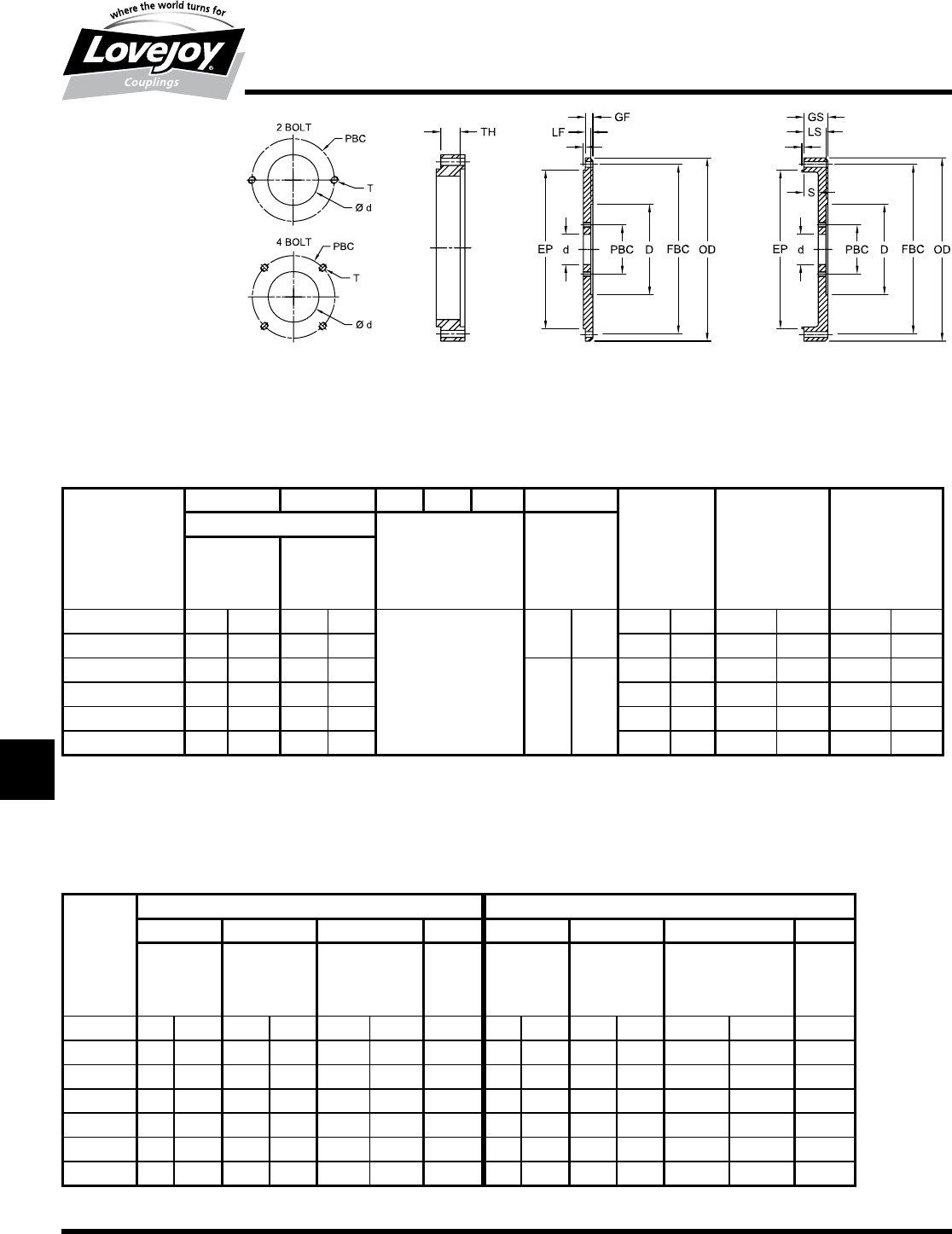
298 630-852-0500
T-40
Torsional
Pump Mounting Plates – SAE J744
Dimensional Data
Spacer Rings
Spacer■rings■are■available■
for■all■SAE■bell■housing■
sizes■(1,2,3,4,5,6).■■The■
rings■provide■additional■
space■standoff■from■the■
engine■flywheel■housing■and■
the■pump■mounting■spacer■
plate.■■The■spacer■ring■will■
provide■the■necessary■area■
between■the■flywheel■and■
the■pump■for■the■proper■
torsional■coupling.■■When■
ordering■spacer■rings,■
specify■the■SAE■bell■housing■
size■and■required■thickness.
0.13 0.13
0.13 0.13
Pump Flange Spacer Ring Pump Mounting Plate Unitized Spacer Ring and
Pump Mounting Plate
Pump Mounting Plates - SAE J744 Dimensional Data
GF LF GS LS S TH* OD EBC EP
Flywheel Pump Mounting Plate Spacer Spacer Ring Bolt Circle Pilot
Housing Plate Minimum Diameter
SAE J617C Thickness
Size in mm in mm in mm in mm in mm in mm
10.88 22.4 0.75 19.1
Based■on■customer■request
0.88 23
21.75 552 20.875 530.2 20.125 511.2
20.88 22.4 0.75 19.1 19.25 489 18.375 466.7 17.625 447.7
30.50 12.7 0.44 11.2
0.63 16
17.75 451 16.875 428.6 16.125 409.6
40.50 12.7 0.44 11.2 15.88 403 15.000 381.0 14.250 362.0
50.50 12.7 0.44 11.2 14.00 356 13.125 333.4 12.375 314.3
60.50 12.7 0.44 11.2 12.13 308 11.250 285.8 10.500 266.7
Notes:■■ n■■■*■indicates:■Minimum■thickness■specified■in■chart.■■Total■thickness■is■based■on■customer■request.■
■n■■■For■use■with■hydraulic■pumps■having■standard■SAE■mountings■and■spline■shafts.
Note:■■ n■■6■bolt■universal■pump■mounting■design■is■available■and■is■typical■standard■design.
Hydraulic Pump Mounting - SAE J744 Dimensional Data
2 Bolt Design 4 Bolt Design
d PBC D T d PBC D T
Pump Pilot Bolt Pump Thread Pilot Bolt Pump Thread
Mounting Dia Circle Face Dia Size Dia Circle Face Dia Size
Flange in mm in mm in mm in in mm in mm in mm in
A-A 2.00 50.80 3.25 82.6 7 177.80 5/16-18 — — — — — — —
A3.25 82.55 4.18 106.4 7 177.80 3/8-16 — — — — — — —
B & B-B 4.00 101.60 5.75 146.0 8 203.20 1/2-13 4.00 101.60 5.00 127.00 8 203.20 1/2-13
C & C-C 5.00 127.00 7.12 181.0 10 254.00 5/8-11 5.00 127.00 6.38 162.05 10 254.00 1/2-13
D6.00 152.40 9.00 228.6 14 355.60 3/4-10 6.00 152.40 9.00 228.60 14 355.60 3/4-10
E6.50 165.10 12.50 317.5 16 406.40 1-8 6.50 165.10 12.50 317.50 16 406.40 3/4-10
F7.00 177.80 13.78 350.0 18 457.20 1-8 7.00 177.80 13.87 352.30 18 457.20 1-8
JWJISCJSFMCGHPGDD
T
SPUJVSDRSLDED
JW JIS CJ SF MC G HP GD D T SP UJ VSD R SLD ED
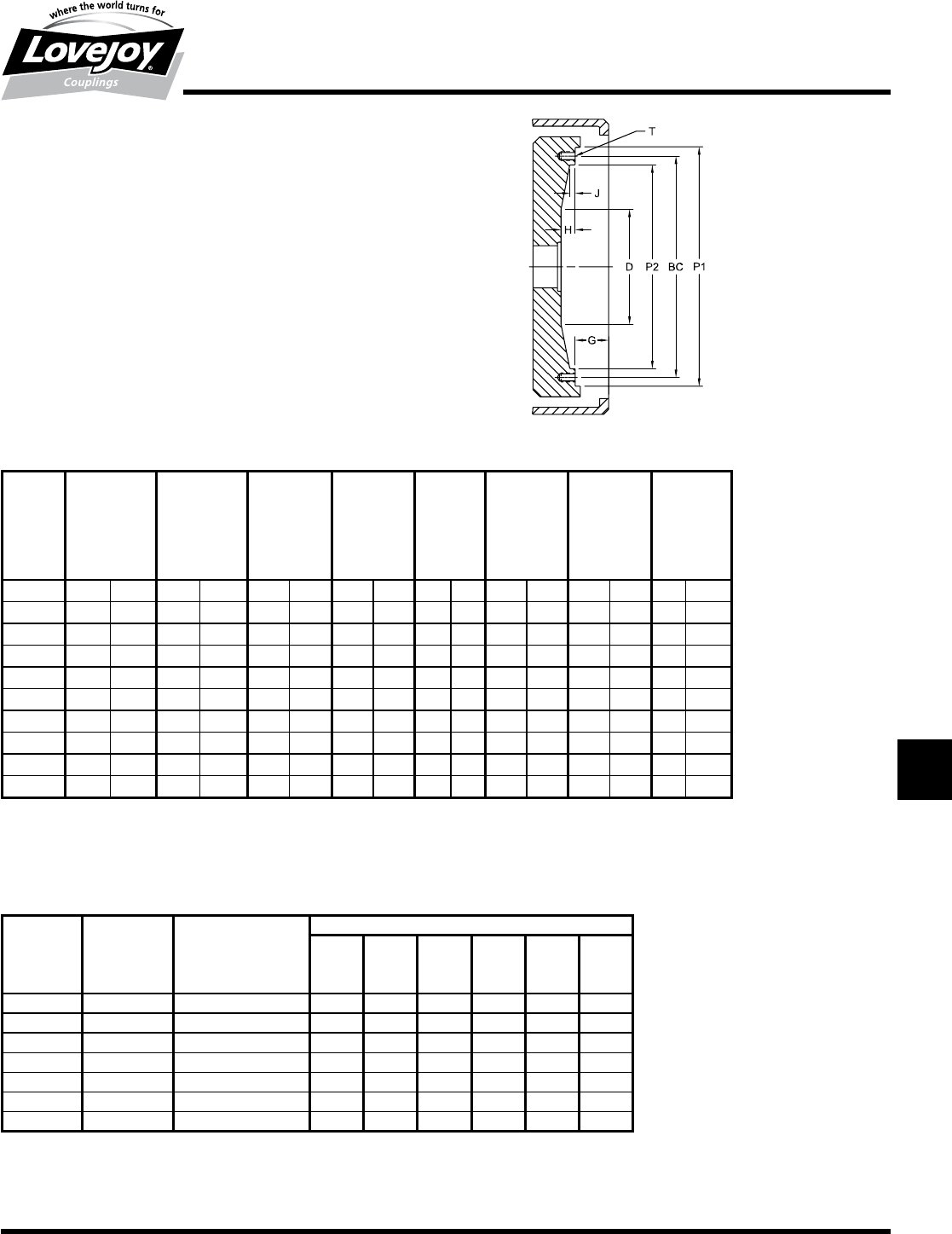
299
www.lovejoy-inc.com T-41
Torsional
Pump Mounting Plates – SAE J620
Dimensional Data
Features
■■Available■in■flat■and■spacer■types
■■SAE■housing■sizes■1■to■6
■■SAE■hydraulic■pump■size■A■to■D
■■DIN■hydraulic■pump■pilot■and■bolt■patterns■also■available
■■Provides■easy■mounting■to■engine■flywheel■housing
Typical Flywheel Housing Combinations
SAE LF Series LK Series SAE J617C Flywheel Housing
J620D
Flywheel
Size Size Size 6 5 4 3 2 1
6.5 8■thru■28 100 s s
7.5 8■thru■28 100 l l
88■thru■30 100 s
10 8■thru■140 100,■125 l s s
11.5 16■thru■140 100,■125,■150,■150D l l s
14 28■thru■250 150,■UNIV l
18 250 UNIV l
Notes:■■ s■indicates:■Preferred■combinations.
■l ■indicates:■Optoinal■sizes■available.
Pump Mounting Plates - SAE J620 Flywheel Dimensional Data
P1 BC P2 J H G D T
Nominal Tapped
Clutch Holes
(flywheel)
Size in mm in mm in mm in mm in mm in mm in mm Qty Size
6.5 8.500 215.90 7.875 200.03 7.25 184.2 0.38 9.7 0.50 0.5 1.19 30.2 5.00 127.0 6 5/16-18
7.5 9.500 241.30 8.750 222.25 8.13 206.4 0.50 12.7 0.50 0.5 1.19 30.2 — — 8 5/16-18
810.375 263.53 9.625 244.48 8.88 225.4 0.50 12.7 0.50 0.5 2.44 62.0 — — 6 3/8-16
10 12.375 314.33 11.625 295.28 10.88 276.2 0.50 12.7 0.62 0.6 2.12 53.8 7.75 196.9 8 3/8-16
11.5 13.875 352.43 13.125 333.38 12.38 314.3 0.88 22.4 1.12 1.1 1.56 39.6 8.00 203.2 8 3/8-16
14 18.375 466.73 17.250 438.15 16.13 409.6 0.88 22.4 1.12 1.1 1.00 25.4 8.00 203.2 8 1/2-13
16 20.375 517.53 19.250 488.95 18.13 460.4 0.88 22.4 1.12 1.1 0.62 15.7 75.00 1905.0 8 1/2-13
18 22.500 571.50 21.375 542.93 19.63 498.5 1.25 31.8 1.25 1.3 0.62 15.7 10.00 254.0 6 5/8-11
21 26.500 673.10 25.250 641.35 23.00 684.2 1.15 29.2 1.25 1.3 — — — — 12 5/8-11
24 28.875 733.43 27.250 692.15 25.38 644.5 1.25 31.8 1.25 1.3 — — — — 12 3/4-10
JWJISCJSFMCGHPGDDTSPUJVSDRSLDED
JW JIS CJ SF MC G HP GD D
T
SP UJ VSD R SLD ED
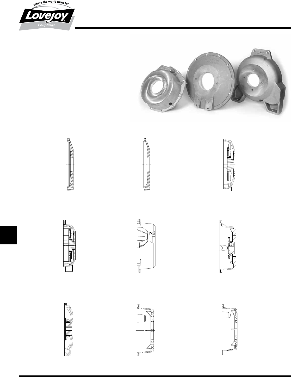
300 630-852-0500
JWJISCJSFMCGHPGDD
T
SPUJVSDRSLDED
JW JIS CJ SF MC G HP GD D T SP UJ VSD R SLD ED
T-42
Torsional
Pump Mounting Housings
Overview
Pump Mounting Housings
Pump■mounting■housings■are■required■to■mount■pumps■
on■engines■that■do■not■have■an■SAE■flywheel■housing.■■
Lovejoy■offers■pump■mounting■housings■for■the■following■
engines.■■All■are■available■with■SAE■pump■mounting■pilots■
and■bolt■patterns.■■Custom■mounting■pilots■and■bolt■patterns■
available■upon■request.■■Housings■are■made■of■high■strength■
Aluminum,■designed■to■support■the■weight■of■the■hydraulic■
pump■without■the■need■for■a■rear■pump■support■mount.■■
The■LK80■and■LK100■are■available■to■match■the■flywheel■
options■for■the■various■engines■and■can■be■paired■with■the■
appropriate■housing■to■provide■a■complete■kit.
Deutz® FL1001
Kubota® Super Mini
Perkins® 103-10
Shown■with■LK100
Cummins® B3.3
Shown■with■LK100
Ford® LRG 425
Shown■with■LK100
Kubota® Super 03
Shown■with■LK100
Ford® VSG 413
Shown■with■LK100
Kubota® Super 05
Shown■with■LK80
Perkins® 104-22
Shown■with■LK100
