UHF_type_II_User_Manual_Rev_1.5_21112018x UHF Type II User Manual Rev 1.5
User Manual:
Open the PDF directly: View PDF ![]() .
.
Page Count: 19

USER MANUAL
UHF Transceiver Type II

ENDUROSAT 2
UHF TRANSCEIVER TYP
E II
–
USER MANUAL
1 Change Log ................................................................................................................... 3
2 Acronyms List................................................................................................................. 4
3 System Overview ............................................................................................................ 5
4 Highlighted Features ....................................................................................................... 5
5 System Description ......................................................................................................... 6
6 RF Characteristics .......................................................................................................... 7
6.1 Transmitter ................................................................................................................................................ 7
6.2 Receiver ..................................................................................................................................................... 10
7 Connector Pinout .......................................................................................................... 12
7.1 Connector Location ................................................................................................................................ 12
7.2 H1 - Stack Connector .............................................................................................................................. 13
7.3 H2 - Stack Connector .............................................................................................................................. 14
7.4 Antenna Release Connector ................................................................................................................. 15
7.5 Jumper ....................................................................................................................................................... 15
7.6 Mini USB .................................................................................................................................................... 15
8 Electrical Characteristics ............................................................................................... 15
9 LED Indicators .............................................................................................................. 16
10 Mechanical Drawing ..................................................................................................... 17
11 Environmental and Mechanical Testing .......................................................................... 18
12 Materials and Processes ............................................................................................... 18
13 Handling and Storage ................................................................................................... 18
14 Warnings ...................................................................................................................... 19
ENDUROSAT 3
UHF TRANSCEIVER TYP
E II
–
USER MANUAL
UHF TRANSCEIVER TYPE II
USER MANUAL
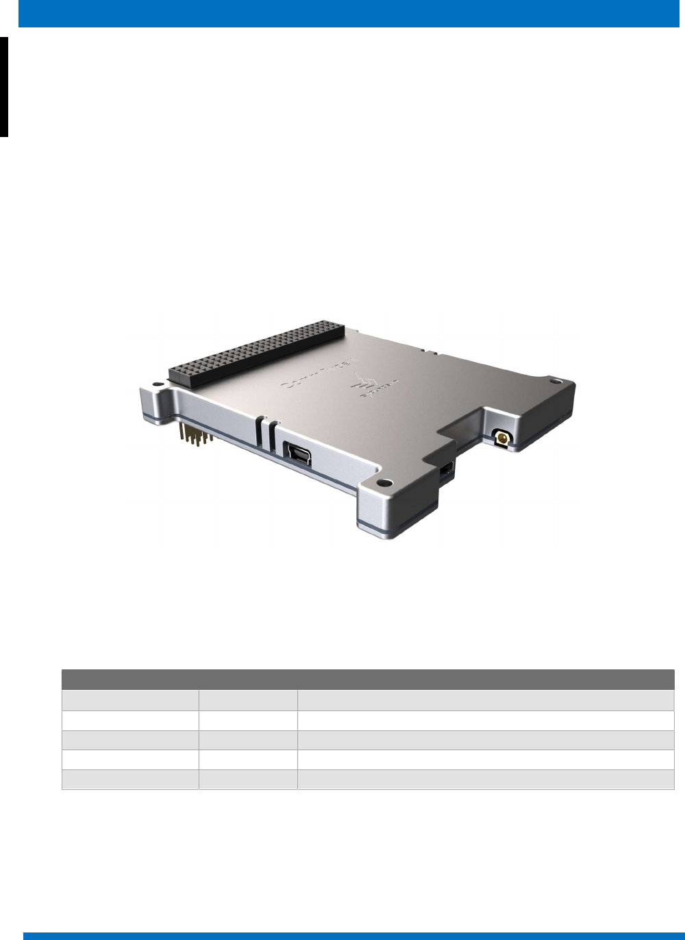
This user manual details the applications, features and operation of EnduroSat's UHF Transceiver Type II
module.
Please read this manual before unpacking and using the module to ensure safe and proper use.
Figure 1 – UHF transceiver type II module
1 CHANGE LOG
Date Version Note
0
2/
11
/201
7
Rev
1
0
2/
04
/2018
Rev 1.2
Detailed antenna release connector pinout
24/04/2018 Rev 1.3 Changes in text
15/06/2018 Rev 1.4 Pinout changes
21
/11/2018
Rev 1.5
Te
c
hnical writing enhancements.

ENDUROSAT 4
UHF TRANSCEIVER TYP
E II
–
USER MANUAL
2 ACRONYMS LIST
AX.25
Amateur X.25 data link layer protocol
AFC Automatic Frequency Correction
CAN
Controller Area Network
ECSS European Cooperation for Space Standardization
EMI Electromagnetic interference
ESD Electrostatic Discharge
FRAM Ferroelectric Random-Access Memory
FSK Frequency-Shift Keying
GEVS General Environmental Verification Standard
GFSK Gaussian Frequency Shift Keying
GMSK
Gaussian Minimum Shift Keying
GND Ground
IC Integrated Circuit
I2C Inter-Integrated Circuit
LNA Low-Noise Amplifier
MCU
Microcontroller Unit
MMCX
Micro
-
miniature Coaxial
NF
Noise Figure
OBC
On
-
Board Computer
O
O
K
On
-
Off Keying
PA
Power
Amplifier
PCB
Printed Circuit Board
PER
Packet Error Ratio
RF
Radio Frequency
Rx Receive
SNR
Signal
-
to
-
noise ratio
SPI Serial Peripheral Interface
Tx Transmit
Tx/Rx Transmit and Receive
UART Universal Asynchronous Receiver/Transmitter
UHF Ultra-High Frequency
USB Universal Serial Bus
VCP Virtual Com Port

ENDUROSAT 5
UHF TRANSCEIVER TYP
E II
–
USER MANUAL
3 SYSTEM OVERVIEW
EnduroSat's UHF Transceiver Type II module operates in the commercial frequency band 400 to 403
MHz (Tx/Rx), and the amateur frequency band 430 to 440 MHz (Tx/Rx). Furthermore, it features
configurable data rates, which can be changed whilst the satellite is in orbit.
The output power can also be tuned in order to maximize the link budget depending on the orbital
altitude, ground station performance and desired minimum elevation angle for communication. The
typical output power is 1W (30dBm) but the system allows the power to be boosted up to 2W (33dBm).
The system has a USB (virtual COM port) which allows the connection of EnduroSat's PC Software or
Terminal Program for monitoring and configuring. The module is designed to fit within a CubeSat, but
a second module can also be integrated in to a ground station to easily create a complete uplink and
downlink communication solution. The module uses the popular AX.25 data protocol.
The UHF transceiver is fully encapsulated in an aluminum box which is designed to dissipate the heat
from the power amplifier, reduce EMI and EMC, and protect the electronics from particle radiation.
4 HIGHLIGHTED FEATURES
Frequency range (Tx/Rx): 400 to 403 MHz, and 430 to 440 MHz
Modulation: OOK, GMSK, 2FSK, 4FSK and 4GFSK are optional, 2GFSK (by default)
Automatic Frequency Correction
Configurable AX.25 telemetry beacon broadcast
Morse code
Audio beacon
Protocols: transparent, AX.25
Maximum transmit power: 1 W (customizable up to 2 W)
Power supply: 3.3 V (customizable to 5 V)
Ultra-low power MCU with FRAM
External FRAM
Typical current consumption during receive mode (idle mode) (Rx): 25mA @ 3.3V
Frequency stability: +/- 2.5 ppm
Data rate in the air: up to 19.2kbps (optional up to 100 kbps)
Sensitivity: up to -121 dBm
Communication interfaces: UART / I2C / USB (VCP) / RS485 (opt.) / CAN (opt.)
Local and remote (in-flight) secured application firmware update
ENDUROSAT 6
UHF TRANSCEIVER TYP
E II
–
USER MANUAL
Type: Half-duplex
Weight: 94g
5 SYSTEM DESCRIPTION
The UHF Transceiver Type II works in the frequency range 400 to 403 MHz, and 430 to 440 MHz.
Different modulation schemes are available, among them 2FSK, 4FSK, the spectrum efficient 2GFSK,
4GFSK, GMSK, and OOK as well.
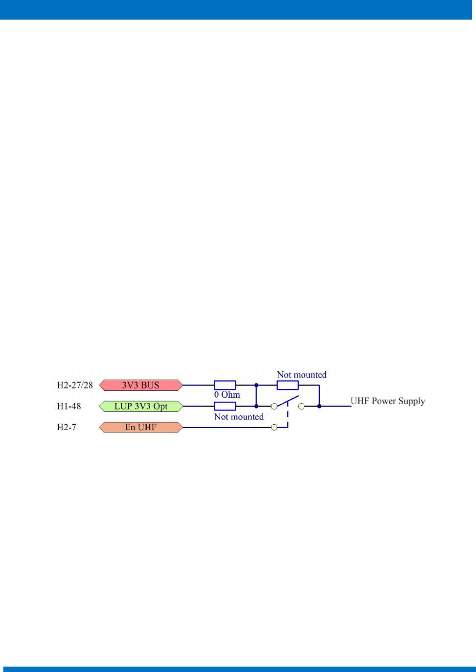
The power supply block diagram is shown in figure 2.
By default, the transceiver works in half-duplex mode with configurable data rate and modulation index
(m). It has the option to transmit a beacon signal with predefined information. The default data and
command interfaces are UART and I2C. Optionally, RS485 and CAN could be used. Additionally, it has
a USB (Virtual COM Port) for configuration by EnduroSat's PC Software or Terminal Program. The
module can also be used in a UHF ground station so that the AX.25 modem, receiver and transmitter
sections can be used for communication purposes. All communication interfaces have dedicated
hardware buffers for protection and when the Enable UHF = OFF (see fig. 2) then the interfaces of the
module go high impedance.
The module can be powered either with 3.3V or 3.3V with latch-up protection with the corresponding
enable pin pulled up in high state. Custom versions of the UHF transceiver can be powered from the
5V bus.
Enable UHF:
ON 1V – 5.5V
OFF 0V – 0.3V
Figure 2: Power Supply Diagram
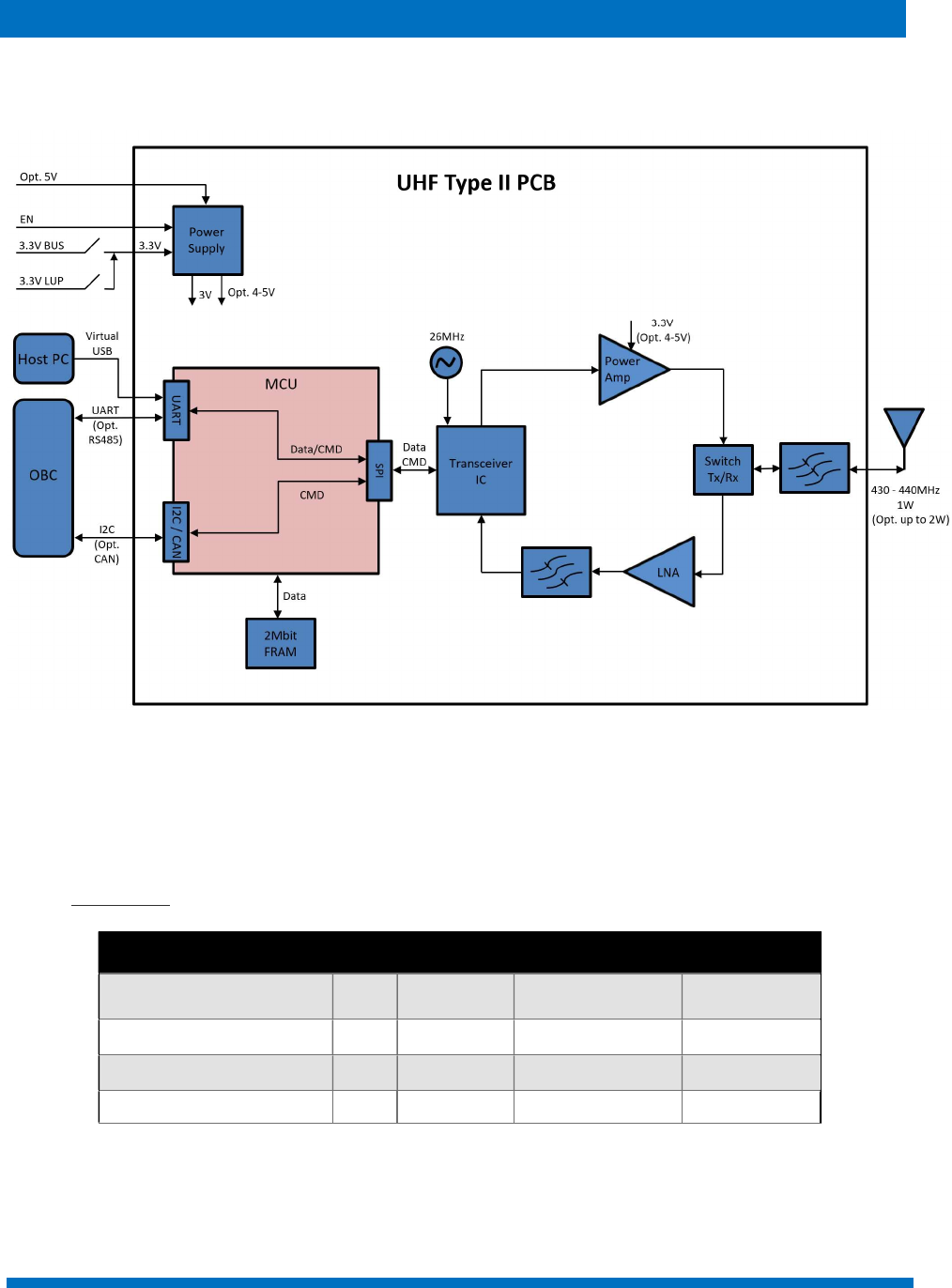
At the core of the RF section there is a high performance transceiver IC. In the transmitter part of the
device, there is a high efficiency RF power amplifier which by default is powered with 3.3V giving an
output power up to 1W. If a 5V bus is used the output power can be boosted up to 2W in specific
versions of the device. In the receiver part, a low noise amplifier with a maximum Noise Figure (NF) of
0.9dB improves the overall receiver performance in terms of sensitivity which is specified down to -
121dBm.
ENDUROSAT 7
UHF TRANSCEIVER TYP
E II
–
USER MANUAL
The device uses a PC-104 connector which is suitable for stackable configurations of other satellite
modules. The RF connector to the antenna is an MMCX.
Figure 3: Functional Block Diagram of the UHF Transceiver Type II
6 RF CHARACTERISTICS
6.1 Transmitter
Parameter
Unit
Min
Typ
ical value
Max
Freq. Range MHz 400 to 403
435 to 438
Output Power W 1 2
Spurious level dBc 60
Baud Rate in The Air bps 1200 19200
ENDUROSAT 8
UHF TRANSCEIVER TYP
E II
–
USER MANUAL
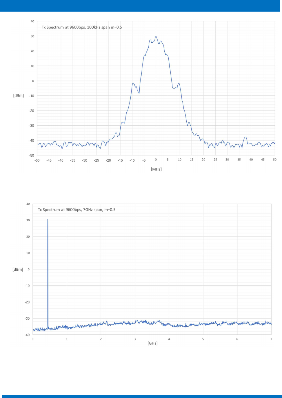
Figure 4: Tx Spectrum at 9600 bps, 100 kHz Span, m=0.5
Figure 5: Tx Spectrum at 9600 bps, 7 GHz Span, m=0.5
ENDUROSAT 9
UHF TRANSCEIVER TYP
E II
–
USER MANUAL
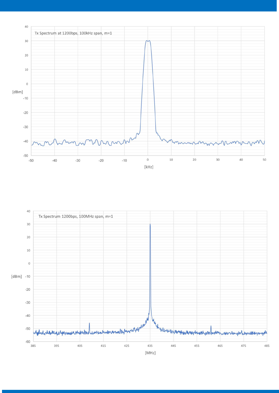
Figure 6: Tx Spectrum at 1200 bps, 100 kHz Span, m=1
Figure 7: Tx Spectrum at 1200 bps, 100 MHz Span, m=1
ENDUROSAT 10
UHF TRANSCEIVER TYP
E II
–
USER MANUAL
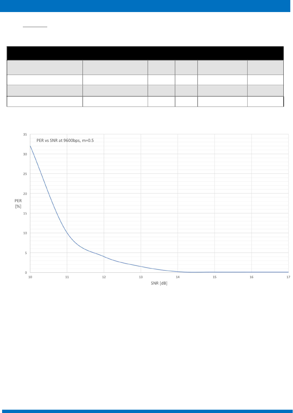
6.2 Receiver
Figure 8 - PER vs SNR at 9600 bps, m=0.5
Parameter
Condition
Unit
Min
Typ
ical value
Max
Freq. Range MHz 400÷403,
435÷438
Baud Rate In The Air bps 1200 19200
SNR
PER<1%
@9600
bps
dB 14
Input Power dBm 10
ENDUROSAT 11
UHF TRANSCEIVER TYP
E II
–
USER MANUAL
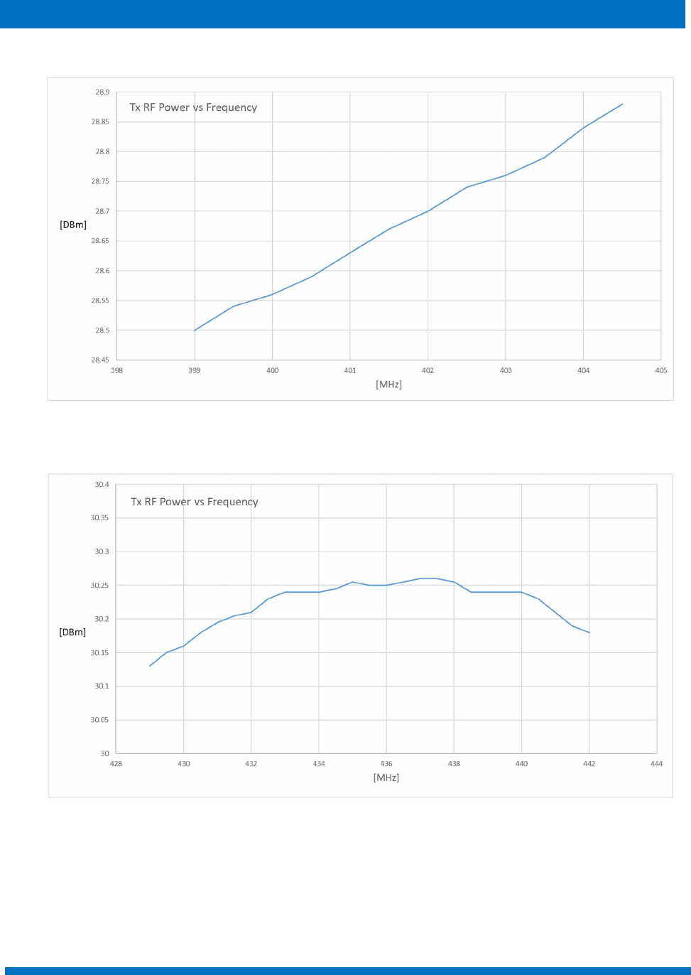
Figure 9: Tx RF Power vs Frequency [399 to 404 MHz] at 3.3Vdc, 24°C
Figure 10: Tx RF Power vs Frequency [429÷442Mhz] at 3.3Vdc, 24°C
ENDUROSAT 12
UHF TRANSCEIVER TYP
E II
–
USER MANUAL
7 CONNECTOR PINOUT
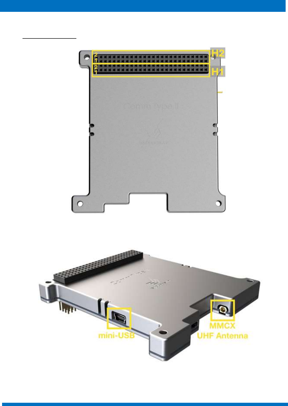
7.1 Connector Location
Figure 11: Main Stack Connector Location
Figure 12: MMCX and Mini-USB Connector Location
ENDUROSAT 13
UHF TRANSCEIVER TYP
E II
–
USER MANUAL
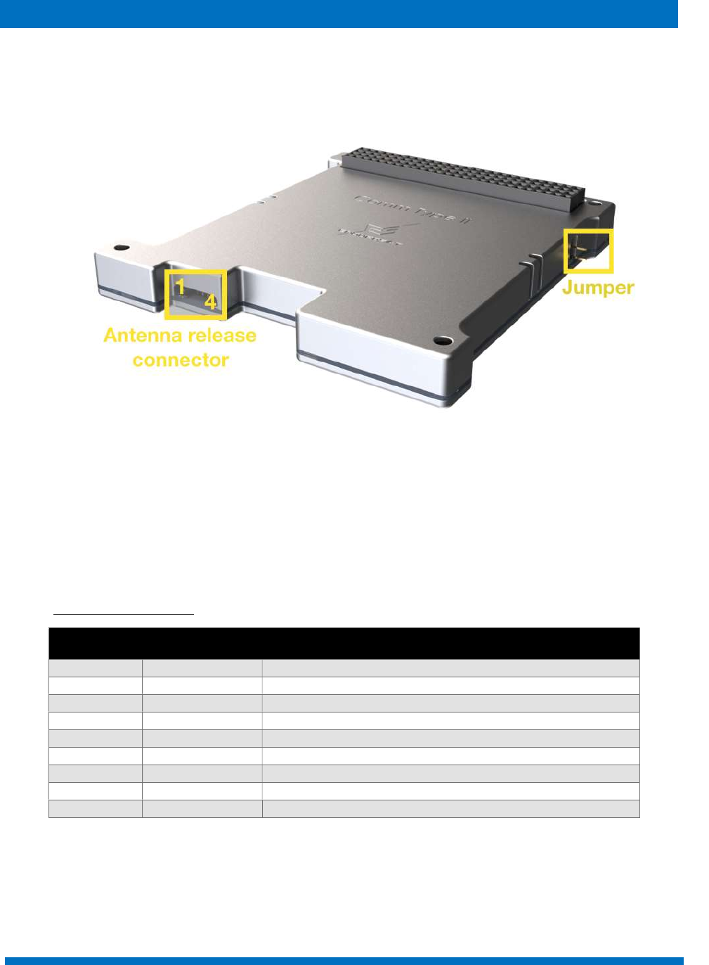
Figure 13 – Antenna Release Connector and Jumper Location
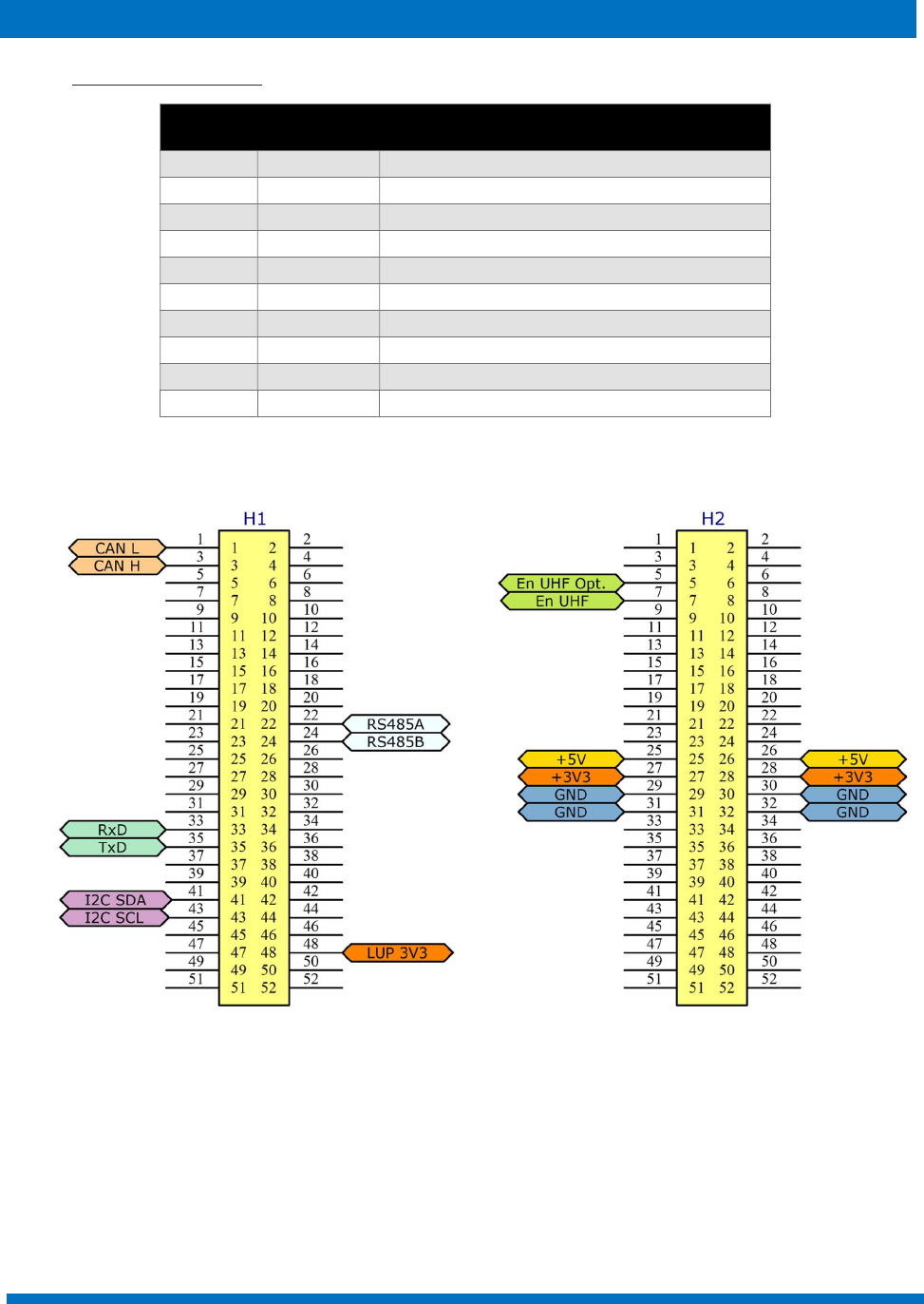
7.2 H1 - Stack Connector
Pin Mnemonic Description
H1-1 CAN L CAN communication Low (3.3V)
H1-3 CAN H CAN communication High (3.3V)
H1-22 RS485A RS-485 Driver output or receiver input (complementary to B)
H1-24 RS485B RS-485 Driver output or receiver input (complementary to A)
H1-33 RxD UART receive data
H1-35 TxD UART transmit data
H1-41 I2C SDA I2C data
H1-43 I2C SCL I2C clock
H1-48 LUP 3V3 Latch-up protected 3.3V power bus (input)
ENDUROSAT 14
UHF TRANSCEIVER TYP
E II
–
USER MANUAL
7.3 H2 - Stack Connector
Pin Mnemonic Description
H2-5
En UHF Opt.
UHF power enable pin (optional)
1
H2-7 En UHF UHF power enable pin
H2-25 +5V +5V BUS Power supply (optional)
H2-26 +5V +5V BUS Power supply (optional)
H2-27 +3V3 +3.3V BUS Power supply
H2-28 +3V3 +3.3V BUS Power supply
H2-29 GND Ground
H2-30 GND Ground
H2-31 GND Ground
H2-32 GND Ground
1
can be used to control a secondary UHF Module
Figure 14: Headers Pinout
ENDUROSAT 15
UHF TRANSCEIVER TYP
E II
–
USER MANUAL
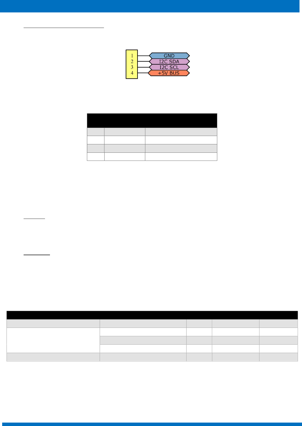
7.4 Antenna Release Connector
Figure 15: Antenna release connector pinout
Pin Mnemonic Description
1 Ground Ground
2 I2C SDA
I
2
C
data
pin
3 I2C SCL
I
2
C
clock
pin
4 +5V +5V BUS
All pins of the antenna release connector are directly connected to the H1&H2 stack connectors.
7.5 Jumper
As shown in figure 13, there is a 2 pin jumper on the side of the module. When the jumper is mounted,
the UHF module starts immediately to transmit Morse code followed by the audio beacon.
7.6 Mini USB
The Mini-B USB shown in figure 12 enables the device to be monitored and configured by EnduroSat's
software or third-party software. The module can be used as an AX.25 receiver.
8 ELECTRICAL CHARACTERISTICS
Parameter
Condition
Min
Typ
ical
value
Max
Supply Voltage [V]
3.2
3.3
1
5V Opt.
Current Consumption [mA]
Receive mode (Idle mode) 20 25
2
30
Transmit mode 413
3
Continuous wave mode
7
0
0
780
4
800
Operating temperature
[°C]
-
35
80
1 This voltage directly supplies the internal power amplifier. Changes in the supply voltage will reflect in the output transmit power.
2 Typical current consumption at 3.3Vdc power supply using only the UART and I2C interfaces (CAN and RS485 are turned off).
3 Typical current consumption depends on the ratio of transmit vs receive mode duration. For 50% Tx / 50%, then the consumption would be
as follows: 0.5*800 mA (Tx CW) + 0.5*25 mA (Rx) = 413 mA @ 3.3 V.
4 Typical current consumption at 3.3Vdc and 435MHz working frequency
ENDUROSAT 16
UHF TRANSCEIVER TYP
E II
–
USER MANUAL
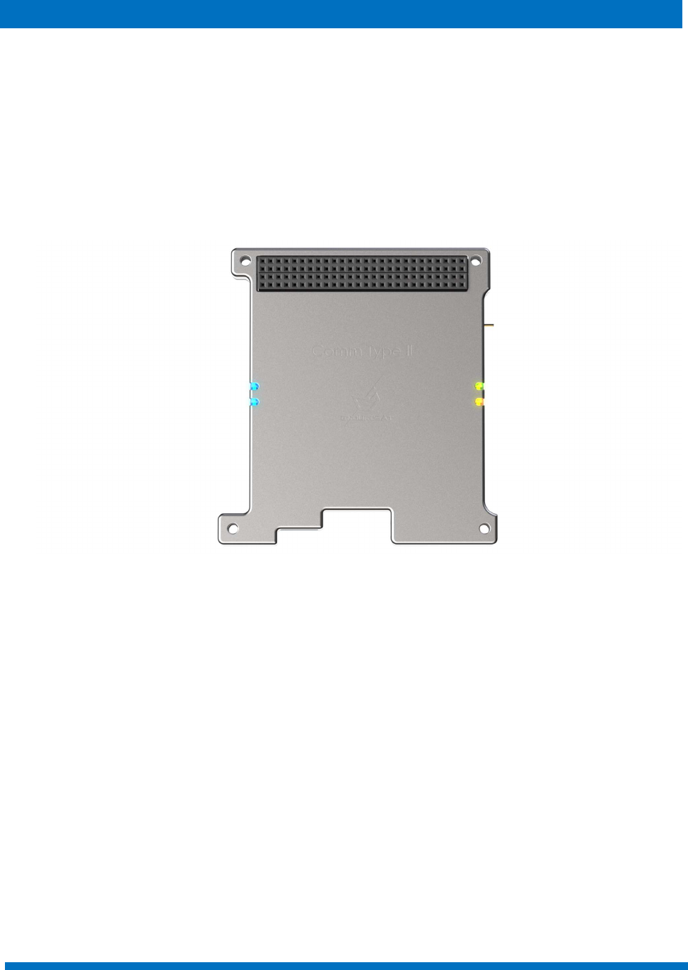
9 LED INDICATORS
As shown in Figure 16, the system has LED indicators to give information about its status.
Blinking of the blue LEDs (left side) – USB communication
Blinking of the green LED (right side) – transmitting;
Blinking of the orange LED (right side) – receiving.
Figure 16: LED indicators
ENDUROSAT 17
UHF TRANSCEIVER TYP
E II
–
USER MANUAL
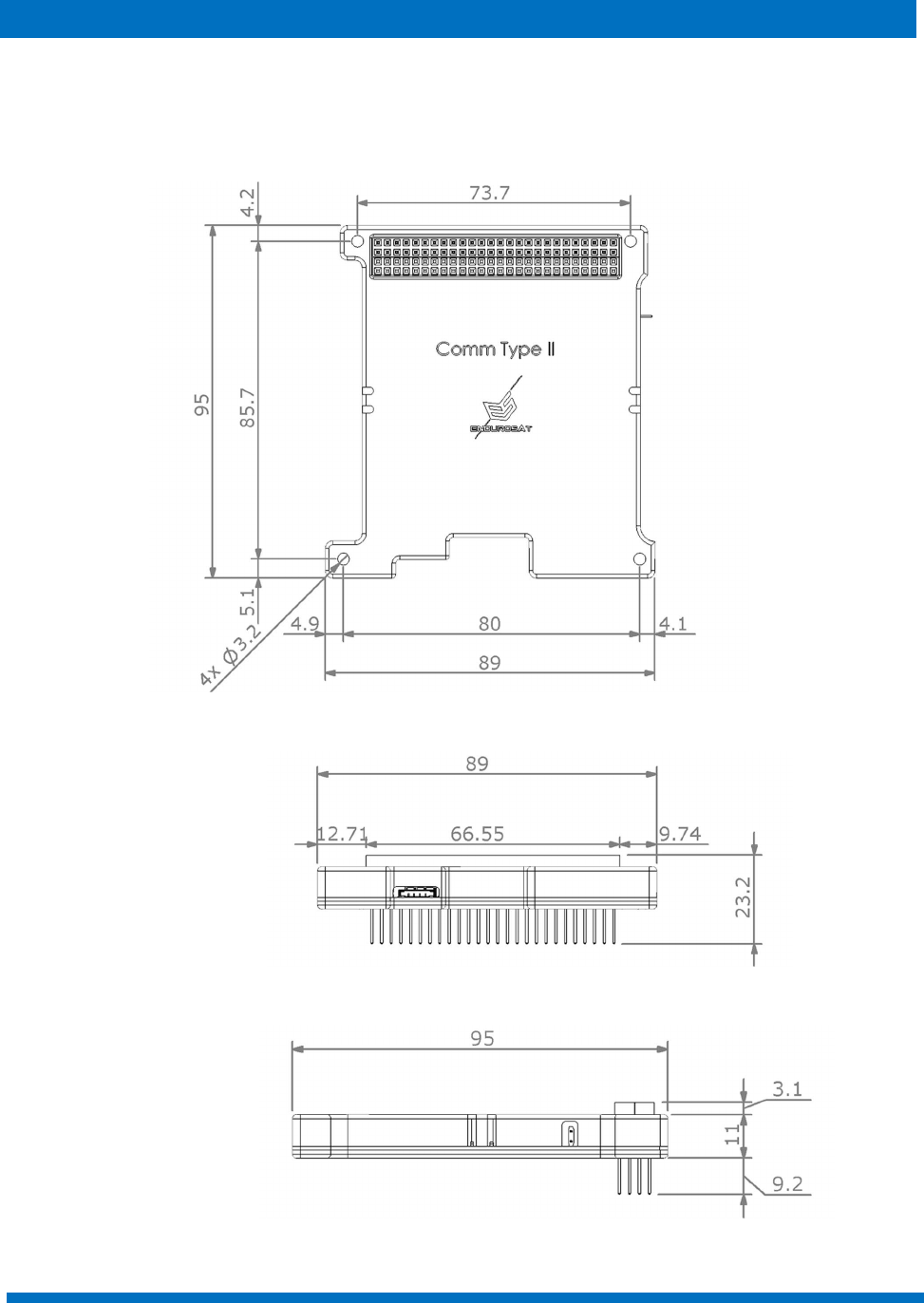
10 MECHANICAL DRAWING
The following pictures show the external dimensions of the UHF Transceiver Type II module.
STEP files can be provided upon request. All dimensions are in mm.
Figure 17: UHF transceiver Type II - Top View
Figure 18: UHF Transceiver Type II - Side View
Figure 19: UHF Transceiver Type II - Side View

ENDUROSAT 18
UHF TRANSCEIVER TYP
E II
–
USER MANUAL
11 ENVIRONMENTAL AND MECHANICAL TESTING
A full campaign of tests at qualification level was performed on the qualification engineering model.
Qualification tests level and duration follow the GEVS standard: GSFC-STD-7000A. Test performed:
Random Vibration
Sinusoidal Vibration
Pyroshock Test
Thermal Cycling
Thermal Vacuum
Total Ionizing Dose
12 MATERIALS AND PROCESSES
Surface mount technology component placement
Standard: IPC-A-610E Class 3
Aluminum 6061 T651 box
Visually inspected
X-ray checked
Functionally verified
13 HANDLING AND STORAGE
Particular attention shall be paid to the avoidance of damage of the communication module during
handling, storage and preservation. The handling of the communication module should be performed
in compliance with the following instructions:
Handle using PVC, latex, cotton (lint free) or nylon gloves.
The environment where the device will be handled shall meet the requirements for a class
environment 100,000, free of contaminants such dust, oil, grease, fumes and smoke from any
source.
Store in such a manner as to preclude stress and prevent damage.
To prevent the deterioration of the module, then the module shall be stored in a controlled
environment (i.e. the temperature and humidity levels shall be maintained within the proper
ranges):
o Ideal storage temperature range: 15ºC to 27ºC
o Ideal storage humidity range: 30% to 60% relative humidity (RH)
ENDUROSAT 19
UHF TRANSCEIVER TYP
E II
–
USER MANUAL
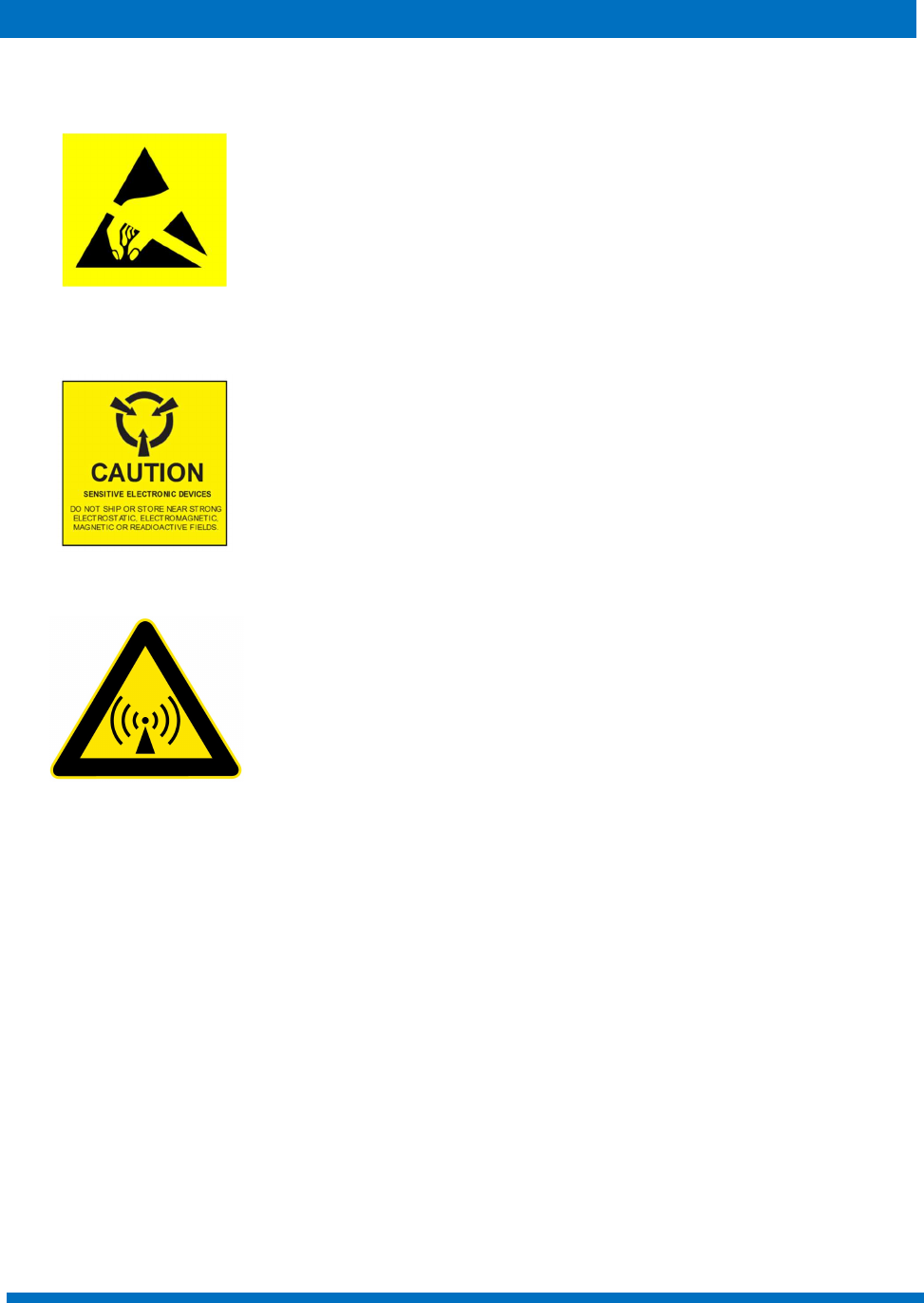
14 WARNINGS
This product uses semiconductors that can be damaged by
electrostatic discharge (ESD). Observe precautions for handling.
Sensitive Electronic device. Do not ship or store near strong
electrostatic, electromagnetic, magnetic or radioactive fields.
Communication module. Do not transmit without antenna or
attenuator. Be mindful of RF interference issues.
