WaveDump UM2091 Wave Dump User Manual Rev13
User Manual:
Open the PDF directly: View PDF ![]() .
.
Page Count: 31
- Purpose of this Manual
- Change Document Record
- Symbols, Abbreviated Terms and Notation
- Reference Document
- Index
- List of Figures
- List of Tables
- 1 Introduction
- 2 Software Interface
- 3 On-line Commands
- 4 Configuration File Syntax
- Common Settings
- OPEN LinkType LinkNumber NodeNumber BaseAddress
- CORRECTION_LEVEL <CORR_MASK> <CUST_TABLE_MASK> <FILENAME1> <FILENAME2> ...
- DRS4_FREQUENCY option
- GNUPLOT_PATH “path”
- OUTPUT_FILE_FORMAT option
- OUTPUT_FILE_HEADER option
- RECORD_LENGHT Ns
- TEST_PATTERN option
- ENABLE_DES_MODE option
- EXTERNAL_TRIGGER option
- FAST_TRIGGER option
- ENABLED_FAST_TRIGGER_DIGITIZING option
- MAX_NUM_EVENTS_BLT Ne
- DECIMATION_FACTOR Ns
- POST_TRIGGER value
- PULSE_POLARITY option
- USE_INTERRUPT value
- FPIO_LEVEL option
- WRITE_REGISTER address data mask
- SKIP_STARTUP_CALIBRATION option
- Individual Settings
- Individual Settings for x742 Fast Trigger Channels
- Common Settings
- 5 Temperature Protection (725 and 730 series only)
- 6 Channel Calibration (725, 730, 751 and 761 series only)
- 7 Technical Support
CAEN
Tools for Discovery
n
Electronic Instrumentation
User Manual UM2091
WaveDump
CAEN Digitizer Readout Application
Rev. 13 - December 22nd, 2017

Purpose of this Manual
This document is the WaveDump User Manual, aligned to the rel. 3.8.2 of the software. It contains information for the
installation, the complete command list explained and the syntax of the configuration file.
Change Document Record
Date
Revision
Changes
April 14th, 2011
04
Revised all chapters, new document format.
March 1st, 2012
05
Revised Chap. 1
June 7th, 2012
06
Updated sections: Sect. System requirements & installation setup
April 3rd, 2014
07
Updated sections: Chap. 4
February 2nd, 2015
08
Revised all chapters, new document format. Major updates in Chap.
2 and 4. Added Chap. 5 7.
November 9th, 2015
09
Updated Chap. 1, 3, 5; added Chap. 6
April 28th, 2016
10
Updated Chap. 2, 4 and 6
January 13th, 2017
11
Updated Chap. 3 and 4
May 31st, 2017
12
Updated Chap. 2, 3 and 4
December 22nd, 2017
13
Updated Sect. Block Diagram. Extended the Decimation support to
the 724 family in Chap. 4. Added note on software compatibility
with A3818 driver in Chap. 2.
Symbols, Abbreviated Terms and Notation
ADC
Analog to Digital Converter
DPP
Digital Pulse Processing
FFT
Fast Fourier Transform
FSR
Full Scale Range
PCB
Printed Circuit Board
Reference Document
[RD1] GD2483 - WaveDump QuickStart Guide
[RD2] GD2783 – First Installation Guide to Desktop Digitizers & MCA
[RD3] Technical Information Manual of V1718 and VX1718 VME – USB2.0 Bridge
[RD4] Technical Information Manual of A3818 PCI Express Optical Link Controller
[RD5] Technical Information Manual of A2818 PCI Optical Link Controller
[RD6] UM1935 - CAENComm User & Reference Manual
[RD7] UM1935 – CAENDigitizer User and Reference Manual
[RD8] Technical Information Manual of x742 Digitizers
[RD9] AN2472 - CONET1 to CONET2 migration
[RD10] GD2512 - CAENUpgrader QuickStart Guide
[RD11] UM5698 - 742 Register Description
[RD12] GD5695 - 742 Quick Start Guide
All documents can be downloaded from: http://www.caen.it/csite/LibrarySearch.jsp

CAEN S.p.A.
Via Vetraia, 11 55049 Viareggio (LU) - ITALY
Tel. +39.0584.388.398 Fax +39.0584.388.959
info@caen.it
www.caen.it
© CAEN SpA – 2017
Disclaimer
No part of this manual may be reproduced in any form or by any means, electronic, mechanical, recording, or otherwise, without the
prior written permission of CAEN SpA.
The information contained herein has been carefully checked and is believed to be accurate; however, no responsibility is assumed for
inaccuracies. CAEN SpA reserves the right to modify its products specifications without giving any notice; for up to date information
please visit www.caen.it.

CAEN
Electronic Instrumentation
UM2091 – WaveDump User Manual Rev. 13
4
Index
Purpose of this Manual .......................................................................................................................................... 2
Change Document Record .................................................................................................................................... 2
Symbols, Abbreviated Terms and Notation ........................................................................................................ 2
Reference Document ............................................................................................................................................. 2
Index ........................................................................................................................................ 4
List of Figures .......................................................................................................................... 5
List of Tables ........................................................................................................................... 5
1 Introduction .................................................................................................................... 6
2 Software Interface .......................................................................................................... 7
Overview .................................................................................................................................................................. 7
Block Diagram ......................................................................................................................................................... 9
Drivers & Libraries ................................................................................................................................................ 10
Drivers ................................................................................................................................................................................10
Libraries .............................................................................................................................................................................10
Installation ............................................................................................................................................................. 12
3 On-line Commands ....................................................................................................... 14
4 Configuration File Syntax ............................................................................................ 16
Common Settings ................................................................................................................................................. 16
OPEN LinkType LinkNumber NodeNumber BaseAddress ..............................................................................16
CORRECTION_LEVEL <CORR_MASK> <CUST_TABLE_MASK> <FILENAME1> <FILENAME2> ... ................16
DRS4_FREQUENCY option ............................................................................................................................................17
GNUPLOT_PATH “path” ...............................................................................................................................................17
OUTPUT_FILE_FORMAT option ...................................................................................................................................18
OUTPUT_FILE_HEADER option ....................................................................................................................................18
RECORD_LENGHT Ns ......................................................................................................................................................18
TEST_PATTERN option ..................................................................................................................................................19
ENABLE_DES_MODE option .........................................................................................................................................19
EXTERNAL_TRIGGER option ........................................................................................................................................19
FAST_TRIGGER option...................................................................................................................................................19
ENABLED_FAST_TRIGGER_DIGITIZING option ........................................................................................................19
MAX_NUM_EVENTS_BLT Ne ........................................................................................................................................19
DECIMATION_FACTOR Ns ...........................................................................................................................................20
POST_TRIGGER value ...................................................................................................................................................20
USE_INTERRUPT value ..................................................................................................................................................20
FPIO_LEVEL option .........................................................................................................................................................20
WRITE_REGISTER address data mask ....................................................................................................................21
SKIP_STARTUP_CALIBRATION option .......................................................................................................................21
Individual Settings ................................................................................................................................................ 22
ENABLE_INPUT option ..................................................................................................................................................22
PULSE_POLARITY option ..............................................................................................................................................20
BASELINE_SHIFT value ..................................................................................................................................................22
DC_OFFSET value ............................................................................................................................................................23
GRP_CH_DC_OFFSET dc_0, dc_1, dc_2, dc_3, dc_4, dc_5, dc_6, dc_7 ..........................................23
TRIGGER_THRESHOLD value .......................................................................................................................................23
CHANNEL_TRIGGER option .........................................................................................................................................24
GROUP_TRG_ENABLE_MASK mask ..............................................................................................................................24
Individual Settings for x742 Fast Trigger channels .......................................................................................... 25
DC_OFFSET value ............................................................................................................................................................25
TRIGGER_THRESHOLD value .......................................................................................................................................25
5 Temperature Protection (725 and 730 series only) .................................................. 27
6 Channel Calibration (725, 730, 751 and 761 series only) ......................................... 28

CAEN
Electronic Instrumentation
UM2091 – WaveDump User Manual Rev. 13
5
Channel Calibration Procedure ........................................................................................................................... 28
7 Technical Support ......................................................................................................... 30
List of Figures
Figure 2.1: C-source files for Windows version. The path is visible in the top bar. .......................................................................7
Figure 2.2: Visual Studio project files for Windows version. The path is visible in the top bar....................................................8
Figure 2.3: CAEN WaveDump software architecture .........................................................................................................................9
Figure 2.4: Required libraries and drivers .........................................................................................................................................11
Figure 2.5: WaveDump message for not supported firmware found ...........................................................................................12
Figure 2.6: Subfolders structure of WaveDump main directory ....................................................................................................13
Figure 4.1: Channel baseline calibration failure when using BASELINE_SHIFT ............................................................................23
Figure 6.1: Example of uncalibrated input channel (baseline case on the right). ........................................................................28
Figure 6.2: Automatic calibration at WaveDump first run ..............................................................................................................28
Figure 6.3: Temperature monitoring with manual calibration command (left) and calibrated input signal (right) ................29
List of Tables
Tab. 1: WaveDump on-line commands ............................................................................................................................................14
Tab. 2: Gnuplot window commands .................................................................................................................................................15

CAEN
Electronic Instrumentation
UM2091 – WaveDump User Manual Rev. 13
6
1 Introduction
The WaveDump User Manual contains information for the installation, the complete command list explained and the
syntax of the configuration file. The user can refer to WaveDump QuickStart Guide (see [RD1]) for a practical first use
example.
WaveDump is a C-based console application developed to control all CAEN digitizer models running the waveform
recording firmware. Digitizers running CAEN special Digital Pulse Processing (DPP) firmware must be controlled by
dedicated readout software, as indicated in the relevant DPP web page.
WaveDump has been thought to demonstrate the use of CAEN libraries and methods for an efficient readout and data
analysis. Besides being a ready to use software, WaveDump is provided with C source files and Visual Studio project to
let the users customize the code for personalized solutions.
Multi-board management is not supported.
WaveDump supports the CAEN digitizers families as in the table below:
Supported
Digitizer Families
720
V1721 – V1731
724
725
730
740
742
751
761
WAVEDUMP MANAGES ONLY CAEN DIGITIZERS RUNNING THE DEFAULT FIRMWARE FOR WAVEFORM RECORDING
WAVEDUMP PERMITS ONLY SINGLE BOARD CONTROL
CAEN
Electronic Instrumentation
UM2091 – WaveDump User Manual Rev. 13
7
2 Software Interface
Overview
WaveDump is a C-based console application for data acquisition management of CAEN digitizer families equipped with
the waveform recording firmware (DPP firmware is not supported). Only a single board can be programmed according
to a text configuration file containing a list of parameters and instructions (see Chap. 4).
Specifically, WaveDump can perform the following operations:
- connect to the digitizer through a physical communication interface (USB, Optical Link);
- read and view information about the board (model, serial number, FW revision, etc.);
- program the digitizer according to parameters written in a configuration file (text file);
- perform channel calibration (automatically at start-up and manually) required by specific digitizer families
- start and stop the acquisition (run on / off);
- enable the software trigger (single shot or continuous);
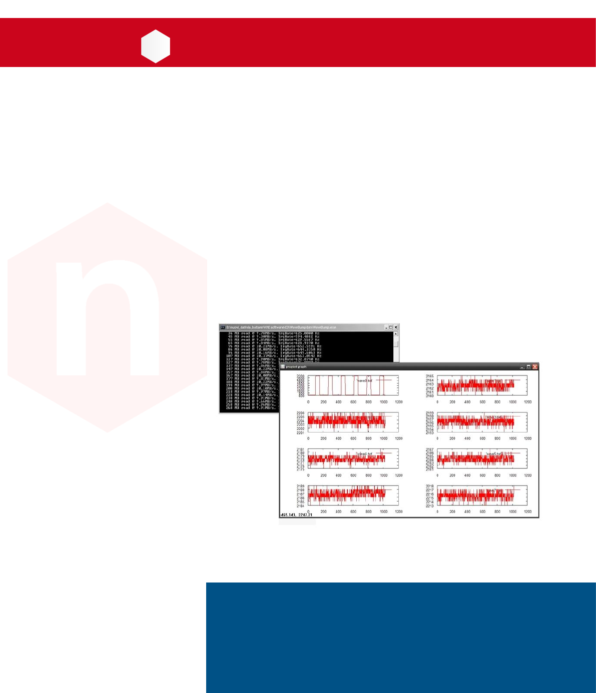
- read the event data and display the data throughput rate (MB/s) and the trigger rate. The readout can take
place with or without the use of interrupts;
- perform some simple data analysis (post processing) such as the signal FFT and the histogram of the samples
amplitude (energy histogram is not supported);
- save the waveforms (sequence of samples) into ASCII or binary output files; the writing can be 'one shot' (i.e.
single event) or continuous (recording of a sequence of events);
- plot, using an external graphical tool (gnuplot), the acquired waveform, the FFT or the histogram of the selected
channels.
WaveDump C-source files and the Visual Studio project are provided for advanced users, allowing for customized
implementations.
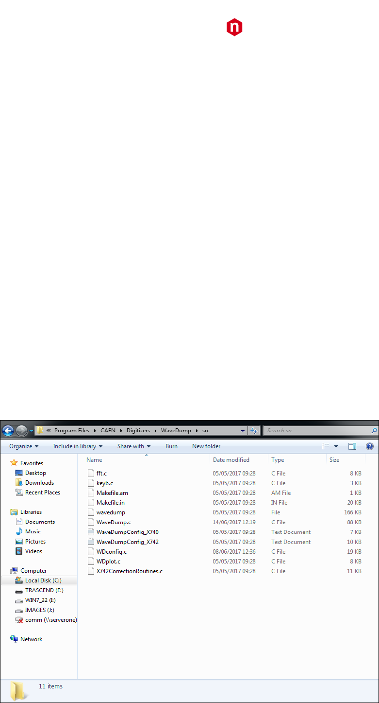
Figure 2.1: C-source files for Windows version. The path is visible in the top bar.
CAEN
Electronic Instrumentation
UM2091 – WaveDump User Manual Rev. 13
8
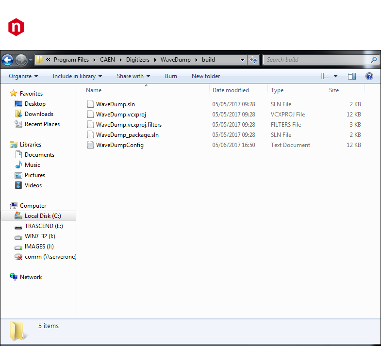
Figure 2.2: Visual Studio project files for Windows version. The path is visible in the top bar.
For Linux version, the C-code files are contained in the “src” subfolder, in the “WaveDump” directory.
The source code of WaveDump shows the sequence of steps to do to program the digitizer and manage the data
acquisition.
Since WaveDump is capable of handling different digitizer types, some parts of the code may be redundant because
they must foresee various cases. Users who want to use a specific digitizer, can remove all those pieces of code that
are not of interest. In case of digitizer with channels managed by groups (e.g. 740 family), to simplify the use of
WaveDump, only 8 channels of one group at a time can be plotted, although all channels are simultaneously enabled
for the acquisition (and so the output files saving.
Beyond the readout, the plot and save of raw data, WaveDump implements also some simple examples of data
analysis (FFT and histogram); starting from them, the user can easily develop his own post-processing algorithms.
Thanks to the C programming language and the absence of a GUI, WaveDump is portable to any platform; the code is
compatible with both Windows and Linux OS.
CAEN
Electronic Instrumentation
UM2091 – WaveDump User Manual Rev. 13
9
Block Diagram
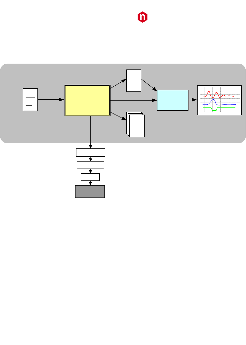
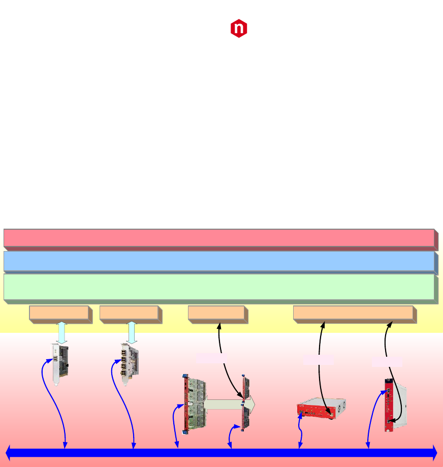
The block diagram of the WaveDump architecture is schematized in Figure 2.3 below.
C application
Config Files
CAENdigitizer
CAENcomm
Drivers
Digitizer
Plot Data File
gnuplot
Commands
Time
ADC counts
1023
1254
9544
123
445
5567
3255
223
44
2334
55643
233
4
Output Files (waveforms)
1023
1254
9544
123
445
5567
3255
223
44
2334
55643
233
4
1023
1254
9544
123
445
5567
3255
223
44
2334
55643
233
4
1023
1254
9544
123
445
5567
3255
223
44
2334
55643
233
4
Plots
pipe
CAEN WaveDump
Figure 2.3: CAEN WaveDump software architecture
The program core is a C application that programs the Digitizer according to a set of parameters as written in the
configuration text file, starts/stops the acquisition and manages the data readout. Data (waveforms, FFTs or
histograms) are plotted using gnuplot, an external plotting tool, or saved to output text files
WaveDump installation directory includes different configuration text files, each one containing a list of possible
parameters including elucidatory comments (see also Sect. Installation and Chap. 4):
• WaveDumpConfig.txt
• WaveDumpConfig_X740.txt
• WaveDumpConfig_X742.txt
The user can edit the configuration file or create a GUI that allows to set the parameters through a control panel and
then generate the configuration file.
As mentioned, to plot the data, WaveDump relies on an external program (namely Gnuplot); data for the plot are
written into a file, while the plot commands are passed from WaveDump to Gnuplot through a pipe. All functions
related to the plotting are contained in a source file separated from WaveDump; the user can replace the calls to
Gnuplot to use other tools. Gnuplot (by version 4.2) is automatically copied to the proper working directory during the
installation of WaveDump (only for Windows installation). Linux users must install Gnuplot apart.

CAEN
Electronic Instrumentation
UM2091 – WaveDump User Manual Rev. 13
10
Drivers & Libraries
Drivers
To deal with the hardware, CAEN provides the drivers for all the different types of physical communication interfaces
featured by the specific digitizer and compliant with Windows and Linux OS:
• USB 2.0 Drivers for NIM/Desktop boards are downloadable on CAEN website (www.caen.it) in the
“Software/Firmware” tab of the digitizer web page (login required).
Note: Windows OS USB driver installation for Desktop/NIM digitizers is detailed in [RD2].
• USB 2.0 Drivers for V1718 CAEN Bridge, required for VME boards interface, is downloadable on CAEN
website (www.caen.it) in the “Software/Firmware” tab of the V1718 web page (login required).
Note: For the installation of the V1718 USB driver, refer to the User Manual of the Bridge [RD3].
• Optical Link Drivers are managed by the A2818 PCI card or the A3818 PCIe card. The driver installation
package is available on CAEN website in the “Software/Firmware” area at the A2818 or A3818 page (login
required)
IMPORTANT:
WAVEDUMP REL. 3.8.1 BUILD DECEMBER 2017 (OR HIGHER) FOR WINDOWS WORKS ONLY WITH A3818 DRIVER
REL. 2.0.0 (OR HIGHER)!
Note: For the installation of the Optical Link driver, refer to the User Manual of the specific Controller [RD4]
[RD5].
Libraries
CAEN libraries are a set of middleware software required by CAEN software tools (including WaveDump) for a correct
functioning. These libraries, including also demo and example programs, represent a powerful base for users who want
to develop customized applications for the digitizer control (communication, configuration, readout, etc.):
• CAENDigitizer is a library of functions designed specifically for the Digitizer family and it supports also the
boards running the DPP firmware. The CAENDigitizer library is based on the CAENComm library. For this
reason, the CAENComm libraries must be already installed on the host PC before installing the
CAENDigitizer.
The CAENDigitizer installation package is available on CAEN website in the ‘Download’ area at the
CAENDigitizer Library page. Reference document [RD7].
• CAENComm library manages the communication at low level (read and write access). The purpose of the
CAENComm is to implement a common interface to the higher software layers, masking the details of the
physical channel and its protocol, thus making the libraries and applications that rely on the CAENComm
independent from the physical layer. Moreover, the CAENComm requires the CAENVMELib library (access to
the VME bus) even in the cases where the VME is not used. This is the reason why CAENVMELib has to be
already installed on your PC before installing the CAENComm.
The CAENComm installation package, and the link to the required CAENVMELib, is available on CAEN website
in the ‘Download’ area at the CAENComm Library page. Reference document [RD6].
CAEN
Electronic Instrumentation
UM2091 – WaveDump User Manual Rev. 13
11
Currently, the CAENComm (and so the CAENDigitizer) supports the following communication interfaces:
• PC → USB → Digitizer (either Desktop or NIM models)
• PC → USB → V1718 → VME → Digitizers (VME models only)
• PC → PCI (A2818) → CONET → Digitizers (all models)
• PC → PCI (A2818) → CONET → V2718 → VME → Digitizers (VME models only)
• PC → PCIe (A3818) → CONET → Digitizers (all models)
• PC → PCIe (A3818) → CONET → V2718 → VME → Digitizers (VME models only)
CONET (Chainable Optical NETwork) indicates the CAEN proprietary protocol for communication on Optical Link. Refer
to [RD9] for useful information.
VME
Digitizers
VMEbus
CONET2 (Optical Link)
Desktop
Digitizers
A2818 A3818
NIM
Digitizers
A2818 driver A3818 driver V1718 driver USB driver
PCI
PCIe
USB 2.0 USB 2.0
USB 2.0
V1718
V2718
CAENDigitizer Library
CAEN WAVEDUMP
CAENComm Library
Figure 2.4: Required libraries and drivers
CAEN
Electronic Instrumentation
UM2091 – WaveDump User Manual Rev. 13
12
Installation
The CAEN WaveDump Software is compliant with both Windows and Linux OS, 32 and 64 bits.
Before installing WaveDump, perform the following steps:
• Make sure that your hardware (Digitizer and/or Bridge, or Controller) is properly installed (refer to the
related User Manual for hardware installation instructions).
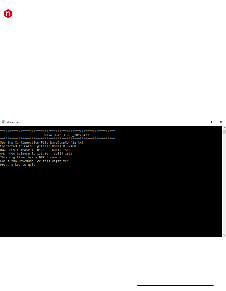
• Make sure that the appropriate firmware is running on the board. You can use the CAENUpgrader tool to
read the digitizer firmware revision (see [RD10]). The waveform recording firmware, which is managed by
WaveDump, can be discriminated by the AMC FPGA firmware revision formatted as:
W.Z
where the major revision number of the AMC FPGA must be less than 128 (i.e. W < 128).
If a not supported firmware is found, WaveDump displays a specific message, as shown in Figure 2.5, and the
user must quit the software.
Figure 2.5: WaveDump message for not supported firmware found
• Make sure you have installed the driver for your OS and the physical communication layer to be used.
Driver installation packages are downloadable on CAEN website (login required) as reported in the Drivers
paragraph.
For Windows users:
CAEN provides the full installation package for WaveDump software in a standalone version for Windows OS. This
version installs all the binary files required to directly use the software (i.e. no need to install the required CAEN
libraries in advance).
• Download the installation package compliant with your OS from CAEN on the WaveDump page (login
required)
• Extract the files to your host.
• Run the installer and complete.
CAEN
Electronic Instrumentation
UM2091 – WaveDump User Manual Rev. 13
13
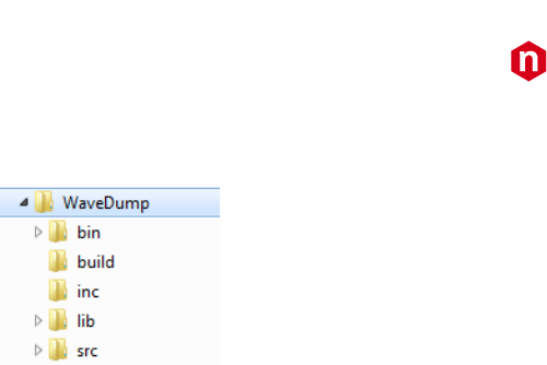
WaveDump is then installed under the folder:
C:\Program Files\CAEN\Digitizers\WaveDump\
Figure 2.6: Subfolders structure of WaveDump main directory
The “bin” subfolder contains the executable file (WaveDump.exe), a general-purpose default configuration file
(WaveDumpConfig.txt), the X742 models default configuration file (WaveDumpConfig_X742.txt) and the X740
models default configuration file (WaveDumpConfig_X740.txt).
Note: In case of a X742 Digitizer, the user should modify directly the X742 configuration file. WaveDump will use that
configuration file when recognizing a X742 board.
Note: In case of a X740 Digitizer, the user can choose to modify the general-purpose file or to modify the X740
template and rename it ‘WaveDumpConfig.txt’.
Note: Administrator rights are required to modify the configuration file WaveDumpConfig.txt of WaveDump under the
“Program Files” folder. To modify the file, the options are to enable full permissions in the original folder or to use the
software without the administrator rights by copying the entire “bin” folder under another location, as for example the
“Documents” folder.
The “build” folder contains the Visual Studio project, while the header and the source code of the WaveDump are in
the “inc” and “src” folders, respectively.
For Linux users:
Linux users must also take care of proper installation of gnuplot graphical tool, as well as of the CAEN Libraries:
CAENVMElib, CAENComm and CAENDigitizer. The libraries can be downloaded from CAEN website (login required).
Installation instructions can be found in the README file inside each library folder.
• Download the WaveDump installation package for Linux from CAEN website on the WaveDump page (login is
required).
• Unpack the installation package (tar –zxf <WaveDump-x.y.z.tar.gz).
• Follow the instruction on the INSTALL file
Type: ./configure
make
sudo make install
Launch the software typing wavedump
The default configuration file location is:
/etc/wavedump/WaveDumpConfig.txt or /etc/wavedump/WaveDumpConfig_x742.txt for X742 boards
Note: Administrator rights are required to modify the configuration file of the WaveDump software under the
“/etc/wavedump” folder.
Alternatively, the user can modify the WaveDumpConfig.txt file that is under the local WaveDump folder:
./wavedump-x.y.z/Setup/WaveDumpConfig.txt
and launch the software typing wavedump and the path of the configuration file.
Note: In case of a X740 or a X742 Digitizer, the user is recommended to modify and use the specific configuration files
WaveDumpConfig_X740.txt and WaveDumpConfig_X742.txt, under the local WaveDump folder
./wavedump-x.y.z/Setup/WaveDumpConfig_X740.txt
./wavedump-x.y.z/Setup/WaveDumpConfig_X742.txt
These files must be loaded typing wavedump and the path of the configuration file.

CAEN
Electronic Instrumentation
UM2091 – WaveDump User Manual Rev. 13
14
3 On-line Commands
Once started (following the instructions in the Sect. Installation), WaveDump parses the configuration file; if a formal
error occurs, it is displayed in the shell.
It is also possible that the parameters and commands are formally correct but some of them are not valid for that type
of digitizer, or a syntax error in the configuration file occurred; this is indicated when programming the digitizer by a
warning message. Although this may not affect the operation of WaveDump, the command that caused the error shall
be found and the wrong value corrected.
Once the digitizer is programmed, WaveDump waits for the start of the acquisition ('s' key). The table below lists the
accepted WaveDump on-line commands associated to specific keys.
Key
Function
s
Start / Stop acquisition
q
Quit WaveDump
R
WaveDump restart; this command allows you to reload the configuration file and restart with a new
acquisition
t
Single Software Trigger; this command sends a software trigger (single shot), useful especially when the
card has no data (no trigger) because it forces the acquisition of an event. In analogy with the
oscilloscope, this command corresponds to the “Force trigger” button.
T
Continuous Software Trigger; this command enables / disables the continuous generation of software
trigger at a fixed rate. Inside the acquisition loop, the program sends a trigger, reads the corresponding
event and executes data analysis. It corresponds to the "Auto trigger” of the oscilloscope.
p
Single-event plot of the waveforms of each channel enabled for plotting (which does not necessarily
coincide with the n channels enabled for acquisition). The plot is single-shot.
P
Continuous Plot; this command enables / disables the continuous plot of the enabled channels.
When enabled, the input signal trace of channel 0 is plotted by default. Check the “c” command to
enable the other channels.
w
Save Single Event to Disk; this command causes the writing of a file for each enabled channel, named
wave_n.txt, where n is the channel number.
Warning: the files are overwritten each time. Each file can be ASCII or binary and may contain a header
or not, depending on the settings assigned in the configuration file.
W
Continuous Event Saving; this command enables / disables the continuous events saving to file. As for
the “w” command, it creates one file per channel; then it writes the events consecutively.
Attention: in this mode, the file size can grow up very quickly.
0 .. 7
This command insert / remove channel n (n = 0 .. 7) from the plot (if such a channel is enabled). In case
of x740, n refers to the channel within the currently active group, for example, if it's on group 2 (channels
16 to 23), press 3 to insert / remove the channel 19. In case of V1725 and V1730, n refers to channel n or
n+8, depending on the visualization mode enabled by the command ‘g’ (see below).
g
In case of 740 and 742 series, this command switches to the next group of 8 channels (only for).
Note: the active group refers only to the plot (in fact, the plotter can handle only 8-traces), while the
acquisition is always enabled on all groups.
In case of V1725 and V1730, this command switches the plot visualization from 0-7 channels to 8-15
channels and vice versa (se also the “0..7” description).
f
This command toggles between waveform plot and FFT plot.
h
This command toggles between waveform plot and histogram samples amplitude plot (not supported by
742 series).
m
This command displays the temperature values (in °C) of the ADC channels. It is supported only by 725,
730 and 751 digitizer families.
c
This command performs the channel calibration required by 725, 730, 751, and 761 digitizer families.
[Space]
This command displays the online help
Tab. 1: WaveDump on-line commands

CAEN
Electronic Instrumentation
UM2091 – WaveDump User Manual Rev. 13
15
Inside the Gnuplot window, there are active bindkeys and functions associated to the mouse:
Key
Function
a
Autoscale to be x-axis and y
r
Enable / Disable ruler
g
Enable / Disable grid
y
Set the scale y at full scale for the specific digitizer (scale x remains unchanged)
p
Return to previous zoom
Tab. 2: Gnuplot window commands
Zoom Area: right click on one corner of the area, release the button, left click on the opposite corner.
Click with the right button on the window bar to open a menu that allows to make the print, copy the screen-shot to
the clipboard, change colours, etc.

CAEN
Electronic Instrumentation
UM2091 – WaveDump User Manual Rev. 13
16
4 Configuration File Syntax
This section describes in detail the WaveDumpConfig.txt general purpose default configuration file; the other text files
include a subset of the settings here defined, which are supported by the relevant digitizer model (740 or 742), to
simplify the use of the software.
The configuration file is located into the “bin” subfolder of the main WaveDump folder (see Figure 2.6), and it is
divided in two parts: common settings, indicated in the [COMMON] section, and individual settings for individual
channel settings indicated in the [n] section, where n is the number of channel (or group in the case of 740 and 742
series). The common settings are set equal to all channels, while the individual settings can be set individually for each
channel (group).
The individual settings can be performed also in the common settings part: in this case, they are applied to all channels.
Note: Settings are executed sequentially, therefore commands written at the end of the file may overwrite settings
written at the beginning, except for the WRITE_REGISTER command that is executed at the end of the file.
Note: The special commands @ON and @OFF allow to skip entire blocks of lines: indeed, the WaveDump software can
ignore all the configurations from the @OFF command to the @ON.
Common Settings
OPEN LinkType LinkNumber NodeNumber BaseAddress
Specifies the path of the physical channel to open communication with the digitizer:
LinkType
Identifies the type of communication channel, choosing between USB and PCI. USB
corresponds to both the direct connection from PC to digitizer (Desktop models or
NIM), and the connection through V1718 and VME bus (VME models). PCI
corresponds to both the direct connection from PC A2818 (PCI controller) or A3818
(PCIe controller) to the digitizer through optical fibre (all models), and connection
through V2718 and VME bus (VME models).
LinkNumber
The number of the connection. Typically, it is 0 (only one digitizer connection to the
PC). In case of more digitizers connected it is necessary to specify which has to be
accessed. Remember that WaveDump can handle only one digitizer at a time.
LinkNumber identifies which USB or A2818/A3818 is in use. Be aware that it is not
known in advance which LinkNumber corresponds to which USB port or PCI slot
NodeNumber
This parameter must be specified only when connected via optical link (PCI) and
indicates the node number in the daisy chain. Typically, it is 0 (only one digitizer in
the optical chain), it may be different if more than one digitizer (or V2718) is
connected in a daisy chain.
BaseAddress
Indicates the Base Address (32-bit hexadecimal number) to access the digitizer via
the VME bus. This number should be 0 for the direct connection from PC to digitizer.
CORRECTION_LEVEL <CORR_MASK> <CUST_TABLE_MASK> <FILENAME1> <FILENAME2>
...
This command allows to apply the data correction (742 digitizer family only). There are three types of corrections: cell
offset, index sampling, and time correction (see [RD8] for further details). The three correction files are available on
each digitizer flash and they can be automatically applied during the event decode. The user can also use his/her
custom correction files. Custom files should have the following name structure:
a. BaseInputFileName + “_cell.txt” for the cell offset corrections
b. BaseInputFileName + “_nsample.txt” for the index sampling correction
c. BaseInputFileName + “_time.txt” for the time correction
CORR_MASK (correction mask) allows to select the combination of corrections to be applied. Options are:
- CORR_MASK = AUTO the three corrections are automatically read and applied to the event (this is the
default configuration). The following fields must be blank.
- CORR_MASK corresponds to a 3-bit number, where bit[0] corresponds to the cell offset correction, bit[1] to
the index sampling correction, and bit[2] to the time correction. For example: if you want to apply only the
first and the third correction, CORR_MASK = 5, etc.

CAEN
Electronic Instrumentation
UM2091 – WaveDump User Manual Rev. 13
17
CUST_TABLE_MASK identifies the groups to which the corrections are applied.
This field must be filled only when CORR_MASK value is different from AUTO. Options are:
- CUST_TABLE_MASK = AUTO: the corrections specified in CORR_MASK are applied to all groups.
- CUST_TABLE_MASK corresponds to a 4-bit number, where n bit corresponds to the n group to be enabled
for corrections. For example, if you want to set the corrections for groups 0, 2 and 3, CUST_TABLE_MASK
= 13, etc.
When CUST_TABLE_MASK is different from AUTO the user must specify the file name to be used for each group of
interest.
FILENAME1, FILENAME2, … corresponds to the BaseInputFileName of the correction files to be used for the
group enabled by the CUST_TABLE_MASK value.
EXAMPLES:
1. Use of the default configuration. The software automatically reads the three correction files from the
digitizer flash and applies them to the events.
CONFIGURATION_LEVEL AUTO
2. Only some of the corrections are enabled and applied to all groups. For example, you can apply the cell offset
and the time corrections.
CONFIGURATION_LEVEL 5 AUTO
Analogously it is possible to disable all corrections.
CONFIGURATION_LEVEL 0 AUTO
3. Different corrections are applied to different groups. The specific file name for each group must be specified.
For example, if you want to apply the cell offset and time corrections to group 0, 1 and 2 (VME form factor)
you should write:
CONFIGURATION_LEVEL 5 7 FILE_GR0 FILE_GR1 FILE_GR2
Where “FILE_GRn” is the “BaseInputFileName” for group n. All files must be available in the working folder
of WaveDump, otherwise the full path must be specified.
DRS4_FREQUENCY option
Set the DRS4 chip frequency (742 digitizer family only).
option can be:
0: 5 GHz (default value);
1: 2.5 GHz;
2: 1 GHz.
3: 750 MHz
Note: Option 3 (750 MHz) requires a 742 AMC firmware release 1.00 or higher. Furthermore, the board should have
the data corrections for this frequency. In case your board does not have the 750 MHz corrections, contact CAEN (see
Chap. 7) for the upgrade.
GNUPLOT_PATH “path”
Path for the gnuplot executable file; for Windows installation, it is normally “.\” since gnuplot is copied into the
working directory. For Linux systems it is “/usr/bin/”

CAEN
Electronic Instrumentation
UM2091 – WaveDump User Manual Rev. 13
18
OUTPUT_FILE_FORMAT option
This command defines the format of the output file.
option can be:
BINARY (2 bytes per sample. 1 byte in case of 721 and 731 series).
ASCII (column of decimal values).
The data format is the following:
Block CH0;
Block CH1;
...
Block CHn (according to which channels have data available);
where each block is:
<header0> (32bit)
<header1> (32bit)
...
<header5> (32bit)
<Nsamples*16bit> (where Nsamples depends on RECORD LENGTH)
In case the HEADER is disabled, each Block is made simply by the <channel> + <samples>.
Note: each sample is in units of the digitizer Trigger Clock, depending on the family: 8 ns for 720-725-740-751-761; 10
ns for 724-743; 8.5 ns for 742 (see the digitizer User Manual)
OUTPUT_FILE_HEADER option
A header for each event can be included in the output file.
option can be:
YES to include the header;
NO to exclude the header.
The HEADER is so composed:
<header0> EventSize (i.e. header + samples)
<header1> Board ID
<header2> Pattern (meaningful only for VME boards)
<header3> Channel
<header4> Event Counter
<header5> Trigger Time Tag
RECORD_LENGHT Ns
Indicates the number Ns of samples to be acquired for each trigger (acquisition window).
Note: Due to constraints on the granularity of this setting, it is possible that the real number of acquired samples is
approximated to a value close to what set. The maximum value of Ns depends on the memory size and varies from
model to model (see specifications); for 742 family, the options available are only 1024, 520, 256 and 136.

CAEN
Electronic Instrumentation
UM2091 – WaveDump User Manual Rev. 13
19
TEST_PATTERN option
Data from the ADC can be replaced by an internal test pattern, that is a triangular wave ranging from 0 to full scale.
option can be:
YES to enable the TEST_PATTERN;
NO to disable it.
ENABLE_DES_MODE option
This command enables the Dual Edge Sampling (DES) mode for 731 and 751 series only. When DES_MODE is enabled,
only half of the channels is enabled (even for 731 and odd for 751), regardless the ENABLE_INPUT setting in the
configuration file. When enabled those channels will work at the double of the sampling frequency of the digitizer (i.e.
1 GSps for 731 and 2 GSps for 751). option can be:
YES to enable it;
NO to disable it.
EXTERNAL_TRIGGER option
This command manages how the External Trigger is used.
option can be:
ACQUISITION_ONLY: the arrival of a trigger on the front panel causes the acquisition of one event in all the
channels of the board.
ACQUISITION_AND_TRGOUT: the same as ACQUISITION_ONLY. In addition, the external trigger is also
propagated to the TRG-OUT (or GPO for the Desktop and NIM versions) front panel connector.
DISABLED: the external trigger is ignored.
FAST_TRIGGER option
This command allows to use the fast trigger inputs TR0 and TR1 to trigger the data acquisition of groups 0-1, and 2-3
respectively (742 digitizer family only). option can be:
ACQUISITION_ONLY to enable it;
DISABLED to disable it.
ENABLED_FAST_TRIGGER_DIGITIZING option
Signal from fast trigger (742 digitizer family only) can be digitized and made available for readout on the eighth channel
of each group.
option can be:
YES to enable it;
NO to disable it.
MAX_NUM_EVENTS_BLT Ne
It indicates the maximum number of events Ne that can be transferred in a block transfer. Higher values of Ne may
lead to a more efficient usage of the readout bandwidth, requiring more memory allocation for the block transfer.
Ne is an integer value ranging from 1 to 1023.

CAEN
Electronic Instrumentation
UM2091 – WaveDump User Manual Rev. 13
20
DECIMATION_FACTOR Ns
This command sets the decimation factor, corresponding to the number of samples Ns to be averaged in the
decimation algorithm.
Ns is an integer value selectable amongst 1, 2, 4, 8, 16, 32, 64, 128.
Data are accordingly stored in the FPGA at a frequency of:
740 Family
Ns
s/MS5.62
724 Family
Note: This parameter is meaningful only for 740 and 724 series
Note: This parameter is supported only by 740 series running a ROC FPGA firmware revision ≥ 0.7
POST_TRIGGER value
This command indicates the post-trigger size in percentage of the total record length. In case of x742 digitizers there is
an additional delay of 35 ns.
value is an integer value ranging from 0 to 100.
PULSE_POLARITY option
This command determines whether the channel input signal polarity is positive or negative
option can be:
POSITIVE if the input signal has positive polarity;
NEGATIVE if the input signal has negative polarity.
USE_INTERRUPT value
This command enables/disables the interrupt acquisition mode. If enabled, the digitizer can give an interrupt to the
reading process; the interrupt can occur either when a number N of events is reached, or when a timeout occurs. It is
useful to set the same number of interrupts as the MAX_NUM_EVENTS_BLT value. Refer to [RD7] for all the
parameters to be set for a correct use the of interrupts (as for example the Rora or Roak release mode, the interrupt
level on the VME bus, the time-out, etc. that must be defined in the source code). value can be:
0 to disable the interrupt acquisition mode;
0 < value < 1024 to set an interrupt after N event read from the board.
FPIO_LEVEL option
Indicates the electrical level for the front panel LEMO I/Os (TRG_IN, TRG_OUT and S_IN for VME; TRG_IN, GPI and GPO
for Desktop and NIM).
option can be:
TTL if the desired I/O level is TTL,
NIM if the desired I/O level is NIM.

CAEN
Electronic Instrumentation
UM2091 – WaveDump User Manual Rev. 13
21
WRITE_REGISTER address data mask
This command allows to write register values on the board.
address is the hexadecimal address offset of the register (16-bit value);
data is the data to be written into the register (16 or 32-bit value);
mask is the bit masking for the data writing (16 or 32-bit value).
EXAMPLES:
1. Set only bit [12] of register 1080 to 1, leaving the other bits to their previous value:
WRITE_REGISTER 1080 1000 1000
2. Set bit [12] = 1 and bit [13] = 0 of register 1080, leaving the other bits to their previous value:
WRITE_REGISTER 1080 1000 3000
3. Set register 1080 to the value of 0x45:
WRITE_REGISTER 1080 45 FFFFFFFF
Note: Writes are executed at the end of the digitizer programming, therefore they can overwrite common or individual
settings.
SKIP_STARTUP_CALIBRATION option
This command controls the start-up automatic channel calibration. It is possible to perform the start-up ADC
calibration (default) or skip it and perform it manually later by a specific procedure (see Chap. 6).
This parameter affects only digitizers which require ADC calibration (725, 730, 751, and 761 families).
option can be:
YES if channel calibration is not to be performed automatically by the software at WaveDump start-up
NO if channel calibration is to be performed automatically by the software at WaveDump start-up (default)
Note: The user is recommended to perform the channel calibration manually (see Chap. 3) if the channel temperature
varies significantly, or after a DC offset change, or Reset (refer to the relevant digitizer User Manual for details).

CAEN
Electronic Instrumentation
UM2091 – WaveDump User Manual Rev. 13
22
Individual Settings
The following settings are usually individually applied on each channel; however, the user can put them also in the
[COMMON] section to apply them to all channels. Parameters not specified into the Individual Settings section are
intended to assume the value defined in the Common Settings section.
The list of individual parameters for each channel has to be reported after the [i] keyword, where “i” is the number of
the selected channel (or group for 740 and 742 series).
Example:
[0]
ENABLE_INPUT YES # setting 1 of channel “0” section
DC_OFFSET 10 # setting 2 of channel “0” section
[1]
ENABLE_INPUT NO # setting 1 of channel “1” section
DC_OFFSET 0 # setting 1 of channel “1” section
...
ENABLE_INPUT option
This command enables or disables the corresponding channel for the acquisition.
option can be:
YES to enable it;
NO to disable it.
Note: For 740 and 742 series, this setting refers to a group of 8 channels: all channels belonging to the group are
enabled/disabled at the same time.
Note: DES_MODE can overwrite the ENABLE_INPUT command. Channels disabled by the DES_MODE remains
disabled.
BASELINE_SHIFT value
The BASELINE_SHIFT command allows to shift the input dynamics accordingly to the input signal polarity (the
signal dynamics is 0 to FSR for positive input polarity or -FSR to 0 for negative input polarity, where FSR is the full-scale
range). The BASELINE_SHIFT value is expressed in percentage of the FSR.
Note: For 740 series, the BASELINE_SHIFT value is the same for all channels in the group. This option
automatically enables the channel DAC calibration. This option is not supported by 742 series.
value is a float number that ranges from 0 to 100.0, where 0 corresponds to the full signal dynamics. Some
examples are provided in the table below
value
PULSE_POLARITY=POSITIVE
PULSE_POLARITY=NEGATIVE
0
0 to +FSR
-FSR to 0
50
+FSR/2 to +FSR
-FSR/2 to 0
100
null (usually not used)
null (usually not used)
Default value is 50.
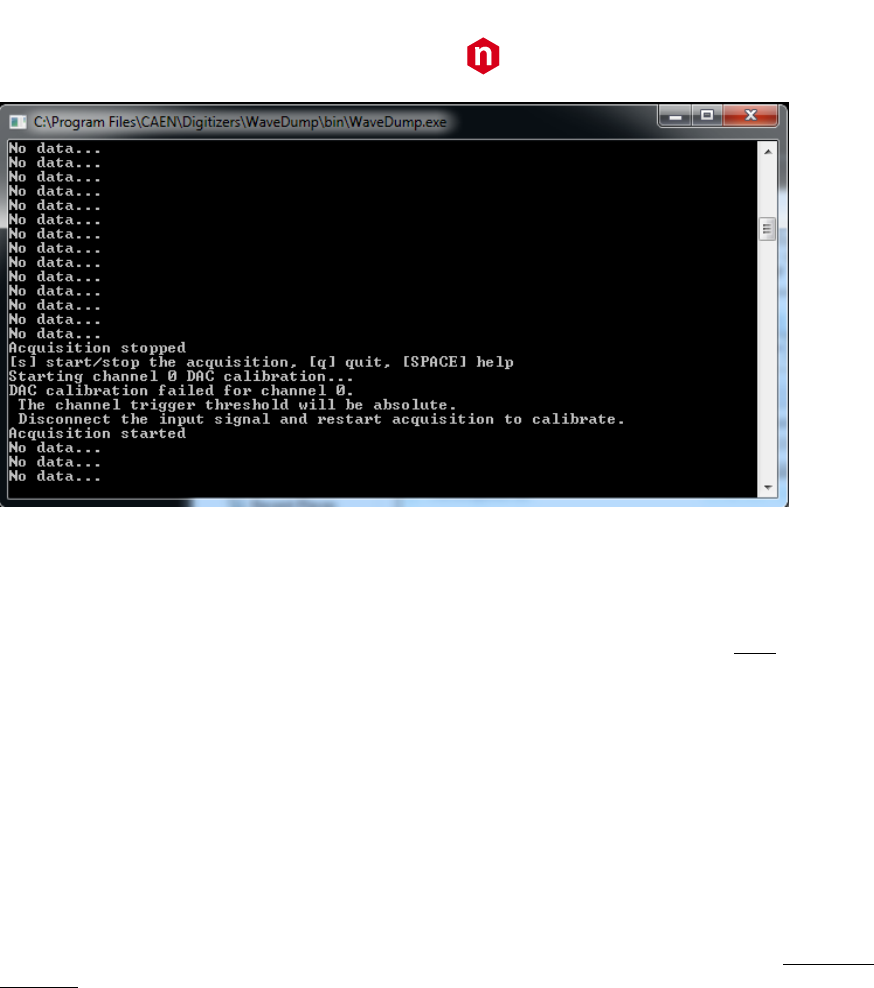
Note: When using BASELINE_SHIFT option, a preliminary check is done on every active channel to check whether
DAC calibration is feasible or not. A temporary 50% BASELINE_SHIFT value is set, and a single waveform acquisition
is performed, with the user-defined record length. In case the baseline samples in the acquired waveform are <60% of
the total record length, or in case the baseline deviates by 25% from the expected value, the calibration will not be
executed. A message will appear in the software interface: “DAC calibration failed for channel n”. The instructions to
recalibrate the channel are given.
CAEN
Electronic Instrumentation
UM2091 – WaveDump User Manual Rev. 13
23
Figure 4.1: Channel baseline calibration failure when using BASELINE_SHIFT
DC_OFFSET value
The DC_OFFSET command allows to shift the input dynamics (-FSR / 2 to +FSR / 2, where FSR is the full-scale range)
towards negative or positive values. The DC_OFFSET value is expressed in percentage of the FSR. NOTE: For 740 and
742 series, the DC_OFFSET value is the same for all channels in the group, though it is possible to set different values
for each channel of a x742 digitizer through the GRP_CH_DC_OFFSET command.
value is a float number that ranges from -50.0 to 50.0, where -50.0 corresponds to a signal dynamic from -
FSR to 0 (completely negative signal), and 50.0 corresponds to a signal dynamic from 0 to FSR (completely
positive signal). Default value is 0, which corresponds to a signal dynamics of-FSR / 2 to +FSR / 2 (bipolar signal).
Note: ranges are different for 742 digitizer series. See GRP_CH_DC_OFFSET command.
Note: DC_OFFSET and BASELINE_SHIFT are intended to be used one alternatively to the other.
GRP_CH_DC_OFFSET dc_0, dc_1, dc_2, dc_3, dc_4, dc_5, dc_6, dc_7
The GRP_CH_DC_OFFSET command allows to adjust the DC_OFFSET level for each channel of a group (742 digitizer
series only).
dc_0 ... dc_n are float numbers that indicate the DC offset level for channel 0, …, n of the groups.
Values range from -50 to 50, where -50 corresponds to a dynamic from -3FSR/2 to -FSR/2 (maximum negative
signal), 50 corresponds to a dynamic from +FSR/2 to +3FSR/2 (maximum positive signal). Default value is 0, which
corresponds to a signal dynamic of -FSR / 2 to +FSR / 2 (bipolar signal).
TRIGGER_THRESHOLD value
Set the trigger threshold (in ADC counts) for the generation of the channel self-trigger.
value is an integer value that ranges from 0 to 2^Nbit-1, where Nbit is the number of bits of the ADC.
Note: if DC_OFFSET is used, the threshold is absolute, while, if BASELINE_SHIFT is used, the threshold is relative
to the baseline. In the latter case, the threshold is calculated as follows:
▪ POSITIVE PULSE POLARITY: threshold = baseline + TRIGGER_THRESHOLD
▪ NEGATIVE PULSE POLARITY: threshold = baseline - TRIGGER_THRESHOLD

CAEN
Electronic Instrumentation
UM2091 – WaveDump User Manual Rev. 13
24
CHANNEL_TRIGGER option
This command enables/disables the self-trigger function for a specific channel (or group in case of 740 series). The OR
of all the enabled channel self-trigger is used as a global trigger for the board. Moreover, as for the
EXTERNAL_TRIGGER command, the CHANNEL_TRIGGER decides how the channel self-triggers generated from the
threshold crossing are used.
option can be:
ACQUISITION_ONLY: the self-trigger causes the acquisition of one event in all the channels of the board,
regardless the channel(s) that generated it.
ACQUISITION_AND_TRGOUT: the same as ACQUISITION_ONLY. In addition, the global trigger is also
propagated to the TRG-OUT (or GPO for the Desktop and NIM versions) front panel connector.
TRGOUT_ONLY: the self-trigger does not cause the acquisition of an event, but the trigger signal is propagated
to the TRG-OUT (or GPO for the Desktop and NIM versions) front panel connector.
DISABLED: the self-trigger of the relevant channel is ignored.
CHANNEL_TRIGGER with x730 digitizers:
Specifically with x730 boards, where even and odd channels are paired, their 'CHANNEL_TRIGGER' value will be equal
to the one specified on the even channel, unless one of the two channels of the pair is set to 'DISABLED'. If so, the
other one behaves as usual.
Please, refer to the specific x730 digitizer User manual for details on the trigger management.
GROUP_TRG_ENABLE_MASK mask
This command enables the channels of a specific group (740 series only) to generate a self-trigger. The OR of the
enabled channels generates the group trigger. Then the OR of all groups generates the global trigger for the board.
mask is a hexadecimal number ranging from 0 to FF.
Note: When using BASELINE_SHIFT option, it is recommended to enable the self-trigger only for those channels
receiving an input signal, to avoid problems in the trigger management.
Note: ACQUISITION_AND_TRGOUT and TRGOUT_ONLY features are not available on x742 Models.

CAEN
Electronic Instrumentation
UM2091 – WaveDump User Manual Rev. 13
25
Individual Settings for x742 Fast Trigger Channels
The following settings are valid for x742 models only, where Fast Trigger channels (TR0 and TR1) are available.
For a complete description of Wave Dump practical use with 742 models, specifically for trigger management, please
refer to the Quick Start Guide [RD12]
The list of individual parameters for each group and Fast Trigger channel must be reported after the [i] keyword, where
“i” is the number of the selected group or the Fast Trigger channel name.
Example:
[0]
ENABLE_INPUT YES # setting 1 of group “0” section
GRP_CH_DC_OFFSET 0,0,50,0,-50,0,0,0 # setting 2 of group “0” section
...
[TR0]
DC_OFFSET 32768 # setting 1 of Fast Trigger 0 section
TRIGGER_THRESHOLD 20934 # setting 2 of Fast Trigger 0 section
For the Fast Trigger channels TR0 and TR1 the following parameters are available:
DC_OFFSET value
Set the DC_OFFSET level of the Fast Trigger channel.
value is a float number ranging from -50.0 to 50.0, where -50.0 corresponds to a signal dynamic from -
3/2 FSR to –FSR/2 (maximum negative dynamics), 0 corresponds to a signal dynamic from –FSR/2 to +FSR/2
(bipolar signal) and +50.0 corresponds to a signal dynamic from +FSR/2 to +3FSR/2 (maximum positive
dynamics).
TRIGGER_THRESHOLD value
Set the TRIGGER_THRESHOLD for the comparison level of the Fast Trigger channel.
value ranges from 0 to 65535.
According to the PCB revision of the board (refer to [RD7] for further details) and to the TRn type of signal we suggest
different values of DC_OFFSET and TRIGGER_THRESHOLD. Here some examples:
1. PCB rev. 0:
a. NIM signal on TR:
DC_OFFSET 4096
TRIGGER_THRESHOLD 29053
b. AC signal on TR:
DC_OFFSET 4096
TRIGGER_THRESHOLD 27776
c. TTL signal on TR:
DC_OFFSET 16384
TRIGGER_THRESHOLD 29016
Note: signal TR0 is the Fast Trigger for both groups 0 and 1 (all form factor versions), while signal TR1 is the Fast
Trigger for groups 2 and 3 (VME only).

CAEN
Electronic Instrumentation
UM2091 – WaveDump User Manual Rev. 13
26
2. PCB rev. 1:
a. NIM signal on TR
DC_OFFSET 32768
TRIGGER_THRESHOLD 20934
b. AC signal on TR
DC_OFFSET 32768
TRIGGER_THRESHOLD 26214
c. +2V signal on TR
DC_OFFSET 43520
TRIGGER_THRESHOLD 26214

CAEN
Electronic Instrumentation
UM2091 – WaveDump User Manual Rev. 13
27
5 Temperature Protection (725 and 730
series only)
The 725 and 730 digitizer families feature a temperature protection procedure saving the hardware from possible
damages due to internal over-temperature conditions. Substantially, this consists in monitoring the channels
temperature and, as soon as it exceeds a fixed limit, the firmware automatically:
• turns off all the channel ADCs;
• stops the acquisition, if running (data possibly stored at that moment can be readout in any case).
Please, refer to the board User Manual for details on the temperature protection procedure.
TEMPERATURE PROTECTION IS NOT SUPPORTED BY ROC FPGA FIRMWARE RELEASES < 4.5
WaveDump manages this feature as follows:
• If the over-temperature condition is reached by the board during the acquisition, while the firmware performs
the channels turning off, a message of “Over Temperature” is displayed, the acquisition is stopped, and the user
is required to quit the program.
• As long as the board remains in over-temperature condition, it is not possible to restart the acquisition (“Over
Temperature” message is still displayed).
• As soon as the board exits the over-temperature condition, a new acquisition can be started by the user.
TEMPERATURE PROTECTION IS NOT MANAGED BY WAVEDUMP SOFTWARE RELEASES < 3.6.6
CAEN
Electronic Instrumentation
UM2091 – WaveDump User Manual Rev. 13
28
6 Channel Calibration (725, 730, 751 and
761 series only)
Digitizers in the 725, 730, 751, and 761 families perform a self-calibration of the ADCs at power-on. Anyway, to achieve
the best performance, the calibration procedure is recommended to be executed, on command, after the ADCs have
stabilized their operating temperature.
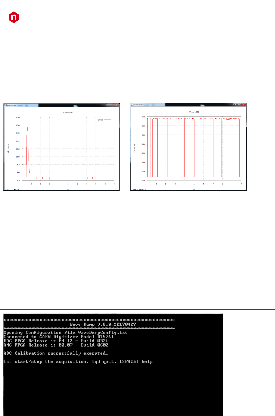
Figure 6.1: Example of uncalibrated input channel (baseline case on the right).
The calibration will not need to be repeated at each run unless the operating temperature changes significantly, or
clock settings are modified (e.g. switching from internal to external clock).
Channel Calibration Procedure
1. Launch WaveDump software. A message of ADC calibration successfully executed will be displayed (see Figure 6.2).
NOTES:
a) If the digitizer doesn't need calibration, calibration is not performed, and the message shown is:
“ADC Calibration not needed for this board family”
b) If SKIP_STARTUP_CALIBRATION parameter is set to YES in configuration file (see Chap. 4), the automatic
start-up calibration is not performed, and no message is displayed
Figure 6.2: Automatic calibration at WaveDump first run
The user can start using the program sure that the digitizer has been calibrated at least once.
2. At any time, the user can check the channel temperatures (with the acquisition not running) by issuing multiple “m”
commands from the keyboard.
CAEN
Electronic Instrumentation
UM2091 – WaveDump User Manual Rev. 13
29
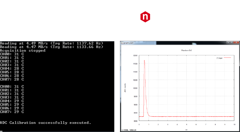
3. In case of significant variations, issuing a “c” command provokes a manual channel calibration to be executed.
Figure 6.3: Temperature monitoring with manual calibration command (left) and calibrated input signal (right)
4. A new acquisition can start.
Please, refer to the User Manual of the specific board for a detailed explanation of the channel calibration.


CAEN
Tools for Discovery
n
Electronic Instrumentation
UM2091 – WaveDump User Manual Rev. 13
31
CAEN SpA is acknowledged as the only company in the world providing a complete range of High/Low Voltage Power
Supply systems and Front-End/Data Acquisition modules which meet IEEE Standards for Nuclear and Particle Physics.
Extensive Research and Development capabilities have allowed CAEN SpA to play an important, long term role in this field.
Our activities have always been at the forefront of technology, thanks to years of intensive collaborations with the most
important Research Centres of the world. Our products appeal to a wide range of customers including engineers, scientists
and technical professionals who all trust them to help achieve their goals faster and more effectively.
CAEN S.p.A.
CAEN GmbH
CAEN Technologies, Inc.
Via Vetraia, 11
Klingenstraße 108
1140 Bay Street - Suite 2 C
55049 Viareggio
D-42651 Solingen
Staten Island, NY 10305
Italy
Germany
USA
Tel. +39.0584.388.398
Phone +49 (0)212 254 4077
Tel. +1.718.981.0401
Fax +39.0584.388.959
Fax +49 (0)212 25 44079
Fax +1.718.556.9185
info@caen.it
Mobile +49 (0)151 16 548 484
info@caentechnologies.com
www.caen.it
info@caen-de.com
www.caentechnologies.com
www.caen-de.com
CAEN
Tools for Discovery
Electronic Instrumentation
UM2091 - WaveDump User Manual rev. 13 - December 22nd, 2017
00117-10-DGT11-MUTX
Copyright © CAEN SpA. All rights reserved. Information in this publication supersedes all earlier versions. Specifications subject to change without notice.
